/


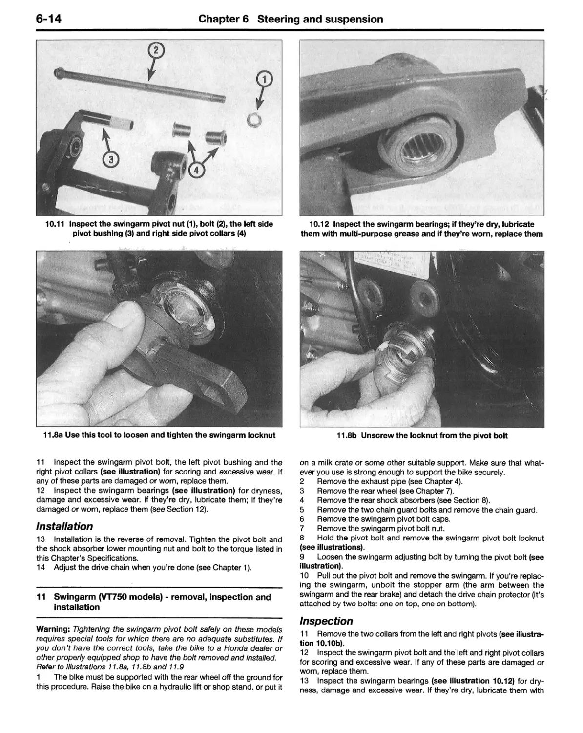


Текст
Acknowledgments
Our thanks to Honda of Milpitas, Milpitas, CA, for providing the motor¬
cycles used in these photographs; to Pete Sirett, service manager, for
arranging the facilities and fitting the project into his shop’s busy
schedule; and to Bruce Farley, service technician, for doing the
mechanical work and providing valuable technical information. Wiring
diagrams originated exclusively for Haynes North America, Inc. by
George Edward Brodd.
© Haynes North America, Inc. 1999, 2000, 2003
With permission from J.H. Haynes & Co. Ltd.
A book in the Haynes Owners Workshop Manual Series
Printed in the U.S.A.
All rights reserved. No part of this book may be reproduced or trans¬
mitted in any form or by any means, electronic or mechanical, includ¬
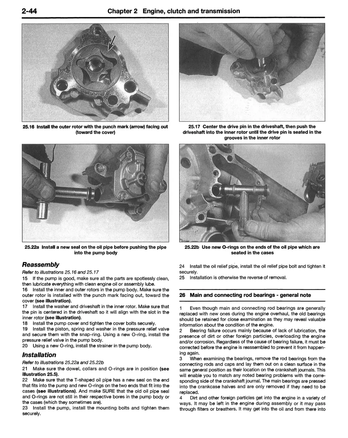
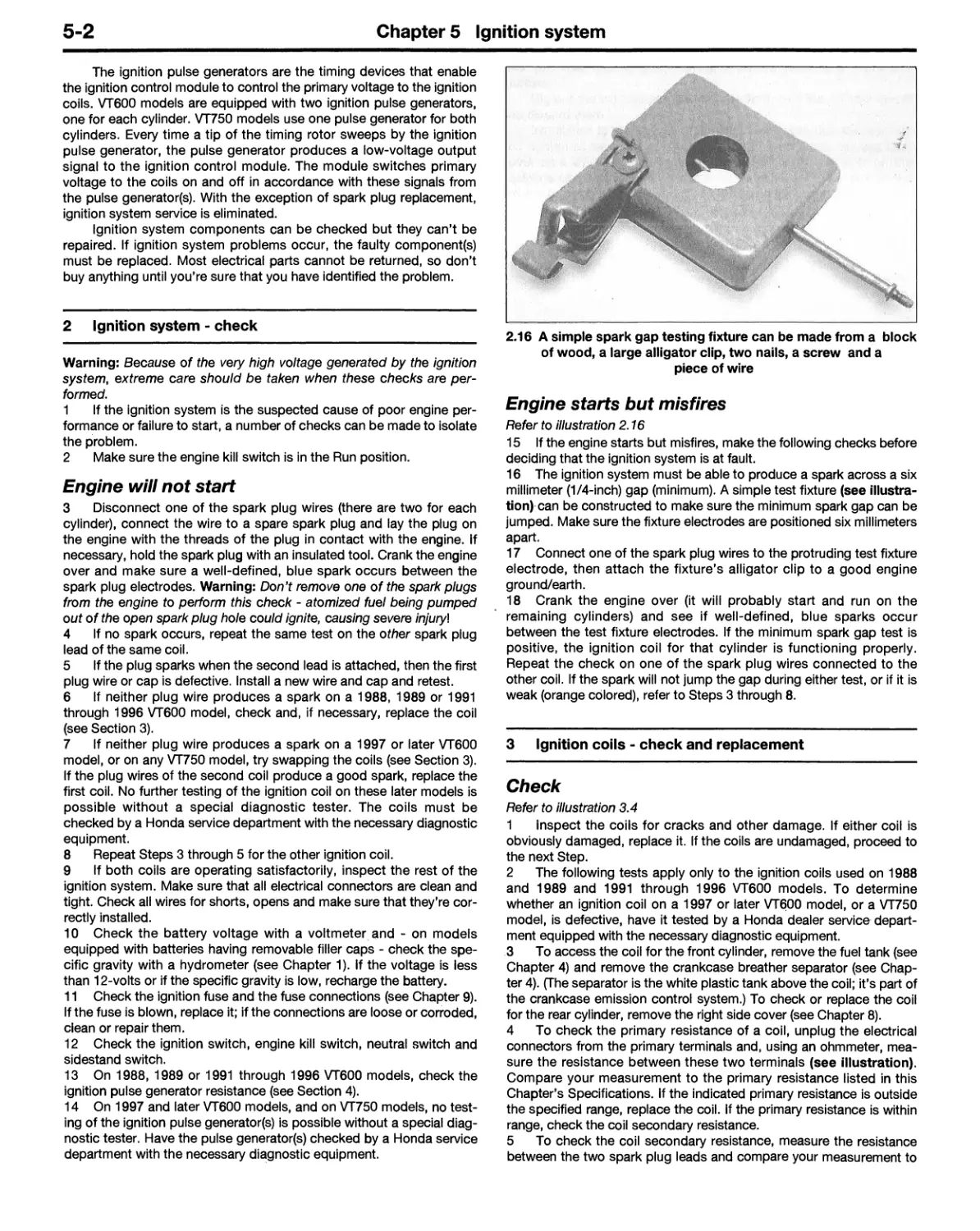
ing photocopying, recording or by any information storage or retrieval
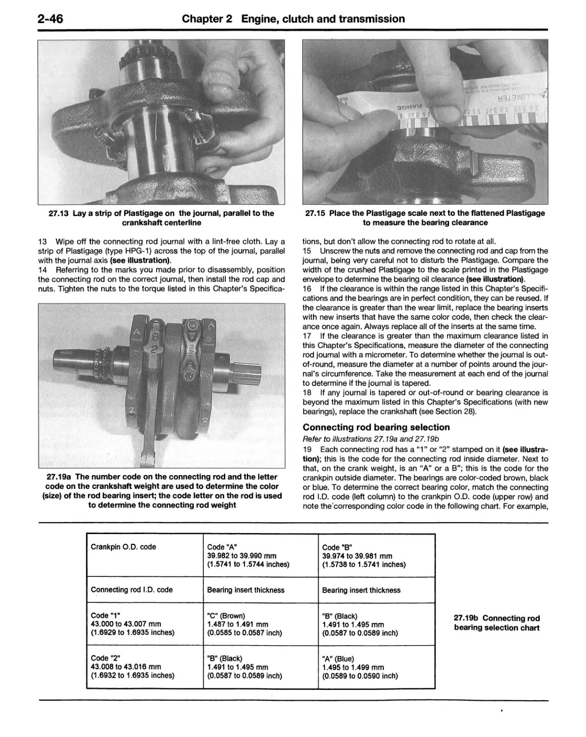
system, without permission in writing from the copyright holder.
ISBN 1 56392 516 8
Library of Congress Control Number 2003110305
British Library Cataloguing in Publication Data
A catalogue record for this book is available from the British Library
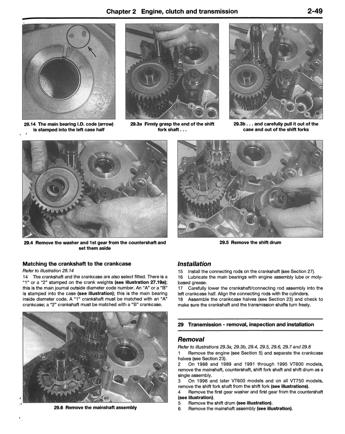
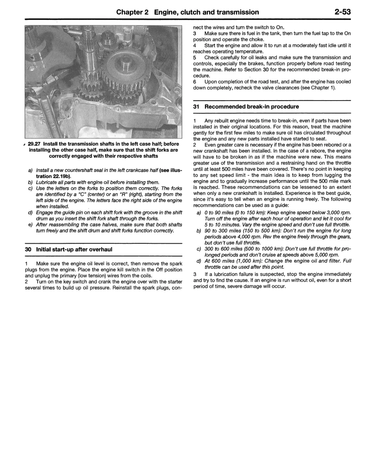
We take great pride in the accuracy of information given in this
manual, but motorcycle manufacturers make alterations and
design changes during the production run of a particular motorcy¬
cle of which they do not inform us. No liability can be accepted by
the authors or publishers for loss, damage or injury caused by any
errors in, or omissions from, the information given.
03-224
Contents
Introductory pages
About this manual
0-5
Introduction to the Honda Shadow
(VT600C/CD and VT750C/CD)
0-5
Identification numbers
0-6
Buying parts
0-7
General specifications
0-8
Maintenance techniques, tools and working facilities
0-10
Safety first!
0-16
Motorcycle chemicals and lubricants
0-18
Troubleshooting
0-19
Chapter 1
Tune-up and routine maintenance
1-1
Chapter 2
Engine, clutch and transmission
2-1
Chapter 3
Cooling system
3-1
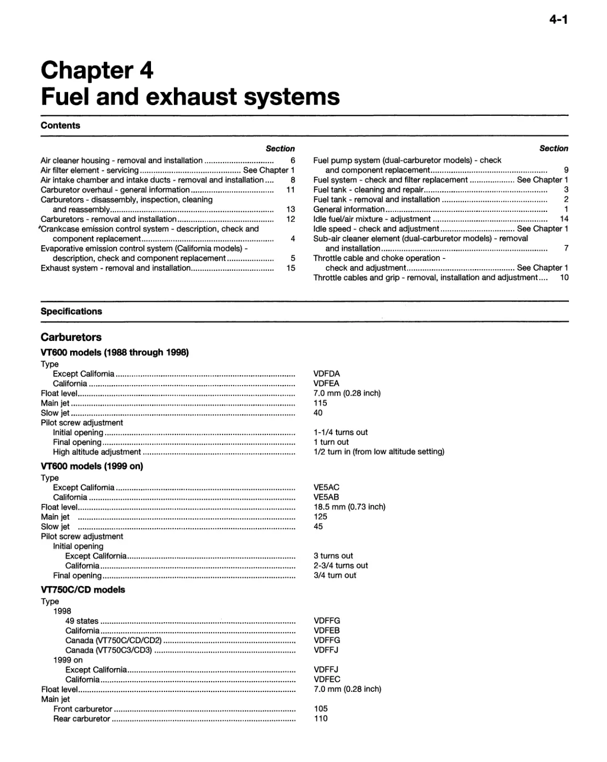
Chapter 4
Fuel and exhaust systems
4-1
Chapter 5
Ignition system
5-1
Chapter 6
Steering and suspension
6-1
Chapter 7
Brakes, wheels, tires and final drive
7-1
Chapter 8
Bodywork and frame
8-1
Chapter 9
Electrical system
9-1
Wiring diagrams
9-24
Conversion factors
9-30
Index
IND-1
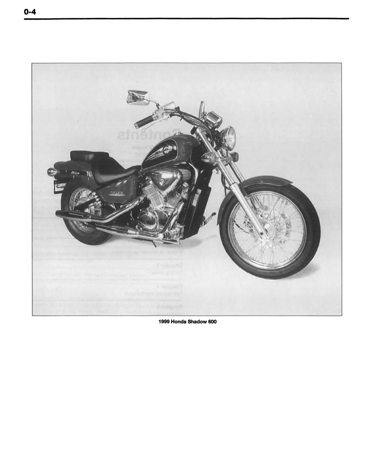
1999 Honda Shadow 600
0-5
About this manual
Its purpose
The purpose of this manual is to help you get the best value from
your motorcycle. It can do so in several ways. It can help you decide
what work must be done, even if you choose to have it done by a
dealer service department or a repair shop; it provides information and
procedures for routine maintenance and servicing; and it offers diag¬
nostic and repair procedures to follow when trouble occurs.
We hope you use the manual to tackle the work yourself. For
many simpler jobs, doing it yourself may be quicker than arranging an
appointment to get the vehicle into a shop and making the trips to
leave it and pick it up. More importantly, a lot of money can be saved
by avoiding the expense the shop must pass on to you to cover its
labor and overhead costs. An added benefit is the sense of satisfaction
and accomplishment that you feel after doing the job yourself.
Using the manual
The manual is divided into Chapters. Each Chapter is divided into
numbered Sections, which are headed in bold type between horizontal
lines. Each Section consists of consecutively numbered paragraphs or
steps.
At the beginning of each numbered Section you will be referred to
any illustrations which apply to the procedures in that Section. The ref¬
erence numbers used in illustration captions pinpoint the pertinent
Section and the Step within that Section. That is, illustration 3.2 means
the illustration refers to Section 3 and Step (or paragraph) 2 within that
Section.
Procedures, once described in the text, are not normally
repeated. When it’s necessary to refer to another Chapter, the refer¬
ence will be given as Chapter and Section number. Cross references
given without use of the word ‘Chapter’ apply to Sections and/or para¬
graphs in the same Chapter. For example, ‘see Section 8’ means in the
same Chapter.
References to the left or right side of the vehicle assume you are
sitting on the seat, facing forward.
Motorcycle manufacturers continually make changes to specifica¬
tions and recommendations, and these, when notified, are incorpo¬
rated into our manuals at the earliest opportunity.
Even though we have prepared this manual with extreme care,
neither the publisher nor the authors can accept responsibility for any
errors in, or omissions from, the information given.
NOTE
A Note provides information necessary to properly complete a procedure or information which will make the procedure easier
to understand.
CAUTION
A Caution provides a special procedure or special steps which must be taken while completing the procedure where the Cau¬
tion is found. Not heeding a Caution can result in damage to the assembly being worked on.
WARNING
A Warning provides a special procedure or special steps which must be taken while completing the procedure where the
Warning is found. Not heeding a Warning can result in personal injury.
Introduction to the
Honda VT600 and VT750 Shadow V-Twins
The Honda VT600 Shadow and VT750 Shadow are popular
cruiser-style motorcycles. Their light weight, V-twin engines, excellent
brakes and good handling have made these machines two of the more
popular mid-size bikes.
The engine on all models is a liquid-cooled V-twin with single
overhead camshafts and three valves (two intake, one exhaust) per
cylinder. Fuel is delivered through one or two carburetors, depending
on model.
The front suspension uses telescopic forks. The rear suspension
on VT600 models consists of a single shock absorber/spring unit,
mounted ahead of the swingarm. VT750 models have a conventional
twin-shock setup. The rear spring preload is adjustable on all models.
The front brake on all models is a hydraulically actuated dual-pis-
ton caliper. The rear brake on all models is a mechanically-actuated
drum brake.
0-6
Identification numbers
The vehicle identification number (VIN) is stamped into the left
side of the steering head, and/or is located on a label affixed to the
right side of the frame, below the exhaust pipe. The frame serial num¬
ber is stamped into the right side of the steering head and the engine
serial number is stamped into the lower right side of the rear cylinder.
These numbers should be recorded and kept in a safe place so they
can be furnished to law enforcement officials in the event of theft.
The VIN, frame serial number, engine serial number and carbure¬
tor identification number should be kept in a handy place (such as your
wallet) so they are always available when purchasing or ordering parts
for your machine.
Other important identification numbers include the carburetor
identification number and the color code. The carburetor identification
number is stamped into the intake side of the carburetor. On VT600
models, the color code is located under the seat, on a label affixed to
the inner side of the left upper frame tube, next to the fuel filter; on
VT750 models, it’s on a label affixed to the front side of the left frame
tube, right below the ignition switch and just ahead of the left passen¬
ger peg. Always refer to the color code when buying painted parts
such as the fuel tank, fenders or side covers. .
The models covered by this manual are as follows:
VT600C Shadow VLX (1988 and 1989)
VT600CD Shadow VLX Deluxe (1988 and 1989)
VT600C Shadow VLX (1991 through 1996)
VT600CD Shadow VLX Deluxe (1991 through 1996)
VT600C Shadow VLX (1997 through 2003)
VT600CD VLX Deluxe (1997 through 2003)
VT750C Shadow American Classic Edition (1998 through 2003)
VT750CD Shadow Deluxe American Classic Edition
(1998 through 2003)
VT750DC Shadow Spirit 750, (2001 through 2003)
The Vehicle Identification Number (VIN) is stamped into the left
side of the steering head
The VIN is also displayed on a label affixed to the right frame rail
The frame serial number is stamped into the right side of the
steering head
The engine serial number is stamped into the right side of the
crankcase, below the rear cylinder
Identification numbers
0-7
The following table is a breakdown of the initial frame numbers for each model and year of production:
Year
Model
Initial frame number
2000
VT600
Except California: PC210 YK or YM
1988
VT600
Except California: PC210 JM
California PC211 JM
VT600CD
California: PC211 YK or YM
Except California: PC213 YK or YM
1989
VT600
Except California: PC210 KM
California: PC211 KM
VT600CD2
California: PC214YK or YM
Except California: PC216 YK or YM
1991
VT600
Except California: PC210 MM
California: PC211 MM
VT750C
California: PC217 YK or YM
Except California: RC440 YK or YK
1992
VT600
Except California: PC210 NM
California: PC211 MM
VT750CD
California: RC441 YM or YK
Except California: RC443 YM or YK
1993
VT600
Except California: PC210 PM
California: PC211 PM
VT750CD2
California: RC444 YM or YK
Except California: RC446 YM or YK
1994
VT600
Except California: PC210 RM
2001
California: RC447 YM or YK
California: PC211 RM
1995
VT600
Except California: PC210 SM
California: PC211 SM
VT600C
Except California: PC210 1K or 1M
California: PC211 1K or 1M
VT600D
Except California: PC213 SM
California: PC214 SM
VT600CD
Except California: PC213 1K or 1M
California: PC214 1Kor1M
1996
VT600
Except California: PC210 TM
California: PC211 TM
VT750CD
Except California: RC443 1K
California: RC444 1K
1996
VT600D
Except California: PC213 TM
California: PC214TM
VT750CD2
Except California: RC446 1K
California: RC447 1K
1997
Not available at time of printing.
VT750DC
Except California: RC440 1K
1998
VT600
Not available at time of printing.
2002
California: RC441 1K
VT750C
Except California: RC440 WM
California: RC441 WM
VT600C
Except California: PC210 2K or 2M
California: PC211 2Kor2M
VT750CD
Except California: RC443 WM
California: RC444 WM
VT600CD
Except California: PC213 2K or 2M
California: PC214 2Kor 2M
Year
Model
Initial frame number
VT750CD,
VT750CD2
Except California: RC446 WM
VT750CD2
VT750DC
Not available at time of printing
California: RC447WM
Except California: RC440 2M
1999
VT600
Except California: PC210 XM9
California: PC211 XM9
2003
California: RC441 2M
VT600D
Except California: PC213 XM9
California: PC214 XM9
VT600C
Except California: PC210 3K or 3M
California: PC211 3K or 3M
VT600D2
Except California: PC216 XM9
VT600CD
Except California: PC213 3K or 3M
California: PC217XM9
VT750CD,
California: PC214 3K or 3M
VT750C
Except California: RC440 XM1
Not available at time of printing
California: RC441 XM1
VT750CD2
VT750DCA
VT750CD
Except California: RC443 XM1
California: RC444 XM1
Except California: RC440 3M
California: RC441 3M
VT750CD2
Except California: RC446 XM1
California: RC447 XM1
VT750DCB
Except California: RC445 3M
California: RC448 3M
Buying parts
Once you have found all the identification numbers, record them
for reference when buying parts. Since the manufacturers change
specifications, parts and vendors (companies that manufacture various
components on the machine), providing the ID numbers is the only way
to be reasonably sure that you are buying the correct parts.
Whenever possible, take the worn part to the dealer so direct
comparison with the new component can be made. Along the trail from
the manufacturer to the parts shelf, there are numerous places that the
part can end up with the wrong number or be listed incorrectly.
The two places to purchase new parts for your motorcycle - the
accessory store and the franchised dealer - differ in the type of parts
they carry. While dealers can obtain virtually every part for your motor¬
cycle, the accessory dealer is usually limited to normal high wear items
such as shock absorbers, tune-up parts, various engine gaskets,
cables, chains, brake parts, etc. Rarely will an accessory outlet have
major suspension components, cylinders, transmission gears, or cases.
Used parts can be obtained for roughly half the price of new ones,
but you can’t always be sure of what you’re getting. Once again, take
your worn part to the wrecking yard (breaker) for direct comparison.
Whether buying new, used or rebuilt parts, the best course is to deal
directly with someone who specializes in parts for your particular make.
0-8
General specifications
600 models
Frame and suspension
Wheelbase
1988 through1998
1999 and later
Overall length
Overall width
1988 and 1989,1991 through 1994.
1995 through 1998 ...
1999 and later
Overall height
1988 through 1998
1999 and later
Seat height
1988 through 1998
1999 and later
Dry weight
1988 and 1999,1991 through 1993.
1994
1995 and 1996
VT600C
VT600CD
1997 and 1998
VT600C
VT600CD
Except California
California
1999 and later
VT600C
Except California
California
VT600CD
Except California
California
Front suspension
Rear suspension
Front brake •
Rear brake
Fuel capacity
1988 and 1989,1991 through 1993
1994 on
Engine
Type
Displacement
Compression ratio
Ignition system
Carburetor type
1988 through 1998
1999 on
Transmission
1605 mm (63.2 inches)
1600 mm (63.0 inches)
2310 mm (90.9 inches)
760 mm (29.9 inches)
890 mm (35.0 inches)
880 mm (34.6 inches)
1125 mm (44.3 inches)
1120 mm (44.1 inches)
690 mm (27.2 inches)
650 mm (25.6 inches)
196 kg (432 pounds)
199 kg (439 pounds)
199 kg (439 pounds)
202 kg (445 pounds)
199 kg (439 pounds)
202 kg (445 pounds)
203 kg (448 pounds)
205 kg (442 pounds)
206 kg (454 pounds)
208 kg (459 pounds)
209 kg (461 pounds)
Telescopic fork
Single shock absorber/coil spring
Single hydraulic disc with 2-piston caliper
Mechanically-actuated drum brake
9 liters (2.4 US gallons)
11 liters (2.9 US gallons)
Liquid-cooled, 4-stroke, SOHC 52-degree V-twin
583 cc
9.2 to 1
Transistorized
Two 34 mm Keihin CV carburetors
Single 34 mm Keihin CV carburetor
4-speed, constant mesh
General specifications
0-9
750 models
Frame and suspension - VT750C/CD Shadow/Shadow Deluxe American Classic Edition 750
Wheelbase 1615 mm (63.6 inches)
Overall length 2450 mm (96.5 Inches)
Overall width 980 mm (38.6 inches)
Overall height
VT750C 1135 mm (44.7 inches)
VT750CD and CD2
1998 through 2000
2001 and later
VT750C3 and CD3
Seat height
Dry weight
Front suspension
Rear suspension
Front brake
Rear brake
Fuel capacity
Frame and suspension - VT750DC Shadow Spirit 750
Wheelbase
Overall length
Overall width
Overall height
Seat height
Dry weight
Except California
California
Front suspension
Rear suspension
Front brake
Rear brake
Fuel capacity
Engine - all 750 models
Type Liquid-cooled, 4-stroke, SOHC 52-degree V-twin
Displacement 745 cc
Compression ratio 9.0 to 1
Ignition system Transistorized
Carburetor type Two 34 mm Keihin CV carburetors
Transmission 5-speed, constant mesh
224.5 kg (494.9 pounds)
225.7 kg (497.6 pounds)
Telescopic fork
Dual shock absorbers/coil springs
Single hydraulic disc with 2-piston caliper
Mechanically-actuated drum brake
13 liters (3.43 US gallons)
1135 mm (44.7 inches)
1110 mm (43.7 inches)
1110 mm (43.7 inches)
700 mm (27.6 inches)
229 kg (505 pounds)
Telescopic fork
Dual shock absorbers/coil springs
Single hydraulic disc with 2-piston caliper
Mechanically-actuated drum brake
14 liters (3.7 US gallons)
1645 mm (64.8 inches)
2335 mm (91.9 inches)
800 mm (31.5 inches)
1071 mm (42.1 inches)
675 mm (26.6 inches)
0-10
Maintenance techniques,
tools and working facilities
Basic maintenance techniques
There are a number of techniques involved in maintenance and
repair that will be referred to throughout this manual. Application of
these techniques will enable the amateur mechanic to be more effi¬
cient, better organized and capable of performing the various tasks
properly, which will ensure that the repair job is thorough and com¬
plete.
Fastening systems
Fasteners, basically, are nuts, bolts and screws used to hold two
or more parts together. There are a few things to keep in mind when
working with fasteners. Almost all of them use a locking device of
some type (either a lock washer, locknut, locking tab or thread adhe¬
sive). All threaded fasteners should be clean, straight, have undam¬
aged threads and undamaged corners on the hex head where the
wrench fits. Develop the habit of replacing all damaged nuts and bolts
with new ones.
Rusted nuts and bolts should be treated with a penetrating oil to
ease removal and prevent breakage. Some mechanics use turpentine
in a spout type oil can, which works quite well. After applying the rust
penetrant, let it -work for a few minutes before trying to loosen the nut
or bolt. Badly rusted fasteners may have to be chiseled off or removed
with a special nut breaker, available at tool stores.
If a bolt or stud breaks off in an assembly, it can be drilled out and
removed with a special tool called an E-Z out (or screw extractor).
Most dealer service departments and motorcycle repair shops can
perform this task, as well as others (such as the repair of threaded
holes that have been stripped out).
Flat washers and lock washers, when removed from an assembly,
should always be replaced exactly as removed. Replace any damaged
washers with new ones. Always use a flat washer between a lock
washer and any soft metal surface (such as aluminum), thin sheet
metal or plastic. Special locknuts can only be used once or twice
before they lose their locking ability and must be replaced.
Tightening sequences and procedures
When threaded fasteners are tightened, they are often tightened
to a specific torque value (torque is basically a twisting force). Over-
tightening the fastener can weaken it and cause it to break, while
under-tightening can cause it to eventually come loose. Each bolt,
depending on the material it’s made of, the diameter of its shank and
the material it is threaded into, has a specific torque value, which is
noted in the Specifications. Be sure to follow the torque recommenda¬
tions closely.
Fasteners laid out in a pattern (i.e. cylinder head bolts, engine
case bolts, etc.) must be loosened or tightened in a sequence to avoid
warping the component. Initially, the bolts/nuts should go on finger
tight only. Next, they should be tightened one full turn each, in a criss¬
cross or diagonal pattern. After each one has been tightened one full
turn, return to the first one tightened and tighten them all one half turn,
following the same pattern. Finally, tighten each of them one quarter
turn at a time until each fastener has been tightened to the proper
torque. To loosen and remove the fasteners the procedure would be
reversed.
Disassembly sequence
Component disassembly should be done with care and purpose
to help ensure that the parts go back together properly during
reassembly. Always keep track of the sequence in which parts are
removed. Take note of special characteristics or marks on parts that
can be installed more than one way (such as a grooved thrust washer
on a shaft). It’s a good idea to lay the disassembled parts out on a
clean surface in the order that they were removed. It may also be help¬
ful to make sketches or take instant photos of components before
removal.
When removing fasteners from a component, keep track of their
locations. Sometimes threading a bolt back in a part, or putting the
washers and nut back on a stud, can prevent mix-ups later. If nuts and
bolts can’t be returned to their original locations, they should be kept in
a compartmented box or a series of small boxes. A cupcake or muffin
tin is ideal for this purpose, since each cavity can hold the bolts and
nuts from a particular area (i.e. engine case bolts, valve cover bolts,
engine mount bolts, etc.). A pan of this type is especially helpful when
working on assemblies with very small parts (such as the carburetors
and the valve train). The cavities can be marked with paint or tape to
identify the contents.
Whenever wiring looms, harnesses or connectors are separated,
it’s a good idea to identify the two halves with numbered pieces of
masking tape so they can be easily reconnected.
Gasket sealing surfaces
Throughout any motorcycle, gaskets are used to seal the mating
surfaces between components and keep lubricants, fluids, vacuum or
pressure contained in an assembly.
Many times these gaskets are coated with a liquid or paste type
gasket sealing compound before assembly. Age, heat and pressure can
sometimes cause the two parts to stick together so tightly that they are
very difficult to separate. In most cases, the part can be loosened by
striking it with a soft-faced hammer near the mating surfaces. A regular
hammer can be used if a block of wood is placed between the hammer
and the part. Do not hammer on cast parts or parts that could be easily
damaged. With any particularly stubborn part, always recheck to make
sure that every fastener has been removed.
Avoid using a screwdriver or bar to pry apart components, as they
can easily mar the gasket sealing surfaces of the parts (which must
remain smooth). If prying is absolutely necessary, use a piece of wood,
but keep in mind that extra clean-up will be necessary if the wood
splinters.
After the parts are separated, the old gasket must be carefully
scraped off and the gasket surfaces cleaned. Stubborn gasket material
can be soaked with a gasket remover (available in aerosol cans) to
soften it so it can be easily scraped off. A scraper can be fashioned
from a piece of copper tubing by flattening and sharpening one end.
Copper is recommended because it is usually softer than the surfaces
to be scraped, which reduces the chance of gouging the part. Some
gaskets can be removed with a wire brush, but regardless of the
method used, the mating surfaces must be left clean and smooth. If for
some reason the gasket surface is gouged, then a gasket sealer thick
enough to fill scratches will have to be used during reassembly of the
components. For most applications, a non-drying (or semi-drying) gas¬
ket sealer is best.
Hose removal tips
Hose removal precautions closely parallel gasket removal precau¬
tions. Avoid scratching or gouging the surface that the hose mates
against or the connection may leak. Because of various chemical reac¬
tions, the rubber in hoses can bond itself to the metal spigot that the
hose fits over. To remove a hose, first loosen the hose clamps that
secure it to the spigot. Then, with slip joint pliers, grab the hose at the
clamp and rotate it around the spigot. Work it back and forth until it is
completely free, then pull it off (silicone or other lubricants will ease
removal if they can be applied between the hose and the outside of the
spigot). Apply the same lubricant to the inside of the hose and the out¬
side of the spigot to simplify installation.
If a hose clamp is broken or damaged, do not reuse it. Also, do
not reuse hoses that are cracked, split or torn.
Maintenance techniques, tools and working facilities
0-11
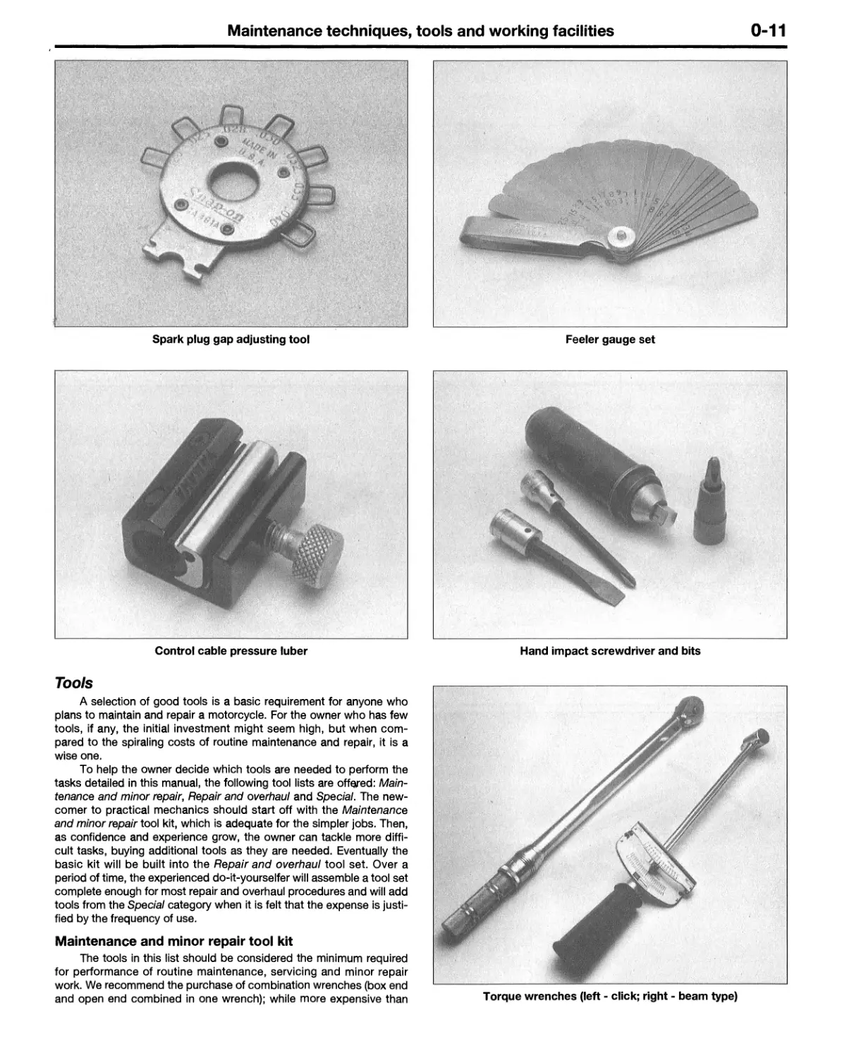
Spark plug gap adjusting tool Feeler gauge set
Control cable pressure luber Hand impact screwdriver and bits
Tools
A selection of good tools is a basic requirement for anyone who
plans to maintain and repair a motorcycle. For the owner who has few
tools, if any, the initial investment might seem high, but when com¬
pared to the spiraling costs of routine maintenance and repair, it is a
wise one.
To help the owner decide which tools are needed to perform the
tasks detailed in this manual, the following tool lists are offered: Main¬
tenance and minor repair, Repair and overhaul and Special. The new¬
comer to practical mechanics should start off with the Maintenance
and minor repair tool kit, which is adequate for the simpler jobs. Then,
as confidence and experience grow, the owner can tackle more diffi¬
cult tasks, buying additional tools as they are needed. Eventually the
basic kit will be built into the Repair and overhaul tool set. Over a
period of time, the experienced do-it-yourselfer will assemble a tool set
complete enough for most repair and overhaul procedures and will add
tools from the Special category when it is felt that the expense is justi¬
fied by the frequency of use.
Maintenance and minor repair tool kit
The tools in this list should be considered the minimum required
for performance of routine maintenance, servicing and minor repair
work. We recommend the purchase of combination wrenches (box end
and open end combined in one wrench); while more expensive than Torque wrenches (left - click; right - beam type)
0-12
Maintenance techniques, tools and working facilities
Snap-ring pliers (top - external; bottom - internal)
Valve spring compressor
Allen wrenches (left), and Allen head sockets (right)
Piston ring removal/installation tool
Piston pin puller
Telescoping gauges
Maintenance techniques, tools and working facilities
0-13
0-to-1 inch micrometer
Cylinder compression gauge
Cylinder surfacing hone
Dial indicator set
Multimeter (volt/ohm/ammeter)
Adjustable spanner
0-14
Maintenance techniques, tools and working facilities
open-ended ones, they offer the advantages of both types of wrench.
Combination wrench set (6 mm to 22 mm)
Adjustable wrench - 8 in
Spark plug socket (with rubber insert)
Sparkplug gap adjusting tool
Feeler gauge set
Standard screwdriver (5/16 in x 6 in)
Phillips screwdriver (No. 2x6 in)
Allen (hex) wrench set (4 mm to 12 mm)
Combination (slip-joint) pliers - 6 in
Hacksaw and assortment of blades
Tire pressure gauge
Control cable pressure luber
Grease gun
Oil can
Fine emery cloth
Wire brush
Hand impact screwdriver and bits
Funnel (medium size)
Safety goggles
Drain pan
Work light with extension cord
Repair and overhaul tool set
These tools are essential for anyone who plans to perform major
repairs and are intended to supplement those in the Maintenance and
minor repair tool kit. Included is a comprehensive set of sockets which,
though expensive, are invaluable because of their versatility (especially
when various extensions and drives are available). We recommend the
3/8 inch drive over the 1/2 inch drive for general motorcycle mainte¬
nance and repair (ideally, the mechanic would have a 3/8 inch drive set
and a 1/2 inch drive set).
Alternator rotor removal tool
Socket set(s)
Reversible ratchet
Extension - 6 in
Universal joint
Torque wrench (same size drive as sockets)
Ball pein hammer - 8 oz
Soft-faced hammer (plastic/rubber)
Standard screwdriver (1/4 in x 6 in)
Standard screwdriver (stubby - 5/16 in)
Phillips screwdriver (No. 3x8 in)
Phillips screwdriver (stubby - No. 2)
Pliers - locking
Pliers - lineman’s
Pliers - needle nose
Pliers - snap-ring (internal and external)
Cold chisel -1/2 in
Scriber
Scraper (made from flattened copper tubing)
Center punch
Pin punches (1/16, 1/8, 3/16 in)
Steel rule/straightedge -12 in
Pin-type spanner wrench
A selection of files
Wire brush (large)
Note: Another tool which is often useful is an electric drill with a chuck
capacity of 3/8 inch (and a set of good quality drill bits).
Special tools
The tools in this list include those which are not used regularly,
are expensive to buy, or which need to be used in accordance with
their manufacturer’s instructions. Unless these tools will be used fre¬
quently, it is not very economical to purchase many of them. A consid¬
eration would be to split the cost and use between yourself and a
friend or friends (i.e. members of a motorcycle club).
This list primarily contains tools and instruments widely available
to the public, as well as some special tools produced by the vehicle
manufacturer for distribution to dealer service departments. As a
result, references to the manufacturer’s special tools are occasionally
included in the text of this manual. Generally, an alternative method of
doing the job without the special tool is offered. However, sometimes
there is no alternative to their use. Where this is the case, and the tool
can’t be purchased or borrowed, the work should be turned over to the
dealer service department or a motorcycle repair shop.
Paddock stand (for models not fitted with a centerstand)
Valve spring compressor
Piston ring removal and installation tool
Piston pin puller
Telescoping gauges
Micrometerfs) and/or dial/Vernier calipers
Cylinder surfacing hone
Cylinder compression gauge
Dial indicator set
Multimeter
Adjustable spanner
Manometer or vacuum gauge set
Small air compressor with blow gun and tire chuck
Buying tools
For the do-it-yourselfer who is just starting to get involved in
motorcycle maintenance and repair, there are a number of options
available when purchasing tools. If maintenance and minor repair is the
extent of the work to be done, the purchase of individual tools is satis¬
factory. If, on the other hand, extensive work is planned, it would be a
good idea to purchase a modest tool set from one of the large retail
chain stores. A set can usually be bought at a substantial savings over
the individual tool prices (and they often come with a tool box). As
additional tools are needed, add-on sets, individual tools and a larger
tool box can be purchased to expand the tool selection. Building a tool
set gradually allows the cost of the tools to be spread over a longer
period of time and gives the mechanic the freedom to choose only
those tools that will actually be used.
Tool stores and motorcycle dealers will often be the only source
of some of the special tools that are needed, but regardless of where
tools are bought, try to avoid cheap ones (especially when buying
screwdrivers and sockets) because they won’t last very long. There are
plenty of tools around at reasonable prices, but always aim to pur¬
chase items which meet the relevant national safety standards. The
expense involved in replacing cheap tools will eventually be greater
than the initial cost of quality tools.
It is obviously not possible to cover the subject of tools fully here.
For those who wish to learn more about tools and their use, there is a
book entitled Motorcycle Workshop Practice Manual (Book no. 1454)
available from the publishers of this manual. It also provides an intro¬
Maintenance techniques, tools and working facilities
0-15
duction to basic workshop practice which will be of interest to a home
mechanic working on any type of motorcycle.
Care and maintenance of tools
Good tools are expensive, so it makes sense to treat them with
respect. Keep them clean and in usable condition and store them
properly when not in use. Always wipe off any dirt, grease or metal
chips before putting them away. Never leave tools lying around in the
work area.
Some tools, such as screwdrivers, pliers, wrenches and sockets,
can be hung on a panel mounted on the garage or workshop wall,
while others should be kept in a tool box or tray. Measuring instru¬
ments, gauges, meters, etc. must be carefully stored where they can’t
be damaged by weather or impact from other tools.
When tools are used with care and stored properly, they will last a
very long time. Even with the best of care, tools will wear out if used
frequently. When a tool is damaged or worn out, replace it; subsequent
jobs will be safer and more enjoyable if you do.
Working facilities
Not to be overlooked when discussing tools is the workshop. If
anything more than routine maintenance is to be carried out, some sort
of suitable work area is essential.
It is understood, and appreciated, that many home mechanics do
not have a good workshop or garage available and end up removing an
engine or doing major repairs outside (it is recommended, however,
that the overhaul or repair be completed under the cover of a roof).
A clean, flat workbench or table of comfortable working height is
an absolute necessity. The workbench should be equipped with a vise
that has a jaw opening of at least four inches.
As mentioned previously, some clean, dry storage space is also
required for tools, as well as the lubricants, fluids, cleaning solvents,
etc. which soon become necessary.
Sometimes waste oil and fluids, drained from the engine or cool¬
ing system during normal maintenance or repairs, present a disposal
problem. To avoid pouring them on the ground or into a sewage sys¬
tem, simply pour the used fluids into large containers, seal them with
caps and take them to an authorized disposal site or service station.
Plastic jugs (such as old antifreeze containers) are ideal for this pur¬
pose.
Always keep a supply of old newspapers and clean rags avail¬
able. Old towels are excellent for mopping up spills. Many mechanics
use rolls of paper towels for most work because they are readily avail¬
able and disposable. To help keep the area under the motorcycle
clean, a large cardboard box can be cut open and flattened to protect
the garage or shop floor.
Whenever working over a painted surface (such as the fuel tank)
cover it with an old blanket or bedspread to protect the finish.
0-16
Safety first!
Professional mechanics are trained in safe working procedures.
However enthusiastic you may be about getting on with the job at
hand, take the time to ensure that your safety is not put at risk. A
moment’s lack of attention can result in an accident, as can failure to
observe simple precautions.
There will always be new ways of having accidents, and the fol¬
lowing is not a comprehensive list of all dangers; it is intended rather to
make you aware of the risks and to encourage a safe approach to all
work you carry out on your bike.
Essential DOs and DON’Ts
DON’T start the engine without first ascertaining that the transmission
is in neutral.
DON’T suddenly remove the pressure cap from a hot cooling system -
cover it with a cloth and release the pressure gradually first, or you may
get scalded by escaping coolant.
DON’Y attempt to drain oil until you are sure it has cooled sufficiently
to avoid scalding you.
DON’T grasp any part of the engine or exhaust system without first
ascertaining that it is cool enough not to burn you.
DON’T allow brake fluid or antifreeze to contact the machine’s paint
work or plastic components.
DON’T siphon toxic liquids such as fuel, hydraulic fluid or antifreeze by
mouth, or allow them to remain on your skin.
DON’T inhale dust - it may be injurious to health (see Asbestos head-
ing).
DON’T allow any spilled oil or grease to remain on the floor - wipe it up
right away, before someone slips on it.
DON’T use ill fitting wrenches or other tools which may slip and cause
injury.
DON’T attempt to lift a heavy component which may be beyond your
capability - get assistance.
DON’T rush to finish a job or take unverified short cuts.
DON’T allow children or animals in or around an unattended vehicle.
DON’T inflate a tire to a pressure above the recommended maximum.
Apart from over stressing the carcase and wheel rim, in extreme cases
the tire may blow off forcibly.
DO ensure that the machine is supported securely at all times. This is
especially important when the machine is blocked up to aid wheel or
fork removal.
DO take care when attempting to loosen a stubborn nut or bolt. It is
generally better to pull on a wrench, rather than push, so that if you
slip, you fall away from the machine rather than onto it.
DO wear eye protection when using power tools such as drill, sander,
bench grinder etc.
DO use a barrier cream on your hands prior to undertaking dirty jobs - it
will protect your skin from infection as well as making the dirt easier to
remove afterwards; but make sure your hands aren’t left slippery. Note
that long-term contact with used engine oil can be a health hazard.
DO keep loose clothing (cuffs, ties etc. and long hair) well out of the
way of moving mechanical parts.
DO remove rings, wristwatch etc., before working on the vehicle -
especially the electrical system.
DO keep your work area tidy - it is only too easy to fall over articles left
lying around.
DO exercise caution when compressing springs for removal or installa¬
tion. Ensure that the tension is applied and released in a controlled
manner, using suitable tools which preclude the possibility of the
spring escaping violently.
DO ensure that any lifting tackle used has a safe working load rating
adequate for the job.
DO get someone to check periodically that all is well, when working
alone on the vehicle.
DO carry out work in a logical sequence and check that everything is
correctly assembled and tightened afterwards.
DO remember that your vehicle’s safety affects that of yourself and
others. If in doubt on any point, get professional advice.
IF, in spite of following these precautions, you are unfortunate enough
to injure yourself, seek medical attention as soon as possible.
Asbestos '
Certain friction, insulating, sealing and other products - such as
brake pads, clutch linings, gaskets, etc. - contain asbestos. Extreme
care must be taken to avoid inhalation of dust from such products
since it is hazardous to health. If in doubt, assume that they do contain
asbestos.
Fire
Remember at all times that gasoline (petrol) is highly flammable.
Never smoke or have any kind of naked flame around, when working
on the vehicle. But the risk does not end there - a spark caused by an
electrical short-circuit, by two metal surfaces contacting each other, by
careless use of tools, or even by static electricity built up in your body
under certain conditions, can ignite gasoline (petrol) vapor, which in a
confined space is highly explosive. Never use gasoline (petrol) as a
cleaning solvent. Use an approved safety solvent.
Always disconnect the battery ground (earth) terminal before
working on any part of the fuel or electrical system, and never risk
spilling fuel on to a hot engine or exhaust.
It is recommended that a fire extinguisher of a type suitable for
fuel and electrical fires is kept handy in the garage or workplace at all
times. Never try to extinguish a fuel or electrical fire with water.
Fumes
Certain fumes are highly toxic and can quickly cause uncon¬
sciousness and even death if inhaled to any extent. Gasoline (petrol)
vapor comes into this category, as do the vapors from certain solvents
such as trichloroethylene. Any draining or pouring of such volatile flu¬
Safety first!
0-17
ids should be done in a well ventilated area.
When using cleaning fluids and solvents, read the instructions
carefully. Never use materials from unmarked containers - they may
give off poisonous vapors.
Never run the engine of a motor vehicle in an enclosed space
such as a garage. Exhaust fumes contain carbon monoxide which is
extremely poisonous; if you need to run the engine, always do so in the
open air or at least have the rear of the vehicle outside the workplace.
The battery
Never cause a spark, or allow a naked light near the vehicle’s bat¬
tery. It will normally be giving off a certain amount of hydrogen gas,
which is highly explosive.
Always disconnect the battery ground (earth) terminal before
working on the fuel or electrical systems (except where noted).
If possible, loosen the filler plugs or cover when charging the bat¬
tery from an external source. Do not charge at an excessive rate or the
battery may burst.
Take care when topping up, cleaning or carrying the battery. The
acid electrolyte, even when diluted, is very corrosive and should not be
allowed to contact the eyes or skin. Always wear rubber gloves and
goggles or a face shield. If you ever need to prepare electrolyte your¬
self, always add the acid slowly to the water; never add the water to
the acid.
Electricity
When using an electric power tool, inspection light etc., always
ensure that the appliance is correctly connected to its plug and that,
where necessary, it is properly grounded (earthed). Do not use such
appliances in damp conditions and, again, beware of creating a spark
or applying excessive heat in the vicinity of fuel or fuel vapor. Also
ensure that the appliances meet national safety standards.
A severe electric shock can result from touching certain parts of
the electrical system, such as the Spark plug wires (HT leads), when
the engine is running or being cranked, particularly if components are
damp or the insulation is defective. Where an electronic ignition sys¬
tem is used, the secondary (HT) voltage is much higher and could
prove fatal.
0-18
Motorcycle chemicals and lubricants
A number of chemicals and lubricants are available for use in
motorcycle maintenance and repair. They include a wide variety of
products ranging from cleaning solvents and degreasers to lubricants
and protective sprays for rubber, plastic and vinyl.
Contact point/spark plug cleaner is a solvent used to clean oily
film and dirt from points, grime from electrical connectors and oil
deposits from spark plugs. It is oil free and leaves no residue. It can
also be used to remove gum and varnish from carburetor jets and
other orifices.
Carburetor cleaner is similar to contact point/spark plug cleaner
but it usually has a stronger solvent and may leave a slight oily reside.
It is not recommended for cleaning electrical components or connec¬
tions.
Brake system cleaner is used to remove grease or brake fluid
from brake system components (where clean surfaces are absolutely
necessary and petroleum-based solvents cannot be used); it also
leaves no residue.
Silicone-based lubricants are used to protect rubber parts such
as hoses and grommets, and are used as lubricants for hinges and
locks.
Multi-purpose grease is an all purpose lubricant used wherever
grease is more practical than a liquid lubricant such as oil. Some multi¬
purpose grease is colored white and specially formulated to be more
resistant to water than ordinary grease.
Gear oil (sometimes called gear lube) is a specially designed oil
used in transmissions and final drive units, as well as other areas
where high-friction, high-temperature lubrication is required. It is avail¬
able in a number of viscosities (weights) for various applications.
Motor oil, of course, is the lubricant specially formulated for use
in the engine. It normally contains a wide variety of additives to prevent
corrosion and reduce foaming and wear. Motor oil comes in various
weights (viscosity ratings) of from 5 to 80. The recommended weight of
the oil depends on the seasonal temperature and the demands on the
engine. Light oil is used in cold climates and under light load condi¬
tions; heavy oil is used in hot climates and where high loads are
encountered. Multi-viscosity oils are designed to have characteristics
of both light and heavy oils and are available in a number of weights
from 5W-20 to 20W-50.
Gas (petrol) additives perform several functions, depending on
their chemical makeup. They usually contain solvents that help dis¬
solve gum and varnish that build up on carburetor and intake parts.
They also serve to break down carbon deposits that form on the inside
surfaces of the combustion chambers. Some additives contain upper
cylinder lubricants for valves and piston rings.
Brake fluid is a specially formulated hydraulic fluid that can with-
' stand the heat and pressure encountered in brake systems. Care must
be taken that this fluid does not come in contact with painted surfaces
or plastics. An opened container should always be resealed to prevent
contamination by water or dirt.
Chain lubricants are formulated especially for use on motorcycle
final drive chains. A good chain lube should adhere well and have good
penetrating qualities to be effective as a lubricant inside the chain and
on the side plates, pins and rollers. Most chain lubes are either the
foaming type or quick drying type and are usually marketed as sprays.
Degreasers are heavy duty solvents used to remove grease and
grime that may accumulate on engine and frame components. They
can be sprayed or brushed on and, depending on the type, are rinsed
with either water or solvent.
Solvents are used alone or in combination with degreasers to
clean parts and assemblies during repair and overhaul. The home
mechanic should use only solvents that are non-flammable and that do
not produce irritating fumes.
Gasket sealing compounds may be used in conjunction with
gaskets, to improve their sealing capabilities, or alone, to seal metal-
to-metal joints. Many gasket sealers can withstand extreme heat,
some are impervious to gasoline and lubricants, while others are capa¬
ble of filling and sealing large cavities. Depending on the intended use,
gasket sealers either dry hard or stay relatively soft and pliable. They
are usually applied by hand, with a brush, or are sprayed on the gasket
sealing surfaces.
Thread cement is an adhesive locking compound that prevents
threaded fasteners from loosening because of vibration. It is available
in a variety of types for different applications.
Moisture dispersants are usually sprays that can be used to dry
out electrical components such as the fuse block and wiring connec¬
tors. Some types can also be used as treatment for rubber and as a
lubricant for hinges, cables and locks.
Waxes and polishes are used to help protect painted and plated
surfaces from the weather. Different types of paint may require the use
of different types of wax polish. Some polishes utilize a chemical or
abrasive cleaner to help remove the top layer of oxidized (dull) paint on
older vehicles. In recent years, many non-wax polishes (that contain a
wide variety of chemicals such as polymers and silicones) have been
introduced. These non-wax polishes are usually easier to apply and
last longer than conventional waxes and polishes.
Troubleshooting
0-19
Contents
Symptom Section Symptom Section
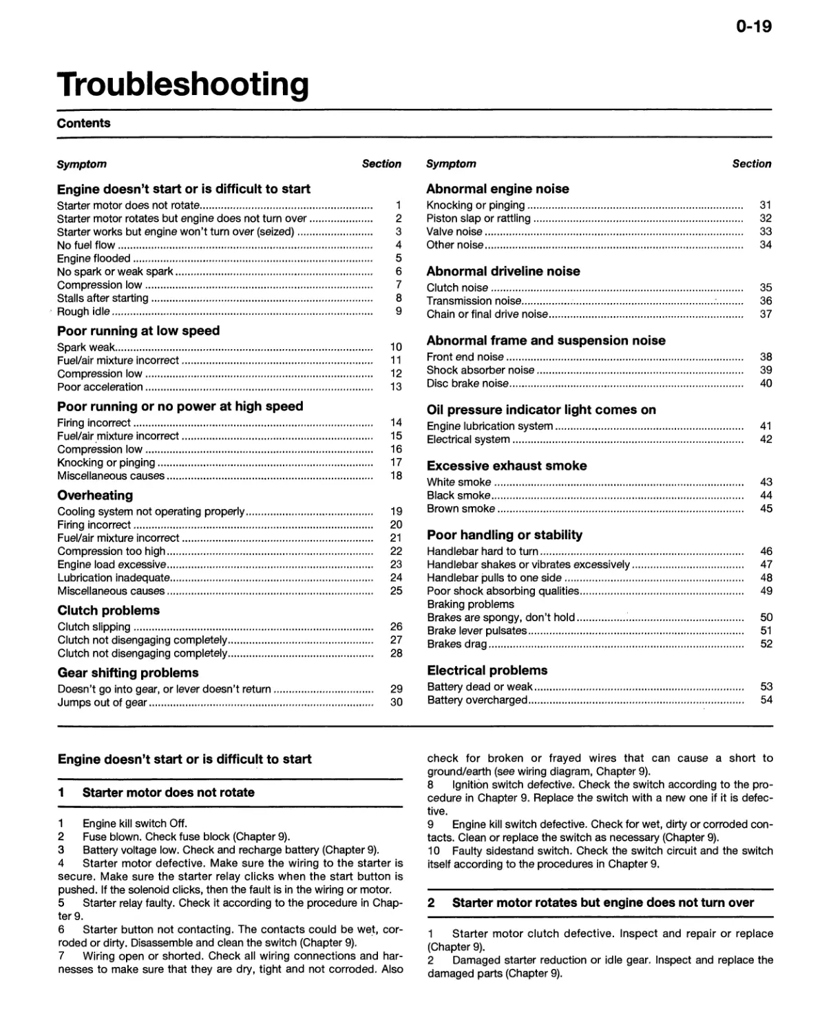
Engine doesn’t start or is difficult to start
Starter motor does not rotate 1
Starter motor rotates but engine does not turn over 2
Starter works but engine won’t turn over (seized) 3
No fuel flow 4
Engine flooded 5
No spark or weak spark 6
Compression low 7
Stalls after starting 8
Rough idle 9
Poor running at low speed
Spark weak 10
Fuel/air mixture incorrect 11
Compression low 12
Poor acceleration 13
Poor running or no power at high speed
Firing incorrect 14
Fuel/air mixture incorrect 15
Compression low 16
Knocking or pinging 17
Miscellaneous causes 18
Overheating
Cooling system not operating properly 19
Firing incorrect 20
Fuel/air mixture incorrect 21
Compression too high 22
Engine load excessive 23
Lubrication inadequate 24
Miscellaneous causes 25
Clutch problems
Clutch slipping 26
Clutch not disengaging completely 27
Clutch not disengaging completely 28
Gear shifting problems
Doesn’t go into gear, or lever doesn’t return 29
Jumps out of gear 30
Abnormal engine noise
Knocking or pinging 31
Piston slap or rattling 32
Valve noise 33
Other noise 34
Abnormal driveline noise
Clutch noise 35
Transmission noise 36
Chain or final drive noise 37
Abnormal frame and suspension noise
Front end noise 38
Shock absorber noise 39
Disc brake noise 40
Oil pressure indicator light comes on
Engine lubrication system 41
Electrical system 42
Excessive exhaust smoke
White smoke 43
Black smoke 44
Brown smoke 45
Poor handling or stability
Handlebar hard to turn 46
Handlebar shakes or vibrates excessively 47
Handlebar pulls to one side 48
Poor shock absorbing qualities 49
Braking problems
Brakes are spongy, don’t hold ' 50
Brake lever pulsates 51
Brakes drag 52
Electrical problems
Battery dead or weak 53
Battery overcharged 54
Engine doesn’t start or is difficult to start
1 Starter motor does not rotate
1 Engine kill switch Off.
2 Fuse blown. Check fuse block (Chapter 9).
3 Battery voltage low. Check and recharge battery (Chapter 9).
4 Starter motor defective. Make sure the wiring to the starter is
secure. Make sure the starter relay clicks when the start button is
pushed. If the solenoid clicks, then the fault is in the wiring or motor.
5 Starter relay faulty. Check it according to the procedure in Chap¬
ter 9.
6 Starter button not contacting. The contacts could be wet, cor¬
roded or dirty. Disassemble and clean the switch (Chapter 9).
7 Wiring open or shorted. Check all wiring connections and har¬
nesses to make sure that they are dry, tight and not corroded. Also
check for broken or frayed wires that can cause a short to
ground/earth (see wiring diagram, Chapter 9).
8 Ignition switch defective. Check the switch according to the pro¬
cedure in Chapter 9. Replace the switch with a new one if it is defec¬
tive.
9 Engine kill switch defective. Check for wet, dirty or corroded con¬
tacts. Clean or replace the switch as necessary (Chapter 9).
10 Faulty sidestand switch. Check the switch circuit and the switch
itself according to the procedures in Chapter 9.
2 Starter motor rotates but engine does not turn over
1 Starter motor clutch defective. Inspect and repair or replace
(Chapter 9).
2 Damaged starter reduction or idle gear. Inspect and replace the
damaged parts (Chapter 9).
0-20
Troubleshooting
3 Starter works but engine won’t turn over (seized)
Seized engine caused by one or more internally damaged compo¬
nents. Failure due to wear, abuse or lack of lubrication. Damage can
include seized valves, camshafts, pistons, crankshaft, connecting rod
bearings, or transmission gears or bearings. Refer to Chapter 2 for
engine disassembly.
4 No fuel flow
1 No fuel in tank.
2 Fuel tap turned off or clogged. Disassemble and clean strainer.
3 Fuel tank breather (in cap) clogged. Usually caused by dirt or
water. Remove it and clean the cap vent hole.
4 Fuel filter clogged. Inspect and, if necessary, replace the filter
(Chapter 4).
5 Fuel line clogged. Pull the fuel line loose and carefully blow
through it.
6 Float valve(s) clogged. If the machine has been stored for many
months without running, old fuel may can turn into a varnish-like liquid
and form deposits on the float valves and jets. Or a bad batch of fuel or
an unusual additive may have been used. Try draining the float bowls
and cleaning the float valves. It that doesn’t alleviate the problem,
overhaul the carburetors. Drain and clean the tank too.
5 Engine flooded
1 Float level too high. Check and adjust (Chapter 4).
2 Float valve worn or stuck open. A piece of dirt, rust or other debris
can cause the float valve to seat improperly, causing excess fuel to be
admitted to the float bowl. Clean the float bowl and inspect the float
valve and seat. If the valve and seat are worn, replace them (Chap¬
ter 4).
3 Starting technique incorrect. If the carburetors are functioning
correctly, the machine should start with little or no throttle. When the
engine is cold, the choke should be used and the engine started with¬
out opening the throttle. When the engine is at operating temperature,
only a very slight amount of throttle should be necessary. If the engine
is flooded, turn the fuel tap off and hold the throttle open while crank¬
ing the engine. This will allow additional air to reach the cylinders.
Remember to turn the fuel back on after the engine starts.
6 No spark or weak spark
1 Ignition switch Off.
2 Engine kill switch turned to the Off position.
3 Battery voltage low. Check and recharge battery as necessary
(Chapter 9).
4 Spark plug dirty, defective or worn out. Locate reason for fouled
plug(s) using spark plug condition chart and follow the plug mainte¬
nance procedures in Chapter 1.
5 Spark plug cap or plug wire faulty. Inspect the plug wires for
cracks or deterioration. Make sure that the caps are still firmly attached
to the wires. Replace the plug wires if they’re worn or damaged (Chap¬
ter 5).
6 Spark plug cap not making good contact. Make sure that the plug
cap fits snugly over the plug end.
7 Ignition control module defective. Check the module (Chapter 5).
8 Ignition pulse generator(s) defective. Check the ignition pulse
generators (Chapter 5).
9 Ignition coil(s) defective. Check the coils, referring to Chapter 5.
10 Ignition or kill switch shorted. This is usually caused by water,
corrosion, damage or excessive wear. The switches can be disassem¬
bled and cleaned with electrical contact cleaner. If cleaning does not
help, replace the switches (Chapter 9).
11 Wiring shorted or broken between:
a) Ignition switch and engine kill switch
b) Ignition control module and engine kill switch
c) Ignition control module and ignition coil
d) Ignition coil and spark plug
e) Ignition control module and ignition pulse generator
Make sure that all wiring connections are clean, dry and tight. Look for
chafed and broken wires (Chapters 5 and 9).
7 Compression low
1 Spark plug loose. Remove the plug and inspect the threads. Rein¬
stall and tighten to the specified torque (Chapter 1).
2 Cylinder head not sufficiently tightened down. The head bolts
should be tightened to the proper torque in the correct sequence
(Chapter 2). If the cylinder head has been loose for awhile, the gasket
or head may be damaged, which could cause coolant or oil leaks.
3 Incorrect valve clearance. If the valve is not closing completely,
compression pressure is leaking past the valve. Check and adjust the
valve clearances (Chapter 1).
4 Cylinder and/or piston worn. Excessive wear will cause compres¬
sion pressure to leak past the rings. This is usually accompanied by
worn rings as well. A top end overhaul is necessary (Chapter 2).
5 Piston rings worn, weak, broken, or sticking. Broken or sticking
piston rings usually indicate a lubrication or carburetion problem that
causes excess carbon deposits to form on the pistons and rings. Top
end overhaul is necessary (Chapter 2).
6 Piston ring-to-groove clearance excessive. This is caused by
excessive wear of the piston ring lands. Piston replacement is neces¬
sary (Chapter 2).
7 Cylinder head gasket damaged. If the head is allowed to become
loose, or if excessive carbon build-up on the piston crown and com¬
bustion chamber causes extremely high compression, the head gasket
may leak. Retorquing the head is not always sufficient to restore the
seal, so gasket replacement is necessary (Chapter 2).
8 Cylinder head warped. This is caused by overheating or improp¬
erly tightened head bolts. Machine shop resurfacing or head replace¬
ment is necessary (Chapter 2).
9 Valve spring broken or weak. Caused by component failure or
wear; the spring(s) must be replaced (Chapter 2).
10 Valve not seating properly. This is caused by a bent valve (from
over-revving or improper valve adjustment), burned valve or seat
(incorrect carburetion) or an accumulation of carbon deposits on the
seat (from carburetion, lubrication problems). The valves must be
cleaned and/or replaced and the seats serviced if possible (Chapter 2).
8 Stalls after starting
1 Incorrect choke operation. Make sure the choke knob is all the
way out (Chapter 4)
2 Ignition malfunction (Chapter 5).
3 Carburetor malfunction (Chapter 4).
4 Fuel contaminated. The fuel can be contaminated with either dirt
or water, or can change chemically if the machine is allowed to sit for
several months or more. Drain the tank and float bowls (Chapter 4).
5 Intake air leak. Check for loose carburetor-to-intake manifold
connections, loose or missing vacuum gauge access plug, or loose
vacuum chamber cover (Chapter 4).
6 Idle speed incorrect. Adjust idle speed (Chapter 1).
9 Rough idle
1 Ignition malfunction (Chapter 5).
2 Idle speed incorrect. Adjust idle speed (Chapter 1).
3 Carburetors not synchronized. Synchronize carburetors (Chap¬
ter 1).
Troubleshooting
0-21
4 Carburetor malfunction (Chapter 4.
5 Fuel contaminated. The fuel can be contaminated with either dirt
or water, or can change chemically if the machine is allowed to sit for
several months or more. Drain the tank and float bowls. If the problem
is severe, a carburetor overhaul may be necessary (Chapter 4).
6 Intake air leak (Chapter 4).
7 Air cleaner clogged. Service or replace air filter element (Chap¬
ter 1).
Poor running at low speed
10 Spark weak
1 Battery voltage low. Check and recharge battery (Chapter 9).
2 Spark plug fouled, defective or worn out. Clean and inspect the
plugs (Chapter 1).
3 Spark plug cap or plug wire defective. Inspect the plug wires
(Chapter 5).
4 Spark plug cap not making contact.
5 Incorrect spark plug. Wrong type, heat range or cap configura¬
tion. Check and install correct plugs listed in Chapter 1. A cold plug or
one with a recessed firing electrode will not operate at low speeds
without fouling.
6 Ignition control module defective (Chapter 5).
7 Ignition pulse generator defective (Chapter 5).
8 Ignition coil(s) defective (Chapter 5).
11 Fuel/air mixture incorrect
1 Pilot screw(s) out of adjustment (Chapter 4).
2 Pilot air passage clogged. Remove and overhaul the carburetors
(Chapter 4).
3 Air bleed holes clogged. Remove carburetor and blow out all pas¬
sages (Chapter 4).
4 Air filter element clogged, poorly sealed or missing (Chapter 1).
5 Air cleaner housing, chamber or intake duct loose or damaged.
Look for cracks, holes or loose clamps and replace or repair defective
parts (Chapter 4).
6 Fuel level too high or too low. Adjust the floats (Chapter 4).
7 Fuel tank breather (in cap) obstructed. Make sure that the air vent
passage in the filler cap is open (except California models, on which
the vent is plumbed into the EVAP system).
8 Carburetor intake manifolds loose. Check for cracks, breaks,
tears or loose clamps or bolts. Repair or replace the rubber boots.
12 Compression low
1 Spark plug loose. Remove the plug and inspect the threads. Rein¬
stall and tighten to the torque listed in the Chapter 1 Specifications.
2 Cylinder head not sufficiently tightened down. If the cylinder head
has been loose for awhile, the gasket and head may be damaged. The
head bolts should be tightened to the correct torque in the correct
sequence (Chapter 2).
3 Incorrect valve clearance. If the valve is not closing completely,
compression pressure is leaking past the valve. Check and adjust the
valve clearances (Chapter 1).
4 Cylinder and/or piston worn. Excessive wear will cause compres¬
sion pressure to leak past the rings. This is usually accompanied by
worn rings as well. A top end overhaul is necessary (Chapter 2).
5 Piston rings worn, weak, broken, or sticking. Broken or sticking
piston rings usually indicate a lubrication or carburetion problem that
causes excess carbon deposits to form on the pistons and rings. Top
end overhaul is necessary (Chapter 2).
6 Piston ring-to-groove clearance excessive. This is caused by
excessive wear of the piston ring lands. Piston replacement is neces¬
sary (Chapter 2).
7 Cylinder head gasket damaged. If the head is allowed to become
loose, or if excessive carbon build-up on the piston crown and com¬
bustion chamber causes extremely high compression, the head gasket
may leak. Retorquing the head is not always sufficient to restore the
seal, so gasket replacement is necessary (Chapter 2).
8 Cylinder head warped. This is caused by overheating or incor¬
rectly tightened head bolts. Machine shop resurfacing or head replace¬
ment is necessary (Chapter 2).
9 Valve spring broken or weak. Caused by component failure or
wear; the spring(s) must be replaced (Chapter 2).
10 Valve not seating properly. This is caused by a bent valve (from
over-revving or improper valve adjustment), burned valve or seat
(incorrect carburetion) or an accumulation of carbon deposits on the
seat (from carburetion, lubrication problems). The valves must be
cleaned and/or replaced and the seats serviced if possible (Chapter 2).
13 Poor acceleration
1 Carburetors leaking or dirty. Overhaul the carburetors (Chapter 4).
2 Timing not advancing. The ignition pulse generator(s) or the igni¬
tion control module may be defective (Chapter 5). If any of these com¬
ponents are defective, they must be replaced; they can’t be repaired.
3 Carburetors not synchronized. Synchronize the carburetors
(Chapter 1).
4 Engine oil viscosity too high. Using a heavier oil than that recom¬
mended in Chapter 1 can damage the oil pump or lubrication system
and cause drag on the engine.
5 Brakes dragging. Can be caused by debris which has entered the
brake piston sealing boot, by a warped disc, or by a bent axle. Repair
as necessary (Chapter 7).
Poor running or no power at high speed
14 Firing incorrect
1 Air filter element restricted. Replace filter (Chapter 1).
2 Spark plug fouled, defective or worn out. Clean or replace the
spark plugs (Chapter 1).
3 Spark plug cap or plug wire defective (Chapter 5).
4 Spark plug cap not in good contact (Chapter 5).
5 Incorrect spark plug. Wrong type, heat range or cap configura¬
tion. Check and install correct plugs listed in Chapter 1. A cold plug or
one with a recessed firing electrode will not operate at low speeds
without fouling.
6 Ignition control module defective. Check and, if necessary,
replace the module (Chapter 5).
7 Ignition coil(s) defective. Check and, if necessary, replace the
coil(s) (Chapter 5).
15 Fuel/air mixture incorrect
1 Main jet clogged. Dirt, water and other contaminants can clog the
main jets. Clean the fuel tap filter screen, the float bowl, the jets and
the fuel passages (Chapter 4).
2 Incorrect size main jet. The standard jetting is for sea-level atmo¬
spheric pressure and oxygen content.
3 Excessive throttle shaft-to-carburetor body clearance. If the throt¬
tle shaft of either carburetor is loose, replace the carburetor (Chap¬
ter 4).
4 Air bleed holes clogged. Remove and overhaul carburetors
(Chapter 4).
5 Air filter element clogged, poorly sealed or missing.
6 Air cleaner-to-carburetor boot poorly sealed. Look for cracks,
holes or loose clamps, and replace or repair defective parts.
0-22
Troubleshooting
7 Fuel level too high or too low. Adjust the float(s) (Chapter 4).
8 Fuel tank air vent obstructed. Make sure the air vent passage in
the filler cap is open.
9 Carburetor intake manifolds loose. Check for cracks, breaks,
tears or loose clamps or bolts. Repair or replace the rubber boots
(Chapter 2).
10 Fuel filter clogged. Clean, and if necessary, replace the filter
(Chapter 1).
11 Fuel line clogged. Pull the fuel line loose and carefully blow
through it.
16 Compression low
1 Spark plug loose. Remove the plug and inspect the threads. Rein¬
stall and tighten to the specified torque (Chapter 1).
2 Cylinder head not sufficiently tightened down. If the cylinder head
is suspected of being loose, then there’s a chance that the gasket and
head are damaged if the problem has persisted for any length of time.
The head bolts should be tightened to the proper torque in the correct
sequence (Chapter 2).
3 Improper valve clearance. This means that the valve is not closing
completely and compression pressure is leaking past the valve. Check
and adjust the valve clearances (Chapter 1).
4 Cylinder and/or piston worn. Excessive wear will cause compres¬
sion pressure to leak past the rings. This is usually accompanied by
worn rings as well. A top end overhaul is necessary (Chapter 2).
5 Piston rings worn, weak, broken, or sticking. Broken or sticking
piston rings usually indicate a lubrication or carburetion problem that
causes excess carbon deposits or seizures to form on the pistons and
rings. Top end overhaul is necessary (Chapter 2).
6 Piston ring-to-groove clearance excessive. This is caused by
excessive wear of the piston ring lands. Piston replacement is neces¬
sary (Chapter 2).
7 Cylinder head gasket damaged. If the head is allowed to become
loose, or if excessive carbon build-up on the piston crown and com¬
bustion chamber causes extremely high compression, the head gasket
may leak. Retorquing the head is not always sufficient to restore the
seal, so gasket replacement is necessary (Chapter 2).
8 Cylinder head warped. This is caused by overheating or improp¬
erly tightened head bolts. Machine shop resurfacing or head replace¬
ment is necessary (Chapter 2).
9 Valve spring broken or weak. Caused by component failure or
wear; the spring(s) must be replaced (Chapter 2).
10 Valve not seating properly. This is caused by a bent valve (from
over-revving or improper valve adjustment), burned valve or seat
(incorrect carburetion) or an accumulation of carbon deposits on the
seat (from carburetion, lubrication problems). The valves must be
cleaned and/or replaced and the seats serviced if possible (Chapter 2).
17 Knocking or pinging
1 Carbon build-up in combustion chamber. Use of a fuel additive
that will dissolve the adhesive bonding the carbon particles to the
crown and chamber is the easiest way to remove the build-up. Other¬
wise, the cylinder head will have to be removed and decarbonized
(Chapter 2).
2 Incorrect or poor quality fuel. Old or improper grades of gasoline
can cause detonation. This causes the piston to rattle, thus the knock¬
ing or pinging sound. Drain old fuel and always use the recommended
fuel grade.
3 Spark plug heat range incorrect. Uncontrolled detonation indi¬
cates the plug heat range is too hot. The plug in effect becomes a glow
plug, raising cylinder temperatures. Install the proper heat range plug
(Chapter 1).
4 Improper air/fuel mixture. This will cause the cylinder to run hot,
which leads to detonation. Clogged jets or an air leak can cause this
imbalance (Chapter 4).
18 Miscellaneous causes
1 Throttle valve doesn’t open fully. Adjust the throttle cable (Chap¬
ter 1).
2 Clutch slipping. Caused by damaged, loose or worn clutch corrv.
ponents. Try adjusting the clutch cable; if that doesn’t work, overhaul
the clutch (Chapter 2).
3 Ignition timing incorrect and/or not advancing. Ignition timing can
be checked, but it is not adjustable. If the timing is incorrect, check the
ignition control module and, if necessary, replace it (Chapter 5).
4 Engine oil viscosity too high. Using a heavier oil than the one rec¬
ommended in Chapter 1 can damage the oil pump or lubrication sys¬
tem and cause drag on the engine.
5 Brakes dragging. Usually caused by debris which has entered the
brake piston sealing boot, or by a warped disc, or by a bent axle.
Repair as necessary.
Overheating
19 Cooling system not operating properly
1 Coolant level low. Check coolant level as described in Chapter 1.
If coolant level is low, the engine will overheat.
2 Leak in cooling system. Check cooling system hoses and radiator
for leaks and other damage. Repair or replace parts as necessary
(Chapter 3).
3 Thermostat sticking open or closed. Check and replace as
described in Chapter 3.
4 Faulty radiator cap. Remove the cap and have it pressure
checked at a service station.
5 Coolant passages clogged. Have the entire system drained and
flushed, then refill with new coolant.
6 Water pump defective. Remove the pump and check the compo¬
nents.
7 Clogged radiator fins. Clean them by blowing compressed air
through the fins from the back side.
20 Firing incorrect
1 Spark plug fouled, defective or worn out. Clean, inspect and, if
necessary, replace the spark plugs (Chapter 1).
2 Incorrect spark plug. Wrong type, heat range or cap configura¬
tion. Check and install correct plugs listed in Chapter 1.
3 Faulty ignition coil(s) (Chapter 5).
21 Fuel/air mixture incorrect
1 Main jet clogged. Dirt, water and other contaminants can clog the
main jets. Clean the fuel tap filter, the float bowl area and the jets and
carburetor orifices (Chapter 4).
2 Main jet wrong size. The standard jetting is for sea level atmo¬
spheric pressure and oxygen content.
3 Air cleaner poorly sealed or missing.
4 Air cleaner-to-carburetor boot poorly sealed. Look for cracks,
holes or loose clamps and replace or repair.
5 Fuel level too low. Adjust the float(s) (Chapter 4).
6 Fuel tank air vent obstructed. Make sure that the air vent passage
in the filler cap is open (except California models).
7 Carburetor intake manifolds loose. Check for cracks, breaks,
tears or loose clamps or bolts. Repair or replace the rubber boots
(Chapter 4).
Troubleshooting
0-23
22 Compression too high
1 Carbon build-up in combustion chamber. To remove the build-up,
use a fuel additive that will dissolve the layer of carbon on the piston
crown and combustion chamber. If that doesn’t work, the cylinder
head will have to be removed and decarbonized (Chapter 2).
2 Improperly machined head surface or installation of incorrect gas¬
ket during engine assembly. Check Specifications (Chapter 2).
23 Engine load excessive
1 Clutch slipping. Caused by damaged, loose or worn clutch com¬
ponents. Inspect and, if necessary, overhaul the clutch (Chapter 2).
2 Engine oil level too high. The addition of too much oil will cause
pressurization of the crankcase and inefficient engine operation. Check
Specifications and drain to proper level (Chapter 1).
3 Engine oil viscosity too high. Using a heavier oil than the one rec¬
ommended in Chapter 1 can damage the oil pump or lubrication sys¬
tem as well as cause drag on the engine.
4 Brakes dragging. Usually caused by debris which has entered the
brake piston sealing boot, by a warped disc, or by a bent axle. Repair
as necessary.
24 Lubrication inadequate
1 Engine oil level too low. Friction caused by intermittent lack of
lubrication or from oil that is “overworked” can cause overheating. The
oil provides a definite cooling function in the engine. Check the oil level
(Chapter 1).
2 Poor quality engine oil or incorrect viscosity or type. Oil is rated
not only according to viscosity but also according to type. Some oils
are not rated high enough for use in this engine. Check the Specifica¬
tions section and change to the correct oil (Chapter 1).
25 Miscellaneous causes
Modification to exhaust system. Most aftermarket exhaust sys¬
tems cause the engine to run leaner, which makes it run hotter. When
installing an accessory exhaust system, rejet the carburetors in accor¬
dance with the exhaust manufacturer’s instructions.
Clutch problems
26 Clutch lever hard to operate
1 Damaged, kinked or dirty clutch cable. Inspect, lubricate and, if
necessary, replace clutch cable (Chapter 2).
2 Faulty clutch lifter plate bearing. Inspect and, if necessary,
replace lifter plate bearing (Chapter 2).
3 Damaged clutch lifter mechanism. Inspect and, if necessary,
replace lifter mechanism (Chapter 2).
4 Incorrectly routed clutch cable (Chapter 2).
27 Clutch slipping
1 Friction plates worn or warped. Overhaul the clutch assembly
(Chapter 2).
2 Metal plates worn or warped (Chapter 2).
3 Clutch springs broken or weak. Old or heat-damaged (from slip¬
ping clutch) springs should be replaced with new ones (Chapter 2).
4 Clutch release mechanism defective. Check the mechanism and
replace any defective parts (Chapter 2).
5 Clutch hub or housing unevenly worn. This causes improper
engagement of the discs. Replace the damaged or worn parts (Chap¬
ter 2).
28 Clutch not disengaging completely
1 Clutch plates warped or damaged. This will cause clutch drag,
which in turn causes the machine to creep. Overhaul the clutch assem¬
bly (Chapter 2).
2 Clutch spring tension uneven. Usually caused by a sagged or bro¬
ken spring. Check and replace the springs (Chapter 2).
3 Engine oil deteriorated. Old, thin, worn out oil will not provide
proper lubrication for the discs, causing the clutch to drag. Replace the
oil and filter (Chapter 1).
4 Engine oil viscosity too high. Using a heavier oil than recom¬
mended in Chapter 1 can cause the plates to stick together, putting a
drag on the engine. Change to the correct weight oil (Chapter 1).
5 Clutch housing seized on shaft. Lack of lubrication, severe wear
or damage can cause the housing to seize on the shaft. Overhaul of the
clutch, and perhaps transmission, may be necessary to repair damage
(Chapter 2).
6 Clutch release mechanism defective. Worn or damaged release
mechanism parts can stick and fail to apply force to the pressure plate.
Overhaul the release mechanism (Chapter 2).
7 Loose clutch hub nut. Causes housing and hub misalignment
putting a drag on the engine. Engagement adjustment continually
varies. Overhaul the clutch assembly (Chapter 2).
Gear shifting problems
29 Doesn’t go into gear or lever doesn’t return
1 Clutch cable out of adjustment (Chapter 1) or clutch not disen¬
gaging (see Section 27).
2 Shift fork(s) or shift fork shaft bent, worn or jammed. Often caused
by dropping the machine or from lack of lubrication. Overhaul the
transmission (Chapter 2).
3 Gear(s) stuck on shaft. Most often caused by a lack of lubrication
or excessive wear in transmission bearings and bushings. Overhaul the
transmission (Chapter 2).
4 Shift drum binding. Caused by lubrication failure or excessive
wear. Replace the drum and bearings (Chapter 2).
5 Gearshift spindle bent or damaged. Replace gearshift spindle
(Chapter 2).
6 Shift lever broken. Splines stripped out of lever or shaft, caused
by allowing the lever to get loose or from dropping the machine.
Replace necessary parts (Chapter 2).
30 Jumps out of gear
1 Shift fork(s) or shift fork shaft bent or worn. Overhaul the trans¬
mission (Chapter 2).
2 Gear dogs or dog slots worn or damaged. The gears should be
inspected and, if necessary, replaced. No attempt should be made to
service the worn parts.
3 Shift drum stopper arm broken (Chapter 2).
4 Broken shift linkage return spring (Chapter 2).
Abnormal engine noise
31 Knocking or pinging
1 Carbon build-up in combustion chamber. To remove the build-up,
use a fuel additive that will dissolve the layer of carbon on the piston
0-24
Troubleshooting
crown and combustion chamber. If that doesn’t work, the cylinder
head will have to be removed and decarbonized (Chapter 2).
2 Old, incorrect or poor quality fuel can cause detonation. This
causes the piston to rattle, thus the knocking or pinging sound. Drain
the fuel, clean the tank and refill with the recommended grade (Chap¬
ter 4).
3 Spark plug heat range incorrect. Uncontrolled detonation indi¬
cates that the plug heat range is too hot. The plug in effect becomes a
glow plug, raising cylinder temperatures. Install the proper heat range
plug (Chapter 1).
4 An incorrect air/fuel mixture can cause the cylinder to run hot and
detonate. Clogged jets or an air leak can cause this imbalance (Chap¬
ter 4).
32 Piston slap or rattling
1 Cylinder-to-piston clearance excessive. Caused by incorrect
assembly. Inspect and overhaul top end parts (Chapter 2).
2 Connecting rod bent. Caused by over-revving, by trying to start a
badly flooded engine or by ingesting a foreign object into the combus¬
tion chamber. Replace the damaged parts (Chapter 2).
3 Piston pin or piston pin bore worn or seized from wear or lack of
lubrication. Replace damaged parts (Chapter 2).
4 Piston ring(s) worn, broken or sticking. Overhaul the top end
(Chapter 2).
5 Piston seizure damage. Usually from lack of lubrication or over¬
heating. Replace the pistons and bore the cylinders, as necessary
(Chapter 2).
6 Connecting rod bearing and/or piston pin-end clearance exces¬
sive. Caused by excessive wear or lack of lubrication. Replace worn
parts.
33 Valve noise
1 Incorrect valve clearances. Adjust the valves (Chapter 1).
2 Valve springs broken or weak. Inspect and, if necessary, replace
the valve springs (Chapter 2).
3 Camshaft or cylinder head worn or damaged. Lack of lubrication
at high rpm is usually the cause of damage. Low oil level or failure to
change the oil at the recommended intervals are the chief causes.
Since there are no replaceable bearings in the head, the head itself will
have to be replaced if there is excessive wear or damage (Chapter 2).
34 Other noise
1 Cylinder head gasket leaking. This will cause compression leak¬
age into the cooling system (which may show up as air bubbles in the
coolant in the radiator). Also, coolant may get into the oil (which will
turn the oil into a bubbly gray-brown sludge). In either case, have the
cooling system pressure-checked by a dealer service department.
2 Exhaust pipe leaking at cylinder head connection. Caused by
improper fit of pipe(s) or loose exhaust flange. All exhaust fasteners
should be tightened evenly and carefully. Failure to do this will lead to
a leak.
3 Crankshaft runout excessive. Caused by a bent crankshaft (from
over-revving) or damage from an upper cylinder component failure.
Can also be attributed to dropping the machine on either of the
crankshaft ends.
4 Engine mounting fasteners loose. Tighten all engine mounting
fasteners to the torque listed in Chapter 2 Specifications.
5 Crankshaft bearings worn (Chapter 2).
6 Camshaft chain tensioner worn or broken. Replace the tensioner
(Chapter 2).
7 Camshaft chain, sprockets or guides worn (Chapter 2).
Abnormal driveline noise
35
Clutch noise
1
Clutch housing/friction plate clearance excessive (Chapter 2).
2
Loose or damaged clutch pressure plate and/or bolts (Chapter 2).
36
Transmission noise
1
Bearings or shafts are worn. Overhaul the transmission (Chap-
ter 2).
2
Gears are worn or chipped (Chapter 2).
3
Metal chips jammed in gear teeth. Probably pieces from a broken
clutch, gear or shift mechanism that were picked up by the gears. This
will cause early bearing failure (Chapter 2).
4
Engine oil level too low. Causes a howl from transmission. Also
affects engine power and clutch operation (Chapter 1).
37
Chain or final drive noise
1
Chain not adjusted properly (Chapter 1).
2
Sprocket (engine sprocket or rear sprocket) loose. Tighten fasten-
ers (Chapter 6).
3
Sprocket(s) worn. Replace sprocket(s) (Chapter 6).
4
Rear sprocket warped. Replace sprockets and chain as a set
(Chapter 6).
5 Wheel coupling worn. Replace coupling (Chapter 6).
Abnormal frame and suspension noise
38 Front end noise
1 Low fluid level or incorrect viscosity oil in forks. This can sound
like “spurting” and is usually accompanied by inconsistent fork action
(Chapter 6).
2 Fork spring weak or broken. Makes a clicking or scraping sound.
Fork oil, when drained, will have metal particles in it (Chapter 6).
3 Steering head bearings loose or damaged. Clunks when braking.
Check and adjust or replace as necessary (Chapters 1 and 6).
4 Triple clamp-to-fork tube pinch bolts loose. Make sure all triple¬
clam p-to-fork tube pinch bolts are tight (Chapter 6).
5 Fork tube bent. Good possibility if machine has been dropped.
Replace tube with a new one (Chapter 6).
6 Front axle nut or axle pinch bolts loose. Tighten all axle fasteners
to the torque listed in this Chapter’s Specifications (Chapter 7).
39 Shock absorber noise
1 Fluid level incorrect. Indicates a leak caused by a defective seal.
Shock will be covered with oil. Replace shock (Chapter 6).
2 Defective shock absorber with internal damage. This is in the
body of the shock and cannot be remedied. The shock must be
replaced (Chapter 6).
3 Bent or damaged shock body. Replace the shock (Chapter 6).
40 Brake noise
1 Squeal caused by dust on brake pads. Usually found in combina¬
tion with glazed pads. Clean parts with brake cleaning solvent (Chap¬
ter 7).
2 Contamination of brake pads. Oil, brake fluid or dirt causing brake
Troubleshooting
0-25
to chatter or squeal. Clean or replace pads (Chapter 7).
3 Pads glazed. Caused by excessive heat from prolonged use or
from contamination. Do not use sandpaper, emery cloth, carborundum
cloth or any other abrasive to roughen the pad surfaces as abrasives
will stay in the pad material and damage the disc. A very fine flat file
can be used, but pad replacement is the preferred cure (Chapter 7).
4 Disc warped. Can cause a chattering, clicking or intermittent
squeal. Usually accompanied by a pulsating lever and uneven braking.
Replace the disc (Chapter 7).
5 Loose or worn wheel bearings. Check and replace as needed
(Chapter 7).
Oil pressure indicator light comes on
41 Engine lubrication system
1 Engine oil pump defective (Chapter 2).
2 Engine oil level low. Inspect for leak or other problem causing low
oil level and add recommended lubricant (Chapters 1 and 2).
3 Engine oil viscosity too low. Very old, thin oil or an improper
weight of oil used in engine. Change to correct lubricant (Chapter 1).
4 Camshaft or journals worn. Excessive wear causing drop in oil
pressure. Replace cam and/or head. Abnormal wear could be caused
by oil starvation at high rpm from low oil level or improper oil weight or
type (Chapter 1).
5 Crankshaft and/or bearings worn. Same problems as above.
Check and replace crankshaft and/or bearings (Chapter 2).
42 Electrical system
1 Oil pressure switch defective. Check and, if necessary, replace
the switch (Chapter 9).
2 Oil pressure indicator light circuit defective. Check for pinched,
shorted, disconnected or damaged wiring (Chapter 9).
Excessive exhaust smoke
43 White smoke
1 Piston oil ring worn. The ring may be broken or damaged, causing
oil from the crankcase to be pulled past the piston into the combustion
chamber. Replace the rings (Chapter 2).
2 Cylinders worn, cracked, or scored. Caused by overheating or oil
starvation. The cylinders will have to be rebored and new pistons
installed.
3 Valve guide oil seal(s) damaged or worn. Replace the valve guide
seals (Chapter 2).
4 Valve guide(s) worn. Remove the heads, take them to a motorcy¬
cle machine shop or a dealer service department and get a valve job
(Chapter 2).
5 Engine oil level too high, which causes oil to be forced past the
rings. Drain oil to the correct level (Chapter 1).
6 Head gasket broken between oil return passage and cylinder.
Causes oil to be pulled into combustion chamber. Replace the head
gasket and measure the head for warpage (Chapter 2).
7 Abnormal crankcase pressurization, which forces oil past the
rings. Clogged crankcase breather or hoses usually the cause (Chap¬
ter 4).
44 Black smoke
1 Air cleaner clogged. Clean or replace the element (Chapter 1).
2 Main jet too large or loose. Compare the jet size to the Specifica¬
tions (Chapter 4).
3 Choke stuck, causing fuel to be pulled through choke circuit
(Chapter 4).
4 Fuel level too high. Check and adjust the float height as neces¬
sary (Chapter 4).
5 Float valve held off seat. Clean float bowl and fuel line and, if nec¬
essary, replace float valve and seat (Chapter 4).
45 Brown smoke
1 Main jet too small or clogged. Lean condition caused by wrong
size main jet or by a restricted orifice. Clean float bowl and jets and
compare jet size to Specifications (Chapter 4).
2 Fuel flow insufficient. Float valve stuck closed due to chemical
reaction with old fuel. Float height incorrect. Restricted fuel line. Clean
line and float bowl and adjust floats if necessary (Chapter 4).
3 Carburetor intake manifolds loose (Chapter 4).
4 Air cleaner poorly sealed or not installed (Chapter 1).
Poor handling or stability
46 Handlebar hard to turn
1 Steering stem locknut too tight (Chapter 6).
2 Steering head bearings damaged. Roughness can be felt as the
bars are turned from side-to-side. Replace bearings and races (Chap¬
ter 6).
3 Steering head bearing races dented or worn. Dents are the result
of wear in only one position (e.g., straight ahead), or can be caused by
hitting a curb, expansion joint or hole, or by dropping the machine.
Replace the steering head bearings and races (Chapter 6).
4 Steering stem lubrication inadequate. Either because the old
grease has gotten hard, or because it has been removed by repeated
high-pressure car washes. Disassemble the steering head and repack
the bearings (Chapter 6).
5 Steering stem bent. Caused by hitting a curb or hole, or by drop¬
ping the machine. Replace the stem; do not try to straighten it (Chap¬
ter 6).
6 Front tire air pressure too low (Chapter 1).
47 Handlebar shakes or vibrates excessively
1 Tires worn or out of balance (Chapter 7).
2 Swingarm bearings worn. Replace worn bearings by referring to
Chapter 6.
3 Rim(s) warped or damaged. Inspect wheels for runout (Chapter 7).
4 Wheel bearings worn. Worn front or rear wheel bearings can
cause poor tracking. Worn front bearings will cause wobble (Chap¬
ter 7).
5 Handlebar clamp bolts loose (Chapter 6).
6 Steering stem or fork clamps loose. Tighten them to the specified
torque (Chapter 6).
7 Engine mount bolts loose. Will cause excessive vibration with
increased engine rpm (Chapter 2).
48 Handlebar pulls to one side
1 Frame bent. Definitely suspect this if the machine has been
dropped. May or may not be accompanied by cracking near the bend.
Replace the frame (Chapter 6).
2 Wheels out of alignment. Caused by improper location of axle
spacers or from bent steering stem or frame (Chapter 6).
3 Swingarm bent or twisted. Caused by age (metal fatigue) or
impact damage. Replace the arm (Chapter 6).
0-26
Troubleshooting
4 Steering stem bent. Caused by impact damage or from dropping
the motorcycle. Replace the steering stem (Chapter 6).
5 Fork leg bent. Disassemble the forks and replace the damaged
parts (Chapter 6).
6 Fork oil level uneven. Replace the fork oil (Chapter 1).
49 Poor shock absorbing qualities
1 Too hard:
a) Fork oil level excessive (Chapter 6).
b) Fork oil viscosity too high. Use a lighter oil (see the Specifications
in Chapter 6).
c) Fork tube bent. Causes a harsh, sticking feeling (Chapter 6).
d) Shock shaft or body bent or damaged (Chapter 6).
e) Fork internal damage (Chapter 6).
f) Shock internal damage.
g) Tire pressure too high (Chapters 1 and 7).
2 Too soft:
a) Fork or shock oil insufficient and/or leaking (Chapter 6).
b) Fork oil viscosity too light (Chapter 6).
c) Fork springs weak or broken (Chapter 6).
Braking problems
50 Front brakes are spongy, don’t hold
1 Air in brake line. Caused by extremely low master cylinder fluid
level or by leakage. Locate problem and bleed brakes (Chapter 7).
2 Pad or disc worn (Chapters 1 and 7).
3 Brake fluid leak. See paragraph 1.
4 Contaminated pads. Caused by contamination with oil, grease,
brake fluid, etc. Clean or replace pads. Clean disc thoroughly with
brake cleaner (Chapter 7).
5 Brake fluid deteriorated. Fluid is old or contaminated. Drain sys¬
tem, replenish with new fluid and bleed the system (Chapter 7).
6 Master cylinder internal parts worn or damaged causing fluid to
bypass (Chapter 7).
7 Master cylinder bore scratched from ingestion of foreign material
or broken spring. Repair or replace master cylinder (Chapter 7).
8 Disc warped. Replace disc (Chapter 7).
51 Brake lever or pedal pulsates
1 Disc warped. Replace disc (Chapter 7).
2 Axle bent. Replace axle (Chapter 6).
3 Brake caliper bolts loose (Chapter 7).
4 Brake caliper shafts damaged or sticking, causing caliper to bind.
Lube the shafts and/or replace them if they are corroded or bent
(Chapter 7).
5 Wheel warped or otherwise damaged (Chapter 7).
6 Wheel bearings damaged or worn (Chapter 7).
52 Brakes drag
1 Master cylinder piston seized. Caused by wear or damage to pis¬
ton or cylinder bore (Chapter 7).
2 Brake lever balky or stuck. Check pivot and lubricate (Chapter 7).
3 Brake caliper binds. Caused by inadequate lubrication or damage
to caliper slider pins (Chapter 7).
4 Brake caliper piston seized in bore. Caused by excessive wear, or
by a deteriorated piston dust seal, which allows dirt or water to enter
piston bore (Chapter 7).
5 Brake pad damaged. Pad material separating from backing plate.
Usually caused by faulty manufacturing process or from contact with
chemicals. Replace pads (Chapter 7).
6 Pads improperly installed (Chapter 7).
Electrical problems
53 Battery dead or weak
1 Battery faulty. Caused by sulfated plates which are shorted by
sedimentation or by low electrolyte level. Also, broken battery terminal
making only occasional contact (Chapter 9).
2 Battery cables making poor contact (Chapter 9).
3 Load excessive. Caused by addition of high wattage lights or
other electrical accessories.
4 Ignition switch defective. Switch either grounds internally or fails
to shut off system. Replace the switch (Chapter 9).
5 Regulator/rectifier defective (Chapter 9).
6 Stator coil open or shorted (Chapter 9).
7 Wiring faulty. Wiring grounded or connections loose in ignition,
charging or lighting circuits (Chapter 9).
54 Battery overcharged
1 Regulator/rectifier defective. Overcharging is noticed when bat¬
tery gets excessively warm or “boils” over (Chapter 9).
2 Battery defective. Replace battery with a new one (Chapter 9).
3 Battery amperage too low, wrong type or size. Install manufac¬
turer’s specified amp-hour battery to handle charging load (Chapter 9).
1-1
Chapter 1
Tune-up and routine maintenance
Contents
Section
Air filter element - servicing 13
Battery electrolyte level/specific gravity - check 4
Brake pads and shoes - wear check 5
Brake system - general check 6
Carburetor synchronization - check and adjustment 19
Clutch - check and adjustment 10
Cooling system - check 20
Cooling system - draining, flushing and refilling 21
Cylinder compression - check 14
Drive chain and sprockets - check,
adjustment and lubrication 11
Engine oil/filter - change 12
Evaporative emission control system
(California models only) - inspection 22
Exhaust system - check 23
Fasteners - check 25
Section
Fluid levels - check 3
Fuel system - check and filter replacement 26
Idle speed - check and adjustment 18
Introduction to tune-up and routine maintenance 2
Lubrication - general 16
Rear brake pedal height and freeplay - check and adjustment 7
Spark plugs - replacement 15
Steering head bearings - check, adjustment and lubrication 24
Suspension adjustments 28
Suspension - check 27
Throttle cable and choke operation - check
and adjustment 9
Tires/wheels - general check 8
Valve clearances - check and adjustment 17
Honda Shadow Routine maintenance intervals 1
Specifications
Engine
Spark plugs
Type
Standard NGK DPR8EA-9 or ND X24EPR-U9
Cold climate NGK DPR7EA-9 or ND X22EPR-U9
Extended high-speed riding NGK DPR9EA-9 or ND X27EPR-U9
Gap 0.8 to 0.9 mm (0.031 to 0.035 inch)
1-2
Chapter 1 Tune-up and routine maintenance
Engine (continued)
Valve clearances (COLD engine)
Intake 0.13 to 0.17 mm (0.005 to 0.007 inch)
Exhaust 0.18 to 0.22 mm (0.007 to 0.009 inch)
Engine idle speed
VT600 1100 to 1300 rpm
VT750 900 to 1100 rpm
Cylinder compression pressure
VT600 12.26 to 14.22 Bars (178 to 206 psi)
VT750 11.77 to 13.73 Bars (171 to 199 psi)
Carburetor synchronization
Maximum vacuum difference between cylinders
VT600
1988 and 1989, 1991 through 1996 40 mm Hg (1.6 inches Hg)
1997 on 20 mm Hg (0.7 inch Hg)
VT750 20 mm Hg (0.7 inch Hg)
Cylinder numbering
Rear cylinder 1
Front cylinder 2
Miscellaneous
Battery electrolyte specific gravity 1.280 at 20 degrees C (68 degrees F)
Brake pedal position
Pedal height (above top of footpeg)
VT600 43 mm (1.7 inches)
VT750
VT750C/CD ACE 50 mm (2.0 inches)
VT750DC Spirit Not specified
Pedal freeplay 20 to 30 mm (3/4 to 1 -1/4 inches)
Clutch lever freeplay 10 to 20 mm (3/8 to 3/4 inch)
Drive chain slack
VT600 20 to 30 mm (3/4 to 1 -3/16 inches)
VT750 15 to 25 mm (5/8 to 1 inch)
Throttle grip freeplay 2 to 6 mm (1/8 to 1/4 inch)
Minimum tire tread depth
Front 1.5 mm (0.06 inch)
Rear 2.0 mm (0.08 inch)
Tire pressures (cold)
Front 2 Bars (29 psi)
Rear
Up to 90 kg (198 lbs) 2 Bars (29 psi)
Above 90 kg (198 lbs) 2.5 Bars (36 psi)
Torque specifications
Cooling system drain plugs
Water pump drain plug
Rear cylinder drain plug
Oil drain plug
VT600
1988 through 1998
1999 on
VT750
Spark plugs
Used
New
Steering head bearing adjustment nut
VT600
VT750
Valve adjustment screw locknuts
Valve adjustment cover bolts (VT600).
13 Nm (108 in-lbs)
13 Nm (108 in-lbs)
34 Nm (25 ft-lbs)
30 Nm (22 ft-lbs)
30 Nm (22 ft-lbs)
14 Nm (120 in-lbs)
Hand tighten until sealing washer touches seat,
then tighten plug 1/2-turn
25 Nm (18 ft-lbs)
21 Nm (15 ft-lbs)
23 Nm (17 ft-lbs)
12 Nm (108 in-lbs)
Chapter 1 Tune-up and routine maintenance
1-3
Recommended lubricants and fluids
Fuel type
Fuel capacity
VT600
1988 and 1989,1991 through 1993
Total
Reserve
1994 on
Total
Reserve
VT750C/CD ACE
Total
Reserve
VT750DC Spirit
Total
Reserve
Engine/transmission oil
Type
Viscosity
Most conditions
Cold weather
Hot weather
Very hot weather
Capacity
VT600
Oil change only
With filter change
VT750
Oil change only
With filter change
Coolant
Type
Capacity
Radiator and engine
VT600
VT750
Reservoir
Brake fluid
Wheel bearings
Swingarm pivot bearings
Cables and lever pivots
Sidestand pivot
Brake pedal/shift lever pivots
Throttle grip
Unleaded
9 liters (2.4 gallons)
1.9 liters (0.5 gallons)
11 liters (2.9 gallons)
3.4 liters (0.9 gallons)
14.0 liters (3.7 gallons)
3.6 liters (0.95 gallons)
13.0 liters (3.43 gallons)
4.0 liters (1.06 gallons)
API grade SF or SG
SAE 10W-40
SAE 10W-30
SAE 20W-40
SAE 20W-50
2.1 liters (2.21 quarts)
2.25 liters (2.38 quarts)
2.2 liters (2.32 quarts)
2.4 liters (2.54 quarts)
50/50 mixture of ethylene glycol-based antifreeze and distilled water
1.6 liters (1.51 quarts)
1.75 liters (1.85 quarts)
0.4 liter (0.42 quart)
DOT 4
Medium weight, lithium-based multi-purpose grease
Medium weight, lithium-based multi-purpose grease
Chain and cable lubricant or 10W30 motor oil
Chain and cable lubricant or 10W30 motor oil
Chain and cable lubricant or 10W30 motor oil
Multi-purpose grease or dry film lubricant
1 Honda Shadow
Routine maintenance intervals
Note: The pre-ride inspection outlined in the owner’s manual covers checks and maintenance that should be carried out on a daily basis. It’s con¬
densed and included here to remind you of its importance. Always perform the pre-ride inspection at every maintenance interval (in addition to the
procedures listed). The intervals listed below are the shortest intervals recommended by the manufacturer for each particular operation during the
model years covered in this manual. Your owner’s manual may have different intervals for your model.
Daily or before riding
Check the engine oil level
Check the fuel level and inspect for leaks
Check the engine coolant level and look for leaks
, Check the operation of both brakes - also check the front
brake fluid level and look for leakage
Check the tires for damage, the presence of foreign objects
and correct air pressure
Check the throttle for smooth operation and correct freeplay
Check the operation of the clutch - make sure the freeplay
is correct
Make sure the steering operates smoothly, without
looseness and without binding
Check for proper operation of the headlight, taillight, brake
light, turn signals, indicator lights and horn
Make sure the sidestand fully returns to its “up” position
and stays there under spring pressure
Make sure the engine STOP switch works properly
After the initial 600 miles/1000 km
Perform all of the daily checks plus:
Check/adjust the carburetor synchronization
Adjust the valve clearances
Check/adjust the drive chain slack
Change the engine oil and oil filter
Check the tightness of all fasteners
Check the steering
Check/adjust clutch freeplay
Check the front brake fluid level
Check the cooling system hoses
Inspect brake pads and shoes
Check/adjust the brake pedal position
Check the operation of the brake light
Check the operation of the sidestand switch
Lubricate the clutch cable, throttle cable(s) and
speedometer cable
Every 300 miles/500 km
Check/adjust the drive chain slack (if equipped)
Every 4000 miles/6000 km or 6 months
Change the engine oil
Clean the air filter element and replace it if necessary
Adjust the valve clearances
Clean and gap the spark plugs
Lubricate the clutch cable, throttle cable(s) and
speedometer cable
Check/adjust throttle cable freeplay
Check/adjust the idle speed
Check/adjust the carburetor synchronization
Check the front brake fluid level
Adjust front brake freeplay
Check the brake disc and pads
Check the rear brake shoes for wear
Check/adjust the brake pedal position
Check the operation of the brake light
Lubricate the clutch and brake lever pivots
Lubricate the shift/brake pedal pivots and the sidestand
pivot
Check the steering
Check the front forks for proper operation and fluid leaks
Check the tires, wheels and wheel bearings
Check the battery electrolyte level and specific gravity;
inspect the breather tube
Check the exhaust system for leaks and check the
tightness of the fasteners
Check the cleanliness of the fuel system and the condition
of the fuel lines and vacuum hoses
Inspect the crankcase ventilation system
Check the operation of the sidestand switch
Check and adjust clutch cable freeplay
Every 12,000 km/8,000 miles or 12 months
All of the items above plus:
Change the engine oil and oil filter
Replace the spark plugs
Every 18,000 km/12,000 miles
Repack the swingarm bearings
Inspect the cooling system and replace the coolant
Every 24,000 km/15,000 miles or two years
Clean and lubricate the steering head bearings
Every 50,000 km/30,000 miles
Replace the drive chain
Every two years
Replace the brake master cylinder and caliper seals and
change the brake fluid
Every four years
Replace the brake hose
Chapter 1 Tune-up and routine maintenance 1 -5
2 Introduction to tune-up and routine maintenance
Refer to illustration 2.3
This Chapter covers in detail the checks and procedures neces¬
sary for the tune-up and’ routine maintenance of your motorcycle. Sec¬
tion 1 includes the routine maintenance schedule, which is designed to
keep the machine in proper running condition and prevent possible
problems. The remaining Sections contain detailed procedures for car¬
rying out the items listed on the maintenance schedule, as well as
additional maintenance information designed to increase reliability.
Since routine maintenance plays such an important role in the
safe and efficient operation of your motorcycle, it is presented here as
a comprehensive check list. For the rider who does all his own mainte¬
nance, these lists outline the procedures and checks that should be
done on a routine basis.
Maintenance information is printed on labels attached to the
motorcycle (see illustration). If the information on the labels differs
from that included here, use the information on the label.
Deciding where to start, or “plug into,” the routine maintenance
schedule depends on several factors. If the warranty has recently
expired, and if the motorcycle has been maintained according to the
warranty standards, you may want to pick up routine maintenance as it
coincides with the next mileage or calendar interval. If you have owned
the machine for some time but have never performed any maintenance
on it, then you may want to start at the nearest interval and include
some additional procedures to ensure that nothing important is over¬
looked. If you have just had a major engine overhaul, then you may
2.3 Decals at various locations on the motorcycle include such
information as tire pressures and drive chain service procedures
want to start the maintenance routine from the beginning. If you have a
used machine and have no knowledge of its history or maintenance
record, you may desire to combine all the checks into one large service
initially and then settle into the maintenance schedule prescribed.
The Sections which outline the inspection and maintenance pro¬
cedures are written as step-by-step comprehensive guides to the per¬
formance of the work. They explain in detail each of the routine inspec¬
tions and maintenance procedures on the check list. References to
additional information in applicable Chapters is also included and
should not be overlooked.
Before beginning any maintenance or repair, the machine should
be cleaned thoroughly, especially around the oil filter, spark plugs,
cylinder head covers, side covers, carburetors, etc. Cleaning will help
ensure that dirt does not contaminate the engine and will allow you to
detect wear and damage that could otherwise easily go unnoticed.
3 Fluid levels - check
Engine oil
Refer to illustrations 3.3a and 3.3b
1 Run the engine and allow it to reach normal operating tempera¬
ture. Caution: Do not run the engine in an enclosed space such as a
garage or shop.
2 Stop the engine and allow the machine to sit undisturbed for
about five minutes.
3 Hold the motorcycle level. With the engine off, remove the filler
cap from the right side of the crankcase and check the oil level on the
dipstick. It should be between the Maximum and Minimum level marks
on the dipstick (see illustrations).
4 If the level is below the Minimum mark, add enough oil of the rec¬
ommended grade and type to bring the level up to the Maximum mark.
Do not overfill.
Brake fluid
Refer to illustrations 3.7 and 3.9
5 In order to ensure proper operation of the hydraulic disc brake,
the fluid level in the master cylinder reservoir must be properly main¬
tained.
6 With the motorcycle held level, turn the handlebars until the top of
the master cylinder is as level as possible.
7 Look closely at the inspection window in the master cylinder
reservoir. Make sure that the fluid level is above the Lower mark on the
reservoir (see illustration).
8 If the level is low, the fluid must be replenished. Before removing
the master cylinder cover, cover the fuel tank to protect it from brake
fluid spills (which will damage the paint) and remove all dust and dirt
from the area around the cover.
3.7 The level of the brake fluid in the
master cylinder reservoir should be
above the Lower line in the window;
3.3a Remove the filler plug (arrow)... 3.3b ... and add oil, if necessary, to bring to remove the cover, remove these
the level up to the maximum mark two screws (arrows)
1-6
Chapter 1 Tune-up and routine maintenance
3.9 To add fluid, carefully remove the 3.17a On VT600 models, the coolant 3.17b On VT750 models, the coolant
cover and diaphragm reservoir filler cap (arrow) is located on reservoir filler cap (arrow) is located on
the right side of the bike, near the the left side of the bike, near the shift
passenger footpeg lever, below the radiator
9 To add brake fluid, remove the reservoir cover screws (see illus¬
tration 3.7) and lift off the cover and rubber diaphragm (see illustra¬
tion). Caution: Do not operate the front brake with the cover removed.
10 Add new, clean brake fluid of the recommended type until the
level is above the inspection window. Do not mix different brands of
brake fluid in the reservoir, as they may not be compatible.
11 Reinstall the rubber diaphragm and the cover. Tighten the screws
evenly, but do not overtighten them.
12 Wipe any spilled fluid off the reservoir body.
13 If the brake fluid level was low, inspect the brake system for leaks.
Coolant
Refer to illustrations 3.17a and 3.17b
14 Warm up the engine and check the coolant level with the engine
running at its normal temperature.
15 On VT600 models, the Upper and Lower level marks for the
coolant are on the front right corner of the coolant reservoir, right
behind the oil filler cap/dipstick (see illustration 3.3a). On VT750 mod¬
els, the Upper and Lower level marks for the coolant are on the left
side of the coolant reservoir, which is located below the radiator, in
front of the engine.
16 The reservoir is translucent plastic, so the coolant level is easily
visible in relation to the marks. The coolant level should be at the
Upper mark on the reservoir.
17 To add coolant, shut off the engine and remove the coolant reser¬
voir filler cap (see illustrations). Using a 50/50 mixture of ethylene gly¬
col and distilled water, bring the coolant level up to the Upper mark on
the reservoir. Install the filler cap.
18 If the coolant level in the reservoir was low, or empty, inspect the
cooling system (see Section 20). It might be leaking.
4 Battery electrolyte level/specific gravity - check
Refer to illustrations 4.4 and 4.7
Warning: Be extremely careful when handling or working around the
battery. The electrolyte is very caustic and an explosive gas (hydrogen)
is given off when the battery is charging.
1 This procedure applies to conventional batteries with filler caps
which can be removed to add water to the battery cells. The original-
equipment battery is a sealed, maintenance-free battery; if the motor¬
cycle is still equipped with the original battery, or an OEM replacement,
it’s unnecessary to check the electrolyte. However, if a conventional
battery has been installed, it should be checked as follows.
2 Remove the battery (see Chapter 9).
3 Clean off the battery and place it on a workbench.
4.4 The electrolyte level should be between the marks on the
battery case
4 The electrolyte level, which is visible through the translucent bat¬
tery case, should be between the Upper and Lower level marks (see
illustration).
5 If the electrolyte is low, remove the cell caps and fill each cell to
the upper level mark with distilled water. Do not use tap water (except
in an emergency), and do not overfill. The cell holes are quite small, so
it may help to use a plastic squeeze bottle with a small spout to add
the water. If the level is within the marks on the case, additional water
is not necessary.
6 Next, check the specific gravity of the electrolyte in each cell with
a small hydrometer made especially for motorcycle batteries. These
are available from most dealer parts departments or motorcycle acces¬
sory stores.
7 Remove the caps, draw some electrolyte from the first cell into
the hydrometer (see illustration) and note the specific gravity. Com¬
pare the reading to the Specifications listed in this Chapter. Add 0.004
points to the reading for every 10-degrees F above 20-degrees C (68-
degrees F); subtract 0.004 points from the reading for every 10-
degrees below 20-degrees C (68-degrees F). Return the electrolyte to
the appropriate cell and repeat the check for the remaining cells. When
the check is complete, rinse the hydrometer thoroughly with clean
water.
8 If the specific gravity of the electrolyte in each cell is as specified,
Chapter 1 Tune-up and routine maintenance
1-7
4.7 Check the specific gravity with a hydrometer 5.2a Using a small flashlight, look at the pads through the small
openings at the bottom of the caliper and note whether the pads
are worn down to the wear indicator marks parallel to the pad
backing plates
5.2b If there are no wear indicator marks on the lower end of the
brake pads, inspect the pad rain grooves from the open front side
of the caliper; when the grooves in the pads are no longer visible,
replace the pads (caliper and pads removed from bike for clarity)
the battery is in good condition and is apparently being charged by the
machine’s charging system.
9 If the specific gravity is low, the battery is not fully charged. This
may be due to corroded battery terminals, a dirty battery case, a mal¬
functioning charging system, or loose or corroded wiring connections.
On the other hand, it may be that the battery is worn out, especially if
the machine is old, or that infrequent use of the motorcycle prevents
normal charging from taking place.
10 Be sure to correct any problems and charge the battery if neces¬
sary. Refer to Chapter 9 for additional battery maintenance and charg¬
ing procedures.
11 Install the battery cell caps, tightening them securely.
12 Install the battery (see Chapter 9). When reconnecting the cables
to the battery, attach the positive cable first, then the negative cable.
Make sure to install the insulating boot over the positive terminal.
Install all components removed for access. Be very careful not to pinch
or otherwise restrict the battery vent tube, as the battery may build up
enough internal pressure during normal charging system operation to
explode.
5 Brake pads and shoes - wear check
Refer to illustrations 5.2a, 5.2b and 5.3
1 The front brake pads and the rear brake shoes should be checked
at the recommended intervals and replaced when worn beyond the
5.3 To check the rear brake shoe thickness, firmly depress the
brake pedal; if the pointer on the brake arm points at or near the
mark on the brake panel (arrows), replace the brake shoes
limit listed in this Chapter’s Specifications. Always replace pads and
shoes as complete sets.
2 To check the thickness of the front brake pads, squeeze the front
brake lever and look at the pads through the lower “window” of the
caliper (see illustration). Note whether the pads are worn down to the
wear indicator marks which run parallel to the pad backing plates. If
they are, replace the pads (see Chapter 6). If there are no wear indica¬
tor marks on the lower ends of the pads, look through the open part of
the caliper facing toward the front of the machine and note the small
rain grooves cut into each pad (see illustration). If these grooves are
still visible, the pads have some service life remaining. If the grooves
are gone, replace the pads (see Chapter 6).
3 To check the rear brake shoes, press the brake pedal firmly while
you look at the wear indicator mark on the brake panel (see illustra¬
tion). If the indicator pointer on the brake arm is close to or at the wear
indicator mark, replace the shoes (see Chapter 6).
6 Brake system - general check
Refer to illustrations 6.6a and 6.6b
1 A routine general check of the brakes will ensure that any prob¬
lems are discovered and remedied before the rider’s safety is jeopar¬
dized.
1-8
Chapter 1 Tune-up and routine maintenance
6.6a The VT600 rear brake light switch (arrow) is located on the
right side, below the right passenger footpeg
2 Check the brake lever and pedal for loose connections, excessive
play, bends, and other damage. Replace any damaged parts with new
ones (see Chapter 7).
3 Make sure all brake fasteners are tight. Check the brake pads and
shoes for wear (see Section 5) and make sure the fluid level in the front
6.6b The VT750 rear brake light switch (arrow) is located on the
right side, in front of the engine, near the brake pedal linkage
brake reservoir is correct (see Section 3). Look for leaks at the hose
connections and check for cracks in the hose(s). If the lever or pedal is
spongy, bleed the brakes (see Chapter 7).
4 Make sure the brake light operates when the brake lever is
depressed.
5 Make sure the brake light is activated just before the rear brake
takes effect.
6 If adjustment is necessary, hold the switch so it won’t rotate and
turn the adjusting nut on the switch body (see illustrations) until the
brake light is activated when required. If the switch doesn’t operate the
brake lights, check the switch and circuit (see Chapter 9).
7 The front brake light switch is not adjustable. If it fails to operate
properly, replace it (see Chapter 9).
7.1a Brake pedal height (A) and freeplay (B)
7 Rear brake pedal height and freeplay - check and
adjustment
Refer to illustrations 7.1a, 7.1b and 7.2
1 The rear brake pedal height, measured from the top of the foot¬
peg to the top of the pedal (see illustration), should be at the height
listed in this Chapter’s Specifications. If it isn’t, adjust the pedal height.
Loosen the locknut (see illustration), turn the adjuster bolt to set the
pedal height and tighten the locknut.
2 Check pedal freeplay (the distance the pedal travels downward
7.1b To adjust brake pedal height, loosen the locknut (arrow) and
turn the adjustment bolt until pedal height is correct, then tighten
the locknut
7.2 To adjust brake pedal freeplay, turn this adjusting nut until
the pedal freeplay is correct
Chapter 1 Tune-up and routine maintenance
1-9
8.2 Measure tread depth at the center of the tire (tread depth
gauges are available at most dealerships and motorcycle
accessory shops)
before the brake shoes contact the drum) and compare it to the value
listed in this Chapter’s Specifications. If the pedal freeplay isn’t within
this dimension, adjust it by turning the nut at the rear end of the brake
rod (see illustration).
3 If necessary, adjust the brake light switch (see Section 6).
8 Tires/wheels - general check
Refer to illustrations 8.2, 8.4 and 8.5
1 Routine tire and wheel checks should be made with the realiza¬
tion that your safety depends to a great extent on their condition.
2 Check the tires carefully for cuts, tears, embedded nails or other
sharp objects and excessive wear. Operation of the motorcycle with
excessively worn tires is extremely hazardous, as traction and handling
are directly affected. Measure the tread depth at the center of the tire
(see illustration) and replace worn tires with new ones when the tread
depth is less than specified.
3 Repair or replace punctured tires as soon as damage is noted. Do
not try to patch a torn tire, as wheel balance and tire reliability may be
impaired.
4 Check the tire pressures when the tires are cold and keep them
properly inflated (see illustration). Proper air pressure will increase tire
life and provide maximum stability and ride comfort. Keep in mind that
low tire pressures may cause the tire to slip on the rim or come off, while
high tire pressures will cause abnormal tread wear and unsafe handling.
8.4 Check tire pressures with an accurate gauge
5 Make sure the valve stem locknuts (see illustration) are tight.
Also, make sure the valve stem cap is tight. If it is missing, install a new
one made of metal or hard plastic.
9 Throttle cable and choke operation - check and
adjustment
Throttle cable
Refer to illustrations 9.3 and 9.6
1 Make sure the throttle grip rotates easily from fully closed to fully
open with the front wheel turned at various angles. The grip should
return automatically from fully open to fully closed when released. If
the throttle sticks, check the throttle cables for cracks or kinks in the
housings and make sure the inner cables are clean and well-lubricated.
2 Start the engine and warm it up. With the engine idling, turn the
handlebars all the way to the left, then all the way to the right. The idle
speed should not increase. If it does, check throttle grip freeplay.
3 Throttle grip freeplay is the distance the throttle grip can be
rotated before resistance is felt, i.e. the point at which the throttle cable
begins to open the carburetor throttle plates. Measure the throttle grip
freeplay (see illustration) and compare your measurement to the value
listed in this Chapter’s Specifications.
4 There are actually two throttle cables - an “accelerator” cable and
a “decelerator” cable. The accelerator cable opens the throttle plates;
' 8.5 Make sure the tire valve locknut (arrow) is snug
and the valve cap is tight
9.3 Rotate the throttle grip to check freeplay; loosen the locknut
and turn the adjuster (arrows) to change it (VT750 shown)
1-10
Chapter 1 Tune-up and routine maintenance
9.6 Lower locknuts and adjusters for accelerator cable
(lower arrows) and decelerator cable (upper arrows)
the decelerator cable closes them. If the throttle grip freeplay must be
adjusted, it can be adjusted at either end of the accelerator cable, but
only at the lower end of the decelerator cable. The upper adjuster at
the throttle grip is used to make fine adjustments to the accelerator
cable; throttle grip freeplay is usually adjusted here. The lower
adjusters at the carburetors are only used to make major adjustments
to the cables. Both cables can be adjusted at the carburetors, but the
accelerator cable is the one that is adjusted to achieve correct throttle
grip freeplay; the decelerator cable is adjusted only to compensate for
the amount of freeplay that’s added or subtracted from the accelerator
cable. There should be no freeplay in the decelerator cable.
5 To adjust freeplay at the throttle grip, loosen the locknut and turn
the adjuster until the freeplay is within the specified distance. Tighten
the locknut.
6 To adjust freeplay at the carburetors, loosen the cable adjuster
locknuts (see illustration), turn the adjuster nut on the decelerator
cable to set freeplay to zero, tighten the decelerator cable adjuster
locknut, then turn the accelerator cable adjuster nut to bring freeplay at
the throttle grip within the range listed in this Chapter’s Specifications.
Once freeplay is correct, tighten the accelerator cable adjuster locknut.
7 Make sure the throttle grip is now in the fully-closed position.
8 Make sure the throttle linkage lever still contacts the idle adjusting
screw when the throttle grip is in the fully-closed position.
9 Again, turn the handlebars all the way through their travel with the
engine idling. Idle speed should not change. If it does, either the cables
are incorrectly routed or freeplay is still insufficient. Warning: Correct
this condition before riding the bike.
Choke
Refer to illustration 9.12
10 The choke system consists of a pair of starting enrichment (SE)
valves - one per carburetor - which control the fuel enrichment circuits
in the carburetors. When the choke knob on the left side of the engine
is pulled out, the cable-actuated SE valves open the fuel enrichment
circuits in the carburetors.
11 Make sure that the choke knob operates smoothly. If the knob is
hard to pull out or push in, pull it out and lubricate its sliding surface
with cable lubricant or a lightweight oil.
12 If the choke knob is still difficult to pull out or push in, pull back
the rubber cover and back off the friction adjuster (see illustration).
13 If adjusting the friction doesn’t help, the SE valve cables need to
be lubricated (see Chapter 4).
14 If the engine is hard to start when it’s cold - but easy to start when
it’s warmed up - the SE valves are not opening completely. If the idle
speed “wanders” up and down, even after the engine is warmed up,
the SE valves are not closing completely. In either case, the SE valves
should be removed and cleaned, and the valves and valve seats
should be inspected (see Chapter 4).
9.12 To adjust the amount of force required to pull out and push
in the choke knob, pull back the rubber cover (right arrow) and
rotate the friction adjuster (left arrow)
10.2 Clutch lever freeplay is the distance from the released
position to the point at which you feel resistance
10 Clutch - check and adjustment
Refer to illustrations 10.2, 10.3 and 10.5
1 Correct clutch freeplay is necessary to ensure proper clutch oper¬
ation and reasonable clutch service life. Freeplay normally changes
because of cable stretch and clutch wear, so it should be checked and
adjusted periodically.
2 Clutch cable freeplay is checked at the lever on the handlebar.
Slowly pull in on the lever until resistance is felt, measure this distance
(see illustration) and compare it with the value listed in this Chapter’s
Specifications. Too little freeplay might result in the clutch not engag¬
ing completely. If there is too much freeplay, the clutch might not
release fully.
3 Normal freeplay adjustments are made at the clutch lever by loos¬
ening the lockwheel and turning the adjuster until the desired freeplay
is obtained (see illustration). Always retighten the lockwheel once the
adjustment is complete.
4 If freeplay can’t be adjusted at the handlebar, major adjustments
can be made on the right side of the engine.
5 Loosen the locknuts at the clutch cable bracket on the engine
(see illustration). Turn the nuts to achieve the correct freeplay, then
tighten them.
6 Recheck freeplay at the clutch lever and make further adjust¬
ments (if necessary) with the adjuster at the lever. If freeplay still can’t
Chapter 1 Tune-up and routine maintenance
1-11
^ 10.3 Normal clutch cable adjustments are made at the handlebar 10.5 The clutch cable can also be adjusted at this bracket on the
- loosen the clutch cable lockwheel (right arrow) and turn the right side of the engine; loosen the locknut (left arrow) and turn the
adjuster (left arrow); tighten the lockwheel after adjustment adjusting nut (right arrow) until clutch lever freeplay is correct (on
pre-1995 models, the adjuster nut and locknut are on the same
side of the bracket)
11.2 Measure chain slack at a point about halfway between the
two sprockets on the bottom run
be adjusted within the Specifications, the cable may be stretched or 11.4 Always loosen the axle nut before adjusting the chain slack
the clutch may be worn. Inspect the clutch cable and the clutch (see
Chapter 2).
11 Drive chain and sprockets - check, adjustment and
lubrication
1
Check
Refer to illustration 11.2
1 Make sure the ignition switch is off. Shift the transmission into
Neutral and place the bike on its sidestand.
2 Push up on the bottom run of the chain and measure the slack at
a point about halfway between the two sprockets (see illustration).
Compare your measurement to the value listed in this Chapter’s Spec¬
ifications and, if necessary, adjust the chain.
3 The chain should be replaced at the specified mileage interval
(see Chapter 5).
Adjustment
' Refer to illustrations 11.4, 11.5, 11.6 and 11.7
/4 Loosen the rear axle nut (see illustration).
' $ Loosen and back off the locknuts on both axle adjuster bolts (see
illustration).
11.5 Loosen both chain adjuster locknuts before turning the
adjuster bolts; on VT600 models (shown), note the pointer on top
of the adjuster and the adjustment marks on the swingarm
1-12
Chapter 1 Tune-up and routine maintenance
11.6 On VT750 models, there’s a single indicator mark (arrow) on
each side of the swingarm, and notches in the
adjusters themselves
6 On VT600 models, there is a single index mark on each of the
adjusters and a series of marks on each side of the swingarm (see
illustration 11.5); on VT750 models, there is a single mark on each
side of the swingarm and a series of notches on the adjusters (see
illustration).
7 Turn the adjusting nuts on both sides of the swingarm until the
proper chain tension is obtained (get the adjuster on the chain side
close, then set the adjuster on the opposite side). Be sure to turn the
adjusting nuts evenly to keep the rear wheel in alignment. If the index
mark on the left adjuster reaches the red zone of the chain wear label
on the left side of the swingarm on VT600 models (see illustration), or
the red zone on the left adjuster reaches the index mark on the left side
of the swingarm on VT750 models, the chain is worn out and must be
replaced (see Chapter 7).
8 When the chain has the correct amount of slack, make sure the
marks on the adjusters correspond to the same relative marks on each
side of the swingarm (VT600 models) or the marks on each side of the
swingarm correspond to the same relative notches on the adjusters
(VT750 models).
9 Tighten the axle nut to the torque listed in this Chapter’s Specifi¬
cations.
10 Tighten the chain adjuster locknuts securely.
Lubrication
11 Lubricate the chain right after the motorcycle has been ridden.
The chain is still warm, so chain lube will penetrate the joints between
the side plates, pins, bushings and rollers and reach the internal load
bearing surfaces. Use a good quality chain lubricant designed for O-
ring type chains. Apply it to the areas where the side plates overlap -
not the middle of the rollers. Apply the lube to the top of the lower
chain run, so that centrifugal force will work the oil into the chain the
next time the bike is ridden. After applying chain lube, let it soak in a
few minutes before wiping off any excess.
12 Check the sprockets for wear while lubricating the chain (see
Chapter 6).
12 Engine oil/filter - change
Refer to illustrations 12.4, 12.5a and 12.5b
1 Regular oil and filter changes are the single most important main¬
tenance procedure you can perform on a motorcycle. The oil not only
lubricates the internal parts of the engine, transmission and clutch, but
it also acts as a coolant, a cleaner, a sealant, and a protectant.
Because of these demands, the oil takes a terrific amount of abuse and
should be replaced often with new oil of the recommended grade and
11.7 When the pointer on the adjuster points at the red zone on
the chain wear label on VT600 models, replace the chain (on
VT750 models, the chain wear label is on the left adjuster; when it
reaches the mark on the swingarm, replace the chain)
12.4 The oil drain plug (arrow) is on the lower left side of the
engine, behind the water pump
type. Saving a little money on the difference in cost between a good oil
and a cheap oil won’t pay off if the engine is damaged.
2 Before changing the oil and filter, warm up the engine so the oil
will drain easily. Be careful when draining the oil; the exhaust pipes, the
engine and the oil itself can cause severe burns.
3 Support the motorcycle securely over a clean drain pan. Remove
the oil filler cap to vent the crankcase and act as a reminder that there
is no oil in the engine.
4 Next, remove the drain plug from the lower left side of the engine
(see illustration) and allow the oil to drain into the pan. Discard the
sealing washer on the drain plug; it should be replaced every time the
plug is removed. While the engine is draining, replace the oil filter.
5 The automotive style spin-on oil filter is located at the left lower
rear part of the engine; with the bike leaned over to the left on its side-
stand, it’s easier to access the filter from the right side (see illustra¬
tion). Remove the filter from the engine with a filter wrench (see illus¬
tration). If you don’t have this type of filter wrench, use a pair of large
water pump pliers to loosen the filter.
6 Coat the threads of the new oil filter and the new filter O-ring with
clean engine oil.
7 Install the new filter and tighten it by hand.
8 Check the condition of the drain plug threads and the sealing
washer.
9 Slip a new sealing washer over the drain plug, then install and
tighten it to the torque listed in this Chapter’s Specifications. Avoid
Chapter 1 Tune-up and routine maintenance
1-13
12.5a The oil filter (arrow) is at the lower rear part of the engine; 12.5b Use a filter wrench to remove the oil filter (if you don’t have
the easiest way to reach it is from the right side, with the bike on this type of filter wrench, use a pair of large water pump pliers)
its sidestand
13.1a To remove the air cleaner housing cover on VT600 models,
remove this Allen screw...
overtightening the drain plug, which can strip the threads in the alu¬
minum engine case.
10 Before refilling the engine, check the old oil carefully. If the oil was
drained into a clean pan, small pieces of metal or other material can be
easily detected. If the oil is very metallic colored, then the engine is
experiencing wear from break-in (new engine) or from insufficient lubri¬
cation. If there are flakes or chips of metal in the oil, then something is
drastically wrong internally and the engine will have to be disassem¬
bled for inspection and repair.
11 If there are pieces of fiber-like material in the oil, the clutch is
experiencing excessive wear and should be checked.
12 If the inspection of the oil turns up nothing unusual, refill the
crankcase to the proper level with the recommended oil and install the
filler cap. Start the engine and let it run for two or three minutes. Shut it
off, wait a few minutes, then check the oil level. If necessary, add more
oil to bring the level up to the Maximum mark. Check around the drain
plug and filter housing for leaks.
13 The old oil drained from the engine cannot be reused in its pre¬
sent state and should be disposed of. Check with your local refuse dis¬
posal company, disposal facility or environmental agency to see
whether they will accept the used oil for recycling. Don’t pour used oil
into drains or onto the ground. After the oil has cooled, it can be
drained into a suitable container (capped plastic jugs, topped bottles,
milk cartons, etc.) for transport to one of these disposal sites.
13.1b ... remove the cover and inspect the foam strip (arrow)
13 Air filter element - servicing
Refer to illustration 13.1a, 13.1b, 13.1c, 13.2 and 13.3
1 Remove the air cleaner housing cover (see illustrations).
2 On VT600 models, remove the filter element holder (see illustra¬
tion).
13.1c To remove the air cleaner housing cover on VT750 models,
remove the six cover screws (three upper screws shown
1-14
Chapter 1 Tune-up and routine maintenance
13.2 On VT600 models, remove the filter element holder
screws (arrows) and remove the holder
3 Lift out the filter element (see illustration).
4 Tap the filter element on a hard surface to shake out dirt. If com¬
pressed air is available, use it to clean the element by blowing from the
inside out. If the element is extremely dirty or torn, or if dirt can’t be
blown or tapped out, replace the element.
5 Installation if the reverse of removal. Make sure the filter element
is seated properly in the filter housing before installing the cover.
14 Cylinder compression - check
1 Among other things, poor engine performance may be caused by
leaking valves, incorrect valve clearances, a leaking head gasket, or
worn pistons, rings and/or cylinder walls. A cylinder compression
check will help pinpoint these conditions and can also indicate the
presence of excessive carbon deposits in the cylinder heads.
2 The only tools required are a compression gauge and a spark
plug wrench. Depending on the outcome of the initial test, a squirt-
type oil can may also be needed.
3 Start the engine and allow it to reach normal operating tempera¬
ture.
4 Support the bike securely so it can’t be knocked over during this
procedure.
5 Remove one spark plug from each cylinder (see Section 15). Work
carefully - don’t strip the spark plug hole threads and don’t burn your
hands.
6 Disable the ignition by unplugging the primary wires from the coils
(see Chapter 5). Be sure to mark the locations of the wires before
detaching them.
7 Install the compression gauge in one of the spark plug holes.
8 Hold or block the throttle wide open.
9 Crank the engine over a minimum of four or five revolutions (or
until the gauge reading stops increasing) and observe the initial move¬
ment of the compression gauge needle as well as the final total gauge
reading. Repeat the procedure for the other cylinder and compare the
results to the value listed in this Chapter’s Specifications.
10 If the compression in both cylinders built up quickly and evenly to
the specified amount, you can assume the engine upper end is in rea¬
sonably good mechanical condition. Worn or sticking piston rings and
worn cylinders will produce very little initial movement of the gauge
needle, but compression will tend to build up gradually as the engine
spins over. Valve and valve seat leakage, or head gasket leakage, is
indicated by low initial compression which does not tend to build up.
11 To further confirm your findings, add a small amount of engine oil
to each cylinder by inserting the nozzle of a squirt-type oil can through
the spark plug holes. The oil will tend to seal the piston rings if they are
leaking. Repeat the test for the other cylinder.
13.3 Remove the filter element (VT600 -shown; on VT750 models,
simply pull the filter element off the air cleaner housing)
12 If the compression increases significantly after the addition of the
oil, the piston rings and/or cylinders are definitely worn. If the com¬
pression does not increase, the pressure is leaking past the valves or
the head gasket. Leakage past the valves may be due to insufficient
valve clearances, burned, warped or cracked valves or valve seats or
valves that are hanging up in the guides.
13 If compression readings are considerably higher than specified,
the combustion chambers are probably coated with excessive carbon
deposits. It is possible (but not very likely) for carbon deposits to raise
the compression enough to compensate for the effects of leakage past
rings or valves. Remove the cylinder head and carefully decarbonize
the combustion chambers (see Chapter 2).
15 Spark plugs - replacement
Refer to illustrations 15.2a, 15.2b, 15.2c, 15.7a and 15.7b
1 Make sure your spark plug socket is the correct size before
attempting to remove the plugs.
2 Disconnect the spark plug caps from the spark plugs (see illus¬
trations). Inspect the caps for damage and wear.
3 Using compressed air, blow any accumulated debris from around
the spark plugs. No dirt or debris must be allowed into the combustion
chamber. Remove the plugs with a spark plug socket.
15.2a There are two spark plugs per cylinder; this is the spark
plug cap for the left plug on the rear cylinder...
Chapter 1 Tune-up and routine maintenance
1-15
15.2b ... and this is the cap (arrow) for the recessed right plug on
the rear cylinder (fuel tank removed for clarity)
4 Inspect the electrodes for wear. Both the center and side elec¬
trodes should have square edges and the side electrode should be of
uniform thickness. Look for excessive deposits and evidence of a
cracked or chipped insulator around the center electrode. Compare
your spark plugs to the color spark plug reading chart. Check the
threads, the washer and the ceramic insulator body for cracks and
other damage.
5 If the electrodes are not excessively worn, and if the deposits can
be easily removed with a wire brush, the plugs can be regapped and
reused (if no cracks or chips are visible in the insulator). If in doubt con¬
cerning the condition of the plugs, replace them with new ones, as the
expense is minimal.
6 Cleaning spark plugs by sandblasting is permitted, provided you
clean the plugs with a high flash-point solvent afterwards.
7 Before installing new plugs, make sure they are the correct type
and heat range. Check the gap between the electrodes, as they are not
preset. For best results, use a wire-type gauge rather than a flat gauge
to check the gap (see illustration). If the gap must be adjusted, bend
the side electrode only and be very careful not to chip or crack'the
insulator nose (see illustration). Make sure the washer is in place
before installing each plug.
8 Since the cylinder head is made of aluminum, which is soft and
easily damaged, thread the plugs into the heads by hand. Since the
plugs are recessed, slip a short length of hose over the end of the plug
15.2c On the front cylinder, the open plug is on the right side and
the recessed plug (arrow) is in the left front corner of the
cylinder head cover (fuel tank removed for clarity)
to use as a tool to thread it into place. The hose will grip the plug well
enough to turn it, but will start to slip if the plug begins to cross-thread
in the hole - this will prevent damaged threads and the accompanying
repair costs.
9 Once the plugs are finger tight, the job can be finished with a
socket. If a torque wrench is available, tighten the spark plugs to the
torque listed in this Chapter’s Specifications. If you do not have a
torque wrench, tighten the plugs finger tight (until the washers bottom
on the cylinder head) then use a wrench to tighten them an additional
1/4 to 1/2 turn. Regardless of the method used, do not over-tighten
them.
10 Reconnect the spark plug caps and reinstall the air ducts.
16 Lubrication - general
Refer to illustrations 16.2a, 16.2b, 16.3a and 16.3b
1 Since the controls, cables and various other components of a
motorcycle are exposed to the elements, they should be lubricated
regularly to ensure safe and trouble-free operation.
2 The clutch lever and brake lever pivots, the brake pedal, shift
lever and sidestand pivots, the rear brake linkage, the shift linkage and
15.7a Spark plug manufacturers recommend using a wire type 15.7b To change the gap, bend the side electrode only, as
gauge when checking the gap - if the wire doesn’t slide between indicated by the arrows, and be very careful not to crack or chip
the electrodes with a slight drag, adjustment is required the ceramic insulator surrounding the center electrode
1-16
Chapter 1 Tune-up and routine maintenance
16.2a Lubricate the brake lever pivot (arrow) and clutch lever
pivot (not shown, but similar)
16.3a Lubing a cable with a pressure lube adapter is easier and
less messy (they’re available at most bike shops)
the footpeg hinges should be lubricated frequently (see illustrations).
In order for the lubricant to be applied where it will do the most good,
the component should be disassembled. However, if chain and cable
lubricant is being used, it can be applied to the pivot joint gaps and will
usually work its way into the areas where friction occurs. If motor oil or
light grease is being used, apply it sparingly as it may attract dirt
(which could cause the controls to bind or wear at an accelerated rate).
Note: One of the best lubricants for the control lever pivots is a dry-film
lubricant (available from many sources by different names).
16.2b Lubricate the shift lever pivot, the footpeg hinge and the
sidestand pivot (arrows)
16.3b If you don’t have a
pressure lube adapter, make
a funnel at one end of the
cable with a small piece of
plastic, tape it to the cable
and carefully pour a small
amount of oil into the funnel
3 To lubricate the throttle cables, disconnect them at the lower end,
thefi lubricate them with a pressure lube adapter (see illustration). If
you don’t have one, disconnect both ends of the cable and use a fun¬
nel (see illustration). It’s a good idea to remove and lubricate the
throttle twist grip whenever the throttle cables are lubricated (see the
handlebar switch removal section of Chapter 9).
4 The choke cables should be lubricated the same way as the throt¬
tle cables (see Chapter 4 for the choke cable removal procedure).
5 The speedometer cable should be removed from its housing and
lubricated with motor oil or cable lubricant (see Chapter 9 for
speedometer cable removal).
6 The swingarm pivot ball and needle bearings should be lubricated
with lithium-based multi-purpose grease (see Chapter 6 for the
swingarm removal procedure).
17.5a Remove the two Allen bolts and remove the intake valve
adjustment cover from the rear cylinder cover (VT600 models)
17 Valve clearances - check and adjustment
Refer to illustrations 17.5a, 17.5b, 17.5c, 17.7, 17.8, 17.12 and 17.13
1 The engine must be completely cool for this maintenance proce¬
dure, so let the machine sit overnight before beginning. Make sure the
ignition switch is turned off and the kill switch is in the Off position.
2 Remove the fuel tank (see Chapter 4).
3 On VT600 models, remove the air cleaner housing cover, holder
and filter element; on VT750 models, remove the air cleaner housing
cover and filter element (see Section 13). On all models, remove the air
cleaner chamber and intake duct assembly (see Chapter 4).
4 Remove the spark plugs (see Section 15) so the crankshaft is eas¬
ier to turn.
5 On VT600 models, remove the valve adjusting covers (see illus¬
trations).
Chapter 1 Tune-up and routine maintenance
1-17
17.5b Remove the two Allen bolts (arrow indicates outer bolt; use
a long Allen bit on the inner bolt)...
6 On VT750 models, remove the cylinder head covers (see Chap¬
ter 2).
7 Remove the crankshaft hole cap and the timing hole cap from the
left side of the engine (see illustration).
8 Adjust the valves for the front cylinder first. Rotate the crankshaft
counterclockwise with a socket (see illustration) until the FT mark on
the flywheel is aligned with the index mark on the left crankcase cover.
This places the front piston at top dead center (TDC). To verify that the
front piston is on its compression stroke, wiggle the tip of each front
cylinder rocker arm. If the front piston is at TDC, the valves will be fully
closed; the rocker arms won’t be pushing against the valves, so they
should feel a little loose. If the rocker arms don’t feel loose, the front
piston is on its exhaust stroke. Rotate the crankshaft one full turn
counterclockwise, so the FT mark again aligns with the index mark.
9 Insert a feeler gauge of the thickness listed in this Chapter’s
Specifications into the gap between the top of each valve stem and its
rocker arm adjuster screw. Pull the feeler gauge out slowly - you
should feel a slight drag. If there’s no drag, the clearance is too loose.
If there’s a heavy drag, the clearance is too tight.
10 To adjust the clearance, loosen the rocker arm locknut with a box
wrench. Turn the adjusting screw to adjust the clearance, then tighten
the locknut.
11 Recheck the clearance with the feeler gauge to make sure it didn’t
change when you tightened the locknut. Readjust it if necessary.
12 Rotate the crankshaft counterclockwise again until the RT mark
17.5c ... and remove the exhaust valve adjustment cover from
the rear cylinder cover (VT600 models)
17.7 Remove the crankshaft and timing hole plugs
on the flywheel is aligned with the index mark on the crankcase cover
(see illustration). The rear piston should now be at TDC. Verify that it
is by wiggling the rear cylinder rocker arms. With the engine in this
position, the valves for the rear cylinder can be checked.
17.8 Rotate the crankshaft counterclockwise
17.12 To bring the rear piston to TDC, align the RT mark on the
flywheel with the index mark on the edge of the timing hole
1-18
Chapter 1 Tune-up and routine maintenance
17.13 To measure the valve clearance, insert a feeler gauge of
the specified thickness into the gap between each rocker arm
and valve stem
13 Referring to Step 9, insert a feeler gauge of the thickness listed in
this Chapter’s Specifications between each rocker arm and valve stem
(see illustration). Adjust the clearances if necessary as described in
Step 10.
14 On VT600 models, inspect the O-rings on the valve adjustment
covers. Replace them if they’re cracked, torn, flattened or distorted.
Install the valve adjustment covers and tighten the Allen bolts to the
torque listed in this Chapter’s Specifications.
15 On VT750 models, inspect the cylinder head cover O-rings.
Replace them if they’re cracked, torn, flattened or distorted. Install the
cylinder head covers and tighten the cover bolts to the torque listed in
the Chapter 2 Specifications (see Chapter 2).
16 Install the spark plugs (see Section 15).
17 Inspect the O-rings for the crankshaft hole and timing hole plugs
and replace them if necessary. Install the plugs and tighten them
securely.
18 Install the air intake ducts and air chamber (see Chapter 4). Install
the air cleaner filter element, holder (VT600 models) and air cleaner
housing cover (see Section 13).
19 Install the fuel tank (see Chapter 4).
18 Idle speed - check and adjustment
Refer to illustration 18.3
1 The idle speed should be checked and adjusted before and after
the carburetors are synchronized and whenever it is obviously high or
low. Before adjusting the idle speed, make sure the valve clearances
and spark plug gaps are correct. Also, turn the handlebars back-and-
forth and see if the idle speed changes as this is done. If it does, the
throttle cables may not be correctly adjusted, or may be worn out. This
is a dangerous condition that can cause loss of control of the bike. Be
sure to correct this problem before proceeding.
2 The engine should be at normal operating temperature, which is
usually reached after 10 to 15 minutes of stop and go riding. Put the
transmission in Neutral and place the bike on its sidestand.
3 Turn the throttle stop screw (see illustration), until the idle speed
listed in this Chapter’s Specifications is obtained.
4 Snap the throttle open and shut a few times, then recheck the idle
speed. If necessary, repeat the adjustment procedure.
5 If a smooth, steady idle can’t be achieved, the air/fuel mixture may
be incorrect. Refer to Chapter 4 for additional carburetor information.
19 Carburetor synchronization - check and adjustment
Refer to illustrations 19.7a, 19.7b and 19.12
Warning: Gasoline is extremely flammable, so take extra precautions
18.3 Turn the throttle stop screw (arrow) to set idle speed
(throttle link cover, throttle cables and choke knob
removed for clarity)
when you work on any part of the fuel system. Don’t smoke or allow
open flames or bare light bulbs near the work area, and don’t work in a
garage where a natural gas-type appliance (such as a water heater or
clothes dryer) is present. Since gasoline is carcinogenic, wear latex
gloves when there’s a possibility of being exposed to fuel, and, if you
get fuel on your skin, wash it off immediately with soap and water. Mop
up any spills immediately and do not store fuel-soaked rags where they
could ignite. When you perform any kind of work on the fuel system,
wear safety glasses and have a class B type fire extinguisher
(flammable liquids) on hand.
1 Carburetor synchronization is simply the process of adjusting
dual carburetors so they pass the same amount of fuel/air mixture to
each cylinder. This is done by measuring the vacuum produced in each
cylinder. Carburetors that are out of synchronization will result in
decreased fuel mileage, increased engine temperature, less than ideal
throttle response and higher vibration levels.
2 To properly synchronize the carburetors, you will need some sort
of vacuum gauge setup, preferably with a gauge for each cylinder, or a
mercury manometer, which is a calibrated tube arrangement that uti¬
lizes columns of mercury to indicate engine vacuum. You’ll also need
an auxiliary fuel tank, since the bike’s fuel tank must be removed for
access to the vacuum fittings and synchronizing screws.
3 A manometer can be purchased from a motorcycle dealer or
accessory shop and should have the necessary rubber hoses supplied
with it for hooking into the vacuum hose fittings on the carburetors.
4 A vacuum gauge setup can also be purchased from a dealer or
fabricated from commonly available hardware and automotive vacuum
gauges.
5 The manometer is the more reliable and accurate instrument, and
for that reason is preferred over the vacuum gauge setup; however,
since the mercury used in the manometer is a liquid, and extremely
toxic, extra precautions must be taken during use and storage of the
instrument.
6 Because of the nature of the synchronization procedure and the
need for special instruments, most owners leave the task to a dealer
service department or a reputable motorcycle repair shop.
7 Remove the screws from the intake vacuum ports and install vac¬
uum gauge adapters (see illustrations). Connect the vacuum gauges
or manometer to the adapters.
8 Start the engine and let it run until it reaches normal operating
temperature.
9 Make sure there are no leaks in the vacuum gauge or manometer
setup, as false readings will result.
10 Start the engine and make sure the idle speed is correct. If it isn’t,
adjust it (see Section 18).
11 The carburetor for the rear cylinder is the “base” carburetor. In
other words, vacuum at the front carburetor should be compared to
vacuum at the rear carburetor. The vacuum readings for both of the
cylinders should be within the allowable deviation listed in this Chap-
Chapter 1 Tune-up and routine maintenance
1-19
19.7a Remove the vacuum screw (arrow) from the right side of 19.7b ... remove the other vacuum screw from the left side of
the front cylinder intake port... the rear cylinder intake port, then install an adapter
tube in each vacuum port
19.12 The carburetor synchronization screw (arrow) is located
between the carburetors and can be accessed (with the fuel tank
removed) through the space between the intake ducts
(carburetors removed for clarity)
ter’s Specifications. If the variance in vacuum between the two carbu¬
retors exceeds the allowable deviation, synchronize the carburetors.
12 To perform the adjustment, synchronize the carburetors by turn¬
ing the synchronizing screw (see illustration) until the vacuum is iden¬
tical or within the allowable deviation for both cylinders.
13 Snap the throttle open and shut two or three times, then recheck
synchronization and readjust if necessary.
14 When the adjustment is complete, recheck the vacuum readings
and idle speed, then stop the engine. Remove the vacuum gauge or
manometer and install the intake port screws.
20 Cooling system - check
Refer to illustrations 20.7 and 20.8
Warning: The engine must be cool before beginning this procedure.
Note: Check the coolant level before checking the cooling system (see
Section 3).
"I The cooling system should be checked carefully at the recom¬
mended intervals. Look for evidence of leaks, check the condition of
the coolant, check the radiator for clogged fins and damage. Make
sure the radiator cooling fan operates when the coolant gets hot. If it
doesn’t, either the fan motor, the fan switch or the circuit is defective
(see Chapter 3).
20.7 To remove the radiator cap, turn it counterclockwise to the
first stop, let any residual pressure escape, then resume turning
the cap counterclockwise until it’s free and pull it off
2 . Inspect the condition of the coolant hoses. Look for cracks, abra¬
sions and any other damage that might cause a leak. Squeeze the
hoses. They should feel firm yet pliable, and should return to their orig¬
inal shape when released. If they feel hard or stiff, replace them.
3 Look for signs of leaks at every cooling system joint (where the
hoses are clamped to the radiator, thermostat and water pump). If a
hose is leaking at one of these components, tighten the hose clamp. Of
course, if a hose is in poor condition, tightening a hose clamp can tear
the hose, making the leak worse. Such hoses must be replaced.
4 Inspect the radiator for signs of leaks and other damage. Leaks in
the radiator teave tell-tale scale deposits or coolant stains on the out¬
side of the core below the leak. If leaks are noted, remove the radiator
and have it repaired or replace it (see Chapter 3). Do not use a liquid
leak-stopping additive to try to repair leaks.
5 Inspect the radiator fins for any debris - mud, dirt, insects, etc. -
which impedes the flow of air through the radiator. If the fins are dirty,
force water or low pressure compressed air through the fins from the
backside. If the fins are bent or distorted, carefully straighten them with
a small flat-blade screwdriver.
6 Remove the fuel tank (see Chapter 4) and the steei ing covers (see
Chapter 8).
7 Remove the radiator cap (see illustration) by turning it counter¬
clockwise until it reaches a stop. If you hear a hissing sound, there’s
still pressure in the system. Wait until it stops. Then press down on the
cap and continue turning it counterclockwise and remove it. Inspect
1-20
Chapter 1 Tune-up and routine maintenance
20.8 An antifreeze hydrometer is helpful for determining
the condition of the coolant
the condition of the coolant in the radiator. If it’s rust-colored, or if
scale has accumulated inside the radiator, drain, flush and refill the
system with a new 50/50 mixture of distilled water and ethylene glycol.
Inspect the cap gasket for cracks and any other damage. If any dam¬
age is evident, have the cap pressure-tested by a dealer service
department or replace it. Install the cap by turning it clockwise until it
reaches the first stop, then push it down and continue turning it clock¬
wise until it stops.
8 Check the antifreeze content of the coolant with an antifreeze
hydrometer (see illustration). Coolant might appear to be in good
condition but might be too weak to offer adequate protection. If the
hydrometer indicates a weak mixture, drain, flush and refill the cooling
system (see Section 21).
9 Start the engine and let it reach normal operating temperature,
then check for leaks again. As the coolant temperature reaches its
upper operating temperature, the fan should come on automatically
and the coolant temperature should begin to come back down. If it the
fan doesn’t come on, inspect the fan, the fan switch and the circuit
(see Chapter 3).
10 If the coolant level is constantly low, and no evidence of leaks can
be found, have the cooling system pressure checked by a Honda
dealer service department or by a motorcycle repair shop.
21 Cooling system - draining, flushing and refilling
Warning: Allow the engine to cool completely before performing this
maintenance operation. Also, don’t allow antifreeze to come into con¬
tact with your skin or painted surfaces of the vehicle. Rinse off spills
immediately with plenty of water. Antifreeze is highly toxic if ingested.
Never leave antifreeze lying around in an open container or in puddles
on the floor; children and pets are attracted by its sweet smell and may
drink it. Check with local authorities about disposing used antifreeze.
Many communities have collection centers that can dispose of
antifreeze safely. Antifreeze is also combustible, so don’t store it or use
it near open flames.
Draining
Refer to illustrations 21.3a and 21.3b
1 Remove the fuel tank (see Chapter 4) and the steering covers (see
Chapter 8).
2 Remove the radiator cap (see Section 20).
3 To drain the cooling system, remove the drain bolts from the
water pump and from the rear side of the rear cylinder, right above the
starter motor (see illustrations). Discard the drain bolt sealing wash¬
ers. Use a funnel to direct the coolant from the rear cylinder drain hole
21.3a There are two cooling system drain bolts: this one (arrow)
is on the water pump ...
21.3b ... the other drain bolt is on the rear side of the rear
cylinder, above the starter motor
away from the starter; make sure that no coolant is allowed to spill
onto the starter. Note: The coolant will rush out with some force, so be
sure to position your drain pan(s). accordingly.
4 Remove the reservoir (see Chapter 3). Drain the reservoir into the
drain pan and wash out the reservoir with clean water. Install the reser¬
voir.
Flushing
5 Flush the system with clean tap water by inserting a garden hose
into the radiator filler neck. Allow the water to run through the system
until clear water comes out the drain hole. If the radiator is extremely
corroded, remove it by referring to Chapter 3 and have it cleaned at a
radiator shop.
6 Clean the drain bolt holes and install the drain bolts with new
sealing washers. Tighten the drain bolts to the torque listed in this
Chapter’s Specifications.
7 Fill the cooling system with a mixture of clean water and flushing
compound. Make sure that the flushing compound is compatible with
aluminum components and follow the manufacturer’s instructions
carefully.
8 Install the radiator cap (see Section 21), start the engine and allow
it to reach normal operating temperature. Let it run for about ten min¬
utes.
Chapter 1 Tune-up and routine maintenance
1-21
22.3 Inspect the condition of the hoses connecting the various
EVAP system components (late-model VT600 shown; refer to the
vacuum hose routing diagram on the inside of the left side cover
for a schematic of the system on your machine)
9 Stop the engine. Let the machine cool for awhile, then cover the
radiator cap with a heavy rag and turn it counterclockwise to the first
stop, wait for it to release any pressure in the system, then push down
on the cap and remove it.
10 Drain the system again.
11 Fill the system with clean water, then repeat Steps 8, 9 and 10.
Refilling
12 Fill the system with a 50/50 mixture of distilled water and ethylene
glycol. When the system is full (all the way up to the top of the radiator
filler neck).
13 Remove the cap from the cooling system reservoir (see Section 3)
and fill the reservoir.
14 To bleed the cooling system of air, place the fuel tank in position
(it’s not necessary to bolt it down), hook up the fuel lines to the carbu¬
retors, put the transmission in Neutral, start the engine and let it idle for
two to three minutes. Snap the throttle three or four times. Stop the
engine and add coolant up to the top of the filler neck again. Install the
radiator cap. Check the coolant level in the reservoir and, if necessary,
fill it to the upper mark. Install the reservoir filler neck cap.
15 Install the steering head covers (see Chapter 8) and the fuel tank
(see Chapter 4).
22 Evaporative emission control system (California
models only) - inspection
Refer to illustrations 22.3 and 22.4
1 Remove the fuel tank (see Chapter 4).
2 Remove the left side cover (see Chapter 8) and study the Vacuum
Hose Routing Diagram on the inside of the side cover. You can order a
new diagram from a Honda dealer if the old one is missing or illegible.
3 Inspect the hoses that connect the fuel tank, the EVAP canister,
the EVAP purge control valve and the carburetors (see illustration).
Look for loose or detached hoses and weak or missing clamps. Note
the condition of the hoses themselves. There should be no cracks,
tears or general deterioration. Make sure that none of the hoses are
kinked or twisted, which will obstruct the passage of crankcase and
fuel system emissions through the system. If any hose is damaged,
replace it (see Chapter 4).
4 Lean the bike over to the left on its sidestand and inspect the
EVAP canister (see illustration), which is located underneath the
22.4 The EVAP canister is located down low, right behind the
engine, below the swingarm pivot; inspect the condition of the
canister and make sure that the hoses and clamps are tight
(VT600 model shown; on VT750 models, the canister is in the
same location, but is installed transversely instead
of longitudinally)
machine, between the engine and the rear wheel, below the swingarm
pivot.
5 Install the left side cover and the fuel tank.
23 Exhaust system - check
1 Periodically check all of the exhaust system joints for leaks and
loose fasteners. If tightening the clamp bolts fails to stop any leaks,
replace the gaskets with new ones (see Chapter 4).
2 The exhaust pipe flange nuts at the cylinder heads are especially
prone to loosening, which could cause damage to the head. Check
them frequently and keep them tight.
24 Steering head bearings - check, adjustment and
lubrication
1 Steering head bearings can become dented, rough or loose as
the machine ages. In extreme cases, worn or loose steering head bear¬
ings can cause steering wobble that is potentially dangerous.
Check
2 To check the steering hear bearings, support the motorcycle
securely and block the machine so the front wheel is in the air.
3 Point the wheel straight ahead and slowly move the handlebars
from side-to-side. If there are any dents or rough spots in the bearing
races, the front end will feel “rough” as the bearings roll over these spots
when the handlebars are turned from side-to-side. If the front end feels
rough, replace the steering head bearings and races (see Chapter 6).
4 Facing the bike from the front, grasp the fork legs firmly and try to
move them forward and backward. If the steering head bearings are
loose, you’ll feel a “clunk” (freeplay) as the fork legs are moved back
and forth. If there’s freeplay in the steering head bearings, adjust the
steering head as follows.
Adjustment
Refer to illustration 24.7
5 Remove the headlight (see Chapter 9).
6 Remove the handlebars, the upper triple clamp, the steering stem
1-22
Chapter 1 Tune-up and routine maintenance
24.7 You’ll need the right socket to torque the steering head
bearing adjustment nut (Honda tool 07916-3710100, or equivalent,
available at Honda parts departments)
locknut and the lock washer (see Chapter 6).
7 Tighten the bearing adjustment nut (see illustration) to the
torque listed in this Chapter’s Specifications.
8 Turn the steering stem from lock to lock five or six times and
check for binding.
9 If there is any binding in the steering stem, disassemble the steer¬
ing stem assembly and inspect the bearings (see Chapter 6).
10 If the steering operates properly, verify that the adjustment nut is
still tightened to the correct torque, then reassemble the front end.
11 Install the lock washer, locknut, upper triple clamp and handle¬
bars (see Chapter 6).
12 Install the headlight (see Chapter 9).
Lubrication
13 Periodic cleaning and repacking of the steering head bearings is
recommended by the marlufacturer. Refer to Chapter 6 for steering
head bearing lubrication and replacement procedures.
25 Fasteners - check
1 Since vibration of the machine tends to loosen fasteners, all nuts,
bolts, screws, etc. should be periodically checked for proper tightness.
2 Pay particular attention to the following:
Brake caliper bolts and banjo bolts
Spark plugs
Engine oil drain plug
Oil drain plug
Cooling system drain plugs
Gearshift pedal (and linkage, if equipped)
Footpegs and sidestand
Engine mounting bolts
Shock absorber or rear suspension unit mounting bolts
Front axle (or axle nut) and axle pinch bolt
Rear axle nut
3 If a torque wrench is available, use it along with the torque speci¬
fications at the beginning of this and the other Chapters.
26 Fuel system - check and filter replacement
Warning: Gasoline is extremely flammable, so take extra precautions
when you work on any part of the fuel system. Don’t smoke or allow
open flames or bare light bulbs near the work area, and don't work in a
garage where a natural gas-type appliance (such as a water heater or
clothes dryer) is present Since gasoline is carcinogenic, wear latex
26.8 Install the fuel filter (left arrow) with its directional arrow
pointing toward the fuel pump (right arrow)
gloves when there’s a possibility of being exposed to fuel, and, if you
get fuel on your skin, wash it off immediately with soap and water. Mop
up any spills immediately and do not store fuel-soaked rags where they
could ignite. When you perform any kind of work on the fuel system,
wear safety glasses and have a class B type fire extinguisher
(flammable liquids) on hand.
1 Remove the fuel tank (see Chapter 4).
2 Inspect the condition of the fuel tank, the fuel tap, the fuel lines
and the carburetors. Look for leaks and signs of damage or wear (see
Chapter 4).
3 If the fuel tap is leaking, note whether the fuel tap-to-fuel tank
locknut is tight. If leakage persists, the tap should be removed from the
fuel tank, disassembled, cleaned and inspected (see Chapter 4).
4 If the fuel lines are cracked or otherwise deteriorated, replace
them.
5 If the carburetor gaskets are leaking, the carburetors should be
disassembled and rebuilt (see Chapter 4).
6 Install the fuel tank.
Fuel filter replacement
Refer to illustration 26.8
7 Remove the fuel tank (see Chapter 4).
8 Disconnect the lines from the filter (see illustration) and remove
the filter from its bracket.
9 Install the new filter with the directional arrow on the filter pointing
toward the fuel pump.
10 Reconnect the lines. Make sure that the hoses fit tightly on the fil¬
ter pipes and the clamps are snug.
11 Install the fuel tank.
27 Suspension - check
Refer to illustration 27.3
1 The suspension components must be maintained in top operating
condition to ensure rider safety. Loose, worn or damaged suspension
parts decrease the vehicle’s stability and control.
2 While standing alongside the motorcycle, lock the front brake and
push on the handlebars to compress the forks several times. See if the
fork tubes move up-and-down smoothly without binding. If the fork
tubes stick in the sliders, disassemble and inspect the fork legs (see
Chapter 6).
3 Carefully inspect the area around the fork seals for any signs of
fork oil leakage (see illustration). If leakage is evident, the seals must
be replaced (see Chapter 6).
4 Check the tightness of all suspension nuts and bolts to be sure
Chapter 1 Tune-up and routine maintenance
1-23
27.3 Inspect each fork seal for oil leaks in the indicated areas
(arrows); if oil is leaking past either side of the seal,
replace the seal
none have worked loose.
5 Inspect the shock absorber(s) for fluid leakage and tightness of
the mounting nuts. If leakage is found, the shock(s) must be replaced.
6 Support the bike securely so it can’t be knocked over during this
procedure. Grab the swingarm on each side, just ahead of the axle.
Rock the swingarm from side to side - there should be no discernible
movement at the rear. If there’s a little movement or a slight clicking
can be heard, make sure the pivot bolt or shafts are tight. If they’re
tight but movement is still noticeable, remove the swingarm and
replace the bearings (see Chapter 6).
7 Inspect the tightness of the rear suspension nuts and bolts (see
Chapter 6).
28 Suspension adjustments
Refer to illustrations 28.2 and 28.3
1 Rear spring preload can be adjusted on all models. Warning: The
rear shock absorber settings on VT750 models must be even to prevent
unstable handling.
2 On VT600 models, remove the left side cover (see Chapter 8) and
adjust rear spring preload with the special pin spanner and expansion
bar provided in the tool kit. The pin spanner fits into the holes in the
preload collar (see illustration).
3 On VT750 models, adjust rear spring preload by turning the
adjuster on the bottom of each shock absorber with the special pin
spanner provided in the bike tool kit. The pin spanner fits into the holes
28.2 To gain access to the spring preload adjuster on VT600
models, remove the left side cover, then use the pin spanner
in the bike tool kit to turn the adjuster (arrow)
28.3 On VT750 models, insert the pin spanner included in the bike
tool kit into the holes (arrows) in the shock body to adjust the
spring preload
in the lower part of the shock body (see illustration).
4 The numerically lower settings are for lighter loads and smooth
roads. The numerically higher settings are for heavier loads and rough
roads. Position 2 is the standard position.
1 -24 Chapter 1 Tune-up and routine maintenance
Notes
2-1
Chapter 2
Engine, clutch and transmission
Contents
Section
Alternator - removal and installation See Chapter 9
Cam chain guide - removal, inspection and installation 13
Cam chains and rear cam chain drive sprocket -
removal, inspection and installation 21
Cam chain tensioner - removal, inspection and installation 9
Camshaft, sprocket and rocker arms - removal, inspection
and installation 8
' Clutch cable - replacement 17
Clutch - removal, inspection and installation 18
Compression test See Chapter 1
Connecting rods and bearings - removal, inspection
and installation 27
Crankcase components - inspection and servicing 24
Crankcase - disassembly and reassembly 23
Crankshaft and main bearings - removal, inspection
and installation 28
Cylinder head and valves - disassembly, inspection
and reassembly 12
Cylinder head cover - removal and installation 7
Cylinder head - removal and installation 10
Cylinder - removal, inspection and installation 14
Engine disassembly and reassembly - general information 6
Engine - removal and installation 5
Section
Gearshift linkage - removal, inspection and installation 22
General information 1
Initial start-up after overhaul 30
Main and connecting rod bearings - general note 26
Major engine repair - general note 4
Neutral switch - check and replacement See Chapter 9
Oil and filter change See Chapter 1
Oil pressure switch - check and replacement See Chapter 9
Oil pump drive chain and sprockets - removal, inspection
and installation 19
Oil pump - removal, inspection and installation 25
Operations possible with the engine in the frame 2
Operations requiring engine removal 3
Piston rings - installation 16
Piston - removal, inspection and installation 15
Primary drive gear - removal, inspection and installation 20
Recommended break-in procedure 31
Spark plug replacement See Chapter 1
Starter clutch - removal, inspection and installation See Chapter 9
Starter motor - removal and installation See Chapter 9
Transmission - removal, inspection and installation 29
Valves/valve seats/valve guides - servicing 11
Water pump - removal and installation See Chapter 3
Specifications
VT600 models
General
Bore x stroke 75.0 x 66.0 mm (2.95 x 2.60 inches)
Displacement 583 cc (35.5 cubic inches)
Compression ratio 9.2 to 1
Camshafts
Bearing oil clearance
Standard 0.050 to 0.111 mm (0.0020 to 0.0044 inch)
Limit 0.130(0.0051 inch)
Camshaft journal diameter
Standard 21.959 to 21.980 mm (0.8645 to 0.8654 inch)
Limit 21.90 mm (0.862 inch)
Camshaft runout limit 0.05 mm (0.002 inch)
Camshaft lobe height
Intake
Standard 37.930 mm (1.4933 inches)
Limit 37.730 mm (1.4854 inches)
Exhaust
Standard 37.950 mm (1.4941 inches)
Limit 37.750 mm (1.4862 inches)
Cam chain tensioner wedge height limit No more than 0.6 mm (0.24 inch)
Rocker arms
Rocker arm inside diameter
Standard 12.000 to 12.018 mm (0.4724 to 0.4731 inch)
Limit 12.03 mm (0.474 inch)
Rocker arm shaft diameter
Standard 11.966 to 11.984 mm (0.4711 to 0.4718 inch)
2-2
Chapter 2 Engine, clutch and transmission
VT600 models (continued)
Rocker arms (continued)
Rocker arm shaft diameter
Limit
1988 and 1989, 1991 through 1996
1997 on
Rocker arm-to-rocker shaft clearance
Standard
Limit
1988 and 1989, 1991 through 1996
1997 on
Cylinder head, valves and valve springs
Cylinder head warpage limit
Valve stem diameter
Intake
Standard
Limit
Exhaust
Standard
Limit
Valve guide inside diameter
Intake
Standard
Limit
Exhaust
Standard
Limit
Stem-to-guide clearance
Intake
Standard
Limit .
Exhaust
Standard
Limit
Valve seat width (intake and exhaust)
Standard
Limit
Valve guide projection height
Intake
Exhaust
Valve spring free length
Outer spring
Intake
Standard
Limit ..
Exhaust
Standard
Limit
Inner spring
Intake
Standard
Limit
Exhaust
Standard
Limit
Cylinders
Bore diameter
Standard
Limit
Warpage (across top of cylinder)
Taper and out-of-round limit
Pistons
Piston diameter
Standard
Limit
11.83 mm (0.466 inch)
11.96 mm (0.471 inch)
0.016 to 0.052 mm (0.0006 to 0.0020 inch)
0.20 mm (0.008 inch)
0.07 mm (0.003 inch)
0.10 mm (0.004 inch)
5.475 to 5.490 mm (0.2156 to 0.2161 inch)
5.45 mm (0.215 inch)
6.555 to 6.570 mm (0.2580 to 0.2587 inch)
6.55 mm (0.258 inch)
5.500 to 5.512 mm (0.2165 to 0.2170 inch)
5.56 mm (0.219 inch)
6.600 to 6.615 mm (0.2598 to 0.2604 inch)
6.65 mm (0.262 mm)
0.010 to 0.037 mm (0.0004 to 0.0015 inch)
0.10 mm (0.004 inch)
0.030 to 0.060 mm (0.0012 to 0.0024 inch)
0.11 (0.004 inch)
0.90 to 1.10 mm (0.035 to 0.043 inch)
1.50 mm (0.06 inch)
19.4 to 19.6 mm (0.76 to 0.77 inch)
17.9 to 18.1 mm (0.70 to 0.71 inch)
42.14
mm
(1
.659
inch)
40.58
mm
(1
.598
inch)
42.83
mm
(1
.686
inch)
41.25
mm
(1
.624
inch)
38.11
mm
(1
.500
inch)
36.47
mm
(1
.436
inch)
38.81
mm
(1
.528
inch)
37.51
mm
(1
.477
inch)
75.000 to 75.015 mm (2.9528 to 2.9533 inches)
75.10 mm (2.957 inches)
0.10(0.004 inch)
0.06 mm (0.002 inch)
74.965 to 74.990 mm (2.9514 to 2.9524 inches)
74.90 mm (2.949 inches)
Chapter 2 Engine, clutch and transmission
2-3
piston-to-cylinder clearance
Standard
Limit
Ring side clearance (top and second rings)
Standard
Limit
Ring end gap
Top and second rings
Standard
Limit
Oil ring
Standard
Limit
Piston pin bore
Standard '.
Limit
Piston pin diameter
Standard
Limit
Piston-to-piston pin clearance
Standard
Limit
Piston pin-to-connecting rod small end clearance
Standard
Limit
Crankshaft, connecting rods and bearings
Connecting rod small end I.D.
Standard
Limit
Main bearing oil clearance
Standard
Limit
Connecting rod side clearance
Standard
Limit
Connecting rod bearing oil clearance
Standard
Limit
Crankshaft runout limit
Oil pump
Rotor tip clearance
Standard
Limit
Pump body clearance
Standard
Limit
Rotor-to-pump body end clearance
Standard
Limit
Oil pump drive sprocket inside diameter
Standard
Limit
Clutch
Friction disc thickness
Plate A
Standard
Minimum
Plate B
Standard
Minimum
Steel plate warpage limit
Spring free length
1988
Standard
Minimum
1989 on
Standard
Minimum
0.010 to 0.050 mm (0.0004 to 0.0020 inch)
0.10 mm (0.004 inch)
0.015 to 0.045 mm (0.006 to 0.0018 inch)
0.10 mm (0.004 inch)
0.10 to 0.30 mm (0.004 to 0.012 inch)
0.50 mm (0.020 inch)
0.20 to 0.70 mm (0.008 to 0.028 inch)
0.90 mm (0.035 inch)
18.002 to 18.008 mm (0.7087 to 0.7090 inch)
18.05 mm (0.711 inch)
17.994 to 18.000 mm (0.7084 to 0.7087 inch)
17.98 mm (0.708 inch)
0.002 to 0.014 mm (0.0001 to 0.0006 inch)
0.040 mm (0.0016 inch)
0.016 to 0.040 mm (0.0006 to 0.0016 inch)
0.060 mm (0.0024 inch)
18.016 to 18.034 mm (0.7093 to 0.7100 inch)
18.07 mm (0.711 inch)
0.025 to 0.041 mm (0.0010 to 0.0016 inch)
0.06 mm (0.002 inch)
0.05 to 0.20 mm (0.002 to 0.008 inch)
0.30 mm (0.001 inch)
0.028 to 0.052 mm (0.0011 to 0.0020 inch)
0.07 mm (0.003 inch)
0.05 mm (0.002 inch)
0.15 mm (0.006 inch)
0.20 mm (0.008 inch)
0.15 to 0.22 mm (0.006 to 0.009 inch)
0.35 mm (0.014 inch)
0.02 to 0.07 mm (0.001 to 0.003 inch)
0.10 mm (0.004 inch)
32.000 to 32.025 mm (1.2598 to 1.2608 inches)
32.10 mm (1.264 inches)
2.62 to 2.78 mm (0.103 to 0.107 inch)
2.30 mm (0.090 inch)
2.92 to 3.08 mm (0.115 to 0.121 inch)
2.60 mm (0.102 inch)
0.30 mm (0.012 inch)
39.0 mm (1.54 inches)
37.4 mm (1.47 inches)
43.2 mm (1.70 inches)
41.6 mm (1.64 inches)
2-4
Chapter 2 Engine, clutch and transmission
VT600 models (continued)
Clutch (continued)
Mainshaft diameter (at clutch outer guide)
Standard
Minimum
Clutch outer guide
Inside diameter
Standard
Limit
Outside diameter
Standard
Limit
Transmission
Gear inside diameter
C1
Standard
Limit !
C3, M2, M4
Standard
Limit
Gear bushing
Outside diameter
C1
Standard
Limit
C3, M2, M4
Standard
Limit
Inside diameter
C1
Standard
Limit
M2
Standard
Limit
Bushing-to-shaft clearance
C1
Standard
Limit
M2
Standard
Limit
Gear-to-bushing clearance (C1, C3, M2, M4)
Standard
Limit
Countershaft diameter (C1 bushing)
Standard
Limit
Mainshaft diameter (M2 bushing)
Standard
Limit
Backlash
1st, 2nd, 3rd
4th
Shift fork/shift fork shaft/shift drum
Shift fork tip thickness
Standard
Limit
Shift fork shaft bore inside diameter
Standard
Limit
Shift fork shaft diameter
Standard
Limit
Left shift drum journal diameter
Standard
Limit
21.967 to 21.980 mm (0.8648 to 0.8654 inch)
21.92 mm (0.863 inch)
21.991 to 22.016 mm (0.8658 to 0.8668 inch)
22.09 mm (0.870 inch)
31.959 to 31.025 mm (1.258 to 1.2589 inches)
31.98 mm (1.259 inches)
24.000 to 24.021 mm (0.9449 to 0.9457 inch)
23.94 mm (0.943 inch)
28.000 to 28.021 mm (1.1024 to 1.1032 inches)
28.04 mm (1.104 inch)
23.959 to 23.980 mm (0.9433 to 0.9441 inch)
24.94 mm (0.982 inch)
27.959 to 27.980 mm (1.1007 to 1.1016 inches)
27.94 mm (1.100 inches)
20.016 to 20.037 mm (0.7880 to 0.7889 inch)
20.06 mm (0.790 inch)
25.000 to 25.021 mm (0.9843 to 0.9851 inch)
25.04 mm (0.986 inch)
0.023 to 0.057 mm (0.0009 to 0.022 inch)
0.10 mm (0.004 inch)
0.020 to 0.062 mm ((0.0008 to 0.0024 inch)
0.10 mm (0.004 inch)
0.020 to 0.062 mm (0.0008 to 0.0024 inch)
0.10 mm (0.004 inch)
19.980 to 19.993 mm (0.7866 to 0.7871 inch)
19.96 mm (0.786 inch)
24.959 to 24.980 mm (0.9835 to 0.9826 inch)
24.94 mm (0.982 inch)
1.021 to 0.110 mm (0.0008 to 0.0043 inch)
1.023 to 0.117 mm (0.0009 to 0.0046 inch)
5.93 to 6.00 mm (0.233 to 0.236 inch)
5.63 mm (0.222 inch)
13.000 to 13.018 mm (0.5118 to 0.5125 inch)
13.04 mm (0.513 inch)
12.966 to 12.984 mm (0.5105 to 0.5112 inch)
12.90 mm (0.508 inch)
11.966 to 11.984 mm (0.4711 to 0.4718 inch)
11.94 mm (0.470 inch)
Chapter 2 Engine, clutch and transmission
2-5
Torque specifications
Cam chain tensioner bolt 10 Nm (88 in-lbs)
Cam chain tensioner set plate bolt 12 Nm (106 in-lbs)
Camshaft end holder bolt
1988 through 1998 9 Nm (78 in-lbs)
1999 on 10 Nm (84 in-lbs)
Camshaft holder
8 mm bolts and nuts 23 Nm (17 ft-lbs)
6 mm bolts (pre-1997 only) 10 Nm (88 in-lbs)
Camshaft sprocket bolt 23 Nm (17 ft-lbs)
Clutch center locknut
1988 through 1998 127 Nm (94 ft-lbs)
1999 on 128 Nm (95 ft-lbs)
Clutch lifter plate bolt 12 Nm (106 in-lbs)
Clutch lock nut 130 Nm (96 ft-lbs)
Connecting rod bearing cap nuts 34 Nm (25 ft-lbs)
Countershaft bearing set plate bolt 9 Nm (80 in-lbs)
Crankcase bolts
1988 and 1989, 1991 through 1996
8 mm stud bolts 20 to 30 Nm (15 to 22 ft-lbs)
10 mm stud bolts 20 to 50 Nm (15 to 37 ft-lbs)
1997 on
6 mm bolts (1997 and 1998) 9 Nm (80 in-lbs)
6 mm bolts (1999 on) 12 Nm (108 in-lbs)
8 mm bolts 23 Nm (17 ft-lbs)
Cylinder head
6 mm bolts
1989 and 1990,1991 through 1996 10 Nm (88 in-lbs)
1997 on 12 Nm (106 in-lbs)
8 mm bolts 23 Nm (17 ft-lbs)
8 mm nuts 23 Nm (17 ft-lbs)
10 mm nuts 47 Nm (35 ft-lbs)
Cylinder head cover bolt 10 Nm (88 in-lbs)
Drum stopper plate bolt 12 Nm (106 in-lbs)
Flywheel bolt 127 Nm (94 ft-lbs)
Gearshift cam plate bolt 12 Nm (106 in-lbs)
Gearshift lever pinch bolt 12 Nm (106 in-lbs)
Gearshift drum stopper bolt 23 Nm (17 ft-lbs)
Left crankcase cover bolts 12 Nm (106 in-lbs)
Mainshaft bearing set plate bolt 12 Nm (106 in-lbs)
Oil pipe banjo bolt (1988 and 1989) 23 Nm (17 ft-lbs)
Oil pump driven sprocket bolt 15 Nm (132 in-lbs)
Primary drive gear bolt 88 Nm (65 ft-lbs)
Right crankcase cover bolts 12 Nm (106 in-lbs)
Starter clutch torx bolts 30 Nm (22 ft-lbs)
Stator socket mounting bolt 12 Nm (106 in-lbs)
VT750 models
General
Bore x stroke
Displacement
Compression ratio
Camshafts
Bearing oil clearance
Standard
Limit
Camshaft journal diameter
Standard
Limit
Camshaft runout (VT750C/CD ACE)
Standard
Limit
Camshaft runout (VT750DC Spirit)
Standard
Limit
79.0 x 76.0 mm (3.11 x 2.99 inches)
745 cc (45.4 cubic inches)
9.0 to 1
0.050 to 0.111 mm (0.0020 to 0.0044 inch)
0.13 (0.005 inch)
21.959 to 21.980 mm (0.8645 to 0.8654 inch)
21.90 mm (0.862 jnch)
0.030 mm (0.012 inch)
0.05 mm (0.002 inch)
Not specified
0.03 mm (0.012 inch)
2-6
Chapter 2 Engine, clutch and transmission
VT750 models (continued)
Camshafts (continued)
Camshaft lobe height
Intake
Standard
Limit
Exhaust
Standard
Limit
Camshaft lobe height (VT750DC Spirit)
Intake
Standard
Limit
Exhaust
Standard
Limit
Cam chain tensioner wedge height limit
Rocker arms
Rocker arm inside diameter
Standard
Limit
Rocker arm shaft diameter
Standard
Limit
Rocker arm-to-rocker shaft clearance
Standard
Limit
Cylinder head, valves and valve springs
Cylinder head warpage limit
Valve stem diameter
Intake
Standard
Limit
Exhaust (VT750C/DC ACE)
Standard
Limit
Exhaust (VT750DC Spirit)
Standard
Limit
Valve guide inside diameter
Intake
Standard
Limit
Exhaust
Standard
Limit
Stem-to-guide clearance
Intake
Standard
Limit
Exhaust
Standard
Limit
Valve seat width (intake and exhaust)
Standard
Limit ''
Valve guide projection height
Intake
Exhaust
Valve spring free length
Intake
Standard
Limit
Exhaust
Standard
Limit
38.381 mm (1.5111 inches)
38.10 mm (1.500 inches)
38.407 mm (1.5121 inches)
38.20 mm (1.504 inches)
37.188 to 37.348 mm (1.4641 to 1.4704 inches)
37.16 mm (1.463 inches)
37.605 to 37.765 mm (1.4805 to 1.4868 inches)
37.58 mm (1.480 inches)
No more than 0.6 mm (0.24 inch)
12.000 to 12.018 mm (0.4724 to 0.4731 inch)
12.05 mm (0.474 inch)
11.966 to 11.984 mm (0.4711 to 0.4718 inch)
11.83 mm (0.466 inch)
0.016 to 0.052 mm (0.0006 to 0.0020 inch)
0.07 mm (0.003 inch)
0.10 mm (0.004 inch)
5.475 to 5.490 mm (0.2156 to 0.2161 inch)
5.45 mm (0.215 inch)
6.555 to 6.570 mm (0.2580 to 0.2587 inch)
6.55 mm (0.258 inch)
6.600 to 6.615 mm (0.2598 to 0.2604 inch)
6.55 mm (0.258 inch)
5.500 to 5.512 mm (0.2165 to 0.2170 inch)
5.56 mm (0.219 inch)
6.600 to 6.615 mm (0.2598 to 0.2604 inch)
6.65 mm (0.262 mm)
0.010 to 0.037 mm (0.0004 to 0.0015 inch)
0.10 mm (0.004 inch)
0.030 to 0.060 mm (0.0012 to 0.0024 inch)
0.11 (0.004 inch)
0.90 to 1.10 mm (0.035 to 0.043 inch)
1.50 mm (0.06 inch)
19.5 mm (0.77 inch)
18.0 mm (0.71 inch)
42.14 mm (1.659 inch)
40.58 mm (1.598 inch)
42.83 mm (1.686 inch)
41.25 mm (1.624 inch)
Chapter 2 Engine, clutch and transmission
2-7
Cylinders
gore diameter
Standard
Limit
Warpage (across top of cylinder)
Taper and out-of-round limit
Pistons
Piston diameter
Standard
Limit
piston-to-cylinder clearance
Standard
Limit
Ring side clearance
Top ring
Standard
Limit
Second ring
Standard
Limit
Ring end gap
Top ring (VT750C/CD ACE, 1998 through 2000)
Standard
Limit
Top ring (VT750C/CD ACE, 2001 on)
Standard
Limit
Top ring (VT750DC Spirit)
Standard
Limit
Second ring (VT750C/CD ACE, 1998 through 2000)
Standard
Limit
Second ring (VT750C/CD, 2001 on)
Standard
Limit
Second ring (VT750DC Spirit)
Standard
Limit
Oil ring
Standard
Limit
Piston pin bore
Standard
Limit
Piston pin diameter
Standard
Limit
Piston-to-piston pin clearance
Standard
Limit
Piston pin-to-connecting rod small end clearance
Standard
Limit
Crankshaft, connecting rods and bearings
Connecting rod small end I.D.
Standard
Limit
Main bearing oil clearance
Standard
Limit
Connecting rod side clearance
Standard
Limit
Connecting rod bearing oil clearance
Standard
Limit
Crankshaft runout limit
79.000 to 79.015 mm (3.1102 to 3.1108 inches)
79.10 mm (3.114 inches)
0.10(0.004 inch)
0.06 mm (0.002 inch)
78.97 to 78.99 mm (3.109 to 3.110 inches)
78.90 mm (3.106 inches)
0.010 to 0.045 mm (0.0004 to 0.0018 inch)
0.10 mm (0.004 inch)
0.025 to 0.055 mm (0.0010 to 0.0022 inch)
0.08 mm (0.003 inch)
0.015 to 0.045 mm (0.006 to 0.0018 inch)
0.07 mm (0.003 inch)
0.20 to 0.35 mm (0.008 to 0.014 inch)
0.5 mm (0.02 inch)
0.025 to 0.055 mm (0.0010 to 0.0022 inch)
0.08 mm (0.003 inch)
0.025 to 0.055 mm (0.0010 to 0.0022 inch)
0.08 mm (0.003 inch)
0.35 to 0.50 mm (0.014 to 0.020 inch)
0.7 (0.03 inch)
0.015 to 0.025 mm (0.006 to 0.010 inch)
0.4 mm (0.020 inch)
0.025 to 0.040 mm (0.0010 to 0.0016 inch)
0.50 mm (0.020 inch)
0.20 to 0.80 mm (0.008 to 0.031 inch)
1.0 mm (0.04 inch)
18.002 to 18.008 mm (0.7087 to 0.7090 inch)
18.05 mm (0.711 inch)
17.994 to 18.000 mm (0.7084 to 0.7087 inch)
17.98 mm (0.708 inch)
0.002 to 0.014 mm (0.0001 to 0.0006 inch)
0.04 mm (0.002 inch)
0.016 to 0.040 mm (0.0006 to 0.0016 inch)
0.06 mm (0.002 inch)
18.016 to 18.034 mm (0.7093 to 0.7100 inch)
18.07 mm (0.711 inch)
0.030 to 0.046 mm (0.0012 to 0.0018 inch)
0.07 mm (0.003 inch)
0.05 to 0.20 mm (0.002 to 0.008 inch)
0.30 mm (0.001 inch)
0.028 to 0.052 mm (0.0011 to 0.0020 inch)
0.07 mm (0.003 inch)
0.03 mm (0.001 inch)
2-8
Chapter 2 Engine, clutch and transmission
VT750 models (continued)
Oil pump
Rotor tip clearance
Standard
Limit
Pump body clearance
Standard
Limit
Rotor-to-pump body end clearance
Standard
Limit
Oil pump drive sprocket inside diameter
Standard
Limit
Clutch
Friction plate thickness
Plate A
Standard
Minimum
Plate B
Standard
Minimum
Steel plate warpage limit
Spring free length
Standard
Minimum
Mainshaft diameter (at clutch outer guide)
Standard
Minimum
Clutch outer guide
Inside diameter
Standard
Limit
Outside diameter
Standard
Limit
Transmission
Gear inside diameter
C1,C2, C4
Standard
Limit
M3, M5
Standard
Limit
Gear bushing
Outside diameter
C1,C2, C4
Standard
Limit
M3, M5
Standard
Limit
Inside diameter
C2
Standard
Limit
M3
Standard
Limit
Bushing-to-shaft clearance
C2
Standard
Limit
M3
Standard
Limit
0.15 mm (0.006 inch)
0.20 mm (0.008 inch)
0.15 to 0.22 mm (0.006 to 0.009 inch)
0.35 mm (0.014 inch)
0.02 to 0.07 mm (0.001 to 0.003 inch)
0.10 mm (0.004 inch)
30.025 to 30.145 mm (1.1821 to 1.1861 inches)
30.15 mm (1.187 inches)
2.62 to 2.78 mm (0.103 to 0.107 inch)
2.3 mm (0.09 inch)
2.92 to 3.08 mm (0.115 to 0.121 inch)
2.6 mm (0.10 inch)
0.30 mm (0.012 inch)
45.5 mm (1.79 inches)
43.9 mm (1.73 inches)
21.967 to 21.980 mm (0.8648 to 0.8654 inch)
21.95 mm (0.864 inch)
21.991 to 22.016 mm (0.8658 to 0.8668 inch)
22.03 mm (0.867 inch)
29.994 to 30.007 mm (1.1089 to 1.1814 inches)
29.98 mm (1.180 inches)
31.000 to 31.025 mm (1.2204 to 1.2215 inches)
31.05 mm (1.222 inches)
28.000 to 28.021 mm (1.1024 to 1.1032 inches)
28.04 mm (1.104 inch)
30.950 to 30.975 mm (1.2185 to 1.2195 inches)
30.93 mm (1.218 inches)
27.959 to 27.980 mm (1.1007 to 1.1016 inches)
27.94 mm (1.100 inches)
27.995 to 28.016 mm (1.1021 to 1.1030 inches)
28.04 mm (1.104 inches)
25.000 to 25.021 mm (0.9843 to 0.9851 inch)
25.04 mm (0.986 inch)
0.015 to 0.049 mm (0.0006 to 0.0119 inch)
0.08 mm (0.003 inch)
0.007 to 0.0049 mm ((0.0003 to 0.0019 inch)
0.08 mm (0.003 inch)
Chapter 2 Engine, clutch and transmission
Gear-to-bushing clearance
01,02,04
Standard
Limit
M3, M5
Standard
Limit
Countershaft diameter
At C2 bushing
Standard
Limit
At case journal A
Standard
Limit
At case journal B
Standard
Limit
Mainshaft diameter
At M3 bushing
Standard
Limit
At case journal A
Standard
Limit
At case journal B
Standard
Limit
Shift fork shaft/shift fork/shift drum
Shift fork tip thickness
Standard
Limit
Shift fork shaft bore inside diameter
Standard
Limit
Shift fork shaft diameter
Standard
Limit
Left shift drum journal diameter
Standard
Limit
Torque specifications
Cam chain tensioner bolt
Cam chain tensioner set plate bolt
Camshaft end holder bolt
Camshaft holder .
Camshaft sprocket bolt
Clutch center locknut
Clutch lifter plate bolts
Clutch lock nut
Connecting rod bearing cap nuts
Countershaft bearing set plate bolt
Crankcase bolts
6 mm bolts
8 mm bolts
Crankcase breather case cover bolt
Cylinder head
6 mm bolts
8 mm bolts
8 mm nuts
10 mm nuts
Cylinder head cover bolt
Cylinder fin socket bolts
Drum stopper plate bolt
Flywheel bolt
Gearshift cam plate bolt
Gearshift lever pinch bolt
Gearshift drum stopper bolt
Left crankcase cover bolts
0.025 to 0.075 mm (0.0010 to 0.0030 inch)
0.11 mm (0.004 inch)
0.020 to 0.062 mm (0.0008 to 0.0024 inch)
0.10 mm (0.004 inch)
27.967 to 27.980 mm (1.1011 to 1.1016 inches)
27.95 mm (1.100 inches)
27.972 to 27.990 mm (1.1013 to 1.1020 inches)
27.95 mm (1.100 inches)
19.980 to 19.993 mm (0.7866 to 0.7871 inch)
19.96 mm (0.786 inch)
24.972 to 24.993 mm (0.9831 to 0.9840 inch)
24.95 mm (0.982 inch)
19.980 to 19.993 mm (0.7866 to 0.7871 inch)
19.96 mm (0.786 inch)
21.967 to 21.980 mm (0.8648 to 0.8654 inch)
21.94 mm (0.864 inch)
5.93 to 6.00 mm (0.233 to 0.236 inch)
5.6 mm (0.22 inch)
13.000 to 13.021 mm (0.5118 to 0.5126 inch)
13.04 mm (0.513 inch)
12.966 to 12.984 mm (0.5105 to 0.5112 inch)
12.90 mm (0.508 inch)
11.966 to 11.984 mm (0.4711 to 0.4718 inch)
11.94 mm (0.470 inch)
10 Nm (88 in-lbs)
12 Nm (106 in-lbs)
10 Nm (88 in-lbs)
23 Nm (17 ft-lbs)
23 Nm (17 ft-lbs)
127 Nm (94 ft-lbs)
12 Nm (106 in-lbs)
130 Nm (96 ft-lbs)
34 Nm (25 ft-lbs)
9 Nm (80 in-lbs)
9 Nm (80 in-lbs)
23 Nm (17 ft-lbs)
12 Nm (106 in-lbs)
12 Nm (106 in-lbs)
23 Nm (17 ft-lbs)
23 Nm (17 ft-lbs)
47 Nm (35 ft-lbs)
10 Nm (88 in-lbs)
10 Nm (88 in-lbs)
12 Nm (106 in-lbs)
127 Nm (94 ft-lbs)
12 Nm (106 in-lbs)
12 Nm (106 in-lbs)
23 Nm (17 ft-lbs)
12 Nm (106 in-lbs)
2-10
Chapter 2 Engine, clutch and transmission
VT750 models (continued)
Torque specifications
Mainshaft bearing set plate bolt
Oil pump driven sprocket bolt
Primary drive gear bolt
Right crankcase cover bolts
Starter clutch torx bolts
Stator socket mounting bolt
1 General information
The engine/transmission unit is a water-cooled V-twin. The valves
are operated by overhead camshafts which are chain driven off the
crankshaft. All models have three-valve heads (two intake and one
exhaust valve per cylinder). The engine/transmission assembly is con¬
structed from aluminum alloy. The crankcase is divided vertically.
The crankcase incorporates a wet sump, pressure-fed lubrication
system which uses a gear-driven oil pump and an oil filter mounted on
the rear of the crankcase.
Power from the crankshaft is routed to the transmission via a coil-
spring, wet multi-plate type clutch, which is gear-driven off the
crankshaft. The transmission on VT600 models is a four-speed, con-
stant-mesh unit; the transmission on VT750 models is a five-speed,
constant-mesh unit.
2 Operations possible with the engine in the frame
The following components and assemblies can be serviced with
the engine in the frame:
Alternator/flywheel
Camshafts/cam sprockets/cam chains
Carburetors
Front cylinder head/cylinder/piston
Clutch
Gearshift linkage
Ignition pulse generators)
Primary drive gear
Starter clutch
Starter motor
3 Operations requiring engine removal
The engine/transmission assembly must be removed from the
frame to gain access to the following components:
Rear cylinder head/cylinder/piston
Water pump body
The crankcase halves must be separated to gain access to the
following components:
Crankshaft, connecting rods and bearings
Oil pump
Transmission
Shift drum and shift forks
4 Major engine repair - general note
1 It is not always easy to determine when or if an engine should be
completely overhauled, as a number of factors must be considered.
2 High mileage is not necessarily an indication that an overhaul is
needed, while low mileage, on the other hand, does not preclude the
need for an overhaul. Frequency of servicing is probably the single
most important consideration. An engine that has regular and frequent
oil and filter changes, as well as other required maintenance, will most
likely give many miles of reliable service. Conversely, a neglected
12 Nm (106 in-lbs)
15 Nm (132 in-lbs)
88 Nm (65 ft-lbs)
12 Nm (106 in-lbs)
30 Nm (22 ft-lbs)
12 Nm (106 in-lbs)
engine, or one which has not been broken in properly, may require an
overhaul very early in its life.
3 Exhaust smoke and excessive oil consumption are both indica¬
tions that piston rings and/or valve guides are in need of attention.
Make sure oil leaks are not responsible before deciding that the rings
and guides are bad. Refer to Chapter 1 and perform a cylinder com¬
pression check to determine for certain the nature and extent of the
work required.
4 If the engine is making obvious knocking or rumbling noises, the
connecting rod and/or main bearings are probably at fault.
5 Loss of power, rough running, excessive valve train noise and
high fuel consumption rates may also point to the need for an overhaul,
especially if they are all present at the same time. If a complete tune-up
does not remedy the situation, major mechanical work is the only solu¬
tion.
6 An engine overhaul generally involves restoring the internal parts
to the specifications of a new engine. During an overhaul the piston
rings are replaced and the cylinder walls are bored and/or honed. If a
rebore is done, then new pistons are also required. The main and con¬
necting rod bearings are generally replaced with new ones and, if nec¬
essary, the crankshaft is also replaced. Generally the valves are ser¬
viced as well, since they are usually in less than perfect condition at
this point. While the engine is being overhauled, other components
such as the carburetors and the starter motor can be rebuilt also. The
end result should be a like-new engine that will give as many trouble
free miles as the original.
7 Before beginning the engine overhaul, read through all of the
related procedures to familiarize yourself with the scope and require¬
ments of the job. Overhauling an engine is not all that difficult, but it is
time consuming. Plan on the motorcycle being tied up for a minimum
of two weeks. Check on the availability of parts and make sure that any
necessary special tools, equipment and supplies are obtained in
advance.
8 Most work can be done with typical shop hand tools, although a
number of precision measuring tools are required for inspecting parts
to determine if they must be replaced. Often a dealer service depart¬
ment or motorcycle repair shop will handle the inspection of parts and
offer advice concerning reconditioning and replacement. As a general
rule, time is the primary cost of an overhaul so it doesn’t pay to install
worn or substandard parts.
9 As a final note, to ensure maximum life and minimum trouble from
a rebuilt engine, everything must be assembled with care in a spot¬
lessly clean environment.
5 Engine - removal and installation
Note: Engine removal and installation should be done with the aid of an
assistant to avoid damage or injury that could occur if the engine is
dropped. A hydraulic floor jack should be used to support and lower
the engine if possible (they can be rented at low cost).
Removal
Refer to illustrations 5.12, 5.23a, 5.23b, 5.24a and 5.24b
1 Support the bike securely so it can’t be knocked over during this
procedure. Place a support under the swingarm pivot and be sure the
motorcycle is safely braced.
2 Drain the engine oil and remove the oil filter (see Chapter 1).
3 Drain the coolant (see Chapter 1).
Chapter 2 Engine, clutch and transmission
2-11
5.12 Drive chain sprocket bolts (left arrows) and gearshift
linkage pinch bolt (right arrow)
4 Remove the seat and side covers (see Chapter 8).
5 Disconnect the cable from the negative battery terminal (see
Chapter 9).
6 Remove the fuel tank (see Chapter 4).
7 Remove the air cleaner housing cover and the filter element (see
Chapter 1).
8 Remove the air cleaner chamber and the carburetors (see Chap¬
ter 4).
9 Disconnect all four spark plug caps and set the spark plug leads
aside.
10 Remove the exhaust pipe protectors and the exhaust pipes (see
Chapter 4).
11 Remove the left rear engine cover (see Chapter 7).
12 Detach the gearshift arm from the gearshift spindle (see illustra¬
tion).
13 Remove the countershaft sprocket and remove the drive chain
(see Chapter 7).
14 Disconnect the electrical leads from the oil pressure and neutral
switches (see Chapter 9). Detach the switch leads from all clamps on
the engine and frame and set the leads safely aside.
15 Disconnect the starter motor cable and ground cable from the
starter motor (see Chapter 9). 1
16 Detach the clutch cable bracket from the engine and disconnect
the cable from the clutch lifter arm (see Section 17).
17 Detach the right footpeg, footpeg bracket and brake pedal from
the frame (see Chapter 8). Disconnect and remove the middle brake
5.23a To detach the front of the engine from the frame, remove
these nuts and bolts (arrows) from the right side ...
rod (see Chapter 7).
18 Disconnect the electrical connector for the ignition pulse genera¬
tors) (see Chapter 5) and detach the wire harness from the engine and
frame.
19 Disconnect the electrical connector for the alternator (see Chap¬
ter 9) and detach the wire harness from the engine and frame.
20 Disconnect and remove the coolant hoses between the radiator
and the water pump, and the hoses between the thermostat and the
cylinder heads (see Chapter 3).
21 Place a floor jack or a special motorcycle lift beneath the engine.
Be sure to place a block of wood between the jack and the engine to
protect the aluminum crankcase.
22 On 1988 and 1989 and 1991 through 1996 VT600 models, remove
the rear wheel (see Chapter 7) and the swingarm (see Chapter 6).
23 Remove the nuts and bolts from the upper and lower front engine
mounting brackets (see illustrations) and remove the upper and lower
front engine mounting brackets.
24 Remove the nut and bolt that attaches the rear engine mounting
bracket to the frame and remove the two bolts that attach the rear
mounting bracket to the engine (see illustrations) and remove the rear
mounting bracket.
25 On 1997 and later VT600 and 1998 and later VT750 models,
remove the swingarm pivot cap and remove the swingarm pivot nut,
locknut, pivot bolt and collars (see Chapter 6).
26 Remove the engine from the right side of the frame. Protect the
frame rails from scratches with duct tape.
5.23b ... and this bolt (arrow) 5.24a To detach the rear of the engine 5.24b ... remove these two bolts (one
from the left side from the frame, remove this bolt (arrow) bolt hidden) and the rear
and nut (not visible)... mounting bracket
2-12
Chapter 2 Engine, clutch and transmission
6.2b Type HPG-1 Plastigage is needed to 6.3 An engine stand can be made from
check the connecting rod oil clearances short lengths of lumber and lag
bolts or nails
6.2a A selection of brushes is required for
cleaning holes and passages in the
engine components
Installation
27 Installation is the reverse of removal. Note the following points:
a) Don’t tighten any of the engine mounting bracket nuts and bolts
until all of them have been installed.
b) Use new gaskets at all exhaust pipe connections.
c) Tighten the engine mounting bracket nuts and bolts securely.
d) Adjust the rear brake pedal height and freeplay, adjust the clutch
cable freeplay and adjust the throttle cable freeplay (see Chapter 1).
e) Be sure to add engine oil and coolant (see Chapter 1) before start¬
ing the engine.
6 Engine disassembly and reassembly - general
information
Refer to illustrations 6.2a, 6.2b and 6.3
1 Before disassembling the engine, clean the exterior with a
degreaser and rinse it with water. A clean engine will make the job eas¬
ier and prevent the possibility of getting dirt into the internal areas of
the engine.
2 In addition to the precision measuring tools mentioned earlier,
you will need a torque wrench, a valve spring compressor, oil gallery
brushes, a piston ring removal and installation tool, a piston ring com¬
pressor and a clutch holder tool (which is described in Section 16).
Some new, clean engine oil of the correct grade and type, some engine
assembly lube or moly-based grease, and a tube of RTV (silicone)
sealant will also be required. Plastigage (type HPG-1) should be used
for checking bearing oil clearances (see illustrations).
3 An engine support stand made from short lengths of lumber
bolted together will facilitate the disassembly and reassembly proce¬
dures (see illustration). The perimeter of the mount should be just big
enough to accommodate the crankcase when it’s laid on its side for
removal of the crankshaft and transmission components. If you have
an automotive-type engine stand, an adapter plate can be made from
a piece of plate, some angle iron and some nuts and bolts. The adapter
plate can be attached to the engine mounting bolt holes.
4 When disassembling the engine, keep “mated” parts together
(including gears, cylinders, pistons, etc.) that have been in contact with
each other during engine operation. These “mated” parts must be
reused or replaced as an assembly.
5 Engine/transmission disassembly should be done in the following
general order with reference to the appropriate Sections.
Remove the cylinder head covers
Remove the rocker arm assemblies
Remove the camshafts and timing chain sprockets
Remove the cylinder heads
Remove the timing chain tensioners
Remove the cylinders
Remove the pistons
Remove the flywheel and starter clutch assembly
Remove the clutch assembly
Remove the primary drive gear
Remove the external gearshift mechanism
Separate the crankcase halves
Remove the crankshaft and connecting rods
Remove the shift drum and forks
Remove the transmission shafts and gears
Remove the oil pump
6 Reassembly is accomplished by reversing the general disassem¬
bly sequence.
7 Cylinder head cover - removal and installation
1 Drain the coolant (see Chapter 1).
2 Remove the fuel tank (see Chapter 4).
3 Remove the steering head covers (see Chapter 8).
4 Remove the air cleaner housing cover and filter element (see
Chapter 1).
5 Remove the air cleaner chamber and the carburetors (see Chap¬
ter 4).
6 Detach the spark plug caps from the spark plugs (see Chapter 1)
and set the high tension leads aside.
7.7 Detach the breather hose (arrow) from the
cylinder head cover (VT600 models)
VT600 models
Refer to illustrations 7.7, 7.8, 7.9a and 7.9b
7 Detach the breather hose from the front or rear cylinder head
Chapter 2 Engine, clutch and transmission
2-13
7.8 Remove the coolant hose and cylinder 7.9a To detach a coolant pipe from the
head cover bolts (arrows) (VT600 models) cylinder head, remove the hold-down
bolt (arrow)...
cover (see illustration).
8 Detach the coolant hose from the cylinder head (see illustration).
9 Remove the coolant pipe (see illustrations).
10 If you’re removing the rear cylinder head cover on a 1995 or later
model, remove the exhaust valve adjusting cover (see Section 17 in
Chapter 1).
11 If you’re removing the rear cylinder head cover on a pre-1995
model, unclamp the wiring harness above the cover and push it aside
7.14a On VT750 models, the cylinder fins are attached to the
cylinder head by four Allen bolts per side, two inner bolts (arrows)
(left side of cylinders shown)...
7.9b ... and pull the pipe straight up
(engine removed for clarity)
(VT600 models)
to provide sufficient clearance for cover removal. If you’re removing
the rear cover on a 1995 or later model, align the wire harness above
the cover with the valve adjustment hole.
VT750 models
Refer to illustrations 7.14a and 7.14b
12 If you’re removing the front cylinder head cover, remove the sub¬
air cleaner housing (see Chapter 4); if you’re removing the rear cylinder
head cover, remove the three breather cover bolts and remove the
breather cover.
13 Remove the two cylinder head cover outer cover bolts and
remove the outer cover. If you’re removing the outer cover from the
rear cylinder head cover, don’t lose the cable guide attached to the
right bolt.
14 Remove the cylinder fins from both sides of the cylinder head
(see illustrations).
15 If you’re removing the front cylinder head cover, remove the ther¬
mostat housing mounting bolt (see Chapter 3) and push the thermostat
housing up to provide clearance.
All models
Refer to illustrations 7.16a and 7.16b
16 Remove the cylinder head cover bolts (see illustration 7.8).
Remove the cylinder head cover and gasket (see illustration). If the
cover sticks, gently pry it loose at the prying points (see illustration).
Caution: Do NOT pry the cylinder head cover anywhere except the
prying points or you may damage the cover, the head or the gasket
Once the cover has been removed, don’t drop anything into the cam
7.14b ... and two outer bolts (arrows) 7.16a Try simply lifting the cylinder head 7.16b If the cover is stuck to the head,
(right side of rear cylinder shown) cover from the head with your hands carefully pry it loose at one of the prying
(VT600 shown) points (arrow); the F or R mark indicates
front or rear cylinder head
2-14
Chapter 2 Engine, clutch and transmission
8.4a There are two wedges (arrow) at the 8.4b To determine whether the cam chain 8.5a Before removing the camshaft, pull
upper end of the cam chain tensioner: the should be replaced, measure how far the up the thin wedge ...
thinner wedge is next to the head, the thick wedge projects above the top of the
thicker one is nearer the cam chain chain tensioner
chain tunnel (the opening below the camshaft sprocket). If you do, it
might end up in the crankcase and you might have to split the cases to
get it out! Stuff clean shop towels into the cam chain tunnel so nothing
accidentally falls into the engine.
17 Pull the old gasket out of its groove in the cylinder head cover and
discard it. Clean out the gasket groove, apply a thin coat of Honda
Bond A, or a similar contact cement, and install the new gasket into the
groove. Apply a thin coat of sealant to the gasket.
18 Separate the rubber grommets from the cylinder head cover bolts
and washers and inspect the grommets. Replace them if they’re dried
out, cracked or torn, or otherwise damaged.
19 Install the cylinder head cover. Make sure that the gasket is not
pinched, kinked or otherwise distorted. If it is, the cylinder head cover
will leak. Install the cylinder head cover bolts and washers and tighten
the bolts to the torque listed in this Chapter’s Specifications.
20 The remainder of installation is the reverse of removal.
8 Camshaft, sprocket and rocker arms - removal,
inspection and installation
Note: The following procedure applies to the front and rear camshaft
and rocker arm assemblies.
Removal
Refer to illustrations 8.4a, 8.4b, 8.5a, 8.5b, 8.6a, 8.6b, 8.8a, 8.8b, 8.8c,
8.9a and 8.9b
1 Remove the cylinder head cover (see Section 7).
2 Remove the crankshaft hole cap and the timing hole cap (see
Section 17 in Chapter 1).
3 Rotate the crankshaft counterclockwise with a socket until the FT
mark on the flywheel is aligned with the index mark on the left
crankcase cover. This places the front piston at top dead center (TDC)
on its compression stroke. To verify that the front piston is at TDC on
its compression stroke, wiggle the tip of each rocker arm. If the front
piston is at TDC on its compression stroke, the valves are fully closed,
so the rocker arms are not pushing against the valves, so they should
feel a little loose. If the front piston is not at TDC on its compression
stroke, rotate the crankshaft counterclockwise another 360 degrees
and re-align the FT mark on the flywheel with the index mark on the left
crankcase cover.
4 Before proceeding, determine cam chain wear as follows. There
are two wedges, one behind the other, at the upper end of the cam
chain tensioner: a thicker wedge adjacent to the chain and a thinner
wedge next to the head (see illustration). To determine whether the
cam chain should be replaced, measure the height that the wedge near
the chain projects above the top of the tensioner (see illustration) and
compare your measurement to the maximum allowable height listed in
this Chapter’s Specifications. If the indicated height exceeds the spec¬
ified maximum height, replace the cam chain (see Section 21).
5 Holding down the thicker cam chain tensioner wedge with a
screwdriver, pull up the thinner cam chain tensioner wedge with a pair
of pliers (see illustrations) and insert a paper clip through the hole in
the thinner wedge to keep it up (see illustration).
6 Remove the bolts from the camshaft end holder (the smaller
holder at the sprocket end of the cam), remove the end holder and
remove the dowel pins (see illustrations). Put the dowel pins in a plas¬
tic bag so you don’t misplace them.
7 Remove the camshaft sprocket bolts (see illustration 8.6b). After
removing the first bolt, rotate the crankshaft 360 degrees to access the
8.5b ... and insert a paper clip through 8.6a Remove the camshaft end holder 8.6b ... then remove the end holder and
the hole in the wedge to keep it up bolts (arrows)... dowel pins (arrows)
Chapter 2 Engine, clutch and transmission
2-15
8.8a Remove the nut and three bolts (arrows), remove the oil 8.8b ... remove the camshaft holder/rocker arm assembly...
guide plate ...
8.8c ... and remove the dowel pins (arrows)
other bolt (the camshaft will rotate 1/2 turn for each full turn of the
crankshaft).
8 Remove the camshaft holder bolts and nut, the oil guide plate, the
camshaft holder and the dowel pins (see illustrations).
9 Remove the camshaft and the camshaft sprocket (see illustra¬
tions). Secure the cam chain with a piece of wire or string to prevent it
from falling into the crankcase. Caution: Do NOT rotate the crankshaft
while either or both camshafts are removed.
8.9a Remove the camshaft...
Inspection
Camshaft
Refer to illustrations 8.10, 8.12a, 8.12b, 8.14, 8.16a and 8.16b
Note: Before replacing camshafts because of damage, check with local
machine shops specializing in motorcycle engine work. A machine
shop might be able to weld, regrind and harden the cam lobes for less
than the price of a new camshaft.
10 Inspect the cam bearing surfaces in the camshaft holder, the cam
end holder and the cylinder head (see illustration). Look for signs of
8.9b ... and remove the camshaft sprocket
8.10 Inspect the camshaft bearing surfaces (arrows) in the
cylinder head (and their corresponding upper surfaces in the
camshaft holder and end holder) for signs of scoring or spalling
2-16
Chapter 2 Engine, clutch and transmission
8.12b Measure the height of the cam 8.14 Lay a strip of Plastigage along each
lobes with a micrometer camshaft journal, parallel with the
centerline but not across an oil hole
8.12a Inspect the lobes of the camshaft
for wear; here’s a good example of
damage that will require replacement or
repair of the camshaft
scoring (scratches or grooves in the bearing surfaces) and spalling (a
pitted appearance), both of which are usually caused by dirty or insuffi¬
cient oil. If either holder is damaged or worn, replace it; if the cylinder
head is worn or damaged, replace it (see Section 10).
11 Support the camshaft on V-blocks and measure the camshaft
runout with a dial indicator and compare your measurement to the
runout listed in this Chapter’s Specifications.
12 Check the camshaft lobes for heat discoloration (blue appear¬
ance), score marks, chipped areas, flat spots and spalling (see illus¬
tration). Measure the height Qf each lobe with a micrometer (see illus¬
tration) and compare the results to the minimum lobe height listed in
this Chapter’s Specifications. If damage is noted or wear is excessive,
replace the camshaft.
13 Measure the camshaft bearing oil clearances. Clean the
camshaft, the bearing surfaces in the cylinder head, and the cam
holder and end holder, with a clean lint-free cloth, then lay the cam in
place in the cylinder head. Secure the cam by installing the cam
sprocket and chain so the camshaft doesn’t turn as the holder nut and
bolts are tightened.
14 Cut strips of Plastigage (type HPG-1) and lay one piece on each
bearing journal, parallel with the camshaft centerline (see illustration).
Make sure that no oil hole in any journal is facing up; if Plastigage is
laid across an oil hole, it will not produce an accurate representation of
the actual clearance. Install the cam holder and the end holder in their
proper positions and install the nut and bolts. Tighten the nut and bolts
evenly in a criss-cross pattern until the specified torque is reached.
While doing this, don’t let the camshaft rotate.
15 Now unscrew the nut and bolts a little at a time, and carefully lift
off the cam holder and end holder.
16 To determine the oil clearance, compare the crushed Plastigage
(at its widest point) on each journal to the scale printed on the Plasti¬
gage container (see illustration). Compare the results to this Chap¬
ter’s Specifications. If the oil clearance is greater than specified, mea¬
sure the diameter of the cam bearing journal with a micrometer (see
illustration). If the journal diameter is less than the specified limit,
replace the camshaft and recheck the clearance. If the clearance is still
excessive, replace the cylinder head and holders.
17 Inspect the visible portion of the cam chain for obvious wear or
damage. Except in cases of oil starvation, the chain wears very little. If
the chain has stretched excessively, the tensioner cannot maintain
correct chain tension; replace the chain (see Section 21).
18 Inspect the cam sprocket for wear, cracks and other damage. If
any damage or wear is evident, replace the sprocket. If the sprocket is
severely worn, the cam chain is probably worn too (see Section 21).
19 Using a flashlight, inspect the condition of the cam chain ten¬
sioner and the cam chain guide. If either of them looks worn or dam¬
aged, remove it for a better look (tensioner, see Section 9; guide, see
Section 13).
Camshaft holder/rocker arm assembly
Refer to illustrations 8.20 and 8.23
20 To disassemble the camshaft holder/rocker arm assembly, tap
the rocker arm shafts with a soft hammer, separate the shafts from the
holders, and remove the rocker arms and wave washers from the
shafts (see illustration). Note the location of the wave washers on the
shafts; they must be reassembled in this exact order.
8.16a To calculate the clearance, compare 8.16b If cam journal diameter is less than 8.20 To disassemble the camshaft
the width of the crushed Plastigage to the the specified minimum, replace holder/rocker arm assembly, tap out the
scale printed on the Plastigage container the camshaft rocker shafts (arrows) with a soft hammer
Chapter 2 Engine, clutch and transmission
2-17
8.23 Camshaft holder/rocker arm assembly details
1
Camshaft holder
6
Intake rocker arm
2
Intake rocker arm shaft
7
Exhaust rocker arm shaft
3
Intake rocker arm
8
Exhaust rocker arm
4
Wave washer
9
Wave washer
5
Wave washer
21
Clean the rocker arm components with solvent and dry them off.
Blow through the oil passages in the rocker arms with compressed air.
Inspect the rocker arm slipper faces (the friction surfaces that ride on
the cam lobes) for pits, spalling, score marks and rough spots. Check
the rocker arm-to-shaft contact areas and the adjusting screws. Look
for cracks in each rocker arm. If the slipper faces are damaged, the
rocker arms and the shafts should be replaced as a set. If the slipper
faces are worn or damaged, look closely at the corresponding cam
lobes; they’re probably also worn and they may be damaged.
22 Measure the inside diameter of each rocker arm, then measure
the diameter of the rocker arm shafts in the area where each rocker
arm rides. Calculate the difference between the inside diameter of
each rocker arm and the diameter of the shaft where it rides. The dif¬
ference is the oil clearance. Compare your measurements with the oil
clearance listed in this Chapter’s Specifications. If the clearance is
beyond the specified limits, replace the rocker arms and shafts as a
set.
23 Apply a coat of molybdenum disulfide oil to the rocker arm shafts
and install the rocker arm shafts, rocker arms and wave washers in the
camshaft holder. Don’t mix up the rocker arms: The exhaust rocker
arm has a larger slipper face than the intake rocker arms. Don’t switch
the two rocker arm shafts; they’re not interchangeable. The intake
8.26 The front and rear camshafts are identified by an “F”
(shown) or “R”; the notch above the F or R indicates TDC
when it’s upward
rocker shaft has a hole in each end for the cam holder bolts; the
exhaust rocker shaft has notches, instead of holes, for the holder bolts
(see illustration). The washers for the intake rocker arms go between
the rocker arms and the middle boss of the camshaft holder; the
washer for the exhaust rocker goes between the right side of the
rocker (with the exhaust rocker arm and shaft facing toward you) and
the right holder boss (which is marked by a D.) Position the grooves in
the rocker arm shafts vertically to align the holes in the intake rocker
shaft and the notches in the exhaust rocker shaft (look through the bolt
holes in the holder to verify that the notches on the exhaust shaft are
aligned; if they aren’t, rotate the exhaust shaft 180 degrees).
Valve timing and camshaft installation
24 Remove the crankshaft and timing hole caps.
Valve timing
Both camshafts removed
Refer to illustration 8.26
25 If both camshafts were removed, install the front cylinder
camshaft first.
26 The camshafts are not interchangeable. Look for the “F” (front
cylinder camshaft) or “R" (rear cylinder cam) on the sprocket end of
each cam (see illustration). The index notch on the camshaft (right
above the F or R) indicates TDC.
27 Turn the crankshaft counterclockwise, align the FT mark on the
flywheel with the index mark on the crankcase cover (see Section 17 in
Chapter 1) and verify that the front cylinder piston is at TDC.
28 Install the front cylinder camshaft (go to Step 43).
29 Turn the crankshaft counterclockwise 232 degrees and align the
RT mark on the flywheel with the index mark on the crankcase cover
(see Section 17 in Chapter 1).
30 Install the rear cylinder camshaft (go to Step 43).
Rear camshaft only removed
31 If the rear cylinder camshaft was removed, but the front cam was¬
n’t, remove the front cylinder head cover (see Section 7) and verify that
the front cylinder camshaft is correctly positioned as follows. The front
cylinder camshaft will be used as a reference for correct installation of
the rear cylinder camshaft.
32 Remove the front cylinder camshaft end holder (see Step 6).
33 Turn the crankshaft counterclockwise, align the FT mark on the
flywheel with the index mark on the crankcase cover (see Section 17 in
Chapter 1) and verify that the camshaft TDC mark is facing up (see
illustration 8.26).
34 If the TDC mark is facing up, turn the crankshaft counterclockwise
232 degrees and align the RT mark on the flywheel with the index mark
on the crankcase cover.
35 If the TDC mark is facing down, turn the crankshaft counterclock¬
wise 592 degrees (360 degrees + 232 degrees) and align the RT mark
on the flywheel with the index mark on the crankcase cover.
36 Install the rear cylinder camshaft (go to Step 43).
Front camshaft only removed
37 If the front cylinder camshaft was removed, but the rear cam was¬
n’t, remove the rear cylinder head cover (see Section 7). Verify that the
rear cylinder camshaft is correctly positioned as follows. The rear cylin¬
der camshaft will be used as a reference for correct installation of the
front cylinder camshaft.
38 Remove the front cylinder camshaft end holder (see Step 6).
39 Turn the crankshaft counterclockwise, align the RT mark on the
flywheel with the index mark on the crankcase cover (see Section 17 in
Chapter 1) and verify that the camshaft TDC mark is facing up (see
illustration 8.26).
40 If the TDC mark is facing up, turn the crankshaft counterclock¬
wise 488 degrees (360 degrees + 128 degrees) and align the FT mark
on the flywheel with the index mark on the crankcase cover.
41 If the TDC mark is facing down, turn the crankshaft counterclock¬
wise 128 degrees and align the FT mark on the flywheel with the index
mark on the crankcase cover.
42 Install the camshaft (go to Step 43).
2-18
Chapter 2 Engine, clutch and transmission
8.43 Install the camshaft sprocket with the “IN” facing toward the
valve springs and the timing marks (arrows) aligned with the
gasket mating surface
Camshaft installation
Refer to illustrations 8.43 and 8.45
43 Place the camshaft sprocket in position with the “IN” mark (see
illustration) facing toward the valve springs and align the timing marks
on the sprocket with the gasket mating surface of the cylinder head.
44 Install the camshaft with the TDC mark facing up (see illustration,
8.26). Install the camshaft holder dowel pins. Lubricate each rocker
arm slipper face with molybdenum oil and install the camshaft
holder/rocker arm assembly. Install the oil guide plate. Install the
camshaft holder bolts and nut and tighten them to the torque listed in
this Chapter’s Specifications.
45 Install the camshaft sprocket on the camshaft flange and verify
that the timing marks are still aligned with the gasket mating surface of
the head (see illustration).
46 Clean the threads of the sprocket bolts, coat them with a thread-
locking agent, align the holes in the cam sprocket with the holes in the
camshaft sprocket flange and install the upper bolt.
47 Rotate the crankshaft counterclockwise 360 degrees and install
the other sprocket bolt. Tighten the second bolt to the torque listed in
this Chapter’s Specifications.
48 Rotate the crankshaft counterclockwise 360 degrees and tighten
the first bolt to the torque listed in this Chapter’s Specifications.
49 Remove the paper clip from the cam chain tensioner. Don’t drop
the paper clip into the cam chain tunnel!
50 Install the dowel pins, the camshaft end holder and the end holder
bolts. Tighten the end holder bolts to the torque listed in this Chapter’s
Specifications.
8.45 Make sure the timing marks on the sprocket are still aligned
with the gasket mating surface after bolting the sprocket to
the camshaft
51 Adjust the valve clearances (see Chapter 1).
52 Install the cylinder head cover (see Section 7).
53 If you removed both camshafts, return to Step 29 to install the
remaining camshaft.
9 Cam chain tensioner - removal, inspection and
installation
Refer to illustrations 9.3, 9.4 and 9.5
Note: The following procedure applies to the front and rear cam chain
tensioners.
1 Remove the cylinder head cover (see Section 7).
2 Remove the camshaft, sprocket and rocker arms (see Section 8).
3 Remove the cam chain tensioner mounting bolts (see illustra¬
tion) and discard the sealing washers.
4 Remove the cam chain tensioner (see illustration).
5 Clean the chain tensioner in solvent and blow dry it with com¬
pressed air. Inspect the friction surface of the tensioner (see illustra¬
tion) for wear and damage. If the friction surface is worn or damaged,
replace the tensioner.
6 Install the chain tensioner. Using new sealing washers, install the
chain tensioner mounting bolts and tighten them to the torque listed in
this Chapter’s Specifications.
7 Install the camshaft, sprocket and rocker arms (see Section 8).
8 Install the cylinder head cover (see Section 7).
9.3 To remove the chain tensioner, remove these two bolts;
discard the old sealing washers
9.4 Remove the chain tensioner from the cam chain tunnel
Chapter 2 Engine, clutch and transmission
2-19
9.5 Replace the chain tensioner if the friction surface
is scored or worn
10 Cylinder head - removal and installation
Note: The following procedure applies to the front and rear cylinder
heads. However, if the rear cylinder is to be removed, the engine must
be removed from the frame.
Removal
Refer to illustrations 10.6, 10.7 and 10.8
1 Detach the exhaust pipe from the cylinder head (see Chapter 4).
2 If you are removing the rear cylinder head, remove the engine (see
Section 5).
3 Remove the cylinder head cover (see Section 7).
4 Remove the camshaft, sprocket and rocker arms (see Section 8).
5 Remove the cam chain tensioner (see Section 9). Secure the
chain so it can’t fall into the crankcase.
6 Loosen the cylinder head nuts and bolts evenly in several stages
(see illustration). Remove the nuts, bolts and washers.
7 Lift the cylinder head off the studs (see illustration). If it’s stuck,
tap jt gently with a rubber or plastic mallet, being careful not to break
the cooling fins. Don’t pry against the gasket surfaces or they will be
gouged.
8 Remove the dowel pins (see illustration) and the old gasket.
9 Inspect the cylinder head gasket and the mating surfaces on the
cylinder head and the cylinder for leakage, which could indicate
10.6 To detach the cylinder head, remove these four nuts and two
bolts (arrows) gradually and evenly, in a criss-cross pattern
warpage. Measure the flatness of the cylinder head (see Section 12).
10 Clean all traces of old gasket material from the cylinder head and
block. Stuff clean shop rags into the cylinder bore and the cam chain
tunnel to prevent gasket material from falling into the engine. Be care¬
ful not to let any debris fall into the crankcase, the cylinder bore or the
011 passages.
11 Remove and inspect the cam chain guide (see Section 13).
12 Loosen the hose clamp screw and remove the carburetor insula¬
tor from the head.
Installation
13 Make sure that ail old gasket material is removed from the cylin¬
der head-to-cylinder mating surfaces.
14 Install the cam chain guide (see Section 13).
15 Install the dowel pins and the new cylinder head gasket.
16 Install the carburetor insulator on the head and tighten the hose
clamp screw securely. Make sure the slot on the insulator is correctly
engaged with the boss on the head. On 1991 and later California
VT600 models, make sure that the pin on the outer clamp (the one
nearer the carburetor) is aligned with the slot on the insulator. Tighten
the clamp screws securely.
17 If you removed both cylinder heads, note the identification mark
on the heads: the front cylinder head is marked with an “F” (see illus¬
tration 10.6) and the rear cylinder head is marked with an “R”.
18 Install the cylinder head. Install the cylinder head mounting wash-
10.7 Try to remove the cylinder head with your hands; if it’s stuck,
tap it loose with a small plastic or rubber mallet
10.8 Remove the dowel pins (arrows) and the cylinder head
gasket; if some of the gasket material sticks to the
cylinder, carefully scrape it off
2-20
Chapter 2 Engine, clutch and transmission
12.7b ... remove the spring retainer and 12.7c ... push on the valve stem ...
the spring(s)...
12.7a Compress the valve springs and
remove the keepers, release the
spring compressor...
ers, nuts and bolts and hand tighten them. Then tighten them gradually
and evenly, in a criss-cross fashion, to the torque listed in this Chap¬
ter’s Specifications.
19 Install the cam chain tensioner (see Section 9).
20 Install the camshaft, sprocket and rocker arms (see Section 8).
21. Install the cylinder head cover (see Section 7).
22 Install the engine, if removed (see Section 5).
23 Install the exhaust pipe (see Chapter 4).
11 Valves/valve seats/valve guides - servicing
1 Because of the complex nature of this job and the special tools
and equipment required, servicing of the valves, the valve seats and
the valve guides (commonly known as a valve job) is best left to a pro¬
fessional.
2 The home mechanic can, however, remove and disassemble the
head, do the initial cleaning and inspection, then reassemble and
deliver the head to a dealer service department or properly equipped
motorcycle repair shop for the actual valve servicing.
3 The dealer service department will remove the valves and springs,
recondition or replace the valves and valve seats, replace the valve
guides, check and, if necessary, replace the valve springs, spring
retainers and keepers, install new valve seals and reassemble the valve
components.
4 After the valve job has been performed, the head will be in like-
new condition. When the head is returned, be sure to clean it again
very thoroughly before installation on the engine to remove any metal
particles or abrasive grit that may still be present from the valve service
operations. Use compressed air, if available, to blow out all the holes
and passages.
Disassembly
Refer to illustrations 12.7a through 12.7e
3 Remove the cylinder head (see Section 10).
4 Before the valves are removed, scrape away any traces of gasket
material from the head gasket sealing surface. Work slowly and do not
nick or gouge the soft aluminum of the head. Gasket removing sol¬
vents, which work very well, are available at most motorcycle shops
and auto parts stores.
5 Carefully scrape all carbon deposits out of the combustion cham¬
ber area. A hand held wire brush or a piece of fine emery cloth can be
used once the majority of deposits have been scraped away. Do not
use a wire brush mounted in a drill motor, or one with extremely stiff
bristles, as the head material is soft and may be eroded away or
scratched by the wire brush.
6 Label three plastic bags, one for each valve spring/valve assem¬
bly, so it can be installed in the same valve guide from which it’s
removed.
7 Compress each valve spring assembly with a spring compressor
(see illustration) and remove the keepers. Do not compress the spring
any more than is absolutely necessary. If the keepers stick to the
groove in the valve stem, use a magnet or a pair of tweezers to pull
them off. Carefully release the valve spring compressor and remove
the retainer (see illustration) and the spring(s) (VT600 models have an
inner and an outer spring; VT750 models use a single spring). Push on
the valve stem (see illustration), pull on the valve head (see illustra¬
tion) and remove the valve from the head. If the valve binds in the
guide, push it back into the head and deburr the area around the
keeper groove with a very fine file or whetstone (see illustration).
12 Cylinder head and valves - disassembly, inspection
and reassembly
Note: If the bearing surfaces in the cylinder head are damaged, a shop
might be able to repair them. A new cylinder head is expensive, so
explore your options before discarding the old head.
1 Valve servicing and valve guide replacement should be done by a
dealer service department or motorcycle repair shop (see Section 11).
However, disassembly, cleaning and inspection of the cylinder head
and valves can be done at home, with the right tools.
2 To disassemble the valve components safely, a valve spring com¬
pressor is absolutely necessary. If you don’t own a valve spring com¬
pressor, you should be able to rent one at a local tool rental yard. If
you’re unable to obtain a valve spring compressor, leave the following 12.7d ... pull on the valve head and remove the valve
procedure to a dealer service department or motorcycle repair shop. from the cylinder head
Chapter 2 Engine, clutch and transmission
2-21
DEBURR
12.7e If the valve binds in the
guide, deburr the area above
the keeper groove
8 Once the valve and valve spring assembly have been removed,
labeled and stored, pull off the valve stem seal and discard it (the old
> seals should never be reused), then remove the lower spring seat and
store it with the other valve spring parts.
9 Repeat the previous two Steps for the other two valves. Be sure
to keep the parts for each valve assembly in separate plastic bags so
they won’t be mixed up.
10 Clean the cylinder head with solvent and dry it thoroughly. Com¬
pressed air will speed the drying process and ensure that all holes and
recessed areas are clean.
11 Clean all of the valve springs, keepers, retainers and spring seats
with solvent and dry them thoroughly. Do one valve assembly to keep
the original parts together.
12 Scrape off any deposits that may have formed on the valve, then
use a motorized wire brush to remove deposits from the valve heads
and stems. Again, make sure the valves do not get mixed up.
Inspection
Refer to illustrations 12.14, 12.16, 12.17, 12.18, 12.19a and 12.19b
13 Inspect the head very carefully for cracks and other damage. If
cracks are found, a new head will be required. Inspect the cam bearing
surfaces for wear and evidence of seizure. Check the camshaft and
rocker arms for wear as well (see Section 8).
14 Using a precision straightedge and a feeler gauge, check the
head gasket mating surface for warpage (see illustration). Lay the
straightedge lengthwise, across the head and diagonally (corner-to-
corner), intersecting the head bolt holes, and try to slip a feeler gauge
under it, on either side of each combustion chamber. The gauge
should be the same thickness as the cylinder head warp limit listed in
this Chapter’s Specifications. If the feeler gauge can be inserted
between the head and the straightedge, the head is warped and must
either be machined or, if warpage is excessive, replaced with a new
12.14 Check the cylinder head for warpage with a
straightedge and feeler gauge
one. Minor surface imperfections can be cleaned up by sanding on a
surface plate in a figure-eight pattern with 400 or 600 grit wet or dry
sandpaper. Be sure to rotate the head every few strokes to avoid
removing material unevenly.
15 Examine the valve seats in each of the combustion chambers. If
they are pitted, cracked or burned, the head will require valve service
that’s beyond the scope of the home mechanic. Measure the valve
seat width and compare it to the seat width listed this Chapter’s Spec¬
ifications. If it is not within the specified range, or if it varies around its
circumference, valve service work is required.
16 Clean the valve guides to remove any carbon buildup, then mea¬
sure the inside diameters of the guides (at both ends and the center of
the guide) with a small hole gauge and a 0-to-1-inch micrometer (see
illustration). Record the measurements for future reference. These
measurements, along with the valve stem diameter measurements, will
enable you to compute the valve stem-to-guide clearance. This clear¬
ance, when compared to the Specifications, will be one factor that will
determine the extent of the valve service work required. The guides are
measured at the ends and at the center to determine if they are worn in
a bell-mouth pattern (more wear at the ends). If they are, guide
replacement is an absolute must.
17 Carefully inspect each valve face for cracks, pits and burned
spots. Check the valve stem and the keeper groove area for cracks
(see illustration). Rotate the valve and check for any obvious indica¬
tion that it is bent. Check the end of the stem for pitting and excessive
wear and make sure the bevel isn’t worn away. The presence of any of
the above conditions indicates the need for valve servicing.
'' 12.16 Measure the valve guide inside diameter with a small hole 12.17 Check the valve face (A), stem (B) and keeper groove (C) for
gauge, then measure the hole gauge with a micrometer signs of wear and damage
2-22
Chapter 2 Engine, clutch and transmission
18 Measure the valve stem diameter (see illustration). By subtract¬
ing the stem diameter from the valve guide diameter, the valve stem-
to-guide clearance is obtained. If the stem-to-guide clearance is
greater than listed in this Chapter’s Specifications, the guides and
valves will have to be replaced with new ones.
19 Check the end of each valve spring for wear and pitting. Measure
the free length (see illustration) and compare it to this Chapter’s
Specifications. Any springs that are shorter than specified have
sagged and should not be reused. Stand the spring on a flat surface
and check it for squareness (see illustration).
20 Check the spring retainers and keepers for obvious wear and
cracks. Any questionable parts should not be reused, as extensive
damage will occur in the event of failure during engine operation.
21 If the inspection indicates that no service work is required, the
valve components can be reinstalled in the head.
Reassembly
Refer to illustrations 12.23, 12.24, 12.28a and 12.28b
22 Before installing the valves in the head, they should be lapped to
ensure a positive seal between the valves and seats. This procedure
requires coarse and fine valve lapping compound (available at auto
parts stores) and a valve lapping tool. If a lapping tool is not available,
a piece of rubber or plastic hose can be slipped over the valve stem
(after the valve has been installed in the guide) and used to turn the
valve.
23 Apply a small amount of coarse lapping compound to the valve
face (see illustration), then slip the valve into the guide. Note: Make
sure the valve is installed in the correct guide and be careful not to get
12.19a Measure the free length of the 12.19b Check the valve springs 12.23 Apply the lapping compound very
valve springs for squareness sparingly, in small dabs, to the valve
face only
12.24 After lapping, the valve face should 12.28a A small dab of grease will hold the 12.28b The small ridge near the top of
have a uniform, unbroken contact keepers in place on the valve while the each keeper locks the keeper into the
pattern (arrow) spring is released groove in the valve stem (valve
springs removed for clarity)
12.18 Measure the valve stem diameter with a micrometer
any lapping compound on the valve stem.
24 Attach the lapping tool (or hose) to the valve and rotate the tool
between the palms of your hands. Use a back-and-forth motion rather
than a circular motion. Lift the valve off the seat and turn it at regular
intervals to distribute the lapping compound properly. Continue the
lapping procedure until the valve face and seat contact area is of uni-
Chapter 2 Engine, clutch and transmission
2-23
13.5 Remove the cam chain guide from 13.7a Make sure that the cam chain guide
the cam chain tunnel and inspect it for tabs are correctly seated in the cylinder...
wear and damage
form width and unbroken around the entire circumference of the valve
face and seat (see illustration).
25 Carefully remove the valve from the guide and wipe off all traces
of lapping compound. Use solvent to clean the valve and wipe the seat
area thoroughly with a solvent soaked cloth.
26 Repeat the procedure with fine valve lapping compound, then
repeat the entire procedure for the remaining valves.
27 Lay the spring seats in place in the cylinder head, then install new
valve stem seals on each of the guides (see illustration 12.7c). Use an
appropriate size deep socket to push the seals into place until they are
properly seated. Don’t twist or cock them, or they will not seal properly
against the valve stems. Also, don’t remove them again or they will be
damaged.
28 Coat the valve stems with assembly lube or moly-based grease,
then install one of them into its guide. Next, install the springs and
retainers, compress the springs and install the keepers. Note: Install
the springs with the tightly wound coils at the bottom (next to the
spring seat). When compressing the springs with the valve spring com¬
pressor, depress them only as far as is absolutely necessary to slip the
keepers into place. Apply a small amount of grease to the keepers (see
illustration) to help hold them in place as the pressure is released from
the springs. Make certain that the keeper ridges are securely locked in
the retaining groove in the valve stem (see illustration).
29 Support the cylinder head on blocks so the valves can’t contact
the workbench top, then very gently tap each of the valve stems with a
soft-faced hammer. This will help seat the keepers in their grooves.
30 Once all of the valves have been installed in the head, check for
proper valve sealing by pouring a small amount of solvent into each of
the valve ports. If the solvent leaks past the valve(s) into the combus¬
tion chamber area, disassemble the valve(s) and repeat the lapping
procedure, then reinstall the valve(s) and repeat the check. Repeat the
procedure until a satisfactory seal is obtained.
13 Cam chain guide - removal, inspection and installation
Refer to illustrations 13.5, 13.7a and 13.7b
Note: The following procedure applies to the front and rear cam chain
guides.
1 Remove the cylinder head cover (see Section 7).
2 Remove the camshaft, sprocket and rocker arms (see Section 8).
3 Remove the cam chain tensioner (see Section 9).
4 Remove the cylinder head (see Section 10).
5 Remove the cam chain guide (see illustration).
6 Inspect the cam chain guide for wear and damage. Replace the
guide if it’s worn or damaged.
7 Install the guide in the cam chain tunnel. Make sure that the guide
mounting tabs are correctly seated in the grooves in the cylinder (see
13.7b ... and that the lower end of the
guide is correctly seated against its stop
on the crankcase (front cam chain guide
shown; rear similar)
illustration) and the lower end of the guide is correctly seated against
the lower guide stop in the crankcase (see illustration).
8 Install the cylinder head (see Section 10).
9 Install the cam chain tensioner (see Section 9).
10 Install the camshaft, sprocket and rocker arms (see Section 8).
11 Install the cylinder head cover (see Section 7).
14 Cylinder - removal, inspection and installation
Note: The following procedure applies to the front and rear cylinders.
However, the engine must be removed from the frame before the rear
cylinder can be removed.
Removal
Refer to illustrations 14.5a, 14.5b, 14.5c, 14.6, 14.7a and 14.7b
1 Remove the cylinder head cover (see Section 7).
2 Remove the camshaft, sprocket and rocker arms (see Section 8).
3 Remove the cam chain tensioner (see Section 9).
4 Remove the cylinder head (see Section 10) and the cam chain
guide (see Section 13).
5 Coolant passes from the front cylinder to the rear cylinder through
a pair of pipes, one on each cylinder, which are connected by a sliding
collar locked into position by a pair of retaining clips (see illustration).
Remove the retaining clips (see illustration) and slide the collar away
from the cylinder you’re removing, far enough to expose the O-ring
and the end of the coolant pipe (see illustration).
14.5a These two retaining clips (arrows) lock the coolant pipe
collar (lower arrow) in position
2-24
Chapter 2 Engine, clutch and transmission
14.5b To unlock the collar, remove the 14.5c ... and slide the collar away from
two retaining clips ... the oylinder you’re removing, until the
coolant pipe and O-ring are exposed
6 If you’re removing the front cylinder, detach the coolant hose
adapter (see illustration).
7 Lift the cylinder straight up to remove it (see illustration). If it’s
stuck, tap around its perimeter with a soft-faced hammer, taking care
not to break the cooling fins. Don’t attempt to pry between the cylinder
and the crankcase, as you will ruin the sealing surfaces. Remove the
old base gasket and discard it. Note the location of the dowel pins
(see illustration), then remove them. Be careful not to let the dowels
drop into the engine.
8 Stuff clean shop towels into the cavity beneath the piston and
carefully remove all traces of old gasket material from the mating sur¬
faces of the cylinder and crankcase. Don’t allow any gasket material to
fall into the crankcase.
Inspection
Refer to illustrations 14.9, 14.10 and 14.13
Note: If the following inspection indicates that a cylinder is warped, it
can be resurfaced or replaced independently of the other cylinder.
However, if a rebore is indicated for either cylinder, that cylinder will
require an oversize piston, so BOTH cylinders must be rebored to
accept the same size pistons, in order to maintain correct balance.
9 Measure the top of the cylinder for flatness (see illustration) and
compare your measurements to the allowable warpage listed in this
Chapter’s Specifications.
10 Inspect the cylinder wall thoroughly for scratches and score
marks. Using a cylinder bore gauge or a telescoping snap-gauge and
14.6 If you’re removing the front cylinder,
remove these two bolts (arrows) and
detach the coolant hose adapter
from the cylinder
micrometer, measure the cylinder diameter. Make three pairs of mea¬
surements (six in all), parallel and perpendicular to the crankshaft axis,
at the top, middle and bottom of the cylinder (see illustration). First,
determine cylinder bore diameter. Take the largest measurement and
compare it to the cylinder bore diameter listed in this Chapter’s Speci¬
fications. Next, determine whether the cylinder is round. Compare the
readings in one direction to the readings in the other direction, subtract
the smaller readings from the larger readings and compare any differ¬
ences to the allowable out-of-round listed in this Chapter’s Specifica¬
tions. Finally, determine whether the cylinder is tapered. Compare the
largest reading to the smallest reading in each direction, subtract the
two and compare the difference to the allowable taper listed in this
Chapter’s Specifications. Note: If you do not have access to a cylinder
bore gauge or a three-inch telescoping snap-gauge and three-inch
micrometer, have a dealer service department or motorcycle repair
shop measure the cylinder(s).
11 If the cylinder walls are worn, out-of-round or tapered beyond
their specified limits, or badly scuffed or scored, have the cylinder
rebored and honed by a dealer service department or a motorcycle
repair shop. Remember, even if only one cylinder must be rebored, the
other cylinder will also have to be rebored to the same diameter, so
that both cylinders have the same oversize pistons, to maintain bal¬
ance.
12 If the cylinder is in reasonably good condition and not worn
beyond the limits, and if the piston-to-cylinder bore clearance (see
Section 15) is still within the allowable range, then the cylinder does
14.7a Lift the cylinder straight up off the studs
14.7b Note the locations of the dowel pins (arrows),
then remove them
Chapter 2 Engine, clutch and transmission
2-25
14.10 Measure the cylinder
bore at the specified
distance from the top of
the cylinder (1); measure
parallel to the crankshaft
centerline, then
at right angles to it
14.9 Measure the top of the cylinder for flatness
in the indicated directions
not have to be rebored; honing is all that is necessary.
13 To hone the cylinder, you will need the proper size flexible hone
with fine stones, or a “bottle brush” type hone, plenty of light oil or
honing oil, some shop towels and an electric drill motor. Hold the cylin¬
der block in a vise (cushioned with soft jaws or wood blocks) when
performing the honing operation. Mount the hone in the drill motor,
compress the stones and slip the hone into the cylinder. Lubricate the
cylinder thoroughly, turn on the drill and move the hone up and down
in the cylinder at a pace which will produce a fine crosshatch pattern
on the cylinder wall with the crosshatch lines intersecting at approxi¬
mately a 60-degree angle (see illustration). Be sure to use plenty of
lubricant and do not take off any more material than is absolutely nec¬
essary to produce the desired effect. Do not withdraw the hone from
the cylinder while it is running. Instead, shut off the drill and continue
moving the hone up and down in the cylinder until it comes to a com¬
plete stop, then compress the stones and withdraw the hone. Wipe the
oil out of the cylinder and repeat the procedure on the remaining cylin¬
der. Remember, do not remove too much material from the cylinder
wall. If you do not have the tools, or do not desire to perform the hon¬
ing operation, a dealer service department or motorcycle repair shop
will generally do it for a reasonable fee.
14 Wash the cylinders thoroughly with warm soapy water to remove
all traces of the abrasive grit produced during the honing operation. Be
sure to run a brush through the bolt holes and flush them with running
water. After rinsing, dry the cylinders thoroughly and apply a coat of
light, rust-preventative oil to all machined surfaces.
Installation
15 Lubricate the cylinder bore and piston with plenty of clean engine
oil. If both cylinders were removed, look for the F or R mark that indi¬
cates front or rear cylinder (see illustration 7.16b).
16 Place a new cylinder base gasket on the crankcase. Make sure
the two dowel pins are in position (see illustration 14.7b).
17 Attach a piston ring compressor to the piston and compress the
piston rings. Or use a large hose clamp; make sure it doesn’t scratch
the piston and don’t tighten it too much.
18 Install the cylinder over the piston and carefully lower it down until
the piston crown fits into the cylinder liner. While doing this, pull the
camshaft chain up, using a hooked tool or a piece of coat hanger. Also
keep an eye on the cam chain guide to make sure it doesn’t wedge
against the cylinder. Push down on the cylinder, making sure the pis¬
ton doesn’t get cocked sideways, until the bottom of the cylinder liner
slides down past the piston rings. A wood or plastic hammer handle
can be used to gently tap the cylinder down, but don’t use too much
force or the piston will be damaged.
19 Remove the piston ring compressor or hose clamp, being careful
not to scratch the piston.
20 Install a new O-ring on the coolant pipe, lubricate the O-ring with
coolant to allow the collar to slide over it without damaging it. Position
the collar in the middle (covering the O-rings of both coolant pipes) and
install the retaining clips.
21 If you’re installing the front cylinder, install a new O-ring in the
groove inside the coolant hose adapter, install the adapter and tighten
the adapter bolts securely. If the coolant hose was detached from the
adapter, reattach the hose and tighten the hose clamp securely.
22 Install the cam chain guide (see Section 13).
23 Install the cylinder head (see Section 10).
24 Install the cam chain tensioner (see Section 9).
25 Install the camshaft, sprocket and rocker arms (see Section 8).
26 Install the cylinder head cover (see Section 7).
15 Piston - removal, inspection and installation
14.13 Move the hone rapidly up-and-down without stopping
Note: The following procedure applies to the front and rear pistons.
1 The pistons are attached to the connecting rods with piston pins
that are a slip fit in the pistons and rods.
2 Before removing the pistons from the rods, stuff a clean shop
towel into each crankcase hole, around the connecting rods. This will
prevent the circlips from falling into the crankcase if they are inadver¬
tently dropped.
Removal
Refer to illustrations 15.3a, 15.3b, 15.4a, 15.4b, 15.4c, 15.5a and
15.5b
3 Using a sharp scribe, scratch the location of each piston (front or
rear cylinder) into its crown (or use a felt pen if the piston is clean
enough). Each piston should also have an IN mark on its crown; this
mark faces the intake side of the cylinder when the piston is installed
2-26
Chapter 2 Engine, clutch and transmission
15.3a The IN mark on the piston must be 15.3b Wear eye protection when pulling 15.4a Push the piston pin partway out,
on the intake side of the cylinder out the circlips; they can pop out of the then pull it out the rest of the way
piston with sufficient force to cause an
injury if they hit your eye
(see illustration). If not, scribe an arrow into the piston crown before
removal. Support the first piston, grasp the circlip with a pointed tool
or needle-nose pliers (see illustration) and remove it from the groove.
4 Push the piston pin out from the opposite end to free the piston
from the rod, then pull it out (see illustration); if it’s too slippery, jam a
pair of snap-ring or needle-nose pliers into the pin and pull it out (see
illustration). You may have to deburr the area around the groove for
15.4b If the piston pin is slippery or difficult to pull out, insert a
pair of needle nose pliers into the pin and work it out of the piston
with a back-and-forth twisting motion
the circlip to allow the pin to slide out (use a triangular file for this pro¬
cedure). If the pin won’t come out, remove the other circlip. Fabricate a
piston pin removal tool from threaded stock, nuts, washers and a piece
of pipe (see illustration).
5 Remove the oil jet (see illustration). Pull it straight up (see illus¬
tration) and discard the old O-ring.
5
15.4c The piston pins should come out with hand pressure
if they don’t, this removal tool can be fabricated from
readily available parts
1)
Bolt
7)
Nut (B)
2)
Washer
A
Large enough for piston
3)
Pipe (A)
pin to fit inside
4)
Padding (A)
B
Small enough to fit
5)
Piston
through piston pin bore
6)
Washer (B)
15.5a There’s an oil jet (arrow) for each 15.5b To remove an oil jet, pull it straight 15.6 Remove the piston rings with a ring
cylinder inside the crankcase up; remove and discard the old O-ring removal and installation tool
and blow out the oil passage in the jet;
install the jet with a new O-ring
Chapter 2 Engine, clutch and transmission
2-27
15.11 Check the piston pin bore and the
piston skirt for wear, and make sure the
internal holes are clear (arrows)
15.13 Measure ring side clearance with a
feeler gauge
15.14 Measure the piston diameter
with a micrometer
A Specified distance from bottom of
piston
B Piston diameter
Inspection
Refer to illustrations 15.6, 15.11, 15.13, 15.14 and 15.15
6 Using a piston ring installation tool, carefully remove the rings
from the pistons (see illustration). Do not nick or gouge the pistons in
the process.
7 Clean the piston thoroughly. Scrape all traces of carbon from the
top of the piston. A hand-held wire brush or a piece of fine emery cloth
can be used once most of the deposits have been scraped away. Do
not, under any circumstances, use a wire brush mounted in a drill
motor to remove deposits from the piston; the piston material is soft
and will be eroded away by the wire brush.
8 Use a piston ring groove cleaning tool to remove any carbon
deposits from the ring grooves. If a tool is not available, a piece broken
off the old ring will do the job. Be very careful to remove only the car¬
bon deposits. Do not remove any metal and do not nick or gouge the
sides of the ring grooves.
9 Once the deposits have been removed, clean the pistons with
solvent and dry them thoroughly. Make sure the oil return holes below
the oil ring grooves are clear.
10 If the pistons are not damaged or worn excessively and if the cylin¬
ders are not rebored, new pistons will not be necessary. Normal piston
wear appears as even, vertical wear on the thrust surfaces of the piston
and slight looseness of the top ring in its groove. New piston rings, on
the other hand, should always be used when an engine is rebuilt.
11 Carefully inspect each piston for cracks around the skirt, at the
pin bosses and at the ring lands (see illustration).
12 Look for scoring and scuffing on the thrust faces of the skirt,
holes in the piston crown and burned areas at the edge of the crown. If
the skirt is scored or scuffed, the engine may have been suffering from
overheating and/or abnormal combustion, which caused excessively
high operating temperatures. The oil pump should be checked thor¬
oughly. A hole in the piston crown, an extreme to be sure, is an indica¬
tion that abnormal combustion (pre-ignition) was occurring. Burned
areas at the edge of the piston crown are usually evidence of spark
knock (detonation). If any of the above problems exist, the causes
must be corrected or the damage will occur again.
13 Measure the piston ring-to-groove clearance by laying a new pis¬
ton ring in the ring groove and slipping a feeler gauge in beside it (see
illustration). Check the clearance at three or four locations around the
groove. Be sure to use the correct ring for each groove; they are differ¬
ent. If the clearance is greater than specified, new pistons will have to
be used when the engine is reassembled.
14 Check the piston-to-bore clearance by measuring the cylinder
bore (see Section 14) and the piston diameter. Make sure that the pis¬
tons and cylinders are correctly matched. Measure the piston across
the skirt on the thrust faces at a 90-degree angle to the piston pin, at
the distance from the bottom of the skirt listed in this Chapter’s Speci¬
fications (see illustration). Subtract the piston diameter from the bore
diameter to obtain the clearance. If it is greater than specified, the
cylinders will have to be rebored and new oversized pistons and rings
installed. If the appropriate precision measuring tools are not available,
the piston-to-cylinder clearances can be obtained, though not quite as
accurately, using feeler gauge stock. Feeler gauge stock comes in 12-
inch lengths and various thicknesses and is generally available at auto
parts stores. To check the clearance, select a feeler gauge of the same
thickness as the piston clearance listed in this Chapter’s Specifications
and slip it into the cylinder along with the appropriate piston. The cylin¬
der should be upside down and the piston must be positioned exactly
as it normally would be. Place the feeler gauge between the piston and
cylinder on one of the thrust faces (90-degrees to the piston pin bore).
The piston should slip through the cylinder (with the feeler gauge in
place) with moderate pressure. If it falls through, or slides through eas¬
ily, the clearance is excessive and a new piston will be required. If the
piston binds at the lower end of the cylinder and is loose toward the
top, the cylinder is tapered, and if tight spots are encountered as the
feeler gauge is placed at different points around the cylinder, the cylin¬
der is out-of-round. Repeat the procedure for the remaining pistons
and cylinders. Be sure to have the cylinders and pistons checked by a
dealer service department or a motorcycle repair shop to confirm your
findings before purchasing new parts.
15 Apply clean engine oil to the pin, insert it into the piston and
check for freeplay by rocking the pin back-and-forth (see illustration).
If the pin is loose, new pistons and pins must be installed. For a more
precise assessment of piston/piston pin wear, measure the diameter of
the piston pin and compare your measurement to the piston pin diam¬
eter listed in this Chapter’s Specifications. Replace the pin if it’s exces¬
sively worn. Next, measure the inside diameter of the piston pin holes
in the piston, subtract the diameter of the piston pin and compare your
measurement to the piston pin-to-piston clearance listed in this Chap¬
ter’s Specifications. If the clearance exceeds the specified maximum,
replace the piston and/or the piston pin (depending on whether the pin
diameter is acceptable). Finally, measure the inside diameter of the
small end of the connecting rod, subtract the diameter of the piston pin
and compare your measurement to the piston pin-to-connecting rod
clearance listed in this Chapter’s Specifications. If the clearance
exceeds the specified maximum, replace the piston pin and/or the
connecting rod (depending on whether the pin diameter is acceptable).
16 Install the rings on the piston (see Section 16).
15.15 Slip the pin into
the piston and try to
wiggle it back-and-forth;
if it’s loose, replace the
piston and pin
2-28
Chapter 2 Engine, clutch and transmission
15.18a Slip the circlip into its bore with its
gap away from the piston cutout...
15.18b ... and push the circlip all the way
into its groove; make sure it’s
securely seated
16.3 Measure ring end gap with
a feeler gauge
Installation
Refer to illustrations 15.18a and 15.18b
17 Install a new O-ring on the oil jet and install the oil jet by pushing it
firmly back into the crankcase until it’s fully seated.
18 Install the piston with the IN mark pointing toward the intake side
of the cylinder (see illustration 15.3a). Lubricate the pins and the rod
bores with clean engine oil. Install new circlips in the grooves in the
inner sides of the pistons (don’t reuse the old circlips). Push the pins
into position from the opposite side and install new circlips. Compress
the circlips only enough for them to fit in the piston. Make sure the cir¬
clips are correctly seated in the grooves (see illustrations).
16 Piston rings - installation
Refer to illustrations 16.3, 16.5, 16.9a, 16.9b, 16.11a, 16.11b, 16.12
and 16.15
1 Before installing the new piston rings, the ring end gaps must be
checked.
2 Lay out the pistons and the new ring sets so the rings will be
matched with the same piston and cylinder during the end gap mea¬
surement procedure and engine assembly.
3 Insert the top (No. 1) ring into the bottom of the first cylinder and
square it up with the cylinder walls by pushing it in with the top of the
piston (see illustration). The ring should be about one inch above the
bottom edge of the cylinder. To measure the end gap, slip a feeler
gauge between the ends of the ring and compare the measurement to
this Chapter’s Specifications.
4 If the gap is larger or smaller than specified, double check to
make sure that you have the correct rings before proceeding.
5 If the gap is too small, it must be enlarged or the ring ends may
come in contact with each other during engine operation, which can
cause serious damage. The end gap can be increased by filing the ring
ends very carefully with a fine file (see illustration). When performing
this operation, file only from the outside in.
6 Excess end gap is not critical unless it is greater than 0.040 in. (1
mm). Again, double check to make sure you have the correct rings for
your engine.
7 Repeat the procedure for each ring that will be installed in the first
cylinder and for each ring in the remaining cylinder. Remember to keep
the rings, pistons and cylinders matched up.
8 Once the ring end gaps have been checked/corrected, the rings
can be installed on the pistons.
9 The oil control ring (lowest on the piston) is installed first. It is
composed of three separate components. Slip the expander into the
groove, then install the upper side rail (see illustrations). Do not use a
piston ring installation tool on the oil ring side rails as they may be
damaged. Instead, place one end of the side rail into the groove
between the spacer expander and the ring land. Hold it firmly in place
and slide a finger around the piston while pushing the rail into the
groove. Next, install the lower side rail in the same manner.
10 After the three oil ring components have been installed, check to
make sure that both the upper and lower side rails can be turned
smoothly in the ring groove.
16.5 If the end gap is too small, clamp a 16.9a Install the oil ring expander first 16.9b Installing an oil ring side rail - don’t
file in a vise and file the ring ends (from use a ring installation tool to do this
the outside in only) to enlarge the
gap slightly
Chapter 2 Engine, clutch and transmission
2-29
D
TOP RING
SECOND RING
16.11a Install the middle ring with its
identification mark up
16.11b The top and middle rings can be
identified by their profiles
16.12 The top and middle rings have
identification marks (arrows); these must
be up when the rings are installed
11 Install the second (middle) ring next (see illustration). Do not mix
the top and middle rings. They can be identified by their profiles (see
illustration), as well as the fact that the top ring is thinner than the
middle ring.
12 To avoid breaking the ring, use a piston ring installation tool and
make sure that the identification mark is facing up (see illustration). Fit
the ring into the middle groove on the piston. Do not expand the ring
any more than is necessary to slide it into place.
13 Finally, install the top ring in the same manner. Make sure the
16.15
Arrange the ring gaps
like this
1)
Top compression ring
2)
Oil ring lower rail
3)
Oil ring upper rail
4)
Second compression
ring
identifying mark is facing up.
14 Repeat the procedure for the remaining piston and rings. Be very
careful not to confuse the top and second rings.
15 Once the rings have been properly installed, stagger the end
gaps, including those of the oil ring side rails (see illustration).
17 Clutch cable - replacement
Refer to illustrations 17.1, 17.2 and 17.3
1 Push the clutch lifter arm forward and disengage the clutch cable
from the lifter arm clevis (see illustration). Note: If necessary, pry open
the lifter arm gap slightly with a screwdriver so the cable can pass
through it
2 Loosen the locknut and adjustment nut (see illustration) and dis¬
engage the cable from the bracket on the engine.
3 Up at the handlebars, pull back the cable rubber dust boot, back
off the locknut and adjuster (see illustration) and disengage the cable
from the clutch lever.
4 Note the routing of the cable and remove it.
5 Installation is the reverse of removal. Make sure the cable is
routed correctly, with no kinks.
6 Adjust the clutch cable freeplay (see Chapter 1).
17.1 Push the clutch lifter arm forward
and disengage the clutch cable; widen the
gap if necessary with a screwdriver
17.2 Loosen the cable locknut and
adjuster nut (arrows) and disengage
the clutch cable from the bracket
17.3 Peel back the dust boot, back off the
locknut (middle arrow), turn the adjuster
(left arrow) all the way in (toward the
lever), align the slots in the adjuster and
locknut with the cable, pull out the cable
and disengage the cable plug from the
slot in the lever
2-30
Chapter 2 Engine, clutch and transmission
18.4a To separate the right crankcase cover from the engine, 18.4b If the clutch cover sticks to the crankcase, carefully tap it
loosen the bolts (arrows), 1 /4-turn at a time, in a criss-cross loose at the bosses provided for that purpose; don’t pry on the
pattern; one upper bolt secures the bracket for the clutch cable crankcase cover or you will damage the gasket mating surface
18 Clutch - removal, inspection and installation
Removal
Refer to illustrations 18.4a, 18.4b, 18.4c, 18.5a, 18.5b, 18.7, 18.8,
18.9a, 18.9b, 18.10, 18.11, 18.12a, 18.12b, 18.13, 18.14a, 18.14b,
18.14c, 18.15a, 18.15b and 18.17
1 Drain the engine oil (see Chapter 1).
2 Disengage the clutch cable from the clutch lifter arm (see Sec¬
tion 17).
3 On 1988 and 1989 VT600 models, remove the oil pipe bracket
and remove the oil pipe banjo bolt and sealing washers from the right
crankcase cover.
4 Loosen the right crankcase cover bolts (see illustration). Once
they’re all loose, remove the bolts and take off the cover. If the cover is
stuck, gently tap on one or more of the cover bosses provided for this
purpose (see illustration). Don’t pry on the cover; prying will damage
the gasket surface. Remove the dowel pins (see illustration) and store
them in a plastic bag. Remove the old gasket and discard it. Carefully
remove any gasket material that’s stuck to the crankcase or the cover.
5 Remove the clutch lifter piece from the lifter arm (see illustra¬
tion). Remove the snap-ring and return spring from the lifter arm (see
illustration).
6 Pull the lifter arm out of the right crankcase cover and set aside
18.4c Right crankcase dowel pin location
the parts for the lifter arm assembly for later inspection. Store the lifter
piece, snap-ring and return spring in a plastic bag so you don’t mis¬
place them.
18.5a Remove the clutch lifter piece from the lifter arm
18.5b Remove the snap-ring and return spring (arrow)
from the lifter arm
Chapter 2 Engine, clutch and transmission
2-31
18.7 Place a penny between the gear
teeth of the clutch housing and the
primary drive gear, then loosen the
* primary drive gear bolt and the oil
pump driven sprocket bolt (arrow)
18.8 Remove the pressure plate bolts
(arrows), gradually and evenly,
in a criss-cross pattern
18.9a Remove the pressure plate
and bearing ...
18.9b ... and remove the four clutch
springs (arrows)
18.10 Unstake the clutch center locknut
7 If you’re planning to remove the oil pump drive chain and sprock¬
ets (see Section 19) and/or the primary drive gear (see Section 20), put
a penny between the clutch housing gear teeth and the primary drive
gear teeth and loosen the primary drive gear bolt and/or the oil pump
driven sprocket bolt (see illustration).
8 Remove the clutch lifter plate bolts (see illustration), gradually
and evenly, in a crisscross pattern.
9 Remove the clutch lifter plate/bearing and the clutch springs (see
illustrations).
18.11 To loosen the clutch center locknut,
immobilize the center with the special
Honda tool or a strap wrench
10 Unstake the clutch center locknut (see illustration).
11 Using the factory clutch center holder tool or equivalent (see
illustration), loosen the clutch center locknut.
12 Remove the clutch center locknut and the spring washer (see
illustrations). Discard the old locknut and washer.
13 Remove the clutch center (see illustration).
14 Before disassembling the clutch pack, take a moment to study
how it’s assembled (see illustration). First, note that the tabs of the
18.12a Remove the clutch center locknut
and lockwasher (arrow); the OUT SIDE
mark faces outward on installation...
18.12b ... and remove the backup
washer (if equipped)
18.13 Remove the pressure plate
2-32
Chapter 2 Engine, clutch and transmission
18.14a Remove the outer friction disc, 18.14b ... remove the first metal plate ... 18.14c ... then alternately, the remaining
judder spring and spring seat (the two friction discs and metal plates
narrow metal rings installed concentric
with the outer friction disc)...
18.15a Remove the washer...
outer friction disc are not aligned with the tabs of the other friction
discs, but are instead seated in their own cutouts in the clutch housing.
Also note that the spring seat and judder spring fit within this outer fric¬
tion disc, which has a slightly larger diameter than the other friction
discs. (This outer friction disc is identified as friction disc “B” in the
Specifications.) Remove the outer friction disc, the spring seat and the
judder spring. Note that the concave face of the judder spring faces
out, toward the spring seat and the clutch center. After removing the
outer friction disc, the spring seat and the judder spring, you’ll see the
first steel plate (see illustration). After removing this steel plate, you’ll
see the first friction disc (see illustration). Remove all the steel plates
18.15b ... and the clutch housing
and all the friction discs. On VT600 models, there are six steel plates
and six friction discs (not counting the outer friction disc described
above); on VT750 models, there are eight steel plates and seven fric¬
tion discs (not counting the outer friction disc).
15 Remove the clutch housing washer and the clutch housing (see
illustrations).
16 Remove and inspect the oil pump drive chain and sprockets (see
Section 19).
17 Remove the clutch housing guide (see illustration) from the
mainshaft.
18 Remove and inspect the primary drive gear (see Section 20).
18.17 Remove the clutch housing guide 18.19 The clutch lifter piece fits in this notch in the lifter arm
Chapter 2 Engine, clutch and transmission
2-33
18.22 Measure the clutch spring 18.23 Inspect the splines on the clutch
free length center; if any wear is evident,
replace the center
18.20 Inspect the lifter arm seal for
cracks, tears and excessive wear; if it’s
worn or damaged, pry it out with a
screwdriver and drive a new seal
into place with a socket
Inspection
Refer to illustrations 18.19, 18.20, 18.22, 18.23, 18.24, 18.25a, 18.25b,
18.26 and 18.28
19 Inspect the lifter arm and the clutch lifter piece (see illustration)
for damage and wear. Make sure the lifter arm isn’t bent. The clutch
lifter piece should slide in and out of its bore in the right crankcase
cover without binding. Inspect the return spring and snap-ring for
fatigue and other damage. If any part of the lifter arm assembly is dam¬
aged, replace it.
20 Inspect the lifter arm seal (see illustration) in the right crankcase
cover. If it’s cracked, torn or worn, remove it and install a new seal.
21 Inspect the lifter plate bearing for wear and damage. Turn the
bearing inner race with your finger; it should turn smoothly and quietly.
Make sure that the bearing outer race fits tightly into the lifter plate. If
the bearing is damaged or worn, replace the lifter plate and bearing.
(The bearing can be replaced separately but it’s a good idea to replace
the lifter plate and bearing as a set to maintain a tight fit between the
two.)
22 Measure the free length of the clutch springs (see illustration).
Replace the springs as a set if any one of them is not within the values
listed in this Chapter’s Specifications.
23 Examine the inner and outer splines on the clutch center (see
illustration). If any wear is evident, replace the clutch center.
24 Inspect the judder spring and spring seat (see illustration) for
distortion, wear and damage. Replace them if necessary.
25 If the lining material of the friction discs is burned or glazed,
18.24 Inspect the spring seat (left) and the judder spring (right)
for distortion and wear; if either of them is damaged
or worn, replace it
replace the friction discs. If the metal clutch plates are scored or dis¬
colored, replace them. Measure the thickness of each friction disc (see
illustrations) and compare your measurements to this Chapter’s
Specifications. If any are near the wear limit, replace the friction discs
as a set.
18.25a Measure the thickness of the friction discs 18.25b The friction disc around the judder spring (B) is
narrower than the other friction discs (A)
2-34
Chapter 2 Engine, clutch and transmission
18.26 Check the metal plates for warpage
18.28 Check for wear in the slots, driven
gear teeth and center bushing or
needle bearing
18.35 Be sure the teeth or pins on the oil
pump drive sprocket align with the
notches or holes in the clutch housing
26 Lay the metal plates, one at a time, on a perfectly flat surface
(such as a piece of plate glass) and check for warpage by trying to slip
a gauge between the flat surface and the plate (see illustration). The
feeler gauge should be the same thickness as the warpage limit listed
in this Chapter’s Specifications. Do this at several places around the
plate’s circumference. If the feeler gauge can be slipped under the
plate, it is warped and should be replaced with a new one.
27 Check the tabs on the friction discs for excessive wear and mush¬
roomed edges. They can be cleaned up with a file if the deformation is
not severe.
28 Check the edges of the slots in the clutch housing (see illustra¬
tion) for indentations made by the friction plate tabs. If the indentations
are deep they can prevent clutch release, so the housing should be
replaced with a new one. If the indentations can be removed easily
with a file, the life of the housing can be prolonged to an extent.
29 Check the primary driven gear teeth on the clutch housing (see
illustration 18.28) for wear or damage. If the teeth are worn or dam¬
aged, replace the clutch housing. If the primary driven gear teeth are
damaged, the primary drive gear teeth may also be damaged. Inspect
the primary drive gear and, if necessary, replace it (see Section 20).
30 On VT600 models, inspect the bushing in the clutch housing hub.
On VT750 models, inspect the needle bearing in the clutch housing
hub. If the bushing or bearing is worn or damaged, have it replaced by
a dealer or by a motorcycle machine shop.
31 Measure the inside and outside diameters of the clutch outer
guide and compare your measurements to the dimensions listed in this
Chapter’s Specifications. If the guide inside or outside diameter is
worn beyond the specified limit, replace the guide.
Installation
Refer to illustration 18.35
32 Lubricate the clutch outer guide with molybdenum disulfide
grease and install the guide on the mainshaft.
33 Install the oil pump drive sprocket, chain and driven sprocket (see
Section 19).
34 Install the primary drive gear (see Section 20).
35 Coat the clutch housing bearing surface with clean engine oil, slip
the clutch housing onto the outer guide, align the clutch housing hub
with the oil pump drive sprocket (see illustration) and push the clutch
housing onto the outer guide.
36 Coat the thrust washer with clean engine oil and install it on the
mainshaft.
37 Lay the clutch center face down, with the splines facing up, and
install the spring seat, then the judder spring, in that order, on the
clutch center; make sure that the concave face of the judder spring
faces away from the spring seat, i.e. toward the other discs and plates,
then install the outer friction disc.
38 Coat the friction discs and the steel plates with engine oil and
install them on the clutch center, alternating between steel plates and
friction discs. Start with a steel plate next to the outer friction disc, then
install a friction disc, then a steel plate, then another friction disc, etc.,
and, finally, install the pressure plate. On VT600 models, there are six
friction discs and six steel plates; on VT750 models, there are seven
friction discs and eight steel plates (which means you will begin with a
steel plate and end with one too).
39 Install the clutch pack assembly on the mainshaft. The tabs on all
the clutch friction discs (except the outer friction disc) should fit into
the slots in the clutch housing (the tabs on the outer friction disc fit into
their own cutouts between the slots).
40 Install the new spring washer with the OUTSIDE facing out.
41 Install the new clutch center locknut, install the clutch center
holder and tighten the locknut to the torque listed in this Chapter’s
Specifications. Remove the holder and stake the locknut. Be careful
not to damage the threads on the mainshaft.
42 Install the clutch springs, the lifter plate and the lifter plate bolts.
Tighten the lifter plate bolts to the torque listed in this Chapter’s Spec¬
ifications.
43 If the oil pump driven sprocket or primary drive gear was
removed, put a penny between the primary drive gear teeth and the
primary driven gear teeth (see illustration 18.7) and tighten the
sprocket retaining bolt and/or primary drive gear bolt to the torque
listed in this Chapter’s Specifications.
44 Clean all traces of old gasket material from the right crankcase
cover and its mating surface on the crankcase. Install a new gasket on
the crankcase and install the dowel pins (see illustration 18.4c).
45 Install the right crankcase cover and install the 14 bolts finger
tight. Don’t forget to reattach the clutch cable bracket.
46 Tighten the bolts in stages, using a criss-criss pattern, to the
torque listed in this Chapter’s Specifications.
47 On 1988 and 1989 VT600 models, install the oil pipe banjo bolt
with new sealing washers and tighten the banjo bolt to the torque
listed in this Chapter’s Specifications. Install the oil pipe bracket.
48 Reattach the clutch cable to the clutch lifter arm (see Section 17)
and adjust the clutch cable (see Chapter 1).
49 Fill the crankcase with the recommended type and amount of
engine oil (see Chapter 1).
19 Oil pump drive chain and sprockets - removal,
inspection and installation
Removal
Refer to illustrations 19.2 and 19.3
1 Remove the clutch (see Section 18). When you get to Step 7 in
Section 18, loosen the oil pump driven sprocket bolt (see illustra¬
tion 18.7).
2 Remove the oil pump driven sprocket bolt (see illustration).
3 Remove the oil pump drive sprocket, chain and driven sprocket
(see illustration).
Chapter 2 Engine, clutch and transmission
2-35
Inspection
4 Inspect the drive chain rollers and side plates and the sprocket
teeth for damage and wear. If the chain or either sprocket is damaged
or worn, replace it. (It’s a good idea to replace the sprockets and chain
as a set.)
5 Measure the inside diameter of the drive sprocket and compare
your measurement to the drive sprocket inside diameter listed in this
Chapter’s Specifications. If the inside diameter of the sprocket
exceeds the limit, replace the drive sprocket. (Again, it’s a good idea to
replace the sprockets and chain as a set.)
Installation
6 Lubricate the clutch outer guide with clean engine oil, install the
driven sprocket first, with the IN facing toward the engine, then slide
the driven sprocket onto the guide. Install the driven sprocket retaining
bolt and tighten it until the sprocket starts to turn.
7 Install the clutch (see Section 18). When you get to Step 43,
tighten the driven sprocket retaining bolt to the torque listed in this
Chapter’s Specifications. Finish the clutch installation procedure.
19.2 Remove the oil pump driven sprocket retaining bolt
20 Primary drive gear - removal, inspection and
installation
Refer to illustrations 20.3, 20.4 and 20.5
1 Remove the clutch (see Section 18). When you get to Step 7 in
Section 18, loosen the primary drive gear bolt (see illustration 18.7).
2 Remove the ignition pulse generator(s) (see Chapter 5).
3 Remove the primary drive gear bolt and washer (see illustration).
4 Remove the ignition pulse generator rotor (see illustration).
5 Remove the primary drive gear (see illustration).
6 On VT600 models, inspect the teeth of the primary drive gear for
wear and damage. If the teeth are worn or damaged, replace the pri¬
mary drive gear.
7 On VT750 models, disassemble the primary drive gear and the
sub gear. Note the relationship of the parts to one another as you take
the assembly apart. Inspect the teeth on both the primary drive gear
and the sub-gear. Inspect the three primary drive gear springs and the
friction spring (washer) for wear and damage. If anything is damaged
or worn, replace the primary drive gear. Reassemble the primary drive
gear and sub-gear. Make sure the three holes on the sub-gear and the
primary drive gear are aligned.
8 On VT600 models, install the primary drive gear with the OUT fac¬
ing out; the gear will only go on one way because of the extra wide
spline (see illustration 20.5).
9 On VT750 models, install the primary drive gear with the sub-gear
19.3 Remove the oil pump drive sprocket, chain and
driven sprocket as a set
side facing out. The gear will only go on one way because of an extra
wide spline.
10 Install the ignition pulse generator rotor. Again, the rotor will only
go on one way because of the extra wide spline.
11 Install the primary drive gear bolt and washer. Install the clutch
(see Section 18). When you get to Step 43, tighten the primary drive
gear bolt to the torque listed in this Chapter’s Specifications. Finish the
clutch installation procedure.
20.3 Remove the primary drive gear
retaining bolt and washer
20.4 Remove the ignition pulse generator
rotor; the extra wide spline (arrow) allows
the rotor to be installed only one way
20.5 Remove the primary drive gear; note
the OUT, which must face out when the
primary drive gear is installed; and again,
note the extra wide spline (arrow) which
means the primary drive gear can
only be installed one way
2-36
Chapter 2 Engine, clutch and transmission
21.8 Loosen the cam chain tensioner set
plate bolt (arrow) and swing the plate out
of the way (set plate at left end of crank
shown; right set plate similar)
21.9 Remove the cam chain from the
drive sprocket and pull the chain up
through the cam chain tunnel (front
cylinder cam chain shown; rear
cylinder cam chain similar)
21 Cam chains and rear cam chain drive sprocket -
removal, inspection and installation
Note: This procedure applies to the front and rear cam chains and to
the rear cam chain drive sprocket on VT600 models (the front cylinder
cam chain drive sprocket on VT600 models and both cam chain
sprockets on VT750 models are part of the crankshaft.)
Removal
Refer to illustrations 21.8,21.9 and 21.10
1 Remove the cylinder head cover (see Section 7).
2 Remove the camshaft, sprocket and rocker arms (see Section 8).
3 Remove the cam chain tensioner (see Section 9).
4 Remove the cylinder head (see Section 10). If you’re removing the
rear cylinder head, remove the engine first (see Section 5).
5 Remove the chain guide (see Section 13).
6 If you’re removing the front cylinder cam chain, remove the left
crankcase cover and remove the alternator rotor (see Chapter 9).
7 If you’re removing the rear cylinder cam chain, remove the right
crankcase cover and the clutch (see Section 18) and remove the pri¬
mary drive gear (see Section 20).
8 Remove the cam chain tensioner set plate (see illustration).
9 Remove the cam chain from the drive sprocket (see illustration)
and pull it up through the cam chain tunnel.
10 If you’re removing the rear cam chain on a VT600 model, the drive
sprocket should be removed from the crankshaft (see illustration) and
inspected. (The front cam chain drive sprocket on VT600 models and
both sprockets on VT750 models are not removable; they’re part of the
crank.)
Inspection
11 Clean the cam chain in solvent and dry it with compressed air.
Inspect the rollers and side plates for wear. Replace the chain if it’s
worn or damaged.
12 If the cam chain is worn, inspect the drive sprocket on the
crankshaft and the driven sprocket on the camshaft (see Section 8). If
the drive sprocket for the rear cylinder cam chain on a VT600 is worn,
replace it; if any other drive sprocket is worn, replace the crankshaft.
Installation
13 If you removed the drive sprocket for the rear cam chain on a
VT600, install it on the crankshaft.
14 Drop the cam chain through the cam chain tunnel and install it on
the drive sprocket at the crank. Wire up the cam chain so it can’t fall
back into the crankcase and install the parts and components removed.
15 If you’re installing the front cylinder cam chain, install the alterna-
21.10 On VT600 models, the cam chain
drive sprocket for the rear cylinder can be
removed from the crankshaft (the drive
sprocket for the front cylinder cam chain
on VT600 models, and both sprockets on
VT750 models, are not removable)
tor rotor and the left crankcase cover (see Chapter 9).
16 If you’re installing the rear cylinder cam chain, install the primary
drive gear (see Section 20) and the clutch and the right crankcase
cover (see Section 18).
17 Install the chain guide (see Section 13).
18 Install the cylinder head (see Section 10).
19 If you removed the rear cylinder head, install the engine (see Sec¬
tion 5).
20 Install the cam chain tensioner (see Section 9).
21 Install the camshaft, sprocket and rocker arm assembly (see Sec¬
tion 8).
22 Install the cylinder head cover (see Section 7).
22 Gearshift linkage - removal, inspection and installation
Removal
Gearshift linkage
Refer to illustrations 22.3, 22.5a and 22.5b
1 Support the bike securely so it can’t be knocked over during this
procedure.
2 Remove the left rear cover (see Chapter 7).
3 Look for the index marks on the gearshift lever and the end of the
gearshift spindle (see illustration). These marks must be aligned when
the shift lever is installed again. If you can’t find any marks, make your
own punch marks to ensure correct realignment during installation.
4 Remove the lever pinch bolt (see illustration 22.3). Pull the lever
off the spindle.
5 Unbolt the left footpeg assembly from the frame and remove the
gearshift pedal, shift rod and shift lever as a single assembly (see illus¬
trations).
External shift mechanism
Refer to illustrations 22.8a, 22.8b, 22.9a, 22.9b, 22.10, 22.11a and
22.11b
6 Disconnect the shift lever from the gearshift spindle (Steps 1
through 4).
7 Remove the right crankcase cover and the clutch (see Section 18)
and the oil pump drive chain and sprockets (see Section 19).
8 Remove the oil pipe bracket and mainshaft bearing set plate bolts
(see illustration). Pull the oil pipe out of the mainshaft bearing set
plate and out of the oil pump and remove the oil pipe and bearing set
plate (see illustration). Remove and discard the O-ring from the lower
end of the oil pipe.
9 Unhook the shifter arm from the gearshift cam plate (see illustra¬
tion) and pull the gearshift spindle out of the crankcase (see illustra¬
tion).
Chapter 2 Engine, clutch and transmission
2-37
22.3 Check for alignment marks on the 22.5a To detach the footpeg bracket from 22.5b ... and remove the
spindle and lever, then remove the the frame, remove these bolts (arrows)... footpeg/bracket/gearshift pedal, shift
pinch bolt (arrow) completely and rod and shift lever as a single assembly
pull the lever off the spindle
22.8a To remove the oil pipe bolt, remove the mainshaft bearing 22.8b ... separate the oil pipe from the set plate and from the
set plate bolts (upper arrows) and the oil pipe bracket bolt oil pump, and remove the O-ring (arrow) from the lower
(lower arrow)... end of the oil pipe
22.9a Unhook the shifter arm from the gearshift cam plate (note 22.9b ... and pull the gearshift spindle out of the crankcase
how the return spring pin on the crankcase is positioned
between the two ends of the return spring)...
2-38
Chapter 2 Engine, clutch and transmission
22.10 Remove this bolt (arrow) and 22.11a Remove this bolt (arrow)... 22.11b ... and remove the gearshift cam
remove the washer, gearshift drum plate; the dowel pin (upper arrow) drum
stopper, bushing and spring and hole (lower arrow) must align
when installed
22.12 Remove this bolt (arrow) and remove the gearshift pedal,
bushing and dust seals
10 Remove the bolt, washer, gearshift drum stopper, bushing and
spring (see illustration).
11 Remove the bolt and gearshift cam plate (see illustrations).
Inspection
Gearshift linkage
Refer to illustrations 22.12 and 22.13
12 Unbolt the shift pedal from the footpeg bracket (see illustration).
13 Disassemble the shift pedal assembly, wipe off all grease and dirt
and inspect the dust seals and the bushing (see illustration) for wear
and damage. If any of these parts are worn or damaged, replace them.
14 Inspect the shift rod. Make sure that the rod is straight and the
locknuts at both ends are tight. If the shaft is bent, replace it.
15 Lubricate the bushing and the dust seal lips with multipurpose
grease and reassemble the shift pedal assembly. Tighten the shift
pedal bolt securely.
External shift mechanism
Refer to illustrations 22.16, 22.17, 22.18, 22.19a and 22.19b
16 Inspect the gearshift spindle and return spring (see illustration).
If the spindle is damaged, replace the gearshift spindle assembly. If the
spring is fatigued, replace it.
17 Inspect the gearshift drum stopper, bushing and spring (see illus¬
tration). If the stopper is worn where it contacts the gearshift cam
plate, replace the stopper. If the spring is distorted, replace it.
22.13 Clean and inspect the gearshift pedal assembly; if the dust
seals or bushing are damaged or worn, replace them
1 Gearshift pedal pivot bolt 5 Gearshift pedal and shift
2 Dust seal rod
3 Bushing 6 Footpeg bracket 22.16 Inspect the gearshift spindle and return spring (arrows);
4 Dust seal make sure the spindle is straight and the spring isn’t fatigued
Chapter 2 Engine, clutch and transmission
2-39
22.17 Shift drum stopper details
t 1 Drum stopper bolt 3 Bushing
2 Drum stopper 4 Spring
18 Remove the three pins from the gearshift cam plate and inspect
the pins and the-holes for the pins in the cam plate (see illustration). If
the pins or holes are worn or damaged, replace the gearshift cam
plate. Reassemble the gearshift cam plate assembly.
19 Inspect the gearshift spindle seal. If it’s leaking, remove the coun¬
tershaft sprocket (see Chapter 7), remove the countershaft bearing set
plate (see illustration) and remove the seal (see illustration). It’s a
good idea to replace the seal whenever the gearshift spindle is
removed. To replace the seal, pry it out with a screwdriver or seal
removal tool and tap a new seal into place with a deep socket.
Installation
20 Install the gearshift cam plate. Make sure the positioning hole on
the cam plate is aligned with the dowel pin on the shift drum (see illus¬
tration 22.11b).
21 Clean the bolt threads of the cam plate bolt, apply a thread lock¬
ing agent to the threads, install the bolt and tighten it to the torque
listed in this Chapter’s Specifications.
22 Install the bushing, spring, gearshift drum stopper, washer and
bolt. Tighten the gearshift drum stopper bolt to the torque listed in this
Chapter’s Specifications.
23 Install the gearshift spindle assembly. Make sure that the dowel
pin on the crankcase fits between the two ends of the return spring
(see illustration 22.9a).
24 Apply clean engine oil to the new oil pipe O-ring and install the
O-ring on the oil pipe. Install the mainshaft bearing set plate and the oil
22.18 Inspect the cam plate pin holes for wear or damage
pipe, install the set plate and oil pipe bracket bolts and tighten them
securely.
25 Install the gearshift pedal and footpeg bracket and tighten the
bracket bolts securely.
26 Install the shift lever on the gearshift spindle. Make sure the
punch marks on the shift lever and the spindle are aligned. Install the
shift lever pinch bolt and tighten it to the torque listed in this Chapter’s
Specifications.
27 Install the left rear engine cover (see Chapter 7).
23 Crankcase - disassembly and reassembly
1 To examine and repair or replace the oil pump, crankshaft, con¬
necting rods, bearings, or transmission components, the crankcase
must be split into two parts.
Disassembly
Refer to illustrations 23.17, 23.18, 23.19a, 23.19b and 23.20
2 Remove the engine from the frame (see Section 5).
3 Remove the cylinder head covers (see Section 7).
4 Remove the camshafts, sprockets and rocker arms (see Sec¬
tion 8).
5 Remove the cam chain tensioners (see Section 9).
6 Remove the cylinder heads (see Section 10).
7 Remove the cam chain guides (see Section 13).
8 Remove the cylinders (see Section 14).
9 Remove the pistons (see Section 15).
22.19a Replace the gearshift spindle seal if it’s leaking
22.19b Gearshift spindle seal (right arrow) and
countershaft seal (left arrow)
2-40
Chapter 2 Engine, clutch and transmission
23.17 Remove these bolts (arrows) from the left crankcase half;
loosen the two 6 mm bolts first, then loosen the other four
(8 mm) bolts, gradually and evenly, in a criss-cross pattern
10 Remove the left crankcase cover and the alternator (see Chap¬
ter 9). Remove all electrical harnesses from the left side of the engine.
11 Remove the right crankcase cover and the clutch (see Sec¬
tion 18).
23.19a Locate the prying points (this one on the underside of the
cases and two more on the front of the crankcase)
23.18 Remove these bolts (arrows) from the right crankcase half;
loosen the three 6 mm bolts first, then loosen the other eight
(8 mm) bolts, gradually and evenly, in a criss-cross pattern
(two right-hand bolts hidden)
12 Remove the oil pump driven chain and sprockets (see Sec¬
tion 19).
13 Remove the ignition pulse generator(s) (see Chapter 5).
14 Remove the primary drive gear (see Section 20).
15 Remove the cam chains (see Section 21).
16 Remove the oil pipe, mainshaft bearing set plate, gearshift spin¬
dle, gearshift drum stopper, gearshift cam plate and countershaft bear¬
ing set plate (see Section 22).
17 Remove the bolts from the left crankcase half (see illustration).
First, loosen the two 6 mm bolts, then loosen the four 8 mm bolts.
Working in a criss-cross pattern, loosen the bolts gradually and evenly.
18 Remove the bolts from the right crankcase half (see illustration).
First, loosen the three 6 mm bolts, then loosen the eight 8 mm bolts.
Working in a criss-cross pattern, loosen the bolts gradually and evenly.
19 With the engine lying on its left crankcase half, carefully separate
the crankcase halves by prying gently and evenly at the pry points
around the crankcase seam (see illustrations). Using a soft hammer,
tap alternately on the transmission shafts and the engine mounting
bosses. If the halves won’t separate easily, double check to make sure
that all fasteners have been removed. Don’t pry against the crankcase
mating surfaces or they’ll leak.
20 Look for the dowels (see illustration). If they’re not in one of the
crankcase halves, locate them.
23.19b Once you’ve broken the seal, carefully
separate the crankcase halves
23.20 Remove both dowel pins (arrows) from the left crankcase
half (front dowel is missing in this photo; it came off with the
other crankcase half) and store them in a plastic bag
Chapter 2 Engine, clutch and transmission
2-41
* 25.3a To remove the oil relief pipe, remove its bolt (lower arrow)
(the other two bolts are the oil pump mounting bolts)...
21 Remove all traces of sealant from the crankcase mating surfaces.
22 Refer to Sections 25 through 30 for information on servicing the
internal components of the crankcase.
Reassembly
23 Make sure the oil pump, crankshaft and transmission shafts are
correctly installed in the upper crankcase half (see Sections 25, 28 and
29, respectively).
24 Pour some engine oil over the transmission gears, the crankshaft
main bearings and the shift drum. Also pour oil into the exposed inter¬
nal oil passages. Don’t get any oil on the crankcase mating surfaces.
25 Make sure the dowels are in place (see illustration 23.20).
26 Apply a thin, even bead of sealant to the crankcase mating sur¬
faces. Caution: Don’t apply an excessive amount of sealant Make sure
that no sealant is applied to oil passages.
27 Carefully assemble the crankcase halves over the dowels. Cau¬
tion: The crankcase halves should fit together completely without
being forced. If they’re slightly apart, DO NOT force them together by
tightening the crankcase bolts.
28 Install the right crankcase bolts in their holes (see illustration
23.18). Make sure you don’t install a 6 mm bolt in an 8 mm hole, or vice
versa. Tighten the bolts gradually and evenly, in a criss-cross fashion,
to the torque listed in this Chapter’s Specifications. Note: There are
different torque settings for the 8 mm bolts and the 6 mm bolts.
29 Turn the engine over and install the left crankcase bolts in their
holes {see illustration 23.17). Make sure you don’t install a 6 mm bolt
in an 8 mm hole, or vice versa. Tighten the bolts gradually and evenly,
in a criss-cross fashion, to the torque listed in this Chapter’s Specifica¬
tions. Note: There are different torque settings for the 8 mm bolts and
the 6 mm bolts.
30 Turn the crankshaft, the mainshaft and the countershaft to make
sure they turn freely.
31 Install the gearshift cam plate (see Section 22). Rotate the shift
cam by hand to make sure the transmission shifts into the different
gear positions.
32 The remainder of assembly is the reverse of disassembly.
33 Be sure to refill the engine oil (see Chapter 1).
25.3b ... and lift the pipe off
2 Remove the oil jets (see illustrations 15.5a and 15.5b). All oil
passages should be blown out with compressed air.
3 All traces of old gasket sealant should be removed from the mat¬
ing surfaces. Minor damage to the mating surfaces can be cleaned up
j with a fine sharpening stone or grindstone. Caution: Be very careful
not to nick or gouge the crankcase mating surfaces or leaks will result.
Check both crankcase halves very carefully for cracks and other dam¬
age.
4 If any damage is found that can’t be repaired, replace the
crankcase halves as a set.
25 Oil pump - removal, inspection and installation
Removal
Refer to illustrations 25.3a, 25.3b, 25.4 and 25.5
1 Remove the engine (see Section 5).
2 Disassemble the engine and separate the crankcase halves (see
Section 23).
3 Remove the oil relief pipe bolt and remove the oil relief pipe (see
illustrations).
4 Remove the oil pump mounting bolts (see illustration 25.3a) and
remove the pump (see illustration).
24 Crankcase components - inspection and servicing
1 After the crankcases have been separated and the oil pump, the
, crankshaft, the shift drum and forks, and the transmission shafts have
,been removed, the crankcases should be cleaned thoroughly with new
solvent and dried with compressed air.
25.4 Remove the oil pump from the crankcase
2-42
Chapter 2 Engine, clutch and transmission
25.5 The collars, O-rings, and dowel (arrows) may stay in the . _ . . * A1_ .A1 . ^
engine or come out with the oil pump; be sure to remove and the 0’nn9 >sn t on the end of the pipe, it s in the pump
install all of them Passa9e <arrow>
25.7a Remove the cover bolts (arrows)... 25.7b ... remove the pump cover..
25.7c ... and locate the dowels
5 Remove the oil pump collars, O-rings and dowels (see illustra¬
tion).
Disassembly
Refer to illustrations 25.6, 25.7a, 25.7b, 25.7c, 25.8, 25.9, 25.10a,
25.10b and 25.10c
6 Remove the oil pipe and discard the old O-rings and seal (see
illustration).
1
2
3
Pump cover
Washer
Driveshaft .
25.8 Oil pump details
4 Drive pin
5 Inner rotor
6 Outer rotor
7 Pump body
7 Remove the pump cover bolts, lift off the cover and remove the
dowel pins (see illustrations).
8 Remove the washer, the driveshaft, the drive pin, the inner rotor
and the outer rotor (see illustration) from the pump body.
9 Pull off the strainer (see illustration). Discard the old O-ring.
Chapter 2 Engine, clutch and transmission
2-43
25.9 Pull off the strainer and discard 25.10a Pull out the pressure relief valve 25.10b Remove the snap-ring from the
the old O-ring and discard the old O-ring pressure relief valve ...
25.10c ... and disassemble the pressure relief valve
1 Snap-ring 3 Spring 5 Pressure
2 Washer 4 Piston relief valve
25.13c Measure the clearance between rotors and the cover
25.13b Measure the clearance between the inner and outer rotors
10 Pull out the pressure relief valve (see illustration). Remove the
snap-ring and remove the washer, spring and piston from the relief
valve (see illustrations). Discard the old O-ring.
< Inspection
''Refer to illustrations 25.13a, 25.13b and 25.13c
11 Wash the oil pump parts in solvent and dry them off.
12 Check the pump body and rotors for scoring and wear. If any
damage or uneven or excessive wear is evident, replace the pump;
(individual parts aren’t available. (If you are rebuilding the engine, it’s a
good idea to install a new oil pump anyway.)
13 Measure the clearance between the inner and outer rotors and
between the outer rotor and housing (see illustrations). Replace the
pump if the clearance is excessive.
14 Inspect the piston and the bore of the relief valve for scoring or
other damage. Inspect the spring for fatigue. If any of the relief valve
parts are worn or damaged, replace the oil pump.
2-44
Chapter 2 Engine, clutch and transmission
25.16 Install the outer rotor with the punch mark (arrow) facing out 25.17 Center the drive pin in the driveshaft, then push the
(toward the cover) driveshaft into the inner rotor until the drive pin is seated in the
grooves in the inner rotor
25.22a Install a new seal on the oil pipe before pushing the pipe
into the pump body
Reassembly
Refer to illustrations 25.16 and 25.17
15 If the pump is good, make sure all the parts are spotlessly clean,
then lubricate everything with clean engine oil or assembly lube.
16 Install the inner and outer rotors in the pump body. Make sure the
outer rotor is installed with the punch mark facing out, toward the
cover (see illustration).
17 Install the washer and driveshaft in the inner rotor. Make sure that
the pin is centered in the driveshaft so it will align with the slot in the
inner rotor (see illustration).
18 Install the pump cover and tighten the cover bolts securely.
19 Install the piston, spring and washer in the pressure relief valve
and secure them with the snap-ring. Using a new O-ring, install the
pressure relief valve in the pump body.
20 Using a new O-ring, install the strainer in the pump body.
Installation
Refer to illustrations 25.22a and 25.22b
21 Make sure the dowel, collars and O-rings are in position (see
illustration 25.5).
22 Make sure that the T-shaped oil pipe has a new seal on the end
that fits into the pump and new O-rings on the two ends that fit into the
cases (see illustrations). And make SURE that the old oil pipe seal
and O-rings are not still in their respective bores in the pump body or
the cases (which they sometimes are).
23 Install the pump, install the mounting bolts and tighten them
securely.
25.22b Use new O-rings on the ends of the oil pipe which are
seated in the cases
24 Install the oil relief pipe, install the oil relief pipe bolt and tighten it
securely.
25 Installation is otherwise the reverse of removal.
26 Main and connecting rod bearings - general note
1 Even though main and connecting rod bearings are generally
replaced with new ones during the engine overhaul, the old bearings
should be retained for close examination as they may reveal valuable
information about the condition of the engine.
2 Bearing failure occurs mainly because of lack of lubrication, the
presence of dirt or other foreign particles, overloading the engine
and/or corrosion. Regardless of the cause of bearing failure, it must be
corrected before the engine is reassembled to prevent it from happen¬
ing again.
3 When examining the bearings, remove the rod bearings from the
connecting rods and caps and lay them out on a clean surface in the
same general position as their location on the crankshaft journals. This
will enable you to match any noted bearing problems with the corre¬
sponding side of the crankshaft journal. The main bearings are pressed
into the crankcase halves and are only removed if they need to be
replaced.
4 Dirt and other foreign particles get into the engine in a variety of
ways. It may be left in the engine during assembly or it may pass
through filters or breathers. It may get into the oil and from there into
Chapter 2 Engine, clutch and transmission
2-45
27.3 Measure the side clearance between
the rods and the crankshaft weights
the bearings. Metal chips from machining operations and normal
engine wear are often present. Abrasives are sometimes left in engine
components after reconditioning operations such as cylinder honing,
especially when parts are not thoroughly cleaned using the proper
cleaning methods. Whatever the source, these foreign objects often
end up imbedded in the soft bearing material and are easily recog¬
nized. Large particles will not imbed in the bearing and will score or
gouge the bearing and journal. The best prevention for this cause of
bearing failure is to clean all parts thoroughly and keep everything
spotlessly clean during engine reassembly. Frequent and regular oil
and filter changes are also recommended.
5 Lack of lubrication or lubrication breakdown has a number of inter¬
related causes. Excessive heat (which thins the oil), overloading (which
squeezes the oil from the bearing face) and oil leakage or throw off (from
excessive bearing clearances, worn oil pump or high engine speeds) all
contribute to lubrication breakdown. Blocked oil passages will also
starve a bearing and destroy it. When lack of lubrication is the cause of
bearing failure, the bearing material is wiped or extruded from the steel
backing of the bearing. Temperatures may increase to the point where
the steel backing and the journal turn blue from overheating.
6 Riding habits can have a definite effect on bearing life. Full throttle
low speed operation, or lugging the engine, puts very high loads on
bearings, which tend to squeeze out the oil film. These loads cause the
bearings to flex, which produces fine cracks in the bearing face (fatigue
failure). Eventually the bearing material will loosen in pieces and tear
away from the steel backing. Short trip driving leads to corrosion of
bearings, as insufficient engine heat is produced to drive off the con¬
densed water and corrosive gases produced. These products collect in
the engine oil, forming acid and sludge. As the oil is carried to the
engine bearings, the acid attacks and corrodes the bearing material.
7 Incorrect bearing installation during engine assembly will lead to
.bearing failure as well. Tight fitting bearings which leave insufficient
bearing oil clearances result in oil starvation. Dirt or foreign particles
trapped behind a bearing insert result in high spots on the bearing
which lead to failure.
8 To avoid bearing problems, clean all parts thoroughly before
reassembly, double check all bearing clearance measurements and
lubricate the new bearings with engine assembly lube or moly-based
grease during installation.
27 Connecting rods and bearings - removal, inspection
and installation
Removal
(tRefer to illustration 27.3
1 Separate the crankcase halves (see Section 23).
27.12 Make sure the tab (arrow) on the
bearing is aligned with the notch (arrow)
in the rod or cap
2 Lift the crankshaft out, together with the connecting rods, and set
them on a clean surface.
3 Before removing the connecting rods from the crankshaft, mea¬
sure the connecting rod side clearance. Insert a feeler gauge between
each side of the big end of each connecting rod and the crankshaft
(see illustration) and compare your measurements to the side clear¬
ance listed in this Chapter’s Specifications. If the side clearance
between either rod and the crank is greater than the specified side
clearance, replace that rod.
4 Using a center punch or a laundry marker pen with indelible ink,
mark the position of each rod and cap, relative to its position on the
crankshaft (left or right) to ensure that the same rod removed from
each crankpin will be reinstalled on the same crankpin.
5 Unscrew the bearing cap nuts, separate the cap from the rod,
then detach the rod from the crankshaft. If a rod cap is stuck, tap on
the ends of the rod bolts with a soft-faced hammer to free it.
6 Roll the bearing inserts sideways to separate them from the rods
and caps. Keep them in order so they can be reinstalled in their original
locations. Wash the parts in solvent and dry them with compressed air,
if available.
Inspection
Refer to illustrations 27.7, 27.12, 27.13 and27.15
I Check the connecting rods for cracks and other obvious damage.
Lubricate the piston pin for each rod, install it in the proper rod and
check for play (see illustration). If it wobbles, measure the outside
diameter of the piston pin, the inside diameter of the connecting rod,
and the inside diameter of the pin bore in the piston (see Section 15).
Replace the piston (see Section 15), the pin and/or the connecting rod
(see Step 20) as necessary.
8 Examine the connecting rod bearing inserts. If they are scored,
badly scuffed or appear to have been seized, new bearings must be
installed. Always replace the bearings in the connecting rods as a set.
If they are badly damaged, check the corresponding crankshaft jour¬
nal. Evidence of extreme heat, such as discoloration, indicates lubrica¬
tion failure. Be sure to inspect the oil pump and pressure relief valve
(see Section 25) as well as all oil holes and passages before reassem¬
bling the engine.
9 Have the rods checked for twist and bending at a dealer service
department or other motorcycle repair shop. If a rod must be replaced,
refer to Step 20.
10 If the bearings and journals appear to be in good condition, check
the oil clearances as follows:
II Start with the rod for one cylinder. Wipe the bearing inserts and
the connecting rod and cap clean, using a lint-free cloth.
12 Install the bearing inserts in the connecting rod and cap. Make
sure the tab on the bearing engages with the notch in the rod or cap
(see illustration).
27.7 Slip the piston pin into the rod and
rock it back-and-forth to check
for looseness
2-46
Chapter 2 Engine, clutch and transmission
27.13 Lay a strip of Plastigage on the journal, parallel to the
crankshaft centerline
13 Wipe off the connecting rod journal with a lint-free cloth. Lay a
strip of Plastigage (type HPG-1) across the top of the journal, parallel
with the journal axis (see illustration).
14 Referring to the marks you made prior to disassembly, position
the connecting rod on the correct journal, then install the rod cap and
nuts. Tighten the nuts to the torque listed in this Chapter’s Specifica-
27.19a The number code on the connecting rod and the letter
code on the crankshaft weight are used to determine the color
(size) of the rod bearing insert; the code letter on the rod is used
to determine the connecting rod weight
27.15 Place the Plastigage scale next to the flattened Plastigage
to measure the bearing clearance
tions, but don’t allow the connecting rod to rotate at all.
15 Unscrew the nuts and remove the connecting rod and cap from the
journal, being very careful not to disturb the Plastigage. Compare the
width of the crushed Plastigage to the scale printed in the Plastigage
envelope to determine the bearing oil clearance (see illustration).
16 If the clearance is within the range listed in this Chapter’s Specifi¬
cations and the bearings are in perfect condition, they can be reused. If
the clearance is greater than the wear limit, replace the bearing inserts
with new inserts that have the same color code, then check the clear¬
ance once again. Always replace all of the inserts at the same time.
17 If the clearance is greater than the maximum clearance listed in
this Chapter’s Specifications, measure the diameter of the connecting
rod journal with a micrometer. To determine whether the journal is out-
of-round, measure the diameter at a number of points around the jour¬
nal’s circumference. Take the measurement at each end of the journal
to determine if the journal is tapered.
18 If any journal is tapered or out-of-round or bearing clearance is
beyond the maximum listed in this Chapter’s Specifications (with new
bearings), replace the crankshaft (see Section 28).
Connecting rod bearing selection
Refer to illustrations 27.19a and 27.19b
19 Each connecting rod has a “1” or “2” stamped on it (see illustra¬
tion); this is the code for the connecting rod inside diameter. Next to
that, on the crank weight, is an “A” or a B”; this is the code for the
crankpin outside diameter. The bearings are color-coded brown, black
or blue. To determine the correct bearing color, match the connecting
rod I.D. code (left column) to the crankpin O.D. code (upper row) and
note the'corresponding color code in the following chart. For example,
Crankpin O.D. code
Code "AH
39.982 to 39.990 mm
(1.5741 to 1.5744 inches)
Code "B"
39.974 to 39.981 mm
(1.5738 to 1.5741 inches)
Connecting rod I.D. code
Bearing insert thickness
Bearing insert thickness
Code "1"
43.000 to 43.007 mm
(1.6929 to 1.6935 inches)
"C" (Brown)
1.487 to 1.491 mm
(0.0585 to 0.0587 inch)
"B" (Black)
1.491 to 1.495 mm
(0.0587 to 0.0589 inch)
Code "2"
43.008 to 43.016 mm
(1.6932 to 1.6935 inches)
"B" (Black)
1.491 to 1.495 mm
(0.0587 to 0.0589 inch)
"A" (Blue)
1.495 to 1.499 mm
(0.0589 to 0.0590 inch)
27.19b Connecting rod
bearing selection chart
Chapter 2 Engine, clutch and transmission
2-47
23 When you’re sure the rods are positioned correctly, lubricate the
threads of the rod bolts and the surfaces of the nuts with molybdenum
disulfide grease and tighten the nuts to the torque listed in this Chap¬
ter’s Specifications. Snug both rod cap nuts evenly, then gradually and
evenly tighten them to the specified torque in several steps.
24 Turn the rods on the crankshaft. If either of them feels tight, tap
on the bottom of the connecting rod caps with a hammer - this should
relieve stress and free them up. If it doesn’t, recheck the bearing clear¬
ance.
25 As a final step, recheck the connecting rod side clearances (see
Step 3). If the clearances aren’t correct, find out why before proceed¬
ing with engine assembly.
27.21 Coat the bearings with assembly lube or
' moly-based grease
a code 2 on the connecting rod and an A code on the crank weight
would indicate a black color-coded rod bearing (see illustration). The
color codes are painted on the edges of the bearings.
Matching the connecting rods to the crankshaft
20 The connecting rods and the crankshaft are “select fitted.” If a
connecting rod must be replaced, make sure you select a new rod with
the same weight code as the rod being replaced. Each connecting rod
has an “A,” a “B” or a “C” stamped on the side of the rod (see illustra¬
tion 27.19a). This is the connecting rod weight code.
Installation
Refer to illustrations 27.21 and 27.22
21 Wipe off the bearing inserts, connecting rods and caps. Install the
inserts into the rods and caps, using your hands only, making sure the
tabs on the inserts engage with the notches in the rods and caps (see
illustration 27.12). When all the inserts are installed, lubricate them
with engine assembly lube or moly-based grease (see illustration).
Don’t get any lubricant on the mating surfaces of the rod or cap.
22 Install each connecting rod on the correct journal, referring to the
marks you made prior to disassembly. Make sure that the connecting
rod code number stamped on the side of the rod across the rod/cap
seam fits together perfectly when the rod and cap are assembled (see
illustration). If it doesn’t, the wrong cap is on the rod. Fix this problem
before proceeding.
28 Crankshaft and main bearings - removal, inspection
and installation
Crankshaft removal
1 Separate the crankcase halves (see Section 23).
2 Lift out the crankshaft and connecting rods and set the assembly
on a clean surface.
3 Mark, remove and inspect the connecting rods and rod bearings
(see Section 27).
Inspection
Refer to illustration 28.6
4 Clean the crankshaft with solvent, using a rifle-cleaning brush to
scrub out the oil passages. Dry off the crank with compressed air.
Inspect the main and connecting rod journals for uneven wear, scoring
and pits. Rub a copper coin across the journal several times - if a jour¬
nal picks up copper from the coin, it’s too rough. Replace the
crankshaft.
5 Inspect the teeth on the cam chain drive sprocket(s) on the
crankshaft. If the sprocket teeth are damaged or worn, replace the
crankshaft. (The rear cylinder cam chain sprocket on VT600 models is
removable; the front cylinder cam chain sprocket on VT600 models
and both sprockets on VT750 models are part of the crankshaft.) If
there’s sprocket wear or damage, inspect the cam chains too (see
Section 21). Inspect the rest of the crankshaft for cracks and other
damage. Have it magnafluxed by a dealer service department or
motorcycle machine shop; magnafluxing will reveal any hidden cracks.
6 Set the crankshaft on V-blocks and measure the crank runout at
the bearing surfaces with a dial indicator (see illustration). Compare
your measurement with the runout listed in this Chapter’s Specifica¬
tions. If the runout exceeds the limit, replace the crank.
27.22 If the halves of the number stamped on the rod and cap
don’t fit together perfectly, the wrong cap is on the rod
(or the cap is on backwards)
28.6 Place the crankshaft in V-blocks or a holding fixture and
check for runout with a dial indicator
2-48
Chapter 2 Engine, clutch and transmission
i
28.7a Measure journal diameter with a micrometer
Main bearing selection
Refer to illustrations 28.7a, 28.7b and 28.7c and 28.10
7 Measure the diameter of the main bearing journals with a microm¬
eter (see illustration). Measure the inside diameter of the main bear¬
ings with a hole gauge and micrometer (see illustrations). The differ¬
ence between these two measurements is the bearing clearance. It
should be within the range listed in this Chapter’s Specifications.
8 If the clearance is greater than the service limit listed in this Chap¬
ter’s Specifications but journal diameter is within specifications, press
out the old bearings. If you do not have a hydraulic press and the cor-
28.7c ... then measure the gauge diameter with a micrometer
28.7b Measure main bearing diameter with a hole gauge ...
rect bearing driver, have the main bearings replaced at a dealer service
department or a motorcycle machine shop.
9 The main journal outside diameter code number, a “1 ” or a “2,” is
stamped on the crankshaft weights (see illustration 27.19a).
10 Measure the inside diameter of the main bearing bores in the
crankcase (with the bearings removed). Record your measurements and
compare them to the two crankcase I.D. size ranges listed in the accom¬
panying chart to determine whether the crankcase I.D. is a code “A” or a
code “B.” Cross reference the crankcase I.D. code to the main journal
O.D. code to select the correct main bearing color (see illustration).
Matching the crankshaft to the connecting rods
13 The crankshaft and the connecting rods are “select fitted” (see
Section 27). Some crankshafts have an “L” or an “H” stamped on the
outside face of the right crank weight; this is the crankshaft weight
code. On most cranks, you will not find an “L” or “H” stamped on the
crank weight; that’s because most cranks have no weight code. To
select the correct crankshaft, refer to the accompanying chart. If the
front and rear connecting rods have an “A” stamped on them, select
an “L” crank; if the rods have a “C” on them, select an “H” crank. Aside
from these two combinations, select a crank with no weight code.
Select the correct crankshaft as follows:
a) If both connecting rods have an "A” stamped on them, select an
“L" crank.
b) If both connecting rods have a "C" on them, select an “H” crank.
c) If both connecting rods have a “B" on them, select a crank with no
weight code.
d) If the two connecting rods have different letters, select a crank
with no weight code.
28.10 Main bearing
selection chart
Main journal O.D. code
Code "1"
44.992 to 45.000 mm
(1.7713 to 1.7717 inches)
Code "2"
44.984 to 44.991 mm
(1.7710 to 1.7713 inches)
Crankcase I.D. code
Bearing insert thickness
Bearing insert thickness
Code "A”
48.990 to 49.000 mm
(1.9287 to 1.9291 inches)
"C" (Brown)
1.993 to 2.003 mm
(0.0785 to 0.0789 Inch)
"B" (Black)
1.998 to 2.008 mm
(0.0787 to 0.0791 inch)
Code "B"
49.000 to 49.010 mm
(1.9291 to 1.9295 inches)
"B" (Black)
1.998 to 2.008 mm
(0.0787 to 0.0791 inch)
"A" (Blue)
2.003 to 2.013 mm
(0.0789 to 0.0793 inch)
Chapter 2 Engine, clutch and transmission
2-49
28.14 The main bearing I.D. code (arrow) 29.3a Firmly grasp the end of the shift 29.3b ... and carefully pull it out of the
is stamped into the left case half fork shaft... case and out of the shift forks
29.4 Remove the washer and 1st gear from the countershaft and 29.5 Remove the shift drum
set them aside
Matching the crankshaft to the crankcase
Refer to illustration 28.14
14 The crankshaft and the crankcase are also select fitted. There is a
“1” or a “2” stamped on the crank weights (see illustration 27.19a);
this is the main journal outside diameter code number. An “A” or a “B”
is stamped into the case (see illustration); this is the main bearing
inside diameter code. A “1” crankshaft must be matched with an “A”
crankcase; a “2” crankshaft must be matched with a “B” crankcase.
Installation
15 Install the connecting rods on the crankshaft (see Section 27).
16 Lubricate the main bearings with engine assembly lube or moly-
based grease.
17 Carefully lower the crankshaft/connecting rod assembly into the
left crankcase half. Align the connecting rods with the cylinders.
18 Assemble the crankcase halves (see Section 23) and check to
make sure the crankshaft and the transmission shafts turn freely.
29 Transmission - removal, inspection and installation
29.6 Remove the mainshaft assembly
Removal
Refer to illustrations 29.3a, 29.3b, 29.4, 29.5, 29.6, 29.7and29.8
1 Remove the engine (see Section 5) and separate the crankcase
halves (see Section 23).
2 On 1988 and 1989 and 1991 through 1995 VT600 models,
remove the mainshaft, countershaft, shift fork shaft and shift drum as a
single assembly.
3 On 1996 and later VT600 models and on all VT750 models,
remove the shift fork shaft from the shift fork (see illustrations).
4 Remove the first gear washer and first gear from the countershaft
(see illustration).
5 Remove the shift drum (see illustration).
6 Remove the mainshaft assembly (see illustration).
2-50
Chapter 2 Engine, clutch and transmission
29.7 Remove the shift forks
29.10 Inspect the grooves in the shift drum and the tips
and pin guides of the shift forks
1 Shift drum 3 Shift fork
2 Shift fork 4 Shift fork shaft
7 Remove the shift forks (see illustration).
8 Remove the countershaft assembly (see illustration).
Inspection
9 Thoroughly wash the transmission components in clean solvent
and dry them off with compressed air.
Shift drum, shift forks and shift fork shaft
Refer to illustration 29.10
10 Inspect the shift drum (see illustration) for evidence of insuffi¬
cient lubrication and inspect the edges of the grooves in the shift drum
for excessive wear. If the drum is worn or damaged, replace it. Mea¬
sure the diameter of the left shift drum journal and compare your mea¬
surement to the journal diameter listed in this Chapter’s Specifications.
If it’s smaller than the limit, replace the shift drum.
11 Inspect the shift forks for distortion and wear, especially the fork
tips. If they’re discolored or severely worn they are probably bent. If
damage or wear is evident, check the shift fork groove in the corre¬
sponding sliding gear as well. Inspect the guide pins too. If the fork tips
or the guide pins are worn or damaged, replace the forks. Measure the
inside diameter of the shift fork shaft bore and the fork tip thickness of
both forks and compare your measurements to the dimensions listed
29.8 Remove the countershaft assembly
29.13 Transmission details (four-speed shown; five-speed similar)
A
Mainshaft
J
Mainshaft fourth gear
B
Thrust washer
K
Thrust washer
C
Mainshaft second gear
L
Countershaft first gear
D
Bushing
M
Countershaft second gear
E
Splined thrust washer
N
Countershaft third gear
F
Snap-ring
0
Lock washer and stop
G
Mainshaft third gear
washer
H
Snap-ring
P
Countershaft fourth gear
1
Splined thrust washer
Q
Countershaft
in this Chapter’s Specifications. If the shift fork shaft bore is bigger
than the limit or the tips are thinner than the limit, replace the shift
fork(s).
12 Inspect the shift fork shaft for excessive wear, evidence of poor
lubrication and straightness (roll it on a flat surface). See if the shift
forks slide freely and smoothly on the shaft. Measure the diameter of
the shaft and compare your measurement to the shift fork shaft diame¬
ter listed in this Chapter’s Specifications.
Countershaft and mainshaft
Refer to illustrations 29.13, 29.19, 29.20, 29.21, 29.22a, 29.22b,
29.22c, 29.23a and 29.23b, 29.25 and 29.26
13 Disassemble the transmission shafts. You’ll need snap-ring pliers
to remove some of the parts from the shafts. It’s a good idea to discard
all old snap-rings and install new ones when reassembling the trans¬
mission. Carefully study each part before removing it from the shaft; if
Chapter 2 Engine, clutch and transmission
2-51
> / 29.19 Inspect the bearings (arrows) for the shift drum, the 29.20 Install the C4 gear on the countershaft
mainshaft and the countershaft; if a bearing is rough or
noisy or loose, replace it (or have it replaced by a
dealer or by a machine shop)
29.21 Install the stopper ring on the countershaft and seat it
in its groove in the shaft adjacent to the C4 gear
the two sides of a part are not the same, make sure you know which
side faces which way before removing that part. There are various
ways to do this. One way to ensure that the parts retain their correct
relationship to one another is to “stack” them on a long dowel, exten¬
sion, etc. or to “thread” them on a piece of wire, as they’re removed. If
you’re still in doubt, label the bigger parts to indicate which side faces
left or right. Once you’re confident that you know how the transmission
•goes back together, carefully lay out the parts in the order in which
they were removed (see illustration).
14 Inspect the gears. Check the gear dogs, gear dog holes and gear
teeth for cracks, excessive wear and other obvious damage. If a gear is
obviously worn or damaged, replace it, and replace its corresponding
gear on the other shaft too. Measure the inside diameter of each gear
and compare your measurements to the inside diameters for the vari¬
ous gears listed in this Chapter’s Specifications. If the inside diameter
of a gear is excessive, replace the gear.
15 Inspect the gear bushings. Check the surface of the inner diame¬
ter of each bushing for scoring or heat discoloration or signs of poor
lubrication. If a gear or bushing is obviously damaged or worn, replace
it. Measure the inside and outside diameters of each bushing and
compare your measurements to the I.D. and O.D. dimensions for the
, bushings listed in this Chapter’s Specifications.
,16 Inspect the mainshaft and countershaft. Check the splines and
sliding surfaces for wear and damage. If either shaft is worn or dam-
29.22a Install the lock washer first, then the stop washer,
on the countershaft
aged, replace it. Measure the diameter of each shaft at the gear and
bushing sliding surfaces. Compare your measurements to the main¬
shaft and countershaft diameters listed in this Chapter’s Specifica¬
tions. If either shaft is worn below the limit, replace it.
17 To calculate the gear-to-mainshaft clearance, subtract the shaft
diameter from the inside diameter of each gear. Compare your mea¬
surements to the gear-to-shaft clearances listed in this Chapter’s
Specifications. If the clearance is excessive, replace the gear and/or
the shaft, depending on which part is causing the excessive clearance.
Calculate the ,bushing-to-shaft clearances the same way and replace
the bushing(s) and/or shaft accordingly.
18 Repeat Step 17 for the gear-to-countershaft clearance.
19 Inspect the bearings for the shift drum and the transmission
shafts (see illustration). Make sure they rotate smoothly and quietly. If
they’re rough or noisy or loose, press them out of the cases and press
in new bearings, or have them replaced at a dealer service department
or motorcycle machine shop.
20 Install the C4 gear on the countershaft (see illustration).
21 Install the stopper ring on the countershaft (see illustration).
22 Install the lock washer and stop washer on the countershaft (see
illustration). Position the lock washer and stop washer so that the big¬
ger tabs of the lock washer are aligned with the bigger grooves of the
stop washer and so that both washers are located at their groove in
the shaft (see illustrations).
2-52
Chapter 2 Engine, clutch and transmission
29.22b Position the lock washer and the stop washer so that the
bigger tabs of the lock washer are aligned with the bigger
grooves of the stop washer...
29.23a Install the stop washer first, then the lock washer,
for the C3 gear...
29.25 The mainshaft assembly should look like this
when it’s reassembled
23 Install the stop washer, then the lock washer, for the C3 gear, and
align them the same way you aligned the stop washer and lock washer
for the C4 gear (see illustrations).
24 Reassembly of the countershaft is otherwise the reverse of disas¬
sembly.
25 Reassembly of the mainshaft is the reverse of disassembly (see
illustration).
29.22c ... and so that both washers are in their
groove in the shaft
29.23b ... and align them the same way you aligned the
washers for the C4 gear
29.26 The transmission assembly should look like this
when it’s reassembled
26 When you’re done this is how the two assembled shafts should
look (see illustration).
Installation
Refer to illustration 29.27
27 Installation of the transmission in the left case half (see illustra¬
tion) is the reverse of removal, noting the following points:
Chapter 2 Engine, clutch and transmission
2-53
nect the wires and turn the switch to On.
3 Make sure there is fuel in the tank, then turn the fuel tap to the On
position and operate the choke.
4 Start the engine and allow it to run at a moderately fast idle until it
reaches operating temperature.
5 Check carefully for oil leaks and make sure the transmission and
controls, especially the brakes, function properly before road testing
the machine. Refer to Section 30 for the recommended break-in pro¬
cedure.
6 Upon completion of the road test, and after the engine has cooled
down completely, recheck the valve clearances (see Chapter 1).
/ 29.27 Install the transmission shafts in the left case half; before
installing the other case half, make sure that the shift forks are
correctly engaged with their respective shafts
a) Install a new countershaft seal in the left crankcase half (see illus¬
tration 22.19b).
b) Lubricate all parts with engine oil before installing them.
c) Use the letters on the forks to position them correctly. The forks
are identified by a "C” (center) or an “R” (right), starting from the
left side of the engine. The letters face the right side of the engine
when installed.
d) Engage the guide pin on each shift fork with the groove in the shift
drum as you insert the shift fork shaft through the forks.
e) After reassembling the case halves, make sure that both shafts
turn freely and the shift drum and shift forks function correctly.
30 Initial start-up after overhaul
1 Make sure the engine oil level is correct, then remove the spark
plugs from the engine. Place the engine kill switch in the Off position
and unplug the primary (low tension) wires from the coils.
2 Turn on the key switch and crank the engine over with the starter
several times to build up oil pressure. Reinstall the spark plugs, con-
31 Recommended break-in procedure
1 Any rebuilt engine needs time to break-in, even if parts have been
installed in their original locations. For this reason, treat the machine
gently for the first few miles to make sure oil has circulated throughout
the engine and any new parts installed have started to seat.
2 Even greater care is necessary if the engine has been rebored or a
new crankshaft has been installed. In the case of a rebore, the engine
will have to be broken in as if the machine were new. This means
greater use of the transmission and a restraining hand on the throttle
until at least 500 miles have been covered. There’s no point in keeping
to any set speed limit - the main idea is to keep from lugging the
engine and to gradually increase performance until the 500 mile mark
is reached. These recommendations can be lessened to an extent
when only a new crankshaft is installed. Experience is the best guide,
since it’s easy to tell when an engine is running freely. The following
recommendations can be used as a guide:
a) 0 to 90 miles (0 to 150 km): Keep engine speed below 3,000 rpm.
Turn off the engine after each hour of operation and let it cool for
5 to 10 minutes. Vary the engine speed and don’t use full throttle.
b) 90 to 300 miles (150 to 500 km): Don’t run the engine for long
periods above 4,000 rpm. Rev the engine freely through the gears,
but don’t use full throttle.
c) 300 to 600 miles (500 to 1000 km): Don’t use full throttle for pro¬
longed periods and don’t cruise at speeds above 5,000 rpm.
d) At 600 miles (1,000 km): Change the engine oil and filter. Full
throttle can be used after this point.
3 If a lubrication failure is suspected, stop the engine immediately
and try to find the cause. If an engine is run without oil, even for a short
period of time, severe damage will occur.
2-54 Chapter 2 Engine, clutch and transmission
Notes
3-1
Chapter 3
Cooling system
dontents
Coolant reservoir - removal and installation
Coolant temperature warning system - check
and component replacement
Cooling fan and thermostatic fan switch - check
and replacement
Cooling system check
Cooling system draining, flushing and refilling
Section
8
5
4
Fluid levels - check
General information
Radiator - removal and installation
Radiator cap - check
Thermostat - removal, check and installation
Thermostat housing - removal and installation
Water pump - check, removal and installation
Section
1
3
2
6
7
9
Specifications
General
Coolant type
See Chapter 1
Mixture ratio
See Chapter 1
Radiator cap pressure rating
VT600
88 to 127 kPa (0.9 to 1.3 kgf/cm2, 12.8 to 18 psi)
VT750
108 to 137 kPa (1.1 to 1.4 kgf/cm2,16 to 20 psi)
Thermostatic fan switch
Closes circuit at
98 to 102 degrees C (208 to 216 degrees F)
Opens circuit at
93 to 97 degrees C (199 to 207 degrees F)
Coolant temperature sensor resistance
VT600 (1988 through 2000), VT750DC
At 50 degrees C (122 degrees F)
130 to 180 ohms
At 80 degrees C (176 degrees F)
45 to 60 ohms
At 120 degrees C (248 degrees F)
10 to 20 ohms
VT600 (2001 on), VT750C/CD
112 to 118 degrees C (259 to 270 degrees F)
Starts to close (continuity)
Below 108 degrees C (252 degrees F)
Starts to open (no continuity)
Thermostat rating
Valve opening temperature
80 to 84-degrees C (176 to 183-degrees F)
Valve fully open at
95-degrees C (203-degrees F)
Valve travel (when fully open)
Not less than 8 mm (5/16-inch)
Torque specifications
Coolant temperature sensor
10 Nm (84 in-lbs)
Filler neck flange-to-thermostat housing cover bolts
9 Nm (78 in-lbs)
Thermostat housing cover bolts
VT600
10 Nm (84 in-lbs)
VT750
9 Nm (78 in-lbs)
Thermostatic fan switch
VT600, VT750DC
18 Nm (156 in-lbs)
VT750C/CD
8 Nm (70 in-lbs)
Water pump cover bolts
13 Nm (108 in-lbs)
3-2
Chapter 3 Cooling system
3.2 Loosen the hose clamp and detach the lower
radiator hose from the water pump
1 General information
The models covered by this manual are liquid-cooled. The liquid-
cooling system uses a water/antifreeze mixture to carry away excess
heat produced during the combustion process. The cylinders are sur¬
rounded by water jackets, through which the coolant is circulated by
the water pump. The pump is mounted on the left side of the
crankcase and is driven by the oil pump shaft. Coolant is pumped
through a flexible hose into the front cylinder. There, it flows through
the water jacket surrounding the front cylinder. Some coolant exits
through a smaller diameter pipe in the head and goes to the thermostat
housing; the rest exits the front cylinder through a connecting pipe to
the rear cylinder, where it again flows through the rear cylinder water
jacket, exits the rear cylinder through another pipe and flows through a
flexible hose to the thermostat housing. From the thermostat housing,
coolant flows down into the radiator (which is mounted behind the
front wheel, on the front of the frame, to take advantage of maximum
air flow), where it is cooled by the passing air, through another hose
and back to the water pump, where the cycle is repeated.
An electric fan, mounted behind the radiator and automatically
controlled by a thermostatic switch, provides a flow of cooling air
through the radiator when the coolant temperature exceeds a an upper
threshold.
The coolant temperature sending unit, threaded into the thermo¬
stat housing, senses the temperature of the coolant and turns on the
coolant temperature warning light on the instrument cluster when the
coolant temperature reaches a dangerous level.
The entire system is sealed and pressurized. The pressure is con¬
trolled by a valve which is part of the radiator cap. By pressurizing the
coolant, the boiling point is raised, which prevents premature boiling of
the coolant. An overflow hose, connected between the radiator and
reservoir tank, directs coolant to the tank when the radiator cap valve
is opened by excessive pressure. The coolant is automatically
siphoned back to the radiator as the engine cools.
Many cooling system inspection and service procedures are con¬
sidered part of routine maintenance and are included in Chapter 1.
Warning 1: Do not allow antifreeze to come in contact with your skin or
painted surfaces of the vehicle. Rinse off spills immediately with plenty
of water. Antifreeze is highly toxic if ingested. Never leave antifreeze
lying around in an open container or in puddles on the floor; children
and pets are attracted by its sweet smell and may drink it. Check with
local authorities about disposing of used antifreeze. Many communities
have collection centers which will see that antifreeze is disposed of
safely.
Warning 2: Do not remove the radiator cap when the engine and radia¬
tor are hot. Scalding hot coolant and steam may be blown out under
pressure, which could cause serious injury. To open the radiator cap,
3.4 The black two-pin connector (upper arrow) for the fan motor
is on the left side, just behind the steering head (the lower arrow
indicates the white turn signal connector)
remove the rear screw from the right side panel on the inside of the fair¬
ing (if equipped). When the engine has cooled, lift up the panel and
place a thick rag, like a towel, over the radiator cap; slowly rotate the
cap counterclockwise to the first stop. This procedure allows any resid¬
ual pressure to escape. When the steam has stopped escaping, press
down on the cap while turning counterclockwise and remove it.
2 Radiator cap - check
If problems such as overheating and loss of coolant occur, check
the entire system as described in Chapter 1. The radiator cap opening
pressure should be checked by a dealer service department or service
station equipped with the special tester required to do the job. If the
cap is defective, replace it.
3 Radiator - removal and installation
Refer to illustrations 3.2, 3.4, 3.6, 3.7a, 3.7b, 3.8 and 3.10
Warning: The engine must be completely cool before beginning this
procedure.
1 Set the bike on its side stand. Disconnect the cable from the neg¬
ative terminal of the battery.
2 Place a drain pan under the water pump, loosen the lower radia¬
tor hose clamp at the pump, detach the hose from the pump (see
illustration) and drain the coolant.
3 Remove the fuel tank (see Chapter 4) and the steering head cov¬
ers (see Chapter 8).
4 Follow the wiring harness from the fan motor to the two-pin black
electrical connector on the left side, right behind the steering head
(see illustration). Unplug this connector and carefully disentangle the
fan motor harness so it doesn’t snag other wiring when the radiator is
removed.
5 On VT600 models, disconnect the horn leads and remove the
horn (see Chapter 9).
6 Loosen the hose clamp on the upper radiator hose (see illustra¬
tion) and detach the hose. Loosen the hose clamp on the lower hose
too, if you can. On some models it’s easier to remove the lower hose
with the radiator, because the hose clamp screw is not accessible until
the radiator has been removed.
7 Remove the radiator mounting bolt from the bottom of the radia¬
tor on VT600 models or from the upper end on VT750 models (see
illustrations).
8 Lift up the radiator and disengage the two rubber insulators on
the underside of the radiator from the insulator bracket on the frame.
Chapter 3 Cooling system
3-3
3.6 Loosen the upper radiator hose clamp and detach the upper
hose from the radiator (VT600 model shown; on VT750 models,
the upper hose is attached to the center of the upper
backside of the radiator)
3.7b On VT750 models, the radiator mounting bolt is up top, right
above the radiator
3.7a On VT600 models, the radiator mounting bolt is
below the radiator
On VT600 models, there are also two insulators located on the upper
backside of the radiator (see illustration).
9 Remove the radiator.
10 Detach the lower radiator hose from the radiator, if you were
unable to do so earlier, and remove the grille from the radiator. On
VT600 models, the radiator grille is secured to the radiator by a single
screw at the upper end of the grille; on VT750 models, the grille is
secured by the same bolt that attaches the radiator to the frame (see
illustration).
11 If the radiator is to be repaired or replaced, remove the insulators
(see illustration 3.10) and remove the fan assembly and the thermo¬
static fan switch (see Section 4).
12 Carefully inspect the radiator for signs of leaks and any other dam¬
age. If repairs are necessary, take the radiator to a reputable radiator
repair shop. If the radiator is clogged, or if large amounts of rust or scale
have formed, the repair shop will also do a thorough cleaning job.
13 Make sure the spaces between the cooling tubes and fins are
clear. If necessary, use compressed air or running water to remove
anything that may be clogging them. If the fins are bent or flattened,
straighten them very carefully with a small screwdriver.
14 Inspect the radiator hoses for cracks, tears and other damage. Be
sure to replace the hoses if they are damaged or deteriorated.
15 Installation is the reverse of the removal procedure.
16 Refill the cooling system with the recommended coolant (see
Chapter 1).
3.8 On VT600 models, seat the two rubber insulators on the upper
backside of the radiator in their saddles on the frame when
installing the radiator
3.10 On VT600 models, detach the lower radiator hose (A);
remove the rubber insulators (B) if necessary
3-4
Chapter 3 Cooling system
4.1 The VT600 fan switch (arrow) is at the lower right rear corner
of the radiator (radiator removed for clarity); the VT750 switch is
at the lower left side of the radiator
4 Cooling fan and thermostatic fan switch - check and
replacement
Check
Refer to illustrations 4.1 and 4.3
1 If the engine is overheating and the cooling fan isn’t coming on,
remove the right side cover (see Chapter 8) and check the 10A fan
motor fuse (see Chapter 9). If the fuse is blown, check the fan motor
circuit for a short to ground (see the Wiring diagrams at the end of this
book). If the fuse is good, locate the fan switch at the lower right rear
corner of the radiator on VT600 models (see illustration) or at the
lower left side of the radiator on VT750 models. Warm up the engine,
turn the ignition switch to OFF, unplug the electrical connector from
the fan switch, ground the connector with a jumper wire, turn the igni¬
tion switch to ON and note whether the fan motor comes on. If the fan
motor comes on, the fan switch is defective. If the fan motor still does¬
n’t come on, inspect the wiring and the connectors (see Wiring dia¬
grams), then check the fan motor itself.
2 To check the fan motor, remove the fuel tank (see Chapter 4),
remove the steering head covers (see Chapter 8), unplug the two-wire
black electrical connector (see illustration 3.4) and, using a pair of
jumper wires connected to the battery terminals, apply battery voltage
to the fan-motor side of the connector. If the fan doesn’t come on,
replace the fan motor. If it does come on, the problem is in the wiring
on the switch side of the connector, or the fan switch itself is defective.
3 To check the fan switch, remove the switch (see Step 10), sus¬
pend it in a pan of water, heat the water and, using a cooking ther¬
mometer and an ohmmeter, test the switch as shown (see illustra¬
tion). Warning: Antifreeze is poisonous. Don’t use a cooking pan. Note
the temperature at which the switch closes the circuit and compare
this to the temperature listed in this Chapter’s Specifications. If the
switch doesn’t perform as described, replace it.
Replacement
Fan motor
Refer to illustrations 4.6 and 4.7
Warning: The engine must be completely cool before beginning this
procedure.
4 Disconnect the cable from the negative terminal of the battery.
5 Remove the radiator (see Section 8).
6 Remove the four bolts securing the fan bracket to the radiator
(see illustration). Note how the harnesses for the fan motor and fan
switch are routed and how they’re clamped to the fan bracket and to
the radiator; they must be correctly rerouted before the radiator is
installed. Separate the fan and bracket from the radiator.
7 Remove the nut that retains the fan to the motor shaft (see illus¬
tration) and remove the fan blade assembly from the motor.
8 Remove the three nuts that secure the fan motor to the bracket
(see illustration 4.7) and detach the motor from the bracket.
9 Installation is the reverse of the removal procedure.
Thermostatic fan switch
Warning: The engine must be completely cool before beginning this
procedure.
10 On VT750 models, remove the radiator (see Section 3).
11 Prepare the new switch by wrapping the threads with Teflon tape
or by coating the threads with RTV sealant. Make sure there’s a new
4.6 These are the fan motor bracket bolts; one bolt secures a 4.7 Here are the fan-to-motor nut (center arrow) and the fan
ground wire motor-to-bracket nuts (outer arrows)
Chapter 3 Cooling system
3-5
O-ring on the switch.
12 Place a drain pan under the radiator and have some rags handy to
soak up the coolant that will inevitably spill out. Unscrew the switch from
the radiator (see illustration 4.1) and quickly install the new switch,
tightening it to the torque listed in this Chapter’s Specifications.
13 Plug the electrical connector into the switch.
14 Check and, if necessary, add coolant to the system (see Chapter 1).
5 Coolant temperature warning system - check and
component replacement
Check
System
Note: Before troubleshooting the coolant temperature warning system,
make sure that the coolant is at the correct level (see Chapter 1) and
there are no leaks in the system.
A The coolant temperature warning light comes on if the engine
coolant exceeds its normal operating temperature. If the warning light,
or the temperature sensor that turns it on, is defective, you will not
know that the engine is overheating until it is too late. To determine
whether the system is operating correctly, turn the ignition key to the
ON position and watch the coolant temperature warning light (located
in the speedometer). It should come on for a few seconds, then go off.
This verifies that the coolant temperature warning system is operating
correctly on all except 2001 and later VT600 and VT750C/CD models.
2 If the coolant temperature warning light doesn’t come on momen¬
tarily when the ignition key is turned to ON, or if it stays on all the time,
check the system.
VT600 models (1988 through 2000)
3 Remove the fuel tank (see Chapter 4) and the left steering head
cover (see Chapter 8).
4 If the coolant temperature warning light isn’t coming on briefly
when the ignition key is turned to ON, locate the electrical connectors
for the black/brown wire and the green/black wire and unplug them.
Turn the ignition key to ON and, using a voltmeter or test light, deter¬
mine whether there’s voltage between the black/brown wire and the
green/black wires on the harness side of the connectors. If there is,
replace the speedometer (see Chapter 9). If there isn’t, inspect the har¬
ness side of the black/brown and green/black wiring for an open circuit
or for loose connections.
5 If the temperature warning light stays on all the time, locate the
electrical connector for the green/blue wire and unplug it. Using an ohm-
meter, determine whether there is continuity between the harness side of
the connector and ground. If there is, look for a short circuit in the
green/blue wire. If there isn’t, check the coolant temperature sensor.
VT600 and VT750C/CD models (2001 on)
6 Turn the ignition switch to the ON position. The temperature indi¬
cator lamp should not light. If it does, follow the wiring harness from
the light to the thermosensor, checking for a break or bad connection.
Make any necessary repairs and retest.
VT750 C/CD models (1998 through 2000), VT750DC models
7 Remove the headlight lens and reflector (see Chapter 9). (Don’t
remove the headlight housing, just remove the lens and reflector; the
wiring for the coolant temperature sensor and the warning light is
inside the headlight housing.)
8 If the coolant temperature warning light isn’t coming on briefly
when the ignition key is turned to ON, unplug the black six-pin electri¬
cal connector for the speedometer. Turn the ignition key to ON and,
using a voltmeter or test light, determine whether there’s voltage
between the black/brown wire and the green/blue wires on the harness
side of the connector. If there is, replace the speedometer (see Chap¬
ter 9). If there isn’t, inspect the harness side of the black/brown and
green/blue wires for an open circuit or for loose connections.
9 If the temperature warning light stays on all the time, unplug the
black six-pin electrical connector for the speedometer. Using an ohm-
5.14 The coolant temperature sensor (arrow) is installed in the
thermostat housing (VT600 shown; VT750 similar)
meter, determine whether there is continuity between the harness side of
the green/blue wire and ground. If there is, look for a short circuit in the
green/blue wire. If there isn’t, check the coolant temperature sensor.
Coolant temperature sensor
10 Remove the coolant temperature sensor (see Step 11).
11 Suspend the temperature sensor in a pan of 50/50
antifreeze/water mixture (plain water will boil before it reaches the
maximum test temperature). Heat the water and test the sensor with a
cooking thermometer and an ohmmeter (see illustration 4.3). Warn¬
ing: Antifreeze is poisonous. Don't use the pan or thermometer for
cooking after this test. Note the temperature at which the resistance
changes and compare your observations to the sensor resistance
listed in this Chapter’s Specifications. If the sensor doesn’t operate as
specified, replace it.
Replacement
Coolant temperature sensor
Refer to illustration 5.14
Warning: The engine must be completely cool before beginning this
procedure.
12 Drain the coolant (see Chapter 1).
13 Prepare the new coolant temperature sensor by wrapping the
threads with Teflon tape or by coating the threads with RTV sealant.
14 Unscrew the coolant temperature sensor (see illustration) from
the thermostat housing.
15 Install the new sensor and tighten it to the torque listed in this
Chapter’s Specifications.
16 Reconnect the electrical connector to the sensor.
17 Refill the cooling system (see Chapter 1).
Speedometer
18 Refer to Chapter 9.
6 Thermostat - removal, check and installation
Removal
Refer to illustrations 6.5a, 6.5b, 6.6 and 6.7
Warning: The engine must be completely cool before beginning this
procedure.
1 If the thermostat is functioning correctly, the engine should warm
up quickly, within a few minutes (unless the temperature is cold), and
should not overheat (indicated by the coolant temperature warning
light coming on). If the engine does not reach normal operating tem¬
perature quickly, or if it overheats, the thermostat should be removed,
checked and, if necessary, replaced.
3-6
Chapter 3 Cooling system
6.5a Remove the siphon tube (A)y the filler neck-to-bracket bolt
(B) and the flange-to-cover bolts (C) (one bolt hidden)
2 Remove the fuel tank (see Chapter 4) and the steering head cov¬
ers (see Chapter 8).
3 On VT600 models, remove the air cleaner housing cover and filter
element (see Chapter 1) and remove the air cleaner housing (see Chap¬
ter 4).
4 Drain the cooling system (see Chapter 1).
6.6 Remove the thermostat housing cover bolts (arrows) and lift
off the cover
6.7 Note how the thermostat is installed, then remove it and
discard the old O-ring
6.5b Detach the radiator filler neck flange from the thermostat
housing and remove the O-ring (thermostat housing assembly
removed for clarity)
5 Detach the siphon tube (see illustration) from the radiator filler
neck. Remove the bolt that secures the filler neck flange to the filler
neck bracket and the two bolts that secure the flange to the thermostat
housing cover. Separate the filler neck flange from the housing cover
(see illustration) and discard the old O-ring.
6 Remove the thermostat housing cover bolts (see illustration) and
remove the cover.
7 Note how the thermostat is oriented in the thermostat housing
(see iljustration), then remove it from the housing and discard the old
O-ring!
Check
Refer to illustration 6.9
8 Remove any coolant deposits, then visually check the thermostat
for corrosion, cracks and other damage. If it was open when it was
removed, it is defective. Check the O-ring for cracks and other damage.
9 To check the thermostat’s operation, submerge it in a container of
water along with a thermometer (see illustration). Warning: Antifreeze
is poisonous. Don’t use a cooking pan. The thermostat should be sus¬
pended so it does not touch the container.
10 Gradually heat the water in the container with a hot plate or stove
6.9 Heat the thermostat in a pan of water and note the
temperatures when it starts to open and when it’s fully open
Chapter 3 Cooling system
3-7
8.2 The VT600 coolant reservoir is under the swingarm, behind
the engine; the lower hose (arrow) is the siphon tube ...
and check the temperature when the thermostat first starts to open.
Continue heating the water and check the temperature when the ther¬
mostat is fully open.
11 Compare your results to the specified thermostat opening tem¬
perature range listed in this Chapter’s Specifications.
12 If the thermostat does not open as described, replace it.
Installation
13 Install the thermostat into the housing, spring end first (see illus¬
tration 6.7).
14 Install a new O-ring in the groove in the thermostat housing.
15 Place the cover on the housing, install the cover screws and
tighten them to the torque listed in this Chapter’s Specifications.
16 Install a new O-ring on the filler neck flange.
17 Attach the filler neck flange to the thermostat housing cover,
install the flange-to-cover bolts and tighten them to the torque listed in
this Chapter’s Specifications.
18 Reattach the filler neck flange to the frame bracket and tighten
the bolt securely.
19 Reattach the siphon tube to the radiator filler neck. If the wire
retainer is fatigued, replace it.
20 On VT600 models, install the air cleaner housing (see Chapter 4),
the filter element and the air cleaner housing cover (see Chapter 1).
21 Install the steering head covers (see Chapter 8) and the fuel tank
(see Chapter 4).
22 Fill the cooling with the recommended coolant (see Chapter 1).
7 Thermostat housing - removal and installation
Warning: The engine must be completely cool before beginning this
procedure.
1 Remove the fuel tank (see Chapter 4) and the steering head cov¬
ers (see Chapter 8).
2 On VT600 models, remove the air cleaner housing cover and filter
element (see Chapter 1) and remove the air cleaner housing (see Chap¬
ter 4).
3 Drain the cooling system (see Chapter 1).
4 Unplug the electrical lead from the coolant temperature sensor
(see illustration 5.13).
5 Detach the siphon tube from the radiator filler neck and remove
the bolt that secures the filler neck flange to the filler neck bracket (see
illustration 6.5a).
6 Loosen the hose clamps and detach both hoses from the thermo¬
stat housing.
7 Remove the thermostat housing.
8.6 ... and the upper hose (arrow) is the overflow tube
8 Installation is the reverse of removal.
9 Fill the cooling system with the recommended coolant (see Chap¬
ter 1).
8 Coolant reservoir - removal and installation
Refer to illustration 8.2, 8.6, 8.7a, 8.7b and 8.7c
1 Drain the cooling system (see Chapter 1).
2 On VT600 models, the coolant reservoir (see illustration) is located
behind the engine, below the swingarm pivot bolt and (on California
models) in front of the evaporative canister. Raise the motorcycle under
the rear part of the frame and support it securely with jack stands.
3 On VT600 California models, remove the evaporative canister (see
Chapter 4).
4 On VT750 models, the coolant reservoir is located ahead of the
engine, behind and below the radiator.
5 On VT750 models, remove the radiator (see Section 3).
6 Place a container under the reservoir to catch spilled coolant.
Detach the siphon tube (see illustration 8.2) and the overflow tube
(see illustration).
7 On VT600 models, remove the filler neck retaining nut (see illustra¬
tion) and the reservoir retaining bolt (see illustration) and detach the
8.7a On VT600 models, remove the filler neck retaining
nut (arrow)...
3-8
Chapter 3 Cooling system
8.7b ... the reservoir retaining bolt (arrow) 8.7c ... pull this positioning pin out of its grommet in the frame
and remove the reservoir (engine removed for clarity)
9.1 If coolant is leaking from the weep hole (arrow),
replace the water pump
reservoir position pin from the grommet in the frame (see illustration).
8 On VT750 models, remove the reservoir retaining bolt and the
filler neck retaining nut.
9 Remove the reservoir.
10 Installation is the reverse of removal. Be sure to fill the cooling
system when you’re done (see Chapter 1).
9 Water pump - check, removal and installation
Check
Refer to illustration 9.1
Note: The water pump on these models can’t be overhauled - it must
be replaced as a unit
1 Inspect the area around the water pump for coolant leaks. Try to
determine whether the leak is simply the result of a loose hose clamp
or deteriorated hose, or whether it’s leaking from a damaged pump
cover O-ring or from the “weep hole” (coolant drainage passage) in the
underside of the pump body (see illustration).
2 If the leak appears to be caused by a loose hose clamp, tighten
the clamp, clean up the area, ride the bike and verify that the leak has
been fixed. If the leak appears to be caused by a damaged hose, drain
the coolant (see Chapter 1) and replace the hose. If the pump is leaking
9.5 Remove the hold-down bolts (A) and cover bolts (B)
and lift off the cover
from a bad cover O-ring, replace the O-ring. If the pump is leaking from
the weep hole, replace the pump.
3 If there is any sign of oil in the area around the water pump, the
pump housing O-ring may be damaged. Remove the pump and
replace the pump housing O-ring.
Removal, inspection and O-ring replacement
Refer to illustrations 9.5, 9.8 and 9.10
4 Remove the engine (see Chapter 2).
5 To inspect the pump cover or the impeller, or to replace the pump
cover O-ring, remove the cover bolts (see illustration) and separate
the cover from the water pump body.
6 Try to wiggle the water pump impeller back-and-forth and in-and-
out. If you can feel movement, the water pump must be replaced.
7 Inspect the impeller blades for corrosion. If they are heavily cor¬
roded, replace the water pump and flush the system thoroughly
(it would also be a good idea to check the internal condition of the
radiator).
8 If the cause of the leak was a defective cover O-ring, remove the
old O-ring (see illustration) and install a new one.
9 Install the pump cover and tighten the pump cover bolts to the
torque listed in this Chapter’s Specifications.
10 If the pump housing O-ring or the pump itself must be replaced,
Chapter 3 Cooling system
3-9
9.8 Locate the cover dowels (arrows); install a new 9.10 Remove the pump hold-down bolts and pull the pump
O-ring if the old one is damaged straight out; use a new O-ring (arrow) on installation
9.12a When installing the water pump, make sure that this slot in
the pump shaft...
remove the pump from the engine by pulling it straight out (see illus¬
tration).
Installation
Refer to illustrations 9.12a and 9.12b
11 Before installing the pump, smear a little engine oil on the pump
housing O-ring.
9.12b ... is aligned with this ridge on the end of the
oil pump shaft
12 The water pump is driven off the left end of the oil pump shaft.
Make sure the slot in the pump shaft is engaged properly with the ridge
on the end of the oil pump shaft (see illustrations).
13 Install the engine (see Chapter 2).
14 Fill the cooling system with the recommended coolant (see Chap¬
ter 1), ride the bike and check for leaks.
3-10 Chapter 3 Cooling system
Notes
4-1
Chapter 4
Fuel and exhaust systems
Contents
Section
Air cleaner housing - removal and installation 6
Air filter element - servicing See Chapter 1
Air intake chamber and intake ducts - removal and installation.... 8
Carburetor overhaul - general information 11
Carburetors - disassembly, inspection, cleaning
and reassembly 13
Carburetors - removal and installation 12
'Crankcase emission control system - description, check and
component replacement 4
Evaporative emission control system (California models) -
description, check and component replacement 5
Exhaust system - removal and installation 15
Section
Fuel pump system (dual-carburetor models) - check
and component replacement 9
Fuel system - check and filter replacement See Chapter 1
Fuel tank - cleaning and repair 3
Fuel tank - removal and installation 2
General information 1
Idle fuel/air mixture - adjustment 14
Idle speed - check and adjustment See Chapter 1
Sub-air cleaner element (dual-carburetor models) - removal
and installation 7
Throttle cable and choke operation -
check and adjustment See Chapter 1
Throttle cables and grip - removal, installation and adjustment.... 10
Specifications
Carburetors
VT600 models (1988 through 1998)
Type
Except California VDFDA
California VDFEA
Float level 7.0 mm (0.28 inch)
Main jet 115
Slow jet 40
Pilot screw adjustment
Initial opening 1-1/4 turns out
Final opening 1 turn out
High altitude adjustment 1/2 turn in (from low altitude setting)
VT600 models (1999 on)
Type
Except California VE5AC
California VE5AB
Float level 18.5 mm (0.73 inch)
Main jet 125
Slow jet 45
Pilot screw adjustment
Initial opening
Except California 3 turns out
California 2-3/4 turns out
Final opening 3/4 turn out
VT750C/CD models
Type
1998
49 states VDFFG
California VDFEB
Canada (VT750C/CD/CD2) VDFFG
Canada (VT750C3/CD3) VDFFJ
1999 on
Except California VDFFJ
California VDFEC
Float level 7.0 mm (0.28 inch)
Main jet
Front carburetor 105
Rear carburetor 110
4-2
Chapter 4 Fuel and exhaust systems
Carburetors (continued)
VT750C/CD models (continued)
Slow jet
Pilot screw adjustment
Initial opening
Final opening
VT750DC models
Type
Except California
California
Float level
Main jet
Front carburetor
Rear carburetor
Slow jet
Pilot screw adjustment
Initial opening
Final opening
High altitude setting
Fuel pump
Discharge volume (minimum)
VT600
VT750
Torque specifications
Fuel tank mounting bolt
Fuel valve nut
VT600
1988 through 1998
1999 on
VT750
40
2-1/4 turns out
1 turn out
VDF2D
VDF2C
7.0 mm (0.28 inch)
05
108
40
2-3/8 turns out
1/2 turn out
1/2 turn in (from low altitude setting)
800 cc (27.1 fl oz) per minute
900 cc (30.4 fl oz) per-minute
19 Nm (14 ft-lbs)
23 Nm (17 ft-lbs)
35 Nm (26 ft-lbs)
34 Nm (25 ft-lbs)
1 General information
The fuel system consists of the fuel tank, the fuel valve, the fuel
pump, the fuel filter, the carburetors, the hoses connecting these com¬
ponents, and the accelerator cables.
The carburetors used on these motorcycles are Keihins with but¬
terfly-type throttle valves. All except 1999 and later VT600 models use
twin carburetors. VT600 models from 1999 on use a single carburetor
equipped with an accelerator pump. For cold starting, an enrichment
circuit is actuated by a choke knob mounted on the left side of the
bike.
The exhaust system routes the exhaust gases through a pair of
exhaust pipes and mufflers on the right side of the bike.
Some of the fuel system service procedures are included in
Chapter 1 as routine maintenance items.
2 Fuel tank - removal and installation
Refer to illustrations 2.3, 2.4, 2.5, 2.10,2.11 and 2.12
Warning: Gasoline (petrol) is extremely flammable, so take extra pre¬
cautions when you work on any part of the fuel system. Don’t smoke or
2.3 Remove the fuel tank mounting bolt 2.4 If you’re planning to clean or replace 2.5 Lift the tank slightly, back off the wire
and bushing; inspect the rubber grommet the fuel tank on a VT600, remove the retainers and detach the fuel hoses
and replace it if it’s damaged fuel valve knob retaining screw and from the fuel valve
remove the knob
Chapter 4 Fuel and exhaust systems
4-3
2.10 Inspect the rubber tank insulators; if
they’re damaged, replace them
2.11 The square hole in the fuel valve
knob aligns with the square lug on the
fuel valve shaft
2.12 If the fuel tank is correctly seated on
the rubber insulators, the hole in the
bracket for the hold-down bolt will be
aligned with the bolt hole in the frame
allow open flames or bare light bulbs near the work area, and don’t
work in a garage where a natural gas-type appliance (such as a water
heater or clothes dryer) is present If you spill any fuel on your skin,
rinse it off immediately with soap and water. When you perform any
kind of work on the fuel system, wear safety glasses and have a fire
extinguisher suitable for class B fires (flammable liquids) on hand.
1 Support the bike securely so it can’t be knocked over during this
procedure.
2 Remove the seat (see Chapter 8). If the motorcycle has a tank-
mounted speedometer, remove it (see Chapter 9).
3 Remove the fuel tank hold-down bolt and bushing (see illustra¬
tion). Inspect the rubber grommet. If it’s cracked, torn or deteriorated,
replace it.
4 If necessary, remove the fuel valve knob retaining screw (see
illustration) and remove the knob.
5 Hold a pan under the fittings to catch drained fuel, lift up the tank
and disconnect the fuel hoses from the fuel tap (see illustration).
6 Remove the tank from the bike. Warning: Pour the drained fuel
into a safe fuel storage container. Don’t leave it in the drain pan.
7 If you’re going to have the tank professionally cleaned, or if you’re
going to replace it, unscrew the fuel valve nut and remove the fuel
valve, the O-ring and the strainer. Discard the old O-ring.
8 Clean the fuel strainer screen thoroughly and inspect it. If the
strainer is clogged, torn or otherwise damaged, replace it.
9 Install the strainer, a new O-ring and the fuel valve in the tank and
tighten the fuel valve nut securely.
10 Before installing the tank, inspect the fuel hoses and the rubber
tank insulators on the frame (see illustration). If the hoses or insula¬
tors are cracked, hardened, or otherwise deteriorated, replace them.
11 If you removed the fuel valve knob on a VT600 model, install it
and tighten the knob retaining screw securely. Make sure that the
square hole in the knob is aligned with the square lug on the fuel valve
shaft (see illustration).
12 Installation is the reverse of removal. Make sure the tank is cor¬
rectly seated on the rubber insulators (see illustration) and make sure
it doesn’t pinch any control cables or wire harnesses.
placed in an area where sparks or open flames could ignite the fumes
coming out of the tank. Be especially careful inside garages where a
natural gas-type appliance is located, because the pilot light could
cause an explosion.
4 Crankcase emission control system - description,
check and component replacement
Description
Refer to illustration 4.1
1 The closed crankcase emission control system prevents
crankcase emissions from escaping into the atmosphere by routing
blow-by gas from the rear cylinder head through a hose into the
crankcase breather separator (see illustration). Blow-by gas is routed
from the separator through another hose to the air cleaner housing,
where it’s mixed with fresh intake air. Finally, the blow-by is drawn into
the intake ducts, through the carburetors and into the combustion
chamber, where it is burned.
3 Fuel tank - cleaning and repair
1 All repairs to the fuel tank should be carried out by a professional
who has experience in this critical and potentially dangerous work.
Even after cleaning and flushing of the fuel system, explosive fumes
can remain and ignite during repair of the tank.
2 If the fuel tank is removed from the vehicle, it should not be
4.1 VT600 emission control components (VT750 similar)
A Crankcase breather separator
B Carburetor air vent control valve (California models)
C Purge control valve (California models)
4-4
Chapter 4 Fuel and exhaust systems
4.2 Inspect the crankcase emission control system hoses from
the rear cylinder head cover to the separator and from the
separator to the air cleaner housing (arrows)
Check
Refer to illustration 4.2
2 Inspect the condition of the system hoses (see illustration).
Make sure that there are no cuts or tears in the hoses and all connec¬
tions are tight. If the hoses are worn or damaged, replace them.
4.4 To detach the crankcase breather separator from the bike,
remove this hold-down screw
3 Inspect the condition of the crankcase breather separator (see
illustration 4.1). If it’s cracked, deteriorated or otherwise damaged,
replace it.
Component replacement
Refer to illustrations 4.4, 4.5 and 4.6
4 Remove the crankcase breather separator hold-down screw (see
illustration) and lift up the separator.
5 Disconnect the drain tube from the separator (see illustration).
6 Disconnect the inlet and outlet hoses from the separator (see
illustration).
7 Installation is the reverse of removal.
8 If you’re replacing any of the three hoses, carefully note how
they’re routed before removing them and route the new hose(s) exactly
the same way.
5 Evaporative emission control system (California
models) - description, check and component
replacement
4.5 Lift up the separator slightly and detach the drain tube (arrow)
from the front of the separator
Description
Refer to illustration 5.1
1 On California models, an evaporative emission control (EVAP)
system captures raw hydrocarbon vapors from the carburetor float
bowls and the fuel tank when the engine is not running. The vapors are
4.6 Detach the hoses from the rear of the separator
5.1 The evaporative emission control (EVAP) system canister
(arrow) is located behind and below the engine
Chapter 4 Fuel and exhaust systems
4-5
5.8a To detach the carburetor air vent control valve,
detach the hose from the air vent port...
stored in a canister located below the swingarm (see illustration).
When the engine is started, these vapors are routed from the canister
into the combustion chambers and burned.
2 The EVAP system is controlled by the carburetor air vent (CAV)
control valve and the purge control valve (see illustration 4.1). When
the engine is started, both valves are opened by intake vacuum. Vac¬
uum from the front intake opens the carburetor air vent valve, venting
the carburetor float bowls through the air vent valve to the canister;
vacuum from the rear intake opens the purge control valve, drawing
vapors from the canister through the purge control valve into the
intakes. When the engine is turned off, intake vacuum is cut, closing
the valves.
3 When the fuel inside the carburetor float bowls heats up, vapors
from the float bowls are pushed into the canister. When fuel inside the
fuel tank heats up, vapors from the fuel tank are pushed into the canis¬
ter. These vapors are stored in the canister until the next time the
engine is started.
4 Periodically, inspect the hoses connecting the canister, the car¬
buretor air vent control valve and the purge control valve and the
intakes.
Check and component replacement
5 Remove the fuel tank (see Section 2).
6 Remove the left side cover (see Chapter 8) and refer to the vac¬
uum hose routing diagram on the inside of the cover for the following
inspection and component tests.
7 Make sure that all the hose connections are tight, the hoses are in
good condition and none of the hoses are kinked. If any of the hoses
are torn, frayed or otherwise deteriorated, replace them.
Carburetor air vent control valve
Refer to illustrations 5.8a, 5.8b and 5.9
Note: You will need a vacuum pump/gauge and a pressure
pump/gauge to do the following test If you don’t have these tools,
have the carburetor air vent control valve checked by a dealer service
department
8 Mark the four hoses attached to the carburetor air vent control
valve to ensure correct reassembly, then disconnect all four hoses
from the carburetor air vent control valve (see illustrations) and
remove the valve.
9 Connect a hand-held vacuum pump/gauge to the port for the No.
10 hose (see illustration), which goes to the carburetor for the front
cylinder. Apply 250 mm Hg (9.8 in-Hg) and verify that the valve holds
vacuum. If it doesn’t, replace the valve.
10 Connect the vacuum pump/gauge to the air vent port (on top of
the valve), apply 250 mm Hg (9.8 in-Hg) and verify that the valve holds
5.8b ... lift up the valve, label the other hoses and detach
them from the valve
vacuum. If it doesn’t, replace the valve.
11 Reconnect the vacuum pump/gauge to the port for the No. 10
hose and connect a pressure pump/gauge to the air vent port. Plug the
port for the No. 4 hose (which goes to the canister), apply 250 mm Hg
(9.8 in-Hg) vacuum to the No. 10 port, pump some air into the air vent
port and verify that air exits from the port for the No. 6 hose (which
goes to the air joint pipe at the carburetors). If it doesn’t, replace the
valve.
12 If the carburetor air vent control valve fails to perform as
described, replace it. Make sure that the hoses are reattached to the
valve as indicated by the vacuum hose routing diagram label on the left
side cover. Install the left side cover and the fuel tank.
Purge control valve
Refer to illustration 5.14
Note: You will need a vacuum pump/gauge and a pressure
pump/gauge to do the following tests. If you don’t have these tools,
have the purge control valve checked by a dealer service department.
13 Mark the three hoses attached to the purge control valve to
ensure correct reassembly, then disconnect all three hoses from the
purge control valve and remove the valve.
14 Connect a hand-held vacuum pump/gauge to the port for the
AIR VENT
PORT
4-6
Chapter 4 Fuel and exhaust systems
No. 5 HOSE
No. 4 HOSE
(to canister)
5.14 The purge control valve (California models)
6.5a Pull off the air cleaner housing ...
No. 5 hose (see illustration), which goes to the three-way joint. Apply
250 mm Hg (9.8 in-Hg) vacuum and verify that the valve holds this vac¬
uum. If it doesn’t, replace the valve.
15 Disconnect the vacuum pump from the No. 5 port and connect it
to the port for the No. 11 hose (which goes to the carburetor for the
rear cylinder). Apply 250 mm Hg (9.8 in-Hg) vacuum and verify that the
valve holds the vacuum. If it doesn’t, replace the valve.
16 Connect a hand-held pressure pump/gauge to the port for the
No. 4 hose (which goes to the canister). Apply 250 mm Hg (9.8 in-Hg)
vacuum to the No. 11 port and pump air into the No. 4 port. Air should
flow through the valve and out the No. 5 port for the three-way joint
hose. If it doesn’t, replace the valve.
17 If the purge control valve fails to perform as described, replace it.
Make sure that the hoses are reattached to the valve as indicated by
the vacuum hose routing diagram label on the left side cover. Install
the left side cover and the fuel tank.
6 Air cleaner housing - removal and installation
Refer to illustrations 6.3, 6.5a and 6.5b
1 Remove the fuel tank (see Section 2).
2 Remove the air cleaner housing cover and the air filter element
(see Chapter 1). Note: It’s not necessary to remove the housing cover
and filter element in order to remove the air cleaner housing. But if
you’re planning to disassemble the air cleaner housing assembly, it’s
easier to remove the cover and filter while the housing is still installed.
6.3 To detach the air cleaner housing from the air intake chamber
on a VT600 model, loosen this hose clamp that secures the
housing to the air intake chamber and remove
these two bolts (arrows)
6.5b ... and detach the crankcase breather separator hose from
the backside of the housing (VT600 model shown)
Of course, if you’re simply removing the air cleaner housing assembly
in order to reach the sub-air cleaner element, the air cleaner chamber,
the carburetors or the engine, then skip this step.
3 Remove the big hose clamp that secures the air cleaner housing
to the air cleaner chamber (see illustrations).
4 Remove the air cleaner housing mounting bolts (see illustra¬
tions).
5 Pull the air cleaner housing away from the bike and detach the
crankcase breather separator hose from the housing (see illustra¬
tions).
6 Installation is the reverse of removal. Before reconnecting the air
cleaner housing to the air intake chamber on VT600 models, apply a
light coat of sealant to the area where the air cleaner housing fits onto
the air intake chamber. Before reconnecting the air cleaner housing to
the air intake chamber on VT750 models, apply a little grease to the
inside of the big hose clamp, and make sure that the positioning pin on
the backside of the housing is correctly aligned with the grommet on
the front cylinder head fin.
7 Sub-air cleaner element (dual-carburetor models)
removal and installation
Refer to illustrations 7.1, 7.3 and 7.4
1 If you’re working on a VT600, remove the air cleaner housing (see
Section 6). Detach the hose between the carburetor and the sub-air
cleaner cover and remove the cover retaining screw (see illustration).
Chapter 4 Fuel and exhaust systems
4-7
/ 7.1 Pull down this coolant hose to expose the sub-air cleaner 7.3 Pull off the sub-air cleaner cover (VT600 shown;
cover, then detach the small hose from the carburetor and VT750 similar)
remove the cover retaining screw (arrows) (VT600 models)
7.4 Remove the filter element from the sub-air cleaner cover 8.4a On VT600 models, loosen the hose clamp screw for the left
(VT600 shown; VT750 similar) intake duct at the rear cylinder carburetor ...
2 If you’re working on a VT750, remove the fuel tank (see Sec¬
tion 2).
3 Remove the sub-air cleaner cover (see illustration).
4 Remove the filter element from the sub-air cleaner cover (see
illustration).
5 Wash the element thoroughly in non-flammable or high-flash-
point solvent, squeeze it out and allow it to dry thoroughly.
6 Soak the element in gear oil (SAE 80/90) and squeeze out the
excess.
7 Installation is the reverse of removal.
8 Air intake chamber and intake ducts - removal and
installation
1 Remove the fuel tank (see Section 2).
2 Remove the air cleaner housing (see Section 6).
1/7600 models (1988 through 1998)
Refer to illustrations 8.4a, 8.4b, 8.4c, 8.5, 8.6, 8.7, 8.8, 8.9, 8.10a
and 8.10b 8 4b loosen the hose clamp screw for the right intake duct at
3 Remove the sub-air cleaner element (see Section 7). the front cy|jnder carburetor
’ 4 Loosen the three intake duct hose clamp screws (see illustra¬
tions).
4-8
Chapter 4 Fuel and exhaust systems
8.4c ... and loosen the hose clamp screw for the right intake 8.5 On VT600 models, detach the air intake chamber drain tube
duct at the air intake chamber from the frame
8.6 On VT600 models, detach this sub-air cleaner hose from the
left carburetor to allow more clearance for removing the air
intake chamber
5 Detach the air intake chamber drain tube from the frame (see
illustration).
6 Disconnect the sub-air cleaner hose from the left carburetor to
provide clearance for removing the left intake duct (see illustration).
7 Pull off the hose clamps so they don’t cut any hoses or wires or
snag on something when the air intake chamber is removed (see illus¬
tration).
8.7 To protect the hoses and wires from damage on VT600
models, remove the three air intake hose clamps before
removing the air intake chamber
8 Disconnect the right air intake duct from the air intake chamber
(see illustration).
9 Remove the air intake chamber and left duct (see illustration).
10 Installation is the reverse of removal. Make sure that the coolant
hoses and the hoses for the crankcase emission control system, the
evaporative emission control system (California models), the air
cleaner housing and the sub-air cleaner element are correctly routed
8.8 On VT600 models, detach the right air intake duct from the air 8.9 On VT600 models, remove the air intake chamber from
intake chamber the left side
Chapter 4 Fuel and exhaust systems
4-9
8.10a When installing the air intake chamber and air intake ducts
on VT600 models, make sure that the coolant hoses ...
around the air intake chamber and intake ducts (see illustrations).
Make sure that none of the hoses are kinked, pinched or pulled loose.
VT600 models (1999 on)
11 Remove the air cleaner housing (see Section 6).
12 Disconnect the front cylinder’s spark plug wire (see Chapter 1 if
necessary).
13 Detach the air cleaner chamber from the mounting boss and
remove it from the left side of the frame.
14 Installation is the reverse of the removal steps.
VT750 models
15 Loosen the two intake duct hose clamp screws.
16 Pull out the air intake chamber.
17 Disconnect the breather tube from the air intake chamber.
18 Remove the air intake chamber.
19 Installation is the reverse of removal.
9 Fuel pump system (dual-carburetor models) - check
and component replacement
1 On VT600 models, remove the seat; on VT750 models, remove
the right side cover (see Chapter 8).
System check
Refer to illustrations 9.3 and 9.9
2 Make sure that the ignition switch is off before proceeding.
3 Locate the white three-pin fuel pump relay connector (see illustra¬
tion). On VT600 models, the fuel pump relay connector is located to the
* left of the fuel pump, behind the fuel filter; on VT750 models, it’s on the
right side of the bike, right above the coil. All fuel pump relay connectors
have a black wire, a black/blue wire and either a yellow wire (1988 and
1989 VT600 models) or a yellow/blue wire (all other models). (Neither the
yellow nor the yellow/blue wires are part of any of the following tests.)
4 Connect the positive lead of a voltmeter to the terminal for the
black wire on the harness side of the fuel pump relay connector and
connect the negative voltmeter lead to ground. Turn the ignition switch
key to the On position and verify that there is battery voltage.
5 If there is no voltage, check the black wire for a loose connection
or an open circuit.
6 If there is voltage, check the black/blue wire for continuity.
7 Connect the leads of an ohmmeter to the terminal for the
black/blue wire on the harness side of the fuel pump relay connector
, and to ground and check for continuity between the black/blue wire
, and ground.
8 If there is continuity, replace the fuel pump relay.
8.10b ... and emission hoses are routed as shown; make
sure none of the hoses are kinked or pinched or
accidentally disconnected
9 If there is no continuity, jump the terminals for the black and the
black/blue wires on the wire harness side of the fuel pump relay con¬
nector, unplug the white two-pin fuel pump connector (see illustra¬
tion). On VT600 models, this connector is located to the right of the
fuel pump; on VT750 models, it’s located on the right side of the bike
(it’s the inner connector of a bank of connectors, including a black
connector and a green connector). Connect the leads of a voltmeter to
the harness side of the fuel pump connector, turn the ignition switch to
9.3 The VT600 fuel pump relay and connector (arrows) are
located under the seat, to the left of the fuel pump
9.9 The VT600 fuel pump connector (white, two-pin) is located to
the right of the fuel pump
4-10
Chapter 4 Fuel and exhaust systems
9.15 Don’t confuse the fuel pump inlet and outlet ports
(VT600 shown; VT750 similar)
1 Inlet port (marked by IN above port)
2 Outlet port
On and verify that there is voltage at the connector.
10 If there no voltage, check the black/blue wire and the green wire
for a loose connection or an open circuit.
11 If there is voltage, replace the fuel pump.
Fuel pump discharge volume check
Refer to Illustration 9.15
12 The fuel pump system may check out okay but still be delivering
poor performance. If the engine lacks power or accelerates poorly, the
fuel pump may be wearing out. Check the fuel pump discharge volume
as follows.
13 Unplug the white three-pin fuel pump relay connector (see illus¬
tration 9.3).
14 Jump the terminals for the black and the black/blue wires with a
suitable jumper wire.
15 There are two fuel hoses attached to the fuel pump (see illustra¬
tion). Disconnect the outlet hose (NOT the hose between the fuel filter
and the fuel pump, but the other hose).
16 Put this hose into a graduated beaker. Turn the ignition switch to
On for five seconds then turn it Off. To determine the fuel pump dis¬
charge volume per minute, multiply by 12. Compare your measure¬
ment to the minimum fuel pump discharge volume listed in this Chap¬
ter’s Specifications.
17 If the pump fails to deliver the minimum discharge volume,
replace it.
Replacement
18 On VT600 models, remove the seat; on VT750 models, remove
the right side cover (see Chapter 8).
Fuel pump relay
19 Locate the fuel pump relay. On VT600 models, it’s to the left, and
slightly to the rear, of the fuel pump (see illustration 9.3). On VT750
models, it’s on the right side of the bike, right above the coil for the rear
cylinder.
20 Unplug the fuel pump relay electrical connector (see illustra¬
tion 9.3).
21 Remove the relay from its mounting bracket.
22 Installation is the reverse of removal.
Fuel pump
Refer to illustration 9.25
23 Unplug the fuel pump electrical connector (see illustration 9.9).
24 Loosen the fuel line clamps and push the ends of the fuel lines off
the pump fittings (see illustration 9.15).
9.25 To disengage the VT600 fuel pump from its rubber mounting
bracket, simply lift it up, then disconnect the fuel pump tube and
remove the pump
10.2 Before opening up the switch housing, back off the throttle
cable-to-switch housing locknuts (arrows) (VT600 shown,
VT750 similar)
25 Disengage the fuel pump from its rubber mounting bracket (see
illustration) and lift it up.
26 Disconnect the fuel pump tube from the pump and remove the
pump.
27 Installation is the reverse of removal. Don’t forget to reattach the
fuel pump tube before installing the pump in its mounting bracket, and
make sure that the hose between the fuel filter and the pump is
attached to the inlet port, marked IN.
10 Throttle cables and grip - removal, installation and
adjustment
Removal
Refer to illustrations 10.2, 10.3a, 10.3b, 10.4, 10.5a, 10.5b, 10.5c and
10.7
1 Loosen the throttle cable adjuster (see Section 9 in Chapter 1).
2 Back off the throttle cable-to-switch housing locknuts (see illus¬
tration).
3 Remove the handlebar switch retaining screws. Separate the
halves of the handlebar switch and detach the throttle cables from the
throttle grip pulley (see illustrations).
Chapter 4 Fuel and exhaust systems
4-11
10.3a Remove the switch housing retaining screws from the
underside of the lower half of the housing, then open up the 10.3b Disengage the upper ends of both cables from the
switch housing throttle grip pulley
10.4 On VT600 models, remove the throttle linkage cover screw 10.5a On VT600 models, remove the two throttle linkage cover
(arrow) and remove the cover screws, remove the bracket...
4 On VT600 models, remove the throttle linkage cover (see illustra¬
tion).
5 On VT600 models, remove the bracket for the throttle linkage
cover and detach the throttle cable bracket from the left carburetor
(see illustrations). It’s not absolutely necessary to detach the throttle
cable bracket to replace the cable(s), but it’s easier to disengage the
cables from the bracket after it’s detached. Note also that the choke
knob is attached to the throttle cable bracket. It’s not necessary to
detach the choke knob from the bracket unless you’re removing the
carburetors (see Section 12) or servicing the starting enrichment valves
(see Section 13).
6 On VT750 models, remove the throttle cable bracket screws and
detach the throttle cable bracket from the left carburetor.
7 Detach the throttle cables from the throttle pulley at the carburetors
10.5b ... remove the decelerator cable protector (small clear 10.5c ... remove the accelerator cable bracket screws and
plastic tube)... remove the accelerator cable bracket
4-12
Chapter 4 Fuel and exhaust systems
10.7 Disengage the lower ends of both cables from the
throttle pulley
(see illustration). Note how the cables are routed, then remove them.
8 Slide the throttle grip off the handlebar.
Installation
Refer to illustration 10.11
9 Clean the end of the handlebar and the inside of the throttle grip,
apply a light coat of multi-purpose grease to both surfaces and install
the twist grip on the handlebar. Verify that it turns freely and smoothly
with no binding or rough spots.
10 Route the cables exactly the same way they were routed prior to
removal. Make sure they don’t interfere with other components and are
not kinked or sharply angled.
11 Lubricate the ends of the accelerator and decelerator cables with
multi-purpose grease and connect them to the throttle pulleys at the
carburetors and at the throttle grip. Make sure that the cable ends are
correctly engaged with the pulleys (see illustration).
12 On VT600 models, install the throttle cable bracket, the throttle
linkage cover bracket and the throttle linkage cover. Tighten the
screws securely.
13 On VT750 models, install the throttle cable bracket. Tighten the
screws securely.
Adjustment
14 Adjust the throttle cables (see Section 9 in Chapter 1).
15 Turn the handlebars back and forth to make sure the cables don’t
cause the steering to bind. With the engine idling, turn the handlebars
back and forth and make sure idle speed doesn’t change. If it does,
find and fix the cause before riding the motorcycle.
11 Carburetor overhaul - general information
1 Poor engine performance, hesitation, hard starting, stalling, flood¬
ing and backfiring are all signs that major carburetor maintenance may
be required.
2 Keep in mind that many so-called carburetor problems are really
not carburetor problems at all, but engine mechanical problems or
ignition system malfunctions. Try to verify that the carburetors need to
be serviced before beginning a major overhaul.
3 Before assuming that a carburetor overhaul is required, inspect
the fuel filter; the fuel lines; the crankcase emission control system
hoses; the evaporative emission control system hoses (California mod¬
els); all vacuum hoses; the hose clamps and connections for the air
intake chamber and intake ducts; the air filter element; the sub-air
cleaner element; the cylinder compression; the spark plugs; the carbu¬
retor synchronization; and the fuel pump.
4 Most carburetor problems are caused by dirt particles, varnish
and other deposits which accumulate in, and eventually clog, fuel and
air passages. Also, gaskets and O-rings shrink or deteriorate, causing
10.11 Make sure that the upper cable ends are correctly engaged
with the throttle grip pulley
fuel and air leaks which lead to poor performance.
5 A carburetor overhaul consists of disassembly, cleaning,
reassembly and adjustments. Completely disassemble both carbure¬
tors, clean all parts thoroughly with a carburetor cleaning solvent, then
dry them with filtered, unlubricated, compressed air. Blow out the fuel
and air passages with compressed air to force out any dirt that may
have been loosened but not removed by the solvent. Finally, reassem¬
ble the carburetors, using new gaskets, O-rings and, if necessary, a
new float valve and seat.
6 Before getting started, make sure that you have the correct car¬
buretor rebuild kit with all the necessary O-rings and other parts, car¬
buretor cleaner, some clean shop rags, an air compressor and a place
to work. If you don’t have a compressor, buy a couple of cans of com¬
pressed air (the type used for cleaning computer keyboards and elec¬
tronic components, available at any office supply store).
7 Overhaul only one carburetor at a time to avoid mixing up parts.
8 We will show you how to separate the carburetors, but it isn’t
usually necessary to do so. Don’t separate the carburetors unless one
of the joints between them is leaking, or one of the carburetors must
be replaced. The vacuum chamber, the air cut-off diaphragm, the float
assembly and the jets can be serviced without separating the carbure¬
tors. Achieving correct synchronization can be tricky after disconnect¬
ing and reconnecting the carburetors.
12 Carburetors - removal and installation
Warning: Gasoline (petrol) is extremely flammable, so take extra pre¬
cautions when you work on any part of the fuel system. Don’t smoke or
allow open flames or bare light bulbs near the work area, and don’t
work in a garage where a natural gas-type appliance (such as a water
heater or clothes dryer) is present. If you spill any fuel on your skin,
rinse it off immediately with soap and water. When you perform any
kind of work on the fuel system, wear safety glasses and have an extin¬
guisher suitable for class B fires (flammable liquids) on hand.
Removal
VT600 (1988 through 1998) and VT750C/CD models
Refer to illustrations 12.6, 12.10a, 12.10b, 12.12a, 12.12b and 12.12c
1 Remove the fuel tank (see Section 2).
2 Remove the drain screws from both float bowls and drain the car¬
buretors into a suitable container.
3 Remove the air cleaner housing (see Section 6).
4 Remove the sub-air cleaner element (see Section 7).
5 Remove the air intake chamber and intake ducts (see Section 8).
6 Detach the fuel line from the T-fitting located behind the carbure¬
tors on VT600 models (see illustration) and below the carbs on VT750
models.
Chapter 4 Fuel and exhaust systems
4-13
12.6 Detach the fuel hose from the T-fitting behind the
carburetors on VT600 models (shown) or below the carbs on
VT750 models
/
7 On VT600 models, remove the throttle linkage cover and the
cover bracket (see Section 10).
8 On VT750 models, remove the left side cover (see Chapter 8).
9 Detach the throttle cable bracket from the left carburetor and dis¬
engage the throttle cables from the pulley (see Section 10). Unless
you’re replacing the throttle cables, it’s not necessary to detach them
from the cable bracket; they can remain attached to the bracket.
10 On VT600 models, separate the choke knob and cable from the
throttle cable bracket (see illustrations).
11 On VT750 models, remove the cylinder fins from the left side of
the rear cylinder (see Section 7 in Chapter 2), detach the choke knob
bracket, then detach the choke knob from the bracket.
12 Loosen the carburetor insulator clamp screws (see illustration),
carefully work the carbs free from the insulators (see illustration), with
a big screwdriver if necessary, pull the carbs from the left side of the
engine (see illustration), detach the air hoses and remove the carbu¬
retors. (If you’re planning to service the cylinder heads, you can also
unbolt the insulators from the cylinder heads and remove the carbure¬
tor assembly and insulators together.)
13 After the carburetors have been removed, stuff clean rags into the
insulators to prevent the entry of dirt or other objects.
14 Inspect the carburetor insulators. If they’re cracked or brittle,
replace them.
VT600 (1999 and later) models
15 Remove the air cleaner (see Section 6).
12.10a On VT600 models, back off the choke shaft locknut on the
backside of the throttle cable bracket...
12.10b ... and disengage the choke knob and shaft
from the bracket
16 Loosen the float bowl drain screw and drain the carburetor into a
suitable container.
17 Remove the fuel tank (see Section 2).
18 Remove the throttle linkage cover. Loosen the throttle cable
adjusters, but don’t remove the cables yet.
19 Remove the choke and idle speed knobs.
20 Label and disconnect the fuel line, vacuum hoses and coolant
12.12a Loosen the insulator 12.12b ... separate the carburetors from 12.12c ... pull the carbs out from the left
clamp screws ... the insulators (if they’re hard to pull out of side of the engine, detach the air tubes
the insulators, use a big screwdriver to (arrow) and remove the carbs
gently pry them loose)...
4-14
Chapter 4 Fuel and exhaust systems
13.2a Carburetor hose routing (top view, as seen from the front)
4
13.2b Carburetor hose routing (top view, as seen from the rear)
4
1 Fuel hose
2 Air hoses
3 Air vent control valve
hose
Choke cable/starting
enrichment valve
5 Sub-air cleaner hose
6 Purge valve hose
hoses. Plug or cap the coolant hoses so they don’t drip.
21 Loosen the clamping band screws and work the carburetor out of
the intake manifold. Pull the carburetor out, slip the throttle cables out
of the brackets, then disconnect the cable ends from the throttle pul¬
ley.
VT750DC models
22 Remove the fuel tank and air cleaner housing (see Sections 2
and 6).
23 Free the fuel line from the retainer on top of the rear cylinder.
24 Remove one screw and take off the throttle cable cover. Working
behind the cover, loosen the throttle cable adjuster locknuts, then
remove the wiring harness retainer, cover bracket and throttle cable
bracket.
25 Slip the throttle cables out of the brackets, then disconnect the
cable ends from the throttle pulley.
26 Unbolt the choke cable bracket from the rear cylinder.
27 At the rear carburetor, disconnect the carburetor heater electrical
connector, detach the sub-air cleaner tube and loosen the clamping
band screw at the cylinder.
28 Repeat Step 27 at the front carburetor.
29 Label and disconnect the vacuum hoses.
30 Work the carburetors and intake tubes free of the cylinders, then
lift the assembly, disconnect the fuel line and take it out.
31 Pull back the choke plunger boots, unscrew the nuts and take the
plungers out of the carburetors.
Installation
32 Place the carburetor assembly in position on the engine and con¬
nect the air intake tube(s), but don’t tighten the clamping screws yet.
33 Reverse the removal steps to connect the throttle cables, fuel
lines, coolant hoses (if equipped) and emission hoses.
34 Make sure the carburetor(s) and securely seated in the
insulator(s), then tighten the clamping screws securely.
35 The remainder of installation is the reverse of the removal steps.
36 Check the idle speed (and carburetor synchronization on dual¬
carburetor models). Adjust if necessary (see Chapter 1).
13 Carburetors - disassembly, inspection, cleaning and
reassembly
Warning: Gasoline (petrol) is extremely flammable, so take extra pre¬
cautions when you work on any part of the fuel system. Don’t smoke or
2 Air hoses
3 Air vent control valve
hose
Choke cable/starting
enrichment valve
Sub-air cleaner hose
13.2c Carburetor hose routing (front view)
Fuel hose 6 Purge valve hose
Air hose
allow open flames or bare light bulbs near the work area, and don’t
work in a garage where a natural gas-type appliance (such as a water
heater or clothes dryer) is present. If you spill any fuel on your skin,
rinse it off immediately with soap and water. When you perform any
kind of work on the fuel system, wear safety glasses and have a fire
extinguisher suitable for class B type fires (flammable liquids) on hand.
Note: The following procedures are specific to dual carburetors, used
on all except 1999 and later VT600 models. Service procedures for the
single carburetor used on the 1999 and later VT600 are similar in
design to those for dual carburetors, but include an accelerator pump.
If you’re working on a single carburetor, ignore the steps which don’t
apply, and sen/ice the accelerator pump diaphragm in the same way as
the air cut-off diaphragm.
Disassembly
Refer to illustrations 13.2a, 13.2b, 13.2c, 13.2d, 13.2e, 13.2f, 13.3a,
13.3b, 13.3c, 13.5, 13.6, 13.7, 13.8, 13.9, 13.10, 13.11, 13.12a,
13.12b, 13.13, 13.14 and 13.15
Note: Work on one carburetor at a time to avoid mixing up the parts,
and to give you a “reference carburetor” to refer to if you can’t remem¬
ber how things go back together. As you disassemble each carburetor,
Chapter 4 Fuel and exhaust systems
4-15
13.2d Carburetor hose routing (rear view)
4
1 Fuel hose
2 Air hose
3 Air vent control valve hose
Choke cable/starting
enrichment valve
Purge valve hose
13.2e Carburetor hose routing (left view)
1 Fuel hose
2 Air hose
3 Air vent control valve hose
4 Choke cable/starting
enrichment valve
13.3a To remove the starting enrichment valve, loosen
it with a wrench ...
13.2f Carburetor hose routing (right view)
1 Fuel hose 5 Sub-air cleaner hose
2 Air hose 6 Purge valve hose
4 Choke cable/starting
enrichment valve
13.3c Each starting enrichment valve assembly consists of the
valve itself (1), the spring (2), the collar (3) and the
choke cable end (4)
13.3b ... and pull out the valve
store the parts for each sub-assembly in a clearly labeled plastic bag so
you don't lose anything.
1 Remove the carburetors (see Section 12), then place them on a
clean working surface.
2 Carefully study how the air and fuel hoses are routed (see illus¬
trations), mark them with adhesive labels or colored electrical tape,
then detach them from the carburetors. Use the accompanying photos
to help you route the hoses correctly during reassembly.
3 Remove the starting enrichment valves (see illustrations).
4-16
Chapter 4 Fuel and exhaust systems
13.5 Back off the synchronization adjusting screw (right arrow) 13.6 Pull the two carburetors apart, remove the thrust spring
and remove the two carburetor attaching screws (arrow) (the (arrow) and put it in>a plastic bag so you don’t lose it
other attaching screw, not visible in this photo, is in exactly the
same location on the side of the other carburetor)
13.8 Remove the float pivot pin and remove the float, the float
valve and the float valve retainer (the small metal retainer that
attaches the float valve to the float)
• 13.7 Remove the float chamber cover screws and remove the
float chamber cover
4 It’s not necessary to separate the carburetors in order to disas¬
semble them. If you’re simply rebuilding the carburetors, skip the fol¬
lowing Steps and proceed to Step 7. If you are replacing a carburetor,
proceed to the next Step.
5 Back off the synchronization adjusting screw and remove the two
carburetor attaching screws (see illustration).
6 Pull the two carburetors apart (see illustration), remove the
thrust spring and put it in a plastic bag so you don’t lose it.
7 Remove the float chamber cover screws (see illustration) and
remove the float chamber cover.
8 Remove the float pivot pin (see illustration) and remove the float,
the float valve and the float valve retainer.
9 Unscrew and remove the float valve seat, the main jet and the
slow jet (see illustration). Don’t lose the washer for the float valve
seat.
10 Center punch the plug for the pilot screw, then drill out the plug
with a 4 mm (5/32-inch) drill bit (see illustration). To protect the pilot
screw from damage, use a drill stop set to prevent the drill bit from
going deeper than 3 mm (1/8-inch). Make sure you don’t damage the
pilot screw.
11 Screw a self-tapping 4 mm screw into the drilled-out plug, grasp
the head of the self-tapping screw and pull out the plug (see illustra¬
tion).
13.9 Unscrew and remove the float valve seat (1), the main jet (2)
and the slow jet (3); don’t lose the washer for the float valve seat
12 Carefully counting the number of turns, screw in the pilot screw
until it seats lightly. Caution: Do NOT keep turning the pilot screw in
after you feel it stop; this will damage the screw. Jot down the number
of turns it took to seat the screw; you’ll need this number when
Chapter 4 Fuel and exhaust systems
4-17
13.10 Center punch the plug for the pilot screw, then drill out the 13.11 Screw a self-tapping 4 mm screw into the drilled-out plug,
, plug with a 4 mm (5/32-inch) drill bit; to protect the pilot screw grasp the head of the screw and pull out the plug
from damage, use a drill stop set to prevent the drill bit from
going deeper than 3 mm (1/8-inch)
13.12a Carefully counting the number of turns it takes to seat the
screw, screw in the pilot screw until it seats lightly and jot down
the number for assembly
reassembling the carburetor. Remove the pilot screw, the washer and
the O-ring (see illustrations).
13 Remove the vacuum chamber screws and remove the vacuum
chamber cover (see illustration). Remove the spring and the
13.12b Remove the pilot screw, washer and O-ring; the bypass
hole (arrow) is an alignment mark for throttle adjustment
piston/diaphragm assembly.
14 Using a Phillips screwdriver, push down on the jet needle holder
(see illustration), turn it counterclockwise 90 degrees to unlock it, and
remove the jet needle holder, the spring and the jet needle.
13.13 Remove the vacuum chamber screws and remove the 13.14 Using a Phillips screwdriver, push down on the jet needle
vacuum chamber cover, the spring and the holder, turn it counterclockwise 90 degrees to unlock it, then
piston/diaphragm assembly remove the jet needle holder, the spring and the jet needle
4-18
Chapter 4 Fuel and exhaust systems
13.15 Remove the air cut-off valve cover screws and remove the
air cut-off valve cover, the spring and the diaphragm; remove and
discard the old O-ring
15 Remove the air cut-off valve cover screws and remove the air cut¬
off valve cover, the spring and the diaphragm (see illustration).
Remove and discard the old O-ring.
Inspection
Refer to illustrations 13.17a and 13.17b
16 Clean or wipe off all the parts well enough to inspect them.
17 Lay out all the parts for inspection (see illustrations).
18 Operate the throttle shaft to make sure the throttle butterfly valve
opens and closes smoothly. If it doesn’t, replace the carburetor.
19 Inspect the carburetor body, the float chamber cover and the vac¬
uum chamber cover for cracks, distorted sealing surfaces and other
damage. If either cover is damaged, replace it. If the carburetor body is
damaged, you’ll have to replace the entire carburetor.
20 Inspect the float for damage. Make sure it’s not cracked or leak¬
ing (this is usually apparent by the presence of fuel inside the float).
21 Inspect the float valve and the float valve seat for scratches and
scoring; if a pronounced groove has formed on the tapered portion of
the valve, replace the valve. Make sure there are no deposits on the
sealing surface of the valve or the valve seat which might prevent the
valve from fully closing against the seat. Make sure that no deposits on
the bore of the seat are blocking fuel flow through the seat. If any of
these parts are damaged, replace them. There’s a small filter in the
seat; make sure it’s not clogged or damaged.
22 Inspect the jets. Make sure that the passages through the jets are
clean and free of deposits.
23 Inspect the tapered part of the pilot screw for wear and damage.
Make sure the spring is in good shape. Replace any worn or damaged
parts.
24 Inspect the spring for the vacuum piston; make sure it’s not
kinked or distorted. Inspect the vacuum chamber diaphragm for
cracks, holes, tears and general deterioration (holding it up to a light
will help to reveal problems of this nature). Inspect the surface of the
vacuum chamber piston for scratches, scoring and excessive wear.
Insert the piston in the piston bore in the carburetor body and note
whether it moves up and down smoothly in the piston bore. If it doesn’t
move smoothly in the bore, replace the carburetor. Inspect the tip of
the jet needle for excessive wear. Make sure it’s not bent. A good way
to check the jet needle for straightness is to roll it on a flat surface,
such as a piece of glass. If the jet needle is damaged, replace it.
25 Inspect the spring for the air cut-off diaphragm; make sure it’s in
good shape. Inspect the air cut-off diaphragm for cracks, holes and
tears. If it’s damaged, replace it.
Cleaning
Caution: Use only a petroleum based solvent for carburetor cleaning.
Don’t use caustic cleaners.
26 Submerge the metal components in the solvent for about thirty
minutes (or longer, if the directions recommend it).
13.17a Float assembly, jets and pilot screw assembly
1
Drain screw
9
Float valve seat filter
2
Float chamber cover
10
Main jet
3
Float valve pin
11
Needle jet holder
4
Float
12
Slow jet
5
Retainer
13
Pilot screw
6
Float valve
14
Spring
7
Float valve seat
15
Washer
8
Float valve seat washer
16
O-ring
27 After the carburetor has soaked long enough for the cleaner to
loosen and dissolve most of the varnish and other deposits, use a
brush to remove the stubborn deposits. Rinse it again, then dry it with
compressed air. Blow out all of the fuel and air passages in the main
body. Caution: Never clean the jets or passages with a piece of wire or
a drill bit, as they will be enlarged, causing the fuel and air metering
rates to be upset.
28 Thoroughly wash the vacuum chamber diaphragm and the air
13.17b Vacuum chamber and air cut-off diaphragm assemblies
1
Vacuum chamber cover
9
Air cut-off diaphragm
screws
cover screw/bracket
2
Vacuum chamber cover
10
Air cut-off diaphragm
3
Spring
cover
4
Piston/diaphragm
11
Spring
5
Jet needle holder
12
Diaphragm
6
Spring
13
O-ring
7
Jet needle
14
Elbow fitting for sub-air
8
Air cut-off diaphragm
cleaner hose
cover screw
Chapter 4 Fuel and exhaust systems
4-19
13.35a Reassemble the float valve and 13.35b ... then attach them to the float
the retainer...
13.31 Align the positioning tab on the
edge of the diaphragm with the notches in
^ the cover and carburetor body
cut-off valve diaphragm with soap and water, then rinse them off with
clean water.
Reassembly
Refer to illustrations 13.31, 13.35a, 13.35b, 13.36, 13.45 and 13.47
Note: When reassembling the carburetors, be sure to use the new O-
rings, gaskets and other parts supplied in the rebuild kit.
29 Install a new O-ring with its flat side toward the carburetor. Install
the air cut-off diaphragm, spring and cover. Tighten the cover screws
securely.
30 Install the jet needle, spring, and jet needle holder in the vacuum
piston. Push down on the jet needle holder and turn it clockwise 90
degrees to lock it into place.
31 Install the vacuum diaphragm/piston assembly in the piston bore.
Make sure that the lip on the underside of the diaphragm is seated in the
groove in the carburetor casting and the positioning tab on the edge of
the diaphragm is aligned with the cavity in the groove (see illustration).
32 Install the spring and the vacuum chamber cover. As you com¬
press the spring, make sure you keep it straight. And don’t pinch the
diaphragm. Install the cover screws and tighten them securely.
33 Install the needle jet holder, main jet and slow jet. Caution: Don’t
overtighten the jets. Because they’re made of soft brass, it’s easy to
strip the threads.
34 Install the float valve seat/filter. Again, don’t overtighten it.
35 Assemble the float valve, retainer and float (see illustrations).
36 Place the float assembly in position and secure it with the float
pin. Make sure that the float valve is correctly seated on the float valve
seat and the float valve retainer is correctly engaged with the
float (see illustration).
37 Using a carburetor float level gauge (Honda special tool 07401 -
0010000), check the float level. Place the carburetor(s) on a bench with
the float chamber on its side, so that the float is hanging from its pivot
pin. Place the gauge so that it’s perpendicular to the machined face of
the float chamber and position it so that it’s aligned with the main jet.
Check the float level and compare your measurement to the float level
listed in this Chapter’s Specifications. If the float level is incorrect,
replace the float assembly.
38 Install the float chamber cover with a new O-ring, install the cover
screws and tighten them securely.
39 Install the pilot screw, return it to its original position in accor¬
dance with your notes and install a new sealing plug. If you’re installing
a new pilot screw, establish a baseline by setting it at the same posi¬
tion as the old pilot screw, then - after the carburetors are installed and
synchronized - adjust it (see Section 14). Don’t install a sealing plug at
this time if you’re using a new pilot screw.
40 Repeat Steps 7 through 39 for the other carburetor.
41 If you separated the carburetors, reattach them as follows. If not,
go to Step 50.
42 Back off the synchronizer adjusting screw (see illustration 13.5)
to remove spring tension.
43 Install the thrust spring (see illustration 13.6) between the throt¬
tle links.
44 Reattach the carburetors with the two carburetor attaching
screws (see illustration 13.5) and tighten the screws securely.
45 Make sure the synchronizer spring is correctly positioned (see
illustration), then tighten the synchronizer adjusting screw.
13.36 Place the float assembly in position and secure it with the
float pin; make sure that the float valve is correctly seated on the 13.45 Make sure that each synchronizer spring is correctly
float valve seat and the float valve retainer is correctly engaged positioned, then tighten the synchronizer adjusting screw
with the float
4-20
Chapter 4 Fuel and exhaust systems
13.47 Use the idle stop screw (arrow) to adjust the throttle valve
of the carburetor for the rear cylinder so that it’s aligned
with the by-pass hole
46 Open the throttle slightly by rotating the throttle valve, then
release the throttle. It should close quickly and smoothly, without drag¬
ging.
47 Turn the throttle stop screw (see illustration) to align the throttle
valve in the rear carburetor with the edge of the by-pass hole (see
illustration 13.12b).
48 Turn the synchronizer adjusting screw (see illustration 13.5) to
align the throttle valve in the front carburetor with the edge of the by¬
pass hole.
49 Operate the throttle and verify that it operates smoothly and that
both throttle valves are aligned with their respective by-pass holes.
50 Reattach the starting enrichment valves. Make sure the valve,
spring and collar are correctly assembled on the end of each choke
cable (see illustration 13.3c) and tighten them securely.
51 Referring to the accompanying photos (see illustrations 13.2a
through 13.2f), reattach all air and fuel hoses.
52 Install the carburetors (see Section 12).
53 Synchronize the carburetors (see Chapter 1).
14 Idle fuel/air mixture - adjustment
1 Because of emissions regulations of the Environmental Protection
Agency (EPA), and the regulatory bodies of some state governments
as well, the idle fuel/air mixture is a critical adjustment. In order to
comply with these regulations, each carburetor has a sealing plug in
the pilot screw hole to prevent tampering. These plugs should only be
removed during a complete carburetor overhaul, after which the
screws must be returned to their original settings.
2 If you replaced the pilot screws during a carburetor overhaul,
adjust the idle fuel/air mixture as follows. Make sure that the carbure¬
tors are synchronized (see Chapter 1) before proceeding.
3 Remove each pilot screw plug, if necessary (see Steps 10 and 11
in Section 13).
4 Turn each pilot screw clockwise until it seats lightly, then back it
out to the initial opening listed in this Chapter’s Specifications. Cau¬
tion: Do NOT overtighten the pilot screw; overtightening it will damage
it.
5 Start the engine and warm it up to its normal operating tempera¬
ture.
6 Turn off the engine and hook up a tachometer in accordance with
the manufacturer’s instructions.
7 Start the engine and adjust the engine idle speed to the idle
speed listed in the Chapter 1 Specifications with the throttle stop
screw.
15.2a Unbolt the cover for access to the front exhaust pipe nuts
on a VT600 (lower nut hidden)
8 Back out each pilot screw 1/2-turn from its initial setting.
9 If the engine speed increases by 50 rpm or more, back out each
pilot screw another 1/2 turn and continue doing so until the engine
speed no longer increases.
10 Adjust the idle speed to the idle speed listed in the Chapter 1
Specifications with the throttle stop screw.
11 Turn in the pilot screw for the rear cylinder carburetor until the
engine speed drops 50 rpm.
12 Back out the pilot screw for the rear cylinder carburetor to the
final opening listed in this Chapter’s Specifications.
13 Adjust the idle speed with the throttle stop screw.
14 Repeat Steps 11,12 and 13 and adjust the pilot screw for the
front cylinder carburetor.
15 Install new sealing plugs into the pilot screw holes with a 7 mm
guide driver (Honda special tool 07942-8230000, or equivalent). When
each plug is fully seated, its surface is recessed 1 mm (1/32-inch).
16 If the engine runs extremely rough or blows black smoke at idle or
continually stalls, and a carburetor overhaul, followed by the preceding
adjustment, does not cure the problem, take the motorcycle to a
Honda dealer service department, or a motorcycle repair shop,
equipped with an exhaust gas analyzer. They will be able to correctly
adjust the idle fuel/air mixture to achieve a smooth idle and restore low
speed performance.
15 Exhaust system - removal and installation
Refer to illustrations 15.2a, 15.2b, 15.2c, 15.4, 15.5a, 15.5b, 15.6, 15.7
and 15.8
Warning: Make sure the engine is cool before performing this procedure.
1 Unless you’re replacing the exhaust pipe covers or the exhaust
pipes themselves, it’s unnecessary to remove the covers. However, at
least on VT600 models, this might be a good time to inspect each pipe
for corrosion and other damage, including the part of the pipe behind
the cover (especially if you live in a damp climate). On VT750 models,
however, you do NOT want to remove the exhaust pipe covers unless
you’re replacing them. If you remove them, they must be replaced;
once removed, VT750 covers cannot be re-used.
2 If you’re replacing the exhaust pipes or the exhaust pipe covers
on a VT600 model, remove the bolts that attach the exhaust pipe cov¬
ers to the exhaust pipes and remove the covers (see illustrations).
3 If you’re replacing the exhaust pipe cover on a VT750 model,
knock the cover loose by hitting the end of the cover with a plastic or
rubber-tipped mallet. Strike the cover hard enough to break the lock
tab, then disengage the cover from the exhaust pipe and discard the
cover (once the lock tab is broken, the cover must be replaced).
4 Remove the two nuts that secure the front exhaust pipe to the
Chapter 4 Fuel and exhaust systems
4-21
^15.2b Remove the clamp (arrow) and rear bolt (not shown) to 15.2c ... off
detach the VT600 rear exhaust pipe cover...
15.4 Remove the two nuts that secure the rear exhaust pipe to 15.5a The VT600 upper muffler is attached to its bracket
the rear cylinder head by this nut...
front cylinder head (see illustration 15.2a) and the rear pipe to the rear
cylinder head (see illustration).
5 On VT600 models, remove the muffler mounting nut and bolt (see
illustrations).
6 On VT750 models, remove the muffler mounting nuts (they’re
below the muffler).
7 Slide back the exhaust pipe joints, pull the pipes out of the cylin¬
der heads, remove the collars (see illustration), disengage the muf-
15.7 Slide back the joint, pull the exhaust pipe out of the head
15.5b ... and the lower muffler is attached to its. and remove the split collar (arrows) (front pipe shown,
bracket by this bolt rear pipe similar)
4-22
Chapter 4 Fuel and exhaust systems
tiers from their mounting brackets and remove the exhaust pipes and
mufflers.
8 Dig out the old gaskets (see Illustration) from the cylinder heads
and discard them.
9 Installation is the reverse of removal. Be sure to use new gaskets
and tighten all fasteners securely. If you. removed either exhaust pipp'
cover on a VT750 model, install a new cover: align the slots on the
backside of the cover with the tabs on the exhaust pipe and slide the
cover into place until the lock tab on the cover locks into place.
15.8 After the exhaust pipes have been removed, carefully pry
out the old gaskets (arrow) (rear exhaust pipe gasket shown,
front gasket similar)
5-1
Chapter 5
Ignition system
Contents
Section
General information 1
Ignition coils - check and replacement 3
Ignition control module - check and replacement 6
Ignition pulse generator(s) - check and replacement 4
Ignition stop switch See Chapter 9
Ignition switch and key lock cylinder -
check and replacement See Chapter 9
Section
Ignition system - check 2
Ignition timing - check 7
Sidestand switch - check and replacement See Chapter 9
Spark plugs - replacement See Chapter 1
Timing rotor - removal and installation 5
Specifications
Ignition coil (1988 and 1989,1991 through 1996 VT600 only*)
Primary resistance 1.89 to 2.32 ohms
Secondary resistance
With plug wires attached 23.55 to 30.45 k-ohms
Without plug wires attached 19.8 to 24.2 k-ohms
Ignition pulse generators) (1988 and 1989,1991 through 1996 VT600 only*)
Coil resistance 450 to 550 ohms
Ignition timing
VT600
1988,1989,1991 through 1996 6.2 degrees BTDC at idle
1997 on 6.5 degrees BTDC at idle
VT750 8 degrees BTDC at idle
*1997 and later VT600 and all VT750 models must be tested by a Honda dealer.
Torque specifications
Ignition pulse generator bolts 12 Nm (108 in-lbs)
1 General information
These motorcycles are equipped with a battery-operated, fully
transistorized, breakerless ignition system. The system consists of the
following components:
Ignition control module
Ignition pulse generators) and timing rotor
Battery and fuse
Ignition coils
Spark plugs
Ignition (main) and engine kill (stop) switches
Primary and secondary circuit wiring
5-2
Chapter 5 Ignition system
The ignition pulse generators are the timing devices that enable
the ignition control module to control the primary voltage to the ignition
coils. VT600 models are equipped with two ignition pulse generators,
one for each cylinder. VT750 models use one pulse generator for both
cylinders. Every time a tip of the timing rotor sweeps by the ignition
pulse generator, the pulse generator produces a low-voltage output
signal to the ignition control module. The module switches primary
voltage to the coils on and off in accordance with these signals from
the pulse generator(s). With the exception of spark plug replacement,
ignition system service is eliminated.
Ignition system components can be checked but they can’t be
repaired. If ignition system problems occur, the faulty component(s)
must be replaced. Most electrical parts cannot be returned, so don’t
buy anything until you’re sure that you have identified the problem.
2 Ignition system - check
Warning: Because of the very high voltage generated by the ignition
system, extreme care should be taken when these checks are per¬
formed.
1 If the ignition system is the suspected cause of poor engine per¬
formance or failure to start, a number of checks can be made to isolate
the problem.
2 Make sure the engine kill switch is in the Run position.
Engine will not start
3 Disconnect one of the spark plug wires (there are two for each
cylinder), connect the wire to a spare spark plug and lay the plug on
the engine with the threads of the plug in contact with the engine. If
necessary, hold the spark plug with an insulated tool. Crank the engine
over and make sure a well-defined, blue spark occurs between the
spark plug electrodes. Warning: Don’t remove one of the spark plugs
from the engine to perform this check - atomized fuel being pumped
out of the open spark plug hole could ignite, causing severe injury\
4 If no spark occurs, repeat the same test on the other spark plug
lead of the same coil.
5 If the plug sparks when the second lead is attached, then the first
plug wire or cap is defective. Install a new wire and cap and retest.
6 If neither plug wire produces a spark on a 1988, 1989 or 1991
through 1996 VT600 model, check and, if necessary, replace the coil
(see Section 3).
7 If neither plug wire produces a spark on a 1997 or later VT600
model, or on any VT750 model, try swapping the coils (see Section 3).
If the plug wires of the second coil produce a good spark, replace the
first coil. No further testing of the ignition coil on these later models is
possible without a special diagnostic tester. The coils must be
checked by a Honda service department with the necessary diagnostic
equipment.
8 Repeat Steps 3 through 5 for the other ignition coil.
9 If both coils are operating satisfactorily, inspect the rest of the
ignition system. Make sure that all electrical connectors are clean and
tight. Check all wires for shorts, opens and make sure that they’re cor¬
rectly installed.
10 Check the battery voltage with a voltmeter and - on models
equipped with batteries having removable filler caps - check the spe¬
cific gravity with a hydrometer (see Chapter 1). If the voltage is less
than 12-volts or if the specific gravity is low, recharge the battery.
11 Check the ignition fuse and the fuse connections (see Chapter 9).
If the fuse is blown, replace it; if the connections are loose or corroded,
clean or repair them.
12 Check the ignition switch, engine kill switch, neutral switch and
sidestand switch.
13 On 1988, 1989 or 1991 through 1996 VT600 models, check the
ignition pulse generator resistance (see Section 4).
14 On 1997 and later VT600 models, and on VT750 models, no test¬
ing of the ignition pulse generator(s) is possible without a special diag¬
nostic tester. Have the pulse generator(s) checked by a Honda service
department with the necessary diagnostic equipment.
2.16 A simple spark gap testing fixture can be made from a block
of wood, a large alligator clip, two nails, a screw and a
piece of wire
Engine starts but misfires
Refer to illustration 2.16
15 If the engine starts but misfires, make the following checks before
deciding that the ignition system is at fault.
16 The ignition system must be able to produce a spark across a six
millimeter (1/4-inch) gap (minimum). A simple test fixture (see illustra¬
tion) can be constructed to make sure the minimum spark gap can be
jumped. Make sure the fixture electrodes are positioned six millimeters
apart.
17 Connect one of the spark plug wires to the protruding test fixture
electrode, then attach the fixture’s alligator clip to a good engine
ground/earth.
18 Crank the engine over (it will probably start and run on the
remaining cylinders) and see if well-defined, blue sparks occur
between the test fixture electrodes. If the minimum spark gap test is
positive, the ignition coil for that cylinder is functioning properly.
Repeat the check on one of the spark plug wires connected to the
other coil. If the spark will not jump the gap during either test, or if it is
weak (orange colored), refer to Steps 3 through 8.
3 Ignition coils - check and replacement
Check
Refer to illustration 3.4
1 Inspect the coils for cracks and other damage. If either coil is
obviously damaged, replace it. If the coils are undamaged, proceed to
the next Step.
2 The following tests apply only to the ignition coils used on 1988
and 1989 and 1991 through 1996 VT600 models. To determine
whether an ignition coil on a 1997 or later VT600 model, or a VT750
model, is defective, have it tested by a Honda dealer service depart¬
ment equipped with the necessary diagnostic equipment.
3 To access the coil for the front cylinder, remove the fuel tank (see
Chapter 4) and remove the crankcase breather separator (see Chap¬
ter 4). (The separator is the white plastic tank above the coil; it’s part of
the crankcase emission control system.) To check or replace the coil
for the rear cylinder, remove the right side cover (see Chapter 8).
4 To check the primary resistance of a coil, unplug the electrical
connectors from the primary terminals and, using an ohmmeter, mea¬
sure the resistance between these two terminals (see illustration).
Compare your measurement to the primary resistance listed in this
Chapter’s Specifications. If the indicated primary resistance is outside
the specified range, replace the coil. If the primary resistance is within
range, check the coil secondary resistance.
5 To check the coil secondary resistance, measure the resistance
between the two spark plug leads and compare your measurement to
Chapter 5 Ignition system
5-3
3.4 Test 1: Check coil primary resistance between the primary
terminals. Test 2: Check secondary resistance between the two
spark plug wire caps, then unscrew the plug leads from the coil
and check secondary resistance between the two high
tension terminals
the secondary resistance listed in this Chapter’s Specifications. If the
indicated secondary resistance is outside the specified range, unscrew
the spark plug leads from the coil, measure the resistance between the
two coil high tension terminals and compare your measurement to the
secondary resistance listed in this Chapter’s Specifications. If the indi¬
cated secondary resistance is now within the specified range, replace
the spark plug high tension leads. If the indicated resistance is still not
within the specified range, replace the coil.
Replacement
Refer to illustrations 3.6 and 3.7
6 To replace the coil for the front cylinder, remove the fuel tank (see
Chapter 4) and remove the crankcase breather separator (see Chap¬
ter 4). (The separator is the white plastic tank above the coil; it’s part of
the crankcase emission control system.) Before detaching the coil,
clearly label the primary electrical connectors (see illustration), then
unplug them from the primary terminals. Detach the spark plug caps
from the front cylinder plugs, remove the two coil mounting bolts, pull
back the ground wire eyelet (attached to the rear mounting bolt) and
remove the coil. (The accompanying photo depicts the front coil on a
VT600 model. The front coil on VT750 models is also located in the
same general location; it’s bolted to the left side of the upper frame
tube.)
7 To replace the coil for the rear cylinder, remove the right side
cover (see Chapter 8). The rear coil (see illustration) is removed basi-
3.6 To remove the coil for the front cylinder, unplug the primary
leads (arrows) and remove the coil mounting bolts (arrows); don’t
forget to reattach the ground wire attached to the rear bolt when
installing the coil (VT600 shown, VT750 similar)
cally the same way as the front coil. (The accompanying photo depicts
the rear coil on a VT600 model. The rear coil on VT750 models is also
located behind the right side cover, except that it’s mounted vertically.)
8 Installation is the reverse of removal.
4 Ignition pulse generator(s) - check and replacement
Check
Refer to illustration 4.3
1 The following test applies only to the pulse generators used on
1988 and 1989 and 1991 through 1996 VT600 models. In order to
determine whether one of the ignition pulse generators on a 1997 or
later VT600 model, or the single pulse generator on a VT750 model, is
defective, have it tested by a Honda dealer service department
equipped with the necessary diagnostic equipment.
2 Remove the fuel tank (see Chapter 4) and the left steering head
cover (see Chapter 8).
3 Unplug the white four-pin connector for the ignition pulse genera¬
tors (see illustration).
4 Using an ohmmeter, measure the resistance between the
white/yellow wire and the yellow wire (front ignition pulse generator),
3.7 To remove the coil for the rear cylinder, unplug the primary
leads from the rear end of the coil (not visible in this photo) and 4-3 To cl?eck the ignition pulse generators, measure resistance at
remove the coil mounting bolts (arrows) (VT600 shown, VT750 white four-pin connector (on the left side, right behind the
similar, except that coil is installed vertically) steering head)
5-4
Chapter 5 Ignition system
4.8 To detach either ignition pulse generator, remove the two
retaining bolts (arrows)
and between the white/blue wire and the blue wire (rear ignition pulse
generator). Compare your measurements to the ignition pulse genera¬
tor coil resistance listed in this Chapter’s Specifications. If the resis¬
tance of either coil is outside the specified range, replace that ignition
pulse generator.
Replacement
Refer to illustrations 4.8, 4.9a and 4.9b
5 Remove the fuel tank (see Chapter 4) and the left steering head
cover (see Chapter 8).
6 Unplug the white four-pin connector for the ignition pulse genera¬
tors (see illustration 4.3). Carefully pull the harness down the right
frame tube. If the connector snags on anything, stop and disengage it
before pulling the harness down.
7 Remove the right crankcase cover (see “Clutch - removal and
installation” in Chapter 2).
8 Remove the ignition pulse generator mounting bolts (see illustra¬
tion) and remove the ignition pulse generator(s).
9 Installation is the reverse of removal. Tighten the pulse generator
mounting bolts to the torque listed in this Chapter’s Specifications. The
wires for the ignition pulse generators exit the engine through a hole in
the crankcase, right in front of the pulse generators. Make sure that the
two grommets are correctly installed (see illustration) before installing
the right crankcase cover. And before routing the harness up the right
4.9a When installing the ignition pulse generator(s), make sure
that the grommets are correctly installed (left grommet); do not
install the right crankcase cover with the grommets unseated
(right grommet), or water will get into the crankcase (and oil
will get out!)
frame tube and plugging in the electrical connector up top, be sure to
route the harness through the harness guide welded onto the frame
(see illustration).
5 Timing rotor - removal and installation
The timing rotor is attached to the primary drive gear by the pri¬
mary drive gear retaining bolt. It’s removed and installed with the pri¬
mary drive gear (see Chapter 2).
6 Ignition control module - check and replacement
Check
1 The ignition control module is basically diagnosed by a process of
elimination. It should never even be checked until after absolutely all
other possible causes have been checked and eliminated. Because a
new module is expensive and cannot be returned, it’s a good idea to
have a Honda dealer test the old module before you buy a new unit.
4.9b Before plugging in the electrical connector for the ignition 6.3 To detach the electrical connector plates from the underside
pulse generators, make sure that the harness is routed correctly of the tool tray, pull them straight out (VT600 models)
through this guide, then up the right frame tube
Chapter 5 Ignition system
5-5
Replacement
VT600 models
Refer to illustration 6.3
2 Remove the left side cover (see Chapter 8). Locate the six-pin and
four-pin electrical connectors for the ignition control module. The mod¬
ule can be identified by its wire colors, referring to wiring diagrams at
the end of the book.
3 Disengage the electrical connector plates from the underside of
the tool tray (see illustration).
4 Remove the tool tray.
5 Unplug the six-pin and four-pin electrical connectors from the
ignition control module.
6 Disengage the module from its mounting stay.
7 Installation is the reverse of removal.
VT750 models
8 Remove the seat (see Chapter 8).
9 Remove the ignition control module from the battery case cover.
10 Unplug the 16-pin or 22-pin connector and remove the module.
11 Installation is the reverse of removal.
7 Ignition timing - check
Refer to illustration 7.1
1 Remove the timing.hole cap from the left side of the engine (see
illustration).
2 Hook up an inductive timing light in accordance with the manu¬
facturer’s instructions to one of the rear (No. 1 cylinder) spark plug
wires.
3 Warm up the engine to its normal operating temperature.
4 With the engine at its normal idle speed (see Chapter 1), check
the timing mark with the timing light. The ignition timing is correct if the
firing (F) mark on the flywheel is aligned with the stationary index mark
7.1 Align the timing mark (left arrow) with the index mark
(right arrow)
on the edge of the timing hole in the left crankcase cover (see illustra¬
tion 7.1).
5 Increase the engine speed and verify that the advance marks on
the flywheel are aligned with the stationary index mark on the edge off
the timing hole.
6 Stop the engine, remove the inductive pickup from the rear cylin¬
der spark plug wire and hook it up to one of the front (cylinder No. 2)
spark plug wires.
7 Start the engine and allow it to return to its normal idle.
8 Check the timing for the front cylinder the same way (see Steps 4
and 5).
9 The ignition timing is not adjustable. If it’s incorrect, either the
ignition control module or an ignition pulse generator is defective. Have
the system checked out by a Honda dealer with the necessary system
diagnostic equipment.
5-6 Chapter 5 Ignition system
Notes
6-1
Chapter 6
Steering and suspension
Contents
Section
Fork oil - change , 3
Fork oil - replacement See Chapter 1
Forks - disassembly, inspection and reassembly 5
Forks - removal and installation 4
Frame - inspection and repair See Chapter 8
General information . 1
Handlebar - removal and installation 2
Rear shock absorber (VT600 models) - removal, inspection
and installation 7
Rear shock absorbers (VT750 models) - removal, inspection
and installation 8
Section
Steering head bearings - check, adjustment and
lubrication See Chapter 1
Steering stem and bearings - removal, inspection
and installation 6
Suspension - check See Chapter 1
Suspension adjustments See Chapter 1
Swingarm (VT600 models) - removal and installation 10
Swingarm (VT750 models) - removal and installation 11
Swingarm bearings - check 9
Swingarm bearings - replacement 12
Specifications
Front fork
Spring free length
VT600
1988 and 1989,1991 through 1992..
1993 on
VT750
Fork oil
Type
Capacity
VT600
VT750
Distance from top of fork tube
VT600
VT750
Rear shock absorber and spring
Spring free length
1988,1989,1991 through 1996 VT600..
All other models
305 mm (12 inches)
333.9 mm (13-5/32 inches)
303.4 mm (11-61/64 inches)
Honda SS-8, or equivalent
449 cc (16.9 ounces)
512 cc (17.3 ounces)
4.4 inches
4.3 inches
135 mm (5-5/16 inches)
Do not disassemble shock
6-2
Chapter 6 Steering and suspension
Torque specifications
Front forks
Axle pinch bolts 22 Nm (16 ft-lbs)
Fork caps
VT600 23 Nm (17 ft-lbs)
VT750 22 Nm (16 ft-lbs)
Damper rod bolts 29 Nm (22 ft-lbs)
Handlebar brackets
Upper bracket bolts
VT600 30 Nm (22 ft-lbs)
VT750 23 Nm (17 ft-lbs)
Lower bracket-to-upper triple clamp nuts 23 Nm (17 ft-lbs)
Rear shock absorber
Upper and lower mounting bolts/nuts
VT600 45 Nm (33 ft-lbs)
VT750 26 Nm (19 ft-lbs)
Damper rod locknut (pre-1997 VT600) 70 Nm (52 ft-lbs)
Steering stem head nut 103 Nm (76 ft-lbs)
Triple clamp/fork tube pinch bolts
VT600
Upper 11 Nm (96 in-lbs)
Lower 50 Nm (37 ft-lbs)
VT750
Upper 26 Nm (19 ft-lbs)
Lower 50 Nm (37 ft-lbs)
Swingarm pivot bolt/nut
VT600 88 Nm (65 ft-lbs)
VT750
Pivot adjusting bolt 25 Nm (18 ft-lbs)
Pivot locknut 64 Nm (47 ft-lbs)
1 General information
The front forks are a conventional coil-spring, hydraulically-
damped telescopic type, designed to run at atmospheric pressure, i.e.
they’re not pressurized).
The rear suspension on VT600 models consists of a single nitro-
gen-charged shock absorber/coil spring assembly and a swingarm.
The rear suspension on VT750 models consists of two shock
absorbers and a swingarm.
The single shock on VT600 models and the twin shocks on VT750
models have spring preload adjusters which allow seven spring
preload settings. Setting one is for light loads and/or good roads; set¬
ting seven is for heavy loads and/or bad roads. Setting two is the stan¬
dard setting.
2 Handlebar - removal and installation
Refer to illustrations 2.1, 2.2 and 2.3
1 If the handlebar is being removed only to service other compo¬
nents, such as the steering head or the fork tubes, simply pry out the
caps from the handlebar brackets (see illustration), remove the Allen
bolts and the upper halves of the brackets, and set the handlebar
aside. It isn’t necessary to disconnect the brake hose, the clutch or
throttle cables, or the wire harnesses for the handlebar switches, but it
is a good idea to support the handlebar assembly with a piece of wire
or rope, to avoid excessive strain on the brake hose, the cables and
the harnesses.
2 If the handlebar itself is being replaced, disconnect the clutch
cable (see Chapter 2), remove the clutch lever bracket (see illustra-
2.1 To get to the handlebar bracket bolts, pry out these four caps
(arrows) with a small screwdriver
2.2 To remove the clutch lever bracket, remove these
bolts (arrows)
Chapter 6 Steering and suspension
6-3
2.3 To detach the lower halves of the handlebar brackets from 3.3a Back out the damper rod bolt from the lower end of
' the upper triple clamp, remove these nuts (arrows) the fork leg ...
3.8 Add the specified type and amount of
fork oil (fork removed from bike for clarity;
3.3b ... remove the bolt, discard the 3.4 Remove the fork cap it’s not necessary to remove the forks to
sealing washer and drain the fork oil add new fork oil)
tion), remove the switch housings (see Chapter 9), disconnect the
throttle cables (see Chapter 4), remove the brake master cylinder (see
Chapter 7), and unbolt the handlebar (see Step 1).
3 To remove the lower halves of the handlebar brackets from the
upper triple clamp, remove the bracket nuts from the underside of the
upper triple clamp (see illustration) and pull the brackets out of the
triple clamp. Remove the rubber bushings.
4 Inspect the rubber bushings for cracks and distortion. If they’re
damaged or worn, replace them.
5 Inspect the handlebar for cracks and distortion and replace it if
any damage is found.
6 Installation is the reverse of removal. Be sure to tighten the han¬
dlebar bracket bolts to the torque listed in this Chapter’s Specifica¬
tions.
3 Fork oil change
Refer to illustrations 3.3a 3.3b, 3.4, 3.8 and 3.9
Note: The following procedure applies to a fork oil change unassoci-
ated with rebuilding the front forks. If you are going to rebuild the forks,
it’s much easier to simply pour out the old fork oil after the forks have
been removed from the bike.
1 Support the bike securely so it can’t be knocked over during this
procedure. The front wheel must be raised off the ground using a
hydraulic lift, a shop stand, a jack and wood support under the
crankcase, axle stands, etc.
2 Remove the front wheel (see Chapter 7).
3 Place a drain pan under the fork legs and remove the damper rod
bolts (see illustrations). Discard the old sealing washers. Damper rod
bolts can be difficult to remove, because the damper rod turns with the
bolt. If this happens, use an air wrench to back out the bolt. If you don’t
have air tools, have an assistant compress the fork while you loosen the
damper rod bolt (compressing the fork makes it harder for the damper
rod to turn with the bolt). If you still can’t loosen the bolt, remove the
fork (see Section 4), put it in a bench vise (be sure to protect the fork
with brass or plastic jaw protectors) and, again, have an assistant com¬
press the fork while you loosen the damper rod bolt (it’s easier to com¬
press the fork when it’s in a bench vise than when it’s on the bike).
4 Remove the fork caps (see illustration).
5 After most of the oil has drained, alternate between slowly com¬
pressing and releasing the forks to pump out the remaining oil. Don’t
try to compress the forks too quickly or you will squirt oil everywhere!
6 Clean the threads of the damper rod bolts with solvent, dry them
off with compressed air, install the bolts with new sealing washers, and
tighten the bolts to the torque listed in this Chapter’s Specifications.
7 Remove the fork springs from the forks.
8 Pour the type and amount of fork oil listed in this Chapter’s Spec¬
ifications into the fork tube through the opening at the top (see illus¬
tration).
9 Measure the level of the oil in the fork with the fork fully com¬
pressed and without the spring in position (see illustration). Compare
6-4
Chapter 6 Steering and suspension
4.6a To detach a fork tube from the triple 4.6b ... and remove each fork tube pinch
clamps, remove each plug (arrow) (lower bolt (arrow) (upper triple clamp shown)
triple clamp shown)...
3.9 Measure the distance from the top of
the fork tube to the fork oil with the spring
removed and the fork fully compressed
it to the value listed in this Chapter’s Specifications. Add or remove oil
as necessary.
10 Install the springs with their more closely-wound coils at the top.
11 Install the fork caps and tighten them to the torque listed in this
Chapter’s Specifications.
12 The remainder of installation is the reverse of the removal steps.
4 Forks - removal and installation
Removal
Refer to illustrations 4.6a and 4.6b
1 The front end of the bike must be off the ground for this proce¬
dure. Raise the bike on a hydraulic lift or shop stand, or put it on a milk
crate or some other suitable support. Make sure that whatever you use
is strong enough to support the bike securely.
2 Remove the front wheel (see Chapter 7).
3 Remove the front fender (see Chapter 8).
4 If you’re planning to remove the left fork, disconnect the brake hose
clamp and unbolt the brake caliper (see Chapter 7). Hang the caliper with
a piece of wire or rope to protect the brake hose. This is a good time to
inspect the caliper and brake pads for wear (see Chapter 7).
5 The tops of the fork tubes are flush with the top surface of the
upper triple clamp. The tube(s) must be reinstalled in exactly the same
position.
6 Loosen the fork upper and lower triple clamp bolt caps and bolts
(see illustrations).
VT600 models
7 Remove the fork(s) from the triple clamps with a twisting motion.
VT750CD models
8 Remove the upper triple clamp (see Section 5).
9 Pull the fork tube(s) down slightly and remove the O-ring(s)
between the upper fork cover(s) and the fork tube(s).
10 Remove the upper fork cover bolts and remove the upper fork
cover(s).
11 Remove the fork(s) from the triple clamps with a twisting motion.
12 Remove the lower fork cover(s).
Installation
13 Installation is the reverse of removal. On VT750CD models, don’t
forget to install the lower and upper fork cover(s); be sure to use new
O-rings with the upper cover(s). Do NOT torque any of the triple clamp
bolts until the front wheel is installed.
14 After removing the bike from the lift, milk crate, etc., pump the
front brake lever several times to bring the pads into contact with the
disc.
5 Forks - disassembly, inspection and reassembly
Disassembly
Refer to illustrations 5.6, 5.7, 5.8, 5.9a, 5.9b, 5.11a, 5.11b and 5.11c
Note: Work on one fork leg at a time to avoid mixing up the parts.
1 Loosen (do NOT remove), the damper rod bolts (see illustration
3.3a) and the fork tube caps (see illustration 3.4).
2 Remove the forks (see Section 3).
3 Place a fork leg in a bench vise (clamp the vise jaws onto the
slider; do not clamp onto the friction surface of the fork tube itself) and
remove the fork cap and O-ring, the spacer, the spring seat and the
fork spring. Discard the old fork cap O-ring.
4 Remove the fork from the bench vise and pour out the fork oil.
5 Place the fork leg back in the bench vise again. To finish disas¬
sembling the fork, you must remove the damper rod bolt (it’s a large
Allen bolt) from the bottom of the slider (see illustration 3.3b). This
bolt attaches the damper rod to the fork slider. When removing the
Allen bolt, retrieve the old copper sealing washer and discard it. This
washer must be replaced when the fork is reassembled. Sometimes,
the damper rod bolt is so tight that the damper rod turns when you try
to loosen the bolt. If this happens, try removing the bolt with an air tool,
if you have it. If not, have an assistant push the inner fork tube firmly
into the slider; compressing the fork spring is usually sufficient to lock
the damper rod cylinder into place while the damper rod bolt is loos¬
ened. If that doesn’t work, try compressing the fork spring and loosen¬
ing the bolt with an air tool. And if that doesn’t work? There are after-
market tools designed to hold the damper rod; see your dealer parts
department or an aftermarket motorcycle accessory shop. If you can’t
5.6 Pry the dust seal from the fork slider
Chapter 6 Steering and suspension
6-5
5.7 Carefully pry the stopper ring out of its groove in the fork
* slider without distorting it
find a suitable special tool, have a dealer service department loosen
the bolt.
6 Pry the dust seal out of the fork slider with a small screwdriver
and slide it up the fork tube, so it’s out of the way (see illustration).
Caution: If you plan to reuse the dust seal, make sure you don' slide it
over rust spots or spots where the chrome is flaking off, or you’ll ruin it.
7 Slide the dust seal up the fork tube and pry out the stopper ring
(see illustration).
8 To separate the fork tube from the slider, hold the slider and yank
the tube upward repeatedly (like a slide hammer) until the seal, back¬
up ring and slider bushing pop loose from the slider (see illustration).
Remove the dust seal, stopper ring, seal and back-up ring from the
fork tube. Discard the dust seal and fork seal. If the stopper ring is
fatigued, replace it too.
9 Remove the oil lock piece from the damper rod (see illustra¬
tions). If it’s not there, it’s probably still in the bottom of the fork slider.
10 Invert the tube and remove the damper rod and rebound spring
(see illustration).
11 The smaller-diameter fork tube bushing and the larger-diameter
slider bushing are on the lower end of the fork tube (see illustration).
The fork tube bushing fits tightly around the end of the fork tube and is
seated against a shoulder on the end of the tube, while the slider bush¬
ing slides freely up and down the fork tube and is seated against a
shoulder inside the fork slider. You need not remove either bushing
unless it appears worn or scratched. If it’s necessary to replace the
5.8 Pull the slider and fork tube in opposite directions with a few
sharp jerks (like a slide hammer); the slider bushing (A), back-up
ring (B) and oil seal (C) will pop out of the slider with the tube
5.9a Remove the oil lock piece ...
fork tube bushing (the lower bushing on the tube, the one that doesn’t
slide up and down), pry it apart at the slit and slide it off (see illustra¬
tion). To remove the slider bushing, simply slide it off the fork tube
(see illustration).
5.9b ... and remove the damper rod and 5.11a Fork tube bushing (A) and slider 5.11b Pry the fork tube bushing apart at
rebound spring from the other (upper) end bushing (B) the slit and slide it off; don’t pry the
of the fork tube bushing apart any more than necessary,
to avoid distorting it
6-6
Chapter 6 Steering and suspension
5.11c The slider bushing can be removed by simply sliding it off
5.19 Insert the damper rod (with its rebound spring) into the
upper end of the fork tube and let it drop through the smaller
opening in the lower end
Inspection
Refer to illustration 5.12
12 Clean all parts In solvent and blow them dry with compressed air,
if available. Lay out the parts for inspection (see illustration).
13 Inspect the fork tube and slider, the bushings and the damper rod
for score marks and scratches. Inspect the chrome surface of the fork
tube for flaking and excessive wear. Look for dents in the tube. If the
fork tube is damaged or worn, replace it.
14 Have the fork tube checked for runout at a dealer service depart¬
ment or other repair shop. Warning: If the fork tube is bent, replace it;
don’t try to have it straightened.
15 Measure the overall length of the fork spring and check it for
cracks and other damage. Compare the length to the minimum length
5.12 The front fork assembly:
1
Fork cap and O-ring
10
Damper rod and rebound
2
Spacer
spring
3
Spring seat
11
Lock piece
4
Fork spring
12
Fork tube and fork tube
5
Dust seal
bushing
6
Stopper ring
13
Fork slider
7
Fork seal
14
Damper rod bolt and
8
Back-up ring
sealing washer
9
Slider bushing
listed in this Chapter’s Specifications. If it’s defective or sagged,
replace both fork springs. Never replace only one spring.
Reassembly
Refer to illustrations 5.19, 5.20, 5.22, 5.23, 5.24a, 5.24b, 5.24c, 5.25a,
5.25b, 5.25c, 5.25d, 5.25e, 5.26 and 5.27
16 Lightly lubricate all parts with clean fork oil as they’re reassem¬
bled.
17 Install the new fork tube bushing, if the old bushing was removed.
Do not pry open the bushing any more than necessary to install it. Be
extremely careful not to damage the bushing friction surface. Make
sure the bushing is seated at the bottom of the fork tube, against the
shoulder.
18 Install the slider bushing on the fork tube.
19 Install the rebound spring on the damper rod. Install the damper
rod into the fork tube, then let it slide slowly down until it protrudes
from the bottom of the fork tube (see illustration).
20 Install the oil lock piece over the end of the damper rod that pro¬
trudes from the fork tube (see illustration).
21 Holding the fork slider upside down (so the lock piece doesn’t fall
off the lower end of the damper rod), insert the fork tube and damper
rod into the slider.
22 Apply a non-permanent thread-locking agent to the damper rod
bolt, then install the bolt and a new sealing washer (see illustration)
and tighten it as much as you can. (Don’t try to tighten to the torque
listed in this Chapter’s Specifications at this time unless you have a
5.22 This is the relationship of the damper rod bolt to the lock
piece and damper rod when the damper rod bolt is installed
through the bottom end of the slider, into the lower end of the
damper rod; if the damper rod isn’t aligned correctly with the hole
5.20 Install the lock piece on the lower end of the damper rod jn the s|jder> the bo|t won-t thread int0 it
Chapter 6 Steering and suspension
6-7
5.23 Install the back-up ring on the
fork tube
5.24a Using a split-type seal driver (this is
a Kent-Moore, but any suitable equivalent
will work)...
5.24b ... tap down gently and repeatedly
to seat the slider bushing; make sure the
bushing is fully seated against the
shoulder inside the slider
5.24c If you don’t have a bushing driver,
use a section of pipe instead; be sure to
tape the ends of the pipe so it doesn’t
scratch the fork tube
suitable tool for holding the damper rod.) If the bolt won’t “catch,” i.e. it
won’t tighten up, the damper rod is not correctly aligned with the bolt.
Using a flashlight and a Phillips screwdriver with a taped tip, align the
threaded bore in the lower end of the damper rod with the bore in the
bottom of the slider.
23 Slide the back-up ring down the fork tube (see illustration).
24 Using a suitable bushing driver (see illustrations), drive the slider
bushing into place until it’s fully seated. If you don’t have one of these
tools, drive the bushing into place with a section of pipe and an old
guide bushing (see illustration). Wrap tape around the ends of the
pipe to prevent it from scratching the fork tube. If you’re unable to fab¬
ricate a suitable bushing driver, take the fork assembly to a Honda
dealer service department or a motorcycle machine shop or repair
shop to have the bushing installed.
25 Lubricate the lip and the outer circumference of the new oil seal
with the fork oil listed in this Chapter’s Specifications and slide the seal
5.25b ... and install the seal on the fork 5.25c Tap the seal gently and repeatedly 5.25d You can also use a bushing driver
tube; be careful not to damage the seal lip with a seal driver until it’s fully seated into to tap the seal into place (one half of the
on the upper edge of the fork tube the fork slider (but don’t keep hitting it bushing driver has been removed
after it bottoms) for clarity)
6-8
Chapter 6 Steering and suspension
5.25e You can even drive the seal into
place with two PVC plumbing fittings of
the correct diameter; place one fitting on
the seal and strike it with the other fitting
(like a slide hammer)
5.26 Compress the stopper ring and fit it
securely into its groove in the fork slider
(if the stopper doesn’t “snap” into place, it
might be too fatigued to re-use)
5.27 Use any of the tools previously
shown to drive the dust seal into place
6.4a Remove the steering stem nut...
down the fork tube with the part number side of the seal facing up (see
illustrations). Drive the seal into place with a seal driver (or use the
same tool used to drive in the slider bushing) (see illustrations) or
make something that will do the job (see illustration). Again, if you
don’t have a suitable tool for this job, take the fork assembly to a
Honda dealer service department or other motorcycle repair shop to
have the seal installed. If you’re extremely careful, the seal can even be
installed with a hammer and a drift punch. Work around the circumfer¬
ence of the seal, tapping gently on the outer edge of the seal until it’s
seated. Be careful! If you distort or damage the seal, you’ll have to dig
it out, which might mean disassembling the fork again (and taking it to
a dealer!).
26 Install the stopper ring (see illustration). Make sure the ring is
correctly seated in its groove in the fork slider.
27 Install the dust seal and drive it into place with the same tool used
to install the oil seal (see illustration), or use the tool used to install the
slider bushing driver. Make sure the dust seal is fully seated.
28 Add the recommended type and amount of fork oil (see Sec¬
tion 3).
29 Install the fork spring, with the closer-wound coils at the top.
30 Install the spring seat, the spacer and the fork cap. Use a new O-
ring on the fork cap.
31 Install the fork assembly (see Section 4). If you won’t be installing
the fork right away, store it in an upright position.
32 Repeat this procedure for the other fork.
6.4b ... and remove the washer
6 Steering stem and bearings - removal, inspection and
installation
Removal
Refer to illustrations 6.4a, 6.4b, 6.5, 6.6a, 6.6b, 6.7, 6.8 and 6.9
1 If the steering head bearing check/adjustment (see Chapter 1)
does not remedy excessive play or roughness in the steering head
bearings, the entire front end must be disassembled and the bearings
and races replaced.
2 Remove the fuel tank (see Chapter 4) and the steering head cov¬
ers (see Chapter 8).
3 Remove the front forks (see Section 3).
4 Remove the steering stem nut and washer (see illustrations),
then lift off the upper triple clamp (sometimes called the fork bridge or
crown). Unless you plan to replace the upper triple clamp, it isn’t nec¬
essary to remove the handlebars - just set the upper triple clamp aside
with everything attached. Caution: If any of the electrical harnesses for
the handlebar switches are pulled tight, unplug them (see Chapter 9). It
isn't necessary to disconnect the brake hydraulic hose, but make sure
that the handlebar/triple clamp assembly is neither hanging by the hose
or putting any strain on the hose.
5 The locknut is secured by four lockwasher tabs. Straighten these
tabs with a screwdriver (see illustration).
Chapter 6 Steering and suspension
6-9
6.5 Straighten the tabs on the lockwasher with a 6.6a Loosen the locknut with ring nut wrench
small screwdriver (also known as a C-spanner)
6.6b Remove the locknut and the 6.7 Remove the bearing adjustment nut 6.8 Remove the upper bearing inner race
lockwasher (arrow) and the upper bearing dust seal (arrow)
6 Using a ring nuts wrench (also known as a C-spanner wrench),
remove the locknut and the lockwasher (see illustrations). There
should be a suitable spanner in the bike’s tool kit; if not, you can obtain
the right wrench from a dealer or motorcycle accessory shop.
7 Remove the bearing locknut and the dust seal (see illustration).
8 Remove the upper bearing inner race (see illustration) and
remove the upper bearing assembly.
9 Pull down on the lower triple clamp and remove the steering
stem/lower bearing/lower triple clamp assembly (see illustration). If
it’s stuck, gently tap on the top of the steering stem with a plastic mal¬
let or a hammer and a wood block.
Inspection
Refer to illustrations 6.12a, 6.12b, 6.13a, 6.13b, 6.13c, 6.13d, 6.14,
6.16, 6.18a and 6.18b
10 Clean all the parts with solvent and dry them thoroughly, using
compressed air, if available. Wipe the old grease out of the steering
head and bearing races.
11 Examine the outer races in the steering head for cracks, dents,
and pits. If even the slightest amount of wear or damage is evident, the g g Carefully pull the steering stem/lower triple clamp assembly
races should be replaced. from the steering head
6-10
Chapter 6 Steering and suspension
6.12a Insert a long punch or rod from 6.12b ... and from above to tap out the 6.13a Position the lower bearing outer
below to tap out the upper steering head lower bearing outer race race in the steering head ...
outer race ...
6.13b ... and tap it into position with a
socket slightly smaller in diameter than
the race
1.13c Tap the upper bearing outer race
into position with the same tools
6.13d ... the upper bearing outer race
should look like this when installed
6.14 The steering stem/lower triple clamp assembly
1 Bearing adjustment nut
2 Dust seal
3 Upper steering head bearing inner race
4 Upper steering head bearing assembly
5 Lower steering head bearing assembly
6 Lower steering head bearing inner race
12 To remove the outer races from the steering head, drive them out
with a hammer and drift punch (see illustrations). A slide hammer with
the right internal-jaw puller will also work.
13 Since the outer races are an “interference-fit” in the frame, instal¬
lation will be easier if the new races are left overnight in a refrigerator
freezer. The frozen races will contract slightly, and slip into place in the
frame with very little effort. When installing the races, tap them gently
into place with a hammer and punch or a large socket (see illustra¬
tions). Do not strike the bearing surface or the race will be damaged.
14 Inspect the bearings (see illustration) for wear. Look for cracks,
dents, and pits in the races and flat spots on the bearings. If either
bearing assembly is damaged or worn, replace both the upper or lower
steering head bearings as a set.
15 Inspect the lower bearing inner race (the one that’s pressed onto
the steering stem) for cracks, dents, and pits. If even the slightest
amount of wear or damage is evident, replace the lower inner race. Ex¬
amine the dust seal under the lower bearing; if it’s damaged, replace it.
16 To remove the lower bearing inner race, use a bearing puller
(available at tool rental yards, if you don’t have one). A hammer and
drift punch will also work (see illustration). Don’t remove this race
unless it, or the dust seal, must be replaced. Removing the race will
damage the dust seal, so replace the seal if the bearing is removed.
17 Inspect the steering stem/lower triple clamp assembly for cracks
and other damage. Do not attempt to repair this component. If any dam¬
age is evident, replace the steering stem/lower triple clamp assembly.
18 Install a new dust seal and the lower bearing inner onto the steer-
Chapter 6 Steering and suspension
6-11
6.18b ... then install the lower bearing
inner race with its bearing surface facing
6.16 Tap the seal and lower bearing 6.18a Install a new seal with its concave up’ and Press ^]e raoe 0"t0 the stem with
bottom race off the steering stem side down... a sect,on P'Pe <taP®d toProtect the
bearing surface)
7.6 Remove the front bolt from the rear ignition coil bracket
ing stem (see illustrations). Drive the lower bearing onto the steering
stem using a bearing driver. If you don’t have access to these tools, a
section of pipe with the same diameter as the inner race can be used.
Drive the bearing on until it’s fully seated.
Installation
19 Pack the bearings with high-quality grease (preferably a moly-
based grease). Coat the outer races in the steering head with grease
also.
20 Install the lower steering head bearing assembly on the steering
stem, then insert the steering stem/lower triple clamp into the lower
end of the steering head. Install the upper bearing, inner race, dust seal
and bearing adjustment nut. Using the spanner wrench (C-spanner),
tighten the adjuster nut while moving the lower triple clamp back and
forth. Continue to tighten the nut, 1/8-turn at a time, until all play has
been removed from the steering head bearings. However, don’t over¬
tighten the adjustment nut, or the steering will be too firm and the new
bearings and/or races will wear out prematurely.
21 Once the adjustment nut is tight and all bearing play has been
removed, install the lockwasher and the locknut. Bend up the tabs on
the lockwasher to secure the locknut, then install the upper triple clamp
on the steering stem. Install the washer and steering stem nut and
tighten the stem nut to the torque listed in this Chapter’s Specifications.
22 Install the handlebar assembly, if removed (see Section 2).
23 Install the front forks (see Section 3).
24 Install the steering head covers (see Chapter 8) and fuel tank (see
Chapter 4).
7.7 Remove the fuel pump bracket mounting nut (on the left side of
the bike, right above the rear end of the ignition control module)
7 Rear shock absorber (VT600 models) - removal,
inspection and installation
Removal
Refer to illustrations 7.6, 7.7, 7.8, 7.9a, 7.9b and 7.10
Warning: Do not attempt to disassemble this shock absorber. It is
nitrogen-charged under high pressure. Improper disassembly could
result in serious injury. Instead, take the shock to a dealer service
department with the proper equipment to do the job.
1 The bike must be supported with the rear wheel off the ground for
this procedure. Raise the bike on a hydraulic lift or shop stand, or put it
on a milk crate or some other suitable support. Make sure that what¬
ever you use is strong enough to support the bike securely.
2 Remove the seat and both side covers (see Chapter 8).
3 Remove the fuel pump and the fuel pump relay (see Chapter 4).
4 Remove the rear ignition coil mounting bolts (see Chapter 5).
5 Remove the turn signal relay from the fuel pump bracket (see
Chapter 9).
6 Remove the front bolt from the rear ignition coil bracket (see
illustration).
7 Locate the fuel pump bracket mounting nut on the left side of the
bike, right above the rear end of the ignition control module and
remove it (see illustration).
6-12
Chapter 6 Steering and suspension
7.8 Remove the fuel pump bracket 7.9a Remove the upper shock absorber 7.9b Remove the lower shock absorber
nut and bolt nut and bolt
7.10 Remove the shock absorber from the top
8 Remove the fuel pump bracket (see illustration).
9 Remove the upper and lower shock absorber nuts and bolts (see
illustrations).
10 Remove the shock absorber from the top (see illustration).
Inspection
11 Inspect the shock absorber for obvious physical damage, such as
a worn damper rod seal or a bent damper rod. Inspect the coil spring
for looseness or signs of fatigue. Inspect the shock for evidence that
it’s leaking shock oil or nitrogen gas.
12 If the shock absorber or the coil spring is damaged or obviously
worn, replace the shock and coil spring as a single assembly. On 1988
and 1989 and 1991 through 1996 VT600 models, either component
could be replaced separately at one time. Check with your dealer for
availability. Unless the parts department has the older separate parts in
stock, you will probably discover that older models are being fitted
with the newer unit, which is only available as a single assembly. Even
if you do find the parts separately, however, special tools are needed
to disassemble the shock/coil spring assembly. Have the unit disas¬
sembled and the coil spring or shock absorber replaced by a dealer
service department with the right tools.
Installation
13 Installation is the reverse of removal. Be sure to tighten the shock
absorber nuts and bolts to the torque listed in this Chapter’s Specifica¬
tions.
8.2 VT750 shock absorber mounting bolts and washers (arrows)
8 Rear shock absorbers (VT750 models) - removal,
inspection and installation
Warning: Do not attempt to disassemble this shock absorber. It is
nitrogen-charged under high pressure. Improper disassembly could
result in serious injury. Instead, take the shock to a dealer service
department with the proper equipment to do the job.
Removal
Refer to illustration 8.2
1 The bike must be supported with the rear wheel off the ground for
this procedure. Raise the bike on a hydraulic lift or shop stand, or put it
on a milk crate or some other suitable support. Make sure that what¬
ever you use is strong enough to support the bike securely.
2 Remove the upper and lower mounting bolts and the washers
from one shock absorber (see illustration). Do NOT remove both
shocks at the same time!
Inspection
3 Inspect the shock for oil leaks and obvious external damage.
Inspect the upper and Ipwer mounting bolt bushings for cracks and
excessive wear. If any damage is evident, replace the shock. It cannot
be overhauled.
Installation
4 Install the shock absorber, install the washers and mounting bolts
Chapter 6 Steering and suspension
6-13
10.8a To detach the VT600 swingarm from the frame, remove the
pivot bolt caps from both ends, remove the nut...
/
and tighten the bolts to the torque listed in this Chapter’s Specifications.
5 Repeat Steps 2 through 4 for the other shock.
6 Remove the bike from its support.
9 Swingarm bearings - check
1 Remove the rear wheel (see Chapter 7).
2 Remove the rear shock absorber(s) (VT600 models, see Section 7;
VT750 models, see Section 8).
3 Grasp the rear of the swingarm with one hand and place your
other hand at the junction of the swingarm and the frame. Try to move
the rear of the swingarm from side-to-side. Any wear (play) in the bear¬
ings should be felt as movement between the swingarm and the frame
at the front. The swingarm will actually be felt to move forward and
backward at the front (not from side-to-side).
4 Move the swingarm up and down through its full travel. It should
move freely, without any binding or rough spots. If it doesn’t move up
and down freely, either the swingarm pivot is too tight or the swingarm
bearings and/or bushings are damaged.
5 If the swingarm has too much play or is stiff, remove the
swingarm (VT600 models, see Section 10; VT750 models, see Sec¬
tion 11) and replace the swingarm bearings and/or bushings (see Sec¬
tion 12).
10 Swingarm (VT600 models) - removal, inspection and
installation
Removal
Refer to illustrations 10.8a and 10.8b
1 The bike must be supported with the rear wheel off the ground for
this procedure. Raise the bike on a hydraulic lift or shop stand, or put it
on a milk crate or some other suitable support. Make sure that what¬
ever you use is strong enough to support the bike securely.
2 Remove the gearshift arm from the gearshift spindle (see Chap¬
ter 2).
3 Remove the rear wheel (see Chapter 7).
4 Remove the chain guard and the drive sprocket (see Chapters 8
and 7).
5 On California models, remove the evaporative emission control
system canister (see Chapter 4).
6 Remove the coolant reservoir (see Chapter 3).
7 Remove the shock absorber lower mounting nut and bolt and dis¬
engage the lower end of the shock absorber from the swingarm (see
Section 7).
8 Remove the swingarm pivot bolt and nut (see illustrations).
9 Remove the swingarm. If you’re replacing the swingarm, unbolt
10.8b ... and remove the pivot bolt (arrow)
10.10a Remove the left side pivot bushing and the dust seals
(arrow) from the swingarm (outer dust seal not visible
in this photo)
10.10b Remove the right side pivot collars and the dust seals
(arrow) from the swingarm (outer dust seal not visible
in this photo)
the stopper arm (the arm between the swingarm and the rear brake)
and detach the drive chain protector (it’s attached by two bolts: one on
top, one on bottom).
Inspection
Refer to illustrations 10.10a, 10.10b, 10.11 and 10.12
10 Remove the bushing from the left swingarm pivot (see illustra-'
tion) and remove the two collars from the right pivot (see illustration).
6-14
Chapter 6 Steering and suspension
10.11 Inspect the swingarm pivot nut (1)f bolt (2), the left side 10.12 Inspect the swingarm bearings; if they’re dry, lubricate
pivot bushing (3) and right side pivot collars (4) them with multi-purpose grease and if they’re worn, replace them
11.8a Use this tool to loosen and tighten the swingarm locknut 11.8b Unscrew the locknut from the pivot bolt
11 Inspect the swingarm pivot bolt, the left pivot bushing and the
right pivot collars (see illustration) for scoring and excessive wear. If
any of these parts are damaged or worn, replace them.
12 Inspect the swingarm bearings (see illustration) for dryness,
damage and excessive wear. If they’re dry, lubricate them; if they’re
damaged or worn, replace them (see Section 12).
Installation
13 Installation is the reverse of removal. Tighten the pivot bolt and
the shock absorber lower mounting nut and bolt to the torque listed in
this Chapter’s Specifications.
14 Adjust the drive chain when you’re done (see Chapter 1).
11 Swingarm (VT750 models) - removal, inspection and
installation
Warning: Tightening the swingarm pivot bolt safely on these models
requires special tools for which there are no adequate substitutes. If
you don’t have the correct tools, take the bike to a Honda dealer or
other properly equipped shop to have the bolt removed and installed.
Refer to illustrations 11.8a, 11.8b and 11.9
1 The bike must be supported with the rear wheel off the ground for
this procedure. Raise the bike on a hydraulic lift or shop stand, or put it
on a milk crate or some other suitable support. Make sure that what¬
ever you use is strong enough to support the bike securely.
2 Remove the exhaust pipe (see Chapter 4).
3 Remove the rear wheel (see Chapter 7).
4 Remove the rear shock absorbers (see Section 8).
5 Remove the two chain guard bolts and remove the chain guard.
6 Remove the swingarm pivot bolt caps.
7 Remove the swingarm pivot bolt nut.
8 Hold the pivot bolt and remove the swingarm pivot bolt locknut
(see illustrations).
9 Loosen the swingarm adjusting bolt by turning the pivot bolt (see
illustration).
10 Pull out the pivot bolt and remove the swingarm. If you’re replac¬
ing the swingarm, unbolt the stopper arm (the arm between the
swingarm and the rear brake) and detach the drive chain protector (it’s
attached by two bolts: one on top, one on bottom).
Inspection
11 Remove the two collars from the left and right pivots (see illustra¬
tion 10.10b).
12 Inspect the swingarm pivot bolt and the left and right pivot collars
for scoring and excessive wear. If any of these parts are damaged or
worn, replace them.
13 Inspect the swingarm bearings (see illustration 10.12) for dry¬
ness, damage and excessive wear. If they’re dry, lubricate them with
Chapter 6 Steering and suspension
6-15
11.9 Unscrew the pivot bolt with an Allen bolt bit
t
multi-purpose grease. If they’re damaged or worn, replace them (see
Section 12).
Installation
14 Place the swingarm in position and install the swingarm adjusting
bolt. Make sure that the tip of the bolt doesn’t protrude in too far (if the
end of the bolt does protrude in too far, you won’t able to install the
swingarm).
15 Apply a coat of grease to the swingarm pivot bolt and install the
pivot bolt.
16 Screw in the adjusting bolt by hand.
17 Push the hex shank of the pivot bolt into the socket head of the
adjusting bolt.
18 Tighten the pivot bolt and adjusting bolt to the torque listed in this
Chapter’s Specifications.
19 Install the swingarm pivot adjusting bolt locknut and tighten it by
hand, then tighten the locknut to the torque listed in this Chapter’s
Specifications. A special tool (07GMA-KT70200, or a suitable equiva¬
lent) is needed to hold the pivot bolt while torquing the locknut. If
you’re unable to obtain this special tool or a suitable equivalent (con¬
sult your dealer parts department), take the bike to a dealer and have
the locknut tightened to the correct torque by the service department.
Warning: Don’t ride the bike until the locknut has been properly tight¬
ened to the specified torque.
20 Installation is otherwise the reverse of removal. Be sure to tighten
the shock absorber mounting bolts to the torque listed in this Chap¬
ter’s Specifications.
21 Adjust the drive chain when you’re done (see Chapter 1).
12 Swingarm bearings - replacement
1 Remove the swingarm (VT600 models, see Section 10; VT750
models, see Section 11).
2 Special tools are needed to press out the old bearings and press
in new ones. Take the swingarm to a dealer service department or to a
motorcycle machine shop with the right tools and have the old bear¬
ings replaced.
3 Install the swingarm.
6-16 Chapter 6 Steering and suspension
Notes
7-1
Chapter 7
Brakes, wheels, tires and final drive
Contents
Section
^rake caliper - removal, overhaul and installation 3
Brake disc - inspection, removal and installation 4
Brake hose - inspection and replacement 6
Brake light switches - check, adjustment
and replacement See Chapter 9
Brake master cylinder - removal, overhaul and installation 5
Brake pads - replacement 2
Brake system - general check See Chapter 1
Brake system bleeding 7
Drive chain - removal, cleaning and installation 16
Driven flange and rubber dampers - removal, inspection
and installation 18
Section
Drum brake - removal, overhaul and installation 8
Front wheel - removal and installation 11
General information 1
Rear brake pedal and linkage - removal and installation 9
Rear wheel - removal and installation 12
Sprockets - check and replacement 17
Tires - general information 14
Tires/wheels - general check See Chapter 1
Wheel bearings - inspection and maintenance 13
Wheels - alignment check . 15
Wheels - inspection and repair 10
Specifications
Brakes
Brake fluid type See Chapter 1
Front brake disc thickness
VT600
Standard 5.0 mm (0.20 inch)
Minimum* 4.0 mm (0.16 inch)
VT750
Standard 5.8 to 6.2 mm (0.23 to 0.24 inch)
Minimum* 5.0 mm (0.2 inch)
Disc runout limit 0.30 mm (0.012 inch)
Front brake pad minimum thickness To bottom of wear groove
Rear brake drum inside diameter
VT600
Standard 160 mm (6.30 inches)
Maximum 161 mm (6.34 inches)*
VT750
Standard 180 to 180.3 mm (7.09 to 7.10 inches
Maximum 181 mm (7.13 inches)*
Rear brake shoe lining thickness
Standard 5 mm (0.20 inch)
Minimum 2 mm (0.08 inch)
*Refer to marks on the disc or drum (they supersede information printed here)
Wheels and tires
Wheel runout
Radial (up-and-down) 2.0 mm (0.08 inch)
Axial (side-to-side) 2.0 mm (0.08 inch)
Tire pressures See Chapter 1
Tire sizes
Front
VT600 100/90-19 57S
VT750 120/90-17 64S
Rear 170/80-15 M/C 77S
7-2
Chapter 7 Brakes, wheels, tires and final drive
Torque specifications
Brake disc mounting bolts
VT600
1988 through 1998 39 Nm (29 ft-lbs)
1999 on 42 Nm (31 ft-lbs)
VT750 42 Nm (31 ft-lbs)
Brake caliper bracket mounting bolts
1988, 1989, 1991 through 1993 VT600 27 Nm (20 ft-lbs)
1994 on VT600, VT750 30 Nm (22 ft-lbs)
Brake hose banjo bolt 34 Nm (25 ft-lbs)
Brake lever pivot bolt nut 6 Nm (53 in-lbs)
Brake pad pin 18 Nm (159 in-lbs)
Front axle
VT600 74 Nm (55 ft-lbs)
VT750 59 Nm (44 ft-lbs)
Front axle pinch bolts 22 Nm (16 ft-lbs)
Master cylinder mounting bolts 12 Nm (108 in-lbs)
Rear axle nut
VT600
1988 and 1989, 1991 through 1996 90 Nm (66 ft-lbs)
1997 on .. 88 Nm (65 ft-lbs)
VT750 93 Nm (69 ft-lbs)
Rear brake stopper arm bolts/nuts
VT600 22 Nm (16 ft-lbs)
VT750 20 Nm (15 ft-lbs)
1 General information
The models covered in this Chapter are equipped with a hydraulic
disc brake at the front and a mechanical drum brake at the rear. All
models are equipped with wire spoke wheels and tube-type tires. And
all models are chain-driven. Caution: Disc brake components rarely
require disassembly. Do not disassemble components unless abso¬
lutely necessary. If any hydraulic brake line connection in the system is
loosened, the entire system should be disassembled, drained, cleaned
and then properly filled and bled upon reassembly. Do not use solvents
on internal brake components. Solvents will cause seals to swell and
distort. Use only clean brake fluid, brake cleaner or alcohol for cleaning.
Use care when working with brake fluid as it can injure your eyes and it
will damage painted surfaces and plastic parts.
2 Brake pads * replacement
Warning: The dust created by the brake system may contain asbestos,
which is harmful to your health. Never blow it out with compressed air
and don’t inhale any of it. An approved filtering mask should be worn
when working on the brakes.
Refer to illustrations 2.3, 2.4, 2.5, 2.7, 2.9 and 2.12
1 Turn the handlebar so that the brake master cylinder is level, then
remove the master cylinder reservoir cover, set plate and diaphragm
(see Section 5).
2 Depress the caliper pistons by pushing the caliper in (toward the
disc) with your thumbs. Watch the level of the brake fluid in the master
cylinder reservoir; it will rise as you depress the caliper pistons. If it gets
too close to the top, siphon off a little fluid from the reservoir. If you can’t
depress the pistons with thumb pressure, try using a C-clamp. If the pis¬
tons stick, remove the caliper and overhaul it (see Section 3).
3 Remove the pad pin plug (see illustration).
4 Remove the pad pin (see illustration).
5 Remove the brake pads (see illustration).
6 If the pads have removable shims, remove the shims from the old
pads.
7 Note whether the friction material on the pads has been worn
down to the bottom of the wear grooves, i.e. if the wear grooves have
disappeared, or are about to disappear (see illustration). If so, replace
the pads, as a pair. If the pads are fouled with oil or are damaged,
replace them.
8 Inspect the condition of the brake disc (see Section 4). If it needs
to be machined or replaced, follow the procedure in that Section to
remove it. If the disc is okay, deglaze it with sandpaper or emery cloth,
using a swirling motion.
2.3 Unscrew and remove the pad pin plug
2.4 Unscrew the pad pin
Chapter 7 Brakes, wheels, tires and final drive
7-3
2.5 Pull out the pad pin plug and remove the brake pads; the
* holes for the pad pin at the lower end of the caliper
9 Inspect the condition of the pad retainer and the pad spring (see
illustration). If either of them is distorted or damaged, replace it. If you
remove the retainer or the spring, make sure that the new part fits into
the caliper exactly as shown. If either of these parts is incorrectly
installed, the pads will not fit into the caliper correctly.
10 Install the shims on the new brake pads.
11 Install the pads in the caliper so that their upper ends rest against
the pad retainer.
12 Push the pads against the pad spring, align the holes in the lower
ends of the pads with the hole in the caliper, insert the pad pin (see
illustration) and tighten it to the torque listed in this Chapter’s Specifi¬
cations.
13 Install the pad pin plug and tighten it securely.
14 Refill the master cylinder reservoir (see Chapter 1) and install the
diaphragm and cover.
15 Operate the brake lever several times to bring the pads into con¬
tact with the disc. Check the operation of the brakes carefully before
riding the motorcycle.
3 Brake caliper - removal, overhaul and installation
Warning: The dust created by the brake system may contain asbestos,
which is harmful to your health. Never blow it out with compressed air
and don’t inhale any of it. An approved filtering mask should be worn
when working on the brakes. Do not, under any circumstances, use
petroleum-based solvents to clean brake parts. Use brake cleaner or
denatured alcohol only!
2.7 There are grooves in new pads (left); if they’re worn
away (right), replace the pads immediately
2.9 Replace the pad retainer (left arrow) and pad spring
(right arrow) if they’re damaged or worn
Removal
Refer to illustrations 3.2a, 3.2b and 3.3
1 Remove the cover, set plate and diaphragm from the master
cylinder and siphon out all of the old brake fluid.
2 Detach the brake hose from the fork slider (see illustration). Dis¬
connect the brake hose from the caliper (see illustration). Remove the
2.12 This is how the pads and the pad pin should look right 3.2a Brake hose clamp (upper arrow); the neck of hose must
before the pad pin is screwed into the caliper be in this notch (lower arrow)
7-4
Chapter 7 Brakes, wheels, tires and final drive
3.2b To disconnect the brake hose from the caliper, remove the
banjo bolt; discard the old sealing washers
brake hose banjo bolt and discard the sealing washers. Place the end
of the hose in a container and operate the brake lever to pump out the
rest of the brake fluid. After all the fluid has been expelled, wrap a
clean shop rag tightly around the hose fitting to soak up any drips and
prevent contamination.
3 Remove the caliper bracket mounting bolts (see illustration) and
separate the caliper from the fork slider.
Overhaul
Refer to illustrations 3.6, 3.11, 3.12 and 3.13
4 Clean the exterior of the caliper with denatured alcohol or brake
system cleaner.
5 Remove the brake pad pin and the brake pads (see Section 2).
6 Separate the caliper bracket from the caliper (see illustration).
7 Remove the caliper pin dust boot and the pad retainer from the
caliper bracket. Inspect the dust boot for cracks, tears and deteriora¬
tion; replace it if it’s damaged or worn. Make sure the retainer is neither
bent nor damaged; if it is, replace it.
8 Remove the caliper bracket pin dust boot and the pad spring from
the caliper. Inspect the boot for cracks, tears and deterioration; replace
it if it’s damaged or worn. Make sure the pad spring is neither bent nor
damaged; if it is, replace it.
9 Place a few rags between the piston and the caliper frame to act
as a cushion, lay the caliper on the work bench so that the pistons are
facing down, toward the work bench surface, then use compressed
3.3 To detach the brake caliper from the fork slider, remove
these two bolts (arrows)
air, directed into the fluid inlet, to remove the pistons. Use only small
quick blasts of air to ease the pistons out of the bore. If a piston is
blown out with too much force, it might be damaged. Warning: Never
place your fingers in front of the pistons in an attempt to catch or pro¬
tect them when applying compressed air. Doing so could result in seri¬
ous injury.
10 If compressed air isn’t available, reconnect the caliper to the
brake hose and pump the brake lever until the piston is free. (You’ll
have to put brake fluid in the master cylinder reservoir and get most of
the air out of the hose to use this method.)
11 Once the pistons are protruding from the caliper, remove them
(see illustration).
12 Using a wood or plastic tool, remove the dust seals and the pis¬
ton seals (see illustration).
13 Clean the pistons and the piston bores with denatured alcohol,
fresh brake fluid or brake system cleaner and dry them off with filtered,
unlubricated compressed air. Inspect the surfaces of the pistons (see
illustration) and the piston bores for nicks and burrs and loss of plat¬
ing. If you find defects on the surface of either piston or piston bore,
replace the caliper assembly (the pistons are matched to the caliper). If
the caliper is in bad shape, inspect the master cylinder too.
14 Lubricate the new piston seals and dust seals with clean brake
fluid and install them in their grooves in the caliper bore. Make sure
they’re not twisted and are fully and correctly seated.
15 Lubricate the pistons with clean brake fluid and install them into
their bores in the caliper. Using your thumbs, push each piston all the
3.6 Pull the caliper and bracket apart; inspect the caliper
pin dust boot (A) and the bracket pin boot (B)
3.11 After popping the pistons loose with compressed air, insert
a pair of pliers inside each piston and pull them out of their bores
Chapter 7 Brakes, wheels, tires and final drive
7-5
3y12 Remove the dust (outer) seals and the piston (inner) seals
from both bores; be careful not to scratch the surface
of the bores
way in; make sure it doesn’t become cocked in the bore.
16 The caliper body should be able to slide in relation to its mounting
bracket. If it was seized or operated stiffly prior to disassembly, inspect
the slider pins on the caliper and the bracket for excessive wear. Minor
blemishes can be cleaned up with crocus or emery cloth. If either pin
shows signs of serious damage, replace it. The pins can be unscrewed
from the bracket and caliper. If you remove either pin, be sure to
tighten the new pin to the torque listed in this Chapter’s Specifications.
Coat the pins with high-temperature disc brake grease.
17 Reassemble the caliper and the caliper bracket. Make sure that
the two parts slide smoothly in and out on the pins.
18 If the pad retainer or pad spring was removed, install it now (see
illustration 2.9).
19 Install the brake pads (see Section 2).
Installation
20 Install the caliper on the fork slider, install the caliper bracket
mounting bolts and tighten them to the torque listed in this Chapter’s
Specifications.
21 Connect the brake hose to the caliper, using new sealing washers
on each side of the banjo bolt.
22 Fill the master cylinder with the recommended brake fluid (see
Chapter 1) and bleed the system (see Section 7). Check for leaks.
23 Check the operation of the brakes carefully before riding the
motorcycle.
3.13 Front brake caliper assembly
1 Pistons 3 Piston seal 5 Caliper
2 Dust seal 4 Pad springs
4 Brake disc - inspection, removal and installation
Inspection
Refer to illustrations 4.3, 4.4a and 4.4b
1 Support the bike securely so it can’t be knocked over during this
procedure.
2 Visually inspect the surface of the disc for score marks and other
damage. Light scratches are normal after use and won’t affect brake
operation, but deep grooves and heavy score marks will reduce brak¬
ing efficiency and accelerate pad wear. If the disc is badly grooved it
must be machined or replaced.
3 To check disc runout, mount a dial indicator to the fork leg with
the plunger on the indicator touching the surface of the disc about 172-
inch from the outer edge (see illustration). Slowly turn the wheel and
watch the indicator needle, comparing your reading with the limit listed
in this Chapter’s Specifications or stamped on the disc itself. If the
runout is greater than allowed, replace the disc.
4 The disc must not be machined or allowed to wear down to a
thickness less than the minimum allowable thickness, listed in this
Chapter’s Specifications. The thickness of the disc can be checked
with a micrometer (see illustration). If the thickness of the disc is less
4.3 Set up a dial indicator with the probe touching the surface of 4.4a Use a micrometer to measure the thickness of the disc at
the disc, turn the wheel slowly and measure runout several points
7-6
Chapter 7 Brakes, wheels, tires and final drive
4.4b The minimum thickness is also stamped into the disc (if it
differs from the value listed in this Chapter’s Specifications, the
information here supersedes the specs)
than the minimum allowable, it must be replaced. The minimum thick¬
ness is also stamped into the disc (see illustration).
Removal
Refer to illustration 4.6
5 Remove the wheel (see Section 11).
6 Mark the relationship of the disc to the wheel, so it can be
installed in the same position. Remove the bolts that retain the disc to
the wheel hub (see illustration). Loosen the bolts a little at a time, in a
criss-cross pattern, to avoid distorting the disc. Once all the bolts are
loose, take the disc off.
7 Take note of any paper shims that may be present where the disc
mates to the hub. If there are any, mark their position and be sure to
include them when installing the disc.
Installation
8 Position the disc on the wheel, aligning the previously applied
match marks (if you’re reinstalling the original disc). Make sure the
arrow (stamped on the disc) marking the direction of rotation is point¬
ing in the correct direction (the direction that the wheel rotates when
the bike is moving forward).
9 Apply a non-hardening thread locking compound to the threads
of the bolts. Install the bolts with new lockwashers, tightening them a
little at a time, in a criss-cross pattern, until the torque listed in this
Chapter’s Specifications is reached. Clean off all grease from the
brake disc using acetone or brake system cleaner.
10 Install the wheel (see Section 11).
11 Operate the brake lever several times to bring the pads into con¬
tact with the disc. Check the operation of the brakes carefully before
riding the motorcycle.
5 Front brake master cylinder - removal, overhaul and
installation
1 If the master cylinder is leaking fluid, or if the lever does not pro¬
duce a firm feel when the brake is applied, and bleeding the brakes
does not help, master cylinder overhaul is recommended. Before dis¬
assembling the master cylinder, read through the entire procedure and
make sure that you have the correct rebuild kit. Also, you will need
some new, clean brake fluid of the recommended type, some clean
rags and internal snap-ring pliers. Note: To prevent damage to the
paint from spilled brake fluid, always cover the top cover or upper fuel
tank when working on the master cylinder.
5 2 Caution: Disassembly, overhaul and reassembly of the brake
4.6 To detach the disc from the wheel, remove these five
Allen bolts in a criss-cross fashion
5.4 Reservoir cover screws (left arrows) and brake hose
banjo bolt (right arrow)
master cylinder must be done in a spotlessly clean work area to avoid
contamination and possible failure of the brake hydraulic system com¬
ponents.
Removal
Refer to illustrations 5.4 and 5.7
3 Remove the rear view mirror.
4 Remove the reservoir cover retaining screws (see illustration).
Remove the reservoir, the set plate and the rubber diaphragm. Siphon
as much brake fluid from the reservoir as you can to avoid spilling it on
the bike.
5 Unplug the electrical connectors from the brake light switch (see
Chapter 9).
6 Pull back the rubber dust boot, loosen the brake hose banjo bolt
(see illustration 5.4) and separate the brake hose from the master
cylinder. Wrap the end of the hose in a clean rag and suspend the hose
in an upright position or bend it down carefully and place the open end
in a clean container. The objective is to prevent excessive loss of brake
fluid, fluid spills and system contamination.
7 Remove the master cylinder mounting bolts (see illustration) and
separate the master cylinder from the handlebar. Caution: Do not tip
the master cylinder upside down or any brake fluid still in the reservoir
will run out.
Chapter 7 Brakes, wheels, tires and final drive
7-7
5.7 Detach the master cylinder mounting bolts (arrows); the UP
mark must be upright when the master cylinder
is installed
5.9b ... and remove the snap-ring from the bore
Overhaul
Refer to illustrations 5.9a, 5.9b, 5.9c, 5.10 and 5.15
8 Remove the brake lever pivot bolt nut, remove the pivot bolt and
remove the lever.
9 Carefully remove the rubber dust boot from the end of the piston
(see illustration). Using snap-ring pliers, remove the snap-ring (see
illustration) and slide out the piston assembly and the spring. Remove
the baffle from the bottom of the reservoir (see illustration).
10 Lay the parts out in the order in which they’re removed to prevent
confusion during reassembly (see illustration).
11 Clean all of the parts with brake system cleaner (available at
motorcycle dealerships and auto parts stores), isopropyl alcohol or
clean brake fluid. Caution: Do not, under any circumstances, use a
petroleum-based solvent to clean brake parts. If compressed air is
available, use it to dry the parts thoroughly (make sure it’s filtered and
unlubricated). Check the master cylinder bore for corrosion, scratches,
nicks and score marks. If damage is evident, the master cylinder must
be replaced with a new one. If the master cylinder is in poor condition,
then the calipers should be checked as well.
12 The dust seal, piston assembly and spring are included in the
rebuild kit. Use all of the new parts, regardless of the apparent condi¬
tion of the old ones.
13 Before reassembling the master cylinder, soak the piston and the
rubber cup seals in clean brake fluid for ten or fifteen minutes. Lubri¬
cate the master cylinder bore with clean brake fluid, then carefully
insert the piston and related parts in the reverse order of disassembly.
Make sure the lips on the cup seals do not turn inside out when they
are slipped into the bore.
5.9a Remove the rubber dust boot (arrow)...
5.9c Pry the baffle plate from the bottom of the reservoir
5.10 Master cylinder assembly
1
Reservoir cover
9
Brake lever pivot bolt
2
Set plate
10
Brake lever
3
Rubber diaphragm
11
Rubber dust boot
4
Master cylinder body
12
Snap-ring
5
Brake hose banjo bolt
13
Washer
6
Sealing washers
14
Piston/spring assembly
7
Master cylinder mounting
15
Brake light switch
bracket
mounting screw
8
Brake lever pivot bolt nut
16
Brake light switch
7-8
Chapter 7 Brakes, wheels, tires and final drive
Replacement
4 The brake hose has a banjo fitting on each end of the hose. Cover
the surrounding area with plenty of rags and unscrew the union bolt on
either end of the hose. Detach the hose from any clips that may be pre¬
sent and remove the hose.
5 Position the new hose, making sure it isn’t twisted or otherwise
strained, between the two components. Install the union bolts, using
new sealing washers on both sides of the fittings, and tighten them to
the torque listed in this Chapter’s Specifications.
6 Flush the old brake fluid from the system, refill the system with
the recommended fluid (see Chapter 1) and bleed the air from the sys¬
tem (see Section 7). Check the operation of the front brake carefully
before riding the motorcycle.
5.15 Lubricate the brake lever pivot bolt and the part of the lever
(arrow) that pushes against the piston assembly
14 Depress the piston, then install the snap-ring (make sure the
snap-ring is properly seated in the groove). Install the rubber dust boot
(make sure the lip is seated properly in the piston groove).
15 Lubricate the brake lever pivot bolt and the friction surface on the
lever that pushes against the piston assembly (see illustration).
Installation
16 Attach the master cylinder to the handlebar and tighten the bolts
to the torque listed in this Chapter’s Specifications.
17 Connect the brake hose to the master cylinder, using new sealing
washers. Tighten the banjo bolt to the torque listed in this Chapter’s
Specifications.
18 Fill the master cylinder with the recommended brake fluid (see
Chapter 1), then bleed the air from the system (see Section 7).
6 Brake hose - inspection and replacement
Inspection
1 Once a week or, if the motorcycle is used less frequently, before
every ride, check the condition of the brake hose.
2 Twist and flex the rubber hoses while looking for cracks, bulges
and seeping fluid. Check extra carefully around the areas where the
hoses connect with the banjo bolts, as these are common areas for
hose failure.
3 Inspect the metal banjo fittings connected to the brake hoses. If
the fittings are rusted, scratched or cracked, replace them.
7 Brake system bleeding
Refer to illustrations 7.5a and 7.5b
1 Bleeding the brake system removes all the air bubbles from the
brake fluid reservoirs, the lines and the brake calipers. Bleeding is neces¬
sary whenever a brake system hydraulic connection is loosened, when a
component or hose is replaced, or when the master cylinder or caliper is
overhauled. Leaks in the system may also allow air to enter, but leaking
brake fluid will reveal their presence and warn you of the need for repair.
2 To bleed the brakes, you will need some new, clean brake fluid of
the recommended type (see Chapter 1), a length of clear vinyl or plas¬
tic tubing, a small container partially filled with clean brake fluid, some
rags and a wrench to fit the brake caliper bleeder valves.
3 Cover the fuel tank and any other painted surfaces near the reser¬
voir to prevent damage in the event that brake fluid is spilled.
4 Remove the reservoir cover screws and remove the cover, set
plate and diaphragm. Slowly pump the brake lever a few times, until no
air bubbles can be seen floating up from the holes at the bottom of the
reservoir. Doing this bleeds the air from the master cylinder end of the
line. Top up the reservoir with new fluid, then install the reservoir
diaphragm, set plate and cover, but don’t tighten the screws; you may
have to remove the cover, plate and diaphragm several times during
the procedure.
5 Remove the rubber dust cover from the bleeder valve (see illus-'
tration) and slip a box wrench over the caliper bleed valve. Attach one
end of the clear vinyl or plastic tubing to the bleed valve (see illustra¬
tion) and submerge the other end in the brake fluid in the container.
6 Carefully pump the brake lever three or four times and hold it
while opening the caliper bleeder valve. When the valve is opened,
brake fluid will flow out of the caliper into the clear tubing and the lever
will move toward the handlebar. Retighten the bleed valve, then
release the brake lever gradually.
7 Repeat this procedure until no air bubbles are visible in the brake
„ ^ ^ ^ 7.5b ... then connect a length of clear plastic tubing to the valve
7.5a Remove the rubber dust boot from the bleed valve, place a and submerge the other end of the tubing in a ■ of
box wrench over the bleed valve... clean brake f|uid
Chapter 7 Brakes, wheels, tires and final drive
7-9
8.2 Push the brake arm forward, unscrew the adjuster nut from
* * the brake rod and disengage the rod from the clevis pin
fluid leaving the caliper and the lever is firm when applied. Note:
Remember to add fluid to the reservoir as the level drops. Use only
new, clean brake fluid of the recommended type. Never re-use the fluid
lost during bleeding.
8 Keep an eye on the fluid level in the reservoir, especially if there’s a
lot of air in the system. Every time you crack the bleed valve open, the
fluid level in the reservoir drops a little. Do not allow the fluid level to drop
below the lower mark during the bleeding process. If the level looks low,
remove the reservoir cover, set plate and diaphragm and add some fluid.
9 When you’re done, inspect the fluid level in the reservoir one more
time, add some fluid if necessary, then install the diaphragm, set plate
and reservoir cover and tighten the screws securely. Wipe up any
spilled brake fluid and check the entire system for leaks. Note: If
bleeding is difficult, it may be necessary to let the brake fluid in the sys¬
tem stabilize for a few hours (it may be aerated). Repeat the bleeding
procedure when the tiny bubbles in the system have settled out.
8 Drum brake - removal, inspection and installation
Removal and disassembly
Refer to illustrations 8.2, 8.3a, 8.3b, 8.5, 8.6a, 8.6b, 8.7a, 8.7b and 8.7c
1 Before you start, inspect the rear brake wear indicator (see Chap¬
ter 1). If the shoes are excessively worn, replace them.
2 Disconnect the brake rod from the brake arm (see illustration).
Store the adjuster nut, the clevis pin and the brake rod spring in a plas¬
tic bag.
8.3a To detach the stopper arm from the brake panel, remove
the cotter pin ...
8.3b ... remove the nut and the metal and rubber washers from
the bolt, slide off the stopper arm and remove the bolt
3 Disconnect the rear brake stopper arm (see illustrations). Store
the nut, bolt and metal and rubber washers in a plastic bag.
4 Remove the rear wheel (see Section 12).
5 Remove the brake panel from the wheel (see illustration).
6 Remove the brake arm pinch bolt (see illustration 12.3b) and
remove the brake arm from the splined spindle end of the brake cam.
Note the punch mark on the end of the brake cam spindle (see illus-
8.5 Remove the brake panel from the wheel
8.6a Remove the indicator plate from the brake cam spindle
7-10
Chapter 7 Brakes, wheels, tires and final drive
8.6b Remove the felt seal from the brake cam spindle 8.7a Remove the cotter pins from the anchor pins and remove
the set plate (arrow)
8.7b Pull the upper ends of the shoes apart and pull the shoes off
the anchor pins
tration 12.3b); this mark indicates the location of the wider spline on
the spindle. This wider spline must be aligned with the corresponding
wider spline on the brake arm when the arm is installed. Remove the
indicator plate and the felt seal (see illustrations). Pull the brake cam
out of the brake panel.
7 Remove the cotter pins from the anchor pins (see illustration)
and remove the set plate (the oblong-shaped spacer that fits over the
ends of both anchor pins). To remove the shoes from the brake panel,
spread them apart slightly to clear the ridges on the brake cam, then
slide them up and off the anchor pins (see illustration). Disengage the
shoes and springs (see illustration).
Inspection
Refer to illustration 8.12
8 Inspect the linings for wear, damage and signs of contamination
from road dirt and water. If the linings are visibly defective, replace them.
9 Measure the thickness of the lining material (just the lining mate¬
rial, not the metal backing) and compare your measurements to the
minimum thickness listed in this Chapter’s Specifications. If the lining
material is worn to less than the minimum, replace the shoes.
10 Inspect the ends of the shoes, where they contact the brake cam
and where they slip over the anchor pins. If there’s visible wear,
replace the shoes.
11 Check the fit of the brake cam in the brake panel hole. If it feels
loose, replace the brake cam or the panel, depending on which part is
8.7c Disengage the brake shoes and springs
worn. Inspect the anchor pins for wear and damage. If the anchor pins
are worn, replace the brake panel.
12 Inspect the brake drum (inside the wheel) for wear or damage.
Measure the diameter at several points with a brake drum micrometer (or
8.12 The maximum diameter of the brake drum is cast into the
drum; if it differs from that listed in this Chapter’s Specifications,
use the specification on the drum
Chapter 7 Brakes, wheels, tires and final drive
7-11
6.14a When installing the brake shoes, make sure the upper ends 8.14b ... and the lower ends are correctly seated against the
of the shoes are correctly seated against the brake cam ... shoulders at the lower ends of the anchor pins
8.14c Once the shoes are correctly positioned on the brake 8.17 To attach the brake rod to the brake arm clevis pin, push the
panel, install the set plate and secure the plate with a pair of new brake arm forward and install the adjuster nut
cotter pins in the anchor pins
have this done by a Honda dealer). If the measurements are uneven (the
brake drum is “out-of-round”) or if there are scratches deep enough to
snag a fingernail, have the drum turned by a dealer service department
or a motorcycle machine shop to correct the surface. If the drum has to
be turned beyond the wear limit to remove the defects, replace it. You’ll
find the maximum diameter of the drum cast into the wheel (see illustra¬
tion). If the specified maximum diameter on the wheel is different from
the maximum diameter listed in this Chapter’s Specifications, the spec
on the wheel supersedes the value in the Specifications.
Installation
Refer to illustrations 8.14a, 8.14b, 8.14c and 8.17
13 Apply high-temperature brake grease to the ends of the springs,
the brake cam and the anchor pins. Install the brake cam, the felt seal
and the indicator plate. Install the brake arm. Make sure the punch
marks on the brake arm and the brake cam spindle are aligned. Install
the brake arm pinch bolt and tighten it securely.
14 Hook the springs to the shoes. Position the shoes over the brake
panel, slide the lower ends of the shoes onto the ends of the anchor
pins, spread the upper ends of the shoes apart far enough to clear the
ridges on the brake cam, push the shoes down onto the anchor pins
and release the upper ends of the shoes. Make sure the upper ends of
the shoes fit correctly against the brake cam and the lower ends are
fully seated on the anchor pins (see illustrations). Install the set plate
and install new cotter pins on the anchor pins (see illustration).
15 Install the brake panel and brake shoe assembly in the wheel.
16 Install the wheel (see Section 12).
17 To reattach the brake rod to the brake arm clevis pin, install the
spring on the rod, insert the rod in the hole in the clevis, push the brake
arm forward and install the adjuster nut (see illustration).
18 Align the wheels (see Section 15).
19 Adjust the rear brake pedal freeplay (see Chapter 1).
20 Adjust the rear brake light switch (see Chapter 1).
9 Rear brake pedal and linkage - removal and
installation
1 If you’re planning to service either the middle brake rod or the
brake pedal assembly, remove the exhaust system (see Chapter 4).
Middle brake rod
Refer to illustration 9.2
2 Remove the cotter pins, nuts and bolts from both ends of the
7-12
Chapter 7 Brakes, wheels, tires and final drive
9.2 The middle brake rod connects the brake shaft arm 9.4 Disconnect the middle brake rod from the brake pedal arm
(left arrow) and brake pedal arm (right arrow) (lower arrow) and remove the footpeg bracket bolts (arrows)
(VT600 shown; VT750 similar)
9.8 The open side of each seal faces inward
middle brake rod and disconnect the rod from the rear brake pedal and
from the brake shaft arm (VT600 models) (see illustration) or the mid¬
dle rod joint (VT750 models). On VT750 models, note the return spring
for the rod (at the middle rod joint) and the return spring for the rear
brake light switch (at the pedal). Disengage both springs from the rod.
3 Installation is the reverse of removal. Tighten the nuts securely
and install new cotter pins. Check and, if necessary, adjust the brake
pedal height and the rear brake light switch (see Chapter 1).
Brake pedal
Refer to illustrations 9.4, 9.8, 9.9 and 9.10
4 Disconnect the middle brake rod from the rear brake pedal (see
illustration).
5 Unbolt the right footpeg bracket from the frame (see illustra¬
tion 9.4).
6 On VT600 models, remove the brake pedal, the pivot collar (bush¬
ing) and the dust seals from the footpeg bracket. On VT750C/CD mod¬
els, remove the pedal pivot bolt, pedal and washer. On VT750DC mod¬
els, remove the snap-ring and bushing washer. Clean the parts thor¬
oughly and dry them off for inspection. Clean out the pivot bore of the
pedal (that fits over the collar or pivot bolt) with a cylindrical wire brush.
7 Inspect the collar or pivot bolt for scoring and other damage. If it’s
worn or damaged, replace it.
8 On VT600 models, inspect the dust seals (see illustration). If
they’re torn, cracked or deteriorated, replace them.
9 Grease the collar (see illustration) or pivot bolt. Make sure the
surface of the bore in the pedal that fits over the collar or pivot bolt is
9.9 Grease the collar and the inside of the pivot bore in the pedal
before reassembling them
9.10 The assembled footpeg bracket and rear brake pedal should
look like this (VT600 shown)
clean and free of debris and old grease.
10 On VT600 models, reassemble the collar, dust seals and brake
pedal (see illustration). On VT750 models, install the washer, pedal
and pivot bolt; tighten the pivot bolt securely.
Chapter 7 Brakes, wheels, tires and final drive
7-13
9.14 Disconnect the middle brake rod from the brake shaft
arm (arrow)
11 Installation is the reverse of removal. Tighten the footpeg bracket
bolts securely.
12 Reconnect the middle brake rod to the brake pedal and install a
new cotter pin.
13 Check and, if necessary, adjust the rear brake pedal height and
the rear brake light switch (see Chapter 1).
Brake rod
VT600
Refer to illustrations 9.14 and 9.18
14 Disconnect the middle brake rod from the brake shaft arm (see
illustration).
15 Disconnect the brake rod from the brake arm (see Section 8).
16 Remove the rear wheel (see Section 12).
17 Remove the swingarm (see Chapter 6).
18 Remove the pinch bolt from the middle brake arm (see illustra¬
tion) and slide the middle brake arm off the brake shaft arm spindle.
Note the punch marks on the brake shaft arm spindle and on the mid¬
dle brake arm. These marks must be aligned when the middle brake
arm is reinstalled on the brake shaft arm spindle.
19 Disengage the middle brake arm return spring and the brake light
switch return spring and remove the middle brake arm.
20 Pull the brake shaft arm out of the frame.
10.2 Measure wheel runout with
a dial indicator, if available, or
with a flat piece of metal and
feeler gauge
1 Radial (up-and-down)
runout
2 Axial (side-to-side) runout
9.18 Middle brake arm pinch bolt (lower arrow), middle brake arm
return spring (middle arrow) and brake light switch return spring
(upper arrow)
VT750 models
21 Disconnect the brake rod from the brake arm (see Section 8).
22 Remove the cotter pin, pull out the clevis pin and disconnect the
brake rod from the middle rod joint.
All models
23 Clean and inspect the parts for wear and damage. Replace worn
or damaged parts. Be sure to clean out the bore in the frame for the
brake shaft arm spindle.
24 Installation is the reverse of removal. Grease the brake shaft arm
spindle before inserting it through the frame. Make sure that the punch
marks on the brake shaft arm spindle and on the middle brake arm are
aligned. Don’t forget to install the middle brake arm return spring and
the brake light switch arm.
25 Check and, if necessary, adjust the rear brake pedal height and
freeplay and the rear brake light switch (see Chapter 1).
10 Wheels - inspection and repair
Refer to illustrations 10.2 and 10.5
1 Clean the wheels thoroughly to remove mud and dirt that may
interfere with the inspection procedure or mask defects. Make a gen¬
eral check of the wheels and tires as described in Chapter 1.
2 Support the bike securely so it can’t be knocked over during this
procedure. Place a jack beneath the engine to raise the front wheel off
the ground, or beneath the frame to raise the rear wheel off the ground.
Attach a dial indicator to the fork slider or the swingarm and position
the stem against the side of the rim. Spin the wheel slowly and check
the side-to-side (axial) runout of the rim, then compare your readings
with the value listed in this Chapter’s Specifications (see illustration).
In order to accurately check radial runout with the dial indicator, the
wheel would have to be removed from the machine and the tire
removed from the wheel. With the axle clamped in a vise, the wheel
can be rotated to check the runout.
3 An easier, though slightly less accurate, method is to attach a stiff
wire pointer to the fork or the swingarm and position the end a fraction
of an inch from the wheel (where the wheel and tire join). If the wheel is
true, the distance from the pointer to the rim will be constant as the
wheel is rotated. Repeat the procedure to check the runout of the rear
wheel. Note: If wheel runout is excessive, refer to the appropriate Sec¬
tion in this Chapter and check the wheel bearings very carefully before
replacing the wheel or paying to have it trued.
4 The wheels should also be visually inspected for cracks, flat spots
on the rim, bent spokes and other damage.
5 Tap the spokes with a metal screwdriver blade or similar tool and
7-14
Chapter 7 Brakes, wheels, tires and final drive
10.5 If a spoke is loose, tighten the spoke nipple with a spoke
wrench (available at any motorcycle dealership or
accessory store)
11.3b ... loosen the axle pinch bolts ...
listen to the sound. If the spoke makes a “clunk” or low-pitched sound,
it’s loose. Tighten the spoke (see illustration).
6 If damage is evident, or if runout in either direction is excessive,
the wheel will have to be trued or, if damage is severe, replaced with a
new one.
11 Front wheel - removal and installation
11.3a Pry out the pinch bolt plugs ...
11.3c ... and unscrew the axle
Inspection
6 Roll the axle on a flat surface such as a piece of plate glass. If it’s
bent, replace it. If the axle is corroded, remove the corrosion with fine
emery cloth.
7 Inspect the wheel bearings (see Section 13).
Removal
Refer to illustrations 11.3a, 11.3b, 11.3c, 11.5a and 11.5b
1 Support the bike securely so it can’t be knocked over during this
procedure. Raise the front wheel off the ground by placing a floor jack,
with a wood block on the jack head, under the engine.
2 Disconnect the speedometer cable from the speedometer gear¬
box (see Chapter 9).
3 Loosen the axle pinch bolts and unscrew the axle (see illustra¬
tions).
4 Support the wheel, then pull out the axle and carefully lower the
wheel from the forks.
5 Remove the speedometer gearbox unit from the left side of the
wheel and remove the collar from the right side (see illustrations). Set
the wheel aside. Caution: When you lay down the wheel and allow it to
rest on the brake disc - the disc could become warped. Set the wheel
on wood blocks so the disc doesn’t support the weight of the wheel.
Note: Don’t operate the front brake lever with the wheel removed.
11.5a Remove the speedometer drive unit from the left side
of the wheel...
Chapter 7 Brakes, wheels, tires and final drive
7-15
11.5b ... and remove the collar from the right side 11.8 When installing the speedometer drive unit, make sure the
tangs align with the slots
12.3a Hold the rear axle bolt...
Installation
Refer to illustration 11.8
8 Installation is the reverse of removal. Apply a thin coat of grease
to the seal lip, then slide the axle into the hub. Slide the wheel into
place. Make sure the lugs in the speedometer drive clutch line up with
the notches in the speedometer drive unit (see illustration). Make sure
the protrusion on the inner side of the left fork fits into the notch in the
speedometer drive unit.
9 Slip the axle into place, then tighten the axle to the torque listed in
this Chapter’s Specifications. Tighten the axle pinch bolts to the torque
listed in this Chapter’s Specifications.
10 Apply the front brake, pump the forks up and down several times
and check for binding and proper brake operation.
12.3b ... and remove the axle nut (right arrow); the punch mark
on the end of the brake cam spindle (left arrow) is used for brake
arm and spindle alignment
12 Rear wheel - removal and installation
Removal
Refer to illustrations 12.3a, 12.3b and 12.4a through 12.4e
1 Support the bike securely so it can’t be knocked over during this 12.4a Remove the left side collar..
procedure.
2 Detach the brake rod from the brake arm and the stopper arm
from the brake panel (see Section 8). ets - check, adjustment and lubrication” in Chapter 1).
3 Remove the axle nut (see illustrations) and unscrew the drive 4 Support the wheel, pull out the axle and remove the adjuster col-
f chain adjusters from the adjuster collars (see “Drive chain and sprock- lars and the spacers (see illustrations). Pull the wheel to the right and
7-16
Chapter 7 Brakes, wheels, tires and final drive
12.4b ... remove the left spacer... 12.4c ... remove the right side collar... 12.4d ... remove the right spacer...
12.4e ... disengage the driven sprocket from the drive chain
and remove the wheel
disengage the drive chain from the sprocket (see illustration).
5 Before installing the wheel, check the axle for straightness by
rolling it on a flat surface such as a piece of plate glass (if the axle is
corroded, first remove the corrosion with fine emery cloth). If the axle is
bent, replace it.
6 Inspect the sprocket (see Section 17) and inspect the driven
13.3a Pry out the left side seal from the front wheel hub with a
seal removal tool
flange and the rubber dampers (see Section 18).
7 Inspect the seals and the wheel bearings (see Section 13).
Installation
8 Installation is the reverse of removal. Apply a light coat of multi¬
purpose lithium-based grease to the lips of the oil seals. Tighten the
axle nut to the torque listed in the Chapter 1 Specifications.
9 Adjust the drive chain (see “Drive chain and sprockets - check,
adjustment and lubrication” in Chapter 1).
10 Adjust the rear brake pedal (see Chapter 1).
11 Carefully check the operation of the brake before riding the
motorcycle.
13 Wheel bearings - inspection and maintenance
1 Support the bike securely so it can’t be knocked over during
this procedure and remove the wheel. Remove the front wheel (see
Section 11) or remove the rear wheel (see Section 12).
2 Set the wheel on blocks so as not to allow the weight of the wheel
to rest on the brake disc or hub.
Front wheel bearings
Refer to illustrations 13.3a, 13.3b, 13.5a, 13.5b, 13.5c and 13.10
3 From the left side of the wheel, remove the speedometer gearbox
13.3b Remove the speedometer clutch unit (see illustration 11.5a), then pry out the grease seal (see illustra¬
tion) and remove the speedometer clutch (see illustration).
Chapter 7 Brakes, wheels, tires and final drive
7-17
13.5a Bearing remover head (right) and 13.5b Tap the head into place (the slotted 13.5c From the other side of the wheel,
wedged shaft (left) end goes into the bearing) tap the wedge end of the shaft into the
head’s slot and drive out the bearing
13.10 Install the new bearings with a seal driver or socket 13.17a Install the 17 mm bearing remover head ...
4 From the right side of the wheel, remove the collar (see illustra¬
tion 11.5b).
5 The usual method of removing wheel bearings is to insert a brass
punch through one side of the hub, place it against the inner race of
the opposite bearing, then tap on the punch to drive the bearing out.
There may not be enough clearance for this method; if not, you’ll need
Honda special tools or equivalents (see illustration). The remover
head goes inside the bearing to be removed. The wedge part of the
remover rod is then tapped into the slot of the remover head from the
opposite side of the hub. This expands the remover head and locks it
to the bearing. Tapping some more on the rod will drive the remover
head and bearing out of the hub (see illustrations).
6 Turn the wheel over and pry out the right side grease seal.
7 Remove the right side bearing the same way you removed the left
one.
8 Clean the bearings with a high flash-point solvent (one which
won’t leave any residue) and blow them dry with compressed air (don’t
let the bearings spin as you dry them). Apply a few drops of oil to the
bearing. Hold the outer race of the bearing and rotate the inner race - if
the bearing doesn’t turn smoothly, has rough spots or is noisy, replace
it with a new one.
9 If the bearing checks out okay and will be re-used, wash it in sol¬
vent once again and dry it, then pack the bearing with high-quality
bearing grease.
10 Thoroughly clean the hub area of the wheel. Install the left side
bearing into the recess in the hub, with the marked or sealed side fac¬
ing out. Using a bearing driver or a socket large enough to contact the
outer race of the bearing, drive in the bearing until it’s completely
seated (see illustration).
11 Install the speedometer gearbox retainer on top of the new bear¬
ing. Make sure the tangs on the retainer are aligned with the slots in
the hub. Install a new left side grease seal with its closed side out. It
should be possible to push the seal in with even finger pressure but, if
necessary, use a seal driver, a large socket or a flat piece of wood to
drive the seal into place.
12 Turn the wheel over and install the right side bearing as described
in Step 10. Install a new right side seal as described in Step 11.
13 Install the speedometer gearbox unit, making sure the tangs on
the speedometer gearbox are aligned with the slots in the retainer (see
illustration 11.8).
14 Clean off all grease from the brake disc using acetone or brake
system cleaner.
15 Make sure the right side collar is in place (see illustration 11.5b)
and install the wheel (see Section 11).
Rear wheel bearings
Refer to illustrations 13.17a, 13.17b and 13.17c
16 Remove the sprocket, driven flange and rubber dampers (see
Section 18).
17 The rear wheel bearings are removed the same way as the front
wheel bearings, in Steps 5 through 10 above (see illustrations).
7-18
Chapter 7 Brakes, wheels, tires and final drive
13.17b ... from the other side of the wheel, install the bearing
remover shaft and drive out the left side bearing
18 While the rear wheel is removed, inspect the drive chain (see Sec¬
tion 16), the driven sprocket (see Section 17) and the driven flange (see
Section 18). The driven flange has an outer dust seal, a bearing, an O-
ring and a collar that should be inspected for wear and, if necessary,
replaced.
14 Tires - general information
1 Tires with tubes are used as standard equipment on this motorcy¬
cle. They are generally easier to change than tubeless tires.
2 Before changing a tire yourself, check with your local dealership
or repair shop to find out the labor charge for changing a tire. Although
the procedure is not complicated, it is time-consuming, and for safety,
it must be done correctly. For these reasons, it may be more practical
to have the job done. Watching a professional technician do the job
before attempting it yourself can provide valuable information.
3 The accompanying illustrations can be used to replace a tube-
type tire in an emergency.
15 Wheels - alignment check
1 Misalignment of the wheels, which may be due to a cocked rear
wheel or a bent frame or triple clamps, can cause strange and possibly
serious handling problems. If the frame or triple clamps are at fault,
repair by a frame specialist or replacement with new parts are the only
alternatives.
2 To check the alignment you will need an assistant, a length of
string or a perfectly straight piece of wood and a ruler graduated in
1/64 inch increments. A plumb bob or other suitable weight will also be
required.
3 Support the motorcycle in a level position, then measure the
width of both tires at their widest points. Subtract the smaller measure¬
ment from the larger measurement, then divide the difference by two.
The result is the amount of offset that should exist between the front
and rear tires on both sides.
4 If a string is used, have your assistant hold one end of it about half
way between the floor and the rear axle, touching the rear sidewall of
the tire.
5 Run the other end of the string forward and pull it tight so that it is
roughly parallel to the floor. Slowly bring the string into contact with the
front sidewall of the rear tire, then turn the front wheel until it is parallel
with the string. Measure the distance from the front tire sidewall to the
string.
6 Repeat the procedure on the other side of the motorcycle. The
distance from the front tire sidewall to the string should be equal on
both sides.
13.17c Install the new bearings with a seal driver or socket
7 As was previously pointed out, a perfectly straight length of wood
may be substituted for the string. The procedure is the same.
8 If the distance between the string and tire is greater on one side,
or if the rear wheel appears to be cocked, make sure the swingarm
pivot bolt and nut are tight (“Swingarm bearings - check” in Chapter 6).
9 If the front-to-back alignment is correct, the wheels still may be
out of alignment vertically.
10 Using the plumb bob, or other suitable weight, and a length of
string, check the rear wheel to make sure it is vertical. To do this, hold
the string against the tire upper sidewall and allow the weight to settle
just off the floor. When the string touches both the upper and lower tire
sidewalls and is perfectly straight, the wheel is vertical.
11 Once the rear wheel is vertical, check the front wheel in the same
manner. If both wheels are not perfectly vertical, the frame and/or
major suspension components are bent.
16 Drive chain - removal, cleaning and installation
Removal
Refer to illustrations 16.2a, 16.2b, 16.2c and 16.2d
1 Loosen the rear axle nut and back off the axle adjuster bolts to
loosen the drive chain (see “Drive chain and sprockets - check, adjust¬
ment and lubrication” in Chapter 1). Push the rear wheel forward as far
as possible to create as much chain slack as possible.
2 Remove the Allen bolt from the left rear cover, remove the retain¬
ing clip (VT600 models only) and pull off the left rear cover (see illus¬
trations). After removing the cover on VT750 models, remove the col-
16.2a To remove the left rear cover, remove this Allen bolt...
TIRE CHANGING SEQUENCE - TUBED TIRES
y. Deflate tire. After push-
ing tire beads away
V-J from rim flanges push
tire bead into well of rim
at point opposite valve.
Insert tire lever next to
valve and work bead
over edge of rim.
Use two levers to
work bead over edge
of rim. Note use of
rim protectors
Remove inner tube
from tire
When first bead is clear,
remove tire as shown
To install, partially
CEl inflate inner tube
and insert in tire
Work first bead over rim
and feed valve through
hole in rim. Partially |p\
screw on retaining nut to *-i/
hold valve in place.
Check that inner tube
>i—I is positioned correctly
CO] and work second
v""1 bead over rim using
tire levers. Start at a
point opposite valve.
Work final area of
bead over rim while
pushing valve inwards
to ensure that inner L-i/
tube is not trapped.
7-20
Chapter 7 Brakes, wheels, tires and final drive
16.2b ... pull off this retaining clip (only on VT600 models)... 16.2c ... and remove the cover (VT600 model shown; on VT750
models, don’t forget to retrieve the collar for the bolt); the
post (arrow)...
Worn Tooth Worn Tooth
(Engine Sprocket) (Rear Sprocket)
Direction of rotation
16.2d ... engages this grommet
lar for the bolt.
3 Remove the gearshift lever from the gearshift spindle (see
“Gearshift linkage - removal, inspection and installation” in Chapter 1).
4 Remove the rear wheel and lift the chain off the driven sprocket
(see Section 12).
5 Detach the swingarm from the frame (see Chapter 6). Pull the
swingarm back far enough to allow the chain to slip between the frame
and the front of the swingarm. Lift the chain off the drive sprocket and
remove it.
Cleaning
6 Soak the chain in kerosene or diesel fuel for approximately five or
six minutes. Caution: Don’t use gasoline or other cleaning fluids.
Remove the chain, wipe it off then dry it with compressed air immedi¬
ately. The entire process shouldn’t take longer than ten minutes - if it
does, the O-rings in the chain rollers could be damaged.
Installation
7 Installation is the reverse of removal. Be sure to tighten the sus¬
pension fasteners to the torque listed in the Chapter 6 Specifications.
Tighten the rear axle nut to the torque listed in this Chapter’s Specifi¬
cations.
8 On VT750 models, don’t forget to install the collar before
installing the left rear cover. To install the left rear cover, place it in
position, push the cover positioning pin into the grommet and align the
bolt hole in the cover with the threaded hole in the bracket on the
engine (see illustration). Install the left rear cover Allen bolt and
17.3 Inspect the teeth on both sprockets in the indicated areas to
determine whether they are excessively worn
tighten it securely. On VT600 models, install the retaining clip.
9 Lubricate and adjust the chain (see Chapter 1).
17 Sprockets - check and replacement
Check
Refer to illustration 17.3
1 Whenever the drive chain is inspected, the sprockets should be
inspected also. If you are replacing the chain, replace the sprockets as
well. Likewise, if the sprockets are in need of replacement, install a
new chain also.
2 Remove the left rear cover from the engine (see illustrations
16.2a through 16.2c).
3 Inspect the wear pattern on the sprockets (see illustration). If the
sprocket teeth are worn excessively, replace the chain and sprockets.
Replacement
Drive sprocket
Refer to illustration 17.4
4 With the chain installed and the rear tire on the ground, have an
assistant apply the rear brake while you loosen the sprocket retaining
bolts (see illustration). Remove the bolts and remove the sprocket
setting plate.
5 Disengage the drive sprocket from the chain and remove the
sprocket.
Chapter 7 Brakes, wheels, tires and final drive
7-21
17.4 Remove the sprocket bolts and retaining plate 17.8 To remove the driven sprocket, remove these
nuts (arrows)...
18.2 ... and lift the sprocket/driven flange assembly
from the wheel
6 Installation is the reverse of removal. Be sure to tighten
the sprocket retaining bolts to the torque listed in this Chapter’s
Specifications.
Driven sprocket
Refer to illustration 17.8
7 If you’re going to remove the drive sprocket, do it before remov¬
ing the chain. Remove the rear wheel (see Section 12).
8 Remove the sprocket retaining nuts (see illustration) and detach
the driven sprocket from the driven flange.
9 While the rear wheel is removed, inspect the wheel bearings (see
Section 13) and inspect the driven flange seal, collar, bearing and rub¬
ber dampers (see Section 18).
10 Installation is the reverse of removal. Be sure to apply a non-hard-
ening thread locking compound to the threads of the studs and tighten
the sprocket retaining nuts to the torque listed in this Chapter’s Speci¬
fications.
18.3 Remove the collar from the driven flange
18 Driven flange and rubber dampers - removal,
inspection and installation
Refer to illustrations 18.2 and 18.3
1 Remove the rear wheel (see Section 12).
2 Lift the sprocket/driven flange off the wheel (see illustration)
from the wheel and check it for cracks, hardening and general deterio¬
ration. Replace it with a new one if necessary.
3 Remove the collar from the driven flange (see illustration).
4 Inspecting and replacing the driven flange bearing and seal is just
like checking and replacing a wheel bearing and seal (see Section 13).
5 Inspect the rubber dampers inside the wheel hub. If they’re
cracked, torn, dried out or deteriorated, replace them.
6 Installation is the reverse of removal. Caution: Don't forget to
install the collar, or the coupling bearing will be damaged when the axle
nut is tightened.
7-22 Chapter 7 Brakes, wheels, tires and final drive
Notes
8-1
Chapter 8
Frame and bodywork
Contents
Section
Chain guard - removal and installation 9
Footpegs - removal and installation 3
Frame - inspection and repair 2
Front fender - removal and installation 10
General information 1
Rear fender - removal and installation 11
Rear grab rails (VT750 models) - removal and installation 13
Section
Rear sub-frame (VT600 models) - removal and installation 12
Seat - removal and installation 6
Side covers - removal and installation 8
Sidestand - maintenance 4
Sidestand - removal and installation 5
Steering head covers (VT600 and VT750C/CD models) -
removal and installation 7
1 General information
The models covered in this manual use a steel frame of round-
section tubing. The front fender is steel; the rear fender and side cov¬
ers are plastic.
2 Frame - inspection and repair
1 The frame should not require attention unless accident damage
has occurred. In most cases, frame replacement is the only satisfac¬
tory remedy for such damage. A few frame specialists have the jigs
and other equipment necessary for straightening the frame to the
required standard of accuracy, but even then there is no simple way of
assessing to what extent the frame may have been overstressed.
2 After the machine has accumulated a lot of miles, the frame
should be examined closely for signs of cracking or splitting at the
welded joints. Corrosion can also cause weakness at these joints.
Loose engine mount bolts can cause elongation of the bolt holes or
fracturing of the mounting tabs. Minor damage can often be repaired
by welding, depending on the extent and nature of the damage.
3 Remember that a frame which is out of alignment will cause han¬
dling problems. If misalignment is suspected as the result of an acci¬
dent, it will be necessary to strip the machine completely so the frame
can be thoroughly checked.
ter 2) and the rear brake pedal linkage on the right side (see Chapter 7).
The rear footpegs are mounted on brackets bolted to the frame.
2 To replace a footpeg pad on a VT600 model, work the rubber pad
off the end of the footpeg. The pad is a tight fit, so this may be difficult.
Cutting off the old pad, then heating the new pad in hot water and
lubricating it with soap, will make the job easier. (The footpegs and
pads on VT750 models are a single assembly.)
3 To replace a footpeg, remove the cotter pin and the washer (see
illustration), pull out the clevis pin and separate the footpeg from the
bracket. On VT750 models, note how the spring is installed, with one
end hooked over the rear clevis pin boss on the footpeg and the other
end hooked into the bracket. Installation is the reverse of removal.
Grease the footpeg clevis pin before installing it.
3 Footpegs - removal and installation
Refer to illustrations 3.3 and 3.4
1 The front footpegs are mounted on brackets that also serve as the
mounting brackets for the gearshift linkage on the left side (see Chap-
3.3 To replace a footpeg, remove the cotter pin and washer and
pull out the pivot pin; the spring is used only on VT750 models
8-2
Chapter 8 Frame and bodywork
3.4 VT750 right footpeg and brake pedal assembly
A Mounting bolts B Brake light switch
4 To replace a front footpeg assembly (footpeg and bracket),
remove the bolts that secure the bracket to the frame (see illustra¬
tion). If you’re removing the left footpeg assembly on a VT600 model,
detach the gearshift pedal from the back of the bracket (see “Gearshift
linkage - removal, inspection and installation” in Chapter 2). If you’re
removing the right footpeg assembly on a VT600 model, detach the
brake pedal from the back of the bracket (see “Rear brake pedal and
linkage - removal and installation” in Chapter 7). (On VT750 models,
the footpeg brackets can be removed separately; they’re not con¬
nected to the gearshift pedal or brake pedal.) Installation is the reverse
of removal. Tighten the bracket bolts securely.
4 Sidestand - maintenance
Refer to illustration 4.1
1 The sidestand is attached to a bracket on the frame. A return
spring anchored to a bracket on the frame ensures that the stand
remains in the extended or retracted position (see illustration).
2 Make sure the pivot bolt is tight and the return spring is not
fatigued. An accident could occur if the stand extends while the
machine is in motion, and damage to the machine could occur if the
stand retracts while the machine is resting on the stand.
4.1 Make sure the sidestand spring is in good condition and
correctly installed; the sidestand pivot bolt is under this cap (arrow)
5
Sidestand - removal and installation
1
Support the bike securely so it can’t be knocked over during this
procedure.
2
Unhook the sidestand spring (see illustration 4.1).
3
Remove.the sidestand switch (see Chapter 9).
4
Remove the dust cap (see illustration 4.1).
5
Remove the sidestand switch pivot bolt and nut.
6
Installation is the reverse of removal. Be sure to grease the pivot
bolt and tighten the nut securely.
6
Seat - removal and installation
1/7600 models
Refer to illustrations 6.1, 6.2, 6.3a and 6.3b
1 Remove the two Allen bolts (one on each side) from under the
seat (see illustration).
2 Grasp the seat firmly and slide it to the rear (see illustration).
3 To install the seat, place it in position, then slide it forward. Make
sure that the lug under the forward end of the seat slides under the
small crossmember on the frame (see illustration) and the two smaller
lugs under the rear end of the seat slide under the two retainers on the
fender (see illustration).
4 Install the two retaining bolts and tighten them securely.
6.1 To detach the seat on VT600 models, remove the
Allen bolt from each side (arrow)
6.2 Grasp the seat firmly and slide it to the rear to
disengage the retaining lugs
Chapter 8 Frame and bodywork
8-3
6.3a To install the VT600 seat, insert the forward retaining lug
f under this crossmember in the frame (arrow)...
VT750C/CD models
Refer to illustration 6.5
5 Remove the passenger seat retaining bolt (see illustration).
6 To remove the rear seat, slide it forward and lift it up.
7 Remove the front seat mounting bolt.
8 To remove the front seat, slide it back and lift it up.
’9 To install the front seat, place it in position, then slide it forward.
Make sure that the lug on the forward end of the seat slides under the
small crossmember on the frame (see illustration 6.3a).
10 Align the hole in the front seat retaining bolt flange with the hole in
the fender, install the bolt and tighten it securely.
11 To install the rear seat, insert the lug on the forward end of the
seat over the front seat mounting bolt, then slide the seat to the rear.
12 Align the hole in the rear seat retaining bolt flange with the hole in
the fender, install the bolt and tighten it securely.
VT750DC models
13 Remove the bolt and washer on each end of the passenger grab
strap. Remove the strap.
14 Slide the seat readward to disengage its front hook from the
bracket. Lift the seat off the bike.
15 Installation is the reverse of the removal steps.
7 Steering head covers (VT600 and VT750C/CD models)
- removal and installation
1 The steering head covers conceal and protect wiring harnesses
6.3b ... and insert the two rear lugs under their retainers, then
slide the seat forward and install the two mounting bolts
A Seat retainers B Rear fender upper
mounting bolt
6.5 To remove the rear seat on VT750C/CD models, remove this
bolt (arrow), slide the seat forward and lift it up (there’s another
bolt just like this at the rear of the front seat)
and connectors in the area between the steering head and the fuel tank.
2 Remove the fuel tank (see Chapter 4).
VT600 models
Refer to illustrations 7.3a, 7.3b, 7.4, 7.5a, 7.5b and 7.5c
3 To remove the joint cover (see illustrations), carefully pry it out.
7.3a To remove the joint cover (arrow) from the steering covers 7.3b ... carefully pry it off (joint cover and steering covers
on VT600 models ... removed for clarity)
8-4
Chapter 8 Frame and bodywork
7.4 On VT600 models, remove the steering cover retaining 7.5a To detach the steering covers from the bike, grasp each
screw (arrow) cover half at the rear and pull it off...
7.5b ... to disengage each mounting lug and grommet (arrows)
4 Remove the retaining screw (see illustration).
5 Pull the two steering cover halves apart from the rear to disen¬
gage their mounting lugs from the grommets on the frame (see illus¬
trations), disengage the tangs and slots of the two cover halves at the
7.5c On VT600 models, the steering cover halves are hinged at
the front; lift the left cover up slightly and pull the tangs out of the
slots (steering covers removed for clarity)
steering head (see illustration) and remove the covers.
6 Installation is the reverse of removal. Make sure that neither cover
half interferes with any wiring harnesses or connectors.
VT750C/CD models
7 Remove the two trim clips, one per side, from each steering cover
half.
8 Pull the two steering cover halves apart to disengage their mount¬
ing lugs from the grommets on the frame (see illustrations 7.5a
and 7.5b).
9 Remove the joint clip and remove the covers.
10 Installation is the reverse of removal. Make sure that neither cover
half interferes with any wiring harnesses or connectors.
8 Side covers - removal and installation
8.1a To remove a VT600 side cover, put your fingers under the
lower edge of the side cover and pull out...
1/7600 models
Refer to illustrations 8.1a, 8.1b, 8.1c and 8.2
1 To remove a side cover, put your fingers under the lower edge of
the side cover (see illustration) and pull out, disengaging the two
mounting bosses on the side cover (see illustration) from their
respective grommets on the frame (see illustration).
Chapter 8 Frame and bodywork
8-5
► * 8.1b ... disengaging the two mounting bosses (side cover 8.1c ... from the two grommets (arrows) on the frame
removed for clarity)...
8.2 To install a VT600 side cover, insert these three tabs under
the lower edge of the rear fender bodywork, then push in the
lower edge of the cover and pop the two mounting bosses
into their grommets
2 To install a side cover, insert the three positioning tabs across the
top of the side cover under the lower edge of the rear fender bodywork
(see illustration), then push in the lower edge of the side cover and
pop the two bosses into their grommets.
VT750 models
3 To remove a side cover, grasp the side cover with both hands and
pull it off, disengaging the three mounting bosses (one on top, one
near the front end, one near the lower rear corner) from their respective
grommets on the frame.
4 Installation is the reverse of removal. Simply position the side
cover with the three mounting bosses aligned with their corresponding
grommets and push in the cover.
9 Chain guard - removal and installation
Refer to illustrations 9.1 and 9.2
1 Remove the front chain guard mounting bolt (see illustration).
2 Remove the rear chain guard mounting bolt and, on VT600 mod¬
els, disengage the guard from the grommet on the swingarm (see
'illustration).
3 Installation is the reverse of removal. Tighten the bolts securely.
9.1 Remove the front chain guard mounting bolt
(VT600 model shown)
9.2 Remove the rear chain guard mounting bolt and, on VT600
models, disengage the guard from the grommet on the
swingarm (arrows)
8-6
Chapter 8 Frame and bodywork
10.2 To detach the fender from the forks, remove these two bolts 11.4 Remove the two VT600 rear fender bolts (arrow)
from the left side and the two bolts from the other side (left bolt shown)
11.5a Disengage the taillight harness from these clips ... 11.5b ... and unplug the electrical connectors (arrows)
for the taillights
10 Front fender - removal and installation
Refer to illustration 10.2
1 Remove the front wheel (see Chapter 7).
2 Unbolt the fender from the forks (see illustration).
3 Installation is the reverse of the removal steps. Tighten the bolts
securely. Don’t forget to route the speedometer cable through the loop
on the left side of the fender.
11 Rear fender - removal and installation
1 On VT600 models, remove the seat; on VT750 models, remove
the front and rear seat (see Section 6).
2 On VT600 models, remove the left and right side covers; on
VT750 models, remove the right side cover (see Section 8).
1/7600
Refer to illustrations 11.4, 11.5a and 11.5b
3 Remove the fuel tank (see Chapter 4).
4 Remove the rear fender mounting bolts (see illustration).
5 Disengage the taillight wiring harness from its clips (see illustra¬
tion) and unplug the electrical connectors for the harness (see illus¬
tration).
6 Remove the taillight assembly from the rear fender (see Chapter 9).
7 Remove the rear fender mounting bolt (see illustration 6.3b) and
nut (see “Taillight assembly - removal and installation” in Chapter 9).
8 Installation is the reverse of removal.
VT750 models
Refer to illustration 11.10
9 Unplug the electrical connectors for the taillight.
10 Remove the fender mounting bolts (see illustration).
11 Remove the fender. If you’re replacing the fender, the tail-
light assembly or the license plate/turn signal assembly, remove the
taillight assembly and the license plate light/turn signal assembly (see
Chapter 9).
12 Installation is the reverse of removal.
12 Rear sub-frame (VT600 models) - removal and
installation
Refer to illustration 12.3
1 Remove the rear fender (see Section 11).
Chapter 8 Frame and bodywork
8-7
11.10 To detach a VT750 rear fender from the grab rails, remove
the fender mounting bolts (arrows) (right side shown)
2 Unplug the electrical connectors for the left and right turn signal
lights (see illustration 11.5b). The wires for the left turn signal are
green and orange; the wires for the right turn signal are green and light
blue.
3 Remove the two rear sub-frame mounting bolts (see illustration).
4 Remove the rear sub-frame from the frame.
5 Installation is the reverse of removal. Be sure to tighten the rear
sub-frame mounting bolts securely.
12.3 To detach the VT600 rear sub-frame from the frame, remove
the two sub-frame mounting bolts (arrow) (left bolt shown)
13 Rear grab rails (VT750 models) - removal and
installation
1 Remove the rear fender (see Section 11).
2 To remove the left fender grab rail, loosen the mounting nut
located at the upper end of the left shock absorber, then remove the
grab rail mounting bolt and washer. Remove the left grab rail.
3 To remove the right fender grab rail, remove the right shock
absorber (see Chapter 6), then remove the grab rail mounting bolts.
Remove the right grab rail.
4 Installation is the reverse of removal.
8-8 Chapter 8 Frame and bodywork
Notes
Chapter 9
Electrical system
9-1
Contents
Section
Alternator - check and replacement 31
Battery - charging 4
Battery - removal, inspection, maintenance and installation 3
Battery electrolyte level/specific gravity - check See Chapter 1
Brake light assembly - removal and installation 14
Brake light switches - check and replacement 12
Charging system - check 30
♦Charging system testing - general information and precautions... 29
Clutch diode - check and replacement 26
Clutch switch - check and replacement 23
Electrical troubleshooting 2
Fuses - check and replacement 5
General information 1
Handlebar switches - check 18
Handlebar switches - removal and installation 19
Headlight aim - check and adjustment 8
Headlight assembly - removal and installation 9
Headlight bulb - replacement 7
Section
Horn - check and replacement 24
Ignition main (key) switch - check and replacement 17
Lighting system - check 6
Neutral switch - check and replacement 20
Oil pressure switch - check and replacement 21
Sidestand switch - check and replacement 22
Speedometer and cable - removal and installation 15
Speedometer light and indicator lights - replacement 16
Starter clutch assembly - removal, inspection and installation 33
Starter motor - disassembly, inspection and reassembly 28
Starter motor - removal and installation 27
Starter relay switch - check and replacement 25
Turn signal assembly - removal and installation 13
Turn signal circuit and relay - check 11
Turn signal, tail/brake light and license plate bulbs -
replacement 10
Voltage regulator/rectifier - check and replacement 32
Wiring diagrams 34
Specifications
Battery type
VT600 12 V, 8 Ah
VT750C/CD 12 V, 14 Ah
VT750DC 12 V, 12 Ah
Fuse specifications
Main fuse 30 amps
All others
1988 and 1989 VT600 models Six 10-amp and one 15-amp
1990-on VT600 models Three 10-amp and one 15-amp
VT750 models Four 10-amp and one 15-amp
Bulb specifications
Headlight bulb 60/55W
Brake light/taillight bulbs
1988.1989.1991 through 1996 VT600 32/3 cp or 27/8W
1997 on VT600 32/3 cp
VT750C/CD 32/3 cp
VT750DC 21/5W
Front turn signal bulbs
1988.1989.1991 through 1996 VT600 32/3 cp or 23/8W
1997 and 1998 VT600 32/3 cp
1999-on VT600, VT750 21/5W
Rear turn signal bulbs
1988.1989.1991 through 1996 VT600 32 cp or 23W
1997 and 1998 VT600 32 cp
1999-on VT600, VT750 21W
License plate bulb
VT600 4cp
VT750 5W
.Speedometer light bulb 3.4W
’ Indicator bulbs (turn signal, high beam, neutral)
VT600 1.7W
VT750C/CD 3.4W
. VT750D LED
9-2
Chapter 9 Electrical system
Charging system
Stator coil resistance
VT600, VT750DC
VT750C/CD
Charging system output
VT600, VT750C/CD
VT750DC
Regulated voltage output
1988,1989,1991 through 1996 VT600
1997 on VT600
VT750C/CD
VT750DC
Maximum current leakage
VT600
VT750
Starter
Starter brush length
Standard
Minimum
Starter driven gear hub
VT600
Inside diameter
Outside diameter
VT750
Inside diameter
Outside diameter
Torque specifications
Neutral switch
Oil pressure switch
Sidestand switch retaining bolt
VT600
VT750
Rotor (rotor) bolt
Stator assembly retaining bolts
Left crankcase cover bolts
Rotor-to-clutch housing bolts
1 General information
The machines covered by this manual are equipped with a 12-volt
electrical system.
The charging system uses an alternator consisting of a rotor (rotor)
with permanent magnets that rotates around a stator coil of copper
wire. The alternator produces alternating current, which is converted to
direct current by the regulator/rectifier. The regulator/rectifier also con¬
trols the charging system output.
An electric starter mounted behind the rear cylinder is standard
equipment. The starter has four brushes. The starting system includes
the motor, the battery, the starter relay switch and the wiring har¬
nesses and switches. When the engine kill switch and the ignition
switch are both in the On position, the starter relay switch allows the
starter motor to operate only if the transmission is in Neutral (Neutral
switch on) or the clutch lever is pulled in (clutch switch on) and the
sidestand is up (sidestand switch on). Note: Keep in mind that electri¬
cal parts, once purchased, can’t be returned. To avoid unnecessary
expense, make very sure the faulty component has been positively
identified before buying a replacement part.
2 Electrical troubleshooting
A typical electrical circuit consists of an electrical component, the
switches, relays, etc. related to that component and the wiring and
connectors, that hook the component to both the battery and the
frame. To aid in locating a problem in any electrical circuit, complete
wiring diagrams of each model are included at the end of this Chapter.
0.1 to 1.0 ohms
0.1 to 0.3 ohms
345 watts at 5,000 rpm
333 watts at 5,000 rpm
14.3 to 15.1 volts at 5,000 rpm
13.5 to 14 volts at 5,000 rpm
14 to 15 volts at 4,000 rpm
Less than 15.5 volts
1.3 mA
1.0 mA
12.5 mm (0.49 inch)
6.5 mm (0.26 inch)
37.10 mm (1.461 inches)
57.60 mm (2.268 inches)
40.10 mm (1.579 inches)
57.73 mm (2.273 inches)
12 Nm (108 in-lbs)
10 Nm (84 in-lbs)
9 Nm (78 in-lbs)
10 Nm (84 in-lbs)
128 Nm (94 ft-lbs)
12 Nm (108 in-lbs)
12 Nm (108 in-lbs)
29 Nm (22 ft-lbs)
Before tackling any troublesome electrical circuit, first study the
appropriate diagrams thoroughly to get a complete picture of what
makes up that individual circuit. Trouble spots, for instance, can often
be narrowed down by noting if other components related to that circuit
are operating properly or not. If several components or circuits fail at
one time, chances are the fault lies in the fuse or ground connection,
as several circuits often are routed through the same fuse and ground
connections.
Electrical problems often stem from simple causes, such as loose
or corroded connections or a blown fuse. Prior to any electrical trou¬
bleshooting, always visually check the condition of the fuse, wires and
connections in the problem circuit. Intermittent failures can be espe¬
cially frustrating, since you can’t always duplicate the failure when it’s
convenient to test. In such situations, a good practice is to clean all
connections in the affected circuit, whether or not they appear to be
good. All of the connections and wires should also be wiggled to check
for looseness which can cause intermittent failure.
If testing instruments are going to be utilized, use the diagrams to
plan where you will make the necessary connections in order to accu¬
rately pinpoint the trouble spot.
The basic tools needed for electrical troubleshooting include a
test light or voltmeter, a continuity tester (which includes a bulb, bat¬
tery and set of test leads) and a jumper wire, preferably with a circuit
breaker incorporated, which can be used to bypass electrical compo¬
nents. Specific checks described later in this Chapter may also require
an ohmmeter.
Voltage checks should be performed if a circuit is not functioning
properly. Connect one lead of a test light or voltmeter to either the neg¬
ative battery terminal or a known good ground. Connect the other lead
to a connector in the circuit being tested, preferably nearest to the bat-
Chapter 9 Electrical system
9-3
tery or fuse. If the bulb lights, voltage is reaching that point, which
means the part of the circuit between that connector and the battery is
problem-free. Continue checking the remainder of the circuit in the
same manner. When you reach a point where no voltage is present, the
problem lies between there and the last good test point. Most of the
time the problem is due to a loose connection. Keep in mind that some
circuits only receive voltage when the ignition key is in the On position.
^ One method of finding short circuits is to remove the fuse and
connect a test light or voltmeter in its place to the fuse terminals. There
should be no load in the circuit (it should be switched off). Move the
wiring harness from side-to-side while watching the test light. If the
bulb lights, there is a short to ground somewhere in that area, probably
where insulation has rubbed off a wire. The same test can be per¬
formed on other components in the circuit, including the switch.
A ground check should be done to see if a component is
grounded properly. Disconnect the battery and connect one lead of a
self-powered test light (continuity tester) to a known good ground.
Connect the other lead to the wire or ground connection being tested.
If the bulb lights, the ground is good. If the bulb does not light, the
grodnd is not good.
A continuity check is performed to see if a circuit, section of cir¬
cuit or individual component is capable of passing electricity through
it. Disconnect the battery and connect one lead of a self-powered test
light (continuity tester) to one end of the circuit being tested and the
other lead to the other end of the circuit. If the bulb lights, there is con¬
tinuity, which means the circuit is passing electricity through it prop¬
erly. Switches can be checked in the same way.
Remember that all electrical circuits are designed to conduct
electricity from the battery, through the wires, switches, relays, etc. to
the electrical component (light bulb, motor, etc.). From there it is
directed to the frame (ground) where it is passed back to the battery.
Electrical problems are basically an interruption in the flow of electricity
from the battery or back to it.
3 Battery - removal, inspection, maintenance and
installation
1 Most battery damage is caused by heat, vibration, and/or low
electrolyte levels, so make sure the battery is securely mounted, check
the electrolyte level frequently (if the battery is a conventional unit) and
make sure the charging system is functioning properly.
Removal and installation
VT600 models
Refer to illustrations 3.3, 3.4a and 3.4b
2 Remove the left and right side covers (see Chapter 8).
3 On the right side, peel back the protective rubber cover from the
fuse box (see Section 5), pull off the fuse box and remove the battery
3.3 To remove the battery case cover on VT600 models,
remove these two screws (arrows)
case cover screws (see illustration).
4 Lift up the cover and disconnect the battery cables from the bat¬
tery terminals, negative cable (left terminal) first, then positive (see
illustrations).
5 Remove the battery from the battery case and inspect it (see
below).
6 Installation is the reverse of removal. Be sure to attach the posi¬
tive cable (right terminal) first, then negative. Tighten the cables
securely. Don’t forget to put the protective cap back on the positive
terminal.
VT750 models
7 Remove the seat (see Chapter 8).
8 , Remove the ignition control module from the battery case cover
(see Chapter 5).
9 Remove the three battery case cover screws.
10 Disconnect the battery cables from the battery terminals, negative
cable (right terminal) first, then positive.
11 Lift the battery out of the battery case and inspect it (see below).
12 Installation is the reverse of removal. Be sure to attach the posi¬
tive cable (left terminal) first, then negative. Tighten the cables
securely. Don’t forget to put the protective cap back on the positive
terminal.
Inspection and maintenance
13 All machines covered in this manual are originally equipped with
maintenance-free batteries. However, if you or a previous owner have
installed a conventional battery, check the electrolyte level and specific
gravity (see Chapter 1).
3.4a On VT600 models, disconnect the negative
cable (left terminal) first...
3.4b ... then disconnect the positive cable (right terminal)
9-4
Chapter 9 Electrical system
14 Check around the base inside of the battery for sediment, which
is the result of sulfation caused by low electrolyte levels. These
deposits will cause internal short circuits, which can quickly discharge
the battery. Look for cracks in the case and replace the battery if either
of these conditions is found.
15 Check the battery terminals and cable ends for tightness and cor¬
rosion. If corrosion is evident, remove the cables from the battery and
clean the terminals and cable ends with a wire brush or knife and
emery paper. Reconnect the cables and apply a thin coat of petroleum
jelly to the connections to slow further corrosion.
16 The battery case should be kept clean to prevent current leakage,
which can discharge the battery over a period of time (especially when
it sits unused). Wash the outside of the case with a solution of baking
soda and water. Do not get any baking soda solution in the battery
cells. Rinse the battery thoroughly, then dry it.
17 If acid has been spilled on the frame or battery box, neutralize it
with the baking soda and water solution, dry it thoroughly, then touch
up any damaged paint. If the battery is equipped with a vent tube,
make sure it’s correctly routed and is not kinked or pinched.
18 If the motorcycle sits unused for long periods of time, disconnect
the cables from the battery terminals. Charge the battery about once a
month (see Section 4).
4 Battery - charging
1 If the machine sits idle for extended periods or if the charging sys¬
tem malfunctions, the battery can be charged from an external source.
Maintenance-free batteries
Refer to illustration 4.5
2 Charging the maintenance-free battery used on these models
requires a digital voltmeter and a variable-voltage charger with a built-
in ammeter.
3 When charging the battery, always remove it from the machine
and be sure to check the electrolyte level by looking through the
translucent battery case before hooking up the charger. If the elec¬
trolyte level is low, the battery must be discarded; never remove the
sealing plug to add water.
4 Disconnect the battery cables (negative cable first), then connect a
digital voltmeter between the battery terminals and measure the voltage.
5 If terminal voltage is 12.6 volts or higher, the battery is fully
charged. If it’s lower, recharge the battery. Refer to the accompanying
illustration for charging rate and time (see illustration).
6 A quick charge can be used in an emergency, provided the maxi¬
mum charge rates and times are not exceeded (exceeding the maxi¬
mum rate or time may ruin the battery). A quick charge should always
be followed as soon as possible by a charge at the standard rate and
time.
7 Hook up the battery charger leads (positive lead to battery posi¬
tive terminal, negative lead to battery negative terminal), then, and only
then, plug in the battery charger. Warning: The hydrogen gas escaping
from a charging battery is explosive, so keep open flames and sparks
well away from the area. Also, the electrolyte is extremely corrosive and
will damage anything it comes in contact with.
8 Start charging at a high voltage setting (no more than 25 volts)
and watch the ammeter for about 5 minutes. If the charging current
doesn’t increase, replace the battery.
9 When the charging current increases beyond the specified maxi¬
mum, reduce the charging voltage to reduce the charging current to
the rate listed in this Chapter’s Specifications. Do this periodically as
the battery charges.
10 Allow the battery to charge for the specified time listed in this
Chapter’s Specifications. If the battery overheats or gases excessively,
the charging rate is too high. Either disconnect the charger or lower the
charging rate to prevent damage to the battery.
11 After the specified time, unplug the charger first, then disconnect
the leads from the battery.
12 Wait 30 minutes, then measure voltage between the battery ter¬
minals. If it’s 12.6 volts or higher, the battery is fully charged. If it’s
Battery Terminal Voltage
4.5 Battery charge-time table (maintenance-free batteries)
between 12.0 and 12.6 volts, charge the battery again (refer to this
Chapter’s Specifications and illustration 4.5 for charge rate and time).
If it’s less than 12.0 volts, it’s time for a new battery.
13 When the battery is fully charged, unplug the charger first, then
disconnect the leads from the battery. Wipe off the outside of the bat¬
tery case and install the battery in the bike.
Conventional batteries
14 To properly charge the battery, you will need a charger of the cor¬
rect rating, a hydrometer, a clean rag and a syringe for adding distilled
water to the battery cells.
15 The maximum charging rate for any battery is 1/10 of the rated
amp/hour capacity. As an example, the maximum charging rate for a
12 amp/hour battery would be 1.2 amps and the maximum charging
rate for a 14 amp/hour battery would be 1.4 amps. If the battery is
charged at a higher rate, it could be damaged.
16 Do not allow the battery to be subjected to a so-called quick
charge (high rate of charge over a short period of time) unless you are
prepared to buy a new battery.
17 When charging the battery, always remove it from the machine
and be sure to check the electrolyte level before hooking up the
charger. Add distilled water to any cells that are low.
18 Loosen the cell caps, hook up the battery charger leads (red to
positive, black to negative), cover the top of the battery with a clean rag,
then, and only then, plug in the battery charger. Warning: Remember,
the gas escaping from a charging battery is explosive, so keep open
flames and sparks well away from the area. Also, the electrolyte is
extremely corrosive and will damage anything it comes in contact with.
19 Allow the battery to charge until the specific gravity is as specified
(refer to Chapter 1 for specific gravity checking procedures). The
charger must be unplugged and disconnected from the battery when
making specific gravity checks. If the battery overheats or gases
excessively, the charging rate is too high. Either disconnect the
charger or lower the charging rate to prevent damage to the battery.
20 It’s time for a new battery if:
a) One or more of the cells is significantly lower in specific gravity
than the others after a long slow charge.
b) The battery as a whole doesn’t seem to want to take a charge.
c) Battery voltage won’t increase.
d) The electrolyte doesn’t bubble.
e) The plates are white (indicating sulfation) or debris has accumu¬
lated in the bottom of a cell.
f) The plates or insulators are warped or buckled.
21 When the battery is fully charged, unplug the charger first, then
disconnect the leads from the battery. Install the cell caps and wipe
any electrolyte off the outside of the battery case.
Chapter 9 Electrical system
9-5
5.2 The VT600 fuse box is located behind the right side cover; to
open the fuse box, remove this screw (arrow); the main (30A)
' fuse is located right above the fuse box
5 Fuses - check and replacement
Refer to illustration 5.2
1 Some fuses are located in the fuse block, which is located on the
right side of the bike, behind the right side cover. Remove the right
side cover (see Chapter 8).
2 On VT600 models, peel back the protective rubber cover (see
illustration) and remove the fuse cover screw. The fuse box houses
six 10-amp fuses and one 15-amp fuse (1988 and 1989 models) or
three 10-amp fuses and one 15-amp fuse (1990 and later VT600 mod¬
els). The main (30-amp) fuse is located right above the fuse box.
3 On VT750 models, remove the cover from the fuse box. The fuse
box houses four 10-amp fuses (headlight, ignition-starter and fan
motor) and one 15-amp fuse (front turn signal lights, rear brake light,
speedometer). The main (30-amp) fuse is on the left side. To check or
replace it, remove the left side cover (see Chapter 8).
4 Other fuses (turn signal/dimmer/horn switch, fan motor switch, oil
pressure switch, neutral switch, sidestand switch, brake light switches,
fuel pump, etc.) are installed inline, often near the electrical connector
for each circuit device. Most of these fuses are easy to find when trou¬
bleshooting a circuit. For further help in locating inline fuses, refer to
the wiring diagrams at the end of this Chapter.
5 If you have a test light, all of the fuses can be checked without
removing them. Turn the ignition key to the On position, connect one
end of the test light to a good ground, then probe each terminal on top
of the fuse. If the fuse is good, there will be voltage available at both
terminals. If the fuse is blown, there will only be voltage present at one
of the terminals.
6 The fuses can also be tested with an ohmmeter or self-powered
test light. Remove the fuse and connect the tester to the ends of the
fuse. If the ohmmeter shows continuity or the test lamp lights, the fuse
is good. If the ohmmeter shows infinite resistance or the test lamp
stays out, the fuse is blown.
7 The fuses can be removed and checked visually. If you can't pull
the fuse out with your fingertips, use a pair of needle-nose pliers. A
blown fuse is easily identified by a break in the element.
8 If a fuse blows, be sure to check the wiring harnesses very carefully
for evidence of a short circuit. Look for bare wires and chafed, melted or
burned insulation. If a fuse is replaced before the cause is located, the
new fuse will blow immediately. Occasionally a fuse will blow or cause
an open circuit for no obvious reason. Corrosion of the fuse ends and
fuse block terminals may occur and cause poor fuse contact. If this hap¬
pens, remove the corrosion with a wire brush or emery paper, then spray
the fuse end and terminals with electrical contact cleaner.
9 Fuse ratings are listed in this Chapter’s Specifications. Fuse rat¬
ings are also marked on the fuses themselves. Never, under any cir¬
cumstances, use a higher rated fuse or bridge the fuse block terminals,
as damage to the electrical system could result.
7.1 VT600 headlight assembly
A) Headlight adjusting screw (1 of 2)
B) Headlight retaining screw (1 of 2)
C) Headlight assembly nuts and bolts
6 Lighting system - check
1 The battery provides power for operation of the headlight, tail-
light, brake light, license plate light, instrument and warning lights. If
none of the lights operate, always check battery voltage before pro¬
ceeding. Low battery voltage indicates either a faulty battery, low bat¬
tery electrolyte level or a defective charging system. If the bike has a
conventional battery, check the battery electrolyte level and the spe¬
cific gravity (see Chapter 1). Inspect the battery; make sure it’s fully
charged (see Sections 3 and 4). Check the condition of the fuses and
replace any blown fuses (see Section 5). Check the charging system
(see Sections 29 and 30).
Headlight
2 If the headlight is out when the engine is running, check the fuse
first with the key or switch On (see Section 5), then unplug the electri¬
cal connector for the headlight and use jumper wires to connect the
bulb directly to the battery terminals (see Section 7). If the light comes
on, the problem lies in the wiring (see the wiring diagrams at the end of
this Chapter).
Turn signal lights/brake light/taillight/license
plate light
3 If a light fails to work, check the bulb and the bulb terminal first,
then check for battery voltage at the electrical connector. If voltage is
present, check the ground circuit for an open or poor connection.
4 If no voltage is indicated, check the wiring between the taillight
and the ignition switch, then check the switch.
Brake light switches
5 See Section 12 for the brake light switch checking procedure.
Speedometer light and indicator lights
6 If the speedometer light fails to operate when the key switch is
On, check the fuse (see Section 5) and the bulb (see Section 16). If the
bulb and fuses are in good condition, check for battery voltage at the
connector. If the turn signal indicator light fails to operate when the
turn signal switch is in the LEFT or RIGHT position, or if the high-beam
indicator light fails to operate when the dimmer switch is in the HI posi¬
tion, see Section 18. If the neutral indicator light fails to operate when
the transmission in Neutral, see Section 20.
7 Headlight bulb - replacement
Refer to illustrations 7.1, 7.2, 7.3, 7.4 and 7.5
Warning: If the bulb has just burned out, allow it to cool. It will be hot
enough to burn your fingers.
1 Remove the headlight retaining screws (see illustration).
9-6
Chapter 9 Electrical system
7.2 Tilt the headlight out and disconnect 7.3 The TOP mark on the dust cover 7.4 Remove the headlight bulb retainer
the wiring connector (arrow) (arrow) goes upward 7
7.5 Lift out the bulb; don’t touch the glass on the new bulb
2 Tilt the headlight forward out of the headlight housing and unplug
the electrical connector (see illustration).
3 Remove the dust cover (see illustration).
4 Remove the bulb retainer (see illustration).
5 Remove the bulb (see illustration).
6 Installation is the reverse of removal. Be sure not to touch the
bulb glass with your fingers - oil from your skin will cause the bulb to
overheat and fail prematurely. If you do touch the bulb, wipe it off with
a clean rag dampened with rubbing alcohol.
8.3 The headlight adjusting screws are located on either side of
the headlight assembly (headlight removed for clarity; the screws
can be adjusted without removing the headlight)
8 Headlight aim - check and adjustment
Refer to illustration 8.3
1 An improperly adjusted headlight may cause problems for
oncoming traffic or provide poor, unsafe illumination of the road ahead.
Before adjusting the headlight, be sure to consult with local traffic laws
and regulations.
2 The headlight beam can be adjusted both vertically and horizon¬
tally. Before performing the adjustment, make sure the fuel tank is at
least half full and have an assistant sit on the seat.
3 The adjusting screws are located in the lower edge of the head¬
light (see illustration).
9 Headlight assembly - removal and installation
9.3 To detach the headlight housing from the bracket, remove
these two nuts (arrows) and pull out the bolts (VT600 models)
1 Remove the headlight (see Section 7).
2 Clearly label, then disconnect, all electrical connectors inside the
headlight housing, then remove the wiring from the housing. Be careful
not to cut any wires when pulling them through the holes in the housing.
VT600 models
Refer to illustrations 9.3, 9.4 and 9.5
3 If you just want to remove the headlight housing itself, remove
the bracket-to-housing nuts (see illustration) and bolts (see illustra¬
tion 7.1) and remove the housing.
4 If you want to remove the headlight housing bracket from the
lower triple clamp, remove the nuts (see illustration) from the bracket
Chapter 9 Electrical system
9-7
9.4 To detach the headlight housing bracket from the lower triple
clamp, remove these two nuts (VT600 models)
10.1 Remove the turn signal lens retaining screws (arrows) and
remove the lens
studs on the underside of the lower triple clamp.
5 Remove the collars and bushings from the bracket (see illustra¬
tion), clean and inspect them, remove any corrosion, lubricate them
lightly and reassemble.
6 Installation is the reverse of removal.
VT750 models
7 Remove the handlebar and the upper triple clamp (see Chapter 6).
8 Remove the headlight and turn signal assembly. Lift the assem¬
bly’s mounting posts out of the grommets in the lower triple clamp.
9 If you’re replacing a turn signal assembly, or if you’re replacing
9.5 Headlight housing assembly (VT600 models)
1
Nuts
4
Collars
2
Bolts
5
Bushing
3
Headlight housing (with
6
Headlight housing
one bushing and set of
bracket
collars assembled)
the headlight assembly itself, remove the turn signal(s).
10 Installation is the reverse of removal.
10 Turn signal, tail/brake light and license plate bulbs -
replacement
Turn signal bulbs
Refer to illustration 10.1
1 To replace a turn signal bulb, remove the lens retaining screws
(see illustration).
2 Push the bulb in and turn it counterclockwise to remove it.
3 Check the socket terminals for corrosion and clean them if neces¬
sary. Line up the pins on the new bulb with the slots in the socket,
push in and turn the bulb clockwise until it locks in place.
4 Position the lens on the housing and install the screws. Be careful
not to overtighten them or the lens will crack.
Tail/brake light bulbs
Refer to illustrations 10.5 and 10.6
5 Remove the lens screws (see illustration) and take the lens off.
6 To remove a brake or taillight bulb, push the bulb in and turn it
10.5 Remove the brake/taillight lens screws (arrows)
(VT600 shown) and take off the lens
10.6 To remove a brake or taillight bulb, press the bulb into its
socket and turn it counterclockwise
9-8
Chapter 9 Electrical system
10.8a To remove the license plate bracket from the rear sub- 10.8b ... and remove this nut from the back
frame on VT600 models, remove these two bolts (arrows)...
10.9 License plate lens and housing bolts (VT600;
VT750 uses two nuts)
counterclockwise (see illustration).
7 Install the bulb (see Steps 3 and 4).
License plate bulb
VT600 models
Refer to illustrations 10.8a, 10.8b, 10.9, 10.10 and 10.11
8 Remove the license plate bracket (see illustrations).
9 Remove the two license plate lens/housing retaining bolts from
10.10 Remove the license plate lens and housing
from the license plate bracket
the back of the license plate bracket (see illustration).
10 Remove the lens and the housing (see illustration).
11 Push the bulb in, turn it counterclockwise and remove it (see
illustration).
12 Installation is the reverse of removal.
VT750C/CD models
13 Remove the license light cover screws and remove the license
light cover.
14 License plate bulb replacement on a VT750 model is otherwise
identical to the procedure for replacing the bulb on a VT600 model
(except that the lens and housing are retained by two nuts instead of
two bolts). Refer to Steps 9,10 and 11 above.
15 Installation is the reverse of removal.
11 Turn signal circuit and relay - check
10.11 To remove the license plate bulb, push it in and turn it
counterclockwise; to install it, push it in and turn it clockwise
Circuit
1 Battery voltage powers the turn signal lights, so if they don’t oper¬
ate, check battery voltage first and, on bikes with a conventional bat¬
tery, the electrolyte level and specific gravity (see Chapter 1). Low bat¬
tery voltage indicates either a defective battery (see Sections 3 and 4)
or a malfunction in the charging system (see Sections 29 and 30). Also,
check the fuses (see Section 5).
2 Most turn signal problems are the result of a burned out bulb or
corroded socket. This is even more likely when the turn signal lights
Chapter 9 Electrical system
9-9
11.4 The turn signal relay is located under the seat 12.5 Disconnect the two electrical leads from the front brake light
on VT600 models switch (VT600 shown, VT750 similar)
12.6 To detach the front brake light switch from the master
cylinder, remove this retaining screw (arrow)
(VT600 shown, VT750 similar)
flash correctly on one side but not on the other. Check the bulbs and
the sockets (see Section 10).
3 If the bulbs and sockets check out okay, check the turn signal relay.
Turn signal relay
Refer to illustration 11.4
4 On VT600 models, remove the seat (see Chapter 8) and detach
the turn signal relay (see illustration).
5 On VT750 models, remove the headlight (see Section 7) and
" remove the turn signal relay from the headlight housing.
6 Locate the terminals of the turn signal relay connector for the
black/brown wire (fuse side of circuit) and the gray wire (switch side of
circuit) (on 1988 and 1989 VT600 models, there’s a white/green wire,
instead of a black/brown wire). Connect the two terminals together
with a jumper wire.
7 Turn the ignition switch to ON and operate the turn signal switch.
8 If the turn signal lights don’t come on, check the turn signal
switch for an open circuit (see Section 18). If the turn signal switch is
okay, look for an open circuit in the black/brown (green/white) wire or
in the gray wire.
9 If the turn signal lights do come on, check for continuity between
the terminal for the green wire and the ground terminal at the connec¬
tor. If there is no continuity, there is an open circuit in the green wire. If
1 there is continuity, either there’s a loose (intermittent) or poor contact
iprthe turn signal relay connector, or the turn signal relay is defective.
12.7 Make sure that the positioning pin on the brake switch is
aligned with the hole (arrow) in the master cylinder
(VT600 shown, VT750 similar)
12 Brake light switches - check and replacement
Circuit check
1 Before checking any electrical circuit, check the fuses (see Sec¬
tion 5).
2 Using a test light connected to a good ground, check for voltage
at the brake light switch. If there’s no voltage present, check the wire
between the switch and the fuse box (see the wiring diagrams at the
end of this Chapter).
3 If voltage is available, touch the probe of the test light to the other
terminal of the switch, then pull the brake lever or depress the brake
pedal - if the test light doesn’t light up, replace the switch.
4 If the test light does light, check the wiring between the switch and
the brake lights (see the wiring diagrams at the end of this Chapter).
Switch replacement
Front brake lever switch
Refer to illustrations 12.5, 12.6 and 12.7
5 Disconnect the two electrical leads from the switch (see illustra¬
tion).
6 Remove the switch retaining screw (see illustration).
7 Installation is the reverse of removal. Make sure that the position¬
ing pin on the switch is aligned with the hole in the master cylinder (see
illustration).
9-10
Chapter 9 Electrical system
12.10 On VT600 models, disengage the rear brake light switch 12.11 To remove the rear brake light switch, turn the adjusting
return spring from the middle brake arm (arrow) nut (arrow), not the switch, and take the switch out of the bracket
13.4a To detach a VT600 front turn signal assembly from the fork
tube, remove this pinch bolt (arrow)...
Rear brake pedal switch
VT600 models
Refer to illustrations 12.10 and 12.11
8 Remove the right side cover (see Chapter 8).
9 Unplug the switch electrical connector (it can be identified by its
wire colors, referring to wiring diagrams at the end of the book).
10 Unhook the switch spring (see illustration).
11 Back off the switch locknut and slide the switch out of its mount¬
ing bracket (see illustration).
12 Installation is the reverse of removal.
13 Adjust the switch (see Chapter 1).
VT750 models
14 The switch used on VT750 models is identical in design to the
switch used on VT600 models, except that it’s located up front, next to
the rear brake pedal (see illustration 3.4 in Chapter 8).
15 To replace the switch on a VT750 model, follow the procedure
outlined above for VT600 models. The electrical connector for the
switch is a black two-pin connector. On VT750C/CD models, it’s
behind the seat. On VT750DC models, remove the right side radiator
mounting bolt and pull the grille forward for access to the connector.
13 Turn signal assembly - removal and installation
Front turn signals
Refer to illustrations 13.4a, 13.4b and 13.4c
1 On VT600 models, the front turn signal wires and connectors are
13.4b ... remove the chrome cover (note the bolt collar)...
13.4c ... and pull off the turn signal assembly
located right behind the steering head. Remove the fuel tank (see
Chapter 4) and the steering head covers (see Chapter 8).
2 On VT750 models, the front turn signal wires and connectors are
located inside the headlight housing. Remove the headlight from the
housing (see Section 7).
3 Locate the electrical leads for the front turn signals. On all mod¬
els, the three left turn signal wires are green, orange and orange/white;
the three right turn signal wires are green, light blue and light
blue/white. Unplug the leads for the turn signal you are removing.
4 On VT600 models, remove the turn signal assembly pinch bolt,
Chapter 9 Electrical system
9-11
13.10a To detach a VT600 rear turn signal assembly, detach the 13.10b ... and remove the turn signal assembly mounting nut
wiring harness from all clips and clamps ... (note how the harness is routed through the hole in the bracket)
14.4a To detach the VT600 brake light/taillight assembly from the
rear fender, remove these two nuts (arrows)...
remove the chrome cover and pull the turn signal assembly from the
fork tube (see illustrations).
5 On VT750 models, remove the turn signal assembly together with
the headlight assembly (see Section 9).
6 Installation is the reverse of removal.
Rear turn signals
Refer to illustrations 13.10a and 13.10b
7 On VT600 models, the rear turn signal wires and connectors are
located on under the seat. Remove the seat (see Chapter 8).
8 On VT750 models, the rear turn signal wires and connectors are
located behind the right side cover. Remove the right side cover (see
Chapter 8).
9 Locate the electrical leads for the rear turn signals. On all models,
the two left turn signal wires are green and orange; the two right turn
signal wires are green and light blue. Unplug the leads for the turn sig¬
nal you are removing.
10 On VT600 models, trace the routing of the harness back to the
turn signal, detach the harness from all clips and clamps on the frame,
then remove the turn signal assembly mounting nut (see illustrations).
'11 On VT750 models, remove two screws from the underside of the
'license light cover and lift the cover off. Disconnect the wires running
to each turn signal stalk and remove the stalk mounting nut.
14.4b ... lift the assembly out of the fender and carefully pull the
wire harness out (pull on the harness, not the taillight) (there’s a
fender mounting nut (arrow) under the taillight)
12 Installation is the reverse of removal.
14 Brake light/taillight assembly - removal and
installation
VT600 models
Refer to illustrations 14.4a and 14.4b
1 Remove the seat (see Chapter 8).
2 The wires for the brake light and tail light are brown, green and
green/yellow. Trace the wires to the electrical connector(s) in the dust
boot to the right of the fuel pump. Unplug the connector.
3 Trace the harness back to the brake light/taillight assembly and
detach all clips and clamps.
4 From underneath the fender, remove the brake light/taillight
assembly mounting nuts (see illustration) and remove the brake
light/taillight assembly (see illustration) and pull out the harness.
5 Installation is the reverse of removal.
VT750 models
6 Remove the right side cover (see Chapter 8).
9-12
Chapter 9 Electrical system
15.1 Speedometer (VT600 shown;
VT750 similar)
A Speedometer housing screws
B Speedometer cable nut
7 The wires for the brake light and tail light are brown, green and
green/yellow. Trace the wires to the electrical connector(s) in the dust
boot behind the right side cover. Unplug the connector.
8 Trace the harness back to the brake light/taillight assembly and
detach all clips and clamps.
9 From underneath the fender, remove the brake light/taillight
assembly mounting nuts, remove the brake light/taillight assembly and
pull out the harness.
10 Installation is the reverse of removal.
15 Speedometer and cable or speed sensor - removal
and installation
1 Depending on model, the speedometer is either mounted on the
upper triple clamp and driven by a cable, or on top of the fuel tank and
connected by a wiring harness to a speed sensor at the front wheel.
Speedometer cable
Refer to illustrations 15.2 and 15.3
2 Unscrew the upper speedometer cable end from the speedome¬
ter (see illustration) and detach the cable from the speedometer.
3 Note how it’s routed, then unscrew the speedometer cable from
the speedometer gear box at the front fork (see illustration).
4 Installation is the reverse of the removal steps. Be sure the
speedometer cable is routed so that it doesn’t cause the steering to
bind or interfere with other components. The squared-off ends of the
cable must fit into their spindles in the speedometer and gearbox.
Speed sensor
5 Remove the mounting screw at the bottom of the speed sensor
and take it off the front fork leg.
6 To test the speed sensor, follow the wiring harness to the connec¬
tor and disconnect it (it’s inside the headlight housing on VT750DC
models). Connect a voltmeter to the terminals in the speed sensor side
of the connector. Place a screwdriver in the sensor slot and spin it. The
voltmeter should indicate pulsing voltage between zero and 5 volts. If
not, and if the wires are good, replace the sensor.
7 Installation is the reverse of the removal steps.
Speedometer
Mounted on triple clamp
Refer to illustration 15.11
8 Disconnect the cable from the speedometer (see illustra¬
tion 15.2).
9 On VT600 models, remove the fuel tank (see Chapter 4) and the
steering head covers (see Chapter 8). Follow the speedometer wires to
the black six-pin connector behind the steering head and unplug the
15.11 To detach the speedometer
assembly from its mounting bracket,
remove this nut (arrow) and
pull out the bolt
connector. Also, unplug the connector for the yellow/black wire.
10 On VT750 models, remove the headlight (see Section 7). Follow
the speedometer wires to the black six-pin connector behind the steer¬
ing head and unplug the connector.
11 Remove the bolt and nut (see illustration) and detach the
speedometer from the mounting bracket.
Mounted on fuel tank
12 If you’re working on a VT750C/CD model, unbolt the fuel tank, lift
it up and disconnect the speedometer connector. Remove two bolts
from the front of the speedometer cover and two bolts from the top
rear. Remove the fuel tank cap and lift the speedometer off.
13 If you’re working on a VT750DC model, remove the two bolts at
the top rear of the speedometer cover. Slide the speedometer forward
to disengage its front retainer from the tank, then lift the speedometer
and disconnect its electrical connector.
14 Installation is the reverse of the removal steps. If you’re working
on a VT750DC model, be sure the rubber mounting pad is in position
on the tank bracket.
16 Speedometer light and indicator lights - replacement
Speedometer light bulb
Refer to illustrations 16.4a and 16.4b
1 The speedometer illumination bulb on VT600 and VT750C/CD
models can be replaced. On VT750DC models, speedometer illumina¬
tion is provided by a light-emitting diode that can’t be replaced.
16.4a To replace the light bulb that illuminates the speedometer
face, pull the bulb socket out of the speedometer assembly...
15.2 To disconnect the lower end of the
speedometer cable from the speedometer
gearbox, remove this screw and
pull out the cable
Chapter 9 Electrical system
9-13
16.4b ... then pull the bulb out
of the socket
16.8 The bulbs for the indicator lights
(arrows) are accessible from the
underside of the triple clamp
17.9 To remove the ignition switch cover,
remove its retaining screw (arrow)
2 Remove the speedometer (see Section 15).
3 Remove the speedometer cover screws (see illustration 15.2)
and remove the cover.
4 Remove the bulb socket (see illustration), then pull the bulb out
of the socket (see illustration). If the socket contacts are dirty or cor¬
roded, they should be scraped clean and sprayed with electrical con¬
tact cleaner before new bulbs are installed.
5 Carefully push the new bulb into position, then push the socket
into the speedometer.
6 Installation is otherwise the reverse of removal.
Indicator lights
Refer to illustration 16.8
7 The indicator lights (turn signal, neutral and high beam) on VT600
and VT750C/CD models are located in the upper triple clamp. The
bulbs can be replaced. On VT750DC models, the indicator lights are
light emitting diodes that can’t be replaced.
8 To replace an indicator light bulb on a VT600, pull down the
socket for the bulb you wish to replace (see illustration), pull out the
bad bulb from the socket, install a new bulb in the socket and install
the new bulb and socket into its receptacle in the triple clamp. Make
sure it’s firmly seated.
9 To replace an indicator light bulb on a VT750C/CD, remove the.
indicator light lens and pull the socket out of the triple clamp and
replace the bulb as described in the previous step.
17 Ignition main (key) switch - check and replacement
Check
1 Remove the left side cover (see Chapter 8).
2 Trace the wiring harness from the ignition switch to the four-pin
white connector and disconnect it. The wires between the ignition
switch are red, red/black and blue/orange (these are, respectively, the
battery, ignition and fan motor wires). On 1988 and 1989 VT600 mod¬
els, there’s also a brown/white wire to this connector, and two more
wires, brown and yellow/blue, lead to a black two-pin connector which
must be disconnected (the extra wires on these models are for the
Park position, which was eliminated after 1989).
3 Using an ohmmeter, check the continuity of the terminal pairs
indicated in the following steps. Connect the ohmmeter to the switch
side of the connector, not the wiring harness side.
4 In the OFF position, there should be no continuity between any of
the wires.
5 In the ON position, there should be continuity between the red,
red/blue and blue/orange wires (and, on 1988 and 1989 VT600 models,
between the brown/white and brown wires).
17.10 To detach the ignition switch from its mounting bracket,
drill out these two “break-off bolts”
6 In the PARK position, on 1988 and 1989 VT600 models, there
should be continuity between the red and yellow/blue wires.
7 If the switch fails any of the tests, replace it.
Replacement
Refer to illustration 17.9 and 17.10
8 Disconnect the electrical connector, if you haven’t already done
so. Free the wiring harness from any clips or retainers.
9 Remove the ignition switch cover screw (see illustration) and
remove the cover.
10 Drill out the two “break-off bolts” (see illustration) and remove
the ignition switch.
11 Installation is the reverse of removal. Be sure to use new break-off
bolts (available at the dealer parts department). Tighten them until their
heads snap off.
18 Handlebar switches - check
1 Most handlebar switch problems are caused by dirty or corroded
contacts, or by worn or broken internal parts. If some part of a switch
breaks, the switch assembly must be replaced. Individual parts are not
available.
2 If a handlebar switch malfunctions, check it for continuity with an
ohmmeter or a continuity test light. Be sure to disconnect the battery
negative cable to prevent a short circuit, before making the checks.
3 On VT600 models, remove the fuel tank (see Chapter 4) and the
steering head covers (see Chapter 8).
4 On VT750 models, remove the headlight (see Section 7).
9-14
Chapter 9 Electrical system
19.1a The handlebar switches are held together by screws
(arrows); this is the throttle side ...
5 Trace the wiring harness from the suspect switch and unplug the
electrical connector(s). All models use nine-pin connectors for the han¬
dlebar switches. The left handlebar switch has an extra two-pin con¬
nector for the horn. On 1988, 1989 and 1991 through 1996 VT600
models, all left handlebar switches use white connectors and the right
switches use red connectors. On other models, the color may vary.
6 Using an ohmmeter, check the continuity of the terminal pairs
indicated in the following steps. Connect the ohmmeter to the switch
side of the connector, not the wiring harness side.
Left handlebar switches
7 The wire colors for the left handlebar switches are as follows:
a) The dimmer switch wires are blue/white, blue and white on all
models.
b) The turn signal switch wires on 1988, 1989 and 1991 VT600
models are green, light blue, orange, brown/blue, orange/white
and light blue/white.
c) The turn signal switch wires on all other models are green, light
blue, orange, brown/blue, light blue/white and orange/white (yes,
they’re the same colors, but the last two wire colors are switched,
which is important to remember when making the following conti¬
nuity tests).
d) The horn switch wires on 1988, 1989 and 1991 VT600 models
are white/green and light green.
e) The horn switch wires on all other models are black/brown and
light green.
Dimmer switch
8 LO position - continuity between blue/white and white.
9 HI position - continuity between blue/white and blue.
Turn signal switch
1988.1989 and 1991 VT600 models
10 LEFT - continuity between green and orange, and between
brown/black and orange/white.
11 RIGHT - continuity between green and light blue, and between
brown/black and light blue/white.
All other models
12 LEFT - continuity between green and orange, and between
brown/black and light blue/white.
13 RIGHT - continuity between green and light blue, and between
brown/black and orange/white.
Horn switch
1988.1989 and 1991 VT600 models
14 RELEASED - no continuity.
15 DEPRESSED - continuity between white/green and light green.
All other models
16 RELEASED - no continuity.
17 DEPRESSED - continuity between black/brown and light green.
19.1b ... the clutch side switches are also held together by
screws (arrows)
Right handlebar switches
18 The wire colors for the right handlebar switches are as follows:
a) The starter switch wires on 1988, 1989 and 1991 through 1993
VT600 models are black, yellow/red, black/red and blue/white.
b) The starter switch wires on 1994 through 1996 VT600 models
are black/white, yellow/red, black/red and blue/white.
c) The starter switch wires on all other models are black/white and
yellow/red.
d) The kill switch wires on 1988, 1989 and 1991 through 1993
VT600 models are black and black/white.
e) The kill switch wires on all other models are black/green and
black/white.
Starter switch
1988.1989 and 1991 through 1993 VT600 models
19 RELEASED - continuity between black/red and blue/white.
20 DEPRESSED - continuity between black and yellow/red.
1994 through 1996 VT600 models
21 RELEASED - continuity between black/red and blue/white.
22 DEPRESSED - continuity between black/white and yellow/red.
All other models
23 RELEASED - no continuity.
24 DEPRESSED - continuity between black/white and yellow/red.
Kill switch
1988.1989 and 1991 through 1993 VT600 models
25 OFF - no continuity.
26 RUN - continuity between black and black/white.
All other models
27 OFF - no continuity.
28 RUN - continuity between black/green and black/white.
29 If any continuity check indicates a problem, remove the switch
(see Section 19), spray the switch contacts with electrical contact
cleaner, then retest. The contacts can also be scraped clean with a
knife or polished with crocus cloth, if they’re accessible. If the switch
still fails to check out as described above, or if it’s obviously damaged
or broken, replace the switch.
19 Handlebar switches - removal and installation
Refer to illustrations 19.1a, 19.1b and 19.1c
1 The handlebar switches are composed of two halves that clamp
around the bars. They are easily removed for cleaning or inspection by
taking out the clamp screws and pulling the switch halves away from
the handlebars (see illustrations).
2 To completely remove the switches, the electrical connectors in
the wiring harness should be unplugged.
Chapter 9 Electrical system
9-15
19.1c Separate the switch halves for access to the
individual switches
3 When installing the switches, make sure the wiring harnesses are
*pr®perly routed to avoid pinching or stretching the wires.
20 Neutral switch - check and replacement
Check
Refer to illustrations 20.3 and 20.5
1 Make sure the transmission is in neutral.
2 On VT600 models, remove the left side cover; on VT750 models,
remove the right side cover (see Chapter 8).
3 The neutral switch connector has two pins and is black (VT600
and VT750C/CD) or red (VT750DC) (see illustration). On most VT600
models, it’s located right on top of the voltage regulator/rectifier; on
some VT600 models, it’s behind the regulator/rectifier, so you may
have to remove the regulator/rectifier to get to it (see Section 32). On
VT750C/CD models, the connector is sandwiched between the white
two-pin fuel pump connector and the three-pin sidestand connector.
On VT750DC models, the connector is located inside a rubber boot
behind the rear engine cylinder. There are two wires to the connector;
the light green or light green/red wire is for the neutral switch.
4 Ground the terminal on the harness side of the connector to bare
metal on the motorcycle frame with a short length of wire. The neutral
indicator light on the upper triple clamp should come on.
5 If the light doesn’t come on, check the bulb (if equipped) (see
Section 16) and the wiring between the ignition switch and the neutral
switch (see wiring diagrams at the end of this Chapter). Remove the
left rear cover (see “Drive chain - removal, cleaning and installation” in
Chapter 7) and locate the switch, right in front of the drive sprocket
(see illustration). Make sure that the electrical lead is connected to
the switch.
6 If the neutral indicator light comes on, the neutral switch might be
bad. Connect an ohmmeter between the terminal on the switch side of
the connector and ground. Shift through the gears. The ohmmeter
should indicate continuity in neutral and no continuity in all other gears.
7 If the neutral switch doesn’t operate as described, replace it.
Replacement
8 Remove the left rear cover (see “Drive chain - removal, cleaning
and installation” in Chapter 7).
9 Locate the neutral switch, right in front of the drive sprocket (see
illustration 20.5) and disconnect the electrical lead.
10 Some oil is going to come out when you unscrew the switch and
remove it from the crankcase, so be prepared to catch it with a drain
pan.
11 Apply thread sealant to the threads of the new switch and tighten
it to the torque listed in this Chapter’s Specifications.
12 Installation is otherwise the reverse of removal. Be sure to route
the wire harness for the oil pressure switch and the neutral switch cor¬
rectly so that it’s not damaged by the drive chain.
21 Oil pressure switch - check and replacement
Check
Refer to illustration 21.3
1 When the ignition switch is turned to ON, the oil pressure warning
light on the speedometer should come on. This verifies that the oil
pressure switch and circuit are functioning normally.
2 If the oil pressure warning light doesn’t come on when the ignition
switch is turned to ON, remove the left rear cover (see “Drive chain -
removal, cleaning and installation” in Chapter 7).
3 Locate the oil pressure switch (see illustration 20.5), right behind
the water pump. Remove the dust boot, remove the electrical lead
retaining screw (see illustration) and detach the lead from the switch.
4 Short the switch lead to ground with a jumper wire. Turn the igni¬
tion switch to ON. The oil pressure warning indicator light should now
come on.
5 If the oil pressure warning light still doesn’t come on, check
the 10A inline mini-fuse and check the switch circuit for an open circuit
somewhere.
6 Start the engine and verify that the oil pressure warning light goes
out.
7 If the oil pressure warning light doesn’t go out, have the oil pres¬
sure checked by a Honda dealer service department.
8 If the oil pressure is normal, replace the oil pressure switch.
Replacement
9 On VT600 models, remove the left side cover; on VT750 models,
' 20.3 VT600 neutral switch connector (this
is also the connector for the oil 20.5 Neutral switch (left arrow) and oil 21.3 Remove the screw to disconnect the
pressure switch) pressure switch (right arrow) oil pressure switch wire
9-16
Chapter 9 Electrical system
22.13 To remove the VT750 sidestand 24.1 Unplug the electrical connectors
switch, remove this bolt (arrow) and pull from the horn and remove its mounting
22.9 VT600 sidestand switch off the switch bolt (arrow)
remove the right side cover (see Chapter 8).
10 Unplug the electrical connector for the oil pressure switch. It’s the
same electrical connector the neutral switch uses (see Section 20).
11 Remove the left rear cover (see “Drive chain - removal, cleaning
and installation” in Chapter 7).
12 Locate the oil pressure switch (see illustration 20.5), right behind
the water pump. Remove,the dust boot, remove the electrical lead
retaining screw and disconnect the lead from the switch.
13 Some oil is going to come out when you unscrew the switch, so
be prepared to catch it with a drain pan.
14 Apply thread sealant to the threads of the new switch, install the
switch and tighten it to the torque listed in this Chapter’s Specifications.
15 Installation is otherwise the reverse of removal. Be sure to route
the wire harness for the oil pressure switch and the neutral switch cor¬
rectly so that it’s not damaged by the drive chain.
tighten it to the torque listed in this Chapter’s Specifications.
12 Installation is otherwise the reverse of the removal procedure. Be
sure to route the electrical lead correctly.
VT750 models
Refer to illustration 22.13
13 Remove the sidestand switch bolt (see illustration) and remove
the switch.
14 When installing the new sidestand switch, align the positioning
pin on the switch with the hole in the sidestand and align the groove in
the switch with the pin on the sidestand.
15 Install the sidestand switch retaining bolt and tighten it to the
torque listed in this Chapter’s Specifications.
16 Installation is otherwise the reverse of the removal procedure. Be
sure to route the electrical lead correctly.
22 Sidestand switch - check and replacement
Check
1 On VT600 models, remove the left side cover; on VT750 models,
remove the right side cover (see Chapter 8).
2 The wires in the sidestand switch circuit are green/white, yel¬
low/black and green. Follow the wiring harness from the switch (at the
upper end of the sidestand) to the green three-pin electrical connector,
then unplug the connector.
3 Connect the leads of an ohmmeter to the terminals for the indi¬
cated wire colors.
4 With the sidestand in the down position, there should be continu¬
ity between the terminals for the yellow/blue and green wires.
5 With the sidestand in the up position, there should be continuity
between the terminals for the green/white and green wires.
6 If the sidestand switch fails either of these tests, replace it.
Replacement
7 On VT600 models, remove the left side cover; on VT750 models,
remove the right side cover (see Chapter 8).
8 Unplug the electrical connector for the sidestand switch (see
Step 2).
VT600 models
Refer to illustration 22.9
9 Remove the sidestand switch bolt, switch holder, washer and
switch (see illustration).
10 When installing the new sidestand switch, align the positioning
pin on the switch with the hole in the sidestand and align the groove in
the switch with the pin on the sidestand.
11 Install the sidestand switch holder, install the retaining bolt and
23 Clutch switch - check and replacement
Check
1 Disconnect the electrical connectors from the clutch switch (see
illustration 19.1b).
2 Connect an ohmmeter to the terminals of the clutch switch. With
the clutch lever pulled in, the ohmmeter should show continuity. With
the lever out, the ohmmeter should show no continuity.
3 If the switch doesn’t check out as described, replace it.
Replacement
4 Disconnect the electrical connectors from the clutch switch (see
illustration 19.1b).
5 Remove the clutch switch from the handlebar bracket.
6 Installation is the reverse of removal.
24 Horn - check and replacement
Check
Refer to illustration 24.1
1 Disconnect the electrical connectors from the horn (see illus¬
tration). Using two jumper wires, apply battery voltage directly to the
terminals on the horn. If the horn sounds, check the switch (see Sec¬
tion 18) and the wiring between the switch and the horn (see the wiring
diagrams at the end of this Chapter). The horn wiring harness is con¬
nected to the main harness at a black two-pin connector (same con¬
nector as the fan motor) behind the steering head. To get to it, remove
the steering head covers (see Chapter 8).
2 If the horn doesn’t sound, replace it.
Chapter 9 Electrical system
9-17
$5.4 The starter relay (arrow) is mounted 27.2 Starter cable nut and mounting bolts 27.4 Lift the right end of the starter
in a rubber holder (arrows); the left bolt secures a slightly and slide it out to the right; inspect
ground wire the O-ring (arrow)
Replacement
3 Disconnect the electrical connectors and unbolt the horn (see
illustration 24.1).
4 Installation is the reverse of removal.
cables from the starter relay switch.
13 Remove the starter relay switch.
14 Installation is the reverse of removal. Reconnect the negative bat¬
tery cable after all the other electrical connections are made.
25 Starter relay switch - check and replacement
Check
Refer to illustration 25.4
1 Make sure the battery is fully charged.
2 Remove the right side cover (see Chapter 8).
3 Warning: Make sure the transmission is in neutral for this step.
Turn the ignition switch to ON and the engine kill switch to RUN. When
you push the starter button, the starter relay switch should click.
4 If the starter relay switch doesn’t click, unplug the starter relay
switch 4-pin electrical connector (see illustration) and check for conti¬
nuity between the terminal for the green/red wire (on the harness side
of the connector) and ground.
5 If there is continuity when the transmission is in Neutral or when
the clutch is disengaged and the sidestand is up (sidestand switch
closed), the ground circuit is okay (you will note a slight resistance in
the circuit because of the clutch diode).
6 Reconnect the starter relay switch electrical connector, shift the
transmission into Neutral and, using a voltmeter, measure the voltage
between the terminal for the yellow/red wire (backprobe the connector)
and ground. Battery voltage should be indicated when the starter but¬
ton is pushed with the ignition switch ON.
7 Unplug the starter relay switch connector again, remove the cable
attaching bolts or nuts and disconnect the cables from the relay. Using
jumper wires, hook up the positive terminal of a 12-volt battery to the
starter relay switch terminal for the yellow/red wire and hook up the
negative terminal of the battery to the starter relay terminal for the
green/red wire. Using an ohmmeter hooked up to the starter relay
cabfe terminals, verify that there is continuity when the battery is con¬
nected to the relay. Disconnect the battery from the relay and verify
that there is no continuity across the relay terminals.
8 If the starter relay switch fails any of these tests, replace it.
Replacement
9 Disconnect the battery negative cable.
10 Remove the right side cover (see Chapter 8).
11 Unplug the starter relay switch electrical connector (see illustra¬
tion 25.4).
12 Remove the cable attaching bolts or nuts and disconnect the
26 Clutch diode - check and replacement
1 The clutch diode on VT600 models is located in the wiring har¬
ness and covered with tape. On VT750 models, it’s mounted in the
fuse box.
2 The clutch diode has three terminals, one for the green/red wire,
one for the light green/red wire and one for the light green wire. The
clutch diode allows current to flow through the first two terminals and
out the third terminal, but it does not allow current the flow the other
way. Think of the first two terminals (green/red wire and light green/red
wire) as the “in” terminals; think of the third terminal (light green wire)
as the “out” terminal.
3 Using an ohmmeter, verify that there is continuity between each
of the “in” terminals and the “out” terminal in one direction, but NOT in
the other direction.
4 If the clutch diode fails either of these tests, replace it.
5 Installation is the reverse of removal.
27 Starter motor - removal and installation
Removal
Refer to illustrations 27.2 and 27.4
1 Disconnect the cable from the negative terminal of the battery.
2 Pull back the rubber cover, remove the nut retaining the starter
cable to the starter and disconnect the cable (see illustration).
3 Remove the starter mounting bolts.
4 Lift the end of the starter slightly and disengage the starter from
the crankcase by pulling it out to the right (see illustration).
5 Inspect the O-ring on the end of the starter and replace it if neces^
sary. Also inspect the teeth on the starter pinion gear and on the
reduction gear; make sure the gear teeth are neither chipped nor
excessively worn. (With a flashlight, you can inspect th ^ reduction gear
teeth through the hole in the case for the starter.)
Installation
6 Apply a little engine oil to the O-ring. Installation is otherwise the
reverse of removal. Tighten the starter mounting bolts to the torque
listed in this Chapter’s Specifications.
9-18
Chapter 9 Electrical system
28 Starter motor - disassembly, inspection and
reassembly
1 Remove the starter motor (see Section 27).
Disassembly
Refer to illustration 28.2
2 Mark the position of the housing to each end cover. Remove the
two through-bolts and their lockwashers and detach both end covers
(see illustration).
3 Remove the nut and push the terminal bolt through the starter
housing, then reinstall the washers and nut on the bolt so you don’t
forget how they go. Pull the armature out of the housing and remove
the brush plate.
4 Remove the two brushes with the plastic holder from the housing.
Inspection
Refer to illustrations 28.5, 28.6, 28.7a, 28.7b, 28.8 and 28.9
5 The parts of the starter motor most likely to require attention are
the brushes. Measure the length of the brushes and compare the
results to the brush length listed in this Chapter’s Specifications (see
illustration). If any of the brushes are worn beyond the specified limits,
replace the brush holder assembly. If the brushes are not worn exces¬
sively, cracked, chipped, or otherwise damaged, they may be re-used.
6 Inspect the commutator (see illustration) for scoring, scratches
and discoloration. The commutator can be cleaned and polished with
crocus cloth, but do not use sandpaper or emery paper. After cleaning,
wipe away any residue with a cloth soaked in an electrical system
cleaner or denatured alcohol. Measure the commutator diameter and
compare it to the diameter listed in this Chapter’s Specifications. If it is
less than the service limit, the motor must be replaced.
7 Using an ohmmeter or a continuity test light, check for continuity
between the commutator bars (see illustration). Continuity should
exist between each bar and all of the others. Also, check for continuity
between the commutator bars and the armature shaft (see illustra¬
tion). There should be no continuity between the commutator and the
shaft. If the checks indicate otherwise, the armature is defective.
8 Check for continuity between the brush plate and the brushes
(see illustration). The meter should read close to 0 ohms. If it doesn’t,
the brush plate has an open and must be replaced.
9 Using the highest range on the ohmmeter, measure the resistance
between the brush holders and the brush plate (see illustration). The
reading should be infinite. If there is any reading at all, replace the
28.2 Starter - exploded view
1
Through-bolt
6
Cable
2
Lockwasher
7
O-rings
3
Brush end cover
8
Starter housing
4
Brush plate
9
O-ring
5
Plastic brush housing
10
Armature
brush plate.
10 Check the starter pinion gear for worn, cracked, chipped and bro¬
ken teeth. If the gear is damaged or worn, replace the starter motor.
28.5 Measure the length of the brushes 28.6 Check the commutator for cracks
and compare the length of the shortest and discoloring, then measure the 28.7a Continuity should exist between the
brush with the length listed in this diameter and compare it with the commutator bars
Chapter’s Specifications minimum diameter listed in this
Chapter’s Specifications
Chapter 9 Electrical system
9-19
28.7b There should be no continuity between the commutator
, bars and the armature shaft
Reassembly
Refer to illustration 28.14
11 Install the brush holder into the housing. Make sure the terminal
bolt and washers are assembled in their original order. Tighten the ter¬
minal nut securely.
12 Detach the brush springs from the brush plate (this will make
armature installation much easier). Install the brush plate into the hous¬
ing, routing the brush leads into the notches in the plate. Make sure the
tongue on the brush plate fits into the notch in the housing.
13 Install the brushes into their holders and slide the armature into
place. Install the brush springs.
14 Install any washers that were present on the end of the armature
shaft (see illustration).
15 Install the end covers, aligning the previously applied match
marks (be sure to install the large O-rings between the starter housing
and end covers). Install the O-rings and washers (if equipped) on the
two through-bolts, then install the through-bolts and tighten them
securely.
29 Charging system testing - general information and
precautions
1 If the performance of the charging system is suspect, the system
as a whole should be checked first, followed by testing of the individual
components (the alternator and the voltage regulator/rectifier). Note:
Before beginning the checks, make sure the battery is fully charged
and that all system connections are clean and tight
2 Checking the output of the charging system and the performance
of the various components within the charging system requires the use
of special electrical test equipment. A voltmeter or a multimeter are the
absolute minimum tools required. In addition, an ohmmeter is generally
required for checking the remainder of the system.
3 When making the checks, follow the procedures carefully to pre¬
vent incorrect connections or short circuits, as irreparable damage to
electrical system components may result if short circuits occur.
Because of the special tools and expertise required, it is recom¬
mended that the job of checking the charging system be left to a
dealer service department or a reputable motorcycle repair shop.
30 Charging system - check
Caution: Never disconnect the battery cables from the battery while
the engine is running. If the battery is disconnected, the alternator and
regulator/rectifier will be damaged.
1 To check the charging system output, you will need a voltmeter or
a multimeter with a voltmeter function.
28.8 There should be almost no resistance (0 ohms) between the
brushes and the brush plate
28.9 There should be no continuity between the brush plate and
the brush holders (the resistance reading should be infinite)
28.14 Be sure the shims and washers are in place on both ends
of the armature shaft
2 On VT600 models, remove both side covers; on VT750 models,
remove the front seat (see Chapter 8).
3 The battery must be fully charged (charge it from an external
source if necessary) and the engine must be at normal operating tem¬
perature to obtain an accurate reading.
Regulated voltage output test
4 Attach the positive (red) voltmeter lead to the positive (+) battery
terminal and the negative (black) lead to the battery negative (-) termi¬
nal. The voltmeter selector switch (if equipped) must be in a DC volt
9-20
Chapter 9 Electrical system
31.2a Alternator wire harness routing
range greater than 15 volts.
5 Start the engine and allow it to warm up to its normal operating
temperature. With the headlight on LOW beam and the engine running
at the rpm indicated in this Chapter’s Specifications, note the regu¬
lated voltage output of the charging system and compare your mea¬
surement to the regulated output listed in this Chapter’s Specifica¬
tions. Turn off the engine.
6 If the charging system fails to produce the specified regulated
voltage output, there could be an open or a short circuit, or a loose,
corroded or shorted connector, somewhere in the charging system
wire harness; there could be an open or short in the alternator (see
Section 31); or the voltage regulator/rectifier could be defective (see
Section 32).
7 If the charging system produces a higher-than-specified voltage
output, the regulator/rectifier is either poorly grounded or it’s defective
(see Section 32), or the battery is defective (see Section 3).
8 If the indicated regulated voltage output is within the specified
range, but the battery is frequently discharged, this is an indication that
the battery is probably worn out. But it’s also possible that there’s a
current leak.
Current leakage test
9 To test for a current leak, disconnect the negative battery cable
(see Section 3) and hook up a digital ammeter capable of readings in
the milliampere range. Connect the positive probe of the ammeter to
the battery negative cable and the negative probe to the battery nega¬
tive terminal. With the ignition switch turned to OFF, note whether
31.8a To remove the left crankcase cover, remove these 11 bolts
(arrows) evenly, in a criss-cross fashion
31.2b The alternators on all models use a white, three-pin
connector located on the left side of the bike,
in the area covered by the left side cover
there is any current leakage. If there is, compare your reading to the
permissible current leakage listed in this Chapter’s Specifications.
10 If the indicated current leakage exceeds the specified allowable
maximum, there’s a short circuit somewhere. To locate the circuit
where the short is occurring, unplug the harness electrical connectors
one by one until the leak stops.
11 If the indicated current leakage is less than the specified allow¬
able maximum, but the battery is frequently discharged, replace the
battery (see Section 3).
31 Alternator - check and replacement
Check
Refer to illustrations 31.2a and 31.2b
1 Remove the left side cover (see Chapter 8) and the engine
sprocket cover (see Chapter 7).
2 Trace the three-wire harness (all three wires are yellow on all
models) from the alternator, on the left side of the engine, to the three-
pin white electrical connector and disconnect the connector (see illus¬
trations).
3 Using an ohmmeter, measure the resistance between each termi¬
nal and each of the other two terminals of the connector (on the alter¬
nator side of the connector, not the wiring harness side). Compare
your measurements to the stator coil resistance listed in this Chapter’s
Specifications.
4 If the reading between any two terminals is outside the range
listed in this Chapter’s Specifications, replace the stator.
5 If the reading is within the Specifications, refer to the wiring dia¬
grams at the end of the book and check the charging circuit for breaks
or poor connections. If the wiring is good, check the voltage regula¬
tor/rectifier (see Section 32).
Replacement
Stator
Refer to illustrations 31.8a, 31.8b and 31.15
6 Remove the left side cover (see Chapter 8).
7 Trace the three-wire harness (all three wires are yellow on all
models) from the alternator, on the left side of the engine, to the three-
pin white electrical connector and disconnect the connector (see illus¬
trations 31.2a and 31.2b).
8 Loosen the left crankcase cover mounting bolts (see illustration)
evenly in a criss-cross pattern and remove the cover. Remove the
dowel pins (see illustration).
9 Remove the two stator wire holder retaining bolts (see illustra¬
tion 31.8b) and remove the stator wire holder. Note how the wire har-
Chapter 9 Electrical system
9-21
31.8b The stator is mounted inside the left crankcase cover
A Cover dowels B Stator Allen bolts
ness is routed in the cover, then disengage it from the cover. Remove
the stator retaining bolts and remove the stator assembly.
10 Thoroughly clean the left engine cover with solvent and blow it dry
with compressed air.
11 Insert the wire harness and grommets in the cover, install the sta¬
tor wire holder and the holder bolts, and tighten the holder bolts
securely. Install the stator retaining bolts and tighten them to the
torque listed in this Chapter’s Specifications.
12 Clean all traces of old gasket sealer from the cover and its mating
surface on the engine.
13 Make sure there are no metal particles stuck to the rotor magnets.
14 Install the dowel pins. Position a new gasket over the dowels.
15 Install the cover and tighten the cover bolts evenly, in a criss¬
cross pattern, to the torque listed in this Chapter’s Specifications.
Route the wiring harness across the top of the crankcase and through
the guide attached to the left rear cover bracket (see illustration).
Connect the electrical connector.
Rotor (flywheel)
Refer to illustrations 31.17, 31.18a, 31.18b and 31.18c
16 Remove the left crankcase cover (see Steps 6, 7 and 8).
17 Install a rotor holder tool (Honda 07725-0040000, or equivalent) to
lock the rotor in place. If you don’t have a suitable rotor holder tool,
shift the transmission into gear and have an assistant apply the rear
31.15 Note the harness routing under the cover; place the
alternator harness in its clip (arrow)
31.17 To detach the rotor (flywheel) from the crankshaft, remove
this (reverse-thread) bolt arrow ...
brake. Remove the rotor bolt and washer (see illustration). Note: The
rotor bolt is reverse thread; turn it clockwise to loosen it.
18 Thread a rotor puller (Honda 07733-0020001, or 07933-3290001,
or equivalent) into the rotor (see illustration). Remove the rotor from
the end of the crankshaft and take the Woodruff key out of its slot (see
illustrations).
31.18c ... and lift the Woodruff key
31.18a ... use a tool like this one to 31.18b ... then take the rotor off... (arrow) out of its slot; as long as the rotor
separate the rotor from the crankshaft... jS removed, this is a good time to inspect
the starter clutch needle bearing (arrow)
9-22
Chapter 9 Electrical system
32.2 On VT600 models, remove the regulator/rectifier 32.7 ... and remove the unit
mounting nuts (arrows)...
33.2a Remove the starter reduction gear (arrow)... 33.2b ... remove the reduction gear shaft.
19 Remove and inspect the starter clutch assembly, if necessary
(see Section 33).
20 Installation is the reverse of the removal steps. Be sure to reinstall
the Woodruff key. Caution: Make sure no metal objects have stuck to
the magnets inside the rotor. Tighten the rotor bolt to the torque listed
in this Chapter’s Specifications.
32 Voltage regulator/rectifier - check and replacement
Check
Refer to illustration 32.2
1 On VT600 models, remove the left side cover; on VT750 models,
remove the right side cover (see Chapter 8).
2 Trace the wiring harness from the regulator/rectifier to the con¬
nector (see illustration). VT600 models use a four-pin connector.
VT750C/CD models use a six-pin connector. VT750DC models use
two connectors, one with two pins and one with three.
3 Using a voltmeter, verify that there is voltage between the termi¬
nals for the red/white and green wires. There shouldn’t be any voltage
between them (if there is voltage between them, there is a short in the
connector).
4 . If there is no voltage between the terminals for the red/white and
green wires, verify that there is voltage between the terminal for the
red/white wire and ground. If there is, then you know that there is
power to the regulator/rectifier. Finally, using an ohmmeter, verify that
there is continuity between the terminal for the green wire and ground.
If there is, then you know that the regulator/rectifier output line is good.
Replace the voltage regulator/rectifier.
Replacement
Refer to illustration 32.7
5 On VT600 models, remove the left side cover; on VT750 models,
remove the right side cover (see Chapter 8).
6 Trace the wiring harness from the regulator/rectifier to the con¬
nectors) (see Step 2).
7 Remove the regulator/rectifier mounting nuts (see illustration
32.2 and the accompanying illustration).
8 Installation is the reverse of removal.
33 Starter clutch assembly - removal, inspection and
installation
Refer to illustrations 33.2a, 33.2b, 33.2c, 33.4, 33.6a and 33.6b
1 Remove the left engine cover (see Section 31).
2 Remove the reduction gear and shaft, and the idle gear and shaft
(see illustrations). Inspect the reduction gear and idle gear for wear
and chipped teeth. Inspect the gear shafts for scoring and excessive
wear. Replace any worn or damaged parts.
3 Remove the rotor (see Section 31). Remove the needle bearing
from the crankshaft (see illustration 31.18c).
Chapter 9 Electrical system
9-23
33.2c ... and remove the idle gear and shaft 33.4 The starter driven gear should turn in one direction only
33.6a Remove the starter driven gear from the rotor, remove
the big washer (A) and inspect the sprag (B)
4 Holding the rotor in one hand, with the rotor facing down and the
starter clutch facing toward you, verify that the starter clutch turns
freely in a counterclockwise direction (see illustration), but not at all in
a clockwise direction.
5 If the starter clutch turns in both directions, or will not turn in
either direction, remove it from the rotor and inspect the starter clutch
assembly.
6 Remove the starter driven gear and the big washer from the rotor
(see illustration). Remove the six Torx bolts from the rotor (see illus¬
tration) and detach the clutch housing and one-way clutch from the
rotor. Remove the washer. Caution: On VT750 models, do NOT sepa¬
rate the one-way clutch from the clutch housing unless you are defi¬
nitely planning to replace it.
7 Clean all parts thoroughly in clean solvent and blow them dry with
compressed air.
8 Inspect the needle bearing, the one-way clutch sprag (see illus¬
tration 33.6a) and the clutch housing for scoring or other signs of
excessive wear. Replace all worn or damaged parts.
9 Measure the inside diameter (I.D.) and outside diameter (O.D.) of
the starter driven gear and compare your measurements to the I.D. and
O.D. listed in this Chapter’s Specifications. If the starter gear hub I.D. is
greater than the specified I.D., or if the hub O.D. is less than the speci-
33.6b To detach the clutch housing from the rotor,
remove these six Torx bolts
fied O.D., replace the starter gear.
10 Apply clean engine oil to the one-way clutch sprags and install
the one-way clutch unit into the clutch housing. Install the housing with
its flange toward the rotor, install the six Torx bolts and tighten them to
the torque listed in this Chapter’s Specifications.
11 Lubricate the big washer and install it on the backside of the
rotor.
12 Lubricate the outer surface of the starter driven gear hub and
install the gear into the clutch housing.
13 The remainder of installation is the reverse of removal.
34 Wiring diagrams
Prior to troubleshooting a circuit, check the fuses to make sure
they’re in good condition. Make sure the battery is fully charged and
check the cable connections.
When checking a circuit, make sure all connectors are clean, with
no broken or loose terminals or wires. When unplugging a connector,
don’t pull on the wires - pull only on the connector housings them¬
selves.
Refer to the table in Chapter 9 for the wire color codes.
9-24
Chapter 9 Electrical system
Wiring diagram -1988 and 1989 VT600 models (1 of 2)
Chapter 9 Electrical system
neutirajl oil press.
_ SWITCH ^ ^ SWITCH _
! | horn I! ! !! r I! ! ia
Lyj Ly
BRAKE A TAJL UCt
F\JS£ CLUSTER
1 - PARMNC
2 - METER LIGHT—TAIL
3 - FRONT * REAR BRAKE it TURN SIGNAL A HORN
4 - OIL k NEUTRAL
5 - HEADUGHT
6 - IGNITION
7 - FAN MOTOR
9-25
Wiring diagram -1988 and 1989 VT600 models (2 of 2)
9-26
Chapter 9 Electrical system
_ ^ UGMT_WBTCM SWITCH
mm
mm
1 1
1 1
CLUTCH
I I
FRONT
ii
REAR
i i
TURN SIG.
i i
1 1
< 1
SWITCH
1 i
COIL
|J
COIL
i ■
RELAY
1 I
1 i
IGNITION
1 i
i i
PULSER
IGNITION CCXLS
Wiring diagram - 1991 and later VT600 models (1 of 2)
Chapter 9 Electrical system
9-27
Wiring diagram -1991 and later VT600 models (2 of 2)
9-28
Chapter 9 Electrical system
4 - (FAN motor)
Wiring diagram - Typical VT750 model (1 of 2)
Chapter 9 Electrical system
9-29
Wiring diagram - Typical VT750 model (2 of 2)
9-30
Conversion factors
Length (distance)
Inches (In)
Feet (ft)
Miles
X 25.4
X 0.305
X 1.609
; Millimeters (mm)
= Meters (m)
: Kilometers (km)
X 0.0394
X 3.281
X 0.621
; inches (in)
: Feet (ft)
: Miles
Volume (capacity)
Cubic inches (cu in; In )
X
16.387 = Cubic centimeters (cc; cm )
X
0.061
= Cubic Inches (cu In; lnJ)
Imperial pints (Imp pt)
X
0.568 = Liters (I)
X
1.76
= Imperial pints (Imp pt)
Imperial quarts (Imp qt)
X
1.137 = Liters (I)
X
0.88
= Imperial quarts (Imp qt)
Imperial quarts (Imp qt)
X
1.201 = US quarts (US qt)
X
0.833
= Imperial quarts (Imp qt)
US quarts (US qt)
X
0.946 = Liters (I)
X
1.057
= US quarts (US qt)
Imperial gallons (Imp gal)
X
4.546 = Liters (I)
X
0.22
= Imperial gallons (Imp gal)
Imperial gallons (Imp gal)
X
1.201 = US gallons (US gal)
X
0.833
= Imperial gallons (Imp gal)
US gallons (US gal)
X
3.785 = Liters (I)
X
0.264
= US gallons (US gal)
Mass (weight)
Ounces (oz)
X
28.35 = Grams (g)
X
0.035
= Ounces (oz)
Pounds (lb)
X
0.454 = Kilograms (kg)
X
2.205
= Pounds (Ib)
Force
Ounces-force (ozf; oz)
X
0.278 = Newtons (N)
X
3.6
= Ounces-force (ozf; oz)
Pounds-force (Ibf; lb)
X
4.448 = Newtons (N)
X
0.225
= Pounds-force (Ibf; Ib)
Newtons (N)
X
0.1 = Kilograms-force (kgf; kg)
X
9.81
= Newtons (N)
Pressure
Pounds-force per square inch
(psi; lbf/ln2; lb/in2)
X
0.070 = Kilograms-force per square
centimeter (kgf/cm2; kg/cm2)
X
14.223
= Pounds-force per square inch
(psi; lbf/ln2; lb/in2)
Pounds-force per square inch
(psi; lbf/ln2; lb/in2)
X
0.068 = Atmospheres (atm)
X
14.696
= Pounds-force per square Inch
(psi; lbf/ln2; lb/ln2)
Pound 8-force per square inch
(psi; lbf/ln2; lb/in2)
X
0.069 = Bars
X
14.5
= Pounds-force per square inch
(psi; Ibf/in2; lb/ln2)
Pounds-force per square inch
(psi; Ibf/in2; lb/in2)
X
6.895 = Kilopascals (kPa)
X
0.145
= Pounds-force per square inch
(psi; Ibf/in2; lb/ln2)
Kilopascals (kPa)
X
0.01 = Kilograms-force per square
centimeter (kgf/cm2; kg/cm2)
X
98.1
= Kilopascals (kPa)
Torque (moment of force)
Pounds-force inches
(Ibf in; lb in)
X
1.152 = Kilograms-force centimeter
(kgf cm; kg cm)
X
0.868
= Pounds-force inches
(Ibf in; Ib in)
Pounds-force inches
(Ibf in; lb in)
X
0.113 = Newton meters (Nm)
X
8.85
= Pounds-force inches
(Ibf in; Ib in)
Pounds-force inches
(Ibf in; ib in)
X
0.083 = Pounds-force feet (Ibf ft; Ib ft)
X
12
= Pounds-force inches
(Ibf in; Ib In)
Pounds-force feet (Ibf ft; Ib ft)
X
0.138 = Kilograms-force meters
(kgf m; kg m)
X
7.233
= Pounds-force feet (Ibf ft; Ib ft)
Pounds-force feet (Ibf ft; Ib ft)
X
1.356 = Newton meters (Nm)
X
0.738
= Pounds-force feet (Ibf ft; Ib ft)
Newton meters (Nm)
Vacuum
X
0.102 = Kilograms-force meters
(kgf m; kg m)
X
9.804
= Newton meters (Nm)
Inches mercury (in. Hg)
X
3.377 = Kilopascals (kPa)
X
0.2961
= Inches mercury
Inches mercury (in. Hg)
X
25.4 = Millimeters mercury (mm Hg)
X
0.0394
= Inches mercury
Power
Horsepower (hp)
X
745.7 = Watts (W)
X
0.0013
= Horsepower (hp)
Velocity (speed)
Miles per hour (miles/hr; mph)
X
1.609 = Kilometers per hour (km/hr; kph) X
0.621
= Miles per hour (mllea/hr; mph)
Fuel consumption*
Miles per gallon, Imperial (mpg)
X
0.354 = Kilometers per liter (km/0
X
2.825
= Miles per gallon, Imperial (mpg)
Miles per gallon, US (mpg)
X
0.425 = Kilometers per liter (km/l)
X
2.352
= Miles per gallon, US (mpg)
Temperature
Degrees Fahrenheit = (°C x 1.8)
+ 32 Degrees Celsius (Degrees Centigrade; °C) = (6F - 32) x 0.56
*lt is common practice to convert from miles per gallon (mpg) to liters/100 kilometers (1/100km),
where mpg (Imperial) x 1/100 km = 282 and mpg (US) x 1/100 km = 235
IND-1
Index
A
About this manual, 0-5
Acknowledgments, 0-2
Air cleaner housing, removal and installation, 4-6
Air filter element, servicing, 1-13
Air intake chamber and intake ducts, removal and
installation, 4-7
VT600 models, 4-7
VT750 models, 4-9
Alternator, check and replacement, 9-20
B
Battery
charging, 9-4
conventional batteries, 9-4
maintenance-free batteries, 9-4
electrolyte level/specific gravity, check, 1 -6
removal, inspection, maintenance and installation, 9-3
Brake light switches, check and replacement, 9-9
Brake light/taillight assembly, removal and
installation, 9-11
Brake pads and shoes, wear check, 1-7
Brake system, general check, 1-7
Brakes, wheels, tires and final drive,
7-1 through 7-22
brake caliper, removal, overhaul and installation, 7-3
brake disc, inspection, removal and installation, 7-5
brake system bleeding, 7-8
drive chain, removal, cleaning and installation, 7-18
driven flange and rubber dampers, removal,
inspection and installation, 7-21
drum brake, removal, inspection and installation, 7-9
front brake master cylinder, removal, overhaul and
installation, 7-6
general information, 7-2
hose, inspection and replacement, 7-8
pads, replacement, 7-2
rear brake pedal and linkage, removal and
installation, 7-11
sprockets, check and replacement, 7-20
tires, general information, 7-18
wheel bearings, inspection and maintenance, 7-16
wheel, removal and installation
front, 7-14
rear, 7-15
wheels, alignment .check, 7-18
wheels, inspection and repair, 7-13
Buying parts, 0-7
C
Cam chain guide, removal, inspection and
installation, 2-23
Cam chain tensioner, removal, inspection and
installation, 2-18
Cam chains and rear cam chain drive sprocket,
removal, inspection and installation, 2-36
IND-2
Index
Camshaft, sprocket and rocker arms, removal,
inspection and installation, 2-14
Carburetors
disassembly, inspection, cleaning and
reassembly, 4-14
overhaul, general information, 4-12
removal and installation, 4-12
Chain guard, removal and installation, 8-5
Charging system
check, 9-19
testing, general information and precautions, 9-19
Clutch
cable, replacement, 2-29
check and adjustment, 1-10
diode, check and replacement, 9-17
removal, inspection and installation, 2-30
switch, check and replacement, 9-16
Connecting rods and bearings, removal, inspection
and installation, 2-45
Coolant reservoir, removal and installation, 3-7
Coolant temperature warning system, check and
component replacement, 3-5
Cooling fan and thermostatic fan switch, check and
replacement, 3-4
Cooling system, 3-1 through 3-10
check, 1-19
coolant reservoir, removal and installation, 3-7
coolant temperature warning system, check and
component replacement, 3-5
cooling fan and thermostatic fan switch, check and
replacement, 3-4
draining, flushing and refilling, 1-20
general information, 3-2
radiator cap, check, 3-2
radiator, removal and installation, 3-2
thermostat housing, removal and installation, 3-7
thermostat, removal, check and installation, 3-5
water pump, check, removal and installation, 3-8
Crankcase
components, inspection and servicing, 2-41
disassembly and reassembly, 2-39
emission control system, description, check and
component replacement, 4-3
Crankshaft and main bearings, removal, inspection
and installation, 2-47
Cylinder compression, check, 1-14
Cylinder head
and valves, disassembly, inspection and
reassembly, 2-20
removal and installation, 2-19
Cylinder head cover, removal and installation, 2-12
all models, 2-13
VT600 models, 2-12
VT750 models, 2-13
Cylinder, removal, inspection and installation, 2-23
D
Drive chain
and sprockets, check,, 1-11
removal, cleaning and installation, 7-18
Driven flange and rubber dampers, removal,
inspection and installation, 7-21
Drum brake, removal, inspection and installation, 7-9
E
Electrical system, 9-1 through 9-30
alternator, check and replacement, 9-20
battery
charging, 9-4
conventional batteries, 9-4
maintenance-free batteries, 9-4
removal, inspection, maintenance and
installation, 9-3
brake light switches, check and replacement, 9-9
brake light/taillight assembly, removal and
installation, 9-11
charging system
check, 9-19
testing, general information and precautions, 9-19
clutch diode, check and replacement, 9-17
clutch switch, check and replacement, 9-16
electrical troubleshooting, 9-2
fuses, check and replacement, 9-5
general information, 9-2
handlebar switches
check, 9-13
removal and installation, 9-14
headlight aim, check and adjustment, 9-6
headlight assembly, removal and installation, 9-6
VT600 models, 9-6
VT750 models, 9-7
headlight bulb, replacement, 9-5
horn, check and replacement, 9-16
ignition main (key) switch, check and
replacement, 9-13
lighting system, check, 9-5
brake light switches, 9-5
headlight, 9-5
speedometer light and indicator lights, 9-5
turn signal lights/brake light/taillight/license plate
light, 9-5 '
neutral switch, check and replacement, 9-15
oil pressure switch, check and replacement, 9-15
sidestand switch, check and replacement, 9-16
speedometer
and cable, removal and installation, 9-12
light and indicator lights, replacement, 9-12
Index
IND-3
starter clutch assembly, removal, inspection and
installation, 9-22
starter motor
disassembly, inspection and reassembly, 9-18
removal and installation, 9-17
starter relay switch, check and replacement, 9-17
turn signal
assembly, removal and installation, 9-10
circuit and relay, check, 9-8
tail/brake light and license plate bulbs,
replacement, 9-7
voltage regulator/rectifier, check and
replacement, 9-22
wiring diagrams, 9-23
Engine, clutch and transmission, 2-1 through 2-54
cam chain guide, removal, inspection and
installation, 2-23
cam chain tensioner, removal, inspection and
installation, 2-18
cam chains and rear cam chain drive sprocket,
removal, inspection and installation, 2-36
camshaft, sprocket and rocker arms, removal,
inspection and installation, 2-14
clutch cable, replacement, 2-29
clutch, removal, inspection and installation, 2-30
connecting rods and bearings, removal, inspection
and installation, 2-45
crankcase components, inspection and
servicing, 2-41
crankcase, disassembly and reassembly, 2-39
crankshaft and main bearings, removal, inspection
and installation, 2-47
cylinder head
and valves, disassembly, inspection and
reassembly, 2-20
removal and installation, 2-19
cylinder head cover, removal and installation, 2-12
all models, 2-13
VT600 models, 2-12
VT750 models, 2-13
cylinder, removal, inspection and installation, 2-23
engine disassembly and reassembly, general
information, 2-12
engine, removal and installation, 2-10
gearshift linkage, removal, inspection and
installation, 2-36
initial start-up after overhaul, 2-53
main and connecting rod bearings, general
note, 2-44
major engine repair, general note, 2-10
oil pump drive chain and sprockets, removal,
inspection and installation, 2-34
oil pump, removal, inspection and installation, 2-41
operations possible with the engine in the frame, 2-10
operations requiring engine removal, 2-10
piston rings, installation, 2-28
piston, removal, inspection and installation, 2-25
primary drive gear, removal, inspection and
installation, 2-35
recommended break-in procedure, 2-53
transmission, removal, inspection and
installation, 2-49
valves/valve seats/valve guides, servicing, 2-20
Engine oil/filter, change, 1-12
Evaporative emission control system (California
models only), inspection, 1-21
Evaporative emission control system (California
models), description, check and component
replacement, 4-4
Exhaust system
check, 1-21
removal and installation, 4-20
F
Fasteners, check, 1-22
Fender(s), removal and installation, 8-6
Fluid levels, check, 1-5
Footpegs, removal and installation, 8-1
Fork oil change, 6-3
Forks
disassembly, inspection and reassembly, 6-4 .
removal and installation, 6-4
Frame and bodywork, 8-1 through 8-8
chain guard, removal and installation, 8-5
fender(s), removal and installation, 8-6
footpegs, removal and installation, 8-1
frame, inspection and repair, 8-1
general information, 8-1
rear grab rails (VT750 models), removal and
installation, 8-7
rear sub-frame (VT600 models), removal and
installation, 8-6
seat, removal and installation, 8-2
side covers, removal and installation, 8-4
VT600 models, 8-4
VT750 models, 8-5
sidestand
maintenance, 8-2
removal and installation, 8-2
steering head covers, removal and installation, 8-3
VT600 models, 8-3
VT750 models, 8-4
Fuel and exhaust systems, 4-1 through 4-22
air cleaner housing, removal and installation, 4-6
air intake chamber and intake ducts, removal and
installation, 4-7
VT600 models, 4-7
VT750 models, 4-9
carburetor overhaul, general information, 4-12
IND-4
Index
carburetors
disassembly, inspection, cleaning and
reassembly, 4-14
removal and installation, 4-12
crankcase emission control system, description,
check and component replacement, 4-3
evaporative emission control system (California
models), description, check and component
replacement, 4-4
exhaust system, removal and installation, 4-20
fuel pump system, check and component
replacement, 4-9
fuel tank
cleaning and repair, 4-3
removal and installation, 4-2
general information, 4-2
idle fuel/air mixture, adjustment, 4-20
sub-air cleaner element, removal and installation, 4-6
throttle cables and grip, removal, installation and
adjustment, 4-10
Fuel system, check and filter replacement, 1-22
Fuses, check and replacement, 9-5
G
Gearshift linkage, removal, inspection and
installation, 2-36
General specifications, 0-8
H
Handlebar, removal and installation, 6-2
Handlebar switches
check, 9-13
removal and installation, 9-14
Headlight
aim, check and adjustment, 9-6
assembly, removal and installation, 9-6
VT600 models, 9-6
VT750 models, 9-7
bulb, replacement, 9-5
Horn, check and replacement, 9-16
I
Identification numbers, 0-6
Idle fuel/air mixture, adjustment, 4-20
Idle speed, check and adjustment, 1-18
Ignition main (key) switch, check and
replacement, 9-13
Ignition system, 5-1 through 5-6
check, 5-2
coils, check and replacement, 5-2
general information, 5-1
ignition control module, check and replacement, 5-4
pulse generators), check and replacement, 5-3
timing rotor, removal and installation, 5-4
timing, check, 5-5
Initial start-up after overhaul, 2-53
Introduction to the Honda VT600 and VT750 Shadow
V-Twins, 0-5
Introduction to tune-up and routine maintenance, 1-5
L
Lighting system, check, 9-5
brake light switches, 9-5
headlight, 9-5
speedometer light and indicator lights, 9-5
turn signal lights/brake light/taillight/license plate
light, 9-5
Lubrication, general, 1-15
M
Main and connecting rod bearings,
general note, 2-44
Maintenance techniques, tools and working
facilities, 0-10
Motorcycle chemicals and lubricants, 0-18
N
Neutral switch, check and replacement, 9-15
O
Oil pressure switch, check and replacement, 9-15
Oil pump
drive chain and sprockets, removal, inspection and
installation, 2-34
removal, inspection and installation, 2-41
P
Piston
removal, inspection and installation, 2-25
rings, installation, 2-28
Primary drive gear, removal, inspection and
installation, 2-35
Index
IND-5
R
Radiator
cap, check, 3-2
removal and installation, 3-2
Rear brake pedal height and freeplay, check and
adjustment, 1-8
Rear grab rails (VT750 models), removal and
installation, 8-7
Rear shock absorbers, removal, inspection and
installation
VT600 models, 6-11
VT750 models, 6-12
Rear sub-frame (VT600 models), removal and
installation, 8-6
Recommended break-in procedure, 2-53
Routine maintenance intervals, 1-4
S
Safety first!, 0-16
Seat, removal and installation, 8-2
Side covers, removal and installation, 8-4
VT600 models, 8-4
VT750 models, 8-5
Sidestand
maintenance, 8-2
removal and installation, 8-2
switch, check and replacement, 9-16
Spark plugs, replacement, 1-14
Speedometer
and cable, removal and installation, 9-12
light and indicator lights, replacement, 9-12
Sprockets, check and replacement, 7-20
Starter clutch assembly, removal, inspection and
installation, 9-22
Starter motor
disassembly, inspection and reassembly, 9-18
removal and installation, 9-17
Starter relay switch, check and replacement, 9-17
Steering and suspension, 6-1 through 6-16
fork oil change, 6-3
forks
disassembly, inspection and reassembly, 6-4
removal and installation, 6-4
VT600 models, 6-4
VT750 models,, 6-4
general information, 6-2
handlebar, removal and installation, 6-2
rear shock absorbers, removal, inspection and
installation
VT600 models, 6-11
VT750 models, 6-12
steering stem and bearings, removal, inspection and
installation, 6-8
swingarm bearings
check, 6-13
replacement, 6-15
swingarm, removal, inspection and installation
VT600 models, 6-13
VT750 models, 6-14
Steering head
bearings, check, adjustment and lubrication, 1-21
covers
removal and installation, 8-3
VT600 models, 8-3
VT750 models, 8-4
Sub-air cleaner element, removal and
installation, 4-6
Suspension
adjustments, 1-23
check, 1 -22
Swingarm bearings
check, 6-13
replacement, 6-15
Swingarm, removal, inspection and installation
VT600 models, 6-13
VT750 models, 6-14
T
Tank, fuel
cleaning and repair, 4-3
removal and installation, 4-2
Thermostat housing, removal and installation, 3-7
Thermostat, removal, check and installation, 3-5
Throttle cable and choke operation, check and
adjustment, 1-9
Throttle cables and grip, removal, installation and
adjustment, 4-10
Timing rotor, removal and installation, 5-4
Tires, general information, 7-18
Tires/wheels, general check, 1-9
Tools, 0-10
Transmission, removal, inspection and
installation, 2-49
Troubleshooting, 0-19
Tune-up and routine maintenance, 1-1 through 1-24
Turn signal
assembly, removal and installation, 9-10
circuit and relay, check, 9-8
tail/brake light and license plate bulbs,
replacement, 9-7
V
Valve clearances, check and adjustment, 1-16
Valves/valve seats/valve guides, servicing, 2-20
IND-6
Index
Voltage regulator/rectifier, check and
replacement, 9-22
W
Water pump, check, removal and installation, 3-8
Wheel bearings, inspection and maintenance, 7-16
Wheel, removal and installation
front, 7-14
rear, 7-15
Wheels
alignment check, 7-18
inspection and repair, 7-13
Wiring diagrams, 9-23
Working facilities, 0-10
Common spark plug conditions
NORMAL
Symptoms: Brown to grayish-tan color and slight
electrode wear. Correct heat range for engine and
operating conditions.
Recommendation: When new spark plugs are
installed, replace with plugs of the same heat range.
WORN
Symptoms: Rounded electrodes
with a small amount of deposits on
the firing end. Normal color. Causes
hard starting in damp or cold
weather and poor fuel economy.
Recommendation: Plugs have
been left in the engine too long.
Replace with new plugs of the
same heat range. Follow the rec¬
ommended maintenance schedule.
TOO HOT
Symptoms: Blistered, white insu¬
lator, eroded electrode and
absence of deposits. Results in
shortened plug life.
Recommendation: Check for the
correct plug heat range, over¬
advanced ignition timing, lean fuel
mixture, intake manifold vacuum
leaks, sticking valves and insuffi¬
cient engine cooling.
CARBON DEPOSITS
Symptoms: Dry sooty deposits
indicate a rich mixture or weak igni¬
tion. Causes misfiring, hard starting
and hesitation.
Recommendation: Make sure the
plug has the correct heat range.
Check for a clogged air filter or
problem in the fuel system or
engine management system. Also
check for ignition system problems.
ASH DEPOSITS
Symptoms: Light brown deposits
encrusted on the side or center
electrodes or both. Derived from oil
and/or fuel additives. Excessive
amounts may mask the spark,
causing misfiring and hesitation
during acceleration.
Recommendation: If excessive
deposits accumulate over a short
time or low mileage, install new
valve guide seals to prevent seep¬
age of oil into the combustion
chambers. Also try changing gaso¬
line brands.
OIL DEPOSITS
Symptoms: Oily coating caused
by poor oil control. Oil is leaking
past worn valve guides or piston
rings into the combustion chamber.
Causes hard starting, misfiring and
hesitation.
Recommendation: Correct the
mechanical condition with neces¬
sary repairs and install new plugs.
GAP BRIDGING
Symptoms: Combustion deposits
lodge between the electrodes.
Heavy deposits accumulate and
bridge the electrode gap. The plug
ceases to fire, resulting in a dead
cylinder.
Recommendation: Locate the
faulty plug and remove the deposits
from between the electrodes.
PREIGNITION
Symptoms: Melted electrodes.
Insulators are white, but may be
dirty due to misfiring or flying
debris in the combustion chamber.
Can lead to engine damage.
Recommendation: Check for the
correct plug heat range, over¬
advanced ignition timing, lean fuel
mixture, insufficient engine cooling
and lack of lubrication.
HIGH SPEED GLAZING
Symptoms: Insulator has yellow¬
ish, glazed appearance. Indicates
that combustion chamber temper¬
atures have risen suddenly during
hard acceleration. Normal deposits
melt to form a conductive coating.
Causes misfiring at high speeds.
Recommendation: Install new
plugs. Consider using a colder plug
if driving habits warrant.
DETONATION
Symptoms: Insulators may be
cracked or chipped. Improper gap
setting techniques can also result
in a fractured insulator tip. Can lead
to piston damage.
Recommendation: Make sure the
fuel anti-knock values meet engine
requirements. Use care when set¬
ting the gaps on new plugs. Avoid
lugging the engine.
MECHANICAL DAMAGE
Symptoms: May be caused by a
foreign object in the combustion
chamber or the piston striking an
incorrect reach (too long) plug.
Causes a dead cylinder and could
result in piston damage.
Recommendation: Repair the
mechanical damage. Remove the
foreign object from the engine
and/or install the correct reach
plug.