/


Текст
DVD KARAOKE SYSTEM
SERVICE MANUAL
DKS-6000/DKS-6001
DKS-6100/DKS-6101
MODEL: DKS-6000/6001
DKS-6100/6101
REVISE (PCB)
SERVICE MANUAL MODEL: DKS-6000/6001 DKS-6100/6101
-1-1-
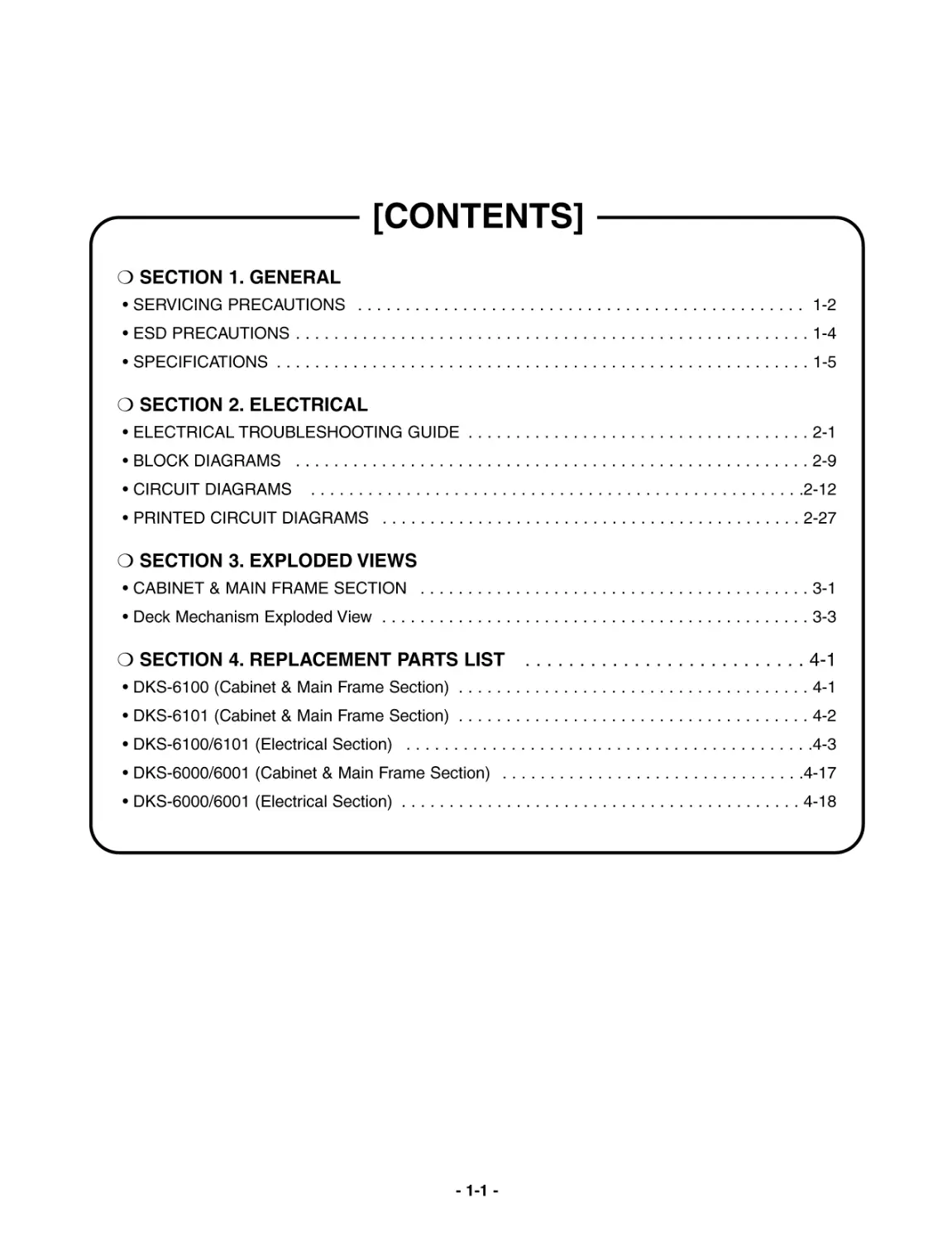
[CONTENTS]
SECTION 1. GENERAL
•SERVICINGPRECAUTIONS...............................................1-2
•ESDPRECAUTIONS......................................................1-4
•SPECIFICATIONS........................................................1-5
SECTION 2. ELECTRICAL
•ELECTRICALTROUBLESHOOTINGGUIDE....................................2-1
•BLOCKDIAGRAMS......................................................2-9
•CIRCUITDIAGRAMS....................................................2-12
•PRINTEDCIRCUITDIAGRAMS............................................2-27
SECTION 3. EXPLODED VIEWS
•CABINET&MAINFRAMESECTION.........................................3-1
•DeckMechanismExplodedView.............................................3-3
SECTION4.REPLACEMENTPARTSLIST..........................4-1
•DKS-6100(Cabinet&MainFrameSection).....................................4-1
•DKS-6101(Cabinet&MainFrameSection).....................................4-2
•DKS-6100/6101(ElectricalSection)...........................................4-3
•DKS-6000/6001(Cabinet&MainFrameSection)................................4-17
•DKS-6000/6001(ElectricalSection)..........................................4-18
-1-2-
SECTION 1. GENERAL
SERVICING PRECAUTIONS
NOTES REGARDING HANDLING OF THE PICK-UP
1. Notes for transport and storage
1) The pick-up should always be left in its conductive bag until immediately prior to use.
2) The pick-up should never be subjected to external pressure or impact.
2. Repair notes
1) The pick-up incorporates a strong magnet, and so should never be brought close to magnetic materials.
2) The pick-up should always be handled correctly and carefully, taking care to avoid external pressure and
impact. If it is subjected to strong pressure or impact, the result may be an operational malfunction and/or
damage to the printed-circuit board.
3) Each and every pick-up is already individually adjusted to a high degree of precision, and for that reason
the adjustment point and installation screws should absolutely never be touched.
4) Laser beams may damage the eyes!
Absolutely never permit laser beams to enter the eyes!
Also NEVER switch ON the power to the laser output part (lens, etc.) of the pick-up if it is damaged.
5) Cleaning the lens surface
If there is dust on the lens surface, the dust should be cleaned away by using an air bush (such as used
for camera lens). The lens is held by a delicate spring. When cleaning the lens surface, therefore, a cotton
swab should be used, taking care not to distort this.
6) Never attempt to disassemble the pick-up.
Spring by excess pressure. If the lens is extremely dirty, apply isopropyl alcohol to the cotton swab. (Do
not use any other liquid cleaners, because they will damage the lens.) Take care not to use too much of
this alcohol on the swab, and do not allow the alcohol to get inside the pick-up.
Storage in conductive bag
Drop impact
NEVER look directly at the laser beam, and don't let
contact fingers or other exposed skin.
Magnet
How to hold the pick-up
Conductive Sheet
Cotton swab
Pressure
Pressure
-1-3-
NOTES REGARDING COMPACT DISC PLAYER REPAIRS
1. Preparations
1) Compact disc players incorporate a great many ICs as well as the pick-up (laser diode). These components
are sensitive to, and easily affected by, static electricity. If such static electricity is high voltage, components
can be damaged, and for that reason components should be handled with care.
2) The pick-up is composed of many optical components and other high-precision components. Care must be
taken, therefore, to avoid repair or storage where the temperature of humidity is high, where strong magnet-
ism is present, or where there is excessive dust.
2. Notes for repair
1) Before replacing a component part, first disconnect the power supply lead wire from the unit
2) All equipment, measuring instruments and tools must be grounded.
3) The workbench should be covered with a conductive sheet and grounded.
When removing the laser pick-up from its conductive bag, do not place the pick-up on the bag. (This is
because there is the possibility of damage by static electricity.)
4) To prevent AC leakage, the metal part of the soldering iron should be grounded.
5) Workers should be grounded by an armband (1M Ω)
6) Care should be taken not to permit the laser pick-up to come in contact with clothing, in order to prevent sta-
tic electricity changes in the clothing to escape from the armband.
7) The laser beam from the pick-up should NEVER be directly facing the eyes or bare skin.
CLEARING MALFUNCTION
You can reset your unit to initial status if malfunction occur(button malfunction, display, etc.).
Using a pointed good conductor(such as driver), simply short the RESET jump wire on the inside of
the volume knob for more than 3 seconds.
If you reset your unit, you must reenter all its settings(stations, clock, timer)
NOTE: 1. To operate the RESET jump wire, pull the volume rotary knob and release it.
2. If you wish to operate the RESET jump wire, it is necessary to unplug the power cord.
Resistor
(1 Mohm) Conductive
Sheet
Resistor
(1 Mohm)
Armband
RESET jump wire
VOLUME
VOLUME KNOB
DOWN
UP
-1-4-
ESD PRECAUTIONS
Electrostatically Sensitive Devices (ESD)
Some semiconductor (solid state) devices can be damaged easily by static electricity. Such components
commonly are called Electrostatically Sensitive Devices (ESD). Examples of typical ESD devices are integrated
circuits and some field-effect transistors and semiconductor chip components. The following techniques should
be used to help reduce the incidence of component damage caused by static electricity.
1. Immediately before handling any semiconductor component or semiconductor-equipped assembly, drain off
any electrostatic charge on your body by touching a known earth ground. Alternatively, obtain and wear a
commercially available discharging wrist strap device, which should be removed for potential shock reasons
prior to applying power to the unit under test.
2. After removing an electrical assembly equipped with ESD devices, place the assembly on a conductive sur-
face such as aluminum foil, to prevent electrostatic charge buildup or exposure of the assembly.
3. Use only a grounded-tip soldering iron to solder or unsolder ESD devices.
4. Use only an anti-static solder removal device. Some solder removal devices not classified as "anti-static" can
generate electrical charges sufficient to damage ESD devices.
5. Do not use freon-propelled chemicals. These can generate electrical charges sufficient to damage ESD
devices.
6. Do not remove a replacement ESD device from its protective package until immediately before you are
ready to install it. (Most replacement ESD devices are packaged with leads electrically shorted together by
conductive foam, aluminum foil or comparable conductive materials).
7. Immediately before removing the protective material from the leads of a replacement ESD device, touch the
protective material to the chassis or circuit assembly into which the device will by installed.
CAUTION : BE SURE NO POWER IS APPLIED TO THE CHASSIS OR CIRCUIT, AND OBSERVE ALL
OTHER SAFETY PRECAUTIONS.
8. Minimize bodily motions when handing unpackaged replacement ESD devices. (Otherwise harmless motion
such as the brushing together of your clothes fabric or the lifting of your foot from a carpeted floor can gen-
erate static electricity sufficient to damage an ESD device).
CAUTION. GRAPHIC SYMBOLS
THE LIGHTNING FLASH WITH APROWHEAD SYMBOL. WITHIN AN EQUILATERAL TRIANGLE, IS
INTENDED TO ALERT THE SERVICE PERSONNEL TO THE PRESENCE OF UNINSULATED "DAN-
GEROUS VOLTAGE" THAT MAY BE OF SUFFICIENT MAGNITUDE TO CONSTITUTE A RISK OF
ELECTRIC SHOCK.
THE EXCLAMATION POINT WITHIN AN EQUILATERAL TRIANGLE IS INTENDED TO ALERT THE
SERVICE PERSONNEL TO THE PRESENCE OF IMPORTANT SAFETY INFORMATION IN SERVICE
LITERATURE.
-1-5-
SPECIFICATIONS
-1-6-
-2-1-
SECTION 2. ELECTRICAL
ELECTRICAL TROUBLESHOOTING GUIDE
POWER Check flow
No 5V_A.
No VF+
No 5.2VA
Check F101
Is there a DC voltage
at R101?
Is there a DC voltage At(+)
terminal of BD101?
Replace IC101.
Is 5.2VA section working?
Check F102
Replace D109.
Is 5.2VA section working?
Is 5.2V present at
emitter of Q107?
Replace Q107.
Replace R101.
Replace BD101.
A.
B.
YES
YES
YES
YES
YES
YES
YES
YES
YES
YES
YES
YES
YES
NO
NO
NO
NO
NO
-2-2-
Check the I2s Signal of
IC601(2-CH IC)
Check the IC501
Check the output
signal of IC601
Check the IC602
Check the L, R of IC601
Check the L, R
Output of JK601.
OK
NO
NO
NO
YES
YES
YES
Check the +5V of IC901
PIN 5, 10, 15, 17
Check the 5.2VA of
CN901 PIN16
Refer to Power circuit
Troubleshooting.
Check the PATTERN
Check the OSC of X901.
Check the IC902
Check the Oscillation
Check the Power (L H) of
IC901 PIN16
Check the IC901
NO
NO
NO
NO
YES
YES
YES
YES
IC901 U-COM IC
TROUBLESHHOTING
-2-3-
1. Power check flow
-2-4-
2. Test & debug flow
-2-5-
-2-6-
-2-7-
-2-8-
-2-9-
BLOCK DIAGRAM
• ESS 3-CHANGER SYSTEM BLOCK DIAGRAM
MITSUMI/SAMSUNG
-2-10-
• ESS 3-CHANGER MEMORY & HOST I/F BLOCK DIAGRAM
-2-11-
• ESS 3-CHANGER SERVO & MOTOR BLOCK DIAGRAM
-2-12-
• ESS 3-CHANGER A/V SYSTEM BLOCK DIAGRAM
IC601
CS4391
2CHDAC
DAC_CLK
DAC_CS2
DAC_DATA
DC-RST
DAMCLK
DABCK
DALRCK
L, R SIGNAL
L, R OUTPUT
JK601
IC602(KA5532)
OP-AMP
OPTION
2-13
2-14
SCHEMATIC DIAGRAMS
1. MPEG SCHEMATIC DIAGRAM
Video signal not oppeared
System not working or
scream is abnormal
27MHz Signal not oppeared
2-15
2-16
2. RF & SERVO SCHEMATIC DIAGRAM
TE, FE, RF Signal isn't
appear or bad
Loading not move
Spindle not move
Focus, Tacking, SLED will not move
CD/DVD LD will not on
2-17
2-18
3. AV JACK SCHEMATIC DIAGRAM
Video Signal Y
Video Signal color
Video Signal CVBS
2cn Audio
2CH Aduio out bad
2CH Aduio out bad
2-19
2-20
4. 5.1 CH & SCART SCHEMATIC DIAGRAM
5.1 CH Audio bad
2-21
2-22
5. MIC SCHEMATIC DIAGRAM
2-23
2-24
6. FRONT TIMER SCHEMATIC DIAGRAM (6000)
LED abnormal
Remocon not operate
Digital abnormal
System not operate or Digitron
abnornd or key not operate.
System not aperate.
2-25
2-26
7. FRONT TIMER SCHEMATIC DIAGRAM (6100)
LED abnormal
Remocon not operate
Digital abnormal
System not operate or Digitron
abnornd or key not operate.
System not aperate.
2-27
2-28
7. SMPS SCHEMATIC DIAGRAM
VF(+) Power Dead
F102 is defective
VF(-) Power Dead
ZD101 is defective
12V Power dead
IC103 is defectuve
3.3V Power Dead
IC106 is defective
Power Dead
IC101 is defective
5V Power Dead
Q107 is defective
8V Power Dead
IC105 is defective
2-29
2-30
PRINTED CIRCUIT DIAGRAM
• FRONT P.C BOARD DIAGRAM (6000)
2-31
2-32
• FRONT P.C BOARD DIAGRAM (6100)
2-33
2-34
• MPEG P.C BOARD DIAGRAM
2-35
2-36
• MPEG P.C BOARD DIAGRAM
2-37
2-38
• MIC P.C BOARD DIAGRAM
• I/O P.C BOARD DIAGRAM
2-39
2-40
• SMPS P.C BOARD DIAGRAM
3-2
3-1
SECTION 3. EXPLODED VIEWS
• CABINET & MAIN FRAME SECTION
A43
A44
452
280
452
284
273
272
264
265
261
266
267
285
A42
281
A26
451
350
451
451
451
A46
451
A47
451
451 A48
451
305
452
301
452
302
303
303
303
442
A49
451
283
271
266
273
261
271
263
272
A44
260
262
NOTE) Refer to SECTION 4 REPLACEMENT
PARTS LIST in order to look for the
part number of each part.
Exposed blade will cause severe injury.
CAUTION
(DKS-6000/6001)
(DKS-6100/6101)
3-3
3-4
• Deck Mechanism Exploded View
429
429
026
010
018
013 014
017
015
015A
011
430
431
011A
012
004
001
002
003
A01
A02
020
430
430
430
430
012
021 433
433
012
012
028
022
432
024
A03
A26
025
030
015B
015C
435
029
031
431
431
431
024A
024A
024B
LOCA. NO. PART NO.
DESCRIPTION
SPECIFICATION
A26
6721RJ0372E
DECK ASSEMBLY,VIDEO
DECK/MECHA DP-7 (43MM)-ESS-MIT
A01
4861R-0016B
CLAMP ASSEMBLY
DISC DP7 - SH
A02
3041R-M009D
BASE ASSEMBLY
MAIN DP-7 (43) HZ
A03
3041R-M002M
BASE ASSEMBLY
SLED DP-7 (MIT VA9)-ESS-HZ
001
3300R-0547A
PLATE
CLAMP
002
5016H-1016B
MAGNET
CLAMP(LDM-R608,10*5,1*1.5T)
003
4860R-0021A
CLAMP
UPPER DP7
004
4930R-0365A
HOLDER
CLAMP DP7
010
6850R-GF10B
CABLE,FLAT
P=1.0 FFC UL2896(0.05X0.65) 6
011
3210R-M001A
FRAME
UP/DOWN DP7 MOLD
011A
6850R-JW24Y
CABLE,FLAT
P=1.0 FFC UL2896(0.035X0.7) 23
012
5040R-0075D
RUBBER
DAMPER DP7 (YAMAUCHI 30)
013
4400H-1009A
BELT
GM-RT1332A
014
4470R-0055A
GEAR
PULLEY
015
6871R-9248D
PWB(PCB) ASSEMBLY,TOTAL
DP-7 LOADING - HZ
015A
4681R-A003D
MOTOR ASSEMBLY
DECK/MECHA LOADING DP-7 HZ
015B
4560R-0008A
PULLEY
MOTOR
015C
4680R-E007A
MOTOR(MECH)
FEEDING BCZ3B01 SANKYO FOR DVD
017
4470R-0056A
GEAR
LOADING
018
4974R-0046A
GUIDE
UP/DOWN(DP-7)
020
3040R-M005A
BASE
MAIN (DP7-43MM) MOLD
021
4680R-C010A
MOTOR(MECH)
SPINDLE JCL9B78 SANKYO FOR DVD
022
4681R-B005D
MOTOR ASSEMBLY
DECK/MECHA FEEDING DP-7 HZ
022A
4680R-E008A
MOTOR(MECH)
FEEDING RF-300EA-1D390 MABUCHI
023
4470R-0119A
GEAR
FEED MOTOR
024
4470R-0124A
GEAR
PINION DP7
024A
5006R-0040A
CAP
SKEW (T) DP7
024B
5006R-0039A
CAP
SKEW (R) DP7
025
4470R-0122A
GEAR
MIDDLE A DP7
026
3390R-0015A
TRAY
DISC DP7
027
4470R-0123A
GEAR
MIDDLE B DP7
028
4370R-0083A
SHAFT
DECK/MECHA DP7 OTHER PU-T
029
4370R-0075A
SHAFT
PU
030
4471R-0010A
GEAR ASSEMBLY
RACK DP7
031
6716DPH005B
PICK UP,DVD
PVR-502W R52 0219 MITSUMI PLAY
032
6871R-9243D
PWB(PCB) ASSEMBLY,TOTAL
DP7 FEEDING - HZ
430
1SZZR-0046A
SCREW,DRAWING
+ 1 D2.0 L6.0 SWRCH16A/FZY
431
1SZZH-1007B
SCREW,DRAWING
+ D2.0 6MM SWRCH16A/ZNBK 4MM 1
433
1SZZR-0050A
SCREW,DRAWING
+ 1 D2.0 L4.5 SWRCH16A/ZNY S-T
434
1SZZR-0023B
SCREW,DRAWING
+ 1 D1.7 L6.0 SWRCH16A/FZY RAC
435
1SZZR-0011A
SCREW,DRAWING
MACHINE
436
1SZZR-0047A
SCREW,DRAWING
+ 1 D1.4 L4.5 SWRCH16A/FZY TAP