/


Теги: military affairs engineering design handbook
Год: 1969
Похожие


Текст
AMS PAMPHLET
АМСР 706-1 25
ENGINEERING DESIGN
HANDBOOK
ELECTRICAL
WIRE AND CABLE
Reproduced by the
CLEARINGHOUSE
lor Federal Scientific & Technical
fnforma'icn Springfield Va. 22151
STATEMENT #2 UNCLASSIFIED
fE8 19
this document is sublect to spec.al export controls and
transmittal to fireJgn ?.<> /eminent s or foreign nationals naj be
nade only with Prlor apProval °"----------—--------------
HEADQUARTERS, U.S. ARMY MATERIEL COMMAND SEPTEMBER 1969
HEADQUARTERS
UNITED STATES ARMY MATERIEL COMMAND
WASHINGTON, D.C. 20315
30 September 1969
AMC PAMPHLET
No. 706-125 ENGINEERING DESIGN HANDBOOK
ELECTRICAL WIRE AND CABLE
Paragraph Page
LIST OF ILLUSTRATIONS...................................... xi
LIST OF TABLES........................................... xiii
LIST OF EQUATIONS - QUICK REFERENCE....................... xvi
PREFACE................................................... xix
CHAPTER 1 CONDUCTORS
1-1 Material Elements......................................... 1—1
I—1.1 Copper (ETP and OFHC) ................................. I—I
1-1.2 Copper (Hot Rolled)....................................... 1-1
1-2 Wire Size (Solid) ........................................ 1-1
1-2.1 Gaging Systems............................................ 1-1
1-2.2 Circular Mil Area (CMA)................................ I—1
1—2.3 Copper Wire Dimensions.................................... 1—2
1-2.4 EX? Resistance ........................................... 1—2
1-3 Coatings ................................................. 1-2
1-3.1 Methods of Coating........................................ 1-2
1-3.1.1 Tin ...................................................... 1-2
1-3.1.2 Silver................................................: 1-3
1-3.1.3 Nickel.................................................... 1-4
1-3.2 Dual Coating.............................................. 1-4
1-3.3 Claddings................................................. 1—5
1-4 Aluminum................................................ i-5
1-4.1 Uses...................................................... 1—5
1-4.2 Coatings ................................................. 1-5
1-5 Alloys.................................................... 1-5
1-5,1 General Properties ....................................... 1-5
1-5.2 High Conductivity Types................................... 1-5
1-5.3 High Conductivity-High Strength Types..................... 1-6
1-6 Stranding.................•....................................... 1-6
1-6.1 Bunched Stranding......................................... I-S
1-6.2 Concentric Stranding...................................... 1-8
1-6.3 Rope Stranding............................................ 1-8
1-7 Soldering...................................<..................... 1-8
1—7.1 Soldering Stranded Wire................................... 1—9
1-7.2 Heavy Tinned Stra.iding................................... 1-9
1—7.3 Silver-coated Stranding................................... 1—9
1-7.4 Nickel-coated Stranding ................................. 1-10
1—7.5 Composite Stranding.................................... I—10
1-8 Terminations........................................... I—10
1-8.1 Crimp Termination........................................ 1-10
1-8.2 Wire Wrap Termination ................................... 1—10
1—9 Shielding.............................................. I—II
1-9.1 General................................................ 1-11
AMСР 706-125
Paragraph Page
1—9.2 Braid Terminology ............................................ 1-11
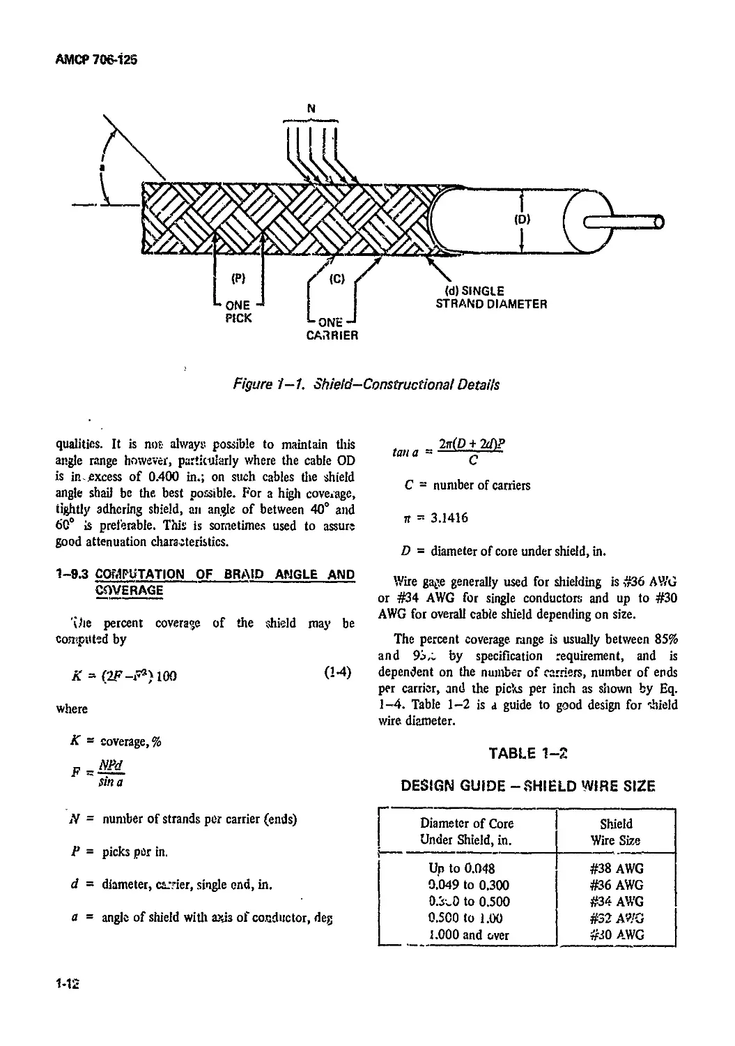
1-9.3 Computation of Braid Angle and Coverage...................... 1-12
1—9.4 Served Shields................................................ 1-13
1—9.5 Shielding Effectiveness....................................... 1—13
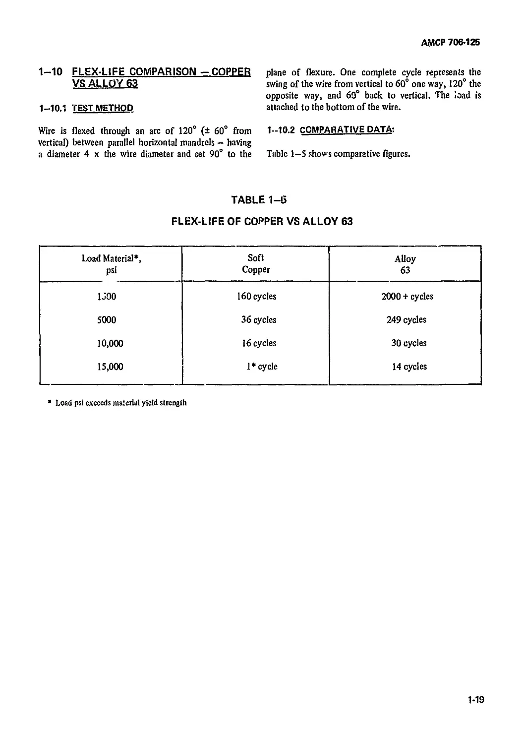
1—10 Flex-life Comparison-Copper vs Alloy 63 1-19
1-10.1 Test Method.................................................. 1-19
1-10.2 Comparative Data.............................................. 1-19
References.................................................. 1-25
CHAPTER 2 INSULATION MATERIALS
2-1 Introduction............................................... 2-1
2-2 Thermoplastic Insulation Materials......................... 2-1
2-2.1 Polyvinylchloride.......................................... 2-1
2-2.2 Polyolefins................................................... 2-2
2—2.2.1 Low-density Polyethylene....................................... 2-2
2-2.2.2 High-density Polyethylene..................................... 2-2
2-2.2.3 Polypropylene................................................. 2-3
2—2.3 Cross-linked Polyolefins ...................................... 2-3
2-2.4 Nylon......................................................... 2-6
2—3 Fluorocarbons.................................................. 2-7
2-3.1 Polytetrafluoroethylene (TFE) ................................. 2-7
2-3.2 Copolymer of Teirafluoroethyiene and
Perfluoropropylene (FEP) ................................... 2-7
2—3.3 Polychlorotrifluoroethyk ne (CTFE)............................ 2-8
2—3.4 Polyvinylidenefluoride (VF-2)................................. 2—8
2-4 Polyurethanes................................................. 2-8
2-4.1 Physical Properties .......................................... 2-8
2-4.2 Thermal Properties............................................ 2-9
2-4.3 Uses.......................................................... 2-9
2-5 Rubber........................................................ 2-9
2-5.1 Natural Rubber (Polyisoprene)................................. 2-9
2-5.2 Styrene-butadiene Rubbers ..................................... 2-9
2-5.3 Chloroprene Rubber .......................................... 2-10
2-5.4 Butyl Rubber ................................................ 2-10
2-5.5 Silicone Rubber............................................... 2-10
2-5.6 Chlorosulfonated Polyethylene.............................. 2-13
2—5.7 Ethylene Propylene Rubber.................................. 2 13
2-5.8 Fluorocarbon Rubber .......................................... 2-13
2-6 Films......................................................... 2-14
2-6.1 Cellulosics .................................................. 2-14
2-6.2 Polyesters ................................................... 2-14
2-6.3 Fluorocarbons ................................................ 2—16
2-6.4 Polyimide .................................................... 2—16
2-7 Fibers........................................................ 2-17
2-7.1 Cotton ...................................................... 2-17
2-7.2 Rayon ........................................................ 2-17
2-7.3 Nylon......................................................... 2-17
ii
АМСР 706-125
Paragraph page
2-TA Polyester................................................... 2—17
2-7.5 Glass ....................................................... 2-17
2-7.6 Ceramic...................................................... 2-18
2-7.7 Asbestos .................................................... 2—18
2-7.8 Fiber Combinations........................................... 2-18
2-7.9 Coated Fibers................................................ 2-18
2-8 Lacquers..................................................... 2-18
2-8.1 Cellulose Acetate Butyrate .................................. 2-18
2-8.2 Nylon...................................................... 2-18
2-8.3 Fluorocarbons................................................ 2—20
2-8.4 Silicones ................................................... 2-20
2-8.5 Specialized Coatings ........................................ 2—20
2-8.6 Bondable Coatings ........................................... 2—20
2-8.7 Polyimide Coatings........................................... 2-20
2-9 Potting Compounds.............................................?. . . 2-21
2-9.1 Types of Potting Compounds................................... 2-21
2—9.2 Potting — Design Criteria.................................... 2—21
2-9.2.1 Surface Preparation.......................................... 2-21
2-9.2.2 Mechanical Factors......................................; . . . . 2—21
2-9.2.3 Chemical Factors............................................. 2-21
2-10 Inorganic Insulations........................................ 2—21
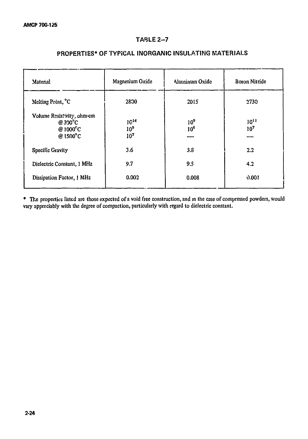
2-10.1 Magnesium Oxide Insulation .................................. 2-23
2-10.2 Magnesium Oxide Beads........................................ 2-23
2-11 Special Environments......................................... 2-23
2—11.1 Fungus Resistance ........................................... 2-23
2—11.2 Radiation Resistance......................................... 2—23
References .................................................. 2-27
CHAPTER 3
DESIGN FACTORS - HOOK-UP AND INTERCONNECTING WIRE
3-1 Scope........................................................... 3—1
3-2 Factors Influencing Design ..................................... 3-1
3-2.1 Environmental Factors........................................... 3-1
3-2.1.1 High Temperature................................................ 3-1
3-2.1.2 Low Temperatuifc................................................ 3-1
3-2.13 Flammability ................................................... 3-1
3-2.1.4 Moisture and Fungus............................................. 3-2
3-2.2 Chemical Factors................................................ 3-2
3-2.2.1 Liquid ......................................................... 3-2
3—2.2.2 Ultraviolet..................................................... 3—2
3—2.2.3 Gaseous......................................................... 3—2
3-2.2.4 Corrosion...............................:............................ 3-2
3-2.2.5 Outgassing...................................................... 3-2
3-2.3 Mechanical Factots.............................................. 3-2
3-2.3.1 Flex-life ...................................................... 3—2
3-23.2 Abrasion Resistance ............................................ 3-3
3--2.3.3 Penetiation................................................. . 3—3
iii
AM СР 706-12 G
Paragraph Page
3-2.3.4 Tensile Strength................................................. 3-3
3—2.3.5 Elongation....................................................... 3-3
3-2.4 Electrical Factors....................................... 3-3
3-2.4.1 Dielectric Constant...................................... 3-3
3-2.4.2 Dielectric Strength ..................................... 3-3
3-2.4.3 Gradient (Electrical) ........................................... 3-3
3-2.4.4 Insulation Resistance.................................... 3-4
3—2.4.5 Loss Factor ..................................................... 3-4
3-2.4.6 Current-carrying Capacity................................ 3-4
3—2.4.7 Voltage Drop .................................................... 3-4
3-2.5 Identification .......................................... 3-5
3—3 Design Considerations .............................."..................... 3-5
3-3.1 Conductor Choices........................................ 3-5
3-3.1.1 Mechanical Factors............................................... 3-5
3-3.1.2 Thermal Factors.......................................... 3-5
3-3.2 ' Insulation Choices .............................................. 3-6
3-3.2.1 Mechanical Considerations................................ 3-6
3—3.2.2 Electrical Considerations................................. 3-6
3-4 Testing To Prove Design.................................. 3-6
3-4.1 Electrical Tests ......................................... 3-7
3-4.2 Physical Tests............................................ 3-7
3-4.3 Aging Tests .............................................. 3-7
3-4.4 Thermal Tests............................................. 3-7
3-4.5 Mechanical Tests ........................................ 3-7
3-4.6 Chemical Tests ........................................... 3-7
3-5 Hook-up vs Interconnecting Wire ......................... 3-7
3-5.1 Hook-up Wire ............................................. 3-7
3-5.2 Interconnecting Wire and Cable........................... 3-8
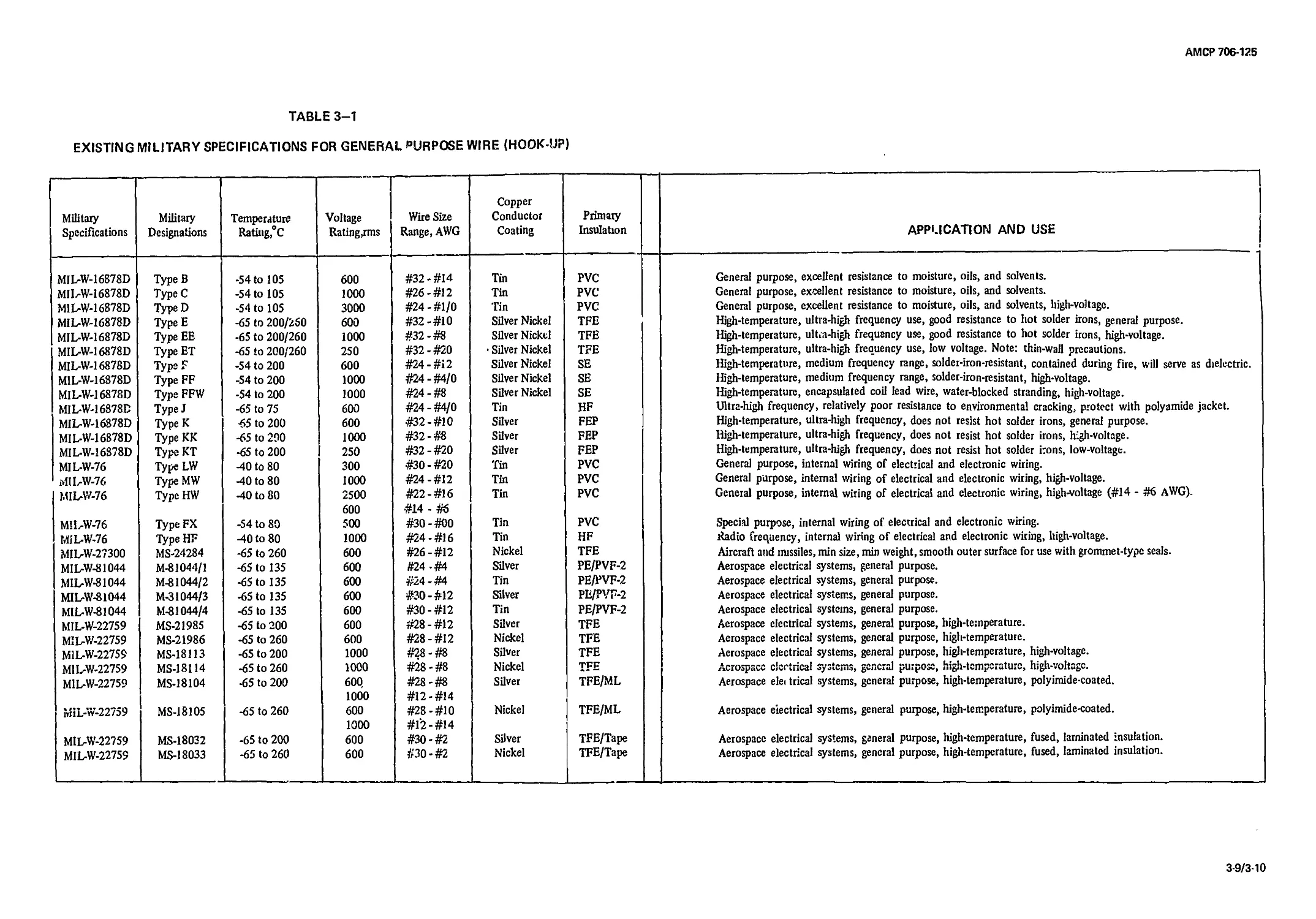
3-6 Comparison of Hook-up Wire Types ........................ 3-8
3-6.1 MIL-W-76 ................................................ 3-8
3-6.2 MIL-W-16878D ............................................. 3-11/3-12
3-6.3 MIL-W-81044 .............................................. 3-11/3-12
3-6.4 MIL-W-27300 .............................................. 3-11/3-12
3-6.5 MIL-W-22759 .............................................. 3-11/3-12
3-7 Comparison of Interconnecting Wire Types.................... 3-11/3-12
3--7.1 MIL-W-5086 ............................................... 3-11/3-12
3-7.2 MIL-W-81044 ................................................ 3-11/3-12
3-7.3 MIL-W-7139................................................. 3-11/3-12
3-7.4 MIL-W-8777 ................................................. 3-11/3-12
References................................................ 3-15/3-16
CHAPTER 4 BUNDLED WIRES
4—1 Laced Bundles..................................................... 4-1
4-1.1 Lacing ........................................................... 4-1
4-1.2 Usage — Laced Bundles............................................. 4-i
4-2 Prefabricated Bundles ............................................ 4-J
4-2..1 Construction...................................................... 4-1
4—2.2 Components.............................................................. 4-2
АМСР 706*126
Paragraph Page
4-2.3 Color Code...................................................... 4—2
4-2.4 Shield.......................................................... 4-2
4-2.5 Jacket.......................................................... 4-2
4-3 Derating Factors for Bundled Wires ............................. 4-2
4-3.1 Introduction.................................................... 4-2
4-3.2 Basic Considerations ........................................... 4—2
4-4 Derating Calculations........................................... 4-6
4-4.1 Symbols and Their Definitions .................................. 4-6
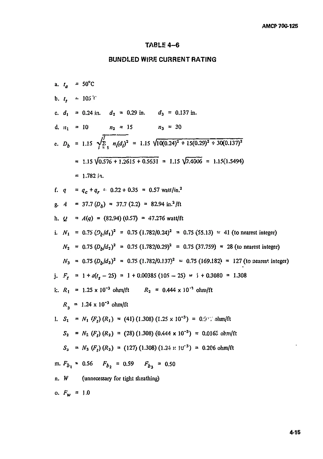
4-4.2 Rating Procedure................................................ 4-6
4-4.3 Usage - Current Rating Procedure................................ 4-7
4-5 Ribbon Cable .................................................. 4—21
4-5.1 Introduction................................................... 4-21
4-5.2 Usage.......................................................... 4-21
4-5.3 Construction................................................... 4-21
4-5.3.1 Adhesive Bonding............................................... 4-21
4-5.3.2 Thermal Fusing................................................. 4-21
4-5.3.3 Direct Extrusion .............................................. 4-21
4-5.3.4 Envelope....................................................... 4-21
4-5.3.5 Braided or Woven............................................... 4-21
4-6 Comparison - Ribbon Cable vs Round Multiconductor Cable. 4-21
4-6.1 Advantages - Ribbon Cable...................................... 4-21
4-6.2 Disadvantages - Ribbon Cab’e .................................. 4—22
4-7 Tape Cable..................................................... 4-22
4-7.1 Introduction................................................... 4—22
4-7.2 Usage.......................................................... 4-22
4-7.3 Flat Wire...................................................... 4-22
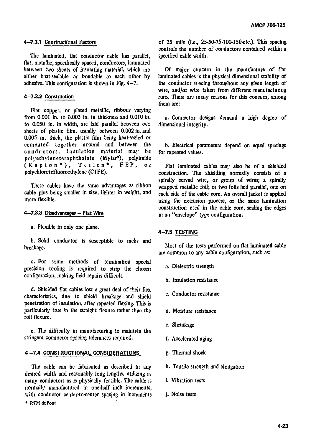
4-7.2.1 Constructional Factors......................................... 4—23
4-7.3.2 Construction................................................... 4-23
4-7.3.3 Disadvantages - Flat Wire...................................... 4-23
4-7.4 Constructional Considerations.................................. 4—23
4-7.5 Testing........................................................ 4—23
4-7.5.1 Folding Test................................................... 4—24
4-7.5.2 Roll Flexure lest.............................................. 4-24
4—7.5.3 Straight Flexure Test.......................................... 4-24
4—7.6 Installation................................................... 4-26
References.................................................... 4—27
CHAPTERS C OAXIAL CABLE
5-1 Introduction.................................................... 5—1
5-2 Types of Coaxial Cable ....................................... 5-1
5-2.1 Definitions..................................................... 5—1
5—2.1.1 Coaxial......................................................... 5—1
5-2.1.2 Twin Coaxial ................................................... 5_1
5—2.1.3 Dual Coaxial.................................................... 5_1
5-2.1.4 Double Shielded................................................. 5—l
5-2.1.5 Triaxial........................................................ 5—1
5-3 Materials....................................................... 5_1
v
АМСР 706-125
Paragraph Page
5-4 Electrical Properties of Coaxial Cable ........................ 5-1
5-4.1 Basic Parameters .............................................. 5-1
5-4.1.1 Capacitance ................................................... 5-2
5-4.1.2 Phase Angle ................................................... 5-5
5-4.13 Power Factor .................................................. 5-5
5-4.1.4 Dielectric Constant....................................... 5-5
5-4.1.5 Velocity of Propagation........................................ 5-5
5-4.1.6 Characteristic Impedance ...................................... 5-5
5-4.1.7 Propagation Constant........................................... 5-8
5-4.1.8 Attenuation and Phase Shift ................................... 5-8
5-4.1.9 Corona and Voltage Rating..................................... 5-14
5-5 Air-spaced Cables............................................. 5-20
5—5.1 General Constructional Details ............................... 5-20
5-5.2 Uses.......................................................... 5-20
5-6 Voltage Standing Wave Ratio (VSWR)........................ 5 -20
5-6.1 Reflection - Coaxial Cable System............................. 5-20
5-6.2 Reflection Causes — Coaxial Cable Systems..................... 5-22
5—7 Power Rating ................................................. 5-22
5-7.1 Power Handling Capacity ...................................... 5-22
5-7.2 Power Rating Due to VSWR ..................................... 5-23
5-8 Shields ...................................................... 5-23
5-8.1 Picks ......................:........................................ 5-23
5-8.2 Caniers....................................................... 5-23
5-83 Ends ......................................................... 5-23
5-9 Shielding Effectiveness....................................... 5-25
5-9.1 Surface Transfer Impedance.................................... 5-25
5—9.2 Reference .................................................... 5-26
5—10 Transmission Unbalance ....................................... 5-26
5-10.1 General....................................................... 5-26
5-10.2 References for Test and Measurement............................ 5-27
5-11 Coverings and Sheaths......................................... 5-27
5-11.1 Uses........................................................... 5-27
5-11.2 Fibrous or Textile ............................................ 5-27
5—12 Special Purpose Coaxial Cables................................ 5—28
5-12.1 Pulse Cables.................................................. 5-28
5-12.2 Delay Lines .................................................. 5-28
5-123 Low Noise Cable ............................................... 5-29
5-13 Practical Constructional Considerations........................ 5-29
5-13.1 Size........................................................... 5-29
5—13.2 Concentricity and Eccentricity................................. 5-30
5—133 Abrasion....................................................... 5-30
5-13.4 Contamination.................................................. 5-30
5—14 Environmental Conditions....................................... 5-30
5-14.1 General Considerations......................................... 5-30
5-14.2 Insulation Guide .............................................. 5-30
5—15 Discussion of Application — Major Usage........................ 5-39
References...............................................5-31/5-32
АМСР 706-125
Paragraph Page
CHAPTER 6 CONTROL AND SIGNAL CABLES
6-1 Introduction................................................... 6-1
6 -2 Applications of Control and Signal Cables ..................... 6-1
6-3 Cor itructional Design Factors ................................ 6-1
6-3.1 Physical Considerations ....................................... 6-1
6-3.2 Electrical Considerations...................................... 6-2
6-4 Cable Types.................................................... 6-2
6-4.1 Portable ...................................................... 6-2
6—4.2 Nonportable.................................................... 6—2
6-5 Multiconductor Cable Design.................................... 6-2
6-5.1 General Considerations.................................... 6-2
6-5.2 Specific Construction Considerations ..................... 6-3
6-6 Multiconductor Construction.................................... 6-3
6-6.1 Conductors and Components................................. 6-3
6-6.2 Component Strandings...................................... 6-6
6-6.3 Basic Insulated Wire .......................................... 6-6
6-6.4 Component Shielding....................................... 6-6
6-6.5 Component Shield Covering and Component Jacket Dimensions 6-7
6-6.6 Cabling................................................... 6—7
6-6.6.1 Lay............................................................ 6-8
6-6.6.2 Pitch Diameter ................................................6—9
6-6.6.3 Lay Construction............................................... 6-9
6-6.7 Cable Fillers............................................. 6-9
6-6.8 Color Coding Control and Signal Cables....................... 6-10
6-6.8.1 Color Coding Methods...................................... 6—10
6-6.8.2 Color Code Application ....................................... 6-10
6-6.8.3 Color Code and Related Numbers ........................... 6—11
6-6.8.4 Specifications ........................................... 6—11
6-6.9 Cable Binders .................................•...................... 6-12
6-6.10 Cable Sheaths............................................. 6-13
6-6.11 Sheath Application........................................... 6-13
6-6.12 Armor .................................................... 6—13
6—6.13 Cable Identification Marking ................................. 6-15
6—7 Multiconductor Cable Testing.................................. 6-16
6-7.1 Cable Cross-talk . ........................................... 6—16
6 7.2 Tests and Test Methods ....................................... 6-16
6-7.3 Multiconductor Cable Tests.................................... 6-16
6-7.3.1 Cold Bend Test................................................ 6-17
6-7.3.2 Impact Test .................................................. 6-17
6-7.3.3 Torque Test................................................... 6-17
6-7.3.4 Twist Test.................................................... 6-17
6-7.3.5 Bend Test .................................................... 6-18
6-7.3.6 Dielectric and Pulse Dielectric Tests......................... 6—19
6-7.37 Insulation Resistance Test.................................... 6-22
6-7.3.8 Measuring Capacitance in a Multiconductor Cable........... 6-23
6-7.3.9 Abrasion Resistance .......................................... 6-25
6-7.3.10 Tensile Strength of Multiconductor Cable ..................... 6-27
References.................................................. 6-29
vii
АМСР 706-125
Paragraph Page
CHAPTER? POWER CABLES
7-1 Introduction.................................................. 7-1
7-1.1 Usage......................................................... 7-1
7-1.2 General Design Factors........................................ 7-1
7—2 Major Constructional Design Factors........................... 7—1
7-2.1 Conductor..................................................... 7-1
7—2.1.1 Conductor Material............................................ 7-1
7-2.1.2 Conductor Size ............................................... 7—1
7—2.1.3 Conductor Form ............................................... 7-2
7-2.2 Insulation ................................................... 7-2
7-2.3 Sheath ....................................................... 7-2
7-3 Miscellaneous Constructional Design Factors................... 7-2
7-3.1 Shields ...................................................... 7-2
7-3.2 Cabling....................................................... 7-2
7-3.3 Ground Wires ................................................. 7-2
7-4 Voltage Drop ................................................. 7—3
References.................................................. 7-25
CHAPTER 8 SPECIAL PURPOSE CABLES
8-1 Introduction.................................................. 8-1
8-1.1 General Types................................................. 8-1
8-1.2 Design Factors.............................................. 8-1
8-2 Hybrid Cable Design Factors .................................. 8-1
8-3 Construction Check List....................................... 8-1
8-3.1 Basic Insulated Wires......................................... 8-1
8-3.2 Component Lay-up.............................................. 8-2
8—3.3 Core Binder .................................................. 8-2
8-3.4 Outer Covering ............................................... 8-2
8-3.5 Cable Identification.......................................... 8-2
8-3.6 Protective Braid.............................................. 8—2
8-4 Sample Hybrid Cable Configuration ............................ 8-2
8-4.1 Sample Cable Requirements..................................... 8-2
8-4.2 Sample Cable Constructional Factors .......................... 8-3
8-4.3 Sample Cable Lay-up........................................... 8-4
8-4.3.1 Component Construction ....................................... 8-4
8-4.3.2 Component Color Coding........................................ 8-5
8-4.3.3 Component Precabling Tests ................................... 8-7
8-43.4 Cable Core Lay-up ............................................ 8-7
8-4.3.5 Core Binder .................................................. 3-7
8-43.6 Core Diameter Calculation..................................... 8-8
8-43.7 Core Shielding........................................... <s—8
8-43.C Cable Separator............................................... 8-8
8-43.9 Cable Sheath.................................................. 8-9
8-43.10 Cable Identification......................................... 8-10
8—5 Choice of Cable for Equipment Design ........................ 8-10
8-5.1 Light-or Medium-duty Cables................................ 8-11
3-5.2 Heavy-duty Cables ........................................... 8-11
viii
AMCP 706-125
Paragraph page
8-6 Nonhosing or Waterblock Cables................................ 8--J2
8-6.1 General Description............................................ 8-12
8-6.2 Nonhosing Cable Applications. ................................. 8-13
8-7 Thermocouple Cables............................................ 8-13
8-7.1 Introduction................................................... 8-13
8-7.2 General Operational Factors.................................... 8-14
8-7.3 Thermocouple Materials......................................... 8-15
8-7.4 Thermocouple Procurement....................................... 8-15
8-7.5 Calibration.................................................... 8-15
8-8 Thermocouples vs Lead V/ires................................... 8-15
8-8.1 Construction................................................... 8-16
8-8.1.1 Conductors..................................................... 8—16
8-8.1.2 Insulation .................................................... 8-16
8-8.2 Constructional Examples........................................ 8—16
8-8.3 Installation................................................... 8-16
8-8.4 Electromotive Force ........................................... 8-17
8-9 Ignition Wire — High Voltage................................... 8—17
8-9.1 Introduction................................................... 8-17
8-9.2 Design Considerations ......................................... 8-17
8-9.2.1 Conductor...................................................... 8-17
8-9.2.2 Insulation .................................................... 8-19
8-9.2.3 Reinforcing Braid.............................................. 8—19
8-9.2.4 Outer Protective Fiber Braid .................................. 8—19
8-9.2.5 Shield......................................................... 8-19
8-9.3 Specifications................................................. 8—19
References.................................................... 8—20
CHAPTER 9 TELEPHONE CABLFS
9-1 Introduction.................................................... 9—1
9-2 Major Categories ............................................... 9—1
9-3 Audio Cord ..................................................... 9—1
9-3.1 Basic Design.................................................... 9—1
9-3.2 Tinsel Cord .................................................... 9-1
9-3.2.1 Basic Design.................................................. 9—2
9-3.2.2 Construction and Tests..................................... 9, .2
9-3.3 Retractile (Helical) Cords ..................................... 9„2
9-3.3.1 Basic Design and Construction .................................. 9-2
9—3.3.2 Tests ........................................................ 9—3
9-3.4 Miniature Cables (Special Purpose).............................. 9-4
9-3.4.1 Basic Design.................................................... 9-4
9—3.4.2 Tests .....................................................
9-3.5 Multiconductor Cord (Retractile)................................ 9—7
9—3.5.1 Usage........................................................... 9—7
9—3.5.2 Basic Design.................................................... 9—7
9—3.5.3 Retractile Construction ........................................ 9—8
9-3.5.4 Retractile Testing.............................................. 9-8
9-3.6 Specifications ................................................. 9_9
lx
AMCP 706-12S
Paragraph Page
9—3.7 Alternate Constructions ....................................... 9-9
9-4 Field Wire .................................................. • • 9-9
9-4.1 Usage.......................................................... 9-9
9-4.2 Installation Factors...................................... 9-9
9-43 Field Wire Types ......................................... 9~9
9-4.4 Construction.............................................. 9-10
9—4.5 Test Data................................................ 9“13
9-4.6 Packaging................................................ 9-^3
9-4.6.1 Canvas Dispenser Construction ........................... 9-14
9™4.6.2 Plastic Dispenser Construction .......................... 9-14
9-4.7 Specifications............................................ 9-16
9-5 Multipair Telephone Cables................................ 9-17
9-5.1 Usage.................................................... 9-17
9-5.2 Cable Requirements ....................................... 9-17
9—5.3 Reasons for Testing..................................’.............. 9-20
9-5.4 Basic Design.............................................. 9-20
9-5.5 Electrical Characteristics................................ 9-20
9-5.5.I Mutual Capacitance (Pair)................................. 9-20
9—5.5.2 Capacitance Unbalance (Pair).............................. 9-21
9-5.6 Construction.............................................. 9-21
9-5.7 Tests for Cable .......................................... 9-22
9-5.8 Specifications ........................................... 9-23
9-6 Telephone Multicnannei Communication Cables............... 9-23
9-6.1 Usage..................................................... 9-23
9-6.2 Construction.................................................. 9-23
9-63 Tests for Cable .............................................. 9-24
9-6.4 Pulse Code Modulation Cables ................................. 9-24
9-6.4.1 FDM and PCM Systems ...................................... 9-24
9-6.4.2 Cable Requirements ........................................... 9-24
9-6.5 Construction and Performance Data............................. 9-25
9-6.6 Cable Testing ................................................ 9-25
9-6.6.1 Test Procedures and Requirements.............................. 9-25
9-6.6.1.1 Test Procedures............................................... 9-25
9-6.6.1.2 Shielding Effectiveness....................................... 9-25
9-6.6.1.2.1 Framing Test ................................................. 9-25
9-6.6.I.2.2 Radiation from Cable ......................................... 9-28
9-6.6.1.23 Calculation of Shielding Effectiveness......................... 9-29
9-6.6.13 Tensile and Sag............................................... 9-30
9-6.7 Lightning Protection of Cable Systems......................... 9-31
9-6.8 References for PCM and Multichannel Cables and Systems . . 9-31
References.................................................. 9-34
GLOSSARY..............,...................................... G-l
BIBLIOGRAPHY................................................. B-l
APPENDIX ............................................... a—1
INDEX........................................................ 1-1
АНЛСР 706-12Б
LIST OF ILLUSTRATIONS
Figure Title Page
1—1 Shield - Constructional Details................................. 1—12
4-1 Calculation of Free Convective Heat Dissipation ........ 4-8
4-2 Calculation of Bundling Factor for 105°C ........................ 4-9
4-3 Wrapping Factor vs Ratio of Unwrapped to Wrapped
Cross-sectional A:ea for Typical Bundle
Diameters................................................... 4-12
4-4 Calculation of Bundling Factor.................................. 4—12
4-5 Calculation of Radiant Heat Dissipation......................... 4—14
4-6 Bonded Ribbon Cable Configuration.............................. 4-22
4-7 Laminated Flat Conductor Cable..................................... . 4—24
4-8 Rolled Flex Test .............................................. 4-25
4-9 Straight Flex Test.............................................. 4-25
5-1 Coaxial Cable ................................................. 5-2
5-2 Twin Coaxial (Parallel).......................................... 5-3
5-3 Twin Coaxial (Twisted) .......................................... 5—3
5-4 Dual Coaxial (Parallel).......................................... 5—3
5-5 Dual Coaxial (Twisted)........................................... 5—4
5-6 Double Shielded Coaxial................................ ,................. 5-4
5—7 Triaxial Cable................................................... 5—4
5-8 Basic Parameters of a Transmission Line .................................. 5—7
5-9 Relationship of Diameters to Dielectric Constant........... 5—9
5-10 Changes in Zo Due to D/d Ratio Change .......................... 5-10
5-11 Twin Coaxial Cross Section...................................... 5-11
5-12 Dual Coaxial Cross Section ..................................... 5—11
5-13 Attenuation vs Frequency — Polyethylene Cable ....... 5—15
5-14 Average Power Ratings of 50-ohm Polyethylene
Cables........................................................ 5—24
5-15 Average Power Ratings of 50-ohm Teflon Cables .................. 5-25
5-16 Power Rat>ng Due to VSWR — Teflon Cable......................... 5-26
5—17 Power Rating Due to VSWR — Polyethylene Cable.......... 5—27
5-18 Shield - Constructional Details................................ 5-28
o-l Typical Multiconductor Cable Design ............................. 6-3
6-2 Braided Shield Angle............................................. 6-8
6-3 Length of Lay.................................................... 6-9
6-4 Pitch Diameter ................................................. 6-10
6-5 Contrahelical Lay............................................... 6-10
6-6 Reinforced Sheath Configuration................................. 6-15
6-7 Impact Test Fixture ............................................ 6-18
6-8 Twist Test Fixture ............................................. 6-19
6-9 Ninety-degree Bend Test Fixture................................. 6-20
6-10 Pulse Dielectric Test Fixture .................................. 6-21
6-11 Capacitance of a Pair (Schematic) .............................. 6-23
6-12 Pair-io-pair Capacitance Unbalance (Schematic).................. 6-24
6-13 Pair-to-shield Capacitance Unbalance (Schematic)........... 6—25
xi
АМС? 705-126
LIST OF ILLUSTRATIONS (CONT.)
Figure Title Page
6-14 Sandpaper Abrasion Test Apparatus.............................. 6-26
6-15 Tungsten Carbide Rod Abrasion Test Apparatus................... 6-27
6-16 Tensile or Breaking Strength Test Methods...................... 6-28
8-1 Hybrid Configuration - Component Placement .................. 8-8
8—2 Hybrid Configuration — Component Placement .................. 8-9
8-3 Hybrid Configuration - Filler Placement .................... 8-10
8-4 Hybrid Configuration - Completed Cable...................... 8-12
8-5 Typical Thermocouple Application............................... 8-15
9—1 Spcsial Purpose Cable — WD 27 A/U ........................... 9-6
9—2 Special Purpose Cable - WM 69 B/U .......................... 9-6
9-3 Special Purpose Cable - WM 70 B/U ........................... 9-6
9-4 Special Purpose Cable — WM 111 A/U........................... 9—7
9—5 Field Wire Comparison — Attenuation vs Frequency .............. 9-14
9-6 Field Wire Comparison - Characteristic Impedance
vs Frequency................................................. 9-15
. 9-7 Field Wire Comparison - Phase Constant vs Frequency .... 9-16
9-8 Field Wire Comparison — Velocity of Propagation
vs Frequency................................................. 9-17
9-9 Field Wire Comparison — Transmission Range
vs Frequency................................................................ 9-18
9-10 Canvas Dispenser - Field Wire ................................. 9-18
9-11 Semi-rigid Dispenser - Field Wire ............................. 9-19
9-12 Field Test Set-up for Transmission and
Shielding Effectiveness...................................... 9-28
9-13 Low Frequency Shielding Effectiveness
Test Set-up................................................................. 9-32
AMCP 706-725
LIST OF TABLES
Table No. Title Page
1-1 Data - Copper-clad Steel Conductors............................. 1-6
1-2 Design Guide - Shield Wire Sire................................ 1-12
1—3 Shielding Effectiveness - Various Materials
and Constructions............................................................ 1—13
1-4 Wire Chart - Solid Conduc ors.................................. 1-15
1-5 Flex-life of Copper vs Alloy 63................................ 1-19
1-6 Wire Chart - Stranded Conductors............................... 1-20
1-7 General Properties of Conductor Materials...................... 1—22
1-8 Stranding Lay Lengths — Stranded Conductors.................... 1—24
2—1 Typical Applications for Polyolefin Resins...................... 2-3
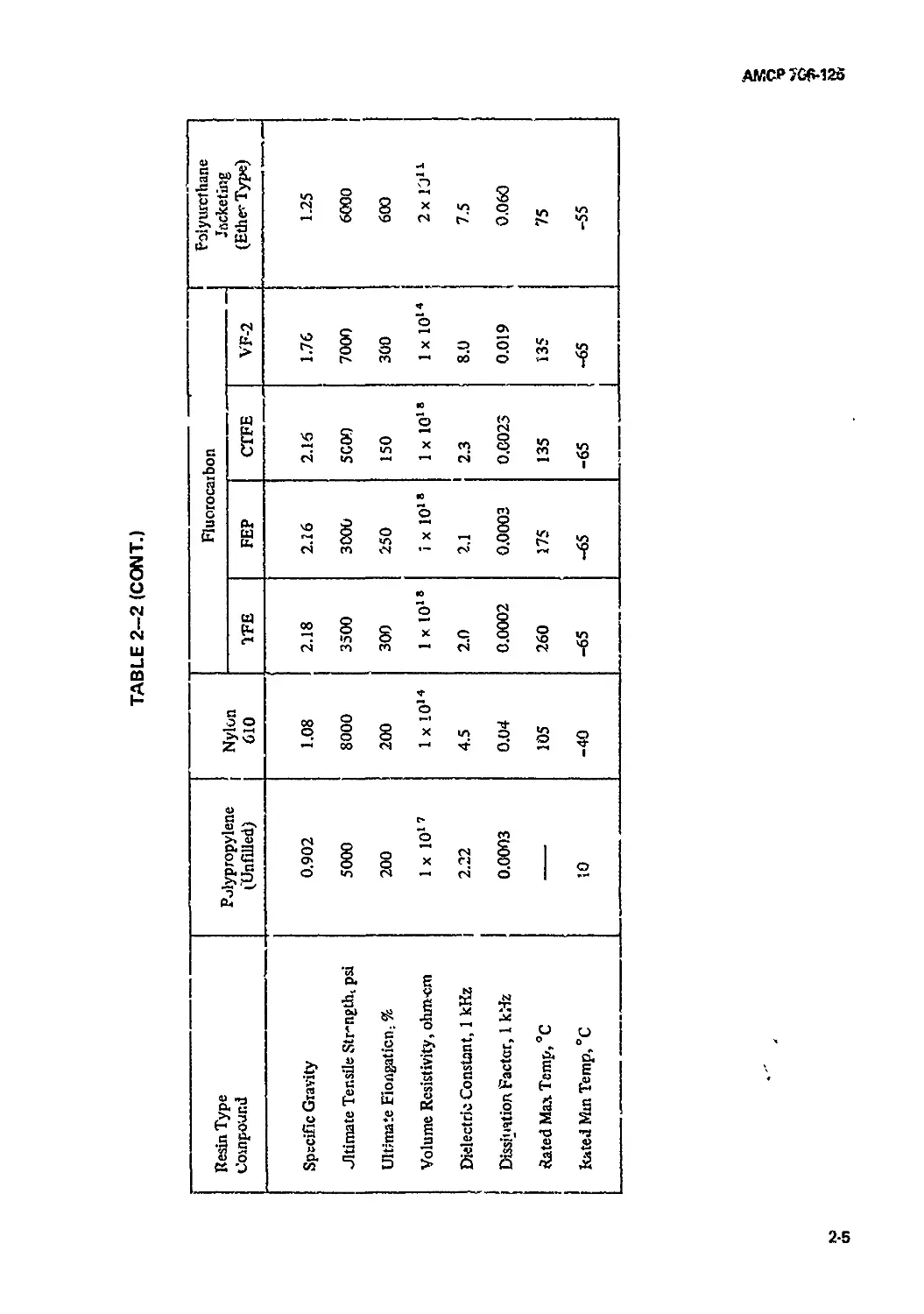
2-2 Typical Properties of Thermoplastic Materials................... 2-4
2-3 Typical Properties of Elastomeric Compositions................. 2—1!
2-4 Typical Properties of Films..................i........................... 2—15
2—5 Typical Properties of Fibers................................... 2—19
2-6 Properties of Typical Potting Compounds........................ 2-22
2—7 Properties of Typical Inorganic Insulating Materials....... 2-24
2—8 Relative Radiation Resistance of Insulating
Materials in Air ............................................................ 2—25
2-9 Relative Costs of Insulating Materials .................................. 2—26
3-1 Existing Military Specifications for General
Purpose Wire (Hook-up) ...................................3-9/3—10
3—2 Existing Military Specifications for
Interconnecting Wire .................................... 3-13/3—14
4-1 Bundle Shield Material Selection Chart ................................... 4-3
4-2 Core and/or Sheath Material Selection for
Bundled Wires............................................. 4 4
4-3 Values of Ideal Heat Dissipation for
Horizontal Cable at Standard
Atmospheric Air Pressure ..................................... 4-10
4-4 Temperature Factors (Derating) . . . ’..................... 4 ц
4-5 Cabled Wire Current Rating — Example No. 1 ................. 4-13
4-6 Bundled Wire Current Rating.................................... 4—15
4-7 Cabled Wire Current Rating - Example No. 2
(First Calculation)........................................... 4—17
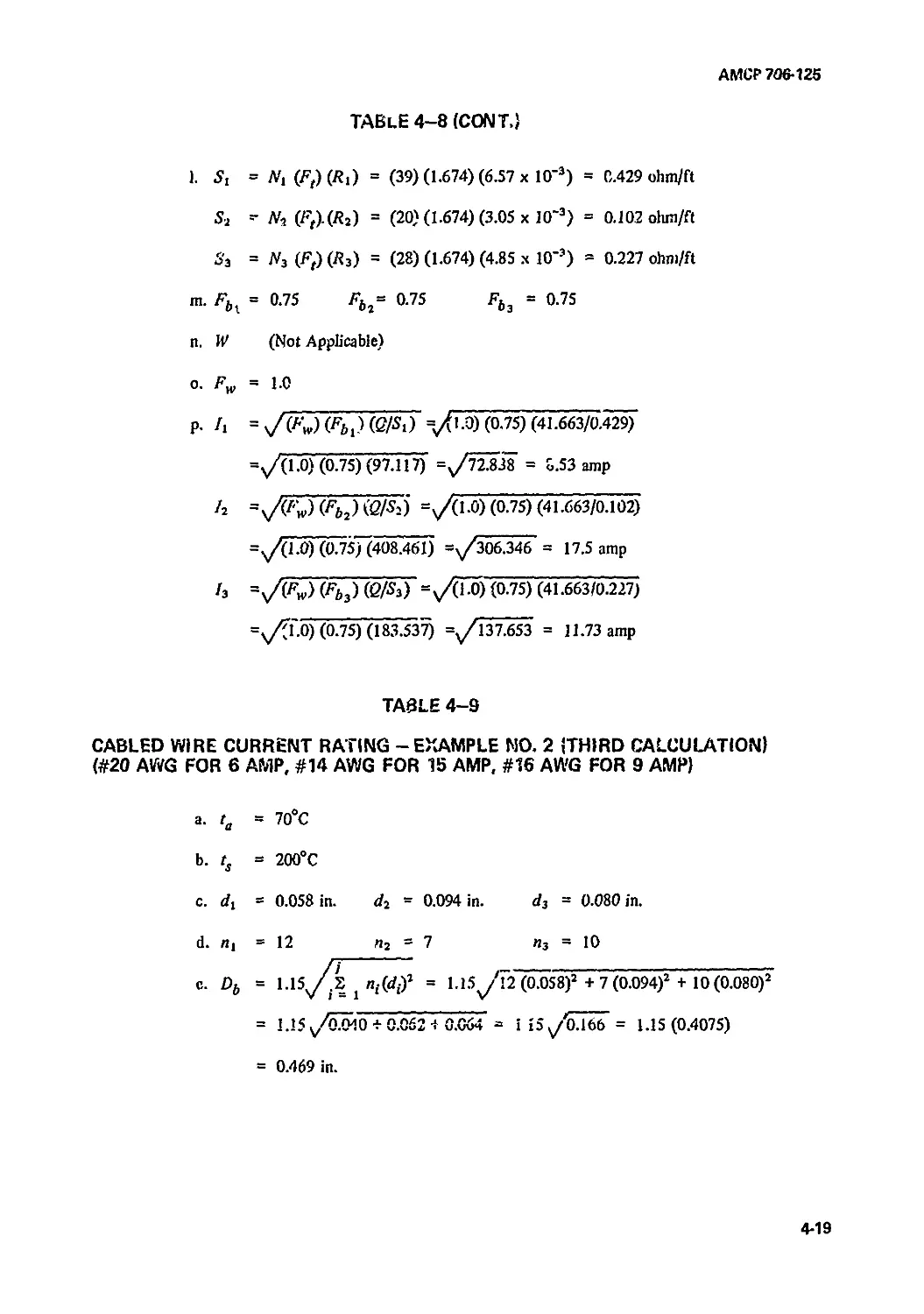
4-8 Cabled Wire Current Rating - Example No. 2
(Second Calculation) ........................................................ 4-18
4-9 Cabled Wire Current Rating - Example No. 2
(Third Calculation).......................................................... 4-19
5-1 Dielectric Constant and Velocity of
Insulating Materials........................................... 5_7
5-2 Characteristics of Standard RF Cables.......................... 5-16
5—3 Characteristics of Semi-solid RF Cables........................ 5—21
5-4 Shielding Effectiveness Kg @ 1 MHz for
Various Shield Materials and Constructions.................... 5—29
6-1 Component Twist - Diameter Multiplying Factor.............. 6-4
6-2 Diameter Increase Due to Shield Application..................... 5-7
6-3 Average Wall Thickness — Shield Covering
(Light- and Medium-duty) ...................................... 6-8
xiii
АЛЛСР 706-125
LIST OF TABLES (CONT.)
Table No. Title 'Page
6-4 Striping - Lay Length...................................... 6-11
6-5 Color Code and Related Numbers ................................ 6-12
6-6 Sheathing Materials and Their Properties....................... 6-14
6-7 Common Overall Polychloroprene Sheath - Wall
Thickness.................................................................... 6-15
6-8 Standard Constriction of Twisted Pair
Multilayer Cable for Reduction of
Cross-talk................................................................... 6-16
6-9 Electrical Constants - Insulation Materials.............................. 6-22
7—1 Current-carrying Capacity in Underground
Ducts, One Single-conductor Cable Per
Duct, 0-600 volts, 0-60 Hz.................................................... 7-4
7—2 Current-carrying Capacity in Underground
Ducts, Three Single Conductors Per
Duct, 0-600 volts, 0-60 Hz..................................... 7-5
7-3 Current-carrying Capacity in Underground
Ducts, One Three-conductor Cable
Per Duct, 0-600 volts, 0-60 Hz ............................................... 7-6
7-4 Current-Carrying Capacity in Enclosed
or Exposed Conduit, Single-conductor
Cables, 0-600 volts, 0-60 Hz................................... 7-7
7-5 Current-carrying Capacity in Enclosed or
Exposed Conduit, Three-conductor Cable,
0-600 volts, 0-60 Hz ......................................................... 7-8
7-6 Current Rating Correction Factors
for Cables in Various Groupings of
Conduits ..................................................................... 7-9
7—7 Current-carrying Capacity in Air,
Single-conductor and Three-conductor
Cables, 0-600 volts, 0-60 Hz.................................. 7„ Ю
7-8 Current Rating Correction Factors for Various
Groupings of Cables in Air.................................... 7-11
7-9 Current-carrying Capacity of Cables
Buried Directly in Earth, Three
Single-conductor Cables Spaced 6
Inches Apart, Buried 3 Feet Underground...................................... 7_j2
7-10 Current-carrying Capacity of Cables
Buried Directly in Earth, Three-Conductor
Cables, Spaced 18 Inches Apart, Buried
3 Feet Underground ........................................... 7_]3
7-11 Current-carrying Capacity, Portable Power
Cable, Rubber-insulated, Rubber-sheathed ..................... 7_14
7—12 “Flexible” Conductor Strandings of
Annealed Copper Wire ......................................... 7-15
7-13 “Extra Flexible” Conductor Strandings of
Annealed Copper Wire ......................................... 7—16
7-14 Conductor Strandings, Aluminum Wire
(EC, Hard-drawn).............................................. 7-17
7-15 Physical Properties of Insulation.............................. 7-18
7-16 Recommended Insulation Wall Thicknesses........................ 7-19
xiv
АМСР 706-125
LIST OF TABLES (CONT.)
Table No. Title Page
7—17 Cable Sheaths — Physical Properties ......................... 7—20
7-18 Recommended Sheath Thicknesses — Polychloroprene .... 7—21
7-19 2ize of Ground Wires, Annealed Copper ....................... 7—22
7-20 Constructional Details of Annealed Copper Ground
Wires for “Flexible” and “Extra
Flexible” Cable Construction .......................... 7 -23
7-21 Estimated Maximum Line Length for I-volt
Drop Copper Conductors at 60°C ............................ 7—24
8-1 Helical Wrap Tape Width Selection Guide.............................. 8-11
8-2 Light- and Medium-duty Cables - Average
Overall Sheath Wall Thicknesses, in.................... 8-11
8-3 Light- and Medium-duty Cables - Average
Jacket Wall Thicknesses for Shielded
Components, in............................................. 8-13
8-4 Heavy-duty Cables - Aveiage Jacket Wall
Thicknesses for Shielded Components, in.................... 8-14
8-5 Heavy-duty Cables - Average Overall
Reinforced Sheath Wall Thickness, in....................... 8-14
8-6 Thermocouple Insulation and Jacket Selection
Guide...................................................... 8-17
8-7 Thermocouple-Temperature-EMF Correlation Chart........... 8-18
9-1 Conductor Chart - Audio Cords................................. 9-5
9-2 Cabling Chart - Audio Cords................................... 9-6
9-3 Installation Factors - Field Wire............................ 9—10
9-4 Comparison Chart - Field Wire............................ 9—11
9-5 Cable Construction Comparison Chart.......................... 9—13
9-6 Multipair Cable — Electrical Characteristics (Pair)...... 9 -22
9-7 Construction and Performance Data — PCM Cables........... 9-26
9-5 Framing or Susceptibility Data — PCM Cables
(Radio Set Operating at 2.304 MHz)......................... 9—27
9-9 Radiation from Cable Data - PCM Cables
(Radio Set Operating at 2.304 MHz)......................... 9-29
9-10 Sag Data - Spiral Four and PCM Cables ....................... 9-32
9-!. I Sag at Various Temperatures — Spiral Four Cable.......... 9-33
xv
АМСР 706-125
LIST OF EQUATIONS - QUICK REFERENCE
Equation No.
Page
1—1 Strand Weight-tc-diameter Proportion............................ 1-2
1—2 DC Resistance (0.010 in. and larger strand)...................... . 1—7
1—3 DC Resistance (0.0099 in. and smaller strand) .................. 1-7
1-4 Shield Braid-Coverage and Angle ............................... 1-12
3—1 Electrical Stress (Gradient) Of Insulation...................... 3-3
3—2 Corrected Conductor Resistivity At Other Than 20°C
Referenced Temperature........................................ 3-4
3—3 Coefficient of Resistivity-Conductor ......................... 3-4
5-1 Velocity of Propagation.................................... 5-5
Characteristic Impedance ...................................... $"6
5—5 Capacitance-Concentric Cylinder ................................ 5-6
5-6 Inductance-Cancentric Cylinder................................ 5-6
5-7 Characteristic Impedance-Concentric Cylinder.................... 5-6
5-8 Characteristic Impedance — Coaxial In RF Range . ............... 5-6
5-9 Characteristic Impedance-Dual Conductor Coaxial............ 5-7
5-10 Capacitance-Dual Conductor Coaxial.............................. 5-7
5—11 Inductance-Dual Conductor Coaxial .............................. 5—7
5-12 Propagation Constant............................................ 5-8
5-13 Propagation Constant (using input Zo) .......................... 5-8
5-i4 Attenuation (using quantities R, L, C, and G) .................. 5-9
5—15 Phase Constant (using quantities R, L, C, and G) ............... 5-9
5-16 Attenuation At High Frequency................................... 5-9
5-17 Phase Constant At High Frequency ............................... 5-9
5-18 Attenuation Due To Conductor Loss
(see Eq. 5-24)............................................................... 5-9
5-19 High Frequency Resistance (solid and tubular
conductors).................................................. 5-11
5—20 tVn Depth (nonmagnetic material) .......................... 5_11
5-21 Resuance of Coaxial Cable (per unit length) ................... 5_]2
5—22 Resistanu of Copper Coaxial Cable (per 100 ft) ............. 5-12
5-23 High Frequency Resistance (stranded or braided
conductors).................................................. 5—13
5-24 Conductor Loss For Eq. 5-18............................................ 5_]3
5—25 Attenuation Due To Dielectric Loss
(db/unit length)............................................. 5-13
5—26 Conductance Of The Dielectric (for Eq. 5-25) .......................... 5—13
5—27 Attenuation Due To Dielectric Loss
(db/unit length)............................................. 5-13
5- 28 Beta (3) Calculation For Eq. 5-2/.............................. 5_13
5-29 Attenuation Due To Dielectric Loss (db/100 ft).............. 5-13
5-30 Total Attenuation Due.To Dielectric Loss ...................... 5_j4
5-31 Maximum Voltage Stress-Insulation (perfect
cylinder in air)............................................. 5-14
5-32 Reflection Coefficient (VSWR) ................................. 5-20
5-33 Reflection Coefficient (as a complex quantity) ................ 5-20
5-34 Relation-Reflected Current To Incident
Current (VSWR)............................................... 5-20
xvi
АМСР 706-125
LIST OF EQUATIONS - QUICK REFERENCE (CONT.)
Page
Equation No.
5-35 Loss Due To Reflection (VSWR)................................. 5-22
5—36 Magnitude Of Reflection Coefficient (VSWR) ................... 5-22
5-37 Peak Power Rating-Coaxial Cable............................... 5-22
5-38 Heat Generated Within A Coaxial System (expressed
in terms of attenuation) ................................... 5-22
5-39 Heat Generated Within A Coaxial System (expressed
in watts/unit length) ..................................................... 5—22
5-40 Average Power Rating-Coaxial Cable............................ 5-23
5-41 Power Rating Due To VSWR...................................... 5—23
6-1 Calculated Diameter of Twisted Components...................... 6—3
6-2 Establishing An Insulation Resistance Value .................. 6-22
6-3 Insulation Resistance-Dire,Measurement........................ 6-22
6-4 Direct Capacitance (pair) .................................... 6-23
6-5 Mutual Capacitance (pair)..................................... 6-23
(>-6 Pair-to-pair Capacitance Unbalance............................ 6-24
6—7 Pair-to-shield Capacitance Unbalance.......................... 6-25
9-1 Mutual Capacitance (pair within paired cable)................. 9—20
9-2 Capacitance Unbalance (pair within paired cable).......... 9-21
9-3 Shielding Effectiveness...................................... 9--29
9-4 Sag Factor (aerial installation) ............................. 9—30
9-5 Tension In Unsupported Cable Span
(aerial installation) ..................................................... 9—30
9-6 Sag For Any Span Length Other Than In
Tables 9-10 and 9-11........................................ 9-31
xvii/xviii
АМСР 706-125
PREFACE
This Engineering Design Handbook, Electrical Wire and Cable, contains basic
information and fundamental data in the design, usage, and development of wire arid
cable used in Army materiel and systems. The handbook contains a wide variety of
useful information and quantitative facts as well as authoritative references helpful in
the design, development, usage, and maintenance, of wires and cables used in modem
Army electronic and electrical systems, 'fire information contained herein will enable
the systems engineer, technician, buying agency, and user, to meet the tactical and
technical needs of the Armed Forces.
The highly technical nature of today’s Army, together with the demands placed
upon it, have greatly enhanced the need for a wire and cable handbook of this scope.
Information which has been amassed through wide experiences of both manufacturer
and user has been systematically recorded so as to expedite the search for the
necessary technical data.
The objective cf this handbook is to provide a practical guide to correct design of
equipment to meet the exacting transmission requirements of the many and varied
aspects of today’s electronic and electrical systems. The designer who considers the
proper technology of wire and cable design can alleviate many problems in proper
transmission and installation techniques; whereas, the designer who ignores this
technology can and does greatly multiply the problems.
1 This handbook contains information on the structure, application, usage, and
installation of most of the wires and cables utilized by the Army. Also included are a
glossary of terms; a listing of equations for quick reference; and an appendix which
presents the applicable Military Specifications, Standards, and Publications.
This handbook, was prepared by International Telephone and Telegraph Corporation
Wire and Cable Division under subcontract to the Engineering Handbook Office of
Duke University, prime contractor to the Army Research Office-Durham for the
Engineering Handbook Series.
The Handbooks are readily available to all elements of AMC including personnel and
contractors having a need and/or requirement. The Army Materiel Command policy is
to release these Engineering Design Handbooks to other DOD activities and their
contractors, and other Government agencies in accordance with current Army
Regulation 70-31, dated 9 September 1966. Procedures for acquiring these Handbooks
follow:
a. Activities within AMC and other DOD agencns should direct their request on an
official form to:
Publications Distribution Branch
Letterkenny Army Depot
ATTN: AMXLE-ATD
Chambersburg, Pennsylvania 17201
xix
АМСР 706-125
PREFACE (CONT.)
b. Contractors who have Department of Defense contracts should submit their
request, through their contracting officer with proper justification, to the address
indicated in par. a.
c. Government agencies other than DOD having need for the Handbooks may
submit their request directly to the Letterkenny Army Depot, as indicated in par. a
above, or to:
Commanding General
U.S. Army Materiel Command
ATTN: AMCAD-PP
Washington, D. C. 20315
or
Director
Defense Documentation Center
ATTN: TCA
Cameron Station
Alexandria, Virginia 22314
d. Industry not having a Government contract (this includes Universities) must
forward their request to:
Commanding Genera!
U. S. Army Materiel Command
ATTN: AMCRD-TV
Washington, D. C. 20315
e. AU foreign requests must be submitted through the Washington, D. C. Embassy
to:
Office of the Assistant Chief of Staff
for Intelligence
ATTN: Foreign Liaison Office
Department of the Army
Washington, D. C 20310
All requests, other than those originating witirin the DOD, must be accompanied by
a. valid justification.
Comments and suggestions on this handbook are encouraged, and should be
addressed to Army Research Office-Durham, Box CM, Duke Station, Durham, N. C.
27706.
xx
АМСР 706-125
CHAPTER 1
CONDUCTORS
1-1 MATERIAL ELEMENTS
Conductors have the junction of getting electricity
from one point to another in an electrical circuit. For
this handbook, copper and aluminum will be the main
materials discussed because of their balance between
high conductivity and reasonable price.
1-1.1 COPPER (ETP and OFHC)
There are two main divisions of copper used for
conductor purposes, electrolytic tough pitch (ETP)
copper, and oxygen-free high conductivity (OFHC)*
copper which is similar, except that the molten copper
is protected by an inert gas cover fiom melt to casting
in OFHC.
Both varieties have similar properties (tensile
strengtn, elongation, melt p Jut, etc.) except that with
ETP when exposed to reducing gases (illuminating gas
and hydrogen) at high temperatures (lOOO'T and
above) embrittlement takes place. The manufacture of
OFHC within an inert atmosphere adds to its cost and
only imparts resistance to embrittlement way abo/e
operating temperature of wire and cable. The eftne,
the premium price paid for OFHC is wasted in most
wire and cable applications except where copper wire
has to be welded.
1-1.2 COPPER (HOT ROLLED)
Hot rolled copper rod used for drawing into wire
usually has embedded in its surface, oxides, scale, and
dirt. When fine gage strmds (0.025 in. or less) are to
be drawn from such rod, the rod should be processed
by pickling and die sliaied to insure round rod and
remove troublesome rolled-in oxides, particles, and
scales.
* Registered Trademark American Metals Climax
1—2 WIRE SIZE (SOLID)
1-2.1 GAGING SYSTEMS
While there are several gage systems for classifying
wire size, the Ameiican Wire Gage (AWG) or Brown
and Sharpe series of size designations is used for
conductor materials in the United States. Table 1-4 Is
arranged by AWG size and shows diameters, areas,
weights, and resistances.
This gage system is a geometric progression whereby
each gage size represents a 20% reduction in area ur
roughly a 10% reduction in diameter. On this basis
every 3 gage sizes approximately doubles the area and
every 6 gage sizes approximately doubles the diameter.
1-2.2 CIRCULAR MIL AREA (CMA)
The area of round conductors is usually expressed
in circular mile. A circular mil is the area of a circle 1
mil in diameter or times a square mil. Therefore,
the area of any circle is simply the square of the
diameter (in mils) expressed in circular mils.
There is an easy rule of thumb which may be used
to obtain approximate sizes of wire if one remembers
that #10 AWG wire is approximately 1/10 in. in
diameter and has approximately 10,000 circular mils
and approximately 1 ohro/1000 ft of length. Example:
What is approximate size, weight, area, and resistance
of #22 AWG wire?
#22 is 12 sizes smaller than #10, therefore, the area
has been halved 4 times (#13, #16, #19, #22) making
the area approximately 625 circular mils.
The diameter has been halved twice (#16, #22) and is
approximately 0.025 in. Since resistance is mversely
proportional to area, it has been doubled 4 times and
is approximately lo ohm/1000 ft.
1-1
ЛМТР 70Г-125
1-2.3 COPPER WIRE DIMENSIONS
The dimensions of soft drawn bare copper wire are
normally controlled by Federal, Military, and ASTM*
Specifications, and Handbook 100 — National Bureau
of Standards, to ±1% of the diameter for sizes larger
thuii 0.010 in. and to ±0.0001 in. for sizes 0.010 in.
and smaller.
1-2.4 DC RESISTANCE
The maximum resistance figures shewn in Table
1—4 were calculated using minimum diameter values.
For other alloys, resistance may be calculated, if %
conductivity is known.
1-3 COATINGS
Copper is lately used on specialized applications in
its bare state because of die oxidation that takes place
on exposure to air. Oxidation or other corrosion is
accelerated by the presence of heat, moisture, and
some insulation materials such as rubber. To prevent
corrosion and enhance, terminating, bare copper is
coated with a metal less susceptible to oxidation and
conosion.
1-3.1 METHODS OF COATING
Coatings may be applied by one of several methods.
The more common are:
a. Electroplating: an electrolytic anodic coating
over the base metal.
b. Hot dipping: the process of running the wire
through a molten bath of the coating material.
c. Cladding: the process of welding under heat and
pressure, producing a heavy outer coating over a base
metal which is then formed into a wire in the usual
fashion.
1-3.1.1 Tin
For ordir:..y usage the least expensive coating is tin.
In addition to its corrosion protection, tin facilitates
the application of solder. However, tin is limited to
120° to 135°C in its usage because at higher
* American Society for Testing ai,d Materials
temperatures tin rapidly oxidizes, turning black, and
conodes.
Historically, tin was applied to copper first by the
hot dip method. With this technique, impurities of the
molten tin bath remain in the coating deposited on the
surface of rhe wire. The control of the thickness of tin
coating by this metnod is relatively poor, varying from
10 to 100 pin. even on wires running through the same
molten tin bath on adjacent spools.
A more accurate method of applying a tin coating
to a conductor is by the electroplating method. Here a
concentric, high purity, uniform layer of tin deposit on
the copper is assured. Tire plating should be done at
rod or intermediate size and redrawn to compact and
reflow the relatively porous coating formed by plating.
The electroplating method of tin coating wire is
chosen so that very accurate control of the deposit can
be maintained after final redraw, and the resulting
plating thickness will be suitable for the required
application This method allows the same diameter
tolerance as bare cupper (±0.0001 in. on 0.010 in. or
smaller strand, end ±1% for larger strand) on iin-evated
wire. The ASTM, Federal, and Military Specifications
permit a +0.0003 in. -0.0001 in. and +3% -1%
tolerance to allow for added tin when processed by the
hot tin d;p method. Tliis tolerance difference can
become a significant factor in applications in aircraft
and space craft where weight is critical. Example:
Nineteen strands of #38 AWG (#26 equivalent) is a
common large usage item in such vehicles. Hie
maximum strand diameter with such a wire, and the
±0.0001 in. tolerance would be 0.0041 in.; with the
0.0003 in. tolerance, 0.0043 in. The weight is
proportional to area, and therefore, to the diameter
squared as depicted in Eq. 1-1.
djh^+dj [(V + x,)1
--------------—------------- x jog = % weight increase
I/2 +<f- + of Xi ovcrxi
(xi =100%) (1-1)
. i.-ie W = wire diameter, nominal :n.
di = density of copper, 8.9
di = density of tin, 7.3
xt = smaller diameter tolemnce, in.
x2 = larger diameter tolerance, in.
1-2
АМСР 706-125
Note
Eq. 1—1, is used for #30 AWG strands
and smaller. To cite an example, and
using the #38 AWG stranding as above, we
would determine the weight proportion as
follows:
dtW2+d2 [(1У + х2)2-И^ , 8,9 x 0.0042 + 7.3 [(0.004 + 0.0003)2 -0.004Я
dt W2 + d2 [(U' + JCt)2 -W^ * * " 8.9 x 0.0042 + 7.3 [(0.004 + 0.0001)2 - 0.0042]
x 100 = 108.26%
We now see that the maximum weight with the looser,
or larger, tolerance is 8.26% greater than the maximum
weight of the lighter, or smaller, tolerance. In addition,
the she is larger, hence more insulation is needed.
Tin-coated wire is normally tested for tensile strength
and elongation, resistivity, continuity of coating, and
adherence of coating and finish. ASTM Standard B-33
specifies parameters for these tests.
Tin thickness for normal applications is 25-30 лип.
on the finished wire. For special applications, heavy
coatings of from 125 to 175 дт. are applied. Testing for
continuity and adhesion of coating should be done prior
to stranding because, due to the softness of the coating,
minor scratches are inevitable during future operations.
Tests should be made to insure that the coating is
applied evenly and adheres firmly to the base metal.*
There is some evidence that pure tin can tran'form to
a grey tin powdery structure when subjected to a
sub-zero environment for prolonged periods. The
addition of small amounts of antimony and/or bismuth
will inhibit this transformation. Antimony and bismuth
can be added to both the hot dip and electroplating
process. This phenomenon has been thcro'ughly
investigated by experts and transformation of tin has
been observed on tui-coated wire in laboratory studies;
however, there is not sufficient evidence that there is a
generally serious problem.**
* ASTM Standard B-33 (tin)
ASTM Standard B-298 (silver).
ASTM Standard B-355 (nickel)
1-3.1.2 Silver \
Silver-coated conductors are reliable for continuous
temperature applications through 200°C. At
temperatures in the order of 350°C silver will rapidly
tarnish and conode. The silver and copper tend to
migrate through the boundary layer and form an alloy
with copper, which rises to the surface.
Silver is applied by the electrodeposit method which
allows a ±0.0001 in. and ‘±1% tolerance on final wire
size. In this case ASTM, Federal, etc., Specifications
require these tolerances. Silver-coated wire has the same
tests applied to it as to tin-coated wire with the addition
of a thickness measurement. The parameters of these
tests are specified in ASTM Standard B-298.
Many specifications require a minimum thickness of
40 дт. of silver coating on rhe finished strand while
others call for 50. ASTM B-298 specifies several classes
of plating thickness by % weight of silver to that of total
wire weight and only recommends by note that a
minimum of 40 дт. be used. This does not help the end
user who is only concerned that sufficient thickness be
required to prevent corrosion.
Example:
Class В ASTM B-298 requires 2.50% silver.
On a 0.010 in. (#30) wire this yields 53 дт. of silver.
On a 0.004 in. (#38) wire this yields only 21 дт. of
silver.
** ASTM Special Technical Publication #319
1-3
АМСР 706-125
This Class В wire is totally inadequate for #38 wire.
Example:
Class D ASTM B-298 requires 6.10% silver.
On a 0.010 in. (#30) wire this yields 129 pin. of
silver.
On a 0.004 in. (#38) wire this yields 52 pin. of silver.
Obviously far too much silver is present on the #30 wire,
resulting in excess cost.
The various classes of ASTM, 'herefore, are only
academic since in practical use sufficient silver must be
applied so that after redraw the required amount is
present.
In spite of its large usage, silver-coated copper has
some limitations as follows:
a. Silver tarnishes, giving poor appearance and
frequently causes misunderstandings with inspectors
expecting a brilliant finish.
b. Silver wets very easily with molten solder, and
solder will wick up into the strands by capillary action
to form a solid conductor at the soldered joint where
flexibility and flex life are most needed. This has caused
conductors to break under conditions of repeated
flexing or vibration. It can be overcome by controlled
soldering techniques - controlling such parameters as
solder pot temperature, time and amount of immersion
during dip, use of heat sinks, and soldering iron
temperature. A much more satisfactory solution is found
in the use of nickel coating which reduces wicking.
c. With silver, in proximity to copper and moisture
being present, electrolytic corrosion can take place with
the copper protecting the silver. Copper is
electropositive to silver so that the corrosion can be
progressive if conditions remain conducive. A red
cuprous oxide formation, sometimes referred to as “red
plague”, has occurred. Usually this is the result of poor
manufacturing procedures, where either insufficient
silver was applied or excessive heating has caused the
copper to migrate to the surface and form sites for
electrolysis. Fifty microinches of silver is very much
more* effective than forty in minimizing this problem.
An effective way of eliminating this oxidation is dual
coating (see par. 1-3.2).
1-3.1.3 Nickel
Nickel plating was developed for continuous service
up to 300°C. The nickel does not tarnish at elevated
temperatures as does silver. Nickel is electropositive
copper, therefore, nickel does not exhibit the oxides
that are sometimes found when using silver. In a
phenomenon of electrolytic action, a flaw in tire nickel
coating will actually heal, preventing the cuprous oxide
from forming. Nickel is much harder than silver, and
b''<>refore, passes through stranding machinery with less
surface scratching.
Again, as in the case of tin coatings, the electrodeposit
method of nickel coating gives assurance of a high purity,
concentric, uniform layer of deposit. The tolerance on
finished nickel-coated wire strands in ASTM B-355 are
+0.0003 in.-0.0001 in. and +3%-l% for tin-coated
copper. Since nickel-coated wire is redrawn through dies
after coating, this extra tolerance is not needed and
normal manufacturing controls can hold this to ±0.0001
in. and ±1%. This smaller tolerance should be specified
to save weight as illustrated in par. 1—3.1.1 for
tin-coated strands.
Nickel coating solders readily with approved
noncorrosive solders but requires higher temperatures.
Solder pots and irons should be run in excess of 675°F
for adequate wetting.
Testing of nickel-coated copper wire includes tensile
strength, resistivity, continuity, coating adherence,
weight, and finish. The parameters of these tests are
specified in ASTM B-355. The normal thickness applied
is 50 pin. minimum. The plating of nickel is more
difficult to accomplish than silver or tin, therefore, the
nickel-coated wire has the additional coating adhesion
test and resistence check. This adhesion test consists of
heat cycling which, because of the differences hi
coefficients of thermal expansion of nickel and copper,
causes the nickel and copper to separate if not
thoroughly bonded. This is a very useful and revealing
test, and should be part of every specification requiring
the use of nickel plating. The resistivity test is utilized to
assure that excessive amounts of nickel arc not present
on the wire.
1-3.2 DUAL COATING
In order to provide silver coating with the corrosion
protection of nickel, a corrosion-resistant coating with
excellent solderability has been developed consisting of i
1-4
АМСР 706-125
thin layer of nickel, and over that a coating of silver.
These combine to give the advantages of both materials.
This coating is usually applied with 10 gin. of nickel and
40 gin. of silver (minimum).
This construction should Ln elude testing for
resistance, thickness of coating, continuity of coating,
adhesion of coating, tensile strength, and elongation.
1-3.3 CLADDINGS
Copper-clad steel consists of a steel core surrounded
by a copper cylinder, the two metals continuously fused
or bonded together under heat and pressure. Nickel-clad
copper is similarly formed. When being drawn to fine
wire, it is important that the cladding process be
accomplished at a small wire size instead of at the billet
stage. When the cladding is done in billet size (4 in. to 6
in. diameter) and drawn to 0.003 in.-0.010 in.
diameter range, the coating will no longer be uniform
and, in fact, the core material may even be exposed.
Resistances will vary along the length of the wire and the
product is unsatisfactory. Table 1-1 shows data of
copper-clad steel conductors.
Nickel is normally applied by the electrodeposit
method, but may be clad. When applied by cladding, the
nickel coating must be heavier than a plated coating.
This normally runs 15% or greater by weight which is
undesirable since the conductivity of nickel is much
lower than that of copper.
1—4 ALUMINUM
1-4.1 USES
Aluminum is frequently used as a conductor material
because of its good conductivity and light weight. Large
diameter transmission lines made of aluminum with a
steel reinforcement are the main uses of aluminum
conductors.
High purity (99.45%) EC grade aluminum is used,
however, it is necessary to use a conductor two gage
sizes larger, where aluminum is substituted for copper,
to have equal current-carrying capacity because of the
increase in resistivity over that of copper (see Table
1-4). Therefore, because the aluminum conductor is
larger, more insulation has to be provided to assure
equivalent protection. Even though the size of the
aluminum configuration is from 20% to 50% larger than
that of copper, the breaking strength is less due to the
much lower tensile strength of aluminum.
1-4.2 COATINGS
Aluminum should not be coated by sny other
metals even though the techniques exist to do it.
Aluminum is very active, high in the EMF series, and
positive, so that electrolytic corrosion between
aluminum and other metah such as, copper, tin, silver,
or nickel is very rapid and destructive at the interface in
the presence of moisture, especially if polar salts are
involved.
1-5 ALLOYS
1-5.1 GENERAL PROPERTIES
Alloying of copper with small amounts of other
metals can increase the hardness, tensile strength, flex
endurance, and resistance to elevated temperatures, with
only a small sacrifice of electrical conductivity (see
Table 1-7).
Reduction of conductor size offers the greatest
opportunity for weight and size reductions where
current and voltage drops permit. In small gages (#26
AWG or smaller) copper does not have sufficient
physical strength to be completely reliable. The
substituion of hard drawn materials is an unsatisfactory
method of increasing strength because they havo little or
no elongation winch would make breakage due to high
stress a very serious problem. Obviously, hard drawn
conductors with no elongation, bound into harnesses of
cable, must break if the cable is bent since there is no
stre'ch available. This rules out the use of cadmium
copper, beryllium copper, or hard drawn copper to
increase the strength of fine wire since in the annealed
srate they offer little or no improvement in physical
properties over soft coppei.
1-5.2 HIGH CONDUCTIVITY TYPES
Flex-life is improved vastly with the use of high
conductivity copper alloy conductors as compared to
similar soft copper Constructions. It is possible to select
a conductor #2 AWG sizes smaller in an alloy
construction, for weight saving designs, while retaining
the breaking strength, elongation, and flex-life
characteristics of the larger and heavier soft copper
conductor. See Table 1-4 for flex-life comparisons.
These alloys can ue acquired with the same protective-
coatings as described for copper.
1-5
АМСР 706-125
TABLE 1-1
DATA-COPPER-CLAD STEEL CONDUCTORS*
AWG# Dia, in. Max DC Resistance, ohm/1000 ft@20"C, Conductivity AWG# Dia, in. Max DC Resistance, ohm/1000 ft @20°C, Conductivity
40% 30% 40% 30%
40 0.003145 2978.0 3955.0 18 0.04030 17.58 24.10
39 0.003531 2324.0 3135.0 17 0.04526 13.96 19.10
38 0.003965 1787.0 2490.0 16 0.05082 ll.Oo 15.15
37 0.004453 1408.0 1974.0 15 0.05707 8.77 12.02
36 0.006000 1143.0 1566.0 14 0.06408 6.96 9.53
35 0.005614 910.0 1242.0 13 0.07196 5.52 7.56
34 0.006304 720.0 984.0 12 0.08081 4.37 6.00
33 0.007080 567.0 780.0 11 0.09074 3.47 4.76
32 0.007950 447.0 619.0 10 0.1019 2.75 3.77
31 0.008928 361.0 491.0 9 0.1144 2.18 2.99
30 0.01003 286.0 392.0 8 0.1285 1.73 2.37
29 0.01126 224.0 308.0 7 0.1443 1.372 1.88
28’ 0.01264 180.0 245.0 6 0.1620 1.088 1.492
27 0.01419 142.0 194.0 5 0.1819 0.864 1.183
26 0.01590 113.5 154.0 4 0.2043 0.684 0.938
25 0.01790 89.2 122.2 3 0.2294 0.542 0.744
24 0.02010 70.7 97.0 2 0.2576 0.431 0.590
23 0.02257 56.0 76.8 1 0.2893 0.341 0.467
22 0.02535 44.7 60.8 0 0.3249 0.271 0.371
21 0.02846 35.2 48.4 00 0.3648 0.215 0.294
20 0.03196 27.9 38.3 090 0.4096 0.170 0.233
19 0.03589 22.2 30.4 0000 0.4600 0.135 0.185
Materia! Conductivity ’ACS** Based on IX? Resistivity Tensile Strength, psi Elongation, % in 10 in.
Min Max Min Norn
Copper-Covered Steel 40% 110,000 120,000 1 2
40% Hard Drawn 40% 55,000 60,000 8 12
3096 Hard Drawn 30% 127,000 135,000 1
30% Soft 30% 60,000 65,000 8 12
* Copper-covered Steel or Copperweld are other common names.
*♦ International Annealed Copper Standard.
1-5.3 HIGH CONDUCTIVtTY-HIGH STRENGTH
TYPES
The high conductivity-high strength alloys can be sub-
jected to much higher temperatures than can copper,
either in processing or in use, without effect on breaking
strength or flex-life. Copper, cadmium bronze, etc.,
anneal at temperatures as low as 450°F, whereas the
alloys can be exposed to 750°F with no change in
properties.
1-6 STRANDING
The majority of high quality, specialized wire is
stranded in order to give it flexibility, long flex-life, and
to improve its reliability.
1-6
АМСР 706-125
Nonstandard strand sizes may be selected so that the
finished wire will have a certain cross-sectional area as
defined by a standard wire gage, or a standard strand size
may be selected so that the finished wire, with a
specified number of strands, does not match the
standard wire gage exactly, but is a close
approximation. Table 1-6 shows a typical comparison
of strandings specified in Specification QQ-W-343 and
ASTM B-286. The ASTM Specification calls for the
measurements of resistivity as a control of the finished
size of a conductor. This is more realistic and is more
readily measured on an insulated conductor than circular
mil area. These values may be controlled more closely by
careful wire processing techniques to cut down on the
amount of cold working of the conductor during
stranding, and stretching in subsequent operations.
Table 1-6 shows typical wire resistance values for
stranded and solid wires of various materials. ASTM
B-286 furnishes Eq. 1-2 for calculating the maximum
D-C resistance of coated and uncoated electrical
conductors. Eq. 1—2 applies to 0.010 in. and larger
strand sizes. Eq. 1—3 is used for computation of
maximum resistance for 0.0099 in. and smaller strand
size.
R x 105.35 xfxm
d* x At x 0.98 x SIG.
- ohm (max)/1000 ft @ 20°C
(1-2)
R x 105.35 xfxm
(<W xNxS.G.
- ohm (max)/1000 ft @ 20°C
R = resistivity, ohm-lb/mi2 @ 20°C
R = 875.20 for bare Copper
R = 939.51 for tinned copper 0.0111 in. to 0.0030
in. diameter
R = 929.52 for tinned copper 0.0201 in. to 0.0111
in. diameter
R = 910.15 for tinned copper 0.103 in. to 0.0201
in. diameter
R = 875.20 for silver-coated copper
R = 875.20 for nickel-coated copper (50pin.)
105.35 = constant conversion factor
f - stranding lay factor
f = 1.02 for bunch or concentric stranding through
27 strands
f = 1.03 for bunch or concentric stranding through
28 or more strands
f = 1.04 for rope lay conductors with 7 members
f = 1.05 for rope lay conductors with 19 members
m - stretch allowance factor to compensate for
stretching of conductor during processing
tn = 1.02
a = nominal strand diameter, mils (i.e., 0.001 in. = 1
mil)
d t ~ rmn*rnun’ allowable strand diameter, mils (same
as above).
Note
For nickel-coated strands use 0.0002 in. less
than minimum allowable strand diameter.
0.98= cross-sectional area factor for minus tolerance
allowance in single end wire.
S.G. = specific gravity
8.89 for copper and Alloy 63
2.7 for aluminum
7.9 for steel
N ~ number of strands
In the stranding of conductors there are specific
numbers of strands which lend themselves to round
configurations. These round configurations may be made
up with 7, 12, 19, 27, or 37 and biger numbers of
strands. Normally the 37 grouping is the largest one
utilized without making up a rope out cf 7 or 19 groups
of stranded conductors. When insulating conductors, it is
extremely d .-sirable to use these configurations which
yield round conductors because the insulation is
exuded from a circular die and is in itself round. If the
conductor is not round, then excessive insulation
requiring additional space and weight must be utilized,
or there will be insufficient insulation on the thin spots
to properly carry the rated voltage without breakdown.
1-7
АМСР 706-125
Wire is stranded in 3 basic configurations - bunched,
concentric, and rope.
1-6.1 BUNCHED STRANDING
Bunched stranding consists of twisting a group of
wires of any number together, all at once - in the
bunching machine, with the same length of lay for all
strands — without regard to roundness or geometric
arrangement. When configurations - such as 7, 12,19,
etc., which may be round — are twisted in this manner,
the bunch stranding lias been called “Unilay”. “Unilay”
stranding is still a bunched stranding with all its inherent
problems, such as strands popping out and sliding from
layer to layer. In order to attempt to minimize this
strand migration, bunched stranding is sometimes passed
through a closing die too small for the conductors and
“mashed” into shape. During this process the round
strands are pressed into polygons. This results in
excessive work hardening, loss of flex life, and scraped
coating.
1-6.2 CONCENTRIC STRANDING
Concentric stranding consists of a central core
surrounded by distinct layers of strands. The only way
such a stranding can be guaranteed to stay round is to
either reverse the direction of the successive layers of
strands, or have a different length of lay for each layer,
so that the inner layer will support the outer layer and
prevent the strand migrate» encountered in a bunched
configuration. When the lay in each layer is reversed,
concentric stranding is called true concentric, and when
the layers are in the same direction, each with a different
lay length, it is called unidirectional concentric.
Unidirectional concentric has an advantage of much
greater flexibility and flex life than the true concentric.
Lay lengths close to, but not greater than, those
specified in Table 1-8 are important for flexibility and
flex life. Concentric stranding is preferred to bunched to
achieve more uniform Wall lliickness of insulation.
1-6.3 ROrT: STRANDING
Rope stranding consists of twisted groups of stranded
conductors. Each group may be either bunched or
concentrically stranded. In rope stranding it is standard
to use a number of groups that lead to round
constructions (7,12,19,27, etc.) - 7 and 19 being most
common. These groups may be twisted in the same
direction in all layers (unidirectional) or in alternate
directions for each successive layer (true concentric). As
with concentric stranding, each layer in a unidirectional
construction must have a different lay length if the
roundness is to be maintained. Unidirectional lay is
preferred to true concentric because of better flexibility
and greater flex life. The lay lengths for each lay should
be between 8 and 14 times the pitch diameter of that
layer for best compromise between flexibility and flex
life. See Table 1-8 for stranded conductor lay lengths.
1-7 SOLDERING
Since soldering is a mutual union involving an action
between two metals, it is essential that the metal being
soldered be as hot as the molten solder for proper
alloying to transpire. If hot solder is dropped on a cold
metal, the solder will only freeze to produce a “cold
joint”, and no alloying action will take place - the result
is a poor electrical connection. Therefore, the soldering
iron or other source of heat that is employed must be of
adequate capacity to heat the metal being soldered to a
temperature that will melt and alloy the solder.
For successful, effective soldering, the soldering iron
must be “tinned” before use. The purpose of this is to
provide a completely metallic surface through which the
heat may flow readily from the iron to the metal being
soldered. If tinning is not present, the hot iron will
oxidize and the heat will not flow readily through the
surface oxide film ‘o the work.
Even the metals - tin, silver, and nickel - which are
added to enhance solderability, will form an oxide
surface which must be removed before a good joint can
be achieved. This is accomplished by chemical fluxes
which must be noncorrosive at the operating
temperature of the finished product. The flux may be
applied by brush, dipping, or most commonly by
incorporating as a core in the solder.
When using flux-core solder, it is important to
remember that this product consists of two substances
(solder and flux) that are physically and chemically
dissimilar. For instance, the flux in most cases is liquid
or semi-liquid at room temperatures with a tendency to
volatilize at 100°C t.212°F), while the solder does not
become liquid below 183’C (361°F) to 327°C (620°F).
For thi4 reason the soldering flux, which is contained
within the solder core, has a tendency to volatilize or
decompose while the solder is being melted. Flux-core
solder must, therefore, be applied not on the top or side
•i О
АМСР 706-125
of the hot jon where it will volatilize and lose its
effectiveness, but rather at the exact junction between
the metal assembly and the soldering iron in order that
solder and flux may be liberated simultaneously at the
specific joint where solder is desired and where it is
needed.
The primary purpose of soldermg is not to secure
mechanical strength, but to secure a permanently sound,
nonporous, and continuously metallic connection that is
not affected by temperature change; that lends itself to
minor torsional strain and stress without rupture; and
that has a constant and permanent electrical value. A
joint must be mechanically secure before soldering, and
allowed to remain undisturbed until it is completely
solid. It is of no value to add solder to a joint after
adequate alloy action has taken place. The alloy
attachment lies in the thin film of solder between the
two metals that are joined together. This film of solder is
preferably in the order of 0.004 in. in thickness.
Some metals solder readily, some solder with
difficulty, and some will not solder. The type of solder
and flux depends on the particular metal being soldered.
1-7.1 SOLDERING STRANDED WIRE
There have been many problems in connection witn
the soldering of stranded wire. The conventional
procedure has been to cut and strip conductors, either
by hand or mechanized equipment, twist the stripped
ends together and dip in a solder pot to tin the
conductors and hold the strands together. This being a
hand operation, it becomes very costly and presents
problems such as melting of the insulation and the
wicking of solder up into the strands. An attempt to
avoid this may be made by running tinned stranded wire
through a hot tin dip in order to fuse all the strands
together continuously throughout the length of the wire
prior to insulating. This approach is costly and results in
a stiff stranded conductor similar to a solid conductor.
A second approach is to lightly tack the strands
together so that, on flexing, these strands wili break
away on the first bend and will then act as stranded
conductors. However, this has the disadvantage that,
when it is bent with tools to insert into lugs or wrap
around terminals, the strands will break open defeating
the purpose of fusing. Neither of these methods is
approved under the governing specifications for hookup
wire, MIL-W-76 or MIL-W-16878D, because of the
obvious implications of reduced flex life compared to
the stranded conductor specified.
1-7.2 HEAVY TINNED STRANDING
The most practical solution to enable this tinning to
be done without sacrifice to wire characteristics is by the
use of stranded wire made with heavy tinned strands
utilizing 100-150 gin. of tin. Heavy tinned, insulated,
stranded wire utilizing such a conductor may be passed
through a coil on a radio frequency induction heater,
and if the correct amount of radio frequency current is
passed through the coil, it will heat the conductor
through the insulation and fuse together the heavy
tinned strands in a section approximately equal to the
coil length. The coil length should be such that when the
fused section is cut in the center and stripped, a tinned
and fused section of conductor will be exposed where
fire insulation is stripped off, with the remainder of the
conductor unfi'sed. This technique may be utilized with
either heavy tin or silver coating to eliminate the tedious
hand dipping operation.
In practice the coil is located an integral number of
cutting lengths from the cutting and stripping machine
so that when the wire stops for cutting a pulse of current
is passed through the coil fusing a spot which will later
be cut and stripped. Example: A run of 9 in. pieces are
to be made with 1/2 in. stripped length at each end. A
coil will be chosen to fuse 3/4 in. of conductor and the
machine set so that the center of the coil is i8 in., 27
in., 36 in., or other convenient multiple of 9 in. from the
cutter. As the machine operates, the cut will be made in
the center of the fused portion and stripped, leaving 3/8
in. of fused and 1/8 in. of unfused conductor exposed.
1-7.3 SILVER-COATED STRANDING
Considerable breakage has been experienced by
equipment manufacturers utilizing silver-coated
strandings, particularly with Teflon insulation. In most
instances, the breakage was due to careless soldering
operations which caused the solder to wick up into the
strands, yielding a solid conductor where the insulation
is stripped and the flexibility is needed most. This
probably occurred for the following reasons: (1) Teflon
being resistant to the heat of soldering causes operators
to become extremely careless and actually dip the
Teflon itself into the solder pot, and (2) silver has a great
affinity for solder, and as long as the temperature of the
silver-ceatcd wire is hot enough to keep the solder
1-9
AMCP 706-12S
melted, it will continue to wick up by capiltay action
higher and higher into the stranded wire nder the
insulation. This condition can be controlled by
exercising extremely careful regulation of solder pot
temoerature, immersion time, immersion depth, solder
iron temperature, and use of heat sinks.
1-7.4 NICKEL-COATED STRANDING
A more, satisfactory solution is to avoid the problem
completely by using nickel plated wire in place of
silver.. While nickel does not have the great affinity for
solder that silver does, it will solder nicely with
ordinary approved noncorrosive fluxes. It does require
slightly higher temperatures for the solder pot, in the
order of 320°C (608°F) to 360°C (680°F).
Experience has shown, both in production and the
laboratory, that the flex life of nickel-plated, stranded
conductor terminations is superior to those of
silver-plated terminations. This can oe traced to the
greatly reduced amount of solder wicking which occurs
with a nickel-platcd strand.
1-7.5 COMPOSITE STRANDING
An unsatisfactory attempt at a solution to wire
breakage was offered several years ago - before
adequate alloy materials were available. Strandings
made of composite materials — such as copper mixed
with stainless steel, copper-covered steel strands, or
other reinforcement - were tried. If composite strands
are stretched or jerked in some manner, the copper
will elongate, and the more springy, harder materials
will retract more readily, causing basket effects a.'.d
kinking of the adjacent copper strands. When materials
such as stainless steel are used, they uo not solder;
and, therefore, are useless in adding strength at the
solder joint where the strength is most needed. Also,
they can become a source of electrical noise rince they
are free to move within the solder joint under
conditions of ribration or stress. These composite
strandings were formerly permitted in M1L-W-16878C
without regard for their solderability. In
MIL-W-16878D this was modified, and if composite
strandings are used, the steel or other material must be
coated with a solderable surface similar to the copper
coating for the particular wire in question.
1-8 TERMINATIONS
1-8.1 CRIMP TERMINATION
A crimp termination can be definied as the joining
together of conductor and terminal through the proper
mechanical displacement of the materials by squeezing
the connector sleeves onto the conductor. The process
is realized through a mechanical bond in lieu of
thermal alloying. The primary concern in the selection
of this termination method is proper execution of the
crimp. Tliis can only be realized through selection of
proper tools and terminals, including contacts, lugs,
etc., and wire sizes. Tools are now available which will
properly execute the termination by means of ratenet,
preset, positive cycle mechanisms. These tools will
function properly over extended periods of time, with
the augmentation of thorough test sampling cycles.
This method lends itself well to semi- and
fully-automated production methods. Crimp
terminations offer the advantages of the selection of
wire, insulation, and terminals without concern for
thermal characteristics. This method also permits
miniaturization and subminiaturization of circuitry
with excellent mechanical and environmental
parameters. The greatest single advantage of crimping,
compared to soldering, is elimination of the human
element always present in soldering. When proper
tooling is used, crimps arc as consistent as the
tolerances that can be maintained on the joined parts.
1-8.2 WIRE WRAP TERMINATION
A relatively recent method of making a reliable
solderless termination, rapidly and adaptable to
automation, is the wire wrapping technique. The
principle of this method involves the wrapping of a
solid wire under tension, 4 to 8 complete turns in the
form of a closed helix, around a rectangular
termination pin made from a relatively harder material
than the wire being used. The wire is bent sharply
around the corners of the pin under enough tension
that the corners displace metal in the wire and form an
increased area of contact. For this reason, the wire
used for wire wrapping must be very ductile and
resistant to notch sensitivity, and is usually controlled
by raising the minimum elongation values of coppei
wire 5% above the normal. In some cases an added
restriction of maximum tensile strength is desirable.
Present usage involves #22 through #30 AWG.
Stranded wire cannot be used for wrap terminations.
1-10
АМСР 706-125
1-9 SHIELDING
1-9.1 GENERAL
Shielding is used to prevent electrical interference,
whether from the protected circuit to other circuits, or
from other circuits into the protected circuit.
Shielding is also helpful in reducing damage to wire
insulations from electrical discharges, due to lightning,
built up on the outside of the insulation and serves as
a safety measure to prevent injury if the insulation is
accidentally pierced or otherwise penetrated or broken.
A shield is applied over the insulated conductor and is
usually grounded while the wire or cable is in
operation. An external shield or armor may be applied
over the jacket and primarily serves the function of
protecting the wire or cable from external physical
damage.
For low frequency electrostatic shielding,
semiconductive coatings, either extruded or tape
wrapped, have been used. Usually this semiconductive
coating is applied over an uninsulated drain wire which
is used for termination purposes. The electrical
effectiveness of those semiconductors leaves much to
be desired, and in fact, the drain wire alone will
furnish the major portion by capacitive coupling.
Shielding may be provided by metallic (usually
copper or aluminum) sheaths in various forms. The
metal may be either spirally or longitudinally applied
in tape form. When sufficient thickness is applied to
furnish effective electrical shielding, the construction is
very stiff - the spirally wrapped version being slightly
more flexible because the layers can slide as the cable
is bent.
The most effective shield, electrically, is a solid
meta; tube applied either by drawing down over the
conductor or by wrapping a sheet of material around
the conductor and welding the seam. This
construction, of course, is very stiff and will only
stand limited bending. It is utilized a great deal for
permanent installations of coaxial cable.
Thin solid metal coatings may be applied by
electroplating directly to the dielectric. These are
unsatisfactory, because, if sufficient plating is applied
to give an electrically .effective shield, the resulting
metal is so brittle it will fracture under bending around
small radii.
Thin metal foils applied by tape wrapping suffer the
same lack of electrical shielding capability as thin
plating. This is especially true at low frequencies where
current penetration is greater. This would apply
particularly to metal-backed plastic films where the
metal is especially thin. Again, as with
semi-conductors, most of the shielding would result
from capacitive coupling to a drain wire wrapped
under the foil.
Flat wire has been applied by braiding over the
insulated wire in an attempt to reduce costs through
weight saving and labor, and improve coverage. One
end of wire per carrier is used. It has been found that
coverage measurements average about the same as
round wire braids and the flat wire adds considerably
to the stiffness of the cable. On sharp bends the flat
wire has a *endency to kink with the relatively sharp
edges cutting into tne insulation.
The most satisfactory shield technique is the use of
braided wires. This yields a high conductivity, flexible,
mechanically sound structure giving an effective
electrostatic and electromagnetic shield at the price of
a weight increase. The size of wire used depends on
the diameter to be shielded, and is chosen on the basis
of machine limitations and mechanical structures.
A typical shield is pictured in Fig, 1—1.
1-9.2 BRAID TERMINOLOGY
In braid terminology the number of ends refers to
the number of parallel wires in a group (C in Fig. 1—1
in this case). The number of carriers refers to the total
number of groups of wires in the braid (total number
of spools on the braiding machine). The number of
picks refers to the number of group cross-overs
measured longitudinally along the cable in any
distance, usually 1 in., (P, Fig. 1-1 in this case). The
ends/carrier is shown as W in Fig. 1-1. An indication
(although not mathematically proportional) of the
shield effectiveness is given by the % of optical
coverage of the shield. it is usual to specil, a braid by
the degree of angle, % coverage, and shield wire gage
size; and leave the actual design up to the
manufacturer.
In order tc facilitate terminations, a shielded
conductor or complex must have good push back
qualities. The use of a 20° to 40° angle, angle a in Fig.
1-1, with the axis of the conductor will assure these
1-11
АМСР 706-125
Figure 1—1. Shield—Constructional Details
qualities. It is nut always possible to maintain this
angle range however, particularly where the cable OD
is in.excess of 0.400 in.; on such cables the shield
angle shaii be the best possible. For a high coverage,
tightly adhering shield, an angle of between 40° and
60° is preferable. This is sometimes used to assure
good attenuation characteristics.
1-9.3 COMPUTATION OF BRAID ANGLE AND
COVERAGE
'\he percent coverage of the shield may be
computed by
К = (2F-№)100 (-’4)
where
К = coverage, %
sin а
N = number of strands per carrier (ends)
P = picks per in.
d = diameter, carrier, single end, in.
а = angle of shield with axis of conductor, deg
2n(D + 2d)?
tan a - —2~—=•
C = number of carriers
n ~ 3.1416
D = diameter of core under shield, in.
Wire gage generally used for shielding is #36 AWG
or #34 AWG for single conductors and up to #30
AWG for overall cable shield depending on size.
The percent coverage range is usually between 85%
and 93,c by specification requirement, and is
dependent on the number of carriers, number of ends
per carrier, and the picks per inch as shown by Eq.
1-4. Table 1-2 is a guide to good design for shield
wire, diameter.
TABLE 1-2
DESIGN GUIDE - SHIELD WIRE SIZE
Diameter of Core Under Shield, in. Shield Wire Size
Up to 0.048 #38 AWG
0.049 to 0.300 #36 AWG
0.3_0 to 0.500 #34 AWG
0.500 to 1.00 #32 AWG
1.000 and over #30 AWG
1-12
AMCP 706-125
1-9.4 SERVED SHIELDS
1-9.Б SHIELDING EFFECTIVENESS
In order to save weig. i, shield wires are sometimes
served in one direction. This cuts down considerably
on electrical effectiveness due to the inductance
introduced as currents spiral around the core. It also
presents some minor problems in fraying if the outer
plastic jacket is removed.
Table 1-3 gives measured values of typical shields
utilizing the method of U.S. Army Electronics
Command Technical Requirement SCLI476. In this
table the shielding effectiveness number is
nondimensional: 0 - perfect shielding l=No
shielding. The values listed in Table 1-3 for shield
effectiveness Ke at 5 MHz are those obtained
experimentally.
TABLE 1-3
SHIELDING EFFECTIVENESS-VARIOUS MATERIALS AND CONSTRUCTIONS
Shield Description Relative Shield Effectiveness £e@5MHz*
1. #36 AWG Tinned Copper Braid 50% Coverage 2. #36 AWG Tinned Copper Braid 75% Coverage 3. #36 AWG Tinned Copper Braid 85% Coverage 4. #36 AWG Tinned Copper Braid 95% Coverage 2.9 x IO'3 1.06 x 10⁻³ 0.850 xW3 0.536 x 10‘3
5. #36 AWG Tinned Copper Served Shield 100% Coverage 6. Flat Wire Braid-0.002 in. Thick 48% Coverace 7. #36 AWG Tinned Copper Braid 85% Coverage (2 conductors twisted together - overall shield) 8. Extruded Semiconductive Thermoplastic (with no 7.65 x IO'3 11.90 x 10‘3 C.0352 x IO’3
drain wire) 9. Extruded Semiconductive Thermoplastic (with drain wire) No Apparent Shielding No Apparent Shielding
10. Double-faced Aluminum on Mylar Backing. Spirally Wrapped Tape - 50% Overlap 11. 1/4 in. Alcoa Aluminum Foil 0.005 in. Thick 12. Impregnated Semiconductive Cloth Tape (no drain wire) 5.2 x IO"3 24.0X. JO"3 0.353 (very poor shield)
13. Semiconductive Black Cloth Tape with #30 Drain Wire . — —' . — 0.900 (no shield effectiveness)
АМСР 706-12S
TABLE !-3 (CONT.)
Shield Description Relative Shield Effectiveness iVe@5MH;i*
.14. Semiconductive /am 40 Denier With No Drain Wire 0.350 (very poor shield)
15. Semiconductive Yam 40 Denier With #30 Diun Wire 0.291 (ver)' poor shield)
* Ке is the shielding effectiveness factor derived from
using cylindrical testers to obtain an absolute
measurement of the shielding effectiveness. Therefore:
0 = perfect shielding
1« no shielding
1-14
si-i
TABLE 1-4
WIRE CHART-SOLID CONDUCTORS
AWG# Nominal Dia, in. Circular Mil Area Material Weight, Ib/lCOOft Maximum D-C Resistance, ohm/1000 ft @ 20°C
Bare Tinned Silver-coated Nickel-coated
10 0.1019 10384 Copper 31.43 1.013 1.059 1.018 1.023
Aluminum 9.55 1.669 —.... м.... м....
11 0.0908 8238 Copper 24.92 1.283 1.334 1.283 1.289
Aluminum 7.57 2.108 ...... —— ......
12 0.0808 6528 Copper 19.77 1.621 1.686 1.621 1.629
Aluminum 600 2.669 м.— м....
13 0.0720 5134 Copper 15.68 2.041 2.123 2.041 2.053
Aluminum 4.76 3.373 "...I м.... м....
14 0.0641 4109 Copper 12.43 2.575 2.675 2.575 2.591
Aluminum 3.78 4.269 ...... —— ......
15 0.0571 3260 Copper 9.858 3.245 3.380 3.245 3.268
Aluminum 2.99 5.402 M.... .......
16 0.0508 2581 Copper 7.818 4.101 4.255 4.101 4.134
Aluminum 2.37 6.856 ...... ——
17 0.0453 2052 Copper 6.200 5.154 5.375 5.154 5.201
Aluminum 1.88 8.666 —.... мм— м....
18 0.0403 1624 Copper 4.917 6.514 6.770 6.514 6.581
Aluminum 1.49 11.012 -MM. —— м....
19 0.0359 1289 Copper 3.899 8.211 8.539 8.211 8.573
Aluminum 1.18 13.569 —— .......
20 0.0320 1024 Copper 3.092 10319 10.731 10.319 10.455
Aluminum 0.939 17.138 МММ —— м....
Chrome Copper 3.09 12.284 MM— 1
Alloy 63»» 3.09 11.465 -Мм. м....
21 0.0285 812 Copper 2.452 13.028 13.549 13.029 13.210
Aluminum 0.745 21.686 __ м....
Chrome Copper 2.45 15.510 ...... мм— Мм——
Alloy 63 ♦♦ 2.45 14.476 — .... —— м....
22 0.0254 645 Copper 1.945 16.5 17.1 16.5 16.7
Aluminum 0.591 28.6 МММ
Chrome Copper 1.940 19.6 МММ 19.6 19.9
Alloy 63»* 1.940 18.3 МММ 18.3 18.6
AMCP 706-125
TABLE 1-4 (CONT.)
AWG# Nomina] Din, in. Circular Mil Area Material Weight, lb/1000 ft Maximum D-C Resistance, ohm/1000 ft @ 20°C
Bare Tinned Silver-coated Nickel-coated
23 0.0226 511 Copper 1.542 20.7 21.5 20.7 21.0
Aluminum 0.468 37.2 ——— ———
Chrome Copper 1.540 24.6 ——— 24.6 25.0
Alloy 63»» 1.540 23.0 I 23.0 23.4
24 C.0201 404 Copper 1.223 26.2 27.2 26.2 26.8
Aluminum 0.371 46.6 ———
Chrome Copper 1.220 31.4 31.4 31.9
Alloy 63»* 1.220 29.2 29.2 29.8
25 0.0179 320 Copper 0.970 33.1 35.2 33.1 33.9
Aluminum 0.295 59.4 ——- —
Chrome Copper 0.969 39.4 1 39.4 40.3
Alloy 63** 0.969 36.8 36.8 37.7
26 0.0159 253 Copper 0.769 42.1 44.7 42.1 43.2
Aluminum 0.234 76.6 a*«*M*«
Chrome Copper 0.769 50.1 50.1 51.5
Alloy 63** 0.769 46.7 46.7 48.0
27 0.0142 202 Copper 0.610 52.2 55.3 52.2 53.7
Aluminum 0.185 97.4 III 1
Chrome Copper 0.610 62.2 62.2 64.0
Alloy 63** 0.625 58.0 58.0 59.7
28 0.0126 159 Copper 0.484 66.4 70.0 66.4 68.5
Aluminum 0.147 126.0 ——...
Chrome Copper 0.483 79.0 -««I.»» 79.0 81.5
Alloy 63** 0.483 73.7 ——— 73.7 76.1
29 0.0113 128 Copper 0.384 82.7 87.7 82.7 85.6
Aluminum 0.117 160.2 a*«*M*« ———
Chrome Copper 0.383 98.5 98.5 101.9
Alloy 63** 0.383 91.9 91.9 95.1
30 0.0100 100 Copper 0.304 105.8 113.7 105.8 110.3
Aluminum 0.092 210.0 - ———
Chrome Copper 0.304 126.0 126.0 131.3
Alloy 63** 0.304 117.4 - 117.4 122.7
АМСР 706-12S
TABLE 1-4 (CONT.)
AWG# Nominal Dia, in. Circular Mil Area Material Weight, lb/1000 ft Maximum D-C Resistance, ohm/1000 ft @ 20°C
Bare Tinned Silver-coated Nickel-coated
31 0.0089 79.2 Copper 0.241 133.8 144 134 140
Aluminum 0.073 225
Chrome Copper 0.241 159 159 167
Alloy 63** 0.241 149 149 156
32 0.0080 64.0 Copper 0.191 166.2 178 166 175
Aluminum 0.058 279 __
Chrome Copper 0.191 198 Г?8 208
Alloy 63** 0.191 185 — 185 194
33 0.0071 50.4 Copper 0.152 211.6 227 212 224
1 Aluminum 0.046 357 »! I -- - --
1 Chrome Copper 0.151 252 ___ 252 267
Alloy 63** 0.151 235 235 249
34 0.0063 39.7 Copper 0.120 270.0 290 270 288
Aluminum 0.037 457
Chrome Copper 0.120 322 ___ 322 343
Alioy 63** 0.120 300 . 300 320
35 0.0056 31.4 Copver 0.095 343.0 368 343 369
Aluminum 0.029 582 -- - --
Chrome Copper 0.095 408 -- - -- 408 440
Alloy 63** 0.095 381 — 381 410
36 n.C050 Copper 0.076 431.9 464 432 470
Aluminum 0.023 738 —
Chrome Copper 0.076 514 514 560
Alloy 63** 0.076 480 480 522
37 0.0045 20.3 Copper 0.060 535.7 576 536 588
Aluminum 0.018* >
Chrome Copper 0.060 639 639 700
Aliov 63** 0.060 596 596 654
38 0.0040 16.0 Copper 0.048 681.8 733 682 757
Aluminum 0.015* > 1 X—»
Chrome Copper 0.048 812 — 812 902
Alloy 63** 0.048 758 758 841
AMCP 706-125
1-18
TABLE 1-4 (CONT.)
AWG# Nominal Dia, in. Circular Mil Area Material Weight, lb/1000 ft Maximum D-C Resistance, ohm/1000 ft @ 20°C
Bare Tinned Silver-coated Nickel-coatcd
39 0.0035 12.25 Copper 0.038 897.1 964 898 1011
Aluminum 0.012* »
Chrome Copper 0.038 1068 1 1068 1202
Alloy 63** 0.038 997 997 1122
40 0.0031 9.61 Copper 0.030 1152 1237 1152 1323
Aluminum 0.009* » »
Chrome Copper 0.030 1372 1372 1578
1 Alloy 63** 0.030 1270 1270 1470
Method of Calculation (Eq. 1—3)
AMCP 706-125
R x 105.35
xS-G.
= ohm/1000 ft
where R = resistivity, ohm-lb/mi2 @ 20°C
bare copper: 875.20
aluminum EC Grade: 436.24
chrome copper (34% IACS): 1041.9
Alloy 63 (30% IACS): 972.44
tinned copper: 910.15 (0.103 in. to 0.0201 in. dia inclusive)
929.52 (0.0201 in. to 0.0111 in. dia inclusive)
939.51 (0.0111 in. to 0.0030 in. dia inclusive)
silver-coated: Same as base materials
nickel-coated: Use base metal values and subtract 0.2 mils from min diameters.
105.35 = conversion factor (constant)
dmin - minimum allowable diameter, in mils (1 mil = 0.001 in.)
S.G. = specific gravity
for copper, chrome-copper, Alloy 63: 8.89
for aluminum EC Grade: 2.703
* EC Grade aluminum is not available in sizes smaller than #36 AWG, however, other grades are available with the
same weights.
** High strength copper alloy, manufactured by I.T.T.
AMCP 706-125
1-10 FLEX-LIFE COMPARISON - COPPER
VS ALLOY 63
1-10.1 TEST METHOD
Wire is flexed through an arc of 120° (± 60° from
vertical) between parallel horizontal mandrels - having
a diameter 4 x the wire diameter and set 90° to the
plane of flexure. One complete cycle represents the
swing of the wire from vertical to 60° one way, 120° the
opposite way, and 60° back to vertical. The load is
attached to the bottom of the wire.
1-10.2 COMPARATIVE DATA:
Table 1-5 shows comparative figures.
TABLE 1—5
FLEX-LIFE OF COPPER VS ALLOY 63
Load Material*, psi Soft Copper Alloy 63
1500 160 cycles 2000 + cycles
5000 36 cycles 249 cycles
10,000 16 cycles 30 cycles
15,000 1 * cycle 14 cycles
* Load psi exceeds material yield strength
1-19
1-20
TABLE 1-6
WIRE CHART - STRANDED CONDUCTORS
Conductor Construction Maximum D-C Resistance, ohm/1000 ft @ 20 ’c
Nickel- Bare & Silver- Nickel-coated
No. of Nominal Dia, Ciieular Nominal Dia, Weight, Bare & Silver- Tin-coated coated coaled chrome chrome
AWG# Wires each strand, in. Mil Area in. lb/1000 ft coated copper copper copper copper copper
0000 2109 0.0100 210900 0.595 674 0.0537 0.0577 0.0559 — —
000 1672 0.0100 167200 0.535 534 0.0678 0.0720 0.0726 — —
00 1330 0.0100 133000 0.455 425 0.0852 0.0915 0.0888 — —
0 1045 0.0100 104500 0.410 334 0.108 0.11b 0.113 — —
1064 0.0100 106400 0.420 340 0.107 0.114 0.111 -----
1 817 0.0100 81700 0.380 261 0.138 0.149 0.144 —— —
836 0.0100 83600 0.385 267 0.136 0.146 0.141
2 665 0.0100 66500 0.315 212 0.169 0.181 0.177 — —
4 133 0.0179 42615 0./69 136 0.263 0.280 0.272 — —
420 0.0100 42000 0.255 134 0.267 0.287 0.281 —— ——
6 133 0.0142 26818 0.213 85.2 0.419 0.445 0.441 — -—
266 0.0100 26600 0.220 85.0 0.422 0.453 0.439
S 133 0.0113 16983 0.169 53.6 0.661 0.702 0.693 — —
168 0.0100 16«00 0.172 53.1 0.668 0.717 0.696 —— ——
10 37 0.0159 9354 0.111 29.1 1.18 1.25 1.23 — —
49 0.0142 9880 0.128 30.5 1.14 1.21 1.17 —
105 0.0100 10500 0.120 32.6 1.07 1.15 1.13
12 19 0.0179 6088 0.091 18.8 1.81 1.92 1.85 — —
37 0.0126 5874 0.089 18.8 1.87 1.99 1.95 ——
65 0.0100 6500 0.093 20.2 1.69 1.82 1.72
AMCP 706-125
TABLE 1-6 (CONT.)
AWG# Conductor Construction Maximum D-C Resistance, ohm/1000 ft @ 20°C
No. of Wires Nominal Dia, each strand, in. Circular Mil Area Nominal Dia, in. Weight, lb/1000 ft Bare & S'lver- coated copper Tin-coated copper Nickel- coated copper Bare & Silver- coated chrome copper Nickel-coated chrome copper
14 19 0.0142 3831 0.072 11.9 2.87 3.05 2.95 —— —
41 0.0100 4100 0.076 12.7 2.69 2.88 2.79 —
16 19 0.0113 2426 0.057 7.44 4.54 4.82 4.70 — —
26 0.0100 2600 0.060 8.06 4.23 4.55 4.41 —— —
18 7 0.0159 1770 0.048 5.49 6.22 6.61 6.37 — —
19 0.0100 1900 0.050 5.89 5.80 6.22 6.03 —- -
26 0.0080 1667 0.047 5.07 6.62 7.10 6.95 —- ——
20 7 0.0126 1111 0.038 3.45 9.90 10.5 10.2 11.8 12.2
10 0.0100 1000 0.038 3.10 11.0 11.8 11.5 13.1 13.7
19 0.0080 1216 0.040 3.70 9.05 9.72 9.52 10.8 11.4
22 7 0.0100 700 0.030 2.17 15.7 16.9 16.4 18.7 19.5
19 0.0063 754 0.032 2.32 14.6 15.7 15.6 17.4 18.6
24 7 0.0080 448 0.024 1.3o 24.6 26.4 25.8 29.3 30.9
19 0.0050 475 0.025 1.47 23.2 24.9 25.1 27.6 30.0
26 7 0.0063 278 0.019 0.856 39.6 42.5 42.2 47.2 50.3
19 0.0040 304 0.020 0.930 36.2 38.8 40.1 43.2 48.0
28 7 0.0050 175 0.015 0.514 62.9 67.5 68.2 74.9 81.4
19 0.0031 183 0.016 0.581 60.3 64.7 69.0 71.8 82.0
30 7 0.0040 112 0.012 0.343 98.0 106 108 117 130.0
32 7 0.0031 67 0.010 0.214 164 176 173 196 224.0
AMCP 706-125
ггч
TABLE 1—7
GENERAL PROPERTIES OF CONDUCTOR MATERIALS
AMCP 706-125
Materia] Specific Gravity Tensile Strength, 10'3 psi Elongction, % in 10% Conductivity, % IACS Max Resistivity, ohm-lb/mi2 @20°C Comment
Hard Drawn Annealed Min Nom
1. Copcer 8.89 60 — 1»* 96 910.15 Poor flex-life
2. Copper - 35 * 20 100 875.20 Best all around-low tensile in fine gages.
3. Silver 10.5 30 — 35 105 984.46 Expensive
4. Cadmium Copper 8.89 90 — 1 1.5** 90 972.22 Poor flex-life. No elongation
5. Cadmium Copper 35 - 20 90 972.22 No mechanical advantage over copper.
6. Alloy 63 8.89 — 60 6 8 90 972.22 Best all around for finer AWG
7. Chrome Copper 8.89 M 58 6 8 84 1042.8 Good properties for fine AWG
8. Aluminum EC 2.7 25 - 1 1.5** 61 436.24 Light weight; poor flex-life and corrosion resistance.
9. Aluminum EC - 12 - 15 61 436.24 Light, poor strength and corrosion resistance.
10. Nickel-clad Copper 8.89 - 42 — 15 73 1232.7 Heavy nickel coating not needed for ordinary corrosion resistance.
11. Beryllium Copper 8.23 185 — 1 1.5** 15 — Conductivity degrades with flexing.
12. Beryllium Copper — 60 6 8 50 — Poor conductivity. No advan- tage over Alloy 63.
13. Copper-covered Steel 8.15 110 — 1 1.5** 40 2218.1 Poor flex-life/conductivity.
14. Copper-covered Steel MW — 50 * 15 40 2218.1 Poor conductivity.
15. Copper-covered Steel 8.15 127 — 1 1.5** 30 3108.4 Poor flex-life/conductivity.
16. Copper-covered Steel — 55 * 15 30 3108.4 Poor conductivity
17. Aluminum 5056 2.64 60 — 1 1.5** 27 — Poor flex-life/conductivity
18. Aluminum 5056 .. 40 — 15 29 Poor conductivity-lt. wt.
19. Nickel 8.89 120 1 1.5** 18 — Poor flex-life/conductivity, corrosion-resistant.
TABLE 1-7 (CONT.)
Material Specific Gravity Tensile Strength, 10“’ psi Elongation, % in 10% Conductivity, %IACS Max Resistivity, ohm-lb/mi1 @ 20°C Comment
Hard Hrawn Annealed Min Nom
20. Nickel - 60 - 20 18 —— Poor conductivity- weldable.
21. Tin 7.3 3 2 30 60 15 —— Poor conductivity/ strength. Corrosion- resistant <®low temps.
22. Steel Low Carbon 7.8 120 — 1 1.5* ** 15 Poor flex-life/conductivity. Magnetic
23. Steel Low Carbon 7.8 60 — 20 15 Poor conductivity Magnetic
24. Stainless Steel 302 7.9 325 - 1 1.5** 2.5 Poor flex-life/conductivity. Magnetic
25. Stainless Steel 302 — 125 30 2.5 —— Poor conductivity. Non- magnetic
* See applicable ASTM Specifications for minimum values.
** It is not recommended that hard wire be used in constructions for electronic purposes.
1-23
AMCP 706-125
AMCP 706-125
TABLE 1-8
STRANDING LAY LENGTHS-STRANDED CONDUCTORS
AWG # No. of Wires Strand Diameter Each Strand, in. Stranded Diameter, in. Length of Lay, in.
Min Max Min Max
0000 2109 0.010x7 0.580 C.605 *5.24 8.47
000 1665 0.0100 0.515 0.540 *4.32 7.56
00 1330 0.0100 0.455 0.480 *3.84 6.72
0 1045 0.0100 0.405 0.425 *3.40 5.95
1 817 0.0100 0.360 0.380 *3.04 5.32
2 665 0.0100 0.320 0.340 *2.72 4.76
4 133 0.0179 0.250 0.274 '•2.19 3.84
6 133 0.0142 0.192 0.217 *1.74 3.04
8 133 0.0113 0.157 0.173 *1.38 2.42
10 37 0.0159 0.103 0.114 0.91 1.82
49 0.0142 0.118 0.128 *1.02 1.79
12 37 0.0142 0.090 0.100 0.80 1.60
19 0.0179 0.083 0.092 0.74 1.47
37 0.0126 0.082 0.090 0.72 1.44
14 19 0.0142 0.066 0.073 0.58 1.17
16 19 0.0113 0.052 0.058 0.46 0.93
18 19 0.0100 0.046 0.051 0.41 0.82
16 0.0100 0.045 0.048 0.38 0.77
20 19 0.0080 C.037 0.041 0.33 0.66
7 0.0126 0.037 0.039 0.31 0.62
22 19 0.0063 0.029 0.033 0.26 0.54
7 0.0100 0.029 0.031 0.25 0.50
24 19 0.0050 0.023 0.026 0.21 0.42
7 0.0080 0.023 0.025 0.20 0.40
26 19 0.0040 0.019 0.021 0.17 0.34
7 0.0063 0.018 0.020 0.16 0.32
28 7 0.0050 0.0147 0.016 0.13 0.26
30 7 0.0041 0.0117 0.013 0.10 0.23
♦ Rope Strandings - Lay Lengths are a mini лит of 8 times, and a maximum of 14 times,
the maximum stranded diameter All other stranding lay lengths are
8 times minimum and 16 times maximum stranded diameter.
1-24
АМСР 706-125
REFERENCES
1. ASTM Reference, Special Technical Publication
#319.
2. ASTM-STD-B33. Tinned Soft or Annealed Copper
Wire for Elect rice! Purposes.
3. ASTM-STD-B286, Specification for Copper Con-
ductors for Use in Hook-up Wire for Electronic
Equipment (Tentative).
4. ASTM-STD-B298, Specification for Silver Coated
Soft or Annealed Copper Wire.
5. ASTM-STD-B355, Specification for Nickel Coated
Soft or Annealed Copper Wire (Tentative).
6. M1L-W-76, Wire and Cable Hook-up Electrical,
Insulated.
7. MIL-W-16878D, Wire, Electrical, Insulated, High
Temperature (Navy).
8. QQ-W-343, Wire, Electrical and Nonelectrical,
Copper, Uninsulated.
9. Einal Report on Extra Flexible Tactical
Cable, USAECOM Contract No. DA-28-043-AMC-
00043(E) with Martin-Marietta Corp., November
1967.
1-25/1-26
AI/1CP 706-125
CHAPTER 2
INSULATION MATERIALS
2-1 INTRODUCTION
Over the past thirty yea;,s or so, the complexity of
materials available for use as primary insulations and as
jackets or sheaths for wire and cable constructions has
vastly increased. The technology associated with the
application of these materials to wire and cable has
also become more sophisticated. This chapter, however,
is a presentation of only the salient characteristics of
the most prominent classes of insulation materials.
The thermal ratings and other characteristics
assigned to the materials hereinafter discussed are those
generally accepted by the military. Throughout the
chapter, tables and figures will be found which list
typical properties of the various insulating materials
under consideration. (Table 2-9 indicates the relative
costs of insulating materials.) The data herein should
not be utilized for specification limiting values because
appreciable variation from the given values may result
from varying wall thicknesses, conditions of processing,
and methods of testing.
2-2 THERMOPLASTIC INSULATION
MATERIALS
The term “thermoplastic” is applied to those
materials whicn repeatedly soften and become
formable cr plastic with the application of heat, In the
application of thermoplastic materials as wire and cable
insulation and jacketing, advantage is taken of their
semi-fluid nature at elevated temperature to form them
around conductors or cable cores by means of
extrusion, without the ns for curing.
Simply stated, the extrusion process consists of
feeding solid resin into a heated barrel in which turns a
worm or screw which forces the resin along the barrel.
As the resin picks up heat it melts into a viscous fluid.
The screw forces the molten plastic into the “head” on
the end of the barrel where it is formed into a tube.
The item to be covered is also introduced through the
head where it contacts the molten resin, and both are
drawn through a sizing die simultaneously. The coated
wire or cable is then drawn through a water bath
which returns the plastic to its solid state. The coated
wire is wound on reels.
The thermoplastic resins most commonly used as
insulation and jacketing for wire and cable are
discussed in the paragraphs which follow. See Table 2-2.
2-2.1 POLYVINYLCHLORIDE
The terms “vinyl” or “PVC” are commonly applied
to polyvinylchloride resins.
Polyvinylchloride resins alone would be useless as
wire insulations even if they could be applied to wire.
They are extremely hard and rigid, and are subject to
autocatalytic degradation at temperatures required for
processing. Therefore, tire resins must be compounded
with various ingredients in erder to prepare useful
products. The compounding ingredients thus become
controlling factors in determining material properties
for the finished vinyl formulation.
Compounds having temperature ratings from a low
-65°C to a high of 105’C are available, although
unfortunately, no single compound is known which
can cover this range. Therefore, five typical compounds
have been selected which cover a wide range of
applications. Their typical properties are listed in Table
2-2.
With reference to the compounds shown in Table
2-2-
a. Compound 1 is a high-grade compound capable
of being used at temperatures up to 105°C as a
primary insulation for wires made to MIL-W-16878D
and NAS-702. It can also be used as a sheath over
shielded single and multiconductoi cable configurations
not exceeding 0.250 in. in diameter.
b. Compound 2 is a “semi-rigid” compound utilized
as the primary insulation over small size conductors
2-1
AMCP 706-125
(approximately #20 AWG) and in thin walls (approx-
imately 0.010 in.) for application as appliance
wire or instrument wire where small diameter
combined with insulation toughness is required.
c. Compound 3 is a typical 80°C compound which
finds application as a primary insulation and jacketing
compound in wires and cables to such specifications as
MIL-W-76, MIL-C-11311, and MIL-C-915.
d. Compound 4 is a typical extreme low
temperature compound utilized as a jacketing material
for ~65°C environments. Its electrical properties are
generally considered to be insufficient for its use in
primary insulatons.
e. Compound 5 is the material widely used as a
“noncontaminating” jacket for MILC-17 cable
constructions. It is compounded with a special
nonliquid (nitrile rubber polymer) plasticizer which
will not migrate into the cable dielectric and thereby
affect its electrical parameters.
Vinyl compounds can be made which arc fairly
resistant to embrittlement in hot oils, but all vinyls are
subject to swelling in ketones, chlorinated
hydrocarbons, and esters. They are generally resistant
to water and dilute acids and bases.
Nearly all vinyl compounds can be made to be
flame retardant. The dielectric properties of vinyl
compounds vary considerably with temperature and
signal frequency. They are not considered adequate for
use as primary insulations in applications requiring the
use of low loss dielectric materials.
2-2.2 POLYOLEFINS
The term “polyolefin” relates to polymers similar to
paraffinic oils and waxes in their basic chemical
structure. The most important of the thermoplastic
polyolefins as regards insulating and jacketing materials
are polyethylene and polypropylene.
Polyethylene resins are generally classified by
density and are roughly grouped into three types:
low-density resins having a density of 0.910 to 0.925
g/cc, medium-density resins having a density of 0.926
to 0.940 g/cc, and high-density resins having a density
of 0.941 to 0.965 g/cc.
In general, such properties as stiffness, hardness,
tensile strength, abrasion resistance, dielectric constant,
and softening temperature increase with increasing
resin density; while such properties as elongation,
impact strength, and cold temperature flexibility
decrease with increasing resin density. Some of the
established applications for the polyolefins, together
with pertinent governing specifications, are listed in
Table 2-1.
Where the polyolefins are to be used in applications
which require exposure to sunlight, it has been found
necessary to add small amounts of carbon black to
protect the resin against ultraviolet degradation. These
compounds quite naturally have higher dielectric
constants and dissipation factors than the natural
resins. Indeed, it is generally true that the addition of
fillers to any of these resins, as for example, to impart
flame retardance or to reduce stress cracking, will
result in the sacrifice of some physical properties and
electrical parameters.
2-2.2.1 Low-density Polyethylene
Low-density polyethylene exhibits good fluid
resistance at room temperature. It also has very low
water absorption. Its general temperature rating is on
the order of -65° io 75°C. The upper temperature
limit is dictated by the softening of the resin as it
approaches its melting point of 97° to 110°C.
Low-density polyethylene is flammable, but it can be
compounded so as to be “flame-retardant” at some
sacrifice of physical and electrical properties.
The mechanical properties of low-density
polyethylene are not outstanding. Generally, where
mechanical abuse is anticipated on relatively
thin-walled hook-up wire constructions, a nylon jacket
or some other suitable outer covering is usually
recommended to improve abrasion and cut-through
resistance.
The electrical properties of low-density polyethylene
are outstanding. It is a low loss material and is used as
the dielectric for many coaxial cables involving high
frequency applications. It exhibits good resistance to
breakdown under corona and is often used in high
voltage applications.
2—2.2.2 High-density Polyethylene
High-density polyethylene has chemical and
electrical properties similar to the low-density resin..
Rs fluid resistance is somewhat better. Its melting
2-2
АМСР 706-125
TABLE 2—1
TYPICAL APPLICATION FOR POLYOLEFIN RESINS
Resin Application Specification
Polyethylene, Low-density Polyethylene, Medium-density Polyethylene, High-density Polypropylene Coaxial Cable Dielectric (WF-8 and CX-4245/G) Hook-up Wire Multiconductor Cable Field Wire (WD-I/TT) Telephone Wire Telephone Singles (WM-I30A/U) Telephone Wire (CX-11230( )/G) M1L-C-17;L-P-39O MIL-W-76 MIL-C-13777; MIL-C-915 MIL-C-13294 L-P-390 MIL-C-55036 Pending
point is generally in the range of 121° to 135°C. The
major difference between the two types lies in the
mechanical area. High-density resins are harder, stiffer,
and better in abrasion and cut-through resistance than
the low-density resins. These resins are suitable for
jackets or sheaths since they have good resistance to
environmental degradation. Although the electrical
properties of high-density polyethylene are similar io
those of the low-density resins, the fact that its
dielectric constant is highei than that of low-density
polyethylene combined with the added stiffness of the
high-density resin generally results in making it
impractical for use in coaxial cables involving heavy
insulation walls.
The chemical, physical, and electrical properties of
medium-density resins, in general, can be regarded as
compromises between those of the high- and
low-density polyethylenes.
2-2.2.3 Polypropylene
Polypropylene has the lowest density of the
polyolefin resins, approximately 0.905 g/cc. The
chemical and electrical properties of these resins are
similar to those of the polyethylenes. Its fluid
resistance is somewhat superior to the polyethylenes, it
is flammable, but flame-retardant grades have been
made available. Its melting point is on the order u
155° to 168°C. Its dielectric constant is somewhat
lower than that of low density polyethylene. The
primary difference between polypropylene and
polyethylene lies in their mechanical properties.
Polypropylene is even harder and stiffer than
high-density polyethylene. For this reason, its abrasion
and cut-through resistance is superior to the
high-density polyethylene resins. However, its use in
heavy-walled coaxial cable or sheathing material is
decidedly limited by its high degree of stiffness. One
other major drawback to the use of polypropylene is
its relatively poor low-temperature flexibility.
2-2.3 CROSS-LINKED POLYOLEFINS
Cross-linking is a term used to describe the process
wherein individual polymer molecules are tied together
to form a network structure. There are two ways to
cross-link polyolefins: (1) by irradiation, and (2) by
chemical means. The end effect of either metho! is the
creation of a three-dimensional network, or “gel", of
the resin molecules. The c: >ss-linked material no longer
has a true melting point. The effects of this
cross-linkage on the properties of the resins are:
a. The electrical properties are essentially
unchanged.
2-3
TABLE 2-2
TYPICAL PROPERTIES OF THERMOPLASTIC MATERIALS
AMCP 706--(25
Resin Type Compound PVC * Polyethylene (Unfilled)
1 2 3 4 5 Low-density Medium-density High-density
Specific Gravity 1.35 1.38 '.37 1.21 1.20 0.920 0 935 0.947
Ultimate Tensile Strength, psi 3000 4000 2400 2000 1800 2200 2500 3400
Ultimate Elongation, % 200 150 250 375 400 625 350 250
Volume Resistivity, ohm-cm 8x 10'5 8x 10ls 4x 10ls 1 x 10J2 1 x 10¹¹ ! x 1017 1 x 10¹⁷ 1 x 10¹⁷
Dielectric Constant, I kHz 5.0 4.8 5.7 6.0 6.0 2.25 2.29 2.32
Dissipation Factor, 1 kHz 0.10 0.U8 0.12 0 15 0.15 u.0002 0.0002 0.0002
Rated Max Temp, °C 105 80 80 60 60 75 ——~~ • —
Rated Min Temp, °C -40 -10 -40 -65 -55 -65 ~65 -65
* Refer to par. 2-2.1 for Detailed Compound Descriptions.
TABLE 2—2 (CONT.)
Resin Type Compound Polypropylene (Unfilled) Nylon 610 Fluorocarbon Polyurethane Jacketing (Ethe-' Type)
TFE FEP CTFE VF-2
Specific Gravity 0.902 1.08 2.18 2.16 2.16 1.76 1.25
Ultimate Tensile Strength; psi 5000 8000 3500 3000 5C00 7000 6000
Ultimate Elongation, % 200 200 300 250 150 300 600
Volume Resistivity, ohm-cm lx 1017 1 x IO14 1 x 10¹⁸ i x IO18 1 x 10¹⁸ 1 x 10¹⁴ 2x IO11
Dielectric Constant, 1 kHz 2.22 4.5 2.0 2.1 2.3 8.0 7.5
Dissipation Factor, 1 kHz 0.0003 0.04 0.0002 0.0003 0.0023 0.019 0.060
Rated Max Temp, °C — 105 260 175 135 135 75
Rated Min Temp, °C 50 -40 -65 -65 -65 -65 _. -55
SZHKMdOWV
АМСР 706-125
b. The chemical properties are enhanced as regards
oil resistance at elevated temperatures.
c. Certain mechanical properties are markedly
improved. The resins will not melt or drip even at
soldci-iron temperatures. This does not mean that it
does not soften at these temperatures, only that the
gel structure introduced by cross-linking is such that
the resin will not melt or drip away.
The polyolefins cross-linked by irradiation may be
compounded to improve heat aging characteristics,
therefore, taking advantage of the increased flow
resistance so as to be rated at 110° to I35°C. The low
temperature properties are essentially unaffected by
cross-linking, so that the-65°C rating for polyethylene
still applies.
In general, only the polyethylene resins have been
successfully cross-linked commercially. Polypropylene
recins tend to embrittle when subjected to the
cross-linking processes.
As to the relative merits of chemical cross-linking
versus irradiation, it might be stated that although
irradiation is the more expensive process, it has the
advantages of:
a. Processing thin walls of insulation without danger
of deformation
l> Versatility
c. Better process control
. d. Freedom from contamination from peroxide
residues
Chemical cross-linking has been confined generally
to applications involving relatively heavy walls of
insulation in which electrical parameters, such as
dielectric constant and power factor, are not critical.
2-2.4 NYLON
The term “nylon” is applied to polyamide resins. In
wire and cab'e consliuction nylon is used almost
exclusively as a jacketing material. Its electrical
properties are generally adequate for 60-cycle service at
low voltages but it does absorb appreciable moisture,
even from the atmosphere, and for this reason it is not
suitable for primary insulation in critical applications.
Nylon is used in wire applications because of its
resistance to abrasion and cut-through and its excellent
resistance to hydraulic fluids including Skydrol. It is
the most inert to fungus of the thermoplastics. It finds
wide use as a protective jacket over polyvinylchloride
primary insulations in wire constructions, such as those
of MIL-W-5086 and MIL-W-16878D and over
polyethylene in constructions as typified in
MIL-C-13777E, Mt’L-W-76, and MIL-C-13294. Although
nylon is listed in the literature as “slow burning”, or
even as “self-extinguishing”, the fact remains that in
the relatively thin walls in which it is used as a
jacketing for wire, it must be considered flammable.
Nylon generally carries a high temperature rating of
105°C for continuous service. Its low temperature limit
is dependent upon the wall thickness, and the diameter
of the construction. As both of these parameters
increase, the susceptibility to cracking or flexing at low
temperatures also increases. For this reason, nylon
fiber braid is substituted for extruded njlon on the
larger conductor sizes of most wire constructions. In
general, in older to achieve a -55°C rating, extruded
nylon jacketing is utilized in wall thicknesses less than
6 mils over construction, less than 0.150 in. in
diameter.
Although nylon has been utilized as a jacketing
material over small shielded wiie constructions, 4
should be pointed out that there is a tendency fc.
cracking of the nylon to occur when such
constructions are exposed to temperatures near the
upper rated limit of I05°C. The combination of the
drying effect, which reduces the elongation of the
nylon, together with the presence of the braided
metallic shield which provides points of stress
concentrations due to iir relatively uneven surface, is
believed to be the cause for the development of cracks.
The use of a heat-sealed, tap s-wrapped,
poiyester/polyethylene jacket (see p-"r. 2-6) to replace
extruded nylon is often recommended for this type of
construction.
Where nylon is to be exposed to considerable
outdoor weathering and sunlight, the addition of a
small amount of carbon black is recommended for
stabilization against embrittlement.
2-6
АМСР 706-125
Table 2-2 shows some typical properties for the
most widely used nylon resin, a “610” polymer
described by Type 111 Grade E of MIL-M-20693. Other
nylon polymers and copolymers are utilized in wire
jacketing for specialty applications, but the 610
polymer is by far the n.ost popular resin for electrical
applications because it absorbs appreciably less
moisture than other types.
2—3 FLUOROCARBONS
There are presently four fluorocarbon resins which
are of importance as insulating and jacketing materials
for wire and cable: (1) polytetrafluoroethylene or
“TFE”, (2) a copolymer of tetrafluoroethyiene and
perfluoropropylene or “FEP”, (3) a resin based upon
polychlorotrifluoroethylene or “CTFE”, and (4)
polyvinylidenefluoride or “VF-2”. All of these resins
are nonflammable in the sense that they will not
support combustion. They are considered to be inert
to fungus. However, in many other properties these
resins are significantly different from each other as will
be noted in ‘he ensuing discussion.
2-3.1 POLYTETRAFLUOROETHYLENE (TFE)
TFE is probably the most widely utilized
fluorocarbon resin. It possesses unexcelled fluid
resistance and is attacked only by alkali metals and by
fluorine at high temperatures and pressures. TFE has
excellent thermal st'bility and a wide range of
operating tempeiaturcs, being rated for continuous
operation from -65° to +260°C. It is useful at
temperatures as low as ~265°C and also for short time
exposures to temperatures as high as 320cC.
TFE does not kossess particularly good mechanical
properties at loom terppeatuie with regard to abrasion
resistance or cut-throng! resistance. Howe1 er, TFE at
elevated temperatures, even up to 200°C, retains a
significant degree of m chanical strength. Even above
its melting point of 327°C, TFF exists as a remarkably
tough, form-stable gel which imparls to the resin the
ability to withstand contact with a het solder iron
without damage.
The electrical properties of TFE are also
outstanding. The dielectric constant is low and remains
stable over a wide range of temperatures and
frequencies. Il is an extremely low loss material. It is
not suitable for high voltage applications Because of its
poor corona resistance in the presence of air or
oxygen, which limits its use to about 100-volt rms
constructions.
As might be expected, TFE finds wide app’ication
in hook-up wire as specified in MIL-W-168/8D and
MIL-W-22759, and in coaxial cable dielectrics and
jackets per MIL-C-17.
2-3.2 COPOLYMER OF TETRAFLUOROETHYLENE
AND PERFLUOROPROPYLENE (FEP)
The copolymer of tetrafluoroethyiene and
perfluoropropylene (FEP) has fluid resistance
properties similar to those of TFE up to about 200°C.
It possesses excellent thermal aging properties.
However, because it does soften at lower temperatures
than TFE, becoming a melt at approximately 290°C,
the maximum temperature rating is generally accepted
to be 175°C. The low temperature properties of FEP
are similar to TFE and result in a-65°C rating.
The mechanical properties of FEP are similar to
TFE, but fall off with increasing temperature at a
faster rate than TFE. FEP will, of course, melt and
flow on contact with a hot solder iron.
Tne electrical properties of FEP are nearly identical
with TFE and remain constant over a wide range of
temperatures and frequencies. However, at frequencies
of around 2000 MHz and higher, FEP starts to exhibit
higher losses than TFE.
The primary differences between TFE and FEP lie
in the melting point phenomena. The fact that FEP
will melt into a fluid state permits its extrusion in a
manner similar to that employed for many
thermoplastic materials. TFE, since it “melts” into a
tough gel, cannot be melt-extruded und must be
paste-extruded and subsequently sintered at 327°C
using techniques approaching those of powder
metallurgy. Therefore, FEP becomes a somewhat more
versatile resin to process than TFE.
FEP finds application as primary insuLtion un
hook-up wires, typically specified in MIL-W-16878D,
and as jacketing over many shielded high-temperature
coaxial cables similar to those of MIL-C-17.
2-7
AMCP 706-125
2-3.3 POLYCHLOROTRIFLUOROETHYLENE
(CTFE)
There is a series of polymers based upon
monochlorotrifluoroethylene. This resin, which is most
commonly utilized as primary insulations and jacketing
for wire and cable, has a melting point of
approximately 210°C. This CTFE rosin is generally
rated for continuous service over a temperature range
of -65° to 135°C. Its useful life falls off rapidly at
temperatures exceeding 135°C however, resulting in a
short term rating of 96 hours at I50°C.
The chemical resistance of CTFE is very good, but
not as universally excellent as TFE and FEP. CTFE
exhibits excellent resistance to a wide variety of acids,
bases, oils, and alcohols at room temperature. It is
swollen somewhat by halogenated solvents and some
oxygenated solvents (ketones, esters, ethers) and is
severely attacked by the hydrazines at mildly elevated
temperatures, by alkali metals, and by liquid halogens.
CTFE is a hard, tough material which imparts
excellent cut-through resistance and good abrasion
resistance to insulations fabricated from it.
The electrical properties of CTFE are excellent. It
has a high volume resistivity, a low dielectric constant,
and a good dissipation factor over a wide frequency
range. Like FEP and TFE, CTFE is not generally
useful as a high voltage insulation because it is
degraded under corona conditions.
CTFE is used as a jacketing material over small size
coaxial cables and as primary- insulation on hook-up
wire made to M1L-W-12349. It also finds application as
primary insulation for hook-up wire in automatic wire
wrapping equipment.
2-3.4 POLYVINYLIDENEFLUORIDE (VF-2)
VF-2 is a relatively new polymer. The present resin
has a melting point of I71°C and is tentatively rated
for continuous use over a temperature range,of from
-65° to 135°C. The relatively high temperature rating,
with relation to the melting point of VF-2, is made
possible by the unique retention of its physical
properties at elevated temperatures.
The chemical resistance of VF-2 is such that the
resin is resistant to attack or penetration by most
corrosive chemicals and organic solvents including
inorganic acids, oxidants, alkalies, halogens, and
hydrocarbons. Strongly polar solvents, such as
dimethylacetamidc, tend to react with and embrittle
the resin.
VF-2 is a very hard material with high tensile
strength which results in insulations having excellent
cut-through resistance and good abrasion resistance.
The material is notch-sensitive, however, and some
drawbacks result when it is extruded over large,
rope-stranded conductors, in that a sharp blow will
cause the insulation to shatter. However, when used on
solid conductors, over otner extruded insulations, or
on small gage, concentrically stranded conductors; the
notch-sensitivity of VF-2 doe', not appear to be a
handicap. VF-2 has the lowest sptcific gravity of the
fluorocarbon polymers.
The dielectric strength of VF-2 is excellent.
However, its dielectric constant and power factor are
quite high, and it is not to be recommended for high
frequency, low loss applications.
VF-2 can be cross-linked by irradiation so as to
impart a degree of resistance to flow at temperatures
above its normal melting point. In *,iis form, it is used
as a jacketing for hook-up and air frame wire specified
in MIL-W-81044. The regular polymer is also adaptable
to uses as primary insulation for hook-up wire, and for
wire utilized in automatic wire-wrapping equipment.
Table 2-2 gives some typical properties of the
fluorocarbon polymers discussed above.
2—4 POLYURETHANES
2-4.1 PHYSICAL PROPERTIES
The thermoplastic polyurethane resins are unique in
rhat at room temperature they have the physical
properties of a very tough rubber, although they are
essentially true thermoplastic materials. These resins
have excellent tensile and elongation properties and
provide the toughest, most abrasion-resistant, jacketing
material presently available.
Polyurethanes possess good resistance to most liquid
fuels and oils, but are attacked, ..nd swollen or
dissolved, by hal' ;;nated solvents ami a variety of
ketones, esters, and polar solvents. Some e.-.ter types
are subject to hydrolysis on water immersion, and,
although propeily compounded polymers will be useful
2-8
АМСР 706-125
for many years of continuous immersion in water at or
below room temperature, any potential application
in’olving continuous immersion in water at
temperatures exceeding 50°C should be carefully
evaluated.
2-4.2 THERMAL PROPERTIES
Polyurethane thermoplastics have not been assigned
specific thermal ratings, but indications are that a
continuous operating range of from -55° to 75°C is
realistic. The upper temperature limit is dictated by
the thennoplastic nature of these resins which soften
appreciably at temperatures of 100° to 120°C.
These resins have outstanding ozone resistance and
resistance to radiation damage. The electrical properties
of the polyurethane formulations are entirely adequate
for jacketing applications, but marginal for primary
insulations.
2-4.3 USES
The polyurethane thermoplastics are used almost
exclusively as jacketing, typified by the requirements
specified in MIL-C-23020 for RG 264B/U.
In general, ether type urethanes have superior
fungus and freeze resistance and hydrolytic stability to
ester types.
Some typical properties of a polyurethane
thermoplastic formulation are given in Table 2-2.
2—5 RUBBER
Rubbers are thermoset elastomers. This means that
the application of heat results in the formation of a
material which cannot be reformed or melted; it is
“set”. Hence, although these materials are extruded,
they are extruded cold, or only mildly heated, and
later subjected to a heating cycle which causes them to
“cross-link” or “vulcanize” into their familiar form.
Elastomers differ from other thermosetting
polymers - such as phenolics, epoxies, etc. - in that
they have the properties of being able to stretch and
retract rapidly, exhibit high strength and modules
while stretched, and recover on release of the stress.
As in the case with PVC insulating and jacketing
application, the basic polymer is extensively
compounded to impart specific properties pertinent to
the end-use of the finished product. The additives .to
the elastomer itself include fillers, plasticizers,
extrusion aids, vulcanizing agents, accelerators,
activators, antioxidants, and antiozonants. Finished
rubber compounds for wire and cable, then, may
contain as little as perhaps «'.0% actual elastomer to
perhaps as much as 90?» elastomer, depending upon
desired properties and cost factors. It is obvious that a
considerable number of compounds having a wide
range of chemical, electrical, and physical properties
can be made from any given elastomer. Since this
handbook is not intended to be a treatise on the
compounding of elastomers, it will be confined to a
very general discussion of the salient properties of the
elastomeric polymers, together with some typical
properties of some of the compounds which find use
as wire and cable insulation or jacketing materials.
2-5.1 NATURAL RUBBER (POLYISOPRENE)
The physical properties of natural rubber are
excellent and offer a wide range of compounding
possibilities. Compounds with thermal ratings of from
-55° to 75°C can be prepared. The electrical properties
of specifically compounded natural rubber are good. It
is generally resistant to water, but its resistance to
liquid fuels and oils is inferior to some of the synthetic
elastomers. The heat aging, resistance to oxidation, and
ozone resistance are only fair. The current trends
appear to be toward using natural rubber only when it
offers price advantage over SBR elastomers, or when
some special end use seems to require its exceptional
high strength and resiliency.
Typical properties for natural rubber compounds are
shown in Table 2-3.
Natural rubbe. compounds have application as
primary insulations for power cables, portable cords,
multiconductor field cable, tinsel wire, and building
wire. It is used as jacketing over flexible cords and in
seme heavy duty applications. The use of natural
lubber as insulation material is becoming obsolete,
especially in military applications, since synthetic
polyisoprenes can replace tne natural polymer.
2-5.2 STYRENE-BUTADIENE RUBBERS
These copolymers are also known by the
designations GR-S, Buna S, and SBR. The most
2-9
АМСР 706-125
common monomer ratio is approximately 75/25
butadiene/styrene, but some copolymers of lower
styrene content (10-15%) are used for special
low-temperature compounds. Compounds with thermal
ratings of from -55° to 90°C can be prepared. The
electrical properties of specifically compounded SBR
are good. It is superior to natural rubber in resistance
to aging, but somewhat inferior in general physical
properties. Its water and solvent resistance is generally
comparable to natural rubber.
Typical properties for SBR cemnounds arc shown in
Table 2-3.
SBR compounds are used as primary insulation and
as jacketing in much the same areas as natural rubber.
The deciding factors as to which is used are in the
majority of cases material cost and processing
considerations.
2—5.3 CHLOROPRENE RUBBER
These elastomers are better known under their
commercial name of “Neoprene” (duPont).
Compounds made from these rubbers are generally
characterized by poorer electrical properties than
natural rubber, SBR, and butyl compounds; and,
therefore, their use as primary electrical insulations is
confined to noncritical applications.
However, the neoprenes have good weathering
properties, oil resistance, flame resistance, ozone
resistance, and good mecaanical toughness. This
combination of properties has led to its being currently
the most widely used jacketing material within its
temperature limitations. Specially compounded
neoprene formulations can be prepared which will
permit thermal ratings as low as-55°C, while other
formulations can be made which will permit thermal
ratings as high as 90°C.
Typical properties for neoprene compounds are
shown >n Table 2-3.
The so called “arctic" (-55°C) neoprene compounds
are used specifically in multiconductor cable jackets to
MIL-C-13777, MIL-C-3432, and telephone drop wires.
2-5.4 BUTYLRUBBER
Butyl elastomers arc copolymers of isobutylene and
small amounts of isoprene. Specifically compounded
formulations have excellent electrical properties and
can be used as primary insulations on high-voltage
power cables having voltage ratings in excess of 25,000
volts.
Butyl rubbers are characterized by generally
superior weathering and ozone resistance, low water
absorption, and good resistance to heat aging. They are
considerably inferior to neoprene it, oil resistance.
Specific compounds can be prepared which can be
thermally rated as low as -55°C, and some others with
thermal ratings as high as 90°C. The mechanical
properties of butyl are not as good as neoprene or
natural rubber, but can be made to be adequate for
many jacketing applications in which its excellent
ozone resistance and resistance to water absorption are
important factors. Butyl rubber is also utilized as a
inulticonductor cable jacket on s< ne ground support
cables for missiles fueled with ni*. < ger. tetroxide and
the hydrazines because of its s. eriority to other
elastomers in its resistance to these chemicals.
Typical properties of butyl rubber compounds are
listed in Table 2-3.
2-5.5 SILICONE RUBBER
The silicone elastomeis can be bioadly divided into
three classifications. The first two are based upon
polymer differences which result in notable differences
in low-temperature properties. Hence, one might be
designated as “standard” and the second as “extreme
low temperature”, for want of b^ Лег designations. The
third class would be the fluorinated silicones. Silicones
have the widest thermal operating range of the
elastomers.
The "standard” elastomers are capable of being
compounded into formulations having thermal ratings
from a low of about -55°C to a high of 200°C.
The “extreme low temperature” elastomers remain
flexible at temperatures of -90°C, and possibiy
somewhat lower without sacrifice of other properties,
but are more expensive.
The fluorinated silicone differs fiom the other two
grades primarily in its improved resistance to oils and
liquid fuels in which the other types are severely
swollen, fts thermal ratings would be about the same
as the “standard” elastomers.
2-10
АМСР 706-125
TABLE 2—3
TYPICAL PROPERTIES OF ELASTOMERIC COMPOSITIONS
Base Polymer Natural SBR Neoprene Butyl Silicone
Specific Gravity 1.3 to 1.7 1.15 to 1.55 1.4 to 1.65 1.15 to 2.5 1.10 to 1.55
Ultimate Tensile
Strength, psi 1500 to 4000 800 to 2500 1200 to 2700 500 to 1500 500 to 1500
Ultimate Elongation, % 300 to 700 350 to 650 300 to 700 300 to 800 100 to 600
Rated Max Use Temp, °C 75 90 90 90 200
Rated Min Use Temp, °C -55 -55 -55 -55 -55 to -100
Volume Resistivity, ohm-cm IO13 toi0ls 1012 to 10IS 10** to i013 1013 to 1016 1013 to 1016
Dielectric Constant, I kHz 3.3 to 5 3.5 to 5 5 to 7 3.2 to 5 2.9 to 3.5
Dissipation Factor, 1 kHz 0.01 to 0.035 0.006 to 0.035 0.02 to 0.05 0.00$ to 0.035 0.002 to 0.02
Resistance to:
Water Absorption excellent excellent good excellent good
Oil and Gasoline poor poor good poor poor
Chlorinated Hydrocarbon poor poor poor poor poor
Weathering poor poor good excellent excellent
Ozone poor fair good excellent excellent
Flame poor poor good poor fair
Radiation fair fair poor poor good
Notes
With the exception of the electrical properties, Table 2-3 shows typical properties of both insulating and jacketing
compounds. The electrical properties shown are typical of insulating compounds containing little or no carbon black,
but are not typical of many jacketing compounds which rnay contain varying amounts of black as reinforcing filler
which can produce considerable variation of electrical properties.
2-11
AMCP 706-125
TABLE 2—3 (CONT.)
Base Polymer Fluorinated Silicone Hypalon (du Pont) EPR Fluorocarbon
Specific Gravity Ultimate Tensile 1.4tol.& 1.35 to 1.7 1.25 to 1.45 1.9 to 2.0
Strength, psi 500 to 1000 1200 to 2200 1000 to 2500 10C0 to 2000
Ultimate Elongation, % 100 to 250 300 to 600 350 to 600 200 to 400
Rated Max Use Temp, °C 200 90 90 200
Rated Min Use Temp, °C -55 -55 -55 -30
Volume Resistivity, ohm-cm 1012 to 1014 1012 to 1014 1013 to 1016 IO12 to 1014
Dielectric Constant, 1 kHz. 6 to 7.5 9 to 11 3.2 to 5 7 to 9
Dissipation Factor, 1 kHz 0.03 to 0.06 0.05 to 0.08 0.007 to 0.035 0.02 to 0.05
Resistance <o:
Water Absorption good good good good
Oil and Gasoline excellent good poor excellent
Chlorinated Hydrocarbon good poor poor excellent
Weathering excellent excellent excellent excellent
Ozone excellent excellent excellent excellent
Flame fair good poor good
Radiation good fair fair fair
Notes
With the exception of the electrical properties, Table 2-3 shows typical properties of both insulating and jacketing
compounds. The el metrical properties shown are typical of insulating compounds containing little or no carbon black,
but -are not typical of many jacketing compounds which may contain varying amounts of black as reinforcing filler
which can produce considerable variation of electrical properties.
2-12
АМСР 706-125
AU silicone elastomers are flammable, but their
unique structure is such that a nonconductive ash
remains after burning. If this ash is contained by a
glass braid, it will function as an insulator for short
time emergency use. This property has facilitated its
use in many military applications.
The mechanical properties of silicone elastomers are
not exceptional. Its abrasion resistance and cut-through
resistance is inferior to that of many of the other
elastomers.
The electrical properties of silicone rubber
compounds are very good. They can be compounded
to have a relatively low dielectric constant and
dissipation factor. Their ability to resist corona and
ozone is excellent. These properties make silicone
rubber a useful high-voltage insulation where
temperature or flexibility requirements rule out the use
of butyl rubber or polyethylene.
Silicone rubber also possesses good ability io resist
radiation damage.
Properly compounded silicone rubbers have been
utilized in iiook-up and interconnecting wires made to
MIL-W-8777 and M1L-W-16878D. They are also used as
primary insulation and jacketing to MJL-C-2194 and
MIL-C-23206, power, control, and thermocouple cables
aboard nu clear-powered naval vessels. Another
application is that of primary insulation and jacketing
for ignition cable made in accordance with
MIL-C-3702.
Typical properties of silicone rubber compounds are
shown in Table 2—3.
2-5.6 CHLOROSULFONATED POLYETHYLENE
These elastomers are better known under the
trade-name, “Hypalon” (dnPont). Compounds
formulated from these elastomers are characterized by
their excellent resistance to ozone, common oil:., liquid
fuels, weathering, flame, and corona. Properly
compounded formulas have been prepared which
indicate a probable thermal range for continuous usage
from a low of -4b°C to a high of 90’C, and possibly
Io 105°C, in wire and cable applications. Special
compounding can reduce the low-temperature rating to
perhaps-5 5°C at some sacrifice in the high-tempirature
raring.
Hypalon vulcanizates have reasonably good physical
properties, but are not particularly resilient. Their
electrical properties are adequate for low frequency
applications, but their high dielectric constant and
dissipation factor make them unsuitable for use as high
frequency dielectrics.
Hypalon compounds are finding application m
mining cable, power cable, motor lead and appliance
wiring, automotive ignition wire, and cord jacketing.
Typical properties of chlorosulfonated polyethylene
compounds are shown in Table 2—3.
2-5.7 ETHYLENE PROPYLENE RUBBER
These elastomers are copolymers of ethylene and
propylene, or more recently, terpolymers of ethylene,
propylene, and a diene. The latter offers vulcanization
with more conventional curing systems.
Compounds made from these elastomers offer
excellent resistance to ozone and weathering, good
heat resistance, good low-temperature properties, and
good resilience. SpeciPc compounds can be made
which appear to offer wire and cable applications
having thermal ratings from a low of about -55°C to a
high of 90°C.
Chemical resistanev is generally good, but oil
resistance is poor. Electrical properties of specific
compounds are very good. It is expected that
compounds based on ethylene propylene rubber may
find application as primary insulation and sheathing for
power cables and flexible cords, in place of butyl
rubber.
Typical properties of ethylene propylene rubber
compounds are given in Table 2-3.
2-5.8 FLUOROCARBON RUBBER
The outstanding properties of pr iperly compounded
fluorocarbon elastomers 're its high temperature
resistance and its excellent oil resistance. Temperature
ratings for continuous service wor-ld appear to be
approximately -30°C to a high of 200°C.
The physical characteristics of compounds based
upon these elastomers are good. They have good
resistance to ozone and weathering.
2-13
AMCP 706-125
The electrical properties are generally poor. The
compounds have a high dielectric constant and
dissipation factor.
The high cost of the fluorocarbon elastomers has
limited their use to specialty jacketing applications
requiring a combination of high temperature resistance,
good chemical resistance, and good mechanical
properties.
Typical properties of compounds based un
fluorocarbon elastomers are listed in Table 2—3.
2-6 FILMS
Film can be defined as sheeting less than 10 mils in
thickness. In this paragraph only those films which are
used as primary insulations or as jacketing will be
considered. Normally, film insulations are used only
when processing factors make extruded insulation
impractical, as in the attainment of extremely thin
insulation walls, or in the instances where the film
material cannot be obtained in a form suitable for
extrusion. The principal reason for the use of films as
insulations is the reduction in size and weight where
the end-use requirements, in combination with the film
properties, permit the utilization of thinner walls than
can be achieved by extrusion.
The application of films, as wire insulation and
jacketing, is done by either spiral wrapping or
longitudinal wrapping of the film as a tape, followed
by jome subsequent operation designed to hold the
wrap in place. Such an operation might consist of the
application of a coating from solution of dispersion, an
overbraid of some suitable fiber, a thermoplastic or
elastomeric extruded jacket, or by heat-sealing. The
most desirable holding method, from the standpoint of
maintaining thin walls together with dielectric
integrity, is that of heat sealing.
In the paragraphs which follow, typical properties
of those films most commonly considered suitable for
application as insulating materials for wire and cable
are presented. Typical properties of these films arc
listed in fable 2-4.
2—6.1 CELLULOSICS
There are three principal types of film - cellulose
acetate, cellulose acetate butyrate, and cellulose
triacetate - made from cellulose derivatives that have
had some use as wire insulation in low voltage,
noncritical applications when high humidity is not
encountered.
a. Cellulose Acetate is one of the first plastic films
to be used as an electrical insulating tape. It has good
electrical properties and good physical properties. Its
resistance to aging makes it useful for continuous
operation over a temperature range of-30° to 60 C. It
is flammable. Cellulose acetate has been used as a film
insulation for lead v/ire and switchboard wiring.
b. Cellulose Acetate Butyrate has somewhat lower
water absorption than cellulose acetate. It has good
electrical properties and good physical properties. It
has good aging properties and can be considered useful
over a temperature range of -40° to 60°C. It is
somewhat softer and more flexible (han cellulose
acetate. It is flammable. Cellulose acetate butyrate
films have been used as insulation for switchboard
hook-up wire.
c. Cellulose Triacetate also has good electucal and
physical properties. It is the most resistant to heat
distortion of this group of celhilosics and can be
considered to have a thermal operating range of-30°
to 75°C. It is flammable. Cellulose triacetate film has
been used as insulation for range wire and lead wire.
2-6.2 POLYESTERS
The polyester films utilized in the wire and cable
industry are based upon terephthalic ester resins. All of
these products are chaiacterized by excellent physical
properties, good chemical resistance, good electrical
properties, and a wide range of service temperatures
(-60°C to l50°C).
The most useful polyester film, as regards
applications for primary insulation and insulation over
shields, is a heat-sealable composite film of
polyethylene and polyester The composite, made from
1 mil polyester and 0.5 mil polyethylene, when
properly double-wrapped and heat-sealed (6-mil
nominal wall) results in an insulation of exceptional
mechanical toughness, abrasion resistance, cut-through
resistance, and puncture res;stance. Long lengths of
both insulated conductors and shields have been made
and subjected to the “tank test” dielectric requirement
of MJL-W-16878D without failure.
2-14
TABLE 2—4
TYPICAL PROPERTIES OF FILMS
General Type Cellulosic Polyester
Specific Compound Cellulose Acetate Cellulose Acetate-Butyrate Cellulose Triacetate Polyester Polyester/Polyethylene, 1/05 mil
Specific Grcvity J ’.0 1 20 1.29 139 1.20
Ultimate -Tensile Strength, psi '0,000 8,000 14,000 25,000 17,000
Ultimate Elongation, % 25 80 25 75 125
Volume Resistivity, olrm-cm 1 x t014 1 x 10¹⁵ 1 x 10ls 1 x 10" 2 x 10"
Dielectric Constant, 1 kHz 3.8 2.9 3.2 3.25 2.7
Dissipation Factor, 1 kHz 0.020 0.0i5 0.016 0.005 0.003
2-15
AMCP 706-125
АМСР 706*125
TABLE 2—4 (CONT.)
General Type Fluorocarbon Polyimidc
Specific Compound TFE FEP Kapton (du Pont)
Specific Gravity 2.2 2.15 1.42
Ultimate Tensile Strength, psi 3300 3000 20,000
UltimateiElongation, % 300 300 70
Volume Resistivity, ohm-cm I x 1018 1 x 10‘8 1 x IO17
Dielectric Constant, I kHz 2.1 2.1 3.5
Dissipation Factor, I kHz 0.0003 0.0003 0.003
2-6.3 FLUOROCARBONS
The fluorocarbon resins described in the paragraphs
on Thermoplastic Insulation Materials (pars. 2—2
through 2-2.4) arc also available in tape form and have
properties essentially the same as those given in those
paragraphs.
Of the group of fluorocarbons,
polytetrafluoroethylene (TFE) is the resin most used in
tape form for insulating purposes. TFE tape is available
in several forms:
a. Cast Tape: This tape is usually required where
thicknesses from 0.25 mil to about 3 mils are involved.
These tapes are used for extremely thin-walled,
wrapped insulations where resistance to mechanical
damage is not a consideration in the end use of the
wire.
b. Skived Tape: This tape (literally shaved or skived
continuously from the surface of a cylindrical block of
molded TFE) is generally used where 5- to 10-mil tape
thicknesses are useful, as in the wrapped dielectric for
some large size coaxial cables.
c. Unsintered Tape: This is a tape which can be
wrapped into place and sintered or fused at
temperatures in excess of the resin melting point of
327°C. Unsin.tc-cd tapes are most commonly used in
thicknesses of f. jm 3 to 7 mils. They find wide use as
both primary wire insulation and as jacketing over
riiklds in a variety of applications and constructions.
2-6.-* POLYIMIDE
A new film, trade-named “Kapton” (duPont), made
from an aromatic polyimide resin has recently become
available. The film has good physical properties,
excellent thermal properties, and good electrical
properties over a very wide temperature range. In an
aging test the film has an extrapolated life of 10 years
at 250°C, I year at 275°C, 1 month at 300°C, and
about I day at 400°C. It exhibits excellent cut-through
resistance at temperatures in excess of 250°C and
maintains its electrical properties at elevated
temperatures. It has excellent solvent resistance. It is
degraded by concentrated acids and alkalies, and has
relatively poor sunlight resistance in its present form.
For purposes of its use as primary insulation, heat
sealability would be required. The polyimide film itself
cannot be heat-sealed. However, composite films of
“polyimide” and FEP fluorocarbon resin are available
which can be heat-sealed. The resulting composite
insulation, combining properties of FEP and polyimidc,
2-16
АМСР 706-125
can properly be rated for service over 200°C, while
maintaining and even enhancing the electrical, physical,
and chemical resistance properties of the polyimide
film alone.
Properties of the composite films are dependent
upon the relative amounts of polyimide and FEP, and
can be approximated by calculating a weighted average
of the respective properties of each.
2—7 FIBERS
The principal uses of fibers in the wire and cable
industry are in the form of protective co'erings,
reinforcements, and fillers. They are usually applied by
serving or braiding, followed by a lacquer coating or
possibly by an extruded jacket of some material either
subsequent to, or in place of, the lacquer coating. See
MIL-E-572 for data on fibers.
Although extruded jackets offer far better
protection against fluid penetration and a greater
contribution to the overall dielectric strength of a v/ire
construction than do fiber braids, there are good
reasons for using the latter. First, fiber braids provide
wire constructions with a more flexible covering than
extruded jacketing, particularly on the larger wire sizes.
Second, in the case of braids utilizing glass yarns, some
degree of physical separation of adjacent conductors is
provided should the insulation be burned out in a fire,
thereby permitting low-voltage circuits to continue
functioning in critical situations. Finally, fiber braids
do mechanically reinforce and strengthen overall
constructions, particularly heavy-duty elastomeric cable
jackets, but also to some degree, even or. small size,
jacketed hook-up wires such as type 3 of MIL-W-5086.
The characteristics of braided coverings are
dependent upon the combination of the properties of
the fiber and the lacquer or saturant. The contribution
of the fiber is one primarily of mechanical strength.
The function of the saturant is the impregnation of the
braided fibers in order to bond them together for
effective abrasion resistance and to minimize fraying
and wicking.
A brief description of some ot the most commonly
used fibers and lacquers is given in the paragraphs
which follow. Typical properties of the fibers to he
discussed are given in Table 2-5.
2-7.1 COTTON
Cotton is a relatively strong and flexible fiber with
good abrasion resistance and resiliency. It is high’y
water absorbent, and has poor fungus resistance unles;
treated. It is flammable. Il has moderate heat
resistance. Cotton finds its principal application as a
reinforcement for elastomeric jacketing typified in
MIL-C-13777E.
2-7.2 RAYON
Rayon is a regenerated cellulose. It is somewhat
lower in tensile strength than cotton, but has abrasion
resistance and resiliency similar to that of cotton. It is
no' fungus-resistant unless treated. It is flammable. It
is less water absorbent than cotton. It has moderate
thermal capabilities, on the order of 30°C. Saponified
acetat-' rayon is commonly used.
2-7.3 NYLON
Njlon is a strong, tough fiber which has excellent
abrasion resistance. In fact, in combination with nylon
lacquer, it forms probably the best braid lacquer team
in this respect. Nylon is inert to fungus. Nylon is
flammable, but much slower burning than other
organic fibers. It has thermal properties which permit
its continuous use at 105°C. Nylon is widely used both
as a reinforcement fur elastomeric jacketed cables and
as outer coverings for many wire constructions, such as
those specified in M1L-W-5086.
2-7.4 POLYESTER
The polyester most commonly utilized :s a
polyethylene terephthalate resin. It possesses good
strength and abrasion resistance. It is flammable. It is
fungus-resistant. Its thermal properties are sufficient to
permit its use аз an outer covering in wire
constructions rated at 20C°C, such as those of
MIL-W-8777.
2-7.5 GLASS
Glass fibers are very strong but brittle. Hence, their
abrasion resistance is relatively poor. The
nonflammability of glass is one of its major
n'laracteristics. It is fungus inert. The thermal
capabilities of glass are excelled only by those of some
of the ceramic fibers and asbestos. Glass is useful at
2-17
AMCP 706-125
temperatures up to about 320°C. Glass braids are
utilized in a number of wire constructions including
MIL-W-5086, MIL-W-16878D, M1L-W-8777, and many
others too numerous to list.
2-7.6 CERAMIC
There is a growing number of ceramic fibers some
of which are reputed to have heat resistance to
temperatures of 1500° to 1700&C. However, only one
of these, a quartz fiber, has seen much application in
the wire and cable field. This quartz fiber is
characterized by being weak and brittle, thus requiring
relatively bulky yams to obtain sufficient strength for
braiding. This fiber finds its principal application in the
so-called “fire-wall” wire of MIL-C-25038 where its
resistance to an 1100°C flame is required.
2-7.7 ASBESTOS
The asbestos fiber commonly used for electrical
applications is derived from the mineral, chrysotile,
principally composed of hydrous silicates of magnesia.
Individual fibers have extremely high tensile strength,
but are not amenable to a spinning process. Hence,
pure asbestos yams are relatively weak and must be
quite bulky in order to be adaptable to braiding and
serving operations. Asbestos yam is characterized by
poor mechanical properties, but excellent thermal
properties, making it useful at temperatures up to
about 480°C. It is nonflammable. It is used for low
voltage applications in lead wire, range wire, appliance
wires and cords, apparatus cable, and thermocouple
leads.
2-7.8 FIBER COMBINATIONS
Of the many combinations of fibers that are
possible, only a few are commonly used. One example
is the combination of cotton with rayon, or nylon
with asbestos. The obvious reason for this latter
combination of fibers is to increase the physical
strength of the asbestos. Such combinations must be
derated thermally. Industrial practice relates the
thermal use, temperature to type and quantity, of
ncnasbestos content. A second example is the
combination of polyester and glass. The obvious
compromise of properties is that of the abrasion
resistance of the polyester with the nonflammability of
glass.
2-7.9 COATED FIBERS
Of tire many possible coated yams, those of glass
coated with polytetrafluoroethylene (TFE) are
probably the most widely used. The fact the TFE
completely surrounds the fiber results in a finished
braid having improved abrasion resistance over that
resulting from applying TFE dispersion to a regular
glass braid. To obtain the ultimate properties of this
braid, it must be heated to the sintering temperature
of TFE t > cause the resin particles to fuse together.
This, of tourse, limits its use to those constructions
capable of withstanding this processing temperature,
generally, TFE of the insulating resins. This fiber has
been widely used in hook-up wire constructions made
to M1L-W-713S.
2-8 LACQUERS
Lacquers are generally solutions of soluble polymers
or dispersions of insoluble polymers. Thus they are
applied to braids as liquids, dried, and in some cases
baked or fused, to form a polymer film. The
characteristics of some of the most commonly used
lacquers or braid saturants are briefly discussed.
2-8.1 CELLULOSE ACETATE BUTYRATE
Lacquers made from solutions of this polymer are
generally compounded with additives to impart fungus
resistance. They form good-looking films with good
abrasion resistance and good oil r-sistance. The thermal
capabilities of these films are limited to about 80°C.
The film is affected by solvents, particularly those in
which it was originally dissolved to form the lacquer.
Cellulose acetate butyrate lacquers are used over
cotton, rayon, and glass braids. A typical construction
in which this lacquer is often used is MIL-W-76.
2-8.2 NYLON
Solutions of nylon make excellent lacquers. Nylon
adheres well to all fibers and forms films which have
excellent abrasion resistance. It is fungus inert. It is
resistant to oils and solvents with the exception of the
alcohols. Its thermal use limit is about 105°C. Nylon
lacquers or biaid saturants are widely used over many
fibers. Typical of the wire constructions in which it is
used are those of MIL-W-5086.
2-18
TABLE 2-5
TYPICAL PROPERTIES OF FIBERS
Type Cotton Rayon Nylon Polyester Glass Asbestos
Specific Gravity 154 1.3 to 1.5 1.14 1.38 2.54 2.4 to 2.6
Tensile Strength, psi 90,000 40,000 100,000 90,000 210,000 500,000
Elongation, % 5 25 25 20 2 —
Resistance to:
Fungus poor poor inert inert inert inert
Flame poor poor fair poor excellent excellent
Abrasion fair fair excellent good poor poor
2-19
AMCP 706-125
АМСР 706-125
2-8.3 FLUOROCARBONS
There are several fluorocarbon resins which have
been utilized as lacquer coatings in the form of
solutions or dispersions. The two most widely used arc
a solution of a specific fluorocarbon resin and a
dispersion of TFE.
The fluorocarbon resin solution is generally applied
over polyester braids and glass braids. It has fair
abrasion resistance and is flame-retardant. It has good
thermal resistance and is used in wire constructions
rated at 200°C, typical of those specified in
MIL-W-8777.
The TFE dispersion results in a coating which must
be heated to the sintering temperature of the resin
(327°C) to form a film. This fact imposes a limitation
in its use to materials which will withstand this
processing temperature — such as glass 01 ceramic fiber
and TFE primary insulation. The thermal, mechanical,
and chemical resistance capabilities of the film are
typical of the resin. As previously noted, this coating is
used in wire constructions typical of those specified in
M1L-W-7139.
2-8.4 SILICONES
Solutions of silicone resins are available for use as
high temperature braid saturants having thermal use
capabilities up to 250°C. To achieve their optimum
properties, however, they must be baked at high
temperatures. As a result, their applications are
generally confined to glass braids and high temperature
primary insulation material. There are some so-called
“silicone” lacquers which do not require this extreme
baking cycle. However, these coating solutions can
contain considerable proportions of nonsilicone resins
and are not capable of the high temperature usage of
the straight silicones. These solutions must be derated
to perhaps 135 to 180 C, depending upon their
silicone resin content.
2-3.5 SPECIALIZED COATINGS
In addition to the braid saturants or lacquer
coatings described above, there are some specialized
coatings which ate designed for use specifically with
wires insulated with extruded polytetrafluoroethylene
(TFE) and polyfluorinated ethylene propylene (FEP)
resins. These can be categorized as bondable coatings
and polyimide coatings.
2-8.5 BONDABLE COATINGS
Both TFE and FEP resins are characterized by
having surfaces which are extremely inert and
nonweltable. Normally this is an advantageous feature
for an electrical insulation, because it results in a high
degree of surface resistivity. However, it becomes a
distinct disadvantage when it becomes desirable to
obtain an adhesive bond to the surface as, for example,
in potting connector assemblies.
There are two ways to obtain a bondable surface.
One is the sodium etching process. This process results
in excellent bondability, but has the disadvantage of
blackening the. surface, particularly of TFE. and
rendering any color coding ^discernible. Additionally,
it is a rather hazardous operation requiring strict safety
precautions.
A number of manufacturers have developed
proprietary bondable coatings applied over TFE and
FEP insulated wires capable of providing adequate
adhesive bonds to common potting compounds. These
coatings de not mask printed, striped, or solid color
identifications and can be procured with a thermal
endurance equivalent to that of the potting compounds
themselves.
2-8.7 POLYIMIDE COATINGS
The development of a polyimide resin solution and
the process for applying it in thin films (about 1 mil
thick) to wires insulated with relatively thin wall- (5-6
mils thick) of extruded FEP have resulted in a ,rast
improvement of mechanical properties, such as
cut-through resistance over the uncoated insulation.
The polyimide coating, when properly applied and
processed, has properites similar to that of the
polyimide film listed in par. 2-6, “Films”, of this
chapter. The presence of the film permits the use of
thinner walls of FEP in areas subject to more
mechanical abuse, without reducing its thermal rating,
than the fluorocarbon resin could be expected to
withstand by itself.
Curret tly, techniques for the application of the
polyimide resin to TFE insulated wires have not been
developed to the point where a consistently
satisfactory product can be manufactured on a
commercial scale.
2-20
АМСР 706-125
Wires having this coating are expected to be
especially valuable in space application where reduced
size and weight are vital considerations.
2—9 POTTING COMPOUNDS
Potting compounds are usually low viscosity liquids
which cure to a thermoset polymer nt room, or
moderately elevated, temperatures. Their major
function is to provide a moisture-tight seal around the
embedded components; however, an important
secondary function is one of providing mechanical
protection and reinforcement.
2-9.1 TYPES OF POTTING COMPOUNDS
There are three major types of potting compounds:
epoxy resin formulations, polyurethane formulations,
and room temperature vulcanizing (RTV) silicone
rubber compounds; also some less frequently used
types, such as polystyrene and unsaturated polyester
formulations. There are literally hundreds, and nerhaps
thousands, of possible formulations of potting
compounds commercially available with a resulting
wide range of physical, thermal, and electrical prop-
erties. Table 2—5 which lists pioperties of some
typical potting compounds, should be utilized
therefore only in a very general way, particularly Ln
the case of the epoxy resin compounds.
It is usually a relatively simple muter to select a
potting compound having the required thermal and
electrical properties for a potting application. The
major problems involved in achieving a satisfactory
potted connection are those which can be classified as
problems of adhesion. The problems can be narrowed
even further by considering that adhesion to the
metallic components of the connection are relatively
easily resolved, thus leaving the adhesive bonds
between the potting compound and who or cable
insulation or jacket materials as the most crit'cal.
2-9.2 POTTING - DESIGN CRITERIA
Some suggestions which should be considered in the
design of potted wire and cable terminations are the
following:
2—9.2.1 Surface Preparation
a. Rely upon the advicr- of the potting
compound supplier with regard to surface preparation
and priming.
b. In the case of bonding TFE or FEP, cither
sodium-etch the area to be bonded or use wires having
u bondable coating.
c. In the case of polyethylene, some method of
oxidizing the surface is usually required. The simplest
method ia that of “fame-treating”.
d Once having prepared the surfaces to be
bonded, keep them clean.
2-9.2.2 Machanical Factors
a. Utilize a potting compound having as low a
volume shrinkage on curing as possible.
b. Ideally, the moduli of elasticity of the potting
compound and the surface to which it is bonded
should be equal. In actual wire and cable applications,
however, this is rarely possible and the best rule of
thumb to follow is that tire potting compound, when
cured, should have a lower elastic modulus than that
of the insulation to which it is adhered.
c. If possible, fillet the potting compound
around the wire or cable to help distribute stresses.
2-9.2.3 Chemical Factors
a. Be aware of the fact that those potting
compounds which are exothermic (generate heat)
during cure should be used in sufficiently small
quantities so that th: heat generated does not exceed
the thermal capabilities of the insulation.
b. Check with th'; supplier of the putting
compound rc be sure tl st none of the compound
components will affect components of the potted
connection.
c. Select compositions which do not readily
volatilize or change composition ratio during vacuum
degassing.
2-10 INORGANIC INSULATIONS
In addition to the inorganic fibers, such as glass,
asbestos, and quartz discussed in par. 2-7 “Fibers”,
other inorganic materials are utilized as insulations in
the form of compressed powders which may or may
not be fused. Cables and wire' using this form of
insulation consist of one or more conductors
surrounded by the preformed insulation and enclosed
2-21
2-22
AMCP 706-126
TABLE 2—6
PROPERTIES OF TYPICAL POTTING COMPOUNDS
Compound Type Epoxy Polysulfide Polyurethane RTV Silicone
Specific Gi'>v?cy 1.2 1.2 1.1 1.4
Tensile Strength, psi 8000 200 5000 700
[ Elongation, % 4 200 500 150
Volume Resistivity, ohin-cm 1O1S to 1016 }010 to 10n IO13 to IO13 1014 to 1O1S
Dielectric Constant. 1 kHz 4 9.5 6.5 3.8
Dissipation Factor, 1 kHz 0.04 0.05 0.03 0.01
AMCP 70G-126
in a liquid and gas tight metallic sheath. Such
constructions, being completely inorganic, are very
heat-resistant, inert to most environments, and
fireproof.
Although such wires and cables can be bent, it is
obvious that they are not truly flexible. Further, their
lengths are limited, because the application of the
insulation is not amenable to a continuous process.
2-10.1 MAGNESIUM OXIDE INSULATION
The most common inorganic insulation is
magnesium oxide. It finds use in “mineral insulated”
cables as a compressed powder. Such cables are used at
voltages up to 600 volts rms under continuous
operating temperatures of 250°C. Short time overloads,
or higher operating temperatures at lower voltage
ratings, are possible depending upon tile melt
temperature of the sheath or conductor (copper melts
at 1080°C). The insulation is physically stable to
2800°C, although its insulation resistance is very low
at that temperature.
Other inorganic materials which have found some
use as wire and cable insulations are aluminum oxide
and boron nitride.
Some of the properties of these materials are given
in Table 2—7.
2-10.2 MAGNESIUM OXIDE BEADS
Double-sheathed, multiconductor cables for unusual
applications may be fabricated by threading the
conductors tlirough preformed magnesium oxide beads
which in turn are placed inside a sheath of the
appropriate diameter and length. The assembly is then
subjected to a process which compresses the
magnesium oxide. The cable is built up by repeating the
operation of “stringing” and compression.
2-11 SPECIAL ENVIRONMENTS
2-11.1 FUNGUS RESISTANCE
Fungi are defined as being saprophytic and parasitic
lower plants which lack chlorophyll.
Certain insulating materials, notably cellulose
derivatives and some rubber and plastic compounding
ingredients, are fungus nutrients. Therefore, these
materials are subject to fungus attack when ambient
conditions are favorable for fungus growth. This attack
can ultimately severely deteriorate or even destroy the
insulating material. Mildew is an example of one type
oi fungus. Generally, warm, damp, and shaded areas
provide the most ideal conditions for fungus growth.
The obvious way to avoid insulation deterioration
arising from fungus attack is to utilize materials which
are non-nutrient, or “inert”, to fungus. It is possible,
however, to utilize fungus nutrient materials if
adequate concentrations of additives which a.e poisons
for fungi (fungicides) are incorporated to render the
insulation fungus-resistant.
A typical test method for determining fungus
resistance is that given in MILSTD-454 and
MIL-STD-810.
2-11.2 RADIATION RESISTANCE
The effect of nuclear radiation upon insulating and
jacketing materials is of concern where wires and
cables must operate in environments which may expose
them to such radiation.
All polymeric insulation materials are adversely
affected by exposure to radiation. The mechanics of
the attack upon polymer structure are either
cross-linking or chain scission. The former results in
eventual embrittlement, the latter results in loss of
physical properties. In general, radiation in a vacuum
or in an inert atmosphere is less severe in its effects
than radiation in air. The inorganic insulations are
quite resistant to radiation damage, and high exposures
are required to effect significant changes in physical
properties. Materials containing boron are an
exception. They are not resistant to thermal-neutron
bombardment, although they are resistant to damage
by high energy electrons. Conversely, thermal-neutrons
have not been found to contribute significantly to the
degradation of organic polymer;.
Table 2-8 shows the approximate, relative gamma
radiation resistance in air of tire materials commonly
used as wire and cable insulations and jackets. The
table is only indicative of the relative service life of the
materials listed and should not be interpreted as actual
service life. Factors such as dose rates, temperatures,
wall thicknesses, compounding variables, and
ventilation conditions will combine to affect actual
service life.
2-23
АМСР 706-125
TABLE 2—7
PROPERTIES* OF TYPICAL INORGANIC INSULATING MATERIALS
Material Magnesium Oxide Aluminum Oxide Boron Nitride
Melting Point, °C 2800 2015 2730
Volume Resistivity, ohm-cm
@300'JC 1G14 10’ 10n
@1000еC 10’ 106 107
@15OO°C 107 — ——
Specific Gravity 3.6 3.8 2.2
Dielectric Constant, 1 MHz 9.7 9.5 4.2
Dissipation Factor, 1 MHz 0.002 0.008 0.001
* The properties listed are those expected of a void free construction, and in the case of compressed powders, would
vary appreciably with the degree of compaction, particularly with regard to dielectric constant.
2-24
АМСР 706-125
TABLE 2-8
RELATIVE RADIATION RESISTANCE OF INSULATING MATERIALS IN AIR
Material — Radiation Resistance, Gamma Exposure, rad
Thermoplastic Polyvinylcliloride Polyethylene, Low-density Polyethylene, High-density Polypropylene Nylon Fluorocarbon, TFE Fluorocarbon, FEP Fluorocarbon, CTFE Fluorocarbon, VF-2 Polyurethane Elastomeric Natural Rubber SBR Chloroprene Butyl Silicone Rubber j Chlorosulfonated Polyethylene EPR Fluorocarbon Rubber £dtw Cellulosic Polyester Polyimide 107 -10® 10® -10’ 107 - 10b 106-J07 106 - iO7 104 - 10s / 10s -106 / 106 - 107 / 106 - IO7 / 10® -109 / 107-10®. ' 107 -10® 106 -107 10s -106 107 -10® 106 -107 106 -107 106 -107 10s -107 106 -10® 10® -10’°
2-25
АМСР 706-126
TABLE 2-9
RELATIVE COSTS OF INSULATING MATERIALS
Material Cost = Weight x Specific Gravity *
PVC 0.4
Polyolefin 0.4
Nylon 1.2
TFE 10.0
FEP 12.0
CTFE 12.9
VF-2 9.0
Polyurethane 1.8
Natural Rubber 0.6
SBR Rubber 0.5
Neoprene Rubber 0.9
Butyl Rubber 0.5
Silicone Rubber 3.8
Silicone Rubber, Fluorinated 25.0
Hypalon Rubber 0.8
EPR Rubber 0.5
Fluorocarbon Rubber 19.0
Cellulosics 0.3
Polyester Films 1.7
Polyimide Films 40.0
* Since wire and cable are sold by length rather than by weight, it is necessary to multiply weight by specific gravity
to reflect the true cost relationship of insulating materials. This table does not include costs imparted by processing
characteristics of the various materials which, in some cases, are a major factor in the cost of finished wire and cable.
2-26
AMCP 706-125
REFERENCES
1. Effects of Radiation on Materials and
Components, Kircher and bowman, Reinhold,
N.Y., 1964.
2. Handbook of Design Data on Ebstomeric Materials
Used in Aero Space Systems, ASD-TR-61-234.
3. High Polymers, Volume XI, Polyethylene, Raff
and Allison, Interscience, N.Y., 1956.
4. Insulating Materials for Design and Engineering
Practice, Clark, Wiley, N.Y., 1962.
5. Insulation Directory - Encyclopedia I'sue, Lake
Publishing Co., Libertyville, Ill., 1966.
6. Textbook of Polymer Chemistry, F.W. BL’lmeyer,
Interscience. N.Y., 1957.
7. The Vanderbilt Rubber Handbook, R.T.
Vanderbilt Co., N.Y., 1958.
8. Vinyl and Related Polymers, Schildknecht, Wiley,
N.Y., 1952.
9. CX-4245/G, Aerial Installation of Cable Assembly,
Special Purpose.
10. CX-11230 ()/G, Evaluation of Preliminary Engineer-
ing Development Models of Cable Assembly, Special
Purpose Electrical.
11. MIL-C-17, Cables, Radio Frequency, Coaxial, Dual
Coaxial, Twin Conductor and Twin Lead.
12. MIL-C-915, Cable, Cord, and Wire, Electrical
(Shipboard Use).
13. MIL-C-2194, Cables, Power, Elec trice1 Reduced
Diameter Type, Naval Shipboard.
14. MIL-C-3702. Cable, Power, Electrical, Ignition,
High Tension.
15. M1L-C-113U, Cables, Telephone, WD 31/U and
WT 24/U (Inside Telephone Station).
16. MIL-C-13294, Cable, Telephone, Electrical
(Infantry Field Wire) Twisted Pair, Wire WD-I/TT
and WD-14/TT.
17. M1L-C-13777E, Cable, Spacial Purpose, Electrical.
18. MIL-C-23020, Cable, Coaxial (For Submarine
Use).
19. MILC-23206, Cable, Electric, Thermocouple.
20. MIL-C-25038, Cable, Electric, Aircraft, High
Temperature and Fire Resistant.
21. MII.rC-55036,G?Z>tet Telephone, WM-130# #/G.
22. MIL-E-572, Environmental Testing, Aeronautical
and Associated Equipment, General Specification
For.
23. MIL-M-20693, Л/о/Лп#, Plastic Material, Polyamide
(Nylon) Rigid.
24. MIL-STD-202, Selected Standards for R.F. and
Acoustical Parts.
25. MIL-STD-810, Environmental Test Methods For
Aerospace and Ground Equipment.
26. MIL-W-76, Wire and Cable, Hook-up, Electrical,
Insulated.
27. MIL-W-5086, Wire, Electrical, 600 Volt, Copper,
Aircraft.
28. M1L-W-7139, Wire, Electrical Polytetrafluoroethy-
lene Insulated, Copper, 600 Volt.
29. MIL-W-8777, Wire, Electrical, Silicone Insulated,
Copper, 600 Volt.
30. M1L-W-12349, Wire, Hook-up, Monochlorotrifluoro-
ethylene Insulated.
31. MIL-W-16878D, Wire, Electrical, Insulated, High
Temperature (Navy).
32. MIL-W-22759, Wire, Electrical, Fluorocarbon
Insulated, Copper.
33. NAS-702, Wire, Electrical. Insulated, Copper
Hook-up and General Purpose (For 105'C
Service).
34. Guide to Test Methods for Plastics and Related
Materials Picatinny Arsenal, Dover, N.J., AD-662
049.
35. Engineering Design for Plastics, E. Baer, Case Inst,
of Tech., Reinhold Publishing Corp.. 1964 (LO#
64-15356).
2-27
АМСР 706-125
REFERENCES (CONT.)
36. M1L-HDBK-7OO(MR), Plastics, Army Materials Re-
search Agency, Watertown, Mass., 1965.
37. Electrical Properties of Plastic Materials, Plastic
Report 23, Plastics Technical Evaluation Center,
Picatinny Arsenal, Dover, N.J., July 1965.
38. Dielectric Materials and Applications, A.R. Von
Hippel, Editor, Technology Press of MIT and John
Wiley & Sons, 1954
39. Subject Index, Bibliography, and Code Description
of Technical Papers on Plastics, 10 Mar 66 -18 May
67, Plastic Report 31, Plastics Technical Evaluation
Center, Picatinny Arsenal. Dover, N.J., July' 1967.
40. Insulation Engineering Fundamentals, Graham Les
Moses, Lake Publishing Co., 1958.
41. Insulating Fundamental Scries, Insulation Magazine,
Lake Publishing Corp., Oct 1967.
42. ASTM Standards on Electrical Insulating Materials -
ASTM Comm. D-9, Oct 1959.
43. Mechanical Iropertie of Polymers, Poljmer
Conference Series, Wayne State University.
44. “Materials"’, Scientific American, Sept 1967.
45. Electro-Technology’s Basic Science & Engineering
Series, C-M Technical Publications Corp.
a. The Fundamental Properties of Plastics, T.D.
Callinan & A.E. Javitz, Aug 1959.
b. Electrical Insulation Deterioration, T.W. Dakin,
Dec 1960.
c. Electrical Breakdown in Solids and Liquids, A.H.
Sharbaugh and J.C. Devins, Oct 1961.
d. Molecular Behavior of Composite Electrical
Insulation. C.R. Vail, Feb 1962.
46. “Materials-lmpact on Design,” Electro-Technology,
Vol 79, No. 6, June 1967.
2-28
АМСР 706-125
CHAPTER 3
DESIGN FACTORS - HOOK-UP AND INTERCONNECTING WIRE
3-1 SCOPE
Conductor materials, coatings, and configurations
were presented in Chapter 1. Insulating materials, their
ratings, properties, and limitations, were presented in
Chapter 2. This chapter proceeds with the choice of
materials and design criteria to meet requirements of
application ror single conductor insulated wires.
3—2 FACTORS INFLUENCING DESIGN
3-2.1 ENVIRONMENTAL FACTORS
3-2.1.1 High Temperature
One of the chief factors contributing to the
degradation of electrical insulation in service is that of
temperature. Temperature degradation is a function of
time, so that the maximum permissible temperature is
higher for a short time than that permissible for
continuous service.
The total temperature of a system determines the
rate of aging and establishes its thermal endurance.
This total temperature is based on two prime factors;
ambient operating temperature and temperature rise
due to internal conductor heatings. The conductor
“hot spot” (the temperature of the conductor at the
hottest spot in the system) should be used as the total
temperature for insulation selection. Chapter 2. should
be referenced for the selection of insulating materials
for continuous upper limit thermal ratings.
3-2.1.2 Lew Temperature
As discussed in Chapter 2, the low temperature
characteristics of the many insulation systems — and
even different compounds of the same system - differ
greatly, depending on the ingredients, method of
processing, and method of testing to verify suitability
for handling at extreme temperatures.
Insulations, both primary and jacketing types, will
withstand extreme low temperatures well below their
“rating”, usually down to absolute zero, provided they
are not disturbed or flexed in any manner. Such being
the case, storage at temperatures below the specified
limits will present no problems if the wire or cable is
returned to a safe handling temperature before
unreeling, flexing, or installation.
Low-temperature ratings or limitations should be
specified in terms of the actual usage expected, and
where applicable should include: (1) mechanical and
electrical performance expected at the temperatures to
be encountered in service, (2) temperature of
installation and maintenance, (3) maximum permissible
variation of properties under temperature cycling
throughout the entire operating range, and (4)
vibration and operational flexing expected within the
operating range.
Specifying only a general low-temperature rating can
be dangerous due to the many adverse conditions and
environments that cannot be duplicated or simulated
by test in the laboratory. Present test methods
employed for low temperature rating define controlled
test conditions, including mandrel sizes for bending or
wrapping, motor driven sheaves at constant speeds,
specific load weight, and controlled temperature
duration. These methods should only be utilized for
comparison in selection of materials, and as a quality
control measure on the material. Chapter 2 lists the
low-temperature ratings of the more commonly used
insulating materials.
3—2.1.3 Flammability
Flame-retardant properties, as discussed in Chapter
2, will vary greatly depending on the ingredients, the
compounding, the construction, and method of test.
Most insulations, except for the fluorocarbons, will
support combustion and convey flame if extensive
flame is present or applied continuously This is
3-1
АМСР 706-125
particularly true if the wire or bundle of wires run
vertically. Again, all adverse conditions and
environments cannot be duplicated in the laboratory,
and the test method should be utilized only as a guide
to determine and compare the flame-retardant
properties of the materials and construction of the
wire. Self-extinguishing properties, and flame travel and
burning rate in air at sea level can be entirely different
from those ia oxygen at zero gravity.
3-2.1.4 Moisture and Fungus
Fungus-resistant materials should be utilized for
wire and cables that are to be used in warm, damp, or
wet installations. This is especially true for use in
tropical or semitropical areas. The materials that are
fungus inert are fluorocarbons, nylon, and some vinyls
(see MIL-STD-454). Fo, further information refer to
Chapter 2.
3—22 CHEMICAL FACTORS
3—2.2.1 Liquid
The mutual compatibility of the basic insulations
with chemicals should be evaluated tc the extent that
they will be encountered. Immersion in, or contact
with, fluids, solvents, oils, fuels, acids, salt water, and
moisture, that may result in mechanical or electrical
degradation should be examined throughout the entire
temperature range to be encountered in operation, it
is, however, not necessary to boil the wire in tests
when only occasional splashing may be encountered at
room temperature. Some ot the degrading effects of
immersion are swelling, cracking, splitting, protrusion,
dielectric breakdown, and insulation resistance loss.
3-222 Ulfraviolat
Ultraviolet produces (1) ozone, causing degradation,
usually on the surface and, (2) attacks most plastic
materials directly. The materials may be protected by
inhibitors for direct exposure to sunlight. Piastics
should be pigmented (black preferred) to exclude
penetration. Infrared raises the temperature of dark
materials above that of the atmosphere.
3—22.3 Gaseous
Oxidation is a predominant cause for deterioration
in plastic materials and can lead to deterioration of
properties - such as stiffening and loss of elongation,
loss of dielectric strength, and discoloration resulting in
loss of identity.
Ozone concentration must also be considered,
particularly with vulcanized rubber and rubber-like
materials. Conditions affecting insulating materials are
the concentration of ozone together with temperature,
stress, additives, sunshine, and rainlal*.
3-22.4 Corrosion
Corrosion problems, for the most part, are
concerned with the basic conductor, but some rubber
insulating materials (particularly those having sulfur in
the curing system) can accelerate this condition. Heat
and moisture also contribute. Corrosive atmospheres
should be evaluated to the extent that they may be
encountered by both insulating materials and basic
conductor metals.
3—2.2.5 Outgassing
Insulation systems containing volatiles (particularly
plasticizers) can outgas, at low pressures in airborne
equipment and space vacuum, to form condensible film
or fog on critical optical and electrical surfaces. PVC,
polyethylenes, irradiated polyolefins, and compounds
containing additives - with the exception of the
fluorocarbons TFE and FEP, and polyimides — are
known to outgas the additives, such as flame retardants
or thermal stabilizers, that are frequently used in these
materials. Some plasticizers, such as used in 60°C PVC
compounds, can form a conductive gas in a closed
(unvented) system.
3-2.3 MECHANICAL FACTORS
3-2.3.1 Flex-life
Flex-life refers primarily to the conductor, relating
to its ability to withstand specific bending or flexing
without breakage. Flex-life is very dependent on
installation techniques — such as type of lug or
termination, whether soldered or crimped, whether the
insulation is supported by the termination, and how
the wire is fastened and secured within the equipment.
The insulation system can contribute greatly as a strain
relief, particularly when utilized with insulation grip
type terminations. Some plastics, particularly the
polycarbonates, exhibit poor flex-life.
3-2
АМСР 706-125
3-2.3.2 Abrasion Resistance
As with low temperature and flammability, abrasion
resistance characteristics are difficult to assess with
laboratory methods because of the many forms of
abrasion encountered in practice. Abrasion is a very
important problem and a control must be established,
again on a comparative basis, even though the tests do
not always simulate practice. Even a change in the
brand (manufacturer) of the abrasive, although
supposedly the same material and grit size, can change
the results.
3-2.3.3 Penetration
Mechanical problems of penetration, cut-through,
slow compression, cold flow, or deformation are really
one and the same, i.e., amounting to stress under load.
These again are dependent on conditions of installation
and mechanical abuse during service. It is important,
however, to specify cut-through testing to simulate use
conditions at the maximum use temperature where the
insulation material is softer than at room temperature.
Specific test methods and test equipment again
determine only the relative capabilities of the
insulation system.
3-2.3.4 Tensile Strength
Tensile strength per se has no real importance to
the finished wire except to serve as a control of the
material chosen.
3-2.35 Elongation
Elongation is also used as a control of material but
differs from tensile strength in that a certain minimum
value must be retained for adequate performance.
Conductor materials should always have greater than
6% elongation at rupture (while maintaining a yield
point of 0.5% at elongation) to prevent conductor
breakage. Insulation should have greater than 50%
elongation to eliminate possible cracking on flexure.
For specific material control however, values in excess
of these may be specified as minimum.
3-2.4 ELECTRICAL FACTORS
3-2.4.1 Dielectric Constant
Factors affecting the dielectric constant of a given
material are signal frequency, temperature, voltage,
moisture absorption, weathering, deterioration, and
electrical history. Dielectric constant is of utmost
importance m a shielded construction (coaxial) for
radio frequency application. It is generally desirable to
have the capacitance, and hence the dielectric constant,
as small as possible.
3—2.4.2 Dielectric Strength
The fundamental requirement of insulation is to
confine the electrical field as close to the conductor as
possible under all applied voltages required by the end
use. The dielectric strength test is necessary to prove
performance as a quality measure. In service there may
be many deteriorating influences — such as heat,
mechanical stress, manufacturing defects, corona and
its products, contaminants, etc.— which may reduce
the breakdown voltage of the insulation below the
value as originally installed. Some of these effects can
be simulated in the laboratory, and followed by a
dielectric test, to obtain an estimate of material
performance under adverse conditions. In dielectric
testing it is important that the voltage be raised from
zero at a uniform rate to prevent transients (500 volts
per second is usually specified).
3-2.4.3 Gradient (Electrical)
Gradient is generally expressed as the quotient of
the applied voltage divided by the insulation thickness
between two oppositely charged conducting members.
The electrical stress of a single core cable with a
conducting cylindrical outer surface may be calculated
at any point in the insulation in terms of the applied
voltage and cable dimensions by Eq. 3-1.
c
(3-I)
S = electrical stress, volt/mil
x = distance from center of the conductor to
point of stress calculation, mil
r = radius of center conductor, mil
R = radius of core (or inner radius of outer
conductor), mil
E = voltage between inner conductor and outer
conductor, volt
Gradient calculations are important in the design of
high voltage cables.
3-3
AMCP 706-125
3-2.4.4 Insulation Resistance
Insulation resistance is a measure of volume
resistivity of insulation and depends on the length of
time of electrification and on the value of the applied
voltage (in addition to the usual material and
environmental variables). This is due to a combination
of polar migration, linear resistance, and displacement
cunent. It is usual to use the value achieved after one
minute of electrification.
Insulation resistance is lower at high temperature
because of increased molecular activity.
The insulation resistance required can be accurately
determined from circuit considerations and should be
specified at the highest operating temperature to be
encountered.
3-2.4.5 Loss Factor
The loss factor is an indication of the power loss in
the insulation system and should be small to reduce
insulation heating and signal degradation.
It is usually of importance only in audio and radio
frequency cables.
Factors affecting loss characteristics are identical to
those affecting the dielectric constant.
3-2.4.6 Current-carrying Capacity
Reliable current ratings are one of the prerequisites
for the design of any electrical system. There are two
general criteria by which the current-carrying capacity
of a cable is determined: (1) the maximum permissible
voltage drop in the conductor, and (2) the maximum
insulation temperature of the conductor. Since the
maximum conductor temperature is limited by the
insulation, the maximum current will depend upon the
maximum operating, or “hot spot”, temperature and
ambient temperature. The higher the ambient, the
lower the allowable temperature rise will be. Under
conditions of thermal equilibrium, the rate at which
heat is produced in the conductor is equal to the rate
at which the heat is removed from the insulation and
dissipated to the surroundings by conduction,
convection, and radiation.
Inasmuch as there are many factors involved in the
determination of current-carrying capacity and its
technical prerequisites, no attempt will be made to
define all the parameters involved in the selection and
ratings of single conductors here. The current-carrying
capacity can be determined experimentally, and can be
accurately calculated using formulas on current and
temperature rise in cables in Refs. 1-3. These
techniques have been verified experimentally in several
laboratories, and are accurate and usable. (For
bundling see Chapter 4.)
3-2.4.7 Voltage Drop
Another criterion that influences the selection of
conductor size is the voltage drop under operating
conditions. This condition is often found in aircraft
cable installations containing low voltage, high current,
and long wiring runs. This factor may be more
important than current-carrying capacity. Voltage drop,
when excessive, can be reduced to a practical value by
resorting to a conductor larger than necessary to carry
the necessary circuit current.
For direct current and 60-Hz circuits (except long
interstate power circuits) the voltage drop may be
calculated from Ohm’s Law. For 400-Hz and
high-voltage systems, particularly 3-phase, the
calculations become involved beyond the scope of this
handbook. Skin effect must also be taken into
consideration. Techniques for these calculations may
be found in Ref. 4. Cognizance must be taken of the
increase in resistance with operating temperature
according to the fundamental relation:
RT = r2o [1 + <ho(7’ -20)]
where
(3-2)
RT = resistance at measurement temperature, ohm
R2q ~ resistance @ 20°C the reference temperature,
ohm
T = measurement temperature, °C
= temp'ratu-e coefficient of resistivity per °C @
1о°с
The value of temperature coefficient of resistivity will
depend on the conductivity of the conductor as well as
the temperature and may be obtained from the
equation
a -
1
«(0.00393)
+ (T -20)
(3-3)
3-4
АМСР 706-125
whire
и - coefficient of resistivity
n ~ percent conductivity of conductor
expressed decimally (99% = 0.99)
0.00393 = copper (100% conductivity)
3-2.5 IDENTIFICATION
Basically there are three requisites for identification:
manufacturer, temperature, and circuit identification.
Manufacturer identification may be accomplished by
the use of color-coded threads placed either within the
strands or under the insulation, braid, or jacket, and
surface printing or Federal Code designation.
Temperature identification may also be
accomplished by a color-coded thread system or by
surface printing.
Circuit identification is accomplished by the use of
color coding or printed numbers. Color coding к chides
solid colored insulation, helical striping, continuous or
broken horizontal striping, “hash-mark” or slash
striping, and, in some instances, a series of dashes.
Color coding by spiral striping is the most common
and least expensive.
Circuit identification may a’so be accomplished by
the surface printing method utilizing a c ior code
number system.
3-3 DESIGN CONSIDERATIONS
3-3.1 CONDUCTOR CHOICES
The selection of the basic conductor involves many
factors which are essential to the satisfactory operation
of an electrical system. The following is a discussion of
the most important of these factors.
3-3.1.1 Mechanical Factors
From the engineering information available, the
tensile strength and elongation of the basic conductor
should be specified.
For applications involving wire sizes #24 AWG -nd
smaller, consideration should be given to the use of
alloy materials for improved strength and flex-life.
Flex-life is primarily a function of the number and
size of the individual strands, the strength of the
•jenductci niu.erial, and the length and direction of
standing lay employed. A greater number of smaller
size strands will increase the flex-life considerably. The
use of a solid conductor should not be considered
when flex-life or flexibility is important. Cold working
due to mechanical vibration, physical abuse in
installation and service, and uncontrolled
manufacturing processes can lead to premature
breakage of solid conductors. See Cliapter 1 for details
and particulars affecting construction and design of the
basic conductor.
3—3.1.2 Thermal Factors
Following the requirements of tensile strength,
elongation, and flex-life of the basic conductor,
consideration must be given to its thermal operating
environment. Selection of a coating, if required, must
be made. Many factors are involved in the selection of
the coating material, i.e., tin, silver, nickel, or dual
coatings. Reference to Chapter 1 will aid in the
selection and determination of the proper coating.
The following examples are typical of conductor
selection:
EXAMPLE NO. 1:
Renuired
Tensile Strength 39,000 psi (max)
Elcngation 20% (min)
Flex-life Essential
Wire Size #,/• AWG
Maximum Conductor Temperature 105°C
Coating Tin
DC Resistance 10.5 ohm/1000 ft @20°C
Conductivity 99%
Corrosion No problem
The following selection would be more than adequate
fo< Example No. 1: 19 strands of #32 AWG tin
3-5
АМСР 706-125
copper, or 27 of #34, or 37 of #36, depending on the
degree of flexibility. (As opposed to a solid or 7
strands of #28 AWG.) Each stranding has a tensile
strength of approximately 37,000 psi, an elongation of
approximately 25%, a coating thickness of
approximately 40 pin., and a DC resistance of less
than the maximum 10.5 ohm/1000 ft @ 20°C
specified.
EXAMPLE NO. 2:
Required
Tensile Strength 50,000 psi (min)
Yield Strength (at 0.5% strain) 45,000 psi
Elongation 8% (min)
i’ic.Jife Essential
Wire Size #26 AWG
Maxirmun Conductor Temperature 260°C
Coating High Temperature
DC Resistance 49.00 ohm/1000 ft @20°C
Conductivity 85% - 90%
Corrosion
Possibility
The following selection would be more than
adequate for Example No. 2: 19 strands of #38 AWG
high strength, nickel-coated copper alloy, with a tensile
strength of approximately 63,000 psi, a yield strength
of 55,000 psi (at 0.5% sixain), an elongation of
approximately 10% at rupture, a nickel coating
thickness of 50 /tin. minimum, a conductivity of 90%
minimum, and a DC resistance of approximately 47.8
ohm/1000 ft @ 20°C.
3-3.’ iNSULATION CHOICES
The following factors govern the choice of the
correct insulating material for the prescribed
installation.
a. Temperature (high): Refer to par. 3-2.1.;
b. Temperature (low): Refer to par. 3-2.1.2
c. Chemical Factors: Refer to par. 3-2.2
d. Electrical Factors: Refer to par. 3-2.4
3-3.2.1 Mechanical Considerations
Factors affecting the mechanical performance of an
insulation are elongation, flexibility, abrasion,
resistance to penetration, cold flow, and deformation.
All of thvse properties are desirable, but the cost
factors involved usually dictate an acceptable
compromise. A careful evaluation of the necessary
properties required for satisfactory operation should be
made and applicable test methods should be specified
to insure sufficient wall thickness for the mechanical
abuse that may be encountered, or exist, under normal
ope-ating conditions.
3-3.2.2 Electrical Considerations
The primary function of wall thickness, in relation
to the electrical properties of a single wire, is to
provide a capability of withstanding the electrical stress
imposed upon it during the application of the nominal
operating voltages and frequencies.
The dielectric stress at any point is a function of
the applied voltage, conductor size, and insulation
thickness. It will be maximum at the surface of the
conductor and will progressively decrease towards the
outer surface of the insulation, and will vary with the
size of the conductor. From this it is obvious that for
a given voltage rating the wall thickness will be
dependent on the physical size of the conductor. When
the wall thickness is increased, for mechanical reasons
or special service conditions, the test voltage and
frequency should be determined by the size of the
conductor and the rated voltage, not the apparent
thickness of the insulation. Minimum wall thicknesses
•nay be limited by permissible interference due to
capacitive coupling. Reference to Chapter 7 should be
made for details involved in voltage ratings vs
insulation thickness.
3-4 TESTING TO PROVE DESIGN
The culmination of all engineering work is in the
practicable application of the materials selected. The
3-6
AMCP 705-125
most expert and knowledgeable selection is only one
step toward the final objective. Another step is the
establishment of suitable test methods which insure
that the end product will perform in accordance with
the requirements to be encountered under operating
conditions for the service life expected.
A general outline of specific tests is presented that
may be utilized in the writing of specifications for
control of production processes, quality control, and
acceptance test procedures. This listing does not
include special test methods applicable to certain wire
and cable that may be described in appropriate detail
specifications, nor does it include all the test methods
for wire and cable used in the industry.
Reference to established Military Specifications,
ASTM Standards, and Federal Test Specifications
should be made for detailed descriptions of the
indicated tests. For additional information refer to the
Appendix.
3-4.1 ELECTRICAL TESTS:
Dielectric Strength Test AC/DC/RF EX? Resistance
Spark Test, Insulation Defect Conductivity
Corona Level Capacitance
Insulation Resistance Surface Resistance
Power Factor Volume Resistance
Dielectric Constant (capacitive coupling in multiconductor cable) Electrical Stress Smoke
3-4.2 PHYSICAL TESTS
Tensile Strength
Elongation
Tension Set
Tear Test
Tensile Stress
Solder
Accelerated Aging
Thickness of Insulation
Concentricity
Specific Gravity
Wicking
3-4.3 AGING TESTS
Air Oven Oxygen Test
Life Cycle Air Pressure Test
Accelerated Aging Humidity Resistance
3-4.4 THERMAL TESTS
Heat Shock Deformation
Heat Distortion Melt Point
Flammability Shrinkage (insulation)
Brittleness 3-4.5 MECHANICAL TESTS Cold Bend Penetration
Flexibility Slow Compression
Flex-life Flow Under Stress
Abrasion Resistance 3-4.6 CHEMICAL TESTS Water Absorption Coating (continuity
Ozone Resistance conductor) Sodium Polysulfide
Resistance to Oils and Solvents
Resistance to Acids and Alkalies
3-5 HOOK-UP VS INTERCONNECTING
WIRE
3-5.1 HOOK-UP WIRE
Major uses of hook-up include internal wiring of
meters, panels, electronic computers, aircraft and
instrumentation wiring, military ground support wire,
industrial and domestic appliances, automotive
industry, telephone equipment, “black boxes” for
aircraft and missile components, and other automated
equipment. As opposed to interconnecting wire, most
hook-up wire is utilized in (I) mechanically protected
areas such as chassis wiring, or (2) as basic components
3-7
АМСР 706-125
iu multiconductor cables protected by either individual
shields or overall sliields and outer protective coverings
such as extruded jackets or sheaths and armor braids.
Most hook-up wires manufactured in accordance
with individual specifications are suitable as component
parts of milticonductor cables. However, it should be
noted that the test requirements of the individual
hook-up wire do net necessarily cover the performance
requirements if those wires are incorporated in
multiconductor cables. Tests required for completed
cable constructions, to assure suitability for operating
conditions, should be agreed upon between the
purchaser and manufacturer.
Th in-wall insulations below 10 mils, usually rated at
250-300 volts rms, are relatively fragile and easily
damaged, and, therefore, should not be used where
subjected to mechanical stress or abrasive environment.
Conductors employing thin-wall insulations are very
susceptible to damage and, consequently, may not be
suitable for circuits requiring the highest degree of
reliability. This problem can be mininuzed by
employing high strength copper alioy conductors in
sizes ^24 AWG and smaller in order to insure greater
tensile strength, elongation, and flexibility. In order to
appear consistent, thin-wall insulations are assigned the
same rated values as those rated values assigned to
heavier walls of the same dielectric material. Care must
be taken with these tliin-wall insulations during
installation to avoid damage to the dielectric - e.g., the
use of hot soldering irons or leaving residual strain on
the dielectric wall - that may cause thermoplastic flow
and subsequent failures. Thin-wall insulations should be
used only where space and weight limitations preclude
the use of more substantial and reliable insulation
thickness.
Most hook-up wire specifications allow, or make
provisions for, alternate strandings and additional outer
coverings such as braids, shields, and jackets that may
be specified by the purchaser for mechanical
protection from abrasives, «Js, fluids, and moisture
environments.
3-5.2 INTERCONNECTING WIRE AND CABLE
The term ‘‘interconnecting” indicates wire or cable
utilized as harnesses between “black boxes”, electrical
equipment, and operational units where they are
exposed to mechanical abuse. This means that a more
ragged construction is necessary than for hook-up wire.
There are innumerable types and designations of
interconnecting wire or cable, both in the commercial
and military fields.
Major uses of interconnecting wire include aircraft,
aerospace and missile wire, mining and refinery
installations, grounded transportation equipment,
communications, and electronic computers. Other uses
are for the interconnection of various interior units of
space vehicles, and exterior ground network systems in
multiconductor configurations.
Due to the rapid increase and growth of electronic
equipment and automation, it was necessary that
specifications for more rugged and compatible
constructions and insulation systems be designed to
meet both the new mechanical and the environmental
service conditions to be encountered. These conditions
necessitated the 105°C temperature range. It was
imperative that more rugged constructions be designed
to meet the mechanical and installation problems that
could not be handled by the more fragile types of
hook-up wire.
3-6 COMPARISON OF HOOK-UP WIRE
TYPES
Characteristics and ratings of hook-up wire are
usually given in detailed specifications, applicable
individual design data sheets, or Military Standards. See
Table 3-1 for comparison of wire types per various
Specifications. Specifications are .object to frequent
revision and their citation in this handbook are for
reference only. Latest issue should be consulted.
3-6.1 MIL-W-76
MIL-W-76 coveis synthetic resin insulated hook-up
wire for temperatures of 80°C for internal wiring of
electrical and electronic equipment. Specifications have
been made for five basic types of 80°C hook-up wire,
including provisions for jackets, shields, braids, outer
jackets, or combinations thereof.
The wire covered by this specification is not
intended for high-temperature applications. The 80°C
rating is approximate, applies to the insulated wire
without covering, and may be raised slightly when the
construction includes a covering over the insulation.
The rating is ambient temperature plus temperature
rise due to conductor current. When a nylon jacket is
used, the temperature rating may be raised to 90°C.
This is possible because the extruded nylon jacket wdl
prevent the escape of plasticizer, allowing the basic
material to maintain its properties and characteristics
for a much greater service life. In direct current
circuits the wire covered by this specification may be
used at voltages 1.4 times the rms voltage rating
specified.
3-8
AMCP 706-125
TABLE 3-1
EXISTING MILITARY SPECIFICATIONS FOR GENERAL PURPOSE WIRE (HOOK-UP)
Military Specifications Military Designations Temperature Rating,°C Voltage Rating,rms Wire Size Range, AWG Copper Conductor Coating Primary Insulation APP'.ICATION AND USE 1
MIL-W-16878D Type В -54 to 105 600 #32-#14 Tin PVC General purpose, excellent resistance to moisture, oils, and solvents.
MIbW-16878D Type C -54 to 105 1000 #26-#12 Tin PVC General purpose, excellent resistance to moisture, oils, and solvents.
M1L-W-16878D Type D -54 to 105 3000 #24-#1/0 Tin PVC General purpose, excellent resistance to moisture, oils, and solvents, high-voltage.
MIL-W-16878D Type E -65 to 200/250 600 #32-#10 Silver Nickel TFE High-temperature, ultra-high frequency use, good resistance to hot solder irons, general purpose.
MIL-W-16878D Type EE -65 to 200/260 1000 #32-#8 Silver Nickel TFE High-temperature, ultra-high frequency use, good resistance to hot solder irons, high-voltage.
MIL-W-16878D Type ET -65 to 200/260 250 #32-#20 • Silver Nickel TFE High-temperature, ultra-high frequency use, low voltage. Note: thin-wall precautions.
MIL-W-16878D Type F -54 to 200 600 #24-#i2 Silver Nickel SE High-temperature, medium frequency range, solder-iron-resistant, contained during fire, will serve as dielectric.
M1L-W-16878D Type FF -54 to 200 1000 #24-#4/0 Silver Nickel SE High-temperature, medium frequency range, solder-iron-resistant, high-voltage.
MIL-W-16878D Type FFW -54 to 200 1000 #24-#8 Silver Nickel SE High-temperature, encapsulated coil lead wire, water-blocked stranding, high-voltage.
MIL-W-16878D Type J -65 to 75 600 #24-#4/0 Tin HF Ultra-high frequency, relatively poor resistance to environmental cracking, protect with polyamide jacket.
MIL-W-16878D Type К -65 to 200 600 #32-#10 Silver FEP High-temperature, ultra-high frequency, does not resist hot solder irons, general purpose.
MIL-W-16878D Type KK -65 to 200 1000 #32-#8 Silver FEP High-temperature, ultra-high frequency, does not resist hot solder irons, high-voltage.
MIL-W-16878D Type KT -65 to 200 250 #32-#20 Silver FEP High-temperature, ultra-high frequency, does not resist hot solder irons, low-voltage.
MIL-W-76 Type LW -40 to 80 300 #30-#20 Tin PVC General purpose, internal wiring of electrical and electronic wiring.
MIbW-76 Type MW -40 to 80 1000 #24-#12 Tin PVC General purpose, internal wiring of electrical and electronic wiring, high-voltage.
MIL-W-76 Type HW -40 to 80 2500 #22-#16 Tin PVC General purpose, internal wiring of electrical and electronic wiring, high-voltage (#14 - #6 AWG).
600 #14 - #6
MIbW-76 TypeFX -54 to 80 500 #30-#00 Tin PVC Special purpose, internal wiring of electrical and electronic wiring.
MIL-W-76 Type HF -40 to 80 1000 #24-#16 Tin HF Radio frequency, internal wiring of electrical and electronic wiring, high-voltage.
MIL-W-27300 MS-24284 -65 to 260 600 #26-#12 Nickel TFE Aircraft and missiles, min size, min weight, smooth outer surface for use with grommet-type seals.
MIL-W-81044 M-81044/1 -65 to 135 600 #24-#4 Silver PE/PVF-2 Aerospace electrical systems, general purpose.
MIL-W-81044 M-81044/2 -65 to 135 600 #24-#4 Tin PE/PVF-2 Aerospace electrical systems, general purpose.
MIL-W-81044 M-31044/3 -65 to 135 600 #30-#12 Silver PE/PVF-2 Aerospace electrical systems, general purpose.
MIL-W-81044 M-81044/4 -65 to 135 600 #30-#12 Tin PE/PVF-2 Aerospace electrical systems, general purpose.
MIL-W-22759 MS-21985 -65 to 200 600 #28-#12 Silver TFE Aerospace electrical systems, general purpose, high-temperature.
MIL-W-22759 MS-21986 -65 to 260 600 #28-#12 Nickel TFE Aerospace electrical systems, general purpose, high-temperature.
MIL-W-22759 MS-18113 -65 to 200 1000 #28-#8 Silver TFE Aerospace electrical systems, general purpose, high-temperature, high-voltage.
MIL-W-22759 MS-18114 -65 to 260 1000 #28-#8 Nickel TFE Aerospace electrical systems» general purpose» iiigh~tcmpcratUiC» hi^lwolta^c.
MIL-W-22759 MS-18104 -65 to 200 600 #28-#8 Silver TFE/ML Aerospace ele< trical systems, general purpose, high-temperature, polyimide-coated.
1000 #12-#14
MIL-W-22759 MS-18105 -65 to 260 600 #28-#10 Nickel TFE/ML Aerospace electrical systems, general purpose, high-temperature, polyimide-coated.
1000 #12- #14
MIL-W-22759 MS-18032 -65 to 200 600 #30-#2 Silver TFE/Tape Aerospace electrical systems, general purpose, high-temperature, fused, laminated insulation.
MIL-W-22759 MS-18033 -65 to 260 600 #30-#2 Nickel TFE/Tape Aerospace electrical systems, general purpose, high-temperature, fused, laminated insulation.
3-9/3-10
АМСР 706-125
3-6.2 MIL-W-16878D
MIL-W-16878D at the present tin.e vive:» hook-up
wire employing several types of primary insulation
systems. Provisions are made for jackets, shields, and
outer covering such as polyimide (nylon), glass braid or
synthetic yarns, polyvinyl, FEP-fluorocarbon and
TFE-fluo.’ ocarbon jackets.
3-6.3 MIL-W-81044
MIL-W-81044 is a new specification with
temperature rating in the mid-temperature rang’.
(135°C), utilizing a combination cf two cross-linked
materials and offers to the industry four designs, two
of which are sufficiently rugged to be used as aircraft
interconnecting wire and are Suitable replacements for
MIL-W-5086 type wire with improved properties and
high temperature rating.
3-6.4 MIL-W-27300
MIL-W-27300 covers extruded
polytetrafluoroethylene primary insulation only. This
Specification covers nickel-coated copper conductor
and incorporates features of minimum size, weight, and
smooth outer surface suitable for use in grommet-type
seals. Care should be exercised in harnessing and outing
of this wire. Mechanical abuse, abrasion, and
concentrated loads should be avoided.
3-6.5 MIL-W-22759
MIL-W-22759 covers both TFE- and
FEP-fluoiocarbon insulation systems, alone, or in
combination with outer insulating materials. It covers
both hook-up and interconnecting or airframe wires.
3—7 COMPARISON OF INTERCONNECTING
WIRE TYPES
Characteristics and ratings of interconnecting, or
“airframe”, wire types are given in detailed
specifications, individual applicable design date sheets,
or Military Standard Sheets (see Table 3-2).
3—7.1 MIL-W-5G86
MIL-W-5086 was drawn up primarily for use as
airframe and missile interconnecting wire. This specifi-
cation at the present time consists of four types of PVC
insulation covered by MS-25190.
3-7.2 MIL-W-81044
MIL-W-81044 a relatively new specification issued in
1964, has made available to the industry two new
“interconnecting” wire types sufficiently rugged for
replacement of MIL-W-5086.
These constructions provide, a long-needed
improvement in the MIL-W-5086 type wires. They
offer improved resistance to fluids, higher temperature
rating, much improved resistance to flow duo to
momentary overloading of conductors or short term
heat aging, physical stability at elevated temperatures,
and improved abrasion resistance (both i-crape and
sandpaper tests) which is maintained at maximum
rated temperatures.
Of all the aircraft types, it offers the lightest weight
for interconnecting service.
3-7.3 MIL-W-7139
MIL-W-7139 covers two classes: Class 1, silver
copper conductor with polytetrafluoroethylene primary
insulation, rated at 200°C, 600 volt rms, and Class 2,
rated at 260°C, 600 volt rms, with nickel-copper
conductor. This specification allows the use of
polytetrafluoroethylene tapes or extruded
polytetrafluoroethylene, glass tapes impregnated wEli
polytetrafluoroethylene, or glass braids which are
impregnated. This particular type of construction has
presented many problems, due to wickihg of the outer
glass braid, causing electrical surface arcs and
termination failures. In addition, the irregular surface
makes sealing in grommet-type connections, such as
those described in MIL-C-26500, difficult.
3-7.4 MIL-W-8777
MIL-W-8777 employs silicone rubber primary
insulation in two constructions. These are covered by
MS-25471 and MS-27110. Both MS types are rated
for 600 volts rms, 200’C, with the basic difference
being the outer jackets. MS-25471 employs a double
braid jacket, glass inner braid, and a polyester outer
braid. Both braids are impregnated with high
temperature finishes. MS-27110 employs a tan glass
braid impregnated with an extruded
fluorinaled-ethylenepropylene jacket to make it more
fluid-and moisture-resistant. Basic problems with these
types have been with the glass braid construction.
3-11/3-12
АМСР 706-125
TABLE 3—2
EXISTING MILITARY SPECIFICATIONS FOR INTERCONNECTING WIRE
Military Specifications Military Designations Temperature Rating, °C Voltage Rating, (rms) Wire Size Range, (AWG) Copper Conductor Material Primary Insulation APPLICATION AND USE
MIL-W-5086 Type 1 (MS-25190-A) -55 to 105 600 #22-#12 Tin PVC Aircraft electrical systems per MIL-W-5088, MILrC-27500, and general purpose within specification limits.
MlbW-5086 Type 2 (MS-25190-B) -55 to 105 600 #22-#0000 Tin PVC Aircraft electrical systems per MIL-W-5088, MILrC-27500, and general purpos', employing glass braid for overload protection.
M1L-W-5086 Type 3 (MS-25190-C) -55 to 105 600 #22-#0090 Tin PVC Aircraft electrical systems per MIL-W-5088, MIL-C-27500, and general purpose, employing glass braid for overload protection and vinyl jacket with nylon or nylon braid for mechanical protection.
MIL-W-5086 Type 4 (MS-25190-D) -55 to 105 3090 #22-#16 Tin PVC Aircraft electrical systems per MIL-W-5088, MIL-C-27500, and general purpose, heavy wall, high-voltage.
MlbW-7139 Class 1 -65 to 200 600 #22-#0000 Silver TFE Aircraft and .missile wiring and genera! purpose, within specification limits, not fire-resistant.
MIL-W-7139 Class 2 -65 to 260 600 #22-#0000 Nickel TFE Aircraft and missile wiring and general purpose, within specification limits, not fire-resistant.
M1L-W-8777 MS-25471 -55 to 200 600 #22-#00 Silver SE Aircraft and missile wiring and general purpose, within specification limits, not fire-resistant, polyester jacket.
MIL-W-8777 MS-27110 -55 to 200 600 #22-#4 Silver SE Aircraft and missile wiring and general purpose, within specification limits, nut fire-resistant, FEP jacket.
M1L-W-22759 MS-17410 -65 to 200 600 #22-#00 Silver TFE Aerospace vehicles and general purpose, within specification limits, TFE, FEP, and fibrous glass combination.
M11AV-22759 MS-17411 -u5 to 200 600 #26-#4 Silver TFE Aerospace vehicles and general purpose, within specification limits, homogeneous, extruded TFE, abrasion-resistant.
M1L-W-22759 MS-17412 -65 to 260 600 #26-#4 Nickel TFE Aerospace vehicles and general purpose, within specification limits, homogeneous, extruded TFE, abrasion-resistant.
M1L-W-22759 MS-17331 -65 to 200 600 #22-#8 Silver TFE Aerospace vehicles and general purpose, within specification limits, abrasion-resistant, asbestos reinforced, combination.
M1L-W-22759 MS-17332 -65 to 260 600 #22-#8 Nickel TFE Aerospace vehicles and general purpose, within specification limits, abrasion-resistant, asbestos reinforced, combination.
M1L-W-22759 MS-18000 -65 to 200 600 #24-#4 , Silver TFE Aerospace vehicles and general purpose, within specification limits, t'omogeneous, extruded TFE, abrasion-resistant, medium weight.
MIL-W-22759 MS-18001 -65 to 260 600 #24-#4 Nickel TFE Aerospace vehicles and general purpose, within specification limits, homogeneous, extruded TFE, abrayon-resistant, medium weight.
M1L-W-81044 M-81044/1 -65 to 135 600 #24-#4 Silver PE/PVF2 Aerospace electrical systems, general purpose.
M1L-W-81044 M-81044/2 •65 to 135 600 #24-#4 Tin PE/PVF2 Aerospace electrical systems, general purpose.
3-13/3-14
АМСР 706-125
REFERENCES
1. Milton Sliach, "Continuous Current and Tempera-
ture Rise in Aircraft Cables", AIEE Trans. 71, Part
2,197-203 (1952).
2. Milton Shach, Current and Temperature Rise In
Aircraft Cables, NRL Report 3587, Part 1, 1949.
3. Milton Shach and Robert E. Kidwell, Jr., Current
and Temperature Rise in Aircraft Cables, NRL
Report 3936,1952.
4. Stephenson, Elements of Power System Analysis,
McGraw-Hill.
5. Method for Calculation of Cunent Rating of
Hook-up Wire, EIA Standard RS-214, November
1958.
6. MILC-27500, Cable, Electrical, Shielded and
Unshielded, Aircraft and Missile.
7. M1L-W-76, Wire and Cable, Hoo!'-up, Electrical,
Insulated.
8. MIL-W-5086, Wire, Electrical, 600 Volt, Copper,
Aircraft.
9. MIL-W-5088, Wiring Aircraft, Installation Of.
10. MIL-W-7139, Wire, Electrical, Polytetrafluoroethy-
lene Insulated, Copper, 600 Volt.
11. MIL-W-8777, Wire, Electrical, Silicone Insulated,
Copper, 600 Volt.
12. MIL-W-I6878D, Wire, Electrical, Insulated, High
Temperature (Navy).
13. MIL-W-22759, Wire, Electrical, Fluorocarbon
Insulated, Copper.
14. MIL-W-27300, Wire, Electrical, Polytetrafluoroethy-
lene instated, Copper, 600 Volt.
15. MIL-W-81044, Wire, Electric, Crosslinked
Polyalkene Insulated. Copper.
16. MIL-STD-454, General Requirements for
Electronic Equipment.
3-15/3-16
АМСР 706-125
CHA PTER 4
BUNDLED WIRES
4-1 LACED BUNDLES
4-1.1 LACING
Bundled and laced cables referred to in this chapter
will be two or more single, insulated conductors, laid
parallel, held by a lacing cord, wrapped and tied
intermittently along tire bundle. In lacing, it is very
difficult to control the tension applied to the cord*,
this is of majo. concern in the fabrication of these
cable types. A too tight tension during application
causes cut-through and insulation flattening, while a
too loose tension will not hold the bundled conductors
in place after repeated flexing. Usually nylon cordage
is used because it is fungus inert, strong, and resists the
usual fluids found in aircraft and other vehicles. When
nylon lacing is applied under tension it stretches, and
when heated, due either to increased ambient
temperature or current flow, it will tend to relax. This
constant tensing and relaxing will apply a great deal of
force to the bundled wires tending to cut-through the
insulation. For this reason, especially when used with a
PVC-insulated wire, and particularly with thin-wall
insulation on the order of 0.015 in. or less, the nylon
cordage used should be a flat braid rather than a round
monofilament. This flat braid should be between 1/16
in, and 3/16 in. Wide.
Also available, as alternate bundling ties, are
blown-on or shrinkable plastics tubes: metal or plastic
clamps, and various types of tie wraps made of various
materials.
4—1.2 USAGE - LACED BUNDLES
The major reason for employing a laced, bundled
cable of this type is that a great many breakouts may
be permitted. These cables are normally used for
relatively short run assemblies where numerous
breakouts of one or more conductors from the main
bundle occur at frequent intervals. Where fewer
breakouts occur, a much more satisfactory assembly
would be factory assembled cables, as discussed under
prefabricated bundles later in this chapter and the
chapter on multiconductor cables. Laced bundles
frequently contain, within a given harness, a
multiplicity of wire sizes and frequently more than one
wire type: e.g., coaxial cable intermixed with
interconnecting wires. Laced bundles are utilized for
either hook-up or interconnecting applications,
dependent upon whether the assembly is to be
enclosed within the chassis or exposed. Laced bundles
utilizing hook-up wire within “black boxes” have been
largely replaced by the printed circuit. Laced bundles
are used in aircraft or missile applications where size
and weight are of major concern.
4-2 PREFABRICATED BUNDLES
Within modem large aircraft there are several
relatively long runs of interconnecting wire without
breakouts. Here a much more satisfactory assembly
results from factory constructed bundles or cables
terminated in juction boxes at either end of the run.
These cables are usually confined to 7 or less
conductors and consist of the assembled, insulated
conductors twisted on a planetary twisting machine to
insure smooth, even component lay-up within the
cable. Conductors are usually twisted with a left hand
lay, and the individual conductor lay ranges between
not less than 16 nor more than 28 times the diameter
of the individual basic cable component.
These preassembled bundles, or cables, have an
advantage in that they are more flexible due to the
twisted construction; are less costly because the hand
labor of lacing is eliminated; the danger of cut-through
is eliminated; and they are more rugged and substantial
because of the outer protective jacket. The Military
Specifications covering this type of cable are
MILC-7078 and MIL-C-27500, both of which am
similar in the latest revision.
4-2.1 CONSTRUCTION
These cables are fabricated in four general
categories:
(1) Two or more spirally laid, coded
wires - unshielded, unjacketcd.
4-1
AMCP 706-126
(2) Two or
wires — jacketed.
more spirally laid, coded
(3) Two or more spirally laid, coded
wires — shielded.
(4) Two or more spirally
wires - shielded and jacketed.
laid, coded
4-2.2 COMPONENTS
The cable components are all constructed from the
specified insulated wires as described in Chapter 2.
4-2.3 COLOR CODE
Color coding should be performed, where possible,
using a. colored ink, spiral stripe on the individual
conductor insulation.
4-2.4 SHIELD
A metallic braid over the bundle should be
employed, where shielding is required, to reduce
electrical interference. This shield may be fabricated
from bare copper, silver-plated copper, nickel-plated or
nickel-clad copper, or stainless steel dependent on the
temperature environment and corrosion resistance
needed. The metallic braid should be so applied that a
20° to 40° angle occurs between the braid carriers and
the bundle axis; this is desirable in order to give a push
back quality to the shield for greater flexibility and
easier termination characteristics. Table 4-1 will aid in
the selection of a correct shield wire material for a
particular environment.
4-2.5 JACKET
The jackets provided for these cabie types are as
follows:
(1) Extruded, clear nylon for cables not over 0.25
in. diameter under the jacket. Braided, saturated nylon
where temperature is not a major factor and good
abrasive qualities are desired.
(2) Braided, saturated Fiberglas is used where
temperature and abrasion factors are encountered.
(3) Extruded PVC is used, where possible, because
of the cost savings incurred over the other type
jackets.
(4) Extruded or taped TFE is used where extreme
temperatures or acid environments are of major
concern. Extruded FEP would be used at slightly lower
temperature environments and for added flexibility
over TFE.
(5) Extruded materials, based on
monochlorotrifluoroethylene (CTFE), would be used
where extreme abrasion factors are encountered.
These specifications allow freedom of design to
optimize cost and performance.
Table 4-2 will aid in the selection of the proper
jacketing material for each cable and environment. It
must be emphasized that the minimum temperature
indicated refers only to bundled wire which remains in
a relatively stationary position.
4-3 DERATING FACTORS FOR BUNDLED
WIRES
4-3.1 INTRODUCTION
A great deal of information has been compiled on
the current-catying capacity of bundled insulated
wires, but it has had very little use. This is true
because the calcuations arc complex and differ for
each particular assembly or circumstance. The
following describes the most accurate method of
determining current ratings of bundled wires.
This method should not be used in calculating wire
size for signal circuits since mechanical strength is
usually the determining factor in this type circuit.
The basic document referenced for many of the
procedures is Current Rating For Bundled Wire - A
Step by Step Procedure, A.M. Samborsky, U.S. Navy
Elect-onics Lab., San Diego, Calif.
4-3.2 BASIC CONSIDERATIONS
The limiting factor for current-carrying capacity is
the maximum allowable wire temperature. Current
rating is, therefore, dependent on the ability of the
bundled wire, or wire configuration, to dissipate
internal heat losses emanating from the current being
transmitted. These losses are determined by cabling
design parameters, physical size of conductor or
bundle, and thermal limits and properties of' the
insulation. A heat balance is calculated for the
configuration in question.
4-2
TABLE 4—1
BUNDLE SHIELD MATERIAL SELECTION CHART
Shield Material Continuous Operating Temp (Air) Max, °C Corrosion Resistance Shielding Effectiveness
Air Atmosphere Liquid Atmosphere
Bare Annealed Coppet 105 Poor Poor Excellent
Tinned Copper 150 Good Fair Good
Silver-plated Copper 200 Good Good Excellent
Nickei-piated Copper 350 Excellent Very Good Good at audio frequency. Poor at radio frequency.
Nickel-clad Copper 500 Excellent Very Good Good at audio frequency. Poor at radio frequency.
Stainless Steel 550 Excellent Excellent Poor
AMCP 706-125
TABLE 4—2
CORE AND/OR SHEATH MATERIAL SELECTION FOR BUNDLED WIRES
AMC? 706-125
Material Temperature Limits, °C Limitations Applications
Maximum Minimum
Ext rude J PVC (Polyvinylchloride) 105 -55 Relatively short temperature span. Relatively inexpensive. Does not support combustion.
Extruded Nylon 120 -40 Use only where cable core does not exceed 0.250 in. Relatively inflexible. Poor nicisture resf.sL-'y.'e. Good solvent resistance. Good physical properties. Good abrasion resistance. Good fungus resistance.
Braided Nylon 120 -55 Material wicks moisture. Frays badly when cut or abraded. Use where flexibility is needed.
Extruded CTFE (Mon ochloro trifluoro- ethylenc) 135 -55 Relatively inflexible. High cost. Good solvent resistance. Good physical properties. Does not support combustion. Good abrasion resistance. Good fungus resistance.
Heat-sealed Mylar 135 -55 Flammable. Good flexibility. Good physical properties. Use where thin walls are required.
Kynar * (Polyvinyiadene Fluoride) 135 -55 Poor flexibility. Use only where cable core does not exceed 0.250 in. Does not support combustion. Good physical properties.
* RTrf - Pennsalt Co.
TABLE 4—2(CGNT.)
Г Material Temperature Limits, °C
Maximum Minimum Limitations Applications
Extruded FEP (Fluorinatedethylene- propylene) 200 -260 Fair physical properties. Apply only over TFE or FEP. High cost. Only fair abrasion resistance. Excellent in extreme solvent or temperature environment. Applied cvir 0.350 in. diameter where extruded fluorocarbon is desired.
Extruded TFE (Tetra fluoroethylene) 260 -260 Apply only over TFE compon .nts. Maximum 0.350 in. diameter. High cost. Excellent in extreme solvent or temperature environment.
TFE Tape Wrap 260 -260 Apply only ever TFE components. High cost material. High cost application. Use over 0.350 in. diameter. Excellent solvent and temperature environment. Particularly good over irregularly shaped core where TFE is needed.
Braided Fiberglas 300 -80 Pool abrasion qualities. Braid will fray when cut. Braid will wick moisture slightly. Poor in solvent environment. Excellent temperature span.
Note
As more data become accumulated it is
suggested that tire polyimides, polysulfor.rs
and urethanes be investigated for bundled
wire sheathing material.
AMCP 706-125
AMCP 706-125
Certain basic qualities of cabled wires have been
assumed, as follows, and verified experimentally to be
true:
a. The difference in temperature between the
ambient and the cabled wires is very large in
comparison with the temperature difference between
the highest and lowest wire temperature within the
bundle. This being true, nominal heat transfer
equations apply - heat in equals heat out.
b. The heat transfer is calculated as a combination
of free convection and radiation. Conduction will assist
in cooling, but is not considered in the calculations
because of the variation in parameters along the run
throughout, giving a conservative result.
c. The insulating material is important to determine
the temperature level above which the insulation will
degrade. Calculations, verified by test, show that a
100% change in insulation thermal resistance can result
in as low as 5% change in maximum current rating of
any given conductor over the entire operating
temperature span.
d. The cabling lay-up, or configuration, greatly
affects the efficiency of the heat dissipation within the
cable.
4-4 DERATING CALCULATIONS
4-4.1 SYMBOLS AND ThEIR DEFINITIONS
A -• surface area per unit length of a cylinder with
diameter equal to Db, hi?/ft
a = temperature coefficient of resistance per °C @
25°C
D6= bundle diameter, in.
internal diameter of sheath, wrap, or other
covering, in.
d = individual wire diameter over insulation, in.
bundling factor, ratio of the allowable heat
dissipation of an unsheathed or unwrapped
cable, of a given physical size, to the heat
dissipation of a cylinder, of equci physical
size, under ideal conditions
F, = temperature factor. Ratio of resistance at
temperature ts to temperature at 25°C
Fw- wrapping factor, ratio of the allowable heat
dissipation of a sheathed or wrapped cable, of
a given physical size, to the heat dissipation of
a cylinder, of the same physical size, under
the same environmental conditions
1 = maximum allowable current, amp
N = number of conductors of diameter d which
can be contained in a bundle of diameter Db
(if all conductors are of diameter d)
n = actual number of conductors of diameter d in
the cable
p = absolute air pressure, in. Hg
Q = heat dissipation ability of bundled conductor
per unit length, watt/ft
q = neat dissipation under ideal conditions,
watt/in?
qc = free convective heat dissipation under ideal
conditions, watt/in?
qr = radiant heat dissipation under ideal conditions,
watt/in?
R = resistance per unit length @ 25°C, olun/ft
Д’ = sum of the series resistances per unit length of
N cabled conductors @ ts, ohm/ft
ta = maximum anticipated ambient temperature,
°C
ts = maximum specified wire temperature, °C
W = ratio of unwrapped cross-sectional area to
wrapped cross-sectional area
4-4.2 RATING PROCEDURE
Following is a general case procedure for
current-rating cabled conductors.
a. Ascertain maximum ambient temperature ta wire
will encounter.
АМСР 706-125
b. Specify maximum allowable temperature ts of
cabled conductors; value should be lowest rated
maximum temperature for any component.
c. Specify nominal wire diameter d. If more than one
size wire, use dt, d2, etc.
d. Specify number n of size d conductors used in
cable. If more than one wire size, use nt, n2, etc.
e. Calculate bundle diameter:
= 1.15a/.S t
f. Determine the heat dissipation under ideal
conditions:
4 = qc+<lr
where qc ai,dtlr are obtained from Fig. 4-1 and
Fig. 4-2, respectively.
For common values of the variables, a table such as
Table 4—3 may be derived.
g. Calculate the surface area per foot length of
cylinder of diameter Db:
A = 37.7 Db, in.2/ft
h. Calculate the heat dissipation ability of the
bundled conductors:
Q = A xq, watt/ft
i. Calculate the number of conductors of size d that
could be circumscribed by a circle of diameterDb:
MV
N = 0.751 ~ I (round to the nearest integer)
j. Calculate the temperature factor:
Ft = 1 +e(f,-25)
For often used values of ts and a, a table such as
Table 4-4 may be calculated.
k. Specify the resistance per foot length @25°CA
for each wire type and size.
1. Calculate the sum of the resistance per foot
length for each wire type and size, as if the cable
contained only that type, from:
S = NxF{ xR
m. Determine the bundling factor Fb from pig.
4-4. For often used values of rs, a simple”figure such
as Fig. 4-2 may be constructed.
(1) Where the bundled or cabled conductors are
properly sheathed, using a close fitting extruded sheath
or tightly applied wrap, use the sheath outside
diameter for Db in steps f and g, and Fw = 1.
(2) For unsheathed bundles^ = 1, also.
(3) When the sheath is loose fitting, such as a
rigid pipe or zipper tubing, the cunent must be further
derated with the use of a calculated Fw.
n. For loosely wrapped or sheathed cables, calculate
the cross-sectional area ratio of unwrapped to wrapped
cable.
where Dw is the inner diameter of the wrap, or
outer diameter of the cabled conductors.
o. Determine the wrapping factor Fw from Fig,
4-3 (Fw = 1 for unwrapped cables).
p. Compute the current rating for each wire size.
z = J\Fw\Fbm
4-4.3 USAGE - CURRENT RATING PROCEDURE
The two more common uses of this current rating
procedure are:
1. Calculating a safe current rating for any given
bundle of conductors.
2. Determining the minimum wire size for the
required current ratings.
The folio.ring examples typify these applications
and illustrate the use of the procedure and graphs.
EXAMPLE NO. 1: Determine the current ratings
for each of three wire types in a single bundle.
1. Given:
a. 55 conductors, cabled and sheathed.
4-7
АМСР 706-125
Point X may be in the left or right family of curves in quadrant. The value of qc is read from the le.’t or right
hand scales, respectively. Dashed lines indicate sample calculation for Table 4-5.
Figure 4—1. Calculation of Free Convective Heat Dissipation
b. Bundled core diameter is 1.79 in., and the
bundle is enclosed in a zipper tubing having an ID of 2
in.
c. Bundle is placed in horizontal attitude.
d. Ambient temperature is 50°C
e. The three types of wire involved are:
(I) Ten (10) SHFS - 9 per MIL-C-915
(2) Fifteen (15) D - 6 per MIL-W-16878
(3) Thirty (30) E - 10 per MIL-W-16878
2. Data:
a. The three wires and jackets have the following
maximum temperature ratings:
(1) Type SHFS Wire - I25°C
4-8
AMCP 706-125
(2) Type D Wire - 105°C
(3) Type E Wire - 200°C
(4) Jacket Type - 105°C
b. Since 10S°C is maximum for type D and
jacket, this is the maximum temperature tlie bundle is
allowed to reach. Therefore, ts = 105°C.
c. The maximum D-C resistances for the three
wire types at 25°C are:
(1) Type SHFS - 9 = 1.2S x l(T3ohm/ft
(2) Type D - 6 = 0.444 x KT3 ohm/ft
(3) Type E - JO = 1.24 x 1СГ3 ohm/ft
d. The nominal diameters for the tliree wire
types are:
(1) Type SHFS - 9 = 0.240 in.
(2) Type D - 6 = 0.290 in.
(3) Type E-10 = 0.137 in.
Figure 4-2. Calculation of Bundling Factor for 105° C. Dashed lines indicate sample calculation
for Table 4—5.
4-9
4-Ю
TABLE 4-3
VALUES OF IDEAL HEAT DISSIPATION FOR HORIZONTAL CABLE AT
STANDAF 'I ATMOSPHERIC AIR PRESSURE
AMCF 706-125
Heat Dissipation q, watt/in.2
Bundle Diameter/^, in. fj = 105°C = 125°C rs = 200°C
tc = 50°C ta = 70°C = 50°C ta - 70°C ta = 50°C te = 70°C
0.25 0.73 0.44 1.10 6.80 2.75 2.42
0.50 0.67 0.41 1.01 0.74 2.55 2.26
1.00 0.62 0.38 0.93 0.69 2.37 2.10
1.50 0.60 0.37 0.89 0.67 2.29 2.03
2.00 0.58 0.36 0.87 0.65 2.22 1.98
3.0U 0.56 0.35 0.84 0.63 2.15 1.92
Note
Values obtained using Figs. 4—1 and 4—2.
AMCP 706-125
TABLE 4-4
TEMPERATURE FACTORS {DERATING)
Specified Temperature Temperature Fac or Ft
G,°c Copper a = 0.00385 Aluminum a = 0.00396
105 1.308 1.317
125 1.385 1.396
200 1.674 1.693
Calculated using equation: Ft = 1 + a (ts - 25)
3. Solution: Ratings are worked out in Table 4-5.
a. Steps a through e are accomplished by
reference to data and given information.
b. Step f may be obtained either from Figs. 4-1
and 4-5 or from Table 4-3. The value of qc is
obtained in 5 steps, as shown by the dashed lines Ln
Fig. 4-1 as follows:
(1) Quadrant I: Follow the 105°C abscissa
left to the curve representing an ambient of 50°C.
(2) Quadrant IV: Proceed down to the line
representing 30 in. Hg absolute air pressure.
(3) Quadrant III: Proceed left to the line
representing horizontal attitude.
(4) Quadrant II:
(a) Proceed up to an interpolated line
representing a 1.79 in. bundled diameter.
(b) Then, read qc = 0.24 watt/in.2, from
the right hand scale.
c. S«ep j may be either calculated or interpolated
from Table 4-4.
d. Step m nay be obtained from either Fig. 4-3
or Fig. 4-4. The value of Fb is obtained in 4 steps, as
shown by the dashed lines in Fig. 4-4, as follo vs (the
127 conductor case is used to illustrate the procedure):
(1) Follow the 105°C ordinate up to an
interpolated curve for 127 conductors.
(2) Proceed to the right to the reference line
representing a 2-in. cabled diameter (Note: Chart is
based on this 2-in. ID).
(3) Draw a curve parallel to the 105°C curve,
to a diameter of 1.79 in.
(4) Read the value of the bundle factor,
Fb = 0.50, from the vertical scale.
The calculation of the cunent rating for given wire
sizes, but using a close fitting sheath or wrapping of
2.20 in. overall diameter, is now performed. From
Table 4-6, it can easily be seen that the use of a close
fitting sheath will noticeably increase the
currentcarrying capabilities of a given conductor or
conductor group over that same conductor or
conductor group utilizing a loose fitting sheath such as
zipper tubing.
4-11
АМСР 706-125
Figu/e 4-3. Wrapping Factor vs Ratio of Unwrapped to Wrapped Cross-sectional Area for
Typical Bundle Diameters.
SPECIFIED TEMP. t,. °C 3UNDLE DIAMETER Db, in.
Figure 4-4. Calculation of Bundling Factor. Dashed lines indicate sample calculation for
Table 4—5.
BUNDLING FACTOR Fb
4-12
АМСР 706-125
TABLE 4-5
CABLED WIRE CURRENT RATING-EXAMPLE NO. 1
a. ta = 50°C
b. ts = 105°C
c. c?t = 0.24 in. d2 = 0.29 in. с?з = 0.137 in.
<1. nt =10 л2 = 15 «з = 30
e. Db = 1.15 t n,(c?;)2 = 1.15^/To(O.24)2 + 15(0.29)2 + 30(0.137)2
= 1.15^/0.576 + 1.2615 + 0.5631 = 1.15 V2.4006 = 1.15(1.5494)
= 1.782 in.
f. q = qc + qr = 0.24 + 0.35 = 0.59 watt/in.2
g. A = 37.7 (Db) = 37.7(1.782) = 67.18 in.2 /ft
h. Q = A(q) = 67.18 (0.59) = 39.64 watt/ft
i. = 0.75 (Ph/di)2 = 0.75 (1.782/0.24)1 = 41 (to nearest integer)
TV2 = 0.75 {Dbid2)2 = 0.75 (1.782/0.29)2 = 28 (to nearest integer)
7V3 = 0.75 (Pb!<l3)2 = 0.75 (1.782/0.137)2 = 127 (to nearest integer)
j. A, = ’ + a(ts - 25) = 1 + 0.00385 (105 - 25) = 1 + 0.3080 = 1308
k. Ri = 1.25 x 1 O'3 ohm/ft R2 - 0.444 x IO*3 ohm/ft
A. = 1.24 x W3 ohm/ft
1. S, = N^F^Ri) = 41 (1.308) (1.25 x IO"3) = 0.067 olim/ft
S2 = N2(Ft)(R2) = 28 (1.308) (0.444 x 10‘3) = 0.01626 ohm/ft
•S3 = N3(Ft-)(R3) = 127 (1.308) (1.24 x IO'3) = 0.206 ohm/..
m. Fbt = 0.56 Fbj = 0.59 Fb3 = 0.50
n. IV = (DblDw)2 = (1.782/2.0)2 -• 0.794
o. Fw = 0.63
4-13
АМСР 706-125
TABLE 4-5 (CONT.)
P- A = = 7(0.63) (0.56) (39.64/0.067)
= ТДбЗ) (0.56) (591.642) = /208.731 = 14.45 amp
A = ^)(Fb2)(e/5i) = /(0.63) (0.59) (39.64 /0.01626)
= /(0.63) (0.59) (2439.884) = /906.162 = 30.10 amp
A = Ж) (Fb J ®/s*) = v^63) (0.50) (39.64/0.206)
= ^63)(0.50)^W7) = /60.615 = 7.78 amp
Figure 4—5. Calculation of Radiant Heat Dissipation. Dashed 'ines indicate sample calculation
for Table 4-5.
4-14
AMCP 700-125
TABLE 4-6
BUNDLED WIRE CURRENT RATING
a. ta = 50°C
b. ts =- 10S
c. dt = 0.24 in. d2 - 0.29 in. d3 ~ 0.137 in.
d. jij =10 n2 = 15 n3 - 30
e. Db = 1.15 yF n^dj)2 = 1.15 V10(0.24)2 + 15(0.29)2 + 30(0.137)2
= 1.15 Vo.576 + 1.2615 + 0.5631 = 1.15 $.4006 = 1.15(1.5494)
= 1.782 i-i.
f. q = qc+qr s 0.22 + 0.35 = 0.57 watt/in.2
g. 4 = 37.7 (Db) = 37.7 (2.2) = 82.94 in.2/ft
h. <2 = A(q) = (82.94) (0.57) = 47.276 watt/ft
i. Nt = 0.75 (.9z./c?i)2 = 0.75 (1.782/0.24)2 = 0.75 (55.13) - 41 (to nearest integer)
N2 = 0.75 (Dbld2)2 = 0.75 (i.782/0.29)2 = 0.75 (37.759) = 28 (to nearest integer)
N3 = 0.75 (Db/d3)2 = 0.75 (1.782/0.137)2 = 0.75 (169.182) = 127 (to nearest integer)
j. = 1 + a{ts - 25) = 1 + 0.00385 (105 - 25) = 1 + 0.3080 = 1.308
k. Ri = 1.25 x 10‘3 ohm/ft R2 = 0.444 x 10‘3 ohm/ft
/?3 = 1.24 x IO’3 ohm/ft
1. S, = Nt (/=))(/?!) = (41) (1.308) (1.25 x IO-3) = 0/5-7 ohm/ft
S2 = N2 (Ft)(R2) = (28) (1.308) (0.444 x IO-3) = 0.0163 ohm/ft
S3 = (Ft)(R3) = (127) (1.308) (1.24 >: !‘J'3) = 0.206 ohm/ft
m. Fbt = 0.56 Fb2 = 0.59 Fb3 = 0.50
n. W (unnecessary for tight sheathing)
o. Fw = J .0
4-15
АМСР 706-125
TABLE 4-6 (CONT.)
P- h = /(/'’h.) (F6j) (2^?)' =7(77(0.56) (4~276/0.067)’
= /(1) (0.56) (705.612) =\/395?143 = 1?.88 amp
A = \/(^) (^2) (2/^) =7(0 (°-59) (47-276/0.0163)
= x/(l) (0.59) (2900.368) =,/17нНГ7 = 41.37 amp
h =y/(Pw) (Fb3) (Q/S3) =v/i)(6.5O) (47.276/0.206)
=/(i) (0.50) (229.495) =^114548* = 10.71 amp
EXAMPLE NO. 2: Dcterraine a minimum wire size for
three different cunent ratings.
I. Given:
a. Current Ratings:
(i) Twelve (12) cunents of six (6) amperes
each.
(2) Seven (7) currents of fifteen (15) amperes
each.
(3) Tea (10) cunents of nine (9) amperes
each.
b. Ambient temperature of 70°C.
c. Conductci'S are tightly tape wrapped.
d. Minimum voltage ratings of 600 volts rms.
e. Type E wire per MIL-W- ’6878, silver-plated
copper (ts = 200°C).
2. Solution:
a. Use an inverse cunent density of 300 circular
mils per ampere for initial conditions. Therefore:
(1) For a 6-ampere cunent, a conductor with
1800 circular mils is needed; tiy Type E, #16 AWG.
(2) For a 15-ampere current a conductoi with
4500 circular mils is required; trv Tvne E, #12 AWG.
(3) For a 9-ampere current, я conductor with
2700 circular mils is required; try Type E, #14 AWG.
Observe from Table —7 that the current ratings are
significantly higher than the requirements. We must
change the conductor sizes accordingly.
b. Therefore, try:
(1) Type E, #18 AWG (for 6 amp)
(2) Type E, #14 AWG (for 15 amp)
(3) Type E, #16 AWG (for 9 amp).
Observe from Table 4-8 that these are satisfactory
sizes from the performance figures obtained.
c. Observe from Table 4—9 that wire size is too
small using Type E wire sizes #20 AWG (6 amp), #14
AWG (15 amp), and #16 AWG (9 amp).
4-15
АМСР 706-125
TABLE 4-7
CABLED WIRE CURRENT RATING - EXAMPLE NO. 2 (FIRST CALCULATION)
(#16 AWG FOR 6 AMP, #12 AWG FOR 15 AMP, #14 AWG FOR 9 AMP)
a. ta = 70°C
b. ts = 200°C
c. di = 0.080 in. d2 = 0.113 in. a3 = 0.094 in.
d, «1 = 12 n2=7 n3 = 10
e. Db = I.I5/2 j nz(<Zt)2 = l.lSs/12 (0.080)2 + 7 (0.113)2 + 10 (0.094)2
= 1.15>/0.0768 + 0.0894 + 0.0884 = 1.15 ч/ 0.2546
= 1.15 (0.5046) = 0.5803 in.
f. q = qc+ qr = 0.90 + 1.33 = 2.23 watt/in.2
g. A = 37.7 (D6) = 37.7 (0.5803) = 21.877 in.2/ft
h. Q = 4(0 = 21.877 (2.23) = 48.786 watt/ft
i. Ni = 0.75 {Db!di)2 = 0.75 (0.5803/0.080)2 = 0.75 (52.618) = 39 (to nearest integer)
N2 = 0.75 (Db/d2)2 = 0.75 (0.5803/0.113)2 = 0.75 (26.372) = 20 (to nearest integer)
N3 = 0.75 (Db/d3)2 = 0.75 (0.5803/0.094)2 = 0.75 (38.111) = 29 (to nearest integer)
j. Ft = 1 + a(ts - 25) = 1 + 0.00385 (200 - 25) = 1.674
k. Ri = 4.85 x 10'3 ohm/ft R2 = 1.92 x 10'3 ohm/ft
R3 = 3.05 x 10'3 ohm/ft
1. Si = Ni (Ft) (Ri) = (.39) (1.674) (4.85 x 10'3) = 031 7 ohm/ft
= A'a (Ft) (Ri) = (20) (1.674) (1.92 x 10’3z = 0.064 ohm/ft
5, = ,уэ (/г,) («,) = (29) (1.674) (3.05 x 10‘3) =• 0.148 ohm/ft
m. Fbl = 0.73 Fb2 = 0.74 Fb3 = 0.73
n. W (Not Applicable)
0. Fw = 1.0
4-17
AMCP 706-125
TABLE 4—7 (CONT.)
P- G = /W,)(0« M10) (°-73) (48-786/0.317)
= /(T.O) (0.73) (153.899) =>/112.346 = 10.60 amp
h = '/№„) (Pbl) (Q/S2) =/1.0) (0.74) (48.786/0.064)
= >/(1.0) (0.74) (762.281) =>/564.088 = 23.75 amp
h = /(Fw) (Fd3)(!2/Sj M10) (°'73) 08.786/0.148)
= /(1.0) (0.73) (329.635) =/240.634 = 15.51 amp
TABLE 4-8
CABLED WIRE CURRENT RATING - EXAMPLE NO. 2 (SECOND CALCULATION)
(#18 AWG FOR 6 AMP, #14 AWG FOR 15 AMP, #16 AWG FOR 9 AMP)
a. ta = 70°C
b. ts = 200°C
c. d1 = 0.068 in. d2 = 0.094 in. d3 = 0.080 in.
d. nt = 12 n2=7 n3 = 10
/7 /
e. Db = 1.15/.2 j n^d-? = 1.15/12(0.068/r 7 (0.094)2 + 10 (0.080)2
= 1.15/(0.055) + (0.062) + (0.064) = I.i5/o.l81
= 1.15 (0.4254) = 0.489 in.
f. q = qc+qr - 0.90+ 1.36 = 2.26 watt/in.2
g. A = 37.7 (D6) = 37.7 (0.489) = 18.435 in.2/ft
h. Q = A (q) - 18.435 (2.26) = 41.663 watt/ft
i. Ni = 0.75 (Dj/dj)2 = 0.75 (0.489/0.068)2 = 0.75 (51.713) = 39 (to nearest integer)
N. = 0.75 <fibjd2)2 = 0.75 (0.489/0.094/ = 0.75 (27.062) = 20 (to nearest integer)
N3 = 0.75 (Z>6/d3)2 = 0.75 (0.489/0.080)2 = 0.75 (37.363) = 28 (to nearest integer)
j. Ft = 1 + a (ts - 25) = 1 + 0.00385 (200 - 25) = 1.674
k. = 6.57 x 10"3 ohm/ft R2 = 3.05 x 10'3 ohm/ft
Л3=4.85х 10'3 ohm/ft
4-18
АМСР 706-125
TABLE 4-8 (CONT.)
1. 5i = Nt (Ft)(Ri) = (39) (1.674) (6.57 x IO’3) = 0.429 ohm/ft
St =• Wj (Ff)-(i?2) = (20) (1.674) (3.05 x 1 O’3) = 0.102 ohm/ft
83 = N3 (Ft)(R3) = (28) (1.674) (4.85 x 10’3) = 0.227 ohm/ft
m. Fbl = 0.75 Fbt* 0.75 Fb3 = 0.75
n. W (Not Applicable)
0. Fw = 1.0
P- Л = y/(Fw)(Fbl)(Q/Si) =/’^ <0'75) (41-663/0.429)
=/(1.0) (0.75) (97.117) =/7W8 = o.53 amp
A ’//>',,) (/=62)&Д2) =/(1-0) (0.75) (41.663/0.102)
=/(1.0) (0.75H408.461) =/306.346 = 17.5 amp
/3 ^/(Fw> (.Fb3) (Qjs3) = /(L0) (0.75) (41.663/0.227)
=/U-0) (0.75) (183.537) =/137.653 = 11.73 amp
TABLE 4-9
CABLED WIRE CURRENT RATING - EXAMPLE NO. 2 (THIRD CALCULATION)
(#20 AWG FOR 6 AMP, #14 AWG FOR 15 AMP, #16 AWG FOR 9 AMP)
a. ta = 70°C
b. ts = 200°C
c. di - 0.058 in. d3 = 0.094 in. d3 = 0.080 in.
d. nt - 12 n2 = 7 n3 = 10
c. Db = 1-15/\S j пДс?,)1 = 1.15/?2 (0.058)2 + 7 (0.094)2 + 10 (0.080)?
= 1.15 У0.040 + 0.052 <0.064 = 1 15/0.166 = 1.15 (0.4075)
= 0.469 in.
4-19
АМСР 706-125
TABLE 4-9 (CONT.)
f. q = qc+qf = 0.94 + J .34 = 2.28 watt/in.2
g. A = 37.7 (Z>6) = 37.7(0.469) = 17.681 in.2/ft
h. Q = A(q) = 17.681 (2.28) = 40.313 watt/ft
i. Nt = 0.75(D6/dj)2 = 0.75 (0.469/0.058)2 = 0.75 (65.387) = 49 (to nearest integer)
N3 = 0.75 (D6/d2)2 = 0.75 (0.469/0.094)2 = 0.75 (24.894) = 19 (to nearest integer)
= 0.75 (Dbd3)2 = 0.75(0.469/0.080)* = 0.75(34.369) = 26 (tc nearest integer)
j. Ft = l+n(rs —25) = 1 + 0.00385 (200 - 25) = 1.674
k. Ri = 10.5 xlO'3 ohm/ft R2 = 3.05 x 10‘3 ohm/ft
R3 = 4.85 x 10'3 ohm/ft
1. Si = (Nt)(Ft)(Ri) = (49) (1.674) (10.5 x 10'3) = 0.861 ohm/ft
S2 ” (AQ (Ft) (Ri) = (19) (1.674) (3.05 x IO'3) = 0.097 ohm/ft
S3 = (N3)(Ft)(R3) = (26) (1.674) (4.85 x IO’3) = 0.211 ohm/ft
m. Fbl = 0.74 Fbi = 0.84 Fb3 = 0.82
n. W = (Db/Dw)2 = Not Applicable
o. Fw = 1.0
P- h = V(Fw)(Fbl)(Q/Si) =\/(0 (&74) (40.313/0.861)
= \/(l) (0.74) (46.821) =\/з4.648 = 5.89 amp
h =\/(Fw)(Fbi)(Q/Si) =У(1) (0.84) (40.313/0.097)
= >/(1) (0.84) (415.598) =\/з49.102 = 18.68 amp
k = \/(Fw) (Fb3) (S/S3) = (0.82) (40.зГз/0.211")
= \/(l) (0.82) (191.057) =y/l 56.666 = 12.51 amp
4-20
AMCP 706-S25
4-5 RIBBON CABLE
4-5.1 INTRODUCTION
Ribbon cable is a construction where a number of
individually insulated conductors are bonded together
in a flat parallel cable. This construction can be seen in
Fig. 4-6.
Numbers of individual constructions — including single
insulated wires, and shielded and jacketed wires -- may
be manufactured into a ribbon-type construction. The
only criterion is that the two materials to be joined
must be bondable.
4-5.2 USAGE
A ribbon-type construction is generally designed
when a multiconductor construction is to be located in
a limited space or where great flexibility in one plane
is needed and no flexibility is needed in the
perpendicular plane. A good example is in the
“drawer” or accessible front of a rack panel where the
“drawer” must be continually opened and closed for
repair and adjustment. A ribbon cable is ideal for a
loop connection from drawei to complex because of
its flexibility and flatness.
4-5.3 CONSTRUCTION
There are five basic ways to construct a ribbon-type
cable after the individual constnictions, or insulated
conductors, have been selected.
4-5.3.1 Adhesive Bonding
Using individually insulated conductors, an adhesive
is applied to the bonding area of the insulation and the
two insulations glued together within a guide or closing
die. The most common materials used in this type
construction are polyvinylchloride or nylon. Extreme
care must be used in the selection of the adhesive
because most adhesives are solvents which leech out
the plasticizer, thus greatly lowering the electrical
properties and tending to make the insulation brittle.
4-5.3.2 Thermal Fusing
Thermal fusing also uses individually insulated
conductors, and by the application of heat to the
insulation' the components are bonded. The bonding
edges of the insulation are heated and the wires are
passed through a closing die which fuses the insulation
together under pressure. The most common materials
used in this type construction are polyvinylchloride
and polyethylene. Care must be exercised here to not
overheat the insulation — allowing the conductors to
cut-through the soft, heated material and short circuit.
Insufficient heat will cause poor bonding with resultant
separation.
4—5.3.3 Direct Extrusion
By use of a number of bare conductors and the use
of a multi-die, the ribbon cable may be actually
extruded as one integral unit. Nearly any type
insulation may be used for this type construction. This
is by far the best way to produce ribbon cable, but the
tooling is very expensive. This method, therefore,
allows a smaller flexibility in the selection of
conductors without retooling, while still maintaining a
reasonable cost.
4—5.3.4 Envelope
With Teflon*, an “envelope” type construction is
usually employed since it cannot be cemented or
melted. A number of individual Teflon insulated wires
are run parallel through a very carefully matched roll
calendar which encloses them in a thin Teflon film, or
“envelope”, formed from two Teflon tapes introduced
onto the rolls, between the rolls and the conductors.
This technique is also very costly and inflexible
because of the tooling involved, but is the only way of
producing a high quality Teflon ribbon cable.
4—5.3.5 Braided or Woven
By modifying conventional braiding machines, a flat
fabric braid may be woven about parallel conductors
to hold them in place. While the product, as
manufactured, can be made to be presentable, it is
very difficult to install without severe fraying and
resultant poor appearance. The fabric braids will also
wick moisture and other fluids. Fabrics used include
cotton, nylon, glass, and Dacron*.
4-6 COMPARISON - RIBBON CABLE VS
ROUND MULTICONDUCTOR CABLE
4-6.1 ADVANTAGES - RIBBON CABLE
a. Can be placed through narrow, rectangular
openings where round cable might not fit.
♦ RTM duPont.
4-21
АМСР 706-125
INSULATION
Figure 4-6. Bonded Ribbon Cable Configuration
b. Greater flexibility in one plane.
c. High current rating.
d. More precise and fixed capacitance between
conductors.
4-6.2 DISADVANTAGES - RIBBON CABLE
a. Flexible in only one plane.
b. More delicate. Careful handling is required to
prevent separations, and other inherent problems.
c. Much less flexible for design. To be practical,
conductors used in a given cable must be nearly the
same physical size. There aie practical limitations to
the number of conductors in a given cable
(approximately 3 in. in width in a single layer).
L For the same mechanical protection the ribbon
ccole may be larger and heavier. AU shielded
constructions must be jacketed, except woven types.
e. Adhesive bonding may degrade insulation.
f. Heat bonding may reduce dielectric strength.
g. The direct extrusion and envelope teclmiques are
inflexible and expensive for short runs.
4-7 TAPE CABLE
4-7.1 INTRODUCTION
Tape cable is similar to ribbon cable, except the
conductors are usually flat, metallic strips covered with
a thin wall of insulating material. The conductors are
not individually insulated first.
4-7.2 USAGE
The usage is for the same applications as ribbon
cable, except the tape cable is much lighter in weight
for the same current ratings as ompared to
conventional cables.
4-7.3 FLAT WIRE
An increasing demand for smaller and lighter
electronic component systems has resulted in the
development of a cable utilizing a flat flexible copper
conductor sandwiched between plastic film. The flat
wire cable possesses some unique qualities; among
them are:
a. Two-dimensional cable harnessing can be
achieved with flat wire, parallel conductor, cables
which are compatible with some of the newly
developed microminiaturized systems and techniques.
b A flat wire cable construction can be bonded to
the equipment chassis or wall to secure the cable
harness. This, in effect, achieves efficient shielding
and/or heat dissipation at the expense of high
capacitance per fool.
c. The precise geometry of flat wire cable requires
greater circuit design accuracy due to the specifically
established capacitance between conductors and/or
ground.
d. Corrugating a flat conductor cable can provide
an extremely flexible harness for drawer-type
applications.
4-22
AMCP 706-125
4—7.3.1 Constructional Factors
The laminated, flat conductor cable has parallel,
flat, metallic, specifically spaced, conductors, laminated
between two sheets of insulating material, wltich are
either heat-sealable or bondable to each other by
adhesive. This configuration is shown in Fig. 4—7.
4—7.3.2 Construction
Flat copper, or plated metallic, ribbons varying
from 0.001 in. to 0.003 in. in thickness and 0.010 in.
to 0.050 in. in width, are laid parallel between two
sheets of plastic film, usually between 0.002 in. and
0.005 in. thick, the plastic film being heat-sealed or
cemented together around and between the
conductors. Insulation material may be
polyethyleneteraphthalate (Mylar*), pclyimide
(Kapton*), Teflon*, FEP, or
polychlorctrifluoroelhylene (CTFE).
These cables have the same advantages as ribbon
cable plus being smaller in size, lighter in weight, and
more flexible.
4—7.3.3 Disadvantages — Flat Wire
a. Flexible in only one plane.
b. Solid conductor is susceptible to nicks and
breakage.
c. For some methods of termination special
precision tooling is required to strip the chosen
configuration, making field repairs difficult.
d. Shielded flat cables lose a great deal of their flex
characteristics, due to shield breakage and shield
penetration of insulation, after repeated flexing. This is
particularly true m the straight flexure rather than the
roll flexure.
e. The difficulty in manufacturing to maintain the
stringent conductor spacing tolerances rec uiicd.
4 -7.4 CONS1 aUCTIQNAL CONSIDERATIONS
The cable can be fabricated as described in any
desired width and reasonably long lengths, utilizing as
many conductors as is physically feasible. The cable is
normally manufactured in one-half inch increments,
with conductor center-to-center spacing in increments
» RTM duPont
of 25 mils (i.e., 25-50-75-100-150-etc.). This spacing
controls the number of conductors contained within a
specified cable width.
Of major concern in the manufacture of flat
laminated cables's the physical dimensional stability of
the conductor spacing throughout any given length of
wire, and/or wire taken from different manufacturing
runs. There ar,- many reasons for this concern, among
them are:
a. Connector designs demand a high degree of
dimensional integrity.
b. Electrical parameters depend on equal spacings
for repeated values.
Flat laminated cables may also be of a shielded
construction. The shielding normally consists of a
spirally served wire, or group of wires; a spirally
wrapped metallic foil; or two foils laid parallel, one on
each side of the cable core. An overall jacket is applied
using the extrusion process, or the same lamination
construction used in the cable core, sealing the edges
in an “envelope” type configuration.
4-7.5 TESTING
Most of the tests performed on flat laminated cable
are common to any cable configuration, such as:
a. Dielectric strength
b. Insulation resistance
c. Conductor resistance
d. Moisture resistance
e. Shrinkage
f. Accelerated aging
g. Thermal shock
h. Tensile strength and elongation
i. Vibration tests
j. Noise tests
4-23
АМСР 706-125
where:
А = total width
В = conductor width
C = conductor spacing
D = conductor thickness
E = total thickness
F = insulation thickness
Figure 4—7. Laminated Flat Conductor Cabie
There are, however, some very important tests
performed which are more or less unique to flat cable
due to the nature of the job expected from the
installation for which these cables were designed. These
tests are presented in the paragraphs wltich follow.
4—7.5,1 Folding Test
This test is designed primarily to ascertain the
physical and/or electrical degradation of a tape cable
construction at a point of extreme bend. The test is
performed as follows: A length of cable, approximately
two feet in length, is folded 180° transversely and a
pressure of 30 psi applied to the folded specimen for
15 minutes. After the 15-minute interval the specimen
is unfolded, laid flat, and the pressure reapplied for 15
minutes. This series constitutes one complete cycle. A
total of two to three cycles is normally applied to a
specimen. The specimen is then subjected to the
insulation resistance and dielectric strength
(conductor-to-conductor and conductor-to-ground)
tests.
4—7.5.2 Roll Flexure Tests
This test is designed primarily to determine the
amount of opening and shutting action a cable can
absorb before failure in a panel mounted “drawer”
type installation. The test is performed as shown in
Fig. 4—8.
The rate of flexure is approximately 30 cycles per
minute, and the tests performed at room temperature.
These two factors will, of course, vary with the cable
construction and installation environment to be
encountered. AU conductors in the cable are series
connected and monitored to detect short circuits or
breaks.
4-7.5.3 Straight Flexure Test
This test is designed primarily to determine the
normal flex-life of a tape cable construction under
conditions where the cable is continuously bent at a
fixed point. The test is performed as shown in Fig.
4-9.
This being a much more stringent lest than the roll
flexure test, the flexure rate will necessarily be reduced
to approximately 1/3 as many cycles per minute. Here
again, all conductors are series connected and
monitored for conductor breakage or short circuits.
4-24
АМСР 706-125
Figure 4-8. Rolled Flex Test
Figure 4-9. Straight Flex Test
4-25
АМСР 706-125
4-7.6 INSTALLATION
It would appear that flat tape cables may have a
value in certain specifically designed military
installations. If installed and used properly, they have
some advantages over conventional designs, specifically
in the savings of space and weight. If improperly used
or installed, the troubles encountered can quickly
overcome these advantages and highly unsatisfactory
performances will result. Highly selective cable design
and equipment design is a must when flat cables are to
be utilized.
4-26
AMCP 706-125
REFERENCES
1. Andrew Samborsky, Current Rating for Bundled
Wire-А Step by Step Procedure, U. S. Navy
Electronics Laboratory, San Diego, California.
2. MIL-C-7078, Cable, Electric. Aerospace Vehicle.
3. MIL-C-27500, Cable, Electrical, Shielded and
Unshielded, Aircraft and Missile.
4. Milton Schach, “Continuous Cunent and
Temperature Rise in Aircraft Cables”, AIEE Trans.
71, Part 2, 197-203 (1952).
5. Milton Schach, Current and Temperature Rise in
Aircraft Cables, NRL Report 3587, Part 1, 1949.
6. Milton Schach and Robert E. Kidwell, Jr., Current
and Temperature Rise in Aircraft Cables, NRL
Report 3936, 1952.
7. EIA Standard RS-214, Method for Calculation of
Current Rating of Hook-up Wire, 1958.
8. E. F. Godwin, “Materials for Flat Cable, The
Interconnecting System of Tomorrow”, IEEE
Trans. PMP-3, No. 4 (1967).
9. W. Angele, “Fiat Conductor Cable Manufacture
and Installation Techniques”, presented at 15th
Annual Wire and Cable Symposium, December
1966.
10. Multilayer Printed Circuit Boards Technical
Manual, Tire Institute of Printed Circuits, March
1966.
11. Flexprint Circuit Design Handbook, Bulletin
FT-169, Sanders Assoc., Inc.., Nashua, N. H., 1965.
4-27/4-28
АМСР 706-125
CHAPTER 5
COAXIAL CABLES
5-1 INTRODUCTION
5—2,1.3 Dual Coaxial
The term “coaxial cable” usually implies that the
cable is to be used to transmit radio frequency energy
(500 kHz to 10,000 MHz). Coaxial cables are often
used at frequencies lower than 0.5 MHz, and have
many applications in the audio frequency range.
However, at frequencies lower than 0.5 MHz, coaxial
cahie is normally designated as merely shielded and
jacketed wire. A more accurate distinction between
shielded wires and coaxial cable is that a coaxial cable
is an RF transmission line for propagation of
electromagnetic energy in the transverse electrical
magnetic (ТЕМ) mode. In shielded wire, the outer
conductor serves only as a screening ground plane to
minimize electrical interference.
In most applications, for the types of coaxial and
triaxial cab'e described, the outer shields are covered
with an insulating sheath which is often referred to as
the outer jacket. This sheath serves to isolate the shield
from adjacent metallic surfaces and to repel moisture,
solvents, and other contaminants.
5—2 TYPES OF COAXIAL CABLE
5-2.1 DEFINITIONS
5—2.1.1. Coaxial
A coaxial cabL may be defined as two concentric
wires, lindrical in shape, separated by some type of
dielectric material; one wire being the center conductor
and the other wire the outer conductor. See Fig. 5-1.
5—2.1.2 Twin Coaxial
A twin coaxial cable consists of two individually
insulated conductors, within a common shield. These
insulated conductors are either laid parallel to one
another or twisted around each other, and placed
concentrically within an additional cylindrical cable
core or dielectric. The shield, or ground, is plac?'1 ovei
this cable dielectric. Se< Figs 5—2 and 5—3.
A dual coaxial cable is two individual coaxial cables,
either laid parallel to one another or twisted around
one another, and placed concentrically within a
common sheath or an additional cylindrical shield and
sheath. See Figs 5-4 and 5-5.
5—2.1.4 Double Shielded
A double shielded coaxial cable is sometimes
specified when small improvements over single
shielding are required. This type of cable has one shield
braided over the other 'vith no insulating barrier
between them. See Fig. 5-6.
5-2.1.5 Triaxial
A triaxial cable is very similar to a coaxial cable and
is used in place of the coaxial cable when further
shielding effectiveness is required. This cable is
cylindrical in shape, having a center conductor located
concentrically within the гаЫе core or dielectric, but
having two siiieids separated by a nonconducting
material such as polyethylene (PE), or
polytetrafluoroethylene (TFE) tape or extrusion. See
Fig. 5-7.
5-3 MATERIALS
Conductor materials are defined in Chapter 1,
dielectric materials in Chapter 2. The important
electrical parameters reouired of these materials will be
evident from the required electrical characteristics of
the cable.
5-4 EJJsGTBlCAL-JEBQPERTLES- QE-_GJ2r
AXIAL CABLE
5-4.1 BASIC PARAMETERS
A transmission line has four line parameters, which
consist of (1) shun! capacitance C between wires, (2)
shunt conductance G, (3) series resistance R. (4) and
5-1
АМСР 706-125
series or self-inductance L. Any uniform line, regardless
of length, has these parameters uniformly distributed
along the entire length. The line or cable may be
represented as in Fig. 5—8, where an infinite number
of infinitesimally small sections are connected end to
end.
These parameters depend upon the materials used
and their physical configurations, which in turn
regulate the electrical performance of the cable.
5-4.1.1 Capacitance
Capacitance is that property of two electrodes
which builds up charges caused by a difference in
potential. The amount of charge built up by a ©ven
voltage, and hence the capacitance, is directly
proportional to a property of the dielectric called the
“dielectric constant” e. When a potential (voltage) is
placed across a dielectric, a certain amount of current
will flow between center conductor and shield.
Part of this “current” charges up the electrodes
through which the potential is applied, and part is pure
current flow inversely proportional to the resistance of
the dielectric, or directly proportional to its
conductance.
The series resistance R is the loop resistance of the
center and outer conductors, and the inductance L is
due to the magnetic flux linkages set up by current
flow in these conductors. The resistance R is inversely
proportional to the area of copper through which the
current flows. The behavior of both the resistance and
inductance is influenced by “skin effect”. At high
frequencies the current is crowded into an area nearer
the outer oerimeter of the conductor, this is due to
the internal magnetic field. The magnetic tiux
determines the inductance; therefore, when current
penetration is large, some of the flux is within the
conductor and the inductance is at a maximum. As the
frequency increases, the flux forces the current toward
the outer perimeter of the conductor, and the
inductance decreases somewhat. Inductance may be
considered to have a constant value (maximum) at
lower frequencies, varying as “skin effect” takes over,
and again returning to a constant value when “skin
effect” no longer varies the value of inductance. In
other words, the “skin effect” has reached its
maximum value and no longer changes the value of
inductance. This constant value is approximately 20
percent less than that of the constant value before the
influence of “skin effect”. The frequency range in
which inductance varies from maximum to minimum is
nominally between 100 kHz and 10 MHz. Variations
of inductance will depend largely on the type of cab'e,
its size, and conductor configuration.
Since the depth of current penetration into the
conductor is re 'need, the effective area of conductor is
reduced, therefore, the conductor resistance has
increased with frequency. The resistance becomes
approximately proportional to the square root of the
frequency when skin effect depth becomes very small.
The use of stranded conductors will not eliminate
“skin effect”, but will reduce it and will increase the
upper limit of the inductance change region. The high
frequency resistance is influenced by the type and
composition of conductor, thickness, size, type, and
quality of conductor plating.
Г" ARMOR
Г-OUTER CONDUCTOR
r—JACKET
r— INNER CONDUCTOR
I—CA8LE CORE
Figure 5-1. Coaxial Cable
5-2
AMCP 706-125
Figure 5-2. Twin Coaxial (Parallel/
ГJACKET
r-BRAID
•-CABLE CORE
OUTER DIELECTRIC
•-CABLE CORE
INNER DIELECTRIC
Figure 5-3. Twin Coaxial (Twisted)
i—ARMOR
r-JACKET
Figure 5-4. Dual Coaxial (Parallel)
5-3
AMCP 706-125
COAXIAL SHIELDS
Figure 5—5. Dual Coaxial (Twisted)
Figure 5—6. Double Shielded Coaxial
T— JACKET
OUTER CONDUCTOR
INTEGRAL BELT
MIDDLE CONDUCTOR
CABLE CORE
INNER CONDUCTOR
Figure 5-7. Triaxia! Cable
5-4
АМСР 7061’5
5-4.1.2 Phase Angle
The dielectric phase angle ф of a dielectric material
is the time difference between the sinusoidal
alternating voltage applied to a dielectric and the
resulting alternating current, as referred to one cycle or
360°.
5-4.1.3 Power Factor
The power factor P is the cosine of the dielectric
phase angle and the dissipation factor is defined as the
cotangent of the phase angle of the dielectric material.
Therefore, when the phase angle approaches 90° the
power factor and the dissipation factor are both small.
Coaxial cables for radio frequency RF transmission
require a dielectric material which has a dielectric
constant e and a low dissipation factor, both of which
are essentially constant from audio frequencies to
microwave frequencies. Three such dielectrics are
polyethylene (PE), tetrafluoroethyiene (TFE), and
fluorinatedethylenepropylene (FEP). In these materials
the shunt capacitance and the dissipation factor are
constant, except that with FEP-type insulation the
dissipation factor increases above 2000 MHz. Rubber-
and PVC-type insulations have a high loss, and the
value of capacitance is not constant with frequencies.
Because of their high attenuation, or loss
characteristics, these latter materials are not normally
used for radio frequency transmissions.
5-4.1.4 Dielectric Constant
The dielectric constant of air, as a dielectric, is one
(1); this value yields the theoretical limitation in
coaxial cable design. The closer the dielectric constant
is brought to one, the higher the velocity of
propagation (and lower the capacitance). It is po-s-ble
to introduce air into the dielectric space and further
reduce the effective dielectric constant. This may be
done by supporting the conductor on beads of
dielectric material spaced intermittently along the
conductor, or by a spirally applied, round
monofilament of dielectric material separating the
center conductor from the outer conductor, л foamed
dielectric material may also be formed by introducing
unicellular gas pockets into the solid insulating
material. This may be done with polyethylene,
polypropylene, and Teflon FEP. With any of these
foams a dielectric constant as low as 1.40 may be
achieved. However, mechanical and electrical strength
is sacrificed. Table 5-1 lists some of the more common
dielectric materials, and shows comparisons of
dielectric constant and velocity of propagation.
5-4.1.5 Velocity of Propagation
The velocity of propagation of electrical energy
through a cable is a function of dielectric constant
only; therefore, the value of velocity would remain the
same regardless of size or configuration of the
dielectric material being used. The dielectric constant
of insulating material is generally a known factor. An
accurate method of determining the dielec tic constant
of any insulating material is the method described in
ASTM-D-150-59T. The velocity of propagation may be
directly measured per MIL-C-17, or calculated from
one of the following equations:
(5-1)
(5-2)
where
V = ratio of velocity of propagation to speed of
light
e - dielectric constant
L = inductance, дЯ/ft
C = capacitance, pF/ft
5-4.1.6 Characteristic Impedance
Assume that a line composed of the basic
parameters R, L, C, and G is infinitely long so that
factors at the receiving end of the line cannot be
measured at the sending ena. Obviously, this line has
an input impedance of some definite value due to the
distributed R, L, C, and G. If a short section of line is
cut off the sending end, the remaining infinite length
still has the same input impedance str.ce it is still
infinitely long. If the piece cut off the front end is
now terminated in the impedance of the infinite line,
the sending end must have the same impedance it did
originally. Since this short piece is made up of a series
of R, L, C, and G elements, any other termination
would reflect a different input value. This value of
impedance, when used as a termination to a
5-5
АМСР 706-12S
transmission line, yields the same ''alue of input
impedance. This is called the “characteristic
impedance” of the cable. When a cable is terminated in
it? characteristic impedance sli energy transmitted
down the line is absorbed in the termination. Any
other termination causes energy to be reflected. A line
terminated in its characteristic impedance is said to be
matched.
The characteristic impedance may be determined by
the following equation used at any frequency, high or
low:
Capacitance C = Z.'^ , pF/ft . .
, D (5~5)
login j
Inductance/ = 0.140 login . pff/ft(5-6)
Characteristic „ 138, D ,
. . Zn = ----------login-? , ohm
Impedance ° [ d (5 7)
G+juC
(5-3)
where
Zo = characteristic impedance, ohm
R = resistance, ohm/unit length
L = inductance, Я/unit length
C = capacitance, F/unit length
G = conductance, mhos/unit length
gj = 2 я /, rad/sec
f = frequency, Hz
/ = 4^
where
D = inner diameter of the outer conductor
d = diameter of inner conductor
e = dielectric constant
The characteristic impedance of a coaxial line in the
radio frequency range is primarily determined by its
physical dimensions and the dielectric constant of the
insulating material used. Fig. 5—10 is a represenlat:on
of the changes in the characteristic impedance when
the ratio D/d was varied from 3.33 to 33.33. Plots
the three most commonly used insulating matenJs
used for coaxial cable were derived from Eq. 5—7.
From Eqs. 5—1 and 5-5
impedence may be expressed as
the characteristi'-
„ 101600 . (5-8)
~ > ohm
where
Obviously the characteristic impedance varies with
frequency and must be ascertained at the frequency of
application. At frequencies where L is much greater
than k, and C much greater than G (approximately
i MHz) Eq. 5-3 reduces to the following:
(5-4)
Since the parameters L and C are a function of the
electrode geometry, the following equations apply to
concentric cylinders, as in coaxial caMe.
v = velocity of propagation, % (See Table 5—1)
C = capacitance, pF/ft
This leans to a simple experimental determination
of the high frequency characteristic impedance. The
capacitance is measured on a bridge, and :hc velocity
either measured or calculated from the dielectric
constant.
Fig. 5-11 may be used for approximations of ZO,C,
and L of a twin coaxial cable where the conductor
insulation and cable core dielectric are of the same
insulating material.
5-6
AMCP 706-125
ABLE 5-1
DIELECTRIC CONSTANT AND VELOCITY OF INSULATING MATERIALS
Dielectric Material Dielectric Constant, e Velocity of Propagation, %
Polyethylene 2.25 67
TFE 2.00 71
Foam Polyethylene 1.65 - 1.60 78-81
Foam FEP 1.60 80
Silicone 3.0 58
Air 1.0 100
Zo
Tlf> ,
= -IT- log to
Je
2x
.d
/1 -й2\
\i +й2Л
.ohm (5-9)
Inductance
L = 28.07
2x/l -ft2
,d \1 + ft2,
(5-И)
Capacitance
where D ~ diameter of cable core
3.68e
C =-----------------t;>
, Г2х/1 — ft2\
d = diameter of conductor
x = distance, center to center, between the
two conductors, in.
5-7
АМСР 706-125
h = ratio, x/D
s = dielectric constant of insulation
Eqs. 5-8 through 5-11 are used as
approximations at frequencies of 10 MHz and higher.
Fig. 5—12 illustrates one type of a dual coaxial
cable. As each component is ал individual coaxial
cable, Eqs. 5-3 through 5-6 are used to determine Zo
C, andL.
5-4.1.7 Propagation Constant
If a line is terminated into its characteristic
impedance, and a signal Is transmitted down the line,
there will be a change in both magnitude and phase of
the voltage and current continuously along the line.
The real part of the propagation constant (attenuation
constant) represents the change in magnitude due to
line loss, and the imaginary part represents the phase
shift from the end of the line.
The propagation constant у may be determined by
the following equations which are valid at any
frequency when R, L, C, and G are known and
accurate.
у =4(R. coL)(Gt/ыС) = a +/p (5-12)
where
7 = propagation constant
R = resistance, ohm/unit length
gj = 2irf rad/sec
rr = 3.14
f = frequency, Hz
L = inductance,///unit length
G = conductance, ohm/unit length
C = capacitance, F/unit length
a. = attenuation constant, neper/unit length
P - phase constant, rad/unit length
Nepers may be converted to decibels by multiplying
by 8.686, and radians to degrees by multiplying by
57.3.
The propagation constant may also be determined
by input impedance measurements. This method is
commonly used when long lengths of coaxial cables are
available. The propagation constant is calculated from
the following equation
a+/0
(5-13)
where
7 = propagation constant
Й = length of cable, ft
Zsc = input impedance, with far end short circuited
ZOL = input impedance, with far end open circuited
Eq. 5-13 is valid at all frequencies and any line
length. The same length must be used for both open and
short circuit measurement.
5-4.1.8 Attenuation and Phase Shift
All transmission lines, or coaxial cables, experience
losses. Those losses, termed attenuation, will decrease
the efficiency of the line, which in turn limits the
power capabilities. Tht loss of electrical power in
coaxial cables can be attributed to two causes — the
first cause being the conductor resistance that results
in power 'oss due to conductor heating by radio
frequency currents passing through the conductors.
The second cau:^ is the dielectric loss caused by poor
dielectric materials. It is, therefore, desirable to use
dielectric compounds having a low power factor and a
low dielectric constant in order to minimize the losses.
On the assumption that the best conductor material is
used, the resistance loss in the conductor then may be
minimized only at the expense of size and weight. The
larger the conductors, the lower the resistance, which
results in lower losses. Again, considering a cable as
having many small sections — with each section
consisting of the lumped parameters R, L, C, and G,
which give a propagation constant 7 = a + / 0 (Eqs.
5—12 and 5-13)-then the total attenuation is equal
to the number of sections times a. Likewise, the total
phase shift is equal to the number of sections times 0.
6-8
AMCP 706-125
Figure 5—9. Relationship of Diameters
to Dielectric Constant
By use of unit quantities R, L, C, and (7 the
attenuation and phase constants may be obtained at
any frequency by Eq. 5-12 as follows:
a+/0 =У(Л +/w£) (G +juC)
By expanding and equating the real and imag.nary
components, the attenuation becomes:
/ _ -lli.
J . ...... P
= ? j ^+ш^2)(С2 + с?С*) + RG - u2LC ?
(5-14)
and the phase constant becomes:
JtR2 + «*£’) (G2 + ofC2) — RG + gSLC
,2(5-15)
If gj is sufficiently large, and RG is very small
compared to w2LC, the following are good approxi-
mations at high frequency (approximately 1 MHz):
GZn , . , t
+~2~а >neper/umt length
(5-16)
cr since one decibel = 8.686 nepers
/ n \
а = 4.343 ly + GZoj db/unit length.
(j = GJ J LC
(5-17)
The attenuation due to conductor loss ac is (for
conductor loss refer to Eq. 5-24)
ac = 4.343“ ,db/unit length (5-18)
5-9
180
9 10
<л
4
3
5
8
2
8
160
140
120
100
80
60
S'
NC ТЕ: 1Г C INER )NST> CONC XNTZ OCT TOJ OR C )30l I AH »L ETE .R К EL >
0.2
0.1
0.4
0.5
0.3
0.6
0.7 0.8 0.9 1.0
AM CP 706-125
DIAMETER OF DIELECTRIC D, IN.
Figure 5—10. Changes in ZQ Due to D/d Ratio Change
АМСР 706-125
Figure 5-11. Twin Coaxial Cross Section
Figure 5-12. Dual Coaxial Cross Section
High frequency resistance for solid and tubular
conductors is:
/?---------&
° 2ir5(d/2)
P - P
2ir6(D/2) 2nS
(d/2)
+ J—
(D/2)
,ohm/unit length
—19)
+
For any nonmagnetic material, the skin depth 6 is:
6 = ' .unit length
(5-20)
where
5-11
AMCP 706-125
Therefore, Eq. 5-19 becomes:
,ohin/unit length
(5-21)
1
where
K = 2nk
Values of К for various nonmagnetic materials are;
К = 41.6 x 10"’ for copper
= 40.2 x 10"c for silver
= 83 x 10"’ for brass (approximately)
For other nonmagnetic materials, К is proportional to
the square root of the resistivity.
For a copper cable, the resistance R per 100 ft can
be expressed as:
R = 0.1 + ^-j.ohm/lOOft (5-22)
The notation for Eqs. 5—18 through S—22 follows:
d = diameter of center conductor, in.
D - diameter of outer conductor, in.
f0 = frequency, Hz
/ ~ frequency, MHz
Ro= resistance of coaxial cable, ohm/unit length
R = resistance of coxial cable, ohm/100 ft
6 = skin depth, unit length
Д = absolute permeability, 1.257 x 10"6 H/m (if
nonmagnetic)
p = conductor resistivity, ohm-unit length
5-12
АМСР 706-125
When the conductors are stranded or braided, the
resistance becomes:
D .
(5-23)
where
Ks = stranding factor (approximately 1.3 for 7 strands)
Kb = braiding factor 2.0 for 0.25 in. diameter core
2.5 for 0.50 in. diameter core
3.0 for 0.75 in. diameter core
4.0 for 1.00 in. diameter core
5.0 for 1.50 in. diameter core
К = resistivity factor when outer conductor material differs
from center conductor.
k о
By use of Eqs. 5—7 and 5—23 the conductor loss of
Eq. 5-18 becomes
0.434377* [Ks
= 1387 "D\d
—=logto —
KbK\
~~pj ,db/100ft
3.14 xlO'3^/^ Кьк\
a. = -------->db/100ft
c log10 D/d \d D /
The attenuation due to dielectric loss is
ad = 4.343 (7Z0,db/unit length
The conductance of the dielectric G is
G = ср C (PF), mhos/unit length
ad = 4.343cpC(PF)J-~ = 4.343<p y/lC(PF) = 4.3430(W:).db/unit length
2я 2я i— _ 2nfje~
p = \ ~ Vе ’ Vo
ad = 2.78/^(Р/Э^Ь/100Й
(5-24)
(5-25)
(5-26)
(5-27)
(5-28)
(5-29)
5-13
АМСР 706-125
where f = frequency, MHz
Vo = velocity in free space, ft/sec
X = wavelength
Xp = wavelength in free space, ft
e « dielectric constant
PF = power factor of dielectric
Total attenuation in db/100 ft then becomes
3.14 x 10’3
* = ac*ad = ~lOg10D/d \7* +
KbKp\ r
-^“4 + 2.78/^)
(5-30)
Fig. 5—13 is a graphical representation of
attenuation versus frequency for some of the more
common radio frequency coaxial cables having nominal
impedances of 50, 75,95, and 125 ohms.
5-4.1.9 Corona and Voltage Rating
Corona is the ionization of air that may exist within
a coaxial cable. This corona effect is produced by self
sustained electrical discharges in these limited air
spaces. These electrical discharges are caused by the
influence of the electrical field in this region;
therefore, small voids resulting from improper
manufacturing techniques will initiate corona at a
much lower voltage than that for a cable of proper
manufacture. Corona has three effects on the
performance of coaxial cable in that it will:
1. Cause premature electrical failure of the
dielectric.
2. Cause interference with electrical
communication, measurements, and control.
3. Cause a reduction in efficiency, due to the
energy loss.
A slightly higher voltage is required to initiate
corona than to sustain it. The corona voltage specified
for coaxial cable is the voltage at which corona, once
initiated, will stop, and is termed "corona extinction
voltage”
The maximum voltage at which a coaxial cable may
be operated is determined by the corona extinction
point.
The voltage that can safely be applied to a coaxial
transmission line is limited by the onset of corona, i.e.,
the ionization of air spaces in the immediate vicinity
of a lug! !y localized stress. The intrinsic surge strength
of the dielectric materials used for support is
extremely high in comparison with gases. For perfect
cylindrical conductors in air the maximum voltage
stress ema; occurs directly at the face of the inner
conductor ard is given by the following equation:
e = .fc^/in-orvolt/mil (5-31)
«« dlog^D/d
where
d = diameter of center conductor, in.
D = diameter of dielectric, in.
The maximum peak voltage Vp which exists at any
point along the line will generally differ from the input
voltage when the line is not terminated properly. The
exact value will depend upon the degree of mismatch,
the electrical length, and the attenuation of the line.
However, the ratio of the maximum voltage to the
input voltage cannot exceed the actual value of the
voltage standing vave ratio (VSWR) which should be
used as a conservative derating factor. Table 5-2
shows the voltage rating and other characteristics of
some of the more commonly used 50- and 75-ohm
(polyethylene and Teflon dielectrics) cc.'xial cables.
5-14
ATTENUATION, db/100 ft
X5 X1O
X5O X1OO
FREQUENCY, MHz
X5OO XIOCO
Figure 5—13. Attenuation us Frequency — Polyethylene Cable
АЖР 705-125
Б-16
TABLE 5—2
CHARACTERISTICS OF STANDARD RF CABLES
Type RG- Inner Conductor OD of Dielectric, Nominal in. Shielding Braid(s) Overall Diameter, Nominal in. Weight, lb/100 ft Maximum Operating Voltage, rms
50-ohm Polyethylene Dielectric
174/U 7/0.0063 Copperweld* 0.060 Tinned Copper 0.100 0.80 1.500
122/U 27/0.005 Tinned Copper 0.096 Tinned Copper 0.160 1.6 1,900
58C/U 19/0.0071 Tinned Copper 0.116 Tinned Copper 0.195 2.5 1,900
55B/U 0.032 Solid Silver Copper 0.116 Two Tinned Copper 0.206 (max) 3.1 1,900
5B/U 0.051 Solid Silver Copper 0.181 Two Silver Copper 0.328 8.3 3,000
7/0.0285 Copper 0.285 Copper 0.405 9.9 5,000
9/BD 7/0.0285 Silver Copper 0.280 Two Silver Copper 0.420 12.6 5,000
14A/U 0.102 Solid Copper 0.370 Two Copper 0.545 20.1 7,000
17A/IJ I 0.188 Solid Copper 0.680 Copper 0.870 44.6 11,000
* Copperweld is a trade name for copper covered steel described in par. 3.2.1.2, MILC-17.
AM CP 706-125
TABLE 5—2 (CONT.}
Type RG- Inner Conductor OD of Dielectric, Nominal in. Shielding Braid(s) Overall Diameter, Nominal in. Weight, Ib/lOOft Maximum Operating 'oltage, rms
19A/U 0.250 Solid Copper 0.910 50-ohm Polyethylene Dielectric Copper 1.120 72.0 14,GTO
59B/U 0.0230 Solid Copperweld* 0.146 75-ohm Polyethylene Dielectric Copper 0.242 3.6 2,300
6A/U 0.0285 Solid Copperweld* 0.185 Inner: Silver- coated Copper Outer: Copper 0.332 7.4 2,70-Э
11A/U 7/0.0159 Tinned Copper 0.285 Copper 0.405 8.9 5,000
13A/U 7/0.0159 Tinned Copper 0.280 Two Copper 0.420 11.4 5,000
34B/U 7/0.O249 Copper 0.460 Copper 0.630 21.6 6,500
164/U 0.1045 Solid Copper 0.680 Copper 0.870 10,000
196 A/U 7/0.004 Silver Copperweld* 0.034 5G-ohm Teflon Dielectric Silver Copper Cables 0.080 (max) 0.58 1,000
cn '* Coppetweld is a trade name for copper cuvered rteel described in pas. Ч.2.1.2, MEL-C-V7.
AMCP 708-125
5-18
TABLE 5—2 (CONT.)
Type RG- Inner Conductor OD of Dielectric Nominal in. Shielding Braidfs) Overall Diameter, Nominal in. Weight, lb/106ft Maximum Operating Voltage, rms
50-ohm Teflon Dielectric Cables
188A/U 7/0.0067 0.060 Silver Copper 0.110 1.09 1,200
Silver Copperweld* (max)
141A/U 0.039 Solid 0.116 Silver 0.190 3.0 1,900
Silver Copperweld* Copper
142B/U 0.039 Solid 0.116 Two Silver 0.195 4.5 1,900
Silver Copperweld* Copper
143A/U 0.059 Solid 0.185 Two Silver 0.325 10.8 3,000
Silver Copperweld* Copper
115/U 7/0.028 0.250 Two Silver 0.375 13.8 5,000
Silver Copper Copper
U5A/U 7/6.028 0.255 Two 0.415 14.9 5,000
Silver Silver
Copper Copper
87A/U 7/0.032 0.280 Two 0.425 15.3 5,000
Silver Silver
Copps-- Copper
119 /U 0.102 Solid 0.332 Two 0.46i> 22.5 6,000
Copper Copper
* Copperwcl'l is a trade name for copper covered steel described in par. 3.2.1.2, MIL-C-17.
AM CP 706-128
TABLE 5-2 (COMT.)
Type RG- Inner Conductor OD of Dielectric, Nominal in. Shielding Braid(s) Overall Diameter, Nominal in. Weight, lb/100 ft Maximum Operating Voltage, rms
94/U 19/0.0225 Silver Copper 0.292 50-ohm Teflon Dielectric Cables Two 0.445 Copper 19.2 7,000
117.A/U 0.188 Solid Copper 0.620 Copper 0.730 52.5 7,000
187A/U 7/0.004 Silver Copperweld* 0.060 75-olun Teflon Dielectric Cables Silver 0.110 Copper (max) 1.06 1,200
140/U 0.025 Solid Silver Copperweld* 0.146 Silver Copper 0,233 4.5 2,300
144/U 7/0.0179 Silver Copperweld* 0.285 Silver Copper 0.410 12.0 5,000
* Copperweld is a trade паше for copper covered stcc* described is ргг. 3.2.i.2. MIL-C-17.
AMCP 706-125
АМСР 706-125
5-5 AIR-SPACED CABLES
5-5.1 GENERAL CONSTRUCTIONAL DETAILS
Table 5—3 lists the characteristics of some typical
semi-solid, air-spaced coaxial cables which incorporate
a variety of dielectric designs and outer conductor
materials. The dielectric core may be in the form of
thread wraps, braided threads, taped or solid helixes,
multiple tubes, splines, or foams. The outer conductor
most frequently is a copper braid, either single or
double, but is often a solid aluminum tube. The exact
construction for a particular cable is specified on its
appropriate drawing, Standard, or Specification, and is
selected for use on the basis of the desired electrical
performance consistent with the required physical and
mechanical properties of its application.
5-5.2 USES
The air-spaced cable is utilized where one of three
following characteristics is desired:
1. Low capacitance and/or attenuation.
2. Smaller in physical size over cables using other
dielectric materials, and of equal impedance.
3. Weight savings, but with, some sacrifice in
dielectric strength.
5-6 VOLTAGE STANDING WAVE RATIO
(VSWR)
Whenever an electrically uniform - R, L, C, and G
constant throughout the line — transmission line is
ten. inated in its characteristic impedance, any energy
sent down the line will be completely absorbed by the
termination. If rhe line is terminated in any other
impedance, there will be reflections retransmitted from
the termination - the sending end of the line. The
reflected voltage Vr is related to the incident voltage
Pj arriving at the load by the relationship of Eq.
5-32.
Vr (5-321
reflection coefficient = 61 = ~
In both magnitude and phase, 61 is a complex quantity.
where Zo is the characteristic impedance of the
uniform line and Zr is the load impedance. Also, the
current reflected may be related to the incident
current by the equation:
61 = ~~~ (5-34)
where is the incident current and lr is the reflected
current.
The voltage at the load is the vector sum of and
Vr> and the load current is the vector sum of and Ir
The reflected voltage and current are subject to the
same propagation constant (attenuation and phase
shift) in traveling back along the line toward the
sending end as is the incident wave in traveling from
sending end to receiving end. At any point on tire line
the actual voltage is made up of the vector sum of the
incident voltage wave traveling down the line and the
reflected voltage traveling back along the line. Since
both these voltages are shifting in phase along the line,
there will be points where the incident and reflection
voltages will add in phase to give a voltage maximum.
There will also be points along the line, half way
between voltage maximum, where the voltage will add
out of phase to give a voltage minimum. If an AC volt
meter is moved along the line, it will rise and fall
between these maxima and minima, therefore, the ratio
у
of vnMlc" is called the voltage standing wave ratio
'min
(VSWR). Obviously there will be current maxima and
minima, and the minimum will be displaced 90° along
the line from a voltage maximum (the current maxima
will be at voltage minimum; current minima, at a
voltage maximum).
5-6.1 REFLECTION-COAXIAL CABLE SYSTEM
It is desirable to minimize reflection in a coaxial
cable system for several reasons, some of which are:
1. The reflection can cause echos that will transmit
false information. In a digital transmission system a
reflected pulse may not be distinguishable from a
transmitted pulse, and cause improper registration. In
TV or visual data transmission the echo can cause
double pictures.
2. Reflected energy represents energy that does not
reach the intended load (attenuation is increased).
5-2l'i
TABLE 5-3
CHARACTERISTICS OF SEMI-SOLID RF CABLES
RG Type Capacitance, W-F/ft Impedance, ohm nominal Conductor Dia, in. Material (Dielectric) Dielectric Dia, in. Overall Dia, in.
62A/U 145 93 0.0253 A-2* 0.146 0242
63B/U 11.0 125 0.0253 A-2* 0.285 0.405
114A/U 6.8 185 0.007 A-2* 0.285 0.405
125/U 7.8 150 0.0159 A-2* 0.406 0.600
189/U 22.0 50 0.251 Mylar tape 0534 0.875
210/U 14.5 93 0.025 F-3** 0.146 0.242
236/U 24.0 50 0.162 Mylar tape 0.421 0.600
244/U 15.5 75 0.102 Mylar tape 0.421 0500
? 252/U 24.0 50 0.165 Polyethylene tubes 0.456 0.630
268/U 23.0 50 0.161 Polyethylene helix 0353 0.498
279/U 20.0 75 0.025 F-3** 0.110 0.14S
280/U 275 50 0.1144 F-3** 0327 0.480
326/U 245 50 0.210 Polyethylene spline 0550 0.697 *S'
• A-2: Ait-spKCd polyethytene
•* F-3: Air-quced polytet
5-21
AMCP 706-125
3. The high voltage standing wave ratio can exceed
the voltage rating of the line if the line is being used
close to its ma.”i.num rated voltage.
4. The current maxima can overheat the conductor
and insulation. The loss due to reflection may be
calculated from Eq. 5—35.
Reflection loss = 10/agio (5—35)
The magnitude of reflection coefficient can be
calculated if measurements of VSWR have been made
from Eq. 5-36.
д=.ЭТ.-1.. (5-36)
PS1W? + 1
The phase angle is equal to 2ф, where ф is the
electrical angle to the nearest voltage maximum on the
generator side of the point where R is measured.
Measuring PSWR and ф gives a powerful tool for
determining impedances at liigh frequency when a
known line ZQ is used.
5-6.2 REFLECTION CAUSES - COAXIAL CABLE
SYSTEMS
Even though a coaxial cable is terminated in its
characteristic impedance, there may be multiple
reflections set up along the entire line. This is due to
r.onuniformity of the cable itself. One principal cause
would be the variation in the diameter of the cable
core dielectric, which results in impedance changes.
Other reasons could be poor concentricity of the
conductor within the dielectric, variations in braid, and
rising sharp bends during installation. If impedance
variations or'discontinuities exist and if they occur at
evenly spaced intervals, each causing only a very small
reflection, a very high PSWR could be obtained at a
particular frequency where these discontinuities are
one half wave length apart on the line, so that each
adds in phase to all the rest.
If a transmission line is to be used over a band of
frequencies where these reflections could cause trouble,
it is important that the 1; .e be measured for FS1W?
over the entire frequency range to be used. This is
most conveniently done by sweep measurement
techniques, v'here the frequency is automatically
shifted over the range and the reflections shown on a
cathode ray tube display.
5-7 POWER RATING
The maximum RF power a coaxial line may safely
transmit can be limited either by the voltage
introduced to the peal: power or the thermal heating
due to the average power. Which of these is the
predominating factor will vary according to operating
conditions and the design of the transmission line. The
peak power Pv rating is determined directly by the
voltage rating, and is expressed by Eq. 5-37
Pv
(5-37)
о
where Vp is the maximum peak voltage.
The peak is affected by any of the design features,
mechanical imperfections, or external factors which
tend to degrade the corona level. For continuous wave
(CW), dielectric losses may limit the power to a level
below that of Eq. 5—36.
5-7.1 POWER HANDLING CAPACITY
The average power handling capacity will be
determined by the attenuation of tire line, and the
minimum “hot spot” temperature that the dielectric or
conductor can withstand continuously. Excessive
temperature can result in conductor migration due to
softening of the dielectric material, mechanical damage
due to differential expansion, or shortened life due to
chemical deterioration. The amount of heat generated
in a matched system is the difference between the
input power Pi and the output power F2, watts/unit
length (generally in ft), and can be expressed in terms
of attenuation a as follows:
a = 10?o^0~ ,db (5 38)
*2
/>, (5--39)
*» anri/og|o(a/10)
The rate of heat dissipation from the line depends
on the diameter, materials, color of the outer covering,
and the ambient temperature and altitude. The amount
of heat which flows radially from the line will depend
on the composite thermal resistivity Rjy/ of the
dielectric, any jacketing materials used, and the
temperature gradients present therein. Heat is
generated internally, at the center conductor, in direct
6-22
АМСР 706-125
proportion to its individual attenuation. By equating
the heat generated, from Eq. 5-39, to the heat
dissipated for a given temperature rise ДГ between the
center conductor and the ambient temperature, the
maximum average power rating Py can be established
from Eq. 5-40.
w =-f~= Pt
kth
1---------1---------
anti /ogio(a/10)
(5-40)
ДТ
anti ZogIO(a/10)
The temperature rise will depend on many factors
such as the dielectric material used, dimensions,
convection and radiation conditions, etc. Polyethylene
(low density) coaxial cables are rated for use at a
maximum temperature of 80°C on the center
conductor. When a higher temperature or an increase
in power ratings is desired, a Teflon insulated coaxial
cable is usvd. Teflon is recommended for temperatures
up to 250°C (482°F) for cables classified as miniature
cables. Figs. 5—14 and 5—15 show average power
curves for some of the more commonly used 50-chm
polyethylene and Teflon cables, respectively.
5-7.2 POWER RATING DUE TO VSWR
Longitudinal variations in voltage and current as a
result of a mismatched load will reduce the average
permissible power. When attenuation is small, so the
VSWR is nearly constant over the entire length, then:
5-8 SHIELDS
There are many type' of shields used in the
construction of coaxiar cables. The more popular types
are the braided shield, sleeved or metallic tubing, and a
conductive spiral or longitudinal wrap. The shield acts
to confine the dielectric field inside the cable
insulation; provide a barrier to any external energy or
radiation; and in the case of high voltage operation,
provide increased safety to human life.
The most commonly used wire gage sizes for
individual shield wires in a braid are from #34 AWQ
through #38 AWG inclusive. The braid is constructed
with machines having 16 or 24 carriers, with the
number of wires per carrier ranging from 2 to 8, and
the number of picks per inch ranging between 10 and
30. The nominal braid angle is approximately 30 to 35
degrees.
5-8.1 PICKS
The point at which two earners cross is called the
pick. The number of these picks per inch in a line
parallel to the axis of the conductor is referred to as
picks per inch.
5-8.2 CARRIERS.
Average power lost in the line with PSWR
Average power lost in the line (matched)
1 Г . !
2 + ИМЯ
(5-41)
The carrier is the spool which carries a group of
parallel wires that are woven to form the shield. In the
weaving process half the carriers spiral in one direction
around the cable and half spiral in the opposite
direction.
Axial heat flow, particularly in the center conductor,
tends to reduce its temperature for short wavelengths.
When the wavelength is very long, the power rating for
the matchc." line should be divided directly by the
РУИ’Л. The maximum temperature rise occurs at the
point of the PSWR minimum.
The amounts by which th., power handling ability
of Teflon and polyethylene cables decrease with KSIW?,
altitude, and temperature arc shown in Figs. 5-16
and 5-17.
5-8.3 ENDS
The ends are the number of parallel wires on each
carrier. Four ends per carrier are shown in Fig. 5—18.
The factors d, N, C, and P can bv varied to give the
desired percent of coverage for tire cable being
shielded. See Eq. 1-4, par. 1-9.3.
5-23
АМСР 706-125
Although solid type sheaths, such as copper or
aluminum tubes, provide low attenuation and good
shielding effectiveness, there is a distinct disadvantage
due to the loss of flexibility.
Copper, steel, and alu. linum tapes .лй foils are also
used for shielding purposes, but -.hey too are much
stiffer than a braid. Tapes are usually considered when
the cables are expected to encounter severe mechanics,
abuse, or in some cases, to prevent rodent damage.
Foils - such as aluminum, copper, or
laminates - are mostly used in shields foi low
frequency applications. This type of shielding is not
recommended for use when the cable will be subjected
to great amounts of flexing. Under extreme flexing this
type of shield may break and the continuity of the
shield will be lost.
Figure 5-14. Average Power Ratings of 50-ohm Polyethylene Cables
5-24
АМСР 706-125
FREQUENCY, MHz
Figure 5-15. Average Power Ratings of 50-ohm Teflon Cables
5-9 SHIELDING EFFECTIVENESS
5-9.1 SURFACE TRANSFER IMPEDANCE
The surface transfer impedance is the most practical
unit of measuring the relative effectiveness of shielding.
It is defined as the ratio of voltage on the surface of
the outer conductor, to the total current carried by
the inner conductor. It is a function only of frequency
and the design parameters of the line. Therefore, at
higher frequencies (above 1000 MHz), the shielding
effectiveness becomes an important factor. A braided
double shield improves the quality of shielding to some
extent, however, some radiation of electrical energy
may occur at microwave frequencies through the
interstices of the shielding braids. The use of a triaxial
construction (two shields insulated from one another)
improves the effectiveness of the shielding
considerably. The effect of ilus type construction is
two individual shields operating separately. To obtain
the best shielding performance using this type
construction, both shields must be brought to the
termination point with the insulating material
separating them. Table 5-4 provides data on shielding
effectiveness for various types of shields which have
been used in the construction of shielded wires or
coaxial cable.
5-25
AMCP 706-125
OVERALL CABLE
DIAMETER, IN.
POWER RATING FACTOR
Figure 5-16. Power Rating Due to VSWR-Teflon Cable
5-9.2 REFERENCE
For additional information on shielding, shielding
effectiveness, and power rating refer to Refs. 15 and
16.
5-10 TRANSMISSION UNBALANCE
5-10.1 GENERAL
In most cases, with the use of dual or twin coaxial
cable, it is required tliat the line be as perfectly
5-26
АМСР 706-425
OVERALL CABLE
3.0 2.8 2.6 2.4 2.2 2.0 1.8 1.6 1.4 1.2 1.0 0.8 0.6 0.4 0.2 0
POWER RATING FACTOR
Figure 5—17. Power Rating Due to VSWR—Poly ethylene Cable
balanced as possible. This means that a cable of a
certain physical length must have both lines equal in
electrical length. If one line differs jn characteristic
impedance from the other, then the electrical length
also differs, which will cause both a voltage drop and
phase angle variation between the lines.
5-102 REFERENCES FOR TEST AND MEASURE-
MENT
Ref. 14 describes the test set-up and method of
measurement. A more comprehensive discussion of the
test and test procedures may be found in Ref. 11.
5-11 COVERINGS AND SHEATHS
5-11.1 USES.
It is commop practice to provide a nonmctallic
covering or sheath over the cable shield. This prevents
the shield from coming’ in contact with other live
electrical circuits, acts as a barrier to moisture,
provides mechanical protection, and reduces
self-generated noise.
5-11.2 FIBROUS OR TEXTILE
Fibrous or textile braids — such as acetate, rayon,
nylon, Dacron and Fiberglas — provide good flexibility.
5-27
АМСР 706-125
N
CARRIER
Figure 5—18. Shield—Constructional Details
where
а = braid angle, deg (relative to cable axis)
N = number of ends per carrier
P = pick
C = carrier
d = diameter of single shield end
D = diameter of cable core under braid
When driven shields are used, extruded nylon,
polyethylene, polyvinylchloride, Teflon, or other
insulation should be used to electrically isolate the
shield from the surroundings.
5-12 SPECIAL PURPOSE COAXIAL
CABLES
5-12.1 PULSE CABLES
Because pulse cables must be capable of
transmitting high voltage, direct ament pulses, with
peak powers in the order of megawatts, the
requirements are much more stringent than that of
conventional coaxial cables. The more important
requirements are in respect to corona levels, shielding
effectiveness, and low frequency attenuation.
To provide a cable with a high corona level, a good
physical bond between center conductor and the
dielectric, and between the dielectric and outer
conductor or sheath, is necessary to eliminate air
pockets. Polyethylene is used as a dielectric for cables
with moderate powers; for higher operating
temperatures and power levels, rubber-type insulations
are used. 'The flexibility of the cable is increased, and
because the rubber-type insulation adheres better to
the inner and outer conductor, voltage stresses during
flexing will be minimized.
Most pulse cables are constructed in triaXial form.
Because of the very high powers involved, a reduction
of spurious electromagnetic radiation is mandatory.
The attenuation and average power handling capacity
under pulse conditions is dependent directly on the
duty cycle, and is established by the system
requirements and limitations.
For a more complete discussion and additional
information refer to Refs. 9, 10, and 12.
5-12.2 DELAY LINES
Delay lines are primarily used in pulse forming
circuits and systems, and for matching high impedance
circuits. Tire high impedance of these cables is achieved
by increasing the series inductance of the center
conductor and the cable capacitance, which results in
phase and attenuation characteristics similar to a low
pass filter. These characteristics remain fairly constant
until frequency cut-cff is reached.
The center conductor consists of a fine enameled
wire which is closely wound around a hollow insulating
core. A thin tape, or extruded dielectric, is placed over
5-28
AMCP 706-125
TABLE 5-4
SHIELDING EFFECTIVENESS Ke @ 1 MHz * FOR
VARIOUS SHIELD MATERIALS AND CONSTRUCTIONS
Where Ke = 0 for perfect shielding Ke = 1 for no shielding
Type of Shield Relative Shielding Effectiveness at 1 MHz
Tinned Copper #36 AWG 50% Coverage 3.4 x 10^
Tinned Copper #36 AWG 75% coverage 1.42 x 10"
Flat Braid Tinned Copper 0.002 in. thick, 50% coverage 8.26 x 10"3
Semi-conductor material oniy No apparent shielding
Double faced aluminum on Myiar backing 100% coverage 22.7 x IO'3
1/4 in. aluminum foil, 0.005 in. thick 100% coverage 16.3 x 10'3
Triax (shields separated with polyvinyl extrusion) 0.200 x IO"3
♦ See par. 1-9.5
this spiraled conductor. The thickness of the wrap or
extrusion will determine the capacitance of the cable.
This is followed by a served or braided outer
conductor. Protection is usually provided by the use of
a vinyl covering or sheath. Construction of such cables
can provide delays of 0.040 to 1.1 psec/ft, with surge
impedance values of 900 to 3000 ohms. Applications
for this type cable are in radar, timing circuits in
conjunction with computers, and television systems.
For a more complete discussion and additional
information refer to Ref. 12.
5-12.3 LOW NOISE CABLE
Low noise cables have constructions very similar to
conventional coaxial cables except that a
semi-conductive material, such as carbon, is dispersed
with another compatible material - such as vinyl or
polyethylene — and placed over the dielectric core.
This semi-conductive barrier, between the dielectric
and shield, tends to suppress mechanical noises which
develop from unusual mechanical abuses — such as the
cable dropping onto a hard surface or receiving a sharp
blow.
For a more complete discussion and additional
information refer to Ref. 12.
5-13 P_BACTICAL CONSTRUCTIONAL
CONSIDERATIONS
5-13.1 SIZE
In selecting the size of a coaxial cable the three
prime factors which must be kept in mind are
attenuation, characteristic impedance, and the
capacitance. Determination of attenuation is a function
of the power losses in the conductor and dielectric,
and with low loss dielectrics, is primarily the I2R
5-29
АМСР 706-125
losses. Therefore, the smaller the center conductor, the
larger the attenuation. The ratio D/d - where D is the
diameter of insulation or core, and d is the diameter of
the conductor - is the prime determining factor of Zo
and capacitance. The capacitance for a given length
will decrease as the ratio D/d increases and, at the
same time, the Zo will increase. Tliis is readily
.understandable by Eqs. 5—2 through 5-4. The most
often used values of characteristic impedance in the
Application of coaxial cables are 50, 75, and 95 oluns.
Values exceeding 125 ohms are very impractical since
they will necessitate the use of a very smail and fragile
center conductor, or a very large core and overall
diameter.
5-13.2 CONCENTRICITY AND ECCENTRICITY
To insure against variable electrical characteristics, a
coaxial cable should be constructed as concentrically as
possible. A mechanically perfect cable would be 100%
concentric and 0% eccentric. Since capacitance is a
function of D/d, the capacitance would vary along a
line length if the concentricity were vary’ng, and
consequently, the characteristic impedance would also
have irregularities. These impedance variations
stemming from eccentricity are lower, or much less,
than those from diameter variation. A 50%
concentricity change produces less than a 10%
impedance change.
5-13.3 ABRASION
The selection of the cable sheath, in respect to its
abrasion resistance qualities, would largely depend on
the environmental conditions to which the cable would
be subjected. Reference should be made to Chapter 2,
“Insulation”, in selecting the proper insulation material
for specified abrasion-resistant requirements.
5-13.4 CONTAMINATION
In some cases there is an additional requirement for
a coaxial cable sheath; it must be noncontaminating.
Over a period of time, within the operating
temperature range of the cable, any sheath materials
used must not leech or exude any materia! which will
pass thiough the braid or shield and contaminate the
primary dielectric material to the extent that it will
affect the power factor of the dielectric material. This
limits some of the sheath material selection possibilities
when using plasticized materials such as vinyl sheaths.
The choice of a vinyl sheath material must be such
that the ingredients will not damage the electrical
properties of the coaxial cable over the specified
operating temperature range. It is extremely important
that the sheaths be truly a moisture barrier because
water, having a very high dielectric constant, will
seriously affect the performance of coaxial cable
should moisture enter into the cable. See Chapter 2,
“Insulation”
5-14 ENVIRONMENTAL CONDITIONS
5-14.1 GENERAL CONSIDERATIONS
The environmental conditions to which a coaxial
cable will be subjected is a prime consideration before
the actual design of such a cable can be considered.
The more important factors are the temperature limits,
reaction from contact with foreign agents and fluids,
humidity, and altitude or vacuum. Each gage size used
in the construction of a center conductor is limited by
the amount of current rt will pass (see Chapter 1
“Conductors”). The heat that the passing current will
generate is also a consideration since it must be kept
within the temperature range of the cable core
insulation material. Chapter 2 “Insulation” lists the
thermal limits of many insulation types available which
are presently being used.
5-14.2 INSULATION GUIDE
A guide to the selection of the proper insulation
materials with respect to immersion, humidity, and
altitude will also be found in Chapter 2 “Insulation”.
Coaxial cables will withstand lower dielectric
breakdown values, and will exhibit lower corona
extinction points, in a partial vacuum. The lowest
co.ona values occur in a vacuum corresponding to
approximately 100,000-foot altitude. If environmental
factors other than atmospheric are to be encountered,
the dielectric properties .'f the cable should be
investigated.
E-15 DISCUSSION OF APPLICATION -
MAJOR USAGE
The application of coaxial cables is found in all
phases of electronics today. Some of the major uses of
coaxial cable are as follows:
a. Construction of electronic equipment
b. Innerconnection for electronic systems of all
types
5-30
АМСР 706-125
с. Lead in for antennas and interconnection of
antenna arrays. Specially constructed coaxial cables
with foam dielectrics (low dielectric constant) are
adaptable to feed antenna systems for broadcast
communications and closed circuit television.
d. Audio frequency applications, because of low
cross-talk qualities
e. High voltage pulse applications
f. Low noise cable. Noise may be caused from
capacitance changes, and electrical shield noise caused
by the resistance of the shield. Some, remedies for this
self-generated noise are the use of a good conductor
materia), and the use of semi-conductive materials
between the cable core (dielectric) and ground or
shield or a mechanically tight shield made with a
noncorrosive material such as silver-coated copper.
g. Radar and sonar applications
h. Computer and data processing
i. Multiconductor cables having coaxial cable
components for control systems
j. High impedance cable, commonly called delay
cable
REFERENCES
I. H.L. Woodbury, Applied Research & Development
of High Temperature, High Power RF Coaxial
Transmission Lines, Andrew Corp.,
ASD-TDR-62-976, Air Force Systems Command
WPAFB, Ohio.
2. Final Report on High Power, Noise Free Pulse
Cable, Signal Corps Contract DA 36-039SC-42669
with Okonite Co.
3. Final Report on Thermoplastic Insulated Pulse
Cables, Signal Corps Contract W-36-039SC-44519
with Federal Telecommunications Labs. (ITT).
4. Quarterly Reports An Investigation of Interference
from Radar Modulators, Air Force Contract
AF-30(602)-401 with Rensselaer Polytechnic
Institute.
5. Final Engineering Rep.rt on Study of Tubular
Shielding and Develop vent of Flexible Shielding
Conduit, Rpt #NS-F2 Vol II., June 29, 1949
prepared by Technicraft Laboratories, Inc. under
Contract NOa(S)-8098.
6. ASTM-D-150-59T, Tests for A-C Capacitance,
Dielectric Constant, and Loss Characteristics of
Electrical Insulating Materials.
7. Ware and Reed, Communications Circuits, Third
Edition, John Wi'ey & Sons, N.Y.
8. H.H. Skilling, Electric Transmission
Lines, McGraw-Hill Book Co., N.Y., 19S1.
9. General Electric Contract,
DA-28-O43-AMC-OO296E, 25 June 1965.
10. General Electric Contract, DA-36-O39-SC-88974,
12 March 1964.
11. Measurement of Transmission Unbalance - Dual
Coaxial and Twin Conductor Cable, Tech. Memo.
M-1344, U.S. Signal Corps Engineering
Laboratories, Ft. Monmouth, N.J., 26 Dec 1950.
12. “RF Transmission Lines and Waveguides”,
Techniques for Application of Electronic
Component Parts in Military Equipment, Volume
2, Chapter 8, McGraw-Hill Book Co.
IS. Reference Data for Radio Engineers, Fourth
Edition, International Telephone and Telegraph
Corp.
14. MIL-C-17, Cables, Radio Frequency, Coaxial, Dual
Coaxial, Twin Conductor and Twin Lead.
15. R. C. Miidner, “The Power Rating of RF Cables”,
AIEEProceedings T978,1949.
16. G. A. Dummer, Wires and RF Cables, Sir Isaac
Pitman, London, England.
5-31/5-32
AMCP 706-125
CHAPTER 6
CONTROL AND SIGNAL CABLES
6-1 INTRODUCTION
Military control and signal cables are defined as
multiconductor cables, shielded and unshielded, for use
in circuits 300 and 600 volts root mean square (rms).
This chapter considers all component parts, regardless
of the number, as being identical in construction (#i 1
AWG and smaller). Cables utilizing component parts
that are not identical are discussed in Chapter 8
“Special Purpose Cables”.
S-2 APPLICATIONS OF CONTROL AND
SIGNAL CABLES
Control and signal cables are sometimes termed
“supervisory cable” and arc used for monitoring data
recordings and for conveyance of information e.g.,
communications, telemetering temperature, pressure,
flow, indicating lights, and operation of inner
connections of protective devices, such as relays,
circuit breakers, motor controllers, transformers, panel
board control switches, and other current sensing
devices.
Control and signal cables are used extensively in the
aircraft, missile and space programs, radar, ground
support, data processing, etc.
6-3 CONSTRUCTIONAL DESIGN FACTORS
Control and signal cables are, in a great many cases
(except when made to a particular MIbSpec), designed
to be incorporated into a particular electrical and
electronic circuit and system. Therefore, prior to the
actual cable design, the engineer must know, or be able
to select, information from the items listed below.
Each will be discussed only briefly in this chapter since
each has been fully detailed in previous chapters.
a. Number of circuits needed
b. Selection of conductors and Insulation (Chaps. 1
and 2)
c. All electrical requirements (such as voltage and
current ratings, DC resistance, attenuation, impedance,
insulation resistance, capacitance, cross-talk. etc. (Chaps.
3to 5)
d. Cable use — portable or nonportable
e. All mechanical and environmental conditions to
which the cable will be subjected.
The required cable may be a simple twisted
pair - designed in a similar manner to cables listed in
MIL-C-27072, MIL-C-55021, MIL-C-13777, and
MIL-C-3432 - or it might be a large multiconductor
cable applicable to the same specifications. Feme
engineers deem it good practice to provide for 2 or 3
extra circuits, to be used as spares, when designing a
cable. The main functions to be considered in the
design of a multiconductor cable are discussed in detail
later in this chapter.
6-3.1 PHYSICAL CONSIDERATIONS
If it is known a cable will bs subjected to great
amounts of flexing, then a strended type conductor
should be considered rather than a solid type. Selected
conductors must also be capable of carrying the
required cunent. Conductor insulations are mainly
selected considering temperature limits, voltage ratings,
current ratings, size, and cost. Voltage rating for
control and signal cable is nominally 300 and 600 volts
(rms). By taking advantage of the high volt-per-mil
rating of insulating materials available today, minimum
diameters can be obtained. A great amount of basic
insulated wire, constructed for cable use, is made in
accordance with MIIAV-16878D. Control and signal
cables are nominally operated using low values of
current, however, it should be kept in mind that the
current capacity of an insulated wire is ’united by
temperature. The operating temperature of the wire,
V'hich is the ambient temperature plus the temperature
increase due to cunent flow, should not exceed the
temperature rating of the insulation. For example,
6-1
АМСР 706-125
using an insulation rated at 10S°C, and operating the
wire or cable in a 90°C ambient temperature, the
maximum allowable increase in temperature due to
current flow will be 15°C. For more detailed
information on conductors refer to Chapter 1. For
insulation, refer to Chapter 2.
6-3.2 ELECTRICAL CONSIDERATIONS
Electrical parameters — such as DC resistance,
attenuation, and impedance - may or may not be a
specific consideration. If these were definite
requirements, then other parameters — such as
capacitance, dielectric constant, and velocity of
propagation — would also enter into the proper cable
design. This would hold true particularly if the
required cable were tc be a multiconductor cable
consisting of a group, or groups, of coaxial cable
whose primary function is to match some type of
input cable, and output is to be matched to a
particular characteristic impedance. Minimum
attenuation may also be a requirement in this case, and
because attenuation is primarily affected by the I2R
losses of the line, the resistance of the line should also
be kept to a minimum. At the same time, the low
attenuated signals may require fast travel time, and
since the velocity of a propagation is mainly affected
by the dielectric constant of the insulating materials,
the proper compound must be selected. Chapter 5,
“Coaxial Cables”, discusses all these electrical
parameters in detail and is a helpful guide in the design
of the cable type discussed here. Cable “cross-talk”
may be minimized by cabling technique of
multicnaducior cables and is discussed par. 6—7.
6-4 CABLE TYPES
Control and signal cables are classified in two
distinct types: “portable” and “ nonportable”, each of
which is discussed.
6-4.1 PORTABLE
Portable types are those cables specified in
MILC-13777E. Portable cable is a configuration that
may be moved many times or used in temporary
installations which might impart abusive handling. The
portable cable construction must employ a much more
flexible and tougher sheathing, such as
polychloroprenc, and may possibly require special
constructional engineering to enable the configuration
to withstand the impacting, bending, and/or twisting
encountered in its use. (Impact, bend, and twist testing
and test fixtures are discussed in par. 6—7.
Cables constructed to MIL-C-3432 are actually
closely related to commercial type cable. This
specification covers the design data for low-, medium-,
and heavy-duty cables. These cables are also of an all
rubber construction which is rapidly becoming obsolete
and being replaced by polychloroprene sheathed cables
which are superior to rubber for environmental and
mechanical reasons. Polychloroprene is more resistant
to oil-based fluids, less affected by ozone, and is less
susceptible to damage due to temperature and
humidity changes. Cables constructed to MIL-C-3432
for use as portable-type cables are not recommended.
Environmental and mechanical guarantees, such as
given with cables constructed to MIL-C-13777E,
cannot be expected.
6-4.2 NONPORTABLE
Nonportable types are those cables specified in
MDzC-27072. Nonportable types of cable are used in a
permanent installation where the cable is not intended
to be moved or abused to any great extent; therefore,
the physical requirement would not be as stringent as
for the portable types.
Regardless of the type, portable or nonportable,
there are environmental and mechanical factors which
shoull be given consideration. Pars. 6-5 and 6-7,
“Mviticonductor Cabie Design” and “Multiconductcr
.Cable Testing”, cover these requirements in detail.
6-5 MULTICONDUCTOR CA3LE DESIGN
6-5.1 GENERAL CONSIDERATIONS
A multiconductor cable may be interpreted as two
or more conductors in any one complex. Normally
speaking, a two-conductor cable is called a pair;
three-conductor, a triplicate; four-conductor, a
quadruplicate; and five-conductor, a quintuplicate. In
this chapter we will be concerned mostly with the
larger configurations of ten and more conductors.
Multiconductor control cables have a large number of
identical components cabled together to form a
complex. The overall cable must be as physically round
as possible, light weight as possible, small as possible in
overall diameter, and not contain a great number of
large air spaces or voids. All these considerations -
plus the flexing quality, physical abuse, and electrical
6-2
АМСР 706-125
parameters — must be taken into consideration in the
design of the completed complex.
6-5.2 SPECIFIC CONSTRUCTION CONSIDERA-
TIONS
The following is a breakdown of the main functions
to be considered in the design and manufacture of a
multiconductor cable complex:
a. Insulated conductor components
b. Cabling or twisting of conductor components
c. Shielding or braiding
d. Fillers
e. Binders
1. Sheathing
g. Armor
Fig. 6—i is a typical multiconductor cable design
showing the relative location and use of each of the
above-mentioned categories.
Table 6—1 considers all conductors, or components,
as being equal in size, and will be helpful in
determining the overall size of various configurations.
A multiplying factor is used, multiplied by the
diameter of one conductor or component, to give D
the calculated diameter of the twisted components
D = fd, in. (6-i)
where
f = multiplying factor from Table 6-1
d = diameter of single component, in.
6-6 MULTICONDUCTOR CONSTRUCTION
Wc shall now consider each of these categories
individually, explaining the functions and design
criteria of each separately.
6-6.1 CONDUCTORSAND COMPONENTS
First, it is necessary to understand that a cabie
component is not necessarily one insulated* conductor;
the component could be a group of insulated
Figure 6~ 1. Tу pica! Multiconductor Cable Design
6-3
AMCP 70S-125
TABLE 6-1
COMPONENT TWIST—DIAMETER MULTIPLYING FACTOR
Cable Design Configuration No. Conductors Multiplying Factor f
2 2.0
3 2.15
4 2.41
5 2.70
6 3.0
6-4
АМСР 706-125
TABLE 6-1 (CONT.)
Cable Design I No. Conductors Multiplying Factor f
7 3.0
8 3.35
9 4.0
10 4.0
6-5
AMCP 706-125
conductors. To define the term “cable component”,
we could say a component is any completed member
that <s to be placed within the complete unit. For
example, a cable may contain sixty (60) conductors
divided into twelve (12) components of five (5) con-
ductors each, every component having the same
construction; or it could contain five (5) components,
consisting of two components of eight (8) conductors
each, two components of fourteen (14) conductors
each, and one component of sixteen (16) conductors,
each component containing a different construction.
Component conductors are chosen with regard to (1)
the environmental and performance requirements such
as flexibility, thermal environment, cold bend qual’ties,
voltage curren-. and (2) installation needs such as
solderability, pottability, etc.
6-6.2 COMPONENT STRANDINGS
Generally, there are three basic strandings used in
the construction of cable components (see Chapter 1).
1. Concentric.The concentric stranding is
recommended for sizes equal to and smaller than #10
AWG where flexibility and conductor concentricity are
essential. This is almost mandatory if thin-wail
insulations are to be used.
2. Bunch.The bunch stranding may be used for
conductor sizes ol #10 AWG and smaller where heavy
wall insulations are needed and economy is a prime
factor. Bunch stranding, however, shoula only be
employed where medium or heavy insulations are
specified uecause it is not a truly round construction
and may have high strands which would result in a
dangerously thin wall at the high strand point.
3. Rope. Rope stranding is recommended for the
larger AWG sizes in order to maintain good flexibility.
6-6.3 SASIC INSULATED WIRE
The conductor insulation can be one or a
combination of materials, dependent on basic overall
cable construction, environment, and function. All
environmental and electrical factors must be considered
in the proper selection of the basic insulation. Refer to
Chapter 2, “Insulating Materials,” for selection of the
best insulation. Where the wall thickness of the
primary insulation if 0.015 in. or less, the use of
extruded nylon as an insulation covering is
recommended, and particularly for conductors used in
temperatures up to 105°C where excellent cut-through
resistance and abrasion resistance is required. In
shielded components, where insulation walls are less
than 0.015 in. thick, the use of nylon or a high
temperature equivalent protective insulation covering is
necessary to prevent short circuits from developing due
to the braid ends puncturing the thin insulation. This
type of protective covering has been highly successful
for use in cables where physical abuse is h_'gh, and is
particularly effective in the protection it affords
shielded components. Fven though the nylon insulation
covering used in multiconductor cables adds to the
stiffness of the component, it does not decrease the
overall flexibility; on the contrary, increased flexibility
is usually obtained due to the extremely smooth
surface of the nylon, which tends to reduce the
binding effect between adjacent layers when the cable
is flexed. Extruded nylon would normally be found on
#12 AWG conductor size and smaller. For the larger
AWG sizes a saturated nylon braid may be used, but
generally, a heavier wall of insulation is supplied with
no additional covering. Refer to Table 7-16.
6-6.4 COMPONENT SHIELDING
In many components, and in many overall
configurations, the use of a sliield may be required. In
the majority of components the generally accepted
AWG size wire used for shielding is #38, #36, or #34.
For larger overall shields the use of AWG #32 or #30
wire may be required to obtain the correct coverage.
The #38 AWG wire for shields, in general practice, is
only used for very small components or cables where a
minimum size is a definite requirement. Table 6-2 lists
the recommended shield braid wire sizes for specified
core diameters, or the overall shielding over the
assembled components. Also listed is the approximate
increase in size due to the shield application.
The overall shield coverage usually specified on
cable components, and overall shields, is between 85
and 90 percent, and is dependent on the cable core
size, number of carriers, number of picks per inch, and
number of ends per carrier. It has been found,
however, that a sh:eld coverage if 75 percent is usually
adequate and results in lower cost a,id lighter weight.
The equations for calculating shield coverage and braid
angle can be found in Chapter 1, “Conductors.”
6-6
АМСР 706-125
TABLE 6—2
DIAMETER INCREASE DUE TO SHIELD APPLICATION
Core Diameter, in. Shield Braid Size, AWG Added Increase in Diameter, in.
0 - 0.05 #38 0.017
0.051-0.300 #36 0.022
0.301 - 0.900 #34 0.027
0.901 -1.700 #32 0.034
1.700 and up #30 0.044
In order to facilitate terminating a shielded
conductor or component, it should have good shield
“push back” qualities; i.e., the shield must easily push
back, or slide away, from the cut end of the conductor
or component. This quality is obtained by the use of a
correct braid angle which is calculated relative to the
axis of the conductor. It has been found that a 20° to
40° angle will assure adequate push back of the shield
for termination purposes. Fig. 6-2 pictorially shows
this angle.
It is noted in Fig. 6—2 that points A and В
denote the braid angle relative to the axis of the
conductor; it can readily be seen that the wider the
angle, or closer to 90° this angle becomes, the more
difficult it becomes to push or slide back the shield.
On larger cable core diameter:' it is not always possible
to maintain a braid angle in the 20° to 40° range,
therefore, in cables with a core diameter in excess of
approximately 0.400 in. the shield angle shall be the
lowest possible.
6-6.5 COMPONENT SHIELD COVERING AND
COMPONENT JACKET DIMENSIONS
In a multiconductor construction, it is advisable
that a shield covering be used for various reasons. This
is fell to be necessary even though the shields may be
electrically common at point of termination. One of
the reasons for a shield covering is to protect
unshieldea, insulated conductors from mechanical
damage by adjacent shields. This is necessary because
of the abrasion produced between shielded components
and unshielded components, which in time may
actually wear through the insulation causing a short
circuit. Another reason is the prevention of random
noise generation and elecirical interference that may
occur when the cable is flexed. This covering will also
help prevent electrical distortion and cross-talk in a
conductor, caused by ground loops within the cable
complex. It also prevents abrasion between the shields
of adjacent conductors. The two most common shield
coverings for low temperature applications are
extruded nylon and a lacquered nylon braid. A shield
cohering must not be confused with a shield insulation
for driven shields. Neither of the above materials is
considered good for dielectric insulation protection.
For dielectric protection, or shield insulation, a heavier
wall of an insulating material-such as polyethylene,
vinyl, or polyester/polyethylene-would be recommend-
ed.
Dimensions of component jackets for light-and
medium-duty cables should be in accordance with
Table 6-3. The minimum wall thickness at any cross
section should not be less than 70% of the average wall
thickness at the cross section.
6-6.6 CABLING
The cabling, or twisting, operation is a very
important function. Its primary effects are felt in the
mechanical performance of the cable. In the design of
a multiconductor complex the conductors should be so
arranged in the overall design that a flexible, circular,
cross section, with the smallest possible overall
6-7
АМСР 706-125
Figure 6-2. Braided Shield Angle
diameter will be obtained. The planetary-type cabling
or twisting machine keeps all components in the same
plane and eliminates any twisting action of the
individual components of a complex.
6-6.6.1 Lay
In the design of z cable complex, cabling lay length
is important. “Cable lay length” is th? distance of
advance, measured axially, of one turn of any one
component within the cabled group. For good cable
design, lay length should be eight to sixteen times the
“pitch diameter” of the layer in which the component
is a member. A longer lay causes excessive stiffness; a
shorter lay is expensive and may contribute to
conductor or component damage during cabling. In the
selection of the lay length, use as long a lay as possible
consistent with flexibility and electrical parameters
required. Use a short lay when hard core cable is
desirable for flexibility, or to allow adjacent layers to
be cabled without the components falling into the
component interstices of the underlying layer.
TABLE 6-3
AVERAGE WALL THICKNESS-SHIELD COVERING (LIGHT- AND MEDIUM-DUTY)
Component OD, in. Shield Covering, in. Shield Insulation, in.
Nylon Ext. Wall Nylon Braid Wall Polyester/ Polyethylene Tape PVC PE TFE or FEP
0.000-0.100 0.004 0.006 0.010 0.010 0.008
0.101-0.200 0.006 " 1 0.006 0.013 0.013 0.010
0.201 -0.2S0 0.008 0.006 0.013 0.013 0.012
0.251-0.500 о-——- 0.007 0.006 0.018 0.018 0.015
0.501-0.750 — 0.007 0.006 0.027 0.027 0.020
0.751-1.000 — 0.007 0.006 0.035 0.035 0.025
6-3
AMCP 706-125
e-6.6.2 Pitch Diameter
“Pitch diameter” refers to that diameter which is
twice the distance measured to the center of any
conductor or component from the center of the cabled
core. Fig. 6-3 depicts lay length and Fig. 6-4 shows
pitch diameter.
6-6.6.3 Lay Construction
Cable lay may be either of two constructions:
1. Unidisecticnal Lay—meaning all component
layers twisted in one direction, with either a right or
left hand lay.
2. Contrahelical Lay-(Fig. 6-3) indicating all
component layers twisted so that each component
layer has a lay that is opposite in direction from each
preceding component layer.
Unidirectional lay, or all layers twisted in the same
direction, is recommended for cables that are required
to withstand physical abuse, or where maximum
flexibility is required. Where physical abuse or
flexibility is not a problem, cables utilizing
contrahelical lays may be used. In a contrahelical type
construction the use of fillers is held to a minimum
because of the opposite direction lapping of the
components in adjacent layers. When using the
midirectional lay, each layer must be full and round
vith no large voids. This must be done to prevent
omponents of the above layers from falling into the
cable interstices, or voids, in the under layers caused
by poor component spacing. Each succeeding layer
should have a different lay length to keep the layers
concentric.
6—6.7 CABLE FILLERS
Fillers in a cable are used for various reasons. The
two most common are as a center core and as a
replacement for missing or unnecessary components in
order to maintain the firm and full outer perimeter of
a layer. Filler materials are available in many forms,
and are composed of nearly every known material.
Some of the more common forms and materials used
are jute, cotton-polyethylene tubes, rods, or twisted
film, polyvinylchic ride rods or tubes, Fiberglas, nylon,
and asbestos yams. The filler material must, of course,
be compatible with the rest of the cable materials used
and must perform the requirements of the pertinent
specification. As an example a PVC filler material
would not ordinarily be used in a cable employing
Teflon component? because a Teflon-type construction
would be expected to have a high temperature
requirement.
A fibrous type filler—i.e., cotton, nylon, etc.-is
most frequently used as a core filler or to fill the
larger cable interstices, because of their softness, ability
to crush into place, and low cost. This is particularly
true when cables must withstand severe flexing and/or
abuse. Fibrous fillers, however, have the disadvantage
that they will wick moisture into the cable; twisted
Figure 6—3. Length of La
69
АМСР 706-125
Figure 6-4. Pitch Diameter
polyethylene film type fillers, if exposed, will also
wick moisture into the cable.
6-6.8 COLOR CODING CONTROL AND SIGNAL
CABLES
The use of color coding in a cable is frequently
required for circuit identification where it is
impractical to electrically check both ends of the cable
after installation. There are many method.1 of color
coding a multiconductor cable, and in many cases the
cable construction will determine the method of color
coding.
6-6.8.1 Color Coding Methods
A few of the more common methods of color
coding are:
a. Color coding the primary dielectric or jacket
using colored compounds.
b. Single, solid color extrusion, usually white, and
then ink striping-using vari-colored, spiral,
longitudinal, or hash mark stripes.
c. Where textile braids are used, the use of
vari-colored textile strands or carriers in order to v’eave
in a colored stripe.
d. Hie use of printed words or numbers to denote
the color desired.
e. The use of a worded or numbered tape, applied
spirally or longitudinally to the- primary dielectric, or
under the shield or sheath.
C-6.8.2 Color Code Application
When using the striping method of color coding, the
stripe sequence is designated as follows: a “base stripe”,
Figure 6-5. Contraheiicai Lay
b-10
АМСР 706-125
or wide stripe, will be applied as a continuous helical
stripe. The base stripe may also be the main body
color of the primary insulation. The base stripe is
distinguishably wider than any of the succeeding
stripes in the color group. The succeeding stripes in the
group are called tracer stripes. All stripes will be
separated from each other, and from each group, by
not less than the width of the succeeding stripe.
The application of the colored stripe will be
accomplished by the use of inks or materials
containing pigments or '’yes which are least affected
by sunlight or the various plasticizers used in the
manufacture of the plastic material being striped. They
must remain fast under the effects of operating
temperature and humidity, and be free from fading
under normal operating conditions and handling. They
must be impervious to abrasion during handb'ng, be
unmistakably readable under incandescent lighting, and
be nonconductive. The length of “lay” of the colored
stripe should be as indicated in Table 6-4.
The stripe width is measured perpendicularly to the
axis of the stripe. The width of the base stripe, or
widest stripe, will be 0.031 in. minimum when the
striping surface is 0.047 in. or larger. When the striping
surface is 0.046 in. or smaller, the base stripe must be
not less than 2/3 the nominal diameter of the striping
surface. The narrow, or tracer stripe, will in all cases
be not less than 1/2 the width of the base stripe when
single stripe coloring is used. The spacing between
stripes should be not less than twice the width of the
base stripe.
The color coding sequence — using numbers to
designate colored stripes — is: if three stripes are
required, the second narrow, or tracer, stripe is of a
higher numerical value than the first narrow, or tracer,
stripe. As an example, the numbers shown in Table
6-5 would be used as follows: A solid black wire
would be number 0, a solid red wire, number 2, etc.
Numerical number 92 would indicate a white
insulation with a red base stripe. Numerical number
936 would indicate a white insulation, an orange base
stripe, and a blue tracer stripe. A three stripe color
coding would follow the same pattern, i.e„ numerical
number 9147 would indicate a white insulation, a
brown base stripe, and tracer stripes of yeliow and
violet, in that order.
6-6.8.4 Specifications
Standards have been set on the depth and shade of
the coloring used in the striping of wire. The standards
used on wire for military use are usually MIL-STD-104,
MIL-STD-686, and MIL-STD-681, in which, the limits
for electrical insulation colors are established. The light
and dark colors, as established by these Specifications,
are the extremes within which the color of the
insulation must fall, when so required. The Military
Specifications regarding color coding or marking are:
a. MIL-STD-104
b. MILC-13777E*
c. MlL-STD-686
6-6.8.3 Color Code and Related Numbers
Standard colors and their related numerical values
should be as shown in Table 6-5.
‘This specification spells out color coding methods and values
for cables pertinent to this specification.
TABLE 6-4
STRIPING—LAY LENGTH
Diameter of Striped Surface Up to 0.088 in. 0.089 in. - 0.110 in. 0.1 И in, and up
Lei gth of Lay Maximum 1.0 in. 1.5 in. 2.0 in.
6-11
АМСР 706-125
TABLE 6-5
COLOR CODE AND RELATED NUMBERS”
Color Number Color Indicated
0 1 2 3 4 5 6 7 8 9 Black Brown Red Orange Yellow Green Blue Violet Gray White
* From Ref. 6
6-6.9 CABLE BINDERS
When twisting components, or groups of
components, together into a completed cable over
which an outer shield or sheath is to be placed, it is
important for this core to be held together so (1) the
original cabled shape will be preserved, (2) the
electrical properties of the component groups will not
be disturbed, and (3) the. outer extruded sheath
material will not adhere to the inner components,
making the cable nearly inflexible and ve-у difficult to
strip for termination. This material, or layer, is called a
binder or separator, and may be applied in various
methods. The most common method utilizes a tape
which must be of a material which is compatible with
both the cabled components and outer sheathing
material. The more common tapes used for thus
purpose are polyethylene terephthalate (Mylar),
polyvinylchloride (PVC), polyethylene, Teflon,
polypropylene, silicone-impregnated glass,
PVC4mpregnated cotton, laminated Mylar and
aluminum^ and Teflon-impregnated glass. Depending
upon the cabled construction, and/or cable
requirements, this tape is usually helically wound with
the overlap from 75 percent to open. The most
common tape wrap utilizes a 50 percent overlap. The
percent overlap, is determined as the amount the
leading edge of one wrap overlaps the trailing edge of
the preceding wrap, expressed as a percent of tape
width. A butt wrap is where the trailing edge of one
wrap just meets the leading edge of the preceding
wrap, giving 100 percent coverage, but no overlap. An
open wrap is where a space is left between the trailing
and leading edges of the tape, giving less than 100%
coverage. Another application method of a binder or
separator is using a fibrous, woven or braided material,
such as cotton, nylon, or glass. In some instances this
method is required because of the rough surface
formed by the woven or braided binder. The rough
surface offers excellent bonding qualities to the outer
sheath extrusion. Normaliy, the braided fiber-type
binder or separator is used in cables which are required
to absorb heavier abusive treatment. In many instances
u Mylar tape binder is used to hold the cabled
components in place during manufacture since it can
be applied immediately at tiie cabling machine; this
application is followed by a braided fibei separator.
6-12
AMCP 706-125
6-6.10 CABLE SHEATHS
The overall covering of a cable is a very important
feature of the overall cable design, both from a service
and appearance standpoint. There are many extrudable
sheathing materials in use today. Some of the more
common materials are polyethylene, polyvinylchloride,
polychloroprene, tetrafl .oroethylene (TFE),
flu«rinatedethylene propylem (FEP), silicone rubber,
natural rubber, butyl rubber, and nylon. There are
varied reasons why certain materials are required, or
would be chosen, for an overall cable sheath. A few of
the more common reasons for a certain sheathing
material selection are flexibility, abusive treatment
protection, moisture resistance, underground or under
water installation, exposure to unusual climates or
enviror.men's. weight of overall cable constructions,
relative costs, etc. Fu further detailed informatic v on
physical and electrical aspects of sheathing compounds
refer to Chapter 2.
Shown in Table 6 -6 are some of the more common
sheathing materials and their properties.
6-6.11 SHEATH APPLICATION
There are several methods for application of sheaths
or outer jackets on control and signal cables. It is
found, however, that the conventional extrusion
method, using thermoplastics and rubber compounds is
the most satisfactory and most often used. With this
method the tooling is adjusted to produce a tight
extrusion. The tubing method is also used. Unlike the
conventional extrusion process, the tubing method
does not impregnate the construction beneath the
sheath, but does follow the general contour or shape
of th? underlying core. Thir method produces a
slightly looser sheath construction than the extrusion
method. Polyester tape wraps are sometimes used as
cable sheatlis or jackets. Heat sealing of the wrap to
produce a continuous sheath may or may not be
required.' This of course will depend upon the
environmental and mechanical conditions en-
countered. In most cases this tape wrap is followed by
an additional extruded shesih. The method of applying
“blown-on tubing” has become obsolete, except for
cable harnessing. This method requires the forcing of
air into a length of tubing which expands it to a point
where the underlying core may be passed through. The
air pressure is then removed and the tubing (smaller
than tire OD of the core) allowed to return to its
normal size. This method is frequently used with
harnesses which require many breakout points. Because
the sheath will be broken at these breakout points,
molding processes around these breakout areas are
normally employed. A primary objection to this
method is that the sheath is continuously under stress
and, therefore, any nicks or splits will propagate down
the cable length.
Construction of elastomeric cable sheaths falls
basically into one of two categories, i.e. reinforced or
nonreinfoiced. See Table 6—7.
A reinforced construction has a reinforcing layer
composed of an open braid between two layers, or
walls, of sheathing compound. The two layers of
sheathing compound join and vulcanize together in the
open spaces between threads and adhere to the thread
yarns. The most common reinforced sheath employs
cotton or seine twine braid, or a left and right serving
of reinforcing agent. The construction can be seen
pictured in Fig. 6-6.
As noted in Fig. 6-6 the reinforcement would be
the seine twine braid.
6-6.12 ARMOR
Because of the extreme abuse a cable is required to
absorb during or after install: lion, more protection, is
often required titan any sheath alone can give. In this
case an overall armor is applied. Since the armor will
be continuously exposed to the elements, it must not
rust or corrode under any condition or climate; it must
absorb unusual punishment without rupture or fraying
and still afford protection to the outer shea»h; and it
must be flexible enough to be usable in any normal
installation. The armor on a cable is usually
constructed utilizing one or more of the following:
aluminum, stainless steel, galvanized steel, or
beryliium-copper. The armor may be in a braided
form, serving in either single or double layer, or in a
solid tube (smooth or corrugated). When aluminum
braid is used, it should be painted with an aluminum
paint to prevent oxidation and deterioration of the
aluminum strands. It is not considered practical to
apply armor to cables of less than 03 in. in diameter.
It is recommended that a #28 AWG wire strand be
used to construct the armor braid. When employing
aluminum armor and paint, it is very important that
the aluminum paint chosen be chemically compatible
with the underlying sheath material used. The
characteristics of an armor, such as percent coverage
and braid angle, are calculated using the same
formula—i.e.. Eq. 1-4—as any inner shield.
6-13
6-14
TABLE
SHEATHING MATERIALS AND THEIR PROPERTIES
Usage PVC 90°e Polyethylene Arctic Poly chloroprene FEP Polyurethane
Continuous Operatic.. Temperature
Stationary Installation -85° to 90°C -85° to 85°C -55° to 75°C -200“ to 200°C -55° to 90°C
Flexed Installation -10° to 90°C -85° to 75cC -55° to 75°C -55° to 200°C -55° to 75°C
Abrasion Resistance Good Excellent Good Fair Excellent
Ability To Take Impact Loading Fair Fair Excellent Poor Excellent
Flexibility 30°C Good Good Excellent Good Excellent
Crack Resistance 0°C Fair Good Excellent Good Good
-40°C Poor Good Good Good Good
Huid Resistance (continual soak) Swells or dissolves in hydrocarbons pmsaiit in fuels rad lubricants. R* cists alcohol ant. paraffin based oils. Dissolves in ketones and esters. Swelled by sor'e fuel hydrocarbons above 60°C. Resists alcohol, minerals, acids, and alkalis. Resistant to oils, greases, and most solvents. Attacked by chlorinated hydrocarbons and benzene based solvents. Resistant to alcohols. Not measurably attacked by any known fluid within useful temperature range. Resistant to oils, greases, alcohols. Swells in ketenes and chlorinated solvents. Water immersion qualities poor (ester types). See Chapter 2
Note
AMCP 706-125
Fluid resistances noted in Table 6—6 apply to continuous soaking. Occasional spillage of reactive sol vents will gener-
ally have little or no effect upon cable capabilities or service.
АМСР 706-125
TABLE 6—7
COMMON OVERALL POLYCHLOROFRENE SHEATH-WALL THICKNESS
Diameter of Cable Under Sheath, in. Minimum Shfath Thickness, in.
Nonreinforced Reinforced
0.425 oi less 0.040 0.090
0.426 *o 0.700 0.050 0.090
GJ 01 to 1.000 0.070 0.110
1.001 to 1.500 0.090 0.125
1.501 to 2.000 0.110 0.5 40
2.C01 & larger 0.125 0.155
It has been found that an armor coverage of
approximately 80% will give adequate physical
prelection to a cable under moderately heavy abusive
conditions and an armor braid angle of approximately
5u° '<o 55°, especially on the larger cables, allows
suf^cient flexibility during normal installation.
For very severe abuse, as experienced in submarine
telephone cable or oil well down hole cable, ? double
serve of very heavy steel strands, laid contrahelically
with 95%-100% coverage on each layer, is used over
the sheath. These strands may be up to 0.25 in. in
diameter.
Figure 6-6. Reinforced Sheath Configuration
6-6.13 CABLE IDENTIFICATION MARKING
In most cases a cable is required to have a
manufacturer’s identification and cable nomenclature
information as an integral part of the cable
construction. This may be done by one of two basic
methods: (1) the outer sheath of the cable may be
printed, using an indented marking, an ink marking or
print applied longitudinally, or (2) if this is impractical
because of an overall armor or unprintable sheathing
material or contour, a printed tape is inserted in the
cabled core or under the outer sheath. This printed
tap? is generally made of a material that will conform
to the cable test requirements. Printed tapes of Mylar,
cotton, glass, and Teflon-impregnated glass are some of
the more common types used. In addition to using
these tapes as identification markers, it sometimes
becomes necessary for a user to have a serially
numbered footage maricer tape inserted into the cable
for installation convenience. These tapes usually have a
width of 1/8 in. They are also manufactured in 3/16
in. and 1/4 in. widths although any width down to
1/16 in. can be obtained with the desired printed
information.
With some materials, such as PVC, the indent
method is sometimes injurious to the sheath because
the depth of the letter indentions onto the sheathing
compound cuts the wall of the sheath down to the
6-1E
АМСР 706-125
depth of the embossing and thus may affect cold bend
properties.
6-7 MULTICONDUCTOR CABLE TESTING
8-7.1 CABLE CROSS-TALK
Cress-talk in a multiconductor cable is the
phenomenon of any conductor, or group of
conductors, having sufficient electrical or magnetic
coupling to induce the signal into another conductor,
or group of conductors, adjacent to it. The solution to
this type of problem is to either contain the signal or
to insure that the induced voltages will cancel as much
cs possible within the given conductor, or group of
conductors. With single condt ctors this is accomplished
by the application of a shield over the individual
conductor. Shielding is considered in Chapter 5. The
cross-talk, or leakage, in a cable component becomes
increasingly worse with the increase in frequency
and/or level of the inducing signal.
Adequate cross-talk reduction may frequently be
achieved in paired constructions without the expense
of shielding by carefully controlling capacitance
unbalance, and by varying the lay of adjacent twisted
components within any layer and from layer to layer.
Changing the direction of lay from right hand lav to
left hand lay in adjacent components within any one
layer also is helpful.
A typical example of a twisted pair, multiconductor
complex is shown in Table 6-8. The cable
construction shown in this table employs the lay
variance method, with unidirectional lay, which may
be accomplished on conventional twisting machines
and is as effective as the opposite direction lay method
in cables employing two or more layers.
Control cables usually do not have cross-talk require-
ments.
5—7.2 TESTS AND TEST METHODS
The requirements of a multiconductor cable dictnt»
the tests needed. Listed are the rr'.re common tests
called for in multiconductoi cable construction. A
discussion of the tests, methods, a.id the effects they
have on constructional design engineering follows.
6-7.3 MULTICONDUCTOR CABLE TESTS
Tests to be considered are:
a. Cold Bend
b. Impact
c. Torque
d. Twist
e. Bend
TABLE 6-8
STANDARD CONSTRUCTION OF TWISTED PAIR MULTILAYER CABLE FOR
REDUCTION OF CROSS-TALK
Pair Location Pair No. Right Hand Lay, in.
Core 1 2.00
2 2.50
3 3.00
First Layer 4-6-8-10 2.75
5-7-9-11 2.25
12 3.25
Second Layer 13-15-17-19-21-23-25 2.50
14-16- 18-20-22-24 2.00
26 3.50
6-16
AMCP 706-125
f. Dielectric (AC and DC)
g. Insulation Resistance
h. Capacitance (Mutual and Unbalance)
i. Abrasion Resistance
j. Tensile or Bieaking Strengths
k. Cross-talk
J-7.3.1 Cold Bend Test
A cold bend test is performed on a cable to
determine if all materials used are compatible with the
lowest operating temperature required, and whethei
processing has been correct, i.e., is the cable
structurally engineered to withstand a bend at the
required lowest operating temperature, and what effect
wdl the sub-zero temperatures and severe bendi?-? have
on the sable electrically? The majority of cold bend
tests require a mandrel diameter that is ten times the
overall cable diameter. The cable is usually arranged so
that one end is attached to a mandrel and a usefully
specified weight attached to the free end of the cable.
This weight is enough to keep the free end of the
cable straight at the required temperature while the
cable is undergoing the bend test. The attached end of
the cable should be wound at least one turn on the
mandrel prior to reducing the temperature to be sure
of a smooth start.
It is important to remember, when evaluating ccld
bend test results, that data received on cable cold
bends are from a controlled bending rate. Sudden
sharp bends, or rapid unreeiing of cable at lowered
temperatu.es, may shatter a cable that has passed the
cold bend test at identical temperatures under
controlled speeds.
It is essential, for test reproductibility.-that ihe
bending rates be maintained by power driven
apparatus. Hand bending is useless because of the
variability of rate. It is necessary, then, to specify the
greatest anticipated benu rute and incorporate this in
the cold bend tesi required. Bending must also be
conducted within the cold chamber without opening
the doors. A very sh'ght exposure to a room
temperature draft invalidates the test; this exposure
causes the surface of the wire to warm and greatly
improves the cable’s chance of passing.
6-7.3.2 Impact Test
The impact test-whether performed at room
temperature, elevated temperatures, or lowered
temperatures-is designed to show tire result of a
continuous, measured impact on the cable materials,
and how this controlled impact affects a cable
electrically. In some cases an impact on a cable would
show no injurious effects to the cable sheath but, with
improper internal construction, could break or damage
one or more of the internal components, causing
electrical short circuits or conductor opens due to
internal component damage. A typical impact test jig is
pictured in Fig. 6—7.
This test simulates vehicular traffic over a cable,
backfilling with stones over directly buried cable, and
other physical abuse.
As noted in Fig, 6—7, a cable design is engineered to
withstand a certain specified weight in pounds,
dropping a specified distance, and impacting a specified
area at a specified rate of impacts per minute. During
impact all cable conductors, including any inner or
outer metallic shields, are electrically tied in series and
a specified electrical load imposed throughout the
cable configuration. The testing apparatus is equipped
with a counter, and any conductor or shield short or
open circuit automatically stops the impact testing
apparatus, showing exactly how many impacts were
absorbed in the given area before breakdown.
6—7.3.3 Torque Tert
Torque tests and twist tests are very similar in
technique, the only difference being the information
sought. A torque test is designed to find the force
required to twist or bend a cable at a specified
temperature, usually the lowest temperature at which
the cable will be handled. The test data sought are
how flexible a cable construction is at a given
temperature. This is generally accomplished by use of a
torque wrench attached to a mandrel end outside the
environmental test chamber, with the cable arranged as
for a cold bend test. This test must be run through
once at a specified temperature, without the cable, to
determine the amount of friction of the apparatus.
6—7.3.4 Twist Test
A twist test is concerned with how many twists of a'
given nature can be absorbed by a specimen before
6-17
АМСР 706-125
destruction. This test is accomplished by attaching a
given weight to trie free end of the specimen, and
twisting the weight, which in turn rotates one end of
the specimen a given amount with respect to the other
end. Fig. 6-8 shows a common twist appara,us which
is especially severe because bending occurs over the top
sheave, while twisting occurs between the sheave and
the weight.
As can be seen by Fig. 6-8, the weight slides a
predetermined distance at a given rate, inflicting both a
180° twist (±90° from center) and a 180° bend
simultaneously. During this test voltage is imposed
between all conductors and sliields, with alternate
wires tied electrically in series, to determine when
conductor failure or short between conductors occurs.
This test may also be conducted at any required
temperature.
6—7.3.5 Bend Test
The majority of multiconductor flex tests are run
on the basis of a 90° bend in one direction and a 90°
318
АМСР 706-125
Figure 6—8. Twist Test Fixture
bend in the opposite direction. This series of bends, or
flexes, constitutes one cycle. This test is used to
ascertain how many extreme bends a cable
construction will absorb before destruction. The first
deteriorations likely to appear are conductor breakage
or sheath cracking. Shown in Fig. 6-9 is a typical 90°
bend test fixture.
A combination of twist test and bend test very well
simulates actual handling of portable cable in the field
where frequent reeling and unreeling with the inherent
kinking and pulling occur.
6-7.3.6 Dielectric and Pulse Dielectric Tests
Dielectric tests should be given to all completed
cables and components in the course of quality
assurance procedures. There are numerous methods of
applying either alternating (AC) or direct (DC)
voltage to a specimen, depending on the configuration.
6-19
A МСР 706-128
20
25
30
35
40
45
50
14,000
17,500
21,000
24,500
28,000
31,000
35,000
Figure 6-9. Ninety-degree Bend Test Fixture
If a cable has no shield, or outer conductor, the
specimen’ may be immersed in water and vol’age
applied between the conductor and water, using the
water as a ground potential. With a shielded wire the
voltage is applied between conductor and shield,
generally using the shield аз a ground potential. In a
two-conductor pair, voltage is applied from conductor
to conductor. If a shield is required, voltage is then
applied from conductor to conductor and each
conductor to shield, again using the shield as ground
6-20
АМСР 706-125
potential. The voltage and length of test vary with
different specifications. A general rule of thumb for
most dielectric applications is a 60 Hz, alternating tert
voltage of twice rated voltage plus 1000 volts. Direct
current test voltages are generally from 2 to 5 times the
nns alternating voltages, depending on the material used.
A recently devised test method, which is a 100
percent substitute for tank testing, is the pulse
dielectric test method. This new dielectric test method
is used on all unshielded wires up to appioximately
0.375 in. in diameter. This dielectric test may also be
useful in testing for flaws in the outer jacket of the
coaxial type component where the coaxial component
diameter is no larger than 0.375 in. This test procedure
has been incorporated in M1L-C-13777E, and is
expected to be included in other pertinent
specifications very shortly. The pulse dielectric test
fixture is shown in Fig. 6-10.
The wav* form of the voltage consists of a sharp
rise pulse followed by a damped wave train. The pulse
repetition rate is such that at least three pulses shall
occur while any ; ortion of the wire specimen is within
the electrode; tin's ’actor governs the speed of the wire
reeling through rhe electrode. The equipment includes
a fault finding ap; aratus whicii, in case of failure,
automatically shuts jff the high voltage, stops reeling
mechanism, and gives a visible indication of failure.
It has been ascertained that this method of test has
many advantages over the tank test method. Among
these advantages are:
a. The testing is done as a final operation, at either
cabling or spooling, prior to shipment, and not as an
extra operation. This reduces costs, facilitates ease and
speed of manufacture, and, due to the elimination of
Figure 6—10. Pulse Dielectric Test Fixture
6-21
AMCP 706-125
reeling and unreeling, assures the high quality of the
win just prior to use or shipment.
b. When test' » a reel of wire in tank test, and
when a dielectric failure occurs, the resulting sudden
power surge emanating from the failure through the
insulation has a tendency to damage adjacent layers of
wire. This proves costly in time and material. This
disadvantage is overcome using the pulse dielectric test
method.
c. The pulse dielectric method does not destroy the
conductor or insulation in the flaw, or failure, area,
therefore, this area can be examined and the cause of
the flaw determined and consequently eliminated or
repaired. This is especially valuable if certain
predetermined lengths of wire are required.
d. Water is not used, eliminating the wicking of
water up into tire conductor and possible conductor
corrosion.
6—7.3.7 Insulation Resistance Test
An inSuiation resistance test <s a method of
determining the loss of a given electrical charge
through an insulation, whether it be a primary
insulation or an outer sheath. Insulation resistance is
measured by enclosing the insulated conductor, or
conductors, within a conducting material (shield,
water, etc.) in intimate contact with the conductor
insulation, and measuring the leakage current between
the center conductor and the conducting material.
Since the insulation resistance consists of many
parallel paths, increasing the length decreases the
insulation resistance; and increasing the outer diameter
of the insulation increases the resistance since the
leakage path is increased. To establish a value for
insulation resistance R Eq. 6-2 may be used.
R=K log 1Q~^, megohm-1000 ft (6—2)
where
D = outer diamu; of insulation
d = inner diameter of insulation
*K = resistivity constant for each insulation
Insulation resistance is normally determined by a
direct measurement, using a high quality megohmeter,
with voltage from 200 to 500 volts DC. Results are
given in megohm-1000 ft from the following formula.
where
R = insulation resistance, megohm-1000 ft
r = megohmeter reading, megohm
L = length of specimen, ft
*It is general practice io use the constant К listed in Table 6-9
io detennine insulation resistance.
TA3LE 6-9
ELECTRICAL CONSTANTS—INSULATION MATERIALS
Insulating Material Resistivity Constant К for Insulation Material Dielectric Constant 6
Rubber, Code Grade 950 4-6
Rubber, ASTM-D-755 2000 3.5-5.5
Rubber, B>'»vl 10,000 2.4
Polyvinylchloride 500 3.5 - 6.0
Polyethylene 20,000 2.3
Tetrafluoroethylene (Teflon) 106 2.0
Monochlorotrifluoroethylene
(Kel-F) 30,000 2.3 - 3.0
6-22
АМСР 706-125
This test is a good quality control check on material
used, the value set for the requirement being a
function of the insulating compound. With the
exception of rubber insulations, the test value is
usually far in excess of circuit requirements. In
materials having polar ingredients, such as rubber and
PVC, a factor of 2 or 3 difference on trf erent material
batches is common, and changes under one order of
magnitude are barely significant. The compounds are
also very temperature sensitive aid measurements must
be made at the specified temperature.
6-7.3.8 Measuring Capacitance in a Multiconductor
Cable
In the measurement of capacitance, in a
multiconductor cable, there are many methods of
taking the measurements, depending on the
information desired and the cable configuration.
Capacitance of a single, shielded conductor is explained
in Chapter 5, “Coaxial Cable.” In the measurement of
multiconductor cables; direct capacitance, mutual
capacitance, capacitance uniformity, and capacitance
unbalance may be important depending on the
application. Fig. 6—11 illustrates the capacitances in a
pair within a multiconductor configuration.
Referring to Fig. 6—11:
a. <?3 represents the direct capacitance of the pair.
b, Mutual capacitance = C3 in parallel with +
C2 in series, and is the actual capacitance seen by the
circuit, unless C\ + C2 are grounded out.
Direct capacitance can be measured using CB, and
Cc by Eq. 6-4.
Ч «-4)
where (in Fig. 6— 11 /
<Я = С1+С3
G?= 9t+ ^3
cc = c, + c2
Figure 6-11. Capacitance of a Pair (Schematic)
Direct measurement using guarded bridge circuit
may also be utilized. The mutual capacitance СЛ1 on
this type cable would be measured on each pair
individually. The measurements would be taken as
follows, using Eq. 6—5.
“ 4
(6-5)
where
Ca = capacitance between the No. 1 conductor of a
pair, and the No. 2 conductor of a pair tied
to all other conductors in the cable.
Cb = capacitance between No. 2 conductor of a
pair, and the No. 1 conductor of a pair ted
to all other conductors in cable.
Cc = capacitance between No. 1 and No. 2
conductors tied together, and all other
conductors in cable.
Capacitance unbalance should be low to prevent
interference or cross-talk between circuits of multipair
cable.
The capacitance unbalance of a paired conductor
cable shall be measured as the imbalance of any
selected pair against any adjacent parr; this includes
i
6-23
АМСР 706-12.5
between pairs, adjacent to each other, and
layer-to-layer.
The capacitance involved and definition of
pair-to-pair unbalance are shown in Fig. 6—12.
For insulated conductors, letters A ar.d В in Fig.
6—12 represent the two conductors of a pair, CandZ?
the two conductors of any other adjacent pair. The
capacitances CAC, CAD, CBC, CBD, and CCD are
direct capacitances.
Capacitances CAg, CBg, CCg, and CDg, \are direct
capacitances between wires A} C} and D,
respectively, and the other three conductors grounded.
The pair-to-pair capacitance unbalance Cu for these
measurements is determined using Eq. 6-6.
Cu = (CAD + CBC) - (CAC + CBD) (6-6)
conductors in this case are left out of the circuit, or
hanging open. The same method would be used
regaiding CBC, CBD, and CAC. When the cable
configuration has an overall metallic shield placed over
the cabled conductors and under the outer sheath, the
capacitance unbalance, pair-to-shield, is measured as in
Fig. 6-13.
Note:
Direct capacitance is defined in American
Standard Definition of Electrical Terms
(1941 — Def. 05.15.080)
The two conductors of a pair are represented by a
and b in Fig. 6-13.
Cag = direct capacit* ico between a a id. shield
Cbg ~ direct capacitance between b and shield
CAD represents the capacitance from wire A in one Cap = direct capacitance between a and all other pairs
pair, to wire D in the adjacent pair only, all other
6-24
AMCP 706-125
Figure 6—13. Pair-to-shield Capacitance Unbalance (Schematic)
Cbp = direct capacitance between b and all other
nairs
%
= direct capacitance between all other pairs and
shields
Then, pair-to-shield capacitance unbalance is
determined as Cog- Cbg. For pair-to-pair unbalance, the
measurement is made exactly as for unshielded pair to
pair, except the shield is connected io the grounded
conductors in all cases. If the cable is constructed of
twisted, shielded, sheathed pairs, the same holds true
in measuring mutual capacitance C t, except the shield
is substituted for all other pairs in the cable as follows:
С ЛСа^Сь)~Сс
m 4
(6-7)
where
Ca = capacitance between No. 1 conductor, and
No. 2 conductor tied to shield.
Cb = capacity ,<x between No. 2 conductor, and
No. I conductor tied to shield.
Cc = capacitance between No. 1 and No. 2
conductors tied together, and shield.
6-7.3.9 Abrasion Resistance
The abrasion resistance of a wire or cable is another
way of determining how much abrasive abuse the
insulation or sheath will absorb before destruction or
failure under the specified conditions. There are three
common methods for determining cable abrasion
rcsistar.ce:
1. A machine utilizing a moving sandpaper strip
applying the abrasive action. This method is described
ii< MIL-T-5438 tnd shown in Fig 6-14.
2. 'lhe second me*hed is a wheel employing
tungsten carbide rods as the abrasive, the rods being
mounted in a rotarug w>eel, or squirrel cage
configuration, as shown ir Fig. 6—15.
3. The third method is rhe scrape test. Tnis method
utilizes a metal rod of specified diameter, the diameter
being dependent on the cable diameter under test. The
rod is laid flat and in the same plane as the specimen,
6-25
АМСР 706-125
Figure 6—14. Sandpaper Abrasion Test Apparatus
but at right angles to the specimen. This rod is then
moved forward and backward over the specimen
surface a specified distance at a given rate under a
specified load; or, in other words, “scraped” along the
surface of the insulation. This test is usually performed
to test the durability of striping or ink printing.
Most of these abrasion tests do not simulate exactly
the service conditions, but do provide a basis for
comparative measurements. The sandpaper abrasion
test of MIL-T-5438, utilizing the #0000 grit paper,
does not simulate use conditions to any degree; but
with #400 grit aluminum oxide paper—as used in
MII-W-27300, MIL-W-22759, and others-the test is
simitar to wire being abraded on anodized aluminum or
oxidized aluminum surfaces, as in an airplane wiring
bundie, and is therefore much closer to use conditions
than is the #0000 grit paper. The scrape abrasion
tester is the closest to usi conditions because it
simulates dragging wise past a chassis edge or over
aircraft structural members. Most abrasion of wire
occurs in bJs fashion during.installation, rather than in
operation, and later if the installation techniques are
improper.
As c;n be seen from Fig. o-14, the sandpaper drags
under the cable specimen, at a given speed, while the
specimen is pressed down over a given area by a given
force on the moving sandpaper belt. The sandpaper has
conductive painted strips spaced evenly over the
surface. When the sandpaper wears through the
insulation, and the conductive strip comes in contact
with the conductor, it breaks an electrical circuit, thus
stopping the machine and indicating the number of
inches of sandpaper needed to abrade th.ough the
insulation.
As can be seen in Fig. 6-15, the squirrel cage
nethod is quite similar to the sandpaper method,
jxcept the rods act as the abrasive. Here again the
wheel is driven at a given speed and the cable specimen
is held with given force onto die abrasive rod surface,?
When break-through occurs, a circuit is broken causing
the fixture to stop. A counter counts the wheel
revolutions. Usually, the sandpaper test fixture and
scrape nbrader are used foi smaller single conductors or
shielded and jacketed components, whereas the squirrel
cagv type is used on larger configurations where sheath
abrasion resistance is the only information sought.
6-26
АМСР 706-125
Figure 6-15. Tungsten Carbide Rod Abrasion Test Apparatus
6—7.3.10 Tensile Strength of Multiconduetor Cable
In considering the tensile, or breaking, strength of a
multiconduetor cable, many problems are faced by the
design engineer. It can be said of this type test that, as
in a chain, the weakest link will break first. In other
words it is entirely possible that, with improper
engineering design, the innermost conductor of a
multiconductor cable could break first under a tensile
load even though the load be applied to the outer
sheath. Usually, in a cable that is required to withstand
severe tensile load, it is best to insert a strength
member sucii as a stainless steel stranded rope as the
center core or, in a woven or served configuration,
incorporated into the outer sheath. This is much the
same a telephone aerial cable which uses a carrier
for strength in installation. Steel strands incorporated
within the stranded copper conductor component, such
as is required in MIL-C-13777, is another good cable
reinforcing method. An alternate method utilizes a
braided, strong, metal shield over the entire cable core,
incorporated as a sheath reinforcement, or applied as
an overall armor. It must be noted, when applying a
shield for tensile strength purposes, that the braid
angle should be kept extremely low so as not to crush
or stretch the cable excessively under tensile load. In
testing cables for tensile strength or breaking strength,
the test method used is a very important factor in
order to gain correct data. Shown in Fig. 6—16 are the
correct and incorrect methods of test.
As noted by Fig. 6-16, the incorrect method uses a
clamp on each cable end; this allows sheath slippage
and great force on the clamps which pull unevenly on
the cable core. The correct method, as shown, has the
cable ends clamped to the cable itself and around a
mandrel, allowing most of the force, or pull, to be
exacted in the center of the cable specimen and away
from the ends thus allowing equal force to be exerted
around the entire cable perimeter.
6-27
АМСР 706-125
Figure 6-16. Tensile or Breaking Strength Test Methods
6-28
AMCP 706-125
REFERENCES
1. American Standard Definition of Electrical Terms,
Definition 05.15.080, “Direct Capacitance”.
2. MIL-C-3432, Cable and Wire, Electrical (Power and
Control, Flexible and Extra Flexible, 300 and 600
volts).
3. MIL-C-13777E, Cable, Special Purpose, Electrical
4. MIL-C-27072, Cable, Special Purpose, Electrical,
Multi-Conductor.
5. MIL-STD-104, Limits for Electrical Insulation
Color.
6. MIL-STD-681, Identification Coding and
Application of Hook-Up and Lead Wire.
7. MIL-STD-686, Cable and Cord, Electrical;
Identification Marking and Color Coding Of.
8. MIL-T-5438, Tester, Abrasion, Electrical Cable.
9. MIL-W-16878D, Wire, Electrical, Insulated, High
Temperature (Navy).
10. MIL-W-22759, Wire, Electrical, Fluorocarbon
Insulated, Copper.
11, MIL-W-27300, Wire, Electrical, Polytetrafluoro-
ethylene Insulated, Copper, 600 Volt.
12. MIL-C-55021, Cables, Electrical, Twisted Pair and
Triples, Internal Hook-Up, General Specification
For.
6-29/6-30
АМСР 706-125
CHAPTER 7
POWER CABLES
7-1 INTRODUCTION
7-1.1 USAGE
Power cables are named for their function - the
transmission of large quantities of electrical power.
Further classifications often include the voltage rating;
the number of conductors; the specific application, i.e.,
switchboard, lighting, etc.; and environmental
conditions of use, i.e., portable, light-duty, heavy-duty,
etc.
7-1.2 GENERAL DESIGN FACTORS
Most military power cables are designed for use at
low voltages (up to 600 volts). The current may be
DC or low frequency AC (usually not over 60
Hz).* In general, conductor sizes for military, primary
power cables fall within the range of #10 AWG to #40
AWG.
7—2 MAJOR CONSTRUCTIONAL DESIGN
FACTORS
Power cables have three basic components; namely a
conductor, insulation, and a protective covering or
sheath. The factors to be.considered in arriving at a
correct choice of each of these basic components, in
order to design a useful power cable for a given
application, are discussed in this chapter. For the sake
of simplicity, each component will be considered
separately, although it must be realized that there may
be instances of interdependence or incompatibility
which must be compromised in the final design
* For aircraft and shipboard cable, some power circuits are
operated from 400 to 1600 Hz. The basic design
considerations remain the same as with 60 ’’z, except that in
larger conductors the current-carrying capacities may need to
be derated. At this writing there is no agreement as to the
degree of derating required at higher frequencies.
7-2.1 CONDUCTOR
There are three major decisions affecting the
selection of the conductor for a power cable: (1) the
conductor material, (2) the conductor size, and (3) the
conductor form, i.e., whether solid or stranded, and if
stranded, the number of strands.
7—2.1.1 Conductor Material
Copper is the most commonly used conductor
material for power cables, although aluminum has
found some use in application where flex requirements
are minimal.
7—2.1.2 Conductor Size
There are three factors to be considered in
determining conductor size: physical strength, required
cunent-carrying capacity, and allowable voltage drop
or resistance. Voltage drop is discussed in some detail
in par. 7—4. Physical strength, as a criterion of
conductor size, requires that the conductor be large
enough to withstand the forces to be encountered in
installation and service. Current-carrying capacity is
determined by the electrical resistance of the
conductor, the maximum allowable temperature for
the insulation, and the ability of the installed system
to dissipate heat. Chapter 4 lists methods for
calculating current-carrying capacity vs temperature
rise, and may be utilized to determine the
current-carrying capacities of power cable. The
temperature limits on insulated materials are defined m
Chapter 2. Normally, the conductor is sized to
facilitate efficient transnussion with acceptable energy
loss due to resistance heating. The referenced tables
will indicate ibe temperatures at which various cables
can be expected to operate under the given current
loading and environment. Type of installation is a
factor because of its influence on the ability of the
cable to dissipate heat. Tables 7-1 through 7-11 show
7-1
АМСР 706-125
the current-carrying capacities of the principal sizes
and types of power cables under various conditions of
environment
7—2.1.3 Conductor Form
In the size range normally used in power cables,
conductors must be stranded to be flexible enough for
installation. Flexibility is of particular importance for
portable cables and Held cables which must be
repeatedly reeled out and re-reeled during their use.
Generally speaking, the finer the strand that is used
to i.iake up the conductor, the more flexible the
finished conductor will be. However, the finer the
strand, the more costly the conductor is to
manufacture. Also, in an insulated cable, the conductor
contributes only a portion of the flexibility (or
stiffness) to the total cable. There is a point beyond
which the insulation stiffness becomes a contributing
factor and a more flexible conductor stranding will
make very little practical difference in the flexibility of
the complete cable. Tables 7-12 through 7-14 list the
commonly accepted standings for “flexible” and
“extra flexible” copper conductors, and the accepted
strandings for aluminum conductors.
7-2.2 INSULATION
The most important properties of insulation
material used in 600-volt rms military power cables are
the mechanical properties which contribute to the
toughness and flexibility of the cable. For the ultimate
in flexibility, elastomers such as SBR, butyl rubber,
and EPR are the usual selections, however, cross-linked
polyethylene or polyethylene witn a protective jacket
of nylon are being utilized as insulations.
Polyvinylchloride compounds are useful in some
applications. For elevated temperature environments,
silicone rubber, TFE, and FEP have been utilized as
primary insulation in special power cables. Generally
speaking, in order to assure adequate mechanical
protection, a minimum wall thickness is specified as
well as minimum physical properties of the insulation.
Tables 7-15 and 7-16 list typical physical properties
specified for the most commonly used insulation
materials and the wall thicknesses recommended for
military power cables.
Although some consideration must be given to the
electrical properties of the insulation, it should be
recognized that at the low voltage levels and low
frequencies under discussion here, such parameters as
corona resistance, dielectric constant, and voltage
breakdown are of relatively minor importance to the
overall performance of the cable.
7-2.3 SHEATH
Polychloroprene compounds are by far the most
commonly used sheath or jacket materials. Some use is
also made of chlorosufonated polyethylene, PVC,
polyurethane polymers, ethylenepropylene rubber, and
SBR for this purpose. Butyl rubber has been used
where resistance to certain missile fuels is a
requirement Table 7—17 lists the requirements
normally specified for sheath compounds. Table 7—18
gives a guide to the wail thickness considered
satisfactory for polychloroprene sheaths of power
cables.
Reference is made to Chapter 2 for further
information on the properties of insulating, jacketing,
and sheathing materials.
7-3 MISCELLANEOUS CONSTRUCTIONAL
DESIGN FACTORS
7-3.1 SHIELDS
Shielding is not generally required for voltage stress
distribution or current leakage drain in 600-volt rms
power cables. Occasionally, shielding may be specified
as a barrier to radio frequency interference outside the
cable, or in the case where switching transients may
result in surge voltages in excess of 2000 volts rms and
require external grounding for safety.
7-3.2 CABLING
Reference is made to Chapters 6 and 8 for a
discussion of good cabling practices.
7-3.3 GROL'dD WIRES
It is common practice to incorporate ground wires
where required, directly into the power cable, very
much as though they were added conductors to
multiconductor cable. In some instances, ground wires
are the same size as the power conductors. However, in
order to reduce cost, weight, and size, it is general
practice to use somewhat smaller gage conductors as
ground wires than those used as the power lines. Table
7-19 shows the minimum recommended size of
ground wires to be utilized with given power
conductors.
7-2
AMCP 70t-126
In all cases, it is mandatory that the ground wires
be insulated, or at least physically separated, from the
other conductors in the cable. Ground wires should
also be stranded as in Table 7—20 to maintain the
flexibility of the finished cable.
7-4 VOLTAGE DROP
While a cable may be designed to carry the
necessary amperes, and have sufficient insulation for
mechanical protection, larger conductors may be
required because of voltage drop due to the conductor
resistance. After determining the proper cable size, it is
necessary to check the length .of run required and
determine that the voltage drop will not be excessive.
If it is, larger cable must be used. Table 7-21 shows
mtiximum cable length for single phase systems on
power cable gage which result in a voltage drop of one
volt.
7 3
TABLE 7—1
CURRENT-CARRYING CAPACITY IN UNDERGROUND DUCTS
ONE SINGLE-CONDUCTOR CABLE PER DUCT, 0-600 VOLTS, 0-60 Hz
Conductor Size, Copper Temperature
60эС 1 75°c : 90°C
AWG* Number of Equally Loaded Ducts in Duct Bank
Three Six Nine Twelve Three Six Nine Twelve Three Six Nine Twelve
Amperes per Conductor
10 49 45 43 41 55 52 49 47 60 55 50 50
8 63 60 56 53 72 68 64 61 80 75 70 65
6 84 78 73 70 96 89 84 79 105 100 95 85
4 109 102 95 90 125 116 108 103 135 125 115 115
2 144 132 123 116 j 53 150 139 133 180 165 155 145
1 163 150 140 132 186 172 159 151 205 190 175 165
0 187 171 159 150 214 196 18? 171 235 215 200 190
00 215 198 182 169 247 226 209 195 270 250 230 215
000 245 223 205 192 283 258 241 222 310 280 265 245
0000 280 255 234 219 322 293 269 251 355 325 295 275
Correction Factors for Various Ambient Earth Temperatures
15°C 1.06 15°C 1.04 15°C 1.04
20°C 1.00 20°C 1.00 20°C 1.00
25°C 0.94 25°C 0.95 25°C 0.96
30°C 0.87 30°C 0.90 30°C 0.93
35°C 0.79 35°C 0.85 35°C 0.89
4(fC 0.71 40°C 0.80 40°C 0.85
Assumptions:
AMCP 706-125
Note:
>U1 cables are in outside ducts.
J-oad Factor: 100%.
Ducts are nonmetallic
Ungrounded sheaths.
Correction factor for aluminum conductors: 0.78.
TABLE 7—2
CURRENT-CARRYING CAPACITY IN UNDERGROUND DUCTS
THREE SINGLE CONDUCTORS PER DUCT, 0- 500 VOLTS, 0-60 Hz
Conductor Copper Temperature _
Size, 60°C 75°C 90 C
AWG# Number of Equally Loaded Ducts in Duct Bank
One Three Six Nine Twelve One Three Six Nine Twelve One Three Six Nine Twelve
Amperes per Conductor
10 41 38 32 30 27 47 42 36 34 31 50 45 40 35 35
8 54 48 43 39 38 62 55 49 45 42 65 60 55 50 45
6 70 61 55 50 46 80 70 63 57 53 90 75 70 65 55
4 91 80 71 64 59 104 91 81 73 68 115 100 90 80 75
2 120 103 92 83 76 137 118 105 95 87 150 130 115 105 95
1 138 118 104 94 86 158 135 119 108 98 175 150 130 120 110
0 156 134 118 106 97 179 153 135 121 111 195 170 150 135 120
00 180 150 135 120 110 205 175 150 135 125 225 190 165 150 140
000 205 175 150 135 125 235 200 175 155 140 260 220 190 170 155
0000 235 200 170 155 140 265 225 195 175 160 295 250 215 195 175
Correction Factors for Various Ambient Earth Temperatures
15°C 1.06 15°C 1.04 15°C 1.04
20°C 1.00 20°C 1.00 20°C 1.00
25°C 0.94 25°C 0.95 25°C 0.96
30°C 0.87 30°C 0.90 30°C 0.93
35°C 0.79 35°C 0.85 35°C 0.89
40°C 0.71 40°C 0.80 40°C 0.85
Assumptions: All cables in given duct are same size and equally loaded.
All cables are in outside ducts.
Load Factor: 100%.
Ducts are nonmetallic.
Ungrounded sheaths.
Note: Correction factot for aluminum conductors: 0.78.
<л
TABLE 7-3
CURRENT-CARRYING CAPACITY IN UNDERGROUND DUCTS
ONE THREE-CONDUCTOR CABLE PER DUCT, 0-600 VOLTS, 0-60 Hz
Conductor Copper Temperature
Size, 60°C 75°C 90°C
AWG# Number of Equally Loaded Ducts in Duct Bank
One Three Six Nine Twelve | One Three Six Nine Twelve One Three Six Nine Twelve
Amperes per Conductor
10 38 35 31 29 28 44 40 35 33 32 50 45 40 35 35
8 50 44 40 37 35 57 50 46 42 40 65 55 50 45 45
6 64 57 52 48 44 73 65 60 55 50 80 70 65 60 55
4 84 74 67 61 57 96 85 77 70 65 105 95 85 75 70
2 108 96 86 78 72 124 110 99 89 83 135 120 110 100 90
1 126 109 97 88 82 144 125 111 101 94 160 140 120 110 105
0 141 123 110 100 93 161 141 126 114 106 176 156 141 126 116
00 160 140 124 113 105 183 160 142 129 120 202 177 156 141 131
000 183 160 143 130 120 210 183 164 150 137 229 204 178 163 153
0000 210 181 161 146 134 240 208 185 167 154 265 229 204 183 168
Correction Factors for Various Ambient Earth Temperatures
15°C 1.06 15°C 1.04 15°C 1.04
20°C 1.00 20°C 1.00 20°C 1.00
25°C 0.94 25°C 0.95 25°C 0.96
30°C 0.87 30°C' 0.90 30°C 0.93
35°C 0.79 35°C 0.85 35°C 0.89
40°C 0.71 40°C 0.80 40°C 0.85
AMCP 706-125
Assumptions: AU conductors in cable of same size and load
All cables are in outside ^ucts.
Load Factor: 106%.
Ducts are nonmetallic.
Ungrounded sheaths.
Note: Correction factor for aluminum conductors: 0.78.
TABLE 1-4
Cl^R-^'f-CARRYING CAPACITY IN ENCLOSED OR EXPOSED CONDUIT
SINGLE CONDUCTOR CABLES, 0-600 VOlTS, 0-60 Hz
Copper Temperature
Conductor 60°C 7 5°C 90°C
Size. Number of Cables in One Conduit
AWG# One Two Three One Two Three One Two Three
Amperes per Conductor
10 30 28 25 40 35 35 45 40 40
8 42 37 33 55 45 45 65 55 50
6 55 49 44 70 65 55 85 75 65
4 73 65 59 95 85 75 110 100 90
2 98 86 78 125 110 100 150 130 120
1 114 98 90 145 130 115 170 150 135
0 130 115 105 165 146 136 195 17J 156
00 150 132 119 195 171 151 225 202 181
000 172 153 138 220 199 178 260 229 209
0000 198 P5 161 255 224 209 300 265 245
Correction Factors for Various Ambient Air Temperatures
10°C 1.58 10°C 1.36 10°C 1.26
20°C l.«*l 20°C 1.25 20°C 1.18
30°C 1.22 30°C 1.13 30°C 1.10
40°C 1.00 40°C 1.00 4GcC 1.00
50°C 0.71 50°C 0.85 50°C 0.89 j
Assumptions: AH ratings based on nownetallic conduits.
Ail ratings based upon one isolated conduit only. Correctk-n factors for groups of conduits are given in
Table 7—6.
Load Factor: 100%.
All conductors in given conduit are the same size.
Note: Correction factor for aluminum conductors: 0.?’.
AMCP 706-125
АМСР 706-125
TABLE 7-5
CURRENT-CARRYING CAPACITY IN ENCLOSED OR EXPOSED CONDUIT
THREE-CONDUCTOR CABLE, 0-600 VOLTS, 0-60 Hz
Conductor Copper Temperature
Size, 60°C | 75°C | 90°C
AWG# Amperes per Conductor
10 27 35 40
8 33 44 50
6 44 57 65
4 57 73 85
2 74 95 110
1 84 109 130
0 97 125 £46
00 110 143 166
000 128 165 193
0000 145 188 219
Correction Factors for Various Ambient Air Temperatures
10° c 1.58 1.36 1.27
20° С 1.41 1.25 1.18
30° c 1.22 1.13 1.10
40° C 1.00 1.00 1.00
50’C 0.71 0.85 0.90
Assumptions: AU ratings based on nonmetaUic conduits.
AU latinos based on one isolated conduit only. Correction factors for groups of
conduits are given in Table 7—6.
Load Factor: 100%.
AU conductors of a given 3-conductcr cable are the same size.
Note: Correction factor for aluminum conductors: 0.78.
7-8
АМСР 706-125
TABLE 7-6
CURRENT RATING CORRECTION FACTORS FOR CABLES IN
(VARIOUS GROUPINGS OF CONDUITS)
Number of Conduits Horizontally
Vertically 1 2 3 4 5 6
1 1.00 0.94 0.91 0.88 0.87 0.86
2 0.92 0.87 0.84 0.81 0.80 0.79
з 0.85 0.81 0.78 0.76 0.75 0.74
4 0.82 0.78 0.74 0.73 0.72 0.72
5 0.80 0.76 0.72 0.71 0.70 0.70
6 0.79 0.75 0.71 0.70 0.69 0.69
Note: These correction factors apply only when the spacing between conduit surfaces is not
greater than conduit diameter, or less tlian one-fourth of conduit diameter.
7-9
АМСР 706-125
TABLE 7—7
CURRENT-CARRYING CAPACITY IN AIR
SINGLE-CONDUCTOR AND THREE-CONDUCTOR CABLES,0-600 VOLTS, 0-60 Hz
Conductor Size, Copper Temperature
60°C 75°C 90°C 60°C 75°C 90°C
AWG# Single-Conductor Three-Conductor
Amperes per Conductor
10 35 44 50 29 38 45
8 47 61 7v 39 50 60
6 64 83 95 50 65 75
4 86 110 130 67 86 100
2 117 150 175 88 113 130
1 135 172 200 100 129 150
0 158 202 235 114 147 170
00 183 235 275 132 171 200
000 212 273 320 150 194 225
0000 245 315 370 171 221 260
Correction Factors for Various Ambient Air Temperatures
10°C 1.58 1.36 1.27 1.58 1.36 1.27
20й C 1.41 1.25 1.18 1.41 J 25 1.18
30° C 1.22 1.13 1.10 1.22 1.13 1.10
40° C 1.00 1.00 1.00 1.00 1.00 1.00
50°C 0.71 0.85 0.90 0.71 0.85 0.90
Assumptions: Only single, isolated cables are considered. For groups of cables see correction
factors listed in Table 7-8.
All conductors of 3-conductor cables are same size.
Load Factor: 100%.
Note:
Correction factor for aluminum conductors: 0.78.
7-10
АМСР 70*4 2S
TABLE 7-8
CURRENT RATING CORRECTION FACTORS FOR
(VARIOUS GROUPINGS OF CABLES IN AIR)
Number of Cables Vertically Number of Cables Horizontally
1 2 3 4 5 6
1 1.00 0.93 0.87 0.84 0.83 0.82
2 0.89 0.83 0.79 0.76 0.75 0.74
3 0.80 0.76 0.72 0.70 0.69 0.68
4 0.77 0.72 0.68 0.67 0.66 0.65
5 0.75 0.70 0.66 0.65 0.64 0.63
6 0.74 0.69 0.64 0.63 0.62 0.61
Note: These correction factors apply only when the spacing between cables surfaces is not greater
than the cable diameter, nor less than one-fourth of the cable diameter.
7-11
АМСР 706-125
TABLE 7-9
CURRENT-CARRYING CAPACITY OF CABLES BURIED DIRECTLY IN EARTH
THREE SINGLE-CONDUCTOR CABLES SPACED 6 INCHES APART, BURIED 3 FEET
UNDERGROUND, 0-600 VOLTS, 0-60 Hz
Conductor Copper Temperature
Size, 60°C 75°C 90°C
AWG# Amperes per Conductor
8 70 80 90
6 90 105 115
4 115 130 145
2 145 170 185
1 165 190 210
0 190 220 240
00 220 250 275
000 245 280 310
OCOO 280 315 350
Correction Factors for Various Ambient Earth Temperatures
15°C 1.06 1.04 1.03
20°C 1.00. 1.00 1.00
25°C 0.94 0.95 0.96
30°C 0.87 0.90 0.93
35°C 0.79 0.85 0.89
40°C 0.71 0.80 0.85
Assumption: Load Factor: 1Л')%
Note: Correction factor for aluminum conductors: 0.78.
7-12
TABLE 7-10
7-13
CUR.RENT-GARRY‘NG CAPACITY OF CABLES BURIED DIRECTLY IN EARTH
THREE-CONDUCTCR CABLES, SPACED 18 INCHES APART, BURIED 3 FEET UNDERGROUND
0-RCC VOLTS, 0-EQ Hz
Conductor Size, AWG# Copper Temperature
60’C J 75°C : 90’C
Number of Equally Loaded Cables
One | Three Six Nine Twelve | One Tiirec | Six 1 Nine Twelve One Three | Six Nine Twelve
10 8 6 4 2 1 Л 0 00 600 ooco Amper's per Conductor
46 61 77 102 131 152 169 190 220 250 42 53 69 90 116 132 148 170 190 215 38 48 63 81 104 117 132 150 170 190 35 15 58 74 94 106 120 135 155 175 34 42 53 69 87 99 111 125 145 160 53 69 83 116 150 174 194 220 250 285 48 61 79 103 133 151 169 192 220 245 42 56 73 93 120 134 151 171 195 220 4G 51 67 «5 108 122 137 155 180 200 39 48 гЛ 79 100 114 127 144 165 185 61 79 97 127 165 195 210 240 270 315 55 67 85 115 145 170 190 2’0 240 270 48 61 79 103 135 145 170 190 21.0 240 42 55 73 91 120 135 150 170 195 220 42 55 67 85 110 125 140 155 165 200
Correction Factors for Various Ambient Air Temperatures
15°C 20°C 25°C 30°C 35°C 40°C 1.06 1.00 0.94 0.87 0.79 0.71 1.04 1.00 0.95 0.90 0.85 0.80 1.04 1.00 0.96 0.93 0.89 0.83
Assumption:
Load Factor: 100%.
Note:
Coneciion factor for aluminum conductors: 0.78.
AMCP 706-125
АМСР 706-125
TABLE 7-11
CURRENT-CARRYING CAPACITY, PORTABLE POWER CABLE
RUBBER-INSULATED, RUBBER-SHEATHED
Conductor Size, Number of Conductors
One Two Three Four Five Six
AWG# Amperes per Conductor
8 45 40 35 30 25 20
6 60 50 50 40 35 30
4 85 70 65 55 45 35
110 95 90 75 65 55
1 130 110 100 85 75 65
0 150 130 120 100 85 70
00 175 150 135 115 95 75
coo 205 175 155 130 110 85
0000 235 200 180 150 125 100
Assumptions: Maximum conductor temperature, 60° C
All conductors in given cable are the same size.
Ambient temperature: 40°C. For other ambient temperatures, use the
following correction factors:
10°C 1.58
20°C 1.41
30’C 1.22
40°C 1.00
50cC 0.7:
Note:
When the cables ar used with one or mve layers on a gathering reel, the above current-
carrying capacity should be corrected as follows:
Layers on Reel Correction Factor
1 2 3 4 and more 0.85 0.65 0.45 0.35
7-14
TABLE 7-12
FLEXIBLE” CONDUCTOR STRANDINGS OF ANNEALED COPPER WIRE
Conductor Size, AWG# Type of Stranding Number of Strands Nominal Dia of Each Strand, in. Nominal Con- ductor Cross- sectional Area, circular mils Nominal Conductor Dia,in. 'Max Con- ductor Resistivity, ohm/1000 fi@ 25°C Approximate Conductor Weight, lb/1000 ft
10 Bunch 104 0.0100 10,380 0.126 1.14 32.5
8 Rope 7x7 0.0184 16,510 0.166 0.715 51
6 Rope 19x7 0.0140 26,240 0.210 0.450 82
4 Rope 19x7 0.0177 41,740 0.266 0.283 132
3 Concentric 19x7 0.0199 52,620 0.299 0.213 167
2 Concentric 37x7 0.0160 66,360 0.336 0.180 210
1 Concentric 37x7 0.0180 83,690 0.378 0.142 266
0 Concentric 37x7 0.0202 105,600 0.424 0.113 334
00 Concerti 37x7 0.0227 133,100 0.477 0.086 422
000 Concentric 37x7 0.0255 167,800 0.536 0.069 5S3
0000 Concentric 37x7 0.0286 211,600 0.601 0.054 670
AMCP 706-125
7-16
TABLE 7-13
"EXTRA FLEXIBLE" CONDUCTOR STRANDINGS OF ANNEALED COPPER WIRE
Conductor Size, AWG# Type of Stranding Number of Strandr Nominal Dia of Each Strand, in. Nominal Con- ductor Cross- sectional Area, circular mils Nominal Conductor Dia,in. Max Conductor Resistivity, ohm/1000 ft @25°C Approxi- mate Con- ductor Weight, Ib/lOOOft
10 Rope 7x37 0.0063 10,380 0.126 1.14 32.5
8 Rope 7x24 0.0063 16,510 0.157 0.715 53
6 Rope 7x38 0.0063 26,240 0.202 • 0.450 84
4 Rope 7x60 0.0063 41,740 0.272 0.283 132
3 Bunch 19x28 0.0100 52,620 0.304 0.213 169
2 Bunch 19x35 0.0100 66,360 0.338 0.180 211
1 Bunch 19x44 0.0100 83,690 0.397 0.142 266
0 Bunch 19x56 0.0100 105,600 0.451 0.113 338
00 Bunch 7x7x27 0.0100 133,100 0.470 0.086 425
000 Bunch 7x7x34 0.0100 167,800 0.533 0.069 535
0000 Bunch 7x7x43 0.0100 211,600 U.627 0.054 676
AMCP 706-125
TABLE 7-14
CONDUCTOR STRANDINGS, ALUMINUM WIRE (EC, HARD-DRAWN)
Wire Designation Type of Strandings Number of Strands Nominal Dia of Each Strand, in. Nominal Con- ductor Cross- sectional Area, circular mils Nominal Conductor Dia, in. Max Con- ductor Resistivity, ohm/1000 ft @20°C Approxi- mate Conductor Weight, Ib/lOOOft
AL-8 Bunch 41 0.0201 16.564 0.155 1.093 16
aL-6 Bunch 7x10 0.0201 28,280 0.205 0.641 27
AL-4 Bunch 7x15 0.0201 42,420 0.255 0.427 41
AL-2 Rope 7x24 0.0201 67,872 0.320 0.268 65
AL-1 Bunch 7x30 0.0201 84,840 0.358 0.214 84
AL-0 Bunch 19x14 0.0201 107,464 0.408 0.169 102
AL-00 Bunch 19x18 0.0201 138,168 0.465 0.133 140
AL-000 Bunch 19x22 0.0201 168,872 0.522 0.109 173
AL-0000 Bunch 19x23 0.0201 214,928 0.575 0.085 218
AMCP 706-125
TABLE 7-15
Ш-L
PHYSICAL PROPERTIES OF INSULATION
Insulation Compound
SBR Butyl** PVC Polyethylene
Physical Property Type IS* Type IS-L* Type IJ-S* Type IP* Type F***
Original Properties
Tensile Strength, min psi 600 600 1000 600 1800 1400
Elongation, min % 250 2SC 300 450 125 250
Set. max in. 1/2 3/8 1/2 30/64 —
Brittleness Temp, max °C -55 1 — — — -
Properties After Aging Bomb Bomb Bomb Bomb Oven Oven
Aging Conditions: Oxygen Oxygen Air Oxygen Air Air Air
Medium Temp, °C 70 80 127 70 127 100 100
Pressure, psi 300 300 80 300 80 —
Time.hr 96 168 20 96 20 96 48
Tensile Strength, min % Retention 75 50 50 75 70 75
Elongation, nan % Retention 65 50 50 75 75 80 75
* Per М1Ы-3930С Designation.
'* Per MIL-C-915B Designation.
* Per MIL-C-13777E Designation.
AM CP 706-125
TABLE 7-16
RECOMMENDED INSULATION WALL THICKNESSES
Duty * Conductor Sizes Insulation Material
SBR Butyl PVC Polyethylene
Wall Thickness, Nominal in.
L 10 0.021 0.021 0.021 0.015
M 10-8 0.038 0.038 0.038 0.020
H 10 0.047 0.947 0.047 0.025
8-6 0.055 0.055 0.055 0.030
4-2 0.063 0.063 0.063 0.035
1 0.070 0.070 0.070 0.040
0-0000 0.078 0.078 0.078 0.045
* Per MIL-C-3432C as follows:
7-19
L - Light-duty Cables Light-duty cables are intended for use in test equipment in short lengths, or for
interconnection of major components. They are intended to withstand any severe
flexing and frequent manipulation. Light-duty cables should not be used where
they will be stepped on, run over by vehicles, beaten, or subjected to severe
impacts. Light-duty cables are suitable for lightweight portable tools or small
motor and generator leads where flexibility, rather than long life, is essential.
M - Medium-duty
Cables Medium-duty cables are intended to withstand the same usage as heavy-duty
cables with the exception that they should not be used where they will be run
over by vehicles or be subjected to severe impacts. They are intended to be a
substitute for all uses of heavy-duty cables when the reduction in weight would
be advantageous to the equipment in which they are used. Medium duty-cables are
suitable for small portable tools, sound equipment, radio receivers, and motor
leads which do not require the heavier, sturdier, heavy-duty cables.
H - Heavy-duty Cables Heavy-duty cables are intended for use where they will be subjected to extreme
service impacts or will be run over by heavy vehicles, such as trucks, tanks, or
the like. They are designed to withstand severe flexing and mechanical
abuse, over long periods of time, without dete.'"'ration. Heavy-duty cables are
suitable for portable tools, extension lamps, charging cables, and control cables.
AMCP 706-125
TABLE 7-17
7-20
CABLE SHEATHS—PHYSICAL PROPERTIES
Physical Properties Sheathing Compound
PVC SBR Polychloroprene
Type .IP ♦ Type JS-L Type JN Type JN-L Arctic *♦
Original
Tensile Strength,
nun psi 1500 1500 1800 1500 1800
Elongation, min % 100 300 300 300 300
Set, max in. — 3/8 1/4 3/8 3/8
Tear Resistance,
min Ib/in. 25 20 20
Brittleness Temp,
max °C — -55 — -55 -55
Aged Air Oil Oxygen Air Oil Oxygen Air Oil Oxygen Air Oil Oxygen Air Oil Oxygen
Oven Bath Bomb Oven Bath Bomb Oven Bath Bomb Oven Bath Bomb Oven Barh Bomb
Temperature, °C 100 70 — 70 — 70 — 121 70 70 121 70 — 121 70
Pressure, psi — — 300 — — 300 — — 300 — — 300
Time, hr 95 18 — 168 — 95 —. 18 95 168 18 95 18 96
Tensile Strength,
min psi ww» «ww— — — 1600 — — 1600
Elongation, min % — - — —. — 250 —- —- — — 250
Tensile Strength,
min % of orig 80 80 — 75 ~ 75 — 60 75f 80 60 75 — 60 —
Elongation, min
% of orig 60 60 — 65 — 55 — 60 75f+ 80 60 75 — 60 j -
Ozone Chamber Type JN and JN-L -50 pphm t cone. @ 38°C for 168 hours - No visible cracking.
Arctic Гуре -50 pphm cone. @ 50°C for 168 hours — No visible cracking. - - ‘
* Per M1L-I-393OC
** Per MIL-C-13777E
f Not leas than 1600 psi
ft Not less than 250%
t Ozone concentration - parts per hundred million.
AMCP 706-125
АМСР 706-125
TABLE 7-18
RECOMMENDED SHEATH THICKNESSES - POLYCHLOROPRENE
Core Diameter, in. Sheath Wall Thickness, Nominal in. ।
Light-dvty* Medium-duty* Heavy-duty*
О.Г25 and Under 0.020 0.027 0.035
0.126 to 0.155 0.022 0.031 0.040
0.156 to 0.219 0.024 0.039 0.045
0.220 to 0.234 0.026 0.039 0.078
0.235 to 0.290 0.031 0.047 0.078
0.291 to 0.300 0.031 0.047 0.094
0.301 to 0.430 0.050 0.063 0.094
0.431 to 0.540 — 0.070 0.094
0.541 to 0.640 — 0.078 0.109
0.641 to 0.740 — 0.094 0.125
0.741 to 0.850 — 0.109 0.141
0.851 to 1.100 — 0.125 0.156
1.101 to 1.320 — 0.156 0.172
1.321 to 1.550 — 0.172 0.188
1.551 to 1.820 — 0.203
Note: Double-layer sheaths shall be used on cables whose sheath wall thickness, as
specified, is 0.109 hi. or over. Such double-layer sheaths should be applied in two
concentric layers so cured or vulcanized that they are strongly bonded together;
the outer layer to be at least 50% of the total thickness. А rcinforvCuicnt, consisting
of an open braid, or two layers applied in reverse directions, of seine twine, or the
equivalent, shall be provided between the layers of the sheath.
* See note in Table 7-16.
7-21
AMCP 706-125
TABLE 7—19
SIZE OF GROUND WIRES, ANNEALED COPPER
Conductor Number of Conductors
Size, Two Three Four
_ AWG# Min Ground Wire Size, AWG
8 10 12 12
t 6 10 10 12
4 8 8 10
2 6 8 9
1 S 7 8
0 4 6 7
00 3 5 6
000 2 4 5
0000 1 3 4
7-22
AMCP 706*125
TABLE 7-20
CONSTRUCTIONAL DETAILS OF ANNEALED COPPER GROUND WIRES FOR "FLEXIBLE"
AND "EXTR' FLEXIBLE" CABLE CONSTRUCTION
Ground Flexible Extra Flexible
Wire Size, AWG# iVpe Stranding Number of Strands Nominal Dia of Each Strand, in. Nominal Conductor OD, in. Type Stranding Number of Strands Nominal Dia of Each Strand, n. Nominal Conductor OD, in.
12 Concentric 19 0.018э 0.092 Bunch 65 0.010 0.101
10 Concentric 19 0.0234 0.117 Bunch 104 0.010 0.126
9 Concentric 7x7 0.0164 0.148 Bunch 7x19 0.010 0.146
8 Concentric 7x7 0.0184 0.166 Rope 7x24 0.010 0.157
1 7 Rope 7x7 0.0206 0.185 Bunch 7x30 0.010 0.179
6 Concentric 19x7 0.0140 0.210 Bunch 7x38 0.010 0.202
5 Concentric 19x7 0.0158 0.237 Bunch 7x48 0.010 0.235
4 Concentric 19x7 0.0177 0.266 Bunch 7x60 0.010 0.272
3 Concentric 19x7 0.0199 0.299 — — —
2 Concentric 19x7 0.0233 0.335 — — —
1 Concentric 37x7 0.0180 0.373 — —
7*23
7-24
TABLE 7-21
ESTIMATED MAXIMUM LINE LENGTH FOR 1-VOLT DROP COPPER CONDUCTORS AT 60°C
-
Conductor Current, Amperes
Size, 5 10 | 15 | 20 | 25 | 30 | 40 | 50 | 60 | 80 1100 1120 1150 | 200 |250 130G | 400 ! 500
AWG# Maximum Line Length (one-way)
10 90 45 30 23 18 15 I
8 138 69 46 34 27 23 17
6 220 110 73 55 43 36 27 22 18
4 347 1 174 116- 87 70 58 43 34 28 22 17
2 553 277 184 138 110 93 69 55 46 34 27 23 17
1 698 349 233 174 140 116 88 70 58 43 34 28 23 17
0 879 439 295 219 176 146 110 88 73 55 -44. 36 29 21 17
00 1108 554 371 277 221 185 138 111 92 69 55 46 37 27 21 18
000 1398 699 465 349 279 233 174 140 116 88 70 58 46 34 27 23 17
0000 1760 880 586 440 352 293 220 176 146 110 88 74 59 44 35 29 22 17 l_ _
Notes: 1. For voltage drops other than 1 volt, multiply above footages by permissible voltage drop.
AMC P 706-125
2. Check tables on current-carrymg capacities to make certain current is not in excess of that
allowed for specific construction and insulation.
3. Above table is based on DC circuits, or AC circuits having 100% power factor and disregarding
the effect of line reactance. For lines in circuits having reactances of appreciable magnitude, it
is suggested that reference be made to the Standard Handbook for Electrical Engineers, McGraw-
Hill Bock Co.
4. For conductvr temperatuies other than 60°C, multiply the footages in the above table by the
appropriate correction factor which follows: (Cont. next page)
AMCP 706-125
(Note 4 continued)
TABLE 7-21 (CONT.)
Conductor Temperature, °C Correction Factor
25 1.14
40 1.C7
50 1.04
60 1.00
75 0.95
90 0.91
REFERENCES
1. MIL-C-1958, Cable, Cord, and Wire, Electrical
(Shipboard Use).
2. MIL-C-3432C, Cable and Wire, Electrical (Power
and Control, Flexible and Extra Flexible, 300 and
600 volts).
3. MIL-C-13777E, Cable, Special Purpose, Flxtrical
4. MlL-l-393i>C, Insulating and Jacketing
Compounds, Electrical (For Cables, Cords and
Wires).
5. Standard Handbook For Electrical Engineers,
McGraw-Hill Book Co., N.Y.
7-25/7-20
AMCP 706-125
CHAPTER 8
SPECIAL PURPOSE CABLES
8-1 INTRODUCTION
8-1.1 GENERAL TYPES
This chapter discusses special purpose cables,
including multiconductor design and application,
ignition wire, and thermocouple cables. Special purpose
cables are defined as cables designed with a specific use
or application in mind. Tnis chapter includes hybrid
cables embodying principles utilized in Chapter 6,
“Control and Signal Cables”, and Chapter 7, “Power
Cables”.
8-1.2 DESIGN FACTORS
Tliis chapter discusses the following two aspects of
design criteria:
1. Design of cable
2. Choice of cable for equipment design
8-2 HYBRID CABLE DESIGN FACTORS
The design factors of a multiconductor hybrid cable
configuration are essentially the same as those used fur
control ami signal cable (Chapter 6), except that the
emphasis is placed on those points dependent on the
cable end urage. The following is a general check list
used in the design of a multiconductor hybrid
complex.
8-3 CONSTRUCTION CHECK LIST
3-3.1 BASIC INSULATED WIRES
a. Determine type and number of basic insulated
wires (there may be several types within a given
component or complex). As an example, a single
hybrid complex may contain any given number of
hook-up wires, coaxial cables, power cables, twit- u
pairs, triplicates, quads, etc., shielded or unshielded,
jacketed or 'mjacketed, all cabled to form a round,
uniform, oveizll cable.
b. Strand selection for each a, par. 8—3.1 (See
Chapter 1).
(1) Strand material determination (copper,
plated copper, steel, aluminum, etc.). More than one
type of strand may be desired in any one stranding;
for example, steel may be used with copper within a
given stranding, the steel strands giving the desired
strength, the copper strands giving the desired
conductivity. A bare copper stranding may incorporate
a silver-plated copper strand for circuit identification.
(2) Strand AWG size selection (dependent on
stranded AWG size). More than one strand AWG size
may be incorporated in any one completed stranding,
i.e, the steel strands used as strength members may
need to be a larger AWG size for the desired strength.
c. Stranding choice (See Chapter 1).
(1) Stranded AWG size selection (dependent on
desired resistance, current, physical strength, etc.).
(2) Type of stranding selected (concentric,
bunch, rope, etc.).
(3) Determine physical size of completed
stranding.
(4) Stranding lay (dependent c.n flexibility, flex
life, etc.).
d. Insulation selection for each of a, par. 8-3.1
(See Chapter 2).
(1) Insulation material (PE, PVC, SE, ТЕ, etc.).
Note that the strand material selection may be
dependent on insulation selected, or vice versa (See
Chapter 1).
(2) Determine insulation thickness and physical
size of each basic insulated wire (See Chapter 2).
(3) Determine thickness of nylon, or other
covering, over basic insulated wire (nylon covering, or
8-1
AMCP 706-125
equal, is recommended in multiconduetor cable for all
insulations other than Teflon and polyester tapes).
Determine overall diameter of each basic wire (See
Chapter 2).
8-3,2 COMPONENT LAY-UP
Cabling (See Chapter 6).
a. Determine location of each component within
overall configuration. Ideally, the larger components
will be located in the center, and each successive layer
will employ progressively smaller components. This
method of conductor lay-up is desirable for the two
following major reasons:
(1) To gain as much flexibility as possible
without sharp bend damage to any component.
(2) It is usually easier to obtain a well rounded,
outer perimeter, thus enhancing the completed cable
appearance as well as making the sheath application
process easier and, in many cases, less expensive.
b. Calculate the diameter of each layer and the
overall construction.
c. Determine the lay length and lay direction of
each cabled layer.
8-3.3 CORE BINDER
Binder (See Chapter 6).
a. Determine binder material to be used.
b. Determine binder application (tape, braid, etc.).
c. Calculate overall diameter over binder.
e. Calculate overall cable diameter.
8r3.5 CABLE IDENTIFICATION
Manufacturers identification (See Chapter 6).
a. Determine what type of manufacturer’s identifi-
cation is required — print, embossing, tape, etc.
b. Determine where manufacturer’s identification is
to be located within cable complex.
8-3.6 PROTECTIVE BRAID
Armor (See Chapter 6).
a. Determine type of armor material to be used —
aluminum, galvanized steel, etc.
b. Calculate percent coverage and braid angle if
armor is of a braided construction.
c. Calculate overall diameter of cable.
8-4 SAMPLE HYBRID CABLE CONFIGU-
RATION
Par. 8-3 presents the basic design criteria to be
considered in the design and lay-up of a typical hybrid
multiconductor cable configuration. We shall now take
as an example the following requirements and follow
them through to cable lay-up and design.
8-4.1 SAMPLE CABLE REQUIREMENTS
a. Number of conductors total = 71
The 71 total conductors are to be broken up as
follows:
8-3.4 OUTER COVERING (1) 13 shielded, jacketed pairs #16 AWG
Sheath (See Chapter 2). (2) 4 singles, unshielded #16 AWG
a. Determine -heath material to be used. (3) 14 shielded, jacketed'-ingles #16 AWG
b. Determine method of application — extrude, tube, etc. (4) 2 singles, unshielded #8 AWG
c. Determine if sheath should be reinforced. (5) 3 shielded, jacketed groups of five #16 AWG
- d. Calculate wall thickness. (6) 2 shielded, jacketed triples #16 AWG
8-2
A MCP 706-125
(7) 1 shielded, jacketed group of four # 16 AWG
Wire sizes were determined by cun’nt to be carried
and allowable voltage drop for required lengths of
cable. Shielding is determined by signals to be carried
and isolation needed.
b. Temperature Range: -55° to 70°C, ambient.
c. Cable Flexibility: flexibility must be maintained
at —55°C.
d. Component identification required.
e. Manufactuier’s identification required.
f. Voltage Requirements:
(1) Up to 1000 volts rms between conductors
(3G00 volts rms test voltage).
(2) Up to 300 volts rms between shields (1000
volts rms test voltage).
g. Medium Mechanical Handling (Portable) (See
Chapter 7).
(1) Impact test (See Chapter 6).
100 complete cycles on each specimen, without
failure, using a 27.5 lb weight at each of the foilowing
temperatures:
(a) 6 specimens at -55°'J
(b) 6 specimens at +70°C
(2) Beni test (See Chapter 6).
1000 complete cycles on each specimen, without
failure, using an 85 lb weight at each of the following
temperatures:
(a) 3 specimens at —55°C
(b) 3 specimens at +70°C
(3) Twist test (See Chapter 6).
1000 complete cycles on each specimen, without
failure, using an 85 lb weight at each cf the following
temperatures;
(a) 3 specimens at -S5°C
(b) 3 specimens at +70°C
h. Minimum overall diameter to meet other require-
ments.
8-4.2 SAMPLE CABLE CONSTRUCTIONAL
FACTORS
The cable would be laid up as follows, with some of
the more important reasons for the selection of
materials.
a. Selection of Strandings (Ref. Tables 1-4 and
1-6).
(1) #16 AWG: 19 strands of #29 AWG, tin-
plated, diameter of each strand = 0 0113 in.
(a) Diameter of 19/29 stranding = 0.0113 in.
x 5 = 0.057 in. (rounded to nearest mil). From Table
1—6, diameter is 0.057 in.
(b) Tinned copper is adequate for tempera-
tures encountered ard improves solderability over bare
copper.
(2) #8 AWG: 133 strands of #29 AWG, tinned
copper, diameter of each strand = 0.0113 in.
(a) Diameter of 133/29 stranding = rope
stranded in 19 groups of 7 strands each = 0.0113 in. x
3 = 0.0339 in x 5=0.170 in. diameter. From Table
1-6, diameter is 0.169 in.
(b) Conductors are stranded for flexibility.
(c) Conductors are plated for corrosion
resistance.
b. Selection of Primary Insulat'on.
Polyethylene (low-density normally) was selected for
both primary insulations because of environmental
temperatures and dielectric properties.
c. Selection of Insulation Coverings.
8-3
AMCP 706-125
fl) #16 rtV/G: All conductor insul'tions covered
with extruded nylon.
(2) #8 AWG* 1 Conductor insulation covered with
impregnated nylon braid.
Conductor insulations are covered for physical pro-
tection from internal cable injury such as shield end
puncture, abrasion of component to component or
conductor insulation to shield, and for performance
under mechanical environment.
Extruded nylon was и cd, except where physical
size of the conductor diameicr was prohibitive.
d. Braided Shield Selections.
(1) Shield material in all cases will be tinned
copper.
(2) Shields will have a minimum coverage of
75%.
(3) Shields will have minimum practical braid
angle (less than 35°) for good flexibility and termina-
tion qualities.
e. Selection of Component Jackets.
AU jackets shall be polyethylene (high- or low-
density dependent upon applications).
Polyethylene was selected for jacketing because of
environmental temperature range and physical qualities
(twist, bend, impact, etc.) desired in overall cable.
8-4.3 SAMPLE CABLE LAY-UP
With the preceding information available, it is now
possible to lay up the individual cable components.
8—4.3.1 Component Construction (Refer to par.
8- 4
(1) Component 1:
(a) Number of conductors: 13 shielded, jacketed
pairs
(b) AWG size: #16(19/29) tinned copper
drmeter 0.057 in.
(c) Primary dielectric: polyethylene, diameter
0.077 in.
(d) Dielectric covering: extruded nylon 0.009 in.
waU, diameter 0.095 in.
(e) Twist: two above cabled together with a 2
in. right hand lay, diameter 0.190 in.
(f) Shield: 6 ends #36 AWG tinned copper, 24
carrier, 8.2 picks/in.
(g) Braid coverage: 91%, braid angle 20.2°,
diamctei 0.212 in.
(h) Jacket: polyethylene (cleai), 0.017 in. wall,
diameter 0.246 in.
Note
Cable components will be exposed for five
feet at either end, when term’nated. This
requirement necessitated the heavy wall of
protective nylon (0.009 in.) over individual
components. Normally, a 0.004 in. wall is
sufficient and gives adequate internal pro-
tection.
(2) Component 2:
(a) Number of conductors: 4 singles
(b) AWG size: #16 (19/29) tinned copper,
diameter 0.057 in.
(c) Primary dielectric: polyethylene, diameter
0.077 in.
(d) Dielectric covering: extruded nylon 0.009 in.
wall, diameter 0.095 in.
(3) Component 3:
(a) Number of conductors: 14 shielded, jacketed
singles
(b) AWG size: #16 (19/29) tinned copper,
diameter 0.057 in.
(c) Primary dielectric: polyethylene, diameter
0.077 in.
8-4
AMCP 706-125
(d) Dielectric covering: extruded nylon 0.009 in.
wail, diameter 0.095 in.
(e) Shield: 5 ends #36 AWG tinned copper, 16
carrier, 9 picks/in.
(f) Braid coverage: 87%, braid angle 20.4°,
diameter 0.117 in.
(g) Jacket: polyethylene (clear), 0.015 wall,
diameter 0.147 in.
(4) Component 4:
(a) Number of conductors: 2 singles
(b) AWG size: #8 (133/29) tinned copper,
diameter 0.170 in.
(c) Primary dielectric: polyethylene, diameter
0.230 in.
(d) Dielectric covering: saturated, braided nylon
fiber, diameter 0.247 in.
(5) Component 5:
(a) Number of conductors: 3 shielded, jacketed
groups of 5
(b) AWG size: #16 (19/29) tinned copper,
diameter 0.057 in.
(c) Primary dielectric: polyethylene/ diameter
0.077 in.
(d) Dielectric covering: extruded nylon 0.009 in.
wall, diameter 0.095 in.
(e) Twist: five above cabled together with a 2.5
in. right hand lay, diameter 0.256 in.
(f) Filler: Place one 0.075 in. fungus-resistant
cotton filler in core.
(g) binder: 0.0005 in. thick x 3/4 in. wide Mylar
tape wrap 50% overlap, diameter 0.258 in.
(h) Shield: 8 ends #36 AWG tinned copper, 24
carrier, 8 picks/in.
(i) Braid coverage: 88%, braid angle 29.Г,
diameter 0.280 in.
(j) Jacket, polyethylene (clear), 0.025 in. wall,
diameter 0.330 in.
(6) Component 6:
(a) Number of conductors: .2 shielded, jacketed
groups of' 3
(b) AWG size: #16 (19/29) tinned copper,
diameter 0.057 in.
(c) Primary dielectric: polyethylene, diameter
0.077 in.
(d) Dielectric covering: extruded nylon 0.009 in.
wall, diameter 0.095 in.
(e) Twist: three above cabled together with a 2
in. right hand lay, diameter 0.204 in.
(f) Shield: 6 ends #36 AWG tinned copper, 24
carrier, 12 picks/in.
(g) Braid coverage: 87.5%, braid angle 30.7°,
diameter 0.251 in.
(h) Jacket: polyethylene (clear), 0.022 in. wall,
diameter 0.295 in.
8—4.3.2 Component Color Coding (Refer to par.
8-4.1)
With a cable of this complex nature it is mandatory
to have a clearly understandable color coding for
circuit identification. The following is one suggestion,
although others may serve as well.
(1) Component 1:
(a) 13 shielded, jacketed pairs.
(b) Each Yielded, jacketed pair shall contain 1
brack and 1 white conductor.
(c) Each shielded, jacketed pair will contain a
1/8 in. wide x 0.001 in. thick, printed Mylar marker
tape placed longitudinally between the outer jacket
and shield. This tape shall be legible through the clear
outer jacket. The tape shall be printed every two
inches as follows:
1. Pair #1 - 1
2. Pair #2 - 2 - etc. to cover the 13 pair
8-5
AMCP706-12S
(2) Component 2:
(a) 4 singles
(b) All primary dielectrics, or dielectric
coverings, shall be colored white.
(c) Each conductor shall be printed with black
ink every 2 in. as follows:
L #1 - 14
2- #2 - 15, etc. to cover the 4 singles.
(3) Component 3:
(a) 14 shielded, jacketed singles.
(b) All primary dielectrics, or dielectric
coverings, shall be colored white.
(c) Each jacket shall be printed with black ink
every 2 in. as follows:
L #1 - 18
2. #2 - 19, etc. to cover the 14 singles.
(4) Component 4:
(a) 2 singles
(b) Primary dielectric is clear.
(c) Nylon braid shall be white.
(d) Extruded* nylon jacket shall be clear.
(e) Each jacket shall be printed with black ink
every 2 in. as follows:
L #1 -- 32
2. #2-33
(5) Component 5:
(a) 3 shielded, jacketed groups of 5 conductors.
(b) All primary dielectrics, or nylon coverings,
white with helical ink striping as follows:
1, white primary
2. white primary — black strip»;
3. white primary — yellow stripe
4. white primary — blue scrips
5. white primary — gray stripe
(c) Each shielded, jacketed group shall contain a
1/8 in. wide x 0.001 in. thick printed Mylar marker
tape placed longitudinally between the outer jacket
and shield. The tape shall be legible through the clear
outer jacket. The tape shall be printed every 2 in. as
follows:
1. #1 - 34
2. #2-35
3. #3 -36
(6) Component 6:
(a) 2 shielded, jacketed groups of 3.
(b) Each shielded, jacketed group of 3 shall
contain conductors with white primary dielectrics, or
nylon coverings, and helical ink striping as follows:
1. white primary
2. white primary - orange stripe
3. white primary - brown stripe
(c) Each shielded, jacketed group shall contain a
1/8 in. wide x 0.001 in. thick printed Mylar marker
tape placed longitudinally between the outer jacket
and shield. The tape shall be legible through the clear
outer jacket. The tape shall be printed every 2 in. as
follows:
L #1 - 37
2. #2-38
(7) Component 7:
) .1 shielded, jacketed group of 4
(b) The shielded, jacketed group of 4 shall
contain conductors with white primary dielectrics, or
nylon coverings, and helical ink striping as follows:
1. white primary
8-6
AMCP 706-125
2. white primary - green stripe
3. white primary - black stripe
4. white primary - yellow stripe
(c) The shielded jacketed group shall contain a
1/8 in. wide x 0.001 in. thick printed Mylar marker
tape placed longitudinally between the outer jacket
and shield. The tape shall be legible through the clear
outer jacket. The tape shall be printed every 2 in. with
the marking “#1 - 39.”
8-4.3.3 Component Precabling Tests
The components for the cable are now complete. It
is suggested that after completion, the components be
given a precabling test to preclude any faulty compo-
nents from being cabled into the complete complex.
This test normally consists of a few very simple
control checks such as conductor continuity, voltage
checks, diameter checks, color coding conformance,
etc.
8—4.3.4 Cable Core Lay-up
With the component parts completed, the next step
is the calculation of cable core lay-up. The cable core,
in this instance, means the cabling of all the compo-
nents out to the binder tape. The major points to keep
in mind for this phase are:
a. Keep larger conductors or components in as close
to the center of the complex as possible, for the
reasons mentioned previously in this chapter under
Construction Check List, par. 8-3.
b. Keep overall core diameter to a minimum.
c. Distribute components throughout the complex
to evenly distribute the weight, and obtain a well
balanced and rounded cable.
d. Cable should employ the least amount of fillers
feasible.
A list of component diameters and how many of
each, will help in the calculation.
The list could be drawn up as follows:
Component 1: 13, of diameter 0.246 in.
Component 2: 4, of diameter 0.095 in.
Component 3: 14, of diameter 0.147 in.
Component 4: 2, of diameter 0.247 in.
Component 5: 3, of diameter 0.330 in.
Component 6: 2, of diameter 0.260 in.
Component 7: 1, of diameter 0.295 in.
With this information displayed in this fashion,
select the group, or groups, of largest diameter compo-
nents and form them in a circle as close to the center
as possible. In this case these groups consist of compo-
nent numbers 4, 5, 6, and 7. This configuration is
shown in Fig. 8—1.
As seen in Fig. 8-1, the components are laid out in
a basic circle and balanced, component 5 opposite
component 5, component 6 opposite component 6,
etc. With this basic part of the cable laid out in this
manner, the next step is mostly arrived at by trial and
error, i. e., fitting in the remainder of the components
as well as possible while maintaining cable balance and
minimum diameter. This is made easier only by experi-
ence and common sense. The best possible solution to
this particular cable is shown in Fig. 8—2.
The next step is to fill all the larger cable voids
with fillers. This is especially necessary around the
outside perimeter in order that a true, round perimeter
will be obtained. If tius is not done, the cable — when
sheathed — will have large irregularities in the sheath,
making the application of the sheath difficult and
presenting a very poor appearance. The placement and
size of fillers in this cable will be as shown in Fig.
8-3.
8—4.3.5 Core Binder
As noted in Fig. 8—3 a binder has been applied to
the overall core, in this case the. binder is to be a
0.001 in. thick x 1.5 in. wide Mylar tape, helically
wrapped with a 50% overlap. The choice of tape width
is dependent on these three basic factors:
1. Core diameter
2. The speed at which the cabling is performed
8-7
AMCP 706-125
DIMENSIONS IN INCHES
Figure 8— 1. Hybrid Configuration-Component
Placement
3. The amount of overlap desired
Table 8-1 is a general guide to help in the selection
of tape widths for specified diameters.
The thickness of tape used is entirely dependent on
the cable design engineer's judgment, but is kept to a
minimum thickness where possible, to save weight and
lower cost. The main function of this binder is to
maintain the cable form until an outer covering, either
shield or sheath, can be applied. If a shield is to be
applied over the cabled core, the binder is of some
value in protecting the components from stray shield
ends puncturing the outer perimeter insulations.
8—4.3.6 Core Diameter Calculation
With the cable laid up to this point, the diameter of
the cabled core can be calculated in one of two basic
methods:
1. A scale drawing can be made, and the diameter
measured.
2. By taking a cross section of the cable, and
adding up all component plus void diameters in a
straight line through the cross section.
The cable core diameter, in this case, comes to
1.614 in. over the binder tape.
8—4.3.7 Core Shielding
The next item to consider is the application of a
shield. In most cases a core of this diameter will
employ a #30 AWG size (see Chapter 1) shield wire,
and the shield will utilize a braid angle as low as
feasible while still maintaining a good percent of
coverage. The braid used in this cable construction is:
1. 9 ends of #30 AWG tinned copper wire
2. 64 carrier braider
3. 4 picks/in.
When calculated, using Eq. 1-4, the braid angle is
32.7° and the coverage 88.5%.
8—4.3.8 Cable Separator
The next step is application of a separator. This
separator is used primarily under a neoprene or rubber
sheathing material so that the sheath, when applied,
will strip easily from the shield and not imbed itself
into the shield strands. The separator also affords extra
strength and flexibility to the overall cable structure.
The separator is usually composed of a braided or
served fibrous material — such as cotton, glass, nylon,
etc. - or a tape wrap such as Mylar, polyethylene, etc.
In this sample cable a 26/2 cotton braid will be
applied. The 26/2 denotes a 2-piy, 26-count cotton,
and is normally purchased wound on bobbins suitable
for use with a braiding machine or wrapping head.
When using a braided-type separator, a coverage of
90% is desirable. Using the braid formula, Eq. 1-4, a
90% minimum coverage braid is calculated, and the
following braid is applied as a separator:
1. 8 ends of 26/2 cotton
2. 48 carriers
3. 10 picks/in.
This braid gives:
1. 91.2% coverage
2. 65.4° angle
Method 1 is by far the most reliable and accurate.
3. J .688 in. diameter over braid separator
8-8
АМСР 706-125
Figure 8-2. Hybrid Configuration-Component Placement
8-4.3.9 Cable Sheath
The application of a sheath is the next operation.
The method for calculating overall cable diameter
follows:
In Table 8-2 the polychloroprene sheath wall thick-
ness recommended for a 1.688 in. core diameter is
0.135 in. Therefore, 1.688 in. core diameter+2(0.135
in.)= 1.958 in. overall diameter.
When determining a sheath or jacket wall thickness
from a known overall diameter, calculate as follows:
1.958 in. overall sheath or jacket diameter
-1.688 in. core diameter under sheath
0.270 in. total of two jacket or sheath wall
thicknesses
Then: ‘n~ = 0.135 in. jacket or sheath wall
thickness
When the cable sheath is of the reinforced type, the
walls are calculated similar to a nonreinforced type
sheath. A good rule of thumb when applying a rein-
forced sheath is 40% and 60%, i.e., the sheath wall is
divided by the reinforcement, leaving 40% of the total
wall thickness next to the core, and 60% of the total
over the reinforcement layer. The heavier portion of
sheath wall is almost always on the outside to afford
greater protection and abrasive resistant qualities to the
cable structure. Generally, the reinforcement is of a
wide open bnid or serve, and can be ignored in the
calculation o. the sheath wall thickness.
8-9
AMCP 706-125
NOTE: THE BLANK CIRCLES REPRESENT THE
CONDUCTORS
DIMENSIONS IN INCHES
Figure 8—3. Hybrid Configuration-Filler Placement
8-4.3.10 Cable ЧлыгЯсеЬ'оп
The manufacturer’s identification on z cable of this
type V. usually an ink print applied to the outside of
the sbi jlh during the sheathing operation. If the
contoi * is such that printing is not feasible, or if an
oveia. ?чпог is applied, or the customer does not wish
printing; a suitable printed manufacturer’s marker tape
is longitudinally laid in, usually under the metallic
shield. These tapes are discussed in Chapter 6.
The cable construction discussed herein will, when
completed, be as shown in Fig. 8-4.
8-5 CHOICE OF CABLE FOR EQUIPMENT
DESIGN
With the correct choice of cable construction to
perform a certain function over a usable length of
time, the user may be assured of relatively trouble-free
operation. There are countless applications or environ-
ments that will be encountered and, therefore, count-
less cable configurations. For this chapter the cable
choices will be broken into two broad categories: (1)
light- or medium-duty cables and (2) heavy-duty
cables.
8-1C
AMCP 706-125
TABLE 8-1
HELICAL WRAP TAPE WIDTH
SELECTION GUIDE
Minimum Tape Width, in.* Core Diameter, in.
3/8 O.C-JO-0.100
1/2 0.101 -0,250
3/4 0.251-0.400
1 0.401-0.750
1-1/4 0.751 -1.000
1-1/2 1.001- 1.300
1-3/4 1.301 - 1.750
2 1.751 -2.250
2-1/2 2.251 and larger
* Widths ate for a 50% overlap of tape over specified core.
8-5.1 L'lGHT- ОЯ MEDIUM-DUTY CABLES
The intended usage of this type cable is for elec-
trical and electronic applications in protected areas.
These cables are flexible multiconduetor cables for use
within tunnels, trailers, or buildings, and in protected
runways between buildings. The cables will be used for
data transmission, audio and video signals, control
power, and radio frequency signals for electronic
equipment. The general construction of these cables Is
to omit any reinforcing agents and limit the insulations
and sheath wall thicknesses to meet in use, operational
demands. These cables will be small, light in weight,
and less expensive than heavy-duty cables.
8-5.2 HEAVY-DUTY CABLES
The intended usage is for portable cables not perma-
nently installed. These cables will be laid in the open
where they may be subjected to vehicular traffic,
direct burial, abuse in back filling, ox shifting soil
conditions caused by frost, heavy pedestrian traffic,
etc. For the most part these cables are strengthened
for extreme abuse by installing steel strands within the
conductors, reinforcing the outer sheath, applying
heavier walls of insulation and sheathing, and, occa-
sionally, the application of an overall armor. The
majority of the cables designed for heavy duty, or
TABLE 8-2
LIGHT- AND MEDIUM-DUTY CABLES—
AVERAGE OVERALL SHEATH WALL THICKNESSES, in.
Core Diameter, in. PVC Polyethylene Polychloroprene FEP
0.000 - 0.250 0.025 0.025 0.072 0.010
0.251 -0.500 0.040 0.040 0.087 0.015
0.501-1.000 0.065 0.065 0.100 0.021
1.001- 1.500 0.085 0.085 0.115 0.025
1.501-2.000 0.110 0.110 0.135 ****»
2.001-2.500 0.125 0.125 0.152
2.501-3.000 0.125 0.125 0.195 —-
8-11
АМСР 706-125
Figure 8—4. Hybrid Configuration-Completed Cable
extreme abuse, will employ a reinforced polychlcro-
prene sheath.
Tables 8-3 through 8-5 wifi aid in the selection of
insulation and sheath wall thicknesses for fight-,
medium-, and heavy-duty cables.
2-6 NONHOSING OR WATERBLOCK CABLE
8-6.1 GENERAL DESCRIPTION
A special purpose cable briefly discussed in the next
few paragraphs is the submarine, or “nonhosing”, cable
types found in MIL-C-915B, MIL-C-2194,
MIL-C-23020, MIL-C-24145, etc. The general construc-
tion of these cables is very similar to any conventional
multiconductor or coaxial type cable, except for one
unique difference; the nonhosing cable type is capable
of withstanding water pressures from 25 psi to 3,000
psi, tke pressure being dependent on the construction
and materials. The appropriate water pressure, when
applied to one open end of a cable specimen, shall
allow no longitudinal passage of water through the
complex to the opposite end of the cable. The normal
test specimen length for this type cable — when testing
for longitudinal hydrostatic leakage - is five feet, and
8-12
AMCP 706-126
TABLE 8-3
LIGHT- AND MEDIUM-DUTY CABLES-
AVERAGE JACKET WALL THICKNESSES FOR SHIELDED COMPONENTS, in.
Core Diameter, in. Nylon (Extruded) Nylon (Braid) PVC Polyethylene FEP Polyester/ Polyethylene Tape
0.000 - 0.100 0.004 — 0.012 0.012 0.008 0.006
0.101 - 0.200 0.006 — 0.015 0.015 0.010 0.006
0.201 - 0.250 0.008 — 0.015 0.015 0.012 0.006
0.251 -0.500 — 0.007 0.020 0.020 0.015 0.006
0.501 - 0.750 •——* 0.007 0.030 0.030 0.020 0.006
0.751-1.000 — 0.007 0.040 0.040 0.025 0.006
the time of pressure application varies from two to six
hours. The nonhosing properties of this cable type are
accomplished by inserting a “blocking compound” in
uU air voids of the cable during manufacture. This
incl’ides: (1) blocking the conductor stranding and
then extruding the primary insulation very tightly over
the blocked stranding, (2) blocking all interstices
between components of a multiconductor configu-
ration, and (3) blocking all braids, both metallic and
fibrous. There must also bs an integral adherence of all
insulating layers; i.e., binder to core, sheath to binder,
etc. A very important part of a waterblock cable is the
selection of the blocking compound. This compound
must be physically compatible with all the materials
found in the cable structure; it must be capable of
passing all the electrical and environmental tests
required of the cable; and, very important, it must last
the required cable shelf, or service, life without losing
any of the inherent blocking qualities for which it was
< upii'.-ri.
8--6.2 NONHOSING CABLE APPLICATIONS
'I he applications of the cable are for any area where
the 'Cable may pass through a liquid - not necessarily
water, or wet installation - such as underground duct
work. The blocked construction of the cable prevents
the internal passage of liquid through the cable causing
damage to the “black box” unit being controlled by
the cable, or flooding of adjacent areas if the cable is
cut or damaged during use.
8-7 THERMOCOUPLE CABLES
8-7.1 INTRODUCTION
When two wires of dissimilar metal are joined
together to form an electrical circuit, and when one
junction is maintained at a higher temperature than the
other, an electromotive force (EMF) will be generated.
This EMF is due to the temperature differential
between the junctures. If the circuit is closed, and as
long as there lemains a temperature gradient from the
“hot” to the “cold” junctions, current produced by
this thermal EMF will continue to flow within the
circuit. The principles which evolve from this
phenomenon provide the basis for thermoelectric
thermometry. The basic factors producing the
thermoelectric output of these thermoelectric materials
can be reproducedly controlled by alloying and heat
treatment of the metals involved. As a result of the
degree of this control, thermocouple wires and cables
have become one of the most reliable and widely used
means of accurate temperature measurement.
8-13
АМСР 706-125
TABLE 8-4
HEAVY-DUTY CABLES-
AVERAGE JACKET WALL THICKNESSES FOR SHIELDED COMPONENTS, in.
Core Diameter, in. Nylon PVC Polyethylene FEP&TFE PE Tape
0.000-0.100 0.007 0.015 0.015 0.010 0.008
0.101-0.200 0.009 0.018 0.018 0.015 0.010
0.201 - 0.250 0.010 0.018 0.018 0.015 0.012
0.251 - 0.500 ——— 0.024 0.024 0.021 0.015
O.5O1-O.75O ——— 0.034 0.034 0.025 0.020
0.751 -1.000 0.045 0.045 0.030 0.025
TABLE 8-5
HEAVY-DUTY CABLES-
AVERAGE OVERALL REINFORCED
SHEATH WALL THICKNESS, in.
Core Diameter, in. Polycliioroprene
0.000-0.250 0.092
0.251-0.500 0.102
0.501 -1.000 0.120
1.001 -1.500 0.140
1.501-2.000 0.165
2.001 - 2.500 0.187
2.501-3.000 0.235
8—7.2 GENERAL OPERATIONAL FACTORS
A thermoelectric thermometer, or thermocouple,
consists essentially of a pair of dissimilar metallic
conductors usually joined by welding. The introduction
of other materials or metals, such as in soldering,
usually results in erroneous and misleading temperature
data.
In order for the circuit to function as a thermo-
couple there must be a temperature difference between
the “hot” and “cold” junctions, and one of the
temperatures must be accurately known in order to act
as a reference point. In extending from one tempera-
ture to the other, the conductor materials selected
must span the needed temperature range or
“temperature gradient”.
In most applications the drop or rise in temperature
is very abrupt, often taking place through a few inches
of insulation. A typical thermocouple application is
shown in Fig. 8-5.
If the thermocouple wires are initially homoge-
neous, and remain homogeneous during service, a sharp
8-14
AMCP 706-125
CONNECTOR
BLOCK
METER
COLD ZONE
(ROOM TEMPERATURE)
Figure 8-5. Typical Thermocouple Application
temperature gradient has no harmful effect upon the
accuracy of the thermocouple unit. Under certain
conditions, however, inhomogeneities may gradually
develop in a pair of thermocouple wires due to oxida-
tion, corrosion, evaporation, contamination, or metal-
lurgical change, and thus create an EMF difference
which may result in erroneous readings.
8-7.3 THERMOCOUPLE MATERIALS
The five most commonly used metals for use in
thermocouple work are copper, iron, constantan,
Chromel* and Alumel*. When united into thermo-
couples, the pairing would be as follows:
Pairs
Temperature Limits
a. Copper - Constantan
b. Iron - Constantan
c. Chromel* - Alumel*
orTl**—T2**
- 190° to 400°C
- 190° to 750°C
-190° to 1360°C
Many other alloy combinations are available for
special purpose applications.
Chromel and Alumel are not normally preferred for
temperatures below 0°C because of the small EMF
* Chromel and Alumel arc trade names of Hoskins Mfg. Co.
** T1 and T2 arc trade names of Driver Hanis Co.
gradient change per degree at the lowered tempera-
tures. Frequently there are long runs from the thermo-
couple device to the instrumentation. These runs are
normally made using copper conductors, but a much
liigher accuracy is obtained if the thermocouple metals
are carried all the way. These long runs, or extensions,
are called thermocouple lead cable" and are discussed
in ensuing paragraphs.
8-7.4 THERMOCOUPLE PROCUREMENT
In the procurement of random lengths of single-
conductor, insulated, extension wire, it must be
recognized that such wire is commercially combined in
matching pairs to conform to establishes calibration
curves. For <*iis reason it is imperative that all single-
conductor, insulated extension, or lead, wires be
procured in the pairs to be installed, at the same time,
and from the same source. For this reason thermo-
couple wires are usually furnished in cable form with ?
number of matched pairs of thermocouple lead wires.
8-7.5 CALIBRATION
All thermocouple cables and lead wires must be
carefully calibrated against known temperature
standards and certificates of calibration furnished.
8—8 THERMOCOUPLES VS LEAD WIRES
To differentiate Lviwee i thermocouple cables and
thermocouple lead wires in procurement, it must be
8-15
AMCP 706-125
remembered that the thermocouple lead wires do not
meet, and are not required to meet, as rigid an EMF
tolerance as thermocouples, and should not be used as
high accuracy measuring devices. Usually on lead wires
and cables the insulation is the temperature limiting
factor, whereas, on thermocouples the conductor is the
temperature limiting factor. Thermocouple lead wires
are used to run from lire thermocouple to the instru-
ment, and should have the same metals as the thermo-
couple in order to eliminate stray thermal EMF caused
by junctions of dissimilar metals.
8-8.1 CONSTRUCTION
8-8.1.1 Conductors
Thermocouple cables and lead wires may be
constructed with either solid or stranded conductors in
any of the thermocouple metals. The AWG size
normally ranges from #16 AWG to #36 AWG, but any
gage size is available from approximately #8 AWG
sohd to #42 AWG solid.
8-3.1.2 Insulation
There are any number of insulations, or combi-
nations of insulations, available for thermocoipie wires
and cables. Because of the low voltage handled in
thermocouple work, low grade, electrically adequate
insulation systems exist. This is generally true because
tire major concern in thermocouple work is environ-
mental conditions. Shown in Table 8-6 is a typical
cross section of some thermocouple insulations and
their recommended, accompanying, overall insulations.
The two general categories looked for when choosing
insulations or jacketing are wicking or nonwicking
properties of the materials. Table 8-6 shows the
constructions that fall into these general areas.
3—S.2 CONSTRUCTIONAL EXAMPLES
Two constructional examples showing typical cables
2nd color coding methods are:
1. Conductor size - #18 AWG stranded (7 strands
#26 AWG).
a. Wire type: Iron — Constantan
b. Cabling: Parallel conductors
c. Insulation:
(1) Iron conductor: PVC - wliite
(2) Constantan conductor: PVC — red
d. Insulation over pair: extruded nylon — black
?. Conductor size: #18 AWG solid
a. Wire type: Chromel — Alumel
b. Cabling: Twisted pair
c. Insulation:
(1) Chromel conductor: extruded TFE -
white — yellow spiral stripe
(2) Alumel conductor: extruded TFE — white
— red spiral stripe
d. Insulation over pair: extruded FEP - clear -
yellow spiral stripe
8-8.3 INSTALLATION
Thermocouples and thermocouple lead wires are
nonmdiy installed with only the consideration due
conventional electrical wiring. There is one very impor-
tant, and often overlooked, difference in the instal-
lation of a thermocouple circuit, i.e., thermocouple
cables and lead wires should always be twisted together
when any outside electrical interference exists which
could generate EMF variations, the result of which
would be erroneous temperature readings.
Selection of conductor size in thermocouples and
lead wires is made for mechanical considerations only.
The one exception to tins rule would be where я small
amount of heat is to be measured in g relatively short
period of time. In this case, using a large size
conductor would act as a heat sink and give erroneous
readings; accordingly, a smaller conductor would be
much preferable in this instance. In ether cases there is
no connection between the selected AWG conductor
size and temperature values or accuracy. A #40 AWG
size conductor will record the same temperature т.к.,
ai>d with са’ла! accuracy, as a #8 AWG conductor size
under the same exact conditions, but may not
physically give the service life required simply because
8-16
АМСР 706-125
TABLE 8-6
THERMOCOUPLE INSULATION AND JACKET SELECTION GUIDE
Single-conductor Insulation Overall Insulation
Wicking Properties
Lacquered glass Lacquered glass
Nylon lacquered g'ass Lacquered glass
Teflon tape - hi temperature varnished glass Hi-temperature varnished glass
Lacquered glass Lacquered cotton
Lacquered glass - nylon Lacquered glass
lacquered glass - polyvinylchloride Lacquered glass
Lacquered glass Lacquered glass - polyvinylchloride
Moisture-proofed asbestos Moisture proofed asbestos
Moisture-proofed asbestos Lacquered glass
Nylon hi temperature varnished asbestos/giass Hi temperature varnished glass
Nylon hi temperature varnished asbestos/glass Stainless steel braid
Teflon tape - hi temperature varnisned asbestos Hi temperature varnished glass
Moisture proofed asbestos Lacquered cotton
Nylon Lacquered cotton
Polyvinylchloride - nylon Lacquered cotton
Glass polyvinylchloride - nylon Nylon
Polyvinylchloride Lacquered glass - nylon
Nonwicking Properties
Teflon tape Teflon tape
Nylon Nylon
Polyvinylchloride Nylcn
Polyvinylchloride - nylon Nyion
Nylon Polyvinylchloride
Extruded tetrafluoroethyiene Extruded tetrafluoroethyiene
Extruded fluormatedcthyknepropylene Extruded fluorinatedethylenepropylene
the smaller size will not stand the abuse likely to
occur.
S—C.-t LLSCTnviViOTiVE FGRCc
Table 8-7 shows the temperature EMF correlation
for the three most widely used thermocouple cables.
transformer to a spark plug. The electrical energy can.
be considered to Row in the form of a high voltage
pulse of low amperages followed by a low frequency,
damped wavetrain. The major applications ire, of
course, hi aircraft and automotive ignition systems.
8—9.2 DESIGN CONSIDERATIONS
8-9 IGNITION WIRE - HIGH VOLTAGE 8-9Л1 Cor^uctor
8-9.1 INTRODUCTION
The function of an ignition wire is the transmission
of high-impulse voltage, electrical energy from a coil or
The electrical properties of the conductor axe
usually not of prime importance. The lengths of wire
are relatively short and the circuit has an initial
inherent resistance of several hundred thousand ohms
6-17
AMCP 706-126
TABLE 8-7
THERMOCOUPLE-TEMPERATURE-EMF CORRELATION CHART*
EMF, Absolute Millivolts Temperature, °C
Reference Junctions 0°C
Thermocouples
Temperature, °C Copper-Constantan Iron-Constantan Chromel-Alumel
-5.411 @-193°C -7.78@-195°C -5.75@-200°C
-150 -4.603 -6.50 -4.81
-100 -3349 -4.63 -3.49
-50 -1.804 -2.43 -1.86
0 0 0 0
50 2.035 2.58 2.02
100 4.277 5.27 4.10
150 6.703 8.00 6.13
200 9.288 10.78 8.13
250 12.015 13.56 10.16
300 14.864 16.33 12.21
350 17.821 19.09 14.29
400 20.874 21.85 16.40
450 24.61 18.51
500 «11, 27.39 20.65
550 30.22 22.78
600 33.11 24.91
650 - 36.08 27.03
700 39.15 29.14
750 - 4232 31.23
800 45.53 3330
850 । « >—» q5.34
900 — w»—»» 37.36
950 39.35
1000 —- 4131
1050 — 43.25
1100 1 « 45.16
1150 a——— 47.04
1200 48.89
1250 50.69
1300 52.46
1350 — — 54.20
1400 54.88 @1370°C
* Taken Cram NBS Circular 561, Ref. 6
8-18
AMCP 706-125
at the spark gap, hence even a few thousand ohms,
more or less, in the conductor docs not significantly
affect ignition performance. In fact, a high-resistance
conductor is often very desirable in helping to suppress
radio noise by damping out oscillations sooner. The
physical properties of the conductor are an important
feature of ignition wire. Because this is considered a
permanent type installation, the physical strength prop-
erties required wou’d only be dependent on the antici-
pated forces or abuse inflicted during installation and
maintenance. Resistance to flex fatigue should be
considered since there is generally appreciable vibration
around an engine. Generally, the same conductor
material and construction is used for ignition wire as
for conventional cables, however, there is one construc-
tion that is unique to ignition-type cable; this is the
carbon-impregnated fiber type of conductor. 'Ibis type
construction has excellent thermal properties and flex
life. If copper is used as a conductor material, plating
should be used because of the corrosion caused by the
thermal conditions around the installation (see Chapter
1, "Conductors”).
8—9.2.2 Insulation
The primary insulation material must have good
electrical properties, be resistant to deterioration due
to corona, and have as low a capacitance value as is
feasible with construction and usage. Butyl and
neoprene rubber, polyethylene, and silicone rubber, for
high temperature, are possible materials. The governing
factors in the choice of these insulating materials are
usually the thermal environment, flexibility, and cost.
In the case of butyl rubber, tliis material is not
considered as good in a high temperature, oil-saturated
environment as some of the other choices, and would
therefore function more efficiently with a protective
sheathing.
8—3.2.3 Rainforcing Braid
A reinforcing braid in most constructions is
optional; the braid would bf dependent upon the
end-use requirement with regard to installation abuse
in pulling the cable through conduits, ducts, etc. The
choice of fiber is largely dependent upon the antici-
pated thermal environment and costs. Here again, a
protective covering is recommended over the butyl
sheath. A recent development utilizes a single extrusion
of ethylene-propylenc rubbe- serving as both primary
insulation and sheathing. This material combines good
electrical properties, good corona resistance, and
adequate oil resistance. Cost savings are realized here
by the single extrusion and the physical amount of
material used.
8-9Л.4 Outer Protective Fiber Braid
An outer fiber braid is permissible in some specifi-
cations. However, this application should be avoided
whenever possible. Wicking and fraying problems arc
inherent in this type of outer covering, and with the
advent of the newer sheatliing materials, the outer
fiber braid is becoming increasingly unnecessary as well
as beirrg very undesirable.
8—9.2.5 Shtald
A metallic shield, whether bra;ded or otherwise,
should be used only when absolutely necessary, and is
required to screen out radio interference. It is generally
used on aircraft ignition wiring, but the shield is not
usually desirable because it contributes to the system
capacitance and increaser the required output needed
from the high voltage source. The shielding material is
usually copper with a tin, silver, or nickel plating. In
some instances solid nickel or stainless steel may be
used when extreme thermal or acid environments are
to be encountered.
8-9.3 SPECIFICATIONS
MIL-C-3702 is an active Military Specification for
ignition wire covering tlirec temperature ranges; -54°
to 121°C, -S4° to 232°C, -54° to 316PC. Only the
latter tv/o are considered for aircraft application.
8-19
АМСР 708-125
REFERENCES
1, MILC-915B, Cable, Cord and Wire, Electrical
(Shipboard Use).
1. MIL-C-2194, Cables, Power, Electrical, Reduced
Diameter Type, Nanai Shipboard.
3. MIL-C-3702, Cable, Power, Electrical; Ignition,
High Tension.
4. MIL-C-23020, Cable, Coaxial (For Submarine Use).
5. MILC-2414S, Cable, Electrical, Special Purpose
For Shipboard Use.
6. National Bureau of Standards Circular 561,
Reference Tables for Thermocouples.
8-20
АМСР 706-126
CHAP"ER 9
TELEPHONE CABLES
9-1 INTRODUCTION
The term “telephone cables” covers a myriad of
constructions and uses in the wire and cable field;
therefore, for purposes of this handbook, telephone
cables will be broken down into four major categories.
9-2 MAJOR CATEGORIES
1. Audio Cord
The relatively small wires and retractile cords used
in telephone handsets and headsets.
2. Field Wire
There are many and varied audio cord designs for
various special uses. The basic design for all audio
cords and cables, however, is very similar, and
incorporates the previously cited basic qualities to the
required degree needed for performance conformance.
9-3.1 BASIC DESIGN
The categories of components to be discussed are:
1. Conductor
Stranded wire, or tinsel ribbon, for flexibility,
Strand material dependent on electrical and/or physical,
properties required.
Wire used to provide tactical units in the field with
relatively portable communications systems. The
equipments are rugged, can be installed and removed
rapidly, and are comparatively easy to maintain.
3. Multipair Telephone
Covering from two- to twenty-six pair cable and
used in relatively short distance telecommunications
systems.
4. Multichannel Communications
Covering special purpose telephone cables for long
distance telecommunications systems.
These four categories cover the major applications
1П nUxluoiy COHuuufiiCaiiOn S/oiCHiS*
9-3 AUDIO CORD
An audio cord is defined as a wire or cable assembly
designed for use on communication equipment at audio
frequencies. The basic considerations required in an
audio cord or cable are ruggedness, conductor resistance,
compatibility with equipment, and mechanical and
environmental performance.
2. Separator
Applied over conductor and under insulation, when
needed, to insure free stripping quality of primary
insulation. Separator material is usually an organic,
synthetic fiber or yam.
3. Shields
Shields are used in audio cords for shielding out
electrical intenerence. A shhld does add to the overall
diameter and weight, bur is sometimes deemed
necessary for the reasons stated.
4. Primary Insulation
9-3.2 TINSEL CORD (MIL-C-3849A1
Normally, in the manufacture of tinsel cord there
are four basic steps to be followed. These four steps
can be considered standard л the manufacture of
tinsel cords, although there are many variations of
each.
9-1
AMCP 706-125
9-3.2.1 Basic Design
The four basic procedures and the terminology used
are given in the paragraphs which follow.
1. Tinsel Ribbon
The single, flat, metalic, conducting material used as
the basic conductor.
2. Tinsel Strand
Made up of one or more tinsel ribbons spirally
wound on a flexible fabric thread strength member.
3. Tinsel Conductor
Consisting of 2 or more tinsel strands around a
fabric thread strength member.
4. Tinsel Cord
The completed product consisting of insulated tinsel
conductors, usually wrapped around a flexible yarn
staycord, with an overall protective covering.
9—3.2.2 Construction and Tests
The paragraphs which follow describe the four basic
manufacturing and testing procedures of the above
components.
1. Tinsel Ribbon
Tinsel ribbon is usually fabricated by rolling a piece
of round wire to a desired thickness and width
consistent with physical and electrical properties
desired. The metals employed to fabricate the tinsel
ribbon are usually pure copper, pure silver, tinned or
silver-plated copper, or a copper alloy (usually tinned)
designed to meet the required properties. The three
main properties of tinsel ribbon are:
a. DC resistance
b. Breaking strength
c. Flexure characteristics
2. Tinsel Strand
The tinsel strand is constructed using a selected
fibrous yarn core and helically wrapping one o: more
tinsel ribbons around this core with a specified lay
length, The fibrous core must be of a strength to meet
the tensile and elongation requirements, and must not
contaminate or corrode the tinsel ribbon under the
specified environmental conditions. High tenacity
rayon is frequently used because of its high strength
and low stretch qualities.
3. Tinsel Conductor
The tinsel conductor is composed of a specified
number of individually insulated tinsel strands cabled
around a fibrous core. The tinsel strands are covered
with a protective, close-knit, fibrous braid or serve, and
insulated with an extruded plastic or elastomer
covering. This insulation is color coded by using
colored compounds or ink striping.
4. Tinsel Cold
The completed tinsel cord is constructed by twisting
the selected number of insulated tinsel conductors into
a smooth uniform core (usually around a staycord) and
covering it with an extruded plastic or rubber sheath
overall. The tinsel cord is now complete except for the
jacket, and if required, is now ready for electrical
extensile/retractile cord construction.
9-3.3 RETRACTILE (HELICAL) CORDS
9-3.3.1 Basic Design and Construction
Retractile cords are accomplished by forming a
precut length of the cord into a helical, spiral form
(except for each end) with adjacent turns contiguous,
and heat-setting the plastic jacket or curing the rubber
jacket in this form to attain a permanent set in the
configuration. The cables, particularly those with a
vulcanized jacket, arc then reverse twisted for
improved' retractile properties. The sheath selection in
this type of cable is very important for the following
reasons:
1. Sheathing compound cannot become <icky or
tacky under operating conditions because extensile
and/or retractile properties will be affected.
2. Sheath must remain very flexible over entire
operating temperature.
3. Sheath must maintain its clastic properties after
repeated flexing over operating temperature range.
9-2
AMCP 706-125
9-3.3.2 Tests
After the helical retractile cord has beep designed
and constructed, the tests are basic for normal usage.
The basic tests are given in the paragraphs which follow.
(Other tests may be employed for special cables or
special usage.)
1. Extension Qualities
A specified cable length must extend to a specified
distance, at a specific temperature, under a specified
load, and remain for a specified time period. After this
time period has expired and the load is removed, the
cable coil must retract to its original length or a
specified percentage thereof.
2. Retractile Qualities (Low Temperature)
The completed electrial cord is placed in a cold
chamber at a specified temperature, in a horizontal
position, for a specified length of time. At the
conclusion of the time period the cord is extended a
specified distance and rate while at this temperature.
No fracture of the jacket, conductor insulation, or
conductors shall occur. While still at this reduced
temperature, the cord is released, and within a
specified time must retract to within a certain
percentage of the original retracted position.
3. Low Temperature Impact Resistance
After a specified time at a specified temperature
(“cold soak”), and while in the cold chamber, a
specified weight is dropped a given distance on the
retractile cord helix. The jacket and insulation are then
examined for cracks or other defects.
4. Static Loading
The cord is suspended vertically at roont
temperature, with a specified weight attached to the
free end, for a specified time period. The weight shall
be sufficient to extend the cord a specified percentage
of its original retracted state. After the time period,
and with the weight removed, the cord is laid at rest in
a horizontal plane; within a specified time the cord
should return to a specified percentage of its original
retracted form.
5. Continuity
Each conductor of the cord shall be continuous
upon final completion. When conducting the
continuity test, many times the cord conductor will
indicate continuity when the conductor is actually
broken. One test procedure to overcome this situation
is to run a noise level test on the cord length. If the
conductor is actually broken, even though the two
broken ends of the conductor are touching and
indicating continuity, the noise level will increase
above the specified limit.
6. DC Resistance
Upon cord completion, the DC resistance of each
conductor shall be as specified.
7. Extension-retraction Hex-life
At a specific temperature the cord is extended a
certain multiple of its relaxed length and allowed to
retract. This action, in this sequence, constitutes one
flex cycle. Rate of extension and retraction per cycle
is specified. After a given number of cycles, the cord
may be given one turn about its longitudinal axis and
the test continued. Upon completion of the specified
number of cycles, continuity and/or conductor
resistance is measured.
8. Flex-life
Retractile cords are'usually of a specified length in
inches, and contain a specified number of turns, with
straight sections at each end for ease of terminating
the individual insulated conductors. The straight
section is placed under tensile load and bent 180° back
and forth around a mandrel of specified diameter at a
specific temperature, for a specified number of bend
cycles. Ths most sensitive indicator for flex-life failure
is the noise level test.
9. Dielectric Strength
A specified voltage is applied between each
conductor, one at a time, with the remaining
conductors at ground potential, for a specified time.
No dielectric failure or breakdown of any conductor
shall occur.
10. Insulation Resistance
A specified insulation resistance shall be realized
when a potential is applied between each conductor of
the cable, one at a time, when other conductors are at
ground potential.
9-3
AMCP 706-125
9-3.4 MINIATURE CABLES (SPECIAL PURPOSE)
(MIL-C-10392B)
These types of straight cables are used at potentials
up to 300 volts rms; utilize a reduced diameter; are
very flexible and light weight; and have excellent
tensile properties for their size. These cables are
designed for an operating temperature range of-40° to
60°C.
9-3.4.1 Basic Design
Some of these miniature special purpose cables and
their constructions are outlined in the paragraphs
which follow.
1. Conductors
The conductors for the various cables in
MIL-C-10392B are as shown in Table 9—1.
2. Conductor Construction
a. The 404 circular mil area conductors will
consist of 41 strands of #40 AWG (0.0031 in.) tinned,
annealed, cadmium copper, bunch-stranded (see Chapter
D-
b. The 1620 circular mil area conductors will
consist of 168 strands of #40 AWG (0.0031 in.)
tinned, annealed, cadmium copper, rope-stranded (See
Chapter 1).
3. Separator
A fibrous yam (rayon or nylon) should be closely
served over the conductor if the insulating compound
is not free-stripping.
4. Insulation
Ihe insulation should be a specially compounded
elastomeric material meeting the requirement of Type
IS*, MIL-I-3930* (Buna S or Buna S and natural
rubber) extruded over the conductor or separator. The
insulation should have a minimum 0.010 in. wall
thickness and a maximum 0.097 in. diameter over the
1620 circular mil conductor.
5. Color Coding
The conductors should be color-coded using
differently colored insulating compounds. For color
coding sequence on cables refer to MIL-C-10392B.
♦ This may eventually be changed to Type IS-L for -55° to
+7S°C.
6. Stay Cords (MIL-C-572).
Stay cords shall consist of a fiber core tightly
overlaid with a closely woven fiber braid. These should
act as flexible strength members and should be
incorporated within the multiconductor configuration.
Stay cords should be as follows for the specified
cables'.
a. Cables: WD 27 A/U, WM 69 B/U, two stay
cords - 25 lb minimum breaking strength each.
b. Cables: WT 15 A/U, WF 11 A/U, WM 59
A/U, WM 60 A/U, WM 61 A/U, WM 62 A/U, WM 64
A/U, WM 70 B/U, WM Ux A/U, one stay cord -60 lb
minimum breaking strength.
7. Cabling
a. The insulated conductors of cables WT 15
A/U, WF 11 A/U, WM 59 A/U, WM 60 A/U, WM 61
A/U, WM 62 A/U, WM 63 A/U, and WM 64 A/U
should be twisted concentrically around a central
staycord in the color-coded sequence of
MIL-C-10392B, with the lay length as shown in Table
9-2.
b. Cable WD 27 A/U should be twisted with two
stay cords and a maximum lay length of 0.500 in.
c. Cable WM 69 B/U should be twisted with two
stay cords and a maximum lay length of 0.875 in.
d. Cable WM 70 B/U should be twisted, around
a central stay cord, with a maximum lay length of
0.875 in.
e. Cable WM 111 A/U should be twisted around
a central stay cord and shall employ three fibrous
fillers. The cable shall have a maximum lay length of
0.875 in.
Figs. 9-1 through 9-4 show cable configurations of
cable types В.СД) and E, and indicate color coding
sequences for cable types АДСД), and E.
8. Separator
An outer, braided, fibrous separator should be
loosely applied over the cabled conductors. Lven
though this braid shall be loosely applied, it should
afford excellent coverage.
9-4
АМСР 706425
TABLE 9-1
CONDUCTOR CHART-AUDIO CORDS
Cable Type No. of Conductors No. of Conductors of Each Size AWG Size (Nominal) Circular Mils (Nominal) Cable Diameter, in. (Nominal)
WD 27 A/U 2 2 24 404 0.146
WT 15 A/U 3 3 24 404 0.212
WF 11 A/U 4 4 24 404 0.212
WM 59 A/U 5 5 24 404 0.212
WM 60 A/U 6 6 24 4b4 0.252
WM69B/U 6 2 18 1620 0.262
4 24 404
WM 111 A/U 7 2 18 1620 0.280
5 24 404
WM 61 A/U 7 7 24 404 0.252
WM62A/U 8 8 24 404 0.262
WM 70 B/U 8 2 18 1620 0.285
6 24 404
WM 63 A/U 9 9 24 404 0.280
WM64A/U 10 10 24 404 0.297
9-b
АМС. 706-125
TABLE 9-2
CABLING CHART-AUDIO CORDS
Cable Max Lay Length, in.
’.VT 15 A/U 0.500
WF 11 A/U 0.875
WM 59 A/U 1.125
WM 60 A/U 1.250
WM 61 A/U 1.250
WM 62 A/U 1.625
WM 63 A/U 1.750
WM 64 A/U 2.250
Figure 9—2. Special Purpose СаЫе-УШ 69 B/U
Figure 9—1. Special Purpose Ctible-WD 27 A/U
9. Sheath
The sheath, in all cases, should be composed of a
specially compounded SBR, meeting the requirements
of Type JS* per М1Ы-3930. The sheath wall should be
0.015 in. minimum for Cable WD 27 «,'U, and 0.020
in. for all other cables.
10. Identification Marking
Cables should be ink printed on the outer sheath
for identification.
* This may eventually be changed to Type JS-L for -55°C
(xui’icr than -4Q’C) operation.
Figure 9-3. Special Purpose Cabie-WM 70 B/U
9-6
АМСР 706-125
Figure 9—4. Special Purpose Cable—WM 111 A/U
9-3.4.2 Tests
1. DC Resistance * (at 20°C)
a. #24 AWG: 39.1- ohm/iOOO ft maximum.
b. #18 AWG: 9.7 ohm/1000 ft maximum.
2. Dielectric Strength*
a. Dry: 1000 volts rms for 1 sec.
b. Wet: 500 volts rms for 1 sec.
3. Insulation Resistance • (at 15.6°C): Conductor
Insulation 600 megohms/1000 ft mirumum.
4. Flex-life**: Conductor continuity should remain
unaffected after 30,000 cycles.
5. Cold Bend**: No cracking of conductor
insulation or sheath when tested at -40°C.
9-3.5 MULTICONDUCTOR CORD (RETRACTILE)
(MIL-C-13273)
The paragraphs which follow discuss the
configurations and requirements for three typical
multiconductor, retractile, electrical cords.
* Tests conducted per J-C-98.
* * Tests conducted per MIL-C-10392B.
NOTE:
Due to the development of new and
different conductor and insulating materials
a contract has been issued by the il-S-Army
Electronics Command for the development
of subminiature retractile cords to reduce
size and weight over existing cords. For
further information on the progress of these
s’ibminiature cords reference should be
made to the following U.S. Aimy Elec-
tronics Command Contracts:
DA-28-043-AMC-00471 (E), Subminiature Cords.
DA-28-043-AMC-00045 (E), Extra Flexible, Light-
weight, Tactical Cable.
9-3.5Л Usage
These cables are designed for basically thd'"same
applications as the existing cords, but are lighter in
weight and smaller in size. The cords to be discussed are:
L Cord WD 9/U (2-conductor)
2. Cord WT 2/U (3-conductor)
3. Cord WF 4/U (4-conductor)
The cord types indicated are for use on
communications equipment at audio frequencies in a
temperature range from -55° to + 85°C for continuous
operation. The cables are designed for extension, in
normal service, to five times their normal retracted
lengths.
9-3.5.2 Basic Design
1. Conductors
The three cables-WD 9/U, WT 2/U, and WF
4/U — all utilize the same cadmium copper alloy
conductor
2. Insulation
The insulating material should be a specially
compounded elastomer. The extruded minimum wall
should be 0.010 in., and the maximum diameter over the
insulated conductor should be 0.080 in.
9-7
АМСР 706-125
3. Color Coding
Color coding shall be attained by use of colored
insuiating material as follows:
a. WD 9/U (2 conductor):
(1) Conductor #1-White
(2) Conductor #2-Black
b. WT 2/П (3 conductor)
(1) Conductor#!-White
(2) Conductor #2-Black
(3) Conductor #3-Red
c. WF 4/U (4 conductor)
(1) Conductor #1-White
(2) Conductor #2-Black
(3) Conductor #3-Red
(4) Conductor #4-Green
Tiie conductors must be capable of free stripping.
4. Cabling
All conductors should be cabled together, in the
specified color code sequence, with a right hand lay of
1.5 in. maximum.
5. Sheath
The sheath shall consist of a specially compounded
elastomer (SBR or SBR-natural rubber blend). When
extruded, the average sheath wall on any cross section
should be 0.C10 in. and the minimum thickness on the
straight sheath tldckness shall be 0,020 in. The average
overall diameters sho’J" be as io'lows:
a. WD 9/U (2-conductor) 0.220 in.
b. WF 2/L (3-conduclor) 0.250 in.
c. WF 4/U (44ondiictor) 0.250 in.
9-3.5.3 Retractile Construction
The completed electrical cord should be helical in
form. The helix shall be left hand in its lay with a
maximum diameter of 7/8 in. for WD 9/U
(2-conductor), and 1-1/8 in. for WT 2/U
(3-ccnductor) and WF 4/U (4-conductor).
9—3.5.4 Retractile Testing
i. Extensile and Retractile Properties
At room temperature the finished cords shall be
extended to five times their retracted length and allowed
to retract freely. After a total of six extensile and
retractile cycles, the adjacent coils shall remain
contiguous when the cord is placed on a horizontal
surface.
2. Stretch
The helical cord shall be capable of 60,000 cycles of
stretching to 4 times its retracted length at 40
cycles/minute. After this cycling the DC resistance of
any conductor shall not have changed by more than 10%
of its original valne, and the cord shall return to within
20% of its original retracted length.
3. Extension
The helix, when suspended, snail be capable of
extension to a minimum of 2-1/2 times its retracted
length at room temperature under an 8-oz load for
two-conductor cables, and a 10-oz load for three- and
four-conductor cables.
4. Other Tests
a. Low Temperature Extension
b. Retraction After Static Load
c. DC Resistance
d. Dielectric Strength
e. Insulation Resistance
f. Continuity
All tests shall be performed per MlbC-13273
(Signal Corps). Tinsel cords may also be used in
9-8
AMCP 706-125
multiconductor configurations where great flexibility is
required. A cable containing a number of tinsel cords
has great flex-life, but is not considered appropriate
where undue physical abuse is a factor. Very good
tensile, or breaking, strength qualities can be
incorporated in a multiconductor tinsel cable but
abuse, such as impacting, will very rapidly cause
damage and deterioration of cable operation.
9-3.6 SPECIFICATIONS
Specifications for telephone retractile cables, cords,
and cord assemblies include:
a. M1L-C-3885A, Cable Assemblies and Cord
Assemblies, Electrical (For use in electronic,
communication, and associated electrical equipment).
b. MILC-3884, Cord, Electrical (Short Lay).
c. МПАМ1997А. (Signal Corps), Cord Assembly,
Electrical, CX-215 ( )/U (Retractile).
d. MIL-W-3795A, Wire, Electrical (Tinsel).
e. MILC-13273 (Signal Corps), Cord, Electrical
(Retractile 2, 3 and 4 Conductor, WD 9)U, WT 2/U,
WF4)U).
f. MIL-C-10392B, Cables, Special Purpose, Electrical
(Miniature).
g. M1LC-3883, Cord, Electrical (Audio Frequency)
h. r'.iIrC-3849A, Cord, Electrical (Tinsel,'.
9-3.7 ALTERNATE CONSTRUCTIONS
Other types of insulation, such as polyethylene or
polyvinylchloride, may be used with success in the
manufacture of retractile cords. They may not require
as heavy a wall of insulating compound, therefore,
creating a cost and weight savings. It must be noted
that the polyvinylchloride used in this operation must
be for either the cold temperature range, to-55°C,or
the high temperature range, to +85°C. A single
polyvinylchloride compound to cover this temperature
range has not been developed to date.
9-4 HELD WIRE
9-4.1 USAGE
Field wire is manufactured in relatively long lengths
(usually 0.5 - or 1 - mile package) and is designed for
use in communication systems in the field. This means
it must necessarily be rugged, very portable and light
weight, of minimum cost, and be compact in package.
A typical field wire communication system coi lists of
field telephones, teletypewriters, switchboards, and
radio wire integration stations all interconnected by
field wire lines. The paragraphs which follow describe
some typical field wire constructions, installations, and
usages, along with some typical phys’eal and electrical
characteristics.
9-4.2 INSTALLATION FACTORS
There are three basic methods for the installation of
a field telephone communication system:
I. Surface
This constitutes simply laying the cable, or cables,
over the ground between equipments in as straight a
line as feasible.
2. Buried
This method employs a ditch where a cable, or
cab’is, are laid, with or without ducts, and covered
over.
3. Aerial
This method of installation strings the cable from
trees or preinstalled poles.
There arc advantages and disadvantages to each
installation method. Listed in Table 9-3 are the
comparable features of each.
9-4.3 FIELD WIRE TYPES
The cables discussed cover the typi'-al range of
construction and usage; they are:
1. Electrical Telephone Cable (Infantry Field Wiie)
Twisted Pair, No.’s WD-l/TT (Std A) and WD-14/TT
(Std B)
9-9
АМСР 706-125
TABLE S-3
INSTALLATION FACTORS—FIELD WIRE
Line Type Advantages Disadvantages
Surface Easy to install. Fastest to install. Easy to maintain and repair. Easily recovered. Subject to carnage by «hides, fire, weapons, peisonnel, and rodents. Affected by weather anJ climate. Requires more rugged cable construction, affecting weight and cost. J
Buried Less subject to damage than surface or aerial. Least affected by weather and cliniatt. Most difficult to repair. More tints and equipment fc< installation. Difficult to recover, cannot be installed in some terrain.
Aerial Less subject to damage than surface lines. Easy to maintain and repair. More construction time than surface lines. Affected by weather and climate. Requires greater cable tensile and/or breaking strength quality.
2. Telephone Cable No. WF-16/U
3. Telephone Cable No. WD-36/TT
Shown in Table 9—4 are some comparative data on
Held cable characteristics. Notes with respect to this
table are:
1. WD-l/TT is standard field wire for U.S. Army.
WD-14/TT could be used as a substitute for WD-l/TT
when WD-l/TT is in short supply.
2. WD-36/TT, because of its small size and
aluminum conductor construction, has application
limitations. This cable, because of its light weight, is
excellent for a quick, temporary, nonrecoverable
installation only-such as demolition or assault
operations. WD-36/TT should not be considered as a
replacement for WD-l/TT or WB-Л/ТТ cables which
are more rugged. WD-36/TT is ueed only in dispenser
form, and is not buried or installed on poles.
9-4.Л CONSTRUCTION
With the advent of new materials, suck as
high-density or cross-linked polyethylene, new
communication cables can be developed to replace the
standards now in operation. The use of high-density
polyethylene improves ihe electrical and physical
capabilities while lowering the cost and weight in a
comparable cable. Lowering the cost and weight are, in
a great part, due to tbe possiblity of omitting the
protective nylon or fiber braid covering over the
primary insulation when using high density
polyethylene.
9-10
TA3LE 9-4
COMFARISOK CHART-HELD WIRE
Characteristics ‘ Cable WD -:/TT Cable WD-14/TT Cable WF-16/U Cable WD-36/TI*
0.170 in. 0.086 in. : О© 1 0.170 in. | 0.086 ». cSJHa i X, 0.010 in. \X raisEC Xs TRACER | 0.083 in. ° ° J 0.072 in. 0.036 in.
9.125 in.
Construction Conductor Insulation Jacket and Diameter Twist Twisted pair 7 Strands/O.Ol 1 in. 3 Galvanized steel 4 Tinned copper Polyethylene Nylon, 0.08S in. max f R.H.L., 6 in. max ’w..-.‘ed pair 7 StmiiGs/0.011 in. 3 Galvanized stee: 4 Tinned copper Polyethylene Hi-strength nylon braid, 0.088 in. max f R.H.L., 6 in. max 2 Parallel pair, twisted 7 Strands/O.Ol I in. Cadmium copper alloy Hi-density polyethylene None-0.125 in. x 0.083 in. Nominal each pair. tR.H.L., 6 in. max Parallel pair Solid #23 ziWG (0.0226 in.) Aluminum Polyethylene None-0.672 in/x 0.036 in. Попе
* Furnished in canvas dispensers only.
f Right hand lay.
AMCP 7C5-125
9-12
TABLE 9-4 (CONT.)
Characteristics Cable WD-i/TT Cable WD-14/TT Cable WF-16/U Cable WD-36/ТУ*
Tensile Strength, ib 200 200 200 (100/pr) 25
Dielectric Breakdown, volts nns 10.000 10,000 10,000 1,000
DC Resistance max, ohm/1000 loop ft Й 20JC 46 46 53.5 125
Capacitance gF/mile Wet 0.124 0.124 0.095 0.135
Dry 0.052 0.052 0.050 0.080
Impedance-ohm, I kHz Wet 520 520 675 875
Dry 810 810 900 1030
Attenuation. .db/mjle, 1 кН?. Wei 2.5 2.5 2.6 5.9
Dry 1.6 1.6 2.0 3.6
Insulation Resistance, megohms-1000 ft (® 1 x 10⁶ min/cond 1 x 10⁶ min/cond 1 x 10⁶ min/cond 5 x 10² min
15.6°C Temperature Range, °C -40 to 1-80 -40 to +80 —55 to +100 -40 to+80
Weight, lb/mile 50 50 62 8.5
Furnished in canvas dispensers only
AMCP 706-125
АМСР 708-125
A comparison was made using standard cables and
cables utilizing high-density polyethylene. The cable
constructions and some comparative electrical and
physical characteristics are shown in Table 9-5.
9-4.5 TEST DATA
In Figs 9-5 through 9-9 some comparative test
data are plotted on the cable constructions shown in
Table 9-5.
9-4.6 PACKAGING
Field cables of the types described are normally
ordered in lengths ranging from 0.25 mile to 2.5 miles
when supplied on reels. There is often a special
packaging requirement other than coiling the wire on a
spool or reel. These packages are called dispensers and
are normally equally concerned with wire pay-off as
well as wire packaging, and contain 0.25 or 0.5 mile
lengths.
Dispensers such as those pictured in Figs 9—10 artd
9—11 haVe many useful features, among them are:
1. Very portable, lightweight, and relatively
inexpensive.
2. Capable of high speed pay out (40 mph or
greater).
3. The wire will lay flat, without Kinks or coils,
after pay-out.
4. No special mounting devices are necessary for
use.
5. Two or more dispensers may be mounted in
tandem for extended wire lengths if required.
TABLE 9-5
CABL.E CONSTRUCTION COMPARISON CHART
Cable A* Cable B** Cable Cf Cable D +
Conductor 7 Strands/0.011 in. 4 copper 3 steel 7 Strands/0.011 in. 4 copper 3 steel 7 Strands/0.011 in. 4 copper 3 steel #23 AWG solid Aluminum
Insulation Material Polyethylene Hi-density poly. Hi-density poly. Polyethylene
Insulation diameter 0.070 in. ea. cond. 0.070 in. ea. cond. 0.070 in. x 0.140 in. 0.036 in x 0.072 in
Jacket Material Jacket diameter Ext. nylon 0.085 in. ea. cond. None None None
Cabling Twisted pair Twisted pair Parallel pair Parallel pair
Weigh t, ib/mile 50 40 40 8.5
Avg. Tensile strength, lb I.R. (minimum), ohms 200 202 203 27.5
Dry 4x 10¹² 5x 10¹² 5x 10¹² 2x IO12
Wet 2x 10’2 5 x 10¹² 5 x 10¹² 5x 10'2
After Humidity DC Resistance, 1 x 10s 2x 10s 1 x 10s 3 x 1O‘;
ohm/mile Dielectric Strength, 220 220 220 620
rms/1 minute 1000 1000 1000 1000
* Standard WD-l
♦♦ Twisted pair WD-l (no nylon jacket)
f Parallel pair WD-l (no nylon jacket)
$ Standard WD-36
9-13
АпЛ? 706-125
• ATTENUATION, db/mi
FREQUENCY, kHz
Figure 9-5. Field Wire Comparison—Attenuation vs Frequency
9—4.6.1 Canvas Dispenser Construction
Fig. 9-IO indicates these features:
1. “D” rings —steel, used for dispenser mounting.
2. Side panels-duck, moisture and mildew
repellant.
3. Grommet-hi strength, flexible, elastomer
compound.
4. Tape, double-backed (white) and single-backed
(olive drab).
Э-4.6.2 Plastic Dispenser Construction
Fig. 9-11 shows another type of dispenser similar
to the one illustrated in Fig. 9-10 but lighter in
weight, more compact, and affording the wire more
physical protection. In this type of dispenser.the wire
is wound on a plastic mandrel attached to one side of
the case. After the wire has been formed over the
9-14
АМСР 706-125
mandrel, the entire coil is then encased in a heat package is complete, it forms a semi-rigid, sealed casing
shrunk, vacuum preformed, plastic cover. When the which can withstand much physical abuse.
Figure 9—6. Field Wire Comparison—Characteristic impedance vs Frequency
9-15
АМСР 706-125
FREQUENCY, kHz
Figure 9—7. Field Wire Comparison-Phase Constant vs Frequency
9-4.7 SPECIFICATIONS
Some pertinent specifications that refer to field wire
and cable, and field wire and cable packaging arc:
1. MIbC-55462(EL),
a. Cable, Telephone, WD-36 /ТТ Dispenser.
b. Cable MX-6894( ЦТТ and Dispenser.
c. Qible MX-6895( J/TT.
2. MIL-C-55425(EL), Cable, Telephone. WF-i6/U.
3. M1LC-10369, Cable, Telephone, Field, for Rapid
Payout (MX 306-A/G).
4. ECOM Technical Report 2657, Laboratory
Evaluation of Field and Assault Cable.
AMCP 706-125
Figure 9-8. Field Wire Comparison-Velocity of Propagation vs Frequency
5. FM 24-20, Field Wire and Field Cable
Techniques.
6. MIL-C-13294B and Amendment 3 (EL), Cable,
Telephone, Electrical (Infantry Field Wire, Twisted
Pair, Wire WD-llTTand WD-14ITT).
9-5 MULTIPAIR TELEPHONE CABLES
9-5.1 USAGE
Multipair telephone cables are normally used inside
a building or in a protected area. They find great use
in work such as switchboard connection cables, where
a great many wires are utilized in a relatively small
space. The construction for multipair telephone cables
is much the same as is required in any other
multiconductor cable, except for the fact that all
components are twisted pairs and are normally all the
same physical size.
9-5.2 CABLE REQUIREMENTS
The requirements of multiconductor telephone
cables are much the same as any other multiconductor
cable, except for the following:
9-17
AMCP 706-125
FREQUENCY, kHz
Figure 9-9. Field Wire Comparison-Transmission Range vs Frequency
r—"O" RINGS
/ r-SIDE PANELS
/ / /—WIRE COILS
Figure 9-10. Canvas Dispenser—Field Wire
9-18
АМСР 706-125
1
"l-----Approx. 6'Л in.--кГ
\A)
PREFORMED PLASTIC
SHEET COVE;.
MANDREL
-------------------------------Approx. 11 in.
I
(B)
MANDREL WITH
WIRE COIL
(C)
MANDREL Wl H WIRE
COIL ENCASED IN
PLASTIC SHEET COVER
Figure 9—11. Semi-rigid Dispenser—Field Wire
9-19
AMCP 706-125
a. Voltages carried are normally very email, and the
same emphasis is not placed on the voltage breakdown
quality of the insulations as on those insulations used
for power circuits.
b. In the paired component construction, the
capacitance - unbalance, mutual capacitance - and
cross-talk qualities are very important for efficient
operation of the system.
The more important electrical characteristics m a
multipair telephone cable are:
a. DC Resistance
b. Insulation Resistance
c. Dielectric Strength
d. Attenuation
e. Mutual Capacitance
f. Capacitance Unbalance
9-5 3 REASONS FOR TESTING
An explanation of why the cited electrical
characteristics are important to cable operation and the
reason for testing follows:
a. DC Resistance
The DC resistance of each conductor r measured
to determine conductor size, material uniformity, and
as a control on attenuation.
b. Ir-tulation Resistance
The insulation resistance is important to assure
dielectric material uniformity and quality, and for a
check on moisture penetration.
c. Dielectric Strength
Cables should be checked 100% for dielectric
strength integrity to assure that the installed cable will
transmit the desired signal in a trouble-free manner.
This is the reason that ihe required dielectric test
voltage is many tirer greater than the operating
voltage.
d. Attenuatior.
The attenuation requirement is limited to insure
against high electrical losses. With correct attenuation,
the desired operating signal will reach the termination
in ufficient strength tG be detected.
e. Mutual Capacitance
The mutual capacitance of each pair in the
multiconductor configuration is checked, one against
the other, to assure capacitance uniformity throughout
the paired cable.
f. Capacitance Unbalance
The capacitance unbalance of conductor to
conductor in a pair, and pair to pair in the cable, is
checked to minimize cross-talk between circuits within
the cable.
9-5.4 BASIC DESIGN
The majority of telephone cables employ 4 basic
AWG-sized conductors: #26 AWG, #24 AWG, #22
AWG, and #19 AWG, and usually utilize solid wires.
These conductors are normally bare copper, but are
sometimes tinned copper. When a stranded conductor
is desired, steel strands should be integrated with the
copper strands to give added strength.
9-5.5 ELECTRICAL CHARACTERISTICS
Tabic 9-6 gives some typical characteristics of a
pair within a multipair cable for the various conductor
AWG sizes. A'.l the data are based on a nominal 0.0 *0
in. wall of polyethylene primary insulation.
9- 5.5.1 Mutual Capacitance (Pair)
The mutual capacitance of a pair is defined as that
capacitance measured between the two wires of a pair
with the remainder of the conductors within a cable
connected to shield or sheath and grounded. Mutual
capacitance Cm is computed using Eq. 9-1.
_ Wa + Ch)-Cc
4
9-20
AMCP 706-125
where
Ca = Capacitance between No. 1 conductor and No.
2 conductor. No. 2 conductor connected to
all remaining conductors (and shield if any)
and ground.
Q = Capacitance between No. 2 conductor and No.
1 conductor. No. 1 conductor connected to
all remaining conductors (and shield if any)
and ground.
Cc = Capacitance of No. 1 and No. 2 conductors
connected together, against all remaining
conductors (and shield if any) and ground.
Э-5.5.2 Capacitance Unbalance (Pair)
The capacitance unbalance of a pair may be
determined using Eq. 6-6. This measurement is often
referred to as the Coefficient of Asymmetry.
_ 400(Cc-Q)
" 2(Ca + Q)-Cc (9-2)
where Ca, Q.and Cc are defined as in Eq: 9-1 for
mutual caoacitance.
9-5.6 CONSTRUCTION
The description of a multipair telephone cable
which follows typifies the construction and material
used in this type of cable as specified in M1LC-55036.
The cable shall be composed of 26 pair. As an example
of a typical construction, we shall use #24 AWG
stranded, tin-coated copper conductors, insulated with
polyethylene, color-coded, cabled, binder-wrapped,
sheathed with either a polyvinylchloride or
polychloroprene compound, and armored with a
galvanized steel braid.
1. Conductors
Each conductor shall consist of 6 strands of
tin-coated copper wire, concentrically stranded around
a single galvanized steel strand. Each strand has a
nominal diameter of 0.008 in., and the stranded
diameter is 0.024 :n
2. Primary Insulation
The conductor shall be insuiated with a nominal
0.010 in. wall thickness of extruded high-deusity
polyethylene. The diameter over each insulated
conductor shall be 0.044 in.
3. Color Code
The 26-pair cable shall be fully color coded, as in
MIL-C-55036 (Signal Corps), using the insulation
material for the base color, with a circumferential ink
stripe for the band.
4. Pair Twist
The insulated conductors shall be twisted into pairs,
utilizing the varied pair lay for reduction of cross-talk
as shown in Table 6-8.
5. Cabling
The varied lay pairs shall then be cabled together to
form a three-layer construction with a left hand lay of
not more than 5 in.
6. Marker
A manufacturer’s marker cf nonhygroscopic
material, denoting the manufacturer’s name, shall be
laid parallel with the cabled core axis under the core
binder, or under the core wrap if no binder is used.
7. Binder
At manufacturer’s option an open serve of nylon
yam may be applied over the core with a right hand
lay.
8. Core Wrap
The core shall be coveted with a 0.001 in. thick
Mylar tape wrap with a minimum of 15% overlap.
9. Inner Sheath
An extruded process, tightly applied,
polyvinylchloride or polyethylene sheath, of a nominal
0.016 in. wall, shall be placed over the core wrap.
10. Braid
A galvanized steel braid consisting of 2 ends #28
AWG wire, 16 carriers, 3 picks/in. shall be applied over
the inner sheath.
9-21
AMCP70S-125
TABLE 9-6
MULTIPAIR CABLE-ELECTRICAL CHARACTERISTICS (PmIR)
Electrical Characteristics AWG Size
#26 #24 #22 #19
Nominal Conductor Resistance, ohm/mi @ 20°C 221 138 86 43
Nominal Conductor Resistance, ohm/loop mi @ 20°C 442 276 172 86
Minimum Insulation Resistance, megohm/rni 1000 1000 1000 1000
Dielectric Strength, DC Voltage conductor-to-conductor for 3 sec 2400 3000 3600 4500
Nominal Attenuation @ 1 kHz, db/loop mi 2.8S 2.28 1.79 1.25
Average Mutual Capacitance, pF/mi @ 1 kHz 0.083 ±0.007 0.083 ±0.007 0.083 ±0.007 0.083 ±0.007
Nominal Capacitance Unbalance, pair-to-pair @ 1 kHz/1000 ft 40 40 40 40
11. Outer Sheath
An extruded process, tightly applied,
polyvinylchloride or polychloroprene outer sheath, of
an 0.047 in. wall, shall be applied over the galvanized
braid.
12. Identification Marking
The outer sheath shall have ink printed cable
identification markings at specified intervals.
S—5.7 TESTS FOR CABLE
a. Low Temperature:
(1) Cold Bend @-40°C,1.5in. mandrel
(2) Cold Bend @-50°C,3.75 in. mandrel
b. Breaking Strength: 800 lb minimum
c. DC Resistance: 62 ohm/1000 loop ft, maximum
each conductor
d. Dielectric Strength: 3/rPDC (3 sec)
e. Insulation Resistance: 10,000 megohm/1000 ft
minimum
f. Conductor Resistance Unbalance: 4% maximum
each pair
g. Mutual Capacitance: 0.090 pF/mile maximum
h. Capacitance Unbalance: 160 ppF/1000 ft
maximum
i. Attenuation: 2.7 db/mile maximum
9-22
AMCP 706-125
9-5.8 SPECIFICATIONS
Some of the specifications now in effect for the
manufacture and procurement of military multipair
telephone cables ate:
a. M1L-C-55425(EL), Cable, Telephone, WF-16/U.
b. MIL-C-55036 (Signal Corps), 26 pair Cable,
Telephone, WM-130( ))G.
c. MIL-C-13268 (Signal Corps), Cable, Telephone
(#19 A WG and #20 A WG Switchboard Cable).
9-6 TELEPHONE MULTICHANNEL
COMMUNICATION CABLES
9-6.1 USAGE
In general telephone multichannel communication
cables are used to form a transmission line to link
stations of a military carrier to telephone
communication systems over relatively long distances.
The assemblies are to be used in any climate. The lines
are laid on the ground, under water, buried, or strung
aerially from trees or poles.
In a transmission system there are various phases
used to form the completed system. In general these
phases are as follows:
a. Phase 1
A multiconductor cable of specified length (the
main, or longest length of the assembly) with a
universal connector at each end for quick assembly or
disassembly. One or more of these lengths are
connected together to form the length desired.
b. Phase 2
A multiconductor cable of approximately 100 feet
in length, the same construction as in Phase 1, with a
universal connector at each end. This shorter assembly
is used to span short distances between equipments,
between equipment and the end of a line, or between
two cabled assemblies.
c. Phase 3
A multiconductor cable of approximately 12 feet in
length, a universal connector at one end and exposed
conductors at the opposite end. This cable assembly is
used for connections to equipments that are not
provided with connectors; for example, when making
local tests on equipments, for connectors to open-wire
lines, or when making tests on cable line.
d. Phase 4
With some carrier telephone systems a telephone
loading coil assembly is used to reduce system
attenuation and thus permit greater spacing of
repeaters. This loading coil is connected in the cable
system at the junction of two Phase 1 cable lengths. A
loading coil assembly is a metallic cylinder
approximately 6 in. in length with a universal
connector at each end and containing one or more
loading coils to suitably decrease the system
attenuation over the system’s usable frequency range.
9-6.2 CONSTRUCTION
The information which follows describes the
constructional details of a typical cable used in a
multi-channel communication system as specified in
MIL-C-10581. The cable to be described is a telephone
field carrier cable of the “Spiral Four” type. “Spiral
Four” means a star quad, long distance communication
cable, and of portable type construction.
1. Conductor
The conductors shall be stranded, annealed, bare
copper. The stranding shall be concentric and each
strand diameter shall be 0.0136 in.
2. Insulation
Polyethylene, heat-stabilized, extruded, with a 0.014
in. minimum wall.
3. Cable Core
Solid polyethylene rod, heat-stabilized.
4. Cabling
Four conductors, two brown-colored (pair #1) and
two natural-colored (pair #2), cabled around the core
with a 2 in. right hand lay. When cabling, the two
conductors constituting a pair shall not be adjacent,
but diagonally opposite when viewed from cross
section.
9-23
АМСР 706-125
5. Inner Jacket
Extruded natural polyethylene. The jacket shall be
extrusion applied. Extrusion application is mandatory
in order to fill all cable core voids and consequently
hold core in above cabled position. Jacket shall have a
round, smooth, outer perimeter.
6. Stabilizing Tape
A capacity stabilizing tape shall be applied over the
inner jacket, either longitudinally or in a helical wrap,
at manufacturer’s option. The tape shall have a surface
resistivity of less than 10,000 ohms per square unit of
material used.
7. Identification Marker
A standard manufacturer’s identification marker
tape shall be inserted over the stabilizing tape, as well
as a separate additional marker tape denoting year of
manufacture.
8. Braid
An open-weave stainless steel braid shall be applied
over the stabilizing tape.
9. Sheath
The outer sheath shall be composed of a tough,
tight fitting, nonfree stripping, low temperature, plastic
compound.
9-6.3 TESTS FOR CABLE
a. Breaking Strength
b. Low Temperature Range to -55°C
c. DC Resistance
d. Dielectric Strength
e. Insulation Resistance
f. Capacitance Unbalance (pair-to-pair)
g. Capacitance Unbalance (pair-to-ground)
h. AC Resistance
i. Mutual Capacitance (conductor-to-conductor)
9-6.4 PULSE CODE MODULATION CABLES
9-6.4.1 FPM and PCM Systems
For many years Spiral Four cables, such as
previously described, were used as standard equipment
in field telephone communication systems. These
systems were referred to as FDM (Frequency Division
Multiplex) systems. These systems operated at a
frequency of approximately 400 kHz. Recently a more
refined system has come into use utilizing two coaxial
cables instead of the usual four wire systems. This
system is called a PCM (Pulse Code Modulation)
system. Cables used in PCM systems are Signal Corp
cables CX-4245 and CX-11230; these two cables are
described and discussed later in this chapter.
9—6.4.2 Cable Requirements
A recent PCM system cable, Signal Corps No.
CX-4245/G, was developed and tested. The cable
exhibited two major deficiencies, although the
electrical characteristics were satisfactory. Accordingly,
this cable was considered only as a limited standard.
The two major deficiencies noted were as follows:
1. Inadequate tensile strength to resist breakage
during typical installation and payout.
2. Excessive weight and stiffness for easy field
handling and payout.
This configuration and the corresponding test results
did, however, point up the necessity and importance of
the shielding qualities of the construction. In PCM
systems this quality is considered a major portion of
the effectiveness of the installed system. Highlighted
also were weight and the tensile properties needed,
especially in aerial installations where the cable is
strung from pole to pole over appreciable spans.
With these points in mind, a second cable
configuration was developed to try to overcome the
deficiencies noted in the CX-4245/G cable. The second
cable, CX-11230 ( )/G (Reference c — par. 9—6.8)
was fabricated utilizing smaller coaxial cable
constructions with an extruded, foamed, polypropylene
dielectric. Thin extruded, polyethylene jackets were
applied over each coaxial shield in order to isolate each
coaxial cable, affording better shielding qualities and
still using the same shield configuration. The two
coaxial cables were then twisted and a Mylar binder
tape, a shielding braid, and an overall sheath were
applied tG the twisted coaxial cables.
9-24
AMCP 706-125
9-6.5 CONSTRUCTION AND PERFORMANCE DATA
Comparative construction and performance data of
CX-4245/G and CX-11230 ( )/G are given in Table
9-7.
To improve the shielding effectiveness and strength
of the cable, and at the same time reduce the weight
of the cable, a shield consisting of a closely woven #32
AWG, 30% conductive, copperweld strand was used on
the CX-11230 ( )/G. Furthermore, the shield of the
cable was carried through the shell of the dual coaxial
connector in the termination of the CX-11230 ( )/G;
whereas, the shield of the CX-424S/G was terminated
approximately two feet from the back of each single
coaxial connector. This shield construction and
carry-through accomplished three things:
1. It increased the shielding effectiveness by the
increased shielding coverage of the cable core, the
increased conductivity of the wires used in the shield
configuration, and the direct shield termination to the
shell of the connector.
2. It increased the flexibility and tensile properties
of the cable.
3. It reduced the weight of the cable.
An extruded, black polyethylene sheath was applied
overall with smaller major and minor diameters.
9-6.6 CABLE TESTING
The qualification tests performed on each cable are
described in the paragraphs which follow.
9-6.6.1 Tost Procedures and Requirements
For procedures and requirements for the following
tests refer to Specification No. 2321606 ITT Federal
Laboratories:
a. Dielectric Strength
b. Dimensional Stability
c. Flow Test
d. Tubing Test
e. —55°C Bend Test
f. Low Temperature After Aging
g. Breaking Strength - Static
h. Breaking Strength - Dynamic
i. Attenuation
j. Impedance
k. Shielding Effectiveness
1. Tensile Strength
m. Sag
Э—6.6.1.1 Test Procedures
The following is a more detailed discussion of the
attenuation, shielding effectiveness, tensile, and sag
qualities of the aforementioned cables.
9—6.6.1.2 Shielding Effectiveness
The shielding effectiveness of the PCM System was
tested in the following tv'o major areas.
1. Framing tests, or susceptibility of. system to
pickup of electromagnetic radiation from) outside
transmitters.
2. Radiation, or interference, from systeni which
could affect outside receivers.
The basic cable communication configuration for
field testing the system consisted of two halfinrile
cable lengths with connector assemblies, mated at -the
half-mile point and installed on a pole line. The
terminal ends were connected to PCM equipment
which was housed in shelters one mile apart.
9— 6.6.1.2.1 Framing Test
The framing, or susceptibility, criterion was the
ability to operate a radio set transmitting at full
power, as close as 100 feet from the system without
causing “loss of frame” of the PCM terminal
equipment. The radiation from the cable criterion was
to have no pickup of the PCM signal greater than 3 db
above ambient noise level, by a suitable detector, at a
distance as close as fifty feet to the system.
9-25
AMCP 706-125 \
J TABLE 9-7
constrOction and performance data-pcm cables
Coaxial Cable " CX-4245/G CX-11230( )/G
Construction:
Conductor #22 AWG (7/0.010 in.), 0.030 in. annealed bare copper #22 AWG (7/0.010 in.), 0.030 in. annealed bare copper
Primary Insulation Solid polyethylene, 0.108 in. Foamed propylene, 0.090 in.
Shield #36 AWG, Copper Alloy 85, 0.138 in. #36 AWG, Copper, 0.117 in.
Jacket Hi-density polyethylene, 0.170 in. Low-density polyethylene, 0.139 in.
Twist 6 in. right hand lay 6 in. right hand lay
Binder None Mylar tape, 0.001 in., 25% overlap
Shield #30 AWG, Copper, 0.400 in. (major dia) #32 AWG, 30% conductivity copperweld, 0.324 in. major dia
Overall Jacket Hi-density polyethylene, 0.440 in. (major dia) Medium-density polyethylene, 0.364 in. (major dia)
Performance Data:
Weight, Ib/mi 500 308
Strength, lb 450 750
Connector
Retention, lb Shielding 140 40G
RFI dist, ft <100 <100
Vehicle Crossings 25,000 30,000
Handling Stiff Flexible
Provisions were made in the test set up to allow
evaluation of the effects of various shielding and
grounding configurations. Shown in Table 9-8 are test
results obtained on cable CX-11230 ( )/G for seven
different test conditions. The equipments used were:
a. AN/TCC-46 PCM equipment housed in the
shelters and connected to cable terminal ends.
b. TD-206 Pulse Restorer modified with two-foot
“pigtail" cables terminated with connectors which
mated v/ith the CX-11230( )/G Cable.
c. AN/GRC - 26 Radio Set transmitting at full
power.
Shown in Fig. 9- K: is a schematic of field test set
up for transmission snJ shielding tests.
9-26
АМСР 706-123
TABLE 9-8
FRAMING OR SUSCEPTIBILITY DATA—PCM CABLES
(RADIO SET OPERATING AT 2.304 MHz)
Test Point Test Condition Number
1 2 3 4 5 6 7
A 130 110 200 55(G,U) 48(U) 65(U) 20(G,U)
В 100 100 300(G) 50(G,U) 45(G,U) 55(U) 10(G,U)
C 90 85 150(0,11) 40(G,U) 50(U) 50(G,U) 10(G,U)
D 85 74 3C0(U) 35(G,U) 50(G,U) 50(U) 10(0,11)
.. ..... Tn Proma FlJctnnr’a frnm PnMoi . . ... ».
ill riaJilu LzlolallUv (TCvl llUlil VaUlvy
Note: C—Shield braids grounded at both shelters.
U=Siiield braids ungrounded at both shelters.
Test Conditions
Condition 1. Without restorer. Coaxial and shield
braids not shorted at connectors. Shield braids not
continuous from cable to cable.
Condition 2. With restorer. Restorer and restorer
leads unshielded. Other conditions same as in
Condition 1.
Condition 3. With restorer. Coaxial and shield
braids shorted at connectors. Other conditions same
as in Condition 2.
Condition 4. Without restorer. Other conditions
same as in condition 3.
Condition 5. Without restorer. Coaxial and shield
oraids not shorted at connectors. Shield braids
continuous from cable to cable.
Condition 6. With restorer. Restorer and restorer
leads shielded. Other conditions same as in Condition
5.
Condition 7. With restorer. Coaxial and shield
braids shorted at connectors. Shield braids continuous
from cable to cable.
9-27
AMCP 706-125
Figure 9-12. Field Test Set-up for Transmission and Shielding Effectiveness
The conclusions, based on the Table 9-8 data,
show that the one significant factor of Conditions 4
through 7 is that the shield braids are continuous
from cable to cable. It is important then, that the
connector utilized provide a means for preserving the
continuity of the shield braid from assembly to
assembly.
9-6.6.1.2.2 Radiation from Cable
Measurements were obtained using the same PCM
cable and system set up as in framing tests. The
measurements were made with an NM-20B, RI-FL
meter at 2.304 MHz. The results of these tests are
shown in Table 9-9 under four different test
conditions, all without continuity of shield braids
from cable to vabie.
9-28
AMCP 706-125
TABLE 9-9
RADIATION FROM CABLE DATA-PCM CABLES (RADIO SET OPERATING AT 2.304 MHz)
fest Point Test Condition Number
1 2 3 4
A 10 20 0 2
В 12 23 0 0
C 7 20 0 1
D 7 21 0 1
- л.. л « • .4
Radiation (db above ambient) >
Note: Radiation was measured at a distance of 50 feet from cable.
Test Conditions
Condition 1 • Without restorer. Coaxial and shield
braids not shorted at connectors. Shield braids not
continue it: from cable to cable.
Condition 2 • With restorer. Restorer and restorer
leads unshielded. Other conditions same as in
Condition 1.
Condition 3 • With restorer. Coaxial and shield
braids shorted at connectors. Other conditions same
as in Condition 2.
Condition 4 • Without restorer. Other conditions
same as in Condition 3.
9—6.3.1.2.3 Calculation of Shielding Effectiveness
(References a and d of par. 9-6.8'
The equation, put in written form, for evaluating
the relative shielding effectiveness of a cable
configuration is presented as:
Shielding Effectiveness(SE)
Energy transmitted into inner coaxial
Energy leakage into outer coaxiai
(9-3)
The resulting mathematical equation as expressed in
logarithmic form is:
fv, \ / R \ / 1
SE = 29 logi0 j ^logl0
-10 logio
R
Z,
(l+w’Q/R2) +3, db
(9-3a)
9-29
AMCP 706425
where
Vj = voltage input
Уд = voltage output
R = resistance across output characteristic
Zo - cable characteristic impedance
Zt = impedance of triaxial tester
CD = discontinuity capacitance
0C = phase constant of cable
<j> - radian
L - length of triaxial test'r
The values of Zo, Zt, fic, and CD are all
dependent on the physical and dimensional
characteristics of tire various test specimens and the
tester. Therefore, from the standpoint of comparison
evaluations of a oarticular cable type, the only
portion of the equation that varies with external
braid type is the 20 logXQ
Vl
relation. Shown in
Fig 9—13 is a schematic diagram of a typical test set
up for low frequency (0.2 to 10 MHz) shielding
effectiveness measurements.
9-6.6.1.3 Tensile and Sag (References b end e, par.
9-6.8)
Very important in the manufacture of a cable to
be used in aerial installations are the tensile or
boxing strength qualities which, in a great part,
determine the sag factors which can be allowed over
a span. Determining the cable tension over a specified
sagging span (such as between two poles) is
calculated according to the following procedure:
a. Determine Sag Factor by Eq. 9-4
(9-4)
Sag Factor =-z~
b. With the Sag Factor calculated by Eq. 9-4,
enter the Sag Table 1, Rome Cable Co. Manual, for
the given parameter and determine a corresponding
values?, the numerical equivalent of the Sag Factor.
c. Determine T by Eq. 9-5
T = (9-5)
x
where
Sp - span, ft
Sa = sag, ft
W = cable weight, Ib/ft
T = tension in unsupported cable span, lb
X - numerical equivalent of sag factor (from
Sag Table 1).
Sample calculation:
a. Given:
Span = 150 ft
Sag in 150 ft span = 2 ft
Cable weight = 0.0964 Ib/ft
b. Solution:
2
Sag Factor = -rr— = 0.0133
9-30
АМСР 706-125
From Sag Table 1, Rome Cable Co. Manual, determine x
(150)(0.0964) for factor of 0.0133 = 0.106 (from Sag Table 1).
T - (150) (0.0964)
0.106
T = 136.4 lb tension
a = srg given in table for span length A, in.
c = sag given in table for span length C, in.
9-6.7 LIGHTNING PROTECTION OF CABLE
SYSTEMS
It is important to note that the tension T as
determined in the calculations, is not the only
determining factor in the amount of tension a cable
span may have to withstand. Environment - or where
the cable is installed — will have a great bearing on
the tension, or tensile properties, of installed aerial
systems. Some factors which must be taken into
consideration are ice and/or snow loading, wind whip,
rain, temperature, etc. Table 9—10 shows minimum
sag for Spiral Four and PCM cable aerial spans based
on tensions of 100 lb at 60°F. The table shows sag
for various span lengths of self-supported cables
carried on poles or frames in medium loading areas.
Cables that are attached directly to trees should have
a greater sag allowance. Normally, wires and cables
increase in length (sag) with a temperature increase
but, because of its construction, Spiral Four cable
will decrease in length, or sag, as temperatures
increase. For this reason greater sags are provided for
Spiral Four cable type at lower temperatures.
Table 9-11 indicates minimum sag for
self-supp >rted Spiral Four cables calculated for
different temperatures.
The sag for any span length other than those
shown Ir Tables 9-10 and 9-11 may be found by
substituting values from the tables and using Eq.
9-6.
(B — A)
Unknown sag = x (c - <i) + a (9_ф
where
В = span length for which sag is required, ft
A = span length in table just before B, ft
C = span length in table just after В, ft
See Electrical Report of Tactical Communications
Systems, Contract DA-36-039-SC-73089, U. S. Army
Signal Research and Development Laboratory, Fort
Monmouth, Now Jersey.
9-6.8 REFERENCES FOR FCM AND
MULTICHANNEL CABLES AND SYSTEMS
The following specifications and documents are
recommended for further information on PCM cables
and systems, and multichannel telephone
communications cables.
a. ECOM Technical Report 2788, Shielding
Effectiveness of PCM Cable System.
b. ECOM Technical Report 2711, Aerial Installation
of Cable Assembly, Special Purpose, Electrical
CX-4245 ( )/G.
с. ECOM Technical Report DA Task
1E640306D48706 Evaluation of Preliminary
Engineering Development Models of Cable Assembly,
Special Purpose, Electrical CX-11230 ( J/G.
d. J. A. Allen of USAECOM, Technical Paper, A
Proposed Standard for Testing the Shielding
Effectiveness of Coaxial Cables and Shielding Materials.
e. TM 11-381, Cable Assembly CX-1065G,
Telephone Cable Assemblies CX-1606/G and
CX1512/U, and Telephone Loading Coil Aisembly
CU-260/G.
f. MIL-C-10581 (Signal Corps), Cable, Telephone;
Cable Assemblies, Telephone; Coil Assembly,
Telephone Loading; Dwg SC-A-46846-B, Cable
Assembly, Special Purpose, Electrical CX-4245! J/G.
9-31
AMCP 706-125
COAX SWITCHER (DPDTJ
BIRD ELECTRIC CORP. TYPE 72-R1
Figure 9—13. Low Frequency Shielding Effectiveness Test Set-up
TABLE 9—10
SAG DATA-SPIRAL FOUR AND PCM CABLES
CX-4245/G CX-11230O/G Spiral 4 WF-8/G
Sag, in. Sag, in.
Span, ft at 60°F at 60°F ,
100 16 11
125 24 17
150 36 25
175 48 37
200 72 64
9-32
AMCP 706-125
TABLE 9-11
SAG AT VARIOUS TEMPERATURES-SPIRAL FOUR CABLE
Span Length, ft 0°F 32°F 60°F । 90°F 120°F
Minimum Sag, in.
100 13 12 11 11 10
125 19 18 17 16 15
150 28 26 25 24 23
175 40 38 37 35 34
200 68 66 64 62 61
250 139 137 136 134 132
300 224 222 221 219 217
9-33
AMCP 706-125
REFERENCES
1. USAECOM Contract No. DA-28-043-AMC-00045
(E), Extra Flexible, Lightweight, Tactical Cords.
2. USAECOM Contract No. DA-28-043-AMC-00471
(E), Subminiature Cords.
3. FM 24-20, Field Wire and Field Cable Techniques.
4. J-C-98, Wire and Cable, Insulated; Methods of
Sampling and Testing.
5. MIL-C-572, Cords, Yams and Monofilaments;
Organic Synthetic Fiber.
6. M1LC-3849, Cord, Electrical (Tinsel).
7. MIL-C-3883, Cord, Electrical (Audio Frequency).
8. MIL-C-3884, Cord, Electrical (Short lay).
9. MILC-3885, Cable Assemblies and Cord Assemblies.
10. MIL-C-10369, Cables, Telephone, Field, For Rapid
Payout, (MX-306 A/G).
11. MILC-10392, Cables, Special Purpose, Electrical
(Miniature).
12. MIL-C-10581, Cable, Telephone; Cable Assemblies,
Telephone; Coil Assemblies, Telephone Loading.
13. MIL-C-11997, Cord Assembly. Electrical, CX-2151
( )/U (Retractile).
14. MIL-C-13268, able, Telephone (No. 19 AWG and
20 A WG) Switchboard Cable.
15. MIL-C-13273, Cord, Electrical (Retractile 2, 3, and
4 Conductor, WD-9/U, WT-2/U, WF-4/U).
16. MIL-C-13294, Cable, Telephone, Electrical,
(Infantry Field Wire) Twisted Pair, Wire WD-l/TT
and WD-14/TT.
17. MIL-C-55036, Cable, Telephone. WM-130( )/G.
18. MIL-C-55425, Cable, Telephone, WF-16 ( )/U.
19. MIL-C-55462, Cable, Telephone WD-36 ( )/TT
Dispersion, Cable MX-6894 ( )/TT and Dispersion,
Cable MX-6895 ( J/TT.
20. MIL-W-3795, Wire, Electrical (Tinsel).
21. USAECOM Technical Report 2657, Laboratory
Evaluation of Field and Assault Cable.
9-34
AMCP 706-125
APPENDIX
Document Title
ASTM-B-33 Tinned, Soft or Annealed Copper Wire for Electrical Purposes.
ASTM-B-286 Specification For Copper Conductors For Use In Hook-up Wire for Electronic Equip- ment.
ASTM-B-298 Specification for Silver-COated, Soft or Annealed Copper Wire.
ASTM-B-355 Specification for Nickel-Coated, Soft or Annealed Copper Wire.
ASTM-D-150-59T Tests for A-C Capacitance, Dielectric Constant, and Loss Characteristics of Electrical Insulating Materials.
ASTM-Reference Special Technical Publication #319
CX-4245/G Aerial Installation of Cable Assembly, Special Purpose.
CX-11230 ( )/'G Evaluation of Preliminary Engineering Development Models of Cable Assembly, Special Purpose, Electrical
J-C-98 Wire and Gib,!, Insulated; Methods of Sampling and Testing.
MIL-C-17 Cables, Radio Frequency, Coaxial, Dual Coaxial, Twin Ginductor and Twin Lead.
MIL-C-572 Cords, Yarns, and Monofilaments; Organic Synthetic Fiber.
MIL-C-915B Cable, Cord, and Wire, Electrical (Shipboard Use).
MIL-C-2194 Cables, Power, Electrical Reduced Diameter Type, Naval Shipboard.
MIL-C-3432C Cable and Wire, Electrical (Power and Control, Flexible and Extra Flexible, 300 and 600 Volts).
MIL-C-3702 Cable, Power, Electrical; Ignition, High Tension:
MIL-C-3849A Cord, Electrical (Tinsel).
MIL-C-3883 Cord, Electrical (Audio Frequency).
MIL-C-3884 Cord, Electrical (Short Lay).
MibC-3885 Cable Assemblies and Cord Assemblies.
MIL-C-7078 Specification For Cable, Electric, Aerospace Vehicle.
A-1
АМСР 706-125
APPENDIX (CONT.)
Document Title
MIL-C-10369 Cables, Telephone, Field, For Rapid Payout (MX-306 A/G).
M1L-C-10392B Cables, Special Purpose, Electrical (Miniature).
MIbC-10581 Cable Telephone; Cable Assemblies, Telephone; Coil Assemblies, Telephone Loading.
MIL-C-11311 Cables, Telephone, WD-31/Uand WT-24/U (Inside Telephone Station).
MIL-C-11997A Cord Assembly, Electrical, CX-2151 ( )/U (Retractile).
MIbC-13268 Cable, Telephone (No. 19 AWG and 20 A WG) Switchboard Cable.
MIL-C-13273 Cord, Electrical (Retractile 2,3, and 4 Conductor, WD-9/U, WT-2/U, WF-4/U).
MIL-C-13294B Cable, Telephone, Electrical (Infantry Field Wire) Twisted Pair, Wire WD-l/TT and WD-14/TT.
MIL-C-13777E Cable, Special Purpose, Electriad.
MIL-C-23020 Cable, Coaxial (For Submarine Use).
MIbC-23206 Cable, Electric, Thermocouple.
MIbC-24145 Cable, Electrical, Special Purpose, For Shipboard Use.
MIL-C-25038 Cable, Electric, Aircraft, High Temperature and Fire Resistant.
MIL-C-27072 Cable, Special Purpose, Electrical, M'dti-Conductor.
MIL-C-27500 Cable, Electrical, Shielded and Unshielded, Aircraft and Missile.
MlbC-55036 Cable, Telephone, WM-13 ( )/G.
MIbC-55425 Cable, Telephone, WF-16/U.
MIL-C-55462 Cable, Telephone, WD-36/TT Dispenser, Cable, MX-6894 ( )/TT and Dispenser, Cahh, MX-6895 ( )/TT.
MIL-E-572 Environmental Testing, Aeronautical and Associated Equipment, General Specification For.
MIL-I-3930C Insulating and Jacketing Compounds, Electrical ( ^or Cables, Cords, and Wires).
MIL-M-20693 Molding, Plastic Material, Polyamide (Nylon) Rigid.
MIL-STD-104 Limits For Electrical Insulation Color.
MIL-STD-202 Selected Standards for RF and A caustical Parts.
А-2
AMCP 706-125
APPENDIX (CONT.)
Document Title
MII.-STD454 General Requirements For Electronic Equipment.
MIL-STD-681 Identification Coding and Application of Hook-up and Lead Wire.
MIL-STD-686 Cable and Cord, Electrical; Identification Marking and Color Coding Of.
MIL-STD-810 Environmental Test Methods For Aerospace and Ground Equipment.
MIL-T-5438 Tester, Abrasion, Electrical Cable.
MIL-W-76 Wire and Cable, Hook-up, Electrical, Insulated.
MIL-W-3795A Wire, Electrical (Tinsel).
MIL-W-5086 Wire, Electrical, 600 Volt, Copper, Aircraft.
MIL-W-5088 Wiring, Aircraft, Installation Of.
MIL-W-7139 Wire, Electrical, Polytetrafluoroethylene Insulated, Copper, 600 Volt.
MD..-W-8777 Wire, Electrical, Silicone Insulated, Copper, 600 Volt.
MIL-W-J2349 Wire, Hook-up Monochlorotrifluoroethylene Insulated.
MIL-W 16878D Wire, Electrical, Insulated, High Temperature (Navy).
MIL-W-22759 Wire, Electrical, Fluorocarbon Insulated, Copper.
M1L-W-27300 Wire. Electrical, Polytetrafluoroethylene Insulated, Copper, 600 Volt.
MIL-W-81044 Wire, Electric, Crosslinked Polyalkene Insulated, Copper.
MSFC-332 Cables, Electrical, General Specification For.
NAS-702 Wire. Electrical, Insulated, Copper, Hook-up and General Purpose (For 105°C Service).
QQ-W-343 Wire, Electrical and Nonelectrical, Copper, Uninsulated.
А-З/А-4
AMCP 706-125
BIBLIOGRAPHY
1. American Standard Definition of Electrical Terms,
1941.
2. Communications Circuits, Third Edition, V/are and
Reed, John Wiley & Sons, N.Y.
3. “Continuous Cunent and Temperature Rise in
Aircraft Cables”, Milton Schach, A1FE Trans. 71,
Part 2, 197-203 (1952).
4. Copper and Copper Alloys, ASTM, Part 5.
5. Current and Temperature Rise in Aircraft Cables,
Milton Schach, NRL Report 3587, Part 1, 1949.
6. Qtrrent and Temperature Rise in Aircraft Cables,
Milton Schach and Robert E. Kidwell, Jr., NRL
Report 3936, 1952.
7. Qtrrent Rating for Bundled Wire - A Step by Step
Procedure, Andrew Samborsky, U. S. Navy
Electronics Laboratory, San Diego, California.
8. Effects of Radiation on Materials and
Components, Kircher and Bowman, Reinhold,
N.Y., 1964.
9. Electric Transmission Lines, H. H. Skilling,
McGraw-Hill Book Co., N.Y. 1951.
10. Elements of Power System Analysis, Stephenson,
McGraw-Hill Book Co., N.Y.
11. Extra Flexible, Lightweight, Tactical (Jords,
USAECOM Contract No
DA-28-043-AMC-00045(E).
12. Field Wire and Field Cable Techniques,PM 24-20.
13. General Electric Contract
DA-28-043-AMC-0029€(E), 25 June 1965.
14. General Electric Contract DA-36-039-SC-88974,12
March 1964.
15. Handbook of Design Data on Elastomeric Materials
Used in Aero Space Systems, ASD-TR-61-234.
16. High Polymers, Volume XI, Polyethylene, Raff
and Allison, Interscience, N.Y., 1956.
17. Insulating Materials for Design and Engineering
Practices, Clark, John Wiley & Sons, N.Y., 1962.
13. Insulation Directoiy - Encyclopedia Issue, Lake
Publishing Co., Libertyville, Ill., 1966.
19. KWIC Index of Technical Papers (USAECOM),
Wire and Cable Symposia 1954-1966, November
1967, AD-661 308.
20. Laboratory Evaluation of Field and Assault Cable,
USAECOM Technical Report 2657.
21. Measurement of Transmission Unbalance - Dual
Coaxial and Twin Conductor Cable, Tech. Memo.
M 1344, U. S. Signal Corps Engineering
Laboratories, Ft. Monmouth, 26 December 1950.
22. Method for Calculation of Qtrrent Rating of
Hookup Wire, E1A Standard RS-214, November
1958.
23. Reference Data for Radio Engineers, Fourth
Edition, International Telephone and Telegraph
Corp.
24. Reference Tables for Thermocouples, National
Bureau of Standards Circular 561.
25. Standard Handbook for Electrical Engineers,
McGraw-Hill Book Co., N.Y.
26. T'cchnicol SCL-1476, U. S. Army
Signal Corps.
27. Techniques for Application of Electronic
Component Parts in Military Equipment, Volume
2, Chapter 8, “RF Transmission Lines and
Waveguides”, McGraw-Hill Book Co., N.Y.
B-1
АМСР 706-125
BIBLIOGRAPHY (CONT.)
28. Textbook of Polymer Chemistry, F. W. Billmeyer,
Interscience, N.Y., 1957.
29. "The Power Rating of RF Cables”, AIEE
Proceedings T978, R. C. Mildncr, ’949.
30. The Vanderbilt Rubber Handbook, R. T.
Vanderbilt Co., N.Y., 1958.
31. Vinyl and Related Polymers, Schildknecht, John
Wiley & Sons, N.Y., 1952.
32. Wires and RF Cables, G. A. Dummer, Sir Isaac
Pitman Publishers, London.
B-2
AMCP 706-125
GLOSSARY
(In general, terms are defined with specific reference to their use in conjunction
with electrical wire and cable)
— A —
abrasion resistance. Ability of materia! or cable to resist
surface wear.
accelerated aging. A test performed on material or cable
meant to duplicate long time environmental conditions
in a relatively short space of time.
accelerator. A chemical additive which hastens a
chemical reaction under specific conditions.
activator. A chemical additive used to initiate the
chemical reaction in a specific chemical mixture.
adjacent conductor. Any conductor next to another
conductor, either in the same multiconductor cable layer
or in adjacent layers.
alternating current resistance. The resistance offered by
any circuit to the flow of alternating current.
ambient temperature. Any all-encompassing temperature
existing within the given area.
American wire gage. A standard used in the
determination of the physical size of a conductor
determined by its circular mil area. Usually expressed as
AWG.
ampere. The unit used for measuring the quantity of an
electric current flow. One ampere represents a flow of
one coulomb per second.
antioxidant. A substance which prevents or slows down
oxygen decomposition of a material.
antiozonant. A substance which prevents or slows down
material degradation due to ozone reaction.
armor. Mechanical protection, usually accomplished by a
metallic layer of tape, braid, or served wires. Normally
found only over the outer sheath.
attenuation. Power loss in an electrical system. In cables
the loss is tr’oressed in decibels per unit length of cable.
audio frequency. Pertaining to that band of frequency
which is audible to the human car. Usually 20 to 20,000
Hz.
autocatalytic degradation. Pertaining to degradation of
certain materials, whereby the breakdown products of
the initial phase of their degradation accelerate the rate
at which subsequent degradation proceeds.
-B-
binder. Usually a spirally served tape or thread wrap
used for holding assembled cable components in place
awaiting further manufacturing operation;.
braid. A fibrous or metallic group of filaments
interwoven in cylindrical form to farm a protective
covering over one or more wires.
braid angle. A term used in the determination of the
braid configuration relating to the angle of the braided
filaments or fibers in relationship to the axis of the cable
core being braided.
braid carrier. A spool or bobbin on a braiding machine
holding one group of strands or filaments consisting of a
specified number of ends. The carrier revolves during the
braiding operation.
braid ends. In a braid, the given number cf strands used
to make up one carrier. The strands are wound side by
side on the carrier bobbin and lay parallel in the finished
braid.
braider. A machine used to apply a woven fibrous or
metallic braid over a cable diameter.
breakout. A term used to define a wire or group of wires
in a multiconductor configuration which terminates
somewhere other than at the end of the configuration.
building wire. Wire used for light and power in
permanent installation utilizing 600 volts or less. Usually
G-1
АМСР 706-125
in an enclosure and which will not be exposed to
outdoor environments.
bunch strand. Any number of conductor strands twisted
together in one direction with the same lay length.
butt wrap. A spirally wrapped tape over a cable core,
where the trailing edge of one wrap just meets the
leading edge of the preceding wrap with neither overlap
nor spacing.
-C-
cr/ble. An insulated conductor or twisted group of
conductors used for the transmission of electrical
energy.
cabling. The act of twisting together two or more
insulated components by machine to form a cable.
capacitance. The ratio of the electrostatic charge on a
conductor to the potential difference between the
conductors required to maintain that charge.
capacitive coupling. Electrical interaction between two
conductors caused by the capacitance between them.
capillary action. The phenomenon of liquid rising in a
small interstice due to surface tension.
cast tape. A material which is formed directly into a tape
by means of flowing or “casting” a solution or
dispersion of the film-forming material onto a suitable
carrier, then removing the solvent-as opposed to skiving
or slicing a block of material into a tape form.
ceramic. Pertaining to a product made from inorganic,
nonmetallic materials fused or fired at high
temperatures; used as an insulation in cables when
extremely high temperatures are to be encountered.
circular mil. A measurement used in determining the
area of wire. The area of a circle one one-thousandth
inch in diameter.
ciadding. A method of applying a layer of metal over
another metal, whereby the junction of the two mefals is
continuously welded.
coaxial. A cable configuration having two cylindrical
conductors with coincidental axes; such as a conductor
with a tubular shield surrounding the conductor and
insulated from it.
cold flow. Permanent deformation of the insulation due
to mechanical forces, without the aid of heat softening
of the insulating material.
cold joint. A soldered joint made with insufficient heat.
cold work. The hardening and embrittlement of a metal
by repeated flexing action.
color code. A colored identification m^rk applied to the
outside of a wire or cable component, usually in the
form of a stripe, to identify a given component within a
complex.
compound. A teim used to designate an insulating
material made by mixing two or more ingredients. To
compound: the mixing together of two or more
different materials »o make one material.
concentricity. In a wire or cable, that measurement
which is the location of the center of the conductor with
respect to the geometric center of the circular insulation.
concentric stranding. A group of uninsulated wire
twisted so as to contain a center core with one or mor
distinct layers of spirally wrapped, uninsulated wires lai, ,
overall to form a single conductor. When more than one
layer is present each layer must have a different lay
length.
conductance. A measure of the ability of any material to
conduct an electrical charge. Conductance is a ratio of
the current flow to the potential difference causing the
current flow at its ends.
conductivity (electrical). A term used in describing the
capability of a material to carry an electrical chaige, i.e.,
conductance of a unit cube of any material.
Conductivity of metals is usually expressed as a
percentage of copper conductivity-copper being one
hundred percent (100%).
conductor. Any material capable of easily cai tying an
electrical charge.
contrahelical. A term meaning the application of two or
more layers of spirally twisted, served, or wrapped
materials, where each successive layer is wrapped in the
opposite direction to the preceding layer.
control cable. A multiconductor cable made for
operation in control or signal circuits, usually flexible,
relatively small in size, and with relatively small current
ratings.
convection. A conveying, or transference, of heat or
electricity by moving particles of matter.
G-2
AMCP 706-125
copolymer. A term used to designate that two or more
monomers are polymerized together to form a dif tent
material.
core. In cables, a term used to denote a component, or
assembly of components, over which other materials are
applied-such as additional components, shield, sheath, or
armor.
corona. A discharge due to ionization of a gas (usually
air) due to a potential gradient exceeding a certain
critical value.
corona initiation point. The critical value, in the
application of an electrical potential, where corona is
first noticed by the detection device.
crimp termination. A wire termination that is applied by
physical pressuring of terminal to wire.
cross-linked. Inter-molecular bonds produced between
long ch.-tn molecules in a material to increase molecular
size by chemical or electron bombardment, resulting in a
change in physical properties in the material - usually
improved properties.
cross-sectional area. The area of the cut surface of an
object cut at right angles to the long axis of the object.
cross-talk. Electrical interference between two adjacent
insulated conductors, whereby a signal in one of the
conductors will be picked up by the adjacent conductor.
current-carrying capacity. The current a conductor of
given size and length is capable of carrying safely
without exceeding its temperature limitations.
current penetration. The depth a current of a given
frequency will penetrate into the surface of a conductor
carrying the current.
cut-through resistance. The ability of a material to
withstand mechanical pressure, usually a sharp edge of
prescribed radius, without separation.
— D —
decibel. Unit to express differences of power level.
Example: The decibel is 10 times the common
logarithm of the power ratio. It is used to express power
gain in amplifiers or power loss in passive circuits or
cables.
delay line. A cable made to provide very low velocity of
propagation with long electrical delay for transmitted
signals.
denier. A term describing the weight of a yarn, which in
turn determines its physical size.
derating factor. A factor used to reduce ? current
carrying capacity of a wire when the wire is used in
other environments from that for which the value was
established.
dielectric. An insulating material, usually having a very
low loss factor.
dielectric constant. That property К of an insulating
material which is the ratio of the parallel capacitance C
of a given configuration of electrodes with the material
as the dielectric, to the capacitance of the same
electrode configuration with a vacuum as the dielectric.
dielectric phase angle. Angular difference in phase
between the sinusoidal alternating potential difference
applied to a dielectric, and the component of the
resulting alternating current.
dielectric strength. A term used to describe the limit,
without damage, of an insulating material to an applied
voltage potential.
direct capacitance. The capacitance measured directly
from conductor to conductor through a single insulating
layer.
direct current resistance. The resistance offered by any'
circuit to the flow of direct current.
direction of lay. The direction of twist, either clockwise
or counterclockwise, of a component, or group of
components, when looking axially down the length.
dissipation factor. The ratio of the conductance of a
capacitor, in which the material is the dielectric, to its
susceptance, or, the ratio of its parallel reactance to its
parallel resistance; or, the ratio of the power loss to the
circulating KVA.
drain wire. In a cable, an uninsulated wire laid over the
component, зг components, and used as a ground
connection. A drain wire is frequently placed under a
shield.
drawing. In the manufacture of wire, pulling the metal
through a die, or series of dies, for reduction of diameter
to specified size.
dual coaxial cable. A configuration consisting of two
individually insulated conductors, parallel or twisted,
placed within an overall shield and sheath.
duct. Ah underground or overhead tube used for
carrying electrical conductors.
G-3
AMCP 706-125
durometer. A measurement used to denote the hardness
of a substance.
— E —
eccentricity. Like concentricity, a measure of the center
of a conductor’s location with respect to the circular
cross section or the insulation; expressed as a percentage
of center displacement of one circle within the other.
elastomer. Any elastic, rubber-like substance, such as
natural or synthetic rubber.
electric gradient. The space rate of change of potential at
a point in the direction of the greatest change.
electrical length. That length of cable expressed as
degrees of a cycle, or fraction of a wavelength, for the
signal transmitted. The equivalent electrical length of a
cable equals the physical length times the square root of
ths dielectric constant.
electrode. A conductor through which a current enters
or leaves an electrolytic cell, arc furnace, vacuum tube,
gas discharge tube, or other nonmetallic conductor.
electrolytic corrosion. Corrosion by means of
electrochemical erosion.
electrolytic tough pitch. A term describing the method
of raw copper preparation to ensure a good physical and
electrical grade copper finished product.
electrolysis. The production of chemical changes by
passage of current through an electrolyte.
electromagnetism. Magnetism caused by the flow of an
electric current.
electromotive force. That force which determines the
flow of electricity; a difference of electric potential.
electroplate. The term used to indicate the application
of a metallic coating on a surface by means of
electrolytic action.
-F-
farad. A unit of electric capacity.
fibrous filler. A material used to fill interstices in cables,
made from fibers such as cotton, glass, etc.
field wire. A term defining a small, light, wire type,
usually produced in long lengths for use in
communications in the field.
filler, (a) A material used in tue cable to fill large
interstices where there are no electrical components,
(b) A substance, often inert, added to a compound to
improve properties and/or decrease cost.
film. Another term to describe thin plastic sheeting.
flat conductor. A wire manufactured in a flattened form,
as opposed to round or square.
flex-life. Ability of a conductor wire or cable to
withstand repeated bending.
flux, (a) A material that helps produce fusion, as solder
flux.
(b) A continuous flowing or passing, as in the field
created by a magnet.
fraying. In cabling, a term -ised to describe the
unraveling of a fibrous braid.
frequency. Of an alternating electric current that
number of hertz (cycles per second), or completed
alternations, per second.
-G-
gage. A term used to denote the physical size of a wire.
giga-. A numerical prefix denoting one billion, as a
gigahertz is one billion cycles per second.
embossing. A means of marker identification, the
thermal molding of lettering in the sheath material of
cable.
ends. In braiding, a term used tc denote the number of
wires or threads wound side by side on a braider carrier.
exothermic. Characterized by the liberation of heat.
ground. An electrical term meaning to connect to the
earth, or other large conducting body to serve as an
earth, thus making a complete electrical circuit.
ground support cable. A cable construction, usually
rugged and heavy, for use in ground support control or
power systems.
G-4
АМСР 706-125
— Н —
hard drawn copper wire. Copper wire that has been
drawn to size and not annealed.
harness. A term used to describe a group of conductors
laid parallel or twisted by hand, usually with many
breakouts, laced together or pulled into a rubber or
plastic sheath, used to interconnect electrical circuits.
iiash mark stripe. A noncontinuous, helical stripe,
applied to a conductor for circuit identification.
hear distortion. Distortion or flow of a material or
configuraf hi due to the application of heat.
heat seal. In cabling, a method of sealing a tape wrap
jacket by means of thermal fusion.
heat shock. A test to determine stability of a material by
sudden exposure to a high temperature for a short
period of time.
helical stripe. A continuous, colored, spiral stripe applied
over the outer perimeter of an insulated conductor for
circuit identification purposes.
helix. A spiral winding.
henry. An electrical unit denoting the inductance of a
circuit in which a current varying at the rate of one
ampere per second produces an electromotive force of
one volt.
hertz. A designation of electrical frequency meaning
cycles per second.
hook-up wire. A wire used for low cuneni, low-voltage
(under 1000V) applications, internally within enclosed
electronic equipment.
horizontal stripe. A colored stripe running horizontally
with the axis of a conductor, sometimes called a
longitudinal stripe, used as a means of circuit
identification.
hot dip. A term denoting the covering of a surface by
dipping the surface to be coated into a molten bath of
the coating material.
hybrid cable. A multiconductor cable containing two or
more types o' conductors.
ignition cable. A cable designed primarily' for automotive
ignition systems.
impact strength. A test designed to ascertain the
punishment a cable configuration can abseb, without
physical or electrical breakdown, by impacting with a
given weight, dropped a given distance, in a controlled
environment.
impedance. The ratio of the effective value of the
potential difference between two terminals to the
effective value of the current flow produced by that
potential difference.
inductance That property of an electrical circuit by
virtue of which a varying current induces an
electromotive force in that circuit, or in an adjacent
circuit.
insulation. A nonconductive material usually
surrounding or separating two conductive materials.
Often called the dielectric in a radio frequency cable.
insulation resistance. That property of an insulating
material which resists electrical current flow through the
insulating material when a potential difference is
applied.
integral belt. In a cable, a layer of insulation or
semi-conductive material applied usually by extrusion
over two or more insulated, twisted or parallel
conductors, to form a round smooth cylinder.
interconnecting wire. A type of wire for external use in
electronic equipments where exposed to physical abuse.
Interconnecting wire encompasses both control and
power circuits.
interstice. In a cable construction, the space or void left
between or around the cabled components.
ionization. The act of splitting into, or producing, ions
irradiation. The exposure of a material to high energy
emissions. In insulations for the purpose of favorably
altering the molecular structure.
-J-
jacket. A material covering over a wire insulation or an
assembly of components. An overall jacket on a complex
cable grouping is also often referred to as a sheath.
G-5
AMCP 706-125
-K-
kilocycle. A term denoting one thousand cycles.
kilohertz. A term denoting one thousand cycles per
second.
kilovolt. A term denoting one thousand volts.
kilowatt. A term denoting one thousand watts.
-L-
lacquer. The term used in cable manufacture to
designate the liquid resin, or compound, applied to a
fibrous braid to prevent fraying, winking, moisture
absorption, etc., in the braid.
laminated tape. A term used to describe a tape consisting
of two or more layers, usually each layer being a
different material, sealed or laminated together to form
one tape.
lay. A term used in cable manufacturing to denote the
distance of advance of one member of a group of spirally
twisted members in one turn, measured axially.
life cycle. A test performed on a material or
configuration to cetermine the length of time before
failure, in a controlled, usually accelerated, environment.
litz wire. A conductor made up of several insulated,
twisted wires to reduce skin effect and lower radio
frequency losses.
longitudinal wrap. A tape applied longitudinally with the
axis of the core being covered, as opposed to a helical, or
spiral, tape-wrapped core.
loop resistance. The total resistance of two conductors
measured round trip from one end (twisted pair, shield
and conductor, etc.).
loss factor. The loss factor of an insulating material is
equal to the product of its dissipation and dielectric
constant.
low loss dielectric. An insulating material, such as
polyethylene, that has a relatively low dielectric loss,
making it suitable for transmission of radio frequency
energy.
low noise cable. A cable configuration specially
constructed to eliminate spurious electrical disturbances,
caused by capacitance changes or self generated noise,
induced by either physical abuse or adjacent circuitry.
lug. A term commonly used to describe a termination,
usually crimped or soldered to the conductor, with
provision for screwing down to a terminal.
-M-
magnetic field. The region within which a body or
current experiences magnetic force.
magnetic flux. The rate of flow of magnetic energy
across or through a surface (real or imaginary).
megacycle. One million cycles.
megahertz. One million cycles per second.
megavolt. One million volts.
megawatt. One million watts.
megohm. One million ohms.
melt extrude. To heat a material above its crystalline
melt point and extrude it through an orifice.
mho. An electrical unit of conductivity, being the
conductivity of a body with the resistance of one ohm.
microfarad. One millionth of a farad.
microhenry. One millionth of a henry.
microinch. One millionth of an inch.
microwave. A short electrical wave, usually a wavelength
of less than 30 cm.
microwave frequency. The frequency of a microwave,
usually above ! 000 hertz.
mil. One one-thousandth of one inch.
millivolt. One one-thousandth of one volt.
mining cable. A flame-retardant cable especially
constructed to withstand long time immersion for
underground use in the environment of a mine or tunnel.
mismatch. A termination having a different impedance
than that for which a circuit or cable is designed.
G-6
AMCP 706-125
modulus of elasticity. The ratio of stress to strain in an
elastic material.
monofilament. A term denoti v single strand filament
as opposed to a braided or twisted filament.
monomer. A term denoting a single property or
ingredient. A molecule of low molecular weight used as a
starting material for polymerization to produce
molecules of larger molecular weight, called polymers.
multiconductor. More than one component within a
single cable complex.
mutual capacitance. Capacitance between two
conductors when all other conductors, including ground,
arc connected together and then regarded as an ignored
ground.
— N —
neper. An electrical unit similar to decibel, used to
express the ratio between two amounts of power
existing at two distinct points. A neper is 8.686 decibels.
noncontaminating compound. A compounded material
that will not l< ach ingredients, so as to contaminate or
degrade adjacent materials, under given environmental
conditions.
-0-
ohm. A unit of electrical resistance, the resistance of a
circuit in which a potential difference of e^e volt
produces a current of one ampere.
ohm-pound/mile. A unit of weight resistivity expressing
the resistance of a wire one pound in weight and one
mile in length.
organic fiber. A fiber derived or composed of matter
originating in plant or anima! life, or composed of
chemicals of hydrocarbon origin, either natural or
synthetic.
overlap. The amount the trailing edge laps over the
leading edge of a spiral tape wrap.
ozone test. Exposure of material to a h'gh concentration
of ozone to give an accelerated indication of degradation
expected in normal environments.
P-
paste extrude. An extrusion method whereby the
extrudable material is in a fine powder form, mixed with
a lubricant, and forced through a die of given size,
without heat, as opposed to melt extrude.
peak voltage. The maximum instantaneous voltage.
percent conductivity. The conductivity of a material
expressed as a percentage of that of copper.
phase. A particular stage, or point of advancement, in an
electrical cycle. The fractional part of the period
through which the time has advanced, measured from
some arbitrary point, usually expressed in electrical
degrees, where 360° represents one cycle.
phase shift. A change in phase of a voltage or current
after passing through a circuit or cable.
pick. In a braid, a pick is the open area left by the
crossing of any two carriers in the weave, axially along
the weave.
picofarad. One trillionth of a farad.
pin. Denoting an electrical terminal, usually in a
connector. Normally a smaller termination than a lug.
pitch diameter. The diameter of a circle passing through
the centers of the conductors in any layer of a
multiconductor cable.
planetary twister. A twisting machine whose payoff
spools are mounted in rotating cradles that hold the axis
of the spool in a fixed direction as the spools are
revolved about one another so the wire will not kink as
it is twisted.
plasticizer. A chemical agent added in compounding
plastics to make them softer and more flexible.
plating. The electrolytic application of one metal over
another.
polar ingredient. Any ingredient in a material or
complex capable of ionization.
polymer. A material having molecules of high molecular
weight, formed by polymerization of lower molecular
weight molecules.
potting. The sealing of a cable termination, or other
component, with a liquid which thermosets into an
elastomer or solid compound to exclude moisture.
G-7
АМСР 706-125
power factor. The >-atio of the' power to the effective
values of the electromotive force multiplied by the
effective value of current, in volts and amperes,
respectively. The cosine of the angle between voltage
applied and the current resulting.
primary insulation. The layer of material which is
designed to do the electrical insulating, usually the first
layer of materia! applied over the conductor.
propagation constant. A complex quantity, characteristic
of a radio frequency transmission line, which indicates
the effect of the line on the transmitted wave. The real
part indicates the attenuation, the imaginary part the
phase shift.
pulse cable. A cable specifically constructed to
withstand and transmit repeated high voltage pulses
without undue physical or electrical degradation.
push back. That property of a braid or sliield which
allows the braid or shield to be pushed back along the
cable core easily.
— R-
rated voltage. That voltage at which an electrical
component can operate for extended periods without
undue degradation or safety hazard.
reactance. That part of the impedance of an alternating
current circuit which is due to capacitance or
inductance.
reflection loss. That part of a signal which is lost due to
reflection of power at a line discontinuity.
reinforced sheath. The outermost covering of a cable, or
that cable sheath which is constructed in layers, with a
reinforcing material, usually a braided Tiber, molded in
place between layers.
resistance. The property of an electric circuit which
determines, for a given current, the rate at which electric
energy is converted into heat, and has a value such that
the cu'ient squared multiplied by the resistance gives the
power converted.
ribbon cable. A cable consisting of two or more
conductors laid parallel in one plane and held in place by
some means.
root mean square. The effective value of an alternating
periodic voltage or current-
rope strand. A conductor composed of a center group of
twisted strands surrounded by one or more layers of
similar groups of twisted strands.
round wire. A wire circular in cross section, as opposed
to flat, square, etc.
rupture. In the breaking strength or tensile strength
tests, the point at which a material physically comes
apart, as opposed to yield strength, elongation, etc.
-S-
semi-rigid. A cable containing a flexible inner core and a
relatively inflexible sheathing material, such as a metallic
tube, but which can be beat for coding, spooling, or
placing in a duct or cable run.
series resistance. Any sum of resistances, installed in
sequential order, within one circuit.
serve. Any filament, or group of filaments, such as wires
or fibers, helically wound around a central core.
sheath. The material, usually an extruded plastic or
elastomer, applied outermost *.o a wire or cable. Very
often referred to as a jacket.
shield. In cables, that metallic layer applied over the
dielectric, or group of dielectrics, composed of woven,
braided, or served wires, foil wrap or tubular metallic
construction, to prevent electrostatic or electromagnetic
interference between the enclosed wires and external
fields.
shunt. A device used to divert part of an electric current.
signal. An electric current used to onvey information;
digital, analog, audio, or video.
sinter. To thermally cure or treat a material.
skived tape. Tape shaved in a thin layer from a
cylindrical block of material.
spark test. A test designed to locate pin-holes in an
insulated wire by application of an electrical potential
across the material for a very short period of time while
the wire is reeled through an electrode.
specific gravity. The ratio of the weight of any volume
of substance to a weight of an equal volume of some
substance taken as a standard, usually water for liquids.
spiral wrap. A term given to describe the hehcal wrap of
a tape or thread over a core.
G-8
AMCP 706-125
square mil. The area of a square, one mil by one mil.
strand. A single uninsulated wire.
strand lay. The distance of advance, of one strand of a
spiral^ stranded conductor, in one turn, measured
axially.
surface resistivity. The surface resistivity of a material is
the ratio of the potential gradient parallel to the current
along its surface to the curient per unit width of the
surface, usually expressed in ohms.
Note: Surface resistivity of a material is numerically
equal to the surface resistance between two electrodes
forming opposite sides of a square, the square size being
immaterial.
-T-
tank test. A term used to describe a voltage dielectric
test, where the specimen to be tr led is submerged in a
liquid and a voltage potential placed between the
conductor and the liquid os ground.
tape wrap. A term denoting a spirally or longitudinally
applied tape material wrapped around the either
insulated or uninsulated wire, and used as an insulation
or mechanical barrier.
tarnish. A term used to describe a discolored or stained
conductor or shield wire, caused by exposure to the
atmosphere.
tear test. A test to determine the tear strength of an
insulating material.
temperature coefficient of resistivity. The amount of
resistance change of a material per degree of temperature
rise.
temperature stress. The maximum stress which can be
applied to a material at a given temperature without
physical deformation.
tensile strejigth. A term denoting the greatest
longitudinal tensile stress a substance can bear without
tearing apart or rupturing.
tensile stress. Force, per unit cross-sectional area, applied
to elongate a material.
tension set. The condition when a plastic material shows
permanent deformation caused by a stress, after the
stress is removed.
thermal aging. Exposure to a given thermal condition or
a programmed series of conditions for prescribed periods
of time.
thermal alloying. The act of uniting two diffeient metals
to make one common metal by the use of heat.
thermal expansion. The expansion of a material when
subjected to beat.
thermal rating. The maximum or minimum temperature
at which a material will perform its function without
undue degradation.
thermal resistance. That change in the electrical
resistance of a material when subjected to heat.
Resistance to heat flow from conductors to outer
surface of insulation or sheath in a wire or cable.
thermal resistivity. Thermal resistance of a unit cube br
material.
thermocouple. A thermocouple wire joined at one end
and used in conjunction with a thermoelectric
temperature measuring device. When a temperature
difference exists between the junction and the device, a
voltage is generated which can be calibrated to indicate
temperature.
thermocouple wire. A two-conductor cable, each
conductor employing a dissimilar metal, made up
specifically for temperature measurements.
thermocouple lead wire. Similar to thermocouple wire,
except the degree of accuracy in- temperature
measurements is not as high, and it is used to transmit
thermocouple information to remote indicators.
thermosetting. The act of a material changing from a
liquid, paste, er plastic form, to an elastomeric or rigid
form, due to the application of heat.
tinsel wire. A very flexible conductor made by serving
one or more very small, flat conductors over a fibious
core, such as a high tenacity rayon or glass fibers.
torque test. A test designed to ascertain the stiffness of a
material under given environmental conditions.
tracer stripe. W?en moie than one color coding stripe is
required, the first (widest) stripe is the base stripe, the
others, usually narrower stripes, being termed tracer
stripes.
triaxial. A cable construction, having tlree coincident
axes, such as conductor, first shield, and second shield,
all insulated from one another.
true concentric. A true concentric stranding, or twisted
cable, occurs when each successive layer has a reversed
direction of lay from the preceding layer.
G-9
AMCP 706-125
twin coaxial. A configuration containing two separate,
complete coaxial cables, laid parallel or twisted around
each other, in one complex.
-U-
ultraviolet degradation. The degradation caused by long
time exposure of a material to sunlight or other
ultraviolet i zs containing radiation.
unidirectional concentric stranding. A unidirectional
stranding is where each successive layer has a different
lay length, thereby retaining a circular form without
migration of strands from one layer to another.
unidirectional stranding. A term denoting, that in a
stranded conductor, all layers have the same direction
lay.
unilay stranding. A bunched construction having 19,27,
37, or any number of strands, which might be found in a
concentric stranding.
— V —
vdocity of propagation. In cable measurements, a
function of dielectric constant. The transmission speed
of an electrical signal down a length of cable compared
to speed in free space - expressed as a percentage of
speed in free space.
volt. A unit of electromotive force.
voltage drop. A term expressing the amount of voltage
loss from original input in a conductor of given size and
length.
voltage standing wave ratio. The ratio of the maximum
effective voltage to the minimum effective voltage
measured along the length of a mismatched radio
frequency transmission line.
voltage stress. That stress found within a material when
subjected to an electrical charge.
volume resistivity. The volume resistance between two
electrodes of unit area and unit distance apart, that are
in contact with, or imbedded in, a specimen, is the ratio
of the direct voltage applied to the electrodes to that
portion of the current between them that is distributed
through the volume of the specimen. Usually expressed
in ohms/centimeter.
— W —
wall thickness. A term expressing the thickness of a layer
of applied insulation.
water absorption test. A method to determine the water
penetration through an insulating material after a given
water immersion period.
waterblocked cable. A cable specially constructed with
no internal voids, to allow no longitudinal water passage
under a given pressure.
watt. A unit of electrical power; the power of one
ampere of current pushed by one volt of electromotive
force.
wavelength. The distance, measured in the direction of
propagation, of a repetitive electrical pulse or waveform
between two successive points that are characterized by
the same phase of vibration.
wetting. The ability of a material to absorb moisture.
wicking. The logitudinal flow of a liquid in a wire or
cable construction due to capillary action.
wire, (a) A single piece of slender, flexible metal, ranging
in approximate size from a piece that is difficult to bend
by hand, to a fine thread, (b) Several wires as in (a)
twisted together (c) Wires as in (a) or (b) insulated.
-Y-
yield strength. The minimum stress at which a material
will start to physically deform without further increase
in lead.
G-10
АМСР 706-125
INDEX
- А-
Abrasion Resistance
coaxial cable ................................. 5—30
hook-up and interconnecting wire .... 3-1
sandpaper method test fixture.......... 6-26
specifications............................... 6-26
test methods ................................ 6-25
tungsten carbide rod method
test fixture............................. 6-27
Acetate Rayon, Saponified...................... 2-17
Adhesive Bonded Ribbon Wire.................... 4-21
Aerial Installation
cable sag calculation.......................... 9-31
cable tension calculation .................. 9-30
Aging Test, Hook-up and
interconnecting Wire............................ 3-7
Air-spaced Coaxial Cable........................ 5-5
Alloy Conductor................................. 1-5
high strength, high conductivity....... 1-6
vs copper conductor, flex-life......... 1-19
Alternate Constructions, Retractile
Multiconductor Cord............................. 9-9
Aluminum Conductor.............................. 1-4
stranding table -power cable........... 7-17
Angle, Braid .................................. 1-11
and coverage calculation ................... 1-12
configuration................................ 6-6
Application
binder ......................................... 6-L
color code................................ 6-10
film........................................ 2-14
polypropylene insulation .................... 2-3
sheath, multiconductor cable........... 6-13
Area, Circular Mil ............................. 1—1
Arrnu."........................................ 6-13
braid coverage ............................. 6-15
hybrid cable................................. 8—2
materials................................... 6-13
paint, aluminum ............................ 6-13
uses........................................ 6-15
Asbestos Fiber................................. 2-18
uses........................................ 2-18
Attenuation..................................... 5-8
calculation.................................. 5-9
due to conductor loss....................... 5-13
vs frequency, coaxial cable................. 5-15
vs frequency, field wire.................... 9-14
Audio Cord
basic design.................................... 9-1
conductor.................................... 9-1
table .................................... 9—5
insulation .................................. 9—1
miniature special purpose.................... 9-4
cable configuration....................... 9-4
cabling................................... 9-4
cabling table............................. 9-6
color code................................ 9-4
conductor................................. 9-4
conductor construction.................... 9-4
design ................................... 9-4
identification ........................... 9-6
insulation ............................... 9-4
separator................................. 9-4
sheath ................................... 9-6
stay cord................................. 9-4
separator.................................... 9-1
shield...................................... 9—1
AWG Wire Size................................... 1-1
-B-
Basic Design
audio cord...................................... 9-1
multipair telephone cable................... 9-20
retractile multiconductor cord.......... 9-7
tinsel cord................................... 9-2
1-1
AMCP 708-125
INDEX
Basic Insulated Wire
hybrid cable..................................... 8-1
insulation selection, hybrid cable .... 8-1
multiconductor cable ........................ 6-6
strand selection, hybrid cable .............. 8-1
Bend Test...................................... 6-18
fixture, ninety degree...................... 6-20
Binder
application .................................... 6-12
butt wrap................................... 6-12
helical wrap, tape width selection table . 8-11
hybrid cable................................ 8-2
materials................................... 6-12
multiconductor cable ....................... 6-12
multipair telephone cable................... 9-21
open wrap................................... 6-12
uses........................................ 6-12
Bonduble Coating, Braid .................. 2 -20
Bonded Ribbon Cable Configuration .... 4-22
Braid
angle........................................... 1-11
carrier..................................... 1-11
coverage.................................... 1-12
coverage and angle calculation .............. 1-12 '
end......................................... 1-11
outer protective fiber, ignition wire . . . 8-19
pick ....................................... 1-11
reinforced, ignition wire................... 8-19
terminology.................................. 1-П
Braided
armor, coverage........................... 15
or woven ribbon cable....................... 4-21
shield...................................... 1-11
Breaking/Tensile Strength, Test Method,
Multiconductor Cable............................ 6—28
Brown and Sharpe, Wire Size .................... 1-1
Bunch Stranding................................. 1-8
Bundle, Prefabricated........................... 4-1
color code................................... 4-2
components................................... 4-2
construction................................. 4-1
(CONT.)
Bundle, Prefabricated (cont.)
jacket ...................................... 4-2
lay ......................................... 4-1
shield....................................... 4-2
Specifications............................... 4-1
Bundled Wire.................................... 4-1
core/sheath material selection table . . . 4-4
derating .................................... 4-2
insulation................................... 4-1
laced....................................... 4-1
lacing...................................... 4-1
references.................................. 4—27
shield selection table....................... 4-3
uses........................................ 4-1
Bundling Ties.................................. 4-1
Butt Wrap Binder .............................. 6—12
Butyl Rubber................................... 2-10
mechanical properties....................... 2—10
thermal properties.......................... 2-10
uses........................................ 2-10
-C -
Cable
choice for equipment design............... 8-18
coaxial..................................... 5-1
control and signal ......................... 6-1
references ............................. 6-29
hybrid...................................... 8-1
multichannel communications............ 9-23
multipair telephone ....................... 9-17
nonhosing/waterblock....................... 8-12
power ...................................... 7-1
references ............................. 7-25
pulse code modulation ..................... 9—24
ribbon..................................... 4-21
sheath..................................... 6-13
special purpose............................. 8-1
references ............................. 8-20
tape ...................................... 4-22
telephone .................................. 9-1
references.............................. 9-34
thermocouple............................... 8-13
triaxial.................................. 5-1
Cabled Wire
current rating procedure .................... 4-6
heat dissipation table .................... 4-19
1-2
AMCP 706-125
INDEX (CONT.)
Cabling
hybrid cable............................ 8—1
miniature special purpose audio cord . . 9-4
multichannel communications cable . . . 9-23
multiconductor cable ......................... 6-7
multipair telephone cable........... 9-21
power cable.......................... 7-2
retractile multiconductor cord......... 9-8
table-miniature special purpose
audio cord.................................... 9-6
Calculation
attenuation ..................................... 5-9
braid coverage and angle .................... 1-12
cable sag, aerial installation............... 9-30
cable tension, aerial installation .......... 9-30
capacitance .................................. 5—6
twin conductor coaxial cable......... 5—7
core diameter, multiconductor cable . . 8-7
DC resistance................................. 1—7
electrical gradient .......................... 3-3
high frequency resistance.................... 5-11
impedance..................................... 5—5
inductance.................................... 5-6
twin conductor coaxial cable......... 5-7
insulation resistance........................ 6-22
phase constant ............................... 5-9
phase shift................................... 5—9
power rating ................................ 5-22
propagation constant ......................... 5-8
reflection loss.............................. 5-20
sheath thkkness-multiconductor cable . 8-9
shielding effectiveness...................... 9-29
temperature coefficient of resistivity . . 3-4
velocity of propagation....................... 5—5
Calibration, Thermocouple Cable ................ 8-15
Canvas Dispenser
construction, field wire........................ 9-14
field wire .................................. 9-18
Capacitance
calculation...................................... 5-6
twin conductor coaxial cable......... 5-7
coaxial cable................................. 5-2
direct....................................... 6-23
multiconductor cable ........................ 6-23
mutual....................................... 6-23
pair...................................... 9-20
Capacitance (cont.)
of a pair....................................... 6-23
unbalance.................................... 6-23
pair..................................... 9-21
pair-to-shield .......................... 6-25
Carrier
braid..................................... . 1—11
shield....................................... 5-23
Cast Fluorocarbon Tape ......................... 2—16
Causes, Coaxial System Reflections.......... 5-22
Cellulose Acetate Butyrate
film, thermal properties........................ 2-14
lacquer...................................... 2—18
Cellulose Acetate Film, Thermal
Properties...................................... 2—14
Cellulosic Film....................... 2-14
Ceramic Fiber, Uses................... 2—18
Characteristics Table
radio frequency cable........................... 5-16
semi-solid radio frequency cable ..... 5-20
Chemical Cross-linking vs Irradiation .... 2—16
Chemical Factors
corrosion, hook-up and
interconnecting wire............................. 3-2
gaseous, baok-up arid
interconnecting wire......................... 3—2
insulation, hook-up and
interconnecting wire......................... 3—1
liquid, hookup and
interconnecting wire......................... 3-2
outgassing, book-up and
interconnecting wire ........................ 3—2
{rotting..................................... 2-21
ultraviolet, hook-up and
interconnecting wire......................... 3-2
Chemical Properties
chloroprene ruuber.............................. 2-10
ethylene propylene rubber.................... 2-13
fluorocarbon rubber.......................... 2—13
natural rubber ............................... 2-9
1-3
АМСР 706-125
INDEX
Chemical Properties (cont.)
polychlorotrifluoroethylene..................... 2-8
polytetrafluoroethylene...................... 2-7
polyurethane ................................ 2-8
polyvinylidene fluoride ..................... 2-8
silicone rubber............................. 2-10
Chemical Tests, Hook-up and
Interconnecting Wire............................ 3-7
Chloroprene Rubber............................. 2-10
chemical properties ........................ 2-10
electrical properties ...................... 2—10
mechanical properties....................... 2-10
thermal properties.......................... 2-10
Chlorosulfonated Polyethylene
electrical properties ......................... 2-13
mechanical properties....................... 2—13
thermal properties.......................... 2-13
uses......................................... 2-13
Circular Mil Area............................... 1—1
Cladding................................ , 1-5
conductor.................................... 1-5
conductor coating............................ 1-2
Coated Fibers.................................. 2-18
Coating
braid, bondable, specialized................... 2-20
cladding, conductor ......................... 1-2
conductor.................................... 1-2
conductor, weight proportions.......... 1-2
dual, conductor.............................. 1-4
testing................................... 1-5
thickness................................. 1-5
electroplate, conductor...................... 1-2
hot dip, conductor........................... 1-2
methods, conductor........................... 1-2
nickel ...................................... 1-4
thermal properties ....................... 1-4
thickness................................. 1-4
polyimide................................... 2-20
silver....................................... 1-3
thermal properties........................ 1—3
thickness................................. 1—3
tin ......................................... 1-2
thermal properties ....................... 1-2
thickness................................. 1-3
(CONT.)
Coaxial Cable.................................... 5-1
abrasion resistance.......................... 5-30
air-spaced .................................. 5-20
attenuation vs frequency .................... 5-15
capacitance .................................. 5—2
construction.................................. 5-3
constructional considerations......... 5-29
contamination ............................... 5-30
coverings and sheaths ....................... 5-27
delay line .................................. 5-28
double shielded............................... 5-1
construction.............................. 5-4
dual ......................................... 5-1
dual parallel, construction .................. 5-3
dual twisted, construction ................... 5-4
electrical properties ........................ 5-1
environmental conditions..................... 5-30
impedance..................................... 5-5
introduction.................................. 5—1
low noise ................................... 5-29
materials..................................... 5-1
power rating ................................ 5-22
pulse........................................ 5-28
references...............................5-31/5-32
single........................................ 5-1
special purpose.............................. 5-28
system, reflection causes ......... . 5-22
twin conductor................................ 5-1
capacitance calculation .................. 5-1
inductance calculation.................... 5-7
parallel construction..................... 5-3
twisted construction...................... 5-3
types......................................... 5-1
uses......................................... 5-30
velocity of propagation....................... 5-5
voltage rating............................... 5-14
Cold Bend Test.................................. 6-17
Color Code
application .................................... 6-10
control and signal cable..................... 6-10
hybrid cable component ....................... 8-5
methods...................................... 6-10
miniature special purpose audio cord . 9-4
multipair telephone cable.................... 9—21
numerical.................................. 6-11
prefabricated bundle.......................... 4-2
retractile multiconductor cord........ 9-8
sequence.............................. 6-11
1-4
AMCP 706-125
INDEX (CONT.)
Color Code (cont.) 6-1 ।
Specifications....................... 6—10
stripy............................... 6-12
table, related numbers...............
2—18
Combinations, Fibers ...................
Comparison
field wire constructions...................... 9-10
hook-up wire types ......................... 3-8
interconnecting wire types...........3-11/3-12
table, field wire constructions...... 9-13
table, field wire types.................... 9-11
Complete Hybrid Cable Configuration . . 8-12
Component
and conductor, multiconductor
construction................................... 6-3
cabling, hybrid cable....................... 8-2
color code, hybrid cable ................... 8-5
construction sample, hybrid cable . . . 8-4
jacket dimensions, multiconductor
cable........................... 6-7
placement, hybrid cable..... 8-8,8-9
precabling test ..................... ’ 8-7
prefabricated bundle............ 4-2
shield covering, multiconductor cable . 6-7
shield covering thickness table...... 6-8
shielding, multiconductor cable .... 6-6
twist, diameter multiplying factor
table ............................ 6-4,6-5
Compound, Potting ............................ 2-21
epoxy resin................................ 2-21
polysulfide ............................... 2-22
polyurethane .............................. 2-21
properties table........................... 2—22
room temperature vulcanizing......... 2-21
types..................................... 2-21
uses...................................... 2-21
Concentric Stranding True...................... 1-8
Concentricity................................. 5-30
Conductor
alloy.......................................... 1-5
aluminum................................... 1-5
audio cord................................. 9-1
cladding................................... 1—5
Conductor (cont.)
coating....................................... 1-2
cladding .................................. 1—2
electroplate .............................. 1—2
hot dip.................................... 1-2
methods.................................... 1-2
nickel..................................... 1—4
nickel, thermal properties........... 1-4
nickel, thickness ......................... 1-4
silver..................................... 1-3
silver, thermal properties .......... 1—3
silver, thickness.................... 1-3
tin ....................................... 1-2
tin, thermal properties.............. 1—2
tin, thickness ...................... 1—2
weight proportions................... 1—2
construction, miniature special
purpose audio cord................... 9-4
copper........................................ 1—1
copper-covered steel.................... 1— 5
data table .......................... 1-6
design, hook-up and interconnecting
wire................................. 3—5
diameter tolerances .......................... 1—1
dual-coated ............................ 1-4
testing.......................... 1-5
thickness............................ 1-4
electrolytic tough pitch (ETP) copper . 1-1
form, power cable....................... 7-2
ignition wire ............................... 8—17
material elements................... 1-1
material, power cables.................. 7-1
mechanical factors, hook-up and
interconnecting wire...................... 3—5
miniature special purpose audio cord . . 9-4
multichannel communications cable . . . 9—23
multiconduetor component
construction.............................. 6-3
multipair telephone cable.................... 9—21
nicko!*co3tod, soldering............. . . • 1—4
nickel-coated, testing ....................... 1-4
oxygen-free high conductivity
(OFHC) copper ............................ 1—1
power cable................................... 7-1
references .................................. 1—25
size, power cable ............................ 7-1
stranded, soldering........................... 1-8
stranding, multiconductor cable .............. 6-6
stranding table, aluminum, power
cable.................................... 7-17
stranding table, flexible copper,
power cable.............................. 7—15
1-5
AMCP 706-125
INDEX (CONT.)
Conductor (cont.)
table, audio cord............................... 9-5
thermal factors, hook-up and
interconnecting wire...................... 3-5
thermocouple cable.......................... 8-13
tinsel ...................................... 9—2
Construction
and performance table, pulse code
modulation cable........................... 9—26
canvas field wire dispenser.......... 9-14
check list, hybrid cable............. 8-1
coaxial cable ....................... 5-2
comparison, field wire............... 9-10
comparison table, field wire ........ 9—13
conductor, miniature special purpose
audio cord................................ 9-4
double-shielded coaxial cable........ 5-4
dual parallel conductor coaxial cable . 5-3
dual twisted conductor coaxial cable . 5-4
examples, thermocouple cable......... 8-16
field wire .................................. 9-9
dispenser................................ 9-13
flat wire tape cable ....................... 4-23
lay ......................................... 6-8
multichannel conununications cable . . 9-23
multiconductor cable ........................ 6-3
multiconductor construction for
cross-talk reduction .................... 6-16
multipair telephone cable............ 9-21
prefabricated bundle......................... 4-1
retractile multiconductor cord....... 9-8
ribbon cable......................... 4-21
sample, hybrid cable......................... 8-2
hybrid cable component............ 8-4
shield...................................... 5-23
tape cable........................... 4-22
thermocouple cable ......................... 8-16
tinsel conductor
cord ....................................... 9-2
ribbon ................................... 9—2
strand ................................... 9-2
triaxial cable .............................. 5-4
twin parallel conductor coaxial cable . 5-3
twin twisted conductor coaxial cable . 5—3
Constructional
considerations, coaxial cable ................. 5-29
flat wire tape cable..................... 4-23
data, hook-up wire........................... 3-8
interconnecting wire.................3-11/3-12
Constructional (cont.)
details, shield.............................
factors, hybrid cable...................
Contamination, Coaxial Cables...............
Continuity, Retractile Cord ................
Contrahelical Lay ..........................
Control and Signal Cable
color code..................................
constructional design factors...........
electrical considerations...............
introduction............................
nonportable.............................
physical considerations ................
portable................................
references..............................
specifications..........................
types...................................
uses....................................
Copper
conductor...................................
electrolytic tough pitch (ETP)..........
hot rolled..............................
oxygen-free high conductivity
(OFHC)...............................
stranding table, flexible,
power cable..........................
voltage drop table ..................
covered steel conductor.................
data table ..........................
ground wire size table, power cable . . .
rod.....................................
vs alloy conductor, flex-life...........
wire, dimensions........................
Cord
audio.......................................
miniature special purpose............
retractile ............................
multiconductor ......................
stay...................................
tinsel ................................
Core
and sheath material selection table,
bundled wire..............................
binder, hybrid cable...................
diameter calculation,
multiconductor cable...................
1-11
8-3
5-30
9-3
6-9
6-10
6-1
6-2
6-1
6-2
6-1
6-2
6-29
6-29
6-2
6-1
1-1
1-1
1-1
1-1
1 -5
J 4
1 -22
1-1
1-19
1-2
9-1
9-4-
9-2
9-7
9-4
9-1
4-4
8-7
8-8
i-6
АМСР 706-125
INDEX
Core (cont.)
lay-up, hybrid cable........................... 8-7
multichannel conununications cable . . 9-23
shield, multiconductor cable........... 8-8
wrap, multipair telephone cable........ 9—21
Corona....................................... 5-14
Correlation Table,
Temperature/Electromotive Force .... 8—18
Corrosion, Hook-up and
Interconnecting Wire........................... 3-2
Cotton Fiber, Uses........................... 2-17
Coverage
armor braid................................... 6—13
braid, calculation........................ 1-12
Coverings
and sheaths, coaxial cables................... 5-27
shielded components,
multiconductor cable....................... 6-7
thickness table, shielded components . . 6-8
Crimp Terminations........................... 1-10
Cross
•linked polyolefin, properties........... 2-3
-linking, chemical vs irradiation.... 2-6
-talk reduction, multiconductor
construction............................. 6—16
Current-carrying Capacity
hook-up and interconnecting wire .... 3-4
portable power cable ..................... 7-14
single-and three-conductor
power cable in air........................ 7-10
single-conductor power cable,
underground duct........................... 7—4
three-conductor power cable
enclosed/exposed conduit.............. 7-8
direct burial.......................... 7-13
underground duct ....................... 7-6
three siltgle-conductor power cable
enclosed/exposed conduit.............. 7-7
direct burial.......................... 7-12
underground duct ....................... 7—5
(CONT.)
Current Rating
conection factors, power cable in air . . 7-11
correction factors,
power cable in conduit...................... 7—9
procedure, cabled wire ..................... 4-6
procedure usage ............................ 4-7
-D-
DC Resistance
calculation.................................... 1-7
retractile cord............................. 9-3
Delay Line ................................... 5-28
Derating
basic considerations........................... 4-2
cabled conductors........................... 4-2
introduction................................ 4-2
nomenclature................................ 4-6
procedure................................... 4—6
Design Factors
control and signal cable......................... 6-1
flammability, hook-up and
interconnecting wire ....................... 3—1
high temperature, hook-up and
interconnecting wire ...................• 3-1
hook-up and interconnecting wire .... 3-1
hybrid cable.......................... 8-1
ignition wire ............................. 8-17
low temperature, hook-up and
interconnecting wire........................ 3—1
miniature special purpose audio cord . . 9-4
multiconductor cable ....................... 6-2
potting.................................... 2-21
power cable........................... 7-1
retractile cord....................... 9-2
Diameter
calculation, multiconductor cable core . 8-8
increase due to shield application .... 6-7
multiplying factor table,
component twist....................... 6-4
pitch................................. 6-9
tolerances, conductor................. 1—1
Dielectric
constant............................... 5-2,5-9
hook-up and interconnecting wire . . 3-3,3—6
1-7
AMCP 706-125
INDEX
Dielectric (cont.)
constant
insulating materials............................ 5-5
value table, insulating materials . . . 6-22
strength, hook-up and
interconnecting wire...................3-3, 3-6
strength, retractile cord.................... 9-3
tank test vs impulse dielectric test .... 6-22
test........................................ 6—19
fixture, impulse......................... 6-21
impulse................................... 6-21
Dimensions, Component Jacket,
Multiconductor Cable ............................ 6-7
copper wire.................................. 1-2
Direct Burial Power Cable,
Current-carrying Capacity ...................... 7-12
Direct Capacitance............................. 6-23
Disadvantages, Flat Wire Tape Cable .... 23
Dispenser
canvas, field wire............................. 9-18
canvas, field wire, construction ........... 9-14
construction, field wire.................... 9-13
operations factors, field wire.......... 9-13
plastic, field wire......................... 9-14
Double-shielded Coaxial Cable................... 5—1
construction................................. 5-4
Dual
coated conductor............................ 1-4
coating, conductor tests..................... 1—5
coating thickness, conductor............ 1—5
conductor coaxial cable...................... 5-1
parallel conductor coaxial cable........ 5—3
twisted conductor coaxial cable......... 5-4
- E-
Eccentricity................................... 5-30
Elastomer, Insulation .......................... 2-9
Elastomer Material, Properties Table .... 2—11
Electrical
characteristics, multipair
telephone cable ............................... 9-20
(CONT.)
Electrical (cont.)
characteristics table,
multipair telephone cable.............. 9-22
considerations, control and signal cable . 6-2
gradient, calculation......................... 3-3
properties
chloroprene rubber....................... 2—10
chlorosulfonated polyethylene .... 2-13
coaxial cable ............................ 5-1
fluorinatedethylencpropylene........ 2-7
fluorocarbon rubber...................... 2-14
high-density polyethylene........... 2-2
insulation, hook-up and
interconnecting wire.................... 3-6
low-density polyethylene ................. 2-2
polychiorotrifluoroethylene......... 2-8
polytetrafluoroethylene................... 2-7
polyurethane ............................. 2-8
polyvinylidene fluoride .................. 2-8
silicone rubber ......................... 2-13
requirements, multipair telephone cable 9-20
tests, hook-up and interconnecting wire 3-7
Electrolytic Tough Pitch (ETP) Copper . . 1-1
Electromotive, Force/Temperature
Correlation Table ............................. 8-18
Electroplate, Shielding .................. 1-11
Electroplated Conductor, Coated........... 1-2
Elongation, Hock-up and
Interconnecting Wire ......................... 3-3
End, Braid .................................... 1—11
shield.............................. 5-23
Envelope Construction, Ribbon Cable . . . 4-21
Environmental Conditions, Coaxial Cable . 5-30
Epoxy Resin Potting Compound .................. 2-21
Extensile and Retractile Properties,
Retractile Multiconductor Cord.......... 9-8
Extension Qualities, Retractile Cord .... 9-3
Extension, Multiconductor
Retractile Cord ................................ 9-8
1-8
АМСР 706-125
INDEX
Extension/Retraction
Flex-life, Retractile Cord.................... 9--3
Extra Flexible Copper Conductor
Stranding Table, Power Cable............. 7-16
Extra Flexible/Flexible Copper Ground
Wire Construction Table, Power Cable . . 7-23
Extrusion Process ............................. 2—1
-F-
Fiber......................................... 2-17
asbestos .................................. 2—18
ceramic ................................... 2—18
coated..................................... 2—18
combinations............................... 2-18
cotton..................................... 2-17
glass ..................................... 2-17
nylon...................................... 2—17
polyester.................................. 2-17
properties table........................... 2-19
rayon...................................... 2—17
uses....................................... 2-17
Field Wire..................................... 9—9
attenuation vs frequency .................. 9-14
canvas dispenser construction ............. 9-14
construction............................... 9-10
comparison ............................. 9-13
comparison table........................ 9-13
dispenser.................................. 9-13
canvas ................................. 9-18
operations factors ..................... 9-13
plastic ................................ 9-14
impedance vs frequency..................... 9-15
installation ............................... 9-9
factors table........................... 9-10
packaging ................................. 9-13
phase constant vs frequency ............... 9-16
Specifications............................. 9—16
transmission range vs frequency....... 9-18
types....................................... 9-9
comparison table........................ 9-11
uses........................................ 9-9
velocity vs frequency ..................... 9-17
Filler, Multiconductor Cable................... 6-9
Filler Placement, Hybrid Cable ............... 8—10
(CONT.)
Film........................................ 2—14
cellulose acetate, thermal properties . . . 2—14
cellulose acetate butyrate,
thermal properties...................... 2—14
cellulosic............................... 2-14
fluorocarbon ............................ 2—16
cast tape............................ 2-16
skived tape ......................... 2-16
unsintered tape...................... 2 -16
insulation .............................. 2-14
application.......................... 2-14
uses................................. 2-14
polyester................................ 2-14
thermal properties .................. 2-14
uses................................. 2-14
polyimide................................ 2—16
thermal properties................... 2—16
uses................................. 2-16
properties table......................... 2—15
Fixture
impact test .................................... 6-17
impulse dielectric test...................... 6—21
ninety-degree bend test...................... 6-20
sand paper abrasion resistance test ... 6-26
tungsten carbide rod
abrasion resistance test.................... 6-27
twist test ................................. 6-19
Flammability, Hook-up and
Interconnecting Wire............................... 3-1
Flat Wire
laminated tape cable............................ 4-23
shielding................................ 1-11
tape cable.................................... 4—22
construction.............................. 4-23
constructional considerations........ 4-23
disadvantages ............................ 4—23
folding tests............................. 4—24
roll flexure test......................... 4-24
tests .................................... 4—23
Flex-life
copper vs alloy conductor ...................... 1—19
hook-up and interconnecting wire .... 3—2
retractile cord............................... 9-3
test method.................................. 1-19
Flexible Copper Conductor
Stranding Table, Power Cable.................. 7—15
1-9
AMCP 706-125
INDEX
Flexible/Extra Flexible Copper Ground
Wire Construction Table, Power Cable .. 7-23
Fluorinatedcthylenepropylene
electrical properties .......................... 2-7
insulation.................................. 2-7
mechanical properties....................... 2—7
thermal properties.......................... 2-7
vs polytetrafluoroethylene ................. 2-7
Fluorocarbon
cast tape...................................... 2-16
film insulation ........................... 2-16
insulation.................................... 2-7
lacquei.................................... 2-20
rubber...................................... 2-13
chemical properties....................... 2-14
electrical properties .................. 2-14
thermal properties........................ 2-13
uses.................................... 2-14
skived tape ................................. 2-16
unsintered tape............................ 2—16
Folding Tests, Flat Wire Tape Cable .... 4-24
Framing Test Result Table,
Pulse Code Modulation Cable............... 9-27
Frequency vs
attenuation, coaxial cable..................... 5-14
attenuation, field wire.................... 9-14
impedance, field wire ..................... 9-15
phase constant, field wire................. 9-16
transmission range, field wire......... 9-18
velocity, field wire....................... 9-17
Fungus Resistance Test........................ 2-23
Fungus-resistant Insulation................... 2-23
-G-
Gjging Systems, Solid Wire.............. 1-1
Gaseous Chemical Factors,
Hook-up and Interconnecting Wire.... 3-2
General Considerations,
Multiconductor Cable Design............... 6-2
(CONT.)
General Data, Pulse Code
Modulation Cable.............................. 9-24
General Design F< ;tors, Power Cable .... 7-1
Glass Fiber ................................... 2-17
uses................................ 2-17
Gradient, Electrical
calculation.................................... 3-3
hook-up and interconnecting wire .... 3-3
Graph
attenuation vs frequency, field wire . . . 9-14
impedance vs frequency, field wire ... 9-15
phase constant vs frequency, field wire . 9-16
power derating, polyethylene cables . . . 5-25
power derating, Teflon cables ............. 5-24
power rating, 50-ohm
polyethylene coaxial cable.............. 5-26
power rating, 50-ohm
Teflon coaxial cable.................... 5-27
transmission range
vs frequency, field wire................ 9-18
velocity vs frequency, field wire...... 9-17
Ground Wire
constiuction table, flexible/extra
flexible copper, power cable........ 7-23
power cable................................. 7-2
size table, copper, power cable........ 7-22
Guide, Shield Wire Size........................ 1-12
-H-
Heat Dissipation Table, Cabled
Components................................ 4—19
Heavy-duty Multiconductor Cable............ 8—11
reinforced sheath wall thickness table . . 8—14
shielded component jacket
wall thickness table.................... 8—14
Heavy Tinned Stranding ......................... 1-9
Helical Wrap Binder Tape
Width Selection. Table..................... 8-11
1-10
АМСР 706-125
INDEX (CONT.)
High
conductivity-high strength alloy .... 1-6
-density polyethylene..............'. . . . 2-2
electrical properties ....................... 2-3
mechanical properties ....................... 2-3
thermal properties .......................... 2-3
frequency resistance calculation .... 5—11
strength-high conductivity alloy .... 1-6
temperature design factors,
hook-up wire.................................... 3-1
-voltage ’gni’ion wire......................... 8—17
Hook-up Wire
abrasion resistance................................ 3-3
rging tests..................................... 3-7
and interconnecting wire ....................... 3-1
chemical tests.................................. 3-6
conductor
design ...................................... 3-5
mechanical properties ....................... 3-5
thermal properties .......................... 3—5
constructional data ............................ 3-8
corrosion ...................................... 3-2
current-carrying capacity ...................... 3-4
design factors.................................. 3—1
dielectric constant............................. 3-3
dielectric strength ............................ 3-3
electrical
gradient .............................. 3—3
loss factor............................ 3-4
tests ................................. 3-7
elongation................................ 3-3
flammability ............................. 3-1
flex-life ................................ 3-2
gaseous chemical properties............... 3—2
liigh temperature design.................. 3—1
high temperature insulation............... 3-6
design considerations .................... 3-5
identification............................ 3-5
insulation
chemical factors ...................... 3-7
dielectric constant ................... 3-3
dielectric strength ................... 3-3
electrical factors .................... 3-3
insulation resistance.................. 3-4
loss factor............................ 3-4
resistance ............................ 3-4
thickness.............................. 3-6
voltage gradient....................... 3-3
liqi>M chemical properties................ 3-2
Нэок-up Wire (cont.)
low temperature design.................. 3-1
low temperature insulation............ 3—1
mechanical tests ........................... 3-7
Military Specifications table.........3-9/3-10
outgassing.................................. 3-2
penetration test............................ 3-3
physical tests.............................. 3-7
references.............................3-15/3-16
Specifications
MIL-W-76 ................................ 3-8
MIL-W-22759 ....................... 3-11/3-12
M1L-W-27300 ....................... 3-11/3-12
MIL-W-16878D........................3-11/3-12
MIL-W-81044 ....................... 3-11/3-12
Specifications.........................3-13/3-14
tensile strength............................ 3-3
testing..................................... 3-6
thermal tests .............................. 3-7
types comparison............................ 3-8
ultraviolet properties...................... 3-2
uses...................................3-13/3-14
voltage drop................................ 3-4
vs interconnecting wire .................... 3-7
Hot Dip Conductor Coating...................... 1-2
Hot Rolled Copper ............................. 1-1
Hybrid Cable
armor ....................................... 8-2
basic insulated wire ....................... 8-1
cabling..................................... 8-2
color code.................................. 8-5
complete configuration .................... 8-12
components.................................. 8-4
construction.............................8-2,8-4
checklist .........................8—1,8—7
factors.................................. 8—3
requirements ............................ 8-2
core binder ................................ 8-2
core lay-up ............................... 8-7
design factors............................. $!-l
filler placement........................... 8-10
identification.............................. 8-2
insulation selection........................ 8—1
multiconductor cable ....................... 8-9
placement................................8-8,8-9
precabling tests............................ 8—7
sheath ..................................... 8—2
strand selection............................ 8-1
Ml
AMCP 706-125
INDEX (CONT.)
— I —
Identification
hybrid cable...................................... 8-2
interconnecting wire.......................... 3-5
marker, multichannel
communications cable......................... 9-24
marker, multipair telephone cable .... 9-22
marking, multiconductor cable........... 6-15
miniature special purpose audio cord . . 9-6
Ignition Wire
conductor....................................... 8-17
design considerations ....................... 8-17
high voltage................................. 8-17
insulation .................................. 8-19
introduction................................. 8-17
outer protective fiber braid................. 8-19
reinforcing braid............................ 8-19
shield.................................. 8 -19
Specifications............................... 8-19
Impact
resistance, retractile cord....................... 9-3
test......................................... 6-17
test fixture ................................ 6-18
Impedance
calculation....................................... 5-6
change due ratio change................. 5-10
coaxial cable ................................ 5-5
surface transfer............................. 5-25
vs frequency, field wire..................... 9-15
Impulse Dielectric Test......................... 6-21
fixture...................................... 6-21
vs tank test dielectric ..................... 6-21
Inductance ...................................... 5-2
calculation................................... 5-6
twin conductor coaxial ................... 5-7
Information Sources, Insulation............ 2-27
Inner Jacket
multichannel communications................ 9-24
multipair telephone cable.................... 9-21
Inorganic Insulation............................ 2-21
magnesium oxide.............................. 2-23
properties table............................. 2-24
Installation
factors table, field wire................... 9-10
field wire ................................... 9-9
tape cable................................... 4-26
thermocouple cable ................... 8-15,8-16
Insulation
and jacket selection table,
thermocouple cable.............................. 8-17
audio cord.................................... 9-1
bundled wire ................................. 4-1
butyl rubber ................................ 2-10
chemical factors, interconnecting wire . 3-2
chloroprene rubber........................... 2-10
chlorosulfonated polyethylene......... 2-13
cross-linked polyolefin....................... 2-3
design, interconnecting wire ................. 3-6
dielectric constant, interconnecting
wire ......................................... 3-3
dielectric strength, interconnecting
wire ......................................... 3-3
elastomer .................................... 2-9
electrical factors, interconnecting wire . 3-3
electrical loss factor,
interconnecting wire................ 3-4
ethylene propylene rubber ................... 2-13
film................................. 2-14
flammability, interconnecting wire .'. . 3-1
fhiorinatedethylenepropylene............ 2-7
fluorocarbon ................................. 2-7
fluorocarbon rubber.................. 2-13
fungus-resistant..................... 2-23
high-dcnsity polyethylene............. 2-3
high temperature, interconnecting wire . 3-1
ignition wire ............................... 8-17
information sources.................. 2-27
inorganic............................ 2-21
inorganic properties table........... 2-24
low-density polyethylene.............. 2-3
low temperature, interconnecting wire . 3-1
magnesium oxide...................... 2-23
material ..................................... 2-1
dielectric constant................ 5—7
dielectric constant table......... 6-22
introduction....................... 2-1
velocity of propagation ................... 5-5
miniature special purpose audio cord . . 9-4
multichannel communication cable . . . 9-23
multipair telephone cable............ 9-21
natural rubber ............................... 2-9
nylon................................. 2-6
1-12
AMCP 706-125
INDEX (CONT.)
Insulation (cont.)
physical properties table, power cable . 7-18
polychlorotrifluoroethylene................... 2-8
polyolefin.................................... 2-2
polypropylene ................................ 2-3
polytetrafluoroethylene...................... 2-7
polyurethane ................................. 2-8
polyvinylchloride............................. 2-1
polyvinylidenefluoride ....................... 2-8
power cable................................... 7-2
radiation resistance table .................. 2—25
radiation-resistant ......................... 2-23
references................................... 2-27
relative costs table......................... 2-26
resistance .................................. 6-22
calculation............................... 6-22
interconnecting wire....................... 3—7
retractile cord............................ 9-3
uses...................................... 6-22
retractile multiconductor cord........... 9-7
rubber........................................ 2-9
selection, basic insulated wire,
hybrid cable.................................. 8-1
silicone rubber ............................. 2-10
special environment .......................... 2-23
styrene-butadiene ivober .................... 2-10
thermocouple cable .......................... 8-16
thermoplastic................................. 2-1
thickness
electrical factors,
interconnecting wire.......................... 3-6
interconnecting wire....................... 3-6
mechanical factors,
interconnecting wire....................... 3-6
table, pewer cable ....................... 7-19
voltage gradient, interconnecting wire . . 3-3
Interconnecting Wire
abrasion resistance.............................. 3-3
aging test ................................... 3-7
and hook up wire ............................. 3-1
chemical tests................................ 3-7
conductor
design ....................................... 3-5
mechanical factors......................... 3-5
thermal factors............................ 3-5
corrosion .................................... 3-2
current-carrying capacity..................... 3-3
design factors................................ 3-1
dielectric constant........................... 3-3
oielectric .strength ......................... 3-3
Interconnecting Wire (cont.)
electrical
gradient ...................................... 3-3
loss factor................................. 3-4
tests ...................................... 3-7
elongation..................................... 3-3
flammability .................................. 3-1
flex-life ..................................... 3-2
gaseous chemical properties............ 3—2
high temperature design........................ 3-1
how to design.................................. 3-5
identification................................. 3-5
insulation
chemical factors ........................... 3-2
dielectric constant ........................ 3-3
dielectric strength ........................ 3—3
electrical factors.......................... 3-3
electrical loss factor...................... 3-4
insulation resistance....................... 3-4
resistance ................................. 3-4
thickness................................... 3-6
thickness, electrical factors....... 3-6
thickness, mechanical factors .... 3-6
voltage gradient............................ 3-3
liquid chemical properties..................... 3-2
low temperature design......................... 3—1
mechanical tests .............................. 3-7
Military Specifications table ............3-13/3-14
outgassing..................................... 3-2
penetration test............................... 3-3
physical tests................................. 3-7
references................................3-15/3—16
Specifications
MIL-W-5086 ........................... 3-11/3-12
MIL-W-7139.............................3-11/3-12
MIL-W-8777 ........................... 3-11/3-12
MIL-W-81044 .......................... 3-11/3-12
Specifications............................3—13/3—14
tensile strength............................... 3—3
testing........................................ 3-6
thermal tests ................................. 3-7
thermocouple cable ........................... 8—16
thermoplastic.................................. 2-1
thickness
electrical factors,
interconnecting wire....................... 3-6
interconnecting wire........................ 3-6
mechanical factors,
interconnecting wire....................... 3-6
table, power cable ........................ 7-19
types comparison..........................3-11/3-12
1-13
AMCP 706-125
INDEX
Interconnecting Wire (cant.)
ultraviolet properties........................ 3-2
uses..................................3-13/3-14
voltage drop............................... 3_4
voltage gradient........................... 3-3
vs hook-up wire ........................... 3-7
Introduction
coaxial cable ................................ 5-1
control and signal cable................... 6-1
derating................................... 4-2
Irradiation vs Chemical Cross-linking . . . 2-3
-J-
Jacket
and insulation selection table,
thermocouple cable........................... 8-17
inner, multichannel telephone cable . . 9-24
physical properties table, power cable 7-20
prefabricated bundled wire.......... 4-2
thickness table
polychloroprene, power cable . . . 7-21
shielded component, heavy-duty
multiconductor cable .................. 8-14
shielded component, light/mc-dium
duty multiconductor cable........ 3-13
- L-
Laced Bundled Wire............................ 4-1
Lacing, Bundled Wire.......................... 4-1
Lacquer...................................... 2-18
cellulose acetate butyrate................ 2-18
fluorocarbon ............................. 2—20
nylon..................................... 2-18
silicone.................................. 2-20
uses...................................... 2-18
Laminated Flat Wire Cable.................... 4-22
Lay
construction.................................. 6-8
ignition wire ............................ 8-17
insulation materials ...................... 2-1
power cable................................ 7-1
ribbon cable...............................4-21
(CONT.)
Lay (cont.)
special purpose cables....................... 8-1
telephone cable............................ 9-1
thermocouple cable ....................... 8-14
contrahelical ............................ 6-10
length .................................... 6-9
length table, stranding................... 1-24
length table, striping.................... 6-11
prefabricated bundled wire................. 4—1
unidirectional............................. 6-9
Lead Wire vs Thermocouple Wire........... 8-15
Length of Lay ................................ 6-8
table, stranding.................. 1-24
table, striping................... 6-11
Light/Medium-duty Multiconductor Cable . 8-11
sheath thickness table............ 8-11
shielded component jacket
wall thickness Uole ...................... 8-13
Liquid Chemical Properties,
Hook-up and interconnecting Wire .... 3-2
Loop Resistance....................... 5-2
Loss Factor, Electrical,
Hook-up and Interconnecting Wiie .... 3-4
Low-density Polyethylene
electrical properties ....................... 2-2
mechanical properties...................... 2—2
thermal properties................. 2-2
Low Frequency Test Set-up,
Shielding Effectiveness .................... 9-32
Low Noise Coaxial Cable.............. 5-29
-M-
Magnesium Oxide Insulation........... 2-23
Manufacturer’s Marker,
Multipair Telephone Cable............ 9-21
Materials
and constructions,
shielding effectiveness table............ 5-29
armor .................................... 6-13
1-14
АМСР 706-126
INDEX CONT.
Materials (cont.)
binder.......................................... 6—12
coaxial cable ................................. 5-1
elements, conductor........................... 1-1
insulation..................................... 2-1
properties table
elastomer .............................. 2—11
fiber .................................... 2-19
film...................................... 2-15
inorganic insulation ..................... 2—24
potting compound.......................... 2-23
sheath ................................... 6-14
thermoplastic.............................. 2-4
selection table,
bundled wire core/sheath material. . . 4—4
thermocouple cable .......................... 8—15
Mechanical Properties
butyl rubber ................................... 2—10
chloroprene rubber........................... 2—10
chlorosulfonated polyethylene........... 2-13
fluorinatedethylenepropylene............ 2-7
high-density polyethylene..................... 2-2
low-density polyethylene...................... 2-2
polychlorotrifluoroethylene .................. 2—8
polytetrafluoroethylene ...................... 2-8
polyurethane ................................. 2-8
polyvinylidene fluoride ...................... 2-8
potting...................................... 2-21
silicone rubber ............................. 2-13
Mechanical Tests, Hook-up and
Interconnecting Wire............................. 3-7
Metal Foil, Shielding ..................... 1-11
Methods
abrasion resistance tests................... t>
color code.............................. f 0
conductor coating.......................
flex-life test................................. 19
multiconductor cable
tensile/breaking strength test.......... 6-28
shielding............................ 1-11
Military Specifications Table
hook-up wire...........................3-9/3-10
interconnecting wire.....................3—13/3—14
Miniature Special Purpose Audio Cord . . . 9—4
cabling............................... 9-4
cabling table ................................ 9-6
Miniature Special Purpose Audio Cord (cont.)
color code....................................... 9-4
conductor...................................... 9-4
conductor construction......................... 9-4
design ........................................ 9-4
identification................................. 9-6
insulation ................................... 9-4
separator...................................... 9-4
sheath ........................................ 9-6
stay cord ..................................... 9-4
tests ........................................ 9-7
Multichannel Communications Cable .... 9-23
cabling...................................... 9-23
conductor..................................... 9-23
construction.................................. 9-23
core ......................................... 9-23
identification marking........................ 9-24
inner jacket................................. 9-24
insulation ................................... 9-23
sheath ....................................... 9-24
shield........................................ 9-24
stabilizing tape.............................. 9-24
tests ........................................ 9-24
Multiconductor Cable
basic insulated wire ............................ 6-6
binders...................................... 6-12
cabling....................................... 6-7
capacitance ................................. 6-22
choice for equipment design............. 8-10
component
jacket dimensions............................ 6-7
shield covering .......................... 6-7
shielding................................. 6-6
conductor and component....................... 5-3
conductor stranding........................... 6—6
construction.................................. 6-6
construction for cross-talk reduction . . 6-16
core diameter calculation..................... 8-8
Г'ЛГА 3—8
design ....................................... 6-2
fillers....................................... 6-9
general design considerations........... 6-2
heavy-duty ............................. 8-11
reinforced sheath wall
thickness table........................... 8-14
shielded component jacket
wall thickness table...................... 8-14
identification............................... 8-10
identification marking....................... 6-15
1-16
AMCP 706-125
INDEX
Multiconductor Cable (cont.)
light/medium-duty . ............................ 8-11
sheath wall thickness table......... 8-1'
shielded component jacket
wall thickness table................. 8-13
ninety-degree bend test fixture........ 6-20
round vs ribbon construction........... 4-21
separator..................................... 8-8
sheath........................................ 8-9
application.......................... 6-И
thickness calculation...................... 8-9
specific design considerations......... 6-3
tensile strength............................. 6-27
tensile/breaking strength test method . . 6-28
tests ....................................... 6-17
Multiconduetor Retractile Ccrd............. 9-7
alternate constructions . :................... 9-9
basic design.................................. 9-7
cabling....................................... 9-8
color code.................................... 9-8
construction.................................. 9-8
extensile/retractile properties......... 9-8
extension .................................... 9-8
insulation ................................... 9-7
sheath ....................................... 9-8
Specifications................................ 9-9
stretch....................................... 9-8
testing....................................... 9-8
uses.......................................... 9-7
Multipair Telephone Cable........................ 9-17
basic design................................. 9-20
binder....................................... 9-21
cabling.................................... 9-21
color code................................... 9—21
conductor.................................... 9-21
construction................................. 9-21
core wrap.................................... 9-21
electrical characteristics table........ 9—22
electrical requirements...................... 9-20
identification marking....................... 9-22
inner sheath................................. 9-21
insulation.............................. S' -21
manufacturer’s marker........................ 9—21
outer sheath................................. 9—22
pair twist .................................. 9-2»
reasons for test............................. 9-20
requirements ................................ 9-17
shield....................................... 9—21
(CONT.)
Multipair Telephone Cable (cont.)
Specifications................................ 9-23
tests ..................................... 9-22
uses....................................... 9-17
Multiplying Factor Table,
Twisted Component Diameter............... 6-4
Mutual Crpacitance............................. 6-23
of a pair.................................. 9-20
-N-
Natural Rubber................................. 2-9
chemical properties ....................... 2-9
thermal properties......................... 2-9
uses....................................... 2-9
Nickel
•coated conductor, soldeiing .................. 1-4
coated conductor, testing........... 1 —»
conductor coating ......................... 1-4
thermal properties ..................... 1-4
thickness............................... 1-4
Ninety-degree Bend Test Fixture,
Multiconduetor Cable.......................... 6-20
Nomenclature, Derating......................... 4-6
Noncontaminating
Polyvinylchloride Insulation................... 2—2
Nonportable, Control and Signal Cable . . . 6-2
Numerical Color Code..................... 6-11
Nylon ......................................... 2-6
fiber .................................... 2-17
lacquer................................... 2-18
thermal properties......................... 2-6
uses....................................... 2-6
-0-
Open Wrap, Binder ............................ 6-12
Operational Factors, Thermocouple Cable 8-14
1-16
AMCP 706-125
INDEX (CONT.)
Operations Factors, Field Wire................ 9—13
Outer Protective Fiber Braid,
Ig.iition Wire ............................... 8-19
Outer Sheath, Multipair Telephone Cable 9-22
Outgassing, Hook-up and
Interconnecting Wire........................... 3—2
Oxygen-free High Conductivity
(OFHC) Copper ................................. 1-1
-P-
Packaging, Field Wire .......................... 9—13
Paint, Aluminum................................. 6-15
Pair
capacitance unbalance......................... 9-21
mutual capacitance............ 9-20
-to-shield capacitance unbalance .... 6-25
twist, multipair telephone cable....... 9-21
Penetration Test, Hook-up and
Interconnecting Wire........................... 3-3
Performance and Construction Table,
Pulse Code Modulation Cable................ 9-26
Phase
angle.......................................... 5-5
constant, calculations ..................... 5-9
constant vs frequency, field wire .... 9-16
shift ...................................... 5-8
shift calculation .......................... 5-9
Physical Considerations,
Control and Signal Cable....................... 6-1
Physical Tests, Hook-up and
Interconnecting Wire........................... 3—7
Pick, Braid .................................... 5—23
shield....................................... 1-11
Pitch Diameter.................................... 6-9
configuration................................. 6-10
Plastic Dispenser, Field Wire.................... 9-14
Polychloroprene
jacket thickness table, power cable . . . 7-21
sheath, reinforced ...................... 6-15
sheath thickness table................... 6-15
Polychloro trifluoroethylene
chemical properties .............................. 2-8
electrical properties ......................... 2-8
mechanical properties.......................... 2-8
thermal properties............................. 2-8
uses........................................... 2-8
Polyester
fiber ........................................... 2-17
film..................................... 2—14
thermal properties............................ 2-14
uses.......................................... 2—14
Polyethylene
cables, power derating........................... 5—25
low -density .................................. 2-2
electrical properties ..................... 2-2
mechanical properties...................... 2-2
thermal properties ........................ 2—2
high-density................................... 2-2
electrical properties ..................... 2-2
mechanical properties...................... 2-3
thermal properties......................... 2-3
Polyimide
coatings ........................................ 2-20
film.......................................... 2-16
thermal properties ....................... 2-16
uses...................................... 2-16
Polyisoprene Rubber .............................. 2-9
Polyolefin........................................ 2-2
cross-linked, properties ...................... 2—3
1-17
АМСР 706Л25
INDEX (CONT.)
Polypropylene
application ................................... 2-3
properties.................................. 2-3
Polysdfide Potting Compound.................... 2-21
Polytetrafluoroethylene
cable, power derating ....................... 5-24
chemical properties ......................... 2-7
electrical properties ....................... 2—7
mechanical properties........................ 2-7
thermal properties........................... 2-7
vs fluorinatedethylenepropylene......... 2—7
Polyurethane
chemical properties .......................... 2-8
electrical properties ....................... 2—9
mechanical properties........................ 2-8
potting compound........................ 2-21
thermal properties........................... 2-9
uses......................................... 2-9
Polyvinylchloride
noncontaminating ............................. 2-1
semi-rigid .................................. 2-2
temperature rated at......................... 2—1
80°C..................................... 2-2
105°C ................................... 2-1
-65°C.................................... 2-2
Polyvinylidene Fluoride
chemical properties .......................... 2-8
electrical properties ....................... 2-8
mechanical properties........................ 2-8
thermal properties........................... 2-8
Portable
control and signal cable...................... 6-2
power cable, current-carrying capacity . 7-14
Potting
chemical factors ............................ 2-21
compound.................................... 2-21
epoxy resin ............................ 2-21
polysulfide............................. 2—21
polyurethane ........................... 2-21
properties table........................ 2-21
Potting (cont.)
compound
room temperature vulcanizing .... 2-21
types..................................... 2-21
uses...................................... 2-21
design criteria.............................. 2—21
mechanical factors........................... 2-21
surface preparation.......................... 2-21
Power Cable
aluminum conductor stranding table . . 7-17
cabling....................................... 7-2
conductor..................................... 7-1
form ...................................... 7-2
material .................................. 7-1
size....................................... 7-1
copper conductor, voltage drop table . . 7-24
copper ground wire size table ............... 7-22
current-carrying capacity
single-and three-conductor in air ... 7-10
single-conductor, underground duct . 7-4
three-conductor, direct burial....... 7-13
three-conductor,
enclosed/exposed conduit .............. 7—8
three-conductor underground duct . . 7-6
three singleconductor, direct burial . 7-12
three single-conductor,
enclosed/exposed conouit......... 7-7
three single-conductor,
underground duct.......................... 7-5
current rating correction factors
in air.................................... 7—11
in conduit................................. 7-9
derating, polyethylene cable ................ 5—24
derating, Teflon cable....................... 5-25
design factors................................ 7-1
extra flexible copper
conductor stranding table............ 7-16
flexible copper conductor
stranding table .......................... 7—15
flexible/extra flexible copper
ground wire construction table .... 7-23
general design factors........................ 7—1
ground wire................................... 7-2
insulation ................................... 7—2
properties table.......................... 7-18
thickness table .......................... 7—20
introduction.................................. 7-1
jacket properties table...................... 7—21
1-18
AMCP 706-125
INDEX
Power Cable (cont.)
pHychloroprene jacket thickness table . 7-22
portable, current-carrying capacity . . . 7-14
references................................... 8-20
sheath........................................ 7-2
shield........................................ 7-2
uses......................................... 7-1
voltage drop.................................. 7-3
Power Factor..................................... 5-5
Power Rating
cables, due to VSWR .......................... 5-23
calculations................................. 5-22
coaxial cable ............................... 5-22
50-ohm polyethylene cables............. 5—26
50-ohm Teflon cables......................... 5-27
Precabling Tests, Multiconductor Cable . . . 8—7
Prefabricated Bundle ............................ 4—1
color code.................................... 4—2
components.................................... 4-2
construction.................................. 4-1
jacket ....................................... 4-2
lay .......................................... 4-1
shield........................................ 4-2
Specifications................................ 4—1
Procedure
cable current rating .......................... 4-6
derating ................................... 4-10
usage, cable current rating ................ 4-7
Procurement Information,
Thermocouple Cable............................ 8-15
Propagation Constant, Calculation......... 5-8
Properties Table
elastomeric materials......................... 2-11
fibers...................................... 2-19
films...................................... 2-15
inorganic insulations...................... 2—21
potting compounds .......................... 2-22
power cable insulations..................... 7-18
power cable jackets ........................ 7-20
sheath materials . :........................ 6-14
thermoplastic materials ..................... 2-4
(CONT.)
Pulse Cable................................... 5-28
Pulse Code Modulation Cable
construction and performance table . . . 9—26
framing test results table ................ 9—27
general.................................... 9—24
radiation from cable....................... 9—28
results table........................... 9-29
requirements .............................. 9-24
shielding effectiveness.................... 9—25
tests and procedures....................... 9-25
transmission and shielding
effectiveness tests set-up.............. 9-28
Purpose
shielding................................... 1—11
soldering................................... 1-9
Push Back Shield Properties.................... 6-6
-R-
Radiation
from cable, pulse code modulation
cable......................................... 9—28
from cable, results table-pulse
code modulation cable.................... 9—29
resistance table, insulations.............. 2—25
resistant insulation....................... 2-23
Radio Frequency Cable.......................... 5-1
characteristics table ..................... 5-16
semi-solid, characteristics table...... 5—21
Rating, Power, Due to VSWR.................... 5—23
Rayon Fiber .................................. 2—17
Reasons for Test,
Multipair Telephone Cable................... 9—20
References
bundled wire................................ 4-27
coaxial cable .........................5—31/5—32
conductors ................................ 1-25
1-19
AMCP 706-125
INDEX
References (cont.)
control and signal cable........................ 6—29
hook-up wire.............................3-15/3-16
insulating materials......................... 2-27
interconnecting wire.....................3-15/3-16
power cable.................................. 7-25
special purpose cable ....................... 8-20
telephone cable.............................. 9-34
Reinforced Polychloroprene Sheath.......... 6-13
Reinforcing Braid, Ignition Wire........... 8-19
Related Numbers, Color Code................ 6-11
Relative Costs Table, Insulations .............. 2-26
Resistance
abrasion........................................ 6-25
DC calculation ............................... 1-7
high frequency................................ 5-9
insulation .................................. 6-22
loop ......................................... 5-2
Retractile Cord.................................. 9-2
continuity.................................... 9-3
DC resistance ................................ 9-3
design ....................................... 9-2
dielectric strength .......................... 9-3
extensicn/retraction flex-life.......... 9—3
extension qualities........................... 9-3
flex-life .................................... 9-3
impact resistance............................. 9-3
insulation resistance......................... 9-3
retractile qualities ......................... 9-3
static loading................................ 9-3
tests ........................................ 9-3
Retractile Multiconductor Cord............. 9-7
alternate constructions ................... 9-9
basic design.................................. 9-7
cabling....................................... 9-8
color code.................................... 9-8
construction.................................. 9-8
extcnsile/retractile properties........... 9-8
extension .................................... 9-8
insulation ................................... 9—7
(CONT.)
Retractile Multiconductor Cord (cont.)
Specifications................................ 9-9
stretch..................................... 9-8
testing..................................... 9-8
uses ....................................... 9-7
Ribbon Cable
adhesive-bonded ............................. 4-21
bonded..................................... 4-21
braided or woven........................... 4-2!
construction............................... 4-21
direct extrusion........................... 4-21
envelope construction...................... 4-21
introduction............................... 4-21
thermal fused.............................. 4-21
uses....................................... 4-21
vs round multiconductor cable.......... 4—21
Ribbon, Tinsel............................... 9-2
Rod, Copper .................................. 1-1
Roll Flexure Test, Flat Wire Tape Cable . . 4-24
Rope Stranding................................ 1-8
Rubber ....................................... 2-9
butyl...................................... 2-10
chloroprene................................ 2-10
ethylene propylene......................... 2-13
fluorocarbon............................... 2-13
natural..................................... 2-9
polyisoprene ............................... 2-9
silicone................................... 2-10
styrene-butadiene........................... 2-9
- S-
Sag
calculation, aerial installation......... 9-31
data cable, telephone cable................ 9-32
properties, telephone cable................ 9-30
Sandpaper Abrasion Resistance
Method Test Fixture.......................... 6-25
Saponified Acetate Rayon..................... 2-17
Semi-rigid Polyvinylchloride .................. 2-1
1-20
AMCP 706-125
INDEX
Semi-solid Radio Frequency Cable
Characteristics Table........................ 5-21
Separator
audio cord.................................... 9-1
miniature special purpose audio cord . . 9-4
multiconductor cable ....................... 8—8
Sequence, Color Code.......................... 6-12
Served Shield................................. 1-13
Sheath
and covering coaxial cables........... 5—27
and core material
selection table, bundled wire...... 4—2
application, multiconductor cable .... 6-13
cable.............................. 6-13
hybrid cable........................ 8-2
inner, multipair telephone cable...... 9-21
material and properties table...... 6-14
miniature special purpose audio cord . . 9-6
multichannel communications table . . . 9-24
multiconductor cable ....................... 8-9
multipair telephone cable.......... 9-22
power cable......................... 7—2
reinforced polychioroprene......... 6-14
retractile multiconductor cord........ 9-8
thickness
calculation.............................. 8-9
table, light/medium-duty
multiconductor cable................. 8-11
table, polychioroprene ................. 6—15
table, reinforced heavy-duty
multiconductor cable................. 8-14
Shield ....................................... 5-23
angie ...................................... 6—7
audio cord.................................. 9-1
са^Цг ..................................... 5-23
construction............................... 5-23
coverage calculation....................... 1—12
covering, multiconductor components . 6-7
covering thickness table,
multiconductor components .................. 6-7
end........................................ 5-23
(CONT.)
Shield (cont.) *
ignition wire ............................. 8-19
multi
channel communications cable .... 9-24
conductor cable............................ 8-8
conductor cable component ................. 6-6
pair, telephone cable................... 9-22
pick ...................................... 5-23
power cable................................... 7-2
prefabricated bundle.......................... 4—1
push back..................................... 6-7
selection table, bundled wire.......... 4-3
Shielded Component
Jacket Thickness Table
heavy-duty multiconductor cable . . . 8-14
light/medium-duty multiconductor
cable ..................................... 8-13
Shielding . . .'............................. 1-11.
braided.................................... 1—11
constructional details .................... 1—12
effectiveness.............................. 1—13
and transmission test set-up,
pulse code modulation cable .... 9—28
calculation............................. 9—29
low frequency test set-up........... 9-32
pulse code modulation cable......... 9-25
table, various materials and
constructions......................1—13, 5-29
electroplated ............................... 1—11
flat wire.............................. 1-11
metal foil .................................. 1-11
methods...................................... 1-11
purpose ..................................... 1—11
served ...................................... 1-13
solid tube............................. 1-11
wire size guide ............................. 1—11
Signal and Control Cable....................... 6-1
Silicone Lacquer................................ 2-20
Silicone Rubber
chemical properties .......................... 2—13
electrical properties ....................... 2-13
mechanical properties........................ 2-13
1-21
АМСР 706-125
(CONT.)
INDEX
Silicone Rubber (cont.)
thermal properties.......................... 2-10
uses..................................... 2-13
Sliver Coating
conductor.................................... 1-3
thermal properties........................ 1-3
thickness................................. 1-3
Single Coaxial Cable......................... 5-1
Skin Effect.................................. 5-?
Skived Fluorocarbon Tape.................... 2-16
Soldering
nickel-coated conductor...................... 1-4
purpose .................................. 1-9
stranded conductors....................... 1-9
temperatures .........................1-8, 1-10
wicking .................................. 1-9
Solid Tube Shielding ....................... 1-11
Solid Wire Table............................ 1-15
Special Environment Insulation ............. 2-23
Special Purposes Cables
coaxial .................................... 5-28
multiconductor............................ 8—1
references................................ 8-20
Specialized Coatings
bondable.................................... 2-20
polyimide................................. 2-20
Specifications
abrasion resistance . ................... 6—25
color code................................ 6-Ц
control and signal cable.................. 6-1
field wire .............................. 9-16
hook-up wire.......................' 3-8
MIL-W-76 .............................. 3-8
MIL-W-22759 ..................... 3-11/3-12
MIL-W-27300 ..................... 3- 11/3-12
MIL-W-16878D......................3-11/3-12
Specifications (cont.)
MIL-W-81044 ............................ 3-11/3-12
ignition wire ............................ 8-19
interconnecting wire..................3-13/3-14
MIL-W-5086 ....................... 3-11/3-12
MIL-W-7139.........................3-11/3-12
MIL-W-8777 ....................... 3-11/3-12
MIL-W-81044 ...................... 3-11/3-12
multipair telephone cable................. 9-23
nonhosing/waterblock cable ............... 8—12
prefabricated bundle....................... 4-1
retractile multiconductor cord...... 9-9
table, hook-up wire .................. 3-9/3-10
table, interconnecting wire.........3-13/3-14
Stabilizing Tape, Multichannel
Communications Table................. 9-24
Static Loading, Retractile Cord .............. 9-3
Stay Cord, Miniature Special Purpose
Audio Cord ................................... 9-4
Straight Flexure Test, Tape Cable........ 4—24
Strand Selection, Basic Insulated Wire,
Hybrid Cable ................................. 8-1
Strand, Tinsel................................ 9-2
Stranded Conductor Soldering........... 1-9
Stranded Wire Table................... 1—20
Stranding .................................... 1-6
bunched............................. 1-8
QQnnAnfri/* 1 О
heavy tinned .............................. 1-9
lay length table........................... l-24
multiconductor cable construction . . . 6-5
rope ...................................... 1-8
table
aluminum conductor, power cable . . 7-17
extra flexible copper conductor,
power cable ............................ 7-16
1-22
AMCP 70C-125
INDEX (CONT.)
Stranding (cont.)
table
flexible copper conductor,
power cable.............................. 7—15
true concentric.............................. 1-8
unidirectional............................... 1-8
unilay ...................................... 1-8
Stretch, Retractile Multiconductor Cord . . 9-8
Striping, Color Code........................... $-10
Striping, Lay Length Table, Color Code . . 6-11
Styrene-butadiene Rubber
thermal properties . . .•................... 2-10
uses........................................ 2-10
Surface Preparation, Potting................... 2-21
Surface Transfer Impedance..................... S-25
-T-
Table
aluminum conductor stranding, power
cable ...................................... 7-17
audio cord conductor......................... 9—5
bundled wire
core sheath material selection .... 4-4
heat dissipation............... 4-18
shield selection................ 4-3
cabling, miniature special purpose audio
cord............................ 9-6
color code numbers ..................... 6-11
component shield covering thickness . . 6-8
construction and performance, pulse code
modification cable ..................... 9-2t>
copper ground wire size, power cable . . 7-22
copper-covered steel conductors ..... 1-6
diameter increase due to shield
application..................... 6-7
diameter multiplying factor, component
twist ....................................... 6-4
dielectric constants for insulating
materials................................... 6-22
electrical characteristics, multipair
telephone cable.......................... 9-22
extra flexible copper stranding, power
crble ................................... 7-16
Table (cont.)
field wire
construction comparison..................... 9—13
type comparison............................. 9—11
flexible copper stranding, power cable . 7-15
flexiblc/extra flexible copper ground
wire, power cable......................... 7-23
framing test results, pulse code
modulation cable............................ 9-27
helical wrap binder tape width
selection................................... 8-11
installation factors, field wire ............ 9-10
Military Specifications
hook-up wire ......................... 3-9/3-10
interconnecting wire..................3-13/3-14
polychloroprene sheath thickness . . . 6-15
properties
elastomeric material ..................... 2-11
fiber .................................... 2-19
film...................................... 2-15
inorganic insulations..................... 2—24
potting compounds......................... 2-22
power cable insulation.................... 7-18
power cable jackets ...................... 7-20
thermoplastic materials .................. 2-24
radiation from cable test results, pulse
code modulation cable................... 9 -29
radiation resistance, insulation........ 2-25
radio frequency cable characteristics . . 5—16
reinforced sheath thickness, heavy-duty
multiconductor cable................. 8-14
relative cost, insulations.............. 2-26
sag data, telephone cables.............. 9—32
semi-solid radio frequency cable
characteristics........................... 5—20
sheath materials and properties ............. 6-13
sheath thickness, light/medium-duty
multiconductor cable ................ 8-11
shielded component jacket thickness
heavy-duty multiconductor cable ., 8-14
light/medium-duty multiconductor
cable................................... 8-13
1-22
АМСР 706-12Ы
INDEX
Table (cont.)
shielding effectiveness of various
materials and constructions................ 5-29
solid wire .................................. 1-15
stranded wire................................ 1-20
stranding lay lengths........................ 1-24
striping lay length ......................... 6-11
thermocouple cable insulation and jacket
material selection.......................... 8—17
thermocouple/temperature/electromotive
force correlation ... -................... 8—18
thickness, power cable insulation .... 7-19
thickness, power cable polychioroprene
jacket.................................... 7-21
voltage drop, copper conductor,
power cable................................. 7-24
Tank Test Dielectric vs Impulse Dielectric
Test ...................................... 6-18
Tape
cast, fluorocarbon ............................. 2-16
skived, fluorocarbon......................... 2—16
unsintered, fluorocarbon .................... 2-16
width selection table,
helical wrap binder......................... 8-11
Tape Cable
construction.................................... 4-23
flat wire.................................... 4-22
construction.............................. 4-23
constructional considerations........ 4-23
disadvantages ............................ 4-23
laminated ................................ 4-23
tests .................................... 4-23
folding tests................................ 4-24
installation ................................ 4-26
laminated, flat wire ........................ 4-23
roll flexure test............................ 4-24
straight flexure test ....................... 4-24
uses......................................... 4-21
Telephone Cable
audio cord....................................... 9-1
introduction.................................. 9-1
multichannel communication.............. 9-23
multipair.................................... 9-17
pulse code modulation ....................... 9-24
references................................... 9-34
(CONT.j
Telephone Cable (cont.)
sag data table................................. 9-32
tensile and sag ............................. 9-30
types......................................... 9-1
Temperature Coefficient of Resistivity,
Calculation .................................... 3-4
Temperatures, Soldering ......................1-8/1-Ю
Tensile
and/or breaking strength test method,
multiconductor cable........................ 6-28
and sag, telephone cable .................... 9-30
strength, hook-up and interconnecting
wire....................................... 3-3
strength, multiconductor cable.......... 6-27
Tension Calculation, Aerial Cable
Installation .................................. 9—30
Terminations
crimp.......................................... 1—10
wire wrap.................................... 1-10
Terminology, Braid ............................. 1-11
Tests
aging, hook-up and
interconnecting wire ...................... 3-7
bend......................................... 6-18
chemical, hook-up and
interconnecting wire....................... 3-7
cold bend.................................... 8—16
component, precabling ........................ g-7
dielectric................................... 6—19
dual coated conductor......................... j_4
electrical, hook-up and
interconnecting wire ...................... 3-7
fixture
impact.................................... 6-18
iiiip'.tlse dielectric.................... 6-20
ninety-degree bend,
multiconductor cable.................. 6-20
sandpaper method,
abrasion resistance................... 6-26
tungsten carbide rod method,
abrasion resistance................... 6-27
twist .................................... 6-19
folding, tape table.......................... 4-24
fungus resistance............................ 2-23
1-24
АМСР 706-126
INDEX (CONT.
Tests (cont.)
hook-up and interconnecting wire .... 3-7
impact....................................... 6-17
impulse dielectric........................... 6—21
mech aical, hook-up and
interconnecting wire...................... 3-7
methods
abrasion resistance......................... 6-25
flex-life................................ 1-19
tensile/breaking strength,
multiconductor cable .................... 6-27
miniature special purpose audio cord . . 9-7
multi
channel, communications cable .... 9-24
conductor cable.......................... 6-16
pair, telephone cable.................... 9-22
nickel-coated conductor....................... 1-4
physical, hook-up and
interconnecting wire...................... 3-7
procedures, pulse code modulation
cable.................................... 9-25
pulse code modulation cable............. 9-25
retractile cord............................... 9—3
retractile multiconductor cord.......... 9-8
roll flexure, tape cable .................... 4-24
set-up, low frequency shielding
effectiveness.............................. 9-32
straight flexure, tape cable................. 4-24
tape cable................................... 4-23
thermal, hook-up and
interconnecting wire........................ 3-7
torque....................................... 5-16
transmission and shielding effectiveness,
pulse code modulation cable............. 9-28
twist....................................... 6-16
Thermal Factors, Conductor, Hook-up and
Interconnecting Wire ............................ 3-5
Thermal Fused, Ribbon Cable....................... 4-21
Thermal Properties
butyl rubber ................................... 2-10
cellulose acetate butyrate film......... 2-14
cellulose acetate film ........................ 2-14
chloroprene rubber............................. 2—10
chlorosulfonated polyethylene........... 2-13
ethylene propylene rubber ................... 2—13
fluorinatedethylenepropylene............ 2-7
fluorocarbon rubber.......................... 2-13
high-density polyethylene....................... 2—3
low-density polyethylene........................ 2-2
Thermal Properties (cont.)
natural rubber ................................. 2-9
nickel coating............................... 1-4
nylon...................................... 2-6
polychlorotrifluoroethylene.................. 2-8
polyester film.............................. 2-14
polyimide film ............................. 2-16
polytetrafluoroethylene...................... 2-7
polyurethane ................................ 2-9
polyvinyiidene fluoride ..................... 2—8
silicone rubber ............................ 2-10
silver coating............................... 1—3
styrene-butadienc rubber.................... 2—10
♦ests, hook-up and interconnecting
wire........................................ 3-7
tin coating.................................. 1-2
Thermocouple Cable
calibration.................................... 8—15
conductor.................................. 8-16
construction............................... 8-16
constructional examples.................... 8-16
installation ..........................8-15/8-16
insulation ................................ 8—16
insulation and jacket material selection
tfble ..................................... 8-17
introduction............................... 8-13
materials................................... 8-15
operational factors......................... 8-14
procurement data ........................... 8-15
temperature/electromotive force,
correlation table..................... 8-18
vs lead wire.......................... 8-15
Thermoplastic Insulation.................. 2-1
Thermoplastic Material, Properties Table . . 2-4
Thickness
calculation, multiconductor sheath . . . 8-9
dual coating........................... 1-4
insulation, hook-up and
interconnecting wire...................... 3-6
nickel coating............................... 1-4
silver coating............................... 1-3
tin coating.................................. 1-2
Tics, Bundling ................................. 4—1
Tin Coating
conductor....................................... 1-2
1-25
AMCP 706-125
INDEX (CONT.)
Tin Coating (coni.)
thermal properties.............................. 1-2
thickness.................................... 1-3
Tinsel
conductor, construction......................... 9-2
cord, bftsic design ......................... 9-1
construction.............................. 9-2
ribbon, construction......................... 9-2
strand ...................................... 9-2
Tolerance, Conductor Diameter............. 1-2
Torque Test.................................... 6-17
Transmission and Shielding Effectiveness
Test Set-up, Pulse Code Modulation
Cable...................................... 9-28
Transmission Range vs Frequency,
Field Wire..................................... 9-18
Transmission Unbalance......................... 5—26
Triaxial Cable.................................. 5-1
construction ................................ 5-1
True Concentric Stranding....................... 1-8
Tubular Shielding ........................ 1-11
Twin Conductor Coaxial Cable ................... 5-1
capacitance calculation ............... 5-1 i
Twin Parallel Conductor, Coaxial Cable
Construction.................................... 5-3
Twin Twisted Conductor, Coaxial Cable
Construction ................................... 5-3
Twist Test...................................... 6-17
fixture...................................... 5-18
Types
coaxial cable .................................. 5-1
comparison
field wire ................................ 9-11
hook-up wire ............................. 3-8
interconnecting wire.................3-11/3-12
control and signal cable..................... 6—2
field wire .................................. 9-9
potting compound............................ 2-21
telephone cable.............................. 9-1
-U-
Ultraviolet Properties, Hook-up and
Interconnecting Wire............................ 3-2
Unbalance, Capacitance......................... 6-24
pair to shield.............................. 6-25
Unidirectional Stranding ....................... 1-8
Unilay Stranding................................ 1-8
Unsintered Fluorocaibon Tape................... 2-16
Usage, Cunent Rating Procedure ................. 4-7
Uses
armor ..................................... 6-13
asbestos fiber............................. 2—18
binder tape ............................... 6-12
bundled wire ............................... 4-1
butyl rubber .............................. 2-10
ceramic fiber ............................. 2—18
chlorosulfonated rubber.................... 2-13
coaxial cable ............................. 5-30
control and signal cable.................... 6-1
cotton fiber............................... 2-17
fibers..................................... 2-17
field wire ................................. 9-9
film....................................... 2-14
fluorocarbon rubber........................ 2-14
glassfiber................................. 2-17
hook-up wire............................3-9/3-10
insulation resistance...................... 6-22
interconnecting wire...................3-13/3-14
lacquer.................................... 2-18
multichannel communkytions cable , . . ’ 9-23
multipair telephone c4 .................... 9-17
natural rubber ............................. 2-9
nonhosing/waterblock cable ................ 8-13
nylon....................................... 2-6
nylon fiber ............................... 2-17
polychlorotrifluoroethylene................. 2-8
polyester film............................. 2—14
polyimide film ............................ 2-16
polyurethane ............................... 2—8
potting compound........................... 2-21
power cable................................. 7—1
retractile multiconductor cord........ 9-7
ribbon cable............................... 4-21
silicone rubber ........................... 2-10
1-26
AMCP 706-125
iNDEX
Uses (cont.)
styrene-butadiene rubber.................. 2-10
tape cable.............................. 4-22
- V-
Velocity of Propagation
calculation................................ 5-5
coaxial cable ........................... 5-5
vs frequency, field wire................ 9-17
Voltage
drop
hook-up and interconnecting wire . . 3-4
power cable........................... 7-3
table, copper conductor
power cable.......................... 7-24
gradient, hook-up and interconnecting
wire insulation.......................... 3-3
rating, coaxial cable................... 5-14
Voltage Standing Wave Ratio (VSWR) . . . 5—20
-W-
Waterblock/Nonhosing Cable
Specifications............................ 8-12
uses................................ b—13
(CONT.)
Weight Proportion, Conductor Coating
to Conductor ................................. 1-2
Wicking, Solder................................... 1-9
Width Selection, Helical Wrap
Binder Tape................................. 8—7
Wire
bundled..................................... 4-1
field ........................................ 9-9
gaging systems ............................... 1—1
hook-up and interconnecting............ 3-1
ignition ................................... 8—17
size
AWG....................................... 1-1
Prown and Sharpe........................... 1-1
guide, shielding......................... 1-12
solid ..................................... 1—1
table
solid .................................. 1-15
stranued.........................'. . 1—20
wrap termination........................... 1—10
Woven or Braided Ribbon Cable ....... 4-21
1-27/1-28
ENGINEERING DESIGN HANDBOOK
Listed below are the Handbooks which have been published or are currently being printed. Handbooks with publication
dates prior to i August 1962 were published as 20-series Ordnance Corps pamphlets. AMC Circular 310-38, 19 duly 1963,
redesignated those publications as 706-series AMC pamp.Jets (i.e., ORDP 20-138 was redesignated AMLP 706-138). All new,
reprinted, or revised Handbooks are being published as 706-series AMC pamphlets.
No.
Title
No. Title
106 Elements of Armament Engineering, Part One,
Sources of Energy
107 Elements of Armament Engineering, Part Two,
Ballistics
108 Elements of Armament Engineering, Part Three,
Weapon Systems and Components
110 Experimental Statistics, Section 1, Basic Con-
cepts and Analysis of Measurement Data
111 Experimental Statistics, Section 2, Analysis of
Etiumerative and Classificatory Data
112 Experimental Statistics, Section 3, Planning
and Analysis of Comparative Experiments
113 Experimental Statistics. Section 4, Special
Topics
114 Experimental Statistics, Section 5, Tables
*115 Basic Environmental Concepts
121 Packaging and Pack Engineering
*125 Electrical Wire and Cable
130 Design for Air Transport and Airdrop of
Materiel
134 Maintainability Guide for Design
135 Inventions, Patents, and Related Matters
136 Servomechanisms, Section 1, Theory
137 Servomechanisms, Section 2, Measurement and
Signal Converters
138 Servomechanisms, Section 3, Amplification
139 Servomechanisms, Section 4, Power Elements
and System Design
140 Trajectories, Differential Effects, and Data
for Projectiles
150 Interior Ballistics of Guns
160(S) Elements of Terminal Ballistics, Part One, Kill
Mechanisms and Vulnerability (U)
161(S) Elements of Terminal Ballistics, Part Two,
Collection and Analysis of Data Concerning
Targets (U)
162(S-RD)Elements of Terminal Ballistics, Part Three,
Application to Missile and Space T’rgets (U)
iwo й^1!,’и®?ос"'ида<8%>
175 Solid Propellants, °art One
176(C) Solid Propellants, Part Two (U)
177 Properties of Explosives of Mi 1 iry Interest
179 Explosive Trains
185 Military Pyrotechnics, Part One, Theory and
Application
186 Military Pyic’.echnics, Part Two, Safety,
Procedure: und Glossary
187 Military Pyrotechnics, Part Three, Properties
of Materials Used in Pyrotechnic Compositions
1B9 Military Pyrotechnics, Part Five, Bibliography
*210 Fuzes
211(C) Fuzes, Proximity, Electrical, Part One (U)
212(5) Fuzes, Proximity, Electrical, Part Two (U)
213(S) Fuzes, Proximity, Electrical, Part Three (U)
214(S) Fuzes, Proximity, Electrical, Part Four (U)
215(C) Fuzes, Proximity, Electrical, Part Five (u)
240(C) Grenades (U)
242 Design .'or Control of Projectile Flight
Characteristics
244 Ammunition, Section 1, Artillery Ai.i?*.mition—
General, with Table of Contents, Glossary
and Index for Series
245(C) Ammunition, Section 2, Design for Terminal
Effects (U)
24? Ammunition, Section 4, Design for Projection
248 Ammunition, Section 5, Inspection Aspects of
Artillery Ammunition Design
249 Ammunition, Section 6, Manufacture of Metallic
Components of Artillery Ammunition
250 Guns—General
251 Muzzle Devices
252 Gun Tubes
255 Spectra’ Characteristics of Muzzle Flash
270 Propellant Actuated Devices
280 Design of Aerodynamically Stabilized Free Rockets
281(S-RD)Weapon System Effectiveness (U)
282 Propulsion and Propellants
283 Aerodynamics
284(C) Trajectories(U)
*285 Elements of Aircraft and Missile Propulsion
286 Structures
290(C) Warheads—General (U)
291 Surface-to-Air Missiles, Part One, System
Integration
292 Surface-to-Air Missiles, Part Two, Weapon
Control
293 Surface-to-Air Mis*,lies, Part Three, Computers
294(S) Surface-to-Air Missiles, Part Four, Missile
Armament (U)
295(S) Surface-to-Air Missiles, Part Five, Counter-
measures (U)
256 Surface-to-Air Missiles. Part Six, Structures
and Power Sources
297(S) Surface-to-Air Missiles, Part Seven, Sample
Problem (U)
327 Fire Control Systems—General
*379 Fire Control Computing Systems
331 Compensating Elements
340 Carriages and Hounts--Geneia1
341 Cradles
342 Recoil Systems
343 Top Carriages
344 Bottom Carriages
345 Equilibrators
346 Elevating Mechanisms
347 Traversing Mechanisms
355 The Automotive Assembly
356 Automotive Suspensions
^currently being printed.