/


Теги: military affairs engineering design handbook
Год: 1969
Похожие


Текст
AMO PAMPHLET
АМОР 706-210
ENGINEERING DESIGN
HANDBOOK
AMMUNITION SERIES
FUZES
< n limited to U.S. Govt, menoles only
. - . other requests
Evaluation, <
dQcuaejJit ausf be referred to
HEADQUARTERS, U.S .ARMY MATERIEL COMMAND NOVEMBER 1969
ENGINEERING DESIGN HANDBOOKS
Listed below «re the Handbooks which nave been published or «re currently under preparation Handbooks with publu*--
tiort dates prior to I August 1962 were published as 20-senes Ordnance Corps pamphlets AMC Circular JlO-Jb,- 19 July
I9b3, redesignated those publications as ZOb-series AMC pamphlets (e g ORuP 20-138 was redesignated AMCP 7D6-U8J,
All new, reprinted, o* revised Handbooks are beb’g published as 706-series ARC pamphlets
Ho. Title
100 ‘Design Guidance for Producibllity
104 ‘Value engineering
10b Elements of Armament Engineering, Part One,'
Sources of Energy
107 Elements of Armament Engineering, Part Two,
Ballistics
’08 Elements of Armament Engineering, Part Three.
Weapon Systems and Components
HO Experimental Statistics, Section I, Basic Con-
cepts and Analysts of Measurement Data
III Experimental Statistics, Section 2, Analysts of
Enumerative <nd Llass’ftcatory Data
112 Experimental $i::'stics. Sectton 3, Planning
and Analysts of Comparative Experiments
113 Experimental Statistics, Section 4,: Special
Topics
114 Experimental Statistics. Section 5,- Tables
IIS Basic Environmental Concepts
116 ‘Baste Environmental Factors
120 ‘Design Criteria for Environmental Control of
Mobile Systems
121 Packaging and Pack Engineering
123 ‘Hydraulic Fluids
125 Electrical Wire and Cable
127 ‘Infrared Military Systems, Part One
12B(S) ‘Infrared Military Systems, Part Two (U)
130 Design for Air Transport and Airdrop of
Materiel
134 Maintainability Guide for Design
135 Inventions,-Patents, and Related Matters
136 Servomechanisms, Section I. Theory
I37 Servomechanisms, Section 2, Measurement and
Signal Converters
138 Servomechanisms, Section 3, Amplification
139 Servomechanisms. Section 4, Power Elements
and System Design
140 Trajectories, Differential Effects, and Data
for Projectiles
145 ‘Dynamics of a Tracking Gimbal System
150 Interior Ballistics of Guns
160(5)' Elements of Terminal Ballistics, Part One,
Kill Mechanisms and Vulnerability (U)
16US) Elements of Terminal Ballistics, Part Two,
Collection and Analysis of Data Concerning
Targets (U)
I62(S-RD) Elements of Terminal Bal list4cs, Part Three,
Application to Missile and Space Targets (U)
165 Liquid-Filled projectile Design
170(C) Armor and Its Application to Vehicles (U)
175 Solid Propellants, Part Dne
176(C) Solid Propellants, Part Two (U)
177 Properties of Explosives of Military Interest
178(C) fProperties of Explosives of Military Interest,
Section 2 (u)
179 Explosive Trains
180 ‘Principles of Explosive Behavior
185 Military Pyrotechnics, Part One, Theory and
Application
186 Military Pyrotechnics, Part Two, Safety,
Procedures and Glossary
187 Military Pyrotechnics, Part Three, Properties
of Materials Used in Pyrotechnic Compositions
188 ’Military Pyrotechnics, Part Four, Design of
Ammunition for Pyrotechnir Effects
189 Military Pyrotechnics, Part Five, Bibliography
190 ‘Army Weapon System Analysis
195 ‘Development Guide for Reliability, Part One
196 ‘Development Guide fjr Reliability,; Part Two
19/ ‘Development Guide for Reliability, Part Three
I/И ‘Development Guide for Reliability. Part Four
149 ‘Development Guide for Reliability, Part Five
/00 ‘Development Guide for Reliability, Part Six
201 ‘Rotorcraft Engineering, Part One, Prelimi-
nary Design
No Title
202 ‘Rotorcraft Engineering,; Part Two,; Detail
Design
203 ‘Rotorcraft Engir eering,- Part Three,; Qual if i-
cation Assurance
205 ‘Timing Systems «nd Components
210 Fuzes
211(C) Fuzes,. Pro>imity,- Electrical, Part One (U)
212(5) Fuzes,, Proximity, Electrical, Part Two (U)
213(5) Fuzes,. Proximity,- Electrical, Part Three (U)
2’4(5) mzes,. Proximity,; Electrical ,. Part Four (u)
215(C) Fuzes, Proximity,- Electrical. Part Five (u),
235 ‘Hardening Weapon Systems Against RF Energy
239(5) ‘Small Arms Ammunition (U)
240(C) Grenades (U)
241 (5) 4«nd Mines (UJ
242 Design for Control of Projectile Flight
Characteristics
244 Ammunition, Section 1, Artillery Ammun.tion--
General, with Table of Contents,; Glossary
and Index for Series
245(C) Ammunition, Section 2,- Design for Terminal
Effects (U)
246 tAmmunition,-Section 3, Design for Control of
Flight Characteristics
247 Ammunition, Section 4, Design for Projection
248 tAmmunition, Section 5, Inspection Aspects of
Artillery Ammunition Design
249 Ammunition, Section 6» Manufacture of Metallic
Components of Artillery Ammunition
25D Guns--General
251 Muzzle Devices
252 Gun Tubes
255 Spectral Characteristics of Muzzle Flash
260 ‘Automatic Weapons
270 Propellant Actuated Devices
280 Design of Aerodynamically Stabilized Free
Rockets
281(5-RD) Weapon System Effectiveness (U)
282 tPropulsion and Propellants
2B3 Aerodynamics
284(C) Trajectories (U)
285 Elements of Aircraft and Missile Propulsion
286 Structures
290(C) Warheads—General (II)
291 $urface-to Air Missiles, Part One, System
Integration
292 Surface-tc-Air Missiles, Part Two, Weapon
Control
293 Surf*ce-to-Air Missiles, Part Three, Computers
294(5) Surface-to-Atr Missile*, Part Four, Missile
Armament (u)
295($)‘ Surf*ce-to-Air Missiles, Part Five, Counter-
measures (U)
296 Surface-to-Air Missiles, Part Six, Structures
and Power Sources
297(5) Surface-to-A1r Missiles, Part Seven, Sample
Problem (u)
327 Fire Control Systems—General
329 ‘Fire Control Computing Systems
331 Compensating Elements
335(S-RD) ‘Nuclear Effects on Weapon Systems (u)
34D Carriages and Mounts—General
34i Cradles
342 Recoil Systems
343 Top Carriages
344 Bottom Carriages
345 Equilibrators
346 Elevating Mechanisms
347 Traversing Mechanisms
350 ‘Wheeled Amphibians
355 The Automotive Assembly
356 Automotive Suspensions
357 ‘Automotive Bodies and wjlls
* MDU available
t 0Л7ПУТГ-- ‘1Л
HEADQUARTER
UNITED STATES ARMY MA ERIEL COMMAND
WASHINGTON, D.C. 20315
18 November 1969
AMC PAMPHLET
No. 706-210*
ENGINEERING DESIGN HANDBOOK
FUZES
Paragraph Page
LIST OF ILLUSTRATIONS ............................. ix
LIST OF TABLES ........... ..... ................. xiu
LIST OF SYMBOLS................................. xiv
PREFACE ............... ........ ........... ...... xvii
PART ONE - FUNDAMENTAL PRINCIPLES
CHAPTER 1. INTRODUCTION
1-1 Definition and Purpose of a Fuze ................... 1-1
1-2 Fuze Action....................................... 1-1
1-3 Typical Ammunition Items........................... 1-2
1-3.1 Projectiles....................................... 1-2
1-3.2 Rockets.......................................*........ 1-2
1-3.3 Bombs............................................. 1-3
1-3.4 Mines ................................................. 1-3
1-4 Requirements ..................................... 1-3
1-5 Categories.......................................... 1-5
1-5.1 Impact Fuzes...................................... 1-5
1-5.2 Time Fuzes........................................ 1-6
1-5.3 Proximity Fuzes................................... 1-6
1-5.4 Command Fuzes..................................... 1-6
1-5.5 Combination Fuzes................................. 1-6
1-5.6 C Lher Fuzes...................................... 1-6
1-5.7 Self-destruction.................................. 1-6
1-5.8 Nonexplosive Fuzes................................ 1-6
1-5.9 Model Designation................................. 1-6
1-6 Description of a Representative Impact Fuze........ 1-7
References.......................................... 1-8
CHAPTER 2. GENERAL DESIGN CONSIDERATIONS
2-1 Philosophy of Design.............................. 2-1
2-1.1 General .......................................... 2-1
2-1.2 Origin of a Fuze Specification.................... 2*1
2-1.3 Design Trade-offs............................... 2*2
namnhlet supersedes ЛМСР 706-210, 30 Aupust 1963.
I
АМСР 706-210
Рш ugi a/>h Page
2-2 Economics . 2-2
2-3 Safety and Reliability . 2-2
2-4 Standardization .......;........... 2-3
2-4.1 Use of Standard Components.:...................... 2-3
2-4.2 Need for Formality ...................................... 2-4
2-5 Human Factors Engineering. . ....................... 2-5
2-5.1 Scope of Human Factors Engineering .................. 2-5
2-5.2 Application to Fuze Design Problems.......... 2-6
2-6 Information Sources ...................................... 2-7
References ......................................... 2-7
CHAPTER 3. PRINCIPLES OF FUZE INITIATION
3-1 General ................................... 3-1
3-2 Target Sensing ....................................... 31
3-2.1 Sensing by Contact .................................. 3-1
3-2.2 Influence Sensing.................................... 3-2
3-2.3 Presetting ........................................ 3-2
3-2.4 Command.............................................. 3-2
3-2.5 Combinations and Self-destruction.................... 3-2
3-3 Mechanical Fuze Initiation........................... 3-3
3-3.1 The Initiation Mechanism............................. 3-3
3-3.2 Initiation by Stab................................. 3-3
3-3.3 Initiation by Percussion............................. 3-4
3-3.4 Initiation by Adiabatic Compression.................. 3-4
3-3.5 Initiation by Friction............................... 3-5
3-4 Electrical Fuze Initiation........................... 3-5
3-4.1 The Initiation Mechanism............................. 3-5
3-4.2 External Power Sources............................... 3-5
3-4.3 Self-contained Power Sources ........................ 3-5
3-4.3.1 Piezoelectric Transducers ........................ 3-6
3-4.3.2 Electromagnetic Generators........................ 3-7
3-4.3.3 Batteries......................................... 3-8
3-4.3.4 Capacitors........................................ 3-9
3-4.4 Timing Circuits...................................... 3-9
3-4.5 Initiation of the First Explosive Element......... 3-9
References.......................................... 3-10
CHAPTER 4. THE EXPLOSIVE TRAIN
4-1 General ....... ....................................... 4-1
4-2 Explosive Materials...... .............................. 4-1
4-2.1 Low Explosives ....................................... 4-1
4-2.2 High Explosives ................................... 4-1
4-2.3 Characteristics of High Explosives...................... 4-2
4-2.4 Precautions for Explosives............................ 4-3
4-2.4.1 General Rules for Handling Explosives.. ................... 4-4
4-2.4.2 Storage c* Live Fuzes..................................... 4-5
II
АМСР 706-210
Paragr aph Page
4-3 Initial Explosive Components .. . ... ... >......... 4-6
4-3.1 General Characteristics................ . .. ..:... . 4-6
4-3.1.1 Stab Initiators ......... .•.; ..,. ..... .;,..,.:.... 4-6
4-3.1.2 Percussion Primers ...........:..:. . . 4-6
4-3.1.3 Flash Detonators .............. ............ . 4-6
4-3.1.4 Electric Initiators.......................... . ...... 4-6
4-3.1.5 Sqniue . . ....... 4-6
4-3.2 Input Considerations . . 4-8
4-3.3 Output Characteristics ........... 4-8
4-3.4 Construction ...................................;........ 4-9
4-4 Other Explosive Components.:............................ 4-9
4-4.1 Delay Elements ................................ 4-9
4-4.1.1 Gas-producing Delay Mixtures ........... v4-9
4-4.1.2 “Gasless” Delay Mixtures... f x.......,.. K,. ,.:.; . 4-9
4-4.2 Relays..............4-10
4-4.3 Leads .................................. 4-10
4-4.4 Booster Charges............................ ....... 4-10
4-4.4.1 Explosives Used in Booster Charges.......... 4-11
4-4.4.2 Description of Booster Charges . .............. 4-11
4-4.5 Special Explosive Elements ....... ................... 4-11
4-4.5.1 Actuators...............;.............................. 4-11
4-4.5.2 Igniters (Squibs)................................. 4-11
4-4.5.3 Fuses.............................................. 4-11
4-4.5.4 Detonating Cord................................... 4-12
4-4.5.5 Mild Detonating Fuze ..................... ....... 4-12
4-5 Considerations in Explosive Train Design... ............... 4-12
4-5.1 General............................................ 4-12
4-5.2 Problems in Explosive Train Design................. 4-13
References.................................. 4-14
PART TWO - BASIC ARMING ACTIONS
Introduction......................................... 5-1
CHAPTER 5. ELEMENTARY PRINCIPLES OF ARMING
5-1 General................................................ 5-1
5-2 Mechanical Arming Concepts........................... 5-1
5-3 Sequence of Fuze Ballistic Environments............... 5-2
5-3.1 Ballistic Equations..................... 5-2
5-3.1.1 Acceleration............................. 5-2
5-3.1.2 Drag.......... ................................ 5-3
5-3.1.3 Rotational Velocity............................... 5-3
5-3.2 Ballistic Conditions .............................. 5-3
5-3.2.1 High Acceleration .............................. ....... 5-3
5-3.2.2 Low Acceleration .......................... ............ 5-4
5-3.2.3 Gravity Accelerate .................... 5-5
5-4 Environmental Energy Source*............ 5-5
5-4.1 Setback................... .............................. 5-5
III
АМСР 708-210
Paragraph Page
5-4.2 Creep ......................................... . 5-5
5-4.3 Centrifugal Force ................................... 5-6
5-4.4 Tangential Force............................... 5-6
5-4.5 Coriolis Force ...................... ............ 5-6
5-4.6 Torque..................... ..................... 5-6
5-4.7 Forces of the Air Stream ........................... . 5-7
5-4.8 Ambient Pressure..................................... 5-7
5-4.9 Other Forces ................... 5-7
5-5 Nonenvironmental Energy Sources............................. 5-8
5-5.1 Springs............................................ 5-8
5-5.2 Batteries............................................... 5-8
5-5.3 Metastable Compounds............................... 5-8
Reference............................................. 5-8
CHAPTER 6. MECHANICAL ARMING DEVICES
6-1 General.................. ........................... 6-1
6-2 Springs ............................................. 6-1
6-2.1 Types of Springs.................................. 6-1
6-2.2 Motion of Masses of Springs.......................... 6-1
6-2.2.1 Elementary Spring Equations ....................... 6-1
6-2.2.2 Examples of Friction............................... 6-3
6-2.2.3 Effect of Centrifugal Force..................... C4
6-2.3 Springs Used in Fuzes............................. 6-5
6-2.3.1 Power Springs...................................... 6-5
6-2.3.2 Hairsprings........................................ 6-5
6-2.3.3 Constant-force Springs............................ 6-5
6-3 Sliders............................................... 6-7
6-3.1 Axial Motion of Spring-driven Sliders................. 6-8
6-3.2 Transverse Motion of Spring-driven Sliders............ 6-8
6-3.3 Transverse Motion of Centrifugally Driven Sliders.... 6-8
6-4 Minor Mechanical Parts................................ 6-9
6-4.1 Pins, Detents, and Links.................................. 6-9
6-4.2 Knobs, Levers, and Pivots ................................ 6-10
6-4.3 Spiral Unwinder........................................... 6-12
6-5 Rotary Device........................................ 6-13
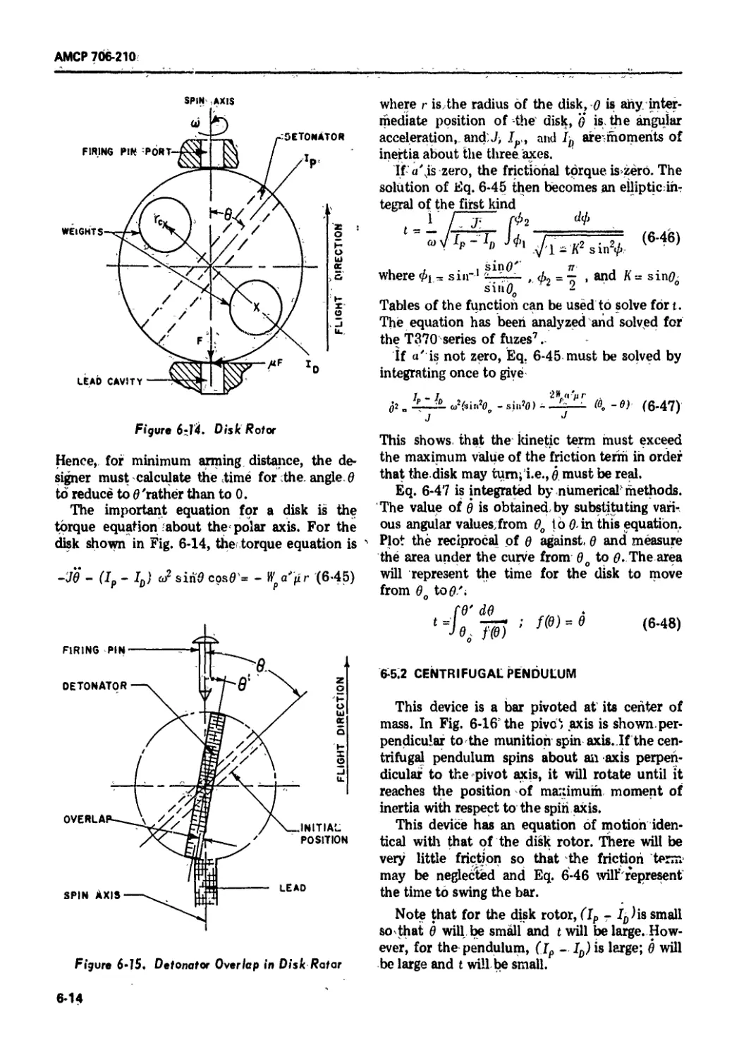
6-5.1 Disk Roto/................................................ 6-13
6-5.2 Centrifugal Pendulum................................. 6-14
6-5.3 The Semple Plunger................................... 6-15
6-5.4 Sequential Arming Segments........................... 6-15
6-5.5 Rotary Shutter..................................... 6-17
6-5.6 Ball Cam Rotor....................................... 6-17
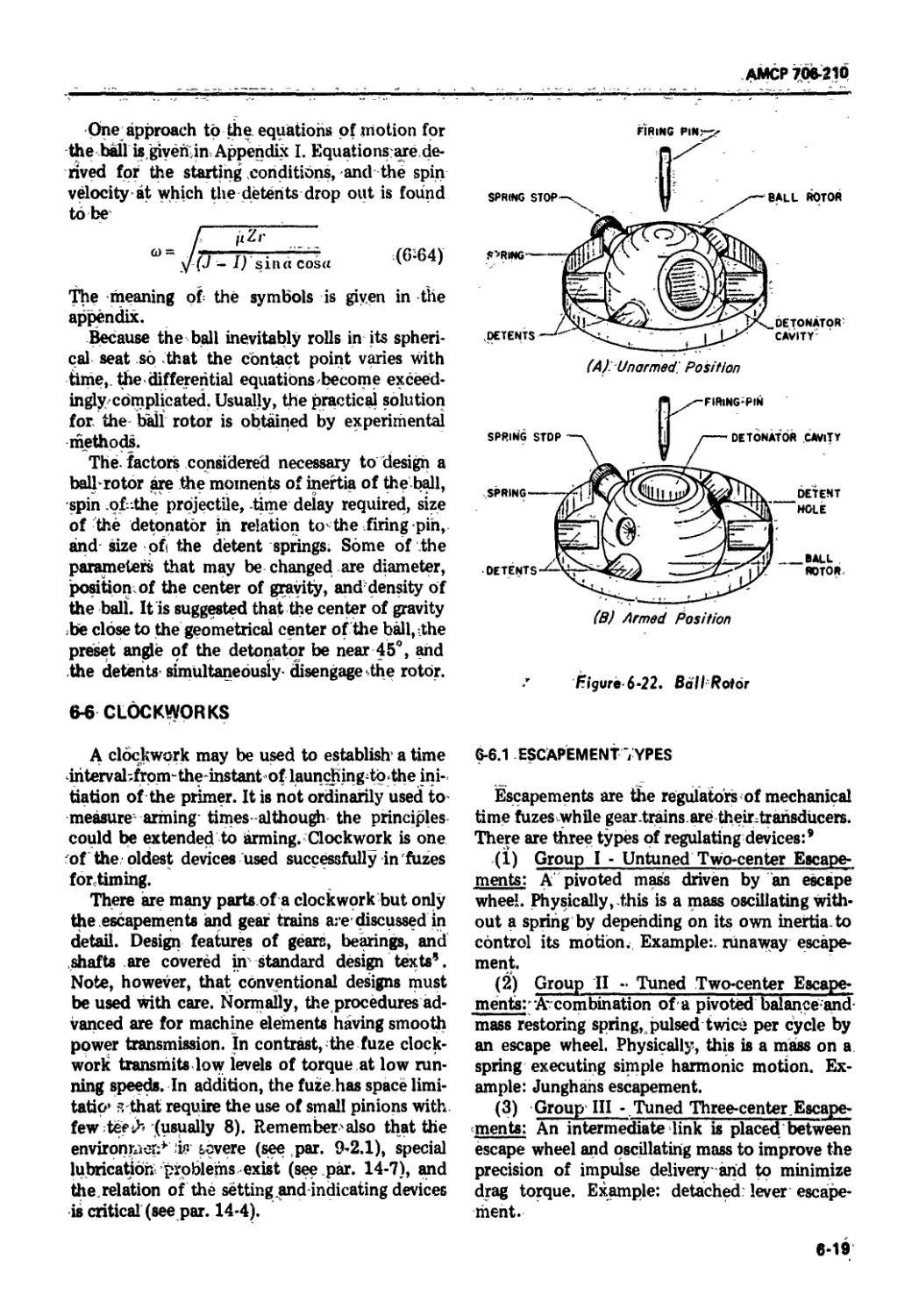
6-5.7 Ball Rotor........................................... 6-18
6-6 Clockworks........................................... 6-19
6-6.1 Escapement Types..................................... 6-19
6-6.2 Untuned Two-center Escapements.......... ............ 6-20
6-6.3 Tuned Two-center Escapements ........................ 6-21
6-6.3.1 Description of Escapement Mechanisms.............. 6-22
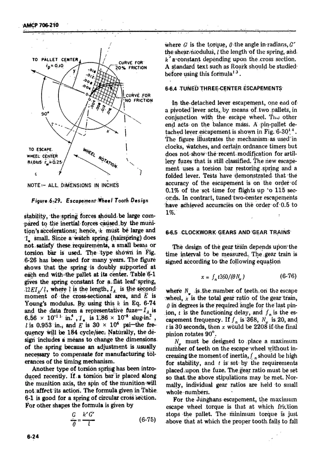
6-6.3.2 Description of Tooth Design.......... ............ 6-23
te
АМСР 706-210
Paragraph Page
6-6.3.3 Description of Spring Design ........................... 6-23
6-6.4 Tuned Three-center Escapements.,......... . ....... 6-24
6-6.5 Clockwork Gears and Gear Trains ....... 6-24
References . ,................... K.. 6-26
CHAPTER 7. ELECTRICAL ARMING DEVICES
7-1 General . 7-1
7-2 Components ................................... 7-1
7-2.1 Switches......7-1
7-2.2 Exp’oai, c Motors ................. . . ......... 7 '3
7-2.3 Electronic Tubes ................. .:......................7-3
7-2.4 Electrical Generators......... . .................... 7-3
7-2.5 Reserve Batteries............................... 7-3
7-3 RC Circuits .............................................. . 7-3
7-3.1 Basic RC Delay Circuits ..........................:.......... . 7-4
7-3.2 Tank Capacitor RC Delay Circuit............ 7-4
7-3.3 Triode RC Delay Circuit............................... . 7-5
7-3,4 Three-wire RC Delay Circuit.............. 7-5
7-3.5 Cascade RC Delay Circuit.,.......................... "6
7-3.6 Ruehlmann RC Delay Circu’t........................... >6
7-3.7 Two-diode Ruehlmann Circuit..... ..................... 7-6
7-3.8 Single-diode Ruehlmann Circuit...................... 7-7
7-3.9 Accuracy of RC Delays .............................. 7-E
References........................................... .7-9
CHAPTER 8. OTHER ARMING DEVICES
8-1 General............................................ 8-1
8-2 Fluid Devices........................................... 8-1
8-2.1 Fluid Flow.......................................... 8-1
8-2.2 Fluerics........................................... 8-1
8-2.2.1 Fluidic and Flueric Systems........................ 8-1
8-2.2.2 Flueric Components Us>:d for Arming................ 8-1
8-2.2.3 Relaxation Oscillator ............................ 8-6
8-2.2.4 Arming Considerations............................ 8-6
8-2.3 Pneumatic Delay............................................ 8-7
8-2.3.1 External Bleed Dashpot .............................. .. 8-7
8-2.3.2 Annular Orifice Dashpot......................... 8-7
8-2.4 Delay by Fluids of High Viscosity.......................... 8-9
8-2.4.1 Silicone Grease................................... 8-9
8-2.4.2 Pseudofluids..................................... 8-10
8-3 Chemical Arming Devices............................... 8-10
8-4 Motion-induced Arming Devices........................ 8-11
References ..................................... 8-12
PART THREE - FUZE DESIGN
Introduction.......................................... 9-1
v
АМСР 706-210
CHAPTER 9. CONSIDERATIONS IN f'UZE DESIGN
9-1 General ........... ..................... ........... 9-1
9-2 Requirements for a Fuze . . .............9-1
9-2,1 Environmental Feattires .............................. . . 9-2
9-2.2 General S..iety Features ....................... . . . 9-2
9-3 Steps in Developing a Fuze . ............................. 9-3
9-3.1 Preliminary Design and Layout ..................... 9-3
9-3.2 Dimensional Design and Calculations...................,,. „ 9-3
9-3.3 Model Tests and Revisions...... ......... 9-4
9-3.4 r i i il Acceptance, Safety, and Proving Ground Tests. .... 9-4
9-4 Application of Fuze Design Principles ........................ 9-й
9-4.1 Requ' ^ments for the Fuze .............. 95
9-4.2 Оечит Considerations ..9-6
9-4.2.1 Booster Assembly ..................9-7
Э-4.2.2 Detonator Assembly........... ...... ....... .-. , . 9-8
9-4.2.3 Initiating Assembly ..... ................ 9-10
9-4.3 Tests and Revisions . . ,,.......... . . . . ,.; .-... . 9-10
9-4.4 Dwign Features of Current Fuzes .... ,.;........ 9-10
9-4.4.1 Examples of Current Fuze Design .... x........., . < 9-10
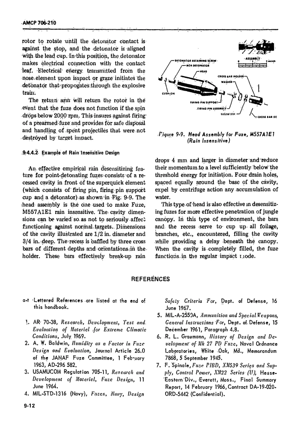
9-4.4.2 Example of Rail. Insensitive Design ...;9-12
References........................................... ;.. 9-12
CHAPTER 10. FUZES LAUNCHED WITH HIGH ACCELERATION
10-1 General .................... ,. . ... . ;.................... 10-1
10-2 Fuze Component, tor Fin-stabilized Projectiles.......; .•... 10-1
10-2.1 Coil Spring Design . ............. ........ ............... .:... 10-1
10-2.1.1 Restraining Motion......................................... 10-1
10-2.1.2 Controlling Motion . . . ,... . . .: 10-2
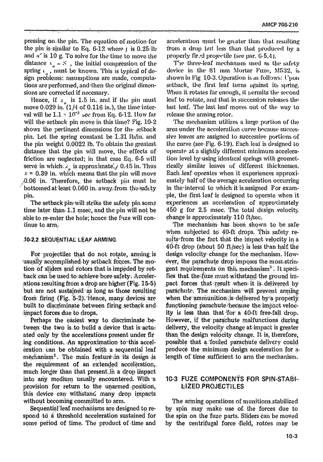
10-2.2 Sequential Leaf Arming ..... 10-3
10 3 Fuze Components for Spin-stabilized Projectiles ........ 10-3
10-3.1 Sliders.,... 10-4
10-3.2 Rotor Detents ............................................ 10-5
10-3.3 Rotary Shutters .:........... .;. .... ..«............. .•10-7
10-3.4 Special Considerations for Rocket-assisted Projectiles :.,. 10-8
10-4 Mechanical Time Fuzes.................. .; x K ....... 10-8
10-4.1 Clockwork Drive ........................................ 10-8
10-4.2 Design of One Component ......................... 10-10
10-5 Small Arm Fuzes.................................................. 10-10
References .;.. ................ ..... ..; 10-11
CHAPTER 11. FUZES LAUNCHED WITH LOW ACCELERATION
11-1 General ......................................... .;....... .: ....... ... 11-1
11-2 Rocket Fuzes ........ ..... ................................ 11-1
11-2.1 Historical Fuzes ......................,....................-...,... <.....:. 11-1
11-2.2 Self-destruction ..... .; ..... , . .;................................... 11-2
11-3 Guided Missile Fuzes . ........................... -....................... 11-2
vi
AMCP 706-210
I'ai agi aph
I’agc
11-4 Grenade Fuzes.......................................... 11-3
11-4.1 Hana Grenades ,........................ ,............-,. 11-3
11-4.2 Rifle Grenades........ . . ....11-5
11-4.3 Launched Grenades .................... 116
References..;,.................................... 11-7
CHAPTER 12. BOMB FUZES
12-1 General,................................. . . .;,
12-1 Fuze Action ......................................
12-2.1 The Arming Process . . .
12-2.2 The Functioning Process .
12-2.3 Clustering ,.:K,
12-3 Impact Fuzes .. ,,...... , ..................... ,.;,,,
12-3.1 Superquick or Short Delay Fuzes . ,,,.... ......... .
12-3.1.1 A Typical Fuze ,,,.
12-3.1.2 Gear Trains ..............,,. .;
12-3.1.3 The Explosive Tram,.... . .,,. ..........................
12-3.2 Delay Fuzes .,.................. ,. . .;.. .:, . ..... .
12-3.2.1 Fuze Operation .................................. .;
12-3.2.2 Drive Assembly ,. . ,,. ,..........
12-4 Time Fuzes K .....,,,........ .:.....
12-4.1 Operation .;....... . . ........... ...... s. . • •. . ....
12-4.2 The Arming Pin .. . ......... x..... .•.
12-4.3 The Propeller . .. ,..... ..,. ... .
12-5 Special Fuzes .;. ...........................................
12-5.1 Bomb Clusters ........., ..................... .:.:....
12-5.2 Depth Bombs ................................. .,
12-5.3 Fragmentation Bombs .- .
12-5.4 Bomblet Fuzes...............,... . .-. .............
References ..................... ,. .... ... ........ .
12-1
12-1
12-1
12-2
12-3
12-3
12-3
12-3
12-3
12-5
12-7
12-7
12-8
12-8
12-9
12-10
12-10
12-11
12-11
12-11
12-12
12-13
12-14
CHAPTER 13. STATIONARY AMMUNITION FUZES
13-1 General................................... 13-1
13-2 Land Mines ...-.................. .. 13-1
13-2.1 Land Mine Types.................-,........... 13-1
13-2.2 Reversing Belleville Spring Trigger ..........;,. . 13-1
13-2.3 Pull-release Trigger .. ,,................. 13-2
13-3 Sea Mines.., .•. .;... . .........,.;.. ......13-4
13-4 Boobytraps ...,.... ,,..... ,.. , ........ 13-5
References . .. , 13-6
CHAPTER 14. DESIGN GUIDANCE
14-1 Need for Design Details ,.,...........
14-2 Prevention of Contact Contamination
14-3 Packaging..................................... .... -,...., ...
14-4 Linkage of Setter Components ............................
14-1
14-1
14-2
14-2
vii
АМСР 706-210
I'ai agiaph
14-5
14-5.1
14-5.2
14-5.3
14-6
14-6.1
14-6.2
14-6 3
14-7
14-8
14-9
14-9.1
14-9.2
14-9.3
14-10
14-11
14-12
Materials................... . . . .......... 14-3
Potting Compounds ..... ........... .... 14-3
Sealing Materials ......... ................ ......... 14 4
Solders ...... .. ................ .; . . ... 14'5
Construction Techniques . 14-5
Mechanical Considerations ..... . .:,. . . .;.;... 14-5
Encapsulation ........ .; . ........,. . .:. -....... . 14-6
Supporting Structure........ «.............................. 14-7
Lubrication .; ....... .; .; ... . .: . .. .. . .; . .; . •: ... . . 14-7
Tolerancing ............... , .<.:....-. ...... ... .•. . 14-9
Components . . ............ . . ... ............. ,... 14-10
SeL-ction of Components...... ..........;. .:.. 14-10
Electrical Components......................-.. ,. 14-10
Mechanical Components ................. 14-11
Use of Analog Computer ..;... .- .-....... ....... .............. 14-11
Fault Tree Analysis ............................................ 14-12
Maintenance ...............- ...................... .:. 14-13
References ..................................... 14-13
CHAPTER 15. FUZE TESTING
15-1 General ...... >- ................................. 15-1
15-2 Performance Tests ................................... 15-1
15-2.1 Development and Acceptance Tests .......... 15-1
15-2 2 Test Programming .......................... 15-1
15-2.3 Component Tests...............:..;. .... l<5-2
15-2.3.1 Explosive Elements............................... 15-2
15-2.3.2 Mechanical Devices............................... 15-3
15-2.3.3 Power Sources..................................... 15-5
15-2.4 Proof Tests 15-5
15-3 Safety Tests .......................................... . 15-6
15-3.1 Destructive 'fests ............................... 15-6
15-3.2 Nondestructive Tests ............................. 15-9
15-4 Surveillance Tests .................................. 15-10
7 5-4.1 Factors Affecting Shelf Life.........<.............. 15-10
15 4.2 Accelerated Environment Tests ....................... 15-10
15-5 Military Standards and Specifications.................. 15-13
15-6 Analysis of Data ..........,............. 15-13
References .......................... ............. 15-16
GLOSSARY ...... . :. .... ...................... .... G-l
GENERAL REFERENCES ................. .............. R-l
APPENDIX I. MATHEMATICS OF THE BALL ROTOR ......... A-l-1
APPENDIX II. JOURNAL ARTICLES OF THE JANAF FUZE
COMMITTEE .................. ............... . A-II-1
INDEX ............................................. 1-1
wiii
АМСР 706-210
LIST OF ILLUSTRATIONS
Fig. Ло. Title Page
1-1 Fuze Arming Process.................................. 1-2
1-2 Typical Artillery Round........................ ........ 1-3
1-3 Rocket, M28, With Fuze, МЛ04А1............. 1-3
1-4 Typical Bomb.......................................... 1-4
1-5 Antitank Mine, M15, With Fuze, M603 ..................... > 1-4
1-6 Fuze, PD, M525 ......................................... 1-7
1-7 Arming Action for Fuze, PD, M525........................ 1-8
2-1 Possible Multiple Fuzing Circuit........................ 2-3
2-2 A Standard Fuze Contour ................................ 2-4
2-3 Setting Mechanism on Fuze, MT, XM571 ................... 2-6
3-1 Typical Firing Pins .................................... 3-4
3-2 Standard Firing Pin for Stab Initiators................... 3-4
3-3 Initiation by Adiabatic Compression ................... 3-5
3-4 Piezoelectric Nose Element.............................. 3-6
3-5 Piezoelectric Base Element ............................. 3-7
3-6 Piezoelectric Control-Power Supply, XM22E4.............. 3-7
3-7 Typical Circuit for Wind-driven Generator .............. 3-8
4-1 Burning Low Explosive .................................. 4-1
4-2 Detonating High Explosive .............................. 4-2
4-3 Examples of Good and Poor Detonations................... 4-2
4-4 Typical Primers and Detonators (Mechanical)............... 4-7
4-5 Typical P^mers and Detonators (Electrical).............. 4-7
4-6 Electric Squib, М2 ..................................... 4-8
4-7 Delay Element, M9 ...................................... 4-9
4-8 Relay, XM11 ............................................ 4-10
4-9 MDF Used in 37 mm Spotting Cartridge. XM415E7........... 4-12
5-1 Simple Arming Device.................................... 5-2
5-2 Ballistic Environments of a Fuze....................... 5-2
5-3 Typical Pressure-travel Curve................................. 5-3
5-4 Drag Coefficient KD........................................... 5-3
5-5 Nomogram for Determining Spin Velocity of a Projectile.. 5-4
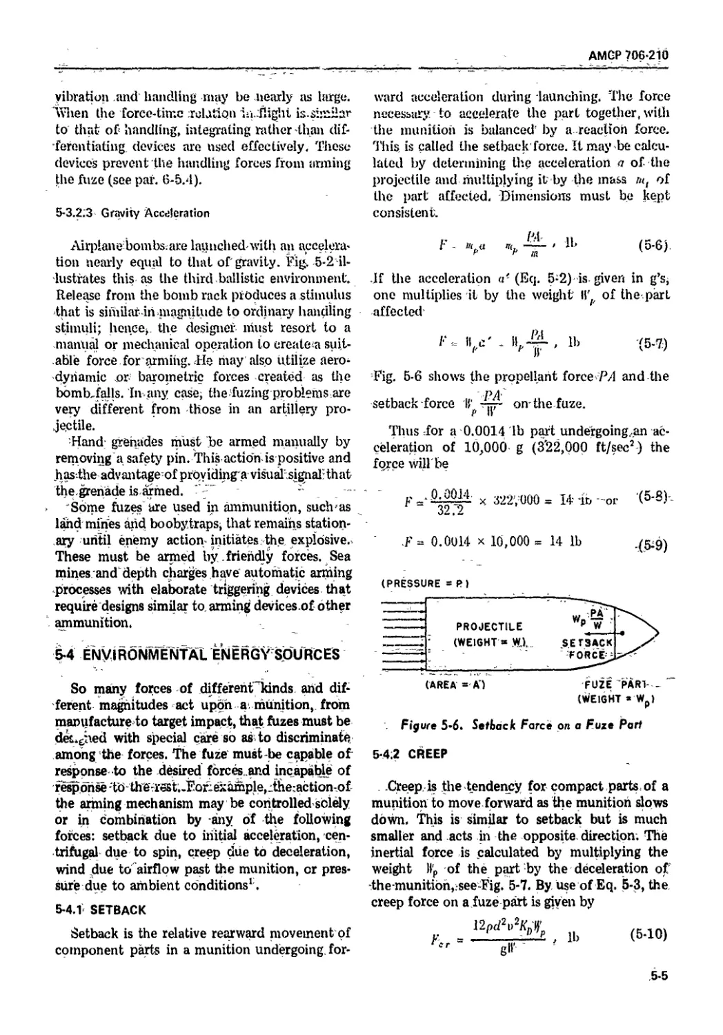
5-6 Setback Force on a Fuze Part............................. 5-5
5-7 Creep Force on a Fuze Part............................... 5-6
5-8 Centrifugal Force on a Fuze Part......................... 5-6
5-9 Coriolis Force on a Fuze Part............................ 5-6
5-10 Torque on a Fuze Part.................................... 5-7
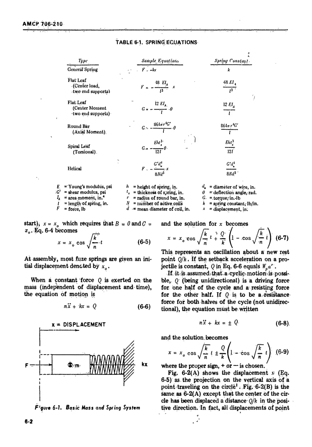
6-1 Basic Mass and Spring System............................. 6-2
6-2 Projection of Spring Motion.............................. 6-3
6-3 Mass and Spring Under Acceleration....................... 6-4
6-4 Compression Spring Data.................................. 6-6
6-5 Typical Cased Power Spring............................... 6-7
6-6 Negator Spring......................................... 6-8
ix
АМСР 706-210
LIST OF ILLUSTRATIONS (Cont'd)
No. Title Page
6-7 Slider at an Angle .................................... 6-9
6-8 Hinge Pin.....,................................... 6-10
6-9 Detent Actions ..................................... 6-10
6-10 Trip Levers........................................ 6-11
6-11 Firing Ring for All-way Switch ..;.................... 6-11
6-12 Spiral Unwinder .................................... 6-12
6-13 Nomenclature for Spiral Unwinder....................... 6-13
6-14 Disk Rotor ........................................ 6-14
6-15 Detonator Overlap in Disk Rotor........................ 6-14
6-16 Centrifugal Pendulum................................... 6-15
6-17 Semple Plunger ...................................... 6-15
6-18 Sequential Leaf Mechanism ............................. 6-16
6-19 Setback Acceleration Curve............................ 6-17
6-20 Rotary Shutter....................................... 6-17
6-21 Ball Cam Rotor ........................................ 6-18
6-22 Ball Rotor............................................. 6-19
6-23 Runaway Escapement..................................... 6-20
6-24 Typical Rocket Accelerations........................... 6-20
6-25 Variation in Rocket Arming Time ....................... 6-21
6-26 Action of Junghans or Deadbeat Escapement.............. 6-22
6-27 Popovitch Modification of Junghans Escapement......... 6-23
6-28 Coordinate System for Analysis of Tooth Design........ 6-23
6-29 Escapement Wheel Tooth Design.......................... 6-24
6-30 Detached Lever Escapement ............................. 6-25
7-1 Trembler Switch......................................... 7-1
7-2 Switch for Rotated Fuzes................................ 7-2
7-3 Thermal Delay Arming Switch............................. 7-2
7-4 Thermal Delay Self-destruction Switch................... 7-2
7-5 Explosive Motors....................................... 7-3
7-6 Basic RC Delay Circuit................................. 7-4
7-7 Tank Capacitor RC Delay Circuit ........................ 7-5
7-8 Triode RC Delay Circuit................................. 7-5
7-9 Three-wire RC Delay Circuit ............................ 7-5
7-10 Discharge Curve for Capacitor C2(Eb 2 > Ebl) 7-6
7-11 Discharge Curve for Capacitor C2 (Eb 2 < Eb{) 7-6
7-12 Cascade RC Delay Circuit ............................... 7-6
7-13 Cascade RC Delay Circuit With Instantaneous Charging... 7-6
7-14 Two-diode Ruehlmann Circuit............................. 7-7
7-15 Circuit After Closure of Switch S2 ..................... 7-7
7-16 Single-diode Ruehlmann Circuit................ ......... 7-7
8-1 Schematic of Flueric Amplifiers ........................ 8-2
8-2 Schematic of Flueric Pressure-compensated Oscillator.... 8-3
8-3 Schematic of Flueric Counter Stage...................... 8-4
8-4 Flueric Timer ......................................... 8-5
8-5 Sample Flueric Timer Elements ........................ 8-5
8-6 Flueric Relaxation Oscillator .......................... 8-6
8-7 Flueric Relaxation Oscillator and Digital Amplifier... 8-7
x
АМСР 706-210
-»___________________
LIST OF ILLUSTRATIONS (Cont'd)
Fig. No. i' tle Page
8-8 Fuze, XM717 ..... . .............. 8-9
8-9 Pneumatic Dashpot for Arming Delay .. .... ........ 8-9
8-10 Delay Assembly of Fuze, XM218 ........................ 8-10
8-11 Chemical Long Delay System ....... ..................... 8-10
8-12 Electromagnetic Induction Sea Mine ................... 8-11
9-1 Caliber Drawing of 40 mm Projectile ............... 9-5
9-2 Ballistic Drawing for 40 mm Gun ...................... 9-6
9-3 Outline of Fuze Contour .. ........................... 9-7
9-4 Preliminary Space Sketch ............................. 9-7
9-5 Booster and Detonator Assemblies ................... 9-8
9-6 Initiating Assembly................................... 9-10
9-7 Complete Fuze Assembly .,... ......................... 9-11
9-8 Fuze, PIBD, XM539E4 .................................. 9-11
9-9 Head Assembly for Fuze, M557A1E1 (Rain Insensitive) .. 9-12
10-1 Fuze Head Assembly ................................... 10-1
10-2 Interlocking Pin ........ ............................ 10-2
10-3 Leaf Arming Mechanism of Fuze, M532 .................. 10-4
10-4 Spiral Spring for Ball Rotor ....... ................. 10-5
10-5 Effect of Detent Length............... ............... 10-6
10-6 Booster, M21A4 ....................................... 10-7
10-7 Timing Movement of Fuze, MTSQ, M502A1 ................ 10-9
10-8 Centrifugal Drive...................................... 10-10
10-9 20 mm Fuze, M505A3..................................... 10-11
11-1 Safing and Arming Mechanism........................... 11-3
11-2 Safing and Arming Device, GM, M30A1 .................. 11-4
11-3 Hand Grenade Fuze, M217............................... 11-5
11-4 Hand Grenade Fuze, M204A2 ............................ 11-6
11-5 Grenade Fuze, PD, M551................................ 11-6
12-1 Bomb Trajectories .................................... 12-2
12-2 Typical Bomb Release Curves.......... ................ 12-2
12-3 Fuze, Bomb Nose, M904E2............................... 12-5
12-4 Gear Assembly of Fuze, M904E2 ........................ 12-6
12-5 Explosive Train of Fuze, M904E2 ...................... 12-7
12-6 Fuze, Bomb Tail, M906 ................................ 12-8
12-7 Constant Speed Governor of Drive, M44................. 12-8
12-8 Fuze, Bomb Nose, M198................................. 12-9
12-9 Arming Pin Assembly of Fuze, М1Э8................. 12-10
12-10 Fuze, Bomb Tail, AN MARK 230 ..... .................... 12-12
12-11 Antenna Pattern of Bomb Proximity Fuze................ 12-13
12-12 Doppler Principle..................................... 12-13
12-13 Typical Amplifier Response Curve .................. 12-13
12-14 Bomb, BLU 7/B ........................................ 12-13
13-1 Action of Reversing Belleville Spring ............... 13-2
13-2 Pull-release Device .................... .......... 13-3
xi
AMCP 706-210
LIST OF ILLUSTRATIONS (Confd)
Fig. Ao. Title Page
13-3 Expansible Socket of Pull-release Device............... 13-3
13-4 Trip Wire Action ...................................... 13-4
13-5 Pressure-release Firing Device, M5 .................... 13-5
13-6 Firing Device, М2 ..................................... 13-5
14-1 Packing Box and Fuze Supports.............................. 14-2
14-2 Linkage of Setter Components......................... 14-3
14-3 Location of Seals in a Typical Electronic Fuze....... 14-5
14-4 Construction of Typical Mortar Fuze, M517 ........... 14-8
14-5 Catacomb Amplifier................................... 14-8
14-6 Catacomb Amplifier With Printed End Plates........... 14-8
14-7 Fuze on Analog Display Board ......................... 14-12
15-1 Arrangement for Detonator Safety Test................ 15-3
15-2 Low-g Centrifuge..................................... 15-4
15-3 Shock Machine ....................................... 15-5
15-4 Typical VHF High-g Telemetry System ................. 15-6
15-5 Acceleration Experienced by 81 mm Mortar Projectile
Dropped Base Down.................................... 15-7
15-6 40-ft Drop Tower.................................... 15-7
15-7 Jolt Machine......................................... 15-7
15-8 Jumble Machine ...................................... 15-8
15-9 Results of Impact Safe Distance Test ................ 15-9
15-10 Transportation-vibration Machine...................... 15-10
15-11 Layout of Salt Spray (Fog) Chamber ................... 15-11
15-12 Cooling and Heating Curves of Fuzes Subjected to the
Temperature and Humidity Test.................................. 15-11
15-13 Vacuum Steam Pressure Chamber......................... 15-12
A-l Ball Rotor Nomenclature .............................. A-I-l
xii
AMCP 703-210
LIST OF TABLES
Table No. Title Page
1-1 Fuze Categories ....................................... 1-5
4-1 Impact Sensitivity of Explosives ...................... 4-3
4-2 Compatibility of Common Explosives and Metals........ 4-4
4-3 Physical Properties of Fuze Explosives............... 4-5
4-4 Common Explosive Materials ............................ 4-5
6-1 Spring Equations..................................... 6-2
6-2 Design Formulas for Constant-force Springs........... 6-7
7-1 Fractional Error Relations for the Ruehlmann Circuit.... 7-8
8-1 Comparison of Fluidics With Other Logic Techniques.... 8-8
9-1 Requirements and Design Data for Sample Fuze......... 9-6
9-2 Computations of Moments of Inertia .................... 9-9
10-1 Summary of Conditions and Calculations.............. 10-5
10-2 Summary of Calculations............................. 10-8
12-1 Tactical Purposes of Bomb Fuzes..................... 12*4
12-2 Bomb Ballistics........................................ 12-4
14-1 Comparison of Properties of Typical Potting Materials ... 14-4
14-2 Low-melting Soft Solders Used in Electrical Equipment .. 14-6
15-1 Safety and Surveillance Tests ......................... 15-2
15-2 Dimensions of Present Day Centrifuges............... 15*4
15-3 Typical Field Proof Tests.............................. 15-6
15-4 Volume of Gas Evolved in 40 Hours in Vacuum
> atl20°C............................................. 15-10
15-5 Military Standards for Fuzes........................ 15-14
xiii
АМСР 706-210
LIST OF SYMBOLS*
4 = Area
.4 - Area of a part
a = Acceleration
a' = Acceleration in g’s
В = Belleville spring parameter
b = Width
C = Capacitance
C = A constant
C? = Coefficient of power derived
c = A constant
cL = Velocity of electromagnetic waves
c - Velocity of sound waves
d - Mean diameter; caliber
d - Inner diameter
I
d = Outer diameter
0
dfi = Diameter of a pin
d - Diameter of a wire
V
E = Young’s modulus of elasticity
Eb = Battery voltage
E = Voltage across a capacitor
E' = Extinction potential of a diode
E* - Generated voltage
E ~ Minimum operating voltage
Et = Striking potential of a diode
F = Generalized force
F. = Centrifugal force
F - Coriolis force
C 0
F c r - Creep force
Fd • Detent force
Ffl = Drag force
F = Form factor
Fg = Force on gear tooth
F = Normal force
n
F ~ Restraining force
F = Trip wire force; tangential force
/ = Force of friction
fn = Frequency of oscillation
f r = Frequency received
f = Frequency transmitted
G • Torque
G' = Shear modulus of elasticity
Gf • Frictional torque
Gg = Initial spring torque
G • Static frictional torque
g = Acceleration due to gravity. 32.2 ft/sec2
H = A constant
Ht = Electrical energy
Hp = Power output
Hs = Potential energy
h = Height
h = Angular momentum
h = Clearance between coils
c
hf - Free height of a spring
hs - Solid height of a spring
I - Moment of inertia
= 2nd moment of area
1 - Moment of inertia of escapement system
- Moment of inertia of escape wheel
i = Current
J = Polar moment of inertia
KD = Drag coefficient
К = Wahl factor
k = Spring constant
k' = Proportionality constant
I = Length
* Symbols that bear subscripts other than those shown here are defined in their immediate context
IV
АМСР 706-210
LIST OF SYMBOLS* (Cont'd)
[' M ж 3 Clearance Moment V ll. V Velocity Velocity of bomb radio receiver Initial velocity (fps)
Ж Friction moment f = Velocity of image radio source
n Ж Mass
ж Mass of a detent И = Weight
nt p Ж Mass of a part Й p ж Weight of a part
Wc = Width of a clevis
N Ж Number of active coils, turns delivered u = Width of an eye
N V Ж Number of teeth on an escapement wheel
n а Twist of rifling in gun A’ ж Force in the x -direction
X ж Displacement
P а Pressure x° Initial displacement
P M S Hydrostatic pressure
p а Damping coefficient Y = Force in у-direction
Pd ж Diametral pitch of a gear У ж Displacement
Pk а Pitch of an unloaded helical spring
I ж Force in z -direction
Q 9- A constant force z Displacement
я S Resistance Greek Letters
Я- S Universal gas constant (approx. 2 cal/° C
mole a Angular acceleration
«д S Load resistance
Г S Radius fl ж Compressibility
г 3 Radial distance to center of gravity
Г ж Concentration of a solution
г/ Ж Final radius
г 0 3 Initial radius 8 Spring deflection
S ж Distance 0 ж Viscosity
s/ Ж Safety factor; stress factor
S 9 Spiral constant 0 ж Angular displacement
0 Q ж Initial angular displacement
Т Ж Absolute temperature in degrees Kelvin
Т с = Time constant К = Rate of reaction
t ж Time
t ж Spring thickness p = General coefficient of friction
Pl, ж Kinetic coefficient of friction
и ж Radial velocity p. ж Static coefficient of friction
♦ Symbols that bear subscripts other than those shown here are defined in their immediate context.
xv
AMC? Ttte-210
LIST OF SYMBOLS* (Conducted)
P “ Density of a gas, liquid, or solid
Pt • Density of air
p9 Density of water
c • Bending stress
Maximum atreae
0 • Normal stere
r •> Shear atreae
v “ Poisson’» ratio
Ф = Magnetic flux
Ф = Angular displacement
фд = Initial angular displacement
X = Gear ratio
Q = Precessional angular velocity
ш = Angular spin velocity, rad/sec
ш ж Angular spin velocity, rev/sec
u>o = Initial angular spin velocity
•Symbol» that bear subscripts other than those shown here are defined in their immediate context
АМСР 706-210
PREFACE
The Engineering Design Handbooks of the U.S. Army Materiel Command
have evolved over a number of years for the purpose of making readily avail-
able basic information, technical data, and practical guides for the develop-
ment of military equipment. While aimed primarily at U.S. Army materiel, the
handbooks serve as authoritative references for needs of other branches of the
Armed Services as well. The present handbook is one of a series on Fuzes.
This publication is the first revision of the Handbook, Fuze , General ami
Mechamca I. Extensive changes were made to update the volume. Information
on explosive trains was condensed, this subject now being treated in its own
publication, AMCP 706-179. Illustrations of sample ammunition items, ref-
erences, and test data were brought up to date. New chapters are included on
design considerations and design guidance. The treatment of electric fuze ac-
tions wa« greatly enlarged with material excerpted from AMCP 706-215.
This handbook presenta both theoretical and practical data pertaining to
fuzes. Coverage includes initiation, arming, design, and tests of fuzes and their
components. Both mechanical and electric fuze actions are treated. The fuz-
ing of all conventional ammunition items is covered.
Prepared as an aid to ammunition designers, this handbook should also be
of benefit to scientists and engineers engaged in other basically related re-
search and development programs or who have responsibility for the planning
and interpretation of experiments and tests concerning the performance of
ammunition or ammunition components.
The handbook was prepared by The Franklin Institute Research Labora-
tories, Philadelphia, Pennsylvania. It was written for the Engineering Hand-
book Office of Duke University, prime contractor to the Army Research
Office-Durham. Its preparation was under the technical guidance and coordi-
nation of a special committee with representation from Picatinny Arsenal,
Frankford Arsenal, and Edgewood Arsenal of the U.S. Army Munitions
Command, and Harry Diamond Laboratories of AMC. Chairman of this com-
mittee was Mr. Wm. A. Schuster of Picatinny Arsenal.
The Handbooks are readily available to all elements of AMC, including
personnel and contractors having a need and/or requirement. The Army
Materiel Command policy is to release these Engineering Design Handbooks
to other DOD activities and their contractors and to other Government
agencies in accordance with current Army Regulation 70-31, dated 9 Sep-
tember 1966. Procedures for acquiring these Handbooks follow:
a. Activities within AMC and other DOD agencies should direct their re-
quests on an official form to:
Commanding Officer
Letterkenny Army Depot
ATTN: AMXLE-ATD
Chambersburg, Pennsylvania 17201
b. Contractors who have Department of Defense contracts should submit
their requests, through their contracting officer with proper justification, to
the address indicated in paragraph a.
xvii
AMCP 701-210
c. Government agencies other than DOD having need for the Handbooks
may submit their requests directly to the Letterkenny Army Depot, as indi-
cated in paragraph a above, or to:
Commanding General
U.S. Army Materiel Command
ATTN: AMCAD-PP
Washington, D.C. 20315
or
Director
Defense Documentation Center
ATTN: TCA
Cameron Station
Alexandria, Virginia 22314
d. Industries not having Government contracts (this includes Universities)
must forward their requests to:
Commanding General
U.S. Army Materiel Command
ATTN: AMCRD-TV
Washington, D.C. 20315
e. All foreign requests must be submitted through the Washington, D.C.
Embassy to:
Office of the Assistant Chief of Staff for Intelligence
ATTN: Foreign Liaison Office
Department of the Army
Washington, D.C. 20310
All requests, other than those originating within DOD, must be accom-
panied by a valid justification.
Comments and suggestions on this handbook are welcome and should be
addressed to Army Research Office-Durham, Box CM, Duke Station, Durham,
North Carolina 27706.
xviii
АМСР 706-210
FUZES
PART ONE-FUNDAMENTAL PRINCIPLES
CHAPTER 1
INTRODUCTION ’
1-1 DEFINITION AND PURPOSE OF A FUZE
The word fuze is used to describe a wide vari-
ety of devices used with munitions to provide
basically the functions of (a) safing, i.e., keeping
the munition safe for storing, handling, (includ-
ing accidental mishandling), and launching or
emplacing; (b) arming, i.e., sensing the environ-
ments) associated with actual use including
safe separation and thereupon aligning explo-
sive trains, closing switches and/or establishing
other links to enable the munition; and (c) fir-
ing, i.e., sensing the point in space or time at
which initiation is to occur and effecting such
initiation. See also MIL-STD-444, Nomenclature
and Definitions in the Ammunition Area.f
There is a very wide variety of munitions in
existence and new ones are continuously being
developed. They include artillery ammunition
(nuclear and non-nuclear), mortar ammunition,
bombs, mines, grenades, pyrotechnics, atomic
demolition munitions, missile warheads (nuclear
and non-nuclear), and other munition items.
Because of the variety of types and the wide
range of sizes, weights, yields, and intended
usage, it is natural that the configuration, size,
and complexity of fuzes vary also over a wide
range. Fuzes extend all the way from a rela-
tively simple device such as a grenade fuze to
a highly sophisticated system or subsystem such
as a radar fuze for a missile warhead. In many
instances the fuze is a single physical entity-
such as a grenade fuze—while in other instances
two or more interconnected components placed
in various locations within or even outside the
mrnition make up the fuze or fuzing system.
*This handbook was revised by Gunther Cohn, The
Franklin Institute Research Laboratories. Valuable con-
tributions were made by С. T. Davey, P. F. Mohrbach,
and M. R. Smith.
"fDistinct fuze terms are defined tn the Glossary.
There is also a wide variety of fuze related com-
ponents, such as power sources, squibs, initia-
tors, timers, safing and arming (integrating) de-
vices, cables, and control boxes which are some-
times developed, stocked, and issued as indivi-
dual end items but which in the overall picture
constitute a part of the fuzing system.
Leading nations such as the U.S.A, employ
the most advanced technology available in the
design of modem weapons and are constantly
advancing the state-of-the-art. This is particu-
larly true of fuzes because of their important
and exacting role, constituting in effect file
brain of the munition. This handbook in the
Engineering Design Handbook Series is con-
cerned with the basic principles underlying the
design of fuzes. Since the final design of any
fuze will depend upon the required role and
performance and upon the ingenuity of the de-
signer, attention in the handbook is focused on
these basic principles. Illustrations of applica-
tions are purposely kept as simplified as possible,
leaving the final design approaches, as they
must be, to the fuze designer.
1-2 FUZE ACTION
Inherent to the understanding of fuze de-
sign is the concept of the progression of the
action of the explosive train starting with ini-
tiation and progressing to the burst of the main
charge in the warhead. Initiation as the word
implies, starts with an input “signal,” such as
target sensing, impact, or other. This “signal”
then must be amplified by such devices as a
detonator (first stage of amplification), a lead
(second stage of amplification), and a booster
(third sLage of amplification) which has an ex-
plosive output of sufficient force to detonate
the main charge. Since the detonator contains
explosives which are very sensitive as required
1-1
AMCP 706-210
to respond to the initial (weak) signals, it is
the basic role of the fuze not only to signal the
presence of the target and to initiate the ex-
plosive train, but also to provide safety by
casualties to property and life in the past have
been directly traceable to inadequate built-in
fuze safety.
As an approach to providing adequate safety,
present design philosophy calls for a fuze to
have at least two independent safing features,
wherever possible, either of which is capable of
preventing an unintended detonation; at least
one of these features must provide delayed
arming (safe separation). This and other aspects
of safety are discussed in detail in Chapter 9.
Reliability of functioning is also a primary
concern of the fuze designer, details of which
are covered in later chapters (e.g., par. 2-3).
Fig. 1-1 is a diagram of the steps involved in
a typical arming process. At the left the fuze is
represented as unarmed so that it may be stored,
transported, handled, and safely launched. The
arming process starts at a by adding energy to
the system in a proper manner. At b enough
energy has been added so that the device will
continue to completion of the arming cycle. At
any time between a and b the device will return
to the unarmed condition if the energy is re-
moved. After b the fuze is committed to con-
tinue the arming process; therefore, b is termed
the commitment point. The detonator is aligned
Figure 1-1, Fuze Arming Process
at <• but provision is made for other arming func-
tions such as switch closures all of which are
finally completed at </, and the fuze is fully
armed and ready to function.
1-3 TYPICAL AMMUNITION ITEMS
Ammunition can carry a fuze in its nose, its
base, or anywhere within depending upon its
tactical purpose. To illustrate this versatility,
several common fuze carriers are briefly des-
cribed below. Greater detail is contained in Part
Three of this handbook.
1-3.1 PROJECTILES
Fig. 1-2 shows a typical round of fixed ammu-
nition for artillery use. The weapon firing pin (at
the bottom of the figure) strikes the cartridge
primer. This initiates the propelling charge with
the help of the igniter. As the propellant bums,
gases form that exert pressure upon the base of
the projectile and force it out of the gun tube.
Rifling in the gun tube engraves the rotating
band thus imparting spin to stabilize the pro-
jectile. In flight, centrifugal forces, set up in
the spinning projectile, turn rotor and move
interrupter so that a continuous explosive train
is formed. The fuze is now armed. Upon target
impact, the firing pin in the fuze is pushed into
the primer which then explodes and ignites
the detonator. It in turn initiates the booster
that amplifies the detonation sufficiently to
reliably detonate the bursting charge.
1-3.2 riOCKETS
Fig. 1-3(A)' * illustrates Rocket, M28, with a
base Fuze, M404A1 that is enlarged in Fig.
1-3(B). Rockets carry, their own propellant
which bums during rocket flight. After the
rocket exits the launch tube, the ejection pin
slides away, due to the force of a compressed
spring, exposing the detonator. Upon impact,
the inertia weight moves forward and causes
the striker to stab the detonator, which causes
the booster charge and in turn the high explosive
bursting charge in the rocket head to detonate.
•Supetscript number-- and letters pertain (e References.
Numt-riidl References are listed al the end of each
Chapter while lettered References are listed at the end
of the (ext.
AMCP 706-210
FIRING PIN
BURSTING
CHARGE
ROTATING
BAND
m
>
m
IGNITER
CARTRIDGE
PRIMER
PROPELLING
CHARGE
PRIMER
INTERRUPTER
CARTRIDGE
CASE
----WEAPON FIRING PIN
Figure 1-2. Typical Artillery Round
> FUZE
— DETONATOR
ROTOR
-- BOOSTER
1-3.3 BOMBS
Fig. 1-42 illustrates a typical bomb with its
main parts. Fins provide stability in flight.
The body contains the high explosive; fuzes
may Ьз located in the nose, the tail, or the side.
Two or three fuzes are used sometimes to in-
sure explosion of the bursting charge. Bomb
fuzes often are armed by vanes that spin in
the air stream. The vanes are prevented from
spinning before bomb release by arming wires
attached to the aircraft.
<л> яосш,ыгв
NOZZLE ANO
FIN ASSEMBLY
WANMEAD
Figure 1-3. Racket, M28, With Fuze, M404A1
1-3.4 MINES
Mines are a class of munitions which are pre-
positioned or emplaced at points or in areas,
typically by burying, so as to deter the enemy
from moving into the area. Fig. 1-53 shows
Mine, Antitank, Ml5 with Fuze, M603. As a
tank or other heavy vehicle rolls over the mine,
it depresses the pressure plate which causes the
Belleville springs to snap through, driving the
firing pin into the detonator, initiating the main
charge in the mine. Various antipersonnel mines
operating under lighter pressure or by trip wires
are also used in minefields.
1-4 REQUIREMENTS
In addition to performing the basic functions
of safing, arming, and firing, fuzes having high
usage rates should be designed so as to be
1-3
АМСР 708-210
F.gure 1-4. Typical Bomb
Figure 1-5. Antitank Mine, M75, With Fuxe, M603
1-4
AMCP 706-210
adaptable to the maximum extent possible to
automated mass projection and inspection meth-
ods. This is necessary in order to minimize
human errors in manufacture and assembly,
and to minimize production costs.
1-5 CATEGORIES
Fuzes may be identified by their end item,
such as bomb or mortar projectile; by the pur-
pose of the ammunition, such as armor-piercing
or training; by their tactical application, such as
air-to-air; or by the functioning action of the
ftize, such as point-detonating or mechanical
time. Fuzes may also be grouped as to location,
such as nose or base; as to functioning type,
such as mechanical or electrical; or as to caliber.
Table 1-1 lists common fuze categories. How-
ever, subtitles within groups are not mutually
exclusive.
Typical nomenclature would be Fuze, Bomb
Nose, M904E1. Whereas identifying features,
such vs MT (mechanical time) or HEAT (high
explosve antitank), were formerly added to
fuze nomenclature, the current trend is to
minimize such descriptive terms. A more de-
tailed description of common classifications
follows.
TABLE 1-1. FUZE CATEGORIES
Ry End Item
Bomb
Granado
GukWMwdl*
Mina
Mortar
Projectile
Rocket
Ry Puryear
Antipenonnei (APERS)
Armor-Piercing (AP)
Biart (HE)
Chemical
Concreta-Piercing (CP)
Hi#i Explort»* Antitank (HEAT)
Htfi Exploit»» Plaatk. (HEP)
Illumination
Signal
Target Practice
Training
Ry Tactical Application
Bp Fmotioning Action
Impact
Point-Detonating (PD)
Bate-Detonating (BD)
Point-Initiating, Baae-
Detonating (P1BD)
Delay (Siort or long)
Grau
Time
Pyrotechnic Time (PT)
Mechanical Time (MT)
Electrical Time (ET)
Self-Destruction (SD)
Proximity
Praeaure
HydrortaUc
Barometric
Ry Lin iltuin
Bart
Internal
Note
Tail
Air to-Air
Air-to-Ground
Emplaced
Ground-to-Air
Ground-to-Ground
1-6.1 IMPACT FUZES
These are fuzes ii which action is created
within the fuze by actual contact with a tar-
get; the action includes such phenomena as im-
pact, crush, tilt, electrical contact, etc. Among
the fuzes operating by impact action (alterna-
tively referred to as contact fuzes) are: (a) point-
detonating (PD) ftizei located in the nose of the
projectile, which function upon impact with the
target or following impact by a timed delay, and
(b) base-detonating (BD) fuzes located in the
base of the projectile, which function with short
delay after initial contact The delay depends on
the design and may include a delay element
specifically delaying the functioning fot as much
as (typically) 0.25 sec. The base location is se-
lected to protect the fuze during perforation of
the target in the case of armor-piercing projec-
tiles. In shaped charge projectiles the fuze is
point-initiating, base-detonating (PIBD) where
the target sensing element is in the nose of the
projectile and the main part of the fuze is in the
base. This base position is required in order that
the explosive wave will move over the shaped
charge cone in the proper direction.
Contact fuzes are conveniently divided ac-
cording to response into superquick, nondelay,
and delay. A superquick fuze is a nose fuze in
which the sensing element causes immediate ini-
tiation of the bursting charge (typically less
than 100 microseconds). To attain this, the sens-
ingelement is located in the extreme nose end of
the fuze. A nondelay ftize is one in which there
is no intentionally designed delay, but where
there is some inherent delay because of inertial
comp onents in the fuze which initiate the explo-
sive train. Nondelay elements may be incorpor-
ated in either PD or BD fuzes. The inertial device
is used when a small degree of target penetra-
tion is acceptable or desired, and for graze
action. Delay ftizes contain deliberately built-in
delay elements which delay initiation of the
main charge, after target impact The elements
of the fuze which bring about the delayed action
are in effect “time fuze’’ elements (see below).
Delay elements may be incorporated in either
PD or BD ftizes; however for very hard targets,
armor-piercing projectiles, which always have
BD fuzes, are called for.
In certain ftizes, such as bomb ftizes, longer
delays are frequently used. For example long
1-6
AMCP 700-210
delay fuzes for bombs and underwater mines
may have delay times after impact (emplace-
ment) of from minutes to days. These fuzes usu-
ally contain antiremoval devices to discourage
defuzing by the enemy.
1-6.2 TIME FUZES
These are fuzes in which action is created
within the fuze at the end of an elapsed time
after arming, impact, etc., as measured by
mechanical, electrical, pyrotechnic, chemical,
radiological, or other means. Time fuzes are
used to initiate the munition at some desired
time after launch, drop, or emplacement These
fuzes are generally settable at the time of use
and the timing (Unction is performed by the use
of such devices as clockwork, analog or digital
electronic circuitry, and chemical and pyrotech-
nic reactions. Time fuzes are used for projectiles
primarily of the illuminating, beehive, and special
purpose categories, as well as for mines, bombs,
and grenades. They also have some limited uses
in HE projectiles. Time fuzes range from those
having set times as low as fractions of a second
to as high as several hours or days. Typically a
projectile ftize gives times up to 200 seconds in
current designs.
1-6.3 PROXIMITY FUZES
These are fuzes in which action is created
within the ftize from characteristics other than
actual contact or elapsed time characteristics.
Proximity fuzes (alternatively referred to as in-
fluence fuzes) initiate the munition when they
sense that they are in the proximity of the tar-
get. This action is particularly effective in uses
against personnel, light ground targets, aircraft,
and superstructures of ships. These fuzes are the
subject of separate Engineering Design Hand-
books p"t
1-6.4 COMMAND FUZES
These are fuzes in which action is created ex-
ternal to the fuze and its associated munition,
and deliberately communicated by the fuze by
electrical, mechanical, optical, or other means
involving control from a remote point.
1-5.5 COMBINATION FUZES
These are fuzes combining more than one of
the above types with one as the Principal (P)
action and otherfs? as Secondary action(s).
1-6.6 OTHER FUZES
These are fuzes that cannot be included in the
above types. Where this occurs the item should
be identified, the action defined, and differences
from other actions should be listed.
1-5.7 SELF-DESTRUCTION
Self-destruction (SD) is an auxiliary feature
provided in the frizes of certain munitions,
primarily ground-to-air or air-to-air to explode
or “dean up** the munition in case of target
miss or failure of primary fuze mode. It may be
accomplished by various timing mechanisms
such as discussed earlier or in the case of more
sophisticated munitions by command through
a radio or radar link. The purpose of SD is of-
course to minimize damage to friendly areas.
1-6.8 NONEXPLOSIVE FUZES
Nonexplosive frizes have specialized uses. A
dummy ftize is a completely inert and more or
less accurate replica of a service fuze. For ballis-
tic purposes, it may duplicate the weight, center
of gravity, and contour of the service ftize. A
practice or training fuze is a service ftize, modi-
fied primarily for use in training exercises. It
may be completely inert (a dummy fuze), may
have its booster charge replaced by a spotting
charge, or may differ in other significant ways
from a service ftize.
1-6.9 MODEL DESIGNATION
Army service ftizes are assigned the letter “M”
followed by a number (such as M100). Modifi-
cations of “M” fuzes are given suffix numbers
starting with “A** (such as M100A1).
Experimental Army ftizes have the letters
“XM” preceding a numerical designation (such
as XM200). When standardized, the “X** is then
dropped. In a previous system, experimental
1-6
АМСР 708-210
fuzes of the Army were identified by a separate
“T” number which was discarded when the fiize
was adopted for manufacture (such as T300),
Many fiizes with “T” numbers are still in
existence.
Navy service fuzes carry a “MARK” number
and their modifications are followed by a
“MOD” number (such as MARK 100 MOD 1).
There is no uniform method for designating ex*
perimental Navy fiizes because each Agency
devisee its own system. However, many such
fiizes carry the letter “X” as a pari of their
nomenclature (such as EX200). Prior to World
War II, some Army service fiizes and projec-
tiles also carried MARK numbers. Items of
Army ammunition so marked may still be
encountered.
1*6 DESCRIPTION OF A REPRESENTATIVE
IMPACT FUZE
A typical fiize for 60 mm and 81 mm mortar
ammunition is Fuze, PD, M525, as shown in
Fig. 1*64. The M525 is a superquick, point-
detonating fuze that has been quite successful
because of its relative simplicity3. It consists of
two major parts:
(1) A head assembly that contains striker,
firing pin, and a clockwork for delayed arming.
The striker with conical striker spring is espe-
cially designed to permit the fiize to be fully
effective when impact is at low angles.
(2) A body that contains the arming mech-
anism (a slider), detonator, lead, and booster
pellet Fig. 1-7 shows the body parts of the fiize
in a perspective view to clarify the arming
actions.
The fiize has two pull wires, connected by a
cord for easy withdrawal, that remove two set-
back pins which lock the fiize in the unarmed
position to insure safety during storage, trans-
portation, and handling. The wire is removed
just before inserting the projc-tile into the
mortar tube.
Operation is as follows:
(1) Upon firing, acceleration of the pro-
jectile produces setback forces that cause the
setback pin to move to the rear (Fig. 1-7). The
safety pin is released as a result of this motion
so that the spring on the safety pin pushes it out-
ward. As long as the projectile is within the mor-
tar tube, the pin rides on the bore. Since the
slider is therefore still retained from moving, the
Figure 1-6. Fuxe, PD, M525
1-7
AMC? 708-210
FIRING PIN
BLANK HOLE
Figure 1-7. Arming Action for Fuse, PD, M525
fuze is bore safe. The pin is thrown dear of the
fuze when the projectile emerges from the muz-
zle. The firing pin in its rearward position is in
the blank hole of die slider (Fig. 1-7) so as to act
as a second detent on the slider.
(2) Setback also frees the escapement pallet
to start the dockwork in the head assembly. At
the end of a 3-second arming delay» a spring
causes forward motion of the firing pin, causing
it to withdraw from the slider. The slider, then,
is prevented from moving until both (a) the pro-
jectile dears the tube, and (b) the clockwork
runs down.
(3) When the slider is free to move, the
detonrtor in the slide is aligned with the firing
pin and lead. Upon target impact, the striker
pushes the firing pin into the detonator. The
detonation sets off the lead and the booster.
REFERENCES
a-t Lettered references are listed at the end of this
handbook.
1. TM 9-1950, Rockets, Dept, of Army, February
1958 (under revision as TM 9-1340-200).
2. TM 9-1325-200, Bombs and Bomb C -nponents,
Dept, of Army, April 1966.
3. TM 9-1345-200, Land Mines, Dept, of Army,
June 1964.
4. Fuze, PD, T336E7, Picatinny Arsenal, Notes
on Development Type Materiel 153, Dover,
N. J., 10 April 1957.
5. TM 9-1300-203, Artillery Ammunition, Dept of
Army, April 1967.
1-8
AMCP7N-210
CHARTER 2
BENEIAL BESIK CONSIBERATIOIIS
The hue is an example of a complex modern
device. Certainly, it* design require* an engi-
neering knowledge to hancRe the force* for
arming and functioning in the environment
within which the fiize operate*. Beyond thia
knowledge, the designer must be familiar with
the general factors that apply to fiize design.
This chapter discusee* these general considera-
tions.
2-1 PHILOSOPHY OF DESIGN
2-1.1 GENERAL
Although the job of designing a fuze is not a
simple one, it should not be considered over-
whelming. In the following pages, the fuze
characteristics of specific munitions as well as
formulas are given with hints for designing the
arming, functioning, and explosive components.
Therein lies one of the methods for solving a
complex problem: break it down into separate,
workable parts. To be sure, there are many areas
where precise formulas have not yet been de-
veloped and many that will never lend them-
selves to precise solutions. Proportioning a given
space to contain the various fuze components,
for example, defies exact calculations known
today. In solving such problems, designers rely
upon past experience and judgment or re-
peated testing. In some cases it may be neces-
sary to develop new materials, processes, or
methods. It is best to keep in mind all aspects
of the problem, for judgment can be sound only
when based on a firm grasp of all pertinent facts.
Once the fuze has been developed, it can
benefit from efforts of production and value
engineering. It is impostant that this effort be
coordinated with the designer so that design
characteristics are not compromised arbitrarily.
2-U ORIGIN OF A FUZE SPECIFICATION
For any product, the requirement for an item
is created when the customer feels the need.
In the Department of Defense, the customer is
the Service using the item. Everyone other than
the customer is considered an outsider because
his prime interest is not to use the product
However, many outsiders have made significant
contributions through their vis^m and under-
standing of someone dee's need.
A fiize requirement is usually originated by
the Combat Arms and sent to the proper sup-
plying agency in the Defence Department The
request pinpoints exactly what is required but is
normally most vague about how it i* to be ac-
complished. For example, a munition may be
needed to inflict certain damage on an aircraft
Limiting values of environmental conditions
may be stated, such as launching site and target
position. There will be a date on which the item
is to be available. Th.xt may be alL The supplying
agency must now decide how this request can be
satisfied by Government installations or indus-
trial contractors. The length of time availabl*
will help to decide whether an existing device
will be modified or whether a new device will
be developed. The final product may be a guided
misrile, a rocket or a projectile with an impact,
time, or proximity fuze. There may be a shq^e
approach or a series of competitive designs.
When an outsider originates a new device, on
the other hand, the sequence is somewhat differ-
ent even though the end result may be the suae.
An individual person or group will express an
idea for a specific device the performance of
which is claimed to be or is actually known. For
example, an inventor conceives a new time fiize
that will operate in a certain way. In fact, the
conception of idea* is one job of the fiize de-
signer because, in a sense, fuze design is organ-
ized invention. The ideas should be communi-
cated to the supplying agency and perhaps to
the Combat Arms. If they seem to here merit,
a feasibility study will be made, and if the re-
sults hie favorable, a development program may
be initiated. Note that a new invention has the
best chance of being used when a specific need
for it can be demonstrated. In fact, many new
weapons have been developed on the bari* of
brilliant ideas.
2-1
амср темпе
2-1Л DESIGN TRADE-OFFS
The ftue designer-dike the designer of any
other component in a weapon system-must be
thoroughly familiar with the basis for the stated
requirements. He then is in a position to evaluate
the requirements and, if indicated, to give an in-
telligent proposal to relax those requirements
that would be too difficult, time-consuming, or
costly to achieve. The relaxing of requirements
is called tradeoff.
By direction, new weapon systems must pro-
vide mote than marginal improvements over
existing systems. The improvement may be in
rhe areas of increased effectiveness, reliability,
safety, or capability not achieved by an existing
system. It could now happen, for example, that
the improvements of a particular new system
may be significant despite failure to accom-
plish all of the design objectives. This would be
a valuable bit of information if a proposed
trade-off is deemed desirable.
An example of this might be the development
of a projectile and fuze for a new weapon. Both
gun ano projectile development are on schedule.
During testing, it is determined that the fuse is
not operable after vacuum-steam pressure tests.
Suppose that existing ftizes in the field were also
not capable of passing this test. The time required
to redesign the fuze would delay the delivery of
the new weapon into the field. In this case, St
would be logical to propose that the vacuum-
steam pressure requirement for the fuze be
waived.
Note that MIL-STD tests are not mandatory
for all applications (see par. 15-5). Being aware
that fuzes off the shelf or presently in produc-
tion may not meet all of the Military Standards
for one reason or another, the good ftize de-
signer judiciously reruns all of his necessary de-
velopment tests even though he is using avail-
able components.
2-2 ECONOMICS
The assessment of a weapon system involves
the comparison of its value with its cost The
value per round may\be considered to be the
product of the military value of the damage of
which a round of ammunition is capable and the
probability that a given round will inflict this
damage. The cost of a round of ammunition in-
2-2
eludes the cost of delivering it to its target as
well as that of producing it Each of these quan-
tities is, in itself, a complex combination of di-
verse factors which may include aspects of sta-
tistics, military strategy and tactics, and all
branches of engineering.
The process of comparing alternative solu-
tions to stated requirements in terms of the
value received (effectiveness) for the resources
expended (costs) is called the Cost/Effeetweness
analysis. The primary ingredients of this analy-
sis are:
(1) Objective^)
( 2) Alternative means or systems
(3) Costs or resources required for each
system
(4) A mathematical or logical model, a set
of relations among the objectives, alternative
means, environment, and resources
(5) A set of criteria tor choosing tire pre-
ferred alternatives usually relating objectives and
costs.
The objective is the establishment of the al-
ternatives among which it is possible to choose.
Alternatives that can achieve the objectives must
be defined and cost or resource consequences
must be attached to each of the alternative
means.
In the course of performing the analysis, each
alternative is related to the objective through
a form of intellectual exercise that can be
called a model от n set of calculations. Basically,
a choice must be made between maximizing ac-
complishment of tire objective for a given cost
or minimizing the cost for achieving a given
objective1
2-3 SAFETY AND RELIABILITY
Considerations of safety and reliability cannot
be separated. The ftize must function as in-
tended (reliability) but must not ftmction under
all but the right conditions (safety).
Reliability is a measure of the extent to which
a device performs as it was designed to perform
during the usually short period between launch-
ing and completion of its mission. Obviously, re-
liability of ammunition and of its components is
of key importance. Weapons are useless if they
don’t ftmction as intended.
Safety is a basic consideration throughout
item life. We are concerned with the extent to
which a device can possibly be made to operate
AMCP 706-210
cremuturely by liny accidental sequence of
events which may occur at any time between the
start of its fabrication a nd its approach to Hie
target.
Reliability is the probability that material
will perform its intended function for a speci-
fied period under stated conditions4. It is de-
fined in statistical terms. We say that a system
has a reliability of, say, 99 percent and we make
this statement with a confidence of, say, 95
percent*.
While safety is also defined statistically, the
approach to safety is somewhat different from
that applied to reliability. The keystone of this
approach is the fail-safe principle. Essentially,
this principle states that any sequence of events
other than that to which a round is subjected in
normal operation shall result in failure rather
than detonation of die round. Compliance with
the fail-safe principle is usually accomplished
mechanically, and is the reason most ordnance
devices must be considered as mechanisms.
In terms of added bulk, weight, and com-
plexity—which can be translated into terms of
reliability, effectiveness, and logistics—safety is
expensive. Hence, the problem of safety is a
double one. The designer must be certain that
his device is safe enough and yet impose the
least impairment of functioning.
A number of policies, rules, and safety codes
that apply to various types of materiel have been
promulgated. In view of the variety of these
codes, it is well for a designer to examine in ad-
vance the safety criteria that will be applicable
to his design.
Note the safety requirements for ftizes in
par. 9-2.2. See also the several safety tests that
have been developed (par. 15-3). The design
techniques that will help protect the weapon
system against radio frequency energy, static
electricity, and lightning are covered in a sepa-
rate publication6.
The following rules can serve for general
guidance in the design of safe and reliable fuzes:
(a) Whenever possible, use standard compo-
nents with established quality level and other
reliability criteria at least as high as that required
by the application.
(b) Wherever possible, particularly in more
complex and expensive material, use multiple
fuzing (see below).
(c) Specify materials for which the proper-
ties of importance to your application are well
known and reproducible. Keep in mind that the
average value for a parameter may be less im-
portant for design purposes til an the extreme
values.
(d) As far as possible, design items in such a
manner that defects which affect reliability and
safely can be detected by means of nondestruc-
tive tests or inspection.
Multiple fuzing refers to the combination of
fuzes or their components into a network to
obtain improved performance over single-fuze
systems. The duplication may involve the deto-
nator, a circuit element, the safing and arming
device, or the entire fuze. Redundant compo-
nents are used to improve the overall p liability
of the system. For example, a multichannel fuze
of 99% reliability can be built from individual
fuze channels having a reliability of only 90%.
Fig. 2-1 illustrates a fuze circuit having three
switches so arranged that closure of any two of
the three double-pole switches assures circuit
continuity. The subject of multiple fuzing is
covered in detail in classified handbooks*.
POWER ELECTRIC
SOURCE DETONATOR
Figure 2-1. Poteible Multiple Feting Circuit
2-4 STANDARDIZATION
2-4.1 USE OF STANDARD COMPONENTS
The decision as to whether to E.dapt a system
design to the use of a standardized component or
to design a new component especially adapted
to a system is often one of the most difficult a
designer has to make. On the one hand, a new
item has often been developed because, in the
layout stage of design, it took less effort to
sketch in something that fit the dimensions than
to find out what was available. On the other
hand, the hard and fast resolution to use only
shelf items has resulted in systems which are
2-3
AMCF70M10
appreciably inferior to the best attainable with
regard to safety, reliability, effectiveness, or
compactness, and in the perpetuation of obso-
lete items.
As a general rule, the standard item must
always be given first preference and must be
carefully considered. An important reason in
fuse design is the cost and time required to
qualify new items (see par. 2-2).
When Standards exist for the design of new
items, their use is mandatory, 'lire designer
should therefore find out whether a Standard
has been issued, pertaining to his assignment,
before he begins to work. For example, the con-
tour of fuzes for 2-inch holes is covered by an
American-British-Canadian-Australian Standard7.
The Standard covers fiizes having 2-12UNS-1A
threads for artillery and mortar projectiles of
75 mm and larger caliber. Fig. 2*2 shows the
contour required for new point-initiated artillery
fiizes of Type A. Projectile cavity and fiize
setting-slot dimensions are also covered in this
standard.
Another standard of this type is MIL-STD-
320. It lists the standardized series of dimen-
sions for newly developed detonators, primers,
and leads.
One of the reasons for standardizing fiize
contours is to enable interchangeability. Maxi-
mum interchangeability is a design god. Every
fiize should be usable on as many munitions as
possible so as to reduce the total number of dif-
ferent types of fiizes required. Savings arise in
Figure 2-2. A Standard Fuse Contour
cost and effort because every fiize requires de-
velopment, drawings, jigs, fixtures, inspection
gages, packaging, and storage space. It is cus-
tomary to make common fiizes interchange-
able*.
In some cases interchangeability may be
neither possible nor desirable. It would not be
economical or feasible to introduce into all
fiizes certain special features that are demanded
by special weapons.
Interchangeability of fuze parts has not always
received the attention that it deserves. All of the
advantages of multiple usage fuzes are valid for
fiize parts. Usually, the manufacturer of small
p^rts designs his parts for his machines and his
know-how. Production engineers are attempting
to cut down on the vast number of parts. Ex-
plosive components have largely been standard-
ized. No doubt, many adventages will accrue
when similar steps are taken for screws, nuts,
nose caps, pins, detents, and other sundry parts.
2-4.2 NEED FOR FORMALITY
By necessity, standards require formality. In
a small shop, the proprietor can make an off-
hand decision or a change to improve his product
without consulting anyone and without causing
any harm. However, sUch shortcuts are detri-
mental for any large private or Governmental
organization. Here, it is absolutely essential that
all ideas be property documented, that all
changes be recorded, and that all established
methods be followed.
The fuze requirements are expressed as full
instructions and detailed specifications. They
come from the customer, the Combat Arms,
who is not readily available for informal discus-
sion. The customer expects a formal reply. Ac-
cepted methods of communication are progress
reports and drawings. The reports should con-
tain brief statements of the problem and the
conclusions reached to date in addition toai
disclosure of the progress. Reports on compli-
cated tasks are enhanced by including an ab-
stract, a brief history, a description of the
apparatus, a discussion of the methods used,
and a list of recommendations proposed. It is
just as important to report failures as to report
successful tests in order to close blind alleys for
others. Drawings will hilly describe the hard-
ware and define the contemplated parts. Also,
adherence to standards and conventions will
2-4
AMCP 706-210
assure clarity and completeness.
All changes must be properly documented
concerning their cause and effect because every
statement in the requirements has a purpose.
Requests for exemptions or modifications may
certainly be made, but they should be properly
handled. The designer might fed, for example,
that a change in color, protrusion, or material
will not affect performance. However, he may
not be aware that the color he chose to vary may
have been standardized as a warning of toxic
gases, that the protrusion may present a pack-
aging problem or that the particular material is
critically needed elsewhere.
The problem is further intensified because
people in many different locations may be work-
ing on this particular fuze. All designers must
have identical and up-to-date information. A
change in one lot or in one drawing, even if an
improvement, could still confuse users, inspec-
tors, and supervisors. Efficiency can be achieved
only by the freest use of clear communication to
avoid error and duplication of effort.
It is essential that patent disclosure be made
for all new inventions9. A patent will not only
insure recognition for the inventor and protect
his interest but it will also protect the rights of
the Government. Any designer who has an idea
that he believes to be new, novel, or unique
should write up a brief description that will iden-
tify it. A simple, freehand sketch always helps.
The dated description or disclosure should then
be signed by two witn. ses and by the designer
himself. Thereafter, a patent application will be
filed and the other customary legal steps can
follow if desired.
2-5 HUMAN FACTORS ENGINEERING
The term Human Factors Engineering has
been used in recent years to characterize design
activities aimed at assuring accurate, reliable,
safe, and efficient use of components, tools,
machines, and systems by human beings. When-
ever and wherever man is the ultimate user of
what we design, his capabilities and limitations
must be considered in the design process. Al-
though many aspects qf Human Factors Engi-
neering rely on the application of common sense,
it is often difficult for the ftize designer to pro-
ject the intended uses of his fuze, or the possible
ways it will be misused because of carelessness
or extreme environmental stress. Then, too, he
must always consider that those who use his
fuzes vary widely in ability to understand their
functioning and in many physical characteristics,
such as hand strength. Human Factors specialists
can often play a vital role in the ftize design proc-
ess by bringing to bear their specialized knowl-
edge in human behavior in the development of
Human Factors design data and in conducting
Human Factors analyses of specific or competing
ftize designs.
2-6.1 SCOPE OF HUMAN FACTORS ENGINEERING
Human Factors Engineering is a science inso-
far as it seeks to experimentally or analytically
determine man’s role in simple or complex man-
machine systems. By understanding the nature of
the system, it is possible for the designer to
specify the tasks human beings will perform and
their criticality to the system’s effectiveness.
For example, the missetting of a delay by one or
two seconds may have little effect on the success
of the ammunition round. A missetting of im-
pact instead of delay msg have more serious con-
sequences. At each point of human use, it is often
possible to estimate the magnitude and effect of
potential human error. Understanding what hu-
mans can or cannot do—their capabilities and
limitations in regard to sight, touch, strength, or
intellectual abilify under stress-can help us to
design ihese man-machine “interfaces” so that
error free performance is enhanced.
Human Factors specialists have, over the past
15 years, accumulated a great deal of perform-
ance data relating to areas such as vision, audi-
tion, design of controls and displays, layout of
workplaces, fatigue, human strength, z otiva-
tional factors, and anthropometries (body size).
Much of these data has been compiled in easy-
to use reference handbooks10'12.: These refer-
ences provide design guidelines for such factors
as maximum torque settings, minimum visi-
bility requirements, and optimal letter dimen-
sions for labels and instructional markings. More
complex application of Human Factors Engi-
neering principles, such as evaluation of fre-
quency and magnitude of potential human er-
rors, are best left to professional Human Factors
specialists.
2-5
АМСР 706210
2-S.2 APPLICATION ТО FUZE DESIGN PROBLEMS
Applying Human Factors Engineering to fuze
design problems reovires that the fuzing mech-
anism be considered both (1) as a component
of a larger ammunition system, and (2) as a sys-
tem unto itself. In the first instance, the Human
Factors specialist must consider the entire stock-
pile-to-target sequence of the ammunition sys-
tem and assess the impact of such factors as how
and where the system will be used; under what
conditions of environment (illumination, weath-
er, etc.), by what types of troops, under what
limiting conditions. As an example, ammunition
designed for rapid salvo firing may preclude mul-
tipon ose fuzing because of the time frame in-
volved, or at least, demand that multipurpose
settings be made under extremely rapid condi-
tions. This would imply that such settings re-
quire minimum applied torque and positive
(visual and auditory) feedback of setting. If
fuzes were armed and set at leisure, prior to
mission firings, more complicated setting and
arming procedures might be permissible. Human
Factors studies might be in order to provide
feedback data on how many fuzes could be
armed or settings be changed per minute under
varying conditions.
Examining ftize design as a component or
system unto itself can be done in a relatively
straightforward manner by considering each
interaction between man and ftize. If ftizes
contain visual displays (arm-safe marks, posi-
tion setting marks, special instructions, etc.),
reference should be made to the guidebook data
for selection of optimal numeral style, size,
color, etc. Choice of control modes—such as
rotating bands, selector switches, or screw set-
tings—can also be made on the basis of pre-
vious study results.
The use of mechanical time fuzes in tank-fired
ammunition is a good illustration of Human
Factors Engineering applied on a system and a
component basis, considering not only ftize de-
sign but the overall use of the ammunition
system itself. Previously, a setting wrench was
used to set the mechanism that was held in posi-
tion by the large torque required to move it
(100 in.-oz). Because of the wide range (100
sec), each 0.1-sec setting represented a circum-
ferential movement of only 0.007 in. Hence, a
vernier scale had to be provided. This fuze,
obviously, was not suitable for firing from a
tank.
Fig. 2-3 shows Fuze, MT, XM571, with the
setting mechanism redesigned for tank firing.
The design has the following features:
(1) There is no need for time settings be-
yond 10 sec for tank-fired ammunition. The
range of the setting was, therefore, reduced
Figure 2-3. Setting Mechanism on Fuse, MT, XM571
2-6
АМСР 706-210
from 200 sec to 10 sec so that each 0.1-sec
setting represents a circumferential movement
of 0.07 in. This increase eliminates the need for
a vender.
(2) The setting torque was reduced so that
the nose can be aimed by hand. A wrench is
thus no longer required. A knurl is provided on
the nose to insure a good grip.
(3) The time setting is held by the release
button. When the button is pushed, the nose
turns freely. The button has five teeth that
mate with an internal ring gear whose pitch is
such that each tooth represents 0.1 sec. When
the button ч released, it will lock the setting
at any 0.2-sec increment.
(4) To eliminate the need for tiling tables,
the scale is calibrated directly in meters. Lines
are numbered for every 200 meters up to 4400
meters. The intermediate 100-meter settings
have a tick mark. Incidentally, the scale is uneven
because the increments are on a time base.
(5) The size, shape, and tnickness of the
numbers and the numbered lines were selected
experimentally so as to be readable under the
red dome light during blackout conditions.
(6) The fiize is shipped in a ready-to-use
condition, requiring no setting for muzzle ac-
tion. (Previously, fuzes were set to safe, thus
requiring a setting before firing.)
If one remembers the trying conditions under
•which the user must adjust a fuze, one can un-
derstand why this amount of attention is re-
quired for so simple a device as a time-setting
mechanism.
2-6 INFORMATION SOURCES
From the many publications available in both
classified and unclassified literature, a basic
library has been selected for the fiize designer.
These general references, listed at the end of
this handbook, are identified by a letter to
make multiple referral easier.
Specific references used for the material dis-
cussed in this handbook are listed at the end of
each chapter. Other Engineering Design Hand-
books also contain information pertinent to
fiizes. For a list of current titles, see the inside
back cover.
REFERENCES
a-t Lettered references are listed at the end of
this handbook.
1. Robert N. Grosse, An Introduction to Cost-
Effectiveness tnulysis, Research Analysis
Corporation, McLean, Va., July 1965, AD-622
112.
2. J. D. McCullough, Cost-Effectiveness: Esti-
mating Systems Costs, Rand Corporation, Sep-
tember 1'965, AD-622 023.
3. AMCR 70-28, Research and Development Sys-
tems Ina lysis, Army Materiel Command Regu-
lation, August 1966.
4. MIL-STD-721A, Definition of Terms for Reli-
ability Engineering, Dept, of Defense, 2 Aug-
ust 1962.
5. AMCP 706-110, Engineering Design Handbook,
Experimental Statistics, Section 1, Basic Con-
cepts and Analysis of Measurement Data.
6. AMCP706-235, Engineering Design Handbook,
Hardening Weapon Systems Against RF Energy.
7. ABCA-Army-STD-IOIA, Standardization of 2”
Fuze Holes and Fuze Contours for Artillery
Projectiles 75 mm and Larger in Caliber In-
cluding 81 mm, 4.2” and 107 mm Mortars,
American-British-Canadian-Australian Armies
Standardization Program, 5 April 1966.
8. TM 9-1300-203, Artillery Ammunition, Dept, of
Army, April 1967.
9. AMCP 706-135, Engineering Design Handbook,
Inventions, Patents, and Related Matters.
10. Morgan, et al., Human Engineering Guide for
Equipment Designers, McGraw-Hill Book Ca.,
N. Y., 1964.
11. AMCP 706-134, Engineering Design Handbook,
Maintainability Guide for Design.
12. MIL-STD-1472, Human Engineering Design
Criteria for Military Systems, Equipment and
Facilities, Dept, of Defense, 9 Feb. 1968.
2-7
AMCP 706-210
CHAPTER 3
PRINCIPLES OF FUZE INITIATION
3-1 GENERAL
A fuze is a device used to cause functioning of
a munition at a desired time or under specific
circumstances. To accomplish this task, the fuze
must become armed, determine a time interval,
sense a target, or recognize some specific cir-
cumstance, and then initiate the desired action,
including any delays or other specialized actions
that might be required. Commonly, the desired
action is to start the propagation of an explo-
sion. These actions are divided into two main
parts, arming and functioning
Arming concerns the shift in the status of a
ftize from a safe condition to Liat in which the
fuze can function. It is discussed extensively in
Part Two.
Fuze functioning is the succession of normal
actions from initiation of the first element to de-
livery of an impulse from the last element of the
explosive train. First, the ftize must sense the
target. When the proper target stimulus is re-
ceived, the ftize mechanism is then ready to go
through the steps that will lead to initiation of
the first element of the explosive train. These
steps differ depending on whether the ftize is
mechanical or electrical.
3-2 TARGET SENSING
Different munitions are assigned specific tasks.
Some are designed to detonate as they approach
their targets, others are expected to detonate up-
on impacting the target, and still others are ex-
pected to detonate only after penetrating the
target. In some cases, it is desired that the ftize
provide for optional actions. Some ftizes are re-
quired to destroy the munition if no target is
sensed within a given time interval or flight dis-
tance. Some items, such as mines, are expected
to lie dormant for indefinite periods and then to
ftinction when a suitable target moves into their
effective range. In every instance, the ftize must
first sense the target at the proper time or dis-
tance so that its subsequent actions may be ini-
tiated. This problem is usually solved in one of
these ways: (1) sensing by contact between
munition and target, (2) influence sensing with
no contact between munition and target, and
(3) presetting in which the functioning delay of
the ftize is set before launching or implacement.
3-2.1 SENSING BY CONTACT
Fuzes which are initiated by contact with the
target are the simplest and afford the most direct
solution of ftizing problems. All functioning ac-
tions start when some part of the munition
touches the target When properly designed, this
system can be used to produce a detonation of
the bursting charge anywhere from a short dis-
tance in front of the target to several feet within
the target.
The electrical or mechanical action of such
ftizes is usually activated by some mechanical
action resulting from contacting the target, for
example, by moving a firing pin, by closing a
switch, or by stressing a piezoelectric transducer.
Contact sensing satisfies a wide range of prob-
lems and results in positive action. On the other
hand, a direct hit is required. Other sensing
features are needed, particularly for antiaircraft
use, to function the ftize in case of near misses.
Contact sensing is applied in a variety of ways.
(1) On the target surface. The most straight-
forward use of contact sensing occurs when it is
desired to have a munition detonate on the front
surface of the target. When the ftize touches the
target, action starts at once and detonation
occurs as a direct consequence of the sensing.
(2) Behind the target. A typical example is a
munition designed to detonate within the struc-
ture of an aircraft. Methods of extending func-
tioning time or delaying detonation of the
bursting charge after first contact are discussed
in par. 4-4.1,
(3) In front of target. Another example is
that of detonating the bursting charge some dis-
tance in front of target. This distance in front of
the target, known as the stand-off distance, per
mits the shaped charge of high explosive, anti
3-1
AMC? 709-210
tank (HEAT) rounds to develop a characteristic
jet that is particularly effective in defeating
armor. Extremely rapid fuze action (20 ц sec)
is required to achieve the proper stand-off dis-
tance. This can be achieved as follows: a piezo-
electric transducer is placed in the nose that will
initiate an electric detonator in the base, or an
explosive element is placed in the nose with
provisions for its detonation products to be
“spit back” through a tube in the base. The
second process is used for slow rounds (1500 fps
or less) and when the spit distance is short
(30 mm weapons).
3-2.2 INFLUENCE SENSING
This type of fazing results in detonation of
the bursting charge »n the vicinity of the target.
Such sensing is useful in a number of tactical
situations: to rain fragments on ground troops
from the air or to fill the air around an aircraft
with fragments; Since a direct hit is not neces-
sary, the net effect is that of an enlarged target.
The leading example of this type of influence
sensing is the proximity faze of the radio type.
Originally, such fazes were called “VT” but the
term proximity is now preferred.
A simple proximity faze of the radio type
contains a continuous-wave transmitter, an an-
tenna, and a receiver. When the emitted waves
strike a target, some of the energy is reflected
back to the antenna. Because of the relative
motion between faze and target, the reflected-
wave frequency differs from the original emitted
frequency and the difference frequency (known
as the Doppler or beat-note frequency) is gen-
erated in the antenna and amplified in the re-
ceiver. When the signal reaches a certain value,
an electric detonator is initiated that in turn
functions the explosive train.
Proximity fuzes are the subject of other Engi-
neering Design Handbooks₽,t. Some farther dis-
cussion is given in par. 12-5.3.
Refinements of influence sensing become es-
pecially important for surface-to-air guided mis-
siles. The missile must sense the target both to
follow it and to initiate the faze action. Several
methods are in use to do this: detectors sense the
target's heat or noise, transmitted radio waves
3-2
sense the location of the target, or independent
commands may artificially cause target sensing.
When operating properly, the missile guidance
system compensates for changes in target posi-
tion. Once the missile has come into target
range, it will then sense the target’s exact posi-
tion by another means to initiate faze action.
3-2.3 PRESETTING
The third type of sensing is achieved by a time
faze. Time is estimated and preset before firing
or launching the ammunition. Time fazed ammu-
nition may be designed to function: (1) against
moving targets, (2) some distance from a fired
target or above ground, or (3) at the target
during subsequent events.
A range of a few seconds to two minutes is
common for time fazes fired to explode against
moving targets or near targets. The decision as
to when the faze shall function is based on in-
formation regarding wind velocity, target range,
position of the target when the missile is due to
reach it, and other pertinent details. On this
basis, the faze is set to detonate at the estimated
most effective time after launching, and the in-
terval of time is measured during flight by ap-
propriate means, usually a clockwork mechanism
or an electric timing circuit carried in the faze.
Time fazed ammunition may also be dropped
or placed at a target and then required to func-
tion a long time (several days) after arrival. Such
action would, for example, permit friendly
troops to leave the area. These long intervals are
achieved by means of clockworks or chemical
delays.
3-2.4 COMMAND
Command fuzes initiate their munition on im-
pulses received after launching. This is usually
done by triggering the fuze with a radio signal
when observation indicates that the faze should
function. This point can be determined and the
command sent automatically by use of radar
and other electronic equipment.
3-2.5 COMBINATIONS AND SELF-DESTRUCTION
It is often desired that a faze be able to sense
the target in more than one way so as to in-
crease its effectiveness. It is possible, for ex-
ample, that a time faze, set incorrectly, might
АМСР7М-210
рам through a light target and then function
far out of range when the time runs out. On the
other hand, a fuze equipped to both contact-
sense the target and to be preset would function
when hitting a target before the predetermined
time setting. In addition, the versatility of a fuze
is increased when it has more than one way of
sensing the target. A fuze may be built so that
the operator may preselect the action(s) desired.
While the impact-time combination mentioned
above is the most common, other combinations
are also used when needed.
An action often combined with contact sen-
sing fuzes is self-destruction. In the sense that a
fuze is informed in advance when to self-
destroy, this action compares to presetting. It
differs, however, in that no target is expected at
that point. This feature is used most often in
fuzes that are fired at aircraft so that they will
function before hitting friendly territory if they
miss their target. Self-destruction is accomplished
when the fUze senses that a certain amount of
time has elapsed or that some change in environ-
ment has occurred. This may be achieved di-
rectly by a timer, or indirectly by spin decay or
by change in acceleration.
3-3 MECHANICAL FUZE INITIATION
3-3.1 THE INITIATION MECHANISM
Once the fuze receives information that it
should start target action, a number of complex
mechanisms may start to operate. The necessary
power to operate the fUze must be made imme-
diately available. This power must then activate
any time delays or other necessary devices prior
to initiation of the first element of the explosive
train.
In a mechanical fuze, contact sensing (impact)
or presetting (time) is converted directly into
mechanical movement of a firing pin which in
tum is driven either into or against the first ele-
ment of the explosive train. This is a simple and
straightforward process. Functioning delays are
usually obtained by pyrotechnic delays which
are an intimate part of the explosive train (see
par. 4-4,1).
A mechanical fUze is simple to produce, rea-
sonably foolproof in operation, and often re-
quires only inexpensive materials. However, such
a fuze is inherently slow in operation when com-
pared to actions taking place in the order of
microseconds, and it is not easily adaptable to
remote sensing.
For initiation then, it is necessary to obtain
relative motion between firing pin and primer.
For the simplest solution, the forces on muni-
tion impact are used to crush its nose, thereby
forcing the pin into the primer. In a base fuze,
the pin or primer may float in a guide through
which it moves when relative changes in mo-
mentum occur. Springs are also used to provide
relative motion between pin and primer, espe-
cially in time fuzes where inertial forces of im-
pact are not available.
Firing pins for stab initiation are different
from those for percussion initiation as ex-
plained in the paragraphs which follow. Typical
firing pins are shown in Fig. 3-1. Initiation by
adiabatic compression, on the other hand, does
not require a firing pin at all.
3-3.2 INITIATION BY STAB
If the pin punctures the primer case and enters
a suitable explosive charge, an explosion can be
produced. This is referred to as stab initiation.
The point of the stab firing pin commonly used
in United States fuzes is constructed in the shape
of the frustum of a right circular conec. A firing
pin with a point in the shape of a pyramid seems
to improve sensitivity, but is more difficult to
manufacture. The criteria below have been de-
veloped for the design of stab firing pins. They
are illustrated in Fig. 3-2.
(1) Flat Diameter. Variations in this diam-
eter have shown little effect on energy input re-
quired for initiation below a diameter of 0.015
in. for stab initiated items of currently prevalent
design. For larger diameters, the energy input re-
quirements increase at a much higher rate.
(2) Included Angle. As this angle is de-
creased, the apparent primer sensitivity is in-
creased. However, some compromise must be
reached; for, the smaller is the angle, the weaker
is the firing pin. The angle should be held under
26° where practical because above this value the
required energy input increases rapidly.
(3) Comer Radius. A sharp comer is desir-
able but a small radius is permissible. A radius
3-3
(A) Stab Pin for Fuze, M5S7
0.126 WOE
(B) Percussion Pin for Bomb Fuze, M904,
to initiate At 9 Delay Element
NOTE:- ALL DIMENSIONS IN INCHES
Figure 3-1. Typical Firing Pin»
Figure 3-2. Standard Firing Pin for Stab Initiators
of 0.004 in. is specified for the stab pin of
Fuze, M557 (Fig. 3-1).
(4) Material. Both steel and aluminum alloys
are in common use as firing pin materials. Tests
indicate a alight sensitivity advantage for steel,
but the difference is not sufficient to rule out
aluminum alloys or even other metals.
(5) Other Criteria. The rear end of the pin
may be shaped in any way convenient for assem-
bly. Two configurations are shown in Fig. 3-1.
34
The firing pin alignment with the primer and the
surface finish of the pin will affect the sensitivity
of a stab initiator. Other considerations of im-
portance pertain dirxtly to the primer and are
discussed in par. 4-3. Generally, the primer speci-
fications indicate the details of a firing pin and
holder. A typical stab detonator is shown in Fig.
4-4(A).
3-3.3 INITIATION BY PERCUSSION
Contrary to initiation by stab, the firing pin
does not puncture the case in percussion initia-
tion. This difference in action is due to primer
construction. In a percussion primer, the explo-
sive is backed up by a metal anvil. The firing pin
dents the case and pinches the explosive between
case and anvil. The minimum energy of the firing
pin is, therefore, a function of the explosive, its
container, and the supporting structure. Energy
must be applied at a rate sufficient to fracture
the granular structure of the explosive. Inciden-
tally, percussion primers are constructed in this
manner to seal the gases. Percussion primers are
discussed more fully in par. 4*3. Typical primers
are shown in Fig. 4-4(B) and (C).
Criteria for percussion firing pins have not as
yet been refined to the same degree as those for
stab pins. However, studies have been made of
the effect of firing pin contour on the sensitivity
of specific primers. It was found that a hemi-
spherical tip gives greater sensitivity than a flat
tip and that there is little effect on primer sensi-
tivity as a result of changing tip radius. A full in-
vestigation of the sensitivity relationship with re-
spect to cup, anvil, charge, and pin has indicated
that sensitivity variations appear to originate in
the nature of primer cup collapse rather than in
the detonation phenomenon itselfc.
A study of the effect of firing pin alignment
on primer sensitivity indicates that there is little
effect if the eccentricity is less than 0.02 in.
Above this eccentricity, sensitivity decreases
rapidly because of primer construction. Sensi-
tivity also decreases as the rigidity of the primer
mounting is decreased.
3-3.4 INITIATION BY ADIABATIC COMPRESSION
A very simple impact ftize that does not con-
tain a firing pin is one that is initiated by a proc-
ess called adiabatic compression. Fig. 3-3 illus-
trates a small caliber ftize of this type. The
АМСР 706-210
Figure 3-3. Initiation by Adiabatic Compression
explosive charge can be considered to be initiated
by the temperature rise resulting from the rapid
compression of the air column upon target im-
pact. It is also possible for fragments of the nose
of the fuze body to cause initiation. While this
fuze is easy to manufacture, it is neither as
sensitive nor as reliable at low velocities or for
thin targets as firing pin fuzes.
3-3.5 INITIATION BY FRICTION
The heat generated by friction is sufficiently
high to initiate an explosive reaction. Friction
can be generated in various ways, such as by
rubbing two surfaces together. An example of
friction initiation is Firing Device, М2 (Fig.
13-6), wherein a wire coated with a friction com-
position is pulled through an ignition mix. Be-
cause the heating time cannot be closely con-
trolled, friction initiation is used only in firing
devices, not in ftizes.
3-4 ELECTRICAL FUZE INITIATION
3-4.1 THE INITIATION MECHANISM
Why should the designer use an electric fuze?
First, the electric fuze can operate within a few
microseconds after target sensing. Second, the
electric fuze can be initiated from remote places;
for example, in a point-initiating, base-detonating
(PIBD) fuze, sensing occurs in the nose while
detonation proceeds from the base of the missile.
Third, electric fuzes provide the potential for
accurate time control for time fuzes and for
functioning delays, both of which have not yet
been fully realized. Fourth, the use of electric
power sources and electric initiation affords in-
creased versatility and possibly less complexity
in achieving ftize safety.
The first step in the initiation of electric ftizes
is generally achieved mechanically. It consists in
connecting the power source (1) by using the
force of impact, (2) by electrical signals received
from the target, or (3) by command to the elec-
tric circuit. The second step consists of activating
any timing circuits which lie between the power
source and the first element of the explosive
train. This action culminates in the initiation of
the first element of the train at the desired time
and place.
More complex, then, than the initiation of
mechanical fuzes, initiation of electric ftizes in-
volves power sources, other electric components,
circuitry, and electrical initiation of the first ex-
plosive element Electric fuzes are either exter-
nally powered or self-powered, each arrangement
having certain advantages. See also Chapter 7 on
electric arming. Additional details on power
sources are covered in other Handbooks* * ‘
3-4.2 EXTERNAL POWER SOURCES
The amount of electrical energy that can be
supplied from an external source is large enough
to ease the restrictions that must normally be
placed on timing circuits and detonator sensi-
tivity. For munitions launched from airplanes
or fired from ships, external power is readily ob-
tained. When a ftize is used in the field, on the
other hand, an external power supply may not
be available.
3-4.3 SELF-CONTAINED POWER SOURCES
The minimum energy required of a self-con-
tained power source is that needed to fire a
detonator. In addition, it may be required to op-
erate vacuum tubes or transistors. The source
must also meet the necessary military require-
ments for temperature, ruggedness, and aging
characteristics. The problems become difficult
because of the small amount of available space
for a power source in a ftize.
3-5
AMCF 706-210
Piezoelectric transducers and electromagnetic
generator! are possibilities for converting the
abundant mechanical energy available in a missile
or projectile into sufficient electrical energy.
Various forma of batteries that convert chemical
or atomic energy into electrical energy have also
proven successful. In addition, a precharged con-
denser makes a satisfactory power source.
3-4.3.1 ffesoelectric Transducers
When a piezoelectric element is stressed me-
chanically, a potential difference will exist across
the element which will cause a charge to flow in
the circuit One common method of manufac-
turing such transducers is to form a polycrys-
tailine piezoelectric material into a ceramic.
These ceramics can be formed into any desired
shape, such as a disk. For actual use in a circuit,
the faces of the ceramic body are usually silver-
coated to form electrodes. In general, the voltage
across such an dement is proportional to the
product of stress and dement thickness while
the charge per unit area produced is proportiond
to the applied stress. The voltage is developed
immediately when the element is stressed.
A straightforward use of a piezoelectric trans-
ducer is to place it in the nose of a projectile. On
impact, the element will be stressed and a voltage
pulse will be supplied directly to an electric ini-
tiator. The element must be designed to provide
the proper voltage. A word of caution—it is pos-
sible to generate high voltage (10,000 volts) up-
on target impact, which will break down the
electrical insulation thereby grov'ding out the
initiating pulse.
Piezoelectric elements are stressed on impact.
The signal is transmitted at once in those appli-
cations where it is desired to function the fuze a
very short time after impact. In HEAT projec-
tiles, for example, the main explosive charge
must be detonated before appreciable loss of
stand-off results from crushing of the ogive or
before deflection occurs from the target at high
angles of obliquity. This necessitates a fuze func-
tion time of 200 ц sec or less after impact1* *
These elements have also been used in appli-
cations where delay after impact is specified.
To accomplish this, the energy pulse generated
by the element at impact can be applied to the
detonator through a delay network. Another
possible solution is to stress the element on
firing to charge a capacitor. At impact, an im-
3-6
pact switch or other device can discharge the
capacitor through the detonator to cause deto-
nation. Delay time will be a function of the RC
time constant of the circuit.
Piezoelectric elements are usually mounted in
either the nose or the base of a projectile. Fig.
3-4 shows a nose-mounted configuration. Electri-
cal connections are brought out from the faces of
the disk. One side of the disk is grounded and the
other side is connected to the fuze base element
by an insulated wire that passes through the high
explosive. To eliminate die wire connection, it
is sometimes possible to use parts of the fuze as
an electrical connection between the nose-
mounted element and the detonator. Any parts
used for this purpose must be adequately insu-
lated from the fuze housing.
Figure 3-4. Piezoelectric Note Element
A somewhat simpler arrangement, in which
the element is mounted in the base of a round,
is shown in Fig. 3-5. This arrangement also
eliminates the connecting wire and results in a
self-contained base fiize. Mounting the element
in the base, however, requires that it be stressed
by the impact shock wave transmitted to the
base along the walls of the projectile.
In some applications, the complete fiize, in-
cluding the piezoelectric element, is mounted
in the nose of a round. As in the case of the base-
mounted element, this results in a self-contained
fiize. Care must be taken to prevent the fuze
from being damaged at impact, particularly in
applications where a delay-after-impact feature
is incorporated.
Quite often, better performance can be ob-
tained by usir two or more elements connected
in electrical parallel rather than a single element.
To reduce the possibility of premature fiize
function, a bleeder resistor is normally con-
nected across the piezoelectric element to dissi-
pate any electrical charge that it might accumu-
late during storage or as a result of stress induced
by setback or spin. The value of the bleeder re-
sistor must be high enough to insure that most
АМСР 706-210
Figure 3-5. Piezoelectric Base Element
of the energy delivered by the element is dissi-
pated in the detonator. Some protection against
prematures as well as decreased sensitivity to
light targets (such as 1/8-in. fir plywood) may be
obtained by the use of a large air gap (in the or-
der of 0.150 in.) in the circuit between the ele-
ment and the detonator. This gap is closed by the
force of impact with heavier targets. A small gap
(in the order of 0.010 in.) may be used if a mate-
rial with a suitable dielectric is added. Upon im-
pact with the target, sufficient energy must be
generated by the piezoelectric element to cause
electrical arcing through the dielectric permitting
normal functioning. The use of a bleeder resistor
is recommended even with a sp»rk gap, The
bleeder resistor should directly shunt the piezo-
electric element and not include the spark gap in
its circuit.
The Piezoelectric Control-Power Supply,
XM22E4, is shown in Fig. 3-62. It is the power
source for the XM539E4 Base Fuze of the
XM409 HEAT Cartridge. The power supply,
housed in the nose, was designed to supply the
base element with an electrical charge at the
proper time. The minimum charge is set at 300
volts with 1000-picofarad capacitance. Basically,
the power supply consists of a piezoelectric
ceramic element and an inertia ball switch, both
contained within a steel envelope that is hermeti-
cally sealed.
The piezoid is held in an anvil that provides
support during setback and also provides electri-
cal connection to the terminal pin. From there, a
wire connects to the fuze in the base. A fulcrum
plate bears against the opposite face of the pi-
ezoid and also acts as the other leg of the elec-
trical connection that follows through the adja-
cent parts and to the impact switch. Further
electrical continuity is interrupted by the switch
insulator. Upon deceleration due to impact or
graze function, the ball is driven forward, de-
flecting the tanks of the switch, and making con-
tact with the steel envelope. The envelope is
grounded to tt.e projectile, thereby completing
the circuit and allowing the energy in the piezoid
to flow to the fuze.
Electrical energy is stored in the piezoid by a
unique reversal of piezo-strain. Setback forces,
acting on the components in front of the piezoid
(viz: the ftilcrum plate, shorting bar, ball sup-
port), generate a compressive strain within the
piezoid. This strain produces an electrical poten-
tial between the piezoid surfaces. As the setback
forces approach a maximum value, setback de-
flects the shorting bar tang and makes contact
with the anvil through the slot provided in the
fulcrum plate, causing a short circuit between
the piezoid surfaces. The short reduces the po-
tential across the piezoid to zero while the pie-
zoid is still strained. When the setback forces
decrease, the shorting bar tang returns to its
original position, removing the short. The pie-
zoid is unstrained as setback decays to zero,
generating a new potential of opposite polarity
which is retained by the capacitance of the ele-
ment until the ball switch is closed. The ball
switch was designed to function upon graze
impact and upon impacting soft targets that do*
not crush the nose of the round.
3-4.3.2 Electromagnetic Generators
Electromagnetic generators are divided into
two general types, rotated and sliding. Both of
SHOATIHt BAR
— 1068 In
Figure 3-6. Piezoelectric Control-Power Supply,
XM22E4
3-7
АМСР70»-210
these necessitate relative movement between a
magnet and a conducting coil.
The generated voltage depends upon the num-
ber of lines of magnetic force which the conduc-
tor can cut and the velocity with which this cut-
ting is accomplished. As an example of the first
type, a ftize may be supplied with energy from
an electric generator that is wind-driven by an
external propeller at speeds up to 50,000 rpm.
The generator must be small, light, rugged,
stable, and simple in operation. The rotor is a
small permanent magnet while the stator carries
two windings, one for low voltage and the other
for high voltage. The low voltage, AC, heats the
vacuum tube filaments but the high voltage is
rectified with a selenium rectifier and the re-
sulting DC signal is filtered for the plate supply.
This voltage may also be used to fire an electric
detonator.
Fig. 3-7 shows a typical circuit for an elec-
trical system that can be solved for the voltage
across the load resistance R£ by applying Max-
well’s loop current methods. Here
t/Ф
£ = _/V—volt (3-1)
« Ji '
where E is the generated voltage, N is the num-
ber of turns in the coil, and аФ/dt is the rate of
change of the flux in weber/sec. The flux is rela-
tively constant, but since the rotor speed varies
widely, E also varies. The voltage may be regu-
lated by ^he following method: The load resist-
ance is made small in comparison with the in-
ductive reactance of the stator winding. Then as
the rotor speed increases, the frequency of the
generated voltage increases. However, the in-
ternal impedance of the generator increases
which tends to hold the output voltage constant.
Also a capacitor is shunted across the load re-
sistor. As the frequency increases, the impe-
(NOUCTIVE REACTANCE XL
--------------Iff.-------
GENERATEDЛ
VOLTAGE ("У) L00F
Sr CURRENT
rARACITIVE
REACTAMCE
Xe LOOP
CURRENT
Rt'ISTIVE
LOAD
E9
Figure 3-7. Typical Circuit for Wind-driven I
Generator
dance falls which again tends to hold the voltage
applied to the load constant.
The other form of electromagnetic generator
can be used in contact-sensing ftizes. Upon im-
pact, a magnet is pushed through a coil or a
coil is pushed past a magnet. This can be done
either by using the impact forces directly to
move one or the other members, or by using the
impact forces to release the moving element
which would then be spring-driven past the other
elements.
Induced voltage for this second type of elec-
tromagnetic generator follows the same law as
that stated for the rotated generator. The flux
can be changed by altering the gap size in the
magnetic circuit, by removing or adding a keeper
to the magnet, or by introducing other materials
into the magnetic circuit. Any of these circuit
changes can be accomplished with the mechani-
cal forces available during impacts.
34.3.3 Batteries
Batteries are appealing because they can be
adapted to a large number of situations. They
are of several types3.
Batteries with radioactive elements are, in gen-
eral, high-voltage low-current-drain cells. These
are usually used to keep a capacitor charged.
They have good temperature and age characteris-
tics. Wet-cell type batteries can be designed with
any output from low-voltage, low-drain batteries
to high-voltage, high-drain batteries. At present
most of them have poor age and temperature
characteristics. In solid electrolyte batteries, a
solid replaces the liquid electrolyte of the wet
cell. Such batteries are restricted to small cur-
rents because of their high internal resistance.
Reserve batteries are those that are activated just
prior to launching (by some external force) or
during launching (by using the launching forces).
They can be designed for a wide range of con-
ditions and have good age and temperature
characteristics.
One of the most common fuze batteries in
use today is the thermal battery. A thermal
battery is basically a primary voltaic cell of the
reserve type4. During storage, the electrolyte is
in an inactive solid state. When heat is applied to
the electrolyte (temperature of about 750° F),
the electrolyte becomes a liquid ionic conductor.
A complete thermal battery contains an integral
source of heat that is inert until required for
3-8
АМСР 706-210
operation. One way of providing heat is to sur-
round the individual cells with a pyrotechnic
material that is ignited by a percussion primer.
The activation time (the time for the electrolyte
to melt) varies from about Й sec to about 8 sec
depending on battery size; the smaller the bat-
tery, the faster the activation time. Thermal
batteries can be designed for a variety of dimen-
sions and outputs. Their active life is about 10
min. They are inherently rugged, withstanding all
required shock and vibration tests, and have a
shelf life of approximately 15 yr.
3-4.3.4 Capacitors
Capacitors can be used as convenient sources
when an electric pulse of short duration is re-
quired. Advantages are lightness, economy, and
stability. Capacitors may either be precharged
from an external power source or from a self-
contained source such as a battery or a piezo-
electric transducer. Assume that the voltage to
which the capacitor is charged, the minimum'
voltage required to initiate the detonator, and
the load resistance are known. Then the time
interval t during which a given capacitor can op-
erate as a power supply, i.e., retain a usable
charge, is given by
E
t = R,Cln — ,sec (3-2)
where
Rl = total leakage resistance of the sys-
tem, including the capacitor, ohm
C = capacitance of the capacitor, farad
Ec = voltage at which capacitor is
charged, volt
E* = voltage required to initiate the det-
onator at the capacitance of the
capacitor, volt
The dielectric materials with the least leakage
for use in fuze capacitors are Mylar*, polysty-
rene, and mica.
•Registered trade name, K. I.duPont de Nemours & Co.,
Ine., for polyethylene glycol terephthalate.
Capacitors are also useful if they are con-
nected in parallel with a battery of high voltage
but of low current. Such a battery can supply
electrical energy over a period of time to charge
the capacitor to the open circuit voltage of the
battery and maintain that charge if its output
is greater than the leakage current. The capacitor
can then discharge this stored energy at the de-
sired time and rate. The electrical energy Ht is
given by
H' = ЦС (E' - E' ) , joule (3-3)
where the E’s are in volts and C in farads.
3-4.4 TIMING CIRCUITS
Electrical time ftizes and electrical functioning
delays are achieved by the same general system.
Since RC timing circuits are used more common-
ly in the arming process, they are discussed in
par.7-3.
3-4.6 INITIATION OF THE FIRST EXPLOSIVE
ELEMENT
While the details of electrical explosive ele-
ments are discussed in par. 4-3.1.4, consideration
must be given to their initiation. In mechanical
initia tion, ftize functioning and initiation of the
first element in the explosive train are directly
related. Electric initiators, however, respond to
an electrical signal that may be produced far
from the initiator so that the electric pulse may
be affected by the transmission line. Also, the
resistance of the initiator can affect size and
duration of this transmitted pulse from the
power source. Different initiators have resist-
ances which vary from a few ohms, or even to
megohms. Energy requirements vary from a
few hundred to several thousand ergs although,
for certain initiators, the initiating energy is not
the most satisfactory or only parameter to
consider.
The designer, after deciding upon a suitable
power source, must first ascertain what part of
its original pulse can be passed on to the initiator
and then he must choose an initiator wh'ch will
detonate when the minimum available pulse is
applied. This is often a difficult problem be-
cause the parameters of the initiator have not
3-9
AMCP 706-210
necessarily been determined in the same terms as
those that define the power source pulse.
Suppose, for example, a battery is chosen
as the source. This battery operates at a cer-
tain voltage with one resistive load for a speci-
fied time interval. However, the voltage or
the time may be greatly changed if an initiator
is chosen with its resistance several orders of
magnitude lower or higher. It then may be
necessary to redetermine the action of tire
battery or to choose another initiator. The ini-
tiators with larger resistance often require higher
voltage levels than those with the small re-
sistances even though the energy requirements
may be less. This circumstance sometimes de-
velops into aii oscillating test program in which
one initiator is chosen to fit the available pulse
and then the power source is modified to make
the fit even closer. Then a new initiator is
chosen, etc.
REFERENCES
a-t Lettered references are listed at the end of this
handbook.
1. L. Doremus, Piezoe leetrie Elements as High
Power Electric Energy Sources, Picatinny Arse-
nal, Technical Report 2562, Dover, N. J., Sep-
tember 1958.
2. F. Spinale, huze PIED. XM539 Series and Sup-
ply, Control Power, XM'22 Series (U), Hesse-
Eastern Civ., Everett, Mass., Final Summary
Report, 14 February 1966, Contract DA-19-020-
ORD-5442, (Confidential).
3. R. G. Amicone, Batteries for Euzes (C), The
Franklin Institute, Report LM-2024-1, Philadel-
phia, Pa., November 1957, Contract DA-36-034-
502-ORD-l, (Confidential).
4. R. B. Goodrich, Thermal Batteries, Reserve
Power Supplies Developed for immunition and
И e ipons -Ipplications, Diamond Ordnance Fuxe
Laboratories (now U.S. Army Harry Diamond
Laboratories),Report TR-155,Washington, D.C.,
14 March 1955.
3-10
AMCP 706-210
CHAPTER 4
THE EXPLOSIVE TRAIN
4-1 GENERAL
The explosive train is an important part of the
ftize system in that it provides transistion of a
relatively feeble stimulus into the desired explo-
sive output of the main charge. An explosive
train is an assembly of explosive elements ar-
ranged in order of decreasing sensitivity. While
both high and low explosive trains exist, we are
concerned mainly with the former in this
chapter.
The reader is urged to study the handbook,
Explosive Trainsr, if his interest is in the design
or development of explosive trains. This refer-
ence contains far more detail and many more
references on the subject than can be included
in the scope of this handbook.
4-2 EXPLOSIVE MATERIALS
Explosive materials used in ammunition are
substances or mixtures of substances which may
be made to undergo a rapid chemical change,
without an outside supply of oxygen, with the
liberation of large quantities of energy generally
accompanied by the evolution of hot gases. Cer-
tain mixtures of fuels and oxidizers can be made
to explode and these are considered to be explo-
sives. However, a substance such as a fuel which
requires an outside source of oxidizer, or an oxi-
dizer which requires an outside source of fuel to
explode, is not considered an explosive. In gen-
eral, explosives can be subdivided into two
classes, low explosives and high explosives ac-
cording to their rate of reaction in normal
usage.
Nearly all types of explosives are represented
in fuzes. Each one has its peculiarities and ef-
fects. Some materials are described in order to
provide a basis for comparison. Since this is a
complex field, only the essential ideas have been
introduced for use in later chapters.
4-2.1 LOW EXPLOSIVES
An explosive is classified as a low explosive
if tile rate of advance of the chemical reaction
zone into the unreacted explosive is less than the
velocity of sound through the undisturbed mate-
rial. When used in its normal manner, low explo-
sive bums or deflagrates rather than detonates.
The burning rate depends upon such characteris-
tics as the degree of confinement, area of burn-
ing surface, and composition. In many instances,
low explosives are fuels mixed with suitable oxi-
dants in order to obtain the proper burning
action.
As shown in Fig. 4-1, burning starts at the
point of initiation О and travels along the col-
umn of explosive as indicated1. The products
travel in every direction away from the burning
surface. As a result, pressure is built up within
the space of confinement. The velocity of propa-
gation increases with pressure until it becomes
constant.
Low explosives are divided into two groups:
(1) gas-producing low explosives which include
propellants, certain primer mixtures, igniter mix-
tures, black powder, photoflash powders, and
certain delay compositions; and (2) non-gas-pro-
ducing low explosives including the gasless type
delay compositions.
COLUMN OF LOW EXPLOSIVE
cs = VELOCITY OF SOUND WAVE
IN UNDISTURBED MEDIUM
Figure 4-J. Burning Low Explosive
4-2.2 HIGH EXPLOSIVES
An explosive is classified as a high explosive if
the rate of advance of the chemical reaction zone
4-1
AMCP 704-210
into the unreacted explosive exceeds the velocity
of sound through this explosive. This rate of ad-
vance is termed the detonation rate for the ex-
plosive under consideration. High explosives are
divided into two groups: primary and secondary.
Primary high explosives are characterized by
their extreme sensitivity in initiation by both
heat and shock2. The detonation rate stabilizes
in a short period of time and in a very small dis-
tance even with a weak mechanical or heat stimu-
lus. It is generally considered that materials such
as lead azide, lead styphnate, diazodinitrophenol,
and hexanitromannite are primary high explo-
sives.
Secondary high explosives are not readily ini-
tiated by heat or mechanical shock but rather by
an explosive shock from a primary explosive.
Materials such as PETN, RDX, tetryl, Composi-
tion B, Composition A-3, Composition C-4, TNT,
and picratol are considered secondary high explo-
sives.
Certain materials can be cited that apparently
show an overlapping of definitions even though
these definitions are the ones commonly used.
For example, a double-base propellant when ini-
tiated with an igniter reacts as a low explosive;
but this material can be made to detonate if it is
initiated with an intense shock. Conversely,
TNT, a high explosive, can be ignited by flame
under certain conditions, and it will bum with-
out detonating.
The detonation velocities of high explosives
are illustrated in Figs. 4-2 and 4-3. Fig, 4-2
shows a column of high explosive that has been
initiated at O. When the reaction occurs prop-
erly, the rate of propagation increases rapid’
exceeds the velocity of sound ct in the unreacteu
explosive, and forms a detonation wave that
has a definite stable velocity.
Fig. 4-3 shows the rate of propagation of a
reaction front under ideal conditions (upper
curve) and poor conditions ower curve). The
reaction starts and becor „•$ a detonation if the
proper conditions exist. However, if the ini-
tiating stimulus is insufficient or if the physical
conditions (such as confinement or packing) are
poor, the reaction rate may follow the lower
curve. The front may then travel at a much
lower speed and this speed may even fall off
rapidiy.;
This growth of a burning reaction to a detona-
tion is influenced considerably by the conditions
if density, confinement, and geometry as well
4-2
as the vigor of initiation, particle size, amount of
charge reacted initially, and other factors.
COLUMN OF HIGH EXPLOSIVE
4 = VELOCITY OF SOUND WAVE
IN UNDISTURBED MEDIUM
Figure 4-2. Detonating High Explosive
4 «VELOCITY OF SOUND WAVE
IN UNDISTURBED MEDIUM
Figure 4-3. Examples of Good and Poor
Detonations
4-2.3 CHARACTERISTICS OF HIGH EXPLOSIVES
Some of the most important characteristics
are sensitivity, stability, detonation rate, com-
patibility, and destructive effect. Although these
properties are the ones of most interest to th<*
fuze designer, they are, unfortunately, difficult
to measure in terms of an absolute index. Stand-
ard laboratory tests, empirical in nature, are still
used to provide relative ratings for the different
explosives. Hence, the designer must rely upon
these until more precise methods of evaluation
are devised.
input sensitivity iefers to the energy stimulus
required to cause the explosive to react. A highly
sensitive explosive is one that initiates as a result
АМСР 706-210
of alow energy input. .Ml explosives have charac-
teristic sensitivities to various forms of stimuli
such as mechanical, electrical, or heat impulses.
The most common form of mechanical stimu-
lus is impact. See Table 4-1 for impact sensi-
tivity ratings of explosives. Sensitivity of an ex-
plosive to impact is determined by dropping a
2-kg weight on a sample of the explosive from
different heights. Sensitivity is then defined as
the least height at which 1 out of 10 tries results
in an activation. The greater the drop height, the
lower is the sensitivity. Different apparatus yield
slight differences in results. There are two types
of apparatus commonly employed:, one devel-
oped by the Bureau of Mines3 and one by
Picatinny Arsenal*.
TABLE 4-1. IMPACT SENSITIVITY OF EXPLOSIVES
Explosive PA Impact Drop of 2~kg Weight, in. Bureau of
Mines, in.
Lead Azide 5 7
Lead Styphnate 3 7
TNT 14 40
RDX 8 13
Tetryl 8 11
Composition В 14 30
Heat energy may be applied as friction. The
friction pendulum test measures sensitivity of an
explosive when exposed to a pendulum on which
a shoe swings and rubs on the explosive. This
test shows to what extent the < .plosive is af-
fected by friction and impact.
Another method for determining sensitivity to
explosive input is provided by a brisance test.
Bnsance is the shattering effect shown by an ex-
plosive. The weight of a primary explosive neces-
sary to obtain the maximum crushed sand from
the sample explosive is found. The standard test
uses a sand bomb holding 200 g of special sand.
A No. 6 blasting cap containing 0.4 g of the
sample explosive is buried in the sand. The
weight of lead azide (used to initiate the sample
explosive) necessary for the sample to crush the
greatest amount of sand is the measure of input
sensitivity. For example, explosive A is con-
sidered more sensitive than explosive В if less
azide is required for A than for B. Other recent
methods for measuring output include tests of
detonation rate, internal blast, plate dent, air
shock, and cord gap tests.
Stability is the measure of an explosive’s abil-
ity to remain unaffected during prolonged stor-
age or by adverse environmental conditions (pres-
sure, temperature, humidity). Samples of the ex-
plosive are removed periodically (annually) from
storage and tested for any change in properties.
Ordinarily the time required for such surveillance
tests is too long, hence accelerated tests are car-
ried out under simulated environmental condi-
tions. Weight loss, volume of gas evolved, time
for traces of nitrogen oxides to appear, tempera-
ture of ignition, decomposition, or detonation
provide data from which the stability of the ex-
plosive may be inferred with a reasonable degree
of certainty.
Compatibility implies that two materials, such
as an explosive charge and its container, do not
react chemically when in contact with or in
proximity to each other, particularly over long
periods of storage. Incompatibilities may pro-
duce either more sensitive or less sensitive com-
pounds or affect the parts they touch. If the
metal container is incompatible with the explo-
sive, coating or plating it with a compatible mate-
rial will often resolve the difficulty. The com-
patibility of two materials may be determined
by storing them together for a long Lime under
both ordinary and extreme conditions of temper-
ature and humidity. Table 4-2 lists compati-
bility relations among various metals and com-
mon explosive materials. The blank spaces indi-
cate no definite results to date.
Table 4-3 lists several physical properties of
high explosives. The densities are given in g/cmJ
and the detonation velocities in m/sec. Other
properties are found in standard reference
books5’6.
Table 4-4 contains a list of common explo-
sive materials. They are used, for example, in
primers, detonators, leads, and boosters (see
par. 4-3).
4-2.4 PRECAUTIONS FOR EXPLOSIVES
No explosive materials are safe; but when
handled properly, all of them are relatively safe7.
The first requisite for safe handling of explosives
is to cultivate respect for them. One who learns
only by experience may find that his first ex-
perience is his last. The potentialities of all com-
mon explosives should be learned so that any
one of them can be handled safely.
4-3
AMCP 70Ф-210
TABLE 4-2. COMPATIBILITY OF COMMON EXPLOSIVES ANO METALS
Lead Azide Lead Styphnate PE TN HDX Tetryl
Magnesium N BNS
Aluminum A N AN A N VS AN VS A N
Zinc C N A В VS
Iron N A в s
Steel C N В N VS A VS S C H
Tin A N A A N
Cadmium C A
Copper D N A В N VS AS S A N
Nickel C A A N
Lead N A A N
Cadmium plated steel BNS VS VS A N
Copper plated steel N В N VS в vs vs A VS
Nickel plated steel N В N VS AN S A N
Zinc plated steel N В N VS AN S AN
Tin plated steel N A В VS
Magnesium aluminum VS BNS
Monel Metal C N
Brass D N BNS AS S в vs
Bronze N A A VS
18-8 stainless steel A N A ANN AN N A N
Titanium N N N
Silver N N N
CODE
A no reaction H heavy corrosion of metals
В slight reaction VS very slight corrosion of metals
C reacts readily S slight corrosion of metals
D reacts to form sensitive materials N no corrosion
4-2.4.1 General Rules for Handling Explosives
(1) Consult the safety regulations prescribed
by the military agency and by the local and
Federal Governments.
(2) Conduct all experiments in the prescribed
laboratory space, never near storage spaces of
bulk explosives.
(3) Experiment with the smallest sample of
explosive that will answer the purpose.
(4) Keep all work areas free from contami-
nants.
(5) Avoid accumulation of charges of static
electricity.
(6) Avoid flame- and spark-producing equip-
ment.
(7) Keep to a minimum the number of per-
sonnel at work in the same area, but one man
should never work alone.
(8) Be sure that the chambers for “loading”
and “exploding” are well shielded electrically
and mechanically.
(9) Some explosive materials are stored wet,
some dry, and some in special containers. In-
sure that the special requirements for each type
are complied with in full.
4-4
AMCP 706-210
TABLE 4-3. PHYSICAL PROPERTIES OF FUZE EXPLOSIVES
Physical Characteristics Detonating Velocity Loading Pre.>sure
Explosive How Loaded Crystal Density g/cm * Melting Point, °C Density Used, g/cm ’ Velocity, m/aec Pressure. psi Density, g/cm *
Tetryla Pressed 1.73 130 1.71 7850 5,000 15,000 1.47 1.63
RDXb Pressed 1.82 204 1.65 8180 5,000 15,000 1.52 1.65
PETNC Pressed 1.77 141 1.70 8300 5,000 20,000 1.58 1.71
Lead Azide Pressed 4.80 Decomposes 4.0 5180 5,000 15,000 2.71 3.07
Lead Styphnate Pressed 3.02 Detonates 2.9 5200 5,000 15,000 2.23 2.57
Tnt^ Castor Pressed 1.65 81 1.56 6640 6825 5,000 15,000 1.40 1.52
NOTE: a 2,4,6, Trinitrophenyl Methylnitramine
b Cyclotrimethylenetrinitramine
c Pentaerythrite Tetranitrate
d 2,4,6, Trinitrotoluene
TABLE 4-4. COMMON EXPLOSIVE MATERIALS
Use
Primer
Normally Used
Lead Azide
Lead Styphnate
Basic or
Normal
Acceptable
for mixtures
Antimony Sulfide
Barium Nitrate
Lead Sulfocyanate
Nitrocellulose
Tetracene
Use Only for
Special Applications
Diazodinitrophenol
Mannitol Hexanitrate
Mercury Fulminate
Nitrostarch
Detonator
Intermediate
Charge
Base Charge
Lead or Booster
Lead Azide
Lead Azide
PETN
Tetryl
RDX
RDX/wax
Tetryl
Same as above
Same as above
Pentolite
Pressed TNT
PETN
4-2.4.2 Stories of Live Fuzes
Fuzes like other explosive items are normally
stored in igloo magazines covered with earth.
Protection is afforded against fiize initiation due
to external explosions and against spreading the
effects of an explosion of the fiizes. For the pur-
pose of hazard categorization, ammunition is di-
vided into twelve classes depending upon their
relative strength and sensitivity. Of these items
fuzes are of medium hazard, hence are listed in
classes 3 to 8 depending upon their contents
and packaging.
4-6
AMC? 704-210
4-3 INITIAL EXPLOSIVE COMPONENTS
4-3.1 GENERAL CHARACTERISTICS
It has been convenient to use the term initiator
to refer to a class of devices including primers,
detonators, and several special devices that are all
in**ial explosive components.
A primer is a relatively small, sensitive explo-
sive component used as the first element in an
explosive train. As such it serves as an energy
transducer, converting electrical or mechanical
energy into explosive energy. In this respect,
then, the primer is unique among the other ex-
plosive components in a train.
A primer, which is loaded with sensitive mate-
rial, has a relatively small explosive output. It
may not detonate, but it may induce detonation
in succeeding components of the train. Some-
times, however, the purpose of a primer is per-
formed, for convenience in ftize design, by other
components such as an electric detonator.
A detonator is a small, sensitive, explosive
component that is capable of reliably initiating
high order detonation in the next high explosive
element in the explosive train. It differs from a
primer in that its output is an intense shock
wave. It can be initiated by nonexplosive energy
or by the output of a primer. Furthermore, it
will detonate when acted upon by sufficient
heat, mechanical, or electrical energy.
Primers and detonators are commonly placed
into two groups, namely mechanical and electri-
cal. Electrical includes those which are initiated
by an electric stimulus while all others are me-
chanical. Therefore, the mechanical group in-
cludes not only percussion and stab elements
which are initiated by the mechanical motion of
a firing pin but also flash detonators which are
included because of their similarity in construc-
tion and sensitivity. As a group, electrical ini-
tiators are more sensitive and differ from the
mechanical group in that they contain the ini-
tiating mechanism, the plug, as an integral part.
The paragraphs which follow describe the com-
mon initiator types.
4-3.1.1 Stab Initiators
The stab initiator is a rather simple item con-
sisting of a cup loaded with explosives an d cov-
ered with a closing disk. It is sensitive to me-
chanical energy. A typical stab detonator is
shown in Fig. 4-4(A).
44
4-3.1.2 Parcdtsion Primera
Percussion primers differ from stab initiators
in that they are initiated and fired without punc-
turing or rupturing their containers. They are
therefore used in fuzes mainly as initiators for
obturated (sealed) delay elements. The essential
components of a percussion primer are a cup, a
thin layer of priming mix, a sealing disk and an
anvil. Initiation is accomplished by a blunt firing
pin which squeezes the priming mix between cup
and anvil. Typical percussion primers are shown
in Fig. 4-4(B) and (C). In general, they are less
sensitive than stab initiators (12 in.-oz is a typi-
cal “all-fire” point). Percussion primer cups are
constructed of ductile metals, commonly brass,
in order to avoid rupture by the firing pin.
4-3.1.3 Flesh Detonators
Flash detonators are essentially identical in
construction to stab initiators. ТЪеу are sensi-
tive to heat. A typical flash detonator is shown
in Fig. 4-4(D). Flash detonators are considered
to be initiators for convenience of grouping even
though they are not the first element in the ex-
plosive train.
4-3.1.4 Electric Initiators
Electric primers and electric detonators differ
from stab initiators in that they contain the ini-
tiation mechanism as an integral part. They con-
stitute the fastest growing class of explosive
initiators (see also par. 4-4.5.2).
Several types of initiation mechanisms are
commonly employed in electric initiators: hot
wire bridge, exploding bridgewire, film bridge,
conductive mixture, and spark gap. Typical elec-
tric initiators are shown in Fig. 4-5. Electrical
contact is by means of two wires, by center pin
and case, or occasionally by two pins.
To describe the construction, let us examine a
wire lead initiator. Two lead wires are molded
into a cylindrical plug, usually of Bakelite, so that
the ends of the wire are separated by a con-
trolled distance on the flat end of the plug. This
gap can then be bridged with a graphite film or a
bridge wire.
4-3.1.Б Squibs
Metal parts of squibs are identical to those of
electric initiators. A typical squib is shown in
Fig. 4-6. A low explosive, flash charge is provided
to initiate the action of pyrotechnic devices (see
also par. 4-4.5.2).
AMCF70MW
(A) Stab Detonator, M55
(A) Bridgewire, Wire 'jead, MSG A!
(B) Percussion Prtmer, M29A!
(B) Graphite Bridge, Wire Lead, MS!
(O' Percussion Primer, M39A1
(C) Graphite Bridge, Button, M69
Output
End
(D) Exploding Bridgewire, Wire Lead
(D) Flash Detonator, MtF
NOTE - ALL DIMENSIONS IN INCHES
NOTE - ALL DIMENSIONS IN INCHES
Figure 4-4. Typical Primers and Detonators
(Mechanical)
Figure 4-5. Typical Piimers and Detonators
(Electrical)
4-7
AMCP WWW
Figure 4-6. Electric Squib, М2
4-3.2 INPUT CONSIDERATIONS
When using primers and detonators, one must
consider both input and output characteristics.
The decision as to which characteristic to use is
often dictated to the designer by the quantity of
input energy available. For details on fuze initia-
tion see pars. 3-3 and 3-4. Sensitivity should be
no greater than necessary in the required appli-
cation.
Output of the initiator must be considered at
the same time as input The system requirements
will usually determine the type of output
needed: a flame, a detonation, or a mechanical
function. While perhaps to a lesser extent in this
regard, the ftize designer is also concerned with
construction features.
Information has been published on the char-
acteristics of initiators that can serve as a good
starting point for consideration1’'0,8. Functioning
times as well as sensitivity are readily available
together with sizes, mounting methods, and con-
nections. The exploding bridgewire initiators
have been surveyed in a journal article9. Many
explosive trains of different types exist that
have a proven record of performance c.
4-3.3 OUTPUT CHARACTERISTICS
The output of a primer includes hot gases, hot
particles, a pressure pulse which, in some cases,
may be a strong shock, and thermal radiation.
Measurable quantities which have been used to
characterize primer output include: the volume
of the gas emitted; the impulse imparted to a col-
ume of mercury by the pressure pulse; the light
output as measured by a photocell; the tempera-
ture rise of a thermocouple exposed to the out-
put gases and particles; the ionic conduction be-
tween a pair of probes exposed to the output;
the pressure rise in a chamber in which the out-
put is confined; the propagation velocity of the
4-8
air shock, the hangfire, namely the time lapse be-
tween supply of mechanical energy to the primer
output; and flame duration. Each of these meas-
urable quantities has been related to effective-
ness in one or another application by experi-
ment, theory, or intuition. However, no general
quantitative relationship of value to a designer
has been developed.
As its name implies, a detonator is intended to
induce detonation in a subsequent charge. The
two features of its output which are useful for
this purpose are the shock wave it emits and the
high velocity of the fragments of its case. The
output effectiveness of detonators of cunent de-
signs is directly related to the quantity of the ex-
plosive which detonates, and to the vigor of
this detonation. These quantities are somewhat
less predictable than in most other components
because the transitions from burning to detona-
tion and from low order to high order detona-
tion take place in the detonator.
These transitions can require anything from a
hundredth of an inch to the whole length of a
detonator, depending upon such factors as load-
ing density, composition, particle size, confine-
ment, and column diameter. However, recent de-
velopments in lead azide production have re-
sulted in materials in which these transitions re-
quire so little explosive that the output of a
detonator can be predicted with a fair degree of
confidence.
The effective output of a detonator includes
factors of pressure, duration, and area over
which the pressure acts. Clearly a simple product
of these quantities is inadequate as a character-
ization because alow pressure of either long
duration or large extent would obviously be
ineffective.
Detonator output is measured by means of
gap or barrier tests, sand test, copper block test,
lead disk test, steel plate dent test, Hopkinson
bar test and in terms of the velocity of the air
shock producedc.
The output characteristics are achieved by
means of the explosives used. Primers are loaded
with one of a variety of priming compositions.
Typical detonators have three charges—a priming
charge, an intermediate charge, and a base
charge—although two of these can be combined.
The priming charge is like that of the primer.
The intermediate charge is usually lead azide
while the base charge can be lead azide, PETN,
tetryl, or RDX.
АМСР 706-210
4-3.4 CONSTRUCTION
Initiators usually consist of simple cylindrical
metal cups into which explosives are pressed and
various inert parts inserted. MIL-STD-320 de-
scribes design practices and specifies the standard
dimensions, tolerances, finishes, and materials
for initiator cups. In general, all initiator designs
snould conform to this Standard. However, it is
not the intent of the Standard to inhibit the de-
velopment of new concepts so that an occasional
departure from the standard may be necessary
for special circumstances.
Initiators are loaded by pressing powdered ex-
plosive into the cup at between 10,000 and
20,000 psi. When the length of an explosive
charge is greater than its diameter, the usual
practice is to load it in increments not over one
diameter long. After loading, the cup is closed
with a sealing disk and crimped. In addition to
the explosive, electric initiators contain a plug
assembly consisting of the plug, electrodes, and
bridge.
4-4 OTHER EXPLOSIVE COMPONENTS
4-4.1 DELAY ELEMENTS
Delay elements are incorporated into an ex-
plosive train to enhance target damage, by allow-
ing the missile to penetrate before exploding, or
to control the timing of sequential operations,
When the explosive train provides a time lag,
the component creating this lag is called a delay
element. The delay must, of course, be so incor-
porated in the fuze that it will not be damaged
during impact with the target. This feature is
most easily achieved by placing the fuze in the
base of the missile. If this is not possible, the
delay must be buried deep in the fuze cavity in
the event that the forward portion of the fuze is
stripped from the missile on target impact.
Generally, delay columns bum like a cigaretta,
i.e., they are ignited at one end and bum linearly.
Delays may be ignited by e suitable primer. Igni-
tion should occur with as little disruption of
the delay material as possible because a violent
ignition can disrupt or even bypass the delay col-
umn. For this reason, baffles, special primer as-
semblies, and expansion chambers are sometimes
included in a delay element. A typical arrange-
ment is that of Delay Element, M9, shown in
Fig. 4-7. Representative delays covering various
time ranges have been compiled in a compen-
dium”.
Explosives for delay elements may be grouped
into two categories: gas-producing delay mix-
tures and “gasless" delay mixtures. (See pars. 6-5
and 6-6 for mechanical means of achieving delay
and par. 7-3 for electrical methods.)
Figure 4-7. Delay Element, M9
44.1.1 Gas-producing Delay Mixtures
Black powder has long been employed as a de-
lay material. Formed into compressed pellets,
columns, or ring segments, it has been used to
obtain delay times from several hundred milli-
seconds to one minute. Black powder is easily
loaded and ignited. It is readily available in a
variety of granulations and quality. However,
since burning black powder produces consider-
able quantities of heat and gas, vents or gas col-
lecting chambers must be incorporated into such
delay systems. Black powder is affected by load-
ing pressure, atmospheric pressure, moisture, and
confinement. It has largely been supplanted by
other delay compositions, particularly in more
recent designs.
44.1.2 "Gasless" Delay Mixtures
Since pressure of the evolved gas affects the
performance of delays, efforts have been made
4-9
AMCP 700-210
to produce “guless" delay mixtures11 •'1. “Gas-
Ims’* mixtures are superior to other types, par-
ticularly where long delay times are needed or
where space is limited and escape of hot gases
cannot be tolerated. In general, “gasless” delays
are intimate pyrotechnic mixtures of an oxidant
and a metallic ftiel carefully selected to yield a
minimum volume of gaseous reaction products.
Delays that are sealed or protected from the
atmosphere produce more consistent times and
have better surveillance characteristics. Hence,
there is a trend toward totally sealed delay
systems.
44.2 RELAYS
A relay is a small explosive component used
to pick up a weak explosive stimulus, augment
it, and transmit the amplified impulse to the
next component in the explosive train. Nearly
all relays are loaded with lead azide, a primary
explosive. The diameter of a relay is generally
the same as that of the preceding and the follow-
ing component but it is often thin. Relay cups
now used are made of aluminum.
Relays are commonly used to “pick up” the
explosion from a delay element or a black pow-
der delay train. They are sometimes used to re-
ceive the explosion transferred across a large air
gap. Subsequently, they initiate a detonator.
A typical Relay, the XM11, is shown in Fig.
4-8. It has a closing disk of onion skin on the
input end to contain the explosive but not to
interfere with picking up a small explosive
44.3 LEADS
The purpose of a lead (rhymes with feed) is to
transmit the detonation wave from detonator to
booster. Leads are less sensitive to initiation than
either detonators or relays and are arranged ac-
cordingly in the explosive train.
Leads may be of the flanged type or of the
closed type. Flanged cups are open on the
flanged end while closed cups have a closing disk
similar to that of the stab or flash detonator
shown in Fig. 4-4(A) and (D). Flanged cups are
pressed into place whereas closed leads are held
by staking. The choice as to type is based on
considerations for handling and safety. For ex-
ample, the flanged type lead, having exposed
explosive on the flanged or output end would
be undesirable in designs where the lead pro-
trudes from the base or where dusting or flaking
of the explosive charge could interfere with the
operation of the ftize mechanism.
The input end, the solid end of the cup or the
closing disk, receives the shock wave from the
detonator. This wall thickness is therefore im-
portant. In practice, the wall is generally 0.005
to 0.010 in. thick.
Loading pressures for leads range from about
10,000 to 20,000 psi. For convenience in manu-
facturing, pellets are often preformed and then
reconsolidated in the cup. Tetryl and RDX are
the most common explosives for leads.
Because leads are used to transmit detonation
waves, their size and shape might conveniently
be set by the configuration of the ftize; i.e., the
diameter is nearly equal to the preceding com-
ponent and the length depends on the distance
between preceding and succeeding components.
However, most efficient functioning is obtained
by properly designing the lead just as any other
component. The efficiency of the lead depends
upon explosive density, confinement, length,
and diameter. A common length to diameter
ratio is 1 to 1. The effectiveness of the lead de-
pends upon its initiating the next component
(booster charge) over a sufficient area so that it
too will form a stable detonation. Some con-
figurations demand duplicate leads so as to as-
sure reliable initiation of the booster charge.
4-4.4 BOOSTER CHARGES
The booster charge completes the fuze explo-
sive train. It contains more explosive mateiid
than any other element in the train. The booster
410
AMCP 706-210
charge is initiated by one or several leads or by a
detonator; it amplifies the detonation wave to a
sufficient magnitude or maintains detonating
conditions for a long enough time to initiate the
main charge of the munition.
In common usage, the term booster charge is
abbreviated to booster. Actually, a booster is a
separate fuze component provided to augment
the other explosive components of a fuze so as
to cause detonation of the main explosive filling.
It consists of a housing, the booster charge, a
detonator, and an auxiliary arming device. A
booster is shown in Fig. 10-6 wherein part О is
the booster charge.
4-4.4.1 Explosives Used in Booster Charges
The density to which the explosive is packed
into a booster charge affects both sensitivity and
output. Thus loading techniques are important.
At present, there are three methods for loading
booster cups: (1) loading a preformed, fully con-
solidated pellet, (2) inserting a preformed pellet
and applying consolidating pressure with the
pellet in place, and (3) pouring a loose charge
into the cup and consolidating it in place.
The first method is the most convenient in
production and the most widely used in fiize
practice. Pellets can be produced to close size
tolerances and uniformity. However, this method
is not acceptable with more complicated shapes
or in some high performance weapons. Conical
shapes, for example, are always pressed in place.
Each of the last two methods assures a firmer
mounting of the explosive by positively pre-
venting voids between pellet and cup. Hence,
one or the other must be used when the round
is subjected to accelerations sufficiently large to
shift, fracture, or further consolidate the pellet
since these conditions may lead to premature or
improper detonations. The third method is the
most convenient when only a few samples are
needed.
Tetryl and RDX are the most widely used ex-
plosives for boosters. Other explosives have been
used, such as granular TNT, RDX and wax mix-
tures, and PETN.
44.4.2 Description of Booster Charges
While the shape of ths explosive charge affects
input and output characteristics to some extent,
the shape is commonly dictated by space con-
siderations. If the booster charge is external to
the bursting charge, extreme ratios of length to
diameter are to be avoided. For best output, the
length to diameter ratio should be greater than
0.3 and less than 3.0. Ratios in the order of 2*3
or 1:2 seem to be optimum. Shapes with an in-
creasing cross section outward from the initiating
end are more- efficient, but difficult to load
uniformly”.
44.6 SPECIAL EXPLOSIVE ELEMENTS
A number of special explosive components
may be found in explosive trains or as inde-
pendent elements.
4-4.5.1 Actuators
An actuator is an explosive-actuated mechani-
cal device which does not have an explosive out-
put In an explosive train, it is used to do me-
chanical work such as close a switch or align a
rotor. Most present actuators are electrically ini-
tiated. They are discussed more fully in par. 7-2.
4-4.Б.2 Igniters (Squibs)
Igniters or squibs are used to ignite propel-
lants, pyrotechnics, and flame-sensitive explo-
sives. They have a small explosive output that
consists of a flash or a flame14. A typical squib
is shown in Fig. 4-6. Igniters are electrically ini-
tiated and are similar in construction to electric
primers, Igniters consist of a cylindrical cup (usu-
ally aluminum, copper, or plastic), lead wires, a
plug and a wire or carbon bridge assembly, and a
small explosive charge. The cup may be vented
or completely open on the output end.
4-4.5.3 Fuses
Fuses are tubes of fabric or metal which con-
tain a column of black powder or pyrotechnic
material. (Note the spelling of fuses as distin-
guished from fiizes.) They aie used to transmit
fire to a detonator but only after a specified
time delay. Delay times are adjusted by varying
the length of the fuse. Delay fuses were em-
ployed in early designs of hand grenade and
pyrotechnic explosive trains.
4-11
АМСР 704-210
Figure 4-9. MDF Used in 37 mm Spatting Cartridge, XM475E7
4-4.Б.4 Detonating Cord
Detonating cord consists of a small fabric or
plastic tube filled with a high explosive, usually
PETN. Detonating cord must be initiated by a
high intensity shock wave; it in turn propagates
a detonation wave along its entire length.
4-4.Б.Б Mild Detonating Fuze
Mild Detonating Fuze (MDF) consists of a
column of high explosive material in a flexible
metal sheath. Currently available MDF is made
with PETN as the explosive charge enclosed in
a lead sheath. Experiments are underway with
other shield materials and explosives1 s.
MDF is used mainly to transfer a detonation
some distance away. It is available in charge
weights from 1 to 20 grains of explosive charge
per foot. Smaller sizes of this material will trans-
mit a detonation with little disturbance to the
surroundings. A minimum of protection is re-
quired to prevent blast and fragments from caus-
ing damage.
A typical ftize application of MDF is shown in
Fig. 4-91'. The problem was to simulate the full-
caliber Davy Crockett round with boom and tail
fin in a subcaliber spotting round. The figure
shows the 37 mm Spotting Cartridge XM415E7,
with Fuze, XM544E1. Operation is as follows:
On impact, the ftize ignites an XM64 Detonator
that ignites a lead cup assembly that in turn ig-
nites the MDF in the igniter tube assembly (1/8
in. inside diameter by 5 in. long). The MDF det-
onates rearward to ignite the black powder ejec-
tion charge through Hash holes in the igniter
tube. The MDF continues to detonate rearward
to ignite the PETN burster charge in the boom.
The PETN burster charge functions before the
ejection charge because the MDF has a faster
reaction rate than the black powder. When the
burster charge explodes, it blows off the boom
with the fin and opens the rear end of the steel
body. The black powder gradually builds up
pressure, ejects the pyrotechnic mixture from
the rear opening of the body, and ignites to
generate gray smoke.
4-5 CONSIDERATIONS IN EXPLOSIVE
TRAIN DESIGN
4-5.1 GENERAL
The explosive reactions employed in ftizes are
usually started by relatively weak impulses. It is
the purpose of the explosive train to amplify
these impulses so that the main charge detonates
at its stable rate. As described above, this proc-
ess can encompass the following steps or proc-
esses; initiation of a deflagration, acceleration of
the deflagration so that shock waves are gen-
er ted, establishment of a detonation, and propa-
ga on and growth o* this detonation to its
stable velocity.
Normally, separate explosive components are
used for most of these steps. If the projectile or
missile small enough, only one component
need be used. Larger projectiles have several
4-12
AMCP 706-210
component* because it is too hazardous to
handie large quantities of primary explosive in
a tingle package. Hence, for safety in manufac-
ture and assembly of ammunition, the explosive
train consists of several small components.
In military items, the smaller, more sensitive
chargee are isolated from the larger ones for
safety in handling until the item is armed. Again
as pointed out earlier, mechanical design consid-
erations indicate the advisability of small com-
ponents, and chemical kinetics design considera-
tions indicate that the most effective explosive
material for one component is not necessarily
the most effective for another; these considera-
tions result in further subdivision of the explo-
sive charges.
In the course of the growth of each detona-
tion, discontinuities are met. Transmission of a
detonation across a discontinuity is affected by
a wide variety of factors including the proper-
ties of the explosive employed, the density at
which the explosive is loaded, the material con-
fining the explosives, the size and geometry of
each charge, the relative positions of charges,
and the nature of intervening materials. The per-
mutations and combinations of these and other
factors are innumerable. Data on all of the vari-
ous combinations of interest cannot be obtained;
in some cases, because of interactions, data that
are available are apparently conflicting.
4-Б.2 PROBLEMS IN EXPLOSIVE TRAIN DESIGN
In the course of designing the train, many
problems arise such as determining sizes of the
various components, packaging each one, spacing
or positioning them, and, most important, mak-
ing use of the new characteristics created by this
train effect
In ftizes employing delay elements, primers
which produce essentially a flame output are
used to initiate the deflagration. It is some-
times necessary to initiate delay mixes across a
sizable air gap. Such an arrangement is practical
but care must be taken to avoid destroying the
reproducibility of the delay time. If initiation
from the primer is marginal, delay times may
become long. On the other hand, the delay time
may be considerably reduced if particles from
the primer imbed themselves in the mix (thus
effectively shortening the delay column) or if
the delay column is disrupted by the primer
blast. Frequently, a web or baffle is employed
between a delay and its primer to reduce Mast
effects and particle impingement In general,
increasing the free volume between these two
will make initiation more difficult. Decreasing
confinement of the delay column will have the
same effect.
Flash detonators and relays are sometimes in-
itiated from a distance by a primer, a delay, or
even another detonator. In this problem particu-
larly, precise performance data are difficult or
impractical to obtain. The alignment of the two
components is probably most important to suc-
cessful initiation, if the air gap is confined, it
should be at least as large as the detonator diam-
eter and perhaps slightly larger.
- Since quantitative daia for any particular con-
dition do not exist, trial and error methods must
be used in design. A convenient method to de-
cide upoii the adequacy of a given system is to
vary the charge weight of the initiating compo-
nent to find the marginal condition for initiation.
Generally, the designer chooses a component
with double the marginal weight.
After the amplification of the explosive-
impulse has carried through several components
in the train and a detonation has been produced,
even more care must be exercised to complete
the process. Initiation of a tetryl lead from a
detonator is indicative of the types of problem
encountered. Once again, confinement is most
important. A heavily confined charge can re-
liably initiate another explosive component,
whereas a charge of twice that amount would be
required if it were unconfined. Empirical data
obtained under various conditions indicate that
the effects of confinement are optimum when
the wall thickness of the confining sleeve is
nearly equal to the diameter of the cobimn. On
the other hand, the nature of the confining
material is nearly equally important. Data have
been obtained which show that a detonation
can be transferred across an air gap nearly
twice as far if the donor is confined in brass or
steel rather than aluminum Relative data on
gap distance for various acceptor-* large con-
fining materials are: steel—13, copper—7, and
aluminum—4.
In fuze explosive trains,none seldom works
with unconfined charges. The explosive compo-
nents used are nearly always loaded into metal
cylinders or cups. Even this relatively thin-walled
confinement gives considerable improvement
over air confinement in transmitting or accepting
4-13
АМСР 706-210
detonation. Further improvement can be made
by increasing the confinement as previously
indicated.
When a detonation is being transmitted from
one explosive charge to another, the air gap
should be kept small for greatest efficiency. Such
a condition exists in initiating a booster from a
lead. However, a different condition sometimes
exists when firing from a detonator to a lead. In
this instance, the output face of the detonator
(donor charge) is confined in a inetal cup. Hence,
a thin metal barrier is interposed in the path of
the detonation wave. The initiation mechanism
of the acceptor charge may now lie somewhat
different because fragments of this barrier will
be hurled at the surfa- c of the next charge. It
lias been found that a small gap lietween the
components greatly aids initiation in this case.
So as a general rule, one can say that where det-
onation must be transferred across a metal har-
rier, the air gap between donor charge and bar-
rier should be negligible but a small gap (in the
order of 1/16 in.) between barrier and acceptor
charge may be desirable. Beyond the interrupter,
explosives no more sensitive than RDX should
be used.
REFERENCES
a-t Lettered references are listed at the end of
this handbook.
1. M. A. Caok, The Science of High Explosives,
Reinhold Publishing Corp., N.Y., 1958.
2. F. P. Bowden and A. D. Yaffe, Initiation anti
Growth of Explosion in Liquids and Solids,
Cambridge University Press, N.Y., 1952.
3. T. L. Davis, Chemistry of Powder and Explo-
sives, John Wiley and Sons, N.Y., 1943.
4. Standard Laboratory Procedure for Sensitivity,
Brisance, and Stability Tests (U), Picatinny
Arsenal, Technical Report 1401, Dover, N. J.,
18 March 1944, (Confidential).
5. AMCP 706*177, Engineering Design Handbook,
Properties of Explosives of Military Interest.
6, B. R. Federoff, Encyclopedia of Explosives
and Related items, Picatinny Arsenal, Dover,
N. J., I960; Vol. I, AD-257,189; Vol II, AD-422
747;Vol. Ill, AD-653 029.
7. AMCR 385*224, Army Safety Manual, Army
Materiel Command Regulation, June 1964.
8. Electric Initiator Handbook (U), 3rd Edition,
The Franklin Institute, Philadelphia, Pa.,
April 1961, AD-319 980 (Confidential).
9. Exploding Bridgewire Surveys, Journal Article
30.0 of the JANAF Fuze Committee, 23 Octo-
ber 1963, AD-831 831.
10. A Compendium of Pyrotechnic Delay Devices,
Journal Article 31.0 of the JANAF Fuze Com-
mittee, 23 October 1963, AD-474 833.
II. H. S. Leopold and E, E. Kilmer, In /пн '.tiga-
lion of Internal Tenting for Delay 'teluator*
(U), U. S. Naval Ordnance Lab., White Oak,
Md., NAVORD Report 5724, September 1957
(Confidential).
12. D. E. Seeger and R. E. Trezona, Development
of the 50-Millisecond-Delay T6I Electric Deto-
nator (U), Picatinny Arsenal, Technical Re-
port 2594, Dover, N. J., April 1959 (Confi-
dential).
13. R. Stresau and M. Lipnick, Some Aspects of
the Des’gn of Boosters, Journal Article 21.0
of the JANAF Fuze Committee, June 20, 1961,
AD-270 275.
14. F. B. Pollard and J. H. Arnold, Jr., Eds., Aero-
space Ordnance Handbook, Prentice-Hall, Inc.,
N. J., 1966.
15. Mild Detonating Cord, Journal Article 44.0 of
the JANAF Fuze Committee, 3 May 1967,
AD-816 229.
16. J. Hl Dickinson, Development of Cartridge
37mm, Spotting, XM415E7 and XM446E2,
V/Fuze, PD, XM544E1 for the XM77E1 Gun
Used With The Davy Crockett XM29 Delivery
System, Picatinny Arsenal, Technical Report
3039, Dover, N. J., April 1964.
4-14
АМСР 700-210
PART TWO-BASIC ARMING ACTIONS
INTRODUCTION
I’.irl Our (Iviib willi tin* Iniiiliiiiipiitid princi-
)ili'4 nf fii/.i’M, Tib* iliscuwiihi iiiclnili’N gi'iiunii ili'-
‘Ui'ii i iinsiih'nilliuiH, |irini'|pli*H of fuzo iiiilinlloii,
л и I tin1 । <\| >11 irtivi I ruin.
Purl J'U’ii bulledll>.i ,'l/ld СЧI'lBjillfil-N IirilIC’l|ik'M
iiividvi’d imc! method* used in the iirining proc-
is-i. Tlii' arinhit proccNN provides a IiiiiiKition
llelWei'fl two ronilillnilM (!) till' h!|f<« I'Olldltlon
wlik’h is tin* nornitil fur liiiiiilliiii;; if tlif M'lihilivi-
I'xploslves of tin* fuze «re initiated before <1«-
Nin*t|, till* l)lin>liflg I'lllirge iff U)l< 11ПIlllUllilion
will nut explode, nnd (2) the armed condition
wldeh In the iiorinnl for functioning: if the
xensitive explosives lire initiated lit the selected
time and place, Hit bursting charge will explode.
See pur. 9-2.2 for safety requirements.
CHAPTER S
ELEMENTARY PRINCIPLES OF ARMING
51 GENERAL
The primary purpose of a fuze is to function
the bursting charge in a munition at a specified
time or place. The need for many types of fuzes
is apparent when we consider the various items
of ammunition in use-’projectiles, bombs, rock-
ets, guided missiles, and mines. The conditions to
which a fuze is subjected when used as intended
inav bo myriad. For the sake of safety, the fuze
must be designed to withstand the effects of con-
ditions encountered throughout the stockpile-to-
target sequence, However, such environments as
pressure, temperature, accelerations, or electri-
cal fields provide forces which can be used to
arm the fuze when they are different from those
encountered before firing, The forces resulting
from the ballistic environment will be discussed
and illustrated in Part Two,
5-2 MECHANICAL ARMING CONCEPTS
The safing and arming mechanism of the ftize
is placed at a point in the explosive train so that
it will be followed only by high explosive mate-
rials no more sensitive to initiation than RDX.
The term detonator safe conventionally desig-
nates a particular status of the arming device, A
fuze is said to be detonator safe when an explo-
sion of the detonator cannot initiate subsequent
components in the explosive train (lead and
booster charge). Fig, 5-1 illustrates a simple
arming device which includes detonator safety.
If the sensitive detonator accidentally explodes
in the unarmed position, the detonation wave is
forced (by the malalignment of the components)
to travel such a tortuous path that it cannot ini-
tiate lead or booster charge.
The arming process consists mainly of the ac-
tions involved in aligning explosive train elements
or in removing barriers along the train, The time
for this process to take place is controlled so
that the fuze cannot ftmction until it has traveled
a safe distance from the launching site, In terms
of personnel or materiel damage, distance is all
important; however, it is frequently more con-
venient to consider tite arming action in terms of
elapsed time from launching, Hence, an arming
mechanism often consists of a device to measure
an r elapsed time interval. The designer must in-
sure that there is sufficient energy to align the
train and to control the action time in accord-
ance with the safety requirements of the particu-
lar munition. Occasionally, in high performance ’
weapons, an elapsed time inherent in the arming
process provides sufficient delay to meet ftize
safety requirements. More often though, the
fuze designer must devote considerable effort
to develop a suitable time-measuring device
that has the required precision,
Arming mechanisms operate upon an input of
energy resulting from the launching environment
This may come from a source contained in the
fuze itself, or it may arise from a potential cre-
ated by an external environment such as accel-
eration, spin, or pressure. The space in a fuze
M
AMCP 706-210
AMCP 706-280
0C IONA1OR
LEAD
\
ROOSTER - '
nRING PIN
(A) Fuze Safe Condition
(OUT OF LINE)
DETONATOR
LEAD
(B) Fuze Armed Condition
(IN linei
Figure 5-1. Simple Arming Device
is often small so that the energy that can be
stored within is much less than that obtainable
from a change in external conditions. Hence,
an external source of energy is usually more con-
venient. However, if the environmental change
is small or its effect is comparable to that created
by rough handling, the designer must incorporate
a power source in the fuze. Such a power source
may be triggered by ballistic forces.
5-3 SEQUENCE OF FUZE BALLISTIC EN-
VIRONMENTS
The three ballistic environments for which a
ftize may be designed c'a depict'd in Fig. 5-2.
They represent the instances when (1) the muni-
tion undergoes very high initial acceleration,
(2) the munition undergoes low initial accelera-
tion, (3) the munition undergoes a very slight or
no acceleration at all. Certain ballistic equations
are applicable to each of these environments but,
from a design viewpoint, eajh presents limita-
tions which are best characterized by examining
the types of missile used in each environment.
6-3.1 BALLISTIC EQUATIONS
The subjec* of ballistics covers both the gross
and tire detailed motions f the munition during
launching, during flight, and at the target; hence,
the three divisions: interior ballistics, exterior
ballistics, and terminal ballistics. The following
basic equations are used to calculate arming
forces.
5-3.1.1 Acceleration
When a projectile is fired from a gun tube, it
accelerates in the gun as a result of the rapid ex-
pansion of propellant gases. This acceleration is
calculated from
« = 3p g.ft/sec2 (5-1)
where P is the gas pressure acting on the projec-
tile, psi; IF is the weight of the projectile, lb; A is
nd11A where d is the caliber of the projectile,
in.; and g is the acceleration due to gravity, 32.2
ft/sec2. Since A, W, and g are constant, the accel-
eration a is proportional to the propellant gas
pressure P. A typical pressure-travel curve for a
projectile in a gun tube is shown in Fig. 5-3.
For convenience in calculating forces, the accel-
eration is often quoted in terms ofg's. In the
case of setback
(M)
INTERIOR
BALLISTICS
(during launching)
EXTERIOR
BALLISTICS
(during flight)
TERMINAL
BALLISTICS
(forget)
Figure 5-2. Ballistic Environments of a Fute
5-2
AMCP 706-210
о
Figure 5-3. Typico1 Pressure-travel Curve
5-3.1.2 Drag
A missile encounters air resistance during
flight and decelerates. Various theoretical deriva-
tions have been proposed for the forces of decel-
eration of which Newton’s method is easiest to
understand. The drag is caused by the impulses
communicated to the projectile as particles hit
and bounce away from it. The formula is
- I2^r’fro/g, II, (5-3)
where P is the density of the air, Ib/in?, d is the
diameter of the projectile, in.; v is the air velocity
of the projectile, ft/sec; and Kd is the drag co
efficient, dimensionless. Fig, 5-4 shows, for a
particular round, the relation of К D to the Mach
number (the ratio of the projectile speed to the
local speed of sound).
Б-3.1.3 Rotational Velocity
Many small arms and artillery projectiles are
stabilized by Нэе spin imparted by the rifling in
the tube. The angular spin velocity, a source of
potential for the arming process, may be calcu-
lated from either of the following equations
b}-2^t-v , rad/sec
nd
w'= rev/sec
(5-4)
(5-5)
where n is the twist of rifling in terms of the
number of calibeni of length in which the rifling
makes one complete turn (the projectile travels r.
calibers when making one completerevolution);
vis the instantaneous projectile velocity, ft/sec;
and d is the caliber, in.
NS. )N$ lN (.*1
0
0 » ? 3 4 !> 6 7 b 9
МДСн NuMfitR
Figure 5-4. Drog Coefficient Kp
I’ig. 5-5 is a nomogram for finding the spin
velocity <’> of a projectile for any muzzle velocity
of several standard guns. The method of use is
illustrated with the example of a 40 mm gun at
2870 fps muzzle velocity.
Б-3.2 BALLISTIC CONDITIONS
Three types of ballistic conditions will be con-
sidered: high acceleration, low acceleration, and
gravity acceleration.
Б-3.2.1 High Acceleration
Projectiles fired from small arms, guns, howit-
zers, mortars, and recoilless rifles are subjected to
th^ ballistic environment called high acceleration
launching (see Fig. 5-2). During the interior
ballistic period, the acceleration of the projectile
reaches a maximum (40,000 g or more in some
weapons) and then drops to zero by the time
(2 to 20 msec! the projectile has traveled a few
calibers beyond the muzzle of the gun tube.
Thus, the useful inertial forces created are set-
back, centrifugal, and tangential (see par. 5-4).
In tiie exterior ballistic environment-free
flight-the missile is decelerated by air friction
and resistance. The drag forces on the missile
produce creep of its internal parts (see par. 5-4).
Finally, at the target, the missile encounten
impact forces often of extreme magnitudes.
These are the ballistic environments for a fiize
and its components which are launched with
high initial acceleration.
Two types of missile are used under these con-
ditions: spin-stabilized and fin-stabilized. In gen-
eral, fins are used for stabilizing missiles having
either low or very high velocities and spin is
5-3
AMCP 706-210
RATES ОТ TV?'?'1
*'0«г»*л $1.\. Ml а MZ< ?5 ">9 "Ак< HRN
5/ »«т CuN, М5.-М4, MV, Mv a M’J, 25 fJV ! rl<‘#
Wmm GUN. MlA.? ft W9, 50 <Д1 *yf(N
•lUnm-n uvN.Mi, 1t‘ 1-Д1/<URN
5?л»Ф GUN. ML-30 uAl I URN
75 rnm VUN, >.V«, $14. MG tt М189Л ‘ At T\^
?•»«.«» gun, м*д»-, гг cAt/iuhN
?5<nrr. HOW. М3, 20 CAI HjflN-
?6«»-л GUN. MIA?, 52 CAt/TvRN
3 IN GUN, M5, MG ft,»?, 4G CAL/TURN
< TGr,r ъи?<, Mi, M? 6 МЛ '/ f Ai t jUN
,v5rt«.. ГОЛ,M:, Mr. М3 a-M4 /О <Al
W-m VU\,M1, ’»U CAi, ’ub5.
I’jt/Trrr GjN Mi, /5 «
Л5*» tr (.Л, M4iH&34l, 2Э ».A П AN
ell. OjN, M,, ?•> CAj.-r^Rf» '
8«N 1Ш, Mi, 25 ГД4 <»><*«
?40-/fir »HaV> M\ '5 CA’ ’ ЯЬ
/4Ctn.R. HOW, M«HlHr 2C CAl; Tv‘IN
MUZZLE VELOCITY ,- fps
Figure, .5-5. Nomogram for Determining Spin Velocity of o-Projectile
used for stabilizing those, having /intermediate
velocities.
_JFhe spin-stabilized missile is subjected to all
^^ё^мй-гмпйспеа^Ьоуе» Through out/free. _
flight, the spin of the missile decays, but the rate
of. decay is so small, in most cases, that for the
arming period the designer may treat the spin as
constant-. Spin decay in flight may be used for
self-destruction but it is not usually used for
arming the fuze.
Fin-stabilized missiles that are launched with
a high initial acceleration, are subjected to all of
the/ forces mentioned ebove except that re-
sulting, from spin. These missiles dp not spin or;
If they do, the spin rate is so small that the
forces usually cannot be used.
Grenades propelled by an infantryman’s rifle
or by a grenade launcher are subjected to a brief,
high acceleration followed by a slight decelera-
tion in flight. The.acceleration or setback forces
are reproducible and large enough to be used for
thearming force.
5-3.2.2 Low Acceleration </
The second type of ballistic environment for
which fuzes may be designed is one in which a
rocket carries its own propellant. Since the pro-
pellant is consumed during the first portion of
the missile’s free flight,.it may be many-seconds,
rather than milliseconds, before the missile at-
tains, maximum velocity . Therefore, the accelera-
tion, isimuch smaller than that of a gun launched
projectile. Fig. 5-2 illustrates this acceleration
condition also. There are no especially large set-
back forces; in fact, forces created by ordinary
5-4
AMCP 706-210
vibration and handling may be nearly as large.
When the force-time relation iu.flight issimilar
to that of handling, integrating rather than dif-
ferentiating devices are used effectively. These
devices prevent the handling forces from arming
the fuze (see par. (5-5.4).
5-3.2.3 Gravity 'Acceleration
Airplane bombs are launched-with an accelera-
tion nearly equal to that of gravity. Fig. 5-2 il-
lustrates this as the third ballistic environment.
Release from the bomb rack produces a stimulus
-that is similar in.magnitude to ordinary handling
stimuli; hen.ee>. the designer must resort to a
manual or mechanical operation to creates suit-
able force for arming. He may also utilize aero-
dynamic or barometric forces created as the
bomb,falls. In .any case; the fuzing problems are
very different from those in an artillery pro-
jectile.
Hand grenades must he armed manually by
removing a safety pin. This action is positive and
.has-the advantage of prqyiding a visual7.signal:that
the grenade is-aimed. ‘ ~ "
Spine fuzes are used in ammunition, suclras
land mines and boobytraps; that remains station-
ary until enemy action- initiates-the. explosive..
These must be armed by friendly forces. Sea
mines and depth charges have automatic arming
processes with elaborate triggering devices that
require designs similar to. arming devices.of other
ammunition.
5-4 ENViRONlvrENTAL ENERG\Z SOURCES
So many forces of differentTdnds and dif-
ferent magnitudes act upon a munition, from
manufacture to target impact, that fuzes must be
deuced with special care so as to discriminate,
among the forces. The fuze must-be capable of
response to the desired forces .and incapable of
response ‘to- 1ЬётГ<а»1..Еог: example, diie;action-of
the arming mechanism may be controlled-solely
or in combination by -any of tire following
forces: setback due to initial acceleration, cen-
trifugal due to spin, creep due to deceleration,
wind due to airflow past the munition, or pres-
sure due to ambient conditions1.
5-4.1 SETBACK
Setback is the relative rearward movement of
component parts in a munition undergoing, for-
ward acceleration during launching. The force
necessary to accelerate the part together, with
the munition is balanced1 by a reaction force.
This, is called the setback force. It may be calcu-
lated by determining the acceleration <i of the
projectile and multiplying it by the mass z«, of
the part affected. Dimensions must be kept
consistent.
F - ntfia
(5-6)
If the acceleration a' (Eq. 5-2) is given in g’s,
one multiplies it by the weight ll’/z of the part
affected
r ” V - «>
Fig. 5-6 shows the propellant force/-*/! and the
PA
setback force If -777- on-the fuze.
Thus .for a 0.0014 lb part undergoingan ac-
celeration of 10,000 g (3’22,000 ft/sec2) the
force will be
F =- {Цф. X 322,000 = 14 -ib -or (5'81
32.2
-F = 0.0014 x 10,000 = 14 lb .(5:9)
(PRESSURE = P)
(AREA = A) FUZE'PART -
(WEIGHT ’ Wp)
Figure 5-6. Setback Farce on a Fuze Part
5-4:2 CREEP
.Creep, is the tendency for compact parts, of a
munition to move forward as the munition slows
down. This is similar to setback but is much
smaller and acts in the opposite, direction. The
inertial force is calculated by multiplying the
weight lip of the part by the deceleration of
•the munitibh,;see-Fig. 5-7. By use of Eq. 5-3, the
creep force on a fuze part is given by
ttpd2»2/^ (5_10)
glf
5-5
fiMCf 706-210
Fig»/re.5-7. ’Creep Force>on.a Fuze Part.
5-4.3 CENTRIFUGAL/FORCE
The most commonly used means of arming a
fuze is centrifugal force; Wherever frictional
forces are increased during setback, centrifugal
arming forces may not prevail until tlie rota-
tional velocity increases sufficiently or setback
ceases dp exist. Centrifugal forces are calculated
fromthe equation
И' r ar
F .= ,, IB
(5-11)
where < is the radius of.'the center “of gravity of
the part frbm the missilb axis; ft (Fig.’5-8).
Figure 5-8; Centrifugal Force on-.a F lie. Part-
54.4 TANGENTIAL FORCE
Tangential forces may be used.in sopч fuzes.
For example, spring-loaded weights move ,кт-
gentially under the application of angularaccel-
eration. The tangential force is given by
Via •
Л = -V Tt •lb (5-V)
d<i>_ ® \;
where dt ' us the angular acceleration.. It can be
obtained by taking the derivative bf Eq. 5-4 with
. " 19 РЛ
respect to time or F, _£ r ! since
' g iul И
pressure-time curves are generally more available
than velocity-time curves.
5=4;5 CORIOLIS FORCE
The Coriolis force is seldoi-i used to operate
an arming device, but in certain fuzes its,effects
may be balanced out to improve fuze-operation.
It is illustrated in Fig. 5^9;as a force on a bail in a
radial slot that.rotates at the angular velocity &>.
If the ball is not moving relative to the slot,
there is no Coriolis force. When the bail moves
in the slot, there must be a Coriolis force. A sim-
ple explanation is afforded by citing the Coriolis
force as lhat necessary to change the tangential:
velocity of the ball as its distance from the cen-
ter of rotation changes. The force is-calcu-
lated; by
Fco t543)'
where v is. the radial velocity, ft/'sec; oLthe part
of-mass'm,, slug, and or is the angular velocity,
rad/sec. The Coriolis force, as shown,in Fig. 5-9,
is directed perpendicular to the radial motion of
the part and in the plane swept out by the radius.
Fco« CORIOLIS FORCE
V. VELOCITY
(Jj •-SFIH VELOCITY
V
, * t
Figure 5-9. Coriolis Force on a'Fuie Part
M-6 TORQUE
Torque is the product of a force and its
lever arm. Usually a torque causes an angular ac-
celeration of a part, and the acceleration is pro-
portional to the-torque above that necessary to
overcome friction. For fuze parts, torque is asso-
ciated with three main types of angular accelera-
tion: (1) that experienced by all parts as the
munition increases or decreases its spin,: (2) that
caused by centrifugal effects, and (3) those
gy roscopic precession al accelerations present . in
AMCP 706-210
all spinning bodies.
Consider the first type. Thetorqne is equal to
the product of the mQrnent of inertia and the
angular acceleration. If an accelerating torque is
transmitted-through a small shaft, the effects of
inertia are useful forearming devices because the
frictional countertorque is small.
Toe second type is more commonly-used. The
driving torque is .derived^ from an inertial force
acting at the center oLinass of-the -moving part
but' not acting through-its pivot point.-The pivot
axis may be perpendicular to the spin axis, as in
die Semple Centrifugal- Plunger shown ini Fig.,
5-10(A) or parallel to it as in the rotor shutter of
Fig. 5-10(B);
The third type is characteristic of allspihning
bodies. If the part experiences a torque about
any axis other than its spin axis, it will precess,
i.e., it will turn about-still another, axis. The rate
and direction of turning may be obtained1 from,
the equations concerning the dynamics of ro-
tating, bodies. It is readily shown that the-part
will turn.about an axis-that is perpendicular to
both the spin axis of the munition and the
torque direction. If the torque is G, the moment
of inertia, is /, and. the spin is co, then the pfe-
cessipnal angular -velocity fi, both co and П in.
rad/sec, is
Ь (5-14)
5-4.7 FORCES OF THE AIR STREAM
Air forces, are used to turn . .propellers .,m
bombs and rockets. The .torque created depends
upon the air flow past, the propeller blades. The.
power developed is a function of area, angle of
attack, and mean radius of the blades as well as''
density and velocity of the air stream. Usually an
empirical solution is developed from tests, in a
wind tunnel. Past work has indicated that the
power output Hp may be expressed.as
flp = Cp p(o2(dso -d*) (5-15)
where CP is the coefficient of power derived;, p is
the air density, a is the rotational velocity, and
d0 and are the outer and inner diameters of
the blade area,-respectively.
5-4.8 AMBIENT PRESSURE
Ambient pressure is often used in sea mines
and depth charges. It may be used in bombs
dropped from aircraft, but the available pres-
surc differences are not asdarge in air as in the
’o^.a.-Tiie hydrostatic pressure P, is given by
P. - p,h (5-16)
where is the density of the water, 0.037
Ib/ind, and h is the height, in.
5-4.8/OTHER FORCES
• /
Two additional environmental, forces affect
ftize operation. However, quantitative analyses
for their consideration do hot yet exist. The
first of these is called setforward. This is a nega-
tive setback—an acceleration in the direction of
projectile travel. Setforward occurs when pro-
jectiles are rammed into an automatic weapon.
Present -point-detonating, time, and proximity
fuzes will withstand abdiit 1000 g setforward.
While weapon designers would like to double or
triple the ram velocity, present fuzes cannot
5-7
АМСР706;210:
survive this force, excepuperhaps point-detonat-
ing fuzes.
The second of these forces is a sHcu-vys
force. In practice, perfect alignment of a .pro-
jectile and -gun axis prior to firing is not con-
sistently achieved. Therefore, upon firing, the
sideways, force results, as the projectile aligns
itself with tiie gun tube. For example, the
175mm.field gun and the 120 nun tank gun have
such high lateral forces that fuze ogives have
broken off. Hence, special fuzes had to be pro-
vided. These forces have not been measured or
calculated to date. In air-gun and drop tests,
damage was simulated by accelerations greater
than 10,000 g.
5-5 NON EN.V IRONM ENT AL ENERGY
SOURCES
When there is no motion of the munition or
when the motion is too small to actuate a fuze
mechanism, an auxiliary power source iniist be
added. This may be a spring, a battery, or active
chemicals.
5-5.1 SPRINGS
A spring is commonly used to. operate a de-
vice-such as a slider, a detent, or a clockwork—
so as to maintain parts in their safe condition
prior to arming or to move parts after they are
triggered or released. Springs are discussed in
.par. 6-2.
5-5.2 BATTERIES
The arming process may involve the battery
in a. mechanical or an electrical way: (1) the
power may be used to throw a switch or turn a
rotor, or (2) the battery may be activated by
bringing the electrolyte into contact with the
electrodes or by activation ofa thermal'battery.
Of course, this battery may also be used for the
functioning process (see par. 3-4.3).
5:5.3 METASTABLE COMPOUNDS
Active chemicals may be mixed to generate
heat. They may also generate gas to expand a
bellows so as to move a fuze component. Since
this must be accomplished rapidly, explosive
chemicals are usually used (see par. 8:3).
Many other principles are in use in fuzes and
many more remain to be developed.
REFERENCE
1. LeoHeppner, Special, Study of Setback, and Spin Proving Ground, Md., Final Report DPS-1963,
for Artillery and Tank Ammunition, Aberdeen April 1966.
5-8
AMCP 706-210
CHAPTER 6
MECHANICAL ARMING DEVICES
6-1 GENERAL
Historically, fuzes -have bee» developed by
improving an existing design. Arming devices
readily lend themselvcs-to this type of develop-
ment. especially those mechanically, hydrauli-
cally, or electrically, operated. Fuz *s operated
by mechanical devices make use of springs,
gears, sliders, rotors, and plungers. Some typical
mechanisms from among those now used in
standard fuzes are described, below under their
appropriate heading.
6-2 SPRINGS
Springs play an important role in fuzes. When
properly designed and manufactured, they pro-
vide a convenient source of stored'energy which
;remains .constant oyer the 20-year shelf life re-
quired or fuzek. They also act as restrainers for
the various .parts of a fuze (detents, pins, balls,
rotors). The information which follows is a de-
scription of the springs normally found in fuzes,
the motion of parts with springs, attached, and
the starting conditions required for spring-held
parts.
TYPES OFSPRINGS
/There are three general types of springs, all of
which are used in fiize arming mechanisms. The
flat leaf spfingys a thin beam which creates ten-
sile and compression stresses when it bends. The
flat spiral spring is similar to a clock spring, i.e.,
a leaf spring wound into a spiral. The helical coil
spring is a wire coil in which a shear stress is in-
duced when the coil is deflected.
The general equation for a spring is an expres-
sion of Hooke’s law (restoring force proportional
to displacement)
F = -b (6-1)
where k is the spring constant, x is the displace-
ment from the equilibrium position, and the
minus sign- is an indication that the force F is in
tli ? opposite direction from the displacement.
Table 6-1 gives equations for the types of
springs mentioned^
The spring constant depends upon the physi-
cal properties of the spring materiaLand the ge-
ometry of the spring configuration. The former
is expressed in the modulus (£' or G ), and the
latter is iIs coefficient. Standard books of tables
contain values of /> and G 'for various materials.
6-2.2 MOTION OF MASSES OF SPRINGS
When unbalanced forces act on a body, differ-
ential equations can be written to express its mo-
tion. The simplest equation couples a simple
force with the acceleration produced. Additional
forces can be included such as spring constant,
frictional, viscous resistance, setback, and cen-
trifugal forces. These are all treated in an' ele-
mentary fashion with solutions to equations
stated as simply as possible:
6-2.2.1 Elementary Spring Equations
When a mass is supported and moved hori-
zontally by an attached^ spring, the force dia-
gram is as indicated in Fig..6-1 where the spring
is under.an initial- compression equal .to. x0. Fol-
lowing Newton’s second law,
F = m x (6-2)*
where x is the acceleration in the x direction and
m the mass of the'bc dy.. When the spring is com-
pressed, there is a displacement x. When measur-
ing x from the equilibrium position,
(6-3)
By means of standard methods, the general solu-
tion of Eq. 6-3 is
x = B sin t + C cos [—• t (6-4)
V. m v m
where t is the time from the release of the body,
and the arbitrary constants В and 0 are evaluated
to fit the boundary conditions. At t = 0 (the
6-1
АМСР 706-210
TABLE 6-1. SPRING EGUATIONS
Tj-7>e Sam pie Eq uat ions Spring Constant.
General'Spring • _ F--for k
Flat' Ix'af 18 El, WEI,
(Center load, F » - -—- x
two end supports) 1» I5
Flat Leaf 12 El, 12 El.
(Center Moment G. — (1
-two end supports) I I
Round Bar 8£>lnr4G' G 0 BMn r'G'
(Axial Moment). I I
EEt3 1 . Eht3
Spiral Leaf G, 0
(Torsional). 121 121
G'd’ G'</’
Helical F - - x ___
81V1I3 8ЛЦ3'
f “ Young’s modulus, psi A = height of spring, in. <4 = diameter of wire, in.
G' = shear modulus, psi = thickness of spring, in. 0 “ deflection angle,-rad.
fi = area moment, in.4 ' = radius of round bar, in. G. =,torque/in.-lb
1 = length of .spring, in. A = number of active coils k = spring constant,-Ib/in.
F = force,lb d •= mean diameter of coil, in. x = displacement, in'.
start); x = x0 which requires that В = 0 and G -
x0. Eq. 6-4 becomes
X = X, cos
0
At assembly, most fuze springs are given an ini-
tial displacement denoted by xo.
When a constant force Q is exerted on the
mass (independent of displacement and time),
tiie equation of motion is
mx + kx = Q
(6-6)
and the solution for x becomes
This represents an oscillation about a new rest
point Q/k. If the setback acceleration on a pro-
jectile is constant, Q in Eq. 6-6 equals H'pa'.
Ifit is assumedthatacyclicmotionis possi-
ble, Q (being unidirectional) is a driving force
for one half of the cycle and a resisting force
for the other half. If Q is to be a. resistance
force for both halves of the cycle (not unidirec-
tional), the equation must be written
nx + kx = + Q
(6-8),
and the solution becomes
where the proper sign, + or — is chosen.
Fig. 6-2(A) shows the displacement x (Eq.
6-5) as. the projection on the vertical axis of a
point traveling on the circle*. Fig. 6-2(B) is the
same: as 6-2(A) except that the center, of the cir-
cle has been displaced a distance Q/k in the posi-
tive direction. In fact, all displacements of point
6-2
AMCP 706-210
A have been raised by the amount Q/k..
Fig. 6-2(0) shows the displacement of the
point when Eq. 6-9 is used. For the first and
third half cycles the displacements are >projec-
tions from the circles drawn with their center at
9Д ; for the second half cycle the displacements
are projections from the circle drawn with its
centerat -Q/k. Since, thecircles must match at
В arid Z?, the radii gradiially decrease until at Fa
circle cannot be drawn as a continuation .with its
center at -Q/k. This illustrates the effect of
frictional forces acting against the motion. At F,.
the resisting force -Q/k is greater than the spring
force, which means that the body stops moving.
This is a frictional type force that always op-
poses the iriotion.
Sometimes the mass m. moves through a fluid.
In this: case a term representing: the viscous
resistance should be added to Eq. 6-3
MX = -kx -px
(6-10)
where x is the velocity and\ pi is the damping
force of the surrounding medium proportional'
to the velocity, the solution to this equation is
This is a truly damped oscillation, whereas that,
expressed; by Eq. 6-9. represents an oscillation
with stepped damping.
6-2,2.2 Examples of'Friction
At times, the compressed spring moves a body
.in spite of small frictional forces. However, for
motion perpendicular to the munition axis,, the
frictional forces causedhy .setback are large
enough to prevent motion. For -example. Fig.
6-3 shows a mass undergoing an accelerating
force such, as setback. is the weight of the
moving part and a' is the imposed acceleration
expressed in g (Eq. 5-2), The force qf;friction is
given by pW./a '+.f where p is the coefficient of
friction and / is the friction of the side walls. In
the case of a nonrotating fuze the equation is
mx + kx = F - (f +.p'Wpa') (6-12)
where Fr is the restraining force that disappears
when, the mass moves. In fired projectiles, a " is a
function of the time after firing, sayg(t). Eq.
6-12 thenbecomes
mx + kx = - p + p ^g (t).|
which cannot be-solved without knowing g (t).
Setback accelerations vary with time; how-
ever, the deceleration of the munition caused by
Figure 6-2. Projection of Spring Motion
6-3
AMCP 706-210
air drag is nearly, constant. Hence,, the deceler-
ating’Torces on-.th'e bbdy can ’be* Wumed con-""
stant and: equal to. 1Гр«'. Then, -far is chosen
large enough to move* tne’body when these fric-
tional .forces caused by- -the drag are present.
Eq.. 6-12 can be solved for x as
and the time to move a distance .8 is obtained by
solving’Eq. 644 for < as
r- / fas* , I
/fll I I,_________________.-r - 1
t' COS'1 I . ‘ J'
V- k \b* . ) . iJ'/iy- .
(6-15)
Fuze, M525 (Fig.. 1-6) contains a spring-
loaded component that moves under two condi-
tions: (1) when the setback acceleration is small
enough to allow transverse motion in the gun-
tube, and: (2) when the: drag forces are constant
in the air. The problem is solved by a step proc-
ess with boundary conditions (velocity, position,
and time) matched at the common point. The
following is a sample sequence.
Condition (1);
(a) Suppose the restraining force. Fr to be re-
moved. The compressed spring will accelerate the
mass to-the left (Fig. 6-3). The friction force
Will be reversed and resist the motion. By using
the-static coefficient, of friction.for p, the value
of a' can lie determined for which the mass will
move to the left with the equation
nx=-kx+ (f+pWpa') (6-16)
(b)- In Condition (T) the projectile "is sti’l*
within the gun tube undergoing a forward accel-
eration a' that is decreasing. As 4he acceleration
fails, the value obtained in Eq. 6-16 will be
reached and the mass will move, and the time
interval during which the acceleration is present
can be found from gun data. Eq._6-l6 is solved
like Eq. 6-12 to give Eq. 6-14 so that the dis-
tance die mass .will move can be determined and
calledS v
Condition (2):
-(a)* After the projectile leaves the gun tube,-
it is acted on by a drag force and the parts, ex-
perience a creep acceleration. From (b) in Condi-
tion (1); the remaining distance which the mass
must move to complete its part in the arming
sequence canbe determined.
(b) Using an equation similar to 6-15 but
having the plus signs replaced by minus sighs, the
«‘4
spring
FORCE
kx
FRICTION " ‘
' ACCELERATING
\\ ’FORCE
Figure 6-3. iAassandSpring Under Kcsel^ration
time to arnrcan be determined.
This last calculation gives the time after
launching for the mass to reach its appointed
position.
6-2.2.3 Effect of Centrifugal Force
Centrifugal forces caused by projectile rota-
tion are effective in moving sliding masses -.per?
pendicular to the spin axis of the projectile. The
force is computed as the , product of the mass of
the body, the distance from its center of gravity
to the axis of rotation, and the square of its
angular velocity in rad/sec..
Suppose, as in Fuze, M48A3, the.centrifugal
force is opposed by a- spring. The equation of
motion is.(see Fig. 6-3)
mx = -kx + пы2 (x+ r°) - J (6-17)
where is the spin of the projectile in rad/sec
and r0 is the* radius of the center of .mass of the
; body’from the spin axis when the displacemen t
is zero. With an initial displacement x0 the equa-
tion for the displacement at any later time is
- Г
k - 'no,2
46-18)
and the time touhove a given distance S is
(6-19)
In some instances, the.interrupter is made of
.twp. parts which separate as .they .move; An ex-
ample is the slider of Fuze,M48A3. In this case,
the inner part is not always under the influence
АМСР 706-210
of the spring. Its inotion them must be. studied
under two condiiionsrEq.6-17 and the foilowing
nx Ifta? (X + Fo )'- / (6-20)
Thesoiution of Eq. 6-20 is
—cosh" I ' . V
" Л -W2 + f -
(6-21)
, ° . (6-22*)
• IIP
where is the inside -diarneter of the case, t/ois
the outside diameter of-the arbor, and t, is the
spring thickness; all dimensions are in inches.
The-number of turns-N -delivered is
41
A'-—77 (6-23*).
The total time for the inner part to move is the
sum of Eqs. 6-19 and 6-21. In Eq. 6-19, S is the
distance the inner part moves while the spring
force is acting on it. In Eq. 6-18, x0 is equalto S,
and .v is the total distance the part must move,
6-2.3 SPRINGS USED IN FUZES
The design of coil springs is covered above.
Fig. 6-4 illustrates . the method of specifying coil
springs Vised in compression. Diameters, length,
type of ends, and wind must be specified as well
as material.and any special features2. Examples
of such features in fuze design are level of impact
sensitivity (maximum is frequently specified),
required: functioning time, and rain, sensitivity.
The Belleville spring is a special spring in the
shape of a conical washer that snaps from one
stable position to another when the proper force
is applied. The spring’s equations are given and
itsapplicationisillustratedforuseina-minein
par. 13-2.2; In addition, ftizes make use of power
springs, hairsprings, and constant-force springs.
Design formulas are given below. Materials and
factors affecting spring life—such as wear and
stress—must also be considered2’3.
6-2.3.1 Power Springs
Power springs, also called mainsprings, are flat
spiral springs used to drive clockworks. The
springs are usually contained inside a hollow case
to which one end of the spring is attached; the
other end. is attached to the. arbor<as shown in
Fig. 6-5. It has been determined experimentally
that a maximum number of turns is delivered
when the wound spring occupies about half the
volume available between arbor and case.. Under
this condition, the length of the spring I is
I ' о
0= . ---- (6-24*)
42(d2^d2)-(d^doy
6-2.3.2 Hairsprings
Classicially, a hairspring is a special spiral
spring. It differs from a power spring by two
major factors: (1) there is a space between the
cops, and (2) the spring is small. The number of
cobs is usually large and the outside end' is
clamped. The number of turns /V produced by a
i moment M;is given by
6 Ml' (6-25<)
where b is the width of the spring, in.; E is the
modulus of elasticity, psi; M is the applied mo-
ment, in .-lb, ts is the spring thickness, in.; and I
is the active length of.the spring, in.
The hairspring regulates the mass system of
the escapement. Because of the various forces
acting on artillery projectiles, spiral springs are
not. suitable. Rather, the escapement has been
regulated with straight springs deflected by bend-
ing of torsion. A typical example is shown in the
Junghans escapement, Fig. 6-26. These springs
are designed with the formulas of Table 6-1
(see also par. 6-6.3.3).
6-2.3.3 Constant-force Springs
Constant-force, also called negator, springs
are spiral'springs so wound.that a constant force
causes a continuous unwinding of the coils. They
are made by, forming a spring of flat stock to a
tight radius, the cops touching one another. The
‘From Mechanical Springs by A. M.-Wahl, Copyright 1962.
Used by permission of McGraw Hill -Book Company, Inc;
8-6
AMCP 708-210
WOUNO Ш6МТ HAW
W Ф
W0UM> ЯНИТ ИМЮ
TYPE Of ENOS
m ИИ:
йй? «енамин,
m tf" iwr'
•VtCf'l м ‘йоишкмта*
MtTHOiry tftCiFYIIW COWWESSWi STOWHOt
T1
-TTPE or <KM
МААС OF SPRING
MIMN mmhtyu оокшмеи. м мп» ими* нот о^моты
«Menon Of «M*M W-
шматимомиеглотыкомом».
ПШАТ, го МИОМ (Мйтнииг. ОПИИ M MOM»» APTU R.ATJM. <»}
rwmmu/ !v .•
‘tn TOLEMMO AT AOOtOOkM MMNT.lA OTATUtHT ММЫ. M HAOt TWAT 0ССА»ЮА*1 C«U WU.M MAOC AFTER C0HFM00MH FOH M IE ЛОТ
Ba AV Vm* UMua tl M^aVt 1-1 " ** v
гош мам» * cact.
SHBOFY AS 40WS&Y0ATA (MAY K VAHEO TO MEET REQUIREMENTS)*
tUOMtfCO TIWAL THE ЙЮКТ TWAT IMT M AOMOTU ТОШСТ LOAOOBMMMOT1
МШМ4 TEHMRATUM AHO TMC TO M M AGCOOOAHQC WITH M ОРЕСРЩАТКМ».
MTWOO VMO FOR RtWOVlNO IMMTTLIIKaT, '•
gXAMH.ES pF ASOVt ЖТН00 OF SFECfflflHQ SHWHCS
/iwm
Д—OOUAMO СИИ.-Д
STRING. PlNlOCK
VEIL. WtAl.COMA
A * KlO MtHMT • JO MAI.
• • VOOLtPT MAOO.
o • MAOMi tmmmusmlv ao тал vmama.
* • ШЛА TO AOMOVt UUlTTLOMOA VITNM 0« WCM»0 MTM HAYMO-
t • LOAO АТ .ГОО OHM • 00. 000000 МАМг .....
F - LOAO At AOMIIOltO WONT,-M MOM • M 0UNM0 MH 1О0ОАОЮШЦ.
ОМОМ MLi. M t*AOt AF1U OOUMOMOH FOR AT L1A0T К NOMAK AT
tm Motaouto mmnt i>L
0 - VIAM AFFtT AFTER QQAIOIHM, KATMO AM TMATMCHT TO MBOVI
IHMTnMtNT.
AfiYt?9*U>ATA (MAY к MW<P Tg ЩТ KWRMHTli
A “ OfAMCTU OF W*E • .ОМ ЯЮН.
SHHNC.CfNTRtFiJGALMH
ОШк, MM. COHO A -
Figure 6*4. Compression Spring Data
6*6
AMCP 706-210
(A) Unwound (8) Wound
Figure 6-5. TypicabCased Power Spring
spring is placed over an arbor of diameter slightly
-greater than the free inside diameter of . the un-
stressed spring.
When a force F is applied in a radial direction
from theaxis, the spiral uncurls as shown, in Fig.
6-6, the load being practically independent of de-
flection.The magnitude of.the force F is
where rn is the minimum > natural (free position
unmounted) radius of curvature of the coil, and
Г| is die outer radius of coll, both in inches.
Design formulas for constant-force springs are
given. i№Table 6-2*. The stress factor Sousedin
the equations depends upon the material used
and the anticipated;spring life.. For high-carbon
steel atless than 5000 cycles, a value of 0.02 is
suggested. In the fable, x is the deflection re-
quired iriJnches, and £ is the modulus in psi.
The other symbols are defined above.
63 SLIDERS
Many fuze components, such as interrupters
and lock-pins, ;mdve without the aid of roller or
ball bearings. Since substantial forces, are.avail-
able for sliding motion in spite of friction, com-
ponents' called, sliders: can- be incorporated in
fuze design. Also, large tolerances can be allowed
in order to-reduce the cost of manufacture..
Sliders arednoved by springs and inertial forces
such as. setback, creep;- of centrifugal forces.
Slidersmay be designed to travel along, normal
to, or at an.angle with the munition axis. They
are usually held in their initial position by
springs.
TABLE 6-2. DESIGN FORMULAS FOR CONSTANT-FORCE SPRINGS
Variable, in.
Springs With
lO'Coit& or Less
Springs Wit??
(her 10 Coils
Spring width , 26.4F 26.4F -b7=-^~ - - Et$
Minimum natural radius of curvature г I^L r r- " V26.4F "'K?
Maxiinum natural radius of curvature — Г..Д V26.4F
Spring thickness. 26.4 F 26.4F t, > —— i > ——.
'EbSf EbS2
Arbor radius Г2» 1.2r„ r2aMr«
Spring length * 8 10^ + 10 Fj’
АМСР 706-210
(A) Free Position (В) Operating Position
Unmounted Mounted OmRpUer
Figure 6-6. Negator Spring
6-ЗЛ AXIAL MOTION OF SPRING-DRIVEN SLIDERS
Components designed to move, along the di-
rection of motion of a munition, are constrained
by springs and moved by inertial forces. That is,
in an impact device a spring holds the part until
impact occurs; then that,part continues its own
motion by sliding within the<munitionaccording
to Newton’s law on conservation of momentum.
Hence, there is relative motion between compo-
nents according.tothe equation
m.v + h = Hp«' - f (6-27)
Under setback or impact conditions, the fric-
tional forces are much smaller than the inertial
force H’pa' and may be neglected. The time of
action may be obtained from Eq. 6-7 where
Q=llpa'-A
However, under drag or air resistance forces
where the deceleration is constant, the solution
to Eq. 6-27 becomes
t
kS - Wpg' + f
kx _ И'с* b f
° p
(6-28)
In this case, xo is measured in the direction of
motion and denotes the amount of compression
of the spring.
6-3.2 TRANSVERSE MOTION OF SPRING-DRIVEN
SLIDERS
Components designed to move in a direction
perpendicular to or with a component perpen-
dicular to the direction of motion of a munition
may be driven either by springs or by centrifugal
forces. Usually the sliders are held in their initial
position by a lock pin which is removed aspart
of the arming process,-and Eq. 6-1? applies. The
situation may easily become that of two separate
conditions with the time to act given by the sum
of Eqs. 6-19 and 6-21.
6-3.3 TRANSVERSE MOTION OF CENTRIFUGALLY
DRIVEN SLIDERS
The motion of the slider under centrifugal
forces is.given by Eqs. 6-17 and 6-20. However,
if the slider is at an angle other than 90° to the
spin axis, setback and creep forces will also in-
fluence the motion directly. This occurs because
these forces have a component in the direction
of motion of the part.
Fig. 6-7 shows the centrifugally operated
slider in which -kx is. the spring force and E is
the normal force (reaction) of the restraining
wall ( F disappears when the slider is not touch-
ing the wail). Fe is the inertial force equivalent
to the centrifugal force ww2?- where r is the
radius of the center of mass of the slider from
the spin axis.
Let a' equal the acceleration of the slider in
the direction of the munition spin axis. Then by
assuming a force "E necessary to provide this ac-
celeration, the forces are resolved in the -V direc-
tion (slide ipotion direction) and the 1' direction.
Upon combining these two equations, one ob-
tains । , -1 , , ,,
+ kx - m<.r.r(cos‘</)-цсо.чф sni(5)
~H«'(sin0 i /icos0) - fcosJd> -/<cosd>sin0J
I mm2t0 (cos0 - s(6-29)
6B
AMCP 706-210
where Ф is the slide angle. This equation is ex-
amined5 to determine <o and a'at which x be-
comes positive; this is the condition under-which
the slider will move. This equation is of tha same
form as Eq. 6-12. Hence, the time to move the
distance 5 is
feS t-
m
/ k - яш*(cos 9 - cos</> siiuft)
Figure 6-7. Slider at an Angle
6-4 MINOR MECHANICAL PARTS
The family of minor mechanical parts used in
fuzes includes shear pins, hinge pins, links,
detents, knobs, screws, trip levers, piyots, bear-
ings, etc. Each one serves a distinct purpose and
may be designed from basic principles. No com-
plicated formulas are required; in fact, many
handbooks contain tables of data or nomographs
for the designer’s use5 »4.
6-4.1 PINS; DETENTS, AND LINKS)
A shear pin may be intended to be broken
ficos<l>)ч ты xo(cos2# —pcos^sin#)
- ты?г0 (созф - /1 sin#) r ni^PS (cos2#- ;icos#sin#)
kx0 + ll’a' (зтлф + |icos#) -г ты2г0 (cos# - psin#)
(6-30)
only when the missile strikes the target; hence,
the,pin is designed to -withstand impacts resulting
from normal handling shocks. The pin can be
sheared, when an inertia weight If strikes it exert-
ing a force II a' that produces a: shear stress
г = ps i (6-Г31)
2A ’*
A is.the piri cross-sectional area in in? , and the 2
is required if. the pin is in double4 sheaf (sup-
ported on twc sides). The area of the pin may be
found fwr any deceleration a' by using the ulti-
mate, shear strength, say 75,000 psi.
Hinge pins (Fig. 6-8) are slightly, different-in
that a larger clearance is necessary for the mating
parts to move. Bending of the pin then occurs
which reduces the allowable shear stress. A max-
imuin bending moment is computed by assuming
that the whole load'is concentrated at the middle
of the pin and that the pin is freely-supported at
the middle of each clevis arm.
The shear stress r will be
F
r = ~ , psi (6-32)
zA
where F is. the force being transmitted. The
bending moment M will.be
Л/=«~,(и>с+~ + T ), in.-lb (6-33)
where we is the width of each clevis eye, is
the width of the eye, and lc is the clearance; all
dimensions in inches. The maximum fiber stress
a from the bending moment is (tension on one
side compressionionthe other)
M dL
o=LL)PSi. (6-34)
h
where </p is the pin . diameter in in. and I, is its
second moment of area ( for a circle).
Therefore by substituting Eq. 6-33. for M in Eq.
6-9
AMCP 706-210
(A) Assembly.
(B) Forces on Hinge Pin
Figure 6-8. Hinge Pin
6-34, the stress caused by bending-is found to'be
16F .7- 4
ff I 4* 4*
<rd3 \
-P \
(6-35)
>Bbth stresses r and о must be-less than the ulti-
mate strength of the pin for it to be safe..
Linkages are bulky, and,are not used often
because space is limited, in<fuzes. Since links are
long slender mer.ibers that are primarily adapted
to transmitting motion in one plane, neither they
nor their joints resist lateral forces well. They
tend to wobble and bind. Setback and centrifu-
gal forces are nearly always at right angles to
each other; hence, linkages are not desirable in
fuzes for use-in spin-stabilized projectiles. They
are better suited to stationary or low velocity
munitions.
Detents are short rods with a length to diam-
eter ratio1 of 2:1 or, 3:1. Their purpose is to re-
strict mot bn by exerting their shear strength.
The shear stress is computedby Eq. 6-32.where
E is the whole load.Thb motion of'the detents is
complicated' if they, are allowed, to become
skewed; i.e;, they twist and jam if the clearance
is too large or if the length in the pride is too
short. With a short rod, large clearance, and sharp
corners, friction is increased because the load is
concentrated at the bearing areas so that there is
a tendency to gall or. gouge the detent. Fig. 6-9
illustrates this general: problem.
6-4.2 KNOBS, LEVERS, AND PIVOTS
Knobs are used,to select or set fuze function.
Normal knob design can be applied because the
(A) Minimum Clearance - Adequate Length
(B) Large Clearance - Adequate Length
(C) Excessive Clearance - Short Length
Figure 6-9. Detent Actions
6-10
АМСР 706-210
bmy conflicting torque arises during angular set-
back. In th^t instance, the frictional torque must
exceed the setback torque. By designing the part
so that linear setback will increase the friction
(the knob bearing surface hasca component per-
.pendiculL. 'to the spin axis), the effects of the
setback torque may be defeated.
As «trip lever restricts the motion of another
part by a locking -action..‘Fig. S-10(A) illustrates
a positive lock in which' any opening torque is
babmced by a definite closing torque. Fig.
6-10(B) (shows a sensitive brake in which the
Figure 6-10. Trip Levers
opening torque present is balanced by a. closing
torque that depends upon friction.' These are
sensitive to small'motions by the driving, force
because a sliding action once started will con-
tinue. The kinetic coefficient of friction pk is
less than the static coefficient p, which means
that the part starts to move when p,Fr < Gt in
the equation^
G; JO, in.-lb (6-36)
where Gs is the spring torque and r is the friction
radiusi in in. (see Fig. 6-10(B)). At the instant
when ps drops to pk ,,the angular acceleration
0 increases with a jump.
Another trip lever is operated by an inertia^
type all-way switch for graze action. Fig; 6-11
shows how an inertia ring will move a trigger
plate regardless of the direction of the force on
(A) Unarmed
(B) Armed
Figure 6-11. Firing Ring for, All-way Switch
6-11
AMCP 706^210
the inertia ring. The fingers theivraise the lever
along its guide.
Pivots are made from hard steel rather than
from ‘jewels because the operating life of the
pivot is, so short. -Thus the impact xength nec-
essary to withstand setback forces .becomes the
important requirement. Sleeve or. ball bearings
can be used when necessary, but simple surface
contact is normally usedibecaiise space is limited;
If the bearing must be lubricated corrosion prob-
lems arise, particularly after long storage.
6-4.3 SPIRAL UNWINDER'
The spiral unwinder system provides arming
delay in fuzes due to the effect of projectile
spin. The unwinder consists of a tightly wound
spiral coil of-soft metal ribbon, located; concen-
tric with the spin axis around a fixed hub, &nd
surrounded by a circular cavity (see Fig. 6-12).
After firing setback has ceased, projectile spin
causes the free end of the ribbon to move out-
ward across the gap to press against the cavity
wall. Continuing; spin transfers successive por-
tions of. the1 coiled ribbon progressively outward
until all of the ribbon has unwound from the
central hub. The time taken by the unwinder to
unwrap provides the arming delay. As the last
coil of the unwinder ribbon opens, successive
members in the arming process are released dr
unblocked. The unwinder has been used to
block a striker in the safe position, to restrain
an explosive train barrier, and to provide elec-
trical switching.
The tightly wound bundle must be free to
rotate around the fixed central, hub, either by a
loose fit or, preferably; a bearing sleeve onto
which, the ribbon is wrapped. Correct direction
of coil winding relative to projectile spin is.
(A) UNARMED (8) ARMED
(Wound) (Unwound,border displaced)
Figure 6-12. Spiral Unwinder
mandatory. A light retainer spring around the
outside of the coil bundle keeps the coil intact
during transport or rough handling.
Delay time can be varied from a few' milli-
seconds to a half second^ depending on projec-
tile spin rate, ribbon length (10 to-36 in.), and
cavity diaineter. Thcnmwinder requires high spin
rates, 12,000 rpm being about the lowest applica-
tion to date. Unwinders have Цееп made of soft
aluminum, copper, and brass' ribbon, about
O.OOP'm. thick.
The unwinder begins to operate, and con-
tinues to operate, when the force causing bundle
rotation exceeds rotational friction drag forces.
See Fig. .6-13 for definition of symbols and
units. The ecutufugal force Fc of the unbalanced
ribbon bridge is л ,
1Г a72 Л’2гл
F - . . , lb //* 0171
‘ 900 g (6'^7)
where ll’p is:the weight of the-ribbon bridge, lb
and Л" is the-rotation in rpm. The force tangent
to the bundle at its outside diametenis
F( = F cos 0 , lb (6-38)
and torque, on the ribbon bundle
G, = F(r, , in.-lb (6-39)
Because of ths many possible varieties of inter-
locks and engagements, calculations for the fric-
tional drag on the unwinder are not given here.
The calculated value of total frictional torque
should be compared with G, for the appro-
priate values of re, q, ll'r, ra at several points
in the unwinding, action, specifically at its be-
ginning and ending. It may then be determined:
from the results w'hether the unwinder bundle
will start to operate and fully operate.
The excess of Gt over Gf will rotationally
accelerate the coil bundle. Rotation of the bun-
dle is necessary to transfer a specific length of
ribbon from a .smaller diameter 2r, to a larger
diameter 2 rc . It may be deduced that, the
larger the difference of Gj oyer Gf. , the less the
unwinder is influenced by variations in friction,
and the more consistent wall be the time delay
provided by the unwinder design.
Unwinding should be smooth and free, with-
out cyclic variations. Folds or ripples in the un-
wound ribbon lying around the inside of the
drum cavity will produce chatter caused by
6-12
АМСР 706-210
changing length of the ribbon bridge and may
stop the unwinder.
The angular.acceleration a of the ribbon bun-
dle due ttf ff/j-t?s) is
a
(6-40)
where J is the moment of inertia
(6-41)
V lb (6-42)
where p is the density, Ib/in? , and w is the rib-
bon width,in.
Then
2SGlrl 2
- jv < (MS).
n (Tj - r? Hop dt2
This angular acceleration will be reduced by
moments due to both the elastic bending re-
straint J/ of the ribbon and friction drag Л/у
2g(Grr1-.V-a//)
a = .—~~------------- , rad/sec (6-44)
Л- (rj4 - r?4
Further derivation can be made for solution of
thevalues of r,and — for increments of time,
dt . dt
yielding an approximation of the delay time
provided by the unwinder and diameter of the
coil bundle remaining. However, the increase in
retarding frictional drag: with increased rota-
tional velocity of the bundle will probably be
unknown, thus producing results somewhat in
error.
6-5 <R0TARY DEVICES
Somecomponents of the arming mechanisms
are pivoted so that they can turn through a speci-
fied angle. This rotation may be caused by cen-
trifugal effects, by air stream effects; or by un-
winding springs. The.axes of'the rotating mem-
bers may be parallel to, perpendicular to, or at
an, angle with the munition axis. These features
are discussed according to whether the devices
are in stable or unstable equilibrium, i.e., wheth-
er the munition spin causes or merely affects
their motion. The devices follow the .general
principle that the rotors turn until the moment
of inertia of the rotor with respect to the muni-
tion spin.axis is a maximum
6-S.1 DISK ROTOR
The disk rotor is forcod; to turn about its di-
ameter that is coincident with the munition
spin axis. In this motion, the disk will rotate in
its own plane about an axis perpendicular to the
spin axis according to-the above principle. The
rotor shown in Fig. 6-14 is in its initial position
with its symmetrical diametral axis at the angle 0
to spin axis of the munition.
When the angk 0 is zero, the disk has assumed
the position, of dynamic equilibrium. According
to Fig. 6-15, the device may actually become
armed before 0 = (f.. This i= because the detona-
tion wave from the detonator, may be propagated
across the gap at the overlap of detonator and
lead edges; This means the fuze.is noJunger safe.
Гс = RADIUS OF CAVITY INTO WHICH
THE UNWINDER OPENS
Г, = RADIUS OF OUTER COIL
Гг = RADIUS OF INNER COIL
I’m = RADIUS OF MIDPOINT OF RIBBON
BRIDGE
S = LENGTH OF RIBBON BRIDGING
-BETWEEN BUNDLE AND CAVITY WALL
ts = RIBBON THICKNESS
ALL DIMENSIONS. ARE IN INCHES
NOTE RIBBON IS ASSUMED TO BE STRAIGHT AND
TANGENT To THE BUNDLE, FOR
SIMPLIFICATION
Figure 6-13. Nomenclature for Spiral Unwinder
,6-13
AMCP 706-210
Hence, for minimum arming distance, the de-
signer must calculate the time for the angle. 0
to reduce to 0 'rather than to 0.
The important equation for a disk is the
torque equation'about the polar axis. For the
disk shown in Fig. 6-14, the torque equation is
-'J0 - (Ip - ID) <i? sin# cps0'= - If a'jtr (6-45)
Figure 6-15. Detonator Overlap in Disk Rotor
where r is the radius of the disk, 0 is any inter-
mediate position of -the disk, 0 is. the angular
acceleration,, and: Ip,, and Ilt aremoments of
inertia about the three axes.
If a'Js zero, the frictional torque is zero. The
solution of Eq. 6-45 then becomes an eiliptic=in-:
tegral of the first kind
r - 1 / f^2 .
" “A’1» 7 ^ K2sin2^ (6’4fe)
. j -1 sin0' 77 ...
where sin*1 ,</>,=— , and К -- sin0-
siii0o 2
Tables of the function can be used to solve fort.
The equation has been analyzed and solved for
the T370 series of fuzes7.
If a' is not zero, Eq. 6-45 must be solved by
integrating once to give
/. - I. I P r
ш’бйпЧ - sin’O) - -L—- №. - в) (6-47)
J J
This shows, that the kinetic term must exceed
the maximum value of the friction term in order
that the disk may tum;’i.e., 0 must be real.
Eq. 6-47 is integrated by numerical methods.
The value of 0 is obtained, by substituting vari-
ous angular values from 0o to 0 in this equation.
Plot the reciprocal of 0 against, 0 and measure
ТЬё area under the curve from 0o to 0. The area
will represent the time for the disk to move
from 0o tO0.';
f=/e 777 - яеМ (6-48)
6-5.2 CENTRIFUGAL PENDULUM
This device is a bar pivoted at its center of
mass. In Fig. 6-16" the pivc1; axis is shown.per-
pendicular to the munition spin axis..If the cen-
trifugal pendulum spins about ail -axis perpen-
dicular to the pivot axis, it will rotate until it
reaches the position of maximum moment of
inertia with respect to the spin axis.
This device has an equation of motion iden-
tical with that of the disk rotor. There will be
very little friction so that the friction term
may be neglected and Eq. 6-46 wilt represent
the time to swing the bar.
Note that for the disk rotor, (Ip - ID Jis small
so that 0 will be small and twill be large. How-
ever, for the pendulum, (Ip — ID) is large; 0 will
be large and t will be small.
6-14
AMCP 706-210<
Figure 6-16-. Centrifugal.Pendulum
6-5.3 THE SEMPLE PLUNGER
This device, shown in Fig. 6-17, operates by
centrifugal effects so as to pivot, when released,
into a preferred orientation. Since the center of
mass is not on a line of symmetry of the .body,
the moment of inertia I about the pivot point
must be calculated from the expression
The quantities shown in Fig. '6-17 lead to the
torque.equation
И'.с
Gf.—~ 6ig,sin0) и2 + W.fia'TegcosO = 10.(6-50)
where Gf is the frictional'torque which may be
very sinall compared to the.centrifugal force and'
r in in. is the radial distance from the pivot to
the center of gravity of the leaf. If is knowm,.
then the equation -niay be solved by numerical
integration aswasEq. 6-45.
/ i ° (6-51)
/ t ________LfsinO-sin0 ) -t_£(0-0)
V I /'
Evaluate the denominator and.plot irreciprocal
against 0. Measure the area under the curve from
06 to zero which-will be the time for the plunger
to move.
6-5.4 SEQUENTIAL ARMING SEGMENTS
This device senses the velocity change resulting
from a-continued-linear acceleration in the di-
rection of the projectile axis as shown, in Fig.
6-18. the mechanisnrconsists of a series of piv-
oted segments, each held in position by a spring..
When a sustained acceleration- occurs—as when
the projectile is launched—the: first segment ro-
tates through an angle sufficient to release the
second segment which, after rotating^ releases
Figure 6-17. Semple Plunger
АМСР 706-210
the third'segment. When this-last segment сорт?
pletesdts rotation, a lock pin disengages a spring-
heid.rotpr..
The segments are designed to operate on set-
back. Any short-period acceleration; such as may
occur in a fall or a jolt will not cause the whole
sequenceto be completed;
Consider/the ’problem, of designinga.sequen
tial leaf. mechanism to-operate when inexperi-
ences. an acceleration of a certain minimum mag-
nitude «"for a certain minimum duration t2~h •
The values of , and would be selected
from the setback acceleration curve, Fig. 6-19,
so as to utilize a large portion of the, area under
the curve (velocity change). The differential
equation of motion for a single leaf is-
10 = »'a' (t)eos(O - ay-- (G^ + kO)-Gf (6-52)
The symbols for this series of equations are
1Г = weight of leaf,lb
- radial distance from pivot to center'of
gravity of leaf, in.
I = moment of inertia of leaf'-aboutSaxis
of rotation, ftb~sec \ jn2
\ in. /
0 = angular displacement of leaf, rad
0 = angularacceleration, red/secI 2
a" = design minimum acceleration assumed
constant, g
a'(t) = applied acceleration, g
a = angle between perpendicular to direc-
tion of acceleration and line through
center of -gravity of leaf, and axis of
rotation of leaf, rad
*»
Go = torque due to prewinding of spring,
in .-lb
k - spring constant, in.-lb/rad
Gy = friction torque, in.-lb
If leaf rotation is limited to the rar.ge of
± 22.5° from the horizontal, cos (0 - a)can be
m.
•RELATIVE
-DIRECTION.
OF, INERTIAL
FORCE ON
LEAVES
*^0° 9C^*
Figurft,6-18.. Sequential Leaf Mechanism
DIRECTION OF
ACCELERATION
-OF PROJECTILE
assumed equal to unity without -introducing
serious error. Also, the initiaLspring torque Go
can be expressed'as Wrcgd''', where a"< a'..Thus
4 the equation becomes
= -IVreg '[a' (t). - a"j -k0 ~Gf (6-53)
Assuming a'(l) = a a constant, and
0 (0) = 0 (0) a 0 , the solution is
H'rcg (a' - a") - G, (6-54)
<? = k . (J - costo t)
6-16
AMCP 706-210
i _ili
f Г.г. =“ C<” I1
•Ы I
whore о к Jk/I . The arming, time Tor a single
leafisthus
kQ.
arm
u' / z z* 6^55),
(a -a ) - Gy
For a mechanism with/-three identical leaves,
arm ® 3,t.| ar„ and in.the case under consider-
ation, t3 iVji = f 2 ~ and a ' ~ a".
For sustained acceleration? of a magnitude
above the minimum, magnitude « ", the arming
—tiine-decreases with increasing acceleration mag-
nitude. A-cOnsequerice of this isthat’a sustained
acceleration ofmagnitudegreater than «"might
arm-the mechanism even though the acceleration
lasts for less than the time interval t.2 -t, .Jthas
been found that a carefully designed mechanism
can be made-not to.arm only fdr drops up to a
height.for which the impact velocity is-one-half'
the design velocity change. For drops where the
impact velocity-is;-equal to or greater than one-
half the design velocity change, each drop pulse
must be examined, individually.
the setback acceleration curve, each leaf would
be designed to operate at a slightly different min-
imum acceleration. This can be done by varying
the thickness of the leaves. Fig. 6-19 shows a
typical-setback acceleration curve and the por-
tions, of the curve» utilized for operation,of each
leaf.
Figure 6-19. Setback Acceleration Curve
6-5.6 ROTARY SHUTTER
This device is illustrated in Fig. 6-20. The
plane of a disk type shutter is rotated about the
spin axis of the munition. There are three points
peculiar to the construction of this shutter:
(1) it is pivoted at the center of the semicircular
part, (2) it is set to rotate in its own plane so
that’either the flash hole before rotation or the
detonator after rotation is centefed'on the muni-
tion axis (the flash hole is a blind hole intended
М0П0Ч TO ARM
Figure:6-20. Rotary Shutter
co capture the burning particles; .flash holes have
been found to be unnecessary in recent designs),
and (3) the center of mass is located neither at
the pivot nor on the munition axis. When the
fuze spins, centrifugal effects will cause the
shutter to turn after the centrifugal pin -re-
leases it.
The moment of inertia I about the pivot must
-be found from Eq. .6-49 and then the equation?
of motion will be
Гф = -лк/г. rj, sin</>+ Gy (6,-56)
where m is the. mass of the disk, r $ and rp are
radii indicated1 in Fig. 6-20, and <£-is the angle as
indicated. The solution- must-again be-f blind by
‘ numerical; integration of the equation
f'/’o"0 dr/)
t =J. ======——=—===
2m(Jrsrp 2Gf
/ —------fcosd - cos<po) + —L(d> -r <bj
у T ' T
z. (6-57)
This will be the time to rotate from do to
(ф0 - 0). At this angle the detonator is aligned
with the munition spin axis. As before, Ф may be
larger than (Ф„ - 0) because the detonator
could be initiated before it is exactly, on center.
6-5.6 BALL CAM ROTOR
A device can bemused that has a-.timing. cycle
inversely proportional to the rotational velocity
of the fuze.,. Since projectiles from a given gun
.6-17
AMCP 706-210
have very-hearty’ the same.spin.when fired under
identical conditions, this device produces a
hearty uniform time delay. The device consists
of three.parts: (l)-a baU which moves in a cen-
trifugal- field, ;(2) a stationary part with a. slot
radialtothe ftize spin axis to guide the ball, and
(3) a rotor with, a spiral slot which is turned as
the* tallrnoyes<radially., Fig. 6-21(A) shows the
ball in the slpte °f the rotor and stator. The
forces on the spiral slot are shown in Fig. 6-21(B)
and those on the bail in Fig. 6-21(C). The
torque equation for the rotor is
(C) Forces on the Bott
Figure 6-21., Ball Com Rotor
Fnrsii>9>-jtFnrcos^.-я 10 (6-58)
where Ф is the slot spiral angle and 0 the rotation.
(The center of rotation is on the fuzespin axis.)
The force equations (F - ma) for the-ball are
mew2 - Fn (cos</>t /zsin0) - цЕс0 = mr (6-59)
F D - ^(siri^-.p'cos^ 0 (6-60)
where Fco is the Coriolis force necessary to-ac-
celerate the ball, about the axis because it has a
radial velocity (see par. 5-4.5). Combine Eqs.
6-58, 6-59, and 6-60 to eliminate Feo and Fn .
The equation becomes
9 2 ,/ X ...
mr ы -tariff----------------1= id rft fill
\1+ 2цtan</> -ji?j
To solve Eq; 6-61 conveniently and obtain an ap-
proximate solution, define ras ro + sf) where sis
the spiral-constant; recognize that г ьапфequals
dr/d0;iet(l - ц/хапф)/ (1 + 2^ tan 0) equal Ci
a constant; assume ц < tan<£ ; and assume
r co2» 7 where r is the radial acceleration of the
ball. Making the indicated substitutions, one
can write the differential equation
If) - miJCsty = mw2Csr6 (6-62)
from which is obtained
t = Д. .Zicoslr*-r/ro (6-63)
(osy/mC
Thisequation shows that; the time to rotate the
rotor is inversely proportional* to the spin of the
projectile.
5-5.7 BALL ROTOR
If the fuze in a spinning projectile requires a
larger arming delay than that obtainable with
some disk rotors,, a ball rotor like that shown in
Fig. 6-22 can be used. The ball has a diametral
cavity for |heodetonator. In the unarmed posi-
tion, the tall is oriented and held by four detents
so that the detonator is out of line with the firihg
pin and the booster. During the arming process,
the detents withdraw from the ball as the.spring
expands when the projectile reaches the proper
spin velocity. The. ball is then free to turn in its
spherical seat until it reaches the position of dy-
namic equilibrium. The detonator is then aligned.
8-18
АМСР 706-210
One approach to the equations of motion for
the ball is,given in Appendix I. Equations are de-
rived for the starting conditions, and the spin
velocity at which the detents drop out is found
to be
/ /jZr
<6‘M)
The meaning of the symbols is giyen in the
appendix.
Because the ball inevitably rolls in its spheri-
cal seat so that the contact point varies with
time,, the differential equations become exceed-
ingly complicated. Usually, the practical solution
for, the ball rotor is obtained by experimental
methods.
The- factors considered necessary to design a
ball rotor are the moments of inertia of the ball,
spin .of-.the projectile, -time delay required, size
of the detonator in relation to the firing pin,
and size of the detent springs; Some of the
parameters that may be changed are diameter,
position of the center of gravity, and density of
the ball. It is suggested that the center of gravity
>be close to the geometrical center of the ball,the
preset angle of the detonator be near 45°, and
the detents- simultaneously- disengage the rotor.
6-6 CLOCKWORKS
A clockwork may be used to establish’ a time
interval-from the instant of launching to the ini-
tiation of the primer. It is not ordinarily used to-
measure- arming times -although the principles
could be extended to iarming. Clockwork is one
of the oldest devices used successfully in fuzes
fortuning.
There are many parts, of a clockworк but only
the escapements and gear trains are-discussed in
detail. Design features of gears, bearings, and
shafts are covered in standard design texts*.
Note, however, that conventional designs must
be used with care. Normally, the procedures ad-
vanced are for machine elements having smooth
power transmission. In contrast, the fuze clock-
work transmits low levels of torque at low run-
ning speeds. In addition, the fuze.has space limi-
tatio’ ’ that require the use of small pinions with
few teesh (usually 8). Remember'also that the
environmer? severe (see par. 9-2.1), special
lubrication problems, exist (see par. 14-7), and
the.relation of the sbtting .fmd-indicating devices
is critical (see par. 14-4).
Figure-6-22. Ball Rotor
6-6.1 ESCAPEMENT A YPES
Escapements are the regulators of mechanical
time fuzes while gear.trains are their transducers.
There are three types of regulating devices:9
(1) Group I - Untuned Two-center Escape-
ments: A pivoted mass driven by an escape
wheel. Physically,.this is a mass oscillating with-
out a spring by depending on its own inertia, to
control its motion. Example:, runaway escape-
ment.
(2) Group II - Tuned Two-center Escape-
ments: A combination of a pivoted balance and
mass restoring springy pulsed twice per cycle by
an escape wheel. Physically, this is a mass on a
spring executing simple harmonic motion. Ex-
ample: Junghans escapement.
(3) Group III - Tuned Three-center.Escape-
ments: An intermediate link is placed between
escape wheel and oscillating mass to improve the
precision of impulse delivery- and to minimize
drag torque. Example: detached: lever escape-
ment.
6-19
AMCP 706-210
6-6.2 UNTUNED TWO-CENTER ESCAPEMENTS
Ari untuned or runaway escapement isatim-
ing device with a cyclic, regulator that does not
execute simple hannonic motion. The. system
consists ofthree.parts:: (1) a toothed wheel actu-
ated by an applied, torque,„(2) a pallet with two
teeth, and (3) a mass oscillatirig without a. re-
storing force. Fig. 6-23tshows' one shape for an
escape wheel. It differs from that in the tuned es-
capement because it must always permit motion
of the pallet. Whem the escape wheel .turns, one
pallet tooth is pushed along the escape wheel
tooth. The other pallet tooth, then engages the
escape wheel. A constant torqueappliedi’to-the
escape"wheel will, cause the oscillating system to
operate like a governor because- the mass of the
oscillating part must be driven through a re-
strictedspath. jMI changes in this torque will alter
the frequency of oscillation of the runaway
escapement..
The .frequency of pallet oscillation f„ may be
calculated from, the torque G on the escape
wheel -if the following assumptions are made:
(1) the half cycles of the pallet are equal in
time, (2) the driving torque is. Constant, (3) the
impact is inelastic, and (4) the friction is negli-
gible. ,If 0 is the angle between extreme positions
of the pallet in radiaris and /. is,the moment of
inertia of the oscillating mass in slug-in? , then
1- lGrp!r» (6-65)
/n = 2/2^
where rp is the radius of- the pallet wheel; in.;
rv is the radius of the escape wheel, in.; G is
the torque, in.-lb. Thus the frequency varies as
the square root of the escape wheel torque. When
designing the gear train, the designer must re-:
member that G.is the actual rather than the theo-
retical torque. (Use 30%.of the theoretical torque
asa first approximation.)-
To meet safety requirements, the fuze must
not become armed until it has traveled a certain
minimum safe distance from, the launcher.. The
ideal device would measure this.distance directly.
In lieu of this difficult if not impossible task, a
time interval , is measured in such a way that it is
directly ^related to the distance. A timing device
would suffice if the speed of the projectile were
constant. Timed arming devices-can be applied
with reasonable confidence to projectiles; how-
ever, the behavior of rockets and missiles is. too
Figure 6-23; Runaway'Escapement
variable to measure arming distances» with timing
devices even if the assumption were true that all
rockets performed normally.
This is brought about by the fact that the ac-
celeration-time diagram for rockets is not the
same even for all those of one type. Fig 6-2"4'
shows the influence of rocket rriotor tempera-
ture (at the time of firing) upon the acceleration-
time diagram. Other factors sucn as air density,
velocity otthe launcher, and steering activity can
have pronounced effects on the acceleration-time
diagram.
Suppose for example, that it is desired to arm
the rocket at 700 plus or minus 100. feet from
the launcher. Fig. 6-25 shows that the arihing
time must vary with the acceleration of the rock-
et if the arming distance would be held within
Figure 6-24. Typical Rocket Accelerations
6-20
АМСР 706710
the specified tolerance. Thus; a fixed-time timer
wouldnot besatisfactory.
The problem can be solved with a runaway es-
capement tinier. If the escapement is drivehby.;a
device which derives its power from the accelera-
tion of the rocket; the escanemeht can be de-
signed, to effect arming iii the same distance
even under differing values of acceleration. Fig.
6-23 shows a device in which the torque applied
to the escapement will be proportional t° the
setback acceleration.
The time t to arm.can be expressed as
‘ = 17 <6‘66)
because it depends-upon the number of< oscilla-
tions of the .pallet and thence upon its frequency
fn. kl is .a proportionality constant. The dis-
tance along the trajectory that-the rocket will
travel during the arming time, assuming constant
acceleration, is
S = |at2 (6-67)-
The torque is given by
*G = marvk2 (6-68)
where m is the mass of the driving mass oh Fig;.
6-23, a is the rocket acceleration, r, is the radius
of the escape wheel, and k 2 ,is the ratio constant
between driving gear and escape wheel. Com-
bining Eqs. 6*65 to 6-68; a .constant arming dis-
tance can be expressed as
41^
in which all terms on the right are independent
of the rocket.ballistics.
The runaway escapement can be employed to
establish a constant arming distance in this cir-
cumstance. However, the analysis assumed that
for any one-rocket the acceleration during flight
would be constant which, is.not necessarily true.
Some rocket motors exhibit characteristics,which
make the rocket accelerations vary with time.
Fortunately, the total arming distance ST is only
moderately, affected as shown in the equation
ST = S4.~ (6-70)
T k3a3
Since both k3 and a are large compared toS, the
second termbecbmes insignificant.
Eq. 6-G5 describes an idealized device arid can-
not account for effects of friction or riiaterials.
For a particular one-second timer, the empirical
equation for the average' velocity 0 of the escape
wheel is given.by
0 = O.23F.F0,1,2 G0-5/^,0*612 (6-71)
where is the moment of.inertia of the escape
wheel, tiie other terms shaving been previously
defined. This is of the same form as Eq. 6-65
because
fn = N$(2n) .(6-72)
where N* is the number of teeth in the escape
wheel.. The constant coefficient in Eq. 6-71 is
found to. deperid upon various factors: center-to-
center distanced between escape, wheel and .pallet,
radius, of the :pitch circle of the escape wheel,
friction of the gear train, and number of times
that the mechanism has been “run down.’’
6-6.3 TUNED TWO-CENTER ESCAPEMENTS
When masses on springs vibrate, the arnplitude
of the oscillation decreases to zero according to
Eq. 6-11. Friction damps out the oscillations so
that a force must be applied to maintain the os-
cillations. It this driving force, adds energy in
phase; the frequency of oscillations will not.be
changed; But the natural frequency is dependent
upon the frictional forces (usually undetermined)
so that the designer must-approach the problem
carefully.
The escapement is the part of a timing device
which (1) counts the number of oscillations exe-
cuted by the .oscillating mass, and (2) feeds
energy to the oscillating mass. The pallet con-
trols the rotation of the escape wheel while it
Figure 6-25. Variation in Rocket Arming Time1
‘6-?1
AMCP 706-210
-receives energy that maintains the oscillation.
As the pallet teeth,trapand release escape wheel
teeth. the rotation of, the escape wheel depends
upon the frequency of oscillations pt the pallet.
6-6.3.1 Description ofEtcapemeni Mechanisms
In the recoil or-Junghans mechanism, the es-
cape wheel recoils pr moves backward after a
pallet tooth impact. Hence, the escape wheel and
the gear train are momentarily reversed. Any
tendency to lengthen the distance4 the pallet
swings is resisted by the recoil forces. The re-
v coil design lends itself to self-starting;, perhaps
at the expense of accuracy. In the deadbeat
Junghans escapement, the escape wheel stops but
does not reverse its motion.. Fig. 6-26(A). shows
tooth A failing on pallet tooth A'. In Fig.
6-26(B), the pallet is passing through the equilib-
rium point in its oscillation where tooth A is
(A) Pallet Tooth Sliding Along Escape Wheel Tooth Face
about to be released by the pallet. In Fig.
6-26(C), the <escape wheel tooth C has fallen
onto the pallet tooth S' which is the opposite
part of the cycle from Fig. 6-26(D). If the,line
of action of the impulse passes through the pivot
of the pallet, the motion of the pallet will not
be- altered; As tooth, B' slides beneath tooth C,
the escape wheel stops. In Fig. 6-26(D), the
pallet has returned to its equilibrium position
and is being driven oy the escape wheel as shown
in Fig. 6-26(B). If the energy is< added as the
pallet passes through its - equilibrium position,
the frequency of. the oscillating mass (regulator),
is least affected.
In order to save space, pallet teeth , are placed
close to the pivot but this is. limited because
steep angles between pallet, and escape wheel
teeth increase wear. Wheel teeth are undercut
to allow the pallet to swing to its fullest extent.
The Junghans escapement described above
(Ch Escape Wheel Tooth Folling qni Pallet Tooth
(D) Pallet of Equilibrium
Figure'6-26. Action al Junghans or Deadbeat Escapement
6-22
AMCP706-210
hasbeen modified by Dock10 ahd.Popovitch*1
to .improve- accuracy. The Dock modification
usesaround wire escapemerit springin place of
the bar-shaped spring of the-Junghans escape-
ment. The Dock modification reduces the spin
sensitivity -of/the mechanism, and also obviates
straightening of the. spring after it is inserted
into'the arbor. The Popoyitch modification is
shown in Fig. 6?27* *. It uses two outboard
springs insteadof an escape spring on the arbor.
This modification- also reduces the spin sensi-
tivity of themechanism. . .
6-6.3.2 Description of Tooth Design
Escape wheel teeth deliver energy -to the
.pallet, and' theadeal. tooth contouriis the locus
; of contact point as the pallet oscillates. Even
though the oscillation is damped, the impulse
should compensate for the.damping forces. How-
ler; such.a design.is impractical because the re-
quired tolerances are too small. Still, the toler-
ances are not so stringent if thepallet velocity
and the torque accelerating the escape wheel are
both constant.
Figure 6*27. Popov itch Modification ad
Junghans Escapement
Kelly and Zar derived an equation for the es-
cape wheel tooth contour using the conditions
for maximum efficiency*2. The x and у coordi-
nates shown in Fig. 6-28 are related by the equa-
tion
1 r. С,У2
? v2i
x
(6-73)
Figure 6*28. Coordinate System for Analysis of
Tooth Design
where r, is equal to the radius of the escape
wheel and G is the.torque thereon, v is its periph-
eralvelocity, arid I is the total moment of inertia;
Fig;. 6-29 enlarges the portion circled in Fig.
6-28. The coordinate system consists of arcs
drawn with the pivot point of the pallet arid the
.escape wheel as respective centers; The origin is
noted'for x = у = о . By assuming representative
values; the contour shown in Fig. 6-29 was
plotted, г? (the radius of the pallet tooth) is 0.1
in., r:t is 0.25 in;, the frequency of oscillation of
the pallet is 110 cycle/sec, I is 10*s slug-in? , the,
minimum torque G is 0.2 in.-oz, and v is
9.65 in./sec. The lower contour curve repre-
sents 100% energy transfer with nb allowance
for frictional losses in the escapement. If the
losses are 20%, the ordinate y, being propor-
tional to G~ x, must be increased by a factor of
16%. The upper curve on Fig. 6?29 is the contour
allowing for these losses.
6-6.3.3 ‘ Description of Spring Design
the natural frequency 'fn of the escapement
neglecting friction is
Л = , cycle/sec (6-74)
iltl
where k is the spring constant and I„ is the mo-
ment of inertia of the oscillating system. For
6:23
АМСР 706-210
NOTE:- ALL DIMENSIONS IN INCHES
Figure.6^29. Escapement Wheel Tooth Design
stability, the spring forces should be large com-
pared to tile inertial forces caused, by the muni-
tion^ accelerations; hence, fe must be large and
'I, small. Since a watch spring, (hairspring) does
not .satisfy these, requirements, a small beam or
torsion bar is used. The type shown in Fig.
6-26 has been used for many years. The figure
shows that the spring is doubly supported at
each end with the pallet at its center. Table 6-1
gives the spring constant for aflat leaf'spring,
12EIA/1, where Z is the length, IA is the second
moment of the cross-sectional area, and Ё is
Young’s modulus. By using this k in Eq. 6-74
and the data from a representative fuze— IA is
6.56 x IO'11 in.4 ,I„ is 1.86 x IO"8 slug-in? ,
/is 0.953 in.j and E is 30 x 10* psi—the fre-
quency will be 184 cycle/sec. Naturally, the de-
sign includes a means to change the dimensions,
of the spring because an adjustment is usually
necessary to compensate for manufacturing tol-
erances of the timing mechanism.
Another type of torsion spring has been intro-
duced recently. If a torsion bar is placed along
the munition axis, the spin of the munition will
not .affect its action. The formula given in Table.
6-1 is good for a spring of circular cross 'section.
For other shapes the formula is given by
where (} is the torque, 0 the angle in radians.G'
the shear niodulus, I the length of the spring, and,
k' a-cbnstant depending upon the cross section.
A standard text such as Roark should be studied1
before using this formula13.
6-6.4 TUNED THREE-CENTER ESCAPEMENTS
In the detached lever escapement, one end of
a pivoted lever acts, by means of two pallets, in
conjunction with the escape wheel. The other
end acts on the balance mass. A pin-pallet de-
tached lever escapement is shown in Fig. 6-30*4.
The figure illustrates the mechanism as used in
clocks, watches, and certain.ordnance timers but
does not-show the recent-modification for artil-
lery fuzes that is still classified. The new escape-
ment uses a torsion bar restoring , spring and a
folded lever. Tests have demonstrated that the
accuracy of the escapement is on the orderof
0.1% of the set time for flights up Lo 115 sec-
onds. In contrast, tuned two-center escapements
have achieved accuracies on the order of 0.5 to
1%.
6-6.5 CLOCKWORK GEARS AND GEAR TRAINS
The design of the gear train depends upon1 the
time interval to be measured.; The :gear train is
signed according to the following equation
x=/nt360ZM) (6-76)
where Nv is the number of teethe on the escape
.wheel, x is the total gear ratio of the gear train,
0 in degrees is the required angle for the last pin-
ion, t is the functioning delay, and f n is the es-
capement frequency. If fn is 368, Nv is .20, and
t is 30 seconds, then x would be 2208 ifjthe final
pinion rotates 90°.
Nw must be designed to place a maximum
number of teeth on the escape-wheel without in-
creasing the moment of inertia, f n should be high
for stability, and t is set by the requirements
placed .upon the fuze. The gear ratio must be set
so that,the above stipulations may be met. Nor-
mally, individual gear ratios are held to small
whole numbers.
For the Junghans escapement, the maximum
escape wheel torque is that at which friction
stops the pallet. The minimum torque is just
above that at which the proper tooth, fails to fall
6-24
АМСР70&210
ontoy-the dead face of tlie other pallet. Eq. 6-73
can be lised for this type of escapement to de-
termine the tooth form when the escape wheel,
is turned by a constant torque.
When the efficiency, of the gear train; is de-
termined, the magnitude of the-applied torque
that can overcome all these losses and still main-
tain tlie necessary torque at the escape wheel can
be approximated. Usually, several trials are re-
quired before all conditions of size, shape; fre-
quency, and torque are satisfied.
The disturbing effects of both linear and angu-
lar acceleration of the munition are-minimized if
the escapement pallet is pivoted on the muni-
tion’s spin axis. As. in all other mechanisms, the
friction of all bearings and the mass of all parts
should be kept as small as is consistent with pro-
per operation.
Note that.setback forces will usually act per-
pendicularly to the plane of thegeafs. This tends,
to bend them so that they will bind.of even drop-
out of mesh with their companion.gears. Conse-
quently, the arming action. should be designed
so that the ,gears are. not expected>to transmit
high torques while undergoing high setback
forces.
Both involute*5 and epicycloid .tooth shapes
are used, and the selection often depends upon
the production facilities, available. The Wicken-
berg gear tooth design allows greater radial tol-
erances because of the largsr root depth. A mini-
mum of six teeth is used on small pinions in cur-
rent practice,
Tooth strength, wheel configuration; shaft
strength,, and bearing .size are calculated by the
usual methods of .general machine design with
due consideration given to the* peculiar condi-
tions stated above*6 »17.
Figure 6-30. Detached Lever Escapement
6-25
AMCP 706-210
REFERENCES
1. В. R. Dudley arid H. W. Swift, “Frictional Re?
taxation Oscillations,” .Phil. Mag., Series 7,
40, 849-861 (1949).
2. MIL-STD-29A, Springs, Mechanical; Drawing
Requirements For,. Dept, of Defense, 1 March
1962.
3. A. M. Wahl, Mechanical Springs, McGraw-Hill
Book Ca., !nc.,,N)Y., 1963, Chapter 12.
4l. F. A. Vatta, “theory and Design of Lang-
Def lectian *C<^stant-F orce Spring Elements”,
Trans. ASME 74„ 439450* (1952).
5. R.. LeGrand, Ed;, 'rhe' liew American. Machin-
ist's Handbook, McGraw-Hill Baak Co., Inc.,
N.Y., 1955, Part 7.
6. Kent's Mechanical' Engineer's Handbook, De-
sign, Shop Practice, John Wiley &<Sans, N.Y.,
1950.
7. R. E. Miller and'W. J. Worley, “Mathematical;
Analysis of a. Dynamic Arming 'Mechanism for
a Projectile: (U)“, University af Illinois, Ur-
bana,.! 11., Appendix .B, rnD.A. Bednar, .Final
Summary Report, Fuze,, PIBD; T370 Series (U),
The Magriqvox Co:, 1 October 1964, Contract
DA-11-022-ORD-3454, (Secret).
8. L, S. Marks, Mechanical Engineers' Handbook,
McGrow-Hii.LBdok-Co., lric.,‘NJY., ,1958.
9. “Clock Escapement Timers (U)“, Part T.wa,
Journal of'‘he J'ANAF Fuze Committee, Serial
No. 27, June 1967, AD-384, 530 (Confidential).
10. K. Schulgasser and C._ Dock, “Development of.
the Dock Escapement”', ^Proceedings of the.
Timers for Ordnance Symposium, Vol I, Spon-
sored by U.S.. Army Harry Diamond-Laboratories
Washirigtah, D.C., November. 1966, .p'p. 15-34;
II. D. Popavitch, Timing Escapement' Mechanism,
U.S. Patent 3,168,833) 9 February 1965.
12. F. G. Kelly and J. L. Zar, "An Improved Fuze
Escapement, for the MK 18 arid‘Other U^S. Navy
^Mechanical Time Fuzes”;J; of Applied'Mech;
13, A285-A290 (December 1946).
13. R. J. Roark, Formulas for Stress, and Strain,
McGraw-Hill BoakCo., Inc., N.Y., 1943) p. 168.
14. D.-Papavitch, S. Alpert, and M. Eneman, ”XM?
577 MTSQ Fuze”, Proceedings of the Timers
for Ordnance Symposium, Vol I, Sponsored by
U.S; Army Harry Diamond5 Laboratories, Wash-
ington, D.C., November 1966, pp. 131-194.
15. Earl Buckingham, Manual of Gear Designs, Spon-
sored by American Gear Manufacturers Associ-
ation, Industrial Press, N.Y., 1935.
16. W. 0. Davis, Gears for Small Mechanisms,
N.A.G. Press Ltd., Loridon, 1953.--
17. Horological Literature Survey (Gear Trains),.
Frankford Arsenal, Philadelphia,. Pa., Report
R-1735, August 1964, AD-453 624L.
6-26
AMCP 70&210
CHAPTER 7
ELECTRICAL ARMING DEVICES
7-1 GENERAL
Electrical arming actions include both all-elec-
tricai'actioris (for example, closing a switch)ahd
movement of mechanical devices by electrical
means. Electrical devices possess many advan-
tages under certain conditions especially when
fast action is desired. Switches and explosive
motors are common .examples.
Electrical'arming is ar. obvious extension for
fuzes that, function by electrical means. It may
be convenient to activate the dut-of-line device
by. electrical means or add electrical arming as an
extra safety device to.interrupt’the circuit’or,to-
short circuit the leads of the electric detonator.
An electric fuze always contains the latter safety
feature. When designing an electric fuze, the
order of arming.is important. Since electrical dis-
charges may occur,, die electric circuit should be
completed before mechanical arming actions
occur.
In addition to convenience, electrical arming
also: makes, possible some features that are ex-
tremely difficult to achieve otherwise., For ex-
ample,. long delays are easily obtained electri-
cally.
For preselected arming,, electrical means have
a pyrotechnic train. Preselected arming implies
that a fuze has several possible-, arming delays;
one of which is selected prior to launching. The
arming delay is selected by adjusting a resistor or
a capacitor. External power for the fuze can be
applied in aircraft or tanks, but unfortunately
this convenience will not always.be available in
the field. Command" arming, transmitted to the
projectile in flight, must be electrical.
The circuitry used for arming is often similar
to that used for functioning (see par. 3-4.4); For
convenience, RC circuits are treated fully in par.
7-3. Some, power sources and other components
are discussed in par. 3-4, while others are treated
in par. 7-2. Devices such as switches and explo-
sive motors are used almost exclusively in arming.
7-2 COMPONENTS
7-2.1 SWITCHES
Switches used in safety and arming deyices
must be small and rugged; must.close (or open) in
a specified time, and must remain closed (or
open), long enough to do their job. Switches
may be operated by setback, centrifugal force,
impact, or other means.
A typical trembler switch (Fig. 7-1) is essen-
tially a weight on a spring. When a munitions ve-
locity changes, inertial forces cause the weight to
deflect the spring1 so that the weight makes con-
tact with the case. The switch.shown has a: cur-
rent rating, of 100 milliamperes and-operates,at
accelerations of 4G to 100 g.
Figure 7-1. Trembler Switch-
Fig., 7-2 shows a mercury-type centrifugal
switch. As the munition spins about its axis,,
mercury in the right compartment penetrates the
porous barrier to open the circuit. The switch
has an inherent arming delay that depends on1
the porosity of the barrier. Мегсцгу-type, switches
should not be used at temperatures below
-40°F.
Heat generated in thermal batteries may be
used to activate simple, reliable time delay
mechanisms that permanently close an electrical
circuit at some specified temperature. Perform-
ance of these devices as delay elements depends
7-1
АМСР706-210
Figure-7-2. Switch for Rotated Fuzes
upon, close control of the rate of heat transfer
from the battery to the thermal switch. Their
application is generally limited to relatively-shpri
time delays (up to a few seconds )"in applications
where high accuracy is not required. Two
switches of this.type are shown in Figs; 7-3 and<
7-41. These fuzibledink thermal switches are
used to provide the electrical arming delay and
the self-destruction delay in the M217 Hand
Grenade Fuze. -Both switches operate over ah
ambient temperature range of —40° to ,125°F.
The arming delay switch, Fig. 7-3, closes
within 1.0 to 2.4 sec after initiation of the ther-
mal battery. The switch contains =a< cadmiurh-
lead-zinc allOy disk having a melting point of
about 280° F. This metal disk is adjacent to a
larger Fiberglas disk,, which is perforated with
a number of small holes. When the metallic disk
.melts, the molten»metal flows through the holes-
in the Fiberglas, bridging the-gap between, the
contacts, and closing the switch. Coating the
Fiberglas insulator with a wetting agent to im-
prove flow of the molten metal gives more uni-
form switch closure.
HEAT SOURCE
AND CONTACT
(A) Open Position (BJ Closed- Position
Figure 7-j. Thermal Delay Arming Switch'
The self-destruction switch* shown-in Fig. 7-4
has an average functioning time of- 4 to. 6 sec.
Closure times range =from 3.5 sec at +i'25°F to
7.0 sec at—40°F. Its thermally-activated element
isiiupressed pellet of mercuric-iodide, which has
insult’ting characteristics at normal temperatures
but becomes a good electrical conductor at.its
melting point, 500° F. More uniform switch.'clo-
sures are obtained by springJoading-ohe of the
switch contacts. This brings the contacting sur-
faces. together sharply when the iodide pellet
melts and reduces contact resistance in the closed,
switch to aTew hundredths of an ohm.
Figure 7-4. ThermdLDelay Self-destruction Switch.
Although other thermal-sensitive devices, such
as bimetals, may be feasible for. thermal switch
applications, the fusible link appears to possess
the advantages of simplicity, safety, and reli-
ability. Its compactness.and.rugged design make
it resistant to damage or malfunction caused by
rough handling, shock, or vibration. There is also
little variation in the temperature at which «the
switch closes because this is determined by the
melting point of the fusible link. Bimetallic ther-
mal switches must often be individually calibra-
ted and'adjusted, and thereafter may be subject
to deformation or premature closure. Cost and
size also favor the fusible-link design.
Ambient temperature variation can. greatly
affect the function- time of a thermal switch.
Care should be taken to install the switches so
that' their ambient temperature is kept as nearly
constant as possible. The following-precautions
will aid in reducing the adverse effects of'varia-
tions in ambient temperature:
(1) Place the thermal switch as close to the
heat source as practicable.
7-2
AMCP 706-210
(2) Minimize the mass of thermal switch
components and of any components interposed
between-, the heatsourceand.the thermal switch.
(3) . Use materials with low specific heat
wherever possible.
It is also important to closely control the
following, other factors that influence perform-
ance:
;(1)д„Т1Гё-'quantity'arid-calorific value of the
heat producing material-.
-(-2)- Thermal insulation of the assembly.
(3) Manufacturing tolerance of.components.
(4) Uniformity of assembly, including assem-
bly, pressure on components, intimacy of contact
between mating surfaces, etc;
7-2.2 EXPLOSIVE MOTORS
(B) Bellows Motor, MB
Ал explosive :motor, also called an explosive
actuator,, uses an electric initiator to provide a
small;controlled motion. It is..a one-shot device.
It is unique among , the explosive components in
that its output is not explosive. Just as in a con-
ventional electric initiator; the electric input
stimulus initiates release of explosive energy
which is converted by. the motor to mechanical',
force.. The charge must produce sufficient gas-
eous products to deform the case as desired.
Two types of explosive ^motors are called
dimpleand bellows motors, as shown in Fig.
7-5. The motor is initiated, the explosive com-
ponents burn to evolve gases; and, the. case de
forms. Dimple motors have a travel of about
0.1 in. and deform faster than the bellows mo-
tors that expand about-1 in. Each is capable of
producing forces up to about ten pounds.
Explosive ^motors may be used to move, lock;
or unlock an arming devic j,.or they may be used
to, operate a switch. Dimple, motors are often
used to close ar lectrical contact. An explosive
switch is a packaged unit containing an explosive
motor and aswitch.
7-2.3 ELECTRONIC TUBES
The time lag from the.time power is applied
to the heater of a diode.mntiL electrical conduc-
tion through the tube takes place has been con-
sidered to delay arming. Delays of 4 to 6O.sec are
possible with commercial tubes of the heater-
cathode type2. Delays of from 0.1 to 1 sec can
be obtained with filament,, type tubes. Delays of
NOTE:-ALL DIMENSION' IN INCHES
Figure 7-5. Explosive Motors
this.type are affected'by high- ambient tempera-
tures, but circuits can be adjusted to correct for
these variations.
7-2.4 ELECTRICAL GENERATORS
Small wind-vane-driven or air turbine-driven
generators have been used in some bomb; rocket,
.and. mortar, fuzes to prcvide delay and electrical'
power for arming1. Generators eliminate the
temperature and shelf life ^problems associated
with batteries. For additional details, see par.
3-4.3.
7-2.5 RESERVE BATTERIES
Reserve batteries are those that have an in-
herent activation delay because'the electrolyte
is riot in chemical or physical contact with-the
plates. Usually,.an additional interval of time is
required after the battery is formed before ft.at-
tains its rated output. See par. 3-4.3.3 for more
details about these batteries. '.
7-3 RC CIRCUITS
RC circuits provide arming delays- in many
fuze applications3 »4. The circuits are simple, rea-
sonably accurate,, and economical. The desired
delay interval may be easily set by varying’the
value, of the resistor, capacitor, or charging
7-3
AMCP 706-210
potential.
In simple delay systems, a battery is switched
on at the start of the delay period to charge a ca-
pacitor, through a resirtor. In other systems, such
asthe BombFuze/Systefn, 10990, a tank capaci-
tor .is charged from»the aircraft power supply4.
The tank capacitor then charges a second capaci-
tor through a resistor to obtain the desired delay.
Six types of RC delay circuit are discussed in
this paragraph: the basic RC delay circuit, the
tank, capacitor RC delay circuit, the triode RC
delay circuit, the three;wire RC delay \circuit,
the cascade RC delay circuit, and the Ruehl-
mann RC delay circuit. The equations for these
circuits are based on the assumption that the ca-
pacitors have negligible internal leakage currents;
Fcr circuits used over wide temperature ranges,
temperature-variations of the leakage resistances,
alongwith temperatiire.variations of other circuit
elements, limit the lengths of delays realizable in
practice.
The simpler types of RG circuits have been
used successfully for delays up to a minute un-
der severe conditions. Cascade and three-wire dif-
ferential circuits ex.tend. the delay range several
fold. Under restricted conditions, RC delays of a.
few hours can be obtained.
7-3.1 BASIC RC DELAY CIRCUITS
Fig. 7-6 shows a simple RC delay circuit with
its power supply. At the beginning of the opera-
tion, capacitor C is assumed uncharged; Switch S
is closed, to initiate charging and is kept closed
during the timing operation. When-potential. Ё*
of capacitor C is lower than striking potential
Es of the diode £>,.current through the diode-is
about 10'13 ampere. This current is too low to
fire a detonator in load A. When Ee equals strik-
ing ^potential £ , the diode fires and permits a
current through thedoad.
In terms of time ?, measured from switch clo-
sure,.potential Ec of capacitor C is given by
= Eb (1: — e.-t/RCy (7-1)
and
E,
t = RC In .—, sec
E. - E A7'2)
o c
where 11 is in ohm, E is in volt, and C in farad.
Eq. 7-2 gives the time t required for potential
Ec toriseto-diode^striking potential^.. -By-use
of «Eqs. 7-T and 7-2, any one of the-five param-
eters can be determined when the others are
known.
7-3.2 TANK CAPACITOR RC DELAY CIRCUIT
In Fig. 7-7 tank capacitor C, is charged to po-
tential Eb -during die brief interval that switch S3
is closed. In. the Bomb Fuze, M990, this interval
is about 10 msec4. It switch S2 is permanently
closed,, delayf begins- when capacitor Cj is
charged. If switch S2 is open at-charging, delay
begins when jt is closed. Since charge flows from
capacitor. Cj through resistor /? to capacitor C2 ,
potential Ecl decreases while potential Ec2 in-
creases. The ratio C/C2 must be considered-in
determining the charging potential Eb because,
at the end of the desired delay, potential Ee2
must reach’ the value Es at which diode D strikes
to initiate operation of load L;
In terms of time 4, measured .from the initia-
tion of the delay, potential Ee2 is given -by
Ec2 Eb (1.. e-4Tj} (7.3)
Cj t-C2
and
дс,с2
T is the time-constant of the tank circuit, in this,
case the time at which Ec2 equals approximately
0.42 E. Eq. 7-3 can be solved to give the time?
required'for capacitor Cj to reach-some prede-
termined value Ё, = Es .
Figure 7-6. Basic-RCDelay Circuit
7-4
AMCP 706-210
Figure 7-7. Tank.Capacitor RC Delay Circuit
7-3.3 TRIODE RC DELAY CIRCUIT
In Fig; 7-8, capacitor C is charged through re-
sistor JR.Potential Ec of capacitor-б? at time t,
measured from closure of switch, S,, is given by
Eq. 7-1, and-the time required for capacitor 0
to attain any potential Ё is given by Eq. 7-2;
When potential V reaches'the required plate
potential of the triode and switch-S2 is closed,
application of .a suitable signal to the grid ofthe
triode causes it to conduct. Capacitor C dis-
charges through load L to initiate the desir.ed
operation. 1
This circuit is used; in the arming system of
some proximity fuzes. Switch may be omitted
if a reserve battery is activated at bomb release.
Switch S2 may be omitted of it may becibsed
by ah auxiliaryarming system at the end of its
delay. When delays of both arming systems are
completed, a signal to the triode grid tires the
triode.
This circuit may be used as a two-event arm-
ing system. The first event closes switch Sj or
activates' the battery source. When capacitor 0
is charged to the required plate potential of the
triode, tlie second event triggers the triode. Load
L is an explosive switch or explosive motor that
aligns the,explosive train, closes functioningcir-
cuits, or^performs other operations to complete
the arming?
Figure 7-8. Triode RCDelay Circuit
7-3.4 THREE-WIRE RC DELAY CIRCUIT
In Fig. 7-9, capacitors Ct and C2 are charged
to different potentials and E'b2 by abrief
closure pt switch^? r. Potential Еь2,тлу be either
higher or lower .than potential f .but the dif-
ference between Eb} and Eb2t must be lese than
striking potential^ Es bf.diodeD. Alep, Ebi must
be higher than: ES.
Potential Eci ofcapacitor (\ remains at the
constant value Ebi . When switch S3 closes,.ca-
pacitor 'C2 discharges through resistor R. At the
end' of a delay t, potential Eb2 finally drops to
such a value that the potential ( Eci - Et2 )
across diode- /? reaches its striking potential Et
The . diode then firesand initiates the desired op-
eration of the load.
Potential Eb2. of capacitor C2 is given by
f'e2 - ЙЬ2 e “ (7-6)
Diode D striking potential Es atthe end of delay'
t is given by
Es = Al - Ec2 = Ebi + Eb2 (e - ,/яс2 ) (7-7)
When this equation is solved for delay t
^Ь2‘
t = RC2 In ~----------- (7-8)
EbV~r E8
Figure 7-9. three-wire RCDelay Circuit
Figs. 7-10 and 7-11 show the discharge- be-
havior, of this circuit. In Fig. 7-16, 'Eb2- is higher
than Ebi ; in Fig. 7-П, Ёь2 is lower than Eb} .
In either case, diode, D' strikes when potential
7?2 falls to the value of Eb}- Es .
This circuit has less variation , in delay with
variation in temperature than the circuits men-
tioned previously; particularly if Eb2 is higher
than Ebl. . Both capacitors leak more at higher
temperatures, but the potential drops of the two
capacitorscaused by this leakage tend to com-
pensate each other. Whemthe diode finally fires,
the difference in potential between the two ca-
pacitors is caused'mainly by the decrease in po-
tential Ee2 of capacitor (72 from discharge
through resistance R.
S2 is a safety switch that is open atthe be-
ginning of arming to prevent pretiring in case
7-6
AMC₽706-2W
Fi'gure-7-10. Discharge Curve.for Capacitor
^2 ^b2? Ebl)
-.Figure J-ll.t Discharge Curve.for Capacitor
C2 (ЕЬ2 < EBp
switch S\ does not close '.both circuits at the
same instant or if there is a break in the cir-
cuit which would, prevent one capacitor from
charging.
7-3.5 CASCADE RC DELAY CIRCUIT
Fig; 742 shows=ah extension of thebasicRC
delay circuit (par. 7-3.1) to lengthen delays sev-
eral, fold, while using componentsof comparable
values. Delay 'begins when switch S, is closed.
The switeh. is kept closed'throughout the opera-
tion of the system.
The.solution is simplified if
R = Rj = R2 and С = C] = C2
Figure 7-12. C'asca'de<RC De Icy Circuit
The value, of potential Ec2 reached at time t after
switch closure is given by
Ec2 a __-----—— (e-«« (ем _ e-<")](7-9)
«(S -])A
where
3 . 1 T3C 1
2RC RC [lR‘ j
In Fig. 743, tank capacitor CT is added to
provide instantaneous charging. Switch' 3, is
closed for a penbd.of-less than l .sec .to charge
capacitor <?r to potential /?4.-. Delay starts when
switch S2 is closed. The-.switch remains closed^
for the duration of the delay operation. Since
the potential of tank capacitor CT falls as charge
leaks to capacitors C, and C2, the delays are
longer than those using the circuit of Fig. 7-12.
Figure 7-13. CascadeRC Delay CircuitWith
Instantaneous Charging.
7-3.6 RUEHLMANN.RC DELAY CIRCUIT
Three tank capacitors give the Ruehlmann
circuit advantages over, simpler RC, circuits.
The diode striking potential,.on which RC delay
accuracy depends, is stabilized immediately be-
fore delay begins. Therefore, wide power supply
variations can be tolerated.
7-3.7 TWO-DIODE RUEHLMANN CIRCUIT
Fig. 7-14 shows a . circuit that gives accurate
delays from 10 to 20 sec. This wide range is ob-
tained by varying charging potential /?,. Varia-
tion of Ej in this .circuit is permitted by the
charging, diode D2 '
Resistances Rb and Ra are set for the desired
delay. The ratio of Z?4 to Et, omwhich delay de-
pends, then remains constant even though sup-
ply potential /?4 may vary.
7-6
AMCP 705-210
Figure 7‘J4. Two-diode Ruehlmann Circuit
Capacitors <7 ,, C, , and are charged during
a brief closure of switch S f .?Capacitor C2 is
charged through diode D2 to a potential (Er —
Ёе2У, where E^ is the extinction potential' of
diode £>,. Capacitor C2 then discharges through
diode /resistor R, ,;and capacitor C3 untihpo-
teritial Ec2 equals ( Esi -t\E ), where Esi is
diode striking potential. If C3 «6’2 ДЕ
may be of the order of 10 millivolts. The param-
eters of the diodes, and potentials ahd E4
must be chosen so that the potential across
diode D2 does not. again reach the striking po-
tential. The resistance of diode D2 can be con-
sidered infinite .after, extinction. The relaxation
operation‘is completed in-about 0.25 sec.
Delay begins when the gang switch S 2 closes
the series circuit shown in Fig. 7-14 giving the
circuit shown in Fig. 7-15. The initially higher
potential;- Fj -- Et opposes the sum of poten-
tials V2 and V4 . Potential V4 = Ei = kEY, where
k is.a function of resistances R and R; . Poten-
a о - •
tial Ед rat time t is Eci = Е3е~^с1 . As stated
previously, Ec2 = (Esi. - &E). During the period
that potential is high enough to dominate the
series/circuit but not high enough to cause diode
C, to strike, terminal m of the diode is at a
higher .potential than terminal n, and the sum of
potentials in the circuit is
Esl " E~t- ~'ETi ~ 0 (current assumed-
zero)
Finally, potential E , drops to the point at
which ETt equals z'ero, and with further de-
creases of Ecl terminal 77^ of diode Dj becomes
more end more negative. At the potential, Er| =
E’ the tube fires, and
Ecl - Ec2 - Ecb-+ Ей = 0 (7-10)
dr, on substitution of values
Ete - (E,i ~ ЛЕ) - l£i + E,i = 0(7-11)
Then,
Е1.Г'/Я^1 = kE, -&E (7-12)
from which-
= /
\ 4
and5 . .
/ A£.\
t =-RjGj, In | fe r —r I (7-14)
\ ' 1 /
When AE is -negligible with respect to El, Eq.
7,-14 very, nearly equals
/
v« /
I
•Figure, 7-J5. Circuit After Closure of Switch
7-3.8 SINGLE-DIODE RUEHLMANN CIRCUIT
The single-diode circuit shown in Fig. 7-16
compares in performance with the two-diode cir-
cuit of Fig. 7-14 except that a smaller variation
range of charging potentials can be tolerated.
This circuit is particularly suited to applications
in which the leakage resistance Rv can be ad-
justed to vary the delay.
Figure 7-16. Single-dioiie'Ruehlmann Circuit
7-7
АМСР706-210
Capacitors Cj, C2. and C\ are charged during
closure, of switch S t . After discharge of capacitor
C2 through P,, ,-ahd C3 „switch S2 is thrown
to initiate the delay, by establishingaseriescir-
cuit-similar to that shown in-Fig. 7.-15. Equa-
tions developed for. the twp-diode circuit appiy
to the single-diode circuit also. When other
parameters of the circuit ere fixed; Л, can be
feund from Eq. 7-14 to give the desired delay
fractional error is computed by differentiating
Eq. 7-14 with respect to each parameter. In
each case, an equation, is obtained.of the form
At = AE The term F represents any one of
the parameters. Table 7-1 contains formulas for
determining delay errors of. Ruehlmann circuits
7-3.9 ACCURACYOF RC DELAYS
Delay errors are due primarily to errors in
measured value ofcomponents and variation of
diode striking potential. The delay error is ex-
pressed as a fraction of the desired delay time,
At/t. By suinming all the errors due to compo-
nent tolerances, there results a maximum possi-
ble error. The probable fractional error would
be the square root of the sum of the squares
due to errors in component values.
Table 7-1 also contains the formula te deter-
mine the delays error due? to variation in striking
potential. The formula is derived from Eq. 7-11
by substituting Esi + AE (the actual potential at
the time of firing) and t + At (the actual time of
firing) for Et j. and v, respectively, and solving for
At/t. -
For a circuit using, a > diode of fixed striking
potential,, the delay may be adjusted by varying
either charging potential E or one or more of the
capacitors or. resisters. An.analysis of the equa-
tions governing delay-error theory points out
that a much greater delay range can beobtained
At AR AC
------- 4.--—
(7-16)
(7-17),
The methods of calculating errors are how
illustrated with the Ruehlmann circuits.^ The
by varying the.charging potential.
The charging,potential can be varied by suit-
able charging gear. Capacitance and resistance
values can be changed directly, or controlled
remotely by applying radio-frequency pulses
from, control equipment to explosive transfer
switches in the fuze. Resistors required for
such a switching system are inexpensive and take
little space.
TABLE 7-1; FRACTIONAL ERROR RELATIONS FOR THE RUEHLMANN CIRCUIT
Type of Error Parameter, F Multiplying Factor, MF Error Equation
Component Errors 1 M Ml,
Gy 1 At ACj, l= >CV.
k 1 Ink ISi 1 Ak t Ink k
Variation,of Striking Potential -1 kink ' At_ -1 AV t ' kink Ei
7-8
AMCP 706-210
REFERENCES
a-t Lettered references-are listed at the-end’of
this handbook;
1. Notes cn' Development Type Materiel: T1012
Electric Impact and Time Fuze [or Hund Gre-
nade (Uj, U.S. Army Harry, Diamond Labora-
tories, Report TR 649; Washington, D.C., 17
October 1958 (Confidential).
2i R. ;E. Rouse, 'Thernal^ Time Delay, у at ionol
Bureau of Standards, NBS Report 17-189 Wash-
ington; D.C., September 1953.
3., H. B. Smith, A Summitry of Mechanical and
Electrical Safety and Arming Devices (U), U.S.
Army Horry Diamond Laboratories,‘Washington,
D.C.-,, Report TR-314, I November 1956 (Cqnfi-
dentia'lj.
4. J. W. Ut'-tcht, et al., Development of Т905Ё1
and Т905Ё4. Electric Homb' Fuzes .(U), U.S.
Army Harry Didmond 'Laboratories, Repor t TR-
159, Washington, D. C., 15 April 1955 (Confi-
dential).
7-9
AMCP 706-210
CHAPTER 8
OTHER ARMING DEVICES
8-1 GENERAL
While mechanical and electrical approaches are
the most used arming techniques at the present
time, there are other devices that can be used in
arming systems. These include fluid, chemical,
and motion-indiiced arming devices. These addi-
tional devices are useful primarily in providing
the arming delay that is necessary-to permit safe
mechanical separation.
8-2 FLUID DEVICES
8-2.1 FLUID FLOW.
Matter is fluid if the force necessary' ,to deform
it approaches zero as the velocity of deformation
approaches zero. Both liquids, arid gases are
classed-as fluids. Their distinguishing character-
istic concerns the.difference-in cohesive forces:
gases expand to fill any volume; liquids coalesce
into the lower regions pf'thevolrime with a free
surface as their upper boundary. In addition to
true fluids, there are certain materials such as
tiny glass beads or greases* and, pastes which,
while technically not fluids, behave very much
like fluids. These pseudofluids are frequently, use-
ful under particular circumstances.
In general,.fluid-operated devices caa be used
to transfer motion with an amplified force or
displacement, ..provide arming or functioning de-
lays, and-program .events for complex devices.
The field of fluid mechanics is large arid complex
but well covered in standard texts1 »2.
8-2.2 FLUERICS
8-2.2.1 Fluidic and Flueric Systems
While the use of fluid devices with few or even
no moving parts can be traced back toancient
history, it is only in recent years that a spe-
cialized technology'has grown making extensive
use of such devices. This technology, is now desig-
nated. by two names: (1) Fluidics- the general
field of fluid devices and systems with their
associated peripheral equipment used to perform
sensing, logic,, amplification, and control func-
tions; and (2) Fluerics- the area within the field
of fluidics, in which fluid components and sys-
tems perform sensing, logic amplification, or con-
trol functions without the use of any moving
parts. The terminology, symbols. and schematics
used-with flueric systems are contained in a pro-
posed MIL-STD3.
The application of flueric techniques to fuze
arming systems is in its infancy. However, a start
has been iriade to apply these devices to fuze de-
sign4’9 . Much of the original research and devel-
opment was concerned with the invention and
improvement of flueric.comporients. Present pro-
grams are more and more concerned with the de-
velopment of. complete flueric systems with' in-
creasing numbers of the individual components
being available off-the-shelf. However, the fuze
designer will stilb find it necessary to have some
of his components, specially developed. Present
technology predicts that many of the control and
sensing functions, now primarily in the doiriain
of electronics. dr other nonfluid .power tech-
niques;can be accoriiplished by flueric systems.
In fact, flueric .analogues exist for most elec-
tronic devices.
8-2.2.2 Flueric Components Used for Arming
In a typical electronic fuze timer, the funda-
mental components are an oscillator and a binary
counter. A flueric timing system can be built up
in the same manner. In a present flueric timer,
the oscillator consists of a proportional fluid
amplifier with modified sonic feedback loops
coupled to a digital fluid amplifier. Fig. 8-1® is a
diagram of the amplifiers. The.digital amplifier,
as do many flueric devices, depends upon en-
trainmerit in which a stream of fluid flowing
close to a surface tends to deflect towards that
surface and, under proper conditions, touches
and attaches .to the surface. The attachinent of
the stream to the surface is known as the Coarida
effect, the proportional amplifier uses the prin-
ciple of jet momentum interaction where one
strearii-is deflected by another.
The digital amplifier (Fig. 8-1. (A)) consists of
a fluid power supply S, two control ports C( and
CB , two.attachmerit walls. И'л and , arid two
8-1
AMCF706-210
output ports 0A and The output.ports serve
as conduits for. directing fluid pulses to thesuc-
ceeding element in the fluid circuit. In this de-
vice, a gas supply. S'-. of ^constant pressure is pro-
vided to. form a jet stream through nozzle. iV. The
jet stream will entrain fluid from the space be-
tween the stream and the wall, lowering the.pres-
sure. The higher atmospheric pressure will force
the stream against the wall. The geometric con-
figuration of the, fluid amplifier can be con-
structed in such a manner that the jet stream will
always attach itself to one preferred wall. This is
accomplished by placing the preferred wall at a
smaller angle with the centerline of the flow of
the jet stream than the nonpreferred wall.
The figure shows a jet stream attached towall
И;в and.m output jet stream from output con-
duit Og ..If it is desired do provide an output jet
stream from conduit 0д , a control jet stream to
control conduit CB will cause the main jet- stream-
to become; detached from wall W'B. Entrainment
on, the opposite side will cause the jet to switch
over to become attached to wall IF* .Thephysi-
cal relationship which occurs in accomplishing the
switching functions is that of momentum inter-
action between the control jetstream at C„ and
the main jetstream at right angles to each other s
direction .of'flow. The fluid amplifier is properly
called an amplifier because the switching of the
main jet stream which has high momentum can
-be accomplished by a control jet stream with
relatively low.momentum. The ratio of momenta
or gain of an amplifier cam be as high as 20 or
above, depending, on. design requirements. The
higher file gain, the less stable'the attachment
of the jet stream to the attachment wall.
The proportional fluid amplifier (Fig. 8-l(B))
has no attachment walls. The main jet stream
flows in a symmetrical, pattern through the noz-
zle to the vent so that nd output is providedat
either condu.it Од or 0B when there is no con-
trol jet;stream in either conduit CA qrCR.When
a control jet stream is applied at CB ,:.the main jet
stream vzill be deflected toward output conduit
0A in proportion to the momentum of the con-
trol jet stream. Correspondingly, the output jet
stream through conduit 0A will be proportional’
to the deflection of the main jet stream. In a sim-
ilar manner, an output jet.stream in conduit 0B
will be caused by a control jet stream in conduit
A fluid oscillator can now be made up of.a
fluid circuit using these two. components as
Figure 8-1. Schematic of Flueric 'Amplifiers
shown in Fig. 8-28. The lower portion, of the
circuit consists of a proportional amplifier liaving
sonic feedback paths PA and PB connected from
the proportional amplifier’s outputs Од and 0B
to its control ports- Сд and CB . The purpose of
the sonic feedback-paths is to make the main jet
stream oscillate from one output port to the
8-2
АМСР70&210
other. The rate of oscillation depends on the
speed (sonic velocity) at which’the portion of
the output jet stream travels through the feed-
back path back to interact with the main jet
stream, causing ii to deflect lC the opposite out-
put port. For example, when the jet stream is
deflected to 0д of this proportional amplifier,
the portion of the jet stream in the feedback
path PB whichris causing the deflection then.be^
comes zero. However, the main jet’stream being
deflected over to 0л now provides an output to
path 0д and feedback'path P . Part of this biit-
put is now diverted back along P to interact
with the main jet stream, causing the main jet
stream to oscillate to the opposite side. The fre-
quency of the oscillation is directly proportional
to the velocity (speed of sound) of the outputs
in the feedback paths.
The outputs of the proportional amplifier in
Fig. 8-2 drive a'digital amplifier so that the out-
puts from the proportional amplifier are con-
nected directly to the control ,ports of the digi-
tal amplifier. In this manner, the main jet stream
of the digital amplifier is switched to follow'the
oscillations of the proportioned amplifier. The
purpose of connecting the two types of amplifier
in tandem is to provide an oscillator (the com-
bination) which has an oscillating frequency that
is relatively insensitive to variations in the com-
mon supply pressure (Sp - SD) The proportional
amplifier will inherently increase its oscillating,
frequency with increasing pressure, and the digi-
Figure 8-2. Schematic of Fluoric Pressure-
compensated Oscillator
tai amplifier will decrease its switching frequency
with increasing pressure. In addition,.a small de-
gree of compensation for temperature variation
is obtained with the combinations. As a result,
variations in the frequency^ of oscillation are +10
percent for variations in pressure from 6 to 18
psig and temperature variations from. —65° to
165° F.
Although the accuracy of.this oscillator is suf-
ficient for some safing and arming applications,
other applications often-require a greater degree
of accuracy, particularly over the above military,
temperature range.. An oscillator,-which is insen-
sitive to both pressure and temperature varia-
tions.is describedrin.par. 8-2.2,3..This oscillator,
which utilizes an R-C-R (resistance-capacitance-
resistance) feedback network, exhibits frequency
variations of less than +1% over the above pres-
sure and temperature ranges. Even greater accu-
racies may be achievable with simple moving part
types of oscillators. f
The binary counter or frequency divider for.
.the timer can’be built up from a number of flip-
flop stages. A complete counter stage is shown
in Fig. 8-38.,The ports Рд/к) and Pb(w,) are used
to preset the1 counter. If this were the first stage
after the oscillator, then the'outputs from-the-
oscillator would be connected to the two control
ports.,!,! (в) 'Яп&'1в(в) ^e buffer amplifier.
This, would cause the main jet stream of the
buffer amplifier to switch back and forth be-
tween its two attachment walls at the same fre-
quency as the oscillator. One output of the
buffer amplifier is vented so that pulses are sup-
plied to input I». of the Warren.loop.at half the
frequency of the oscillator. The outputs
and 0b(w) the jet stream of the counter are
connected to the two control ports of the buffer
amplifier of the second stage in the same manner
as the outputs of the oscillator are connected to
the first stage. Similarly, the second stage is con-
nected to .the third stage, and. so on until the
last stage.
The operation of the counter is as follows;
A jet stream of gas, supplied by pressurized gas
(from power supply 5^ , is caused to flow through
the orifice and will attach itself to one of the
walls. Fig. 8-3 shows the stream attached to wall
IVд (W) after being switched by the buffer ampli-
fier signal applied at input . When the buffer
amplifier signal is removed from input a par-
tial vacuum will now be formed at the attach-
ment wall (Bernoulli’s principle), causing
8-3
AMCP 706-210
an entrainment flow of gas from the control
port of the wall И’л around the Warren
loop in a clockwise direction. When a signal; from
the buffer amplifier is reapplied at Iw it follows
the preferred direction setup in the Warren loop
.(clockwise) and’causes the main streamed switch
to 0B(w) • When the buffer amplifier signal is
removed, the entrainment flow in the Warren
loop will reverse to a counterclockwise direc-
tion. Thebuffer amplifier signal, when reapplied^
will be directed around the 'Warren loop in a
counterclockwise direction and, switch the main
stream back to 0A(W) ,. as shown in Fig. 8-3.
Each counter stage receives pulses; at a specific
frequency,, divides that frequency By two, and
provides pulses at this reduced frequency to the
next counter stage which, in turn, repeats the op-
eration. For-example,, the first counter stage re-
ceives. an' input of 640 pulses per second from
the oscillator. It divides «this frequency by two,
producing.an output of 320 pulses per second
which are provided as input to the second stage
of the counter. The second'stage^similarly pro-
vides pulses to the third stage at a frequency of
160 pulses per.second, and so on.
While other devices are required and are being
'Figure 8-3. Schematic of Flueric Counter Stage
8-4
AMCP 706-210
SETtlNG GAS SUPPLY—
? SETTING CARD
FLIP FLOP
POWER GAS SUPPLY'TX POWER JET
OSCILLATOR-------X Wniicurv n
OUTPUT PORT
GAS .
(ARV COUNTER
(12 STAGES)
- VENT PORTS
AMPL. POWER J£T
AMPLIFIER PORTS
VOLUME: 5 CUBIC INCHES
SETTING: 2 to200 StlONUS '
~ 0.1 SEC INCREMENTS
FREQUENCY DIVIDER ( 5 STAGES)
Figure 8-4'. ’Flueric Timer
developed for a complete arming system, those
discussed above are the basic building blocks.
Fig. 8-48 shows a timer constructed from units
of this type while Fig; 8-58 shows sample ele-
ments used. The oscillator of this timer has a fre-
quency of 640 pulses per second. The oscillator
is followed by 18 counter stages. However, the
first 5 stagesare not settable «and act as afre-
quency divider. The last stage is always-set one
way because, when it switches, it delivers its
output to whatever function the timer is to trig-
ger. In between these two end packages are 12
settable binary counter stages. The counter can
be built up so that if n counters are connected in
series^ thd output frequency of the final stage is
reduced by a factor of 2n over the frequency
provided to the first stage by the oscillator.
Therefore, if the frequency of the pulses pro-
vided by the oscillator to the first stage is 640
pulses per second, the frequency of pulses, sup-
plied by the seventeenth stage to eighteenth
stage, causing the eighteenth, stage to provide an
output, is 640 divided by 21 ’, or 0.0048828125
pulse per second, or approximately 200.seconds
per pulse. The 12 settable stages can be set by
means of a card which allows a preset signal to be
applied to the desired control ports and blocks
the preset signal from the remaining ports. Any
time from 2 to 200 seconds can be preset, in' this
manner, in 0.1-second increments.
The ‘volume of the flueric system is 5 in? of
which the timer (1/2 x’3/4 x 1-1/4 in.) accounts
OSCILLATOR
FLAIL
•ROPORllONAL
"amplifier
A INPUF
SEPARAIION
PLATE
oscillator
SEPARATION
PLATE FEED
BACK LOOP
OSCILLATOR
SEPARATION
PLATE
OSCILLATOR
PLATE DIGITAL
MEMORY
oscillator
FEED BACK LOOP
Figure 8-5. Sample Flueric Timer Elements
8-5
AMCP 706-210
for: аБои1,-1/2 ЛпГ while air supply system occu-
pies the rest'of the space.
8-2.2.3 Relaxation Oscillator
A relaxation oscillator (Fig. 8r6)’ is basically
an R-C-Rfeedback type; some of the fluid from'
the power jet is returned-to the control port
through the feedback network causing the unit.
toMMciHate. The amount of. fluid entering the ca-
pacitance is determined by the resistance /?] ,
placed in the upper portion of the capacitance,,
and the fluid leaving, it by the resistance /?2,
located at the bottom of the capacitance. Hence,
ftp R2 , and the capacitor volume determine the
filling time oi the capacitance; which will in tum
determine the frequency of the oscillator.
The oscillatory mode is excited only for pres-
sure ratios for which the jet . spreads to occupy
the full width of the output channel. This, is nec-
essary to achieve a feedback process that wpl in-
duce oscillation. The spreading of the power jet
is a function of the input pressure and the pres-
sure of the field into which it is operating. If the
pressure at the output of the oscillator is atmos-
pheric, a high pressure at the input is required to
achieve the pressure ratios-necessary; for oscilla-
tion. Such behavior>is normal and. is characteris-
tic of jet flow.
Figure 8-6. Flueric Relaxation Oscillator
In this particular case, tlie oscillator exhausts
into a binary device, (Fig. 8-7)’ which has a pres-
sure below ambient in its interaction region; The
amplifier control area sets a fixed load on the os-
8-6
cillator output.which causes a back pressure. The
back pressure ’induces the oscillatorpo wer jet to
; spread and: forces a portion to feed back into the
R-C-R network initiating oscillations^
The binary amplifier arid: the oscillator have a
common supply so that a change of input pres-
sure in one is accoihpanied by a change in .the
other.. Thisactiohns needed because some of the
increase in flow through the oscillator nozzle is
conveyed to the lower pressure region in the
•binary amplifier.control ports.
In addition,, the binary amplifier is.provided
with a set of bleeds, located in the separation
region; The function of the bleeds is'to exhaust
any increase in back pressure that arises when the
amplifier is loaded. The biriary amplifier isused
as a buffer because, an appreciable gain is needed*
to amplify the oscillator output.
The compensation in the network takes place
as follows:. As. the temperature rises, toe resist-
ance of the network increases, causing-the bias
flow to diminish. If this increase in resistance,
were the only change in the network, the fre-
quency of oscillation would drop. However, the
tank capacitance decreases with higher tempera-
ture with a consequent rise in frequency. Hence
by adjusting the size of the resistances and-vol-
ume of the capacitance so that one cornpensates
the other, temperature insensitivity can be
achieved1. Pressure independence is achievedin a
similar manner. With proper design, temperature
arid pressure insensitivity can be achieved simul-
taneously. As a result, variations in the fre-
quency of oscillation are +1,percent for varia-
tions in the frequency of"30 psig arid tempera-
ture variations from —65° to 200°F.
8-2.2.4 Arming Considerations
The size limitations that fuze arming devices
place upon the designer create a special'problem
with respect to flueric systems, namely, the.
problem of the power source. To drive a flueric
system, one must have a reservoir of fluid:of suf-
ficient size to deliver the proper amount.of fluid
for the desired period of time. Most of the pres-
ent thinking has resulted in the use of self-
contained pressurized gas bottles. If times are
short and space is not too critical, then gas bot-
tles are a valid solution. If times are longer and
space problems are critical, small volumes must
be used with the fluid at high pressure. Since op-
erating pressures for typical miniature flueric
АМСР 706-210
RELAXATION OSCILLATOR
CAPACITOR TANKS
ASSEMBLY
Figure 8-7. Flueric RelaxationOscillator and Digital Amplifier
devices are 1/2 to 20 psi, rather sophisticated
pressure regulating equipment would then be
•required.
One of the more promising possibilities for
military applications, is to" make use of ram . air
after the projectile starts moving. This source of
energy will be widely used within the atmosphere
on.projectiles with velocities in excess of 400 ft
per sec.
Table 8-110 compares the fluidic approach
with the other, logic .and control' techniques.
Problems still remain in fluid systems,, but the
promises of flueric systems-appear to oiitweigh
their problems and to offer an effective timing
and control mechanism for. fuze application.
8-2.3 PNEUMATIC DELAY
Arming delays can be achieved using theprin-
ciple of a fluid dashpot. Industrial dashpots often
use oil in a piston-cylinder arrangement where
the oil is bled through a small orifice or through
a porous member. Oil dashpot units cannot be
applied to fuzes because of leakage problems
and variations in time with temperature. When
air is .the fluid, leakage is eliminated, and vis-
cosity changes can be minimized by various de-
sign features.
8-2.3.1 External Bleed Dashpot
Fuze, XM717 is one of a family of single-
action, superquick mortar fuzes that has a slider
assembly- which provides for an arming delay
'after firing. The delay, 1-1/2 to 6 sec, is achieved
by an external bleed dashpot111. The fuze is
shown in Fig; 8-812. After the setback pin (not
shown in this view) has moved rearward and the
bore-riding pin (G) has been ejected, the slider (F)
is driven into the anned position by a music-wire
spring. However, slider motion is retarded-by. the
cap assembly.. This assembly consists of alumi-
num cap (R), aluminum plug (S), and a sintered
monel alloy restricter (T). A rubber O-ring,(U)
is fitted on the slider to provide a seal so-that air
can pass only through- the restricter. A plastic
disk covered with pressure-sensitive tape (V) pro-
tects the restricter during shipping.
The present design was empirically developed
for interim use due to the need of mortar fuzes
with a delay function to provide for the safety of
mortar crews. Additional developmental work.is
required to. improve its storage and temperature
characteristics.
8-2;3.2 Annular Orifice Dashpot
An annular orifice dashpot is shown in Fig.
8-913. The “orifice” is‘the minute clearance be-
tween pistomand cylinder. By selecting materials
for piston and cylinder having different thermal
coefficients of expansion, the orifice will change
with .temperature, thus affording a means of ap-
proaching a constant flow in spite of air viscosity
changes with temperature1 *. A glass cylinder can
be accurately produced-and the piston can be
8-7
8-8
TABLE 8-1. COMPARISON OF FLUIDICS WITH OTHER LOGIC TECHNIQUES
Characteristics Fluidics Electrica I Relays Solid State Electronics Integrated Circuits (electronic Conventional ) Hydraulics Conventional Pncunat tcJ.ogic Medianichl Systems
Size small, miniaturiza- tion capability about the same as current technology in fluidics smaller than current fluidics - potential about same will always be smaller, than fluidics always larger than larger - ultimately fluidics much'larger than fluidics always larger
Moving Parts none requires moving parts none none always moving parts always moving parts always moving parts
Tempera- ture Effects not affected by temperature damaged by high temperatures - damaged by high temperatures damaged'by high temperatures . could be damaged- could be damaged or rendered inop- or rendered inop- erative by high erative by high temperatures temperatures may dr may not be affected by high temperatures depending on design
Radiation Effects do not affect performance cause damage (degradation) of insulation mate- rials cause damage cause damage probably cause damage ‘ ,probably cause damage pfcbablyinot affect performance
Acceler., Shock Vibration do not affect performance ' high accelerations affect performance could resist high accelerations if properly supported would resist high accelerations high, accelerations would be affected affect performance by high accelera- tion rates wbuldbe affected serious! j’ t>'y high acceleration rates
Produci- bility easy to fabricate and produce .fabrication more complex them fluidics about the same order of com- plexity as fluidics about the same or slightly less> complex to pro- duce relatively.cdmplex. ‘relatively complex fabricaiion process fabrication process relatively complex, fabrication process
Cost ultimately, low cost - though not yet achieved on a production basis, higher probably about the same as fluidics less costly will likely, always be more costly tbamfluidics probably more costly than fluidics .probably more costly than fluidics
Interface Require- ments single phase (fluid) systems requires electrical to mechanical or fluid interfacing requires electrical to mechanical or fluid interfacing requires multiphase interfacing single phase (liquid) single phase (gas) system capability, system capability single phase ^mech- anical) capability
Response To Hazard- ous Envi- safe for use in hazardous en- vironments generally not safe for hazardous en- vironments - with- out special pre- cautions generally would be safe for hazardous environments safe for hazardous environments. -may or may not may,or may not be hazardous, be hazardous, ‘depending on con- depending on con- trol means trol means not likely hazard* ous
AMCP 706-210
AMCP 706-210
«ground fromceramio or metallic materials.
The piston is pushed byaspring. The holder,
of silicone crubber or,polyethylene, holds and
seals the parts. Models have been riiade from
1/8 in. diameter and T/3 in. long to 1-1/2 in.
diameter and 6 in. Tong: Time delay varies be-.
tween1 0;l second' and one'hour. The dashpot
has .been used in experimental fuzes and is
planned for incorporation in Fuze, XM431 for
the 2.75-inch rocket?5.
и
STRIKER
SPRING
-FIRING PIN
HEAD
PIN' .
SLIDER .
SAFETYSPIN
GUIDE PIN.
DETONATOR
BOOSTER LEAD .
TFTRYL BOOSTER
PELLET
-BODY
CAP
-PLUG
RESTRICTER
"O" RING
SEAL
x
s
T
"R
G
H
D
t
M
r
s
Figure-8-8^ Fuze, XM717
(A) Bthrt Dtlaf (B)Alttr DttOf
Figure 8~9. Pneumatic. Dashpot for Arming Delay
Theory of operation is based on the com-
pressible flow of air through the orifice. The
annular orifice, in this case, acts the same as a
rectangular duct of the same dimensions, he.,
width equal- to clearance and length equal to
circumference. The clearance
Г йт/ r I2/’] 71.1/3
t /pz _p2?)
where h is the.clearance from piston to cylinder,
in.; q is the viscosity?of the air, slug/ft-sec; r is
the radius, in;; I is the.lerigth of air travel, in.; P]
is the pressure in the cylinder, psi; P2 is the am-
bient pressure, psi; and t is the desired time de-
lay, sec.
8-2.4 DELAY BY FLUIDS OF HIGH-VISCOSITY
8-2.4.1 Silicone Grease.
The viscosity of silicone greases and gums
offers resistance to motion. The temperature
viscosity curve of silicone grease is flatter than
that of other oils and greases. In the past, use of
this substance has therefore been attempted to
provide time delay. However, the leakage prob-
lem was severe: the grease gummed up the arming
mechanism so as to render it useless. This prob-
lem was overcome in Grenade Fuze, XM218 and
XM224 by sealing a silicone gum in a plastic sac
made up of heat’sealable Mylar tape. This fuze
provides safing, arming, and functioning for-a
number of grenades-and bomblets. The fuze arms
when a specified spin fate is achievedby the de-
scending grenade. At .that point, centrifugal*
forces disengage from four lock weights to per-
mit a detonator rotor to turn 90° to the armed
position thus releasing the delay assembly.
Fig., 8-1016 shows the sac and rotor delay
mechanism of Grenade Fuze, XM218. The sac
assembly consists of a metal backing disk arid a
plastic capsule, about 3/4 in. in diameter ana
1/8 in. thick, containing silicone grease. The
periphery and a segment of the plastic disk are
heat sealed to the metal disk to form a pocket
for the delay fluid. The sac assembly is placed
against the delay rotor assembly (the space be-
tween the two assemblies in the illustration was
introduced solely to show the sac assembly
clearly). In operation, the delay is obtained when
the four blades of the delay rotor, by virtue of a
torsion spring, slide over the surface of the fluid
sac, thus displacing and metering the fluid from
one side of each blade to the other. After rota-
tion of the delay rotor, a firing pin is released to
'/
8-9
AMCP 70^210
initiate .the explosive train. The design described
was obtained by empiricatnieans. The^analysis »
complex because the flowun the fluid sack pas-
sages varies as a function of rotor radius. Analyti-
cal techniques relating td the interactions .of
timer geometry, silicone fluid properties, and
friction levels have not yet been completed;
Figure 8-70. Delay Assembly of Fuze, XM2J8
8-2.4.2 Pseudofluids
It has been found that small glass beads flow
somewhat like a fluid. .Hence, their use has been
investigated for arming delays and safety detents
in fuzes and S&A’s17"20. Glass beads.are em-
ployed as follows: Motion of a piston caused by
acceleration is regulated by the flow of beads
through an orifice. Either a central hole or the
• annular space surrounding the piston'can. serve as
that orifice.
Glass beads have the advantage that their op-
eration is much less temperature dependent than
that pf thie fluids. Glass' bead:delay mechanisms
have been successfully1 tested in mortar fuzes
with Jaunch accelerations from 500, to 10,000 g.
Other glass bead safety switches have been used
in missiles and rockets under accelerations of.
10-50 g.
Factors that affect the performance of glass-
bead accelerometers include:
(1) Orifice, piston, and container configura-
tions
(2) Bead size and material
(3) Bead shape
(4) Moisture content
(5) Surface lubrication
(6) Electrostatic charge
No design parameters have been established
for the size relation of orifice, piston, arid con-
tainer;. past designs have been empirical. Beads
of approximately 0.005-in. diameter formed
8-10
from crown-barium type glass have been used in
these devices. It is critical that beads are near
perfect spheres or they tend to interlock, Pre-
conditioning of parts- and; assembly areas with
controlled atmosphere she required to exclude
moisture which causes sticking. Properly applied
dry surface lubricants, such as molybdenum dir
suplhide, improve performance. At low g values,
difficulty has-been experienced with static elec-
tricity. Generated by the rubbing beads, static
electricity tends to' make the beads stick arid
impede flow. Silver plating the;glass beads mate-
rially, improves the dissipation of static’charges,
8-3 CHEMICAL ARMING DEVICES
Chemical reactions are used to-provide heat,
to-dissolve dbstructors, or to-activate electrical
batteries. The first example, heat processes, in-
volves explosive reactions described in par. '4-2,
and the last example, electrical batteries, » de-
scribed in par. 3-4.3.3.
Time, bombs may contain a chemical long-
delay fuze. One form contains a liquid that dis-
solves, a link in order to release a firing pin; This
is usually termed a functioning delay. The liquid
is kept in a glass vial that is broken to activate
the system. Fig. 8-11 illustrates a system in
which a plastic collar is dissolved in acetone so
that the firing pin will slip through and strike
the detonator.
This delay is relatively simple to build but the
time interval is hot consistent because the rate
of reaction is so strongly dependent upon ambi-
ent temperature,. Further, if the solution is
stirred or agitated, the reaction rate increases;
AMCP 706-210
and ifthe original ..concentration varies, there-
action>rate varies accordingly. For simple reac-
tions, the Arrhenius equation is a good approxi-
mation for the rate of reaction21.
K = Ko.e-»/KT (8-2)
where Ko in reactions/sec and // in cal/mole
are constants, is the universal -gas^coristant,
arid T is the ^absolute temperature,. For first
order reactions.'Ko is approximately 10?3 re-
actions per second and for second order re-
actions it is about 10’. (A first order reaction is
one in which the rate of reaction is directlypro-
portional to the concentration of the reacting,
substance. A second order reaction is one in
which the rate of reactiori depends upon the
concentration of two reacting substances:)
For first.order1 reactions, the concentration Г
after a time t is
Г=Гое-*‘ (8.3)
. where Го in mojes/cc/sec is the initial concen-
tration and К is.given by Eq. 8-2. Although these
equations are valid, they should be used only as
an approximation. Then, empirical methods
should be employed to set the dimensions. These
tests involve ineasurements of, concentrations
which can be done in any of the following ways:
(1) measure the solution concentration by quan-
titative-chemical analysis (the most reliable^but
expensive), (2) measure the volume of gas pro-
duced (simple but greatly affected by tempera-
ture); (3) correlate.the eoncentration with light
absorption (continuous measurements), (4) meas-
ure the density of the solution (comparatively
simple and widely used), (5) iheasure the re-
fractive index (continuous and not too depend-
ent upon temperature), (6) measure the viscosity
of the solution (slow, inaccurate, and incon-
venient), and (7) use radioactive isotopes as
tracers (expensive and not as well known). Once
the rate of reaction is determined, the approxi-
mate delay time may be found by calculations.
8-4 MOTION-INDUCED ARMING DEVICES
Moving arming devices.are possible in certain
cases. They require high relative velocities or
very strong interactions. They have been used
mainly for the initiation of fuzes but they could
be applied to arming process. Also commands
could be relayed to munitions"to control their
fuzes.,
Elfctromagnetic induction signifies
that an electromotive force.-is iriduceddri ah elec-
tric circuit when the magnetic field, about that
circuit is changed. The basic equation is.
(1Ф
where E - is the induced voltage, in volts; Nis the
number of coils of wire through which the mag-
netic flux Ф, in webers, changes.
This is Useful in sea mines as shown-in Fig.
8-12. The earth’s magnetic field is shifted by the
iron ship. so. that the magnetic flux threading the
coil is changed, as the ship passes, over the mine.
The electric voltage induced in the coil actuates
a sensitive relay which closes the detonator firing
circuit (See also par. 3-4.3.2;)
COMMAND FUZES operate by receiving sig-
nals from an operator. For example, harbor de-
fenses have been operated thusly; an observer
notes when enemy ships pass through mine fields
so that he may explode the mines by remote con-
trol (see par.,13-3).
Munitions are sometimes operated, by, radio
signals. Usually, this method is reserved, for
guided missiles' in which other signals are re-
ceived via radio-as well as arming and initiating
signals.
(Ah Earth's MogMtiC Eitld hnos
(8) Of toil of Mnt
.Figure 8-12. Electromagnetic Induction Sea Mine
8-11
АМСР 70С-210
REFERENCES
-1,. R;- L. Daugherty and A. -C. Ingersoll, Fluid'
Mechanics, 'McGraw-Hill; Book Co., Inc., New
York, N.Y., 1954.
2. H.'W.r King'arid E. F.. Brater, Handbook of
Hydraulics, 5th Edition, McGraw-Hill Book
.Co., Inc., New York, N.Y.,4963;
3. MIL-STD-1306 (proposed), binaries, Terminpl-,
ogy, Symbols,, and. Schematics,. Military Stand-
ard, Dept, of-Defense, April-1967.
4. R. ’A. Shaffer,. The- Application of Pure Fluids
Technology to Artillery Fitzes (U), Frankford
Arsenal, Report M66-20, Philadelphia,. Pa.,
May. 1965, AD619 054,„(Confidential);.
5. The Application of Flueric Devices to Ord-
nance Timers, Journal Article 51.0 of the
JANAF Fuze Committee, 3 May .1967, AD-834
083.
6. R. ‘A. Shaffer, '‘Fluid-Mechanical Problems
Associated witha.Flueric Timer Designed for
Artillery, Fuze ApplicationsProceedings, of
the Timers for Ordnance Symposium, Vol'. 4,
Sponsored by U.S. Army Harry Diamond Labora-
tories, Washington, D.C., 15-16 November 1966,
pp. 59-78, AD-813 504.
7; Carl' J. Campagnuolo, Fluidic Safing-Arming
System (U), ’U.S. Army Harry Diamond Labs.,
Report TR-1333, Washington, D.C., Dec. 1966,
(Confidential).
8. .1. Berg and. L.A.'-Parise, Flueric Timer Evalu-
ation for Ordnance Application,. Picatinny Ar-
senol, Technical Report 3613, Dover, N.J.,
February 1968.
9. C. J.'Campagnuolo and S. E. Gehman, Flueric
Pressure- and Temperature-Insensitive Oscil-
lator for Timer Application, -U.S. Army Harry
Diamond Laboratories, Report TR 1381е,. Wpsh-
ingion, D.C., February .1968.
10. Russ Henke, "Fluidics Control: Yesterday,
Today and-Tomorrow", Electromechanical De-
sign 12, 5 (1968).
11. Nathan Seiden and, Donald Ruggerie, Product
improvement of the M4?A2 Fuze, Picatinny
Arsenal, Technical Report 3568, Dover, N.J;,
February ,1967.
12. TM 9-1300-203, Artillery Ammunition, Dept, of
Army, April. 1967.
13. D;S..Breed, 77re Theory and'Design of a-Pneu-
matic Time Delay Mechanism, Massachusetts
.Institute af Technology, Cambridge, Mass.,
Master of Science Thesis, September 1961.
14. PAOD, A Pneumatic Annular Orifice .Dashpot
Suitable for Use in.Ordhqnee Safety and- A'rm-
ing.Delay Mechanisms,, Breed’Gbrp., Fairfield,
N.J., January -1967.
15. U.S. .Patent 3,,171)2455 Dashpot Timer, 2 March
1965, assigned to Breed Corp.} Caidwell,. N.J.
16. I.P. Parisi, Product-.Improvement of the XM218
Fuze and Development of .the Short Delay
XM224 Fuze (U), Picatinny'Arsenal Technical
Report 3425, Dover, N;J;, August 4966 (Confi-
dential)'.
17. Glass-Bead Study (U), Eastman Kodok Co.,
Final'Summary Report, February-1959, Con-
tract DA-30-115-501-ORD-873 (Confidential).
18. .Integrating, Arming. Device for Fuzes: Used, in
Non-Rotating Ammunition (U),, Magnavox Co.,
Summary Report) 1> December ,1960; Contract
DA-11-022-501-ORD-3121, (Confident io I).
19. Parameters Affecting 'Performance of Pellet
Flow Accelerometers, General,''Electric Co.,
.Missile and Space Vehicle Dept., Final Re-
port, June 1962, Contract DA-36-Q34-ORD-
,3230 RD.
20. Development Summary Report on Fuze Sup-
porting Research Investigation Toward a
Mortar Fuze Integrated Arming Device (U),
Magnavox Co,,. 1 July 1963, Contract DA-11-
022-ORD-4097 (Confidential).
21. E.B. Millard, Physical Chemistry for Colleges,
McGraw-Hill Book Co., Inc., N.Y., 1953, p. 450.
8-12
АМСР706-210
PART THREE-FUZE DESIGN
INTRODUCTION
There are few,nF any, mechanical devices for
commercial or military use that must satisfy as
many stringent requirements as the fuze for am-
munition. It must not„only withstand the rigors
^transportation, field storage in any/part of the
world,and launching under a multitude of condi-
tions, but also it must function as designed upOr
the first application of the proper stimulus. From
the assembly line at the loading plant until use=
on .the battlefield, the fuze must be safe to
handle.
Thus,, the fuze designer’s.problem is twofoid.
He must design a fuze that first will amplify a
small stimulus so as to detonate a high explosive
charge as described in Part One, and-second that
will contain a safety mechanism so as to.prevent
premature functioning as described in Part Two.
In Part Three, considerations for fuze design are
discussed and then applied to simple but repre-
sentative fuzes. Subsequent chapters are devoted
to sample designs of specific fuzejeattires and to
fuze testing;
It ^should be stressed that the examples given
are not meant to restrict the principles to the few
described. That is, examples of sliders and rotors
are given for fuzes of spin-stabilized munitions,
but such fuzes are also armed and functioned-
with sequential arming.leaf systems, setback ac-
tuated de"ices, and clockworks. To avoid repe-
tition, different items have been.discussed with
various munitions to cover as many types as
possible.
CHAPTER 9
CONSIDERATIONS IN FUZE DESIGN
9-1 GENERAL
A designer’s ability to develop a fuze is con-
tingent on his knowledge of exactly what a fuze
must do and of all environments to which it will
be exposed. The purpose of.this Chapter is to dis-
cuss the more basic safety and environmental re-
quirements; to present a general plan for the
major phases of development from first pencil
sketch to final fuze acceptance for production;
ancTto illustrate the sequence of design and the
application of the principles developed in Parts
One and Two.
9-2 REQUIREMENTS FOR A FUZE
Fuzes are designed for tactical situations. They
are used with various series of ammunition items;
artillery projectiles, aircraft bombs, sea mines,
small arms, rockets, and guided missiles. Each
series has its own set of tactical requirements and
launching conditions which govern the final de-
sign of its fuzes. Within a series of ammunition
items (artillery projectiles, for example) a fuze
may be designed for a specific round that is used”
with one particular weapon or it may be designed
for assembly to any one of a given type^of pro-
jectile, say all HE projectiles used for guns and
nowitzers ranging from' 75 mm to 175 mm and.'
8 inch. The first fuze satisfies a set of specific re-
quirements, whereas the second must be operable
over a range of launching conditions, muzzle ve-
locity of 420 fps (105 mm howitzer) to 3000 fps
(175 mm gun). In addition,..the fuze is designed
for different tacticd situations—for ground de-
molitiom(on the surface or after target,penetra-
tion) or for air burst.
These illustrate the scope of target and firing
conditions that may dictate design considera-
tions for only one series of ammunition items;
similar lists could be made for the fuzes of other
series. Therefore, before undertaking the develop-
ment of a fuze, a designer must be thoroughly
familiar with the tactical requirements of the
fuze and the conditions prevalent in the weapon
concerned.
All fuzes, regardless of tactical use, must
satisfy definite basic requirements of environ-
ment.and safety.
9-1
AMCP 706-210
i+2.1 ENVIRONMENTAL features
Tactical requirements vary -for specific fuzes,
but every fuze will undergo a number ofenviron-
mental conditions-from assembly to-use. While
all fuzes do not undergo the same environmental
conditions, the more common areas have been
standardized^ and grouped together for conven-
ience!. Accordingly, the specifications for new
fuzes can be written simply by reference. The en-
vironmental conditions influence choice of mate-
rials,;:methodof sealing and protecting the fuze,
layout and design of component parts and
method of packaging; Many of the-widely used
features are included in the following, list (for.
more details^ see pars. 15-3 and 15-4):
(1) OPERATING TEMPERATURE. The fuze
mustwithstand temperatures ranging from an air
temperature of 125°F (ground temperature of
145°F) in hob-dry climates to an air temperature
of —50°F (ground temperature of — 65"'F) in
cold climates’. Temperatures can drop to — 80° F
in’bomb-bays of "high flying aircraft,, arid aero-
dynamic. heating can raise the temperature of
missiles launched from high speed planes above
145°F.
(2) STORAGE TEMPERATURE. The fuze
must be capable of withstanding storage teriiper-
atures .from —70° to 160° F and be operable
after removal from storage1.
(3) ' HUMIDITY. The fuze- must withstand
relative humidities up to 100%2.
(4) RAIN. The fuze must function as in-
tended even when fired in a rain storm.
(5) WATER. The fuze даау, in certain in-
stances, be required to be waterproof; showing
no leakage, and be safe and operable after immer-
sion in water at 70° + 10°F under a gage pres-
sure of 15+5 psi for one hour.
(6) ROUGH TREATMENT. The fuze must
withstand the rigors of transportation (including
perhaps parachute delivery), and rough handling.
(7) FUNGUS.' The fuze must be able to with-
stand fungus growth.
(8) SURVEILLANCE; The fuze must remain
safe and operable during and after storage in a
sealed can for 10 years (20 years are desired).
9-2.2 GENERAL SAFETY FEATURES
The basic mission of-а fuze is to function re-
liably, and to’ receive and amplify a stimulus
when subjected to the,proper target conditions.
The tactical situation often requires the use of a
very sensitive explosive train—one that responds
to small impact forces, to beat, or to electrical
energy. Another of the designer’s important con-
siderations is safety in manufacture, in loading,
in transportation, in storage, and-ih assembly to
the munition. In some cases,, the forces against
which the fiize must be protected may be greater
than, the target stimulus. Safety then is a real
challenge for the designer. No phase can be ig-
nored because an unsafe fuze may become a
subtle weapon for the enemy.
A fuze designer knows the safety require-
ments; these govern the approach he takes. At
each step- in design and development-of a fuze,
he must be conscious, of safety. Safety applies
not only to the complete fuze but also to each-
step during processing and asseinbly of the vari-
ous, components of the explosive train. If the
requisite detonator carinot be manufactured
safely, then the design of the fuze-may^have to
be changed*.
Safety enters every -facet of fuze and compo-
nent development. In addition to the broad as-
pects, there are safety features in.fuzes that are
mandatory, desirable, or both. Frequently, the.
desirable features can: be included at the de-
signer’s discretion without interfering with the
basic design. It should be noted that these
“extra” features represent the designer’s com-
petence andingenuity.
A cardinal requirement for all fuzes is that
they be detonator safe,, i.e.; functioning-of the
detonator cannot initiate subsequent explosive
train components prior to arming. An inter?
rupted explosive train (mechanical separation) is
the basic method for attaining the detonator safe
feature. Examples are out-of-line elefnents such
as a slider or a rotor. The interrupter should
have a positive lock while in the safe position.
The detonator must be assembledun the safe po-
sition so that the fuze-is safe during, all final as-
sembly steps and during subsequent -handling.
Artillery projectiles, mortar projectiles, arid
rockets must be bore sa/e. The fuze must be so
designed that the detonator will not initiate a
bursting charge while the projectile or rocket is
in the launching tube. Hence, it may be neces?
sary to add a device to delay the arrriing of the
fuze until after the munition has left the
launcher.
9-2
AMCP-706-210
The fuze mus* never remain in the partially
armed position. As soon as the force that caused,
partial arming is removed, the fuze must return
to the unarmed position. For example, if a fuze
that became partially armed' during transporta-
tion were loaded into a gun, that fuze might be
neither bore safenor.iletonator safe.
Fuzes must ha vet u'о uulepeiilenl safingfear
tiires whenever possible, either of which is ca-
pable of preventing an unintended detonation-
before the munition is projected of emplaced.
The philosophy is. based on the. low probability
that two features will fail simultaneously..If pos-
sible, both-safing features should be “fail safe”
and each should be actuated by a separate force.
The safety requirements for Army fuzes are
contained in a MUCOM Regulation3 while those
for Navy fuzes are contained in a MIL-STD4.
An arming indicator is an example of a de-
sirable safety feature for fuzes if it can be seen in
the assembled round. The indicator clearly shows
whether the fuze is safe or armed. Some bomb
fuzes and safing and arming devices'aiready have
this feature, and.it is becoming more popular,for
other fuzes. An anti-insertion feature is also con-
venient in the field. Some fuzes cannot be in-
serted in .their fuze cavity unless properly
adjusted.
Some fuzes and fuze components are assem-
bled in.production by mechanical spin assembly
equipment. To insure that spin-actuated fuzes of
37 mm and above are not armed by this opera-
tion, the fuze must at no time be spun in excess
of 300 rpm nor can the fuze be accelerated to
300 rpm in Jess than one second5 Thus the de-
signer must insure that production methods can-
:nbc compromise the safety features of f .'uze.
9-3 STEPS IN DEVELOPING A FUZE
Development of. a fuze is considered successful
arid complete only -when pilot lots have passed
all tests and the fn has been accepted as a
standard item ready lor mass production. Many
steps are involved between the fir.-t preliminary
sketch and the production of standard fuzes.
Throughout development, the designer must con-
sider a myriad of details at each of four basic
phases: (1) preliminary design and lay cut,(2) di-
mensional design and calculations, (3). model
testing and revision, and (4) final acceptance,
safety, andproving ground tests.
S3.1 PRELIMINARY DESIGN AND LAYOUT
Many times;, tactical situations in ihe field es-
tablish the need for a new fuze or a revision of
an existing fuze to extend the use or lethality of
a weapon. In either case, the first step in the de-
velopment of a fuze is a thorough analysis of
what firing conditions the fuze will encounter
and precisely what the fuze must do. -Further-
more, the fuze designer should maintain close
liaison with the designers of the complete
weapon system just, in case specifications are
changed. It is discouraging but true that impor-
tant changes have gone unnoticed until it was all
but too late.
A good fuze design includes the following
features: (1) reliability of action, (2) safety in
handling and use, (3) resistance to damage in
handling arid use, (4) resistance to deterioration
in storage, (5) simplicity of construction, (6) ade-
quate strength in use, (7) compactness, (8) safety
and ease of manufacture and loading, and
(9) economy in' manufacture.
With the knowledge of what the fuze must ac-
complish, preliminary sketches are prepared to
depict the components of the explosive train and
arming device.
Present manufacture g policies dictate layout
and design of all components. A design, even in
the preliminary stages, is subject to severe criti-
cism if'it is.not kept in mind that parts must be
mass produced .economically.. For assembly line
techniques, the coriipor.ents of a fuze must be
relatively simple, difficult to omit or malas-
semble, and, of course, safe to handle.
9-3.2 DIMENSIONAL DESIGN AND CALCULATIONS
After the preliminary design, has been ap-
proveu, the required explosive train has been es-
tablished, and the.basic arming actions have been
selected, the detail drawings are,prepared from
which iprototype models can be made. Materials
are considered. As was done in the preliminary
stage, all tactical, environmental, safety, and de-
sign requirements for fuzes are reviewed criti-
cally. Other similar fuzes alreadyrin production
should be examined for typical,parts that might
be used intercharigeably (screws, shafts, and col-
lars); this step frequently reduces manufacturing
costs.
At this point, the designer evaluates forces
9-3
AMCP 706-210
acting' on the fuze, selects materials, and de-
termines component sizes. External' forces to
which a fuze may be subjected are shocks and vi-
brations that occur when a fuze is transported or
when accidentally dropped. Accelerating forces
on different fuze parts occur during launching
(setback), during flight (centrifugal and creep),
and at the ^target (impact). All these forces the
fuze must be able to withstand without changing
its operating characteristics. Forces must be com-
puted in detail. Finally, the choice-of materials
and dimensions for the parts depend on elastic
modulus, strength, corrosion resistance; machin-
ability, availability in times of emergency, and
cost. During this phase, performance is calcu-
lated and reliability is estimated.
Secondary effects that might necessitate a
change in shape or balancing of parts are reso-
nant vibration frequencies, Coriolis effects, and
overweight. Those who are familiar with hand-
ling, storage', and tactical requirements may sug-
gest other changes.
The final drawing-board layout should include
different views, sb that interferences may be de-
tected and the correct motion of every part may
be assured. The failure to make such checks is
often responsible for costly delays in the model'
shop and in scheduling1 proof tests. See also
Chapter 14 for additional guidance on design
details.
-9-3.3' MODEL TESTS AND REVISIONS
The complexity of forces acting and the strin-
gent.requirements imposed on a fuze.emphasize
the need for extensive tests after the prototype
or model has been fabricated. The actual schedule
used and the number of items tested for evalu-
atinga fuze design depend on the type of fuze,
severity of requirements, available time and
funds, and related factors. On one hand, the
evaluation must be reliable. On the other hand,
it must be realistic, must permit design revisions
at various stages of testing, and must allow short
cuts when indicated by the particular applica-
tion. The tests are described in more detail in
Chapter 15 on Fuze Testing.
While most tests are performed on the com-
plete assembly of the prototype fuze, model test§
during the preliminary layout stage can be most
helpful and may save many headaches. For in-
stance, a novel idea for an arming action could be
evaluated by mbjecting the pertinent compo-
9/4
nents to the required setback and centrifugal
forces. Model L sts of partial assemblies and sub-
assemblies in the early stages of development will
often reveal flaws that are not evident on the
drawing board.
Model tests at.each stage and detailed layouts
of the design are important for the successful de-
velopment of a fuze. They .permit early ^evalua-
tion and revision of component parts before the
design has progressed to the advanced stages. It
is possible that a change iri one component might
precipitate >a; series of. changes in other compo-
nents that are already being fabricated in the
model shop.
9-3.4 FINAL ACCEPTANCE, SAFETY, AND PROV-
ING GROUND'TESTS
A fuze that has ,passed all of the preliminary
model tests satisfactorily is ready for rigorous
safety and surveillance tests and for proving
ground acceptance tests. These are generally .per-
formed on samples selected from a pilot lot,and-
thus are nearly representative of ^production
quality. The safety and surveillance tests are
described in pars. 15-3 and 15-4.
The only completely reliable test for the effec-
tiveness of a fuze is the firing or proof test that
is made under actual conditions of use. The fuze,
if it functions, is destroyed; henCe, design fea-
tures must be judged good or bad by the applica-
tion of statistical analysis. The1 evaluation of a
proof test is extremely important. Sometimes
the results are surprising and perhaps discourag-
ing. Accumulated tolerances and compromises
by designers of other components of the weapon
system (projectile, gun chamber, and propellant)
cause the operating conditions to differ from
those on which the fuze designer based his calcu-
lations and. thus can cause malfunctions, This
should encourage the fuze designer.to learn more
about the complete weapon system and to main-
tain close liaison with the designers of the other
major components to arrive at a well integrated
system.
The proof test may indicate the need for basic
modifications to the fuze of an area for coriipro-
mises so that the fuze can be used throughout an
ammunition series. Likewise, the pilot plant pro-
duction run may suggest other refinements to en-
hance the ease of manufacture. These changes
must be made and evaluated by additional model
АМСР 706-210
and firing tests. In the end, the success of the.de-
sign depends oir whether the fuze is practical and
its cost reasonable.
9-4 APPLICATION: OF FUZE DESIGN PRIN-
CIPLES
A review of the foregoing parts of this Hand-
book shows that concepts and formulas have
been.presented for functioning and arming of a
fuze. The purpose'now is to develop and illus-
trate the.rudiments of a design procedure. Such
a procedure could be illustrated in two ways:
(1) the voluminous notes, sketches, calculations,
and drawings of a fuze could be edited and tran-
scribed as an example* or (2) a commentary on
the highlights of a step-by-step development of a
fuze could be presented; The latter has been
chosen. The discussion will treat the problem as
though itapplied to a.new.fuze fora new weapon
system.
The fuze selected for development was chosen
for its simplicity. It illustrates the design princi-
ples, discussed above and lends itself readily to a
step-by-step presentation. However, it does not
necessarily meet all of the current fuze require-
ments nor use the latest available components.
Hence; the following presentation serves as a
sample design procedure rather than as^an ex-
ample of current fuzevdesign. Design features of
a current fuze are summarized in par. 9-4.4.
9-4.1 REQUIREMENTS FOR THE FUZE
A new weapon system can evolve in one of.
two ways. Either a combat element determines
a . need to meet certain tactical situations or it
capitalizes on a brilliant idea (designs in some
cases) for a new weapon. In either case, the tacti-
cal requirements provide the input data for ex-
tensive ballistic studies from which the general
size and shape of the complete projectile or
missile are derived. Assume now that a,fuze for a
projectile is required. With scale factors in hand,
the theorist allows space for the fuze based on
existing; standard projectiles. (He Jias already es-.
tablished the outside surface of the fuze by fix-
ing length and radius of the ogive.) All these.are
shown on what is termed a caliber drawing of the
projectile, Fig. 9rl. At the same time, the theorist
has calculated the amount of high explosive to be
carried by the projectile. Additional data avail-
able are ballistic curves for the weapon in' which
the projectile will be fired (Fig. 9-2). From
these, the fuze designer.can determine the forces1
available during projectile travel in the gun tube
and" at the muzzle. The tactical use establishes
the minimum armihgrdistance.and how the fuze
should function.
( All Dimensions in Calibers)
Figure 9-1. Caliber Drawing of 40 mtn Projectile
9-5
AMCP 706-210
The requirements which govern the fuze de-
sign for the illustrative example are summarized
in Table 9-1.
In addition to-the specific tabulated require-
ments,the designer must keep in mind the gen-
eral requirements (par. 9-2) and.the acceptance
tests (pars. 15-2 to 15-5).
The fuze designer has his assignment; the re-
quirements :have been outlined. In essence, he
has been handed.a chunk of metal with'the limi-
tations shown in Fig.9-3. Into this space he must
fit explosive train and arming mechanism.
9-4.2 DESIGN CONSIDERATIONS
The first step is to make a series of sketches,
of which Fig. 9-4 might-be one, to illustrate the
components of theexplosive train. It is firstmec-
essary to apportion the. available , space among
the components. At least a booster charge, a det
onator which.can be moved away from the open-
ing to the.booster charge, an arming device, and
the firing pin are -required. Thus, the design of
the fuze wilt include three basic subassemblies—
booster assembly, detonator asseriibly, land ini-
tiating assembly—all of which must be fitted into
TABLE 9-1. REQUIREMENTS AND DESIGN DATA
FOR SAMPLEJFUZE
From the Bal Us tic Curves
Maximum Gas Pressure
Gas Pressure, At Muzzle
Muzzle Velocity
Rifling Twist
Bore Diameter
Projectile Weight
40,000 psi
9000 psi
287Qfps
Tturn in-30 cal
1.575 ш.ДО.1312 ft)
1.985 lb
-Other
Arming Distance Bore safe
BoosterPellet Material Tetryl
Type of initiation Impact
Functioning Action PDSQ
the space allotted; This space can be machined
out of single block for the fuze or it.can be gen-
erated by assembling separate pieces. For this
small fuze; a die cast block may be cheaper to
manufacture- than any other type. Then for con-
venience in the loading plant; booster, detonator,
and initiating assemblies should be encased in
Figure 9-2. Ballistic Drawing for 40 mm Gun
9-o
AMCP 70в-210
NOTE;- ALL DIMENSIONS IN INCHES
-Fioure 9-3., Outline of Fuze Confour-
tbeir own housings.. A description of these as-
semblies follows.
Figure 9-4, Preliminary Space Sketch
9-4.2.T Booster Assembly
The booster assembly includes the booster
pellet, the booster, cup, the lead, and a closing
<disk. From start to finish, the designer must al-
ways consider, in addition to fuze functioning
and operating requirements;, the manufacturing
and loading,techniques that are in common use.
One;may.decide that 5.4 grams of tetryl at a den-
sity<of 0.057 ib/iri? are required' to initiate the
bursting charge0. For best-output, the length to
diameter ratio should be greater than 0.3 and
less than 3 .(see par. 4-4.4). Two standard tetryl
pellets (each 2.7 grams, 0.56 in. in diameter, and
0.42 in. long) could be used. This will still leave
enough space for a stab detonator between firing
pin and booster.
The above figures are based on the assumption
ithat the pellet is allowedto extend into the pro-
jectile cavity to increase the reliability of initi-
ating the bursting charge. Enough space must be
provided for metal side walls on the booster to
properly confine the explosion.
Since, the booster should be held in ahousing
as described above, Fig. 9-5 shows the fuze with
the? ^booster pellet encased in a cup that is
screwed into the fuze body. Since the cup isr
open end out, a closing disk has .been.placed over
the output end'of the booster to retain the tetryl
explosive filler.
The bottom of the booster cup at the input
end of the booster, however, must have a thick
wall, so that if the detonator should explode
prior to arming, the booster will be adequately
protected. For initiation at the .target stimulus
when the detonator is aligned; a small central
hole is pierced in the cup. Another complica-
tion now arises: the detonator cannot reliably
initiate the booster if the gap (hole through the
booster cup), is too.long. To assure reliability of
9-7
АМСР 706-210
the explosive train,-the same.type of explosive as
the booster pellet, tetryl, is inserted in the hole
to carry the detonation wave lo the booster, This
is termed a lead. This component is initiatedby
the detonator andleads the detonation into the
booster.
9-4;2.2' Detonator Assembly
* f
in this simple fuze, the detonator converts the
kinetic energy of the. firing pin into a detonation
wave; Thus a stab detonator is required that will
be sensitive;to the results of.the expected target
impact and yet wilLhave an outputthat willre-
liably initiate the tetryl booster.
In accordance with the desire -that standard
components be used wherever possible, a stab
detonator is sought that will "fulfill the require-
ments. For example, the MARK 18 MOD 0 stab
detonator has. ah input sensitivity of 24 in.-oz.
The explosive components part of the Arniy-
Navy-Air Force Fuze Catalog0 and the volume
on Explosive Components'list additional data.
Output is given as an. indentation of «t least
0.090 in. in a lead disk. This output has been
shown to be sufficient toanitiate a tetryl booster
and the input sensitivity is great enough-for this
fuze (shown later),
In order to,provide detonator safety. the deto-
nator must be moved, out of. line with the lead.
A simple device for doing this is a disk rotor that
carries the detonator. In the unarmed position,
the explosive train is completely interrupted be-
cause the firing pin is blocked from the detonator
and the detonator output end is not close to the
lead. In the armed position, the disk will be ro:
tated so that both' of these safety precautions
will be removed: Eig. 9-5 shows these features.
The rotor diameter must be just larger than
the length of the detonator (0.41in.), and'the
rotor thickness (the detonator has a diameter of
0.11 in.) must surround the detonator with
enough material to provide adequate confine-
ment (see par. 4-3). These considerationsfix the
dimensions of the rotor. Detents are added to
hold the disk in the unarmed position; the detent
springs are held in place by the detonator assem-
bly housing shown in ;Fig. 9-5.
Fig. 6-14 shows a representative disk rotor.
The approximate dimensions of the rotor will be
Figure 9-5. Booster and Detonator Assemblies
9-8
AMCP 706-210
selected "as 7/16 in. in diameter and 5/32 in.
thick in order tqproperly house the detonator.
Rotor material is selected on the basis of den-
sity, confinement, and safety. An aluminum alloy
that can be die cast would be convenient.
Next, the designer determines the arming,
limits. While in theory a fuze-arms at a certain
instant, in practice, allowances must be made for
dimensional tolerances and variations in friction.
Hence, both minimum and maximum arming
limits must be selected. The specified arming
levels are converted into1 units applicable to the
particular design, such as setback or spin levels.
The minimum arming level (must-not-arm value)
must be sufficiently high to assure safety during,
handling arid testing. The maximum arming
level (must-arm value) must be well within the
.capability of the weapon and must fulfill; the
stated requirement The spread between these
two values must be. reasonable from a viewpoint
of manufacturing tolerances. Experience dictates
which of the many'values'that meet these broad
limits are optimum.
For the sample projectile, the spin at the muz-
zle is «found from Fig. 5-5 as 730 rps or 44,000
rpm. Reasonable arming limits, based on the
above considerations, would be 12,000. and
20,000 rpm.,
With the equations in par. 6-5.1, the time to
arm (the time for the rotor to turn into the
:aligried position) is calculated. For a first approx-
imation Eq. 6-46 may be solved for t by neglect-
ing friction., This value shpuldbe the minimum
arming) time.
Note frorri Eq. 6-46 that the time to arm de-,
pends only upon the ratio of the . moments of
inertia of the disk. However, density is not an ig-
norable factor. The individual moments of inertia
depend upon density of rotpr and its components.
Table 9-2 lists the various moments,of inertia
for the rotor and its parts as calculated by, the
usual formulas. By using Eq. 6-4 6 with 0e =. 55°
and 0' = 0, the time to arm at the spin for.the
muzzle velocity (Table 9-1) is found.to be about
3 msec. Since the friction present always de-
creases the velocity as evident in Eq., 6-47, the
time to ann will be greater than 3. msec. While
the lead'weights decrease the arming, time, they
also increase the stability of the rotor in the
arriied position which increases, the reliability of
the fuze to initiate the bursting charge.
To, restrain the disk in the unarmed position,
detents are inserted that are held by springs.
If friction between detent and rotor hole is.con-
sidered negligible; these spririgs are set with an
initial compression equivalent to the centrifugal
force produced by the detents at the minimum
spin to arm. At the latter spin rate the detents
will be in equilibrium while at any higher spin
rate they will move radially outward to release
tire rotor. Eq. 6-17 defines the motion for the
detents. Two.items are important: (1) the spring
force increases, as the spring'is compressed, but
the centrifugal force increases at the. same rate;
therefore, once the part moves it will continue
to move radially outward;.and (2) the frictional
forces arise from the torque induced in the rotor.
The resisting torque on the rotpr is represented,
by the second term on the leftihand side of Eq.
6,-45. From the value of-the disk assembly in-
Table 9-2, the torque is found to.be 3.72 x IO’3
Ib-ft and the frictional force on each detent is
0.15 lb. The centrifugal force on the detent,
weight 4 grains, is calculated from Eq. 5-11 as
0.37 lb.. The initial spring load, according to Eq.
6-17 must be at least 0;22 lb to prevent arming
below the spin of 12,000 rpm. The spring design
is explained in par. 10-2.1.,
TABLE 9-2. COMPUTATIONS OFiMOMENTS OF INERTIA, Slug-Ft2
J Ip Ip T - T Jp - -ip
Solid disk 1.1.74'x 10'8 1.042 x 10’8 1.042 x 10’8 0 X 10’1
Hole for lead 0.078 0.082 0.0092 0.073
Hole for. detonator 0.151 0.014 0.151 -0.137
Hole for detent 0.0046 0.0032 0.0019 0.0013
Disk 0.830 0.836 0.858 -0.022
Detonator 0.0954 0.0106 0.0954 -0.0848
Lead weights 0.322 0.340 0.038 0.302
Disk assembly 1.569 1.527 1.029 0.498
9-9
АМСР706-210
94.2.3 FI nithting Ammbiy
This assembly, shown in Fig. 9-6, contains the
firing pin, the firing,pin extension, two.detents,
a firing pin housing, arid the spiral spring; One
notes that the firing pin will be subject to rear-
ward motion oh setback. Since this is highly un-
desirable (the point will be damaged), some
means are usually, provided to prevent such rear-
ward motion. Fig; 9-6 indicates two hourglass
shaped detents between firing pip shoulders and
container to prevent rearward motion. These
detents are subject to the same considerations as
rotor detents 'relative to length and clearance
(see par. 6-4.1). The hourglass shape provides a
more positive lock than a cylinder because set-
back-tends, to1 cock the detents to restrain their
motion. Therefore, these detents will be released
at a.higher spin than the rotor detents. This ar-
rangement assures that the firing pin cannot
move,,until the detonator has rotated interline.
Once- the setback acceleration is removed, the
detents are free to.move radially outward just as
the rotor detents are
For this geometry, a spiral (wrap-around)
Figure 9-6. Initiating Assembly
spring is convenient to hold the firing pin det-
entsunward. See par. 10-3.2 for the calculations
appropriate for such a spring.
Ercm the specifications provided for the ogive
shown on Fig. 9-3, an enlargement of Fig. 9-1,.it
is noted that themose of this particular projectile
is rather long. Hence, the designer should use.a
light firing pin in order to decrease the inertial
effects. A plastic firing pin extension on the
metal* firing pin will suffice if the two parts are
rigidly connected to provide for oblique impacts.
The firing pin iteelf can be reducedto a weight
of 1-1/4 grains and the firing pin extension to 2
grains.
Wiirthis firing pin assembly provide the neces-
sary .24 in.-oz to initiate the detonator? One
could calculate the kinetic energy for a reason-
able firing,pin velocity, say 130fps, making the
necessary assumptions, for friction, in the firing,
pin motion for both square and oblique im-
pacts. However, such computation -is not of
much value; It is more reasonable to assume
that the firing pin stops (in effect)on impact,
and that the energy of .the projectile is available
to fire the detonator. Hence, the, detonator has
a satisfactory input sensitivity for this fuze.
9-4.3 TESTS AND REVISIONS
Finally, the design shown in Fig. 9,-7 is
derived. Parts.are manufactured and assembled
into the fuze. The design must now meetproof
ststandards. When the fuze passes the appli-
cable tests of pars. 15-2 to 15-4, the designer
has achieved his goal.
9-4.4 DESIGN FEATURES OF CURRENT FUZES
9-4.4.1 Example of Current Fuze Design
Fuze, XM539E4, is. a point-initiated, base-
detonated fuze for the XM409 HEAT Cartridge.
It has few moving parts (no clockwork), as*a-
matter of fact, has few total parts. It meets
stringent safety requirements through mechani-
cal and electrical safety. It is spin armed and has
delayed arming. The point-initiating element in
the nose is the piezoelectric Power Supply,
XM22E4 (see par. 3-4;3.1).
The fuze is shown in Fig. 9-87. During storage
and handling, the explosive train—that consists
9-10
АМСР 706-210
Figure.9*7. Complete Fuze Assembly
of. the XM65 Electric Detonator, a.lead; and the
booster pellet—is.interrupted by the outrof-line
position of the rotor. The rotor is locked in the
out-ofdine, or unarmed, position by two op-
posing and spring-loaded detents that engage
into holes at each end of the rotor.
Two set screws serve as thrust bearings on the
ends of the rotor shaft. A return arm assembly;
consisting of a weight brazed to the return frame
is pivotable about a return pin and is held against
the rotor stop pins-by the rotor return spring.
All are contained .in an aluminum die-cast hous-
ing that in turn is4 contained in the body,., and
held by the booster cap assembly. A plastic
plate carrying the rotor stop, terminal post, and.
contact leaf is held between body and rotor
housing.
Centrifugal force,.generated by the high spin
velocity of the projectile, .acts on the detents
forcing them to move radially outward', unlock-
ing the rotor. Setback and centrifugal forces;
also acting on the return weight, cause the re-
turn arm to .pivot away :ffom the rotor; The
rotor is then free to arm. Spin forces acting on
the dynamic unbalance of the rotor induces the
ASSEMBLY
O ' ~ I . 2 INCHES
ROTOR HOUSING-,
_ SPRING PIN —
(ALIGNMENT)-
r- BOOSTER- DISK
г-BOOSTER PELLET
BOOSTER
ГCUP
PLATE-
XM65 ELECTRIC A,„
LETONATOR '"A. V
ROTOR RETURN- r \ ’ft ,
WEIGHT f , V.
MACHINE ; \ ASSaWLY^
'--LEAD CUP ASSEMBLY
'**—ROTOR RETURN PIN
'<*— SPIN DETENT (2)
/ \_SPIN DETENT
WASHER12)
SCREW
Figure 9-S. Fuze, PIBD, XM539E4
9-11
AMCP 706-210
rotor to rotate until the detonator contact is
against the stop, and the detonator is aligned
with the lead cup. In this position, the detonator
makes electrical connection with the contact
leaf. Electrical energy, transmitted from the
nose»eleinent upon impact or graze initiates the
detonator that’pfopogates.through the explosive
train.
The return arm will return the rotor in the
event that the fuze does not function if the spin
drops below 2000 rpm. This-insures against firing
of a prearmed-fuze and provides for safe disposal
and handling of. spent projectiles that were not
destroyed by target impact.
9-4.4.2 Example of Rain Insensitive Design
An effective empirical rain desensitizing fea-
ture for point-detonating fuzes consists of a re-
cessed cavity in front of the superquick element
(which consists of firing pin, firing pin support
cup and a detonator) as shown <in Fig: 9-9. The
.head assembly is the one used to make Fuze,
M557A1E1 rain insensitive. The cavity dimen-
sions can be varied so. as not to seriously affect
functioning against normal targets. Dimensions
of the cavity illustrated are 1/2 in. diameter and
3/4 in.'deep. The recess is baffled by three cross
bars of different depths and orientations in the
holder. These bars effectively break-up rain
Figure 9-9. Head Assembly for Fuze, M557A1E]
(Rain Insensitive)
drops 4 mm and larger in diameter and reduce
their momentum,!» a level sufficiently below the
threshold energy for initiation. Four drain holes,
spaced equally around the base of the cavity,
expel by centrifuge action any accumulation of
water.
This type-of’head is also effective in desensitiz-
ing fuzes for more effective penetration of jungle
canopy. In this type of environment, the bars
and the recess serve to- cup up all foilage,
branches, etc., encountered, filling the cavity
.while providing a delay beneath the canopy.
When the cavity is completely filled, the fuze
functions, in the regular impact r lode.
REFERENCES
a-t Lettered References are listed at the end of
this handbook.
1. AR' 70-38, Research, Development, Test and.
Evaluation of Materiel -.for Extreme Climatic
Conditions, July 1969.
2. A. W. Baldwin, Humidity as a Factor in Fuze
Design and Evaluation, Journal Article 26.0
of the JANAF Fuze Committee, 1 Feb-.uary
1963, AD-296 582.
3. USAMUCOM Regulation 705-11, Research and
Development of Materiel, Fuze Design, 11
June 1964.
4. MIL-STD-1316 (Navy), Fuzes, Navy, Design
Safety Criteria For, Dept, of Defense, 16
June 1967.
5. MIL-A-2550A, Ammunition and Special H'eapons,
General Instructions For, Dept, of, Defense, 15
December 1961, Paragraph 4.8.
6. R. L. Graumann, History of Design and De-
velopment' of Mk 27 Pl) Fuze, Naval Ordnance
Laboratories, White Oak, Md., Memorandum
7868, 5 September 1945.
7. F. Spinale, Fuze PIRD, A’J/539 Series and Sup-
ply, Control Power, XM22 Series (U), Hesse-
Eastern'Div., Everett, Moss., Final Summary
Report, 14 February 1966, Contract DA-19-020-
ORD-5442 (Confidential).
9-12
AMCP 706-210
CHAPTER 10
FUZES LAUNCHED WITH HIGH ACCELERATION
1C-1 GENERAL
As stated in par. 5-3, munitions, are launched
with a high_сг.‘Э .’low. acceleration. Munitions are
normally called projectiles if fired from guns,,
howitzers, and< recoilless rifles. The .projectiles
parts must withstand great setback forces and
yet retain their operability. This requires strong
parts. While .the projectile is in the guri tube, set-
back forces ail’parts rearward along the munition
axis. Motioh in the tangential direccion for both
arming and functioning can begin when the set-
back acceleration is sufficiently reduced after
the projectile leaves the muzzle. Mechanical
arming and percussion initiation are the.simplest:
lor the fuzes.
This Chapter contains design examples of parts
found in projectile fuzes. Springs; rotors, sliders,
lock pins, and sequential/leaves are typical parts.
10-2 FUZE COMPONENTS FOR FIN-STABL-
LIZEDPROJECTILES
Fin-stabilized projectiles either do notspin at
alT dr spin at a rate below that required to stabi-
lize projectiles. The centrifugal-forces actingjon
the fuze parts cannot be used-for arming because
they are not sufficiently different from thpse.of
normal handling. Tail fins on, these projectiles
prevent tumbling; during flight. Arming is accom-
plished by means of springs and-mitiatibn by, the
effect of-target impact. The springs may move
sliders, hold lock pins, or turn rotors. Each must
be designed according to its purpose;
10-2.1 COIL CPRING DESIGN
One common ^problem for a fuze designer-is
that of designing a spring to support a certain
load; Usually the designer calculates the load and
then fits a spring into the available space that will
support that load. He- determmes wire size and
material,, number of. coils, and free height neces-
sary to fulfill the requirements. An approximate
design is made that may be modified later, if nec-
essary. The following example illustrates the
procedure.
10-2.1.1 Restraining Motion
Assume the following problem: Design a
striker spring.for .a fuze head assembly as shown
in.Fig; 10-1. The spring is required to prevent the
forces experienced in flight (exterior ballistics
forces)*from driving ihe firing pin into the deto-
natpr until the target is struck. Approximate di-
mehsions are scaled from the outside dimensions
.ofcflje hgad.
Figure 10-1. Fuze Head Assembly.
The drag force on the striker is calculated by
Eq, 5-3,in which Aj, = 0.35, d. = 0.82 irn, P =
0.0806 lb/ft3, and the'velocity= 700 fps. Hence,
thedrag force is 2,0 lb. Note that;.because of the
streamlining-of the projectile, the overall drag
coefficient is -0.066 for-the 6№mm Mortar Pro-
jectile, M49A2?. To prevent firing pin.-motion, a
firing-pin spring must be.designed to have an ini-
tial compression load of at least.,2;0 lb,
If a helical wire.spring.is usedpthe wire diam-
eter may be estimated from the. empirical formula
(10-1.)
where F is the load at solid-height, say, 4 lb;. J is
the mean diameter of the spring, in.; and ns the
safe-shear stress-in the wire, psi. From Fig. 10-1
the allowable meai diameter is 0Л5 in. Let this
be d and the allowable stress be 90,000 psi..Eq.
10-1 indicates the wire diameter to be 0.040 in.
Although the spring formulas take intc ac-
count only torsional stress, the stress caused by
10-1
АМСР 706-210
transverse shear may be accounted for by in-
cluding the Wahl factor Kv . This correction fac-
tor depends upon the ratio of the mean diameter
of the spring to.the wire diameter.
For this spring
C d/d^ -11.3 (10-2*)
The Wahl factor A is estimated from
„ 1.2 0.56 0.5
Л я Г |. ----- i —— + —-
C & (?
(10-3)
so that = 1.12. The designer calculates the
actual shear stress under the given load by the
equation
8F<.
——~ - 80,000 psi
rr cr
(10-4)
which is within, the allowable limit.
The following.parameters.are needed.to com-
plete the solution:
(1) Pitch of the'unloaded helix (0.14 in.)
P W(l > ,
Ph = 7ПТ + d* + in-
G u
(10-5)
where Ji is: the clearance between coils (usually
10% of the wire diameter or of the first term of
Eq. 10-5) and G' is the shear modulus of the
wire;
(2) . Number of active coils N for a closed
end coil '
= coils (10.g)
where hs is the solid height, 0.60 in. (the height
at load minus the dead coils divided by the wire
diameter plus the clearance). For this case, N is
13 active coils;
(3) Free height li^. of.the coil (1.94 in.)
hf . + 2d„, in. (10-7)
The formula,Tor the spring constant is given in
Table 6-1 from which the constant is found to be
3.1 Ib/in. Therefore,.if the designer specifics an
ihitia1 compression of one meh, there will be a
safety factor of 1.6 because the load to be re-
sisted was calculated to be 2 lb. Usually a fac-
*From ilcchnnical Springs byA.M. Walil,Copyright 1963.
I'sc<l by pnrmissiioh of McGraw-Hill Book Company.
10-2
tor of safety of 2 is preferred. However, if a high:
safety factor is required, the sensitivity of the
fuze will, be decreased:
10-2.1.2 Controlling Motion
Helical springs may also be used to-controh
the motion of a mass. As.an example, the lock-
ing action of a setback pm on another pin will
be discussed. A suggestecLihteriock is shown in
Fig. 10-2.
Diiringlaunching.setbackforces drive the set-
back pin rearward which releases,the safety pin
so that the safety pin spring campull thepimput-,
ward. Since the setback pin is free to return fol-
lowing launching, The designer, must be certain
that the safety pin moves far enough during or
just after launching to prevent the setback pin
from re-entering the locking hole after setback
forces cease:
The motion of .the safety pin is controlled by
the frictional force Д , where p is the coeffi-
cient of friction, If is the weight of the part, lb;
and a' is the acceleration, g. Diking setback; a' is
large.so that /dl' a-' > F which predicts that the
safety pin does not move during launching.
Therefore, it must move fast enough after launch-
ing.so that the setback pin does not re-enter the
locking,hole. (This is the marginal condition.)
Let the design set the. condition that:the safety
pin will move a distance greater than; 1/4 the
diameter of the setback pinbefore.it returns to
lock the safety pin. Thefmass of the pin-is 0:455
x 10'3 slug, its spring constant is 1.31 lb/in., and
the coefficient of friction is assumed to be 0.20.
This safety pin is-acted upon by the spring, the
friction force resulting from creep idl'pa' , and
the frictional force /caused by the slider shutter
9
u
Figure 10-2. Interlocking Pin
AMCP 706-210
pressing onthe pin. The equation of motion for
the pin is-similar to Eq. 6-12 where j is 0.25 lb
and «' is 10 g. To solve for the time to move the
distance - S , the initial compression of the
spring , must be known. This is typical of de-
sign problems: assumptions are made, computa-
tions are performed, and-then the original dimen-
sions are corrected if necessary.
Hence, if x is 1.5 in. and if the pin must
move 0.029 in. (1/4 of 0.116 in.), the time inter-
val will be 1.1 x 10'3 ъес from Eq. 6-12. How far
will the setback pin move in this time? Fig. 10-2
shows the pertinent dimensions for the setback
pin. Let the spring constant be 1.31 Ib/in. and
the pin weight 0.0022 lb. To obtain the greatest
distance that the pin will move, the effects of
friction are neglected; in that case Eq. 6-5 will
serve in which./ is approximately 0.45 in. Thus
x = 0.39 in. which means that the pin will move
z0.06 in. Therefore,, the setback pili must be
bottomed at least 0.060 in. awayfrom the^saftty
pin.
The setback pimwill strike the safety pin soma
time later tham 1.1 msec, and the pin will not be
able to re-enter the hole; hence the fuze will con-
tinue to arm;
10-2.2 SEQUENTIAL LEAF ARMING.
For projectiles that do not rotate, arming, is
usually accomplished by setback forces. The mo-
tion of sliders and rotors that is impeded by set-
back, can be used to achieve bore-safety; Acceler-
ations resulting from a drop are higher (Fig. 15-5)
but are not sustained as long as those resulting
’from firing (Fig. "5-2)‘.'Hence, many, devices are
built to discriminate between firing setback and
impact forces due to drops.
Perhaps the easiest way to discriminate be-
tween the two is. to build a device that isactu?
ated only by the accelerations present under fir
ing conditions.. An approximation to this accel-
eration. can be obtained with a sequential leaf
mechanism2. The main featuredn its design is
the requirement of an extended acceleration,,
much longer than that presentjn a drop impact
into any medium usually encountered. With a
provision for return to the unarmed /position,
this device can withstand many drop impacts
without becoming committed to arm.
Sequential'leaf mechanisms are designed to re-
spond to a threshold acceleration sustained for
some period of time. The product of time and
acceleration must be greater than that resulting
from a drop but less than that produced by a
properly fired projectile (see par. 6-5.4 J.
The three-leaf mechanism used as the safety
device in the 81 mm Mortar Fuze, M532, is
shown in Fig 10-3. Operation is us follows: Upon
setback, the first leaf turns against its spring.
When it rotates far enough, it permits the second
leaf to rotate, and that in succession releases the
last leaf. The last leaf moves out of the way to
release the anning rotor.
The mechanism utilizes a large portion of the
area under the acceleration curve because succes-
sive leaves are assigned to successive portions of
the curve (see Fig. 6-19). Each leaf is designed to
operate at a slightly different minimum accelera-
tion level by-using identical springs with geomet-
rically similar leaves of different thicknesses.
Each leaf operates when it experiences approxi-
mately half of the average acceleration occurring
in the interval to which it is assigned For exam-
ple, the first leaf is designed to operate when it
experiences an acceleration of approximately
450 g for 2.5 msec. The total design velocity
change is approximately 110 ft/sec.
The mechanism has been shown to be safe
when subjected to 40-ft drops. This safety re-
sujtsTrom the fact that the impact velocity in a
40-ft drop (about 50 ft/sec) is less than half the
design velocity change for the mechanism. How-
ever, the parachute drop imposes the most.strin-
gent requirements on this mechanism3. It speci-
fies that theTiize.must withstand the ground im-
pact forces that-result when; it is. delivered by
parachute. The mechanism will prevent arming
when the ammunition is delivered by a. properly
functioning parachute ^because the impact veloc-
ity is less than that Tor a 40-ft free-fall drop.
However, if the parachute malfunctions during
delivery, the velocity change at impact is greater
than, the design velocity change. It is, therefore,
possible that a/fouled parachute delivery could
produce the minimum design acceleration for a=
length of time sufficient to arm the mechanism.
10-3 FUZE COMPONENTS FOR SPIN-STABI-
EIZED.PROJECTILES
The arming,operations of munitions.stabilized
by spin may make use of. the forces due to
the spin on the fuze parts. Sliders can be moved
by the centrifugal force field, rotors may be
10-3
АМСР 706-210
repositioned by turning, and detents can be with-
drawn against spring pressure.
10-3.1 SLIDERS
Sliders form a convenient way to hold the
detonator out-of-line. Here the designer is in-
terested in the time interval, after firing the
projectile, during which the fuze is safe or the
slider ha*- not moved. He calculates this from
estimated dimensions of the slider. The time
interval requirement may be slated in this fash-
ion: (1) the time interval for sliders must not
begin until after the projectile 'eaves the gun be-
cause the fuze must be bore safe (the separate
time delay, required while the fuze is in the bore,
is usually achieved by setback), (2) the fuze must
not arm below a certain spin velocity (the cen-
trifugal field is too weak to cause arming),,and
(3) the fuze must defin tely arm above,a certain
spin velocity. These concepts are discussed more
fully in par. 9-2.2.
If the slider is placed.at ah!angle less than 90°
to the spin axis, setback forces will have a com-
ponent that opposes radial outward motion of
the slider. This provision can satisfy requirement
ogive. An angle of 75° will serve as a first ap-
proximation. The final angle depends on the
ratio of setback to centrifugaTforces.
A retainer spfing can. satisfy requirement (2)
as well as the rough handling-requirements. It re-
mains to adjust the spring constant and the posi-
tion of slider mass center with respect to the
spin axis. Fortunately, requirement (3) is ob-
tained with the same calculations.
Since the slider will generally continue to
move once it starts (the spring force is balanced
by the increasing centrifugal force and the ki-
netic friction coefficient is less than the static
one), the designer needs to know the conditions
under which the slider will move. Set x - *o in
Eq. G-29 and reduce it to
trix - -kx - l|'«.'(sin</> i ,icos</<)
° (10-8)
j. wo2ro (cosd> - ц$1пф)
For requirement (1) x < 0 for all possible
values of w, for requirement (2)'x < Ofora' = 0
and where is <the lower spin specification, and
for requirement (3). x > 0 where a is the creep
deceleration and w is the upper spin specifica-
tion.
(1). For a mose fuze, a convenient angle is that
As an example, suppose it is desired to find
Figure 10-3. Leaf Arming Mechanism of Fuze, M532
10-4
AMCP 706-210
having the slider shown in-Fig.-6--7.The data aiv
= 15° , \,= 0.300 in., ' ,,= 0.062 in., p - 0.2,
and the spring constant k - 1.0 Ib/m. Table 10-1
shows a summary, of the conditions and calcula-
tions. For Л • 0, ,ki„ . Il.i' (.sllK.6 r •
н,и ’у icos<i - pin^l winch implies that
Ал,, t !la' (11u,< t pcoscd
st)*' 4 ~~ 1 ...............
mi (соаф - sin-St
V '
(10-9)
The specifications state that this fuze must not
arm at 2400 rpm but must arm at 3600 rpm.
Calculations show that the specifications are
satisfied.
10-3.2 ROTOR DETENTS
Another device usedin fuzes to obtain detona-
tor safety is a- spherical ball rotor as shown in
Fig; 6-22. The ball in a spinning munition tries to
align its polar moment of. inertia axis with the
spin-axis (see par. 6^5.7). This alignment must be
prevented' both before firing and until the pro-
jectile clears the gun. Usually detents hold the
rotor, ih the unarmed position. In turn ;the
detents are held by a spring.
A 57 mm recoilless-rifle projectile will serve as:
an example. Ballistic constants are the following:
muzzle velocity = 1200 fps, weight = 2.75 lb,
rifling twist of 20 cal/turn, anda propellant pres-
sure at the muzzle of 2000 psi. Eg. 5-4 states
that the spin angular velocity is .2014 rad/sec
while Eq. 5-2 shows that the projectile accelera-
tion at the muzzleis 2876g.,
To keep the rotor dynamically balanced, four
cavities are drilled radially into it. for the detents.
Because of the rotor’s small size, one turn of a
flat spiral spring serves to hold the. detents in the
ball/How long should the designer make the.det-
ents arid’how far should they,penetrate into the
ball?
Suppose the detent sizing is a beryllium
copper strip 2.505 in. long, 0.115 in. wide and
0.005 in. thick. This i> wound into a coil 0.65 in.
in diameter when unloaded. Therefore, the rotor
unit will appear approximately as shown in Fig.
10-4. A spring slop is needed to prevent the
spring from walking around the ball.
By taking advantage of the axis of symmetry
through the spring stop, deflections need be cal-
culated for only two detents. The deflection of
the spring at detent В will be calculated because
if H can move far enough to release the rotor,
then 1, being closer to the open end of the
spring, will also release the rotor. The spring de-
flection at В will be caused by three effects of
centrifugal forces: (1) the cantilever action pro-
duced at В by the motion of detent A, (2) the
motion of detent B, and (3) the expansion of the
spring.itself.
Spring an iysis shows that the radial defied
tion of the spring yB.at the detent В by a force
F. at the detent A on Fig: 10-4 is
Figure 10-4. Spiral Spring for Ball Rotor
TABLE 10-1. SUMMARY OF CONDITIONS AND CALCULATIONS
General Conditions
Actual Values
ReguifcwjnC x „ o' (I) Arm Spring in Vi>e a', e? A-л , 0 * lb I о arm, (•'I run
(1) <o very large setback reasonable value No' No “13,600 0 .59,000
<0 muzzle value setback muzzle spin No No .2,500 0 25,000
(2) <0 0 muzzle spin No Yes 0 0.300 .2,980
(3) >0< <0’(creep) muzzle spin Yes Yes -10 0.300 2,520
10-5
AMCP 706-210
(10 10)
Terms are defined in the figure. This equation
can lx* used for effects (1) and (2) but <ij <i ,
for effect (2). The third effect, the expansion of
the spring \i( , is calculated with the equation
!;1Ч.-
»1 ‘ c«><U
(10-11)
NOTE-- ALL DIMENSIONS IN INCHES
Figure 10-5. Effect of Detent Length
where
E •= Young’s modulus; psi
= second moment of the cross-sectional
area, in.4
!> = density of the spring, lb/ft3
= spring thickness; in.
r = radius of the spring loop, ft
Note that F = for the detent" where
rtg is the radial distance to the center of gravity
(oi- the detent. Fig; 10:5 shows two extremes for
the length of the detent. The* ball diameter is
0.563 in. and the spring, diameter is (0.136 +
2;505)/t7 = 0.841 -in; Therefore, the length of
:detent extending outside of the balEis 0.-139 in.
The distance to the center of mass for the detent
is
-J rcg a ^°-281 + °-139' ~ in- (10-12)
and
у = (I - 0.139), in. (10-13)
-where 1 is the length of the detent, in., and у is
the radialdeflectionofthe detent, in.
Since the detent mass is m = p 1Лр; the force F
is
F = p fo.0353 - ^k>2, Lb
(10-14)-
where p is the density of the brass detent,
Ib/in?, and Яр is ;the cross-sectional area of the
detent, in? Thus by combining Eqs. 10-16,
10-11, and 10-12, thelength of the detent can be
determined as a function of the spin velocity w
Уцл Увв + Уве = УМ (10-15)
The foliowing data apply
«2 =120°
5 = 60°
r = 0.0360‘ff
4 = 0.005.in.
P = 531 slug/ft3
-E r 18xl06psi
V = 1.20’xi0^'in?'
’ Яр = 8.62 x IO'5 ft3
The expression for I as a function of w becomes
1-0.0116 =
'(0.7361 10.3812 + 0.00155) <o2 >; IO"5
(10-16)
The rotor ’.must not arm at 2525 rpm. Hence, 1
can be 0'246. in. The spring has been deflected
0.432 — 0.650/2 = 0.107 in. during assembly so
that the detent will not move until, the spin
reaches at least 2525 rpm-. What spin is required
with an initial spring deflection of 0.107 in. if I is
0.246 in. long? According to Eq. 10-16, the
10-6
АМСР 7 0 6-2 W
detent will release the rotor at a spin, of 2560
rpm which is in the specified range.
There is one feature that has been neglected:
the torque of the ball rotor squeezes the detents
laterally. This will put a friction force on the
detents, which, will hinder their tendency to
move outward. Therefore, the spin- -must be
greater than the value calculated to cause arm-
ing, or the length of the detents can be less. In
-the actual fuze, the detent is only 0.208 in.
long which according to Eq; 10-16 would re-
lease .the rotor at 2370 rpm.
Л0-3.3 ROTARY SHUTTERS
Since the bursting charges of high explosive
projectiles are relatively insensitive to shock, a
comparatively powerful detonation is necessary
to initiate them. This is provided by a booster.
For example, Booster M21A4 is used in certain
fixed, semi-fixed, and separate loading projec-
tiles. Fig. 10-6 shows this, booster with two ma-
jor parts: (1) the booster cup .which, contains a
tetryLcharge,.and (2) a brass body containing a
tetryl lead and a detonator-rotor assembly. The
latter provides..an out-of-line feature within the
booster in order to make it safe, if handled’alone.
The rotary shutter is used to pivot the deto-
nator into alignment with the other explosive
elements in fuze and booster. The center of
gravity of the rotor is not on the center line of
the rotor pivot and not on the-spin axis. The
centrifugal force that is developed will there-
fore 'rotate the'rotdr. Detents are- used-to lock-
the rbtdr iri both unarmed and armed position.
The shutter action is described in par. 6-5.5
and illustrated in Fig. 6-20. The torque caused by
.the .projectile spin is calculated with Eq. 6-56 in
wTiich the drivinigtofqueterm is'
G = wo2 r r sine!) (10?17)
$ rp r
where m is the mass of the shutter, slug; w is the
angular velocity, rad/sec; ф is an angle, rad; and1
rs and rp are radii, in., all defined in Fig. 6-20: In’
order for .the shutter- to turn, G. must be greater
than the frictional torque Gy (after the locking
detents are'removed).
When the angle -becomes zero, the driving
torque ceases; therefore, the detonator ^ust
move into alignment before ^becomes zero.
Fig, 6-20 shows the actual rotary shutter of
A* BODY
D-COVER
E—ONION SKIN PAPER
F -ROTOR STOP PIN
G-DETONATOR
H-ROTOR
I'-ROTOR LOCK<P!N
J-ROTDR tOCiC?IN LOCK
K-CENTRIFUGAL’PIN
I—ROTOR’ PIVOT PIN
M-LEAO
N-0COSTER CUP
O-BOOSTER CHARGE
P-CENTRIFUGAL PIN LOCK PIN
Figure 10-6. Booster, M21A4
r
Booster, ,M21A4. Basically,. the^shutterJs,a,disk.
with -two large segments removed.'It fits a circu-
lar cavity,. The segments are cut out to create an
unbalance so as to shift the mass center to a point
.diametricaJly.opposite to the detonator. This will
insure that the detonator can move toward the
spin axis. Since these rotors can be sliced from an
extruded bar or made by a sintered metal, tech-
nique, it is not diff^ult to produce this shape.
With the limited space allotted to the rotor,rs
and r will be small (on the order.of 0.1 in.). Eq;
6-56 indicates the torque required to accelerate
the rotor; Suppose the frictional torque effec-
tively acts at the center qf gravity; it will be
Gy = nW,a'rp, lb-ft
(10-18)
in which a' is setback or creep acceleration, and
10-7
AMCP 706-210
•l( is the Weight of the tutor, lb. lablv 10-2 lists
the various conditions for /• ~ 0.2.
If ihe rotor moves, о must be greater than <.
or
мио (.10-10)
For the above cases, i = 0.22 in. and » 1 15
TABLE 10-2. SUMMARY OF CALCULATIONS
a' g , Il
Setback 20,000 0.050 0.2 0.00833 166
Creep 10 0.050 0.2 0.00833 8.33 104
At what spin will this condition be true? By solv-
ing Eq. 10-19, is found to be 550 rev/sec for
setback and 12 rev/sec for creep conditions. Thus
the booster will not arm during setback but will
arm once the projectile is out of muzzle. Arming
probably occurs largely in that interval when set-
back changes to creep and g forces arc momen-
tarily zero.
In order to obtain a rough estimate of the
time to arm,, the designer may use the expression.
(фо-ф). '2ф t2 (10-20)
where (ф9 - ф) is the angular displacement fad,
and the angular acceleration,^; is assumed con-
stant for the dime-L. 'From. Eq. 6-56j-with .the
conditions и = 0.0016 lb slug, co - 12,000 rpm,
andJ = 1.4 x IO’6 slug-ft2—the initial accelera-
tion Ф is 0.154 x 10⁶ rad/sec2', If (Фо - Ф) =
1.71 rad, then t will be 4.5 msec.
Once the arming time is found to be within
the proper order of-magnilude, the designer may
solve the problem by. numerical integration or he
may build a model and test it. Usually a certain
amount -of computational .work will, be worth-
while; however,-thia depends upomhow valid the
assumptions are and how closely the mathematics
will describe the actual conditions.
10-3.4 SPECIAL CONSIDERATIONS FOR ROCKET-
ASSISTED PROJECTILES
When designing fuzes for use with rocket-
assisted projectiles, certain factors need to be
considered. Mechanical time fuzes for these
rounds require longer run.Jng limes and might
undergo angular aceeleration»d’iring flights while
the timing mechanism is in operation). Also, the
levels of setback and spin in rocket-assisted pro-
jectiles will normally be lower, r>r the same
ranges, than levels for regular service projectiles.
In addition to designing the fuze so that it will
have to sense two different environments before
arming, special considerations are necessary to
provide safely in the evenLof rocket motor mal-
function. Rocket motors malfunction if the
motor fires when it is not desired, producing a
projectile with a longer range than planned; Al-
ternatively, the motor may not fife when de-
sired, producing a short-range projectile. In the
former case, a sensor woulddie desirable to func-
tion the projectile in the air before it passes be-
yond the intended target. In the latter case, it
would be desirable for the fuze to dud any pro-
jectile that falls short of the target.
10-4 MECHANICAL TIME FUZES
Mechanical time fuzes are used to provide a
preset functioning time. They are applicable to
antiaircraft projectiles, rbombs serto‘burst above-
ground, or artillery projectiles set for air bufst.
They are initiated when they are launched rather
than when they-sense the target. A large.number
of timing mechanisms has been employed in
fuzes in the past4. Notethat rocket-assisted pro-
jectiles wOl require longer running times and
might undergo angular acceleration during flight
(while--the timing mechanism is-in operation):
For details of clockwork design, see par. 6-6.
10-4.1 CLOCKWORK DRIVE
In current fuzes, the clockwork is driven by a
prewound clock-type power spring (see par.
6-2.3.1); OlderTuzes in spinning projectiles were
sometimes driven by thei action of two centrifu-
gal weights in. the centrifugal field produced by
the spinning projectile'. Although this drive is no
longer used, it is described here to illustrate a de-
sign'approach.
.Fuze;MTSQ, M502Al,is an example of a fuze
having a centrifugal drive. Its timing movement is
shown in Eig. 10-7s. The centrifugal weights.at-
temptto move radially thereby applying a torque
to the main pinion which is geared to the es-
capement wheel'and lever. The safety lever plate
locks the escapement, lever in position until the
10-8
AMCP 706-210
Hf’iON
SETTING LUG
SAFETY DISK
WEIGHT
SPRING
HAMMERS “
SETTING PIN
iFHTKIHJG»u WEIGHT
PINJ
ESCAPEMENT LEVER
iFIRING ARM SHAFT
FIRING' PIN SAFETY PLATE
SAFETY ‘.EVER
PLATE
Figure 10-7. Timing Movement of Fuze, MTSQ; M502A1
TIMING DISK'
UPRIGHT into FIRING NOTCH
FIRING
SETBACK PIN'
fuze is spuirat a .ate approaching.that produced
during- launcbiiifCs The Tiring pin is spring-loaded
but is -held, ii -position, by the firing pin-safety
plate until the firing arm rotates into the firing
notch on the timing Jisk. A setback pin. prevents
premature rotation.-of, the firing arm shaft until
it shifts on setbacz Th< timing disk is rotated
with respect to safety-disK and1 main pinion when
the time delay is s°t. .pon launching the-pro-
jectile, the hainmers'depress the setting lug. from
the .setting pin and the setback pin drops away
from the firing arm shaft. As the projectile spins;
the safety lever plate moves so that the escape-
ment lever is free to swing. Release of .the es-
capement lever allows the centrifugal weights to
move the main pinion (the gear train is free to
move) and hence to rotate The timing disk.
When the upright of the firing arm indexes
with the firing notch in the timing disk, the
firing arm shaft rotates and releases the firing
10-9
АМСР 706-210
pin safety plate. The firing pin spring then drives
the firing pin into the primer.
10-4.2 DESIGN OF ONE COMPONENT
The fuze can be used only in spin-stabilized
projectiles because centrifugal force is required
to drive the timing mechanism. The centrifugal
weights, acting as the pjwer source for the.es-
capeinent- move radially outward^ thereby creat-
ing a torque on the'"centrifugal gear about its
center shaft. This, gear forces the main pinion to
turn. The torque on the centrifugal gear is ex-
pressed in-Eq. 6-56 as
G - mw2 r r„ sind (4.0-21)
where G is the torque on,the pivot shaft, m is the
mass of the gear segment with its center of mass
at .4, the radii r- and rs are shown in Fig. 10-8,
and 6 represents the angle through which the gear
could be turned by this torque.
For this gear, the mass is 0^014 slug; rs andrP
are 6.48 and 0.16 in., respectively; and ф is 135 °.
Let ds assume this projectile and-fuze are fired.
£rom/sl05 mm howitzer with-a-velocity of 2200
fps^ac a<spin of 225 rps (see Fig. 5-5). This pro-
duces an applied torque of 39.5,in.-lb. The gear
ratio is 275 so that the torque on the escapement
shaft is decreased to 0.6144 in.-lb. However, be-
Figure JO-8; Centrifugal Drive
cause there are fric tion and bearing lushes within
the gear train, only 28% of the theoretical.torque
will appear at the escapement shaft or 0.0040
in.-lb. Since two centrifugal-gears are always used
in a drive-system of this Type, all torque values
should be doubled. This value is of. the same
order of magnitude as quoted in par. G-G.3 where
the clockwork escapement is discussed. Particular
attention is given to escapements in that para-
graph because they represent the heart of the
clockwork.
The timing,disk-rotates with the main pinion
so that the centrifugal gear rotates the timing
disk at a rate controlled by the escapement lever.
Thus the clockwork measures the functioning
delay because°the explosive train is not initiated
until the firing pin is released. The firing arm is
spring-loaded and counterbalanced to assure that
it will release the firing pin when the firing
notch presents itself.
10-5 SMALL ARM FUZES
Cal .09 and cal .50 ammunition do not require
separate fuzing with out-of-line detonator safety.
The quantity of explosives and incendiary mixes
used in them is so small and the damage possible
due to propagation is minimal. The chemical
compositions in these bullets react oh impact.
For example, incendiary and spotting charges
will ignite themselves upon impact. Tracer and
some- incendiary cartridges are ignited by the
propellant through a pyrotechnic delay6.
On’the other hand, 20 mm and 30 mm rounds
require fuzes having all safety features just like
laager projectiles; There must be two independent
anding -actions7. Small aim rounds differ from
larger calibers in three main respects:
(1)- Obviously, they are’smaller. The initia-
tion and arming, mechanisms must be compact
because little space is available for them. Arming
devices most commonly used are disk rotors (see
par. 6-5.1), ball rotors (see par. 6-5.7), and
spiral unwinders (see par. 6-4.2). While the
booster is small—because the main, explosive
filler is small—it nevertheless occupies a signifi-
cant portion of the space allotted to the fuze.
(2) Spin rates of small arm fuzes are higher
than those of larger sizes; Rates of 35,000 to
100,000 rpm are common;
(3) Small arm fuzes are subjected to addi-
tional forces while being fed into the weapon.
During feeding from magazine or belt into the
10-10
Mr • 706:210
chamber of the weapon, the cartridges, and1
therefore the fuzes, are subjected to acceleration
and impact in both longitudinal and transverse
directions. High rates of fire require considerable
velocities in the feeding, operation that leads to
severe impact loading on sudden checking in the
chamber.
Fig. 10-9 shows a typical small arm fuze, the
20 nim point-detonating Fuze, M505A3. The
ftize is used in the M210 and AI56E2 Cartridges.
Its. construction is simpie—consisting of a fuze
body with windshield, a firing pin that shears on
impact, an unbalanced rotor that holds the r.let-
onator out-of-line, and a sealed booster assembly.
The rotor is restrained' from turning by a C-rihg
detent that will release the rotor after setback
cease., and a spin.of 70,000 rpm is reached.
-C-RING ROTOR DETENT
PERCUSSION PRIMER
SHEAR COLLAR
Firing pin
HMX BOOSTER
CHARGf
^WINDSHIELD
DISK ROTOR
Figure 10-9. 20 mm Fuze, M505A3
REFERENCES
1. Handbook- of Ballistic and F'ngineering Data
far Ammunition (U), Ballistic Research Labora-
tories, Aberdeen Proving Ground5, Md., Vol. 1,
July 1950, p..60-1-49 (Confidential).
2. William E. Ryan, Analysis -and Design; Rotary-
Type Setback Leaf S&A Mechanisms, U.S.-Army
Harry Diamond Laboratories, Report TR-1190,
Washington,. D.C.,,1'1 February 1964.
3. R. O. Nitzsche; Effects of Parachute Delivery
Requirements and -Recent Drop Studies on De-
sign of Fuze Mechanisms (U), Second Fuze Sym-
posium; Diamond Ordnance Eyze-’Labordtqries;,
(now :U.S.,, Army* Harry Diamond Laboratories),,
Paper No. 12, Washington, D.C., 13 March 1966
(Confidential).
4. Survey of Mechanical Impact Devices for Use
on Mechanical Time-Fuzes, Hamilton Watch Co.,
Contract- DA-36-038-ORCM8508,. June 1957.
5. Fuze, MTSQ, MS02AI, Frankford Arsenal, Notes
on Materiel, Report MT:F-8, 'Philadelphia, Pa.,
January 1954'.
'6. AMCP 706-185, Engineering Design Handbook,
Military Pyrotechnics, Part One, Theory and
Application-
Tr. AMCP 706-239 (S’), Engineering Design Hand-
book, Small Arms Ammunition (U).
10-11
AMCP 706’210
CHAPTER 11
FUZES LAUNCHED WITH LOW ACCELERATION
11-1 GENERAL
Chapter 10 discusses, examples of fuzes-under-
going high accelerations during launching. Accel-
erations on the order of 10,000 to 50,000 g and
•rotational rates of 10,000 to 10.0,000-rpin are
common in those items.
Munitions having accelerations of less than
10,000 g may be classified together for purposes
of describing the force fields useful for arming.
Examples are rockets, guided missiles, grenades,
and some mortar projectiles. Rockets have ac-
celerations in three,ranges: up to 40 g, from 40
to 400 g, and 400 to 3000 g. The last are usually
obtained by virtue of an assist (gun-boosted
rockets). Guided missiles generally have acceler-
ations of less tharid.00 g. Hand grenades have but
a few g’s, and rifie grenades may experience ac-
celerations up to> 1000 g. On the other hand, the
acceleration of mortar projectiles depends upon
the amount of charge used. Hence, their fuze de-
sign is more complicated.
Therefore, the forces available to move fuze
components for arming in munitions launched
with low acceleration are smaller than those for
high-acceleration projectiles: Fortunately, the
time duration of this acceleration is compara-
tively long, from two to four seconds in some
rockets. In these rockets, accelerations of 20 g
may be developed at-launching. The bulk of the
munitions launched with low acceleration are fin-
stabilized. With a few exceptions, therefore, cen-
trifugal forces are not available for arming.
A differentiation will be made between rockets
and guided missiles. In military use, theterm
rocket describes a free flight missile, merely
pointed' in the intended direction of flight, and.
depending upon a rocket motor for propulsion.
Guided missiles, on the other hand, can be di-
rected to their target while in flight or motion,,
either by a preset or self-reacting device within
the missile, by radio command outside the mis-
sile, or through wire linkage to the missile. Note
also that a ballistic missile, while commonly
grouped with guided missiles, is guided in the
upward part of its trajectory but becomes a free
falling body in the latter stages of its flight
through the atmosphere.
11-2 ROCKET FUZES
Rocket fuzes usually cannot depend upon
.spin for stabilization or arming. In general, the
fuzes in modern nigh-g rockets are of the same
general type as those used’in artillery projectiles.
Arming methods suitable for rocket fuzes are
discussed in Chapters 6—8. Two types of rocket
fuzes are mentioned because they are of histori-
cal interest.
11-2.1 HISTORICAL FUZES
Early rocket fuzes had wind-driven generators
or were gas armed. Wind-driven generators de-
pend upon air flowing past the round while it is
in flight to turn a generator which supplies the
voltage riecessary for fuze operations. Wind-
driven generators, were popular for electronic cir-
cuits contained in low' acceleration, nonspin
munitions because they were small, rugged; and
had a long shelf life. However, while these gen-
erators were theoretically very suitable for.
rocket fuzes, they introduced problems of sealing
and position-dependence in the round which have
caused them io be practically dropped from con-
sideration. The fuze of today is entirely sealed,
has no external pull pins or vanes, and in many
.cases can be located anywhere in the round;
Gas-armed fuzes used the pressure developed
by the rocket motor to operate some device. For
proper design of such a system,, one must deter-
mine the available pressure as a function of time
in, order to know how long .it would take .to com-
plete a given action. Gas-aimed fuzes can and
have been used effectively, but their use make:
the fuze dependent on the, detailed motor design
and closure pressure. The tendency is to elimi-
nate fuze mechanisms that can be used only with
one motor and1 warhead. While it is true that a
ftize, as such, is designed for a particular round
and ogive, modern fuzes are becoming -much
more versatile. Hence, gas-armed fuzes are now
practically obsolete.
11-1
AMCP 706-210
41-2.2 SELF-DESTRUCTION
Self-destruction- devices are added to- guided
missiles (and projectiles) designed for defeat of
aircraft. Such- devices are to prevent arnied am-
munition from falling to the ground and:causing
damage in friendly territory. The.follbwing mech-
anisms, hlany of whiclware also used for arming
and have been described elsewhere-in. this hand-
book, are used to provide self-destruction:
(1) An ordinary mechanical time fuze con-
taining a clockwork that will detonate the burst-
ingchargeat the end of a preset time interval; if
the target range is too short, the missile will over-
shoot, in which case the clockwork acts as a self-
destruction device (see par. 10-4);
(2) ,A pyrotechnic delay eler it that is usu-
ally designed- to be initiated on setback with a.
separate firing pin; the output of the delay ele-
ment ties >in with the" explosive train (see par.
4-4.1):
(3) In case of a spinning rocket,;spin decay
devices may be used; the devices may consist of
sequential lever mechanisms (operated ;by cen-
trifugal force); of -detents, -or of centrifugal
weights that release a spring-loaded firing pin
'see par. 6-5).
(4) A barometric device which will initiate
the weapon when it has fallen below a predeter-
mined height;
11-3 GUIDED MISSILE FUZES
Guided missile fuzes contain an arming mech-
anism and an explosive train'just as other fuzes1.
However, the various fuze components may be
separated from the warhead as well as from each
other. The term for the separate arming device is
the safingand arming'(S&A) mechanism. The ini-
tiation sources may be physically separated from
this mechanism. The S&A mechanism may also
be separated from the warhead, the only connec-
tion being a length of detonating cord or an
electric cable. S&A mechanisms are the subject
of a compendium2.
The guided missile is a large, expensive item
with high functioning probability required so
that multiple fuzing is commonly employed. The
advantage of the multiple paths is that" the prob-
ability of failure decreases exponentially. For
example, one warhead detonating system Ofa
missile consists of two paralleled S&A mechan-
isms, each containing a detonator. Then five
lengths of detonating cord fitted with PETN re-
lay caps, connect the output of these mechan-
isms to three warheads. Only one of the paths
need’be completed for successfuLmissile-opera-
tion.
Even though several of the-fuzes described in
the foregoing text might operate in guided mis-
siles, the conditions on these mechanisms war-
rant designs peculiar to them alone. Al the
present- time, missiles are limited to an,accelera-
tion of about 60 g;.therefore, the arming mech-
anism must-be designed to operate with this,ac-
celeration. Although a wound spring might be
used as a source of power, as a general rule any
arming system-that uses stored energy is thought
to be undesirable. Perhaps the best power source
for these low accelerations involves a time accel-
eration integrator.
Suppose an arming device is required for a
hypothetical, missile that has the following char-
acteristics: (1) it shall arm when under an accel-
eration of 11 g if this acceleration lasts for five
seconds, and (2) it shall not arm when’under an
acceleration less than 7 g for a period of one
second. Consider the arming device shown in
Fig. 11-1. Setback forces encountered during ac-
celeration of the missile apply an inertial force to
the slider. Thus after a specified time, the det-
onator will be> aligned with the booster and the
latch will drop down to lock the slider in the
armed position. If at any time during this proc-
ess the acceleration drops below 7 g, the slider
must be returned‘to its initial position By a re-
turn spring. Because of its weight, the slider
would move too fast under these, accelerations;
hence; a restraining force is necessary.;It is possi-
ble that a clockwork escapement may be used to
regulate the motion; The following data and;as-
sumptions will help to determine the size of
springs and weights: (1) neglect friction in the
system, (2) a tangential force is needed to over-
come the initial restraint of the clockwork,
(3) the weight to be found includes the inertial
effects of the whole system, and (4),the spring is
not stretched beyond its elastic limit.
In order to prevent motion of the slider under
setback accelerations less than 7 g, an initial ten-
sion F = kxo is given to the assembled spring.
The differential equation of motion can be used
to determine the restraining force E,r
II' ..
— x'= J',(' - kx - br
11-2
АМСР 706-210
FLIGHT DIRECTION
---;----------------у.
Figure ,11-1- Safing and.ArmingrMechanisni'
where x is the acceleration of the weight with re-
spect to the mechanism, «'is the acceleration of
the mechanism in g, and k is the spring constant;
By assuming that the velocity of the weight
reaches a steady value quickly and then remains
coristant.until the arming process is completed’, a
long arming time can be. realized. The expression
for the velocity x may take the form
x = v0 (1 - e~t/Tc) (П-2)
in which the velocity is zero at t = 0 and ap-
proaches vo, the initial velocity; as t becomes
infinite. The time constant of'the equation Tc
fixes the time for x to reach 37% of vo . By inte-
grating Eq. 11-2 to obtain.*, differentiating it to
obtain x, and substituting these three (x, x, and
x) into Eq. 11-1, Fr is determined as
F = (a', H’ - kx + kv T )— kv t
(w V \
+ kvT] e~t/Tc (11-3)
g T ° у
This equation contains three terms: a constant
term as expected, a time-dependent term that de-
creases to, compensate for the increase in the
spring force, and a transient term 'that is neces-
sary to allow the weight to accelerate to the
velocity v- . The time-dependent, force is typical
of the forces produced in-an unwinding clock.
Hence,, a clockwork escapement is applicable.
Eq. 11-3 determines the design of the clockwork.
With this force function it will produce the re-
quired arming delay..
At any other acceleration the.time to aim
will, be different. By substituting.!',. in Eq. 13.-1
and using a. new.-acceleration a' , the Hme to
move the distance S may be found ry solving the
transcendental equation
+ vot + v0Ic (e - U (ii-4)
Since ^solutions of these equations are obtained
by interpolation formulas; it is best to/ estimate
slider weight and spring constants (note that 1Г
and k always occur as a= ratio); then to calculate
arming time and adjust as necessary.
In some fuze applications, the slider is made
light.and a separate weight is coupled to it with
a spring so as to cushion the clockwork against
shock loads. This additional spring'changes the
equation of motion for the mechanism.
An example of this type of mechanism is the
Safing and Arming Device, GM..M30A1 shown
in Eig. 11-2, This device is,, of course, much
more refined than the example cited. Some of
the data .for the above example were taken from
this device.
11-4 GRENADE FUZES
11-4.1 HANDGRENADES
A hand grenade is a munition hurled against
the enemy. Its function is explosive (blast or frag-
mentation): or chemical (irritant, incendiary, or
smoke). Unlike projectiles that strike oh their
nose,, the trajectories of hand grenades are un-
stable so that the direction of target impact can-
not be set. They experience no unique-forces
that can be used, for arming, none that are not
also present during normal shipping and hand:
ling. For this reason, the requirements for out-
of-line detonator safety arid an independent arrii-
ing force have been waived for all past grenade
fuzes. While there are no present grenade ’fuzes
having the detonator safety features, it is highly
desirable that a practical detonator safety device
be developed arid incorporated into future de-
signs. Grenades are treated more fully in a sepa-
rate publication?.
Fuze action, is either time (4-5 sec) or impact.
Impact action fuzes also contain a 1-2 sec arming
11-3
AMCP 706-210
Figure 11-2. Safing and Arming Device, GM, M3OA1
delay and.a self-destruction feature that will ex-
plode the grenade in 4-5 sec. Since timing accu-
racy is not critical', a pyrotechnic element is the
simplestand most widely used method to.achieve
delay. The explosive train consists of a percussion
primer, an obturated delay element, and a flash
detonator dr blasting cap that will, detonate the
grenade. The detonator base charge may be
omitted in chemical grenades where the main
charge is merely ignited.
Since, the grenade’s orientation to the target
at the time of functioning cannot be. predicted,
impact action is difficult to achieve by mechan-
ical means. With an electric detonator, an omni-
directional switch will £olve this problem. Two
trembler switches (Figi 7-1) at right angles to
each-other perform thfe desired action; but this
arrangement is probably too bulky. The M217
Grenade Fuze (Fig. 11-3), for example, has an
all-ways ball switch. Energy is provided by a
thermal battery having an activation time of 0.5
sec. This interval plus that of a thermal arming
switch, closing in 1.5 sec,, provides the arming
delay. A self-destruction switch closes in 4.5 sec.
Manual arming of grenade fuzes occurs in two
steps: the operator pulls a safety ?pin (pulLring)
and a safety latch (hand lever), is released when
the grenade leaves, the operator’s hand. The.trig-
ger mechanism of hand grenades is similar to that
of. ;the firing device shown in Fig. 13-5. The
M204A2 Hand Grenade Fuze is shown in Fig.
11-44. An example is given in par.. 13-4 in which
the design features of the striker spring, are dis-
cussed.
Let us design a typical hand grenade fuze
using the firing: device and1 other standard com-
ponents with a functioning delay of 4 to 5 sec.
The energy used to initiate the percussion primer
is derived from the potential energy H, stored in
the spring and released when the striker swings
Hs = Ge = k6 nde (W5)
Jo
where G -is the torque that is proportional tq.the
deflection (= kO), and r is the radius arm of the
striker that swings through n .radians (180°).
Since r is 0.5 in. and k is 28/ * Ityrad
//, = 7-я-lb-in.» 352 in.-oz (11*6)
If the device is 50% efficient because of firic-
tion, the energy available аз the striker hits the
1’1-4
AMCP 706-210
Figure J1-3. HaruTG'enade Fuze; М217
percussion delay- element is 176 iri.-oz.. The
velocity of. impact is important, too, but the
specifications are not so easily set.(see par., 3-3).
A suitable obturated; pyrotechnic delay is se-
lected in. regard to time, size, input sensitivity,
and output. The output would be a flash that can
ignite a standard flash detonator. A standard
blasting cap will then be sufficient to initiate the
bursting chiirge.
11-4.2 RIFLE GRENADES
It is recognized that the current standard serv-
ice rifle is not designed to accommodate a rifle
grenade. The inclusion of fuzing for a rifle gre-
nade is for.the record and to make.the handbook
complete. Rifle grenades are used by the infantry
to hurl larger charges of explosives longer dis-
tances than can be thrown by hand. They are
fired from a rifle by use of a grenade adapter.
-Unlike those-for hand grenades, thefuzes of
explosive rifle grenades must contain all of the
required arming features. Fired at a velocity of
about 150 fps; the grenades are subjected to set-
back accelerations of 500 to 1000 g; about mid-
way between hand grenades and small mortar
projectiles. This setback force in combination
with an escapement timer can serve for arming
safety. Grenades are treated more fully in a sepa-
rate publication3.
Rifle grenades are commonly used today for
HEAT.or chemical rounds. Chemical rounds (sig-
nal or smoke) are set off by a simple igniter.
HEAT rounds require a base-detonating fuze
(point-initiated) to make room for the shaped-
charge cone in the nose. Mechanical fuzes (spit-
back- or firing pin backed by a high-inertia mass);
are no longer used in rifle grenades because of
their low reliability and slow action. The best
design is,-a piezoelectric nose element that ini-
tiates an electric base fuze (see par. 3-4.3.1).
11-Б
АМСР 706-210
Figure 1’1-4. Hand Grenade Fuze, M204A2
11-4.3 LAUNCHED GRENADES
A. grenade launcher has a function similar to
that of a rifle grenade, namely to propel a gre-
nade farther than it can be thrown by hand.
Grenade launchers have a range of about'400
meters. The launcher, differs from the rifle in
that it also imparts spin to the grenade; Hence,
both setback and spin can be used for arming in
a grenade; launcher.
Fuze. PD; M551 (Fig. 11-5)-is used for gre-
nades launched, from the 40’mm XM79 Grenade
Launcher. It functions by impact or graze and
requiresthe following-fouractions to arm:
(l‘)j The-setback pin retracts from the rotor
against its spring retainer due. to setback, arid the
pin locks* into' the retainer at the 4 leaves, in the
rear position.
,(2) The hammerweights of the wagon-wheel
centerplate assembly pivot; outward against the
hammerweight spring under centrifugal' force
allowing the firing pin and spring assembly to
push forward on the push?pin,. thus disengaging
the firing,pin from the rotor.
-FIRING PIN 8 CENI^S^LL°CK~7
SPRING ASSY a SPRINGS
HAMMER WEIGHTS
(3)
STARWHEEL
A,
SPRING RETAINERS
SET BACK PIN
ROTOR GEAR
HAMMER- WEIGHT SPRING
'-CENTERPLATE
'-DETONATOR
Figure‘11’5, Grenade Fuze, PD, M55I
11:6
AMCP 706-210
(3) At 3000 to 60C0 rpm the, centrifugal:
force is sufficient to cause the centrifugal lock to
compress its spring and urilock the starwheel,
thus allowing the escapement to operate.
(4)' The rotor spring rotates the -rotor gear
assembly (containing the detonator) into the
armed position, but its movement is slowed'
down, by the verge through the starwheel and
pinion assembly. The verge oscillates with, a
regular, beat governed by its weight >ahd rotor
spring, torque; releasing one tooth of' the star-
wheel on each oscillation. This action provides
an arming time of 66 to 132 msec;.correspond-
ing to 60 to 120 ft in range of the temperature
extremes.
Upon impact, the hammerweights pivot inward
-due to their/inertia arid strike the push/pin which
in turn; strikes the firing pin. Thetfiring-pin initi-
ates. the M55 Detonator causing detonation in
turn of the booster. On. graze impact, one
hammerweight provides sufficient energy to ini-
tiate the detonator.
REFERENCES
1. K. A. Vari Oesdel, Primary factors That Af-
fect the Design of Guided Missile. Fuzing Sys-
tems, Naval- Ordnance Laboratory, NAVWEPS
Report 5953; Corona, Calif., G July .1960.
2. A-Compendium ‘of Mechanics Used- in Missile
Safety and Arming Devices (V), Part I, Journal
Article 27.0 of the JANAF Fuze Committee,
March 1962, AD-346 125 (Confidential).
3. AMCP 706-240 (C), Engineering Design Hand-
book, Grenades (U).
4. TM9*1330-200,-Grenades, Hand and Rifle,.Dept.
of Army, June 1966.
11-7
AMCP 706-210
CHAPTER 12
BOMB FUZES
12-i GENERAL
A bomb fuze, like other munition fuzes, must
arm at an appropriate time after release and func-
tion at or near tiie target. However, certain pecu-
liarities arise from the following considerations:-
(1) The bomb is chopped, rattier than pro-
jected, usually from fast flying aircraft.
* (2) Bomb fuzes do not experience setback
forces.
(3) After release, the bpmbfpllows the air-
craft closely for a shorirtime.
(4) Adarge risk to personnel and materiel is
involved in the delivery of a bomb to a target.
(5) Two and sometimes three fuzes are war-
ranted to' increase the probability of function-
ing.
(6) If an electric power supply is used, it
must be of a type that will operate at the low
temperatures encountered at high altitudes.
(7): Bombs released in clusters may experi-
ence cross detonation, if prematurely set off.
These considerations account for some differ-
ences in fuze actions compared to artillery fuzes.
In tum,!the action affects impact, time, and spe-
cial bomb fuzes. Additional infonnation oh bomb
fuzes is contained in bomb manuals1 and a cata-
log on air-launched weapons fuzing2 .
12-2; FUZE ACTION
Fig. 1-4- illustrates a typical general purpose
bomb. Nose and tail fuzes are shown and the im-
portantparts are identified. A transverse or body
fuze is not shown on the drawing because it. is not
used in this type of bomb. Attention is directed/
particularly to arming wire and arming vanes.
Bombs are commonly armed by a vane. Ex-
cept for clusters, functioning action is the same
as that for other fuzes.
12-2.1 THE ARMING PROCESS
When a bomb is carried in an aircraft, the
fuze arming process is held in abeyance by one
or more arming wires. One end of the wire is at-
tached by a swivel loop to a pawi on the bomb
rack/The other end is threaded.thrbugh the arm-
ing vane so that it prevents the vane rfrom ro-
tating. When the bomb is released, the wire being
attached,to the bomb rack is withdrawn from the
fuze, (he vane is free to rotate in the air stream,
ahd the arming process can begin. This feature
gives the- vane-actuated mechanism a definite
advantage over a clockwork because the clock-
work is only held, inoperative by the arming'
wire. If it becomes necessary to>/jettison the
bombs, 015 arming wire is not withdrawn from
the fuze but is allowed to fall with the bomb.
While tlie arming process appears straight-
forward and is usually successful, certain diffi-
culties may arise and.steps,inuGt.be..taken„to..min-
imize their danger: the wire may break before
the bomb is released so that‘the part remaining
in the fuze-will prevent its arming; the wire may
not be securely attached to the bomb rack so
that it falls with the bomb, and- when the bomb
isijettisoned, the wire may catch on the aircraft
and be withdrawn unintentionally. Onthe other
hand, air-integrating zero-g .devices could be used
that would operate when the bomb is in free fall.
Such ,a device must be capable of differentiating
between free fall of the bomb and free fall of the1
aircraft with bomb.
Fig. 12-1 shows the trajectories of a bomb
after release from .ah aircraft in horizontal flight
at various speeds. Parameters commonly used:
are indicated on this figure end are defined as
follows:
(1) SVD:
Safe vertical drop,. SVD, is; the- vertical
distance below release altitude in< which the
fuze must be safe. The distance along.the. bomb
trajectory to this point is called minimum safe
air travel, or Min SAT. Hence, SVD is the vertical
component of Min SAT. The arming zone is that
part bLthe bomb trajectoryinwhichthearming
process is completed; Even for fuzes of the same
type, the arming process is not complete at the
same point in. the trajectory. This spread is cre-
ated by the existence of manufacturing toler-
ances and the variations of speed and altitude of
the plane at the moment of release.
12-1
АМСР706-210
SVO • SAFE. VERTICAL DROP
MDA. MAXIMUM DROP TO ARM
в « POSITION OF PLANE AT BOMB IMPACT
j Q '• POSITION OF PLANE AT' BOMB-RELEASE
-------— 600
RANGE, ft:
Figure 12-1. Bomb Trajectories
(2) MDA:
The maximum'drop to arm, MDA, is the
vertical distance below release altitudeat which-
the fuze, must be armed. The minimum release
altitude, MAA, is a minimum altitude at which:
the bomb may be released and still have an
armed fiize upon arrival at the target, it is the
same distance as MDA.
An inherent disadvantage of..basing arming de-
lay directly on air travel:is shown on Fig. 12-1.
Bomb trajectory depends upon aircraft speed, the
greater the speed the flatter the trajectory.
Hence, arming, measured by air travel does not
provideconsistent safety distances between bomb
and plane. However, the vertical drop is a direct
function of time, practically independent of
plane speed. For this reason an arming delay sys-
tem based on. time instead of air travel is de-
sirable. Such a system is readily obtained, by at-
taching a constant, speed governor to the fuze
mechanism. Another method involves construct-
ing the vanes with flexible blades so that they
tend to rotate at a constant speed:
The trajectories shown in Fig. 12-1 present the
simple case where bombs are dropped" from an
aircraft in horizontal flight. It-is common, how-
ever, to forcibly eject bombs when the plane is in
a dive. For this condition, the initial bomb veloc-
ity due to ejection—on the order of 5-10 fps~is
another factor to be considered. Also, vertical1
drop time is. now no. longer, independent of
plane speed and; trajectory. Fig. 12-23 displays
an example-of this .complex situation where
time of flight is a function of release angle,
trajectory, and altitudes.
.12-22 THE FUNCTIONING PROCESS
A: bomb fuze functions like any other fuze. If
it is desired to detonate the bomb in air, the
parameter used may ;be time, barometric pres-
sure, or target stimulus. (Proximity fuzes are
the subject of other,handbooksp"t. j If a bomb is.
to be detonated at; the moment it first contacts
the target, this is accomplished either .fey means
of a striker^Or.-by the- inertia-ofi-sbme movable,
-compohent. If penetration is desired, 8; delay
feature is built intothe fuze.
As in projectiles, the nose fuze in a bomb may
be designed , to function ^before, at, or after im-
_pact. A combination of nose and tail fuzes is
often used: to insure detonation of the bursting
charge. For example,' a typical combination con-
sists of an. impact nose fuze having'mechanical
time action and a nondelay tail fuze having im-
pact inertia action.. With this combination, the
позе fuze is expected to fiinction in the air after
the expiration. of a certain time interval. But if
impact occurs befcre the interval expires, the
firing pin will-initiate the nose-fuze;-:Further;-if
the nose fuze fails, the tail fuze will be.initiated
on impact. Nose and tail fuzes used to supple-
ment- each other in this way are known as com-
panion fuzes. In the case of certain; very, large
bombs, three fuzes of the same type are some-
times employed to insure initiation.
Figurt 12-2. Typical Bomb .Release Curves
12-2
AMC.P 706 210
12-2.3 CLUSTERING
Clustering accomplishes two purposes. First, Jt
enables an aircrafttocarryitsfulLbombioad-.re-
gardless of individual bomb size. For example; a
certain plane is designed to carry two 1000-ib
bombs, tri order to carry the same weight of
100-ib bombs, these smaller bombs can be
grouped into two clusters of 10 bombs each.
Secondly, clustering, also provides a convenient
means of releasing bombs for area bombing in
contrast to^oint-bombing.
Cluster bombs.are.held together and suspended
from die plane by ineansbfa’cluster. adapter. The
adapter .may--be designed to open imme.diately
upon release from the plane or after a delay. Us-
ually, a mechanical time fuze with its associated
arming, wire opens the adapter. Each bomb in
the cluster is equipped with its own fuze, the
arming of which .may be started by withdrawal
of an arming wire, by opening of. a fuze vane
lock, or by other nfeans.
12-3 IMPACT FUZES
Impact fuze is a term used for bomb fuzes just
as for other fuzes. The tactical purposes of-bomb
fuzes" are depicted in Table 12-1. The general
categories of detonation when approaching,
when contacting, and after impacting the target
are also typical of other items of ammunition;
Bombs do not strike the ground at 90° hut al-
ways at a smaller angle depending upon release
altitude1 and aircraft- velocity. Table 12-2~gives
approximate striking velocities and angles for
two altitudes and several bombs. This table indi-
cates that the fuzes inust be initiated atan ob-
lique impact.
12-3.1 SUPERQUICK OR SHORT DELAY. FUZES
12-3.1.1 A Typical Fuze
Short delay fuzes are exemplified by Fuze,
Bomb Nose, M904E2 (Fig. 12-3)1 . Operation
is described as follows:
Rotation of' the vane (1) driyes-the governor
drum and spindle assembly (2) directly. A gov-
ernor spring (3) holds centrifugal weights in con-
tact with this drum; design of spring and weights
provides for a governing speed of approximately
1800 rpm. This motion translated through a gear
reduction rotates the arming stop (4). Drive lugs
of the arming .stop rotate the striker body assem-
bly (5) that in turn drives the striker,pin and
guide assembly (6); Arming delay is determined
by the.arc through. which;the striker body, assem-
bly must rotate before, it indexes with the.index
stop (7). At this time, the striker, body spring.(8)
forces the striker body assembly forward to make
contact with the bottom plate on the arming
stop. Immediately thereafter, a striker ball (9) is
forced by spring action into the void above the
striker pin.
At the same Time, a longitudinal slot in the
striker pin guide indexes with the rotor release
plunger (16) allowing it to move forward, by
spring action. This fre'es-the rotor assembly (11)
to rotate by spring-action bringing the detonator
info line with'the rest of the explosive train. A
detent (12) locks the rotor in the armed position.
•Subsequent impact on the nose of the fuze
shears the lugs holding itin position allowing the
entire nose assembly to move rearward. This mo-
tion forces the striker body assembly against the
striker pin which in: turn -initiates the explosive
'train.
Various.arming delay times are selected by de?
pressing the indexlock pin (13) and rotating the
nose assembly as a unit. This establishes the arc
through which the striker body assembly must ro-
tate before it indexes with the.index stop. A min-
imum arming setting of 2 seconds is provided by
tin index ring (14).
blperquick action and functioning?delays of
0:610, 0.025, 0.050, 0.100, and 6.250 sec,are
selectable by inserting the proper Delay Element,
M9, in the fuze cavity just aft of the striker pin.
This is a pyrotechnic element, shown in Fig. 4-7,
which contains Primer, M42, a pyrotechnic delay
column, and an Element Relay, M6. The output
of the element flashes into an addi ional lead
azide relayand thence into the detonator.
12:3.1.2 Gear-Trains
Gear trains are needed in bomb fuzes because
the power source for the fuze is a. high spedd
propeller. Normally, the propeller vanes turn at a
high speed with a governor used for regulation.
The rotation must be transferred to low speed
arming shafts that actuate restraints onthe arm-
ing mechanisms:.
When designing a gear .train for bomb fuzes,
12-3
АМСР:70в-210
Bomb Pos i t ion Be Га t ive'
to Target at Detonation
Approaching
First
Contacting
Penetrating,
Bouncing, or
Resting in
Contact
with.
TABLE 12-1. TACTICAL PURPOSES OF BOMB FUZES
• Characteristic Furic tianing De lay. Ptfs.it ion of Fuze in Bomb- Possible Type оf Faze
(Airburst, before5 contact) Nose or laii Mechanicals Time
Nose Proximity
•Minimum (instantaneous) Nose Impactr-SQ (instantaneous).
Tail Impact inertia— nondelay
Short Nose Impact- short delay
Tail Impact inertia- short delay
Medium Tail Impact inertia triggered— medium delay
Long Tail “Impact” chemical or mechanical triggered long delay
Plus, anti withdrawal
TABLE 12-2. BOMB^BALLISTICS
All released from an aircraft at 400 miles/hour
Altitude 10,000 Feet 25,000 Feet
Weight, Striking Ve loc.iiy. •Angle of Impact, Striking Velocity, Angle of Impact,
Bomb No. lb fPS- 0 fps. 0
J- .
AN-M30 100 750 6i 850 72
AN-M57 250 800 59 975 72
AN-M6.4 500 850 55 1050 69
AN-M65 1000 850 55 1050 64
AN-M66 2000 875 55 1050 68
AN-M56 4000 850 57 1050 69
the following factors are important: gear ratio of
the train, torque output desired, space allotted'
friction dosses, manufacturing costs, and mate-
rials to be employed.
The gear.ratio is usually large, about 1000 to
1, so that multiple, pairs of spur gears are indi-
cated. Since there cannot be less than six teeth
on pinion gears for efficient operation, an upper
12-4
AMCP 70&210
FLIGHT'
0 1 4 5' '6 9 INCHES
(5
THRUST BEARING*
VANE ANO HUB (Ti
ASSEMBLY WITH^
FORWARD BALL
RACE
safety
> TAG '
INSTRUCTION
STRIKER PM ANO GUIDE ASSEMBLY
RETAINING RING
ASSEMBLY
STRIKER BODY
COMPRESSION SPRlK.
6) geartrain .
AND GOVERNOR
j ASSEMBLY
GOVERNOR DRUM ©
NOSE RETAINING RINGy ,L0&r AND SPINDLE
' V HOUSING ASSEMBLY’
INDEX RING-*®
2 ROTOR.RELEASE COLLAR
RETA!NiNG“RINGS. V
ROTOR RELEASE EPRINGX \ \
DELAY LOCK PIN \ Y
Q '•INDEX STOP I
' FUZZ WDYJ J
•BODY BUSHING^
ROTOR DETENT
SPRING 7
WINDOW
/STRIKER
-SHEAR PIN
STRIKER «ШОС
RETAINING RIMS'
STRIKER,'BODY 'SPRING®
ARMING STDPJ0<
SLEEVE BEARING
DELAY LOCK WASHER—О
COMPRESSION SPRING-
@ INDEX LOCK PIN
INDEX LOCK SPRING —J
WOVE PIN
SHEAR PIN
XM> RELAY-4
ROTOR TORQUE
4 SPRING . “
YrOTOR WINDOW WASHER
BODY WINDOW WASHER
WINDOW' s'.
ROTOR DETENT
BOOSTER DISK
FILLER DISK-\
BOOSTER PELLET IE)-y
^LEAD CHARGE
LEAD CUP
i BOOSTER CUP
ROTOR COVER DISK
MS5 DETONATOR ’ ' '
DETONATOR ROTOR ASSEMBLY
© ••
Fzgure J2-3. Fuze, Bomb Nose, M904E2
limit is placed upon: the gear ratio. Space may be
saved' with internal,gears, but.they are moreex-
pensive and require more complex mountings
than spur gear trains. Hence; their use should be
limited. A main shaft and a' countershaft can.be
arranged with identical pairs of gears and pinions.
The spur gears are designed with these criteria:
(1) meta! gears satisfy the 20-year shelf life re-
quirements better than plastic or fiber gears;
(2) stampings are satisfactory :for gears because’
their-life span is short; '(3) involute tooth con-
tours'are. considered better than cycloidal tooth
contours by some designers, however, tire relative
virtues are..still unresolved. Gears of standard
pitch eliminate production bottlenecks-for the
manufacturer. In general, many of the design
considerations are similarto those used for clock-
works discussed,in par. 6-6;
The M904E2 Fuze contains a gear box be-
tween governor and arming.stop assembly (see
Fig. 12-4)1 . The first gear speed is limited to
1800 rpm. A 240° rotation of the last,gear is de-
sired for a maximum arming delay of nearly 18
seconds. These data require a gear ratio on. the
oi‘der of 1000:1.. The use of. integral gear ratios
of 3,3;3,3,3,4 produces an overall ratio of 972:1.
Five identical pairs and a last internal gear can
be fitted into the two-inch cavity. For a gear
ratioof3:lthespurgearcanbe%inchandthe
pinion ‘Xinch. A safe value for the face width of
the gears can be computed from the Lewis
formula which assumes that the load F. is spread
evenly across the tooth face 6
ncn bF.
F =—IL—L, lb
’ SfPd (12-1)
where on is the allowable normal stress, psi; Sy is
a safety factor (say 3); b is the tooth face width,
in.; pd is the diametral pitch, in.; and;Ff is the
form factor for the tooth (approximately' 0.1).
For brass, an is about 25,000 psi so that with
Fg = 3 lb. the face width will then be 0.055 in.
Usually the pinions have a wider face (150%)
than the spur gears to prevent the teeth from be-
coming malaligned axially.
12-3.1.3 The Explosive Train
The explosive train of a bomb fuze is designed
to convert the target impact forces or the results
12-Б
АМСР 706-210
. Figure ]2-4. Gear Assembly 6bFute, M904E2
of target influence into a detonation that will ini-
tiate the bursting charge of the bomb. This is:the
same action that is required .for any other fuze
explosive train. Specifications for bomb fuzes,
commonly, require that a functioning delay be
incorporated into the explosive train/One bomb
may be used against many different targets and
its effectiveness against each target often depends
upon the functioning delay. It is convenient to
provide,plug-in delay elements to make the fuzes
more versatile.
Delay is usually achieved by pyrotechnic
means. A primer is needed to initiate the delay
element because it requires input,energy in the
form of. flash or flame. Further, since deflagra-
tion of the delay, element does not produce a'
flash that will initiate a detonator, a relay, is
heeded to amplify the output of the delay-ele-
ment. Of course,1 the detonator is required to
produce a detonation wave. A booster is neces-
sary to enlarge the detonation wave for reliable
initiation of the high .explosive bursting- charge.
Further, a lead is useful to guide the detonation
waveTnto the booster. These components (firing
pin, primer,, delay, relay, detonator,, lead, .and
booster) form the explosive train.
A.designer might,start his work at the.output
end of the train. The size of the booster charge is
determined from empirical data. For the M904E2
Fuze; 1100 grains of tetryl pressed at 10,000 psi
12:6
will be sufficient if used as a cylinder with a'
length to diameter ratio of 3:2;, This makes.the
cylinder 2 in. long (density, of tetryl is 0.056;
lb/in.3): Itisusually convenient to make up the
booster charge of two or three pellets. The cup
may be made df’aluminum because it is easy to
form, is readily available, is?light; will, prdtectithe
tetryl against effects ofлrough handling, and' is
compatible with tetryl (see Table 4-2).
The initiating inpubrequirementfor tetryl is a
detonation wave that isprovided by a detonator.
A detonator is sensitive td shock and heat, ,se.;fpr
safety, it must be placed put of Tine with^flre
booster. Thus it will be held.in a movable part
and shielded ,from the booster charge until the
fuze,is armed. A large thick plate is used to sepa-
rate them, as shown on Fig. 12-51>4. When the
cletonator swings into alignment, there will be a
large gap (the thickness of the shield, 0.30, in.)
between it and the' booster; While possible in
some .designs, it cannot be assumedthat the out-
put. wave from the detonator will. carry across
this, gap and reliably initiate the booster charge.
Hence, a tetryl' lead (same explosive as booster
charge) is, added to eliminate part of the gap.
It is necessary to. center the lead oven the
booster face. Approximately 1;5 grains'of tetryl
with a specific gravity of 1.45 to 1.60 encased in
an aluminum cup is sufficient. A slight gap be-
tween detonator, and lead is desirable in order to
AMCP 706-210
Figure 12-5. Explosive Train of Fuze, M904E2
raise the reliability of lead initiation (see.par.
4-2). A gap of as much as 0.060 in. will suit this'
case as a first trial. Tests will dictatecany change.
The detonator must.be sensitive and initiated
by flash; hence, it will contain-an igniting, mix-
ture, a primary explosive, and an explosive, simi-
lar to that in the lead. For the detonator to fit
into the arming rotor, it cannot be over 0.4 in.
long. It should have a length to diameter ratio of
about 3:2 for proper propagation? of the deto-
nation wave (see par; 4-4Л.2). The M35 Deto-
nator meets these requirements. The. aluminum
cup is 0.370 in. tong by 0.241 in. diameter. It
has a base charge of 200 mg.tetryl, and a primary
charge of 266 mg lead azide.
ILis convenient to have the plug-in delay ele-
ment contain primer, pyrotechnic delay column,
and relay. Delay Element, M9 is such a unit (Fig.
4-7). Actually, ifis six different units, depending
on the. delay, (noridelay, 0.010,. 0.025, <0.050,
0.100; and 0.250 sec). The primerds a standard
Percussion Primer, M42, and the relay element.a
lead azide relay similar to the M6; Zirconium/
barium chrohiate delay composition is used for
the delay, .added between, primer and'relay to
make up the component which is stamped and
coded as to delay for easy identification. A lock-
ing pin is added to the ftize to orient this com-
ponent in the proper position in order to mini-
mize the possibility of the fuze being inserted:
intb the bomb without.this part.
On target impact,..the frangible nose of .the
fuze 'is crushed so that the striker'body .is driven
rearward forcing the striker pin into the primer.
For this percussion primer, the firing pin has a-
hemispherical point to fit the anvil of-the primer
(see par. 3-3.1). It should be made of steel to re-
sist bending or compression duririg target pene-
(ration-. A shear wire is used’to hold the: pin in
place prior to target impact.
•12-3.2 DELAY FUZES
Delay fuzes are made so, that pyrotechnic de-
lays may be inserted .in the explosive train as,de-
sired. They are usually in the tail ormidsection
of the bomb for protection during impact.. Fig.
12-6 illustrates Fuze; Bomb Tafl„M906* The
operation, is described in the paragraphs which
follow;
T2-3.2.1 FuzeOperation
A drive assembly acting through a flexible
shaft rotates.pinion and-extension assembly (1).
at a constant speed of approximately 1800 rpm.
This (notion,drives the plunger release screw (2)
directly, which withdraws from the plunger as-
sembly (3) freeing it to move longitudinally upon
sufficient deceleration of the fuze;; A creep
spring (4) prevents the plunger from.moving be-
cause of velocity changes of the bomb duringfree
fall..
As the,plunger release screw rotates, the rotor
release, screw assembly (5); being keyed to it,
withdraws from the rotor cavity allowing the
rotor (6) to move by spring action thus bringing
the detonator into line with the rest of the explo-
sive train. This occurs approximately 0.4 sec be-
fore release of the plunger. A detent (7) locks
the rotor in the anriedposition;
Impact then causes .the plunger assembly to
move forward until an annular groove in: it in-
dexes with a steel ball (8). The spring-loaded’
firing pin (9) then forces the ball into the.groove
and is thus freed to be propelled into the primer.
This particular fuze has a desirable safety fea-
ttire. An inspection window (10) judiciously
placed serves to indicate whether the fuze is
safe or armed. The flexible drive shaft drives the
spindle from which the plunger release screw is
turned. As the plunger release turns, the gear
moves away froiri the window.
A Delay Element, T6, loaded to give cither
4-5 sec or ll-14;sec functioning delay, is inserted
into.the fuze cavity just forward of the firing pin.
This delay element coritains a primer, a pyrotech-
nic delay column,-anci a lead azide.relay charge.
The output of this delay element flashes into an,
additional relay arid thence into the detonator.
12-7
АМСР 706-210
I - PINION ANO EXTENSION ASSEMBLY 6-ROTOR.
2— PLUNGER RELEASE SCREW- 7—DETENT
3- PLUNGER ASSEMBLY 8-STEEL BALL
4,- CREEP SPRING. .9—FIRING PIN
5 - ROTOR RELEASE SCREW ASSEMBLY IO-INSPECTION
WINDOW
t_______________,___________________________ -
Figure 12-6. Fuze, Bomb-Tail, M906
This unit is similar to Delay Element, M9,
shown in Fig. 4-7.
12-3.2.2 Drive Assembly
The fuze arming mechanism is driven through
a flexible shaft by- Drive Assembly, M44, in the
tail- fin of the bomb. Since the fuze can .be used:
on many sizes of bombs, this arrangement allows
drive and fuze to be. separated?different’.distances
as required by. various tail fin.assemblies. Three
different lengths of flexible shafts cover,the nec-
essary range of bomb sizes.
The governor is the same as that in Fuze,
M904E2, Figs. 12-3 and 12-4. A. close-up of the
governor is shown in Fig. 12-7. Vanes spin the
internal drum which engages one-piece die-cast
aluminum weights. At the proper speed (1800;
rpm) the weights disengage from the drum under
the influence: of the centrifugal field, thereby
preventing further increase of output shaft speed.
The governor spring is made strong enough to
hold’ the weights in contact with the internal
drum at the desired speed. Note that,the centrif-
ugal force upon the parts increases as they move
radially outward. The- equation of motion for
these parts at a constant spin velocity w is (see
par. 6-2 for terms)’
mr = (mat - k) r (12-2)
where r is the radius to the centrifugal weights.
To release the rotor, r must be positive so that
ma2 > k . For the drum to grab the rotor, r must
be negative or k > ma2 . Therefore, the grab
speed is less than the release speed. Thus the
grab speed is the proper one to use in designing
the governor.
The spring will stretch because it is in the cen-
trifugal field..Hence, this factor must also be con-
sidered in designing the spring. The assembly is
broken down into parts, their masses determined,
and the centrifugal forces, calculated, to deter-
mine the initial spring tension. The spring is dfr;
signed as discussed in pars. 10-2.1 and 10-3.1.
124 TIME FUZES
Time fuzes may. be used to function bombs in
Figure 12-7. Constant Speed Governord Drive-,
M44
12-8
AMCP 705-210
theair. An explosion above thegrouhd creates
an area of greatest lethality for ground troops
and’for soft surface targets. The newest fiizes
use timing devices for both arming and func-
tioning-processes.
12-4.1 OPERATION
Fig. 12-8* iilustrates Fuze, Bon)b Nose, M198,
that contains a.timer for both amihgand firing,
.processes. The parte operate as follows; Upon
release, from the -aircraft and' consequent with-
drawal of arming wire, the arming pin (1) is
ejected allowing the firing pin,-(2): to move for-
ward out of the slider, cavity. This motion per-
mits the T5 movement assembly to start. Simul-
taneously, the vane (3) is freed to.rotate. Then
(a) ARMING IS ACCOMPLISHED AS FOL-
LOWS: Rotation of the vane drives the governor
drum (4) directly. A governor spring'(5) holds
centrifugal weights in:c:ontac^with-this:.drum;.de-
sign of -tlje spring and weights /provides for a-
governing speed of approximately1 1950' rpm.
This,motion translated through-а gear reduction
(6) drives the arming gear (7). The arming delay
is determined by the arc through which this gear
I — ARMING PIN
2 — FIRIN G>PIN
3— VANE
4 - GOVERNOR ORUM
5 — GOVERNOR SPRING
6 - GEAR' REDUCTION
7 — ARMING GEAR
END VIEW
Figure 12-8. Fuze, Bomb Nose, Mi98
8—-ARMING STEM
9 — SLICER
IO- PRIMER
41- DETENT
12 — OISK ASSEMBLY T5.
13— TIMING'DISK LEVER
14—FIRING PIN‘SPRING
RETAINER.
12-9
AMCP 706-210
must rotate to index a notch in it with the
arming stem (8). The stem then moves forward
and allows the slider (9)to move by spring action
.bringing'.the:primer (10) into line with'the firing
kpimand the rest of theexplosive train. A.spririg
loaded detent (11) thendrops into a hole in the
slider and holds it in the armed position.
(b) FUNCTIONING IS ACCOMPLISHED
AS FOLLOWS: Ejection of ,the= arming pin re-
moves a^projectiqri-on^H from-a slotjn the Disk
AssemWy,iT5:;(12)< flowing the movemen.V;:to-
start. Starting:.is assured by a spring-loaded mem-
ber (not shown) which sweeps across the escape
wheeL imparting motion to it. The timing disk
lever (13) rids the periphery of-the disk assembly
until the.notch ih the disk, from'which the arming
pin was ejected indexes with the lever, the spring?
loadedtever then drops into the slot releasing a<
systenrof levers which in--turn releases the spring-
loaded'retainer firing pin spring?(4). This retainer
then drives the firing pin into the pnmer.firing
the fuze. The functioning delay is determined by
the. arc through which the Disk Assembly, T5
must'rotate before the system of levers is ac-
tuated.
The functioning, delay may^be set in 0.5 sec
intervals between 4 and’ 91 sec. This4 is accom-
plished by rotating jhe head and bearing housing
assembly relative to the. body assembly. The arm-
ing delay is automatically-set at about half the
functioning; delay.
12-412 THE ARMING PIN
The-arming pin must be removed before the
disk assembly can turn. Fig. 12-9 shows the de-
tails of the arming pin assembly. The arming pin
is held by a cotter pin. during shipment and in-
stallation in the bomb rack. The initial spring
load on the cotter pin can be calculatedfrom the
equation for a helical spring given in Table 6-1
and by using Fig; 12;9; it is found to be 3:53.1b.
The shear stress on the pin is then 580 psi which
is well within normal limits.
Computation of time to arm is based on Eq.
6-3 without friction or on Eq. 6-6 with friction..
If one assumes negligible friction, the minimum
time, t for the arming pin to move a distance S is
then obtained (see pars. 6-2.2.2 and 6-2.2;3 for
terms)
t Л -1 *o-S
W k x? (12-3)
The mass, 6.34 x IO'4 slug, is calculated from
volume and density; the spring constant, 6;43
in.-lb, is obtained from Table 6-1; and Ъу letting
S be 0;55 in>, one-half the maximum travel (the
same as xo ), the tiine-is-found to be 4.5 msec.
This short time may be neglected. Even with, a
friction force;of 1 lb, the time is only extended
to .6 msec. For all .prScticaLpurposes then, the
time to eject the arming pin may be neglected
in computing the arming delay.
12-4.3 THE PROPELLER
The propeller has two vanes which act like the
blades ofa windmill as shown on. Fig, 12-8. They
0.090
0.350
NOTE:- ALL DIMENSIONS IN INCHES
Figure 12-9. Arming Pin Assembly of Fuze, MI98
12-10
AMCP706-210
spin in theair stream at a high rate to turn the
governor drum which then regulates thfe rotation
of the first shaft of'the gear reduction train.
The power output of the vanes depends upon
their, efficibncy in assimilating die energy of
the air stream.. If the vanes- aretfeated.likesails,
<m .^expression for the power developed. // ,.
ffclb/secyis 1
"P^AP. A? sind cost?
where R. is die mean radius of-the vahe, in.; J is
the area, in? ;,P0 is the air density,Tb/ft3; v ,is the
velocity behind the blade, fps; vo is ,the velocity
in front of the bladfe; fps; and 0 is the angle Of
attack of the vane, deg. This.equation requires
empirical validation because the velocity of the
air stream near the vane is now known. If we as-
sume a, vane angle-0 of 20°, the air near the vane
moving at 42 mph (61.6. fps j, an increase in air
speed after passing through the yarie by 10% to
67.76 fps, a leO.n-rad/sec, an area of 0.04 in?,,
and a radius of 1.2 in.,.the power generated will
be 10.5 watt, The density of air pa is assumed
to be 0.08072 jb/ft3. Thus the power generated
is slightly more than that cmisumed by an elec-
tric clock.
12:5 SPECIAL FUZES
A number of special fuzes are used in bombs
that cover various, tactical uses,^e.g.,.bomb'clus:
ters, depth bombs, and fragmentation bombs.
12-5Л BOMB CLUSTERS
Bomb clusters are used to drop several bombs
at one time with one borribsighting. Usually,
several small bombs are enclosed in a single
casing. Ari-explosive device disrupts the casing
and separates the bombs before they strike the
ground. Hence, a fuze is needed to operate the
explosive device. Since this fuzefunctionsfairly
close to the aircraft, lbw explosives, such as
black powder or nitrocellulose, are specified
with initiators similar to cartridge primers. Of
course, each bomb has its г own fuze that must
not be initiated by the cluster fuze.
If the bombs are too large to be enclosed in
one casing, they may be, packed in a bundle that
separates-upon ^release from the aircraft. In this
instance, a safety device such as an arming wire
-is needed for each bomb. The usual practice is
to employ an-octopus-type device-in which the
arming-wires from the separate bombs are com
nected to one pawl on the bomb rack.
12-5.2 DEPTH-BOMBS
Depth bombs are dropped from aircraft and
are expected; to explode after-.sinking to a cer-
tain depth. Fuze actions then follow this se-
quence: the fuze arms during.its free fall; water
impact does not affect the fuze, and the fuze
functions by the increased water pressure present
at the required depth.>Of the many, features nec-
essary, only the method for preventing water
impact from affecting the fuze will be discussed;
Let Fuze, Bomb Tail, AN MARK 230 (Fig. 12-10)
serve as an example.
This fuze is armed;in the air.before it hits.the
water; The arming 'process^releases detents (5)
that, free the-depth spring, (9). Upon water sur-
face impact, the firing plunger (7).tends to move
forward into the firing pin (6) but the inertia
counterbalance (8) restrains it. An approximate
setback force may be calculated'from Eq. 5-10
from the drag force on the bomb because the
drag coefficient for the bomb in water is the
same as that for the bomb in air5.
While bomb velocity varies with drop height,
velocity reaches a constarit value eventually when
the drag force in air just equals the bomb weight.
This steady, velocity, .attained .during free fall, is.
also the water entry velocity; Eq., 5-3 isthen
used to determine KD (see par. 5-3.1.1 for
tenhs)
к irg
° = (12-5)
from which the force on the part of weight
isfrom Eq. 5;10
F = — H'p - 775 ll; (12-6)
P'a
when the densities of water pv and air pa at 20° C
are substituted in Eq. 12-6.,
The counterbalance weights (8) are effective
because they create a larger moment, than the
firing plunger (7) at the pivot piri (3). Eq. 12-6 is
used to calculate the forces from which the stress-
in the pivot is found (see par. 6-4.2).
12-11
AMCP 706-210
I — BELIOWS 'S^DESENJS
J-'WATER*O»T 6-ftRING'.FiM’
3'—pTvOT P(n ,i—hr.ngVujngea
4- WATEA'POAr |—I4£RHA COUNTERBALANCE
9 —OE*TH SPAJNC STEM
Figure 12-10. Fine, Bomb Tall,.AN MARK,230
Water seeps through1 the water ports (4) and
(2) into the bellows (1). When the water, pres-
sure exceeds the pressure outside the bellows,,
the expansion moves, the firing plunger. Bellows
are manufactured with specified.pressure-motion-
ratios.
12-5,3FRAGMENTAT!ON BOMBS
Fragmentation bombs contain fuzes that may
be initiated-either after a preset time interval or
upon target influence®. The proximity fiize il-
lustrates the latter initiation features. Proximity
fuzes detonate the. missile upon its approach to a
target (a direct hit is not required). In many, in-
stances, explosion before .actual contact is the
condition in which maximumdam age is inflicted.
The-concept-ofoperatiohbfproximityfuzes
is offered merely as an introduction to the sub-
ject of proximity fuzes.. These fuzes are treated
in detail in other publications ₽"t г
Since, proximity fiizes detonate as they ap-
proach the target, they are ideal for bombs in-
tended to be exploded as a ir burs ts. Air bursts
have advantages over ground bursts because frag-
ments of an exploded bomb and dispersed chem-
icals travel in relatively straight lines. A ditch or
Sight hill offers a high degree of protection from
ground bursts to soldier dr truck. If the bomb ex-
plodes in the air, fragments or chemicals will be
hurled into foxholes or over barriers .so that the
shielding effect is greatly reduced. The height at
which an air burst produces its maximum damage
is rather critical. It._ihust.be high enough to ex-
pose the proper target area but not so high that
the target is beyond the lethal range of fragments
or the optimum.range of chemicals.
The operation of prpximity fuzes requires the
following components: radio transmitter and re-
ceiver, selective amplifier, electronic switch,, elec-
tric detonator, electric.power supply, and safing
and aiming device.
For bombs, the radio must be-built so thatit
is relatively insensitive to vibrations prpduced by
the buffeting of-the air stream. The radio signals
should be concentrated in. front of the bomb so
that the ground will reflect the waves strongly. A
dipole antenna with a reflector has a lobe-shaped
radiation pattern as shown -in Fig: 12-11: The
wide lobe indicates that; the.sensitivity is about
the. same for all: angles of impact near the yerti-
caLCommon angles of ground-impact for.bombs
dropped from various heights vary from 55? to
72° as shown in Table 12-2:
The proximity fuze is initiated by circum-
stances explained by the Doppler principle: If
there is relative motion between source and re-
ceiver,the received waves will differ in-frequency
from the transmitted waves. Fig. 12-12 shows the
condition in which the receiver gets waves re-
flected from the ground just as though an image
sources beneath the ground were sending-them.
Since this image is equidistant from ground level
with the source; it moves toward the ground sur-
face at. the same velocity as the bomb fads. The
received frequency ,fr is
/cL + v\
fr = f t I —-----), cycle/sec (12-7)
Г VCL ~ Vt /
in which cL is the velocity of the radio w~aves,
f is the frequency: transmitted, and vL = vt the
vertical velocities of receiver and source. Since
the bomb velocity vt « cL , the expression for
/rcan be approximated.by
f . f / + (12-8)
Г \ 4
and- -the -difference in frequencies -becomes
2v«/t/CL-
The receiver compares the two signals (the re-
flected and a portion of the transmitted) by am-
plifying the beat frequency note (2vtft/cL)pro-
duced by the. two signals. The amplitude of this
note depends upon the amplitude of the reflected
signal which is a function of target range. In this
way, fuze initiation is controlled by bomb-target
distance.
12-12
AMCP 706-210
Fuze
wants the fuze to lie.initiated at a certain-height
aboveground regardless of bomb release.altitude.
Therefore, he must design’ the amplifier to
have a constant gain, throughput the possible
range of beat frequencies. A response curve
shaped as shown in-Fig. 12-13 will suffice..
Figure /12-13. Typical Amplifier Response Curve
12-5.4 BOMBLET FUZES
CL-= VELOCITY OF RADIO WAVES
GROUND
Figure (12?12. Doppler Principle
Bomb velocity varies with drop height as
shown in Table 12-2, which means that the fre-
quency of the received signal will vary and hence
the beat frequency will vary. But the designer
As mentioned in par. 12-5.1, bomb clusters are
made up of several bombs of’bdmbiets, each
bomblet being fuzed individuallyi Bombjet fuzes
are designed1 in the same manner as bomb fuzes;
the intended application dictates the functioning
action. An example of a bomblet is shown in
Fig. 12-14. It,is the antitank Bomb, BLU 7/B,.
equipped with a mechanical impact fuze,
Fuze action is as follows: When the bomblet is
ejected from its dispenser, the fuze safety clip (1)
is withdrawn. The air stream tears off the retain-
ing clip (2) that permitslhe retainirig strap (3)
and airchute (parachute) protector (4) to fall off.
This action permits the: ribbon airchute—folded
within the protector—to open up and. function.
Functioning of the airchute yanks out the cap (5)
approximately !4 inch. The firing pin; attached
to the cap by a spring,pin, also moves with the
Figure>12-14. Bomb, BLU 7/B
12-13
АМСР 706-210
cap. Withdrawal5 of the firing pin from its posi-
tion against the side of the rotor permits the
spring-loaded rotor to turn. However, rotation
of the rotor is.slowed down by a delay mecha-
nism that provides a delay of 0.8 to 1.3 sec, at
which time the.stab detonator is in line with the
firing, pin. The explosive train consists of deto-
nator, lead, booster pellet, and shaped charge.
REFERENCES
a-t Lettered references are listed ah the-end of this
handbook.
1. TM<9-1325-200, '.Bombs and Bomb Components,
Dept, of Army, April -1966.
2. Fuzing Systems for Air .Launcked. Weapons
Joint Technical Coordinating Group for Air
Launched Non-Nuclear Ordnance, JTCG-ALMNO,
issued by the Naval Air Systems Command,
Washington, D”.C>, 1966.(Confidential).
-3; Marvin Kosper ond Arthur Wrenri, MK 81 and
MK 82 Bomb Release Curves, U;S. Naval Ord-
nance Laboratory, White Oak, Md., Technical
Report 65-230, 20 May 1966.
4. ТВ 9-1980-T, Fuze, Bomb: Nose, M901Series;
Fuze, Bomb: Tail M905; Fuze, Bomb:Tail, M906;
Fuze, Bomb: MT, M907, M908, M9Q9 and Delay
Elements M9, T5E3;,and T.6E4: Description and
Use,, Dept. of Army, February 1966 .
5. G. Birkoff, Drag of Projectiles Without Yaw,
U.S. Army Ballistic Reseorch Laboratories, Re-
port 422,. Aberdeen Proving Ground,- Md., 300c-
tober >1943.
6. J. J. Gehrig, Lethal Areas of Some Fragmenta-
tion Weapons, U.S. Army. Ballistic Reseorch
Laboratories, Report 717, Aberdeen Proving.
Ground, Md., September-1953.
12-14
AMCP 706-210
CHAPTER 13
STATIONARY AMMUNITION FUZES
13-1 GENERAL
Stationary ammunition, such as a mine,:is am-
munition th'atis setirito.place to impede enemy-
advance. Whereas other ammunition travels to
the target, stationary ammunition «demands that
the target approach-it. Its fiizes are designed with
the same considerations as those for other ammu-
nition except that environmental forces-cannot
usually be used for arming action. Fuzesfbr sta-
tionary. ammunition contain a triggering, device,
two independent arming actions, and an explosive
output charge. Incendiary and chemical charges
are used: occasionally. Stationary ammunition is
often hidden from view .by burying it in the
ground, planting it under water, or disguising it
in harmless looking objects (boobytraps). Fuzes
are initiated 'by. mechanical or electrical stimuli
through either contactor proximity action of the
approaching target.
13-2 LAND WINES
13-2.1 LAND MINE TYPES
A land mine is acharge of high explosive, in?
cendiary mixture, or chemical, composition en-
cased in a metallic or nonmetal’ic housing with
an appropriate fuze, firing device, or. both that
is designed to- be actuated unknowingly by
enemy personnel or vehicles. Although meant to
damage or destroy enemy vehicles and other
materiel or to kill dr incapacitate enemy person-
nel, tire primary function of a land mine is to de?
lay and restrict the movements of the enemy* »2.
Land mines are divided into two general classes,
designated antipersonnel and antitank. Anti-
personnel mines may be of fragmentation or
blast, type; Both types may Ьё’ designed to ex-
plode in place, whether buried or emplaced above
ground. Others, known as bounding.mines, con-
tain an expelling charge-that projects «the frag-
menting component of the mine above ground be-
fore it; detonates. Antitank mines are used against
tanks and other wheeled or tracked vehicles.
These mines may be of the blast type br may em-
ploy the shaped charge effect. Mines are emplaced
manually, mechanically by minelayer, or de-
livered aerially.
Fuze},M603, a typical mine fuze, is shown in
Fig. 1-5, installed in the high explosive.Antitarik
Mine,-M15. When pressure is applied to the top,
a Belleville spring is reversed and drives the firing
pin into the detonator;
Land mines are triggered mechanically by pres-
sure, (as Fuze; M603L Pull> release of tension.
Pressure-operated antipersonnel mines are de-
signed to be triggered by loads of about 25 lb.
Antitank mines are designed so that they will not
initiate, when-a person walks on them. They are
triggered by a force from 200 to 750 lb. Hidden
trip5wires can be used to set off the mine when
pullfed (tension) or cut (tension releases).
Influence devices such as magnetic dipneedles
or magnetometers may also be used to fire anti-
tank mines in cases where it is desirable for firing
to occur between the treads of the.vehicle. Here,
technology must be applied, involving study of
the magnetic disturbances produced by moving
armor of the weight and speed it is.desired to in-
tercept; and the heading in the earth’s magnetic
Held.
13-2.2 REVERSING BELLEVILLE SPRING TRIGGER
Reversing Belleville springs provide a conven-
ient method for initiating land mines. When a
force is applied to this special type of Belleville
spring in one of its equilibrium positions; the
spring flattens and then moves rapidiy into its-
other equilibrium position. As indicated in Fig.
13-1, the spring does, not require any external
force to snap- through to the second position
after passing the flat position. These springs are
designed with the equations below. In applying
the equations it is important that dimensions be
consistent; The spring force is given by
4£
<2fi - i'2)B
h "t)(h" < + <3
у
(13-1)
F maximuHboccurs when
13-1
AMCP 706:210
Figure 13-1. Action of Reversing Belleville Spring
(13-2)
where E is the modulus of elasticity of the mate-
rial,ts is the leaf thickness, у is the spring deflec-
.tion^/i-isJthe initial.distence.of.the.leaf; frpmlhe
center point (see Fig. 13-1), у is Poisson’s ratio
for the material, dn and cL are the outer and inner
diameters, respectively. В is the following pa-
rameter
. 6 W. -d,>!
D = * -—I-.-
”• in (d0/4i)
(13-3)
Maximum stress аяах occurs on the inner edge
of the spring when у - h and is given by
h
4Eh
a & । —
дах i 2
" V[2 (lnz)(d° -di)2 (13'4)
+'2d. fd„ + dfz
For purposes, of reliable initiation, the designer
mayprofer to place the detonator at the position
in. which the firing pin has the.maximum kinetic
energy. This position is found by further deriva-
tions based on the above equations’.
Suppose a reversing Belleville spring is needed
for'a mine that-is actuated-by a minimum force
of 35 lb. According to the. space available do
may be 2 in. and cF = 0.5 in. For nonmagnetic
arid nonmetallic mines a phenolic laminate
(E = 13.5 x 10? psi, у = 0.3) is used for the
spring material. This leaves the spring height h
and the thickness ts to be determined. Eq; .13-2
gives the deflection у formaximum pressure in
terms of h andj,. As a trial lei ts = 0.025 in. and
h ? 0.25-ih. so that у becomes 0.107Jin. Substi-
tution of these values in Eq. 13-1 gives the maxi-
mum spring force F as 1441b which is too great
for a 35 lb actuating force;
For a second .trial, h is reduced to 0.15 in.
from which у at the maximum load becomes
0.066 in; Then from Eq. 13-1, the maximum
force becomes 31 lb. This value falls within the
specifiedlimit.
It remains to determine whether the spring
material will withstand the stresses caused by
this load. Eq. 13-4 indicates that the maximum
stress in the spring аяох is 49;000 psi which is
not excessive for a phenolic laminate.
13-2.3 PULL-RELEASE TRIGGER
The pull-release device is a trigger ;that illu&:
trates the use of a trip wire..One fora land mine
is shown in Fig. 13-21. The main fuze body is
mounted firmly to the mine. The trip wire is
stretched across the expected path-of enemy ad-
vance and the slack taken up by turning the
knurled knob. The safety cotter pin is removed
and the device cocked by turning the knurled
knob until the safety pin can be removed from
its slot. The shoulder on the safety pin and. the
safety wire are interlocks that require the device
to be armed in this sequence. The device is now
ready to be triggered.
The pull-release device also serves to provide
an antiremoval feature. When the mine is buried
in the ground, the device is,planted on the mine
with the wire attached to the jpround. Personnel-
who remove the mine will set the fuze off.
The essential part of the trigger is an.expansible
socket shown schematically in Fig. 13-3. When a
13-2
АМСР 706-210
Figure 13-2. Pull-release Device
tension is applied to the trip wire, the trip plun-
ger and the firing pin with four cantilever spring
ringers move-to the right and compress the coil
spring. If the large section of the fingers passes
from, beneath the shoulder, only the stiffness of
the fingers and the friction at the joint can retard
their opening..As the spring force F$, increases,
the forces at point В increase causing the fingers
to deflect and the joint to separate. The trip
plunger continues to the right, and the firing,
pin is driven into the detonator by the firing
pin spring.
The forces on the trip plunger and finger are
indicated on Fig. 13-3. The force Ft (acting as
the, reaction to a concentrated load on a canti-
lever beam) is given by
F, . Sy (13-5)'
I3
where у is the deflection at В, 1 is the effective
length of the finger, £ is.the modulus of elasticity ,
and'J. is the second moment of area’at the sec-
• Л 1 ......... ’
tion 44 . Any consistent set of dimensions may
be used.
If F„ is the component of /•} normal to the
faces of the fingers, the equations Of equilibrium
will be
F F. *
-« e.s9+ I.F, sint> = -
F. = F sind - uF cosd
I Л, г Л,
The two equations are solved simultaneously
with Eq. 13-5 to yield the trip wire triggering
force Ft (perpendicular to the wire)
PIN
Figure 13-3. -Expansible Socket of Pull-release
Device
13-3
АМСР 706-210
Е * ffii у. Л (13.7)
‘ ,|,3 . Vsiiif?' - ц cos# /•
where jr4s the coefficient of-friction and у is
the deflection necessary for the parts to separate;
The following design criteria are evident:
(1) for a sensitive trip wife, the required trip
force-shoul^ hot be.great, hence (2) the fingers
should not be too stiff yet should, return to the
closed position quickly so,as not to engage the
shoulder on-,the firing stroke.,
To design a device similar to that in Fig. 13-2;.
the designer might start with, steel fingers one
inch long. The cross section of the fingers must
be a quadrant of a ring so that its second moment
of area is
Z_3*_,.3)2
r /1 И-/4 П 8 (' 2 . '
(13-8)
where r, and r,.are the inner and outer radii,
respectively. Ifr,-= 0.036 in. and r2. = 0:10 in.,
IA = 2.0 x 10'6 inf The radial interference be-
tween fingers and trip .plunger can be .0:005 in..
From Eq. 13-7 with 0 = 30°„the pull force on
the trip wire must be 8 lb to release the firing
pin.
When the trip wire is set and the deyiceds
cocked, the firing pin» spring is compressed two
inches. In this condition, the. fingers.->v.nH not. be
forced apart ( Ff= 7.6 lb) and the body shoulder
will continue to restrict their cantilever action.
Only after the spring has-been compressed'an-
other 0;30 in.-can the increased section pass the
body shoulder. Since the spring force now ex-
ceeds the 8-lb release requirement, the fingers can,
open to release the firing pin.
To determine the sensitivity of the device to a
tripping force Ff the following equation may be
used
FJ /21s, \ S? 2 IS, + Sj Л \2
—rv’7 (13’9)
where F is the spring force, at release, Stfis the
distance the spring must be compressed from the
cocked position .to release the firing pin, 1 is the
trip wire length, arid S (is the distance froin the
fuze to the trip force. This is illustratedon Fig.
13-4.
If the tripping force occurs at the center of a
ten-foot wire, I = ? 20 in., S f - 60 in.,,3, = 013‘in,;.
and F= 8.7 lb;4hemF( = 1.2 lb.
13-3 SEA MINES
Sea mines are explosive devices ^placed in the
path of vessels to impede their progress. The in-
herent strength of a ship requires that sea mines
contain large explosive charges usuallyHBXor
TNT. They are actuated when touched or closely
approached by a ship; Since concealrnent inwater
is relatively easy, size-is not necessariiy limited
so that generally there .is abundant space for the
fuze mechanisms.
All nayal underwaterihines fall within one or
the other of two broad classes, independent or
ccntrolled. Once planted.and anned, independent
mines are actuated automatically by the presence
of a ship. In contrast, controlled mines transmit
an electrical signal to a shore station when a ship
passes; Personnel at the,shore station may either
merely observe the signal or may detonate the
mine by a return, signal. This broad system of
classifying mines is cut across by three other
classification methods, namely: (1) method of
planting (by minelayer; submarine; or aircraft),
(2) position after planting (bottom, .moored, dr
drifting),..and (3) by type, of firing mechanism4.,
The firing mechanism, can' be activated fby con-
tact (electrochemical, galvanic, or mechanical
action) or by influence (magnetic, acoustic, or
pressure action):
Safety is, provided in a number of ways. Sur-
face laidmines usually have a soluble washer that
prevents arming until the washer has been dis-
solved by sea water (see.par. 8-3). Aircraft laid
mines employ an arming wire just like bombs.
Submarine mines have a positiye lock safety bar
which falls free when the mine is ejected from a
torpedo tube. Detonator safety is provided by
separating the detonator from ‘the booster. A
hydrostatic extender mechanism is a corifmori de-
vice for moving the detonator close to the
booster charge. Many mines also have a timing
mechanism to delay arming for a preset time
after planting. This same timer can-also serve as
Figure 13-4. Trip-Wire Action
13-4
AMCP 706-210
a self-destruction mechanism to destroy the mine
after.a fixed elapse of time.
13-4 BOOBY-TRAPS
Boobytraps are explosive charges fitted with a
detonator arid a firing device, .all usually con-
cealed andsetto explode when?an-unsuspecting-
percon triggers its firing..mechanisin as: by step-
ping. upon; lifting, or moving harmless looking
objects5. The-pressure-releases type firing device
(mousetrap), is an example. Fig; 13-55 illustrates
the actiorvof lhe M5 Firing Device. The release
plate has a long lever so that a light weight will
restrain it The spnng prbpels the firing pin
against the primer when the release plate lifts.
The firing pin spring turns the firing pin through
ah angle of about 180°.
The explosive train in the fuze consists simply
of the firing phi and a percussion primer. A tube
directs theXlash;to;the?base cup which .is coupled^
at the threads. Nordelay is usedi'Safety is pro-
vided by a safety pin inserted and.held by a cotter
pin so as.to prevent the release plate fromlifting.
The firing pin spring is of the torsion type in
which a,wire coil is wound as the device is cocked.
This spring force is calculated ftom the equation1
EL
F = —~o (13-10)
lr
where I is the length of the spring, r is the lever arm
of the force F,-andJdis:th€rangle pf;tw:jt imrad for
the coil. For this spring .the approximate dimen-
sions might be 1= 0.50 in., r = 0.50Tn., dv =
trd^
0.035 in., so that I. =r-- = 0.073 x 10‘6 in?,
• л 64
E = 30 x 106 psi, andd = it rad. F then is 28 lb,
smd, because of the 7:1 lever ratio, the force on
the release plate will be about 4-lb. Thus, a heavy
book could serve as the bait for this booby trap;
A different method of. initiating booby traps
is employed in the.М2 Firing Device, shown in
Fig. 13-65. A friction device initiates a fuze from
the heat created’by an action similar to that of a
safety match being pulled through a pair of
striker covers placed face to face. The-head of
the wire, coated with a friction composition,,
usually a red phosphorus compound,;is supported
in a channel by a silicone compound. The igniter
compound may be a mixture of potassium chlo-
rate; charcoal, and dextrine.
In addition to servirig. as a seal, the silicone
Figure 13-5. Pressure-release Firing Device, M5
provides static friction on the shaft. When a
force is exerted on tire pull wire, the spring de-
flects until the force is large enough.to overcome
shaft friction; At this time the shaft slips through'*
the explosive and'wipes against the igniter mix.
The friction- generates enough- heat to start-the
chemicals reacting in order to ignite the charge.
Design of this mechanism, therefore, depends
critically upon the force required to overcome
shaft friction. The spring should store enough
energy to extract the- shaft, once motion is
started,, because the- rise in temperature at toe
interface of head and explosive is’a function of
shaft velocity.
Figure 13-6. Firing Device, М2
13-5
AMCP 706-210’
REFERENCES
1. TM '9T 1345:200, Lanil Mines, Dept, of Army,
June 1964.
2; AMCP 706-241, (S), Engineering DesigirHgnd-
book, -Lantl'Mines- (JJ).
3. A. M. Wahl, Mechanical Springs, McGraw-HiII
Book’C'6., lnc.,/N.>Y., 1$63, pp. 155-175.
4. NAVPERS 10797-A, Naval Ordnance and Gun~
ner.y — V'ol.T, Bureau of Naval Personnel,. Wash-
ington,;D.C., 1957;
5.. FM 5-31’, Bbobytfaps, Dept, of Army> Septem-
ber 1965.,
13-6
AMCP 706-210
CHAPTER 14
DESIGN GUIDANCE
14-1 NEED FOR DESIGN DETAILS
Because military fuzes are subjected to greater
rigors than switches, timers, or other commercial-
- devices, their designrequires unusual care and,at-
tention to detailed features; Fuzes: must function
reliably, operate over a wide range ofenviron-
merits, and perform without maintenance after
long-storage; -Ndicohimercial-system; -Ьё-it elec-
trical or mechanical, is called upon kb fulfill all
of these stringent conditions. Once the fuze has
been, manufactured,, it is stored until’ used. It
must then perform as intended. For this reason,
the fiize designer must-make certain, that all de-
teils are .given theirproper attention during de-
sign arid'development;
Guidance is provided in this Chapter for sev-
eral details. This information complements the
considerations in .fuze design (Chapter 9) con-
cerned with.having the fuze function as intended
as wells*as die general design considerations
(Chapter 2) treating such factors as design philos-
ophy, economics, standardization, and human
factors engineering. Some of the details presented
here pertain to common components, such as
switch contacts or time setters. Others treat the
useof-materialsandlubricants.-theselectipnof
which can adversely affect fuze performance.
Subjects like tolerancing, potting, and packaging
deal with assembly problems.
14^2 PREVENTION OF CONTACT CONTAMI-
NATION
The widespread use of transistor circuits in
-fuzes for electromechanical devices such as re-
lays and switches has emphasized the problem of
contact failure in. low-level switching circuits.
Since transistor circuits are characterized by low
voltages and currents, care.must be exercised in
the selection.of the contacts employed. A high
percent of relay failures can be charged directly
to contact failure; One of the most prevalent fac-
tors that causes contact failures is contamination
which, results in excess contact resistance and
-wear.
Many switch contact contamination problems
are due to oversight. Fuze designers are apt to.
consider components as. complete- items with
little .attention-given to their materials of con-
struction until a failure or high contact resistance
occurs that could possibly/be the. result of the
outgassing of organic plastic materials. Erratic
contact, behavior can be minimized by monitor-
-ing^Ufechpice.of-’materiids andrby-cleaning:'
jNq contact’material is adequate fcr all switch-
ing situations and compromises must,always be
made keeping in .mind the most critical charac-
teristics to be satisfied. The contact, material
should have the following idea! characteristics:
(1.) Conductivity of copper or silver
(2) Heat resistance of tungsten
(3) Freedom from oxidation of.platinum or
palladium
(4) Resistance to organic film formation of
gold
(5) Inexpensiveness ofiron.
There are two distinct types of contact con- -
tamination, organic or thin T’lm contamination
and, particle or.particuiate cohtaminatipnL. The
effect of particle contamination can be highly
disastrous because of its erraticibehavipr. Monitor
tests can show low resistance Tor. hundreds of
operations with a sudden risetpeaweryhigh,^
sistance value. Since not all particles can be. burnt
away by the contact current and'vpltages, it is
evident that particulate -bpniafiiinatiqh caibper-
sist. for a very long:’ timec/Organic film contamp
-nation, on the other hand. will generally indicate
a gradual rise in the contactiresistahce and can-be.
partially burnt away if ‘the voltages are high
enough.
Particle cohtaniiifatiph- can be caused’ by:
(1) Poor choice of insulatirig:materiai\
(2) Poor-cleaning, of machinedand finished
parts
(3) Use of poor grades of internal gas
(4) Normal wear or erusioii particles.
Organic film contamination can be caused by:
(1) Poor choice of-insujating materials
(2) . Inferior cleaning.techniques
(3) No bake-out of organic- parts
(4) Poor choice of. soldering-techniques
(5) Poor-hermetic scaling
14-1
AMCP 706-210
(6) Lubricating oils-
(7) Organic dyes present, in anodized protect
tive coatings.
When contamination—particle dir organic filrir-
occurs, the following steps should be taken:
(i) Determine if the contact requireinents
are realistic.
(2) Detomine :if wiping action and,contact—
:pressures?rcan;be;ihcreasdd vvithout -adversely ’af~
~'teting,tihe.opaHit|p!V.ot:the-device:
(3)/ Make sm initial, simple chemical analysis
test of contaminant.
(4) Determine if the contamination problem,
is of a particle mature, organic film nature, or
both. Some of the methods for analysis, are
solubility tests,, spectrographic analysis, chem-
ical. spot tests, microscopy,: electron microscopy,.
electron diffraction, X-ray diffraction, radio-
active tracers, infrared spectroscopy, and plastic
replica1.
(5) Take appropriate steps ,to eliminate the
contamination by acompletematerials review of.
metals, insulators, and gases used, an inspection
of the manufacturer’s quality control and clean-
ing techniques, and an inspection of the. validity
of test results for the hermetic seals.
14-3 PACKAGING
Safety in transportation and storage.depends
to a large degree on how the fuze is packaged. Al-
thoughspecifications and packaging designs; have
been standardized, the designer should be fa-
miliar with the various levels of shipment as they
might affect his design. A packaging handbook
should be consul, ed3.
For the most part, , the packaging of fuzes has
been standardized4 . For overseas shipment (Level
A); 8 artillery or 10 rocket fuzes are packaged in.
a water-vaporprpof, rectangular, quick-opening
type, metal box having polystyrene suppdrts to
contain the fuzes (Fig. 14-1). Two metal boxes
are overpacked with a wooden wirebound, box.
For Jong term storage (Level B), 36 metal boxes
of packaged fuzes are placed in a.pallet type box.
For interplant shipment (Level C), the assembled
or partially assembled fuzes are packaged in a
fiberboard carton utilizing the same polystyrene
supports used in the metal boxes. The rocket
fuzes are placed in a carton having, an eggcrate
type separator. The cartons are overpacked with
an inexpensive wooden wirebound box.
Figure J4-1. Packing Box and Fuze Supports
14-4 LINKAGE OF,SETTER COMPONENTS
Designs of mechanical setter devices should
include consideration of the linkage of the.setter
components and setter display components in
conjunction with the device being set.
The' parallel mechanicallinkageJFig;i 14-2(A));
.pennits concurrent positioning of setter display
components and the item to be set. This type of
linkage could cause the display of a false reading
because the setter display does not necessarily
have to agree with the information actually set
into item (the linkage to either lhe setter display
components or item being set could be faulty).
The series linkage (Fig. 14-2(B)) is little improve-
ment over the first because the linkage to the
item to be set could be deficient even though a
setting is displayed. Deficiencies are more prone
to occur in the high-torque gear trains of the item
to be set rather than in tire low-torque gear trains
of the setter display assembly (theJihkage be-
tween,the two could shear). The - most reliable
and safest linkage (at no increased’ costs) is a
different series linkage (Fig. 14-2(C)) in which
the setting actually positioned' into item being
set is displayed after the fact of actual setting.
14-2
AMCP 706-210
Figure-14-2; Linkage of .Setter Components
14-5 MATERIALS
The characteristics and properties of the engi-
neering materials used in. the construction of
fuzes are best determined by consulting hand-
books and specification sheets provided' ^manu-
facturers., The ^materials агё continuously sub-
ject to improvements, because’ of development
work, and technical data.are subject to constant
revision. This paragraph, therefore; presents in-
formation only on a few special'materials of par-
ticular,interest to the fuze designer,
14-5.1 POTTING COMPOUNDS
Potting compounds are used to encapsulate
electronic parts for protection against tempera-
tiire, pressure, moisture, dirt, corrosion, fungus,
vibration, shock, and -arcing between compo-
nents..
The electronic components of mcderate.power
rating, such as those used in fuzes, arc more re-
liable and have longer life when properly encap-
sulated. In this case the potting material provides
not only protection from the adverse environ-
ments but also structural rigidity.
Disadvantages of potting electronic compo-
nents are: (1) replacing, wires and components of
a potted assembly is almost impossible, (2),com-
pounds generally do not withstand very, high or
very low temperature, (3) since the pottinig;ma-
terial occupies all free spate in an* assembly, it
sometimes adds weight to-the assembly; (4) the
circuit must.be<specifically designed for potting,
(5) extra time and labor :are required to clean the
circuit and to protect components prior to em-
bedment, (6) component heat is. trapped and re-
tained by the insulating, character of the potting
compound, and (7)potting compounds may af-
fect the electrical characteristics of a circuit.'
The most common, types of potting com-
pounds in use are: epoxies, polyqrethanes, poly-
esters, and silicones. Typical characteristics of
these potting.materids are shown in Table 14-1*'.
Some potting formulations may be incom-
patible with explosives; If; the .potting resin and
explosive are not in close proximity, incompati-
bility is-of little concern. Curing ofc some resins,
directly in-contact with .explosives is the most
risky, condition.. Also; intimate mixtures of pre-
cured resins with certain explosives may ^dan-
gerous. It is the amine curin'g;agent andnotthe
resin itself that is incompatible with an explo-
sive. Frequently, acid-anhydride curing agents
can be used near explosives if temperatures are
not too high. In any event, the ftize designer
should always specify that materials.used near
explosives must be compatible with them61
The potting compound desired for a fuze
assembly should:
(Г) ’Hermetically seal the unit from: its en-
vironment with 'a minimum of stress at the
boundaries and a minimum of strain in the resin
itself.
(2) Siipport the unit and cushion it. from
shock. This requires some resiliency at all oper-
ating temperatures.
(3) Provide good electrical insulation at all
frequencies, and-low absorption .especially at
high frequencies;
(4) Protect the unit from extreme tempera-
:ture changes,, yet dissipate the internal ;heat
generated.
(5) Be transparent sb‘that embedded’com-
ponents can be seen.
(6) Haye good adhesion to all.potted surfaces
including sides of the container.
(7) Have a curing or baking temperature not
higher than 150°F. Have low internal’tempera-
tures due to controlled, slow exothermal reaction.
(8) Not shrink during curing.
(9) Not become brittle at temperatures as
low as -65° Ft, melt at high temperatures, or lose
any of the above desirable qualities at any op-
erating temperature.
(10) Resist deterioration by the weather and
chemical' agents.
(ll)<Be compatible with the embedded com-
ponents and adjacent materials.
(12) Not cause organic or particle contami;
nation of electrical’!contacts (see par. 14-2).
14-3
АМСР706-210
TABLE 14-1. COMPARISON OF PROPERTIES OF TYPICAL POTTING MATERIALS
-/ " : ~ . i - % „..’jMaterrul Z, Linear Shrinkage Theinal Expansion, ' Thenyl, Coiihicttvity., Volume Resistivity. /Jie/ecfrie Strength
,Ер6жу% . Unfilled Filled (rigid) Filled (flexible) Syntatic very low-rhed. very low-low law-high- very-low-low low-high low low-high verylow 1 low,medium high- medium very low-low. good^xcek very godd-excel. good-very good very, good very-good very good-excel. very good good
Polyurethane :F6am- Сай „ -very, low Very low-high low-high high very low very low Very good -good-very good (hot avail.) good-very good-
Polyester Filled (rigid) FUled (flexible) med.-very high med.-very high low-high high. -medium medium .good-very good good very good- godd-very good
Silicone Cart (filled) RTV rubber Gel , rt - - I ,, low- high verylow high very high vary high very high medium- medium excellent verygood excellent- . good- very good excellent
Key to-Range*
LINEAR SHRINKAGE, (in./in.): very low 0.002; low O.OO21-O.OO4;,medium 0.0041-
0.016; high 0.0101-0.010; very high 0.0201..
THERMAL EXPANSION, (in./in,°C) x ipr»: very low 2.0; low 2.1-5.0; high 5.1-10;
very highTO.l (figures referenced against aluminum).
THERMAL CONDUCTIVITY, (cal/sec/em2 /°C per cm) x IO’4: very low Г.5; low 1.6-
410; medium 4.1—9.0;high9.1—20; very high 20.1.
VOLUME RESISTIVITY, (ohm-cm): good 10’ ‘ —10*1; very good 10’ J-10‘4; excellent
10‘ ‘-TO*7.
DIELECTRIC STRENGTH, (volt/mil): good 225-399; very good 400-500' excellent,500.
14-5.2 SEALING MATERIALS
In addition to-thepottirigcompourid^ the se-
lection of sealing methods for.fuzes requires the
careful consideration,of the designer.
A sealant is a liquid or paste which is applied
to a joint to. prevent or reduce the .penetration
of gases,, liquids, dust or all-of these. Two types
of joints on which secants are often used in fuze
construction are thebutt or crimped joint, and
the threaded joint. A sealant used on threads
must not act as a cement for the threaded joint,
but must be easily broken to permit inspection
or. repair of enclosed components. A sealant for
a butt or crimped joint has greater latitude be-
cause this type of joint is usually a permanent
one and’cementing is desired.
The term sealing.materials is.also one which
refers to the sheet stock and* molded. shapes of
resilient character which form the gasket type
of seal commonly used in fuzes. The materials^
most often used for this,purpose include natural-
14-4
rubber, synthetic rubber, and plastics. Whenever
possible, the designer should use this kind of me-
chanicalsealratherthanliquidorpastebecause
production quality is more readily assured.
The locations and uses of seals in a typical elec-
tronic fuze are shown.in Fig. 1'4-3.
The following factors must be carefully
weighed when selecting a sealant or sealing
material.:
(1) Physical properties, of the sealant or
sealing; material, such as tensile^ strength, com-
pression set, elongation, and hardness.
(2) Chemical compatibility. The seal must be
chemically compatible with the metals, fuels,
lubricants, explosives, acids, or other materials
to which it may be exposed (see also item (4).
below).
(3) Storage, characteristics. The seal must
withstand exposure to a wido range of environ-
ments over a long period of time in storage.
(4) Outgassing. Any products of outgassing,
especially during the curing process of the sealing
АМСР706-210
material, must not cause particle ororganic con-
tamination of electrical'contacts (see?par. 14-2)'
nor fouling or corrosion of other fuze parts.
(5) Temperature.
No sealant or sealing material has all the quali-
ties required. The problem, then; is to choose the
best combination^ of characteristics. Choice is
usually based primarily on the overall physical
and chemical properties of the materials and
secondarily on its aging properties. Other things
to be considered before a final decision is made
are availability of materials, cost, ease of applica-
tion, toxicity", usefidpot life,<and service life7.
The materials commonly used as-sealants in-
clude various rubbers, neoprene, polyesters,
alkyds, phenolics, vinyls; and flexible ёроху
resins’. No- sealant has been found which will
produce a joint as tight-as a well-soldered joint.
The designer, should look to the present ef-
fort made to apply one-component sealers so as
to avoid pot life problems.
*
NOTE' 'O’ RINGS COATEO.WfTH 00W-CORNINCTYRE 0-C-S3
SILICONE GREASE OR EQUAL'
Figure 14-3. Location of Seals, in a Typical'
Electronic Fuze
14-5.3 SOLDERS
Solders are; one of the more troublesome en-
gineering materials9’1 °. The two general.classes
of solder are soft solder and hard solder;
Soft solders, which are used extensively in
electric and proximity fuzes, have a number of
desirable properties. Some- of these are:
(1) They can be uaedrto join metais,at rela-
tively low -temperatures.
(2) ’ They can withstand considerable bend-
ing without fracture.
(3) ^ They, ban usually be applied by simple
means' ^id’ ^n. be used with metals having (da-
tively low melting points.
The most commonly used soft solders are tin-
dead, alloys. These soft solders have the primary
disadvantage that they have-low strength com-
pared with the metals usually joined. Character-
istics of soft solder alloys are shown in. Table
14-2.
Conductive adhesives can sometimes be used
in applications where heat generated: during the
soldering process might damage temperature-
sensitive components, Typical applications in-
clude bonding barium titanate elements together
or to.ferrite rods,, making electrical connections
to battery terminals,, arid repairing printed cir-
cuit!
14-6 CONSTRUCTION TECHNIQUES
Two important aspects must be considered in
the design-of a fuze. First, the components must
be selected and incorporated into the fuze in
such -a manner that they will perform their in-
tended function properly. Second, the com-
ponents. must, be assembled intorthe. completed;"
fuze so as to maintain their integrity, their re-
lationship-with one another. and their function-
ing reliability in spite of the extreme environ-
ment, to which they are subjected. This second
aspect requires unusual care in the construction
and assembly of the fuzes in order to assure
proper performance.
1Ф6.1 MECHANICAL CONSIDERATIONS
The permissible volume and weight of the fuze
and its location are -generally specified at the
start of a program. The anticipated fuze environ-
.ments during operational use and during storage,,
handling, and «transportation are also specified.
These environments, particularly ;any unusual
ones, must be kept in mind from the.start of a
fuze program.
When designing housings, packages, and other
mechanical parts of a fuze, it ist not sufficient to
consider only the mechanical requirements for
14-5
АМСР706-210
TABLE.14-2. LOWMELTINGSOFT5 SOLDERS USED IN 1 ELECTRICAL EQUIPMENT
41*. %. Po,.% Bi, Ъ G/; % Liqiiidus,0^' Solidus, °F b'se
30 35 70 65 361 361 496 477 Wiping solders
40 45 50 60 55 50 361 361 361 460 441 421 Generalpurpose, radio, TV
60 62 40 38 361 361 eutectic 370 361 Electronics, printed circuits
16 25 .37.5 50 32 25 50 25 52. 50 12.5 25 205eutectic 266 374 338 205 205 .205 205 tow tern perature
51 31 18 288 eutectic 288. Lowtemperature
strength, volume, and weight. In many instances,
their effect on the performance of the fuze must
be considered^ The dimensions of some parts,
and the tolerances,on the dimensions, may have
a directr relation to. performance. On other parts,
the degree .of stiffness or positional’variation
under conditions of shock or vibration may af-
fect the perfonnance of a fuze.
Many mechanical design problems can be elim-
inated by. fQUovring.aJogical.design.approach.. A.
suggested approach is as follows:
(1): Determine-the mechanical requirements
in shape, dimension, rigidity, material, and'finish
imposed by. the functions ofthe fiize.
(2) Determine the mechanical requirements
in shape, dimension,, strength, material, and
finish, etc., imposed by operational use, trans-
portation, handling, and storage.
(3) Make a preliminary design and check
critical , elements for stress, resonant frequency,
static and "dynamic balance, etc.
(4) . Examine these designs with respect, to
ability of the shop to manufactureand to main-
tain the required tolerances (see par. 14-8).
(5) Check the preliminary designs by ob-
serving tire performance, of a; preliminary fuze
model subjected to tests pertinent to the verifi-
cation of the design.
(6) Revise the design as> indicated by the
model tests and repeat the tests if necessary.
T4-6
(7) Design, all fuzes, with the possible excep-
tion of the most inexpensive designs, so that
they may. be taken apart should a functional or
safety failureoccur in subsequent lot acceptance
testing.
(8) tocateor orientfunctionabcomponents
so as to experience the least detrimental, effect
ftom interior and exterior ballistic environments.
'(a) Orient gear and pinion assembly in
timers if possible so that:tiie.pinion shpulder.sup-
ports the gear under setback loading rather than
relying on .the-staking or spin operations used in
assembling the gear to the pinion to accomplish
the required structural integrity under setback.
(b) Use a vertical hairspring m the
Popovitch escapement to reduce hairspring dis-
tortion due to ballistic environments, thereby in-
creasing timer accuracy.
(9) Prepare the manufacturing.information,
incorporating all of the information which must,
be observed in the manufacture and inspection
of ;the fiize;
14-6.2 ENCAPSULATION
One of the most cpinmonly used methods of
maintaining the functional relationship of com-
ponents and preserving the integrity iof the fiize
is that of encapsulation of the. main fuze assem-
bly. The materials used for encapsulation are de-
scribed in par. 14-5. The present discussion is
AMCP 706-216=
concerned, with encapsulation as a-construction
technique.
The basic encapsulating, methods are potting,
dipping,- coatihg,/arid, citing. Potting involves
melting the.embedding compound and. pouring it
into a pot or mold. The pot is normally left in
place: and «the nein .used' is comparatively, soft
Dipping and coating are generally confined to
single components such as coils, resistors, or. ca-
pacitors. Casting usually involves the us6 of, resins
which require the chemical process of polymeri-
zationto set. The resulting compound-is hard and
the mold is strippedfrom it Molds may be made
of metals or rigid plastics.
Two different approaches are; possible irnthe
embedment, of' dectrp’ric assemblies. One is to
embed the. entire circuit in one large casting. The
disadvantage of this is, if? one. component fails,,
the entire circuit is useless ,and must be<discarded
The repair of embedded circuits is difficult be-
cause dissolving the resin is time-consuming and.
.may be injurious tor elements ofthe circuit.
Drilling and .other; machining processes. to gain
access, tot defective components are: expensive,
time-consuming, and practical -only where ..clear
resins have been used.
The second approach is to make several smaller
castings, embedding components such as tubes
(having High failure rates) separately. This re-
duces the possibility of; having to throw away
large castings containing many usable compo-
nents wh’6ri~ one component fails; Tdeally; unit
casting, should contain components having simi-
lar life expectancies.
14-6.3 SUPPORTING STRUCTURE
Because of the extreme environments of shock
and* vibration in which fuzesz must operate, a
great deal of design effort is devoted to the main
structure of the fuze. There are two common
concepts used in the construction’ of the main
fuze structure—the catacomb concept, and the
central spine support concept.
Fuzes for conventional weapons, such as
rockets: and ;mortar projectiles, are generally of
catacomb construction. Ideally, all parts should
be. made as a block so that the completed, fuze is
literally “as solid as a rock?*
Fig. 14-4 shows the .basic construction of a
typical mortar proximity fuze. The top; part,
which is made of plastic, contains a four-tube
electronic system with the RF oscillator in the
nose of the ftize. The remaining electronic com-
ponents, consisting of a two-stage amplifier and a
thyratron firing circuit, are mounted immediately
below, the qscUiator tube. A plastic catacomb,
which bouses many of the electronic compo-
nents, is/shown in the lower right part of Fig.
14-4. The catacomb also serves as a «mounting
block around which the coinpohents are wired
(Eig; 14-5); In other applications, printed-end
plateshave been,used on one or both sides of the
catacomb (Fig. 14-6).
The catacomb may-be molded from aplastic
material, cast, die-cast, or machined, from, metal.
Sometimes the catacombs are also molded and
fired from a ceramic material.
Fuzes; for missiles often use the central, spine
support concept; In this type of construction, a
structural shape, usually an 1 or cruciform sec-
tion, is used as' the central frame of the fuze. The
components of the fuzing system are attached to
this1 frame, then joined by interconnecting cab-
ling, with the covering skin forming a second
portion of the-structure-surrounding the fuze,
14-7 LUBRICATION
A lubricant is expected to perform the jobs of
minimizing friction, wear, and galling between
sliding or rolling parts. It must do these jobs
under, two types of conditions: (1) those which
are inherent in the component element itself—
such, as load; speed-, geometry, and= frictional
heat—and (2) those which are. imposed from ex-
ternal sources—such as-temperature and compo-
sition of the surrounding atmosphere, nuclear
radiation; inactive storage, vibration, and mech-
anical shock. The imposed conditions are usually
the more, restrictive ones for lubricant selection.
Mechanical fuze components contain elements
which undergo a variety of sliding* and rolling
motions, and combinations of the two. For ex-
ample, a mass translating on guide rods involves
linear sliding only, the balls in a ball bearing in-
volve essentially all .rolling motion, and meshing
.gear teeth surfaces experience both.rolling and
sliding.motions. For any given type of motion,
the lubricant found to be satisfactory in one case
will not necessarily be suitable for another if
loads, speeds, etc;, are not similar.
Selection of'the proper lubricant requires not
only knowledge of the specific function which
the lubricant is required to perform in the de-
vice being, lubricated but also consideration of
14-7
AMCP 70010
ASSEMBLED
ELECTRONIC
HEAD
OSCILLATOR
AMPLIFIER
ASSEMBLY
ANTENNA
i
inches
3
2
PRINTED
CIRCUIT
AMPLIFIER
PLASTIC
CATACOMB
4 ' <5 ' ” •_ 6
Figure 14-4. Construction of Typical Mortar
Fuze,;M5I7
!Figure 14*5. Catacomb Amplifier
Figure 14-6. Catacomb Amplifier With Printed'
End Plate*
14-8
AMCP 706-210
die interactions include' chemical processes—
wch . as . corrosion of the;metal parts by coinp.6-
nenta ppthe lubricariVe.g.; corrosion- due .to
oxidation of>M6S2 intthe absence of suitable ih-
hibiton; of.solution of copper alloys during lub-
ricant oxidation procetaes^or physical ihterac-
tidns; .e;g.j attack ‘by-active organic materials .on
synthetic elastomers and plastic structural mem-
bers. In, addition; the mherent-^bility-of the
lubncantiihus^be considerjedl;SMpWty-;is of par-
ticular importance if sfora/e/foWbrig-periods of
time with' or without elevated temperatures
(which speeds up oxidation rate) is involved.. (In
general; lubricants are inhibited against-oxidation
by appropriate additives,, but since temperature
is an important parameter, the oxidation sta-
bility characteristics of" the lubricant? should^ be
taken into account in connection with the ex-,
pected -storage life and' pertinent temperatures
of the mechanism being lubricated). Oxidation
of fluid of semi-fluid lubricants may lead .to
thickenings of: thelubrirfaht with consequent in-
creased >f6rces; being required for operation, or
corrosive attack on the materials of construction?
A wide variety of fluid and* semi-fluid lubri-
cants are available covering a wide temperature
range of applicability, arangeof compatibility
with organic and inorganic structural materials,
and a range-of other properties which may be
pertinent, e.g., nonspfeading, lubricity; etc; In
addition, bote dry powdered and bonded solid-
filmlubricants ate available. The choice of a lub-
ricant depends on the totality of functions which
the lubricant must perform, and the structural
and functional features of tee mechanism being
lubricated. For example, a very severe nonspread-
ing and low vapor pressure requirement in con-
nection with long term storage may lead to a
choice of a solid lubricant; whereas adhesion
problems with bonded lubricants at high loads or
with tliin films associated with low mechanical
tolerances' may complicate, the use of dry film
lubricants. In fuzes subject to high rates of spin
(above 25,000 rpm), fluid and semi-fluid lubri-
cants tend to be displaced by centrifugal force
causing loss of lubricant and possible contami-
nation of other fuze parts. Requirements for
corrosion protection may require ^additives not
accessible with dry lubricants.
In simpler fuzes, choice of proper, materials,
plating; and finishes can obviate a separate
lubricant.
Descriptions of available- lubricants—oils,
greases, and solid~wite summaries of‘their, pro-
perties are contained in a JANAF Journal
Article1’.
14 8 TOLERANCING
AU' fuze parts must be property, toleranced
following good design practice. Every length,
diameter,. angle, and location dimension must be
given and. defhied in tolerances as broad as the
performance of -the part can tolerate to. permit
most economical mariufacterihg procedute.. Par-
ticularly in high-volumeparts, costs rise rapidly
as .tolerances are made tighter. All fits must be
stipulated. These fits should: be chosen with pri-
mary consideration for function and; accuracy;
but they- should be .usable in inspection and
manufacturing; All tolerance combinations and
permutations must be both workable and safe.
Assembly drawings, can readily show the,phy-
sical ^relationship of various; components but
interferences and clearances must-be calculated
from the dimensions*2. Tolerance stack-ups in-
dicate whether parts can be properly assembled
and whether an assembly will operate as ex-
pected. Consideration should be given to ex-
pected user environments, temperature extremes,
and their effects upon critical interference and
clearance fits.
It is imperative in the development of mech-
anical timers and- fuzing that tolerance stack-up
determinations be complete before the manu-
facture of developmentteardware. .It is further
imperative teat dll engineering change orders
(development arid production) request continual
review, revision, and updating of original stack-up
calculations with every contemplated change.
This is.extremely important.because tolerances in
mechanical timer and fuzing systems are on order
of 0,001inch. Value engineers must be particu-
larly alert to this requirement. Even extremely
small’ undesired iriterferences and/or clearances
can <cause:-(l) expensive failures, those teat are
difficult to debug, (2) delay in meeting sched-
ules, (3) cancellation of ideas that are worthy of
continued effort, (4) failures of an inconsistent
nature, (5) inability to apply corrective measures,
arid (6) uncontrollable quality assurance pro-
grams.
The true-position dimensioning system (de-
fined in MIL-STD-8B) is a method of expressing
accurately- tee location and size of critical fea-
tures ofmating parts. True-position dimensioning
1Л-6
АМСР706-210
consists ofestabiishing exact locations of .import
tantfeatures, identify ihg these locations as exact
pr basic,\antf using the true position symbol,.with
a tolerance, to control the variation .of the future.
The system should be applied where cloto.control
or precise interpretation of locations is needed;
it involves circulating tolerance limits early in
thedesign stage. This, in tarn, Encourages the use
of realistic and practical dimensions, to satisfy
designintent
Tolerancing affects the interchangeability of
components. Complete interchangeability of
componentsis desirable-whenever feasible; lip w-
«eyef, in “complex medianisms, .tach as timers,
where-compphents* are small*anti- tolerances.Me
^critical, cdmpJeteiinterch^'geabUity is* often im-
practical. In these- instances; conformance with
the tolerance specifications may be achieved by
selective assembly of parts.
14-9 COMPONENTS
> -
<4-9.1 SELECTION OF COMPONENTS,
In many cases, .failure of a fuze component is-
a greeter calamity than failure of a.component
in another system. Early .activation .can cause;a
personnel «hazard. Improper activation results in
failure of the weapon after other systems have
done their job.
-When selecting fuze components, the fuze de-
signer -must.bear in mind that many components
-of. questionable reliability for long-time applica-
tions may be. entirely .suitable, for use in fuzes.
Components with a relatively short operating
life or with failure rates that rise sharply with
cycling might not be usable in other types of sys-
tems. These components, however^ might be quite
satisfactory for fuzing applications. Even though
some fuzes-undergo many tests prior to actual
use, their total operating life expectancy'is nor-
mally much-less than that of other weapon sys-
tem components, and they arc subjected to far
less cycling. Similarly, tolerances of some com-
ponents may prohibit their use in certain types
of electronic equipment, but they might be used
in an on-off fuze application.
The factors working against fuze component
reliability vary with'the type of fuze with which
“the components are used. The requirements.for
long inactive shelf life, extreme environmental
conditions while in operation, and the inability
to pretest for complete fanction before use add
14-10
to.tiie difficulty in the selection dfcomponEnis;
For these reasons; the designer should use
standard components whenever possible (see
pat 2-4); he. must be weiVacquainted-with file
environmental conditions .under which the fuze
operates (toe par. 9-2J.)phe must alto recognize
the-effect of the cpmbination,,of different cohr
ditions. Of;particu!ar importance- is the relation-
ship between temperature.' and rate <of chemical
action. This relationship ds^ajcnticai factor, afi
fecting the-storage jife/qf equipment. Explosive
components present special problems to th&fuze
designer (toe Chapter 4).
14-9.2 ELEGTRICAL COMPONENTS
Electrical components-are those electric ele-
ments used in toe circuits of electric fuzes:
Capacitors, resistors, inductors,, transformers,
switches, transistors, and tabes^ have special
problems as a result/of their -environment that
put stringent requirements on their ruggedness,
aging, and temperature characteristics. In addi-
tion, the components must, meet, many other
specifications depending upon the particular
fiizein which they are. to be used.
Components must be rugged’enough to oper-
ate after withstanding. setback.forces,.high.ro-
tational forces, and occasionally severe'decelera-
tion forces’imposed by target’ impact) To alle-
viate these requirements, Components can 'be
mounted in a preferred orientation. For ex-
ample, a.fuze which is subjected: to high rota-
tional forces can have its components so mounted
that the rotational forces operate on their strong-
est dimensions. Another solution is to. pot all-of
tire components so as to add strength to the en-
tire configuration and to give,added support to
the wire leads.
To relieve the. effects o" aging .and thermal
changes, three solutions are available: (l) com-
ponents might be.used whose original properties:
are adequate (to begin with or after bum-in);
(2) the fuzeorthe components alone may be
hermetically sealed to prevent excessive damage
from toe environmental conditions^ or, (3) the
components can be so chosen that-the'variation
in one is opposed by that in another. The third
indicates that carefill selection-could minimize
the total effect in the circuit. For example, in a
simple RC circuit, a resistor whose value in-
creases with increasing temperature can be
coupled with a condenser whose value decreases
with increasing temperature. If the changes in
these components are comparable, then the net
-effect on the RC time constant is small,
At present, practical limitations of size an . rug-
gedness on components limitthe maximum time
delay possible with RC operated'devices to an or-
der of magnitude of ten: seconds.. Resistors are
available up to. 10*2 ohms and' capacitors-for
ftize circuits are limited to a maximum<of 103
microfarads.
An additional problem is introduced with cold,
cathode diodes and triodes. These tubesdepend
upon light to provide initial ionization. This
problem has been solved by, placing a band of
radioactive material around the tube; The band
helps to obtain a consistent-breakdown voltage.
The choice between'a diode and a triode is often
made on the basis of available energy because a
triode, while slightly more complicated, has more
efficient energy transfer characteristics.
Switches must be positive, in action, must close
every time; should have as low power losses as
possible, i.e., low contact resistance; and should
remain closed sufficiently long to permit the
powersource to deliver adequate energy to thie
circuit.
14-9.3: MECHANICAL COMPONENTS
Mechanical components are the, operating,
mechanical elements used in fuzes. Some exam-
ples of these components are safing and arming
mechanisms, arming <rotdrs, 'timers; accelerom-
eters,and power-operated switches.
These components differ from the electrical
components in that they are not usually avail-
able as standard items.- It is often required that
the fuze~ designer provide mechanical compo-
nents having characteristics different from those
presently in use. In this case it is to his advantage
to reap the benefits of previous work in the field
by starting with the basic features of an existing
design having similar characteristics. In tnis way,
the reliability and environmental resistance of
the basic design, are incorporated into the new
design.
The mechanical components must be rugged
enough to perform reliably and to withstand the
setback, rotational, creep, and .target impact
forces that are imposed. One of the major prob-'
lems encountered in the design and application
of operating mechanical components in fuzes is
that of maintaining the proper frictional charac-
AMCP706-210
teristics after long periods of inactive storage.
Lubricants, if used, must be carefully chosen
(see par. 14-7). In components where the parts
require operating clearances,, there is the possi-
bility of /retting corros ion that will inactivate
the component.
To relieve 'the effects of aging and thermal
changes, several solutions areavailable. The ftize
or its components may be hermetically sealed,
the components may. be chosen1 so that their
performance is more than adequate, or the com-
ponent design; may be such that any variation
in performance with time would be inanori-
critical direction.
14 10 USE OF ANALOG COMPUTER
The analog .simulation technique s a valuable
tool in the design of fuzes. This technique will
reduce the number ofpreliminary tests.and will
aid in‘the determination of effects that, are diffi-
cult to evaluate by other means.
The equations describing.fuze-behavior are ex-
tremely time-consuming to solve without the aid
of a computer. Also, the.iristrumentation tom on-
iior the performance of various components in
proving grounds tests is complex. The usual test
result determines' only whether the fuze func-
tions or,not.
In “contrast, the analog computer determines
the Elemental behavior of the fuze-'under con-
trolled laboratory conditions where every vari-
able'isneasily changed and;its influence on each
component observed. For. example, the effect,
of different setback forces or the effect of vary-
ing design parameters such as masses or spring
constants can be readily investigated.
Fuzes of many different types have been an-
alyzed using analog simulation13"'s. These ftizes
have included components such as mass-spring
systems, with various types of spring, clockwork
mechanisms,-dash pots, gear trains, rolling, balls,
sliders, and rotors. The simulations involve a.sub-
siantial amount of logic elements to account for
the various operations such as the movement of
a detent a certain distance freeing another1 com-
ponent and “bottoming arid topping” actiori of
springs.
Analog simulation is used by the test engineer
to-provide a more directed and economical test-
ing program by providing more information
about the performance of the fuze. In cases
where manufactured fuzes are not functioning as
14-11
AMCP 706-210
required, simulation; can- often indicate the
teo'ubledbarea; Also, where it is -desired- io use
proven :fuzeszfor new applications,, simulation is
useful because any type of setback curve can be
applied to the computer “model” of-the fuze.
Often a change in a fiizecomponent is suggested
such as use of a lcwer cost material. The physi-
cal characteristics of this-material could affect
the functional performance of the fuze. This
change ean be investigated .on -the analog.com-
puter,. possibly saving needless manufacture.
Tolerance studies have also been performed on
the analog computer to determine, what toler-
ance range of a fuze component is permissible
without changing the required functioning.
The fuze simulations mentioned above are
typical of the many that have been, performed;
With tire advent of.hybrid simulation; the possi-
bilities for these fuze*studies are unlimited. This
type of'equipment is well suited to these investi-
gations-because results are immediately obtained
in a meaningfulpresentation. With the repetitive
operation feature of this quipment it is possible
to rapidly optimize a fuze design.
A typical application of.the analog simulation
technique was the analysis of performance of a
proposed 81 inm mortar fuze. Given the blue-
prints for the proposed fuze and the weights of
its components, the equations of motion of the
various, parts of the fuze were simulated and-
solved'on the analog computer.
A visual;; display was set up to showthe move-
ment of the main parts of the fiize. The pictorial
display (Fig. 14-7). used cardboard cut-outs to
simulate moving parts. Time was scaled .'by afac-
tor ofrlO* (10 tec of computer time representing
1 msec of real time) to achieve slow motion. The
board aided in visualizing the problem arid proved
useful in evaluating the design.
The arming of the fuze, was studied for two
different setback functions: (1) a 40-foot drop
•test,- and: (2)_ a zone-zero, charge-zero setback
force. It wasfoundthatthe fuze would arm on.
setback but would not arm-in the drop test.
14-11 FAULT TREE ANALYSIS
One of the important functions of a fuze or a
safing and arming device is to keep the ammuni-
tion item safe to store, handlei.and^ute.-This
safety must continue after fire, item has been
placed into use, and until it is safely separated
from its launcher and no longer pretents a hazard
to the crew or surrounding friendly troops..
To test enough fuzes-of a new design to as-
certain its safety-features would' require so many
samples that the cost would become prohibitive.
To overcome this problem, a new method using
Figure 14-7r. Fuic on Analog Display Board
14-12
AMCP706-210
logic- diagrams, ^Boolean' algebra, andprobability
values.hastbeen developed; This method, known;
as Fault Tree Analysis, helps to assess the safety
pf a ftize by;pointing. out <the^wea]messes’of de-
sign; material', manufacturing processes, inspec-
tionprocedures,; or adverse environmental condi-
tions16 »* 7.
An; item, may fail in several' different ways.
Hence, it is essential that a Fault Tree clearly
States the situation! to be investigated. Some
typical,situations are:
•(!)- <Fiize prematurely 'detonates. projectile
during transportation and rough handling.
(2) Safing and arming device detonates mis-
sile before minimum, safe distance down range.
(3) Fuze prematurely detonates rocket in
launcher.
HavTng~selected the! situation to be investi-
gated, the-Fault Tree is constructed in diagram-
matic form based on the proposition -that a<
logical statement is either true or false, but never
partially true or partially false. These logical
statements are used to describe a condition which
alpne^pr in combination with another.condition
would cause an event. If several conditions, inde-
pendently, can. cause an event,, the branch is
made, through an QR gate. If two or more condi-
tions are^needed to cause an event, the branch is
made through an AND gate..
'When the Fault Tree construction has, been
completed, ,aR the ^contributing conditions are
combined by the use of Boolean algebra. Further
each of the contributing conditions can be given
probability value of occurrence. These values
can>be actual numbers; if sufficient data exist or
the values can be hypothetical; based on engi-
neering judgment. After the values have been as-
signed and properly substituted in the algebraic
expression, final probability number can be de?
termined for the hazardous condition being
scrutinized.
While not the only method which can be used,
the Fault! Tree technique is considered to be a
very effective analytical' tool {in assessing the
safety of ftizes;.
14-12: MAINTENANCE
Ideally,, fuzes should be completely mainte-
nance free. They should be so designed that they
can-lie placed on the shelf and perform perfectly/
when withdrawn for use 20 years later. Every
effort should be made to approach this condition'
to produce ammunition having optimum proper-
ties of handling, storage, shelf life, and service^
ability:
Design for .maintainability requires incorpora-
tion of at least the following maintenance
principles18.
(1) Design to minimize maintenanceandsup-
ply requirements through attainment of optimum
durability and service life of materiel.
(2) Recognition of field maintenance prol>
lems encountered in earlier designed items.
(3) Design for ease of maintenance by as-
suring accessibility to facilitate inspection, re-
pair, and replacement.
(4) Consideration of field maintenance based
on geographical locations and climatic conditions.
(5) Design for maximum utilization of inter-
changeable.components.
(6) Detection of conditions which will ad-
versely affect the conduct of maintenance, op-
erations or generate excessive maintenance and
supplyrequirements.
(7) Design to effect maximum compatibility
of maintenance operations with contemporary
common tools.
(8) Evaluation for ease of. packaging, car-
loading, and shipment.
(9) Design to enable removal! of major, com-
ponents as individual units.
!(10) Assurance-that proper materials and spe-:
cial treatment are used for maximum resistance
to deterioration.
(11) Consideration of long term storage with
a minimum of periodic checks and maintenance
in storage.
REFERENCES
1. J. J. McManus, "Improving Contact Reliability
in Low-Level Circuits,". Electro-Technology
69, 98-101 (1962).
2. S. W. Chaikin, Study of Effects and Control of
Surface Contaminants on Electrical Materials,
Stanford-Researchdnstitute,'Menlo Park, Colif.,
Finol Report, June 10, 1961, Contract DA-36-
039-SC-85274, AD-261 743.
14-13
AMCP 7.06-210
REFERENCES (Cont'd)
3. AMCP 706*121; Engineering4 Design Handbook,
Packaging and Pack Engineering.
4. MIL-P-60412, Packaging, Packing and Marking
for Shipment of Artillery.Type and Rocket Fuzes,
General Specification for.
5. E. A. Schatz, “A Survey of Encapsulating Sys-
tems," Product Engineering 31, 38 (Л960);
6. AMCP 706-177, Engineering Design Handbook,
Properties of’ Explosives- of Military Interest.
7; M1L-HDBK-212. Gasket Materials (Nohmetallic);
Dept., of:Defense,26September 1958.
8. A. Damysis,. Ed., Sealants, Reinhold 'Publish-:
ing Corp., N.Y.; N.Y., 1967.
9. M.‘ Schwartz, Solders and Soldering-Techniques,,
Diamond 0rdhance-Fuze.Laboratdries,.'(now U.S.
Army Harry'Diamond Laboratories), Report-R53-
57-43, Washington, D.C., 18 November 1957.
10. R. Mels and'W;, Roeser, Solders and Soldering,
National. Bureau of Standards; Circular 492,.
Washington, D.C., 28 April 1950.
11. The Lubrication of Ammunition Fuzing Mecha-
nisms, Journal Article 49.0 of the JANAF Fuze
Committee,. May 1967, AD-829 739.
12. J. C. Howell, Design of Fuze, PlBDj T199E6
(V), -Picatinny Arsenal, Technical'Membrandum
CRDBB-TE5-20, Dover, NJ., Dec. 1959 (Con-
fidenfial).
13. A,-G. Edwards, A Performance-Investigation.of
a Proposed 81 mm-Mortar Fuze Design by Analog
Simulation Methods (U), Picatinny Arsenal,
Dover,. N.J., Confidential; Jn "Tripartite Tech?
nical Co-operation Program (U);”'U.S',, United
Kingdom, Canada, Panel 04'(Fuzes and'initi-
ators), Minutes of Fifth Meeting,. September
1965 (Secret).
14.1; A. Engle and ^Edward Lee, Analog Study, of
M52 Fuze, Picatinny; Arsenal,. TechnicaLMemo
-1776, Dover, NJ., June 1966.
'15.1. A. Engle and Edward' Lee, Simulation -of
XM423- and XM427 Fuzes, Picotinny Arsenal,
Technical Memo 1737, Dover,. NJ., June 1966.
16.-Wf.F-. ‘Lorsen; Fault- Tree Analysis, Picatinny
Arsenal, Quality.Assurance Directorate, ARDIP
No. 20, Dover, NJ., Aug. ,1968.
’17. Maxine Bohacz; et al;, A Guide to Developing
Safer and More Reliable Fuzes, Picatinny Arse-
nal, Technical Report 3795,t Dover, N.J., Oct.
1968.
18. AMCP 706-134, Engineering Design-Handbook,
Maintainability Guide for Design, Chapter 28.
14-14
AMCP 706-210
CHAPTER15
FUZE TESTING
.15 -T GENERAL
Throughout the development of a fuze, the de-
signer submits each component to development
tests to answer the question:' Does this compo-
nent actin the.manner for-which it is designed?
When the prototype of the fuze is built, It is sub-
jected to performance or- proof -tests in order to
answer the question: Does this fiize satisfy Its re-
quirements1:.? Since-these tests, often destroy the
fiize and since the available number of fuzes is
limited, it is necessary to apply, special methods
of analysis to the test data/ There is a definite
trend toward: standardization so that-special at-
tention is given to standard tests (see Table 15-5
inpar. 15-5). There are, however, many estab-
lished procedures that can serve in the absence
of a standard (see Joumal articles, Appendix П).
15-2 PERFORMANCE TESTS
Fuzes are tested in various ways to determine
whether-they operate as intended, whether they
are safe, and whether they withstand: different
environments. Performance tests include both
those concerned with operation of the complete
fuze and of the individual components. Common
or standard tests are described and typical labora-
tory programs for testing fuzes during develop-
ment phase or acceptance phase of the fuze de-
sign are suggested; It is necessary to include test
programming in the initial planning for a; fuze
development project.
15-2.1 DEVELOPMENT AND ACCEPTANCE TESTS
Development tests are performed to evaluate
the designer’s latest effort; acceptance tests are
performed to evaluate the final design and are
often called approval tests or evaluation tests.
Development tests seek an answer,"while accept-
ance tests confirm it. The tests are .similar, yet
they differ in three respects:
(1) Development tests are applied to indivi-
dual components, to modified fuzes, or to the en-
tire fuze; acceptance tests are applied to the en-
tire fuze only. A modified fuze or a test model
thatTacks one or more components of the entire
fuze is often constructed'for development test-
ing. Sometimes a .special component is substi-
tuted for the purposed facilitating the, test of a
particular fuze function or action. To test arm-
ing distance, for example, the designer may re-
place the explosive train by a flash;.charge .that
ignites when the arming process is completed. In
acceptance’ tests, on the other hand, the fuze cari-
not besOimqdified; /Неге,- thefuzeisrpresumed ter
have armed when. it functions at the target. A
separate acceptance test is required to check: the
safe arming distance.
(2) Development tests are often more pre-
cise or more severe than acceptance tests. Rather
than stop at the required limit, the designer pre-
fers:to test a given part until it is destroyed so as
to-acquire useful design date ,Fpr example most
fuzes are accepted if they withstand 1750 jolts
in each of three positions on a-standard machine.
However; the designer may profit from the knowl-
edge that his fuze withstood 5 times that number
of jolts. As another example, in the arming test
mentioned above, a flash charge permits the de-
signer to locate the distance at which the fuze be-
came armed, not merely to determine that it
armed within a certain zone. These examples
showhowatestcan'indicatethe marginaTpdint,
i.e.; the point where engineering judgment can
be effective in specifying further refinement.
(3) Development tests .are specified by the
designer; acceptance tests, on the other hand, are
specified^ by a Service Board. This arrangement
permits an evaluation by an independent engi-
neering agency. The designer will always test the
complete fuze to ascertain that the modifications
he .has introduced do not adversely affect its
overall performance. However, since -judgment
governs the type of tests selected and the number
of samples chosen, final acceptance tests must
-confirm the fact that the fuze does perform as
specified.
15-2.2 TEST PROGRAMMING'
!
Before any tests , are made, a test program
should be set up to include appropriate tests for
15-1
АМСР 706-210
each component arid for the entire fuze. Each
program should b4 adapted to the particular
fuze '-being designed; A^sample program'of safety
md suryeUlance,.is 'drown in Table 15-1. It is rec-
ommended that schedules of this sort be set at
the*start.of a development program; Such plan-
ning; will avoid wasting- fuzes in.pveftesting^and’
will,pennit sequeritial testing when desired. For
any particular fuze design, some of these tests-
may be omitted while other riiore: appropriate,
ones may be added; It is important that the sam-
ple size be sufficiently large that the. conclusions
are valid (see par. 15-6).
The. order of tests must be considered care-
fully. Sometimes» thb order is one of mere com
yenience;at-other times»a.definite order is'esseh?
tial. Generally prior to firing tests,-a particular
fuze design- should be subjected to a variety of
rough handling tests to insure that it is safe'while
being handled by proving ground personnel. It is
most desirable to perform sequential tests where-
the same fuze is subjected first to one test, then
to another. In this way,-cumulative effects may
beevaluated1. It isnecessaryto haveextra fuzes-r
15 is a typical quantity—for comparison pur
poses. These, are inserted as controls at various
stages in the sequential test.
TABLE 15-1. SAFETY AND SURVEILLANCE TESTS
.Test MIL-STB-331 Test No. Typical Quant tty
Jolt 101 6*
Jumble 102 6
Five-foot drop 111 10
Forty-foot drop 103 10
Transportation vibration 104 10
Temperature and humidity 105 5
Vacuum—steam pressure 106 5
Waterproofhess 108 5
Salt spray 107 2
* Sequential in 3 positions
15-2.3 COMPONENT TESTS
The performance of most components is tested
by-means other than firing, although firing tests
are used occasionally, in addition to housing
parts, components may be .divided into three
groups; (1) explosive elements, (2)mechanical
devices that must be displaced (rotors, sliders,
15-2
detents, springs), and (3) power sources that1
provide the energy needed to: initiate the first ex-
plosive element. The tests .described :beibw are
concerned with performance and simulate actual
conditions satisfactorily.
15-2.3.1 Explosive Elements
Since fuzes must .function* explosive compo-
nents are the key parts. They are tested singly or
in combination with other elements of the train.
Component tests are normally divided into three
parts—input, output, and train continuity—where
thedast one is really a combination of the other
two.
For stab and percussion detonators and prini-
ers; input is simulated by dropping onto tire fir-
ingpin a ball bf а квота weight from a measured
height Flash detonators and other flash initiated
components are setoff with a standard primer of
the particular train. Electric detonators are ini-
tiated from test sets, that simulate the charac-
teristics—such as voltage, current, capacity,.and
duration—of the planned power source.
There are. several explosive output,tests but as
yet there is no definite agreement as to which
test most aptly indicates the ability of a compo-
nent to transmit defoliation to the next com-
ponent'. While absolute results of these tests
may be in doubt, they are a good yardstick for
quality assurance and for measuring the effect of
minor changes; In the sand' bomb test, the deto-
nator is set off in a prescribed fixture where it
crushes sand of a specified grade. The amount bf
sand crushed is a measure of output (see par.
4-2.3). In the lead.disk test (MIL-STD-331, Test,
302), the detonator is placed on top of a speci-
fied disk (usually Grade В lead sheet, .0.1345 in.
thick and 114 in. diameter). The size of the hole-
blown through the disk is a measure of output.
In the steel-dent test (MIL-STD-331, Test 301);
the detonator is placed within a prescribed sleeve
on top oLa specified size steel block. The depth
of the dent is a measure of output. Depths range
from 0.005 to 0.100 in.
The explosive train continuity test detennines
whether each component in the train will be ini-
tiated and whether the final detonation will be
sufficient for its purpose. During this test, the
components may be assembled in line (the armed
position) in either a fuze or a test fixture. In cases
where different triggering actions (impact, time,
graze) set off separate trains, each train must be
AMCP706-210
tested individually. Test results will be more
meaningMjif- the actual rather than some simu-
lated- tests indicate but do not guarantee field.
performance^ In addition to learning «whether , a
train functions, it is.often desirable, particularly
when delay elements are used, to know hp.w.long.
it takes the fuze to function; Functioning time
may be measured on an electronic counter started
With an impulse from the input device and
stopped by a. transducer that, picks up light or
ionization of the output flame.
The static detonator safety-test (MIL-STD-
331, Test 115) determines whether the rest of
the train will be. set off when the detonator is.
initiated in the unarmed position. Results of this
test are in a sense directly opposite to those of
-the last named test. The ftize or test fixture must
be modified;so that the detonator may be initia-
ted inthe safe position. A typical modification is
shown in Fig. 15-1. The test, is successful if no
explosive part beyond.-the arming device chars or
deforms and there lias been no hazardous ejec-
tion of parts.
Typical quantities are ten for each explosive
train continuity and detonator safety tests.
It may also be.desirable to measure the cook-
off temperature of the explosives as described ,in
JANAF Journal Article 43.0 (see Appendix II).
* THIS^HOIE IS ORltlEO IN FUZE BOOY IN ORDER TOJNITlATE THEDETONATOR
IN THE UNARMED.POSITION.
Figure J5-1. Arrangement for Detonator Safety Test
15-2.3.2 Mechanical Devices
Centrifugal or setback forces that are encoun-
tered by a ftize can be employed, to move me-
chanical devices. These forces are simulated for
test conditions by centrifuges, spin machines,
air guns, and other miscellaneous devices.
A- centrifuge consists of an; arm or plate ro-
tated about an axis. Its principal use is?for simu-
lation, of setback. The fuze тог its/parts-caitebe
mounted: in-various positions on the arm of the
centrifuge as shown in Fig. 15-2. It can be seen
from Eq. 5-11 (‘Fc = r<z>2/g) that by rotating
the centrifuge arm, adforce is exerted on the part.
The equation also shows that when the« radius r
is large, the angular rotational velocity must be
kept small .so that the forces will not exceed the
'physical: limitations of the equipment. Many
novel' and valuable techniques have been applied
to these centrifuges,,suchas:;(l) optical, systems-
to observe^the.partduri'ng the test, (2) slip rings
to take off signals for data recording, (3) data
storage systems to be carried on the rotating arm,
and (4) telemetering systems using high frequency
radio waves. The acceleration-time patterns may
be programmed for the part. Since the centrifugal
forces depend upon tire radial distance to the
part, that force changes if the part moves radially
but not if it moves perpendicularly to the radius.
Hence, by proper fixture design, the effects of
axial accelerations (propulsion), lateral accelera-
tion (steering), and rolling accelerations can be
simulated and measured. Since the strength of
the test device limits the. size of the specimen
that may be mounted, centrifuges are built in
various sizes with approximate extremes as.given
in Table 15-2.
A spin machine is ;used to simulate the spin-
ning of a fuze in flight. In this test, a fuze is
mounted on an arbor and spun at the.required
-speed. Itcanthenbe ascertained,-for-example,.
whether a rotor does riot turn at the nonarm
limit, (say, 1500 rpm) but does turn at the arm
limit (say, 2100 rpm). Measurement is by means
of a light shining through the detonator hole in
the rotor of by means of’a probe, depending on
fuze construction. The movement of other parts,
such as detents, under the influence of spin can
also be. determined by this machine. Instrumen-
tation similar to that used with centrifuges is
employed.
Setback forces maybe simulated in a drop test
fixture.or, moire conveniently, in an air gun. The
air gun is a; smooth bore cannon, with a high-
pressure air »tank attached to the breech and a
long pipe extending (from the muzzle. One type
of air gun operates as follows: when a valve is
opened, a piston with the test component at-
tached is propelled through’tube and pipe against
a target. A velocity of 750 fps has been reached
15-3
AMCP 706-210
Figure 15-2. Low-g Centrifuge
TABLE 15-2. DIMENSIONS OF PRESENT DAY
CENTRIFUGES
Type Яссе lerat ion, g Specimen weight,, lb Arm Length, ft
Low g 100 100 14.5
High g 60,000 1 1.5
in air guns. Опё advantage of. both centrifuge and
air gun .tests over a firing.test is the fact that the
specimen may be examined afterwards. Auxiliary
instrumentation is provided in the form of high
speed cameras and strain gages; For impact tests
in. an air gun, the instrumentation can be greatly
simplified if the specimen is mounted stationary
at the target, position and a simulated target
fastened to ths piston ,is shot against it.
Test quantities vary with requirements. Five
to ten items are a reasonable sample size for air
gun teste. If the items are not damaged in the
test, they can be used repeatedly.- Both air gun
and centrifuge tests also lend themselves well to
operability teste at extreme temperatures.
Since centrifuge and spin tests .may be non-
destructive,-developmental fuze samples are fre-
quently so tested before and after other testing
a? applicable. These tests are also. used in quality
154
assurance inspection of fuzes in production.
A shock machine covers the range, of low ac-
celerations,, below those, of drop teste and air
guns. Fig. 15-3 shows a hydraulic shock ma-
chine— in.ite concrete test pit—having a range of
0 to 3000-5000 g. It is used to test graze impact
sensitivity, fiize load during automatic ramming,
or setback ;in a- mortar -tube; Itcan=operateon
controlled start or stop of the piston. Piston mo-
tion is controlled by a series of valves to vary the
shape,of the shock.
Rocket sleds, that now approach hypersonic
velocities, are used for two purposes in testing
fuzes and ammunition: (lj with the sled fired in
the. same direction as the projectile, the relative
velocities of sled and projectile can be adjusted
for projectile recovery in excellent condition,
and (2) with «opposing velocities, performance
under extremely high velocity impact can- be
assessed.
Parachute recovery methods are useful in
testing fuzes. Missile fuze systems that operate
on burst height may be allowed to go through1
the firing sequence with subsequent parachute
deployment and intact recovery. Hypersonic
rockets, mortars, and bombs may be used as test
vehicles for fuze components. The vehicle body
AMCP 706-210
Figure 15-3. Shock Machine
contains the parachute and deployment mecha-
nismin addition to the fuze component under
test. .
Telemetering in the broad sense involves the
transmission vof data by any means from a re-
mote arid usually inaccessible point to, an access-
ible location2. Usually, telemetering refers to
electrical means of acquiring and transmitting
data, transmission usually being accomplished
by means of an RF link from the munition to a;
ground station. The requirement for telemetering
data from fuzesmay be quite severe, as in the
artillery fuze where survival of the telemetering
transmitter, power source, and antenna is essen-
tial under accelerations in excess of 50,000 g
during setback. A typical system.meeting these
requirements is shown in Fig. 15-43. On the other
hand, the telemetering equipment in rockets,
bombs, and>grenades need not be as rugged al-
though size and weight might be critical’:,
Often in military applications, a simple yes or
,no response will provide answers that will isolate
troublesome portions of the fuze in development
programs. Simple modifications of the munition
may give a light flash or a puff of smoke that can
be detected by a human observer or by a de-
tecting device. However, for variable data such
as acceleration, strain in a member, or rotor posi-
tion,-conventional RF telemetering is necessary.
Transducers in the device being tested convert
the variable being measured into an electrical sig-
nal- that is subsequently used* to modulate the
carrier of an ;RF transmitter. Modulation -in-
volves changing the amplitude, frequency, or
phase of the carrier. The sigrial is received, ampli-
fied, and. demodulated on the ground and re-
corded on magnetic tape or on an oscillograph
for subsequent analysis.
If development tests appear to warrant tele-
metering,<it is well: to seek guidance from some-
one familiar with equipment and facilities of the
test area being considered for use.
15-2.313 Power Sources
Power sources require special ,tests only occa-
sionally;. When the source is a mechanical .trans-
ducer, such as a spring or a rotor, it is tested like
any other mechanical-device. Hydraulic sources
may require pressure tanks or wind tunnels if the
indium is air or a gas;.Electric sources, as well as
auxiliary electric circuit components, are tested
as breadboard models in conventiorial ways. In
all instances, the final test must establish that the
power-source can set off the-primer, or detona-
tor, in the particular fuze.
15-2.4 PROOF TESTS
The performance of, a final design for a fuze
is evaluated by actually firing a complete round
containing the-new fuze; this.is called a- proof-
test. Firing tests are not only a powerful check
on the validity;of.simulated tests, but they also
permit a check-on perfonnance of the complete
fuze' when subjected to the total environment
that it will experience. The proof test is the only
means of evaluating final assembly operations
and . possible effects of force combinations that
were not apparent when.individual components
were subjected to single forces one at a time.
Table 15-3 enumerates the type of information
that can be determined by proof tests..
Proof tests have not'been standardized to the
•same extent as other tests because they must be.
adapted to individual, requirements that vary
widely.. It is, therefore, not possible to describe
individual tests in detail. Test conditions, equip-
ment, quantities, and methods of analyzing re-
sults differ from fuze td fuze.
The basic concept of the proof test is: A fuze
15-5
Figure 15-4. Typical VHF'High-'g Telemetry System
TABLE 15-3. TYPICAL FIELD PROOF TESTS
ARMING DETAILS*
Arming distance
Arming time
Parachute delivery
FUNCTIONING DETAILS*
Dependent upon Target
NormaL or oblique impact
Penetration
Delay
Graze action
Sensing (for proximity fuzes)
Manual disturbance
Independent of Target
Clockwork
'Fluid flow
Pressure (for mines)
Self-destruction
Rain and snow
* Proof tests should be made both at ambient and
extreme temperatures.
is tested at all conditions similar to those under
which it is expected to perform.
15-3 SAFETY TESTS
Safety tests, designed to investigate the re-
quirements for safe handling as, given in par.
9-2.2;>are of two types:
(1) Destructive tests are those where opera-
15-6
biiity .is not required. Here, the design is accept-
able even though the fuze may be damaged pro-
vided no explosive element past the safety de-
vice functions, the fuze does not arm, and,it is
safe to dispose of thereafter;
(2) Nondestructive tests are those where op-
erability is required. Here, the design is accept-
able-onlywhen<the.-fuzeis:notharmedand“sur-
vives”the test by virtue of functioning afterward
as intended. Specific tests are listed below and a
suggested test program is given in par. 15-2.2;
15-3:1 DESTRUCTIVE TESTS
Drop, jolt, and jumble tests check the rugged-
ness of a fuze and. measure the sensitivity of ex-
plosive components when subjected to severe im-
pacts. Drop tests simulate the effects of free fall
of fuzed.items of ammunition during handling or
transportation. It is advisable to perform teste at
extreme temperatures (-65° to 16O’F)'in order
to find out whether the materials or the compo-
nents are vulnerable at thesetemperatures.
The- 40~foot drop test (MIL-STD-331, Test
103) simulates a severe condition that may be
met during normal handling. Ammunition with
live fuzes is dropped in free fall onto a steel plate
AMCP 706-210
on a reinforced concrete base. The severity of
drop tests is demonstrated in the acceleration -
time traces reproduced in Fig. 15-54. Five dif-
ferent striking orientations are used: nose down,
-base down; horizontal, axis 45° from’ vertical
with hose down, and axis 45° from.vertical with
nose up. Fig. 15-6 is a photograph of,a 40-foot
drop-tower. Not just a mere tower, a fuze drop
towerrequires many accessories for ammunition
Hoisting and observation..
Figure 15-5. Acceleration Experienced by 81?mm
Mortar Projectile Dropped Base Down
Thejolt test(MIL-STD-331, Test 101) requires
that the sample fuze be jolted or bounced 1750
timesin^eachofthreepositions. This=testis=de-
signed to expose the most vulnerable plane of
weakness. A photograph of the appropriate test
machine, is shown in Fig. 15-7. During.the devel-
opment phase, tests are sometimes continued.un-
til destruction to gain additional design informa-
tion. On the other hand, many designers re-
quire operability after both standard jolt and
jumble tests.
In the jumble test (MILrSTD-331, Test 102),
fuzes are tumbled in the appropriatefmachine.
This test establishes the basic ruggedness of a
•ftize design. The machine (Fig. 15-8) consists of
a wood-lined.steel box which, is rotated about
two.diagonal comers at 30 rpm.
It should be noted, that shape and size of the
fuze being jumbled are- important factors and
may cause the machine to record shocks different
from those experienced by the ftizedn actual use.
Aircraft may drop ammunition with unarmed
fuzes for two reasons: (1) as planned (jettisoning
Figure 15-6. 40-rft Drop Tower
Figure 15-7. Jolt Machine:
or parachute delivery), and (2) notas planned (ac-
cidental missile release during takeoff or land-
ing). Several tests have been standardized, that
simulate such fail from aircraft. For example,
jettison tests may be performed in one of four
ways (MIL-STD-331, Tests 201-205): (1) drop,
from aircraft (for munitions that are released),
(2) launched from aircraft (for munitions that
are fired), (3) simulated'aircraft drop by firing
from a ground launcher into a sand filled bin at a
velocity that approximates the terminal speed of
15-7
;AMCP706-210
Figure 15-8. Jumble Machine
a high-altitude drop, and (4) simulated aircraft
launch by fifing from a ground launcher. In all.
cases, arming wires are left in place and the fuze
must not .explode af ter dropping; Tests like these
are becoming m ore.popular and:are expected to
become more applicable to all types of military
items.
The accidental release ( low altitude, Hard-
surface) test (MIL-STD-331, Test. 206) is used
to determine whether,: fuzes assembled Л6 muni-
tionsfreleasied from an aircraft during lake off or
landing will remain safe after hard-surface impact.
The need for this test arises from the possibility
that the malfunction of <an aircraft or its release
equipment (occurring during or immediately
after takeoff or landing); could accidentally re-
lease or necessitate the release of munitions.
The muzzle impact test (MIL-STD-331j Test
207) determines, whether a fuze is bore safe.
Ibis test is performed under actual conditions but
with inert missiles. A target-that reliably, initiates
the fuze is placed as close as feasible to the
muzzle.
The impact safe'distance test (MIL-STD-331,
Test 2nfi) determines the distance from the
weapon within which the fuze will not.function
as a result of impact if free to arm. This test is
performed under the. same conditions as those
for' themuzzleimpacttest exceptthat thetarget
is placed at several positions near the minimum
distance specified in design requirements.. 'Hie
percentages that function are determined at each,
position alongthe range. Fig. 15-9 shows a typical?
curve'bf results for a 20 mm fuze.
The missile pul.l-off.from aircraft test.(MIL-
SriD-33i, Test 209) is to test the field safety
during arrested landing. It is used to assure that
the fuze will undergo impacts in the unarmed'
condition equivalent to- those that might be re-_
<ceived if the munition were to strike a hard sur?
face after accidental release during arrested
landing.
The time-to-air burst test.(MIL-STD-331, Test
210) is an operational test used to determine the
timing error of the fuze under field firing condi-
tions. It consists of firing a time fuze, assembled
to an appropriate explosive loaded projectile, set
to function at a predetermined time. The time to
15-8
AMCP 706-210:
burst of,the fuze is determined by measuring life
time of flight, of the projectile froniThewveapon
to:, the point, oFbiirst. ?Some of. the sys tems'used
toimeasufej' tinie to ail : burst are 'slop watches,
electric cloaks, and fuze chronographs.
Figure ’15-9. Results of Impcicf SafeDistance Test
15-3.2 NONDESTRUCTIVE TESTS
These tests check the permanence, ruggedness,
and reliability of the fuze safety features;by simu-
lating, a wide variety of actual, ^handling arid
transpo .ion-conditions such.,as:vibration and
short drops. Some designers also require opera-
bility after jolt and jumble tests. These-are.de;
scribed in the foregoing text. A number of tests-
deliberately exaggerate the conditions to which
the fuze may be exposed; Often these tests are
performed in sequence to make sure that curriu-
lative effects of the tests do not.weaken the fuze.
The parachute (drop lest (MIL-STD-331; Test
211) is a field-test to determine whether the fuze
will remain safe and operable after subjection.to
the forces incident to parachute delivery. It con-
sists of dropping, from an aircraft, fuzes in pack-
ages to which parachutes are attached. Fuzes are
aisoetesfed^fqr. safety ;in .the event of annalfunc-
:tionirig:parachute.
'I'hQ catapuLcaiul arresi.ed landing test (MIL-
STDt331, Test 212) is needed Ip: assure That
. fuzes can. with stall d ca tapu'It takeof f an d arrested1
landing forces and’-'.yet remain safe' to transport,
-handle; and'-store, as'welhas.reriiain-in.operabie
coridiliori.. The fuze is assembled, unarmed, in
ithe inertdoaded munition for whichdt isidesigried*
or in-a suitable test fixture. The test item is cata-
pulted or accelerated-to obtain the acceleration
time patterns required. -Each accelerated fuze is
examinedfor evidence of unsafe conditioris.
The transportal ionuibration test'(MIErSTD-
331,. Test 104) consistsipf yibrating!sample fuzes
according,To a specified schedule pf.frequericibs,,
amplitudes, and duratioris. They are vibrated"
both in- and out of their shipping/containers. In
this test, fuzes are accepted if they'show reason-
able wear, but they are rejected if seriously,
damaged. Engineering judgment arid laboratory
or field- testing determine whether borderline
damage is likely ;to; affect safety or operability.
The equipment for this test consists of a spring-
mounted table having an adjustable, unbalanced,,
rotating weight attached to the underside. A re-
mote-controls system regulates the vertical-mo-
tion of the table by shifting the rotating weights
and. manual control of the motor speed regulates*
the frequency of vibration. A photograph of the
transportation-vibration machine is shown in
Fig. 15-10.
The 5-foot;drop test(MiL-STD-331,;Test 111)
siriiulates severe shocks encountered during acci-
dental mishandling in transportation or service
use. Fuzes (assembled to their inert-loaded
carrier) are dropped, 5 feeton to a concrete sup-
ported steel1 plate. Five different striking orienta-
tions are used: (1) nose'down, (2) base down,
(3) horizontal, (4) axis 45° from vertical, nose
down, and (5) axis 45° from vertical, base down..
The 5-foot drop- test differs from the 40-foot
drop test whichws solely a destructive test at an
extreme condition. After the 5-foot drop test,
the fuze must perforni as intended.
The rough handling test (MIL-STD-331, Test
114) simulates rough handling which may be en-
countered by fuzes during transportation and
handling while m the standard packaged condi-
tion. The test consists of subjecting the packaged
fuzes to vibration, free fall drops, and recurring
impacts.
15-9
АМСР706-210
Figure ,15-10. Trans porfafion-vibrafiomMachine.
15-4 SURVEILLANCE TESTS
Sunreillance is the observation „inspection, in-
vestigation,. test, study, and classification of am-
munition, ammunition components, and explo-
sives in movement, storage, and use with respect
.to degree of serviceability-and rate: of.deteriora-
tion. Since fuzes may be kept in storage over a
number of years, they require surveillance at their
place of storage .to determine their serviceability
at any given time. Tests td detect physical and
chemical changes as wellas to check operability,
are performed at intervals of six months pr a
year.
15-4.1 FACTORS AFFECTING SHELF LIFE
Fuzes are adversely, affected by corrosive at-
mospheres and extreme heat or cold; but the two
most destructive factors are moisture and fire.
Protective coatings are used .to decrease the for-
mation of harmful chemical combinations. Pro-
tection against fire is best afforded if the packing
cases.are constructed of metal instead of wood.
The designer should keep these basic concepts in
mind: (l).the fuze should be as moistureproof as
possible, and (2) the explosive components and
the methods of loading should be such that long
storage of the fuze, either alone or assembled in
loaded projectiles, will not result in deteriora-
tion or in formation of sensitive chemical com-
pounds. If hermetically sealed cans are used,
many, problems do not arise.
Since explosives deteriorate more rapidly and
metals corrc.de more easily in the ,presence of
moisture^ the problems of moisture sealing;and
surface.treatmeht are paramount. Corrosion is re-
duced by plating and sealing. Since acoating also
seals in any entrapped moisture, a small amount
of silica gel as an absorbent has on occasionbeen
inserted in each fuze. In certain.instances, fuzes
are filled with an. inert gas such as, freon. Poly-
sulfide rubbers and.epoxy resins are represent^
tive of sealing materials..Each has certain quali-
ties that make it suitable for the different compo-
nents ofafuze.
Of all fuze parts, the explosive components
are the least stable so that precautions should be
taken to insure their operability over an ex-
tended, period; It is expedient to conduct accel-
erated tests under simulated conditions because
the storage interval is. measured in years. Some
indication of the deterioration can be obtained
if tests are carried out at high, temperature and;
weight loss, gas evolved, time until nitrogen ox-
ides-appear, and ignition temperature are meas-
ured.
For example, toe rate of gas evolution<is;given
in Table! 5-4 for equal weights of some common
explosives. These values indicate 'the chemical;
stability of tlie explosives from which their per-
formance may be deduced. Lower values are pre-
ferred and all up to 5 ml are acceptable,
TABLE 15-4. VOLUME.OF GAS EVOLVED IN 40
HOURS IN VACUUM AT 120?C
jSO/SO'Amatol 4:53-mi
Tetryl 2.98
Explosive D 0.52
TNT 0.44
15-4.2 ACCELERATED ENVIRONMENT TESTS:
The fuze designer should get advance informa-
tion on how well his fuze will withstand the ef-
fects of storage by subjecting it to accelerated
tests of salt spray, humidity, temperature,.moist-
ure, and fungus. Since long-term tests cannot be
tolerated during development, severe environ-
ments are used for a short period to simulate
milder environments over bxtended periods;
hence, the tests are accelerated.
All environmental tests are performed with
bare fuzes containing all of their elements. The
15-10
AMCP 706-210
iests^are'«nondestructive, i.e., theTuZes must-be
'.both safe and operable after the tests;
The t41t spray (fog) test (MIL-STD?33iTest
107) is used to ascertain the extent to which the
fuze is- waterproof and corrosion resistant. The
test consistsof exposing bare'fuzes to a Sait spray
atmosphere contintously for 48 hours, to check
operability and'fdr;96 hours to check safety. The
fuzes must be safe following the 96:hoUr test but.
both safe and operable following the 48-ho'ur
test- Many, times,-individual components are re-
quired to be able to pass a similar fest as a quality
control; check oh their protective,coatings;
A schematic-layout of the test chamber and
the orientation of the, fuzes to be,tested: is shown
in Fig. 15-11.
The standard temperature and humidity test
(MIL-STD-331, Test 105) is considered to be
best for use during development of fuzes. The
fest involves exposing bare fuzes to two identical
14-day cycles- for a total of 28, days. During
these periods, ’fuzes are heated to 160°F.and:
then* cooled to -65° F nine times. A relative
humidity of 95 percent at.the high femperatures
is.used to accelerate the damage; Static and oper-
ational, tests under field conditions are used to
determine whether the fuze withstood the test.
Fig. 15-12 shows average heating and cooling
characteristics of fuzes subjected to the tempera-
ture and humidity test cycle..
-The-.extreme temperature storage test (MlL-
STD-331, Test 112) is used to check the ability
Figure ,15-12. Cooling^and Heating. Curves of
Fuzes Subjected'toJhe Temperature
arid Humidity Test
of fuzes to withstand prolonged storage at ex-
treme temperatures. The test: consists of-placing,
the Гигёв in a temperature chamber at -65° F
for 28 days, followed by exposure-at 160°F for
an additional 28 days.
The vacuum-steam-pressure test' (MIL-STD-
331, Test 106) simulates tropical climates. It is
especially important for’fuzes that contain elec-
trical components. The test<has been found to be'
the equiyalent of about eight months storage’iri
the Pacific. Each sample fuze is exposed to 1000
consecutive, 15-mihute cycles in ayacuum-steam-
pressure chamber. Fig. 15-13 shows a typical
installation..
AXES',OF ALL FUZES ARE IN THE PLANE
PARALLEL“TO LONS -SIDES OF CHAMBER
15-11
'Ill the waterproofness test' (MIL-STD-331',
Test 108), fuzes are. immersed in water to de-
termine their ability to withstand water pene-
tration.-Aftersoakingforonehourinwatercon-
tainihg a fluorescent dye, they are examined
under ultraviolet light for evidence, of moisture.
The, rain exposure test (MIL-STD-331,. Test
109) is intended to simulate field operations to
which- the ftize might be subjected during stor-
age in rainy weather. The test consists of placing
bare fuzes in a test chamber where a- water dis-
tribution system, generally simulating rainfall,
causes droplets to fall upon the- test fuzes.
The fungus resistance test (MIL-STD-331, Test
110) consists of exposing bare fuzes inoculated
with fungi to conditions conducive to fungus
growth to determine if fuze performance is ad-
versely affected by this environment. The ap-
pearance of fungi on the fuze is not in itself a
cause for rejection, unless the growth could con-
ceivably interfere with the safety and operability
of the fuze. la this respect,’this-test differs from
tests designed to evaluate fungus resistance pro-
perties as such.
15-12
The thermal ehocktest (MIL-STD-331,,Test,
113). consists of. subjecting, the fuze-to,thermal,
shocks (three hot and three cold), between the
-temperatures of -65° and j60°F<within 2 hours
to detennme whether the fuzes will withstand
the effects of sudden changes- in temperature..
In addition to these-more common tests,, the
fuze may be subjected to other environmental
conditions that it inay encounter; e.g., the cold
and dryness of the polar regions arid the low-
pressure, cold air streams at high altitude. Pro-
cedures are available to test effects>of sand and,
dust, solar radiation, low pressure, and sensi-
tivity of the fuze to rainfall5. Anumber of rain
simulation techniques have been developed6; a
description of a sirnulated rain field test facility
follows’.
A simulated rain field ((located at Holloman
Air Force Base, Alamogordo, New Mexico) has
been successfully used in testing for rain,sensi-
tivity and erosion of point-detonating fuzes.
Functioning of various standard PD fuzes, (not
desensitized against rain functioning), has been
induced by firing the fuzes from cannon or by
AMCP 706-210
transporting the fuzes, on rocket-propelled sleds
through the simulated rain field. Velocities from
1500 to 2700 ft/sec appear to be the critical
range for-fuze functioning. Functioning at higher
velocities can also be realized, however, approx-
imately 3,000 ft/sec seems to be the limit for
most present day artillery munitions requiring
«point-detonating fuzing. A typical rain field is
created by placing .water spray nozzles parallel to
the line, of fire or pandlel tq-the rocket sled rail
at a suitable height and angle; Water is supplied,
to the nozzles at the pressure which .will -produce
the desired amount and size of water, droplets.
Availability pi: water in sufficient, volume and
pressure is critical. The.density of large rain drops
(greater than 4 mmi diameter) in.simulated rain
should be several times greater than that of a
typical heavy tropical rain so. that a correspond-
ingly greater range will be simulatgdrby aiprac-
tical distance of rainjacility. ‘For example, rain
produced by-а-test, facility of 1200 ft in length
should be>5 times greater in density of rain drops
in order to simulate a natural rain shower of ap-
proximately 6000 ft of depth.
In both cases,f the probability of impacting a
similar numberof drops of equivalent size would
be. approximately the same.
15:5 MILITARY STANDARDS AND SPECIFY
CATIONS
Standard tests arid specifications are essential"
for efficient operation,, intelligent design, and
successful mass production. They permit uni?
form evaluation and promote interchangeability.
Military Standard Tests have been.established for
all military items-and the tests in MIL-STD-331
contain the bulk, of the information on fuze
teste.
In addition, there is for each service fuze a
Military Specification’ that describes it fully.
Typical, headings of a fuze specification-include
«name; purpose, description, requirements, related
specifications, handling or safety precautions,
and assembly drawings.
A series of Military Standards covering perti-
nent technical knowledge has been developed
jointly by the Army, Navy, and Air Force. Some
of these Standards and Specifications list mate-
rials and components used in fuzes, and suggest
methods for testing, sampling, and packaging.
The Military Standards for fuzes are tests for
checking both safety features, and operation of
fuzes;and fuze components..)! is the purpose of
the safety tests to detect unsafe conditions and.
to make sure that fuzes will not break, deform,
arm, or become otherwise dangerous to;hand»e
or use. It is the purpose of.the operatioirteste to
determine whether-а fuze operates satisfactorily
during and after a given set of conditions, and to
make sure that fuzes arm, penetrate targets,
destroy themselves, and, otherwise function as
intended.
MIL-STD tests on- fuzes are divided into three
main Categories (1)- Laboratory, given the 100
series of test numbers'42) Field, givemthe 200
series of test numbers; and (3)'Explosive Compo-
nent, given the 300 series of’ test numbers. In
addition to these portions.of MILtSTD-331, there
are three .additional Military Standards that ap-
ply to fuzes. MIL-STD-320 covers terminology,,
dimensions, and; materials of explosive compo?
nents used in fuzes;. MIL-STD-322 covers the
evaluation of electrically initiated explosive de-
vices that are used'in fuzes; and a MIL-STD not
yet numbered covers fuze threads and contours
for artillery and mortar ammunition8. All of the
pertinent MIL-STD tests that apply toTuzes are
listed in TableT5-5.
MIL-3TD tests are not usually'specified unless
they serve a definite purpose. The selection of
tests for. application in a specific case, requires
engineering judgment. In no case should tests be
applied indiscriminately without due considera-
tion as- to «necessity and costs involved. The fuze
tests are grouped together „for convenience', but
not with the intentthat«all’should apply to every
development or production. On the other hand,
these 4ests are standards. Once «a particular test
has been prescribed, it is mandatory- that itbe
performed, precisely as.specified without excep-
tion оь deviation.
Occasionally during, development, certain teste
are conducted on fuzes where deviations from
the MIL-STD’s.are required. If this is the case,
when the test is.reported, the deviations should
be sufficiently described, in order to permit
another person to.repeat this test.
15-6 ANALYSIS OF DATA
To make certain that his conclusions are valid,
the fuze designer employs statistical procedures.
Such procedures have been developed- from the
first step of selecting a sample to the final in-
ference of future performance.
15-13
AMCP706-210
TABLE15-5. MILITARY STANDARDS FOR FUZES
1., MIL-STD,-331, Fuze diubFuze Components, -Environmental and De rfor/nance Tests..-For,
lOJahuary 1966.
Stipe rseded'Jilll>STD
Test Not Tule jVos . Date
Class LOO, Laboratory Tests
101 Jolt 300, 350 6 July 1951
102 Jumble 301,351 6 July 1951
103 40-foot Drop 302, 352. 6 July 1951
104 Transportation. Vibration збз 22 July 1963
353 15 October 1963
105 Temperature,Humidity 304, 6 July 1951
354 27 March 1952
106 Vacuum- Steam Pressure 305, 26 March 1952
355 13 Apnll953
107 Salt Spray(Fog) 3Q6, 27 March 1952
356 13 April 1953'
108 Waterproofness 314 20: September. 1954.
1Q9 Rain Test (Exposed Fuze Stcrage) 323 ’5 June 1953
110 Fungus Resistance 324 12 June .1963.
111 5-foot Drop 325, 30 September 1963
358 17 Nbvemberl958
112 Extreme Temperature Storage 326 ’7 Octbberl963
113, Thermal Shock 327 11October 1963
114 Rough HandlingXPackaged) .328 15 October 1963>
115 Static Detonator Safety 315 29 November 1954,
Class 200,J?ield Tests
201 Jettiscn;(Aircraft Safe Drop) (Fuzes) 307 17 November 1958
202 Jettison (Simulated Aircraft Safe Firing, From Ground-Launcher) (Rocket Type) 308 4 August 19,53
203 Jettison (Simulated AircraftSafe Drop, From Ground Launcher) 309 5 August 1953
204 Jettison (Aircraft Safe Firing) (Rocket Type) 310 5 August 1953
15-14
AMCP 706-210
TABLE 15-5. MILITARY STANDARDS FOR FUZES(Cont'd)
Test. No. Tit le Supei Nos t rscilfid MJl.-Xll), Date
Class^ 200, Field Tests/(ConL.'d)
205 Jettison (Aircraft Sate.Drop) =(Fiize Systems) 321 Г Septem ber 1959
206 Accidental:*Rele..se (Low: Altitude, Hard Surface), 311 4 Aug'ust.1953-
-207 Muzzle Impact Safety. (Projectile) .312 15 January 1954
208; Impact Safety Distance (Projectile) 313 15 January 1954
209 Missile Pull-off from Aircraft on Arrested Landing,(Ground Launcher Simulated) 1181 6 February 1959
210 Time-to-air Burst (Projectile Time) 319 20 May 1959
211 Field Parachute Drop 329 4 November 1'963
212 Catapult and Arrested Landing 330 7 November 1963
Class 300, Explosive Components Tests
301 Detonator Output,Measurement by Steel Dent 316 23 November 1961
302 Detonator Output Measurement by. Lead- Disc 317 17 December 1959
2. MIL-STD-320, Terminology, Dimensions, ana Materials of Explosive Component's, Eor'Use
i n Fuzes, 2 Ju ly l96 2;
3. MIL-STD-322, Basic Evaluat ionrfor '.Use in Deve lopment of Electrically 'Initiated
Explosive Components for Use in Fuzes, 15‘October 1962.
4. MIL-STD- ; Fuze Thread, Fuze Contour and Projectile Cavity Designs for Art illery
and Mortar Ammunition. (Under preparation’ at present-use ABCA-Army STD-lOlA
during interim.)
It is important'that all variables.be considered"
when analyzing test results. While the important
variables may be obvious, care must be taken not
to overlook any critical parameters. Often a
check list is helpful for this purpose.
Fuzes are manufactured in huge lots from
which only a few are chosen to be'tested. These
constitute a “sample” that must be selected care-
fully. Standard statistical- methods m:e available
to make sure that samples are selected “at
random” to represent the lot faithfully. If the
sample is large, .its behavior-under test wilt con-
form closely with that of the original lol. How-
ever, the sample size has practical. limitations
based on costs of procuring fuzes and running
tests, particularly so because many’tests are de-
structive so that each fuze can be tested only
once.
Realizing the importance of considering all as-
pects of evaluation, the fuze designer is particu-
larly concerned with the peculiarities arising
from fuze testing, with sampling procedures, and
15-15
AMCP 706-210
with data analysis.-Analysis of. variable data dif-
fers from that of yes-омю data and safety analy-
sis is separated frbm emphasis.
The development of fiizes is complicated by
thd fact that the only completely reliable test is
the proof test; i.e., testing the fuze in the muiii-
.tipn for which it; was designed but under, simu-
lated combat conditions. Since proof testing
usually destroys imd certainly damages the fuze,
the causes of malfunctions can not be reliably
found-by examination. Thus fuze criteria'haye
to be. determined by statistical inference. Econ-
omy requires that a small sainple be .tested, but
confidence in a high reliability cannot be assured
if the test sample is too small.. Since theiprinciples
of statistics make it possible to. attribute a cer-
tain degree df-confidence to the results obtained
with a sample of given-size, the designer can de-
termine what compromise between accuracy and
economy must be adopted in his particular,case.
In laboratory teste, it is possible to measure the
parameters of the fuze arming mechanism as a
continuous variable. On the other hand,, it is.
possible to measure those of the fuze functioning
mechanism, only for quanta! response (yes dr.no,
fire or misfire). Even though the data from-thesc
two types of test must be treated differently, the
conclusions , may be drawn in the same manner.
Since test, data exhibit dispersion or scatter;
nearly all measurements have a deviation front
the average value. Thus there are at least two im-
portant qualifying terms about a set of-data,
namely, the average value or arithmetic mean,
and the standa,d deviation « defined as the root
mean square of the deviations. The first-indicates
the ceritral vaiue of the data and the second the
spread around that value. Further, when apply-
ing <the average sample measurement to the lot
from which the sample was chosen, the designer
must speak.only of a probable value.of the meas-
ured parameter. Then-from the standard devia-
tion of the sample value and from the sample
size,, this probable value isqualified by a state-
ment of confidence in its correctness.
The concepts of random, sampling, frequency
distributions, measures of reliability, statistical
significance, and, practical significance should all:
become part of the designer’s working vocabu-
lary so that, at the very minimum, he can recog-
nize those situations where a professional statis-
tician is required. The subject of experimental;
statistics aimed specifically toward militarya'ppli?
cations is the subject of other handbooks9'13.
REFERENCES
a-fLettered teferences are listed at the end of this
handbook;
1. Combined 'Environments Testing, Journal Ar-
ticle 53.0 of the. JANAF’ F.uze,<Committee, 12
April: 1968; AD:835 813;
2. P. A. Borden and W. Ji Mayo-Wells, Telemeter-
ing Systems, Reinhold Publishing Corporation,
N;Y., 1959)
3. W. H. Mermageh et dl., VHF- and UHE High-G
Telemetry-Instrumentation [or HARP' Vehicles,
U.S. .Army Ballistic Research Laboratories,
'Memorandum Report 1768, Aberdeen Proving
Ground, ,Md., Mgy ’l?66j>.
4. Edward<N. Dean; Acc'elerometer and'Drop Test
.Studies and Recommendations for Revision of
MIL-STD-302, Rheem Mfg. Co., N.Y., Report:
R:159-19, 30 September -1955.
5; MIL?E-5272B, Environmental Testing, Aero-
nautical and Associated1 Equipment, General
Specification for, Dept, of Defense, 5 June 1957.
6. A Rain Survey of Rain Simulation Techniques,
Journol Article 52.0 of the JANAF Fuze Com-
mittee, 3 May 1967, AD-834 086.
15-16
7. M.-C. Reynolds, Rain Measurement and'Simula-
tion ‘for Supersonic Erosion Studies, Sandia
Corp.,.Albuquerque, N.M./Feb. 1962.
8. ABCA-Army:STD-l61A; Standardization of 2”
'Fuzedloles- and Euze Contours.for Artillery. Pro-
jectiles 75 mm and .Larger in Cqlib"r, ihclttding
81 mm, 4.2” and 107' mm Mortars, 'American-:
British-Cangdian-Australi.ah; Armies St ndardi-
zgtion Program, 5 April (1966.
9. AMCP 706-.110, Engineering. Design Handbook,
’Experimental Statistics, Section 1 Basic Con-
cepts and Analysis of Measurement Data,.
10. AMCP- 706-111', Engineering Design Handbook,
Experimental Statistics, Section 2, Analysis of-
Enumerative and Classificatory Data,
11. ДМСР 706-112, Engineering-Design Handbook,
Experimental' Statistics,. Section? 3, Planning
and Analysis of Comparative. Experiments.
12. AMCP'706-113, Engineering Design Handbook,
Experimental Statistics, Section 4; Special
Topics.
13. AMCP 706-114, Engineering Design Handbook, •
Experhnenlal'Statistics, Section 5, Tables.
AMCP 706-210
GLOSSARY
This Glossary is principally an excerpt of
Notiericla t ure arid Def in .1 ioris in t he Лттт i -
tiori Area, MIL-STD-444, Change 2, 9 July.1964.
Definitions; are often abbreviated and rion-fuze
terms are not included,
Actuator—An explosive device that produces gas
at.high.pressure in short periods of time into.a
confined* volume for the purpose of'doing
work. ^Dimple motors, bellows motors, and
'Switches are examples of actuators.
Aligned—Said of an explosive, train when ar-
ranged in. such order that the detonation
wave can propagate as required, for func-
tioning.
Ammunition—A generic term. for. munition 'in-
cluding all materials thrown-or used against an
enemy. Items of .ammunition ,iire explosive or
pyrotechnic devices used 'mainly, to inflict dam-
ageupon military objectives, but also used for
such purposes as illuminating, signaling; de-
molishing,or operating mechanisms.
Angle of Entry—The acute1 angle between the
tangent tothe trajectory-and. the perpendicu-
lar to the target surface. Itis the complement
of the angle of impact. Also called angle .of
obliquity and angle of incidence;
Angle of Impact—The acute angle between the
tangent to the trajectory and the target plane.
It is thecomplementof the angle of entry.
Angle of !ncidence-Se e Angle of Entry.
Angle of Obliquity-See Angle of Entry.
Antifemoval Device—A device attached to a land
mine to protect it against removal'.
Armed—The condition of a fuze normally re-
quired' to permit functioning.
Arming—The changing from a safe condition <to a
state of readiness for functioning. Arming per-
tains to safety and is one.of the two principal
actions of a fuze (the other is functioning).
Arming Delay-See Delay, Arming.
Arming Pin or Wire-See Pin, Arming.
Arming Range—The distance from a weapon or
launching point at which a fuze is expected to
become, armed. Also called’ safe arming dis-
tance.
Arming Vane—See Vane, Arming.
Black Powder (BP)—A low explosiye consisting of
an intimate mixture of potassium nitrate or
podium hitrate charcoal and sulphur.. It5 is
easily ignited and is friction sensitive. For-
merly extensively used as a propellant, but
now its.military use is almost exclusively in
propellant-igniters 'and primers, in fuzes to
give short delay, in powder train time fuzes,
in blank ammunition, and as spotting charges.
Boobytrap—An explosive charge usually con-
cealed and set to explode when anunsuspect-
ing person touches bftitsfiring mechanism as
by stepping upon, lifting, or-moving a harmless
looking object.
Booster—An assembly -of metal parts and explo-
isive charge provided to augment the explosive
componen ts of-a fuze to cause detonation of
the main explosive charge of the ammunition.
It may be an integrabpart of the fuze. (This
term is often used at an abbreviation for
booster charge.)
Booster Charge-1. The explosive charge con-
tained in a booster,. It must be sufficiently
sensitive to be actuated by the small explosive
elements in the fuze and powerful'enough/to
cause detonation of the.main explosive filling.
2. The amount or type of explosive used.to re-
liably detonate the bursting1 charge of ammu-
nition.
Bore Riding Pin—See Pin, Bore Riding.
Bore.Safety.r See Fiize, Bore Safe.
Brisance—The ability of an explosive to shatter
themedium'whichconfinesiit;theshattering
effect shown by an explosive.
Burster—An explosive element used in chemical
ammunition to open the container and disperse;
the contents,.
Bursting Charge—The main explosive charge in a.
mine, bomb, projectile, or the.like th д breaks
the casing and produces fragmentation or de-
molition. It is the pay load';
Committed—The condition of a fuze in which the
arming'process'has reached; the point from
which arming will continue to completion
even though the arming, forces cease.
Cook-off-The deflagration or detonation of am-;
munition by the absorption of .heat from-.its
environment. Usually it consists of the acci-
dental and spontaneous discharge of, or ex-
plosion in, a gun or firearm caused by an
overheated chamber or barrel; igniting a fuze,
propellant charge, or bursting charge.
G.-1
АМСР 706-210
Cbfarbeionatihg—Aflexibie fabric fabe Contain-
ing a filler of High explosive intended’to be in-
itiated by a blasting cap or electric detonator.
Creep—The^forward motion of fuze -parts-rela;
tive to tlie missile that-is caused-bydecelera-
tion; of the missile during flight. Also called
creep action.
Deflagration—A very rapid' coinbustion some-
times* accompanied by flame, -sparks, or spat-
tering of burning particles. A deflagration, al-
though-classed/as; an^explosioh, generally im-
plies the'burning of a substance with self-
contained* oxygen so that-the reaction zone
advances into -the unreacted material at less
than, the velocity of sound in. the unreacted
material'.
Delay—An explosive train componeritthat intro-
duces a controlled»time delay m\the function-
ing process.
Delay, Arming-J. The interval expressed in time
or distance'between the instant a piece bf am?
munition carrying a fuze is launched-and.the
instant the fuze becomes.armed. 2. The. time
interval required for the arriiing processes.to be
completed in a. nonlaunched piece of ammu-
nition.
Delay-, Functioning—The interval expressed in
time or distance between initiation of the fuze'
and; de tonatiph of the -bursting.cheurge.
Destructor—A cylindrical, metallic item.contain-
ing explosive components for destruction of
material by explosion.
Detent—A releasable element used to restrain a.
part before or'after its motion. Detents are
common in arming mechanisms.
Detonation—An- -exothermic chemical reaction
that propagates- with such rapidity that the
irate of advance of the. reaction zone into the
unreacted material exceeds the velocity of
sc.und; in the unreacted material., The rate of
advance of the reaction-zone is termed.detq-
nation velocity. When this.rate,of advance at-
tains such a value that it will continue without
diminution through the unreacted material, it
is termed the stable detonation velocity. When
the detonation velocity is equal to or greater-
than the stable detonation velocity of the ex-
plosive, the reaction -is termed a high order
detonation. When it is lower, the.reaction is
termed a low order detonation.
Detonator-An explosive train component that,
can .be ac tivated by either a ridnexplosive im-
pulse such as.a firing pin or by the action of.a
primer, In the former case-it is also called ini-
tiator. It is capable-of reliably initiating nigh
order detonation in. the next high explosive
cpmijphent of ;the train.
Detonator Safety—A fuze is said'to have, a deto-
nator safetywhenfurictionirig of the detonator-
cannot initiate subsequent explosive train com-
ponents.
Dud—Ah explosive ammunition or component
-that has failed, to explode; although detona-
tion was intended.
Escapement^A mechanical;device that regulates
the -rate of transmission of energy. It is nor-
mally used as a part of the clockwork in a
mechanical-time fuze.
Explosion—A chemical reaction or change of
state which is effected in a.n exceedingly short
time witlvliie generation of a high temperature
and.generally a large quantity of gas..An ex-
plosion produces a shock wave in the surround-
ing medium. The term “includes both detona-
tion and deflagration;
Explosive- A substance.or.mixture of substances
which may be made to undergo a rapid chem-
ical change; without an.outside supply of.oxy-
3gen; with the liberation of large quantities of
energy generally accompanied by the evolution,
of:hot gases.
Explosive, High-See. High Explosive.
Ex plosive, Low-Se ё Low Ex plosive;
Explosive. Primary High-See Primary High Ex-
. plosive.
Explosive Train—A train of combustible.and ex*
.plosive elements arranged' in an order of de-
creasing sensitivity. Its function is to ассотт
plish the controlled augmentation of a small
impulse into bne of suitable energy to cause
the main- charge of the munition to-function.
Ifmay consist, of primer, detonator, delay, re-
lay, lead-and booster charge, one or more of
which may be either omitted or combined!
«Fail Safe—Descriptive of fuze design features
whereby a component failure prevents,the fuze
from functioning.
Firing Device—A.mechanism design to detonate
the main charge of explosives contained in
boobytraps, mines,- and? demolition charges.
There are several types of either metallic or
nonmetal’ic construction: pressure, pull, re-
lease, or combination thereof!
Firing Pin-'ScesPin, Firing..
Func*ioning—The succession of normal actions
from initiation of the first element to delivery
G-2.
AMCP 706-210
•of an impulse fronr the last element of the ex-
plosive train. Functioning is one of the two
principal;actions of a fuze (the other one is
•arming).
Functioning Deiay—See Delay, Functioning.
Fuse—An ignitingjar explosive device in the form
of, a-cord,, consisting of a flexible fabric tube
and. a=core of,low or high explosive. Used in
blasting and demolition wbrk,.aridtin certain,
ammunition.
Fuze—A device with explosive components»de-
signed to initiate a train of fire or detonation
in ahiteni of ammunition by airaction such as
hydrostatic pressure; electrical energy,, chem-
ical action, impact,^mechanical time, or a com-
bination of these; Types'of fuzes are distin-
guished by modifying terms formmg part of
the itenf .hame.~(Iri some cases the explosive
components may be simulated or omitted.).
Fuze, Alkway— An impact-fuze designed to func-
tion regardless, of the direction of target im-
pact.
Fuze, Antidisturbance—A fuze designed to be-
come armed after ifnpact, or after being.em-
placed, so that any further movement or dis-
turbance will result in.detonation..
Fuze, Bare—An unprotected and unpackaged
fuze separated from dts. intended piece of
ammunition.
Fuze, Base—A fuze installed in the base of a
projectile.
Fuze, Base-detonating (Bp)—A fuze, located on
the base of a projectile; designed to be.acti-
vated as a result of impact;
Fuze; Bore Safe—A fuze” that has a means for
preventing the detonator from initiating an ex-
plosion of the bursting charge while the pro-
jectile is within its launching? tube.
Fuze, Command—A fuze that functions as a result
of intelligence transmitted to it from a remote
location by means not directly associated* with
its environment.
Fuze, Delay—Any impact fuze incorporating a
means of delaying its action after-contact with
the target. Delay fuzes are classified according
to the length of time of the delay. (See also
Fuze, Long Delay; Fuze, Medium Delay; Fuze,
Short De!ay;.and Fuze, Time.).
Fuze, Dummy—Animitation of a fuze which has
the same shape, weight and center of gravity as
the fuze hut has no explosives or moving parts.
Fuze, Electric—A'fuze which depends for its arm-
ing and functioning’upon events of an elec-
tfonic nature; Such a fuze does not necessarily
have io be entirely electric but may contain
mechanical components.
Fuze,/Electric Time^-A fuze in which? the* time
from initiation of action to functioning can be
controlled by setting, and is determined by-
electronic events.
Fuze.Hydrostatic—A fuze.employed with depth
bombs or depth charges to cause underwater
detonation.at a predetermined depth. Initia-
tion is'caused;by. ambient- fluid pressure.
Fuze, Impact—A fuze in which,the action is ini-
tiated by"the force of impact..It is sometimes
called a contact fuze of. percussion fuze.
Fuze, Long Delay—A type of delay fuze,, espe-
cially for bombs, in which the fuze section is'
delayed, for a relatively long period, of time,
from minutes to days.
Fuze, Mechanical Time-тА fuze which is actuated
by a clocklike mechanism pre^et-tcbthe desired
time.
Fuze, Medium Delay—A type di delay fuze, es-
pecially for bombs, in which the fuze action
is delayed' normally four to fifteen seconds.
Fuze, Mild Detonating—A small-diameter, con-
tinuous metal tubing having a high-explosive
core. The core consists of 1 to 5 grains per foot
of PETN.lt is. initiated by a.detonator or lead.
Fiize, Nondelay—A fuze that functions as a re-
sult of inertia of firing pin (or primer) as the
munition is retarded during penetration of tar-
get. The inertia causes.the firing pin to strike
the primer, initiating fuze action. This type of
fuze is inherently slower in action ^usually
250-500 jisec) than the superquick or in-,
staneous fuze because its action depends upon
deceleration (retardation)- of .the munition
during impact with the target: Also called iner-
tiafuze.
Fuze, Nose—A fuze-for use in the forward end
(note) of a’bomb or other munition. The term
is not generally applied to fuzes for use in ar-
tillery projectiles, where .the term point, fuze
is more commonly used.
Fuze, Point-detonating (PD)-rA fuze which is-lo-
cated in the- nose of acprojectile and is.de-
signed to be actuated as a result of impact.
Fuze, Point-initiating (PI)—A fuze which has the
target sensing element in the nose of the muni-
tion. The detonating portion of such a fuze is
usually in the base.
Fuze, Proximity—A fuze wherein primary initia-
tion occurs by sensingthe pressure, distance
G-3
AMCP 706-210
also propagate a detonation wave in an ex-
tremely small diameter column.
Primer-A relatively small and sensitive initial
explosive train component which on being ac-
tuated initiates functioning of the explosive
traiiband will not reliably initiate high explo-
sive charges. In general, primers are classified
in accordance with lhe-melhods of initiation;
such as,percussion or stab.
Primer, Percussion-Primer designed to be initi-
ated by percussion, i.e., crushing the explosive
between a blunt firing pin ahd an anvil.
Primer, Stab—Л primer designed to be initialed:
by piercing it with a pointed firing pin.
Relay-An explosive train component that pro-
vides the required explosive.energy to reliably
function the next element in the train. It is es-
pecially applied to small charges that’ are in-
itiated by a delay element and, in turn, cause,
the functioning of-а detonator.
Safing and Arming Device—A mechanism which
prevents or allows the warhead train of ex-
plosives to operate.
Selfrdestruction (SD)-A term descriptive of an
event which occurs,from fuze action without
outside stimulus, when proyided for in the de-
sign, by which the fuze effects,.munition de-
struction; <<f ter flight to a range greater than
that of tl target.
Setback—The relative rearward movement of
component parts in a munition or fuze under-
going forward accelerations during its launch-
ing... These movements,. and the setback force
which causes them, are used to promote events
which participate, in the arming and. eventual
functioning of the fuze.
Shear Pin—A pin or wire provided in a fuze de-
sign to hold parts in a fixed relationship until
forces are exerted on one or more of tlie parts
which cause shearing of lhe.pin or wire.
Shelf Life -The storage time during which an
ilern remains serviceable.
Shu tter— >'<: e I nterr u pier.
Signature-The identifying characteristics pecu-
liar to each type of'target which enable fuzes
to sense and differentiate targets.
Spin—The rotation of a munition about its longi-
tudinal axis to provide stability during flight
Spin Safe—Said of a fuze that is safe when ex-
periencing a rotation equivalent to that at
tained during flight; thus, other forces are nec-
essary to arm the fuze.
Squib-A small explosive device, similar in. ap-
pearance to a detonator, but loaded with low
explosive, so that its ontpubis primarily heat
(flash). Usually electrically initiated, ana pro-
vided to initiate action of pyrotechnic devices.
Unarmed—The pondition of a fuze (or other
firing device) in which the necessary steps to
put in condition to function have not taken
place. It is the condition of the fuze when it is
safe for handling, storage, and'transpqrtation.
Vane, Arming-A metallic item designed for at-
tachment to the fuze mechanism of a bomb.
The. vane arms the-fuze through action of the
air stream created by falling of the bomb.
Warhead—That portion of a rocket or guided:
missile designed to coritain the load which the
vehicle-is to deliver. It:may be empty or con-
tain high explosives, chemicals, instruments,
or, inert materials. It may include: booster,
fuze(s), and burster.
Windshield—A rounded or pointed hollow cup
added to the nose of. a,projectile to improves
streamlining. Also called a false ogive or ballis-
tic cap.
G-5
AMCP 706-210
GENERAL REFERENCES
11 is assumed that the reader has a general
knowledge of military ammunition. For this
reason, the basic elements of ammunition are.not
treated m this handbook. Such information is
covered m References <i and b. The fuze explo
sive tram, of key importance in fuze design, is
covered in Chapter 4, and, in greater depth; in
Reference <-. Military Standards on fuze testing,
References d, <, and J, are discussed in detail in
Chapter 14. The set on Information Pertaining
t о Fu;< л, References g to m, is a series of volumes
that covers useful information on fuzes and'fuze
development, as well as historical information.
Various subjects on fuze design have been
grouped in a collection of Journal Articles,;
Reference n. Individual citations are listed in
Appendix II. The fuze catalog, Reference o, is a
descriptive listing of all fuzes. Note that Ref-
erence j and I contain a more recent, although
less detailed, listing' of Army components and
fuzes. АИ aspects of proximity fuzes are- dis-
cussed' in the classified handbooks, References
P to' 4.
Note that specific references used for the
material discussed in this handbook are listed at
tlie end of each chapter.
a. T. C. Ohart, Elements of Amin unit ion,. John
Wiley and Sons-/. Inc., N.Y.. .1946..
Discusses the basic elements involved in the
design and development of ammunition.
b. TM9-1900; Ammunition General, Dept, of Army,
June 1956.
Contains basic information and illustrations oh
types and identification of ammunition (under
revision as TM 9-1300-200). !
c. AMCP 706-179, Engineering Design Handbook,
Explosive,!'r ains.
Contains the principles and factors applicable
to the design of The various elements of explosive
trails.
d. MIL-STD-331"; Fuze and Fuze Components, En-
vironmental and Performance Tests For, 10 Jon-
uary 1966.
Specifies the environmental and performance
tests for use in 'the development and production
of fuzes and fuze components.
e. MlL-STD-32.0, Terminology, Dimension* and
Materials of Explosive Components for Ise in
Fuzes, July 1962.
Establishes terminology, dimensions, and pre-
ferred structural materials for explosive eompo
nenLs.
f. MlLrSTD-322, B<i.sic Evaluation Test fur Ise
HI Development of Elei trii ally Initiated Explo-
sive Components fur Cse in Fuzes, 15 October
1962.
Provides a uniform evaluation of input, output,
and environmental response oPinitiated explosive
elements prior to their use in military items.
g. S. Odierno, Information Pertaining to Fuzes,
Volume I, Mechanical and Electronic Time
Fuzes (U), Picot inny Arsenol, Dover, N.J.,
15 August 1963, AD-355- 052 ^Confidential).
Catalogs the characteristics of artillery time
fuzes.
-h. S'. Odierno, Information Pertaining to Fuzes,
Volume II, Propelling Charges, Picatinny Arse-
nal, Dover,N.J., 22 November 1963,AD-451 449.
Catalogs the characteristics of propelling
charges for ammunition.
i. S.. Odierno, Information- Pertaining to Fuzes,
Volume III', Artillery, Armor 'Defeat and Mortar
Fuzes’) RD, BD, PIBD and Time (Pyrotechnic
Type)(U), Picatinny Arsenal, ^Dover, N.J., 1
March 1964, AD-355 053 (Confidential).-.
Catalogs the characteristics of fuzes for artil-
lery, and mortar projectiles.
j. S. Odierno, Information Pertaining to Fuzes,.
Volume IV, Explosive Components, Picatinny.
Arsenal, Dover, N.J., September 1964, AD-451
450.
Catalogs the characteristics of explosive com-
ponents used in fuzes and of die sizes, for booster
pellets.
k. S. Odierno; Information -Pertaining to Fuzes,
Volume V, Fuze Safing- Philosophy, Picatinny
Arsenal, Dover, N.J., April 1965, AD-456 253.
Describes methods for establishing realistic
safety and reliability goals for fuzes.
R-1
АМСР 706-210
!. S. Otierno, InforiiuititUi Pertaining to Fuzes,
Volume V|, Ene\clopedia o[ U.S. Irmy Eiic.es
(UI, Picatinny Arsenal, Dover, N.J., January
1966, AD;371 076L (Confidential).
Tabulates .the characteristics of all Army
fuzes.
m. Sj Odierno, Injounation Pertaining to Fuses,
Volume VII,. Fuze Design Testing Teelnih/ues,
Picatinny Arsenal, Dover, N.J., November 19o6,
AD-801 678L.
Describes and reviews laboratory and field
tests (AifL-STD-331) and the JANAF Journal
articles on fuzes.
n. JANAF Fuze Committee Journal Articles (see
Appendix 11).
Contains at present 53. articles covering-various
subjects dealing with fuzes.
o. Gunther Cohn, Army, Navy.-, and Air Force -Fuze'
Catalog (U), The Franklin Institute, Report
F-A2238, Philadelphia, Pa., March 1959, and
Supplement F-A2238-1, November 1959, AD-305
024 and AD-313 702 (Confidential).
Compiles military and, technical data on_all
standard and developmental fuzes and fuze ехт
plosive components.
p. AMCP 705-211 (C), Engineering Design-Hand-
book, ‘Fuzes, Proximity, ElectricaJ, Part -One
(U).
Introduces the various-typesofelectricabfuze
and presents basic philosophies inydlyedrin fuze
design
q. AMCP 706-212 {£>).• -Engineering Design Hand-
book-, Fuzes, Proximity, -Electrical, Part Twa
(U)
Discusses basic principles-and design, consider-
ations for radio proximity fuzes*pperated.dnfthe
VriF and-UHF bands.
r. AMCP 706-213 (S), Engineering.Design Hand-
book, Fuzes, Proximity, -Electrical, -Part Three
(U).
^Describes various types of radio proximity
fuzes that operate at microwave frequencies.
s. -AMCP 706-214 (S), -Engineering Design Hand-
book-, Fuzes, dlroximity, Electrical; Part Four
'(U).
-Discusses various types of nonradio, fuzing sys-
tems and describes the use of multiple fuzing
methods.
t. AMCP 706-215 (C), Engineering 'Design Hand-
book, Fuzes, Proximity, Elect rical, 'Part Five
Discusses fuze testing and various, types of
power sources used in the design of-safing and
arming devices.
R-2
AMCP 706-210
APPENDIX I. MATHEMATICS OF THE BALL ROTOR
Fig. A-l «hows a ball1 rotor witli a diametral
hole eojihiining a detonator. A typical i, y,
triad is oriented willuts : direction along the det-
onator and is turned in space at the velocity £2
exactly as the detonator axis turns. The ball may
further rotate about this triad with the velocity ф.
The ball is encased within the missile that is as-
sumed to be following a straight path along-its
axis arid to be spinning at the rate<
In.lhe figure, the у ,-the z, and the spin :ixes arc
in the plane of the paper which, makes the x axis
perpendicular to the paper. The moment of-in-
ertia with respect, to the x and у axes is 1 and with
respect to the z axis-isd. The angular motionof
the ball'is given by d> about the z axis, u> about the
missile spin,axis, and 0. about the x axis,
To solve for the motion of the ball, one as-
sumes the following: The ball is acted upon by
the setback or creep forces, Z, with A’ and У the
frictional forces given by (zZ, arid -gZ respec-
tively and the detent-forces, Fd . Z acts along the
missile axis, A* is parallel to life x axis, Y is.per-
pendicular to A', and Ed is in the plane of the
paper.
Fonthe dynamics of- rotating bodies, the gen-
eral differential equation for unbalanced torque
is given in vector notation as
dh
G = 7Г + £1 x h
dt
(A-l)
where /j is the vector angular momentum, G is
the torque applied to the body, and fids the
Figure A-l, Ball Rotor Nomenclature
angular velocity of the triad in the body. The
vector components of angular velocity,.momen-
tum, and torque are
It - (I
*
£2^ -wsin (a - 0)
iti wcosfu - 0) t ф (A-2)
\ - 10
h ~ -Ausin (a - 0)
h* - Jlwcos (a - 0) * ф] (A-3)
G Уг - 21-y-- -/zZr-2/^r
;G -A'r cos ( a - 0) = -;iZr cos (a - Q)
G = -AV sinfa - 0) = -gZrsin (a - 0) (A-4)
Combining'Eqs. A-2, A-3, and A-4 according to
Eq.,A-l, one.obtains the.equations
- /iZr - - 10
- (J~I)a?cos(a-0)siri(a-U')-(J-1)фыsin.(a-0)
- [tZr cos(a - 0) ~ - Iws in(a -0) - (J - ,1ф ф в
-J0a)cos(a - 0) + 2J(u0cos (a>- 0)
~[iZrsin-(a - 0) =
Jacosfa— 0) + J<w0sin(d - 0,)~ + Фф (A-5)
when the detents.are effective,.0 = 0; 6= -Ф -=0,
a = <wo, and 0 = ф.= <y = 6. Eq. A-5become
(iZr + 2Fdr - (J- 1)<<? cosa sina (A-6)
Before the detents drop out, the problem is
statically indeterminate. and therefore, nd.value
can be assigned to the friction torque about.the
.x-axis, All that is known.is that its absolute mag-
nitude must be less. than;|uZ|. Impafticulaf;in
Eq. A-6 only the sum friction torque aboutfthe
x-axis (+2Frfr ) is. known. To obtain a first ap-
proximation, assume*a coefficient of friction, и
and that Frf is applied at radius r. An approxi-
mate value of Fj can than be. solved for because-
all the other terms are known.
(J-I) a>2 sina cosa - uZr
<A1”
From Eq; 6-17 and f = uFd , the approximate
spin at which the detents tend to. move will be
A -1-1
AMCP70S-21Q- я
obtained by combining h'qs. G-17 and A-6
/ 2ki x < u“7r
4. - L-~-±---------------------------=.(,V8)
у/ u( l-Jl sliu: COS« 1 2r nf (x1 ! I
Does the ball rotate when the detents drop
out? Set F. 0 in the first Eq. A-5. Since uZ can
'..«u^r-.n.i.v.. ..
never cause a change in o,x>, or >.<, the dynamic
Icrms-nntstdriveTho ball.
Tlierufote, sin « co^e must be - u7.t
for f) to be greater than zero. When they are
equal, the bail will be ready to move. Then,
because <> й
/ i' 7t
J - Tj мм* еоч« ( A-9)
REFERENCES
]. K. L. Nielson,- and J; L. Synge, “Or. ihe Motion
of ,q Splining Shell,'1 Q. Appl. Math. IV 3 (Oc-
tober 1946).
2. W*. Kizner, The Hull Rotor Problem (('), Pica-
tinny Arsenal-, Research Memorandum No. 4,
Dover, N.J,, Januory 1955 (Confidential).
3. Vi'. Kizner, ///.- Bull Rotor ProRli‘111 — \o. // (I. ).
Picatinny Arsenal,.Research Memorandum-Ng. 7,.
•Dover, N.J., February 1955-(Confidential).
А-Г-2
д >' AMCP70G-210
‘'Л '- - ~ : : ~ ' '-
APPENDIX II. JOURNAL ARTICLES QF THE JANAF FUZE COMMITTEE
O’.O iutrislu. Hon Sv tire I •>> of V-lllfilf. Standaid-.,
(Nos. 300-3991,23 August J955, AIM67 997.
02.0 b!M»J v; ft ate.' Fun, tivnln^ Test i-ч l м nt
lietelopnu nt oj l-ti.e-., 23 August 1955. AD-'
467 998.
03.0 Citi-ck List lor E stablishtng n Testing
Aehidule tor l-nidid Missile /а.’Сч and
lately and :rmti:g Ueehuuisms, 18 January
1956, AD-467 999^
04.0 I tir^fl I'unetu'tmrg lest lor I sc itt bet il-
» opmcni nt Impat I Fuze», 20 June 1956, AD-
468'066.
05.0 ''aft t\.and Operability lest at Upper ''tn it <•
Extremes of lecelerations, tor Use in De-
velopment of Projectile Fuzes, 20 June ]956,
AD-468 067.
06.0< Target Impact Ruggedness Test for Use in
Development of Fuzes Incorporating Delay
After Impact, 20 June 1956, AD-468 068.
07.0 Safety and Operability lest at Service Ex-
tremes of Temperature and Maximum Accel-
erations. for Use in Development of Projec-
tile Fuzes. 20. June 4.956, AD-468 .069.
08.0 Investigation of Arming Distance for the 2”
Aircraft Rocket Fuzes (U), 20 June 1956
(Confidential) AD-112 815.
09.0 Some Problems Associated' with Arming
ft'ires',_20 Jude 1956,, AD-112 814.
10;0 Fuze Test Facilities of the U.S. Department'
of Defense, Revised 7 June- I960, -AD-208'
140.
11.0 Automatic-beading Test for'Use in Develop-
ment of Projectile Fuzes, 10 September 1957,
AD-210 744.
12.0 Breakdown of Tested Fuzes, 10 September
1957, AD-208 251.
13.0 The Sensitivity of Explosive Initiators, 13
February 1958, AD-208 252.
14.0 Я Discussion of the Need for Study of the
Causes of Unintentional Initiations of Ex-
plosive Devices Such as Are Used in Fuze
Explosive Trains, 13 February 1958; AD-
210 743.
15.0 Methods of Measuring Arming Distances of
Rocket Fuzes, 11 February 1958, AD 217 966.
16.0 Я Procedure for Measuring Functioning Char-
acteristics of Acceleration Armed Fuzes,
8 December 1959, AD-232 555, .
17.0 I he Pliysiial Propeilte.s of Lxplvstvi s and
Inert Mairriiti-, ft hi'»e Phssital Piopt-t/»,
Kfni ud'tf Those <>i Explosives, I ‘Match I960,
AD-468 070.
18.0 .'putting ( barges as I S'-d to Monitor l uzt
Aciuins. / June I960, AD-468 071.
19.0 1 Ribliog.aphi af Flta troitix. lazing Prin-
ciples (I), 6-December 1cj0-(Secret).
20.0 I Survey vj kx.plosit'i'ly Ideated Deni es
Used in Fuzes, September 1960, AD-222'604-.
21.0 Some Aspects, of the Design oj Boosters,
Richard Stresgu and Milion Lipnick, Diamond
Ordnance Fuze Laboratories, (now U.S-. Army
Harry, Diamond. ^Laboratories), Washington,
D.C., 20 June 1961, AD-270 275.
22.0 Some Aspects- oj Pycvlcthuic Delays, 5 De-
cember 1961, AD-270 444.
23.0 4 Method for Instrumentating Fly-Over Tests,
5 December 4961, AD-269 551.
24.0 Scone, Purpose and Use of Military Standards
for Fuzes, A- W. Baldwin, U.S. Naval Ord-
nance Laboratory,, White. Oak,. Md., ,15 Feb-,
ruary 1962, AD-281 845.
25.0 Я Target Firing Procedure for Evaluation of
of Missile Impact Fuzing Systems, T. W.
Truslow, U;S. Naval Weapons Laboratory;
Dahlgren, 'Va, 11: September 1962, AD-285
504.
26;0‘ dlumidity as a Factor in Fuze Design and
Evaluation, A. W. Baldwin, (UiS'-iNeyql Ord-
nance Laboratory, White Oak, Md., ’j Febru-
ary 1963, AD-296 5821
27.0' Я Compendium of Mechanics Used in-Missile
Safety and Arming Devices (U), “Acceler-
ometers (U),“ Part I, ''Runaway.. Escape-.
ments,(U)," Section- I, THe Mechanical- and
^Electromechanical Systems Subcommittee,
U.S. NavaL'OrdnahcejLoboratory,.White-Ouk,
Md., March -i962i!(Cbnf identic I) AD-346 125.
"Clock Escapement Timers (U),“ Port II,
Section I, June .1967'(Conf identic I), AD-384-
530.
2810: Jumble Testllistory, -C. A. Dock, Frankford
/Arsenol, Philadelphia,. Pa., 13. September
1963, AD-453 62 L
29.0 Random Vibration Testing, A. J. Karlsen,
A-ll-1
AMCP 706-210,
U.S. Naval Ordnance -Laboratory, Corona,
Calif., 17 July 1962, AD-486 920.
30;0 А'лр/ui/nig liridgeuiire Surveys. Explosives
Component Subcommittee, 23 October 1963,
AD-831 831'.
31.0 A Compendium of-Pyrolechtdc Dcla-i Devices,
Explosives- Components- Subcommittee, 23
October 1963,-ADU74.833.
32i0 -Method of Computing Impact Safe Distance
For MIL-STF>-il l, Picatinny Arsenal, Dover,
NJ., 10\September 1964, AD-447 755.
33.0’ И ire-'I elemclry b llgh,-Test Technique, L. J.
Shkolnik, U.S. Naval Ordnance’ Laboratory,
White Oak, Md., 18 August 1964, AD-454?840.
34-0 'Captive-E light, I'crraine-lutercept, Fuze Test
Technique, A.P. Sutten, U.S. Army Harry
Diamond- Laboratories, Washington, D.C.,
14 September 1964, AD-449 941.
35.0 Flush X-Ray Techniques for Studying Fuze
Operation, L. J. Shkolnik, U.S. Naval Ordr
nance Laboratory,. White Oak, Md., 18 August
1964, AD-460 1.19.
36.0 Techniques- Employed in Two Methods of
Field Testing Missile and Rocket Infrared
Fuzes, T. W., Harwell, Field Tests Subcom-
mittee, 25’Noveniber 1964, AD;453 164.
37.0 Sealed Cavity (Fuze) Leakage Detection and
Measurement; V. Quail, Laboratory Tests
Subcommittee,. 11 January 1965, ^AD-457 963.
38.0 Rotary Acceleration Methods and Instrumen-
tation, R. K. Krueger, Explosive Components
Subcommittee,„5, Novdmber 1964.
39.0 Я Field Test Program for Missile -Radar
Fuzes, Field Tests Subcommittee,. -T Sep- -
tember 1965, AD-468 871.
40.0 Air Delivery of Ammunition and Explosives-
by Parachute, Laboratory Tests Subcom-
.rnittee, 1 September ;1965,.-AD-475 515.
4Г.0 Vertical Firing -Recovery, Field Tests Sub-
committee, ,1-July 1966, AD-486 508.
42.0 icotfiically ludufd libration. Laboratory
Tests Subcommittee, 15 December 1966, AD-
84 1-648.
43.0 Drtftmimilion с/ Cook-Off Tempcfalur's,
Explosive Components Subcommittee, 3 May
1967, AD-816 238.
44.0 Mild Detonating Cord, Explosive Components
Subcommittee, 3 May 1967, AD-816 229.
45.0 The ''oft Recover, of Ittillery >heII by the
Rocket-Sled Method, Field Tests Subcom-
mittee, October 1967.
46.0 RF Attenuation of Initiators. Explosive Com-
mittee, 3 May 1967, AD-828 308.
47.0 Techniques for Determining Hurst Heights
of Fuze Detonation, Field Tests Subcom-
mittee;-3 May 1967, AD-829 738.
48.0 The Use of Conductive Mixes in Electro-
Explosive Devices. H.S. Leopold, Naval
Ordnance Laboratory, White Oak, Md., Ex-
plosive Components Subcommittee, 3 May
1967, AD-829 731.
49.0- The Lubrication of Ammunition Fuzing Mech-
anisms, Mechanical and Electro-mechanical
Systems Subcommittee, 3 May 1967, AD-829
739.
'50:0‘ Comments cn the Inclusion of Explosives
in Laboratory and Field Tests of luzes,
Laboratory Tests Subcommittee, 3 May 1967,
AD-831'138.
51.0 The Application of Flueric Devices to Ord-
nance Timers, Mechanical and Electro-
mechanical" Systems Subcommittee, 3 =May
1967,-AD-834’ 083. '
52.0 /Г Rain Survey of Rain Simulation Tech-
niques, Laboratory Tests Subcommittee,
3 May 1967, AD-834 086.
53.0 -Combined Environments Testing, Labora-
tory tests Subcommittee, 12 AjariI 1968, AD-
835 813.
A-ll-2
AMCP 706-210
INDEX
A
Acceleration
drop, 15-6
firing, 5-2
high, fuze design, 10-1
low, fuze design, 11-1
rocket, 5-3, 6-21
Actuator, 4-11, 7-3
Adiabatic compression initiation, 3-4
Air force, 5-7
Air gun test, 15-3
Alignment force, 5-7
Ambient pressure, 5-7
Ammunition, typical l-*j
Analog computer use, 14-11
Analysis of data, 14-12 15-14
Antiremoval device, 13-2
Arming
bomb fuze, 12-1, 12-7
chemical, 8-10
consideiatons, 8;2
delay, 8-2, 8-7, 8-9,,8-10,12-6
electric, 7-1
fluid, 8-1, 8-9
mechanical
concept, 5-1
devices, 6-1
rotary devices, 6-13, 9-8,16-3, A-I-l
sequential leaf, 6-16,10-3
spiral unwinder, 6-12
motion-induced, 8-11
pin, 1-7,12-9
principles, 5-1
process, 1-2
two-feature requirement, 9-3
—
Bal!rotor, ball cam rotor, 6-17, A-I-l
Ballistic environments, 5-2,12-4,15-5
Battery, 3-8, 5-8
Belleville spring, 13-1
Bellows motor, 7-3
Bomb
bomblet fuze, 12-13
clustering, 1 2-3,12-11
depth,’12-11
explosive train, 12-5
fragmentation, 12-12
fuze action, 12-1
impact fuze, 12-3
propeller gear train, 12-3
proximity fuze, 12-12
time fuze, 12-8
trajectories, 12-1
typical, 1-3
Boinbletfuze, 12-13
Boobytrap, 13-5
Booster
M21A4,10-7
assembly, 4-11 9-7
charge, 4-10
Bore safety, 9-2
C
Capacitor, 3-9; 14-10
Centrifugal force, 5-6, 6-4
Centrifugal pendulum, 6-14
Centrifuge test, 15-3
Chemical arming delay, 8-11
Clockwork,’6-19,10-8.See also Escapement
Clustering, bomb, 12-3,12-11
‘Goanda effect, 8-1
Coirspring; 6-1,16-1
Combination.fuze,.l:6 .
Command fuze, 1-6, 3-2, 8-11
Compatibility of common explosives and metals,
4-3
Components, 14-10. See also Explosive com-
ponent
Compression spring data, 6-5
Computer, analog, 14-11
Constant force spring, 6-5
Construction, techniques, 4-9, 14-5
-Contact contamination prevention, 14-1
Contact sensing, 3-1
Contour, .2-4
Cord, detonation, 4-12
Coriolis force, 5-6
Creep; 5-3
D
Dashpot, 8-7
Definition and. purpose of fiizes, 1-1
1-1.
АМСР70&2Ю
Delay
element, 4-9, 12-7
for arming, 8-1, 8-7, 8-9, 8-10, 12-5
for functioning, 1-5, 3-9, 12-2, 12-10
mixture, -Г-9
Depth bomb fuze, 12-11
Design
explosive train, considerations for, 4-12
for high acceleration, 9-6, 10-1, 10-3
for low acceleration, 11-1, 12-1
for stationary ammunition, 13-1
general considerations, 2-1, 9-1, 14-1
guidance, 14-1
human factors engineering, 2-6
need for formality, 2-4
trade-offs, 2-2
use of standard components, 2-3
Detent, 6-10, 9-8; 10-5
Detonating cord, 4-12
Detonation, 4-2
Detonator; 4-6, 9-8
Detonator safe, 5-1, 9-2
Development steps, 9-3
Dimple motor, 7-3
Disk rotor, 6-13
Dock escapement 6-23
Drag, 5-3
E-
Economics, 2-2
Electric
arming,. 7-1
component, 14-10
component initiation; 4-6
"'fuze initiation, .4-6: . _
generator, 7-3
initiator, 4-6
power- source
battery, 3-8
electrostatic generator; 3-7
piezoelectric generator, 3-6
test, 15-2
timing, circuit, 3-9
Electronic tube, 7-3
Electrostatic generator, 3-7
Encapsulation, 14-6
Environment, 5-5, 9-1, 15-10
Escapement
clockwork; 6-19, 10-8
description, <6-22
gear train, 6-22, 6-24
Junghans, 6-22
runaway, 6-20
spring design, 6-23
tuned, three center, 6-24
tuned, two center, 6-21
untuned, two center, 6-20
Explosive
actuator, 4-11, 7-3
compatibility, 4-3
component, 4-1,' 15-2
detonation velocity, 4-2
element initiation, 3-9
gas evolved. 15-19
initiation, 3-1, 3-5
materials, 4-1, 4-4
motor. 7-3
precautions for safety, 4-3
properties, 4-4
rules for handling, 4-4
sensitivity, 4-3
train, 4-1, 4-12, 12-5=
E
Fault tree analysis, 14-12
Fin-stabilized projectile, fuzes for, 10-1
Firing pin, 3-3
Flash detonator, 4-6
Fluerics, 8-1
Fluid flow, 8-1
Forces of the air stream, .5-7
Formality, need for, 2-4
Fragmentation bomb,. 12-12
Friction initiation, 3-5, 13-5
Functioning, 1:5, 3-9, 12-2, 12-10
Euse,. .4:12:
Fuze
AN MARK 230, 12-11
M48A3, 6-4
M198, 12-9
M204A2,, 11-4
M217, 11-4
XM218, 8-9
M404A1, 1-2
M502A1, 10-8
M505A3, 10-11
M517, 14-8
M525, 1-7, '6-4
M532, 10-3
XM539E4, 3-7, 9-10
XM544E1, 4-12
M551, 11-6
1-2
АМСР706-210
Euze- (Cont’d)
XM557A1, 9-12
XM571, 2-6, 3-4
M603, 1 3
XM717, 8-7
M904E2, 3-3, 12-3.
M906, 12-7
action, 1-1
calculations, 9-3 ‘
categories, 1-5
definition of fuzes, 1-5
design considerations,- 2-1, 9-3, 9-3
development steps, 9-3
model designation, 1-6
purpose, 1-5
requirements, 1-5, 9-1, 9-3
specification origin, 2-1
G i
Gasless and gas producing delay mixture, 4-9
Gear train, 6-22, 6-24,12-3
Glass beads for arming delay, 8-10
Glossary, G-l
Grenade fuze, 8-9. 11-3
Guided missile fuze,. 11-2'
IL
Hairspring; 6-5
Hand grenade fuze, 11-3
High explosive, 4-1
Hinge pin, 6-9
Human factors engineering, 2-5
Humidity env ironment, 9-2
Hydrostatic pressure, 5-j
I
Igniter, 4-11
Illustrations, list, ix
Impact fuze
action,.1-5
bomb,.12-3
description of representative, 1-7/
design, 9-5, 12-2
Impact sensitivity of explosives, 4-3
Influence sensing, 3-2
Information sources, 2-7
Initiation
electric fuze, 3-5
:mechanical fuze, 3-3
principles, 3-1
Initiator, 4-6, 9-7
Interrupter, 6-7,10-5,11-2
J
Journal articles of JANAF Fuze Committee,
A-l 1-1
Junglians escapement, 6-22
К
Knob, 6-10
L
Land mine fuze, 13-1
Launched grenade fuze, 11-6
Lead, 4-10
Lever, 6-10
Linkage,.6-10,.14-9
Logic techniques, compared with flueric, 8-8
Low explosive, 4-1
Lubrication, 14-7
M
Maintenance, 14-13
Materials, 14-3
Mathematics of the ball rotor, A-I-l
Mechanical
components; 14-11
fuze initiation, 3-3
time fuze, 10-8
Mild detonating fuze, 4-12
MIL-S^D test, 15-1,15-13:
Mine fuze, 1-3,13-1
Model designation of fuzes, 1-6
Mortar projectile,fuze, 1-7,10r3
Motion-induced arming, 8-11
Multiple,fuzing, 2-3
N
Nonexplosive fuze, 1-6
О
Output characteristics of initiators, 4-8
P
Packaging, 14-2
Patenting, 2-5
Percussion initiation, 3-4
1-3
AMCP 706-210
Percussion primer,. 4-6
Performance-test, 15-1
Philosophy of design, 2-1
Physical properties of explosives, 4-5
Piezoelectric transducer, 3-6
Pin
arming, 1-7, 12-10
firing, 3-3
linkage, 6-10
shear,.6-9
Pivot, 6-10
Pneumatic arming delay, 8-7
Popovitch escapement, 6-23
Potting compound, 14-3
Power source, 3-5, 3-7,15-2, 15-5
Power spring, 6-5
Presetting of time fuzes, 3-2
Pressure, ambient, 5-7
Pressure-travel relation of projectile, 5-2
Primary high explosive, 4-2
Primer, 4-6
Projectile fuze
design, 9-5, 9-10,12-2
impact, 1-5,1-7,12-3
mechanical time, 10-8
typical, 1-2.
Proof test, 15-5
Propeller, bomb fuze, 12-10
Proximity fuze, 1-6, 3-2,12-12
Pull-release device, 13-2
Purpose of fuzes, 1-1
R
Rain insensitive fuze, 9-11
Rain test facility, 15-12
RC circuit, 3-9, 7-4
References, R-l.See also theend,of.each chapter
Relay, 4-10
Reliability, 2-2
Requirements, 1-3,-9-1
Resistor, 14-10
Rifle grenade.fuze,ll-5
Rocket
•assisted projectile, 10-8
fuze<'l-2,11-1
sled test, 15-4
Rotary device
ball cam rotor,,6-18
ball rotor, 6-18, A-I-l
centrifugal pendulum, 6-14
disk rotor, 6-13, 9-8
rotary, shutter, 6-17,10-7
Semple plunger, 6-15
'sequential leaf, 6-15,10-3
Rotational velocity, 5-3
;RUehlmann RC circuit, 7-6
Runaway escapement, 6-20
S
Safety
considerations,.'2-2
features, 9-2
requirements, 2-2, 9-2
tests, 9-4,15-2,15-6
Safing and arming mechanism, 11-2
Sea mine fuze, 13-4
Sealing material, 14-4
Secondary high explosive, 4-2
Self-destruction, 1-6, 3-2,11-2
Semple plunger, 6-15
Sensitivity of explosives, 4-3
Sequential leaf arming, 6-15,10-3
Setback, 5-5,
Setfdrward, 5-7
Setter components linkage, 14-2
Shear pin, 6-9
Shelf life factors, 15-10
Shock machine, 15-4
Slider, 6-8,10-4,11-2
Small arms fuze, 10-10
Solder, 1.4-5.
Specifications,^-!, 2-4, 9-1
Spin
during assembly , 9-3
-stabilized,projectiles,, fuzes for, 10-3
test, 15-3
velocity, 5-3
Spiral unwinder, 6-12
Spring
Belleville, 6-5,13-1
coil, 6-1,10-1
compression data, 6-5
constant force, 6;5
design, 6-23,10-1’, 10-3,12-10,13-1
equations, 6-2
escapement, 6-19
hair, 6-5
motion of masses of springs, 6-1
power, 6-5
type?, 6-1
Squib, 4-6, 4-11
Stab initiation, 3-3
Stab initiator, 4-6
Standardization, 2-3
1-4
AMCP 706-210
Stationary ammunition, 13-i
Statistical data analysis, 15-13
Storage life, 4-5
Superquick fuze, 1-5
Surveillance test, 15-10
Switch, 7-1,14-1
Symbols, List of, xiv
T
Tables, List of, xiii
Tactical purpose of bomb fuzes, 12-11
Tangentialforce, 5-6
Target sensing, 3-1
Telemetry, 15-5
Temperature environment, 9-2
Testing
development step; 9-3=
environment,.15-10
MIL-STD, 2-2; 15-13
performance,. 15-1
procedure, 9-3,15-1
safety, 9-4,15-2
surveillance, 15?10
Thermarbattery, 3-8
Time
circuits, 3-9; 7.-3
fuze, 1-6,12-.8
presetting, 3-2.
setting.inechanism, 2-6
Tolerancing; 14-9
Tooth design for escapements;;6-23, 6-24
Torque, 5-6
Trade-offs in design, 2-2
Trembler switch, 7-1
Trip lever, 6-11,. 13-4
Tube,, electronic; 7-3
у
Vane, 12-10
Velocity of detonation, 4-2
1-5