/


Теги: military affairs engineering design handbook
Год: 1972
Похожие


Текст
AMC PAMPHLET
АМСР 706-445
ENGINEERING DESIGN
HANDBOOK
SABOT
TECHNOLOGY
ENGINEERING
Distribution limited to U.S. Gov't, agencies only}
Test and Evaluation; 4 Qgy Other requests
for this document must bo referred to у
HEADQUARTERS, U S ARMY MATERIEL COMMAND Ш 1972
Хоз/S'
АМСР 706-445
DEPARTMENT OF THE ARMY
HEADQUARTERS, UNITED STATES ARMY MATERIEL COMMAND
Washington, DC 20315
AMC PAMPHLET 10 July 1972
No. 706-445
Engineering Design Handbook
SABOT TECHNOLOGY ENGINEERING
Paragraph Page
LIST OF ILLUSTRATIONS............................. v
LIST OF TABLES............................... vi i
PREFACE...................................... vi i i
CHAPTER 1. INTRODUCTION
1 -0 List of Symbols.............................. 1-1
1-1 Background...................................... 1-1
1-2 Sabots.......................................... 1-5
1-2.1 Definition......................................... 1-5
1-2.2 Classification.................................. 1-6
1-2.3 Action Inside the Gun Tube...................... 1-6
1-2.4 History of Sabot Use........................... 1-12
1-3 Guns . ...................................... 1-14
1-3.1 Definition..................................... 1-14
1-3.2 Classification................................ 1-14
1-3.3 Action Inside the Gun.......................... 1-14
1-3.4 Pressure-travel Curves......................... 1-16
References..................................... 1-16
CHAPTER 2. SABOT SYSTEM ANALYSIS
2-0 List of Symbols................................. 2-1
2-1 Geometric Classification of Sabots.............. 2-1
2-1.1 Generic Types of Cup Sabots .................... 2-2
2-1.2 Generic Types of Ring Sabots.................... 2-6
2-2 Sabot Design Constraints........................ 2-6
2-3 The Comparison Between Cup and Ring Sabots ... 2-12
2-4 Fluid Buoyancy Support of Gun-launched
Structures................................... 2-13
2-5 Obturation and Sabot Seal Dynamics............. 2-18
2-5.1 General........................................ 2-18
2-5.2 Obturation Methods............................. 2-18
2-5.3 Sabot Seal Dynamics............................ 2-19
References .................................... 2-20
AMCP 706-448
TABLE OF CONTENTS (Con't.)
CHAPTER 3. STRUCTURAL DESIGN
CONSIDERATIONS
Paragraph Page
3-0 List of Symbols........................................... 3-1
3-1 Structural Design Fundamentals...................... 3-2
3-2 Material Characterization........................... 3-3
3-2.1 Linear Elastic Behavior................................. 3-4
3-2.2 The Fitzgerald Modification of Hooke’s Law
for Incompressible Media...................... ? -5
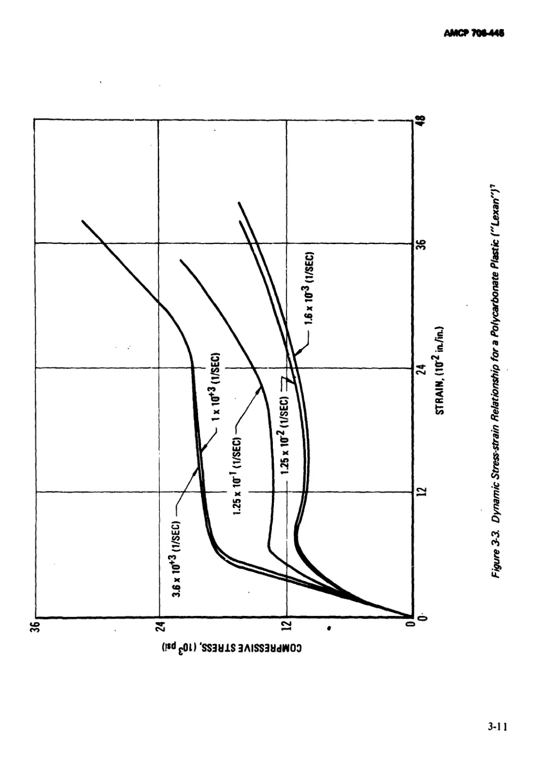
3-2.3 Loading Rate Effects................................ 3-6
3-2.3.1 Linear Viscoelasticity ............................... 3-6
3-2.3.2 Behavior of Materials at High Loading Rates .... 3-9
3-2.3.3 Other Observations.................................... 3-9
3-2.4 Failure Criteria ................................... 3-9
3-3 Elementary Design Considerations for Cup
Sabots............................................ 3-12
3-3.1 Standard Cup Sabot ................................ 3-12
3-3.1.1 Bending of Base Plate................................ 3-14
3-3.1.2 Crushing of the Base Plate......................... 3-14
3-3.1.3 Buckling of the Sabot Wall ........................ 3-15
3-3.2 Cup Sabot With External Undercut................. 3-15
3-3.3 Cup Sabot With Internal Undercut ................ 3-15
3-3.4 Cup Sabot With Rider............................. 3-16
3-3.5 Cup Sabot With Base Plate....................... 3-17
3-3.6 Cup Sabot With Shear Plate Restraint............. 3-18
3-3.7 Special Considerations for Spin-stabilized
Applications .................................... 3-18
3-3.7.1 Eccentrically Located Pin.......................... 3-18
3-3.7.2 Torque Key......................................... 3-19
3-3.7.3 Torque Key for Constant Twist...................... 3-23
3-3.8 Special Cup Sabots................................. 3-23
3-4 Elementary Considerations for Ring Sabots............. 3-23
3-4.1 Buckling of the Forward Portion of the
Projectile................................................... 3-24
3-4.2 Tensile Failure in Projectile Aft Section ............. 3-25
3-5 The Finite Element Technique............................. 3-25
3-5.1 Background......................................... 3-25
3—5.1.1 Geometry........................................... 3-25
3-5.1.2 Materials.......................................... 3-25
3-5.1.3 Boundary Conditions ............................... 3-26
3-5.1.4 Dynamic Problems .................................. 3-26
3-5.1.5 Miscellaneous Applications......................... 3-26
3-5.1.6 Reliability and Accuracy............................. 3-26
3-5.1.7 Summary............................................ 3—26
ii
АМСР 70644В
TABLE OF CONTENTS (Con't.)
Paragraph Page
3-5.2 Theory of the Finite Element Method................ 3-26
3-5.2.1 Variational Principles ...........".............. 3-27
3-5.2.2 Finite Elements................................ 3-27
3-5.2.3 Summary........................................ 3-29
3-5.3 Application of the Finite Element Method..... 3-29
3-5.3.1 Input Data..................................... 3-29
3-5.3.2 Output Data.................................. 3-30
3-5.3.3 Summary........................................ 3-31
3-5.4 Example Problems .............................. 3-31
3-5.4.1 Uniaxial Compression of a Right Circular
Cylinder .................................... 3-31
3-5.4.2 Thermal Expansion of a Right Circular
Cylinder .................................... 3-35
3-5.4.3 Centrifugal Loading of a Right Circular
Cylinder .................................... 3-35
3-5.4.4 Internal Pressurization and Rotation of a <
Hollow Cylinder ......................................... 3-35
3-5.4.5 Internal Pressurization of a Composite Cylinder . 3-35
3-5.4.6 Cup Sabot With Metal Base Plate ............... 3-42
3-5.5 Conclusions ....................................... 3-42
References ..................................... 3-47
CHAPTER 4. EXPERIMENTAL METHODS
FOR SABOT DEVELOPMENT
4-0 List of Symbols................................. 4-1
4-1 Introduction.................................... 4-1
4-2 Dynamic Failure Characterization of Materials
Under Gun Loading Conditions.................... 4-2
4-2.1 Structural Test Vehicle......................... 4-2
4-2.2 Loading Analysis................................ 4-3
4-2.3 Experimental Procedures......................... 4-3
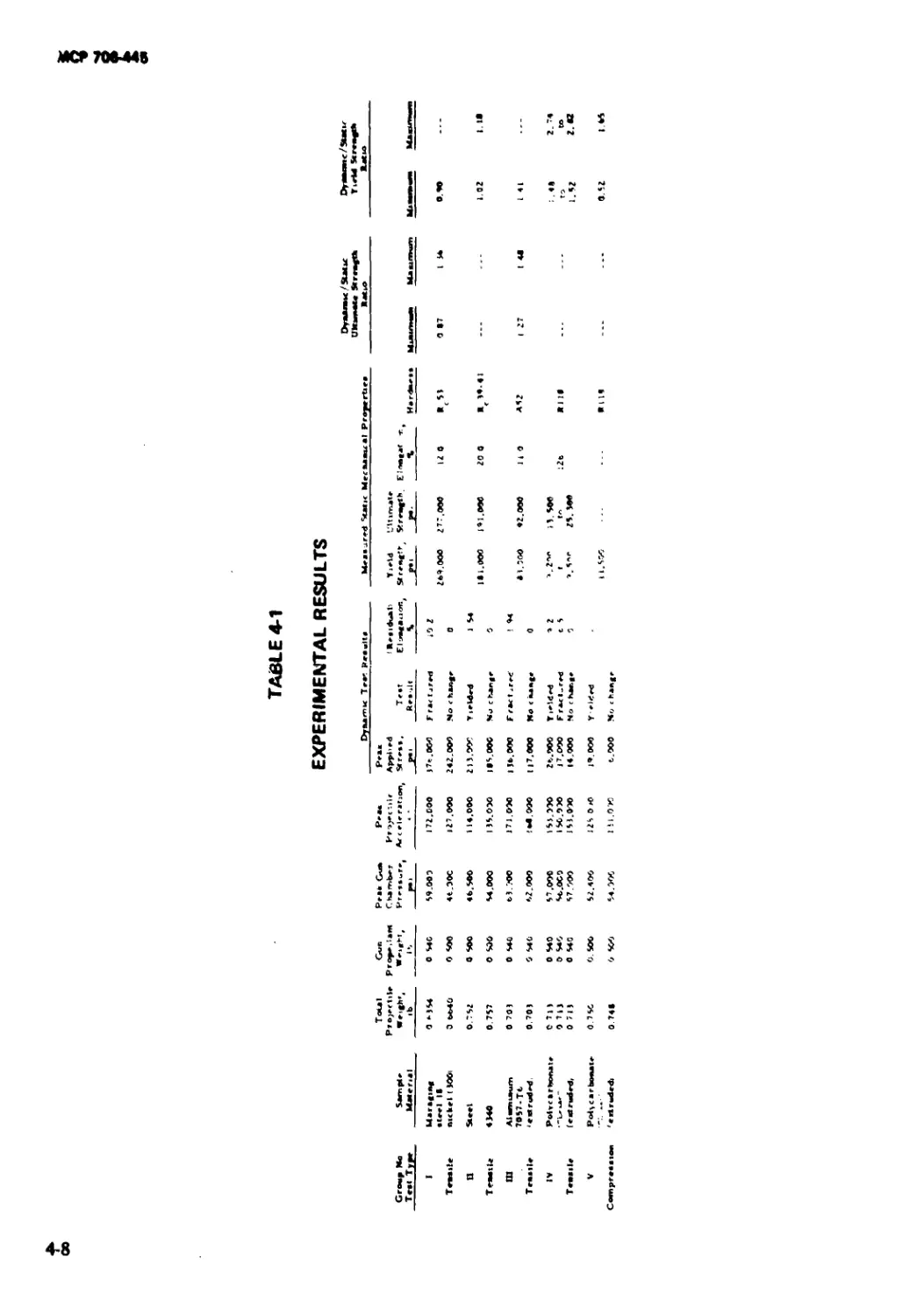
4-2.4 Results of Feasibility Study ................... 4-7
References....................................... 4-7
APPENDICES
Page
APPENDIX A
SUMMARY OF SABOT DESIGNS AND THEIR
CHARACTERISTICS........................................... A-l
iii
АМСР70М4В
TABLE OF CONTENTS (Con't.)
Page
APPENDIX В
SUMMARY OF STRUCTURAL PROPERTIES FOR
MATERIALS USED IN SABOTS........................ В-1
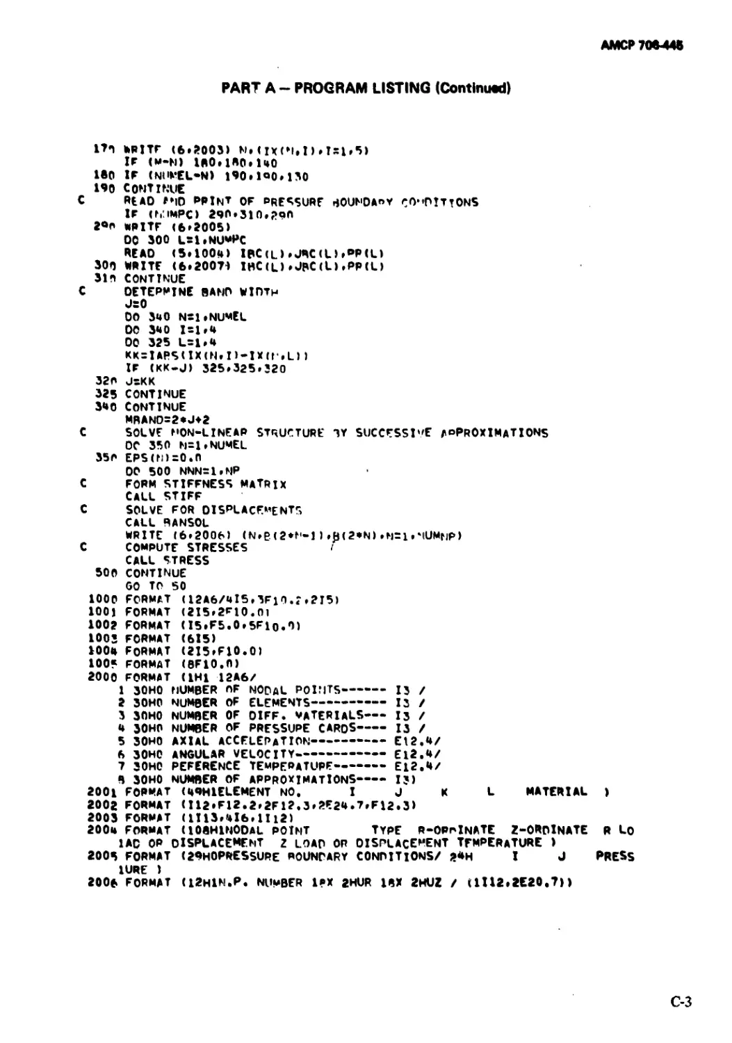
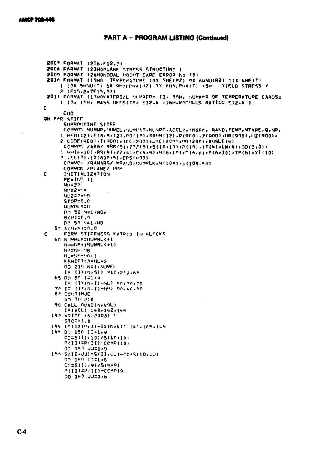
APPENDIX C
A FINITE ELEMENT PROGRAM FOR DETERMINING
THE STRESSES AND STRAINS IN AX1SYMMETRIC,
ELASTIC BODIES.................................. C-l
Part A: Program Listing (UNIVAC 1108,
FORTRAN IV) ................................... C- 2
Part В: Input Data.............................. C15
Part C: Additional Remarks and Output Data .... C 21
APPENDIX D
ABSTRACT BIBLIOGRAPHY OF SABOT TECHNOLOGY . . D 1
Preface ....................................... D-2
Table of Contents.............................. D-3
Abstracts...................................... D-6
I ‘
*
iv
АМСР 706-445
LIST OF ILLUSTRATIONS
Fig. No. Title Page
1-1 The Design Process................................... 1-2
1-2 Examples of Group 1, Type 1 Sabots................. 1-7
1 - - 3 Examples of Group I, Type 2 Sabots................. 1-8
1 -4 Examples of Group 1, Type 3 Sabots................. 1-9
1 -5 Examples of Group 2 Sabots........................ 1-10
1- 6 Sabot in Gun Tube................................... 1-11
1-7 Gun System.......................................... 1-15
1 -8 Pressure-travel (Solid Lines) and Velocity-travel
(Dotted Line) Curves........................................ 1-19
2-1 Basic Cup Design..................................... 2-2
2-2 Basic Ring Design ................................... 2-2
2-3 Basic Cup Design..................................... 2-3
2-4 Cup With Rotating Band (imparts spin to
projectile).................................... 2-3
2-5 Cup With Obturator (seals launch tube) ................... 2-3
2-6 Cup With Forward Bevel (augments aerodynamic
separator of sabot and projectile) .......................... 2-3
2-7 Cup With Internal Taper (thrust and spin
transmitted to the projectile through the
tapered surface)............................................. 2-4
2-8 Cup With External Undercut (weight reduction)... 2-4
2-9 Cup With Internal Undercut (weight reduction) ... 2-4
2-10 Cup With Rider............................ 2-4
2-11 Cup With Base Plate (bearing surface multiplier)... 2-4
2-12 Cup With Base Plate and Shock Absorber (for
highly brittle projectiles)........................ 2-5
2-13 Cup With Shear Plate Restraint........................... 2-5
2-14 Cup With Support Sting (for thin-walled
models)...................................................... 2-5
2-15 Cup With Fluid Support (for fragile projectiles
such as rocket-assisted projectiles)........................' 2-5
2-16 Basic Ring Design ................................... 2-6
2-17 Ring With Obturator (seals launch tube).............. 2-6
2-18 Ring With Forward Bevel (augments aerodynamic
separation of sabot and projectile) ......................... 2-6
2-19 Ring With Unsupported Forward Undercut
(aero-augmented separation and weight savings) .. 2-7
2-20 Ring With Longitudinally-supported Forward
Undercut........................................... 2-7
2- 21 Ring With Circumferentially-supported Forward
Undercut........................................... 2-7
2-22 Two-piece Ring....................................... 2-7
2-23 Two-piece Self-sealing Ring.......................... 2-7
2- 24 Performance Limits and Capabilities of Different
Sabot Designs..................................... 2-10
v
АМСР70М48
LIST OF ILLUSTRATIONS (Con't.)
Fig. No. Page
2-25 Performance Limits and Capabilities of Different
Sabot Designs..................................... 2-11
2-26 Comparison of Cup and Ring Sabots....................... 2-12
2-27 Projectile, Gun Launch Schematic for Fluid
Buoyancy Support System .......................... 2-14
2-28 Schematic Diagram of Gun Tube, Ring, and Sabot
Projectile........................................ 2-20
3-1 Illustration of Possible Stress-strain Behavior .......... 3-4
3-2 Response Characteristics of a Viscoelastic
Material........................................... 3-8
3-3 Dynamic Stress-strain Relationship for a
Polycarbonate Plastic (“Lexan”) .................. 3-11
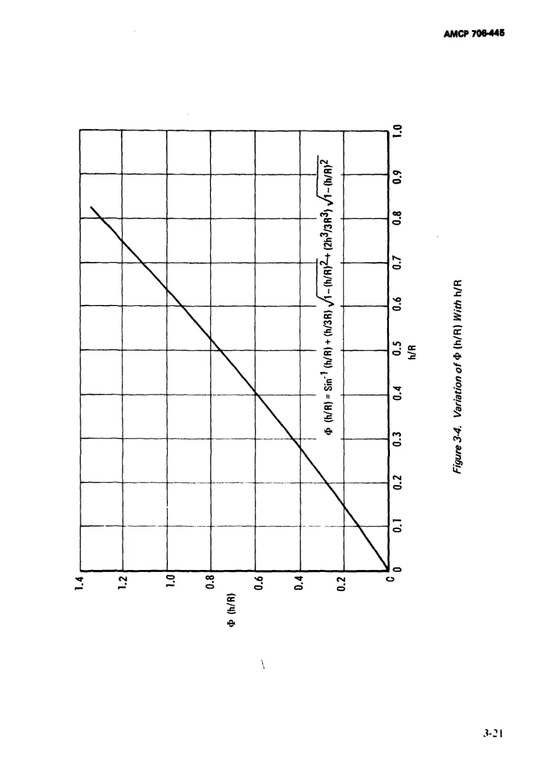
3-4 Variation of Ф(Л/Л) With h/R........................ 3-21
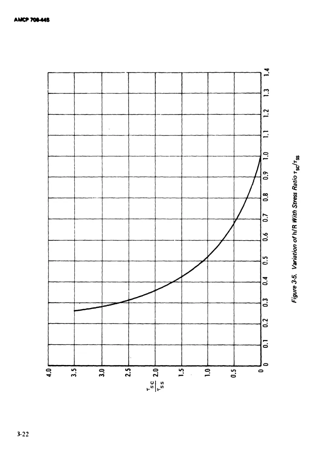
3-5 Variation of h/R With Stress Ratio tsc!tss ......... 3-22
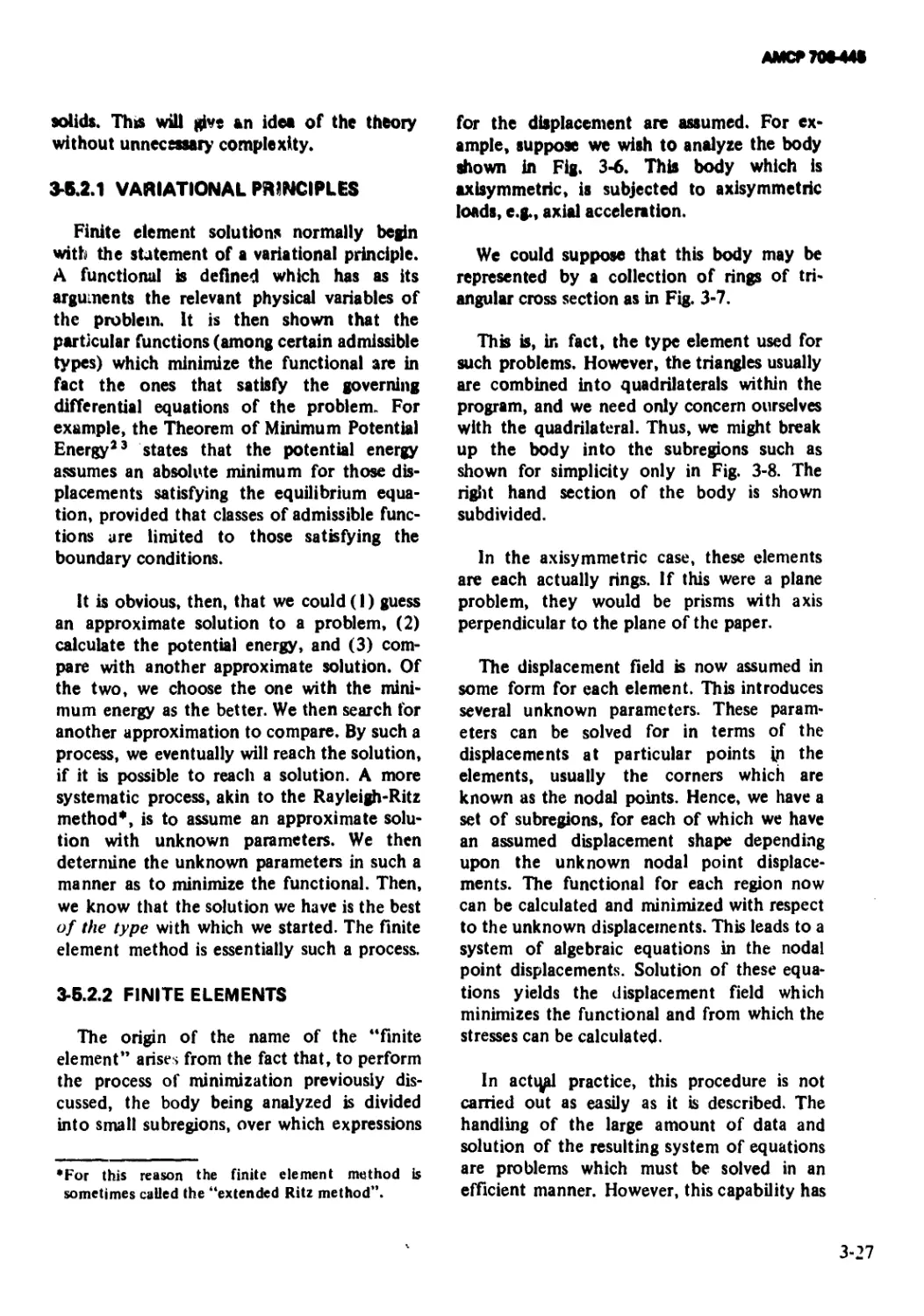
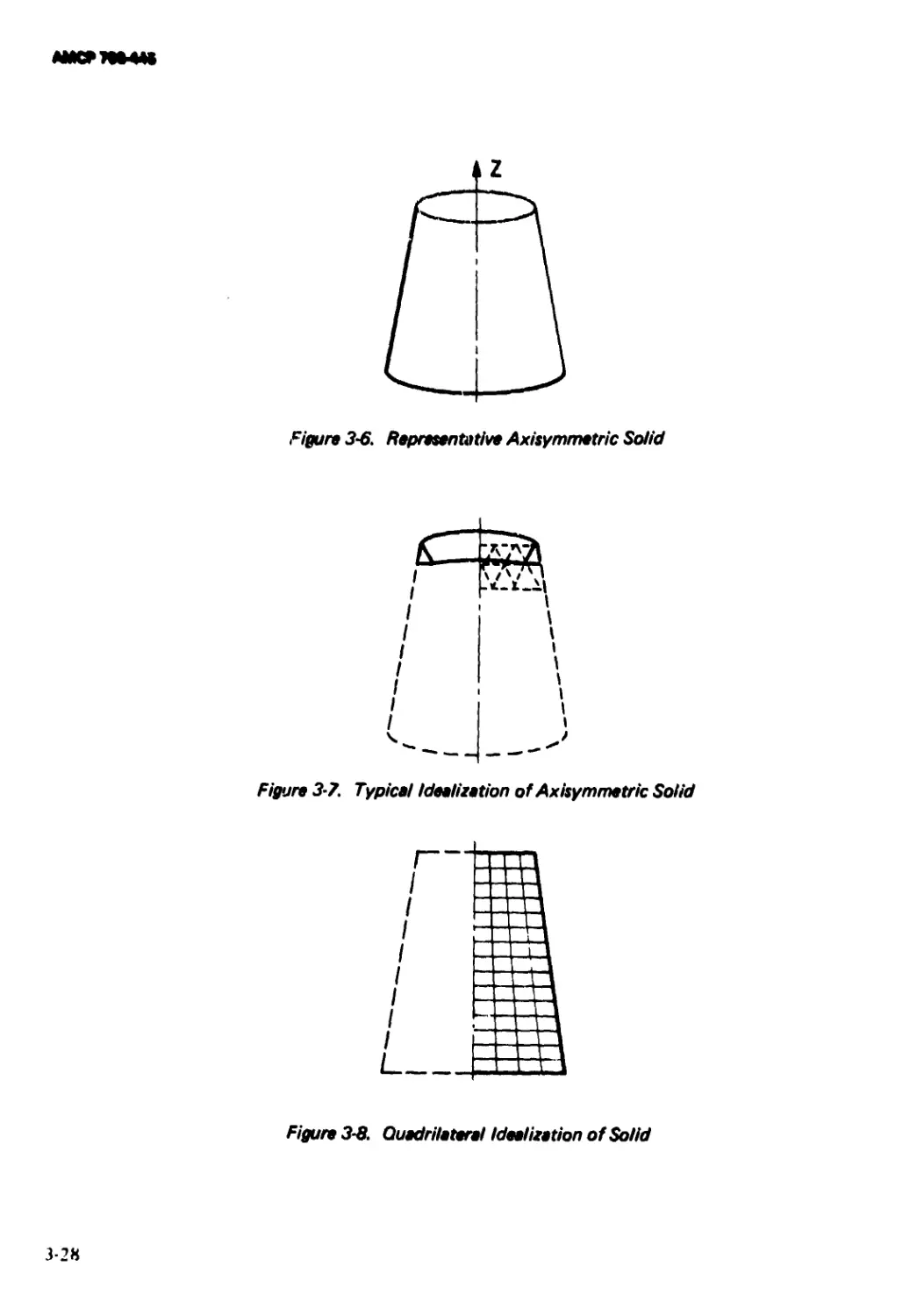
3-6 Representative Axisymmetric Solid................... 3-28
3-7 Typical Idealization of Axisymmetric Solid....... 3-28
3-8 Quadrilateral Idealization of Solid ................ 3-28
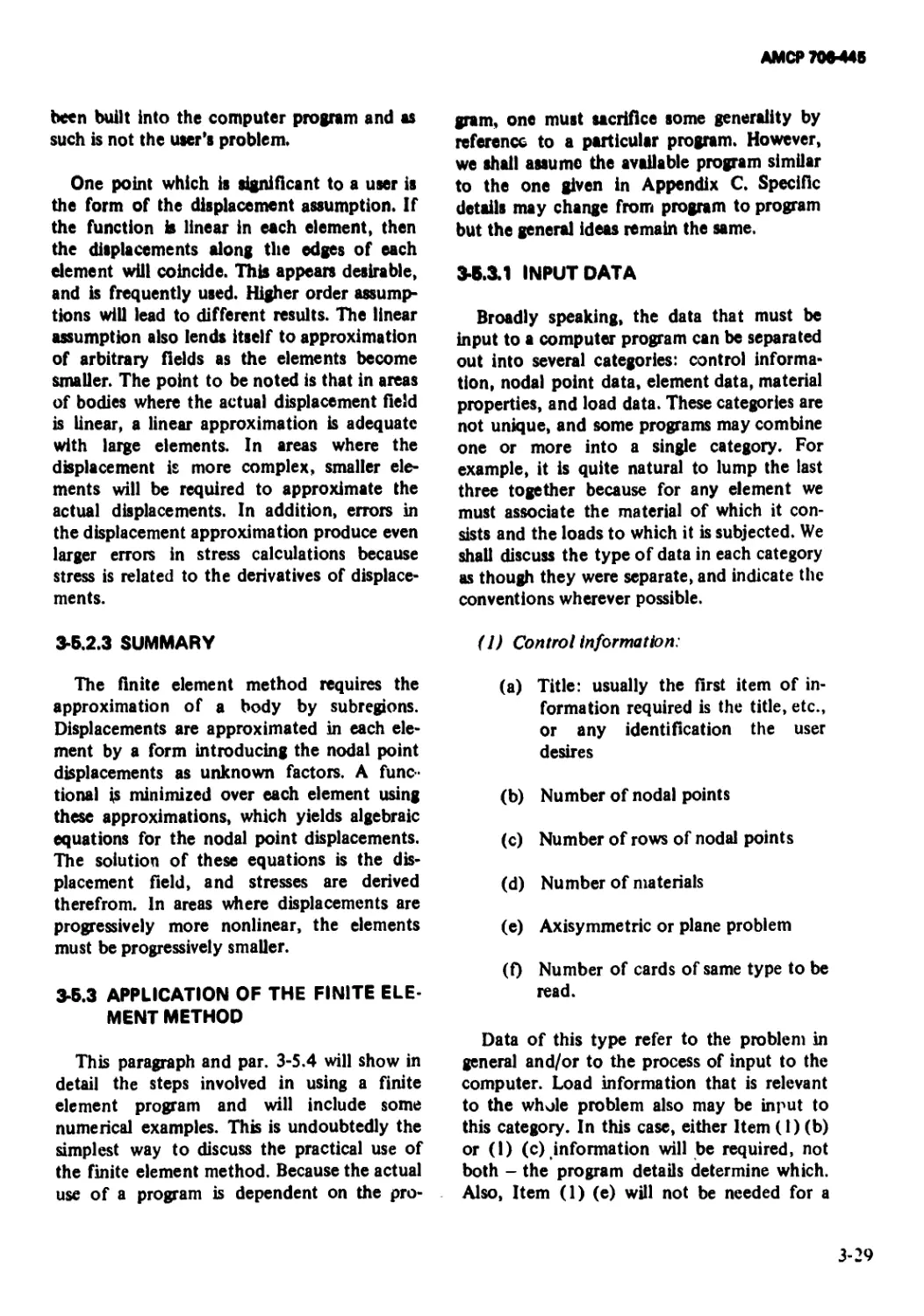
3-9 Setup of Simple Compression Problem................. 3-32
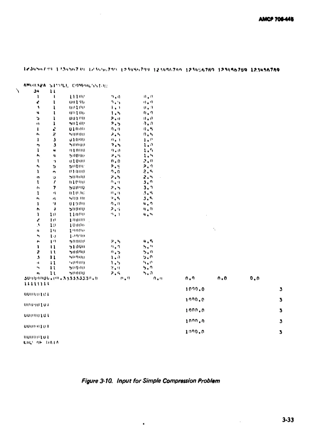
3-10 Input for Simple Compression Problem ............... 3-33
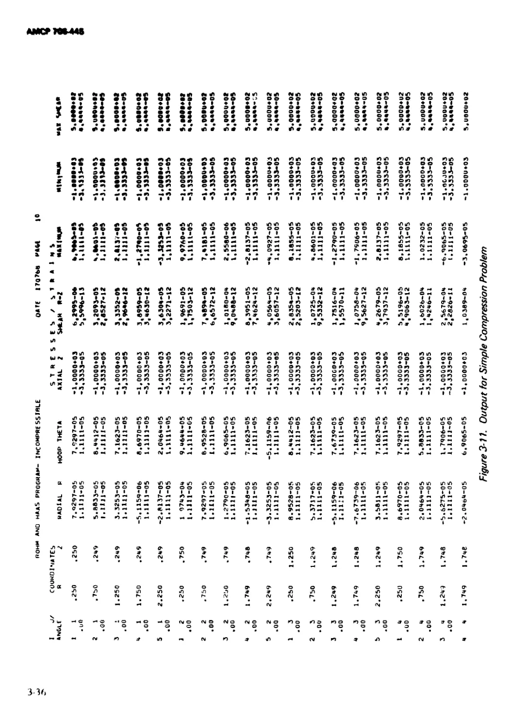
3-11 Output for Simple Compression Problem .............. 3-36
3-12 Input for Restrained Thermal Expansion
Problem........................................... 3-37
3-13 Output for Restrained Thermal Expansion
Problem........................................... 3-38
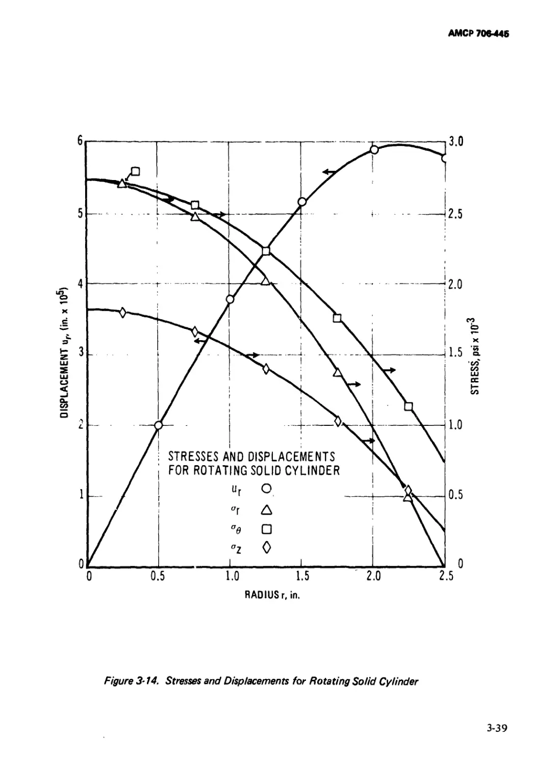
3-14 Stresses and Displacements for Rotating Solid
Cylinder.......................................... 3-39
3-15 Displacements and Stresses for Hollow Cylinder
With Internal Pressure....................................... 3-40
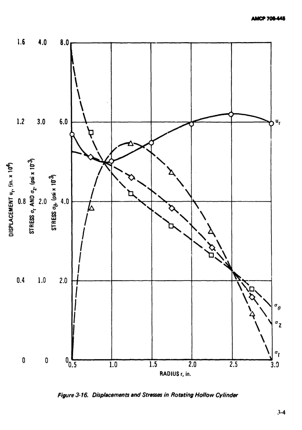
3-16 Displacements and Stresses in Rotating Hollow
Cylinder....................................... 3-41
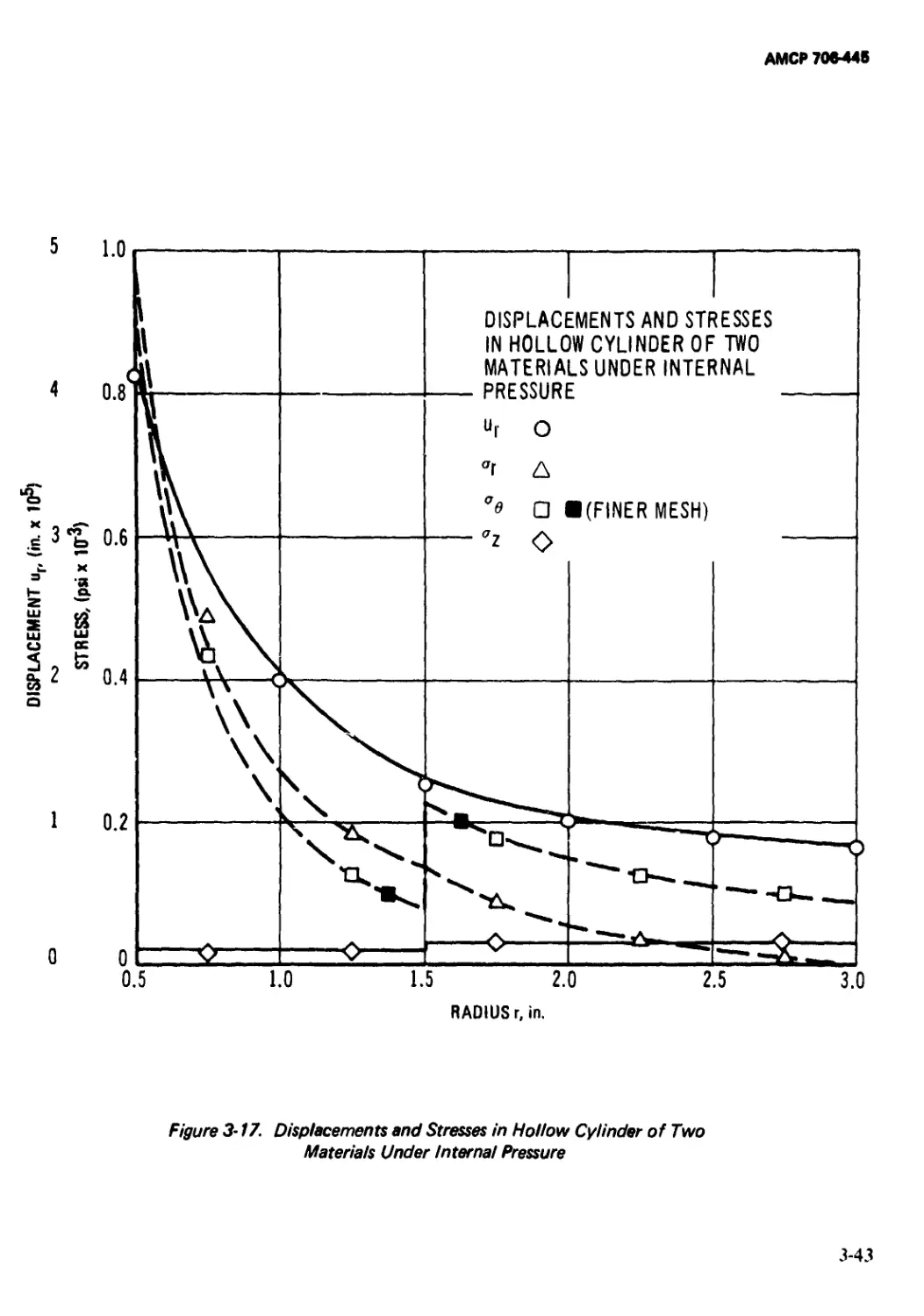
3-17 Displacements and Stresses in Hollow Cylinder
of Two Materials Under Internal Pressure....... 3-43
3-18 Simple Sabot........................................ 3-44
3-19 Element Layout for Sabot ........................... 3-44
3-20 Input Data ......................................... 3-45
3—21 Selected Element Results for Sample Sabot
Problem........................................... 3—46
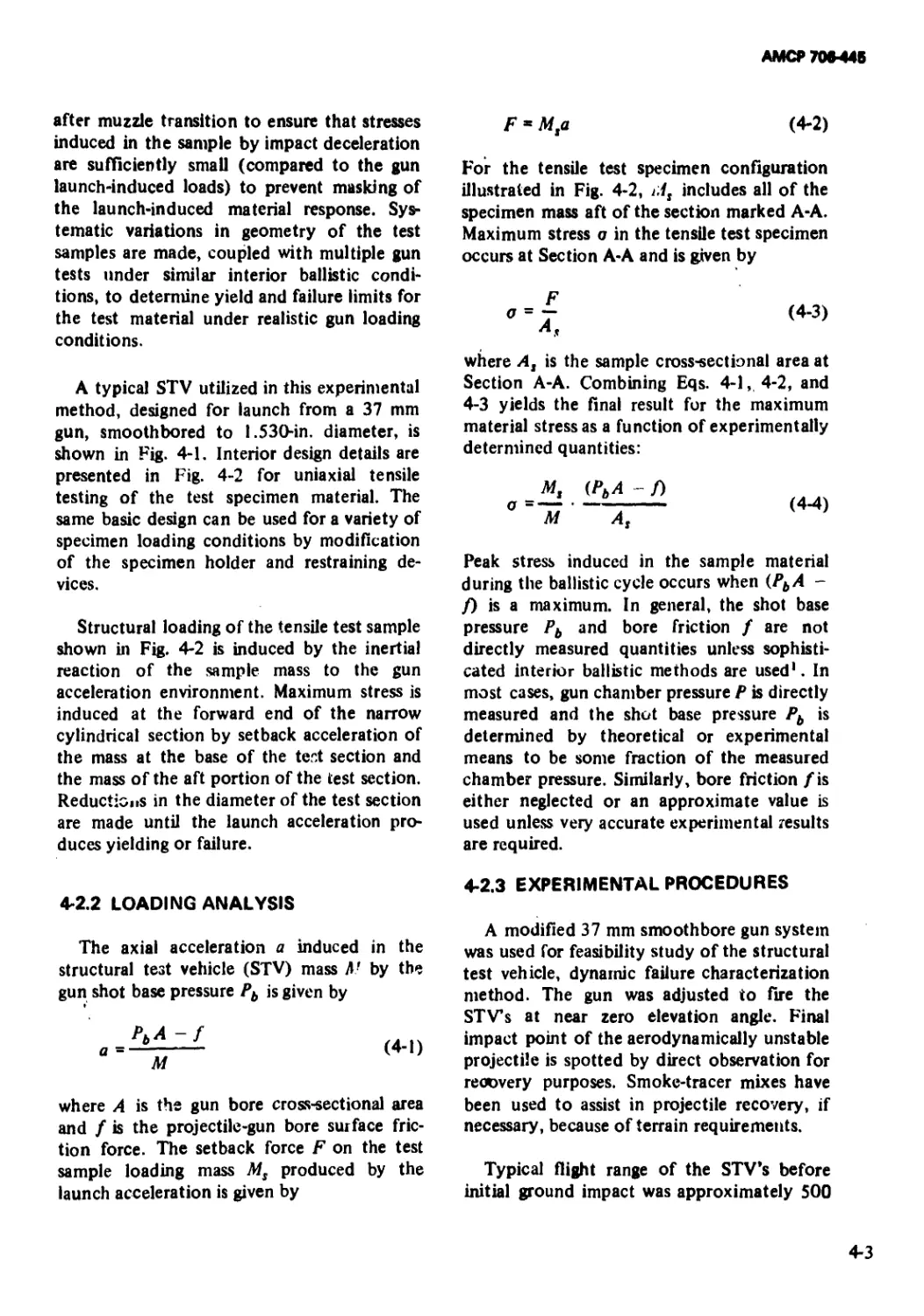
4-1 Structural Test Vehicle.............................. 4-4
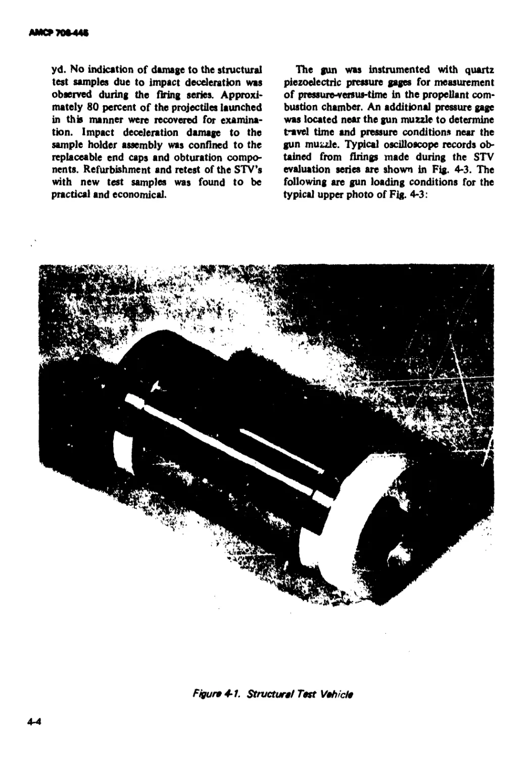
4-2 Structural Test Vehicle Schematic ................... 4-5
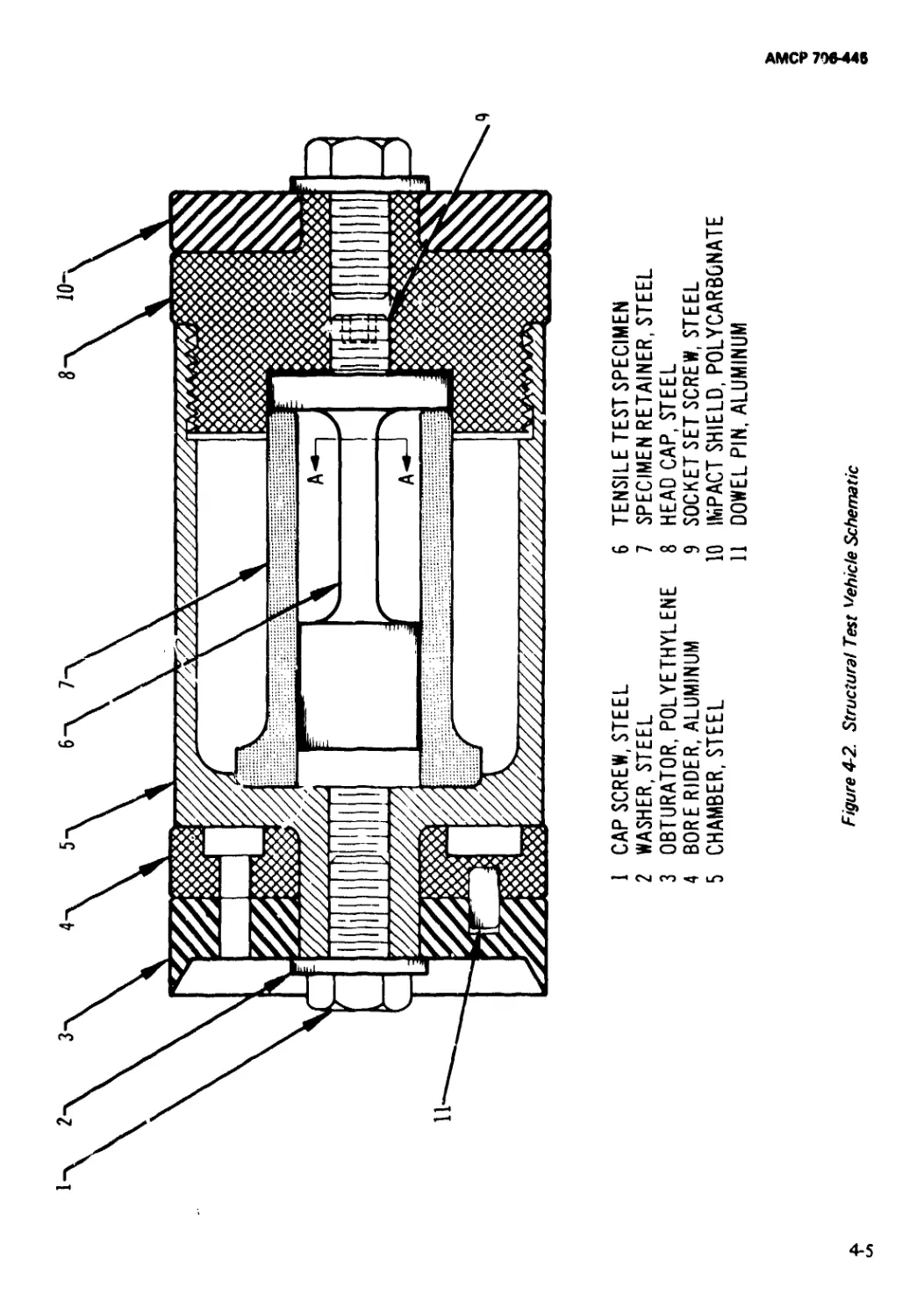
4-3 Typical Chamber and Muzzle Pressure*time
Response........................................... 4-6
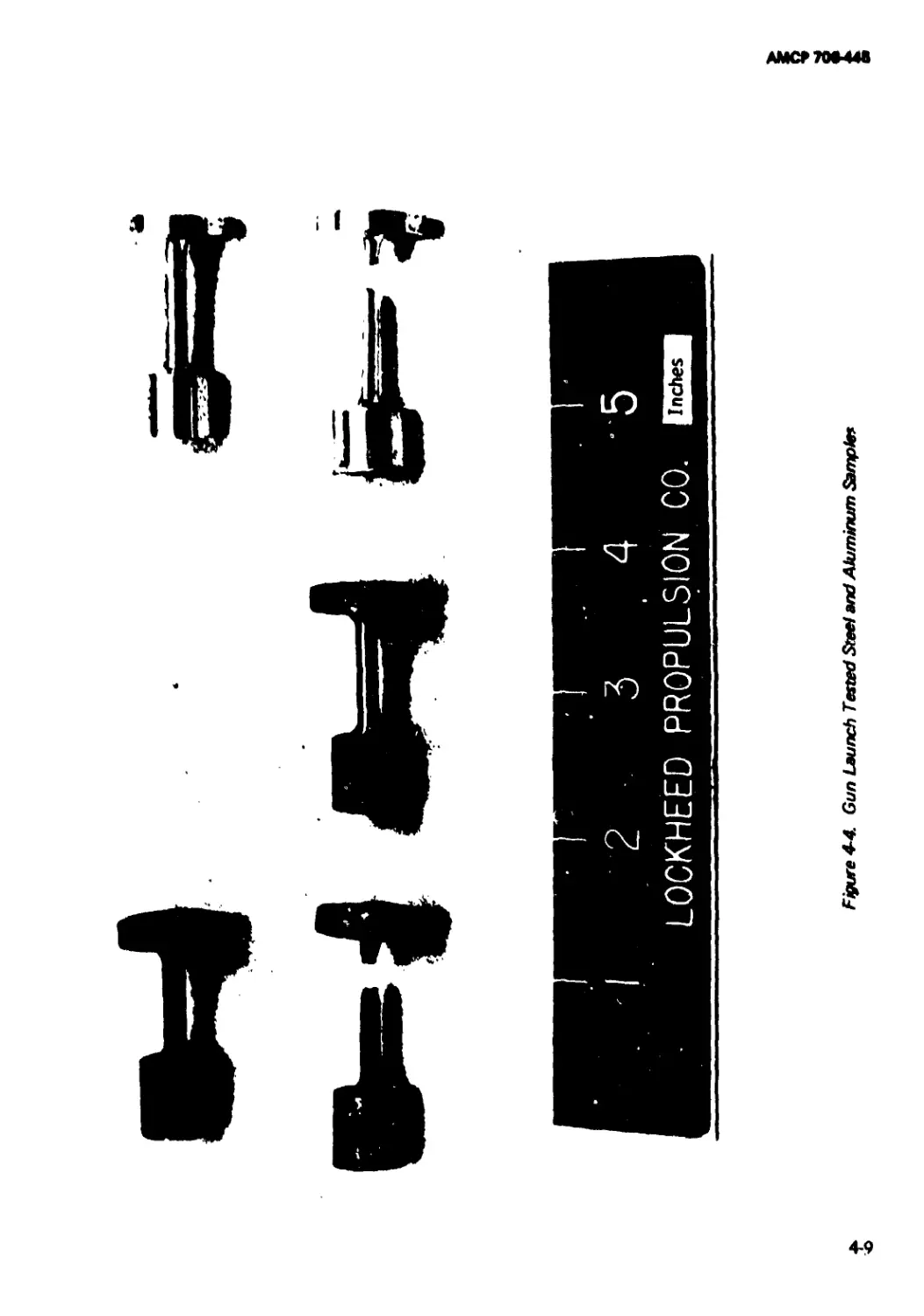
4-4 Gun Launch Tested Steel and Aluminum
Samples............................................ 4-9
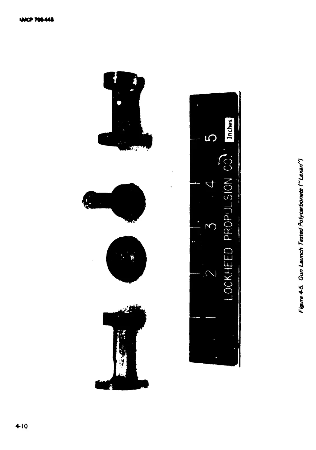
4-5 Gun Launch Tested Polycarbonate (“Lexan”)............. 4-10
vi
АМСР 706-446
LIST OF TABLES
Table No. Tit'e Page
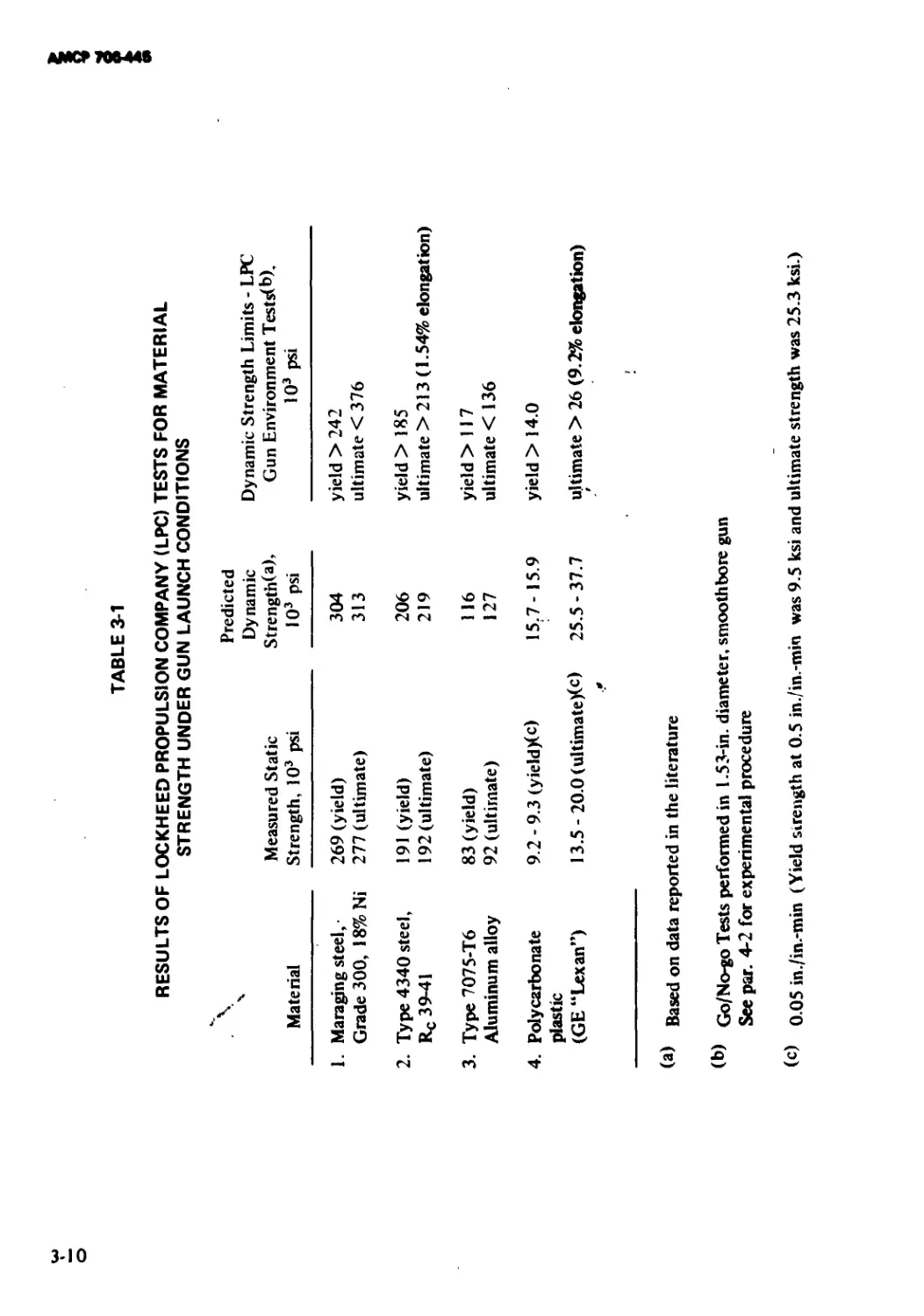
3-1 Results of Lockheed Propulsion Company (LPC)
Tests for Material Strength Under Gun Launch
Conditions.............................................. 3-10
4-1 Experimental Results ................................ 4-8
vii
АМСР 70*448
PREFACE
The Engineering Design Handbook Series of the Army Materiel Command
is a coordinated series of handbooks containing basic information and
fundamental data useful in the design and development of Army materiel
and systems. The handbooks are authoritative reference books of practical
information and quantitative facts helpful in the design and development of
Army materiel so that it will meet the tactical and the technical needs of the
Armed Forces.
The purpose of this handbook is to compile meaningful engineering
analysis information pertaining to sabots. Emphasis is on numerical
techniques for practical stress analysis and methods for determining material
strength properties under realistic gun-launch conditions. An exhaustive
abstract and reference bibliography is included as Appendix D.
Acknowledgment is offered for the services of Utah Research and
Development Corporation, to Mr. Dalton Cantey of Lockheed Propulsion
Company, and to Mr. E. L. Bannister, Ballistic Research Laboratories,
Aberdeen Proving Ground, Maryland, for the Sabot Technology Engineering
Handbook, Second Edition, 29 August 1969, which is the document upon
which this handbook is based.
The Engineering Design Handbooks fall into two basic categories, those
approved for release and sale, and those classified for security reasons. The
Army Materiel Command policy is to release these Engineering Design
Handbooks to other DOD activities and their contractors and other
Government agencies in accordance with current Army Regulation 70-31,
dated 9 September 1966. It will be noted that the majority of these
Handbooks can be obtained from the National Technical Information
Service (NT1S). Procedures for acquiring these Handbooks follow:
a. Activities within AMC, DOD agencies, and Government agencies other
than DOD having need for the Handbooks should direct their request on an
official form io:
Commanding Officer
Letterkenny Army Depot
ATTN: AMXLE-ATD
Chambersburg, Pennsylvania 17201
b. Contractors and universities must forward their requests to:
National Technical Information Service
Department of Commerce
Springfield, Virginia 22151
viii
АМСР7М-44*
(Requests for classified documents must be sent, with appropriate “Need to
Know’’ justification, to Letterkenny Army Depot.)
Comments and suggestions on this Handbook are welcome and should be
addressed to:
U.S. Army Materiel Command
ATTN: AMCRD-TV
Washington, D. C. 20315
ix
AMCF70M4B
CHAPTER 1
INTRODUCTION
1-0 LIST OF SYMBOLS
1-1 BACKGROUND
a •• longitudinal acceleration
cross-sectional area of gun bore
d diameter of projectile
D diamctur of bore
F force
KE kinetic energy
L - length
ni mass
mt predicted sabot mass
m0 sabot mass design objective
ntp mass of projectile
Pc pressure of propellant gases acting on
base of sabot projectile
/у probability of failure
Rt structural reliability
v velocity or muzzle velocity
к weight or weighting factors
p,s" subscripts referring to projectile and
sabot, respectively
Sabots are used as supports for projectiles
during gun tube travel. When high velocity is
the desired characteristic of the supported
projectile, the lightest weight sabot feasible is
desired. Generally, engineering steps taken to
minimize sabot weight increase the stress and
deformation requirements imposed upon the
sabot during its travel through the bore of the
gun. This handbook presents engineering de-
sign procedures for sabots. It takes into
consideration the conflicting criteria associ-
ated with maximum performance and maxi-
mum reliability.
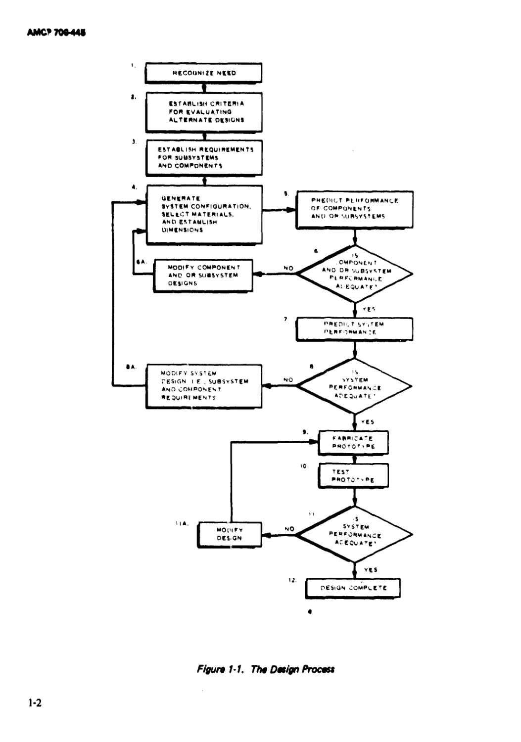
The steps and decisions which must be
made in the process of producing an engineer-
ing design are summarized in Fig. I-I. It will
be noted that the design process contains the
following six different types of activities1 *3 *:
(1) To recognize need for the product
(Block 1 in Fig. 1-1)
(2) To establish criteria for evaluating al-
ternatives (Blocks 2 and 3)
(3) To generate one or more tentative
designs or prototypes (Blocks 4 and 9)
(4) To analyze each alternative (Blocks 5,
7, and 10)
*Referencra are located at the end of each chapter
unless specific reference ia made to the abstract
bibliography of Appendix D.
1-1
АМС*70М4«
Figure 1-1. 77» Design Process
1-2
АМСР 706448
(5) То compare alternatives with previ-
ously established criteria or require-
ments (Step 2) and, if necessary, modi-
fy the design and repeat the preceding
step (Blocks 6, 6A, 8, 8A, 11, and
11 A). This is the optimization phase of
the design process
'6) To implement the best alternative
(Block 12).
Assume that the need for a sabot has been
established; the next step in its design (Block
3) is establishment of the sabot design cri-
teria. A sabot is a component of a weapon
system designed for an ultimate goal to
deliver a specified projectile to a target at a
prescribed range and terminal velocity. The
projectile should have an acceptable impact
velocity and should reaih the target within an
acceptable dispersion. Qualitatively the sabot
must accomplish the following:
(1) Position and structurally support the
projectile during its launch
(2) Seal or obturate the powder gases
within the launch tube
(3) Minimize balloting of the projectile,
i.e., undesired lateral or yawing motion
produced by bore and/or projectile
asymmetries, variations in bore fric-
tion, and powder burning phenomena
(4) Impart rotation to spin-stabilized pro-
jectiles
(5) After discharge from the launch tube,
separate from projectile without dis-
turbing the flight of the projectile and
without creating a hazard to personnel
in the immediate area.
The quantitative requirements fora specific
sabot application can be established from a
knowledge of weapon system performance
goals,4 using the techniques of external5
and terminal ballistics.10'12 The loads im-
posed upon the sabot can be predicted using
the analytical methods of interior ballis-
tics.* 248 The output from this stage of the
sabot design process (Block 3) should be (1) a
definition of the projectile, i.e., mass, dia-
meter, length, and other dimensional consid-
erations; (2) gun configuration and perfor-
mance requirements, i.e., bore diameter, muz-
zle velocity, etc.; (3) the sabot load environ-
ment, i.e., base pressure, acceleration, bore
friction, etc.; and (4) permissible r iomalies in
launch conditions, primarily maximum allow-
able lateral displacement, lateral velocity, yaw
angle, and yaw rate.
Having at least tentatively established the
design criteria, the next step (Block 4) is to
select a basic sabot configuration, materials,
dimensions, and manufacturing processes con-
sidered capable of satisfying the design cri-
teria. This step normally is performed in one
or a combination of three different ap-
proaches to design - intuitively, empirically,
or rationally2. The intuitive approach defies
description because it depends upon the
designer’s “feel” for the problem and his
individual creativity. The empirical approach
is the scaling to new requirements of proved
designs and experimental results. The rational
approach to design is the systematic applica-
tion of established scientific laws, principles,
and rules of logic to a properly defined
problem. If it were possible to establish a
general design; analyze it for all combinations
of conditions; and produce a closed-form
solution that could be solved for the various
dimensions of the design in terms of material
properties, performance requirements, loading
conditions, etc.; complete rational design
could be performed. Furthermore, there
would be no need for succeeding steps
(Blocks 5, 6, and 6A). In practice this is rarely
possible, however, and the rational approach
to design normally consists of establishing
critical design parameters using complete solu-
tions of idealized problems with limited but,
hopefully, the significant loading or perfor-
mance condition. Despite its shortcomings,
the rational design approach permits the
designer to establish without bias the “base”
design required as an input to the subsequent
1-3
AMCF70M4S
prediction, evaluation, and optimization
phases. The rational approach may be thought
of as providing precise solutions to approxi-
mate problems. Solutions of this type appro-
priate io sabot design are presented in a
subsequent chapter of this handbook.
The “base” design established in Block 4 is
a necessary input to the analysis or prediction
stage of tire design process (Block 5). This
step consists of taking the specific design
configuration, dimensions, detailed material
properties, loading conditions, etc., and pre-
dicting the system's behavior. For example, in
the case of a structural design problem, one
would predict the stresses and strains induced
in the body by the mechanical and thermal
loads imposed upon it. Electronic computers
have been a particularly useful asset in this
phase of design. Their widespread availability
and ability to perform computations at high
speed makes it possible to achieve approxi-
mate solutions to “exact” problems which are
more accurate than the exact solutions to
“exact” problems which are more accurate
than the exact solutions of approximate
problems referred to above.11 ’19 »21 Digital
computer algorithms could be used for hand
calculations but they are so lengthy that
manual solution is neither economically feas-
ible nor reliable, and would take too long to
provide answers for design decisions on a
timely basis.
The next step (Block 6) in the design
process is to compare the predicted perfor-
mance to the desired performance, i.e., the
design criteria. In the traditional ‘go - no
go” concept of structural design, the predic-
ted stresses and/or strains are compared to the
stresses and/or strains that the material is
capable of withstanding to determine if a
desired safety factor is achieved. If the desired
safety factor is not achieved, design changes
are made (Block 6A); whereas if an adequate
safety factor is obtained, the design progresses
to the system performance evaluation phase
(Block 7).
Alternately, statistical techniques can be
employed to combine the uncertainties in the
predicted stresses or strains with the random
variations in the ultimate properties of the
material to establish the probability of failure
or the structural reliability. To employ this
latter technique, a design criterion or figure of
merit that uses both the structural reliability
and an appropriate performance parameter
should be used. For example, one might
maximize the figure of merit formed by a
linear combination of the structural reliability
and the ratio of the desired sabot mass to the
predicted sabot mass, each multiplied by a
weighting factor, i.e.,
Figure of Merit = F of M e V» Rr + W2 ( —)
(1-1)
where
Л, = 1 - Pf = structural reliability
Pf = probability of failure
ms = predicted sabot mass
mo - desired sabot mass (design objec-
tive)
K'i, W2 s subjectively established weighting
factors designed to give more or
less emphasis on either the struc-
tural reliability or the sabot mass.
Optimization techniques can then be em-
ployed (Block 6A) to determine and imple-
ment those changes that improve the figure of
merit. This technique is repeated until the
figure of merit reaches an extreme value.
Observe that the figure of merit is used for
comparison purposes only and does not neces-
sarily have a physical significance.
To avoid the problem of suboptimization,
i.e., achieving an “optimum” component de-
sign that does not result in optimum system
performance, it is important that the design
procedure include prediction (Block 7), evalu-
ation (BJock 8),. and optimization phases
(Block 9) for the entire system. In the sabot
design problem, the system evaluation phase
АМСР
would consist of predicting th** time-depend-
ent motion, velocity, ассеЛтиюп, chamber
pressure, etc., for a given, projectile-sabot
design, charge configuration, gun barrel
length, etc.13"17»19 The figure of merit for
system optimization must employ a system
performance parameter such as muzzle velo-
city. In an expanded performance evaluation
p ogram, the figure of merit would be ex-
panded to include obturation and/or seal
dynamics considerations.
Once the optimal, or at least an acceptable,
design has been achieved analytically, it gener-
ally becomes necessary to demonstrate the
capability of the design. For this purpose, one
or more prototypes are manufactured, tested,
and the results are evaluated. The purpose of
this phase of the design is to (1) verify the
analysis, (2) determine the effect of phenom-
ena not included in the analytical design, and
(3) confirm that the design meets the design
objectives. The similarity between the analyti-
cal and prototype sequences will be noted.
Instead of developing an analytical model, a
prototype is fabricated (Block 9). Instead of
predicting the response of the component or
system, the response is measured (Block 10).
The evaluation and optimization phases also
are similar to the analytical cycle. The pri-
mary difference is that measured data are
used in lieu of theoretical predictions. Suc-
cessful completion of all performance and
qualification tests resulted in a completed
design.
This handbook is organized in accordance
with the previous discussion. Sabot design
considerations covered include (1) structural
considerations, (2) obturation, and (3) seal
dynamics. Elementary, closed-form equations
for preliminary design of sabots are presented
as well as sophisticated computer programs
for detailed analysis. More material is in-
cluded under structural design considerations
(Chapter 3) than for either obturation or seal
dynamics. This is due to the fact that struc-
tural design is further advanced than either
obturator design or the evaluation of dyr^nic
phenomena excited during launch. This
should not be construed to mean that struc-
tural considerations are more important. It
merely points out the need for additional
work in the latter areas.
Chapter 2 is a preliminary chapter because
it establishes the basic types of sabots, their
classification, and the nomenclature us^d in
this handbook. References are listed at the
end of each chapter and a comprehensive
bibliography is included as Appendix D.
The remainder of Chapter 1 is devoted to
generalized background information pertinent
to guns andsabots.
/
/
1-2 S^feOTS
/
1-2.1 DEFINITION
The term “sabot” in this handbook is a
derivative of a term referring to a wooden
shoe. A military use of sabot is inherited from
its description as “a piece of soft metal
formerly attached to a projectile, to take the
grooves of the rifling”. In modern terms, a
sabot is a device conforming on one surface to
a gun bore and on the other surface to a
projectile. It carries the projectile down the
gun bore, under action of propellant gases.
Nearly ail sabots separate from the projectile
after exit from the gun, leaving the projectile
to fly to its target unaccompanied. In addi-
tion to being a projectile carrier, a sabot also
may be designed to reinforce structurally or
to protect the projectile under the high
pressure, temperature, and acceleration en-
vironment in the gun bore. To satisfy its mair
function as a projectile carrier, the sabot not
only must remain intact during bore travel,
but also must serve as a gas seal. Even minute
leakage of gun gas around or through a sabot
structure is inimical because of the intense
erosive power of the gas flow.
Generally, a sabot projectile is subcaliber
with respect to the gun, i.e., a projectile with
a diameter less than the bore diameter of the
launch tube, and which uses the sabot as an
adapter or carrier to support it during launch.
AMCF7W44B
Because the sabot usually is separated or
discarded from the projectile after it emerges
from the launch tube, it also is referred to as
“a discarding sabot projectile". When the
basic objective to be achieved is the highest
possible muzzle velocity (or projectile acceler-
ation) for a given projectile weight, a perfor-
mance improvement will be achieved only if
the average cross-sectional density of the
sabot is less than that for the projectile alone.
1-2.2 CLASSIFICATION
Sabot projectile applications can be
grouped into two categories based upon the
configuration and. function of the projectile.
The first group is characterized by high
density, high ballistic coefficient projectiles
designed for maximum impact kinetic energy,
and terminal ballistic effects. Of outstanding
importance in this group are kinetic energy
penetrator rounds designed for defeat of
medium and heavy armor. Literature review
and initial analysis indicate that these configu-
rations have been developed to a relatively
high degree of sophistication on the basis of
qualitative design procedures and an extensive
background of experimental evaluation test-
ing. Within this , group, there are basically
three different types of sabot projectiles: (1)
spin-stabilized projectile with a cup sabot, (2)
aerodynamically stabilized* projectile with a
cup sabot, and (3) aerodynamically stabi-
lized* projectile with ring sabot. Typical
designs for these three types are depicted in
Figs. 1-2 through 1-4.
A second group of sabot projectiles is
characterized by medium- and low-density
projectiles that may be gun-hunched for
many uses. Applications for its group in-
clude aeroballistic testing of a wide variety of
aerodynamic models using light gas-gun tech-
niques, weapon systems employing high ex-
plosive and shaped charge warhead configura-
tion, gun-boosted rockets, and a variety of
tactical and research projectiles including
flares, chaff, probes, electronic packages, and
•Fins or flared aft lections.
liquid payloads. Typical sabot designs of the
second group are shown in Fig. 1-5. Research
studies show that fluid sabot buoyancy sup-
port techniques can provide significant struc-
tural design advantages for relatively low-den-
sity gun-launched structures. Projectile sup-
port during launch acceleration provided by
the buoyancy and pressure distribution effect
of the fluid can result in significant reductions
in strength and weight requirements. Such
projectiles, without fluid support, would be
exposed to destructive acceleration loads dur-
ing gun launch. Functional and design limita-
tions imposed on buoyancy-supported projec-
tiles are controlled primarily by configura-
tional requirements, density, fluid compress-
ibility, and hydrodynamic effects.
1-2.3 ACTION INSIDE THE GUN TUBE
Consider the simple sabot-projectile system
shown in Fig. I-6 as the system is acted upon
by the propellant gas pressure Pc, accelerating
the system to the right (as shown in the
figure). The accelerating force Fis given by
F = PCA, =Pc(-r) (l-2)
where Pc is the pressure* acting upon the shot
base area AB = irD1 /4, AB also equals the
bore cross-sectional area. This force causes an
acceleration a of the shot
_______(i.3)
(mp + mt) 4(mp + mt)
where mp is the mass of the projectile and mt
is the mass of the sabot.
The acceleration gives rise to coupling
stresses at the contact interfaces as indicated
by the arrows in Fig. 1-6(B). The coupling
stresses as indicated, over-simplified by com-
parison to reality, are a mixture of shears and
normal stresses generated by force Fand the
differential inertial resistance to motion of
*The “back pressure” at the forward end of the
projectile (usually atmospheric condition) is neg-
lected in comparison to the higher magnitude of Pc.
1-6
Flgun 1'2. Example of Group 1, Typo 1 Sabots
1-7
AMCP7M44S
)
Figure 1-3. Examples of Group 1, Type 2 Sabots
1-8
AMCF7M*44C
LESS SUPPORT
t. POLYCARBONATE RESIN
2. 7075 ST6 OR 7178 ST6 ALUMINUM ALLOY
Figure 1-4. Examples of Group 1, Type 3 Sabots
AMCP70M4S
(A) MODIFIED CUP SABOT FOR LAUNCHING THIN WALLED AERODYNAMIC MODELS
(B)CUP SABOT FOR
LAUNCHING SPHERICAL
BODIES
(ORING SABOT FOR
LAUNCHING SPHERICAL
BODIES
(D) FLUID SUPPORT SABOT FOR’LAUNCHING
ROCKET-ASSISTED PROJECTILES OR PROBES
Figure 1-5. Examples of Group 2 Sabots
1-10
АМСР706Л4В
PROJECTILE WEIGHT Wp
SABOT WEIGHT Ws
(B)
Figure 1'6. Sabot in Gun Tube
Ml
ММР70М4»
the projectile and sabot, as well as by the
confinement of the barrel. The result of the
action is to cause frictional shear gripping of
the cylindrical surface of the projectile by the
sabot and a push normal to its back (left) end.
Thus, the acceleration force F is transmitted
from the sebot through the interfaces as
indicated to cause its acceleration along with
the sabot. This scheme is operative until an
allowable stress or deformation is exceeded in
the material of the sabot or the projectile,
causing failure of the parts. The objective •*(
structural analysis of sabots is to deduce,
formally, how the load F is distributed
through the sabot and projectile, particularly
near the contact surfaces between which
failure is likely to be initiated. The stress
analysis prediction then can be compared to
the strengths of the materials and the design
evaluated. Alternatively, the capability for
adequate stress and strength analysis is syn-
onymous with the capability for design
optimization because the stress-strength anal-
ysis capability permits permuting design de-
tails to arrive at design optima.
The design depicted schematically in Fig.
1-6, while simple, is representative of ap-
proaches to many sabot applications. The
complications arising in the details of an
analysis by geometric variations in the sabot
in no. way alter the generic approach illus-
trated.
1-2.4 HISTORY OF SABOT USE
Sabot is the French word for wooden shoes
worn by peasants in France, Belgium, and
neighboring countries. Recently, however, the
word has been applied to the “shoe” carrier
used to launch various aerodynamic shapes
and subcaliber projectiles, at hypervelocity
speeds.
The Canadians were among the first to
apply the potentialities of sabot-launched
projectiles. The success they achieved by
1949 in the development of an APDS (armor-
piercing, discarding-sabot) shot for a 20-lb
cannon encouraged the United States to
launch into the development of a 76 mm
HVAPDS (hypervelocity, armor-piercing, dia-
carding-sabjt) shot in competition with the
T66 rigid shot previously under development.
The experimental version of this 76 mm
riVAPDS shot was designated the T145. It
subsequently was redesignated as the M331
when accepted for use by the U.S. Army.
Until 1953, sabots were made of metal,
primarily aluminum and magnesium alloys
because of their high strength-to-weight
ratio.. Sabot discard was achieved by design-
ing the sabot so that when it was in the
launch tube the centrifugal forces associated
with spinning the sabot and projectile would
expand the sabot out against the launch tube
but would not fracture it. When the sabot and
projectile emerged from the launch tube,
removal of the radial restraint caused the
sabot to disintegrate under the centrifugal
loading.
In 1953, the advantages of plastic sabots
were recognized and the development of a
plastic version of the T145 sabot projectile,
designated T89, was begun. This sabot projec-
tile was highly successful and later became
part of the M88 cartridge. Advantages of
plastic sabots32 include:
(1) Their strength is adequate for many
applications.
(2) They cost less because they are easier
to manufacture.
(3) They do not require critical materials.
(4) They do not create as much wear on
the launch tube.
(5) They break into less lethal pieces.
The Brat plastic sabots were made of
glass-fiber filled diallylphthalate sheathed in
nylon and they included metal reinforcements
whenever it was felt necessary to redistribute
the stresses. The nylon sheath was necessi-
tated by the abrasive nature of glass-filled
1-12
АМСР70М4В
materials. Nylon also is used for rotating
banv on projectiles and on metal sabots.
Other plastics used for the structural portions
of sabots include polypropylenes, polycarbon-
ates, celluloses, epoxies, and phenolics. Poly-
ethylene, neoprene, and silicone rubbers are
used for seals and obturators.
The United States began development of a
series of high L/D (length-to*diameter) fin-
stabilized, high-density, kinetic-energy репе-
trators in 1951. This type projectile some-
times is called an "arrow” projectile and is
typified by the T32O and T208 shot se-
ries.’ 4,15 Because of the high L/D ratio, the
traditional cup or push sabot was inadequate
and ring or push-pull sabots were developed.
This type of sabot wraps around the central
or forward section of the projectile, and
partially pulls, partially pushes the projectile
through the launch tube. To transfer accelera-
tion forces from the sabot to the projectile, a
series of buttress-shaped, annular grooves are
made on both the projectile body and mating
sabot surface. These grooves interlock when
the sabot and projectile are assembled. Be-
cause this type of projectile usually is fired
from smoothbore guns*, centrifugal forces
cannot be relied upon for separation. Ring
sabots, therefore, are usually made in several
segments and incorporate air scoops or bevels
on the forward end of each segment so that
aerodynamic forces and stored strain energy
tend to peel or petal the sabot segments away
from the projectile.
The aft end of both ring and cup sabots
also are scooped out, permitting the high gas
pressures generated by the burning powder to
assist in sealing against gas leakage.
It also should be observed that the annular
grooves on the projectile body increase its
drag coefficient and, therefore, are objection-
* Rifled barrels have been used but it is anticipated
that there is sufficient slippage between the sabot
and the projectile that the latter will not develop
significant spin.
able. Aircraft Armaments, Inc. (AAl) has
developed a friction-type, ring sabot and
demonstrated its use in both small (cal .22)
and large (152 mm) caliber weapons.’6’ ’ '
Twd serious disadvantages exist with the
fin-etabilized, "arrow” projectile and ring
sabot combination: (1) both the launch tube-
sabot and the sabot-prqjectile interfaces must
be sealed against gas leakage and the destruc-
tive erosion associated with gas leakage, and
(2) the fins of the projectile are exposed to
high temperature gases during both the launch
and flight portions of operation. The latter
results in extreme fin ablation which is
extremely undesirable. To overcome these
difficulties, a series of delta-finned projectiles
was developed that can be launched from a
modified cup sabot.’8 The modified cup
sabot consists of a base plate upon which the
weight of the projectile rests and four to six
circumferentially spaced radial supports to
position the projectile in the launch tube.
The possibility of employing gun-launched
rockets and space vehicles as a means of
obtaining improved performance at reduced
cost has not gone unnoticed. The SPRINT
high-speed intercepter missile is a typical
example of a high-performance ejection-
launched rocket. It uses a modified cup sabot.
Studies also indicate the feasibility of launch-
ing space vehicles 14 ft in diameter using a
mass-restrained atomic-powered ca* non.’9
In 1964, in connection with Project HARP
(Joint United States-Canadian High Altitude
Research Program), interest was expressed in
launches of high-performance rockets from
guns of up to 16-in. in bore diameter30'3 s. In
a typical high-performance rocket motor,
axial accelerations of order only 10 or 10’ g
can be tolerated before axial buckling causes
catastrophic failure. In 1964, Lockheed Pro-
pulsion Company and Ballistic Research Lab-
oratories (BRL) cooperated to demonstrate
survivability of high-performance rocket vehi-
cles at * 104 gravities acceleration in 3- to
5-in. bore sizes. The support technique used
1-13
АМСРЖММ
has been termed “fluid buoyancy support”*
and consists, in essence, of neutral flotation
of the structure in a gun tube, from which the
rocket-containing fluid slug is expelled as a
unit1’*”.
A summary of sabots, sabot-projectiles, and
their characteristics is included in Appendix
A.
1*3 QUNS
1-3.1 DEFINITION
The term “gun” in this handbook, unless
otherwise indicated, may be taken in its
general sense - i.e., a projectile-throwing de-
vice consisting essentially of a projectile-guid-
ing tube, with connected reaction chamber in
which the chemical energy of a propellant is
rapidly converted into heat and the hot gases
produced expand to expel the projectile at c
high velocity.
1-3.2 CLASSIFICATION
For convenience of discussion, guns are
classified according to their salient features,
functions, modes of operation, etc.*0 The
boundaries of these classifications are not
always clearly defined, and the classifications
and nomenclature are often traditional. The
classifications are useful, however, and are in
common use. The principal one is based
roughly on size and portability and classifies
“gun” as small arms and artillery. Small arms
are in general less than 30 mm in caliber.
Artillery consists of the larger weapons usu-
ally mounted on carriages and moved by
other than human power. Small arms are
more variable in design and function. They
include such weapons as rifles, machine guns,
pistols, etc. Artillery weapons include guns
(specific), howitzers, and mortars. Guns (spe-
cific) include those firing Usually at lower
elevation and higher velocity. Howitzers in-
clude those generally operating in a lower
velocity range. The latter can be fired at high
angles and use zoned charges, i.e., charges
*Patenl Numbers 3,369,455 and 3,369,485
loaded in separate increments and ones that
can be varied within limits by the gunner.
Mortars operate at high angles similar to
howitzers. Mortars possess lower velocities
and generally are loaded from the muzzle.
They are not complex in design and may be
taken apart and transported by foot soldiers.
Pistols, mortars, howitzers, and guns that
produce medium or low velocities under
ordinary circumstances are not ordinarily
considered for use as projectors for high-veloc-
ity sabot projectiles. When sabot-support of
subcaliber projectiles for attainment of muz-
zle velocities in excess of 4,000 fps is a design
objective, the guns most suitable for use as
launchers arc typically long in caliber length
and/or designed for high pressure opcration(*
75,000 psi).
1-3.3 ACTION INSIDE THE GUN
Essentially, a gun is a heat engine. Its
action resembles the power stroke of an
automobile engine with the expansion of hot
gases driving the projectile instead of a piston
(Fig. 1-7). When the charge is ignited, gases
are evolved from the surface of each propel-
lant grain, and the pressure in the chamber
increases rapidly. Resistance to initial motion
of the projectile is great, and relatively high
chamber pressures are attained before much
motion of the projectile takes place. The
chamber volume is increased by the move-
ment of the projectile. This has the effect of
decreasing the pressure. However, the rate of
burning of the charge increases. The effect is a
rapid increase in the propellant pressure until
the point of maximum pressure is reached.
This occurs at a relatively short distance from
the origin of rifling. Beyond that point,
pressure drops and, at the muzzle, reaches a
value considerably less than maximum pres-
sure, probably on the order of 10 to 30
percent thereof, depending upon the weapon
design and the propellant. This muzzle pres-
sure continues to act on the projectile for a
short distance beyond the muzzle. Thus, the
projectile continues to accelerate beyond the
muzzle.
1-14
1-15
RECOILING PARTS
Figure 1-7. Gun System
AMCF 700-445
АМСР 70*44*
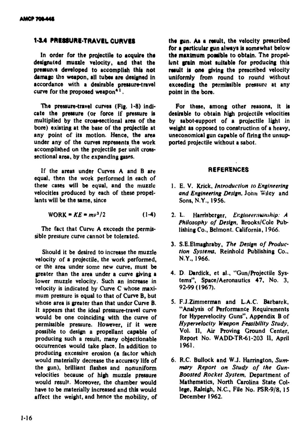
1*3.4 PRE88URE-TRAVEL CURVES
In order for the projectile to acquire the
designated muzzle velocity, and that the
pressunts developed to accomplish this not
damage the weapon, all tubes are designed in
accordance with a desirable pressure-travel
curve for the proposed weapon*1.
The pressure-travel curves (Fig. 1-8) indi-
cate the pressure (or force if pressure is
multiplied by the cross-sectional area of the
bore) existing at the base of the projectile at
any point of its motion. Hence, the area
under any of the curves represents the work
accomplished on the projectile per unit cross-
sectional area, by the expanding gases.
If the areas under Curves A and В are
equal, then the work performed in each of
these cases will be equal, and the muzzle
velocities produced by each of these propel-
lants will be the same, since
WORK - KE - mP/2 (1-4)
The fact that Curve A exceeds the permis-
sible pressure curve cannot be tolerated.
Should it be desired to increase the muzzle
velocity of a projectile, the work performed,
or the area under some new curve, must be
greater than the area under a curve giving a
lower muzzle velocity. Such an increase in
velocity is indicated by Curve C whose maxi-
mum pressure is equal to that of Curve B, but
whose area is greater than that under Curve B.
It appears that the ideal pressure-travel curve
would be one coinciding with the curve of
permissible pressure. However, if it were
possible to design a propellant capable of
producing such a result, many objectionable
occurrences would take place. In addition to
producing excessive erosion (a factor which
would materially decrease the accuracy life of
the gun), brilliant flashes and nonuniform
velocities because of high muzzle pressure
would result. Moreover, the chamber would
have to be materially increased and this would
affect the weight, and hence the mobility, of
the gun. Aa a result, the velocity prescribed
for a particular gun always is somewhat below
the maximum possible to obtsin. The propel-
lent grain most suitable for producing this
result is one giving the prescribed velocity
uniformly from round to round without
exceeding the permissible pressure at any
point in the bore.
For these, among other reasons, it is
desirable to obtain high projectile velocities
by sabot-support of a projectile light in
weight as opposed to construction of a heavy,
uneconomical gun capable of firing the unsup-
ported projectile without a sabot.
REFERENCES
1. E. V. Krick, introduction to Engineering
and Engineering Design, John Wiley and
Sons, N.Y., 1956.
2. L. Harrisbcrger, Engineer,тапМр: A
Philosophy of Design, Brooks/Cole Pub-
lishing Co., Belmont. California, 1966.
3. S.E.EImaghraby, The Design of Produo
tion Systems, Reinhold Publishing Co.,
N.Y., 1966.
4. D Dardick, et al., "Gun/Projectile Sys-
tems'*, Space/Aeronautics 47, No. 3,
92-99(1967).
5. F.J.Zimmerman and L.A.C. Bar ba re к,
"Analysis of Performance Requirements
for Hypervelocity Guns”, Appendix В of
Hypervelocity Weapon Feasibility Study,
Vol. II, Air Proving Ground Center,
Report No. WADD-TR-61-203 II, April
1961.
6. R.C. Bullock and W.J. Harrington, Sum-
mary Report on Study of the Gun-
Boosted Rocket System, Department of
Mathematics, North Carolina State Col-
lege, Raleigh, N.C., File No. PSR-9/8, 15
December 1962.
1-16
AMCP 706445
7. АМСР 706-140, Engineering Design
Handbook, Trajectories, Differential Ef-
fects. and Data for Projectiles.
8. AMCP 706-242, Engineering Design
Handbook, Design for Control of Projec-
tile Flight Characteristics.
9. R.E. Carn and A.B. Stinson, Handbook
of Trajectory Data for Spin Stabilized
Projectiles,Typical Fin Stabilized Flech-
ettes, Spheres and Cubes, URL Report
No. R-1336, August 1966.
10. a. AMCP 706-160(S), Engineering Design
Handbook, Elements of Terminal Ballis-
tics, Part One, Kill Mechanisms and Vul-
nerability (U).
b. AMCP 706-161(S), Engineering De-
sign Handbook, Elements of Terminal
Ballistics, Part Two, Collection and Anal-
ysis of Data Concerning Targets (U).
c. AMCP 706-162(S-RD), Engineering
Design Handbook, Elements of Terminal
Ballistics, Part Three, Application to
Missile and Space Targets (U).
11. AMCP 706-245(C), Engineering Design
Handbook, Design for Terminal Effects
(U). '
12. AMCP 706-107, Engineering Design
Handbook, Elements of Armament En-
gineering, Part Two, Ballistics.
13. AMCP 706-150, Engineering Design
Handbook, Interior Ballistics of Guns.
14. G.V. Parkinson, Simple Internal Ballistics
Theory for Single and Double Chamber
Guns, Space Research Institute, McGill
University, Report No. SR1-H-TN-4, 26
August 1966.
15. J.M. Frankie, An Interior Ballistic Study
of a 24-inch Gun for Project HARP, BRL
Technical Note No. 1606, May 1966.
16. A.E. Seigel, The Theory of High Speed
Guns, AGARDograph-91, May 1965.
17. L.A. DeStefano, A Digital Computer Sim-
ulation of Breech-Launched Rockets,
Frankford Arsenal, Report No. M67-18-1,
January 1967.
18. J.B. Goode, Definitions of Pressures for
use in the Design and Proof of Guns and
Ammunition, Royal Armament Research
and Development Establishment, Memo-
randum No. 11 /66, April 1966.
19. V.iOskay, Proof Testing and Computer
Analysis of BRL 81/26mm Light-Gas
Gun, BRL Memorandum Report No.
1855, July 1967.
20. E.B. Becker and J.J. Brisbane, Applica-
tion of the Finite Element Method to
Stress Analysis of Solid Propellant Rock-
et Grains, Rohm and Haas Company,
Report No. S-76, November 1965.
21. E.L. Wilson and R.E. Nickell, “Applica-
tion of the Finite Element of Heat
Conduction Analysis”, Proceedings of the
Fifth U.S. Congress of Applied Mechan-
ics, ASME, N.Y., 1966.
22. L.C. MacAllister, On the l)se of Plastic
Sabots for Free Flight Testing, BRL
Memorandum Report No. MR-782, May
1954.
23. J.D. Peters, Development Test of Plastic
Discarding Sabot Shot for 76mm Gun,
T91 (U), APG Report No. TA 1-5002-8,
22 January 1958 (C).
24. E.W. Bailey, Development of Shot,
APFSDS, 90140mm T320 for 90mm
Smoothbore Guns, APG Report No.
TAI-1475, 21 November 1957.
25. S.J. Doherty, Sabot Materials and Designs
for High Velocity Kinetic-Energy Artil-
lery Ammunition, ARMA TR 67-11,
April 1967 (C).
1-17
АМСР70М48
26. Aircraft Armaments, Inc., Development
of a Special Type Small Arms Cartridge
(Sabot Supported) (U), Report No. ER-
1414, July 1958 (C).
27. W.L. Black, Design and Fabrication of
APDS Shot (U), Aircraft Armaments,
Inc., Report No. ER-4341, March 1966
(C).
28. E. Huchital,- Development of Delta Wing
Armor Penetrating Shot (U), Electro
Mechanical Research Co., Report No. 2,
September 1958; Report No. 11, March
1960; Design and Development of Low-
Drag, High-Energy, Armor-Penetrating
Projectiles (U), EMRC Report No. 16, 31
March 1961; Report No. 30, 31 October
1962 (C).
29. AVCO Corp., Feasibility Study of a
GASP Launch Payload Vehicle (U), Re-
port No. RAD-SR-26-60-54, 5 July 1960
(C).
30. G.V. Bull, D. Lyster, and G.V. Parkin-
son, Oribital and High Altitude Prob-
ing Potential of Gun-Launched Rockets,
Space Research Institute, McGill Univer-
sity, Report No. SRI-H-R-13, October
1966.
31. F.W. Eyre, “The Development of Large
Bore Gun Launched Rockets”, Canadian
Aeronautics and Space Journal, 12,
143-149(1966).
32. F.M. Groundwater, The Development of
Gun Launched Rockets, Space Research
Institute, McGill University, Report No.
SR1-H-R-6, February 1968.
33. J.A. Brown and S.T. Marks, “High Alti-
tude Gun Probe Systems for Meteorolog-
ical Measurements”, The Meteorological
Roc’:et Network, IR1G Document No.
111-64, February 1965, pp. 211-221.
34. G.V. Bull, “Development of Gun Launch-
ed Vertical Probes for Upper Atmosphere
Studies”, Canadian Aeronautics and
Space Journal, 10, 236-247 (1964); “Pro-
ject HARP", Ordnance, LH, 482-486
(1968).
35. C.H. Murphy and G. V. Bull, Aerospace
Application of Gun Launched Projectiles
and Rockets, Space Research Institute,
McGill University, Report No. SRI-R-24,
February 1968; “Gun Launched Missiles
for Upper Atmosphere Research”, AIAA
Preprint No. 64-18, January 1964.
36. R. Rossmiller and M. Salsbury, 16-lnch
HARP Work at Rock Island Arsenal-Sum-
mary Report, Rock Island Arsenal, Tech-
nical Report No. 66-1493, April 1966.
37. D.E. Cantey, “Gun Launch of Rocket
Vehicles by Fluid Support Techniques”,
Paper presented at the 3rd ICRPG/A1AA
Solid Propulsion Conference held in At-
lantic City, 4-6 June 1968.
38. D.E. Cantey, RS-RAP Feasibility Demon-
stration, Phase I, Final Technical Report
(U), Lockheed Propulsion Company, Re-
port No. 953-F, 25 October 1968 (C).
39. D.E. Cantey and F. Saam, F-RAP Feasi-
bility Demonstration, Phase I (U), Lock-
heed Propulsion Company, Report No.
962-F, December 1968 (C).
40. AMCP 706-250, Engineering Design
Handbook, Guns-General.
41. AMCP 706-252, Engineering Design
Handbook, Gun Tubes.
1-18
Figure 1-8, Pressure-travel (Solid Lines) and Velocitytravel (Dotted Line) Curves
AMCP 706-446
AMCP 706445
CHAPTER 2
SABOT SYSTEM ANALYSIS
2-0 LIST OF SYMBOLS Ф = a pressure function of£ A
В = bulk compressibility r* Subscripts:
d = projectile diameter В = bore
D = gun bore diameter c = chamber
d = projectile diameter f = fluid
F - force g = gravitational
g = acceleration G = grain
к = gun tube length in bore diameters о = nominal
L = length p = projectile or propellant
m = mass s = sabot
p = hydrostatic pressure t = total
P = pressure Bar (-) over symbol indicates vector or tensor quantity
s = surface area element 2-1 GEOMETRIC CLASSIFICATION OF
S’ = stress tensor SABOTS
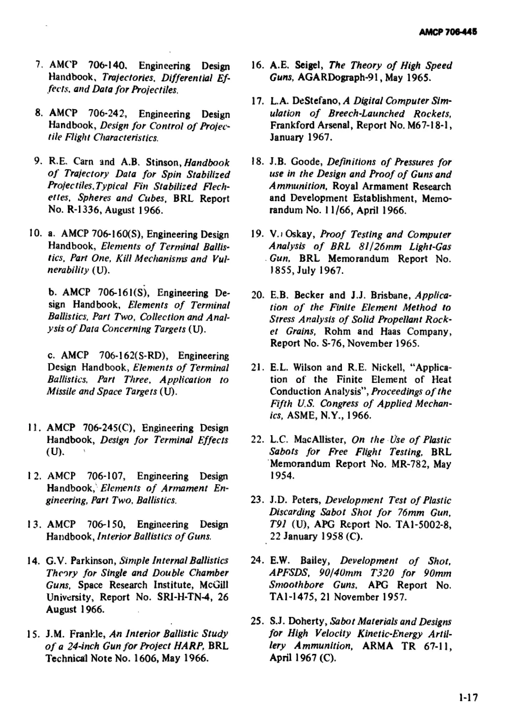
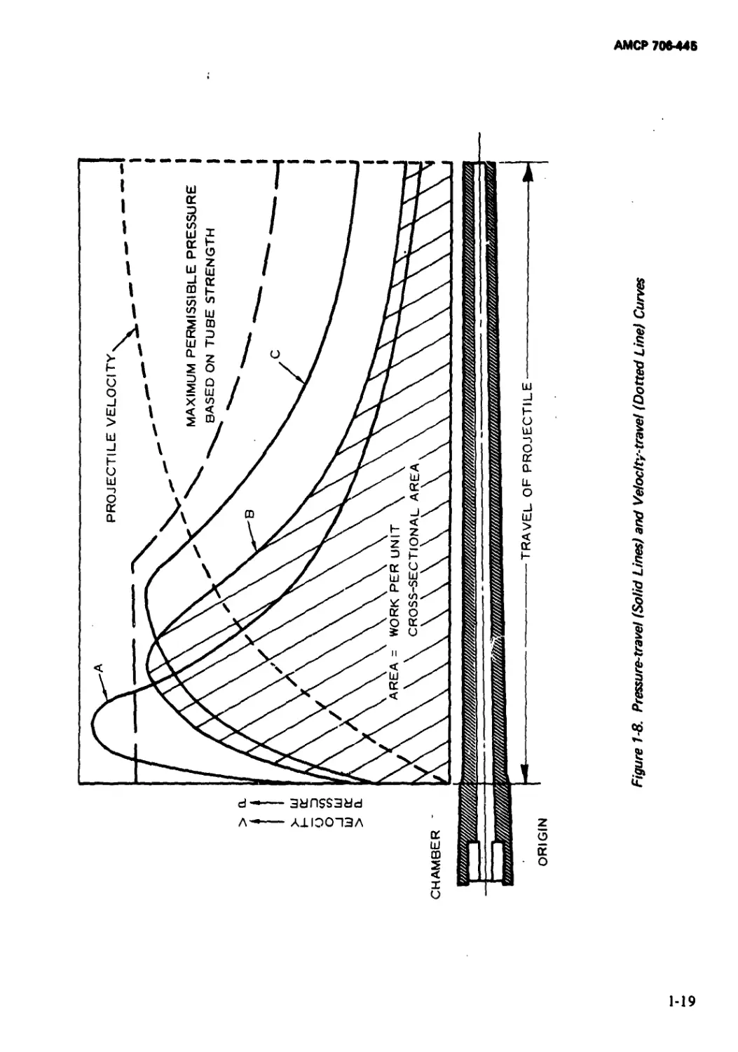
t = time * For current purposes, the various sabot designs are divided into two main classes: (1)
V = volume or acceleration potential the cup type (Fig. 2-1), including both the spin-stabilized and nonspin-stabilized projec-
v = velocity tiles, and (2) the ring type (Fig. 2-2). Al- though 12 variations of the basic cup design
x = distance and seven modifications of the basic ring design are identified and shown in the accom-
p = density panying figures, the simple dual geometric
2*1
AMCPKM4S
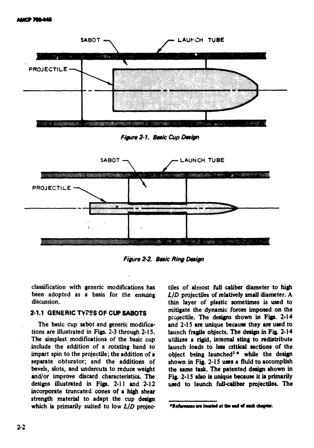
Figure 2-1. Betic Cup Detign
SABOT
j— LAUNCH TUBE
classification with generic modifications has
been adopted as a basis for the ensuing
discussion.
2-1.1 GENERIC TYPES OF CUP SABOTS
The basic cup sabot and generic modifica-
tions are illustrated in Figs. 2-3 through 2-15.
The simplest modifications of the basic cup
include the addition of a rotating band to
impart spin to the projectile; the addition of a
separate obturator; and the additions of
bevels, slots, and undercuts to reduce weight
and/or improve discard characteristics. The
designs illustrated in Figs. 2-11 and 2-12
incorporate truncated cones of a high shear
strength material to adapt the cup design
which is primarily suited to low L/D projec-
tiles of almost hill caliber diameter to high
LfD projectiles of relatively small diameter. A
thin layer of plastic sometimes is used to
mitigate the dynamic forces imposed on the
projectile. The designs shown in Figs. 2-14
and 2-15 are unique because they are used to
launch fragile objects. The design in Fig. 2-14
utilizes a rigid, internal sting to redistribute
launch loads to less critical sections of the
object being launched1* while the design
shown in Fig. 2-15 uses a fluid to accomplish
the same task. The patented design shown in
Fig. 2-15 also is unique because it is primarily
used to launch full-caliber projectiles. The
•RefatMM an located at tha and of each chapter.
2-2
AMCP 70*44*
Figure 2-3. Basic Cup Design
ECCENTRICALLY LOCATED PIN
FOR TRANSFERRING SPIN LOADS
TO PROJECTILE
Figure 2-4. Cup With Rotating Band (imparts spin to projectile)
Figure 2-5. Cup With Obturator (seals launch tube)
Figure 2-6. Cup With Forward Bevel (eugments aerodynamic separation
of sabot and projectile)
2-3
ftMCTTWIK
Figure 2-7. Cup With internal Taper (thrust and spin transmitted to
the projectile through the tapered surface)
Figure 2-8. Cup With External Undercut (weight reduction)
Figure 2-9. Cup With Internal Undercut (weight reduction)
Figure 2-10. Cup With Rider
Figure 2-11. Cup With Base Plate (bearing surface multiplier)
2-4
AMCF70B44*
PLASTIC DISC
Figure 2-12. Cup With Base Fiat» and Shock Absorber (for highly brittle projectiles)
Figure 2-13 Cup With Sheer Plate Restraint
jre 2-14. Cup With Support Sting (for thin-walled models)
Figure 2-15. Cup With Fluid Support (for fragile projectiles such as rocket-assisted
projectiles) (Patent Numbers 3,369,455and 3,369,485)
PAYLOAD
2-5
АМСР7М-44*
objective of this sabot is to reduce the launch
weight of the projectile instead of increasing
the muzzle velocity.
2-1.2 GENERIC TYPES OF RING SABOTS
The basic configuration for the ring sabot
and its generic variations is shown in Figs.
2-16 through 2-23. The simple modifications
of adding obturators, bevels, slots, etc., to
improve sealing characteristics and reduce
sabot weight are illustrated. Figs. 2-22 and
2-23 incorporate the high shear-strength
characteristics of a metal with the low density
properties of plastics to achieve higher perfor-
mance.
2-2 SABOT DESIGN CONSTRAINTS
The fundamental objective of a large class
of sabot-projectiles is to achieve higher projec-
tile muzzle velocity from guns which operate
at some nominal efficiency level. The general
design problem can be viewed from two
alternate positions. Given a specific projectile
of mass mp and diameter d which achieves a
muzzle velocity from a nominal gun of
diameter d, it is desired to attain a higher
muzzle velocity va by using a larger gun
(diameter D) and a sabot to fit the given
projectile into the larger diameter tube. The
problem is to determine the gun size and
sabot configuration capable of achieving the
Figure 2'16. Basic Ring Design
PROJECTILE
2
Я
Figure 2-17. Ring With Obturator (seals launch tube)
Figure 2-18. Ring With Forward Bevel (augments aerodynamic separation of
sabot and projectile)
2-6
АМСР70М48
Figure 2-19. Ring Witn Unsupported Forwent Undercut (aero-augmanted
separation end weight savings}
Figure 2-2Q. Ring With Longitudinally-supported Forwent Undercut
Figure 2'21. Ring With Circumferentially-supported Forward Undercut
Figure 2-22. Two-piece Ring
Figure 2-23. Two-piece Self-sealing Ring
2-7
ЛИСТ ТОМШ
detired pel forma псе. Alternatively, the de*
signer may be given a specific gun of diameter
D, capable of launching a nominal mass m0 at
an initial velocity Vj, and be required to
determine the reduced piojectile mass and
sabot configuration which will permit attain-
ment of the desired higher velocity v2. The
purpose of this paragraph is to illustrate the
general constraints imposed upon the sabot
design by these system performance require-
ments.
Consider first the problem of velocity
increase for a given projectile mass by gun size
increase and the use of a sabot. Neglecting
bore friction and gas compression ahead of
the projectile, the only force acting on the
sabot projectile is the propellant gas pressure
assumed to be uniformly distributed over the
shot base. The kinetic energy delivered to the
projectile of mass mp by expansion of gas in
the gun of diameter d is given by
For equivalent peak pressure and piezo-
metric efficiency - i.e., ratio of peak to average
pressure, in the gun system - the integrals in
Eqs. 2*1 and 2-2 are proportional to the bore
diameters, d and D, respectively. Using this
result, dividing Eq. 2-2 by Eq. 2-1 and
rearranging, yields an expression for the sabot
mass m, and gun size D required to achieve
the desired velocity p2 as follows:
From the alternate point of view, in which
the gun size is fixed and the projectile is
reduced in size with a sabot to achieve higher
velocity, an equivalent result can be obtained
as follows: The kinetic energy delivered to a
nominal projectile mass m,, by the gun of
diameter D and caliber length к is given by
1 i
pdx = ynpv\
(2-1)
CkD , - 1 J
•Л1
(2-4)
where к is the length of the launch tube in
bore diameter or caliber lengths, P] is *the
muzzle velocity, and
pdx
is the integral of the shot base-pressure travel
curvpior the gun. The velocity p2 achieved by
the'same projectile inass nip when lired from
a gun of diameter D with the same caliber
iength к peak pressure, and piezometric effi-
ciency is given by
For constant energy delivered by the gun. an
increased muzzle velocity r2 can be achieved
by reducing the sum of the projectile and
sahot mass as given by Eq. 2-2. Combining
Eqs. 2-2 and 2-4 results in
(2-5)
Assuming constant projectile shape and den-
sity (as its mass is reduced to achieve the
velocity increase) results in the following
proportionality:
ir 1 <2’2>
pdx = -(mp + mx)v2
4
(2-6)
where mt is the mass of the sabot required to
support and transmit the additional kinetic
energy to the projectile.
Substituting this result into Eq. 2-5 and
rearranging yields the result previously ob-
tained into Eq. 2-3.
2-8
AMCP 70444*
it may be observed that Eq. 2*3 involves
three dimensionless ratios. This permits the
ratio of the sabot mass to the projectile mass
to be plotted as a function of the ratio of the
projectile diameter to the bore diameter, with
the ideal velocity increment
h h
as a parameter (Fig. 2*24). Lines of equal
velocity-increase for the ideal gun performance
assumed are shown in the figure. One must
remain on the left side of the zero velocity
increment curve if there is to be any increase
in the muzzle velocity due to the use of a
sabot unless the gun is operated at an in-
creased peak pressure or piezometric effi-
ciency.
in general, choice of the gun system perfor-
mance level is dictated by such other system
constraints as tube material strength, erosion
resistance requirements, system weight and
length limits, interior ballistic effects, muzzle
blast, and flash limitation requirements, etc.,
which will not be considered here. One
important effect not included in the simple
analysis discussed here is the decrease in
piezometric efficiency that results as muzzle
velocities are increased. This performance
degradation is caused by the work necessary
to accelerate the propellant gases themselves
to high velocity. In the limit as shot weight
approaches zero, the shot velocity approaches
a fixed upper limit determined by the expan-
sion properties of the gun propellant combus-
tion products. Light gas guns are able to
exceed the velocity limit imposed on powder
gas guns by the use of low molecular weight
gases in the expansion process.
The shaded area of Fig. 2-24 shows the
region occupied by existing sabot-projectile
designs as listed in Appendix A. Observe that
this region was determined by plotting the
sabot-projectile mass ratio versus the projec-
tile-gun bore diameter ratio for representative
designs. In general, the large ideal velocity
increment increases indicated by the theoreti-
cal calculations for the designs located at the
left side of the shaded region (low projectile-
to-bore diameter ratios) are not achieved for
two reasons. First, the analysis resulting in
Eq. 2-3 implicitly assumes constant projectile
shape and composite density as the gun size is
increased or the projectile size is decreased to
achieve higher velocities. This assumption
becomes increasingly poor as the projectile-to-
bore diameter ratio decreases. In general, the
projectile length-to*diameter ratio and com-
posite density tends to increase because of
aerodynamic flight stabilization and terminal
ballistic requirements. Thus, the left part of
the shaded region should be shifted to the
right relative to t ie lines of constant velocity
increase. Second, the gun efficiency problem
at high velocity previously described causes
severe degradation in velocity performance
for the very light shotweight designs.
Another instructive way to consider the
performance limits and capabilities of sabot-
projectile designs is illustrated in Fig. 2-25,
which shows the sabot-to-projeetile mass ratio
mslmp plotted versus the projectile-to-
nominal shot mass ratio mplm0 of Eq. 2-5.
Plotted in this fashion, the effects of projec-
tile shape and density are excluded from the
analysis and the actual achieved velocity
increases are closer to ideal values. Choice of
the nominal projectile mass m0 is arbitrary
and is associated with the efficiency level
assumed for the gun systems. The existing
sabot-projectile design data shown in Fig.
2-25 were obtained from the performance
summary data of Appendix A, assuming m0
equal to 96 lb for a 155 mm gun (an artillery
weapon). Values of mo for other gun sizes
were obtained by scaling 96 lb as the cube of
the gun bore diameter which approximates
equivalent gun peak pressure and piezometric
efficiency.
These elementary system analysis consider-
ations illustrate the general design require-
ments for velocity increase by the use of
sabot-subcgliber projectiles. Projectile mass
must be reduced to achieve velocity increase
for constant gun performance. Generally, the
2-9
днщ joj щ
Figure 2-24. Performance Limits and Capabilities of Different Sabot Designs
2-10
AMCP 700448
Figure 2-25. Performance Limits and Capabilities of Different Sabot Designs
2-11
АМСР70Ы45
projectile mass is the useful end product of
the system and, therefore, there are system
requirements to maximize the projectile mass.
Additional velocity increase can be achieved
for a fixed projectile mass by decreasing the
weight of the sabot as illustrated in Fig. 2-25.
This latter design goal is of primary impor-
tance in sabot-projectile technology.
2-3 THE COMPARISON BETWEEN CUP
AND RING SABOTS
The first decision which the sabot designer
must make is whether or not to employ a ring
or a cup sabot configuration. Based upon
empirical evidence, investigators at BRL es-
tablished the following criteria2:
-£->0.40,-£< 10
D a
^>O.4O,4f> 10
D a
One-piece cup sabot
(Figs. 2-3 through
2-9)
Cup sabot with
bearing plate (Figs.
2-11 or 2-12)
< 0.40 Ring sabot (Figs.
D 2-16 through 2-23)
The performance capability of a cup and
ring sabot both designed to the same set of
conditions using the same material are given
in Fig. 2-26. It may be observed that although
the ring sabot consistently gives better perfor-
mance than the cup sabot, the amount of
Figure 2-26. Comparison of Cup and Ring Sabots (6-in diameter bore, projectile
L/D = 10, effective density of projectile = 0.260 Ibm/iri?, maximum
gas pressure = 50,000 psi, density of sabot = 0.040 lbm/in?, and shear
strength = 10,000psi) (Ibm = pounds mass)
2-12
AMCP 706-446
improvement at relatively large projectile dia-
meters ($ > 0.40) is significantly less than at
smaller diameters. This is sufficiently less so
that one must consider other quantifiable
criteria, i.e, cost of manufacture, reliability,
etc.
In ring sabots the means normally em-
ployed to transfer the shear forces developed
between the sabot and the projectile is a series
of annular grooves shaped like a buttress
thread. To ensure an effective transfer of
these shear forces, the grooves on the projec-
tile body must fit carefully into the grooves in
the sabot. The manufacturing costs for pro-
ducing a ring sabot, therefore, can be much
higher than for an equivalent cup sabot.
In addition, the ring sabot has one more
joint to seal than does the cup sabot, i.e., the
joint between the sabot and the projectile.
Failure to achieve an effective seal on this
joint has been blamed for the failure of ring
sabots to function properly. The exposure of
the aft end of the projectile associated with
ring sabots also is considered a problem area
that must be considered. It is concluded that
the BRL rule-of-thumb is a reasonable criter-
ion for preliminary design of sabots but that a
more detailed parametric study may be war-
ranted for a specific set of performance
criteria.
24 FLUID BUOYANCY SUPPORT OF
GUN-LAUNCHED STRUCTURES
The fluid buoyancy sabot is a special
development of the Lockheed Propulsion
Company* and has application to the generic
structure that is typically weak in longitudinal
buckling, but which can be gun-launched to
achieve some system advantage. One such
structure is a rocket-assisted projectile
where the projectile may be considered to
be in the range between an artillery bombard-
ment projectile and an earth orbit satellite.
System performance in all cases appears to be
maximized by gun launch of a flight vehicle
‘Patent Numbers 3,369,455 and 3,369,485.
incorporating a high mass fraction (ratio of
propellant and total weight) propulsion unit.
It is desirable that the rocket propulsion
unit be designed for its intrinsic operating
parameters only. When this is accomplished,
the respiting unsupported propulsion unit is
too fragile for gun launch (except in the
trivial case of a “blow gun”L Fluid immersion
makes the rocket unit (and/or payload) rug-
ged, rendering it virtually insensitive to gun
bore loads. This paragraph presents a theoreti-
cal analysis of the fluid buoyancy, sabot
system.
A schematic diagram of the fluid buoyancy
support projectile and gun launch system is
presented in Fig. 2-27. The thin-walled aft-
section of the motor chamber is encased in a
close fitting polymeric cup containing a fluid
that fills the motor chamber cavity and nozzle
assembly. The purpose of this fluid is to
transmit pressure, resulting from gun propel-
lant gas expansion and inertial reaction of the
projectile, throughout the interior of the
booster rocket, thereby counteracting forces
tending to destroy the motor chamber and
grain.
The ballistic trajectory can be divided into
the following three regions for discussion
purposes:
(1) Gun tube acceleration
(2) Transition from gun tube to exterior
(3) Exterior ballistic flight.
Relative to an inertial frame of reference
traveling with the projectile, the projectile-can
be considered to be at rest in a time-varying
inertial acceleration field with equipotential
planes oriented normal to the gun bore axis
(neglecting spin effects for the moment).
After transition of the projectile from the gun
tube to the exterior, the acceleration field
drops abruptly as the driving gun gas dissi-
pates. For the case of exterior ballistic flight
in an atmosphere, aerodynamic drag effects
2-13
2-14
ELASTOMERIC
OBTURATION CUP
PRESSURE
TRANSMITTING
FLUID
GUN BARREL AND
BREECH CLOSURE
GUN PROPELLANT
CHAMBER—i
ROCKET
MOTOR
PROPELLANT
GRAIN /
-THIN WALL
MOTOR
CHAMBER ,
PAYLOAD
тшшштша
77777/////////I Ezzzzz
FLUID RESERVOIR
X (BARREL LENGTH)
Figure 2-27. Projectile, Gun Launch Schematic for Fluid Buoyancy Support System
АМСР 708448
will cause the acceleration field to drop below
zero, resulting in projectile deceleration. The
orientation of the deceleration field with
respect to the projectile is determined by
projectile pitch and yaw. From the standpoint
of projectile structural integrity, the primary
effect of interest is the physical response of
the projectile to this transient inertial acceler-
ation field resulting from the gun launch and
exterior ballistic flight.
In general, the equations of motion for a
deformable body are obtained by equating
the material density p times the convective
derivative of velocity with respect to time, to
the forces acting on unit volume3. The forces
acting on any elemental volume are due partly
to body forces, e.g., gravitational and inertial
forces, and partly to the resultant of the
surface tractions acting because of the state of
stress of the body. Thus, using vector nota-
tion, the equation of motion can be written
as:
p^=pg + divS (2-7)
Bars (-) over the symbols denote vector or
tensor quantities. Symbols used are defined as
follows:
p = average mass per unit volume (den-
sity)
v = velocity field
g = body force per unit mass (acceleration
field)
S = stress tensor
t = time
This basic equation is applicable to solids,
liquids, and to materials that display charac-
teristics of both limit conditions. The distinc-
tion among these various forms of matter is
embodied in the nature of the internal stresses
given by the stress tensor. An additional
differential relationship, which must be satis-
fied by the density and velocity fields, results
from conservation of matter and is known as
the equation of continuity, i.e.,
к
^+pdiv7«0 (2'8)
at
It should be emphasized that the indicated
density derivative with respect to time is a
so-called “convected derivative” defined as:
(2-’>
where p is the ordinary variation with time of
the material density at a fixed point in space.
The second term accounts for the additional
material density variation resulting from the
motion of the observer traveling with the
velocity field during unit time.
The material under consideration is said to
be “incompressible” if changes in the material
density with time are negligible for the
physical process in question. In this approxi-
mation dp/dt = 0, and, therefore, the velocity
field must satisfy the condition div v = 0.
Before these relations can be applied to the
specific problems involving real materials, a
supplementary set of “material characteriza-
tion” relationships is required expressing the
stress S in terms of the deformation, the rate
of deformation or the history of the deforma-
tion, depending upon the complexity of the
material. That is, a rheological equation of
state must be obtained for each important
material. Before discussing the required spe-
cific material characterization, it would be well
to consider the projectile in the gun launch
environment in greater detail to establish a
qualitative understanding of the relative im-
portance of the various effects.
Refer again to the projectile gun launch
schematic, Fig. 2-27, and consider the instan-
taneous st^te of the projectile when it is near
maximum acceleration in the gun barrel.
Forces on the projectile under these condi-
tions are primarily body forces resulting from
inertial reaction of the various projectile
elements to the very large acceleration field
2-15
АМСРЯМ4В
(10*-IO*g). It is clear that gravity loading
effects can be neglected under these condi-
tions as contributing a negligible amount to
the total body forces on the projectile. In
addition to the body forces resulting from the
linear acceleration field, another source of
body forces is the angular acceleration resist-
ing from the bore rifling in spin-stabilized
projectiles. For the current discussion, body
forces will be assumed to result only from the
linear acceleration. Finally, surface tractions
are introduced during the gun tube travel by
frictional forces at the gun tube walls.
The general effect of the linear acceleration
on the rocket motor portion of the projectile
is intuitively clear. Pressure will be developed
in the pressure transmitting fluid resulting
from inertial reaction of the payload mass and
body forces in the fluid. At the base of the
projectile, pressure in the elastomeric obtura-
tion cup will precisely balance the gun propel-
lant chamber pressure. Moving toward the
forward end of the projectile along the axis of
symmetry, the fluid pressure will decrease to
a value determined by the,payload mass as the
fluid ’‘surface*’ (located at the fluid-payload
interface) is approached. The fluid, motor
chamber, and obturation cup walls are con-
strained by the gun barrel walls in exactly the
same way that water in a stand pipe tank is
constrained by the pipe walls.
Considering the dynamics of the gun tube
acceleration process now, it is clear that for
the limit case of incompressible behavior for
all materials, adequate protection of the
thin-walled motor chamber during the gun
tube travel requires only that the velocity of
transmission of the pressure wave through the
fluid be at least as large as the propagation
velocity of a deformation wave in the obtura-
tor cup walls or the velocity of gun gases
around the outsides of the cup walls. The
situation is complicated, however, by the
compressible пакте of real materials. Because
adequate protection of the motor chamber
and nozzle assembly requires that the internal
volume remain reasonably constant, it is
evident that bulk compression of the fluid
and motor propellant as pressure increases
means that the extra volume must be filled
with fluid flowing into the chamber through
the nozzle from an external reservoir. To scale
the effect, consider the case of the rocket
motor shown in Fig. 2-27 where the propel-
lant volume occupies 50 percent of the
total chamber volume Kr with the remainder
filled with fluid Vf. Assume that bulk com-
pressibilities of the fluid Я/and propellant Bp
are 3 X 10'* and 0.9 X 10"* psi‘*, respective-
ly, and that the average maximum fluid pres-
sure ДР is 15,000 psi. For equilibrium condi-
tions, the total volume change, А И/И. is:
^(100) = AF
lz (100) = 2.9%
Thus, for this example, a volume of fluid at
15,000 psi equal to 2.9 percent of the total
internal chamber volume must flow through
the nozzle from the reservoir quickly enough
to prevent deformation of the motor chamber
because of gun gas pressure. In addition, it is
evident that the compressibility of the obtura-
tion cup walls should be as low as possible to
limit motor chamber expansion.
Returning now to the mathematical formu-
lation and assuming that stress transmission is
sufficiently rapid to permit the assumption
that the fluid system is quasi-static, i.e., close
to equilibrium conditions at all times, Eq. 2-7
becomes
pg + div S = 0
(2-10)
Furthermore, if it can be assumed that the
fluid is sufficiently perfect, i.e., that it can
support no shearing stresses, then the stress
distribution within it will be isotropic and
div5=-gradp (2-11)
Under these conditions,
pg = grad p (2-12)
Now, in general, the hydrostatic pressure p
is a function of the density p. If the fluid
2-16
AMCF 70*448
density changes, for example, because of
compressibility, temperature field, impurity
content, etc., then it is clear that the pressure
distribution will be affected. In genend, lines
of constant density may or may not coincide
with lines of constant pressure. If the former
can be assumed, an auxiliary pressure func-
tion can be defined
(2-13)
which, combined with Eq. 2-12, results in
grad Ф
(2-14)
Now, for the inertial acceleration field g,
under consideration here, the following may
be written:
g«=-gradK (2-15)
where V is the inertial acceleration field
potential. Eqs. 2-14 and 2-15 result in
V + Ф = constant
(2-16)
Because the inertial acceleration field V of
the projectile can be considered to be
spatially uniform, V = - gx may be written
where g is the magnitude of the acceleration
field, and x is the distance from the fluid-pay-
load inte-fs back toward the aft end of the
projectile. Thus,
Ф = gx + constant (2-17)
and for the limit of incompressible behavior
Ф»£ = де+— (2-18)
P P
so
p = pgx+po (2-19)
This relation expresses, mathematically, the
fact previously mentioned, that the total
pressure in the fluid is equal to the sum of a
constant value po resulting from the inertial
reaction of the payload mass plus a compo-
nent increasing linearity with depth due to
inertial reaction of the fluid itself. The accu-
racy of this result is, of course, dependent on
the validity of the various simplifying assump-
tions made during the derivation.
In addition to the previous effects, buoy-
ancy phenomena are certain to play a major
role in development of high acceleration
systems of the type discussed here. Consider
the propellant grain shown schematically in
Fig. 2-27, immersed in the pressure transmit-
ting fluid and case-bonded to the chamber
wall. The total force /у acting on the grain by
the fluid is
Ff - - ff pd! (2-20)
where ds is a vector surface area element of
the grain directed outward from the grain.
Now, in general, for a scalar field such as p\
fSPds •fffffii pdVc (2-21)
where Kc is the volume of the propellant
grain. Again, assuming the fluid stress distri-
bution to be isotropic, Eq. 2-12 can be used
to show that
Hpds~fffndVG (2-22)
Comparison of this result with Eq. 2-20
shows that the total force acting on the grain
by the fluid is equal and opposite to the total
weight of the displaced fluid given by the
right hand side of Eq. 2-22. Observe that only
the gradient portion of the total hydrostatic
pressure of Eq. 2-19 results in a buoyancy
effect on the submerged grain. The relation-
ship expressed by Eq. 2-22 is called Archi-
medes’ principle. The total body force acting
on the grain and resulting from the inertial
acceleration field g is given by
I2 »)
Thus, the total resultant grain force FG, is
Fg •Fa+Ff-fffPG&V-JffpgdVG(2-24)
Because the inertial acceleration field is
uniform and the fluid and propellant densities
2-17
АМСР70М4В
are assumed to be uniform, i.e., independent
of position. Eq. 2-24 simplifies to
Fc - (pc - p)TVG (2-25)
A positive resultant force corresponds to a
negative buoyancy, i.e., corresponds to a
“sinking” tendency. Observe that even though
the density difference between the grain and
fluid is relatively small, the resultant buoy-
ancy force can be large because of the
magnitude off. In the current case, this force
results in a shear deformation of the circular
port grain.
Up to now, consideration was given only to
conditions during travel of the projectile
through the gun barrel. Just as the projectile
emerges from the muzzle, it is clear that a
potentially catastrophic situation is produced.
Specifically, the projectile is still being accel-
erated by the gun gases bearing against the aft
of the projectile but the lateral pressure
constraint of the gun barrel is removed from
the forward portions of the projectile.
Clearly, the internal fluid pressure either must
be contained by the rocket chamber, relieved
by expansion and possible rupture of the
chamber, or the acceleration and resultant
pressure must be reduced by flow of fluid
from the reservoir around the outside of the
chamber to the atmosphere. The results of
experiments*'1 indicate that these muzzle
transition effects can be accommodated in
high-performance gun-boosted rocket designs
launched at practical gun energy levels. Flow
properties of the fluid during launch acceler-
ation are clearly of great importance to the
success of the rocket launch projection sys-
tem.
2-5 OBTURATION AND SABOT SEAL
DYNAMICS
2-5.1 GENERAL
The combined requirements of efficient
gun gas obturation during bore acceleration
and of rapid and smooth sabot separation
after muzzle exit provide challenging design
problems for sabot projectiles. Poor gun gas
obturation leads to augmented gun wear, and
degradation of projectile performance because
of erosion damage. Solution of the obturation
problem often results in sabot separation
difficulties with attendant poor ballistic per-
formance. The use of elastomeric seals for
obturation of high-performance sabot projec-
tile rounds has become common. These low-
modulus materials flow readily under pressure
to provide good obturation and excellent
sabot discard characteristics.
The general methods used for obturation of
sabot projectiles are described qualitatively in
this paragraph with reference to the widely
diversified applications literature for specific
techniques and results. Sabot projectile obtur-
ation design principles are not sufficiently
well defined or understood at this time to
permit a classical “handbook” treatment.
Research investigations directed specifically at
the detailed motion of practical obturator
designs during gun launch are relatively new
and few in number.
2-5.2 OBTURATION METHODS
Historically, the sealing of gun gases has
been accomplished by forcing a projectile
with a rotating band through the gun tube
rifling. In small caliber ammunition, the entire
cylindrical length of the projectile, which is
made from or sheathed in soft metal, is
engraved to provide a gun gas seal. Larger
caliber ammunition generally utilizes one or
more discrete rotating bands that are engraved
by the rifling under the action of the acceler-
ating propellant gases. In addition to provid-
ing the necessary sliding gas seal, rotating
bands generally are required to transmit tor-
que from the rifling to the projectile, thereby
providing the spin necessary for gyroscopic
stability. Requirements of the obturating de-
vice for spin-stabilized sabot projectiles are
much the same with the additional complica-
tion that the sabot and obturating device be
capable of smooth discard at the gun muzzle.
Both metal and fiber materials have been used
in spin-stabilized sabot projectile develop-
2-18
AMCP 70*448
nwnts (see, for example, Fig. 1*2). As higher
projectile velocities are obtained by reducing
the projectile inass and diameter, the mass of
the sabot becomes a critical performance
design constraint as described in par. 2-2.
Under these conditions, the use of a relatively
dense metal such as copper for the gun gas
obturator becomes prohibitive and low-den-
sity materials such as plastics and elastomers
have become important as sabot obturating
devices (see, for example, Figs. 1-3 and 1-4).
Many applications of sabot projectiles fired
from rifled and smoothbore guns exist, and
the use of plastic or elastomeric seals located
at the periphery of the sabot is common (see
the abstract bibliography, Appendix D). For
deformable sabot materials such as plastics,
the obturation means often is incorporated
ipto the sabot structure by making the aft end
larger than the gun bore as described in Ref.
2. This procedure also provides an initial
resistance to motion resulting in a fixed value
of shot start pressure which has certain
advantages from an interior ballistic stand-
point. In many cases, however, particularly
those in which the sabot must be inserted
initially forward of the entrance to the gun
bore, the use of oversize sabots is not prac-
tical and a self-sealing action by the obturator
is required. Peripheral undercuts of “flaps” on
the base of the sabot often are used to
accomplish this self-sealing action by reducing
the stiffness of the sabot material at the end
of the flap, which allows it to deform easily
under the action of low initial gas r>- ssures.
Examples of this procedure are ated in
the sabot designs shown in Figs, i-3 and 1-4.
An investigation of the literature indicates
that design of these components is accom-
plished largely on an empirical basis for each
specific application. Par. D-13 of the bibliog-
raphy (Appendix D) contains a list of ref-
erences on the subject on static and dynamic
seals in general.
2-5.3 SABOT SEAL DYNAMICS
The general motion of the sabot compo-
nents relative to the projectile during gun
launch acceleration is referred to here as sabot
seal dynamics. Control of this motion is a
central design problem in many sabot projec-
tile applications.
High-performance kinetic energy penetra-
tor sabot projectiles usually are aerodynamic-
ally stabilized and, therefore, it is desirable
that the projectile spin remain far below the
rate that would be achieved if the projectile
were directly coupled to the gun rifling. The
use of conventional, rifled tube guns for
launch of these projectiles often is dictated by
the necessity for firing conventional spin-
stabilized projectiles from the same weapon.
Thus, it is necessary to decouple the projectile
from the rifling through a sliding element
incorporated in the sabot obturator. In many
cases of interest, the general practice of
forcing the obturator into the gun rifling to
achieve a tight fit for gas sealing purpose
cannot be used; the obturator device must
expand under action of the gun accelerating
gases to fill the rifling grooves and provide the
necessary gas seal with minimum gas leakage.
To accomplish these requirements in high-
performance, ring sabot applications, relative-
ly complex sabot configurations have been
developed employing sliding j lastic obtura-
tion rings as indicated in Fig. 2-286. The
motion of this ring or combination of rings
relative to the sabot projectile body during
the launch acceleration cycle is critical to the
success of the round. Analytical and experi-
mental procedures have been developed6 that
can be used in the design and development of
sliding plastic obturator rings. Static and
dynamic friction between the ring and gun
bore and between the ring and sabot projec-
tile, combined with a knowledge of the
obturating ring mechanical properties, are
critical inputs into the analysis defining the
resulting motion and sealing effects.
Another application in which motion ol
the sabot materials relative to the projectile is
critical is the general area of fluid buoyancy
support of gun-launched structures discussed
in par. 2-4 (see also Fig. 1-5). In this case, a
2-19
MMCF VW44S
component of the “sabot is a pure fluid that
distributes the launch acceleration loads uni-
formly, thereby protecting fragile structures,
e.g., rocket motors, from the otherwise de-
structive effects of the launch acceleration.
Flow effects in the fluid relative to the
supported structure and the containing device
are of critical importance to the utility of this
method of structural support for fragile gun-
launched structures. Analyses of these effects
for specific applications are still being de-
veloped at the time of this writing.
REFERENCES
1. C.H. Murphy and G. Taylor, An Interest-
ing Sabot Design, BRL Memorandum Re-
port No. 1304, September 1960.
2. G. Taylor, Sabot-Launching Systems for
Experimental Penetrators, BRL Memoran-
dum Report No. 1505, August 1963.
3. Condon and Odishaw, Handbook of
Physics, McGraw-Hill Book Co., Inc., N.Y.,
1958.
4. D.E. Cantey, RS-RAP Feasibility Demon-
stration, Phase I (U). LPC Report No.
953-F, 25 October 1968 (C).
5. D.E. Cantey and F.S. Saam, F-RAP Feasi-
bility Demonstration, Phase 1 (U), LPC
Report No. 962-F, December 1968 (C).
6. R.C. Geldmacher, The Dynamic Behavior
of a Sliding Plastic Obturating Ring as
Used in the 152-mm XM 578 APFSDS
Projectile, Stevens Institute of Tech-
nology, Technical Report No. 3488,
September 1967. (AD-820 330) (See also
abstract No. 381, Appendix D)
2-20
АМСР 706-448
CHAPTER 3
STRUCTURAL DESIGN CONSIDERATIONS
3-0 LIST OF SYMBOLS К bulk modulus
a Ж acceleration £ к length
A s: area L ж length
d a diameter m к mass; or, reciprocal of Poisson’s ratio
D a diameter; or, creep compliance n a twist rate, turns per caliber
c coefficient of base thickness sine function N X twist r» turns per unit length
E к Young’s modulus of elasticity P = buttress groove pitch
E' = effective modulus
P ж pressure
E, = glassy modulus
x frequency a base pressure
Pc ж chamber pressure
F s force; friction force R a radius
G = shear modulus t a time; or, base plate thickness
h X rider width T = torque; or, temperature
H thermal pressure u, r, W 3 displacements in x-, y-, z-directions,
Ic a moment of inertia of projectile about longitudinal axis respectively
V = velocity
h a moment of inertia of projectile cross section about its central axis wd = distortional energy per unit volume
к = (I-r)/£ “ sabot length, base plate W = weight
thickness/projectile length X = distance from commencement of rifling
3-1
AMCP P0C44B
.V, j\ ? • Cartesian coordinates Subscripts:
a thermal expansion coefficient' В a gun bore
P a “ length of sabot wall/radius c a compressive
of projectile cr ж critical
У * t/Rp baseplate thickness/radius of f ж friction; forward
projectile I a inertial
percentage of sabot not undercut К a key
6 * max a maximum
ж Kronecker delta N a normal
e ж strain oct ж octahedral
P a projectile
| normal strain, i « / | r ж radial
& | | L / “ Jt, У, 2 ring; required
(shear strain, i ч* / J R a
sc a strength of core
в ж angle ss ж strength of sabot
= Rp/RB radius of projectile/radius s ж sabot; shoulder
or gun barrel str ж strength
P а coefficient of friction s ж stud
t ж tangential
V ж Poisson's ratio T ж torque
P ж material density w = wall
6 ж tangential
0 stress ж friction
o' = critical stress
1 normal stress, i = j
shear stress, i
i,j*x,y,z
oo « mean shear or deviatoric stress
<Jrt = shear stress
aw = working stress
r = shear stress or shear strength cap-
ability of materials
ы - angular velocity
ш - angular acceleration
3-1 STRUCTURAL DESIGN FUNDAMEN-
TALS
The verification of the structural integrity
of a design consists of two phases: (I) a
prediction of the stress and strain states
induced in the body by various loading
conditions and/or combinations of loading
conditions, and (2) application of failure
criteria to determine if failure will occur, the
margin of safety, or the probability of fail-
ure1 *. Input data required for the stress-strain
prediction phase include (1) characterization
ь ’Reference» are located at the end of each chapter.
3-2
ДМСР70М48
of the material itran-etrain behavior which
alio is known as the constitutive equation for
the material, and (2) the loading conditions to
which the body is expected to be subjected or
to which the design must be qualified. Inputs
to the failure assessment phase include (I)
appropriate failure criteria, i.e., a quantitative
description of the conditions under which the
material will fracture or deform into an
unacceptable shape, and (2) a criterion for
acceptable behavior for the specific applica-
tion under consideration. The latter may take
the form of an acceptable margin of safety
also known as a safety factor, or a permissible
probability of failure. The margin of safety is
a subjective measure of acceptable structural
performance that should account for (1)
uncertainties in load predictions, (2) possible
errors in structural analysis techniques, (3)
statistical variations in material properties, (4)
the inability to identify and correct potential
failure conditions before catastrophic failure,
and (5) the consequences of experiencing a
failure.
With the improvement of load prediction
and structural techniques, and the develop-
ment of statisitical means for predicting the
uncertainties in predicted quantities, it has
been possible to predict the effects of Items 1
through 3 relative to margin of safety. The
result is a statistical prediction of the prob-,
ability of failure. The advantage of the statis-
tical approach is that it reduces the level of
reliance upon judgment, which may be biased,
to a lower level than the margin of safety
approach.
The remainder of this chapter is devoted to
a general discussion of material characteriza-
tion, structural analysis, and failure criteria
followed by specific analyses pertinent to
structural design of sabots, and the presenta-
tion of a computerized, finite-element ap-
proach to the solution of structural integrity
problems with complicated geometry.
3-2 MATERIAL CHARACTERIZATION
Before performing the structural analysis of
a sabot or sabot-projectile system, it first is
necessary as well as expedient to establish
assumptions of material behavior under which
the analysis will be conducted. Notwithstand-
ing glaring deficiencies that will be discussed
subsequently, particularly in connection with
failure theory, it is proposed to consider the
medium as isotropic, homogeneous, and con-
tinuous. The practical objections to these
assumptions are based upon the fact that if
one examines the material on a sufficiently
small scale, it can be shown that neither
homogeneous, nor perhaps isotropic, media
exist. One must only assume that there does
exist, on the average macroscale, an equiva-
lent medium of this type. For many analyses,
this approximation will be satisfactory, cer-
tainly at the current stage, although the
assumption can be seriously in error on the
microscale, especially at the origin of failure
where fracture or tearing begins. Next, the
assumption of continuity is not always ful-
filled because it implies that there is always a
bond between the components of multiphase
materials, e.g. Fiberglas. Actually, this as-
sumption may not be correct under excessive
tensile stress. On the other hand, the bond
still will exist between those surfaces in
compression, therefore leading to (noncon-
tinuum) load-induced isotropy. Nevertheless,
to conduct present analyses, it is customary,
and at least temporarily appropriate, to as-
sume an isotropic, homogeneous continuum.
The second assumption is that the strains
will be sufficiently small so that infinitesimal
deformations can be assumed. Actually, for
the loads and geometries used in current
designs, strains of 30 percent frequently are
computed from infinitesimal theory, certainly
pushing the limit of validity for this assump-
tion. On the other hand, Unite strain analysis
is complex. Considering the widespread know-
ledge of infinitesimal deformation theory and
its relative ease of application, it is considered
appropriate pending some later qualifica-
tions, to begin at this point.
Third, the material stress-strain behavior
must be considered. Generally, only three
types of stress-strain behavior will be con-
3-3
AMCF 70M4S
side red: (I) linear elastic, (2) rigid-plastic, or
(3) elastic-plastic (Fig. 3-1). The first is
customary and appropriate for most materi-
als. It merely implies that the deformation or
recovery of the material from deformation
under applied loading will be instantaneous
and complete upon application or removal of
the load, with no delay or viscoelastic re-
sponse. On the other hand, some components
will be so highly, and intentionally, loaded
that the material will yield or permanently
deform. Actual behavior usually is somewhere
between these two limits, but experience
shows that for the majority of situations
analyzed herein, a careful assessment of the
behavior of these two limits will suffice.
3-2.1 LINEAR ELASTIC BEHAVIOR
The material properties required to per-
form a stress-strain analysis assuming linear
elastic behavior lire:
(I) Material density p usually given in
units of lbm/in.J
(2) Modulus of elasticity E usually given in
units of psi
(3) Poisson's ratio v which is dimensionless
(4) Coefficient of thermal expansion or
usually given in units of ln./in.-°F
Density p is the measure of the mass of a unit
volume of the material. The modulus of
elasticity E and Poisson’s ratio are material
constants that describe the stress-strain be-
havior of the material. The coefficient of
thermal expansion describes how the dimen-
sions of the material change with changes jn
temperature. A compilation of the room
temperature properties for the materials com-
monly used for sabots is given in Appendix B.
It will be noted that it is also possible to
define a shear modulus G and bulk, modulus К
for the material. In the case of a linear elastic
material, however, these properties can be
shown to be simple functions of £ and v (Ref.
2):
r. A'
2(l+v)
In fact, given the assumption of linear elastic
behavior and any two material constants, e.g.,
E and a, the other material constants G, A.
STRAIN
(A) LINEAR ELASTIC BEHAVIOR
(B) RIGID-PLASTIC BEHAVIOR
(C) ELASTIC PLASTIC BEHAVIOR
Figure 3- E Illustration of Possible
Stress-strain Behavior
3-4
АМСР70Ы4*
or any other property one might want to
define may be calculated. Furthermore,
given the material constants and either the
stresses о or the strains e, the other quantities
(strains or stresses) may be calculated using
the stress-strain relationships. For a linear,
thermomechanically coupled elastic solid, in
general, three-dimensional Cartesian coordi-
nates, the stress-strain relationships1 are
*XX V {Gyy + °tt
eii -аГ"7 [°ti -V<°xx +<^)]
*y G у» G *» G
(3-2)
These equations are also known as Hooke’s
law. The yield strength usually determined in
a uniaxial tensile test describes the limit of
clastic behavior.
3-2.2 THE FITZGERALD MODIFICATION
OF HOOKE'S LAW FOR INCOM-
PRESSIBLE MEDIA
The deformation characteristics of rubbers
and some polymers are found to approach
incompressible behavior, i.e., v -* and
К -* °”. Due to the occurrence of a (i - 2p)
term in the denominators of certain stress
analysis formulas, however, the assumption of
incompressible behavior can create serious
computational difficulties and may result in
oscillations in computer solutions for stresses
and strains. One approach to avoiding this
difficulty is to assume nearly-incompressible
behavior, i.e., v = 0.498, 0.499, or 0.4999.
Unfortunately, this is not satisfactory because
calculated stresses are sensitive to the value of
v, which is assumed.
An alternate approach growing out of the
Griineiscn relationships of polymer physics
and because of Fitzgerald*, is the postulate
that the quantity 3aK is a constant. This
quantity, denoted by H, is known as the
'Professor of Civil Engineering, University of Utah,
Salt Lake City, Utah.
thermal pressure and does appear to be a
material constant. Furthermore, it appears to
be the same constant for polymers in general
- approximately 75 psi/”F. Physically, this is
the pressure that would develop in the poly-
mer for each degree of temperature change if
the polymer were heated under absolute
confinement.
To illustrate the effect that this hypothesis
will have upon the stress-strain law, it is
convenient to begin with the Duhamel-
Neuman form3 of the stress-strain relation-
ships for thermomechanically coupled, linear
elastic systems. Using tensor notation, these
expressions are
°‘l "(1 + p)(l - 2p) e** + 2 Ge'>
(3-3)
eU " (*^) °U ~ E °** 64 + ®
where the indices i and j take on the values of
1, 2, and 3 (denoting the three ('artesian
coordinates v, >, z). repeated subscripts indi-
cate summation, and 5(y is the Kronecker
delta defined as
The second of these equations is identically
the stress-strain law previously given. For
convenience, however, the stresses have been
divided into an equivalent system of a pure
hydrostatic pressure (P • -cxx - ayy
- ott) component and pure shear compo-
nents (/ =# /), and tensor notation has been
employed to avoid having to explicitly write
down all six relationships implied by the
tensor expression. The deformations associ-
ated with the hydrostatic pressure and shear
components of stress are known as the unit
dilation (or volume expansion) and the distor-
tional or shear deformations, respectively.
Insetting the assumption that 3a£ = con-
stant = H and rewriting yields the result
3-5
АМСР 706446
e,
°kk c HT t
«/ з И 3K 11
(3-5)
where e(f = 2 G'e(/, К = K/(2G), and v = 0.5
and E = 3K (1 - 2p) from Eq. 3-1.
The first term on the right-hand side
represents shear or distortion. The second
term represents pressure loadings or volume
change, and the third term represents temper-
ature stress or temperature volume change.
It will be observed that this transformation
has replaced the E, v, and a appearing in the
usual stress-strain law for a linear elastic
material with the shear modulus G; a relative
bulk stiffness К = K/(2G), which is always
.mite; and the thermal pressure H, a general
material constant almost the same for all
polymers.
The important result is that the (1 - 2v)
factor causing the singularities or oscillations
in stress calculations has disappeared from the
equations. The choice this gives the structural
analyst is that he may continue to use the
strictly continuum approach and obtain un-
believable answers (or play with solutions
varying greatly as v goes from 0.499 to 0.498)
or accept the fundamental physical reasoning
and experimental verification which suggest
that 3aK is indeed a constant and employ the
Fitzgerald modification of the linear elastic
stress-strain laws for incompressible or nearly
incompressible media. Experience has shown
that the latter gives physically acceptable
answers while the former gives highly erratic
results.
3-2.3 LOADING RATE EFFECTS
At the loading rates normally encountered
in engineering practice, the behavior of metals
and metallic alloys is adequately described by
the linear-elastic material model. Plastics and
rubbers generally exhibit viscoelastic be-
havior, i.e., the mechanical state (stress or
strain) depends not only upon the magnitude
of the load but also upon its rate of applica-
tion and to a lesser degree upon the history of
the loading. Under these conditions, the
linear-elastic material model, which assumes
material properties that at the most may
depend upon temperature of the material, is
not adequate.
3-2.3.1 LINEAR VISCOELASTICITY
Linear viscoelastic models*, which intro-
duce time-dependency to material behavior in
a special fashion, can be used to describe at
least the sm?'l deformation characteristics of
materials whose mechanical response is time
dependent3’4. The moduli used to describe
the behavior of viscoelastic materials are also
dependent upon the rate at which the mater-
ial is loaded. The following loading modes
were found useful in structural analysis of
viscoelastic bodies:
(1) The relaxation modulus, Eft) or G(t),
defined as the tirhe-dependcnt stress
resulting from a suddenly (ideally in-
stantaneously) applied strain divided
by the magnitude of the strain step.
(2) The creep compliance D(t) defined as
the time-dependent strain resulting
from a suddenly (ideally instantane-
ously) applied stress divided by the
magnitude of the stress step.
(3) The dynamic modulus, £*(gj) or
<7*(w), or compliance D*(cj) which is
the amplitude of the steady-state stress
or strain resulting from a sinusoidally
applied strain or stress divided by the
amplitude of the applied strain or
stress. The dynamic properties are a
function of the frequency / of the
applied load and can be divided into an
♦The assumption of linearity is similar to that in
linear elasticity in that stresses are proportional to
strains but it must be stated that the “time-
dependent stresses’* are proportional to the “time-
dependent strains’*.
3-6
AMCP 706446
in-phase or real component, E'(w) or
Z)'(w). and an out-of-phase or loss
component, E"(w) or D"(cj), i.e.,
E*(w) = E'(w)+ /£''( w)
where
i = \/-T.
The relaxation modulus or creep compli-
ance is used in problems with slowly or
monotonically varying loads, and the dynamic
properties are used for oscillatory loadings.
Fig. 3-2 shows the typical plots of these
moduli of a viscoelastic material plotted on
log-log scales. It will be observed at very short
times or high frequencies that the material
behaves like an elastic material while at very
long times or low frequencies it also behaves
like an elastic material but with a modulus
several orders of magnitude (powers of ten)
smaller than the short time modulus value.
The short- and long-time relaxation modulus
are known as the glassy and rubbery or
equilibrium moduli, respectively.
Because of the assumption of linear be-
havior, the solution of stress problems involv-
ing viscoelastic materials is at least philosophi-
cally possible. The labor involved, however, is
several orders of magnitude greater than an
equivalent elastic problem5’6 and essentially
consists of the following:
(I) Transformation of material properties,
boundary conditions, etc., from time-
space into Laplace-transform space
(2) The solution of a linear elastic problem
in transform space for every time
period of interest
(3) Transformation of answer in transform
space back into time space.
*The assumption of linearity is similar to that in
linear elasticity in that stresses are proportional to
sirains but it must be stated that the “time-
dependent stresses” are proportional to the “time-
dependent strains”.
A significant decrease in computational
detail would be achieved if the assumption of
elastic behavior could be justified. If the
loading rate were sufficiently high, the modu-
lus of a viscoelastic material would approach
the glassy modulus and the material behavior
would be elastic. Fortunately, however, even
though the sabot strain rates are not high
enough to cause the effective modulus to
approach the glassy modulus the range of
strain rates and loading rates in most sabot
applications is within narrow limits. This
makes the assumption of elastic behavior and
the resulting simplifications reasonable. For
example, consider a cup sabot made of
“Lexan”, a polycarbonate plastic material.
Assuming that the time to maximum local
strain of 25 percent is approximately 2 msec,
the strain rate then would be 125 in./in./sec.
Under these conditions, Ref. 7 indicates that
the effective modulus would be Ee = 300,000
psi. The maximum modulus for “Lexan” is
approximately 320,000 psi and corresponds
to strain rates of 700 in./in./sec and above.
For all rates below about 0.01 in./in./sec, the
effective modulus is approximately 200,000
psi.
The finite element approach to the solution
of structural problems discussed in par. 3-5
and the finite element computer program
given in Appendix C are capable of handling
the bilinear behavior. For example, for the
“Lexan” being described in this paragraph,
one merely need insert the yield stress (the
stress at the bilinear break in the stress-strain
curve) of a = 18,500 psi and the modulus
ratio which for “Lexan” is 6700/320,000 =
0.02, and the computer will automatically
carry out the calculations through the end of
the bilinear segment. To determine failure for
curves of this sort, assume that the maximum
strain of 38 percent governs. Thus, extending
the second portion of the bilinear curve out
to 38 percent will imply a failure stress of
24,000 psi. The error involved will be ap-
proximately the ratio of the neglected area
between the bilinear extension and the actual
tri-linear section of the stress-strain curve to
the total area. In the case of “Lexan”, this
3-7
AMCP 706445
(A) RELAXATION MODULUS
(C) DYNAMIC MODULUS E* =E'+ IE”
Figure 3-2. Response Characteristics of a Viscoelastic Materia!
3-8
АМСР 70844В
error ratio is approximately 7 percent and on
the conservative side.
Thus, it has been shown that the availabil-
ity of high strain rate data establishing the
asymptotic value of the modulus permits
one, within acceptable accuracy, to ignore
viscoelastic effects in the analysis provided
the appropriate modulus is . used for the
“elastic” analysis. /'
3-2.3.2 BEHAVIOR OF MATERIALS AT
HIGH LOADING RATES
At high loading rates such as those en-
countered in guns, tlie behavior of even those
materials previously considered elastic be-
come rate dependent. Although increasing the
strain rate for viscoelastic materials increases
the modulus of the material, the effect of
strain rate upon most “elastic” materials is to
increase the yield stress and decrease the
toughness. The dynamic strength has been
found to be 30- to 50-percent higher than the
static strength8. Available data on dynamic
behavior of sabot materials arc summarized in
the remarks column of the properties tables
given in Appendix B. The fact that the
dynamic strength of materials is appropriate
for the gun launch environment has been
adequately demonstrated using gun-launched
aerodynamic models9’10. Lockheed Propul-
sion Company (LPC), using a technique for
determining material strength in a gun launch
environment, confirms that high rate material
properties are appropriate for the structural
design of projectiles, models, and sabots. The
results of the LPC study are described in
Chapter 4 and summarized in Table 3-1.
Although the “go-no-go” nature and the
limited number of the LPC tests only permit
one to establish limits on the strength parame-
ters, the limits are consistent with those
predicted from other high rate tests.
In examining the behavior of materials at
high strain rate it is further noted that the
largest increase in strength occurs at the low
strain rates and there appears to be a strain
rale above which the material’s strength does
not increase. Fig. 3-3 presents dynamic stress-
strain curves for “Lexan”7. It will be ob-
served that a 32.5 percent inc»ease in strength
accompanies the ten-fold increase in strain
rate from 0.0125 to 0.125 in./in./sec whereas
the further increase in strain rate of approxi-
mately one-hundred thousand fold (0.0125 to
1,000 in./in./sec) only increases the strength
88.5 percent, and that there is essentially no
change in the material strength for strain rates
above 1,000 in./in./sec. A similarity thus is
noted between the strength of essentially
clastic solids and the moduli of viscoelastic
materials.
3-2.3.3 OTHER OBSERVATIONS
Examination of Fig. 3-3 shows that the
dynamic stress-strain curves have a definite
bilinear form, i.e., the plot points can be
approximated by two straight lines. The first-
line has a relatively high slope or modulus (as
much as 320,000 psi) and applies up to
6-percent strain and is followed by a low
modulus (6700 psi) portion which holds to
28-percent strain. Actually, there is a third
high modulus portion which holds up to the
breaking strain of 38 percent but this is
usually ignored becauf" available computa-
tional techniques are limited to bilinear or
“elastic-strain hardening plastic” behavior.
3-2.4 FAILURE CRITERIA
Calculation of the stresses and strains in-
duced in a body by the loads imposed upon it
is but an initial step in the structural analysis.
To complete the analysis, one must apply
criteria to ascertain if the body has failed.
Failures fall into two general categories: de-
formation failures and fractures. In a defor-
mation failure, failure occurs whenever the
body deforms to the point that it cannot
perform its function. In sabots, a deforma-
tion-type failure would occur if during launch
the sabot permitted the projectile it carries
either to translate or pitch to the point that
there would be excessive dispersion at the
target. Another possibility is the excessive
deformation of sabot parts that result in
3-9
3-10
TABLE 3-1
RESULTS OF LOCKHEED PROPULSION COMPANY (LPC) TESTS FOR MATERIAL
STRENGTH UNDER GUN LAUNCH CONDITIONS
\ Predicted
Dynamic Dynamic Strength Limits - LPC
Measured Static Strength(a), Gun Environment Tests(b).
Material Strength, 103 psi IO3 psi 103 psi
1. Maraging steel, 269 (yield) 304 yield >242
Grade 300, 18%Ni 277 (ultimate) 313 ultimate < 376
2. Type 4340 steel, 191 (yield) 206 yield > 185
Rc 39-41 192 (ultimate) 219 ultimate >213 (1.54% elongation)
3. Type 7075-T6 83 (yield) 116 yield >117
Aluminum alloy 92 (ultimate) 127 ultimate < 136
4. Polycarbonate plastic 9.2 - 9.3 (yield/c) 15.7 - 15.9 yield > 14.0
(GE “Lexan”) 13.5 - 20.0 (ultimate)(c) .0 25.5-37.7 ultimate > 26 (9.2% elongation)
(a) Based on data reported in the literature
(b) Go/No-go Tests performed in 1.53-in. diameter, smoothbore gun
See par. 4-2 for experimental procedure
Ю 0.05 in./in.-min (Yield strength at 0.5 in./in.-min was 9.5 ksi and ultimate strength was 25.3 ksi.)
36
STRAIN, <1(Г2 injinj
Figure 3-3. Dynamic Stress-strain Relationship for a Polycarbonate Plastic ("Lexan"}1
АМСРМММ
separations between the parts and. therefore,
gas leakage.
Fracture failure is the condition where the
material is incapable of withstanding the
stresses or strains imposed upon it and physi*
cally yields or separates, creating one or more
cracks or Gssures. There have been numerous
criteria established to predict this type of
failure. Five of the criteria commonly used
are4’’1,
(1) Maximum principal stress theory
(2) Maximum principal strain theory
(3) Maximum shear stress theory
(4) Maximum strain energy theory
(5) Maximum distortional strain energy or
maximum octahedral shear stress
theory.
Each criterion defines a particular functional
of the stress or strain field so that if a critical
value of the functional is exceeded, the
associated yield, rupture, or fracture takes
place. The critical value of the functional
must be empirically determined for each
material of interest. The test most commonly
used is the uniaxial tensile test. The limiting
value of the functional then may be expressed
in terms of the yield or ultimate strength as
determined in a simple tensile test.
Criteria (1) and (2) utilize the fact that the
maximum stress (strain) at any point in the
material is the largest of the three principal
stresses (strains), a,, a2, о 3 (e,, e2, e3) at
this point. Failure is assumed to occur when
the principal stresses (strains) in the body
reach the yield or ultimate stress value deter-
mined in a uniaxial test.
Criterion (3). also known as the maximum
principal stress difference theory, stems from
the observation that many materials - partic-
ularly those that evidence ductile fracture -
do so along a pair of planes or a cone lying in
the direction of greatest shear. The maximum
shear stress has the value (a, o3)/2 and is
obtained on a plane inclined 45 deg to the
direction of the principal normal stresses.
Alternately, Criterion (5) may be used. It is
based upon a mean value of the principal
stress differences or the strain energy associ-
ated with shear deformations, i.e.. distortions.
The proposed von Mises form is
= v^oi Oj )J +(o2 o3)’ +(oj a, p
and ao is termed the mean shear or deviatoric
stress. For both simple uniaxial tension and
biaxial tension, ao is identical with the yield
or fracture stress. For pure shear, the yield
stress turns out to be оо/>/з7
An alternate form of the above is that due
to Huber and Hencky. They observe that wd,
the distortional energy per unit volume, is
_ Др _ < fl | O3 P +(O3 03P + (03 О, P
' 12Л
This mean deviatoric stress is also imes
a quantity known as the octahedral shear
stress. The results obtained from the latter
two theories usually are similar.
The total strain energy theory was pro-
posed by Baitrami and Haigh. It does not
prove satisfactory because there is no correla-
tion between behavior in pure shear and in
pure hydrostatic compression.
The important point to observe is that no
universal fracture criterion has been estab-
lished, and that the success of a given fracture
hypothesis depends in large measure upon the
material with which it is associated.
3-3 ELEMENTARY DESIGN CONSIDERA-
TIONS FOR CUP SABOTS
3-3.1 STANDARD CUP SABOT
The elementary cup sabot and its principal
dimensions are shown as follows :
3-12
AMCP70M4S
The quantities d, D, and £ are inputs to the
sabot design as well as the mass of the
projectile and a target mass for the sabot and
sabot loads. The sabot design problem is to
establish the sabot material and the dimen-
sions t and L. For present purposes it may be
assumed that the amount of the projectile
length which is supported, i.e., L - t, is
established by launch dynamic considerations
and probably lies somewhere between 0.5 to
1.0 of the projectile length. Therefore, let
к=^~ (3-6)
when. 0.5 < к <1.0
Let it now be assumed that the basic failure
mode for the cup sabot will be a shearing out
of a piece of the sabot bottom the same
diameter as the projectile.
A free body diagram for this piece of the
sabot is given as follows:
where P gas pressure
r shear stress
“ mass of the projectile
a acceleration
pf density of sabot material
which can be solved for the shear stress
/*d\ 1
.ЛТР.о-ТК (3-7)
ltd \ 4 / *J \ 4//
which will be maximum whenever the acceler-
ation is maximum (pressure will also be
maximum). The maximum shear stress
r <3'8)
Г% /ird\ I /ж/\_
'тех / тех
and if the sabot is to be structurally sound the
maximum shear stress must be less than the
shear strength of the material, i.e.,
Tmex < rttr
Substituting the equation for the maximum
shear stress and solving for the thickness of
the sabot base yields
mpamex-Pmax
*dTtlr-ptameX («^M)
mpa,
ltd г
(3-9)
r,tr
where Ф =
~1 ( Pmtx
4 \mn
X p тяХ/
and the expression for the sabot mass be-
comes
0(3-10)
A summation of the forces yields
But L --1 = ki therefore
/irdl\ /ird2\
ZFX = J т ~ mpa - P, ta
ж - Г d2'
aTD V
3-13
or substituting Гог the thickness and rearrang-
ing terms gives
> Ф/Х Pflma^r 1 pt g\
% 4\ тчг /L(375jJ 4 \ mp /
1______
.(d/O)1
(3-11)
where pp is an effective density of the
projectile defined by
4 mp
Pp “ ltd3 8
(3-12)
These equations are adequate for preliminary
sizing of cup sabots. Having tentatively estab-
lished the dimensions of the sabot, it now is
possible to consider more complicated load-
ings.
3-3.1.1 BENDING OF BASE PLATE
where ои
contact area
Fp friction force pFN
Fn normal force acting on sabot
p coefficient of friction
The analysis leading to Eq. 3-13 considers
the effects of (1) inertial load because of the
projectile, (2) inertial load because of the
sabot wall, (3) inertial load because of the
base plate, (4) base pressure load, and (S)
frictional load between sabot and launch tube
walls. Aerodynamic loads such as drag forces
arising from compressing air in the barrel in
front of the projectile are not considered
because they are in the opposite sense of the
inertial loads and will subtract from the net
loads on the sabot. The exclusion of this load
will make the analysis more conservative.
Observe that the dependence of the maximum
bending stresses on the chamber pressure has
been eliminated in favor of expressing the
stresses as a function of the acceleration and
thickness of the base plate.
Because (I) the stresses imposed on the top
of the sabot base plate by the set back of the
sabot walls and the projectile will not be
' equal and (2) frictional forces will be applied
around the outer edge of the sabot base plate,
bending stresses will be induced into this
plate. The bending stresses will be a maximum
at the center of the base plate. In addition,
the radial and tangential stresses will be equal
and are given by the equation
3
('^max 8 (t/d)3 (d/D)
(3 +
The octahedral shear stress is given by
°Oct = [Ч>2 ~°r°» +(°e)3
i
T
= °r
thus applying the octahedral shear stress
theory of failure the design will be adequate if
(3-14)
where oy is the uniaxial tensile yield strength
of the sabot material.
jr(d/D)| 4Р*ЛЧ^7
(3-I3)
Based on the maximum shear stress theory,
yielding will occur whenever ar = ay.
3-3.1.2 CRUSHING OF THE BASE PLATE
Although probably not of serious concern,
a check on the compressive stresses induced
by inertial forces should be made
3-14
AMCPVMJita
0 *
* *D2
(3-15)
The calculated compressive stress can be
compared with the material capabilities or the
stress can be set equal to the working stress
and an alternate calculation of the thickness
can be made.
3-3.1.3 BUCKLING OF THE SABOT WALL
Because for the standard cup sabot there is
no room for lateral displacement of the sabot,
wall buckling of the sabot is of no concern.
3-3.2 CUP SABOT WITH EXTERNAL UN-
DERCUT
The previous expressions may be used for
calculating stresses with a slight modification
of the expression for the frictional stress
and for the mass of the sabot.
where
X -i;0£X£0
L* • length of sabot wall
t base plate thickness
projectile radius
RB gun bore radius
mw sabot wall mass
mp projectile mass
There is the possibility of a shear failure along
plate A-A due to frictional forces. However,
this is not an expected failure mode. It is
more likely that this forward ring will deform
plastically. An analysis of friction surfaces is
presented in Appendix В of Ref. 12.
With the addition of an undercut, the
possibility of lateral displacement is intro-
duced and buckling of the sabot wall becomes
a possibility. An approximation for the criti-
cal compressive stress is
now
6L
where is the friction force per unit contact
area and 6 is the percentage of sabot length
that is not undercut, i.e., percentage in
contact with gun barrel. The bending stresses
are thus
(o,) e(oe)
тех тех
3 (3+у)(у+рб)аи
4у2\
- (1-X’)mp I (1—f)(l—X1) - 4(1-НОlogX
(3-17)
The approximation is valid whenever the
length of the undercut is several times greater
than 1.72 D^^^l The ^atter >s the
length of a halt wave of buckling.
It will be observed that because the com-
pressive load is primarily due to inertial
loading, the check should be made at the
bottom of (he undercut.
3-3.3 CUP SABOT WITH INTERNAL UN-
DERCUTS
The expressions used for calculating
stresses in the cup sabot with external under-
3-15
AMCP V044IB
cut (see Fig. 2-9) also apply in this case. In
addition, if the cavity is not filled with a
hydrostatic liquid, compressive stresses on the
sabot walls could cause them to collapse and
allow blow-by of the gas.
zzzzar
3-3.4 CUP SABOT WITH RIDER
With the modifications, the expressions gener-
ated in pars. 3-3.1.1 and 3-3.1.2 may also be
used in obtaining stresses in a cup sabot with
a forward rider. Buckling need not be con-
sidered. Shearing of the forward ring from the
projectile and radial tension failure between
the leading edge of the forward ring and the
projectile will be considered.
(2)
~Rp)hpRa
where Ff = inertial reaction force.
The solution to (1) is
(o,)’ =
max 2irlr
2R*Am + 1) Юв(Ля/Л) - I) - Я2(т - 1)
о о p о p
Rl(m + 1) + Я2(т - I)
ЗЯддд
h
% + Rp) Pr a
2RP
_ + Pr a ~ Rp^
ъ
2a + pR aRB (1 - X2)
-------------------- (3-19)
- 2 (m + 1) log X + (m - 1) - X2 (m - 1)
(m+ l) + X2 (m- 1)
3 Rp
h
~-2 (1 + p) log X+ (1 - p) - X2 (1 - p)
(1 + p) + X2 (1 -v)
The problem of radial tension failure due
to bending is given as the sum of solutions for
the following two problems:
where
m B reciprocal of Poisson’s ratio .
3-16
AMCP 706-448
О’-^£Л
' Л
-2(1 + ») logX + (l - »)(l - X2j~
(I+p) + X*(1-p)
The solution to (2) is
4ft
Rg
4Я«(1+ж) log----Я|(3+ж) + Я*(ж-1)+4Л^Л2
___________RP_________________________
Я«(1+ж) +Л2(ж-1)
_3рл а
4Л
Г -4(l+m)logX-(w»+3)+X* (m-l) + 4XJ ,
[ (l+m) + X1 (m-1) Р
, 3P/t *
4 Л
—4(р+1)1о1Х-(ЗЖ) + Х* (1-р) + 4Ха у
(H-D+X’(l-H
where p* is the density of the ring material.
Note that from this expression it again is
possible to calculate the actual stresses or,
given a working stress, calculate the required
thickness h of the ring.
З-З.Б CUP SABOT WITH BASE PLATE
This design basically provides for an auxili*
ary base plate or bearing surface multiplier A,
and its analysis pertains to the configurations
shown inFigs. 2-11 and 2-12.
R„ <ДЯ„ 1 <Д< 1/X
p p ®
Rp
where X
4 radius of auxiliary base plate
Д — — — — ii
radius of projectile base (Rp)
The same expression? used in par. 3-3.2 in
calculating stresses apply, but with ДЯр sub-
stituted for Rp. Thus, for example
The combined stress is thus
(a,)
ж«*
0,1
h
'-2 (НИ log X + (l-p)(l-Xa)~
a+io + x’a-io
3 Ря aRB
4Л
-4( I +i>) log X - ( 1+3f) + X» (I —p) + 4X2 v
(1+H + X2 (1-p)
. . / ч 3 (3+»Xfl*7)%
(a,) - (o ) ~2
r m<tx m«x 4 у2 X (Д)
___________3___________
+ 81Г (1-Х» Д1)?2 Д2Яа
г -i(3-21)
т^Х’СД)2 -(l-XJ Д2)т .
. * "J
(1 -vX I -X2 Д2) - 4( I +p) log (X Д)
and
a,
(3-22)
m а г 1
5^-7
where arg is the shear stress (see Eq. 3-27).
3-17
АМСР НМ-448
Buckling need not be considered for this case
since the configuration does not lend itself
readily to buckling.
3-3.8 CUP SABOT WITH SHEAR PLATE
RESTRAINT
The expressions for the stresses in this case
are similar to those used above in Eqs. 3-13
through 3-22. The fracturable plastic disc is
included for fragmentation of the sabot once
in free flight.
Metal stud attached
3-3.7 SPECIAL CONSIDERATIONS FOR
SPIN-STABILIZED APPLICATIONS
In addition to the analysis of set-back
forces given previously in par. 3-3, if the
projectile is to be spin stabilized, a means for
transmitting torque between the sabot and
the projectile must be provided. Two such
means are (1) the use of an eccentrically
located pin, and (2) a key located on the aft
end of the projectile.
3-3.7.1 ECCENTRICALLY LOCATED PIN
plastic disc
Ds e 2RS e diameter of stud
The bearing area of the projectile is now
changed from
4 irRl
p p
to л;-»(/?;-яр.
R distance (£ pin to <£ projectile
r radius of pin
The shear force, due to torque, is given by
and the maximum tangential stress at r « R$
is given by
°г~°в 272X(/?2 -J?2)2 ((Л*
[(3+p)/?2 - (I-p)/?2]
-4 (1+p) Я2 Я2 log(/?//?s)|
За I mw
+ 4irg72R’ I (R2B - /фа ['
[(3+р)Я2 - (1-p)/?2]
-4(1+р)Я| Z?2 log(/?,//?s)
+ 2mp [( 1+p) - % (I-X’)
(R| - /ф
(3-23)
FT - TlRp
The shear stress due to torque transmission is
p \ p / p
This stress is added to the shear stress
calculated under conditions of axial acceler-
ation only to give the combined maximum
shear stress.
Contact pressure on the sabot base due to
torque transmitted through N torque pins :
Force Transmitted per Pin —-
and the contact pressure is
3-18
AMCF708-44B
Т
it NR г %
(3-25)
where Т torque
К length of pin
N turns per unit length
R distance center line of pin to cen-
ter line of projectile
r radius of pin
3-3.7.2 TORQUE KEY
The geometry of the key is shown below.
unreasonable to assume a distribution of shear
stress that is similar to that found with the
solid section. The torsional capacity of the
split section will, of course, be less than that
of the solid, and will be given by the integral
of the circular shear distribution over the area
of the key or over the area of the shoulder,
whichever is less.
Thus, we will assume that the shear stress
acting over the cross section of the key at
maximum load is given by Eq. 3-27. The
torque that can be transmitted is then
(3-28)
From the geometry,
In a complete circular section, the applica-
tion of a torque T will result in a shear stress
distribution given by
ori(0) = (r (*)]-£ (3-26)
• A
where orl(0) is the shear stress at radius r
If T is increased to the maximum allowable
value, r(7?) becomes ts, the shear strength of
the material, and
(i) (3-27)
If the cross section is changed, the stress
distribution will change, and distortion of the
planes normal to the longitudinal axis will
occur. Distortion will also occur in the case
shown in the figure in this paragraph where
the circular cross section is made up of the
key and the mating shoulders, because of the
discontinuity in the shear stress. However, in
the presence of a high axial compression
which keeps the plane sections plane, it is not
= —nfor0i (3’29)
re sm 6 2
or
_ ,т» Ггв| R* Г12 л* de
Tr a 4 — I — de + / ------—
K R [Jq 4 4 sin* e
Now
de
sin* 6
or
1 cos e 2
3 sin3 e 3
cot e
r’r/2 2 cos 0(
sin* e 3 sin3
Now _____
-h2
R
h
R
y/R2 - h2
h
(3-30)
cost?!
sin 0!
cot 0!
(3-31)
3-19
AMCFVQMU
If we write
then
(3-34)
Then the torque that can be carried by the
shoulders is given by:
1Г^3 Ts
T =_________£ _ т
1S 2 *K
The function Ф(Л/Л) is shown in Fij. 3-4, and
Eq. 3-34 is shown in Fig. 3-5 as tsc/tss versus
or
Ts=rs/?3
2Л3
(3-33)
In order to evaluate the torsional capacity
of a given key-sabot combination, we first
obtain the optimum value of h/R from Eq.
3-34 or Fig. 3-5, and then the corresponding
value of Ф from Fig. 3-4. The torque capacity
is then simply
7Y = т R3 Ф^
K s \R
(3-35)
where h
R
Tk
Ts
ts
= key or rider width
= radius to axis of eccentrically
located pin
= key torque capacity
= torque capacity of shoulder
= shear strength of shoulder
It should be noted that for a given shear
strength and core size, the variation of TK
with key width is the same as that shown
for Ф (h/R).
If the core and sabot have shear strengths
tsc and tss, respectively, and we wish to make
the torque capacities TK and Ts equal, then
Nomenclature
x = distance from commencement of
rifling
N(x) = twist rate, turns per unit length
n(x) = twist rate, turns per caliber (2 RN)
v(x) = speed of projectile at x
u/x) = angular velocity at x . , .
cb(x) = angular acceleration at x =~~^~
TR = required torque
lc = moment of inertia of core about its
longitudinal axis
PB = base pressure
AB = area of bore, cross-sectional
= mass of projectile
.<•20
Figure 3-4. Variation of Ф (h/R) With h/R
AMCP 706-445
К)
KJ
Figure 3-5. Variation of h/R With Stress Ratio t^/t^
AMCP 708448
At any point x in the bore, the angular
velocity of the projectile will be w(x) =
Y(x)v(x) turns per second, or
dx
w(x) » 2 jtMx)-—, rad/sec (3-36)
dt
Now
Then
and
cd(x) = 2 tr
dMx) dx
d\x
dt2
dt2 mp
i.e.
dj(.r) = 2 ir
dN(x)/dx\2
dx \dt)
+ A'(x)~(3-37)
Equation of rotary motion for the core,
2irIeN(P,) AB
_ ' 'тех
тех m.
(3-40)
t = d ц(х)1
rW dt
or
lc is a constant therefore
Гя(х) = 7ссь(х)
or
Гл(х) = 2я/С
dN(x)/dx\2 d2x
"T—( —) +Mx) —
_ dx \dt / \
(3-38)
\TR] must be less than the torque
\ /тех
capacity of the mechanism required to spin
the core in order to prevent slip.
Torsional requirement data are presented in
Figs. 3-4 and 3-5.
TR(x) is then the torque capacity of the
mechanism required to spin the core. The
maximum value of 7^(x) can be found easily
by differentiating Eq. 3-38 with respect to x
and equating the result to zero. However, to
do this it is required that the velocity and
pressure profiles along the barrel be known or
better still, the displacement-time profile.
3-3.7.3 TORQUE KEY FOR CONSTANT
TWIST
If the twist is constant along the length of
the barrel, then Eq. 3-38 is simplified and the
maximum torque requirement only requires a
knowledge of the maximum base pressure,
i.e.,
dN(x)
dx
and
TR (x) = 2irlc
d2x
Mx) —r
dt2
(3-39)
3-3.8 SPECIAL CUP SABOTS
Several special cup sabot designs have been
developed for special purposes such as launch-
ing free flight aerodynamic models. One of
particular interest is a cup sabot with a
hemispherical base [see Figure I-5(A)]. Equa-
tions for the design of this type sabot are not
included in this handbook because of the
limited applications for which it may be used.
Complete and detailed analyses are available
in Ref. 13.
3-4 ELEMENTARY CONSIDERATIONS
FOR RING SABOTS
The basic configuration and principal di-
mensions of a ring sabot are given as follows:
3-23
АМСР70М4В
in addition to having to size the sabot
(dimension L), it now becomes necessary to
decide where on the projectile the sabot shall
be located (dimension £y). It is highly likely
that launch dynamic considerations also may
play an important role in locating the sabot
on the projectile.
The basic failure mode for a ring sabot is
shear along the sabot-projectile interface. To
ensure a good transfer of shear along this
interface, it is conventional to employ a series
of buttress-shaped grooves or detents. A
typical buttress groove geometry is
where p is the pitch.
The shear stress is determined by summing
forces on the projectile in the axial direction,
i.e.:
т ir kLd = mpa
or
_ a
irkLd
(3-42)
where к is a constant less than one that
converts the projected shear area into the
effective shear area. If it is noted that the
maximum shear stress which must be less than
the shear strength of either the sabot or
projectile materials corresponds to the maxi-
mum acceleration, the following can be writ-
ten:
1 /
1 f p tn ex |
кк \ d rltr /
(3-44)
3-4.1 BUCKLING OF THE FORWARD
PORTION OF THE PROJECTILE
In locating a ring sabot on a projectile, it is
important to note the possibility of (I) a
buckling of the forward portion of the pro-
jectile due to column action, and (2) tensile
failure of the aft section of the projectile
which is pulled along by the sabot.
Because of the acceleration of the sabot
projectile, a body force is generated, part of
which serves as a compressiv; force on the
portion of the projectile extending forward of
the sabot. The effective weight of this for-
ward section is approximately
= pp — d2 %f-a (3-46)
The critical load* for buckling of a fixed
free-ended column under load distributed
uniformly along its length is
( \ - ^EIe
\ U cr (1.122By)^ (3-47)
where
IE = moment of inertia of projectile cross
section taken about its central axis
Because the maximuni load corresponds to
the maximum acceleration condition
_ mpamax
Tmax itkLd
str
(3-43)
*S. Timoshenko, Theory of Elastic Stability, Engi-
neering Societies Monograph, McGraw-Hill Book
Company, Inc., New York, 1936.
3-24
АМСР 70*44*
' 4 С* 'max
ОГ
к
(1.1222,)’ > 4 d PP ^атах
and
2 3 < 4ff £/g
' 0-122)’ d2ppamex
(3-48)
3-4,2 TENSILE FAILURE IN PROJECTILE
AFT SECTION
The forces acting on the aft section of the
projectile are (I) the inertial forces, (2)
pressure forces, and (3) tensile stresses. Sum-
ming these forces requires that
(P + o)“ d’ d2 (2 - L - 2,) a
4 4 p . •
or simplifying and noting that amax (a =
amax) must be less than oy (maximum
principal stress theory of failure), requires
that
£ - £ [mBX ° у
' Pp amax
(3-49)
3-5 THE FINITE ELEMENT TECHNIQUE
This paragraph is an introduction to the
finite element method of structural analysis.
Because of the lengthy and repetitive nature
of the calculations involved in the finite
element technique, it is most efficiently uti-
lized when programmed for solution on a
digital computer. The emphasis of this discus-
sion is on the use of a finite element program,
such as the one given in Appendix C, instead
of upon the theory of the technique or the
mechanics of computer programs. This para-
graph thus reflects the attitude of the user
instead of the producer. Those persons
desiring to pursue the theory in greater detail
than presented herein are referred to the
many text books and survey articles written
on this subject. Refs. 14 and 15 listed at the
end of this chapter are particularly lucid,
thorough treatises on the subject.
3-6.1 BACKGROUND
For current purposes, the finite element
method is a technique for the stress analysis
of solid bodies*. Various geometries, loadings,
and types of materials are admissible -
depending upon the particular formulation.
Limitations are imposed for various reasons.
Par. 3-5 discusses generally what can and what
cannot be done.
3-5.1.1 GEOMETRY
Analysis is generally restricted to two-
dimensional problems; i.e., plane strain
(stress), and axisymmetric problems. This is a
limitation imposed by current computers. The
accurate representation of a body requires a
fine subdivision of the body, which generates
considerable information to be stored, more
than can be economically handled. However,
three-dimensional problems have been
studied.1 s»16 This is one of the areas in
which one may expect future developments.
3-5.1.2 MATERIALS
Great freedom in material properties is
allowed. Materials can be anisotropic, as well
as isotropic. Perhaps the most impressive
feature concerning materials is the fact that
bodies of several materials can be analyzed. In
the process of formulating the problem, the
type of material in any given portion of the
body is specified, and the analysis proceeds
without difficulty.
One problem arises with certain materials
for which the Poisson ratio approaches 0.5
(p-*0.5), indicating incompressibility in the
infinitesimal deformation theory. The
difficulty is the fact that the equations
become increasingly ill-behaVed, due to the
* Actually,.the finite element method can be applied
far more generally, as will become clear subse-
quently.
3-25
AMCP70M4S
appearance of the term I - 2? in denominators
of the governing equations. This problem has,
however, been resolved by use of the so-called
“reformulated” approach17 or by the Fitz-
gerald modification of Hooke’s law (par.
3-2.2). With the reformulated approach, there
still is a tendency for stresses to oscillate in
problems with high restraint and Poisson’s
ratio near 0.5.
Finite element analysis generally treats
linear elastic materials. Viscoelastic materials
have been studied”, however. Large deforma-
tions and plasticity also have been studied.
Both these areas require further study to put
them on a dependable level. Nonlinear be-
havior can be handled quite easily, and
programs (including the one in Appendix C)
are equipped to handle bilinear behavior such
as that displayed by “Lexan” (see par.
3-2.3.1).
3-5.1.3 BOUNDARY CONDITIONS
Finite element solutions allow for the
boundary conditions which are most com-
mon. Typically, the analyst can prescribe
either concentrated forces or displacements in
either of the coordinate directions at bound-
ary points of the structure. Provision is
generally made for application of shears or
pressure loads on the boundary by specifica-
tion of the distributed magnitude, the pro-
gram internally converting these to concentra-
ted forces as required. Provision is also made,
in general, for internal generation of body
forces such as centrifugal force or accelera-
tions.
3-5.1.4 DYNAMIC PROBLEM
The majority of finite element work has
been devoted to solution of quasi-static prob-
lems, i.e., problems in which loads are applied
slowly enough that stress waves are not
created in the body. The technique has,
however, been used to study dynamic phe-
nomena in both elasticity and viscoelasticity
media.1 *» 30
3-5.1.6 MISCELLANEOUS APPLICATIONS
It is worth noting that transient heat
conduction problems have been studied by
finite element techniques*.
Also to be pointed out is the fact that
finite element analysis has been applied to
plates and shells, which, although they are
solid, are of a special geometry. Programs for
analysis of specific bodies such as rocket
motors frequently include shell elements to
represent the motor case2 2.
3-Б.1.6 RELIABILITY AND ACCURACY
As with all approximate techniques, the
results obtained are subject to some un-
certainty. The reasons for this will become
clear in the paragraphs which follow. The
reader is cautioned at this point that the finite
element method is accurate and reliable in
direct proportion to the intelligent use of the
method and interpretation of the results. In
particular, the user must be careful in the
posing of the problem to be solved, and in the
modeling of the problem for computer analy-
sis. Properly used and interpreted, the finite
element method is as satisfactory an analysis
tool as any other and offers a versatility
which is recompense for care in use.
3-5.1.7 SUMMARY
Generally, it can be said that the finite
element technique is presently in common use
for two-dimensional, quasi-static, elastic
analysis of solid bodies. However, extension
to other type problems, some of which are
mentioned previously, is possible.
3-6.2 THEORY OF THE FINITE ELEMENT
METHOD
This paragraph outlines the theory upon
which the finite element method is based. For
a particularly lucid discussion of this theory,
the reader is referred to Ref. 14, and for a
detailed treatise, to Ref. 22. The current
development will be limited to the compres-
sible, elastic stress problem for axisymnietric
3-26
АМСР7М-44*
solids. This will give an idea of the theory
without unnecessary complexity.
3-Б.2.1 VARIATIONAL PRINCIPLES
Finite element solutions normally begin
with the statement of a variational principle.
A functional is defined which has as its
arguments the relevant physical variables of
the problem. It is then shown that the
particular functions (among certain admissible
types) which minimize the functional are in
fact the ones that satisfy the governing
differential equations of the problem. For
example, the Theorem of Minimum Potential
Energy23 states that the potential energy
assumes an absolute minimum for those dis-
placements satisfying the equilibrium equa-
tion, provided that classes of admissible func-
tions are limited to those satisfying the
boundary conditions.
It is obvious, then, that we could (I) guess
an approximate solution to a problem, (2)
calculate the potential energy, and (3) com-
pare with another approximate solution. Of
the two, we choose the one with the mini-
mum energy as the better. We then search for
another approximation to compare. By such a
process, we eventually will reach the solution,
if it is possible to reach a solution. A more
systematic process, akin to the Rayleigh-Ritz
method*, is to assume an approximate solu-
tion with unknown parameters. We then
determine the unknown parameters in such a
manner as to minimize the functional. Then,
we know that the solution we have is the best
of the type with which we started. The finite
element method is essentially such a process.
3-Б.2.2 FINITE ELEMENTS
The origin of the name of the “finite
element” arises from the fact that, to perform
the process of minimization previously dis-
cussed, the body being analyzed is divided
into small subregions, over which expressions
•For this reason the finite element method is
sometimes called the “extended Ritz method”.
for the displacement are assumed. For ex-
ample, suppose we wish to analyze the body
shown in Fig. 3-6. This body which is
axisymmetric, is subjected to axisymmetric
loads, e.g., axial acceleration.
We could suppose that this body may be
represented by a collection of rings of tri-
angular cross section as in Fig. 3-7.
This is, in fact, the type element used for
such problems. However, the triangles usually
are combined into quadrilaterals within the
program, and we need only concern ourselves
with the quadrilateral. Thus, we might break
up the body into the subregions such as
shown for simplicity only in Fig. 3-8. The
right hand section of the body is shown
subdivided.
In the axisymmetric case, these elements
are each actually rings. If this were a plane
problem, they would be prisms with axis
perpendicular to the plane of the paper.
The displacement field is now assumed in
some form for each element. This introduces
several unknown parameters. These param-
eters can be solved for in terms of the
displacements at particular points in the
elements, usually the corners which are
known as the nodal points. Hence, we have a
set of subregions, for each of which we have
an assumed displacement shape depending
upon the unknown nodal point displace-
ments. The functional for each region now
can be calculated and minimized with respect
to the unknown displacements. This leads to a
system of algebraic equations in the nodal
point displacements. Solution of these equa-
tions yields the displacement field which
minimizes the functional and from which the
stresses can be calculated.
In actiyd practice, this procedure is not
carried out as easily as it is described. The
handling of the large amount of data and
solution of the resulting system of equations
are problems which must be solved in an
efficient manner. However, this capability has
3-27
Figure 3-6. Representative Axisymmetric Solid
Figure 3-7. Typical Idealisation of Axisymmetric Solid
Figure 3-8. Quadrilateral Idealisation of Solid
3-28
AMCP 706-445
been built into the computer program and as
such is not the user's problem.
One point which is significant to a user is
the form of the displacement assumption. If
the function is linear in each element, then
the displacements along the edges of each
element will coincide. This appears desirable,
and is frequently used. Higher order assump-
tions will lead to different results. The linear
assumption also lends itself to approximation
of arbitrary fields as the elements become
smaller. The point to be noted is that in areas
of bodies where the actual displacement field
is linear, a linear approximation is adequate
with large elements. In areas where the
displacement is more complex, smaller ele-
ments will be required to approximate the
actual displacements. In addition, errors in
the displacement approximation produce even
larger errors in stress calculations because
stress is related to the derivatives of displace-
ments.
3-5.2.3 SUMMARY
The finite element method requires the
approximation of a body by subregions.
Displacements are approximated in each ele-
ment by a form introducing the nodal point
displacements as unknown factors. A func-
tional fs minimized over each element using
these approximations, which yields algebraic
equations for the nodal point displacements.
The solution of these equations is the dis-
placement field, and stresses are derived
therefrom. In areas where displacements are
progressively more nonlinear, the elements
must be progressively smaller.
3-5.3 APPLICATION OF THE FINITE ELE-
MENT METHOD
This paragraph and par. 3-5.4 will show in
detail the steps involved in using a finite
element program and will include some
numerical examples. This is undoubtedly the
simplest way to discuss the practical use of
the finite element method. Because the actual
use of a program is dependent on the pro-
gram, one must sacrifice some generality by
reference to a particular program. However,
we shall assume the available program similar
to the one given in Appendix C. Specific
details may change from program to program
but the general ideas remain the same.
3-5.3.1 INPUT DATA
Broadly speaking, the data that must be
input to a computer program can be separated
out into several categories: control informa-
tion, nodal point data, element data, material
properties, and load data. These categories are
not unique, and some programs may combine
one or more into a single category. For
example, it is quite natural to lump the last
three together because for any element we
must associate the material of which it con-
sists and the loads to which it is subjected. We
shall discuss the type of data in each category
as though they were separate, and indicate the
conventions wherever possible.
(1) Control information:
(a) Title: usually the first item of in-
formation required is the title, etc.,
or any identification the user
desires
(b) Number of nodal points
(c) Number of rows of nodal points
(d) Number of materials
(e) Axisymmetric or plane problem
(f) Number of cards of same type to be
read.
Data of this type refer to the problem in
general and/or to the process of input to the
computer. Load information that is relevant
to the whole problem also may be input to
this category. In this case, either Item (1) (b)
or (I) (c) information will be required, not
both - the program details determine which.
Also, Item (1) (e) will not be needed for a
3-29
ДМСР MfrMt
program that is specifically either plane or
axisymmetric.
(2) Nodal point data:
(a) Nodal point number - either a sin-
gle number or two (/, J) coordinates
if the nodal point array is associated
with a matrix
(b) Coordinates of the nodal point
(c) Indication of whether forces or dis-
placements, or neither, are specified
in each coordinate direction
(d) Specified forces and/or displace-
ment, if any
(e) Any other relevant information,
e.g., temperature, if it is associated
with nodal points, or special types
of control information.
(3) Element data:
(a) Element number
(b) Nodal points to which element is
connected
(c) Material identification.
All this information may be absorbed into
other areas. The element number may be
associated with a particular nodal point to
which the element is connected; this elimi-
nates Item (3)(a) and Item (3)(b); Item (3)(c)
can be handled by a request to read the data
while reading nodal point information.
(4) Material properties:
(a) Mechanical properties - modulus,
etc.
(b) Thermal properties - expansion co-
efficient
(c) Physical properties - density, etc.
(d) Identification.
(5) Load data:
(a) Element to which load is applied
(b) Magnitude of load - pressure, tem-
perature change, etc.
These data and material properties may be
associated with element data, and hence to
specific nodal points under some sort of nodal
point-element correspondence. It is not neces-
sary to do so, however.
(6) Final comments on the input data:
In general, it is necessary to define the
position of every nodal point, the elements
connected to that nodal point, the material
properties for each element, as well as nodal
point and element loads. Because a given
problem might involve close to 1000 nodal
points, with somewhat fewer elements, the
amount of data would be prohibitive if each
nodal point and element were treated sepa-
rately. This is not done, of course. A program
will incorporate some sort of self-generating
feature. For example, if two nodal points are
separated by several for which no data are
specified, the program might generate the
required intermediate points along a straight
line joining the given points, with uniform
spacing. Similarly, the elements omitted
would be generated.
By this self-generating process, the number
of input data are considerably reduced. The
only nodal points and elements that require
specification are those along the boundary of
the object, as well as interior points*for which
changes from previous data occur. For ex-
ample, when two different materials are adja-
cent, the transition from the first to the
second must be specified.
3-5.3.2 OUTPUT DATA
At the conclusion of an analysis, a great
deal of information has been created -
3-30
AMCP 704-448
stresses, displacements, strains, etc. All this
information is output. At this point, there is
no convenient way to reduce the volume
unless the analyst knows that only certain
results are needed. In general, the analysis will
yield hundreds of pages of results. Provision
can be made, however, to write the results on
a tape and then to have this information
presented graphically in terms of stress and
strain contours, etc.
The user must be cautioned against placing
total confidence in the results of the analysis.
The finite element method is a useful tool,
but still is not a panacea for the analyst.
Res *.lts will be dependent on the ability of
the analyst to capture the essential features of
the problem by proper layout of the nodal
points and elements describing the object of
concern. There is no substitute for intelligent
engineering consideration of the problem.
35.3.3 SUMMARY
Par. 3-5.3 discussed the general type of
input to a finite element program and the
resulting output. While each specific program
incorporates the information differently, the
same items are needed in any case. One must,
however, exercise a degree of judgment in the
use of the results.
3-5.4 EXAMPLE PROBLEMS
This paragraph makes more specific the
comments of par. 3-5.3 by presenting a group
of examples of finite element analyses, includ-
ing the whole process of solving the problem.
For additional examples, the reader is referred
to Refs. 14, 18, 21,22, and 24.
The program used to solve the examples is
the Rohm and Haas AMG032A, suitably ~
modified for use on a UNIVAC 1108 com-
puter. The program in Appendix C is due to
Wilson and is similar in operation to the
Rohm and Haas program used for these
examples.
3-Б.4.1 UNIAXIAL COMPRESSION OF A
RIGHT CIRCULAR CYLINDER
The first example is the simplest problem
that one can formulate - uniaxial compres-
sion of a circular cylindrical sample. The
setup of the problem is shown in Fig. 3-9. Fig.
3-9(A) shows the physical problem with the
necessary defining quantities. As shown in
Fig. 3-9(B), it is possible to reduce the
problem to one of smaller proportions by
taking into account symmetry. This is in a
form that can be analyzed by an axisym-
metric program, i.e., a body of revolution
loaded by axisymmetric forces. We note that
points on the axis of the body can only
deform in the z-direction, while points on the
r-axis can only move in the /--direction, this
from the symmetry of the problem. Thus, we
have established displacement boundary con-
ditions along the z- and r-axes. On .the top
surface, the pressure is known, while the side
is free. The grid is added and nodal points
defined in Fig. 3-9(C). The grid is the simple,
obvious one - an array of squares 0.5 in. X
0.5 in. covering the section of the cylinder, a
total of 50 elements and 66 nodal points. The
nodal points now have (I,J) coordinates asso-
ciated with them as shown*. The displace-
ment conditions are indicated by rollers. The
nodal points on the two axes can roll along
those axes, except that the (1, 1) nodal point
cannot move at all.
This figure defines the problem in enough
detail to generate the input data, which is
shown in Fig. 3-10. For convenience in
discussing the data, we have numbered the
columns in groups of 10, 1-9 and blank.
The first line of data is simply a title in the
required format.
The second line of data gives the number of
nodal polht cards to be read (34), and number
of rows (11).
•Note that I = column number, J = row number.
3-31
AMCP 70644В
DIAMETER: 5 IN.
HEIGHT: 10 IN.
PRESSURE: 1000 PSI
E = 30 x 106 psi
(A)
(B)
(O
Figure 3-9. Setup of Simple Compression Problem
3-32
AMCF70M48
^Зцч.» / «ч >’Л'»5Ы4<) 1 2 4<> ',ь?1ч |?V»S>>7'VI 1?M»5f,7no | ? Ч(» «;;Л 7Л0 123i|5e>7U9 1Й34567М
ftMVDAjJA SI” I'Ll. C'rM'UL'iS t.)!;
34 11
1 1 11 UH' 5. ll 0 , n
г I DO I 'lb 1.5 0.0
5 I 00100 1 . I 0 , )
4 I 1)11 >()b 1 .5 o.’l
‘J 1 DO 1 HU 2.0 o.o
1) 1 5111'10 2.5 1.0
1 4. 0 1 <1 OU 1.0 0,5
к 2 51)00(1 2.5 0.5
1 3 01(100 ". 1 l.l'
5 3 5(101)0 ’.5 1.1
1 4 III 0110 0.0 1.5
5 >1 50000 2.5 1.5
I 5 0 1 000 n.n .’.0
5 5 51'001 2.5 2.1
> n 01 ОНО 1.0 2.5
о □ 511000 2.5 2.5
t / 01(41(1 n.'l 3,i
6 7 5011'10 2.5 3.1
1 1 010. h: ".0 3.5
5 M 5'10 HI >. 5 3.5
1 'I 01 non 1.0 4.1
b 7 511000 2.5 •1.0
> 1(1 1 1000 1 4.5
г 1 ll 1'IOIItl
3 1U 1 Uli Hr
>1 1'1 1 00(10
5 I J 1.10'10
h |O 5000(1 2.5 4,5
1 1 1 51 ООП '1.1 5. "
2 1 I 500'1(1 ".5 5,0
.5 1 1 5000(1 1.0 5.1
4 1 1 50'1 II1) 1 .5 5.0
5 i I 50000 2.0 5.1
11 1 I 50000 2.5 5.0
зочоопоо .I'll . 3 53333330,0 n . '1 1 .n
111 и ж
IIUIIDO 11.' 1
DOUDlUUl
UU(IIII) 10 I
uuuhh i ii I
null 1111 lu I
LNv’ 'It- IM I Л
П.П П.0 0.0
>010.0 3
>110,0 3
inno.o 3
>nnn,0 3
1110.0 3
Figure 3-10. Input for Simple Compression Problem
3-33
МЭС* 706-445
The next 34 cards are nodal point cards,
followed by 12 cards giving element proper-
ties and loads, and finally a card ending the
data.
In the system used in the program here, the
number of an clement is associated with the
nodal point of smallest (l,f) connected to it.
As nodal points are input, we then specify
whether an element is to be associated or not,
and what to do about the element properties.
This is probably most easily seen by reference
to the data. As the computer r?ads the nodal
point cards, the following data is found: I, J,
element type, four boundary condition codes,
/•-coordinate, z-coordinate, four loads and/or
displacements. For example, Card 1 reads as
follows:
Column Data Meaning
5 1 1
10 1 J= 1
15 1 read element data
16 1 ur specified
17 1 u2 specified
18 0 no moment or rotation
specified
19 0 no slope specified
21-30 0.0 /•-coordinate
3M0 0.0 z-coordinate
41-50 0.0 ur
51-60 0.0 u2
61-70 0.0 moment/rotation
71-80 0.0 slope
If the number in Column 15 were 0, the
program assum' the same data as for the
previous elemen,. if it were 5, no element is
associated with this point, 2, 3, and 4 also
have specific meanings. If the number in
Columns 16-18 is zero, no data is specified; if
1, displaceinent/roiation data; if 2, force/
moment data. Column 19 has a 1 if displace-
ment is along a slope, 0 otherwise. Column 20
is blank. The remaining columns, by 10’s,
contain r, z, ur, u2. moment of rotation, and
displacement slope. If the data in a given field
are zero, it may be left blank.
Thus, the first six cards refer to nodal
points (1, 1) to (6, 1), for all of which the
z-displacement is zero, the r-displacement
specified (as zero) for only (1, 1). Each nodal
point has an element associated with it,
except (6, 1). The element data is read for (1,
1), and the same for the rest. No slope or
moment is specified. Coordinates are given
and applied forces or displacements are zero.
Note that all the nodal points in Row 1 are
specified since it is part of the boundary.
For nodal point (1, 1), element data is to
be read, and the same data hold until nodal
point (1, 10) be se only 1 in Column 15
requests data. The iirst element card is 27, on
which is read, by 10’s, the following: E; u;
thermal load, JoidT-, radial body force; axial
body force; pressure; shear; and a number to
indicate where the pressure and/or shear acts.
Card 28 is also read, and indicates what
information is new by a 1 in the appropriate
column. For all the elements up to (1, 10),
£ = 30X 106 psi, p= 1/3.
Note that all the boundary nodal points are
entered as data; and on the left, an element is
entered with each nodal point.
Starting with (1, 10), the lower left corner
of the left element, we must indicate the
pressure load on the top of this element.
Thus, we request element data to be read as
Cards 29 and 30, where p = 1000.0 psi and a
3 indicates the pressure and face on which it
acts (according to a standard scheme). Since
we don’t change E or i>, these values carry on.
For element (2, 10) we again read the
pressure, since the program does not carry on
the pressure from element to element. This
process continues to nodal (6, 10), with
which no element is associated.
Nodal points (1, 11) through (6, 11) finish
the boundary of the regions. No element is
associated with these, and only (I, 11) has a
specified force or displacement (ur = 0).
While the previous description is somewhat
tedious, it givec< a detailed illustration of data
requirements, both in kind and arrangement.
3 34
AMCP 706445
Output for this problem is shown in Fig.
Ml.
Not all the output is shown; it is too
voluminous. It consists of the following:
(1) Boundary condition information for
verifying the boundary conditions
(2) Coordinates of all nodal points - in-
cludes all the interior points for which
no coordinates were specified
(3) Displacements of ali nodal points
(4) Stresses and strains in each ele-
ment - radial, hoop, axial, and shear
stress and strain; and maximum and
minimum stresses and strains
Only data for elements (1,1) through (4, 4)
are shown. There is no need to show more, as
the values are the same for each row, changing
only in r-a phenomenon we should have
anticipated, due to symmetry. (We could have
saved considerable labor by only using one
row of elements). Notice that oz = -1000 psi,
or 0, og - 0, as is correct. Also ez = oz/E =
1/3 X 10"*; ef =eg = -vez =0.111 X 10"*. as
is correct. In this very simple problem, the
displacement field is linear, with consequent
good results.
3-5.4.2 THERMAL EXPANSION OF A
RIGHT CIRCULAR CYLINDER
This example uses the same shape as
Example 1, a circular cylinder, but the load-
ing and boundary conditions are different. In
this example we subject the cylinder to a
temperature rise of 100°F so that $adT = 6.5
X 10'4. and restrain the expansion which
would normally occur. This requires removal
of the input cards specifying the applied
pressure, and addition of a 1 to Column 17 of
each card for Rqw 11 to indicate that «, = 0
for these points. Note that both the nodal
point cards for the interior nodes of Row 10,
and the material cards corresponding to those
nodal points are removed. On the first mate-
rial card the thermal load is then added. The
input is shown in Fig. 3-12. The results are
shown in Fig. 3-13 in the form of the output
for elements (1, 1) - (4, 4). Again the
displacement field is linear, and the resulting
stresses are exactly correct.
3-5.4.3 CENTRIFUGAL LOADING OF A
RIGHT CIRCULAR CYLINDER
Example 3 uses the same data as Example
2, except that the thermal load is replaced by
a radial body force, rw2 = 1000. This gives
the stresses set up by rotation with angular
velocity co. The results for this case are
summarized in Fig. 3-14. The stresses or, o0
o2, and displacement ur are shown. The exact
solutions are given as solid lines and the
results from the finite element program as
points. Again, the agreement is excellent.
3-5.4.4 INTERNAL PRESSURIZATION
AND ROTATION OF A HOLLOW
CYLINDER
In the next two examples the geometry is
changed to a hollow cylinder. The inner
radius is 0.5 in. and the outer radius 3.0 in. so
that the wall thickness is 2.5 in., as was the
radius of the original cylinder, in both ex-
amples, the longitudinal deformation is re-
strained, creating a problem in plane strain.
For Example 4, an internal pressure of 1000
psi is applied; and for Example 5, radial body
force is applied, with roj2 = 1000. The results
of the analyses are shown in Figs. 3-15 and
3-16.
3-5.4.5 INTERNAL PRESSURIZATION OF
A COMPOSITE CYLINDER
To illustrate the ability of the program to
handle problems with multiple materials, con-
sider the problem of a composite cylinder
subjected to internal pressure. The loading is
again an internal pressure of 1000 psi magni-
tude. The cylinder is now composed of two
materials: an inner portion (r - 0.5 in. to r -
1.5 in.) of copper, and an outer portion (r =
1.5 in. to r - 3.0 in.) of steel. The result of
3-35
ROHM ANO HAAS PROGRAM- INCOMPRESSIBLE
QATE 170766 PAM
1C
I J/ ANGLf COORDINATES R 2 RADIAL P HOOP THETA S T R E S AXIAL 2 Sts / 51» shear R-2 AIMS MAXIMUM MtHfMUM MAX SMCAM
I 1 • un .250 .250 7.9297-05 1.1111-05 7.9297—05 1.1111-05 -1.0000*03 -3.3333-05 6,2995-0» 5,5996-13 4.9MS-05 1,1111-85 -l.MM*03 -3.3333-OS 5.0M0*02 • ,4444-05
2 1 • 06 .750 «249 5.«833-05 1.1111-05 8.4412-05 1.1111-05 -1.0000*03 -3.3333-05 3,2093-05 2,8527-12 Ч.М01-05 1,1111-05 -1.«000*83 -3.3313-05 9.0004*02 4.••••-•5
3 . 00 1.250 .249 3.3253-05 1.1111-05 7.1623-05 1.1111-05 -1.0000*03 -3,3333—05 3,3352-05 2,96*6-12 2.8137-05 1.1111-05 -1.0000*03 -3.3333-09 9.0000*02 •.*•••-05
4 1 • 00 1.750 .249 -5.1159-06 1.1111-05 8.6970-05 1.1111-05 -1.0000*03 -3,3333—05 3,8959-05 3,4630-12 -1.2790-05 1.1111-05 -1.0000*03 -3.3333-09 5.0800*02 4.«444-«5
5 1 .00 2.250 .249 -2.8137-05 1.1111-05 2.0464-05 1.1111-05 -1.0000*03 -3.3333-05 3,6304-05 3,2271-12 -3,3253-05 1.1111-05 -1.0000*03 -3.3333-05 9.0000*02 •,••44—09
J 2 • 00 .250 .750 1 074J-04 1.1111-05 9.4644-05 1.1111-06 -1.0000*03 -3.3333-05 1,9691-05 1,7503-12 9.9760-05 l.lllt-05 -1.0000*03 -3.3333-05 5.0880*02 4.4444-05
2 2 • DO .750 .749 7.9297-05 I.1111-05 8.9528-05 1.1111—05 -1.0000*03 -3.3333-05 7,4894-05 6,6572-12 7,4181-05 1.1111-05 -1.0000*03 -3.3333-05 5.0000*02 4,4444-05
3 2 • 00 1.250 .749 1.2790-05 1.1111-05 6.9065-05 1.1111-05 -1.0000*03 -3.3333-05 1,0180-04 9,0488-12 2.5580-06 1.1111-05 -1.0000*03 -3.3333-05 5,0000*02 •,•••4-05
4 2 • 00 1.749 .745 -1.5348-05 1.1111-05 7.1623-05 1.1111-05 -1,0000*03 -3.3333-05 8,3951-05 7,4624-12 -2.8137-05 1.1111-05 -1.0000*03 -3.3333-05 5.0000*02 •.«••4-v5
5 2 • 00 2.249 .749 -3.3253-05 1.1111-05 -5.1159-06 1.1111-05 -1.0000*03 -3.3333-05 4,0564-05 3,6057-12 -4.0927-05 1.1111-05 -1.0000*03 -3.3333-05 5.0000*02 4.44*4-05
1 3 • 00 .250 1.250 «.9528-05 1.1111-05 8.4412-05 1.1111-05 -1.0000*03 -3.3333-05 2,8354-05 2,5203-12 8.1855-05 1.1111-05 -1.0000*03 -3.3333-05 5.0000*02 «,••••-05
2 3 • 00 .750 1.249 5.3717-05 1.1111-05 7.1623-05 1.1111-05 -1.0000*03 -3.3333-05 1,0725-04 9,5332-12 4.8601-05 1.1111-05 -i.oooo*o3 -3.3333-05 5.0000*02 4.4*44-05
3 3 • 00 1.249 1.248 -5.1159-06 I.1121-05 7.6739-05 1.1111-05 -1.ooco*o3 -3.3333-05 1,7516-04 1,5570-11 -1.2790-05 1.1111-05 -1.0000*03 -3.3333-05 5.0000*02 4.4444-05
4 3 • 00 1.749 1.248 -7.6739-06 1.1111-05 7.1623-05 1.1111-05 -1.0000*03 -3.3333-05 1,0758-04 9,5627-12 -1.7906-05 1.1111-05 -1.0000*03 -3.3333-05 5.0000*02 4.4*44-05
3 • 00 2.250 1.249 3.58Ц-05 1.1111-05 7.1623-05 1.1111-05 -1.0000*03 -3.3333-05 4,2679-05 3,7937-12 2.8137-05 1.1111-05 -1.0000*03 -3.3333-05 5.0000*02 4.4444-05
1 u • 00 .250 1.750 fl.6970-05 1.1111-05 7.9297-05 1.1111-05 -1.0000*03 -3.3333-05 5,5196-05 4,9063-12 8,1855-05 1.1111-05 -1.0000*03 -3.3333-05 5.0000*02 4.4***—05
2 *♦ • 00 .750 1.749 2.0464-05 1.1111-05 5.8833-05 1.1111-05 -1.0000*03 -3.3333-05 1,6026-04 1,4246-11 1.0232-05 1.1111-05 -1.0000*03 -3.3333-05 5.0000*02 *.**4*-05
3 .00 1.249 1.748 -5.6275-05 I.1111-05 1.7906-05 1.1111-05 -1.0000*03 -3.3333-05 2,5679-04 2,2826-11 -6.9065-05 I.1111-05 -1.0CJO*03 -3.3333-05 5.0000*02 4.4444-05
« 4 1.749 1.748 -2.0464-05 6.9065-05 -1.0000*03 1,0389—04 -3.0695-05 -1.0000*03 5.0000*02
Figure 3-11. Output for Simple Compression Problem
12?i5rt/.vi l.’545b7>VJ j? 545->7->4 ’ P V> 667fi 12345^789 12.3456784 123456780
AMl.ii 52A R) SIPAINLI' 11 q •• -• 'AL ) XIV’IS I ,'M 1
5П 1 1
1 4 1 I l':(! о . 0 0.3
2 1 UP 1 111! .0.5 1.1)
5 1 Ijl) 1 JO 1 .0 (1,0
4 1 lit) 11) (l I .5 0,0
5 1 (10 100 2.0 0.0
6 1 5l)ll)li 2.5 0.0
I ’> 4. 111 ll'iu 0 . I) •1.5
b J 5DTIU 2.5 0.5
1 .5 1)1 ')i)0 n.i) 1.0
6 .5 50 OH 0 2.5 1.0
1 u 01 ODO 1.0 1.5
H 4 50000 2.5 1.5
1 5 01030 0 . и 2.0
5 50000 2.1 2. n
1 о 0109U 0,1) 2.5
6 6 51)000 2.5 2.5
1 I 01000 O.o 5.n
6 7 50000 2.5 5.0
1 H I) I 0 0 U 0.0 3.5
6 , < 500UU 2.5 3.5
Г П ninon • 0.0 4. n
ь <J 50 000 2.5 4.0
1 1 :i 01 onu 0.0 4.5
в 11) 5UOO(1 2.5 4.^
1 1 I 5) 100 0.(1 5.0
2 1 i 50100 0.5 5. 0
3 11 50 1 OU 1.0 5.0
4 1 1 501 DU 1.5 5.0
6 1 1 5ПЦ10 2.0 5.0
b 1 1 50 100 2.5 5.0
5i i n f > (i о i) u . ti!’ 1.335533.5 5H . O'V 'if,5 o.n n ,
11111111
t.OIJ 'П- ‘JAIA
0. -i
C .0
o.o
Figure 3-12. Input for Restrained Thermal Expansion Problem
Я£-£
ROHM AND HAAS PROGRAM- INCOMPRESSIBLE DATE 170768 PAGE 19
I J/ ANGLE coordinates R Z RADIAL R HOOP THETA S T R E S AXIAL Z SES / S T R A SHEA» r-z I N S MAXIMUM MINIMUM MAX SHEAR
1 1 .00 .230 .250 -1.3097-03 8.6667-04 -1.6371-03 8.6667-04 -1.9500*04 -1.0674-10 3,5384-04 3,1453-11 -1.4734-03 8.6667-04 -1.9500*04 -9.8225-11 9.7500*03 8.6667-04
2 1 • 00 .730 .250 -2.6193—03 B.6667-04 -2,7031-03 8.6667-04 -1.9500*04 -1.5507-10 5,3481-04 4,7539-11 -2.7831-03 8.6667-04 -1.9500*04 -1.4916—10 9.7500*03 8.6667-04
3 1 • 00 1.250 .250 -2.7831-03 8.6667-04 -4.4201-03 8.6667-04 -1.9500*04 -1.8230-10 3,8674-04 3,4377-11 -2,9468-03 8.6667-04 -1.9500*04 -1.7826-10 9.7500*03 8.6667-04
0 1 • 00 1.7=0 .250 -2.9468-03 8.6667-C4 -4.0927-03 8.6667-04 -1.9500*04 -1.6224-10 1,6628-04 1,4780-11 -3.1105-03 8.6667-04 -1.9500*04 -1.5643-10 9.7500*03 8.6667-04
5 1 • 00 2.250 .250 -1.8008-03 8.6667-04 -3.1105-03 8.6667-04 -1.9500*04 -8.3680-11 1,3724-03 1,2199-10 -1.9645-03 8.6667-04 -1.9500*04 -7.6398-11 9.7500*03 8.6667-04
1 2 • 00 .250 .750 1.6371—04 8.6667-04 -1.6371-04 8.6667-04 -1.9500*04 -1.3930-10 -3,2961-04 -2,9299-11 0.0000 8.6667-04 -1.9500*04 -1.3461-10 9.7500*03 8.6667-04
2 2 • 00 .750 .750 -2.1282-03 8.6667-04 -1.3097-03 8.6667-04 -1.9500*04 -9.9746-11 -8,4509-04 -7,5119-11 -2.2919-03 B.66&7-04 -1.9500*04 -9.0949-11 9.7500*03 8.6667-04
3 2 • 00 1.250 .750 -3.2742-03 8.6667-04 -4.0927-03 8.6667-04 -1.9500*04 -7.6725-11 -4,0884-04 -3,6341-11 -3.4379-03 B.6667-04 -1.9500*04 -6.9122-11 9.7500*03 8.6667-04
4 2 • 00 1.750 .750 —4.4201—03 8.6667-04 -4.2564-03 8.6667-04 -1.“500*04 -5.4282-11 -1,0157-03 -9,0283-11 -4.5839-03 8.6667-04 -1.9500*04 -4.7294-11 9.7500*03 8.6667-04
5 2 .00 2.250 .750 -2.7831-03 8.6667-04 -4.9113-03 8.6667-04 -I.9500*04 -3.3305-11 -1,2371-03 -1,0997-10 -2.9468-03 8.6667-04 -1.9500*04 -2.5466-11 9.7500*03 8.6667-04
1 3 • 00 .250 1.250 —4.9113—04 8.6667-04 -8.1855-04 8.6667-04 -1.9500*04 -4.4774-11 -3,6250-04 -3,2222-11 -6.5484-04 8.6667-04 -1.9500*04 -4.0018-11 9.7500*03 8.6667-04
2 3 • 00 .750 1.250 -2.4556-03 8.6667-04 —2.1282-03 8.6667-04 -1.9500*04 -3.4753-11 -9,5028-04 -8,4469-11 -2.6193-03 8.6667-04 -1.9500*04 -2.5466-11 9.7500*03 8.6667-04
3 3 • 00 1.250 1.250 -3.6016-03 8.6667-04 -4.5839-03 8.6667-04 -1,9500*04 -2.0663-11 -8,6841-04 —7,7192—11 -3.7653-03 8.6667-04 -1.9500*04 -1.0914-11 9.7500*03 8.6667-04
4 3 • 00 1.750 1.250 -4.7476-03 8.6667-04 -4.4201-03 8.6667-04 -1.9500*04 —1.4734—11 2,5420-04 2,2595-11 -4.9113-03 8.6667-04 -1.9500*04 -1.0914-11 9.7500*03 8,6667—04
5 3 .00 2.250 1.250 —3.4379—03 8.6667-04 -5.4024-03 8.6667-04 -1.950C*04 -3.2465-11 8,0371-04 7,1441-11 -3.4379-03 8.6667-04 -1.9500*04 -2.9104-11 9.7580*03 8.6667-04
1 4» • 00 .250 1.750 -1.6371-03 8.6667-04 -1.9645-03 8.6667-04 -1.9500*04 1.3895-11 -1,3184-04 -1,1719-11 -1.8008—03 8.6667-04 -1.9500*04 1.0914-11 9.7500*03 8.6667-04
2 4 • 00 .750 1.750 -3.4379-03 8.6667-04 -3,1105-03 8.6667-04 -1.9500*04 2,2268-11 -1,9639-04 -1,7457-11 -3.6016-03 8.6667-04 -1.9500*04 2.5466-11 9.7500*03 8.6667-04
3 4 • 00 1.250 1.750 -4.4201-03 8.6667-04 -5,4024-03 8.6667-04 -1.9500*04 2.3319-11 -2,2414-04 -1,9923-11 -4.5839-03 8,6667-04 -1.9500*04 2.5466-11 9.7500*03 8.6667-04
* 4 1.750 1.750 -5.4024-03 -5.4024-03 -1.9500*04 —2,6645—04 -5.5661-03 -1.9500*04 9.7500*03
Figure 3-13. Output for Restrained Thermal Expansion Problem
AMCP 706-446
STRESS, psi x 10
Figure 3-14. Stresses and Displacements for Rotating Solid Cylinder
3-39
AMCP 706-445
DISPLACEMENT up (in. x 10a)
STRESS, (psi x 10"2)
Figure 3-15. Displacements and Stresses for Hollow Cylinder With Internal Pressure
3-40
AMCP70M4B
DISPLACEMENT up (in.
Figure 3-16. Displacements and Stresses in Rotating Hollow Cylinder
3-4
AMCP 706-445
the finite element analysis and exact solution
jre shown in l-'ig. 3-17. Note that discon-
tinuities exist in the displacement gradient
and gradient of as well as in oe and ог. In
this particular example an analysis with a
mesh of one-half the original size (0.25 in.
compared to 0.5 in.) was performed. The
solid points for og are from the second
analysis to demonstrate the accuracy with
which the discontinuity is captured.
3-5.4.6 CUP SABOT WITH METAL BASE
PLATE
To conclude this discussion of the finite
element approach to structural problems,
consider the sabot shown in Fig. 3-18. This
problem was selected at random to illustrate
the application of the finite element tech-
nique to more realistic problems. The dimen-
sions, materials, etc., arc chosen arbitrarily
and thus do not represent a problem of any
real situation. It is merely a demonstration of
the finite element technique applied to multi-
material problems with peculiar shapes. Be-
cause this is an idealized problem, only one
loading is considered, a unit acceleration,
which generates body forces proportional to
the densities of the materials.
The sabot projectile combination is some-
what more than 8 in. long, the projectile
diameter is 2 in., and the sabot diameter is 4
in. The projectile is steel. The sabot is plastic
and the shock attenuator is a second plastic.
Thus, the combination is fairly realistic.
The element layout for the problem is
shown in Fig. 3-19. The solid points show
prescribed nodes, and the open points the
nodes then generated. Observe that the mesh
generating routine tends to yield a uniform
grid. The points of the grid joining two
materials are prescribed, of course. The
boundary conditions are indicated, i.e., no
radial motion on the centerline or at the gun
bore. Observe that the lower left node is fully
fixed to remove the possibility of rigid-body
motion. As is apparent, no effort has been
made to provide a really fine mesh, only to
provide one that is realistic.
The input data are given in Fig. 3-20.
Observe that the boundaries between mate-
rials are given, and that corresponding mate-
rial properties cards are included.
The results of this analysis again consist of
displacements for all the nodal points, and for
each element the radial, tangential, axial, and
shear stresses and strains, as well as principal
stresses and strains. While all these data might
be meaningful in a real problem, it certainly is
not pertinent here, because the whole prob-
lem is so idealized and the mesh so crude.
For this reason the only results presented
are those (see Fig. 3-21) for the elements
around the junction of the projectile, attenua-
tor, and sabot. Referring to Fig. 3-19, these
elements are seen to be those with nodes in
Rows 4 through 7. The nodes actually on the
line between materials are in Column 4. Thus,
the elements of interest (shown shaded in Fig.
3-19 are (3, 4), (4, 4), (3, 5), (4, 5), (3, 6),
and (4, 6). Again, it must be emphasized that
no inferences are to be drawn from such a
crude illustration.
3-5.5 CONCLUSIONS
The purpose of par. 3-5 has been to give a
beginner some idea of the finite element
technique in stress analysis. To that end a
very sketchy description of the basic ideas of
finite element analysis has been given, and a
more detailed discussion of the mechanics of
use of computer programs using finite ele-
ment methods. Problems have been presented
tc demonstrate the accuracy of which the
method is capable, and a final example was
given showing more of the versatility achie-
vable. This by no means can be considered a
full treatment of any phase of the topic, nor
is it intended as such. If the reader is now
aware of the tool at his disposal, however, and
has a reasonable idea of how the tool works,
the purpose has been fulfilled.
3-42
AMCP 706-445
DISPLACEMENT ur, (in. x 105)
N) GO
STRESS, (psi x 10Г3)
RADIUS r, in.
Figure 3-17. Displacements and Stresses in Hollow Cylinder of Two
Materials Under Internal Pressure
3-43
AMCP70A44S
ELEMENT LAYOUT
v « 0.45
S.G.= 0.9
Figure 3-19. Element Layout for Sabot
Figure 3-18. Simple Sabot
3-44
V
123456789012345678°П12345б7В°012345678901 234*678001
AMG032A SAMPLE SAPPT PPOPLFM
<*a 1 15 1 11100 0.0 0.0 7 io 51000 2.0 4.0
2 1 onooo 0.5 0.0 2 11 01O00 0.0 4.5
5 1 ^0000 1.0 0.0 4 11 50000 1.0 4.5
4 1 00000 1.5 0.0 2 12 51000 0.0 4.875
5 1 51000 2.0 0.0 3 12 01000 0.0 5.25
I 2 01000 0.0 0.5 4 12 50000 1.0 5.25
5 2 51000 2.0 0.5 3 13 01000 0.0 6.25
J 3 01000 0.0 1 .0 4 13 5ПООО 1.0 6.25
5 3 51000 2.0 1.2 3 14 01000 0.0 7.25
1 4 ninoo 0.0 1 .5 4 14 50000 1.0 7.25
5 4 51000 2.0 1.75 3 15 51000 0.0 8.0
1 5 11000 0.0 2.0 4 15 50000 0.5 7.75
2 5 0.5 2.0 50ООПП.00ОП.45000000 О.^ОПООПпО
3 4 5 5 1 1.0 1.5 2.0 2.0 1111111111 300.nnoooon.50000000 .9СПООГ0О
5 6 5 5 niooo 51000 2.0 2.0 2.25 2.5 1111111111 50000П.0000.450noooo O.aOOOOOf'O
1 6 11000 0.0 2.5 1111111111
2 6 .375 2.5 ЗООПОООО.ОП.2Ч 7.4
3 6 .75 2.5 1111111111
4 6 1 1.0 2.5 500000.0000.45000000 n.OOOOOOoO
6 6 51000 2.9 2.75 1111111111
1 7 11000 0.0 2.875 30000000.00.2° 7.8
4 7 1 1.0 2.875 1111111111
b 7 oi ooo 2.0 3.15 500000.0000.45000ПОП o.oonooono
T 7 51000 2.0 3.35 1111111111
1 8 11000 0.0 3.25 30000000.00.2° 7.я
4 8 1 1.0 3.25 1111111111
7 8 51000 2.0 3.5 5000П0.0000.45000000 П.-iOOOOOnO
1 9 51000 0.0 3.375 1111111111
2 9 11000 0.0 3.625 30000000.00.29 7.8
4 9 1 1.0 3.625 1111111111
7 9 51000 2.0 3.75 500000.0000.4500ОООП 0.90П000П0
2 10 11000 0.0 4.0 1111111111
4 10 50000 1.0 4.0 30000000.00.2° 7.8
5 10 50000 1.375 4.0 1111111111
6 10 50000 1.75 4.0 ENO OF DATA
Figure 3-20. Input Data
АМСР 70M4B
ИОН' *4 I I'U, I’Hjr.m». {N(O4P«‘ SSIHLt
out игояов page ч
i
•«ап!?» *>a:>9t »i<o
t J. ANbLL CCC^cr --ТГ-. к J. г AL I.-L г H^OP ТЦЕТА S T R L S AXIAL 2 StS / SIR* SHEAR R-2 I 9 S MAXIMUM MINIMUM M*X SKAR
3 4 -32.65 1.250 1.7»’ 1.24E0*01 7 .A7<.o-u« 5.5864*00 -°.2066-06 1.2380*01 7.сЛ5Н-ОЬ -1.0642-01 —6.2663—07 1.25*9*01 6.0764-06 1.2310*01 7.3643—06 1.l°39-01 6.9214-07
4 A 3.01 1.750 1.в46 1 ,«7.4,*v» 1 .64£7-<)4 7.4810*00 -2.6129-06 4.461,5*110 -1.0195-05 5.1965-01 3.0139-06 1.4769*01 1.8506-05 •.6392*00 —1.0279—05 9.9621*U0 2.67OU-05
3 t 1.063 ?.2У> 1.6912*01 1.6911*01 1.6921*01 5.0&06-03 1.8923*01 1.8910*01 6.6323-03
65.12 .clc9-0f -I.16vI-05 П53-05 5,0606-05 4.7760-05 -1.6543-05 6.6323-05
9 21.39 1.5’3 2.345 7.4o27*00 c.1953-01 «.5311*00 -2.3064-06 5.7669*00 1.2774-Ob 7.8479-01 4.5516-06 7.7701*00 7.0869-06 5.*599*00 3.6582-07 1.1559*00 6.70Ц-06
? 6 -65.92 .355 l.-jBg -1.52t2*01 -7.^336-07 -1.2232*111 -6.6222-07 3.6336*01 1.5122-06 -4.3214*00 -3.7169-07 3.8662*01 1.5271-06 —1.5628*01 -8.0826-07 2.7155*01 2.3353-06
4 6 -«7.92 1.2Бь 2. 7sl 2.73°5»0<, 5.t ’|5-0* 2.4965+00 -J.3162-П7 3.1648*00 •.65fe6-06 -2.1774*00 -1.2629-05 5.1509*00 7.36H5-06 7.7J34-01 —5.3346—06 2.1888*00 1.2695-05
Figure 3-21. Selected Element Results for Simple Sabot Program
AMCP 706445
REFERENCES
I. M. L Williams, “Systems Approach to
Solid Rocket Design", Section VI of
Solid Propellant Structural Test Vehicle,
Cumulative Damage and Systems Analy-
sis, Lockheed Propulsion Co., Tech. Rpt.
AFRPL-TR-68-130, October 1968, pp.
307-316.
2. S. Timoshenko and J. N. Goodier,
Theory of Elasticity, McGraw-Hill Book
Co., Inc., New York, 1951.
3. J. E. Fitzgerald, “Solid Propellant Grain
Structural Analysis”, in Mechanics and
Chemistry of Solid Propellants, Pergam-
mon Press, New York, 1967.
4. M. L. Williams, P. J. Biatz, and R. A.
Schapery, Fundamental Studies Relating
to Systems Analysis of Solid Propellants,
California Institute of Technology, Re-
port No. GALCIT SM 61-5, February
1961.
5. M. L. Williams, “Structural Analysis of
Viscoelastic Materials”, AIAA Journal,
May 1964, pp. 785-808.
6. H. H. Hilton, “An Introduction to Visco-
elastic Analysis", Engineering Design for
Plastics, Reinhold Publishing Co., pp.
199-276, 1964.
7. J. L. Rand, J. C. S. Yang, and J. M.
Marshall, Dynamic Compression Testing
of a Strain-Rate Material, U. S. Naval
Ordnance Laboratory, Report No.
NOLTR 65-10, February 1966.
8. D. P. Kendall an,d T. E. Davidson, The
Effect of Strain Rate on Yielding in
High-Strength Steels, Watervliet Arsenal,
Report No. WVT-6618, May 1966.
9. A. J. Cable, An Examination of Failing
Loads in Model Launching Experiments,
AEDC Report No. AEDC-TR-65-56,
March 1965.
10. G. Bertrand and P. Brooks, Parametric
Study for Light Gas Gun Models (U),
CARDE Report No. TR 411/64, August
1964.
U.S. Timoshenko and G. H. MacCullough,
Elements of Strength of Materials, 3rd
Edition, D. Van Nostrand Co., Inc., N.Y.,
1949.
12. P. N. Brooks, Methods of Transferring
Torque to an Armour Piercing Core,
CARDE Report TN 1612/64, February
1964.
13. P. N. Brooks, On the Design of a Light-
Weight Sabot with Hemispherical Base
for Launching Aeroballistic Models,
CARDE Report TR 493/64, April 1964.
14. E. L. Wilson, “Structural Analysis of
Axisymmetric Solids”, AIAA Journal 3,
No. 12(1965).
15. Charles H. Parr, “The Application of
Numerical Methods to the Solution of
Structural Integrity Problems of Solid
Propellant Rockets”, Solid Rocket Struc-
tural Integrity Abstracts, 4, No. 1 (1967).
16. F. A. Akyuz and E. Heer, Stress Analysis
of Solid Rocket Motors, Technical Re-
port 32-1253, Jet Propulsion Laboratory,
California Institute of technology, July
1968.
17. L. R. Herrmann, “Elasticity Equations
for Incompressible and Nearly Incom-
pressible Materials by a Variational
Theorem”, AIAA Journal 3, No. 10,
(1965).
18. R. Taylor and T. Y. Chang, “An
Approximate Method for Thermovisco-
elastic Stress Analysis”, Nuclear Engi-
neering and Design, Vol. 4, North Hol-
land Publishing Company, Amsterdam,
1966.
3-47
AMCP 706-445
19. E. L. Wilson, A Computer Program for
the Dynamic Stress Analysis of Under-
ground Structures, University of Califor-
nia Structural Engineering Laboratory
Report, No. 68-1, January 1968.
20. R. E. Nickell and J. L. Sackman, The
Extended Ritz Method Applied to Tran-
sient, Coupled Thermoelastic Boundary-
Value Programs, University of California
Structural Engineering Laboratory Re-
port, No. 61-3, February 1967.
21. E. L. Wilson and R. E. Nickell, “Applica-
tion of the Finite Element to Heat
Conduction Analysis”, Proc. Fifth U. S.
National Congress of Applied Mechanics,
ASME, New York, 1966.
22. Eric B. Becker and John J. Brisbane,
Application of the Finite Element
Method to Stress Analysis of Solid Pro-
pellant Rocket Grains, Report Number
S-76, Rohm and Haas Company, Novem-
ber 1965.
23. I. S. Sokolnikoff, Mathematical Theory
of Elasticity, McGraw-Hill, N.Y., 1956.
24. О. C. Zienkiewicz and G. S. Hollister,
Stress Analysis, John Wiley and Sons,
N.Y., 1965, Chapter 7.
3-48
AMCP 706448
CHAPTER 4
EXPERIMENTAL METHODS FOR SABOT
DEVELOPMENT
44) LIST OF SYMBOLS
A = gun bore cross-sectional area
As = sample cross-sectional area
a = axial acceleration
P = force
f = projectile-gun bore surface frictic lai
force
M = structural test vehicle mass
Ms = specimen mass
Pb = gun shot base pressure
о = maximum tensile strength
4-1 INTRODUCTION
The objective of this chapter is to describe
specialized techniques for obtaining experi-
mental data on sabots and sabot materials.
In genera), the methodology associated
with evaluation of sabot projectile perform-
ance by gun firing tests is similar to that used
in evaluation and development of convention-
al gun ammunition. Experimental techniques
employed in this field have been extensively
documented in various publications available
in the literature, and the reader is referred to
the reference list at the end of this chapter
and the bibliography contained in Appendix
D for detailed discussions.
Experimental methods used for measure-
ment of gun and projectile performance dur-
ing travel of the projectile through the gun
tube are described in detail in Ref. 1*,
Interior Ballistics of Guns. Experimental
topics in this handbook work include:
'References are located at the end of each chapter.
(I) Pressure Measurements
(2) Measurement of Muzzle Velocity
(3) Travel-time Measurements
(4) In-bore Velocity and Acceleration
Measurements
(S) Measurement of Base Pressure
(6) Measurement of Bore Friction
(7) Measurement of Barrel Erosion
(8) Barrel Temperature Measurements
(9) Motion of the Propellant During Burn-
ing.
All of these areas are of importance in the
development of sabot projectiles.
A unique feature of most sabot projectile
systems is the requirement for uniform and
reliable discard of the sabot carrier after
transition from the muzzle of the gun. Sabot
separation and discard usually are achieved by
muzzle blast effects, elastic rebound of the
sabot, and aerodynamic forces. During the
early critical stages of this discard process, the
sabot projectile is enveloped in a cloud of
high-velocity propellant gas which for a short
time out-runs the projectile after muzzle
transition. The gas cloud and blast effectively
obscure the sabot and projectile from view
during the critical sabot discard period,
rendering optical photographic techniques of
limited use. Flash X-ray photography is useful
4-1
AMCP70M4S
for detailed study of the sabot discard process
during this period. High resolution shadow-
graphs result from this technique, which
effectively penetrates the muzzle blast cloud.
Sequential and orthogonal exposures are pos-
sible, yielding the precise relative motion of
projectile and sabot parts during the initial
free flight period.
Because of the complex nature of the
phenomena associated with high velocity
launch of sabot projectiles and the relative
difficulty of obtaining detailed experimental
information during the gun ballistic cycle, the
experimentalist usually is faced with the
necessity for conducting a large number of
tests to study the detailed effect of design on
sabot structural and launch dynamic phenom-
ena. Particularly during the early stages of
research and development applications, the
use of subscale testing and dynamic similarity
analysis' •3 > 4 is of significant importance. In
many cases, use of subscale modeling tech-
niques permits the acquisition of considerably
more information for a given amount of
expended effort than could be obtained if the
initial experimental research were carried out
in full caliber size.
4-2 DYNAMIC FAILURE CHARACTERI-
ZATION OF MATERIALS UNDER GUN
LOADING CONDITIONS
Analytical methods for structural design of
sabot projectile configurations are described
in detail in Chapter 3. It is clear from this
treatment that failure characterization of the
materials involved is as critical as the accurate
determination of loading conditions for the
prediction of useful design criteria and limits.
The high loading levels and extreme confine-
ment experienced by most practical sabot
designs, coupled with the high loading rates
involved in gun ballistics, contribute to the
questions concerning applicability of conven-
tional static or dynamic material failure prop-
erty data in sabot design.
A survey of conventional dynamic material
property testing methods shows that the
various combined loading effects experienced
in guns cannot be duplicated accuntely by
existing dynamic testing machines. High-rate
testing machines can duplicate gun loading
rates in direct strain or load application but
cannot induce the body forces and resulting
stress distributions induced by high accelera-
tion gun launch. Conventional shock testing
machines produce the correct type of loading
but the acceleration pulse magnitudes and
durations experienced by gun projectiles can-
not be duplicated readily.
To rectify these deficiencies in material
failure property characterization methods for
gun projectiles, the experimental technique
described in the following paragraphs was
developed for dynamic failure characteriza-
tion of materials by actual gun launch testing.
4-2.1 STRUCTURAL TEST VEHICLE
The sabot projectile designer usually is
charged with the responsibility of producing
the lightest weight sabot that will function
properly and survive the gun launch environ-
ment reliably. To utilize the structural engi-
neering design principles described in this
handbook, and to avoid the excessive effort
required by the purely empirical design and
proof testing approach, the sabot and projec-
tile material failure characteristics must be
Known for the loading conditions to which
they will be subjected in the actual design. In
general, the yield and failure strength limits
must be determined under a variety of known
multjaxial stress conditions with inertial load-
ing applied in the rapid pulse form associated
with gun projectile acceleration.
The approach utilized here to achieve these
results involves high acceleration gun launch
of a material sample carrier within which the
materia] under study is subjected to the
launch acceleration condition. The Structural
Test Vehicle (STV) carrier serves to isolate
the material sample from all launch effects
except the axial acceleration induced in the
STV by the propellant gas expansion. Aero-
dynamic drag is utilized to decelerate the STV
4-2
AMCP 704445
after muzzle transition to ensure that stresses
induced in the sample by impact deceleration
are sufficiently small (compared to the gun
launch-induced loads) to prevent masking of
the launch-induced material response. Sys-
tematic variations in geometry of the test
samples are made, coupled with multiple gun
tests under similar interior ballistic condi-
tions, to determine yield and failure limits for
the test material under realistic gun loading
conditions.
A typical STV utilized in this experimental
method, designed for launch from a 37 mm
gun, smoothbored to l.53O-in. diameter, is
shown in Fig. 4-1. Interior design details are
presented in Fig. 4-2 for uniaxial tensile
testing of the test specimen material. The
same basic design can be used for a variety of
specimen loading conditions by modification
of the specimen holder and restraining de-
vices.
Structural loading of the tensile test sample
shown in Fig. 4-2 is induced by the inertial
reaction of the sample mass to the gun
acceleration environment. Maximum stress is
induced at the forward end of the narrow
cylindrical section by setback acceleration of
the mass at the base of the tert section and
the mass of the aft portion of the test section.
Reductions in the diameter of the test section
are made until the launch acceleration pro-
duces yielding or failure.
4-2.2 LOADING ANALYSIS
The axial acceleration a induced in the
structural test vehicle (STV) mass Ji' by the
gun shot base pressure Pb is given by
PbA~f
M
(4-1)
where A is the gun bore cross-sectional area
and f is the projectile-gun bore surface fric-
tion force. The setback force F on the test
sample loading mass Ms produced by the
launch acceleration is given by
F « M,a (4-2)
For the tensile test specimen configuration
illustrated in Fig. 4-2, r.1s includes all of the
specimen mass aft of the section marked A-A.
Maximum stress a in the tensile test specimen
occurs at Section A-A and is given by
F
a = T (4-3)
where At is the sample cross-sectional area at
Section A-A. Combining Eqs. 4-1, 4-2, and
4-3 yields the final result for the maximum
material stresses a function of experimentally
determined quantities:
M, (PbA - /)
M As
(4-4)
Peak stress induced in the sample material
during the ballistic cycle occurs when (PbA -
f) is a maximum. In general, the shot base
pressure Pb and bore friction f are not
directly measured quantities unless sophisti-
cated interior ballistic methods are used1. In
most cases, gun chamber pressure P is directly
measured and the shot base pressure Pb is
determined by theoretical or experimental
means to be some fraction of the measured
chamber pressure. Similarly, bore friction /is
either neglected or an approximate value is
used unless very accurate experimental results
are required.
4-2.3 EXPERIMENTAL PROCEDURES
A modified 37 mm smoothbore gun system
was used for feasibility study of the structural
test vehicle, dynamic failure characterization
method. The gun was adjusted to fire the
STVs at near zero elevation angle. Final
impact point of the aerodynamically unstable
projectile is spotted by direct observation for
recovery purposes. Smoke-tracer mixes have
been used to assist in projectile recovery, if
necessary, because of terrain requirements.
Typical flight range of the STV’s before
initial ground impact was approximately 500
4-3
AMCP7M44S
yd. No indication of damage to the structural
test samples due to impact deceleration was
observed during the firing series. Approxi-
mately 80 percent of the projectiles launched
in this manner were recovered for examina-
tion. Impact deceleration damage to the
sample holder assembly was confined to the
replaceable end caps and obturation compo-
nents. Refurbishment and retest of the STV’s
with new test samples was found to be
practical and economical.
The gun was instrumented with quartz
piezoelectric pressure gages for measurement
of pressurewersus-time in the propellant com-
bustion chamber. An additional pressure gage
was located near the gun muzzle to determine
travel time and pressure conditions near the
gun muzzle. Typical oscilloscope records ob-
tained from firings made during the STV
evaluation series are shown in Fig. 4-3. The
following are gun loading conditions for the
typical upper photo of Fig. 4-3:
Figure 4-1. Structural Test Vehicle
4-4
1 CAPSCREW, STEEL
2 WASHER, STEEL
3 OBTURATOR,POLYETHYLENE
4 BORE RIDER, ALUMINUM
5 CHAMBER,STEEL
6 TENSILE TEST SPECIMEN
7 SPECIMEN RETAINER, STEEL
8 HEAD CAP, STEEL
9 SOCKET SET SCREW, STEEL
10 IMPACT SHIELD, POLYCARBONATE
11 DOWEL PIN, ALUMINUM
Figure 4-2. Structural Test Vehicle Schematic
о
8*W0Z«NNV
Figure 4-3. Typical Chamber and Muzzle Pressure-time Response
CHAMBER 20,000 PSI/MAJOR DIVISION
MUZZLE 5,000 PSI/MAJOR DIVISION
CHAMBER 20,000 PSI/MAJOR DIVISION
MUZZLE 5,000 PSI/MAJOR DIVISION
AMCP 70644В
Shot weight 0.7131b
Gun charge weight 0.540 lb
Propellant type М2, single perforated
The small oscillations superimposed on the
chamber pressure traces were relatively con*
stant from test to test and were not con-
sidered objectionable for these research eval-
uations of material response to gun accelera-
tion conditions. Peak gun chamber pressure
values used for computation of projectile
peak acceleration were obtained from these
photographs and similar high speed oscillo-
graph recordings.
4-2.4 RESULTS OF FEASIBILITY STUDY
Feasibility of the STV procedure for deter-
mination of material dynamic fracture prop-
erties under actual gun acceleration con-
ditions was confirmed by conducting a
limited series of tests on representative projec-
tile structural materials, primarily in the
uniaxial tension test mode.
A summary of selected test results is
presented in Table 4-1. Static mechanical
properties obtained on conventional testing
machines are included for comparative pur-
poses. The static test samples were fabricated
of the same bar of material used for fabrica-
tion of the gun launch test samples. Typical
examples of metal and plastic tensile test
samples after gun-launch testing are shown in
Figs. 4-4 and 4-5, respectively.
The results of this experimental study
showed that the gun-launched STV technique
described can be used to determine the
material failure characteristics needed for
detailed engineering design of sabot projec-
tiles. Repetitive testing of specific materials
can be expected to produce the dynamic
strength values needed to the accuracy re-
quired, including determination of statistical
variations and lot-to-lot changes in properties.
Of significant importance is the fact that the
effects of complex geometry, inertial loading,
and multiaxial stress fields on failure behavior
for specific developmental problems can be
directly determined by use of this technique.
REFERENCES
1. AMCP 706-150, Engineering Design Hand-
book, Interior Ballistics of Guns.
2. W. G. Soper, Scale Modeling, International
Science and Technology, Feb. 1967.
3. Langhaar, Dimensional Analysis and
Theory of Models, John Wiley & Sons,
N.Y., 1951.
4. Sedov, Similarity and Dimensional Meth-
ods in Mechanics, Academic Press, N.Y.,
1959.
4-7
TABLE 4-1
EXPERIMENTAL RESULTS
Croup Mo T”1 T»F Sample Material Total Peojectile Weigh», ib Ргоре.’.ам Peak Oa Chamber Pra< DyMmk Tea- peewits 14e a a ~j r *4 5cati< Mecnaaua t Prepertiee DrWmc/SlatM: ОТгмаег» Streagtk Draawif/StMn TieM 5« i ie^9 latui
7 H ’ Teat Ree.lt 'Meeiduab E 1 5, Yield Strength L'lt imate Streagth EJrmtat X H»ripen Mrirn— Ыашямвп Maaa>»«a Масшмя)
I Maraging 0 *154 0 540 59.000 172,000 j7t.0G0 Гr»ftireH *rJ z
Meet I» 269.000 277.000 12 0 R 51 0 »7 I 56 0.90 - - -
ТемНе nickel ( JOGi 0 0040 0 500 46.00C 127.000 242.000 No c hMfr 0
П Steel 0.7$£ 0 SOO 46,500 1 14,000 211.000 TieMed 1 54
1» 1.000 191.000 20 0 49-41 ... 1.02 1.10
Trwk 4 MO 0.757 0 500 54.000 1 15.000 l»5.000 Nu change 0
Ш Al enisum 0 70] 0 540 61.700 17).000 116.000 f r ac tie ее' I 94
7057.Tt • 1.500 92.000 J 1 0 АЧ2 I 27 I 40 I 41
Teasite 'eatrudedi 0.70) 0 540 62.000 iU.OOO I|7.000 No c haage 0
tv Poire krteonete 0 7j) 0 540 57,000 155.000 26.000 Yielded 9 2 *. 2'*' И.М0 : . 48 2. 74
• * u* kA* “ 0 7 I J 0 5*0 54.000 150.070 17,000 F raci-red t 5 12b Ж1 1» ... to 6»
Teaaiie (etf rvded> 0 7|) 0 540 57.000 151.000 14.000 No c hange 0 Ч^г 25.500 1.52 Z.f2
V РоЦ carbonate 0.750 C5OG 52.400 125 0Ю 19.000 Y-elded
• ..• i l.Sr^j R 119 - O.U 165
CompmitM 'ertrwdedi 0.74» G 5Zj 54.000 1 ‘1.070 6.000 No c hang?
LOCKHEED PROPULSION CO.
Inches
Figure 4-4. Gun Launch Tested Steel and Aluminum Samples
LOCKHEED PROPULSION CO.
Figure 4~5. Gun Launch Tested Polycarbonate ("Lexan"!
АМСР 70В-44В
Appendix А
SUMMARY OF SABOT DESIGNS
AND THEIR CHARACTERISTICS
A-!
♦ Reference numbers refer to the abstract bibliography of Appendix D.
AMCP 706446
АЗ
L/П Sabot .Meter<al» Member of Saboc :S H| lx К Ш 14 h Hi *'lii Remark*
10.4 copper ahpt*«tarl км4 added 4 Ditto еже ep* augperta ее me tod to baae plate Bate driven 5U0 fpa 4*.000 p«i A capper if- i->tart band laseepeeaard oa aabet aignifiraMty reduced laaacb vetocity and chamber preaaere diaperaian.
IM 5.8Г r* h :3 X J 1 4 Same aa above Bare driven ii и ’ Total rabo* preyectile maa> >• "..*0 Ibm.
#.2в l.zs Same at above except tee! bate plate replaced try alumtouan altojr baae pkt* with >«MI »teel bearing put* 4 above $)b0 fpa 72.000 pa> 5. Tatot rabit pre/ectUe >a 14.02 Ibm
в.7* O.MO '3.0)4 •aba) Four titaaivm alky oog* mente. copper «hoc atari band. 4-cyJiadr»cal rubber aaOlera. and terge riag'type. rubber obturator 4 Aerody- amir peuiliag Bearer»' •hoped a neuter bb.OOOpa. Total rabat projectile mtti >a I).*4 Ibm.
Г 4.25 0,7)0 Mb»» Four steel aegmenti 4 Same *• above above ♦470 lp« bl.-TOC p»<
S<«<l and plaauc Amielar #400 ipa bO.OOO P4I
АМСР 70644В
А-5
A-6
AMCP 706-445
A-7
8-V
6-V
9*ИММ ЛИП
AMCP /Ов-446
Appendix В
SUMMARY OF STRUCTURAL PROPERTIES
FOR MATERIALS USED IN SABOTS
Notorial Density» Wcu.ln. Nodulua if Elasticity 1, 10* psi Poisson's Ratio V Shear Nodulua 0, 10* psi Tensile Yield те Ultimate Tensile Strength. 10* psi Elonga- tion. 1 Reduction of area, 1 Shear Strength» 10* pH Coefficient of Linear Thenml мРПмьЛ Rom
Alweimmi end Aluwtaue Alloy* 0.096-0.104 9.9-11.4 0.32-0.34 3.7-3.45 • a .. 11.1-13.4 Spec
hire Al -- • * -- 0.0 13.0 40.0 • « — Str
A356-T6 — -• •a 30.2-34.7 40.0*41.5 2.1-6.6 6-10 26.5-30.0 •• Note
200C Series 0.100 10.3*10.0 — 42.0-70.0 47-75.0 4.0-14.6 31.0 35.0-41.0 12.3 Compj
6061-T6 -- 0.7-10.3 — 43.5-44.5 4S.0-47.4 11.0 — 26.7 -• Str J
6062-T6 •• — 40.0 45.0 17.0 • • -•
7039-T6 — -- •• IS.5-50.1 46.0-50.1 0.5-15.0 .. -• Note)
7075-T6 -- 10.4 4.0 66.0-78.0 55.0-67.4 4.6-16.0 •• 52.5 -- Str a
7079-T6 -- «• -- 51.7-63.0 56.7-63.0 6.0-13.0 10.7-23.0 •• « K1c
7178-T6 -- •• •- 76 66 10 •• • a
Copper and
Copper Alloy»
Pure Cu 0.323-0.324 17.0-18.0 0.33-0.36 5.8-6.7 10.0*40.0 32.0-45.0 15.0-45.0 -a 9.2-9.4 Str a
Cartridge Braat 0.302-0.307 14.5-15.9 0.33-0.36 5.3-6.0 30.0-75.0 48.0-100.0 8.0-55.0 a- -- 11.0-11.6
Beryllium Copper -- 17.0-18.0 — 6.9*7.1 •“ 70.0-200.0 2.0-4.5 — 1OC.0 -- Comp.
Load 0.385-0.406 2.0 — — 1.9 2.5 50.0 — -• 14.4-16.0 Specif
Ncgnetiue Alloy» 0.0635-0.066 -» -- •• — — • • • • -- 14.0
Cast • • 6.5 -• -- 20.0-22.0 30.0-33.0 1.0-3.0
Extruded -- 6.5 -- 27.0-38.0 40.0-50.0 6.0-16.0 -- 20.0-22.0 - Str a
Forged -- • • • • -- 19.0-25.0 33.0-41.0 6.0-9.0 •• 16.0-21.0 — -
Mg-9y-0.5 3r - •• -- 46.0-52.0 59.0-61.0 6.0-8.0 -a Comp.
Mg-l4L1-0.3S1 -- — -- 9.5 15.0 10-35 -- ““ — —
Ng-14L1-0.9S1 -- •• •• 13.3 18.2 6.0 -• ““ 1
Niokel Alloy ?18 0.296 30.7-31.0 ““ — 89.9-165.9 174-275 17.0-30.0 23.0-48.0 -- 9.3 Therrna
Steele
Carbon and Low 0.279-0.284 28.0-32.0 0.26-0.29 11.0-11.9 34.0-130.0 36.0-188 41.0-120 5.5-7,1 Spec11
Alloy AISI 1040 a- 58.0-88.0 91.0-113 17.0-27.0 42.0-62.0 a «
AISI 4130 — -- -- 52.0-158.0 81.0-167.0 15.0-28.0 54.0-56.0 • • -- Str at
AISI 4140 -- 30.0 -- 12.0 100.0-177.0 134.0-195.0 12.0-25.0 -a 90.0-150.0 -- Charpy
AISI 4340 -- -- -- 225.1 230.0-264.4 10.3 43.0 • • Str at
Gun Steel -- -- 178-185 194-200 11.1-13.2 29.6-36.4 -- Std Ch
SAE 6145 -- 30.0 -- 12.0 98-210 105-230 12.0-25.0 a a 75-180 --
HY-80 -- -- -- 89.6 109 26.1 78.2 о «
HY 130/150 (5N1-Cr-Mo-V) -- -- 131-149 140-182 16-22 56-68 Charpy
H-ll -- -- • « 190-250 225-305 5-15 52 .. J
H-19 (Tool Steel) -- -- 178-183 204-215 5.4 12.0 --
9N1-4CO-0.25C 0.28 27.3-27.8 -- 175-250 185-295 9-18.5 40.0-68.0 128.0 6.2-6.4 Comp. ।
Maraging Steel -- -- -- 110-290 150-300 10.0-18.0 51.0-72.0 w о .. Str at
18N1, 250 grade -- -- • a 174-290 283-300 a a aa m о — Ш
18N1, 350 grade -- -- — 233-335 339-346 4-14.5 19-39 -- Charpy
Stainleee Steel
18XCr. 8XN1 0.276-0.286 28.0-30.0 0.30 10.6-12.0 35-175 90-215 5-60 a « 60-150 8.3-9.4 Specif
AISI 301 -- 25.3-26.8 -• 143-233 200-253 5.0-5.4 a -• Str at
AISI 321 0.285-0.2g — 33.6-36.6 85.1-85.3 35-40 .a -- 8.5 Specif 1
АМСР ТОМ
wtfflClMt of
Raaarks
MO 11.0 25.5-30.0 35.0-41.0 25.7 11.1-13.4 12.3 Specific Hwt 0.214Btu/lbn-°F, Str at Weoinyin.i»*? 1i 2.1 «title ttrength Notched itr 1.25-1.70 unnotched itr flap, itr 43-50 ksl. Specific Heit 0.23 Btu/ltom °F. Themaal Conductivity 90 Btu/(hr) (ft2) (°F/ft). Str it 10,800 In/ln.sec 1.1» itatic itr. Notched itr 1.05 unnotched itr.
ш ж .. • • Notched str 0.96-0.97 unnotched itr.
52.5 Str it l.Qin Jln.-iec 1,06 «title itr. Str it 6600 In/ln.iec 1.70 «title itr. Notched itr . 1.30-1.47 ur.notched itr.
7-23.9 ... — Kfc 27.0-37.7 ksl Лп7
-• -•
-- 9.2-9.4 Str it ? > 1001nyin.-'-*c • 1.23-1.33 «title itr.
11.0-11.6
-- 100.0 .. Comp, itr • 128-206 kil
• • -- 14.4-16.0 Specific Heat 0.031-0.032 Btu/lbm-°F. Thermal conductivity 16-19 *ltu/<hr) (ft2) (°F/ft).
•- •- 14.0
20.0-22.0 .. Str at > lOOlnyinrsec 1.17-1.44 static itr.
16.0-21.0 • •
•• •- — Comp, itr 48.0-52.0 ksl. Notched itr 0.40-0.47 unnotched itr.
— —
к 48.0 -• 9.3 Thermal conductivity 11.2 Btu/(hr) (ft2) (°F/tt).
I* 41.0-120 5.5-7.1 Specific Heat 0.107 BtU/lbm-°F.
-62.0 -- —
-56.0 -- -- Str at 1.01nyin.-sec 1.04 static itr.
to 90.0-150.0 -- Charpy V-notch energy absorption • 14.0 ft-lbf 9 32°F. Str at > 100ln?1r see* 1.06-1.13 itatic itr.
>0 -- Str at 21n./1nTiec 1.14 itatic itr. Kjc 62.7 ksl /Tn7
“36.4 — -- Std Charpy energy absorption * 16-20 ft-lbf.
№ 75-180 ••
,2 -•
•68 -• Charpy V-notch energy absorption 53-113 ft-lbf 9 RT.
t •• -- K^. 25-25.3 ksl /In.
.0 — —
*бв.О 128.0 6.2-6.4 Comp, itr • 188-201 ksl. Charpy V notch energy absorption 35-60 ft-lbf 9 0°F. Notched itr 1.05-1.08 unnotched str.
p2.0 — Str at lOlnyinrtec « 1.13 static str. Chirpy V-notch energy absorption • 28-99 ft-lbf 9 30°F.
^-39 — — Charpy V-notch energy absorption • 5.5-12.0 ft-lbf f -40°F.
£ 60-150 8.3-9.4 Specific Heat 0.115 8tu/lbm-°F. Thermal conductivity • 8 Btu/(hr) (ft2) (°F/ft). Str at > lOOin./lnrsec 1.19 static
*• • • — Str at 1.0inyinriec 1.15 static itr. Notched strength 0.94-1.05 unnotched str.
-- 8.5 Specific Heat - 0.12 Btu/lbm-°F. Thermal conductivity • B.75 Btu/(hr) (ft2) (°F/ft).
B3/B
Materiel Density, Ibm/cu.In. Modulus of Elasticity E, 106 psi Poisson's Ratio V Sheer Modulus G, 10® psi Tensile Yield Strength, 103 psi Ultimate Tensile Strength, 103 psi Elonga- tion, Reduction of area, < Shear Strength, 10’ psi Coefficient of linear Thermal Expansion, 10-® In./ln.-F Ramarl
Titaniim and Titanium Alloy* 0.163 15.4-16.6 0.34 6.0 92.0-154 123-197 5.0-15.0 10.0-43.0 4.9 Charpj Bias
T1-5A1-2.5Sn -- 16.2-16.5 -• • 100-105 110-122.5 15-24.В 40.6-43.2 86.1 -- Notch!
T1-6A1-4V -- 15.5-15.9 -- • • 106-141.2 115-156 8.0-16.2 3.8-36.0 -- -- KjC
T1-6Al-6V-2Sn -- 16.5-16.7 -- 146-195 150-202 3.6-13.6 3.8-44.7 -• -- •4c
Tunytttn Alloy* 0.604 53.9-54.7 0.286-0.28820.9-21.2 -- 15.5 (435O°F) — -- -- Bulk a
W-4R.-0.35Hy- 0.024C -- -• -- 75.0 (3800eF) -• -- -- 1 1
W-12Ch-0.29V- 0.1?3r-0.07C -- -- -- •- 65.0 (3000°F) -- -- --
RMSRP Sheet -- 30.0 — -- 190-215 190-216 0 •• --
Plattic*
Epoxy 0.040 0.30-1.0 -- -- -- 2.0-12.0 20-6.0 -• 16.7-50.0 Specif
Methyl Methe- crylete 0.042-0.04Э 0.35-0.50 -- -- 10.0 -- -- 50.0
Nylon 0.041 0.16-0.28 — -- 12.0 50-300 -• 27-29
Polycarbonate (GE "Lexen") 0.0412-0.0475 0.32-0.37 -- 8.0-11.0 8.2-16.4 60-110 -- 39-61.2 Comp. Izod
Polyethylene, low density 0.033 0.014-0.055 -- -- — 1.5-2.4 400-700 2.35 83-167 Specif
Polyethylene high density 0.0336-0.0346 0.025-0.090 -• -- -- 2.5-5.5 100-300 З.Г ГЗ-167 Unnot^
Polypropylene 0.0325 0.17 -- -- 5.0 7220 -- 3.4
Polystyrene 0.0383-0.0386 0.40-0.60 -- -- « 5.5-8.0 1.0-3.0 -- 33-45 Comp.
Rigid Polyvinyl- chloride 0.054 0.20-0.0 -- -- -- 6.0-9.0 5.0-25 -- 28-33 Comp.
Rubbers 0.036-0.049 0.00011-0.00060 0.50 0.00004- 0.00020 -- 0.525-0.60 — 3b-110 Specif'
Polyisobutylene Butyl Rubber 0.033 0.0002-0.0020 -- •• — 0.80-2.5 650-850 -- 105-172
PolyIsoprene Rubber 0.033 0.00015-0.0060 -- -* O.B-4.5 480-510 — 117
Polyurethene O.O394-O.O47 0.0004-0.0026 -- -- -- > 5.0 540-750 * a. 55-110
АМСР 70*444
Reduction of area, S Sheer Strength, 103 pti Coefficient of Linear Thermal Expansion. IO-» In./ln.-F Remark!
10.0-43.0 .. 4.9 Charpy V-notch energy absorption 17-28.5 ft-lbf • 32°F. Str at t l.Ofnjinrsec • 1.07-1.35 static str. Biaxial str • ’.15-1.53 uniaxial str.
40.6-43.2 86.1 -- Notched st** 1.135 unnotched str. Biaxial str • 1.37 uniaxial str.
3.8-36.0 -• -• KIC * 104-106 ksl ЛпГ Charpy V-notch energy absorption • 15-30 ft • RT. Notched str • 1.ig-1.30 unnotched str.
3.8-44.7 -- -• KjC 32-95 ksl Лп7
... — — Bulk modulus • 42.3-42.6 x 10⁶ psi.
-- -- --
-- -- 16.7-50.0
— -- 50.0 Specific Heat • 0.33 Btu/ltm-°F. Str 0 12OOin7Ircsec • 7.12 static str.
.. .. 27-29
-- •- 39-61.2 Comp, str • 11.0-11.В ksl. Specific Heat • 0.30 Btu/lbm-°F. Thermal conductivity • 2.46 Btu/(hr) (ft?) (°F/ft). Izod V-notched energy absorption 10-16 ft-lbf. Str • 700 In/ln/sec 31.4 ksl
-- 2.35 83-167 Specific Heat 0.55 Btu/lbm-°F.
-- 3.10 83-167 Unnotched Izod energy absorption • 32 ft-lbf. Notched Izod energy absorption • 0.5-5.5 ft_lbf.
.. .. 3.4
-- -- 33-45 Comp, str 11.5-13.5 ksl. Specific Heat • 0.33 Btu/lbm-°F. Izod energy absorption 0.20-0.35 ft-lbf.
-- -- 28-33 Comp, str 12.0 ksl.
-- — 36-110 Specific Heat * 0.42 Btu/lbm-°F.
-- -- 105-172
117
$5-110
АМСР70М48
REFERENCES
1. “Materials Selector Issue”, Materials
Engineering, Vol. 66, No. 5, Mid-October
1967.
2. F.A. McClintock and A.S. Argon, Eds.,
Mechanical Behavior of Materials, Addi-
son-Wesley Publishing Co., Inc., Reading,
Mass., 1966.
3. J.E. Campbell, Mechanical Properties of
Metals, Defense Metals Information Cen-
ter, Battelle Memorial Institute, DMIC
Review of Recent Developments, 13 May
1966; 5 August 1966; 23 November
1966; 3 February 1967; 24 May 1967; 22
August 1967; 8 November 1967; 16
February 1968; 10 May 1968; 19 July
1968.
4. J.B. Hallowell, Aluminum and Magne-
sium, Defense Metals Information Center,
Battelle Memorial Institute, DMIC Re-
view of Recent Developments, 17 Octo-
ber 1967; 26 April 1968; 13 November
1968.
5. D.P. Kendall and T.E. Davidson, The
Effect of Strain Rate on Yielding in High
Strength Steels, Benet Laboratories,
Watervliet Arsenal, Technical Report
WVT-6618, May 1966 (AD-637 217).
6. A. Vallance and V.L. Doughtie, Design of
Machine Elements, McGraw-Hill Book
Co., Inc., New York, 1951;
7. R.S. DeFries, An Evaluation of Elevated
Temperature Materials for the 81 mm
Mortar Tube, Benet R E Laboratories,
Watervliet Arsenal, Technical Report
WVT-6629, November 1966 (AD-807
425).
8. P.P. Puzak, et al., Metallurgical Charac-
teristics of High Strength Structural
Materials, U.S. Naval Research Labora-
tory, Report No. 6364 (8th Quarterly
Report), August 1965 (AD-625 374).
9. W.H. Asche and M.R. Gross, Effect of
Tempering on the Strength, Hardness,
and Notch Toughness of HY-130/150,
5Ni-Cr-Mo-V Steel, U.S. Navy Marine
Engineering Laboratory, Report No.
72/66, March 1966 (AD-630 464).
10. T.P. Groeneveld, High-Strength Steels.
Defense Metals Information Center,
Battelle Memorial Institute, DMIC Re-
view of Recent Developments, 16 Decem-
ber 1966; 22 March 1967; I September
1967; 20 December 1967; 20 March
1968; 27 September 1968.
11. Mechanical-Property Data HP 9Ni-4Co-
25C Steel: Tempered Plate, AF Materials
Laboratory, October 1966 (AD-803
546).
12. J.G. Sessler and V. Weiss. Eds., “Ferrous
Alloys”, Suppl. 4, Aerospace Structural
Metals Handbook, Vol. 4, AF Materials
Laboratory, AF Systems Command, Re-
port No. ASD-TDR-63-741, March 1967
(AD-819 736).
13. R.A. Wood and DJ. Maykuth, Titanium
and Titanium Alloys, Defense Metals
Information Center. Battelle Memorial
Institute, DMIC Review of Recent Devel-
opments, 16 November 1966; 24 Febru-
ary, 1967; 24 August 1967; 5 December
1967; 29 May 1968; 23 August 1968.
14. J. Van Orsdel, E.S. Bartlett, and V.D.
Barth, Refractory Metals (Cb, Ta, Mo,
W), Defense Metals Information Center,
Battelle Memorial Institute, DMIC Re-
view of Recent Developments, 19 Janu-
ary 1968; 28 July 1967; 27 July 1966.
15. F. St: Germain, Evaluation of RMSRP
Tungsten Sheet, Solar: A Division of
International Harvester Co., Report No.
ER 1399-6, 9 July 1965 ,(AD-6T7 733).
16. “Plastics: Sheet, Rod, Tube, Film",
Cadillac Plastics and Chemical Co., 1966
Catalog and Price List.
B-7
AMCP 7064*5
17. J.L. Rand and W. Hinckley, Dynamic
Compression Testing of Shock Mitigating
Materials, U.S. Naval Ordnance Labora-
tory, Report No. NOLTR 66-39, 9 Janu-
ary 1966 (AD-639 062).
18. J.L'. Rand, J.C.S. Yang, and J.M. Mar-
shall, Dynamic Compression Testing of a
Strain-Rate Material, U.S. Naval Ord-
nance Laboratory, Report No. NOLTR
65-10, 1 October 1965 (AD-477 279).
19. E.P. Stiles, Extruding High Density Poly-
ethylene for Quality and Savings, Paper
presented at the 11th Annual Wire and
Cable Symposium held in Asbury Park,
N.J., 28-30 November 1962 (AD-656
065).
20. G.H. Sollenberger, General Properties of
the New Super-Polyethylenes, Paper
presented at the 4th Annual Wire and
Cable Symposium held December 1955
(AD-656 389).
B-8
AMCP 706-445
A FINITE ELEMENT PROGRAM FOR DETERMINING
THE STRESSES AND STRAINS IN
AXISYMMETRIC, ELASTIC BODIES
Part A: Program Listing (UNIVAC 1108, FORTRAN IV)
PartB: Input Data
Part C: Additional Remarks and Output Data
c-i
АМСР70М48
PART A - PROGRAM LISTING (UNIVAC 1106, FORTRAN IV)
ON FOR ViILSON
C APRITRARY AXISYMMETRIC SOLIDS
C 0*M0N NUMNP,NIJWEL,NUWI'AT,NUMPC ,AC EL Z, AHGFR, RAND,TEMP,MT YPE,Q,NP,
1 HEO(12>,E(8»8,12>,RO(12),XXNN(12),P(900),7(900),UR (900) .112(900)»
2 CODF(900),T(«00),IPC(200)•J()C<200).PR<20П),ANOLE(9)
COMMON ZARGZ PRR(5),2’7(5),S(10,10),n(0),TT(4),LM(4)«DO(3,3),
I HH(6»10>»RR<4),ZZ(4)»C(4,4),H(6,10),D(6,6)»F(6,10)»T₽(6),Xl(10)
2 ,EE(7),IX(800»5),EPS(POO)
COMMON Z8ANARG/ MRANO»MUMRl.K ,R (105) , д (108,5*)
COMMON ZPLANEZ NPP
C REAO ANO PRINT OF CONTROL INFORMATTO" ANO MATERIAL PROPERTIES
5n REAO (5,1000) HED,MiJmnP,mUMEL,NUMMAT.NUMPr»ACELZ,ANGFO»Q,NP,NPP
WRITE (6,2000) HED,riU’*NP,NUMEL• NUmmaT,NUMPC , ACELZ•ANG^C•Q»NP
IF (№P) 54.56>54
54 WRITE (6,2008)
56 DO 50 M=l,NUMMAT
READ (5,1001) MTYPF,NUA-TC,PO(MTYPF) .XXMN(MTYPE)
WRITE (6,2011) MTYnE • NI.'MTC • PO(MTYPr ) , X*NN(mTYPE)
READ (5,1005) ((E(I,J.MTYPE),J=1,P),1=1«NUmTC)
WRITE (6,2010) ((E(I,J,MTYPE)»J=1,5)•1=1,NUMTC)
00 5P. 1= NUMTC.6
DO 58 J=l,8
5e E( T , J • MTYPE)=p(NUMTC»J.MTYPE)
5o CONTINUE
C READ 'NO PRINT OF NODAL POINT DATA
WRITE (6,2004)
L=0
60 READ(5,1002) N,CODE(N),R(N),Z(N),UR(.N),UZ(N),T(N)
NL=L+1
ZX=N-L
0R=(P(t')-R(L) )Z?X
DZ=(Z(N)-Z(L))ZZX
DT=(T(N)-T(L))ZZX
70 L=L*1
IF(N-L) 100,90,80
8Г CODE(L)=0.0
R(L)=R(L-1)*DP
Z(L)=7(L-1)*DZ
UR(L)=0.0
U?(L)=0.0
T(L)=T(L-l)*DT
GO TO 70
°r WpITE(6»2002) (KK ,CnL;E (EK ) ,R(KK) ,Z(KK ) ,'JR (KK ) ,UZ(KK ), T (KK) ,KK=NL,N)
IF(NUMNP-N) 100,110,60
100 WRITE (6,2009) N
CALL EXIT
110 CONTINUE
C PEAn ANO PRINT OF ELEMENT PROPERTIES
WRITp (6,2001)
N=0
13(3 READ (5,1003) M, ( IX(м, I), 1 = 1,5)
14П N=N+1
IF (M-N) 170,170,150
150 IX(N,1)=IX(N-l,1)*1
IX(N,2)sIX(N-l*2)*l
IX (N, 3)=1X(N-1,3)♦1
1X (N,4) = IX (N-l •**)*•!
IX(N,5) = IX(N-l,5)
C-2
AMCP 700448
PART А - PROGRAM LISTING (Continued)
IT*) WRITE (6.2003) N.(IX(N,I)»I=1»5)
IF (M-N) 1В0.И0.140
180 IF (NUMEL-N) 190. loo ИЗО
190 CONTINUE
C READ AND PRINT OF PRESSURE HOUND*"* CONDITIONS
IF (NtlMPC) 29П.310.2ОП
2«n WRITE (6.2005)
DO 300 Lsl.NUMPC
READ (5.1004) IBC(L).JRC(L).PP(L)
300 WRITE (6.20071 IBC(L)»JRC(L)»PP(L)
310 CONTINUE
C DETERMINE BAND WIDTH
J=0
DO 340 NS1.NUMEL
DO 340 1=1.4
DO 325 L=l»4
KK = I APS (IX (N. I)-I X (t •. L) )
IF (KK-J) 325.325.320
320 JsKK
325 CONTINUE
34o continue
MRAND=2*J*2
C SOLVE NON-LINEAR STRUCTURE 3Y SUCCESSIVE APPROXIMATIONS
DC 350 №1.NUMEL
350 EPS(N)=O.n
DO 500 NNNsl.NP
C FORM STIFFNESS MATRIX
call stiff
С SOLVE FOR DISPLACEMENTS
CALL RANSOL
WRITE (6.2006) (N.e<2*N-l).B(2»N).N=l.MUMNP)
С COMPUTE STRESSES t
call stress
500 CONTINUE
60 TO 50
1000 FORMAT (12A6/4I5»3F10.Г»215)
1001 FORMAT (2I5.2F10.Oi
1002 FORMAT (I5.F5.0.5F10.0)
100! FORMAT (615)
1004 FORMAT (2I5.F10.0)
100* FORMAT (BFlO.n)
2000 FORMAT (1H1 12А6/
1 30H0 NUMBER nF NODAL POINTS------ 13 /
2 30H0 number of ELEMENTS----------13 ✓
3 30H0 NUMBER OF OIFF. MATERIALS--- 13 /
4 30H0 NUMBER OF PRESSURE CAROS---- 13 /
5 30H0 AXIAL ACCELERATION----------Е12.4/
6 30H0 ANGULAR VELOCITY------------Е12.4/
7 30H0 REFERENCE TEMPERATURE------ Е12.4/
R 30H0 NUMBER OF APPROXIMATIONS---- I?)
2001 FORMAT (49H1ELEMENT NO. I J К L MATERIAL
2002 FORMAT (I12.F12.2.2F12.3.2E24.7.F12.3)
2003 FORMAT (1113.416.1112)
2004 FORMAT (108H1NODAL POINT TYPE R-OPrlNATE Z-ORDlNATE
1AD OP DISPLACEMENT Z LOAD OR DISPLACEMENT TEMPERATURE )
2005 FORMAT (29H0PRESSURE BOUNDARY CONDITIONS/ 2*H I J
1URE )
2006 FORMAT (12H1N.P. NUMBER IPX 2HUR 1BX 2MUZ / 11I12.2E20.7))
)
R LO
PRESS
C-3
PART A - PROGRAM LISTING (Continued)
пмсртамтт
«00’ FORMAT (216,F12.?)
«00а FORMAT (23H0PLANF. STRESS STRUCTURE )
«001 FORMAT (26HONODAL 1’OPlT CAPP ERPOP N: TK)
2010 FORMAT (15H0 Т₽мРгрдтгРЕ 10* 5H£(PZ) «X 6hNU(RZ» 11X 4HE(T)
1 10X 5hNU(T) 6X ohm 1'MA(|>71 7X AHAlPuA/T) i 5H YIELD STRESS Z
2 (F!%«.?n4,M 1
201» FORMAT ( 17НПМ ATER I Al. »n ”°F1= 13» ЗОН, MUMprR OR TEMPERATURE CARDS:
I 13» 15H, MASS DENSITY: E12.U ,16H,MopuLUS RATIOS E12.U )
C
EHD
ON Fop STIFF
SUBROUTINE STIFF
Common NUMNP•MUmel,• iCWЛT.NU’aPC.ACEL’,1MGFC, RAND,TEMP,MT YPE,Q,NR,
1 WED (12 > ,E(R, 4» 12» .”O( 1?» ,XXNN( 12) .RJQOO),?(o00),UR(9001,UZ(900)»
2 CODF(100»,T(«00).Ir C(?00),JRC(200),"0(2001,ANGLE(4)
COMMON ZARGZ RRR(5).7’7(5)»S(Ю»Ю)»P(10»,TT(4),LM(4),DO(3,3),
1 HH(H10) »RR(U)»7Z(U).C<U»U) .Н(6»1*).П(А4) .F(6»10)»TP(f>) .Xl(10)
? ,EE(7).IX(eon.S).EPS(»no)
COMMON ZRANARGZ MRA'.D.'AIMRLk.'M 10«) ..И 10B.su )
COMMON /PLANEf t'PP
C INITIALIZATION
PEWinp 11
Nf< = 2?
Nl's2*H°
tJL'2 = ?*4n
STOPsO.O
NUMPLк=0
po 50 N=l»N02
R(H)sO.O
P" 5П M:1»ND
5r A(H»M):0.0
C FORM STIFFNESS maTbjx TN FLOCKS
6(1 Ni.lMRLK sflUMBLK ♦ 1
NW:NP« (NUMRLkM )
NvsNW-NS
NL = NM-rin+ 1
KSHIFT=2*HL-2
00 210 N=1»NUmEL
IF (I*(U.5)> 2 in,2!o.6K
65 Do en 1=1.4
IF (IX(N.I)-NL» 40,70,70
70 IF (TX(N.I»-NM» Q0.c,G,A0
80 CONTINUE
GO TO 210
90 CALL GUAD(NrVOL)
IF(VOL) 142.142,144
14? ИО1ТЕ (6.2003) H
stop;).o
144 IF( IX(|.',3)-IX(N,4) ) 14»,1*5,145
144 Dc ISO 11=1,9
CC=S(II.iO)/S(in,10>
P(II)=P(II»-CC*P(10)
DC !=•() JJ=1,9
15n S(11.JJ)=S(I!,JJ)-CC*S(10,JJ)
DO 160 11=1,6
CC = S(11,9)ZS(o.o)
P(II)SP(II)-CC»P(9)
DO 160 JJ=l,b
C-4
AMCP 706-448
PART А - PROGRAM LISTING (Continued)
16" S(11>JJ)=S(11»)-CC*S(9.JJ)
e
C AGO ELEMENT STIFF^SS To TOTaL STIFFNESS
169 DO 166 1:1*4
166 (-•'( I) =2»IX (N, I)-2
DO 200 1:1,4
DO 200 K=1.2
Ii:LH t)*K-K SHIFT
KK=2*I-2*K
S<IDs«(!I)*P(Kn
DO 200 J:b«
00 200 L=l»2
JJ=L*(J)+L-11♦1-KSh J FT
LL:2*J-2*L
IFCJJ' 200,200*175
IT* IF(NP-JJ) 180.195*195
180 WRITE (6*2004) N
STOP"-! .0
GO TO 210
199 A( IX* JJ)=A( IX» JJHS(FK.LL)
200 CONTINUE
210 CONTINUE
С ADD CONCENTRATED FORCES WITHIN BLOCK
DO 250 №NL*NM
K=2*b-«SHIFT
B(K ):B(K)*UZ(N)
250 B(K-1)=9(K-1)*UR(H)
C BOUNDARY CONDITIONS
C I. PRESSURE B.C.
IF (NUMPC) 260*310*;>fcO
2b" DO 300 L=1.NUMPC
I:I0C(L)
JSJBC(L)
PP:PP(L)/6,
DZ=(Z(I)-Z(J))*Pp
DF=(R<J)-P(I)>»₽P
RX=2.0«R(I)*R(J>
ZX:R(I)*2,0*R<J)
IF (ГРР) 262.264,262
262 RX:3.0
Z>=3.0
26« I !:*♦ I-KSHIFT
JJ=2«J-KSHIFT
IF (II) 280.220*265
26* IF (II-ND) 270*270.280
271? SINA-O.O
COSAsl.n
IF (СООЕ(П) 271*??2.’72
271 SJNA:SIN(COOt(1>)
COSA=COS(COOE(I))
27? 8(11-1>=B(11-1)*RXv(COSA*nZ+SINA»nR)
8(11)=R(11)-RX*(STKA*nZ-CoSA*OB)
280 IF <JJ) 300»3O0»28r-
285 IF (JJ-ND) 290.290,300
290 SINAsO.O
COSAsl.O
IF (CODECJ)> 291,2*2.292
29! SINA=SIN(COOF(J))
C-5
PART A - PROGRAM LIFTING (Continued)
MMP7W44*
CO$A=COS(C0DE(J) )
29? P(JJ-1)=R(JJ-1>*2X»tCOSA*D2»SlNA*DP)
H(.JJ)=H( JJ)-7X*(SlNA*nz-COSA»DP)
300 CONTINUE
C 2. .niSPL*Cr’*ENT Л.С.
31" DO UHO MsNL.NH
IF (M-NUMNP) 315.315*900
319 UsUR(M)
Nx2»M-l-KSHlFT
IF (CODE(M)) 390.900*316
316 IF (CODE(M)-l.) 31?,370,31?
31’ IF (CODE(M)-2.> 31A.3or.3IP
31A IF (СОПЕ(М)-З.> 39?»39C»390 ’
3?o call modify(a.h,nd2,mrand»n,u>
GC TO 900
3«o CALL M0D1FY(A,8,N02,mRAN0,N,U>
3O<* U=UZ('’>
NsN+1
call modify(А,в,иог,мпАио,м,и)
900 CONTINUE
C .1PITE BLOCK OF EQUATIONS ON TAPE AMO SwlFT UP LOWER BLOCK
WRITE (11) (R(N),(A(M,m),M=1,MRANC),nsi»ND)
DO 92^ N=1.NC
KsN*ND
R(N)=B(K)
B(K)=0.0
00 920 M=l.ND
A (N.V) =A (К, м)
920 A(K.M)=0.0
c check for last plock
IF (NV-NUMNP) 60.UAC.UFO
9H0 CONTINUE
End file ii
IF(STOP) 990,500,990
99o call exit
SO") RETUPtl
2003 FORMAT (26H0NEGATI'»E abfa FLEMFNT mQ, 19)
200ц FORMAT (29M0RAND WIDTH EXCEEDS ALLOWABLE lu)'
End
GN FP4 QUAD
subroutine quad in.vol»
C0MM0U NUMNP.NUMEL. Г'UMFAT.NUMPC,ACFL?,ANGFO»MRAND.TEMP»MTYPE•Q•NP
I HE0(12).E(e.R.l?).RO(12).XXNH(12),R(9nO),2(90П)»UR<900).U2C900).
2 CODE (ООО) .T (900)»IPC (?O0). JBC<200) .РЖ200) .ANGLE (9)
Common /arg/ pRR(5)»Z??(5)»S(10.in),p(i0).TT(9)»LM((»)»DD(3.3).
1 HH(A.10).RR(U).ZZ(u).C(U.U).M(6.t0).D(6.6).F(6.10).rP(6).Xl(10)
’ .EE(?).IX(800.e).FPS(eOO>
COMMON ZBANAPfiZ ND. t.l'MnLK .R (1 OR) » A ( ЮР . 59 )
COMMON ZPLANEZ NPP
9Л IslX(N.l)
JsIX(N.2)
K=IX(N.3)
L=IX(tl.U)
MTYPF=IX(n.5)
IX (IJ.5) =-IX(N.5>
C FORM STRFSS-ETRAIH RELATIONSHIP
TEMp=(T(I)*T(J)fT(K)*T(L))ZU.O
DO 1ПЗ M=2»8
C-6
АМСР 708-448
PART A - PROGRAM LISTING (Continued)
IF (E(Mt 1 »*ТГПП-ТГмП ) )03,10Ц,10«
103 CONTINUE
104* R*TIf'=n.O
OFN=C (м, i, мТТРЕ > -E ( m- 1»1»VT YPE»
IF (OEM
7л RATIP=(TENP-E(M-l»b*TYPF» >/DEt‘
7, DC Ю*' t X = l»7
109 ЕГ(KF)sE(M“l»**♦!»MTYPE1♦RATIO»(E(m,kK*1,MTYPE)“E(M“1,KK»1,MTYP£))
TEMPsTFMP-0
EPSRSEF<71/ЕЕ<1♦
IF (rt»SR-FPS(NJ) int.,trR»jOR
10* RATIO:(EE(7>/(EPSCN)«FF(D > j»(1.0-*Xt:N(*TVOE) »*XXNN(MTYPE>
ЕГ (1»=EE (1) »РАТЮ
EE<3>=EE(31»RATIO
10л CONTINUE
* IF (UPP1 8U»86»RU
R«. X*sEf(11/ЕЕ( 3)
CO*h'=EE (1 )/• XX“FE (?)••? )
C(l»l)sCOMM*XX
C(1»2)=COMM»EF(2)
C(l,3)=0.0
C (2»1' =C (1,2)
C(2»2)=COMM
C(2,4=0.0
C(3»l1=0.0
C(3<?)=0.0
C(3»J)=0.0
С(Ц, ч):.5»EE(1)/(XX.EE(2>)
GO TO ЛВ
Об C(1.1»=1.0/EE(l)
C(1.?1=-EE(21/ЕЕ(11
C(l,3>s-EF(U1/EE(3)
С(2»1)=C(1,2)
C(2»2)=C(1»1)
C(2,3)=C(1.3)
C(3,l)=C(b3)
C: Y.2)=C(2.3)
tiJ.3)sl.0/EE(31
CALL SYMINVIC.3)
Г(U,U)=EE(l)/(2.0*2.n*fE(2))
<L О 110 Ms 1,3
. Т(М) = ((С(М,1)*С(М,2»)*ЕЕ(М>С(М,3»*гЕ(6))»ТЕМР
FORM QUAORlLATERAL STIFFNESS MATRIX
'«»(« 1 s(R (11 <R(J) »R (K 1 »R (L11/U,0
Z»S»=(Z<I»*Z«J>*?(K>*Z(tll/L.O
DO 9U M=l,*
MMsp
IF 93,89,93
80 IF -(MMH 93.91,93
9f R(Mk)s,01*RRR(5>
JF ?COOEIMM)> 93,92,93
9? Ct MMlsi.O
9« RPP(V)=R(MM)
9u 2/2lv)r2(MM>
DO ЮП Ilsl,in
P(II>=0.0
DC 9S JJsl,6
99 HM(JJ,II1=0.0
AMCP 708448
PART A - PROGRAM LISTING (Continued)!
DO ICO JJsbin
ЮП S(II,JJ)=0.0
DO 11” IT=1»U
JJ=I*(N,II)
1П ANGLE (II )aCO(‘r<JJ>/».T.j
IF (K-l) 125*120,12b
12*> call tkistf(),?,з>
RPR («.) = ( RPR (1 ) «•RRP (p ) ♦ RPR (3))/3.0
ZZZ(*) = (Z2Z(1> «777(2)*?7Z(3)1/3.0
V0Ls*I(l)
GO TC 130
12* VnLsn.O
CALL TRISTF («♦, 1,51
VOL=VOL*XI(1)
CALL THISTF(1.2,5)
VOL=VOL«XI(1)
call tristf(2,з•5>
VCLsVOl^XKl)
call tristfi3.4,51
VCL=VOL*XI(1)
DC 1*0 II=1»6
DO 140 JJ=l,10
140 Hh(Tl,JJ)=HH(Il,JJ)/<4.f
130 RFTIJP’'
Cr;D
ON FOP TPISTF
SUBROUTINE TRIS-TF ( Ц • JJ,KK )
СЛММСП NUMNP,NUMFL.vumvaT,HUMPC,AOELZ,3NQFQ»MB A ND,TEMP,MT VPE,Q, I,?
1 KED(1?) ,E(A,*,)2) ,R0(12)»XXMM(12),R(9nO),?l900),UR(900) ,U7«900)»
2 СООГ (''OO) ,T(o00) , I< C (200)»J*C (20П ) ,?P(20ni «ANGLE (4)
Сомме*' /arg/ RPR (5 ),Z^Z (5) , S (10,1 n ) ,о (1П),tT ( ц ) ,|.M(4) ,00(3,3) ,
1 HH(t ,10) ,RR(4) ,ZZ(U) ,C (4,4) ,H(fe,m) ,0(6,6) »F(6,101 »TP(fe> ,XI(1O)
2 ,EE(7),IX(800»5),E>S(?OO)
COMMC'N /PLANE/ MPP
c i. initialization
Lv(l)=II
L-(2)=JJ
LM(3)=KK
Rp(1)=PRR(11)
RR(?)=PRR(JJ)
R0(3)SPRR(KK)
RP(U)=RRR(II)
ZZ(1)=ZZZ(II)
ZZ(2)=ZZZ(JJ)
22(3)=ZZ2(KK)
ZZ(4)=ZZZ(II)
R* DC ion 1=1,6
DC 9Г ЛЫ0
F(I,J)=O.O
90 H(I,J)=0.0
DO 1ПП Jsl,6
10П D(I,J)=0.0
С 3. F0OM INTEGRAL(r)Т»(C)*(G)
CALL INTEP(XI,RP,Z7)
D(2,6)=XI(l)«(C(l,j>)*r(2,3))
0(3,*)=XI(1)»C(4,4)
0(*,5> =XI (1)»C (4,4)
0(6,6)=XI(1)»C(2,2)
C-8
AMCP 706-446
PART A - PROGRAM LISTING (Continued)
IF (NPP) 104.106,104
104 0(2»2>=Xl(l)*C(l.l)
D(3.3):XI (• )»-.(4,4)
GO TO 10G
106 0(1.1 )=XK3)*C(3»3)
O(1.R):XT(2>*(C(1.3)*C(3.3)1
D( 1.3)=X1(S>*C(3»3)
0 (1.6)=XI(2)*C(2.3)
0(2.2>=XI(1)•(C(1.1)♦?,0*C(1,5)*C(3.3)>
0(2.3)sXI(U)•(C(1»3)(3»3))
D(3»3)=XI(6>*C<3»3)*XT(1)»C(4.4)
0(3.6)=XI(4>»C(2.3)
10» 00 110 1:1.6
00 110 J:I,6
lln 0(J.I)=0(I.J)
C 4. FORM COEFFICIENT-DISPLACEMENT TRANSFORMATION MATRIX
CCMM:FP(2)*(Z?<3)-?Z(1 ))♦<”»( 1 )*(2?(2)-V(.4» > *RR(31 • (ZZ(1)-ZZ(2))
0П(1.1)=(RR(2)*?Z(3)-OR( 3)*ZZ(2 >)/СОмМ
Of(1.2>=(PR(3>(1)-”Г(I)*ZZ(3>)ZCOvm
0D(1,3) = (RR(1)*ZZ(2)-RR(2)»ZZ(1> >/COMM
00(2.1 > = (ZZ(2>“ZZ( 3))/COMM
D0(2.2) = (Z?(3»-22(l D/COMM
00 (2.3) = (22(1)-ZZ(2))/C0MM
00(3.1)=(RR(3)“RP(2)l/COMM
00(3.2)=(RR(1)“₽R(3))/СOMm
0П (3» 3) = (RR (2 ) -PR (1 M/COMM
00 120 1:1.3
JS2»LM(I)-1
H(1.J):D0(1 • I)
K(2.J)=00(2.1)
H(3,J):00(3»I)
H(4, j*i )=00( 1 ’ I >
H(5.J*l»=L0(2.T)
120 H(6.J*1>=00<3.I)
C ROTATE UNKNOWNS if RFOIHRFO
Of 123 J=1.2
I:LM(J)
IF (ANGLE(I>) 122.125.125
122 SINA=SIN(ANGLE<I))
COSA=COS(ANGLE(I))
IJ=2»I
Ot 12* K=1.6
T£M:H(K.IJ-l)
H(K.IJ-1)=TEM»COSATH(K,IJ)»SINA
12U H(K.IJ)= -TEM#STNA*H(K.IJ)*COSA
125 CONTINUE
C 5. FORM ELEMENT STIFFNESS MATRIX (Н>т»(Г)»(Н)
DO 130 J=1.1O
00 130 K=(.6
IF (H(K.J>) 128.130.12R
128 00 129 1:1.6
129 F(I.J):F(I,J)*D(I.K)»H(K.J)
13n CONTINUE
00 1*0 1=1.10
00 l“0 K=1.6
IF (H(K.I>) 138.140.132
1ЗЯ DC 139 J=l»10
139 S(I.J)=S(I.J)*H(K.I)*r(K.J>
C-9
АМСР70М4В
PART A - PROGRAM LISTING (Continued)
140 ССМТ’ЧИЕ
C 6. FORM THFRMaL loAH MATRIX
IF (Г1РР> 145,150,14*'
145 TT(3)=0.0
Ccw=xi < M«EE(U)
S(O.<4=S(R»<?)*C0Mr
s<io»io>=s<io»io)*c.omm
15n COMM^RO (MTYPE ) ♦ ANRff,*»?
TP(1)=COMM'XI(?) ♦ XI(2)*TT(3)
T₽(2)=COM«»XI(9> ♦ XI(t)♦(TT(1)♦TT(?))
тп(з)=сомм»х1 (10)4 xt(t»)»TTn)
СОММГ-КО(MTYPE)»ACFIZ
Tr(<i)srOM*»XI(l)
Tp(5)=COMM*XI(7)
ТР(Ы=СОММ»Х1 (в) ♦ ХК1)»ТТ(2)
DO 16П 1=1,10
0* len K:)|6
150 P(I)=P(t)4H(K»I)*TP(K)
c form straim transforation matrix
400 Do 410 1=1'6
DO 410 J=l.tQ
410 HM(I,J)=HH(I,J)4H(I,J)
RETURN
end
ON F^R STMfNV
subroutine syminv(a*nmax>
DIMENSION A (4,4)
DO 200 N=1,NMAX
O=A(t;,'i)
DC 1ГС J=1iNVAX
100 A(N,J)=-A(’I»J)/O
DO 150 I=l,NMAX
IF(N-t) 110*150,110
1 in DO 140 J=1,NMAX
IF(N-J) 120*140,1?O
12n A (I, J)=A(T,J)*A (I,N)*A(M*J)
140 CONTINUE
150 A(I,ri)=A(T,N)/D
A(N,N)=1.0/0
200 CONTINUE
RETURN
END
AN FOR INTER
subroutine inter(xi,rp,2?>
dimension rrii)*zzti),xiti>,xm<6>,r(6>*Z(6>*xx<6)
Common /PLANE/ NPP
Data <xx(I)•l = l,6)/з»,,o,3‘3.o/
COMMSRR (2) * (?T(?)-??(1)) *RR( 1 )*(Z?(2)-V(M )*RR(3)*(ZZ(1 )-ZZ(2))
COMMsCOMM/24.0
R(1)SRR(1)
R(2)SRR(2)
R(3)=PR(3)
R(4):(P(1)*R(?))/2.
R(5)s(P(2)*R(3))/2.
R(6)=(P(3)*R(1))/2,
Z(D=?Z(1)
Z (2)=ZZ(2)
1(3)=ZZ(3>
C-IO
АМСР7ММ46
PART A - PROGRAM LISTING (Continu'd)
Z15)=(Z(2)*Z(3))/2.
?(6)=(7(3)♦?(1))/?.
IF (t'PPI 10.30И0
in DO 20 U1.6
<" XV(I)5XX(I>
GO TO 40
30 00 35 1=1.6
34 XM(I)гхХ(I)*R( 1 )
Un 00 e0 1=1.10
5" XKDSO.O
00 160 1=1,6
XI(l)=Xl(l)+y«(I)
XI(7»=MIt7HXf*(D*P(D
XI(6)=XI(Д>+XM(I»•?(I)
XI(9)=XI(9)*XM( I)»P(I) »»2
XI(lfO=Xl(10)*XV(T).P(f)*7(I)
IF(R<I).LT.l.r-IO) GO TO 100
X J(2)=X1(2)*УМ(I)/₽(I)
XI(?)=XI(3)+XM(I)/(p(T)♦»?)
XI(4>=Xl(4)♦ХМ!I)*Z(I)/R(I 1
х|(я)=хк9нхмт»г( t i/ir( !)••?)
X’(*)=XI(6)+XM(T)*?(I)* >2/(R(T»**2»
10" CONTINUE
Do l*>0 1 = 1.10
150 XI(D=XI(I)»COMM
RETURN
ENO
©N FOR MODIFY
SUBROUTINE MODIFY!»,Ц,. FQ.MQAND,N.U)
Dimension A(1П8.54),m(108)
DO 250 M=2.MRANP
IF(K) 235.235.230
23n R(K)=”(K)-A(K.M).u
A(K.N)=0.0
234 K=H**‘-l
IF(NEO-K) 250.240.240
240 В(К 1=P(X1-A(N.М»»iI
A(N,M)=0.0
250 CONTINUE
AfN.l) = 1.0
R(N)=U
RETU°N
EnO
ON FnR RANSOL
suprout inf ranSol
COMMO*: /BANARG/ MM, M j.’nLK . R ( 1 OR) . A (1 OR. 54 )
NN = 64
nl=nn*i
tlhsNNHlN
REW IT'D 11
R£WlNn 12
Np=0
GO TC 150
C REDUCE EQUATIONS RY BLOCKS
C 1. SHIFT RLOCK OF EQUATIONS
10П NpsNP+l
AMCP V0M4I
PART A - PhOGRAM LISTING (Continued)
ОС 1Я Ns! .Nt)
6(N)r«(NM)
B(NM>SO.O
(x i;* usi.M»»
A(N.v)
124 A PIM.M) =0.0
C 2. READ NEXT BLOCK CF EQUATIONS b'TO CnRE
И (NUM«LK-t|(l) 140.20n.j50
15Л READ <11> (B(N).(A(N.M>.Msl,MM).NrNL.NH)
IF (ЧП) 200.1П0.2ПП
C 3. RFPUCE BLOCK OF LOUATlpNS
200 DO 300 Nsl.NN
IFIAIN.iJ) 22К»30П,224
22* B(N) = P(N)/A(N»1)
DO ??5 L=2.MM
IF(AUJ.L)) 230.,’7’>.?30
23" CsAU.»l.)/A(N. ! )
I=N«L-1
J=0
CO 2*0 KsL.Mj*
JsJ+1
25П AtI. J) SA (I. J)-C* A (*'.К I
B(T)=n(I)-A«N.L)»R(N)
A(N.I)=C
2?*i CONTINUE
ЗОП CONTINUE
C <♦, WRITE BLOCK nF REDUCED EQUATIONS ON TAPE 2
IF (NUMRLK-Np) 37*.UQn,3?s
37< WOJlr (12) (R(N> . (A (N.’’) .N= l.U'i)
60 TC 100
C BACK-SUBSTITUTION
Ч0л De t'O Msl.NN
NsNN+l-M
DC “25 Ksg.Mt/
LsN*K-j
Ч2К f)(tl):'»(N)-A(l,.K)*R(i_>
Nh'=N«NN
R(NM)=P(N)
Ц5Л A(NM.NB)=R(NI
NnsNn-J
IF (NR) Ц75.*Л0.А?4
“7< BACKSPACE 12
READ (12) (8(N). (A (t;.M> .M=?.MMJ ,№ j.N*1»
BACKSPACE 12
GO TO «00
C OPDEp UNKNOWNS in P ДОГАТ
50П K=n
DO 6nn nrsj.numrlk
DC 60П Nsl.NN
NM=N*NN
KSK + 1
60" B(K)-A(NM.NR)
RFTUPN
End
ON F"P STRESS
Subroutine stress
COMMON NUMNP.NUMEL.IiUMMAY.NUMPC.ACEL’.ANGFQ.mBAND.TEMP.MTVPE.O.NP
C-12
АМСР 706448
PART А - PROGRAM LISTING (Continued)
1 hE0( 12) ,Е(в.Г ,1?) ,P0( 12) ,ХхчМ(12) ,Р(ОП0) ,7(9ПП),UP(900) ,U7(900)»
2 COM (900).T(ООО),Ti.C(200) ,JAC(200),PRf200),ANOLE(4),$IG(10)
CCMkON /ARG/ 9RP(5) .Z?’(5) • S(10. 1П) ,«( 10) ,тТ(4) ,LM(4) ,n0(3,3) »
I MH(6,10).PR(4)>7?(u),C(4.4),M(6,)0),D(6.6)»F(6»10 I»TP(6)»XI(10)
? .EE(7).IX(900.5),ПS(Я00)
CCMVCN /BANAPG/ МП," i**rL И . R 11 OR ). A (1 OR, 54 )
CCMVO‘1 /PLANE/ ПРГ
COMPUTE ELEMENT ST^ESSFS
ХкЕ=П.О
ХГЕ=П,0
MPRP'TzO
DC 300 Msl.NUMEL
I X(N,5):IABS(IX (N, 5 ) )
MTYPr=IX(N,5)
call ouao(n.voL)
Ix(N.5)SMTYPE
DC 120 1:1.4
11=2*1
JJ=2*TX(N,I)
P(II-D=B(JJ-J>
120 P(II)=B(JJ)
DO 150 1:1.2
RP(I)-P(T*B)
DO 150 K:1,R
15o Rp (I) :PR(1)-S (I *e*K * •)>(K )
CCMM:S(9,9)»S(10.If) *(4.10)»S(10.«)
IF (ГОММ) 155.160«155
155 P(9):<5( 1Л, 10)»RR( 1 )-5(O,) 0) «PF- (?) )/CO iM
P(1 0) = (-S(10,°)»RP(1)*5(9»°)»RR(2)j/rovM
GO Tf 165
160 P(4)=0.0
P(10)=0.0
165 DO 170 1:1,6
TP(I)=0.0
DO 170 K=l,10
17П TP (I)=TP(I)*HH(I,К),P(И)
RR(1)=TP(2)
RP(2)=TP(6)
RP ( 3 ) = ( TP (1) ♦ TP (2 ))*QRP (5) ♦ TP ( 3) »Z7Z (5) I /RPr (5)
RR(4)= TP(3)+TO(5)
175 DC 1«O 1:1,3
SIG(I>=-TT(I)
DO 1AO K = l,3
1A0 SIG(I):SIG(I)*C(I,к)»рр(K)
SIG(4):C(4.4)*RP(4)
calculate energy tfrmr
DC 250 1=1.10
COMM:C.O
DO 200 K=l,10
20A COHM=COMM>S(I,K)*P(K)
25П XPf:XPE»COMM*P(I)
XKF=XKE*VOL*PO(MTYPr)•(P(O)*«2»P(|n)••?1
CALCULATE EFFECTIVE STRAIN
IF (NPP) 251,252,25)
251 RP(3)=-(SIG(1)*SIG(2))»EE(2)/EE(1)
252 CC=(PR(1)*RR(2))/2.0
C-l
AMCP 70*445
PART A - PROGRAM LISTING (Continued)
CR=SQRT( ((RP(2>-PR(1))/2.П>♦ (pp(U)/2.0)♦•? )
RF(1)=CC*CR
PR ( 21 -CC—CR
EPS(N)=SQRT((RR(1)-RR(2)»»»2*(RR(1)-HP(3))(RR(2)-RR(3))*»2>
1 • . 71’7/(1 , fl+EE (2 ) )
C 4?UTPUT STRESSES
c CALCULATE principal STRESSES
CC=(SlG(l)*SIG(2)J/2.0
CR=SPRT(((SlG(2>-SIG(1))/2•0)»*2 ♦ SIG(U)**2 )
SIG(M-CC+CR
STG(h)=CC-CP
bTGf’»=2fi.6Ue*ATAM2(?.»SIG(4) » (S1Г, (J )-SIG (9 > ) )
C STRESSES PARALLEL To LINE T-J
IsIX(M,1)
^=!X(N.2) w.
ANG=2.*ATAN2(Z(J)-Z(I)»R(J)-R(I))
CcS2A=C0S(ANC) •"
SIN2A=SIN(ANG)
CX=.C*(SIG(1)-SlG(2) )
SIC-(8>:CX»COS2A + S1G(U )«SIM2A*CC
SIG(")=2.*CC-SIG(ft)
SIG(10)=-CX*SIN2A*SIG(4)*C0S2A
IF (’PP) 103.104.in?
10' SIG(°>=EE(4)*P(Q)
SIG(lf’)sEE(4)*P<10>
104 IF (MPRINT) 110.IOS,110
10®. WRITE (6.2000)
MPPINT=5O
11П PPPIMT-MPPTNT-1
30® WRITE (£.2001) N.RRR(=).ZZZ(5).(SIG(I).Irt,10)
зол continue
IF (УКЕ) 310.320.310
310 WzSQRT(XPE/XKE)
WRITE (6.2006) W
327 RETURN
200л FORMAT (7HJEL.NO. 7X ’HR 7X JHZ 4X RHR-STRESS UX 8H2-STPESS UX
1 P.HT-STRESS 3X OHR7-STRESS 2X 1ОЦмдХ-STRERS 2X iOHMlN-STRESS
2 37H ANGLE IJ-STPESS JK-5TRESS SH’AR )
2001 FORMAT (I7,2FA.2.1P6E12.4.0P1F7.2,1P3E10.2)
2006 FORMAT (36HOAPPROXIMATF FUNDAMENTAL FREQUENCY = E12.5)
END
C-14
AMCP 706445
PART В - INPUT DATA
The following is a description of the input
data used to describe the problem to the
computer:
A. IDENTIFICATION CARD - (72H)
Columns 1 to 72 of this card contain
information to be printed with results.
B. CONTROL CARD-(415, 3F10.2,
215)
Columns 1 - 5 Number of nodal points
(900 maximum)
6-10 Number of elements
(800 maximum)
11-15 Number of different
materials (12 maximum)
16-20 Number of boundary
pressure cards (200 maximum)
21-30 Axial acceleration in
the Z-direction
31-40 Angular velocity
41-50 Reference tempera-
ture (stress free temperature)
51-55 Number of approxi-
mations
56- 60 = 0 Axisymmetric
. analysis
= 1 Plane stress analy-
sis
C. MATERIAL PROPERTY INFORMA-
TION
The following group of cards must be
supplied for each different material:
First Card - (215, 2F10.0)
Columns 1 - 5 Materials identifica-
tion — any number from 1 to
12.
6—1C Number of different
temperatures for which prop
erties are given - 8 maximum
11-20 Mass density of ma-
terial
21-30 Ratio of plastic mod-
ulus to elastic modulus
Following Cards - (8F 10.0) One card
for each temperature
Columns 1 - 10 Temperature
11 - 20 Modulus of elasti-
city - Er and Ег
21-30 Poisson’s ratio — vrz
31 -40 Modulus of elasti-
city - Ee
41 -50 Poisson’s ratio —1>
and vet
51-60 Coefficient of thermal
expansion — <xr and a2
61-70 Coefficient of thermal
expansion - cte
71—80 Yield stress - oy
D. NODAL POINT CARDS - (215, F5 0,
5F10.0)
One of the first steps in the structural
analysis of a two-dimensional solid is to select
a finite element representation of the cross
section of the body. Elements and nodal
C-15
AMCP 706-445
points are then numbered in two numerical
sequences each starting with one. The follow-
ing group of punched cards numerically
define the twoHlimensional structure to be
analyzed. There is a card for each nodal point
and each card contains the following informa-
tion:
Columns 1 - 5 Nodal point number
5-10 Number which indi-
cates if displacements or forces
are to be specified
11-20 Я-ordinate
21-30 z-ordinate
31 - 40 XR
41 - 50 XZ
51 - 60 Temperature
If the number in column 10 is
0 - XR is the specified Я-load
and
XZ is the specified Z-
load.
1 - XR is the specified Я-dis-
placement and
XZ is the specified Z-]oad.
2 - XR is the specified Я-load
and
XZ is the specified /-dis-
placement.
3 - XR is the specified Я-dis-
placement and
XZ is the specified /-dis-
placement.
All loads are considered to be total forces
acting on a one radian segment (or unit
thickness in the case ui plane stress analysis).
Nodal point cards must be in numerical
sequence. If cards are omitted, the omitted
nodal points are generated at equal intervals
along a straight line between the defined
nodal points; the necessary temperatures are
determined by linear interpolation; the boun-
dary code (column 10), XR and XZ are set
equal to zero.
E. ELEMENT CARDS - (615)
1. Order nodal points counterclockwise
around element.
2. Maximum difference between no lai
point ID must be less than 27.
One card for each element
Columns 1 - 5 Element number
6-10 Nodal Point 1
11-15 Nodal Point J
16-20 Nodal Point К
21-25 Nodal Point L
26 - 30 Material Identification
Element cards must be in element num-
ber sequence. If element cards are omitted,
the program automatically generates the omit-
ted information by incrementing by one the
preceding I. J, K, and L. The material identifi-
cation code for the generated cards is set
equal to the value given on the last card. The
last element card must always be supplied.
Triangular elements are also permissible,
they are identified by repeating the last nodal
point number (i.e., /, J, K, L).
F. PRESSURE CARDS-(215, 1F10.0)
One card for each boundary element
which is subjected to a normal pressure.
Columns 1 - 5 Nodal Point /
6-10 Nodal Point J
As shown above, the boundary element
must be on the left as one progresses from /
to J. Surface tensile force is input as a
negative pressure.
C-16
AMCP 706-448
INPUT FOR A TYPICAL PROBLEM
SAMPLE sabot- emo PRESSURE
*5* 340 3 31
1 10.0007269 1.0
0.0 ? 30000000. 10.0002532) 0.29 41.0 30П0С000. П.29 1. 1. 100000000*
0.0 э inoooooo. о.зз 10.000081111.0 looooooo. 0.33 1. 1. 100000000.
0.0 1 <1 5 170000. 10.0 .625 io.o 0.49 0.0 0.0 0.15 l^OGOO. n.u9 1. 1. IOqOOOOOO.
’ .625 0.15
4 10.0 0.35
12 .625 0.35
13 10.0 0.55
16 .625 0.55
17 10.0 0.75
2n .625 0.75
21 10.0 0.95
24 .625 0.95
25 10.0 1.15
29 .625 1.15
2o in.o 1.35
3? .625 1.35
33 10.0 1.55
36 .625 1.55
37 10.0 1.75
40 .625 1.75
41 10.0 1.95
44 .625 1.95
«•5 in.o 2.15
“8 .625 2.15
49 10.0 2.35
52 .625 2.35
53 10.0 2.55
56 .625 2.55
57 10.0 2.75
60 .625 2.75
61 10.0 2.95
64 .625 2.95
65 in.o 3.15
68 .625 3.15
69 1Г.0 3.35
72 .625 3.35
74 .875 3.35
76 Ь2 3.35
12.5 3.35
84 1C.0 3.55
87 .625 3.55
89 0.94375 3.55
90 1 .2 3.55
97 12.5 3.55
98 10.0 3.75
Ю1 .625 3.75
ЮЗ 1.0125 3.75
104 1.2 3.75
111 12.5 3.75
112 10.0 3.95
C-17
АМСР 70*448
INPUT FOR ATYPICAL PROBLEM (Continued)
lift .625 3."ft 255 12.5 5.75
nt 0.4 3.95 256 10.0 5.95
11Я 1.04125 3.95 25« .625 5.95
120 1.4 3.95 26u 1.6 5.95
12ft 12.5 З.05 26ft 1.76875 5. oft
12’ 10.0 4.15 266 2.0 5.95
13n .625 4.15 26« 1 2.5 5.95
13? 1.0 4.15 270 10.0 6.15
13? 1.15 4.15 273 .625 6.15
134 1 .40 4.15 27ft 1.6 6.15
140 12.5 4.15 279 1.8375 6.15
1*4 1 10-0 4.35 280 2.0 6.15
144 .625 4.35 283 12.5 6.15
14ft 1.0 4.3s 284 10.0 6.35
14’ 1.21875 4.35 287 .625 6.35
140 1 .4 4.35 292 1.6 6.35
154 12.5 4.35 294 1.90625 6.3ft
15ft 10.0 4.55 29ft 2.2 6.35
15a .625 4.55 29r 12.5 6.35
IfcA 1 .n 4.55 290 10.0 6.55
162 1.2875 4.55 30? .625 6.55
164 1.6 4.55 30ft 1.8 6.55
Ifec • 12.5 4.55 30o 1 .975 6.55
17-1 10.0 4.75 31ft 2.2 6.55
17' .625 “.75 31? 12.5 6.55
176 1.2 4.75 313 10.0 6.75
177 1•3jb25 4.75 316 .625 6.7*
170 1 .6 4.75 322 1.8 6.75
l*»3 12 .5 4.7ft 323 2.04375 6.75
1A4 lr.n 4.9ft 324 2.2 6.75
16’ .625 4.9 = 326 12.5 6.75
19ft 1 .2 4.95 327 10.0 6.95
191 1.425 4.95 330 .625 6.95
1Q? 1 .6 4,05 33ft 1.8 6.95
197 12.5 4.95 338 2.1125 6.95
19ц 10.0 5.15 346 12.5 6.95
20j .625 5.15 3*1 If .0 7.15
204 1 .2 5.15 344 0.625 7.15
20ft 1.49375 5.15 35] 2.0 7.15
204 1.8 5.15 35? 2.18125 7.15
21? 12.5 5.1S 354 12.5 7.15
213 10.0 5.35 356 10.0 7.35
21ft .625 5.35 355 .625 7.35
220 I .4 5.35 36ft 2.0 7.35
221 1.5625 5.35 366 2.25 7.35
22? 1.8 5.35 365 12.5 7.35
22ft 12.5 5.35 360 10.0 7.55
227 10.0 5.55 37? .625 7.55
23’ .625 5.55 3?3 Ю.0 7.75
234 1.4 5.55 376 .625 7.75
2 3< 1.63125 5.55 377 10.0 7.95
23ft 1.8 5.55 380 .625 7.95
24n 12.5 5.55 38] 10.0 8.15
241 10.0 5.75 384 .625 8.15
244 .625 5.75 38ft 10.0 8.35
24ft 1 .4 5.75 388 .625 8.35
25n 1 .7 5.75 389 10.0 8.55
252 2.0 5.75 39? .625 8.55
C-18
AMCP 706-446
INPUT FOR A TYPICAL PROBLEM (Continued)
39’ in.о 8.75 5’ 74 79 89 89 3
39a .625 B. ’5 5» 75 78 90 89 3
3«*’ 10.0 8.95 66 80 as 99 98 1
uon .625 B.05 69 87 88 102 101 2
un. 1Г.0 9.13 71 89 90 104 10? 3
ЦП,, .625 9.13 79 98 99 113 11? 1
uo? 10.n °.35 82 101 102 116 115 2
UO« .625 9.35 8ц 103 118 117 117 2
«0П Ю.0 9.55 88 103 104 119 li« 3
01 9 .625 9.55 112 113 128 127 1
«1’ 1Г.0 9.75 95 115 116 131 130 2
U1A .625 9.7* 99 118 119 133 133 3
ut- 10.0 9.05 10n 119 120 134 133 3
.625 9.95 10’ 127 128 142 141 1
U?1 10.0 in.i< 115 130 131 145 144 2
424 .625 10.15 113 133 134 148 147 3
42’ 10.0 10.35 126 141 142 156 155 1
*2*» .625 10.3е 123 JOO 145 159 153 9>
420 10.0 1П.5П 126 147 162 161 161 2
03? .625 10.5t) 127 147 148 163 162 3
0’4 10.0 10.70 134 155 196 171 170 1
4 3a 0.5625 10.70 137 158 159 174 173 2
03’ 10.0 10.90 14j 162 163 17» 17’ 3
44Г 0.5 10.<»n 14? 163 164 178 17’ 3
OU I 10.0 11.1 14» 170 171 185 184 1
44’ 0.0375 11.1 15! 173 174 188 1?7 2
04Ц 10.0 И.З 155 177 178 192 1<»1 3
44A .375 11.3 161 184 185 199 198 1
44’ 10.0 11.5 16« t97 188 202 2П1 2
440 0.3126 11.5 165 191 206 205 2П«. 2
4S-> 10.0 11.7 189 191 192 207 2ПА 3
05, 0.25 11.7 175 198 199 214 213 I
449 1П.0 11.0 17Д 201 202 217 216 2
054 0.1675 ll.*> 18’ 206 207 221 2?1 3
oSb 1 n.o 12.1 180 207 208 222 221 3
055 .’25 12.1 180 213 214 228 ??7 1
055 10.o 12.3 19Z 216 217 231 230 г
45’ 0.0625 12.3 197 221 222 236 23< 3
054 30.0 12.5 20» 227 228 242 241 i
1 1 2 6 5 1 205 230 231 245 24Ц 2
4 r 6 1П 9 1 2Ш 235 250 249 24Q 2
. 10 10 13 1 21) 235 236 251 250 3
13 13 10 1" 17 1 216 241 242 257 256 1
10 17 18 22 21 1 21? 244 2o5 260 259 2
IA 21 22 26 25 1 225 250 251 265 265 3
1« 25 26 30 29 1 226 251 252 266 265 3
29 2<> 30 34 33 1 23? 256 257 271 27П 1
2*1 33 34 38 3’ 1 23? 259 260 270 273 2
29 37 38 42 01 1 23o 265 266 280 279 3
3t 01 02 46 45 1 24? 270 271 285 284 1
34 05 06 50 09 1 246 273 274 289 287 2
3? 04 50 54 53 1 г 5» 279 294 293 293 2
un 53 50 58 57 1 25’ 279 280 295 2«4 3
0» 57 58 62 61 1 257 284 285 30е 299 1
4A 61 62 66 65 1 260 297 288 303 302 2
40 65 66 70 6« 1 26» 294 295 309 309 3
52 64 70 85 84 1 268 295 296 310 309 3
55 72 73 88 87 2 271 299 300 314 313 1
C-19
AMCP7M44S
INPUT FOR A TYPICAL PROBLEM (Continued)
274 ’0? 303 317 516 2
281 ЗП9 310 324 32? 3
28'* 313 314 328 327 1
28’ 316 317 33! 336 2
2Ou 323 338 337 337 2
29* 323 324 338 338 3
296 ’24 325 339 338 3
29a 327 328 342 34J 1
301 330 331 345 344 2
309 338 339 353 352 3
31! 34 1 342 356 355 1
31 4 ’44 345 359 358 2
32’ 352 353 367 366 3
324 355 3*6 370 369 1
327 369 370 374 373 1
330 373 374 378 377 1
33a 377 378 382 381 1
335 381 382 386 38е 1
33\ 365 386 390 3«o 1
34» 389 390 394 393 1
348 3°3 394 398 397 1
34 • 397 398 402 401 1
351 401 402 406 405 1
35u 405 406 4Щ 40o 1
35’ uro 410 414 413 1
36П 413 414 418 417 1
363 417 418 422 421 1
366 421 422 426 425 1
369 425 426 430 42« 1
37? 429 430 4’4 4’3 1
375 4 33 <*34 4 38 437 1
37a 437 4 38 442 44] 1
380 439 440 443 443 1
38! 441 442 445 444 1
383 444 445 448 447 1
385 44 7 448 451 450 I
386 448 449 451 451 1
387 450 451 453 452 1
38« 452 453 455 454 1
380 454 455 457 456 1
3”n <*56 457 458 45»
1 2 1000. 0
? 3 1000. 0
a 4 1000. 0
4 a 1000. 0
8 12 1000. 0
12 16 1000. 0
16 20 1000. 0
2« 24 1000. 0
24 28 1000. 0
28 3? 1000. 0
3? 36 1000. 0
36 «Э 1000. 0
4r 44 1000. 0
44 48 1000. 0
46 52 1000. 0
59 56 1000. 0
56 60 1000. 0
С-20
АМСР706-44В
PART С - ADDITIONAL REMARKS
AND OUTPUT DATA
A. MATERIAL PROPERTIES
Material properties vs temperature are
input for each material in tabular form. The
properties for each element in the system are
then evaluated by interpolation. The mass
density of the material is required only if
acceleration loads are specified or if the
approximate frequency is desired. Listing of
the coefficients of thermal expansion are
necessary only for thermal stress analysis. The
plastic modulus ratio and the yield stress are
specified only if nonlinear materials are used.
B. SKEW BOUNDARIES
If the number in columns 5-10 of the
nodal point cards is other than 0, 1,2 c.r 3, it
is interpreted as the magnitude of an angle in
degrees. This angle is shown below.
The angle в must always be input as a
negative angle and may range from -0.001 to
-180 deg. Hence, + 1.0 deg is the same as
-179.0 deg. The displacements of these nodal
points which are printed by the program arc:
ur = displacement in the «-direction
uf = displacement in the n-direction
C. USE OF THE PLANE STRESS OP-
TION
A one punch in column 60 of the
control card indicates the body is a plane
stress structure of unit thickness. In the case
of plane stress analysis, the material property
cards are interpreted as follows:
Columns 11-20 Modulus of elasti-
city - Er
21—30 Poisson’s ratio - и
31-40 Modulus of elasti-
city - Et
The correspond!) ? stress-strain relation-
ship used in the analysis is:
The terms in columns 31-50 of ->odal
point card are then in* ' as fr’
XR is the specified load in the «-direction
XZ is the specified displacement in the
n-direction
D. OUTPUT DATA
The following information is developed
and printed by the program:
I. Reprint of input data
2. Nodal point displacements
3. Stresses at the center of each element
АМСРШ44В
4. An approximate fundamental fre-
quency. (The displacements for the
given load condition are used as an
approximate mode shape in the cal-
culation of a frequency by Rayleigh's
procedure. A considerable amount of
engineering judgment must be used in
the interpretatk i of this frequency.)
E. PLOT OF FINITE ELEMENT MESH
The program automatically develops a
plot of the outline of each element in the
system. This serves as an excellent check on
the input data. In order to obtain the plot
from AGC’s computer operation, an addi-
tional charge card must be submitted with the
job. If only a plot of the mesh is desired, the
calculation of displacements and stresses may
be eliminated by specifying more pressure
cards than actually exist. The first 30 columns
of the identification card are used as a title
for the plot.
(22
AMCP 706-448
Appendix D
ABSTRACT
BIBLIOGRAPHY OF SABOT TECHNOLOGY
D-l
ЛМСР70М4В
PREFACE
Thia it the second edition of an abstract bibliography of publications related
to sabot technology. The first edition of thia bibliography appeared in Sabot
Technology Engineering Handbook, Lockheed Propulsion Co. Report No.
800-F, Rev. 0, 15 November 1967. All references contained in the first
edition are included in this second edition.
Each of the publications abstracted was reviewed and deemed appropriate
to sabot technology. The first edition of the bibliography emphasized pro-
jectiles and other shots which incorporated sabots in their design. It there-
fore included a summary of pertinent data for each different sabot design.
This summary of sabot designs and their characteristics is included in this
second handbook edition as Appendix A. The number of different sabot
designs uncovered during preparation of the second edition was significantly
decreased and therefore the sabot summary was not materially revised.
The entries added in the second edition of the bibliography emphasizes sabot
materials and their properties.
The major subject headings used are the same as those in the first biblio-
graphy edition with the exception of two new categories, i. e. a general
category and one on obturators. Author and corporate author indexes
covering the entire bibliography are included in this issue. Reference
entries are numbered sequentially throughout the entire bibliography.
Unclassified references and unclassified abstracts of classified literature
have been included in the bibliography. Information concerning classified
subjects may be obtained directly from the Defense Documentation Center
or from the originating source by authorized users.
D-2
АМСЯ70М41
BIBLIOGRAPHY
TABLE OF CONTENTS
Section No. Title Раде
D-l GENERAL D-6
D-2 ARMOR-PIERCING, DISCARDING-SABOT (APDS) PROJECTILES D-7
D-2.1 Canadian 20-PR APDS Shot D-7
D-2.2 T89 or M331, 76/50 mm HVAPDS Shot D-8
D-2.3 T102, 120/75-MM HVAPDS Shot D-ll
D-2.4 T137, 90/60-MM HVAPDS Shot D-12
D-2.5 APFSDS Projectile for 90-105 MM Guns D-16
D-2.6 CARDE "Minnow" Project D-16
D-2.7 AMF Optimum Sabot Ammunition Study D-16
D-Z.8 T32C 90/40-MM APFSDS Shot D-19
D-2.9 T382 or M392, 150-MM APDS Shot D-20
D-2.10 Other APFSDS Shots (371, T346, etc.) D-25
D-2.11 Delta-Finned, Armor Piercing Shot D-27
D-2.12 152 mm APFSDS Shot D-30
D-2.13 Sabot Development for APFSDS Projectiles D-30
D-2.14 Miscellaneous D-31
D-3 HIGH EXPLOSIVE, DISCARDING-SABOT (HEDS) PROJECTILES D-32
D-3.1 75/60-mm HEDS-AA Shell D-32
D-3.2 75-mm, 90-mm, 120-mm HEDS-AA Shells D-32
D-3.3 T162, T 163 or T 164, 155/ 105-mm HEDS«Shell D-33
D-3
амсртовмв
Section
No. Title Page
D-3.4 T121, 280/203-mm HEDS Shell D-33
D-3,5 T144, 127/60-mm HEDS-AA Shell D-35
D-3.6 Other HEDS Shell D-35
D-4 OTHER SABOT PROJECTILES D-37
D-4.1 "5/3.75" Spin Stabilized Discarding-Sabot Projectile D-37
D-4.2 Gun-Launched Anti-Missile Defense (GADS) D-30
D-4.3 Miscellaneous Sabot Projectiles D-38
D-5 SMALL-CALIBER SABOT PROJECTILES D-40
D-5.1 General D-40
D-5.2 0.22 Caliber Flechette D-43
D-5.3 Multiple Projectile Shots D-46
D-5.4 Miscellaneous D-49
D-6 ROCKET-ASSISTED PROJECTILE (RAP) D-50
D-7 GUN-LAUNCHED ROCKETS, PROBES, AND SPACE
VEHICLES D-52
D-7.1 High Altitude Research Probes (HARP) D-54
D-7.2 HARP Instrumentation D-61
D-7.3 Target Placement System D-63
D-7.4 Gun-Launched Antimissile System (GLAM) D-63
D-7.5 Martlet System D-63
D-7.6 Related Systems D-63
D-7.7 Ground-Accelerated Space Platform (GASP) D-64
D-7.8 HIBEX Program D-65
D-8 TERMINAL BALLISTICS STUDIES D-66
D-9 FREE FLIGHT AERODYNAMIC TESTING D-92
D-4
АМСР 70644В
Section
No. Title Page
D-10 GUN DEVELOPMENT STUDIES D-101
D-l 1 MUZZLE BLAST EFFECTS D-108
D-12 MATERIAL PROPERTIES D-lll
D-12.1 Experimental Techniques D-121
D-12.2 Steele and Refractory Metals D-123
D-12.3 Lead D-132
D-12.4 Light Alloys D-132
D-12.5 Plastics and Rubbers D-13a
D-13 SEALS AND OBTURATORS D-138
D-14 UNCLASSIFIED ABSTRACTS FROM CLASSIFIED DOCUMENTS D-139
AUTHOR INDEX D-148
AGENCY INDEX D-1S8
D-5
АМСР 706-445
ABSTRACTS
D-I GENERAL
1 Dardick, David; Green, Stanley, Rush, Stanley; Fedowitz,
Frank, Jr.; "GUN/PROJECTILE SYSTEMS, " Space/Aero-
nautics, Vol. 47, No. 3, March 1967, pp. 92-99.
Gun system analysis starts with the mission goal, target
defeat, and works back through inflight ballistics to the
weapon itself, making tradeoffs all the way: impact velo-
city vs. projectile shape, fragment dispersion near the
target vs. at the muzzle, peak chamber pressure vs. bore
size, etc.
2 Doherty, Stephen J. ; "SABOT MATERIALS AND DESIGNS
FOR HIGH VELOCITY KINETIC-ENERGY ARTILLERY
AMMUNITION," U. S. Army Materials Research Agency,
Technical Report AMRA TR 67-11, April 1967, Confidential.
(AD 382 260)
Experimental ballistic studies were conducted in which fin-
stabilized, kinetic-energy artillery projectiles equipped with
plastic sabots were launched at high velocity to: (1) determine
the feasibility of a three-segment sabot with two incorporated
steel load-bearing inserts. (2) evaluate the durability of the
plastic coating on the sabot and aluminum fin surfaces to heat
and friction developed during inbore travel. Discarding charac-
teristics of the sabot material and their relationship to terminal
accuracy were also observed and evaluated. An optimum
pressure-velocity level was determined for the sabot material
and gun tube. Plastic sabot material molding techniques,
procedures, and properties were also presented. The feasi-
bility of internal load-bearing inserts in a sabot to launch
fin-stabilized kinetic-energy projectiles was established.
Finally, the long-term storage capability of the experimental
rounds at temperatures of 40 to 90°F was also noted.
3 Geldmacher, R. C. ; "THE DYNAMIC BEHAVIOR OF A SLIDING
PLASTIC OBTURATING RING AS USED IN THE 152 ММ XM578
APFSDS PROJECTILE, " Stevens Institute of Technology,
Technical Report No. 3488, September 1967. (AD 820 330)
The purpose of this investigation has been to develop analytical
and experimental procedures which can be used by ordnance
engineers in the design and development of a sliding plastic
obturation ring. The analytical formulation defines the para-
meters to be measured and the analytical solution brings for-
ward the relative importance of each parameter.
D-6
AMCP 706-446
3 Two Bets of measurable quantities, based on the theoretical
(Cont'd) analysis, are given. From these quantities the magnitudes
of the critical parameters of the system can be obtained under
quasi-dynamic and dynamic conditions.
Examples have been calculated which illustrate the effects of
changing critical parameters. Recommendations for design
procedures are given.
4 Marshall, Melvin R.; "STRESS ANALYSIS OF FIVE-INCH
ANTI-PERSONNEL PROJECTILES, " U. S. Naval Weapons
Laboratory, Technical Memorandum No. T-35/65, December
1965. (AD 370 496)
5 Symonds, P. S. ; "SURVEY OF METHODS OF ANALYSIS FOR
PLASTIC DEFORMATION OF STRUCTURES UNDER DYNAMIC
LOADING," Brown University, Final Report, NSRDC 1-67,
June 1967. (AD 659 972)
This survey provides a critical study of methods for the analysis
of metal structures under dynamic loads leading to large plastic
deformation. Relevant material behavior and analytical and
numerical methods are summarized. Emphasis is put on criti-
cal study of experiments, particularly on beams, with consider-
ation of strain rate sensitive plastic behavior.
D-2 ARMOR-PIERCING, DISCARDING-SABOT (APDS) PROJECTILES
D-2.1 Canadian 20-PR APDS Shot
6 Permutter, L. ; Goode, J. B. : "Principles of A. P. Shot Design,
Part II, Experimental Study and Application of New Principles in
the Development of New Sub-Projectiles for the 20 Pr. A. P. D. S.
Shot (U)"; (Confidential Report), Armament Research Establish-
ment, Report 45/54, 1954, AD 71 7 66.
(Unclassified Abstract) This report forms part of a series dealing with the
principles of design of A. P. shot. A. P. shot design has two objects: The
best penetration for a given gun energy and adequate accuracy. This part
reports research aimed at improving the penetrative performance of A. P.
shot.
7 Permutter, L.; Goode, J. B. : "Principles of A. P. Shot Design,
Part III, Sabot Design: Accuracy Trials with Experimental and
Service Designs for the Q. F. 20 Pr Gun (U)"; (Confidential
Report), Armament Research Establishment, Report 46/54,
December 1954, AD 71 765.
D-7
AMCP70M4S
(Unclassified Abstract) An improved design of sabot for the sub-projectiles
report in Part II is described and details given of strength of design and
accuracy trials. Other accuracy trials arranged to determine the effect of
sub-projectiles eccentricity in the sabot and to compare the effect of nylon
and fibre driving bands are reported and the results analyzed statistically.
It is concluded that the new design is significantly more accurate than the
present service design and that the major part of the improvement can be
attributed to the difference in driving band material; that of the service
projectile is of nylon, that of the experimental projectile is of fibre.
Pictorial representations of the sabot are included.
8 McLennan, Dr. D. E. ; "Development of a Cooled Cartridge for
20 Pr APDS/T (U);" (Confidential Report), CARDE Technical
Memorandum No. 149/57, April 1957, AD 136 998.
9 Bertrand, Guy: "Development of Cartridge Practice Shot/T,
XC3 for 20-Pr Gun (U)"; (Confidential Report!, CARDE Report
313/59, September 1959, AD 314 852.
(Unclassified Abstract) A full calibre practice shot was designed to match
the standard 20-pr APDS/T shot at ranges up to 1500 yards. This new shot
is less expensive to manufacture and it also increases the life of gun. It
therefore is an ideal shot for training purposes.
D-2.2 T89 or M331, 76/50 mm HVAPDS Shot
(Unclassified Abstract) The following list of reports are mostly monthly
progress reports of the General Electric Company doing work for Picatinny
Arsenal on Malfunction and Improvement of Shot HVAPDS-T, 76/50-MM,
M331Aw. Very little is accomplished during the time, period covered by
these reports, making them of little value. They are helpful, however, in
giving a brief background on the project. Also, a few design study drawings
are included.
The first report listed contains detailed information concerning the deter-
mining of the 1000-yard accuracy of the M331A2X1 design projectile at
temperatures ranging from -40 to 125°F, using a service charge of M17
propellant and an eimite primer. Included in this report are complete
round-by-round firing data.
10 "Test of Cartridge, HVAPDS-T, M331A"; (Unclassified Report),
Army Field Forces, unnumbered report on Project Number
ATBBJ P-1689-6(C), 28 April 1954, AD 46 249.
11 Ritner, F. C. : "Malfunction Investigation of Shot, HVAPDS-T,
76/50-MM, M331A2 Improvement of Shot, HVAPDS-T, 76/50-
MM, M331A2"; (Unclassified Report), General Electric MPR
No. 1, 9 November 1954, AD 51 005.
D-8
АМСР 70в-445
12 Ritner, F. С.: "Malfunction Investigation of Shot, HVAPDS-T,
76/50-MM, M331A2, Improvement of Shot, HVAPDS-T, 76/50-
MM, M331A2"; (Unclassified Report), General Electric MPR
No. 2, 9 December 1954, AD 57 549.
13 Ritner, F. C.: "Malfunction Investigation of Shot, HVAPDS-T,
70/50-MM, • M331A2, Improvement of Shot, HVAPDS-T, 70/50-
MM, M331A2"; (Unclassified Report), General Electric MPR
No. 3, 9 January 1955, AD 57 248.
14 Ritner, F. C. 5 "Malfunction Investigation of Shot, HVAPDS-T,
76/50-MM, M331A2, Improvement of Shot, HVAPDS-T, 76/50-
MM, M331A2"; (Unclassified Report), General Electric MPR
No. 4, 9 February 1955, AD 58 990.
15 Ritner, F. C. : "Malfunction Investigation of Shot, HVAPDS-T,
76/50-MM, M331A2, Improvement of Shot, HVAPDS-T, 76/50-
MM, M331A2"j (Confidential Report), General Electric MPR
No. 5, 9 March 1955, AD 57 250.
16 Ritner, F. C. : "Malfunction Investigation of Shot, HVAPDS-T,
76/50-MM, M331A2, Improvement of Shot, HVAPDS-T, 76/50-
MM, M331A2"; (Confidential Report), General Electric MPR
No. 6, 9 April 1955, AD 72 743.
17 Ritner, F. C. : "Malfunction Investigation of Shot, HVAPDS-T.
76/50-MM, M331A2, Improvement of Shot, HVAPDS-T, 76/50-
MM, M331A2"; (Confidential Report), General Electric MPR
No. 7, 9 May 1955, AD 69 998.
18 Ritner, F. C. : "Malfunction Investigation of Shot, HVAPDS-T,
76/50-MM, M331A2, Improvement of Shot, HVAPDS-T, 76/50-
MM, M331A2"; (Confidential Report), General Electric MPR
No. 8, 9 June 1955, AD 69 999.
19 Ritner, F. C.: "Malfunction Investigation of Shot, HVAPDS-T,
76/50-MM, M331A2, Improvement of Shot, HVAPDS-T, 76/50-
MM, M331A2"; (Confidential Report), General Electric MPR
No. 10, 9 August 1955, AD 74 208.
20 "Test of Cartridge, HVAPDS-T, 76-MM, M331A2 for Guns,
M32 and T124 (U)"; (Confidential Report), Continental Army
Command Report Number 1689-10, 17 August 1955, AD 68 824.
21 Ritner, F. C. : "Malfunction Investigation of Shot, HVAPDS-T,
76/50-MM, M331A2, Improvement о Shot, HVAPDS-T, 76/50-
MM, M331A2"; (Confidential Report), General Electric MPR
No. 11, 9 September 1955, AD 75 694.
D-9
AMcrmw
22 McGregor, J. M.: "Cartridge, 76/50-MM, HVAPDS-T,
M331A2"; (Unclassified Report), Aberdeen Proving Ground
Report No. DPS/OAC-I-59/3, June 1959, AD 217 548.
(Unclassified Abstract) The following group of reports concerns develop-
ment of the T89, 76/50MM HVAPDS shot. The study includes afmor-
piercing ability, accuracy studies, pressure-velocity level, and design and
development tests of the plastic-discarding sabot (including one completely
moldable model).
Included in the study are design drawings, pictorial representations, and
in-flight photographs.
23 "Development of Shot, HVAPDS, 76/50-MM, T89E3 for 76-MM
Gun, T91, Investigation of Flight Characteristics"; (Unclassified
Report), Aberdeen Proving Ground No. P-57205, 13 August 1953,
AD 31 204.
24 "Development of Shot, HVAPDS, 76/50-MM, T89E3"; (Unclassi-
fied Report), Aberdeen Proving Ground No, P-58336,
19 January 1954, AD 31 205.
25 Peters, J. D.: "Investigation of Launching and Flight Charac-
teristics of Shot, HVAPDS, 76-MM T89 Series, Models E3 and
E5 (u)"» (Confidential Report), Aberdeen Proving Ground, TA1-
1302-25, 2 October 1957, AD 146 464.
26 Peters, J. D. : "Development Test of Plastic Discarding Sabot
Shot for 76-MM Gun, T91 (U)"; (Confidential Report), Aberdeen
Proving Ground TAI-5002-8, 22 January 1958, AD 155 206.
27 Nelson, J. G. : "Development Tests of Plastic, Discarding Sabot,
Shot, T89, for the 76-MM Gun(U)"; (Confidential Report),
Aberdeen Proving Ground No. TAI-5002-9, 19 June 1958,
AD 300 465.
28 Rosan, S. P. *, Barnet, F. Robert: "Plastics Sabot Development,
76/50-MM: Report III (U)"; (Confidential Report), NAVORD
Report 6195, 24 September 1958, AD 306 933.
29 Nelson, J. G. : "Pressure and Velocity Limits and Accuracy of
Shot, HVAPDS, .’6/50-MM, T89E3, Plastic Sabot (C)
(Confidential Report), Aberdeen Proving Ground No. TA1-5008-
6, 27 October 1958, AD 303 563.
30 Bertrand, Guy: "Development of Shot HVAPDS/T, 76-MM (U)";
(Confidential Report), CARDE Report No. 311/59» January 1959,
AD 305 806.
D-10
АМСР70М48
31 Strujre, J. R.: "Test of Shot, HVAPDS, 76/50-MM, Plaetic
Sabot, T89 (U)"J (Confidential Report), Aberdeen Proving
Ground Report No. DPS/TW-426/9, September 1959, AD 312 693.
32 Prosen, S. P.; Johnson, Walter T.: "Plastic* Sabot Development,
76/50-MM: Report IV (U)"; (Confidential Report), NAVORD
Report 6757, 15 December 1959, AD 315 727.
33 "Development of 76-MM Hypervelocity Armor-Piercing
Discarding-Sabot Shot, T89 Series (U)"; (Confidential Report),
University of Pittsburgh TIR 6-6-4Al(3), February I960,
AD 351 778, for U. S. Army Materiel Command.
D-2.3 T102, 120/75-MM HVAPDS Shot
34 Huchital, E. : "Design and Development of Shot, HVAPDS-T,
120/75-MM, T102E2 and Shot, HVTP, 120-MM, T106E1";
(Unclassified Report), Electro-Mechanical Research Co.,
Progress Report Project TAI-1602, 31 March 1953, AD 18 159.
(Unclassified Abstract) Work being performed under the subject contract
is the continuation of design and development of *hot, T102E2 and T106E1
initiated under the contract and is referred to as Phase II of the project.
Data calculations are started to fix the weight of the T106E1 so that its tra-
jectory crosses that of the sub-projectile of the T106E2 at 1500 yards.
Magnesium alloy for experimentation and prototypes of the sabot base and
sabot ring is being used. The tooling and machining of a prototype of the
shot T102E2 is in progress.
35 Bushey, B. W. : "Development of Shot, HVAPDS, 120-MM, T102
(U)"; (Confidential Report), Frankford Arsenal Report No. R-1417,
November 1957, AD 157 411.
36 Bailey, E. W. : "Accuracy, Armor Plate Penetration and General
Evaluation of Shot, HVAPDS-T, 120/75MM, T102E4 for 120-MM
Gun, T123(U)"; (Confidential Report), Aberdeen Proving Ground
Report No. TAI-1602-14, 8 March 1957, AD 131 417.
37 Thompson, E. W. : "Functioning and Accuracy of Q. F. 120 MM
TK Experimental DS/T Practice Shot(C)"; (Confidential Report),
Armament Research and Development Establishment Memorandum
(P)2/59, January 1959, AD 305 735.
D-l I
AMCF70M4S
D-2.4 T137, 90/60-MM HVAPDS Shot
(Unclassified Abstract) The first group of reports are General Electric
Monthly Progress Reports concerning development and fabrication of
HVAPDS-T Shot 90/60-MM, T137 Series.
The second group are Monthly Progress Reports made by General Electric
to Picatinny Arsenal for a product engineering study of shot HVAPDS-T,
90-MM, T137E1. There is seme detail concerning the design of the sabot
and its parts.
The other reports recorded progress in the development of the HVAPDS
shot for the 90-MM, tank gun Til? and other related designs. Flight
characteristics, terminal ballistics, accuracy, parts security, plate
penetration at various obliquities, and general functioning characteristics
are studied.
Several inflight photographs of sabot separation, firing records, and
pictorial representations are included.
38 Hittenberger, О. K. : "Development of HVAPDS-T Shot 90/60-
MM, T137 Series"; (Unclassified Report), General Electric
MPR No. 1, 9 November 1953, AD 31 948.
39 Hittenberger, О. K. : "Development of HVAPDS-T Shot 90/60-
MM, T137 Series"; (Unclassified Report), General Electric
MPR No. 2, 9 December 1953, AD 31 947.
40 Hittenberger, О. K. : "Development of HVAPDS-T Shot 90/60-
MM, T137 Series"; (Unclassified Report), General Electric
MPR No. 3, 9 January 1954, AD 26 126.
41 Hittenberger, O.K. : "Development of HVAPDS-T Shot 90/60-
MM, T137 Series"; (Unclassified Report), General Electric
MPR No. 4, 9 February 1954, AD 31 946.
42 Hittenberger, O.K. : "Development of HVAPDS-T Shot 90/60-
MM, T137 Series"; (Unclassified Report), General Electric
MPR No. 5, 9 March 1954, AD 31 945.
43 Hittenberger, О. K. : "Development and Fabrication of Shot,
HVAPDS-T, 90/60-MM, T137 Series"; (Unclassified Report),
General Electric MPR No. 6, 9 April 1954, AD 31 944.
44 Hittenberger, О. K. : "Development of HVAPDS-T Shot, 90/60-
MM, T137 Series"; (Unclassified Report!, General Electric
MPR No. 7, 9 May 1954, AD 61 433.
D-12
AMCP 705445
45
46
47
48
49
51
52
53
54
55
56
Hittenberger, О. K. : "Development and Fabrication of Shot,
HVAPDS-T, 90/60-ММ, T137 Serie» (U)(Confidential Report),
General Electric MPR No. 10, 9 August 1954, AD 47 965.
Ritner, F. C. : "Development and Fabrication of Shot, HVAPDS-
T, 90/60-MM, T137 Series"; (Unclassified Report), General
Electric MPR No. 11, 9 September 1954, AD 47 964.
Ritner, F. C. : "Development and Fabrication of Shot, HVAPDS-
Т. 90/60-MM, T137 Series (U)"; (Confidential Report), General
Electric MPR No. 12, 9 October 1954, AD 47 963.
Ritner, F. C. : "Development and Fabrication of Shot, HVAPDS-
Т. 90/60-MM, T137 Series"; (Unclassified Report), General
Electric MPR No. 13, 9 November 1954, AD 56 396.
Ritner, F. C. : "Development and Fabrication of Shot, HVAPDS-
Т. 90/60-MM, T137 Series"; (Unclassified Report), General
Electric MPR No. 14, 9 December 1954, AD 56 395.
Ritner, F. C. : "Development and Fabrication of Shot, HVAPDS-
Т. 90/60-MM, T137 Series (U)"; (Confidential Report), General
Electric MPR No. 17, 9 March 1955, AD 68 023.
Ritner, F. C. : "Development and Fabrication of Shot, HVAPDS-
Т. 90/60-MM, T137 Series (U)"; (Confidential Report), General
Electric MPR No. 18, 9 April 1955, AD 68 022.
Ritner, F. C. : "Development and Fabrication of Shot, HVAPDS-
Т. 90/60-MM, T137 Series (U)"; (Confidential Repoi’t), General
Electric MPR No. 19, 9 May 1955, AD 68 021.
Ritner, F. C. : "Development and Fabrication of Shot, HVAPDS-
Т. 90/60-MM, T137 Series (U)"; (Confidential Report), General
Electric MPR No. 20, June 1955, AD 68 661.
Ritner, F. C. : "Development and Fabrication of Shot, HVAPDS-
Т. 90/60-MM, T137 Series (U)(Confidential Report), General
Flectric MPR No. 21, July 1955, AD 82 324.
Ritner, F. C. : "Development and Fabrication of Shot, HVAPDS-
Т. 90/60-MM, T137 Series (U)"; (Confidential Report), General
Electric MPR No. 22, 9 August 1955, AD 75 693.
Ritner, F. C. : "Development and Fabrication of Shot, HVAPDS-
T, 90/60-MM, T137 Series (U)"; (Confidential Report), General
Electric MPR No. 28, 9 February 1956, AD 101 334.
D-13
57
58
59
60
61
62
63
64
65
66
67
68
Ritner, F. C.: "Shot, HVAPDS-T, 90-MM, T137E1, Product
Engineering Study (U)"; (Confidential Report), General Electric
MPR No. 2, November 1955, AD 91 746.
Ritner, F. C.: "Shot, HVAPDS-T, 90-MM, T137E1, Product
Engineering Study (U)"; (Confidential Report), General Electric
MPR No. 3, December 1955, AD 87 975.
Ritner, F. C. : "Shot, HVAPDS-T, 90-MM, T137E1, Product
Engineering Study"; (Unclassified Report), General Electric
MPR No. 4, January 1956, AD 91 610.
Ritner, F. C. : "Shot, HVAPDS-T, 90-MM, T137E1, Product
Engineering Study (U)"; (Confidential Report), General Electric
MPR No. 7, April 1956, AD 99 912.
Ritner, F. C.: "Shot, HVAPDS-T, 90-MM, T137E1, Product
Engineering Study (U)"; (Confidential Report), General Electric
MPR No. 8, May 1956, AD 105 768.
Ritner, F. C. : "Shot, HVAPDS-T, 90-MM, T137E1, Product
Engineering Study (U)(Confidential Report), General Electric
MPR No. 9, June 1956, A.D 105 769.
Ritner, F. C. : "Shot, HVAPDS-T, 90-MM, T137E1, Product
Engineering Study (U)"; (Confidential Report), General Electric
MPR No. 10, July 1956, AD 112 026.
Ritner, F. C. : "Shot, HVAPDS-T, 90-MM, T137E1, Product
Engineering Study (U)"; (Confidential Report), General Electric
MPR No. 11, August 1956, AD 112 027.
Ritner. F. C. : "Shot, HVAPDS-T, 90-MM, T137E1, Product
Engineering Study (U)"; (Confidential Report), General Electric
MPR No. 12, September 1956, AD 112 581.
Ritner, F. C. : "Shot, HVAPDS-T, 90-MM, T137E1, Product
Engineering Study (U)"; (Confidential Report), General Electric
MPR No. 18, March 1957, AD 134 953.
Ritner, F. C.: "Shot, HVAPDS-T, 90-MM,_Т137E1, Product
Engineering Study (U)"; (Confidential Report), General Electric
MPR No. 19, April 1957, AD 139 241.
Ritner, F. C. : "Shot, HVAPDS-T, 90-MM, T137E1, Product
Engineering Study (U)"; (Confidential Report), General Electric
MPR No. 20, May 1957, AD 142 937.
D-14
АМСР 704-448
69
70
71
72
73
74
75
76
77
78
79
Ritner, F. С. : "Shot, HVAPDS-T, 90-MM, T137E1, Product
Engineering Study (U)"J (Confidential Report), General Electric
MPR No. 21, June 1957, AD 142 938.
Ritner, F. C. : "Shot, HVAPDS-T, 90-MM, T137E1, Product
Engineering Study (U) (Confidential Report), General Electric
MPR No. 22, July 1957, AD 142 939.
Ritner, F. C. : "Shot, HVAPDS-T, 90-MM, T137E1, Product
Engineering Study (U)"j (Confidential Report), General Electric
MPR No. 23, August 1957, AD 154 476.
Ritner, F. C. : "Shot, HVAPDS-T, 90-MM, T137E1, Product
Engineering Study (U)"; (Confidential Report), General Electric
MPR No. 24, September 1957, AD 159 246.
Ritner, F. C. : "Shot, HVAPDS-T, 90-MM, T137E1, Product
Engineering Study (U)"J (Confidential Report), General Electric
MPR No. 25, October 1957, AD 159 247.
Sheffer, Bruce M. : "Shot, HVAPDS-T, 90-MM, T137E’
Product Engineering Study (U)"; (Confidential Report), General
Electric MPR No. 26, November 1957, AD 157 226.
Sheffer, Bruce M. : "Shot, HVAPDS-T, 90-MM, T137E1,
Product Engineering Study (U)"; (Confidential Report), General
Electric MPR No. 27, December 1457, AD 157 227.
Sheffer, Bruce M. : "Shot, HVAPDS-T, 90-MM, T137E1,
Product Engineering Study (U)"; (Confidential Report), General
Electric MPR No. 30, March 1958, AD 159 881.
Crater, R. E. : "Production Engineering Study of Shot, HVAPDS-
Т. 90/60-MM, T137E1(U)"; (Confidential Report), Picatinny
Arsenal Technical Report DC-TR: 12-58, December 1958,
AD 304 890.
Sleeper, J. C. Jr. : "Final Engineering Tests of Shot, HVAPDS-T,
90/60-MM, T137E1 Mod 3, for 90-MM Gun, M36 (T119) (U)";
(Confidential Report), Aberdeen Proving Ground Report No.
TAI-1460-38, 29 January 1959, AD 305 259.
Riel, R. H. : "Firing Trials of Shot, HVAPDS-T, 90-MM,
T137 (U)"; (Confidential Report), Aberdeen Proving Ground
Report No. TAI-1460-23, 18 October 1955, AD 85 041.
D-15
AMCP7M-44S
80 Sleeper, J. C. Jr,: "Development of Shot, HVAPDS-T, 90/60-
MM, T137E1, Model 9, for 90-MM Gun, M36, (T119) (U)"J
(Confidential Report), Aberdeen Proving Ground Report No.
TAI-1460-40, 29 January 1959, AD 305 260.
81 Rieden, William J. : "Test of Shot HVAPDS 90-MM T137 Mod 1,
with Swivel-Cap Penetrator for Determination of Ballistic Limits
Against Armor Plate at Various Obliquities (U)"; (Confidential
Report), Aberdeen Proving Ground Report No. DPS/TW-426/6,
July 1959, AD 309 709.
82 Sleeper, Joseph C. Jr. : "Development of Shot, HVAPDS-T,
T137 for 90-MM Gun, M41 (Т119 and T139) (U)"; (Confidential
Report), Aberdeen Proving Ground Report No. TAI-1460-30,
9 August 1965, AD 149 230.
83 Jacobson, Sidney: "Development of the 90-MM T137E1 Mod 3
HVAPDS-T Cartridge for the M36(TU9, М4ЦТ139), and T125
Guns (U)"; (Confidential Report), Picatinny Arsenal Technical
Report 2443, November 1957, AD 149 394.
84 Peters, J. D. : "Development Test of Shot, HVAPDS, 90-MM,
T137 (U)"; (Confidential Report), Aberdeen Proving Ground
Report No. TAI-1460-35, 6 February 1958, AD 155 21 1.
D-2.5 APFSDS Projectile for 90-105 MM Guns
85 Riel, R.H.: "Development of Armor Piercing, Fin Stabilized,
Discarding Sabot, "Arrow" Projectiles for 90 MM and 105 MM
Tank Guns"; (Unclassified Report), Aberdeen Proving Ground,
No. TAI-1475-1, 21 February 1955, AD 78 795.
D-2.6 CARDE "Minnow" Project
86 Hubbard, F. T. : "A Summary of Development on the Minnow
Project from February 1956 to March 1957 (U)"; (Secret
Report) 13, Technical Memorandum No. 144/57, April 1957,
AD 300 017.
87 Hubbard, F. T. : "A Summary of Development of the Minnow
Project from April 1957 to March 1958 (U)"; (Secret
Report) 14, CARDE Technical Memorandum 187/58, April 1958,
AD 302 575.
D-2.7 AMF Optimum Sabot Ammunition Study
(Unclassified Abstract) The following list of progress reports contains a
theoretical study leading to the design of sabot ammunition of optimum
performance, to be used in various conventional guns in the 75 to 280-MM
calibre range. Actual design was carried out for the 90-MM T-119 gun,
but the procedure is applicable to the other guns mentioned.
D-16
АМСЯ 704-445
The scope of the project is confined to the HVAPDS (Hypervelocity Armor
Piercing Discarding Sabot) shot.
A detailed analysis of performance optimization, carried out numerically
for an actual 90-MM gun (T-119), plus the development test of the shot, is
presented in the above mentioned monthly progress reports of this project.
The final report summarizes the optimization theory developed to date. The
theory is presented in dimensionless form to be applicable to a gun of
arbitrary calibre. Results of tests of the 90-MM AMF sabot round, as well
as the subsequently analyzed spin-cone stabilization procedure, are taken
into account in the final report.
88 "Design and Development of Optimum Sabot Ammunition for
Artillery Weapons"; (Unclassified Report), American Machine
and Foundry Report No. PR-1, 29 November 1954, AD 50 201,
89 "Design and Development of Optimum Sabot Ammunition for
Artillery Weapons"; (Unclassified Report), American Machine
and Foundry Report No. PR-2, 30 December 1954, AD 57 850.
90 "Design and Development of Optimum Sabot Ammunition for
Artillery Weapons"; (Unclassified Report), American
Machine and Foundry Report No. PR-3, 31 January 1955,
AD 57 849.
91 "Design and Development of Optimum Sabot Ammunition for
Artillery Weapons"; (Unclassified Report), American
Machine and Foundry Report No. PR-4, 28 February 1955,
AD 62 912.
92 "Design and Development of Optimum Sabot Ammunition for
Artillery Weapons"; (Confidential Report), American
Machine and Foundry Report No. PR-5, 31 March 1955,
AD 65 515.
93 "Design and Development of Optimum Sabot Ammunition for
Artillery Weapons"; (Confidential Report), American
Machine and Foundry Report No. PR-6, 30 April 1955,
AD 64 869.
94 "Design and Development of Optimum Sabot Ammunition for
Artillery Weapons"; (Confidential Report), American
Machine and Foundry Report No. PR-7, 31 May 1955,
AD 68 033.
95 "Design and Development of Optimum Sabot Ammunition for
Artillery Weapons"; (Confidential Report), American
Machine and Foundry Report No. PR-8, 30 June 1955,
AD 67 948.
D-17
AMCP70S44S
96
97
98
99
ICO
101
102
103
104
105
"Design and Development of Optimum Sabot Ammunition for
Artillery Weapons"; (Confidential Report), American
Machine and Foundry Report No. PR-9, 31 July 1955,
AD 70 961.
"Design and Development of Optimum Sabot Ammunition for
Artillery Weapons"; (Confidential Report), American
Machine and Foundry Report No. PR-10, 31 August 1955,
AD 71 295.
"Design and Development of Optimum Sabot Ammunition for
Artillery Weapons"; (Confidential Report), American
Machine and Foundry Report No. PR-11, 30 September 1955,
AD 76 951.
"Design and Development of Optimum Sabot Ammunition for
Artillery Weapons"; (Confidential Report), American
Machine and Foundry Report No. PR-13, 30 November 1955,
AD 82 732.
"Design and Development of Optimum Sabot Ammunition for
Artillery Weapons"; (Confidential Report), American
Machine and Foundry Report No. PR-14, 30 December 1955,
AD 84 548.
"Design and Development of Optimum Sabot Ammunition for
Artillery Weapons"; (Confidential Report), American
Machine and Foundry Report No. PR-15, 31 Januarv 1956,
AD 88 042.
"Design and Development of Optimum Sabot Ammunition for
Artillery Weapons"; (Confidential Report), American
Machine and Foundry Report No. PR-17, 30 March 1956,
AD 95 641.
Finch, H. Lt. : "Development Test of Shot, HVAPDS-T,
90/54-MM T-, Optimum Sabot (Accuracy and Plate Phase)";
(Confidential Report), Aberdeen Proving Ground TAI-5002-5
March 1956, AD 107 744.
"Design and Development of Optimum Sabot Ammunition for
Artillery Weapons"; (Confidential Report), American
Machine and Foundry, Final Report, 30 September 1956,
AD 127 567.
"Design and Development of Optimum Sabot Ammunition for
Artillery Weapons"; (Confidential Report), American
Machine and Foundry Report No. PR-18, 15 June 1956,
AD 108 876.
D-18
AMCP 706-44B
D-2.8 T320 90/40-MM APFSDS Shot
(Unclassified Abstract) The following list of reports covers development of
the APFSDS, 90-MM, T320 shot for the 90-MM smoothbore gun.
During development, problems arose concerning cartridge extraction and
tin damage. The cartridge case of the T320 was bulging at the side walls
near the base flange because of firing pressure. The fins were damaged
because of excessive aerodynamic heating, causing some accuracy loss.
Both situations were overcome satisfactorily after a number of changes in
procedure and design.
After evaluation of various materials, the lightest possible sabot was
developed for the launch. The sabot consisted of four segments and was
discarded shortly after it left the muzzle. Many in-flight photographs,
firing records, accuracy reports, and drawings are included in the reports.
106 Bailey, E.W.: "Development of Shot, APFSDS, 90/40-MM
T320 for 90-MM Smoothbore Guns"; (Confidential Report),
Aberdeen Proving Ground TAI- 1475, 21 November 1957,
AD 151 245.
107 Carothers, H. E. W. : "Development of Lightweight Sabot for
Shot, APFSDS, 90/40-MM T320"; (Confidential Report),
Aberdeen Proving Ground TAI- 1475-7, 27 January 1958,
AD 155 273.
108 Miller, O,G. : "Development of Shot, 90/40-MM, APFSDS,
T320"; (Confidential Report), Aberdeen Proving Ground
TAI-1475-19, May 1958, AD 300 425.
109 Miller, O.G. : "Development of Shot, 90/40-MM, APFSDS,
T320"; (Confidential Report), Aberdeen Proving Ground
TAI-1475-18, 4 June 1958, AD 300 486.
110 Miller, O.G. : "Development of Shot, 90/40-MM, APFSDS,
T320"; (Confidential Report), Aberdeen Proving Ground
TW-418-1, 2 5 June 1958, AD 300 426.
Ill Allen, Ralph H. : "Test of Cartridge, 90/40-MM, APFSDS,
T320E60, and Cartridge, 90-MM, HEFS, T340E14";
(Confidential Report), Aberdeen Proving Ground TAI-1475-15,
12 August 1958, AD 301 629.
112 Miller, O.G.: "Development of Shot, 90/40-MM, APFSDS,
T320"; (Confidential Report), Aberdeen Proving Ground
TW 418-3, 4 September 1958, AD 301 967.
113 Miller, O.G.: "Development of Shot, 90/40-MM, APFSDS,
T320"; (Confidential Report), Aberdeen Proving Ground
TW-418-4, 15 September 1958, AD 302 188.
D-19
АМСРТОМ4Б
114 Miller, O.G.: "Development of Shot, 90/40-MM, APFSDS,
T320"; (Confidential Report), Aberdeen Proving Ground
TW-418-5, 15 May 1958, AD 300 428.
115 Miller, O.G.: "Development of Shot, 90/40-MM, APFSDS,
T320"; (Confidential Report), Aberdeen Proving Ground
TW-418-10, 22 September 1958Г, AD 304 717.
116 Miller, O. G. : "Development of Shot, 90/40-MM, APFSDS,
T320"; (Confidential Report), Aberdeen Proving Ground
TW-418-11, 7 November 1958, AD 303 744.
117 Miller, O.G.: "Development of Shot, 90/40-MM, APFSDS,
T320"; (Confidential Report), Aberdeen Proving Ground
TW-418-12, 12 November 1958, AD 303 745.
118 Miller, O.G. : "Development of Shot, 90/40-MM, APFSDS,
T320"; (Confidential Report), Aberdeen Proving Ground
TW-418-13, 20 January 1959, AD 304 882.
119 Miller, O.G.: "Development of Shot, 90/40-MM, APFSDS,
T32O"; (Confidential Report), Aberdeen Proving Ground
TW-418-15, 11 February 1959, AD 305 569.
120 Miller, O.G.: "Development of Shot, 90/40-MM. APFSDS,
T320"; (Confidential Report), Aberdeen Proving Ground
TW-418-16, 12 February 1959, AD 305 626.
121 Miller, O.G.: "Development of Shot, APFSDS, 90/40-MM,
T32O Series"; (Confidential Report), Aberdeen Proving Ground
TW-418-17, 22 April 1959, AD 307 410.
D-2.9 T382 or M392, 150-MM APDS Shot
(Unclassified Abstract) The following group of reports deals with studies
on or related to the M392. The studies include:
(1) Comparison studies of U.K. and U.S. rounds
(2) Propellant studies
(3) Emergency zero studies
(4) Ballistic tests (interior, exterior and terminal)
(5) Temperature tests
(6) Design analyses
(7) Jump evaluation
11-20
АМСР70М4В
(8) Cartridge tests
(9) Tube wear studies
(10) Dispersion tests
(11) Accuracy tests
(12) Penetration capabilities
Several photographs, charts, graphs, etc. , are included concerning all
aspects of the testing. Very little detailed sabot information is included,
however. The majority of the information relates firing test results.
122 Allen, Ralph H. ; "Test of Cartridge, 105-MM, APDS, T382";
(Confidential Report), Aberdeen Proving Ground Report No.
DPS/DSCLOG 517-FY58/1, April 1959, AD 306 683.
123 Allen, Ralph H. : "Test of U.S. Propellant-Ignition and Shot,
APDS, M392A1 for 105-MM Gun, M68"; (Confidential Report),
Aberdeen Proving Ground Report No. DPS/DCSLOG-5 17-FY58/2,
February I960, AD 315 352.
124 Allen, R.H. : "Evaluation of Preproduction Shot, APDS,
105-MM M392A1 for M68 Gun (Secret Report) 4, Aberdeen
Proving Ground Report No. DPS/OAC-l/60/2, June 1960,
AD 3 17 307.
125 Heinemann, Robert W,; Schimmel, Robert T. : "Development
of a Bridgewire Initiator for the 105-MM Tripartite Round
(Secret Report) 7, Picatinny Arsenal Technical Memorandum
ORDBB-TE9-31, August I960, AD 319 754.
126 Lamon, H.J. ; Elsner, J.W.: "Determination of Emergency
Zero for M60 Tank (105-MM Gun, M68, Firing 105-MM Shot,
HVAP-DS-T, M392E1)"; (Confidential Report), Aberdeen
Proving Ground Report No. DPS-102, November I960,
AD 319 945.
127 Allen, Ralph H. : "Test of UK Gun, 105-MM TK X15E8, APDS
and HESH Ammunition, and Related Components"; (Confidential
Report), Aberdeen Proving Ground Report No. DPS-127,
January 1961, AD 321 189.
128 Yuen, Jason G. : "Desert Summer Environmental Test of
Cartridge, 105-MM, APDS, M392 and M392A1"; (Confidential
Report), Aberdeen Proving Ground Report No. DPS/OTA-48,
March 19ol, AD 322 266.
D-21
AMCP 704445
129 Allen, Ralph H.: "Production Evaluation of Cartridge, 105-MM,
APDS-T, M392E1"; (Confidential Report), Aberdeen Proving
Ground Report No, DPS-153, March 1961, AD 322 267.
130 Rieden, W. J. : "Preliminary Evaluation of T36 and T28
Propellants with Projectile, APDS, M392A1 for 105-MM
Guns, M68 (US) and S7A1 (UK)"; (Confidential Report),
Aberdeen Proving Ground Report No. DPS-207, May 1961,
AD 323 049.
131 Angstadt, R. P.: "Granulation Test of T36 Propellant for
Cartridge, 105-MM, APDS-T, M392E1"; (Confidential Report),
Aberdeen Proving Ground Report No. DPS-25-7, June 1961,
AD 323 961.
132 Callis, Ben: "Evaluation of Shot, APDS-T, 105-MM, M392E1
(Modified Forward Sheath) with T36 Propellant"; (Confidential
Report), Aberdeen Proving Ground Report No. DPS-279,
July 1961, AD 324 305.
133 Elsner, James: "Jump Firings and Tube-Wear-Effect
Studies of APDS-T, M392E1, and HESH, M393 (UK),
105-MM Cartridges lor the M60 Tank"; (Confidential
Report), Aberdeen Proving Ground Report No. DPS-311,
A' gust 1961, AD 324 918.
134 "Report of Project No. 2167 Service Test of Cartridge,
105-MM, APDS-T, M392E1 "; (Secret Report) 8, U.S. Army
Armor Board,Fort Knox, Kentucky, 14 December 1961,
AD 326 862.
135 .Lindsey, W.L. : "Production Engineering TestofM115Bl
Steel Cartridge Case for 105-MM, M68 Gun"; (Unclassified
Report), Aberdeen Proving Ground Report No. DPS-428,
January 1962, AD 270 162.
136 Allen, Ralph H. : "Test of Laminar Coolant in Cartridge,
105-MM, APDS-T, M392E1, for 105-MM Gun, M68";
(Confidential Report), Aberdeen Proving Ground Report No.
DPS-412, February 1062, AD 327 736.
137 Reynolds, M. A. : "Test of 1 O^-MM Gun Tank, M60E1, Pilot
No. 1 (Turret Phase)"; (Confidential Report), Aberdeen Proving
Ground Report No. DPS-438, February 1962, AD 327 737.
138 Dempsey, R.N. : "Safety Certification Test of T36 Propellant
with Projectile, APDS-T, M392E1 for Gun, 105-MM, M68";
(Confidential Report), Aberdeen Proving Ground Report No.
DPS-449, February 1962, AD 328 041.
D 22
AMCP 706-446
139
140
141
142
143
144
145
146
147
148
Lindsey, W.L. : "Granulation Teat of MP, T36 Propellant with
105-MM Shot, APDS-T, M39^E1 for Gun, M68"; (Confidential
Report), Aberdeen Proving Ground Report No. DPS-460,
February 1962, AD 327 739.
Dempsey, R. N. , "Production Engineering of Armor-Penetrating
Capabilities of Projectile, 105-MM, APDS-T, M392 ";
(Secret Report) 5, Aberdeen Proving Ground Report No. DPS-492,
March 1962, AD 328 882L.
Ages, J. A. Jr.: "Accuracy Test of 105-MM, M68 Gun Tube
No. 978"; (Confidential Report), Aberdeen Proving Ground
Report No. DPS-499, AD 328 570.
"Service Test of Cartridge, 105-MM, APDS-T, M392E1";
(Confidential Report), U.S. Army Artic Test Board Report
No. 2-22, 9 May 1962, AD 329 523.
Wagner, E.W.: "Artic Winter Envircnmental Tests, 1961-62,
of Breech Operating Cam for Gun, 105-MM, M68; Cartridge,
105-MM, APDS, M392E1; Cartridge, 105-MM, HEP-T,
M393E1; and Cartridge, 105-MM, HEAT-T, T384E4";
(Confidential Report), Aberdeen Proving Ground Report No.
DPS/OTA-148, July 1962, AD 330 176.
Echtenkamp, A.: "Metal-Parts Security of Projectile, 105-MM,
APDS-T, M392E3, Special Lot FA-5-MPC-15"; (Confidential
Report), Aberdeen Proving Ground Report No. DPS-602,
July H62, AD 331 499.
Allen, Ralph H. : "Preliminary Evaluation of Projectile 105-MM,
APDS-T M392E3, Assembled with Uranium Alloy Nose Pad
Component"; (Confidential Report), Aberdeen Proving Ground
Report No. DPS-606, July 1962, AD 331 125.
Dempsey, R. N. : "Production Engineering Test to Investigate
Accuracy Dispersion of Projectile, 105-MM, APDS-T, M392";
(Confidential Report), Aberdeen Proving Ground Report No.
DPS-515, August 1962, AD 331 593.
Allen, Ralph H. : "Second Evaluation of Projectile, 105-MM,
APDS-T, M392E3, Assembled with D38 Alloy Nose-Pad
Component"; (Confidential Report), Aberdeen Proving Ground
Report No. DPS-667, September 1962, AD 332 154.
Zeller, G. A. ; Kirby, R. L. ; Bolte, P. L. : "Report of the
Group Appointed to Evaluate the 105-MM APDS, M392A1, and
Heat, M456, Projectiles "; (Secret Report), USA Armor
Board BRL Memorandum Report No. 1446, January 1963,
AD 334 41 1.
D-23
АМСР 70*445
149 "Report of USATECOM Test Project No. 1C-3651-60 (23-OBX),
Check Test of Cartridge, 105-MM, APDS-T, M392A2";
(Confidential Report), U.S. Army Arctic Teat, 25 April 1963,
AD 335 917L.
150 Crisman, W. N.: "Comparison Teat of Projectile, 105-MM,
APDS-T, M392A1"; (Confidential Report), Aberdeen Proving
Ground Report No. DPS-986, June 1963, AD 337 950.
151 "Development of Ammunition for M68 105-MM Gun Cannon
(Secret Report), U.S. Army Materiel Command Technical
Information Report 1-1-2J5 Supplement I, October 1963,
AD 347 105.
152 "Minutes of the Meeting of Working Group "A" - Tanks - of the
Trilateral Military Subcommittee"; (Confidential Report),
Military Assistance Advisory Group, Bonn, Germany, Report
No. WGA-MM, November 1963, AD 350 145.
153 Dempsey, R. N. : "Final Report of Product Improvement Test
of Projectile, 105-MM, APDS-T, M392 (Lubrication of Sabot
Groove)"; (Confidential Report), Aberdeen Proving Ground
Report No. DPS-1332, May 1964, AD 349 915.
154 Scudder, Russell W. ; "Final Report of Engineer Design Test
of Armor Plate, Steel, Cast and Rolled, versus Projectile,
105-MM, APDS-T (Ballistic Penetration Data)"; (Confidential
Report), Aberdeen Proving Ground Report No. DPS-1616,
April 1965, AD 359 701.
155 Demaree, C. L. : "Final Report of Engineer Design Test of
Ribbed Cast Armor (Ballistic Evaluation)"; (Confidential
Report), Aberdeen Proving Ground Report No. DPS-1643,
April 1965, AD 360 016L.
(Unclassified Abstract) Cast homogeneous steel armor ribbed plates with
three different rib designs were tested with 105-mm ADPS-T, M392 and
AP-T, T182E1 projectiles during the period 21 January to 28 February
1965. The V-50 ballistic limits (protection) were determined at 60 degrees
obliquity with both projectile types. The ribbed plate designs were com-
pared with each other and rated against flat cast armor on a weight-to-
weight basis.
Photographs of plate damage are included along with round-by-round
firing data.
156 "Development of Ammunition for M68 105-MM Gun Cannon ";
(Secret Report), U. S. Army Materiel Command Technical
Information Report 27.3.3.1, January 1966, AD 369 753.
D-24
AMCP 706-446
D-2.10 Other APFSDS Shot» (371, T346, etc.)
(Unclassified Abstract) The following list of reports deals with development
of several different APFSDS shots. The following aspects of development
are included:
(1) A limited range target-practice round simulating the
T320, APFSDS
(2) A new fin design to resist in-gun and aerodynamic heating damage
(3) Accuracy and flight performance of T346E17 and T346E17 Mod. 1;
spaced-armor plate penetration of the T346E17 Mod. V
(4) Results of U. S. antitank lethality trials in which KE projectiles
were used
(5) Development of a smoke tracer as the trajectory-sensing device
to be incorporated in the delta-wing shot
157 "Development of 105-mm Hypervelocity Armor-Piercing Dis-
carding Sabot Shot, T279 (U)"; (Confidential Report, U.S. Army
Material Command, Technical Information Report 6-9-4АЦЗ).
December 1957, AD 31 1 633.
158 Allen, R.: "Development Test of Shot, HVAPDS-T, 105/60 mm,
T279 (C); (Confidential Report), Aberdeen Proving Ground
Report No. TAI-1503-4, 28 January 1957, AD 122 068.
159 Allen, R. H.: "Test of Shot, Quasi, APFSDS, for 90-mm Gun
T208E4 (U)"; (Confidential Report), Aberdeen Proving Ground
Report No. TW-424-1, 11 August 1958, AD 301 446.
160
"Report on XM60 Weapon System Evaluation (U) (Secret
Report)’, Aberdeen Proving Ground First Report on Project
TW-419, October 1958, AD 327 007.
161 Miller, D. G. : "Development of Shot, 90/40-mm, APFSDS,
Quasi, T371 (U)"; (Confidential Report), Aberdeen Proving
Ground Report No. DPS/TW-424-2, March 1959, AD 306 432.
162 Miller, D. G. : "Evaluation of Cartridge, APFSDS, 90/40 mm,
T342, in T139 Gun (U)"; (Confidential Report), Aberdeen Proving
Ground Report No. DPS/TW-426/5, June 1959, AD 308 615.
163 Jacobson, Sidney; Barrieres, Elie L. : "A Proposed Armament
System for Medium Tanks (U)"; (Confidential Report), Feldman
Research and Engineering Laboratories, Technical Memorandum
Report No. ORDBB-TE 5-9, July 1959. AD 312 751
D-2 5
ЛМСРПЫ4В
(Unclassified Abstract) This report describes an armament system designed
to provide increased firepower for existing medium tanks and to provide a
weapon system for future generation tanks. The system consists of a 105-mm
smoothbore gun designed to minimise turret intrusion and gun length. It fires
a discarding-sabot, kinetic-energy projectile capable of penetrating more
than five inches of armor plate at 60° obliquity at a range* of 2000 yards or
six inches at 60° at ranges up to 500 yards. The ammunition complement
of this system will include HEAT, HE, and WP cartridges.
The system proposed in this report is designed to incorporate discarding-
sabot and heat ammunition of minimum size and weight for ease of handling
and rapid loading to minimize time to hit.
164 Sleeper, J. C.: "Development of Shot, APFSDS, 105/40-mm,
T346E17 and T346E17 Mod I, for 105-mm Gun, T210 (U)";
(Confidential Report), Aberdeen Proving Ground Report No.
DPS/TW-426/7, November 1959, AD 313 368.
165 Sleeper, J. C.: "Development of Shot, APFSDS, 105/40-mm,
T346E17, for 105-mm Gun T210 (U)"; (Confidential Report),
Aberdeen Proving Ground Report DPS/TW-420/1, April 1959,
AD 306 685.
166 Herring, J. L.: "Development and Fabrication of T384 Ammu-
nition for Gun, 105-mm, M68 (U)": (Confidential Report), The
Budd Company Report PR-15, December 1961, AD 327 686.
(Unclassified Abstract) This is the fifteenth and final progress report for
Part L of this contract.
All T384 rounds were delivered. Final engineering and «afety tests were
satisfactory. User tests are complete and are being evaluated. The round
exhibited superior performance in all tests made to date. The probable error
characteristics are about 0.08 at 1000 meters, 0. 10 at 1200 meters and 0.20
at 2000 meters. The first-round hit probability is excellent. Gun crews
can sense a hit or miss when using the round, thus providing valuable time
for obtaining a second shot at a target.
Firing tests for the heat, APDS, and HEP rounds using the M60 tank are
included.
167 "Development of 105-mm Armor-Piercing Fin-Stabilized
Discarding-Sabot Shot, T346 (U)"; (Confidential Report,
US Army Material Command Technical Information Report
6-9-lA2(l) TIR 6-9-lA2(l), September 1959, AD 311 639.
(Unclassified Abstract) This report covers development of the T223 105-mm
smoothbore tank gun designed to provide a special weapon for continuing
the test program for armor-piercing fin-stabilized discarding sabot projectiles
The 40-mm penetrator and the windshield of the T320E10 90-mm APFSDS
shot were adopted for the T346 shot tested in the T223 gun.
D-26
АМСР 708-448
168 Benjamin, William C. Jr,; Gholstron, William; "Compilation
of Results Obtained from Some U.S, Firing• of Kinetic Energy
Projectiles Against Tanks (U)"; (Confidential Report), BRL
Memorandum Report No. 1295, August I960, AD 320 090.
169 Sissom, B.; Lamon, Lt. H.; Anderson, H. B.: "Visit to Fort
Hood, Texas Regarding Inaccuracy of the M60 Tank-Gun-
Ammunition System (U) "; (Secret Report) 10, Aberdeen Proving
Ground Report No. DPS-64, September I960, AD 319 077.
170 Erwin, T. W.: "Development of Smoke Tracer for APDS Shot
(U)"; (Confidential Report), Aberdeen Proving Ground Report
No. DPS-483, March 1962, AD 328 420.
171 Permutter, L.; Temple, E. P.; James, S. M. : "Uranium
Alloy and Tungsten Alloy Cores for A.P. D. S. Shot, Compara-
tive Plating Trials in 105-mm and 120-mm Calibres (Uj
(Secret ReportP 5, Royal Armament Research and Development
Establishment Memorandum (P)l3/63, February 1963, AD 337 629.
172 Nadin, V.: "Antitank Projectile"; (Unclassified Report), Foreign
Technology'Division Translation FTD-IT-63-643, 23 August 1963,
AD 428 312.
(Unclassified Abstract) General discussion and brief history of armor
piercing, subcalibre sabot projectiles.
173 Bertrand, G. ; Hansen, Capt. P. : "Improved APDS Shot for
Tank Guns (U) (Secret Report)!^, GARDE T. N. 1601 Zt4,
July 1964, AD 357 466.
(Unclassified Abstract) This article includes a brief discussion of th^
development of armor protection and of antitank projectiles designed to
defeat such armor. Three types of projectiles - armor piercing, sub-
calibre, and shaped charge - are described.
174 Dempsey, Robert N.: "Research Test of Cartridges, 105-mm,
UK, APDS-T, L52A1 and US, Heat-T, M456 Series for BRL
Study (U) "; (Secret Report)^!, Aberdeen Proving Ground Report
No. DPS-1983, April 1966, AD 371 829.
D-2.11 Delta-Finned, Armor Piercing Shot
175 Huchital, Eugene; "Development of Delta Wing Armor Penetrating
Shot (U)"; (Confidential Report), Electro Mechanical Research Co.
Report No. 2, September 1958, AD 302 242.
D-2 7
ДМСР70Г44В
(Unclassified Abstract) Thia and following EMRC reports include a portion
of the design and development of a delta-wing armor-penetrating shot. Aside
from the normal studies of tube wear, accuracy, penetration capabilities, etc.
some history of previous work and some stress analysis of the carrier are
included. Detailed description of the sabot is given.
176 Jacobson, Sidney; Barrieres, Elie L. : "Design and Testing of
a Delta-Finned, Discarding Sabot, Armor-Penetrating Projectile
for Use in the Smoothbore 90mm Gun, T208E4 (U)"; (Confidential
Report), Feltman Research and Engineering Laboratories Tech-
nical Memorandum Report Nr. ORDBB-TE5-10, June 1959,
AD 312 180.
(Unclassified Abstract) Two designs of delta-finned, discarding-sabot,
armor-penetrating shot were made and tested. These designs showed that
fin deterioration from in-gun and aerodynamic heating common to other
hypervelocity, fin-stabilized ammunition had been eliminated. Propellant
gas obturation was excellent even at the fiftieth round level in the 90-mm
smoothbore gun T208E4. Deficiencies were noted, however, in the launching
of the sub-projectile; launching imparted excessive yaw to the sub-projectile
and caused erratic flight. Retardation of the flight projectile was lower than
that of the arrow design; this was anticipated from experimental wind tunnel
data.
Several in-flight photographs, pictorial representations, and drawings of
the projectile and sabot are included.
177 Huchital, Eugene: "Development of Delta Wing Armor
Penetrating Shot (U)"; (Confidential Report), EMRC Report
No. 11, March I960, AD 315 893.
(Unclassified Abstract) Nine rounds of shot, F. S. , 105-mm, Mod 3, were
proof-tested at the Aberdeen Proving Ground for general flight performance
and security of parts. Velocities were of the order of 5550 feet per second,
with chamber pressures at about 52, 000 psi. Several sabot "T" sections
were recovered and examined.
178 Crox, J. F. Jr.,; "Development of Shot, 10 5/40-mm APFSDS,
Mod. 3 (U)"; (Confidential Report), Aberdeen Proving Ground
Report No. DPS/TW-426/13, April 1960, AD 315 926.
(Unclassified Abstract) Ten rounds of 105-mm, FS, Mod. 3 ammunition for
the T210 gun were test-fired on a 1000-yard range. It was concluded that
the stability and drag characteristics of the Model 3 design are good over a
range of 1000 yards, and that the sabot-discarding mechanism is workable,
though too lightly joined to the obturator.
Mention is made of the failure of the sabot used on Models 1 and 2 during
launch. Obturation photographs are shown. Study drawings of the sabot
and delta shot are included.
D-28
AMCP 70644В
179 Hu chit* 1, Eugene: "Design and Development of Low-Drag, High-
Energy, Armor-Penetrating Projectiles (U)"; (Confidential
Report), EMRC Report No. 16, 31 March 1961, AD 322 620.
180 Callis, Ben: "Development of Shot, 105-mm FS (Delta Wing) (U);
(Confidential Report), Aberdeen Proving Ground Report No.
DPS-386, December 1961, AD 327 233.
(Unclassified Abstract) Testing was conducted during the period July 1960
to May 1961 to evaluate the 105-/4C-mm shot, APFSDS. During July I960,
a Model 4 design was eval*\ated. Because of several sabot failures, accuracy
data were not obtained at any range, nor was it possible to determine the
protection ballistic limits (PBL) of the shot against armor plate at 1000 yards,
because so many rounds missed the plate. In a firing against 6-inch plate
at a range of 2000 yards 30 July I960, a PBL could not be established because
of an inability to obtain a complete penetration. Also, breaking of the sabot
occurred during this firing. In May of 1961 a Model 8 design was evaluated
against 5- and 6-inch armor plate and also against the tripartite triple-spaced
armor target. A PBL of 4648 fps was obtained on the 5-inch plate, 5131 fps
on the 6-inch plate, and 5105 on the tripartite plate. Results indicate that
there was no complete breakup of any sabot assembly. However, some of
the sleeves collapsed inward. Photographs show that fins began to separate
from the shell.
181 Erwin, T. W. : "Development of Shot, 120/40-mm, APFSDS,
Model 6 and 7 (U)"; (Confidential Report), Aberdeen Proving
Ground Report No. DPS-472, March 1962, AD 328 571.
(Unclassified Abstract) The "Delta" projectile was developed as a kinetic-
energy penetrator to replace the "Arrow" projectile. The Delta incorporates
the Arrow penetrator and a pusher-type sabot instead of the pull-type used
with the Arrow.
Complete study drawings of both Delta models and the sabot are included.
The function and performance of the sabot and obturator are given with
recommendations. Obturation and flight photographs are shown. Overall
performance of both models is discussed.
182 Huchital, Eugene: "Design and Development of Low-Drag, High-
Energy, Armor-Penetrating Projectiles (U)"; (Confidential
Report, EMRC Report No. 30 (Final), 31 October 1962,
AD 333 623.
183 Holmes, Rolf F. : "Feasibility Test of the APFSDS Delta Program
(1962 Progress Report) (U)"; (Confidential Report), Aberdeen
Proving Ground Report No. DPS-816, March 1963, AD 335 255.
(Unclassified Abstract) This program is an experimental effort to gain
increased knowledge of kinetic energy antitank projectiles. Deficiencies
in velocity dispersion and projectile launch were previously encountered.
D-29
АМСР70М48
A ahot-start band, incorporated into the bate of the sabot, ended the
velocity-dispersion problem. No solution for the launch problem was
found. A low-order detonation of the propellant severely damaged the
weapon after a propellant-assessment and granulation study was com-
plete. Protection ballistic limits of 5169 and 5175 fps for 6-inch, 60°,
rolled homogeneous armor were determined for Delta shot, Mod 9 and
10, respectively. A PBL of 4750 fps for the Delta Mod 9 shot was
determined against a modified medium triple tripartite armor. However,
the Mod 10 could not effect a complete penetration of this target. Loss of
fins because of setback loads prevented the Mod 9 shot from obtaining a
PBL against the heavy triple tripartite armor target.
184 "Research Test of Shot, APFSDS, Delta, Models 11 and 12
(Armor Penetration Phase) (U) (Secret Report), Aberdeen
Proving Ground Report No. DPS-1109, November 1963,
AD 344 980L.
185 "Research Test of 120-mm Delta System (with Prototype Gun)
(U) "; (Secret Report), Aberdeen Proving Ground, Report No.
DPS-1326, June 1964, AD 351 586.
186 Barrieres, Elie L. : "First Report on Ammunition Development
for the US/FRG Main Battle Tank - Feasibility Study of the
120mm Delta Shot (U) (Secret Report), Picatinny Arsenal
Technical Report 3249, July 1965, AD 364 536.
D-2.12 152 mm APFSDS Shot
187 "152-mm Gun/Launcher Full-Tracked Combat Tank, XM70
(MBT-70) (U) "; (Secret Report), US Army Materiel Command
Technical Information Report 27. 3. 1. 1, August 1966, AD 376 323.
188 "152-mm Gun-Launcher Cannon, XM150 Series (U) "; (Secret
Report), University of Pittsburgh Technical Information Report
27.3.2.1, February 1967, AD 380 824.
D-2.13 Sabot Development for APFSDS Projectiles
189 Hollmann, Alfred: "Analysis of Scope of Work and Report of
Results for Development of Plastic Sabots (U)"; (Confidential
Report), Universal Match Corp. Report, 9 June 1958, AD 300 685.
(Unclassified Abstract) The scope of work under the subject contract origi-
nally was based upon the exclusive use of anti-aircraft projectiles. However,
this requirement was changed to the use of an A. P. shot tank projectile,
using the 76-mm tank gun in lieu of the original 75-mm sky-sweeper gun.
This report briefly summarizes the results of the sabot testing at UMC
between March of 1953 and December of 1957, and provides recommendations
for additional development of the sabot for use in 90- and 120-mm guns.
D-30
AMCP 700*445
190 Miller, О. G. : "Evaluation of Friction Sabot Round for 90-mm,
T208 Gun (U)"; Aberdeen Proving Ground (Confidential Report),
APG. Report No. DPS/TW-426/3, May 1959, AD 307 407.
191 Brooke, P. N. : "Methods of Transferring Torque to an Armour
Piercing Core"; (Unclassified Report), CARDE T. N. 1612/64,
February 1964, AD 422 304.
(Unclassified Abstract) A theoretical analysis of two methods of transferring
torque to an armor-piercing core is given, i.e. , sabot spin torques: the
torsion key, and the friction surfaces. The torsional capacities of both
methods are determined and compared with the estimated torsional require-
ment for spin stabilization.
192 Black, W. L. : "Design and Fabrication of APDS Shot (U)":
(Confidential Report), Aircraft Armaments, Inc, Final Report
No. ER-4341, March 1966, AD 372 916, for Picatinny Arsenal.
(Unclassified Abstract) The feasibility of adapting a friction technique to
the design of a large-calibre, armor-piercing, discarding - sabot round was
investigated. The program was conducted in three phases. Phase I was a
theoretical study establishing the expected performance of a 152-mm round
employing a 8. 2-pound projectile. Calculations were made to establish the
characteristics of a subscale (22-mm) round possessing performance
characteristic equivalent to the full-scale unit. Phase II was an experimental
program that determined the character and several of the features desirable
in the full-scale design. The information developed during this phase guided
the design of the full-scale round. Phase III was a design, fabrication, and
test program for the development of a full-scale, large-calibre round.
Closeup still photographs of recovered sabots, plus several pictorial
representations, are shown.
D-2.14 Miscellaneous
193 Galagher, W. J. ; "ELEMENTS WHICH HAVE CONTRIBUTED TO
THE DISPERSION OF THE 90/40 PROJECTILE. " Ballistic
Research Laboratories, Report No. R-1013, March 1957.
(AD 135 306)
194 MacAllister, L. C. ; "DRAG PROPERTIES AND GUN LAUNCH-
ING LONG ARROW PROJECTILES, " Ballistic Research Labora-
tories, Memorandum Report No. MR-600, April 1952. (AD 802
165)
195 Rottenberg, Mark; Settles, Charles; "DEVELOPMENT OF 20MM
ARMOR-PIERCING CARTRIDGE TYPE MLU-36/C, " AAI Corpor-
ation, ATL-TR-67-94, August 1967. (AD 387 167)
D-31
АМСГ?Ов-МВ
196 "DESIGN AND TESTING OF A DELTA-FINNED, DISCARDING
SABOT, ARMOR-PENETRATING PROJECTILE FOR USE IN
THE SMOOTHBORE 90MM GUN, T208E4, "Picatinny Arsenal,
Report No. ORD BB-TE5-10.
197 "DEVELOPMENT OF 105-MM HYPERVELOCITY ARMOR-
PIERCING DISCARDING SABOT SHOT, T279, " University
of Pittsburgh, Technical Information Report 6-9-4Al(3),
December 1957. (AD 31 1 633)
D-3 HIGH EXPLOSIVE, DISCARDING-SABOT (HEDS) PROJECTILES
D-3.1 75/60-mm HEDS-AA Shell
(Unclassified Abstract) The three reports listed below are progress
reports dealing with the design and development of the sabot used on the
75-mm high-explosive discarding-sabot (HEDS) shell. This work was done
in conjunction with the UMC contract described in the next abstract.
Through the use of many firing records, yaw cards, drawings, pictorial
representations, still photographs, and in-flight photographs, the reports
follow the development of the sabot through many design changes and tests.
198 Lombard, E. Maj.: "To st of She! 1, HEDS, 75/60-mm (U)";
(Confidential Report), Aberdeen Proving Ground Report No.
TAI-5008-2, 26 October 1955, AD 99 767.
199 Roberts, E. A. Test of Shell, HEDS, 75/60-mm (U)";
(Confidential Report), Aberdeen Proving Ground Report No.
TAI-5008-3, 10 January 1956, AD 99 765.
200 Burns, Benjamin Jr. : "Development of Shell, HEDS, 75/60-mm
(U)"J (Confidential Report), Aberdeen Proving Ground Report
No. TAI-5008-5, 23 August 1957, AD 144 083.
D-3.2 75-mm, 90->nm, 120-mm HEDS-AA Shells
(Unclassified Abstract) The following monthly progress reports from the
Universal Match Corporation, covering the period July 1953 through
February 1956, deal with various stages in the design and development of:
HEDS 75/60-mm T-(for 75-mm gun T83E6) shell.
HEDS 90/72-mm T-(for 90-mm gun Ml and М2) shell.
HEDS 120/80-mm T-(for 120-mm gun Ml) shell.
D-3 2
АМСР 706-44В
Of prime interest was the design and development of sabots to fit the above
configurations best. Several different materials ranging from fortisan,
reinforced plastic, to a mixture of nylon, chopped glass, and epon-thiokol
resin were used and tested during the progress of these reports.
The test procedures involved static testing of all components fabricated,
static testing of the complete round, proof firing of the complete round,
and evaluating the results. Included in the series of reports are many
pictorial representations of both sabot and shell. Stress analysis of the
shell and of the sabot also are given.
201 "HEDS AA Shells, 75-mm, 90-mm, 120-mm (U)";
(Unclassified and Confidential Reports), Universal Match
Corporation, Monthly Progress Reports, 23 July 1953,
AD 19 585; 5 October 1953, AD 25 5 13; 4 November 1953,
AD 2 5 5 12; 3 December 1953, AD 25 511; 24 December 1953,
AD 26 662; 2 February 1954, AD 28 263; 23 February 1954,
AD 31 406; 24 March 1954, AD 3 1 405; 27 April 1954,
AD 3 1 403; May 1954, AD 33 554; 25 June 1954, AD 35 408;
30 July 1954, AD 38 692, 25 August 1954, AD 40 047;
20 September 1954, AD 43 097; 22 November 1954, AD 50 910;
20 December 1954, AD 50 908; 24 January 1955, AD 54 096;
20 February 1955, AD 56 865; 20 March 1955, AD 58 862;
25 April 1955, AD 62 673; 19 May 1955, AD 66 552; 10 June 1955,
AD 69 688; 22 October 1955, AD 75 64 1; 22 November 1955,
AD 81 603; 2 1 February 1956, AD 92 575.
D-3.3 Tlb2, T163 or T161, 155/'105-mm HEDS Shell
202 Detaranto, J. : "Continued Design & Development of 155/ 105-mm
(Discarding Sabot) H. E. Shell (U)"; (Unclassified Report),
Marotta Engineering Company, Report No. 245P9, October 1953,
AD 22 997, for Picatinny Arsenal.
(Unclassified Abstract) The aim of this contract was to ensure the manu-
facturing services of this facility in producing and evaluating twenty-five
each experimental models of seven different proposed configurations of dis-
carding sabot ammunition in the 155/105-mm calibre combination.
Sabot and shell stress analysis are included, as well as detailed drawings
of both the shell and sabot with dimensions and weights. Drop test results
of the sabot are also included.
D-3.4 T 1 2 1, 280/ 203 -mm HEDS Shell
203 Detaranto, J.: "Design Development of 280/203-mm HEDS
Shell"; (Unclassified Report), Marotta Engineering Company,
Report No. 226P11, 30 September 1954, AD 47 264.
I
D-33
АМОР 706445
(Unclassified Abstract) This report discusses the designing and developing
of a 280/203-mm HEDS shell. Calculations of stability factors and dynamical
constants, along with stress analyses of torque pins, shells, and sabots,
are given.
204 Tag, Donald K. : "Development of Shell, HED3, 280/203-mm,
T12 1 Type (’J)"; (Confidential Report), Aberdeen Proving
Ground, Report No. TA.i-2040-8, May 1956, AD 151 463.
(Unclassified Abstract) Increased range potential of standard artillery
weapons has been of continuing interest to the Ordnance Corps, and various
means of accomplishing this end have been investigated and developed
through the years. This report outlines the development progress to date
using the sabot principle in the 280-mm gun, T13 1. One type of sabot,
employing an 8-inch shell, HE, M106 (sub-projectile), held in a 280-mm,
rear-ariving "pot sabot", was tested and is reported herein. The sabot
principle adapts a subcalibre projectile to a larger bore weapon, and the
attendant reduction in weight permits substantially . ,,her velocities and
ranges than can be reached normally. This feature in turn necessitates a
change of the propelling charges used. Accordingly, a limited charge
establishment was conducted using T161 proof slugs to simulate the weight
of the prototype round.
205 "Development of 280-mm High-Explosive Discarding Sabot Shell,
T12 • Series (U)"; (Confidential Report), U.S. Army Materiel
Command, Technical Information Report 6-19-7A2(2),
December 1958, AD 3.1 1 659.
(Unclassified Abstract) This report covers the development of ’arge-calibre
field artillery weapons able to cover large area? under all weather conditions.
in May of 1950 the Ordnance Technical Committee (OTC) approved develop-
ment of the T13 1 280-mm gun and two rounds of ammunition for it, the T122
high-explosme (HE) shell and the T 12 1 HEDS shell. It was estimated that a
shell with a sabot would enable the T13 1 gun to fire to a range of between
45, 000 and 49, 000 ya rds, as compared to 35, 000 ya r de for the larger and
more lethal conventional projecti'e.
Because work was to begin immediately, it was necessary to use existing
weapons as prototypes wherever possible. Consequently, shells of the T 163
series, with 155-mm sabots and 105-mm projectiles, were designed and
employed to evaluate proposed designs for 280/203-mm projectiles.
As the rt it of the T 163 development, tw'o designs for aluminum sabots
were accepted. The first was a pot-type sabot with a square base, a short
forward bourrelet with a single steel band, and a relatively long rear
bourielet with two gilding-metal bands. The second design called for a two-
piece assembly consisting of a pot-type, square-base, sabot with three
gilding-mvial bands and a steel cap, and a forward multipiece sabot ring
Handed with a steel ring. Cutaways of the sabot and shell are shown.
AMCP 706446
D-3.5 T144, 127, 60-mm HEDS-AA Shell
The following reports are part of a series of engineering progress reports
dealing with the development and testing of the HEDS 12 7/60-mm T144
projectile. Complete firing data on each round, plus detailed drawings,
are included in each report.
206 Falvey, D. R. and Shober, G. B. ; "Research and Development
of 127/60-mm Non-Lethal Discarding Sabot"; (Unclassified
Report), The Budd Company, Engineering Progress Reports,
15 February 1953, AD 32 157; 15 March 1953, AD 32 158;
15 April 1953, AD 32 157; 15 May 1953, AD 32 160.
207 Dunne, S. G. : "The Development of a Procedure to Fabricate
Shell HEDS 127/60-mm"; (Unclassified Report), Murray Tube
Works, Final Report, 29 June 1954, AD 35 269.
208 Falvey, D. R. ; "Engineering Progress Report on the 127/60-mm
T144 and 90-mm T82 Shell (U)"; (Confidential Report), The
Budd Company, MPR-24, 30 June 1955, AD 70 285, for
F rankford.
(Unclassified Abstract) A brief report is given on the evaluation of the
performance of an aluminum, .four-segment, discarding sabot design for
the 90/40-mm T320 projectile.
209 Falvey, D. R. : "Engineering Progress Report on the 127/60-mm
T144 & 90/40-mm T320 Shell (U)"; (Confidential Report),
The Budd Company, MPR-25, 3 1 July 1955, AD 70 286, for
F rankfo r t.
(Unclassified Abstract) The purpose of this test was to determine suitability
of preloaded coil springs in aiding the separation in flight of sabot segments
from the T.32O projectile.
D-3.6 Other HEDS Shell
210 Nicolaides, J. D.: " On The Development of a Low-Spin, Anti-
Tank Projectile (U)", (Unclassified Report), BRL Memorandum
Report No. 527, November 1950, AD 805 133
(Unclassified Abstract) The data obtained from the supersonic wind tunnel at
M = 1.72 and from the transonic range at M = 1.5 to 1.1 furnished a basis for
estimating the center of pressure variation with Mach number for the E-20
shell configuration. With these data and the assumption that the normal force
coefficient is constant over the range of flight Mach numbers, the missile
velocity, spin, stability factor, precession rate rate, and drift as a function
of distance down range may be estimated for the Standard E-20 model. An
analysis of the results furnishes a partial explanation of the results obtained
from accuracy firings at 1000 yards for the Standard E-20 model.
D-35
ДМСР70Г44Б
Calculations also are carried out for other center of gravity locations for
the E-20 configuration, upon which new model designs were based. The
results obtained from accuracy firings of these new designs are given herein
and briefly discussed.
It is shown both theoretically and experimentally that the performance of the
E-20 shell can be substantially improved by locating the center of gravity
in a particular rear position.
211 Rosenberg, M. : "The Selections of Optimum Sabots for HE, Spin-
Stabilized Ammunition to Obtain Maximum Range"; (Unclassified
Report), Picatinny Arsenal Report No. RDL-6, January 1955,
AD 75 813, Theoretical Discussion
(Unclassified Abstract) A brief theoretical discussion of the sabot is given,
including a definition of the sabot.
212 "Concerning the Development of the Spin Stabilized Non-Rotating
Hollow Charge 105mm Shell (U)"; (Confidential Report),
LABORATOIRE D'Etudes BALISTIQUES, de Saint-Louis, France
Progress Report, December 1962, AD 336 530.
(Unclassified Abstract) The repo t gives a short discussion of the possibility
of adapting the British or American design of APDS round to French
applications.
213 Labuwi, L. R. : "Engineer Design Test of Cartridge, 90-mm,
with 81-mm, HE warhead"; (Unclassified Report), Lewis R.
Labuwi, APG Report No. DPS-1949, March 1966, AD 478 820L.
(Unclassified Abstract) The performance of the 90-mm, M371E1, HEAT-FS,
cartridge (anti-personnel) was evaluated. Data were collected from concept-
feasibility, propellant charge establishment, fuze arming and fuze reverse
functioning, vertical target dispersion, range firings, evaluation of sabot
design, and sight reticle verification firings.
Complete detailed sabot design drawings are included. Five sabot designs
were tested. The basic sabot design is discussed.
214 "DESIGN AND DEVELOPMENT OF SET-BACK MECHANISM
FOR FUZE, T-265, FOR 127/60MM DISCARDING SABOT SHELL,
Hesse-Eastern Corporation, Progress Report 19-553, May 1953
(AD 31 624); Progress Report 20-653-6A, June 1953
(AD 31 625); Progress Report 21-753-6A, June 1953.
D-36
AMCP 70Б-44Б
D-4 OTHER SABOT PROJECTILES
D-4. 1 5'7 3. 75" Spin Stabilized Discarding-Sabot Projectile
(Unclassified Abstract) The following reports describe the 5. 0"/3. 75" spin-
stabilized discarding sabot projectile developed by the Naval Ordnance Lab-
oratory. This projectile, designated the NOL XS-IB projectile, uses torque
drive pins and gas-pressure actuated shear release studs for sabot attach-
ment to the sub-projectile. The torque pin drive is a positive drive in which
a pair of truncated conical pins are threaded to the sabot base and match
corresponding conical recesses in the base of the sub-projectile. The shear
release stud is a conventional stud with а 45е silver-brazed joint at mid-
length. Severance is accomplished by using powder pressure to load the
stud in compression by a flexible diaphragm, thus shearing the stud at the
silver-brazed joint. The pot-type sabot is aluminum with a nylon rotating
band and a soft-iron front bourrelet. A group of twenty rounds fired from
a special high twist 5'738 gun barrel averaged a 3, 800-ft/sec muzzle
velocity. Sabot separation was complete for all rounds and the performance
generally was satisfactory. It has been concluded that the XS-IB projectile,
although capable of further refinements and improvements, is an operable
round.
The five reports listed below deal with this development. Included in these
reports are many drawings, pictorial representations, still photographs,
and in-flight photographs of the projectile and sabot.
215 Butler, Rex B. : "Ballistic Test of 5"/3, 75" Spin-Stabilized
Discarding Sabot Projectile Design XS-1A"; (Unclassified Report),
NPG Report No. 1253, 15 March 1954, AD 310 058.
216 Butler, R. B. : deGaetano, Felix P. : "Ballistic Test of 5"/3. 75"
Spin-Stabilized Discarding-Sabot Projectile Design XS-1B";
(Unclassified Report), NPG Report No. 1294, AD 41 103.
217 Butler, R. B. : deGaetano, Felix P. : "Development of a 5"/3.75"
Spin-Stabilized Discarding-Sabot Projectile"; (Unclassified
Report), NPG Report No. 1300, 25 October 1954, AD 45 659.
2 18 Butler, R. B. : deGaetano, Felix P. ; "Development and Evalua-
tion of a 5"/3. 75" Spin-Stabilized Discarding-Sabot Projectile";
(Unclassified Report), NPG Report No. 1310, 26 November
1954, AD 47 701.
219 Nardis, L. : "Development of the 5. 0'73. 75" Spin-Stabilized
Discarding Sabot Projectile"; (Confidential Report), NAVORD
Report 3987, 19 September 1955, AD 82 450.
D-37
AMCP70M4S
D-4.2 Gun-Launched Anti-Missile Defense (GADS)
220 "Parametric Study of Gun-Launched Anti-Missile Defense System
(GADS) (U)"; (Secret Report)^9 Naval Ordnance Laboratory
Report No. NOLTR 62-56, 3 Sept, 1963, AD 350 416.
D-4.3 Miscellaneous Sabot Projectiles
221 Rossbacher, R. I. : "A Summary of Firing Results in Angled
Arrow Projectile Propellant Development Through 1953 (U)";
(Confidential Report), NPG Report No. 1378, 24 May 1955,
AD 70 790.
(Unclassified Abstract) A summary is given of the firing results in the
propellant development for the angled Arrow projectile. The material covers
the period from 1951-1953. Test rounds weighed approximately 105 pounds
and were supported by a discarding sabot and base plate.
222 Naylor, P. W. : "A Preliminary Design Study of the Adaptability
of Fin Stabilized Discarding Sabot Projectiles to the 5"/38 Gun
(U)"; (Confidential Report), NAVORD Report 4245, 21 August
1956, AD 130 644.
(Unclassified Abstract) A study has been made of the adaptability of fin-
stabilized, discarding sabot projectiles to the 5"/38 gun. Such a projectile
has a definite time-to-target and range advantage over spin-stabilized
projectiles. Preliminary design details of fixed and semifixed 5-inch
rounda incorporating an FSDS projectile are presented. These projectiles
could be fired through rifled barrels interchangeably with standard spin-
stabilized ammunition, but modifications to ammunition handling and fire
control equipment would be required for compatibility with the FSDS round.
The magnitude of the alterations involved would depend upon the efficiency
desired in the overall system. The fixed-round, one-piece ammunition
offers several advantages in respect to stowing, handling, and increased
cyclic rate. Relative merits of using the British 127/59-mm round in the
5"/38 gun also are discussed. Pictorial representations are given.
223 McCallum, F. L. ; Miller, R. J. ; McMurtry, W. M. ; Jones,
W. A. : "An Adaptation of the Shock Tube to Smoke Trail
Production (U)"; (Unclassified Report), Sufiield Experimental
Station Technical Note No. 48, 25 November 1964, AD 454 983.
(Unclassified Abstract) This note is an evaluation of an air-fired smoke "mor
tar" developed at the S.E.S. shock tube laboratory. The device basically is a
small shock tube fired by a standard shock wave valve and using commer-
cially available smoke-producing chemicals to give well defined white smoke
trails extending from the tube "muzzle" to heights exceeding fifty feet.
A simple plastic cylinder sabot is used for launching. Photographs and
functional drawings are included.
D-3 8
АМСР 706-446
224 Quinn, R. В. : "Round Requirement for Aren Bombardment with
a Proposed Long Range Gun (U)"; (Confidential Report), Bureau
of Naval Weapons Report No. TM-R-58-66-2/1, January 1966,
AD 370 647.
(Unclassified Abstract) Need for longer range effectiveness of gunfire has
led to a proposal for a smoothbore saboted gun. The proposal of "Operation
Gunfighter" envisions a range of 50 miles. One version of such a gun would
use a bored-out 6"/47 barrel and a 3" saboted projectile. The HARP
program has encouraged a renewed interest in the possibilities for sub-
calibre projectiles. This memorandum estimates the number of rounds
required for an expected 0. 3 coverage of a soft target as a measure of the
effectiveness of the proposed weapon.
225 Giraud, M. ; "EXPERIMENTAL STUDY OF A SWEPT-BACK
PROJECTILE," Institut Franco-Allemand de Recherches,
Report No. ISL-T-26/67, July 21, 1967 (in French).
Development and construction of a four-part thrust ring for
firing projectiles at 1000 m/s velocity in a 30 mm caliber
smooth barrel is described. Comparison between molded
and machine formed thrust rings established the latter as
the better propelling device.
226 Giraud, M.; "SWEPT-BACK TYPE PROJECTILES. MANU-
FACTURE AND PRELIMINARY TESTS, " Institut Franco-
Allemand de Recherches, Report No. ISL-T-25/67, July 21,
1967 (in French).
The test evaluation of an 18.5 mm long fin-stabilized projectile
in a free flight test range showed a medium velocity decrease
of 0.13 m/s per meter flight distance. At an initial velocity
of 1000 m/s, the projectile stability remained high with a maxi-
mal deflection angle of less than 2° at 130 m distance from the
gun muzzle.
227 Michaels, J. V.; Burnett, W. M.; Lindemann, M. J.;
Goldberg, M. I.; Duda, J. L.; "OPERATIONAL EFFECTIVE-
NESS OF THE 8-INCH, 55-SUBCALIBER FIN-STABILIZED
GUNFIGHTER PROJECTILE, " Naval Ordnance Station, Report
No. NOS-IHTR-264. (AD 389 632L)
228 Nicolarder, J. D. •, "A TRANSONIC RANGE STUDY OF THE
FREE FLIGHT PERFORMANCE OF THE 127/60 ANTI-AIRCRAFT
MISSILE T-144E2. " Ballistic Research Laboratories, Memoran-
dum Report No. MR-746, December 1953. (AD 30 118)
D-39
AMC* TW-441
D-5 SMALL-CALIBER SABOT PROJECTILES
D-5.1 General
229 Oliver, Alfred G. ; Merkler, Jules M. ; Brown, Bernard J. :
"Wound Ballistics of the 7. 2-Grain Steel Flechette (U)" (Secret
Report)^ Edgewood Arsenal, Army Chemical Research and
Development Laboratories Technical Report CRT R 3066, April
1961, AD 323 1 1 3.
230 Little, Arthur D. Inc. : "Feasibility Study of Caliber Diameter
Finned Flechettes (U)"; (Confidential Report), Report No. C63851,
May 1962, AD 367 1 14.
(Unclassified Abstract) rhe equation governing the energy decay of flechettes
is examined theoretically in this report and the basic performance feasibility
of small calibre diameter flechettes is established. Several designs are presented
Methods of testing small diameter projectiles are discussed. Full-calibre
diameter finned flechettes requiring no sabot are investigated to determine
if they can compete, (from a performance standpoint), with the sabot-type
flechette.
231 Kymer, J. R. ; Reagan, R. : "Special Ammunition for Calibre
. 50 М2 and M85 Machine Guns (U)"; (Confidential Repoit), No.
M64-10-1, September 1963, AD 345 372.
(Unclassified Abstract) A studv was conducted to determine the feasibility
of developing, for the calibre . 50 М2 and M85 machine guns, a flechette
round capable of defeating armored personnel carriers at ranges greater
than 600 yards. Based on an empirical formula and using the combined
sabot-flechette weight, the limit velocities required by the proposed fle-
chettes to defeat various targets at 600 and 1000 yards, were calculated.
From known interior and exterior ballistic performance of various fle-
chettes, the calculated velocity of the proposed flechette was determined
both at the muzzle and at the 600 and 1000-yard ranges.
232 Scanlon, John J. ; Stevenson, Thomas: "Sabotless Flechette in
Caseless ammunition (C) Investigation of Special Projectiles in
CaselesB Ammunition (U)"; (Confidential Report), Technical
Report R-1696, September 1963, AD 348 833.
(Unclassified Abstract) A study was conducted to develop a sabotless fle-
chette with solid propellant caselees ammunition. A calibre diameter
(sabotless) finned flechette with terminal effects, exterior ballistics, accu-
racy, and physical properties comparable to the Special Purpose Infantry
Weapon (SPIWj 10-grain super calibre finned flechette, was demonstrated
and a molded 17. 0-grain caseless charge of IMR 4895 granular propellant
was developed for firing the sabotless flechette. Drawings of various rounds
and flechette types are included.
D40
AMCP 708*448
233 Katlin, J. M. ; Kymer, J. R. ; Baldini, L. F.: "Effect of Project-
ile Hardneee and Plate Composition on Penetration of Spin
Projectiles (U)"; (Confidential Report) Frankford Arsenal
Technical Report R-1711, March 1964, AD 349 745, for Ordnance
Corps.
(Unclassified Abstract) Calibre 5. 6-mm flechette type projectiles of Rock
11 C60, C45, and B90 hardnesses were fired against steel and 2024-T4 and
5083 aluminum armor. Protection ballistic limits were detex'mined for
several conditions of attack by the various projectiles against plates of
equivalent areal densities.
Two types of sabots were used for launching the flechettes: A four piece
magnesium sabot held together by a silicone rubber ring, and a fiber glass
sabot slotted to form 16 partial segments.
234 MacMillan, J. T. : "Final Summary Report - To Develop and
Supply Experimental Shotgun Ammunition" ; (Secret Report)^,
Remington Arms, Report No. AB 64-19, October 1964, AD 354
449.
235 "Sabot, Flechette & Tracer Flechette Investigations"; (Confi -
dential Report), Tfcchnik Incorporated, Report No. TR #65-14,
June 1965, AD 366 463.
(Unclassified Abstract) Report summarizes the flechette investigations
performed by Technik, Inc. under the SPIW program. It is an edited
compilation of the progress reports issued during the course oi this program.
The work consisted of sabot and flechette analyses, including flechette tracer
studies. The program as summarized herein, was designed to investigate
problem areas and make necessary recommendations.
The sabot investigations consist of those given below:
A. Sabot Gripping
1. Sabot pulling force requirements
2. Sabot edge sensitivity
3. Sabot slot effect
4. Sabot contact gap
B. Sabot Strength
C. Sabot Types
1. Straight cylinder type sabot
2. Adhesive-type sabot
D-41
АМСРПИМ4В
236 Dziemian, Arthur J. ; Olivier, Alfred G. ; McDonald, Walter C. :
" Wound Ballistics of SPIW Flechettes (U)" ; (Secret Report),
Edgewood Arsenal Army Chemical R 8c D Lab. , Report No.
CRDLR 3308, July 1965, AD 364 425.
237 Nusbaum, M. S. : "Small Arms Ammunition Supporting Research
Defeat of Armor (U)"; (Confidential Report), ITT Research
Institute, Final Report DA-36-038-AMC- 1685(A), September 1965,
AD 368 026, for Frankford Arsenal.
(Unclassified Abstract) This report describes studies conducted to develop
a 20-mm discarding sabot for a 4. 17-mm-diameter tungsten carbide pene-
trator having a length-to-diameter ratio of 25. The successful design per-
mitted launching a stable penetrator at the required velocity. Dynamic
strength evaluations made for the components used.
238 Hebert, J. R. ; Settles, С. P. ; Hartlove, C. F. : "Study and
Development of 20-mm Armor Piercing Ammunition (U)";
(Confidential Report), Aircraft Armaments Inc. Report No.
ATL-TR-66-37, May 1966, AD 373 665.
(Unclassified Abstract) The objective for this program was the feasibility
investigation and preliminary development of 20-mm armor piercing ammuni-
tion using the sub calibre flechette and discarding sabot principle success-
fully developed for . 22 calibre ammunition. The various configurations
tested under this program are illustrated.
Design studies and experimental investigation on the 20-mm ammunition
established that a 370-grain sabot was adequate for a 420-grain projectile
and that this assembly could be launched at a muzzle velocity of approxi-
mately 4670 ft/sec. The maximum projectile length that was compatible
with the Ml 03 cartridge case was 6 inches. This resulted a projectile diam-
eter of 0.221 in. for steel and 0. 159 in. for tungsten alloy. Penetration of
rolled homogeneous armor plate (250 Brinell) at 60* obliquity at 1000 yards
was originally computed to be 0. 8 and 1.2 inch thick plate for steel and
tungsten respectively (based on BRL MR1442). Test results conformed the
computed performance for steel, however, tungsten carbide resulted in
penetrations that were 59 percent in excess of the computed performance.
The above performance figures are predicated on the stated muzzle velocity,
projectile mass to sabot mass ratio, and projectile drag coefficient of 0. 3.
Extrapolation of experimental test data and analytical studies indicated that
a refined tungsten carbide round should penetrate approximately 1. 9 inches
of armor plate at 60* obliquity or 3. 8 at 0е obliquity at 1000 yard range
from a ground mounted weapon. This means that this round is capable of
defeating light tanks from the sides and back in low level attack modes and
all tanks, heavy and light from the top in 30* dive angle attack modes.
The report is saturated with charts, graphs and pictorial representations of
the test procedures and results.
lJ-42
АМСР7(ММ4В
239 Cavell, Winston W. ; Diets ch, Frank W. ; Caven, James J. ;
DiGirolamo, Ronald D. : "Tracer Projectile for SPIW Point
Target Ammunition (U)"; (Confidential Report), June 1966,
AD 374 357.
(Unclassified Abstract) Of all the small arms tracer ammunition, the SPIW
tracer projectile possesses the highest muzzle velocity (4600 fps), the
lightest projectile weight (14. 5 grains), the smallest tracer cavity and
tracer charge (0. 060 in. diameter cavity and one grain tracer charge), and
is the only sabot-launched small arms tracer projectile, thus making It
the most unconventional tracer ever designed and developed. To il'.ustiite
the important differences in design features between special purpose
individual weapon (SPIW) tracers and conventional tracers, a comparison
first is presented of the arrangement of the major components of the SPIW
tracer and of the smallest standard military tracer of conventional design,
namely, 7. 62 mm M62 NATO tracer.
This presentation describes the SPIW tracer cartridge design features,
ballistic and pyrotechnic functioning characteristics, and some of the
problems encountered during developmental studies and tests.
240 "Special Purpose Individual Weapon (U)"; (Confidential Report)
Aircraft Armaments, Inc. , Report No. ER-4681, December 1966,
AD 378 554.
(Unclassified Abstract) The primary objectives were as follows:
a. To continue the design, development, test, and fabrication of an
improved model weapon system leading to a final prototype rifle,
5. 6-mm; with grenade launcher, 40-mm.
b. To develop a 5. 6-mm cartridge and associated accessory types
of point target cartridges.
c. To design and fabricate simulated production processes for fab-
ricating and assembling the point target cartridge.
d. To manufacture 130, 000 cartridges by a method simulating the
mass production processes to be delivered to the Government.
A special section describing the operation of the sabot injection molding
machine is included , as also are drawings of the sabot assembly.
D-5.2 0.22 Caliber Flechette
241 LaCosta, N. J.: "Small Arms Cartridge (U)"; (Confidential
Report), Aircraft Armanents, Inc. Report No. ER-1026, March
1957, AD 126 947.
D-43
АМСРИМ-446
(Unclassified Abstract) During the performance of this contract, the object-
ive w»» to establish the feasibility of launching a fin-stabilized projectile
at an approximate velocity of 4000 feet per second. Various projectiles and
sabot configurations were launched successfully at this velocity. All of the
rounds were launched from a calibre . 22 smoothbore Mann barrel.
Several pictorial representations of different sabot types and rounds are
given.
242 "Development of a Special Type Small Arms Cartridge (Sabot-
Supported) (U)"; (Confidential Report) Aircraft Armaments, Inc.
Report No. ER-1414, July 1958, AD 300 912.
(Unclassified Abstract) The feasibility of a new lightweight weapon system
is established. Short, lightweight rounds producible by mass production
techniques are developed. The major objective of the work was develop-
ment of a special type small arms cartridge using a fin-stabilized projectile
that could be launched at a muzzle velocity of 4000 feet per second and
could achieve terminal velocities high enough to be lethal at reasonable
ranges.
The development of a . 22 calibre projectile puller type sabot configuration
that would use a smooth surface projectile is discussed in considerable
detail.
243 "Development of a Snecial Type Small Arms Cartridge (U)";
Aircraft Armaments, Inc. , (Confidential Report), Report No.
ER- 1725, June 1959, AD 309 272.
(Unclassified Abstract) Continuation of the development of a special type
small arms cartridge, . 22 calibre, employing a fin-stabilized projectile.
A considerable improvement in round performance was achieved, and the
feasibility of satisfying the down range velocity and accuracy objectives was
proven. A gun mechanism was fabricated and tested. An extensive section
on sabot projectile development, including down range velocity problems,
pulling problems, accuracy problems and manufacturing problems is pres-
ented.
244 "Evaluation of Single Flechette (U)" , (Secret Report), Army
Infantry Board, Fort Benning, Georgia, Report of Project Nr.
2876, 18 March I960, AD 316 128.
245 "Small Calibre Demonstration Guns (U)"; (Confidential Report),
Aircraft Armaments, Inc. Report No. ER-2059, June I960,
AD 317 351.
(Unclassified Abstract) The design and firing capabilities of a fivebarrel
. 22 calibre demonstration-gun are given. The gun was developed to demon-
strate a new .22 calibre fin-stabilized sabot ammunition.
D-44
AMCP 706*446
Mention is made of a sabot stripper threaded to the muzzle of each barrel
to disperse the sabot pieces from the projectile.
Muzzle velocity was 4, 400 feet per second and the peak primer pressure
was 3, 540 psi.
Photographs of the gun, assembled and disassembled, are shown.
246 Sober, John: "Test of Flechette Flight Characteristics (C)";
(Confidential Report), Picatinny Arsenal Report No. ET 182-60,
25 May I960, AD 371267.
(Unclassified Abstract) A firing range was set up and a special smooth bore
. 220 swift high-velocity gun was used to fire the individual flechette pro-
jectiles over a distance of 150 feet. Most of the tests conducted involved
firings of the flechette with he front or pointed end in the rearmost
position at the time of firint, The purpose here was to check stabilizing
characteristics under the most adverse condition. This factor gave rise
to a problem in how to sabot the projectile properly. The sabots used were
aluminum and soft enough for a deep penetration of the flechette point into
the butt-plate when firing flechettes backward. On a few occasions, this
penetration was deep enough to cause the butt-plate to stick to the flechette
over the full range of travel.
247 Ricchiazzi, Antonio J. ; Herr, E. Louis; Grabarek, Chester L. :
"An Experimental Study of the Characteristics and Effectiveness
of Particles Ejected Behind Armor Plate Attached by Flechettes
(U)"; (Confidential Report), BRL Memorandum Report No. 1311,
November i960, AD 321 770.
(Unclassified Abstract) Experimental data are given on the velocity and mass
distribution of particles ejected from the backside of a steel target, attacked
by a flechette. The experimental method is described. The capability of
the particles to incapacitate personnel is computed for a few cases.
The flechettes were sabot-launched by pusher type fiber sabots from a
smoothbore gun.
248 Lentz, S. S. : "An Investigation of the Characteristics of
Flechette Rounds When Fired from a Multi-Barreled Tcsi Jun
(U)"; (Confidential Report), BRL Technical Note
No. 1379, February 1961, AD 355 191.
(Unclassified Abstract) Experimental firings were conducted with a uve-
barreled test gun firing cal. 0. 22, single flechette rounds in single shots,
in salvos, and in a burst at a rate of fire of 2680 rds/min. Measurements
were made of action time and velocity; dispersions were obtained of the
flechettes and sabots at several locations down range and photographs were
taken of the flechettes and sabots at two positfons along their trajectories.
D-45
АМСРМЫЙВ
249 Martin, Luther S.: "Effectiveness of Flechettes Against the
90-mm T108 HEAT Shell (U)", (Confidential Report) Picatinny
Arsenal Technical Memorandum 1246, January 1964, AD 347954.
(Unclassified Abstract) Several organisations conducted programs to invest-
igate the vulnerability of simulated HEAT-type warheads to high velocity
flechettes. Results of these tests were promising since the flechettes were
able to detonate the explosive filler, but this did not establish the capabilities
of flechettes against actual HEAT projectiles. Thus, a program was Initiated
at Picatinny Arsenal to study the possibility of using flechettes fired from a
special 0. 220 calibre smoothbore gun, to defeat HEAT projectiles.
The 90-mm T108 HEAT round was chosen as the test vehicle. Angles of
attack from 0 to 90* were used for these tests.
Best results were obtained by using a sabot consisting of an aluminum butt-
plate with paper wadding packed around the flechette inside the cartridge.
250 "Research and Development on . 22-Calibre Arrow Ammunition
(U)"; (Confidential Report) Aircraft Armaments, Inc. Report
No. ER-3361, February 1964, AD 363 368.
(Unclassified Abstract) Section II of this report gives a summary of the
statue of each of the following as of 30 June I960: 1) sabot-projectile
configuration, 2) cartridge case configuration, 3) stripper development,
4) propellant charge development, 5) projectile accuracy investigation, and
6) sabot lethality investigation.
The remainder of the report covers the research and development
activities conducted by AAI on calibre . 22 arrow ammunition during the
period 1 July I960 through the end of the R&D program, approximately
31 January 1963. The effort involved the sabot, projectile, and cartridge.
Investigation of multipiece sabots and sabot materials and configurations to
reduce manufacturing costs, improve accuracy, and decrease short range
sabot lethality is presented with emphasis on plastic-type sabots.
251 "Design, Development and Manufacture of Interim Tooling for
Fabrication and Assembly of .22-Calibre Ammunition (U);
Aircraft Armaments, Inc. (Confidential Report), Report No.
ER-3491, May 1964. AD 350 673.
(Unclassified Abstract) This report is a description of the tooling processes
for fabricating the sabot and projectile for the XM110 cartridge. Included is
a description of the machines used for assembling the cartridge automatically.
D-5.3 Multiple Projectile Shots
252 Long, J.E. : "Photographic Study of Separation of Shotgun
"Scatter" Projectile Clusters," (Unclassified Report), Reming-
ton Arms, Aeroballistic Research Report 207, 4 November 1953,
AD 49 699.
D-46
АМСР 706-448
(Unclassified Abstract) The purpose of thia study was to find the causes of
the excessive dispersion of the shotgun "scatter" projectile clusters. Sepa-
ration characteristics of the atotgun clusters have been obtained. Results
are presented in the form of photographs taken near the gun muzzle of the
cluster in free flight.
Investigation of sabot separation on launching the 20-mm cluster is briefly
included.
253 McDonough. John P. : "Preliminary Study of the Application of
Plastic Discarding Carriere and Missile Binders for Canister
Shot (C)," (Confidential Report), Watertown Arsenal Laboratory
Report No. WAL 763/885-1, 3 June 1955, AD 68995.
(Unclassified Abstract) This report describes the preliminary study of the
use of WAL Type Discarding Carriers in establishing the range-velocity
characteristics of steel spheres and cylinders at velocities ranging from
700 to 4000 ft/sec. This was accomplished by mounting a single missile
separately in a plastic discarding carrier and firing it from a small arms
barrel.
254 McDonough, John P. : "Development of Plastic Discarding Type
Carriers as Casings for 40-mm Canister Shot, T229E3 (C), "
(Confidential Report), Watertown Arsenal Laboratory Report No,
WAL 763/885-2, 3 June ’955, AD No. 69132.
(Unclassified Abstract) This report describes the ballistic performance of
standard and special plastic compounds tested in the development of the WAL
Type 40-mm Canister Shot, T229E3, considering the range-velocity perfor-
mance of the canister missile spheres, the significance of the missile binder,
molding techniques, and preparation of the experimental canister shot.
255 Weistling, L.: Air-to-Ground Effectiveness Study of Scatter
Projectiles (U);" (Confidential Report), Aircraft Armaments,
Inc. , Report No. ER-703, 9 January 1956, AD 84 048.
(Unclassified Abstract) This study investigates the air-to-ground effective-
ness of scatter projectile weapons, determines an optimum weapon of this
type, and compares it with standard and developmental weapons of a more
conventional nature. A number of scatter projectile weapons are evaluated
and compared with conventional guns and a rocket installation relative to a
variety of targets and tactical situations. A scatter projectile weapon is
defined as a gun installation that fires rounds containing a number of fin-
stabilized sub-projectiles which are constrained by a sabot while in the gun
bore, but which are released as distinct projectiles at the muzzle.
256 Calhoun, J. Ц, : "Final Summary Report, " Remington Arms Co.
Inc., Report^Jo. A13-62-1, 31 January 1962, AD 327 683.
D-47
(Unclassified Abstract) This report outlines in detail the design and develop-
ment Svork conducted by Remington Arms Co., Inc. from 22 March to 31
December 1961 to develop the cartridge, 5.6 mm XM-110. The component
designs which were developed are delineated, as well as the tools and
processes used to carry out this development. Complete results and recom-
mendations are detailed and test procedures are outlined.
A sabot of minimum weight was developed of such a design and material as
to reduce sabot lethality and increase projectile accuracy. Detailed draw-
ings of these are given.
257 Long, J.E.: "Photographic Study of Sabot Separation of Scatter
Projectile Clusters" (C); (Confidential Report), NAVORD
Report 2893, 9 June 1963, AD 58 813.
(Unclassified Abstract) The Naval Ordnance Laboratory was requested by
Aircraft Armaments, Incorporated, through the Office of Naval Research,
to investigate the sabot separation characteristics of the 20-mm scatter
projectile clusters and the shotgun clusters. Photographs taken in the
Aerodynamics Range are shown, and a detailed description of the sabots
used is given.
258 Anderson, H. K. ; Chadwick, G. ; Degan, M.: "Ballistic Range
Testing of Self-Dispersing Shapes, " (Unclassified Report),
Aberdeen Proving Ground, Report No. AVMSD-0154-66-RR,
May 1966, AD 486 505.
(Unclassified Abstract) An experimental test program was conducted at the
Ballistic Research Laboratories* 1000-foot transonic free flight range to
determine feasibility of using this type of ground test facility to obtain
measurements of the aerodynamic performance and structural survivability
of self-dispersing configurations in unrestrained flight.
Test results are discussed, test models are discussed and shown, and sabots
are shown in detail and briefly discussed.
Spherical bomblets and fluttner rotors were the two models launched from a
smoothbore conventional gun. Velocities up to 3200 ft/sec were attained.
259 Weg, H. W. ; Flesher, F. E. ; Sweeney, Patrick E. : "Antiair-
craft Feasibility Study Scatter Projectile All-Arms Weapon (U)";
(Confidential Report), Aircraft Armaments, Inc., Report No.
ER-1287, January 1958, AD 161 411.
(Unclassified Abstract)This report discusses briefly the history of the
Aircraft Armaments, Inc. , scatter projectile for use in an antiaircraft
weapon system. It contains a narrative summary of all the work performed
during the contractual period, 1 July 1957 to 24 January 1958. Primary
objective of this contract was the preliminary design of an integrated, all-
arms antiaircraft weapon system based on the scatter projectile concept.
IMS
AMCP 708448
The report discusses the housing of multi'projectile* in a. sabot to facilitate
higher muzzle velocities, better ballistics, and greater efficiency. The
ammunition ia a 40-mm round containing aix (6) finned sub-projectile* in
a plastic aabot.
260 Haag, C. W. ; Clarke, С. C.: "Design, Manufacture and Testing
of Canister Fillers (C);" (Confidential Report), Whirlpool Corp.
Month); Progress Report No. 2, 10 July 1958, AD 302 826.
(Unclassified Abstract) This report summarizes previous work done under
the contract and is a continuation of the design and development of canister
and other anti-personnel ammunition fillers. Sabot carriers for the three
sizes of flechette were designed and released to shop for fabrication in
trial quantities. These designs varied in dimensional size to match the
flechette and were made either of balsa wood, hard maple wood, or magne-
sium. Detailed-drawings, as well as photographs of the sabot and projec-
tile, are included.
261 "Summary Report Volume I - Design, Manufacturing and Testing
of Canister Fillers (U) ": (Secret Report) Whirlpool Corpora-
tion, October 1959, AD 315 434.
262 Moore. David J.: "Evaluation of Special Flechette for Beehive
Ammunition (U)"; (Confidential Report), Remington Arms Co. ,
Inc., Report No. MPR No. 1, 13 December 1961, AD 327437.
(Unclassified Abstract) This is the first monthly report under this contract
and it states that tools have been designed and are being fabricated for the
manufacture of a flechette fragment composed of an incendiary-pyrophoric
alloy mixture. Test facilities include a calibre . 222 barrel with the
flechette driven by a plastic sabot which will strip upon exit. Projectiles
are to be used for mine detonation and will be fired against a "D60" steel
plate target.
D-5.4 Miscellaneous
263 Hegge, Edward N.; McDonough, John P.; "SUBCALIBER PRO-
JECTILE AND SABOT FOR HIGH VELOCITY FIREARMS
(ARMY), " U. S. Patent Office, No. 3, 148, 472, September
15, 1964.
The plastic sabot is for use with a projectile. A portion of
the mating surfaces between the sabot and projectile is con-
toured to form a shear area which is capable of resisting rela-
tive movement between the sabot and the projectile during
passage through the bore of the gun. The sabot disintegrates
after leaving the barrel of the gun.
D-49
AMCF70M4S
264 Kimura. William S.; "ANTI-PERSONNEL RECOILLESS RIFLE
AMMUNITION (BEEHIVE). Army Concept Team in Vietnam,
Final Report, covering period July-December 1967. March 1968,
(AD 388 467)
265 McNeill, Joeeph W.i "AN EVALUATION OF A PROPOSED
SCATTER PROJECTILE FOR USE IN THE ALL-ARMS ANTI-
AIRCRAFT WEAPON." Ballistic Research Laboratories,
Report No. TN 1053, November 1955. (AD 384 615)
266 Moore, David J.; "EVALUATION OF SPECIAL FLECHETTE
FOR BEEHIVE AMMUNITION, " Remington Arms Company, Inc. ,
Monthly Progress Report No. 2, MPR-2, January 1962.
(AD 327 925)
267 Watt, R. M.; "FREE-FLIGHT RANGE TESTS OF FLECHETTE-
TYPE PROJECTILES AT NOMINAL MACH NUMBERS OF 4 AND
5, " ARNO, Inc. , Arnold Engineering Development Center,
Final Report AEDC-TR-67-259, January 1968. (AD 386 279)
268 Wheeler, R. E. ; "DEVELOPMENT OF WDU-4A/A FLECHETTE
WARHEAD, " Nortronics, Division of Northrop Corp. , Final
Report, No. 67yl61, November 1967. (AD 388 328)
269 "BLU-26 В BOMBLET: LIGHT/RIFLE LAUNCHED WEAPONS:
ATAW AND LAW, " Lockheed Missiles & Space Company,
Report No. A373656, February 1967.
270 "PHOTOGRAPHIC STUDY OF SEPARATION OF SHOT-GUN
"SCATTER" PROJECTILE CLUSTERS, " Naval Ordnance
Laboratory, Aero-ballistic Research Report No. ARR-207,
November 1953, (AD 49 699)
D-6 ROCKET-ASSISTED PROJECTILE (RAP)
271 "Feasibility of Field-Artillery-Boosted Rockets";' (Confidential
Report), Arthur D. Little, Inc. Progress Report, May 1961,
AD 324 928.
(Unclassified Abstract) A series of trajectory calculations for a 155-mm,
40-pound projectile was described in the progress report for April. These
calculations have been analyzed with the aid of an IBM 7090 Computer. The
results of the analysis are discussed. Curves are presented that show the
effect of the following:
(1) Sustainer thrust level and burning time on range
(2) Sustainer thrust level on Mach number and drag of the projectile
(3) Quadrant elevation on projectile drag
D-50
АМСРУОММ
i (4) Sustains г action on maximum range
(5) Delayed thrust on maximum range
Curve* that show the quadrant elevation for maximum range, the projectile
Mach number virtue horizontal distance, and the characteristic* of optimum
boost sustalner'systems alio are included. A brief evaluation of the per-
formance of subcalibre (sabot) projectiles is presented. A section is
included on the hazards from sabot fragments.
272 "Feasibility of Field-Artillery-Boosted Rockets"; (Confidential
Report), Arthur D. Little, Inc. Report No. C-63625, September
1961, AD 327 571.
(Unclassified Abstract) This report summarizes work carried out in a
program comprised primarily of theoretical design studies of field artillery-
boosted rocket systems. An evaluation of weapon systems based on the
first-order criteria of propulsion efficiency, launcher weight, accuracy,
lethality, and; cost is presented. Trajectories for 115-mm and 155-mm
gun-boosted dockets were computed and an analysis of the trajectories is
included. The merits of spin stabilization and fin stabilization are com-
pared. Methods for improving the effectiveness of the XM54 projectile are
described. The use of sabots, ramjets, and ducted rockets for increasing
the range of gun-fired projectiles is briefly assessed. The possibility is
explored of improving projectile performance by the addition of a guidance
system.
It is concluded that the use of a sabot with subcalibre ammunition can result
in considerable range increase. Hazards presented by the sabot to friendly
troops and materials can be eliminated by suitable design.
273 Barnett, F. Q. i King, I*. G. •, "COMPARISON OF T-212 ROCKET-
ASSIST GUN WITH CONVENTIONAL GUNS, " Ballistic Research
Laboratories, Memorandum Report No. MR-562, August 1951.
(AD 377 331)
274 Bastres*, E. K.; Allan, D. S.; "THEORETICAL EVALUATION
OF PROPULSION PARAMETERS FOR ZONED ROCKET-ASSISTED
ARTILLERY PROJECTILE, " Arthur D. Little, Incl, Bulletin
of 20th ISP Meeting, Vol. IV, July 1964, pp. 329-343, Confidential.
275 Chadwick, W. R. et ah "DYNAMIC STABILITY OF THE 5-INCH/
54 ROCKET ASSISTED PROJECTILE (THE INFLUENCE OF A
NON-LINEAR MAGNUS MOMENT), " Naval Weapons Laboratory,
Report No. 2059, October 1966. (AD 802 001)
276 Chadwick, W. R. •. Sylvester, J. F. •. "DYNAMIC STABILITY OF
THE 5-INCH/38 ROCKET ASSISTED PROJECTILE, " Naval
Weapons Laboratory, Technical Memorandum No. TM К-63/66,
November 1966. (AD 803 358)
D-51
277 Harnett, Stephen J. et all "ED REVIEW POINT NOTES FOR THE
105MM, XM548 HE ROCKET ASSISTED CARTRIDGE, " Picatinny
Arsenal, Technical Report No. TR-3347, November 1966.
(AD 378 269)
278 Marshall, Melvin R, j "FIVE-INCH ROCKET ASSISTED PRO-
JECTILE (RAP) WARHEAD DEVELOPMENT TEST PROGRAM
OUTLINE, " Naval Weapons Laboratory, Technical Memorandum
No. T-31/65, October 1965. (AD 368 204)
279 Remington, Richard D. j Barnett, Fred Q. •, "RAM-JET ASSISTED
SHELL COMPARED WITH ARROW SHELL FOR USE AS UN-
GUIDED AA MISSILES. " Ballistic Research Laboratories,
Technical Note No. TN 728, September 1952. (AD 384 622)
280 Scharf, R. W. •, Watson, J. G. •, "CLOSED TUBE LAUNCHED
SOLID ROCKET ORDNANCE SYSTEM, " Bulletin of 20th ISP
Meeting, Vol. IV, July 1964, pp. 383-400, Confidential.
281 "SOLID ROCKET PROPULSION SYSTEMS FOR THE 105 MM
HOWITZER AND THE 107 MM MORTAR BOOSTED SPIGOT
PROJECTILES, " Picatinny Arsenal, Technical Report No.
TR 3741, March 1968, Confidential.
A program was undertaken by the Ammunition Engineering
Directorate's Solid Rocket'Propulsion Laboratory which
demonstrated the feasibility of achieving an extended range
for a heavy weight supercaliber projectile when launched
from the 107 mm XM95 mortar with the aid of a rocket assist.
The program culminated in successful maximum range flight
firings within an extended temperature range. Additionally,
range zoning by thrust termination was successfully demon-
strated by several different techniques.
Initially, a termination device was designed that caused the
rocket motor to separate from the warhead section at any
predetermined velocity or time. A requirement was subse-
quently established to accomplish thrust termination without
in-flight separation. This was done in two different ways;
in one design the rocket motor action was terminated by
suddenly venting the gases and dropping the pressure; in the
other approach, liquid quenching of the rocket motor caused
the motor to stop burning. Additional studies in the 107 mm
system demonstrated the feasibility of delivering an even
heavier warhead to full range.
D-7 GUN LAUNCHED ROCKETS, PROBES, AND SPACE VEHICLES
282 Bull, G. V.; Lyster, D.; Parkinson, G. V. i "ORBITAL AND
HIGH ALTITUDE PROBING POTENTIAL OF GUN-LAUNCH ED
D-S2
АМСР 708*448
283
284
285
286
287
288
289
290
291
292
293
ROCKETS. " Space Research Institute. McGill University. SRI-
H-R-13, October 1966, (AD 807 731)
Cox, R. N.; "THE CASE FOR GUN-LAUNCHED SPACE PROBES, "
New York Scientist, Vol, 36, November 9, 1967, pp, 337-340.
Eyre, F. W. j "THE DEVELOPMENT OF LARGE BORE GUN
LAUNCHED ROCKETS, " Canadian Aeronautics and Space Journal,
Vol. 12, April 1966, pp. 143-149.
Groundwater, F. M.} "THE DEVELOPMENT OF GUN LAUNCHED
ROCKETS, " Space Research Institute, McGill University, SRI-H-
R-6, February 1968.
Hurst, N. J.; Burleson, W. G. ; "ANALYSIS, DESIGN, AND
COGENT FLIGHTS OF THE FIRST LARGE DIAMETER GUN
LAUNCHED TEST BODIES - LAHIVE, " U.S. Army Missile
Command, Report No. RS-TR-67-4, April 1967. (AD 818 372)
Kardos, G.; "NOTES ON MECHANICAL DESIGN OF GUN LAUNCHED
VEHICLES," Report No. TN-62-5, July 1962. (AD 450 668)
McCluney, Eugene L. •, "THEORETICAL TRAJECTORY PERFOR-
MANCE OF 5" GUN PROBE SYSTEM, " ECOM 5015, ERDA,
WSMR, October 1965. (AD 473 271)
McKee, R. M.; "A PARAMETRIC STUDY OF MULTI-STAGE GUN
LAUNCHED ROCKETS, " Space Research Institute, McGill University,
SRI-H-R-2, March 1965; see also "CONTINUATION OF GUN-
LAUNCHED ROCKET PARAMETRIC STUDY, " SRI-H-R-5, May
1965.
Parkinson, G. V.; "SIMPLIFIED FORMS OF PRELIMINARY TRA-
JECTORY CALCULATION FOR GUN-LAUNCHED VEHICLES, "
Space Research Institute, McGill University, SRI-R-19, August
1967.
Raymond, H. A.; "ORBIT INJECTION CONTROL FOR HARP, "
Canadian Aeronautics and Space Journal, Vol. 11, May 1965,
pp. 154-159.
"AN EVALUATION OF PAYLOAD DELIVERY SYSTEMS FOR
NIKE-X, " Brown Engineering, Report No. TN AS-214, September
15, 1966.
"GUN LAUNCHED VEHICLES COST EFFECTIVENESS STUDY, "
Lockheed Missiles and Space Company, Report No. LMSC-
688043, September 29, 1967. (AD 826 497)
D-53
МК970М4В
D-7.1 High Altitude Re «ear ch Probe • (HARP)
294 MacAllister, L. C. ; Bradley, J, W.: "Comments on the Use
of Gone to Launch High-Altitude Probee"; (Unclassified Report),
BRL Memorandum Report No. 1252, March 1960, AD 237 038,
(Unclasaified Abstract) The capability of current conventional and light-gas
guns to launch altitude probea ia reviewed. Peak altitudea from 200,000 to
1,000, 000 feet appear poaaible depending on the aize of the gun launcher and
on the amount о». effort put into deaign, or redesign, of the gun and projec-
tile to optimize the system for upper atmosphere probes.
Weight penalty for using sabots is discussed.
295 Marks, Spence T. ; MacAllister, Leonard C. ; Gehring, J.
William; Vitagliano, H. Douglas; Bentley, Bedford T.: "Feasi-
bility Test of an Upper Atmosphere Gun Probe System"; (Unclas-
sified Report), BRL Memorandum Report No. 1368, October
1961, AD 267 354.
(Unclassified Abstract) The feasibility teat of an upper atmosphere gun probe
system, employing a smoothbore 120-mm gun, and a fin stabilised (non-spinning)
60-mm probe, is described. Results obtained from the first and second
vertical test series are given (a total of twelve rounds). The present gun
probe system is evaluated, and the future prospects for such z system are
discussed. Major parts of the sabot used are briefly discussed and photo-
graphs of sabot separation are included. Pictorial representations and
photographs of probe vehicles and sabots are given.
296 Boyer, Eugene D.: "Five-Inch HARP Tests at Wallops Island,
September 1963;" (Unclassified Report), BRL Memorandum
Report No. 1532, January 1964, AD 430 232.
(Unclassified Abstract) The results of vertical firing tests of the five-inch
HARP system are presented. The tests were conducted at the NASA facility,
Wallops island, with successful radar tracks of both projectile and payloads.
Package function and exact altitude were the prime concern.
In-flight photographs of sabot separation, plus a still photograph of the actual
projectile and sabot, are shown. Sabot diameter and weight are given.
297 "Project HARP, Report on the First Twelve Firings and Status
as of July 30, 1963;" (Unclassified Report), McGill University,
Report No. 63-5, November 1963, AD 428 795.
D-54
amcptoUm
(Unclassified Abstract) Project HARP is the code name covering a program
of research and development into the capabilities of vertically fired gun probes.
A 16,4" vertical firing gun facility has been established in Barbados for the
following purposes: 1) studies of the potential of vertical firing guns launching
saboted vehicles, 2) determine the economic and engineering feasibility of
placing significant payloads at altitudes of interest, 3) demonstrate the
ability of these vehicles to perform studies of scientific interest, and
4) application of the technique for preparation in various scientific studies
of the earth's atmosphere.
This report describes both the current range status and the results of test
firings as of 30 July 1963. Several pictorial representations of different
Martlet vehicles and sabots are given.
298 Wasserman, S. *, Lattal, G. ; Smolnik, J. : "Parametrics Studies
on use of Boosted Artillery Projectiles for High Altitude
Research Probes, Project HARP;" (Unclassified Report),
Picatinny Arsenal Report No. 3147, January 1964, AD 601 409.
(Unclassified Abstract) This Report contains a general parametric and pre-
liminary design study of rocket-boosted artillery projectiles for high altitude
probes when fired from existing gun systems. The following systems were
studied:
э" diameter boosted projectile fired from a 5" gun
4 . 5" diameter boosted projectile fired from a 7" gun
7 " diameter boosted projectile fired from a 7" gun
8 .4" diameter boosted projectile fired from a 16.4" gun
1 3.8" diameter boosted projectile fired from a 16.4" gun
1 6.4" diameter boosted projectile fired from a 16.4" gun
The rocket is supported about the periphery of the base of each compartment
by the sabot. The sabot also envelopes the base of the projectile, including
the nozzle and folding flare stabilizer. The rocket igniter assembly is
located within the nozzle. A sabot drag device is housed within the hemi-
spherical base of the sabot.
299 Eyle, F.W, : "Outline Aerodynamics and Performance of the
Martlet 2C;" (Unclassified Report), McGill University Tech
Note S.R.I.-H. TN-1, November 1964, AD 454 878.
(Unclassified Abstract) This note gives the predicted basic aerodynamic
data pertinent to the vehicle, and presents performance as a function of the
major parameters. The combination of weight and muaale velocity neces-
sary to meet the 125 KM specification are presented together with center of
gravity tolerance.
D-55
АМСР 704441
Trajectory studies have been run for a range of parameter* on the McGill
I» В. M. 7040 computer. The dominant variable - - mueele velocity • - ie the
object of continuoue improvement. Currently feasible is 6000 ft/sec for
the saboted Martlet 2C at 400 lbs. assembled weight, 6500 ft/вес should
soon be achieved. Results are summarised.
300 "Shells into Orbit"; (Unclassified Article), Machine Design,
Vol. 37, No. 1, January 7, 1965, pp. 115-17.
(Unclassified Abstract) A general interest article on the activities of the
HARP program. The purposes of the Wallops Island 7-inch, 58 ft gun and the
Barbados Island 16-inch, 80 ft gun are discussed briefly. One of the goals of the
HARP program is to be able to put a gun-launched vehicle into earth orbit.
To accomplish this, sabots are necessary. Clear photographs of the guns
and photographs of the sabot separation arc shown. A typical projectile has
an aluminum sabot and four fins slightly canted to induce a roll of about
9 rev/sec.
301 Luckeot, H. J. : "Report of March 1965, Test Firing Series,
Project HARP;" (Unclassified Report), McGill University
Report No. SRI-H-R-9, July 1965, AD 475 146.
(Unclassified Abstract) The purpose of the scries was to demonstrate the
mechanical and ballistic performance of the 16.4" gun at Barbados with the
new 51-foot extension, and secondly, to conduct engineering reliability and
proving tests of vehicles and payloads, with scientific data gathering where
possible. The series were successful in both aspects.
Five Martlet series vehicles were tested: 2A, 2C, 2D, 3B fiberglass and
3B steel. Cross sections of vehicles and sabots are shown. Sabot and launch
system component weights arc given. In-flight sabot separation photographs
are given. Fiberglass sabot and gun-boosted rocket system, Martlet 313
series, was successfully launched at 3600 g's.
302 Marks, Spence T. ; Pilcher, Janies О, П; Brandon, Fred J. :
"The Development of a High Acceleration Testing Technique
for the Electronic Instrumentation of HARP Projectile Systems;"
(Unclassified Report), BRL Memorandum Report No. 1738,
March 1966 AD 635 782.
(Unclassified Abstract) A brief description of Project HARP (High Altitude
Research Project) which uses smoothbore 5-inch, 7-inch, and 16-inch guns
to launch sub-calibre saboted projectiles for upper atmospheric research, is
given. Acceleration testing requirements for the electronic instrumentation
of the projectiles are stated. The acceleration testing methods employed pre-
viously are reviewed. A BRL project for the development of a satisfactory
acceleration testing technique for this purpose is described. Test results
are given. Test results are analyzed, and test criteria are established and
evaluated. A detailed photographic coverage of the test is given.
D-56
AMCP70M4S
303 Braun» Walter Г.: "An Inbore Velocity Measuring Probe
System for Large Calibre Guns;" (Unclasaified Report), BRL
Technical Note No. 1610» April 1966, AD 637 280.
(Unclasaified Abstract) Of prime interest is the description of an inbore
velocity measuring technique using contact switches. Reliability and accuracy
requirements are discussed and typical field results are given.
Inflight photographs of the 16-inch sabot and projectile are given.
Shock waves at velocities above 6000 fps and leakage of powder gases past
the sabot cause tx ansient and undefinable contact switch operation. Success
in measuring velocity depends chiefly on the proper functioning of the sabol.
304 Murphy, С. H. ; Bull, Q. V.: "Review of the High Altitude
Research Program (HARP);" (Unclassified Report), BRL Report
No. 1327, July 1966, AD 645 284
(Unclassified Abstract) Project High Altitude Research Program (HARP) is
directed toward the use of guns for scientific probing of the upper atmosphere.
The attractive features of guns for this purpose include the basic economy of
such a system and the high inherent accuracy of guns for placement at
altitude, as well as accuracy in ground impact. The basic liability for such
an approach lies in the very high accelerations experienced by gun-launched
payloads.
The guns used in Project HARP vary in site from 5-inch and 7-inch extended
guns on mobile mounts to transportable fixed 16-inch guns. Altitude per-
formance varies from 20-pound, 5-inch projectile reaching 240,000 feet to
185-pound, 16-inch projectiles reaching 470,000 feet. Single and multiple
stage rockets launched from the 16-inch gun possess promising predicted
performance and are under development,
Scientific results to date are primarily wind profiles measured by radar
chaff, aluminised balloons and parachutes, and tri-methyl-aluminum trails,
although a number of successful 250 MHs and 1750 MHz telemetry flights
have been made. Sun sensors, magnetometers, and temperature sensors
have been flown and an electron density sensor was fired earlier. Develop-
ment of other active sensors is continuing.
The role of the sabot in the HARP is discussed briefly. Photographs of the
gun and sites are included.
305 Boyer, Eugene D.: "Five-Inch HARP Tests at Barbados, West
Indies, January-February 1966;" (Unclassified Report), BRL
Memorandum Report No. 1771, July 1966, AD 640 438.
(Unclassified Abstract) The installation of a 5-inch HARP gun system at
Barbados, West Indies, is presented. Primary interest is in carrying a
D-57
AMCP 708448
low-cost wind sensor to 200,000 foot. Secondary interest is in the firing
data, payload acquisition, vehicle altitude, charge weight, gun pressure,
and vehicle and sabot weight, A sectioned view of the HARP 5-1 probe
projectile and sabot is shown.
306 Billings, R. O.| Atmore, R. F.: "A STUDY TO QUIDS RESEARCH
AND DEVELOPMENT TOWARD AN OPERATIONAL METEOROLO-
GICAL SOUNDING ROCKET SYSTEM, " Thiokol Chemical Corpor-
ation, NASA CR-91057, April '967.
307 Boyer, Eugene D. I "FIVE-INCH GUN METEOROLOGICAL
SOUNDING SITE, HIGHWATER, QUEBEC," Ballistic Research
Laboratories, Report No. MR-1929, July 1968. (AD 673 712)
The use of a meteorological gun-probe in a confined area has been
demonstrated. A program utilising the 5 in. HARP system at
Highwater, Province of Quebec, near the Vermont state boru^r,
is described. Wind soundings were made to altitudes of 230, 000
ft with a ground impact area limitation of 1 sq mi for the spent
projectile.
308 Boyer, E. D.; MacAllister, L. C. i "SEVEN-INCH HARP GUN
LAUNCHED VERTICAL PROBE SYSTEM: INITIAL DEVELOP-
MENT, " Ballistic Research Laboratories, Report No. MR-1770,
July 1966. (AD 640 825)
309 Boyer, E. D. j Williamson, L. E. ; "FIVE-INCH HARP SYSTEM--
INITIAL TEST SERIES -- FORT GREELEY, ALASKA, " Ballistic
Research Laboratories, Technical Note 1657, May 1967.
(AD 655 267)
310 Braithwaite, K.; Lucke rt, H. J. i "REPORT OF THE AUGUST/-
SEPTEMBER 1965 TEST FIRING SERIES PROJECT HARP, ”
Space Research Institute, McGill University, Report No. SRI-
R-17, December 1967. (AD 825 694)
311 Brown, J. A.; Marks, S. T.; "FEASIBILITY TEST OF A POTENT-
IAL METEOROLOGICAL SHELL FOR THE STANDARD 175 MM
GUN," Ballistic Research Laboratories, Technical Note 1584,
February 1966. (AD 631 245)
312 Brown, J. A.«, Marks, S. T. ; "HIGH ALTITUDE GUN PROBE
SYSTEMS FOR METEOROLOGICAL MEASUREMENTS, " The
Meteorological Rocket Network, IRIG Document 111-64,
February 1965, pp. 211-221. (AD 464 583)
313 Bull, G. V., "DEVELOPMENT OF GUN LAUNCHED VERTICAL
PROBES FOR UPPER ATMOSPHERE STUDIES, " Canadian Aero-
nautics and Space Journal, Vol. 10, October 1964, pp. 236-247.
D-58
АМСР70Ы48
314 Bull, G. V., "PROJECT HARP," Ordnance, Vol. LU, March -
April 1968, pp. 482-486.
315 Bull, G. V. | Murphy, С. H.; "GUN BOOSTED ROCKETS FOR
HIGH PERFORMANCE SOUNDING MISSIONS, " AIAA Sounding
Rocket Vehicle Technology Specialist Conference Proceedings,
February 1967, pp. 581-593.
316 Bull, G. V.; Murphy, С. H., "GUN LAUNCHED MISSILES FOR
UPPER ATMOSPHERE RESEARCH, AIAA Preprint, No. 64-18,
January 1964.
317 Edwards, J. W.; Kirk, В. P. ; Temchin, J. R. ; Carsey, J. N.;
"SURVEY OF DEVELOPMENTS IN GUN-LAUNCHED HIGH ALTI-
TUDE PROBES, " U.S. Naval Propellant Plant, Report No. NPP/
RP 66-7, September 1966.
318 Lathrop, Wayne; "STUDY OF 280-MM GUN AS A TOOL FOR UPPER
ATMOSPHERIC RESEARCH," Sandia Corporation, Report No. SC-
RR-66-149, November 1966.
An estimate of the capability of the 280-mm gun as a research
tool to perform upper atmospheric studies for Sandia's Aero-
space Nuclear Safety Program is presented. Performance
characteristics of the 280-mm gun are compared with those of
the 16-inch and 7-inch guns presently used for upper atmospheric
studies by the Ballistic Research Laboratory, Aberdeen Proving
Ground, and McGill University, Montreal.
319 Lorimor, George; "7-INCH HARP (NAVY MODEL) FINAL REPORT, "
Rock Island Arsenal, Technical Report 67-296, January 1967.
(AD 808 813L)
320 Lorimor, George; "7-INCH HARP FINAL REPORT, " Rock Island
Arsenal, Technical Report 66-3411, November 1966. (AD 808
327L)
321 Luckert, H. J.; "REPORT OF THE MAY/JUNE 1965 TEST FIRING
SERIES PROJECT HARP, " Space Research Institute , McGill Uni-
versity, Report No. SRI-H-R-10, September 1966. (AD 649 116)
322 Luckert, H. J.; "REPORT OF THE NOVEMBER 1965 TEST FIRING
SERIES PROJECT HARP, " Space Research Institute, McGill
University, Report No. SRI-R-20, January 1968. (AD 666 744)
323 Marks, S. T.; Boyer, E. D.; "A SECOND TEST OF AN UPPER
ATMOSPHERE GUN PROBE SYSTEM, " Ballistic Research Labora-
tories, Memorandum Report 1464, April 1963. (AD 405 889)
D-59
МММ> ЖМИ4В
324 Millman, Р. М.; "BIG GUN ON BARBADOS, " Sky and Telescope,
Vol. 32, August 1966, pp. 64-67.
325 Murphy, Charles H.; Bull, Gerald V.; "AEROSPACE APPLICA-
TION OF GUN LAUNCHED PROJECTILES AND ROCKETS, "
Space Research Institute, McGill University, Report No. SRI-
R-24, February I960. (AD 666 746)
Project High Altitude Research Program (HARP) is directed
toward the use of guns for scientific probing of the upper atmos-
phere. The attractive features of guns for this purpose are the
basic economy of such a system and the high inherent accuracy
of guns for placement at altitude as well as accuracy in ground
impact. The basic liability for such an approach lies in the very
high accelerations experienced by gun-launched payloads. The
guns used in Project HARP vary in size from 5-inch and 7-inch
extended guns on mobile mounts to transportable fixed 16-inch
guns. Altitude performance varies from 20 pound, 5-inch pro-
jectiles reaching 240, 000 feet to 185-pound, 16-inch projectiles
reaching 590, 000 feet. Scientific results to date are primarily
wind profiles measured by radar chaff, aluminized balloons and
parachutes, and tri-methyl-aluminum trails, although a number
of successful 250 MHz and 1750 MHz telemetry flights have been
made.
326 Murphy, С. H. ; Bull, G. V.; "GUN-LAUNCHED PROBES OVER
BARBADOS, " Bulletin of the American Meteorological Society,
Vol.49, June 1968, pp. 640-644.
327 Murphy, С. H.; Bull, G. V. i "REVIEW OF THE HIGH ALTITUDE
RESEARCH PROGRAM, " The Fluid Dynamic Aspects of Ballistics,
AGARD CP 10, September 1966, pp. 403-437. (AD 803 753)
328 Murphy, С. H.; Bull, Gerald V.; Edwards, H. D.; "UPPER
ATMOSPHERE WINDS MEASURED BY GUN-LAUNCHED PRO-
JECTILES, " Ballistic Research Laboratories, Memorandum
Report 1747, May 1966. (AD 637 850)
329 Rossmiller, R.; Salsbury, M.; "16-INCH HARP WORK AT ROCK
ISLAND ARSENAL -- SUMMARY REPORT, " Rock Island Arsenal,
Technical Report 66-1493, April 1966. (AD 482 573)
330 Wasserman, S.; Bull, G. V.; Murphy, С. H. ; "ROCKET ASSIST
PROJECTILES FOR HIGH ALTITUDE RESEARCH PROBES
(PROJECT HARP), " Bulletin of the 20th Interagency Solid Pro-
pulsion Meeting, Vol. IV, Chemical Propulsion Information
Agency Publication No. 49B, October 1964, pp. 371-382.
(AD 355 356)
D-60
АМО» 706445
331 We b«te г, R. c.; Dunfte, D. D. ; Pete г «on, J. S.; "A CLOSED
TUBE LAUNCHED SOUNDING ROCKET, " Bulletin of the 20th
ISP Meeting, Vol. IV, July 1964, pp. 401-412, Confidential.
332 WillUmson, L. E.; "GUN-LAUNCHED VERTICAL PROBES AT
WHITE SANDS MISSILE RANGE, " Atmospheric Science! Office,
Report No. ECOM-5030, February 1966. (AD 482 330)
333 Williamson, L. Edwin} Boyer, E. D.; "THE GUN-LAUNCHED
METEOROLOGICAL SOUNDING SYSTEM, " AMS/Al A A Paper,
No. 66-382, March 1966.
334 Williamson, L. Edwin; Kennedy, Bruce; "METEOROLOGICAL
SHELL FOR STANDARD ARTILLERY PIECES. A FEASIBILITY
STUDY," Atmospheric Sciences Lab., White Sands Missile Range,
Report No. ECOM-5161, October 1967. (AD 667 914)
A feasibility study has been performed which considered the appli-
cability of an instrumented shell for a standard rifled gun as a
means of obtaining meteorological data for tactical Army appli-
cations. The conclusions have shown that the technical feasibility
of a meteorological shell is within the state-of-the-art of engineer-
ing practices.
335 "REPORT OF THE NOVEMBER 1965 TEST FIRING SERIES PRO-
JECT HARP, " Space Research Institute, McGill University,
Report No. SRI-R-20, November 1966.
336 "REPORT OF THE AUGUST/SEPTEMBER 1965 TEST FIRING
SERIES PROJECT HARP, " Space Research Institute, McGill
University, Report No. SRI-R-17, September 1965.
7.2 HARP Instrumentation
337 Cruickshank, W. J.; "A FEASIBILITY TEST OF A 1750 Mc/s
TELEMETRY AND TRACKING SYSTEM FOR FIVE-INCH HARP
PROJECTILES, " Ballistic Research Laboratories, Memorandum
Report No. 1651, May 1965. (AD 469 653)
338 Cruickshank, W. J.; "HIGH ’G' UHF TELEMETRY FOR GUN-
LAUNCHED SOUNDING PROBES," Ballistic Research Labora-
tories, Memorandum Report No. 1632, January 1965.
(AD 463 928)
339 Cruickshank, W. J. 1750 MHz TELEMETRY/SENSOR RESULTS
FROM HARP FIRINGS AT BARBADO*S AND WALLOPS ISLAND,
1965, " Ballistic Research Laboratories, Memorandum Report
No. 1824, February 1967. (AD 815 761)
D-61
1
AMCP 708-448
340 Evans, J. W.; "DEVELOPMENT DF GUN PROBE PAYLOADS
AND A 1750 Mc/i TELEMETRY SYSTEM, " Ballistic Research
Laboratories, Memorandum Report No. 1749. May 1956.
(AD 637 747)
341 Evane, J. W.; "EVALUATION OF A TUNNEL-DIODE OSCILLA-
TOR FOR USE IN GUN PROBE TELEMETRY, " Ballistic Research
Laboratories, Memorandum Report No. 1711, November 1965.
(AD ЬЗ1 514)
342 Marks, S. T.; "HIGH-G COMPONENT TEST," Ordnance, Vol.
LII, January 1968, pp. 386-388. J
343 Mermagen, W. H.; "HARP 250 MC TELEMETRY EXPERIMENTS,
JUNE/-OCTOBER 1964," Ballistic Research Laboratories, Memor-
andum Report No. 1614, November |964. (AD 459 576)
344 Mermagen, W. H. ; "HARP 250 Me/s\ TELEMETRY EXPERIMENTS,
WALLOPS ISLAND, March 1965, " Ballistic Research Laboratories,
Memorandum Report No. 1694, September 1965, (AD 631 268)
345 Mermagen, W. H. ; "HIGH 'G' TELEMETRY FOR BALLISTIC
RANGE INSTRUMENTATION," Ballistic Research Laboratories,
Memorandum Report No. 1566, April 1964. (AD 444 246)
346 Mermagen, W. H.; "TELEMETRY EXPERIMENTS CONDUCTED
ON THE HARP PROJECT IN BRITISH WEST INDIES AND WALL-
OPS ISLAND, VIRGINIA, DURING THE PERIOD JAN-MAR 1964, "
Ballistic Research Laboratories, Memorandum Reoort No. 1578,
July 1964. (AD 449 867)
347 Mermagen, W. H. *, Cruickshank, W. J.; Vrataric, F.; "VHF
AND UHF HIGH-G TELEMETRY FOR HARP VEHICLES, " The
Fluid Dynamic Aspects of Ballistics, AGARD CP 10, September
1966, pp. 439-464. (AD 805 753)
348 Mermagen, W. H.; Cruickshank, W. J.; Vrataric, F. ; "VHF
AND UHF HIGH-G TELEMETRY INSTRUMENTATION FOR
HARP VEHICLES," Ballistic Research Laboratories, Memor-
andum Report No. 1768, May 1966. (AD 640 596)
349 Northcote, D. L. S. ; "HARP */* SCALE MODELS -- GENERAL
DESCRIPTION OF INSTRUMENTATION, " Inspection Services,
Canadian DND, TN 5/64, December 1964.
350 Pulfer, J. K.; "TELEMETRY SYSTEMS FOR GUN-LAUNCHED
UPPER ATMOSPHERE PROBES, " National Research Council of
Canada, Report No. ERB-742, June 1966. (AD 655 874)
D-62
АМСР70М4В
351 Wilkin, N. D. j "TM RESEARCH PROGRAM -- HIGH-G TESTS
OF COMPONENTS, " Harry Diamond Laboratory, Report No.
TM-65-33, July 1965. (AD 622 405)
D-7.3 Target Placement System
352 Bull, G. V.; Aikenhead, B. i Palacio, L.i Lye ter, D. t "A GUN
LAUNCH TARGET PLACEMENT SYSTEM," Space Research
Institute, McGill Univereity, Report No. SRI-2-TN-4, August
1966. (AD 475 146).
D-7.4 Gun-Launched Antimissile System (GLAM)
353 Galati, L.i Marhefka, A.; "CONCEPT STUDY OF A GUN-
LAUNCHED ANTIMISSILE SYSTEM GLAM, " Picatinny Arsenal,
Report No. SMUPA-TK-900, July 1964.
D-7.5 Martlet System
354 Delfour, M. C.; Galiana, F. D.; Aikenhead, B. A. i "THE
EFFECT OF DISPERSION IN TRAJECTORY PARAMETERS
ON A NOMINAL MARTLET IV TYPE ORBIT, " Space Research
Institute, McGill University, Report No. SRI-R-26, September
1967.
355 Eyre, F. W. •. "THE MARTLET 2A BALLISTIC VEHICLE --
SUMMARIZED PERFORMANCE DATA, " TN 64-4, May 1964.
D-7.6 Related Systems
356 Kumar, S.; Murray, J. J. i Ra«an, J. R. N.; "VACUUM-AIR
MISSILE BOOST SYSTEM, " T irnal of Spacecraft and Rockets,
Vol. 1, September-October i>64, pp. 464-470.
The vacuum-air missile boost system consists of a partially
evacuated vertical launching tube with a breakable seal at the
top and with the lower end sealed by a missile on a held-down
sabot. When the sabot is released, atmospheric pressure from
air entering the base of the tube accelerates the missile. A
"muscle chamber" near the top of the tube reduces the velocity
loss due to compression of the residual air above it, and the
D-63
tube length beyond the muesle chamber serves as an "atmospheric
shock reducer. " The system is considered suitable for small -
and medium-sised missiles. Advantages compared to the usual
surface-launching technique are a significant ftiel saving or an
increase in payload, less sensitivity to surface gusts, and a shel-
ter prior to firing. The motion of the missile is analysed by
assuming Incompressible, quasi-steady air flow} effects of muzzle
chamber size, viscous loss, and turbulence are Included. Theore-
tical curves of mussle velocity vs vehicle weight are given for
various tube lengths for maximum accelerations of 8 and 15 g's.
Muzzle velocities of 600 to 800 fps appear to be feasible at these
acceleration levels. Results obtained in experiments in 3- and
1.25 in. - 1. d. by 20-ft tubes show good agreement with theory.
357 Valenti, A. M.; Molder, S.; Salter, G. R.; "GUN LAUNCHING
SUPERSONIC COMBUSTION RAMJETS, " Astronautics and Aero-
space Engineering, Vol. 1, December 1963, pp. 24-29.
358 "SELF EJECT SYSTEM LAUNCH-TESTED IN UTAH, " Aerospace
Facts (published by Thiokol Chemical Corp.), April-June 1968.
Announcement of a test to demonstrate that chamber pressure
below a missile can be regulated to allow use of the motor
exhaust gases to eject the missile from a launch tube. The test
vehicle was launched from a 90-foot long steel tube to an altitude
of 1, 200 feet. Flight duration was 18 seconds. A 15.5-inch dia-
meter rocket motor with a short duration solid propellant grain
was utilized for the demonstration.
359 "A FEASIBILITY STUDY OF THE SCRAMJET IN-TUBE CONCEPT, "
General Applied Science Laboratories, Technical Report No. TR
669, AFAFL-TR-67-131, November 1967. (AD 388 535)
D-7.7 Ground-Accelerated Space Platform (GASP)
360 "Feasibility Study of a GASP Launch Payload Vehicle;" (Confi-
dential Report), AVCO Corp. , Research and Advanced Develop-
ment Division, Report RAD-SR-26-60-54, 5 July I960,
AD 319 583.
(Unclassified Abstract) The feasibility of launching payload-vehicles into
space by the use of a mass-restrained, atomic-powered cannon is discussed.
This is part of the ground accelerated space platform (GASP) program.
The primary objectives of the study was the establishment of a GASP-
launched payload-vehicle design. Two other objectives are included:
(1) Design of a sabot to guide the payload-vehicle in the tube and to protect
it from the expanding high-temperature propellant gases, and (2) determi-
nation of the extent of erosion in the launch tube caused by high-temperature
and high-velocity gases sweeping over the launch tube walls and by mechani-
cal contact of the aabot with the tube walls.
D-64
АМСР70Ы4В
A got»’’ general discussion of the sabot and the problem* to be concerned
with la presented. The following phases are discussed under sabot design:
(1) general requirements, (2) initial shock, and (3) acceleration phase.
Some comments on the basic problems dealing with high-strain rate loading
are included under the topic initial shock.
361 Brogan, J. L.: "Arbalist Progress Report;" (Confidential
Report), Douglas Aircraft Company Report No. E250-AN-3022,
17 July 1964, AD 366 574, for U.S. \rmy Missile Command.
(Unclassified Abstract) In this 21st progress report, the general status of
the program is given. Launching techniques and tests are discussed. Draw-
ings of the arbalist rocket and forward supporting damping sabot are shown.
362 Barakauskas, E. J.; Small, D. A; Murphy, J. J.: "Final Report
Large Cold Launch Missile (LCLM) Feasibility Demonstration;"
(Confidential Report), Westinghouse Electric Corporation Report
No. R501, September 1965, AD 365 487L.
(Unclassified Abstract) The objectives of the LCLM program were to:
(1) demonstrate the feasibility of eject launch of large 300, 000-pound class
missiles (2) demonstrate the feasibility of an air-supported elevator for
elevation of a missile or missile segments in inaccessible launch tubes, and
(3) develop a sabot and seals for eject launch. A launch tube was installed
at Edwards Air Force Base to conduct eject launch and air-elevator feasi-
bility tests. The 327, 000-pound, water-filled dummy missile and sabot were
ejected from the silo using off-the-shelf rocket motors as gas generators.
The launch demonstrated that eject launching could provide an acceptable
launch velocity at a low acceleration level. The air elevator concept was
demonstrated by the assembly of the segmented dummy missile upon the
sabot and by adjusting air pressure to raise and lower the dummy missile
within the launch tube. The air elevator could be remotely controlled,
precisely positioned, and held in a fixed position. Elevating and lowering
rates of approximately 4 feet per minute were achieved. These tests,
summarised in this final report, accomplished all program objectives and
proved the feasibility of eject launch of large missiles. The tests demon-
strated that the air elevator is a practical device for the assembly and main-
tenance of large missiles.
D-7.8 HIBEX Program
363 "ARFA Project HIBEX Flight Test Report Vehicle D-2;" (Confi-
dential Report), The Boeing Co. Report No. D2-99579-5, 10
December 1965, AD 367 8V2L.
(Unclassified Abstract) This reporKoresents the results of the fifth test oft.
HIBEX (High-g Boost Experiment) vehicle. The vehicle, designated D-2, was
launched from a closed breech silo to evaluate launch effects and performed
a programmed maneuver using both pitch and yaw TVC injection to continue
D-65
•valuation of the performance of the flight control system. Data were
obtained on eilo heating rate*, silo pressures, and the effect of silo pressure
on rocket motor exhaust gas flow. Accurate pitch and yaw control was
obtained with reference to vehicle body axes. Sabot base pressure is
discussed and pictorial representations of the sabot and vehicle are included.
364 "HI В EX Flight Test Report Vehicle D-3;" (Confidential Report),
The Boeing Co. Report No. D2-99579-6, 17 January 1966»
AD 368 691L.
(Unclassified Abstract) This report presents the results of the sixth flight
test of the HIBEX (High-g Boost Experiment) vehicle. The vehicle, desig-
nated D-3, was launched from a closed breech silo of reduced plenum volume
from the preceding silo launch test to evaluate launch effects at relatively
high silo pressure. Following vehicle exit from the silo, a programmed
maneuver using liquid injection thrust vector control was performed to con-
tinue evaluation of the performance of the flight control system and to obtain
rocket motor performance data at high lateral accelerations and aerodynamic
data at large angles of attack. An external burning experiment was incor-
porated into the second stage to provide an indication of the effectiveness of
this technique for controlling guided missiles. Data were obtained relative
to all flight objectives. The external configuration of the D-3 vehicle and
sabot assembly was the same as that of the D-2 assembly.
D-8 TERMINAL BALLISTICS STUDIES
365 "Development of Sabot for Firing Spherical Munitions from the
Range 72E Air Gun, Work Assignment B-5; (Unclassified Report)
Chicago Midway Laboratories, Technical Note No. CML-57-TN-
M107.4, 1 January 1957.
(Unclassified Abstract) Development work and testing involved to determine
feasibility of using an air gun to launch a spherical munition are described.
Velocities of 200 fps were obtained. Purpose of launching was to obtain
termina\ballistic data. Sabot development and stripping are described.
Photographs of sabot and stripper are given.
366 Partridge, William S.: "Construction of a High Velocity Gun for
Propelling Small Irregular-Shaped Pellets; (Unclassified Report)
University of Utah, Interim Technical Report No. 8, March 1957,
AD 142 784.
(Unclassified Abstract) A . 22 calibre accelerator capable of firing irregular
shaped fragments weighing 1/2 to 15 grains was constructed. The gun
barrel was made in two sections joined together with an О-ring seal and
flange. The barrel was smooth-bored and had an adapter on the muzzle to
allow evacuation of the barrel with a mechanical vacuum pump. The gun was
chambered for a standard . 220 Swift shell and fired electrically by means of
a 110 volt a-c solenoid.
D-66
АМСР 708*448
То tire the irregular shaped pellets, a sabot wn constructed to carry the
pellets and separate from them within 36 inches from the end of the barrel.
The problem of measuring the velocity of these small pellets is discussed
and three systems are described which were used successfully.
By evacuating the barrel and using 1/2 grain pellets, velocities of more than
9,000 feet per second were obtained. Five-grain pellets were accelerated to
a velocity of approximately 8,000 feet per second.
Drawings and photos are included of the gun and sabot.
367 Warren, H. R.: "Aeroballistic Range Tests of the CF-105
Phase l-Rounds 1 to 10 ;"(Secret Report 27), CARDS Report
No. TM AB-43, March 1958, AD 301 144.
368 Genevese, F.; Editor; "Third Symposium on Hypervelocity;"
(Unclassified Report) Volume 1- February 1959, Held 7-9
October 1958, Chicago, AD 233 487.
Table of Contents (U)
(1) "Microsecond Framing Camera Observations of High
Velocity Impact," M. A. Cook and R. T. Keyes
(2) "Electrostatic Accelerator for Impact Studies,"
C. D. Hendricks, H. Shelton and R. F. Wuerker
(3) "Cratering by High Velocity Microparticles," G. D. Anderson,
D.G. Doran, F. S. Hempy and M. C. Kells
(4) "An Analysis of Microparticle Cratering in a Variety of
Target Materials," J.W. Gehring, Jr.
(5) "Perforation and Penetration Effects of Thin Targets,"
W.S. Partridge, C. R. Morris and M. D. Fullmer
(6) "An Empirical Study of Residual Velocity Data for Steel
Fragments Impacting on Four Materials," D. Malick
(7) "High-Speed Impact of Metal Projectiles in Targets of
Various Materials," J. L. Summers and A. C. Charters
(8) "The Anomalous Behavior of Lead-to-Lead Impact,"
H.B. Vanfleet, W.S. Partridge and E. T. Cannon
(9) "Volume-Energy Relation for Crater Formed by High-
Velocity Projectiles," F. L. Culp
(10) "An Experimental Study of Crater Formation in Lead,"
J.H. Kineke, Jr.
(11) "Dinner Address" - Today's Military Technology - Ultra-
modern, M. Schilling, Deputy Chief, Research and Develop-
ment Division, Redstone Arsenal.
D-67
AMCP 70*444
(12) "Hypervelocity Penetration Studies," W.W, Atkina
(13) "Volume-Energy Relatione from Shaped Charge Jet
Penetrations," J.B. Feldman, Jr.
(14) "Surface Roughness Caused by Meteoroid Impacts,"
M. Kornhauser
(15) "High-Velocity Impact of Small Metal Spheres Upon Flat
Metal Targets," R. J. McKenaie, F. F. Martin,
H.M. Kenworthy
(16) "A Review of the Theories Concerning Crater Formation
by Hypervelocity Impact," F.E. Allison
(17) "Interplanetary Dust Distribution and Erosion Effects,"
D.B. Beard
(18) "Variation of Emissive Properties of Surfaces Due to
Atomic Molecular Bombardment," R. P. Stein
(19) "Experimental Studies of Penetration by Shaped Charge Jets,"
H.J. James and J.S. Buchanan
(20) "Sputtering from Hypersonic Vehicles in the Free Molecule
Flow Region," G.D. Magnuson and D. B. Medved
(21) "Experimental Techniques Developed for Impact Studies of
Microparticles," M. C. Kells, F.B. Burkdoll, G.D. Anderson,
D.E. Davenport, D.G. Doran, F.S. Hempy, and T. C. Poulter, Jr.
(22) "Facilities and Instrumentation of the NRL Hypervelocity
Laboratory," S.O. Bailey, A. B. J. Clark, D. A. Hall and
H.F. Swift
(23) "Calibration of Micrometeoritic Detectors Used in Satellites
and Rockets," H.A. Cohen, A. Corman and M. Dubin
(24) "The Utah Light-Gas Gun," W.A. Boyd, W.S. Partridge
and E. T. Cannon
(25) "An Experimental Study of the Input Parameters for an
NRL-Туре H-Gun," G. C. Crews
(26) "An Expendable High-Explosive, Light-Gas Gun for
Projecting High-Velocity Projectiles," J.W. Gehring, Jr.
(27) "High-Explosive Hypervelocity Projectors," R. Stresau
and J. Savitt
D-68
АМСР7М448
(28) "EM Accelerator!," D. L. Wennersten
(29) A Critical Study of the Air Cavity Technique for
Projecting Intact Hypervelocity Fragments," L. Zernow,
K.N. Kreyenhagen, P.G. McManigal and A.W. Hall
(30) "Some Results of Hypervelocity Explosive Charge
Investigations," E. N. Clark and A. MacKensie
(31) "A Multi-Stage H. E. -Actuated Hypervelocity Gun,"
F.J. Willig and H.W. Semon
(32) "Aerodynamic Heating of Missiles --Experimental
Determination of Heat Transfer Coefficients,"
K.H. Abbott
(33) "Observations of Projectile Impacts of Sand Particles at
Velocities Ranging from 2,900 ft/всс to 7,000 ft/sec,"
J.P. McDonough and E. N. Hegge
(34) "The Hyperballistics Launcher at A. R, D. R. Fort Halstead
and Preliminary Results on Impact Phenomena," R. N. Cox
and W.A. Clayden
(35) "Multi-Phase Magnetic Propulsion of Projectiles,"
W.W. Salisbury
369 "Hypervelocity Impact, Fourth Symposium, April 26, 27, 28,
I960,*" (Unclassified Report), Air Proving Ground Center,
APGC-TR-60-39 (I), September 1960, AD 244 275
Table of Contents - Volume I (U)
(1) "Hypervelocity Gun for Micrometeorite Impact Simulation
Employing Capacitor Discharge in a Condensed Phase,"
Charles N, Scully and David L. Cowan
(2) "An Exploding Wire Hypervelocity Projector," V. E. Scherrer
and P. I. Richards
(3) "Acceleration of Projectiles with the Sequenced High-
Explosive Impulse Launcher," W.E. Fogg and
C. W. Fleischer
(4) A Multi-Stage Hypervelocity Projector," M.H. Bengson,
T. K. Slawecki, and F.J. Willig
(5) "Electroballistic Techniques," H.F. Swift
D-69
(6) "Experimental Production of HypervelocityPellets by
Meant of Condenser Dischargee in Hydrogen,"
D. Bloxom, Jr.
(7) "The Addition of Electrical Energy to Helium,"
J am re R. Kymer
(8) "The Fexitron - A New, Short-Pulse, High-Intensity
X-Ray Tube," F. J. Grundhauser and W.P. Dyke
(9) "Studies of Hypervelocity Impact on Lead," E.N. Clark,
A, Mackenzie, F.H, Schmitt, and I. L. Kintish
(10) "An Experimental Study of Crater Formation in
Metallic Targets," JohnH. Kineke, Jr.
(11) "Hypervelocity Penetration Studies," W.W. Atkins
(12) "Mechanics of Hypervelocity Impact of Solids," H.G. Hopkins
and H. Koisky
(13) "Cratering; Experiment and Theory," E.P. Palmer,
R. W. Grow, D.K. Johnson, and G.H. Turner
(14) "Effects of Target Temperature on Hypervelocity Cratering,"
F, E. Allison, K. R. Becker, and R. Vitali
370 "Hypervelocity Impact - Fourth Symposium, April 26, 27, 28,
I960;" (Unclassified Report) Air Proving Ground Craur,
September 1960, APGC-TR-60-39 (III), AD 244 477.
Table of Contents - Volume III (U)
(1) "Framing Camera Observations of Ultra-High Velocity
Penetration in Transparent Targets and A Mechanism
for Crater Expansion," R. T. Keys, R.W. Bartlett, and
M. A. Cook
(2) "An Analytical Approach to Hypervelocity Impact
Mechanics," M. Zaid /
(3) "Impact Crater Formation ir> Rock," William C. Mauerer
and John S. Rinehart
(4) "A Model of Oblique Impact," G. M. Bryan
(5) "Further Studies of Micyo-Particle Cratering in a
Variety of Target Materials," J. William Gehring, Jr.,
and L.G. Richards
D-70
АМСР70М4*
(6) "A Metallurgical Approach to the Hypervelocity Problem,"
Coy M. Glass and Robert B. Pond
(7) "High«Velocity«Projectile Drag Determination,"
S, Halperson, P. T. Bolte, andD.A. Hall
(8) "Experimental Investigation of Spray Particles Producing
the Impact Flash," R.W, Grow, R, R. Kadesch,
E.P. Palmer, W.H. Clark, J.S. Clark and R. E. Blake
(9) "An Investigation of Spalling and Crater-Formation by
Hypervelocity Projectiles," C.J. Maiden, J, Charest,
andH.P. Tardif
(10) "Ballistic Impacts by Microscopic Projectiles,"
J.F. Friichtenicht and B. Hamermesh
(11) "The Penetration of Thin Rods into Aluminum,"
R, E, Slattery and W.G. Clay
(12) "A Sequential Electrical Discharge-Light Gas Gun,"
V. F. Volpe and F, J. Zimmerman
371 Oliver, Alfred G. ; Brown, Bernard J. ; Merkler, Jules M. :
"Wound Ballistics of the 0.85-Grain Steel Disk "; (Secret
Report) • Chemical Warfare Laboratories Technical Report
CWLR 2372, May 1960, AD 317 999.
372 Bllek, Andrew G. : "Hypervelocity Impact Studies - Improvement
of APGC 37 -mm Light-Gas (Helium) Projector"; (Unclassified
Report), Air Proving Ground Center Report No. APGC-TR-
60-29, July I960, AD 240 378.
(Unclassified Abstract) This project was conducted to determine the causes
of difficulties encountered in the operation of the APGC 37-mm light gas
(helium) projector, to effect corrective measures, and to discover methods
for increasing the velocity obtainable with the projector.
Velocities obtainable with the gun were increased rubstantially through a
series of modifications. New projectile launch and velocity measuring
techniques were developed.
Improvements to the gun made during and subsequent to this test have
resulted in firings with projectile velocities in excess of 18,000 fps.
Sabot design and testing, plus some discussion jf sabot materials and
problems, are included. Photographs of the sabot and other components
are given.
D-71
AMCPY*M4t
373 Fendick, R. В.: "Hypervelocity Impact Facility « Light Gas
Projector"; (Unclassified Report), Air Proving Ground Center
Report No. APGC-TN-60-102, November I960, AD 246 789L.
(Unclassified Abstract) Development efforts on the APGC light gas projec-
tor from March to August I960 were conducted to meet specific test
requirements. The major objective of the development program during the
interval reported here was to upgrade the velocity capability of the APGC
light gas projector to meet test requirements for current and future projects
Effort has been centered on:
Sabot investigation
Lightweight pistons
Projectile barrel adapters
Cal . 60 projectile1 barrels (120-in, length)
Propellant powder
Pressure measurements.
The section concerning sabot investigation includes:
Tae material used,
Purpose of sabot,
Design of sabot (pictorially shown), .and
The sabot stripping device.
374 Hegge, E. N. ; McDonough, J. P. : "Watertown Arsenal Light-
Gas Gun"; (Unclassified Report), Watertown Arsenal Labora-
tories, Technical Report No. WAL TR 761/64, December 1960,
AD 249 527.
(Unclassified Abstract) A simple, practical, low-cost light-gas gun was
developed to conduct terminal-ballistic studies in the velocity range of 6000
to 13, 000 ft/sec. Standard cartridge cases and propellants are used to
propel a lightweight plastic piston to compress the light gas (helium). The
light gas is shaped to flow uniformly behind the projectile through the
launching tube or rifled barrel by a disposable cone of plastic material
which also serves as a buffer to decelerate the piston without appreciable
damage to any major structural component. Either full-calibre conventional
shear-type projectiles or subcalibre projectiles, fragments, and other
irregularly shaped missiles can be fired, the latter by means of plastic-
discarding-carrier techniques, in either smoothbored launching tubes or
rifled barrels.
The light gas gun, projectile, and sabot designs are pictorially shown and
discussed.
375 "Weapon System 107 A-2"; (Confidential Report), Research and
Advanced Development Division AVCO Corporation, Progress
Report No. 4 of RAD-SR-61-25, 28 February 1961, AD 326391L,
Prepared for Air Force Ballistics Missile Division.
D-72
АМСР90М48
(Unclassified Abstract) This report contains only the appendixes of the
complete report. The appendixes contain 28 papers concerning different
phases of the program. The appendix in which this study is most interested
io entitled "The Development of Sabots for Hypervelocity Guns. " The
present sabot design is adequate for launching projectiles of tungsten
carbide, at least at velocities up to 15,000 ft/sec.
376 Zimmerman, F. J.; Barbarek, L. A. C. ; "Hypervelocity
Weapon Feasibility Study - Volume II"; (Unclassified Report),
Illinois Institute of Technology, Report No. WADD-TR-61-203
(II), April 1961, AD 255 805 L, for APGC.
(Unclassified Abstract) This is the appendix portion of report of same title
(Vol. 1). The appendix consists of three parts: (1) catalog of hypervelocity
projector types. Included in this section is a general definition of the sabot
along with a pictorial representation. (2) Analysis of performance
requirements for hypcrvelocity guns. The purpose of this theoretical
analysis is to determine the design characteristics that will insure the
adequate performance of a hypervelocity gun in a co* planar tactical situation.
(3) The ARF traveling charge gun program.
377 Fendick, R. B. : "Hypervelocity Impact Facility - Light-Gas
Projector Development"; (Unclassified Report), Air Proving
Ground Center, Report No. APGC-TR-61 -3 1. June 1961
AD 263 373. ’
(Unclassified Abstract) The major accomplishment during this reporting
period was the launch of a 1/8-in. diameter aluminum projectile at a
velocity of 22, 030 fps. Refinements were made in saboting techniques pro-
ducing clean projectile impacts on the target. Launching 1/4-in. diameter
tungsten carbide projectiles was successful upto 12,800 fps and 1/4-in.
diameter aluminum projectiles to 16,000 fps. Modifications to the light-
weight piston (4 or.) were responsible for achieving higher velocities.
A discussion of sabot development and design, accompanied by pictorial
representations, is given. Also included is sabot stripping and intercepting
techniques.
378 Austin, D. W. ; "Vulnerability of Mark 111 Nose Cone Materials
(Phase 2) (U)!!; (Secret Report)^, Air Proving Ground Center,
Report No. APGC-TDR-61 -28, July 1961, AD 344 345.
379 Heerema, С. E. : "Carde Support Program, Tasks, 1, II, III,
V"; (Confidential Report), (Bendix Systems Division), Report
No. BSC-22748, March 1961, AD 346 217, for CARDE.
D-73
AMCF70M4S
(Unclassified Abstract) Under the CARDE support program, the Bendix
Systems Division of the Bendix Corporation provides a supporting staff to
the Army Rocket and Guided Missile Agency (ARGMA) Project Officer,
an operating budget for on-site expenses administered by the ARGMA
Project Office, and a technical supporting staff integrated into the existing
CARDE organization.
This report is divided into five (5) sections. The first describes the basic
elements of a hypervelocity test range. The second describes the basic
elements of a ballistic range. The third considers the status of each range
currently in use or under development at CARDE. The fourth describes
the status of the various tests complete or in process which are of concern
of the project officer. The fifth is a summary of services provided by the
Bendix Corporation to the Project Office.
Included are brie' comments on the sabot used in light-gas gun launching,
the problems to be concerned with re-sabot design, and the function of the
sabot. No technical discussions are included.
380 "Carde Support Program, Tasks I, II, and III"; (Unclassified
Report), The Bendix Corporation, Report No. BSR-543,
June 1961, AD 261 934, for CARDE.
(Unclassified Abstract) This report covers the period 1 January to 30 June
1961 of the CARDE support program. The report is comprised of four
sections. The first describes the level of activity maintained in the project
office staff and the technical support staff. The second describes the status
and progress of tl facilities during this report period. The third gives the
status cf the various programs in progress. The contract is summarized
in the fourth section.
Included are brief comments on the sabot, the type used, and the problems
of discarding.
381 "CARDE Support Program 1961"; (Unclassified Report), The
Bendix Corporation, Report No. BSC-29473, December 1961,
AD 424 196, for CARDE.
Range instrumentation and status are discussed. Programs being carried
out either by U.S. sponsorship or otherwise are discussed, and CARDE
support is discussed.
Brief mention is made of the use of sabots in light-gas gun launching.
382 Cowan, P. L. ; Roney, P. L. : "CARDE Impact Studies Progress
Report "; (Secret Report)28, CARDE Report No. TM 620/61,
August 1961, AD 326 113.
D-74
AMCF70M48
383 Solnoky, P. : "Some Recent Developments in Projectile Launch-
ing Techniques at CARDE"; (Unclassified Report), CARDE
T. M. 727/62, November 1962, AD 299 606.
(Unclassified Abstract) This paper deals with some of the methods used in
hypersonic ranges for the launching of sabot projectiles. Three techniques
are described: the ramp deflector, the arrestor tube, and the air tube.
These provide the basic means to satisfy these requirements over a wide
range of velocity, range pressure, and gun size when using basic aero-
dynamic shapes such as spheres, cones, and slender rods as projectiles.
Photographs of sabots and models are included. Sabots are described.
384 McKay, William ly. : "Performance of a Three-Stage Arc
Heated Light Gas Gun"; (Confidential Report), AVCO Corp. ,
Technical Memorandum RAD-TM-62-40, 28 July 1962,
AD 331 262, Prepared for Air Force Ballistic Systems
Division Air Force Systems Command.
(Unclassified Abstract) A launcher was designed to accelerate fragile
projectiles to high velocities (15, 000-20,000 fps) without distortion. This
has been accomplished by coupling an arc heating stage to the calibre
0. 600 light gas gun. A program of developmental firings was completed,
from which performance data were obtained. The result and analysis of the
firings are presented in this report. A brief description of the 4 piece
delux sabot is given.
385 Grabarek, Chester; Herr, Louis: "Performance of Long Rods
Against Steel Armor Targets": (Confidential Report), BRL
Memorandum, Report No. 1442, January 1963, AD 334 319.
(Unclassified Abstract) Penetration data are provided for 1 and 1. 36-lb.
tungsten carbide rod penetrators, length-to-diameter ratio of 25, tested
against single and spaced tripartite targets. The present data for single
targets are combined with published data on small scale rod-type pro-
jectiles against rolled homogeneous armor at 60-degree obliquity to
indicate the scaling law. A curve of the ratio of target thickness to rod
body diameter is presented as a function of the specific limit energy for a
single target at 60°. A description and photograph of the push-pull type
sabot used to launch the rods from a 90-mm smoothbore gun are given.
386 "Development of a Sabo ting Technique for Light Gas Hyper-
velocity Projectors"; (Unclassified Report), MB Associates,
Report No. MB-R-63/14, February 1963, AD 605 836.
(Unclassified Abstract) A sabot, using internal gas expansion to separate
its halves, was developed for use in the launching of hypervelocity pro-
jectiles. Most sabots are designed so that aerodynamic forces will strip
parts away from the projectile. Here, separation was achieved by burning
a propellant inside the sabot while it traveled down the gun barrel. Upon
launch, the high pressure gases imparted lateral velocity to the halves by
expansion.
D-75
АМСР МММ
It was deaired to .achieve separation velocities of 1. 5 by 10^ cm/eec. At
this velocity, each half of the sabot would be displaced 10 cm from the
trajectory at 6 meters from launch when fired at a velocity of 29, 500
feet per second, A total of 33 experimental firings was carried out from
cal 0. 60 powder and light gas guns. Both aluminum and fiberglas sabots
were used.
387 "Hypervelocity Capability and Impact Research"; (Unclassified
Report), NRL Memo Report 1412, March 1963, AD 410 310L.
(Unclassified Abstract) The primary objective of this program is to launch
a controlled shape projectile weighing approximately two grams to a
velocity of 9. 5 km/sec. Studies of impacts by high velocity projectiles
on a variety of target configurations also are carried out. Studies are
presented of the use of electrical energy pulses for augmenting the
performance of light-gas guns. A positive augmentation effect was
measured when the gun was operated under reduced parameters and
electrical energy was added to the driver gas during the compression stroke.
This report also contains the results of an effort to develop explosively
separating sabots for carrying sub-calibre projectiles during light-gas gun
launches. The sabots are made in two segments and contain an explosive-
filled cavity as well as the projectile. The acceleration of the sabot during
its launch in the gas gun ignites the explosive which generates a high gas
pressure within the sabot cavity. This pressure causes the sabot segments
to separate upon leaving the launch tube.
388 Chandler, Robert L. : "The Effects of Physical Projectile
Properties on Thin Target Damage at Hypervelocities";
(Confidential Report), IIT Research Institute Technology
Center, Report No. ASD-TDR-63-4, March 1963,
AD 335 636.
(Unclassified Abstract) Projectiles of various metallic materials (including
tungsten, nickel, Armco iron, steel, and tin) were fired at a standard
spaced aluminum plate target configuration. Impact velocities varied from
15, 000 to 19, 000 fps for the 0. 5-gram projectiles. The objective of the
firings was to determine the material property or properties contributing
most to the maintenance of projectile integrity after first hypervelocity
impact.
Experimental results and techniques are presented. Preliminary indications
of material properties are discussed. Pictorial representation of a
mechanical sabot stripper adapter is given.
389 "Proceedings of the Sixth Symposium on Hypervelocity Impact";
Cleveland, Ohio, April 30, May I, 2, 1963, Sponsored by the
Firestone Tire and Rubber Co., Akron, Ohio
D-76
AMCP 706-448
Table of Contents * Volume П. Part 1
AD 423 063
(1) Review of Physical Processes in Hypervelpcity Impact and
Penetration
Robert L. Bjork ............................................
(2) Hydrodynamics of Hypervelocity Impact
J. M. Walsh and J. H. Tillotson ............................
(3) Vi sco-Plastic Solution of Hypervelocity Impact Cratering
Phenomenon
T. E. Riney.................................................
(4) The Calculation of Stress Waves in Solids
Mark L. Wilkins and Richard Giroux .........................
(5) A Hypervelocity Impact Model for Competely Deforming
Projectiles
J. L. Luttrell .........................................
(6) A Blast-Wave Theory of Crater Formation in Semi-
Infinite Targets
William J. Rae and Henry P. Kirchner........................
(7) Spherical Shock Waves and Cavity Formation in Metals
N. Davids, H. H. Calvit, and О. T. Johnson .................
(8) Properties of Spherical Shock Waves Produced by
Hypervelocity Impact
Ray Kinslow ...............................................
(9) Shock Front Variation in Time for High Speed Impact
Into Water
James F. Heyda .............................................
D-77
Table of Conte nt в - Volume II, Part 2
AD 423 064
(10) Hypervelocity Cratering Data and г Crater-Depth Model
for the Regime of Fluidity
Olive G. Engel ........................................
(11) Fluid Impact Craters and Hypervelocity -- High-Velocity
Impact Experiments in Metal and Rocks
H. J. Moore, R. W. MacCormack, and D. E. Gault . . .
(12) Energy Balances in Hypcrvelocity Penetration
R. B. Pond, C. Mobley, and С. M. Glass ......... . . .
(13) The Partition of Energy for Hypervelocity Impact
Craters Formed in Rock
Donald E. Gault and Ezra D. He it о wit ...............
(14) Transient Observations of Crater Formation in Semi-
Infinite Targets
J. H. Kineke, Jr., and Richard Vitali..................
(15) Influence of Target Strength on Hypervelocity Crater
Formation in Aluminum
J. H. Kineke, Jr., and L. G. Richards .................
(16) Some Phenomena Associated with Impacts into Aluminum
S. M. Halperson ................................,...........
(17) Particle-Solid Impact Phenomena
E. H. Goodman and C. D. Lites ................. . . . .
(18) Investigation of the Impact of Copper Filaments into
Aluminum Targets at Velocities to 16, 000 Feet Per
Second
C. Robert Nysmith, James L. Summers and
B. Pat Denardo........................................
(19) Ionization Associated with Hypervelocity Impact
J. F. Fritchtenicht and J. C. Slactery ................
(20) Investigation of Impact Flash at Low Ambient
Pressures
Robert W. MacCormack ..................................
(21) An Investigation of the Phenomena of Impact Flash and
Its Potential Use as a Hit Detection and Target
Discrimination Technique
J. W. Gehring and R. L. Warnica ............................
D-78
AMCPV0M4S
Table of Contents > Volume III
AD 423 602
(22) Two Dimensional Analysis of,a Hypervelocity Impact
upon a Visco-Plastic Plate
H. Kraus......................................................
(23) A Meteoroid Bumper Design Criterion
P. E. Sandorff................................................
(24) Experimental and Theoretical Results Concerning the
Protective Ability of a Thin Shield Against Hypervelocity
Projectiles
O. J. Maiden .................................................
(25) Effects of 3 to 12 КМ/SEC Impacts on Finite Targets
R. B. Mortensen, J. E. Ferguson, J. P. Joyce, and
K. N. Kreyenhagen.............................................
(26) Thin Plate Perforation Studies with Projectiles in the
Velocity Range from 2 to 5 KM/SEC
R. W, Watson, K. R. Becker, and F. C. Gibson .................
(27) A New System of Protection from Hyper velocity
Particles
B. W. Reynolds and R. H. Emmons ........................
(28) Hypervelocity Puncturing of Self-Sealing Structures
Philip J. D'Anna............................ .......... . .
(29) An Investigation of the Penetration of Hypervelocity
Projectiles into Composite Laminates
A. R. McMillan . . . .........................................
(30) Meteoroid Effects on Nuclear Rocket Space Vehicle
Mission Success
William H. Sterbentz and Loren L. Long .......................
Table of Contents - Volume IV
AD 345 054
(31) (Secret) Application Aspects of Hypervelocity Impact
1963 (U)
J. M. Brown and P. K. Margous.................................
(32) (Confidential) Jet Pellet Projection Technique (U)
S. Kronman ...................................................
(33) (Confidential) Hypervelocity Projectile Investigation
for Multiple Thin Plate Penetration (U)
R. L. Chandler, T. Watmough and F. J. Zimmerman . .
D-79
Table of Contents * Volume IV (Continued)
(34) (Secret) Lethality of Hollow Shapes (U)
W. H. Dittrich, D. R. Christman, J. W. Gehring,
K. N. Kreyenhagen, and R. B. Mortensen..........................
(35) (Confidential) A Warhead Concept for Defeat of Hard
Targets in Space (U)
Dale M. Davis ..................................................
(36) (Secret) Aimed Warhead Concepts (U)
Samuel D, Stein, George M. Gaydos,
and Edmund M. Harrity ..........................................
(37) (Confidential) Hypervelocity Impact Experiments
with Laminated Complex Targets (U)
С. M. Cox and E. S. Thorn ......................................
(38) (Secret-No Foreign) Hypervelocity Impacts into
Ablative Materials (U)
Mario A. Persechino..............................................
(39) (Confidential) Determination of Perforation Energies
for Composite Targets (U)
Murray Rockowitz and Charles A. Carey ..........................
(40) (Secret) A Short Review of the Statue of the Aero-
Thermal Phase of the Hypervelocity Kill Mechanisms
Program (U)
Coleman duP. Donaldson ...................................
(41) (Secret-No Foreign) Lethality of Small Fragments Versus
ICBM Re-entry Vehicles (U)
James J. Dailey.................................................
(42) (Secret-No Foreign) Vulnerability of Large Missile Systems
During the Launch Phase (U)
H. S. Zimney, R. B. Mortensen, W. A. Rhea,
and R. B. Coley ................................................
(43) (Confidential) Free, A Hypervelocity Rocket Weapon (U) '
D. C. Lane......................................................
(44) (Confidential) Armour Research Foundation Traveling
Charge Gun (U)
Louis A. G. Barbarek ...........................................
D-80
***** умлаа
390 Dmitr loff-Koklive, A.: "Spectrographic Studies of the
Radiation Emitted by Hypersonic Projectiles"; (Unclassified
Report), CARDE Technical Note 1564, May 1963, AD 417 898.
(Unclassified Abstract) Some preliminary results arc presented of spectro-
graphic observations of the distribution of intensities 'emanating from
the environment of hypersonic projectiles. An account is given of the
development of a spectrographic system suitable for operation under range
conditions. Experimental results are given, together with some discussion
on their interpretation.
Mention is made that sabots are used in launching and several drawings of
sabots are given.
391 Taylor, G. : "Sabot-Launching Systems for Experimental
Penetratora"; (Unclassified Report), BRL Memorandum Report
No. 1505, August 1963, AD 428 223.
(Unclassified Abstract) Performance details for special purpose, high
velocity sabots are described. These sabots were designed and developed
for launching high-density projectiles, of rod form, with overall length to
diameter ratios varying from less than one to twenty-five.
Sabot systems for я rod penetrator device of the base-push type and
combinations of pu» t and pull are described. Many in-flight photographs of
sabot separation are included.
392 "Effect of Projectile Physical Properties on Thin Target
Damage at Hypervelocities (C)"; (Confidential Report), UT
Research Institute Technology Center, Report No. ASD-TDR-
63-36, September 1963, AD 341 871.
(Unclassified Abstract) An investigation of the effects of projectile material
and shape on thin plate 'mpact at hypervelocities being conducted. This
report covers the re u ' of the materials phase of this work.
One-half gram project-. * of various materials were sabot-launched in the
velocity regime of 15, C to 20, 000 fps at 0. 1 in. thick 2014-T6 aluminum
sheets spaced 24 inches apart. The impact effects, photographically shown,
were monitored with a sequential flash X-ray device and by post-fire
examination of the target a 1 witness plates. A large number of materials
were tried to determine the effects of melting point, strength, toughness,
density, latent heat of fur t, liquid metal surface tension, and latent heat
of vaporization. Appendix a considers the viscosity of molten metals.
393 "Hypervelocity Kill Mechanisms Program ARPA Order 149";
(Secret Report), Dynamics Branch Mechanics Division,
NRL (Naval Research Laboratory) NRL 6032, October 1963,
AD 344 803L.
D-81
394 Condon, J. J.; Halper son, S. M.: "Hypervelocity Kill
Mechanism* Program ARPA Order No. 149-60 Impact
Damage Phase", (Secret Report), NRL (Naval Research
Laboratories) NRL NR 1492, February 1964, AD 348 245L.
395 Cable, A. J. : "Experimental Studies of the Oblique Hypervelocity
Impact of Inert and Explosive Projectiles on Thin Targets";
(Confidential Report), Royal Armament and Development
Establishment Memo 17/64, April 1964, AD 350 908.
(Unclassified Abstract) Inert and explosive projectiles were fired at a
velocity of 13, 500 ft. /sec. against targets consisting of copper sheets
inclined at 15е to the line of flight. The experiments show that under these
circumstances enhanced damage is caused by the use of explosive pro-
jectiles of the same mass and velocity as inert projectiles. The area of
hole produced by inert projectiles is proportional to the kinetic energy of
the projectile for each thickness of target.
Little is said concerning the hole of the sabot. However, a drawing of the
projectile and sabot is given. This work is in support of project Helmet.
396 Nagaoka, H. H. : "Spaced Armor Penetration Studies";
(Confidential Report), I1T Research Institute Technology
Center Technical Report No, ATL-TR-64-69, 9 November 1964,
AD 354 600.
(Unclassified Abstract) An experimental and analytical program was con-
ducted to investigate the effectiveness of the composite laminated projectile
concept in the hypervelocity penetration of a standard aluminum spaced
target plate configuration. Representative projectile configurations
designed, fabricated, and evaluated included a rigid-core composite pro-
jectile, a tubular projectile, a plastic capsular projectile, and a plastic
capsulated tubular projectile. The projectile-target interaction
phenomenon was investigated analytically. One-dimensional effects were
considered to gain insight into attenuator response. The kinematics of
interaction of an impact shock in the attenuator material with the unloading
wave originating from the stress-free periphery of the projectile were
studied.
Mention is made that the projectiles were sabot-launched.
397 Malik, Donald: "The Characteristics of Particles Formed
During the Perforation of Steel Armor by Steel Fragments";
(Confidential Report), BRL Technical Report No. 57,
December 1964, AD 358 893.
(Unclassified Abstract) When steel fragments impact on and perforate a
structural material, one or more particles are emitted from the rear
D-82
AMCF70M4B
surface of the material under attack. An analysis is made of the weight,
speed, and spatial distributions and the number of these particles when
the structural material is steel armor. Empirical formulas are provided
relating certain characteristics of these distributions to selected param-
eters defining the impact conditions.
Mention is made only of the fact that sabots were used for high-speed
launching. Velocities of 13,000 F/S were obtained.
398 "Proceedings of the Seventh Hypervelocity Impact Symposium";
Tampa, Florida, 17-19 November 1964. Sponsored by Eglin Air
Air Force Base.
Table of Contents - Volume II - Theory
AD 463 228
(1) On the Theory of Hypervelocity Impact
J. M. Walsh and W. E. Johnson ...............................
(2) Hypervelocity Impact Calculations
T. D. Riney and J. F. Heyda ............................
(3) Late-Stage Equivalence and Similarity Theory for One-
Dimensional Impacts
John K. Dienes ..............................................
(4) The Strong Plane Shock Produced by Hypervelocity Impact
and Late - Stage Equivalence
P. C. Chou, H. S. Sidhu, and L. J. Zajac ...............
Table of Contents - Volume III, Theory
AD 463 229
,(1) Impact of a Porous Aluminum Projectile on Aluminum at
20 and 72 KM/Sec
M. H. Wagner, N. B. Brooks, and R. L. Bjork.............
(2) Numerical Solution of Oblique Impacts
K. N. Kreyenhagen, R. L. Bjork, and Nancy B. Brooks . .
\
(3) Peak Axial Pressures in Semi-Infinite Media Under Hyper-
velocity Impact
J. F. Heyda and T. D. Riney ........................
(4) An Investigation of Crater Formation by Hypervelocity
Impact
S. W. Yuan and R. W. Courter ...........................
(5) Hypervelocity Impact - A Series Solution
P. Marnell, M. Soifer, and M. Zaid .....................
D-83
АМСРЭ0Ы4*
(6) On the Mechanics of Indentation and Cratering in Solid
Targets of Strain-Hardening Metal by Impact of Hard and
Soft Sphere!
J. N. Goodier .........................................
(7) A Penetration Method for Determing Impact Yield Strength
N. Davids, R. Minnich, and J. Sliney .......................
Table of Contents - Volume IV - Theory
AD 463 230
(1) A Physical Basis for Scaling Hypervelocity Impact
Robert J. Naumann' .........................................
(2) Change of Effective Target Strength with Increasing Size
of Hypervelocity Impact Craters
H. J. Moore, D. E. Gault, and E. D. Heitowit ..........
(3) A Linear-Elastic Treatment of the Spall-Fracture
Problem
W. J. Rae ........................................k . . .
(4) Thin Sheet Impact
C. J. Maiden, A. R. McMillan, and R. E. Sennett III ....
(5) A Jtudy by a Perturbation Method of the Hypervelocity
Impact of Rod-Like Projectiles Upon a Thin Viscoplastic
Plate
Lit S. Han and Raymond E. Hess.........................
(6) Hypervelocity Impact of End-Oriented Rods
R. L. Bjork and M. Rosenblatt .........................
Table of Contents - Volume V * Experiments
AD 463 231
(1) Calculation of Maximum Hyper velocity Impact Damage
from Material Properties
Andrew M. Dietrich, R. B. Pond, and С. M. Glass ............
(2) Energy Partitioning in High-Velocity-Impact Cratering
in Lead
E. P. Palmer and G. K. Turner .........................
(3) The Application of Metallurgical Gaging for Hypervelocity
Impact Studies
P. E. Kyle and G. Gerard...............................
(4) Energy Balances for Hypervelocity Targets
C.E. Mobley, Jr., and R. B. Pond ...........................
(5) Electron Microprobe Study of a Crater and Ejecta Produced
by Hypervelocity Impact Against a Ni-Fe Target
Richard A. Schmidt, Klaus Keil, and Donald E. Gault . . .
D-84
AMCP 70*448
(6) The Behavior of Wax Targets Subjected to Hypervelocity
Impacts
J. T. Frasier, B. G. Karpov, and L. S. Holloway ......
(7) Experimental Studies of Impact Phenomena and Correlation
with Theoretical Models
J. W. Gehring, C. L. Meyers, and J. A. Charest .............
(8) Mechanics of ^Hypervelocity Impact
F. E. Allison ......................... ....................
(9) Comparisons Between Hydrodynamic Theory and Impact
Experiments
S. M. Halperaon ........................................
(10) Determination of the Yield Strength as an Effective Mechanical
Strength Property in the Catering Process of Hypervelocity
Impact
R. Piacesi, R. H. Waser, V. C. D. Dawson ....................
(11) Effect of Target Material Yield Strength on Hypervelocity
Perforation and Ballistic Limit
Robert G. Thomson and E. T. Druszewski ......................
Table of Contents - Volume VI - Experiments
AD 463 232
(1) The Effect of Material Properties on Threshold
Penetration
Richard H. Fish and James L. Summers .......................
(2) Brittle Behavior of Beryllium, Graphite, and Lucite
Under Hypervelocity Impact
J. H. Diedrifch, I. J. Loeffler, and F. S. Stepka ..........
(3) Observations of Hypervelocity Impact of Transparent
Plastic Targets
Ray Kinslow.................................................
(4) Impact Flash Investigations to 15.4 km/sec
F. D. Rosen and C. N. Scully . , ...........................
(5) Hyper velocity Impact on Single Thin Sheet Structures
Incipient Perforation Conditions
E. P. Bruce ................................................
(6) Penetration Mechanisms of High-Velocity Rods
D. R. Christman, A. B. Wenzel, and J. W. Gehring............
D-85
АМСРЯММ4В
(7) Investigation of Catastrophic Fracturing and Chemical
Reactivity of Liquid*Filled Тапкя When Impacted by
Projectiles of High Velocity
Francis S. Stepka, Robert P. Deng'er, and
Ct Robert Morse ............................................... 1
(8) Systematic Investigation of Crater Formation in Metals
Neil R. Sorensen............... ........................... .
(9) Dustwall Shielding Against Meteoroids
Dr. Carl N. Klahr .............................................
(10) Scaling Relationships for Microscale to Megascale
Impact Craters
Donald E. Gault ........................ .......................
399 "Proceedings of the Seventh Hypervelocity Impact Symposium *
Volume VII * Applications"; (Secret Report), February 1965,
AD 365 243. Sponsored by Eglin Air Force Base.
(Unclassified Abstract) Included in this volume are six different papers on
hypervelocity impact and its applications. Under the topic, "The Role of
Projectile Material Properties in the Hypervelocity Penetration of Thin
Plates," brief discussion is made of sabot materials and sabot stripping
techniques.
Under the topic, "Spaced Armor Penetration Studies," various sabot pro*
jectile configurations are khown and briefly discussed.
The other sections do not relate any pertinent information on sabots.
Table of Contents
(I) Military Uses of Hyper velocity’Impact Research
R. L. Hayford and J. M. Brown .................................
(2) The Role of Projectile Material Properties in the Hyper-
velocity Penetration of Thin Plates
R, L. Chandler and T. Watmough.................................
(3) Spaced Armor Penetration Studies
H. H. Nagoaka and T. A. Zaker .................................
(4) Effect of Projectile Geometry and Impact Angle on the
Vulnerability of Multiple Sheet Targets
R. L. Warnica and D. R. Christman .............................
(5) Rod Lethality Studies
J. J. Condon .............................................
(6) Hypervelocity Penetration of Thin Targets by Long Rods
S. Kronman, С. M. Glass, and M. Gorrell .......................
D-86
AMCP 700*448
Volume VIII - Applications (U): (Secret Report), February
1965, AD 365 244, Sponsored by Eglin Air Force Base.
(Unclassified Abstract) Hypervelocity system applications. No sabot
launching mentioned.
Table of Contents
(1) The Air Force Program in Hypervelocity Weapons
D. M. Davis ............................................
(2) Stabilised Rod Warhead
P. A. Saigh and R. E. Stern.............................
(3) Radially Expanding Fragmentation Warhead Study
William R. Porter ....................................... .
(4) Preliminary Development of an Automatic Light - Gas
Weapon
E. Ashley, D. M. Jeffreys, and E. Poston................
(5| A Traveling Charge Type Hypervelocity Projector
L. A. C. Barbarek ......................................
(6) Hypervelocity Penetration of Composite Targets
R. W. Watso.i, K. R. Becker, and F. C. Gibson...........
(7) Massive Impact into Ablative Structures
C. D, Por'.er................................................
(8) Hypervelocity Impact into Composite Targets with One
Megajoule Pellets
С. M. Cox and E, R. BerUs ..............................
(9) Hypervelocity Impact on Thin Plate Targets; Spall
Particles Distribution
B. VanZyl .............................................
(10) Impact Failure of Pressure Vessels
J. F. Lundeberg, G. T. Burch, Jr., and D. H. Lee .......
400 "Electrical Augmentation of a Light Gas Gun"; (Unclassified
Report), Arnold Engineering Development Center Report No.
AEDC-TR-65-32, January 1965, AD 455 81 1.
(Unclassified Abstract) This report covers the experimental and analytical
research directed toward the development of a system for electrical
augmentation of a light gas launcher.
The first phase involved the use of a medium performance light gas
launcher and served the purpose of developing techniques and providing
proof that electrical augmentation was experimentally practical. In the
second phase, a high-performance launcher was used and optimization of
these augmentation techniques was attempted.
D-87
АМСР И» 445
Higher efficiency of augmentation was obtained in the Phase I work where
the sabot was heavier and normal launch velocity was lower. The highest
velocity obtained with the augmented launcher was 8.23 kilometers per
second, representing a velocity increase of .98 kilometers per second
and a sabot kinetic energy increase of 2. 68 kilojoules.
401 "Annual Report of the Canadian Armament Research and
Development Establishment"; (Confidential Report), Canadian
Armament Research and Development Establishment, CARDE
Technical Report 523/65, March 1^65.
(Unclassified Abstract) Included in this report on the activities at CARDE
during 1964 is mention of a type of sabot capable of withstanding pressures
and "g" loading experienced when firing a light-gas gun. An exceptional
in-flight photo of the sabot discard is shown.
Considerai e emphasis is being placed on designing a lightweight sabot used
primarily lor the 105-mm tank gun.
Included also is a complete list of technical reports and technical notes
published by CARDE i'n 1964, and a list of lectures given by CARDE
scientists during the same period.
402 Condon, J. J. : "Rod Lethality Studies(Confidential Report),
Naval Research Lab Report No. ATL-TR-65-18, March 1965,
AD 358 533.
(Unclassified Abstract) Data are presented for the loss in rod length of
aluminum rods, with length-to-diameter ratios equal ten, after normal
impact at 4. 6 km/sec and perforation of each plate in a spaced array.
Various thickness aluminum plates were impacted, but each plate in an
array was of constant thickness. The rod consumption values are
compared with calculations based on one-dimensional analysis. Progress
is summarized toward a solution of a two-dimensional hydro-dynamic
numerical analyses for the same experimental parameters. The deceleration
of the rod because of plate impact, plate perforation diameter, and semi-
infinite target penetration are compared with published analytical and
semi-empirical expressions. Preliminary results on the effect of plate
and rod orientation also are examined.
All rods were sabot-launched. Brief mention of rod stability and sabot
launching is given. Photographs of sabots and launching are given.
403 Sodickson, Lester A. ; Carpenter, Jock W. ; Davidson, Gilbert:
"A New Method of Producing High Speed Molecular Beams";
(Unclassified Report), American Science and Engineering, Inc.
Report No. AFCRL-65-337, 17 March 1965, AD 617 142,
for Air Force Cambridge Research Laboratories, Office of
Aerospace Research, United States Air Force, Bedford,
Massachusetts.
(Unclassified Abstract) A new method of producing a pulsed, cold beam
of high velocity neutral molecules is shown to be feasible. A hollow
container filled with a chosen gas is mechanically accelerated to a high
velocity in a rifle or light gas gun. The container (called a sabot) is
D-88
AMCF70&448
subsequently opened to allow the gas to emerge. The sabot then is slowed
or deflected. Velocities up to about 3 km/sec can be achieved with a Super
Swift rifle and up to about 10 km/sec with a light gas gun. It appears
feasible to produce a pulsed beam at 10 km/sec with an angular divergence
of ±2. 5* and a spread in velocity of ±4 percent. A R sec pulse with an
instantaneous intensity of the order of 2 x 10²³ molecules/cm^-sec can be
achieved. A beam of Nz crossed with a low velocity beam of CO or COz
produces vibrationally excited molecules in sufficient quantity to be detected
with atate-of-the-art techniques. It appears feasible to measure the cross
sections for collisional ex-itation of the vibrational levels of CO2 and CO
by Nz and the cross sections for the exchange of vibrational energy between
Nz and COz or CO. The total cross section, which gives the mean free path,
also can be obtained.
Pictorial representations of „he sabot are given. Proposed techniques for
sabot opening are shown.
404 Chandler, R.L. ; Watmough, T. ; "Effect of Projectile Physical
Properties on Thin Target Damage at Hypervelocities, "
(Confidential Report), ПТ Research Institute Technology Center,
Report No. ATL-TR-65-95, December 1965, AD 368899.
(Unclassified Abstract) Experimental firings using light-gas guns were con-
ducted aa part of studies to provide a basis for maximizing the lethal effec-
tiveness of hypervelocity fragments for specialized warhead applications.
The overall program was divided into two phases: projectile material
investigations and projectile configuration investigation.
The materials investigation was designed to determine material properties
contributing most to the maintenance of projectile integrity after hyperveloc-
ity impact on a thin target plate.
The configuration investigation consisted of experimental firings to determine
the lethal effectiveness of specific projectile configurations designed to
defeat, specified thin-plate targets. A complete section on the role of various
sabot types, including photographs and pictorial representation, is included.
405 Payne, J. J.; "The Impact of Thin Disks into Semi-Infinite
Aluminum Targets, " (Unclassified Report), AEDC Report
No. AEDC-TR-66-35, May 1966, AD 482038.
(Unclassified Abstract) Hypervelocity impact tests were performed using
aluminum targets and projectiles comprising low-fineness-ratio disks of
1100-0 aluminum, commercially pure titanium, mild steel, and Kennertium.
To ensure the desired projectile attitudes upon impact, rifled launch tubes
were used to produce spin stabilization. These tubes allowed the establish-
ment of the deaired projectile orientation, and the removal of a multi-
pieced sabot, without a mechanical stripping device.
A photograph of the sabot is given and a description of its function is
included.
D-89
АМСР7М-М8
406 McLaughlin, W. L.; Armistead, D. M.; Partington, R.L. ;
Pascoe, R.A.: "Small-Scale Sabot Separation Test Program;"
(Confidential Report), BOEING Report No. D2-36383-13,
September 1966, AD 376505.
(Unclassified Abstract) The objectives of the Small-Scale Sabot Test pro-
gram were to: (1) develop design criteria for two BSD-supplied sabot/missile
separation concepts, (2) conduct parametric and subscale demonstration
testing and design studies, (3) produce preliminary design drawings, a
material and processes report, and a reliability report, and (4) submit a
performance specification. In-flight sabot/missile separation consisted of
bleeding eject-launch gases through an opening into the volume between the
missile base and the sabot precharge volume. Pre-charge volume pressure
then ejected the sabot axially away from the missile upon exit from the
launch tube and decay of the eject gas pressures under the sabot. In-silo
sabot retention involved stopping the sabot at the top of the launch tube by
engaging the sabot with a retention mechanism that absorbs sabot arrest
energy by crushing a crushable material. It may be concluded from the
overall design analysis presented in this final report that a feasible full-
scale separation design can be completed for either of the two concepts
developed and tested in this program.
407 Braun, Walter F. ; "Feasibility of Launching Micron-Size
Particles at Speeds of 12, 000 ft/sec To 1 8, 000 ft/sec;'1
(Unclassified Report), BRL Memorandum Report No. 1780,
September 1966, AD-643537.
(Unclassified Abstract) A technique is described whereby a light gas gun
was used to launch micron-size spherical particles of the stable isotope of
a radioactive salt at velocities up to 18, 000 ft/sec. The required sabot was
successively retarded, deflected, and stopped before reaching the range
area. It was a 0.2 inch lexan cylinder a few thousandth inch overbore
diameter. Spark shadowgraph and streak camera techniques were used to
observe the particles in free flight.
408 Berus, E. R. ; "HYPERVELOCIT Y IMPACT STUDIES. " Firestone
Tire & Rubber Co. , Defense Research Div. , Reoort No. DRD-6.
(AD 387 269)
409 Brooks, P. N. ; "ON THE DESIGN OF A MINIMUM WEIGHT
SABOT FOR THE BALLISTIC LAUNCHING OF SPHERES. "
Canadian Armament Research and Development Establishment,
Report No. CARDE-TR-490/64, August 1964.
410 Cross, Bruce; Ralston, Margaret; "H YPERVELOCTTY GUNS, "
Product Engineering, Vol. 33. November 12, 1962, pp. 116-117.
Describes sabot used by Armour Research Foundation in a light
gas gun. The sabot is a bullet-shaped nylon case surrounding
the projectile. Sabot is stripped away in a blast tank after
leaving the launch tube.
D-90
ЛМСР7М-44В
411 Gehring. J. W.; "PENETRATION MECHANISMS OF HIGH-
VELOCITY PROJECTILES, " General Moton Defense Re• earch
Laboratories, Technical Report No. TR-65-50, 1965.
(AD 829 635)
412 Murphy, J. R. B. •, "EXPERIMENTAL INVESTIGATION OF A
SABOT STRIPPING METHOD FOR A 0.5 INCH LIGHT GAS GUN.
FINAL REPORT, " Computing Devices of Canada, Ltd., Report
7457/R1, Sup. 1, NASA CR 90503, 24 October 1967.
An experimental program to develop a sabot stripping method
for an 0.5 inch light gas gun is described. Sabots carrying
spherical projectiles of various densities and sixes were
employed, at velocities in excess of 20,000 feet per second.
Dispersion of the sabot fragments was required within a length
of less than two feet. It was found that a combination of a
gasdynamic decelerator tube and a cruciform configuration of
wedge shaped tungsten pins provided best results. The deceler-
ator tube separated the sabot and projectile, and the pins inter-
fered with the sabot to produce high energies a id pressures which
dissipate the sabot material.
413 Pereshino, Mario A.; Schlemmer, Harold V.; "AUGMENTOR
AND SABOT STRIPPER FOR HYPERVELOCITY LIGHT GAS
GUN (NAVY)," U. S. Patent Office, No. 3,212,208.
The hypervelocity augmentor and sabot stripper is a two-stage
device designed to eliminate the sabot and to provide velocity
augmentation to a projectile fired from a light-gas gun by utilizing
the kinetic energy in the carrier of sabot. The hypervelocity
augmentor and sabot stripper is secured to the end of a gun
muzzle by use of screw threads or a suitable bolt and nut or
screw arrangement.
414 Porter, C. D. i Swift, H. F.; Fuller, R. H. i "SUMMARY OF
NRL HYPERVELOCITY ACCELERATOR DEVELOPMENT, "
Proceedings of the Fifth Symposium on Hypervelocity Impact,
Denver, Vol. I, Part 1, October 30-November 1, 1961, pp.
23-52.
A study is made of high-performance gas-powered accelerators
for ballistic research studies. Research is necessary in order
to produce velocities in excess of 6 km/sec with sufficiently
low pressure and acceleration to avoid breakup of fragile saboted
packages. Experimental work is continuing to increase mats,
size, and velocity capabilities using saboted projectiles for
impact research. Use of isometric charts to interpolate Na rec
results to a new set of design parameters representing a speci-
fic gun has resulted in about 95 % agreement with experimental
results. Increased energy storage and distribution capabilities
and development of electric ballistic techniques will considerably
extend the scope of electro-ballistics.
D-91
AMCPKM4S
415 Teng, R. N.i "ADVANCES IN LIGHT-GAS GUN MODEL-LAUNCHING
TECHNIQUES, " AIAA Journal, Vol. 5, November 1967, pp. 2082-
2084.
Description of a light-gas-gun model launching technique which
appears to have the advantages of both the aerodynamic and
mechanical methods of stripping the sabots from the models.
If the driving pressure is relieved when the projectile approaches
the muzzle, the friction and drag forces begin to impede the sabot.
At first a minute separation between the model and the sabot is
achieved, principally because of wall friction. Thereafter, the
aerodynamic drag on the projectile vanishes, so that both friction
and aerodynamic drag on the sabot work to increase the separation
distance. After an adequate separation is achieved, a ramp, for
example, can be placed at the muzzle to deflect the sabot away
from the trajectory of the model. Significant gains in launch
velocity capability were obtained.
416 "DEVELOPMENT OF AN EXPLOSIVE SABOTING TECHNIQUE
FOR LIGHT GAS GUNS," MB Associates, First Progress Report,
April 15, 1962.
The feasibility of an explosive sabot for use in light-gas hyper-
velocity guns that fire into an evacuated range is being investi-
gated. The sabot is designed to fit a 0,60-caliber bore and carry
a spherical steel projectile. The sabot consists of two halves
split longitudinally, with a hollowed out cavity that contains a
small explosive charge with an appropriate initiation system.
Upon firing the gun, the explosive charge is detonated, creating
a very high pressure in the cavity, which causes the saber halves
to fly apart, thus separating from the projectile. The projectile
is then free to travel down the range and strike a target without
having the effects on the target obscured by parts of the sabot.
The major problem, is in initiating the explosive charge without
causing the sabot halves to separate. Another problem is in
saboting a light-gas gun to carry a high density projectile, such as steel,
without the acceleration effects causing the projectile to damage
the sabot.
417 "HYPERVELOCITY CAPABILITY AND IMPACT RESEARCH, "
Naval Research Laboratory, Memorandum No. MR-1412, Semi-
annual technical progress report, covering period 1 July - 31
December 1962, March 1963. (AD 410 310L)
D-9 FREE FLIGHT AERODYNAMIC TESTING
418 Clancy, T. M. ; Chaplin, H.R.: "Wind-Tunnel Investigation of
the Body of a Fin-Stabilized, Discarding-Sabot Projectile (U);
(Unclassified Report), U.S. Naval Ordnance Laboratories,
Aeroballistic Research Report No. 128, 24 September 1952,
AD 76103.
D-92
AMCP 706448
(Unclassified Abstract) Wind tunnel tests ware conducted to obtain stability
data for the body of the FSDS. and to investigate the differences in drag,
normal force, and location of center of pressure, because of a groove in the
projectile head and a buttress thread at midbody,
419 Gamblin, W. E. S.; Bertrand, G.: " 1 /8-Scale Missile Model
Tests with 5. 9-Inch Smoothbore Gun (Sabot Type B-l) (U);"
(Confidential Report), CARDE Report No. N-44-132, 1 April
1953, AD 365979.
(Unclassified Abstract) Following the development of a sabot for launching
1/16" scale guided missile models, a request was given to design a sabot
to launch 1/8" scale guided missile models at velocities ranging from
1200 f/s to 2400 f/s.
This new design is described, test results are given, and sabot and model
photographs are included.
420 Gamblin. W. E. S. ; Peacock, W. B.; Bertrand, G.: "Sabot
Design for 1/16-Scale Model 3-In. Smoothbore Gun (U):"
(Confidential Report). CARDE, Technical Letter No. N-44-110,
10 February 1953, AD 365980.
(Unclassified Abstract) Presented is a means of launching 1/16" scale
guided missile models for aerodynamic study. A radially discarding sabot
was designed to meet the following requirements: (1) capable of being fired
from a 3.125 in. smoothbore gun at velocities up to 2500 f/s, (2) sabot must
support the model rigidly during shot travel. (3) separation must occur as
soon as possible after shot ejection, and the sabot must not interfere with
the model during separation, and (4) sabot must be as light as possible.
Nine sabot designs are included and are verbally and photographically
described.
421 Cohen. J.: "Supersonic Wind Tunnel Tests on Scale Models of
Two F. S. D. S. Projectiles (U);" (Confidential Report),
CARDE Memorandum (B) 26/56, September 1956. AD 116280.
(Unclassified Abstract) The results of test on exact scale models of the
5.0"/2. 32" and 5.0"/1.78" F.S. D. S. projectiles are presented. Normal
force and pitching moment coefficients and centers of pressure are given
for Mach numbers between 2.0 and 4.0 and compared with "theoretical"
estimates given by methods currently in use.
Aerodynamic characteristics are graphically presented and discussed for
the fin-stabilized discarding sabot projectile bodies.
D-93
июями
422 Loeb, Alfred A.: "Static Longitudinal Stability and Drag of a
105/40 mm Delta-Fin Shell at Maeh Numbers of 4. 00, 4. 53,
and 4.89 (U);" (Confidential Report) Picatinny Arsenal,
Technical Report 2422, June 1957. AD 133 377.
(Unclassified Abstract) Wind tunnel tests were performed at Mach numbers
of 4. 00, 4.53, and 4. 89, on full-scale models of a delta-finned, 105/40-mm
projectile. Static longitudinal stability and drag information was obtained
for this configuration at angles of attack from -42 to 10е, with experimental
measurements of normal force, pitching moment, and drag. The material
received from BRL represents experimental data. This report presents the
data, as well as an analysis.
Mention is made that the projectile is sabot-supported.
423 Seiff, Alvin: "The Use of Gun-Launched Models for Experimental
Research at Hypersonic Speeds (U);" (Unclassified Report).
Advisory Group for Aeronautical Research and Development.
Report No. ’.38. July 1957, AD 1 5031 5.
(Unclassified Abstract) The purpose of this paper is to discuss the difficul-
ties and the advantages associated with doing high mach number research and
also to discuss the high performance gun. which extends the capabilities of
the technique far out into the hypersonic regime.
Two methods of attaining hypervelocities are discussed: (1) launching
upstream in a wind tunnel, and (2) light-gas gun launching. Use of a sabot
is mentioned.
424 Fontenot, John E. Jr.: "Free Flight Model Tests for Drag and
Stability of Three Cone-Cylinder-Flare Configurations (U);"
(Confidential Report) AVCO Corporation Report No. 26. May
1960. AD 321 809.
(Unclassified Abstract) Three 1CBM shapes were fired to determine drag,
stability, and pressure distribution in a Mach number range of 4.0 to 8.0.
Possible real gas effects also were noted in the drag coefficient of the
bluntest shape above Mach 7.
This report also discusses launching difficulties incurred in Mach 8 firings.
Aerodynamic data are presented in graph form. Models of sabots are shown
Sabot materials are mentioned. Launching difficulties and aerodynamic
coefficients are discussed.
425 Scott. E. R.: Stability Derivative from Minuteman Aero-
ball.Stic Range Tests (U);" (Confidential Report), Boeing,
Document No. D2-9557, 14 April 1961, AD 364619.
D-94
АМСР 708*448
(Unclassified Abstract) Subscale free-flight stability teste of the Minuteman
missile were conducted during late fall and early winter of I960 to 1961. In
the tests, models of the basic missile were launched at high speed on the
CARDS Aeroballistic Range. The models were sabot-launched via a 4 inch
smoothbore powder gun. The tests were made at nominal Mach and Reynolds
numbers of about 5. 5 and 30 million respectively. Stability data have been
reduced by assumptions of both linear and nonlinear pitching-moment
characteristics. Data obtained from the initial aeroballistic tests are
presented.
Description of the sabot, along with a photograph and a pictorial
representation, is given.
426 Cheers, B. : "Aeroballistics Range Test on the Transonic Drag
of Spherically-Blunted Cones (U);" (Confidential Report), CARDE
Technical Memorandum 654/61. November 1961, AD 328789.
(Unclassified Abstract) Tests were conducted to determine the variations,
due to body geometry, of drag coefficient and shock-wave detachment
distance, in the transonic region, of a series of seven spherically-blunted
cone configurations. 1
The models had cone half-angles of 10, 13. 5, and 15 degrees and nose radii
varying from 0.2 to 0. 5 of the base radius. The Mach number range covered
in the tests was from 0. 8 to 1.5 giving a corresponding variation in Reynolds
number from 1 x 10° to 1.8 x 10°, based on model base diameter. Twenty-
four models were fixed and all provided useful data points.
Mention is made and photographs are shown of the 4-petal saw-cut aluminum
cup-shaped sabots used to launch the cones.
427 "Status Report on the Reentry Physics Program, December 31,
1962 (U);" (Unclassified Report), Staff of the Radiation Physics
Section, Aero/Physics Wing, CARDE Technical Memorandum
740, January 1963, AD 403 391.
(Unclassified Abstract) This report is a description of progress achieved
up to 31 December 1 962 in the present C .R.D.E. re-entry physics
program. A brief description is given oi the instrumentation employed in
the radiation measurements. Some of the results obtained are presented.
Supporting theoretical research at C. A. R.D.E. is discussed. An appendix
describes the status of hypersonic range technology at C.A.R.D. E. as it
affects the re-entry physics program. The results presented consist
essentially of raw data only. One drawing and brief mention of sabot used
in launching are the only two references to sabots.
428 Cowan, P. L: "A Simple Sabot Retarding Device for Light Gas
Launchers (U);" (Unclassified Repor‘‘ CARDE Technical
Note 1549, April 1963, * -1.
D-95
(Unciallifted Abstract) Thii report presents a description of a sabot-
retarding device for separating the sabot and model in a light gas launcher.
The device consists basically of a column of air contained in the launch
tube at the muzzle. The shock pressure generated by the projectile in the
tube separates the sabot and projectile. Operating curves are presented
for determining the loading conditions for any particular sabot discard
problem. An application of the technique for the Launching of cone models
in the CARDE 20-mm launcher is <? ascribed.
42? Golbghat, G. ; Lemay, A.: "Temperature Measurement of the
Near Wake Generated by Hypervelocity Bodies (U);" (Unclassified
Report), CARDE T.R. 502/64, July 1964, AD 448749.
(Unclassified Abstract) The wake radiation associated with hypervelocity
ablating (lexan) one-inch diameter spheres fired from light gas guns into a
pressurized range facility was found to be grey body within detectable limits.
A two wavelength temperature method then was used to measure the color
temperature of the radiation of the wake from immediately behind the body,
through the recompression zone to approximately seven body diameters.
The temperature results, as well as the emissivity values, are given for
initial range pressures varying from 30 to 150 millimeters for sphere
velocities of approximately 15, 000 feet per second. A photograph of the
sabot and projectile is given.
430 Bertrant, G. ; Brooks, P. : "Parametric Study for Light Gas
Gun Models (U);" (Confidential Report), CARDE T.R. 411/64,
August 1964, AD 356609.
(Unclassified Abstract) This report covers a parametric study on the design
of very light projectiles for use with hypervelocity launchers. Three basic
model configurations, the sphere, the Atlas XV cone, and the Blue Streak
GW-20, and one type of sabot, the "cup" sabot which discards radially under
air drag, are considered. Theoretical approaches to projectile and sabot
design are given. General comment on materials and high strain rate are
included. f
431 Crogan, L. E. : Drag & Stability Obtained fWom Free-Flight
Firings of a Spherically Blunted 1 0-Degree Semi-Angle Cone
with Four Variations in Base Geometry (U) (Secret Report)
Report No. NOLTR 62-136, 13 August 1964,\ AD 373 233.
432 Normand, M. : "A Review of Model Design for Free Flight
Aerodynamic Studies (U);" (Unclassified Report), CARDE
Technical Note 1657, February 1965, AD 461279.
(Unclas sified Abstract) This report presents the design aspect of some
scaled models that were successfully fired in the CARDE Aeroballistic
Range: (1) 30° bimetal cone with sabot, (2) Apollo Launch Escape System,
(3) Apollo Command Module, (4) Armad Configuration, (5) Half cone lifting
vehicle, and (6) Delta wing.
D-96
AMCP 70644В
The subject matter is presented according to the following inter»related
topics: (1) description of range facilities, (2) description of guns, (3) design
philosophy for sabots and models, and (4) classification of models. Of
particular interest is the design philosophy for sabots. Several in-flight
photographs of sabot separation are given,
433 Ball, Henry W.: "Initial Operation of the Pilot Counterflow
Test Unit (1) (U)(Unclassified Report), AEDC Report
No. AEDC-TR-65-132, July 1965, AD 465893.
(Unclassified Abstract) A small counterflow test unit consisting of a shock
tunnel and a hypervelocity launcher is being evaluated at the VKF, AEDC.
The results of the shock tunnel calibration, the performance of the mpdel
launcher system, counterflow operating experiences, and some preliminary
measurements of shock-cap radiation are reported. The shock tunnel
calibration data for a room-temperature, helium driver gas are shown to
confirm theoretical calculations and indicate clean uniform flow during a
4- to 5-msec run time. Aluminum spheres of 0. 95-cm diam (0. 375 in.)
were sabot-launched with a 2-stage, light-gas gun at velocities between
4. 0 and 5.5 km/sec (13,000 and 18,000 fps). During counterflow runs,
relative velocities up to 7.5 km/sec (25, 000 fps) were attained. Measure-
ments of total radiation from the shock-caps of the small spheres are in
reasonable agreement with theories and previous measurements from free-
flight and shock-tube facilities.
434 Madagan, A. N. ; Welsh, C. J.: "Free-Flight Range Tests of a
Missile Configuration at Hypersonic Speeds (U);" (Confidential
Report), Report No. AEDC-TR-66-98, May 1966, AD 372 309.
(Unclassified Abstract) Results are presented of free-flight range test of an
AMICOM missile configuration, with and without fins, at hypersonic speeds.
Drag' coefficients and static and dynamic stability derivatives were measured.
The teats were conducted over a Mach number range of 5.6 to 10.9 and
Reynolds numbers of 7.3 to 33.6 by 10°. The models were light-gas gun
launched by a 4-piece sabot. Photographs of the sabot and model are given.
435 Barrett, Benjamin J. ; Rogers, Walter K.: "Second Interim
Report on GM DRL'S 2-1/4 Inch Gun Project (U);" (Unclassified
Report), General Motors Report No. TR66-01P. September 1966,
AD 800958, for G.M. and Advanced Research Projects Agency.
(Unclassified Abstract) This report contains an account of the results of
firing rounds five through seven of the 2-1/4" light-gas gun. Sphere and
cone firing test results, shadowgraphs of launch, and sphere and sabot
photographs are included.
436 "Third Technical Progress Report Hypervelocity Range Program
(HYRAP 11) .(1 May through 31 August 1966) (U);" (Confidential
Report), General Motors Corporation, Report No. BSD-TR-66-
366, November 1966, AD 377774.
D-97
amcpmmm
(Unclassified Abstract) Thia report describes work conducted at GM
Defense Research Laboratories between 1 May and 31 August 1966 on an
extension (HYRAP II) of the original Hypervelocity Range Program (HYRAP).
This is the final progress report on the HYRAP II program that extended
from 1 September 1965 through 31 August 1966. The broad objective of the
program is the study of re-entry observables on slender bodies in a free*
flight ball! Stic range. Work described in the present report includes radar
scattering from wakes, wake growth and transition, wake ionisation studies
and radiation measurements, theoretical ionisation calculations, and results
of shock-tube studies and molecular beam experiments. A bibliography of
technical reports generated under this program is included in an appendix.
437 Brooks, P. N. i "ON THE DESIGN OF A LIGHT-WEIGHT SABOT
WITH HEMISPHERICAL BASE FOR LAUNCHING AEROBALLIS-
TIC MODELS, " Canadian Armament Research and Development
Establishment, Report No. CARDE TR 493/64, April 1964,
(AD 441 868)
The design of a hemispherical-base sabot for launching near-
full-bore aeroballistic models is presented. Two cases are
considered: (a) the base has a constant thickness, (b) the base
thickness is varied with rotational symmetry so as to provide
a first approximation to a constant stress base. In both cases,
the stress in the base is calculated for the inertial loads of the
model, the cylindrical sabot wall and the material of the base
itself. All pertinent information is given in terms of physical
parameters and is expressed as dimensionless functions of the
critical length of the sabot material and the combined weight of
the model and cylindrical sabot wall. Finally a comparison is
made between the two cases and also the standard cup sabot
when used to launch a model of the Atlas XV nose cone.
438 Charters, A. C.; Curtis, John S.; "HIGH VELOCITY GUNS FOR
FREE-FLIGHT RANGES," GM Defense Research Laboratories,
Technical Memorandum No. TM 62-207, April 1962. (AD 203 473)
439 Curtis, John S. : "SABOTS, " GM Defense Research Laboratories,
Report No. CTN 64-04, August 1964. (AD 448 061)
This report describes a successful and novel Sabot which has
been developed for the gun launching of aerodynamic models
at GM Defense Research Laboratories, Flight Physics Region.
The sabot satisfies all requirements and operates in a satis-
factory and reliable manner. It is constructed of a vacuum-
annealed polycarbon resin (LEXAN). Sabot separation is achieved
by aerodynamic forces, muzzle blast effects, and elastic rebound
of the sabot. Using this sabot, both cones and spheres have been
launched at velocities in excess of 24,000 feet per second.
D-98
AMCF7MM48
440 Fedenia, John N. l Carter, Hilton, L.; Chamberline, Amy A. *,
"EXPERIENCES IN THE LAUNCHING OF FRAGILE AERO-
DYNAMIC SHAPES IN THE NOL 1,000 FT. HYPERBALLISTICS
RANGE NO. 4," Third Hypervelocity Techniques Symposium,
Denver, March 17-18, 1964, pp. 517-550. 4
The technique of launching aerodynamic models at hypersonic
speeds with a two-stage gun has been under development in the
NOL 1,000 ft. HyperbaHistic Range No. 4. Severe accelerating
conditions to obtain high speeds makes it difficult to launch fra-
gile aerodynamic shapes such as slender cones and thin-walled
models. To investigate the projectile launching conditions, an
analysis has been made of several modes of operation of the 1.6
in two-stage gas-gun. The gun cycle was investigated using three
pump tube piston weights and projectile release pressures. Cal-
culated performance is compared with experimental results.
Typical model and sabot construction and experiences in launch-
ing are described. Various model and sabot designs have been
launched at velocities from 13,000 to 20,000 ft. per second.
441 Glaes, I. I. j "RESEARCH FRONTIERS AT HYPERVELOCITIES, "
Canadian Aeronautics and Space Journal, Vol. 13, Nos. 8/9,
October/November 1967, pp. 347-426.
Report summarises several facets of hypervelocity, real gas
flow and presents work on the use of stable, explosive-driven
implosion waves as drivers for shock tubes and hypervelocity
launchers that theoretically possess very impressive hyper-
velocity performance capabilities. In practice, however, loss
mechanisms and the projectile-integrity problem may limit the
actual attainable hypervelocities of shock waves and projectiles.
These problems are now under investigation.
442 MacAllister, L. C.; "ON THE USE OF PLASTIC SABOTS FOR
FREE FLIGHT TESTING, " Ballistic Research Laboratories,
Memorandum Report No. MR-782, May 1954. (AD 44 457)
A description of the use of sabots to adapt winged and/or finned
projectiles for gun-launching in free flight range testing is given.
Examples of adaptions for 20-mm, 37-mm, 57-mm, 90-mm,
and 155-mm guns are described.
Good photographs of sabots and models are included. Several
muaxle exit and sabot separation photographs are also given.
443 Motomura, F. j "CONE LAUNCHING TECHNIQUES AT C. A. R. D. E. , "
Canadian Armament Research and Development Establishment,
Report No. CARDE-TN-1604/64, July 1964.
D-99
АМС* 706*448
This note dealt with some of the experiments carried out to
launch aerodynamically stable cones at velocities of 13.500
fps-14,500 fps. This was achieved in a 20-mm light gas gun
at the range pressures in excess of 40 mm of Hg. The design
concepts for the projectiles and the launch techniques used are
presented, together with graphs that show the effect of pressure
range on the stability of the cones. Efforts made to trace and
analyze the source of destabilization, both by theoretical and
experimental methods, are also discussed in detail.
444 Seigel, Arnold E. ; "A TWO-INCH LAUNCHER FOR AERO-
DYNAMIC MODELS, " Journal of the Aerospace Sciences, Vol.
29, November 1962, pp. 1383-1384.
Description of the design and principles of an aerodynamic-
model launcher, which hrs been firing regularly into a 1,000-
ft hyperballistic range since January 1962. Fragile models
have been fired at velocities in excess of 18,000 ft/ sec.
445 Slattery, R. E. i Clay, W. G. ; Stevens, R. R.; "INTERACTIONS
BETWEEN A HYPERSONIC WAKE AND FOLLOWING HYPER-
SONIC PROJECTILE, " AIAA Journal, Vol. 1, April 1963, pp.
974-975.
The presence of the sabot in the wake of a spin-stabilized cone
radically altered the flow around the cone. The base section of
the sabot is partially split, so that normally it breaks upon
leaving the gun muzzle and the pieces are separated from the
cone's flight path by centrifugal forces. When the sabot base
fails to split, as sometimes occurs, it continues down range
along the same path as the cone, slowly falling behind it because
of the difference in drag. Photographs show cone after firing
with the base of the sabot located in the wake of the cone chang-
ing the normal flow about the cone. Interpretation is that the
sabot is immersed in a fluid with respect to which it has a sub-
sonic velocity. It can propagate energy back up the cone's trail,
countercurrent .o the flow in the trail, and alter the character-
istic flow about the cone.
446 Taylor, G.; Murphy, С. H.; "AN INTERESTING SABOT DESIGN, "
Ballistic Research Laboratories, Memorandum Report No. MR-
1304, September I960. (AD 247 270)
The design and performance of a sabot making use of internal
support (as opposed to the conventional wrap-around or external
variety) are described. The sabot makes use of an internal
string for support and the expanding gun gases for separation.
Drawings and photographs of the sabot are given. Photographs
of sabot discarding are also included.
D-100
АМСР70М48
44? "BALL VALVE DOUBLES AS GATE FOR PROJECTILE IN
TEST FIRING, " Product Engineering, Vol. 37, October 24,
1966, p. 30.
Problem was to provide a quick-opening tunnel gate that would
let a test model of a projectile pass through yet would stop the
debris following close behind. Work done by CARDE was to
simulate space vehicle performance at 4u-mi. elevation by
shooting a test projectile at ground level into a vacuum tank.
Projectile wrapped in a plastic sabot begins its flight in the
muzzle of a 264-ft. hypersonic gas gun. It then passes through
two tanks leaving plastic sabot in first tank where it has peeled
away from the projectile.
D-10 GUN DEVELOPMENT STUDIES
448 Nelson, R. H. ; Whitcraft, J.S.. "Accuracy and Erosion Studies
of Modified T254 Scries Gun Tubes for 105-mm Gun, M68 (U)";
(Confidential Report), APG Report No. DPS-469, February 1962,
AD 328 368.
449 "Preliminary Final Report Project Helmet (U)"; (Confidential
Report) ARPA Division, Army Missile Comi land, Report
RN-62-1, 31 December 1962, AD 337 575.
(Unclassified Abstract) The technical and economic feasibility of two high-
performance methods of delivering heavy payloads to specified altitudes are
analyzed. Limitations of each approach are considered in relationship to
the state of art in each subsystem area. A total delivery cost model is
described showing the pattern of costs for wide variations in payload we ight
and peak acceleration.
The final variation of the undergun involves fitting a 24-foot sabot to the
projectile to increase the area exposed to the high-pressure propellant
gases. With such a large sabot, the problem arises of controlling the
falling pieces to avoid damage to the surrounding area.
450 "Final Report of Helmet Delivery Study (U)"; (Confidential
Report), AMF Document No, G-16262A, 19 April 1963, AD 336
483.
(Unclassified Abstract) Volume 1 of this report summarized the conclu-
sions and recommendations resulting from the Helmet delivery feasibility
study conducted by AMF. This document presents the analytical-back-
ground to support conclusions reported in the first volume. The program
reported here was initiated to evaluate the feasibility of using an under-
ground gun to deliver the Helmet AICBM payload. In the Helmet program,
a systematic investigation was undertaken to determine the technical and
economic feasibility of delivering large pellet payloads--in the range of
tens to thousands of tons--from ground-based launch facilities.
D-101
AMCFXM4S
451 Comer, Richard H. ; Jones, Richard N. ; Shearer, Robert B. ;
"Predicted Performance of a High-Pressure, High-Velocity
Liquid Propellant (U)"; (Confidential Report), BRL Memorandum
Report No. 1573, July 1964, AD 354 590.
(Unclassified Abstract) Extrapolation of BRL 37-mm data, and other data
from 30, 77, and 90-mm firings, indicates that an 8-pound projectile
might be launched at about 7000 ft/sec from a 120-mm gun.
452 Haden, H. G. : "A Note on Swedish Additive (U)"; (Confidential
Report), Royal Armament Research and Development Establish-
ment Memorandum 43/64, September 1964, AD 354 196.
(Unclassified Abstract) Substances such as titanium dioxide, in a finely
powdered state, placed around the propellant in a gun charge, markedly
reduc ‘ >ar of the gun. This note sketches a theory on one possible?
mode u., „on of the additive, the theory that it affects the transmission of
heat from the main gas stream across the boundary layer to the bore
surface.
453 Wolff, Robert O. : "Reduction of Gun Erosion, Part II, Barrel
Wear-Reducing Additive"; (Unclassified Report), August 1963,
Picatinny Arsenal Technical Report 3096, AD 416 237.
(Unclassified Abstract) The superiority of the additive method over the
laminar coolant method in reducing barrel wear was demonstrated in firings
of the M392 Round with the M68 Gun. Tungsten trioxide (WO3) and titanium
dioxide (TiO2) additives were considered. Titanium dioxide was chosen for
intensive evaluation on the basis of effectiveness and cost. The use of the
additive did not degrade ballistics, storage, or handling characteristics of
the rounds tested. Similar results were obtained for l1TiO2 additive with the
105-mm cartridge, HEAT-T, M456 (also TP-T, XM490) and the 90-mm
cartridge, HEAT-T, M431. Technical Data Packages were modified to
include the additive for all future production of these rounds. The 105-mm
cartridge APDS-T, M392, was used as the vehicle for the preliminary work
to provide direct comparison with laminar coolant.
454 Temchin, J. R . ; Nicol, W. R. ; Edwards, J. B. ; Fauth, M. I. ;
Richardson, A. C. ; Heinen, F. J. ; Gauthier, C. J. : "Survey of
Developments in Gun Propulsion (U)"; (Confidential Report),
NAVWEPS Report 8693, 30 June 1965, AD 366 968.
(Unclassified Abstract) A state-of-the-art survey on various phases of gun
propulsion technology is presented. Current gun systems and recent
developments in cartridge cases, gun-barrel erosion, liquid gun systems,
gun-boosted rockets, and hyper.velocity systems are included, as well as
a note on possible future artillery applications.
It is concluded that (1) hypervelocity systems offer a means of developing
more effective gun systems, and (2) lightweight or sabot-type projectiles,
combined with standard or smoothbore barrels, would increase muzzle
velocity with standard charges.
Included are pictorial representations and an extensive bibliography.
D-102
AMCF 704448
455 Sylvester, David; Lehner, Robert: "Naval Gun Study (U)";
(Confidential Report), Aircraft Armaments, Inc. Report
No. ER-4434, July 1966, AD 374 741.
(Unclassified Abstract) This study was conducted to investigate an improved
and more versatile gun system and types of ammunition for surface vessels.
The ammunition family investigated included a sabot-launched Arrow pro-
jectile (slap) round, a multiple projectile antiaircraft (AA) round, an
anti-submarine warfare (ASW) round consisting of four rocket-assisted
sub-projectiles, and a massive high-explosive round for landing support
operations (LSO).
Many pictorial representations and several photographs of the different
types of ammunition, including sabots to be used in the enlarged bore, are
given. The sabot and its technique of operation are described in the body
of the study.
456 Baker, J. R.; Condon, J. J.; Porter, C. D. •, Swift, H. F. ;
"NRL HYPERVELOCITY ACCELERATOR DEVELOPMENT, "
Proceedings of the Sixth Symposium on Hypervelocity Impact,
Cleveland, April 30 - May 2, 1963, Vol. 1, August 1963, pp.
175-246.
Present accelerators are light-gas guns of the semi-expandable -
central-breech design which vary in size from 0.830 in. , 0.30
in. units to an 8.2 in. , 2.5 in. gun. The current launch capa-
bility of the facility ranges from 0,1 g at 9.35 km/sec to 250 g
at 5.6 km/sec. The operation of gas guns is being studied
theoretically with a computer program. An experimental
study of various aspects of gun operations including projectile
release, driver gas leakage, projectile-bore friction, and sabot
breakup is also being conducted.
457 Bertrand, G.; Gallagher, G.; Maroney, J. J.; "A HIGH PERFOR-
MANCE EXPERIMENTAL SMOOTH BORE GUN, " Canadian Arma-
ment Research and Development Establishment, Technical Report
No. CARDE TR-484/64, August 1964. (AD 451 971)
458 Cam, Robert E.; Stinson, Anna B. i "HANDBOOK OF TRAJEC-
TORY DATA FOR SPIN STABILIZED PROJECTILES, TYPICAL
FIN STABILIZED FLECHETTES, SPHERES AND CUBES, "
Ballistic Research Laboratories, Report No. R-1336, August
1966. (AD 809 904)
459 Crosby, John K.; Gill, Stephen P.; "FEASIBILITY STUDY ON AN
EXPLOSIVE GUN, " Stanford Research Institute, April 1967.
The component requirement for a gun with near-optimum per-
formance were specified as (1) low detonation velocity in the
first stages to allow the use of a short, high pressure helium
D-103
AMCP 766446
reservoir; (2) & transition section around the original projectile
position to allow containment of high pressures during the low
velocity stages of projectile acceleration; and (3) detonation
velocities increasing gradually to very high values as the acceler-
ation proceeds. The experimental work performed on these three
problems is discussed, along with experiments on a constant
velocity-constant wall thickness gun using thin-walled, high streng-
th steel tubing. Different modes of gun operation were studied
using the artificial viscosity computer code. A theoretical design
of an explosive system, which will provide a piston with constant
acceleration, is proposed. Theoretical calculations are presented
on ionization, radiative cooling, and boundary layer effects along
with calculations on the NASA-Ames 4"-l" deformable piston
light gas gun. It was concluded that the gun operation was experi-
mentally demonstrated, and that fair agreement between theore-
tical and experimental performance was shown.
460 Darpas, J. G.; "TRANSVERSE FORCES ON PROJECTILES
WHICH ROTATE IN THE BARREL, " Ballistic Research Labora-
tories, Memorandum Report No. 1208, March 1959. (AD 218'873)
461 de Stefano, Leonard A. ; "A DIGITAL COMPUTER SIMULATION
OF BREECH-LAUNCHED ROCKETS, " Frankford Arsenal, Report
No. M67-18-1, January 1967. (AD 648 152)
The report documents a digital computer simulation of solid pro-
pellant breech-launched rockets. The equations describing the
system are presented and solved by Runge-Kutta methods pro-
grammed in Fortran for the Univac Solid State 90 digital computer.
The computer program, its input and output formats, and com-
parison with experimental performance are also presented. It is
also shown how the program can be used to simulate certain other
ballistic devices.
462 Frankie, J. M. ; "AN INTERIOR BALLISTIC STUDY OF A 24-
INCH GUN FOR PROJECT HARP, " Ballistic Research Labora-
tories, Technical Note No. 1606, May 1966. (AD 486 743)
463 Frankie, Jerome M.; "INTERIOR BALLISTICS OF HIGH VELO-
CITY GUNS: EXPERIMENTAL PROGRAM PHASE 1, " Ballistic
Research Laboratories, Memorandum Report No. 1879, (AD
830 408)
464 Geldmacher, R. C. ; Roach, T. M. , Jr.; "MEASUREMENTS
OF GUN AND SHELL STRAINS DURING FIRING, " General
Technology Corporation, Research and Development, Techni-
cal Report No. 1-13, February I960.
D-104
ЛМСР70М4В
465 Goodall, A. M.; "GUNS USING LIQUID PROPELLANTS, " Arma-
ment Research and Development Establishment, Propulsion '
Munitions Division, Progress Report No. 6, covering period 1
January - 30 June 1957, Report No. (P)48/57, September 1957.
(AD 146 319)
466 Goode, J. B.; "DEFINITIONS OF PRESSURES FOR USE IN THE
DESIGN AND PROOF OF GUNS AND AMMUNITION, " Royal
Armament Research and Development Establishment, Guns and
Ammunition Division, Memorandum No. 11/66, April 1966.
(AD 481 141)
467 Howell, W. G. ; Ipson, T. W.; Recht, R. F.; "HYPERVELOCITY
AUGMENTATION TECHNIQUES, " Proceedings of the Sixth Sym-
posium on Hypervelocity Impact, Cleveland, April 30 - May 2,
1963, Vol. 1, August 1963, pp. 305-316.
This paper presents analytical and experimental results from
an initial investigation of a light-gas-gun projection system, a
third stage is added to the end of the launch tube of a conven-
tional two-stage light-gas projector. This third stage is designed
to make use of the kinetic energy which is available in the sabot at
the time that a sabot-projectile combination is normally fired
from the launch tube. It has a convergent section which acts as
an acceleration chamber leading into a final launch tube having a
smaller bore. The projectile is carried centrally on the face of
the sabot and fits the bore of the final launch tube.
468 Howell, W. G.; Kottenstette, J. P.; "ELECTRICAL AUGMEN-
TATION OF A LIGHT GAS GUN, " Denver Research Institute,
Mechanics Division, January 1965.
This report covers the experimental and analytical research
directed toward the development of a system for electrical
augmentation of a light gas launcher. The first phase involved
the use of a medium performance light gas launcher to develop
techniques and prove that electrical augmentation was experimen-
tally practical. The second phase used a high performance
launcher to attempt optimisation of these augmentation techniques.
469 Kaufman, William F., Jr.; "PROJECTILE^ARMY), " U. S. Patent
Office, No. 3,216,356, November 9, 1965.
The caseless round is used in a recoilless rifle. A somewhat
elastic ring is secured to the projectile and is fitted within a
groove rearwardly of the projectile rotating band to extend radi-
ally outward far enough for engaging an inwardly extending ledge
within the chamber of the' gun. This ring is preferably of a
plastic having an ultimate shear strength of about 20,000 pounds
per square inch, so that on rupture of the ring, the projectile is
D-105
given more rapid acceleration and velocity for a given propellant
than it would have had with a metal cartridge case having a con-
ventional base flange arrangement.
470 Kennedy, Bruce; "MUZZLE VELOCITY MEASUREMENT, "
Atmospheric Sciences Laboratory, Report No. ECOM 5083,
October 1966. (AD 642 859)
471 Lorimor, George; "ANALYSIS OF CARRIAGES SUITABLE FOR
7-INCH HARP GUN, " Rock Island Arsenal, Report No. 3-65,
January 1965.
472 McCluney, E. L.; "PROJECTILE DISPERSION AS CAUSED BY
BARREL DISPLACEMENT IN THE 5-INCH GUN PROBE SYSTEM,
Atmospheric Sciences Laboratory, Report No. ECOM 5060,
July 1966. (AD 639 960)
473 Moore, E. T. , Jr. ; "EXPLOSIVE HYPERVELOCIT Y
LAUNCHERS, " Physics International Company, Final Report
No. FR-051, NASA CR-982, February 1968.
474 Nelson, R. H.; "FIRST PARTIAL REPORT OF A STUDY TO
SUMMARIZE PRESSURE AND VELOCITY DISPERSION CHARAC-
TERISTICS FOR SEVERAL ARTILLERY WEAPONS, " Aberdeen
Proving Ground, Development and Proof Services, Report No.
DPS-1343, June 1964. (AD 442 313L)
475 Oskay, Vural; "PROOF TESTING AND COMPUTER ANALYSIS
OF BRL 81/26 MM LIGHT-GAS GUN," Ballistic Research
Laboratories, Memorandum Report No. 1855, July 1967.
(AD 661 289)
A computer program and its use to simulate the performance of
a light-gas gun is described. This technique is applied tc simu-
late proof tests of the 81/26 mm light-gas gun. The analysis is
extended to determine performance characteristics and maximum
muzzle velocity attainable with a 29-gram launch weight. Results
of computer analysis indicate that a sabot/model combination of
that weight could be launched at a velocity above 21,000 ft./sec.
if it could be designed to v'ithstand about 1,000,000-g acceleration
loads.
476 Parkinson, G. V. : "SIMPLE INTERNAL BALLISTICS THEORY
FOR SINGLE AND DOUBLE CHAMBER GUNS, " Space Research
Institute, McGill University, Report No. SRI-H-TN-4, August
26, 1966.
The equations of the well-known simple one-dimensional unsteady
gas dynamics model for the internal ballistics of a conventional
gun, assuming instantaneous uniform density throughout the pro-
pellant gas volume, are presented for use in HARP project. The
D-106
ДМСР7*М4в
principal equation* give ratio* of breech and space mean pres-
sure* to projectile base pressure in terms of charge to projectile
weight ratio. The theory is extended to cover the problem of a
double chamber gun system» with the chambers separated by a
free piston. Again» result* are given in the form of relatation*
among the various significant gas pressure ratio* in terms of
charge to projectile and piston weight ratios.
477 Seigel, Arnold E.; "THE THEORY OF HIGH SPEED GUNS, "
Advisory Group for Aerospace Research and Development,
Report No. AGARDograph-91, May 1965.
This monograph summarises the gas dynamics of high-speed
guns, utilising a gas of low molecular weight at high tempera-
ture. Theory and test results are presented. The reader is
assumed to be an advanced student in engineering. The funda-
mental ideas and equations are fully developed.
478 Swotinsky, J. M.; Spies*, I.; Long, J. A.; Lombardi, C. A.;
"DESIGN AND USE OF A CLOSED BREECH LAUNCH SIMU-
LATOR FOR THE SHILLELAGH GUIDED MISSILE, " Bulletin
oi 20th Interagency Solid Propulsion Meeting, Vol. IV, July
1964. pp. 413-426, Confidential.
479 Thurnborg, S., Jr.; Ingram, G. E.; Graham, R. A.*,
"COMPRESSED GAS GUN FOR CONTROLLED PLANAR IMPACTS
OVER A WIDE VELOCITY RANGE, " Review of Scientific Instru-
ments, Vol. 35, January 1964, pp. 11-14.
A description is given of the mechanical characteristics and per-
formance of a comp-eased gas gun capable of accelerating pre-
cisely aligned flat-faced projectile* over a wide velocity range.
Predetermined reproducible velocities may be achieved between
150 and 5700 ft/sec with an angular misalignment between the
impacting surfaces as small as 1.3 x 10“4 rad. The impact
occurs in a vacuum with pressures as low as 10“4 mm Hg. The
gun has an inside diameter of 2-% in., a length of 100 ft., and
ueee either air or helium at pressures as high as 5000 psi. The
gun is particularly suited for experiments in which a well-defined
impact is desired. (The projectile is grooved for a hard rubber
0-ring with Teflon back-up rings.)
480 "HYDROSTATIC COMBUSTION SEAL DEMONSTRATION FEASI-
BILITY, " Aerojet-General Corporation, Progress Report No.
AGC 10784-Q-l, covering period 7 March - 15 September 1965,
October 15, 1965, Confidential.
481 "INVESTIGATION OF THE EFFECT OF RAM FORCE ON BREECH
PRESSURE AND MUZZLE VELOCITY IN THE 16.5" SMOOTHBORE
GUN," Inspection Services, Canadian DND, Technical Note No.
4/65, February 1965.
D-107
AMCP W4M
D-ll MUZZLE BLAST EFFECTS
482 Zaroodny, S. J.: "On Jump Due to Muzsle Disturbances (U)";
(Unclassified Report), BRL Report No. 703, June 1949,
AD 805 876.
(Unclassified Abstract) A review of the current approach to the problem is
given. Formulas are compiled giving jump as a function of the muzzle
disturbances, and which can also be used for analysis of the jump, i. e.,
for evaluating these disturbances from the observed motion of the shell (in
particular, its yawing motion). Muzzle disturbances are assumed to con-
sist of three planar vector quantities: a lateral linear momentum, an
initial yaw, and an initial yawing. In this way the restrictive assumptions
that have been customary with respect to the jump are removed, and the
way is open for experimental verification of these assumptions and for
further analysis of jump.
483 Witt, Jr., W.R.: "Spark Shadowgraph Pictures from Tests with
Two 20-mm Muzzle Blast Reducers (U)"; (Unclassified Report),
NAVORD Report 5759, November 1957, AD 162 939.
(Unclassified Abstract) An investigation of the performance of two muzzle
blast reducers for a 20-mm barrel was carried out in the Naval Ordnance
Laboratory Block Mount Range. Spark shadowgraph pictures were taken
to obtain a qualitative measure of the muzzle blast intensity. No analysis
of the data was made at the Naval Ordnance Laboratory. However, because
of the considerable interest shown by many people in the spark pictures and
the limited number of such pictures appearing in the literature, several
shadowgraphs are presented comparing the muzzle blast patterns for the
case of no reducer with those obtained with the two reducer designs.
484 Berry, John: "Development of UBU Muzzle Brake as Applied
to the 105-mm Howitzer, XM102 (U)"; (Unclassified Report),
Rock Island Arsenal Research & Engineering Division Report
No. TR-64-2560, August 1964, AD 448 463.
(Unclassified Abstract) A design, development, and test program was con-
ducted to determine what effect a Upward Blast Utilizer (UBU) muzzle
brake would have on overall weapon performance with regard to: (1) overall
stability during firing, (2) obscuration during firing, (3) overpressure in
the gun crew area, and (4) accuracy of the weapon.
485 Salsbury, Mark J.: "Experimental Test of Reservoir-Type
Muzzle Brake (U)"; (Unclassified Report), Rock Island Arsenal
Research & Engineering Division Technical Report 65-1517,
June 1965, AD 466 201.
D-108
AMCP7W448
(Unclassified Abstract) The object of this test was to evaluate a reservoir-
type mutale brake as a blast suppression device for artillery pieces, the
theory being that by throttling the gases the mass rate of diocharge would be
smoothed out and overpressures reduced. The value of thia typo of muaale
brake test lies in the fact that very little actual firing data is available
dealing with the theoretical aspects of a muzsle brake design instead of one
specific brake.
486 Oswatitsch, K.: "Intermediate Ballistics"; (Unclassified
Report), U.S. Army Foreign Science and Technology Center
Report No. FSTC 381-T65-372 October 1965, AD 473 249.
^Unclassified Abstract) Intermediate ballistics means the transitional
phenomena between "interior ballistics" and "exterior ballistics," near the
muaale. This stage is marked by the emission of gas from the barrel in
front of the projectile and by the discharge of the propellant gases behind the
projectile. Here the use of the momentum of the propellant gas and the
effect on the delivery of the projectile are of special interest. The present
paper gives a first brief exposition of "intermediate ballistics. "
487 Donselman, R. W. ; Johnson, R.R.: "Hai'dening Technology
Studies. Ballistic Range Test Data and Analysis Report ";
(Unclassified Report), LMSC Report No. BSD TR-66-96,
30 September 1965, AD 480 644.
(Unclassified Abstract) A ballistic range test program was conducted as part
of the Hardening Technology Studies (HARTS). Purpose of this test was to
obtain experimental data on a re-entry vehicle flying through a blast, these
data then to be used to correlate with and confirm analytical prediction
techniques. This report discusses the test program, the test technique,
the instrumentation used, the test facility, and the data obtained. Aluminum
pushers and wooden (pine) sabots were used to support the launchings.
Basic drawings are given.
488 Townsend, Philip E.: "Development of a Gas Gun to Investigate
Obscuration Effects"; (Unclassified Report), Rock Island
Arsenal, Research & Engineering Division Technical Report
66-3281, November 1966, AD 804 815.
(Unclassified Abstract) The objective of this study was to develop a method
for obscuration investigation. A serious problem associated with artillery
firings is the obscuration of the target by the cloud of smoke, dust, and
debris raised by the muzzle blast. In an attempt to study this problem a
development program was outlined and initiated on a model basis under
laboratory conditions. A gas gun was designed and tested in conditions
modeling a prototype test using flat plates as blast deflectors.
Three items of discussion are presented: (1) generation of the muzzle
blast, (2) raising of the dust cloud with the muzzle blast, and (3) use of an
inert-gas gun as an approach in the investigation of gas deflection to
minimize obscuration.
D-109
489 Berry, John M.i "ACCURACY COMPARISON FIRINGS OF 5-K
AND UBU 105 MM MUZZLE BRAKES, " Rock Island Arsenal,
Report No. RIA-68-267, 1968. (AD 828 858L)
490 Borton, I. P. T. T.; "ON THE TRIGGER ACTION OF X-RAY
APPARATUS AT THE MUZZLE OF A GAS TUBE TO STUDY
/ THE BEHAVIOR OF A PROJECTILE LAUNCHED BY A LIGHT
GAS GUN, " Laboratoire de Recherches Balistiques et Aero-
dynamiques, Report No. LRBA-E. 1023-NT- 12, November 20,
1967 (in French).
Details are given on an experiment in which X-ray photography
was used to study the containment and separation of the pro-
tective sabot within the mouth of an ejection tube in a light gas
gun. Using a gas laser as a light source, an X-ray apparatus
was placed at the mouth and intermediate chambers of the g&s
gun to study the passage of projectiles through the tube. It was
concluded that the combined use of the gas laser with the X-ray
equipment resulted in effective studies of the mechanism of sabot
separation and conditions which cause the separation.
491 Francis, David J.; "ENGINEER DESIGN TEST OF CHARGE,
PROPELLING, 155-MM, ХМ119Е4 (BLAST STUDY), " Aberdeen
Proving Ground, Development and Proof Services, Final Report
No. DPS-1964, March 1966. (AD 479 856)
492 Schlenker, George; "THEORETICAL STUDY OF THE BLAST
FIELD OF ARTILLERY WITH MUZZLE BRAKES, " Rock Island
Arsenal, Technical Report No. 62-4257, December 1962.
(AD 296 587)
493 Spalinger, R. E.; "SOUND AND PRESSURE LEVEL MEASURE-
MENTS OF THE HARP-BARBADOS 16.5-INCH GUN WITH A
51 FT. MUZZLE EXTENSION, " Egbn Air Force Base, Report
No. APGC-TR-65-50, July 1965. (AD 467 721)
494 Taylor, Wayne L. ; "REDUCTION OF BLAST OVERPRESSURE
FIRING EXTENDED RANGE AMMUNITION IN THE 155MM Ml09
SP HOWITZER, " Picatinny Arsenal, Ammunition Engineering
Directorate, Technical Report No. TR-3499, December 1966.
(AD 805 582)
495 White, С. E.; "SOUND PRESSURE LEVEL MEASUREMENTS OF
THE HARP 16.5" SMOOTHBORE GUN AT BARBADOS DURING
THE FIRINGS IN DECEMBER 1964, " Inspection Services,
Canadian Department of National Defence, Report No. TN 1/65,
January 1965.
D-110
AMCF70M4B
496 "DETERMINATION OF BLAST PRESSURE WITHIN A SUB-
TERRANEAN WOODEN BUNKER WHILE FIRING A 106 MM
RECOILLESS RIFLE, " Aberdeen Proving Ground, Development
end Proof Service!, Report No. TS4-4020-28, March 1958.
(AD 159 775)
497 "INVESTIGATION OF MUZZLE BLAST OF HOWITZER, 155-MM,
M1A2E3, " Aberdeen Proving Ground, Development and Proof
Services, Report No. DPS-169, March 1961. (AD 251 955)
D-12 MATERIAL PROPERTIES
498 Tardif, H. P. ; Erickson, Wm.: "The Mechanical Properties
of Metals Under Dynamic Loading"; (Unclassified Report),
CARDE, PCC No. D46-95-35-08, April 1958, AD 210 559.
(Unclassified Abstract) This report is a general survey of published litera-
ture on the effects of rate of loading on the mechanical properties of metals.
It is generally known that properties such as yield stress and ultimate stress
increase with an increase in the rate of load application. However, it is
believed that this effect seldom is taken into account for design purposes.
Were this effect of sufficient magnitude, there would be an advantage in
using it to lighten the weight of structures submitted to dynamic loading.
The purpose of this report was to survey and assess metal dynamic prop-
erties published to date. Properties were found for mild steel, medium
carbon steel, quenched and tempered alloy steels, aluminum alloys, and
a few other metals. Although the yield stress of mild steel may be
increased during dynamic deformation by as much as 2 or 3 times its static
value, the increase in most other metals is much smaller, of the order of
approximately 0 to 30%.
499 Hendrix, R.E.: "Microwave Measurements of Projectile
Kinematics Within Launcher Barrels"; (Unclassified Report),
AEDC Report No. AEDC-TDR-62-213, November 1962,
AD 104 637.
(Unclassified Abstract) Microwave reflectometry has been applied success-
fully to the study of the kinematic behavior of projectiles within launcher
barrels and of pistons within compression (pump) tubes in the Hypervelocity
Pilot Range of the von Karman Gas Dynamics Facility. Well-defined mathe-
matical treatment enables the calculation of an accurate time history of pro-
jectile position inside the launcher barrel. Microwave excitation in
extraneous modes has been attenuated, resulting in an increase in the
accuracy of the reflectometer system.
D-lll
АМСР 70*44*
500 Mescall, John F.: "Thin Cylindrical Shells Under Local Axial
Loadings"; (Unclassified Report), U.S. Army Materials
Research Agency Technical Report AMRA TR 64-39, December
1964, AD 456 337.
(Unclassified Abstract) The linear equations due to Flugge for thin elastic
circular cylindrical shells are solved by use of the finite Fourier transform
for the case of distributed tangential (axial) loading with simply supported
edge conditions. This solution supplements prior results obtained by
Bijlaard for radial (normal) distributed loadings.
Combining Fiilaard's results with the solutions obtained in this report
permits discussion of localized loadings having components both normal
and tangential to the shell's middle surface. Such an application is dis-
cussed and numerical results arc provided.
501 Cable, A. J.: "An Examination of Failing Loads in Model
Launching Experiments"; (Unclassified Report), AEDC Report
No. AEDC-TR-65-54, March 1965, AD 457 907.
(Unclassified Abstract) Tests were conducted to evaluate the structural
adequacy of the design of a 9-degree semi-angle, blunted cone to be launched
from light-gas guns in aeroballistic ranges. Because of the high accelera-
tions of the model necessary if muzzle velocities of interest are to be attained,
structural design constitutes a prominent part of the overall problem.
Measurements of model accelerations during launch, using microwave reflec-
tometers, compared favorably with accelerations arrived at analytically,
and have allowed determination of failing loads during launching. These
dynamic loads were correlated both with static compression tests and
theoretical estimates. The failing accelerations for 7075-T6 aluminum
models have ranged from 1. 6 x 10^g for a 1. 75-in. (44. 5-mm) caliber cone
to 6 x lO^g for a 0. 45-in. (11. 4-mm) caliber cone. Drawings of the cone
model and four-petaled sabot are given.
502 Huffington, Norris J., Jr. (Ed): "Behavior of Materials Under
Dynamic Loading"; (Unclassified Report), American Society
of Mechanical Engineers (ASME), 1965
(Unclassified Abstract) Recently, technology has made differences in
material properties under dynamic and static conditions increasingly signi-
ficant. This book concentrates attention on intense transient loading, such
as is produced by impact or explosives, where departures of material
behavior from the static case should be maximal. It covers the range of
impact velocities from those just sufficient to exceed the linear elastic
regime up through those attainable with hypervelocity particle projectors.
The papers of this Colloquium principally employ the "macro-analytical",
or phenomenological, approach. The advantages of this procedure are
two-fold; there is the prospect of greater short-term progress in system-
atizing information regarding dynamic material behavior, as well as the
natural expression of new developments in terms of the macroscopic
(continuum) variables which the dynamics analyst wishes to employ.
D-112
АМСРТ0М4В
ГЬе papers of this Colloquium were prepared by recognised authorities who
have presented their views on the following topics:
(1) The Propagation of Mechanical Pulses in Anelastic Solids,
H. Kolsky.
(Unclassified Abstract) Stress wave propagation in linear video-
elastic solids is discussed for one dimensional propagation
along rods or filaments and in blocks where dilatatlonal waves
are propagated. The information such experimental studies give
with regard to suitable constitutive relations for real polymers
under conditions of.tiiaxial loading is described. The use of
numerical Fourier methods for treating pulse propagation also
is discussed. A short account of plastic wave propagation and
the information plastic wave experiments give about strain-rate
effects is included.
(2) The Dynamic Plasticity of Metals at High Strain Rates: An
Experimental Generalisation, James F. Bell.
(Unclassified Abstract) "Extended quasi-static" impact and
indirect dynamic impact experiments are compared critically
with direct dynamic experiments. The success of the direct
dynamic experiments in establishing the applicability of the
finite amplitude wave theory to a variety of metals is des-
cribed. In such direct experiments diffraction grating mea-
surement of dynamic plastic strain and wave speeds in the
symmetrical free-flight impact of polycrystals may be used to
predict the stage III deformation of nearly 400 aluminum, copper,
nickel, lead, gold, and silver single crystals in the metal
physics literature. This fact is evidence of the generality of
these results.
Recent experiments on initially work-hardened metals are dis-
cussed. These data include a brief description of the success
of the writer's linearly temperature-dependent generaliaed
parabolic stress-strain law governing strain rate independent
finite amplitude wave propagation in predicting dynamic ultimate
strength data of numerous earlier experimentalists.
(3) Dynamic Deformation of Metals, Ulric S. Lindholm.
(Unclassified Abstract) Mechanical testing of metals over a
wide range in strain rates is discussed. The experimental
methods described are the split Hopkinson pressure bar for
uniaxial compression testing and a new pneumatic machine for
dynamic testing under combined stress conditions. Results
are presented for a number of metals. Theoretical aspects of
rate-sensitive plastic deformation of metals are discussed
briefly in terms of thermally activated dislocation mechanisms.
D-113
АМСР70М4В
(4) Dynamic Plastic Behavior of Aluminum, Copper, and Iron,
E. A. Ripperger.
(Unclassified Abstract) Aluminum, copper, and iron all are
strain-rate sensitive in that (1) they are capable of developing
stresses appreciably higher than the stresses at corresponding
strains under static conditions, and (2) the dynamic yield stress
increases with strain rate and is appreciably higher than the
static yield stress. It is also shown that extensive cold-working
of high-purity aluminum does not appreciably affect the strain-
rate sensitivity. The presence of a hydrostatic stress com-
ponent during rapid straining of copper and iron has an appre-
ciable effect on strain-rate sensitivity. The experimental
results presented indicate a logarithmic relation between plastic
strain rate and the dynamic overstress ratio. For solid cylin-
drical specimens, it is shown that lateral inertia has no
appreciable influence on dynamic yield stress.
(5) Experimental Studies of Strain-Rate Effects and Plastic-Wave
Propagation in Annealed Aluminum, L. E. Malvern.
(Unclassified Abstract) Dynamic compressive stress-strain
measurements on annealed aluminum specimens and longitudinal
compressive plastic-wave propagation experiments on long bars of
the same material are described and discussed in relation to the
rate-dependent theory of plastic-wave propagation. At room tem-
perature the material exhibits very little rate dependence, but the
rate dependence increases with temperature in tests up to
550* C. In the wave-propagation studies at room temperature,
particle velocity measurements with an electromagnetic trans-
ducer are correlated well by a single dynamic stress-strain
curve slightly above the static curve.
(6) Strain Rate Effects in Dynamic Loading of Structures,
S, R. Bodner.
(Unclassified Abstract) Approximations made in analytical
determination of the inelastic response of structures to dynamic
loading are discussed, with particular reference to the applica-
bility of rigid-plastic theory. A brief review of the dynamic
properties of structural metals is given from the viewpoint of
the methods of incorporating the properties in structural
response analyses. The importance of strain rate effects in
such analyses and in experimental results is considered in
detail. References are made to theoretical and experimental
investigations that consider materials with strain rate dependent
yield stresses.
D-114
AMCP70M4S
(7) Viscoplastic Behavior in Response of Structures to Dynamic
Loading, P. S. Symonds.
(Unclassified Abstract) Methods to analyse plastic deformations of
structures under dynamic loads are reviewed, with experimental
evidence from tests on mild steel and aluminum alloy beams.
An approximate method for quickly estimating final deflections,
taking account of strain rate sensitivity and strain hardening,
is outlined and comparisons made with relevant test results.
The use of simple representations of strain rate sensitivity in
dynamic structural analysis is discussed in the light of recent
experiments on the behaviour of various metals.
(8) Spherical Elasto-Plastic Waves in Materials, N. Davids and
P. K. Mehta.
(Unclassified Abstract) Expansion of spherical cavities in impul-
sively loaded thick metal spheres is investigated analytically
and experimentally. The method of analysis is one bypassing
formulation in terms of differential equations and associated
boundary conditions which, due to their intractable form, would
have to be solved by coding for automatic computation. Rather,
the computer program is constructed directly from the physical
laws and the finite formulation of the material constitutive
, relations. The results show that spherical plastic waves prop-
agate at the speed of bulk compressional waves as long as
discontinuities persist across the boundary.
(9) Wedge Penetration in a Thick Target, W. G. Soper.
(Unclassified Abstract) Analysis of a wedge penetration into a
thick aluminum target is compared with penetration experi-
ments at velocities from 1 to 500 ft/sec. The penetration data
follow the "rough" wedge solution at low velocity but approach
the frictionless case at several hundred ft/sec. This behavior
is ascribed to adiabatic heating and consequent softening of
target material adjacent to the penetrator. It is concluded that
a strain-rate-insensitive Tresca maximum shear stress pro-
vides a satisfactory specification of the dynamic material
properties, but that work-hardening and thermal phenomena
must be included for accurate analysis.
(10) Hypervelocity Impact, R. J. Eichelberger.
(Unclassified Abstract) Impact phenomenology at high velocities
is discussed in detail and supported by a summary of pertinent
theoretical and experimental studies. Emphasis is placed upon
the current understanding of the transient events leading to
crater formation. The relative importance of material proper-
ties and of impact conditions in determining the form and
dimensions of the crater is considered, and the formulas
derived from both theory and experiment are described and
evaluated.
D-115
АМСРИММ45
503 Kendall, David P. ; Davidson, Thomas E. : "The Effect of
Strain Rate on Yielding in High-Strength Steels"; (Unclassified
Report), Watertown Arsenal Report No. WVT-6618, May 1966,
AD 637 217.
(Unclassified Abstract) Effect of strain rates ranging from 10"* to 10 in./in./
sec on yield strengths of several high-strength alloy steels is investigated.
Quenched and tempered-type alloys exhibit two regions of strain rate sensi-
tivity, with the strain rate dividing the sensitive and insensitive regions
varying from 0. 5 to greater than 10 in/in/sec, depending < n composition,
microstructure, and grain size. At the higher rates, a power law relation-
ship is found which is consistent with a yielding model involving breakaway
of dislocations from solute atmospheres.
Maraging steel exhibits a continuous power law strain rate sensitivity over
the entire range. The ratio of static (yield strength) to dynamic strength
is given for aluminum, copper, magnesium, titanium, plastic and fiberglas.
504 Groeneveld, Т.Р./ "Review of Recent Developments in High-
Strength Steels"; (Unclassified Report), Defense Metals
Information Centen, 22 March 1967, AD 810 150.
(Unclassified Abstract) A review is presented of nine recent developments
in high-strength steels. In particular, the effect of strain rate on yielding
in high-strength steels is discussed. An equation is given describing the
relationship between strain rate and yield stress. Brief comment on strain
rate as a function of material grain size is included.
505 Beebe, Wayne M. ; "AN EXPERIMENTAL INVESTIGATION OF
DYNAMIC CRACK PROPAGATION IN PLASTIC AND METALS, "
ir Force Materials Laboratory, Research and Technology
ivi >ion, Report No. AFML TR 66-249, November 1966.
Crack propagation experiments were conducted in polyester
resin sheets containing a central crack. Uniaxial tension load-
ing at several loading rates was applied perpendicular to the
crack direction. Two types of experiments were conducted:
(1) High loading rate tests at 24°C and -45°C, with a constant
loading rate to ftudy the acceleration characteristics of cracks
running in a glassy material, and (2) High temperature-low
leading rate tests to study slow crack propagation when apprecia-
ble visccus dissipation could occur.
DI 16
AMCP706-44S
During crack propagation, full frame photographs were taken
of the photoviscoelastic isochromatic patterns and crack tip
position at framing rates from 250 to 100,000 frames per second.
The principal conclusions were as follows: (1) Even at loading
rates exceeding 105 psi per sec, isochromatic patterns prior to
crack propagation compare closely with static patterns. (2)
Constant crack velocities were achieved in the high loading rate
tests and it was found that the isochromatic patterns compare
closely with the theoretical solution of Broberg. (3) During the
crack acceleration period, the experimental data could not be
represented adequately by the Berry elastic theory. (4) For the
early phase of the slow (viscous) crack growth period, the crack
length could be predicted using a simple theory proposed by
Schapery and Williams.
Several tests were conducted on silicon-iron metal sheets; it
was concluded that the same testing technique can be applied to
the study of crack growth in metals.
506 Bodner, S. R.; "CONSTITUTIVE EQUATIONS FOR DYNAMIC
MATERIAL BEHAVIOR, " Material Mechanics Laboratory,
Technion, Sci. Report No. 7, MML Report No. 10, September
1967. (AD 659 369)
The constitutive equations that have been developed for the
dynamic behavior of materials presuppose the existence of a
reference "static" yield criterion. An alternative formulation
motivated by the work on dislocation dynamics considers the
total deformation to consist of elastic and plastic components
throughout the deformation history. This procedure permits
the consideration of large deformations (finite strains) in a
direct manner. The present paper outlines an elastic -
viscoplastic theory based on this approach and includes numer-
ical results for an internally pressurized thick walled sphere.
507 Campbell, J. D.; "PLASTIC INSTABILITY IN RATE-DEPENDENT
MATERIALS, " Brown University, ARPA E44, June 1967.
(AD 656 732)
The paper presents a theoretical analysis of the time variation
of strain gradients in a tensile specimen of rate dependent
material, the analysis being based on the assumption that the
strain rate in *he material is a function of the local values of
stress and strain. The theory is used to determine the criterion
for the growth of strain gradients, and it is shown that for a
given material there exists a region of the stress-strain plane
in which these gradients increase indefinitely with time. The
theory is applied to materials with specific types of rate-depend-
ence, and the results are related to experimental data obtained
at constant rates of strain.
D-117
AMO 708448
508 Chu, Boa-Teh; "RESPONSE OF VARIOUS MATERIAL MEDIA
TO HIGH VELOCITY LOADINGS, II. FINITE ELASTIC DEFOR-
MATION, " General Applied Science Laboratories, Technical
Report No. TR 475, March 1, 1966. (AD 803 659)
Analytical prediction of the stress and finite deformation pro-
duced by an intense pressure step moving on one face of a slab
of a perfectly elastic material at a speed greater than the wave
propagation speeds in the medium are studied. Analytic solu-
tions are given for the case when the slab occupies a half space.
Depending on the nature of the material, a fast and/or a slow
shock may be produced, or there may be no shocks at all. The
characteristic theory is then presented. Its application to the
computation of stress and deformation fields in a finite slab is
discussed,
509 Jones, Norman; "FINITE DEFLECTIONS OF A SIMPLY SUP-
PORTED RIGID-PLASTIC ANNULAR PLATE LOADING
DYNAMICALLY, " International Journal of Solids and Struc-
tures, Vol. 4, No. 6, June 1968, pp. 593-603.
A theoretical analysis is presented for the dynamic behavior
of a simply supported rigid, perfectly plastic annular plate
subjected to a rectangular pressure pulse. It is shown that this
theory, which considers the simultaneous influence of membrane
forces and bending moments, predicts final deformations which
are considerably smaller than those given by the corresponding
bending theory even when maximum deflections only of the order
of the plate thickness are permitted. It is believed that this
theoretical analysis could be developed further in order to des-
cribe the behavior of plates having other support conditions and
different dynamic loading characteristics.
510 Jones. N. ; "INFLUENCE OF STRAIN-HARDENING AND
STRAIN-RATE SENSITIVITY ON THE PERMANENT DEFOR-
MATION OF IMPULSIVELY LOADED RIGID-PLASTIC BEAMS."
Brown University. ARPA E46, July 1967. (AD 657 129)
A simple method is presented for estimating the combined influ-
ence of strain-hardening and strain-rate sensitivity on the per-
manent deformation of rigid-plastic structures loaded dynamically.
A study Is made of the particular case of a beam supported at the
ends by immovable frictionless pins and loaded with a uniform
impulse. The results of this work indicates that considering
аг rain-hardening alone when appropriate or strain-rate sensi-
tivity alone gives permanent deformations which are similar to
those predicted by an analysis retaining both effects simultane-
ously.
Di 18
АМСР 700445
511 Kramer, I. R.; "SURFACE EFFECTS ON MECHANICAL PRO-
PERTIES OF METALS, " Air Force Material Laboratory,
Report No. AFMLTR 67-75, May 1967. (AD 816 627)
The research reported was conducted in three separate parts.
First the stress associated with the surface layer was deter-
mined for iron and molybdenum. The measurements show that
the surface layer plays a very important role in the plastic de-
formation of b. c. c. metals.
Secondly, the effect of diameter on the flow stress of polycry-
stalline aluminum (99.997 ) was studied. The increase in flow
stress is attributed to an increase in the surface layer stress
with decreasing specimen size.
Finally, the low temperature transient ^reep behavior of poly-
crystalline aluminum was investigated in terms of the recovery
of the surface layer stress. The creep compliance was found
to vary exponentially with time.
512 Kramer. I. R.; "RELATIONSHIP OF SURFACE EFFECTS TO
THE MECHANICAL ВЕНАУЮл OF METALS. " Air Force
Materials Laboratory, Report No. AFML TR 66-2, January
1966. (AD 630 661)
The role of the surface is discussed in terms of its effect on the
mechanical behavior of metals. There is adequate evidence
which demonstrates that a region of high dislocation concentra-
tion exists in the region at the surface of a deformed metal.
This dislocation rich layer impedes the movement of mobile
dislocations. It was shown in aluminum by means of strain
rate cycling tests that for a given applied stress, the avei'age
velocity of the dislocations is affected by the surface. It appears
possible to explain the surface effects in terms of stress field
associated with the surface layer, and the m* values, where V* т*m*,
V is the dislocation velocity and r* is the effective stress. For
aluminum crystals additional internal dislocation barriers were
not formed in Stage I and it was possible to show that Stage I
ends when the difference between the applied stress and the sur-
face stress on the secondary slip system equals the critical
resolved shear stress.
The effect of the surface was found to be greater on polycrystal-
line specimens than on single crystals. For Armco iron, the
surface stress was almost twice as great as that due to internal
obstacle s.
It is also shown that the yield point in high purity metals is
associated with the surface layer.
D-119
513 Nicholas, Т.; "THE MECHANICS OF BALLISTIC IMPACT -- A
SURVEY," Air Force Materials Laboratory, Report No. AFML
TR 67-208. July 1967. (AD 820 356)
A major portion of this report is devoted to a summary of the
response of materials to dynamic loading. A list of 245 refer-
ences is included.
514 Perrone, Nicholas; "IMPULSIVELY LOADED STRAIN-RATE-
SENSITIVE PLATES, " Journal of Applied Mechanics, Transac-
tions of ASME, Series E, Vol. 34, No. 2, June 1967, pp. 380-
384. (AD 657 221)
The response of an impulsively loaded, isotropically rate-
sensitive annular plate is calculated via "exact" and approximate
viewpoints. For a typical example, numerical results differed
by about 3% • The essence of the approximate approach which
represents a natural extension of a previously one-dimensional
analysis, is that the initial stress profile remains substantially
constant during the dominant portion'of plastic flow.
515 Perrone, Nicholas; £1-Kasrawy, Tamim; "COMPLETE DYNA-
MIC RESPONSE OF RATE-SENSITIVE STRUCTURES, " Catholic
University of America, Report No. 2, October 1966. (AD 643
282)
Recently a simplified general method was developed to determine
the response of impulsively loaded, etly plastic, rate-
sensitive structures with highly non-linear yield stress-strain
laws.
In the present paper this approach is extended to encompass the
dynamic load application phase. In other terrris, a mathematical
model closer to the physical situation is considered, namely, a
pressure loaded rather than an impulsively loaded structural
element.
As the prototype of a general structure the dynamically loaded
thin ring is considered. For a constant pressure pulse, exact
and approximate responses are calculated and differ by only a
few percent. In the approximate solution the yield stress is
taken to be a constant associated with the peak strain rate (which
occurs at the instant of load termination).
D-120
АМСР70М4В
The results suggest that one should be able to determine the com-
plete response of a complex structure with arbitrary load pulse
by enforcing an impulse/momentum change condition, while neglec-
ting forces arising owing to deformation, to determine the initial
strain rate distribution. The associated yield stress distribution
may be calculated and assumed to be constant at each field point
during the entire motion. This enormous simplification should
bring a wide variety of practical physical problems within the
scope of accurate solution via relatively modest effort.
516 Thurston, G. A. ; "EIGHTH QUARTERLY REPORT OF TECHNI-
CAL PROGRESS: CENTER FOR HIGH ENERGY FORMING, "
Martin Marietta Corporation, Denver Division, Report No.
AMRA CR 66-05/9, July 1, 1967. (AD 655 521)
A parametric study was initiated using the computer program
to predict strains in blanks formed into ellipsoidal dies. Techni-
ques and instrumentation for dynamic strain measurements have
been checked out.
Brief descriptions of papers on shock hardening, high-atrain-rate
ductility, explosive welding, and strain-rate experiments that
were presented at the First International Conference of the
Center for High Energy Forming are in this report. Papers pre-
sented by representatives of the Center at the conference will be
included in the Second Annual Report of the Center. The complete
proceedings of the conference will be edited and published at a
later date.
D-12.1 Experimental Techniques
517 Beach, Norman E. ; "GUIDE TO TEST METHODS FOR PLASTICS
AND RELATED MATERIALS, " Plastics Technical Evaluation
Center, Picatinny Arsenal, Plastec Note 17, August 1967.
A listing of test methods pertaining to plastics materials and
processes is presented^ They are identified from lists of existing
standards and test methods, promulgated by various government
and national groups; and from physical examination of specifi-
cations relating to plastics. Thus there are included standard-
ized methods and those which exist only as within-specification
write ups. The citations are presented in alphabetical order, by
test-subject ("Creep") rather than by material tested ("cushion-
ing material"). The work covers 1000 test subjects and over
4000 citations.
D-121
АМСР70М4В
518 Nicholas, T. ; "A NOTE ON TENSILE TESTING AT HIGH STRAIN
RATES, " Air Force Materials Laboratory, Report No. AFML
TR 66-341, October 1966. (AD 809 825)
The response of an elastic uniaxial tension specimen to a con-
stant velocity applied at one end is presented. The application
to the problem of testing specimens with high rate testing
machines where the velocity of the ram approaches the dilata-
tional wave velocity of the material is discussed. The concept
of high strain rates is shown to break down under high loading
rates.
519 Perrone, Nicholas; "ON THE USE OF THE RING TEST FOR
DETERMINING RATE SENSITIVE MATERIAL CONSTANTS, "
Catholic University of America, Report No. 3, November 1966.
(AD 646 609)
An explosive ring test is reappraised in light of recently developed
material behavior models and analytical predictive techniques. It
is demonstrated in complete detail how this test may be utilized
to determine the uniaxial flow laws of rate sensitive perfectly
plastic and strain hardening materials,
520 Rand, James L.; Marshall, John M.; "STRESS WAVE PROPA-
GATION IN A STRAIN-RATE SENSITIVE MATERIAL, " Naval
Ordnance Laboratory, Report No. NOLTR 65-11, Ball. Res.
143, April 1965. (AD 626 634)
It is known that some materials will behave differently when
subjected to dynamic loading than when loaded statically. The
purpose of this study is to examine the one-dimensional strain
rate independent theory of T. von Karman and G. I. Taylor and
the plastic rigid theory of E. H. Lee for material response,
utilizing the dynamic stress-strain properties of these "rate
sensitive" materials. All the predictions made from the theories
were verified experimentally. An air gun was used to accelerate
small lexan cylinders to a constant velocity, impacting them 1
against a high strength target. The deformation, as well as the
propagation of the stress wave resulting from the impact was
observed. The predicted deformations by the plastic rigid
theory, and the one-dimensional theory were within 7.0% and
8.7% of the measured deformations, respectively. The stress
predicted by the one-dimensional theory was within 8.5% of the
average measured stress.
D-122
AMCP 706-448
521 Stewart, Wayne Lee*, Rowe, Pierce Edward; Pahl, Peter Jan;
"DYNAMIC TESTS OF MODEL STEEL STRUCTURES, " Massa-
chusetts Institute of Technology, Report No. R65-32, November
1965. (AD 628 063)
The objective of this research project is to investigate the effect
of strain rate on the resistance function of structural elements
and to develop modeling techniques for steel structures.
The dynamic loading machine capable of rise times of 3 milli-
seconds or more and maximum loads of 2000 pounds was developed.
This machine can also be used for static loadings.
The beam tests indicate that the resistance function in bending
for SAE 1113 steel models of 8 WF 67 sections is essentially
independent of the strain rate. An equivalent single degree of
freedom system yields good predictions of the experimental
deflection-time curves for the beams. The consistency of tests
on essentially identical beams was good. Tests on SAE 1020
steel models of 14 WF 103 beams indicate that for this steel,
the resistance function in bending is strain rate dependent.
The frame tests confirm the observations made during the beam
tests.
D-12.2 Steels and Refractory Metals
522 Asche, W. H.; Gross, M. R.; "EFFECT OF TEMPERING ON
THE STRENGTH HARDNESS, AND NOTCH TOUGHNESS OF
HY-130/150, 5Ni-Cr-Mo-V STEEL, " U. S. Navy Marine
Engineering Laboratory, Phase Report 72/66, March 1966.
(AD 630 464)
The effect of tempering in the range of 900 to 115OF on the
tensile properties, hardness, and Charpy V-notch toughness
of HY-130/150, 5Ni-Cr-Mo-V steel was investigated. The
investigation confirmed high tempering resistance claimed
for the steel. The strength and hardness properties were
found to be similar over a tempering range of 900 to 105OF.
The notch toughness, however, increased with increasing
tempering temperature.
D-123
AMCF7QM48
523 Bartlett, E. S.; Barth, V. D.; et al; "REFRACTORY METALS
(Cb, Ta, Mo, W), " Defense Metals Information Center, Battelle
Memorial Institute, Review of Recent Developments, April 22,
1966*, July 27, 1966; November 9, 1966; January 26, 1967; July
28, 1967; November 3, 1967; January 19, 1968; October 4, 1968.
Reviews recent developments relating to Columbium, Tantalum,
Molybdenum and tungsten. Information presented includes pro-
perties, processing characteristics, and applications.
524 Boulger, F. W. et al; "METAL DEFORMATION PROCESSING,
VOLS. II AND III: A SURVEY CONDUCTED AS PART OF THE
METALWORKING PROCESS AND EQUIPMENT PROGRAM
(MPEP), " Defense Metals Information Center, Battelle Memor-
ial Institute, Reports 226 and 243, July 7, 1966 and June 10, 1967.
As part of the Metalworking Processes and Equipment Program,
information was collected on deformation characteristics of
metals and their effect on processing operations. This report
presents the information collected from technical engineering
reports on Government contracts and from general engineering
and metallurgical publications. The objective is to help the non-
specialist in recognizing the implications of scientific findings
and in applying them in specific operations. This report con-
tains a series of articles covering the following subjects: Ductile
Fracture; Application of High Pressure to the Forming of
Brittle Metals; Superplasticity; Lubrication in Metal-Deformation
Processes; Swaging; Adiabatic Conditions in Deformation Pro-
cessing; Residual Stresses Produced by Deformation. These
subjects are treated in two ways: (1) generalized discussions
of common processes point out why specific variables must be
modified in order to deform certain types of metals satisfactorily;
and (2) data on the more difficult-to-form metals are used to
illustrate the principles, limitations, and effects of the processes.
525 Buttner, F. H. ; Hale, R. W.; "THE REFRACTORY METALS --
AN EVALUATION OF AVAILABILITY, " Defense Metals Infor-
mation Center, Battelle Memorial Institute, Memorandum 235,
March 1968.
This memorandum discusses the supply, production, consump-
tion, and applications of the refractory metals, columbium,
tantalum, molybdenum, tungsten, and rhenium. List of manu-
facturers of mill products of these metals are included.
526 Campbell, J. E.; "MECHANICAL PROPERTIES OF METALS, "
Defense Metals Information Center, Battelle Memorial Institute,
Reviews of Recent Developments, October 22, 1965 (AD 803 124);
May 13, 1966; August 5, 1966; November 23, 1966 (AD 803 357);
February 3, 1967 (AD 807 491); May 24, 1967 (AD 814 796);
August 22, 1967; November 8, 1967; February 16, 1968; May 10,
1968; July 19, 1968.
D-124
АМСР 70M4S
Review of the latest properties for steels, titanium alloys,
aluminum, etc.
527 Caywood, W. C. i Rivello, R. M. ; "STRUCTURAL EFFICIENCY
OF VARIOUS MATERIALS AT ELEVATED TEMPERATURES, "
Johns Hopkins University, Applied Physics Laboratory, Report
No. APL/JHU CF-2578, October 1956. (AD 657 110)
Curves are presented for determining the relative efficiencies
of several structural materials at elevated temperatures for
various loading conditions. The materials considered are:
Aluminum: 6061-Тб, 2024-T4
Steel: NAX (high strength low alloy steel made by Great Lakes Steel Corp. )
Stainless Steel: 301-1/2H, 321 Annealed, 17-7PH Condition TH 1050, 17-7PH Condition RH950
High Nickel Alloy: Inconel X Solution treated
Magnesium: HK31A-T6, HM21XA-T8
Titanium: 6AL-4V
These materials were examined for (1) tensile ultimate strength;
(2) tensile yield strength; (3) bending stiffness of thin-walled
cylinders; (4) thin-walled cylindex s under compression, bending,
and pressure loadings; and (5) buckling of thin flat plates.
528 Clark, H. T.; Manfre, J. A.; "BASIC METALLURGY OF
TITANIUM," Defense Metals Information Center, Battelle
Memorial Institute, Memorandum 234, April 1, 1968, pp. 1-7.
A survey of the properties and applications of titanium and
titanium alloys.
529 DeFries, Richard S.; "AN EVAL UATION OF ELEVATED
TEMPERATURE MATERIALS FOR THE 81MM MORTAR TUBE,"
Watervliet Arsenal, Report No. WVT 6629, November 1966.
(AD 807 425)
An evaluation of test results for room and elevated temperatures
and their effect on the mechanical properties of seven steel
alloys for application to the 81mm Mortar Tube was made. Ele-
vated temperature yield strength, ductility, impact and fracture
toughness, and fatigue properties are discussed. Availability
and cost of materials are also compared. Results of elevated
temperature testing of the seven alloys reveals yield strength
decreases rapidly with temperature and slightly with time at
temperature. INCO 718 steel exhibited the best combination
of properties to warrant its use in the 81mm Mortar Tube.
D-125
АМСЯЛЖ-Ш
530 Groeneveld, Т. Р.; "HIGH STRENGTH STEELS," Defense Metals
Information Center, Battelle Memorial Institute, Review of
Recent Developments, December 16, 1966 (AD 804 273); September
1, 1967; December 20, 1967; March 20, 1968.
Summary of recent developments relating to high strength steels
including properties, strengthening mechanisms, weldability,
corrosion characteristics, etc.
531 Gurev, Harold S. ; "HIGH-ENERGY-RATE PROCESSES, " Defense
Metals Information Center, Battelle Memorial Institute, Review
of Recent Developments, February 17, 1967; August 23, 1967;
January 12, 1968 (AD 824 959).
Periodic reviews and summaries of reports relating to such
high-energy-rate processes as explosive forming, explosive
welding, shock treatment, powder compaction, etc. Often
summarizes mechanical properties of materials, such as,
maraging steel, alloy steels, titanium, etc.
532 Kalish, D.; Kulin, S. A.; "THERMOMECHANICAL TREATMENTS
APPLIED TO ULTRA-HIGH-STRENGTH STEELS, " Manlabs Inc. ,
Final Report, April 1965. (AD 614 806)
The response of 9% nickel and 4% cobalt steels to thermomechani-
cal treatments was evaluated with particular emphasis on fracture
toughness. Two carbon contents, 0.25 and 0.45%, were studied.
The thermomechanical treatments involved austenite deformation
processes and strain-tempering processes with either martensite
or bainite being the transformation product. The properties of
undeformed structures were also measured for comparison
purposes.
Thermal and strain-tempering treatments applied to 9-4-45
develop two bands of precracked Charpy impact energy versus
yield strength, one for martensites and one for bainites. In
the yield strength range 20,000 to 340,000 psi the bainites
possess substantially higher impact strengths than the marten-
sites at equivalent strength levels. Austenite deformation pro-
cesses do not improve the impact strength of 9-4-45 for treat-
ments involving 50% deformation. Strain-tempering of the 9-4-
25 steel develops yield strengths from 200,000 to 300,000 psi.
At these strength levels this steel has higher impact energies
than the 0.45% carbon steel.
The level of both Kjq and yield strength in the 9-4-xx steels
may be increased by thermomechanical treatments, such that
combinations of Kj- and yield strength are obtained that are
equivalent or superior to those developed in the 18 nickel
maraging alloy.
D-126
AMCP 706-44B
533 Lannelli, Armando A.; Rizzitano, F. J.; "NOTCHED PROPER-
TIES OF HIGH STRENGTH ALLOYS AT VARIOUS LOAD RATES
AND TEMPERATURES, " U. S. Army Material# Research Agency,
Technical Report AMRA TR 66-13, July 1966. (AD 647 884)
Tests have been conducted to determine the notched and unnotched
strengths of aluminum alloys 7001-T6 and 7075-T6, titanium alloy
6Al-6v-2Sn, uranium alloy 8Mo-0.5Ti, Rocoloy steels and 18%
Ni maraging steel at load durations of 10 milliseconds to 5 minutes,
and at temperatures from -320°F to500*F,
At room temperatures, as load duration was increased from 10
milliseconds to 5 minutes, the notched and unnotched tensile
strengths of these materials were maintained within 10%, except
that they increased approximately 30% for the notched aluminum
alloys, and decreased 30% for the unnotched uranium alloy.
The notched strength of Rocoloy steel is less than its unnotched
strength over the entire test temperature range. Notched strengths
of all the other alloys tested are less than their unnotched strengths
in the lower test temperature range but exceed the unnotched
strengths in the higher ternperature range.
534 Maykuth, Daniel J.; Hanby, Kenneth R. ; "CURRENT AND
FUTURE TRENDS IN THE UTILIZATION OF TITANIUM, "
Defense Metals Information Center, Battelle Memorial Institute,
Memorandum 226, October 27, 1967.
This report has been prepared almost entirely from information
available in trade magazines, newspapers, and press releases.
The report points out trends in the application of titanium and
its alloys, and provides some statistics on the current availability
of titanium sponge, ingot, and mill product. A final section points
out some of the factors which will be involved in the future supply-
demand situation, and provides a preliminary assessment of that
situation. In the appendix, price data as well as detailed data on
the availability of specific mill forms is given.
535 Owen, W. S. •, Averbach, B. L.; Cohen, M.; "BRITTLE FRAC-
TURE OF MILD STEEL IN TENSION AT -196C, " Massachusetts
Institute of Technology, Report No. SSC-109, November 5, 1967.
(AD 635 082)
The tensile fracture behavior of a mild steel at -196C has been
studied in some detail. With the aid of long thin strip specimens
loaded at controlled crosshead speeds between 8.9 x 10"* and 1.6
x 10"1 in./min, the strain pattern and microscopic changes pre-
ceding fracture were observed, and the magnitude local strain
was measured. Specimens heat-treated to alter the tendency
toward brittle behavior, but maintaining ferrite-pearlite struc-
tures, were also examined.
D-127
АМСР70М4В
Under these conditions, all the Luder’s bands display micro-
cracks in some ferrite grains. However, the as-received and
normalized specimens do not fracture at low yield stresses (slow
loading speeds) during the spread of the Luder's bands. By
raising the loading speed, a critical stress is reached when
fracture occurs after a delay time. The formation of micro-
cracks and fracture is always preceded by gross yielding. On
further increasing the loading rate, the fracture stress rises
along with the yield stress.
Deductions from the dislocation pile-up theory of fracture in
polycrystalline metals are not compatible with th*, experimental
data. It is concluded that the microcrack model suggested b}
Low is more appropriate.
Some observations on the creep occurring in Luder's bands
during their propagation at -196 C are included.
536 Polosatkin, G. D.; Kudriavtseva, L. A. ; Glazkov, V. M. ;
"STUDY OF THE DYNAMIC YIELD POINT OF METALS AT
SHOCK VELOCITIES TO 1000 M/SEC, " Lockheed MissiLs
& Space Company, 1966 (AD 644 178); Translation from Izv.
AN SSSR, Metnlly, No. 5, 1966, pp. 121-124.
The dynamic yield point was determined for a steel alloy and
aluminum using three different methods, i.e. , the residue
strain, motion picture, and strain gages. All methods agr^e.
The dynamic yield point was found to rise in both materials
as the impact velocity increased up to 250 m/sec. The dynamic
yield point then remained constant up to 1000 m/sec.
537 Prosvirin, V. I.; Zaytsev, A. I.; Mortikov, V. D. ; "INFLU-
ENCE OF WORKING TEMPERATURES ON PROPERTIES OF
ALLOY EI-437, " Foreign Technology Division, Air Force
Systems Command, "Studies of Steels and Alloys (Selected
. Articles)", Machine Translation No. FTD-MT-65-383, June
30, 1966. (AD 640 724)
Translation of AN SSSR Nauchnyy Sovet Po Probleme Zharopro-
chnykh Splavov (Russian). Isskedovaniya Staley I Splavov,
1964, pp. 166-171. This article is an investigation of the effect
of prolonged heating in the temperature range of 550° to 700°C
upon the properties of a Russian heat-resisting alloy designated
EI-437. The alloy is used in gas-turbine engines.
538 Puzak, P. P.; Lloyd, К. B.; "METALLURGICAL CHARACTER-
ISTICS OF HIGH STRENGTH STRUCTURAL MATERIALS, "
Naval Research Laboratory, Report No. NRL 6364, August
1965. (AD 625 374)
D-I28
AMCP 708-445
A progress report covering research studies in high strength
structural materials conducted in the period May 1965 to July
1965 is presented. The report includes fracture toughness
studies on the 12 Ni maraging and 9Ni-4C0-.XXC steels, a
variety of titanium alloy MIG, EB, and plasmarc weldments,
and some aluminum alloys. The current fracture toughness
index diagrams are presented for steels, titanium alloys, and
aluminum alloys. Results are presented of (!) a study of the
plane-strain fracture toughness of the alloys Ti-6A1-4V and
Ti-6A1 -6V-2.5Sn over respective yield strength ranges of
130-140 ksi and 147-186 ksi; (2) heat-treatment studies on
several titanium alloys; and (3) a low cycle fatigue crack pro-
pagation study of 5Ni-Cr-Mo-V steel in dry and wet environ-
ments in which considerable microcrack formation and growth
was encountered.
539 Sessler, J. G.; Weiss, V. (editors); AEROSPACE STRUCTURAL
METALS HANDBOOK, Air Force Materials Laboratory, Vole.
I, II, and ПА, Report No, ASD-TDR 63-741 (in 3 volumes),
March 1963, with supplements issued yearly (Vol. IIA, Suppl. 3,
AD 802 121; Vol. I, Suppl. 4, AD 819 736; Vol. II, Suppl. 4,
AD 819 792).
The Aerospace Structural Metals Handbook consists of three
volumes I, II and ПА. Volume I contains data for 66 ferrous
alloys. Volume П contains data on 56 light metal alloys.
Volume IIA contains data on 54 non-ferrous heat resistant
alloys.
540 Severdenko, V. P.; Kal'nitskiy, R. M. ; "PLASTICITY AND
STRENGTH OF TUNGSTEN DURING SHORT TIME TESTS, "
Foreign Technology Division, Air Force Systems Command,
"Studies of Steels and Allovs (Selected Articles)", Machine
Translation No. FTD-MT-65-383, June 30, 1966, pp. 1-7
(AD 640 724)
Translation of AN SSSR Nauchnyy Sovet Fo Problem* Zharopro-
chnykh Spl&vov (Russian). Issledovaniya Staley I Splavov, 1964,
pp. 114-117. This is a study of the plasticity and strength of
preliminary deformed cermet tungsten. Tests were conducted
at strain rates of from 2.36 x IO”2 to 5.55 x 10“l and over the
temperature range of 20-1000°C.
541 Simmons, W. F. ; "RUPTURE STRENGTHS OF SELECTED
HIGH-IRON, NICKEL-BASE, COBALT-BASE, AND REFRAC-
TORY METAL ALLOYS, " Defense Metals Information Center,
Battelle Memorial Institute, Memorandum 236, May 1, 1968.
D-129
Rupture strengths, in graphical form, are presented for selected
superalloys at 100 hours and 1000 hours, and for selected refrac-
tory metal alloys at 10 hours and 100 hours. Nominal chemical
compositions are tabulated for all of the alloys covered.
542 St. Germain, F. ; "EVALUATION OF RMSRP TUNGSTEN SHEET, "
Solar, Report No. ER 1399-6, July 9, 1965. (AD 617 733)
The final report of a study to determine the metallurgical uniform-
ity, mechanical properties, forming characteristics, and fabri-
cation properties of tungsten sheet. Data presented includes
tensile properties over the ambient to 3000°F temperature range,
five different joining techniques, and optimum temperat- res for
brake forming, dimpling, corrugating, joggling, and deex draw-
ing proce s se s.
543 Strohecker, D. E. ; "FORMING OF TITANIUM AND TITANIUM
ALLOYS, " Defense Metals Information Center, Battelle Memor-
ial Institute, Repox' 238, September 1, 1967.
This report represents a portion of the information contained in
the March, ’967, revised edition of the "Aircraft Designer's
Handbook for Titanium and Titanium Alloys" which was prepared
by the Defense Metals Information Center under the joint sponsor-
ship of the U. S. Air Force Research and Technology Division, and
the Federal Aviation Agency.
Tue important techniques discussed include; (1) brake forming,
(2) stretch forming, (3) deep drawing, (4) trapped-rubber form-
ing, (5) tube bulging, (6) bending, (7) drop-hammer forming,
(8) roll forming, (9) roll bending, (10) spinning and (11) shear
forming, (12) dimpling, (13) joggling, and (14) hot sizing.
Auxiliary metalworking operations, preparation for forming,
blank heating methods, lubricants for forming and tooling
materials are discussed. Other data available in the open
literature have been summarized and referenced to present a
comprehensive picture on the state of the art of these fabrication
methods as related to titanium and its alloys.
544 Wagner, H. .. Simmons, W. F. ; "NICKEL- AND COBALT-BASE
ALLOYS, " Defense Metals Information Center, Battelle Memor-
ial Institute, Review of Recent Developments, November 3, 1966;
January 20, 1967; May 3, 1967; August 1 1, 1967; October 27,
1967; January 31, 1968; May 15, 1968.
Surveys and summarizes recent reports on the properties,
physical metallurgy, process development, and applications of
nickel- and cobalt-based alloys.
U i <0
АМСР70М4В
545 Weinberg, Mark H. ; "TENSILE TESTING OF PEARLITIC
MALLEABLE CAST IRON PROJECTILE BODY, 81MM, M362A1,"
Picatinny Arsenal, Report No. PA-TR-3390, July 1968.
(AD 673 691)
A detailed study is made of the mechanical properties of 81MM
pearlitic malleable cast iron projectile bodies, using a precise
method foi measuring elongation of tensile specimens. A criti-
cal analysis is made of the minimum percentage elongation
requirement as an acceptance criterion. A high degree of
inhomogeneity is found with respect to percentage elongation.
Recommendations are made to eliminate the percentage elonga-
tion requirement, replace with other material characteristics.
546 Weiss, V. -, Kot, R.; Krause, G.; "INVESTIGATION OF PHENO-
MENON OF SUPERPLASTICITY IN METALS, " Syracuse Univer-
sity, Final Report, October 1966. (AD 807 264)
The influence of stress on the deformation of Ti-6A1-4V speci-
mens was investigated during cycling through the phase trans-
formation. A linear relationship between deformation per cycle
and stress was observed. The experimental slope value (6«/6<r) -
2.22 x 10⁻⁵ (psi)**1 was in excellent agreement with the theoretical
predictions of the Greenwood-Johnson pseudo-creep theory.
Isothermal creep tests, required for comparison with the above
theory, were conducted on the same specimen geometry and in
the same test stand аз that used for the temperature cycling
tests. A change of the deformation mechanism at a constant
temperature, just below the transformation temperature for
stress levels, causing the same flow rate as that observed in
the cycling test, was observed from these creep tests.
Static room temperature tension tests were performed on Ti-
6A1-4V specimens after repeated temperature cycling through
the phase change under various stresses and performing the
usual aging treatment. The mechanical properties were measured
and compared with those of specimens given the conventional
solution treatment and the same aging treatment. The specimens
cycled through the phase change exhibited a small decrease of
Young's modulus, strength and ductility.
547 Wood, R. A.; Maykuth, D. J.; "TITANIUM AND TITANIUM
ALLOYS, " Defense Metals Information Center, Battelle
Memorial Institute, Review of Recent Developments, November
16, 1966; February 24, 1967; August 24, 1967; December 5,
1967; May 29, 1968; August 23, 1968.
Reviews recent developments in the properties, processibility,
metallurgy, and applications of titanium and titanium alloys.
D-131
AMCF7M446
548 "MECHANICAL-PROPERTY DATA HP 9Ni-4Co-25C STEEL:
TEMPERED PLATE, " Air Force Materials Laboratory, October
1965. (AD 803 546)
This data sheet was prepared by Battelle Memorial Institute. It
contains mechanical property data for a nickel-cobalt quanched
and tempered martensitic steel which exhibits excellent toughness
at yield-strength levels up to about 200 ksi. The alloy is a vial -
able as sheet, plate, wire, rod, bar, and forging.
See also: Abstract No. 520
D-12.3 Lead
549 Condusky, J. M.; Duffy, J. ; "THE DYNAMIC STRESS-STRAIN
RELATION OF LEAD AND ITS DEPENDENCE ON GRAIN
STRUCTURE, " Brown University, Technical Report 53,
May 1967.
Several specimens of commercial and high-purity lead of various
grain size and crystallographic orientation were loaded dynami-
cally in compression by means of the split Hopkinson bar. Strain
rate was held constant at approximately 1200 sec"’ for strains
up to about 15%. The dynamic stress-strain curves were found
to lie approximately 50% higher than the corresponding static
curve s.
The compression tests described formed part of a larger project
whose purpose was to determine dynamic values of Tabor's con-
stant for lead and its dependence on crystal orientation. For this
purpose the results of the compression tests were combined with
those of dynamic indentation tests previously performed on the
same lead specimens. It was found that dynamic values of Tabor's
constant range from 2.4 to 6.0 depending upon grain size and
orientation. These values are approximately equal to the corres-
ponding static values. They may be compared to the value of 2.8
obtained by Tabor and other investigators for numerous fine-
grained polycrystalline materials, including lead, and for strains
up to about 20 %.
See also: Abstract No. 525
D-12.4 Light Alloys
550 Bodner, S. R.; Rosen, A.; "DISCONTINUOUS YIELDING OF COM-
MERCIALLY PURE ALUMINUM, " Israel Institute of Technology,
Sci. Rpt. No. 2, MML Rpt. No. 2, September 1966 (AD 641 990);
See also: Journal of the Mechanics and Physics of Solids, Vol.
15, 1967, pp. 63-77 (AD 652 082 and AD 641 995).
D-132
AMCP 706-446
The discontinuous, repeated yielding of commercially pure
aluminum under slowly applied dead weight loading is examined
as a dynamic instability problem. The destabilizing factor is
shown to be the negative slope of the flow stress-strain rate
relation which, for aluminum, is a consequence of rapid strain
aging. The essentials of the phenomenon are illustrated by a
dry friction model which incorporates a counterpart of strain
hardening. More generalized models show the equivalent of
progressive yielding over the specimen length and delayed
yielding under incremental loading. A stepped stress-strain
curve is derived from the experimental flow stress-strain rate
relation which agrees well with the observations in dead weight
loading tests. Additional experiments on an Instron testing
machine were performed with variable machine flexibility and
strain gage recording. These test results support the explana-
tion of the origin of the stepped stress-strain curves.
551 Grant, Nicholas J.; Blucher, Joseph T.; Ritter, Donald L. ;
"RESEARCH ON THE ROLE OF STRAIN RATE AND TEMPERA-
TURE IN FATIGUE, " Air Force Materials Laboratory, Report
No. AFML TR 66-39, January 1967. (AD 813 619)
This study is concerned with the roles of strain rate and tem-
perature on fatigue behavior. For the purposes of the immed-
iate work pure aluminum and an aluminum - 10% zinc alloy
were selected. To simplify analyses of the observed behavior,
an axial fatigue machine was designed to eliminate strain rate
and stress gradients in the specimen cross-section. Strain
rates of 5 and 150% per minute strains of ±1%, and tempera-
tures from 80 to 900ffF were the variables studied. A number
of grain sizes were utilized to evaluate the role of alloy struc-
ture. Other strain rates, strains and structures, including
two phase systems, are being examined to extend the studies.
Thermal fatigue behavior will be examined and the results com-
pared with the present observations in mechanical fatigue.
552 Hallowell, J. B. •, "ALUMINUM AND MAGNESIUM, " Defense
Metals Information Center, Battelle Memorial Institute, Review
of Recent Developments, October 17, 1967; April 26, 1968.
Survey of recent developments including alloying agents, pro-
perties, applications, etc.
553 Kenig, Marvin Jerry, "EXPERIMENTS ON ANNEALED
ALUMINUM, " Princeton University, Report No. 737, AFOSR
65-0983, 1965. (AD 618 088)
The stress-strain relationship for biaxial stressing of an
annealed, commercially pure aluminum were determined
under quasi-static and dynamic conditions. The main points
D-133
AMCF70M4B
of the report are that (1) all existing commonly used theories
of plasticity cannot possibly apply to mechanically unstable
materials such as the 1100 aluminum tested, and (2) all experi-
mentally observed wave speeds can be predicted by shock wave
and the Karman-Taylor theory with respect to strain rate effects.
554 Ritter, D. L. i "EFFECT OF TEMPERATURE ON DEFOR-
MATION AND FRACTURE OF ALUMINUM DURING HIGH
AMPLITUDE CYCLIC STRAIN, " Air Force Materials Labora-
tory, Report No. AFML TR 67-85, March 1967. (AD 816 195)
Low cycle axial fatigue tests were performed on high purity
aluminum and an Al-10 % Zn alloy. Constant strain rates of
5 and 150% per minute were employed at a strain amplitude
of 2 % ( ± 1%) over the temperature interval 20 to 482“C.
Electron microscopy was applied extensively, utilizing improved
replication techniques, to study crack initiation, crack growth
and failure. A number of crack growth curves were established.
At temperatures above 260°C, where grain boundary sliding
and migration become active, the one to one migration-cycles
process (for fine grained materials yielded an activation energy
of 18.5 к cal/mol, approximately equal to that for self-diffusion
along boundaries).
Double kinking in single crystals, orthogonal boundary diffusion
and fracture at very high temperatures, and the role of strain
rate are discussed in considerable detail.
555 Smith, S. H. et al; "FATIGUE-CRACK-PROPAGATION AND
FRACTURE-TOUGHNESS CHARACTERISTICS OF 7079
ALUMINUM-ALLOY SHEETS AND PLATES IN THREE AGED
CONDITIONS, " The Boeing Company (Renton Division), NASA
CR-996, February 1968.
See also: Abstract Nos. 526, 536, and 539
D-12.5 Plastics and Rubbers
556 Eichenberger, T. W.; "MECHANICAL PROPERTY AND
FRACTURE TOUGHNESS EVALUATION OF 2219-T6E46 FOR
CRYOGENIC APPLICATIONS, " The Boeing Company, Final
Report, August 15, 1964. (AD 455 312)
Mechanical properties and fracture toughness characteristics
were determined for 2219-T6E46 aluminum alloy plate and forged
ring material from room temperature to -422°F. Static tension
tests; notched tension, fatigue and creep tests; and center cracked
tear resistance tests were conducted at room temperature, -109°,
-320°, and -423°F.
D-134
AMCP 706-446
Design Allowable tensile strengths, plane strain fracture tough-
ness and flaw growth characteristics, and plane stress tear
resistance characteristics were determined for cryogenic appli-
cations.
557 Landrock, Arthur H.; "PROPERTIES OF PLASTICS AND
RELATED MATERIALS AT CRYOGENIC TEMPERATURES, "
Plastics Technical Evaluation Center, Picatinny Arsenal, Plastic
Report No. 20, July 1965.
This report reviews the effects of cryogenic temperatures on
plastics and such related materials as elastomers and adhesives.
It presents an annotated bibliography of 319 references from the
open literature, government project and contract reports, and
conference papers. A detailed subject index and a number of
supplemental indexes are included. Topics covered are: molded
polymeric materials (plastics); cryogenic insulation; structural
plastic laminates; elastomers, seals, and sealants; adhesives;
plastic films, film laminations and vapor barriers; fibers; electri-
cal applications; wear and friction; liquid oxygen (LOX) compati-
bility; radiation and combined effects; and miscellaneous appli-
cations. Test Methods are not treated in the discussion, but the
subject index refers to many references with information on test
procedures and apparatus.
558 Lifshitz, J. M.; Kolsky, H. ; "NON-LINEAR VISCOELASTIC
BEHAVIOR OF POLYETHYLENE, •' Brown University (AD 652
537); see also International Journal of Solids and Structures,
Vol. 3, 1967, pp. 383-397.
The response of viscoelastic solids to quasi-static loading,
under conditions where non-linear theories have to be used, are
discussed. Creep measurements of tension and of torsion in
polyethylene specimens are described. Step loading was used
and the deformations were measured optically by means of
traveling microscopes for the tension experiments and by the
reflection of light beams from mirrors for the torsion experi-
ments. The deformations were too large for the theory of linear
viscoelasticity to hold and the constitutive relations used were
of multiple integral form; some of the kernels involved have
been determined. It was found that for the loading range used,
two kernels were sufficient to describe pure shear deformations
and three kernels were required for tension. Some experiments
in which two loading steps were applied are also described and
discussed.
559 Nicholas, T.; Freudenthal, A. M.; "THE EFFECT OF FILLER
ON THE MECHANICAL PROPERTIES OF AN ELASTOMER AT
HIGH STRAIN RATES, •' Columbia University, Technical Report
No. 36, November 1966. (AD 807 737)
D-135
AMCFWHI
Results are presented which show the effect of filler siee and
content on the stress-strain curves of an elastomer at high
strain rates. An equation is proposed for the prediction of
the apparent increase in modulus of an elastomer due to the
addition of rigid spherical particles.
560 Rand, J. L.; Hinckley, W.; "DYNAMIC COMPRESSION TEST .'G
OF SHOCK MITIGATING MATERIALS, " Naval Ordnance Lab^c,-
tory, Report No. NOLTR 66-39, Ball. Res. Rpt. No. 156,
January 9, 1966. (AD 639 062)
The purpose of this report is to present the stress-strain rela-
tions of a variety of materials obtained at room temperature
in compression and at rates of strain in excess of those achieva-
ble by standard testing techniques. The data are presented in
the same form as most structural materials (stress versus
strain) for the purpose of comparison with the conventional
"static" relationship. Type.? of materials tested Include rubbers,
molded thermoplastics, and cast resins.
561 Rand, J. L.; Yang, J. C. S.; Marshall, J. M.; "DYNAMIC
COMPRESSION TESTING OF A STRAIN-RATE MATERIAL, "
Naval Ordnance Laboratory, Report No. NOLTR 65-10, Ball.
Res. Rpt. No. 142, October 1, 1965. (AD 477 279)
Complete compressive stress, strain and strain-rate data
have been obtained at room temperature for annealed Lexan,
a typical polycarbonate material, for strain-rates of 1.6 x
lD“r in/in/ sec to 4 x 10³ in/in/sec. It has been observed that
although this material is violently sensitive to the rate of
loading at lower strain-rates, this sensitivity becomes negli-
gible as the rate of strain is increased and the resulting stress-
strain relation may be considered to be a limiting curve. The
existence of this limiting curve is an extremely significant
characteristic of the material since it will permit a rate inde-
pendent analysis to be used tp predict material response at
extremely high rates of strain.
562 Roberts, J. •, "POLYMER MOLECULAR STRUCTURE AND
MECHANICAL PROPERTIES, " Explosives Research and
Development Establishment (AD 612 979); see also Philosophi-
cal Magazine, Vol. П, No. 109, 1965, pp. 1-9.
The theoretical problem of relating the mechanical properties
of a polymer to molecular structure is considered for the
simplest case where an amorphous polymer is subjected to a 1
hydrodynamic stress system at high rates of deformation.
The theoretical basis is that under such conditions the mechani-
cal properties can be attributed to the London forces between
nearest atoms on neighbouring chain molecules.
D-136
AMCF70M4S
'For the amorphous polymers polymethylmethacrylate and poly>
styrene the calculations give room temperature values of maxi-
mum hulk modulus, triaxial and uniaxial brittle fracture strengths
and probable brittle fracture strain. Theoretical values of hulk
modulus are also obtained for polyethylenes of various deg ees
of crystallinity by considering strain in the amorphous regions
only.
It is indicated how time dependent or viscoelastic effects might
be introduced into the analysis to describe mechanical properties
at much lower rates of deformation.
563 Sollenberger, Goerge H. ; "GENERAL PROPERTIES OF THE
NEW SUPERPOLYETHYLENES, " Paper presented at Fourth
Annual Wire and Cable Symposium, December 1955. (AD 656
389)
Lists the properties of superpolyethylene and discusses possible
applications.
564 Stiles, E. Parker; "EXTRUDING HIGH DENSITY POLYETHYLENE
FOR QUALITY AND SAVINGS, " Paper presented at Eleventh
Wire and Cable Symposium, November 1962. (AD 656 065)
High density polyethylene has proved itself to be an excellent
wire and cable resin from both an electrical and a mechanical
point of view. There are some extrusion technique modifi-
cations necessary in order to fully utilize the superior charac-
teristics of this material. Improved polymer technology has
developed the wherewithal to produce a very stable material
capable of long term reliable service under the most severe
environments.
Mechanical properties of both high and low density polyethylene
are presented.
565 Titus, Joan B.; "EFFECT OF LOW TEMPERATURE (0 to -65°F)
ON THE PROPERTIES OF PLASTICS, " Plastics Technical
Evaluation Center, Picatinny Arsenal, Plastec Report No. 30,
July 1967.
The effects of low temperature on the mechanical, electrical *
and thermal properties of plastics is discussed. Data are
given at three temperatures; namely, low temperature, about -
65°F room temperature and around 160°F to permit complete
evaluation. The material is presented by plastic family (in
alphabetical order) and is divided into three parts: thermo-
plastics, thermosets and foams.
See also: Abstract No. 519
D-137
AMCPKM4S
D-13 SEALS AND OBTURATORS
566 Ewbank, W. J. ; "DYNAMIC SEALS -- A REVIEW OF THE
RECENT LITERATURE, " American Society of Mechanical
Engineers Winter Annual Meeting and Energy Systems Expo-
sition, Paper No. 67-WA/LUB-24, Pittsburgh, November
12-17, 1967.
This paper is an attempt to review and discuss all the signifi-
cant papers which have been printed since 1952 on rotary shaft
seals, both of the flat face and of the circumferential type.
Seals for reciprocating motion are included. Discrepancies
between reported results are pointed out where noted, and
suggestions are made for needed future experimental work.
567 Jepsen, Robert E.; "INVESTIGATION OF MATERIALS AND
DESIGN CONCEPTS FOR LONG LIFE RECIPROCATING PISTON
SEALS," Air Force Flight Dynamics Laboratory, Report No.
AFFDL TR-66-212, September 1966. (AD 814 784)
This report covers the effort involved in the investigation of
material combinations and designs for 3/8 diameter unlubri-
cated pistons and seals for use in miniature cryogenic pistons
and reciprocating compressors.
568 Larsen, A. E.; "A DYNAMIC SEAL TESTER FOR PRO-
PELLANT ACTUATED DEVICES, " Frankford Arsenal, Report
No. R-1753 SEG-TR-65-11, April 1965.
A study was conducted concerning the conception, design,
fabrication, and preliminary evaluation of a test fixture to
measure the static and dynamic performance of seals appli-
cable to propellant actuated devices (PAD). Efforts were
directed toward determination of the quantitative performance
of seals, sealing materials, and sealing techniques. Three
separate seal testing devices were conceived; one of these con-
cepts was placed on contract for detail design, fabrication, and
preliminary performance testing.
569 "HYDROSTATIC COMBUSTION SEAL DEMONSTRATION
FEASIBILITY, " Aerojet-General Corporation, Progress
Report No. AGC 10784-Q-l, covering period 7 March - 15
September 1965, October 15, 1965, Confidential.
570 "SEALS REFERENCE ISSUE, 3RD EDITION, " Machine Design,
Vol. 39, No. 6, March 9, 1967.
A part of the Machine Design Reference Issue series, this
issue is devoted to seals. Both design data and a product
D-138
АМСР 706446
directory are presented. Types of seals cover, include (1) felt
radial seals, (2) radial positive-contact seals, (j) exclusion de-
vices, (4) clearance seals, (5) split-ring seals, (6) circumfer-
ential seals, (7) axial mechanical seals, (8) compression pack-
ings, (9) molded packings, (10) diaphragm seals, (11) static
0-ring seals, (12) nonmetallic gaskets, (13) metallic gaskets,
and (14) sealants.
See also: Abstract No. 3
D-14 UNCLASSIFIED ABSTRACTS FROM CLASSIFIED DOCUMENTS
571 Barrieres, Elie L. : "First Report on Ammunition Development
for the US/FRG Main Battle Tank -- Feasibility Study of the
120mm Delta Shot (U)"; (Secret Report), Picatinny Arsenal
Technical Report 3249, July 1965, AD 364 536.
(Unclassified Abstract) The Joint US/FRG Exploratory Development testing
program for the 120mm Delta Shot evaluated five models for metal parts
security, component functioning, aerodynamic characteristics and armor
penetration. The ignition and burning characteristics of the propulsion
components were determined at ambient and extreme temperature
conditions.
During the metal parts security phase, five sub-projectile designs and four
sabot designs were evaluated -- utilizing flash X-ray in the muzzle blast,
smear, and framing cameras and recovery of fired parts to form conclu-
sions. Armor penetration firings were conducted to obtain protection
ballistic limits against heavy armor targets on three penetrator designs.
Model and test results are given. Photographs and drawings of sabots and
projectiles are given.
572 "Research Test of 120mm Delta System (with Prototype Gun)(U)";
(Secret Report), Aberdeen Proving Ground, Report No. DPS-1326,
June 1964, AD 351 586.
(Unclassified Abstract) All testing was conducted with the Delta Prototype
Gun No. 2. Tests of various cartridge case-primer assemblies with
various lots and web sizes of propellants, T28, T28E1, and T36, MP, were
performed with the Delta proof slugs. Tests were conducted to determine
the exterior ballistics of four series of base-driven Delta shots. These
tests were conducted with and without the muzzle gas diffuser attached to the
prototype gun.
Drawings of projectile and sabot, Models 13 and 14, are included.
D-139
AMCF70M4B
573 "Research Test of Shot, APFSDS, Delta, Models 11 and 12 (Armor
Penetration Phase)(U)"; (Secret Report), Aberdeen Proving
Ground, Report No. DPS-1109, November 1963, AD 344 980L.
(Unclassified Abstract) Models 11 through 20 of the 120/40mm APFSDS
were tested to evaluate the following projectile properties: armor penetra-
tion, exterior ballistics, metal parts security, and discard characteristics
of the sabot.
Drawings and photographs of the various sabot and projectile configurations
are given.
574 Heinemann, Robert W. ; Schimmel, Robert T. : "Development of
a Bridgewire Initiator for the 105mm Tripartite Round (U)";
(Secret Report), Picatinny Arsenal, Technical Memorandum
ORDBB-TE-31, August I960, AD 319 754.
(Unclassified Abstract) The results of a study in developing a bridgewire
igniter to replace the United Kingdom conductive composition cap in the
105mm Tripartite Round are given. Low-energy premature initiation was
experienced in the British cap.
575 "Repbrt of Project No. 2167 Service Test of Cartridge, 105mm,
APDS-T, M392E1 (U)"; (Secret Report), U.S. Army Armor
Board, Fort Knox, Kentucky, 14 December 1961, AD 326 862.
(Unclassified Abstract) Ammunition was fired and achieved satisfactory
results at 1,000 and 1,500 meters. Gunner zeroing inaccuracy
and line-of-sight parallax caused most misses. The test ammunition per-
formance was similar to that of the British ammunition except for tracer
burnout. Empty cartridge cases were not consistently ejected. Dispersion
was satisfactory except in the desert firing, where USCONARC criteria
were exceeded.
576 Sissom, B; Lamon, Lt. H. ; Anderson, H. B. : "Visit to Fort
Hood, Texas, Regarding Inaccuracy of the M60 Tank-Gun-
Ammunition System (U)"; (Secret Report), Aberdeen Proving
Ground, Report. No. DPS-64, September I960, AD 319 077.
(Unclassified Abstract) Troop tests with the M60 tank system led to reports
of inaccuracy. This trip report concluded that the main difficulty during
the troop test had been inability to zero the 105mm gun. The establish-
ment of an emergency zeroing procedure was recommended.
105mm, APDS, T382 and UK, L36A1, rounds were used in the test. Photo-
graphs of a cutaway and complete T382 round were shown. Photographs of
both U.S. and U.K. sabots and petals that were recovered are shown.
D-140
AMCP 704-449
577 "Report on XM60 Weapon System Evaluation (U)"; (Secret Report),
D&tPS Aberdeen Proving Ground, First Report on Project TW.-419,
October 1958, AD 327 007.
(Unclassified Abstract) A weapon system evaluation for the XM60 tank was
conducted to provide a basis for selection of a gun-ammunition combination.
The following aspects were covered: (1) armor penetration test, (2) rate
and accuracy of fire, (3) terminal effectiveness, and (4) overall system
capabilities. Results are included and discussed. Conclusions and recom-
mendations are given.
578 Bertrand, G. ; Hansen, Capt. P. : "Improved APDS Shot for Tank
Guns (U)"; (Secret Report), Canadian Armament Research and
Development Establishment, CARDE T. N. 1601/64, July 1964,
AD 357 466.
(Unclassified Abstract) Tests of theM39 APDS projectile were conducted
to evaluate plate penetration, accuracy, and bridgewire initiator. Test
results are given.
579 Hubbard, F. T. : "A Summary of Development on the Minnow
Project from February 1956 to March 1957 (U)"; (Secret Report),
Canadian Armament Research and Development Establishment,
Technical Memorandum No. 144/57, April 1957, AD 300 017.
(Unclassified Abstract) The Minnow project represents a Canadian contri-
bution to the Tripartite effort on the defeat of armor. The project supple-
ments and extends work being done in the U.S.A, on the "Arrow" shell
launched from a smoothbore gun.
The object of the Minnow project is to establish: (1) principles upon which a
kinetic energy APFSDS projectile can be designed for smoothbore guns; and
(2) the method of application of these principles to the use of larger cores in
AP projectiles fired from rifled bore guns.
The following areas of interest are discussed:
(a) Internal ballistics
(b) Core movement
(c) Aerodynamic characteristics
(d) Penetration
(e) Miscellaneous investigations
(f) Future program
D-141
АМСР 70*448
The transport zone and some of the basic problems concerned with it are
discussed under the topic aerodynamic characteristics. An analytical
method for the calculation of a fin-stabilized round of non-uniform density
with optimum aerodynamic performance is presented. Sectioned repre-
sentatives of the projectile and sabot are given; launch photographs are
included.
580 Hubbardi F. T. : "A Summary of the Development of the Minnow
Project from April 1957 to March 1958 (U)"; (Secret Report),
Canadian Armament Research and Development Establishment,
CARDE Technical Memorandum 187/58, April 1958, AD 302 575.
(Unclassified Abstract) Two types on projectiles, the moving-core Minnow
and the hanging-fin Minnow, were investigated during the year. Serious
doubts as to the practicability of the moving-core Minnow arose and con-
centration was placed on the hanging-fin concept.
Discussion of the following points is given:
(1) Plating trials
(2) Aeroballistic range tests
(3) Plastic sabot
Photographs of launches, projectiles, and sabots are given.
581 Permutter, L. ; Temple, E. P. ; James, S. M. : "Uranium Alloy
and Tungsten Alloy Cores for APDS Shot, Comparative Plating
Trials in 105mm and 120mm Calibres (U)"; (Secret Report),
Royal Armament Research and Development Establishment,
CARDE Memorandum (P) 13/63, February 1963, AD 337 629.
(Unclassified Abstract) Comparative plating trials were fired with uranium
alloy (98% U/2% Mo) cored APDS with tungsten allow (90% W/7.5% Ni-2.5%
Cu) cored APDS with the object of testing the relative efficiency of the two
alloys. A 3/4 scale sectioned view of the 120mm APDS L15A3 shot is given
582 "152mm Gun-Launcher Cannon, XM150 Series (U)"; (Secret
Report), University of Pittsburgh, Technical Information Report
27.3.2.1, February 1967, AD 380 824, for Army Materiel
Command.
(Unclassified Abstract) The XM150 152mm gun-launcher cannon is the
principal armament of the XM70 rnain battle tank being jointly developed by
the United States and the Federal Republic of Germany. This cannon has a
separable-chamber breech and fires, selectively, a high explosive antitank
(HEAT) guided missile or conventional rounds with combustible cartridge
cases. This report discusses the gun-launcher and the different types of
ammunition used.
D-142
AMCP 70644В
583 "Development of Ammunition for M68 105mm Gun Cannon (U)";
(Secret Report), University of Pittsburgh, Technical Information
Report 27,3.3,1, January 1966, AD 369 753, for Army Materiel
Command.
*
(Unclassified Abstract) This report is a description of the ammunition for
the M68 gun cannon of the M60 and M60A1 105mm gun full*-tracked combat
tanks. (See October 1963 report on same subject.)
584 "152mm Gun/Launcher Full-Tracked Combat Tank, XM70
(MBT-70)(U)"; (Secret Report), Univer sity of Pittsburgh,
Information Report 27.3.1.1, August 1966, AD 376 323.
(Unclassified Abstract) The United States and the Federal Republic of
Germany are jointly developing XM70 152mm gun/launcher full-tracked
combat tank. This tank fires both the Shillelagh extended-range guided
rnissile and five kinds of conventional ammunition. It is also armed with
a 20mm automatic gun that can be retracted in the turret and a coaxial
7.62mm machine gun. The crew of three, stationed in the turret, not only
have armor protection against projectiles but protection against radiation
and chemical and bacteriological agents as well. The XM70 can ford
streams and can submerge for concealment or for protection against
nuclear effects. This report describes the systems and capabilities of
the XM70 tank.
585 "Evaluation of Single Flechette (U)".’ (Secret Report), Army
Infantiy Board, Fort Benning, Georgia, Report of Project
Nr. 2876, 18 March I960, AD 316 128.
(Unclassified Abstract) An evaluation of the .22 calibre single flechette is
given and recommendations are made.
A complete description of the cartridge, flechette, and s^bot is given in
regard to material and operation. A sectioned view of the assembled pro-
jectile is given. The single flechette is a prototype round developed for
Frankford Arsenal by Aircraft Armaments, Inc. , to meet a requirement
to replace standard small arms ammunition.
586 Dziemian, Arthur J. ; Oliver, Alfred G. ; McDonald, Walter C. :
"Wound Ballistics of SPIW Flechettes (U)"; (Secret Report),
Edgewood Arsenal - Army Chemical Research Ь Development,
Report No. CRDLR 3308, July 1965, AD 364 425.
(Unclassified Abstract) All the work done in C.R.D. L. R. on Flechettes
specifically designed for S. P.I. W. has been connected and analyzed for
this report.
The S. P.I. W. program uses lightweight lethal arms for launching the
arrow-like Flechette. The pull-type sabots supporting the Flechette are
briefly described under the topic materials and methods.
D-143
AMCP 70*448
587 MacMillan, J. T.: "Final Summary Report to Develop and Supply
Experimental Shotgun Ammunition (U)"; (Secret Report),
Remington Arms Company, Inc. , Report No. AB 64-19,
October 1964, AD 354 449.
(Unclassified Abstract) A 12-gauge shotshell with explosively charged
No. 4 buckshot (.240 dia.) was developed and tested as an antipersonnel
ammunition. Sabot systems (complete rounds) for firing single No. 4
buckshot are shown for both .12 gauge and .410 gauge guns.
588 "Summary Report Volume I - Design, Manufacturing and Testing
of Canister Fillers (U)"; (Secret Report), Whirlpool Corporation,
October 1959, AD 315 434.
(Unclassified Abstract) The design, manufacture and test of antipersonnel
ammunition fillers (Flechettes) for use in flapper and behive rounds is
presented. Drawings of the pushers and sabots in launching the Flechettes
up to velocities of 4000 fps are included. Material and round loading pro-
cedures are given.
589 Austin, D.W. : "Vulnerability of Mark III Nose Cone Materials
(Phase 2)(U)"; (Secret Report), Eglin Air Force Base, Report
No. APGC-TDR-61 -28, July 1961, AD 344 345.
(Unclassified Abstract) Information is presented on the results of 32 good
data shots which were fired against target specimens of three different
ablating materials. The targets were either cut from a General Electric
Mark III re-entry vehicle or were constructed to' resemble portions of the
actual vehicle. Spherical projectiles of aluminum, stainless steel, and
tungsten-carbide were fired against the targets at velocities ranging from
10,000 to 20,000 fps and at three different angles of impact. Twenty-two
shots were fired against targets at room temperature and 10 against targets
which had been heated to the char point. An ultra high-speed framing
camera was used to obtain the projectile velocity prior to impact.
A description of the types of sabots and the stripping techniques used is
given.
590 Warren, H. R. : "Aeroballistic Range Tests of the GF-105 Phase 1
Rounds 1 to 10 (U)"; (Secret Report), Canadian Armament
Research and Development Establishment, Report No. TM AB-43,
March 1958, AD 301 144.
(Unclassified Abstract) The present report describes a preliminary series
of tests of the CF-105 supersonic, delta-winged aircraft consisting of 10
rounds using 1/12Oth scale models fired at a Mach number of about 1.6.
The models were launched from a 5.9-inch smoothbore gun. The launching
techniques and sabot are described.
D-144
AMCP 708*448
591 Cowan, P.L.; Ron*у, P.L.: "CARDE Impact Studies Progress
Report (U)"; (Secret Report), Canadian Armament Research and
Development Establishment, Report No. TM 620/61» August 1961,
AD 326 113.
(Unclassified Abstract) A comparison is made between the damage caused
to targets by active and inert pellets. Two types of targets are used. The
first is a steel plate of semi-infinite thickness, and the second a phenolic
glass fiber laminate, backed with aluminum to simulate an ablative re-entry
nose cone. No difference in damage is noted for the impact of inert and
active pellets of the same density (1.78 g/cc) into steel.
In the case of the»,«ablative targets, damage is found to vary with pellet
material for inert pellets. Crater volume in the ablative targets seems to
be dependent on pellet velocity» but independent of pellet density for a wide
range of the latter (pellet mass constant). Penetration is strongly dependent
on pellet density. Detonation of the active pellets is not definitely
established for impact into either type of target. No difference is noted
between impact in vacuum and in atmospheric air.
The sabots for launching the pellets are shown. The sabots were made of
zelux plastic. Sabot separation techniques are described.
592 "Parametric Study of Gun-Launched Anti-Missile Defense System
(GADS) (U)"; (Secret Report), U.S. Naval Ordnance Laboratory,
Report No. NOLTR 62-56, 3 September 1963, AD 350 416.
(Unclassified Abstract) This is a report of a theoretical investigation into
the feasibility of using a gun-launched projectile as a system for Ballistic
Missile Defense.
The report describes a method and contains graphs for simple, adequate
estimates of gun parameters to obtain a desired muzzle velocity with a
given projectile weight. The parameters are: propellant sound speed, gun
length, area of bore and chamber pressure. This method is applied to a
500-pound 8-inch projectile - 100 calibre 16-inch gun - Al - HaO. - Ha pro-
pellant system. The resulting gun system is described and rough cost
estimates made. The conclusion is: the system is technically feasible
but economically not useful.
Brief general discussion of the sabot and its function in launching is given.
Two fin-stabilized discarding sabot (FSDS) projectiles for a 16-inch gun are
proposed. A schematic of the 16-inch sabot and projectile is included.
D-145
АМСР 704446
593 "Polaris Progress Reports (U)"; (Secret Report), U.S. Naval
Ordnance Laboratory, 1 April 1964 to 1 July 1964, AD 359 904.
(Unclassified Abstract) This abstract covers Polaris Progress Reports in
general from 1 April 1964 to 30 June 1965, four reports being covered.
These reports deal with aerodynamic studies, pressure distribution, drag,
pitching moment, normal force, turbulent wake investigation, etc., of
various cone and missile shapes launched from light gas guns. Test
results are given and discussed.
Launching techniques, model and sabot designs are discussed. Brief
general descriptions are given of several different sabots.
594 "Polaris Progress Reports (U)"; (Secret Report), U.S. Naval
Ordnance Laboratory, 1 July 1964 to 30 September 1964,
AD 359 891.
(Unclassified Abstract) A discussion and results of the hypervelocity wake.
A general discussion of the launching techniques and the sabots used in
given.
595 "Polaris Progress Reports (U)"; (Secret Report), U.S. Naval
Ordnance Laboratory, 1 October 1964 to 3 1 December 1964,
AD 373 547.
(Unclassified Abstract) A discussion of model launching and aerodynamic
characteristics/wake characteristics. Brief mention of launching techniques
and sabot design.
596 "Polaris Progress Reports (U)"; (Secret Report), U.S. Naval
Ordnance Laboratory, 1 April 1965 to 30 June 1965, AD 374 499.
(Unclassified Abstract) The aerodynamic characteristics of cones and cone
shapes are discussed. Brief discussion of launching and range improvements
597 Jusino, J. B. : "Experimental Data Obtained from Free-Flight
Tests of a SARV Configuration (U)",* (Secret Report), U.S. Naval
Ordnance Laboratory Technical Report 63-189, 8 March 1965,
AD 363 890L.
(Unclassified Abstract) Drag and stability coefficients obtained from free-
flight tests of a SARV vehicle configuration are given. Shadowgraphs of the
model in flight are given and a still photograph of the vehicle and sab\>t is
included. Sabots were manufactured from ethocel.
D-146
ДМСГ ТКИ SSIT
598 Condon, J.J.; Halperson, S.M.: "Hypervelocity Kill
Mechanisms Program ARPA Order No, 149-60 Impact Damage
Phase (U)"; (Secret Report), U.S, Naval Research Laboratory,
NR 1492, February 1964, AD 348 245L.
(Unclassified Abstract) In this reporting period emphasis was placed on
the perforation characteristics of different types of ablative materials.
The targets were flat ablative plates bonded to metal plates for simulation
of R/V outer construction. The ablation materials impacted were laminated
and random-chopped phenolic refrasil and nylon and G. E. Series 124A. The
thickness varied from 2-lnches to 0.5-lnch. The majority of the materials
used in these impact experiments were one-inch thick. For the phenolics
the back-up materials were steel, aluminum and magnesium varying in
thickness from 1/8-inch to 1/4-inch. For the G.E, Series 124A, the back-
up was a one-inch aluminum honeycomb. The projectiles were solid steel,
aluminum and plastic spheres. The tests were made primarily with steel
spheres. The projectile velocity ranged from 3 to 7 km/sec and angles of
obliquity from 90 degrees (normal impact) to 15 degrees. Correlations of
the hole else with target thickness and composition, projectile energy,
velocity, site and density were examined for each of the composite targets.
Some comparisons are made between impacts into an actual ablative struc-
ture and the simulated flat plate targets. Photographs of all impacted targets
discussed in the text are shown in the Appendix. A brief description is given
of a solid sabot and stripping device which was developed during this period
for higher velocity impacts. Also included as a separate topic are data and
discussion on steel into steel impacts. These data were gathered from
materials used as targets in firings in the development of a sabot for firing
dense projectiles. A drawing of the sabot is included.
D-147
АМСР 706-445
(AMCRD-TV)
FOR THE COMMANDER:
OFFICIAL:
CHARLES T. HORNER, JR,
Major General, USA
Chief of Staff
DISTRIBUTION:
Special
Alt.». GOVERNMENT PRINTING OFFICE'. 1ГПЛ1«.МЗ/Н
ENGINEERING DESIGN HANDBOOKS
}**’,!**!• !* *** «^vitl#», DOO agencies, an# tev«n«Mt agenclH from LetGeHtanmy Arw tewt. CAMAtnOurf. A
?!!! •5!,Л* ani *'»4г*11'*» ,г** NetioM) Technical tnfermetien Service (NTiSh Depertaant if CM
Mrinjf*•»«. v* 22111 ikipt ммм мотто.
11111
100 Design Guidance for Pro#ucibil1ty
)0* Value Engineering
10» Element! of Armament Engineering, Pert Ono,
Sources of Energy
107» Elements of Armeemnt Engineering, Part Two,
Ballistics
100# Elements of Armament Engineering, Part Throe,
W»*POh System* *n# Components
109 Table* of th* Cumulative Ginonial Probabilities
110 Experimental Statistics, Section 1, title Con*
ciptt on# Analyst* of Measurement DoU
III Experimental Statistics, Section 2, Analysis of
Enumorattve an# ClassIftcatory Dote
117 Experimental Statistics, Section 1, Plennlng
on# Analyst* of Comparative Expertawnts
113 Experimental Statistics, Section 4, Special
TopiCl
114 Experimental Statistics, Section S, Tables
115 Environmental Series, Port One, tone Environ-
mental Concepts
lib •Environmental Soriot, Port Two, toile Environ-
men to I Factors
120 Criteria for Environment*! Control of Ifcbile
System
121 Packaging on# Pock Engineering
123 Hydraulic Fluid*
125 Electrical wtr* and Cobl*
127 Infrarod Militory Systems, Part On*
l28(S)e «Infrared Military Systems, Port Two (U)
130 Oatign for Air Trontport and Airdrop of Notarial
132 •Maintenance Engineering
133 ‘Maintainability Engineering Theory and Proctic*
134 Maintainability Guide for Design
135 Invention!, Patent», end Related Hatters
135 Servomechanisms, Section I, Theory
137 Servomechanisms, Section 2, Measurement and
Signal Converters
138 Servomechanisms, Section 3, Am Iificatlon
139 Servomechanisms, Section 4, Power Elements and
System Design
140 Trajectories, Differential Effects, and Data
for Projectiles
150 Interior Ballistics of Guns
160(5)» Elements of Terminal Ballistics. Part One, Kill
Mechanisms and Vulnerability (U)
lol(S)e Elements of Terminal Ballistics, Part Two.
Collection an# Analysts of Data Concerning
Targets (U)
162(SRD)» Elements of T*rmln»i Ballistics, Part Three.
Application to Missile and Space Targets (u)
IBS liquid-filled Projectile Design
i?u(C)w “Armor and Its Applications (u)
175» Solid propellants. Part On*
175(C)* Solid Propellants, Part Two (U)
177 Properties of Explosives of Military Interest
178(C) «Properties of Explosives of Military Interest,
Section 2 (U) (REPLACED BV -177)
179» ••Explosive Trains
180 Principles of Explosive Behavior
181 •Explosions in Air. Part On*
182IS)» ‘Explosions in Air, Part Two (U)
185» Military Pyrotechnics, Part Oqe, Theory and
Application
1B6 Military Pyrotechnics, Part Two. Safety,
Procedures an# Glossary
1В7» Military Pyrotechnics, Part Thro*, Properties
of Materials Used in Pyrotechnic Compositions
188» ‘Military Pyrotechnics, Part four. Design of
Ammunition for Pyrotechnic Effects
189 Military Pyrotechnics, Part Five, Bibliography
190 ‘Army Weapon System Analysis
191 System Analysis and Cost-Effectiveness
I9S ‘Development Guide for Reliability, Part One,
introduction, Background, and Planning for
Army Materiel Requirements
196 ‘Development Guide for Reliability. Part Two.
Design for Reliability
197 ‘Development Guide for Reliability, Part Throe,
Reliability Prediction
198 ‘Development Guide for Reliability. Part Four,
Reliability Measurement
199 'Development Guide for Reliability, Part five,
Contracting for Reliability
7U0 ‘Development Guide for Reliability, Part Six,
Mathematical Appendix and Glossary
•UNDER REPARATION--not available
♦OBSOLETE—out of stock
“REVISION UNDER PREPARATION
•NOT AVAILABLE FROM NTIS
Sb TO.-
2OI
202
t03
104
205
210
til
2121
213
214
215
235
23*
239
240(5)9
242
C)#
s •
S)i
SI
C)9
244
245(C)#
246
2479
248
249
250
251
252
253
255
260
270
280
•Holtcopter Engineering, Part One, Proltmtnery
Design
•Helicopter Engineering, Part Two. D*tat) D«*1p
Helicopter Engineering. Part Thr**. Qualifica-
tion Assurance
•Helicopter Performance Testing
•Timing Systems an# Components
Fui*S
Fuses, Proximity, Electrical, Part Ona (U)
Fuses, Proximity, Electrical, Part Two (U1
Fuses, Proximity, Electrical, Part Thro* (U)
Funs, Proximity, Electrical, Part Four (U)
Fuses, Proximity, Electrical. Part Ft** (Uj
Hardening Weapon Systems Against RF Energy
•Recoillest Rifle Weapon Systam*
‘Smell Arm* Weapon Syitem*
Grenades (U)
Design for Central of Projectile Flight
Characteristics (REPLACES -246)
Aeseunition, Section I, Artillery Aa^ttion--
Genersl, with Table of Contents, Glossary,
on# Index for $«rl«s
Aeseunition, Section 2, Design for Terminal
Effect* (U)
•Ammunition, Section 3, Design for Control of
Flight Characteristics (REPLACED IV -242)
Ammunition, Section 4, Design for Projection
♦Ammunition, Section 5. Inspection Aspects of
Artillery AiMunltion Design
Ammunition, Section 6, Msnufacturo of Metallic
Components of Artillery Aesminitlon
Guns—General
Muiile Devices
Gun Tubes
•Breech Mechanism Design
Spectral Characteristics of Muicle Flash
Automatic Weapons
“Propellant Actuated Devices
Design of Aerodynamically Stabilised Fro*
Rockets
281(SR0)9 Weapon System Effectiveness (U)
282 •Propulsion and Propellants (REPLACED IV -285)
283 Aerodynamics
284(C)» Trajectories (U)
285 Elements of Aircraft and Missile ’repulsion
(REPLACES -282)
286 Structures
290(C)# Warheads-General (U)
291 Surface-to-Air Missiles, Part One, System
Integration
292 Surface-to-Atr Missiles, Part Two, Weapon
Control
293 Surface-to-Air Missiles, Part Throe, Computers
294(5)» Surface-to-Air Missiles. Part Four, Missile
Armament (U)
295(5)9 Surf*c*-to-Atr Missiles, Part Five, Counter-
measures (U)
296 Surface-to-AIr Missiles, Part Six, Structures
and Power Sources
297(5)» Surface-to-Air Missiles, Part Seven, Sample
Problem (u)
327 Fir* Control Systems—General
329 Fir* Control Computing Systems
331 Compensating Elements
335(SRD)9*Dasign Engineers' Nuclear Effects Manual,
Volume I, Munitions and Weapon Systems (U)
336(SRD)9•Design Engineers' Nuclear Effects Manual,
Volume II, Electronic System* and Logistical
Systarn* (U)
337(SRD)9*Design Engineers' Nuclear Effects Manual,
Volume III, Nuclear Environment (U)
338(SRD)9*Desiai Engineers' Nuclear Effects Manual,
Volume fv. Nuclear Effects (U)
340 Carriages and Mounts—General
341 Cradle*
342 Recoil Systems
343 Top Carriages
344 Bottom Carriages
345 Equilibrators
346 Elevating rochanisms
347 Traversing Mechanisms
350 Wheeled Amphibians
356 Th* Automotive Assembly
356 Automotive Suspensions
357 Automotive Bodies and Hulk
360 •Military Vehicle Electrical System*
445 4abot Technology Engineering