/


Теги: weapons military affairs patent
Год: 1994
Текст
United States Patent [19]
Teetzel
llllllllllllllllllllllllllllllllllllllllllllllllll»
USOO53556O8A
[ii] Patent Number: 5,355,608
[45] Date of Patent: Oct. 18, 1994
[54] CONCEALED LASER MODULE SIGHT
APPARATUS
[76] Inventor: James W. Teetzel, 14 Stratham
Green, Stratham, N.H. 03885
[21] Appl. No.: 73,766
[22] Filed: Jun. 8, 1993
[51] Int. Cl.5.............F41G 1/35; F41G 1/36
[52] U.S. Cl................... 42/103; 362/113
[58] Field of Search .......... 42/103, 100, 1.06;
362/110, 113, 114; 89/14.3, 14.05
[56] References Cited
U.S. PATENT DOCUMENTS
1,201,052 10/1916 Jakubyansky.............42/103
1,263,667 4/1918 Henderson et al....... 362/114
2,464,010 3/1949 Vonella.............. 89/14.05
4,715,140 12/1987 Rosenwald..............89/14.3
4,934,086 6/1990 Houde-Walter .......... 42/103
FOREIGN PATENT DOCUMENTS
3546295 7/1987 Fed. Rep. of Germany.42/103
Primary Examiner—Stephen M. Johnson
Attorney, Agent, or Firm—William B. Ritchie
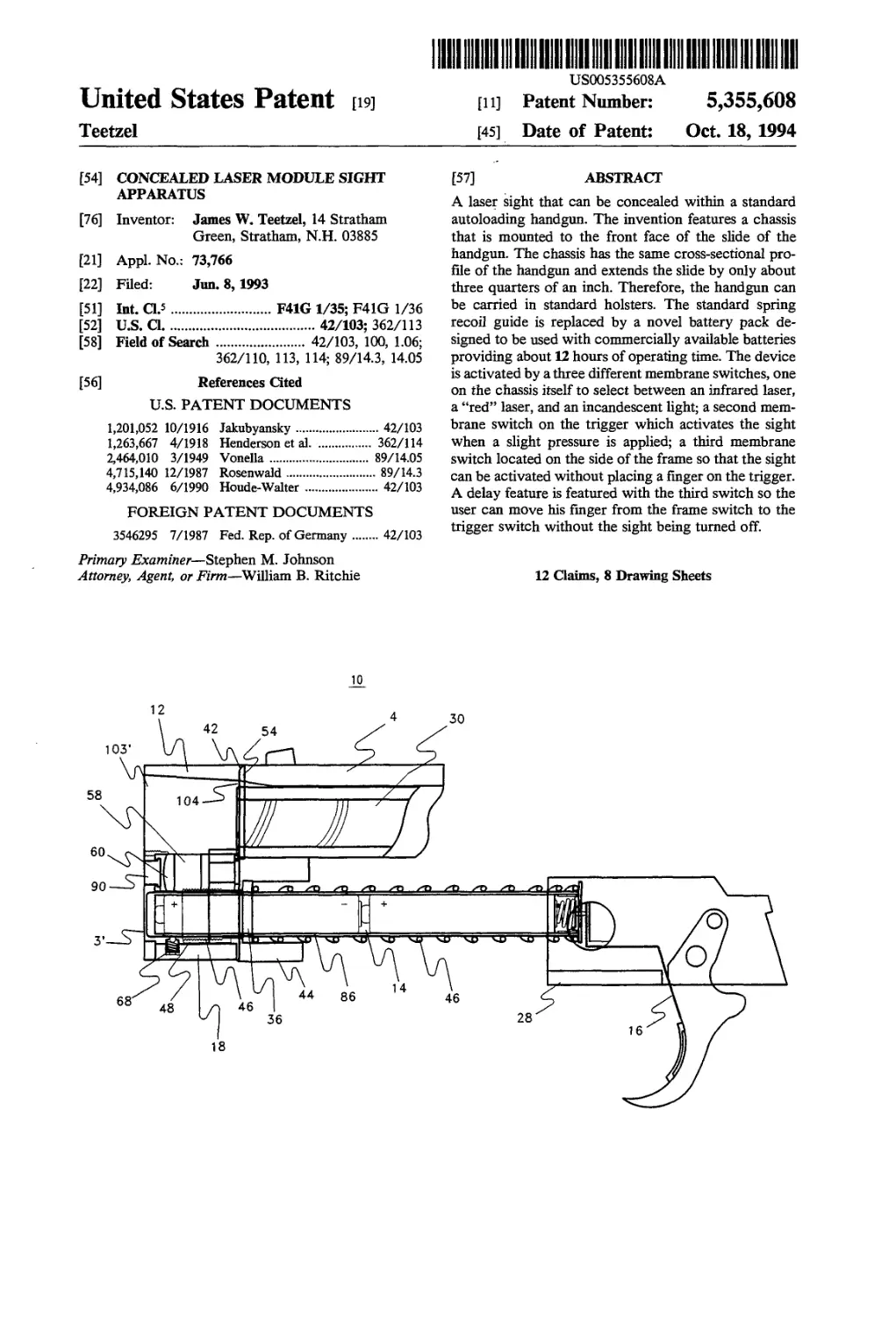
[57] ABSTRACT
A laser sight that can be concealed within a standard
autoloading handgun. The invention features a chassis
that is mounted to the front face of the slide of the
handgun. The chassis has the same cross-sectional pro-
file of the handgun and extends the slide by only about
three quarters of an inch. Therefore, the handgun can
be carried in standard holsters. The standard spring
recoil guide is replaced by a novel battery pack de-
signed to be used with commercially available batteries
providing about 12 hours of operating time. The device
is activated by a three different membrane switches, one
on the chassis itself to select between an infrared laser,
a “red” laser, and an incandescent light; a second mem-
brane switch on the trigger which activates the sight
when a slight pressure is applied; a third membrane
switch located on the side of the frame so that the sight
can be activated without placing a finger on the trigger.
A delay feature is featured with the third switch so the
user can move his finger from the frame switch to the
trigger switch without the sight being turned off.
12 Claims, 8 Drawing Sheets
U.S. Patent
Oct. 18, 1994
Sheet 1 of 8
5,355,608
\ j
U.S. Patent
Oct. 18, 1994
Sheet 2 of 8
5,355,608
FIG.
U.S. Patent Oct. 18, 1994 Sheet 3 of 8 5,355,608
52
FIG. 3
36
U.S. Patent
Oct. 18, 1994
Sheet 4 of 8
5,355,608
FIG,
U.S. Patent
Oct. 18, 1994
Sheet 5 of 8
5,355,608
FIG.
U.S. Patent
Oct. 18, 1994
Sheet 6 of 8
5,355,608
FIG. 7
U.S. Patent
Oct. 18, 1994 Sheet 7 of 8
5,355,608
FIG. 8
58
98
FIG. 10
58
FIG. 9
U.S. Patent Oct. 18, 1994 Sheet 8 of 8 5,355,608
5,355,608
1
CONCEALED LASER MODULE SIGHT
APPARATUS
BACKGROUND OF THE INVENTION
1. Field of the Invention
The invention relates to laser sights for use on small
firearms, particularly semi-automatic handguns.
2. Description of the Related Art
It is well known that even skilled marksman with a
handgun have been unable to hit a target as close as 7
meters when attempting to draw the weapon and fire at
speed. In target shooting, the shooter must obtaining
the proper stance by carefully positioning the feet and
the “free” hand to find the most stable condition, pro-
ducing no muscular strain that will adversely effect the
accuracy of the shot. Most importantly, the shooter
must be able to obtain an identical position each time the
weapon is fired to achieve the greatest accuracy. As the
whole upper torso moves during each breath, breath
control plays a vital role in the process. Since there can
be no body movement at the time the trigger is fired,
obviously the act of breathing must be stopped during
the time the weapon is aimed and fired.
Sight picture and aim are critical if the shooter is to
fire the most accurate shot or series of shots. When a
mechanical pistol sight is properly aligned, the top of
the front sight should be level with the top of the rear
sight, with an equal amount of light on either side of the
front sight. Using this sight picture requires that the
shooter focus his shooting eye so that the sights are in
focus and the target is out of focus. Added to the diffi-
culty, the trigger, all of the above must be maintained
while the trigger is released using direct, even pressure
to keep the barrel of the gun pointing at the target.
These skills require tremendous practice, with each shot
fired needing the utmost concentration if the shooter is
to obtain maximum accuracy.
It is clear that the recommended methods of achiev-
ing maximum shooting accuracy useful for target shoot-
ing, must be severely modified when a handgun is used
in a law enforcement situation. While the degree of
accuracy necessary for target shooting and the dis-
tances and substantial lower, accuracy is still vital. Law
enforcement official are instructed to fire only as a last
resort, cognizant of the fact that their intended target
will mostly be killed. Shooting to wound occurs only in
the movies. Law enforcement officers typically use
higher caliber handguns, mostly 9 mm, which are de-
signed to immobilize with a single shot if that shot
strikes a vital area. Given the inherent inaccuracies in
the shooting process itself, exacerbated by the stress and
fear of the police officer in what may be a life threaten-
ing situation for him/her, the exact location of the bullet
where millimeters can mean the difference between
death and survival cannot be known a priori by the even
the most skilled marksman.
Mechanical sights have limited value in many situa-
tion where an officer must quickly draw his gun, per-
haps while moving, and fire at a close target without
sufficient time to properly obtain a sight picture. Under
these circumstances, instinctive aiming, that is, not
using the sights but rather “feeling where the gun barrel
is pointing using the positioning of the hand holding the
gun, is the preferred method. While this method, akin to
the typical television cowboy shootouts, can be reason-
ably effective at short distances, obviously large errors
in aiming are easily introduced, especially when the
5
10
15
20
25
30
35
40
45
50
55
60
65
2
officer must frequently fire his/her weapon from a dif-
ferent hand position that has been used for practice. For
example, bullet proof shields are used to protect the
officer from being fired upon such as in a riot situation.
In those circumstance, the officer must reach around
his/her shield or other barricade and instinctively aim
and fire his/her gun with the handgun in a very differ-
ent orientation that would be experience if fired from a
standing, drawn from a holster position. Small changes
in barrel orientation due to the sight radius of the typi-
cal law enforcement handgun can produce substantial
errors relative to the target. Accurate instinctive shoot-
ing is not considered practical beyond 20 feet for the
average shooter.
A solution to this problem has been the introduction
of laser sights for use with handguns. The typical laser
sight is mounted on the top on the handgun or on the
bottom. The laser sight when properly aligned, places a
red light dot on the target where the bullet will strike if
the gun is fired. Using this type of sight, enables the law
officer to rapidly instinctively properly position the
weapon and be certain of his/her intended target. Using
a laser sight enables accurate shots to be fired at dis-
tances of more than 50 feet, sufficient for most combat
law enforcement situations requiring the use of hand-
guns.
U.S. Pat. No. 4,934,086, issued to Houde-Walter on
Jun. 19, 1990, discloses installing the laser sight within
the recoil spring guide. The iise of the recoil spring
guide to house the laser sight components enables the
firearm to be bolstered in a normal manner. The use of
the spring recoil guide presents alignment problems to
ensure accuracy. In other words, the laser within the
recoil guide is difficult to align with the barrel of the
firearm. Therefore, misalignment of the sight resulting
in poor accuracy is likely.
However, prior art laser devices have several disad-
vantages. As they are mounted either on the top or the
bottom of the weapon, the balance of the gun is dis-
turbed which makes it more difficult for the shooter to
rapidly use his/her instinctive sighting technique to
move gun into alignment for hitting the desired target.
Also, since prior art laser sights are very bulky in com-
parison to traditional mechanical sights, the weapon
cannot be used in a standard holster. Further, the laser
sight is extremely vulnerable to being hit due to extend-
ing substantially beyond the normal profile of the
weapon and thereby misalignment of the sight and de-
feating the advantages offered by the laser sight. A laser
sight capable of being installed in a semi-automatic
handgun, easily and accurately adjustable, is not dis-
closed in the prior art.
SUMMARY OF THE INVENTION
It is an object of the invention to provide a laser
module sight apparatus that is completely concealed
within the standard framework of the handgun.
It is another object of the invention to provide a laser
module sight apparatus that can be retrofitted to stan-
dard semi-automatic handguns.
It is still another object of the invention to provide a
laser module sight apparatus that enables the gun to be
used with standard holsters designed for that particular
weapon.
It is still another object of the invention to provide a
laser module sight apparatus that can be fitted to vari-
5,355
3
ous semi-automatic handguns requiring a minimum re-
placement of standard parts.
It is another object of the invention to provide a laser
module sight apparatus that can easily adjusted by the
user to permit accurately alignment of the laser sight 5
with the barrel of the gun.
It is another object of the invention to provide a laser
module sight apparatus that can be inexpensively pro-
duced using primarily commercially available parts.
It is another object of the invention to provide a laser 10
module sight apparatus that can incorporate an infrared
diode that makes the dot invisible to the naked eye, but
clearly visible using standard night vision equipment.
It is still another object of the invention to provide a
laser module sight that can easily substitute a flashlight 15
bulb in place of the laser diode.
It is another object of the invention to provide a laser
module sight apparatus that is extremely light compared
to existing lasers and their mounts.
It is still another object of the invention to provide a 20
laser module sight apparatus that can be activated from
a trigger switch or a frame mounted switch.
It is another object of the invention to provide a laser
module sight apparatus that can be powered by com-
mercially available batteries, providing at least several 25
hours of service time before needing to be changed.
It is another object of the invention to provide a laser
module sight apparatus that will incorporate a delay
when the frame mounted switch is deactivated before
the laser is turned off, thus permitting time for the user 30
to activate the trigger switch without losing sight on the
target.
Finally, it is another object of the invention to pro-
vide a laser module sight apparatus that eliminates the
need for a pressure pad on the grip handle which is 35
awkward when holding the gun and requires adjust-
ments to the shooter’s grip to keep the laser off while
maintaining stability.
The invention is a laser sight for an autoloading hand-
gun, said handgun having a barrel and a spring recoil 40
guide, a trigger, a frame, a slide having a cross-sectional
profile with a front face having two holes therein, with
one hole corresponding to the diameter of the barrel
and the other hole corresponding to the diameter of the
spring recoil guide. The invention has a chassis, having 45
a cross-sectional profile corresponding to the cross-sec-
tional profile of the slide of said handgun, said chassis
having a front face, a back face, and having two holes
extending therethrough from the back face to the front
face of said chassis, with the holes corresponding to the 50
holes in the front face of the slide of said handgun, with
said chassis having at least one light source wherein the
light of said fight source is emitted from the front face of
said chassis, and with the back face of said chassis se-
curely mounted on the front face of the slide of said 55
handgun.
BRIEF DESCRIPTION OF THE DRAWINGS
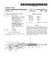
FIG. 1 is a breakdown view of typical autoloading
handgun, in this, the SIG Model P228. 60
FIG. 2 is a cross-sectional view of the laser diode
sighting system attached to the autoloading handgun
shown in FIG. 1 in accordance with the invention.
FIG. 3 is a detailed cross-sectional view of the sight-
ing system chassis locked to the slide of the typical 65
handgun.
FIG. 4 is a detailed isometric view of the chassis
bushing.
,608
4
FIG. 5 is a front isometric view of chassis.
FIG. 6 is a cross-sectional view of the batten pack.
FIG. 7 is a detailed view of the trigger switch.
FIG. 8 is a detailed flattened view of the membrane
control switch.
FIG. 9 is rear view of the chassis showing the retainer
member in place.
FIG. 10 is cross-sectional view of the laser module
assembly within the chassis.
DETAILED DESCRIPTION OF THE
INVENTION
FIG. 1 is breakdown view of a typical autoloading
handgun which can be adapted to incorporate a con-
cealed laser module sight in accordance with the inven-
tion. The pistol shown is SIG-SAUER Model P228, 9
mm, with a 13 cartridge clip or magazine 101. This
particular pistol has been adopted by numerous military
and law enforcement agencies as the weapon of choice
because of its large magazine.capacity, reliability, and
accuracy. In operation, slide 4, guided by recoil spring
guide 2 and tensioned by recoil spring 46, is slid back-
wards along frame 45, tensioning recoil spring 46. Bar-
rel 30 and recoil spring guide 2 extend through barrel
hole 103 and recoil spring guide hole 3 respectively.
Once slide 4 is released, spring 46 causes slide 4 to move
forward, strip a round (not shown) from magazine 101,
and place the cartridge into the firing chamber of barrel
30. When slide 4 is in its most forward position on frame
45, recoil spring guide 2 and barrel 30 are substantially
flush with front face 104 of slide 4 via their respective
holes 3 and 103.
Some autoloading handguns, such as the Colt Gov-
ernment Model 45 (not shown), incorporate a barrel
bushing that positions barrel 30 within barrel hole 103
of slide 4. The barrel bushing in that model extends
slightly beyond the front face 104 of slide 4. Other, such
as the S & W Model 39, incorporate a barrel bushing
that also acts as a bushing for recoil spring guide 2. The
S & W bushing occupies a substantial portion of the
front face 104 of slide 4. However, the invention can be
adapted to fit any autoloading handgun by merely mak-
ing minor changes as will be shown later.
The invention takes advantage of the basic design of
this type of firearm. Recoil spring guide 2 is modified to
house a concealed battery compartment to power a
laser that is mounted in a chassis, adapted to be attached
to the front face 104 of slide 4. Further, the chassis is
provided with holes corresponding to barrel hole 103
and spring recoil guide hole 3 so that the normal func-
tioning of the firearm does not have to altered. This
enables the handgun to function in every respect the
same as a firearm not equipped with laser sight if the
sight is not turned on. Yet, when the laser sight is
needed, the invention is easily activated by a conve-
niently placed switches will be discussed below.
FIG. 2 is a cross-sectional view of the laser diode
sighting system 10 attached to the autoloading handgun
shown in FIG. 1 in accordance with the invention. The
laser diode sighting system 10 has five subsystems, laser
diode chassis 12, retaining bushing 36, membrane switch
18, recoil spring guide battery pack 14 and the trigger
switch 16.
The laser diode chassis 12 is dimensioned to have the
same profile as slide 4. Chassis 12 also has holes 103' and
3' that correspond to barrel hole 103 and spring recoil
guide hole 3. Since the barrel 30 of the Sig Model P288
tilts upward when slide 4 is in the fully retracted posi-
5,355,608
5
tion, hole 103' is modified accordingly. Also, hole 3' is
dimensioned to allow recoil spring guide 2 to slide
through when slide 4 travels backwards.
Since system-10 mounts on the front face 104 of slide
4, little modification of the handgun is required. The
major internal modification is replacing the standard
spring recoil guide 2 with battery pack 14.
Chassis 12 is held in place on front face 104 by means
of retaining bushing 36. As shown, chassis 12 mounts on
the front slide face 104 of the slide 4. Retaining bushing
36 extends from the inside the spring housing 44 of the
slide 4 out through the recoil spring guide hole 3 where
as the threads 46 extended out, screw into the chassis
threaded hole 48 in chassis 12. Bushing 36 has an open-
ing 51 that corresponds to diameter of battery pack 14
so that battery pack 14 may easily slide therethrough.
Bushing 36 holds the back surface 52 of chassis 12
snug against the front slide face 104 of the slide 4. As
shown in the detail FIG. 3, locking radiuses 54 prohibit
the laser diode chassis 12 from rotating by matching
with radius 56 on front of slide 4. This is a preferred
method. Other methods may be by gluing, pinning,
notching, etc. depending on the configuration of the
front face 104 of slide 4. For example, for handguns that
use a barrel bushing, a second bushing may be used in
addition to bushing 36 or in lieu of, to hold chassis 12
firmly in place.
Laser diode chassis 12 is preferably made of a heat
treatable steel material. This would make a more dura-
ble housing to resist against damage. However, other
materials for chassis 12 are also suitable such as hard
plastic and aluminum.
Lens protector 90 will be glued in from the inside of
the laser diode chassis 12. Lens protector 90 is prefera-
bly made of material that is clear to allow a light beam
to travel through it without distorting it and will resist
flash bums, residue, abrasion and keep water and dirt
from getting into the laser diode chassis 12. Clear glass
would be a preferable material.
As shown in FIG. 4, retaining bushing 36 is prefera-
bly made of a high tensile stainless steel that resists
cracking. Slot 50 in retaining bushing 36 allows for ease
of installation with a screwdriver.
FIG. 5 is a front isometric view of chassis 12 and
membrane switch 18. Chassis 12 houses one or more
laser diode lights 58 with a collimating lens 60 (shown
in FIG. 2). Laser diode light 58 with a collimating lens
60 is preferably the type manufactured by Roam or
Lyte Obtronics. It should be recognized that light 58
could also be a standard incandescent bulb to act as a
flash fight. The laser diode light 58 with a collimating 60
can be positioned anywhere on the face 64 of the chas-
sis. However, the preferable placement is as shown with
one light opening 58 emitting a red beam and the other
light opening 58 emitting an infrared beam to be de-
tected by night vision goggles.
The precise positioning of lights 58 can be manipu-
lated by turning in and out three socket head set screws
110 equally spaced located on face 64. Socket head set
screws 110 are preferably 2-56 UNEF socket head set
screw modified with chamfer. This allows wedging
along surface light 58 thereby aligning laser diode light
58 with collimating lens 60 in relation with barrel 30.
The preferred method of mounting the chassis to the
slide limits the amount of stack-up tolerances in relation
to the laser diode and the center fine of the barrel,
whereas, prior art devices mount the diode in other
locations, such below the slide or in the recoil guide,
5
10
15
20
25
30
35
40
45
50
55
60
65
6
which may substantially effect the accuracy of the
sighting apparatus.
By enabling the shooter to easily adjust alignment of
the laser diode light 58 in relation with the barrel, the
shooter can reflect his/her personal shooting habits
such as pulling the pistol to one side when the trigger is
pulled.
Referring again to FIG. 2, laser diode 58 with a colli-
mating lens 60 could also be positioned off from the
centerline of the barrel 30 and reflected out of light
opening by using a prism.
The exact placement and orientation of the laser di-
odes within chassis 12 and light openings 58 can be
varied as long as face 64 of chassis 12 does not extend
greater than the face 104 of slide 4. When the gun is
fired, and it recoils, the slide 4 travels backward with
the frame 45 as is shown in FIG. 1. Clearance is re-
quired between chassis 12 and cavity 66 of frame 45.
Referring now to FIG. 6, the details of battery pack
14 and its operation will be presented. The invention
requires a recoil spring guide battery pack 14 to ener-
gize the laser diode chassis 12. Battery pack 14 is electri-
cally connected to frame 45 via springloaded electric
contact pin 68 as shown in FIG. 2. Spring-loaded elec-
tric contact pin 68 is required so that when the gun is
fired and the slide 4 with the laser diode chassis 12
attached will ride along the surface housing 86.
Pin 68 is the preferred method, however, a roller, or
a deformed piece of metal could be used to contact the
front cap 70 of the recoil spring guide battery pack 14.
The electric operation requires the gun to become the
ground or negative charge. This is accomplished by
having a battery insulator 72, insulate the positive
charge from the main housing 86 of the recoil spring
battery pack 14. The negative charge of the recoil
spring battery pack 14 is insulated in the same fashion.
Battery pack 14 has a front cap 70 preferably a heat
treated steel, that is bonded to a non conductive mate-
rial preferably black DELRON or ABC polymer plas-
tic material called battery insulator 72. The battery
insulator 72 is then bonded to the main housing 86.
Preferred material is heat treated steel. The wall thick-
ness is relatively thin to minimize the overall diameter
of the recoil spring guide battery pack 14.
Two H volt batteries 40 preferably EVERREADY
E96VP will be replaceable by unscrewing spring cap
126 from main housing 74. The spring cap 126 will
house the aft insulator 76, a contact point 78 preferably
brass that is tin plated to prevent corrosion, and a spring
128. The spring 128 takes up whatever distance there
may be caused by manufacturing tolerances of the
AAAA battery 40. Spring 128 will be attached to
contact point 78 by soldering as preferred method.
Spring 128 also serves as a shock absorber to counter
the recoil shock when the firearm is discharged.
Contact point 78 will be bonded to aft insulation 76
using epoxy as preferred method. Aft insulation 76 will
be bonded to spring cap in a similar fashion.
This is insulated by aft insulation 76 allowing only for
the main housing 86 to have a negative charge when the
trigger switch is activated.
Referring now to the FIG. 7, the contact point 78
allows for a circuit to be complete when the laser is
activated by depressing trigger membrane switch 80 on
trigger 136 . A closed circuit is present across face 82.
Face 82 then creates a circuit through surface contact
84 (shown in FIG. 6). This is a preferred method of
switching. There are many other ways by means of
5,355,608
7
switching using a phototransducer/LED switch, a
transmitter/receiver, etc. As shown in FIG. 7., trigger
switch 16 is a membrane switch with electric terminals
130. The pad 32 will be bonded to the take down re-
tainer 132 with the preferred method of bonding being
epoxy. The take down retainer 132 snaps in the cavity
133 of take down lever 134 (shown in FIG. 1) with the
loose electric terminal 130 it allows the shooter to rotate
the take down lever 134 to strip the slide 4 from the
frame 45. This is a normal operation to clean the gun.
The pad 80 is bonded to the trigger 136 using a sticky
backed paper. Pad 80 is a pressure sensitive switch
which is in the “on” condition when the shooter presses
pad 80 and is in the “off’ when released.
A second pad 81 can be mounted to frame 45 so that
sight 10 can be activated without the shooter placing a
finger on the trigger 136. The placement of pad 81 will
depend on whether the shooter is right or left-handed.
Pad 81 can also activate sight 10. However, when pad
81 is released, a slight delay, supplied by membrane
switch 18, occurs before the sight is shut-off, thus giving
the shooter time to activate the sight using pad 80. This
prevents the shooter from losing his/her sight picture of
the target in the brief time it takes for the shooter to
move his/her finger from pad 81 to pad 80.
FIG. 8 is a detailed flattened view of the membrane
control switch. Membrane control switch 18, prefera-
bly made of shock resistant plastic molded chassis with
built-in switching circuitry such as manufactured by
SPECTRA SYMBOL. Membrane switch 18 acts as an
electrical circuit to energize and control the infrared
and/or visible laser. On buttons 120, and off buttons 122
allow the shooter to preselect an environmental condi-
tion or switch hit back, if the shooting conditions
change. Membrane switch 18 also accommodates laser
warning labels 124 as shown. Membrane switch 18 pro-
vides connection to laser diode 58 via electrical contacts
96. Membrane switch 18 is preferably bonded to chassis
12 using epoxy.
FIG. 9 is rear view of chassis 12 showing the retainer
38. The “dog bone” shaped retainer 38 is preferably
made of heat treatable steel will be fastened down by a
socket head cap screw 98 and a locating pin 100. The
purpose of retainer 38 is to hold diode 58 in place in
chassis 12 (shown in outline) and to ensure that a good
electrical contact is made. Pocket 114 will allow a space
for the membrane switch 18 to lay into when assembled.
Referring now to FIG. 10, laser diode light 58 will
have one negative lead 104 that will ground to retainer
38 on surface 94 (shown in FIG. 9) and a positive lead
106 that will contact with switch contact 96 of mem-
brane switch 18 (shown in FIG. 8) when assembled in
place. Retainer 38 will also allow the back end 102 of
the laser diode light 58 to pivot when adjusted using
alignment screws 110.
While there have been described what are at present
considered to be the preferred embodiments of this
invention, it will be obvious to those skilled in the art
that various changes and modifications may be made
therein without departing from the invention and it is,
therefore, aimed to cover all such changes and modifi-
cations as fall within the true spirit and scope of the
invention.
What is claimed is:
1. A laser sight for an autoloading handgun, said
handgun having a barrel and a spring recoil guide, a
trigger, a frame, a slide having a cross-sectional profile
with a front face having two holes therein, with one
hole corresponding to the diameter of the barrel and the
5
10
15
20
25
30
35
40
45
50
55
60
65
8
other hole corresponding to the diameter of the spring
recoil guide, said laser sight comprising:
a chassis, having a cross-sectional profile correspond-
ing to the cross-sectional profile of the slide of said
handgun, said chassis having a front face, a back
face, and having another two holes extending
therethrough from the back face to the front face of
said chassis, with said another two holes corre-
sponding in positional alignment to the holes in the
front face of the slide of said handgun, with said
chassis having at least one light source;
a battery pack dimensioned to fit within the spring
recoil guide of said handgun and to power said
light source; wherein the fight of said light source
is emitted from the front face of said chassis, and
with the back face of said chassis securely mounted
on the front face of the slide of said handgun.
2. The laser sight of claim 1 further comprising a
retainer bushing to lock said chassis to the front face of
the slide of said handgun.
3. The laser sight of claim 2 further comprising a first
membrane switch, attached to said chassis, wherein said
switch electrically connects said light source to said
battery pack.
4. The laser sight of claim 3 further comprising a
second membrane switch, attached to the trigger of said
handgun, wherein a user may activate said light source
by pressing on said second membrane switch with a
pressure sufficient to cause said second membrane
switch to make contact but insufficient pressure to
cause said handgun to fire.
5. The laser sight of claim 4 further comprising a third
membrane switch, attached to the frame of said hand-
gun, wherein the user may activate said fight source by
pressing on said third membrane switch.
6. The laser sight of claim 5 further comprising delay
means for delaying the time that said fight source is
turned off once the user releases pressure on said third
switch, with the delay time sufficient in duration to
allow the user to press said second membrane switch to
permit continuous operation of said light source.
7. The laser sight of claim 6 wherein the light of a
second light source is emitted from the front face of said
chassis wherein the fight of the second fight source is
visible only when viewed with night vision goggles.
8. The laser sight of claim 1 wherein the light of a
second light source is emitted from the front face of said
chassis wherein the fight of the second light source is a
standard incandescent bulb to act as a flash light.
9. The laser sight of claim 7 wherein said battery pack
utilizes commercially available size AAAA batteries.
10. The laser sight of claim 9 wherein said battery
pack is electrically connected to the frame of said hand-
gun by a spring-loaded pin within said chassis such that
said pin maintains electrical contact with said battery
pack when said chassis recoils with the slide of said
handgun during firing.
11. The laser sight of claim 10 with said chassis fur-
ther comprising a first set of adjustment screws on the
front face of said chassis for said first fight source and a
second set of adjustment screws on the front face of said
chassis for said second light source, wherein said first
set of adjustment screws can align the fight from said
first light source relative to the position of the barrel of
said handgun and said second set of adjustment screws
can align the fight from said second light source relative
to the position of the barrel of said handgun.
12. The laser sight of claim 11 where said first mem-
brane switch further comprises at least one button that
can be activated by the user and select between said first
fight source and said second light source.
*****