/
Теги: weapons military affairs patent
Год: 1979
Текст
United States Patent [i9j
Allen
[ii] 4,151,782
[45] May 1, 1979
[54] HANDGUN WITH INDEXING MEANS
[76] Inventor: Edward A. Allen, 173 Highland Ave.,
Westfield, Mass. 01085
[21] Appl. No.: 809,022
[22] Filed: Jun. 22, 1977
[51] Int. Cl.2........................F41D7/04
[52] U.S. Q...................... 89/155; 42/1 S;
89/145; 89/161
[58] Field of Search ...... 89/155, 156, 157, 161;
42/10, 11
[56] References Cited
U.S. PATENT DOCUMENTS
726,109 4/1903 Stow ....................... 89/155
932,183 8/1909 Schwarzlose................. 89/161
1,487,722 3/1924 Coenders ................... 89/155
2,699,006 1/1955 Maerk ...................... 89/161
2,835,171 5/1958 Lyon ....................... 89/161
FOREIGN PATENT DOCUMENTS
10587 of 1886 United Kingdom .... 89/161
180238 5/1922 United Kingdom .. 89/161
Primary Examiner—Stephen C. Bentley
Attorney, Agent, or Firm—Chapin, Neal & Dempsey
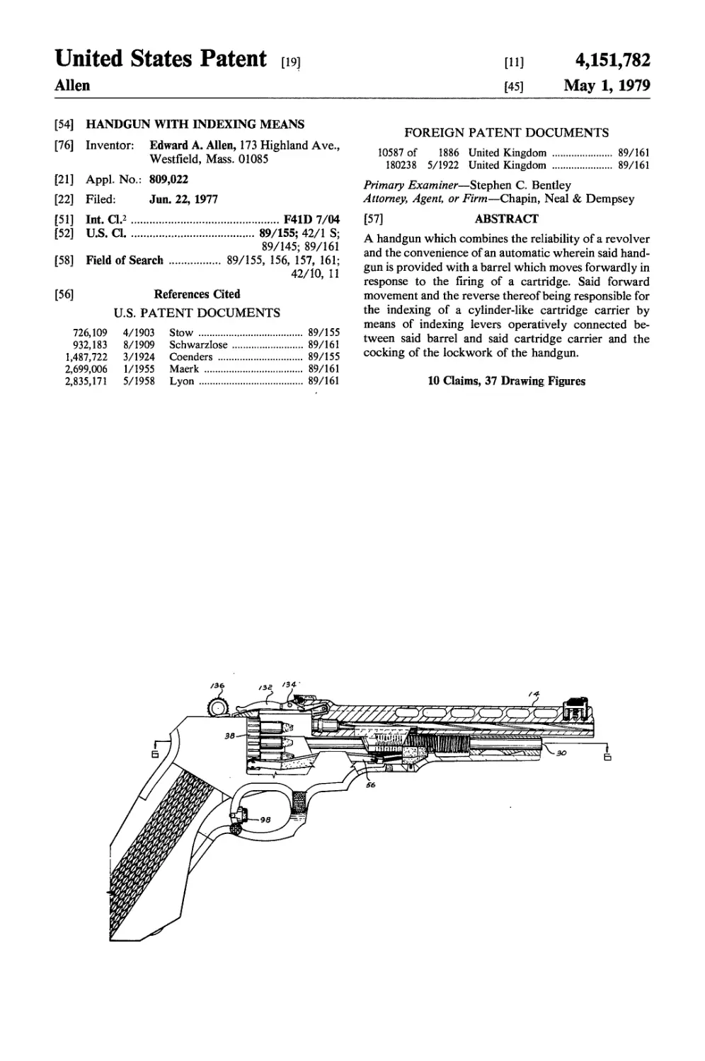
[57] ABSTRACT
A handgun which combines the reliability of a revolver
and the convenience of an automatic wherein said hand-
gun is provided with a barrel which moves forwardly in
response to the firing of a cartridge. Said forward
movement and the reverse thereof being responsible for
the indexing of a cylinder-like cartridge carrier by
means of indexing levers operatively connected be-
tween said barrel and said cartridge carrier and the
cocking of the lockwork of the handgun.
10 Claims, 37 Drawing Figures
I,
U.S. Patent May i, 1979
Sheet 1 of 7
4,151,782
Л__I
U.S. Patent May 1, 1979
Sheet 2 of 7 4,151,782
U.S. Patent May i, 1979
Sheet 3 of 7
4,151,782
U.S. Patent May i, 1979
Sheet 4 of 7
4,151,782
/г>4
4)
N
00
U.S. Patent May 1, 1979
Sheet 5 of 7
4,151,782
U.S. Patent May i, 1979
Sheet 6 of 7
4,151,782
U.S. Patent May 1, 1979
Sheet 7 of 7
4,151,782
4,151,782
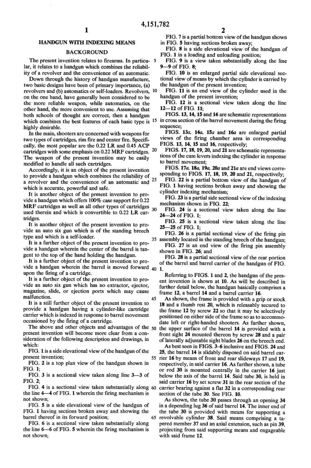
1
HANDGUN WITH INDEXING MEANS
BACKGROUND
The present invention relates to firearms. In particu-
lar, it relates to a handgun which combines the reliabil-
ity of a revolver and the convenience of an automatic.
Down through the history of handgun manufacture,
two basic designs have been of primary importance, (a)
revolvers and (b) automatics or self-loaders. Revolvers,
on the one hand, have generally been considered to be
the more reliable weapon, while automatics, on the
other hand, the more convenient to use. Assuming that
both schools of thought are correct, then a handgun
which combines the best features of each basic type is
highly desirable.
In the main, shooters are concerned with weapons for
two types of cartridges, rim fire and center fire. Specifi-
cally, the most popular are the 0.22 LR and 0.45 ACP
cartridges with some emphasis on 0.22 MRF cartridges.
The weapon of the present invention may be easily
modified to handle all such cartridges.
Accordingly, it is an object of the present invention
to provide a handgun which combines the reliability of
a revolver and the convenience of an automatic and
which is accurate, powerful and safe.
It is another object of the present invention to pro-
vide a handgun which offers 100% case support for 0.22
MRF cartridges as well as all other types of cartridges
used therein and which is convertible to 0.22 LR car-
tridges.
It is another object of the present invention to pro-
vide an auto six gun which is of the standing breech
type and which is a self-loader.
It is a further object of the present invention to pro-
vide a handgun wherein the center of the barrel is tan-
gent to the top of the hand holding the handgun.
It is a further object of the present invention to pro-
vide a handgun wherein the barrel is moved forward
upon the firing of a cartridge.
It is a further object of the present invention to pro-
vide an auto six gun which has no extractor, ejector,
magazine, slide, or ejection ports which may cause
malfunction.
It is a still further object of the present invention to
provide a handgun having a cylinder-like cartridge
carrier which is indexed in response to barrel movement
occasioned by the firing of a cartridge.
The above and other objects and advantages of the
present invention will become more clear from a con-
sideration of the following description and drawings, in
which:
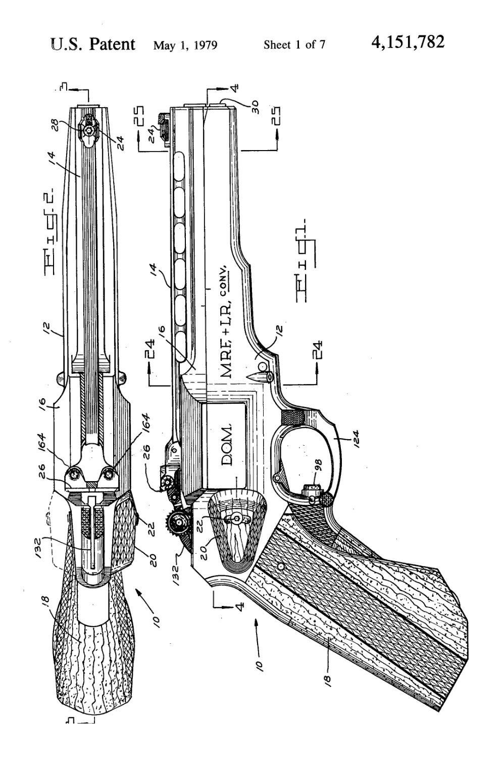
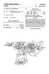
FIG. 1 is a side elevational view of the handgun of the
present invention;
FIG. 2 is a top plan view of the handgun shown in
FIG. 1;
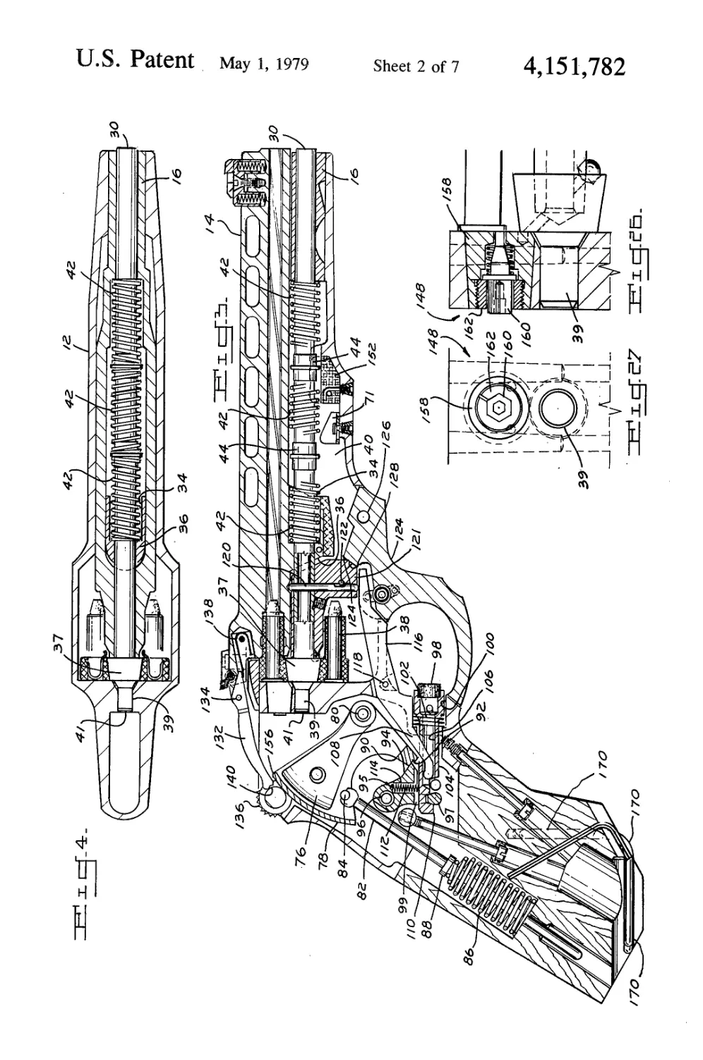
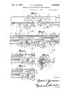
FIG. 3 is a sectional view taken along line 3—3 of
FIG. 2;
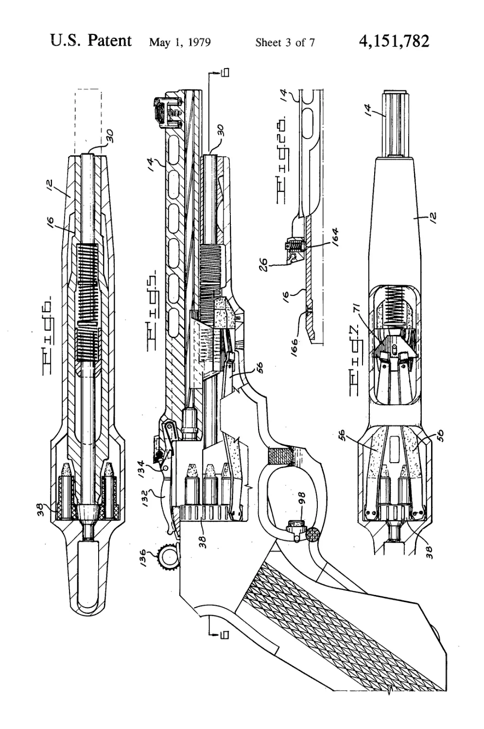
FIG. 4 is a sectional view taken substantially along
the line 4—4 of FIG. 1 wherein the firing mechanism is
not shown;
FIG. 5 is a side elevational view of the handgun of
FIG. 1 having sections broken away and showing the
barrel thereof in its forward position;
FIG. 6 is a sectional view taken substantially along
the line 6—6 of FIG. 5 wherein the firing mechanism is
not shown;
5
10
15
20
25
30
35
40
45
50
55
60
65
2
FIG. 7 is a partial bottom view of the handgun shown
in FIG. 5 having sections broken away;
FIG. 8 is a side elevational view of the handgun of
FIG. 1 in a loading and unloading position;
FIG. 9 is a view taken substantially along the line
9—9 of FIG. 8;
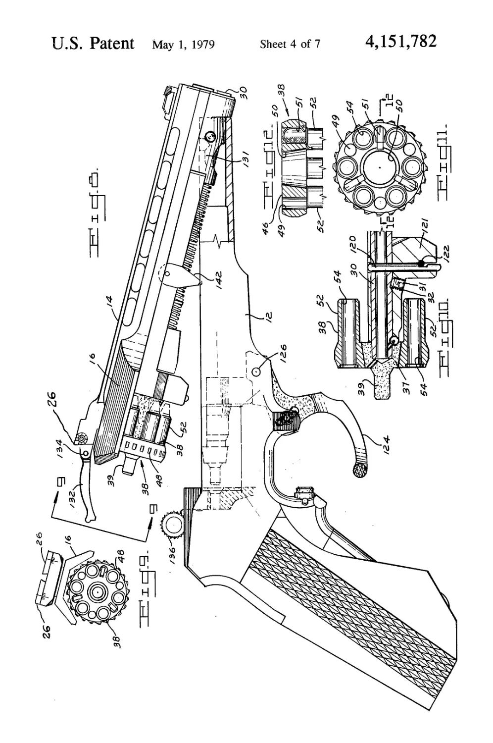
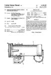
FIG. 10 is an enlarged partial side elevational sec-
tional view of means by which the cylinder is carried by
the handgun of the present invention;
FIG. 11 is an end view of the cylinder used in the
handgun of the present invention;
FIG. 12 is a sectional view taken along the line
12—12 of FIG. 11;
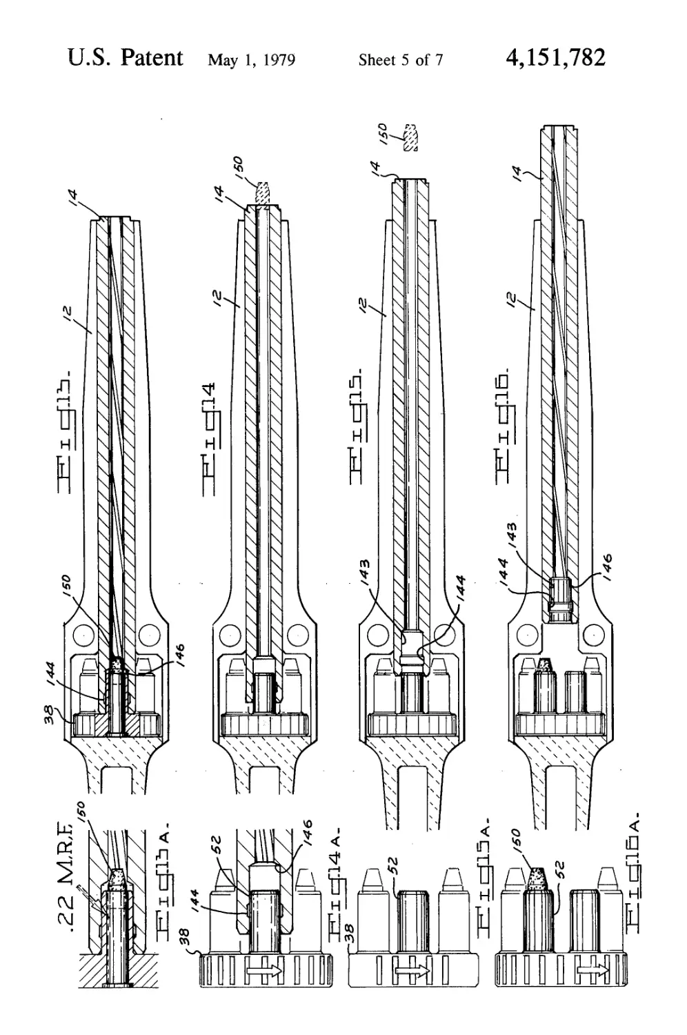
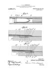
FIGS. 13,14,15 and 16 are schematic representations
in cross section of the barrel movement during the firing
sequence;
FIGS. 13a, 14a, 15a and 16a are enlarged partial
views of the firing chamber area in corresponding
FIGS. 13, 14, 15 and 16, respectively;
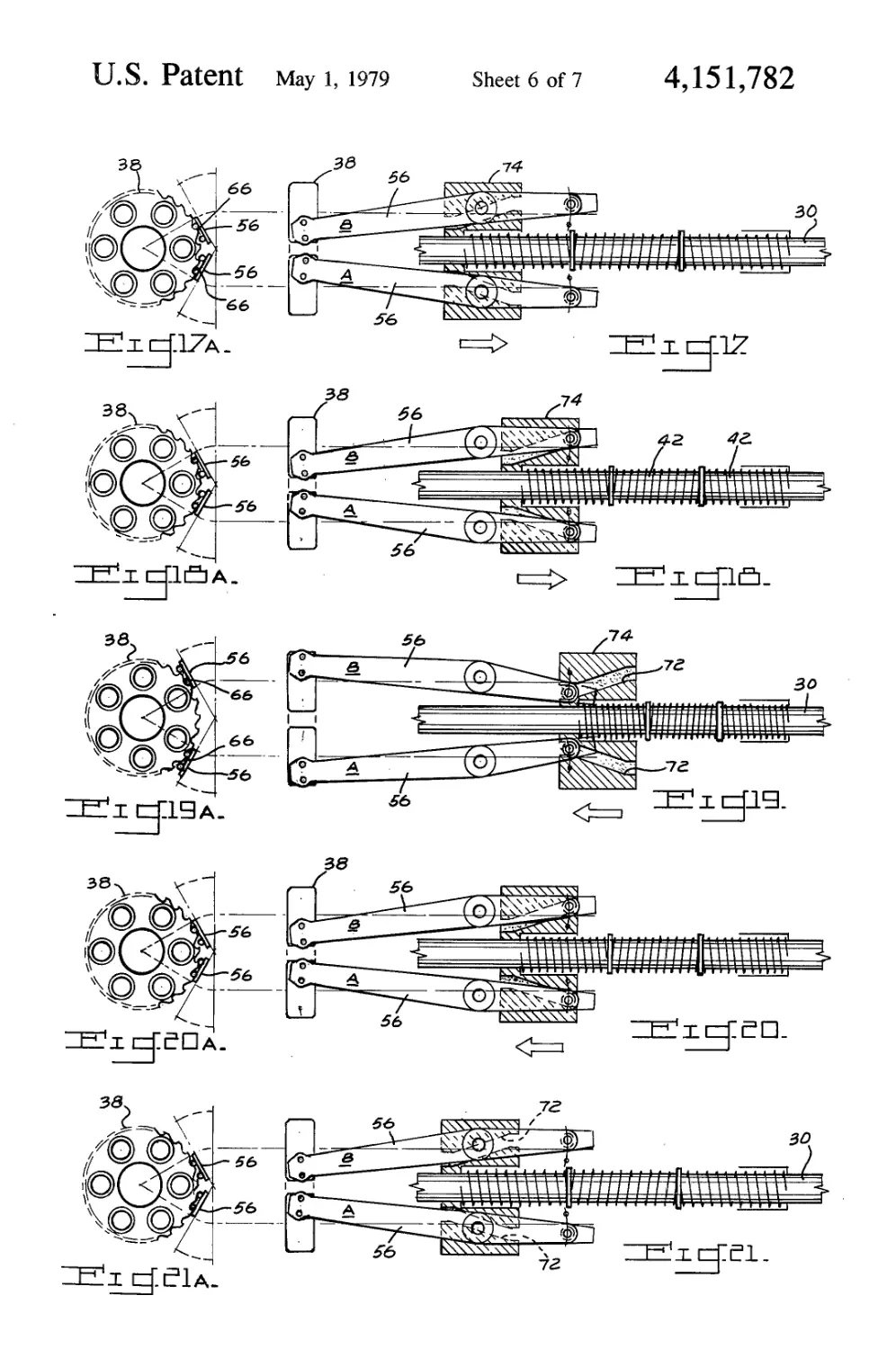
FIGS. 17,18,19, 20, and 21 are schematic representa-
tions of the cam levers indexing the cylinder in response
to barrel movement;
FIGS. 17a, 18a, 19a, 20a and 21a are end views corre-
sponding to FIGS. 17, 18, 19, 20 and 21, respectively;
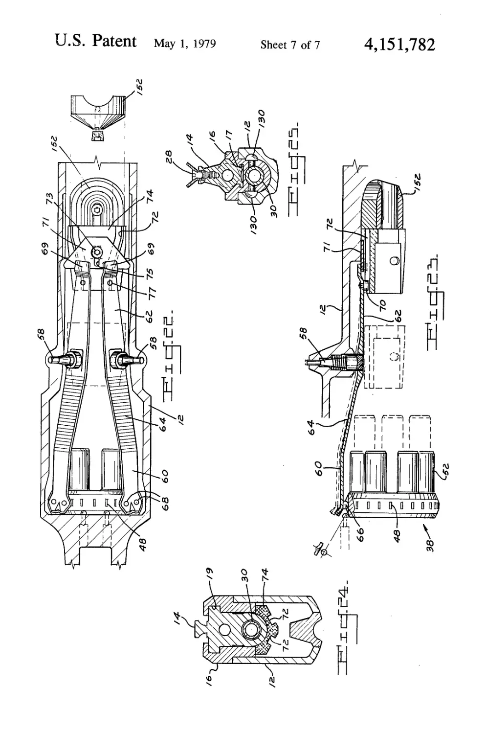
FIG. 22 is a partial bottom view of the handgun of
FIG. 1 having sections broken away and showing the
cylinder indexing mechanism;
FIG. 23 is a partial side sectional view of the indexing
mechanism shown in FIG. 22;
FIG. 24 is a sectional view taken along the line
24—24 of FIG. 1;
FIG. 25 is a sectional view taken along the line
25—25 of FIG. 1;
FIG. 26 is a partial sectional view of the firing pin
assembly located in the standing breech of the handgun;
FIG. 27 is an end view of the firing pin assembly
shown in FIG. 26; and
FIG. 28 is a partial sectional view of the rear portion
of the barrel and barrel carrier of the handgun of FIG.
1.
Referring to FIGS. 1 and 2, the handgun of the pres-
ent invention is shown at 10. As will be described in
further detail below, the handgun basically comprises a
frame 12, a barrel 14 and a barrel carrier 16.
As shown, the frame is provided with a grip or stock
18 and a thumb rest 20, which is releasably secured to
the frame 12 by screw 22 so that it may be selectively
positioned on either side of the frame so as to accommo-
date left or right-handed shooters. As further shown,
the upper surface of the barrel 14 is provided with a
front sight 24 mounted thereon by screw 28 and a pair
of laterally adjustable sight blades 26 on the breech end.
As best seen in FIGS. 3-6 inclusive and FIGS. 24 and
25, the barrel 14 is slidably disposed on said barrel car-
rier 16 by means of front and rear slideways 17 and 19,
respectively, in said carrier 16. As further shown, a tube
or rod 30 is mounted centrally in the carrier 16 just
below the axis of the barrel 14. Said tube 30, is held in
said carrier 16 by set screw 31 in the rear section of the
carrier bearing against a flat 32 in a corresponding rear
section of the tube 30. See FIG. 10.
As shown, the tube 30 passes through an opening 34
in a depending lug 36 of said barrel 14. The inner end of
the tube 30 is provided with means for supporting a
revolvable cylinder 38. Said means comprising a ta-
pered member 37 and an axial extension, such as pin 39,
projecting from said supporting means and engageable
with said frame 12.
4,151,
3
The tube 30, which lies partially within a cavity 40 of
the carrier 12, is provided with recoil means. Such
means takes the form of a plurality of springs 42 dis-
posed about said tube 30 and separated by slidably dis-
posed spacers 44. The recoil means is positioned on said 5
tube 30 between the forward end of the cavity 40 and
the rear wall of opening 34 in the depending lug 36 of
the barrel 14. Accordingly, the springs are compressed
by forward movement of the barrel 14, as will be ex-
plained below. 10
Referring now primarily to FIGS. 8-11 inclusive, it
will be noted that the cylinder 38 is unusual in design
and may more properly be referred to as a cluster of
bushings. In general, the cylinder comprises a cylindri-
cal base member 46 having a toothed periphery 48 of 15
fundamental ratchet form to permit rotation in only one
direction, and an axially tapered mounting aperture 50
for rotatably mounting the same on the cylinder support
means. As shown, the base member is provided with a
plurality of forward projecting members 52 which are 20
integral therewith. Cartridge receiving and supporting
apertures 54 are provided in each of said projections 52.
Said apertures 54 are designed so as to fully receive and
support a cartridge of specified size and shape. As fur-
ther shown, the base member 46 is also provided with a 25
plurality of additional apertures 49, some of which are
notched so as to snugly hold snap springs 51. Said snap
springs 51 extend forwardly of said base member 46 into
snap engagement with the cylinder support means to
hold said cylinder on said means. 30
With reference to FIGS. 5, 7, 22 and 23, it will be
noted that indexing means for the cylinder 38 is opera-
tively disposed between the barrel 14 and the cylinder.
As shown, such means comprises a pair of matched
levers 56 disposed for pivotal and oscillating movement 35
within the frame 12 beneath the barrel 14 on pins 58, the
ends of which are mounted in the frame 12. Each lever
56 is comprised of two offset sections 60 and 62 con-
nected by an inclined web 64. The breech end 60 of
each lever 56 is provided with hard hemispherical 40
pusher teeth 66, with shanks 68, which are designed to
mesh with the toothed periphery 48 of the cylinder 38.
The muzzle end 62 of each lever is provided with a
small offset section 69 which engages fulcrum plate 71
affixed to the frame 12 by screw 73 passing through 45
elongated slot 75 in said plate 71. Additionally, said
section 62 is provided with a cam follower 70 which is
disposed adjacent the offset section 69. Said cam fol-
lowers 70 are engageable with cam slots 72 of cam 74
which is attached to the bottom of the depending lug 36 50
of the barrel 14. The operation of the levers 56 will be
explained below.
The lockwork of the present handgun is best seen in
FIGS. 1, 2, 3 and 4. A hammer 76, which is of limited
motion, as will be described below, is disposed within 55
the general confines of a hammer shell 78. Both the
hammer 76 and the hammer shell 78 are pivotably
mounted on pin 80 which is journaled between the side
walls of the frame 12. The hammer shell is urged for-
wardly by the action of a push rod 82 which contacts a 60
pin 84 mounted between the sides of the shell 78 at the
rear thereof. Said push rod 82 extends downwardly into
the grip 18 where it functionally engages hammer
spring 86 via integral collar 88 on said rod 82. The shell
78 is also provided with a rearwardly extending projec- 65
tion 90 having a sear notch 92 thereon. The sear notch
92 is releasably engageable with sear 94 on member 95
which is pivotably disposed on pin 96 mounted between
,782
4
the side walls of the frame 12. Member 95 is also pro-
vided with a projection 97 which extends downwardly
and has passage 99 therethrough.
A trigger 98, which is shown as a button type which
may be made of rubber or the like is slidably disposed in
a cavity 100 in the frame and is urged forwardly by
spring 102. As shown, the trigger 98 has a rearward
rod-like member 104 which extends into the grip por-
tion of the weapon. Said rod-like member 104 is pro-
vided with an axially disposed cavity 106 and a slot 108
disposed in the top thereof which communicates with
said cavity 106. Said rod-like member 104 is also pro-
vided with means for engaging the projection 97 of the
member 95. As shown, said member 104 also has a
hooked end 110 which is passed through passage 99 of
said member 95. Said hooked end is urged downwardly
by springs 112 disposed in cavity 114 of said member 95.
Interrupter means is also associated with the lock-
work. To this end, an interrupter lever or bar 116 is
pivotally mounted in the frame 12 on pine 118 and has
one end thereof which extends through the slot 108 of
member 104 into the cavity 106 thereof. The opposite
end of the lever 116 is disposed beneath the cylinder 38
and contacts interrupter pin 120 which is slidably dis-
posed in a hole vertically disposed in a depending por-
tion 121 of the barrel carrier 16. (See FIG. 10.) The
interrupter pin 120 which is normally urged upwardly
by lever 116 is maintained in place by transverse pin 122
which engages a notch in the interrupter pin 120.
Referring to FIGS. 3 and 8, it will be noted that the
trigger guard 124 is a lever which is pivotally mounted
on pin 126 disposed in the lower part of the frame 12.
While the guard does in fact guard the trigger 98, it also
provides the means by which the weapon may be
opened and closed for loading, unloading and cleaning
purposes. As will be noted, the lever is provided with a
boss 128 which while in contact with the forward end
of depending portion 121 of the barrel carrier 16, se-
curely locks the weapon against opening.
When lever 124 is pulled downward, the boss 128
clears the depending portion 121, thus permitting the
barrel carrier 16 and the barrel 14 to be slid forward on
round end hinge pins 130 in T-slots 131 a distance suffi-
cient to allow the pin 39 to clear its aperture 41 in the
frame 12. At this point, the barrel 14 and the barrel
carrier 16 may be pivoted about hinge pins 130 (FIG.
25) adjacent the muzzle end of the weapon to the posi-
tion shown in FIG. 8.
The hinge pins 130, which are pressed into the for-
ward end of the barrel carrier, engage identical T-slots
131 on either side of the frame 12 and may be so posi-
tioned therein so as to enable the barrel carrier to be
completely removed from the frame.
As shown in FIGS. 1, 2 and 3, cocking means for the
hammer 76 is provided by a cocking finger 132 pivot-
ally mounted on the top rear end of the barrel 14 on pine
134. the finger 132 extends rearwardly towards the
hammer shell 78 passing between the bifurcated ham-
mer spur 136. As the rear portion of the finger 132 is
urged downward by the action of spring 138 contacting
the underside of the opposite end thereof, the rearward
free end of the finger 132 which is provided with notch
140 is engageable with the top forwardmost portion of
the shell 78. As will be explained below, the contact
between the shell 78 and the finger 132 provides the
cocking action for the lock mechanism.
4,
5
OPERATION
The operation of the firearm of the present invention
is intricate yet precise. With the weapon in its open
position as shown in FIG. 8, a cylinder 38 having car- 5
tridges inserted therein is positioned on the tapered
member 37. When so loaded, the props 142 are pushed
inwardly and the barrel and barrel carrier 14 and 16,
respectively, pivot into the frame 12 about hinge pins
130, and the pin 39 brought into engagement with pin 10
receiving aperture 41 in the standing breech portion of
the frame 12. The barrel carrier 16 is secured in this
position by the action of boss 128 contacting the for-
ward portion of depending lug 121 of the barrel carrier
when lever 124 is drawn to a closed position, such as 15
shown in FIG. 3.
As also shown in FIG. 3, the breech end of the barrel
14 has received one of the forwardly projecting mem-
bers 52 of the cylinder 38 with cartridges disposed in
the cartridge receiving apertures 54 thereof. As best 20
seen in FIG. 13a, the member 52 is slidably engageable
with counterbore 143 in the breech end of the barrel 14.
The counterbore 143, which is provided with a gas seal
144, extends beyond the end of the member 52 and
terminates in shoulder 146, thus creating a gas trap.- The 25
presence of the gas trap and the shoulder 146 provides
the means by which the barrel 14 is actuated forwardly
as will be explained below.
With the weapon so loaded, it is prepared for firing
by cocking the hammer 76 by rearward actuation of the 30
hammer shell 78 by hammer spur 136. This action
causes hammer spring 86 to be depressed and sear 94 to
engage the sear notch 92. This condition of readiness is
shown in FIG. 3.
In order to fire the weapon, the trigger 98 is de- 35
pressed, which causes the sear notch 92 and the sear 94
to disengage in response to the rearward movement of
member 104 against projection 97 of member 95. This in
turn releases the hammer shell 78 with the floating
hammer 76 therein which is urged against the firing pin 40
assembly 148, shown in FIGS. 26 and 27. Said assembly
comprises a plug 158 bored to receive a spring loaded
firing pin 160 which is held in said bore by collar 162.
The firing pin assembly which is depicted as a rim fire
assemblage contacts the rear of the cartridge causing 45
the same to fire.
Upon firing, the subsequent sequence of events
within the weapon is best understood by reference to
FIGS. 13 through 21 inclusive. At the instant of firing,
the barrel 14, the cylinder 38 and the levers 56 are essen- 50
tially in the state as shown in FIGS. 13,13a, 17 and 17a.
Once the slug 150 has cleared its cartridge and is within
the confines of the bore of the barrel 14, gas pressure
from the cartridge in the gas trap area working against
the shoulder 146 of the counterbore 143 urges the barrel 55
14 on the carrier 16 forwardly against the biasing force
of springs 42 and the holding force exerted by spring
loaded ball detents 164 in recesses 166 provided in the
top of the barrel carrier 16 (see FIG. 28). Said detents
164 are primarily provided to help hold the barrel 60
against hammer fall and to prevent manual opening of
the action. At the same instant, the cam 74 which is
supported on the lug 36 of the barrel carrier 16 is also
moved forward therewith.
With further forward movement of the barrel, such as 65
to a position shown in FIGS. 14 and 14a, it will be noted
that the barrel 14 has not yet cleared the projection 52
of the cylinder 38. When the barrel does clear the pro-
782
6
jection 52 of cylinder 38 such as shown in FIGS. 15 and
15a, the cam 74 engages the cam follower 70, causing
the levers 56 to begin to pivot about pins 58. See FIGS.
18 and 18a. The movement of lever A from the position
shown in FIG. 18 to the position shown in FIG. 19
causes the cylinder 38 to rotate approximately 30° due
to the action of the pusher teeth 66 on lever A against
the toothed periphery 48 of the cylinder 38. Once the
barrel 14 has reached its forwardmost movement as
detailed in FIGS. 16, 16a, 19 and 19a and in FIG. 5,
further movement is stopped by the cam coming into
contact with the bumper 152. At this point, the travel of
the barrel is reversed under the influence of springs 42.
As the barrel begins its reverse movement, the cam
urges the cam followers 70 away from each other thus
urging the other end of the levers toward each other.
Accordingly, the cylinder 38 is rotated an additional 30°
under the influence of pusher teeth 66 as lever В
contacts the toothed periphery 48 of the cylinder 38.
The cylinder’s rotation is essentially completed by the
time the barrel 14 returns to a position, such as that
shown in FIGS. 15,15a, 20 and 20a. When the barrel 14
finally returns to rest, as shown in FIGS. 13,13a, 21 and
21a, the cylinder 38 has been rotated a full 60° and a
different projecting member 54 with a cartridge therein
is received by the counterbore of the barrel 14.
Not only does the movement of the barrel 14 on
barrel carrier 16 index the cylinder 38, it also accounts
for the cocking of the hammer 76 in order to fire a
subsequent round. As explained above, the cocking
finger 132 is pivotally mounted on the top rear end of
the barrel 14 on pin 134 (see FIGS. 3 and 8). The for-
ward end of the finger 132 is urged upwardly by spring
138 located in slot 154 disposed beneath rear sight
blades 26. When the hammer 76 is in its cocked position,
the rearward portion of finger 132 is disposed above the
hammer shell 78 between the bifurication of hammer
spur 136. Upon release of the firing mechanism and the
subsequent firing of the weapon, the barrel 14 is driven
forward and thus carries the finger along with it. On the
reverse movement of the barrel 14, the notch 140 of the
finger 132 engages the forward top edge 156 of the
hammer shell 138 and drives the same in a rearward
(counterclockwise direction as shown) direction to a
point where the sear notch 92 and the sear 94 engage
one another, thus fully cocking the weapon.
Once each cartridge in the cylinder-like cartridge
carrier 38 has been expended, the handgun may be un-
loaded by first pulling down lever 124 so as to disen-
gage boss 128 from the forward portion of depending
lug 121 which permits the barrel 14 and barrel carrier 16
to be moved forwardly together and pivoted about pin
131 to the open position shown in FIG. 8. At this point,
the cylinder 38 may be removed from the tapered
mounting member 37 on tube 30 and rods 170 which are
fixed in the butt of grip 18 may be used to remove the
spent cartridges from said cylinder 38 two at a time.
While the description and operation of the handgun
of the present invention is primarily directed for use
with a 0.22 cartridge, it will be understood by those
skilled in the art that it may be adapted for 0.45 ACP as
well as other types of cartridges.
What is claimed is:
1. A handgun comprising in combination a frame, a
barrel carrier pivotally mounted in and removable from
said frame, a barrel slidably disposed in said barrel car-
rier for forward and reverse movement thereof in re-
sponse to firing said handgun, a cylinder-like cartridge
4,151,782
8
carrier rotatably disposed adjacent the breech end of
said barrel carrier, said cartridge carrier having projec-
tions extending forwardly therefrom parallel to the axis
of said cartridge carrier, a counterbore in said breech
end of said barrel for receiving a projection of said 5
cartridge carrier, a lockwork mechanism for firing said
handgun and means for indexing said cartridge carrier
in response to said forward and reverse movement of
said barrel, said indexing means comprising a pair of
indexing levers pivotally disposed on said frame be- ’°
neath said barrel and barrel carrier, said levers having
cam followers disposed thereon adjacent the forward
end thereof and pusher teeth disposed thereon adjacent
the breech end thereof, a cam affixed to said barrel and
movable therewith, said cam and cam followers being
engageable with one another, said indexing means fur-
ther comprising a toothed periphery about said cylin-
der-like cartridge carrier engageable with said pusher
teeth whereby forward and reverse movement of said 2o
barrel causes said cam to pivot said levers thereby in-
dexing said cartridge carrier.
2. The handgun of claim 1 wherein said indexing
levers rotate said cartridge carrier independently of one
another. 25
3. The handgun of claim 1 further including cocking
means for said lockwork mechanism, said cocking
means being activated by said barrel movement.
4. The handgun of claim 3 wherein said cocking
means includes a cocking finger disposed on the breech 30
end of said barrel and engageable with said lockwork
mechanism during reverse movement of said barrel.
5. The handgun of claim 1 wherein said counterbore
is provided with a shoulder at the bottom thereof
whereby pressure against said shoulder developed as a
result of firing a cartridge forces said barrel forwardly.
6. The handgun of claim 5 further including recoil
means for urging said barrel rearwardly from its for-
wardmost position.
7. The handgun of claim 6 wherein said recoil means
includes at least one spring disposed between said barrel
and said barrel carrier whereby forward movement of
said barrel compresses said spring.
8. The handgun of claim 5 wherein said counterbore
includes an annular groove around the periphery
thereof, said annular groove functioning as a gas seal
when said handgun is fired.
9. The handgun of claim 1 wherein front and rear
sights are affixed to said barrel, said rear sight compris-
ing identical blades having independent lateral adjust-
ment.
10. The handgun of claim 1 wherein said cartridge
carrier comprises a cylindrical base member having said
toothed periphery and a central, axially tapered mount-
ing aperture therein and said projections comprise a
plurality of bushings integral with said base member and
generally evenly spaced therearound, each of said bush-
ings being chamferred at the forward end thereof for
ease in reception within said barrel counterbore.
*****
40
45
50
55
60
65