/
Теги: weapons military affairs patent
Год: 1979
Текст
United States Patent [19]
Lichtman
[ii] 4,155,187
[45] May 22, 1979
[54] MANUALLY CYCLED PISTOL
[76] Inventor: Philip R. Lichtman, 3 Valley Spring
Rd., Newton, Mass. 02158
[21] Appl. No.: 851,114
[22] Filed: Nov. 14, 1977
Related U.S. Application Data
[62] Division of Ser. No. 699,083, Jun. 23,1976, abandoned.
[51] Int. Cl.2 ......................... F41C 3/00
[52] U.S. Cl............................ 42/11; 42/7;
89/147
[58] Field of Search............ 42/10, 11, 7; 89/147,
89/161
[56] References Cited
U.S. PATENT DOCUMENTS
834,753 10/1906 Reifgraber.................. 42/7
839,911 1/1907 Wesson .................... 42/11
918,380 4/1909 Schwarzlose............... 89/161
1,519,806 12/1924 Wesson .................... 42/11
Primary Examiner—Stephen C. Bentley
Attorney, Agent, or Firm—Schiller & Pandiscio
[57] ABSTRACT
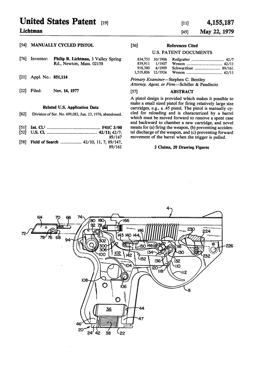
A pistol design is provided which makes it possible to
make a small sized pistol for firing relatively large size
cartridges, e.g., a .45 pistol. The pistol is manually cy-
cled for reloading and is characterized by a barrel
which must be moved forward to remove a spent case
and backward to chamber a new cartridge, and novel
means for (a) firing the weapon, (b) preventing acciden-
tal discharge of the weapon, and (c) preventing forward
movement of the barrel when the trigger is pulled.
2 Claims, 20 Drawing Figures
FIG. 1
са
ся
ЕГ
ет>
ет>
U.S. Patent May 22,1979
Sheet 2 of 7
4,155,187
г ш. b
U.S. Patent May 22,1979
Sheet 3 of 7
4,155,187
U.S. Patent May 22,1979
Sheet 4 of 7
4,155,187
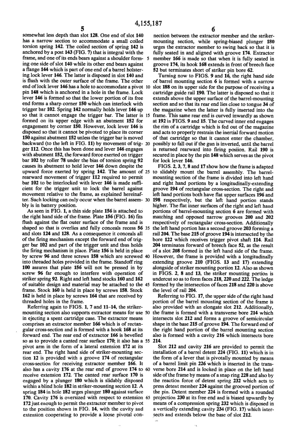
FIG. 18
FIG. 9
U.S. Patent May 22, 1979 Sheet 5 of 7 4,155
U.S. Patent May 22, 1979 Sheet 6 of 7 4,155,187
FIG. 12
112
U.S. Patent May 22,1979
Sheet 7 of 7
4,155,187
4,155,187
2
MANUALLY CYCLED PISTOL
This application is a division of my copending appli-
cation Ser. No. 699,083, now abandoned filed June 23, 5
1976, for Manually Cycled Pistol.
This invention relates to firearms and more particu-
larly to a pistol of novel and improved structure.
The primary object of this invention is to provide a
pistol which combines the advantages of small size and 1°
relatively large fire power. Another object is to provide
a sidearm which is especially suitable as a concealable
defensive sidearm. Still another object is to provide a
pistol which is relatively light weight, simple in con-
struction, reliable, and compact. A more specific object 15
is to provide a multi-shot .45 pistol which not only
weighs less and is smaller than other known pistols of
the same cartridge size but is actually smaller than and
weighs less than the best known .380 pistols of the type
which are classified as concealable handguns, e.g., a 20
Walther PPK .380. Still another object is to provide a
repeating pistol which is manually fed and easily field
stripped and adapted for use with a silencer. A further
specific object is to provide a novel firing mechanism.
These objects and other objects hereinafter stated or 2
rendered obvious are achieved by providing a manual-
ly-cycled repeating pistol which is similar to the
Schwarzlose “blowforward” design to the extent that it
comprises a barrel assembly which is moved forward
for cartridge ejection and feeding. However, unlike the
Schwarzlose design, the barrel is locked in place on
firing, so that the pistol is fired from a locked breech.
The pistol comprises (1) means for freezing a cartridge
in the feed position and preventing its accidental dis-
lodgement from the breech in the event the weapon is
canted while the barrel is out of battery position (2)
means for locking the barrel during firing and unlocking
the barrel when the trigger is released, (3) a striker-type
firing mechanism, and (4) a novel magazine release. Still 40
other features and advantages of the invention are de-
scribed or rendered obvious by the following detailed
descriptions of a preferred embodiment of the invention
which is to be considered together with the drawings
wherein: 45
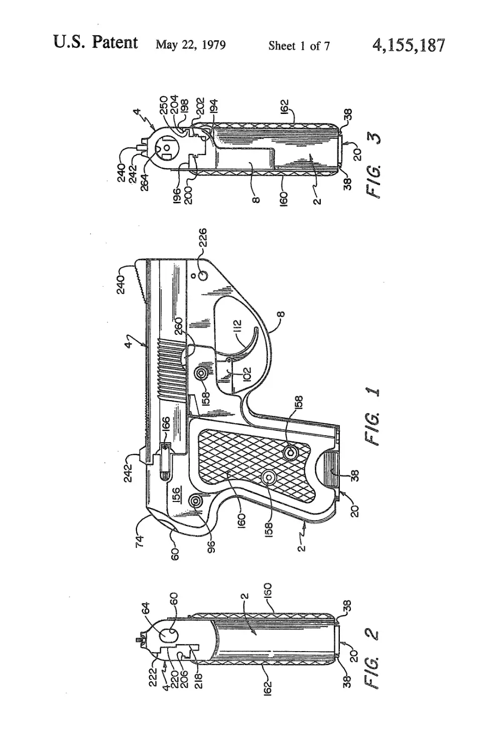
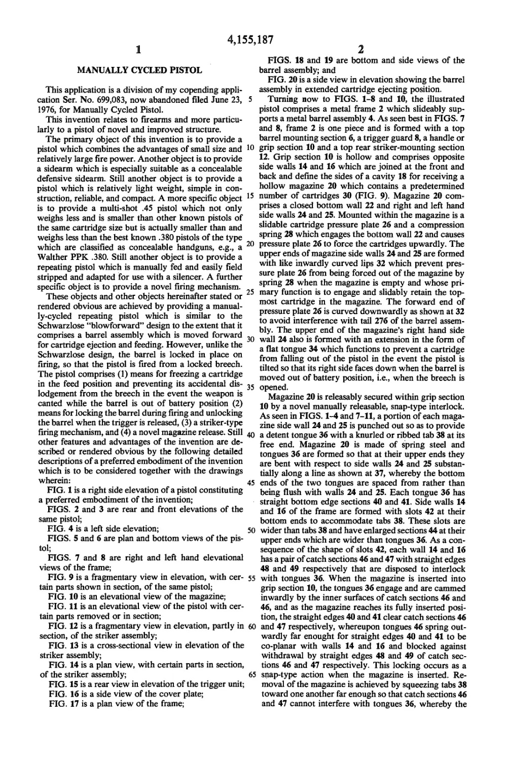
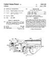
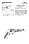
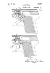
FIG. 1 is a right side elevation of a pistol constituting
a preferred embodiment of the invention;
FIGS. 2 and 3 are rear and front elevations of the
same pistol;
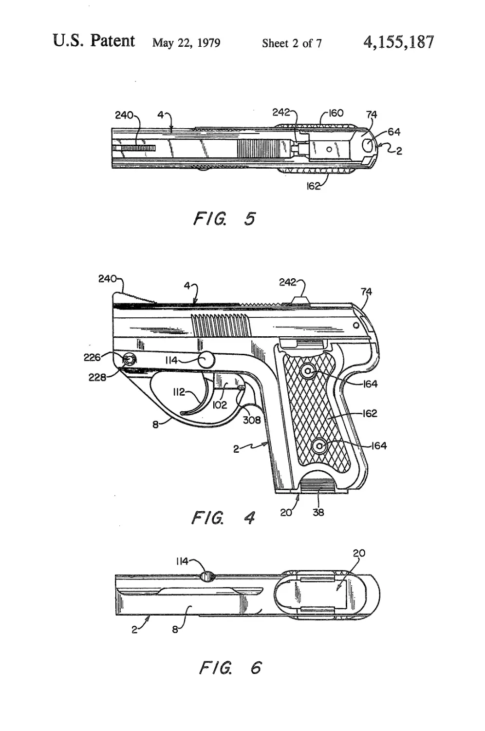
FIG. 4 is a left side elevation; 50
FIGS. 5 and 6 are plan and bottom views of the pis-
tol;
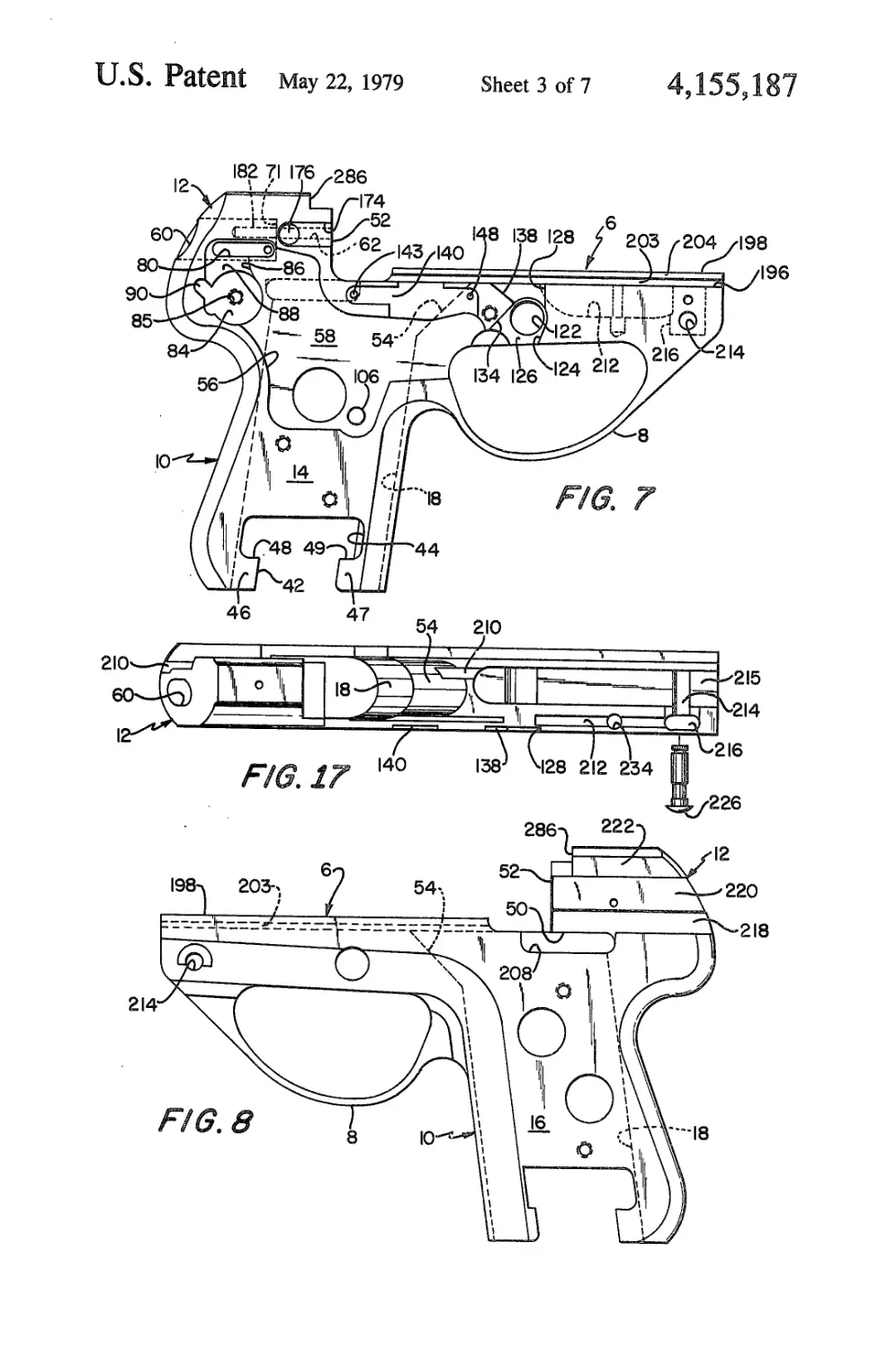
FIGS. 7 and 8 are right and left hand elevational
views of the frame;
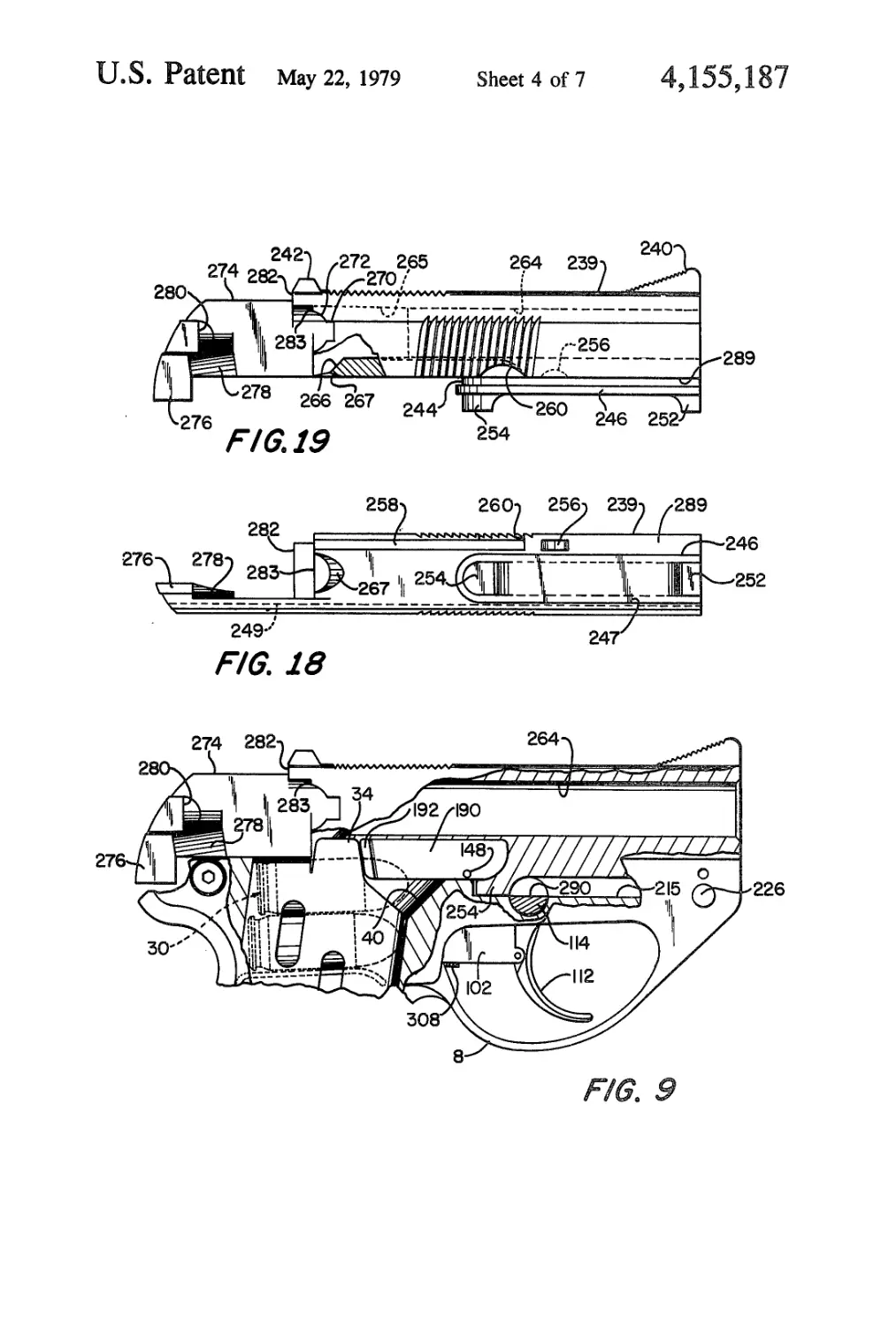
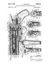
FIG. 9 is a fragmentary view in elevation, with cer- 55
tain parts shown in section, of the same pistol;
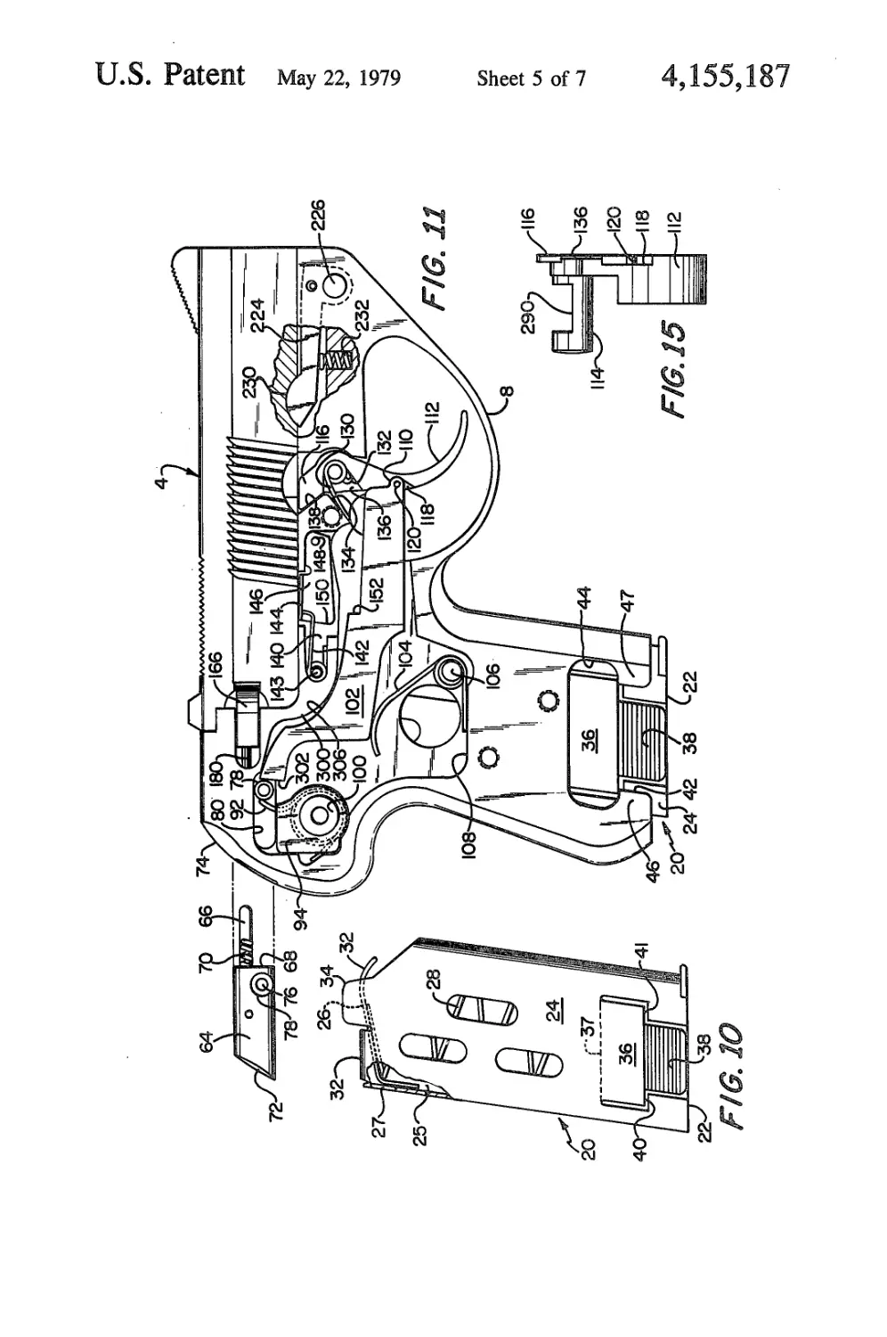
FIG. 10 is an elevational view of the magazine;
FIG. 11 is an elevational view of the pistol with cer-
tain parts removed or in section;
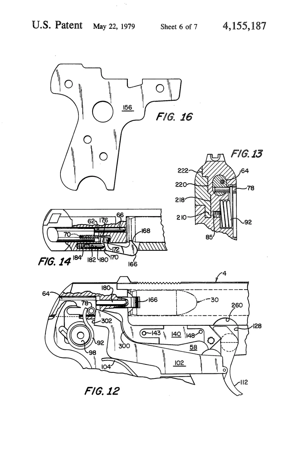
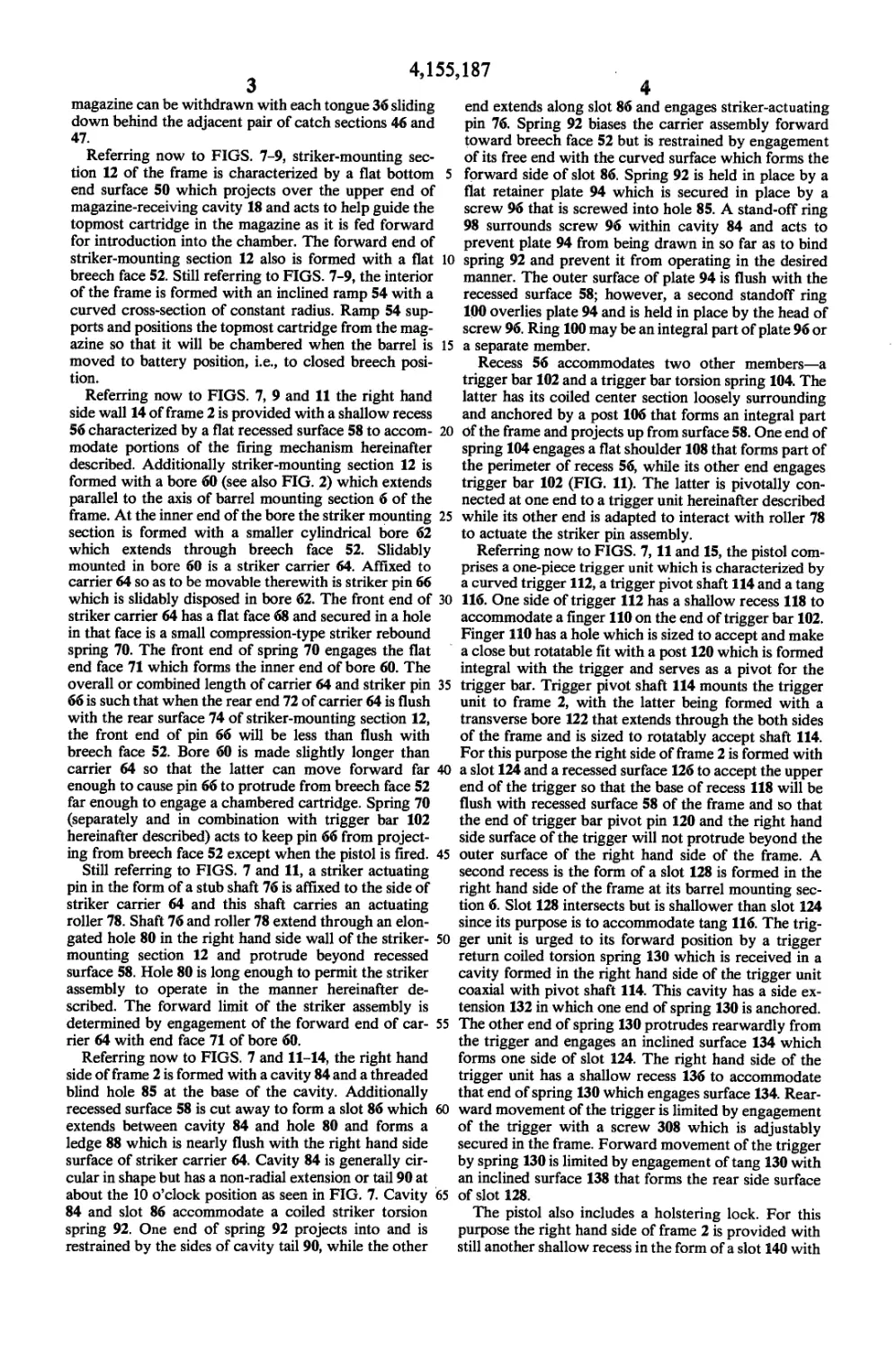
FIG. 12 is a fragmentary view in elevation, partly in 60
section, of the striker assembly;
FIG. 13 is a cross-sectional view in elevation of the
striker assembly;
FIG. 14 is a plan view, with certain parts in section,
of the striker assembly; 65
FIG. 15 is a rear view in elevation of the trigger unit;
FIG. 16 is a side view of the cover plate;
FIG. 17 is a plan view of the frame;
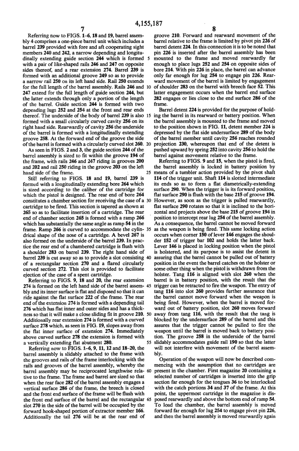
FIGS. 18 and 19 are bottom and side views of the
barrel assembly; and
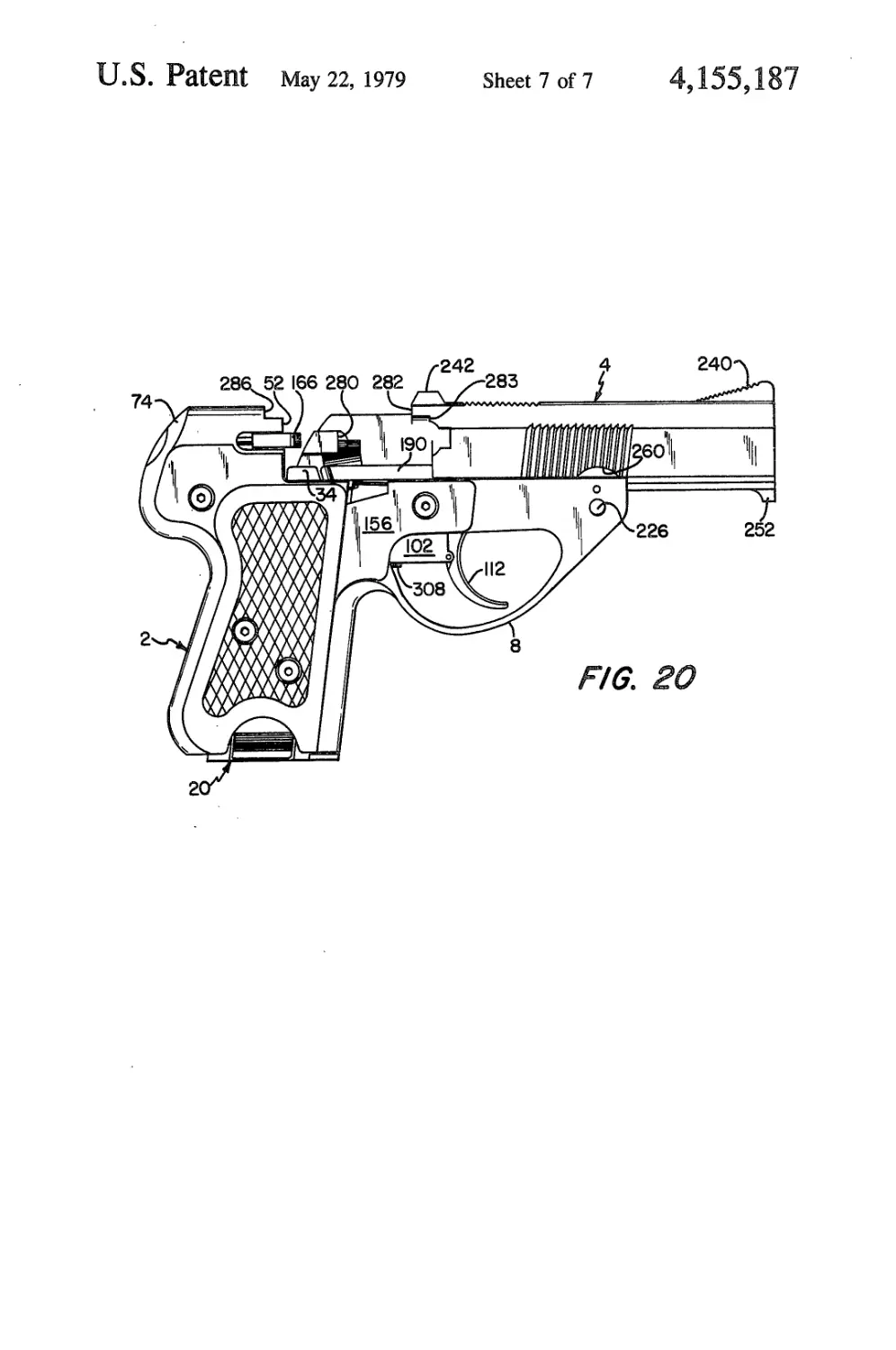
FIG. 20 is a side view in elevation showing the barrel
assembly in extended cartridge ejecting position.
Turning now to FIGS. 1-8 and 10, the illustrated
pistol comprises a metal frame 2 which slideably sup-
ports a metal barrel assembly 4. As seen best in FIGS. 7
and 8, frame 2 is one piece and is formed with a top
barrel mounting section 6, a trigger guard 8, a handle or
grip section 10 and a top rear striker-mounting section
12. Grip section 10 is hollow and comprises opposite
side walls 14 and 16 which are joined at the front and
back and define the sides of a cavity 18 for receiving a
hollow magazine 20 which contains a predetermined
number of cartridges 30 (FIG. 9). Magazine 20 com-
prises a closed bottom wall 22 and right and left hand
side walls 24 and 25. Mounted within the magazine is a
slidable cartridge pressure plate 26 and a compression
spring 28 which engages the bottom wall 22 and causes
pressure plate 26 to force the cartridges upwardly. The
upper ends of magazine side walls 24 and 25 are formed
with like inwardly curved lips 32 which prevent pres-
sure plate 26 from being forced out of the magazine by
spring 28 when the magazine is empty and whose pri-
mary function is to engage and slidably retain the top-
most cartridge in the magazine. The forward end of
pressure plate 26 is curved downwardly as shown at 32
to avoid interference with tail 276 of the barrel assem-
bly. The upper end of the magazine’s right hand side
wall 24 also is formed with an extension in the form of
a flat tongue 34 which functions to prevent a cartridge
from falling out of the pistol in the event the pistol is
tilted so that its right side faces down when the barrel is
moved out of battery position, i.e., when the breech is
opened.
Magazine 20 is releasably secured within grip section
10 by a novel manually releasable, snap-type interlock.
As seen in FIGS. 1-4 and 7-11, a portion of each maga-
zine side wall 24 and 25 is punched out so as to provide
a detent tongue 36 with a knurled or ribbed tab 38 at its
free end. Magazine 20 is made of spring steel and
tongues 36 are formed so that at their upper ends they
are bent with respect to side walls 24 and 25 substan-
tially along a line as shown at 37, whereby the bottom
ends of the two tongues are spaced from rather than
being flush with walls 24 and 25. Each tongue 36 has
straight bottom edge sections 40 and 41. Side walls 14
and 16 of the frame are formed with slots 42 at their
bottom ends to accommodate tabs 38. These slots are
wider than tabs 38 and have enlarged sections 44 at their
upper ends which are wider than tongues 36. As a con-
sequence of the shape of slots 42, each wall 14 and 16
has a pair of catch sections 46 and 47 with straight edges
48 and 49 respectively that are disposed to interlock
with tongues 36. When the magazine is inserted into
grip section 10, the tongues 36 engage and are cammed
inwardly by the inner surfaces of catch sections 46 and
46, and as the magazine reaches its fully inserted posi-
tion, the straight edges 40 and 41 clear catch sections 46
and 47 respectively, whereupon tongues 46 spring out-
wardly far enought for straight edges 40 and 41 to be
со-planar with walls 14 and 16 and blocked against
withdrawal by straight edges 48 and 49 of catch sec-
tions 46 and 47 respectively. This locking occurs as a
snap-type action when the magazine is inserted. Re-
moval of the magazine is achieved by squeezing tabs 38
toward one another far enough so that catch sections 46
and 47 cannot interfere with tongues 36, whereby the
4,155,187
magazine can be withdrawn with each tongue 36 sliding
down behind the adjacent pair of catch sections 46 and
47.
Referring now to FIGS. 7-9, striker-mounting sec-
tion 12 of the frame is characterized by a flat bottom 5
end surface 50 which projects over the upper end of
magazine-receiving cavity 18 and acts to help guide the
topmost cartridge in the magazine as it is fed forward
for introduction into the chamber. The forward end of
striker-mounting section 12 also is formed with a flat 10
breech face 52. Still referring to FIGS. 7-9, the interior
of the frame is formed with an inclined ramp 54 with a
curved cross-section of constant radius. Ramp 54 sup-
ports and positions the topmost cartridge from the mag-
azine so that it will be chambered when the barrel is 15
moved to battery position, i.e., to closed breech posi-
tion.
Referring now to FIGS. 7, 9 and 11 the right hand
side wall 14 of frame 2 is provided with a shallow recess
56 characterized by a flat recessed surface 58 to accom- 20
modate portions of the firing mechanism hereinafter
described. Additionally striker-mounting section 12 is
formed with a bore 60 (see also FIG. 2) which extends
parallel to the axis of barrel mounting section 6 of the
frame. At the inner end of the bore the striker mounting 25
section is formed with a smaller cylindrical bore 62
which extends through breech face 52. Slidably
mounted in bore 60 is a striker carrier 64. Affixed to
carrier 64 so as to be movable therewith is striker pin 66
which is slidably disposed in bore 62. The front end of 30
striker carrier 64 has a flat face 68 and secured in a hole
in that face is a small compression-type striker rebound
spring 70. The front end of spring 70 engages the flat
end face 71 which forms the inner end of bore 60. The
overall or combined length of carrier 64 and striker pin 35
66 is such that when the rear end 72 of carrier 64 is flush
with the rear surface 74 of striker-mounting section 12,
the front end of pin 66 will be less than flush with
breech face 52. Bore 60 is made slightly longer than
carrier 64 so that the latter can move forward far 40
enough to cause pin 66 to protrude from breech face 52
far enough to engage a chambered cartridge. Spring 70
(separately and in combination with trigger bar 102
hereinafter described) acts to keep pin 66 from project-
ing from breech face 52 except when the pistol is fired. 45
Still referring to FIGS. 7 and 11, a striker actuating
pin in the form of a stub shaft 76 is affixed to the side of
striker carrier 64 and this shaft carries an actuating
roller 78. Shaft 76 and roller 78 extend through an elon-
gated hole 80 in the right hand side wall of the striker- 50
mounting section 12 and protrude beyond recessed
surface 58. Hole 80 is long enough to permit the striker
assembly to operate in the manner hereinafter de-
scribed. The forward limit of the striker assembly is
determined by engagement of the forward end of car- 55
rier 64 with end face 71 of bore 60.
Referring now to FIGS. 7 and 11-14, the right hand
side of frame 2 is formed with a cavity 84 and a threaded
blind hole 85 at the base of the cavity. Additionally
recessed surface 58 is cut away to form a slot 86 which 60
extends between cavity 84 and hole 80 and forms a
ledge 88 which is nearly flush with the right hand side
surface of striker carrier 64. Cavity 84 is generally cir-
cular in shape but has a non-radial extension or tail 90 at
about the 10 o’clock position as seen in FIG. 7. Cavity
84 and slot 86 accommodate a coiled striker torsion
spring 92. One end of spring 92 projects into and is
restrained by the sides of cavity tail 90, while the other
end extends along slot 86 and engages striker-actuating
pin 76. Spring 92 biases the carrier assembly forward
toward breech face 52 but is restrained by engagement
of its free end with the curved surface which forms the
forward side of slot 86. Spring 92 is held in place by a
flat retainer plate 94 which is secured in place by a
screw 96 that is screwed into hole 85. A stand-off ring
98 surrounds screw 96 within cavity 84 and acts to
prevent plate 94 from being drawn in so far as to bind
spring 92 and prevent it from operating in the desired
manner. The outer surface of plate 94 is flush with the
recessed surface 58; however, a second standoff ring
100 overlies plate 94 and is held in place by the head of
screw 96. Ring 100 may be an integral part of plate 96 or
a separate member.
Recess 56 accommodates two other members—a
trigger bar 102 and a trigger bar torsion spring 104. The
latter has its coiled center section loosely surrounding
and anchored by a post 106 that forms an integral part
of the frame and projects up from surface 58. One end of
spring 104 engages a flat shoulder 108 that forms part of
the perimeter of recess 56, while its other end engages
trigger bar 102 (FIG. 11). The latter is pivotally con-
nected at one end to a trigger unit hereinafter described
while its other end is adapted to interact with roller 78
to actuate the striker pin assembly.
Referring now to FIGS. 7,11 and 15, the pistol com-
prises a one-piece trigger unit which is characterized by
a curved trigger 112, a trigger pivot shaft 114 and a tang
116. One side of trigger 112 has a shallow recess 118 to
accommodate a finger 110 on the end of trigger bar 102.
Finger 110 has a hole which is sized to accept and make
a close but rotatable fit with a post 120 which is formed
integral with the trigger and serves as a pivot for the
trigger bar. Trigger pivot shaft 114 mounts the trigger
unit to frame 2, with the latter being formed with a
transverse bore 122 that extends through the both sides
of the frame and is sized to rotatably accept shaft 114.
For this purpose the right side of frame 2 is formed with
a slot 124 and a recessed surface 126 to accept the upper
end of the trigger so that the base of recess 118 will be
flush with recessed surface 58 of the frame and so that
the end of trigger bar pivot pin 120 and the right hand
side surface of the trigger will not protrude beyond the
outer surface of the right hand side of the frame. A
second recess is the form of a slot 128 is formed in the
right hand side of the frame at its barrel mounting sec-
tion 6. Slot 128 intersects but is shallower than slot 124
since its purpose is to accommodate tang 116. The trig-
ger unit is urged to its forward position by a trigger
return coiled torsion spring 130 which is received in a
cavity formed in the right hand side of the trigger unit
coaxial with pivot shaft 114. This cavity has a side ex-
tension 132 in which one end of spring 130 is anchored.
The other end of spring 130 protrudes rearwardly from
the trigger and engages an inclined surface 134 which
forms one side of slot 124. The right hand side of the
trigger unit has a shallow recess 136 to accommodate
that end of spring 130 which engages surface 134. Rear-
ward movement of the trigger is limited by engagement
of the trigger with a screw 308 which is adjustably
secured in the frame. Forward movement of the trigger
by spring 130 is limited by engagement of tang 130 with
an inclined surface 138 that forms the rear side surface
of slot 128.
The pistol also includes a bolstering lock. For this
purpose the right hand side of frame 2 is provided with
still another shallow recess in the form of a slot 140 with
4,155,187
5
6
somewhat less depth than slot 128. One end of slot 140
has a narrow section to accommodate a small coiled
torsion spring 142. The coiled section of spring 142 is
anchored by a post 143 (FIG. 7) that is integral with the
frame, and one of its ends bears against a shoulder form-
ing one side of slot 140 while its other end bears against
a flange 144 which is part of one end of a barrel bolster-
ing lock lever 146. The latter is disposed in slot 140 and
is flush with the outer surface of the frame. The other
end of lock lever 146 has a hole to accommodate a pivot
pin 148 which is anchored in a hole in the frame. Lock
lever 146 is formed so that the lower portion of its free
end forms a sharp corner 150 which can interlock with
trigger bar 102. Spring 142 normally holds lever 146 up
so that it cannot engage the trigger bar. The latter is
formed on its upper edge with an abutment 152 for
engagement by corner 150. However, lock lever 146 is
disposed so that it cannot be pivoted to place its corner
150 against abutment 152 unless the trigger bar is moved
backward (to the left in FIG. 11) by movement of trig- 20
ger 112. Once this has been done and lever 146 engages
with abutment 152, the forward force exerted on trigger
bar 102 by roller 78 under the bias of torsion spring 92
causes its abutment to hold lever 146 down despite the
upward force exerted by spring 142. The amount of 25
rearward movement of trigger 112 required to permit
bar 102 to be interlocked with lever 146 is made suffi-
cient for the trigger unit to lock the barrel against
movement relative to the frame, as explained hereinaf-
ter. Such locking can only occur when the barrel assem- 30
bly is in battery position.
As seen in FIG. 1, a thin side plate 156 is attached to
the right hand side of the frame. Plate 156 (FIG. 16) fits
flush against the flat outer surface of the frame and is
shaped so that is overlies and fully conceals recess 56 35
and slots 124 and 128. As a consequence it conceals all
of the firing mechanism except the forward end of trig-
ger bar 102 and part of the trigger unit and thus holds
the firing mechanism in place. Plate 156 is held in place
by screw 96 and three screws 158 which are screwed 40
into threaded holes provided in the frame. Standoff ring
100 assures that plate 156 will not be pressed in by
screw 96 far enough to interfere with operation of
striker spring 92. Right and left hand stocks 160 and 162
of suitable design and material may be attached to the 45
frame. Stock 160 is held in place by screws 158. Stock
162 is held in place by screws 164 that are received by
threaded holes in the frame.
Referring again to FIGS. 1, 7 and 11-14, the striker-
mounting section also supports extractor means for use 50
in ejecting a spent cartridge case. The extractor means
comprises an extractor member 166 which is of rectan-
gular cross-section and is formed with a hook 168 at its
forward end. The rear end of extractor 166 is bevelled
so as to provide a canted rear surface 170; it also has a 55
pivot arm in the form of a lateral extension 172 at its
rear end. The right hand side of striker-mounting sec-
tion 12 is provided with a groove 174 of rectangular
cross-section for receiving extractor member 166. It
also has a cavity 176 at the rear end of groove 174 to 60
receive extension 172. The canted rear surface 170 is
engaged by a plunger 180 which is slidably disposed
within a blind hole 182 in striker-mounting section 12. A
spring 184 in hole 182 urges plunger 180 against surface
170. Cavity 176 is oversized with respect to extension 65
172 just enough to permit the extractor member to pivot
to the position shown in FIG. 14, with the cavity and
extension cooperating to provide a loose pivotal con-
nection between the extractor member and the striker-
mounting section, while spring-biased plunger 180
urges the extractor member to swing back so that it is
fully seated in and aligned with groove 174. Extractor
5 member 166 is made so that when it is fully seated in
groove 174, its hook 168 extends in front of breech face
52 but terminates short of striker pin bore 62.
Turning now to FIGS. 9 and 16, the right hand side
of barrel mounting section 6 is formed with a narrow
10 slot 188 on its upper side for the purpose of receiving a
cartridge guide rail 190. The latter is disposed so that it
extends above the upper surface of the barrel-mounting
section and so that its rear end lies close to tongue 34 of
the magazine when the latter is fully inserted into the
15 frame. This same rear end is curved inwardly as shown
at 192 in FIGS. 9 and 15. The curved inner end engages
the rim of a cartridge which is fed out of the magazine
and acts to properly restrain the inertial forward motion
of that cartridge so that it cannot enter the chamber,
possibly to fall out if the gun is inverted, until the barrel
is returned rearward into firing posiion. Rail 190 is
secured in place by the pin 148 which serves as the pivot
for lock lever 146.
FIGS. 2,3,7,8 and 17 show how the frame is adapted
to slidably mount the barrel assembly. The barrel-
mounting section of the frame is divided into left hand
and right hand portions by a longitudinally-extending
groove 194 of rectangular cross-section. The right and
left hand portions both have flat upper surfaces 196 and
198 respectively, but the left hand portion stands
higher. The flat inner surfaces of the right and left hand
portions of barrel-mounting section 6 are formed with
matching and opposed narrow grooves 200 and 202
respectively of rectangular cross-section. Additionally
the left hand portion has a second groove 203 forming a
rail 204. The base 215 of groove 194 is intersected by the
bore 122 which receives trigger pivot shaft 114. Rail
204 terminates forward of breech face 52, as the result
of a slot 208 formed in the left hand side of the frame.
However, the frame is provided with a longitudinally
extending groove 210 (FIGS. 13 and 17) extending
alongside of striker mounting portion 12. Also as shown
in FIGS. 2, 8 and 13, the striker mounting portion is
undercut so as to form faces 218,220 and 222. The ledge
formed by the intersection of faces 218 and 220 is above
the level of rail 204.
Referring to FIG. 17, the upper side of the right hand
portion of the barrel mounting section of the frame is
also provided with an elongate slot 212. Additionally,
the frame is formed with a transverse bore 214 which
intersects slot 212 and forms a groove of semicircular
shape in the base 215 of groove 194. The forward end of
the right hand portion of the barrel mounting section
also is formed with a cavity 216 which intersects bore
214.
Slot 212 and cavity 216 are provided to permit the
installation of a barrel detent 224 (FIG. 11) which is in
the form of a lever that is pivotally mounted by means
of a barrel limit pin 226 which is inserted in the trans-
verse bore 214 and is locked in place on the left hand
side of the frame by means of a snap ring 228 and also by
the reaction force of detent spring 232 which acts to
press detent member 224 against the grooved portion of
the pin. Detent member 224 is formed with a rounded
projection 230 at its free end and is biased upwardly by
means of a compression spring 232 which is disposed in
a vertically extending cavity 234 (FIG. 17) which inter-
sects and extends below the base of slot 212.
4,155,187
8
Referring now to FIGS. 1-6,18 and 19, barrel assem-
bly 4 comprises a one-piece barrel unit which includes a
barrel 239 provided with fore and aft cooperating sight
members 240 and 242, a narrow depending and longitu-
dinally extending guide section 244 which is formed 5
with a pair of like-shaped rails 246 and 247 on opposite
sides thereof, and a rear extension 274. Barrel 239 is
formed with an additional groove 249 so as to provide
a narrow rail 250 on its left hand side. Rail 250 extends
for the full length of the barrel assembly. Rails 246 and 10
247 extend for the full length of guide section 244, but
the latter extends through only a portion of the length
of the barrel. Guide section 244 is formed with two
depending lugs 252 and 254 at the front and rear ends
thereof. The underside of the body of barrel 239 is also 15
formed with a small circularly curved cavity 256 on its
right hand side. Rearwardly of cavity 256 the underside
of the barrel is formed with a longitudinally extending
groove 258. At the forward end of the groove the side
of the barrel is formed with a circularly curved slot 260. 20
As seen in FIGS. 2 and 3, the guide section 244 of the
barrel assembly is sized to fit within the groove 194 of
the frame, with rails 246 and 247 riding in grooves 200
and 202 and rail 250 riding in the groove 203 on the left
hand side of the frame. 25
Still referring to FIGS. 18 and 19, barrel 239 is
formed with a longitudinally extending bore 264 which
is sized according to the caliber of the cartridge for
which the pistol is designed. The rear end of bore 264
constitutes a chamber section for receiving the case of a 30
cartridge to be fired. This section is tapered as shown at
265 so as to facilitate insertion of a cartridge. The rear
end of chamber section 265 is formed with a ramp 266
which has substantially the same angle as ramp 54 in the
frame. Ramp 266 is curved to accommodate the cylin- 35
drical shape of the nose of a cartridge. A bevel 267 is
also formed on the underside of the barrel 239. In prac-
tice the rear end of a chambered cartridge is flush with
a shoulder 283 on barrel 239. The right hand side of
barrel 239 is cut away so as to provide a slot consisting 40
of a rectangular section 270 and a flared circularly
curved section 272. This slot is provided to facilitate
ejection of the case of a spent cartridge.
Referring to FIGS. 9, 18 and 20, the rear extension
274 is formed on the left hand side of the barrel assem- 45
bly and its inner surface is flat and disposed so that it can
ride against the flat surface 222 of the frame. The rear
end of the extension 274 is formed with a depending tail
276 which has flat inner and outer sides and has a thick-
ness so that it will make a close sliding fit in groove 210. 50
Additionally rear extension 274 is formed with a curved
surface 278 which, as seen in FIG. 19, slopes away from
the flat inner surface of extension 274. Immediately
above curved surface 278 the extension is formed with
a vertically extending flat abutment 280. 55
Referring now to FIGS. 1-6, 9,11,12 and 18-20, the
barrel assembly is slidably attached to the frame with
the grooves and rails of the frame interlocking with the
rails and grooves of the barrel assembly, whereby the
barrel assembly may be reciprocated lengthwise rela- 60
tive to the frame. The frame and barrel are sized so that
when the rear face 282 of the barrel assembly engages a
vertical surface 286 of the frame, the breech is closed
and the front end surface of the frame will be flush with
the front end surface of the barrel and the rectangular
slot 270 in the side of the barrel will be occupied by the
forward hook-shaped portion of extractor member 166.
Additionally the tail 276 will be at the rear end of
groove 210. Forward and rearward movement of the
barrel relative to the frame is limited by pivot pin 226 of
barrel detent 224. In this connection it is to be noted that
pin 226 is inserted after the barrel assembly has been
mounted to the frame and moved rearwardly far
enough to place lugs 252 and 254 on opposite sides of
bore 214. With pin 226 in place, the barrel can advance
only far enough for lug 254 to engage pin 226. Rear-
ward movement of the barrel is limited by engagement
of shoulder 283 on the barrel with breech face 52. This
latter engagement occurs when the barrel end surface
282 engages or lies close to the end surface 286 of the
frame.
Barrel detent 224 is provided for the purpose of hold-
ing the barrel in its rearward or battery position. When
the barrel assembly is mounted to the frame and moved
to the position shown in FIG. 11, detent member 224 is
depressed by the flat side undersurface 289 of the body
of the barrel member until cavity 256 reaches rounded
projection 230, whereupon that end of the detent is
pushed upward by spring 252 into cavity 256 to hold the
barrel against movement relative to the frame.
Referring to FIGS. 9 and 15, when the pistol is fired,
the barrel assembly is locked in battery position by
means of a tumbler action provided by the pivot shaft
114 of the trigger unit. Shaft 114 is slotted intermediate
its ends so as to form a flat diametrically-extending
surface 290. When the trigger is in its forward position,
flat surface 290 is flush with the base 215 of groove 194.
However, as soon as the trigger is pulled rearwardly,
flat surface 290 rotates so that it is inclined to the hori-
zontal and projects above the base 215 of groove 194 in
position to intercept rear lug 254 of the barrel assembly.
As a consequence, the barrel cannot be moved forward
as the weapon is being fired. This same locking action
occurs when corner 150 of lever 146 engages the shoul-
der 152 of trigger bar 102 and holds the latter back.
Lever 146 is placed in locking position when the pistol
is holstered, and its purpose is to assist the detent in
assuring that the barrel cannot be pulled out of battery
position in the event the barrel catches on the holster or
some other thing when the pistol is withdrawn from the
holster. Tang 116 is aligned with slot 260 when the
barrel is in battery position, with the result that the
trigger can be retracted to fire the weapon. The entry of
tang 116 into slot 260 provides further assurance that
the barrel cannot move forward when the weapon is
being fired. However, when the barrel is moved for-
ward out of battery position, slot 260 moves forward
away from tang 116, with the result that the tang is
blocked by the undersurface 289 of the barrel and this
assures that the trigger cannot be pulled to fire the
weapon until the barrel is moved back to battery posi-
tion. The groove 258 in the underside of the barrel
slidably accommodates guide rail 190 so that the latter
will not interfere with movement of the barrel assem-
bly.
Operation of the weapon will now be described com-
mencing with the assumption that no cartridges are
present in the chamber. First magazine 20 containing a
selected number of cartridges is inserted into the grip
section far enough for the tongues 36 to be interlocked
with the catch portions 34 and 37 of the frame. At this
point, the uppermost cartridge in the magazine is dis-
posed rearwardly and above the bottom end of ramp 54.
To load the chamber, the barrel assembly is moved
forward far enough for lug 254 to engage pivot pin 226,
and then the barrel assembly is moved rearwardly again
9
4,155,187
10
to battery position. On the forward stroke of the barrel
assembly, the tail 276 passes through a narrow slot 27 in
the upper end of the rear wall of the magazine and
engages the rear surface of the upper cartridge in the
magazine and forces it forwardly out from between the
lips 32 and toward ramp 54. As the barrel continues to
move forward (FIG. 20), tail 276 forces the cartridge
along ramp 54 far enough to release it from the maga-
zine and cause it to be raised by pressure plate 26 and
ramp 54 up between surface 278 of rear extension 274 of
the barrel assembly and tab 34 and guide rail 190. The
cartridge is moved forward far enough for the inturned
portion 192 of guide rail 190 to enter the ejector groove
of the cartridge and engage the rim on the rear end of
the cartridge. This stops the cartridge and this occurs as
the barrel reaches its forward position. At this point the
nose of the cartridge is spaced from ramp 266 and the
barrel. When the barrel is returned to battery position,
the nose of the cartridge which has been freed from the
magazine is engaged by ramp 266 and this action forces
it up out from between guide rail 190 and extension
surface 278. As the barrel moves rearwardly the freed
cartridge cams the extractor member 166 laterally far
enough for the rim of the cartridge to pass hook 168,
whereupon the extractor member moves inwardly
again to place hook 168 in engagement with the front
end of the cartridge rim, as shown in FIG. 14. As this
point the cartridge is fully chambered and is held in
place by extractor member 166. If now the barrel were
to be moved forward again without firing the weapon,
the unfired cartridge would automatically be ejected
from the weapon. This is achieved by coaction of slot
272 on the right hand side of the barrel extractor mem-
ber 166, and abutment 280. As slot 272 moves forward
of the nose of the cartridge, the abutment 280 exerts a
forward force on the rear end of the cartridge, causing
the latter to pivot about hook 168, whereby the nose of
the cartridge moves outwardly past the slot 272 and is
ejected by the continuing forward pressure exerted by
abutment 280. The same ejecting action occurs with a
spent cartridge case. In either situation, as the cartridge
or spent case is ejected the next cartridge is pulled into
position for chambering by operation of the tail 276 in
the manner previously described. Chambering of this
cartridge occurs on the return stroke of the barrel as
previously described.
Operation of the firing mechanism will now be de-
scribed with reference to FIG. 11. When the trigger is
held in its forward position by spring 130, trigger bar
102 is held by spring 104 against the curved edge sur-
face 300 which forms part of the perimeter of recess 56
and the flat rear end surface 302 of the trigger bar is
nearly in engagement with roller 78 of the striker assem-
bly, with the latter being restrained against spring 92 by
rebound spring 70. When the trigger is pulled to fire the
pistol, trigger bar 102 moves rearwardly and also up-
wardly at the trigger end due to the arc described by
pivot pin 120. Since the curved center surface 306 of the
trigger bar bears on the radiused surface 300 approxi-
mately midway between the trigger and the striker
assembly, the trigger bar functions as a first class lever
pivoted at its center. Therefore, the striker end has to
move downward as well as rearward as the trigger bar
moves rearward under the force exerted by the trigger
motion. The rearward movement of the trigger bar
causes its end surface 302 to act on roller 78 to cause the
striker assembly to overcome the force of spring 92 and
move back. Since the striker end of trigger bar 102 is
20
60
65
5
10
15
25
30
35
40
45
50
55
moving down at the same time as it is moving rear-
wardly, at some point in its motion the rear end of the
trigger bar will slip off of roller 28. This releases the
striker assembly so that it can be propelled forward by
spring 92 to fire the weapon. Thereafter when the trig-
ger is released in preparation for the next round, the
trigger bar moves forward until spring 104 pops it back
up into engagement with the striker roller 78, whereby
the trigger bar is ready again to fire the round. When
the trigger bar releases the striker assembly, as de-
scribed, the striker moves forward far enough for its
striker pin 66 to ignite the chambered cartridge. As
previously noted the upper end of striker spring 92 is
limited as to how far it can move forward as a result of
its being intercepted by the forward edge of slot 86.
Hence when the weapon is fired and torsion spring 92
drives the striker assembly forward, inertia keeps the
striker assembly moving forward to penetrate breech
face 152 even after the spring 92 is intercepted by the
forward edge of slot 86. Thereafter rebound spring 70
urges the striker assembly backward far enough for
roller 70 to be reengaged by spring 92, and when the
roller is in this position, trigger bar 102 has room to be
moved by spring 104 back into the position of FIG. 11
where it serves to block forward motion of the striker.
Set screw 308 may be replaced by a hollow set screw
containing a spring-biased plunger which is disposed in
position to be engaged and forced back into the set
screw by the trigger. This plunger provides added resis-
tance to movement of the trigger and serves as a
“feeler” to indicate when the trigger is just short of the
point at which the gun will fire.
The above-described pistol has a number of advan-
tages. For one thing, it is compact and lightweight. In a
.45 model, the pistol has a weight of about 21 ounces
and measures about 0.93" wide through the stocks (if
the stocks are used) and about 0.75" wide through the
barrel or frame, with an overall height of about 3
23/32" and an overall length of about 5 7/32". It does
not require a recoil spring, and is ideal for use with a
silencer since the latter must be attached to the barrel
and the latter is locked closed at all times during firing,
which prevents gas leakage and avoids mechanical clat-
ter. The weapon also has two safety features. One is that
the firing pin is always non-protruding from breech face
52 due to rebound spring 70 and the restraint imposed
on spring 92 by the side of slot 86. So in the static-posi-
tion of the pistol, the pin 66 does not touch the primer
of the chambered cartridge. The second safety feature is
that trigger bar 102 holds the striker back to prevent
accidental firing should the weapon be dropped. Other
safety features are the barrel restraining tumbler action
of the trigger unit and the trigger lock provided by tang
116 when the barrel is out of battery position.
Another advantage of the invention is that the
weapon is highly accurate since (1) the sights are inte-
gral with the barrel and (2) the barrel length is relatively
long in relation to the overall length of the weapon. The
weapon also is relatively comfortable to fire because of
(1) the low placement of the barrel with respect to the
shooter’s hand, which reduces nuzzle jump, and (2) the
high backstrap arch and the narrow section of the han-
dle, both of which are possible because of the use of
torsion spring 92 to propel the striker assembly. It is to
be noted also that the weapon is provided with serra-
tions on the top as well as on the sides of the barrel (see
FIGS. 1, 4, 5,11,12 and 18-20) for gripping the barrel.
The serrations on top allow the barrel to be recipro-
4,155,187
11
cated by the thumb of the non-firing hand of the
shooter, so that the barrel may be moved by the shooter
for rapid cycling of the weapon without any change in
the shooter’s firing stance.
Notwithstanding the advantages of the design herein 5
described, the weapon may be modified to operate semi-
automatically by adding a recoil spring to return the
barrel to battery position and means for propelling the
barrel forward on firing to eject the spent case and feed
a new cartridge out of the magazine. Such means may
comprise means for directing gases so that they dis-
charge against flat surfaces at the front of the barrel to
effect opening of the breech, or a relatively deep rifling
in the front end of the barrel to cause the moving bullet
to frictionally drive the barrel forward. Another ap-
proach is to divide the barrel into a front male section
and a back female section which are in telescoping
relation to one another, with the chamber being in the
back section and the rifling in the front section, and the
front section being adapted to be driven forward away 20
from the stationary back section by expanding gases
(acting against the telescoping back end of the front
section) when the weapon is fired, and the rear section
being locked against the breech face (by the expanding
cartridge case acting on the chamber wall) until after 25
the front section has moved forward a predetermined
distance and the bullet has left the front section, where-
upon the back section is pulled forward by a linkage
connected to the moving front section to effect ejection
and reloading in the manner herein described. Still 30
other modifications will be obvious to persons skilled in
the art.
What is claimed is:
1. A pistol comprising a frame with a handle, a barrel
slidably mounted to the frame and movable from a first
position in which a cartridge is positioned for firing and
a second position in which the cartridge can be ejected
from the pistol, a firing mechanism carried by the frame
for firing a cartridge when the barrel is in said frame, a
cavity in said frame for receiving a magazine, and a
magazine disposed in said cavity, said frame having a
pair of opposite side walls defining at least part of said
cavity, each of said frame side walls having a slot form-
ing a pair of catch sections and said magazine having a
12
pair of opposite side walls extending parallel to said
frame side walls, each of said magazine side walls being
made of a resilient material and being cut so that a por-
tion thereof constitutes a tongue having a pair of edges
arranged so as to engage the two catch sections of the
adjacent frame side wall, whereby to releasably lock
said magazine in said cavity, each of said tongues also
being formed with a tab at its free end and the slots in
said frame side walls being shaped so that said tabs are
10 exposed through said slots, the locking of said magazine
being releasable by squeezing said tabs toward one an-
other.
2. A manually cycled repeating pistol comprising a
frame with a handle, a barrel slidably mounted to the
15 frame and movable from a rear position in which a
cartridge is positioned for firing and a forward position
in which a cartridge can be ejected from the pistol, a
firing mechanism carried by the frame for firing a car-
tridge when the barrel is in its rear position, a cavity in
said frame for accommodating a cartridge magazine, a
magazine disposed in said cavity, means for directing a
cartridge released from said magazine into the chamber
of the barrel as the barrel is moved rearwardly to bat-
tery position, means defining a breech when the barrel
is in its forward position, an extractor member attached
to said frame for shucking a cartridge out from the
breech as the barrel is moved to its forward position,
means on said frame forming a ramp for aligning a car-
tridge released from said magazine so that said cartridge
will enter said chamber when said barrel is moved back
to battery position, means carried by said barrel for
engaging a cartridge in the magazine and forcing it out
of the magazine toward said ramp as the barrel is moved
forward out of battery position, an arrestor adapted to
35 snap into the extractor groove of a cartridge as it is
forced out of the magazine toward said ramp, said frame
having a pair of opposite side walls defining at least part
of said cavity and a pair of catch sections on each side
thereof formed by slotting of said side walls, and said
40 magazine being made of a spring steel and having a
spring tab formed on each side thereof for engagement
with a corresponding pair of said catch sections,
whereby to releasably lock said magazine in said cavity.
50
55
60
65