/

Теги: weapons military affairs patent
Год: 2012
Похожие


Текст
US 20120047786A1
(19) United States
(12) Patent Application Publication («» Pub. No.: US 2012/0047786 Al
Dextraze et al. (43) Pub. Date: Mar. 1,2012
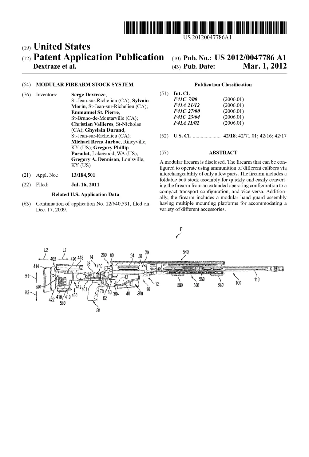
(54) MODULAR FIREARM STOCK SYSTEM
(76) Inventors: Serge Dextraze,
St-Jean-sur-Richelieu (CA); Sylvain
Morin, St-Jean-sur-Richelieu (CA);
Emmanuel St. Pierre,
St-Bruno-de-Montarville (CA);
Christian Vallieres, St-Nicholas
(CA); Ghyslain Durand,
St-Jean-sur-Richelieu (CA);
Michael Brent Jarboe, Rineyville,
KY (US); Gregory Phillip
Paradat, Lakewood, WA (US);
Gregory A. Dennison, Louisville,
KY (US)
(21) Appl.No.: 13/184,501
(22) Filed: Jul. 16, 2011
Related U.S. Application Data
(63) Continuation of application No. 12/640,531, filed on
Dec. 17, 2009.
Publication Classification
(51) Int.Cl.
F41C 7/00 (2006.01)
1'41 A 21/12 (2006.01)
F41C 27/00 (2006.01)
F41C 23/04 (2006.01)
1'41 A 11/02 (2006.01)
(52) U.S. Cl................ 42/18; 42/71.01; 42/16; 42/17
(57) ABSTRACT
A modular firearm is disclosed. The firearm that can be con-
figured to operate using ammunition of different calibers via
interchangeability of only a few parts. The firearm includes a
foldable butt stock assembly for quickly and easily convert-
ing the firearm from an extended operating configuration to a
compact transport configuration, and vice-versa. Addition-
ally, the firearm includes a modular hand guard assembly
having multiple mounting platforms for accommodating a
variety of different accessories.
Patent Application Publication Mar. 1, 2012 Sheet 1 of 18
US 2012/0047786 Al
Patent Application Publication Mar. 1, 2012 Sheet 2 of 18
US 2012/0047786 Al
СЧ5
Patent Application Publication Mar. 1, 2012 Sheet 5 of 18
US 2012/0047786 Al
FIG. 5
Patent Application Publication Mar. 1, 2012 Sheet 6 of 18
US 2012/0047786 Al
Риь«'мо„
X'“r-I-2III2
S/Ieet 7 «Г 18
t'S2°W/oo477S64i
Patent Application Publication Mar. 1, 2012 Sheet 8 of 18
US 2012/0047786 Al
303
С1Г2 Я
i I » о
Patent Application Publication Mar. 1, 2012 Sheet 9 of 18
US 2012/0047786 Al
FIG. 9
Л*>РИс9г
Patent Application Publication Mar. 1, 2012 Sheet 11 of 18 US 2012/0047786 Al
Patent Application Publication
Mar. 1,2012 Sheet 12 of 18
US 2012/0047786 Al
Patent Application Publication Mar. 1, 2012 Sheet 13 of 18 US 2012/0047786 Al
Patent Application Publication Mar. 1, 2012 Sheet 14 of 18 US 2012/0047786 Al
Patent Application Publication Mar. 1, 2012 Sheet 15 of 18 US 2012/0047786 Al
Patent Application Publication Mar. 1, 2012 Sheet 16 of 18 US 2012/0047786 Al
Patent Application Publication Mar. 1, 2012 Sheet 17 of 18 US 2012/0047786 Al
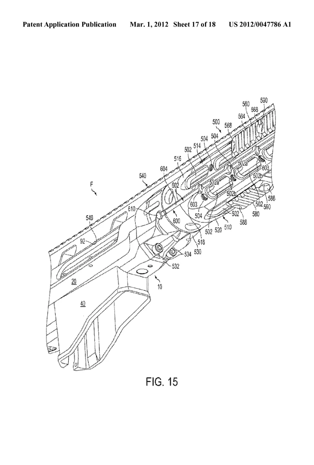
FIG. 15
Patent Application Publication Mar. 1, 2012 Sheet 18 of 18 US 2012/0047786 Al
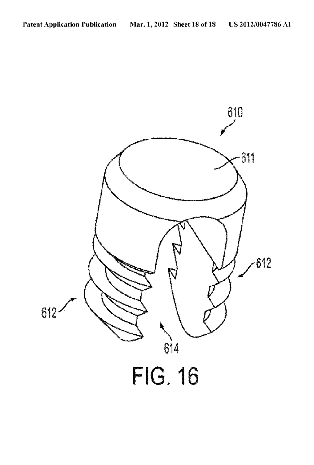
614
FIG. 16
US 2012/0047786 Al
Mar. 1,2012
1
MODULAR FIREARM STOCK SYSTEM
CONTINUITY
[0001] This application is a continuation of and claims
priority to U.S. application Ser. No. 12/640,531, filed on Dec.
17, 2009, which claims priority to U.S. application Ser. No.
61/184,630, filed Jun. 5, 2009. The specifications of which
are incorporated herein in their entirety by reference.
FIELD OF THE INVENTION
[0002] The present disclosure relates to a modular firearm.
BACKGROUND OF THE INVENTION
[0003] Typically, most conventional firearms have been
adapted for specific tasks and generally are limited to use with
specific calibers and/or types of ammunition. However,
demand is increasing for firearms that can be modified to fire
different types of ammunition, and/or can be reconfigured for
different environments and uses. For example, in military
applications today, the environments in which soldiers are
forced to fight are changing such that they can be in open
desert and then move into close quarter’s battle in a more
urban area within the matter of a few hours. At the same time,
their weapons needs can further change, i.e., they might be
faced with need for a longer range, sniping weapon or alter-
natively with needs for a more standard infantry rifle depend-
ing on the environment or situation. Carrying multiple differ-
ent firearms is, however, impractical as adding undue weight
and bulk to soldiers’ packs and gear. Additionally, for more
specialized uses, such as for sniping and other tactical situa-
tions, the weapon must be configurable as needed to fit the
shooter’s particular needs and/or use in a particular combat
situation.
SUMMARY
[0004] The present disclosure generally is related to a
modular firearm that is easily reconfigurable based on opera-
tional needs. More specifically, the disclosure relates to a
modular firearm that is configurable to enable operation using
ammunition of different or varying calibers via interchange-
ability of minimal parts, accommodates a variety of different
accessories, is easily convertible from an operating condition
to a compact and secure transport configuration, and can be
configured with various accessories and stock arrangements
as needed to meet a specific combat or tactical situation
and/or the preferences of the user/shooter.
[0005] According to another embodiment, the modular
firearm can comprise a folding butt stock assembly that is
moveable between an extended position for placing the fire-
arm in an operating configuration and a folded position for
placing the firearm in a transport configuration. The butt stock
assembly includes a latch mechanism including a latch arm
operable to remove a detent element from engagement with a
chassis of the firearm, thereby enabling the stock to be
unlocked from the extended position and pivoted into its
foldedposition. In the foldedposition, the latch arm lockingly
engages the chassis of the firearm, thereby securing the butt
stock in the folded position. According to a further embodi-
ment, the butt stock assembly can include a bolt handle open-
ing configured to receive and retain a portion of the bolt
assembly, such as, a projection, tab, or a bolt handle of the bolt
assembly of the firearm when the butt stock is in the folded
position, thereby helping to secure the bolt during transport of
the firearm.
[0006] According to a further embodiment, the modular
firearm can additionally comprise a modular hand guard
assembly for mounting accessories on the firearm. The hand
guard assembly includes a hand guard having a plurality of
rail mounting platforms, with each platform being disposed in
a separate plane, including a top rail for mounting accessories
on a top platform of the hand guard, and which attaches the
hand guard assembly to a top portion of the receiver, and one
or more rail sections attached about different planes of the
hand guard and firearm for mounting accessories on the fire-
arm. A bottom portion of the hand guard assembly can also be
attached to a chassis of the firearm, with the hand guard
assembly generally being free from direct attachment to a
barrel of the firearm. One or more recoil-absorbing mounting
lugs further may be integrated in each rail or rail section.
[0007] According to still another embodiment, the modular
firearm can include an integrated wire management system
including one or more wire channels formed in an exterior
surface of a chassis of the firearm and/or in an exterior surface
of a hand guard of the firearm for accommodating cabling for
one or more firearm accessories. Clips may be inserted in the
channel(s) to secure the cabling and/or accessories at various
locations along the channel(s).
[0008] According to yet another embodiment, the modular
firearm further may include an actuator for a bolt stop/guide
mechanism. The actuator may be centrally located on an
upper rear surface of the receiver to enable ease of actuation
or engagement by right and left-handed users.
[0009] Those skilled in the art will appreciate the above
features and advantages, as well as additional features and
advantages upon reading the following detailed description
with reference to the accompanying drawings and appendix.
DESCRIPTION OF THE FIGURES
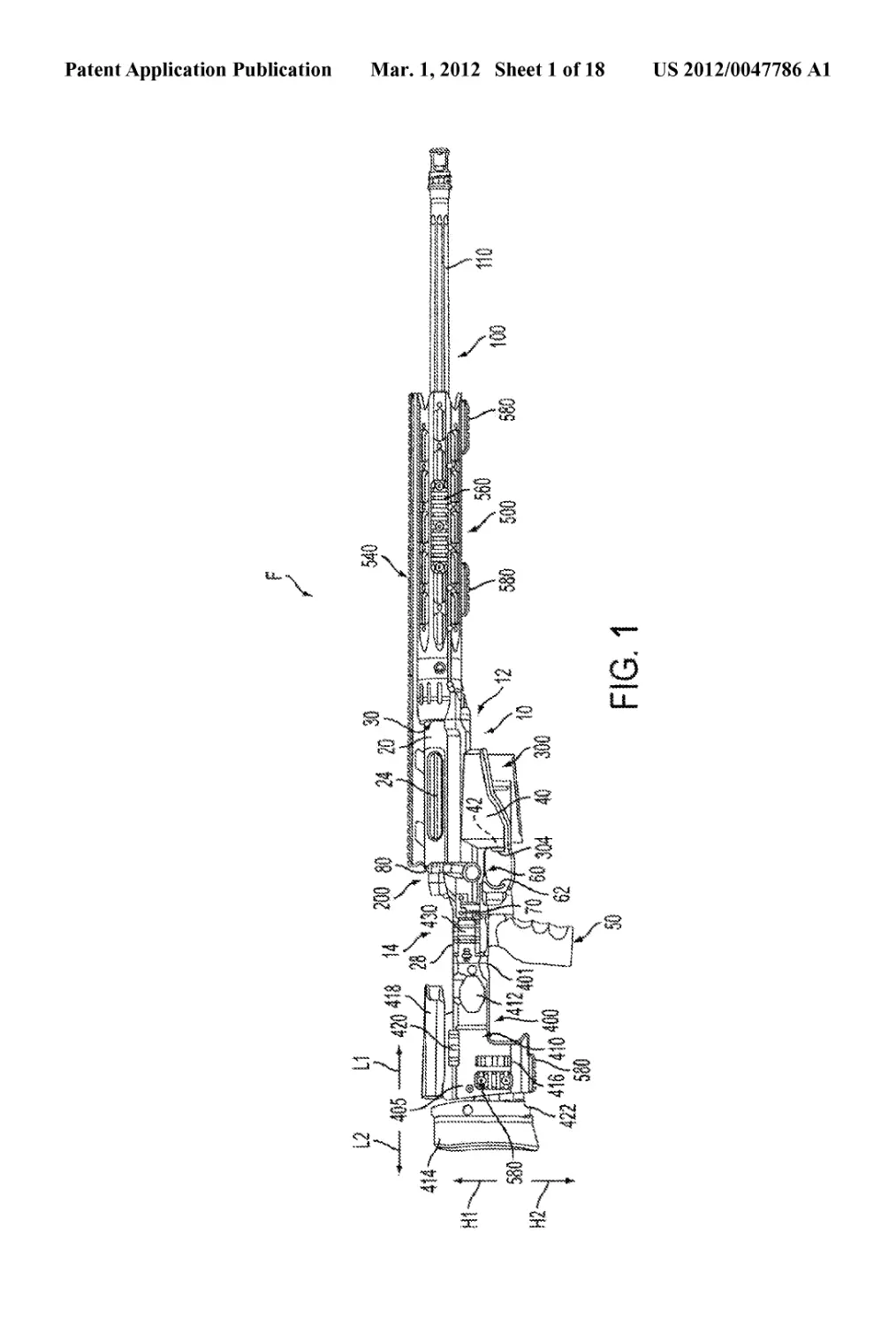
[0010] The FIG. lisa side view showing one embodiment
of a modular firearm, according to one example embodiment;
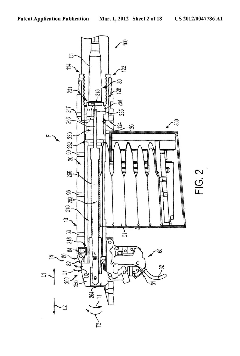
[0011] FIG. 2 is a partial cross-sectional view of the fire-
arm;
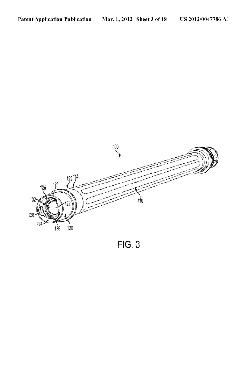
[0012] FIG. 3 is a perspective view of a barrel assembly of
the firearm;
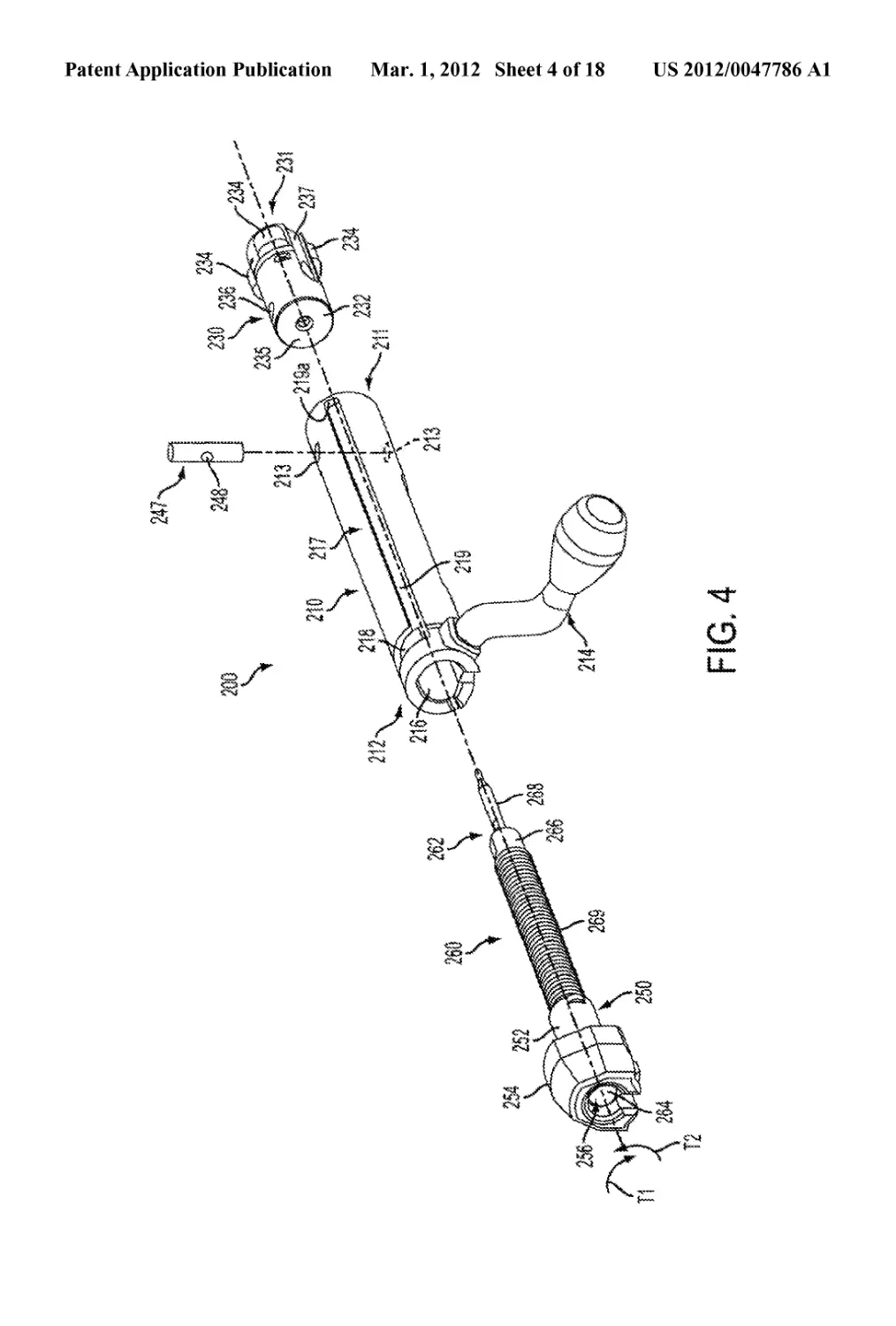
[0013] FIG. 4 is an exploded view of a bolt assembly of the
firearm;
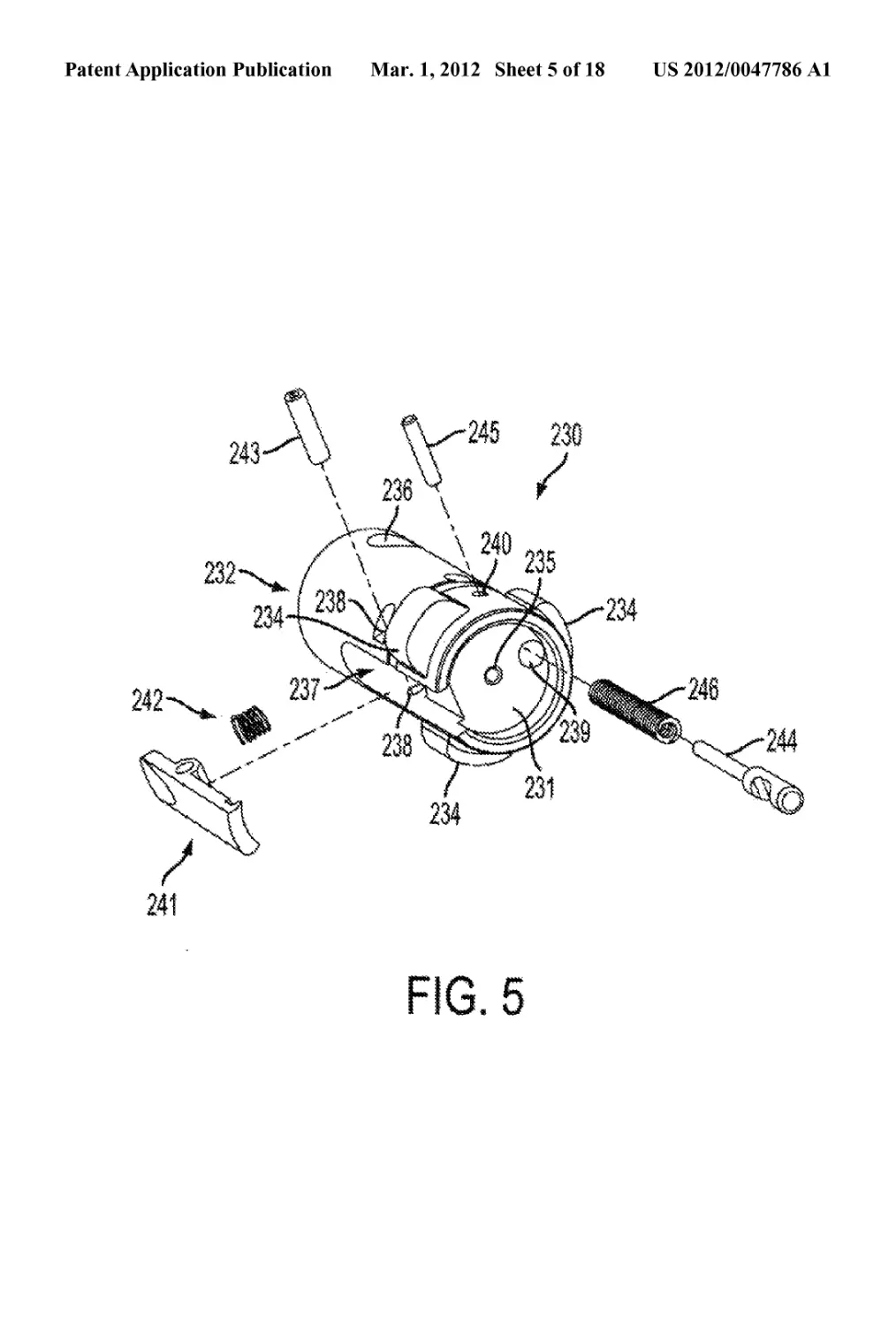
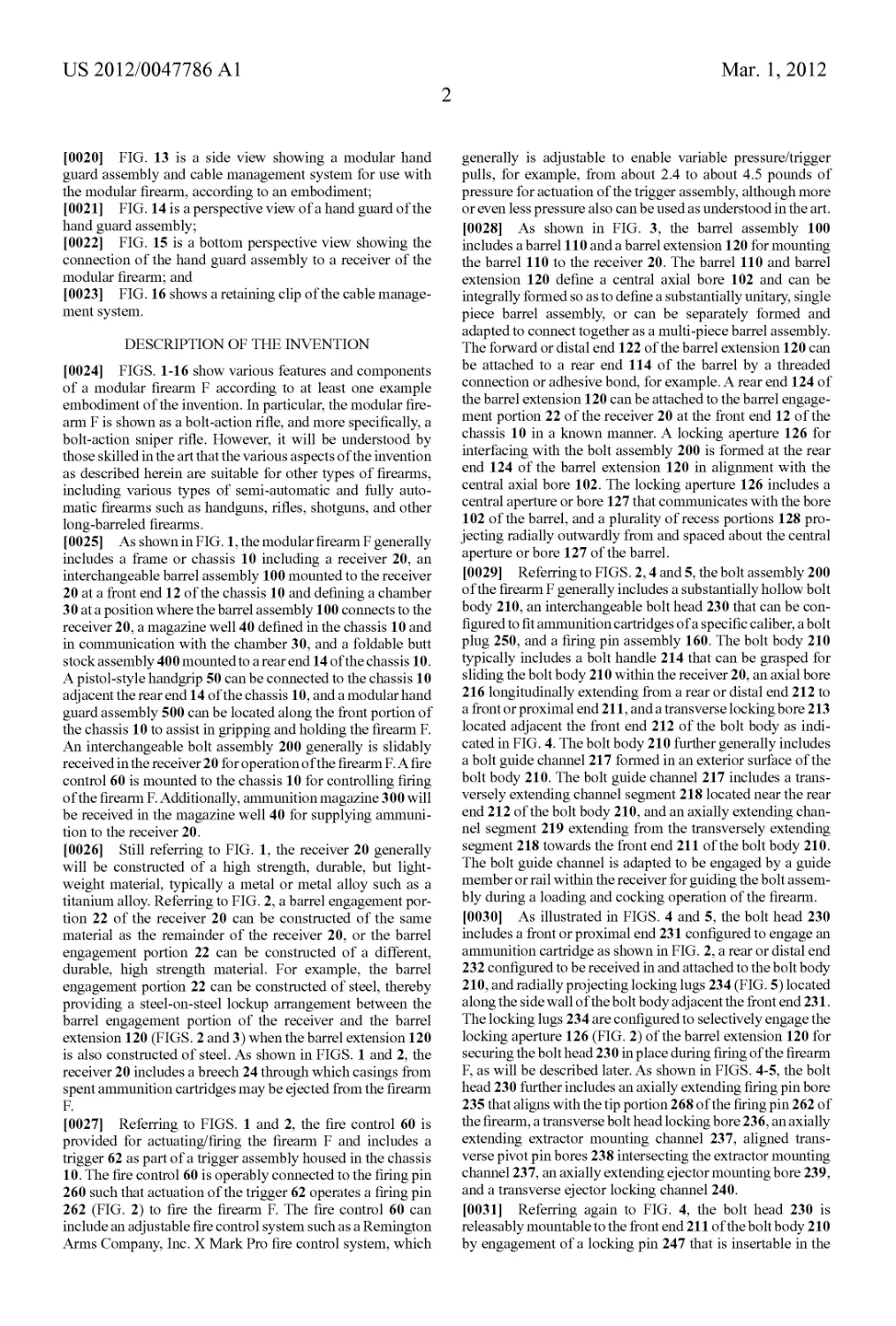
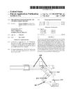
[0014] FIG. 5 shows an interchangeable bolt head of the
bolt assembly, according to an embodiment, for use with the
modular firearm of the present invention;
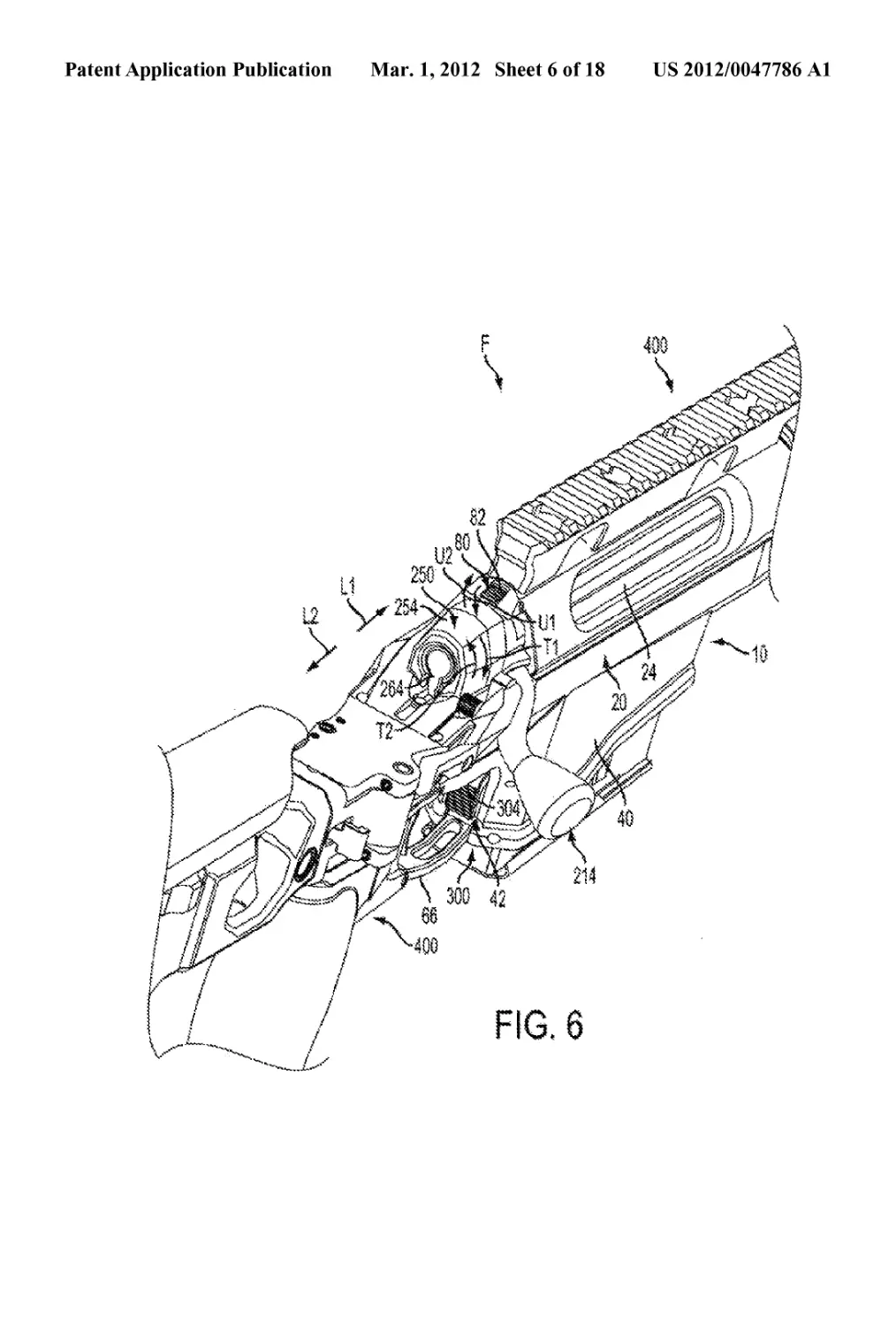
[0015] FIG. 6 is a perspective view of the firearm illustrat-
ing operation of the bolt assembly of FIG. 5;
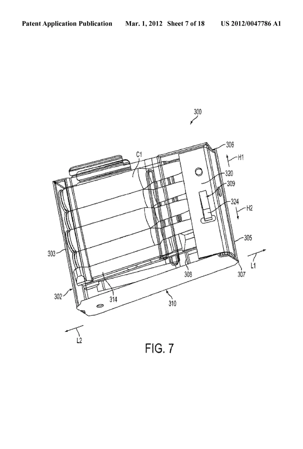
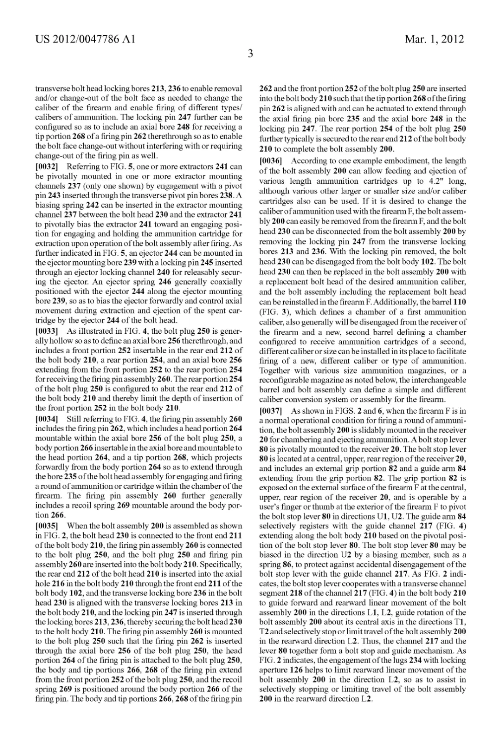
[0016] FIGS. 7-8 show an embodiment of a modular
ammunition magazine for use with the modular firearm of the
present invention;
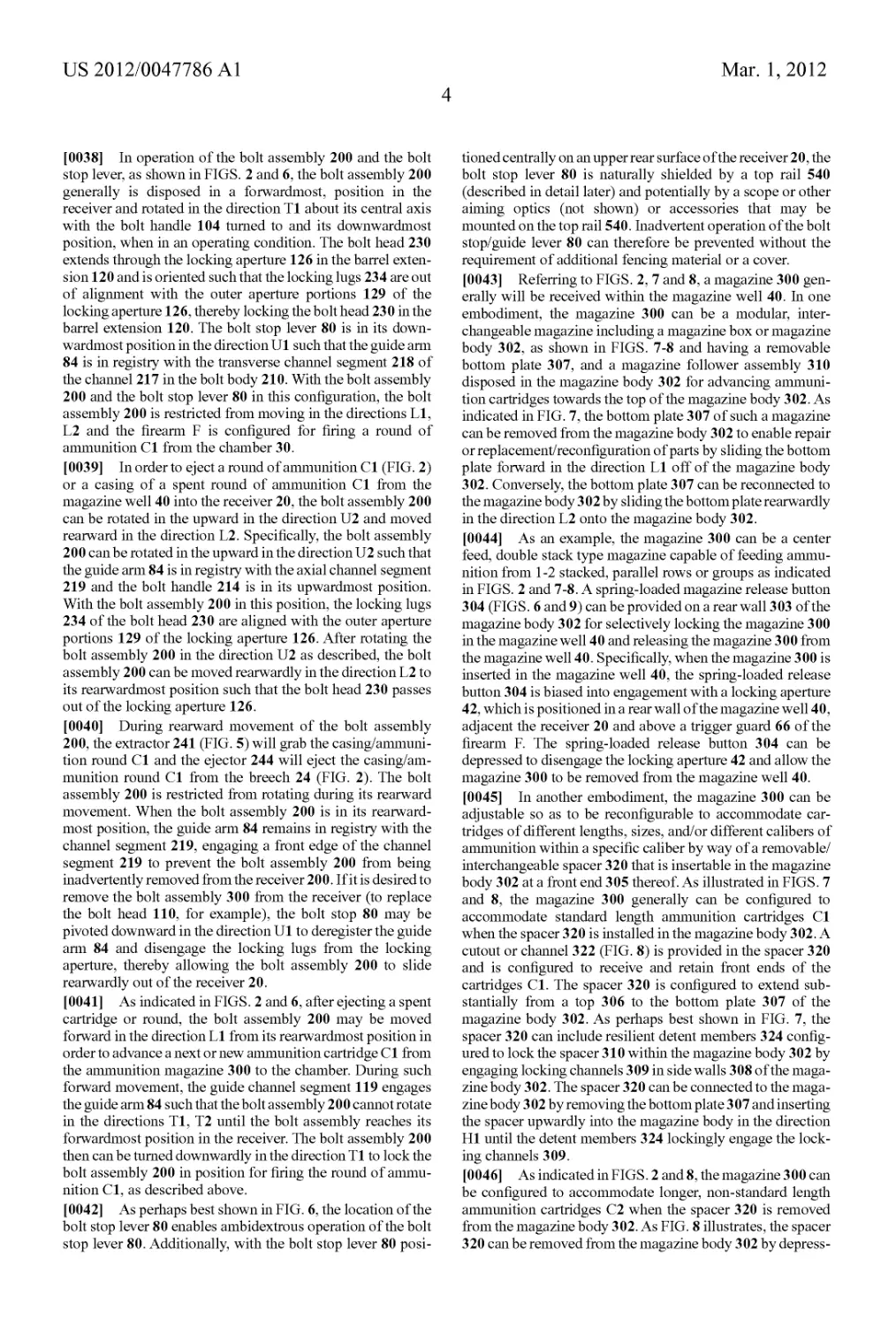
[0017] FIGS. 9 and 10 show an ammunition magazine con-
version block, according to one example embodiment;
[0018] FIGS. 11A-11C are partially transparent views
showing a butt stock assembly for the modular firearm,
according to one example embodiment, and illustrate a pro-
cess for folding the butt stock assembly from an extended
position for operating the firearm to folded position for trans-
porting the firearm;
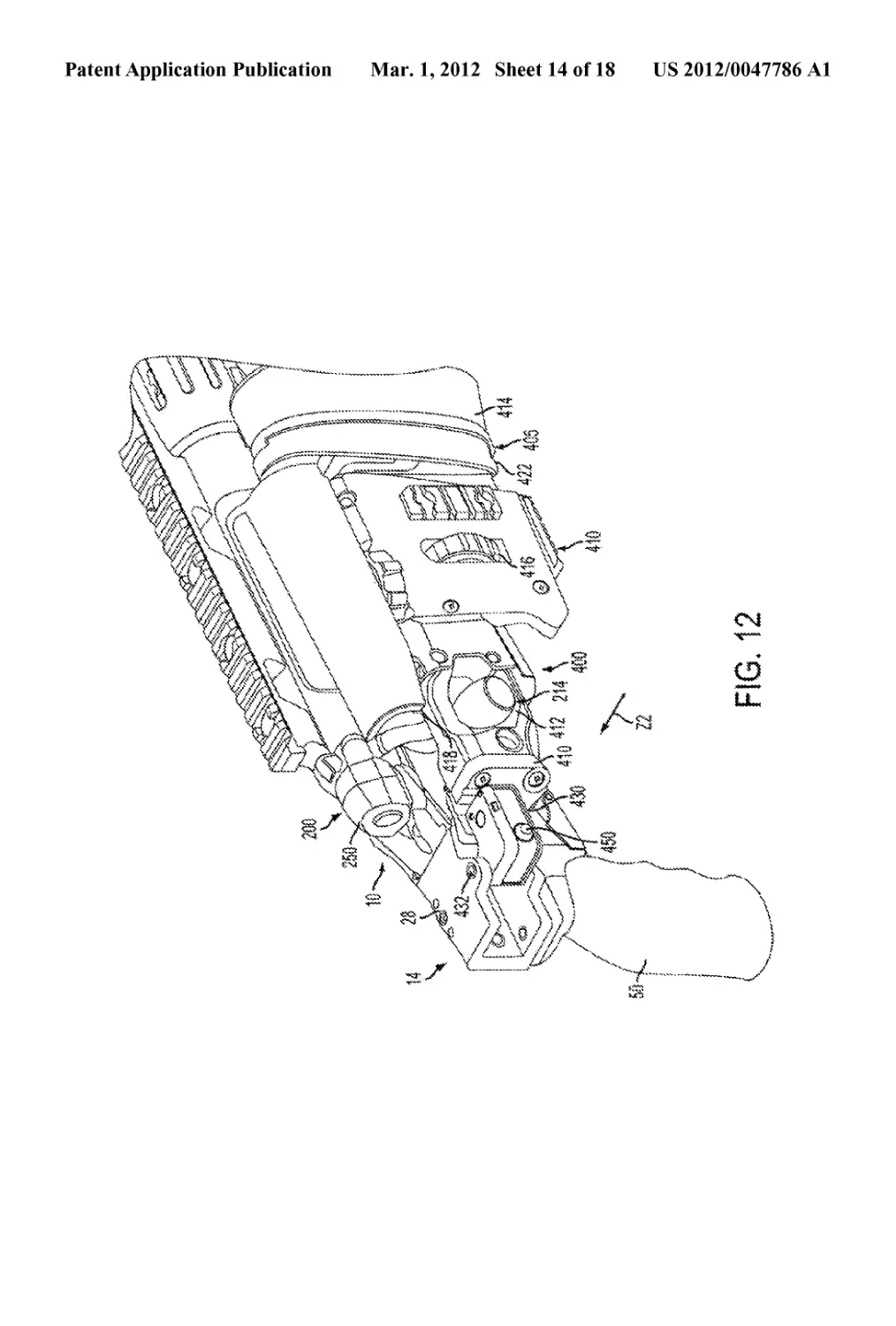
[0019] FIG. 12 is a perspective view of the butt stock in a
folded position;
US 2012/0047786 Al
Mar. 1,2012
2
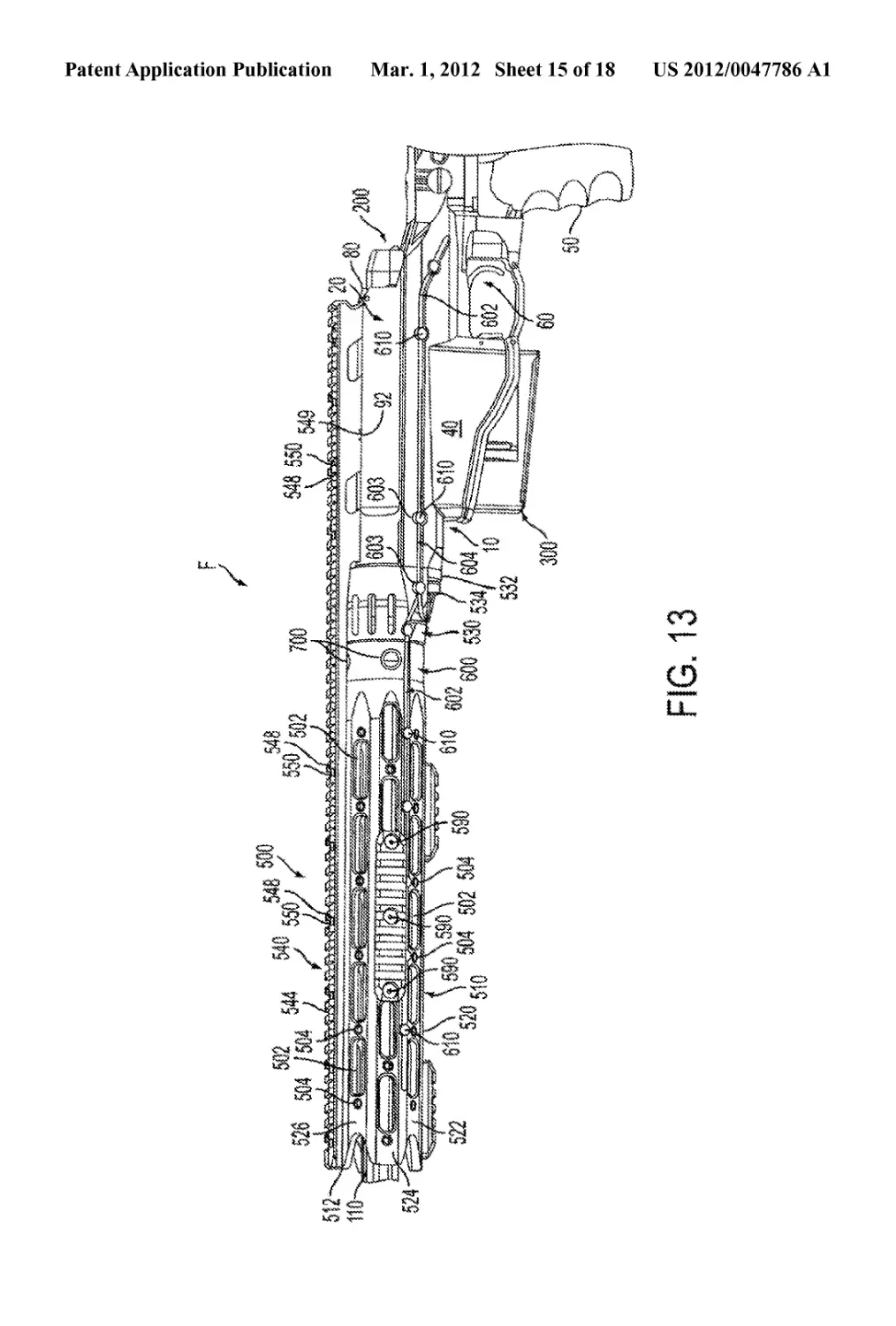
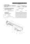
[0020] FIG. 13 is a side view showing a modular hand
guard assembly and cable management system for use with
the modular firearm, according to an embodiment;
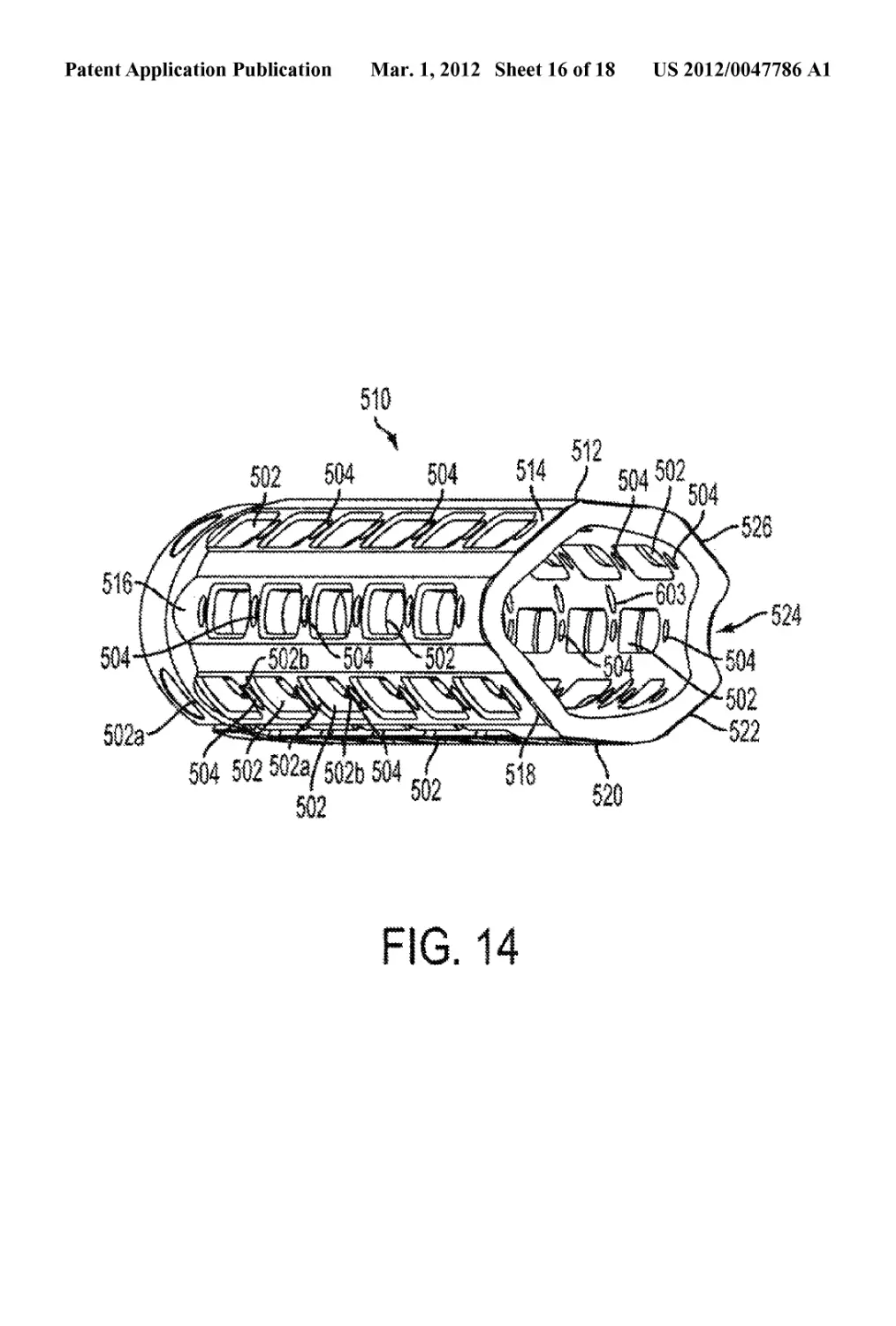
[0021] FIG. 14 is a perspective view of a hand guard of the
hand guard assembly;
[0022] FIG. 15 is a bottom perspective view showing the
connection of the hand guard assembly to a receiver of the
modular firearm; and
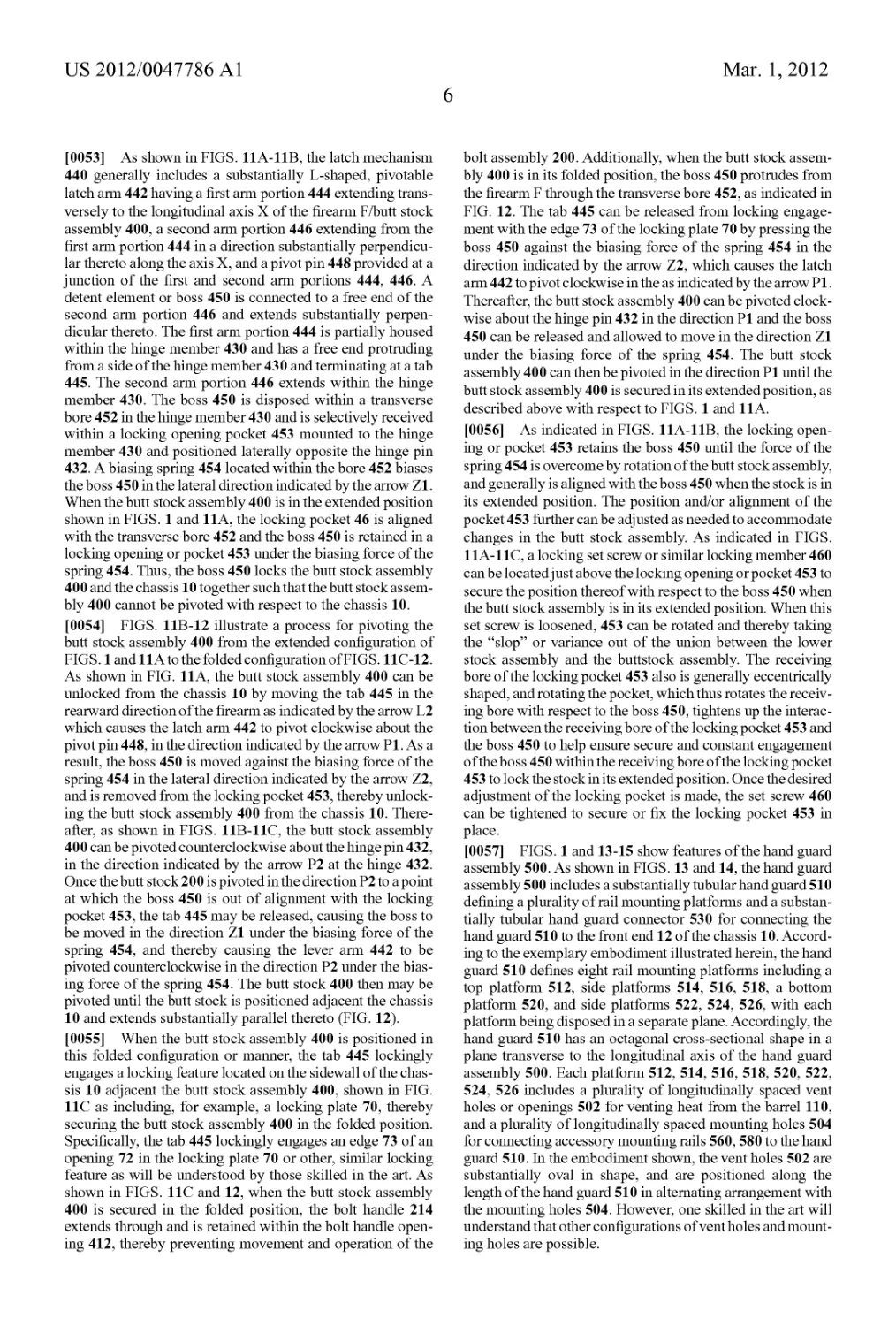
[0023] FIG. 16 shows a retaining clip of the cable manage-
ment system.
DESCRIPTION OF THE INVENTION
[0024] FIGS. 1-16 show various features and components
of a modular firearm F according to at least one example
embodiment of the invention. In particular, the modular fire-
arm F is shown as a bolt-action rifle, and more specifically, a
bolt-action sniper rifle. However, it will be understood by
those skilled in the art that the various aspects of the invention
as described herein are suitable for other types of firearms,
including various types of semi-automatic and fully auto-
matic firearms such as handguns, rifles, shotguns, and other
long-barreled firearms.
[0025] As shown in FIG. 1, the modular firearm F generally
includes a frame or chassis 10 including a receiver 20, an
interchangeable barrel assembly 100 mounted to the receiver
20 at a front end 12 of the chassis 10 and defining a chamber
30 at a position where the barrel assembly 100 connects to the
receiver 20, a magazine well 40 defined in the chassis 10 and
in communication with the chamber 30, and a foldable butt
stockassembly 400 mounted to a rear end 14 of the chassis 10.
A pistol-style handgrip 50 can be connected to the chassis 10
adjacent the rear end 14 ofthe chassis 10, and a modular hand
guard assembly 500 can be located along the front portion of
the chassis 10 to assist in gripping and holding the firearm F.
An interchangeable bolt assembly 200 generally is slidably
received in the receiver 20 for operation of the firearm F. A fire
control 60 is mounted to the chassis 10 for controlling firing
of the firearm F. Additionally, ammunition magazine 300 will
be received in the magazine well 40 for supplying ammuni-
tion to the receiver 20.
[0026] Still referring to FIG. 1, the receiver 20 generally
will be constructed of a high strength, durable, but light-
weight material, typically a metal or metal alloy such as a
titanium alloy. Referring to FIG. 2, a barrel engagement por-
tion 22 of the receiver 20 can be constructed of the same
material as the remainder of the receiver 20, or the barrel
engagement portion 22 can be constructed of a different,
durable, high strength material. For example, the barrel
engagement portion 22 can be constructed of steel, thereby
providing a steel-on-steel lockup arrangement between the
barrel engagement portion of the receiver and the barrel
extension 120 (FIGS. 2 and 3) when the barrel extension 120
is also constructed of steel. As shown in FIGS. 1 and 2, the
receiver 20 includes a breech 24 through which casings from
spent ammunition cartridges may be ejected from the firearm
F.
[0027] Referring to FIGS. 1 and 2, the fire control 60 is
provided for actuating/firing the firearm F and includes a
trigger 62 as part of a trigger assembly housed in the chassis
10. The fire control 60 is operably connected to the firing pin
260 such that actuation of the trigger 62 operates a firing pin
262 (FIG. 2) to fire the firearm F. The fire control 60 can
include an adjustable fire control system such as a Remington
Arms Company, Inc. X Mark Pro fire control system, which
generally is adjustable to enable variable pressure/trigger
pulls, for example, from about 2.4 to about 4.5 pounds of
pressure for actuation of the trigger assembly, although more
or even less pressure also can be used as understood in the art.
[0028] As shown in FIG. 3, the barrel assembly 100
includes a barrel 110 and a barrel extension 120 for mounting
the barrel 110 to the receiver 20. The barrel 110 and barrel
extension 120 define a central axial bore 102 and can be
integrally formed so as to define a substantially unitary, single
piece barrel assembly, or can be separately formed and
adapted to connect together as a multi-piece barrel assembly.
The forward or distal end 122 of the barrel extension 120 can
be attached to a rear end 114 of the barrel by a threaded
connection or adhesive bond, for example. A rear end 124 of
the barrel extension 120 can be attached to the barrel engage-
ment portion 22 of the receiver 20 at the front end 12 of the
chassis 10 in a known maimer. A locking aperture 126 for
interfacing with the bolt assembly 200 is formed at the rear
end 124 of the barrel extension 120 in alignment with the
central axial bore 102. The locking aperture 126 includes a
central aperture or bore 127 that communicates with the bore
102 of the barrel, and a plurality of recess portions 128 pro-
jecting radially outwardly from and spaced about the central
aperture or bore 127 of the barrel.
[0029] Referring to FIGS. 2,4 and 5, the bolt assembly 200
of the firearm F generally includes a substantially hollow bolt
body 210, an interchangeable bolt head 230 that can be con-
figured to fit ammunition cartridges of a specific caliber, a bolt
plug 250, and a firing pin assembly 160. The bolt body 210
typically includes a bolt handle 214 that can be grasped for
sliding the bolt body 210 within the receiver 20, an axial bore
216 longitudinally extending from a rear or distal end 212 to
a front or proximal end 211, and a transverse locking bore 213
located adjacent the front end 212 of the bolt body as indi-
cated in FIG. 4. The bolt body 210 further generally includes
a bolt guide channel 217 formed in an exterior surface of the
bolt body 210. The bolt guide channel 217 includes a trans-
versely extending channel segment 218 located near the rear
end 212 of the bolt body 210, and an axially extending chan-
nel segment 219 extending from the transversely extending
segment 218 towards the front end 211 of the bolt body 210.
The bolt guide channel is adapted to be engaged by a guide
member or rail within the receiver for guiding the bolt assem-
bly during a loading and cocking operation of the firearm.
[0030] As illustrated in FIGS. 4 and 5, the bolt head 230
includes a front or proximal end 231 configured to engage an
ammunition cartridge as shown in FIG. 2, a rear or distal end
232 configured to be received in and attached to the bolt body
210, and radially projecting locking lugs 234 (FIG. 5) located
along the side wall of the bolt body adjacent the front end 231.
The locking lugs 234 are configured to selectively engage the
locking aperture 126 (FIG. 2) of the barrel extension 120 for
securing the bolt head 23 0 in place during firing of the firearm
F, as will be described later. As shown in FIGS. 4-5, the bolt
head 230 further includes an axially extending firing pin bore
235 that aligns with the tip portion 268 of the firing pin 262 of
the firearm, a transverse bolt head locking bore 236, an axially
extending extractor mounting channel 237, aligned trans-
verse pivot pin bores 238 intersecting the extractor mounting
channel 237, an axially extending ejector mounting bore 239,
and a transverse ejector locking channel 240.
[0031] Referring again to FIG. 4, the bolt head 230 is
releasably mountable to the front end 211 of the bolt body 210
by engagement of a locking pin 247 that is insertable in the
US 2012/0047786 Al
Mar. 1,2012
3
transverse bolt head locking bores 213,236 to enable removal
and/or change-out of the bolt face as needed to change the
caliber of the firearm and enable firing of different types/
calibers of ammunition. The locking pin 247 further can be
configured so as to include an axial bore 248 for receiving a
tip portion 268 of a firing pin 262 therethrough so as to enable
the bolt face change-out without interfering with or requiring
change-out of the firing pin as well.
[0032] Referring to FIG. 5, one or more extractors 241 can
be pivotally mounted in one or more extractor mounting
channels 237 (only one shown) by engagement with a pivot
pin 243 inserted through the transverse pivot pin bores 238. A
biasing spring 242 can be inserted in the extractor mounting
channel 237 between the bolt head 230 and the extractor 241
to pivotally bias the extractor 241 toward an engaging posi-
tion for engaging and holding the ammunition cartridge for
extraction upon operation of the bolt assembly after firing. As
further indicated in FIG. 5, an ejector 244 can be mounted in
the ejector mounting bore 239 with a locking pin 245 inserted
through an ejector locking channel 240 for releasably secur-
ing the ejector. An ejector spring 246 generally coaxially
positioned with the ejector 244 along the ejector mounting
bore 239, so as to bias the ejector forwardly and control axial
movement during extraction and ejection of the spent car-
tridge by the ejector 244 of the bolt head.
[0033] As illustrated in FIG. 4, the bolt plug 250 is gener-
ally hollow so as to define an axial bore 256 therethrough, and
includes a front portion 252 insertable in the rear end 212 of
the bolt body 210, a rear portion 254, and an axial bore 256
extending from the front portion 252 to the rear portion 254
for receiving the firing pin assembly 260. The rear portion 254
of the bolt plug 250 is configured to abut the rear end 212 of
the bolt body 210 and thereby limit the depth of insertion of
the front portion 252 in the bolt body 210.
[0034] Still referring to FIG. 4, the firing pin assembly 260
includes the firing pin 262, which includes a head portion 264
mountable within the axial bore 256 of the bolt plug 250, a
body portion 266 insertable in the axial bore and mountable to
the head portion 264, and a tip portion 268, which projects
forwardly from the body portion 264 so as to extend through
the bore 235 of the bolt head assembly for engaging and firing
a round of ammunition or cartridge within the chamber of the
firearm. The firing pin assembly 260 further generally
includes a recoil spring 269 mountable around the body por-
tion 266.
[0035] When the bolt assembly 200 is assembled as shown
in FIG. 2, the bolt head 230 is connected to the front end 211
of the bolt body 210, the firing pin assembly 260 is connected
to the bolt plug 250, and the bolt plug 250 and firing pin
assembly 260 are inserted into the bolt body 210. Specifically,
the rear end 212 of the bolt head 210 is inserted into the axial
hole 216 in the bolt body 210 through the front end 211 of the
bolt body 102, and the transverse locking bore 236 in the bolt
head 230 is aligned with the transverse locking bores 213 in
the bolt body 210, and the locking pin 247 is inserted through
the locking bores 213,236, thereby securing the bolt head 230
to the bolt body 210. The firing pin assembly 260 is mounted
to the bolt plug 250 such that the firing pin 262 is inserted
through the axial bore 256 of the bolt plug 250, the head
portion 264 of the firing pin is attached to the bolt plug 250,
the body and tip portions 266, 268 of the firing pin extend
from the front portion 252 of the bolt plug 250, and the recoil
spring 269 is positioned around the body portion 266 of the
firing pin. The body and tip portions 266,268 of the firing pin
262 and the front portion 252 of the bolt plug 250 are inserted
into the bolt body 210 such that the tip portion 268 of the firing
pin 262 is aligned with and can be actuated to extend through
the axial firing pin bore 235 and the axial bore 248 in the
locking pin 247. The rear portion 254 of the bolt plug 250
further typically is secured to the rear end 212 of the bolt body
210 to complete the bolt assembly 200.
[0036] According to one example embodiment, the length
of the bolt assembly 200 can allow feeding and ejection of
various length ammunition cartridges up to 4.2" long,
although various other larger or smaller size and/or caliber
cartridges also can be used. If it is desired to change the
caliber of ammunition used with the firearm F, the bolt assem-
bly 200 can easily be removed from the firearm F, and the bolt
head 230 can be disconnected from the bolt assembly 200 by
removing the locking pin 247 from the transverse locking
bores 213 and 236. With the locking pin removed, the bolt
head 230 can be disengaged from the bolt body 102. The bolt
head 230 can then be replaced in the bolt assembly 200 with
a replacement bolt head of the desired ammunition caliber,
and the bolt assembly including the replacement bolt head
can be reinstalled in the firearm F. Additionally, the barrel 110
(FIG. 3), which defines a chamber of a first ammunition
caliber, also generally will be disengaged from the receiver of
the firearm and a new, second barrel defining a chamber
configured to receive ammunition cartridges of a second,
different caliber or size can be installed in its place to facilitate
firing of a new, different caliber or type of ammunition.
Together with various size ammunition magazines, or a
reconfigurable magazine as noted below, the interchangeable
barrel and bolt assembly can define a simple and different
caliber conversion system or assembly for the firearm.
[0037] As shown in FIGS. 2 and 6, when the firearm F is in
a normal operational condition for firing a round of ammuni-
tion, the bolt assembly 200 is slidably mounted in the receiver
20 for chambering and ejecting ammunition. A bolt stop lever
80 is pivotally mounted to the receiver 20. The bolt stop lever
80 is located at a central, upper, rear region of the receiver 20,
and includes an external grip portion 82 and a guide arm 84
extending from the grip portion 82. The grip portion 82 is
exposed on the external surface of the firearm F at the central,
upper, rear region of the receiver 20, and is operable by a
user’s finger or thumb at the exterior of the firearm F to pivot
the bolt stop lever 80 in directions Ul, U2. The guide arm 84
selectively registers with the guide channel 217 (FIG. 4)
extending along the bolt body 210 based on the pivotal posi-
tion of the bolt stop lever 80. The bolt stop lever 80 may be
biased in the direction U2 by a biasing member, such as a
spring 86, to protect against accidental disengagement of the
bolt stop lever with the guide channel 217. As FIG. 2 indi-
cates, the bolt stop lever cooperates with a transverse channel
segment 218 of the channel 217 (FIG. 4) in the bolt body 210
to guide forward and rearward linear movement of the bolt
assembly 200 in the directions LI, L2, guide rotation of the
bolt assembly 200 about its central axis in the directions Tl,
T2 and selectively stop or limit travel of the bolt assembly 200
in the rearward direction L2. Thus, the channel 217 and the
lever 80 together form a bolt stop and guide mechanism. As
FIG. 2 indicates, the engagement of the lugs 234 with locking
aperture 126 helps to limit rearward linear movement of the
bolt assembly 200 in the direction L2, so as to assist in
selectively stopping or limiting travel of the bolt assembly
200 in the rearward direction L2.
US 2012/0047786 Al
Mar. 1,2012
4
[0038] In operation of the bolt assembly 200 and the bolt
stop lever, as shown in FIGS. 2 and 6, the bolt assembly 200
generally is disposed in a forwardmost, position in the
receiver and rotated in the direction T1 about its central axis
with the bolt handle 104 turned to and its downwardmost
position, when in an operating condition. The bolt head 230
extends through the locking aperture 126 in the barrel exten-
sion 120 and is oriented such that the locking lugs 234 are out
of alignment with the outer aperture portions 129 of the
locking aperture 126, thereby locking the bolt head 230 in the
barrel extension 120. The bolt stop lever 80 is in its down-
wardmost position in the direction U1 such that the guide arm
84 is in registry with the transverse channel segment 218 of
the channel 217 in the bolt body 210. With the bolt assembly
200 and the bolt stop lever 80 in this configuration, the bolt
assembly 200 is restricted from moving in the directions LI,
L2 and the firearm F is configured for firing a round of
ammunition Cl from the chamber 30.
[0039] In order to eject a round of ammunition Cl (FIG. 2)
or a casing of a spent round of ammunition Cl from the
magazine well 40 into the receiver 20, the bolt assembly 200
can be rotated in the upward in the direction U2 and moved
rearward in the direction L2. Specifically, the bolt assembly
200 can be rotated in the upward in the direction U2 such that
the guide arm 84 is in registry with the axial channel segment
219 and the bolt handle 214 is in its upwardmost position.
With the bolt assembly 200 in this position, the locking lugs
234 of the bolt head 230 are aligned with the outer aperture
portions 129 of the locking aperture 126. After rotating the
bolt assembly 200 in the direction U2 as described, the bolt
assembly 200 can be moved rearwardly in the direction L2 to
its rearwardmost position such that the bolt head 230 passes
out of the locking aperture 126.
[0040] During rearward movement of the bolt assembly
200, the extractor 241 (FIG. 5) will grab the casing/ammuni-
tion round Cl and the ejector 244 will eject the casing/am-
munition round Cl from the breech 24 (FIG. 2). The bolt
assembly 200 is restricted from rotating during its rearward
movement. When the bolt assembly 200 is in its rearward-
most position, the guide arm 84 remains in registry with the
channel segment 219, engaging a front edge of the channel
segment 219 to prevent the bolt assembly 200 from being
inadvertently removed from the receiver 200. Ifitis desired to
remove the bolt assembly 300 from the receiver (to replace
the bolt head 110, for example), the bolt stop 80 may be
pivoted downward in the direction U1 to deregister the guide
arm 84 and disengage the locking lugs from the locking
aperture, thereby allowing the bolt assembly 200 to slide
rearwardly out of the receiver 20.
[0041] As indicated in FIGS. 2 and 6, after ejecting a spent
cartridge or round, the bolt assembly 200 may be moved
forward in the direction LI from its rearwardmost position in
order to advance a next or new ammunition cartridge Cl from
the ammunition magazine 300 to the chamber. During such
forward movement, the guide channel segment 119 engages
the guide arm 84 such that the bolt assembly 200 cannot rotate
in the directions Tl, T2 until the bolt assembly reaches its
forwardmost position in the receiver. The bolt assembly 200
then can be turned downwardly in the direction Tl to lock the
bolt assembly 200 in position for firing the round of ammu-
nition Cl, as described above.
[0042] As perhaps best shown in FIG. 6, the location of the
bolt stop lever 80 enables ambidextrous operation of the bolt
stop lever 80. Additionally, with the bolt stop lever 80 posi-
tioned centrally on an upper rear surface of the receiver 20, the
bolt stop lever 80 is naturally shielded by a top rail 540
(described in detail later) and potentially by a scope or other
aiming optics (not shown) or accessories that may be
mounted on the top rail 540. Inadvertent operation of the bolt
stop/guide lever 80 can therefore be prevented without the
requirement of additional fencing material or a cover.
[0043] Referring to FIGS. 2, 7 and 8, a magazine 300 gen-
erally will be received within the magazine well 40. In one
embodiment, the magazine 300 can be a modular, inter-
changeable magazine including a magazine box or magazine
body 302, as shown in FIGS. 7-8 and having a removable
bottom plate 307, and a magazine follower assembly 310
disposed in the magazine body 302 for advancing ammuni-
tion cartridges towards the top of the magazine body 302. As
indicated in FIG. 7, the bottom plate 307 of such a magazine
can be removed from the magazine body 302 to enable repair
orreplacement/reconfiguration of parts by sliding the bottom
plate forward in the direction LI off of the magazine body
302. Conversely, the bottom plate 307 can be reconnected to
the magazine body 3 02 by sliding the bottom plate rearwardly
in the direction L2 onto the magazine body 302.
[0044] As an example, the magazine 300 can be a center
feed, double stack type magazine capable of feeding ammu-
nition from 1-2 stacked, parallel rows or groups as indicated
in FIGS. 2 and 7-8. A spring-loaded magazine release button
304 (FIGS. 6 and 9) can be provided on a rear wall 303 of the
magazine body 302 for selectively locking the magazine 300
in the magazine well 40 and releasing the magazine 300 from
the magazine well 40. Specifically, when the magazine 300 is
inserted in the magazine well 40, the spring-loaded release
button 304 is biased into engagement with a locking aperture
42, which is positioned in a rear wall of the magazine well 40,
adjacent the receiver 20 and above a trigger guard 66 of the
firearm F. The spring-loaded release button 304 can be
depressed to disengage the locking aperture 42 and allow the
magazine 300 to be removed from the magazine well 40.
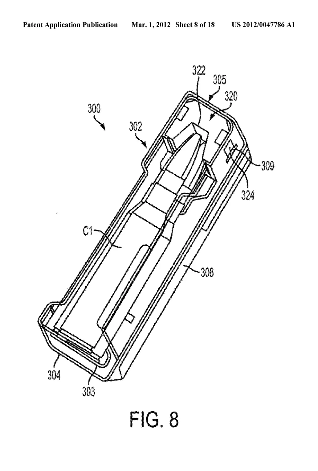
[0045] In another embodiment, the magazine 300 can be
adjustable so as to be reconfigurable to accommodate car-
tridges of different lengths, sizes, and/or different calibers of
ammunition within a specific caliber by way of a removable/
interchangeable spacer 320 that is insertable in the magazine
body 302 at a front end 305 thereof. As illustrated in FIGS. 7
and 8, the magazine 300 generally can be configured to
accommodate standard length ammunition cartridges Cl
when the spacer 320 is installed in the magazine body 302. A
cutout or channel 322 (FIG. 8) is provided in the spacer 320
and is configured to receive and retain front ends of the
cartridges Cl. The spacer 320 is configured to extend sub-
stantially from a top 306 to the bottom plate 307 of the
magazine body 302. As perhaps best shown in FIG. 7, the
spacer 320 can include resilient detent members 324 config-
ured to lock the spacer 310 within the magazine body 302 by
engaging locking channels 309 in side walls 308 of the maga-
zine body 302. The spacer 320 can be connected to the maga-
zine body 3 02 by removing the bottom plate 307 and inserting
the spacer upwardly into the magazine body in the direction
Hl until the detent members 324 lockingly engage the lock-
ing channels 309.
[0046] As indicated in FIGS. 2 and 8, the magazine 300 can
be configured to accommodate longer, non-standard length
ammunition cartridges C2 when the spacer 320 is removed
from the magazine body 302. As FIG. 8 illustrates, the spacer
320 can be removed from the magazine body 302 by depress-
US 2012/0047786 Al
Mar. 1,2012
5
ing the detent members 324 until the detent members 324
disengage the locking channels 307, and then moving the
spacer 320 downward in the direction H2, out of the magazine
body 302.
[0047] It is further envisioned that the spacer 320 can be
interchanged with other spacers of different configurations to
accommodate other ammunition cartridges of various
lengths/sizes and/or calibers. Additionally, the magazine 300
may be interchanged with other magazines configured to
accommodate ammunition cartridges of different calibers
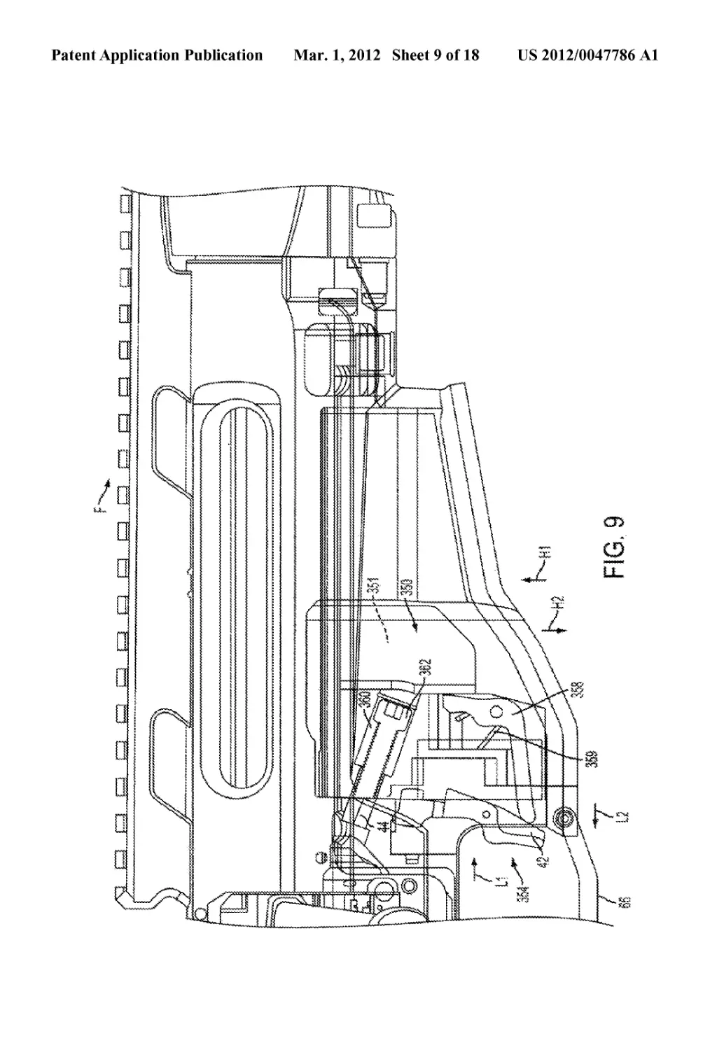
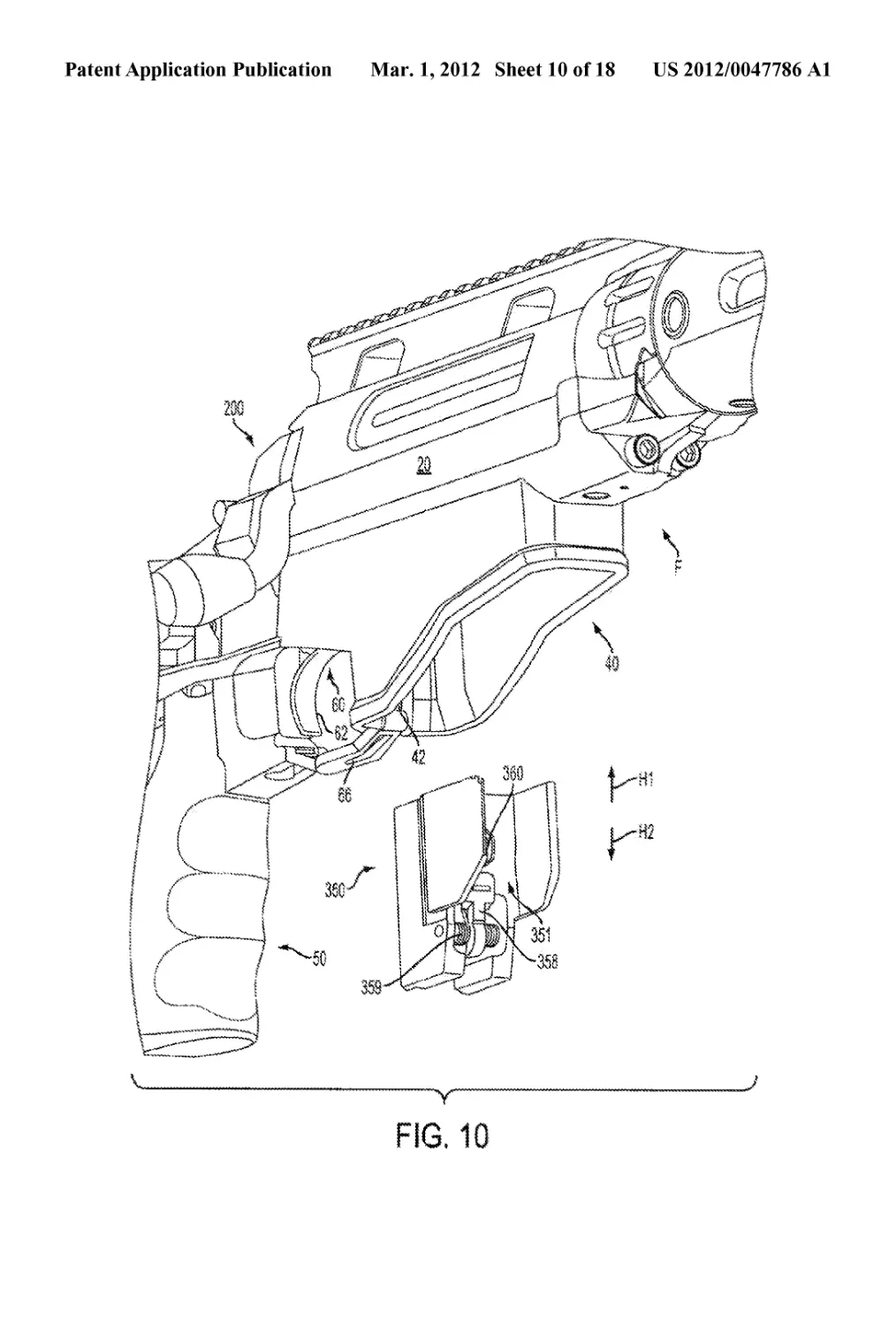
and/or lengths. For example, as shown in FIGS. 9-10, the
receiver 20 can include a conversion block mounting bore 44
adjacent the magazine well 40 for mounting a magazine con-
version block 350 in the magazine well 40. The magazine
conversion block 350 can be, for example, a 7.62 mm NATO
conversion block that enables smaller 7.62 mm NATO ammu-
nition magazines to be inserted in the magazine well 40.
Referencing FIG. 10, the magazine conversion block 350
includes a cradle portion 351 for receiving an ammunition
magazine (not shown) that is smaller than the magazine 300
described above. As illustrated in FIGS. 9 and 10, the maga-
zine conversion block 350 includes catch assembly 354
including a release arm 356 that is biased rearward in the
direction L2 by a pivotable biasing arm 358. The biasing arm
358 is biased rearward against the release arm 356 by a
torsional spring 359. The magazine conversion block 350 also
has a central mounting bore 360 configured for alignment
with the conversion block mounting bore 44.
[0048] As can be understood from FIGS. 9 and 10, the
magazine conversion block 350 can be installed in the maga-
zine well 40 by sliding the conversion block 350 upward in
the direction Hl until the release arm of the magazine release
button 304 (FIG. 9) snaps into the locking aperture 42 above
the trigger guard 66 and the central mounting bore 360 is
aligned with the conversion block mounting bore 44. A fas-
tener 362, such as a bolt or screw, can then be inserted into the
bores 360, 44 to secure the magazine conversion block 350 in
place. The magazine conversion block 350 can be uninstalled
from the magazine well 40 by removing the fastener 362,
pressing the release arm 356 forward in the direction LI
against the bias of the biasing arm 358 until the release arm
356 disengages the locking aperture 42, and then sliding the
magazine conversion block 350 downward in the direction
H2 out of the magazine well 40.
[0049] It can be understood from the above disclosure that,
due to the reconfigurability of the barrel assembly 100 and the
bolt assembly 200, the firearm F can be modified to operate
with ammunition of multiple calibers by changing or recon-
figuring only the barrel 100, bolt head 230, and the magazine
3 00 if needed. According to one example, the barrel assembly
100, bolt head 230 and magazine 300 may be packaged
together as a caliber conversion assembly or kit configured
for operation with ammunition of a specific caliber. Due to the
modular designs of the barrel assembly 100, the bolt assem-
bly 200 and the magazine 300, the barrel assembly 100, bolt
head 230 and magazine 300 can easily and quickly be
installed in and uninstalled from the firearm F to replace and
be replaced by respective barrel assemblies, bolt heads and
magazines as needed for accommodating operation of the
firearm with ammunition of other, different calibers and/or
sizes. For example, the firearm F can be convertible to operate
with ammunition calibers including, but not limited to, 338
Lapua Magnum and 300 Winchester Magnum. Furthermore,
with the use of the magazine conversion block 350, operation
of the firearm F with 7.62 mm NATO ammunition is possible.
It should be understood that, due to the modular design of the
barrel assembly 100, bolt assembly 200, the firearm F also can
be configured to be convertible to operate with ammunition
calibers other than those specifically discussed.
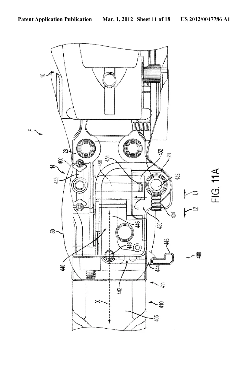
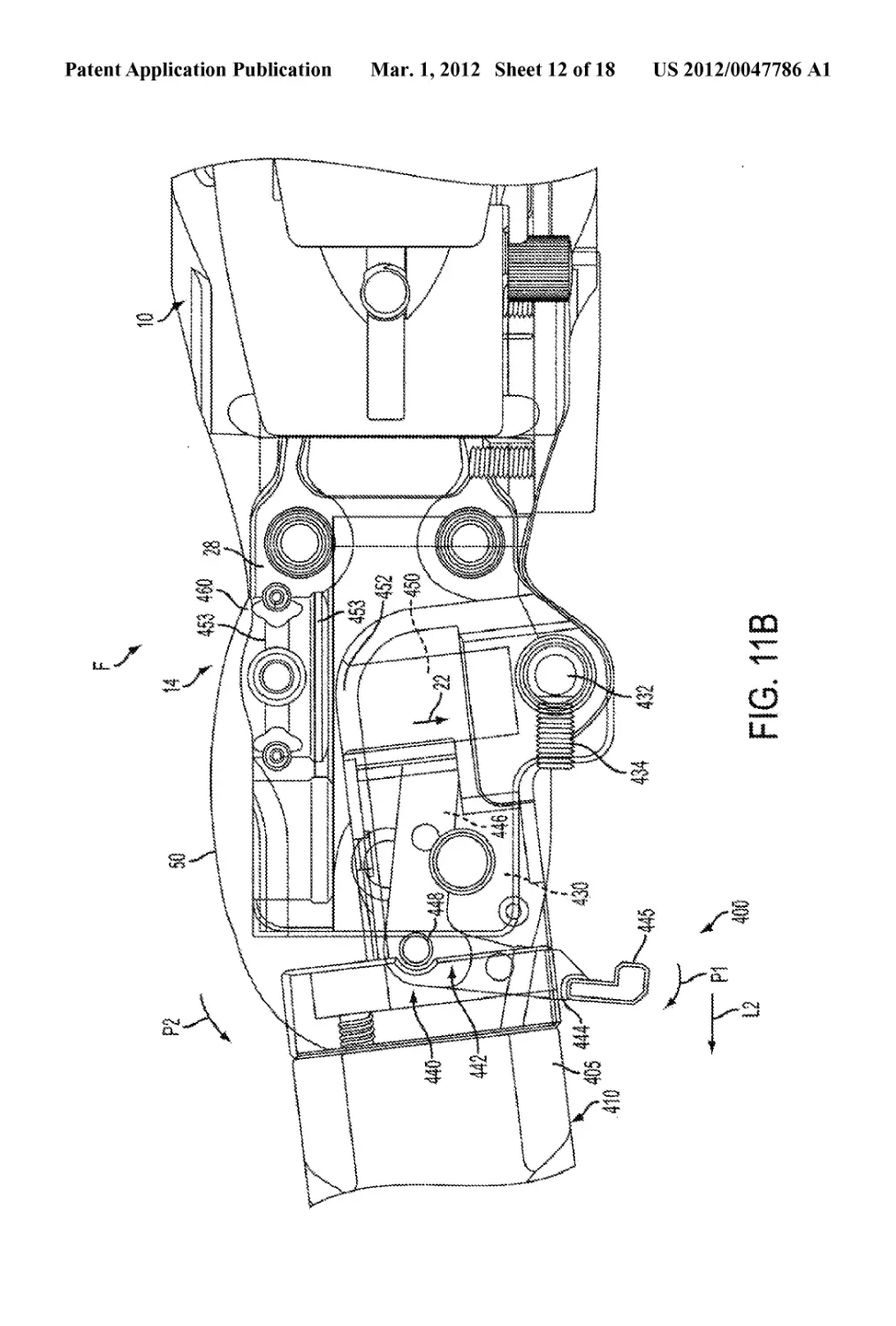
[0050] FIGS. 1 and 11A show the firearm F in a shooting
configuration with the foldable butt stock assembly 400 in an
extended position, in line with the chassis 10. As illustrated in
FIGS. 1 and 11A-11C, the butt stock assembly 400 includes
a butt stock 410 having a body or frame 405, and a hinge
member 430 connected to a front end 411 of the butt stock
410. The hinge member 430 is pivotally connected to hinge
bracket 28 at the rear or distal end 14 of the chassis by a hinge
pin 432. A threaded member such as a screw 434 can extend
transversely to and bear against the hinge pin or bolt 432
within the hinge member 43 0 to reduce slack or spacing in the
connection between the hinge member 430 and the hinge
bracket 28, and further helps prevent the hinge pin 432 from
separating from the chassis system. The axial position of the
screw 434 in the directions LI, L2 can be adjusted to vary the
degree to which the screw 434 bears against the hinge pin 432,
and thereby adjust the amount of slack in the connection
between the hinge member 430 and the hinge bracket 28. The
butt stock 410 includes a bolt handle window or opening 412
for receiving the bolt handle 214 when the stock is in the
folded (or retracted) configuration (FIGS. 11C-12).
[0051] An adjustable butt plate 414 further generally is
connected to a rear end of the stock body or frame 405. The
butt plate 414 can be vertically adjustable upwardly and
downwardly in the directions Hl and H2 by an adjustment
feature or member 422 adjacent a lower or bottom portion of
the butt plate and pad 414. The length of pull of the butt plate
is adjustable, as indicated by arrows L1-L2 in FIG. 1, by
engagement/rotation of a first adjustment knob or wheel 416.
An adjustable cheek piece or comb 418, typically formed
from a resilient cushioning material, also can be connected to
the stock body 405, extending upwardly from the butt stock
410, and is adjustable in a vertical direction with respect to the
firearm F via a second adjustment knob or wheel 420. As a
result, the comb or cheek piece 418 can be adjusted in the
direction of arrows H1-H2 to fit a user’s preference or com-
fort. The cheek piece further can be adjusted in the longitu-
dinal direction (indicated by arrows L1-L2) by disengaging
fasteners securing the check piece, adjusting it forwardly or
rearwardly as desired, and thereafter resecuring the cheek
piece with the fasteners. Additionally the length of pull of the
butt stock assembly 400 canbe adjustable via the addition and
removal of spacers, that are insertable between the butt stock
body 405 and the butt plate 414. According to an exemplary
embodiment, the length of pull may be adjustable between
about 12.4 inches and about 14.4 inches.
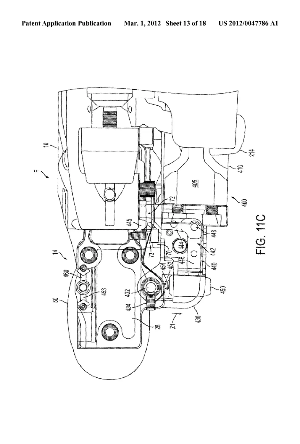
[0052] FIGS. 11A-11C illustrate a latch mechanism 440 for
the foldable butt stock assembly 400, which is operable to
selectively enable pivoting of the butt stock assembly 400
between an extended configuration (FIGS. 1 and 11A) and a
folded configuration (FIGS. 11C and 12). In the extended
position, the butt stock assembly 400 extends rearwardly
from the rear end 14 of the chassis 10, in line with the chassis
10 (FIGS. 1 and 11A), enabling the firearm to be operated. In
the folded configuration, the butt stock assembly 400 extends
forwardly from the rear end 14 of the chassis 10, substantially
parallel to the chassis 10, and is secured to a lateral side of the
chassis 10, thereby reducing the length of the firearm F to
facilitate transporting the firearm.
US 2012/0047786 Al
Mar. 1,2012
6
[0053] As shown in FIGS. 11A-11B, the latch mechanism
440 generally includes a substantially L-shaped, pivotable
latch arm 442 having a first arm portion 444 extending trans-
versely to the longitudinal axis X of the firearm F/butt stock
assembly 400, a second arm portion 446 extending from the
first arm portion 444 in a direction substantially perpendicu-
lar thereto along the axis X, and a pivot pin 448 provided at a
junction of the first and second arm portions 444, 446. A
detent element or boss 450 is connected to a free end of the
second arm portion 446 and extends substantially perpen-
dicular thereto. The first arm portion 444 is partially housed
within the hinge member 430 and has a free end protruding
from a side of the hinge member 430 and terminating at a tab
445. The second arm portion 446 extends within the hinge
member 430. The boss 450 is disposed within a transverse
bore 452 in the hinge member 430 and is selectively received
within a locking opening pocket 453 mounted to the hinge
member 430 and positioned laterally opposite the hinge pin
432. A biasing spring 454 located within the bore 452 biases
the boss 450 in the lateral direction indicated by the arrow Z1.
When the butt stock assembly 400 is in the extended position
shown in FIGS. 1 and 11 A, the locking pocket 46 is aligned
with the transverse bore 452 and the boss 450 is retained in a
locking opening or pocket 453 under the biasing force of the
spring 454. Thus, the boss 450 locks the butt stock assembly
400 and the chassis 10 together such that the butt stock assem-
bly 400 cannot be pivoted with respect to the chassis 10.
[0054] FIGS. 11B-12 illustrate a process for pivoting the
butt stock assembly 400 from the extended configuration of
FIGS. 1 andllA to the folded configuration ofFIGS. 11C-12.
As shown in FIG. 11A, the butt stock assembly 400 can be
unlocked from the chassis 10 by moving the tab 445 in the
rearward direction of the firearm as indicated by the arrow L2
which causes the latch arm 442 to pivot clockwise about the
pivot pin 448, in the direction indicated by the arrow Pl. As a
result, the boss 450 is moved against the biasing force of the
spring 454 in the lateral direction indicated by the arrow Z2,
and is removed from the locking pocket 453, thereby unlock-
ing the butt stock assembly 400 from the chassis 10. There-
after, as shown in FIGS. 11B-11C, the butt stock assembly
400 can be pivoted counterclockwise about the hinge pin 432,
in the direction indicated by the arrow P2 at the hinge 432.
Once the butt stock 200 is pivoted in the direction P2 to a point
at which the boss 450 is out of alignment with the locking
pocket 453, the tab 445 may be released, causing the boss to
be moved in the direction Z1 under the biasing force of the
spring 454, and thereby causing the lever arm 442 to be
pivoted counterclockwise in the direction P2 under the bias-
ing force of the spring 454. The butt stock 400 then may be
pivoted until the butt stock is positioned adjacent the chassis
10 and extends substantially parallel thereto (FIG. 12).
[0055] When the butt stock assembly 400 is positioned in
this folded configuration or maimer, the tab 445 lockingly
engages a locking feature located on the sidewall of the chas-
sis 10 adjacent the butt stock assembly 400, shown in FIG.
11C as including, for example, a locking plate 70, thereby
securing the butt stock assembly 400 in the folded position.
Specifically, the tab 445 lockingly engages an edge 73 of an
opening 72 in the locking plate 70 or other, similar locking
feature as will be understood by those skilled in the art. As
shown in FIGS. 11C and 12, when the butt stock assembly
400 is secured in the folded position, the bolt handle 214
extends through and is retained within the bolt handle open-
ing 412, thereby preventing movement and operation of the
bolt assembly 200. Additionally, when the butt stock assem-
bly 400 is in its folded position, the boss 450 protrudes from
the firearm F through the transverse bore 452, as indicated in
FIG. 12. The tab 445 can be released from locking engage-
ment with the edge 73 of the locking plate 70 by pressing the
boss 450 against the biasing force of the spring 454 in the
direction indicated by the arrow Z2, which causes the latch
arm 442 to pivot clockwise in the as indicated by the arrow Pl.
Thereafter, the butt stock assembly 400 can be pivoted clock-
wise about the hinge pin 432 in the direction Pl and the boss
450 can be released and allowed to move in the direction Z1
under the biasing force of the spring 454. The butt stock
assembly 400 can then be pivoted in the direction Pl until the
butt stock assembly 400 is secured in its extended position, as
described above with respect to FIGS. 1 and 11 A.
[0056] As indicated in FIGS. 11A-11B, the locking open-
ing or pocket 453 retains the boss 450 until the force of the
spring 454 is overcome by rotation of the butt stock assembly,
and generally is aligned with the boss 450 when the stock is in
its extended position. The position and/or alignment of the
pocket 453 further can be adjusted as needed to accommodate
changes in the butt stock assembly. As indicated in FIGS.
11A-11C, a locking set screw or similar locking member 460
can be located just above the locking opening or pocket 453 to
secure the position thereof with respect to the boss 450 when
the butt stock assembly is in its extended position. When this
set screw is loosened, 453 can be rotated and thereby taking
the “slop” or variance out of the union between the lower
stock assembly and the buttstock assembly. The receiving
bore of the locking pocket 453 also is generally eccentrically
shaped, and rotating the pocket, which thus rotates the receiv-
ing bore with respect to the boss 450, tightens up the interac-
tion between the receiving bore of the locking pocket 453 and
the boss 450 to help ensure secure and constant engagement
of the boss 450 within the receiving bore of the locking pocket
453 to lock the stock in its extended position. Once the desired
adjustment of the locking pocket is made, the set screw 460
can be tightened to secure or fix the locking pocket 453 in
place.
[0057] FIGS. 1 and 13-15 show features of the hand guard
assembly 500. As shown in FIGS. 13 and 14, the hand guard
assembly 500 includes a substantially tubular hand guard 510
defining a plurality of rail mounting platforms and a substan-
tially tubular hand guard connector 530 for connecting the
hand guard 510 to the front end 12 of the chassis 10. Accord-
ing to the exemplary embodiment illustrated herein, the hand
guard 510 defines eight rail mounting platforms including a
top platform 512, side platforms 514, 516, 518, a bottom
platform 520, and side platforms 522, 524, 526, with each
platform being disposed in a separate plane. Accordingly, the
hand guard 510 has an octagonal cross-sectional shape in a
plane transverse to the longitudinal axis of the hand guard
assembly 500. Each platform 512, 514, 516, 518, 520, 522,
524, 526 includes a plurality of longitudinally spaced vent
holes or openings 502 for venting heat from the barrel 110,
and a plurality of longitudinally spaced mounting holes 504
for connecting accessory mounting rails 560, 580 to the hand
guard 510. In the embodiment shown, the vent holes 502 are
substantially oval in shape, and are positioned along the
length of the hand guard 510 in alternating arrangement with
the mounting holes 504. However, one skilled in the art will
understand that other configurations of vent holes and mount-
ing holes are possible.
US 2012/0047786 Al
Mar. 1,2012
7
[0058] As shown in FIGS. 13 and 15, the hand guard con-
nector 530 can be formed integrally with or connected to a
rear end of the platforms 512, 314, 516, 518, 520, 522, 524,
526, and includes a flange 532 for connecting the hand guard
510 to the chassis 10. The flange 532 is formed at a lower
portion of the hand guard connector 530, and the hand guard
connector 532 can be connected to a lower portion of the front
end 12 of the chassis 10 with fasteners, such as bolts or screws
534, inserted through the flange 532.
[0059] As also shown in FIGS. 13 and 15, a top accessory
mounting rail 540 for mounting accessories to the firearm F is
provided on the top platform 512 (at the 12 o’clock position)
of the hand guard 510. The top rail 540 can be adjustable and
can be a replaceable Mil. Std. 1913 rail, for example. Refer-
ring to FIG. 22, the top rail 540 includes a top surface 544 for
interfacing with an accessory (not shown) such as a scope or
other optic device, a bottom surface 546 for interfacing with
the top platform 512. A plurality of mounting holes 548
extend through the top and bottom surfaces 544, 546 for
mounting the top rail 540 to the top platform 512. At least one
recoil absorbing lug 549 extends from the bottom surface 546
of the top rail 540 at a rear section thereof. Each recoil
absorbing lug 549 can be integrally formed with the bottom
surface of the top rail 540 or with an associated platform of the
hand guard assembly, or can be separately insertable into or
engageable with the top rail and/or an associated platform. As
shown in FIG. 19, the top rail 540 can be secured to the hand
guard 510 by aligning mounting holes 548 with correspond-
ing mounting holes 504 in the top platform 512 and corre-
sponding mounting bores 90 (shown in FIG. 2) in the receiver
20, aligning each and inserting fasteners such as threaded
fasteners 550 through aligned mounting holes 548, 504 and
aligned mounting holes and bores 548,90. The recoil absorb-
ing lug can engage a recess in the top of the receiver 20, for
seating the lug and helping secure the accessory mounting rail
to the receiver. The rail 540 further can be a substantially
continuous long rail so as to ensure that all optics and/or
accessories mounted on the top rail are planarly aligned.
[0060] Each of the remaining platforms 512,514,516,518,
520,522,524,526 may have one ormore accessory mounting
rails, such accessory mounting rails 360, 380, connected
thereto for mounting accessories on the firearm F. The rails
360, 380 and any other mounting rails connected to the plat-
forms 512,314, 516,518, 520,522,524, 526 can also be Mil.
Std. 1913 rail sections. The rails 360,380 may be constructed
to be shorter in length than the platforms as shown, or they
may be constructed to extend substantially the entire length of
the platforms 512, 514, 516, 518, 520, 522, 524, 526.
[0061] Referring to FIGS. 14 and 15, the rails 560,580 each
include a top surface 564, 584 for interfacing with an acces-
sory, a bottom surface 566,580 for interfacing with one of the
platforms 514, 516, 518, 520, 522, 524, 526, a plurality of
mounting holes 568, 588, and one or more recoil absorbing
lugs 590 received within the Mounting holes 588 formed in
the rail surfaces. The Mounting holes 568,588 are configured
to be aligned with corresponding mounting holes 504 in one
of the platforms 514, 516,518, 520,522, 524,526. The recoil
absorbing lugs 569, 589 also can be formed integrally with
the bottom surfaces 566, 586 or the rails or can be inserted
into the rail and platfonn(s) of the hand guard assembly. The
recoil absorbing lugs 569 of the rail 560 are spaced such that
they are configured to engage a rear edge 502a and a front
edge 502/> of the same vent hole 502. The recoil absorbing
lugs 569 of the rail 560 are spaced such that they are config-
ured to engage a rear edge 502a of one vent hole 502 and a
front edge 502/> of another vent hole 502.
[0062] Thus, a rail section 360 or 380 can be secured to the
hand guard 510 by inserting the pair of lugs 569 or 589 in one
or more vent holes, and/or by aligning each mounting hole
568 or 588 with a corresponding mounting hole 504, and
inserting fasteners such as threaded fasteners 570 through
aligned mounting holes 568 and 504 or aligned mounting
holes 588 and 504.
[0063] By way of example, a scope (not shown) or other
optic can be attached to the top rail 540 and/or a bipod (not
shown) can be attached to a bottom rail section 350. However,
because each platform 514, 516, 518, 520, 522, 524, 526 is
positioned in its own plane and includes a plurality of mount-
ing holes 502, rails of different sizes and/or configurations
can be mounted at various positions and in various configu-
rations and numbers along the length of each platform,
thereby enabling various types and combinations of accesso-
ries to be mounted on the hand guard 510. Furthermore, it
should be understood that the accessory mounting rails 560,
580 can be mounted on other surfaces of the firearm F, such
as, but not limited to the butt stock 410 (FIG. 1).
[0064] Due to the maimer in which the hand guard assem-
bly 500 is connected to the chassis 10/receiver 20, the hand
guard assembly 500 surrounds the barrel 110, but is not
directly connected to the barrel 110. Because the hand guard
assembly 500 is not directly connected to the barrel 110, the
hand guard 510 is substantially free-floating with respect to
the barrel, thereby improving accuracy in operating the fire-
arm F. The recoil absorbing lugs 549, 569, 589 absorb recoil
forces generated by firing the firearm F and thereby resist
shearing of accessories mounted on respective rails 540, 560,
580.
[0065] In addition, radially located sling swivel cups, such
as indicated at 700 in FIG. 13, can be attached adjacent the
fore-end and the butt stock of the firearm F. There typically
can be four sling swivel cups, although more or fewer sling
swivel cups also can be used. One to three of these sling
swivel cups can be used to attach carrying slings to the
weapon via a push-fit sling swivel. The chassis 10 and the
buttstock body 400 also can include one or more of such sling
swivel cups for attaching an opposite end of the carrying sling
thereto.
[0066] Certain electronic accessories, such as optics, which
can be attached to the firearm F by mounting on the hand
guard 510 or other parts of the firearm F, often require wire or
cable connections in or on the firearm. Thus, as illustrated in
FIGS. 13 and 15, the firearm F can include a wire manage-
ment system 600 including one or more wire channels 602
integrated in exterior walls of the chassis 10, the hand guard
510, and/or the hand guard connector 530. One or more wires
or cables 604 can be placed in the channel(s) 600 and routed
to components and/or accessories in and/or on the firearm F.
The wire(s) 604 can be secured in the channel(s) 600 by
retaining clips 610 inserted into openings 601 the channel(s)
600. Each retaining clip 610 (FIG. 16) can include a top 611
and a pair of deformable ribbed arms 612 defining a passage
614 therebetween sized to receive a wire 604. The ribbed
arms 612 can be configured to engage an opening 601 by a
press-in fit. To secure a wire 604 (FIG. 13) in a channel 602,
the wire 604 can be inserted through the passage 614 of one or
more clips 610, and the each clip 610 can be pressed into an
opening 601 in the channel 602. When a clip 610 is pressed
US 2012/0047786 Al
Mar. 1,2012
8
into an opening 601, the ribbed arms are deformed towards
each other and, as a result, engage the wire 604 by an inter-
ference fit.
[0067] The foregoing disclosure provides illustrative
embodiments of the invention and is not intended to be lim-
iting. It should be understood that modifications of the dis-
closed embodiments are possible within the spirit and scope
of the invention, and the invention should be construed to
encompass such modifications.
We claim:
1. A stock system comprising: a butt stock assembly piv-
otable between an extended position and a folded position and
including a pivoting stock frame and a latch mechanism oper-
able to selectively lock the butt stock assembly in the
extended position and the folded position; the latch mecha-
nism comprising a latch arm having a detent member con-
nected thereto and configured to lock the butt stock assembly
in the folded position; a locking feature disposed along a
firearm chassis to which the butt stock assembly is attached in
a position for engagement by the latching mechanism, and
wherein the locking feature is engaged by at least a portion of
the latch arm when the butt stock assembly is in the folded
position to lock the butt stock assembly in the folded position;
wherein the latch arm is operable to remove the detent mem-
ber from locking engagement, thereby enabling the butt stock
assembly to be pivoted between its extended position and its
folded position; and wherein the detent member is configured
to engage a locking opening to lock the butt stock assembly in
the extended position, and wherein the latch arm is operable
to remove the detent member from engagement with the
locking pocket to enable the butt stock assembly to be
unlocked and pivoted from the extended position.
2. The stock system of claim 1, wherein the detent member
is biased into engagement with the locking pocket by a bias-
ing member when the butt stock is in the extended position.
3. A firearm comprising: a chassis; a receiver located along
the chassis; a barrel assembly mounted to the receiver and
defining a chamber of the firearm adjacent the receiver; a bolt
assembly having a bolt handle, the bolt assembly operable
within the receiver for chambering and ejecting ammunition
cartridges; and a butt stock assembly comprising a bolt handle
opening positioned and configured to substantially enclose
the bolt handle when the butt stock assembly is in the folded
position, thereby securing and limiting movement of the bolt
assembly when the butt stock assembly is in the folded posi-
tion.
4. The firearm of claim 3 and wherein the bolt assembly
comprises: an interchangeable bolt assembly having a bolt
body slidably received within the receiver and defining an
axial bore extending therethrough from a distal end to a
proximal end; and wherein the barrel assembly comprises an
interchangeable barrel assembly releasably mounted to the
receiver.
5. The firearm of claim 4 and wherein the bolt assembly
further comprises an interchangeable bolt head received
within the axial bore at the proximal end of the bolt body; and
wherein the firearm can be reconfigured to be operable with
ammunition cartridges of multiple different calibers by inter-
changing the barrel and bolt head to adapt the firearm to fire
different caliber ammunition.
6. The firearm of claim 4 and wherein the interchangeable
barrel assembly comprises at least one substantially unitary
barrel mounted to the receiver.
7. The firearm of claim 3 and further comprising a maga-
zine well defined within the chassis and in communication
with the chamber for feeding ammunition to the chamber; and
a magazine receivable in the magazine well for holding
ammunition.
8. A firearm comprising: a receiver; a chassis; a barrel
connected to the receiver and defining a chamber adapted to
receive an ammunition cartridge therein; a fire control includ-
ing a trigger for initiating firing of the ammunition cartridge;
and a foldable butt stock assembly connected to the chassis,
the butt stock assembly having a butt stock pivotable between
an extended position extending longitudinally with respect to
the chassis, and a folded position wherein the butt stock
assembly is located adjacent the chassis; and a latch mecha-
nism comprising a latch arm and a detent member connected
to the latch arm and configured to engage a portion of the
chassis to selectively lock the butt stock in its extended posi-
tion and its folded position; a magazine received in the chassis
in communication with the receiver for supplying ammuni-
tion to the chamber; a hand guard assembly mountable along
the chassis; and a wire management system along the chassis
and including at least one wire channel adapted to receive a
wire for connection of an accessory to the firearm.
9. The firearm of claim 8, wherein the magazine comprises
a magazine box and a spacer configured to be selectively
inserted in the magazine box, wherein the magazine is con-
figured to accommodate ammunition cartridges of a first
length when the spacer is inserted in the magazine box, and
wherein the magazine is configured to accommodate ammu-
nition cartridges of a second length different from the first
length when the spacer is not inserted in the magazine box.
10. The firearm of claim 8, wherein the detent member is
configured to engage a locking opening in the chassis to lock
the butt stock in the extended position, and wherein the latch
arm is operable to remove the detent member from engage-
ment with the locking opening to enable the butt stock to be
unlocked and pivoted from the extended position.
11. The firearm of claim 10, wherein the detent member is
biased into engagement with the locking opening by a biasing
member when the butt stock is in the extended position.
12. The firearm of claim 11, wherein the detent member
and the biasing member are disposed in a transverse channel
defined in the butt stock.
13. The firearm of claim 8, and further comprising a lock-
ing feature disposed along the chassis in a position for
engagement by the latching mechanism, and wherein the
locking feature is engaged by a portion of the latch arm when
the butt stock is in the folded position to lock the butt stock in
the folded position.
14. The firearm of claim 8 and wherein the hand guard
assembly comprises a plurality of platforms and at least one
accessory rail mounted to at least one of the plurality of
platforms and extending therealong in a position bridging the
hand guard assembly and the receiver of the firearm.
15. The firearm of claim 8, and further comprising: an
interchangeable bolt assembly operable within a receiver of
the firearm for chambering and ejecting ammunition car-
tridges in the firearm, the bolt assembly comprising a bolt
body having a bolt handle, bolt head having an extractor for
engaging ammunition cartridges within the chamber, and a
firing pin operable by the fire control for engaging and firing
an ammunition cartridge within the chamber.
16. The firearm of claim 8 and wherein the butt stock
assembly further comprises an opening positioned and con-
US 2012/0047786 Al
Mar. 1,2012
9
figured to engage a bolt handle of a bolt assembly of the
firearm when the butt stock is in the folded position, thereby
substantially securing and limiting movement of the bolt
assembly when the butt stock is in the folded position.
17. The firearm of claim 8 and wherein the wire manage-
ment system comprises: at least one wire channel formed
integrally with an outer wall of the chassis for receiving a wire
for an electronic firearm accessory; and at least one clip
configured to be secured within the at least one channel and
adapted to receive the wire and secure the wire in the at least
one wire channel.
18. The firearm of claim 17, wherein the at least one clip
comprises: a top; a pair of deformable arms extending from
the top; and a passage defined between the pair of deformable
arms and configured to receive the wire.
19. The firearm of claim 8 and further comprising at least
one accessory mounting rail comprising: a top surface for
interfacing with an accessory; a bottom surface interfacing
with the firearm; and at least one pair of lugs extending from
the bottom surface and engaging an opening in the firearm,
the at least one pair of lugs being formed integrally with the
bottom surface and configured to transfer recoil forces gen-
erated during operation to the chassis.
20. The firearm of claim 8 and further comprising a caliber
conversion assembly, comprising: a first barrel assembly hav-
ing a barrel defining a chamber configured to receive ammu-
nition of a first caliber, and configured to be interchanged with
at least one second barrel assembly mountable on the firearm
and having a second barrel defining a chamber configured to
receive ammunition of a second caliber; a first bolt head
configured to be interchanged with at least one second bolt
head operable in the firearm, wherein the first and second bolt
heads are removably securable to a bolt body operable within
a receiver of the firearm; and at least one ammunition maga-
zine for supplying ammunition cartridges of a desired caliber
to the chamber of the firearm; wherein interchanging of the
first barrel assembly and the first bolt head with the at least
one second barrel assembly and the at least one second bolt
head respectively, enables the firearm to reconfigured to be
operable with ammunition cartridges of different calibers
without other modifications to the firearm.
21. The firearm of claim 20 and wherein the magazine
comprises a plurality of ammunition magazines each config-
ured for supplying ammunition of a desired different caliber.
22. The firearm of claim 8 and further comprising a maga-
zine conversion block received within the chassis and adapted
to receive a different size magazine therein to enable use of
different ammunition magazines by the firearm.
23. A firearm comprising: a chassis; a receiver mounted
within the chassis; a barrel assembly mountable to the
receiver in operative engagement therewith and defining a
chamber of the firearm for receiving ammunition therein; a
bolt assembly operable within the receiver for chambering
and ejecting ammunition cartridges, the bolt assembly com-
prising a bolt body adapted to be moveable along the receiver
to chamber and eject ammunition cartridges; and a butt stock
assembly connected to the chassis and comprising a butt stock
having an opening, the butt stock being pivotable between an
extended position and a folded position adjacent the chassis;
wherein the opening of the butt stock is configured to receive
and enclose a portion of the bolt assembly therein when the
butt stock assembly is in its folded position, thereby substan-
tially limiting movement of the bolt assembly when the butt
stock assembly is in the folded position.
24. The firearm of claim 23, further comprising: a hand
guard assembly at least partially located along the chassis and
barrel assembly, the hand guard assembly substantially sur-
rounding the barrel assembly and comprising a plurality of
platforms including at least a top platform and a bottom
platform; and a top accessory mounting rail mounted on the
top platform and connected to a top portion of the receiver so
as to substantially bridge the receiver and barrel assembly.
25. The firearm of claim 24, wherein the plurality of plat-
forms comprises at least eight platforms, and wherein each
platform defines a separate accessory mounting plane.
26. The firearm of claim 24, and further comprising: at least
one additional accessory mounting rail mountable on the
bottom platform or a side platform; and at least one recoil lug
integrally formed with the at least one additional accessory
mounting rail and receivable in at least one opening in the
hand guard assembly, wherein the at least one lug is adapted
to transfer recoil forces generated during operation to the
chassis.
27. A folding stock assembly for a firearm, comprising: a
pivoting butt stock moveable between an extended position
extending longitudinally and a folded position; a latch
mechanism operable to selectively lock the butt stock in its
extended and folded positions, the latch mechanism compris-
ing a latch arm, a locking opening and a detent member
configured to engage the locking opening in locking engage-
ment therewith for securing the butt stock in its extended
position, the latch arm being moveable for disengaging the
detent member from the locking pocket; and a locking mecha-
nism located along the firearm in a position to be engaged by
the latch arm when the butt stock is moved to its folded
position for securing the butt stock in its folded position.
28. The folding stock assembly of claim 27 and further
comprising an opening formed in the butt stock and config-
ured to substantially enclose a portion of a bolt assembly of
the firearm when the butt stock is in its folded position,
thereby substantially limiting movement of a bolt assembly of
the firearm when the butt stock is in its folded position.
29. The folding stock assembly of claim 27 and further
comprising a biasing member for urging and substantially
maintaining the detent member and locking opening in lock-
ing engagement.
30. The folding stock assembly of claim 27 and further
comprising a hand guard assembly adapted to connect to a
portion of the stock assembly and comprising a plurality of
platforms each defining a separate accessory mounting plane,
and at least one accessory rail mounted along at least one
platform.
31. The folding stock assembly of claim 30 and further
comprising at least one recoil lug for mounting the at least one
accessory rail to its at least one platform of the hand guard
assembly and adapted to transfer recoil forces to the hand
guard assembly during operation.
32. The folding stock assembly of claim 27 and further
comprising a hinge member pivotally connected to a hinge
bracket mounted to the butt stock and to a chassis of the
firearm, the hinge member being adjustable with respect to
the hinge bracket to adjust the location of the locking opening
with respect to the detent member.
33. A foldable butt stock assembly for a firearm, compris-
ing: a stock body pivotable between an extended position
extending longitudinally with respect to the firearm, and a
folded position wherein a portion of the stock body is folded
and located adjacent a remaining portion of the stock body; a
US 2012/0047786 Al
Mar. 1,2012
10
latch mechanism comprising a latch arm and a detent member
connected to the latch arm and configured to selectively lock
the stock body in its extended position and its folded position;
wherein the stock body further comprises an opening formed
therein at a location configured to receive and substantially
retain a portion of a bolt assembly of the firearm; and whereby
when the stock body is in its extended position, the latch arm
is operable to remove the detent member from an engaged,
locked position, thereby enabling the stock body to be pivoted
between its extended and folded positions.
34. The foldable butt stock assembly of claim 33, wherein
the detent member is configured to engage a locking opening
for locking the stock body in its extended position, and
wherein the latch arm is operable to remove the detent mem-
ber from engagement with the locking opening to enable the
stock body to be unlocked and pivoted from its extended
position to its folded position.
35. The foldable butt stock assembly of claim 34, wherein
the detent member is biased into engagement with the locking
opening by a biasing member when the stock body is in its
extended position.
36. The foldable butt stock assembly of claim 34, and
further comprising a hinge member pivotally connected to a
hinge bracket mounted to the stock body and to a chassis of
the firearm, the hinge member being adjustable with respect
to the hinge bracket to adjust the location of the locking
opening with respect to the detent member.
37. The foldable butt stock assembly of claim 33, and
further comprising a hand guard assembly adapted to connect
to a portion of the butt stock assembly and comprising a
plurality of platforms each defining a separate accessory
mounting plane, and at least one accessory rail mounted along
at least one platform.