/


Текст
SCHAUM'S OUTLINE OF
THEORY AND PROBLEMS
of
ENGINEERING MECHANICS
Statics and Dynamics
FIFTH EDITION
E. W. NELSON, B.S.M.E., M.Adm.E.
Engineering Supervisor, Retired
Western Electric Company
CHARLES L. BEST, B.S.M.E., M.S., Ph.D.
Emeritus Professor
Lafayette College
W. G. McLEAN, B.S.E.E., ScM., Eng.D.
Emeritus Director of Engineering
Lafayette College
SCHAUM'S OUTLINE SERIES
McGRAW-HILL
New York San Francisco Washington, D.C. Auckland Bogota Caracas Lisbon
London Madrid Mexico City Milan Montreal New Dehli
San Juan Singapore Sydney Tokyo Toronto
E. W. NELSON graduated from New York University with a B.S.M.E.,
and an M.Adm.E. He taught Mechanical Engineering at Lafayette
College and later joined the engineering organization of the Western
Electric Company (now Lucent Technologies). Retired from Western
Electric, he is currently a Fellow of the American Society of Mechanical
Engineers. He is a registered Professional Engineer and a member of Tau
Beta Pi and Pi Tau Sigma.
CHARLES L. BEST is Emeritus Professor of Engineering at Lafayette
College. He holds a B.S. in M.E. from Princeton, an M.S. in Mathematics
from Brooklyn Polytechnic Institute, and a Ph.D. in Applied Mechanics
from Virginia Polytechnic Institute. He is coauthor of two books on
engineering mechanics and coauthor of another book on FORTRAN
programming for engineering students. He is a member of Tau Beta Pi.
W. G. McLEAN is Emeritus Director of Engineering at Lafayette
College. He holds a B.S.E.E. from Lafayette College, an Sc.M. from
Brown University, and an honorary Eng.D. from Lafayette College.
Professor McLean is the coauthor of two books on engineering mechan-
mechanics, is past president of the Pennsylvania Society of Professional Engi-
Engineers, and is active in the codes and standards committees of the
American Society of Mechanical Engineers. He is a registered Profes-
Professional engineer and a member of Phi Beta Kappa and Tau Beta Pi.
Schaum's Outline of Theory and Problems of
ENGINEERING MECHANICS
Copyright © 1998, 1988, 1978, 1972 by The McGraw-Hill Companies, Inc. All rights
reserved. Printed in the United States of America. Except as permitted under the Copyright
Act of 1976. no part of this publication may be reproduced or distributed in any forms or by
any means, or stored in a data base or retrieval system, without the prior written permission
of the publisher.
2 3 4 5 6 7 8 9 10 11 12 13 14 15 16 17 18 19 20 PRS PRS 9 0 2 10 9 8
ISBN 0-07-0ЧЫЧЗ-7
Sponsoring Editor: Barbara Gilson
Production Supervisor: Tina Cameron
Editing Supervisor: Maureen B. Walker
Library of Congress Calaloging-in-Publication Data
Nelson, E. W. (Eric William)
Schauin's outline of theory and problems of engineering mechanics,
statics, and dynamics / E.W. Nelson, Charles L. Best, W.G. McLean. —
5th eil.
p. cm. — (Schauin's outline series)
McLean's name appears 1st on previous edition.
Includes index
ISBN 0-07-046193-7 (paper)
I. Mechanics. Applied. I. Best, Charles L II. McLean, W. G.
(William G.) III. Title. IV. Title: Theory and problems of
engineering iiiccrunics, statics, and dynamics.
TA35O.M387 1997
620.1—UC21 97-24244
CIP
McGraw-Hill
Л Division of TheMcGrawHittCompames
Preface
This book is designed to supplement standard texts, primarily to assist
students of engineering and science in acquiring a more thorough knowledge and
proficiency in analytical and applied mechanics. It is based on the authors'
conviction that numerous solved problems constitute one of the best means for
clarifying and fixing in mind basic principles. While this book will not mesh
precisely with any one text, the authors feel that it can be a very valuable adjunct
to all.
The previous editions of this book have been very favorably received. This
edition incorporates the U.S. Customary units and SI units, as did the third and
fourth editions. The units based in the problems are roughly 50 percent U.S.
Customary and 50 percent SI: however, the units are not mixed in any one
problem. The authors attempt to use the best mathematical tools now available to
students at the sophomore level. Thus the vector approach is applied in those
chapters where its techniques provide an elegance and simplicity in theory and
problems. On the other hand, we have not hesitated to use scalar methods
elsewhere, since they provide entirely adequate solutions to most of the problems.
Chapter 1 is a complete review of the minimum number of vector definitions and
operations necessary for the entire book, and applications of this introductory
chapter are made throughout the book. Some computer solutions are given, but
most problems can be readily solved using other means.
Chapter topics correspond to material usually covered in standard introduc-
introductory mechanics courses. Each chapter begins with statements of pertinent
definitions, principles, and theorems. The text material is followed by graded sets
of solved and supplementary problems. The solved problems serve to illustrate
and amplify the theory, present methods of analysis, provide practical examples,
and bring into sharp focus those fine points that enable the student to apply the
basic principles correctly and confidently. Numerous proofs of theorems and
derivations of formulas are included among the solved problems. The many
supplementary problems serve as a complete review of the material covered in
each chapter.
In the first edition the authors gratefully acknowledged their indebtedness to
Paul B. Eaton and J. Warren Gillon. In the second edition the authors received
helpful suggestions and criticism from Charles L. Best and John W. McNabb.
Also in that edition Larry Freed and Paul Gary checked the solutions to the
problems. In the third edition James Schwar assisted us in preparing the computer
solutions in Appendix C. For the fourth edition we extend thanks again to James
Schwar and to Michael Regan, Jr., for their help with the Appendix С computer
solutions. For this fifth edition the authors thank William Best for checking the
solutions to the new problems and reviewing the added new material. For typing
the manuscripts of the third and fourth editions we are indebted to Elizabeth
Bullock.
E. W. NhisoN
С L. Best
W. G. McLean
iii
Contents
PROBLEMS AND SECTIONS ALSO FOUND IN THE COMPANION
SCHAUM'S ELECTRONIC TUTOR
IX
Chapter / VECTORS
1.1 Definitions 1.2 Addition of Two Vectors 1.3 Subtraction of a Vector
1.4 Zero Vector 1.5 Composition of Vectors 1.6 Multiplication of
Vectors by Scalars 1.7 Orthogonal Triad of Unit Vectors 1.8 Position
Vector 1.9 Dot or Scalar Product 1.10 The Cross or Vector Product
1.11 Vector Calculus 1.12 Dimensions and Units
Chapter 2 OPERATIONS WITH FORCES
2.1 The Moment of a Force 2.2 A Couple 2.3 The Moment of a
Couple 2.4 Replacing a Single Force 2.5 Coplanar Force Systems
2.6 Notes
19
Chapter 3 RESULTANTS OR COPLANAR FORCE SYSTEMS
3.1 Coplanar Forces 3.2 Concurrent System 3.3 Parallel System
3.4 Nonconcurrent, Nonparallel System 3.5 Resultant of Distributed Force
Systems
31
Chapter 4 RESULTANTS OF NONCOPLANAR FORCE SYSTEMS
4.1 Noncoplanar Force Systems 4.2 Resultants of a Noncopkmar Force
System 4.3 Concurrent System 4.4 Parallel System 4.5 Nonconcurrent.
Nonparallel System
46
Chapter 5 EQUILIBRIUM OF COPLANAR FORCE SYSTEMS
5.1 Equilibrium of a Coplanar Force System 5.2 Two-Force Members
5.3 Concurrent System 5.4 Parallel System 5.5 Nonconcurrent.
Nonparallel System 5.6 Remarks—Free Body Diagrams
56
Chapter 6 EQUILIBRIUM OF NONCOPLANAR FORCE SYSTEMS
6.1 Equilibrium of a Noncoplanar Force System 6.3 Concurrent System
6.2 Parallel System 6.4 Nonconcurrent. Nonparallel System
80
Chapter 7 TRUSSES AND CABLES
7.1 Trusses and Cables 7.2 Trusses 7.3 Cables
97
VI
CONTENTS
Chapter 8 FORCES IN BEAMS 115
8.1 Beams 8.2 Types of Beams 8.3 Shear and Moment 8.4 Shear and
Moment Diagrams 8.5 Slope of the Shear Diagram 8.6 Change in Shear
8.7 Slope of the Moment Diagram 8.8 Change in Moment
Chapter 9 FRICTION 127
9.1 General Concepts 9.2 Laws of Friction 9.3 Jackscrew 9.4 Belt
Friction and Brake Bands 9.5 Rolling Resistance
Chapter 10 FIRST MOMENTS AND CENTROIDS 155
10.1 Centroid of an Assemblage 10.2 Centroid of a Continuous Quantity
10.3 Theorems of Pappus and Guldinus 10.4 Center of Pressure
Chapter // VIRTUAL WORK 184
11.1 Virtual Displacement and Virtual Work 11.2 Equilibrium 11.3 Stable
Equilibrium 11.4 Unstable Equilibrium 11.5 Neutral Equilibrium
11.6 Summary of Equilibrium
Chapter 12 KINEMATICS OF A PARTICLE
12.1 Kinematics 12.2 Rectilinear Motion 12.3 Curvilinear Motion
12.4 Rectangular Components 12.5 Tangential and Normal Components
12.6 Radial and Transverse Components 12.7 Units
195
Chapter 13 DYNAMICS OF A PARTICLE
13.1 Newton's Laws of Motion 13.2 Units 13.3 Acceleration
13.4 D'Alembert's Principle 13.5 Problems in Dynamics
229
Chapter 14 KINEMATICS OF A RIGID BODY IN PLANE MOTION .
14.1 Plane Motion of a Rigid Body 14.2 Translation 14.3 Rotation
14.4 Instantaneous Axis of Rotation 14.5 Coriolis' Acceleration
261
Chapter /5 MOMENTS OF INERTIA 298
15.1 Axial Moment of Inertia of an Element of Area 15.2 Polar Moment
of Inertia of an Element of Area 15.3 Product of Inertia of an Element
of Area 15.4 Axial Moment of Inertia of an Area 15.5 Radius of
Gyration of an Area 15.6 Polar Moment of Inertia of an Area
15.7 Product of Inertia of an Area 15.8 Parallel Axis Theorem
15.9 Composite Area 15.10 Rotated Set of Axes 15.11 Mohr's Circle
15.12 Axial Moment of Inertia of an Element of Mass 15.13 Axial
Moment of Inertia of a Mass 15.14 Radius of Gryation of a Mass
15.15 Product of Inertia of a Mass 15.16 Parallel Axis Theorem for
a Mass 15.17 Composite Mass
CONTENTS
VII
Chapter 16 DYNAMICS OF A RIGID BODY IN PLANE MOTION
16.1 Vector Equations of Plane Motion 16.2 Scalar Equations of Plane
Motion 16.3 Pictorial Representation of the Equations 16.4 Translation
of a Rigid Body 16.5 Rotation of a Rigid Body 16.6 Center of
Percussion 16.7 The Inertia-Force Method for Rigid Bodies
330
Chapter 17 WORK AND ENERGY 394
17.1 Work 17.2 Special Cases 17.3 Power 17.4 Efficiency 17.5 Kinetic
Energy of a Particle 17.6 Work-Energy Relations for a Particle
17.7 Kinetic Energy Г of a Rigid Body in Translation 17.8 Kinetic
Energy T of a Rigid Body in Rotation 17.9 Kinetic Energy T of a Body
in Plane Motion 17.10 Potential Energy 17.11 Work-Energy Relations
for a Rigid Body 17.12 Law of Conservation of Energy
Chapter 18 IMPULSE AND MOMENTUM 424
18.1 Linear Impulse-Momentum Relation for a Particle 18.2 Linear
Impulse-Momentum Relation for an Assemblage of Particles 18.3 Moment
of Momentum Ho 18.4 Moment of Relative Momentum H'a
18.5 Corresponding Scalar Equations 18.6 Units 18.7 Conservation of
Linear Momentum 18.8 Conservation of Angular Momentum
18.9 Impact 18.10 Variable Mass
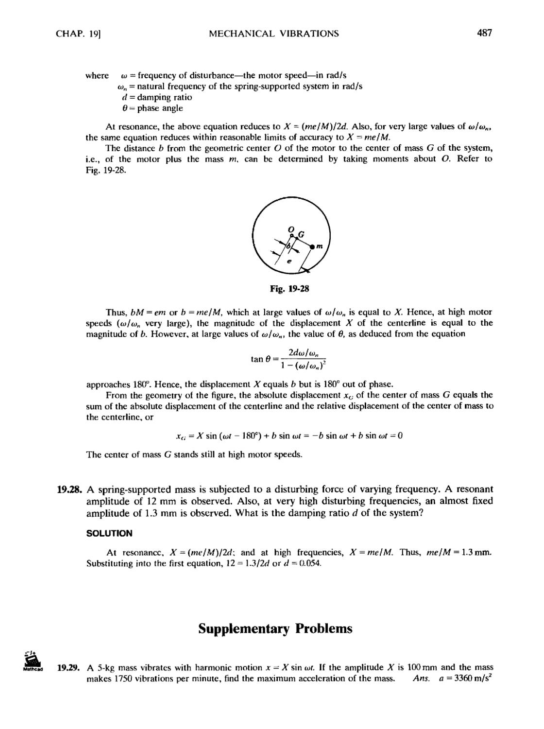
Chapter 19 MECHANICAL VIBRATIONS 462
19.1 Definitions 19.2 Degrees of Freedom 19.3 Simple Harmonic Motion
19.4 Multicomponent Systems 19.5 Units
Appendix A SI UNITS 493
Appendix В FIRST MOMENTS AND CENTROIDS 495
Appendix С COMPUTER SOLUTIONS TO SELECTED PROBLEMS 497
Appendix D SAMPLE SCREENS FROM THE COMPANION SCHAUM'S
ELECTRONIC TUTOR 501
INDEX 517
Problems and Sections Also Found in the Companion
SCHAUM'S ELECTRONIC TUTOR
Some of the problems and sections in this book have software components in the
companion Schaum's Electronic Tutor. The Mathcad Engine, which "drives" the Electronic
Tutor, allows every number, formula, and graph chosen to be completely live and interactive.
To identify those items that are available in the Electronic Tutor software, please look for the
-Jl
Mathcad icons, JSL. placed adjacent to a numbered item or problem number. A complete list
of these Mathcad entries follows below. For more information about the software, including the
sample screens, see Appendix D on page 501.
Problem 1.3
Problem 1.5
Problem 1.10
Problem 1.15
Problem 1.17
Section 2.3
Problem 2.3
Problem 2.4
Problem 2.12
Problem 2.13
Problem 2.28
Problem 2.30
Problem 3.1
Problem 3.4
Problem 3.9
Problem 3.46
Problem 3.50
Problem 4.1
Problem 4.2
Problem 4.4
Problem 4.19
Problem 5.5
Problem 5.6
Problem 5.15
Problem 5.42
Problem 5.57
Problem 6.1
Problem 6.2
Problem 6.5
Problem 6.9
Problem 6.15
Problem 6.29
Section 7.3
Problem 7.14
Problem 7.16
Problem 7.18
Problem 8.3
Problem 8.7
Problem 9.1
Problem 9.2
Problem 9.20
Problem 9.35
Problem 9.47
Problem 9.60
Problem 10.11
Problem 10.28
Problem 10.42
Problem 10.95
Problem 10.96
Problem 10.108
Problem 11.6
Problem 11.8
Problem 12.3
Problem 12.7
Problem 12.17
Problem 12.18
Problem 12.36
Problem 12.85
Problem 13.4
Problem 13.10
Problem 13.53
Problem 13.57
Problem 14.5
Problem 14.9
Problem 14.10
Problem 14.27
Problem 14.50
Problem 15.12
Problem 15.28
Problem 15.32
Problem 15.51
Problem 15.57
Problem 15.74
Problem 15.76
Problem 16.8
Problem 16.25
Problem 16.27
Problem 16.31
Problem 16.34
Problem 16.62
Problem 16.70
Problem 16.76
Problem 16.80
Problem 16.125
Problem 16.128
Problem 16.131
Problem 16.132
Problem 16.134
Problem 16.156
Problem 17.42
Problem 17.43
Problem 17.48
Problem 17.56
Problem 17.89
Problem 17.92
Problem 18.27
Problem 18.40
Problem 18.82
Problem 18.83
Problem 18.84
Problem 18.109
Problem 19.29
Problem 19.32
Problem 19.43
Problem 19.48
Problem 19.50
VJll
Chapter 1
Vectors
1.1 DEFINITIONS
Scalar quantities possess only magnitude, e.g.. time, volume, energy, mass, density, work. Scalars
are added by ordinary algebraic methods, e.g.. 2 s + 7 s = 9 s: 14 kg - 5 kg = 9 kg.
Vector quantities possess both magnitude and direction.* e.g.. force, displacement, velocity,
impulse. A vector is represented by an arrow at the given inclination. The head of the arrow
indicates the sense, and the length represents the magnitude of the vector. The symbol for a vector is
shown in print in boldface type, such as P. The magnitude is represented by |P| or P.
A free vector may be moved anywhere in space provided it maintains the same direction and
magnitude.
A sliding vector may be applied at any point along its line of action. By the principle of
transmissibility the external effects of a sliding vector remain the same.
A bound or fixed vector must remain at the same point of application.
A unit vector is a vector one unit in length.
The negative of a vector P is the vector -P that has the same magnitude and inclination but is of
the opposite sense.
The resultant of a system of vectors is the least number of vectors that will replace the given
system.
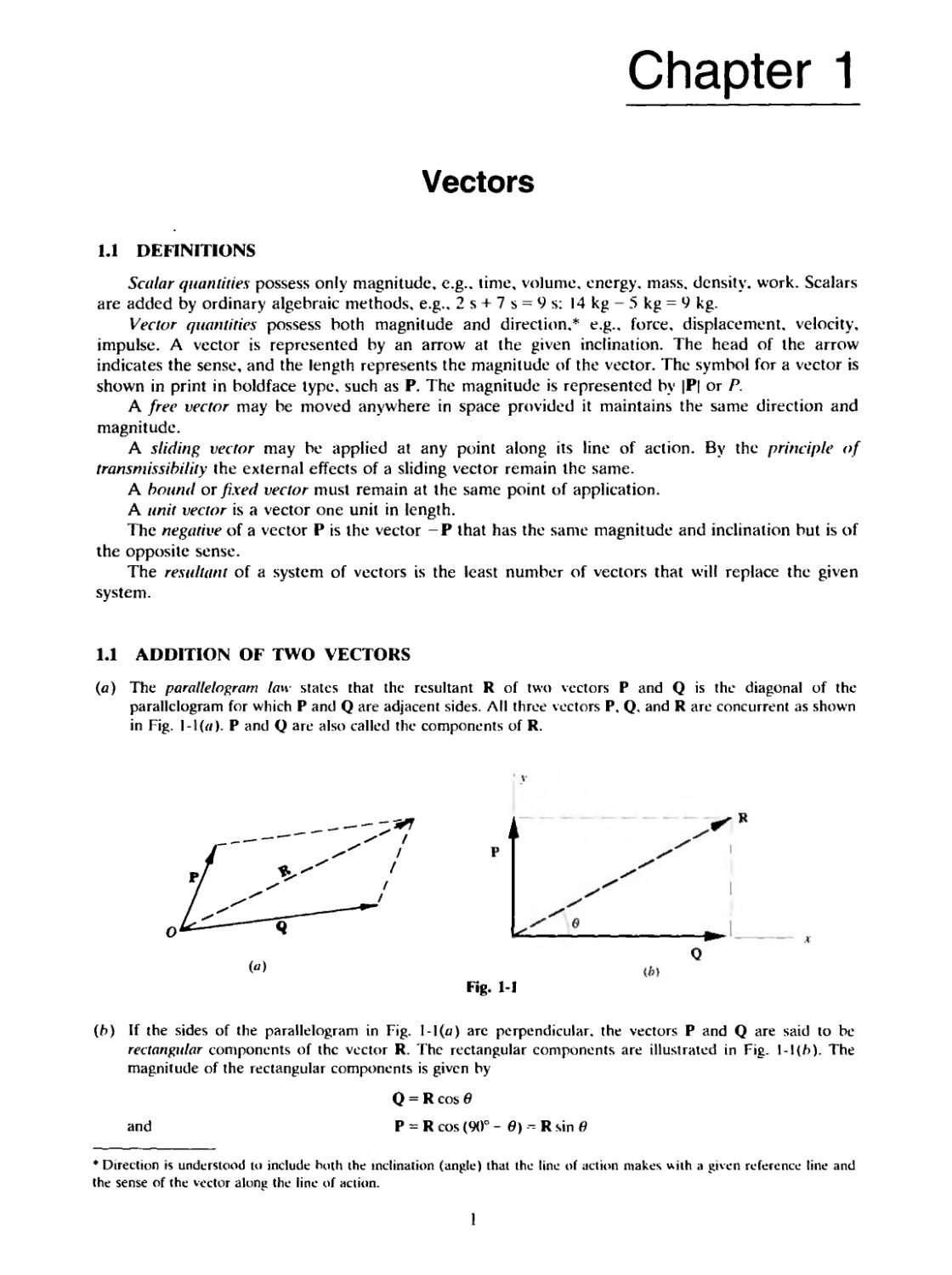
1.1 ADDITION OF TWO VECTORS
(a) The parallelogram law states that the resultant R of two vectors P and Q is the diagonal of the
parallelogram for which P and Q are adjacent sides. ЛИ three vectors P, Q. and R are concurrent as shown
in Fig. l-I(e). Р and Q are also called the components of R.
Fig. 1-1
(b) If the sides of the parallelogram in Fig. I-l(u) are perpendicular, the vectors P and Q are said to be
rectangular components of the vector R. The rectangular components are illustrated in Fig. \-\{h). The
magnitude of the rectangular components is given by
and
Q = R cos в
P = R cos (90° - в) -- R sin в
* Direction is understood to include both the inclination (angle) that the line of action makes with a given reference line and
the sense of the vector along the line of action.
1
VECTORS [CHAP. 1
(с) Triangle law. Place the tail end of either vector at the head end of the other. The resultant is drawn from
the tail end of the first vector to the head end of the other. The triangle law follows from the parallelogram
law because opposite sides of the paralleloram are free vectors as shown in Fig. 1-2.
(d) Vector addition is commutative: i.e.. P + Q = Q + P.
1.3 SUBTRACTION OF A VECTOR
Subtraction of a vector is accomplished by adding the negative of the vector; i.e.,
P-Q = P + (-Q)
Note also that
-(P + Q)=-P-Q
1.4 ZERO VECTOR
A zero vector is obtained when a vector is subtracted from itself; i.e., P - P = 0. This is also
called a null vector.
1.5 COMPOSITION OF VECTORS
Composition of vectors is the process of determining the resultant of a system of vectors. A
vector polygon is drawn placing the tail end of each vector in turn at the head end of the preceding
vector as shown in Fig. 1-3. The resultant is drawn from the tail end of the first vector to the head
end (terminus) of the last vector. As will be shown later, not all vector systems reduce to a single
vector. Since the order in which the vectors are drawn is immaterial, it can be seen that for three
given vectors P. Q, and S,
R = P + Q + S = (P + Q) + S
= P + (Q + S) = (P + S) + Q
The above equation may be extended to any number of vectors.
1.6 MULTIPLICATION OF VECTORS BY SCALARS
(я) The product of vector P and scalar m is a vector mP whose magnitude is \m\ times as great as the
magnitude of P and that is similarly or oppositely directed to P, depending on whether m is positive or
negative.
CHAP. 1]
VECTORS
Fig. 1-3
(fo) Other operations with scalars m and n are
(m +n)P =
1.7 ORTHOGONAL TRIAD OF UNIT VECTORS
An orthogonal triad of unit vectors i, j. and к is formed by drawing unit vectors along the x, y,
and z axes respectively. A right-handed set of axes is shown in Fig. 1-4.
A vector P is written as
where Pxi, Py\, and Pzk are the vector components of P along the x, v, and z axes respectively as
shown in Fig. 1-5.
Note that PX=P cos вх, Py = P cos 6V, and P, = P cos 6Z.
Fig. 1-4
Fig. 1-5
VECTORS
[CHAP. 1
1.8 POSITION VECTOR
The position vector r of a point (v, v, z) in space is written
r — xl + vj + rk
where r = VV + v2 + г2. See Fie 1-6.
V
A
Hg. 1-6
Fig. 1-7
1.9 DOT OR SCALAR PRODUCT
The dot or scalar product of two vectors P and Q. written P • Q. is a scalar quantity and is
defined as the product of the magnitudes of the two vectors and the cosine of their included angle в
(see Fig. 1-7). Thus
P • Q = PQ cos в
The following laws hold for dot products, where m is a scalar:
PQ = QP
P-(Q+S) = PQ + PS
Since i. j. and к are orthogonal.
i-j = i-k=j-k = (l)(l)cos90° =
Also, if P = Pvi + Pj + P(.k and Q = Q,i + OJ ' ??,k then
PP = p= Pi - p] + Pi
The magnitudes of the vector components of P along the rectangular axes can be written
Px = P • i P, . = P • j P: = P • к
since, for example,
P • i - (P,i + P,j + Prk) • i = P( + 0 - 0 = P,
CHAP. 1]
VECTORS
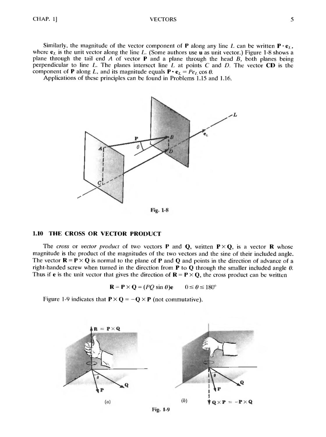
Similarly, the magnitude of the vector component of P along any line L can be written P ¦ e;,
where ел is the unit vector along the line L. (Some authors use u as unit vector.) Figure 1-8 shows a
plane through the tail end A of vector P and a plane through the head B, both planes being
perpendicular to line L. The planes intersect line L at points С and D. The vector CD is the
component of P along L, and its magnitude equals P • eL = PeL cos в.
Applications of these principles can be found in Problems 1.15 and 1.16.
Fig. 1-8
1.10 THE CROSS OR VECTOR PRODUCT
The cross or vector product of two vectors P and Q, written P X Q, is a vector R whose
magnitude is the product of the magnitudes of the two vectors and the sine of their included angle.
The vector R = P X Q is normal to the plane of P and Q and points in the direction of advance of a
right-handed screw when turned in the direction from P to Q through the smaller included angle в.
Thus if e is the unit vector that gives the direction of R = P X Q, the cross product can be written
R = P X Q = (PQ sin 0)e 0 < в < 180°
Figure 1-9 indicates that P X Q = -Q X P (not commutative).
R - PXQ
Fig. 1-9
VECTORS
[CHAP. I
The following laws hold for cross products, where m is a scalar:
PX(Q + S) = PXQ fPxS
= PxS4-PxT + QxS + Qx
/и(Р X Q) = (mP) X Q = P X (/hQ)
Since i, j, and к are orthogonal.
ixj=k jxk=i kxi=j
Also, if P = Pj + PJ + P,k and Q = Q,i + (?,j -i- Q.k then
P X Q = (PyQ. - P,Q,)i + (P,Qt - P.Q.Oj + (PXQ, - PyQx)k =
For proof of this cross-product determination see Problem 1.12.
1.11 VECTOR CALCULUS
(a) Differentiation of a vector P that varies with respect to a scalar quantity such as time / is performed as
follows.
Let P = P(f); that is, P is a function of time i. A change AP in P as time changes from i to (i + Ar) is
Then
e. о,, e,
(IP ЛР P(f + Af)
- = lim = lim
dt ai -и Af л, -и Af
If P(f) = P.i + Pj + P.k. where Px. f\. and /'. arc functions of time t, we have
(IP (P. + A/'Ji + (P, + AP,)j + {P. + Д/> )k - P.i P'i ~ P
= lim —
f/f Л..П Af
AP.i + APJ + ЛР-k f/P, r/P, (/P.
= lim ~ — — = - - -i + - j t- - к
Л/ -и Af (It (It (It
The following operations are valid:
d dP Aф
¦- {ФР) = ф— •• н P where i/i is a scalar function off
CHAP. 1] VECTORS
(b) Integration of a vector P that varies with respect to a scalar quantity such as time t is performed as follows.
Let P = P(r); that is, P is a function of time t. Then
[' P(r) dt = [ ' (Pvi + Pyj + P.k) dt
= i(' P,dt+j\ P>dt + k\ P:dt
-4i Л1 ¦''i.
1.12 DIMENSIONS AND UNITS
In the study of mechanics, the characteristics of a body and its motion can be described in terms
of a set of fundamental quantities called dimensions. In the United States, engineers have been
accustomed to a gravitational system using the dimensions of force, length, and time. Most countries
throughout the world use an absolute system in which the selected dimensions are mass, length, and
time. There is a growing trend to use this second system in the United States.
Both systems derive from Newton's second law of motion, which is often written as
where R is the resultant of all forces acting on a particle, a is the acceleration of the particle, and M
is the constant of proportionality called the mass.
U.S. Customary System
In this engineering system, the unit of length is the foot (ft), the unit of time is the second (s),
and the unit of force is the pound (lb). A mass M falling freely near the earth's surface is pulled
toward the earth's centre by a force W with an acceleration of gravity g. The force W is the weight
measured in pounds and the acceleration g is in ft/s2. Hence Newton's second law becomes, in scalar
form,
W = Mg
The value of the acceleration of gravity g varies with the observer's location on the surface of the
earth. In this book the value of 32.2 ft/s2 will be used. An object that weighs 1 lb at or near the
earth's surface will have a free-fall acceleration g of 32.2 ft/s2. The above equation yields
W lib 1 lbs2 1
g ~ 32.2 ft/s2 " 32.2 ft 2.2 g
In solving statics problems, the mass is not mentioned. It is important to realize that the mass in
slugs is a constant for a given body. On the surface of the moon, this same given mass will have
acting on it a force of gravity approximately one-sixth of that on the earth.
The International System (SI)
In the International System (SI),* the unit of mass is the kilogram (kg), the unit of length is the
meter (m), and the unit of time is the second (s). The unit of force is the newton (N) and is denned
* SI is the acronym for Systeme International d'Unites (modernized international metric system).
VECTORS
[CHAP. 1
as the force that will accelerate a mass of one kilogram one meter per second squared (m/s2). Thus
1 N = A kg)(l m/s2) = 1 kg • m/s2 = I kg • m • s'2
A mass of 1 kg falling freely near the surface of the earth has an acceleration of gravity g that
varies from place to place. In this book we shall assume an average value of 9.80 m/s2. Thus the
force of gravity acting on a 1-kg mass becomes
W = Mg = A kg)(9.80 m/s2) = 9.80 kg • m/s2 = 9.80 N
Of course, problems in statics involve forces; but, in a problem, a mass given in kilograms is not
a force. The gravitational force acting on the mass must be used. In all work involving mass, the
student must remember to multiply the mass in kilograms by 9.80 m/s2 to obtain the gravitational
force in newtons. A 5-kg mass has a gravitational force of 5 X 9.8 = 49 N acting on it.
The student should further note that, in SI, the millimeter (mm) is the standard linear dimension
unit for engineering drawings. Therefore, all engineering drawing dimensions must be in millimeters
(lmm =10 ' m). Further, a space should be left between the number and unit symbol; e.g.,
2.85 mm, not 2.85mm. When using five or more figures, space them in groups of three starting at the
decimal point as 12 832.325. Do not use commas in SI. A number with four figures can be written
without the space unless it is in a column of quantities involving five or more figures.
Tables of SI units. SI prefixes, and conversion factors for the modern metric system (SI) are
included in Appendix A. In this text about 50 percent of the problems are in U.S. Customary units
and 50 percent in SI units.
Solved Problems
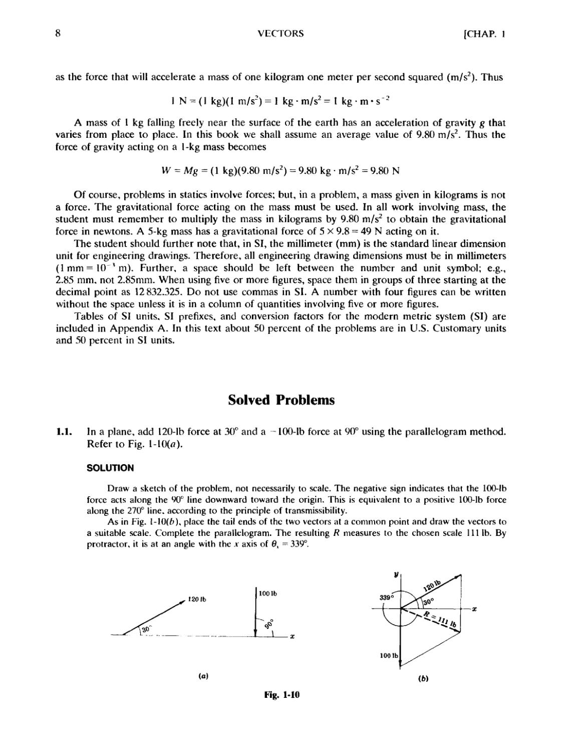
1.1. In a plane, add 120-lb force at 30° and a -100-lb force at 90° using the parallelogram method.
Refer to Fig. l-10(«).
SOLUTION
Draw a sketch of the problem, not necessarily to scale. The negative sign indicates that the 100-lb
force acts along the 90° line downward toward the origin. This is equivalent to a positive 100-lb force
along the 270° line, according to the principle of transmissibility.
As in Fig. 1-10F), place the tail ends of the two vectors at a common point and draw the vectors to
a suitable scale. Complete the parallelogram. The resulting Ft measures to the chosen scale 111 lb. By
protractor, it is at an angle with the .v axis of 0, = 339°.
120 tb
100 lb
100 lb
Fig. 1-10
CHAP. 1]
VECTORS
Consider the triangle, one side of which is the у axis, in Fig. 1-10F). The sides of this triangle are R,
100, and 200. The angle between the 100 and 120 sides is 60°. Applying the Law of Cosines,
R2 = 1202 + ЩJ - 2A20)A00) cos 60° Л = 111 lb
Now applying the Law of Sines,
120 Ш «о»
= a = 69
sin a sin 60
The angle of 60° added to 270° yields the measured angle of 339°.
1.2. Use the triangle law for Problem 1.1. See Fig. 1-11.
SOLUTION
It is immaterial which vector is chosen first. Take the 120-lb force. To the head of this vector attach
the tail end of the 100-lb force. Draw the resultant from the tail end of the 120-lb force to the head end
of the 100-lb force. When measured to the chosen scale and the direction determined, the results are the
same as in Problem 1.1.
g
Fig. 1-11
Fig. 1-12
1.3. The resultant of two forces in a plane is 400 N at 120°. One of the forces is 200 N at 20°.
Determine the missing force. See Fig. 1-12.
SOLUTION
Select a point through which to draw the resultant and the given force to a convenient scale.
Draw the line connecting the head ends of the given force and the resultant. Place a head on the
end of this line near the resultant. This line represents the missing force. When measured to scale, the
desired force is 477 N with вх = 144°.
This result is also obtained analytically by the laws of trigonometry. The angle between R and the 200-N
force is 100°, and hence, by the Law of Cosines, the unknown force F is
f2 = 4062 + 2002-2D00)B00)cosl00° f
Call the angle between F and the 200-N force a. Then, by the Law of Sines,
477
400
sin 100 sin a
a = 55.7° 6X = 144°
1.4. In a plane, subtract 130 N, 60° from 280 N, 320°. See Fig. 1-13.
SOLUTION
To the 280-N, 320° force add the negative of the 130-N, 60° force, obtaining a resultant force of
330 N, 297°. All angles are measured with respect to the x axis.
10
VECTORS
[CHAP. 1
130 N4
Fig. 1-13
1.5. Determine the resultant of the following coplanar system of forces: 26 lb, 10°; 39 lb, 114°;
63 lb, 183°; 57 lb, 261°. See Fig. 1-14.
SOLUTION
Applying the polygon method, place the tail of each vector in turn at the head of the preceding
vector. See Fig. l-14(a).
The resultant vector is the force drawn from the tail of the first vector to the head of the last vector.
Measured to scale, R = 65 lb with 6X = 197°.
This problem can also be solved analytically using the idea of rectangular components. Resolve
each force in Fig. 1-14F) into x and у rectangular components. Since all the x components are collinear,
they can be added algebraically, as can the у components. Now, if the x components and у components
are added, the two sums form the x and у components of the resultant. Thus
Rx = 26 cos 10° + 39 cos 114° + 63 cos 183° + 57 cos 261° = -62.1
flv = 26 sin 10° + 39 sin 114° + 63 sin 183° + 57 sin 261° = -19.5
R = V(-62.lJ + (-19.5J R = 65 lb 6X
tan0x=
—62.1
= 180° + 17° = 197°
631b
67 lb
39 Ib
631b
391b
571b
(b)
Fig. 1-14
CHAP. 1]
VECTORS
11
1.6. In Fig. 1-15 the rectangular component of the force F is 10 lb in the direction of OH. The
force F acts at 60° to the positive x axis. What is the magnitude of the force?
SOLUTION
The component of F in the direction of OH is F cos ft Hence, F cos 15° = 10 or F = 10.35 lb
О
Fig. 1-15
784 N
Fig. 1-16
1.7. An 80-kg person is standing on a board inclined 20° with the horizontal. What is the
gravitational component (a) normal to the board and (b) parallel to the board? See Fig. 1-16.
SOLUTION
(a) The normal component is at an angle of 20° with the gravitational force vector, which has a
magnitude of 80 (9.8) = 784 N. To scale, the normal component measures 740 N. By trigonometry,
the normal component is 784 cos 20° = 737 N.
(b) To scale, the parallel component is 270 N. By trigonometry, it is 784 cos 70° = 268 N.
1.8. A force P of 235 N acts at an angle of 60° with the horizontal on a block resting on a 22°
inclined plane. Determine algebraically (a) the horizontal and vertical components of P and
(b) the components of P perpendicular to and along the plane. Refer to Fig. l-17(a).
SOLUTION
(a) The horizontal component Ph acts to the left and is equal to 235 cos 60° = 118 N. The vertical
component Pv acts up and is equal to 235 sin 60° = 204 N as shown in Fig. 1-17F).
(b) The component PY parallel to the plane = 235 cos F0°-22°) = 185 N acting up the plane. The
component P± normal to the plane = 235 sin 38° = 145 N as shown in Fig. l-17(c).
235N
(a)
Fig. 1-17
(b)
(c)
12
VECTORS
[CHAP.
1.9. The three forces shown in Fig. 1-18 produce a resultant force of 20 lb acting upward along the
v axis. Determine the magnitudes of F and P.
SOLUTION
For the resultant to be a force of 20 lb upward along the v axis. R, = 0 and R, = 20 lb. As the sum
of the .v components must be equal to the x component of the resultant RK = P cos 30° - 90 cos 40° = 0,
from which P = 79.6 lb. Similarly, Rx = P sin 30° + 90 sin 40° - F = 20 and F = 11.1 lb.
901b
40
У
7
р
4т
/
Зт
/
А
Fig. 1-18
Fig. Ы9
1.10. Refer to Fig. 1-19. The x, y. and z edges of a rectangular parallelepiped are 4, 3, and 2 m
respectively. If the diagonal OP drawn from the origin represents a 50-N force, determine the
x, v, and z components of the force. Express the force as a vector in terms of the unit vectors
i, j, and k.
SOLUTION
Let в,, в,., в. represent respectively the angles between the diagonal OP and the .v, v, z axes. Then
PK = P cos 0, Pr = P cos 0, P, = P cos 6r
Length of OP = V42~+ 32 + 22 = 5.38 m. Hence.
Since each component in the sketch is in the positive direction of the axis along which it acts.
P, = 50 cos 0, = 37.2 N />, = 50 cos 0V = 27.9 N P = 50 cos 0. = 18.6 N
The vector P = PJ + PJ - Prk = 37.2i + 27.9j - 18.6k N.
1.11. Determine the x, y, and z components of a 100-N force passing from the origin through point
B. -4,1). Express the vector in terms of the unit vectors i, j, and k.
SOLUTION
The direction cosines of the force line are
2 -4
COS 6X = -, ;
= = 0.437 cos 0,. = -7= = -0.873
(\)? V21
cos в- = 0.281
Hence Px=43.7N, P, = -87.3 N. P. =21.8 N; and the vector P = 43.7i - 87.3J + 21.8k N.
CHAP. 1]
VECTORS
13
1.12. Show that the cross product of two vectors P and Q can be written as
PXQ =
j
э р р
I Qv Qz
SOLUTION
Write the given vectors in component form and expand the cross product to obtain
P x Q = (Pvi + Pv\ + Rli) x @vi + 0rj + Q.k)
+ (Rft )k x i ¦+ (RQ,)k x j + (Rft)k x к
But ixi=jXj = kxk = O; and ixj = k and jxi= -k, etc. Hence
P x Q = (P,Bv)k - (P,Q,)i - (PyQ,)k + (PvQ-)i ¦
These terms can be grouped as
PXQ= (P,Q, - PZQK)\ +
or in determinant form as
PXQ =
ft ft ft
Be careful to observe that the scalar components of the first vector P in the cross product are
written in the middle row of the determinant.
1.13. A force F = 2.63i + 4.28j - 5.92k N acts through the origin. What is the magnitude of this
force and what angles does it make with the x, v, and z axes?
SOLUTION
F = V(Z63J + D.28J + (-5.92J = 7.75 N
2.63
cos ev = +
7.75
0, = 70.2°
4.28
cos в, = + —- ву = 56.3°
5 92
cose, = -— 0, = 139.8°
1.14. Find the dot product of P = 4.82i - 2.33j + 5.47k N and Q = -2.81i - 6.09J + 1.12k m.
SOLUTION
P • Q = P.Q, + PyQ, + P:Q; = D.82)(-2.81) + (-2.33K-6.09) + E.47)A.12) = 6.72 N • m
L
l?d 1.15. Determine the unit vector e^ for a line L that originates at point B,3,0) and passes through
point (-2,4,6). Next determine the projection of the vector P = 2i + 3j - к along the line L.
SOLUTION
The line L changes from +2 to -2 in the x direction, or a change of —4. The change in the у
direction is 4 - 3 = + 1. The change in the z direction is 6 = 0 = +6. The unit vector is
4 1 6
" ' = j + —j= к = -0.549i + 0.137J + 0.823k
V53 V53
14 VECTORS [CHAP. 1
The projection of P is thus
P • e, = 2(-0.549) + 3@.137) - 1@.823) = -1.41
1.16. Determine the projection of the force P = lOi - 8j + 14k lb on the directed line L which
originates al point B, -5,3) and passes through point E,2, -4).
SOLUTION
The unit vector along L is
л VE - If + [2 - (-5)]2 + (-4 - 3K VlO7 VT07
= 0.290i + 0.677J - 0.677k
The projection of P on L is
P • eL = (lOi - 8j + 14k) • @.29i + 0.677J - 0.677k)
= 2.90 - 5.42 - 9.48 = -12.0 lb
The minus sign indicates that the projection is directed opposite to the direction of L.
1.17. Find the cross product of P = 2.85i + 4.67j - 8.09k ft and Q = 28.3i + 44.6j + 53.3k lb.
SOLUTION
PK Pr P7
Qi Qy Qr
i j к
2.85 4.67 -8.09
28.3 44.6 53.3
= i[D.67)E3.3) - D4.6X-8.09)] - j[B.85)E3.3) - B8.3)(-8.09)]
+ k[B.85)D4.6) - B8.3)D.67)]
= iB49 + 361) - jA52 + 229) + kA27 - 132) = 610i - 381j - 5k lb-ft
1.18. Determine the time derivative of the position vector r = xi + 6y2j - 3zk, where i, j, к are fixed
vectors.
SOLUTION
The time derivative is
1.19. Determine the time integral from time ?! = 1 s to time t2 = 3 s of the velocity vector
v = t2\ + 2/j - к ft/s
where i, j, and к are fixed vectors.
SOLUTION
f (/2i + 2fj-k)dr = i[ t2dt+j\ 2tdt-k\ dt = 8.67i + 8.00J - 2.00k
CHAP. 1] VECTORS 15
Supplementary Problems
1.20. Determine the resultant of the coplanar forces 100 N,0° and 200 N,90°. Ans. 224 N. 0, =64°
1.21. Determine the resultant of the coplanar forces 32 N, 20° and 64 N. 190°. Ans. 33.0 N. 0, = 180°
1.22. Find the resultant of the coplanar forces 80 N, -30° and 60 N. 60°. Ans. 100 N. в, = 6.87°
1.23. Find the resultant of the concurrent coplanar forces 120 N, 78° and 70 N, 293°.
Ans. 74.7 N, 0, = 45.2°
L24. The resultant of two coplanar forces is 18 oz at 30°. If one of the forces is 28 oz at 0°, determine the
other. Ans. 15.3 oz, 144°
1.25. The resultant of two coplanar forces is 36 N at 45°. If one of the forces is 24 N at 0°, find the other force.
Ans. 25.5 N, 87°
1.26. The resultant of two coplanar forces is 50 N at 143°. One of the forces is 120N at 238°. Determine the
missing force. Ans. 134 N, в, = 79.6°
1.27. The resultant of two forces, one in the positive x direction and the other in the positive у direction, is
1001b at 50° counterclockwise from the positive x-direction. What are the two forces?
Ans. Rx = 64.3 lb, Л, = 76.6 lb
1.28. A force of 120 N has a rectangular component of 84 N acting along a line making an angle of 20°
counterclockwise from the positive x axis. What angle does the 120-N force make with the positive x
axis?
Ans. 65.6°
1.29. Determine the resultant of the coplanar forces: 6 oz, 38°; 12 oz, 73°; 18 oz, 67°; 24 oz, 13Г.
Ans. 50.0 oz, в, =91°
1 JO. Determine the resultant of the coplanar forces: 20 lb, 0°: 20 lb. 30°; 20 lb. 60°; 20 lb. 90°: 20 lb. 120°; 20 lb.
150°. Ans. 77.2 lb, в, = 75°
131. Determine the single force that will replace the following coplanar forces. 120 N, 30°; 200 N. 110°; 340 N.
180°; 170 N, 240°; 80 N, 300°. Ans. 351 N, 175°
131. Determine the single force that will replace the following coplanar forces: 120 N. 30°: 200 N. 110°: 340 N.
180°; 170 N, 240°; 80 N, 300°. Ans. 351 N, 175°
132. Find the single force to replace the following coplanar forces: 150 N, 78°; 320 N, 143°; 485 N, 249°: 98 N.
305°; 251 N, 84°. Ans. 321 N, 171°
133. A sled is being pulled by a force of 25 lb exerted in a rope inclined 30° with the horizontal. What is the
effective component of the force pulling the sled? What is the component tending to lift the sled
vertically? Ans. Ph = 21.7 lb, Pu = 12.5 lb
134. Determine the resultant of the following coplanar forces: 15 N, 30°; 55 N, 80°; 90 N, 210°; and 130 N.
260°. Ans. 136 N, ^ = 235°
135. A car is traveling at a constant speed in a tunnel, up a 1-percent grade. If the car and passenger weigh
3100 lb, what tractive force must the engine supply to just overcome the component of the gravitational
force on the car along the bottom of the tunnel? Ans. 31 lb
16
VECTORS
[CHAP. 1
1.36. A telephone pole is supported by a guy wire that exerts a pull of 2001b on the top of the pole. If the
angle between the wire and the pole is 50°, what are the horizontal and vertical components of the pull
on the pole? Ans. Р„ = 153 lb, Pv = 129 lb
1.37. A boat is being towed through a canal by a horizontal cable that makes an angle of 10° with the shore. If
the pull on the cable is 200 N, find the force tending to move the boat along the canal.
Ans. 197 N
1.38. Express in terms of the unit vectors i, j, and к the force of 200 N that starts at the point B,5. -3) and
passes through the point (-3,2.1). Ans. F = -141i - 84.9j + 113kN
139. Determine the resultant of the three forces F, = 2.0i + 3.3j - 2.6k lb, F2 = -i + 5.2j - 2.9k lb. and
F, = 8.3i - 6.6j + 5.8k lb. which are concurrent at the point B.2, -5).
Ans. R = 9.3i + I -9j + 0.3k lb at B,2, -5)
1.40. The pulley shown in Fig. 1-20 is free to ride on the supporting guide wire. If the pulley supports a 160-lb
weight, what is the tension in the wire? Ans. T = 234 lb
11601b
Fig. 1-20
1.41. Two cables support a 500-lb weight as shown in Fig. 1-21. Determine the tension in each cable.
Ans. TAl) = 433 lb, TBr = 250 lb
1.42. What horizontal force P is required to hold the 10-lb weight W in the position shown in Fig. 1-22?
Ans. P = 3.25 lb
ТУ 90°
101b
20 N
Fig. 1-22
Fig. 1-23
1.43. A charged particle is at rest under the action of three other charged particles. The forces exerted by two
of the particles are shown in Fig. 1-23. Determine the magnitude and direction of the third force.
Ans. F = 14.7 N, 0, = 76.8°
CHAP. 1] VECTORS 17
1.44. Determine the resultant of the coplanar forces 200 N. 0° and 400 N. 90°.
Ans. Since each force in Problem 1.20 has been multiplied by the scalar 2, the magnitude of the
resultant in this problem should be double that of Problem 1.20. The angle should be the same.
1.45. What vector must be added to the vector F = 30 N, 60° to yield the zero vector?
Ans. 30 N, 0, = 240°
1.46. At time / = 2 s, a point moving on a curve has coordinates C, -5,2). At time / = 3 s, the coordinates of
the point are A. -2.0). What is the change in the position vector? Ans. Дг = -2i + 3j - 2k
1.47. Determine the dot product of P = 4i + 2j - к and Q = -3i + 6j - 2k. Ans. +2
1.48. Find the dot product of P = 2.12i + 8.15j - 4.28k N and Q = 6.29i - 8.93j - 10.5k m.
Ans. -14.5 N • m
1.49. Determine the cross product of the vectors in Problem 1.47. Ans. P x Q = 2i + 11 j + 30k
1.50. Determine the cross product of P = 2.12i + 8.15J - 4.28k and Q = 2.29i - 8.93J - 10.5k.
Ans. -124i + 12.5j -37.6k
1.51. Determine the derivative with respect to time of P = jri + 2yi - z2k.
dV dx. „rfv. „ <*z,
Ans. -r = -r* + 2-j-i-2z — k
dt dt dt dt
1.52. If P = 2fi + 3rj - fk and Q = ri + rj + t% show that
d
, (P • Q) = 4/ + 8/1
dt
Check the result by using
1.53. In the preceding problem show that
j (P x Q) = A5r4 + 3r)i - (8/4 + 2r)j - 3f2k
Check the result by using
dV dQd
dt dt dt
1.54. Determine the dot product for the following vectors:
P Q Ans.
(a) 3i-2jJ-8k -i-2j-3k -23
(b) 0.86i + 0.29J - 0.37k 1.29i - 8.26J + 4.0k -2.77
(c) a\ + b] - ck d\ - e'i + /k ad - be - cf
1.55. Determine the cross products for the following vectors:
P Q Ans.
(a) 3i-2j+8k -i-2j-3k 22i+j-8k
(b) 0.86i + O.29j - 0.37k 1.29i - 8.26J + 4.0k -1.90i-3.92j - 7.48k
(c) ai + bj-ck di-e\+fk (bf - ec)\ - (af + cd)\ - (ae + bd)k
18
VECTORS
[CHAP. 1
1.56. Determine the component of the vector Q = lOi - 20j - 20k along a line drawn from point B,3, —2)
through the point A,0,5). Ans. -11.72
1.57. Determine the component of the vector P = 1.52i - 2.63J + 0.83k on the line that originates at the point
B,3,-2) and passes through the point A,0,5). Ans. P, =+1.59
1.58. Given the vectors P = i + Pj - 3k and Q = 4i + 3j, determine the value of Pv so that the cross product of
the two vectors will be 9i - 12j. Ans. Py = 0.75
1.59. Given the vectors P = i - 3j + P.k and Q = 4i - k, determine the value of P, so that the dot product of
the two vectors will be 14. Ans. P. = -10
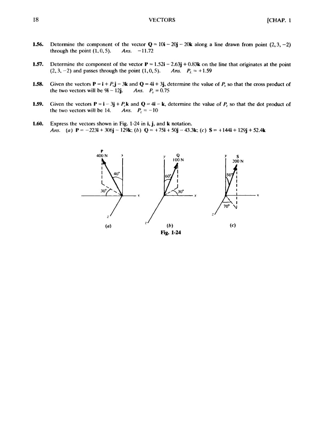
1.60. Express the vectors shown in Fig. 1-24 in i, j, and к notation.
Ans. («) P = -223i + 306j - 129k; (b) Q = +75i + 50j - 43.3k; (c) S = + 144i + 129j + 52.4k
400 N
(c)
Fig. 1-24
Chapter 2
Operations with Forces
2.1 THE MOMENT OF A FORCE
The moment M of a force F with respect to a point О is the cross product IV1 = г x F. where r is
the position vector relative to point О of any point P on the action line of force F. Physically. M
represents the tendency of the force F to rotate the body (on which it acts) about an axis that passes
through О and is perpendicular to the plane containing the force F and the position vector r.
Fig. 2-1
If a set of x, y\ and z axes is drawn through О as shown in Fig. 2-1.
r = jci + vj + 2k F = Fx\ + Fj + Ek M = M,i + /l/J + M.k
and, by definition,
= rXF =
i J к
л у с
/•; i-\ f
Expanding the determinant,
M = i(/-:у - Fyz) +j{f\z - F.x) -r k(/vv - /;.v)
Comparing this expression for M with the one listed above, it can be seen that
Mx = P. v - Fyz M,. = Pxz - p-x M7 = /-> - Fy у
19
20
OPERATIONS WITH FORCF.S
|CHAP. 2
The scalar quantities Мл, My, and M- arc the magnitudes of the respective moments of the force
F about the x. y, and z axes through O. See Problems 2.3 and 2.4.
Note that Mx can be obtained by the dot product of the moment M and the unit vector i along
the x axis. Thus,
M • i = (M,i + M,j + Л/-к) • i = /I/,A) - Л/, @) + M.@) = Mv
Similarly, the magnitude of the moment of F about any axis L through О is the scalar component
of M on L. It can be obtained by the dot product of M and unit vector e; along the line L. Thus,
M,_ = M • e,
2.2 A COUPLE
A couple consists of two forces equal in magnitude and parallel, but oppositely directed.
2.3 THE MOMENT OF A COUPLE
The moment С of a couple with respect to any point О is the sum of the moments with respect to
О of the two forces that constitute the couple.
The moment С of the couple shown in Fig. 2-2 is
С = ЕМо = r, X F + r2 x (-F) - (r, - r2) x F = a X F
^F *
FiS. 1-1
Thus С is a vector perpendicular to the plane containing the two forces (a is in the same plane).
By definition of the cross product, the magnitude of С is a X F[ = aF sin 0. Since d, the perpendicular
distance between the two forces of the couple, is equal to a sin в, the magnitude of С is С = Fd.
Couples obey the laws of vectors. Any couple С can be written С = C,i + C,j + CM, where Cv,
Cy, and C, are the magnitudes of the components.
Note that point О is any point; hence, the moment of a couple is independent of the choice of
point O.
CHAP. 2] OPERATIONS WITH FORCES 21
2.4 REPLACING A SINGLE FORCE
A single force F acting at point P may be replaced by (a) an equal and similarly directed force
acting through any point О and (b) a couple C = rXF. where r is the vector from О to P. See
Problems 2.11 and 2.12.
2.5 COPLANAR FORCE SYSTEMS
Coplanar force systems occur in many problems of mechanics. The following scalar treatment is
useful in dealing with these two-dimensional problems.
1. The moment Ma of a force about a point О in a plane containing the force is the scalar momeni of the force
about an axis through the point and perpendicular to the plane. As such, the moment is the product of (a)
the force and (b) the perpendiculat distance from the point to the line of action of the force. It is customary
to assign a positive sign to the moment if the force tends to turn in a counterclockwise direction aboui the
point. See Problem 2.1.
2. Varignon's theorem states that the moment of a force about any point is equal to the algebraic sum of the
moments of the components of the force about that point. See Problem 2.2.
3. The moment of a couple will not be changed if (a) the couple is rotated or translated in its plane, (b) the
couple is transferred to a parallel plane, or (r) the size of its forces is changed, provided the moment arm is
also altered to keep the magnitude of the momeni the same.
4. A couple and a single force in the same plane or parallel planes may be combined into one force of the
same magnitude and sense as the given force and parallel to it. See Problem 2.9.
5. Conversely, a single force as indicated above may be replaced by (a) an equal and similarly directed force
acting through any point and (b) a couple lying in the same plane as the single force and the chosen point.
See Problem 2.11.
2.6 NOTES
In some of the solved problems vector equations are used, but in other problems the equivalent
scalar equations are used. In figures, vectors are identified by their magnitudes when the directions
are obvious.
Also note that in the U.S. Customary System the units for moments are pound-feet (lb-ft). In SI
the units for moments are newton-meters (N • m).
Solved Problems
2.1. Determine the moment of the 20-lb force about the point O. Sec Fig. 2-3.
SOLUTION
Drop the perpendicular OD from О to the action line of the 20-lb force. Its length to scale is 4.33 ft.
The moment of the force about О (actually about an axis through О perpendicular to the xy plane) is
therefore -B0 X 4.33) = -86.6 lb-ft.
22
OPERATIONS WITH FORCES
[CHAP. 2
-20 sin 60"= 17.321b
-201b
90'
:os60°= 101b
Fig. 2-3
Fig. 2-4
The minus sign is used because the direction of rotation viewed from the positive end of the г axis
(not shown) is clockwise.
2.2. Solve Problem 2.1 using Varignon's theorem. See Fig. 2-4.
SOLUTION
In using this theorem the 20-lb force is replaced with its rectangular components parallel to the x
and v aces and acting at any convenient point along the line of action.
If the point В is chosen on the x axis, then it should be apparent that the x component has no
moment about O. The moment of the 20-lb force about О is then only the moment of the у component
about O, or -A7.32 X 5) = -86.61b-ft.
If the point A on the у axis is chosen, then the у component has no moment about O. The moment
of the 20-lb force aboul О is then only the moment of the x component about O, or -A0x8.66) =
-86.61b-ft.
2.3. A 100-N force is directed along the line drawn from the point whose x, y, z coordinates are
B,0,4) m to the point whose coordinates are E,1,1) m. What are the moments of this force
about the x, v. and z axes?
SOLUTION
In Fig. 2-5. assume the scale is such that the 100-N force is measured by the diagonal of the
parallelepiped whose sides are parallel to the axes. The sides represent to the same scale the components
of the force.
CHAP. 2]
OPERATIONS WITH FORCES
23
The x side is 5 - 2 = 3 m long; the у side is 1 - 0 = 1 m long, and the z side is 1 — 4 = —3 m long.
This means that the component Fz is directed toward the back or negative direction of the z axis.
length of* side
length of diagonal
_x 100 = -jLx 100 = 68.7 N
? Vl9
Similarly,
VT9
x 100 = 22.9 N
F =
-3
Vl9
x 100 = -68.7 N
To find the moment of the 100-N force about the x axis, determine the moments of its components
about the x axis. By inspection the only component that has such a moment is Fy. Therefore Mx for the
100-N force is the moment of Fy about the x axis and equals -22.9 x 4 = —91.6 N • m. The minus sign
indicates that the rotation of Fy is clockwise about the x axis when viewed from the positive end of the x
axis.
In finding the moment about the у axis, note that Fy is parallel to the у axis and has no moment
about it. Now, however, both Fz and Fx must be considered. It is better to determine the sign of the
moment by inspection rather than by writing signs for the component and its arm. Accordingly,
My = +F8.7 X 2) + F8.7 x 4) = +412 N • m.
By similar reasoning using Fy only (since Fz is parallel to the z axis and Fx intersects it),
Mz = +B2.9 x 2) = +45.8 N ¦ m.
Be sure to affix signs for moments and to understand the significance thereof.
2.4. Repeat Problem 2.3 using the cross-product definition of moment.
SOLUTION
From Problem 2.3, F = 68.7i + 22.9J - 68.7k.
The vector r is the position vector of any point on the action line of F with respect to the origin. If
we use point B,0,4), r = 2i + Oj + 4k. Then
= rxF=
•
2 0 4
68.7 22.9 -68.7
= i[0 - 4B2.9)] - j[2(-68.7) - 4F8.7)] + k[2B2.9) - 0]
= -91.6i + 412j + 45.8kN-m
Next, using point E,1,1) on the action line of F, r = 5i + j + k. Then
j *
M=
1
1
68.7 22.9 -68.7
= i[-lF8.7) - 22.9A)] - j[5(-68.7) - 1F8.7)] + k[5B2.9) - 68.7A)]
= -91.6i + 412j + 45.8k N • m
The scalar moments about the x, y, and г axes are the coefficients of the unit vectors, i, j, and k.
2.5. Determine the moment of the force Г = 2i + 3j — к lb acting through the point C,1,1) with
respect to the line passing from B,5, -2) through C,-1,1). The coordinates are in feet.
SOLUTION
The moment arm r may be found by using the vector from either point on the line to the point on
the force. From B,5, —2) the vector r = i — 4j + 3k. The moment M about the chosen point is
l = rxF =
1 -4
= -5i + 7j + Ilk
3 -1
24
OPERATIONS WITH FORCES
[CHAP. 2
Now
e, .=-
i - 6j + Зк
V46
Hence the moment of F about the line is
M, =M-e, =(-5i
V46 V46 V46
If the moment arm is chosen from the point C,-1, 1), the arm is г = 2j. The moment M is
M=rxF=
Hence the moment of M about the line is
M-e, =(-2i + Oj-4k)
1 J к
0 2 0
2 3-1
= -2i-4k
V46
~2 ~ П = ~ = -2.06 lb-ft
V46 V46
2.6 Determine the moment of a force P whose rectangular components are P, = 22 N, P, = 23 N.
P. = 7 N and acting at a point A, — 1, -2). Take the moment about a line from the origin
through point C, -1,0). Coordinates are in meters.
SOLUTION
P = 22i + 23j + 7k N
The moment arm. r = (l -0)8 +(-1 -0)j + (-2 - 0)k = 8 - j - 2km
i j к
= rxF =
1 -1 -2
22 23 7
2.7. A couple of moment +60 lb-ft acts in the plane of the paper. Indicate this couple with (a)
10-lb forces and (b) 30-lb forces.
SOLUTION
In («) the moment arm must be 6 ft, while in (b) it is 2 ft.
The direction of rotation must be counterclockwise. The parallel forces may be drawn at any angle,
as shown in Fig. 2-6.
801b
ION
ION
ION
ION
2.8. Combine couple C, = +20 N • m with couple C2
See Fig. 2-7.
Fig. 2-7
-50 N • m, both in the same plane.
CHAP. 2]
OPERATIONS WITH FORCES
25
SOLUTION
To combine graphically, show both couples with forces of the same magnitude, say 10 N. and drawn
in such a way that two of the forces, one from each couple, are collinear but oppositely directed.
It is evident that the collinear forces cancel, leaving two 10-N forces with an arm of 3 m. The
resultant couple is -30 N • m, a result which can also be obtained by algebraic addition.
2.9. Replace a couple of moment -100 N • m and a vertical force of 50 N, acting at the origin, by
a single force. Where does the single force act?
SOLUTION
In Fig. 2-8 the couple is represented by two equal and opposite forces of 50 N at a perpendicular
distance of 2 m. One force of the couple is aligned with the given 50-N force at the origin. These two
forces cancel leaving the single, upward force of 50 N acting 2 m to the left of the origin.
50 N
2m
50 N
50 N
Fig. 2-8
2.10. Combine a force of 30 N, 60° with a +50 N • m couple in the same plane. See Fig. 2-9.
SOLUTION
A couple as such cannot be reduced to a simpler tystem, but it can be combined with another force.
Draw the given couple with 30-N forces and in such a way that one of its forces is collinear with the
given single 30-N force but oppositely directed.
By inspection the collinear forces cancel, leaving only a single force of 30 N parallel to and in the
dame direction as the original force but at a distance 1.67 m from it.
SON
Given Single
Force
Fig. 2-9
Г ¦ = 40 N m
1 С - -So N m
Fig. 2-10
26
OPERATIONS WITH FORCES
[CHAP. 2
2.11. As shown in Fig. 2-10, a couple C, of 20 N • m acts in the xy plane, a couple C2 of 40 N • m
acts in the yz plane, and a couple C3 of -55 N • m acts in the xz plane. Determine the
resultant couple.
SOLUTION
The couple C, is positive and acting in the xy plane. When viewed from the positive end of the z
axis, it tends to turn in a counterclockwise direction about the z axis. By the right-hand rule, it is
represented by a vector along the z axis drawn toward the positive end. Using this type of reasoning, all
three couples are drawn in the figure. Adding vectorially,
С =
С
cos ф,=у= +0.564
= VB()J + D0J + (-55f = 70.9N ¦ m
cos
С
=у= -0.777
С
cos фг = -— = +0.282
These are the direction cosines of the couple C. The couple acts in a plane perpendicular to this
vector.
The couple С may be written in vector notation,
С = +40i - 55j + 20k N • m
from which the value of С is derived as above.
2.12. A 2-in-diameter pipe is subjected to a force of 25 lb applied vertically downward to the
horizontal rod at an arm of 14 in. Replace the 25-lb force with A) a force at the end of the
pipe which causes bending and B) a couple that twists the shaft, placing it in torsion. What
are the moments of the force and the couple? See Fig. 2-11 (a).
20"
251b
25 lb / /
Fig. 2-11
SOLUTION
Place two vertical 25-lb forces oppositely directed through the center of the pipe as shown in
Fig. 2-ll(?>). The three forces are still equivalent to the original force.
The upward force combines with the original to form a couple С = 25 X 14 = 350 Ib-in. This couple
tends to twist the pipe counterclockwise when viewed from the right.
The other 25-lb force down on the pipe causes a bending moment M = -25 X 20 = —500 lb-in about
the z axis.
CHAP. 2]
OPERATIONS WITH FORCES
27
2.13. Solve Problem 2.12 by determining the moment of the 25-lb force about the point O.
SOLUTION
The position vector of the point of application of the 25-lb force with respect to the origin is
r = 20i + 14k. The force F = -25j. Thus the moment of the 25-lb force with respect to the origin is
MrXF
20 0 14
= i[0 - 14(-25)] - j[0 - 01 + k[20(-25) 0] = 350i - 500k lb-in
0 25 0
This agrees with the results of Problem 2.12.
2.14. The crane in Fig. 2-12 is on level ground. The x axis is through the contact points of the
rearmost wheels with the ground, the v axis is parallel to the front-to-back centerline, and the
z axis is vertical as shown. The bed (platform) of the crane is 3 ft above the ground. For
practical purposes the pivot point of the bottom of the boom can be considered in the bed of
the crane and 6 ft from the center of the cab. The center of the cab is on the centerline 15 ft
forward (to the left) of the rearmost axle. The 50-ft boom makes an angle of 60° with the bed
of the crane in a vertical plane, and the cab and boom are swiveled 45° horizontally from the
fore and aft centerline of the truck bed. The distance between the contact points of the rear
wheels is considered to be 8 ft. Determine the turning moment of the 4000-lb load about the x
axis.
40001b
Fig. 2-12
SOLUTION
Relative to the origin О of the axes, the coordinates of the cab center are (—4, —15, +3). The
coordinates of the bottom of the boom are (-4 + 6sin45°, -15 + 6cos45°, +3) or (+0.24, -10.8, +3).
The coordinates of the top of the boom are (+0.24 + 50 cos 60° sin 45°, -10.8 + 50 cos 60° cos 45°,
+3-50 sin 60°) or ( + 17.9, тб.91, +46.3).
28
OPERATIONS WITH FORCES
[CHAP. 2
The moment of the 4000-lb weight about О is
= rXF =
17.9 6.91
0 0
к
46.3
-4000
The scalar coefficient of the i term is the moment about the x axis. Hence M, = - 27,600 lb-ft. Thus
the moment is clockwise about the x axis when viewed from the front.
Supplementary Problems
2.15. In each case find the moment of the force F about the origin. Use Varignon's theorem.
Magnitude of
F
201b
641b
151b
8oz
4N
96 N
Angle of F with
horizontal
30°
140°
337°
45°
90°
60°
Coordinates of point of
application of F
E. -4) ft
(-3,4) ft
(8,-2) ft
F,1) in
@, -20) m
D,2) m
Answer
+ 119 lb-ft
+72.9 lb-ft
-19.3 lb-ft
+28.3oz-in
0
+236Nm
2.16. In Problem 2.15 use the cross-product definition of moment (M = r x F) to determine the moment. Each
answer will be accompanied by the unit vector k.
2.17. A 50-N force is directed along the line drawn from the point whose x, y, z coordinates are (8,2,3) m to
the point whose coordinates are B, -6,5) m. What are the scalar moments of the force about the x. y.
and z axes? Ans. M, = +137 N ¦ m, M, = -167 N • m, M. = -255 N • m
2.18. Given the force P = 32.4i - 29.3J + 9.9k Ib acting at the origin. Find the moment about a line through the
points @. -1,3) and C,1, 1). Coordinates are in feet. Ans. M = -88.2 lb-ft
2.19. A force acts al the origin. The rectangular components of the force are P, =68.7N, P, =22.9N,
P= -68.7 N. Determine the moment of the force P about a line through the points A,0.-1) and
D, 4. - 1). Coordinates are in meters. Ans. M = —13.7 N • m
2.20. Combine C, = +20 lb-ft, C2 = -80 lb-ft, and C, = -18 lb-ft, all acting in the same plane
Ans. С = -78 lb-ft acting in the same or parallel plane
2.21. Replace a vertical force of 2701b acting down at the origin by a vertical force of 2701b acting at
x = -5 in and a couple. Ans. С = -1350 lb-in
CHAP. 2]
OPERATIONS WITH FORCES
29
2.22. Determine the resultant vector of the three couples -16 N - m. -45 N • m. + 120 N ¦ m acting respectively
in the xy, vz. and xz planes.
Ans. С = +129 N ¦ m. cos ft, = -0.349, cos ft, = 0-931, cos ft = 0.124
2.23. Add the couple С = 30i - 2l)j + 35k N - m to the resultant couple in Problem 2.22.
Ans. С = - 15i + l(X)j + 51k N ¦ m
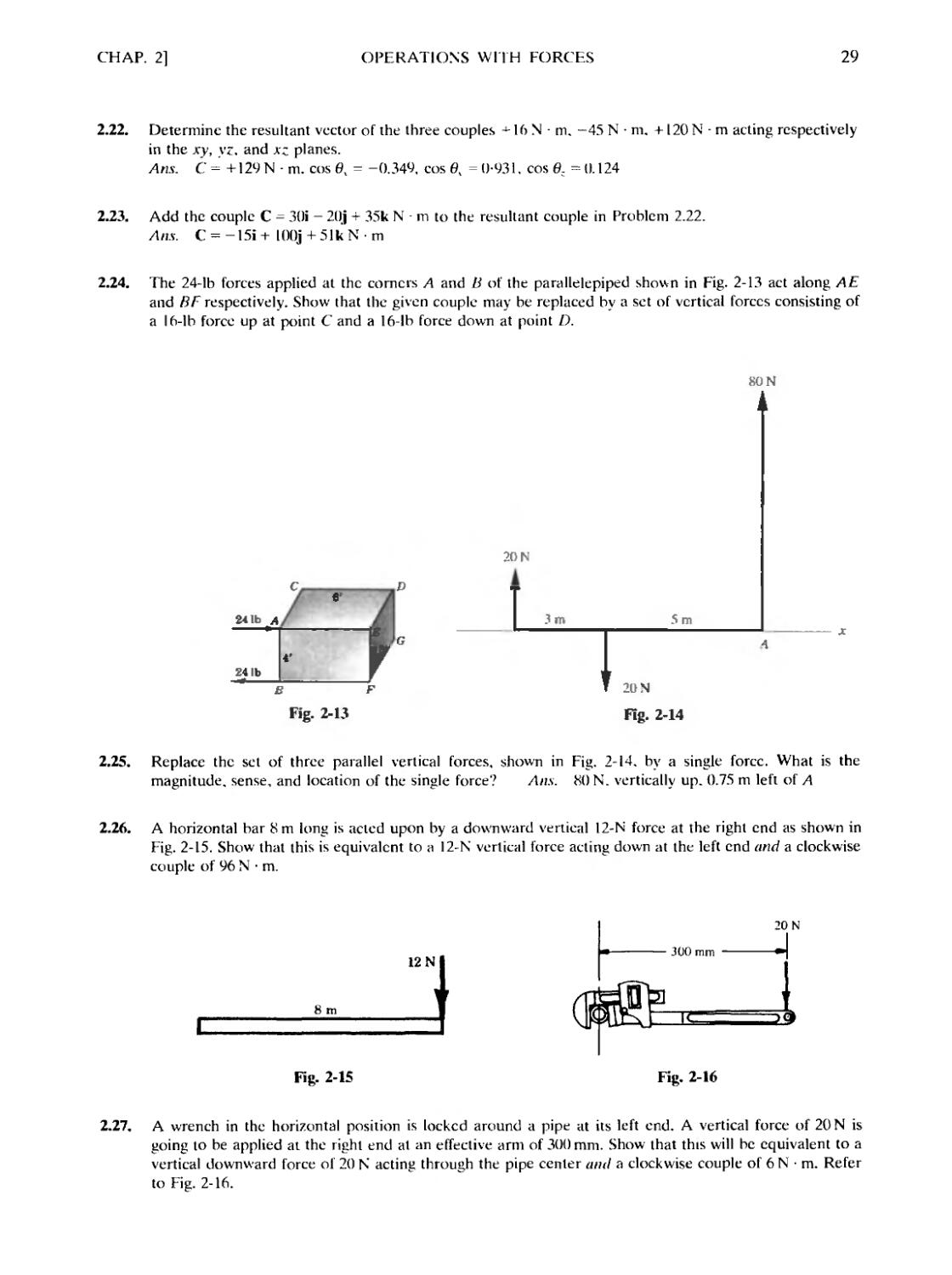
2.24. The 24-lb forces applied at the corners A and В of the parallelepiped shown in Fig. 2-13 act along AE
and BF respectively. Show that the given couple may be replaced by a set of vertical forces consisting of
a 16-lb force up at point С and a 16-lb force down at point D.
241b
*'
В F
Fig. 2-13
SON
20 N
t
3 m
5 m
1
20 N
Fig. 2-14
2.25. Replace the set of three parallel vertical forces, shown in Fig. 2-14. by a single force. What is the
magnitude, sense, and location of the single force? Ans. 80 N. vertically up. 0.75 m left of A
2.26. A horizontal bar 8 m long is acted upon by a downward vertical 12-N force at the right end as shown in
Fig. 2-15. Show that this is equivalent to a 12-N vertical force acting down at the left end and a clockwise
couple of 96 N ¦ m.
8 m
12 N f
20 N
300 mm
Fig. 2-15
Fig. 2-16
2.27. A wrench in the horizontal position is locked around a pipe at its left end. A vertical force of 20 N is
going to be applied at the right end at an effective arm of 300 mm. Show that this will be equivalent to a
vertical downward force of 20 N acting through the pipe center and a clockwise couple of 6 N • m. Refer
to Fig. 2-16.
30
OPERATIONS WITH FORCES
[CHAP. 2
?l±
2.28. Reduce the system of forces in the belts shown in Fig. 2-17 to a single force at О and a couple. Forces
are either vertical or horizontal. Arts. 78.3 lb, 0V = 296.5е, С = 0
201b
100 N
400 N
ОТО N
A 4 m
r
600 N
Fig. 2-17
Fig. 2-18
2.29. Reduce the system of forces acting on the beam shown in Fig. 2-18 into a force at A and a couple.
Ans. R = 100 N up at А, С = 6000 N • m
2.30. Referring to Fig. 2-19, reduce the system of forces and couples to the simplest system using point A.
Ans. Rx = +48.1 lb, R, = -3.9 lb, С = +36.2 lb-ft
3'
,331b
4 280 lb-ft
,681Ь
/V5
861b
Fig. 2-19
iro
220 N
3m
-4 m
Fig. 2-20
2.31. Determine the moments of the two forces about the x, y, and z axes shown in Fig. 2-20.
Ans. M = 488i + 732kN ¦ m or M, = +488N • m, My =0, Mz = +732N ¦ m
Chapter 3
Resultants of Coplanar Force Systems
3.1 COPLANAR FORCES
Coplanar forces lie in one plane. A concurrent system consists of forces that intersect at a point
called the concurrence. A parallel system consists of forces that intersect at infinity. A nonconcur-
rent, nonparallel system consists of forces that are not all concurrent and not all parallel.
Vector equations may be applied to the above systems to determine resultants, but the following
derived scalar equations will be more useful for a given system.
3.2 CONCURRENT SYSTEM
The resultant R may be (o) a single force through the concurrence or (b) zero. Algebraically,
*)' + B Fy
where 2 Fx, 2 Fy = algebraic sums of the x and у components, respectively, of the forces of the
system
0, = angle that the resultant R makes with the x axis.
3.3 PARALLEL SYSTEM
The resultant may be (o) a single force R parallel to the system, (b) a couple in the plane of the
system or in a parallel plane, or (c) zero. Algebraically,
R = ^F and Ra = ^Mo
where 2F= algebraic sum of the forces of the system
О = any moment center in the plane
a = perpendicular distance from the moment center О to the resultant R
Ra = moment of R with respect to О
2 Mo = algebraic sum of the moments of the forces of the system with respect to О
If 2 F is not zero, apply the equation Ra = 2 Mo to determine a and hence the action line of R.
If 2 F = 0, the resultant couple, if there is one, has a magnitude 2 Mo.
3.4 NONCONCURRENT, NONPARALLEL SYSTEM
The resultant may be (a) a single force R, (b) a couple in the plane of the system or in a parallel
plane, or (c) zero. Algebraically,
^J + B^ and tan0v = |^
where 2 Fx, 2 F} = algebraic sums of x and у components, respectively, of forces of system
0, = angle that the resultant R makes with x axis
To determine the action line of the resultant force, employ the equation
31
32
RESULTANTS OF COPLANAR FORCE SYSTEMS
[CHAP. 3
where О = any moment center in the plane
a = perpendicular distance from moment center О to the resultant R
Ra = moment of R with respect to О
2 Mo = algebraic sum of the moments of the forces of the system with respect to О
Note that even if R = 0, a couple may exist with magnitude equal to 2 Mo.
3.5 RESULTANTS OF DISTRIBUTED FORCE SYSTEMS
A distributed force system is one in which forces cannot be represented by individual force
vectors acting at specific points in space; they must be represented by an infinite number of vectors,
each of which is a function of the point at which it acts. Consider the coplanar (parallel) distributed
force system shown in Fig. 3-1. In the U.S. Customary System the units for f{x) would be, for
example, lb/ft. In the International System, the units might be N/m. The resultant R of the force
system and its location can be found by integration. Thus
R=\ f(x)
Ja
dx and Rd =
= xf(x)
¦1л
dx
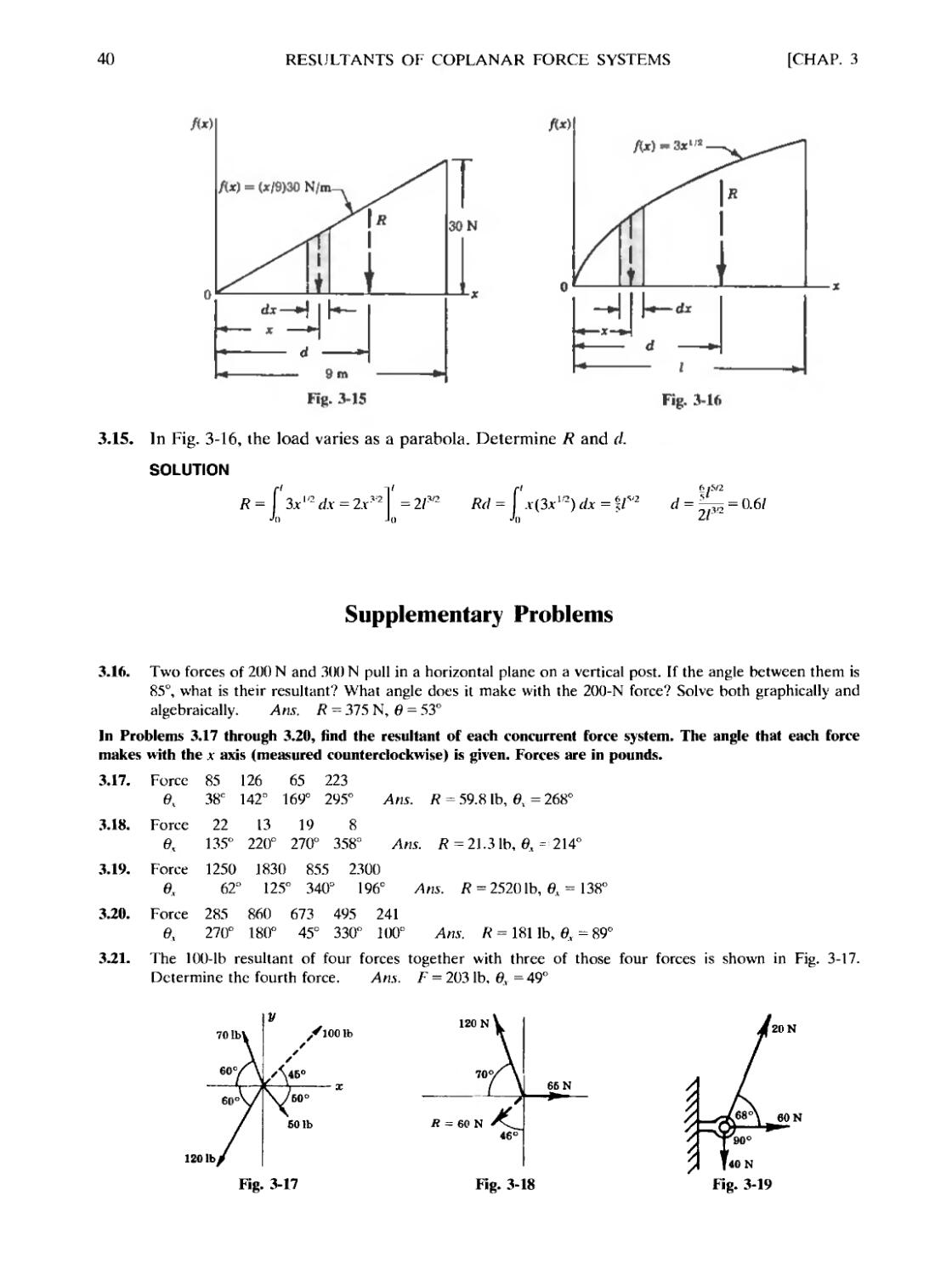
Problems 3.13 through 3.15 are specific examples.
fix)
В
-II
dx
t
Fig. 3-1
Solved Problems
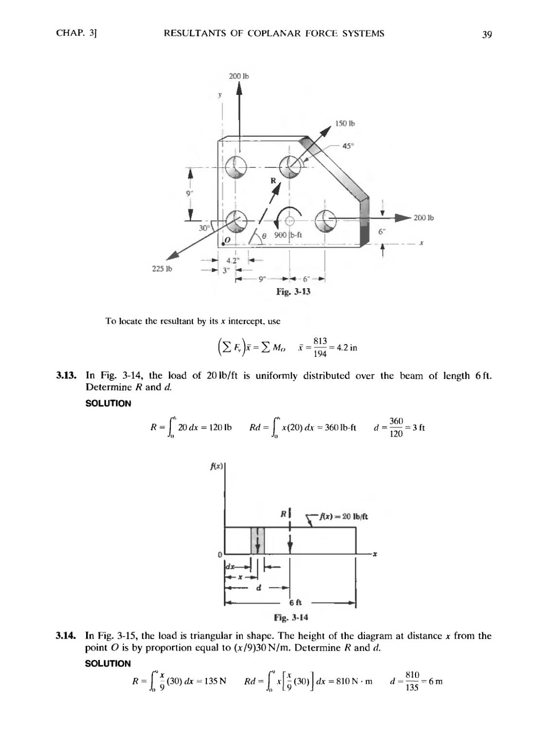
3.1. Determine the resultant of the concurrent force system shown in Fig. 3-2.
2001b
1501b
1801b
Fig. 3-2
CHAP. 3]
RESULTANTS OF COPLANAR FORCE SYSTEMS
33
SOLUTION
Find the x and у components of each of the four given forces. Add the x components algebraically
to determine 2 Fx. Find 2 F, for the у components. A tabular form may present the information more
clearly.
Force
150
200
80
180
cosfl,
+0.866
-0.866
-0.500
+0.707
sine,
+0.500
+0.500
-0.866
-0.707
F,
+ 129.9
-173.2
-40.0
+ 127.3
К
+75.0
+ 100.0
-69.2
-127.3
x = +44.0, 2 Fv = -21.5, and R = VBF,J + BFV~J = VD4.0J + (-21.5)- = 49.01b.
from which
в, = 360° - 26° = 334°
3.2. Determine the resultant of the force system shown in Fig. 3.3. Note that the slope of the
action line of each force is indicated in the figure.
SOLUTION
100 N
Force
50
100
30
MN
30 N
Fig. 3-3
FK
+ 50 X;
-100 X;
+30 x-
/FTP
1
/FT?
+50 x -
lOOx
V2
VTo
V5
Sf, = -46.1, 2 /\ = -23.0, and R = V(-46.1J + (-23.0J = 51.6 N, with в, = 207°.
3.3. Find the resultant of the coplanar, concurrent force system of Fig. 3-4.
SOLUTION
^ F, = 70 - 100 cos 30° - 125 sin 10° = -38.3 lb
^ /v = 125 cos 10° - 100 sin 30° = 73.1 lb
tan в,=
-38.3
=V(-38.3J
= -1.91 в, =62°
ilb
34
RESULTANTS OF COPLANAR FORCE SYSTEMS
[CHAP. 3
from which 6= 180°-62°= 118° to the nearest degree. The resultant is shown as a dashed vector in
Fig. 3-4.
30 N
V
6m
20 N
5N
8 m —-t— 5 m —
40 N
Fig. 3-5
3.4. Determine the resultant of the parallel system of Fig. 3-5.
SOLUTION
In Fig. 3-5 the action lines of the forces are vertical as shown.
R = -20 + 30 + 5 - 40 = -25 N (i.e., down)
To determine the action line of this 25-N force, choose any moment center O. Since the moment of
a force about a point on its own action line is zero, it is advisable but not necessary to choose О on one
of the given forces. Let О be on the 30-N force.
2 Mo = +B0 x 6) + C0 x 0) + E x 8) - D0 x 13) = -360 N • m
Then the moment of R must equal -360 N • m. This means that R, which is down (-), must be placed to
the right of О because only then will its moment be clockwise (-).
Apply Ra = 2 Mo to obtain
360 N ¦ m
a = —- —— = 14.4 m to the right of О
Note the determination of a without regard to the signs of R or 2 Mo but by using reasoning.
3.5. Determine the resultant of the parallel force system in Fig. 3.6.
SOLUTION
R = -100 + 200 - 200 + 400 - 300 = 0. This means that the resultant is not a single force. Next find
E Mo- Choose O, as shown, on the 100-lb force.
Y,MO= +A00x 0) + B00x2) -B00x 5) + D00x9) -C00x 11) = -300lb-ft
The resultant is therefore a couple С = -300 lb-ft, which can be represented in the plane of the
paper in accordance with the laws governing couples.
400 lb
200lb I I
vf -• f 4--UJ
401b-
I—I j ¦ 201b
151
-201b
Fig. 3-6
Fig. 3-7
CHAP. 3]
RESULTANTS OF COPLANAR FORCE SYSTEMS
35
3.6. Determine the resultant of the horizontal force system acting on the bar shown in Fig. 3-7.
SOLUTION
R = E F,, = +20 + 20 - 40 = 0. This means that the resultant is not a single force, but it may be a
couple.
2 Mo = -B0 x 3) + B0 x 3) = 0
Hence in this system the resultant force is zero and the resultant couple is also zero.
3.7. The three parallel forces and one couple act as shown on the cantilever beam of Fig. 3-8.
What is the resultant of the three forces and the couple?
SOLUTION
R = 2 F = 500 - 400 - 200 = -100 N
Mo = 2 x 500 - 4 x 400 - 6 x 200 + 1500 = -300 N - m
—300
Ra = ^Mo a=~1{^ = 3m
For the resultant, which is downward, to yield a negative moment the resultant must be to the right of
point O. The resultant and its location is shown as a dashed vector in Fig. 3-8.
400 N
tUON
3m
200 N
О
'-* 2 m
2m
i5O0N*m
500 N
Fig. 3-8
3.8. Determine the resultant of the coplanar, nonconcurrent force system shown in Fig. 3-9.
SOLUTION
2 F, = 50 - 100 cos 45° = -20.7 lb
X Fv = 50-100 sin 45° = -20.7 lb
R = V(-20.7J + (-20.7J = 29.3 lb 0 = tan '|^ = 45О вх
Mo = 5 X 50 - 4 X 50 = 50 lb-ft
Ra = У Mo = 50 a = 50/29.3 = 1.71 ft
R
36
RESULTANTS OF COPLANAR FORCE SYSTEMS
[CHAP. 3
50 tb
1.71"
1001b
Fig. 3-9
R is directed downward to the left, and hence must be above the origin to produce a positive (+)
moment.
3.9. Determine the resultant of the nonconcurrent, nonparallel system shown in Fig. 3-10(a).
Assume that the coordinates are in meters.
120 N
У
@,3)
A,
с,
A.1)
Cx
в,
I-
(8,5)
(в)
R - 194 N
(Ь)
Fig. 3-10
SOLUTION
For convenience the forces are lettered A, B, C, D. The simplest method of attack is to use a
tabular form listing ж and у components for each force and also the moment of each component about
some moment center—for this example O. The forces are now replaced with their components at the
same points in the action lines as indicated in Fig. 3-10(fc). It may be convenient at times to use
components at a different point in the action line than that which is given, e.g., force С acting at 45° has
an action line that passes through the origin O. The moment about О is easily seen to be zero in this
case. However, the components used in this example will be shown acting horizontally and vertically
through the given points of application.
CHAP. 3]
RESULTANTS OF COPLANAR FORCE SYSTEMS
37
The following table is useful in compiling the necessary information. Be sure to place the proper
sign before each component and to determine the moment signs by inspection.
Force
A
В
С
D
cos в,
0
-0-866
+0.707
+0.940
sin в,
+ 1
+0.500
+0.707
-0.342
F,
0
-103.9
+70.7
+47.0
F,
+80.0
+60.0
+70.7
-17.1
Moment of Ft
about О
0
+519.5
-70.7
+47.0
Moment of Fr
about О
0
+480.0
+70.7
-136.8
Ma
0
+999.5
0
-89.8
F, = +13.8N
=+193.6 N
.8J + (+193.6)r =
To find the moment arm of the resultant, divide 910 by 194 to obtain 4.69 m.
Since R acts upward and slightly to the right, it must be placed as shown because 2 M<, is positive;
i.e., R must have a counterclockwise moment.
Another method to locate the action line of the resultant is to determine its intercept with, say, the
jt axis. If the components of the resultant are drawn through the intercept on the x axis, the jt component
would have no moment about O. The moment would be determined solely by the у component and
would be equal to the product of the у component and the x distance to the intercept (x coordinate of
the intercept).
2 Ma 910
2 F, 193.6
= 4.70 m
Draw the resultant as shown with the intercept +4.70 m to the right because 2 F, is positive and
2 Mo is positive.
3.10. Determine the resultant of the force system shown in Fig. 3-1 l(a). Assume that the
coordinates are in feet.
63.7
\
V
1-6,20)
X
n
во- eoi
A.
A0,10)
B6, Щ
ПИ»
Ь J 136,1Б)
511201b
IK
,r
63.4-
\
\
Ш №
(e)
31.У
Fig. 3-11
38
RESULTANTS OF COPLANAR FORCE SYSTEMS
[CHAP. 3
SOLUTION
The summation of components can be written directly as an alternative to the tabular form of
Prob. 3-9: ]? /r = 100 cos 60°+ 80 cos 45°+ 150 cos 75°= 145.41b
2 /¦; = - 100 sin 60° + 80 sin 45° - 120 - 150 sin 75е = -294.9 Ib
— 7940
К =VA45.4J-4-294.9)- = 3281b в = tan ' ^^ = 63.7е
145.4
Summing the moments of the components about О:
2л/„ = -B0I00 cos 60°^ E) 100 sin 60°-A0)80 cos 45°
+ A0)80 sin 45° - B5I20 - A5I50cos 75° - C5I50sin 75° = -92201b-ft
To determine the .v intercept of the resultant, use
= 5Ж v= 31.3 ft
To determine the у intercept of the resultant, use
/•'.)>" = 2 Mo у =63.4 ft
The resultant is shown in Fig. 3-11(A>).
3.11. Determine the resultant of the four forces tangent to the circle of radius 3 ft shown in
Fig. 3-12(д). What will be its location with respect to the center of the circle?
1501b
45'
1281b
1001b
(*)
Fig. 3-12
SOLUTION
Note that the horizontal and vertical components of the l(K)-lb force are both -70.7 lb. Hence
2 ft = + 150 - 70.7 =+79.3 Ib, i.e., to the right: and 2 F,. = +50 - 80 - 70.7 = - 100.7 Ib, i.e., down. The
resultant R = VB>AJ + B F,,J = 128 lb.
The moment of R with respect to О is R x a. and this equals the sum of the moments of all the
given forces about O. Hence 128л = +50 x 3 150 x.U 80 x 3 - 100 x 3 - -360. The resultant is shown,
in Fig. 3-12(/>). at a distance of 2.81 ft from the center О of the circle, causing a negative moment.
3.12. Find the resultant of the force system acting on the thin gusset plate of Fig. 3-13. Locate the
resultant by giving the .v intercept.
SOLUTION
2 F, = 150 cos 45° + 200 - 225 cos 30° = 111.2 lb
2 /\ = 150 sin 45° - 225 sin 30° + 200 = 193.6 lb
R = \TfTT.2J + A93.6J = 223 lb в = tan
—
= 60°
Mt, = CJ00 - A5I50 cos 45° + A2I50 sin 45° - FJ00 ь 900 + FJ25 cos 30° - CJ25 sin 30°
= 813 lb-ft
CHAP. 3]
RESULTANTS OF COPLANAR FORCE SYSTEMS
39
2001b
2251b
2001b
To locate the resultant by its x intercept, use
3.13. In Fig. 3-14, the load of 20 Ib/ft is uniformly distributed over the beam of length 6 ft.
Determine R and d.
SOLUTION
2Qdx = 1201b Rd =
= I jcB0) dx =
Л)
= 360 Ib-ft d = — = 3 ft
- 20 lb/ft
til
6 ft
Fig. 3-14
3.14. In Fig. 3-15, the load is triangular in shape. The height of the diagram at distance jt from the
point О is by proportion equal to (x/9K0N/m. Determine R and cl.
SOLUTION
R= I
Jo
Jo L 9
J.v=810N-m d = ~ =
135
40
RESULTANTS OF COPLANAR FORCE SYSTEMS
[CHAP. 3
30N
rfl
Lil
Fig. 3-16
3.15. In Fig. 3-16, the load varies as a parabola. Determine R and d.
SOLUTION
R = Г3xdx = 2rMT = 2/3'2 Rd = \ лCл1/2)dx = fГ2 d = ^ = 0.
Л) Jo Л) ^'
= 0.6/
Supplementary Problems
3.16. Two forces of 200 N and 300 N pull in a horizontal plane on a vertical post. If the angle between them is
85°, what is their resultant? What angle does it make with the 200-N force? Solve both graphically and
algebraically. Am. R = 375 N, 0 = 53°
In Problems 3.17 through 3.20, find the resultant of each concurrent force system. The angle that each force
makes with the л* axis (measured counterclockwise) is given. Forces are in pounds.
3.17. Force 85 126 65 223
в, 38е 142а 169° 295° Am. R = 59.81b, в, = 268°
3.18. Force 22 13 19 8
0, 135° 220° 270° 358= Am. R = 21.3 lb, 0, = 214°
3.19. Force 1250 1830 855 2300
6X 62° 125° 340D 196° Arts. R = 25201b, вх = 138°
3.20. Force 285 860 673 495 241
в, 270° 180° 45° 330° 100° Am. R = 181 lb, 0, = 89°
3.21. The 100-lb resultant of four forces together with three of those four forces is shown in Fig. 3-17.
Determine the fourth force. Am. F = 203 lb, 0, = 49°
70 ibV
60°
120 lb J
,/100 lb
120 N
Б0°
601b
R = 60 N
46°
66 N
20 N
60 N
40 N
Fig. 3-17
Fig. 3-18
Fig. 3-19
CHAP. 3]
RESULTANTS OF COPLANAR FORCE SYSTEMS
41
3.22. Three coplanar forces of 80 N each pull on a small ring (diameter negligible). Assuming that their lines
of action make equal angles with each other A20°). determine the resultant. This system is said to be in
equilibrium. Ans. R = 0
3.23. The resultant of three forces is 60 N as shown in Fig. 3-18. Two of the three forces are also shown as
120 N and 65 N. Determine the third force. Ans. 169 N. в, = 246°
3.24. Three wires exert the tensions indicated on the eyebolt in Fig. 3-19. Assuming a concurrent system,
determine the force in a single wire that will replace the three wires. Ans. T = 70.8 N, 0, = 343°
3.25. Determine the resultant of the three forces originating at point C, -3) and passing through the points
indicated: 126 N through (8,6). 183 N through B, -5), 269 N through (-6,3).
Ans. R = 263 N, 0, = 159° through C, -3)
3.26. Determine the values of P and Q in Fig. 3-20 so that the resultant of the three coplanar forces is 1001b
at 20° to the x axis. Ans. P = 240 lb; Q = 161 lb
45V
30°
2001b
Fig. 3-20
Find the resultant in each of Problems 3.27 through 3.29. The forces are horizontal and expressed in pounds.
The у distances to the action lines are expressed in feet.
3.27. Force +50 +20 -10
у +3 -5 +6 Ans. K =-60 lb, у =-0.167 ft
3.28. Force +800 -300 +1000 -600
у -6 -5 -4 0 Ans. Я =+900 lb, у = -8.11 ft
3.29. Force +160 -220 +80 -180 +160
у +3 -7 -3 +10 0 Ans. C=+201b-ft
3.30. See Fig. 3-21. Find the resultant of the three loads shown acting on the beam.
Ans. R = 38 T down, distance from left support = 8.37 ft
20 T
20 N
1CT
Sf/JSS
77777
У
40
Fig. 3-21
SON
Fig. 3-22
42
RESULTANTS OF COPLANAR FORCE SYSTEMS
[CHAP. 3
3.31. Determine the resultant of the four forces shown in Fig. 3-22. The side of each small square is 1 m.
Ans. R = +35 N, x = 2.99 m
3.32. Six weights of 30, 20. 40, 25, 10, and 35 lb hang in one plane from a horizontal support at distances 2, 3,
5. 7. 10, and 12 ft, respectively, from a wall. What single force would replace these six?
Ans. R = -160 lb, 6.34 ft from wall
3.33. Three forces act on the beam, two of which are shown in Fig. 3-23 together with the resultant of all
three. What is the third force? Лил. F = 20 T down, x = 10 ft from left support
R Б0Т
10 T
20 T
}s/}f
10 T I 20 T
* -| 8 -|. В \-S'.
//?//
Fig. 3-23
К 30 lb
¦ 15 1Ь —
Fig. 3-24
3.34. Determine the resultant of the coplanar parallel system shown in Fig. 3-24.
Ans. 30 lb to left, 2 ft above bottom
3.35. Determine the resultant of the coplanar parallel system shown in Fig. 3-25.
A us. R = 100 N down, 55 mm up along plane from A
40 N
30 N
20 N
Fig. 3-25
In Problems 3.36 through 3.38. determine the resultant of the nonconcurrent, nonparallel systems of forces. F is
in пен tons and the coordinates are in meters.
3-36. F 20 30 50 10
0л 45° 120° 190° 270°
Coordinates of point of application A,3) D.-5) E,2) (-2.-4)
Ans. R = 54.7 N. 0, = 157°, v intercept = 3.52 m
3.37.
F
0,
50
90°
100
150°
200
30°
90
45
Coordinates of point of application B,2) D.6) C,-2) G 2)
Ans. R = 303 N. 0, = 60.3°, .v intercept = 6.77 m
CHAP. 3]
RESULTANTS OF COPLANAR FORCE SYSTEMS
43
3.38. F 2 4 5 8
0V 45° 290° 183° 347°
Coordinates of point of application @, 5) D.3) (9, -4) B, -6)
Ans. R = 7.12 N. в, = 322°, x intercept = 1.20 m
3.39. Determine completely the resultant of the five forces shown in Fig. 3-26. The forces are in ounces, and
the squares are 1 in by 1 in Ans. С = -268oz-in
3500 Ib
,100
2000 lb
1000lb
50
Б0'
100
HI
Fig. 3-26
15001b
Jj
— 10
Fig. 3-27
12 -Щ
3.40. Determine completely the resultant of the four forces shown in Fig. 3-27. Each force makes a 15° angle
with the vertical, except the 2(KK)-lb force, which is vertical.
Ans. R = 6830 lb down, horizontal distance from hinge = 16.8 ft
3.41. A thin steel plate is subjected to the three forces shown in Fig. 3-28. What single force would have an
equivalent effect on the plate?
Ans. R = 18.7 N, в, = 285°, bottom intercept = 4.23 m to left of О
3.42. Determine the resultant of the forces acting on the bell crank shown in Fig. 3-29.
Ans. R = 247 lb, в% = 259е. horizontal intercept = -6.3 in from О
3.43. Determine the resultant of the three forces acting on the pulley shown in Fig. 3-30.
Ans. R = 742 N, в, = 357°, R cuts vertical diameter 2.27 m above О
8 m
•19N
-24N
18 N
Fig. 3-28
701b
560 N
180 N
Fig. 3-30
3.44. Solve for the resultant of the six loads on the truss shown in Fig. 3-31. The loads are given in kips (K)
A kip = l(XX)lb). Three loads are vertical. The wind loads are perpendicular to the side. The truss is
symmetrical.
Ans. R = 10.7 к, в, = 281°, R cuts lower member of truss +15.3 ft from left support
44
RESULTANTS OF COPLANAR FORCE SYSTEMS
[CHAP. 3
зк
2 К 2-К
2K
I 2.5 m I
o1 *-
27N
Fig. 3-31
Fig. 3-32
3.45. The resultant of four vertical forces is a couple of 300 N • m counterclockwise. Three of the four forces
are shown in Fig. 3-32. Determine the fourth. Ans. 33 N up at 4.46 m to right of О
3.46. Determine M, P, and Q in Fig. 3-33 so that the resultant of the coplanar nonconcurrent force system is
zero.
Ans. M = 293 lb-ft. P = 76.7 Ib, Q = 227 lb
100 lb
501Ы-
>
2501b
Fig. 3-33
3.47. Determine the resultant of the forces shown in Fig. 3-34. The coordinates are in feet.
Am. 73.4 lb, вх = 107°, x intercept = 8.38 ft to left of О
88 fb
( 2. 2)
401b
200 Ib ft
9 te-
Fig. 3-35
3.48. What is the maximum value of the moment M such that the beam in Fig. 3-35 does not leave the support
Ans. M = 13,500 lb-ft
3.49. Determine the resultant of the force system shown in Fig. 3-36. Coordinates arc in millimeters.
Ans. R = 24.7i + 12.9J N, x intercept is 24.5 mm
CHAP. 3]
RESULTANTS OF COPLANAR FORCE SYSTEMS
45
40 N
Fig. 3-36
20 N
B0,10)
0.5 N-m
C0,-15)
3.50. A 50-ft airplane wing is subjected to a test load that varies parabolically from 0 to 5001b/ft. Refer to
Fig. 3-37 and determine k, the resultant load and its location. Am. R = 16,700lb, x = 30 ft, к = 70.7
3.51. Do Prob. 3.50 if the test load is the first 90° of a sinusoidal cycle that varies from zero to 500 lb/ft in
50 ft. Hint: Px = k sin (лх/100).
Ans. к = 500, R = 15,900 lb, x = 31.9 ft
Chapter 4
Resultants of Noncoplanar Force Systems
4.1 NONCOPLANAR FORCE SYSTEMS
Noncoplanar force systems are categorized as follows. A concurrent system consists of forces
that intersect at a point called the concurrence. A parallel system consists of forces that intersect at
infinity. The most general system is called nonconcurrent, nonparallel (or skew), and, as the name
implies, the forces are not all concurrent and not all parallel.
4.2 RESULTANTS OF A NONCOPLANAR FORCE SYSTEM
The resultant of a noncoplanar force system is a force R and a couple C, where R = 2 F, the
vector sum of all forces of the system, and C=XM, the vector sum of the moments (relative to a
selected base point) of all the forces of the system. The value of R is independent of the choice of
the base point, but the value of С depends on the base point. For any force system it is possible to
select a unique base point so that the vector С representing the couple is parallel to R. This special
combinaiton is called a wrench or screw.
The vector equations in the preceding paragraph may be applied directly to noncoplanar systems
to determine the resultant, or the following derived scalar equations may be used.
4.3 CONCURRENT SYSTEM
The resultant R may be (a) a single force through the concurrence or (b) zero. Algebraically,
with direction cosines
cos 6X = —— cos 6V = -~ cos 6Z =
cos 6V cos 6Z
/< A A
where 2 Fx, 2 /\. 2 Fz = algebraic sums of the x, y, and z components, respectively, of the forces of
the system
0,, 0V, б? = angles that the resultant R makes with the .v, y, and z axes, respectively.
4.4 PARALLEL SYSTEM
The resultant may be (a) a single force R parallel to the system, (b) a couple, or (c) zero.
Assume the у axis is parallel to the system. Then, algebraically,
where 2 F = algebraic sum of the forces of the system
x= perpendicular distance from the yz plane to the resultant
46
CHAP. 4] RESULTANTS OF NONCOPLANAR FORCE SYSTEMS 47
z = perpendicular distance from the xy plane to the resultant
Mx, 2 Mz = algebraic sums of the moments of the forces of the system about the л and z
axes, respectively.
If 2 F = 0, the resultant couple C, if there is one, will be determined by the following equation:
C=y(SMtJ+(Sw;J with tan<?
where ф = angle that the vector representing the resultant couple makes with the .v axis.
4.5 NONCONCURRENT, NONPARALLEL SYSTEM
As already indicated, the resultant is a force and a couple where the couple varies with the
choice of a base point. In the following discussion a set of jc, y, and z axes is placed with their origin
at the base point.
Replace each force of the given system by the following setup: A) an equal parallel force but
acting through any chosen origin and B) a couple acting in the plane containing the given force and
the origin.
The magnitude of the resultant R of the concurrent system at the origin is given by the equation
with direction cosines
cos вх = —— cos ву = —— cos 0. =
cos ву cos 0.
к к к
where the above quantities have the same meaning as listed in Section 4.3.
The magnitude of the resultant couple С is given by
with direction cosines
cos ф, = —— cos ф, = —— cos ф: = ——
where 2 Mx, 2 My, 2 Л/. = algebraic sums of the moments of the forces of the system about the .v,
y, and z axes respectively
Фх, Ф*, Ф: ~ angles which the vector representing the couple С makes with the .v. y,
and z axes respectively.
Solved Problems
In the following problems equivalent scalar equations are used when more convenient than the vector
equations. Similarly, in the diagrams the forces are indicated by their magnitudes if the directions are clearly-
indicated.
48
RESULTANTS OF NONCOPLANAR FORCE SYSTEMS
[CHAP. 4
Forces of 20, 15, 30, and 50 lb are concurrent at the origin and are directed through the points
whose coordinates are B, 1, 6), D, —2, 5), (—3, —2, 1), and E, 1, —2), respectively. Determine the
resultant of the system.
SOLUTION
F
20
15
30
50
Coordinates
B,1,6)
D,-2,5)
(-3,-2,1)
E, 1, -2)
cos 0,
4^ = +0.313
V41
+4
-7= - +0.597
V45
^L = -0.803
Vl4
+5
-7= = +0.912
V30
cos 0%
^= - +0.156
V41
-^ - -0.298
V45
-^ = -0.535
Vl4
4^=+0.183
V30
cos 0.
-4= = +0.938
V41
-^ - +0.745
V45
~ = +0.268
Vl4
-^i = -0.365
V30
+6.26
+8.96
-24.1
+45.6
Fr
+3.12
-4.47
-16.1
+9.15
Fz
+ 18.8
+11.2
+8.04
-18.3
The denominator in each case is determined by taking the square root of the sum of the squares of
x, y, and z intervals of differences. For the 30-lb force this is V(-3J + (~2J + (IJ =
Fx is the product of F and cos 0V. Watch signs. It is advisable to write signs before inserting any
values.
2FV = +6.26 + 8.96-24.1+45.6= +36.7. Similarly, 2 Fv = -8.30 and 2/C = +19.7. Then
r. = 42.51b
cos 0t=?-^ = ±^= +0.864 0,=3O.2°
R 42.5
cos 0.- =
^
R 42.5
=-0.192 0v=79.O=
=+0.463 0-=62.4
The negative value of cos 0V signifies that the resultant has a negative component in the у direction.
This is illustrated in Fig. 4-1.
В = 42.6 lb
tig. 4-1
R SON
20 N 10 N
I U.2)
B,3)
F.25,4)
Fig. 4-2
CHAP. 4]
RESULTANTS OF NONCOPLANAR FORCE SYSTEMS
49
fthcad
4.2. Three forces of +20 N, -10 N, and +30 N are shown in Fig. 4-2. The у axis is chosen parallel
to the action lines of the forces. These lines pierce the xz plane at the points whose x and z
coordinates in meters are respectively B,3), D,2), and G,4). Locate the resultant.
SOLUTION
r =
= -^20- 10 + 30 = +40N
To determine the x coordinate of the resultant (i.e., of the point where the action line of the
resultant pierces the xz plane), use the projected system in the xy plane as shown in Fig. 4-3. Apply the
equation Rx = 2 M/.
S^ = EMo= +B0 x 2) - A0 x 4) + C0 x 7)
= +210N-m
О
SON
20 N
ION
-2 m -|» 2 m—+— 3 m ¦
30 N
20. N
1 ION
I i „_ _
; 111 z in ¦
1 mil mi
Fig. 4-3
Fig. 4-4
The x coordinate must be such that a force of +40 N (acting up) will have a positive or
counterclockwise moment. Therefore R must be to the right of O.
x = + — =+5.25m
40
Be sure to determine the sign by inspection as indicated in the previous paragraph, and not by
combining the signs of the moment and the force.
Figure 4-4 shows the projection of the system into the yz plane.
Em»=Imo= -C0 x 4) - B0 X 3) + A0 X 2) = -160 N • m
The г coordinate must be such that a force of 40 N (acting up) will have a negative or clockwise
moment of 160 N • m. Therefore R must be to the left of O. In this case the z coordinate is positive when
it is to the left of О (refer to the space diagram).
160
z = +— = +4.00 m
40
The problem may now be summarized by saying that the resultant is a 40-N force acting up. Its
action line is parallel to the у axis and pierces the xz plane at the point whose x, z coordinates are
(+5.25, +4.00) m. This is shown in Fig. 4-2.
4.3. Find the resultant of the system of forces shown in Fig. 4-5. The coordinates are in meters.
SOLUTION
R = 2 F = +100 + 50 - 150 = 0
This indicates that the resultant is not a single force. It may, however, be a couple.
Next find 2 M, and 2 M. as in the preceding problem.
2 M, = -A00 x 2) + E0 x 2) + A50 x 3) = +350 N • m
2 Mz = +A00 x 2) + E0 x 4) - A50 x 8) = -800 N ¦ m
Since 2 F = 0, 2 Mx and 2 Мг represent couples in the yz and xy planes respectively. These are
shown in Fig. 4-6.
50
RESULTANTS OF NONCOPLANAR FORCE SYSTEMS
[CHAP. 4
EON
Fig. 4-5
Mathcad
The two vectors representing the couples are shown combined into a resultant couple С with
magnitude
M. = 874 N - m
The vector С in the xz plane makes an angle в, with the z axis as shown in figure, where в, = вх.
According to the convention about couples, the resultant couple acts in a plane perpendicular to
the vector С representing it. In the figure this could be in a plane containing the у axis with trace TT in
the xz plane.
This trace makes an angle with the x axis of
4.4. Determine the resultant of the nonconcurrenl, nonparallel system of forces shown in Fig. 4-7.
C,2.0)
0.2,2}
0.2.4)
2.0.4)
Fig. 4-7
SOLUTION
In working this example, replace each force by an equal force parallel to it through the origin and a
couple. The forces at the origin are resolved into x, v, z components using direction cosines. Thus the
40-lb force has direction cosines that are determined by the differences in the coordinates of the two
given points on its line of action.
The x difference is 0 - 2 = -2; the >¦ difference is 2 - 0 = +2; the z difference is 2 - 4 = -2. The
cosine of the angle the 40-lb force makes with the x axis is
—2
-2
V(-2J + (+2J + (-2f Vf2
Similarly, cos 04 = +2/VT2 and cos в, = -2/VI2.
CHAP. 4]
RESULTANTS OF NONCOPLANAR FORCE SYSTEMS
51
The results are most conveniently set down in tabular form
F
40
30
20
cose.
-2
Vn
-гЗ
V25
+3
VI7
cose.
+2
Vn
0
+2
Vi7
COS в-
-2
Vn
-4
V25
+2
Vf7
F,
-23.1
+ 18.0
+ 14.6
F,
+23.1
0
+9.71
F
-23.1
24.0
-¦-9.71
2 Fv = +9.5 2 Fy = +32.8 X /V = -37.4
From the above table determine the resultant of this system of transferred forces concurrent at the
origin.
?) () () :Г)Т = 50.8 1b
cose =
^
=+0.187
cos©,. =— 2= +0.645
К 50.8
The resultant of the transferred forces is shown graphically in Fig. 4-8.
cos er = — = -0.737
R
82 81b
К Б0.8 1Ь
9.61b
Fig. 4-8
The foregoing did not use the couple associated with each transferred force. Determine the
moments of each of the three forces about the three axes to esgablish the magnitude and direction of
these couples. Referring to Fig. 4-7, consider the 40-lb force acting at the point B, 0,4). Its moment
about the x axis is the algebraic sum of the moments of its three components about the x axis. However,
its only component possessing a moment about the x axis is the у component. The moment of the 40-lb
force about the x axis is therefore -B3.1 x 4) = -92.4 Ib-ft. In finding the moment about the у axis (i.e..
Af,), consider the moments of both the x and z components. The moment of the x component about the
у axis is -B3.1 X 4) = -92.4 lb-ft. The moment of the г component about the v axis is +B3.1 X 2) =
+46.2 lb-ft. Therefore M, is equal to -92.4 + 46.2 = -46.2 lb-ft. The moment of the 40-lb force about
the z axis is the same as the moment of its у component about the г axis. Hence M. = +B3.1 x 2) =
+46.2 lb-ft.
A tabular solution is given for the moments of the forces.
F
40
30
20
F,
-23.1
+ 18.0
+ 14.6
+23.1
0
+9.71
/;
-23.1
-24.0
+9.71
-92.4
-48.0
-19.4
-46.2
+72.0
+9.8
M7
+46.2
-36.0
+ 19.4
= -159.8
. = +29.6
52
RESULTANTS OF NON'COPLANAR FORCE SYSTEMS
[CHAP. 4
The magnitude of the resultant couple is
with direction cosines
cos ф, =
'^
= -0.963
cos </j, = '' % = +0.214
с
У= 166 lb-ft
cos 6- = ':- = +0.178
С 166
The vector С is shown in Fig. 4-9. The resultant couple acts in a plnae perpendicular to the vector C.
The resultant of the system is the combination of the force R and the couple C.
Fig. 4-9
4.5. Find the general force-couple resultant of the noncoplanar. nonconcurrent force system
consisting of a 150-lb force along the line from B.0.0) through @.0. 1), a 90-lb force along
the line from @. -2, -1) through (-1,0. -1). and a 160 lb-ft couple lying in the .vv plane.
Distances are in feet. Rather the moments to the origin.
SOLUTION
Express each force in i. j, к notation and lind the moment of each force relative to the origin.
@- 2)i + @-0)i - A -0)k
F, = 150- 7^1 — -—-— = -134i + 67.1 к Ib
vf-2)' + (())' + (I)'
Then R = F, - F, = -174i + 80.5J +¦ 67.1 к 1b
Next determine C, and G..
C, = r, x F, = 2 0 0 = -134j lb-ft
i
2
-134
i
0
-40.25
j
0
0
к
0
67.1
j
-2
80.5
= -
к
-1
0
= 80.5i -г- 40.25J - 80.5k lb-ft
The given couple in the xy plane can be written as C, = 160k lb-ft. The total resultant couple is
С = C, + C, + C, = S0.5i - 93.8J f 79.5k lb-ft
Supplementary Problems
Determine the resultants in Problems 4.6 through 4.9, which involve concurrent systems of forces. The forces
are in pounds and the coordinates of the points on the lines of action are in feet. All forces in each problem are
concurrent at the origin. (Negative answers involve negative components.)
CHAP. 4]
RESULTANTS OF NONCOPLANAR FORCE SYSTEMS
53
4.6.
100
200
500
300
Coordinates A,1.1) B,3,1) (-2,-3,4) ( 1,1,-2)
Ans. R = 286 Ib. 0, = -60е, 0Л = 78°. 0. = 33°
4.7.
4.8.
5
8
Coordinates B,2.3) E,1.-2) (-3.-4,5) B,1,-4) E,2,3)
Ans. R - 13.3 Ib, 0, = 33°, 0, = 70°, 0, = 66°
F 1000 1500 1800
Coordinates (-5.2,1) F,-3,-2) (-2.-1,-1)
Ans. R = 1780 Ib, 6r = -52°. 0V = -55°. 0. = -57°
4.9.
F
40
80
30
20
Coordinates F,5.4) A,-3.-2) (8,10,-7) (-10,-9,-10)
Ans. R = 80.1 Ib, 0V = 49°, 0 = 67°, 0, = -51°
4.10. Determine the resultant of the three forces shown in Fig. 4-10. Note that their lines of action lie in the
three coordinate planes and pass through the origin.
Ans. R = 19.7 Ib. 0, = 43°, 0, = 56°, 0- = 66°
In each of Problems 4.11 through 4.14, find the resultant and the coordinates of the intersection of its line of
action with the xz plane. The given forces are in newtons and parallel to the v axis, and the coordinates of the
intersection of each action line with the л - plane are in meters.
4.11. F 100 150 200 300
(.v,c) C,-2) A,6) B,-3) (-1,-1)
Ans. R = 750 N, x = 0.733 m, f = -0.267 m
4.12. F -25 18 -12 -30 36
(x.z) A,2) B, 1) @,0) (-6.-2) C,2)
Ans. R = -13 N. jr = -23.0 m, z = -4.92 m
4.13. F 3 -4 2 -5
{x.z) B.5) A,-5) C.3) (-4,-4)
Ans. R= -4N.x = -7.00 m, г = -15.3 m
4.14. F +10 +20 -30
(.v. z) A,1) B,-5) C.-4)
Ans. C. = -30 N ¦ m, С = -40 N ¦ m
4.15. Five weights of 20, 15, 12, 6, and 101b rest on a table with the coordinates @.5,15°), A.5,90°),
@.8, 185°), @.7,262°). and A.2.340°), respectively, where the first number in parentheses represents the
radial distance in feet from the center of the table and the angle is measured counterclockwise from a
reference radius as the table is viewed from above. Determine the resultant weight.
Ans. R = 63 Ib down. ;¦ = 0.3, 0 = 56°
54
RESULTANTS OF NONCOPLANAR FORCE SYSTEMS
[CHAP. 4
4.16. Find the resultant of the system shown in Fig. 4-11. The forces are in pounds and the distances in feet.
A in. R = 40.3 tb, cos 0, = +0.594, cos в, = +0.673, cos 0. = -0.428 at origin, С = 251 lb-ft, cos ф, =
-0.660, cos <f>, = +0.633, cos <br = -rO.3%
4.17. In Problem 4.4 find the couple С by determining the sum of the moments of the three forces about the
origin using vector cross products. The reader should be aware that in finding the moment of a force
about a moment center, the position vector г may be drawn from the moment center to any point on the
action line of the force. The reader should prove this by using more than one point on the action line of
one of the forces.
4.18. Determine the resultant of the three forces shown in Fig. 4-12. Coordinates are in meters. Use the origin
as the base point.
Am. R = 3530i + 267j + 1200k N through the origin, and С = -3200i + 4810J - 534 к N ¦ m
2000 N
I000N
"F.4.0)
3000 N
400 N panllcl toy axis
200 N
600 N parallel to laxia
Fig. 4-12
Fig. 4-13
4.19. Replace the three forces shown in Fig. 4-13 by a resultant force R through О and a couple.
Am. R = 200i-400j 500k N
or R = 671 N with cos 0, = 0.298, cos 0V = -0.597, cos 0. = -0.745
C=1500j-2400kN-m
or С = 2830 N • m with cos d>, = 0, cos фг = 0.530, cos rf,r = 0.848
4.20. Given the two forces F, = 20i - lOj + 60k lb acting at @, -1, +1) and F2 = 30i + 20j - 40k lb acting at
( — 1,-1,-1), and a couple of moment —80 lb-ft in the xy plane, determine the resultant force-couple
system. Coordinates are in feet.
Ans. R = 50i + lOj + 20k lb, С = lOi - 50j - 50k lb-ft
CHAP. 4]
RESULTANTS OF NONCOPLANAR FORCE SYSTEMS
55
4.21. Replace the three forces shown in Fig. 4-14 by a resultant force at A and a couple.
Am. R = 80i - 1 OOj - 50k lb, С = 1 OOi + 1 OOj - 200k lb-ft
501b
4.22. Repeat Prob. 4.21 with the resultant force acting at В rather than A.
Ans. R = 80i - l(X)j - 50k lb, С = lOOi lb-ft
Chapter 5
Equilibrium of Coplanar Force Systems
5.1 EQUILIBRIUM OF A COPLANAR FORCE SYSTEM
Equilibrium of a coplanar force system occurs if the resultant is neither a force R nor a couple C.
The necessary and sufficient conditions that R and С be zero vectors are
R = ? F = 0 and С = ? M = 0
where 2 F = vector sum of all forces of the system
2 M = vector sum of the moments (relative to any point) of all the forces of the system.
The two vector equations above may be applied directly, or the following derived scalar
equations may be used for the three types of coplanar force systems.
5.2 TWO-FORCE MEMBERS
A two-force member is in equilibrium under the effect of two resultant forces, one at each end,
which are equal in magnitude but opposite in sense. Each resultant force acts along the member.
Thus the force effect of a two-force member that is in contact with any other body must act in the
direction of the two-force member. Any member on which the resultant force at each end does not
act in the direction of (along) the number is called a three-force member.
5.3 CONCURRENT SYSTEM
Any of the following sets of equations ensures equilibrium of a concurrent system; i.e., the
resultant is zero. Assume concurrency at origin.
Set
A
В
С
Equations of Equilibrium
(l) 2/\=o
B) 2 /•; = о
A) IF, =0
B) I.W,, = 0
A) 1MA=O
B) 2 М„ = О
Remarks
2 F, = algebraic sum of the .v components of the forces of
the system.
2 Ft = algebraic sum of the у components of the forces of
the system.
2 Мл — algebraic sum of the moments of the forces of the
system about A, which may be chosen any place in
the plane except on the v axis
2 Мл and 2 Mн = algebraic sums of the moments of the forces of the
system about A and B. which may be chosen any
place in the plane provided А, Й, and the origin do
not lie on the same straight line
If only three nonparallel forces act in a plane on a body in equilibrium, these three forces must be
concurrent.
5.4 PARALLEL SYSTEM
Any of the following sets of equations ensures equilibrium of a parallel system: i.e., the resultant
is neither a force nor a couple.
56
CHAP. 5]
EQUILIBRIUM OF COPLANAR FORCE SYSTEMS
57
Set
A
В
Equations
A) 2F = 0
B) 2Мл = 0
A) ЪМЛ=О
B) 2 М„ = 0
Remarks
2 F = algebraic sum of the forces of the system parallel to the action
lines of the forces
2 Мл = algebraic sum of the moments of the forces of the system about
any point A in the plane
2 Мл and 2 MB = algebraic sums of the moments of the forces of the system about
A and B, which may be chosen any place in the plane provided
the line joining A and В is not parallel to the forces of the
system.
5.5 NONCONCURRENT, NONPARALLEL SYSTEM
Any of the following sets of equations ensures equilibrium of a nonconcurrent, nonparallel
system; i.e., the resultant is neither a force nor a couple.
Set
A
В
С
Equations
0) 2?=о
B) Z/>=0
C) 2 мА = о
A) 2Ft=0
B) 2Мл=0
C) 2MB = o
О) 2мл = о
B) 2 MB = 0
C) 2MC =o
Remarks
2 Fx = algebraic sum of .v components of the forces
2 Fv = algebraic sum of v components of the forces
2 MA = algebraic sum of the moments of the forces of the system
about any point A in the plane
2 Fx = algebraic sum of .v components of the forces
2 Мл and 2 MB — algebraic sums of the moments of the forces of the system
about any two points A and В in the plane, provided that
the line joining A and В is not perpendicular to the .v-axis
2 MA, 2 MH, and 2 Mc = algebraic sums of the moments of the forces of the system
about any three points A, B, and С in the plane, provided
that A, B, and С do not lie on the same straight line
5.6 REMARKS—FREE-BODY DIAGRAMS
In the solution of the problems, the following comments may be of assistance.
1. Draw free-body diagrams. The force system being analyzed will be holding a body or system of bodies in
equilibrium. A free-body diagram is a sketch of the body (bodies) showing all external forces acting on the
body (bodies). These include (a) all active forces, such as applied loads and gravity forces, and (b) all
reactive forces. The latter forces are supplied by the ground, walls, pins, rollers, cables, or other means. A
roller or knife-edge support means that the reaction there is shown perpendicular to the member. A pin
connection means the reaction can be at any angle—it is represented by a force at an unknown angle or by
using components of the pin reaction, e.g., Ax and Ay in a plane.
2. Note further that if the angle the reaction makes is known, the sense is then assumed along the reaction
line. A positive sign in the result indicates that proper sense was assumed. A negative sign indicates the
reactive force has the opposite sense to that assumed.
58
EQUILIBRIUM OF COPLANAR FORCE SYSTEMS
[CHAP. 5
3. It may not be necessary to use all three equations of a set to obtain a solution. The proper choice of a
moment center, for example, may yield an equation containing only one unknown.
4. The x and у axes in the above equations need not necessarily be chosen horizontally and vertically,
respectively. Actually, if a system is in equilibrium, the algebraic sum of the scalar components of the
system along any axis must be zero.
5. In the diagrams, a force is identified by its magnitude if the direction and sense are readily apparent.
6. The force in a spring is equal to the product of its spring constant к and its deformation from the unstressed
position. In U.S. Customary units, к is in lb/in; thus F = [&(lb/in)][jt(in)] = fat(lb). In SI Units, к is in N/m
or N/mm; thus F = [?(N/m)][.*(m)] = kx(N).
Solved Problems
5.1. Figure 5-1 (a) shows a 25-lb lamp supported by two cables AB and AC. Find the tension in
each cable.
(a)
Fig. 5-1
261b
SOLUTION
A free-body diagram of the knot at A is shown in Fig. 5-l(fc) with the 25-lb force (weight of lamp)
acting vertically down and the tensions in AC and AB.
Using Set A of the equations for a concurrent system, we have
О)
B)
There are two equations in two unknowns. The problem is therefore statically determinate; i.e., it
can be solved.
From equation A), TAC = \^/2 TAH =0.942Глв. Substuting into B),
0.9427^+7^-25=0
from which TAli = 33.6 lb and TAC = 0.942TAB = 31.7 1b.
The solution could be obtained by using Sets В or С for a concurrent system. By choosing a
moment center on one of the unknown forces, an equation is obtained that yields one unknown.
Suppose, for example, point В is chosen as a moment center. Then
XMe=0 = -25X4+ 7;u x —Х4 + Гж х —Х2 or TAC = 31.71b
V40 * '"
CHAP. 5J
EQUILIBRIUM OF COPLANAR FORCE SYSTEMS
59
The moment of the force TA( is equal to the moment of its components taken about point В Another
moment center, say at C". will yield an equation involving only the unknown "/'.,„.
5.2. Determine the horizontal force P necessary to push the IQO-lb roller in Fig. 5-2(я) over the
2-in obstruction. The roller is smooth.
16
1001b
Fig. 5-2
SOLUTION
The free-body diagram is shown in Fig. 5-2(/>). At the instant the roller starts to pass over the
obstruction the reaction at the floor goes to zero. Ihe reaction moves to Л' at the corner of the
obstruction, and is normal to the surface of the roller. The angle 6* ~- sin ' A4/16) = 6Г'. The equations
of equilibrium are
X f;- ="- .V sin 61 100 - 0 /V - 114.3 Ib
2fi, = P- :Vcosf>r = () Л = .45.41b
5.3. A boom 20 m long supports a load of 1200 kg as shown in Fig. 5-3(я). The cable ВС is
horizontal and 10 m long. Solve for the forces in the cable and the boom.
Fy' 1200 x 9.8- 11160 N
I
10 m
Fig. 5-3
60
EQUILIBRIUM OF COPLANAR FORCE SYSTEMS
[CHAP. 5
SOLUTION
Both the cable and the boom are examples of two-force members. Thus the force F, in the cable is
along the cable and the force F2 in the boom is along the boom. By inspection, the arrows are placed as
shown in Fig. 5-3(/>). indicating tension in the cable and compression in the boom.
, , 17 3
AB = VB0) - A0)- = 17.3 m cos 0 = —'- = 0.866
By taking moments about A, only one unknown enters into the equation.
?/W,, = 0=+(f, хЛЯ)-(П760х 10) 0 = /=,A7.3) - 117600 F,=6800N
Summing forces vertically, 2 F,. = 0 = -11 760 ¦+¦ F2 cos 0, 0 = - 11 760 + 0.866Л, Л = 13 600 N.
5.4. Solve for the forces in members AB and ВС under the actions of the horizontal and vertical
1000-lb forces shown in Fig. 5-4(a). А В is at an angle в and ВС is at an angle /8 with the
horizontal.
I.MIL
1000 Ib
ma
1000 Ib
Fig. 5-4
SOLUTION
Draw the free-body diagram in Fig. 5-4(Л), assuming that {AB) and (ВС) are compressive forces.
The equations of equilibrium are
2^=0 = (AB) cos в - (ВС) cos (i + 1000
2 /;=(» = (AB) sin в +(ВС) sin f3- 1000
cos 0 = 9/15=; cos?J= 12/15 = ^ sin 0 = , sin 0 =
Substitution yields
\(AB)-\(BC)+ 1000 = 0
\(AB) + \(BC)- 1000 = 0
Thus, (AB) = 200 Ib compression
(ВС) = 1400 Ib compression
A)
B)
CHAP. 5]
EQUILIBRIUM OF COPLANAR FORCE SYSTEMS
61
«-!¦
5.5. In Fig. 5-5(a) the bar AB weighs 10 lb/ft and is supported by a cable AC and a pin at B.
Determine the reaction at В and the tension in the cable.
-
1201b
Fig. 5-5
SOLUTION
The tension in the cable is along the cable (two-force member). The boom AB is not a two-force
member, since forces act at three points. In the free-body diagram of Fig. 5-5(b) the force at В is shown
with unknown magnitude and direction. Because there are three non-parallel forces acting on the boom,
these three forces must be concurrent at a point, in this case the point D. From trigonometry в = 30°.
The equilibrium equations yield
/•; = T cos 30° - R cos 30° = 0
/\ = T sin 3()c + R sin 30° - 120 = 0
From which 7 = R = 120 Ib.
5.6. A and B, weighing 40 lb and 30 lb, respectively, rest on smooth planes as shown in Fig. 5-6.
They are connected by a weightless cord passing over a frictionless pulley. Determine the
angle в and the tension in the cord for equilibrium.
Fig. 5-6
40 lb 30 Ib
(«) ib)
Fig. 5-7
SOLUTION
Draw free-body diagrams of Fig. 5-7(я) and (b).
There are three unknowns in Fig. 5-ЦЬ): Т, NK. and 0. Since only two equations are available, the
system seems statically indeterminate as it stands. However, Fig. 5-7(o) contains only two unknowns
including T which also occurs in Fig. 5-7(b), thereby making the system determinate when T has been
found.
62
EQUILIBRIUM OF COPLANAR FORCE SYSTEMS
[CHAP. 5
Summing forces parallel to the 30° plane, the equation of equilibrium obtained is
X^i = 0=+7"-40sin30° or 7" = 20lb
Returning to Fig. 5-7(fo) and summing forces parallel to the plane, we have
2 Sjn0 = ^ = ^ 0 = 41.8°
( 3
5.7. A uniform slender beam of mass M has its center of gravity as shown in Fig. 5-8(a). The
corner on which it rests is a knife-edge; hence the reaction N is perpendicular to the beam.
The vertical wall on the left is smooth. What is the value of the angle в for equilibrium?
(a)
(b)
Fig. 5-8
SOLUTION
The free-body diagram is shown in Fig. 5-8(fc).
Summing moments about O,
COS €7
-Mg(y cos в)
Summing forces vertically,
2, /v= 0 = /V cos в - Mg or N =
Substitute N = Mg/cos в into the first equation to obtain
Mga Mgl cos в
Mg
cose
cos26
= 0 or cos в = л'/—
5.8. A beam considered weightless is loaded with concentrated loads as shown in Fig. 5-9(a).
Determine the reactions at A and B.
126 N 200 N 340 N 180 N
7 m 'I ¦ 7 m—^5 mJ
126 N 200 N 340 N 180 N
A
\A
f-4 im] 17 i
— 3m
•—10 m-»
- 16 m-
17 m -
Fig. 5-9
CHAP. 5]
EQUILIBRIUM OF COPLANAR FORCE SYSTEMS
63
SOLUTION
To find beam reactions RA and RB shown in Fig. 5-9(fc), it is advisable to take moments about A
and then about B. In this way each equation yields only one unknown. Each reaction is thus found
independently of the other. Then the summation of the forces should equal zero, providing an excellent
check. Many readers may prefer to determine one reaction by a moment equation and then determine
the other by the sum of the forces. This is, of course, a correct procedure. But the authors prefer the two
summations of moments, thereby reserving the summation of forces as a check equation. Using this
procedure, the two equations are
2m/,=0=+A25x4)-B00x3)-C40x 10)-A80 x 15) + Лв х 17
?,WB = 0=+A25X21)-fi4x 17 + B00X14) + C40X7) + A80X2)
or fiH = 365N A)
or RA=48QN B)
Checking, 2 F = -125 + 480 - 200 - 340 - 180 + 365 = 0. This sum should, within the limits of accuracy,
equal zero. Since it does, the beam reactions are correct.
5.9. Determine the reactions for the beam with both concentrated and distributed loads, as shown
in Fig. 5-10.
aoooib
Fig. 5-10
SOLUTION
Note that the distributed load of lOOlb/ft is replaced in the free body diagram (Fig. 5-11) with a
concentrated load of 10001b at its midpoint. This is permissible only in determining beam reactions.
iooo ib
M
2000 lb
l2(>01b
N
Fig. 5-11
The equilibrium equations are
X M4 = 16fiv - 1000 - (8)A200> - A4)B000) = 0, R-, = 2410 lb
2 Ms = - 16Я.„ + A5)A000) + (8)A200) + B)B0O0) = 0, RM = 1790 lb
64
EQUILIBRIUM OF COPLANAR FORCE SYSTEMS
[CHAP. 5
5.10. Determine the force P required to hold a mass of 10 kg in equilibrium utilizing the system of
pulleys shown in Fig. 5-12(a). Assume that all pulleys are the same size.
9И N
T, P T,
(а) (Ь) (с) (<t,
Fig. 5-12
SOLUTION
Figure 5-12(?>) is a free-body diagram of the lowest pulley. The gravitational force of 10 x 9.8 N acts
down. Acting up is the pull in the rope on each side of the pulley. Since the rope is continuous and since
frictionless pulleys are assumed, the tension in the rope leaving one side is the same as the tension in the
rope entering the other side. The tension T, is therefore equal to 49 N, since a vertical summation of
forces yields 2 Fv = 0 = +27, - 98.
Next draw a free-body diagram of the middle pulley, Fig. 5-12(c). From the reasoning just
explained, the tension in the rope around this pulley is T2. Summing forces vertically, the equation
obtained is 2 Fl: = 0 = +2T2 - Г, = 2Тг - 49. whence T2'= 24.5 N.
Finally, draw a free-body diagram of the top pulley, Fig. 5-12(d). Since the rope is continuous,
P = T2, or P = 24.5N.
5.11. The rigid beam in Fig. 5-13(o) is supported by a pin at A and springs at В and C. If each
spring constant is 20 lb/in, determine the reaction at A and the force in each spring. The
uniform load is 20 lb/ft.
200 1b
20 lb/ft
7^7
(*)
Fig. 5-13
SOLUTION
Assume, as shown in Fig. 5-13(?>), that the angle в is small and thus the spring deflections in feet
are 86» and 146». The force at Б is then 86» X 20 X 12 = 192061b. The force at С is similarly
146» X 240 = 33606» 1b. To solve for в. use the sum of the moments about A.
=0= -200 X 9 + 19206» X 8 + 33606» X 14
Force В = 19206» = 55.31b
Force С = 33606 = 96.81b
or 0.0288 rad
CHAP. 5]
EQUILIBRIUM OF COPLANAR FORCE SYSTEMS
65
To find the reaction at A. use a vertical summation of forces as follows:
2 F = 0 = A + 55.3 + 96.8 - 200 or A = 47.91b up
5.12. A cantilever beam 3.8 m long with a mass of 10 kg/m carries a concentrated load of 1000 N at its
free end. The other end of the beam is inserted into a wall 0.8 m thick. What are the reactions on the
beam at A and B? Refer to Fig. 5-14(a).
1000 N
OON
1
* Зш
A
m
Ш.
372.4 N
,llmi
0 6m
(a)
Fig. 5-14
SOLUTION
Assume the beam bends so that the wall pushes up at A and down at В on the beam. Draw the
free-body diagram showing at the midpoint the gravitational force 372.4 N C.8 m X 10 kg/m X 9.8 m/s2).
See Fig. 5-14F).
To determine reaction A, sum moments about В to obtain
X MH = 0 = +1000 X 3.8 + 372.4 X 1.9 - 0.8Л A = 5630 N
To determine reaction B. sum moments about A to obtain
Y, Ma 0 = +1000 X 3.0 + 372.4 X 1.1 - 0.8В В = 4260 N
5.13. Blocks A and В weigh 400 and 200 lb, respectively. They rest on a 30° inclined plane and are
attached to the post which is held perpendicular to the plane by force P parallel to the plane
[see Fig. 5-15(a)]. Assume that all surfaces are smooth and that the cords are parallel to the
plane. Determine the value of P.
(o)
(b)
Fig. 5-15
66
EQUILIBRIUM OF COPLANAR FORCE SYSTEMS
[CHAP. 5
SOLUTION
Draw free-body diagrams of A, B, and the post as shown in Fig. 5—15F). It is seen by inspection
that Тл and TB may be found by a summation of forces parallel to the plane. Thus. TA = 400 sin 30° =
2001b. Similarly, TB = 1001b.
In the free-body diagram of the post, sum moments about О to obtain —P X 24 + TB x 12 + TA x
6 = 0. Substitute the value of Тл and TB to obtain P = 100 lb.
5.14. A vertical force F of 50 N is applied to the bell crank at point A as shown in Fig. 5-16(a). A
force P applied at В prevents rotation of the crank about point O. Determine the force P and
the bearing reaction R at O.
50 N
(b)
Fig. 5-16
SOLUTION
Since only three forces act on the bell crank, which is in equilibrium, they must be concurrent. This
means that the reaction R must pass through poiint С where F and P intersect.
The force triangle is shown in Fig. 5-16F). The reaction R is parallel to the line ОС. Measurement
of the force triangle yields P = 43.0 N, and R = 80.8 N with вх = 62.5°.
5.15. Determine the reactions on the beam loaded as shown in Fig. 5-17(a). The loads are in
kilonewtons (kN). Neglect the thickness and mass of the beam.
5kN
2kN
Щ I г
ir
?7y7
m ¦
5kN 2kN
1.6 kN
C.
I /\
t
с.
Fig. 5-17
SOLUTION
In the free-body diagram, Fig. 5-17F), the horizontal and vertical components Ch and C,. of the pin
reaction at С are assumed positive, the roller support at D is normal to the beam, as shown.
CHAP. 5]
EQUILIBRIUM OF COPLANAR FORCE SYSTEMS
67
Summing forces horizontally yields an equation with Ch as the only unknown.
? Fh = 0 = Ch - 2 cos 60° + 3 cos 45° - 1.5 cos 80° Ch = -0.86 kN
This means that Ch acts to the left instead of as assumed.
To find D, take moments about C; this will yield an equation involving only D:
? Mc = 0 = -5 x 2 - B sin 60°) x 6 - C sin 45°) x 13 - A.5 sin 80°) x 17 + D x 17
Note that the moment of each given force about С is equal to the moment of only its vertical component
about С because each horizontal component has a line of action passing through С Solving this moment
equation for D, D = 4.3 kN.
To find С„, the summation of moments about D is convenient.
Z MD = 0 = -C, x 17 + 5 x 15 + 2 sin 60° x 11 + 3 sin 45° x 4 Q = 6.03 kN
A check on the values for Cv and D may be obtained by summing the forces vertically, because this
equation has not been used yet. This summation, 2 K., should equal zero when the values of Cv and D
are inserted.
"Z К = 6.03 - 5 - 2 X 0.866 - 3 X 0.707 - 1.5 + 4.30 = -0.02
Since this is within the limits of accuracy of the problem, the values check closely enough.
5.16. For the beam shown in Fig. 5-18(a) determine the reactions at A and B.
SOLUTION
The free-body diagram is shown in Fig. 5-18(b).
The equilibrium equations are
^ MA = 4/? -AJ00 -CJ00 + 500 = 0 /?B=75N
~Zmb= -4ft + CJ00 + AJ00 + 500 = 0 /?„ = 325 N
5.17.
—2m—
100 N/m
I m p*- -•¦ Ira *
200 N
»¦ Ira *
] m
2m
)
500N-m
200 N I
1 m
200 N
T
J J 5O0N-1
(a)
(b)
Fig. 5-18
Determine the tension in the cable AB that holds a post ВС from sliding. Figure 5-19(a)
shows the essential data. The weight of the post is 18 lb. Assume that all surfaces are smooth.
SOLUTION
Figure 5-19(b) is the free-body diagram. Note that RD is normal to the post and ftB is normal to the
floor, because frictionless surfaces are assumed.
68
EQUILIBRIUM OF COPLANAR FORCE SYSTEMS
[CHAP. 5
One procedure is to make moments about В to find Rn. and then to sum the forces horizontally to
find 7". The following equations ensue.
У MB = 0 = 18G cos 60°) + R» - У Г,, = 0 = Г - Rn cos 30° = T - 5.46@.866)
cos 30
from which R,, = 5.46 lb, T = 4.72 1b.
R
(o)
(*)
Fig. 5-19
5.18. Determine the following forces for the A-frame shown in Fig. 5-20(я): A) the floor reactions
at A and E, B) the pin reactions at С on CE, C) the pin reactions at В on AC. The floor is
assumed to be smooth. Neglect the weight of the members.
^ 3.644' -1-" 1
ДЛЩЬ
в
4001b
(rf)
Fig. 5-20
SOLUTION
To determine the floor reactions at A and E, consider the entire frame as a solid free body as
shown in Fig. 5-20(ft). The manner in which the frame distributes the 400-lb load within itself has no
CHAP. 5] EQUILIBRIUM OF COPLANAR FORCE SYSTEMS 69
bearing in determining the external reactions at A and E. Taking moments about A and ?, the following
solutions result:
X M., = 0 = R,: X 8.00 - 400 X (8.00 - 3.54) R,. = 223 lb
X M: = 0 = -RA x 8.00 + 400 x 3.54 /?., = 177 lb
As a check, the vertical summation of forces does equal zero.
In working parts B) and C) of the problem, draw a free-body diagram of the member CE in
Fig. 5-20(c). Assume that the reactions of the pins on CE are as shown. There are four unknowns in the
figure with only three equatons available. Another free-body diagram must now be drawn involving
some of the same unknowns. Draw a free-body diagram of member BD in Fig. 5-20(d) showing the pin
reactions acting at D on BD opposite in direction to those assumed in Fig. 5-20(r).
The 2.126' dimension in Fig. 5-20(rf) is obtained by subtracting the horizontal projection of the
2.00' dimension from 3.54'. By similar reasoning, the other dimensions are obtained.
The following equations may be written for Fig. 5-20(c):
Vc — n — +C + Л СП
2_j n, — и — +l,, + uh (i)
?/г. =о=+С,. + Д + 223 B)
X Mn = 0 = +223 X 2 cos 45° - C,. X 5.173 cos 45° - Ch x 5.173 sin 45° C)
For Fig. 5-20(rf) write the following equations:
X MB =0= -400X3.644- Д.Х 5.770 D)
YJMn=Q=-Bv-X 5.770 + 400 x 2.126 E)
]>>„=0=+В„ - Д, F)
In solving the above equations, look for equations each with only one unknown.
„ -400X3.644 . .
From D),
From E), B,. = -—— = 147.4 lb
Substitute Д. = -252.6 lb in equation B) to obtain C,. = -223 - (-252.6) = 29.6 lb.
Substitute С = 29.6 lb in equation C) to obtain C,, = 56.6 lb.
From F) and A), Bh = +Д, = +(-С„) = +(-56.6) = -56.6 lb.
To summarize the results, with particular emphasis on signs:
1. Floor reactions.
RA = 1771b up R,,= 2231b up
2. Pin reactions at С on CE. These were assumed to act on CE in positive directions.
С = 56.6 lb to right С,. = 29.6 lb up
3. Pin reactions at В on AC. In Fig. 5-20(rf) the pin reactions at В were shown acting on BD.
Therefore they act in the opposite direction on AC. In the solution for the reaction on BD it was
found that: B,, = -56.6 lb, i.e., to left; Bv = 147.4 lb. i.e.. up. therefore, on AC the pin reactions are
Bh = 56.6 lb to right B,. = 147.41b down
Note: A computer solution to Problem 5.18 is available in Appendix C.
70
F.QU1LIBR1LM OF COPI.ANAR FORCE SYS1I-MS
[CHAP. 5
5.19. A cylinder 1 m in diameter and of 10-kg mass is lodged between cross pieces that make an
angle of 60° with each other as shown in Fig. 5-21(й). Determine the tension in the horizontal
rope DE. assuming a smooth floor.
98 N
49 N
SOLUTION
Treat the entire structure as a free-body diagram. Because of symmetry, it is apparent that
Л = В = 49 N vertically upward (gravitational force is 10 x 9.8 = 98 N).
Next draw a free-hody diagram of the arm DH showing the rope tension T and the reactions C, and
C\. of pin С [Fig. 5-21 (/>)]. The reaction .V of the cylinder is perpendicular to the arm.
If Л'| were known then a summation of moments about С would yield the tension T. But Л', can be
found by drawing a free-body diagram of the cylindei [Fig. 5-21(<")]. From the geometry involved, Л',
extends through the center of the cylinder. Hence a vertical summation of forces yields
X F,- = 0 = 2,V, sin 30" - 98 /V, - 98 N
Also note that the perpendicular distance from /V to С is ().5/(tan 30':) = 0.866 m.
Return to the free-hody diagram of the arm HI) and sum moments about С to obtain
X -4 = 0 = - 7' x 1.5 cos 30" i- 98 x 0.866 + 49 X I sin 30" I = 84.2 N
Supplementary Problems
5.20. A weight of 100 Ib is suspended by a rope from a ceiling. Л horizontal force pulls the weight until the
rope makes an angle of 703 with the ceiling. Find the horizintal force H and the tension T in the rope.
Use both algebraic and graphical methods. Am. II = 36.41b, T = 106 1b
5.21. A rubber band has an unstretched length of 8 in. It is pulled until its length is 10 in. as shown in
Fig. 5-22. The horizontal force /' is 6 oz. What is the tension in the band? Ans. Г = 5 oz
5.22. As shown in Fig. 5-23, a small piece of round rod is welded to the pinch bar at A to serve as a fulcrum.
A force P equal to 1200N is required to lift the left side of a box fi. To lift the right side of the box. the
same pinch bar is used, and P is then 1000 N. What is the mass of the box?
Ans. M - 2240 kg
CHAP. 5]
EQUILIBRIUM OF COPLANAR FORCE SYSTEMS
71
5.23. Refer to Fig. 5-24. The body A weighs 32.8 1b and rests on a smooth surface. The body В weighs 14.3 lb.
Determine the tensions in 5, and S? and the normal reaction of the horizontal surface on A.
Ans. S, = 12.4 lb. S2 = 14.3 lb, /V = 25.7 lb
50 mm
Fig. 5-22
Fig. 5-23
Fig. 5-24
5.24. Two guy wires are fastened to an anchor bolt in a foundation as shown in Fig. 5-25. What pull does the
bolt exert on the foundation? Ans. P = 1030 Ibm 6V = 135°
5.25. Three concurrent forces have magnitudes of 40, 60, and 50 N, respectively. Determine the angles among
them that will produce a state of equilibrium. Ans. 97°, 138°, 125°
5.26. A pulley to which is attached W, rides on a wire that is attached to a support at the left and that passes
over a pulley on the right to weight W (see Fig. 5-26). The horizontal distance between the left support
and the pulley (neglect the dimensions of the pulleys) is L. Express the sag d at the center in terms of W,
W,,andL. Ans. d = {L/VpW/Wtf - 1
Fig. 5-25
Fig. 5-26
«kg
Spring with
modulo* " N mm
Fig. 5-27
120
Fig. 5-28
5.27. What is the normal reaction between the mass that rests on the ground, as shown in Fig. 5-27, and the
ground? The pulley is assumed massless and in frictionless bearings. Ans. N = 282 N
5.28. Refer to Fig. 5-28. What force 7' parallel to the smooth plane is necessary to hold the 35-kg mass M in
equilibrium? Ans. T = 117.6 N
5.29. Refer to Fig, 5-29. A weight of 80 lb is suspended from a weightless bar AB, which is supported by a
cable CB and a pin at A. Determine the tension in the cable and the pin reaction at A on the bar AB.
Ans. Г = 1971b, Ax = 1801b, A, = 01b
5.30. Refer to Fig. 5-30. In the figure, three spheres each with 2-kg mass and each 350 mm in diameter rest in
a box 760 mm wide. Find (a) the reaction of В on A, (b) the reaction of the wall on C, and (c) the
reaction of the floor on B.
Ans. (я) 12.1 N along the line joining their centers, (b) 7.09 N to left, (c) 29.4 N up
72
EQUILIBRIUM OF COPLANAR FORCE SYSTEMS
[CHAP. 5
5.31. In Fig. 5-31, a weight of 5001b is supported by rigid members AB and ВС pinned as shown. By drawing
a free-body diagram of the pin at B. determine the forces F, and F2 in members AB and ВС,
respectively. Ans. /4 = 433 1b C, F2 = 2501b С
801b
Fig. 5-29
Fig. 5-30
Fig. 5-31
5.32. What horizontal force through the center is necessary to start a 20-kg wheel of 1-m diameter over a
block 150 mm high? At the moment motion impends, the force between the wheel and the ground is
zero. Note also that the reaction of the block on the wheel must pass through the center of the wheel.
Им. F = 200 N
5.33. The roller shown in Fig. 5-32 weighs 339 1b. What force T is necessary to start the roller over the block
A? Ans. T = 4031b
Fig. 5-32
Fig. 5-33
Fig. 5-34
5.34. In Fig. 5-33, express in terms of 6, /3, and W the force T necessary to hold the weight in equilibrium.
Also derive an expression for the reaction of the plane on W. No friction is assumed between the weight
and the plane. Ans. T = W sin 0/cos /3, N = W cos @ + /3 )/cos /3
5.35. The derrick shown in Fig. 5-34 supports a mass M of 200 kg. Using a free-body diagram of pin E, find
the forces in cable BE and boom CE. Ans. BE = 2450 N tension, CE = 3360 N compression
5.36. If the structure in Problem 5.31 rested at A and С on the smooth floor but a cable joined pins A and C,
determine the tension in the cable AC, Ans. T =217 1b
5.37. A 50-kg smooth cylinder is at rest in a box that has smooth walls at right angles to each other. If the box
is tipped up to a 45° angle, what is the reaction of the bottom of the box on the
cylinder? Ans. 693 N
5.38. A 12-ft beam is simply supported at its ends. The beam supports a uniform load of 2001b/ft throughout
its length and an applied clockwise couple of 2000 Ib-ft at its center. Determine the reactions at the ends
of the beam. Am. RL = 1033 1b, RK = 1367 1b
CHAP. 5]
EQUILIBRIUM OF COPLANAR FORCE SYSTEMS
73
5.39. Determine the reactions on the beam loaded as shown in Fig. 5-35. The uniformly distributed load is
300 kg/m. Neglect the mass of the beam. Ans. RA = 3540 N, RB = 930 N
150 N
3 65 m
4-4rn-J* hm *"| J mT*
Fig. 5-35
Fig. 5-36
5.40. Determine beam reactions in Fig. 5-36. Consider only the two concentrated loads.
Ans. KA
5.41. The bar A shown in Fig. 5-37 weighs 30 lb/ft and is 12 ft long. The left end is inserted into a wall 14 in
thick. The 2-ft diameter pulley weighs 401b. The tension T in the rope is 801b. Determine the reactions
at points В and С on the bar. which fits loosely in the wall.
Ans. R( = 3910 lb up, RB = 33501b down.
— 14"
?.00' dis -
12'
t
Fig. 5-37
ISm
Fig. 5-38
5.42. How far out on the plank can an 80-kg person walk if the allowable crushing force on the rollers at A
and В in Fig. 5.38 is 1500 N? Neglect the weight of the plank. Ans. x = 14.6 m
5.43. In Fig. 5-39, what force P is required to raise the mass M of 90 kg at constant speed?
Ans. P = 441 N
5.44. In Fig. 5-40, what force P is required to hold a weight of 600 lb in equilibrium? Ans. P = 200 lb
f
Fig. 5-39
W 6001b
Fig. 5-40
SS//SSS///S
Fig. 5-41
Fig. 5-42
74
EQUILIBRIUM OF COPLANAR FORCE SYSTEMS
[CHAP. 5
5.45. The upper block in Fig. 5-41 is suspended from a fixed support. The rope is secured to the lower end of
the casing of the upper block and then passes around the sheave in the lower block. Then it passes
around the sheave in the upper block and is acted upon by a force P. Show that for equilibrium the force
P is 245 N when a 50-kg mass is suspended from the bottom of the casing of the lower block.
5.46. The upper block in Fig. 5-42 contains two sheaves, and the lower block has one sheave. The rope is
attached to the upper end of the casing of the lower block and then passes around one sheave in the
upper block. It then returns to the sheave in the lower block, and finally passes around the second
sheave in the upper block, where a force P is exerted upon it. Show that for equilibrium the force P is
33.3 lb when a 100-lb weight is suspended from the bottom of the casing of the lower block.
5.47. In Fig. 5-43 a system of levers is shown supporting a load of 80 N. Determine the reactions at A and В
on the lever. Arts. RA = -71.1 N, RH = +124 N
80 N
/SL
ЗиЛ. 4 m
Fig. 5-43
*m
-i
L
АЛ LB
Г ^-«Е'Ц-я— 12'
Fig. 5-44
5.48. The wheels of a traveling crane move on tracks at A and В as shown in Fig. 5-44. The weight of the
crane is 10 tons, and the center of weight is 3 ft to the right of A. The counterweight С is 4 tons, with its
center of weight 7 ft to the left of A. What maximum weight W. 12 ft to the right of B, may be carried
without tipping? Ans. W = 5.67 tons
5.49. A person whose mass is 70 kg, represented by M, holds the 25-kg mass as shown in Fig. 5-45. The pulley
is assumed frictionless. The platform on which the person is standing is suspended by two ropes at A and
two ropes at B. What is the tension in one of the ropes at A1 Ans. A = 147 N
3001b 360 lb ?00 lb
Fig. 5-45
Fig. 5-46
5.50. Figure 5-46 shows an overhanging beam that weighs 32 lb/ft. A uniformly distributed load of 2001b/ft is
shown together with three concentrated loads. Determine beam reactions. Consider the weight of the
beam. Ans. Ял = 1280 lb, RH = 2440 lb
CHAP. 5]
EQUILIBRIUM OF COPLANAR FORCE SYSTEMS
75
5.51. A differential chain hoise is shown in Fig. 5-47. The top unit connected to the support consists of two
grooved pulleys keyed together but of diameters d, and d2. The lower pulley is of diameter 'r(d-, + d,).
The weight is attached to the lower pulley. A continuous chain passes over the pulleys as shown.
Assume no tension in the slack side (that part of the chain shown to the right of the smaller pulley at the
top). What force P is necessary to just start the weight W in the upward direction?
Arts. P = \W(d2-d,)ld?
Fig. 547
Fig. 5-48
5.52. In Fig. 5-48, AB is a rigid rod and CB is a cable. If M is 900 kg, what is the pin reaction at A on the rod
AB1 What is the tension in the cable? Ans. A,, = 15.3 kN. A,. = 8.82 kN, 7~ = 15.3 kN
5.53. A horizontal force F of 5 lb is applied to the hammer shown in Fig. 5—19. Assuming the hammer pivots
about point A, what force is exerted on the vertical nail that is being pulled from the horizontal
floor? Ans. P = 15.81b
5.54. Determine the force P to maintain the bell crank shown in Fig. 5-50 in equilibrium. Neglect friction at
the pivot point O. Ans. P - 52.2 N
¦ ЧА
BOO mm ¦;
Fig. 5-50
r. 5-51
5.55. The 450-kg mass M is attached to a pin at С as shown in Fig. 5-51. Determine the forces acting in
members Л С and ВС Ans. AC = 5880 N, ВС = 7350 N
5.56. In Fig. 5-52 the forces are shown acting on the beam divided into equal intervals. The loads are in kN.
Determine the reactions at A and B. Ans. A,, = 1.65 kN, A,. = 4.60 kN, В = 8.71 kN
76
EQUILIBRIUM OF COPLANAR FORCE SYSTEMS
[CHAP. 5
2kN
5kN 4kN
-Н-ЧМ -У f-^~4--I—Р7
Tig. 5-52
t
i'—+*- i*
'Э0° оиУ
100 lb 2001b
Fig. 5-53
5.57. A beam ED is loaded as shown in Fig. 5-53. The beam is pin-connected to the wall at E. At D an
8-in-diameter pulley is attached through frictionless bearings to the beam. A rope passes around the
pulley and is connected to A and В vertically above the extremities» of the horizontal diameter of the
pulley. Determine the pin reaction at E and the tension in the rope.
Ans. E = 160 lb. 6V = 51°, 7" = 74.4 lb
5.58. The 8-ft uniform bar shown in Fig. 5-54 weighs 40 lb. The floor and the vertical wall are smooth.
Determine the tension in the string AC. Ans. T = 11.55 lb
С
Fig. 5-54
5.59. Determine the reactions at A and В for the bracket shown in Fig. 5-55.
Ans. В = 333 lb, /1, = -333 lb. A> = 250 lb
750 Ib-fi
0
2.5'
А О
2.5
1.5'
Fig. 5-55
2501b-*-
CHAP. 5]
EQUILIBRIUM OF COPLANAR FORCE SYSTEMS
77
5.60. Refer to Fig. 5-56. Determine the tension in cable ВС. Neglect the weight of AB.
Ans. T = I()(H lb
Fig. 5-56
Fig. 5-57
5.61. Refer to Fig. 5-57. A uniform door with 18-kg mass is hinged as shown at A and B. Determine hinge
reactions at A and В on the door. Assume that the vertical components of the reactions at A and В are
equal. Ans. A = 49.8 N. 6, = 118°: В = 99.8 N, 6X = 62.1е
A
200 кк
Fig. 5-58
Fig. 5-59
5.62. Refer to Fig. 5-58. The frame illustrated is used to support a mass of 200 kg at F. Determine (я) the pin
reaction of E on DE, (b) the pin reaction of С on CF, and (c) the floor reaction at В on AB.
Ans. (a) E = 6570 N, 6, = 2(O;>: (/>) С = 5960 N. б, = 189°; (с) Вх = 2350 N, В, = I960 N
5.63. The bolt B is held by a gripping force of 101b perpendicular to the jaws of the pliers as shown in
Fig. 5-59. What forces P must be applied perpendicular to the handles to supply the gripping force?
Ans. P = 4.07 lb
5.64. Referring to Fig. 5-60, determine the components of the pin reaction at A on the frame. The member
AB is horizontal and the member DBC is vertical. All pin connections are frictionless.
Ans. A, = 2730 N left. /I, = 250 N up
78
EQUILIBRIUM OF COPLANAR FORCE SYSTEMS
[CHAP. 5
SOON
3000 N
1000 mm
1000 mm
lm
t
600 Nftn
SOOONm
I V//S/S/////S/S//S//S///S///////////SS/.
Fig. 5-61
5.65. Figure 5-61 illustrates a frame carrying a distributed load on 6 m of the horizontal member DEF of total
length 8rn. A moment of 3000 N • m is applied at the end of DEF. Determine the tension in the wire
AC, which is horizontal. Ans. T = 1900 N
5.66. The frame in Fig. 5-62 consists of the vertical member GFHCB and the horizontal member CDE, to
which are attached by means of frictionless pins the two pulleys fhown. Each pulley is 400 mm in
diameter. The 50-kg mass is held in equilibrium by a cord, which passes over the pulleys and which is
parallel along part of its length to the two-force member FD. The cord AB is needed to hold the entire
frame in equilibrium. Determine the tension T in AB and the magnitude of the pin reaction at С on
CDE. Ans. T = 490 N, С = 1100 N
200 mm
4LN
Fig. 5-62
Fig. 5-63
5.67. The two triangular thin plates in Fig. 5-63 have vertical sides and horizontal tops as shown. They are
pinned together at С by a frictionless pin. The loads shown are either vertical or horizontal. Determine
the magnitude of the pin reaction at C. Ans. С = 4.86 kN
CHAP. 5]
EQUILIBRIUM OF COPLANAR FORCE SYSTEMS
79
5.68. In the structure shown in Fig. 5-64, determine the magnitude of pin reaction at В on the horizontal
member BD. The smooth surface on which the structure rests is horizontal.
Ans. В = 79.4 kN
Fig. 5-64
Fig. 5-65
5.69. The horizontal 200-N force in Fig. 5-65 is applied to the sloping member BCD, whose bottom rests on a
smooth horizontal plane. Its upper end is pinned at В to the horizontal member AB. What couple M
must be applied to the member AB to hold the system in equilibrium? What is the magnitude of the pin
reaction at В Ans. M = 3700N • m, В = 306N
5.70. Determine the reactions on a horizontal beam loaded as shown in Fig. 5-66. The system is
nonconcurrent, nonparallel. Ans. Ax = —0.44 k, A- = 2.98 к, В = 6.27 к
15k
75
12Г
4 ¦-« 4 » |
Fig. 5-66
Chapter 6
Equilibrium of Noncoplanar Force Systems
6.1 EQUILIBRIUM OF A NONCOPLANAR FORCE SYSTEM
Equilibrium of a noncoplanar force system occurs if the resultant is neither a force R nor a
couple C. The necessary and sufficient conditions that R and С be zero vectors are
R = ? F = 0 and С = ?М = О
where 2 F = 0 vector sum of all the forces of the system
2 M = vector sum of the moments (relative to any point) of all the forces of the system.
The two vector equations above may be applied directly or, in the simpler problems, the
following derived scalar equations may be used for the three types of noncoplanar systems.
6.2 CONCURRENT SYSTEM
The following set of equations ensures equilibrium of a concurrent, noncoplanar system of
forces:
?/v = 0 B)
?F- = 0 (J)
where 2 Ft, 2 Fv, 2 F, = algebraic sums of the x, y, and z components, respectively, of the forces
of the system.
2 M = 0 may be used as an alternative to one of the above equations. For example, if it replaces
equation C) then 2 M must be the algebraic sum of the moments of the forces of the system about
an axis neither parallel to nor intersecting the z axis.
6.3 PARALLEL SYSTEM
The following set of equations ensures equilibrium of a parallel, noncoplanar system of forces:
B)
C)
where 2 Fv = algebraic sum of the forces of the system along the у axis, which is chosen
parallel to the system
80
CHAP. 6] EQUILIBRIUM OF NONCOPLANAR FORCE SYSTEMS 81
, S Л/. = algebraic sums of the moments of the forces of the system about the x and z
axes, respectively.
6.4 NONCONCURRENT, NONPARALLEL SYSTEM
The following six equations are necessary and sufficient conditions for equilibrium of the most
general force system in three-dimensional space:
Sft = o @
lFy = 0 B)
5>* = o C)
]>>.v = 0 D)
2>, = 0 E)
Sm7 = o F)
where 2 Fx, 2 Fv. SK = algebraic sums of the x, y, and z components, respectively, of the
forces of the system
2 MK, X A/v, 2 Л/, = algebraic sums of the moments of the forces of the system about the
x, y, and z axes, respectively.
All systems previously studied are special cases of this system. Not all of the six equations are
necessary in these special cases.
Solved Problems
mSSSi 6.1. In Fig. 6-1, a pole 30 ft high is shown supporting a wire in the xy plane. The wire exerts a
force of 150 lb on the top of the pole at an angle of 10° below the horizontal. Two guy wires
are affixed as shown. Determine the tension in each guy wire and the compression in the
pole.
SOLUTION
Since the pole is subjected only to end loads, it is a two-force member carrying an axial compressive
load P. For the concurrent system shown in the free-body diagram (see Fig. 6-2),
^F.=0= +Л cos 60° sin 30°-fi cos 60° sin 30° or A = B
and
^ /\ = 0 = +150 cos 10° - В cos 60° cos 30° - A cos 60° cos 30°
Substituting A for В and solving, we obtain A = 171 lb T.
To determine P, sum the forces vertically along the v axis.
or P = 3221bC
82
EQUILIBRIUM OF NONCOPLANAR FORCE SYSTEMS
[CHAP. 6
1БО1Ь
1501b
Fig. 6-1
Fig. 6-2
SSL 6.2. Rework Problem 6.1 using 2 Mc = 0.
SOLUTION
The pole is in equilibrium under the action of the following four forces as shown in Fig
A = (-A cos 60° cos 30°)i + (-Л sin 60°)j + (A cos 60° sin 30°)k
= -0.433Л1 - 0.8664j + 0.25Лк
В = (-B cos60°cos30°)i + (-B sin 60°)j + (-B cos60° sin 30°)k
= -0.433fii - 0.866BJ - 0.25fik
С = Cri + Cyi + Czk
The 150-lb force is+A50cos 10c)i+A50sin 10°)j = +149i - 25.9J
The position vector of О relative to С is r = 30j. Then, using 2 M<- = 0.
. 6-3.
B)
C)
I
о
J
30
0
+ B
J
30
к
0
-0.433 -0.866 -0.25
j
30
+ 149 -25.9
-0.433 -0.866 +0.25
Expanding the determinants and combining,
G.5Л - 7.5B)i + @)j + A3Л + 13B - 4470)k = 0
or 7.5Л - 7.5B = 0 and 13Л + 13B - 4470 = 0, from which A = 171 lb T, В = 1711b T.
Summing forces in the у direction yields Cv, which is also the compression in the pole:
X^v = C, - 0.866Л - 0.866B -25.9 = 0 or CY= 3221b
The sum of the moments about О indicates Cx = Cz = 0.
= 0
6.3. A mass of 6.12 kg is supported by the three wires as shown in Fig. 6-4. AB and AC are in the
xz plane. Determine tensions T,, T2, and Тъ.
CHAP. 6] EQUILIBRIUM OF NONCOPLANAR FORCE SYSTEMS
83
6m
Fig. 6-4
SOLUTION
AC = V42 + 22 = 4.47
First sum the forces in the v direction because this equation involves only one unknown, 71.
?/\,=0 = -6.12x9.8 + ^71 71=70N
Now sum forces in the x and z directions:
^0 ггта
Multiply the S /^ equation by 2 and add to the 2 -F, equation to obtain 7, = 70 N. Substitute this
value into the 2 Fx or 2 f- equation to obtain Г2 = 80.5 N.
6.4. Solve Problem 6.3 by expressing each force in terms of its i, j, and к components.
SOLUTION
Point A is in equilibrium under the action of the following four concurrent forces:
Then
W = -6.12 x 9.8j = -60j
Fv = 0 = ? 71 j - 60j or Г, = 70 N magnitude
A)
B)
C)
D)
In vector form, T, = -30i + 60j - 20k.
84
EQUILIBRIUM OF NONCOPLANAR FORCE SYSTEMS
[CHAP. 6
Also,
3 4 „ 3
F>=0=--7,i-
lF,=0=-?7,k-^72k + 73k
or D/4.47O2- C/5O, = C/7O, =30 and -B/4.47O2 + D/5O, = B/7O, =20, whose simultaneous
solution is 72 = 80.5 N and 73 = 70.0 N.
6.5. The 80-kg mass in Fig. 6-5(a) is supported by three wires concurrent at D B,0, -1). The
wires are attached to points A A, 3, 0), В C, 3, -4), and С D, 3, 0). The coordinates are in
meters. Determine the tension in the wire attached to C.
Y
784 N
Fig. 6-5
SOLUTION
The tension in the wire attached from D to С is most easily found by setting the sum of the
moments about the line AB equal to zero. In this equation the moments of the forces in DA and DB will
be zero because these forces intersect AB. The only forces with moments about AB will be the force in
DC and gravity force (80 x 9.8 N in the negative j direction).
The free-body diagram in Fig. 6-5(fc) shows all the forces acting at point D. The tension in DC will
be written
,2i + 3j + k
= (
VBJ + CJ
=
Vl4
To find the sum of the moments about the line AB, we first need the unit vector along the line.
Hence,
_ C - l)i + C - 3)j + (-4 ~ Q)k _ i ~ 2k
The moments of the tension С and the gravity force can be found about any point on the line AB.
Let us choose point A. The position vector for both forces as chosen here will be from A to D. Hence,
tAD = B - l)i + @ - 3)j + (-1 - 0)k = i - 3j - к
The sum of the moments of the two forces will be
j к „ i j
+ 1 -3 -1
+ 1 -3
0 -784
"Vl4
+2 +3 +1
= -1 + 784i - 784k + -j= (Oi - 3j + 9k)
Finally, we get
or
-1 x 784i - 784k) + —j=~ (-?= )(-3j + 9k) = -1 x 784V5 + —r r y= = 0
V5 \Vl4/ J ; , V5 V5 x Vl4
This yields С = 163 N.
CHAP. 6]
EQUILIBRIUM OF NONCOPLANAR FORCE SYSTEMS
85
The reader may wish to use point В on AB as the center for moments. This will yield the same
result.
6.6. A 200-lb weight is being lifted out of a 4-ft-diameter hole. Three topes attached to the weight
are held by three people equally spaced around the rirn of the hole. What pull is being exerted
in each rope when the weight is 4 ft from the top? Assume that (л) each person exerts the
same pull, (b) the weight is centered, and (c) each person is holding the rope so that it just
clears the rim.
SOLUTION
The verlical components of the three forces must equal the 200-lb weight; that is. 37 cos в = 200 1b,
where в is the angle between a rope and the vertical through the weight. Then
в = tan ' 5 = 26.6°
and
T = 74.5 lb
6.7. The system shown in Fig. 6-6 is subjected to a horizontal load P of 100 N lying in the _vv plane.
Determine the force in each leg.
Fig. 6-6
SOLUTION
Calculations yield СЕ = 5. ВС = V34, and AC = V4I m.
Assume that the three lumcoplanar forces /,, F2. F, are in the directions shown.
Sum forces parallel to the z axis to obtain a relationship between F, and F,. Take moments about
the line AB to determine /¦=. Then sum forces parallel to the л axis to obtain another relationship
between F, and F,. These equations are
, f,-
V34 V41
- 100X4
B)
(.3)
The
results are F, = 55.6 tension, /s = 45.7 N tension, F} = 83.3 N compression.
6.8. Solve Problem 6.7 using vector notation.
86
EQUILIBRIUM OF NONCOPLANAR FORCE SYSTEMS
|CHAP. 6
SOLUTION
The four forces may be expressed for the assumed directions as follows:
J V3411"
3 ... 4 „. 4 „.
P = 100i
Since the system is in equilibrium, the sums of the i, j. and к components must each equal zero:
3 4
+^= F, - -7= F2 = 0
V34 V41
The simultaneous solution of these three equations is F, = 55.6N (tension as assumed), F2 = 45.7N
(tension as assumed), /•", = 83.3 N (compression as assumed).
Note: A computer solution to Problem 6.8 is available in Appendix C.
ЗШ1 6.9. A table 600 mm by 600 mm is mounted on three legs. Four loads are applied as shown in
Fig. 6-7. Determine the three reactions. Since three equations are available for a parallel
system, only three supports are necessary.
Fig. 6-7
SOLUTION
Applying the three equations of the parallel system, the following equations result:
2 l\ = 0 = «i + R2 + R> - 20 - 30 - 10 - 50
2 Л/, = 0 = -/?, x 600 - «2 x 600 + 20 x 500 + 30 x 300 + 50 x 500 + 10 x 200
2 Л/, = 0 = +R2 x 600 + Я3 x 6a) - 20 x 200 - 50 x 400 - 10 x 400 - 30 x 200
A)
B)
CHAP. 6]
EQUILIBRIUM OF NONCOPLANAR FORCE SYSTEMS
87
Upon simplification, these become
Л, + Д2 + Л_,= 110
R, + R2 = 76.7
R2 + ft, = 56.7
Substitute ft, + ft, =¦ 76.7 into equation (/') to obtain 76.7 + ft, = 110, or ft, = 33.3 N.
B')
C')
Substitute ft, + ft, = 56.7 into equation (/') to obtain ft, + 56.7 = 110, or ft, = 53.3 N.
Finally, from equation (/'), ft2 = 110 - ft, - ft, = 23.4 N.
Note: Another method of solving is to sum moments about edges ft,ft2 and ft2ft, to obtain ft, and
ft,, respectively.
6.10. A crankshaft is subjected to pulls F, and F3 parallel to the z axis, and F> and F4 parallel to the у
axis. See Fig. 6-8. What are the bearing reactions at A and В if the pulls are each equal to F?
Fig. 6-8
SOLUTION
The bearing reactions arc assumed to act in the positive directions of the у and z axes. The
equations of the equilibrium are
X M7 = 0 = +F2(a + b) - F4(a + Щ +ВД2« + 3b) A)
? M, = 0 = -F,0) + F,(a + 2b) - B:Ba + 3ft) B)
2 M«. = 0 = -AyBa + 3ft) - R(a + 2b) + F4(e) C)
2 M«, = 0 = +A,Ba - 3ft) + F,(e + 3ft) - F,(« + ft) D)
In an actual engine the Fs would not be equal, and each of the above equations would be solved for
the unknown it contains. If the Fs are assumed equal then
2b _ 2b -2ft
2a + 3ft
Д. =
2a + 3ft
-2ft
" 2a + 3ft '
The minus signs indicate that the components A. and Av actually act to the rear and down,
respectively. The total reaction at В is parallel to the total reaction at A; it is equal to it in magnitude but
opposite in direction. The two form a couple as one would expect, because F,, F,, and F2, F4 form
couples when the forces are assumed to be of equal magnitude.
6.11. Assume that an automobile door weighing 60 lb is of rectangular shape 3 ft wide by 4 ft high
with its center of gravity at the geometric center (see Fig. 6-9). The door is opened 45°. A
wind load of 50 lb is applied perpendicular ot the door and is assumed concentrated at the
geometric center. A door handle is 28 in from the bottom and 3 in from the right edge. What
force P, applied in a horizontal plane at the handle but at an angle of 20° with the
perpendicular to the door, is necessary to keep the door open? What are the components of
the hinge reactions at A and B? Choose the x axis along the door of the automobile. Assume
that the lower hinge В carries all vertical loads, that is, Ay = 0.
88
EQUILIBRIUM OF NONCOPLANAR FORCE SYSTEMS
[CHAP. 6
F »in 20°
Fig. 6-9
SOLUTION
In Fig. 6-9 the components (assumed positive) of each hinge reaction are shown. Note that the two
components of the force P are shown, one perpendicular to the door and one parallel to the door.
Taking moments about the у axis yields an equation with only one unknown P-, from which P can
be found.
Summing forces along the z axis yields an equation in the unknowns A. and В.. Taking moments
about the x axis produces another equation involving A. and B:. Solve simultaneously.
Taking moments about the z axis and summing forces along the x axis yields two equations in Ax
and Bt.
Summing forces vertically yields an equation involving Bv.
The above paragraphs indicate the type of analysis that can be made before any equations are
written. The equations follow:
My = 0 = -50 x 18 + P. x 33
F. = 0 = A. + B, + 50 - P.
M, = 0 = +A, X 28 + В, X 10 + 50 X 24 - Pz X 28
M, = 0 = -Bx + P, X 28 - 60 X 18 - Ax X 28
^=0 = Л,+В,-Р>
F, = 0 = By - 60
U)
B)
(-?)
D)
E)
F)
From equation G). P. = E0 X 18)/33 = 27.3 lb. But P cos 20° = P, -27.3 lb: then P = 29.11b.
Substitute Рг = 27.3 lb into equations B) and C) and regroup terms as follows:
A7 + B; = -5() + 27.3
28Л- + 10Й- = -1200 + 765
B')
Solve equations B') and C') simultaneously to obtain A, = -11.61b, B. = -11.1 lb. Next, substituting
in equations D) and E). we obtain
-10B, + 28B9.1 x 0.342) - 28ЛД = 1080
A, + B, -29.1X0.342 = 0
D')
E')
Solve equations D') and E') simultaneously to obtain A, = -501b, 6, = +60lb. From equation F),
Br = 60 lb.
CHAP. 6]
EQUILIBRIUM OF NONCOPLANAR FORCE SYSTEMS
89
Fig. 6-10
6.12. A homogeneous rod ВС 10 m long and having a mass of 1 kg rests against a smooth wall at В
and on a smooth floor at С (see Fig. 6-10). Determine the tensions in AB and DC, which are
cords to hold the rod in equilibrium. Note in Fig. 6-10 that BD is perpendicular to the z axis,
and that AB is in the yz plane.
SOLUTION
Add the wall and floor normal reactions N[s and Nc to complete the free-body diagram of the rod.
The following equations of equilibrium apply:
/\ =Q=NB-T< cos45°
Мг = 0 = -9.8 x 5 cos 30° cos 45° + N( X 9.8 cos 30° cos 45° - NH X 5
B)
The three equations contain four unknowns and appear at first glance impossible to solve.
However, for a stable position the sum of the forces perpendicular to the plane BCD must be zero.
There are only two forces (NH and TB) that have components perpendicular to this plane. Hence,
Tpxix cos 45° = NB cos 45°, or Tnxi = N,t.
Substitute this value into equation B) and obtain Л'с- = 9.8 — lNB. This, substituted into equation
C), yields NH = 3.03 N. Then TH = %X 3.03 N = 3.79 N.
From equation (/), Tc = 3.03/0.707 = 4.29 N.
6.13. Two views of a windlass are shown in Fig. 6-ll(«). The bearings are frictionless. What force P
perpendicular to the crank is necessary to hold a 200-lb weight in the position shown? What
are the bearing reactions at A and B'l
25°
W = MO lb
Fig. 6-11
90
EQUILIBRIUM OF NONCOPLANAR FORCE SYSTEMS
[CHAP. 6
SOLUTION
A free-body diagram is drawn in Fig. 6-11 (ft) showing all forces acting on the windlass. Since no
forces act along the axis of the windlass, no x components of the bearing reactions are shown.
Sum moments about the x axis: 2 Mx = 0 = -P x 12 + 200 x 5. Hence, P = 83.3 lb.
To determine the bearing reactions, the following four equations may be used:
My = 0 = -Bz x 36 + P cos 25° x 48
M. = 0 = -200 x 20 + B, x 36 - P sin 25° x 48
Fv = 0 = Av - 200+ By-P sin 25°
F: = 0 = Az + Bz - P cos 25°
B)
C)
D)
Note that the force />(83.3 lb) is resolved into its components P cos 25° and P sin 25° along the z
and у axes, respectively. The moment, for example, of P about the у axis is then only the moment of its
z component about the v axis, because the у component is parallel to the у axis and therefore has no
moment about ii.
From equation (/), B. = 101 lb; from equation B), B, = 158 lb.
Substituting for Bv. В., and P in equations C) and D), we obtain A} = 77.2 lb and Az = -25.5 lb.
6.14. Determine the bearing reactions at A and В on the horizontal shaft shown in Fig. 6-12(a). The
pulleys are integral with the shaft. The loads on the larger pulley are horizontal, while the
loads on the smaller pulley are vertical.
8" dia
601b p B
jf 801b I I
Fig. 6-12
SOLUTION
Figure 6-12(ft) shows the free-body diagram, with axes chosen conveniently. To determine force P,
sum moments about the x axis, thus obtaining
PX2-80X2 +40X4 -60x4 = 0 or f = 1201b
Because no external loads are applied in the x direction, we can say Av= Bt=0. The sum of the
moments about A. yields
80X6+ 120X6 + B, x 9 = 0
Hence, B, =-133.31b
The sum of the moments about B. yields
-80X3- 120X3 -A X9 = O
From this, Л, = -66.7 lb
As a check, the sum of A% and Й, is 200 lb down, which equals the two upward forces acting on the
smaller pulley.
CHAP. 6]
EQUILIBRIUM OF NONCOPLANAR FORCE SYSTEMS
91
To determine В., use the sum of the moments about Av. Hence,
From this, B. = +22.2 lb forward
To determine A,, use the sum of the moments about B,. Hence,
-60X7 + 40X7 Л, X9 = O or A z =77.8 lb forward
As a check, note that the sum of A. and B. is 100 lb forward, which equals the sum of the two back
forces acting on the larger pulley.
6.15. The beam ?F in Fig. 6-13 weighs 10 lb/ft and carries the 138-lb weight at its end. It is
supported by a ball-and-socket joint at ? and the cables AB and CD. Determine the tensions
in AB and CD. Find the joint reactions at ?.
Fig. 6-13
SOLUTION
Select x, y, and z axes as shown in Fig. 6-13. For equilibrium of the beam EF, choose 2 M,. = 0 and
The forces acting on the system are as follows:
(/) The weight W of 1381b acts vertically down and may be written -138j.
B) The weight of the beam is 8 times 101b and may be written -80j.
C) The ball-and-socket reaction is ?,i -r E,.j -r ?.k.
D) The tension in AB may be written as /l,i + Aj + Azk, where
3 3 .
A, = A cos 6V =
= +0.512Л
A.=A cos в- = - -f=A = -0.768,4
V61
92
EQUILIBRIUM OF NONCOPLANAR FORCE SYSTEMS
[CHAP. 6
The sign of each component is defined once we assume tension in AB, which must then pull on the
beam ЕЕ in the direction from В to A, which is in the negative л direction, the positive у direction, and
the negative z direction.
E) The tension in CD may be written Cj + C,j + C\k, where
С = С cos в, = + ^^ С = + ^ С = +(,.577C
C\ = С cos 0, = f ^== С = +0.577C
с. = с cos a = -
V27
С = -0.577C
It is advisable to summarize the five forces and the points on their lines of action to which the
position vectors from point E will be drawn:
(/') -I38j at @,0,8)
B') -8C|j at @.0.4)
C') ?, i + ?, j + ?. к at @,0.0)
D') -0.384>4i -^ 0.512Л] - ().768Лк at @,0,6)
E') +0.577CI + 0.577Cj - 0.577Ck at @,0.3)
The sum of the moments of these five forces about E will be set equal to zero. Using each position
vector from point @, 0, 0) to the point on the force vector listed above, we have
i
0
0
j
0
-138
к
8
0
+
i
0
0
j
0
-80
к
4
0
+
• J
о о
?, ?,.
к
0
E.
1
0
-0.384Л
J
0
+0.512Л
+
i
0
к
6
0.768Л
j
(
к
) 3
= 0
0.577C 0.577C -0.577C
or 8(l38)i + 4(80I + [-6@.512/t)i - 6@.384,4)j] + [-3@.577C)i + 3@.577C)j] = 0
Equating the coefficients of i to zero, and then the coefficients of j to zero.
1424-3.072Л- l.731C = 0 and -2.304Л + I.73IC = 0
from which A = 265 lb and С = 353 Ib. Hence,
A = -0.384B65I + ().512B65)j - ().768B65)k = - IO2i + 136j - 204k
С = 0.577C53)i + ().577C53)j - 0.577C53)k = 204i + 204j - 204k
To find the pin reaction, equate successively to zero the coefficients of the i, j, and к terms in the
2 F = 0 equation:
?v - 102 + 204 = 0 - 138 80 + ?, + 136 + 204 = 0
from which E, = - 102 Ib, E, = - 122 lb, Ez = +408 Ib.
E. - 204 - 204 = 0
Supplementary Problems
6.16. In Fig. 6-14, a mass of 30 kg is supported by a compression member CD and two tension members AC
and ВС. CD makes an angle of 40° with the wall. A, B, and С are in a horizontal plane.
AE = EB = 1000 mm. Find the forces in AC, ВС. and CD.
Ans. AC = ВС = 143 N 7", CD = 384 N С
CHAP. 6]
EQUILIBRIUM OF NONCOPLANAR FORCE SYSTEMS
93
D
?000lb
Fig. 6-14
Fig. 6-15
6.17. In Fig. 6-15, the crane consists of a boom RE, column BD (vertical), and three cables AD. CD, DE. A,
B, and С are in a horizontal plane. Л С is bisected by the plane containing BD, RE, and DE. Determine
the forces in AD. CD, and BD.
Hint: First consider the coplanar, concurrent system at E to obtain the force in DE. Then
consider the noncoplanar, concurrent system at D. Arts. AD = CD = 2910 lb T, BD = 2970 lb C.
6.18. In Fig. 6-16. a horizontal pull of 400 N is shown acting on the top of post DB. The post is held in
equilibrium by the two guy wires AD and CD. A, R, and С are on level ground. Find the forces in AD
and CD. Am. AD = 366 N T, CD = 293 N T.
6.19. A video camera with a mass of 2 kg rests on a tripod with legs equally spaced and each making an angle
of 18° with the vertical. Assume that the system of forces is concurrent at a point 1200 mm above level
ground and determine the forces in each leg. Лга. С - 6.87 N
fim
«m
Fig. 6-16
Fig. 6-17
6.20. A 500-lb weight is hung on a rope in a tripod with legs of equal length, as shown in Fig. 6-17. Each leg
makes an angle of 30° with the rope. A. B, and С are in the horizontal plane and form an equilateral
triangle. Determine the force in each leg. Am. AD = BD = CD = 192 lb С
6.21. The circular table 1800 mm in diameter, shown in Fig. 6-18, supports a load of 400 N located on a
diameter through the support R, and 300mm from the center on the opposite side from Л,. Rlt R2, and
Rx are equally spaced. Determine their magnitudes.
Am. K,=44N, «,= 178N.fi, = 178 N
94
EQUILIBRIUM OF NONCOPLANAR FORCE SYSTEMS
[CHAP. 6
Fig. 6-18
Fig. 6-19
6.22. Refer to Fig. 6-19. If the maximum allowable strength for each cable is 35001b, determine the
permissible weight of the homogeneous circular plate of radius 5 ft. Ans. 7800 lb
6.23. The triangular plate in Fig. 6-20 carries a 140-N load 1200 mm from the left vertex on the bisector of that
vertex angle. 7*,, T2, and Тъ are the tensile loads in three vertical supporting wires. What are their
values? Ans. 7*, = 41.0 N, T2 = /], = 49.5 N
1200 mm
Fig. 6-21
6.24. A uniform cube of weight W is supported by six strings attached to corners, as shown in Fig. 6-21. Each
string is perpendicular to a face, i.e., a continuation of an edge of the cube. Determine the tension in
each string to hold the cube in equilibrium. Ans T = W/2
6.25. See Fig. 6-22. Assume that a motor weighing 500 lb has its center of gravity five-eighths of the overall
length from the front on the longitudinal centerline. If the base is 22 in wide and 34 in long, what is the
magnitude of the reactions of the supports, assuming one at each front corner and one at the middle in
the rear of the motor? A block diagram is shown in the figure. Ans RF = 94 lb, and RR = 312 lb
6.26. See Fig. 6-23. A vertical shaft weighing 401b carries two pulleys at В and D weighing 12 and 91b,
respectively. The pulley at В has a 16-in diameter, and the one at D has a 12-in diameter. The 15- and
60-lb pulls are parallel to the x axis. The 20-lb pull and P are parallel to the z axis. The bearing at С and
the step bearing at A are to be considered frictionless. Determine the force P and the reactions at A and
С Ans. P = 80 lb, AK = 50 lb, A, = 61 lb, Az = -33 lb. Cx = 25 lb, Сг = 133 lb, Cy = 0
CHAP. 6]
EQUILIBRIUM OF NONCOPLANAR FORCE SYSTEMS
95
201b
Fig. 6-22
161b
601b
D
J
A
Fig. 6-23
8"
16"
8"
6.27. In the simple crane shown in Fig. 6-24, СИ is vertical, GD is horizontal, and AC and ВС are guy wires.
Points A and В are equidistant from the plane which contains СИ, DG, and EF. Weight W = 4000 lb.
Determine the tension in AC and the reactions at H.
Ans. AC = 2590 lb T, Hx = 2800 lb, Д = 8040 lb. H. = 0
W
Fig. 6-24
.
/'6670 mm /
к *
D 16
2000 nun
юооо
/J
10000 nun
Fig. 6-25
6.28. A vertical pole is subjected to a pull of 620 N in the yz plane and 15° below the horizontal. The guy wires
AB and AC are attached to supports in the xy plane. The pole rests in a socket. See Fig. 6-25. What is
the tension in each cable? Ans. TAU = Тлс = 689 N
6.29. The homogeneous trapdoor weighs 96 lb. What rope tension T is needed to hold the door in the 26°
position shown in Fig. 6-26? What are the hinge reactions at A and Bl Assume that the pulley D is on
the vertical z axis.
Ans. T = 52.4 lb, Ax + BX = -28.8 lb. Av = +30.0 lb, Az = +30.7 lb, Bv = -4.3 lb. Bz = +29.9 lb
96
EQUILIBRIUM OF NONCOPLANAR FORCE SYSTEMS
[CHAP. 6
6.30. The boom EF shown in Fig. 6-27 may be considered massless. It is supported by the cables AB and CD
and a socket at E. Determine the tensions in the two cables and the pin reactions at E.
Am. Tension in AB = 9020 N, tension in CD = 5590 N, EK = -1600 N, ?\ = 8600 N, Ez = -3630 N
500 kg
Fig. 6-27
Fig. 6-28
6.31. The door shown in Fig. 6-28 is attached to straps that are welded to the rod EB. The rod EB is carried in
bearings at A and B, and carries a gear ?' at its end. A pinion (not shown) exerts a horizontal force F at
the bottom of gear E. Assuming that the homogeneous door weighs 30 lb, determine the force F and the
bearing reactions when angle a is 58°.
Am. F = 71.5 lb, Ax = -89.5 lb. A,. = 15 lb, A, = 0, BT = 17.9 lb, B,. = 15 lb, B7 = 0
6.32. Repeat Prob. 6.31 with a = 32°.
Am. F= 114.51b, Л, = -143.1 lb, Дч =151Ь,Лс=0, Bt=28.61b,B, = 15 lb, Sr = 0
6.33. In Prob. 6.30, if the maximum strength of either cable is 8000 N, what is the maximum allowable mass at
F? Ans. M = 443 kg
Chapter 7
Trusses and Cables
7.1 TRUSSES AND CABLES
These arc examples of coplanar force systems in equilibrium (see Chapter 5).
7.2 TRUSSES
Assumptions
1. Each truss is assumed to be composed of rigid members all lying in one plane. This means that coplanar
force systems are involved.
2. The weights of the members are neglected, because they arc small in comparison with the loads.
3. Forces are transmitted from one member to another through smooth pins fitting perfectly in the members.
These members, which are called two-force members, will be either in tension G") or compression (C).
Solution by the Method of Joints
To use this techinque, draw a free-body diagram of any pin in the truss, with the proviso that no
more than two unknown forces act on that pin. This limitation is imposed because the system of
forces is a concurrent one, for which, of course, only two equations are available for a solution.
Proceed from one pin to another until all unknowns have been determined.
Solution by the Method of Sections
In the method of joints as just explained, forces in various members are determined by using
free-body diagrams of the pins. In the method of sections, a section of the truss is taken as a
free-body diagram. This involves cutting through a number of members, including those members
whose forces are unknown, in order to isolate one part of the truss. The forces in the members cut
act as external forces helping to hold that part of the truss in equilibrium. Since the system is
nonconcurrent, nonparallel, three equations are available. Therefore, in any one sectioning no more
than three unknown forces can be found. Be sure to isolate the free body completely and at the same
time have no more than three unknown forces.
7.3 CABLES
Parabolic
The cable is loaded with w force units per horizontal unit of length, e.g., Ib/ft or N/m. It assumes
a parabolic curve, as shown in Fig. 7-1, which illustrates such a suspension from supports on the same
level. Temperature variations, which change the tension, are neglected.
The following equations apply to this coplanar system:
B)
97
98
TRUSSES AND CABLES
[CHAP 7
where d = sag in feet or meters
w = load in lb/ft or N/m
a = span in feet or meters
H = tension at midpoint in pounds or newtons
Г= tension at supports in pounds or newtons
/ = length of cable in feet or meters
Fig. 7-1
Fig. 7-2
Catenary
This cable carries a load in lb/ft or N/m along the cable, rather than horizontally as in the
parabolic case. It assumes a catenary curve as shown in Fig. 7-2, which illustrates such a suspension
from supports at the same level.
To solve this type of problem, neglecting temperature changes, let
T = tension at distance x from midpoint
x = length along cable from midpoint to point where tension is T
w = load in lb/ft or N/m along cable, e.g., gravitational pull per foot or meter
a = span in feet or meters
d - sag in feet or meters
/ = total length in feet or meters
H = tension at midpoint in pounds or newtons
Tmm — tension at support in pounds or netwons
Referring to the free-body diagram of a portion of the cable to the right of center (Fig. 7-3), note
that the x axis is at a distance с below the center of the cable. This simplifies the derivation.
The following equations apply to the catenary. Note that T becomes 7max when x = a/2 and
>- = с + d.
LI
V)
B)
C)
{4)
E)
The following types of problems involving cables of w force units per unit of length may present
themselves for solution:
(д) given the span and sag, that is, a and d;
(b) given the span and length, that is, a and /;
(c) given the sag and length, that is, d and /.
y-
т
у2
,х
=с cosh -
с
= wy
s = с sinh
= c2+s2
and
X
с
Н
с = —
W
and
Т
л та
and
and
с +d =
х = W(C
I
{c + d)
: с cosh
+ d)
. . a
sinh —
2c
2 = c2 +
a
2c
I2
4
CHAP. 7]
TRUSSES AND CABLES
99
In case (a) solve equation B) by trial to obtain с Then equation C) yields Fmax, and equation
D) or E) determines /.
Fig. 7-3
In case (b) solve equation D) by trial to obtain с Then equation E) yields d, and equation C)
'max*
In case (c) solve equation E) for c. Then Fmax may be obtained from equation C). To find a,
solve either equation B) or D).
Solved Problems
7.1. The simple triangle truss in Fig. 7-4(o) supports two loads as shown. Determine reactions and
the forces in each member.
2000lb 40001b
ЛАВ)
t • (AC)
2000
/. \(BC)
2500
2890
(ВС)
(c)
(rf)
1460
677 (CD)
(CE)
3600
Fig. 7-4
100 TRUSSES AND CABLES [CHAP. 7
SOLUTION
Figure 7-4(A>) is a free-body diagram of the entire truss from which to determine /?., and R,. Since
the two loads are vertical, only one component of the pin reaction at A is shown.
'Z M, = 0 = R, x 40 - 4(XH X 30 - 2(KK) x 10 R, = 3500 lb (/)
? M, = 0 = -RA x 40 + 2000 x 30 + 4000 + 10 R., = 2500 lb B)
Of course a vertical summation of the two given forces and the two reactions just determined
equals zero, thereby checking the results.
Figure 7-4(c) is a free-body diagram of pin A. The 2500-lb reaction is drawn up. The only force that
can have a downward component to balance /?,, is the force in the member АИ. This is shown acting
toward the pin, which means that the member AB is in compression. Since the force (AB) acts to the left
as well as down, some force must act to the right to balance it. Therefore force (AC) is shown to the
right pulling on the pin. The pin pulls to the left on the member AC, which means that (AC) is a tensile
force.
Writing the equations of the concurrent system of Fig. 7-4(r),
MB)cos60° (.?)
2 F, = 0 = +2500 -(AB) sin 60° D)
Solving, (AB)= +2500/0.866= +2890 lb, (AC) = (AB) cos 60°= + 14501b. The plus signs indicate that
the directions chosen are correct. Hence, (AB) = 28901b C. (AC) = 14501b 7".
Next draw a free-body diagram for pin B. See Fig. 1-A(d). Some might have chosen pin C, but there
are three unknown forces there: (ВС), (CD), and (CE). In this figure, the member AB is in compression
and must be shown pushing on the pin. The 2000-lb load is shown acting directly down on the pin. The
directions of forces (BD) and (ВС) are unknown. Instead of spending time trying to decide the direction
of each of these, assume they are in tension. A plus sign in the result indicates that tension is correct,
whereas a minus sign indicates compression. The equations for this system are
2 Л. = 0 = (BD) + 2890 cos 60° + (ВС) cos 60c E)
X F. = 0 = 2890 sin 60° - 2(KK) - {ВС) sin 60° F)
Solving equation F). (BC) = 5771b 7. Substituting in equation E), (BD) = -17301b. Since the sign is
minus, this member is actually in compression.
Next draw a free-body diagram of pin C. as shown in Fig. 7-4(e). The two known values (AC) and
(ВС) are inserted. Since (ВС) has a component acting vertically up. (CD) must be shown as
compression. If this is not clear, assume it in tension and a minus sign will result, indicating compression.
The equations are:
X F,, = 0 = (CE) - 1450 - 577 cos60° ~ (CD) cos 60° G)
XFv = ()= (-577 sin 60° - (C) sin 60° (tf)
Solving, (CD) = 577 lb С and (CE) = 2020 lb 7.
The next free-body diagram may be at either D or E to determine the last force (DE). Figure
7-4(/) shows the free-body diagram for pin E. Note that force (CE) is inserted as an unknown. This is
done deliberately to provide a check on this value as obtained at pin C. The equations are
2 F = 0 = 35(X) - (DE) sin 60° (9)
2 Fh = 0 = (DE) cos 60° - (CE) A0)
Solving, (DE) = 4030 lb С and (CE) = 2020 lb 7.
CHAP. 7] TRUSSES AND CABLES 101
7.2. Determine the forces in FH, HG, IG, and IK in the truss shown diagrammatically in Fig. 7-5.
Each load is 2 kilonewtons (kN). All triangles are equilateral with sides of 4 m.
E g \/ к м
Fig. 7-5
SOLUTION
As a first step, check the members in which the forces are to be found. Cut through as many
members as possible, but through no more than three in which the forces are unknown. The first cut
should be through FH, HG, and Gl. A free-body diagram of either the left or right portion may now be
drawn. Choose the one involving as few external forces as possible—the left part in this case. Draw a
free-body diagram of this portion as shown in Fig. 7-6. It is usually wise to assume the forces in the
members as tension, realizing that a minus sign in the result indicates compression. An arrow pointing
away from the free body means that the member pulls on the body and is therefore in tension.
The left reaction of 7 kN is determined by inspection of the entire truss, which is symmetrical and
symmetrically loaded.
Any three equations of equilibrium may be applied to the free-body diagram. The summation of
moments about G yields an equation with only one unknown force (FH). A summation of moments
about H (external to the figure) involves one unknown force (GI), since members FH and HG intersect
in H. Finally, a vertical summation of forces will result in a solution for force (HG). Using this
procedure, the results are
2A/f.. = 0=-(/7tf)x2tan60°-7x 12 + 2x10+ 2x6 + 2x2 (FH) = -13.9 kN С (/)
2M,,=0 = +(G/)x2tan30°-7X14+ 2X12+ 2x8+ 2x4 (Gl) = 14.4kN T B)
2/v=0= +7-2-2-2 + (HG)sin60° (HG) = 1.15 kN С C)
2kN 2kN
1 4 ш С 4m E 4m G (Cl)
|7kN
Fig. 7-6 Fig. 7-7
As a check on this particular free-body diagram and its solution, sum the forces horizontally—an
equation not used in the solution—to determine whether or not the result is zero:
2 Fh = -13.9 +14.4- 1.15cos60° = 0 D)
To determine the force in member IK, make a cut as shown in Fig. 7-7. Take moments about point
J, yielding
?A/,=0=-(//0x2tan60o-2x4-2x8 + 7xl0 (IK) = 13.3kN T E)
7.3. The maximum allowable force (tensile or compressive) in members DC, DF, or EF in the
pin-connected truss shown in Fig. 7-8 is known to be 40 kips D0,0001b). Determine the
maximum permissible load P.
102
TRUSSES AND CABLES
[CHAP. 7
Fig. 7-8
SOLUTION
Using the method of sections, draw the free-body diagram shown in Fig. 7-8F).
The sum of the moments about A has only one force DF in the equation; hence DF = 0.
Next use the sum of the moments about D to find EF. Note that DC and DF intersect at D, and
hence their moments equal zero. Also visualize EF moved along its line of action to A: its moment is
then the moment of only its vertical component. Thus,
X Л/„ = 0 = -36P - (EF sin 30°K6 or EF = -2/>
The sum of the moments about F will yield DC as follows (note CF = 24 tan 30° = 13.84 ft):
^Mf=0 = DC x 13.84 -24Я or DC=1.73P
To find the maximum P, set EF = 40,000 = IP. Thus,
P = 20ЛХЮ Ib
7.4. Determine the forces in members BD, CD, and CE of the Fink truss shown in Fig. 7.9.
SOLUTION
Use the method of sections to solve this problem. First determine the vertical reaction at A and the
pin reaction at G by treating the entire truss as a free body as shown in Fig. 7-10.
1000 N
2000 N
, 1000N
2000 N
1000 N
Fig. 7-10
The distance FG = 12 cos 30°= 10.4 m, and distance DC, = 18/(cos30°) = 20.8 m. To find force A,
sum moments about G to obtain 2 M(.= 0 = +1000x 12 + 2000x 10.4 + 1000x 20.8 -36A Hence,
A = 1490 N.
To determine Gt, sum forces horizontally to obtain 2 F,, = 0 = G( - 4000 sin 30°. Hence. G, =
2000 N. A vertical summation yields Gv = 2970 N.
To determine the forces in the members, select the section as shown in Fig. 7-11. The left portion is
chosen, since only one known force A is acting together with the unknowns.
Sum moments about С to determine (BD). Sum moments about D to determine (CE). To obtain
(CD), sum the forces vertically. These equations in the order given are as follows."
M( =0=-(fiD)x6- 1490x L2
м„ = 0= -1490 x 18 + (CE) x 10.4
/г = о = +1490 + (BD) cos60° + (CD) cos в
A)
B)
CHAP. 7]
TRUSSES AND CABLES
103
Note that tan в = 6/10.4; hence, cos в = 0.866. From (/), (BD) = -2980 N. i.e.. compression. From
B), (CE) = +2580 N, i.e., tension as assumed.
Substitute (BD) as a negative quantity into equation (.?) to obtain (CD) = 0.
1000 Ib 20001b
1000 lb
H90
Fig. 7-11
Fig. 7-12
7.5. Determine the force in each member of the truss shown in Fig. 7-12. The triangles are all
equilateral.
SOLUTION
By symmetry, the reactions on the truss at A and E are 2000 lb each. The free-body diagrams of
pins А, В and G are shown in Figs 7-13, 14 and 15 respectively. All unknown forces are drawn in the
free-body diagrams as tension. When the internal forces are calculated, a plus force means tension and a
minus force means compression. From Fig. 7-13,
Fy = AB sin 60° + 2000 = 0 AB = -2309 Ib С
0 AG=+U55lbT
From Fig. 7-14,
From Fig. 7-15,
Fy = -AB cos 30° - 1000 - BG cos 30° = 0 BG = +1155 lb 7
Fx = -AB sin 30° + BG sin 30° + ВС = 0 ВС = -1732 lb С
X Fy = BG sin 60° + GC sin 60° = 0 GC = -1155 lb С
? Fx = -AG - BG cos 60° + GC cos 60° + GF = 0 GF = +2309 lb T,
By the symmetry of the structure and loading,
DE = AB = -23091b С
FE = AG + 11551b 7
CD = ВС = -17321b С
CF=CG= -11551b С
AB
60°
AG
20001b
Fig. 7-13
1000 Ib
в
ВС
60°
60°
AB BG
Fig. 7-14
BG
AG
GC
60° \/\b0°
*+ ?—^>
Fig. 7-15
GF
104
TRUSSES AND CABLES
[CHAP. 7
7.6. Determine the forces in the members BD and CD of the truss in Fig. 7-16. All triangles are
equilateral.
500 N 500 N 500 N
500 N
BD
CD
/777
1 kN
lkN
Fig. 7-16
Fig. 7-17
SOLUTION
It is convenient in this case to isolate a section of the truss (Fig. 7-17) as pointed out in Section 7.2,
and solve it as a free-body diagram. Because, in general, a section of the truss results in a nonconcurrent,
nonparallel force system, the maximum number of unknown forces cannot exceed three. In the current
problem, rather than solving pin A, then pin B, then pin С in order to find the forces in BD and CD,
Fig. 7-17 shows a free-body diagram in which the forces in BD and CD can be found directly once the
reaction at С is known.
Using the entire truss of Fig. 7-16 as a free body and writing moments about G, the resulting
equation of equilibrium becomes
2 Ma = -40R< + F0)A000) + E0)E00) + C0)E00) + A0)E00) = 0
Rc = 2625 N
Returning to Fig. 7-17, the equations of equilibrium can be written
2 M( = B0)A000) + A0)E00) - B0 sin 60°)(BD) = 0
BD = 1440 N T
^ /\ = 2625 - 1000 - 500 + CD sin 60° = 0
CD= -BOON С
This so-called -method of sections" allows the determination of the required forces without finding
the intermediate values that the "method of joints'" would require.
7.7. Each cable of a suspension bridge carries a horizontal load of 800 lb ft. If the span is 600 ft
and the sag is 40 ft, determine the tension at either end of the cable and at the midpoint.
What is the length of the cable? This is an example of a parabolic cable.
SOLUTION
The tension at either end is the same.
= Wa V1 + & =
V
Ы
8X40
O):
32
256
....]
CHAP. 7]
TRUSSES AND CABLES
105
Usually, two or three terms of a series that converges rapidly are sufficient for the accuracy desired.
It is well to check as shown below.
d_ 40_
я" 600
= 0.0667 (-) =0.0045 (-) =0.00002
Using two terms.
Using three terms,
/ = 600[l + 1@.0045)] = 607 ft
/ = 600[l + ^@.0045) - ^@.00002)] = 607 ft
If four terms are used, the value will increase slightly, but the magnitude of each term beyond the
second is negligible.
7.8. Solve for the desired tensions in Problem 7.7 without recourse to formulas.
SOLUTION
A free-body diagram of the right half of the cable (see Fig. 7-18) contains the horizontal tension H
at the low point, the maximum T at the support, and the load 800C00) = 240,000 lb. Since only three
forces act on the cable, they must be concurrent as shown. Summing the forces horizontally and then
vertically,
2,F,,=0=Tnmcase-H A)
= 0 = Гтах sin в - 240,000
B)
from which (/) Ттаксо%в=Н and B) Tmaxsin в = 240,000. Dividing B) by (/), tan в = 240.000/W. But
tan в = 40/150; hence 40/150 = 240,000/W and H = 900,000 lb.
H,
240.0001b
Fig. 7-18
Squaring equations G) and B) and adding,
7~Lx(sin- в + cos2 в) = B40.000J + H1 72max = B40,000J + (900ДЮJ 7"max = 932,000 lb
7.9. A cable suspends a mass of 3 kg/m between two supports not at the same level, as shown in
Fig. 7-19. Determine the maximum tension.
Fig. 7-19
C x 9.8)л:
Fig. 7-20
106 TRUSSES AND CABLES [CHAP. 7
SOLUTION
In Fig. 7-20, a free-body diagram is shown of a piece of the cable to the right of the lowest point P,
whose location is unknown. Let H be the unknown tension in the cable at point P, and let T be the
tension at a point P' a distance x to the right of P. The gravitational force on the cable for this distance x
is C X 9.8)jc and acts at a distance x/2 from P. Summing forces horizontally and vertically,
2 Fx =0=7cos©-// or Тств = Н (/)
2/\=0 = 7"sine-Cx9.8).v or Tsin e = C x9.8)* B)
Dividing B) by (/), tan e = C X 9.8)x/H. But from the free-body diagram, tan e = у /(x/2) = 2y/x;
hence Cx9.8)x/H =2y/x or Ну = C X 9.8)*72. Since x=a, when y = 10m, 10// = C X 9.8)a]/2 =
14.7a]. Similarly, for the section to the left of P, 30// = 14.7«l Now
and «,= ^—=110m ei=^, —=l90m
Squaring equations (/) and B) and adding, T2 = 864.V2 + H2. Since the maximum tension occurs at
the left support, where x = -190 m, 7L» = 864(-190J + A7.720J or 7max = 18.58 kN.
7.10. A horizontal load of 2000 N/m is carried by a TV cable suspended between supports at the
same level and 20 m apart. The maximum permissible tension is 140 kN. Determine the
required length / of the cable and its sag d.
SOLUTION
Hence
Г 8/rf\2 32 /d\4 256/<Л"
Use l = a 1+ (-) -- -I- +— -
L 3\fl/ 5 \al 7 \al J
Since d/a = 0.72/20 = 0.036, use only the second power to obtain / = 20.07 m.
7.11. A wire weighing 10 oz/ft is supported on frictionless pulleys as shown in Fig. 7-21. The load P
is 500 lb. The distance between the centers of the pulleys is 80 ft. Determine the sag. Assume
the curve to be parabolic and neglect the diameter of the pulleys.
SOLUTION
The tension at the pulleys is the weight P, 500 lb. Then
or d = 1 ft
Fig. 7-21
CHAP. 7]
TRUSSES AND CABLES
107
7.12. A wire weighing 0.518 lb/ft is suspended between two towers at the same level and 500 ft
apart. If the sag is 50 ft, what is the maximum tension in the wire and what should iis
minimum length be? This is an example of a catenary.
SOLUTION
Since a and d are given, this is an example of case (a) under the catenary where equation B) yields
с + d = с cosh — or с + 50 = с cosh '
2c 2c
A graphical solution is perhaps easier than substitution of values. Plot the line с + 50 against r. and
the curve с cosh 500/2c against с The value of с at which these two curves intersect is the solution. The
values for plotting are shown in the table below. The extra points at 150 and 250 were chosen to ensure
that the curves do not meet at a lower value of с
с
0
100
200
300
400
500
600
700
800
150
250
с f50
50
150
250
350
450
550
650
750
850
200
300
500
2c
ос
2.5
1.25
0.833
0.625
0.500
0.417
0.357
0.313
1.667
1.000
500
cosh —
2c
DC
6.1323
1.8884
1.3678
1.2018
1.1276
1.0882
1.0644
1.0494
2.7427
1.5431
500
с cosh —
2r
613.2
377.7
410.3
480.7
563.8
652. V
745.1
83 V. 5
411.4
385.8
The curves are plotted against c, and intersect at approximately с = 650. See Fig. 7-22.
900
800
§ 700
* 600
! WO
с 400
S зоо
° 200
100
\
0 100 200 300 400 500 600 700 800
с
Fig. 7-22
108
TRUSSES AND CABLES
[CHAP. 7
For greater accuracy an enlarged plot could be made of that portion of the graph where the curves
cross. However, try с = 650 in the equation to determine a more accurate balance:
But
r + 50 - 650 + 50 - 700
650 cosh =698.8
2 x 650
Now try с = 640 to obtain 640 - 50 or 690:
500
640 cosh ' ¦¦- -689.5
2 X 640
A check on с = 635 indicates that 635 is sufficiently accurate.
Using equation (.?), /max = w[c ~d) = 0.518F35 + 50) = 355 Ib
Using equation E), (r + d)"' = c2 - i/~ F35 - SOJ = F35J + \l2 / = 514 ft
Note: The computer solution in Appendix С shows the power of such a technique.
7.13. A cable that has a mass of 0.6 kg/m and is 240 m long is to be suspended with a sag of 24 m.
Determine the maximum tension and maximum span.
SOLUTION
This is an example of case (c). in Section 7.3. "Catenary."
Using equation E). (c - dJ = c2 + \l2 (t + 24J = c2 + \B4{)f с = 288
Using equation (.?). 7m!ix - w(c + d) - 0.6 x 9.8B88 + 24) - 1835 N
1
Using equation (¦*),
I - r sinh
2 2r
B40) =288 sinh "
2. j/n
a = 234 m
Supplementary Problems
7.14. The Howe truss supports the three loads shown in Fig. 7-23. Determine the forces in AB, BD, CD, and
EF by the method of joints.
Arts. ' AB = 25.0 kN C. BD = 15.0 kN C. CD = 12.5 kN C. Eh - 22.5 kN f
10 kN 20 kN 10 kN
2K зк
l 4.5 m С 4 S m ? 4.S m F 4.5 mT j
Fig. 7-23
Fig. 7-24
2K
7.15. Determine the forces in all members of the cantilever truss shown diagrammaticallv in Fig. 7-24. Loads
are in kips. Solution may be started with pin G. Use method of joints.
Am. BD = 10,500 lb 7, ВС = 4200 1b T, AC = 14,800 lb C. DF = 6000 lb T. DE = 4730 lb T,
CE - 11.100 lb С FG - 6000 lb T, EG = 6330 Ib С CD - 3490 Ib C, EF = 3000 Ib С
CHAP. 7]
TRUSSES AND CABLES
109
7.16. In the truss shown in Fig. 7-25, determine the forces in members AC and RD by the method of joints.
Arts. AC = 35.3 kN C. RD = 47.9 kN 7
В 81
/777
Fig. 7-25
10K
Fig. 7-26
7.17. Determine the forces in all of the members of the truss shown in Fig. 7-26.
Am. AR = BD= 8.66 К С, АС = 5 К T, CD = 10 К T, CR = 8.66 К Т
7.18. The Fink truss is subjected to the loading shown in Fig. 7-27. Determine the forces in all members by the
method of joints.
Am. AB = 10.04 К 7, AC = 9.87 К С, CD = 8.87 К С. RD = 3.72 К T, RE = 6.33 К Т, DF = 8.30 К С,
FG = 9.30 К С, EG = 8.06 К Т
2К
Fig. 7-27
7.19. Determine forces in AR. AC, EG, and FG in Fig. 7-28.
Am. AB = 1.73 kN 7', /1С = 0.866 kN C, EG = 2.89 kN C, FG = 5.77 kN T
1 kN 2 kN I kN
Fig. 7-28
/
/ 90
1 Зт
В
/
Г
с
/
/ 90
Зт
/
Г
Е
D
/
/
/
90
Зт
F
/
Г
G
\ \
р
6kN
Fig. 7-29
по
TRUSSES AND CABLES
[CHAP. 7
7.20. Determine the forces in Л В and CD in the cantilever truss using the method of joints. See Fig. 7-29.
Ans. AB = 7.81 kN T, CD =7.81 kN T
7.21. Determine the forces in Л С and AB in the Howe truss using the method of joints. See Fig. 7-30.
Am. AC = 4.3 К С, AB = 2.8 К Т
2K SK
6001b
Б001Ь
20' В 20' S 20' F 20'
Fig. 7-30
,2kN
2kN
Fig. 7-31
7.22. Find the forces in members AB and CD in Fig. 7-31. Ans. AB = 3.06 kN C, CD = 2.31 kN С
Solve Problems 7.23 through 7.26 by the method of sections for the forces in the members checked in the
individual figures.
7.23. Figure 7-32. Ans. DF = 3.46 kN C, DE =0,CE = 3.46 kN T
10.000 Ib
10 m С 10 m E 10 m G 101
Equileterel Tnengles
Fig. 7-32
Fig. 7-33
7.24. Figure 7-33. Ans. CE = 11.9 К Г. CD = 0
7.25. Figure 7-34. Ans. DF = 833NC,D? = 322N T
7.26. Figure 7-35. Ans. BD = 5000 Ib C, EF = 0
1Б00 N 2000 N
800 N
1000 N Equilateral Triangle*
Fig. 7-34
60001b
BS and G/ Horiiontal
Fig. 7-35
CHAP. 7]
TRUSSES AND CABLES
111
7.27. Solve for the forces in kips in the members CE and DF in the truss of Fig. 7-36. All triangles are
equilateral. Use the method of sections. Ans. CE = 4.04 KT, DF = 4.04 К С
] К
2K
2К
/777
777/
Fig. 7-36
7.28. Solve Prob. 7.15 for members DF and CE only. Use method of sections.
7.29. Solve Prob. 7.25 by the method of joints.
7.30. Determine the forces in all members in Fig. 7-37.
Ans. AB = 4.00 kN C, AD = 2.00 kN C, BD = 4.00 kN T, ВС = 3.46 kN C, CE = 3.46 kN C,
CD = 4.00 kN C, DE = 2.00 kN T
r 2VN
2kN
Fig. 7-38
7.31. A car is located on the span CD as shown in Fig. 7-38. It impresses a load of 4000 Ib, which is equally
distributed on all four wheels. Since there are two identical trusses to support the rails, the load is
10001b at С and 10001b at D. What are the forces in the members of the truss?
Ans. AB = 3.0 KT,AF = 0.47 К T, AG = 1.67 К T, GF = 3.72 К С, BF = 0.5 К С, ВС = 2.0 К Т,
BE = 1.12 К Т, FE = 3.35 КС,СЕ = 1.0 К С, CD = 2.0 К Т, ED = 2.24 К С
7.32. In Fig. 7-39, the 1800-kN load is applied horizontally to the truss shown with a pin support at A and a
roller support at E. Determine the forces in AB and CE. Ans. CE = 4070 N T, А В = 1300 N С
1800 N r G I m
В
/ 1
\
\
F
I m
D
5 m
Fig. 7-39
Fig. 7-40
112
TRUSSES AND CABLES
[CHAP. 7
7.33. Determine the forces in all members of the truss subjected to the three loads shown in Fig. 7-40.
Am. AC = 7.83 kN C, AB = 7.00 kN T, ВС = 2.00 kN С, CD = 7.83 kN C, BD = 2.83 kN T
DE = 0, DG = 10.1 kN C, DF = 5.67 kN 7", БЯ = 5.00 kN T, EF = 5.00 kN T,
FG = 4.00 kN C, FH = 9.00 kN T, GH = 10.1 kN С
7.34. For the truss shown (Fig. 7-41), pin-supported at A and roller-supported at E, determine the forces in
CE and DE when a horizontal load of 3000 lb is applied at D. Arts. CE = 943 lb T, DE = 2150 lb С
Fig. 7-41
Fig. 7-42
7.35. For the truss shown in Fig. 7-42 determine the forces in members ВС, AD, and CD. Assume that the
pulley is weightless and frictionless. Its diameter is 2 ft. The load of 600 lb is held by a rope inclined 30°
with the horizontal. Arts. ВС = 600 lb T, CD = 1200 lb T, AD = 850 lb С
7.36. A truss that is pin-supported at A and roller-supported at D is inclined 40° with the vertical as shown in
Fig. 7-43. The members AC and CD are cables designed for a maximum load of 2000 N (in tension
obviously). What is the maximum that M may have? Ans. 180 kg.
1200 N
Fig. 7-43
Fig. 7-44
7.37. In Fig. 7-44, the truss is pin-supported at A and roller-supported at C. Determine the forces in each
member caused by the horizontal 1200-N load.
Ans. AC = 1200 N T, AB = 900 N T, ВС = 1500 N С
7.38. A truss is pin-supported at A and roller-supported at D as shown in Fig. 7-45. Determine the force in
each member caused by the 500-N load.
Ans. AB = BD = 417 N С, А С = CD = 333 N T, ВС = 500 N T
CHAP. 7]
TRUSSES AND CABLES
113
7.39. A cable is suspended between two supports at the same elevation and 200 m apart. The load is 100 N per
horizontal meter. The sag is 12 m. Find the length of the cable and the tension at the support.
Am. t = 202 m, T = 42.9 kN
7.40. Calculate the sag in a wire 100 ft long held between two supports 99.8 ft apart and at the same level. Use
equation (.?) in Section 7.3, "'Parabolic," neglecting powers of d/a beyond the second.
Am. d = 2.73 ft
7.41. In Problem 7.40, assuming the load on the wire is 0.01 lb per horizontal foot, what tension is necessary to
hold it at the support? Am. T = 4.59 lb
7.42. The maximum allowable tension in a cable is 3000 lb. A sag of no more than 10 ft is to be allowed under
a load of 100 lb per horizontal foot. How far apart may the supports be placed and how long should the
cable be? Am. a = 41.6 ft, / = 47.4 ft
7.43. The maximum allowable tension in a cable is 1000 lb. A sag of no more than 4 ft is to be allowed under a
load of 1 lb per horizontal foot. How far apart may the supports be placed? Am. a = 178 ft
7.44. The maximum allowable tension in a cable is 90,000 lb. It is to carry a load of 200 lb per horizontal foot
when suspended between level supports 300 ft apart. What is the minimum permissible sag?
Ans. d = 26.6 ft
7.45. Using the data of Problem 7.40, compute the maximum tension in the wire and its sag assuming the
weight is 0.0] lb per lineal foot along the wire. Ans. T = 4.4 lb, d = 2.9 ft
7.46. A wire having a mass of 0.73 kg/m is stretched between two level supports 48 m apart. If the sag is 12 m,
determine the length of the wire and the maximum tension. Ans. I = 54.9 m, T = 268 N
7.47. A transmission wire 230 m long having a mass of 0.97 kg per lineal meter is suspended between towers of
equal elevation 229 m apart. Find the maximum tension and the sag. Am. T = 6840 N, d = 9 m
7.48. A transmission line cable is to be strung between two towers at the same elevation and 800 ft apart. The
cable weighs 5 Ib/ft and its length is 1000 ft. What are the sag and maximum tension?
Am. d = 266 ft, Tmax = 3020 lb
7.49. A rope 50 ft long weighs 0.1 lb per lineal foot. How far apart should supports be placed so that a
maximum tension of 101b is induced? Use equations C) and E) in Section 7.3, "Catenary".
114 TRUSSES AND CABLES [CHAP. 7
7.50. A wire weighing 0.5 Ib/ft is stretched between two level supports 160 ft apart. If the sag is 40 ft,
determine the length of the wire and the maximum tension. Ans. I = 184 ft, T = 63 Ib
7.51. A parabolic cable carries a load of 2001b per horizontal foot. The distance between anchors is 100 ft.
The difference in elevation of the two anchors is 20 ft, with a sag, measured from the lower anchor, of
8 ft. Determine the tension at the two anchors. Ans. T, = 20 K, TR = 16.7 К
7.52. A transmission line, weighing 4 lb/ft, is strung between two towers 2000 ft apart that have a 200-ft
difference in elevation. The line is strung in such a way that the slope is horizontal at the lower tower.
Determine the tensions at the two towers. Ans. Г„,„х = 40.8 К, Н = 40.0 К
7.53. During an ice storm, a cylinder of ice forms on a telephone line. The line is strung between poles 80 ft
apart. The weight of the clean line is 0.3 lb/ft. How much ice can form if the sag is not to exceed 5 ft and
the maximum allowable tension in the line is 6000 lb? Assume the ice to be a solid cylinder with weight
density 56 lb/cu ft. Ans. dia. = 10.8 in
7.54. A rope weighing 1.5 lb/ft is anchored to a wall and passes over a small frictionless drum 40 ft from the
wall and at the same elevation. The sag of the rope is 2 ft. What must the length of the hanging rope be
to prevent slip on the drum? Ans. h = 102 ft
7.55. A cable is to be strung from two towers at the same elevation and 800 ft apart. The weight of the cable is
5 lb/ft and the maximum sag can be 270 ft. What is the length of cable? Ans. 1010 ft
Chapter 8
Forces in Beams
8.1 BEAMS
A beam is a structural member that has a length considerably longer than its cross-sectional
dimensions. It carries loads that are usually perpendicular to the longitudinal axis of the beam, and
thus the loads are at right angles to the length. The loads may be distributed over a very small
distance along the beam, in which case they are called concentrated, or they may be distributed over
a measurable distance, in which case they are called distributed.
Because design criteria usually are concerned with the ability of a beam to withstand shear forces
and bending moments, this chapter will not treat external loads that are not perpendicular to the
beam. These cause axial forces in the beam.
8.2 TYPES OF BEAMS
(a) Simple: Supports are at the ends. See Fig. 8-1(я).
(b) Cantilever: On end is mounted in a wall and the other end is free (this is the only type considered here).
See Fig. 8-l(fc).
(c) Overhanging: At least one support is not at the end. See Fig. 8-1 (c).
1 II
m
Simple Beam with Cantilever Beam with Overchangmg Beam with
Concentrated Loads Uniformly Distributed Load Nonrmiforaily Distributed Load
(о) (Ь) (с)
Fig. 8-1
8.3 SHEAR AND MOMENT
Shear and moment at a cross section C-D in a beam are best visualized by dividing the beam
into two parts A and В (see Fig. 8-2) to the left and right respectively of C-D. A free-body diagram
of part A must show all the external forces acting on A as well as the forces that В exerts on A to
hold it in equilibrium.
The equilibrating forces that part В exerts on part A in the free-body diagram are (a) a vertical
force V and (?>) a set of horizontal distributed forces that, because they have a zero sum, are
represented only by their moment M.
Shear at the section C-D is the vertical force V obtained by equaitng the sum of all the vertical
forces to zero.
Moment M at the section C-D is obtained by equating to zero the sum of the moments of all
115
116 FORCES IN BEAMS [CHAP. 8
forces about a point in the cross section. In the types of problems considered here, any point in the
cross section can be used as a moment center.
Г Г T
lb ft or N.i'tn
,
LLLLL
A \D
R,
i
V
Fig. 8-2
In beam theory it is customary to call the shear V positive if it acts down on the left part A (if the
right part В is used as a free-body diagram then positive shear V must act up). Bending moment M
at a section is positive if it acts counterclockwise on the left part A (if the right part В is used as a
free-body diagram then a positive moment M must act clockwise). Figure 8-3 illustrates these points.
Г
Fig. 8-3
Л1 \Р'
I I tt- Ib/ft or N
T I <4M <lt 1 HiHt
m
j
\Rk
Shear V at a section may now be thought of as the sum of all the vertical forces to the left of the
section, where an up force is said to cause positive shear (if the sum of the forces to the right of the
section is used a down force is said to cause positive shear).
Moment M at a section may be evaluated as the sum of the moments about that section of all of
the forces to the left of the section. An up force to the left of the section causes a positive moment at
the section. If the right portion is used an up force contributes positive moment (in contrast to the
sign reversal in defining shear).
Naturally, shear and moment will usually vary with the location of the section. Problems 8.1 and
8.2 illustrate these principles.
8.4 SHEAR AND MOMENT DIAGRAMS
Shear and moment diagrams present a graphical picture of the variation of V and M across a
beam. Summations of forces and moments of forces to the left of the section (or to the right if
desired) can be used to plot V and M directly for simpler problems.
8.5 SLOPE OF THE SHEAR DIAGRAM
The slope of the shear diagram at any section along the beam is the negative of the load per unit
length at that point.
CHAP. 8]
FORCES IN BEAMS
117
Proof: Figure 8-4 shows a portion dx of a beam. The load per unit length is approximately w
on this short piece. The shear V and moment M at the left are assumed positive. The shear and
moment at the right arc assumed to increase to V + dV and M + dM, respectively. Then
2 Fv = 0 = +V - wdx - (V + dV)
from which dV = -wdx or dV/dx = —w.
w dx
Fig. 8-4
8.6 CHANGE IN SHEAR
The change in shear between two sections of a beam carrying a distributed load equals the
negative of the area of the load diagram between the two sections.
Proof: From the preceding proof, use dV = —wdx and integrate from jt, to x2. Thus.
or
where
\ dV=\ (-w)dx
( + w) dx is the area of the load diagram between the two sections.
•4
8.7 SLOPE OF THE MOMENT DIAGRAM
The slope of the momeni diagram at any section along the beam is the value of the shear at that
section.
Proof: Using the diagram of the preceding proofs, equate the sum of the moments about the
right end to zero and obtain
-M - Vdx + wdx — + M+dM = 0
Neglecting differentials of second order, this becomes dM — V dx or dM/dx — V. This also indicates
that the moment is a maximum (or minimum) where the shear diagram crosses the zero line.
8.8 CHANGE IN MOMENT
The change in the moment between two sections of a beam equals the area of the shear diagram
between the two sections.
118 FORCES IN BEAMS [CHAP. 8
Proof: From the preceding proof, use dM ~ V dx and integrate from x{ to x2.
\ dM=\ Vdx or A/2-M,= j Vdx
where V dx is the area of the shear diagram between the two seetions.
Л ¦
Refer to Problems 8.3-8.5.
Solved Problems
8.1. In the simple beam shown in Fig. 8-5, determine the shear V and moment M at section C-D
2 m from the left end.
A
ЧН« 4 m -*"J"*2n)-^200N
I яоо n |3<
2m
lOONbt 4m -H-*2m-4,nnM llOO N | 200 N
Fig. 8-5
SOLUTION
The reactions are 100 and 200 N as shown. Free-body diagrams of left and right portions of the
beam are shown in Fig. 8-5. Using the left part A, the shear is the sum of the forces to the left, or
If the right portion В is used, the shear is the sum of the forces to the right of the section (but now
a down force is positive): hence.
V=+100N
The moment M at the section can be evaluated as the sum of the moments of all vertical forces to
the left. An up force causes positive moment at the section; hence, referring to Fig. 8-5,
M = +100B) = +200N-m
If the rinhi portion is used, an up force contributes positive moment: hence, for the right portion in
Fig. 8-5.
M = -300B) + 200D) = +200 N ¦ m
8.2. Draw shear and moment diagrams for Problem 8.1. It is necessary to use two free-body
diagrams as shown in Fig. 8-6.
SOLUTION
The free-body diagram A, shows that for 0<jt<4m, V/ = +100N and M = +100xN-m. The
free-body diagram A? shows that for 4m<.t<6m, V = -200N and M = +100* - 300(.t -4) =
-200л + 1200 N ¦ m. If the free-body diagram B2 is used then M = +200F - x) = -200* + 1200 N • m
(be sure to use л as the distance from the left end). The value of M at x = 4 m is M = +400 N • m.
The above information may now be plotted as shear and moment diagrams (see Fig. 8.7).
CHAP. 8]
FORCES IN BEAMS
119
300 NI
100N^ |"*»ч-М"~|моИ
100 N
100 N
If)"
A,
Цг .«
Fig. 8-6
300 N
г—
IOOnH1 4l
+ 100
?00
-2 m*-
200 N
-ZOO
Fig. 8-7
8.3. Determine the shear and moment equations for the beam shown in Fig. 8-8. Draw shear and
moment diagrams.
SOLUTION
First determine the right reaction RH by equating the sum of the moments of all external forces
about the left end to zero. The 20-kg/m mass may be replaced (this should only be done to determine
the reactions) by a B0 X 9.8)F) or 1176-N load at its midpoint.
2 MRl = 18/?,, - 4000 - CI176 = 0 RR = 418 N
2Л/„И= -18Kt-4000 + A5I176 = 0 RL = 158U
In the interval 0 < x < Ь m the free-body diagram shown in Fig. 8-9 holds.
196 N/m
Г* ¦¦•
4000N«m
6m * * 6m
Fig. 8-8
6m
(ккбгп
758 N
Fig. 8-9
A vertical summation of all forces acting on the free-body diagram yields
2 Fi = 758 - 196* - V = 0 V = 758 - 196* N
2 M,, = -758.v + 196.t(.t/2) + M = I) M = 758x - 98x2 N - m
The shear shows that V is the sum of the forces to the left of the section, and M shows that the moment
at a section is the sum of the moments of all vertical forces and couples to the left of the section.
120
FORCES IN BEAMS
[CHAP. 8
The free-body diagrams are shown in Fig. 8-10 for sections (o) and (b) along the beam. The
equations are as follows:
from Fig. 8-10(o),
from Fig. 8-10(b),
l/ = -418N
M = -418x+3528N-m
K=-418N
M = -418* + 7528 N ¦ m
1L76N
6m<r<12m
f
6m
758 N
(a)
.0
L176N
M
О v
12ггкг<1Вт
6m-
758 N
Fig. 8-10
4000N*m
0
м
6m »j* 6m ^-
196 N/m
•* 6m -»
4000N
/~
^^— 6m *-*
•m
N.
6m —^
75EN
f 1
-41BN
2S14N-m
1467 N • m
[486N-m
Fig. 8-11
CHAP. 8]
FORCES IN BEAMS
121
Shear and moment diagrams are shown in Fig. 8-11. To determine the location and value of the
maximum moment, remember that the slope of the moment diagram is equal to the shear value at that
point (see Sec. 8.7). The moment will be a maximum when the slope (or shear force) is zero. Hence,
758 - 196a =0 a = 3.87 m
The maximum moment then becomes the area under the shear curve from 0 to a m, or
Mmax = 758 C.87)/2 = 1467 N • m
It should be noted that, at the right end of the moment diagram, the value calculated from the shear
curve is not exactly zero. This is due to rounding off.
8.4. The simple beam shown in Fig. 8-12 supports a triangular load and a uniformly distributed
load. Derive the shear and moment equations.
SOLUTION
To determine the reactions R, and R2, visualize the resultant of the triangular load [5A20)(9) =
5401b] at the two-thirds point F ft from the left end). Then visualize the resultant of the rectangular
load [120A0) = 1200 lb] at its midpoint, which is 5 ft from R2. Sum moments about the left end to obtain
- Hl20)(9)F) - A20)A0)(9 + 5) + \9R2 = 0
From this equation, R2 = 1055 lb.
Now sum moments about the right end to obtain
+ Kl20)(9)A9 - 6) + A20)A0)E) - 19Я, = 0
Hence, R,= 6851b.
Note that, as a check, R,+R2 = 1740lb, which is the sum of the two loads [^A20)(9) + A20)A0)].
Next draw a free-body diagram of a section of the beam and its loading in the interval 0<.r <6ft.
This is shown in Fig. 8.-13. Using similar triangles, we get a height for the load at x of (дг/9)A20) Ib/ft.
The total loading is здг(лг/9)A20), located at x/3 to the left of the section. Thus,
V = - ~ x(* Vl20) + 685 = - 6°.t- + 685 lb
M = -^.t^
^ + 685* = - jx* + 685* lb-ft
*,
(лг/9)A20)
685 lb
*2
Fig. 8-12
Fig. 8-13
To determine shear and moment for a section that is in the interval 9ft<.t<19ft, draw the
free-body diagram shown in Fig. 8-14. The triangular load is equal to \(9)(\20) = 540 lb located 6 ft from
the left end or x - 6 to the left of the section. The rectangular load is 120(.r-9) and is located
122
FORCES IN BEAMS
[CHAP. 8
2000 №
Fig. 8-14
Fig, 8-15
9 + (* - 9)/2 = */2 + 4.5 ft from the left end, or x/2 - 4.5 ft to the left of the section. Thus,
V = 685 - 540 120(* 9) = -120* + 1225 lb
M = 685.v - 540(.v - 6) - 120(.v - 9)(- - 4.s) = -60*' + 1225* - 1620 Ib-ft
The reader can check the last equations to see if the moment at the right end is close to zero, as it
should be.
8.5. Draw shear and moment diagrams for the bear shown in Fig. 8-15.
SOLUTION
Summing moments about R,,
+2000E) - 1400A3) + 20RR = 0 or RR = 410 lb
Summing moments about RK,
+2000B5)-20/?,+1400G) =0 or R,. = 29901b
In drawing the shear diagram (see Fig. 8-16) make use of the fact that the shear at any section is the
sum of the forces to the left of the section, an up force contributing positive shear.
For a section a very small distance e in from the left. V = -2000 lb and remains this value until the
left reaction is reached. Thus, an e to the left of the left reaction, V = -20001b; but an e to the right of
this reaction, V = +990 lb. It remains this amount until the distributed load is reached. Then the shear
decreases (load is down) at the rate of lOOlb/ft. It reaches zero at 9.9 ft (990/100). Its value an e to the
left of the right end is —410 lb. The right reaction thus closes the shear diagram.
To draw the moment diagram (see Fig. 8-16), first determine the moment at the left end (really an
e to the right of the left end). This value is -2000c lb-ft or zero at the left end. From jt=0to*=5ft,
the shear is negative (constant value); hence, the slope of the moment diagram is a constant negative
value. The moment just to the left of the left reaction equals the moment at the left end (zero) plus the
area of the shear diagram from the left end to the left reaction [negative 5B000) = -10,000 Ib-ft].
The shear is a constant positive value from * = 5 ft to .v = 11 ft; hence, the slope of the moment
diagram is positive. The change in moment is the area of the shear diagram from x = 5 ft to x = 11 ft; or
+6(990) = +5940. Thus, the moment changes from -10,000 to (-10,000 + 5940) = -4060 lb-ft.
The shear area is positive over the next 9.9 ft, at which point the moment is a maximum (where
V = 0). The increase in moment from x = 11 ft to x = 20.9 ft is the area of the triangular shear diagram,
that is, K990)(9.9) = 4900 lb-ft.
Thus M at * =20.9 ft is (-4060 + 4900) = +840 lb-ft. Since the shear is positive but decreasing in
this interval 11 ft<*<20.9ft, the moment diagram has a positive but decreasing slope up to the value
of 840 lb-ft.
CHAP. 8]
FORCES IN BEAMS
123
-?OO0
M(lb-ft)
2000 tb
100 Ib/ft
-10,000
4101b
S.9'-
+840
-40W
-410
Fig. 8-16
To complete the moment diagram, note that the last shear area is negative but the magnitude of V
is increasing. Hence, the moment curve has a negative slope that becomes more negative. Also, the
moment curve drops in value an amount equal to the last shear area, which is 1D.1 )D10) = 840 lb-ft.
This means the moment at the right end is zero, as it should be.
Supplementary Problems
8.6. A cantilever beam supports a triangular load, and the uniformly distributed load is shown in Fig. 8-17.
Derive the shear and moment equations.
Ans. 0 < x < 6 ft, V = - *"x2 lb. M= - IV lb-ft: 6 ft < x < 12 ft, V = +600 - 200.V Ib,
M = -1200 + 600л - 100.Г lb-fl
Fig. 8-17
124
FORCES IN BEAMS
[CHAP. 8
8.7. For Figs. 8-18 to 8-24, derive the shear and moment equations for the beams shown. Also verify the
shear and moment diagrams. All x distances are measured from the left end of each beam.
Fig. 8-18
Fig. 8-19
Arts. 0 < x < 2 m
2m<jt <5m
^ = -200N
\i = -200л- N ¦ m
V = - 102 - 49a- N
4 = -98 - 102a- - 24.5л2 N ¦ m
Arts. 0 < x <
2 \M=l
-<x<L
= iPx
r = -F/4
1 = -P/4(x-l)
CHAP. 8]
FORCES IN BEAMS
125
tf(lbit)
Fig. 8-20
Fig. 8-21
Ans. 0<x<L
V = +vW/2 -iv.vlb
Лил-. 0 < .v < -
- < x < I
/ _ I)
'= -Px
<V = -P
\М=-Р<х
= -P(x + l/2)
126
FORCES IN BEAMS
[CHAP. 8
1800 1b
V(N)
«IN
icN/m
Fig. 8-22
0<x<l
-1800
M(lb-ft)
Fig. 8-23
4ft<*<8ft
8ft<*<20ft
{V =
M =
+ 18001b
= +1800* lb-ft
7200 lb-ft
+800 - 100л: Ib
+4000 + 800л: - 50л:2 lb-ft
«(lb-ft) •
120 Ib
¦6"
-120
ZOlb/П
12'
+90
-eo
. 0 < д- < 6 ft
6ft<jt<18ft
=-1201b
M=- 120л: lb-ft
Г1/=+300-20д:1Ь
1л/=-2160 +
ЗООд: - Ш2 lb-ft
Chapter 9
Friction
9.1 GENERAL CONCEPTS
1. Static friction between two bodies is the tangential force that opposes the sliding of one body relative to the
other.
2. Limiting friction F' is the maximum value of static friction that occurs when motion is impending.
3. Kinetic friction is the tangential force between two bodies after motion begins. It is less than static friction.
4. Angle of friction is the angle between the action line of the total reaction of one body on another and the
normal to the common tangent between the bodies when motion is impending.
5. Coefficient of static friction is the ratio of the limiting friction F' to the normal force N:
F'
6. Coefficient of kinetic friction is the ratio of the kinetic friction to the normal force.
7. Angle of respose a is the angle to which an inclined plane may be raised before an object resting on it will
move under the action of the force of gravity and the reaction of the plane. This state of impending motion
is shown in Fig. 9-1.
Fig. 9-1
The resultant R of F' and N is shown acting opposite but equal in magnitude to the force of
gravity W = Mg. Although motion impends, the body is still in equilibrium. By trigonometry, a = ф.
Hence, the coefficient of friction /x may be determined by raising the plane to the angle a at which
motion impends. At that angle, /j. = tan ф and hence /j. = tan a.
9.2 LAWS OF FRICTION
(a) The coefficient of friction is independent of the normal force; however, the limiting friction and kinetic
friction are proportional to the normal force.
(b) The coefficient of friction is independent of the area of contact.
(c) The coefficient of kinetic friction is less than that of static friction.
(d) At low speeds, friction is independent of the speed. At higher speeds, a decrease in friction has been
noticed.
127
128 FRICTION [CHAP. 9
(e) The static frictional force is never greater than ihat necessary to hold the body in equilibrium. In solving
problems involving static friction, the student should assume the frictional force to be an independent
unknown unless the problem clearly states that motion is impending. In the latter case, one may use
limiting friction F' = fxN, as in E) above.
9.3 JACKSCREW
The jackscrew is an example of a frictional device. For the square-threaded screw shown in
Fig. 9-2, there are essentially two problems: (o) the moment of the force P necessary to raise the
load and (b) the moment of the force P necessary to lower the load.
In each case the turning moment is about the longitudinal (vertical in the figure) axis of the
screw.
In case (a) the turning moment must overcome friction and raise the load W, whereas in case (b)
the load W helps to overcome the friction. To raise the load W, the screw must turn counter-
counterclockwise when viewed from the top.
Let /3 be the lead angle, i.e., the angle whose tangent is equal to the lead divided by the mean
circumference (the lead is the distance the screw moves in one turn). Let ф be the angle of friction.
The formulas for the two cases, where r is the mean radius of the thread, are
(a) M = Wr tan (ф+C)
(b) M = Wr tan (ф - /3)
These formulas hold also if the screw is turning at constant speed. Of course, ф is then the angle
of kinetic friction. They also apply to a jackscrew in which a cap is added to act as a bearing for a
load. To be accurate, another term should be added to the right-hand side of each formula to
represent the moment necessary to overcome the friction between the cap and the screw. This extra
CHAP. 9] FRICTION 129
term is of the form W/xr^, where W is the load, /x is the coefficient of friction between the cap and
the screw, and rc is the mean radius of the bearing surface between the cap and screw. See Problem
9.14 for an application of this formula. This is an approximation for the more accurate expression for
collar frictional moment.
9.4 BELT FRICTION AND BRAKE BANDS
Belt friction and brake bands also illustrate the use of friction. When a belt or band passes over a
rough pulley, the tensions in the belt or band on the two sides of the pulley will differ. When slip is
about to occur, the following formula applies:
where 7| = larger tension
T2 = smaller tension
fi = coefficient of friction
a = angle of wrap in radians
e = 2.718 (base of natural logarithms).
9.5 ROLLING RESISTANCE
Rolling resistance occurs because of the deformation of the surface under a rolling load.
Figure 9-3 exaggerates this effect. A wheel of weight W and radius r is being pulled out of the
depression and over the point A by the horizontal force P. Naturally this is a continuous process as
the wheel rolls.
Fig. 9-3
A summation of moments about point A yields the following equation:
^M,, = 0=№xff-Px (OB)
Since the depression is actually very small, the distance (OB) may be replaced by r\ hence,
Pxr = W xa
The horizontal component of the surface reaction R is equal to P by inspection, and is called
rolling resistance. The distance a is called the coefficient of rolling resistance, and is expressed in
inches or millimeters. Values of the coefficients for various materials have been tabulated, but the
results have not been uniform.
130
FRICTION
[CHAP. 9
Solved Problems
9.1. The 12-ft-long ladder AB weights 30 lb. It rests against a vertical wall and on the horizontal
floor, as is shown in Fig. 9-4(я). What must the coefficient of friction /j. be for equilibrium?
/777777777
Fig. 9-4
SOLUTION
The free-body diagram in Fig. 9-4(fc) shows the 30-lb weight, the normal forces at A and B, and the
limiting frictional forces fiNA and дЛ^. The equations of equilibrium are
X Fx = 0 = NA - дЛ^ A)
? Мд = 0 = -30F cos 50°) + N«A2 cos 50°) - /xN«A2 sin 50°) C)
Substitute the value of NA from equation (/) into equation B) to find NB = 30/A + д2).
Use this value of NB in equation C) to get
30 30
-30F cos 50°) + j A2 cos 50°) r /xA2 sin 50°) = 0
1 + fX 1 + /i.
This yields д - 0.36.
9.2. Determine the smallest angle в for equilibrium of a homogeneous ladder of length / leaning
against a wall. The coefficient of friction for all surfaces is /x.
SOLUTION
Assuming slipping to impend, draw a free-body diagram of the ladder. There are three unknowns:
Nt, N2 and в (see Fig. 9-5). The three equations of equilibrium are
B)
/г, = о = N2 - W + fiN,
Mu = 0 = - wy cos в + N2l cos в - fiN2l sin в
CHAP. 9]
FRICTION
131
Substitute Nt = fxN2 into equation B) to get N2 = VV/A + д2). Substitute this value of N2 into
equation C) to get в = tan [A - д2)/2д]. This is the critical value of в below which slip will occur.
w
Fig. 9-5
9.3. Determine the value of P that will cause the 70-kg block in Fig. 9-6(a) to move. The
coefficient of static friction between the block and the horizontal surface is \.
3m
4 m
0
,¦,.. .
1.- ' v
:• . 1
- j
- , .
t
',/ ¦•
(a)
(b)
Fig. 9-6
fv = 0 = P sin 20° - 686 + N,
SOLUTION
Motion may ensue in two ways, assuming that P is applied gradually. The block may slide to the
left or it may tip about the forward edge O.
First determine the value of P to cause sliding to the left. In this case limiting friction is used as
shown in Fig. 9-6(fo). The equations that apply are
A)
B)
C)
D)
E)
F)
Since F' = fiNt = \N, substitute into equation B). The equations are then
P sin 20° -J- N, = 686
or
P sin 20° + N,=686
4Pcos20°-A'1=0
Add equations E) and F) to obtain P = 167 N.
Refer to Fig. 9-6(c). Next assume that the block will tip about the forward edge at O. Determine
the value of P to do this. Note that in this determination no indication of the size of the frictional force
132 FRICTION [CHAP. 9
is given. It must be labeled F, as shown in Fig. 9-6(c). Since the block is assumed to tip, the normal force
is at O. The equations of equilibrium arc
X Mo = 0 = P cos 20° x 4 - 686 x 3/2 G)
J F (8)
,у.-686 (9)
Equation G) yields directly P = 274 N. The investigation can be slopped here, since to cause sliding
P must equal 167 N, whereas to cause tipping P must go to 274 N. It is thus seen that sliding will be the
first to occur as P increases steadily from zero to a maximum.
9.4. Will the 200-lb block shown in Fig. 9-7(«) be held in equilibrium by the horizontal force of
300 lb? The coefficient of static friction is 0.3.
2001b
Fig. 9-7
SOLUTION
In this case it is unlikely that the force of friction is exactly the limiting value. Assume that the
300-lb force is more than sufficient to hold the block from sliding down the plane. Then it may be large
enough to cause motion up the plane. To check this condition, assume that F acts down the plane as
shown in the free-body diagram in Fig. 9-7F).
The equations summing the forces parallel and perpendicular to the plane are
?д = 0=-Г- 200 sin 30° + 300 cos 30° (/)
Xf. = 0 = +Л1, - 200 cos 30° 300 sin 30° B)
Solving these equations. F = 160 lb: Л', = 323 lb.
This indicates that the value of F necessary to hold the block from moving up the plane is 1601b.
However, the maximum value obtainable is /•"' = 0.3 /V, = 0.3 X 323 = 97 lb. This means that the block
will move up the plane. What happens after motion starts is the subject of later chapters.
9.5. What horizontal force P on the wedges В and С is necessary to raise the weight of 20 tons
resting on A? See Fig. 9-H(a). Assume /u, between the wedges and the ground is 4 and /j.
between the wedges and A is 0.2. Also assume symmetry of loading.
SOLUTION
By considering the entire setup as a free body, it is evident that the normal force between the
ground and each wedge is 10 tons or 20,000 lb.
Draw a free-body diagram of wedge В (see Fig. 9-8(ft). Here the normal force of 20,000 lb is shown
acting vertically up. The force of friction between the wedge and ground opposes motion, as shown.
CHAP. 9]
FRICTION
133
F F-
Г
f F' = .2Na
1 f/ = i^i = 6000 lb
20,0001b
Fig. 9-8
Since motion impends, its value is i X 20,000 lb = 5000 lb. The normal force of A on b is of course
perpendicular to their tangent surface, while F' is the limiting value of friction drawn so as to oppose
motion. This completes the free-body diagram of B. showing only forces acting on B. The equations of
equilibrium are then
^ 1 10
ЛКГ CO
B)
From equation B), N2 = 20,500 lb. Substituting into equation (/). P = 11,100 lb.
9.6. Block В rests on the block A, and is attached by a horizontal rope ВС to a wall as shown in
Fig. 9-9(я). What force P is necessary to cause motion of A to impend? The coefficient of
friction between A and В is \, and between A and the floor is \. A has a mass of 14 kg and В
has a mass of 9 kg.
p
»r
A
_
/
/
/
jf
/
/
18 x 9.8 =88 2 N
N.
F'» = 22.1 N
137 N
Fig- 9-9
SOLUTION
Since motion of A impends to the left, it will tend to drag В with it because of friction. A free-body
diagram of В shows F'H acting to the left [see Fig. 9-9(/?)].
A summation of forces vertically indicates that ,VB = 88.2 N. Therefore, F'n = 22.1 N, and, since В
does not move, the tension T is also 22.1 N.
Draw a free-body diagram of body A as shown in Fig. 9-9(c). In this figure F'lt is shown acting to
the right, opposing motion. The equations of equilibrium are
Sfi.=0=-/'cos45o + —+ 22.1 (O
3
/•;. = 0=+Psin45° + NA- 137 - 88.2
B)
134
FRICTION
[CHAP. 9
Since sin 45° = cos 45°, add the two equations to obtain NA = 152 N. Substitute for i\A in equation B) to
obtain /> = 104 N.
9.7. What should be the value of the angle в so that motion of the 40-kg block impends down the
plane? The coefficient of friction fi for all surfaces is ^. Refer to Fig. 9-10(a).
13.5 kg \
\
40 kg
SOLUTION
V/////
(a)
13.5 x 9.8 = 132 N
40 x 9.8 = 392
<*>
Fig. 9-10
Draw free-body diagrams of the two weights and sum the forces parallel and perpendicular to the
plane. By inspection, Л/, = 132 cos в in the free-body diagram of the 13.5-kg mass. The equations for the
40-kg mass are
? fi, = 0 = -392 sin в + \i\, + \N2
XF = 0 = N2 - 392 cos в - N,
Substitute Nt = 132 cos в into equations (/) and B). Then eliminate Л/2 to find в = 29.Г.
(Л
B)
9.8. A body weighing 350 Ib rests on a plane inclined 30° with the horizontal as shown in Fig. 9-11.
The angle of static friction between the body and the plane is 15°. What horizontal force P is
necessary to hold the body from sliding down the plane?
3601b
Fig. 9-11
SOLUTION
Since a slight decrease in P would cause motion down the plane, the limiting value of friction F' is
used. The reaction R is shown acting at the angle of friction ф of 15° with the normal and in such a way
as to assist the force P.
CHAP. 9]
FRICTION
135
It should be noted that the angle of static friction can be used only if motion impends.
The equations of motion are obtained by summing forces parallel and perpendicular to the plane:
X F = 0 = P cos 30° - 350 sin 30° + R sin 15°
X F, = 0 = R cos 15C - 350 cos 30° - P sin 30°
Solving simultaneously by multiplying the first equation by cos 15° and the second equation by sin 15°,
we obtain P = 93.4 lb.
9.9. Refer to Fig. 9-12(a). Determine the necessary force P acting parallel to the plane to cause
motion to impend. Assume that the coefficient of friction is 0.25 and that the pulley is smooth.
135 x 9.8-1323 N
/s//////
45 x 9.8 ¦= 441 N
(fl)
Fig. 9-12
SOLUTION
Draw free-body diagrams of the two masses in Fig. 9-12(fc) and (c), indicating the tension in the
rope by T. By inspection, iV2=1323N: hence, T = 0.25Л/2 = 331 N. Also by inspection, Nt =
441 cos 45° = 312 N; thus, F|=78N. A summation of forces parallel to the inclined plane yields
x 0.707 - 331 - 78, or P = 97.2 N.
9.10. See Fig. 9-13(a). What is the least value of P to cause motion to impend? Assume the
coefficient of friction to be 0.20.
160
(a)
(b)
Fig. 9-13
1001Ъ
№ 10.2JV.
136
FRICTION
[CHAP. 9
SOLUTION
Draw free-body diagrams of both weights. Note that P is shown at an unknown angle в with the
horizontal. By inspection, N, = 150 cos 60° = 75 lb; hence, T = 0.207V, - 150 cos 30° = 145 lb. The equa-
equations of equilibrium for the 100-lb weight are
A)
B)
X F, = 0 = P cos 0 - Q.20N2 - 145
X /i, = 0 = P sin 0 + N2 - 100
Eliminate N2 between these two equations to obtain
cos 0 + 0.20 sin 0
The value of P will be a minimum when the denominator (cos 0 -+- 0.20 sin 0) is a maximum. Take
the derivative of the denominator with respect to ft and set this equal to zero to determine the value of 0
that will make P a minimum:
-' (cos 0 + 0.20 sin 0) = -sin 0 + 0.20 cos 0 = 0 or 0 = tan 0.20 = 11°20'
Hence, the minimum value of P is
- = 162 lb
cos lln20' + 0.20sin 1Г20'
9.11. See Fig. 9-14. Will the 180-N force cause the 100-kg cylinder to slip? The coefficient of friction
is 0.25.
180 N
SOLUTION
Since it is unknown whether or not the cylinder slips, it is not possible to say F, = jjlN, and
F> = imN2. Therefore, consider Ft and F2 as unknowns together with Л/, and i\2. The equations of
equilibrium are
Л. = 0 = N, + F2 - 980
= 0=-180x2r +/sXr
B)
E)
Solve for TV,, N2, and F, in terms of F2. These values are N, = 980 - F2, N, = 360- F2, and
F, = 180 - F2.
Let us assume F2 is at its maximum value, that is, 0.25Л/2, and solve for N2, Nlt and F using
equations A), B), and C). Then N2 = 288 N, .V, = 908 N, and F, = 108 N.
CHAP. 9]
FRICTION
137
This means that if F2 assumes its maximum static value then F, must be 108 N to hold the system in
equilibrium. Since the maximum value of fj obtainable is 0.25/V, = 227 N, the cylinder will not rotate.
9.12. See Fig. 9-15(a). What must be the coefficient of friction between the gripping surfaces of the
tongs and the mass m to prevent slipping?
80mm
N
(d)
Fig. 9-15
SOLUTION
A free-body diagram of the tongs and mass m would indicate that P = mg.
The free-body diagram of the top pin in Fig. 9-15(fo) shows that
The free-body diagram of the mass m in Fig. 9-15(c) shows that
F>¦— 0 = 2fi,N - mg or fiN =
mg
Draw a free-body diagram of one arm of the tongs [refer to Fig. 9-15(d)]. Here
+X Mc = 0 = - T x -| x 360 - T x -| x 120 + N x 240 - fiN x 40
Substituting,
Hence,
Finally,
B40 + 60 + 20)mg 4mg
' 240 ~^T
fiN mg/2
l~~N~4mJ/3~ "
138
FRICTION
[CHAP. 9
9.13. Refer to Fig. 9-16. The coefficient of friction between a copper block A and an aluminum
block В is 0.3, and between the block В and the floor is 0.2. The mass of block Л is 3 kg and
of block В is 2 kg. What force P will cause the motion of block A to impend?
Fig. 9-16
SOLUTION
This represents a class of problem that is characterized as a multiple-mode slip problem, in that
there is more than one way for motion to impend. The procedure for analysis can be summarized in four
steps.
1. Assume a possible mode of slipping.
2. Calculate the friction necessary to prevent slip at all the other possible slip surfaces.
3. Test whether there is sufficient friction at these other surfaces to prevent slip.
4. If there is enough friction, the problem is solved. If there is not enough friction to prevent slip,
choose a second possible mode of slipping and repeat the process.
In this problem let us assume that slip will impend at the surface between A and B, but not
between В and the floor. The free-body diagrams are shown in Fig. 9-17. Note that since we assume no
impending slip between block В and the floor, F'H Ф 0.2NB. The equations of equilibrium are
For A,
2 Fv = NA- 29.4 = 0
2 F,, = P - 03NA = 0
For B,
^FV = NB-NA-19.6 = 0
Eft = 0.3NA-FB=0
Solving yields FB = 8.82 N and NB = 49 N. The largest value of friction before slip impends is
F'B = Q.2NB = 9.8 N. Since we need only 8.82 N of friction for equilibrium but can generate 9.8 N, block
В is not at impending slip and so the initial assumption is correct. If FB > F'g then slip would occur and
the initial assumption would be incorrect. In that case the process would be repeated with F'B = 0.2NB
and F'A?=Q3NA.
From the equilibrium equation for P, P = 8.82 N.
CX9.8)N
t
•3/V,
В
B X 9.8) N
Fig. 9-17
CHAP. 9]
FRICTION
139
9.14. See Fig. 9-18. Two cylinders, each of weight W and radius r, rest in a box of width 3r. The
sides of the box are smooth. The coefficient of friction between cylinder Л and the bottom of
the box is 0.12 and between the two cylinders is 0.3. Find the couple M that should be applied
to cylinder В for motion of В to impend.
Fig. 9-18
SOLUTION
There are two possible modes of impending slip for cylinder B:
(a) counterclockwise rotation of B, no rotation of A:
(b) counterclockwise rotation of B, clockwise rotation of A.
Choose (a) as the mode of impending motion. For this case, in the free-body diagrams of
Fig. 9-19. F2 = 0.37V,, but F{ #
0.3N.
Fig. 9-19
140
FRICTION
[CHAP. 9
The equilibrium equations become
For A.
X F. = N, - N? sin 60° - 0.3A1, cos 60° - W = 0
X Fh = A', - f j - /V, cos 60° + 0.3M sin 60° = 0
X M,, = F,/- ().3.\> = 0
For fi.
X f, = A': sin 60° + 0.3 A, cos 60° - IV = 0
V^,= -;V, + N2 cos 60° - 0.3 A, sin 60° = ()
Solving for F, and /V, yields /•; = 0.295VV, Л', = 2IV. Now, F\ = /^A7-, = 0.24W, and since F>>Fl there is
insufficient friction between cylinder A and the floor to prevent slip there, and so assumption (a) is false.
This means that (/>) is the mode of impending motion for cylinder B.
The free-body diagrams are shown in Fig. 9-20. The equilibrium equations become
For A,
Ft = Nf - F2 cos 60° - <V2 sin 60° - W = 0
F,, = N4 + 0A 2N?, + f; sin 60° - N, cos 60° = 0
For B.
*ZF,= /V, sin 6(f + /s cos 60° - W = 0
X /v, = -A'i + A', cos 60° - К sin 60° = 0
X М„ =М- F2r = 0
Solving. A; = 0.24W and Л/ = 0.24Wr.
To check that {h) is indeed the mode of slip, calculate N2 = 1.02W and F'2 = 0.306W. So f 2 > f2 and
there is no impending slip between the cylinders.
A possible mode of motion other than the two studied above is that cylinder В will roll up and over
cylinder A. For this not to happen, /V, must have a positive value. The equilibrium equation of horizontal
forces for cylinder В in Fig. 9-20 gives
2 Fh = -Л7, + A;, cos 60° - /-, sin 60° = 0 N, = 0.302W
This means that cylinder В does not leave the wall.
Finally, the couple M for impending motion is M = 0.24VW.
Fig. 9-20
CHAP. 9] FRICTION 141
9.15. The mean diameter of the threads of a square-threaded screw is 2 in. The pitch of the thread
is д in. The coefficient of friction fi =0.15. What force must be applied at the end of a 2-ft
lever that is perpendicular to the longitudinal axis of the screw to raise a load of 4000 lb?
What force must be applied to lower the load?
SOLUTION
To raise the load, apply formula (я) under Section 9.3: M = HVtan (Ф + /3).
The turning moment M is equal to the product of the force and the length of the lever, ф is the
angle whose tangent is 0.15. or d> = 8.5°.
(i = tan ' ' — = tan ' °- = tan ' 0.0397 = 2.27е
mean circumference тг2
M = P x 24 = 40(X> X 1 uin (8.53° + 2.27°). Hence, P =31.8 lb to raise the load.
To determine the force to lower ihe load, apply the formula M = Wr tan (d> - /3).
M = P X 24 = 4000 x 1 tan (8.53° - 2.27°). Hence. P = 18.3 lb to lower the load.
9.16. A jackscrew has 4 threads per inch. The mean radius of the threads is 2.338 in. The mean
diameter of the bearing surface under the cap is 3.25 in. The coefficient of friction for all
surfaces is 0.06. What turning moment is necessary to raise 15001b?
SOLUTION
As indicated in the theoretical discussion, a term musi be added to account for the additional
moment necessary to overcome the friction between the cap and the screw.
/V/ = Wr tan (Ф + /3) + fiWr, , where r, is the mean radius of the bearing surfaces between cap and
screw, ф = tan ' 0.06 - ЗЛУ. /3 = tan ' 0.25/Bтг x 2.338) = 1.00°.
M = 1500 x 2.338 tan C.43° + 1.00е) + 0.06 x 1500 x C.25/2) = 418 lb-in.
9.17. Two pulleys, each of 750-mm diameter, are connected by a belt so that each has the belt
around half of its circumference. The tension in the tight side of the belt is 200 N. If the
coefficient of friction is 0.25, determine the tension in the slack side when the belt is about to
slip.
SOLUTION
The angle of wrap for either pulley is 180° or ;rrad. Using the equation T, = T2e', we have
2O0=7;xc'1--' or 7\ = 91.2 N
9.18. In Fig. 9-21 (я) a drum 635 mm in diameter is encircled by a brake band, which is tightened by
a vertical force P of 178 N on the lever AC. Assume that the coefficient of friction between
the drum and the band is '. Neglect friction on all other surfaces. Determine the net braking
moment on the drum if rotation is impending clockwise.
SOLUTION
In solving with rotation of the drum impending clockwise, note that friction Fan the drum acts to
oppose motion, i.e., counterclockwise. This same friction acts on the belt in an opposite or clockwise
direction. In considering the free-body diagram of the belt, the band tension T, must be greater than Т„,
since it holds both Tn and F in equilibrium.
Taking moments about С of the forces acting on the lever, we obtain
X И = 0 = + Т„ sin 60° x 100 - 178 x 760 or Т„ = 1560 N
The angle of wrap must be found before the formula for tensions can be applied. Figure 9-22 is
drawn to show the trigonometry of the problem. First we determine the value of ft
In Fig. 9-22(«).
DF _ DE - EF 317.5 - HE cos 30° 317.5 - 100 cos 30°
"sin 30° ~ sin 30° ~~ sin30° '~ sin 30°" ~ 4 mm
142
FRICTION
[CHAP. 9
Fig. 9-21
F)
From Fig. 9-22(b), в = sin GD/CD = sin ' 317.5/462 = 43.4°.
From Fig. 9-22(c), angle of wrap = 180° + 30° + 43.4° = 253.4° = 4.4227 rad.
Tc is greater than TH. Hence, Tc = TFeOIJ = 6814 N.
Hence, the braking moment is (T( - TB) x 317.5 = F814- 1560) x 317.5 = 1 670 000 N- mm =
1670 N ¦ m.
С к» в
mm
(a)
D
30°
¦E
(c)
9.19. Four turns of rope around a horizontal post will hold a 1000-lb weight with a pull of 10 lb.
Determine the coefficient of friction between the rope and the post.
SOLUTION
Use the equation 7", = T7e°», where Tx = 1000 lb and T2 = 101b. Hence, e"" = 100.
But a = the angle of wrap = 4 X 2тг rad.
From exponential tables, e4605 = 100. Hence, ац = 8тгд = 4.605, or /it = 0.18.
SSSSL 9.20. What force is necessary to hold a mass of 900 kg suspended on a rope wrapped twice around a
post? Assume the coefficient of friction to be /x = 0.20.
SOLUTION
Use the equation Г, = T2eau, where Г, is the larger force (900 x 9.8 N). Hence, the holding force
T2 = 8820/e"", where a = 2 x 2тг rad and \i = 0.20. The solution is T2 = 714 N.
CHAP. 9]
FRICTION
143
9.21. A steel wheel 760 mm in diameter rolls on a horizontal steel rail. It carries a load of 500 N.
The coefficient of rolling resistance is 0.305 mm. What is the force P necessary to roll the
wheel along the rail?
SOLUTION
9.22. A circular shaft of diameter D in is resting in a support as shown in Fig. 9-23(я). The shaft
supports a weight W lb. Assuming the coefficient of friction is /x, determine the twisting
moment M necessary to cause rotary motion to impend.
F)
Fig- 9-23
SOLUTION
The resisting friction dF acting on the differential area dA = pdpdO is shown in Fig. 9-23(b). The
moment of this friction about the centerline of the shaft is p dF'.
But the normal force on this differential area is the product of the area and the unit load, which is
the total weight divided by the total area. Thus, we can write
W
dF' = ц dN = ц 7^-^ p dp d6
M
-rr
\nD2
p—,pdpdQ
Ы„
Supplementary Problems
9.23. A clamp exerts a normal force of 100 N on three pieces held together as shown in Fig. 9-24. What force
P may be exerted before motion impends? The coefficient of friction between the pieces is 0.30
Ans. P = 60 N
P/2
P/2
Pig. 9-24
144
FRICTION
[CHAP. 9
9.24. A homogeneous ladder 18 ft long and weighing 1201b rests against a smooth wall. The angle between
the ladder and the floor is 70°. The coefficient of friction between the floor and the ladder is j. How far
up the ladder can a 180-lb person walk before the ladder slips? Ans. 14.6 ft
9.25. A person can pull horizontally with a force of 1001b. An 800-lb weight is resting on a horizontal surface
for which the coefficient of friction is 0.20. The vertical cable of a crane is attached to the top of the
block as shown in Fig. 9-25. What will be the tension in the cable if the person is just able to start the
block to the right? Ans. T = 300 lb
9.26. Refer to Fig. 9-26. The wedge В is used to raise the load of 200 X 9.8 N resting on block A. What
horizontal force P is required to do this if the coefficient of friction for all surfaces is
0.2? Ans. 1510 N
t
200 x 9.8 N
'100 №
Fig. 9-25
Fig. 9-26
M
Fig. 9-27
9.27. What force P is needed to drive the 5° wedge to raise the 500-kg mass shown in Fig. 9-27. The coefficient
of friction for all surfaces is 0.25. Ans. P - 3190 N
9.28. In Fig. 9-28 a 5" wedge is shown splitting a log. The coefficient of friction between the log and the wedge
is 0.2. If the blow is equivalent to 200 lb, what is the splitting force normal to the wedge?
Ans. Ans. N = 4101b
9.29. Refer to Fig. 9-29. Block A having a mass of 45 kg rests on block В having a mass of 90 kg, and is tied
with a horizontal string to the wall at C. If the coefficient of friction between A and В is k and that
between В and the surface is i, what horizontal force P is necessary to move block B?
Ans. P = 550 N
2001b
Fig. 9-28
Fig. 9-29
Fig. 9-30
9.30. Refer to Fig. 9-30. Block A weighing 60 lb rests on block В weighing 80 lb. Block A is restrained from
moving by a horizontal rope tied to the wall at C. What force P parallel to the plane inclined 30° with
the horizontal is necessary to start В down the plane? Assume /x for all surfaces to be j.
Ans. P=40.3Ib
CHAP. 9]
FRICTION
145
9.31. Refer to Fig. 9-31. Cube A having a mass of 8 kg is 100 mm on a side. Angle 6 =
friction is i, will the cube slide or tip as the force P is gradually increased?
Arts. Slide: PuppinE = 48.0 N, PJld,ng = 39.2 N
= 15° If the coefficient of
9.32. Refer to Fig. 9-32. The mass of A is 23 kg; the mass of В is 36 kg. The coefficients of friction are 0.60
between A and B, 0.20 between В and the plane, and 0.30 between the rope and the fixed drum.
Determine the maximum mass of M before motion impends. Ans. M = 18.9 kg
2'
Fig. 9-31
Fig. 9-32
Fig. 9-33
9.33. Refer to Fig. 9-33. The homogeneous body A weighs 120 lb. The coefficients of friction are 0.30 between
A and the plane and 2/л between the rope and the drum. What value of W will cause motion of A to
impend? Ans. W = 81.5 lb
9.34. A rope holding a 50-lb weight E passes over a pulley and is attached to a frame at A as shown in
Fig. 9-34. The weight of С is 60 lb. What is the minimum coefficient of friction /x between the outer rope
and the pulley for equilibrium? Ans. /л = 0.291
l'dia
2'dia
Fig. 9-34
////////7/
Fig. 9-35
9.35. Refer to Fig. 9-35. The homogeneous bar A having a mass of 18 kg is 2 m long and is inclined 60° with
the horizontal plane. The mass M of 7 kg is connected by the rope to the bar. The rope leaving the bar is
horizontal. The coefficient of friction between the rope and the drum В is 0.20. What is the minimum
coefficient of friction between the bar and the plane for equilibrium? Ans. ^ = 0.284
146
FRICTION
[CHAP. 9
9.36. Refer to Fig. 9-36. The angle of static friction between the block with mass M and the plane is Ф. For the
angles shown in the figure, what is the expression for the force P to move the block up the plane?
Ans. P = [9.8M sin @ + rf>)]/[cos (y3 - ф)]
9.37. In Problem 9.36, show that the minimum value of P for a given angle в is 9.8M sin (в + ф).
Fig. 9-36
Fig. 9-37
9.38. A homogeneous bar of length / and weight w lb rests horizontally as shown in Fig. 9-37 with its free end
on a block of weight W. the block W is at rest on a plane inclined at the angle a with the horizontal.
Determine the necessary coefficient of friction ix between the block and the plane for equilibrium.
Assume no friction between the bar and the block. Ans. /x = (sin 2a)/(\v/W + 2 cos2 a)
9.39. In Fig. 9-38 a cone clutch is drawn showing the mating surfaces. Assume that the mating parts are forced
into contact with a normal pressure on the mating surfaces of 10 psi. The area of contact is the product
of the 2-in dimension and the mean circumference of the mating parts, that is, 2 X л- X 8. The total
normal force in pounds is 10 times the area just found. If the coefficient of friction is /x = 0.35, determine
the force of friction between the mating surfaces. Ans. F = 176 lb
je.eM
Fig. 9-38
Fig. 9-39
9.40. The lift shown in Fig. 9-39 slides on a vertical shaft 75 mm square. How far out on the platform can a
weight 9.HM be placed so that the lift will slide down without binding on the shaft? Assume fj. = 0.25.
Ans. x = 438 mm
9.41. Refer to Fig. 9-40. The homogeneous 360-kg block rests against the vertical wall, for which the
coefficient of friction is 0.25. A force P is applied to the midpoint of the right face in the direction shown
in the figure. What range of values may P have without disturbing equilibrium?
Ans. 5260 N < P < 7890 N
CHAP. 9]
FRICTION
147
Fig. 9-40
Fig. 9-41
9.42. What couple M is needed to cause the wheel of weight W and radius r shown in Fig. У-41 to have
impending motion? The coefficient of friction for all surfaces is /x.
Ans. M 2
9.43.
A vertical force P exerted on a lever А В holds a 20-kg mass M from falling, as shown in Fig. 9-42. The
coefficient of friction between the lever and the 300-mm drum is \. Neglect the mass of the drum and
lever, and determine the force P to hold the mass. Ans. P = 327 N
Fig. 9-43
9.44. In Fig. 9-43, W, weighs 50 Ib and W2 weighs 30 lb. They are tied together by a rope parallel to the plane.
The coefficient of friction between W, and the plane is j, and between W, and the plane is \. Determine
the value of the angle 0 at which sliding will occur. What is the tension in the rope?
Ans. 0 = 19.0°, T = 4.41b
9.45. Determine the force P to cause motion to impend if the coefficient of friction for both blocks and the
plane shown in Fig. 9-44 is 0.25. The force P and the ropes are parallel to the plane. The pulley is
frictionless. Ans. P = 6.6 N
Fig. 9-44
Fig. 9-45
148
FRICTION
[CHAP. 9
ЯИЦ)
9.46. The drum shown in Fig. 9-45 is subjected to a counterclockwise torque of 16 in-lb. What horizontal force
P is necessary to resist motion? The coefficient of friction between both braking members (pinned
together at B) and the drum is 0.40. Neglect weight of braking members. Ans. P ~ 3.431b
9.47. A body with a mass of 30 kg rests on a plane inclined 45*" with the horizontal. The coefficient of friction
is \. What is the range of values of a horizontal force P that will keep the mass from moving up or down
the plane? Ans. 147 N < /' < 588 N
9.48. A plane is inclined at an angle в with the horizontal. A body can just rest on the plane. Determine the
least force P to draw the body up the plane. (Him: в -¦ и. since в is the angle of repose: also assume
that P acts at angle (i with the plane.) Am. P - W sin 26
9.49. See Fig. 9-46. The uniform bar has a mass of 35 kg. What rightward force P is needed to start the bar
moving? The coefficient of friction for all surfaces is U.30. Ans. P = 246 N
Fig. 9-46
9.50. Two blocks of equal weight W can slide on a horizontal surface. The coefficient of friction between the
blocks and the surface is /x. A string of length / is suspended between the blocks and carries a weight M
at its midpoint. How far apart will the blocks be for equilibrium?
lfx(W + .M/2)
Ans. x = —,
V(A//2)"
9.51. A prism whose cross section is a regular polygon of n sides rests on a horizontal face. An insect is
crawling up the inside. The coefficient of friction between the insect and the inner faces is /jl. Show that
the highest face that the insect can climb (counting the horizontal bottom face as one) is given by the
expression и/360 x tan ' (/j. + 360/n).
9.52. A weightless bar A is pinned to a homogeneous 6(M)-lb prism li at point С as shown in Fig. 9-47. A
horizontal force P is applied 2 ft above the horizontal plane. If the coefficient of friction between the
plane and either the bar or the prism is 0.4. what value of P is necessary to cause motion to impend?
Analyze for slipping and tipping of the prism. Ans. P = 209 lb
С
CHAP. 9]
FRICTION
149
9.53. The uniform, thin slab in Fig. 9-48 weighs 0.25 lb/in. Given the coefficients of friction at the support
surfaces as shown, what couple M will cause the motion of the disk to impend counterclockwise. The
radius of the disk is 6 in. Ans. 9.72 lb-in
8"
40"-
jr 24"
В
/77777/
I ц = 0.3
Fig. 9-48
9.54. Repeat Prob. 9.53 with the couple M clockwise and the coefficient of friction at the disk equal to 0.1.
Ans. 7.56 lb-in
9.55. Applying the results of Prob. 9-53. what horizontal force will cause the motion of the slab to impend to
the right? Ans. 3.24 lb
9.56. In Fig. 9-49 a bar of weight 12 lb and length 6 ft is supported I ft from its left end and rests on a 6-in
radius wheel at its right end. The weight of the wheel is 4 lb. The coefficients of friction are as shown.
Find the magnitude of the force P that will cause impending motion of the wheel. Ans. 0.96 lb
-« Г »"•
АЛ
/7777/
/
Hi = 0.2
0-1
//////777
Fig. 9-49
9.57. Solve Prob. 9.56 with /л, = ix? = 0.15. Ans. 1.44 lb
9.58. In Fig. 9-50 the block A weighs 15 N and wheel В weighs 20 N. A and В are connected by a weightless
link. The coefficient of friction under A is 0.25 and under В is 0.15. The diameter of the wheel is 1 m.
What is the value of the couple M to cause impending motion of B'? Ans. 1.5 N • m
Fig. 9-50
150
FRICTION
[CHAP. 9
9.59. In Prob. 9.58 what coefficient of friction under wheel В will cause motion to impend at block Al What
moment M will then cause motion of the system? Ans. ixH = 0.19, M = 1.87 N • m
9.60. Л jackscrew has 3 threads per inch, with the mean thread radius equal to 0.648 in. A lever 18 in long is
used to raise or lower a load of 2400 lb. If the coefficient of friction is 0.10, what force perpendicular to
the arm is required to («) raise the load and (/?) lower the load? Ans. (a) 15.9 lb, (b) 1.55 Ib
9.61. Suppose that the mean radius of the bearing surface between the cap and the screw in Prob. 9.60 is
1.4 in. What value of Г is necessary to raise the load if the coefficient of friction between the cap and the
screw is 0.07? Ans. 28.9 Ib
9.62. A hand press has 5 square threads per inch. The mean diameter is 1.2 in. If the coefficient of friction is
0.08, what force in the press can be exerted by a force of 20 Ib applied normal to a lever 20 in
long? Ans. 5000 lb
9.63. The screw in a press has 6 threads per inch. The mean dimaeter is 1.38 in and the coefficient of friction is
0.14. If forces of 401b are applied as a couple with a moment arm of 20 in, what force does the press
exert? Sec Fig. 9-51. Ans. 65001b
40 lb
Fig. 9-51
9.64. Refer to Fig. 9-52. What force P applied perpendicular to the handle of the vise is needed to clamp the
piece A with a force of 201b? The vise screw is square-threaded, with 10 threads per inch. The mean
diameter of the screw is 0.438 in. The coefficient of friction is 0.20. Ans. P = 0.3 lb
Fig. 9-52
CHAP. 9]
FRICTION
151
9.65. A square-threaded jackscrew has a pitch of 0.4 in and a mean diameter of 3.0 in. The mean diameter of
the bearing surface between the cap and the screw is 3.5 in. The coefficient of friction between all
surfaces is 0.10. What force is required at the end of a lever 36 in long to raise 4000 Ib?
Am. P = 43.3 lb
9.66. (a) Determine the load that can be raised with a single-threaded jackscrew having 2§ threads per inch
and a mean diameter of 3 in when a force of 200 lb is exerted on a bar 30 in long. Use /x = 0.05. (ft) If
the mean diameter of the bearing surface between the cap and the screw is 3| in and the coefficient of
friction between these surfaces is 0.12, what load can be raised by the 200-Ib force?
Ans. (a) W = 43,100 lb, W =¦ 17,200 lb
9.67. A jackscrew has a square thread with a pitch of 0.3 in. The mean thread diameter is 2 in. The cap has an
inner diameter of 2 in and an outer diameter of 3 in. If the coefficient of friction for all surfaces is 0.15,
what force is necessary to cause motion of a 5000-lb load (o) upward and (ft) downward? Use a bar 3 ft
long. Ans. (a) 53.7 lb to raise, (ft) 40.1 lb to lower
9.68. A square-threaded jackscrew has 2 threads per inch and a mean diameter of 2.4 in. Using a coefficient of
friction of 0.08, determine the capacity of the jack if a maximum force of 30 lb is recommended at a lever
arm of 18 in. Ans. W = 3060 Ib
9.69. Refer to Fig. 9-53. The weight of A is 500 Ib and that of В is 100 Ib. What force P must be exerted
perpendicular to the arm of the jack and 20 in from the jack centerline to raise Al The jackscrew has a
lead of 0.32 in and a mean diameter of 2.00 in. The coefficient of friction between the jack and the screw
is 0.15. Ans. P = 3.041b
Fnctiontaaa Pulley
P (Perpendicular
to Plant of Paper)
Fig. 9-53
9.70. What force is necessary to hold a mass of 50 kg suspended on a rope wrapped three times around a fixed
drum? Assume fx = 0.3. Ans. F = 1.7 N
9.71. In Prob. 9.70 what force is needed to raise the mass? Ans. F = 140 kN
9.72. In Fig. 9-54 a mass of 20 kg is attached to a rope wrapped з turn around a fixed drum. The coefficient of
friction is 0.25. Determine (a) the value of F to hold the mass from falling and (b) the value of F to start
raising the mass. Ans. (a) 132 N, (b) 290 N
152 FRICTION [CHAP. 9
F-*
20 kg
Fig. 9-54
9.73. A weight W^is attached to a rope that is wrapped around a fixed drum. If the rope is wrapped twice around the
drum, a force of 200 Ib is required to support the weight. If the rope is wrapped three times around the drum,
the required force to support the weight is 150 Ib? What is the weight? Arts. W = 356 lb
9.74. A worker lowers a 400-lb boiler section into a pit by means of a rope snubbed \\ turns around a
horizontal pole. If the coefficient of friction is 0.35, what force must be exerted? Arts. F = 25.6 lb
9.75. Three turns of a rope around a horizontal post with a pull of 30 N will hold a 100-kg mass. Determine
the coefficient of friction between the rope and post. Arts, ix =0.185
9.76. Refer to Fig. 9-55. The two pulleys are held apart by a spring with compressive force S. The diameter of
each pulley is d. The coefficient of friction between the belt and the pulley is fx. Determine the
maximum torque that may be transmitted. Arts. Torque = l2Sd(e^" - 1 )/(eM" + 1)
„ Driver
(alack ride)
Fig. 9-55
9.77. Refer to Fig. 9-56. A mass of 55 kg is prevented from falling by a rope wrapped \ turn around drum В
and 1 i turns around drum A. Assuming that drum В is smooth and the coefficient of friction between the
rope and A is |. what is the value of the holding force Fl Ans. F = 75.7 N
9.78. In Prob. 9.77 assume that the coefficient of friction between the rope and the drum В is not zero but \.
What is the value of the holding force F'l {Hint: Use the free-body diagram of В to determine tension in
the rope between A and B.) Arts. F = 44.8 N
9.79. A mass of 200 kg is held by passing a rope around a horizontal post and exerting a pull of 220 N. If the
coefficient of friction between the post and the rope is 3, how many turns of the rope around the post are
necessary? Ans. 1.39 turns
CHAP. 9]
FRICTION
153
9.80. Refer to Fig. 9-57. Determine the range of values of tension 7" for equilibrium. The coefficient of friction
between the belt and each fixed drum is l/я. The tension at the other end of the belt is 15 N.
Arts. 1.23N<r<183N
, 1SN
1.Б'
smooth
friction]***
puil«y
Fig. 9-57
Fig. 9-58
9.81. In Fig. 9-58, body A weighs 100 Ib and body В weighs 300 Ib. The coefficient of friction between A and
the plane is 0.20. The coefficient of friction between A and В is 0.20. The coefficient of friction between
the rope and the drum is 0.25. Determine the minimum weight W to cause motion of В to impend.
Arm. W = 167 Ib
9.82. A platform of negligible weight is held in a horizontal position by a rope fastened to each end and
passing over fixed drums, as shown in Fig. 9-59. If the coefficient of friction between the rope and each
drum is 0.20, determine how far from the center a 10-lb weight can be placed without upsetting the
balance. Ans. x = 1.82 ft
U 6' —-\+— 6' -\
Fig. 9-59
9.83. What horizontal pull is necessary to move a 1200-ton train along a level track if the coefficient of rolling
resistance is 0.009 in and the wheels are 3 ft in diameter? Ans. P = 1200 Ib
9.84. A brake band encircling drum D is fastened to a horizontal lever at В and C, as shown in Fig. 9-60. The
diameter of the drum is 450 mm. The coefficient of friction between the brake band and the drum is \.
Force P is 30 N. What braking moment on the drum is possible (a) if the drum is rotating clockwise, (ft)
if the drum is rotating counterclockwise? Ans. Ma = 10.2 N - m. Mh =29.1 N • m
Fig. 5-60
154
FRICTION
[CHAP. 9
9.85. Refer to Fig. 9-61. What force P is necessary to cause the brake to resist motion of the drum under the
action of the moment Ml The coefficient of friction between the brake and the drum is fx. The angle of
wrap is a. Ans. P = (M/rc)/[(ae^' - b)i(el±a - 1)]
Fig. 9-61
Fig. 9-62
9.86. A mass M = 90 kg hangs on a compound pulley A free to rotate in frictionless bearings as shown in
Fig. 9-62. The coefficient of friction between the facing of brake В and the pulley is 0.25. What minimum
force P is needed to prevent rotation? Ans. P = 567 N
9.87. A mass M of 1400 kg rests on an oak beam. The beam rests on 200 mm-diameter rollers. Assuming the
coefficient of rolling resistance between the beam and the rollers to be 0.89 mm, what horizontal force is
necessary to move the load on a level surface? Ans. P = 122 N
9.88. A wheel 500 mm in diameter carries a load of 20 000 N. If a horizontal force of 20 N is necessary to move
it over a level surface, determine the coefficient of rolling resistance. Ans. a = 0.25 mm
9.89. An automobile weighing 3900 lb has 29 in-diameter wheels. Assuming a coefficient of rolling resistance
between the tires and the road of 0.02 in, determine the force necessary to overcome rolling friction on a
level road. Ans. P = 5.4 lb
9.90. A central horizontal force of 1.4 N is necessary to move a drum 900 mm in diameter on a level surface.
Assuming that the coefficient of rolling resistance is 0.635 mm, what is the mass of the drum?
Ans. M = 101 kg
9.91. The collar bearing shown in Fig. 9-63 supports a load of 680 lb. If the coefficient of friction is 0.20 and if
uniform distribution of pressure is assumed, what turning moment M is necessary?
Ans. M = 212 lb-in
6801b
Chapter 10
First Moments and Centroids
10.1 CENTROID OF AN ASSEMBLAGE
The centroid of an assemblage of n similar quantities, Д,, Д2, Дз Д,. situated at points
P\, P2, Pi, - • . Pn for which the position vectors relative to a selected point О are rb r2, r3,..., г„ has
a position vector r defined as
2Д,
where д; = /th quantity (for example, this could be an element of length, area, volume, or mass)
r, = position vector of /th element
n
2 Д, = sum of all n elements
1-1
n
2 г,Д/ = first moment of all elements relative to the selected point O.
In terms of x, y, and z coordinates, the centroid has coordinates
n n n
2 xAt 2 у A, 2 zAt
x = — y = — z=— B)
AI « tl
2 Д, 2 Д, 2 Д,
;=i ;=i 1=1
where Д, = magnitude of the /th quantity (element)
x, y, z = coordinates of centroid of the assemblage
xt, У» Zi ~ coordinates of Pf at which Д, is concentrated.
10.2 CENTROID OF A CONTINUOUS QUANTITY
The centroid of a continuouus quantity may be located by calculus using infinitesimal elements
of the quantity (such as dL of a line, dA of an area, dV of a volume, or dm of a mass). Thus, for a
mass m we can write
I
rdm
I dm
In terms of x, y, and z coordinates the centroid of the continuous quantity has coordinates
jxdm jydm jzdm
=^ J_ = =_
I dm I dm I
dm
where Qxy, Qvz, QX7 = first moments with respect to xy, yz, xz planes.
The centroid of a homogeneous mass coincides with the centroid of its volume.
155
156
FIRST MOMENTS AND CENTRIODS
[CHAP. 10
The following table indicates the first moments Q of various quantities Д about the coordinate
planes.
л
Line
Area
Volume
Mass
j zdl.
[ zdA
j zdV
1 Z dm
0.,
f.vr/L
\xdA
\xdV
1 .V(//71
0.,
\ydL
jydA
jydV
1 у dm
Dimensions
I/
Ll
L4
mL
where
?)„, ?),., Qx: = first moments with respect to xy\ yz. xz planes
L = length
m = mass
dL, dA, dV, dm = differential elements of line, area, volume, mass, respectively.
Note that in two-dimensional work, e.g., in the xy plane, ?)u- becomes Q, and Qi: becomes Qy.
10.3 THEOREMS OF PAPPUS AND GULDINUS
The first theorem states that the area of the surface generated by revolving a plane curve about a
nonintersecting axis in its plane is equal to the product of the length of the curve and the distance
traveled by the centroid G of the curve during the generation. Suppose, as shown in Fig. 10-1, the
curve AB of length L is in the xy plane and is revolved through an angle в about the .v axis to the
position A'B'. The length dL in moving through the distance yd generates a surface dS — yddL.
Then S=JdS = J ув dL = 6/ у dL = 6yL. Since 6y is the distance traveled by the centroid G of the
curve, the first theorem is proved.
The second theorem states that the volume of the solid generated by revolving a plane area
about a nonintersecting axis in its plane is equal to the product of the area and the length of path the
centroid travels during the generation. Suppose that A BCD of area A is in the xy plane and is
revolved through an angle в about the x axis to position AB'C'D as shown in Fig. 10-2. The area dA
in moving through the distance у в generates a volume dV = yddA. Then V = / dV = / \6dA =
6j у dA = By A. Since By is the distance traveled by the centroid G of the area, the second theorem
is proved.
Fig. 10-1
Fig. 10-2
CHAP. 10]
FIRST MOMENTS AND CENTRIODS
157
10.4 CENTER OF PRESSURE
When an area is subjected to a pressure, a point in the area exists through which the entire force
could be concentrated with the same external effect. This point is called the center of pressure. If the
pressure is uniformly distributed over an area, the center of pressure coincides with the centroid of
the area.
Solved Problems
10.1. Determine Qx and QY for the area bounded by the parabola v2 = 4ax and the lines у = 0,
л: = Ъ.
SOLUTION
To determine ?>,. choose the differential strip parallel to the .v axis, as shown in Fig. 10-3. The
height of the strip is dy and the width is b — x.
Qt=\ydA=f~ *y{b-x)dy
Note that the upper limit of у is determined by allowing .v to equal b, whence у = ±\4ab. Choose
the positive value.
О
¦»- X -»
/ a»
1
V
\
F,2
— dx
Fig. 10-3
Fig. 10-4
To determine Qy, choose the differential element parallel to the у axis, as shown in Fig. 10-4. It is
at a distance л from the v axis. Hence,
But d/1 is the product of y, the distance from the x axis to the parabola, and dx. the width of the
element. Also, x must vary from 0 to b to include the given area.
Qy = f xy dx = \ xVux dx = 2Va \ x dx = %BVa)xs -],'; = th2Vrf>
158
FIRST MOMENTS AND CENTRIODS
[CHAP. 10
10.2. Determine Qx and Qv in Problem 10.1 using the differential element shown in Fig. 10-5.
SOLUTION
In this case a double integration is involved, as shown in the following:
Qt=(ydA=( Г "vdydx = I"\b2\^dx =\b2axdx=ab2
J Jq J|j Jq -»o
Gv= \xdA= l Г "dyxdx = \ [yff^xdx = \ 2X^xxdx = ib2Vrf>
J Л) Л) Jo A>
The upper limits of the variable у must be expressed in terms of x as shown, because the
summation vertically is limited by the curve, which is of varying height.
10.3. Determine the moment of the volume of a right circular cone with respect to its base. Refer to
Fig. 10-6.
Fig. 10-5
Fig. 10-6
Fig. 10-7
SOLUTION
As shown in Fig. 10-6, choose a differential volume parallel to the base. It is at a distance у above
the xz plane, which contains the base.
A cross section in the xy plane yields similar right triangles, as shown in Fig. 10-7. Hence,
dV=Kx2dy=~T(h-yJdy
To find Qxy, use
— L*(l 2 , К
-¦^АA-з+«)
CHAP. 10]
FIRST MOMENTS AND CENTRIODS
159
10.4. Locate the centroid of the arc of the circle in Fig. 10-8.
AL-rdt
Fig. 10-8
SOLUTION
The jc axis was chosen as an axis of symmetry. Polar coordiantes often simplify the integration.
From the figure,
x = r cos в у = г sin в
xrd6
[xdL \
' J-аП
L \dL \ rd6
j-nr/2
I r2cos6d6
f rd6
_ r2[sin \a - sin {-\a
r(sin \a + sin \a)
a
2r sin \a
Note that a is the subtended angle for the entire arc of the circle.
If у were determined by the same method, the integration would yield a cosine term, which when
the limits were substituted would disappear. Hence, у =0. This can be observed directly, however,
because the centroid always lies on the axis of symmetry.
If the arc is a semicircle, a equals 180° or jrrad. Then
It sin \n 2r
x = = —
it n
160
FIRST MOMENTS AND CENTRIODS
[CHAP. 10
10.5. Locate the centroid of the bent wire shown in Fig. 10-9.
SOLUTION
Let
50 mm I 50 mm
1
Parallel to x axia
Fig. 10-9
L, = 75-mm piece at 45° with x axis
L2 = semicircular piece
L} = piece at 60° with x axis
75 cos 45°
Length of /., = —; — = 61.2 mm
sin 60
The following table indicates the centroidal distances for each component.
Component
L,
L2
L,
Length
75
яг=157
61.2
X
G5/2) cos 45° = 26.5
75 cos 45° + 50 = 103
75 cos 45° + 100 т F1.2/2) cos 60° = 168.3
V
G5/2) sin 45° = 26.5
75 sin 45° + 2rln = 84.9
F1.2/2) sin 60° = 26.5
L,x, + L-.X-, + /.,*, G5 x 26.5) + A57 XI03J +F1.2x168.3)
~ /Г, ТТГ+ТГ = 5 ГгётТыТ = 97'l mm
G5x26.5)+ A57X84.9)+ F1.2X26.5)
v
L, + L2 + Ц 293.2
Note that Zr/n, used in determining y2, is taken from Problem 10.4.
= 57.8 mm
10.6. Locate the centroid of the bar built up as shown in Fig. 10-10. Assume that the diameter of
the bar is negligible compared with the dimensions of the figure.
SOLUTION
The enlarged Fig. 10-11 indicates the trigonometry needed to locate the centroid of the arc. It is on
the axis of symmetry, which makes an angle of 75° with the vertical and is at a distance from the center
of the arc equal to Br/a) sin \a, where a = 150Л-/180 rad. (Refer to Problem 10.4).
Hence, the distance along the radius to the centroid is [2(l)/2.62]sin 75° = 0.738 in. The у distance
for the arc is therefore -0.738 sin 15° = -0.191 in.
The length of one arc is та = 1B.62) = 2.62 in.
CHAP. 10]
FIRST MOMENTS AND CENTRIODS
161
V'R
Fig. 10-11
Figure 10-12 indicates the method of determining the length of the sloping side.
DF=AB= 7 in
BF= ВС cos 30° = 1@.866) = 0.866 in
FC = ВС sin 30° = 1 @.500) = 0.500 in
DC = DF + FC = 7.5 in
The centroid of EC is at G, at a distance above the x axis equal to yilorK, where
Ki.,pu = GH + FB = 5(8.66 sin 30°) + 0.866 = 3.03 in
The centroid of the horizontal bar is below the x axis. Hence, its у is -1 in.
By symmetry, x for the composite figure is 0.
To determine у for the composite figure, apply the following equation:
- _
2B.62)(-0.191)
2(8.66)C.03)
2B.62L-14 + 2(8.66)
= 1.02 in
Fig. 10-12
10.7. Locate the centroid of a triangle.
SOLUTION
Choose the differential element of area as shown in Fig. 10-13, where dA =sdy.
162
FIRST MOMENTS AND CENTRIODS
[CHAP. 10
Note that s/b = {h-y )/h.
jydA j^ysdy l >[1& -y)]
dy
\bh
\bh
One could now determine x, but ordinarily it is sufficient to know that the centroid is located at a
point whose distance from the base is one-third of the altitude. Draw two lines that are parallel to any
two sides and that are at distances from those sides equal to one-third of the altitudes erected on the
respective sides. The intersection of these two lines is the centroid.
10.8. Determine the centroid of a sector of a circle where the radius is r and the subtended angle is
2a. The x axis is the axis of symmetry. Solve by (a) using the differential element shown in
Fig. 10-14 and (b) using the differential element shown in Fig. 10-15.
rd»
Fig. 10-14
SOLUTION
(a) Using the differential element in Fig. 10-14, we write
(rV3)[sinQ_sm(_a)]
_ 2r sin a
3a
For a semicircular sector, 2a = n rad and
_ _ 2r sin nil _ Ar
X ~ Ъпп ~~ Ъп
Of course, у = 0 by the symmetry of the figure.
(b) Using the differential element in Fig. 10-15, we note that the centroid of the triangle is two-thirds of
the distance from the vertex (the origin) to the base. Note that x for the triangle is >r cos в.
\ {\rd6r)(\r cos в) \А cosGde
f
\rd6r
d6
2r sin a
3a
10.9. Determine the centroid for the area bounded by the parabola y2 = Aax and the lines x = 0,
y = b.
CHAP. 10]
FIRST MOMENTS AND CENTRIODS
163
SOLUTION
Choose the differential strip parallel to the jc axis, as shown in Fig. 10-16.
Similarly,
. q,
y л ьз
f xdy \ xdy \ (y2l4a)dy
Л) Jo J{i
J У xdy
A b3l\2a b3l\2a b}/\2a *
Fig. 10-16
Fig. 10-17
10.10. Determine the centroid of the area remaining after the circle of diameter r is removed from a
circle of radius r, as shown in Fig. 10-17.
SOLUTION
By symmetry, у - 0: i.e., the centroid is on the x axis.
Using the formula for composite areas in which A,, is the area of the large circle and As is the area
of the small circle, we have
__A,_xL-Asxs nr2(G)-{nr2lA)(-rl2) ,
A,-As кг2-кгг/4
Hence the centroid is one the jc axis at a distance \,r to the right of the у axis.
10.11. A semicircular area is removed from the trapezoid as shown in Fig. 10-18. Determine the
centroid of the remaining area.
Г
100 mm
I
—100 mm « I » 100 nm-»
Fig. 10-18
1
160 mm
164
FIRST MOMENTS AND CENTRIODS
[CHAP. 10
SOLUTION
The shaded area consists of A) a rectangle plus B) a triangle minus C) a semicircular area.
Л,.г, + A2x2 - A3x, _ 2 x 10⁴A00) +5x K)'A33.3) - nE()f(\5())/2
A^A2-A^ ~~ 2 x 10⁴ + 5 X 10' - tt( 50O2
: = 98.6 mm
Л, + А2-А)
2 х Ю4E0) + 5 х 10чA00 -+ 50/3) - [тгE0)У2][D х 5())/3/r]
21 070 "
= 71.2 mm
10.12. The area in Fig. 10-19(я) is revolved about the у axis. Determine the centroid of the resulting
volume shown in Fig. 1
О
dy
(a, 2a)
(a)
Fig. 10-19
SOLUTION
By symmetry in Fig. 10-19(fc), x = 0, z = 0. Choose a differential volume parallel to the xz plane. Its
thickness or height is dy and it is at a distance у above the xz plane. Its radius is л\
f y(nx2dv) k\ y(yV\6a2)dy
I nx2 dv n\ (v''f\6a1)dv
Jn Л)
10.13. Locate x for the volume of any pyramid or cone whose base coincides with the yz plane. The
altitude is h and the area of the base is A.
SOLUTION
In Fig. 10-20 choose a differential volume at a distance x from the yz plane. Its area varies with „v.
Call the area A, and the thickness dx.
From geometrical considerations,
Ax = (h~x);
A h2
Then,
f f'1 f"
\xdV xAxdx x(A/h2)(h-xYdx
\dV Axdx (A/h2)(h-xYdx
Thus, the centroid of any pyramid or cone is at a distance from the base equal to one-fourth the
altitude.
CHAP. 10]
FIRST MOMENTS AND CENTRIODS
165
area A
Fig. 10-20
Fig. 10-21
10.14. Locate the centroid of the volume of one-fourth of the right circular cylinder shown in
Fig. 10-21.
SOLUTION
It is only necessary to derive lhe value of x. since z=x and of course у is one-half the height h.
Choose the differential volume dV parallel to the yz plane.
dV = zh dx
However, since the section cut from the solid by any plane parallel to the xz plane yields a quarter
circle, the relationship between x and z is x2 + z7 = r2.
- a.-
x = :
4r
/
xzh dx
dV | zhdx
h [(xB)(r - x2I2 + (/-72) sin ' (x!r)l Ъп
Note that the result is exactly the same as for the centroid of the quadrant of a circle. This should
be expected, since the only factor that might influence the centroidal position in the solid as compared
with the area is the altitude h, which was shown to be a common term in both numerator and
denominator.
10.15. A sphere of radius /- is cut from a larger sphere of radius R. The distance between their
centers is a. Locate the ccntroid of the remaining volume.
SOLUTION
This is an example to illustrate the technique employed for composite volumes.
VK = lnR:' Vr = \nr<
Assume the origin of the x, v, z axes is at the center of the larger sphere and that the positive x axis
is the line of centers of the two spheres. Then xK = 0 and xr = a.
Applying the formula.
This means that the centroid is on the line of centers and to the left of the yz plane at a distance of
166
FIRST MOMENTS AND CENTRIODS
[CHAP. 10
10.16. Locate the centroid of the composite volume shown in Fig. 10-22. The 40-mm hole is drilled in
the center of the top face and is normal to that face.
SOLUTION
From the symmetry of the figure, f = 120 mm.
Let the parallelepiped be denoted by 1, the triangular piece by 2, and the cylinder by 3. The values
needed in the formulas below are given in the following table.
Shape
1
2
3
V
1728 x 10'
432 x W
7.54x10'
X
60
140
60
У
30
20
30
1728 X 10'F0) + 432 X 103A40) - 75.4 x 10³F0)
x = ————; —;—: -4—— . .„, = 76.6 mm
У -
1728 x 101 + 432 x 10' - 75.4 x 10³
1728 x 103C0) -r 432 X U)'B0) - 75.4 x 10³C0)
2084.6 x Го3
= 27.9 mm
/-IMinnV
Fig. 10-22
Fig. 10-23
10.17. Three spheres whose volumes are 10, 15, and 25 in3 are located with reference to the shaft as
shown in Fig. 10-23. Locate the centroid of the three volumes.
SOLUTION
Assume that the x axis is along the shaft. Use a tabular form to list the data.
V
10
15
25
X
+4
+ 12
+24
V
+4 cos 30°
-6 cos 45°
-4 cos 60°
z
-4 sin 30°
+6 sin 45°
-4 sin 60°
A0X4)-! A5x12)+ B5X24) AfA.
x = = 16.4 in
10+15 + 25
__ A0x4x0.866) - A5 x 6 x 0.707) - B5 x 4 x 0.500) _
y- - --1.58 in
(-10 x 4 x 0.500) + A5 x 6 x 0.707) - B5 x 4 x 0.866)
z = = —0.86 in
CHAP. 10]
FIRST MOMENTS AND CENTRIODS
167
Incidentally, this same procedure would be followed if the numbers 10, 15, and 25 represented
weights or masses concentrated at the centers of the corresponding spheres.
10.18. Determine the centroid of the surface of a hemisphere with respect to its base.
SOLUTION
Refer to Fig. 10-24. The xz plane is chosen in the base of the hemisphere.
The differential strip of area dS is chosen as in the figure. Note that the width dL of this differential
surface is not vertical but sloping. Let в = tan (y/x).
>'=¦
Q:
\dx2 dx2
I ydS \yBnxdL) \ 2лухУ\ +(dy/dxJdx
frfS i2nxdL f 2^Vl + (dyldxJ dx
In the xy plane the equation of the circle is x1 + y2 = r2.
Then >• = vV2 - x2. Differentiating, dyldx = -x(r2 -x2I'2. Making these substitutions,
2nr x dx
2nr\ x{r-x2Y1'2
'a
dx
z/
Fig. 10-24
Fig. 10-25
10.19. Determine the centroid of the surface of a right circular cone with respect to its base. The
altitude is h. Refer to Fig. 10-25.
SOLUTION
In Fig. 10-25, the x axis is chosen along the altitude of the cone. The differential element of surface
dS is 2/ry dL.
- Q
f xdS I xlny dL
S f f
dS 2ку dL
If f is the radius of the base, then by similar triangles in the xy plane, >/r = (ft — x)/h.
Hence dyldx = -r/h and dL = dx Vl + (dyldxJ = dx Vl + r/ft1.
168
FIRST MOMENTS AND CENTRIODS
[CHAP. 10
Substituting and simplifying,
(hx-x2)dx
A>
f (ft - x) dx
10.20. Find the center of mass of the right half of the homogeneous ellipsoid x2/a2 + y2/b2 + z2/c2 - 1.
SOLUTION
Choose the differential mass parallel to the yz plane as shown in Fig. 10-26. Let the density be S.
Note that dV = A dx, where A is the area of an ellipse with axes of length 2v and 2z. The area
A = nyz-
Then
_ Q
x = —
m
dm = SdV = Snyz dx
x dm Й7Г xyz dx
I dm 8n\ yzdx
To determine v in terms of л', let z = 0 in the equation of the ellipsoid. This yields
-h\T^ 2
a
Similarly, with >• = 0,
a2 b2
or
— + -., = 1 or z =- va2 — x2
а' с а
Substituting and simplifying, we have
I (x-Va2 .r-Vc2 -xAdx
\, \ a a I ,
\' (-VaT-'xiC-\far'^xi),
i,i \a a I
'-x2\dx
Of course, v = z = 0.
10.21. Find the center of mass of a hemisphere whose density varies as the square of the distance
from the base.
CHAP. 10]
FIRST MOMENTS AND CENTRIODS
169
SOLUTION
Let the base of the hemisphere be the yz plane as shown in Fig. 10-27. Then the density varies with
x2, or 8 = Kx2.
dx
Fig. 10-27
Choose dm parallel to the yz plane and at a distance x from the yz plane.
_ Cv.- J
x dm I xSkv2 dx
m
I dm I 8ny2 dx
In the лгу plane the coordinates (x, y) lie on a circle of radius r. Hence, v2 = r2 — x2
Substituting the values of v2 and 8. the equation becomes
f xKx2n{r - x2) dx \ jcV "
2) dx
Г Г -г
Kx2K(r-x2)dx x\r2-x2)dx
10.22. The density at any point of a slender rod varies with the first power of the distance of the
point from one end of the rod. Where is the mass center?
SOLUTION
The density is proportional to the distance x along the rod from the one end chosen as origin, that
is, 8 = Kx where 8 equal s mass per unit length.
To find dm, multiply the differential length dx at the point x by the density at that point. This yields
the equation dm = 8 dx = Kx dx. Then
xdm j
xKx dx
x = '. — ~j = \I
dm I Kx dx
The center of mass is two-thirds of the length from the end chosen as a reference.
10.23. Find the surface area of the annular torus formed by revolving the circle about the x axis in
Fig. 10-28. Use the theorems of Pappus and Guldinus.
SOLUTION
The centroid of the circumference is at a distance d from the x axis. Thus in a complete revolution
the centroid moves on a circular path of radius d. The distance it travels is 2nd. The length 2nr of the
generating curve is the circumference of the circle. Hence, the surface of the torus is 2nd x 2nr = 4n2rd.
170
FIRST MOMENTS AND CENTRIODS
[CHAP. 10
Fig. 10-28
Fig. 10-29
10.24. Determine the centroid of a quadrant of a circle using the theorems of Pappus and Guldinus.
SOLUTION
This is really an application of the theorems in reverse. The area in Fig. 10-29 when revolved
generates a hemisphere whose volume is known to be Inr3.
The length of the path of the centroid is the volume divided by the area of the quadrant:
But the length of the path of the centroid is 2ny. Hence, 2ny = 8/73, or у = 4г/3тг. This value was
derived previously by the methods of the calculus. See Problem 10.8 above.
Of course, x= у for the quadrant of the circle.
10.25. In Fig. 10-30, a box with dimensions /, b, and Amis shown half full of gravel having a density
of S kg/nr\ Assuming that the height of the gravel varies linearly from zero at the left end to
h at the right, determine how far the center of pressure is from the left end.
Fig- 10-30
SOLUTION
At a distance x from the left end select a differential volume as shown. The height у =xh/l and the
gravitational force on dV is dW = gS(xh/l)bdx. To locate the center of pressure, use
\xdW (gShb/l)i x2dx
\dW (g8hb/l)i xdx
The center of pressure of the gravel is on a vertical line located \l from the left end and kb back
from the front wall. The entire mass of the gravel if placed along this vertical line would induce in the
box supports the same forces as the distributed mass does.
CHAP. 10]
FIRST MOMENTS AND CENTRIODS
171
10.26. (a) Refer to Fig. 10-31. A beam carries material that weighs w lb/ft'1 and has a height v lhat varies in a
known fashion with the distance x from the left end. Determine each right reaction RR. Assume
that b is constant and that the height у for a selected strip does not vary along the h distance.
(b) In part (я), suppose w - 150 lb/ft1 and that the height of the load varies linearly from zero at the
left end to 2 ft at the right end as shown in Fig. 10-32. The span is 8 ft and the distance b is 2 ft.
Determine each of the two right supports, neglecting the weight of the beam.
Fig. 10-32
SOLUTION
(a) The weight of a differential volume at a distance x from the left end is d\V = wbyilx. The moment
of this dW with respect to the left end (the vertical plane perpendicular to /) is x dW = ivfty.r dx.
The sum of the moments of the weights of all such differential volumes about Ihe left end must
be balanced by the moments of the two right supports RR. Thus,
wbyx dx = 2RRl
The integration may be performed directly if v is a convenient function of x. If not. other
means must be employed.
Ф) The height у of a differential load at a distance x from the left end is v = 2.v/8 = v/4.
The moment of the entire load relative to the vertical plane containing the two left reactions is
M=
= \xdW= I x(\5()dV)= J
12,800 ft-lb
The moment about the left end of the two right reactions must equal the moment of the load.
Hence,
2RH(8) = 12,800 or RR = 800 lb
The moment of the load may also be found by using the load in pounds per foot along the
beam. If the load at the right end is visualized as 2 ft high, 2 ft back along the beam, and 1 ft in the
x direction centered at the right edge, the magnitude of the load will be 2 x 2 x 1 x 150 = 6001b
per linear foot. Thus, in this problem the load varies from zero at the left end to 6(){)lb/ft at the
right end.
The load on a length dx that is at a distance x from the left end is p, dx, where p, = load per
linear foot at x. By similar triangles, pjx = 600/8 or pK = 75.v. Then the moment of the entire load
about the left end is
M =
xpy dx = j
xG5x)ilx= 12,800 ft-lb
172
FIRST MOMENTS AND CENTRIODS
[ГНАР. 10
10.27. The tank shown in Fig. 10-33(a) is full of water having a mass density of 1000 kg/m3. The
plate covers a rectangular hole 300 mm high by 600 mm wide. Determine the force induced in
each of the two top bolts В by the water acting against the plate. (Note: In the solution all
dimensions arc in meters.)
dy\
воавш— Ola
Fig. 10-33
(*)
SOLUTION
The diagram in Fig. 10-33(ft) shows a differential element of the plate a distance v above the
bottom of the hole, since we are interested only in the area of the plate that the water touches, the
element of area dA is 0.6 dy. [Note: If the width of the plate had been a function of у then the
differential area would have been /(v) dy.]
The force dF of the water on the selected differential element is the product of the area dA and the
pressure at that distance у above the bottom of the hole.
The pressure /; at the point у m above the bottom of the hole is numerically equal to the
gravitational force exerted by a column of water 1 m2 in cross section and A.2-y)m high:
p = 9.8 x 1000A.2 - v)N/m-. Then the differential force on the small area is dF = 9.8 x 1000A.2 -
y)@.f,Kv.
The moment of dF about the bottom of the hole is у dF. The moment of the total water force is
/ v dF. This must be balanced by the moment of the bolt forces В about the bottom of the hole. Hence,
2B@.3) = I v9.8 x 1000A.2 - y)@.6) dy, from which
Let the reader show that the force induced in each bottom bolt is 485 N.
В = 441 N
10.28. Figure 10-34(я) shows a rectangular gate which separates fluids of two different densities. The
gate is hinged at the top and rests against a stop at the bottom. Find d, the greatest difference
in depth for which the gate will remain closed.
SOLUTION
Figure lO-34(fc) shows the pressure distribution on the gate. The maximum pressure at the bottom
at the left is the weight of a 12-ft-high column of fluid (water) on a square foot:
/;,=62.4xl21b/fr
CHAP. 10]
FIRST MOMENTS AND CENTRIODS
173
Fig. 10-34
The total force on the left side is
F, = i/;, xarea= U62.4)(I2)(I2)(fl)
where a is the distance along the gate (perpendicular to the paper). This force (F,) acts at the center of
pressure, which for a triangular variation is at the ccntroid of the triangle (8 ft from the top of the gate).
The maximum pressure at the bottom at the right is the weight of a column of fluid on a square foot
and A2- (I) ft high:
/;,= 105A2 - rf) lb/fr
The total force on the right side is
F2= 'p:x
- d)(\2-d)(a)
This force F2 acts at the center of pressure, which is \ x height = ,A2 - d) from the bottom.
In order to take moments about the hinge, we use a moment arm of 8 ft for F, and a moment arm
of 12 - 1A2 - d) - 8 + \d. Equate the two moments for equilibrium to obtain
(8) = 1(Ю5)A2 - dJ(a)(K+\d)
685 = A44-24rf+rf2)(8+U) or U/'" - I44rf+ 467 = 0
A value of d = 3.33 ft satisfies this equation.
Supplementary Problems*
10.29. A filament is stretched from a point on the x axis which is 4 in to the right of the origin to a point on the
у axis which is 4 in above the origin. Determine the first moment of the filament with respect to the x
axis. Arts. Q = 11.3 in'
10.30. Find Q, for the mass m of half the rim of a wheel shown in Fig. 10-35. Assume the thickness of the
wheel is small compared with the radius. Use polar coordinates as indicated. Density is S units of mass
per unit length. Ans. Q, = 2Sr2 = Irmjn
10.31. Determine the first moment of a half circular area about its diameter. Ans. Q = \rx
10.32. Find Qx and <2, for the area hounded by y3 = 4ax, x = 0. у = b. Ans. 0, = Ьл/\6а. Qv = bl\(tia2
* The lable of lirst moments and cenlroids in Appendix В may be helpful in the solution of numerical problems.
174
FIRST MOMENTS AND CENTRIODS
[CHAP. 10
10.33. Determine Q for the volume of a hemisphere with respect to its base. Ans. Q = \пгл
10J4. Apply the results of Problem 10.33 to determine Q about the base of a hemisphere whose radius is 6 in
Ans. Q = 1020 in".
10.35. Determine Q, and Qt for one quarter of an ellipse whose major and minor axes are 100 mm and 75 mm,
respectively. Ans. Q, = 23 400 mm3, Qy = 31 300 mm'
1036. Apply the results of Problem 10.3 to find the first moment of a right circular cone about its base whose
radius is 75 mm. The height is 100 mm. Ans. Q = l4.7x № mm"
1037. A uniform bar 18 in long is bent at its midpoint at a 90° angle. Locate its centroid using the sides as axes.
Ans. .f=v = 2.25in
1038. Suppose the bar in Problem 10.37 is bent so that the angle at its midpoint is 70°; how far is its centroid
from the line joining its ends? Ans. d = 3.69 in
1039. A wire is bent as shown in Fig. 10-36. Locate its center of gravity. Ans. x = 56.5 mm, у = 103 mm
10.40. Find the centroid of the figure composed of lines as shown in Fig. 10-37.
Ans. x = -77.0 mm, v = 67.6 mm
10.41. Determine the centroid of a uniform rod bent into triangular shape. See Fig. 10-38.
Ans. x = 2.52 in, v = 3.11 in
40 mm
160 mm
Fig. 10-36
1001
1001
.ParmlMtoztxU
Fig. 10-37
Fig. 10-38
CHAP. 10]
FIRST MOMENTS AND CENTRIODS
175
mUhSj
10.42. Show that the following values hold for the indicated areas.
Figure
la. 6)
О
A.6)
<«.
(о.Ь)
?'•
.v = »-?»•
О
Area
kab
ab
n + 1
ab
jab
nab
4
«fc2
2Bл
In ~\
ab2
ft
•2)
<rb
3
Centroid
n + l
4a
Зя
и + 1
2л+ 1
Ib
4b
Ъп
176
FIRST MOMENTS AND CENTRIODS
[CHAP. 10
10.43. Determine the centroid for the area bounded by the parabola y3 = Aax and the lines x = 0, у = b.
Ans. x=3b2l40a, y = lb
10.44. Compute x for the area between the semicubical parabola ay2 = x3 and the line x = a.
Ans. x = ^a
10.45. Locate the centroid of the area bounded by y2 = 2x, x = 3, у = 0. Ans. x = 1.8, у = |V6
10.46. Locate the centroid of the area between the parabola y2 = 4ax and the line у = bx.
Ans. x = 8a/5b2,y=2a/b
10.47. Determine the centroid of the area bounded by the curve x2 = у and the line x = y.
Ans. jc=0.5, у =0.5
10.48. Locate the centroid of the area bounded by the parabolas у3 = 4дг and дг2 = 4у. Ans. jc = v = 1.8
10.49. Determine the у coordinate of the centroid of the area between the jc axis and the curve у = sin jr. Use
the interval 0 =? jr < n. Ans. у = щП
10.50. Determine x for the area bounded by the hyperbola xy = c2 and the lines x = a, x = b, у = 0.
Ans. x = (b- a)/(\oge b - log,, a)
10.51. Locate the centroid for the area between the ellipse дг2/а2 + y2/b2 = 1 and the lines x = а, у = b.
Ans. x = 0.776a, у = 0.776b
10.52. Find the centroid of the composite area in Fig. 10-39. Ans. x = 64.4 mm, у = 80.6 mm
10.53. Compute the distance from the top line to the centroid of the T section in Fig. 10-40.
Ans. d = 2.97 in
-»¦ ¦*— 40 mm
Fig. 10-40
10.54. Locate the centroid of the shaded area formed by removing the triangle from the semicircular area in
Fig. 10-41. Ans. x=0, у =23.4 mm
10.55. Determine the coordinates of the centroid of the shaded area in Fig. 10-42. The area removed is
semicircular. Ans. x = 3.77 in, у = 2.69 in
CHAP. 10]
FIRST MOMENTS AND CENTRIODS
177
Fig. 10-41
Locate the centroids of the following figures with respect to the axes shown,
10.56. Fig. 10-43. Ans. x = 10.0 mm, у = 110 mm
10.57. Fig. 10-44. Ans. x =0in, v =4.37 in
10.58. Fig. 10-45. Ans. x = 11.9 mm, у = 0 mm
10.59. Fig. 10-46. Ans. x = ]32in,y = 3.59in
T I» 80 mm «
200 mm
L
*-?0mm-*
20 о
Fig. 10-43
Fig. 10-44
ISO i
6 mm
"в ПШ1
V
60 mm
Fig. 10-45
V
1
V
1
-•—
Ц
1
1"
- V
l'
t
ж
1"
?"
¦
Fig. 10-46
178
FIRST MOMENTS AND CENTRIODS
[CHAP. 10
10.60. Fig. 10-47. Ans. x = 99.3 mm, у = 41.1 mm
10.61. Fig. 10-48. Ans. x = 3 in, у = 3.40 in
Fig. 10-47
Fig. 10-48
10.62. Show by integration that the centroid of the volume of a right circular cone is at a distance from the base
equal to one-fourth the altitude.
10.63. A cone is formed by revolving the area bounded by the lines by = ax, у = 0 and x = b around the x axis.
Determine x for the volume of the cone. Ans. x = \b
10.64. Show by integration that the centroid of the volume of a hemisphere is at a distance from the base equal
to three-eighths the radius.
10.65. The area formed by the parabola y2 = 4ax and the lines x = b, у = 0 is revolved about the x axis. Show
that x for the volume of the paraboloid so formed equals lb.
10.66. The first quadrant of the ellipse x2/a2 + y2/b2 = 1 is revolved about the x axis. Show that x for the
volume generated equals ?a.
10.67. The area bounded by the hyperbola x2la2 - \2/b2 = 1 and the lines у = 0, x = 2a is revolved about the jc
axis. Compute i" for the solid so generated. Ans. x = }la
10.68. The area bounded by the curve у = sin x and lines v = 0, x = 0, x = тг/2 is revolved about the x axis.
Compute x for the volume generated. Ans. x = тг/4 + 1 /2л
10.69. The area formed by the curve у = «?' and lines x = 0, x = b, у = 0 is revolved about the x axis. Locate the
centroid of the volume formed. Ans. x = (be'1' - \e2h + \)l(e21' - 1)
10.70. The area formed by the curve x2/a2 + y2/b2 = 1 and the lines x = а, у = b is revolved about the x axis.
Determine x for the generated volume. Ans. x = ^a
10.71. Determine the centroid of volume for a right circular cone with a base diameter of 100 mm and an
altitude of 200 mm. Ans. el = 50 mm
10.72. A right circular cone with altitude 8 in and radius of base 6 in is welded to a 12-in-diameter hemisphere
so that their bases coincide. Locate the centroid of the total volume.
Ans. Distance from vertex of cone = 8.55 in
CHAP. 10] FIRST MOMENTS AND CENTRIODS 179
10.73. A right circular cone of altitude 250 mm and a base of diameter 200 mm rests on top of a right circular
cylinder of the same base and 300 mm high. Locate the centroid of the composite volume.
Ans. Distance from vertex of cone = 354 mm
10.74. A hemisphere of radius a rests on a right circular cylinder whose base also has radius a. If the height of
the cylinder is a, locate the centroid of the composite volume.
Ans. Distance from bottom of cylinder = 0.85o
10.75. The frustum of a right circular cone has an altitude of 4 ft. The radii of the bases are 2 ft and 4 ft,
respectively. Locate the centroid of its volume. Ans. Distance from large base = 1.57 ft
10.76. From a hemisphere of radius a is cut a cone of the same base and altitude. Show that the centroid of the
remaining volume is at a distance from the base equal to \a
10.77. A block is 600 mm x 600 mm X 1200 mm. A hole 150 mm in diameter is cut normal to the top
F00-by-600 face) at its center. If the depth of the hole is 460 mm, locate the centroid of the remaining
volume. Ans. Distance from bottom = 593 mm
10.78. Figure 10-49 illustrates a piece turned down in a lathe. Compute its centroid with reference to the left
end. Ans. d = 5.48 in
10.79. Two spheres of volumes 5 in1 and 15 in3, respectively, are connected by a small rod whose volume is
10 in3. If the distance between centers is 10 in, how far from the center of the sphere of 5 in3 is the
centroid? Ans. d =6.67 in
10.80. A sphere of radius 400 mm has a spherical cavity of radius 100 mm. If the distance between the centers
of the spheres is 200 mm, where is the centroid? Assume that the positive axis passes from the center of
the large sphere through the center of the cavity. Ans. d =-3.18 mm.
10.81. Rework Problem 10.19 placing the vertex at the origin of the axes. Ans. d = -\h
10.82. A tank consists of a cylinder 20 ft in diameter and 20 ft high. It has a hemispherical bottom and a
cone-shaped cover 5 ft high. Locate the center of gravity of the empty tank by assuming that it is the
same as the center of gravity of the outer surface. Ans. у = 17.6 ft from bottom
10.83. A hemisphere whose radius is 75 mm is attached to a cone with the same size base and an altitude of
100 mm. Where is the centroid of the surface, assuming full opening between the two?
Ans. Distance from vertex = 105 mm
10.84. An open tank is made of a right circular cylinder 36 in high with a diameter of 20 in. The bottom extends
below the cylinder for 4 in as a cone with base coinciding with the cylinder. Determine the centroid of
the surface. Ans. Distance from vertex = 19.5 in
180
FIRST MOMENTS AND CENTRIODS
[CHAP. 10
10.85. The radius of the base of a right circular cone is 200 mm. Its altitude is 250 mm. Locate the centroid (a)
of its sloping surface and (b) of its volume with respect to its base.
Ans. («) d = 83.3 mm, (/)) d = 62.5 mm
10.86. Find the mass center of the first octant of the homogeneous ellipsoid x2/a2 + \2/h~ + z~lc~ = 1.
Ans. x = la, v = ib, z = ic
10.87. Locate the mass center of a hemisphere in which the density at any point varies [a) with the first power
from the base, and (b) with the square of the radial distance from the center.
Ans. (a) d = ?r, (b) d = 0.417/-
10.88. Locate the mass center of a right circular cone in which the density at any point varies directly as the
distance of the point from the base. Ans. d = ih
10.89. A mallet has a cylindrical wooden head and <i cylindrical wooden handle. The head has a diameter of
4 in and a length of 6 in. The handle has a diameter of 1.', in and is 12 in long. Where is the center of mass
with respect to the free end of the handle? The wood weighs 50 lb/ft \ Ans. d = 12.7 in
10.90. A cylinder 50 mm in diameter and 50 mm high is cut out of a right circular cone with 200-mm-diameter
base and 250-mm height. The base of the cylinder lies in the plane of the base of the cone. If the cone is
made of steel of density 7850 kg/m1. how far is the center of mass of the remaining mass above the
base? Ans. d = 64.0 mm
10.91. A tank 2.5 m in diameter lias its center of mass 1.2 m above the bottom when empty. It is filled to a
height of 1.8 m with oil (density 880 kg/m'). Locate the center of mass of the tank and oil if the tank has
a mass of 3600 kg when empty. Am. Distance above base = 0.995 m
10.92. A 2-in-diameter hole is drilled 6 in deep in to the center and normal to the top face of a brass cube 8 in
on a side. The hole is filled with lead. Brass weighs 525 lb/ft' and lead weighs 710lb/ft\ Locate the
center of mass of the two metals with respect to the bottom. Ans. 4.04 in
10.93. A steel cylinder has a 4-in-diameter base and a height of 6 in. A hole in the shape of a right circular cone
with its base coincident with the base of the cylinder and axis coincident with the axis of the cylinder is
filled with lead. The diameter of the base of the cone is 2 in and its height is I in. Steel weighs 490 lb/ft'
and lead weighs 710 lb/ft'. Locate the centroid with respect to the base. Ans. d = 2.97 in
10.94. In Fig. 10-50. compute the distance from the left side of the composite mass to its center of mass. The
large cylinder has a density of 7850 kg/m\ and the small cylinder has a density of 8500 kg/m3.
Ans. d = 299 mm
¦• sooi
400 mm
Fig. 10-50
CHAP. 10]
FIRST MOMENTS AND CENTRIODS
181
10.95. In Fig. 10-51, determine the surface generated by revolving the arc of the semicircle of radius r about
the у axis. Note that the centroid of the arc of the semicircle is at distance x=d + 2rjn.
Am. S=2n1rd+Anr1
O
О
Fig. 10-51
Fig. 10-52
10.96. Determine the volume generated by revolving a semicircular area of radius r about the v axis. Refer to
Fig. 10-52. Am. V = irrd + (яг
10.97. Find the volume generated by revolving the ellipse x2/a2 + y2/lr = 1 about the line x = la.
Am. V - 47Г a'fc
10.98. Figure 10-53 shows the flywheel on a small compressor. A cross section of the rim is assumed to be
rectangular, with a semicircular groove of \-'m radius cut therein. Compute the distance from the center
to the centroid of the cross-sectional area shown at A-A. Using this centroidal distance, determine the
volume of the rim only. Ans. V = 95 in'
10.99. A right triangle of base h and altitude r is revolved about its base through 360°. What volume does the
triangular area generate? Ans. V = knrh
14"
T
Section A-A
АО-
10.100. A right triangle ABC is shown in Fig. 10-54.
(a) Locate the centroid of the three lines forming the sides,
(fc) Locate the centroid of the enclosed area.
(c) Assume that masses of 3, 2. and 1 oz are concentrated at the points A, B, and С respectively, and
locate the mass center.
Ans. {<t) x = 3 in. у = 2 in: (b) x = 2.67 in, у = 3 in: (t) x = 2.67 in. v = 1 in
10.101. A wall 6 m high is subjected to water pressure on a vertical face. Where is the center of pressure of the
water on the wall? Ans. 4 m below the surface
10.102. In Problem 10.101. what is the turning moment about the base of the water on a section of the wall
12 m long and 1 m thick? Water has a density of 1000 kg/m\ Am. 4.23 x Hf N • m or 4.23 MN ¦ m
182
FIRST MOMENTS AND CENTRIODS
[CHAP. 10
10.103. A beam 12 ft long carries a uniform unit force of 1(X) Ib per linear ft for a distance of 4 ft from the left
end. From that unit force of 100 Ib per linear ft the force increases uniformly to a maximum of 3001b
per linear foot at the right end. What are the reactions at the ends? Ans. R, = 780 Ib, RR = 1220 Ib
10.104. A beam is subjected to a uniform unit force of w lb/ft for one-third the length. The unit force then
decreases uniformly to zero at the right end. What is the total force acting, and how is it distributed to
the supports? Ans. P = \wl Ib. К, = Цн1 Ib, /?„ = Цн/ Ib
10.105. The gate ЛВ in a tank filled with water is inclined as shown in Fig. 10-55 and is 600 mm wide
(perpendicular to the view shown). The gate is hinged at В and clamped at A. Determine (a) the total
normal force acting on the gate due to the water and (b) the horizontal clamping force needed at A.
Ans. {a) 11.4kN. (b) 5.3 kN
1500 r
Fig. 10-55
Fig. 10-56
10.106. Refer to Fig. 10-56. A plate covers a 300-mm square hole in the side of the tank, which is filled with oil
having a density of 800 kg/m\ Two bolts at A and two at В are used to secure the plate. Find the force
in each bolt. Ans. Force in each bolt at A = 179 N, at В = 192 N
10.107. Suppose the plate in the preceding problem covers a circular hole 300 mm in diameter. Find the force in
each bolt. Ans. Force in each bolt at A = 140 N, at В = 150 N
10.108. A concrete dam has the cross section shown in Fig. 10-57. Determine the reaction of the ground on the
bottom of a section of the dam 1 ft long. Use the specific weight of water = 62.4 lb/ft3, of
concrete = 150 lb/ft3. (Hint: Include in the free-body diagram the volume of water above the sloping
face of the dam.) Ans. Rh = 7020 Ib, /?,. = 29,000 Ib at 5.64 ft to the right of A
*¦.-¦. -V-..•¦*..-»
CHAP. 10]
FIRST MOMENTS AND CENTRIODS
183
10.109. A semicylindrical trough with a 3-ft radius is filled with fluid having a density of 100 lb/ft3. A gate at the
end of the trough holds the fluid within the trough. Determine the magnitude of the resultant force on
the gate and its location relative to the top. Arts. F = 1800 lb, v = 1.77 ft below top
10.110. Solve Prob. 10.108 if the face of the dam is flat instead of parabolic.
Arts. Rh = 7000 lb, Л„ = 31,000 lb at 5.92 ft to the right of A
10.111. Solve Prob. 10.109 if the cross section of the trough is triangular with a 3-ft depth and 3-ft width at the
top. Ans. F = 450 lb, v = 1.5 ft
10.112. In Fig. 10-58 what is the maximum height of dam and water before overturning is imminent?
Ans. h = 37.4 ft
Fig. 10-58
Chapter 11
Virtual Work
11.1 VIRTUAL DISPLACEMENT AND VIRTUAL WORK
A virtual displacement 8s of a particle is any arbitrary infinitesimal change in the position of the
particle consistent with the constraints imposed on the particle. This displacement can be imagined;
it does not have to take place.
Virtual work 8(J done by a force is defined as F, 8s, where F, is the magnitude of the component
of the force along the virtual displacement Ss.
Virtual work SU done by a couple of moment M is defined as M SO, where 60 is the virtual
angular displacement.
11.2 EQUILIBRIUM
Equilibrium of a particle: The necessary and sufficient condition for the equilibrium of a
particle is zero virtual work done by all the forces acting on the particle during any virtual
displacement 8s.
Equilibrium of a rigid body: The necessary and sufficient condition for the equilibrium of a
rigid body is zero virtual work done by all the external forces acting on the body during any virtual
displacement consistent with the constraints imposed on the body.
Equilibrium of a connected system of rigid bodies: Defined as above for rigid bodies. Keep in
mind that for a virtual displacement consistent with constraints no work is done by internal forces, by
reactions at smooth pins, or by forces normal to the direction of motion. The external forces that do
work (including friction if present) are called active or applied forces.
Equilibrium of a system: Exists if the potential energy V* has a stationary value. Thus, if V is
a function of one independent variable such as x then dV/dx = 0 will yield the equilibrium value(s)
of x.
11.3 STABLE EQUILIBRIUM
Stable equilibrium occurs if the potential energy V is a minimum. If in Fig. ll-l(a) a bead is
placed at the bottom of the frictionless wire bent as a circle, intuition indicates this is a position of
stable equilibrium with the potential energy of the bead a minimum because any disturbance will be
followed by a return to the bottom position. Using the x axis as a standard (datum), the potential
energy of the bead any place below the x axis is
Set dV/dx equal to zero to find the equilibrium position:
dV Wx
dx~ + V^rr7~°
¦The potential energy V of a mass m at a distance h above any plane chosen as a reference plane (datum) is mgh. If m is
below the datum plane, V is -mgh.
The potential energy V of a spring with constant к and that is stretched or compressed a distance л from its unstressed
position is U.(".
184
CHAP. 11]
VIRTUAL WORK
185
(a) Stable Equilibrium
Fig. 11-1
F) Unstable Equilibrium
Hence, the solution needed here is x = 0 (the bead is then at the bottom). In determining the
type of equilibrium, it is necessary to evaluate d2Vdx2 at the equilibrium position. Thus,
d2V
dx2
¦ = + ¦
W
Wxz
(a2 - x2)
2\3/2
and at x = 0, d V/dx = + W/a (positive), showing stable equilibrium.
11.4 UNSTABLE EQUILIBRIUM
Unstable equilibrium occurs if the potential energy V is a maximum. If in Fig. ll-l(b) the bead is
placed at the top of the wire, intuition indicates that this is a position of unstable equilibrium, with
the potential energy of the bead a maximum. Using the x axis as a standard (datum), the potential
energy of the bead any place above the x axis is
Set dV/dx equal to zero to find the equilibrium position:
dV_ Wx
dx
/a - x
Hence, the solution needed here is x = 0 (the bead is then at the top). Note also that
d2V W Wx2
dx7
\3/2
and at x = 0, d2V/dx2 = -W/a (negative), showing unstable equilibrium.
11.5 NEUTRAL EQUILIBRIUM
Neutral equilibrium exists if a system remains in any position in which it is placed. For example,
a bead can be located any place on a horizontal wire and will remain there.
11.6 SUMMARY OF EQUILIBRIUM
To determine the value(s) of the variable(s) for which a system is in equilibrium, express the
potential energy V of the system as a function of the variable(s). In the foregoing discussion x was
the variable. Then set dV/dx = 0 to determine the value(s) of x for equilibrium. Evaluate d2V/dx2 to
186
VIRTUAL WORK
[CHAP. 11
ascertain the type of equilibrium:
d2V
> 0 equilibrium is stable
—2 < 0 equilibrium is unstable
dx2
dx
dx:
= 0
equilibrium is neutral
Solved Problems
11.1. A homogeneous ladder having a mass M and length / is held in equilibrium by a horizontal
force P as shown in Fig. 11-2. Using virtual work methods, express P in terms of M.
SOLUTION
Assuming that x is positive to the right, the virtual work done by P for an increase 8x is — P8x.
since P is directed to the left.
Assuming that у is positive up. the virtual work done by the downward force of gravity for an
increase Sy is -MgSy.
The total virtual work 8U is zero; hence
SU =-P8x - Mg 8y =0 (/)
From the figure, x = I sin в and у = \l cos ft Then,
8x = /(cos в) 8в and fiv = - W(sin в) 8в
Substituting these values into equation (/), gives P = kMg tan ft
F x
Fig. 11-2
Fig. 11-3
11.2. In the toggle device shown in Fig. 11-3, express the relationship between forces F and P in
terms of angle в.
SOLUTION
Assuming x positive to the right, the virtual work done by ffor an increase 8x is —FSx, because F
is directed to the left. Assuming у positive up, the virtual work done by P for an increase Sy is -PSy,
CHAP. 11]
VIRTUAL WORK
187
because /•" is directed down. The total virtual work 8U is zero: hence,
8U=-F8x-P8y = 0
From the figure, дг = 21 cos в and у = / sin в. Then
8x = - 2/(sin в) 8в and 8y = /(cos в) 8в
Substituting these values into equation (/) gives P = IF tan в.
0)
11.3. Using the method of virtual work, determine the relationship between the moment M applied
to the crank R and the force F applied to the crosshead in the slider crank mechanism shown
in Fig. 11-4.
Fig. 11-4
SOLUTION
Assuming в positive counterclockwise, the virtual work done by M for an increase 80 is -M 80.
Assuming .v positive to the right, the virtual work done by ffor an increase 8x is -F fix. The total virtual
work 8U is zero; hence.
8U=-M8e-F8x=i)
V)
But from the figure, x = R cos в + I cos ф. To express ф in terms of 0, use h - R sin 0 = I sin ф and
obtain cos ф = Vf-"sin7* = Vl - (RIO2 sin" в.
Putting
R2 sin в cos в
fix = -«(sin в) SO - ~ , 2
' I V\- (Rll? sin2 в
8в
into equation (/) gives
11.4. See Fig. 11-5. Using the method of virtual work, determine the value of Fto hold the frame in
equilibrium under the action of force P. Each link is of length 2a, and в = 45°.
SOLUTION
Let в be any angle in the analysis. Later the actual value 45° will be used, [f there is an increase Й0,
P will rise doing negative work. The magnitude of the differential rise is \8{a cos 0)| = a sin в 8в. At the
same time the F forces will do positive work. The magnitude of the differential movement of either F is
8(a sin в) - a cos в 8в.
Thus, 8U = -P(a sin в 8в) *¦ 2F(a cos в 60) = 0.
The solution is F = ',/' tan 0; at в = 45°, F = 0.5P.
188
VIRTUAL WORK
[CHAP. 11
Fig. 11-6
11.5. Three homogeneous links, each weighing 10 Ib, and each 6 ft long, are held in the equilibrium
position by a 15-lb horizontal force, as shown in Fig. 11-6. Determine the values of 6,, 62, and
03 at the equilibrium position.
SOLUTION
For an increase Sx, the 15-lb force will do positive work. For an increase fiv,, 8y2> and Sy3, the 10-lb
weights will do positive work. Hence,
SU = +15 Sx + 10 Sv, + 10 Sy2 + 10 Sy, = 0
From the figure,
у = 3 cos 0,
x =6 sin 0, -1- 6 sin 02 + 6 sin 0,
y, = 6 cos 0, + 3 cos 02 у'з = 6 cos 0, + 6 cos 02 f 3 cos 03
Hence, &r = 6 cos 0, Й0, + 6 cos 02 802 -r 6 cos 0, rf03
Sv, = -3sin0, Й0,
Sy2 = -6 sin 0, S0, - 3 sin 0, 502
6>S = -6 sin 0, Й0, - 6 sin 0, 602 - 3 sin, Й0,
Substituting. 8U = +15F cos 0, S0, + 6 cos 02 Й02 + 6 cos в, Й03)
- 10C sin 0, Й0,) - 10F sin 0, Й0, + 3 sin 02 S02)
- 10F sin 0, 80, + 6 sin 02 802 + 3 sin 03 60,) = 0
To solve for 0,, allow only 80, to exist. This leads to
(90 cos 0, - 30 sin 0, - 60 sin 0, - 60 sin 0,) 80, = 0
from which tan 0, = 90/150 or 0, = 30°58'.
To solve for 02) allow only <502 to exist, and obtain
(90 cos 62 - 30 sin 02 - 60 sin 02) 80, = 0
from which 02 = 45°.
Similar reasoning yields (90 cos 0, - 30 sin 0,) 80, = 0, from which 0, = 7ГЗЗ'.
11.6. The horizontal spring in Fig. 11-7 is compressed 5 in to the position shown. The coefficient of
friction between the 100-lb block and the horizontal plane is 0.3. Using the method of virtual
work, determine the moment M that must be applied to the vertical bar pivoted at the top in
order to cause motion to the right.
CHAP. 11]
VIRTUAL WORK
189
к" -»+•-
a"-*-
к = 20 Ib/in
f S///'/¦ f ////////////
Fig. 11-7
SOLUTION
Assume that the block moves a distance Sx to the right. Then the spring compresses from 5 to
5 V Ьх'т. Also, the bar rotates through an angular distance fi.v/8. The normal force that the plane exerts
on the block is 1001b, and hence friction is equal to 301b. The total virtual work done is equal to the
negative work of the friction, the negative work of the spring, and the positive work of the moment.
Hence,
SU = -30 8x - 420)[E + SxJ - ?\ + M -* = 0
8
or
-30 Sx - 10B5 + 10 Sx + 8x2 - 25) + M^ = 0
8
Since Sx is small, we neglect Sx2, and the expression becomes
-30&V-100&K
Hence, ,V/= 104()lb-in.
8
11.7. Using the principles of virtual work, determine the components of the pin reactions at A and
В in Fig. ll-8(rt). Neglect friction at all pins. The force at E is horizontal.
3m
-t
Яш —» ч
I
н
200 N
10 kg
A,
Fig. 11-8
190 VIRTUAL WORK [CHAP. 11
SOLUTION
A free-hody diagram in Fig. 1 l-8(ft) shows the pin В removed and the frame given a virutal angular
displacement 8в about pin A. The virtual displacement of В to B' can be thought of as a displacement
Sy down and a displacement 8x to the right. For the small angular displacement, all points on the
member BDF. move down an amount Sy; hence, point С will undergo one-half the displacement of D.
Since the bar BDE rotates through the angle 8в, point E undergoes a horizontal displacement which is
two-thirds that of point В (i fix). The pin reactions at A do no work. The virtual work is
8U = +Щ'2 Sy) ~ Br 8y + B, 8x - 200(> &*) = 0
or 8U = D4 - Bx) 8y + (B%. - 133) 8x = 0
Now since 8x and Sy are completely independent and arbitrary virtual displacements, fit/ will be zero if
and only if
49-?v=0 and Bx-133 = 0
From these. B, = 49 N up and Bx = 133 N to right.
The equations of equilibrium can be applied as follows:
Y.F, =A + B, +200-0 or A, = 333N to left
XFv = /1,-48 + Bv=() or ,4%. p
Without the method of virtual work, it would have been necessary to use several free-body
diagrams of parts of the frame.
11.8. Two weights W and w are supported as shown in Fig. 11-9 by a bar of negligible weight that is
pivoted about an axis at О perpendicular to the plane of the paper. Discuss equilibrium.
DISCUSSION
If в = 0° is selected as the standard or reference configuration then, at any angle в, W has lost
potential energy Wa(l - cos в) and w has gained wb(] -cos0). The total potential energy V of the
system at angle в is
V = - Wa(\ - cos в) + wh(\ - cos в)
To study equilibrium, set dV/de = 0:
dV
— = - Wa sin в + wb sin 0 = 0
dO
This is satisfied when sin в = 0 (в = Or) or when wb = Wa (в may then be any angle).
To discuss stability, find d'V/der = - Wa cos в + wb cos ft
Next evaluate d2V/de2 for the two conditions of equilibrium. At в = 0°, d2V/eW2 = -Wa + wb. For
stable equilibrium, the value must be positive; this obtains when wb > Wa. The other state of
equilibrium occurs when wb = Wa, that is, when d2V/de' = 0; this means neutral equilibrium.
To summarize, if wb > Wa. the system will be in stable equilibrium when в = 0°. If wb = Wa, the
system will stay in any position in which it is placed.
CHAP. 11]
VIRTUAL WORK
191
Fig. 11-9
Fig. 11-10
11.9. A uniform bar of length / and weight W is held in equilibrium by a spring with constant k.
When в = 0°, the spring is not stressed. Discuss equilibrium.
DISCUSSION
Refer to Fig. 11-10. Using 0 = 0° as the standard or reference configuration, the bar in position ft
has lost potential energy equal to {Wl(\ -cose) and the spring has gained an amount |Ъ:2. From the
geometry, x2 — a2 + I2 - 2al cos ft. Hence, the potential energy V for the system at any angle ft is
and
V = -ШЦ1 - cos ft) + \k(a2 + t2 - 2al cos ft)
dV
— =-\Wl sin в + kal sm в
du
which will be zero for sin ft = 0 (ft = 0c) or for к = \Wla.
Next find d2Vld02 = -\WI cos в + kal cos ft At в = 0°, d2V/de2 = -\Wl + kal\ this will be positive
if к > Wla. At any other angle, drV/dO2 = Q\fk = \\Vja.
In conclusion, if к = \W/a, the system will remain in any position in which it is placed.
11.10. In Fig. 11-11, the two identical gears rotate about frictionless pivots. A weightless 2-ft bar
rigidly attached to the gear holds the 20-lb weight. The other gear is attached to a vertical
spring with constant к = 12 Ib/in. Determine the angle(s) в for equilibrium.
SOLUTION
If ft = 0° is used as the standard or reference configuration and the spring is unstressed, then for any
other angle ft the weight loses a potential energy equal to Wl(\ - cos ft). The spring gains an amount
^(rftJ. The total potential energy of the system is
V = -Wl{\ - cos ft) + ^A:r2ft2
Then,
. ,_ d2V
-2
= -Wl cos ft + kr
The first derivative will be zero if ft = 0° or if sin ft = (kr/WI)e.
At ft = 0°, d2Vld02 =-Wl + kr2 = -20B) + A44)(|J = -4 (not stable).
The other angle for equilibrium is determined from
which, by trial and error, is satisfied by ft = 44.1°. Then d2Vlde2 = -20B) cos 44.1° + 36 = +7.2, which
indicates stable equilibrium.
192
VIRTUAL WORK
[CHAP. 11
W = 20 lb
Fig. 11-11
Fig. 11-12
11.11. A uniform rope with mass M is placed on a sphere of radius r as shown in Fig. 11-12. Find the
tension T in the rope when it is in a horizontal plane at a vertical distance b below the top.
Use the method of virtual work.
SOLUTION
The rope is at a height у above the xz plane. Its length is / = 2кх = 27rVr2 - y2.
If the rope is given a virtual displacement Sy down, the virtual work done is
Substituting
we obtain
2л-(')(-2уЙу) -2луЙу
r-.v2I- Bbr~
MgBbr - b2)'12
T =
2n(r-b)
Supplementary Problems
11.12. Using the method of virtual work, find the force T in the horizontal cross member in terms of the load P
and the angle ft See Fig. 11-13. Ans: T = \P tan в
Fig. 11-13
M
Fig. 11-14
11.13. In Fig. 11-14 the masses /V/, and M2 are held on the frictionless orthogonal planes by a rigid inextensible
bar of length /. Find the equilibrium angle ft Ans. tan в = (M2/M,)cos в,
CHAP. 11]
VIRTUAL WORK
193
11.14. Refer to Fig. 11-15. Using the method of virtual work,
equilibrium. Ans. P = \Mg
find the force P to hold the mass M in
Fig. 11-15 Fig. 11-16
11.15. In Fig. 11-16 the bars AB, AC, UK, and Kl are a ft long. The other bars are 2я ft long. The bars are
connected by frictionless pins. Using the method of virtual work, determine the relationship between P
and Q. Ans. Q = AP
11.16. In Fig. 11-17 a spring with its free end at A is stretched 2 in from its unstressed position. At В it is
stretched 4 in from its unstressed position. If the spring constant к = 10 lb/in, find the work done against
the spring force in moving the free end from A to B. Ans. U = 60 in-lb
В
Fig. 11-17
Fig. 11-18
11.17. A chain of weight W is placed on a right circular cone of height h and base radius r. Find the tension T
in the chain when it is in a horizontal plane a distance b below the apex. Ans. T = Wh/2nr
11.18. The two masses m and M are connected by a light inextensible cord, as shown in Fig. 11-18, on the
smooth cylindrical surface. If the angle between their respective radii is 90°, determine the angle of
equilibrium. Is it stable equilibrium? Ans. tan в = m/M: no
11.19. Suppose the masses of the preceding problem are connected as shown in Fig. 11-19. Determine the angle
of equilibrium. What type of equilibrium is it? Лил. sin в = m/M, unstable
Fig. 11-19
Fig. 11-20
194
VIRTUAL WORK
[CHAP. 11
11.20. In Fig. 11-20 the 40-lb homogeneous ladder rests on smooth surfaces. The spring is unstretched when
в = 0°. Study equilibrium conditions if spring constant к = 50 lb/ft.
Arts, в = 0°, stable equilibrium; в = 27.2°. unstable equilibrium
11.21. Fig. 11-21 shows a Roberval balance in which r2>r^ and the weights of the members are considered
negligible. What is the relation between R, and R2 for equilibrium? Ans. Rt = R2
201b
Fig. 11-21
Fig. 11-22
11.22. Determine the angle в for equilibrium of the three-bar linkage shown in Fig. 11-22. What type of
equilibrium exists at that angle? Ans. в = 7.59°, unstable
11.23. A homogeneous bar has a mass of 50 kg and is 3 m long as shown in Fig. 11-23. What are the values of
the spring constant к to insure stable equilibrium? The spring is undeformed in Fig. 11-23.
Ans. fc>81.7N/m
у
О
T7T
Fig. 11-23
Chapter 12
Kinematics of a Particle
12.1 KINEMATICS
Kinematics is the study of motion without regard to the forces or other factors that influence the
motion.
12.2 RECTILINEAR MOTION
Rectilinear motion is motion of a point P along a straight line, which for convenience here will
be chosen as the .v axis. Vector symbols are omitted in this part.
(a) The position of point P at any time t is expressed in terms of its distance л from a fixed origin О on the .v
axis. This distance л is positive or negative according to the usual sign convention.
(b) The average velocity v^ of point P during the time interval between t and t + Ar during which its position
changes from x to x + Дл is the quotient Дл/Дл Mathematically this is written
(c) The instantaneous velocity v of point P at time t is the limit of the average velocity as the increment of time
approaches zero as a limit. Mathematically this is written
,= >im^ B,
л.-ii ДГ dt
(d) The average acceleration д.„ of point /' during the time interval between t and t •*¦ Д/ during which its
velocity changes from i- to v + Ди is the quotient Ди/Дг. Mathematically this is written
Iv
(e) The instantaneous acceleration a of point P at time t is the limit of the average acceleration as lhe
increment of time approaches zero as a limit. Mathematically this is written
Ди dv d\\
a= hm -- = - =-гт (-Л
л- -ii ДГ dt til'
., dvdx dv
Also. a =- = v
dx dt d.x
(f) For constant acceleration a - к the following formulas are valid:
v=vu + kt E)
v2 = vl + 2ks (ft)
s^Vnt + ikr G)
where i\> = initial velocity
v = final velocity
к = constant acceleration
t - time
л = displacement
195
1% KINEMATICS OF A PARTICLE (CHAP. 12
(g) Simple harmonic motion is rectilinear motion in wheh the acceleration is negatively proportional to the
displacement. Mathematically this is written
a = -K'.x (9)
As an example, equation (9) is satisfied by a point vibrating so that its displacement x is given by the
equation
x = h sin tot A0)
where h = amplitude in linear measure
im = constant circular frequency in radians per second
t = time in seconds
Thus, since л = h sin tot. then v = tlxldi = a>h cos tot and n = tl2x/tlr = -lo'h sin wt = -io2x. That is.
a = —K'x. where К = w, a constant, and the motion is simple harmonic.
12.3 CURVILINEAR MOTION
Curvilinear motion in a plane is motion along a plane curve (path). The velocity and acceleration
of a point on such a curve will be expressed in (я) rectangular components, (b) tangential and
normal components, and (c) radial and transverse components.
12.4 RECTANGULAR COMPONENTS
The position vector r of a point P on such a curve in terms of the unit vectors i and j along the x
and у axes, respectively, is written
r = xi + yj
As P moves, r changes and the velocity v can be expressed as
dt dx dv
v = — = —i + —i
dt dt dts
Using dx/dt = x and dy/dt = v and dxldt = r as convenient symbols, we have
The speed of the point is the magnitude of the velocity v: that is,
|v| = Vjr + y2
If в is the angle which the vector v makes with the .v axis, we can write
i V i dv/dt , dy
0 = tan '--=tan -rTT = tan ,
x dx/dt dx
Thus, the velocity vector \ is tangent to the path at point P (see Fig. 12-1).
CHAP. 12]
KINEMATICS OF A PARTICLE
197
The acceleration vector a is the time rate of change of v; that is,
_dv__cFr_tfx_. d2y.
a" dt~ dt2~ dt2* + dt2*
Using the symbolic notation a = \ = f, x = d2x/dt2, and у = d2y/dr, we can write
a = v = r = Jci + vj
The magnitude of the acceleration vector a is
A2)
Do not make the mistake of assuming that a is tangent to the path at point P.
Fig. 12-1
О
Fig. 12-2
12.5 TANGENTIAL AND NORMAL COMPONENTS
In the preceding discussion the velocity vector v and acceleration vector a were expressed in
terms of the orthogonal unit vectors i and j along the .v and у axes, respectively. The following
discussion shows how to express the same vector v and the same vector a in terms of the unit vector
e, tangent to the path at point P and the unit vector е„ at right angles to e,.
In Fig. 12-2, point P is shown on the curve at a distance s along the curve from a reference point
Po. The position vector r of point P is a function of the scalar quantity s. To study this relationship,
let Q be a point on the curve near P.
The position vectors ф) and ф) + Дф) for points P and Q, respectively, are shown as well as
the change Дф), which is the directed straight line PQ. The distance along the curve from P to Q is
As. The derivative of ф) with respect to 5 is written
ds
As
Д.Т-.0
As
As Q approaches P, the ratio of the magnitude of the straight line Аф) to the arc length As
approaches unity. Also, in direction the straight line Дф) approaches the tangent to the path at P.
Thus, in the limit, a unit vector e, is defined as follows:
dr(s)
ds
A3)
198
KINEMATICS OF A PARTICLE
[CHAP. 12
Next consider how e, changes with s. As shown in Fig. 12-3(я), the center of curvature С is a
distance p from P.
о
(а)
+ Ле,
в, + Дв,
(Ь)
Fig. 12-3
If we assume point Q is close to P, the unit tangent vectors at P and Q are e, and e, + Ae,,
respectively. Since the tangents at P and Q are perpendicular to the radii drawn to C, the angle
between e, and e, + Ae, as shown in Fig. 12-3(b) is also A0. Because e, and e, + Ae, are unit vectors,
Ae, represents only a change in direction (but not magnitude). Thus the triangle in Fig. 12-3(/>) is
isosceles and is shown drawn to a larger scale in Fig. 12-3(c). From Fig. 12-3(c) it should be evident
that
Ik Ae,|
1
¦ = sin k A0 = i A6 from which |Де,| = Ав
But from Fig. 12-3(я). Av = p A0; hence, we can write As = p |Ae,|. Thus,
|Ae,| = 1^
P
lim
лд—d As
Also, in the limit Ae, is perpendicular to e, and is directed toward the center of curvature С Let е„
be the unit vector that is perpendicular to e, and directed toward the center of curvature С Then
de, |Ae,| 1
— = lim —— е„ = - е„
as av^«i as p
A4)
The velocity vector v may now be given in terms of the unit vectors e, and e,,. Using equation
A3), and noting ds/dt = s is the speed of P along the path, we can write
dr dtds
A5)
A5):
But,
The acceleration vector a is the time derivative of the velocity vector v defined in equation
dv de,
a = — = 5"e, + s —-
dt dt
de, de, ds
dt ds dt
CHAP. 12]
KINEMATICS OF A PARTICLE
199
and from A4) this may be written
de,_ s
Then а = $е,+-е„ A6)
P
Note that s along the tangent is the time rate of change of the speed of the point.
12.6 RADIAL AND TRANSVERSE COMPONENTS
The point P on the curve may be located with polar coordinates in terms of any point chosen as
a pole. Figure 12-4 shows the origin О as the pole. These polar coordinates are useful in studying the
motion of planets and other central force problems. The velocity vector v and the acceleration vector
a are now derived in terms of unit vectors along and perpendicular to the radius vector. Note that
there is an infinite set of unit vectors because any point may be chosen as a pole.
The radius vector r makes an angle ф with the x axis. The unit vector e, is chosen outward along
r. The unit vector e^, is perpendicular to г and in the direction of increasing ф.
Since the vector r is r units long in the er direction, we can write
r = rer
The velocity vector v is the time derivative of the product in equation (/7):
A7)
v = r = rer + re.
where er = dejdt.
(b)
e, + Де,
Fig. 12-4
(a)
Fig. 12-5
To evaluate er and ёф, allow P to move to a nearby point Q with a corresponding set of unit
vectors er + Де, and e^, 4- Де^, as shown in Fig. 12-5(o).
Figures 12-5(b) and (c) illustrate these unit vectors. Since the triangles are isosceles, we can
deduce the following conclusions by reasoning similar to that used in the explanation of e, and е„
vectors: der in the limit has a magnitude dф in the e^, direction, and de^ in the limit has a magnitude
dф in the negative er direction. Hence,
and
deфdф
200
KINEMATICS OF A PARTICLE
[CHAP. 12
where ф is the time rate of change of the angle ф that the radius vector r makes with the x axis.
The velocity vector v may now be written
\ = гег + гфеф A8)
The acceleration vector a is the time derivative of the terms in equation A8):
a = re, + fer + гфеф + гфеф + гфёф
= rer 4 гфеф + гфеф + гфеф- гф2ег
where ф is the angular acceleration (time derivative of the angular velocity ф). Collecting terms, this
becomes
гф + гф)еф
= (г-гф2)е,
A9)
As a special case of curvilinear motion consider a point moving in a circular path of radius R.
Substituting R for r in equations A8) and A9), noting R = R = 0, we obtain
B0)
B1)
v = Rфeф (tangent to the path)
Thus, the acceleration has a tangential component of magnitude Rф and a normal component
directed toward the center of magnitude /?ф2.
12.7 UNITS
Units have been omitted purposely in the foregoing discussion. The following table lists the units
used in the U.S. Customary (so-called engineering) System and in SI.
Symbol
.«, p, R, x, v
V, X, V, S
a, x. y,s
в,ф
О), в, ф
а, в. ф
Engineering Units
ft
ft/s or fps
ft/s2
radians (rad)
rad/s
rad/s2
SI Units
m
m/s
m/s2
radians (rad)
rad/s
rad/s2
Solved Problems
12.1. A rocket car moves along a straight track according to the equation x = 3f3 +1 + 2, where .v is
in feet and t is in seconds. Determine the displacement, velocity, and acceleration when
/ = 4s.
CHAP. 12J
KINEMATICS OF A PARTICLE
201
SOLUTION
-v = Зл'
= 3D)' + 4 + 2 = 198 ft
v = ^ = 9r + 1 = 9DJ + 1 = 145 ft/s
at
a=^=№ = 18D) = 72 ft/s2
of
12.2. In Problem 12.1, what is the average acceleration during the fifth second?
SOLUTION
The velocity at the end of the fifth second is v = 9EJ +1 = 226 ft/sec. Hence, the change in
velocity during the fifth second is 226 ft/s - 145 ft/s = 81 ft/s.
The average acceleration is
Av 81 ft/2
fl,v=~" = — = 81 ft/s2
Дг 1 s
12.3. A point moves along a straight line such that its displacement is 5 = 8/2 + It, where s is in
meters and t is in seconds. Plot the displacement, velocity, and accelertaion against time.
These are called s-t, v-t, a-t diagrams.
SOLUTION
Differentiating s = 8г + Ъ yields v = ds/dt = 16r + 2 and a = dv/dt = d2s/dt2 = 16.
This shows that the acceleration is constant, 16m/s2.
To determine values for plotting, use the following tabular form, where t is in seconds, s is in
meters, and v is in meters per second.
t
0
1
2
3
4
5
10
r3
0
1
4
9
16
25
100
Sr
0
8
32
72
128
200
800
It
0
2
4
6
8
10
20
i = 8r ¦*¦ 2r
0
10
36
78
136
210
820
16/
0
16
32
48
64
80
160
v = Ш + 2
2
18
34
50
66
82
162
These data are plotted in the s, v, and a diagrams on the next page. Some valuable relationships
may be deduced from these diagrams. The slope of the s-t curve at any time t is the height or ordinate
of the v-t curve at time t. This follows since v = ds/dt.
Again, the slope of the v-t curve (in this particular case the slope is the same at any point of the
straight line. i.e.. 16m/s2) at any time t is the ordinate of the a-t curve at any time t. This follows since
a = dvldt.
The two equations just given may also be written as
a dt = dv and v dt = ds
Integration between proper limits yields
Га dt = I dv = v — v,; and I vdt = I <
•II ff> '*} Si
202
KINEMATICS OF A PARTICLE
[CHAP. 12
where J[n a (It = area under a-t diagram for time interval from f,, to t
Д, vdt = area under v-t diagram for time interval from r,, to t
v — un = change in velocity in same time interval /„ to /
л - л„ = change in displacement in same time interval tn to t.
800
600
,§. «00
ZOO
160
120
| 80
40
-~ 16
123466789 10
t(8)
123466789 10
123466789 10
Us)
The first equation in (/) states that the change in the ordinate of the v-t diagram for any time
interval is equal to the area under the a-t diagram within that time interval. A similar statement may be
made for the change in the ordinate of the s-t diagram in the second equation in (/).
12.4. An automobile accelerates uniformly from rest to 60 m/h in 28 s. Find its constant
acceleration and its displacement during this time.
SOLUTION
The following data are given: v,, = 0, v = f>0 mi/h = 88 ft/s, t = 28 s.
To determine the acceleration, which is a constant k. apply the formula v = v,, + kt.
k=
v-vu (88-0) ft/s
o3.14 f
t 28 s
To determine the displacement using only the original data.
12.5. A particle moves with rectilinear motion. The speed increases from zero to 30 ft/s in 3 s and
then decreases to zero in 2 s.
(a) Plot the v-t curve
(b) What is the acceleration during the first 3 s and during the next 2 s?
(c) What is the distance traveled in the 5 s?
(d) How long does it take the particle to go 50 ft'?
CHAP. 12]
KINEMATICS OF A PARTICLE
203
SOLUTION
(e) The plot of the v-t curve is shown in Fig. 12-6.
Fig. 12-6
(b) The acceleration is the time derivative of the velocity, which is the slope of the v-i curve.
Thus,
dv 30
atr = 3s я =—= —= lOft/s"
dt 3
atf = 5s e=^=-^=-15ft/r
at 2
(c) The velocity is the time derivative of the displacement. Thus.
v — — ds = v dt J.v = \ v ill
dt J
The integral of v dt is also the area under the v-t curve. Thus.
for i = 5 s = (ЗО)C)/2 н C0)B)/2 = 75 ft
(d) The distance traveled in the first 3 s is 45 ft as calculated from the area under the v-t curve. The
velocity is given by the equation of the v-t curve for the region / = 3 to / = 5 s. Thus, for the added
5 ft traveled, the area under the v-t curve is the area under the shaded trapezoid, which is the sum
of the rectangle and triangle. Or
C0-150'+ A5f)-'=5.
Solving the resulting quadratic equation, i = 0.175 s. Note that the other solution of the quadratic
equation is 3.826 s, which is greater than 2 s, the maximum value that / can have. Hence the total
time is 7=3 + 0.175 = 3.175 s.
12.6. A balloon is rising with a velocity of 2 m/s when a bag of sand is released. If the height at the
time of release is 120 m, how long does it take the bag of sand to reach the ground?
SOLUTION
The sand is rising at the same rate as the balloon at the instant of release. Hc-nce
v,, = +2 m/s v = 120 m g = a = 9.8 m/s
204 KINEMATICS OF A PARTICLE |CHAP. 12
First solve using the ground as the datum (v = 0), with up being positive. {Note: у =0 as the sand
reaches the ground.)
у = у„ + v,,t ~ \at2
0=+120 + 2f+H-9.8)f2
This yields t = 5.16 s
Next solve using the balloon as the datum. Use up as positive. (Note: у = -120 as the sand reaches
the ground.)
У = у„ + fnf + \af
This, of course, yields
f = 5.16s
tS&Sa 12.7. A ball is projected vertically upward with a velocity of 80 ft/s. Two seconds later a second ball
is projected vertically upward with a velocity of 60 ft/s. At what point above the surface of the
earth will they meet?
SOLUTION
Let t be the time after the first ball is projected that the two meet. The second ball will then have
been traveling for t - 2 s. The displacements for both balls will be the same at time t.
Let -v, and s2 be the displacements of the first and second balls, respectively. Then
*! = Ы,1 - [gt2 and s2 = KJ(r - 2) - \g(t - 2J
Equating л, and s2 and substituting the given values of (и,,), and (vnJ, we obtain
80f- 16.U2 = 60(r -2) - 16.1(r -2)? or f=4.15s
Substituting this value of t in the equation for s. (or s2), the displacement is
.*, = 80 ft/s X 4.14 s - 1C2.2 ft/s2)D.14 sJ = 54.6 ft
12.8. A ball is thrown at an angle of 40° to the horizontal. With what initial speed should the ball be
thrown in order to land 100 ft away? Neglect air resistance.
SOLUTION
Choose the x у axes with the origin at the point where the ball is thrown. By neglecting air
resistance the x component of the acceleration is zero. The >¦ component of the acceleration is -g.
From equation G) with a, = 0 and a, = -32.2 f/s,
x = vo,t and у = vOyt - sC2.2)f2
Given that when x = 100, у = 0 and u(lr = i»0 cos 40°, uOv = i»0 sin 40е, the above equations become
100 = u(,cos40c@
Solving the first equation for i»Ol substituting in the second equation and solving for t gives t = 2.28 s.
Substituting this value in the first equation yields
D0 = 57.3 ft/s
12.9. A particle moves along a horizontal straight line with an acceleration a = Ь^/s. When ( = 2s,
its displacement s - +27 ft and its velocity v = +27 ft/s. Calculate the velocity and
acceleration of the point when i = 4s.
CHAP. 12]
KINEMATICS OF A PARTICLE
205
216
180
144
108
72
36
0
108
90
72
54
36
18
0
36
30
24
18
12
б1
— V
-1
, *
, - (( + 1)'
v = 3A+ 1)" —
_^
yS
а = 6(«+ 1)-
У
у
г
>
г
у
г
у/
12 3 4 5
/(S)
SOLUTION
Since the acceleration is given as a function of the displacement, use the differential equation
a (l.i = v ilv. Then
\
= [ vdv
or
Substitute the condition
Since f = +27 when v = +27, C, = 0 and v = 3s2'\
Next use v = dsldt to obtain ds/s2* = 3dt: from this, 3.v'" = 3/ +
.* = +27 when r = 2 to obtain C2 = 3 and i = (f + 1)'.
The equations are therefore .v = (r + l)\ u = 3(( + lJ. a = 6(f + l). When f = 4s, s = 125ft,
v = 75 ft/s. and л = 30 ft/s2.
A plot of these quantities against time is shown above. Note that the ordinate of the v-t curve at
any time t is the slope of the s-t curve at the same time. Also, the ordinate of the a-t curve at any time /
is the slope of the v~t curve at that time.
12.10. A particle moves on a vertical line with an acceleration a = 2Vu. When t = 2 s, its
displacement 5 = 64/3 ft and its velocity v = 16 ft/s. Determine the displacement, velocity,
and acceleration of the particle when / = 3s.
SOLUTION
Since a=dv/dt, then 2Vv = dv/dt. Separating the variables, 2dt = dvlv1". Integrating, 2/+ C, =
2i/". But v = 16 ft/s when / = 2 s: hence, C, = 4.
The equation becomes t + 2 = vm or v = (I + 2J = ds/dt. Then ds = (t + 2J dt. Integrating,
i = \(t + 2)x J- C\. But л = 64/3 ft when t = 2 s: hence, C, = 0.
The equations are therefore .v = i(/ + 2)\ i> = (r + 2)", and a = 2(t + 2).
When t = 3 s, x = 41.7 ft. v = 25 ft/s, and a = 10 ft/s2.
206
KINEMATICS OF A PARTICLE
[CHAP. 12
12.11. The acceleration of a point moving on a vertical line is given by the equation a = Ylt - 20. It is
known that its displacement s = —10 m at time t = 0 and that its displacement s = +10 m at
time / = 5 s. Derive the equation of its motion.
SOLUTION
Integrate a = dvldt = Mr - 20 to obtain i» =6r - 20r + C,. Integrate this once more to obtain
s=2t'~U)r + C,t + C2.
The constants of integration may now be evaluated. Substitute the known value of s and t:
-10 = 2@)-' - 10@J + C, @) + C2 or С2 = -10
+ 10 = 2E)' - 10EJ f C,E) - 10 or C, = +4
The equation of motion is v = 2/' — Юг + 4t — 10.
12.12. In the system shown in Fig. 12-7(я) determine the velocity and acceleration of block 2 at the
instant.
2ft;.1
Fig. 12-7
F)
SOLUTION
Figure l2-7(fr) is drawn to show the position of each weight relative to the fixed support. The
length of the cord between the weight 1 and point Л is a constant and equals one-half the circumference
of the top pulley plus x, + x. The length of the cord between weights 2 and 3 is a constant and equals
one-half the circumference of pulley A plus ,v: - x + .*., - x.
Thus, .v, + x = constant; .v2 + .v, - 2x = constant. Time derivatives then show
-v, + .v = 0 (/) .v, + .v, - 2v = 0 (.?)
A1, + x = 0 B) AS + .v3 - 2x = 0 D)
Calling the upward direction positive and substituting „v, = 6 ft/s into equation (/), we find
CHAP. 12] KINEMATICS OF A PARTICLE 207
x- -6ft/s. Substituting this value together with i, = 3ft/s into equation C). we find x2 = 2x -.v,
2(-6) - C) = -15 ft/s (down).
Similar reasoning for the accelerations shows
x = +2 and x2 = 2x-x, = 2( + 2)-(-4)
12.13. Show that the curvature of a plane curve at point P may be expressed as
where p is the radius of curvature, x and у are the .v and у components of the speed of P, and
x and у are the * and у components of the magnitude of the acceleration of P.
SOLUTION
From the calculus, the curvature of any curve у = fix) at that point P is
p [l+(dy/dxJY'2 K
dy_dydt__y ,. d2y d (dy\ d /dy\ dt d /y\ 1 xy -y.r
dx~d~tdx~i a" d^ ~ dx \dx I ~ d~t\Jx ) d~x ~ d~t\ ~x) i ~ x2x
Substituting in A), we obtain the required equation.
12.14. A particle describes a path у = 3.6*2, where x and у are in meters. The velocity has a constant
x component of 2 m/s. Assume that the particle is at the origin at the start of the motion and
solve for the components of displacement, velocity, and acceleration in terms of time.
SOLUTION
Since dx/dt = 2 m/s, we can integrate to obtain x = 2t + C,. But x = 0 at t = 0: hence. C, = 0.
Thus x = 2i m
Also, у = 3.6л:2 = 3.6BrJ = 14.4/2 m. Thus,
dv
— = 28.8f m/s
dt
Finally, TT^0 and ^=28.8 m/s2
at dt
12.15. A particle describes the path у = 4x2 with constant speed v, where x and у are in meters.
What is the normal component of the acceleration?
SOLUTION
1_ d2v/dx2
(dy/dxff
T5 m
12.16. A particle moves on a path with a velocity vector of v = 3f2i - 4fj + 2k in/s.
(a) Determine the coordinates of its position after 4 s.
The particle is at the origin when t = 0.
(b) Determine the equation of its path.
(c) Determine the projection of the velocity vector in the direction of the vector n = 4i + j - 3k when
/ = 4s.
208
KINEMATICS OF A PARTICLE
[CHAP. 12
ffittSd
SOLUTION
(a) The position vector is the integral of the velocity vector. This can be seen from the definition of
velocity
= di/di so that r = I vdt = t3i- 2i2j + 2tk
At t = 4 s, r = 64i - 32j + 8k in. The coordinates of the position at t = 4 s are then x = 64 in,
у = —32 in and у = 8 in.
(b) At any time t the so-called parametric equations of position arc given by the coefficients of i, j, and
к in r. Thus, x = tJ, у = -2t2, and z = 2r. Eliminating t from these parametric equations yields
Combining equations gives
or
У + I - I =-Xм
Xго + у
Ш1-
0
the equation of the path. Let the reader show that at t = 4 s this equation is satisfied,
(c) The unit vector in the desired direction is
4i+j-3k
Hence, the projection of v on n at i = 4 s is
^Ti2 + (-3J
[3DJ!" 4D)j + 2k] = 333 in/s
12.17. A particle moves along the path whose equation is r = 20 ft. If the angle в = t2 rad, determine
the velocity of the particle when в is 60°. Use two methods.
SOLUTION
A plot of the path is shown in Fig. 12-8(a) with unit vectors e,, along r and ee perpendicular to r
and in the direction of increasing ft
(o)
CHAP. 12]
KINEMATICS OF A PARTICLE
209
-
(a) Polar coordinates. See Fig. 1
Since 0 = г, в = 2f. since r = 20 = 2t2, r = 4r.
The velocity vector v at 0 = л/3 rad is found as follows:
0 = ™ = r or t= 1.023 s
v = rer + r0ee = 4A.023)e, + [2(l.O47)][2(l.O23)]ee = 4.09e, + 4.28ee
and v = VD.09J + D.28J = 5.92 ft/s with 0V = 30° + tan"' D.09/4.28) = 73.7°.
(fc) Cartesian coordinates. See Fig. 12-8(c).
x = r cos 0 = 20 cos 0 у = r sin 0 = 20 sin 0
= 2f2 cos r2 = 2t2 sin r
Then i = 4/ cos r2 + 2r2(-sin /2)Br) = -1.66 ft/s
у = to sin r + 2r(cos r)Bf) = +5.68 ft/s
at f = 1.023 s (cos t2 = cos я/3, sin r = sin 7t/3). Hence,
,5.68
v = V(~1.66J + E.68J = 5.92 ft/s with e,=tan '^ = 73.7°
1.66
12.18. In the preceding problem determine the acceleration of the particle using the same two
methods.
SOLUTION
(a) Polar coordinates. See Fig. 12-9.
Bгв + r0)efi = -4.77e, -r 20.94ee
Since 0 = t2, в = 2t, 0 = 2; r = 26 = 2t2, r = 4f, r = 4; f = 1.023 s at 0 = л/3. Thus,
a = V(-4.77J + B0.94J = 21.5 ft/22 with 6, = 30° - 12.8° = 17.2°
6S4
Fig. 12-10
Cartesian coordinates. See Fig. 12-10.
Continuing the time derivatives and evaluating at t = 1.023 (г = л/3).
x = 4 cos r + 4f(-sin f2)Bf) + 12/2(-sin Г) - 4f3(cos t2)Bt) = -20.52 ft/s2
v = 4 sin t2 + 4f(cos r)Bt) + 12f2(cos r) + 4t\s\n t2)Bt) = +6.34 ft/s2
Hence, a = V(-20.52J + F.34J = 21.5 ft/s2 with вЛ. = tan '-^-= 17.2°
210
KINEMATICS OF A PARTICLE
[CHAP. 12
12.19. In the Stotch yoke shown in Fig. 12-11 the crank О A is turning with a constant angular
velocity a> rad/s. Derive the expressions for the displacement, velocity, and acceleration of
the sliding member.
Tig. 12-11
SOLUTION
Let В represent the position of the left end of the slider when в = 0°. The displacement x is written
л = OB - I - OA cos ft When the crank is horizontal, OB = I + OA, and hence
x = / + OA - / - OA cos в = OA{\ - cos в)
Let OA = R. Also, since the crank is turning with constant angular velocity w, the expression wt
may be substituted for ft Differentiating x = R{\ — cos a>t) yields
dx
v — — — Rw sin tot
dt
dv ,
and a - —- = Ru) cos wt
dt
12.20. In Fig. 12-12, the oscillating arm OD is rotating clockwise with a constant angular velocity
10 rad/s. Block A slides freely in the slot in the arm OD and is pinned to block B, which
slides freely in the horizontal slot in the framework. Determine, for в = 45°, the total velocity
of pin P as a point in block В using (a) Cartesian coordinates and (b) polar coordinates.
Fig. 12-12
SOLUTION
Note that the total or absolute velocity of Я as a point in block В can only be horizontal, since it is
a point in В and all points in В move horizontally. But as a point in block A it has this same velocity
also.
CHAP. 12]
KINEMATICS OF A PARTICLE
211
(a) Let x = distance of P from C. Then x = 0.5 tan в and v,. = dx/dt = 0.5(scir в) dd/dt. When в = 45°,
vr = 0.5(secJ 45°) 10 - 10 m/s.
(b) Let p = distance of P from (A which will be used as a pole in studying the motion. Then
p = 0.5 sec ft
The radial component of the velocity along Of is dp/dt =0.5 sec в tan Bddjdt. For 0 = 45°,
this becomes 0.5 sec 45° tan 45C x 10 = 7.07 m/s. This component is directed outward along OP.
The transverse component of the velocity is pdO/dt =0.5 sec 6d6dt. For 0 = 45°, this
becomes 0.5 sec 45° x 10 = 7.07 m/s. This component is perpendicular to the arm OP and acts down
to the right because w is clockwise.
The two components are shown to the right of the figure. Hence, v,. = V(dp/dtJ + (p dO/dtJ =
10 m/s and is horizontal.
12.21. The bar AB shown in Fig. 12-13 moves so that its lowest point A travels horizontally to the
right with constant velocity ьл = 5 ft/s. What is the velocity of point В when в = 70°? The
length of the bar is 6.24 ft.
SOLUTION
Let .v and v be the distances of A and В from point О at any time during the motion. Since
x2 + y2 = I2, then
- dx dy
2x и 2v — = 0
dt - dt
and Vll=l-±= -- — = _(cot qvvf) = -1.82 ft/s
dt у dt
The minus sign indicates that В is traveling down. Note that vB is independent of /.
r
О
fe\A
Fig. 12-13
Fig. 12-14
12.22. In the quick-return mechanism shown in Fig. 12-14. the crank AB is driven at a constant
angular velocity со rad/s. The slider at В slides along the rod OP, also causing it to oscillate
about the hinge O. In turn. OP slides in and out of the slider at P and also moves the second
slider pinned at P along the horiozntal slot. A cutting tool attached to this second slider will
be subjected to a reciprocating motion. The cutting tool reaches the extremes of its horizontal
travel when OP is tangent to the crank circle at B, and B2- Cutting occurs while the crank pin
moves from B2 counterclockwise to B]. The return stroke occurs in the remaining arc from Й,
to B2. Since the speed is constant, the times of the working and return strokes are
proportional to the angles traversed. The cutting stroke occurs during the larger angle and
212
KINEMATICS OF A PARTICLE
[CHAP. 12
hence takes the longer time. The return stroke is faster: hence, the name quick-return
mechanism is appropriate. Determine the expressions for displacement, velocity, and
acceleration of the cutting tool at P.
SOLUTION
From the figure,
x OD
ВС ОС
Let OD =1, AB= R, OA = d. Then ВС = R sin 0, ОС = О A - AC = d - R cos ft Substituting in
the original expression in x.
I
R sin 0 d - R cos в
or
Rl sin в
d - R cos в
A)
and
_ dx _ Rl[(d - И cos_0) cos ede/dt - sin в (R sin 6de/dt)]
V~ dt~ (d-K cos в)'
Since de/dt is the angular velocity ы, this equation becomes
_ Rl(x){d cos 0 - R cos2 0 - R sinJ 0)
(d - R cos 0)"
or v — RIw
d cos в - R
(d - R cos 0)'
B)
dv (d - R cos 6J(-d sin в de/dt)-(d cus 6-R)[2(d-R cus 6)R sin
and a = — = K/tu — —
t/f (d - R cos 0)
_ -«/to2 sin 0(</2 - 2«2 + Rd cos 0)
((/ - R cos 0)'
Equations G), B), and (.?) give the displacement, velocity, and acceleration for any value of the
angle ft This information is necessary to design the members of the mechanism to withstand the
accelerating forces involved.
12.23. Determine the linear displacement, velocity, and acceleration of the crosshead С in the slider
crank mechanism for any position of the crank К which is rotating at a constant angular
velocity to rad/s.
SOLUTION
Let C,, be the extreme left position of the crosshead. which travels horizontally along the centerline
as shown in Fig. 12-15. It is evident from the figure that x = C,,A - С A and С A — CD + DA.
Fig. 12-15
CHAP. 12] KINEMATICS OF A PARTICLE 213
When С is at C(), В is on the centerline; hence, C{)A = / + /?. Also, С A = / cos ф +
R cos 0. Then
x = / + /?-/ cos ф- R cos 0
The relation between ф and 0 is derived from the right triangles ADB and DCB:
h = / sin ф = /? sin в
Then sin ф = — sin 0 and cos <? = Vl - sin2 ф = ¦»/l - -7- sin2
and the displacement is
R2
- -p sin2 в - R cos 0
Differentiation of this expression with respect to time is somewhat involved because of
the radical. However, an approximation of the radical that is sufficiently accurate when
Rll<\ is obtained by using the first two terms of the power series expansion of the square
root term:
Making this substitution, the displacement becomes
R2 R2
x =l + R- / + — sin20-/? cos 0 = /?(l -cos0) +—sin20
Differentiation yields
dx d6 /?2 . л d6 ( R . „ \
v = — = R sin 0 У- — 2 sin 0 cos 0 — = Ru)\ sin 0 н— sin 20
Л Л 2/ Л V 21 I
de /?_ . _rf0\ _ ,/ . R
and a = ^. = RJcosg +-2cos20—) = /?ur(cos0+ -cos20)
dt V dt 21 dt) \ I I
12.24. A point P moves on a circular path with a constant speed (magnitude of its linear velocity) of
12 ft/s. If the radius of the path is 2 ft, study the motion of the projection of the point on a
horizontal diameter. Refer to Fig. 12-16.
vP= 12 ft/s
Fig. 12-16
214
KINEMATICS OF A PARTICLE
[CHAP. 12
SOLUTION
Point A is the projection on the horizontal diameter of point P. Assume the origin is at the center
of the circle. The displacement x of the point A is the projection of the radius vector OP on the x axis
(along the horizontal diameter).
Since the line OP sweeps out equal angles in equal times (the angular velocity is constant), the
expression for в may be written в = M. The x coordinate of P is therefore
x = OP cos в = 2 cos air
The angular velocity of the radius is w = v/r = 12/2 = 6 rad/s. Then x = 2 cos 6r and
dx dv
v — — = -12 sin 6r and a = — = -72 cos 6r
At dt
The equation for a may be rewritten a = -C6)Bcos6f) = -36*. But this means that point A
moves so that its acceleration a is negatively proportional to its displacement x. Since this is the
requirement of simple harmonic motion, it is evident that if point P moves on a circular path with
constant speed, the projection of point P on a diameter moves with simple harmonic motion.
12.25. Plot the displacement, velocity, and acceleration of point A in Problem 12.24 against time.
SOLUTION
The amplitude of the displacement x is the maximum value, which occurs when cos 6/ assumes its
maximum value of unity (either plus or minus). The amplitude is therefore 2.
The amplitude of velocity v is 12, and the amplitude of acceleration a is 72.
The period is the time T to complete one cycle. It is evident that the motion will repeat itself after
the radius vector OP has gone through a complete revolution в = 2;rrad. Equating the function 6/ to the
value of в = 2n for a cycle yields
6 rad/s x T = Ik rad or
7=-s=l.O5s
6
It is now possible to correlate the angle в with time t. For example, when в = к/2 or 90°, / is
one-fourth of a revolution, that is \ x 1.05 s = 0.263 s. Proceeding in this fashion, draw up a table as
follows.
в
()-'
МГ
ЫГ
90-'
120е
150-
l№
210
240
2701
300'
330r
M)
t
0
0.08K
0.175
0.263
0.350
0.43K
0.525
0.612
0.700
0.7K8
0.875
().%2
1.05
cos 6r
or cos в
t-l.O(K)
+0.866
+0.500
0
-0.500
-0.866
-l.(KK)
-0.866
-0.5ВД
0
+0.5IK)
+0.866
+ 1.000
sin6r
or sin в
0
+0.500
+0.866
+ 1.000
+0.866
+0.500
0
-0.500
0.866
1.000
-0.866
-0.500
0
x = 2 cos 6f
+ 2.00
+ 1.73
+ 1.00
0
-1.00
-1.73
-2.00
-1.73
-1.00
0
+ 1.00
+ 1.73
+2.00
v = - 12 sin 6/
0
-6.00
-10.4
-12.0
-10.4
-6.00
0
+6.00
+ 10.4
+ 12.0
+ 10.4
+6.00
0
a = -72 cos 6/
-72.0
-62.3
-36.0
0
+36.0
+62.3
+ 72.0
+62.3
+36.0
0
-36.0
-62.3
-72.0
CHAP. 12]
KINEMATICS OF A PARTICLE
215
The plotting of these points provides a visual picture of the motion during one cycle. Naturally, as
time increases, these curves duplicate in succeeding cycles. The following graphs indicate the motion
during one cycle.
S
-2
л
\
2 \
* = 2c
.3
\
4
os6(
.4
tin
.6
8
.6
У
У
/
.8
.9
1.0
1Б
10
С Б
-Б
-10
-IB
\
\
.1
\
.2
V
.3
_/
= -12
.4 .5
/
/
sin6t
/
tin a
/
.6
.7
.8
\
.8
\
1.0
а
.1
2
100
60
о
-60
-100
-¦
= -7:
л
сое 6(
у
.3
.4
tin
.5
s
S.
.6
\
.7 .8
к
.9
1.0
12.26. A flywheel 1.2 m in diameter accelerates uniformly from rest to 2000 rpm in 20 s. What is its
angular acceleration?
SOLUTION
In the analysis of this problem, first note that a constant acceleration is involved. This means that
the formulas for constant acceleration may be used. These are similar in angular motion to those in
rectilinear motion; that is, ы replaces v, a replaces k, and в replaces .?.
The wheel starts from rest; hence, ыо = 0. The three known quantities are to,,, to, t. The quantity
sought is angular acceleration a. The formula involving these four quantities is
od = wB + at
A word of warning is in order regarding units: it is recommended in SI to use w in rad/s and a in rad/s2
when f is in seconds
Hence,
2000 rev rad rad
„ = 0 w = 2000 rpm = x 2k— = 209 —
60 s rev s
o) - at,, 209 rad/s - 0 rad/s rad
a = = = 10.5 —j-
I 20s s2
216 KINEMATICS OF A PARTICLE [CHAP. 12
12.27. In Problem 12.26, how many revolutions does the flywheel make in attaining its speed of
2000 rpm?
SOLUTION
To determine the number of revolutions в. select the equation expressing the relation between в
and the three given quantities w,,, oj, t. Of course, a formula may be used involving the angular
acceleration a just determined, but it is advisable to proceed with data given in the problem to derive
the value в independently of the a, which could by chance have been found incorrectly.
в = ;1(ы + w{,)t = B09 rad/s + 0 rad/s)B0 s) = 2090 rad
To express в in revolutions,
n 2090 rad .
в = r , = 333 revolutions
2k rad/rev
The same result is obtained using ы in rev/s as follows:
B000/60) rev/s + 0 rev/s
в = '— — x 20 s = 333 revolutions
12.28. Determine the linear velocity and linear acceleration of a point on the rim of the flywheel in
Problem 12.26, 0.6 s after it has started from rest.
SOLUTION
The velocity of a point on the rim is found by multiplying the radius by the angular velocity.
The angular velocity is ы = to,, + at = 0 + A0.5 rad/s2)@.6 s) = 6.30 rad/s.
The magnitude of the linear velocity of a point on the rim when t = 0.6 s is
v = rto = @.6 m)F.30 rad/s) = 3.78 m/s (tangent to the rim)
To determine the acceleration completley, use the normal and tangential components. The
tangential component a, is a, = ra = @.6 m)( 10.5 rad/s2) = 6.3 m/s2. The normal component a., is
а„ = no2 = @.6 m)F.3 rad/sJ = 23.8 m/s2. Figure 12-17 illustrates these components for any point P on
the rim.
a, — 6.3 m/i1
Fig. 12-17
The total acceleration a is the vector sum of the two components a, and «„. Let ф be the angle
between the total acceleration and the radius. The normal acceleration a,, is directed toward the center
of the circle.
в = Vfl,2 ¦*¦ fl2 = V~F.3JTd3Xf = 24.6 m/s2
<? = tan '- = tan '-^- = 0.259 rad = 14.8°
«„ 23.8
12.29. A uniform slender rod is 4 ft long and rotates on a horizontal plane about a vertical axis
through one end. If the rod accelerates uniformly from 40 to 60 rpm in a 5-s interval, what is
the linear speed of the center of the rod at the beginning and end of that time interval?
CHAP. 12] KINEMATICS OF A PARTICLE 217
SOLUTION
The speed of the center is v = гы. Thus the speeds at the beginning and end of the time interval
are, respectively,
Vb = rW/j = B ftjf—^ rad/s) = 8.38 ft/s
vE = rwt = B ft)FQ>l2;rrad/s) = 12.6 ft/s
12.30. In Problem 12.29, determine the normal and tangential components of the acceleration of the
center of the rod 2 s after acceleration begins.
SOLUTION
The uniform acceleration a at any time during the 5-s interval is
- -ов Ч§п-Шл
r 5
The angular velocity to after 2 s is
o) = o)B + at = %x + 0.419B) = 5.03 rad/s
The components of the desired acceleration are
a, = ra = 2@.419) = 0.838 ft/s2
a,, = no2 = 2E.03J = 50.6 ft/s2
12.31. A wheel 200 mm in diameter coasts to rest from a speed of 800 rpm in 600 s. Determine the
angular acceleration.
SOLUTION
Given oH = 800 rpm = 83.8 rad/s, ы = 0, t = 600 s, then
- = -0.14 rad/s2 (deceleration)
w — tii0 -83.8 rad/s
/ 600s
The acceleration is negative. This means that the angular velocity is in one direction, while the
angular acceleration is oppositely directed, thereby indicating a slowing down of the wheel.
12.32. A wheel accelerates uniformly from rest to a speed of 200 rpm in \ s. It then totates at that
speed for 2 s before decelerating to rest in \ s. How many revolutions does it make during the
entire time interval?
SOLUTION
{: в, = |(ы0 + w)t = |@ + 200/60 rev/s) (\ s) = 0.83 rev.
From r = 5 to t = 2\: в2 = ш = B00/60 rev/s)B s) = 6.67 rev.
From / = 2i to rest: 03 = {(a>t) + a>)t = ^B00/60 rev/s + 0)(з s) = 0.56 rev.
Total number of revolutions в = в, + в2 + в3 = 8.06 rev.
12.33. Two friction disks are shown in Fig. 12-18. Derive the expression for the angular velocity ratio
in terms of the radii.
218
KINEMATICS OF A PARTICLE
[CHAP. 12
SOLUTION
The linear velocities of the mating points A and В on the two wheels are equal. If this were not
true, the wheels would slip relative to one another.
The linear velocities of points A and В are, respectively,
vA = R1tol vB = R2io2
But vA = va if the drive is positive, i.e., without slip. Then
,Ш,= R2h>2 ОГ =
(xJ Rt
О
v, -1.62 ml»
v,-
A * О
Fig. 12-19
12.34. A point P moves on a circular path in a counterclockwise direction so that the length of arc it
sweeps out is s = t3 + 3. The radius of the path is 4 m. The units of s and f are m and s,
respectively. Determine the axial components of velocity (vx, vy) when f = 1 s. Refer to Fig.
12-19.
SOLUTION
The distance AP is traversed in Is, or AP = s = I3 + 3 = 4 m. By inspection, л: =4 cos в and
у = 4 sin ft Differentiating, vx = (-4 sin ft) de/dt and vP = D cos ft) dQldt.
These may be evaluated provided that ft is found as a function of time. The relation s — rQ yields
Q = s/r = (r3 + 3)/4, where ft must be in radians. Differentiate to obtain dQ/dt = 0J5t2. When t = 1 s,
ft = 1 rad and de/dt = 0.75 rad/s.
Substitution yields v, = - 2.52 m/s and v, = 1.62 m/s. The negative sign indicates that the x
component of the velocity is directed to the left. The у component of the velocity is directed up.
The total velocity v = 'v/(u7J + (vyJ = 3.0 m/s. This could be obtained directly from v = r dQldt =
4(.075r2) when t = 1 s, or from s = t3 + 3 and hence v = ds/dt = 3f2.
1235. In Problem 12-34, determine the axial components of the acceleration ax and ay when f = 1 s.
SOLUTION
Differentiate the expression for v, to obtain ax = -4 cos 6(dO/dtJ - 4 sin в d2Q/dt2.
Since de/dt = 0.75r2, then d2e/dt2 = 1.5r.
At t = 1 s, a, = -4(cos l)@.75J - 4(sin 1)A.5) = -6.27 m/s2, i.e. to the left.
Similarly, ay = -4sin 6(d6/dtY_ + 4cos^6d26/dt2 = +1.35 m/s2, i.e., up.
The total acceleration a = V(fl,j2 + (avJ = 6.41 m/s2.
This could be obtained also by combining the tangential component a, and the normal component
а„ of the acceleration. These arc a, = ra = r d20/dt2 = 4A.5/) or 6 m/s2, and а„ = ru>2 - r(dQ/dtJ =
4(.O75J or 2.25 m/s2. Hence, a = V(a,J + (а„J = 6.41 m/s2.
Note that a, = d2s/dt2 = 6t and а„ = v2/r = 9t*/4 give the same results with / = 1.
12.36. The л: and у components of the displacement in feet of a point are given by the equations
x = At2 - 3/ у = t3 - 10
Determine the velocity and acceleration of the point when / = 2 s.
CHAP. 12]
KINEMATICS OF A PARTICLE
219
SOLUTION
The velocity components obtained by differentiation are
83
dt
At / = 2 s, v, = 13 ft/s and vr = 12 ft/s. Hence,
u,=3r
12
v = V(vxf + (v,J = 17.7 ft/s and 0, = tan ' ^ = tan '-= 42.7°
u, 13
where 0, is the angle between the total velocity and the _r axis.
A second differentiation yields the acceleration components: a, = dv< Idt = 8 and a, =
At / = 2 s, ач = 8 ft/s- and a,. = 12 ft/s2. Hence
u, /A = 6r.
a = V(fl,J + («vJ = 14.4 ft/s2
and
*>, = tan ' - = tan ' — = 56.3°
a, 8
1237. An automobile is moving south with an absolute velocity of 20 mi/h. An observer at О is
stationed 50 ft to the east of the line of travel. When the automobile is directly west of the
observer, what is the angular velocity relative to the observer? After moving 50 ft south, what
is its angular velocity relative to the observer at 0?
SOLUTION
As indicated in Fig. 12-20, the velocity vA,,, of the automobile at A relative to О is 20 mi/h or
29.3 ft/s.
However, the linear velocity of A relative to О (in this case it is perpendicular to О A) is the
product of the distance OA and the angular velocity of A relative to O. Then
vA,o =OAx wA a
29.3 ft/s = 50 ft X ыА,„ and шл „ = 0.588 rad/s
For the next part of the problem note that the absolute velocity vH of the vehicle at В is still south
20 mi/h B9.3 ft/s). The component vHa (velocity of В relative to O) is perpendicular to the arm BO:
hence, vH.,, = 29.3 cos 45° = 20.8 ft/s. Then
vlt,.,,= OBXwB,a 20.8ft/s = E0V2Л)(шй,„) and ы„{, = 0.294 rad/s
60 ft
В
vB=TSi mi/h
60 ft
О
Fig. 12-20
Fig. 12-21
12.38. A boat is traveling 12 mi/h due east. An observer is stationed 100 ft south of the line of
travel. Determine the angular velocity of the boat relative to the observer when in the
position shown in Fig. 12-21.
220 KINEMATICS OF A PARTICLE [CHAP. 12
SOLUTION
Select unit vectors i and j in the east and north directions, respectively. Let r be the position vector
of the boat relative to the observer O. Then
r = ri +¦ l(H)j = 100 tan ei + KK)j
The velocity v of the boat is
v = r= l(K)(sec2 0)(e)i + Oj
Since the speed v = 12 mi/h = 17.6 ft/s and в = 30°.
17.6 = lOOfsec2 3O°H or w = 6 = 0.132 rad/s clockwise
12.39. The motion of a point is described by the following equations:
i\ = 20r + 5 v, = r - 20
In addition it is known that л: = 5 m and у = —15 m when t = 0. Determine the displacement,
velocity, and acceleration when (=2s.
SOLUTION
Rewriting the given equations as v, = dx/dt = 20r + 5. vr = dyldt = r - 20 and integrating, the
expressions for .r and у are x = IQt2 + Si + С,, у = jf' - 2()r + O..
To evaluate C,. substitute x = 5 and t = 0 in the x equation. Then C, = 5.
To evaluate C\, substitute у = -15 and r = 0 in the у equation. Then C\ = -15.
Substituting the values of C, and C\, the equations for displacement become
x = I0r + 5; + 5 у = U2 - 2()i - 15
Differentiate vx and i\. to obtain the equations for acceleration:
dt dt
Substituting t = 2 s in the expressions for displacement, velocity, and acceleration, the following
values are obtained: x = 55 m, у = —53 m: u, = 45 m/s, uv = —16 m/s; a, = 20 m/s\ av = 4 m/s2.
The magnitudes and directions of the total displacement, velocity, and acceleration can be found by
combining their components as before.
12.40. The 100-mm-diameter pulley on a generator is being turned by a belt moving 20 m/s and
accelerating 6 m/s2. A fan with an outside diameter of 150 mm is attached to the pulley shaft.
What are the linear velocity and acceleration of the tip of the fan?
SOLUTION
In Fig. 12-22 point A on the pulley has the same velocity as the belt with which it coincides at the
instant. Hence, the angular velocity ш of the pulley (and also of the fan keyed to the same shaft) is equal
to v/r = 20/0.05 = 400 rad/s. The linear velocity of the fan tip v,, = (O.(O5)DOO) = 30 m/s.
Fig. 12-22
CHAP. 12] KINEMATICS OF A PARTICLE 221
The tangential component of the linear acceleration of point A is equal to the acceleration of the
belt; that is, a, = га or 6 = 0.05a. From this, the angular acceleration о of the system is 120rad/s2. Then
the tangential component of the acceleration of point В is @.075)A20) = 9m/s;.
Of course it has a normal component that equals no2 = @.075 )D00)J =A2 000 m/s".
Hence, the magnitude of the linear acceleration is a = VA2 000)~ + (9)- = 12000 m/s-.
12.41. A ball is thrown at an angle of 40° to the horizontal. What height will the ball reach if it lands
100 ft away? Neglect air resistance.
SOLUTION
Choose the .r and v axes with the origin at the point where the ball is thrown. Neglecting air
resistance, the x component of the acceleration is zero. The у component of the acceleration is -g.
From equation G) with я, =0 and a, = -32.2 ft/s,
x = vn,t and у = vnj - iC2.2)r
Given that when x = 100, у = 0, vn> = vlt cos 40" and vlh. = v0 sin 40°, the above equations become
100 = u,,cos40°(/)
0 = i/,,sin40°(f)- 'C2.2)r
Solving the first equation for vtl, substituting this in the second equation and solving for / gives / = 2.28 s.
Substituting this value in the first equation yields v,, = 57.3 ft/s. The maximum height occurs at one-half
the distance. Therefore, for r = 1.14 s, >>m<ix = 57.3 sin 40° A.14) - lC2.2)(I.I4J = 21.1 ft.
Supplementary Problems
12.42. If a car moves at the rate of 30mi/h for 6min, then 60mi/h for lOmin, and finally 5 mi/h for 3 min,
what is the average velocity in the total interval? Ans. 61.3 ft/s
12.43. A jet-propelled object has straight-line motion according to the equation л = 2r3 - r - 2, where x is in
meters and / is in seconds. What is the change in displacement while the speed changes from 4 m/s to
48 m/s? -4 ns. \x = 44 m
12.44. A body moves along a straight line so that its displacement from a fixed point on the line is given by
.v = 3f" + 2л Find the displacement, velocity, and acceleration at the end of 3 s.
Ans. 33 ft, 20 ft/s, 6 ft/s2
12.45. The motion of a particle is defined by the relation s = iA - 3r + 2f" - 8, where s is in meters and r is in
seconds. Determine the velocity i and the acceleration s when r = 2 s.
Ans. s = 2
12.46. A motorbike travels along a straight road between two points at a mean speed of 88 ft/s. It returns at a
mean speed of 44 ft/s. What is the mean speed for the round trip? Ans. 58.7 ft/s
12.47. An automobile accelerates uniformly from rest to 72 km/h and then the brakes are applied so that it
decelerates uniformly to a stop. If the total time is 15 s, what distance was traveled?
Ans. rf
222
KINEMATICS OF A PARTICLE
[CHAP. 12
12.48. A bullet is fired with a muzzle velocity of 600 m/s. If the length of the barrel is 750 mm, what is the
average acceleration? Ans. 240km/s2
12.49. An automobile is accelerating from rest at a uniform rate of 8 ft/s2. How long will it take to reach
30mi/h and in what distance? Ans. 5.5 s, 121 ft
12.50. A stone is dropped from a balloon that is ascending at a uniform rate of 30 ft/s. If it takes the stone 10 s
to reach the ground, how high was the balloon at the instant the stone was dropped? Ans. 1310 ft
12.51. A person in a balloon rising with a constant velocity of 4 m/s propels a ball upward with velocity of
1.2 m/s relative to the balloon. After what time interval will the ball return to the balloon?
Ans. t = 0.245 s
12.52. A stone is dropped with zero initial velocity into a well. The sound of the splash is heard 3.63 s later.
How far below the ground surface is the surface of the water? Assume that the velocity of sound is
1040 ft/s. Ans. л = 1 УЗ ft
12.53. Child A throws a ball vertically up with a speed of 30 ft/s from the top of a shed 8 ft high. Child В on
the ground at the same instant throws a ball vertically up with a speed of 40 ft/s. Determine the time at
which the two balls will be at the same height above the ground. What is the height?
Ans. f= 0.8 s. Л =21.7 ft
12.54. A truck, traveling at constant speed, passes a parked police car. The policeman gives chase immediately,
accelerating at a constant rate to 80 mi/h in 10 s, after which he maintains a constant speed. If the police
car overtakes the truck in one-half mile what is the constant speed of the truck? Ans. v = 65 mi/h
12.55. A radar-equipped police car notes a car traveling 70 mi/h. The police car starts pursuit 30 s after the
observation and accelerates to 100 mi/h in 20 s. Assuming the speeds are maintained on a straight road,
how far from the observation post will the case end? Ans. s = 13.700 ft
12.56. An automobile accelerates uniformly from rest on a straight level road. A second automobile starting
from the same point 6 s later with initial velocity zero accelerates at 6 m/s2 to overtake the first
automobile 400 m from the starting point. What is the acceleration of the first automobile?
Ans. a = 2.62 m/s2
12.57. Plane A leaves an airport and flies north at 120 mi/h. Plane В leaves the same airport 20 min later and
flies north at 150 mi/h. How long will it take В to overtake A"! Ans. t = 1.33 h
12.58. A particle moves on a straight line with the acceleration shown in the graph in Fig. 12-23. Determine
the velocity and displacement at time / = 1, 2, 3, and 4 s. Assume that the initial velocity is +3 ft/s and
the initial displacement is zero.
Ans. d, = +1 ft/s, л, = +2 ft: v2 = +3 ft/s, л, = +4 ft: v, = -1 ft/s,.?, = +5 ft; u4 = -3 ft/s, .v4 = +3 ft
1
+2
2 ;
time (s)
4
-2
-4
Fig. 12-23
CHAP. 12]
KINEMATICS OF A PARTICLE
223
12.59. A particle of dirt falls from an elevator that is moving up with a velocity of 3 m/s. If the particle reaches
the bottom in 2 s. how high above the bottom was the elevator when the particle started falling?
Ans. s = 13.6 m
12.60. A bullet is fired vertically upward with a speed of 600m/s. Theoretically, to what height would the
bullet ascend? Ans. 18.4 km
12.61. A ball is thrown vertically upward with a speed of 30 ft/s from the edge of a cliff 50 ft above sea level.
What is the highest point above sea level reached? How long does ii take the ball to hit the water? With
what velocity does it hit the water? Ans. h = 64.0 ft. I = 2.93 s. v = 64.3 ft/s
12.62. A particle moves with an acceleration a = -6u. where a is in ft/s" and v is in ft/s. When t = 0s, the
displacement v = 0 and the velocit) v = 9 ft/s. Find the displacement, velocity, and acceleration w:hen
/ = 0.5 s. Ans. v = 1.43 ft. л = v' = 0.448 ft/s. s = a = 2.69 ft/s'
12.63. A body moving with velocity t>,, enters a medium in which the resistance is proportional to the velocity
squared. This means a = -kv2. Determine the expression for the velocity in terms of time t.
Ans. v = M(kt + I/i>,,)
12.64. The speed of a particle is given by v = 2tx + 5r. What distance does it travel while its speed increases
from 7 to 99 ft/s? Ans. s = 83.3 ft
12.65. A particle moves to the right from rest with an acceleration of 6 m/s2 until its velocity is 12 m/s to the
right. It is then subjected to an acceleration of 12 m/s: to the left until its total distance traveled is 36 m.
Determine the total elapsed time. Ans. t = 4.73 s
12.66. Water drips from a faucet at the rate of 6 drops per second. The faucet is 8 in above the sink. When one
drop strikes the sink, how far is the next drop above the sink? Ans. h = 7.75 in
12.67. A particle moving with a velocity of 6 m/s upward is subjected to an acceleration of 3 m/s' downward
until its displacement is 2 m below its position when the acceleration began. The acceleration then
ceases for 3 s. The particle is then subjected to an acceleration of 4 m/s2 upward for 5 s. Determine the
displacement and the distance traveled. Ans. s = —7.4 m relative to start, d = 62.2 m
12.68. The velocity time curve for a point moving on a straight line is shown in the graph in Fig. 12-24. How
far does the point move in the 2 s? Ans. x = 5.09 ft
Fig. 12-24
224
KINEMATICS OF A PARTICLE
[CHAP. 12
12.69. An object moves on a straight line with constant acceleration 2 m/s2. How long will it take to change its
speed from 5 to 8 m/s? What change in displacement takes place during this time interval?
Arts. t = l.5s,d = 9.75 m
12.70. The motion of a particle along a straight path is given by the acceleration a = r1 - 2f2 + 7, where a is in
ft/s2 and t is in seconds. The velocity is 3.58 ft/s when / = 1 s and the displacement is +9.39 ft when
f = I s. Calculate the displacement, velocity, and acceleration when t = 2 s.
Am. s= 15.9 ft, v = 9.67 ft/s, a = 7 ft/s2
12.71. A point moves in rectilinear motion along the дг-axis. Given и = л1'2 m/s, determine the position,
velocity, and acceleration at / = 4 s. At t = 0, и = 1 m/s. Arts, .v = 9 m, i> = 3 m/s, a = => m/s2
12.72. In the system shown in Fig. 12-25, determine the velocity and acceleration of block 3 at the instant
considered. Arts, v, = 10.5 ft/s up. a, = 5.0 ft/s2 up
V) X] 4.0 ft/> |
II,-I, 1 Sft/s1
Oj X]
Fig. 12-25
12.73. A point moves along the path у - iv2 with a constant speed of 8 ft/s. What are the x and у components
of the velocity when x = 3 ft? What is the acceleration of the point when x = 3 ft?
Arts, x = 3.58 ft/s, v = 7 16 ft/s, a = 3.82 ft/s2
12.74. A particle moves along the curve у = j.v1 + 2. When ,v = 2 in. the x-component of the velocity is 3 in/s.
What is the total velocity Arts, v = 12.4 in/s, Z_76°
12.75. A point has a normal acceleration of 120 ft/s3 when traveling on a circular path with a constant
peripheral speed of 80 ft/s. What is the radius of the circle? Arts, r = 53.3 ft
12.76. A point P moves at a constant speed и in a counterclockwise direction along a circle of radius a as
shown in Fig. 12-26. Selecting a pole О at the left end of the horizontal diameter, derive expressions for
the radial and transverse components of the acceleration. {Hint: r = 2a cos в.)
Ans. a, = -(v2/a) cos в, ае = -(v2/a) sin в
v = constant
Fig. 12-26
Fig. 12-27
CHAP. 12] KINEMATICS OF A PARTICLE 225
12.77. In the preceding problem show that total acceleration is v2/a, which is the normal component for
circular motion of a point with constant speed (there is no tangential component).
12.78. In the slider crank mechanism shown in Fig. 12-27, the crank is rotating 200 rpm. Determine the velocity
and acceleration of the crosshead when в = 30° Ans. v = 7.6 m/s, a = 260 m/s2
12.79. In Problem 12.78, determine the velocity of the crosshead when в = 90°. What is the angular velocity of
the member connecting the crosshead and the crank? Ans. v = 12.6 m/s, zero
12.80. A particle oscillates with an acceleration a = —kx. Determine Ac if the velocity i>=2ft/s when the
displacement x = 0, and v = 0 when x = +2 ft. Ans. к = — 1
12.81. A particle moves with simple harmonic motion with a frequency of 30 cycles/min and an amplitude of
6 mm. Determine the maximum velocity and acceleration.
Ans. vmax = 18.8 mm/s, ama« = 59.2 mm/s"
12.82. A body having simple harmonic motion has a period of 6 s and an amplitude of 4 ft. Determine the
maximum velocity and acceleration of the body. Ans. ;,тг ft/s, %ir ft/s2
12.83. A particle having a constant speed of 15 ft/s moves around a circle 10 ft in diameter. What is the normal
acceleration? Ans. 45 ft/s2
12.84. The normal acceleration of a point on the rim of a 3 m-diameter flywheel is a constant 15 m/s2. What is
the angular speed of the flywheel? Ans. 3.16 rad/s
12.85. A point moves on a path 3 m in diameter so that the distance traversed is s — 3/". What is the tangential
acceleration at the end of 2 s? Ans. 6 m/s:
12.86. A particle moves on a 4-in-radius circular path. The distance, measured along the path, is given by
s = 8t3 in. What is the magnitude of the total acceleration after the particle has traveled around the
circular path once? Ans. a = 667 in/s2
12.87. The flywheel of an automobile acquires a speed of 2000 rpm in 45 s. Find its angular acceleration.
Assume uniform motion. Ans. 4.65 rad/s2
12.88. A rotor with a 0.592-in diameter is spinning 2,000,000 rpm in a high-vacuum chamber. What is the
normal component of the acceleration of a point on the rim? Ans. a,, - 1.08 x 109 ft/s2
12.89. a point moves on a circular path with its position from rest defined by s = t* + 5i, where s and / are
measured in meters and seconds, respectively. The magnitude of the acceleration is 8.39 m/s2 when
t = 0.66 s. What is the diameter of the path? Ans. d = 10.8 m
12.90. A horizontal bar 1.2 m long rotates about a vertical axis through its midpoint. Its angular velocity
changes uniformly from 0.5 rad/s to 2 rad/s in 20 s. What is the linear acceleration of a point on the end
of the bar 5 s after the speedup occurs? Ans. a, = 0.045 m/s2, а„ = 0.46 m/s2
12.91. Particle P travels on a circular path with radius 2.5 m as shown in Fig. 12-28. the speed of P is
decreasing (the tangential component of the acceleration is thus directed opposite to the velocity vector)
at the instant considered. If the total acceleration vector is as shown, determine the velocity of P and
the angular acceleration of the line OP at that instant.
Ans. v = 6.07 m/s, 6>, = 135°; a = 3.4 rad/s'
226
KINF.MATICS OF Л PARTICLE
[CHAP. 12
10" ,
Fig. 12-28
12.92. Disk A drives disk В without slip occurring. Determine the velocity and acceleration of the weight D,
which is connected by a cord to drum С which is keyed to disk В as shown in Fig. 12-29.
Ans. vo = 2.40 in/s up, a,, = 3.60 in/s" up
12.93. The angular acceleration of a rotor is given by a = Ki ' ~. where a is in rad/s2 and t is in seconds. When
t = 1 s, the angular velocity v = 10 rad/s and the angular displacement в = 3.33 rad. When / = 0 s. the
angular displacement в = —4 rad. Determine ft w, and a when t = 4 s.
Ans. в = 46.7 rad. ы = 18 rad/s. a = 2 rad/s"
12.94. The displacement in meters of a point is described in terms of л and у components» as follows:
x=2r~5i y=4.9r
Determinc the velocity and acceleration at the end of 4 s.
Ans. i\ - 21 m/s, v, = 39.2 m/s: «( = 4 m/s\ «, = 9.8 m/sJ
12.95. A bicycle rider travels 250 m north and then 160 m northwest. What is the rider's displacement? What
distance does the rider cover? Ans. s = 381 in. 72.7° north of west: </ = 410 m
12.96. Car A is moving northwest with a speed of lOOkm/h. Car В is moving east with a speed of 60km/h.
Determine the velocity of A relative to B. Determine the velocity of В relative to A.
Ans. vA.H = —1311 ¦*¦ 70.7J km/h, vHA = 131 i - 70.7J km/h
12.97. Body A has a velocity of 15 km/h from west to east relative to body B, which in turn has a velocity of
50 km/h from northeast to southwest relative to body С Determine the velocity of A relative to C.
Ans. vA,c = 40.8 km/h. at 60° southwest
12.98. Refer to Fig. 12-30. A rotating spotlight is at a perpendicular distance / from a horizontal floor. The
light revolves a constant N revolutions per minute about a horizontal axis perpendicular to the paper.
Derive expressions for the velocity and acceleration of the light spot traveling along the floor. Let в be
the angle between the vertical line / and the light beam at time /.
Ans. jf = 0.105//V sec2 ft x = 0.022/Л'-' sec2 в tan в
Light
x \. Spot on floor
Fig. 12-30
CHAP. 12]
KINEMATICS OF A PARTICLE
227
12.99. A particle moves in a straight line such that its v-t curve is as shown in Fig. 12-31. How far has it gone
after 10 s? What is the acceleration at 9 s? Ans. s = 120 ft. a = -8 ft/s2
Fig. 12-31
12.100. A particle moves with rectilinear motion. Given the as curve shown in Fig. 12-32, determine the
velocity after the particle has traveled 30 m if the initial velocity is l()m/s. Ans. v = 20m/s
15
Fig. 12-32
12.101. A particle moves in a straight line with an a-t curve shown in Fig. 12-33. The initial displacement and
velocity are zero. At wha! time and with what displacement will the particle come to rest again?
Ans. f = 10 s..v= 29.3 m
10 j
(fs)
-2
Fig. 12-33
12.102. A particle moves in rectilinear motion such that its as curve is as shown in Fig. 12-34. If, initially, .v = 0
and v = 4 m/s, what is the velocity when the position is 8 m? 12 m? Ans. v = 10.6 m/s, u = 12 m/s
228
KINEMATICS OF A PARTICLE
[CHAP. 12
s (ml
Fig. 12-34
12.103. A particle at rest starts to move on a circle of 2-ft radius. Its tangential component of acceleration, as a
function of arc distance, increases linearly from zero to l()ft/s2 in one trip around the circle, after which
the tangential acceleration remains constant. What is the velocity and what is the normal component of
the acceleration after the second trip around the circle? Ans. у = 19.4 ft/s. a,, = 188 ft/s2
12.104. A projectile is fired at an elevation angle of 30° with an initial speed of 1500 ft/s. Neglecting air
resistance, determine the range, time of flight and maximum altitude of the projectile.
Ans. R = 60,400 ft, / = 46.6 s, h = 8760 ft
12.105. A shell from a mortar is fired onto a 300 ft-high plateau 6000 ft away. How far beyond the edge of the
plateau will the shell strike if the initial speed is 800 ft/s and the elevation of the mortar is 60°?
Ans. x= 11,000 ft
12.106. In Prob. 12.105 how close to the base of the cliff can the mortar be placed so that the shell will just clear
the edge of the cliff? Ans. x = 176 ft
12.107. A batter hits a ball, giving it a velocity of 100 ft/s at 40° to the horizontal. One second after the ball is
hit, a fielder standing in the direct path of the ball at a distance of 250 ft starts running after the ball at a
constant speed. How fast must be run to catch the ball? Ans. v = 18.7 ft/s
12.108. A point moves on a path such that its position vector is given by r = <?2'i + 40e 2'j m. Determine the
velocity and acceleration of the point when r = 2 s. Ans. v = IO9i - 5.41J m/s, a = 218 i + 5.41j m/s2
12.109. A particle moving on a curve has a velocity of v = 2i + Bf +- 20)j m/s. At r = 2 s the position is
4i + 75j m. What is the equation of the path? Ans. v = W +- Юл + 31
12.110. In Prob. 12.109 what is the acceleration at x = 0? Ans. a = 2j m/s*
12.111. Given the acceleration vector as a = /i + 2fj - 3k m/s2, what is the velocity vector at / = 2 s. The velocity
vector at f = 1 sec is v = i •+¦ j + к m/s. Ans. v = ч + 4j - 2k m/s
12.112. In Prob. 12.111 what is the component of the acceleration vector in the direction of the velocity vector
at / = 2s? (Note: This is the tangential component of the acceleration.) Ans. a, = 5.27 in/s2
Chapter 13
Dynamics of a Particle
13.1 NEWTON'S LAWS OF MOTION
1. A particle will maintain its state of rest or of uniform motion (at constant speed) along a straight line
unless compelled by some force to change that state. In other words, a particle accelerates only if an
unbalanced force acts on it.
2. The time rate of change of the product of the mass and velocity of a particle is proportional to the force
acting on the particle. The product of the mass tn and the velocity v is the linear momentum G. Thus, the
second law states
d(mv) dG
FKK
If m is constant, the above equation becomes
d\
F= Km — = Ктл
dt
If suitable units are chosen so that the constant of proportionality К = 1, these equations are
F = —— or ? = ma
dt
3. To every action, or force, there is an equal and opposite reaction, or force. In other words, if a particle
exerts a force on a second particle then the second particle exerts a numerically equal and oppositely
directed force on the first particle.
13.2 UNITS
(a) Units depend on the system. In most engineering work, the value of К in the above formulas is made equal
to unity by proper selection of units. The two fundamental units assigned in the U.S. Customary System
are Ib for force and ft per sec per sec or ft/s2 for acceleration. The unit of mass is then the derived unit in
terms of these two. In the case of a freely falling particle near the earth's surface, the only force acting is its
weight W. Its acceleration is the acceleration of gravity g (assumed to be 32.2 ft/s2 for most localities in the
United States). The equation of the second law is then written (vector notation is not used, since this is
straight line motion)
W = Kma or W = (\)mg
T. W Ib W Ib-s-
Then m = =
gft/s2 g ft
This derived unit of mass is called a slug.
(b) In SI units, the value of К is 1 in the above equations because of the coherence of the system. Thus,
where m = mass in kilograms
a = acceleration in m/s2
F = force in newtons
229
230 DYNAMICS OF A PARTICLE [CHAP. 13
13.3 ACCELERATION
The acceleration of a particle may be determined by the vector equation according to Newton's
law
2 F = ma = mi
where 2 F = vector sum of all the forces acting on the particle
m = mass of the particle
a = г = acceleration
13.4 D'ALEMBERT'S PRINCIPLE
Jean D'Alembert suggested in 1743 that Newton's second law of motion, as given in Section
13.3, could be written
2 F - ma = 0
Thus, an imaginary force (called an "inertia force"), which is collinear with 2 F but oppositely
sensed and of magnitude та, would if applied to the particle cause it to be in equilibrium. The
equations of equilibrium would then apply. Some authors state that the particle is in dynamic
equilibrium. Actually the particle is not in equilibrium, but the equations of equilibrium can be
applied.
13.5 PROBLEMS IN DYNAMICS
The solutions of problems in dynamics vary with the type of force system. Many problems
involve forces which are constant; Problems 13.1 through 13.16 are examples of this type. In other
problems, the forces vary with position (rectilinear or angular); Problems 13.17 through 13.22 are
examples of this type. The subject of vibrations is built on force systems that vary not only with
distance but also with velocity. Problems 13.23 and 13.24 deal with forces that vary with the first and
second powers of the velocity.
The subject of ballistics is introduced in an elementary manner in Problem 13.25, which deals
with the motion of a projectile under the action of the constant force of gravity. To this solution may
be added retarding forces that vary with the velocity of the projectile.
An object is said to be moving with central force motion if the force acting on the object is always
directed through a central point. Satellites and planets are examples of central force motion. These
are discussed in Problems 13.26 through 13.31.
Solved Problems
In solving problems, the vector equation F = ma is replaced by scalar equations using components. In the
diagrams, vectors are designated by their magnitudes when the directions are apparent.
13.1. A particle weighing 2 lb is pulled up a smooth plane by a force F as shown in Fig. 13-1 (a).
Determine the force of the plane on the particle and the acceleration along the plane.
CHAP. 13]
DYNAMICS OF A PARTICLE
231
F 1 ЫЬ>
10
151b
21b
(в)
Fig. 13-1
SOLUTION
The free-body diagram is shown in Fig. 13-1 (b). The acceleration a is shown as a dashed vector
acting parallel to the plane and upward. If the value obtained is negative, this indicates that the
acceleration acts parallel to the plane but downward.
It is important to keep in mind that the force system shown acting on the particle is not in
equilibrium. If it were in equilibrium, the particle would not accelerate.
Applying Newton's laws, there result two equations along the x and у axes chosen, respectively,
parallel and perpendicular to the plane.
\Fx= — ax or 1.5 cos 10°-2 sin 30° = ax
^ g 32.2
?Fv = — av or 1.5 sin 10° -2 cos 30° + N, = 0
Assuming that the particle does not leave the plane, its velocity in the у direction is zero. Therefore
ay must also be zero.
The second equation yields the force of the plane on the particle, N, = 1.471b. From the first
equation, ax = 7.68 ft/s2.
13.2. A particle having a mass of 5 kg starts from rest and attains a speed of 4 m/s in a horizontal
distance of 12 m. Assuming a coefficient of friction of 0.25 and uniformly accelerated motion,
what is the smallest value a constant horizontal force P may have to accomplish this? Refer to
Fig. 13-2.
|(9.8X5)N
Fig. 13-2
SOLUTION
Equation of motion in the horizontal direction: 2 F = P — 0.257V, = ma.
By inspection, TV, = 9.8 X 5 = 49 N.
232
DYNAMICS OF A PARTICLE
[CHAP. 13
To determine the acceleration a, apply the kinematic equation v2 = vl + 2«.v. Hence,
„=§?? = 0-667.^
2A2 m)
Substituting into the original equation, P = 5@.667) + 0.25 X 49 = 15.6 N.
13.3. A mass of 2 kg is projected with a speed of 3 m/s up a plane inclined 20° with the horizontal.
Refer to Fig. 13-3(a). After traveling 0.8 m, the mass comes to rest. Determine the coefficient
of friction and also the speed as the block returns to its starting position.
2 x 9.8= 19.6 N
19.6 N
n
(a)
(b)
Fig. 13-3
SOLUTION
In the free-body diagram of Fig. 13-3(a), friction is shown acting down the plane. By inspection, the
normal force N = 19.6 cos 20° = 18.4 N. To determine the acceleration a, apply the kinematic equation
v2 - v2, + 2as. Hence
Summing forces parallel to the plane (up being positive) yields
-19.6 sin 20° - mA8.4) = 2(-5.63)
Thus, н = 0.25.
To solve for the return speed, refer to Fig. 13-3(?>), which shows the frictional force acting up the
plane. Using the down direction as positive, the equation of motion becomes
+ 19.6 sin 20° - 0.25A8.4) = 2(a)
Hence, a = 1.05 m/s2 down the plane.
Finally,
u2 = v2a + las or v2 = 0 + 2A.05)@.8)
From this,
и = 1.3 m/s
13.4. An automobile weighing 1800 lb goes around a 2000-ft curve at a constant speed of 40 mi/h.
If the road is not banked, what frictional force must the road exert on the tires so that they
will maintain motion along the curve?
CHAP. 13] DYNAMICS OF A PARTICLE 233
SOLUTION
In Fig. 13-4, О is the center of the curve 2000 ft from the automobile. The forces acting on the
automobile are its weight W; the normal force N, which is equal to W: and the friction force F.
Assuming to the left is positive, the equation of motion becomes
v c W Wv2 18001b E8.7 ft/sJ ^
2F=V=77 °r F = s= 2000 ft =%31b
a. vVr
Fig. 13-4 Fig. 13-5
13.5. A small block of mass m is on a rotating turntable at a distance r from the center as shown in
Fig. 13-5. Assuming a coefficient of friction /u, between the mass and the turntable, what is the
maximum linear velocity the mass may have without slipping?
SOLUTION
The only force acting horizontally is the friction F, which equals fiN.
Sum forces along the radius: 2F = ma,, or F = та„.
Since the normal force N between the block and table is equal to mg and а„ = v2i r,
mv2 I
or v = y/xgr
r
13.6. Figure 13-6 indicates a particle of mass m that can move in a circular path about the у axis.
The plane of the circular path is horizontal and perpendicular to the у axis. As the angular
velocity W increases, however, the particle rises, which means that the radius r of its circular
path also increases. The mass and cord are called a spherical (sometimes conical) pendulum.
Derive the relationship between в and ы for constant angular velocity, and find the frequency
in terms of в.
SOLUTION
Assume that the constant angular velocity of the particle (or of its cord /) is a> radians per second.
The angle в is the angle between the cord and the у axis. The forces acting on the particle are the force
of gravity and the tension T in the cord.
Since the particle is moving with constant angular velocity, its only linear acceleration is the normal
component а„ directed toward the center of the path (i.e., toward the intersection of the horizontal plane
of travel and the у axis).
234
DYNAMICS OF A PARTICLE
[CHAP. 13
Fig. 13-6
Summing forces along this normal, 2 /y, = T sin в = та„.
Since а„ = гш2 = (I sin 8)co2, this equation becomes
T sin 6 = m{l sin 6)w2
Summing forces in the у direction, 2 Fv= T cos 6-trig = ma^ = 0 or T = mg/cos в.
Substituting this value T into equation A).
A)
mg
cos в
sin в = w(/sin в)со2 or
If в is known, this equation can be solved for the necessary angular velocity w to maintain в
constant. Or, if w is known, в may be found.
Since со is constant for a given angle в.
frequency / =
rad/s
1
2n rad/rev 2n \ I cos в
Hz
This is the frequency about the у axis.
13.7. A block, assumed to be a particle and weighing 10 lb, rests on a plane which can turn about
the у axis. See Fig. 13-7(fl). The length of the cord / is 2 ft. What is the tension in the cord
when the angular velocity of the plane and block is 10 rev/min?
(a)
77Ы77
Fig. 13-7
F)
CHAP. 13]
DYNAMICS OF A PARTICLE
235
SOLUTION
From the free-body diagram of the block shown in Fig. 13-7F), r = 2 cos 30° = 1.732 ft.
The only acceleration present is the normal component а„ directed horizontally toward the у axis:
а„ = ra>
l = A.732 ft)(
10 rev/min x 2л rad/rev\3
= 1.91 ft/s-
60 s/min /
Sum forces horizontally along the radius r and along the у axis to obtain the following equations:
Solve equation B) for
W 10
F, = T cos 30° - N sin 30° = - a,, = — - x 1.91
g 32.2
W
Yf>=N cos 30° + T sin 30° - 10 = — ar = 0
S
10 sin 30°
~ cos 30° cos 30°
Substituting into equation (/),
T cos 30° - (—^f - -
Vcos 30 cos 30°
sin 30" = ~ x 1.91
or
(I)
B)
T = 5.52 Ib
13.8. The 4-lb object at В in Fig.l3-8(a) moves in a circular, horizontal path under the action of a
cord AB and a rigid bar ВС, which can be considered weightless. At the instant В has a speed
of 6 ft/s, what are the forces in the supporting members AB and ВС?
*-i4-™*
41b
, 40c
f\
4 1b
(Г)
18 ft/s:
Fig. 13-8
SOLUTION
The free-body diagram in Fig. 13-8(fc) shows the object under the action of its weight, tension 7",
and compression С The normal acceleration is v2/r = FJ/2 = 18 ft/s2 directed to the left. Summation
of forces yields the following equations:
X Fv = T cos 40° + С cos 20° - 4 = 0
У Fh = T sin 40° - С sin 20° = — = - x 18 = 2.24
r g
236
DYNAMICS OF A PARTICLE
[CHAP. 13
The solution of these equations yields
T = 4.011b and С = 0.991b
Another solution, using D'Alembert's Principle and the "inertia force", is shown in Fig. 13-8(c).
The figure is the free-body diagram with the inertia force, ma,, = D/g)A8), acting on the particle
outwardly from the center of rotation. Thus,
y.Fh=-T sin 40° + С sin20° + - X 18 = 0
The solution of these equations yields
T = 4.01 lb and С = 0.99 lb
In circular motion, the inertia force is called the centrifugal force. The centrifugal force is often
erroneously thought of as an actual force. It is not!
13.9. In a device as Atwood's machine, two equal masses M are connected by a very light
(negligible mass) tape passing over a frictionless pulley as shown in Fig. 13-9(я). A mass m
whose magnitude is much less than M is added to one side, causing that mass to fall and the
other of course to rise. The time is recorded by an inked stylus resting on the tape and
vibrating. Study the motion.
77777
\M
M
Fig. 13-9
SOLUTION
The free-body diagrams of the two mass systems are shown in Fig. 13-9F) and (c). The same
tension 7' is acting on each system through the tape because the friction of the pulley is assumed
negligible.
The equations of motion, using the same acceleration (otherwise the tape would have broken or
become slack) for the two free-body diagrams, are
F= Mg + mg -T = (M + m)a
B)
CHAP. 13]
DYNAMICS OF A PARTICLE
237
Add equations (/) and B) to eliminate the tension Г and obtain
ing = 2Ma + ma or a = ——
This expresses the relation between the acceleration of gravity g at the locality where the
experiment is performed and the acceleration a of the masses as determined by measurement of distance
and time on the tape.
13.10. Figure 13-10 shows a 2-kg mass resting on a smooth plane inclined 20° to the horizontal. A
cord which is parallel to the plane passes over a massless, frictionless pulley to a 4-kg mass
which will drop vertically when released. What will be the speed of the 4-kg mass 4 s after it is
released from rest?
2x9.8= 19.6 N
4 к 9.8-39.2 N
(С)
SOLUTION
The free-body diagrams are shown in Fig. \3-\Q(b) and (c). Both bodies have the same magnitude
of acceleration. The tension "/' acting on each free body is the same.
The equations of motion are
]>>;, = r-19.6sin2()° = 2o
X К = 39-2 - T = 4a
Adding, the acceleration is
a = 5.42 m/s2
The velocity of the 4-kg mass after 4 s is
к =va + at = 0-t 5.42D) = 21.7 m/s
13.11. Blocks A and B, weighing 20 and 60 lb, respectively, are connected by a weightless rope
passing over a frictionless pulley as shown in Fig. 13-11 (a). Assume a coefficient of friction of
0.30 and determine the velocity of the system 4 s after starting from rest.
SOLUTION
Free-body diagrams are drawn for bodies Л and В [see Fig. 13-11F) and (c)]. Summing forces
perpendicular and parallel to the planes, the equations of motion are
F = N, - 20 cos 30° = ^ @) = 0
F\ = Г - 20 sin 30° - 0.30/V, = -2-^ a
20
(°) °
F = N? ~ 60 cos 60° =
60
60
F = 60 sin 60 - T - 0.30/V2 = —- a
B)
D)
238
DYNAMICS OF A PARTICLE
[CHAP. 13
(a)
Fig. 13-11
Solve equations (/) and (.?) for TV, and N2. Substitute these values in equations B) and D) and add
the two equations to eliminate T. This yields an acceleration a = 11.1 ft/s2.
Applying the kinematics equation v - vn + at, v = 0 + 11.1D) = 44.4 ft/s.
13.12. Refer to Fig. 13-12(я). Determine the least coefficient of friction between A and В so that slip
will not occur. Л is a 40-kg mass, В is a 15-kg mass, and F is 500 N, parallel to the plane,
which is smooth.
SS x 9.8 - 53»
(b)
Fig. 13-12
(e)
SOLUTION
To determine the acceleration я of the system, draw a free-body diagram of the two masses taken
as a unit as shown in Fig. 13-12F). Summing forces along the plane, 500 - 539 sin 30° = 55o or
o=4.19m/s2.
Draw a free-body diagram of В as shown in Fig. 13-12(c). Sum forces along the acceleration vector
and perpendicular to it to obtain
X F, = -147 cos 30° + NB cos 30° - ^NB sin 30° = 0 (/)
i = IJ-^k cos 30° + NK sin 30° - 147 sin 30° = A5) D.19)
B)
Multiply the first equation by cos 30° and the second by sin 30°. Then add to obtain N,, = 178 N.
Substituting into either equation (/) or B), д =0.30.
CHAP. 13]
DYNAMICS OF A PARTICLE
239
13.13. A horizontal force P = 70 N is exerted on mass A = 16 kg as shown in Fig. 13-13(й). The
coefficient of friction between A and the horizontal plane is 0.25. В has a mass of 4 kg and the
coefficient of friction between it and the plane is 0.50. The cord between the two masses
makes an angle of 10° with the horizontal. What is the tension in the cord?
16 x 8.8 - 1ST N
(a)
W
Fig. 13-13
SOLUTION
The equation of motion from the two free-body diagrams are [see Fig. 13-13F) and (c)]:
X Fh = 70 - T cos 10° - Q.25NA = 16fl
X Fv = NA- 157 - T sin 10° = 0
X Fh = T cos 10° - 0.50Л/„ = 4a
X Fv = NB - 39.2 + T sin 10° = 0
TON
V)
B)
C)
D)
Substitute NA in terms of T from equation B) into equation G). Substitute Л'в in terms of T from
equation D) into equation (.?). Eliminate a between these two new equations to obtain T = 20.5 N.
13.14. A box is dropped onto a conveyor belt inclined 10° with the horizontal and traveling 10 ft/s. If
the box is initially at rest and the coefficient of friction between the box and the belt is 5, how
long will it take before the box ceases to slip on the belt?
SOLUTION
Refer to Fig. 13-14. The equations of motion for the box are
X F. = 0 = N - W cos 10°
- W
W
= —a
g
Solving these equations, we get a = 4.98 ft/s2.
To find the time that will elapse before slipping ceases, use
d - d,, + at
10 = 0 + 4.98f
Thus, / = 2.00 s
240
DYNAMICS OF A PARTICLE
[CHAP. 13
Fig. 13-15
13.15. In the system shown in Fig. 13-15, the pulleys may be considered massless and frictionless.
The numbers indicate the masses in kilograms. Determine the acceleration of each mass and
the tension in the fixed cord.
SOLUTION
By continuity and the assumptions of no mass for the pulleys and cords, we can state 2T, = T2 and
2T3 = T2. Also the cords over pulleys A, B, and С are constant in length. Hence,
(дг, ~хА) + (х2-хл)
where К,, К2, and К, are constants.
Second derivatives yield
хА+хв=Ку
a, + а2 = 2ал a3 + aA = 2aB aA + aB = 0
The equations of motion, assuming downward as the positive direction, are
lx9.8-7;=o,
2 x 9.8 - 7", = 2o2
4 x 9.8 - 7], = 4a4
B)
C)
D)
Substitute 7| = T2/2 into equation (/) and then multiply by 2. Substitute Г, = Г3/2 and a2 = 2ал - а,
into equation B). These equations become
Add these two equations to get
2 x 9.8 - y = 2o>
2 x 9.8 - у = 4ал - 2я,
4X9.8- 1.57", =
(П
B')
E)
Substitute ТЪ=Т212 into equation C) and then multiply by 4. Substitute ТЪ=Т212 and o4 =
2aB - a-, = -2ад - а3 into equation D) and multiply by 3. These equations become
4X3X9.8- у=
3 x 4 x 9.8 - ~ = ЯЧ~2ал -
C1
{4')
CHAP. 13]
DYNAMICS OF A PARTICLE
241
Add these two equations to get
24х9.8-3.5Г2= -24a.
F)
Combine equations E) and F) to find T2 = 37.6N.
To find the accelerations of the masses, substitute Г, = T3 = T2/2 = 18.8 into equations A), B), C),
and D). These yields
o, = -9.0m/s2
a2 = 0.4 m/s2
a} = 3.53 m/s2
ол = 5.1 m/s2
(up)
(down)
(down)
(down)
The tension in the fixed cord is 27^ = 75.2 N.
13.16. Two masses of 14 kg and 7 kg connected by a flexible inextensible cord rest on a smooth
plane inclined 45° with the horizontal as shown in Fig. 13-16(a). When the masses are
released, what will be the tension T in the cord? Assume the coefficient of friction between
the plane and the 14-kg mass is \ and between the plane and the 7-kg mass is §.
'iV,
7 X в.а - 68.6 N
Fig. 13-16
(c)
SOLUTION
Free-body diagrams of the two masses are shown in Fig. 13-16F) and (c).
The equations of motion for the 14-kg mass are as follows, where the summations are parallel and
perpendicular to the plane:
X *i' = 137.2 sin 45° - F, - T = 14a
? F± = Nt - 137.2 cos 45° = 0
The equations of motion for the 7-kg mass are as follows:
2 Fi{ = T + 68.6 sin 45° -F2 = la
2 F, =N2- 68.6 cos 45° = 0
B)
C)
D)
Assume that both masses are moving. Of course, if the friction is great enough, the upper mass may
not move.
242
DYNAMICS OF A PARTICLE
[CHAP. 13
From equation B), ,V, = 137.2 X 0.707. Then F, = i/V, = 24.3.
From equation D), M = 68.6 X 0.707. Then F, = '/V2 = 18.2.
Substituting these values into equations (/) and (J), the following equations result:
137.2 + 0.707 - 24.3 - T = 14«
T f 68.6 x 0.707 - 18.2 = la
Multiply equation F) by 2 and subtract from equation E) to obtain T = 4.0N.
E)
F)
13.17. A particle of weight W is suspended on a cord of length / as shown in Fig. 13-17(я).
Determine the period and frequency of this simple pendulum.
ia)
Fig. 13-17
SOLUTION
The only forces acting on the particle are its weight vertically down and the tension T in the cord.
The position of the particle at any time / may be specified in terms of the angle ft
Choosing as the x axis the tangent to the path of the particle in the position shown in Fig. 13-17F),
the equation of motion becomes
V __ • -™
g
Thus, the acceleration is zero when в is zero, i.e., at the lowest position of the particle.
The above differential equation may be solved by noting that o, is tangent to the path and may
therefore be written
я, = la
where a = angular acceleration of the cord and particle. Then
_W _W d26 g _A2в
g g dt2 I dt2
The solution of this differential equation is simplified by using a series expansion for sin ft
V V
3! + 5! 7! +
For small angular displacements, sin в is approximately equal to в expressed in radians. Thus, for small
displacements, the equation of motion becomes
CHAP. 13] DYNAMICS OF A PARTICLE 243
The solution as derived in the theory of differential equations is in the form of sines and cosines:
0 = A sin ,/-/ + Bcos •» i -
\ I \ I
The constants A and В can be evaluated in a given problem by using the boundary conditions.
The frequency ю in radians per second is Vg//. The frequency / is (l/2n)VgJlHz (cycles per
second).
Incidentally, a cycle is the motion of the particle from a starting point through all possible positions
back to the same point. A cycle is complete when the particle moves, let us say, from its top left position
to its right position and back to its top left position.
The time to complete one cycle is called the period T. This is then the reciprocal of the frequency /
"/' = = - seconds per cycle
/(cycles per second) /
13.18. Consider the motion of a particle of mass M resting on a smooth horizontal plane as shown in
Fig. 13-18(«). It is attached to a spring that has a constant of К in force units per unit
deformation. Displace the mass a distance x0 from its equilibrium position (spring tension or
compression is zero at equilibrium position) and then release it with zero velocity. Study the
motion.
Rat
г—ф
N
Fig. 13-18
SOLUTION
Figure 13-18(?>) is a free-body diagram showing the particle in a position a distance x from
equilibrium. Acting on the particle in the horizontal direction is the force T in the spring, which is
stretched the distance x.
Within the elastic limit of the material, it is assumed that the tension in the spring is proportional to
its change in length from the unstressed position. Then
T = Kx
where 7" = spring force
К = constant
x = change of length
A summation of forces horizontally yields "Z Fr = -T = Max.
Note that forces directed to the left, and distances to the left of the rest position, are assumed
negative. In this case, the distance x is to the right: hence, ev is written positive. Tension T is to the left,
i.e., negative.
Substituting T — Kx and a, =d2x/dt2, the above equation becomes —Kx = M(d2x/dt2) (a simple
harmonic motion). This differential equation is similar to the one found in Problem 13.17. Its solution is
in the form of sines and cosines:
244
DYNAMICS OF A PARTICLE
[CHAP. 13
The values of A and В can now be calculated. The value of x is xn when t is zero: hence,
— O + Bcos -./ — 0 = 0 + B and В = х„
м V л/
and
То evaluate Л, it is necessary to differentiate я with respect to time, since the other known
condition is that the velocity v is zero when the time I is zero:
dx [к JK
= 7=А\!со*л1'-
k
When t = 0, v = 0 and sin V/C/M 0 = 0. Then 0 = aVk/M cos 0 - 0, and A = 0. The equation of motion
is x = лгц cos УКЩ t. Of course, if the initial velocity had some value other than zero, say v,,, then
A =
13.19. In Problem 13.18, (a) find the frequency / and period 7* of the system if the mass M has a
weight of 12 oz and the spring constant is 2 oz/in, and (b) find the frequency if the mass M is
0.34 kg and the constant К is 22 N/m.
SOLUTION
-
2л
2л
1 /2/16 lb/in xl 2C2.2) in/s2
12/16 lb
= 1.28 Hz
T — - = = 0.782 seconds per cycle
/ 1.28 Hz
2я\/Л/ 2л VO.
22 N/m
= /
0.34 kg 2л V 0.34 kg
=
13.20. A particle of mass m rests on the top of a smooth sphere of radius r as shown in Fig. 13-19(a).
Assuming that the particle starts to move from rest, at what point will it leave the sphere?
(a)
/vA mg
(b)
Fig. 13-19
mra m
U)
CHAP. 13] DYNAMICS OF A PARTICLE 245
SOLUTION
Let в be the angular displacement at any time t during its travel. The free-body diagram indicates
the only two forces acting on the particle, i.e., the plane reaction along the radius and the weight mg [see
Fig. 13-19(fc)].
The equations of motion found by summing forces along the radius and the tangent are
X F, = -NA + mg cos в = wrw2 A)
X F, = mg sin в = mra. B)
A third equation is necessary for a solution. This is the one expressing a relationship among в, w,
and a; and for review it is derived here.
Eliminating dt from w = dQ/di and a = doi/dt yields
From equation B ), a = (g/r) sin в. Substituting into C), (g/r) sin в d6 = u> do). Then
-sin6rfe= wrfw or -(l-cos6) = — D)
J,, r Jo r 2
At the position of departure from the sphere, the normal reaction NA will be zero. Equation (/)
now becomes
rr
mg cos в = mrw2 or - cos в = w2 E)
r
Replacing w2 in equation D) by its value in equation E), we obtain
- A - cos в) = - cos в cos в = 2, в = 0.841 rad or 48.2°
r 2r
For an alternate solution, let Fig. 13.19(c) be the free-body diagram showing the two inertia forces
mra and mru>2. The resulting equilibrium equations become
X F,, = NA cos в — mg + mrw2 cos в + mra sin в = 0
X Fh = NA sin в + mrw2 sin в - mra cos 0 = 0
When the particle leaves the sphere, Л^ = 0. Eliminating w2 from the simultaneous equations gives
a = (g/r) sin в. Eliminating a from the equations gives w2 = (g/r) cos в. Using Equation C) and
substituting for a gives equation D). Substituting for ы2 yields
r 2r
This equation gives в = 48.2°.
13.21. A particle of mass m slides down a frietionless chute and enters a "loop-the-loop" of diameter
d. What should be the height h at the start in order that the particle may make a complete
circuit in the loop?
SOLUTION
A free-body diagram of the particle at any time in its travel down is shown in Fig. 13-20(b). The
equations of motion parallel and perpendicular to the plane are
2i, Ff = mg sin в = ma (I)
0 B)
246
DYNAMICS OF A PARTICLE
[CHAP. 13
N mg
(a)
(b)
Fig. 13-20
From equation (/), the acceleration is a=gsin6. This value of a is now substituted into the
kinematics equation a ds = v dv, where s refers to displacement along the plane. Then g sin 6ds = v dv
and
.2
I g sin в ds = I d dv
or g sin 6s = -
C)
At the bottom of the plane the speed is found by substituting h /sin в for s in equation C):
This indicates that the speed at the bottom of the smooth incline is independent of the slope of the
incline and is the same as if the particle fell vertically downward.
Next draw a free-body diagram of the particle at the top of the loop (see Fig. 13-21).
Fig. 13-21
The forces acting are the gravitational force mg and the force of the loop along the vertical radius.
Since the minimum speed is the one with which we are concerned, the value of NA in this case is zero.
Expressed somewhat differently, as the speed v increases, the normal acceleration а„ increases. To
provide this increasing value of а„, the reaction NA must increase also, because 2 Fn = man.
In determining the speed at the top of the loop, use the fact just determined that the motion on a
smooth path (such as the plane or the side of the loop) is equivalent to vertical motion under the
acceleration of gravity only. Hence, the particle loses speed in moving up the side of the loop in an
amount equal to the loss in straight-line vertical motion:
vlv = "Li - 2gd
CHAP. 13]
DYNAMICS OF A PARTICLE
247
But the speed at the bottom м^, has been expressed in equation D) in terms of height h. Then
A summation of forces along the vertical radius when the particle is at the top results in the
following equation, since NA = О:
or
Hence, h = 5rf/4. This means that the particle must leave at this height (or above) in order that a
minimum speed be obtained. Otherwise, the particle will not follow the circular path at the top, but
rather will "jump across."'
13.22. A flexible chain of length / rests on a smooth table with length с overhanging the rounded
edge, as shown in Fig. 13-22(a). The system, originally at rest, is released. Describe the
motion. The chain weighs w lb/ft. Assume that the chain maintains contact with the table
surfaces.
1-е
Original Condition J
^
o-o-p
v(l - x)
¦OO—
N
¦1-х
I tux
Fig. 13-22
SOLUTION
The free-body diagrams of the two pieces of the chain are drawn with the same tension T shown
acting on each piece. See Fig. 13-22(fc) and (c). The equations of motion are
w(l - x) w(l - x)d2x
T = a= 77 (/)
dt
E
Add G) and B) to obtain
g
wx wx d1x
wx - I = — a= -r
g g dt2
wld x d x g
g dt2 dt2 I
B)
(This is not simple harmonic motion. Why?) _
The solution of this second-order differentia] equation is л = ae *"' + Be v*';'.
To evaluate the constants A and B, note the initial conditions, namely x = с and v = 0. Substituting
x = с when t = 0, we get с = A + B. _ _
Differentiate x with respect to 1: v = dx/dl = AVgJlev*"' - BVgJle'""''.
Substituting the condition v = 0 when / = 0, we get A - В = 0.
248
DYNAMICS OF A PARTICLE
[CHAP. 13
Solving simultaneously A - В = 0 and c_f= Л + В, we get Л = В = \c.
The solution of the problem is я = \cev":" + \ce~v>1'".
The exponential functions should be evaluated for any given time to determine the length x of the
overhang. See Appendix С for a computer solution.
13.23. An object of weight W falls in a medium with the resistance R proportional to the velocity.
This is approximately true for slowly moving objects. Study the motion.
SOLUTION
The free-body diagram of the object shows the weight W acting down and the retarding force R
acting up (see Fig. 13-23). Assuming that x, x, and x are positive in the downward direction, the
differential equation of the motion is
„, , W Wdx
+ W -kx =—x =
Rewriting this equation and then integrating.
Assuming x = x0 when t - 0. —In (W/k - xn) = C, and
from which
or
W/k-x
= e
(?»'»
- e
Since the limiting velocity xmall occurs as »—»cc,
_W
"" к
To determine the distance x as a function of time, write (/) as
dx = j A - «-<**'"") dt + xae-*':w)!dt
Integrating,
x = ~t - (-
Assuming x = 0 when I = 0, 0 = 0 + W2/k2g - Wxjkg + C, and
x - }У t + Y!.- e
к k2
t + ee +
к k2g kg k7g kg
Using W/k= хтах, this expression is regrouped as
IV 1
r— — t+-(i i - i2 \(Л - е <**/tv>'1
(I)
B)
C)
//s///s/Sssjs
CHAP. 13]
DYNAMICS OF A PARTICLE
249
13.24. An object of mass m falls in a medium with the resistance R proportional to the square of the
speed. This is approximately true for high-speed objects. Study the motion.
SOLUTION
The free-body diagram of the object (Fig. 13-24) shows the gravitational force mg acting down and
the retarding force R acting up. Assuming that x, x, and x are positive in the downward direction, the
differential equation of motion is
dx dx dx
+mg - kx = mx =m = m — x
dx dl dx
Rewriting this equation and integrating,
xdx
mg/k —x2 m
Assuming x = x0 when x = 0, — j In (mg/k — x2,) = C, and
к
and -\ In (mg/k - x2) = — x + C,
m
- \ In (mg/k - x2) = — x - i In (mg/k - x?,)
m
Then
2k
j
m
mg/k-x2
— r2
mg/k - xo
„
and
The limiting velocity occurs as x—»^; thus,
'mg
к
B)
13.25. A projectile of mass m is given an initial velocity v0 at an angle в with the horizontal.
Determine the range, the maximum height, and the time of flight, assuming that the projectile
hits on the same horizontal plane from which it is fired. Neglect air resistance in this solution.
SOLUTION
The horizontal line is chosen as the x axis. The range is r. The projectile is shown in Fig. 13-25 at
some point (x, y) along the path. The only force acting is its weight mg.
О
Fig. 13-25
250 DYNAMICS OF A PARTICLE [CHAP. 13
The equations of motion in the я and у directions are
2, F, — 0 = mx and 2 ^ = ~mS ~ тУ
from which x = 0 and v = —g.
Integrating, x ~ Ct and v = —gt + C2. But x has constant value i\, cos в; and at t = 0, v = u,,sin 0
Hence,
x = t\, cos в and у = -#f + d,> sin в
Another integration yields
x = (v,, cos 6)t + C, and у = (u,, sin 6)t - \gr + C,
Since x = 0 and у = 0 when t = 0, C, = C, = 0, and the equations of motion are
x = (u,, cos 6I and v = (uM sin 0)f — j#r
To obtain the equation of the path in Cartesian coordinates, eliminate t from the equations. This is
most easily done by solving the x equation for t and substituting its value into the у equation.
Substituting t = */(t\,cos в) into the у equation yields
x 1 x2 e
v = va sin в и —,—,— = л- tan в —' ——x~
v,, cos в 2 i),-, cos^ 0 2vr, cos' в
which is the equation of a parabola.
To determine the time of flight, equate v to zero. The height is zero at the beginning of the motion
and also when the projectile hits the ground.
у = 0 = (и„ sin вI - \gr = i(i),, sin в - \gt)
The values of t that satisfy this equation are t = 0 (beginning of flight) and t = Bu,, sin #)/# (time of
flight) obtained from vu sin 0 = Igf.
The range may be calculated by substituting this value of t into the л equation of motion:
/2i\, sin6\ v;,
= f = i\,cose |= — sin 20 (range)
Note that the maximum range for a given initial velocity v,, is achieved when sin 26 = 1. or when
26 = 90°. Thus 6 should be 45° for maximum range for a given м„.
The maximum height can be determined either by assuming that it occurs at half the time of flight
(theoretical considerations only) or by solving for the time i when the у component of velocity is equated
to zero. Assume that the time is half the time of flight. Substituting this value into the у equation results
in
. /u,,sine\ 1 /u,,siner insure . ....
ft = Do sin 61 I — el I = (maximum height)
V g / 2 \ g / 2g
13.26. A particle of mass m moves under the attraction of another mass M [see Fig. 13-26(я)], which
we shall assume to be at rest. Study the motion of the mass m, noting that the distance
between the two particles is not necessarily constant.
SOLUTION
The particle m has radius vector r with respect to mass M. The unit vectors er and ел for the polar
coordinate system are shown. A free-body diagram of mass in contains only the attractive force F, which
is in the negative er direction [see Fig. 13-26(fe)]. According to Newton's law of gravitation, this central
force is
Mm
F=-G —e, (/)
CHAP. 13]
DYNAMICS OF A PARTICLE
251
(a)
Fig. 13-26
GMm
(b)
where G is the universal gravitational constant:
G = 6.658 x 10 '' m7(kg • s2) in SI
G = 3.43 x JO K Ib-ft2/(slugJ in the engineering system
In polar coordinates, the acceleration a is (see Section 11.6)
a = (r - r<j>2)er + (rib + 2гф)е„
Substituting from equations (/) and B) into
F = «la
gives
GMm
5— e, = +m(r - гф)ег + т(гф + 2гф)еф
Equating coefficients of ert and then of er to zero,
гф + 2гф = О
~GM
and —-— = (r — гф~
B)
E)
Equation E) is identical with
G)
Integrating G), г2ф = С a constant (8)
Note that in Fig. 13-27 the radius vector r sweeps out an area dA as it rotates through the angle d<t>.
The differential area dA is approximately equal to \r(rd<b) = \гг dф. Dividing by dt,
dA _ 1 2dф _\ 2 - _ , ,
dT = 2r ~dt=2r Ф = ~
Thus, the radius vector r sweeps out equal areas in equal times.
Next solve equation F) to determine the path of mass m. For a convenient solution, let r = l/u:
then dr/du = —\/u2 and
dr du с1ф — 1 du ¦
r = 1~ ТГ ~Г = ~T 77 *
аиаф dt и d<l>
But from equation (#), ^ = C/r2 = Си2: then
1 rfi/ , du
and
dr
„ ,rf2"
252
DYNAMICS OF Л PARTICLE
[CHAP. 13
M
Fig. 13-27
d- гсошф
Fig. 13-28
Substituting into equation F), we obtain
,^2"
or
dhi CM
As an intelligent guess, the solution of (9) might be of the form
и = A cos ф + В A0)
This form must be substituted into (9) to determine the necessary conditions to make it a solution; thus,
du d2u
- = —A sin Ф , -T = ~A cos ф
dф dф2
and
CM
-A cos ф + A cos Ф J- В - :f
Hence, fi = GM/C2, and the solution of (9) is
CM , I
и — A cos ф н — where и = -
С" г
Equation (//) represents a conic section, which from analytic geometry is the path of a point that
moves so that the ratio of its distance from fixed point M (a focus) to its perpendicular distance from a
fixed line (the directrix) is a constant e (the eccentricity). Figure 13-28 illustrates the distances involved
in the definition
e = -
d - r cos Ф
Equation A2) can be solved for 1/r. yielding
1 1
= -
r d
1
—
ed
The following table lists the types of conies (curves) with their e values.
e
curve
0
circle
<1
ellipse
1
parabola
>1
hyperbola
A2)
CHAP. 13]
DYNAMICS OF A PARTICLE
253
Comparison of equations (//) and (/.?) indicates that
The equation of motion is
GM
1
г
1
d
or
cos ф
e,
+
GM
{14)
(/5)
13.27. In the preceding problem the path of a planet m around the sun M is elliptical (eccentricity
e < 1). The sun is at one of the foci of the ellipse. Show that the period T (time for a complete
revolution of the planet around the sun) is given by
¦у-
2mrV2
Vgm
where a = semimajor axis of ellipse
G = gravitational constant
M = mass of sun
SOLUTION
The path is an ellipse with semimajor axis a and semiminor axis b. Figure 13-29 shows that
Also, from equation (/.?) of Problem 12.26.
1 1 I
- = - cos <b н—,
г л «/
When ф = 0°. r = g: and when « = 180°. r =/. Thus. B) becomes
1 (-<?
g a ea ea
and 1 '
f a
Solving these two equations for/and g and substituting into (/). we find
ed ed
= 2a or
, ed
e = --
a
1+ с 1-е
But by equation (/4) of Problem 13.26, ed - ClGM. Hence. (.?) becomes
- e? = -C
~GMa
The area Л of the ellipse is A = nub = rorVl — e2. Thus.
С __ 2naj С
У/Ш~2
Л =
B)
D)
254 DYNAMICS OF A PARTICLE [CHAP. 13
Equation D) gives the area swept out in one complete revolution, or in time T. This area is also the
product of the constant rate dAldt and time 7": A = (dA/dt)T. Finally, substituting dA/dt = C/2 as
determined in Problem 13.26, we have
С 2na' - С 2ла^
С
2 VG
13.28. Convert the gravitational constant G = 6.658 X 10 8 cmVg • s2 into the equivalent in engineer-
engineering units.
SOLUTION
С = 6.658 x ,0 ^U 6.658 xio "- (^^1()^^.43x,»^ ,-
g-s" B.205/32.2I0 'slug-s2 slug-s'
Since 1 slug = 1 ibV/ft.
,_\=1_.Jl_=1 ?.
slug-s- (lb-s-/ft)s- lb-sJ
ft4
Thus С = 3.43 x 10 * — ,
lb-s
13.29. The satellite shown in Fig. 13-30 was fired from point A on the surface of the earth. The
burnout point at which all fuel is expended is at P, which is 5000 mi from the earth's center С
Assume the velocity at P is u() and that it is perpendicular to the earth's radius extended.
Determine the value of vtl so that the satellite's orbit is (a) circular and (b) parabolic.
SOLUTION
(a) From equation (#) in Problem 13.26,
С = гф = г{гф) = rv,, = E000 x 5280K (/ )
The solution of the differential equation (9) in problem 13.26 is given in equation (//) as
1 CM
и = - = A cos <b + —, B)
r C*
The solution of equation A3) in the same problem is given as
Hence, we see
I I 1
- =-cos <*> + -, (.?)
r d ed
1 1 GM
A= and - = —r D)
d ed C"
CHAP. 13] DYNAMICS OF A PARTICLE 255
which combine to give
<? = -- E)
GM У '
where M, the mass of the earth, is 4.09 x 10" slugs.
Substituting into equation B) above, we find
1 „ , C.43X10 ")D.09xl0")
= y»cosO° + /f/w» „„.,„„ ,-, F)
or
5000 x 5280 E000 x 5280u,,J
1 / 5.31 Х1ГЛ
A — I 1 ~~ I 17)
5000 X 5280 V vl )
Substitute e = 0 (for circular orbit) and the value of A from equation G) into equation E) to
find
1 / 5.31 x 10"\ С-
000x5280 V1 vr, I GM
Equation (8) can only be satisfied if
i=o
Thus Щ = 23,000 ft/s or 15,700 mi/h
(b) If the path is to be parabolic then e = 1. Substituting e = 1 into equation E), we get
1
'
/ 5.31 x 1(Л С
5000x5280 V ~ vl I GM
_ 1 / _ 5.31 x 1Q"\ E000 x 5280)V.
~ 5000 X 5280 V ~ vl /C.43x10 ^D.09 X 10")
This simplifies to
vu = 32,500 ft/s or 22,200 mi/h
Note that a vn greater than this last value will yield an eccentricity greater than 1, which means that
the satellite will depart on a hyperbolic path and never return to earth.
13.30. A satellite with all fuel expended is at a point 500 mi from the earth's surface and is traveling
with a velocity of 36,000 ft/s in a direction perpendicular to an earth radius extended.
Determine the eccentricity of the orbit. Assume the earth has a radius of 3940 mi.
SOLUTION
Equation (/2) of Problem 13.26 can be written as ed — er cos ф — r. From this, we can write
ed C2/GM
1 + e cos Ф 1 + e cos ф
Our initial conditions are (a) r = 3940 + 500 = 4440 mi and (b) ф=0. Also, С = г2ф = r(va) = 4440 X
5280v(), G = 3.43 x 10"R, and M = 4.09 x 10²³. Hence, with va = 36,000 ft/s, we can write equation A) as
D440 x 5280 x 36,000J/C.43 x 10 K)D.09 x 10")
4440x5280 = '
or 1 + e =
1+e
4440 x 5280 x C6.000J
C.43 x 10~8)D.09 x 10")
From this, the eccentricity of the orbit is e = 1-17, and the path is hyperbolic.
13.31. Given that the period T for the passage of the earth around the sun is 1 yr and that the earth
at its perihelion is 91,340,000 mi from the sun and at its aphelion is 94,450,000 mi from the
sun, determine the mass M of the sun. Assume 1 yr = 365 days, and ignore the effects of the
other planets.
256
DYNAMICS OF A PARTICLE
[CHAP. 13
SOLUTION
Figure 13-31 shows the earth in both its near and far positions (perihelion and aphelion,
respectively). The semimajor axis a of the elliptical orbit is obtained by adding the two distances and
dividing by 2; this gives a = 92.9 X10⁶ mi. Using the formula derived in Problem 13.27
, 4л2в3 4я2(92.9 x 106 x 5280K
C.43 X
x 24 X 3600f
Earth / Sun
at perihelion
Earth at aphelion
91.34X10'mi
Fig. 13-31
Supplementary Problems
13.32. An automobile weighing 4000 lb is accelerated at the rate of 3 ft/s2 along a horizontal roadway. What
constant force F (parallel to the ground) is required to produce this acceleration? Ans. 373 lb
13.33. A body is projected up a 25° plane with an initial velocity of 15 m/s. If the coefficient of friction between
the body and the plane is 0.25, determine how far the body will move up the plane and the time required
to reach the highest point. Ans. 17.7 m, 2.36 s
13.34. A meteorite weighing 1000 lb is found buried 60 ft in the earth. Assuming a striking velocity of 1000 ft/s,
what was the average retarding force of the earth on the meteorite? Ans. F = 265,000 lb
13.35. Two particles of the same mass are released from rest on a 25° incline when they are 10 m apart. The
coefficient of friction between the upper particle and the plane is 0.15, and between the lower one and
the plane it is 0.25. Find the time required for the upper one to overtake the lower one.
Ans. t = 4.74 s
13.36. Refer to Fig. 13-32. An automobile weighing 2800 lb and traveling 30 mi/h hits a depression in the road
which has a radius of curvature of 50 ft. What is the total force to which the springs are subjected?
Ans. N = 61701b
Fig. 13-32
Fig. 13-33
CHAP. 13]
DYNAMICS OF A PARTICLE
257
13.37. A small bob of 25-g mass is whirled in an assumed horizontal circular path on a string 400 mm long as
shown in Fig. 13-33. What is the tension in the string when the constant angular speed is 30rad/s?
Ans. T = 9.0 N
13.38. A 90-lb weight has a velocity of 30 ft/s horizontally on a smooth surface. Determine the value of the
horizontal force that will bring the weight to rest in 4 s. Ans. 21.01b
13.39. The ball of a conical pendulum weighing 101b hangs at the end of an 8-ft string and describes a circular
path in a horizontal plane. If the weight is swung so that the string makes an angle of 30° with the
vertical, what is the linear speed of the ball? Ans. 8.63 ft/s
13.40. Two masses of 40 and 35 kg, respectively, are attached by a cord that passes over a frictionless pulley. If
the masses start from rest, find the distance covered by either mass in 6 s. Ans. 11.8m
13.41. A 40-kg mass is dragged along the surface of a table by means of a cord which passes over a frictionless
pulley at the edge of the table and is attached to a 12-kg mass. If the coefficient of friction between the
40-kg mass and the table is 0.15, determine the acceleration of the system and the tension in the
cord. Ans. 1.13 m/s2, 104 N
13.42. A block A has a mass of 8 kg and is at rest on a frictionless horizontal surface. A 4-kg mass В is attached
to a rope as shown in Fig. 13-34. Determine the acceleration of the mass В and the tension in the cord.
The pulley is frictionless. Ans. a = 3.27 m/s2 down. T = 26.2 N
^%
Fig. 13-34
A
Mlb
Fig. 13-35
D
161b
13.43. Two blocks are connected as shown in Fig. 13-35. The coefficient of friction between block A and the
plane is 0.30. The pulley is frictionless. Determine the tension in the rope. Ans. T = 13.01b
13.44. A block В rests on a block A, which is being pulled along a smooth horizontal surface by a horizontal
force P. If the coefficient of friction between the two blocks is д, determine the maximum acceleration
before slipping occurs between A and B. Ans. a = fig.
13.45. A 20-lb box is dropped onto the body of a truck moving 30 mi/h horizontally. If the coefficient of friction
is 0.5, calculate how far the truck will move before the box stops slipping. Ans. s = 120 ft
13.46. The 90- and 80-lb weights in Fig. 13-36 are attached to ropes passing over pulleys. Neglecting the weight
of the pulleys and cords and assuming no friction, compute the tensions in the cords. Note that the
length of the cord passing over the pulleys is constant.
x2 + (x2 — c) + x,= constant - 2 half-circumferences
Ans. T, = 52.81b. T2 = 1061b
258
DYNAMICS OF A PARTICLE
[CHAP. 13
OX-
Fig. 13-36
Fig. 13-37
13.47. In the system of pulleys and weights shown in Fig. 13-37, let xu x2, x3 be the positions of the 1-, 2-, and
3-lb weights, respectively, during any phase of the motion after the system is released. Neglect the
masses of the pulleys and the cords, and assume no friction. Determine the tensions T{ and T2.
Am. T, = 1.41 lb, T2 = 2.82 lb
13.48. Refer to Fig. 13-38. The weights A and В are 15 and 55 lb, respectively. Assume that the coefficient of
friction between A and the plane is 0.25 and that between В and the plane is 0.10. What is the force
between the two as they slide down the incline? In the free-body diagrams, P is the unknown force
between A and B. Am. P = 1.35 lb
561b
13.49. Two solid blocks resting on a smooth plane are connected by a string as shown in Fig. 13-39. Determine
the maximum force P that can be applied to the 8-lb block if the maximum strength of the string is
0.5 lb. Consider the blocks as particles. Am. P = 2.35 lb
Fig. 13-39
CHAP. 13]
DYNAMICS OF A PARTICLE
259
13.50. Do Problem 13-49 using D'Alembert's Method.
13.51. The two blocks A and В in Fig. 13.40 are connected by a flexible weightless cord. The coefficient of
friction between the blocks and the turntable is 0.35. The weights of blocks A and В are 10 Ib and 20 Ib,
respectively. If the turntable rotates about a vertical axis with a constant angular speed, determine the
speed at which the blocks begin to slide. Also find the tension in the string.
Ans. ш = 2.6 rad/s, T = 9.8 Ib
13.52. While the two blocks shown in Fig. 13-41 are at rest, a 5-lb force is applied to the top block. The
coefficient of friction between the two blocks is 0.20 and the floor is smooth, (a) Determine the
acceleration of each block, (b) Determine the time that elapses before the right edge of the top block
lines up with the right edge of the bottom block. Ans. aA = 9.66 ft/s2. aB = 3.22 ft/s2, f = 0.28 s
?l
** Ih Ш
¦* у *¦
10 Ib
* 3' ¦*¦
20 №
к
2
z
1
/7/ / /
Fig. 13-41
13.53. In Problem 13.52, find the accelerations if the 5-lb force is replaced by a 1.5-lb force.
Ans. Both blocks have acceleration 1.61 ft/s
uilibrium and released with initial
+ x0 cos VWfKt.
13.54. In Problem 13.18, the mass M is displaced a distance xv from
velocity v0. Show that the equation of motion is x = v0VM/K sin
13.55. At what height above the earth's surface must a 1.8-m pendulum be in order to have a period of 2.8 s?
Assume g = 9.8 m/s2 at the earth's surface and the gravitational force varies inversely as the square of
the distance from the earth's center. Take the radius of the earth as 6450 km. Ans. 257 km
260 DYNAMICS OF A PARTICLE [CHAP. 13
13.56. In Problem 13.21, assume the mass is 14kg and the diameter of the loop is 12 m. Determine the vertical
reaction of the track on the mass when the mass is at the top of the loop for (a) h = 15 m and (b)
h = 18 m. Ans. (a) /V = 0. (ft) N, = 137 N
5fd 13.57. A chain 32.2 ft long is stretched with one-half its length on a smooth horizontal table and the other half
hanging freely. If the chain starts from rest, find the time for the chain to leave the table. See
Fig. 13-22. Ans. / = 1.32 s
13.58. A body of mass 1.5 kg falls in a medium where the resistance is R = kx and к = 0.7 (N • s)/m. What is the
terminal velocity? Ans. jcnliix = 21 m/s
13.59. A particle of mass m is projected vertically upward with a velocity u,, in a medium whose resistance is
kv. Determine the time for the particle to come to rest. Ans. t -¦ (inIk) In A + kvjmg)
13.60. A particle of mass m is projected vertically upward with a velocity и„ in a medium whose^ resistance is
kv2. Determine the time for the particle to come to rest. Ans. t = \'ni/kg tan"' vt,Vk/mg
13.61. The planet Mars at its aphelion in its orbit is 154.8x10''mi from the sun. At its perihelion it is
128.8 X 10* mi away. Show that the time for one complete revolution by the methods of this chapter is
close to the actual value of 687 days.
13.62. The Soviet satellite Sputnik I had a mass of about 83 kg and orbited on a path around the earth that
varied between 220 and 900 km above the surface of the earth. Using the radius of the earth as 6340 km,
show that the time for a revolution is about 1.5 h.
13.63. The spherical plastic balloon satellite F.cho 1 was orbited on a path that varied from 945 to 1049 mi from
the earth's surface. Show that the time for a revolution was initially about 2 h.
13.64. A satellite with all fuel expended is at a point 300 mi from the earth's surface and is traveling with a
velocity of 30,000 ft/s in a direction perpendicular to an extended radius of the earth. Determine the
type of path which the satellite will follow. Ans. e — 0.434; path is elliptical
13.65. At what point on a journey from the earth to the moon will the attractive forces of the two masses on
the spaceship be equal? Take the mass of the moon as 0.012 times that of the mass of the earth, and the
distance from the earth to the moon as 239,000 mi. Ans. d --¦ 216,000 mi from the earth's center
13.66. Given the period of the earth around the sun as 365 days and the perihelion and aphelion as
91.3 X 10" miles and 94.4 x 10" miles, respectively, determine the eccentricity of the earth's orbit.
Am. e = 0.017
13.67. Л weather satellite is to be placed in a circular orbit around the earth at an altitude of 300 miles. Its
initial velocity in orbit is parallel to the earth's surface. What should this initial velocity be?
Ans. v,,= 17,000 mi/h
13.68. Referring to the satellite in Problem 13.64, find the maximum altitude and the velocity at that
altitude. Ans. h = 6800 mi. и = 8100 mi/h
13.69. Communication satellites complete a circular orbit around the earth in one day. They are seen to be
stationary relative to the earth. Determine the necessary altitude and velocity for a communication
satellite. Ans. h = 22.300 mi, i; = 6870 mi/h
Chapter 14
Kinematics of a Rigid Body in Plane Motion
14.1 PLANE MOTION OF A RIGID BODY
Plane motion of a rigid body takes place if every point in the body remains at a constant
distance from a fixed plane. In Fig. 14-1, it is assumed that the XY plane is the fixed reference plane.
The lamina shown is representative of all laminae that compose the rigid body. The Z distance to
any point in the lamina remains constant as the lamina moves.
It is customary to select an arbitrary point В in the body as the origin of a non-rotating reference
frame xyz.
The position vector rA of any point A (fixed or moving) in the lamina may now be written in
terms of the position vector rB of В and the vector BA, which is labeled p. Thus,
If, as a rigid body implies, AB is constant the time rate of change of p is that given in equation
B0) of Chapter 12. Thus, we can write
= iB + p
A)
where rB = linear velocity of pole В relative to the fixed axes X, Y and Z
o> = magnitude of angular velocity of p about any line parallel to the Z axis
e* = unit vector perpendicular to p and in the direction of increasing ф (as indicated by the
right-hand rule, this is counterclockwise about the z axis).
The acceleration aA may next be found by applying equation B1) in Chapter 12:
= \A = rA = rB -
where ifB = linear acceleration of pole В relative to the fixed axes X, Y and Z
er = unit vector along p directed from В toward A
еф = unit vector as specified in equation (/) above
a = magnitude of angular acceleration of p about any line parallel to the Z axis.
B)
Fig. 14-1
261
262 KINEMATICS OF A RIGID BODY IN PLANE MOTION [CHAP. 14
An alternative method of writing equations (/) and B) may be developed as follows:
со = фк = (ok and a ~ фк ~ a>k = ak
where a> and о will be positive if they are in a counterclockwise direction about the z axis as viewed
from the positive end of the axis (right-hand rule).
Then in equation (/) the term рюеф may be replaced by the cross product to X p. which is
identical with it. (See Problem 14.1.) Likewise, in equation B) the component of the acceleration
раеф is equivalent to a X p. The component - pw:et is identical with со X (to X p). These
substitutions give
\A = \H+taXp C)
a,4 = aw4 toX(toXp) + aXp D)
Equations C) and D) may also be written
v,i ¦¦=- v,, + \Allt E)
F)
where \л:н and aA.H are the relative velocity and relative acceleration that Л possesses as it rotates
around B. which as we have seen is moving with respect to the X. Y, and Z reference frame.
14.2 TRANSLATION
Translation is motion in which the line p from В to И does not rotate. Thus, as the lamina
moves, every straight line in the lamina is always parallel to its original direction.
14.3 ROTATION
Rotation is motion in which the base point В is fixed. Extending this to the rigid body, there is a
line through В parallel to the Z axis that is fixed in the X, Y, and Z system. To describe this motion,
the velocity \H and acceleration a,, in equations (/) and B) or in equations (.?) and D) are equated
to zero.
14.4 INSTANTANEOUS AXIS OF ROTATION
The instantaneous axis of rotation is that line in a body in plane motion (or the body extended)
that is the locus of points of zero velocity. It is perpendicular to the plane of motion (parallel to the
Z axis in our system). All other points in the rigid body rotate about that line at that instant. It is
important to realize that the position of this line of zero velocity in general changes continuously. To
locate the instant center / for a lamina that has an angular velocity to, write the velocity expressions
for any two points A and С in the body in terms of / as the base point. (See Fig. 14-2). Thus.
vA - v, + to X p,,
v, — v, + со X p(
But v, is zero because / is the instant center. Hence, v,, ~ ы x pA and v<¦ = со х р(. These equations
mean pA is perpendicular to \A (/ is on p,,) and that p( is perpendicular to v< (/ is on pc). Therefore
the instant center / is the intersection of the perpendiculars to vA and v,.
CHAP. 14]
KINEMATICS OF A RIGID BODY IN PLANE MOTION
263
Fig. 14-2
Fig. 14-3
14.5 CORIOLIS' ACCELERATION
In Section 14.1, the velocity and acceleration of a point in the rigid body was derived when the
relative reference frame xyz was nonrotating. Figure 14-3 shows the lamina, in plane motion, where
the pole В is the origin of a rotating reference frame. The acceleration of P is given by
= ар/path + &M+2taX vP/path
G)
where
ar/palh = acceleration of P relative to the path considered as fixed—use components
tangent and normal to the path
aM = acceleration of that point M that moves along the path and with which P
coincides at the instant
Vp/Paih = velocity of P relative to the point M that is on the path and with which P
coincides at the instant (this velocity can only be tangent to the path along
which the particle is moving in the body)
со = angular velocity of the path (or lamina)
2to X V/vpath = Coriolis' component, the direction of which is obtained by visualizing the
rotation in the plane of the lamina of vP/path through a right angle in the same
sense as to.
It can be seen in equation G) that referring the acceleration to rotating axes gives rise to a third
term in the acceleration equation. The velocity equation is unchanged. This third term is called the
Coriolis component of acceleration, named after the French engineer and mathematician Gustav
Coriolis A792-1843). The Coriolis component of acceleration arises from the fact that p, measured
in the rotating reference frame, is defined with respect to ijk. The unit vectors ijk change directions
and hence have derivatives.
The proof of Coriolis' law is as follows.
In the lamina shown parallel to the fixed XY plane in Fig. 14-3, let
R = position vector of base point В
г = position vector of point P, which is moving on some path on the lamina
p = radius vector of P with respect to base point В
to = angular velocity of the lamina about the Z axis
Let i and j be unit vectors along the x and у axes, which are fixed in the lamina and hence rotate
with angular velocity wk (note to is the same about either z axis or Z axis). Since i and j rotate,
264 KINEMATICS OF A RIGID BODY IN PLANE MOTION [CHAP. 14
there is a time change in these unit vectors. In Section 12.6, it was shown that the time rate of change
of a unit vector is a vector that is at right angles to the unit vector and has a magnitude equal to the
angular speed w. Thus, i = wj = to X i and j = - wi = to X j. Now write
r = R + p (8)
Next take the time derivative of equation (8), obtaining
r=R + p (9)
But in terms of the moving axes,
P = xi + yj A0)
and p = xi + yj + xi + yj = vppath + to x p
where xi + yj = V/,/palh and xi + yj = х(ы X i) + y(to X i) = u» X (xi + yj) = a» X p.
Thus, we can rewrite equation (9) as
г = R + a» x p + у„ра,„ (//)
Note that the first two terms on the right-hand side of equation (//) give the absolute velocity of the
point M that is fixed on the path but coincides with P at the instant [refer to equation C)]. Equation
(//) may be expressed as
vr = va, + \Plpath {12)
To derive the expression for the acceleration of P, take the time derivative of equation (9) but
express p as ,vi + vj + a» X p:
Thus, if=R + xi^yj+
= R + ал/ра1Ь + a» X (xi + yj) +a X p + a» X {xi +>>j + a» x p)
r = R + aWpaih + a» x vPlpMh faXp + ыХ v/>/palh + о» х (a» x p) A3)
The first, fourth, and sixth terms on the right-hand side of equation A3) give the absolute
acceleration of the point M thai is fixed on the path and that coincides with P at the instant [refer to
equation D)]. Equation A3) can be written
r = aw + aP/path + 2o> x v,,/pmh
which is equivalent to equation G).
Solved Problems
As in previous chapters, vectors in the diagrams are identified only by their magnitudes when the directions are
evident by inspection.
14.1. Determine the linear velocity v of any point p in the rigid body rotating with angular velocity
u» about an axis as shown in Fig. 14-4.
CHAP. 14] KINEMATICS OF A RIGID BODY IN PLANE MOTION 265
Fig. 14-4
SOLUTION
Select any reference point О on the axis of rotation. The radius vector p for point P relative to О is
shown. The velocity vector v for point P is tangent to a circle that is in the plane perpendicular to the
axis of rotation. The magnitude of the vector v is the product of the radius of the circle and the angular
speed to. It is apparent from the figure that the radius of the circle is p sin в. Hence, the magnitude of v
is pu> sin Q.
By the definition of the cross product, to x p has the same magnitude pw sin в and is perpendicular
to the plane containing p and to. Hence, we conclude
v = to x p
In the plane motion of the lamina shown at the beginning of this chapter, to is perpendicular to the
plane of the lamina and p is in the plane of the laminar; hence, v = to x p is in the plane of the lamina
and is perpendicular to p.
14.2. A flywheel 500 mm in diameter is brought uniformly from rest up to a speed of 300 rpm in
20 s. Find the velocity and acceleration of a point on the rim 2 s after starting from rest.
SOLUTION
This problem illustrates the application of the equations of rotation.
First determine the magnitude of the angular acceleration a that obtains until operating speed is
attained.
^-to,, 2тгC00/60) rad/s-0
= — = 157 rad/s
= 1.57 rad/s
a
t 20 s
Next determine the angular speed of the wheel 2 s after starting.
w, = w0 + <*t = 0 + A.57 rad/s2)B s) = 3.14 rad/s
The speed of a point on the rim is
v = ru> = @.25 m)C.14 rad/s) = 0.785 m/s
The magnitude of the normal acceleration of a point on the rim is
an = ruJ = @.25 m)C.l4 rad/s)' = 2.46 m/s2
The magnitude of the tangential acceleration of a point on the rim is
a,=ra = @.25 m)A.57 rad/s2) = 0.39 m/s?
The magnitude of the total acceleration of a point on the rim is
a = VaT+a] = V(Z46Y+ F.39J" = 2.49 m/s2
266
KINEMATICS OF A RIGID BODY IN PLANE MOTION
ICHAP. 14
The angle between the total acceleration vector and the radius to the point is
в = cos ' "- = cos ' -" - = 0.155 rad or 8.9"
a 2.49
Figure 14-5 indicates the acceleration result.
o, = 0.39m/s2
a =2.46m/s2
Fig. 14-5
Fig. 14-6
14.3. A ball rolls 2 m across a flat car in a direction perpendicular to the path of the car. In the
same time interval during which the ball is rolling, the car moves at a constant speed on a
horizontal straight track for a distance of 2.5 m. What is the absolute displacement of the
ball?
SOLUTION
The vector equation for the absolute displacement s,, of the ball В in terms of the absolute
displacement s, of the car С is
s,, = s/( ( + s(
The displacement s« < of the ball relative to the car is 2 m at right angles to the track. The absolute
displacement of the car is 2.5 m along the track. Figure 14-6 indicates these relations.
The absolute displacement s,, of the ball is the sum of the two given vectors. Its magnitude is
*« = V(.v«<V + (л, )" = VB)-"+ B.5): = 3.2
m
The angle that the vector s,, makes with the track is в = tan '(.»¦„</.v, ) = tan 'B/2.5) = 0.675 rad or
38.7°.
14.4. Automobile A is traveling 20 mi/h along a straight road headed northwest. Automobile В is
traveling 70 mi/h along a straight road headed 60° south of west. See Fig. 14-7(«). What is the
relative velocity of A to B! Of В to Л?
SOLUTION
The vector equation relating the velocities is
Vi = *,rn + v«
The equation may also be written as follows by subtracting v/( from both sides:
v.\ n = v.\ ~ v«
The vector subtraction is performed by adding the negative of vH to v., as indicated in Fig. \4-7(h).
CHAP. 14]
KINEMATICS OF A RIGID BODY IN PLANE MOTION
267
20mi/h
70mi/h
(b)
Fig. 14-7
w
Ъг
74.8 mi/h
= 74.4°
к
20.9 mi/h
Use the following tabular setup to find the magnitude of the v and у components of v.( „.
Vector
x component
-20 x 0.707
+70x0.500
v component
+ 20X0.707
+ 70X0.866
The magnitude of the x component of yA!B is +20.9 mi/h and the magnitude of the v component is
+74.8 mi/h. See Fig. 14-7(c). Then
Va,h = vB0.9J + G4.8); = 77.7 mi/h
The angle that \AlB makes with the easterly direction is в = tan ' G4.8/20.9) = 74.4°.
To determine the velocity of В relative to A, it is necessary to subtract v,, from v,, as indicated in the vector
equation
Figure 14-8 indicates the subtraction.
Again use a tabular setup.
Vector
x component
-70 x 0.500
+20 x 0.707
v component
-70x0.866
-20x0.707
The magnitude of the x component of \BlA is —20.9 mi/h and the magnitude of the у component is
-74.8 mi/h. It is apparent that vH,A is the negative of \AIB.
268
KINEMATICS OF A RIGID BODY IN PLANE MOTION
[CHAP. 14
Fig. 14-8
wind speed = 20 mi/h
Fig. 14-9
28в° Т.Н.
295° T.C.
МиКсМ
14.5. An airplane pilot determines from a sectional map that the true course over the ground
should be 295° to a destination 95 mi away. There is a south wind of 20 mi/h (blowing from
the south). Airspeed (speed relative to the air which is moving north 20 mi/h) is 120 mi/h.
What should be the pilot's true heading to accomplish the task and how long should it take,
assuming no change in the wind?
SOLUTION
Figure 14-9 shows the true course of 295° measured clockwise from the true north line. The wind
speed 20 mi/h is drawn to the north from O, the point of departure. A graphical solution is perhaps the
easiest. Swing an arc. from the arrow end of the wind vector, with a radius 120 mi/h long. This intersects
the true course line in point С
It is seen from the velocity triangle that ОС = OW + WC. This is merely the statement that the
velocity of the plane along the true course line (its magnitude is called ground speed or absolute speed)
is equal to the plane velocity relative to the wind (its magnitude is called airspeed) plus the velocity of
the wind to the ground.
From the figure, the angle between the airspeed line WC and the true north is 286°. This is the true
heading Т.Н.. or the direction along which the fore and aft line of the plane should be placed.
The ground speed ОС scales 127 mi/h. Hence the estimated time of flight is 95 mi divided by
127mi/h. or 45 min.
14.6. Correcting for magnetic deviation and variation, a pilot calculates the plane's true heading to
be 58°. Airspeed is 250 mi/h. Several checkpoints indicate that the plane is making good a
true course of 63° at a ground speed of 295 mi/h. Determine the wind direction and
magnitude.
SOLUTION
Draw the true heading line at an angle of 58° with the true north line as shown in Fig. 14-10. Along
it, draw OP to scale as 250 mi/h. Draw the true course line at an angle of 63° with the true north line
through O. Along it, draw OW to scale as the ground speed 295 mi/h. But OW = OP + PW. This is
interpreted as follows: the absolute velocity of the plane equals its velocity relative to the air plus the
velocity of the air (wind vector) or vPt; = vr,, + v,il;.
To scale. PW is approximately a 50-mi/h wind from the west or from 270°.
14.7. The rod of length / moves so that the velocity of point A is of constant magnitude and
directed to the left. Determine the angular velocity со and angular acceleration a of the rod
when it makes an angle в with the vertical as shown in Fig. 14-11.
CHAP. 14]
KINEMATICS OF A RIGID BODY IN PLANE MOTION
269
N
О
Fig. 14-10
TTTTTTQ
Fig. 14-11
SOLUTION
The absolute velocity v,, of point A should be expressed in terms of the relative velocity of A to В
(v,i «) because this term will introduce the desired quantity со:
The table indicates the known parts of the vectors.
Vector
v,,
v«
Direction
horizontal
Irod
vertical
Magnitude
Iio (id unknown)
unknown
The unknowns are the two magnitudes. Draw a vector triangle starting with \A, which is known
completely. Draw a line through one end of v,, perpendicular to the rod. and draw a vertical line through
the other end to close the triangle as shown in Fig. 14-12.
Label the vertical leg vH and the leg perpendicular to the rod v,, H as indicated. In the right triangle,
vA „ = u,i/cos в. But и., f, = Iw. Hence, w = ьл.„/1 = v,JI cos в.
Since v., „ is directed up to the left, A must turn clockwise about B: that is, со is clockwise.
Now determine the angular acceleration a. The magnitude of the tangential component of A
relative to И is la. The equation is a,t = (a,, /(), + (a,, „)„ + a,,.
Fig. 14-12
270
KINEMATICS OF A RIGID BODY IN PLANE MOTION
|CHAP. 14
Vector
(a. in).
(a., „)„
a«
Direction
none
1 rod
along the rod
vertical
Magnitude
0, since vA = constant
la (a unknown)
/or (a» = v,Jl cos в)
unknown
The two unknowns arc listed. The sum of the three vector quantities on the right side of the vector
equation must equal zero. In Fig. 14-13, start with the known {ал „)„ and through its end points draw two
lines, one perpendicular to the rod and the other vertical, i.e.. making an angle в with (a, „)„. Note that
the acceleration (a^ «)„ must be directed from A to B.
In this right triangle, [ал „), = la = /or tan 9. Hence, a = or tan в = (to, tan в)/A2 cos" в). This is
clockwise because the tangential component (a.,,,), indicates that A accelerates around В in a clockwise
direction.
14.8. The ladder of length / makes an angle в with the vertical wall, as shown in Fig. 14-14(«). The
foot of the ladder moves to the right with constant speed vyi. Determine в and 6 in terms of
vA. I, and в.
(a)
(b)
Fig. 14-14
(*)
SOLUTION
Let i and j be unit vectors along and perpendicular to the ladder: they move with the ladder. In
vector notation.
гл = г„ + /i
Taking the time derivative, we have
f,, = f „ + /i
In the above equation, r, is v,,. which is known completely. Also, i is 6} (the time derivative of a
unit vector was stressed in Chapter 12), and i,, can only be vertical. Figure 14-14(A>) shows this
relationship. Thus.
v, v .
cos0= -'.- or 6= — - (/)
16 I cos в
Since 16} is in the positive j direction, в is positive (ladder is moving counterclockwise).
The derivative of equation (/) with respect to time is
/" COS" в
CHAP. 14]
KINEMATICS OF A RIGID BODY IN PLANE MOTION
271
в could also be obtained by differentiating iA = iH + /<5j, which yields
In C), г„ is zero because iA is constant, 'i,, can only be vertical, the j component (magnitude 16) is
positive, and the i component [magnitude /(?' = ьл/A cos2 <?)] is negative. Figure 14-I4(r) shows these
relations. Then
or
which is identical with equation B). Since /0j is in the positive j direction, в is positive (the ladder is
accelerating counterclockwise).
Note that в in equation (/) agrees (as it should) with the magnitude of to in Problem 14.7. Also, the
в in equation B) equals the magnitude of a in Problem 14.7.
14.9. A rod 2.5 m long slides down the plane shown in Fig. 14-15 with v^ = 4 m/s to the left and
aA = 5 m/s2 to the right. Determine the angular velocity a» and the angular acceleration a of
the rod when в = 30°.
SOLUTION
As in Problem 14.7,
V/l = *A'U + *U
The table indicates what is known.
Vector
*A
*A.U
*Я
Direction
horizontal
1 rod
along the 45° line
Magnitude
4 m/s to left
Iw (a» unknown)
unknown
Draw the vector triangle to fit the vector equation given above (see Fig. 14-16).
Measurement yields ил,в = 2.93 m/s. Hence a» = vA:Bll = 1.17 rad/s. to is clockwise.
To determine a, use the vector equation а„ = (лА.я), + (a,,.«),, + ай with the following table.
Vector
(а„,в),
(ял,я)„
a*
Direction
horizontal
j_rod
along the rod from
Л to В
along the 45е line
Magnitude
5 m/s2 to right
la (a unknown)
2.5A.17)- = 3.42 m/s2
unknown
Draw the vector polygon to fit the above table. First draw a,,. (See Fig. 14-17.) Then through the
tail of this vector draw (а„,в)„. Through the head of the vector а„ draw a line along a 45° line, and
through the head of the vector (лл,в)п draw a perpendicular to the rod in the 30° plane.
The value of (aAIB), is 2.75 m/s2. Hence, a = 2.75/2.5 = 1.1 rad/s2. a is counterclockwise.
Note: A computer solution to Problem 14.9 is available in Appendix С
272
KINEMATICS OF A RIGID BODY IN PLANE MOTION
[CHAP. 14
Fig. 14-15
¦ Centerline of rod
Fig. 14-16
14.10. In the slider crank mechanism shown in Fig. 14-18, the crank is rotating at a constant speed of
120 rpm. The connecting rod is 24 in long and the crank is 4 in long. For an angle of 30°,
determine the absolute velocity of the crosshead P.
Fig. 14-18
SOLUTION
The angular speed of the crankpin С is 120 rpm. Then w = 2лA20/60) = 4л rad/s.
The linear speed of the crankpin С is therefore v = гш = D/12)D7r) = 4.19 ft/s.
Figure 14-19 indicates this velocity in a direction perpendicular to the crank.
The component of this velocity along the connecting rod PC will next be determined.
Angle в must first be found. The figure indicates that в = 90° - 30° - /3. But p may be found by
using the sine law in the triangle PCO:
4 24
sin /3 sin 30°
from which /3=4.8° and в = 60° - 4.8° = 55.2°. Hence, the component of the velocity of С along the
connecting rod is 4.19 cos 55.2° = 2.39 ft/s.
But all points on the connecting rod must have the same velocity along the rod otherwise the rod
would be either crushed or pulled apart. Hence, point P, which is a point on the rod, has a velocity
component of 2.39 ft/s along the rod. However, its total velocity is along the line of travel of the
crosshead. Then
2.39 ft/s 2.39 ft/s
— = —
cos/3 0.9965
= 2.40 ft/s
Fig. 14-19
CHAP. 14]
KINEMATICS OF A RIGID BODY IN PLANE MOTION
273
14.11. In Problem 14.10, determine the velocity of the crosshead by graphical means.
SOLUTION
Use the vector equation v,, = v,.,f¦ + vc-
In Fig. 14-19, v< is shown perpendicular to the crank at C. Its length is 4.19 ft/s.
The absolute velocity of point P is along the line of travel of the crosshead (horizontal in this
figure). The velocity v,..c of P to С is perpendicular to the line joining P and С (the connecting rod). The
vector equation for this problem contains three vectors, each of course with magnitude and direction. If
four of the six quantities (counting direction and magnitude as two quantities per vector) are known, the
other two may be found.
Vector
*#•
v/vr
Direction
horizontal
Irod
± crank
Magnitude
9
9
4.19 ft/s
The table indicates that the magnitude of v,, may be found, since four of the six quantities are
known.
First draw the one vector vc that is known both in magnitude and direction. Through one end of vc-
draw a horizontal line and through the other end draw a line perpendicular to the connecting rod. The
choice of ends is immaterial. Both are shown in Fig. 14-20.
Measurement to scale yields v,, equal to 2.40 ft/s.
Perpendicular to
connecting rod
Parallel to travel of P
^/^Perpendicular to
..-4.,9ft/. у L
connecting rod
/-Line of
/travel of P
Fig. 14-20
14.12. In Problem 14.10, determine the velocity of the crosshead by use of instant centers.
SOLUTION
The instant center of the connecting rod relative to the frame is the point about which all points in
the rod appear to rotate at that instant. Point С is a point on the crank and on the rod. Its absolute
velocity (relative to the frame) is the same whether it is a point on the crank or the rod. However, as a
point on the crank, its velocity is perpendicular to the crank. Therefore, since its velocity is the same
when it is considered as a point on the rod, the instant center foT the rod is somewhere along the crank
extended. (The velocity of a point in rotation is perpendicular to the radius drawn to it from the center
of rotation.)
Similarly, point P is a point on the crosshead and on the connecting rod. As a point on the
crosshead, its velocity is horizontal. Hence, as a point on the rod, its velocity is the same (i.e.,
horizontal). The instant (instantaneous) center for the rod is therefore on a perpendicular to the line of
travel of the crosshead, i.e., on a vertical line through P.
The instant center / is at the intersection of the vertical line through P and the crank extended, as
shown in Fig. 14-21.
Since / is the center of rotation for all points on the rod, it follows that the linear velocity of a
particular point is perpendicular to the line joining / and the point, and the magnitude of the velocity is
proportional to the distance of the point from /, i.e., center of rotation.
274
KINEMATICS OF A RIGID BODY IN PLANE MOTION
[CHAP. 14
С
vc = 4.19 ft/»
Fig. 14-21
These facts are utilized in a graphical solution as follows. Swing an arc with radius 1С until it
intersects the line connecting / with the point whose velocity is desired, i.e., /-*. 1С equals 1С. Draw the
vector 4.1V ft/s perpendicular to 1С at (". Draw a gauge line from / to the tip of this vector. The
velocity of point P is drawn from P perpendicular to 1С out to the gauge line. Its value is 2.40 ft/s.
14.13. Determine the angular velocity of the connecting rod, referring to Problem 14.11.
SOLUTION
Direct measurement of the figure in Problem 14.11 yields v,..c =3.68 ft/s.
Then the angular speed of the rod is found by dividing v,. { by the length of the rod.
IV, .3.68 ft/s
iv - - = - - - = 1.84 rad/s
iv is counterclockwise.
14.14. Referring to Problem 14.10, find the acceleration of the crosshead in the slider crank
mechanism.
SOLUTION
Since the angular velocity of the crank is constant, the linear acceleration of point С consists of only
the normal component directed toward the center O. Its magnitude is rw2.
(«< )„ = riv' = пDя)" = 52.6 ft/s2
The acceleration of /'. which is horizontal, is determined by the following vector equation:
The acceleration a,. < of point P relative to point С is one of rotation. It is well to write it in terms
of its tangential and normal components, which are respectively perpendicular and parallel to the
connecting rod. The equation now becomes
where n and t denote normal and tangential components. Eight elements are involved, and the equation
mav be solved if no more than two of these elements are unknown. Tabulate the elements as follows.
CHAP. 14]
KINEMATICS OF A RIGID BODY IN PLANE MOTION
275
Vector
a(
(a,>f),
(a,.,),,
a,.
Direction
along crank
1 connecting rod
along connecting rod
horizontal
Magnitude
52.6 ft/s-
(length of rod) x (wrilJ):
Note that the magnitude of the normal component (я,., )„ is actually
(a,,,c )„ = B ft)A.84 rad/s)' = 6.77 ft/s2
The vector diagram is now drawn starting with the known vectors (both magnitude and direction)
a( and (a,. r),, (see Fig. 14-22).
Through the tail end of a, draw a horizontal line, and through the arrow end of (ar <)„ draw a line
perpendicular to the connecting rod. These lines meet in a point M. which determines the length of a,,
and (a,. (),. By measurement, a,, = 50.0 fl/s2.
250 mm
Fig. 14-22
Fig. 14-23
14.15. If the angular velocity of ВС is as shown in the quadric crank mechanism in Fig. 14-23.
determine the angular velocity of AD and the velocity of point D for the phase indicated.
SOLUTION
The velocity of point С as a point on ВС is perpendicular to ВС and its magnitude is found to be
v( =BCXwm =@.15m)A0rad/s)= 1.5 m/s
To determine the velocity of D by resolution of velocities, first analyze Fig. 14-23 to find angles. By
the cosine law.
AC = V(ABJ + (ВСJ - 2AB x ВС cos 45° = VB50J + A50J - 2 x 250~x 150 x cos 45= = 179 mm
By the sine law,
ВС АС АВ
Hence,
sin/3 =
sin у =
sin/3
ВС sin 45°
AC
AB sin 45°
sin 45° sin у
150 sin 45°
179
250 sin 45°
/3
У
= 36.3е
- 99.0°
276
KINEMATICS OF A RIGID BODY IN PLANE MOTION
[CHAP. 14
In triangle ADC, angle DAC = 60° - 36.3° = 23.7°. Applying the cosine law in triangle ADC.
CD =¦ V(ADf+~(ACY ~
= Vf20()jr+ (Т79У -TB00)( 11Ч) cos 23.7° = 80.5 mm
By the sine law, CD/sin 23.7" = /Ш/sin в = ДС/sin D or 80.5/sin 23.71' = 2l)l)/sin в = 179/sin /).
Solving, в = 87.0° and D = 63.4°.
It is now evident that the angle tj between CD and the velocity v, is
i) = 360° - (W + 6 4 y) = 360° - (90° + 87.0= + W.(f) = 84.0°
The component of this velocity along the bar CD is 1.5 cos 84.0° =0.157 ni/s. Note that this
component is directed from С toward D. This is also the component of the velocity of D along CD.
The angle 5 between velocity vector of D and bar CD is fi = 180° - D(f + 63.4C) = 26.6°.
The magnitude of the velocity of D is v,, =0.157/cos 26.6" = 0.176 m/s. Note that this velocity is
directed such that the arm AD turns clockwise whereas the arm ВС turns counterclockwise.
The angular speed of AD is ыл„ = v,,/AD = @.176 m/s)/0.2 m = 0.88 rad/s clockwise.
14.16. Solve Problem 14.15 graphically. See Fig. 14-24.
SOLUTION
The vector equation involved is v,, = v,, < + v(.
List the six components.
Vector
V/.
v,.<
v<
Direction
lAD
LDC
1 IK
Magnitude
•)
1.5 m/s
A solution is possible, since only two components are unknown. Draw the vector v,, since it is
known both in direction and magnitude. Through the ends of this vector draw lines parallel to the
direction of v,> and v,)( until they meet. This determines the velocity v,, when measured to the scale of
the drawing. Hence, v,, = 0.176 m/s.
250 mm
0.176 m/s
Fig. 14-24
14.17. Solve Problem 14.15 by use of instant centers.
SOLUTION
Points С and D are points on the arm CD. The instant center of CD relative to the frame is the
intersection of the lines drawn perpendicular to the absolute velocities of С and D. The latter velocities,
however, are perpendicular to ВС and AD. Hence, the instant center / is at the intersection of ВС and
AD as shown in Fig. 14-25.
CHAP. 14]
KINEMATICS OF A RIGID BODY IN PLANE MOTION
277
The velocity of С is shown perpendicular to ВС and of magnitude 1.5 m/s. In Fig. 14-26 draw an arc
with 1С as radius and / as center cutting the line AD in С
Draw a vector at С perpendicular to AD and of magnitude 1.5 m/s. Draw lhe gauge line IE. The
velocity of D is found by erecting a perpendicular to A D at D. Its length to the gauge line is 0.176 m/s.
250 mm
300 mm
и = 3 rad/s
Fig. 14-26
Fig. 14-27
14.18. Figure 14-27 shows a quadric crank mechanism with various lengths given (or calculated). If
the crank AB is rotating 3 rad/s counterclockwise, determine the linear velocities of points В
and С and the angular velocities of ВС and DC.
SOLUTION
Since point В is on the rotating crank AB, its velocity is
v« = »>д« X P,w, or 3kXC00x0.5i + 3(X)x0.866j) = 450j-779imm/s
Note that the magnitude of v,, can be found directly from vH-rw= 300C) = 900 mm/s. Since this vector
is perpendicular to the crank, it is directed to the left and up. It can be written
900( -cos 30° i + sin 30° j) = 450j - 779i mm/s
This is, of course, the same expression as that found by using lhe vector cross product.
To determine the motion of ВС, we shall use
v< = у и + v,,« = vB + со,,, X pm (/)
To use equation (/), assume that DC is rotating counterclockwise. This means that point С moves to the
left and down. Since a 30° angle is involved, we write
v, = -vc cos 30° i - v, sin 30° j = -0.866d, i - 0.5u, j
Next, assume that ВС" is rotating counterclockwise: hence, we can write
co« = ы« к
Also note that
pHC = 350i + 86.6j
Make these substitutions in equation (/) to get
-0.866t)ti -0.5vrj = -779i + 450j
or -0.866i\ i - 0.5u<J = -779i + 450j +
Equating the i terms and then the j terms will yield
-0.866vc = -779 -
-0.5vc = 450
m к X C50i + 86.6J)
ж j ~~ 86.6o>,(, i
B)
D)
278
KINEMATICS OF A RIGID BODY IN PLANE MOTION
[CHAP. 14
Multiply equation C) by 350/86.6 and add to equation D). This yields v( = 675 mm/s, and шт is
then found to be -2.25 rad/s. This means that ВС is rotating clockwise instead of counterclockwise as
assumed at the beginning.
To find w,H , we note that
v, =
:(-200i + 346.4j) or v, =-675 x 0.866i - 675 x 0.5j
= —2(K)ai/J( j - 346.4fa>/)( i
E)
Equate either the i terms or the j terms to find wm = + 1.69 rad/s (counterclockwise as assumed).
Sow: The following is a different method that can be used to solve this problem. It involves the
use of the law of sines to solve the relative velocity part of equation (/) or
We know that v,, has a magnitude of 900 mm/s directed to the left and up at an angle of 30° with
the horizontal. We also know that v< has a magnitude of 400 mm/s, with io,,c unknown in this second
solution of the problem. Thus, v, is along a line making an angle of 30° with the horizontal, although its
sense is unknown. Also known is the fact that v( B is perpendicular to ВС, with a magnitude equal to the
product of wm and the length ВС. ВС is equal to VC5Op + (8бТбУ = 361 mm. The velocity of С to В
(since it is perpendicular to RC) makes an angle with respect to the vertical given by в -
tan '(86.6/350) = 13.9°.
Figure 14-28(«) shows v,t, which is completely known, drawn from an arbitrary point О to point R.
with a length of 900 mm/s and at an angle of 30°.
From И draw a line, making an angle of 13.9° with the vertical. Then draw a line from O. making
an angle of 30' with the horizontal. These lines meet at point S.
The figure is redrawn in Fig. 14-28(b) to make the law of sines easier to apply. From Fig. \4-28(h),
we can see that
v, в v, 900
sin 60° sin 46.1° sin 73.9°
This yields i>, - 675 mm/s, and leads to a>,,< = 1.69 rad/s clockwise. Also, vLH = 812 mm/s, and leads to
ш„, = 2.25 rad/s clockwise.
ve = 900 mm/s
13.9°
13.9°
Fig. 14-28
14.19. In Problem 14.18. determine the linear accelerations of points В and С and the angular
accelerations of ВС and CD.
SOLUTION
The mechanism is shown in Fig. 14-29, with components of accelerations some of which are known
completely and some of which are known only in direction.
The acceleration of С as a point on ВС is expressed as
a< =
он)„ + aB
Note that a,, has only a normal component. If there were an aAh, there would be a tangential
component to add to the equation.
CHAP. 14] KINEMATICS OF A RIGID BODY IN PLANE MOTION 279
Fig. 14-29
Of course. С is a point on DC. and its acceleration is then written a< = (a, /,), + (a, „)„. Hence, we
write
(a, „), + (a< „)„ = (a( „), -t- (a, „)„ + aB (/)
Three of the terms in equation (/) are known completely. They are the normal components of the
accelerations, because all angular velocities were found in Problem 14.18.
To determine the normal acceleration of B, use equation D) in Section 14.1 or co,IB x co,,B x pAH or
use AR x (oi.,,,J. В has an acceleration of 2700 mm/s2 directed from В toward A as shown.
Similarly, (a< „)„ is directed from С toward В and has a magnitude ВС х (шт f = 361B.25)"" =
1830 mm/s2. Also. (a( „)„ is directed from С toward D and has a magnitude DC x (u>lH J = 400A.69J =
I14()mm/s2.
The (a( „), is perpendicular to ВС and is assumed to act to the left and up. A positive value would
mean that am is counterclockwise.
The (a( „), is perpendicular to DC and is assumed to act to the right and up. A positive value would
mean Q,,( is clockwise.
The five acceleration vectors in equation (/) are
aB = 2700( -cos 60° i - sin 60° j) = -1350i - 2340J
(a< „)„ = 1140(cos 60° i - sin 60° j) = 570i 987j
(a( „)„= 1830(-cosl3.9°i-sinl3.9°j) = -1780I - 440j
(a, „), = 400а„( (cos 30° i + sin 30° j) = 346«,H i + 2(ЮаЛ( j
(a( „), = 361аж (-sin 13.9°i -* cos 13.9°j) = -86.7а„с i + 350а„< j
Equation (/) now becomes
346q/k i + 200а„< j + 570i - 987j = -86.7а,„ i -¦- 350aw j - 17801 - 440j 13508 - 234()j B)
Equating coefficients of the i and j terms in equation B). we have
346aw + 570 = -86.7a,,( - 1780 - 1350 C)
200aw- - 987 = 350aB( - 440 - 2340 D)
These simplify to
346a „<• + 86.7aBC = - 3700 (.?')
200a,,, - 350aB( = -1790 D')
Hence. a,,( has a magnitude of 10.5 rad/s2. Since its sign is negative, it is counterclockwise
(opposite to the direction originally assumed).
Also, a,l( has a magnitude of 0.87 rad/s2. Since its sign is negative, it is clockwise (opposite to the
direction originally assumed).
14.20. A wheel 3 m in diameter rolls to the right on a horizontal plane with an angular velocity of
8 rad s (clockwise of course) and an angualr acceleration counterclockwise of 4 rad/s2 as
shown in Fig. 14-30. The latter merely indicates that the angular velocity of the wheel is
decreasing. Determine the linear velocity and acceleration of the top point В on the wheel.
280
KINEMATICS OF A RIGID BODY IN PLANE MOTION
[CHAP. 14
\
Fig. 14-30
SOLUTION
Draw Fig. 14-31 illustrating the problem. For convenience, the center О is chosen as the base point
in this relative motion.
It is necessary to show first that the velocity and acceleration of the center О of a rolling wheel may
be expressed in terms of the given ю and a, respectively, and the distance from О to the surface on
which the wheel rolls A.5 m in this case).
In Fig. 14-31, О is displaced to O' through a distance s. Since rolling takes place, MM" on the wheel
contacts MM' on the horizontal surface. Hence, the arc MM", which is гв, equals MM', which is equal
to OO' or s.
Therefore, 5 = гв, where s is the magnitude of the linear displacement of center О, г is the radius of
the wheel, and в is the magnitude of the angular displacement of the wheel.
Differentiation yields
de _ da> _
Vf> ~ т —- то) and (i() ~- г ~- ret
dt dt
These facts may now be applied to the present problem:
vo = A.5 m)(8 rad/s) = 12 m/s
ao = A.5 m)D rad/s2) = 6 m/s2
v,, is directed to the right and ao is directed to the left.
The velocity vector equation that will be used is
The velocity of В relative to О is perpendicular to the radius OB and to the right (since OB is
moving clockwise). Its magnitude is
vBIU = OB x w = A.5 m)(8 rad/s) = 12 m/s
The absolute velocity vfl is therefore made up of two components {\B,O and \o) each horizontal to
the right and each 12 m/s. Hence, \H has magnitude 24 m/s and is directed horizontally to the right.
To determine the absolute acceleration а„, apply the vector equation
The relative acceleration (aH/o), is directed horizontally to the left (since the angular acceleration of
OB is counterclockwise). Its magnitude is equal to OB times the magnitude of the angular acceleration
a, or
(uwo), = A-5 m)D rad/s2) = 6 m/s2 (directed left)
The (ан,(,)„ is directed toward О at the instant considered and is equal in magnitude to OB times
the square of the angular speed to:
(«„,„)„ = A.5 m)(8 rad/sJ = 96 m/s2 (directed down)
CHAP. 14]
KINEMATICS OF A RIGID BODY IN PLANE MOTION
281
Figure 14-32 presents these facts more clearly.
The acceleration of В may be found graphically or analytically- For an analytical solution, note that
the horizontal component of 6 + 6=12 m/s2 to the left. The vertical component is 96 m/s2 down.
Therefore,
aB = Via,,J + (avf = VA2J + (96J = 96.7 m/s*
and tan ф = 12/96 or ф = 0.124 rad G.12°).
\ao-t m/i1
Fig. 14-32
Fig. 14-33
14.21. In Problem 14.20, what are the velocity and acceleration of point A, 0.6 m from the center
and on a line making an angle of 30° above the horizontal radius? See Fig. 14-33.
SOLUTION
The usual vector equations apply.
V)
B )
Tabulate the six elements in the velocity equation A).
Vector
*AIO
Direction
±OA
horizontal
Magnitude
О A x w = @.6 m)(8 rad/s) = 4.8 m/s
12 m/s to the right
The velocity equation A) is represented by Fig. 14-34.
The magnitude of the horizontal component of v,, = 4.8 sin 30° + 12 = 14.4 m/s.
The magnitude of the vertical component of v^ = 4.8 cos 30° = 4.16 m/s.
Hence, vA = VA4.4J + D.16J = 15 m/s and ф = tan ' D.16/14.4) = 0.281 rad or 16.1°
Next tabulate the eight elements in the acceleration equation B).
282
KINEMATICS OF A RIGID BODY IN PLANE MOTION
[CHAP. 14
vo - 12 ra/i
Fig. 14-34
Vector
a.,
(a,, „),
(a,, „)„
a,,
Direction
•>
ЮА
along OA
horizontal
Magnitude
•)
ОАХа = 0.6 m x 4 rad/s2 = 2.4 m/s"
OA x w2 = 0.6 m X (8 rad/sJ = 38.4 m/s2
6 m/s2 to the left
Figure 14-35 represents equation B).
To obtain the value of ал, note that the magnitudes of its components horizontally and vertically
are
(я,,),, = -6 - 38.4 cos 30° - 2.4 sin 30c = -40.5 m/s:
(ал)„ = 38.4 sin Ш + 2.4 cos 30° = - 17.1 m/s'
Hence, ал = V("-~4().5J- ~+"(-"l.11! = 44.0 m/s' with ф = Ian ' ( - 17.I/-40.5) = 0.4 rad or 22.9е.
Note that d> is below the negative x axis.
6 m/«*
'(ол,„), = 24 m/l1
Fig. 14-35
14.22. A cylinder and axle roll under the influence of a weight W as shown in Fig. 14-36. What is the
displacement s(, of the center of the cylinder when the weight is displaced 10 ft down? The
pulley is assumed to work in frictionless bearings.
CHAP. 14]
KINEMATICS OF A RIGID BODY IN PLANE MOTION
283
SOLUTION
Point / is the instant center between the cylinder and the surface on which it is rolling. Hence, the
magnitude of the absolute displacement of A. which is equal to that of the displacement of W, may be
expressed as 56. where the radius AI = 5 ft and в is the magnitude of the angular displacement. Since
56 = 10, б = 2 rad and sf, = 36 = 6 ft (directed to the right).
Fig. 14-36
Fig. 14-37
14.23. Figure 14-37 shows a weight Л on a frictionless plane. The weight is attached to a cord that is
wrapped around the small step of pulley B, which turns on frictionless bearings. Another
cord, which is wrapped around the large step of pulley B, is in turn wrapped around the
smaller of two cylinders C, which are integrally connected. The center of cylinder С is moving
with a speed of 12 in/s and an acceleration of 18 m/s2, both down the plane. Determine the
velocity and acceleration of the weight A. Assume that the cords are parallel to the planes as
shown.
SOLUTION
Point ? on cord 1I: has the same speed as point D, which is on the cylinder. As a point on the
cylinder, D has a speed of [A8 + 6)/18| X 12 = 16 in/s. The mating point on the pulley В has the same
speed as E A6 in/s). Then the speed of point /•' is 6/12 x 16 = 8 in/s. This then is the speed of weight A;
i.e., 8 in/s up along the plane.
The component of the acceleration of point D that is parallel to the plane is 24/18 x 18 = 24 in/s2.
This, then, is also the magnitude of the tangential component of the acceleration of point E.
Finally, the tangential component of the acceleration of point F is 6/12 x 24 = 12 in/s'. Thus, the
acceleration of weight A is 12 in/s? up along the plane.
14.24. Solve Problem 14.23 if the cord ED is unwrapping from the bottom of the smaller cylinder
instead of from the top. Move the pulley so that the cord ED is parallel to the plane.
SOLUTION
The speed of point D in its new location is fA8-6)/18]x 12 =8 in/s. The speed of point F is
6/12x8 = 4 in/s. Thus, the velocity of the weight A is 4 in/s up along the plane.
The component of the acceleration of point D in its new location is 12/18 x 18 = 12 in/s2. Then the
acceleration of point F is 6/12 x 12 — 6 in/s:. The acceleration of weight A is thus 6 in/s up along the
plane.
14.25. In Fig. 14-38, the cylinder of radius r rolls on the surface of radius R. Study the motion.
284
KINEMATICS OF A RIGID BODY IN PLANE MOTION
[CHAP. 14
SOLUTION
Let OGP be the original position and OG'B the position after some time has elapsed. Point P has
then moved to point P' and, since pure rolling is assumed, the arc BCP' of the cylinder must equal the
arc PB on the surface.
The angle в is the angular displacement of the G'P' with respect to its original position GP (or
G'C, which is parallel to GP). The angle ф is the angular displacement of the line OGP in the same
time interval. Hence, в + ф is the total angular displacement of the line G'P'.
Arc BCP' = arc PB. or г{в Л Ф) = 1<Ф.
Solve this for
Hence.
R-rdtb
r dt
and —7 =
R-rd-ф
dt r dt dt'
If the linear speed of point G is vc, and the magnitude of its linear acceleration tangent to its
circular path (of radius R—r) is (a,,), the angular speed d(j>ldt and angular acceleration magnitude
d2d>ldr of G are found as follows (note again that G moves on a circular path of radius R - r):
dФ
— and —
dr
dt R~r
and --, =
R-r
The angular speed dO/dt and angular acceleration magnitude d'Qldv of any point on the cylinder
relative to its center arc then
dt
К-п1ф v,, d2e
¦¦ -=— and
r dt r dr
The absolute velocity and the absolute acceleration of any point on the cylinder may now be found
by referring the motion of the point first to the center and then adding the motion of the center.
For example, the velocity v,, of the contact point В equals the sum of the velocity of В relative to
the center (magnitude is rdO/dt) and the velocity of the center vf,. If the wheel is rolling up the plane.
dO/dt is clockwise, and rd6/dt is thus tangent to the cylinder and directed down to the left. Its
magnitude is rd6/dt or r(v(;/r) = v,,. Add this to the velocity of G, which is of the same magnitude,
parallel to it but directed up to the right. The absolute velocity of В is found to be zero: i.e.. В is the
instant center.
О
Fig. 14-39
14.26. In an epicyclic gear train, the arm is moving 6 rad/s clockwise and has an acceleration of
10 rad/s2 counterclockwise. Determine the linear velocity and acceleration of point В in the
phase shown in Fig. 14-39.
CHAP. I4|
KINHMAT1CS OF Л RIGID BODY IN PLANE MOTION
285
SOLUTION
In the previous problem, it was shown that the magnitudes of the angular velocity ai and angular
acceleration a of the small wheel about its own center are given by
de R rdd> d:6 R-rd-6
w - --- = and —т - — — .
dt r dt dl r df
where d> is the angular change of the arm ОС Hence, w - [G5 25)/25] x b - 12 rad/s (counterclock-
(counterclockwise) and a = |G5 - 25)/25[ x 10 - 20rad/sJ (clockwise). By inspection, clockwise motion of the arm
means counterclockwise motion of the small gear.
The velocity v,( of point В is [he vector sum of its relative velocity to G and the velocity of G.
v« - »«(, + v,,. The table follows.
Vector
Vfi
v«,.
v(.
Direction
vertically up
horizontally to left
Magnitude
rut - 3(K) mm/s
(K-r)ft-3(K)inm/s
The sum shown graphically in Fig. 14-40 is 424 mm/s.
The acceleration a;, of point li is [he vector sum of its relative acceleration to G (two components:
normal and tangent) and the acceleration of G (two components also).
a« = (a«r.),+ (a«r.)., + (a,.), + (a,.),,
300 mm/s
vt = 424 mm
Fig. 14-40
The table follows.
Vector
(a/(,.).
(a,,,.).,
(a,.),
(a,,),,
Direction
vertically down
horizontally to left
horizontally to right
vertically up
Magnitude
ra = 500 mm/s:
ra>~ ~ 36(X)mm/s'
(R -r)№- 5Mnim/s-'
(R -rN:=- I800mm/s'
Л vector diagram need not be drawn. The vertical summation is a net amount of 1800 -500 =
1300mm/s: up. The horizontal summation is a net amount of 31(K)mm/s% to the left. The resultant
absolute acceleration of li is thus to the left and up of magnitude 3360 mm/s'.
Note: The absolute velocity v/( may be determined also by using the instant center, the common
point of tangency of the two circles (see preceding problem). Although the absolute velocity of the
instant center is zero, its absolute acceleration is not.
286
KINEMATICS OF A RIGID BODY IN PLANE MOTION
[CHAP. 14
14.27. In Fig. 14-41, the washer is sliding outward on the rod with a velocity of 4 m/s when its
distance from point О is 2 m. Its velocity along the rod is increasing at the rate of 3 m/s2. The
angular velocity of the rod is 5 rad/s counterclockwise and its angular acceleration is 10 rad/s2
clockwise. Determine the absolute acceleration of point P on the washer.
Fig. 14-41
Fig. 14-42
SOLUTION
According to Coriolis' law. the absolute acceleration of P is expressed as
a,- = (a,..riKi), * (а,.г<к1)„ + (а„), ~ (а„)„ + 2oi X v,,.rild
where (*•/¦„„,), = acceleration of P along its path relative to the rod. i.e.. 3 m/s2 outward along the
rod
(a;. „,d),, = acceleration of P normal to its path along the rod. i.e., zero here since it is moving
on a straight-line path
(а„), = tangential component of the acceleration of the point M on the rod that coincides
with P at the instant involved: magnitude rtx = 2A0) = 20 m/s2, down to the right
(a,,),, = normal component of the acceleration of the point M on the rod that coincides
with P at the instant involved: magnitude no2 = 2E2) = 50 m/s2, along the rod
toward О
2o> x v,. r,,,i = supplementary or Coriolis" acceleration with the magnitude indicated and in a
direction obtained by rotating the vector v,, r,,j through a right angle in the same
sense as ai (counterclockwise in this problem): magnitude 2E)D) = 40 m/s2, up to
the left
The vector diagram indicates each of these accelerations and their vector sum a,, (see Fig. 14-42).
Thus. a,. = 51 m/s:. with в = 22°.
14.28. One vane of an impeller wheel has its center of curvature С located as shown in Fig. 14-43 at
a given instant. A particle P, 8 in from the center O, has a velocity 10 m/s and an
acceleration 20 in/s2 directed outward and tangent to the vane. Determine the acceleration of
P if the angular velocity of the wheel is 2 rad/s counterclockwise and the angular acceleration
is 3 rad/s2 clockwise.
SOLUTION
According to Coriolis' law. the absolute acceleration of P is
a,. = (a, ,J, + (a, ,.)„ + (a,,), + (а„)„ + 2и,„1с x v,,wint
CHAP. 14]
KINEMATICS OF A RIGID BODY IN PLANE MOTION
287
Fig. 14-43
Fig. 14-44
where (яГк,тс), = 20 in/s2 outward and 1 to PC
(ал-^пЛ, = (vr..^JlPC = A0O8 = 12.5 m/s' directed from P to С
(aM), = tangential component of the acceleration of the point M on the vane that
coincides with P at the instant; magnitude = OP X a = 8 X 3 = 24 in/s2, di-
directed down to the right and ± to OP
(Ям)„ = normal component of the acceleration of the point M on the vane that
coincides with p at the instant: Magnitude = OP x u>2 = 8B)' = 32 in/s2,
directed from P to О
(V'»ane) = 10 'n/s. outward 1 to PC
(м,„) = 2 rad/s, counterclockwise
2aivant. x v,,,vant. = 2B)A0) = 40 in/s2 directed from С toward P\ the direction is obtained by
rotating vPvant., which is 1 to CP and outward, through 90° in the sense of
и„пи, i.e., counterclockwise in the plane of the paper.
The vector sum of these components yields a,, = 21 in/s2 and 0, = 215°. See Fig. 14-44.
Supplementary Problems
14.29. A rigid body is rotating 12 rad/s about an axis through the origin and has direction cosines 0.421, 0.365,
and 0.831 with respect to the x. y, and z axes, respectively. What is the velocity of a point in the body
defined by the position vector (with respect to the origin) г = -2i + 3j - 4k?
Ans. v = -47.4i + 0.26J + 23.9k m/s
14.30. A rigid body is rotating 200 rpm about the line i - 3j + 4k. The origin is on the line. What is the linear
velocity of the point PC, 3, -1)? Ans. v = -37.0i + 53.6J + 49.3k m/s
14.31. Determine the angular velocities, in rad/s, of the second and minute hands of an old-fashioned
watch. Ans. 0.105 rad/s; 0.0018 rad/s
14.32. A rigid body is rotating at a rate of 60 rpm about a line from the origin to the point C,0,5), where the
coordinates are in feet. Determine the linear velocity, in ft/s, of the point A,-2.2) in the
body. Ans. 10.8i-1.08j- 6.47k ft/s
288
KINEMATICS OF A RIGID BODY IN PLANE MOTION
[CHAP. 14
14.33. Refer to Fig. 14-45. The equal bars AB and CD are free to rotate about pins in the frame. The bar BD is
equal in length to the distance AC. The constant angular velocity of AB is lOrpm counterclockwise.
Determine the motion of BD.
Arts. All points on BD have v = 753 in/min to the right; a = 47,300 in/min2 up
Fig. 14-45
14.34. At a given time, a shaft is rotating 50rpm about a fixed axis: 20 s later, it is rotating 1050 rpm. What is
the average angular acceleration a in rad/s2? Ans. a = 5.23 rad/s2
14.35. A flywheel with diameter 500 mm starts from rest with constant angular acceleration 2 rad/s2. Determine
the tangential and normal components of a point on the rim 3 s after the motion began.
Ans. a, = 500 mm/s2, a,, = 9000 mm/s2
14.36. A particle is at rest on a phonograph turntable at a radius r from the center. Assuming that the turntable
starts from rest and accelerates with a uniform angular acceleration C, determine the magnitudes of the
tangential and normal components of the acceleration of the particle at time t.
Ans. а„ = С2In2, a, = Cr
14.37. A rotor decreases uniformly from 1800 rpm to rest in 320 s. Determine the angular deceleration and the
number of radians before coming to rest. Ans. a = -0.589 rad/s2, в = 30,100 rad
14.38. A bar pivoted at one end moving 5 rad/s clockwise is subjected to a constant angular deceleration. After
a certain time interval the bar has an angular displacement of 8 rad counterclockwise and has moved
through a total angle of 20.5 rad. What is the angular velocity at the end of the time interval?
Ans. w =7.58 rad/s
14.39. the drum shown in Fig. 14-46 is used to hoist the weight W a distance 6 ft. The drum accelerates
uniformly from rest to 15 rpm in 1.5 s and then moves at a constant speed of 15 rpm. What is the total
elapsed time? Ans. t = 6.48 s
14.40. Refer to Fig. 14-47. The hoisting mechanism consists of a drum 1200 mm in diameter around which is
wrapped the cable. Integral with the drum is a gear with pitch diameter 900 mm. This gear is driven by a
pinion with a 300-mm pitch diameter. The acceleration of the mass M is 6 m/s2 up. What is the angular
acceleration of the pinion? Ans. a = 30 rad/s2 clockwise
CHAP. 14]
KINEMATICS OF A RIGID BODY IN PLANE MOTION
289
ZOm
Fig. 14-46
Fig. 14-47
Fig. 14-48
14.41. Rain is falling vertically at 5 ft/s. A person is walking on level ground with a speed of 4 ft/s. What is the
velocity of the rain relative to the person and at what angle forward of the vertical should an umbrella
be held? Ans. 6.4 ft/s, 38.6°
14.42. A person is walking due east at 3 km/h. The wind appears to be coming from the north. When the pace
is dropped to 1 km/h, the wind appears to be coming from the northwest. What is the speed of the
wind? Ans. v = 3.61 km/h
14.43. Mass A moves to the right at 15 m/s from the position shown in Fig. 14-48. Mass В starts from В at the
same instant moving vertically upward at 20 m/s. Determine the relative velocity of Л to В \s after
motion begins. Ans. vA.n = 25 m/s, 6, = 307°
14.44. Refer to Fig. 14-49. Points О and P are on a thin lamina that has motion in the xy plane. Point О is
known to have the velocity shown. Determine the absolute velocity of point P. Ans. vr = 0
?
- 2.Б nd/eee
At.
G m
Fig. 14-49
Fig. 14-50
14.45. The iron bar in Fig. 14-50 is attracted by two large but unequal magnets in such a way that end A has a
vertical acceleration of 4 m/s2 and end В has a vertical acceleration of 6 m/s2. Determine the
acceleration of the center and the angular acceleration of the bar.
Ans. a, = 5 m/s2 up, a = 0.333 rad/s2 counterclockwise
14.46. A ladder of length / leans against a vertical wall. The bottom moves away from the wall along a
horizontal floor with a constant velocity vu. Determine the velocity and acceleration of the top of the
ladder. (Hint: х=ь„1.)
. . -v,,t -i>2,/2
Ans. v = ,., ,^, v = —z ;^Г7т,
290
KINEMATICS OF A RIGID BODY IN PLANE MOTION
[CHAP. 14
14.47. A ladder of length / makes an angle в with ihe horizontal floor and leans against a vertical wall. Show
that the center of the ladder moves on a circular path of radius U.
14.48. The bar Л В in Fig. 14-51 slides so that its bottom point A has a velocity of 400 mm/s to the left along the
horizontal plane. What is the angular velocity of the bar in the phase shown? Use the instantaneous
center method. Ans. to = 0.293 rad/s clockwise
s// / ' /7У/ //
Fig. 14-51
14.49. The top of a ladder 10 ft long slides down a smooth wall while its bottom slides along a smooth plane
perpendicular to the wall. Show that the velocity of its midpoint is directed along the ladder when the
ladder makes an angle of 45° with the horizontal plane.
14.50. In Fig. 14-52. the velocity of point Л is 5 m/s to the right and its acceleration is 8 m/s2 to the right. What
are the velocity and acceleration of point B'! Ans. vB = 8.66 m/s down, аи = 33.9 m/s2 down
Fig. 14-52
Fig. 14-53
14.51. The crank CB of the slider crank mechanism is rotating at a constant 30 rpm clockwise. Determine the
velocity of the crosshead A in the phase shown in Fig. 14-53. Use two methods of solution.
Ans. ьл = 9.68 in/s to the right
14.52. In the slider crank mechanism shown in Fig. 14-54, the crank is turning clockwise at 120 rpm. What is the
velocity of the crosshead when the crank is in the 60° phase0 Use two methods of solution.
Ans. 10.3 ft/s toward the right
14.53. The linear velocity of the crosshead (slider) in Fig. 14-55 is 2.4 m/s to the left along the horizontal
plane. Using the instant center method, determine the angular velocity of the crank AB in the phase
shown. Ans. fc> = 2.44 rad/s counterclockwise
CHAP. 14]
KINEMATICS OF A RIGID BODY IN PLANE MOTION
291
Fig. 14-54
Fig. 14-55
14.54. A bar slides on a vertical post and is attached to a block A that is moving to the right with a constant
velocity C. See Fig. 14-56. Determine the angular velocity в of the bar. Ans. в = -(С/я) sin2 в
Fig. 14-56
Fig. 14-57
14.55. In the linkage shown in Fig. 14-57. the pins A and В are fixed. Link AD rotates with angular speed шл.
Prove that the angular speed w,, of link ВС is given by the expression coH = coA(AE/BF), where AE and
BF are perpendicular to DC.
14.56. In the four-bar linkage (quadric crank mechanism) shown in Fig. 14-58, the angular velocity of AB is
8 rad/s clockwise. Determine the angular velocity of CD and the angular velocity of ВС.
Ans. cocl) = 12.0 rad/s clockwise. colu = О
//SS/S//S//SSSSS/
Fig. 14-58
Fig. 14-59
14.57. Crank AB is moving 2 rpm clockwise in the phase shown in Fig. 14-59. What is the angular velocity of
the arm CD'? Use two methods of solution. Ans. w( „ = 3.28 rpm counterclockwise
14.58. In the linkage shown in Fig. 14-60. bar AB is constrained lo move horizontally and bar CD rotates
about point D. If the left end of the horizontal bar has a velocity of 24 in/s to the left and an acceleration
of 40 in/s2 to the right, what are the angular velocity and acceleration of CD?
Ans. со = 5.33 rad/s clockwise, a = 73.3 rad/s2 clockwise
292
KINEMATICS OF A RIGID BODY IN PLANE MOTION
[CHAP. 14
о
С
D
Fig. 14-60
14.59. A 3-m diameter wheel rolls without slipping. The velocity and acceleration of the center of the wheel are
8 m/s and 5 m/s? to the right. What is the acceleration of the top point.
Ans. a -- 43.8 m/s2, 0, = 2Ю?
14.60. A wheel 300 mm in diameter rolls to the right without slipping on a horizontal plane. Its angular speed is
30 rpm. What is the velocity of (я) the top point on the wheel and (h) the point on the front end of the
horizontal diameter? Ans. (a) v = 0.942 m/s. 0, =- 0"; (/>) i- - 0.666 m/s, 0, = 315°
14.61. The block in Fig. 14-61 moves on two 4-in-diameter rollers as shown. If the block has a velocity of
3.0ft/s and an acceleration of 2.0 ft/s". both to the right, determine the velocity and acceleration of the
center of one of the rollers. Ans. v = 1.5 ft/s to the right, a = 1.0 ft/s" to the right
\\Л\
Fig. 14-61
Pig. 14-62
14.62. The disk in Fig. 14-62 rolls without slipping on the horizontal plane. Its center has an acceleration of
4 ft/s"' directed horizontally to the left. At the instant that its center has a velocity of 3 ft/s to the right,
determine the acceleration of point P. Ans. a = 7.32 ft/s"', 0, = 183°
14.63. A composite wheel rolls without slipping with angular velocity 30 rpm clockwise. See Fig. 14-63.
Determine the absolute velocities of points A and B. Use two methods of solution.
Ans. vA -- 2.22 m/s, 0, = -45°: vH -- 4.71 m/s to the right
T77777
Fig. 14-63
CHAP. 14]
KINEMATICS OF A RIGID BODY IN PLANE MOTION
293
14.64. The composite wheel shown in Fig. 14-64 rolls without slipping on the horizontal plane. If the angular
velocity of the wheel is 20rad/s clockwise, determine the absolute velocities of the top and bottom
points of the wheel. Ans. vA = 35 ft/s to the right, v,, = 15 ft/s to the left
14.65. The wheel in Fig. 14-65 moves such that its center has a velocity of 4m/s horizontally to the right. The
angular velocity of the wheel is 4 rad/s clockwise. Determine the absolute velocity of the points P
and Q. Ans. v,. = 5.32 m/s, 0, = 25.0"; vL, = 0
frictumleu
pulley
Fig. 14-66
14.66. The composite wheel Л in Fig. 14-66 rolls without slipping on the horizontal plane. The cord wrapped
around the axle is attached to the weight С as shown. The velocity of С changes uniformly from 2 ft/s
downward to 6 ft/s downward in 2 s. Determine the angular displacement of A during the interval.
Ans. 0 = 8 rad clockwise
14.67. The cylinder С shown in Fig. L4-67 is 500 mm in diameter and rolls without slipping on the horizontal
plane. The pulley Б is frictionless. If the displacement of A is 100 mm down, what is the angular
displacement of C? Ans. в - 0.4 rad clockwise
14.68. In the preceding problem, the velocity and acceleration of A are lOOmm/s and 50mm/s7, respectively.
What are the angular velocity and angular acceleration of the cylinder C?
Ans. to - 0.4 rad/s clockwise, a = 0.2 rad/s2 clockwise
Fig. 14-67
Fig. 14-68
14.69. Weight W in Fig. 14-68 is suspended from the pulley, which turns in frictionless bearings. As the pulley
turns, the cord ЛИ from the axle of the cylinder is wrapped upon the pulley. The weight descends from
rest with a constant acceleration of 16 ft/s'. Determine the displacement, velocity, and acceleration of
the center О of the cylinder afler 3 s. Cord AB is parallel to the inclined plane.
Ans. л„ = 72 ft, v,, = 48 ft/s, «„-16 ft/s'
294
KINEMATICS OF A RIGID BODY IN PLANE MOTION
[CHAP. 14
14.70. Solve Problem 14.69 if the cord AB is unwrapping from the top of the axle instead of the bottom. Move
the pulley so that AB is still parallel to the plane. Am. sn = 12 ft. v0 = 16 ft/s, aa = 5.33 ft/s2
14.71. In Fig. 14-69. the valve A is actuated by the eccentric rotating 30rpm counterclockwise. Express the
velocity and acceleration of the valve in terms of the angle ф.
Ans. x = 7.85 sin ф in/s to the left, x = 24.6 cos ф in/s2 to the left
-200
>C
Fig. 14-69
Fig. 14-70
14.72. Refer to Fig. 14-70. The gear rack A is stationary whereas the gear rack В has a velocity of 600 mm/s
down and an acceleration of 450 mm/s2 down. Determine the velocity of the gear center, the
acceleration of the gear center, and the acceleration of the contact point С on the gear.
Ans. vn = 300 mm/s down, а„ = 225 mm/s2 down, ac = 1000 mm/s2 at 6X = 207°
14.73. In Fig. 14-71, the upper plate is moving to the right with a speed of 10 ft/s and a linear acceleration of
4 ft/s2. The lower plate is also moving to the right, with a speed of 5 ft/s and a linear acceleration of
3 ft/s2. What are the angular velocity and acceleration of the 4-ft-diameter disk. There is no slip between
the disk and the plates. Ans. w = f rad/s clockwise, a = \ rad/s2 clockwise
10 ft/s, 4 ft/s2
2 radius
5 ft/s, 3 ft/s2
Fig. 14-71
14.74. Solve Problem 14.73 if the lower plate moves to the left with a speed of 5 ft/s and an acceleration of
3 ft/s2 Ans. w = l} rad/s clockwise, a = \ rad/s2 clockwise
14.75. In Fig. 14-72, the disk rolls without slipping on the horizontal plane with an angular velocity of 10 rpm
clockwise and an angular acceleration of 6 rad/s2 counterclockwise. The bar AB is attached as shown.
The line OA is horizontal. Point В moves along the horizontal plane shown. Determine the velocity and
acceleration of point В for the phase shown.
Ans. vB = 1.1 m/s to the right, aH = 7.47 m/s2 to the left
CHAP. 14]
KINEMATICS OF A RIGID BODY IN PLANE MOTION
295
Fig. 14-72
Fig. 14-73
14.76. The 8-ft bar Л В in Fig. 14-73 is connected by a frictionless pin at В to the 4-ft-diameter cylinder, which
is rolling with constant center velocity 12 ft/s down the plane inclined 30° with the horizontal. The end A
slides on the frictionless plane, which makes an angle of 60° with the horizontal. For the phase shown
with the bar horizontal, determine the angular velocity and acceleration of the bar.
Am. (o = 6.0 rad/s clockwise, a = 62.4 rad/s2 counterclockwise
14.77. The crank OB in Fig. 14-74 is rotating with constant angular velocity 6 rad/s clockwise. Disk С rolls
without slipping inside the fixed circle. Determine (a) the angular velocity of disk С and (b) the
absolute acceleration of point P in the phase shown, where crank OB is horizontal and P is the top point
on disk С Am: (a) a>c = 18 rad/s counterclockwise, (b) aF = 341 ft/s2 at 0Л = 252°
Fig. 14-74
14.78. A bead moves along a rod such that r = 0.5r. At the same time, the rod moves such that в = t2 +t.
Determine the radial and transverse components of the velocity and acceleration of the bead at time
I = 2 s. Assume that r is in meters. Am. vr = 2 m/s, v0 = 10 m/s, ar = -49 m/s2, ae = 24 m/s2
14.79. A rod is rotating in a horizontal plane at a constant rate of 2 rad/s clockwise about a vertical axis
through one end. A washer is sliding along the rod with a constant speed of 4 ft/s. Determine the radial
and transverse components of the acceleration at the instant when the washer is 2 ft from the vertical
axis. Am. ar = -8 ft/s2, ae = 16 ft/s2
14.80. In Fig. 14-75. the ball P moves with a constant velocity 2 m/s down along the smooth slot cut as shown in
the disk rotating with angular velocity 3 rad/s clockwise and angular acceleration 8 rad/s2 counterclock-
counterclockwise. Determine the acceleration of P in the phase shown. Ans. a = 14.9 m/s2, with 6X = 171°
296
KINEMATICS OF A RIGID BODY IN PLANE MOTION
[CHAP. 14
Fig. 14-75
Fig. 14-76
14.81. A particle moves with speed 600mm/s around the circumference of a 1200-mm-diameter disk that is
rotating in the opposite direction with angular velocity of 2 rad/s (clockwise). See Fig. 14-76. The disk
has angular acceleration 4 rad/s2 clockwise. Determine the acceleration of the particle in the phase
shown. Ans. a = 2.47 m/s2 with 0, = 256°
14.82. A bug moves with constant speed v ft/s along the circumference of a disk of radius r ft. The disk rotates
in the opposite direction with constant angular velocity ы rad/s. What is the absolute acceleration of the
bug?
Ans. (v — rwflr
14.83. A bug moves with constant speed v along a radius r of a disk rotating with constant angular velocity w.
What is the absolute acceleration of the bug as it reaches the rim of the disk?
Ans. a = toV/-2w2 + 4v2
14.84. In Fig. 14-77, the member AD slides inside a collar pinned to PC at P, which is at a fixed distance from
C. If M is the fixed point on the member AD coincident with P at the instant considered, then the
velocity and acceleration of P relative to M are horizontal. Detemrine the angular velocity and
acceleration of member CP.
Ans. ioCF = 10 rad/s counterclockwise, aCF = 75 rad/s2 counterclockwise
D
Fig. 14-77
Fig. 14-78
14.85. In Fig. 14-78, the member CD slides inside a collar pinned to AP at P, which is a fixed distance from A.
In this problem, M is the point in CD that is coincident with P; thus, the velocity and acceleration of P
relative to M are along the line CD. Determine the angular velocity and acceleration of the member CD.
Ans. oiCD = 6.4 rad/s counterclockwise, aCD = 13.4 rad/s2 counterclockwise
CHAP. 14]
KINEMATICS OF A RIGID BODY IN PLANE MOTION
297
14.86. The rod AB in Fig. 14.79 is pinned at В and rests on the 8-in-radius wheel. The wheel rolls without
slipping with an angular velocity of 12 rad/s clockwise and an angular acceleration of 3 rad/s2
counterclockwise. What are the angular velocity and acceleration of the rod AB?
Ans. w = 1.6 rad/s clockwise, a = 19.7 rad/s2 counterclockwise
8 radius
В
О
Fig. 14-79
14.87. The two rods AB and CD in Fig. 14-80 rotate about A and D, respectively. The 30-in rod is free to slide
in a collar at В and is pinned at C. If the angular speed of AB is constant at 10 rad/s clockwise and the
angular speed of CD is constant at 8 rad/s counterclockwise, what are the angular speed and
acceleration of the 30-in rod? Ans. ы = 0.353 rad/s clockwise, a = 0.78 rad/s2 counterclockwise
О
D
Fig. 14-80
Chapter 15
Moments of Inertia
15.1 AXIAL MOMENT OF INERTIA OF AN ELEMENT OF AREA
The axial moment of inertia / of an element of area about an axis in its plane is the product of
the area of the element and the square of its distance from the axis. The moment of inertia is also
called the second moment of area.
In Fig. 15-1. the moments of inertia are
dlx = y- dA
15.2 POLAR MOMENT OF INERTIA OF AN ELEMENT OF AREA
The polar moment of inertia J of an element about an axis perpendicular to its plane is the
product of the area of the element and the square of its distance from the axis. This can also be
thought of as the moment of inertia about the ; axis.
In Fig. 15-1, the polar moment of inertia is
dJ = p2 dA = (л- + у2) dA = dls + dlx
Fig. 15-1
15.3 PRODUCT OF INERTIA OF AN ELEMENT OF AREA
The product of inertia of an element of area in the figure is defined as follows:
f//(, = лv dA
15.4 AXIAL MOMENT OF INERTIA OF AN AREA
The axial moment of inertia of an area is the sum of the axial moments of inertia of its elements:
¦-/>¦
298
dA
dA
CHAP. 15]
MOMENTS OF INERTIA
299
15.5 RADIUS OF GYRATION OF AN AREA
The radius of gyration of an area with respect to an axis is given by the equation к = VTJa.
15.6 POLAR MOMENT OF INERTIA OF AN AREA
The polar moment of inertia of an area is the sum of the polar moments of inertia of its
elements:
J = [p2 dA
15.7 PRODUCT OF INERTIA OF AN AREA
The product of inertia of an area is the sum of the products of inertia of its elements:
'xy=jxydA
15.8 PARALLEL AXIS THEOREM
The parallel axis theorem states that the axial or polar moment of inertia of an area about any
axis equals the axial or polar moment of inertia of the area about a parallel axis through the centroid
of the area plus the product of the area and the square of the distance between the two parallel axes.
In Fig. 15-2, x and у are any axes through O, while x' and y' are coplanar parallel axes through
the centroid G.
Ix = lx. + Am2
h = 7V- + An2
Io=j + Ar2
The product of inertia of an area with respect to any two axes equals the product of inertia about
two parallel centroidal axes plus the product of the area and the distances from respective axes:
Ixy = Ly + Amn
where m and n are the coordinates of С relative to the (x, y) axes through О or the coordinates of О
relative to the (x',y') axes through G. In the first case, m and n are positive, whereas in the second
case, they are negative. In either case, their product is positive. See Fig. 15-2.
Fig. 15-2
15.9 COMPOSITE AREA
The axial or polar moment of inertia, or product of inertia, of a composite area is the sum of the
axial or polar moments of inertia, or products of inertia, of the component areas making up the
whole.
300 MOMENTS OF INERTIA (CHAP. 15
Units of any of the foregoing are the fourth power of length. In the U.S. Customary system, the
units are usually in4. In SI, the units are m4 or mm4. In using mm4, it is convenient to use 10h mm4
(particularly in tables listing properties in SI units).
15.10 ROTATED SET OF AXES
The moment of inertia of any area with respect to a rotated set of axes (.v', v') may be expressed
in terms of the moments and product of inertia with respect to the (x, v) axes as follows:
Л =кЛ + А) + з(А- A)cos20-/,v sin26
A = kh + A) - з(А - A) cos 26 + /u sin 26
Л-л = H/v - A) sin 26 + /„. cos 26
where A. A = moments of inertia with respect to the (x, v) axes
A . A = moments of inertia with respect to the (,v\ y') axes, which have the same origin as
the (.v. v) axes but are rotated through an angle 6
Ai = product of inertia with respect to the (.v, v) axes
/,-,.- = product of inertia with respect to the (.t', v') axes
For a proof of this, refer to Problem 15.21.
Maximum moments of inertia of any area occur with respect to principal axes: a special set of
(.t'. y') axes for which 26' = tan ' [-2/lv/(/, - /,)].
A. = HA + A)± VJ(/. - /vJ + /;,.
A- = MA + А) т Vi(/( - /,J + /;y
For details, refer to Problem 15.22.
15.11 MOHR'S CIRCLE
Mohr's circle is a device that makes it unnecessary to memorize the formulas connected with
rotation of axes. Refer to Problems 15.23 and 15.24.
15.12 AXIAL MOMENT OF INERTIA OF AN ELEMENT OF MASS
The axial moment of inertia of an element of mass is the product of the mass of the element and
the square of the distance of the element from the axis.
15.13 AXIAL MOMENT OF INERTIA OF A MASS
The axial moment of inertia of a mass is the sum of the axial moments of all its elements. Thus,
for a mass of which dm is one element with coordinates (.v, v. ;). the following definitions hold (see
Fig. 15-3):
A = f (У2 + z2) dm
A = f (л2 + z1) dm
I, = I (x2 + y2) dm
where /,, /v, /. = axial moments of inertia (with respect to the .v, y, and ; axes, respectively).
CHAP. 15]
MOMENTS OF INERTIA
301
For a thin plate essentially in the .vv plane, the following relations hold (see Fig. 15-4):
/, = J Г dm
/v = I л2 dm
Jo = jp2dm = j (x2 + r) dm = I, + /,
Table 15-1 Moments of Inertia of Areas
Figure
Area and moment
Figure
Area and moment
RECTANGLE
A =bh
TRIANGLE
г
ih
+
1
h
I
HOLLOW RECTANGLE
Л = BIl - bh
ELLIPSE
•c
b
h
H
A = nab
I, = \лаЬ}
CIRCLE
A - nr~
Л = >
SEMIELLIPSE
A = \nab
/, = 0.
46/3n
I
SEMICIRCLE
A = \/rr
/, =0.11/J
QUARTER CIRCLE
A = i^r2
/, = 0.055/-4
302
MOMENTS OF INERTIA
[CHAP. 15
where /f, /v = axial moments of inertia about the x and у axes, respectively, and Jo = axial moment of
inertia about the z axis.
Fig. 15-3
Fig. 15-4
15.14 RADIUS OF GYRATION OF A MASS
The radius of gyration A; of a body with respect to an axis is к =
the quotient of its moment of inertia divided by the mass.
film, that is, the square root of
15.15 PRODUCT OF INERTIA OF A MASS
The product of inertia of a mass is the sum of the products of inertia of its elements (see
Fig. 15-4):
xy = J xydm
The product of inertia is zero if one, or both, of the reference axes is an axis of symmetry.
15.16 PARALLEL AXIS THEOREM FOR A MASS
The parallel axis theorem states that the moment of inertia of a body about an axis is equal to
the moment of inertia I about a parallel axis through the center of gravity of the body plus the
product of the mass of the body and the square of the distance between the two parallel axes.
15.17 COMPOSITE MASS
The axial or polar moment of inertia, or product of inertia of a composite mass, with respect to
an axis, is the sum of the axial or polar moments of inertia, or products of inertia of the component
masses, with respect to the same axes.
Units of all the foregoing moments involve those of mass and square of length. In the U.S.
Customary system, the units are slug-ft2 or Ib-s2-ft. In SI, the units are kg • m2.
CHAP. 15]
MOMENTS OF INERTIA
303
Solved Problems
15.1. Determine the axial moment of inertia of the rectangle with base b and altitude h about a
centroidal axis parallel to the base. Refer to Fig. 15.5.
SOLUTION
Choose an element of area dA parallel to the base and at a distance у from the centroidal x axis as
in Fig. 15-6:
Ix = 7=(y2dA=(
J J-A/
+ b ъ-
Fig. 15-5
dA bd
Fig. 15-6
к
A
I
к
к
T
dA
bd
к
h
T
fig. 15-7
15.2. Determine the axial moment of inertia of the rectangle in Problem 15.1 with respect to the
base. Refer to Fig. 15-7.
SOLUTION
Ix=\y2dA=\ y2bdy = \bh3
15.3. Determine the axial moment of inertia of a rectangle with respect to its base by means of the
parallel axis theorem. See Fig. 15-8. Assume that the results of Problem 15.1 are known.
SOLUTION
h=I + A(\hJ = iibh3 + bh(\h2) = \ЬИ'
dv
Fig. 15-8
\h
l-.-l
Fig. 15-9
Fig. 15-10
15.4. Determine the axial moment of inertia for a triangle of base b and altitude h about a
centroidal axis parallel to the base. Refer to Fig. 15-9.
SOLUTION
г /-2АО i-2/1/З L
=\y2dA=\ yzzdy=\ y2-{\h
since by similar triangles, b/h =zl(\h - y) or z =(b/h)Bh -y).
304
MOMENTS OF INERTIA
[CHAP. 15
15.5. Determine the axial moment of inertia for a triangle of base b and altitude h about the base.
Refer to Fig. 15-10,
SOLUTION
Ih = jy2dA = JT
since, by similar triangles, zl(h — y) = blh or г = (bjh){h - y).
= JTyhdy = |ylb-(h -y)dy = hbtf
15.6. Knowing the results of Problem 15.5 (a comparatively simple integration problem), find
the axial moment of inertia of the triangle about a centroidal axis parallel to the base. See
Fig. 15-11.
SOLUTION
This is really an application of the parallel axis theorem in reverse.
Fig. 15-11
Fig. 15-12
15.7. Determine the axial moment of inertia for a circle of radius r about a diameter. Refer to Fig.
15-12.
SOLUTION
/v = \y2dA=2 [y\2xdy)=A \'
J Jn Jn
= 4[0 + F@ + r2 sin1) + 0 - ir2@ + 0)] = 4(|r4)(^) = kr4
Note that this integral could have been evaluated from — r to r instead of as twice the integral from
0 to r. This is permissible since the moment of inertia of the two halves of the area is equal to the
moment of inertia of the whole.
15.8. Determine the axial moment of inertia of a circle of radius r about a diameter, using the
differential area dA shown in Fig. 15-13.
SOLUTION
where v = p sin в and dA = pdp d6. Then,
Jr2n rr rin Г/14~К
p3 dp sin2 в d6 = sin2 в dd \ — \
a Jo Jo L 4 Jo
= \г*?в - k sin 20];;* = \r\n - bin Ал - 0 + k sin 0) = \кг*
This problem illustrates the ease of finding moments of inertia if the proper choice of element of
area is made.
CHAP. 15]
MOMENTS OF INERTIA
305
Fig. 15-13
Fig. 15-14
15.9. Determine the polar moment of inertia for a circle of radius r about an axis through its center
and perpendicular to the plane of the circle. Refer to Fig. 15-14.
SOLUTION
Choose as the differential area an annular ring of radius p and thickness dp. Hence, dA equals the
circumference, 2np, times the thickness, dp.
J = \ p2 dA = f P22xp dp = 2n[\p% =
J Jo
At this point, it is possible to derive the value of the axial moment of inertia about a diameter.
Since 7= Д + /v and /, = /v, fx = У = алт4.
15.10. Determine the axial and polar moments of inertia for the ellipse shown in Fig. 15-15.
SOLUTION
where x2/a2+y2/b2 =lor.( = (a/b)Vb2 -y\
Then
(h
/,= y2Ba/b)\'b2-y2dy
J-h
= Balb)[-ky^{bT^7? + ib'iyVb1'- f + b2 sin (y/h)}t,, = \каЬъ
A similar integration would yield Д. = |яд3Ь. Of course, J = IK+Iy = \шЪ{а2 + b2).
dA = &dy—v
/
IV
V
¦ G777ffir- ,—
T
•— a —»¦
Л,
G
I—
Ai
d,
i
Fig. 15-15
6"
Fig. 15-16
15.11. Determine the axial moment of inertia of the T section shown in Fig. 15-16 about the
centroidal axis parallel to the base.
SOLUTION
The first step is to locate the centroid G using the two subdivisions of area shown.
306
MOMENTS OF INERTIA
[CHAP. 15
Subdivision
A
A2
Area
12
8
Distance from base
to centroid
1
4
Hence, (A, + A2)y =Alyl+ A2y2, A2 + &)y = 12 X 1+ 8 X 4, and у = 2.2 in.
Next determine / for each subdivision about its own centroidal axis parallel to the base, using
/i = nF)B3) = 4 in
/2 =
= 10.7 in4
The final step is to transfer from each subdivision's centroidal axis to the axis through С to
determine 7 for the entire area. By the parallel axis theorem (rf, = 2.2 - 1 = 1.2; d2 = 4 - 2.2 = 1.8),
/ = (/, +Axd\) + (/2 + /Ml) = D + 12 X 1.44) + A0.7 + 8 X 3.24) = 57.9 in4
15.12. Determine the axial moment of inertia about a centroidal axis parallel to the base of the
composite area shown in Fig. 15-17.
— 200 mm
Fig. 15-17
60-mm dia.
SOLUTION
The first step is the location of the centroid of the composite area. Let T represent the top
rectangular area, В the bottom rectangular area, and С the circular area. Using the base as the reference
line, we have
_ _ A TyT + AByB - Acyc
Ay 4- AB — /\c
_ A00 X 100)A50) + B00 X 100X50) - [кF0J/4]A50)
A00 X 100) + 200 X 100 - л-F0J/4 - 7 .4 mm
The distance dT from the centroid of the top area to the common centroid is
150 - 76.4 = 73.6 mm
Similarly,
and
dB = 76.4 -50 = 26.4 mm
dc= 150-76.4 = 73.6 mm
CHAP. 15]
MOMENTS OF INERTIA
307
The values of / for each component area about that area's centroidal axis parallel to the base of the
composite area are as follows:
It = hb-rhr = nA00)A00K = 8.33 X 106 mm4
h = hbHhl = i^B00)A00K = 16.67 X 10" mm"
h = zTtr4 = UC0L = 0.64 X 10° mm4
Finally,
= (IT +A,d2r) + (/„ + ABd2B) - {Ic + Acd2c)
= [8.33 X 10⁶ + A00)A00)G3.6J] + [16.67 X 10⁶ + B00 X 100)B6.4J
- [o.64 X 106 + ^^- G3.6Jj = 77.1 X 10" mm4
15.13. Determine the axial moment of inertia for the channel shown in Fig. 15-18 about a centroidal
axis parallel to the base b.
ь-к
d
t
Fig. 15-18
SOLUTION
In this case the centroidal axis is, by symmetry, at half the height.
Consider the channel as made up of a rectangle of base b and altitude h from which have been
deleted two triangles of altitude / and base a together with a rectangle of base a and height 2d. Refer to
Fig. 15-19.
To determine Ix for the channel, subtract /v of the triangles and the smaller rectangle from Ix for the
large rectangle. That is,
= /,-(/2+ /3+/.,)
Then
/2 = It. = >gflf3 + \at (d + УJ = ^af3 + |a?rf2 + \at2d + i^a?1
and /, = nfc/r3 ~ aid2 - \at2d - ^af3 - jjad3
Of course, this result will be less formidable when numerical values are assigned.
308
MOMENTS OF INERTIA
[CHAP. 15
О
i
d
d
Fig. 15-19
15.14. A column is built up of 2-in planks (actual size) as shown in Fig. 15-20. Determine the axial
moment of inertia about a centroidal axis parallel to a side.
SOLUTION
The centroid is located by inspection at the midpoint. To determine /, it is only necessary to double
the summation of the axial moments of areas / and 2 about a line through the midpoint.
/, = hb,h\ = T5B)(83) = 85.3 in4
h = hb2hl + A2d22 = ?>D)B3) + (8)C2) = 74.7 in4
7= 2(85.3+ 74.7) = 320 in"
Another technique is to subtract / for the inner square from / for the outer square, both about an
axis through the midpoint and parallel to a side:
/, = lo ~ /, = kboho - hb,h] = ,'2(8)(83) ~ UW) = 320 in4
12 ¦
Fig. 15-20
12 m-,
Fig. 13-ZJ
12
-I ¦
15.15. Determine the axial moment of inertia about the horizontal centroidal axis of the Z section
shown in Fig. 15-21. What is the radius of gyration?
SOLUTION
The centroidal axis is an axis of symmetry in this case. The axial moment of inertia / is then equal
to the sum of the axial moments of area 2 and two areas /.
A = A62)A2) + 2G5 X 12) = 3.74 X 10' mm2
/, = ^b,h\ + Axd\ = 115G5)A2)л + G5 x 12)G5J = 5.07 X 10" mm4
h = Г2М2 = тгA2)A62K = 4.25 X 10" mm4
72 = 2Л + /2 = 14.4 X 10" mm4
// /14.4 X 10" ^
=у1А = >1шш=е2-и
CHAP. 15]
MOMENTS OF INERTIA
309
15.16. What is the product of inertia about two adjacent sides of a rectangle of base b and altitude hi
dA — dx dy—\
Fig. 15-22
SOLUTION
As shown in Fig. 15-22(a), the x and у axes are along two adjacent sides.
Denote the product of inertia as /„. Then
/Vl, = I xy dA = I I xy dx dy = [Wfjfo2]* = \b2h2
J Jo Jo
Next choose the у axis as the right side of the rectangle [see Fig. 15-22F)]. Then
/„ = f f xy dx dy = [Wf.h[{y2l = @ - W)(W - 0) = -\b2h2
J» J-h
This indicates that the product of inertia may be positive or negative, depending on the location of the
area relative to the axes.
15.17. Determine the product of inertia about two centroidal axes parallel to the sides of a rectangle
of base b and altitude h.
SOLUTION
In Fig. 15-23, it is seen that the x' limits of integration are from -ft/2 to ft/2. The y' limits of
integration are from —h/2 to h/2. Hence,
r rhli rhl2
Ix;.= \x'y'dA=\ x'y'dx'dv'=0
J J-h/2 J-ыг
This could also be deduced from the result of Problem 15.16 using the parallel axis theorem for
product of inertia:
1ху=1хУ+АСФ)т
where \b and \h are the perpendicular distances between the x, у and x', y' axes.
1
—V
x'
[
**
t
r
Fig. 15-23
Fig. 15-24
310
MOMENTS OF INERTIA
[CHAP. 15
15.18. Determine the product of inertia with respect to the base and altitude of a right triangle.
Refer to Fig. 15-24.
SOLUTION
Bv definition.
/„ = f f лv dx
dv
The upper limit of the x integration depends on v. Therefore it must be evaluated from the equation of
the sloping line, which is
h b
v = - , x t- h or x = — (v - h)
b h '
rl, r ,'.',,.. А) л/, ,/, b2
/,. -- xydxdy = [W] '"")(v "]ydy= --2
J,, J{, J{) Jtt Zfi
15.19. Determine the product of inertia with respect to the bounding radii of a quadrant of a circle
of radius r. Use (a) the element of the area shown in Fig. 15-25, and (b) the element of the
area shown in Fig. 15-26.
dA=dxdy
Fig. 15-25
Fig. 15-26
SOLUTION
{a) By definition.
'•¦¦IT1
xy dx dy
Here the doublt integration means a summation first with respect to the variable .v. which depends
on у according to the equation x2 + у2 = Г. Substituting,
(/>) As before.
/„ = xy dx dy = [lt2D •"~> у dy = \(r2 - y2)y dy = У
Л| A) Al -III
/,, = I I xy dA = \ \ p cos Op sin Op dp d6
J J Jf) Jn
Г2
A. = I [ipJ]u cos в sin Ode = ir4[i sin2 в],Т2 = У
CHAP. 15]
MOMENTS OF INERTIA
311
15.20. In Problem 15.19, determine the product of inertia for a quadrant of a circle of radius r equal
to 50 mm.
SOLUTION
'w = к' = йE0L = 7.81 X 1(Г mm4
15.21. Show that the moments of inertia of an area with respect to the rotated set of axes (x',y')
may be expressed as follows:
4 = W* + K) + 2U, ~ h) cos 26 - /vv sin 26
h = K/r + A) " W* ~ ly) cos26 + Ixr sin 26
Ky- = Шх - h) sin26 + /tv cos26
where lx, ly. = moments of inertia with respect to (x, y) axes
/,-, /v- = moments of inertia with respect to (x't y') axes
lxy = product of inertia with respect to {x, y) axes
Ixy = product of inertia with respect to (x',y') axes
Fig. 15-27
SOLUTION
Figure 15-27 indicates an element dA of the area. By definition,
,. = jy12 dA h = | x'2 dA /v.v. =
/v.v. = [x'y'
dA
But from the figure, x' = x cos в + у sin в and у' = -x sin в + у cos в. Squaring,
jc'2 = x2 cos2 в + 2xy cos в sin в + v2 sin2 в
у '2 = x2 sin2 в — lxy sin в cos 6 + y~ cos2 8
Also, x'y' = -x1 cos в sin в - xy sin2 в + xy cos2 в + у2 cos в sin в
A)
312
MOMENTS OF INERTIA
[CHAP. 15
Substituting into equation (/).
/, = I x2 sin' 0dA - I xy sin 26dA+ I y2 cos2 в dA
/, • = I .r cos2 0 dA + I xy sin 20 dA + Г у2 sin2 0 dA
/, % = I -.v2 cos 6 sin в dA+ I >>2 sin в cos 6 dA + I *v(cos2 0 - sin2 в) dA
Since the integration over the area is independent of 0, the above equations may be written (using
/, = J г </Л, /, = Jx2 dA, and /„ = Jxy d/1) as
Л = A sin2 в - /„ sin 2в ± /, cos2 в
/v = /,. cos2 в + /,Y sin 26 + I, sin2 в
h , = ИЛ - A) sin 2в + /„ cos 26
Using cosJ в = j(l ^ cos 20) and sin2 0 = j(l - cos20), we finally obtain
I,- = Ш, + A) + з(Л - A) cos 20 - /„ sin 20
A = KA + A) " UA " A) cos 20 ¦+¦ /„ sin 20
Л , • = U A - A ) sin 20 + /„. cos 20
15.22. Determine the values of lx and /v- in Problem 15.21 with respect to the principal axes (these
axes yield maximum or minimum values of /).
SOLUTION
To determine the value of в that will make /, a maximum, take the derivative of /, with respect to
0 and equate the resulting expression to zero. Thus,
-- = ИА - АН-2 sin2 в) - /vvB cos 20) = 0 or tan 20' = - ——
d6 lx ~~ ly
This the value 0' of 0 that will make /r a maximum (or minimum). It is necessary to evaluate sin 20' and
cos 26': this is most easily done from Fig. 15-28. Thus,
cos 20' = ±
A-A
sin 20' =
2A,
/t - /vJ
-21,,
Fig. 15-28
CHAP. 15]
MOMENTS OF INERTIA
313
Substituting these values and simplifying, we obtain
By taking the derivative of /,- with respect to 6, it can be seen that the same value в' makes /,.- a
maximum (or minimum). Substituting the values of sin 20' and cos 20' yields
л = Ш, + iy) * vtj(/r-/,)f+ /jv
Since /,.. has a negative sign before the radical for the value of 0' that gives /, a positive sign before
the radical, we can consolidate the results by stating that, with respect to the principal axes {x',y'), one
value, say /,-, is maximum while the other value, Iy-, is minimum. Note further that for this particular 6'
(principal axes),
/„•»¦ = h(l, ~ /v) sin 26 + /л> cos 26 = 0
15.23. Given lx, Iy, and lxy for an area with respect to {x, y) axes, determine graphically, using
Mohr's circle, the values Ix-, ly, and lsy- for a set of (x',y') axes located counterclockwise at
an angle в with respect to the (x, y) set of axes.
Fig. 15-29
SOLUTION
Figure 15-29(a) shows the orientation of the axes. In Fig. 15-29(fc) an orthogonal set of lines is
drawn. Any moment of inertia 1 will be located to the right of the vertical line. Any product of inertia
will be located above or below the horizontal line.
Assume that /, >/,, and lxy is positive. Locate the point X that has coordinates (/,, +/,,.) and the
point У that has coordinates (/,, -Ixy). Draw the line XY that crosses the horizontal line at С as shown.
Draw a circle with С as centei and containing X and V (see Fig. 15-30).
Next draw a line at an angle 26 from the XY line in a counterclockwise direction. The coordinates
of A" and Y' are the values of !„., /„., and lxy-.
These values can be seen as follows. Draw vertical lines XA and YB. The distance ВС = CA =
\AХ — Iy). The distance XA is Ixy. The radius of the circle CX is the hypotenuse of the right triangle
ACX. As such, any radius equals V[|(/, - /,)]2 + I\r
Now the / coordinate of A" equals the distance from О to the center |(/r + /v) plus the projection
CX' on the horizontal. CX' (a radius) makes an angle B0 + 26') with the horizontal / axis. The 26' is
the angle referred to in Problem 15.22 that makes /»• a maximum.
Projection of CX' = V[i(/, - /v)]2 + I,y[cos B0 + 20')]
* ~ Iy)Y + 4[cos 20 cos 20' - sin 20 sin 26']
314
MOMENTS OF INERTIA
[CHAP. 15
Substituting
ex
AX
and sin 20' = — =;
'¦>
into equation (/) and simplifying, we find
projection of CX' = j(/, - /v) cos 26 - lxv sin 26
Thus, /, = ^(/, + /v) + \{I, - Iy) cos 26 - /,, sin 26
Similarly, /v = ?(/, + /v) - j(/, - /,) cos 26 + /,v sin 26
Note that the maximum / occurs at the right end of the diameter of the circle with a value equal to
the distance to the center plus a radius. Hence,
A™. = W. +A) + vfKAWJ]2 +/2,
The minimum value is at the left end of the diameter and is
A™ = i</. + A) - y/[W.-iy)Y + Hy
Product* of
Inertia
Fig. 15-30
MsnMntiof
InwrtU
Г
8"
1.15""
t
1.35"
-2.15"
_J_,
¦»A-
frl* I l"
Fig. 15-31
15.24. Determine the principal centroidal moments of inertia for the unequal angle shown in Fig.
15-31.
SOLUTION
First locate the centroid of the angle using the (x", у") axes as shown. The angle is divided into the
parts A and B.
= 1.65 in
5A)+ 8A)
У -
13
= 2.65 in
Next draw (x, y) axes through this centroid G whose coordinates have been found. They determine
/, and Iy by transferring from the parallel centroidal axes of A and B:
h = ггE)AK + 5B.15J + f2(l)(8)-4 + 8A.35J = 80.8 in4
h = ггО)EK + 5A.85J + ^8AK + 80.15J = 38.8 in"
In order to determine the principal moments of inertia, the value of the product of inertia lxy must
be found. This also is transferred from the parallel centroidal axes of A and B, keeping in mind that the
products of inertia about the centroidal axes of A and В are both zero because these centroidal axes are
CHAP. 15]
MOMENTS OF INERTIA
315
axes of symmetry. Hence, in terms of the transfer distances, the value of Ixy becomes
hy = 0 + (8 X 1)(-1.15)( + 1.35) + 0 + E x 1)( + 1.85)(-2.15) = -32.3in"
Note: The signs of the transfer distances are important in determining the product of inertia. In
the above equation, the values 1.85 and -2.15 are the coordinates of the centroid of A relative to the
(x, _v) axes. Likewise, the values -1.15 and +1.35 are the coordinates of the centroid of В relative to the
(x, y) axes.
The Mohr's circle analysis will now be used to determine the values of the principal moments and
their axes. The points x and у are located as shown in Fig. 15-32. Then, using xy as the diameter, draw a
circle.
The distance to the center of the cirlce is i(Ix + Iy) = 59.8, and the radius of the circle is
VB1J + C2.3J = 38.5. Thus, the maximum / is 59.8 -*- 38.5 = 98.3 in4 and occurs clockwise from the у
axis at an angle в' defined by в' = \ tan C2.3/21) = 28.5°. The minimum value of / is 59.8 - 38.5 =
21.3 in" and is located clockwise from the x axis as shown in Fig. 15-33.
x(80.8,-32.3)
—J Лтпп
Fig. 15-32
Fig. 15-33
15.25. Calculate the principal moments of inertia for the L-section about its centroid. Refer to Fig.
15-34.
SOLUTION
First locate the centroid of the L-section, which is split into two areas, A and B:
_ -B5)A25)A25/2) - B5)A00)B5/2)
B5)A25)+B5)A00)
-„ +BS)A2S)B5/2) + BS)A00)G5) ^ _
У ~ 5621 =+40.3 mm
The centroid is 40.3 mm above the base and 40.3 mm to the left of its right side.
- = -40.3 mm
2i mm Д
25 mm
У
H
П
- 125 mm <
125 i
Fig. 15-34
316
MOMENTS OF INERTIA
[CHAP. 15
Next determine the values Ix, ly, and lxy for the (x, y) axes through the centroid of the entire area.
This will be done by transferring each value from the individual centroids of parts A and B:
lx = ^A25)B5K + 125 x 25D0.3 - 12.5J + ?B5)A00K + 25 x 100G5 - 40.3J = 7.67 x 106 mm"
ly = ^B5)A25K + 25 x 125F2.5 - 40.3J + ^A00)B5K + 100 x 25D0.3 - 12.5J = 7.67 X 106mm"
The second computation checks the first; they should be equal for an L-section with equal legs:
/„. = 0 + A25)B5)(+22.2)(+27.8) + 0 + A00)B5)(-27.8)(-34.7) = 4.34 x 106 mm4
Using a Mohr's circle construction with point X as Ix and Ixy, that is, 7.67 X 10⁶ and +4.34 x Ю6, and
point Y as Iy and -Ixy, that is, 7.67 x 10⁶ and -4.34 x Ю6, it is evident that the radius is 4.34 X 10⁶. See
Fig. 15-35. Hence,
4,ax = 7-67 x 106 + 4.34 x 1С6 = 12.0 x 106 mm"
/mm = 7-67 x 106 - 4.34 X 106 = 3.33 x 106 mm"
The principal axes are at 26 = 90° in Mohr's circle or 45° in the actual figure. The maximum value
in Mohr's circle is clockwise from the X point. Hence, in the actual figure, it is 45° clockwise from the x
axis. Similarly, the minimum value is 90° clockwise from the У point, and in the actual figure is 45°
clockwise from the у axis as shown in Fig. 15-36.
Product* of
Inertia
X< + 7.67 x 10". +4.91 x 10«)
Momenta of
Inertia
V< + 7.67 x 10*. -4.34 x 10е)
Fig. 15-35
^
Г 7
Fig. 15-36
15.26. Derive the expression for the moment of inertia about a centroidal axis perpendicular to a bar
of length /, mass m, and small cross section as shown in Fig. 15-37. Find its radius of gyration.
SOLUTION
By definition, ly = fx2 dm.
But dm is the mass of a portion of the bar of length dx. Its mass dm is dx/l of the entire mass m, that is,
(dx/l)m = dm.
Hence,
,= xl — dx =
J-H2 I
The radius of gyration к = У/lJm = //Vl2.
CHAP. 15]
MOMENTS OF INERTIA
317
Centroidal moments of inertia of masses for some common shapes are listed below with reference
to problems in which these results are derived.
Table 15-2 Centroidal Moments of Inertia of Masses
Problem
Figure
Name
15.26
Slender bar
15.28
Rectangular
parallelepiped
15.29
Thin circular
disk
kmR2
\mR2
15.32
15.33
Right circular
cylinder
+ h2)
15.34
Sphere
ImR2
15.36
Right circular
cone
318
MOMENTS OF INERTIA
[CHAP. 15
dx
Fig. 15-37
1 -
* it —-|
(dm
Fig. 15-38
В
15.27. Derive the expression for the moment of inertia of a bar about an axis through one end and
perpendicular to the bar, whose length is /. Assume that the mass is m and the cross section is
small in comparison with the length. Refer to Fig. 15-38.
SOLUTION
As in Problem 15.26, write
The same result could be obtained by use of the parallel axis theorem.
1E = 1 + mCity = hml2 + \mf = \ml2
1
x2dm= \хг~йх = \
J
15.28. What is the moment of inertia about a centroidal axis perpendicular to a face of a rectangular
parallelepiped (block)?
SOLUTION
As can be seen in Fig. 15-39, the moment of inertia of the block about the z axis is equal to the sum
of a series of thin plates each of thickness dz, cross section b by c, and mass dm.
First determine Iz for a thin plate with cross section b by c, thickness dz, and mass dm (see
Fig. 15.-40).
.-4
Fig. 15-39
Fig. 15-40
CHAP. 15]
MOMENTS OF INERTIA
319
Since lz=l'x + I'y, find l'x and l'y to obtain the result. However, I'x is really the sum of the centroidal
moments of a series of bars of mass dm' and of negligible cross section (dx' by dz) and height b.
According to Problem 15.26, this may then be written
Similar reasoning yields
It follows from this that Iz for a thin plate of mass dm is equal to I'x + l'y, or /z = и dm(b2 + c2).
For the entire block, it is seen that
L = [ ^ dm (b2 + c2) = hm(b2 + c2)
or, more rigorously, since dm = (dz/a)m,
Jo 12 a
15.29. Determine the moment of inertia about a diameter for a homogeneous thin circular disk of
radius r and density 8.
(a) Consider the disk to be made of thin bars dx by t in cross section and of varying heights 2y, as
shown in Fig. 15-41.
(b) Consider the differential element as that shown in Fig. 15-42.
Fig. 15-41
Fig. 15-42
SOLUTION
(a) The mass of the chosen strip is dm = 28ty dx. Using Problem 15.26, its moment of inertia is
и dm ByJ. For the entire disk,
/v=f hB)8tydxByJ=\ \l
J—r J—r
320
MOMENTS OF INERTIA
[CHAP. 15
But у = Vr2 — x2, and substituting, we have
^7K dx = |5r[|
L
sin1 -
This yields
(b)
/, = |5г|г"[|тг - (-?*)] = \(nr2St)r2 = ijwr2
= ( p2 sin2 edm=\ \ p1 sin2 0 Sfp dp dQ = Ы \ \ p3 sin2 в dp de
J J<) Jo JO Jo
f2"
= St [Jp"]0 sin2
Jo
= 5r(k")E X In) = kS
^e - J sin в]2
= \mr2
15.30. Assume that the disk in Problem 15.29 is made of steel with a density of 490 lb/ft3. Its
thickness is 0.02 in and its diameter is 4 in. Determine the moment of inertia with respect to a
diameter.
SOLUTION
The weight of the disk is
1728
Its mass is 0.071/32.2 = 0.0022 slugs, and its moment of inertia is
\mr2 = ij@.0022)(?J = 15 x 10~6 slug-ft2
15.31. Show that the polar moment of inertia for the disk in Problem 15.29 is \rrit2. What is its radius
of gyration? Refer to Fig. 15-43.
Fig. 15-43
SOLUTION
Since Iy = Ix = \mrl, the polar moment of inertia lz is
Iz = Ix+ly = \mr2
The radius of gyration is
15.32. Determine the moment of inertia about a geometrical axis of a right circular cylinder of radius
R and mass m. See Fig. 15-44.
CHAP. 15]
MOMENTS OF INERTIA
321
SOLUTION
Consider the cylinder to be made up of a series of thin disks of height dz as shown.
For a thin disk (Problem 15.31), /г = |(mass)K2 = \(m dz/h)R2.
For the entire cylinder,
/,=
Fig. 15-44
Fig. 15-45
1533. Determine the moment of inertia for a right circular cylinder of radius R and mass m about
the centroidal x axis shown in Fig. 15-45. What is the radius of gyration?
SOLUTION
As in Problem 15.32, consider the cylinder as made up of a series of thin disks of height dz and
mass m dzlh. The moment of inertia of the thin disk about its x' axis parallel to the x axis is given by
Problem 15.29 as lx- = \(m dz/h)R2. Transferring to the x axis by the paralelel axis theorem,
_ m dz 2 _\ m dz 2 mdz 2
To determine Ix for the entire cylinder, sum the Ix for all disks:
4« J-hlZ " J A/2
V m
15.34. Determine the moment of inertia about a diameter of a sphere of mass m and radius R. What
is its radius of gyration?
SOLUTION
Choose a thin disk parallel to the xz plane as shown in Fig. 15-46. Assume density 5.
The moment of inertia of a thin disk of radius x about the у axis is ^(mass)^2. To find ly for the
entire sphere, add the individual moments just indicated, where dm = S dV = 6Gu:2 dy):
Iy=\ k(Snx2 dy)x2 = \itS I x" dy
J-R -I-R
322
MOMENTS OF INERTIA
[CHAP. 15
But, from the equation of the cross section of the sphere in the xy plane (a circle), x2 + y2 = R2.. Hence
Since the mass is m = j/?35, we have
ly = (inR3S)(lR2) = \mR2
The radius of gyration к = V/^./w = VfR.
Fig. 15-46
Fig. 15-47
15.35. Determine the moment of inertia of a homogeneous hollow right circular cylinder with
respect to its geometric axis. Refer to Fig. 15.47
SOLUTION
For the outer cylinder,
For the inner cylinder,
For the tube,
Expanding,
Iz = (khnSd - \hnSr2)(r2, + r2) = (\т„ - km,)(rl + r2) = \т(гг„ + r2)
where m refers to the mass of the tube.
, = \mur2o = k(
h = (/«)„ " (/«). = \яЩг1 + r2){r2o - r2)
15.36. Determine the moments of inertia about the x and у axes of the right circular cone of mass m
and dimensions shown in Fig. 15.48. If the cone has a mass of 500 kg, a radius R = 250 mm,
and a height h = 500 mm, show that /, = 9.38 kg • m2 and / = 79.7 kg • m2.
Fig. 15-48
Л
Fig. 15-49
CHAP. 15]
MOMENTS OF INERTIA
323
SOLUTION
To find Ix, choose a thin lamina perpendicular to the x axis as shown in Fig. 15-48. Assume density 5.
The moment of inertia about the x axis of this lamina of radius у is j(mass)_y2. To find Ix for the
entire cone, add the individual moments just indicated, noting that the mass of the chosen lamina is
dm = 8dV = 8(ку2 dx). Since у = Rx/h (Fig. 15-49.)
kSGcy2 dx)y2 = I \Sn\ — I dx = foSnR
But the mass of the entire cone is \nSR2h. Thus, we can write
Ix = (lnR2h5)(hR2) = k
To find Iy, which equals /z, it is necessary to apply the transfer theorem to obtain the moment of
inertia for the lamina relative to the у axis. Since у = Rx/h,
/, = J (\ dm y1 + dm x2) = j" (8лу2 dx)(\y2 + x2)
= J Insi—^x'dx + \ Ks(~\x*dx = ^,nSR4h + knSR2h3
Using m = \nSR2h, this expression becomes Iy = mmR2 + \mh2 = \m{\R2 + h2).
For the numerical part,
/, = 0.3E00)@.25J = 9.38 kg • m2 and /„ = |E00)[^@.25J + @.5J] = 79.7 kg • m2
15.37. Compute the moment of inertia of the cast-iron flywheel shown in Fig. 15-50. Cast iron weighs
450 lb/ft3.
Section A-A
Г- 10"-
Fig. 15-50
SOLUTION
In analyzing the problem, consider the hub and the rim as hollow cylinders and the spokes as
slender rods. First determine the weights of the components:
Whub = (nr\ - 7ir2)h8 = тг[D/12J - B/12J](9/12)D50) = 88.2 lb
Wtim = (ml - m2)hS = w[A8/12J - A6/12J]A0/12)D50) = 556 lb
For one spoke, elliptical in cross section,
0W = тгаЫЪ =ттB.5/24)C.5/24)A2/12)D50) = 21.5 lb
324
MOMENTS OF INERTIA
[CHAP. 15
Next determine / for each component about the axis of rotation. For the spokes, this will entail a
transfer from the parallel centroidal axis.
4иь = \m{rl + r2) = i(88.2/32.2)[D/12J + B/12J] = 0.19 Ib-s2-ft
/nn, = \m{rl + r2) = |E56/32.2[A8/12J + A6/12J] = 34.8 Ib-s2-ft
Др„ке> = 6(>/2 + md2) = 6[^B1.5/32.2)A2/12J + B1.5/32.2)A0/12J] = 3.11 Ib-s2-ft
= @.19 + 34.8 + 3.11) Ib-s2-ft = 38.1 Ib-s2-ft
Supplementary Problems*
15.38. A rectangle has a base of 2 in and a height of 6 in. Calculate its moment of inertia about an axis through
the center of gravity and parallel to the base. Ans. 36 in*
15.39. Determine the moment of inertia of an isosceles triangle with base of 150 mm and sides of 125 mm about
its base. Ans. 12.5 X lCf mm4
15.40. Determine the moment of inertia of a circle of radius 2 ft about a diameter. Ans. 12.6 ft4
15.41. Find the moment of inertia with respect to the у axis of the plane area between the parabola у = 9 — x2
and the jc axis. Ans. ^f
15.42. Determine the moment of inertia with respect to each coordinate axis of the area between the curve
у = cos x from x = 0 to x = \n and the x axis. Ans. 1, = %, /, = kn2 — 2.
15.43. Find the moment of inertia with respect to each coordinate axis of the area between the curve v = sin x
from x = 0 to x = n and the x axis. Ans. Ix = %, Iy — n2 - 4
15.44. Refer to Fig. 15-51. Determine the moment of inertia of the composite figure about an axis through its
center of gravity and parallel to the base. What is the radius at gyration? Ans. 46.3 in", 2.24 in
I 1
I
240 mm
|
125 mn
125
mm
nun
125
mm
Fig. 15-51
Fig. 15-52
¦Table 15.1 may be helpful in the solution of numerical problems.
CHAP. 15]
MOMENTS OF INERTIA
325
15.45. Referring to Fig. 15-52, determine the moment of inertia of the composite figure about a horizontal
centroidal axis. Ans. 883X106 mm4
15.46. Refer to Fig. 15.53. Compute the moment of inertia of the composite figure about a centroidal axis
parallel to the 250-mm side. What is the radius at gyration? Ans. 1.35 X 10fi mm", 21.1 mm
в
I
75 nun
6 mm
Г 16 mm 16 mm —*J /
T 1
-6 mm
75.
h-
- Ц- -
t
Fig. 15-53
Fig. 15-54
15.47. Refer to Fig. 15-54. Compute the moment of inertia of the composite figure about a horizontal
centroidal axis. Ans. 12.8 in4
15.48. What is the polar moment of inertia of a circle 80 mm in diameter about an axis through its center of
gravity and perpendicular to its plane? Ans. 4.02 X 106 mm"
15.49. Calculate the product of inertia of a rectangle with a base of 100 mm and a height of 80 mm about two
adjacent sides. Ans. 16х10^тт"
15.50. Calculate the product of inertia of a rectangle having a base of 150 mm and height of 100 mm about two
adjacent sides. Ans. 56.3 X 106 mm"
15.51. Determine the values of Ix, Iy, and lxv for the area bounded by the x axis, the line x = a, and the curve
у = ф/а")х". Ans. Ix = аЬъ1Ъ(Ъп + 1), Iy = a3b/(n + 3), Ixy = a2b2/2Bn + 2)
15.52. In the preceding problem the area becomes triangular when и = 1. Check the values by direct
integration. Ans. Ix = п«?>3, К ~ ka*b, Ixy = \a2b2
15.53. Determine the values of Ix, Iy, and Ixy for the area bounded by the у axis, the line у - b, and the curve
у = (b/a")x". Ans. Ix = nabVQn + 1), Iy = na3b/3(n + 3), Ixy = na2b2/4(n + 1)
15.54. The figures in problems 15.51 and 15.53 form a rectangle when added together. Add the values of Ix and
check with Problem 15.1 to see if you obtain the moment of inertia of a rectangle about its base. Repeat
the process for Ixy and check your result with Problem 15.16.
15.55. Determine /_,, and Ixy for Fig. 15-52, where the x, у axes pass through the centroid.
Ans. Iy = 590 x Ю6 mm4, lxy = 0
15.56. Determine Ix, Iy, and Ixy for the x, у axes that pass through the centroid of the unequal angle shown in
Fig. 15-55. Ans. Ix = 63.5 X 10fi mm4, Iy = 114 X 106 mm4, Ixy = -46.9 X 106 mm4
326
MOMENTS OF INERTIA
[CHAP. 15
60 r
200 mm
z
60 ma
Шил
Fig. 15-55
7
Fig. 15-56
15.57. In the preceding problem use Mohr's circle to locate the principal axes and determine the principal
moments of inertia (see Fig. 15-56).
Ans. /max = 142 x 106 mm" at 30.9° clockwise from у axis, /min = 35.5 X 106 mm" at 30.9° clockwise from x
axis
15.58. Locate the principal axes through the centroid of the area shown in Fig. 15-57. Next determine the
principal moments of inertia for those axes.
Ans. /max = 373 in4 at 28.8° clockwise from у axis, /min = 45.0 in4 at 28.8° clockwise from x axis
15.59. Find Ix for the shaded area in Fig. 15-58. Ans. 17,900 in4
15.60. Determine lx for the area formed by subtracting the square of side r from the circle of radius r as shown
in Fig. 15-59. Ans. lx = 0.702r4
Fig. 15-59
Fig. 15-60
CHAP. 15]
MOMENTS OF INERTIA
327
15.61. Determine /, for the area formed by subtracting the circle of radius 20 mm from the square of side
80 mm as shown in Fig. 15-60. Ans. 7X = 3.29 x 106 mm4
15.62. Determine the moments of inertia of the thin elliptical disk of mass m shown in Fig. 15-61. Refer to
Problem 15.29. Ans. Ix = \mb2, Iy = \ma2, Iz = \m(a2 + b2)
15.63. Determine the moments of inertia of the ellipsoid of revolution with mass m shown in Fig. 15-62.
Ans. lx = \mb2, Iy = IZ = \m{a2 + b2)
Fig. 15-61
Fig. 15-62
Fig. 15-63
15.64. Determine the moments of inertia of the paraboloid of revolution with mass m shown in Fig. 15-63. The
equation in the xy plane is y2 = -(R2/h2)x2 + R2. Ans. Ix = \mR2, Iy=Iz = \m(R2 + h2)
15.65. Show that the moment of inertia about a diameter for a thin hollow sphere of mass m is \mR2.
15.66. Determine the moment of inertia about a diameter for a hollow sphere of mass m with inner and outer
radii R,and R,, respectively. Ans. I = \m{Rl~ R*)/(R?,- Rf)
15.67. Show that the moment of inertia about a centroidal axis parallel to a side for a cube of mass m is
/ = \ma2, where a is the length of a side.
15.68. Find the moment of inertia of a 4-ft-long, |-in-diameter steel rod about an axis through one end and
perpendicular to the rod. The steel weighs 490 lb/ft3. Ans. 0.44 slug-ft2 or Ib-s2-ft
15.69. Determine the moment of inertia of a 10-ft-long steel pipe with a 3.50-in outside diameter and a 2.89-in
inside diameter with respect to its longitudinal axis. The steel weighs 490 lb/ft\
Ans. 0.058 slug-ft2
15.70. Find the moment of inertia of a brass cylindrical shaft 75 mm in diameter and 3 m long with respect to its
geometric axis of rotation. Use a density of 8500 kg/m3. Ans. 0.079 kg • m2
15.71. In Problem 15.70, what is the moment of inertia of the mass about an axis that is (a) centroidal and
perpendicular to the geometric axis and (b) through the end and perpendicular to the geometric axis?
Ans. (a) 84.5 kg • m2, (b) 338 kg • m2
328
MOMENTS OF INERTIA
[CHAP. 15
15.72. Calculate the moment of inertia of a rectangular prism that is 6 in high, 4 in wide, and 10 in long, with
respect to its longitudinal centroidal axis. Use a weight of 40 lb/ft3. Arts. 0.005 slug-ft2
15.73. Find the moment of inertia of an aluminum sphere 200 mm in diameter with respect to a centroidal axis.
Aluminum has a density of 2560 kg/m3. Ans. 0.043 kg ¦ m2
15.74. Determine the moment of inertia of the flywheel shown in Fig. 15-64 (solid web) with respect to its axis
of rotation. Cast iron weighs 4500 lb/ft3. Ans. 2.12 slug-ft2
B0"
Fig. 15-64
Fig. 15-65
15.75. As shown in Fig. 15-65, a brass cone is mounted on the top of an aluminum cylinder. The density of
brass is 8500 kg/m3 and that of aluminum is 2560 kg/m3. Determine the moment of inertia for the system
about the vertical geometric axis. Ans. Iy = 3.86 kg ¦ m2
15.76. A steel shaft and a steel disk are joined as shown in Fig. 15-66. The density of steel is 7850 kg/m3.
Determine the moment of inertia of the system about the у axis through the end.
Ans. Iy = 5.38 x 10" kg • m2
Fig. 15-66
Fig. 15-67
15.77. Fig. 15-67 shows in schematic form an open steel bucket made with a wall and base that are 6 mm thick.
The bucket is half full of concrete mix. The density of steel is 7850 kg/m3 and that of the concrete mix is
2400 kg/m3. Determine the total moment of inertia about a vertical centroidal axis.
Ans. 5.79 kg • m2
CHAP. 15] MOMENTS OF INERTIA 329
15.78. A 10-kg homogeneous sphere is 1 m in diameter. Two slender bars are attached diametrically opposite
to one another in a horizontal line. Each bar has a mass of 2 kg and is 1.5 m long. What is the moment of
inertia of the three masses about a vertical centroidal axis? Ans. I = 8 kg • m2
15.79. A dumbell-like weight consists of two 4-in-diameter solid spheres attached to each end of a 36-in
slender rod of 1-in diameter. The spheres and rod are of copper with a density of 560 lb/ft3. What is the
mass moment of inertia about an axis perpendicular to the rod at its midpoint?
Ans. I = 2.17 slug-ft2
15.80. Figure 15-68 shows a simulated communications satellite. The solid central hub has four identical arms
each weighing 2 lb, attached 90° apart, as shown. The hub has a weight of 342 lb. What is the mass
moment of inertia about the y-centroidal axis? Ans. Iy = 2.84 slug-ft2
16 »"* 16
15.81. In Problem 15.80, what is the mass moment of inertia with respect to the x-centroidal axis?
Ans. /, = 1.64 slug-ft2
Chapter 16
Dynamics of a Rigid Body in Plane Motion
16.1 VECTOR EQUATIONS OF PLANE MOTION
In Section 14.1, plane motion of a rigid body was denned as that motion in which every point in
the body remains at a constant distance from a fixed plane. In the case of kinetics of a rigid body,
there is a further condition, namely the body shall have a plane of symmetry. This is more restrictive
than necessary, but it does simplify the moment equation.
The vector equations of plane motion can be written
^ F = ma
X Mo = /o«k + mr<;,o x Яо = (/«or + mxaOr - myflOl)k
where 2 F = resultant of the external forces acting on the body
2 Mo = resultant of the external moments acting on the body
m = mass of the body
a = acceleration of the mass center of the body
яо = acceleration of reference point О
a = angular acceleration of the body
Io = moment of inertia of the body relative to the reference point О
x, v = coordinates of the mass center relative to the reference point О
'сна = position vector of the mass center relative to the reference point О
вох- <*os — magnitude of the components of the acceleration of the reference point О along
the -v and у axes
A right-hand set of coordinate axes is assumed in the above vector equations. This means that if
the .v and у axes are chosen positive to the right and up then counterclockwise rotation must be
chosen positive to be consistent with the right-hand system. Problem 16.1 illustrates this point.
16.2 SCALAR EQUATIONS OF PLANE MOTION
The moment equation in the preceding section may be simplified by the proper choice of the
reference point O. One such choice is to use the mass center as O. Then .v and у are zero.
With this choice, the scalar equations of plane motion are
X /\ = ma, X /\ = mOf X ^ = /or
where 2 /\. 2 /y = algebraic sums of the magnitudes of the components of the external forces
along the x and у axes, respectively
m = mass of the body
a,, av = components of the linear acceleration of the mass center in .v and у directions,
respectively
2 M = algebraic sum of the moments of the external forces about the mass center
7= moment of inertia of the body about the mass center
a = magnitude of the angular acceleration of the body
330
CHAP. 16]
DYNAMICS OF A RIGID BODY IN PLANE MOTION
331
Note that the moment equation can also be written as ? Mo = Ioa, provided that the point О is
a point whose acceleration either is zero or is directed through the mass center of the body.
Note also that the component of a force acting in the same direction as that chosen for the mass
center acceleration is assigned a positive sign (if opposite in sense, it should be assigned a negative
sign).
Similarly, moments of forces are considered positive if they have the same sense as that assigned
to the angular acceleration a.
It will be seen later that translation and rotation are special cases of Plane Motion.
16.3 PICTORIAL REPRESENTATION OF THE EQUATIONS
A pictorial representation of the equations can be used to emphasize that plane motion is a
combination of translation and rotation. The drawing in Fig. 16.1 shows an object with all external
forces acting on it equated to the object with the effective forces ma and with the moment la of the
effective forces. It is apparent that 2 Fx = max, 2 Fy = may, and ? M = 7a. Keep in mind that
moments are taken relative to the mass center G.
Fig. 16-1
16.4 TRANSLATION OF A RIGID BODY
Translation of a rigid body is defined as the motion in which all particles of the body have the
same acceleration. Then, the scalar equations of Section 16.2 become
Fx = max
= may
= 0
where 2 Fx, 2 Fy = algebraic sums of the components of the external forces in the x and у
directions, respectively
m = mass of the body
ax, ay = components of the acceleration of the body in the х and у directions,
respectively
2 M = sum of the moments of the external forces about the mass center
of the body
332 DYNAMICS OF A RIGID BODY IN PLANE MOTION [CHAP. 16
16.5 ROTATION OF A RIGID BODY
Rotation of a rigid body about a fixed axis is defined as the motion in which all particles along
the fixed axis are at rest and all other particles of the body move on circular paths with centers along
the axis of rotation.
(a) If a body has a plane of symmetry and rotates about a fixed axis perpendicular to this plane, then, from
Section 16.2, the scalar equations of motion of the body under the action of an unbalanced force system are
2) Fn = mrw2
2 К = rrira
2 Mo = loa
where S F, = algebraic sum of the components of all external forces (which are the applied forces Fu F2,
F3, etc., the gravitational force on the body, and the reaction R of the axis on the body)
along the n axis, which is the line drawn between the center of rotation О and the mass
center G; note that the positive sense is from G toward О because an = Fu>2 has that sense
S F, = algebraic sum of the components of the external forces along the t axis, which is
perpendicular to the n axis at O; note that the positive sense along this axis agrees with that
of a, = Fa
2 Mo = algebraic sum of the moments of the external forces about the axis of rotation through O;
note that positive sense agrees with the assumed sense of the angular acceleration a
m = mass of the body
G = center of mass of the body
F = distance from the center of rotation О to the mass center G
lu = moment of inertia of the body about the axis of rotation
ш = angular speed of the body
a — magnitude of the angular acceleration of the body
This type of rotation is called non-centroidal rotation.
(b) If the rotation is about a fixed axis through G (i.e., if G and О coincide) then F = 0 and moments are taken
about the mass center. The equations of motion, again from Section 16.2, become
where 2?» = algebraic sum of the components of the external forces along any axis chosen as the x axis
S Fy = algebraic sum of the components of the external forces along the у axis
2 M = algebraic sum of the moments of the external forces about the axis of rotation through the
mass center G (axis of symmetry)
7= moment of inertia of the body about the axis of rotation through the mass center G
a = magnitude of the angular acceleration of the body
This type of rotation is called centroidal rotation.
16.6 CENTER OF PERCUSSION
The center of percussion is that point P on the n axis in Fig. 16-2 through which the resultant of
the effective forces act. It is at a distance q from the center of rotation O. The distance q is given by
q=k2o/r
where k2o = square of the radius of gyration of the body with respect to the axis of rotation
through O; note that k2o = /o/w. Jo being the mass moment of inertia of the body
about О and m its total mass
r = distance from the center of rotation О to the mass center G
CHAP. 16]
DYNAMICS OF A RIGID BODY IN PLANE MOTION
333
16.7 THE INERTIA-FORCE METHOD FOR RIGID BODIES
In Chapter 13, D'Alembert's Principle was applied to particles in motion. Similarly,
D'Alembert's Principle can be applied to rigid bodies in motion. In the case of rigid body motion,
not only must a force equal and opposite to ma be applied to the body at the center of mass but also
Г\У
\
\
a couple equal and opposite to la must be applied to the free body. In Fig. 16-3, then, the reversed
effective force and the reversed effective couple will balance out the external forces and couples.
Hence,
2 M - Iak = 0
The advantage of the inertia-force method, based on D'Alembert's Principle, is that it converts a
dynamics problem into an equivalent problem in equilibrium. This allows moments to be
conveniently taken about any axis and not only centroidal axes.
334
DYNAMICS OF A RIGID BODY IN PLANE MOTION
[CHAP. 16
Fig. 16-3
Solved Problems
Vectors are designated in the diagrams by their magnitudes when the directions are evident by inspection.
General Plane Motion
16.1. A ring of negligible mass and radius r has attached to it three small masses as shown in Fig.
16-4(й). What is the angular acceleration immediately after the ring is placed on the
horizontal plane? Assume no angular velocity and that sufficient friction exists so that there is
no slipping.
SOLUTION
The free-body diagram in Fig. 16-4F) shows the plane reactions (a normal force N and a frictional
component F). A nonrotating set of axes through the geometric center О of the ring is shown. The total
gravitational force, which acts through the mass center G of the three masses in Fig. 16-4(e), is 4mg.
Note that the coordinates of G are
_ mg(-r) + mg@) -r 2mg@.866r)
X — — U. 1 ojr
y=-
4/ng
i@) + mg{-r)+2mg@.5r)
4mg
= 0
No slipping is assumed, and thus the geometric center О has acceleration components.
aOx = ret and aOy = 0
To be consistent with the sense of ao, shown acting to the right in Fig. 16-4(b), a must be shown
2m
(ao)y
Fig. 16-4
CHAP. 16]
DYNAMICS OF A RIGID BODY IN PLANE MOTION
335
acting clockwise. The moment equation is given in vector form in Section 16.1. In scalar form, this
becomes
X Mo = Ioa + mx(ao) - my(ao)
This equation is based on a right-hand set of axes with a positive in the counterclockwise direction. In
using the equation, we must substitute -a for a because we assumed its sense to be clockwise.
Using the free-body diagram, the equations of motion are
X Fx = maOx or F = 4/nra
X Fy = maOy or N - 4mg = 0
The moment equation becomes
+Fr - 4/ng(+0.183r) = 4mr2(-a) + 4/n(+0.183r)@) - 4/n@)ra
Using F = 4mra, the moment equation becomes
Dmra)r - 0.732mgr = -4mr2a
Thus a = @.0915g/r) rad/s2. If g = 32.2 ft/s2 then a = B.95/r) rad/s2.
16.2. A 600-lb wheel with a 30-in diameter rolls without slipping down a plane inclined at an angle
of 25° with the horizontal. Determine the friction force F and the acceleration of the mass
center.
SOLUTION
Figure 16-5 shows the force system acting on the wheel.
Considerable difficulty is usually experienced in indicating the direction of the friction force F. (F
may have any value between -fiN and цЫ). In this case, the friction must act up the plane; otherwise,
the wheel would slip down the plane. Also, friction is the only force that has a moment about the mass
center, and therefore is the force causing the angular acceleration (JM = 7a).
Choose the x axis parallel to the plane, with the positive direction down. The у axis is positive up.
The mass m = 600/32.2 = 18.6 Ib-s2/ft or slugs. The moment of inertia is
7= \mr2 = |A8.6 Ib-s2/ft)A5/12 ftJ = 14.5 Ib-s2-ft or slug-ft
The above units have been commonly used in engineering textbooks.
The equations of motion are G) J,Fx=max, B) ?,Fy=may, C)
b
these become
600 sin 25° - F = 18.6c,
N - 600 cos 25° = 18.6av = 0
= 1а. Substituting values,
(П
B')
C')
FA5/12) = 14.5a
These three equations involve four unknown quantities; hence, another equation in the unknowns is
needed. Since this is an example of rolling, we shall use ax = ra= A5/12)a.
Substitute a = %ax into equation C') to obtain F = 9.27ax.
Substitute F = 9.27c» into equations G') to obtain ax = 9.19 ft/s2. Then F = 84.3 lb.
Fig. 16-5
Fig. 16-6
336
DYNAMICS OF A RIGID BODY IN PLANE MOTION
[CHAP. 16
16.3. The center of a wheel having a mass of 18 kg and 600 mm in diameter is moving at a certain
instant with a speed of 3 m/s up a plane inclined 20° with the horizontal (see Fig. 16-6). How
long will it take to reach the highest point of its travel?
SOLUTION
The free-body diagram shows the friction F acting up the plane. Here, as in Problem 16-2, friction
is the only force with a moment about the mass center. It therefore causes the angular acceleration,
which must be counterclockwise. Note that the angular velocity ui is clockwise until the wheel stops at its
highest point. Of course, on the way down the a and ui will be in the same direction—counterclockwise.
The equations of motion are A) ? Fx = max, B) X /y = may, and C) 2 M = Та.
Substitute values to obtain the following equations (assume the wheel is a disk, so that 1 = k
9.8 x 18 sin 20°-F = 18a.
NA - 9.8 x 18 cos 20° = 18ey = 0
F x 0.3 = U8@-3Ja
(П
B')
C1
As in Problem 16.1, я, = ra = 0.3 a.
From C'), F = 9ax. Substitute into (Г) to obtain ax = 2.23 m/s2. The value of ax is positive, i.e.,
down the plane.
To determine the time to come to rest, i.e., to reach its highest point after the initial speed of 3 m/s
was observed, apply the kinematics scalar equation v = v0 + at.
Keep in mind that the downward direction is positive. The final speed v is zero, the initial speed v0
is up the plane and is therefore -3 m/s. The acceleration ax is down the plane and is therefore
+2.23 m/s2.
Then v = v0 + at, 0 = -3 + 2.23f, and t = 1.35 s.
16.4. Study the motion of a homogeneous cylinder of radius R and mass m that is acted upon by a
horizontal force P applied at various positions along a vertical centerline as shown in
Fig. 16-7. Assume movement upon a horizontal plane.
SOLUTION
The free-body diagram shows the force P applied at a distance h above the center.
Assume F acts to the left. The equations of motion are
¦%T* ?. p p — ,J\
^M = Pxh+FxR = \mR2a C)
Note that P must be greater than F for motion to ensue to the right. Is it possible for motion to occur with
friction F equal to zero?
CHAP. 16]
DYNAMICS OF A RIGID BODY IN PLANE MOTION
337
Substitute a, = Ra into C) to obtain
Divide equation C') by {R to obtain
—
C')
C1
Equating the left-hand sides of C") and (/), 2Ph/R+2F = P-F or 3F = P(l - 2h/R).
It is evident that F will be zero if the term A - 2h/R) is zero, i.e., if h = |/?. Thus, if the force P is
applied at a point one-half the radius above the center, the frictional force F is zero.
Also note that if h = R, the equation becomes 3F = P(\-2R/R) =-P. The friction has now
reversed itself and acts to the right. With F= —\P, equation C) becomes, for the case where h= R,
PR - \PR =
or
IP = \mRa
This indicates that a is positive or the cylinder rolls to the right.
Next assume that h becomes smaller until finally P is applied through the mass center, where h is
zero. Under these conditions, 3F = P[l - B X 0)/R] = P.
Naturally, at any time in the previous discussion, if P becomes too large, F will tend to increase. As
soon as the maximum possible value of the friction is exceeded, the cylinder will slip. A new assumption
must then be made, namely, that the friction F is now equal to the product of the coefficient of friction
and the normal force NA. The equationsof motion are now
2>х = Р-мЛЬ = ию, D)
^Fy = NA-mg = 0 E)
X M = Ph + ftNAR = \mR2a F)
These equations indicate the existence of both sliding (linear acceleration a,) and rolling (angular
acceleration a). Refer to Problems 16.6 and 16.22.
16.5. A homogeneous sphere with a mass of 20 kg has a peripheral slot cut in it as shown in Fig.
16-8. A force of 40 N is exerted on a string wrapped in the slot. If the sphere rolls without
slipping, determine the acceleration of its mass center and the frictional force F. Neglect the
effect of the slot.
40 N
Fig. 16-8
SOLUTION
Assume rolling to the right. The angular acceleration will be clockwise, and the mass center
acceleration will be to the right.
338 DYNAMICS OF A RIGID BODY IN PLANE MOTION [CHAP. 16
Assuming that friction acts to the left, the equations of motion are
Y,F = ma or 40-F = 20a A)
Y,M = Ia or Fx0.6-40x0.45 = !B0)@.6Ja B)
Since a = 0.6a, the second equation may be rewritten
F x 0.6 - 40 x 0.45 = 4.8c
Combine this with equation A) to get
a = 0.37 m/s2 and F = 7.14 N (to the left as assumed)
16.6. The coefficient of friction between a plane and a homogeneous sphere of weight 16.1 lb is
0.10. Determine the angular acceleration of the sphere and the linear acceleration of its mass
center.
SOLUTION
Draw a free-body diagram showing the frictional force F as unknown. See Fig. 16-9. At the
beginning, it is not known whether or not the sphere will slip; therefore determine F to see whether or
not it is greater than fiN, that is, 0.10Л/. If it is greater, this means that not enough friction is available
and both rolling and sliding occur.
The equations of motion are
^ or 16.1 sin 30°-F = -^-с A)
Note that a is assumed counterclockwise; hence, a must be positive down the plane. Also, a = ra = \a.
From (/), 8.05 -F = \a\ from B), F = \a. Hence, я = 11.5 ft/s2 and F = 2.30 lb.
By inspection N = 16.1 cos 30° = 13.91b. Maximum friction available is fiN = 0.10A3.9) = 1.391b.
But the F to prevent sliding (or cause rolling) is 2.30 lb. This means that the problem must be reworked
using the maximum friction available, namely 1.39 lb instead of F. The relation a = ra will no longer
hold. Incidentally, we are also assuming that the coefficients of static and kinetic friction are equal.
Draw a new free-body diagram (see Fig. 16-10). The equations of motion are
16.1 sin 30° - 1.39 = (^)o (•?)
Hence, a = 13.3 ft/s2 and a = 13.9 rad/s2. The sphere will both roll and slip.
F = i.se ft
Fig. 16-9 Fig. 16-10
CHAP. 16]
DYNAMICS OF A RIGID BODY IN PLANE MOTION
339
16.7. The cord passes over a massless and frictionless pulley, as shown in Fig. 16-ll(a), carrying a
mass Л/, at one end and wrapped around a cylinder of mass M2 that rolls on a horizontal
plane. What is the acceleration of the mass M,?
JW,
(a)
(b)
p
ic)
Fig. 16-11
?¦'¦
16.8.
SOLUTION
The free-body diagrams are shown in Fig. 16-l(b) and (c). Note that the magnitude of the
acceleration ay of M, does not equal the magnitude of the acceleration a of the center of gravity of the
cylinder.
Equations A) and B) apply to the cylinder, and equation C) applies to the mass M,:
= ma,
or T - F = M2a
or (F + T)r = \
or Myg-T = M,a,
Substitute a/r for a in B) and divide through by r to obtain
F -r T = \M2a
Add equation D) to equation G) to obtain
G)
B)
C)
D)
T = lM2d E)
This may be solved simultaneously with equation C) if the relation begween a and e, is obtained. The
horizontal component of the acceleration of the top point of the cylinder is equal to the sum of the
acceleration a of the center and the product ra. In this case, assuming pure rolling, ra is equal to a by
kinematic considerations. Hence, the acceleration of the top point, which is the same as the acceleration
ax of the mass M,, is a + ra = 2a.
From E), T = |M2(|c,). Substituting into C) and solving, e, = М^1{МХ + |M2).
A wheel with a groove cut in it as shown in Fig. 16-12(a) is pulled up a rail inclined 30° with
the horizontal by a rope passing over a pulley and supporting an 80-lb weight. The wheel
weighs 100 lb and has a moment of inertia /equal to 4 slug-ft2. How long will it take the mass
center to attain a speed of 20 ft/s starting from rest?
so ib
W
1
180 1Ь
Fig. 16-12
340
DYNAMICS OF A RIGID BODY IN PLANE MOTION
[CHAP. 16
SOLUTION
The free-body diagrams for the wheel and the weight are shown in Fig. 16-12(b). Note that tension
T in the rope is not 80 lb, because the weight is accelerating.
The necessary equations for the weight and the wheel are
V *r en т 80 - m
j i-i ^ Wl 1 / — ft I / I
/ j * weight "" ¦* —л n " V-* /
JZ.Z
100
Sf»heC.= 7"-F-100sin30° = — я B)
Y,M = Fx{ = 4a C)
Since с = ret = |a, equation (J) may be written FX5 = 4x2c=8corF = 16a.
Putting F = 16a in B) gives T - 16a -100 x 0.500 = A00/32.2)c or T = 19.1a + 50.
Putting T = 19.1c + 50 in A) gives 80 - 19.1c - 50 = 2.48a or о = 1.39 ft/s2.
To find the time required to attain a speed of 20 ft/s from rest, apply the kinematics equation:
1.39r
t = 14.4 s
16.9. Assuming the pulley in Fig. 16-13 to be massless and frictionless, determine the smallest
coefficient of static friction that will cause the cylinder to roll. For the cylinder, M = 70 kg and
ko = 400 mm. Refer to Fig. 16-13(a).
f 34x9.8
(e)
Fig. 16-13
SOLUTION
Draw free-body diagrams of the cylinder and weight as shown in Fig. 16-13(b) and (c). Assume that
the cylinder is rolling up the plane. Since pure rolling is called for, the relation a = ra holds.
(Acceleration a, has the same magnitude as the component of the absolute acceleration of point A
parallel to the plane.) By kinematic considerations, аА = лАЮ + a. Dealing only with components parallel
to the plane, the component of алю = QA x а = 0.45a down the plane since a is clockwise. The value of
a is 0.6a up the plane. Hence, ax = 0.15a up the plane.
The equations of motion may now be written. The moment of inertia for the cylinder is
/ =/nfco = 11.2 kg-m2.
\F = max or 35 x 9.8 - T = 35c,
,F=ma or T - F-70x 9.8sin30° = 70a
M = Ia or F x 0.6 - T x 0.45 = 11.2a
A)
B)
C)
But c=0.6a and с, = 0.15а, as has been shown. Eliminate F between B) and C) to obtain
0.257" - 686 x 0.5 = 60.67a. Solve this simultaneously with A) to find а = -4.15 rad/s2 and T = 365 N.
CHAP. 16]
DYNAMICS OF A RIGID BODY IN PLANE MOTION
341
Hence, F = 196N. By inspection NA = 70x 9.8 cos 30° = 594 N. Thus, the required coefficient of
friction /x = 196/594 = 0.33.
Note that in this problem the cylinder will roll down the plane and the 35-kg mass will ascend.
16.10. In Fig. 16-14, the homogeneous 200-kg sphere rolls without slipping on a horizontal surface.
Determine the acceleration of the mass center and the friction needed.
Fig. 16-14
SOLUTION
Assume that the sphere rolls to the left and that the friction force F is also to the left. By
inspection, N = 200 x 9.8 = 1960 N.
The equations of motion are
?f = /ne or F + 1400 - 1000 = 200«
Y,M = la or -F x 1.2 - 1000 x 1.2 = |B00)A.2Ja
Using a = 1.2a, these equations yield a = -2.14 m/s2 and F = -828 N.
Thus, the sphere will roll to the right and the friction is to the right, instead of the direction
originally assumed.
16.11. Assume that the disk A in Fig. 16-15 rolls without slipping. Determine the tensions in the
ropes and the acceleration of the mass center of disk A.
w, iei ib
*„ 3ft
0A6
Fig. 16-15
SOLUTION
1A = mkl = A61/32.2)CJ = 45 Ib-s2-ft, IB = A93.2/32.2)B5J = 37.5 Ib-s2-ft.
342
DYNAMICS OF A RIGID BODY IN PLANE MOTION
[CHAP. 16
Draw free-body diagrams of A, B, and C. See Fig. 16-16.
Assume in the diagrams that С moves down the plane and that A rolls up the plane. The following
kinematic ideas are needed to solve the problem. First, aA = \a. Second, the acceleration of rope Ty
equals that component of the absolute acceleration of point D (on disk A) that is parallel to the plane.
This component has a magnitude that is the sum of the magnitude of the acceleration relative to the
mass center A x aA) and the magnitude of the acceleration of the mass center (a). Therefore the
magnitude of the absolute acceleration of 7j is fa. Since this is also the magnitude of the acceleration of
a point 2 ft from the center of B, aB = f c/2 = jjc. The magnitude of the acceleration of T2 is equal to that
of ac(f с X 4 = |c).
The equations of motion for A are
Fig. 16-16
or 7; + /u - 161 sin 30° = ~ с
X M = 1&A or Г, x 1 - FA x 4 = 45 X \a
The equation of motion for В is
YjM = laB or 7 X 4 - 71 x 2 = 37.5 x %S
The equations of motion for С paralell and perpendicular to the plane are
300 /5
N
X F^mac or 300 x 0.707 - 0.257V - T2 =
or N - 300 x 0.707 = 0
A)
B)
C)
D)
E)
Solve equation E) for N; substitute this into equation D). Solve equation D) for T2 in terms of a.
Eliminate FA between equations A) and B) to find 7i in terms of a. Substitute these values of Tt and T2
into equation C) to find a.
These values are N = 212 lb, T2 = 159 - 23.3c, Г, = 64.4 + 6.25c.
Substitute into equation E) to obtain 4A59 - 23.3o) - 2F4.4 + 6.25c) = 23.4a.
Hence, о = 3.93 ft/s2, 7", = 89.0 lb, T2 = 67Л lb.
16.12. A solid homogeneous cylinder weighing 644 lb rolls without slipping on the inclined rails
shown in Fig. 16-17. Determine the mass center acceleration.
SOLUTION
Draw the free-body diagram assuming that the cylinder rolls up the plane. Note that a = ra = 1.5a
in this case.
CHAP. 16]
DYNAMICS OF A RIGID BODY IN PLANE MOTION
343
The equations of motion are
644
Xf = "io or F - 644 sin 30°+ 30 cos 30° = —e (/)
EM = /a or -F X 1.5 + 30X2 = ^ (|?-)BJ(^) B)
Solve simultaneously to obtain a= -6.78 ft/s2. This indicates that the cylinder will roll down the plane.
30 lb horfa
N.
Fig. 16-17
Fig. 16-18
16.13. A uniform bar of length / and mass m rests on smooth surfaces as shown in Fig. 16-18.
Describe its motion. Choose the x axis along the horizontal surface and the у axis along the
vertical surface.
SOLUTION
The free-body diagram shows only normal reactions of the surfaces on the bar, because friction is
negligible.
The equations of motion are
К = Nn-mg = mas
M = NA(\l sin в) - NH(\l cos в) = 7a
B)
C)
Note that / for the rod about its mass center is ^т1г, and that a is the second derivative of в with
respect to time.
Since the three equations contain five unknowns, two more equations in the unknowns are required
to obtain a solution. The geometry of the figure indicates that
x = У cos в and у — У sin в
Then
Differentiate again to obtain
and
dx dxde . de
— = — — = -|/sme—
dt de dt dt
dy dydO ,
and — = — — = j
dt d6dt
d6
—
dt
ax =—7= -j/ cos 6»
Л6Л cf6 , cf2e
) 1/ «in fl
dt/ dt
Л2
d2e
344
DYNAMICS OF A RIGID BODY IN PLANE MOTION
[CHAP. 16
These values will be substituted for a, and av in the original equations. However, it is well to substitue
first the values NA = max and NB = may from equations (/) and B), respectively, into equation C). Thus,
equation C) becomes, after dividing all terms by \mgl,
sin в _ cos в _ / d2e
ax a,. = cos 6 + — —7
g bgdt2
g
g
bgdt2
Next substitute the values of ax and ay just determined and simplify to obtain
d2e 3g
Using the method developed in Problem 16.39, the angular speed со is found to be
7(
16.14. Figure 16-19(я) shows a 12-ft, 20-lb homogeneous ladder restrained in a 60° position. The
floor and the wall are smooth. If the ladder is suddenly released and the top is given a speed
of 3 ft/s down, what will be the reactions of the floor and the wall on the ladder at the
moment immediately following release?
Fig. 16-19
SOLUTION
The free-body diagram in Fig. 16-19(i>) shows the angular acceleration a assumed counterclock-
counterclockwise. Using the instant center /, the angular velocity is vB/IB = 3.6 = 0.5 rad/s.
The acceleration of the mass center G will be written referring to the acceleration of both A and B:
aG = («см), + (ясм), + a a (I)
a<; = ("cm), + (во-/в)п +aB B )
The quantities on the right-hand sides of equations (/) and B) have the following information:
(я) (aaiA), is 6a down to left at 30° with horizontal;
(b) (я<;м)„ is 6@.5J = 1.5 down to right at 60° with horizontal;
(c) aA is horizontal;
CHAP. 16]
DYNAMICS OF A RIGID BODY IN PLANE MOTION
345
(d) (aGIB), is 6a up to right at 30° with horizontal;
(e) (aGIB)n «s 6@.5J = 1.5 up to left at 60° with horizontal;
(/) aB is vertical.
From equation A), where ал has no vertical component, we sum vertically to get
is) («c)> with components 6a sin 30° down and 1.5 cos 30° down or Ca + 1.3) down.
From equation B), where aB has no horizontal component, we sum horizontally to get
(h) (ac)x with components 6a cos 30° right and 1.5 cos 60° left or E.2a - 0.75) right.
The equations of motion are
or
', = m{aG)y or
+B= — E.2a -0.75)
g
20-Л= — (За+ 1.3)
g
or
C)
D)
E)
From these, we find В = 3.2a — 0.466 and A = 19.2 — 1.86a. Substitute these values into equation E)
and solve for a =2.6rad/s2 counterclockwise.
Hence, A = 14.41b up and В = 7.93 Ib to the right.
16.15. A homogeneous right circular cone is precariously balanced on its apex in unstable equlibrium
on a smooth horizontal plane as shown in Fig. 16-20(я). If it is disturbed, what is the path of
its center of mass G?
SOLUTION
Fig. 16-20
Draw a free-body diagram to indicate the cone in any position while falling [see Fig. 16-20(b)].
Note that there is no horizontal force present (no friction assumed). Then the sum of the horizontal
forces is zero. But the sum of the horizontal forces equals the product of the cone's mass m and the
horizontal acceleration ax of the mass center. Since there is a mass, the product max can be zero only if
«,. is zero.
If the initial horizontal speed is zero and the value of ax is zero, the center of mass G can only have
motion in a vertical line passing through the point where the apex of the cone was in its original
undisturbaed position.
16.16. Two homogeneous cylindrical disks are rigidly connected to an axle as shown in Fig. 16-21.
Each disk has a mass of 7.25 kg and is 900 mm in diameter. The axle is 200 mm in diameter
346
DYNAMICS OF A RIGID BODY IN PLANE MOTION
[CHAP. 16
and has a mass of 9 kg. A string wrapped as shown exerts a force of 45 N at the middle of the
axle. Analyze the motion.
'//// /JSSSS/
Fig. 16-21
SOLUTION
A free-body diagram is shown indicating only a side view (see Fig. 16-22). Friction F is assumed
acting to the left. The equations of motion are
2 Fy = NA- 9.8X23.5 = may = O
2M= 0.45F - 45@.1) = Та
The moment of inertia 7 is the sum of the moments of inertia of the two disks and the axle:
7 = 2(^diskr2disk) + I/twLc = 7.25@.45J + |(9)@.1J = 1.513 kg • m2
Substituting these values, equations A), B), and C) become
B)
C)
/44-230 = 0
0.45F - 4.5 = 1.513a
B')
C')
Since a = ЯдУО.45 where the distance from the center of rolling to the surface on which the rolling occurs
is 0.45 m, equation C') may be written
or F - 10 = 7.47a,
Add this equation to (/') to obtain ax = 1.13 m/s2 to the right.
16.17. A homogeneous sphere and a homogeneous cylinder roll, without slipping, simultaneously
from rest at the top of an inclined plane to the bottom. Which reaches the bottom first?
SOLUTION
It is likely from the wording of the problem that the radii of the solids have no influence. Let the
subscripts s and с refer to the sphere and cylinder, respectively.
CHAP. 16]
DYNAMICS OF A RIGID BODY IN PLANE MOTION
347
The free-body diagram shown in Fig. 16-23 refers to either solid.
The equations of motion are listed below. The moments of inertia for the sphere and cylinder are,
respectively, \msr\ and \mcr*.
2'
2^
Substitute
obtain
Substitute
Sphere
Fx = msg sin 0 - F, = ms(ax)s
%— Ns — msg cos 0 = 0
rsas = (a,)s into equation C) and
/i = 1|иДйД
this value into A) to obtain
(ax)s = |g sin в
A)
B)
C)
C')
Cylinder
2 ? = w<? sin e-F,= m<(ax)c
2 Fv =NC— mc.g cos 0 = 0
2 * = ^л = Я^Ч
Substitute rcar = («,)c into F) and obtain
Fc = \mc(ax)c
Substitute this value into D) to obtain
(ax)c = \g sin 0
D)
E)
F)
F')
Ю
Thus, the sphere, having the larger acceleration, will reach the bottom first or the object
with the least mass moment of inertia.
у S//S////// /// ////
о.
Fig. 16-23
16.18. A cylinder 100 mm in diameter has a cord wrapped around it at the midsection. Attach the
free end of the cord to a fixed support and allow the cylinder to fall. Analyze the motion.
SOLUTION
Two equations—one summing the forces in the vertical direction assuming downward as positive
and the other summing moments about the mass center assuming clockwise moments as positive—are
useful here. They are
^jF, = mg- F = та„ A)
^M=fr = 7a B)
Refer to Fig. 16-24. Fis the tension in the cord. The moment of inertia 7= \mr2, where r = 0.05 m.
Also, a =av/r = 20av, since the motion is equivalent to rolling the cylinder on the cord. Equation B)
becomes
0.05F = ?w@.05JB0flv) or F= \mav
Substitute this value of F into equation (/) to obtain av = 2g/3 = 6.53 m/s2.
The yo-yo works on this principle. It is designed so that я„ is much smaller than g. This occurs if the
cylinder is grooved so that F is applied at a smaller radius than that of the cylinder.
348
DYNAMICS OF A RIGID BODY IN PLANE MOTION
[CHAP. 16
16.19. A solid sphere and a thin hoop of equal masses m and radii R are harnessed together by a
rigging and are free to roll without slipping down the inclined plane shown in Fig. 16-25(я).
Neglecting the mass of the rigging, determine the force in it. Assume frictionless bearings.
Fig. 16-25
SOLUTION
Draw free-body diagrams assuming that С is the compression in the rigging [see Fig. 16-25(fc)]. If
the sign should be negative, this merely indicates that С is tension.
Let the subscripts S and H indicate sphere and hoop, respectively. The acceleration a is the same
for either mass center; and since the radii are equal, the angular acceleration a for each is the same. Sum
forces parallel to the plane to obtain the following two equations:
mg sin ft - Fs — C = ma
mg sin ft — Flf + С = та
V)
B)
Since there are four unknowns (Fs, FB, C, a), two more equations are necessary. These are obtained by
taking moments about the mass centers:
X r = lsa - \тгга
= mr2a
C)
D)
The relation a = ra holds for either equation. From C) and D), Fs = \ma and FH = ma. Substitute
these values into equations (/) and B); then add the resulting equations to eliminate С and obtain
a = Yjg sin ft Next solve for С = Tfmg sin в (compression).
16.20. At what height above the table should a billiard ball of radius r be hit with a cue held
horizontally so that the ball will start moving with no friction between it and the table? Refer
to Fig. 16-26.
к
-0
Fig. 16-26
CHAP. 16]
DYNAMICS OF A RIGID BODY IN PLANE MOTION
349
SOLUTION
The equations of motion are
%Fy=P = max A)
%Fv = NA-mg=0 B)
^M=Pl=imr2a C)
Since a = ajr, equation (.?) reduces to P = 2mrajbl.
Substitute this value of P into equation (/) to obtain / = \r.
In other words, the proper distance above the table is r + \r = }r.
The same procedure is used to find the proper height of the cushion on a billiard table so that the
ball rebounds without causing any friction on the table. In this case the force P of the cushion takes the
place of the force of the cue. Of course, the answer is the same.
16.21. A solid homogeneous cylinder weighing 16.1 lb rolls without slipping on the inside of a curved
fixed surface. In the phase shown, the speed of the mass center of the cylinder is 9 ft/s down
to the right. What is the reaction of the surface on the cylinder?
SOLUTION
Draw a free-body diagram showing the reaction components F and N. See Fig. 16-27(я). Figure
16-27(fc) illustrates any position of the cylinder to study the kinematic relationship necessary to solve the
problem. Note that as the cylinder rolls up to the left, ф and в increase as indicated. Hence, assume that
the angular acceleration of the cylinder is positive in the counterclockwise direction and thus that a, is
positive to the upper left.
16.1 lb
The equations of motion are
Fig. 16-27
= та,, or
16.1
-16.1 sin 30 +F = ——a,
1 1/16.1\/1
FX()
or -10.1Sin3U + /<=;^;a, B)
C)
where а„ and a, are the magnitudes of the components of the acceleration of the mass center G and a is
the magnitude of the angular acceleration of the cylinder about G. The mass center G can be considered
as rotating about the center of curvature O. Hence, а„ = v2/OG = 81/4.5 = 18 ft/s2. The tangential
magnitude a, is as yet unknown.
350
DYNAMICS OF A RIGID BODY IN PLANE MOTION
[CHAP. 16
To express a in terms of a,, refer to Fig. 16-27(b), where D is the point on the cylinder originally in
contact with M. Since pure rolling is assumed , the arc BM in the curved surface must equal the arc BD
on the cylinder (otherwise slip occurs). Let r = radius of the cylinder and R = radius of surface.
Then г(ф + в) = НФ or в = (R/r - \)ф. This relationship also holds for the time derivatives of в
and ф. The second derivatives of в with respect to time is the magnitude of the angular acceleration a.
The second derivative of ф with respect to time may be found in terms of a,, since center G is considered
to rotate about O; that is, a, = (R - г)(с}2Ф/с}г). Hence,
d2e
dr
- rd2фR-r a,
dr
R-r
In this case, R = 5 ft and r = \ ft; therefore a = 2a, and the equations of motion simplify to
N - 13.9 = 9
-F=ia,
B')
C')
from which F = 2.68 lb and N = 22.9 lb.
16.22. A disk of mass m and radius of gyration к has an angular speed w0 clockwise when set on a
horizontal floor. See Fig. 16-28(o). If the coefficient of friction between the disk and the floor
is ft, derive an expression for the time at which skidding stops and rolling occurs.
lnitimlly
Fig. 16-28
SOLUTION
A free-body diagram shows the friction force n,NA, the normal force Л^, and the gravitational force
mg acting on the disk. These will cause a mass center acceleration a to the right and an angular
acceleration counterclockwise as shown in Fig. 1
The equations of motion are
2j Fh = ma or n.NA = ma
2 Ft, = 0 or NA = /«g
2jM=la or ixNAr = mk2a
Substituting Л/„ =mg into equation (/) and then into equation C), we obtain
The speed v at any time t can be found from equation D) to be
v = vo + ngt = /xgt
B)
D)
E)
F)
CHAP. 16]
DYNAMICS OF A RIGID BODY IN PLANE MOTION
351
since vn = 0. Also, the angular speed со at any time t can be found from E) to be
CO = COn — -
G)
where it is assumed that clockwise is positive.
When skidding stops and rolling occurs, v = rco. Hence, we multiply G) by r to obtain v, which is
also given by F). This yields the required time t':
Hgt =no,,-
or t' =
(S)
16.23. A uniform cylinder of radius R is on a platform that is subjected to a constant horizontal
acceleration of magnitude a. Assuming no slip, determine aa, the magnitude of the
acceleration of the mass center of the cylinder.
SOLUTION
The free-body diagram is shown in Fig. 16-29 with all forces acting on the cylinder.
ao=T
The angular acceleration of the cylinder is assumed clockwise. Point / is the instant center between
the cylinder and the platform, and therefore has an acceleration to the right equal to that of the
platform.
From kinematic concepts, we can write
Summing in the horizontal direction, this equation yields (to the right is positive)
The equations of motion are next applied to the cylinder:
X Fh = mao or F= mao
^Mo = loa or -FR = \
B)
C)
The sign on the moment of the frictional force F is negative because the moment is opposite to the
assumed a.
Substituting from equation A) into B), we find F = m(Ra + a). Now put this value of F into
equation (.?) to obtain Ra = -\a. Thus, by equation G), the acceleration of the mass center is
= — \a + a =
16.24. The homogeneous bar ABC in Fig. 16-30(«) is 3000 mm long and has a mass of 20 kg. It is
pinned to the ground at A and to the homogeneous bar CD, which is 2000 mm long with a
352
DYNAMICS OF A RIGID BODY IN PLANE MOTION
[CHAP. 16
mass of 10 kg. Determine the angular acceleration of each bar immediately after a restraining
wire is cut. Assume no friction as О starts moving to the right.
1000 N
1000N
10 x 9.8
SOLUTION
Figures 16-30(fc) and (c) are free-body diagrams of the two bars at the instant of release. The
acceleration of В is the same on either bar, and thus we write
aB = (aBID)n + (a BiD), + a,} (/)
The acceleration of В as a point on ABC is 2aAB, and since it is perpendicular to the bar, it is
directed to the right and down at an angle of 30° with the horizontal.
The acceleration {aBID)n is zero because there is no angular velocity at the instant of release. The
acceleration (aBID), is to the left and down at an angle of 30°, and equals 2aBD. Finally, note that aD can
only be horizontal. In equation G), we sum the vertical components of the accelerations with down
positive and obtain
2aAB sin 30° = 2aBD sin 30° + 0
Since this shows aAB = aBD, we shall use a for both quantities.
Summing the horizontal components of the accelerations in equation (/), with positive to the right
being used, we obtain
2aAB cos 30° = -2aBD cos 30° + aD
Writing a for both angular accelerations, we now have aD = 3.46q to the right.
For the bar BD, we can write for its mass center G the following acceleration:
B)
As before, (au,D)n is zero. The (a0/0), = (l)a is directed to left and down at an angle of 30°. Of
course, we have already shown aD = 3.46a directed to the right.
Sum components horizontally in equation B) to get
(a(:), = 3.46a - (la)@.866) = 2.6a (to the right)
sum components vertically to obtain
(вс)у =(la)@.5) or 0.5a (down)
CHAP. 16]
DYNAMICS OF A RIGID BODY IN PLANE MOTION
353
D)
E)
In Fig. 16-30(e), sum horizontally, using to the right as positive, and sum vertically, using down as
positive. This yields
Bx = т(ас)х = 10B.6o) = 26a (to the right) C)
-Bv + 10x9.8-D = 10@.5a)
Next sum moments about G, using counterclockwise as positive. This yields
-B, x 0.866 - By X 0.5 + D X 0.5 = ^A0)BJa
Equation D) yields
D = -By + 98-5a
Using this value of D and that of Bx from equation C) in equation E) to get
-0.866B6a) - fiv@.5) -r 0.5(-fiv + 98 - 5a) = 3.33a
From equation F),
By = 49 - 28.3a
Sum moments about A for the free-body diagram in Fig. 16-30(fc) to obtain
2 Мл = B0 x 9.8)@.75) + 1000A.5) + Bvxl- B, X 1.732 = зB0)CJа
Solve equations F) and G) simultaneously to find
a = 12.7 rad/s2
F)
G)
Translation
16.25. A 50-lb homogeneous door is supported on rollers A and В resting on a horizontal track as
shown in Fig. 16-31. A constant force P of 10 lb is applied. What will be the velocity of the
door 5 s after starting from rest? What are the reactions of the rollers? Assume that roller
friction is negligible.
А, В
Щщ, щей.
ь - " —1 - ¦' - 1
1 1 i
G
Fig. 16-31
SOLUTION
t*-P 10 lb
1'
|
1
Ак В
1 мть
4
i
О, ^
Fig. 16-32
The acceleration a, is assumed to be in the x direction in the free-body diagram shown in Fig.
16-32.
Apply the equations 2 Fx = max, 2 Fy = mav, and 2 M = 0 to obtain the following;
^ 50
32.2
ax
— 0
32.2
4 - 10 X 1 = 0
V)
B)
C)
From equation G), ax = 6.44 ft/s2. Since ax is constant, the formula involving the known quantities va, a,
t, and the unknown v should be used:
v = v0 + at = 0 + F.44 ft/s2)E s) = 32.2 ft/s
Solve equations B) and (.?) simultaneously to obtain A = 23.7 lb and В = 26.3 lb.
354
DYNAMICS OF A RIGID BODY IN PLANE MOTION
[CHAP. 16
16.26. Figure 16-33(a) shows a homogeneous bar AB that is 2000 mm long and has a mass of 2 kg.
The ends are constrained to slide in smooth horizontal guides. Determine the acceleration of
the bar and the normal forces at A and В under the action of the horizontal 20-N force.
,NB
20 N
20 N
Fig. 16-33
SOLUTION
The free-body diagram in Fig. 16-33(?>) shows the given force, the normal forces at A and B, and
the gravitational force 2X9.8N. The acceleration is shown acting to the right. (There is no angular
acceleration.)
Assume that forces to the right are positive, forces up are positive, and counterclockwise moments
are positive. The equations of motion are
Fx = ma or 20 = la
f,. = 0 or NA-NB = 19.6 = 0
Mo = 0 or 20A)C/5)-ЛЬA)D/5)-ЛГвA)D/5) = 0
V)
B)
C)
From equation G), a = 10m/s2. Equations B) and C) solved simultaneously yield NA = 17.3 N up and
NB = —2.3 N up. (The reactions are not in the directions assumed to be correct. A minus sign means that
the reaction acts opposite to the direction shown, i.e., NB acts up.)
16.27. A freight car starts from rest at the top of a 1.5 percent grade 1 mi long. Assuming a
resistance of 8 lb/ton, how far along the level track at the bottom of the grade will it roll
before coming to rest?
SOLUTION
On the incline the forces acting parallel to the track are the component of the weight 0.015 W and
the resistance of (8/2000)W = 0.004W lb. The first accelerates the car, but the latter decelerates it.
The equation of motion is 2 F} = 0.015W - 0.004VV = (W/g)a.
The resulting acceleration is a = 0.01 Ig. The velocity at the bottom of the grade is found from
v2 = vf, + las = 0 + 2@.0 llg)E280)
To determine the distance s along the level, apply the same formulas, noting that the only
horizontal force acting is a constant decelerating one (because of train resistance), that is, - 0.004W.
As before, S /j] = -0.004W = (W/g)a; hence, a = -0.004g. Also, vl now becomes the value of v2
found above. Thus,
v2 = v\ + las or 0 = 2@.01 lg)E280) - 2@.004#s)
from which s = 14,500 ft along the level.
CHAP. 16]
DYNAMICS OF A RIGID BODY IN PLANE MOTION
355
16.28. A block A rests on a cart В as shown in Fig. 16-34. The coefficient of friction between the cart
and the block is 0.30. If A has a mass of 70 kg, investigate the maximum acceleration the cart
may have.
SOLUTION
The two possibilities to consider are (a) the acceleration that will cause the block to slide off the
cart and (b) the acceleration that will cause tipping.
In case (a), the friction is a maximum and is equal to the product of the coefficient of friction and
the normal force between the cart and the block.
In case (?>), the necessary friction may be A) less than maximum, B) maximum, or C) greater than
maximum. If the friction necessary to cause tipping is greater than maximum, naturally it cannot be
obtained, and therefore the block will slide at the value of the acceleration calculated in (a).
The free-body diagram for case (o) is shown in Fig. 16-35. Note that the normal force NA is applied
at some unknown point in this representation. The friction is shown acting to the right, since the cart is
being accelerated to the right and pulls the block with it because of friction. Only two equations are
necessary:
mah;
ma,, = 0;
that is,
that is.
F = ma,,
NA - 686 = 0
V)
B)
From equation B), NA = 686 N.
Equation (!) becomes 0.30 X 686 = 70aA or ah = 2.94 m/s2.
Accelerations above 2.94 m/s2 will cause the block to slide.
The free-body diagram for the case of tipping is shown in Fig. 16-36. In this case motion impends
about the back edge of the block. Therefore the normal and frictional forces are shown there.
Fig. 16-34
Fig. 16-35
Fig. 16-36
Note that F is not placed equal to О.ЗОЛ^. The limiting value of friction is used only if slipping
impends, as in case (a). The equations are
Fh = ma,,
F. = та,, = О
C)
E)
These become
Л^ - 686 = 0
-N. x 0-3 + Fx 1-2 = 0
D1)
(У)
From D'). NA = 686 N. Substituting into E'), F = 172 N.
Substituting F = 172 N into C'), a,, = 2.46 m/s2.
Thus at an acceleration of 2.46 m/s2 the block tends to tip. Since at this acceleration the force of
friction is 172 N, which is less than the limiting value @.30 x 686 N), the tipping will occur before sliding
can exist.
Or, looking at the problem slightly differently, an acceleration of 2.46 m/s2 will cause tipping,
356
DYNAMICS OF A RIGID BODY IN PLANE MOTION
[CHAP. 16
whereas an acceleration of 2.94 m/s2 will cause sliding. Since the acceleration 2.46 m/s2 is reached first,
tipping will occur before sliding.
It can be deduced directly from equation E') that tipping will occur first, since the ratio of F to NA
in this case is 0.25, which is less than the maximum ratio of 0.30.
16.29. A 60-kg operator is standing on a spring scale in a 600-kg elevator that is accelerating 6 m/s2
up. What is the scale reading in kilograms and what is the tension in the cables?
SOLUTION
Figure 16-37 shows the free-body diagram of the 60-kg elevator operator, with the gravitational
force acting down and the scale force acting up. Because the acceleration is up, we shall assume that
direction is positive. The equation of motion for the operator is
X К =¦ P ~ 60 x 9.8 = ma = 60 x 6
From this, P = 948 N and the scale reading will be 948/9.8 = 96.7 kg. Thus, there is an apparent
increase in the mass of the operator of 96.7 — 60 = 36.7 kg.
60x9.8N
I a = 6 m/s2
I
a = 6 m/s2
Fig. 16-37
660 x 9.8 N
Fig. 16-38
To determine the tension T in the cable, draw the free-body diagram as shown in Fig. 16-38. If we
call the up direction positive, the equation of motion for the elevator and the operator is
or T - 660 x 9.8 = 660 x 6
From this equation, T = 10,400 N.
16.30. Block В is accelerated along the horizontal plane by means of a mass A attached to it by a
flexible, inextensible, massless rope passing over a smooth pulley as shown in Fig. 16-39.
Assume that the coefficient of friction between B, which has a mass of 2 kg, and the plane is
0.20. Discuss the motion if A has a mass of 1.2 kg.
JOOmirt
W0 mm
Sf/SSSSSSSff
Fig. 16-39
*~T
= 0.20iVB
Fig. 16-40
I"
t
1.2 X 9.8
CHAP. 16]
DYNAMICS OF A RIGID BODY IN PLANE MOTION
357
SOLUTION
Draw the free-body diagrams of Л and В (see Fig. 16-40). Note that the force Nn is shown acting at
a distance x from the vertical line through the mass center of block B. Assume the acceleration of block
В is to the right as shown.
Sum the vertical forces acting on block A (assume down is positive to agree with the arrow on the
acceleration vector) to obtain
1.2X9.8-Г = 1.2л (I)
By inspection of the diagram for block B, NB = 2 X 9.8 = 19.6 N.
Sum the horizontal forces on block В (to the right is positive) to obtain
T - 0.20M, = 2a
B)
Equations A) and B) yield a = 2.45 m/s2.
The sum of the moments of the force about the mass center of В is equal to zero; thus, with
counterclockwise moments being positive, the equation is
-T x 0.15 - NB Xjt - F x 0.15 = 0
C)
Substituting the values of T, F, and Л^ into equation C), the value of x = —97.5 mm. The minus sign
indicates that the force NB is acting to the right of the mass center instead of to the left as assumed.
16.31. Refer to Fig. 16-41. The stand A is accelerated to the left at 2.5 m/s2. But В is pinned at P,
and its top rests against the smooth vertical surface at H. A and В have masses of 30 kg and
7 kg, respectively. Determine the horizontal force F and the horizontal push H on the top of
the bar.
S////S// /ss/ //////////
Fig. 16-41
Fig. 16-42
SOLUTION
Taking the entire body as a free body, sum the forces horizontally (to the left is positive) to obtain
F = Ma = C0 + 7)B.5) = 92.5 N
Next draw the free-body diagram or bar В as shown in Fig. 16-42. The equations of motion are
2>„ = А/я„ or P,+H = 7B.5) A)
Х^. = Мя„ or />v-7X9.8 = 0 B)
ХМ = О or @.037 5)H - @.037 5)PX - @.05)PV = 0 C)
Px = 17.5 - Я
Py = 68.6
From equation A),
From equation B),
Substituting these in equation C) gives
@.037 5)tf - @.037 5)A7.5) + @.037 5)tf - @.05)F8.6) = 0
Hence, Я = 54.5 N.
358
DYNAMICS OF A RIGID BODY IN PLANE MOTION
[CHAP. 16
16.32. Both bodies A and В in Fig. 16-43 have a mass of 20 kg. A small strip is nailed to В to prevent
A from sliding while P accelerates the system to the left on the smooth plane. Determine the
maximum value of P without causing A to tip. If the system was moving initially with velocity
3 m/s is to the right, what will be its velocity after moving 4 m?
160 nun
250 mm
ВЮ
- Strip
150 mm
20 x 9.8 '
Fig. 16-43
Fig. 16-44
SOLUTION
Draw a free-body diagram of A (see Fig. 16-44). The normal force NA is shown acting up at the
extreme right, since the block is about to tip. The equations of motion are
2 Fh = Mah or F = 20a
2 Fv = Ma,, = 0 or NA - 20 x 9.8 = 0
^M = 0 or NA x 0.075 -Fx 0.125 = 0
V)
B)
Substitute NA = 20x9.8 from equation B) into equation C) to obtain F = 118N. Substitute into
equation G) to find a =5.9m/s2.
To determine the velocity after traversing 4 m, first consider the distance moved to the right before
the velocity becomes zero. Applying the kinematics equation,
v2 = v% + 2as 0 = (+3J - 2E.9)s s = 0.76 m
The remainder of the 4 m will be to the left, i.e., 3.24 m. Using the same kinematics equation and
assuming the positive direction to the left, v2 = 0 + 2 X 5.9 X 3.24. Hence, the final velocity is to the left
and equals 6.18 m/s.
16.33. Block A with mass 30 kg is located on top of a block В with mass 45 kg as shown in Fig. 16-45.
The coefficient of friction between the blocks is |. The coefficient of friction between block В
and the horizontal plane is ^. Determine the maximum value of P that will not cause block A
to slide or tip.
100 nun
В
226 mm
— P
125 mm
100 nu
A
30x9.8
Г
l * —a—*-
В
X 45x9.8
\Nb
Fig. 16-45
Fig. 16-46
CHAP. 16]
DYNAMICS OF A RIGID BODY IN PLANE MOTION
359
SOLUTION
First determine the force P to cause A to slip on B. Draw the free-body using friction as \NA
between blocks. See Fig. 16-46.
The location of the reaction NA is unknown, but is also immaterial in this solution. By inspection,
its value is 30 X 9.8 = 294 N. Likewise by inspection, the reaction NB = 294 + 45 X 9.8 = 735 N.
The other equation of motion for body A is
zl Fh = ma,, or P — ]iNA = 30a A)
For body B, the needed equation of motion is
= mah
or
~ TdNB = 45a
B)
These equations yield a = 0.544 m/s2 and P = 114 N (for slip of A on B).
Next draw free-body diagrams to determine the force P to cause tipping (see Fig. 16-47). Now the
normal component NA of the reaction must be drawn at the lower right corner. The frictional component
F of the reaction is unknown.
A
30x9.8
50
mm
i
50
mm
25 mm
60 mm
a
75 mm
' F
Fig. 16-47
By inspection, NA = 30 x 9.8 = 294 N, NB = 735 N, and the friction at the bottom is xo of
735 = 73.5 N.
For block A, the equations of motion are
Z,r = mah or
^M = 0 or
For block B, the needed equation is
2 Fh = ma,
-PX0.05
XO.O5O-FXO.O75 =
or F- 73.5 = 45a
V)
B)
C)
Solve equations (/), B), and (.?) simultaneously to obtain P = 132 N.
The smaller of the two values of P, i.e., 114 N, is the maximum value that will not cause block A to
slide or tip.
16.34. Find the minimum time for the lift truck shown in Fig. 16-48 to attain its rated speed of
1.5 m/s without causing the six cartons, 1500 mm high, to tip. Each carton is 250 mm high
with a base 400 mm on each side. Assume coefficient friction present so that sliding will not
occur.
SOLUTION
The free-body diagram of the cartons on the truck indicates motion to the right. Thus, the reversed
360
DYNAMICS OF A RIGID BODY IN PLANE MOTION
[CHAP. 16
effective force Ma is applied to the left through the mass center to hold the system in "equilibrium for
study purposes." Tipping will tend to occur about the left lower edge.
Moments about that edge yield
M x 9.8 x 0.2 = Ma x 0.75
The maximum acceleration is thus a = 2.61 m/s2. Since v — vf, — ai, minimum time t = 0.57 s.
Ma
Jtfx0.«
О
П
Fig. 16-48
Fig. 16-49
16.35. The car shown in Fig. 16-49 has a rear-wheel drive.
(«) What force must the rear wheels exert on the ground to cause an acceleration a to the right?
(b) Neglecting the rotational inertia effect of the wheels, what is the maximum acceleration possible for
a given coefficient of friction fi between the tires and the pavement?
(c) Assuming sufficient friction to be available, what is the acceleration required to cause the car to
start to tip backward?
SOLUTION
(a) Apply the reversed effective force (W/g)d to hold the car in "equilibrium for study purposes."
Summing forces horizontally, "? Fh = F - (W lg)u = 0. From this equation, F = (W/g)a.
{b) to find the maximum acceleration possible, solve for RR. The greatest friction may be determined
from F = fiKH.
Taking moments about Rr to obtain
-RH
From this equation.
Hence,
F =
Wd
c + d
= /л.
W _
S
Wba
g(c id)
I Wba
(c)
c + d g(c+</)
Substitute this value of F into F = (W/g)a and then solve for a = ц. dg/(c + d - fib).
Notice that with this type of solution (using the equations of motion as shown), moments may
be taken about a point other than the mass center.
In this case the reaction RF on the front wheels is zero. Sum moments about the line of contact of
the rear wheels with the ground to obtain 2 MKr = 0 = (W/g)a x b - W x с Hence, the accelera-
acceleration to cause tipping is a = cg/b.
CHAP. 16]
DYNAMICS OF A RIGID BODY IN PLANE MOTION
361
16.36. The van shown in Fig. 16-50 has a front-wheel drive. It can accelerate from 0 to 60 mi/h in
13.8 s. Determine the vertical reactions (Rf- and RK) on the front and rear wheels under this
acceleration and also the necessary frictional force between the front wheels and the road.
The van weighs 3385 lb. Its mass center G is located 46 in behind the front-wheel contact with
the road and is 31 in above the road.
/1
в*
6А"
*—щг
Fig. 16-50
SOLUTION
To find a, use the equation v = v,, + at or
60 x 5280/3600 = 0 -r- a x 13.8
Hence, a = 6.38 ft/s2
Summation of the horizontal forces yields the friction force:
2 Fh = F = C385/g) x 6.38 F = 671 lb
Summation of the vertical forces and summation of the moments about G yields simultaneous equations
in RF and RK:
X F,- = Kk + Я/ " 3385 = 0
X M = -66Я„ + 46Я, + 671 x 31 = 0
tfF= 18091b Я„ = 15761b
Rotation
16.37. The homogeneous bar in Fig. 16-51 is on a smooth horizontal table. It is pivoted at its left end
about a vertical axis through O. A horizontal force F is applied perpendicular to the bar at its
free end. Note that the mass of the bar is m, its length is /, and its angular speed is zero when
the force is applied. Determine the acceleration a and the reaction at the axis through O.
Fig. 16-51
362 DYNAMICS OF A RIGID BODY IN PLANE MOTION [CHAP. 16
SOLUTION
The equations
of
motion are
У_ Fn = тгш2
У, F, = /что
У Мо = I,,a
= 0
or
or
or
о„
о,
Fl
, = 0
+ F
= ifl
nl2a
[о
It can readily be determined that a = 3F/ml and O, = \F.
16.38. Solve Problem 16.37, but assume that the horizontal force F is applied through the center of
percussion.
SOLUTION
The arm for F is the distance q to the center of percussion. Thus,
= kh_ l<> _ \ml2 2
r mr \ml
The equations of motion then become
^ F, = mra or On + F = \mlct
У. Mo = 1„а or F(:,/) = (\m!2)a
The solution becomes a = 2F/ml and O, = 0.
This means that the tangential component of the reaction is zero if the force passes through the
center of percussion. Batters know that a ball that hits their bat about two-thirds of its length from their
hands does not sting. This is because O, equals zero or nearly so.
16.39. A bar pivoted about a horizontal axis through its lower end is allowed to fall from a vertical
position. Describe the motion.
SOLUTION
Assume that the bar is of length / and mass m. The free-body diagram in Fig. 16-52 shows the
gravitational force mg acting down and the reactions R, and R,, at the point of support. The bar is
assumed to be at a position в from the vertical rest position.
The bar is rotating about a fixed axis under the action of an unbalanced force system, the equations
of motion being YF,, = тгш2, Л. F, = mra, and 2 M,, = I,,a. However, in describing the motion, it will
be sufficient to determine the magnitudes of the angular velocity and acceleration as functions of
displacement в. Hence, the only equation needed is 2 M(, = I,,a.
The only external force with a moment about О is the gravitational force nig. Hence, taking
clockwise moments as positive, mgd = l,,a.
But d = \l sin в. I,, = \mP. and a = d2e/ilr. Hence,
mg(\l sin в) = [ml1 —— or —; = —- sin в
dr dr 2/
This differential equation may be solved by noting that
d2e _d П1в\_ dto diode _ dio
dr ~ di \(lt' di ~ d6 di ~ d6 W
The original equation d29/dt2 = C#/2/) sin в is now written as
Multiply both sides of the equation by d6 to obtain
Зк
w du) = sin в dO
CHAP. 16]
DYNAMICS OF A RIGID BODY IN PLANE MOTION
363
Integration yields \io2 = -Cg/l) cos в + С, where С is the constant of integration. To evaluate C, note
that ш = 0 when 0 = 0. Hence, 0 = -Cg/2/)A) + С or С = 3g/2/. Then
№ = - №) cos в + j and со = J^ A - cos в)
This indicates a method of finding со in terms of в and, of course, a = Cg/2/) sin в.
Fig. 16-52
Fig. 16-53
16.40. A uniform bar of length / and mass m is rotating at a constant angular velocity <л about a
vertical axis through a point at a distance a from one end. For the phase shown in Fig. 16-53,
when the bar is passing through the plane of the paper, determine the horizontal and vertical
components of the reaction of the support on the bar.
SOLUTION
Assume that a is less than half the length. The gravitational force is mg, and the horizontal and
vertical components of the bearing reactions are shown acting on the rod.
Note that, since the angular speed ш is constant, the magnitude a of the angular acceleration
(about the vertical axis) is zero. Hence, there are no forces acting that have moments about the vertical
axis. This conclusion should be evident from the scalar equation 2 Mv = /„a = /„@).
Note also that the equations of motion B F, = mrio2, 2 F, = mra. and 2 Mo = l(>a) do not apply to
the body as a whole, since the rod is rotating about an axis that is not perpendicular to the plane of
symmetry of the rod.
Consider the bar to be composed of a series of thin pieces, each moving with an angular velocity со
about the vertical axis and at a distance p from the axis.
From Fig. 16-54,
p = г sin в
and
dm = —m
Each differential mass is moving on a circular path (radius p). Hence, a normal acceleration a,,
exists toward the axis along p. A normal force dF accompanies this acceleration а„ (dF = dm X а„). The
sum of all such normal forces (all horizontal) must be the horizontal bearing reaction Rh on the bar.
Since in the phase shown the longer length of the bar is to the right of the axis, the normal forces
directed to the left will be greater than those acting to the right. Hence, the reaction Rh that supplies
these normal forces acts to the left.
The normal force on the particle dm shown in the figure acts toward the axis, i.e., to the left, which
means in a negative direction. Hence,
dF = — dm pco2 = - — m(z sin в)со2
364
DYNAMICS OF A RIGID BODY IN PLANE MOTION
[CHAP. 16
and the total force is
F=\dF=\ - у m(z sin 6)w2
Since в and w2 may be removed from within the integral sign:
moi2sin в f' " ,,,
/•=/?„ = zdz = -m<i>2(\l-a)s\t\6
To determine R,,, use the fact that the sum of the vertical forces must equal zero:
'2,Fv=Q = R,-mg or /?,. = mg
For an explanation of the relation between со and в, refer to Problem 16.42.
t—к
Fig. 16-55
16.41. In Problem 16.40, determine the location of the reversed effective forces to hold the bar in
"equilibrium for study purposes only."
SOLUTION
Since the rod is rotating about an axis that is not perpendicular to a plane of symmetry, we take
elements of mass of the rod thai may be considered as rotating in a plane perpendicular to the axis of
rotation.
In Fig. 16-55. the reversed effective normal forces
dm pco2 =
dz ,
- mco'p
for the masses of rod of length dz are shown acting away from the vertical axis. Also shown is the single
force R at a distance z from the support. This force must equal the sum of the individual forces for the
elements and must also have the same moment as they have about the pivot point. Hence.
„ Г' "dz , (' "dz 2 i
R = I — ты p = I — ты г sin в = ¦
This result, of course, is equivalent in magnitude to that derived in Problem 16-40.
Next take moments of the individual inertia forces about the pivot point and equate them to the
moment of R about the pivot point. In all cases, the forces are horizontal and the moment arms are
vertical (therefore equal to the product of the z distance and cos в).
dz
z cos в ¦ mco'p
г'-"
Rz cos в =
Substituting for R its value just derived and for p its value г sin в, the equation becomes
тсо2%\п6, „ cos6m&j2sin в С' " -.
—-7 (/-2fl)fcose= I z'dz
CHAP. 16]
DYNAMICS OF A RIGID BODY IN PLANE MOTION
365
When в * 0 or 90°,
2 (Г~-31а+За2\
or
2 /
~3\
I -2a
Of course, if the bar is turning about an axis through its end, the above equation for z reduces to У,
since a will then be zero. Under this condition, the force R is
R = \mw?l sin в
16.42. Rework Problem 16.40 using the inertia force method.
SOLUTION
In Problem 16.41 it was indicated that the reversed effective force (\rnlw2 sin в) for a bar of length /
rotating about its end should be applied at a distance two-thirds of the length of the bar. Apply reversed
effective forces to each of the two parts of the bar as shown in Fig. 16-56 and solve as a problem in
statics.
Fig. 16-56
Note that a couple С is applied to the system at the pivot point because it is not evident by
inspection that the sum of moments about the pivot point of the two reversed effective forces and the
weight will be zero.
The equations of equilibrium are
2 /v, =0= +Rh - ("™](l«rsine)« + (—- m)(^w2 sin в)A - a)
?/¦=0=-,
ft..
B)
C)
From equation (/). R,: = - \io2m(l - 2a) sin ft
This checks, of course, with the result in Problem 16.40. The minus sign indicates that Rh was
assumed in the wrong direction, and therefore actually acts to the left.
From equation C), С = m sin 6[g(\l - a) - \co2(l2 - 3la + 3a2) cos 6].
The significance of the couple С may now be appreciated. To hold the bar at a desired angle в
М„ = 0 - [(/т^»1 }С2<о2 sin 6)(l - a) j[?,(/ - a) cos в]
- U- «i)(V sin <Э)«1(?,« cos в) - mg(\l ~ a) sin в + С
366 DYNAMICS OF A RIGID BODY IN PLANE MOTION [CHAP. 16
when it is rotating with a given angular speed со requires a couple C" of the magnitude just derived.
However, if the couple С is not available at the pivot, then the rod will seek and maintain a definite
angle в for a given angular speed <<>. This angle в may be determined by setting the expression for С
equal to zero. Then, since sin в Ф 0,
Wil - a)
cos в =
/-' - 3/fl + a2)co?
Once the value of в has been determined, the value of Rh may be found by substituting the value of
sin в in its equation.
16.43. A cylinder of weight 161 lb (chosen because mass in slugs is then 5.(Ю) rotates from rest in
frictionless bearings under the action of a weight of 16.1 lb carried by a rope wrapped around
the cylinder as shown in Fig. 16.57(o). If the diameter is 36ft, what will be the angular speed
of the cylinder 2 s after motion starts?
W = 16.1 Ib
Fig. 16-57
SOLUTION
Free-body diagrams of the cylinder and the weight are shown in Fig. 16-57(b). Note that the
tension 7' in the rope is common to both diagrams.
To determine the angular speed w after 2 s, it is necessary to find the magnitude a of the angular
acceleration. This is done by the principles of the present chapter. The only equation necessary for the
cylinder is the moment equation:
X :VfAH = Lea
The subscript AB means with respect to the axis AB. Then
Гхг = Уо or 7x1.5 =
Since both tension T and angular acceleration a are unknown, another equation is required. Write
the equation of motion of the weight W by summing forces in the vertical direction:
Y,F.=mat. or 16.1 lb - T = —- a,. B)
Substituting a,. = га ~ 1.5a into equation B),
^.5a) B')
Solve (/) for T = 3.75a and substitute into B') to obtain a - 3.58 rad/s2.
To find w after 2s: w = о>„ + at = 0 + C.58)B) = 7.16 rad/s.
CHAP. 16]
DYNAMICS OF A RIGID BODY IN PLANE MOTION
367
16.44. Study the motion of the compound pendulum shown in Fig. 16-58.
SOLUTION
The compound pendulum differs from the simple pendulum in which only one small particle is
considered. Here we are concerned with many particles with various linear velocities and accelerations.
The system rotates about an axis perpendicular to the plane of the paper but not a centroidal axis.
Assume the pendulum to be moving counterclockwise: that is, в is positive in that direction. Then
its weight has a moment about the axis of rotation that tends to retard motion. Hence, the equation
obtained by taking moments about the axis of rotation is
and since the horizontal moment arm for the weight (force) №? is rsin в, this is written
d'e d2e g
=
Ma= -
in6) = Io—- or
dr dr
:sin0
This is the same type of equation as derived for the simple pendulum of length /, that is.
Thus, it is seen that the compound pendulum has the same period as a simple pendulum whose length /
is equal to I()lmf.
This may be stated somewhat differently if instead of /,, there is substituted its value in terms of the
radius of gyration ko of the compound pendulum about the axis of rotation.
Since lo = mk2v, the length / of the equivalent simple pendulum may be written
._]u_ _ mko = kh
mF mr F
The compound pendulum behaves as a simple pendulum with its mass concentrated at a point kj-,F
from the axis of rotation. This value k^/F occurs frequently in problems of rotation.
Fig. 16-58
16.45. Find the stress in the rim of a flywheel rotating with constant angular speed w.
SOLUTION
Draw a free-body diagram of one-half the rim as shown in Fig. 16-59. The n axis is shown with
sense from С to O, where С is the mass center of the thin semicircular rim. Note that OG = 2r/n.
The lensile forces P represent the pull of the other half of the rim on the free body shown. Since
368
DYNAMICS OF A RIGID BODY IN PLANE MOTION
[CHAP. 16
the wheel is rotating with constant angular speed, there is no angular acceleration; thus, no tangential
effective force (mra) need be shown.
Let 8 be the mass density of the material. Only one equation of motion is necessary:
У\ F. = mdn or 2P =m — to2
n
But the unit tensile stress is the force P (on one side) divided by the cross-sectional area A on
which or through which it acts, or ст = PI A = тгыг/лА.
Next express the mass m of the half rim in terms of the rim cross section A, half rim length кг, and
mass density 8:
m =Anr8
This is, of course, based on the assumption that the rim thickness is small compared with the rim
diameter. Substituting this expression for m in the equation for stress, we have
Since the rim speed v is equal to ra>, the formula for stress may also be written
where in U.S. Customary units, cr is the unit stress in lb/fr, 8 is the mass density in slugs/ft3, and v is the
rim speed in ft/s.
In SI units, a is the unit stress in N/m2, б is the mass density in kg/m3, and v is the rim speed in
m/s.
16.46. It is necessary to bank rail road tracks on a curve in such a way that the outer rail is above the
inner rail. Since the roadbed is usually at some elevation above sea level, it is customary to
call the vertical distance of the outer rail above the inner rail not elevation but the
superelevation e. The greater the superelevation e, the faster a train may travel around the
curve. Determine the value of e in terms of the speed v of the train, the radius r of the curve
and the angle of bank. Refer to Fig. 16-60(a).
SOLUTION
Fig. 16-60
This is an example of rotation of a mass that can be considered a particle turning about the center
of the curve.
Consider the curve to be properly banked for a definite speed v. This means that the train has no
tendency to slide in or out along the radius. Hence, the side pressure of either rail against the flange of
the wheel is zero. The only reaction on the car is the push, perpendicular to the roadbed, of the tracks
on the wheels.
The free-body diagram in Fig. 16-60(b) shows the gravitational force mg and a single reaction NA
CHAP. 16]
DYNAMICS OF A RIGID BODY IN PLANE MOTION
369
of the tracks. Note that the acceleration a,, is directed to the left toward the center of the curve. Its
magnitude is rw7. The equations of motion are
^ Fn = mroJ or NA sin в = mrw2
^ /v. = 0 or NA cos в = mg
Dividing, tan в = rarlg.
Since в is usually a small angle, tan в is approximately equal to sin в (up to about 6°); therefore the
above equation may be written
no2 rW
sin в ~ tan в = - =
g gr
But from the figure, sin в = eld. Hence, eld = r2w2/gr = v2lgr or e = dv2/gr.
16.47. In Problem 16.46, calculate the superelevation for a 2000-ft curve for a speed of 120 mi/h.
Assume that the gage d = 4 ft &{ in.
SOLUTION
dv2 D.71ft)A76ft/s)j
gr C2.2 ft/s2)B000 ft)
= 2.27 ft = 27.2 in
16.48. In Fig. 16-61 (a) weight A is accelerating down 5 ft/s2. It is connected by a weightless, flexible,
inextensible rope passing over a smooth drum to a homogeneous cylinder В of weight 161 lb.
The cylinder is acted upon by a moment С = 50 lb-ft counterclockwise. Detemrine the weight
of A and the components of the reaction at О on the cylinder B.
Fig. 16-61
SOLUTION
Draw free-body diagrams of the cylinder and the weight A as shown in Fig. 16-61 (b).
The magnitude a, of the tangential acceleration of a point on the rim is 5 ft/s2. Hence, the
magnitude a of the angular acceleration is ajr = 5 rad/s2. Since the cylinder rotates about an axis of
symmetry, the three equations of motion for the cylinder are
The equations of motion for weight A is
or / x ]
or Ox +
or Oy-\6l-r{^=) =
g
B)
C)
370
DYNAMICS OF A RIGID BODY IN PLANE MOTION
[CHAP. 16
Equation (/) yields T = 62.5 1b. hence, from equation D), У/л = 74.01b.
Solve equations B) and C) to obtain O, = -55.9 Ib and Oy = +1891b.
16.49. A homogeneous sphere having a mass of 100 kg is attached to a slender rod having a mass of
20 kg. In the horizontal position shown in Fig. 16.62(a), the angular speed of the system is
8 rad/s. Determine the magnitude of the angular acceleration of the system and the reaction
at О on the rod.
8 rad/s
а„ - f to»
O,\
¦ 875 nun
(a)
Fig. 16-62
SOLUTION
Locate the centroid of the system with reference to the pin O:
__ 20C00) + 100G50)
120
= 675 mm
Figure 16-62(b) shows the three external forces О„, О,, and the gravitational force through G acting
on the system. Note that О„ is shown to the left to agree with the sense of а„, and O, is shown down to
agree with the sense of a,.
The total moment of inertia / equals the moment of inertia of the rod about its end (\ml2) plus the
transferred moment of inertia of the sphere (\mr2 + md2), where d = 750 mm = 0.75 m.
/ = 1,20@.6)? + ^100@.15)' + 100@.75J = 59.55 kg • m2
To find the angular acceleration, use the moment equation
or 120x9.8x0.675 = 59.55a
Hence, a = 13.3 rad/s2
Sum forces horizontally (along the n axis) to obtain
О„ = т?ш2 = I2O(O.675)(8J = 5180 N (to the left)
Sum forces vertically (along the t axis) to obtain
O, + 120 X 9.8 = mra = 120 x 0.675 x 13.3
or O, = -98.7 N (therefore up)
16.50. An eccentric cylinder used in a vibrator weights 40 lb and rotates about an axis 2 in from its
CHAP. 16]
DYNAMICS OF A RIGID BODY IN PLANE MOTION
371
geometric center and perpendicular to the top view shown in Fig. 16-63. If the magnitudes w
and a of its angular velocity and angular acceleration are, respectively, 10 rad/s and 2 rad/s2
in the phase shown, determine the reaction of the vertical shaft on the cylinder.
Fig. 16-63
SOLUTION
The equations of motion are
or
or
O,=
40 /1
32.2
О
X2
B)
C)
Here the reactions О„ and O, of the shaft are the external forces acting on the cylinder.
Note that Ia is found by the transfer formula. The necessary couple Ina equals 0.38 Ib-ft applied
clockwise to the cylinder by the shaft.
The reaction components are О„ = 20.7 Ib to the right and O, = 0.411b up.
16.51. The 6-lb sphere in Fig. 16-64(a) moves in a circular and horizontal path under the actions of
the 8-ft weightless bar А В and the very light cord ВС. When the speed of В is 10 ft/s,
determine the forces in the two supporting members.
D
-—^- man = ¦
6 1b
Fig. 16-64
372
DYNAMICS OF A RIGID BODY IN PLANE MOTION
[CHAP. 16
SOLUTION
The free-body diagram in Fig. 16-64(A>) shows the reversed effective force applied to hold the
sphere in "equilibrium for study purposes." From trigonometry. DB = r = 4ft. Hence, the reversed
effective force is
6 A0J
g 4
= 4.66 lb
The equations become
X Fh =0 = Ccos60° - T cos30° + 4.66
? /г = о = С cos 30° + T cos 60° - 6
The solutions are С = 2.87 lb and T = 7.04 lb.
In this particular problem, with ВС and А В at right angles, a neat solution would be setting the
sum of the forces along AB and the sum along ВС equal to zero. In each equation, only one unknown is
involved.
16.52. In Fig. 16-65(a) the bar AB is held in a vertical position by the weightless cord ВС as the
system rotates about the vertical y-y axis. The pin at a is smooth and the bar AB weighs
32.2 lb. If the breaking strength of the cord is 120 lb, how fast can the system rotate without
breaking the cord?
т—Щ—Ш
T
А"
1-
2"
(b)
Fig. 16-65
SOLUTION
Draw a free-body diagram of the bar AB, omitting the weight and the vertical component Ay for
simplicity. See Fig. 16-65(b). The reversed effective force is placed at the center of the bar. This is true
only because each horizontal element or slice of the bar is the same distance from y-y as any other
element.
Take moments about A to obtain +тгш2 хЗ-Гх|х4 = 0. Note that only the horizontal
component of T has a moment about A. Substitute m = 1 slug, T = 1201b, and г = 6/12 ft to obtain
io = 13.8 rad/s or 132 rpm, the value beyond which the cord will break.
16.53. The compound pulley system shown in Fig. 16-66(a) has a mass of 30 kg and a radius of
CHAP. 16]
DYNAMICS OF A RIGID BODY IN PLANE MOTION
373
gyration of 450 mm. Determine the tension in each cord and the angular acceleration of the
pulleys when the masses are released.
50 k(
ISO kg
(a)
БОквв
Fig. 16-66
150ХВ.8
SOLUTION A
Draw free-body diagrams of the three components of the system as in Fig. 16-66F). Note that
at = 0.6a and a2 = 0.3a.
The equations of motion are
A)
B)
C)
X F = I] - 50 X 9.8 = 50a, = 30a
X /•' = 150 x 9.8 - T2 = \50a2 = 45a
Y,M = la or T2 x 0.3 - 7", x 0.6 = 30@.45Ja = 6.08a
The solution is a = 3.9 rad/s2. From this the tensions are
7, =490+ 30C.91)= 607 N and T2= 1470 -45C.91) = 1290N
SOLUTION В
If the reversed effective (inertia) forces and moments are applied to the system to hold it in
"equilibrium for study purposes only," the method of virtual work can be applied for a solution (see
Problems 11.6 and 11.7).
Apply the inertia forces as follows: 50@.6a) down through the center of the 50-kg mass, 15O(O.3a)
up through the center of the 150-kg mass, and a counterclockwise moment of 6.08a to the puley. Since
the system is now in "equilibrium," we can give the system a virtual displacement 8в clockwise. The
work done by the external forces only for this virtual displacement is zero. Note the virtual
displacements are 86 for the pulleys. @.6) 86 for the 50-kg mass, and @.3) 8в for the 150-kg mass.
Hence,
8U = [-50 x 9.8 - 50@.6)a]@.6) 86 + [150 x 9.8 - 150@.3)a]@.3) 86 + (-6.08a) 66 = 0
The solution after dividing each term of 86 is a = 3.9 rad/s2. The convenience in finding the angular
acceleration is noted, but to find the tension in either cord, a free-body diagram must be drawn.
16.54. In Fig. 16-67(a), the weight С of 28 lb is moving down with a velocity of 16 ft/s. The moment
of inertia of drum В is 12 ft-lb-s2, and it rotates in frictionless bearings. If the coefficient of
374
DYNAMICS OF A RIGID BODY IN PLANE MOTION
[CHAP. 16
friction between the brake A and the drum is 0.40, what force P is necessary to stop the
system in 2 s? What is the reaction at D on the rod?
28 Ib
D,
F)
Fig. 16-67
SOLUTION
Draw the free-body diagrams of the bar, the drum, and the weight as shown in Fig. 16-67(fc). Next
determine the magnitude of the acceleration of the weight knowing the initial speed is 16 ft/s down, the
final speed is zero, and the time is 2 s. The value of acceleration is 8 ft/s2 up.
A vertical summation of forces acting on weight С gives T - 28 = B8/g)(8) or T = 35.0 lb.
To find the friction F, sum moments of forces about О of the drum. The angular acceleration of the
drum is counterclockwise (the system is slowing down). Its magnitude may be determined because the
linear acceleration of a point 15 in from О is 8 ft/s2. Hence, a = 8/A5/12) = 6.40 rad/s2. The moment
equation is FB) - 7A.25) = la or FB) - 35.0A.25) = 12F.40). from which F = 60.3 lb.
But /•' = ц,\: Hence the necessary normal force N = 60.3/0.40 = 151 lb.
Summing moments about D of all forces acting on the bar, -PD0) + N(8) + FC) =0 or
Г = 34.7 lb.
Sum forces horizontally on the bar to obtain 34.7 - 151 + Dx = 0 or Dx = 116 lb to the right.
Summing forces vertically, Dv + 60.3 = 0 or Dv = 60.3 lb down.
16.55. An 8-kg ball A is mounted on a horizontal bar attached to a vertical shaft as shown in
Fig. 16-68(fl). Neglecting the mass of the bar and shaft, what are the reactions at В and С
when the system is rotating at a constant speed of 90 rpm?
300 mm-
8х9Я
(a)
Fig. 16-68
CHAP. 16]
DYNAMICS OF A RIGID BODY IN PLANE MOTION
375
SOLUTION
The free-body diagram in Fig. 16-68(fc) shows the forces C, Bx, Bt. and the gravitational force
8 x 9.8 = 78.4 N. The value of the angular speed is ш = 90 x 2л/60 = 9.42 rad/s.
The equations of motion are
2^ Ft = mrw2
or B, -t-C = 8@.3)(9.42J = 213
B, - 78.4 = 0
or
or CX0.9-S, x 0.3- B, x 0.3 = 0
The solutions are B, = 140N, Bx =78.4N, and C = 72.9N, all acting as shown in the free-body
diagram.
Inertia-Force Method
16.56. Solve Problem 16.55 using the inertia-force method.
SOLUTION
Figure 16-69 shows the free-body diagram, with the reversed effective force indicated. The
equivalent equilibrium equations are then
тгш2 = 8@.3)(9.42J = 213 N
X Мн = 1.2С - 78.4@.3) - 213@.3) = 0 С = 72.9 N
?/\ =-йд-С + 213 = 0 fi, = 140N
X /\ = B, - 78.4 = 0 B, = 78.4 N
By
2UN
78.4 N
Fig. 16-69
16.57. Solve Problem 16.33 using the inertia-force method.
SOLUTION
Figure 16-70 shows the free-body diagrams of A and B, with the reversed effective forces indicated.
Writing the equivalent equilibrium equations, we have
for A,
for B,
But NA = 294 N and NB = 735 N.
2 ft = f-300-^=0
X Fh = -45o + i^ - l,NH = 0
B)
376
DYNAMICS OF A RIGID BODY IN PLANE MOTION
[CHAP. 16
From equation B), a = 0.544 m/s2
Substituting in equation (/), P = 114 N
30x9 8
30ая
0\NB
Fig. 16-70
16.58. Find the reactions on the rollers in Problem 16.25 using the inertia-force method. The height
of the door is 5 ft.
SOLUTION
Figure 16-71 shows the free body diagram of the door, with the inertia force indicated.
The equations for the equivalent equilibrium problem can be written as
2Е = 10-E0/32.2)я=0
Мл = 8fi + A.5I0 - B.5)E0/32.2)a - DM0 = 0
?^ = Л+ B-50 = 0
B)
C)
Hence, from (l),a= 6.44ft/s2
from B), B= 26.31b
from C),A= 23.71b
It can be seen that, without D'Alembert's Principle, it would require a solution of simultaneous
equations to determine A and B. This is generally the advantage to be gained from the inertia-force
method.
A
i
41
50 №
7 »¦ 10 ft
~l x
Fig. 16-71
16.59. Solve Problem 16.37 using the inertia-force method.
CHAP. 16]
DYNAMICS OF A RIGID BODY IN PLANE MOTION
377
SOLUTION
Figure 16-72 shows the free-body diagram, with the reversed effective force and reversed effective
couple indicated.
The equivalent equilibrium equations are
Solving these equations yields
Mo = Fl - m(\l)a(\l) - h.mPa = 0
a = 3F/ml
O=0
\
la
i-K-
Fig. 16-72
16.60. Find the angular acceleration in Problem 16.49 using the inertia-force method.
SOLUTION
Figure 16-73 shows the free-body diagram, with the reversed effective forces and couples indicated.
Writing the moment equation with respect to О yields
^Mo= -20gr, + mj\a + 7,a - W0gr2 + m2f22n + 72a = 0
SMO= -20(9.8)@.3) + 20@.3Ja + B0/12)@.6Ja
- 100(9.8)@.75) + 100@.75Ja + |A00)@.15J« =0
from which a = 13.3 rad/s2
О„
1
I-
t
Ot 20 g
300 mm »"• 300 mm
Fig. 16-73
378
DYNAMICS OF A RIGID BODY IN PLANE MOTION
[CHAP. 16
16.61. Solve Problem 16.2 using the inertia-force method.
SOLUTION
Figure 16-74 shows the free-body diagram, with the reversed effective force and couple indicated.
Now, m = 600/32.2 = 18.6 slugs and / = \mr2, 7= |A8.6)(НJ = 14.5 slug-ft2
Fig. 16-74
The equations for the equivalent equilibrium problem become
W -
У Mo = r(W sin 25°) - r — ax - la = 0
g
Or
where
Solving yields
W
У, Fx = W sin 25° - F я, = О
g
XMO = (i§N00 sin 25° - (ЦI8.6я, - 14.5« = 0
ax = 9.09 ft/s2
Fx = 600 sin 25° - F - 18.6(9.09) = 0 F = 84.3 lb
16.62. A 7-kg cylinder is supported by a string wrapped around it and attached to the ceiling. Find
the force in the string using the inertia-force method. See Fig. 16-75(a).
500 mm
О
f
т *
(a)
Fig. 16-75
(b)
CHAP. 16] DYNAMICS OF A RIGID BODY IN PLANE MOTION 379
SOLUTION
Figure 16-75F) shows the free-body diagram with the reversed effective force and couple indicated.
Now, m = 7 kg, 1 = \ттг = (jO@.5J = 0.875 kg • m2 and a = Q.5a.
The equations of the equivalent equilibrium problem become
^ Ma = -mgr + mar + /a = 0
^M=-rT + Ia=0
Or X Mo = -G)(9.8)@.5) + 7a@.5) + 0.875a = 0
X M = -0.57 + 0.875a = 0
Solving for a and T gives
a = 13.1rad/s2
7= 22.9 N
Supplementary Problems
16.63 A wheel weighing 1501b is 10 ft in diameter and rolls down a 45° plane. If there is no slippage,
determine the angular acceleration of the wheel. Ans. 3.04 rad/s2
16.64. A 180-kg cylinder is 200 mm in diameter and rests on horizontal rails perpendicular to its geometric
axis. A force P of 550 N is applied tangentially to the right at the bottom of the cylinder. Assuming that
the coefficients of static and kinetic friction are 0.29 and 0.25, respectively, what is the motion? Refer to
Problem 16.4.
Ans. Cylinder slides to right and rotates counterclockwise; a = 0.6 m/s2; a = 12.1 rad/s2
16.65. In Fig. 16-76, a cylinder of weight W and radius of gyration к has a rope wrapped around a groove of
radius r. Determine the acceleration of the mass center if pure rolling is assumed. Force P is horizontal,
as is the plane. Ans. a = PgR(R - r)/W(R2 -i- k2)
'SS///////S.
Fig. 16-77
16.66. A homogeneous cylinder having a mass of 15 kg has a narrow peripheral slot cut in it as shown in
Fig. 16-77. A force of 50 N is exerted on a string wrapped in the slot. If the cylinder rolls without
slipping, determine the acceleration of its mass center and the frictional force F. Neglect the effect of
the slot. Ans. a = 0.556 m/s2, F = 41.7 N to the left
16.67. A 50-kg cylindrical wheel 1200 mm in diameter is pulled up a 20° plane by a cord wrapped around its
380
DYNAMICS OF A RIGID BODY IN PLANE MOTION
[CHAP. 16
circumference. If the cord passes over a smooth pulley at the top of the plane and supports a hanging
mass of 90 kg, determine the angular acceleration of the wheel. Assume that the cord pulls at the top of
the wheel and is parallel to the plane. Ans. 6.1rad/s2
16.68. What is the tension in the cable in the system shown in Fig. 16-78. Assume that the pulleys are
weightless and frictionless. the plane is smooth. Ans. T = 5.16 lb
16.69. In Problem 16.68 assume that the lower pulley is a homogeneous cylinder 1 ft in diameter and weighing
4 lb. What is the tension in the cable parallel to the plane? Ans. T = 7.79 lb
Fig. 16-78
16.70. A constant force of 225 N is applied as shown in Fig. 16-79. How long will it take the 25-kg block to
reach a speed of 1.2 m/s starting from rest? Assume that the pulleys are massless and frictionless.
Ans. t = 0.145 s
16.71. In the system shown in Fig. 16-80, the pulleys are to be considered weightless and frictionless. The
masses are 1, 2, 3, and 4 kg. Determine the acceleration of each mass and the tension in the top cord.
Ans. ax = 9.02 m/s2 up, a2 = 0.39 m/s2 down, я3 = 3.53 m/s2 down, a4 = 5.10 m/s2 down, T = 75.3 N
/////////¦/,/////
Fig. 16-80
16.72. In Fig. 16-81 assume that the weight W2 is moving down. If the pulleys are "weightless" and frictionless,
determine the tension in the rope when the weights are released from rest.
Ans. I = 3W, W2/DWi + W2)
16.73. A horizontal force of 180N is applied tangentially at the top of a 45-kg cylinder having a diameter of
CHAP. 16]
DYNAMICS OF A RIGID BODY IN PLANE MOTION
381
1500 mm. If there is no slippage at the ground, determine the linear acceleration of the center of the
cylinder. Arts. 5.33 m/s2 horizontally
16.74. A thin hoop of weight W rolls horizontally under the action of a horizontal force P applied at the top as
shown in Fig. 16-82. Express the mass center acceleration a in terms of P, W, and radius R. Also show
that the frictional force of the plane on the hoop is zero. Ans. a = Pg/W
16.75. In Problem 16.11, what must be the weight of С so that the acceleration of the disk A is 6ft/s2 up the
plane? Ans. 1340 lb
16.76. A 2-kg uniform sphere of radius 80 mm has a rope wrapped around it with one end attached to the
ceiling as shown in Fig. 16-83. If the sphere is released from rest, determine the tension in the rope, the
angular acceleration of the sphere, and the speed of the mass center 2 s after release.
Ans. T = 5.6 N, a = 87.5 rad/s2 clockwise, v = 14.0 m/s down.
Q
or
Fig. 16-82
Fig. 16-83
Fig. 16-84
16.77. A cylinder of weight W and radius of gyration к is released from rest in the position shown in Fig.
16-84. If the radius of the cylinder is R, determine the tension in the cord and the acceleration of the
mass center. Ans. T = W/(l + R2/k2), a = g/(\ + k2/R2)
16.78. Figure 16-85 shows a 40-lb weight attached to a cord that wraps around a 30-lb cylinder. The cylinder
rolls without slipping up the 30° plane. Determine the angular acceleration of the cylinder.
Ans. 0.98 rad/s2
3 ft
200 mm rad.
.A
100 mm rad.
Fig. 16-85
Fig. 16-86
16.79. In Fig. 16-86, a 2-kg cylinder В with a radius of 100 mm is free to turn in frictionless bearings. A rope is
wrapped around В and is then wrapped around the 4-kg cylinder with radius 200 mm. Determine the
angular accelerations of A and В immediately after the cylinders are released with zero velocity.
Ans. aA = 14 rad/s2, aH = 56 rad/s2
16.80. In Fig. 16-87, a homogeneous cylinder and a homogeneous sphere of equal masses m = 8 kg and equal
382
DYNAMICS OF A RIGID BODY IN PLANE MOTION
[CHAP. 16
radii R are harnessed together by a light frame and are free to roll without slipping down the plane
inclined 28° with the horizontal. Determine the force in the frame. Assume that the bearings are
frictionless. Ans. 1.27 N
16.81. A homogeneous ball of diameter 3 ft is spinning at 60 rpm about a horizontal centroidal axis when it is
lowered onto a plane for which the coefficient of sliding friction is 0.30. Determine the time it takes
before rolling begins. Ans. t = 0.279 s
16.82. A homogeneous cylinder with a mass of 3 kg and of diameter 120 mm is rotating 8 rad/s about a
horizontal axis when dropped on a horizontal plane for which the coefficient of friction is 0.25. How far
will the center travel before rolling begins and skidding stops? Ans. d = 5.2 mm
Sphere
Cylinder
88°i
Fig. 16-87
Fig. 16-88
16.83. A homogeneoous cylinder of mass m and radius R is at rest on a horizontal plane when a couple С is
applied as shown in Fig. 16-88. Determine the magnitude of the coefficient of friction between the
wheel and the plane so that rolling will occur. Ans. yx > \ClmgR
16.84. In Fig. 16-89, the thin-walled cylinder is on a horizontal platform that has an acceleration a. Determine
the acceleration of the center assuming rolling without sliding. Ans. 5 = 0.5a
Fig. 16-89
Fig. 16-90
16.85. In Problem 16.84, assume that the coefficient of friction is д = 0.35. Determine the maximum
acceleration the platform may have without slip between the cylinder and platform.
Ans. a = 6.86 m/s2 or 22.5 ft/s2
16.86. The 30-kg semicircular homogeneous plate of 900-mm radius is released from rest in the position shown
in Fig. 16-90. What are the forces in the two cords for this position?
Ans. TAB = 148 N, TCD = 59.8 N
16.87. In a loop-the-loop 20 ft in diameter, a car weighing 500 lb leaves the platform 30 ft above the bottom of
the loop. What is the normal force of the track on the car at the top of the loop? Assume that the
center of gravity of the car is 10 ft from the center of the loop. Ans. 500 lb
16.88. A disk of weight W has its center of mass С at a distance e from the geometric center O. The disk is
CHAP. 16]
DYNAMICS OF A RIGID BODY IN PLANE MOTION
383
rolling on the horizontal plane with constant angular velocity w. Determine the normal force and
frictional force of the floor on the disk when it is in the position shown in Fig. 16-91.
Ans. F = (W/g)ew2 cos в to the left, N = W + (W/g)ew2 sin в up
Fig. 16-91
Fig. 16-92
«50 mm
16.89. The disk in Fig. 16-92 has a mass of 50 kg, a radius of 600 mm, and a radius of gyration relative to its
mass center of 450 mm. The uniform slender bar is 1200 mm long and has a mass of 18 kg. Its left end is
pinned to the disk. It is initially held in the horizontal position. Determine the angular accelerations of
the disk and bar immediately after release from rest.
Ans. adisk = 2.25 rad/s2 clockwise, «bilr = 10.5 rad/s2 clockwise
16.90.
A 20-kg drum is homogeneous and has a radius of 450 mm. A 10-kg bar is homogeneous and is
1200 mm long. Its upper end is pinned to the bottom of the drum as shown in Fig. 16.93. Assuming that
a couple with moment of 20 N • m is applied to the drum, determine the angular accelerations of the
drum and the bar. Ans. «drum = 7.9 rad/s2 counterclockwise, ahar = 4.44 rad/s2 clockwise
Translation
16.91.
A homogeneous door weighing 200 lb is free to roll on a horizontal track on frictionless wheels at A and
В as shown in Fig. 16.94. What horizontal force P will reduce the vertical reaction at A to zero? What
will be the acceleration of the door under the action of this force PI What will be the reaction at B?
Ans. P = 450 lb to the left, а = 72.5 ft/s2 to the left, В = 200 lb up
777/77.
Fig. 16-94
Fig. 16-95
16.92.
Figure 16-95 shows a homogeneous slender bar with a mass of 4 kg and a length of 500 mm being
pushed along the smooth horizontal surface by a horizontal force P = 60 N. Determine the angle в for
translation. What is the accompanying acceleration? Ans. в = 33.2е, а = 15 m/s2
384
DYNAMICS OF A RIGID BODY IN PLANE MOTION
[CHAP. 16
16.93. A cylinder having a mass of 10 kg with a diameter of 1.2 m is pushed to the right without rotation and
with acceleration 2 m/s2. See Fig. 16-96. Determine the magnitude and location of the force P if the
coefficient of friction is 0.20. Arts. P = 39.6 N to the right, h = 0.3 m above surface
Fig. 16-96
Fig. 16-97
16.94. A homogeneous lamina with a face that is an isosceles triangle is pulled to the right with an acceleration
of 1.2 m/s2. See Fig. 16-97. Assuming the supports at A and В are frictionless, determine the force P
and the reactions at A and В if the mass is 2.5 kg.
Ans. P = 3 N to the right, A = 15.2 N up, В = 9.25 N up
16.95. A homogeneous sphere of weight W lb and radius R is acted upon by a horizontal force P as shown in
Fig. 16-98. The coefficient of sliding friction between the plane and sphere is fi. Where must the force P
be applied in order that the sphere skids without rotating? What is the acceleration?
Ans. d = R(l- fiW/P), a = g(P/W - д) to the right
Fig. 16-98
Fig. 16-99
16.96. Refer to Fig. 16-99. What horizontal force is needed to give the 50-kg block an acceleration of 3 m/s2 up
the 20° plane? Assume a coefficient of friction between the block and the plane of 0.25.
Ans. P = 507 N to the right
16.97. A body is projected up a 30° plane with initial velocity 12 m/s. If the coefficient of friction between the
body and the plane is 0.20, how far will the body move up the plane and how long will it take to reach
this point? Ans. 10.9 m, 1.82 s
16.98. A water slide is inclined 35° with the horizontal. Assuming no friction, how long will it take a child
starting from a rest position to slide 15 ft? Ans. t = 1.27 s
16.99. An object weighing W lb starts from rest at the top of a plane that has a slope of 50° with the
CHAP. 16]
DYNAMICS OF A RIGID BODY IN PLANE MOTION
385
horizontal. After traveling 20 ft down the plane, the object slides 30 ft across the horizontal floor and
comes to rest. Determine the coefficient of friction between the object and the surfaces.
Am. ц = 0.357
16.100. A dish slides 500 mm on a level table before coming to rest. If the coefficient of friction between the
dish and the table is 0.12, what was the time of travel? Ans. t = 0.92 s
16.101. A 9.3-lb block is prevented from slipping by means of a strip as shown in Fig. 16-100. What is the
greatest acceleration the cart may have without tipping the block? Ans. a = 12.1 ft/s2 to the left
Fig. 16-100
Fig. 16-101
16.102. The homogeneous cube in Fig. 16-101 is moved along the horizontal plane by a horizontal force P. If
the coefficient of friction is 0.2, what is the maximum acceleration the block can have if it slides but is
on the verge of tipping? Ans. a = 5.88 m/s2 to the right
16.103. A cylindrical shaft 6 ft in diameter and 35 in high stands on end in a flat car that has a constant velocity
of 35 mi/h. If the car is brought to rest with uniform deceleration in a distance of 40 ft, will the cylinder
tip? Ans. No
16.104. An 8-kg mass is being lowered by a rope that can safely support 60 N. What is the minimum
acceleration the mass can have under these conditions? Ans. 2.3 m/s2 down
16.105. An elevator requires 2 s from rest to acquire a downward velocity of 10 ft/s. Assuming uniform
acceleration, what is the force of the floor during this time on an operator whose normal weight is
1501b? Ans. 1271b
16.106. An elevator having a mass of 500 kg is ascending with an acceleration of 4 m/s2. The mass of the
operator is 65 kg. Assuming that the operator is standing on spring scales during the ascension, what is
the scale reading? What is the tension in the cables? Ans. 91.5 kg, 7800 N
16.107. A body with a mass of 12 kg at rest is on a spring scale in an elevator. What should be the acceleration
(magnitude and direction) in order for the scale to indicate a mass of 10 kg?
Ans. a = 1.63 m/s2 down
16.108. A 10-lb weight hangs from a spring balance in an elevator that is accelerating upward at 8.05 ft/s2.
Determine the spring balance reading. Ans. 12.51b
386
DYNAMICS OF A RIGID BODY IN PLANE MOTION
[CHAP. 16
16.109. An elevator having a mass of 700 kg is designed for a maximum acceleration of 2 m/s2. What is the
maximum load that may be placed in the elevator if the allowable load in the supporting cable is 19 kN?
Ans. M = 910 kg
16.110. A horizontal cord connects the 10- and 20-kg masses shown in Fig. 16-102. There is no friction between
the masses and the horizontal plane. If a 4-N force is applied horizontally, determine the acceleration of
the masses and the tension in the cord. Ans. a = 0.133 m/s2. T = 2.67 N
C00 mm
3000
20 kg
Fig. 16102
Fig. 16-103
16.111. A 5-kg block A is pulled to the right under the action of a falling 5-kg mass В as shown in Fig. 16-103. If
the coefficient of friction between the block A and the plane is 0.5, determine the acceleration of B.
Also determine the maximum value of h if block A is not to tip.
Ans. a = 2.45 m/s2 down, h = 730 mm above plane
16.112. In Fig. 16-104, the 30-lb weight is on a horizontal floor. The coefficient of friction between the weight
and the floor is 0.2. The pulleys shown are assumed to be massless and frictionless. Determine the
acceleration of the system and the tensions in the cords.
Ans. a = 3.33 ft/s2, TAB = 8.83 lb, TBC = 17.9 lb
Fig. 16-104
// f fS/S/
Fig. 16-105
16.113. A 1000-lb block stands on a truck as shown in Fig. 16-105. The weight W falls, accelerating the block
and the 300-Ib truck. A strip nailed to the platform prevents sliding. What is the maximum acceleration
the system may have without tipping the block? Find W. Assume rolling of the truck and neglect the
inertia effects of the wheels. Ans. a = 5.03 ft/s2 to the right, W = 241 lb
16.114. In Fig. 16-106, the homogeneous bar AB has a mass of 5 kg and is fastened by a frictionless pin at A
CHAP. 16]
DYNAMICS OF A RIGID BODY IN PLANE MOTION
387
and rests against the smooth vertical part of the cart. The cart has a mass of 50 kg and is pulled to the
right by a horizontal force P. At what value of P will the bar exert no force on the cart at J5?
Ans. P = 642 N
7777777777777777777777777
Fig. 16-106
Fig. 16-107
16.115. The platform A accelerates to the right on a horizontal plane as shown in Fig. 16-107. The bar В is held
in the vertical position by the horizontal cord CD. Determine the tension in the cord and the pin
reactions at E. The bar is uniform and weighs 181b.
Ans. T = 6.71 Ib. ?v = 18.0 lb up, ?. = 2.24 lb to the right
16.116. In Fig. 16-108, a block is moving to the right with an acceleration of 1.5 m/s2. A homogeneous bar 1 m
long with a mass of 1 kg is suspended as shown by means of a frictionless pin at A. What is the angle
6»? Ans. в = 8.7°
16.117. A chain hangs freely from the rear of a truck. If the truck accelerates to the left 3 m/s2, what will be the
approximate angle between the chain and the horizontal? Ans. в = 73°
16.118. A helicopter carrying an 80-ft transmission-line tower by means of a sling
horizontally. What angle does the centerline of the tower make with the vertical?
accelerates 6 ft/s2
Ans. в = 10.5°
a = 1.5 mjs*
Fig. 16-108
Fig. 16-109
Fig. 16-110
16.119. A small block moves with an acceleration a along the horizontal surface shown in Fig. 16-109. The bob
at the end of the string maintains a constant angle в with the vertical. Show that в is a measure of the
acceleration a in this simple accelerometer. Ans. a = g tan в
16.120. In Fig. 16-110, the 50-kg block is subjected to an acceleration of 3 m/s2 horizontally to the right under
the action of a horizontal force P. The homogeneous slender bar has a mass of 8 kg and is 1 m long.
Assuming a frictionless surface, determine P and 9. What are the horizontal and vertical components of
the pin reaction on the bar? Ans. P = 174N, в = IT, V = 78.4N, H = 24.0N
388
DYNAMICS OF A RIGID BODY IN PLANE MOTION
[CHAP. 16
16.121. In the preceding problem, what are the values of P and в if the coefficient of friction between the block
and the plane is 0.25? Ans. P = 316 N. в = 17°
16.122. A box weighing 1000 lb is shown on a truck in Fig. 16-111. The coefficient of friction between the block
and the truck is 0.30. Determine the forward acceleration at which the box tips or slides. Assume
homogeneity. Ans. Tips at a = 8.05 ft/s" to the right
ГТ
Fig. 16-Ш
Fig. 16-112
16.123. A block of mass M is on a surface (the coefficient of friction is /x) that is inclined at angle 9 with the
horizontal as shown in Fig. 16-112. This surface is part of a triangular block of mass M,. A horizontal
force P causes the system to have an acceleration a to the right. What value of P will cause the top
block to move relative to the surface? Assume no friction on the bottom surface. What is the
acceleration?
Ans.
- tan 9) _ _ [(M, + M2)g)(ti - tan в)
1 + ix tan в '
P =
tan 9
16.124. A truck is traveling along a level road at a constant speed. Its body has a mass m and contains a box of
mass m. Show that if the box drops off the truck, the truck body will experience an upward acceleration
of mglM.
16.125. The 2500-lb automobile in Fig. 16-113 is brought to rest from a speed of 60 mi/h. If the car is equipped
with four-wheel brakes and the coefficient of friction between the tires and the road is 0.6, what will be
the time required to bring the car to rest? What will be the distance covered in that time?
Ans. 4.56 s, 200 ft
—И
Л/WWflfi
F\c
SSSSSS/////SS///SS///S///SS///S
Fig. 16-113
Fig. 16-114
16.126. In Problem 16.125, determine the vertical reaction on the two front tires and on the two rear tires.
Ans. RF = 2275 lb, RK = 225 lb
CHAP. 16] DYNAMICS OF A RIGID BODY IN PLANE MOTION 389
16.127. The bar ВС in Fig. 16-114 is vertical when the system is at rest. The bar is 3 m long and has a mass of
10 kg. It is noted that the bar is rotated 5° from the vertical when the cart to which it is fastened is
accelerating. The spring constant is 100 N/m. Assuming the spring remains horizontal, determine the
acceleration. The cart is on a smooth horizontal surface. Ans. a = 4.37 m/s2
Rotation
16.128. The 6-m homogeneous bar of mass M shown in Fig. 16-115 falls from its vertical rest position. Assuming
no friction at the pivot, determine the angular velocity of the bar at the time when the tangential
component of the acceleration of the unpivoted end is equal to g, the acceleration due to gravity.
Ans. в = 0.73 rad, в = 1.12 rad/s
Fig. 16-115
16.129. A homogeneous cylinder 600 mm in diameter with a mass of 40 kg has an angular acceleration of
2 rad/s2 about its geometric axis. What torque is acting to produce this acceleration?
Ans. 3.6 N • m
16.130. A homogeneous disk 6 ft in diameter weighs 800 lb and is made to revolve about its geometric axis by a
force of 80 lb applied tangentially to its circumference. Determine the angular acceleration of the disk.
Ans. 2.15 rad/s~
16.131. A 90-lb solid cylindrical disk 3 ft in diameter is rotating 60 rpm about a central axis perpendicular to a
diameter. What constant tangential force must be applied to the rim of the disk to bring it to rest in
2min? Ans. 0.111b
16.132. A 200-kg mass hangs vertically downward from the end of a massless cord that is wrapped around a
cylinder 900 mm in diameter. The mass descends 8 m in 4 s. What is the mass of the cylinder?
Ans. 3520 kg
16.133. A homogeneous bar 10 ft long weighs 30 lb and is suspended vertically from a pivot point located at one
end. The bar is struck a horizontal blow of 90 lb at a point 2 ft below the pivot point. Determine the
horizontal reaction at the pivot. What is the angular acceleration of the bar due to the blow?
Ans. Rh = 63 lb. a = 5.8 rad/s2
16.134. A slender bar 1200 mm long has a mass of 3.6 kg. It is hanging vertically at rest when struck by a
horizontal force P = 12N at the lower end as shown in Fig. 16-116. Determine (я) the angular
acceleration of the bar and (b) the horizontal and vertical components of the pin reaction О on the bar.
Ans. a = 8.33 rad/s2 counterclockwise, O, = 35.3 N up, Ox = 6 N to right
390
DYNAMICS OF A RIGID BODY IN PLANE MOTION
[CHAP. 16
1200 i
Fig. 16-116
Fig. 16-117
16.135. In the preceding problem, where should the 12-N force be applied so that the horizontal component of
the pin reaction will be zero? Ans. 800 mm below О
16.136. At what point should the horizontal force P be applied to the homogeneous bar, the homogeneous
cylinder, and the homogeneous sphere so that the horizontal component of the pin reaction at О is
zero? See Fig. 16-117. Ans. dh = \d. d, = ]d. d, = fol
16.137. The coefficient of friction between the horizontal floor and a runner's shoes is 0.5. Find the radius of the
smallest circular path around which the runner can travel at a constant speed of 16 ft/s without slipping.
Ans. r = 15.9 ft
16.138. A train weighing 100,0001b has its center of gravity 5.5 ft above the rails. At a speed of 30mi/h, it
rounds an unbanked curve having a radius of 2500 ft. If the centerlines of the rails are 4 ft 85 in apart,
find the vertical force on the outer rail. Ans. 52,800 lb
16.139. Determine the angle of banking for a roadway to allow an automobile speed of lOOkm/h on a curve of
90-m radius so that there will be no side thrust on the wheels. Ans. 41.2°
16.140. A highway curve with a radius of 600 m is to be banked for a speed of 80 km/h. What should be the
angle of bank so that at the design speed there will be no frictional force necessary on the tire in a
direction perpendicular to the plane of rolling? Ans. в = 0.084 rad or 4.8°
16.141. A 0.06-Ib bead slides from rest down a frictionless wire, bent as shown in Fig. 16-118. Determine the
normal force of the wire on the bead at point A. Next find the normal forces at points В and С with the
bead on the arc of the circle.
Ans. NA = 0.036 lb, вх = tan 0.75 = 36.9°; NB = 0.276 lb, 6, = 36.9°; Nc = 0.348 lb up
Fig. 16-118
CHAP. 16]
DYNAMICS OF A RIGID BODY IN PLANE MOTION
391
16.142. A flywheel with radius of gyration к and mass m is acted upon by a constant torque M = C. What will
be the angular speed after the flywheel has rotated в rad from rest? Ans. ш = (\/k)v2C9/m
16.143. A uniform disk of diameter 6 ft and weighing 34 lb is released from rest when О and G are on a
horizontal line as shown in Fig. 16-119. What will be the angular velocity when С is vertically below O?
Determine the reactions at О at that time. Ans. ы = 3.78 rad/s, O,, = 79.3 lb, О, = О
4-R
Fig. 16-119
Fig. 16-120
16.144. If the complete object of Problem 16.49 is used as a pendulum, determine the frequency of the motion.
Ans. 0.581 Hz
16.145. Refer to Fig. 16-120. A moment M of 45 lb-ft is applied to the uniform disk A, which then drives
uniform disk В without slip occurring between the two disks. What is the angular acceleration of each
disk? Disk A weighs 64.4 lb and disk В weighs 128.8 lb.
Ans. aA = 3.75 rad/s2 counterclockwise, aB = 1.88 rad/s2 clockwise
16.146. A massless bar 4 m long rotates in a horizontal plane about its center. From each end of the rod is
suspended a 4-kg mass on a 600-mm cord. When the system is revolving at 5 rev/s, determine the angle
between the cords and the vertical.
Ans. B -+¦ 0.6 sin 0)/tan 9 = 0.559 and 9 = 77.8° by computer solution
16.147. What is the angular acceleration of the pulley shown in Fig. 16-121 turning under the action of the two
masses? Ans. a = 0.666 rad/s2 clockwise
= 16 5 kg-m2
¦f2T
?
275 nun
Skg
13.5 kg
Fig. 16-121
Fig. 16-122
16.148. In Fig. 16-122, the simple Atwood machine has weights of 10 and 151b measured on earth with
g = 32.2 ft/s2. If the machine is moved to the moon, where the acceleration of gravity is 0.16 of the
earth's g, what will be the tension in the cord when the masses are released from rest?
Ans. T = 1.29 lb
392
DYNAMICS OF A RIGID BODY IN PLANE MOTION
[CHAP. 16
16.149. Two masses are connected by a light inextensible string that passes over a pulley rotating in frictionless
bearings. See Fig. 16-123. At a place where g = 9.8 m/s2, the masses of A, B, and the pulley are 14, 9,
and 5 kg, respectively. The radius of gyration of the pulley is 400 mm. Determine the acceleration of the
masses if the system is released from rest at a place where g = 4.9 m/s2. Ans. a = 0.935 m/s2
16.150. In Fig. 16-124, the disk of weight 76 lb and radius of gyration 2.34 ft is rotating at 600 rpm. What force P
must be applied to the braking mechanism to stop the disk in 25 s? Use a coefficient of friction between
the disk and the horizontal member equal to 0.30. Ans. P = 17.8 lb
2.66'ff
Fig. 16-123
Fig. 16-124
16.151. A thin triangular lamina of weight 20 lb is rotating at 30 rpm about a horizontal axis in two frictionless
bearings at A and В as shown in Fig. 16-125. When the lamina is vertical as shown, determine the
bearing reactions at A and B. Ans. A = 8.9 lb up, В = 10.7 lb up
Fig. 16-125
Fig. 16-126
16.152. In Fig. 16-126, AB = 600 mm, ВС = 900 mm, M = 50 kg, and R = 600 mm. If the system is rotating at
l| rev/s, determine the support reactions due to "centrifugal" force at journals A and C. Neglect the
weight of the arm. Ans. A = 1970 N, В = 1320 N
16.153. Solve Problem 16.152 if the speed is 16| rev/s. Ans. A = 197 kN, В = 132 kN
16.154. A disk rotates uniformly at i rev/s in a horizontal plane. A 40-kg mass is placed on the disk at a point
2 m distant from the axis of rotation. If the mass is just about to slip in this position, what is the
coefficient of friction between the mass and the disk? Ans. fj, = 0.5
16.155. A 2-lb block is held stationary on a stop 18 inches from the center and a horizontal turntable by a cord that
passes down through a hole in the shaft as shown in Fig. 16-127. What tension in the cord is necessary to
keep the block 18 in from the center as the block and turntable rotate around the center at 30 rad/s? Assume
that there is no friction. Ans. T = 83.8 lb
CHAP. 16]
DYNAMICS OF A RIGID BODY IN PLANE MOTION
393
Fig. 16-127
24"
24" -*¦
2 Ib 2 №
Fig. 16-128
16.156. The horizontal member in Fig. 16-128 is 48 in long and is rotating at 20 rpm about a vertical axis
through its midpoint. Each 2-lb ball is suspended by a cord that is 12 in long. What angle в will each
cord make with the vertical? Use a trial-and-error solution. Ans. в = 17.4°
Do the following Problems using the inertia-force method.
16.157. Solve Problem 16.78.
16.158. Solve Problem 16.79.
16.159. Solve Problem 16.90.
16.160. Solve Problem 16.93.
16.161. Solve Problem 16.101.
16.162. Solve Problem 16.111.
16.163. Solve Problem 16.115.
16.164. Solve Problem 16.145.
16.165. Solve Problem 16.150.
Chapter 17
Work and Energy
17.1 WORK
Work U done by a force F acting on a particle moving along any path is defined as the line
integral from position F, at time f, to position P2 at time t2,
U = [ F • dr
-i
where dr is the infinitesimal change in the position vector r.
The expression for work may also be written (see Fig. 17-1) as
U = [ ' F, ds
4
where sit s2 = respective distances of the particle from reference point Plt at the beginning
and end of the motion
F, = magnitude of the tangential component of the force F as indicated in Fig. 17-1
ds = infinitesimal change in position of the particle along the path
Then, since
F = /\i + Fvj + F-k and dr = d.x i - dy j
Fig. 17-1
the above line integral can be written as
U=\ (Fr\ + /\j + Frk) • {dx i + dy j f dz k) = I (/\. d.x + /\ dv + F dz)
This can be converted to a time integral as follows:
dt * dt " dt
394
CHAP. 17] WORK AND ENERGY 395
17.2 SPECIAL CASES
Special cases arise as follows:
1. Force constant in magnitude and with its direction along a straight line:
U = Fs
where U = work done
F = constant force
s = displacement during the motion along the straight line
2. Force constant in magnitude but at a constant angle with a straight line displacement:
U = Fs cos в
where U = work done
F = constant force
s = displacement during the motion along the straight line
в = angle between the action line of the force and the displacement
3. Forces constituting a couple (rotation occurs):
U= I Md6
where M = couple
d6 = differential angular displacement
в,, 82 = initial and final angular displacements
Work is positive if the force acts in the direction of motion. Work is negative if the force acts
opposite to the direction of motion.
The work done on a rigid body by two or more concurrent forces during a displacement is
equivalent to the work done by the resultant of the force system during the same displacement.
Work is a scalar quantity. In the U.S. Customary system, the unit is the foot-pound (ft-lb). In SI.
the unit is the newton-meter (N • m), which is called the joule (J). A N • m = 1 J.)
17.3 POWER
Power, which is the rate of doing work, equals dU/dt = F • dr/dt = F • v. In the case of a couple,
this would be Power = dU/dt = M • ы.
(a) In the U.S. Customary system, the unit of power is the foot-pound per second (ft-lb/s). This unit is small:
thus, a larger unit, the horsepower, which equals 550 ft-lb/s, is used.
The formulas used for horsepower are
Fv , Mw
hp = — and hp = —
where F = force in pounds
v = velocity in ft/s
M = moment of couple in Ib-ft
со = angular velocity in rad/s
(b) In SI, the unit of power is the joule per second (J/s). This is, of course, the watt A J/s = 1 W).
17.4 EFFICIENCY
Efficiency is equal to work output divided by work input for the same period of time. It is also
expressed as power output divided by power input. The work output is less than the work input by
the work dissipated (usually in overcoming friction).
396 WORK AND ENERGY [CHAP. 17
17.5 KINETIC ENERGY OF A PARTICLE
Kinetic energy Г of a particle with mass m and moving with speed v is defined as kmv2.
In the U.S. Customary system, the unit is the foot-pound (ft-lb).
In SI, the unit is the joule (J).
17.6 WORK-ENERGY RELATIONS FOR A PARTICLE
Work done on a particle by all forces is equal to the change in the kinetic energy T of the
particle.
П Г- f* dx
Proof: U=\ F-dx=\ mx-dx=\ mx-—dt
I, X, J,, dt
\ - \mv\ =T2-T,
where V = work done
m = mass of particle
ui, v2 = initial and final speeds, respectively, at P, and P2
TUT2 = initial and final kinetic energy, respectively, at P, and P2
17.7 KINETIC ENERGY T OF A RIGID BODY IN TRANSLATION
The kinetic energy Г of a rigid body in translation is T = \mv2.
Proof: All particles of the rigid body have the same velocity v. Then, if m, = mass of the /th
particle.
= X 2-m,v2 = \v2 ^ rn, = \mv2
where m = mass of the entire body
v = speed of the body
17.8 KINETIC ENERGY T OF A RIGID BODY IN ROTATION
The kinetic energy Г of a rigid body in rotation is T = ^/(,ш2.
Proof: Let r, be the radius vector of the ;th particle and r, its velocity as shown in Fig. 17-2;
then
1=1
where Io = mass moment of inertia of the entire body about the axis of rotation
ы = angular speed
CHAP. 17]
WORK AND ENERGY
397
Fig. 17-2
Fig. 17-3
17.9 KINETIC ENERGY Г OF A BODY IN PLANE MOTION
The kinetic energy Г of a body in plane motion is T = \mv2 +kloj2.
Proof: Study the motion of the /th particle, choosing the mass center as the base point. Refer to
Fig. 17-3. Then
r, ^ R + p, and f, = R + p,
if = (R + p,) • (R + p,) = R2 + 2R • p, + p2
Then T = 2 kmj; = i ? nhR2 + ? m,.R • p,¦ + \ ? mj»?
i—l i-l ;-l i-l
But R2 = v2, p, = со X p,, and w,R • p, = m,R - (ы X p,) = R - (со X m,p,). Thus
T = kv2 2 m,+ R • ы X 2 /ил ) + i 2 m,w2p:
i=i ¦ j-i ' 1=1
Since 2Г= i WiPi = 0 when p, is drawn from an axis through the mass center,
T = \mv2 -i- 0 + ^7w2
where v = linear speed of the mass center
(o - angular speed
7= moment of inertia about an axis through the mass center parallel to the z axis
17.10 POTENTIAL ENERGY
A conservative force is one that does the same amount of work regardless of the path taken by
its point of application. (See Problem 17-1).
The potential energy of a body is measured by the work done against conservative forces acting
on the body in bringing the body from some reference or datum position to the position in question.
The potential energy may be defined as the negative of the work done by the conservative force
acting on the body in bringing it from the datum position to the position in question. The selection of
the datum position is arbitrary—usually for convenience.
17.11 WORK-ENERGY RELATIONS FOR A RIGID BODY
The principle of work and energy states that the work done by the external forces acting on a
rigid body during a displacement is equal to the change in kinetic energy of the body during the same
displacement.
398
WORK AND ENERGY
[CHAP. 17
17.12 LAW OF CONSERVATION OF ENERGY
The law of conservation of energy states that if a particle (or body) is acted upon by a
conservative force system, the sum of the kinetic energy and potential energy is a constant.
Proof: Let P and Q be respectively the initial and final positions of the particle. The work done
by a conservative force F as the particle moves from P to Q has been defined as U = /? F • dr. But,
in terms of our standard position S with radius vector rs, we can write
U=\ F• dr + F• dr = F• dr- F• dr
Jr Л Jp Jq
But potential energy Vf> = JJ.F- dr and Vo = JqF- dr. Hence,
U=VP-VQ
We have also shown in terms of kinetic energy that
и = tq - Tr
Thus, VP-VQ = TQ-TP or Vr+T,,= VQ + TQ
Solved Problems
17.1. Determine the potential energy V of a body of mass mata height h above a datum plane
(assumed as a standard position). Assume that h is small enough that the gravitational force
on m does not vary.
SOLUTION
The potential energy V is the negative of the work done against the only force acting on the body
as it traverses any smooth path from 5 (datum) to P. This force is the gravitational force mg, which is
assumed constant throughout this travel. Refer to Fig. l7-4(n).
Since F is constant, we can write
v= -
=-F- j''dr=-
F-(r,,-rs)
But Fig. l7-4(fr) indicates that
-F • (r,, - r») = F- (r4 - ip) = mg |гл - r,,| cos в = mgh
Thus, the potential energy V of a body of mass m at a height h above an arbitrary datum plane is
mgh.
L_
Fig. 17-4
CHAP. 17]
WORK AND ENERGY
399
17.2. A body on a frictionless horizontal plane is attached to a spring with modulus к lb/in. Refer
to Fig. 17-5(«) for the top view. When the body is at 5, a distance / from the wall, there is no
force in the spring (kl = 0). This will be considered the standard position. When the body is at
P, a distance I + x from the wall, determine the potential energy VP of the system (actually of
the spring, because there is no change in the potential energy of the body, which is always on
the horizontal plane).
-лллл?] Y]
о
F = -
0
№>
Fig. 17-5
SOLUTION
Figure 17-5(b) shows the body at a distance r from the wall as the origin. The force acting on the
body in this position is proportional to the deformation of the spring from the standard unstressed
length; thus, F = —k(r — /)er. The work done by this force for a differential change dt (where dx = dr e,)
is -k(r - l)er • drer = -k(r - I) dr, since e, • er = 1. The potential energy is
The body possesses this potential energy because of the pull of the spring, which varies with the
deformation. The pull of the spring (its internal force) always acts along the spring. Thus, the potential
energy for a given deformation remains the same even if the spring is moved sideways on the smooth
horizontal surface, provided the distance from О does not change. This sideways motion could be
conceived as the sum of infinitesimal displacements perpendicular to the spring during which forces act
only along the spring (zero work is done perpendicular to the spring).
In Problem 17.1, the given body possesses potential energy because of the attraction of the earth
considered constant for relatively small changes of height h. Problem 17.3 introduces an attractive force
that varies inversely with the square of the distance.
17.3. Determine the potential energy of a body attracted by a force that is inversely proportional to
the square of the distance r from the source О of the force.
SOLUTION
The standard position 51 of the body will be chosen at infinity. {Note: Some students might have
tried the source О as the standard position, but V is defined in terms of the work done in moving from
the standard position; and since the force tends to become infinite as the body approaches O, the choice
of О is seen to be unwise.) The body is shown in Fig. 17-6 at a distance r from the origin. The force
acting on the body in this position is F = — (C//-2)e,. As in Problem 17.2, the potential energy is
Vp=\ - h:
с
400
WORK AND ENERGY
[CHAP. 17
Fig. 17-6
17.4. A spring is initially compressed from a free length of 8 in to a length of 6 in, making a net
initial compression of 2 in. What additional work is done in compressing it 3 in more E in
total) to a 3-in length? Assume that the spring modulus к = 20 Ib/in.
SOLUTION
By definition, the work done in compressing the spring from 2 in to 5 in is
U=\ * F,ds=\
= | 205 ds = 210 in-lb
The same value may be obtained by using Problem 17.2 to determine the work done in compressing
the spring first 2 in and then 5 in. Note that both expressions are for work done from the unstressed or
zero position. Their difference is the required value;
U=\ 20s ds - I
20s ds = 250 - 40 = 210 in-lb
17.5. Solve Problem 17.4 graphically.
SOLUTION
To solve graphically, plot the varying force F = 20s against the displacement as shown in Fig 17-7.
Note that the area included between the 2- and 5-in displacements is in terms of inches horizontally
and pounds vertically.
The shaded area is therefore equal to the work done, or equal to the average height in pounds
times change in displacement in inches:
100
so
/
/
113 4
a (inches)
frig. 17-7
Fig. 17-8
17.6. Determine the total work done on a 5-kg body that is pulled 6 m up a rough plane inclined
30° with the horizontal, as shown in Fig. 17-8. Assume that the coefficient of friction ц =0.20.
CHAP. 17]
WORK AND ENERGY
401
SOLUTION
From the free-body diagram, NA may be found by summing forces perpendicular to the plane:
Xf,=0=-5x 9.8 cos 30° + NA + 70 sin 10°
solving, NA = 30.3 N.
The work done by each force is determined next. The sign is positive if the force acts in the
direction of motion of the body.
Force
70 N
5X9.8
Na
F
Sign of work done
+
-
Magnitude of work done
G0 cos 10°)F)
E x 9.8 sin 30°)F)
no work, since NA acts ± to direction of motion
-
@.20 x 30.3)F)
Result, N • m
+413.6
-147
0
-36.4
Therefore the total work done = +413.6 - 147 - 36.4 = 230 N • m.
Now find the resultant of all the forces and then determine the work done by the resultant.
Since only the x component of the resultant will do work, determine only that:
«v = 2 Fx = +70 cos 10° - 0.20C0.3) - 5 x 9.8 sin 30° = 38.4
Since 38.4 N is a constant force, the total work done = /?Д6) = 38.4F) = 230 N • m.
17.7. Find the work done in rolling a 20-kg wheel a distance 1.5 m up a plane inclined 30° with the
horizontal as shown in Fig. 17-9. Assume a coefficient of friction of 0.25.
130 N
.NA
Fig. 17-9
Fig. 17-10
SOLUTION
The normal force NA does no work because it has no component in the direction of motion.
The force of friction F also does no work, but for a different reason. Its point of contact moves
with the wheel, and since there is no relative motion (no slipping involved) between the frictional force
and the wheel, the work done by the force of friction is zero. This is not the case in the preceding
problem, where the frictional force did negative work, but of course the body slipped along the plane.
Another way of attacking the friction work in this problem would be to replace the single force F
with an equal parallel force F in the same direction through the center and a couple as shown in
Fig. 17-10. (Neglect all other forces for the time being.)
The work done by the equivalent system is equal to the sum of the work done by the force F and
the couple M (magnitude FR). Let us determine the work done for one revolution, i.e., for lizxad. The
center moves a distance 2nR during one revolution. Hence, the work done by F is -FBnR). The work
402
WORK AND ENERGY
[CHAP. 17
done by the couple aids the wheel in moving up the hill and equals -гМв or 2nFR. The sum of these two
values is zero work.
Therefore, of the given system, the only forces doing work are the 130-N force and the component
of the gravitational force along the plane (refer to Fig. 17-9). The component of the gravitational force is
20 X 9.8 sin 30°.
Work done = +130( 1.5) - B0 X 9.8 sin 30°)A.5) = 48 N • m
17.8. Work is expressed as U - J (? Fr) dx, where 2 Fx is the sum of the forces in the x direction.
Show that the work of the expanding gas in the simple engine shown in Fig. 17-11 is
U - f p dV, where p is the gas pressure in lb/ft2 and v is the volume in ft3.
SOLUTION
The force F acting on the pistion is pA, where A is the area of the piston in square feet. Also, the
change in volume dV = A dx. Hence.
tsjjjs^Ss j-jtM I ТГ/Г7ГТГТГ&
J
m
•rssj-j-ssss-f «¦yyri
1.B2 uj. in.
3.20"
Fig. 17-11
Fig. 17-12
17.9. Figure 17-12 illustrates an indicator card taken on the head end of a steam engine. The
horizontal line is proportional to the stroke of the engine and therefore to the volume of the
steam in cubic feet. The height of the card indicates the internal pressure in either psi or
lb/ft2. Assume that the length of the card is 3.20 in and that the engine is 6 in by 8 in. The
indicator spring scale is 100. This means that a pressure of 100 psi produces a vertical
displacement on the card of 1 in. The area of the card as measured with a planimeter is
1.82 in2. Determine the work represented by the card.
SOLUTION
The 3.20 in horizontally represents the volume contained in the engine. Since the bore is 6 in and
the stroke Sin, this volume is
V=Al = \nd2l = i*rF/12)z(8/12) ft3 = 0.131 ft'
One horizontal inch represents @.131 ft3)/3.20 = 0.041 ft3.
One vertical inch represents A001b/in2)A44in2/ft2) = 14,400 lb/ft2.
Then 1.82 in2 of card area represents 1.82A4,400)@.041) = 1075 ft-lb of work.
17.10. At a certain instant during acceleration along a level track, the drawbar pull of an electric
locomotive is 100 kN. What power is being developed if the speed of the train is 90 km/h?
SOLUTION
Power = A00 000 N)(9000°m) = 2 500 000 N • m/s = 2.5 x 10" J/s
\ 3600 s /
= 2.5 MJ/s or 2.5 MW
CHAP. 17]
WORK AND ENERGY
403
17.11. A belt wrapped around a pulley 600 mm in diameter has a tension of 800 N on the tight side
and a tension of 180 N on the slack side. What power is being transmitted if the pulley is
rotating at 200 rpm?
SOLUTION
The torque M is found by taking the algebraic sum of the moments of the tensile forces in the belt
about the center of the pulley:
Torque M = 800 X 0.3 - 180 X 0.3 = 186 N • m.
Power = M(N - m)-oj(rad/s) = A86 N • m)B00 X 2л760 rad/s) = 3.9 kW.
17.12. The force P acting on the Prony brake shown in Fig. 17-13 is 25.6 lb. The moment M
transmitted by the shaft of the engine to the brake drum gives it a counterclockwise angular
velocity of 600 rpm. Determine the power dissipated by the Prony brake. Neglect the weight
of the brake.
Fig. 17-13
SOLUTION
The moment M being transmitted by the shaft equals the moment of the force P about the drum
center: that is, B5.6 lb)D2/12 ft) = 89.6 lb -ft.
_ Mw _ 89.6 lb-ft x Bл- x 600/60) rad/s _
Hp " 550"" 550ft-lb/s ~ 10'2
Thus, the power being transmitted by the shaft is 10.2 hp.
17.13. The power measured by a Prony brake attached to an engine flywheel is 3.8 brake horsepower
(bhp). The indicated horsepower (ihp), as measured by means of indicator cards, is 4.1. What
is the efficiency of the engine?
SOLUTION
. power output 3.8 bhp
Efficiency = — = — = 93%
power input 4.1 ihp
17.14. A block of mass m is projected with initial speed v0 along a horizontal plane. If it covers a
distance s before coming to rest, what is the coefficient of friction, assuming that the force of
friction is proportional to the normal force?
SOLUTION
The initial kinetic energy is 7", = \mv^y Its final kinetic energy is zero.
The normal force is mg. Hence, the friction is /j.mg and does an amount of work equal to -
U = T2— I\ or —fxmgs = — 2/ии„, from which ц = vf,/2gs.
404
WORK AND ENERGY
[CHAP. 17
17.15. The strength of a magnetic field is given by F = -3/x, where F is in pounds and x is the
distance from the magnet in feet. A disk weighing 4 oz is placed 6 ft from the magnet on a
smooth horizontal plane. What will be the speed of the disk when it is 3 ft from the magnet?
SOLUTION
Using the work-energy relation U = A7, we have
f Г 3
U = Fdx =\ - - dx = [-3 In.v]^ = 2.08 ft-lb
J Jf) X
(
2\ g
Hence,
v = 23.1ft/s
17.16. A slender rod 2 m long and having a mass of 4 kg increases its speed about a vertical axis
through one end from 20 to 50 rpm in 10 revolutions. Find the constant moment M required
to do this.
SOLUTION
The moment of inertia /„ of the rod about an axis through one end is
/„ = \m\- = \D)B)" = 5.33 kg • nr
w, = 2л-B0/60) = 2.09 rad/s, w2 = 2^E0/60) = 5.23 rad/s, and в = 2^A0) = 62.8 rad.
Work done = changes in kinetic energy of rotating body
MF2.8) = iE.33)E.232 - 2.092) or M= 0.975 N • m
17.17. A slender rod having a mass m and length / is pinned at one end to a horizontal plane. The
rod, initially in a vertical position, is allowed to fall. See Fig. 17-14. What will be its angular
speed when it strikes the floor?
//////// /// ///////////
Fig. 17-14
SOLUTION
The only force doing work is the gravitational force mg, assumed concentrated at the center of
gravity, which falls a total vertical distance \l. The work done by gravity is thus \mgl.
The kinetic energy is changed from Г, = 0 to T7 = \IaoJ = \(\ml2)uJ. Then
t/ = Г, - 7,
or \mgl = \ml2or
from which
W = л / —
CHAP. 17]
WORK AND ENERGY
405
17.18. A car and four wheels weigh 1800 lb. Each wheel weighs 200 lb and is 2.50 ft in diameter. The
car, moving at 15 mi/h, coasts to rest on a level track in 2 mi. What is the rolling resistance F?
SOLUTION
The initial kinetic energy Tx is the kinetic energy (of translation) of the 1000-lb car and the kinetic
energy (both rotation and translation) of the four wheels. The final kinetic energy T2 = 0. The work done
by the rolling resistance F equals FB)E280) ft-lb. Also, 15 mi/h = 22 ft/s. Then
U=T2-T,
10,560F = 0- iA000/32.2)B2J -4(^)B00/32.2)[B2J + \г2ш2]
Substitute o) V = v2 = B2J into the expression to obtain F = —1.57 lb.
17.19. A 100-lb slender rod 4 ft long falls from rest in the horizontal line to the 45° position shown in
Fig 17-15. In that phase, what are the bearing reactions at О on the rod?
SOLUTION
Choose n and t axes along and perpendicular to the bar. apply reversed effective forces through the
center of percussion P to hold the bar in "equilibrium for study purposes.'"
To determine the angular acceleration a in the phase shown, use the equation ? Mo = 0 or
-WB)(Q.7Q7) + mra(k;Jr) = Q. The distance to P is k?jF= ljmr = %iv The equation then becomes
-100B)@.707) + A00/32.2)Ba)(!0 = 0, whence a = 8.53 rad/s2.
Summing forces along the t axis, O, + mm - 100 cos 45° = 0 or O, = 17.7 lb in direction assumed.
To determine ()„, it is first necessary to find со. Use work-energy methods. The only force doing
work is the weight, whose center С has fallen 2@.707) = 1.414 ft. Hence, work = +100A.414) =
141.4 ft-lb.
The kinetic energy change is the final value \Iow2 = ЩA00/32.2)DJ]аГ = 8.28w2.
Since U = change in T, we have 141.4 = 8.28to2 or со2 = 17.1.
Summing the forces along the bar,
-О„ + 100@.707) + A00/32.2)B)A7.1) =
or On = 177 lb
тлта
w
Fig. 17-15
JWfu*
\
Fig. 17-16
17.20. A solid homogeneous cylinder of radius R and mass m rotates freely from its initial rest
position (G vertically above O) about a fixed horizontal axis perpendicular to the plane of the
paper. What is the value of its angular speed in the position 6? Refer to Fig. 17-16.
SOLUTION
By inspection, G falls a vertical distance R — R cos ft The work done on the cylinder by gravity is
thus equal to mgR(\ - cos ft).
406
WORK AND ENERGY
[CHAP. 17
The kinetic energy in its rest position is 7", = 0. The kinetic energy in the в position is T2 = |/()to2. By
the transfer theorem for moments of inertia.
IO = I + mR2 = \mR2 + mR2 - \mR2
Then
U=T2- f, mgR{\ - cos в) = lmR2(o2 w =
4g{\ -cose)
V 3ft
17.21. a sphere, rolling with an initial velocity of 9 m/s, starts up a plane inclined 30° with the
horizontal as shown in Fig 17-17. How far will roll up the plane?
Fig. 17-17
SOLUTION
The initial kinetic energy 7~, decreases to 7^ = 0 at the top of the travel. The only force that does
work is the component (negative) of the weight W along the plane.
Work done = —{mg sin 30°)л:, where x is the required distance.
The initial kinetic energy 7] for the body in plane motion is T, = jmv\ + jlto2.
Since here I = \mR2 and v, = a^ft, we have Г, = \mv\ + \mv\ = jrtm{9J. Then
U=T2- T.
-{mg sin 30°).v = 0 - wm{9f x = 11.6 in
17.22. Fig. 17-I8(a) shows a 322-lb homogeneous cylinder that rolls from rest without slipping on a
horizontal plane under the action of the horizontal 12-lb force. Determine the angular velocity
of the cylinder after it has rotated 90°. The diameter is 3.2 ft.
Fig. 17-18
SOLUTION
In the free-body diagram. Fig. 17-18F), the only force doing work is the 12-lb force. Using an
(x, y) set of axes as shown, the radius vector for the top point is r = R + 1.6j.
When the cylinder rotates through a differential angular displacement d<b, we can write
CHAP. 17]
WORK AND ENERGY
407
Also note that dR = \.b(ttd>)i. The differential work done by the 12-lb force is now written
clL'= 12i-r/r=12i-A.6r/<6i+ 1.6
and
""f
=60.3ft-lb
This result can also be obtained by replacing the 12-lb force at the top with a horizontal 12-lb force
through the center and a clockwise couple equal to 12 X 1.6 = 19.2 lb-ft.
The work done by the force through the center and the couple is
U=\2x l.fix-%
^) =60.3 ft-lb
Next determine the kinetic energy of the cylinder as
322
Equating this to the work done, we find
1
ш = 2.6У rad/s
/322
17.23. A solid homogeneous cylinder rolls without slipping on the horizontal plane. The cylinder has
a mass of 90 kg and is at rest in the phase shown in Fig. 17-19. The modulus of the spring is
450 N/m and its unstretched length is 600 mm. What will be the angular speed of the cylinder
when the spring has moved the center 500 mm to the right?
SOLUTION
The cylinder has initial kinetic energy 7", = 0 and final T2 = *mv? + 'Jwl. Substituting v2 = rco2 =
O.l5uJ and 7= W2 = j.(90)@.15)- = 1.01 kg • rrr, we obtain T2 = \.52u>?2.
Since the point of application of the frictional force moves with the cylinder (and hence friction
does no work), the forces form a conservative system, The conservation of energy law will be used here.
The system possesses potential energy because of the spring configuration (see Problem 17.2).
The initial and final lengths of the spring are s, = V@.6J -1- @.9J = 1.08 m and s2 =
VfO.6f+~(QAJ = 0.72 m. Then
V\ = \k(\.08 - 0.6)" = lD50)@.48)- = 51.8 N ¦ m V: = \k@.72 - 0.6)' = 3.24N • m
Finally, from the conservation of energy law. we can write
7; + V, = 7;-K 0+ 51.8= 1.52a.;-^ 3.24 <u, = 5.65 rad/s
T
600 mm
W, 3E2 lb
Fig. 17-19
Fig. 17-20
17.24. In the phase shown in Fig. 17-20 the block A is moving down 5 ft/s. The cylinder В is
considered a homogeneous solid and moves in frictionless bearings. The spring is originally
compressed 6 in and has a modulus of 6 lb/ft. What will be the speed и of A after dropping
4 ft?
408
WORK AND ENERGY
[CHAP. 17
SOLUTION
Consider the system consisting of bodies A, B, and С as a unit in determining kinetic energy and
work done. The initial kinetic energy 7j is the sum
2
+ ](~)vi = 225 ft-lb
2\
where IB = 12(У/Н1е){\J, and а>! = vjr = 5/| = 10 rad/s, since no slip of rope on cylinder is assumed. The
final kinetic energy T2 in terms of the required speed v is
Work is done on the system as follows: WA does positive work; friction on С @.20 X 322) does
negative work: for the first 6 in. or \ ft, the spring does positive work, but after that it is being stretched
from the neutral position and does negative work. Thus,
,1/2 ,3 5
Work U = +161D) - 64.4D) i- ks ds ~ ks ds = +26.4 ft-lb
Л) Jo
Then U=T2-Tlt 26.4 = 9.0v2 - 225, and v = 5.29 ft/s.
17.25. A cylinder is pulled up a plane by the tension in a rope that passes over a frictionless pulley
and is attached to a 70-kg mass as shown in Fig. 17-21. The 45-kg cylinder has radius 600 mm.
The cylinder moves from rest up a distance of 5 m. What will be its speed?
SOLUTION
The initial kinetic energy of the cylinder and mass is T, = 0. The final kinetic energy of the system is
T2 = Z + Т„, = (\mcv2 + \l(o2) + {2mmv2) = 68.75C2
After substituting, mc = 45, m,,, = 70, 7C = \mcR2, and R2a>2 = v2.
The initial potential energy for the cylinder will be assumed zero, and it will gain potential energy
(9.8 X 45)E sin 50°). The initial potential energy of the 70-kg mass will be assumed zero, and it will lose
potential energy (9.8 X 70)E). Thus,
T, + V, = T, + V7_
0 + 0 = 68.75v2 + (9.8 X 45)E sin 50°) - (9.8 X 70)E) v = 5.03 m/s
itttn
128.8 Ш
Fig. 17-21
Fig. 17-22
19.26. The 96.6-lb block shown in Fig. 17-22 rests on a smooth plane. It is connected by a flexible
inextensible cord that passes around weightless, frictionless pulleys to a support. The 128.8-lb
weight is attached as shown. After the system is released from rest, in what distance will the
block on the plane attain a speed of 8 ft/s?
CHAP. 17] WORK AND ENERGY 409
SOLUTION
The 128.8-lb block travels half the distance that the 96.6-lb block does, and its speed is half the
speed of the 96.6-lb block.
The initial kinetic energy of the system is Tx = 0. Its final kinetic energy is
T2 = \C)(8)г + lD)(8/2J = 128 ft-lb
Work is done by the component of the weight along the plane and by the 128.8-lb weight.
Assuming motion up the plane, the work done is
U = -(96.6 sin 30> + 128.8 S- = 16. b
16.1a- = 128 or s = 7.95 ft (up the plane)
17.27. A flexible chain of length / and mass a kg/m is released when it has a free overhang of с
meters. What will be its speed when leaving the smooth table?
SOLUTION
The free overhang of mass ac will fall a distance 1-е; the work done by gravity on this part will be
gac{l - c). The part on the table will fall an average distance \{1 - c); the work done by gravity on this
part is ga{l - с) х \(l - c). The total work equals the final kinetic energy \mv2 = \alv2. Then
lei I - c2)
gac(l - c) + 2go(l - cf = \alv2, from which v = л/^— '-
17.28. Determine the work done in winding up a homogeneous cable that hangs from a horizontal
drum if its free length is 6 m and it has a mass of 50 kg.
SOLUTION
Figure 17-23 shows the cable in its original phase. In analyzing the problem, note that any element
dx is acted upon by a gravitational force 9.8E0/6) dx = 81.7 dx.
Assume that the element dx is at a distance дг from the free end. This element is then raised a distance
F - x) m. The work done on it is the product of the gravitational force and the distance raised.
The total work is the integral of the work done on a differential element. Note that x varies from
zero to 6 m.
:= f 81.7F -x
Work = 81.7F - x) dx - 1470 N • m
JO*
Fig. 17-23 Fig. 17-24
17.29. Refer to Fig. 17-24. If weight W hangs freely, it stretches the spring a distance с Show that if
the weight (held so that the spring is unstressed) is suddenly released, the spring stretches a
distance 2c before the weight starts to return upward.
410 WORK AND ENERGY [CHAP. 17
SOLUTION
The kinetic energy of the weight at the top (initial position) and the bottom is zero. Hence, the
total work done on the weight must be zero. But the total work done is the positive work of gravity.
(Ws) offset by the negative work of the spring (kks2) on the weight. Therefore
Ws - kks2 = 0
But in the freely hanging position, W is balanced by the spring force kc. Putting W = kc in the above
equation, we obtain s = 2c.
The tension in the spring for this type of loading is double the weight.
17.30. In the spring gun shown in Fig. 17-25, ball W rests against the compressed spring of constant
k. Its initial compression is x0. What will be the speed of the ball leaving the gun? Assume the
spring is unstressed when the bearing plate is at the end of the gun.
SOLUTION
The ball is shown is any position x from the end of the gun. The force doing work is the spring
force F = kx.
The work done = /„" kx dx = kkx2,. This is equal to the gain in kinetic energy of the ball, which is
h(W/g)v2. Hence, v =x0VkglW.
17.31. Two balls are connected by a spring whose unstressed length is 450 mm and whose modulus is
0.044 N/mm. The balls are pushed together (compressing the spring) until they are 150 mm
apart. They are then released on a smooth horizontal table. What work is done on the balls in
returning them to their original distance apart?
SOLUTION
The work done on the balls by the varying spring force is equal to the work done in compressing
the spring from 450 to 150 mm; that is, U = J<T kx dx = [5/at2];1"" = i@.044)C00J = 1.98 N • m.
17.32. A rope is wrapped around a 10-kg solid homogeneous cylinder as shown in Fig. 17-26. Find
the speed of its center G after it has moved 1.2 m down from rest.
SOLUTION
The only force doing work is the gravitational force 10 x 9.8 = 98 N.
Initial kinetic energy is zero. Final kinetic energy is
tv2\
kmv2 + Uw2 = kmv2 + i{\mr2)\ — = %mv2 = 7.5v2
Then t/ = 98x1.2 = 7.56т and v = 3.96m/s
CHAP. 17]
WORK AND ENERGY
411
////s
2 cord
= 100 Ib/ft
Hg. 17-26
Fig. 17-27
17.33. In Fig. 17-27. block A initially rests on the spring, to which it is connected by a 2-ft
inextensible cord, which becomes taut after the system is released. What will be the stretch of
the spring to bring the system to rest? The cylinder may be considered homogeneous; it
weighs 161 Ib and rotates in frictionless bearings.
SOLUTION
First determine the kinetic energy of the system before the spring comes into play, i.e.. while the
weight A rises 2.0 ft. the work done equals IO0.v/( 150s..,.
The weight В drops 4.0 ft while A rises 2.0 ft. Hence, the kinetic energy when the spring action
starts is the work done, or 7", = 100D.0) - 150B.0) = lOOft-lb. The final kinetic energy of the system is
T2 = 0.
The work done on the system (A and И) by gravity and by the spring as it stretches a distance x ft is
U = - 10()B.v) - 150(.v) - 'fcr = 50.* - 5O.v2
Since U =T2 /,. where 5().v - 5O.v' = 0 - 100. .*' - x - 2 = 0, and x = 2.0 ft.
17.34. In Fig. 17-28, what weight of В will cause the cylinder having an /= 100 slug-ft2 to attain a
speed of 4 rad/s after rotating counterclockwise 6 rad from rest?
SOLUTION
The work done in the counterclockwise direction is
U = [WHB) - 64.4(j;)]0= \2WH - 193
The system has initial kinetic energy T, = 0 and final kinetic energy
T2 = \mBv'H + 5/to2 + i/я, V(
But vlt = 2(i). vL = {со. and со =4 rad/s: hence,
T2 = K^Y*J + Hl00)DJ + 1B)B)" = 0.994W,, - 804
Then U=T2-T,, \2Wn - 193 = 0.994W« + 804, and Wlt = 90.6 lb.
17.35. In Fig. 17-29. block A weighs 96.6 lb and block В weighs 128.8 lb. The drum has a moment of
inertia 7= 12 slug-ft2. Through what distance will A fall before it reaches a speed of 6 ft/s?
SOLUTION
Work done = 96.6.V,, - I28.8.v,f =53.7.?.,. since .v,, = i.v,,.
The system has initial kinetic energy I\ = 0 and final kinetic energy T2 = iw^ic, + 5/w2 +
86 ft-lb, since vA = 6 ft/s, vK = 2 ft/s. and w = v.Jr = 6/3 = 2 rad/s.
Then 53.7.V., = 86 or s = 1.60 ft.
412
WORK AND ENERGY
[CHAP. 17
7x9.8
Fig. 17-28
Fig. 17-29
Fig. 17-30
17.36. The 7-kg block shown in Fig. 17-30 is released from rest and slides a distance s down the
inclined plane. It strikes the spring, which it compresses 75 mm before motion impends up the
plane. Assuming that the coefficient of friction is 0.25 and that the spring constant
к = 2.8 N/mm, determine the value of s.
SOLUTION
The initial kinetic energy and the final kinetic energy (when the block has moved s -r 0.075 m) are
zero. Hence, the work done by friction, gravity, and the spring must be zero.
The normal reaction = 9.8 x 7 cos 30° = 59.4 N, does no work.
The friction = 0.25 X 59.4 = 14.85 N. The component of the gravitational force along the plane =
9.8 x 7 sin 30° = 34.3 N. Each of these forces does work for s + 0.075 m; frictional work is negative, the
other is positive.
The work of the spring is negative and equals =;A:@.075J = 7.88 N • m.
U = C4.3 -14.85)(s+ 0.075) -7.88 and s = 330 mm
17.37. A 5-kg mass drops 2 m upon a spring whose modulus is 10 N/mm. What will be the speed of
the block when the spring is deformed 100 mm?
SOLUTION
The mass drops B + 0.1) m = 2.1 m. The work done by gravity is 9.8 x 5 x 2.1 = 102.9 N ¦ m. The
work done by the spring on the mass is negative and equals {kx1 = 1A0000 N/m)@.1 mJ = 50 N- m.
The kinetic energy of the block increases from zero to \mv2 = \E)v2 = 2.5ir.
U = change of kinetic energy 102.9 - 50 = 2.5v2 v = 4.6 m/s
17.38. A weight dropped from rest through 6 ft on a spring whose modulus is 20 lb/in causes a
maximum shortening in the spring of 8 in. What is the value of the weight?
SOLUTION
Work done by gravity = WG2 + 8) = SOW in-lb.
Work done by the spring = -\kx2 = - 5B0)(82) = -640 in-lb.
Since the block starts from rest and ends at rest, the change in kinetic energy is zero. Then U = 0,
SOW - 640 = 0, and W = 8 Ib.
17.39. Determine the speed of escape, i.e., the initial speed, that must be given to a particle on the
earth's surface to project it to an infinite height.
SOLUTION
The particle of weight W is shown in Fig 17-31 at a distance x from the center of the earth of radius
R. The earth's attraction F is known to be inversely proportional to the square of the distance x: that is,
F = -C/x2.
CHAP. 17]
WORK AND ENERGY
413
Fig. 17-31
To determine C, note that the attraction on the earth's surface is the weight W. Thus,
W = -C/R2, С = WR\ and hence F = -WR2/x\
The work done in going from x = R to .v = эс is
This work done equals the change in kinetic energy. T, = \(W/g)vn and 7^ = 0 (since v=0 when x
becomes infinite). Hence,
WR = - ^(-)i'r, or vn =
Assuming the diameter of the earth to be 7900 mi, the required speed of escape is calculated to be
6.93 mi/s.
17.40. Determine the spring constant к in Fig. 17-32 such that the slender rod AB just reaches the
vertical down position when it is released from rest in the horizontal position. The spring is
stretched 1 in in the position shown. The weight of the bar is 8 lb.
SOLUTION
The unstretched length of the spring is 19 in. In the vertical position, the spring is stretched
28 in — 19 in = 9 in. The work done by the spring is
~[k(s\-s])= -{k\(^\ -(}-)} =-Q.27%kiX-\b
12"
16"
Fig. 17-32
414 WORK AND ENERGY [CHAP. 17
The work done by the gravity force is
Since the bar starts from rest and ends at rest, the change in the kinetic energy is zero. Hence.
U=T2- T{ -0.278* +7 = 0
and k= 25.2 lb/ft.
17.41. Refer to Fig. 17-33. A 100-lb cylinder of radius 1 ft rolls without slipping under the action of
an 80-lb force. A spring is attached to a cord that is wound around the cylinder. What is the
speed of the center of the cylinder after it has moved 6 in? The spring is unstretched when the
80-lb force is applied.
k-Wthft
BO Ih
Fig. 17-33
SOLUTION
Since the cylinder rolls without slipping, the spring becomes stretched 12 in when the center of the
cylinder moves 6 in to the right. Noting that the friction force and normal force under the cylinder do no
work (see Problem 17.7), the work is
U= - \50(i2 - s2) + Fs = --'5
The initial kinetic energy is zero. Hence, the change in kinetic energy, where vn = 1 w for no slip, is
.,. ,. -, ,..,.,. , HOO 2 . 1/1 100.,
Hence. U = T-- I\. 15 = -( — )v2,, vt) = 2.54ft/s
4\ g I
Supplementary Problems
Si 17.42. A cylindrical well is 2 m in diameter and 12 m deep. If there is 3 m of water in the bottom of the well,
determine the work done in pumping all this water to the surface. Ans. 970 kN • m
17.43. Referring to Problem 17.42. what work must be done by a pump that is 60-percent efficiient?
Ans. 1620 kN-m
CHAP. 17]
WORK AND ENERGY
415
17.44. A person who can push 60 lb wishes to roll a barrel weighing 200 Ib into a truck that is 3 ft above the
ground. How long a board must be used and how much work will the person do in getting the barrel
into the truck? Am. 10 ft, 600 ft-lb
17.45. A 10-lb block slides 4 ft on a horizontal surface, (a) If the coefficient of friction is 0.3 what work is done
by the block on the surface? (/;) What work is done by the surface on the block?
Am. (a) U = 0, (h) U = 12 fl-lb
17.46. The 8-kg block is acted upon by a 100-N force as shown in Fig. 17-34. If the coefficient of sliding friction
is 0.30, determine the work done by all forces as the block moves 4 m to the right.
Am. L' = 241 N • m
Fig. 17-34
17.47. A 10-lb block slides 6 ft down a plane inclined 40° with the horizontal. Determine the work done by all
forces acting on the block. The coefficient of sliding friction is 0.40. Am. U = 20.2 ft-lb
17.48. A particle moves along the path x = 2/, у = Л where t is in seconds and distances are in feet. What
work is done in the interval from / = 0 to / = 3 s by a force whose components are Fx=2 + t and
/\ = 2<2? Forces arc in pounds. Am. t/ = 313 ft-lb
17.49. A 2-oz bead is raised slowly along a frictionless wire from A to В as shown in Fig. 17-35. What work is
done? Am. U = 0.5 ft-lb
17.50. A freestanding crane has a horizontal boom 250 ft long that is 400 ft above the ground. If the crane is
slowly lifting 8000 lb of concrete up a distance of 300 ft, what work is done? During this lifting, what is
the moment that tends to overturn the crane? Am. U = 2.4 X 10" ft-lb, M = 2.0 X 106 ft-lb
so
f f//Sff//*
Fig. 17-35
Fig. 17-36
17.51. The 20-kg solid cylinder shown in Fig. 17-36 is released from rest. Determine the work done by the
earth's pull when the bottom hits the floor. Arts. U = 1.25 N • m
17.52. The empty cylindrical tank A in Fig. 17-37 is filled with water from the cubical tank B. Water has a
density of 1000 kg/m\ Assume that В was filled at the beginning. How much work is done?
Am. t/=176kN-m
416
WORK AND ENERGY
[CHAP. 17
1200 mm diem
Fig. 17-37
17.53. The 16-kg mass in Fig. 17-38 drops 2.5 m. It is attached by a light rope to a drum that rotates in
frictionless bearings. A constant torque M = 80 N • m is supplied to the drum. What work is done on the
system? Ans. U = 59 N • m.
BOO zniD
601b
Fig. 17-39
200 mm-
50 mm
800 mm
Fig. 17-40
ithcad
17.54. The drum shown in Fig. 17-39 rotates in frictionless bearings. What work is done on the system when
the 60-lb weight falls 3 ft? Ans. U = 60 ft-lb
17.55. The homogeneous object shown in Fig. 17-40 is 25 mm thick and has a mass density of 7840 kg/m\ It
falls from a horizontal to a vertical position. What work is done on the object? Ans. U = 138 N • m
17.56. A couple M = 2в3 - в is applied to a shaft that rotates from в = 0° to в = 90°. Determine the work done
ifMisinN-m. Ans. f/=1.81N-m
17.57. A force of 30 N will stretch an elastic cord 250 mm. If the force required to stretch the cord varies
directly as the deformation, what is the work done in stretching the cord 1500 mm? Ans. 135 N ¦ m
CHAP. 17] WORK AND ENERGY 417
17.58. A force of 200 1b is required to compress a spring through a distance of 4 in. If the force required to
compress the spring varies directly with its deformation, how much work is done in compressing it
through 9 in? Arts. 2025 in-lb
17.59. At a certain instant during acceleration along a level track, the drawbar pull of a locomotive is 90 kN.
What power is being developed if the speed of the train is 60 km/h? Arts. 1.5 MW
17.60. An automobile weighing 25(K) lb climbs a 10-percent grade at a uniform rate of 15 mi/h. If the resistance
is 20 lb/ton, what horsepower is the car developing? Arts. 11.0 hp
17.61. A steam engine raises an 1800-kg mass vertically at the rate of 9 m/s. What is the power of the engine
assuming an efficiency of 70% Arts. 227 kW
17.62. The power measured by a Prony brake attached to an engine flywheel is 6.3 brake horsepower (bhp).
The indicated horsepower (ihp), as measured by means of indicator cards, is 7.1. What is the efficiency
of the engine? Arts. Eff=89%
17.63. What horsepower is required to raise a 100-lb weight to a height of 8 ft in 4 s? Arts. 0.36 hp
17.64. A 50-kg homogeneous cylinder 1200 mm in diameter is rotating at 100 rpm. A torque of 30 N ¦ m is
needed to keep this speed constant (overcoming friction). What power is required? Arts. 314 W
17.65. A 6-in-diameter pulley is rotating at 2000 rpm. The belt driving it has tensions of 1 and 3 lb in the slack
and tight sides, respectively. What horsepower is being delivered to the pulley? Arts. 0.19 hp
17.66. A 100-g body falls 1500 mm to the surface of the earth. What is its kinetic energy as it hits the
ground? Arts. 7" = 1.47N-m
17.67. A 50-kg body starts from rest and is pulled along the ground by a horizontal force of 300 N. If the
kinetic coefficient of friction is 0.1 and the force acts for a distance of 2 m and then ceases to act,
determine the distance required for the body to come to rest. Arts. 10.2 m
17.68. A bullet enters a 2-in plank with a speed of 2000 ft/s and leaves with a speed of 800 ft/s. Determine the
greatest thickness of plank that could be penetrated by the bullet. Arts. 2.38 in
17.69. If the block in Problem 17.6 starts from rest, what is its speed after traversing the 6 m?
Arts. 9.6 m/s
17.70. A 2-kg block slides down a plane inclined 50° with the horizontal. The coefficient of friction between
the block and the plane is 0.25. Determine the speed of the block after it has moved 4 m along the plane
starting with a velocity of 2 m/s. Arts, v = 7.17 m/s
17.71. A block weighing 801b is acted upon by a 30-lb horizontal force. The coefficient of friction is 0.25.
Determine the speed of the block after it has moved 20 ft from rest. Refer to Fig. 17-41.
Arts, v = 12.7 ft/s to the right
aoib ._
17.72. Determine the kinetic energy possessed by a 100-kg disk that is 500 mm in diameter, 75 mm thick, and
rotating at 100 rpm about its center. Arts. 171 N ¦ m
17.73. A 100-lb 6-in-diameter sphere rotates at 120 rpm about an axis 16 in from its center. What is the kinetic
energy of rotation? Arts. 442 ft-lb
418
WORK AND ENERGY
[CHAP. 17
17.74. A homogeneous cylinder weighing 20 lb and with a radius of 8 in is moving with a mass center speed of
6 ft/s. What is its kinetic energy? Ans. T = 16.8 ft-lb
17.75. A 4-kg sphere has a radius of 1000 mm and a radius of gyration of 600 mm. It is rolling on a horizontal
plane with angular speed 3 rad/s. What is the kinetic energy of the sphere? Ans. T = 24.5 N • m
17.76. In Fig. 17-42, the angular velocity of crank CD is 1.5 rad/s clockwise. The weights of the slender bars
are as follows: AB is 3 lb, ВС is 5 lb, and CD is 4 lb. Determine the kinetic energy of the system.
Ans. 4.09 ft-lb
•T77?
90°
Fig. 17-42
Fig. 17-43
17.77. The slender rods AB and ВС in Fig. 17-43 weigh 10 and 6 lb, respectively. AB rotates with an angular
velocity of 8 rad/s clockwise, while ВС has an angular velocity of 6 rad/s counterclockwise. Determine
the kinetic energy of the system. Ans. 243 ft-lb
17.78. A 900-kg solid cylindrical flywheel is 1200 mm in diameter. If the axle is 150 mm in diameter and the
coefficient of journal friction is 0.15, find the time required for the flywheel to coast to rest from a speed
of 500 rpm. Ans. 85.5 s
17.79. An electric motor has a rotor weighing 201b with radius of gyration к - 1.83 in. A frictional torque of
8 oz-in is present. How many revolutions will the rotor make while coming to rest from a speed of
в = 979 rev
present.
1800 rpm? Ans.
17.80. A drum rotating 20 rpm is lifting a 1-ton cage connected to it by a light inexlensible cable as shown in
Fig. 17-44. If power is cut off. how high will the cage rise before coming to rest? Assume frictionless
bearings. Ans. h = 0.36 ft
Fig. 17-44
Fig. 17-45
17.81. A car travels down the smooth incline and then moves inside the loop shown in Fig. 17-45. Determine
the least value of h so that the car will remain in contact with the track. Ans. h = 25 m
17.82. a 4-kg homogeneous slender bar is 1 m long. It pivots about one end. When released from rest in the
horizontal position, it falls under the action of gravity and a constant retarding torque of 5 N • m. What
will be its angualr speed as it passes through its lowest position? Ans. ш = 4.19 rad/s
CHAP. 17]
WORK AND ENERGY
419
17.83. The 30-kg drum in Fig. 17-46 has a radius of gyration к = 800 mm. Assume no friction and determine
the speed of the drum after it has made one revolution starting from rest. Ans. w = 3.35 rad/s
20 kg
50 kg
Kg. 17-46
Fig. 17-47
i
J
17.84. A well bucket of weight №', is attached to a windlass of weight Ж and radius of gyration k. See
Fig. 17-47. If r is the radius of the windlass, how long will it take the bucket to drop a distance s from
rest to the water level? Neglect bearing friction and the weight of the rope.
Am. / = V2.v(l + W2k2IW,r)/g
17.85. A homogeneous bar of length /. is pivoted about a point a distance a from one end as shown in
Fig. 17-48. If the bar is released from rest in the 30° position, what will be the angular speed when the
bar is vertical?
, 0.402g(L-2fl)
Ans. cj' = — - —
I- -3Lu + 3<r
17.86. A 200-lb sphere, 2ft in diameter, rolls from rest down a 25° plane for a distance of 100 ft. What is its
kinetic energy at the end of the 100 ft? Ans. 8450 ft-lb
17.87. In Problem 17.86, what is the speed of the center of the sphere after it has traveled the 100 ft?
Ans. 44.2 ft/s
17.88. A homogeneous sphere rolls a distance s down a plane inclined at angle в with the horizontal. What is
the speed of the sphere if it starts from rest? Ans. v = 6.78\4 sin~#
17.89. A car has a 900-kg body, four 20-kg wheels, and a 70-kg driver. The wheels are 700 mm in diameter and
have a radius of gyration к = 300 mm. What will be the speed of the car if it moves from rest 300 m
down a 5-percent grade? Ans. 60 km/h
17.90. The 8-lb homogeneous sphere shown in Fig. 17-49 has a string wrapped around a slot as shown. What
will be the speed of the center if it falls 3 ft from the rest position? Ans. v = 11.8 ft/s
Fig. 17-4«
FiB. 17-49
Fig. 17-50
420
WORK AND ENERGY
[CHAP. 17
17.91. A 5-lb homogeneous disk 2ft in diameter is attached rigidly to a 20-lb homogeneous disk 4ft in
diameter. If the assembly is released from rest as shown in Fig. 17-50, what will be the angular speed
when the small disk is at the bottom of its travel? Ans. w = 2.25 rad/s
•rl
17.92. In Fig. 17-51, A has a mass of 7 kg and В has a mass of 4 kg. If В falls 400 mm from rest, determine its
speed (я) if no friction exists and (b) if the coefficient of friction between A and the horizontal plane
is 0.20. Ans. (a) v = 1.69 m/s, (h) v = 1.36 m/s
s/ss/
I - B.2 riug-ft"
W - 1001b
/ = 10.0 ilug-ft1
W = 100 lb
Fig. 17-51
Fig. 17-52
17.93. In the system shown in Fig. 17-52, all ropes are vertical. The 45-lb weight rises 1.6 ft from rest. What
will be its speed? Ans. v = 3.21 ft/s
17.94. A 36-Mg freight car moving 8 km/h horizontally hits a bumper with a spring constant of 1750 N/mm.
What will be the maximum compression of the spring? Ans. d = 320 mm
17.95. A 16-lb weight slides 6 in from rest down the 25° plane shown in Fig. 17-53. It hits a spring whose
modulus is lOlb/in. The coefficient of kinetic friction is 0.20. Determine the maximum compression of
the spring. Ans. d = 2.57 in
Fig. 17-53
CHAP. 17]
WORK AND ENERGY
421
17.96. A spring compressed 75 mm and with a modulus к = 5 N/mm is used to propel a 50-g mass from the
frictionless tube shown in Fig. 17-54. Determine the horizontal distance r at which the mass will be at
the same height as it was initially. Neglect air resistance. Ans. r = 55.4 m
17.97. (a) In Fig. 17-55(й), the 2-lb weight W slides from rest at A along a frictionless rod bent into a quarter
circle. The spring with modulus к = 1.2 Ib/ft has an unstretched length of 18 in. Determine the speed of
W at B. (fc) If the path is elliptical, as in Fig. 17-55(b). what is the speed at S?
Am. (д) t> = l 1.3 ft/s, (fc) l>= 9.49 ft/s
A
2'
A
2'
В
(a)
Fig. 17-55
3' Б
(Ь)
Fig. 17-56
17.98. The pull of the earth on a particle varies inversely with the square of the distance from the center of the
earth. If W is the weight of the particle on the earth's surface (radius R) then the pull at distance p is
WR2/p2. (a) What work must be done against this gravitational pull to move the particle from the
earth's surface to a distance x from the earth's center? (b) To infinity? See Fig. 17-56.
Am: (a) U=WR- WR2/x, (h) U = WR
17.99. The wheel shown in Fig. 17-57 weighs 322 lb and has a radius of gyration of 1.20 ft with respect to its
center of mass С In the initial phase shown, the velocity of G is 6 ft/s down the plane, and the spring is
stretched 0.50 ft. If the spring modulis is 80 Ib/ft, what will be total stretch of the spring?
Ans. 3.78 ft
Fig. 17-57
17.100. In Problem 17.40, the bar is started, when it is vertically up and the spring is unstretched, with an
angular velocity of 2 rad/s clockwise. What will be the angular velocity when the bar rotates through
180°? Ans. w = 7.63 rad/s
17.101. Using the result of Problem 17.100, determine the moment on the bar at A thai will bring the bar to rest
when it is horizontal to the left. Ans. M = 4.74 Ib-ft
422
WORK AND ENERGY
[CHAP. 17
17.102. The circular disk in Fig. 17-58 has a mass of 3 kg and the slender bar AB has a mass of 8 kg. The initial
angular velocity of the disk is 6 rad/s as shown. What is the value of the moment M that will stop the
disk when it has rotated 90° counterclockwise? Assume that the roller at В is massless.
Ans. 0.54 N • m counterclockwise
1m
z_
Fig. 17-58
17.103. The plank AB in Fig. 17-59 has a mass of 7 kg. The rollers D and E are each of mass 5 kg and are 0.5 m
in diameter. The plank is released from rest with roller D under the end A and roller E under the mass
center C. Assuming no slip, determine the velocity of the plank when roller E is under end B.
Ans. 7.11 m/s
Fig. 17-59
17.104. In Fig. 17-60, the 5-kg slender rod Л В is pinned at Л to a 3-kg uniform disk. The rod rests on the
horizontal plane at B. If the system is released from rest in the position shown, what will be the velocity
of the center of the disk when the bar is horizontal? The disk rolls without slipping, and the friction
under the bar at В can be neglected. Ans. v,,— 1.81 m/s to the right
3001
500 mm
Fig. 17-60
CHAP. 17]
WORK AND ENERGY
423
17.105. In Fig. 17-61, gear A drives gear В under the action of a clockwise moment M = 2501b-in. If the
two gears are at rest when the moment is applied, what is the angular velocity of gear В when gear A
has turned through four revolutions? Assume the gears A and В to be disks of weight 8 Ib and 32 Ib,
respectively. Arts. wfl = 27.4 rad/s
IS
Fig. 17-61
Chapter 18
Impulse and Momentum
18.1 LINEAR IMPULSE-MOMENTUM RELATION FOR A PARTICLE
The linear momentum of a particle was defined in Section 13.1 as
G = m\
where m = mass of the particle
v = velocity of the particle
The vector sum of the external forces acting on a particle is equal to the time rate of change of
the linear momentum G:
Integration over the time interval during which of the velocity of the particle changes from v, to
v2 results in the expression
my, B)
Г'2 ^ f°2
The left-hand side of equation B) is called the linear impulse I of the resultant force B F) during
the time interval from /, to t2. Thus, the linear impulse is equal to the change in the linear
momentum during this time interval.
18.2 LINEAR IMPULSE-MOMENTUM RELATION FOR AN ASSEMBLAGE OF
PARTICLES
The vector sum of the external forces acting on an assemblage of n particles equals the time rate
of change of the linear momentum of a mass m that is equal to the sum of the masses of the n
particles and that possesses a velocity equal to that of the mass center of the n particles:
where IF = sum of the external forces acting on the group of particles
m = 2Г= i m, = mass of all n particles
v = velocity of the mass center of the group of n particles
As in the case of one particle, the above equation may be integrated as
f'2 fV2 _
2 F di = d(m\) = m\2 - mvl = AG D)
Л, Jv,
This states that the linear impulse I of all the forces acting in the stated time interval is equal to the
change in^ linear momentum of a mass m, as stated in the first sentence of this section. Note that the
vector AG does not, in general, pass through the mass center of the assemblage of particles.
424
CHAP. 18] IMPULSE AND MOMENTUM 425
18.3 MOMENT OF MOMENTUM Ho
The moment of momentum Ho (also called angular momentum) is the moment about any point
О of the linear momentum vector G. In Fig. 18-1, О can be any point, fixed or moving. Thus,
v) E)
where p = radius vector of particle P relative to О
v = absolute velocity of P (tangent to the path)
The sum of the moments about a fixed point О of the external forces acting on a particle is equal
to the time rate of change of the moment of momentum Ho; that is,
^ = HO F)
Proof: From equation E), Ho = г X (mv), where г is the radius vector in a Newtonian frame
of particle m, and v = absolute velocity of the particle. Taking the time derivative,
—- = г X (my) + г X (mv)
Since г = v, v X v = 0, mv = та = IF, and г X (та) = г X B F) = 2 Mo, we obtain dHo/dt = ? Mo.
Equation F) may be integrated as follows:
I * M° dt ~ JH] dHo ~ Hz Hl"
G)
The integral on the left is the angular impulse acting throughout the time interval /, to t2, and the
right-hand side of G) is the change that occurs in angular momentum during this time interval.
Equation F) can be applied as follows to an assemblage of particles. The sum of the moments
about point О of the external forces acting on an assemblage of n particles is equal to the time rate of
change of the moment of momentum Ho about this point O, only if (a) point О is at rest or (b) the
mass center of the n particles is at rest or (c) the velocities of О and the mass center are parallel
(certainly true if О is the mass center). See Problem 18.1, which proves equation F) holds for an
assemblage of particles.
18.4 MOMENT OF RELATIVE MOMENTUM Hi,
The moment of relative momentum Ho is the moment about any point О of the product of the
mass of the particle and the time rate of change of the radius vector p of the particle relative to О
(see Fig. 18-2):
(8)
where p = radius vector of particle P relative to О
p = time rate of change of p
426 IMPULSE AND MOMENTUM [CHAP. 18
The sum of the moments about О of the external forces acting on an assemblage of n particles is
equal to the time rate of change of the moment of relative momentum H^ about this point O. that is
^ ciH'a
only if (fl) О is the mass center of the n particles or (ft) О is a point of constant velocity (or at rest)
or (с) О is a point with an acceleration vector that passes through the mass center. See Problems
18.2 and 18.3.
18.5 CORRESPONDING SCALAR EQUATIONS
For a body in translation (all particles have the same velocity), equation (.?) can be replaced by
the scalar equations
2 (Imp), = AC, = m{v: v[) A0)
where 2 (Imp),. 2 (Imp), = linear impulses of external forces in the x and v directions
m = mass of the body
i\, v" = final velocities of the body in the .v and у directions
v[. v[ = initial velocities of the body in the л and у directions
For a body in rotation about a fixed axis, the above equations become
^ (Ang Imp),, = 1HO = l,,(w" w') A2)
where 2 (Ang Imp),, = angular impulse of external forces about the axis of rotation through О
l() = moment of inertia of the body about the axis of the rotation
w" = final angular velocity of the body
w' = initial angular velocity of the body
For proof see Problem 18.4.
For a body in plane motion, the above equations become
, = AC, =
,. = AC, =m(v"~ v[) A4)
, = A//=7(ft>"-w') (/5)
where 2 (Imp),, 2 (Imp), = linear impulses of external forces in the .v and у directions
m = mass of the body
v", v" = final velocities of the mass center in the x and у directions
v[, v[ = initial velocities of the mass center in the л and у directions
2 (Ang lmp)(, = angular impulse of the external forces about the axis through the
mass center С
1 = moment of inertia of the body about the mass center С
to" - final angular velocity of the body
w' = initial angular velocity of the body
For proof, see Problem 18.5.
Alternatively, for a body in general plane motion, if the axis of angular momentum is not the
center of mass, the scalar angular momentum becomes
CHAP. 18]
IMPULSE AND MOMENTUM
427
where Ho = angular momentum about an axis through О
lo - moment of inertia about an axis through О
w = angular velocity of the body
m = mass of the body
x,y = coordinates of the mass center
vOx, vOy = components of the velocity of the axis О
This formulation of the angular momentum is of particular value in problems involving eccentric
collisions.
18.6 UNITS
Unit
Mass
Linear impulse
Linear momentum
Angular impulse
Angular momentum
U.S. Customary
slug = Ib-s2/ft
lb-s
slug-ft per s = lb-s
lb-s-ft
(slug-ft2)(rad/s) = lb-s-ft
SI
kg
N-s
kg • m/s = N • s
N ¦ m • s
(kg • nr)(rad/s) = N • m • s
18.7 CONSERVATION OF LINEAR MOMENTUM
Conservation of linear momentum in a given direction occurs if the sum of the external forces in
that direction is zero. This follows because there is then no linear impulse in that direction, and
hence no change in linear momentum can occur.
18.8 CONSERVATION OF ANGULAR MOMENTUM
Conservation of angular momentum about an axis occurs if the sum of the moments of the
external forces about that axis is zero. This follows because there is then no angular impulse about
that axis, and hence no change in angular momentum can occur.
18.9 IMPACT
Impact covers the cases where the time intervals during which the forces act are quite small and
usually indeterminate. The surfaces of two colliding bodies have a common normal, which is the line
of impact.
(a) Direct impact occurs if the initial velocities of the two colliding bodies are along the line of impact.
(b) Direct central impact occurs if the mass centers in (я) are also along the line of impact.
(c) Direct eccentric impact occurs if the initial velocities are parallel to the normal to the striking surfaces but
are not collinear.
(d) Oblique impact occurs if the initial velocities are not along the line of impact.
In direct central impact of the two bodies, the coefficient of restitution is the ratio of the relative
velocity of separation of the two bodies to their relative velocity of approach. Thus.
e =-
u2
«2 "Ml
428 IMPULSE AND MOMENTUM [CHAP. 18
where e = coefficient of restitution
«,, «2 = velocities of bodies 1 and 2, respectively, before impact (н, > u2 for collision to
occur if both are moving in the same direction)
V], v2 = velocities of bodies 1 and 2, respectively, after impact
Note: When the impact is oblique, the normal components of the velocities are used in the
above formula.
Since during impact the same force acts on each body (equal and opposite reaction), the sum of
the momenta before impact must equal the sum of the momenta after impact; i.e., momentum is
conserved. This relation is expressed as
т,и, + mzu2 = tt?iv, + m2v2
18.10 VARIABLE MASS
Suppose at time t a mass m is moving along a straight line with an absolute speed v (see
Fig. 18-3). Further suppose a mass dm immediately in front of mass m is moving along the same
straight line with absolute speed u. If the mass m absorbs the mass dm in a time interval dt then the
combined mass (m + dm) will move with speed (v + dv).
The momentum of the system at time / is (mv + dm u). The momentum of the system at time
(t + dt) is (m + dm)(v + dv). The change in momentum is then
dG = (m ¦+¦ dm)(v + dv) - (mv + dm u)
= mv + mdv + dm v + dm dv — mv — dm и
Since the magnitude of (dm dv) is of second order, we shall drop the term. Dividing by dt,
dG dv dm
— = m — +—~(v- u)
dt dt dt
If the mass is released (decrease in mass) then dm/dt will be negative.
The above formula was shown for straight line motion, but is of a more general nature.
Since the sum of the forces acting equals the time rate of change of momentum,
v, dG dv dm
Solved Problems
18.1. Given an assemblage of n particles of masses mu m2, тъ,..., mn, show that the sum of the
moments about point О of the external forces equals the time rate of change of the moment
CHAP. 18]
IMPULSE AND MOMENTUM
429
of momentum of the group of particles about this point О only if (a) point О is at rest or (b)
the mass center of the n particles is at rest or (c) the velocities of О and the mass center are
parallel (which is certainly true if О is the mass center).
SOLUTION
Figure 18-4 shows the tth particle of the group with mass m,. The given point О has a position
vector xo relative to a Newtonian frame of reference: O' is fixed. The position vector of P, relative to the
fixed frame, is i>. Let Ho be the angular momentum relative to О of all the particles of which m, is
representative. Thus,
n
Ho = Ip,x(m,v,) (я)
i=i
Taking the time derivative of equation (a),
" " d
Ho = Z P- x (тл.) + Z P/ + T (™'v<) (fc)
i-\ .=i "'
From the figure, i> = ro + p, and hence iF = io + p,. Substituting for p, into (b),
i-i i-i
Expand the first term on the right of (c) into
n n
2 ip x («i,-v,) — 2 io x («i,v,) (d)
1=1 1=1
Since iP is the absolute velocity v, of P, the first term of (d) is zero. Also, since io does not change
during the summation and is therefore independent of /, the second term of (d) can be written
or io x (wv)
where v is the velocity of the mass center.
The last term of equation (c) is equal to 2 Mo, the sum of the moments of the external forces on
all the particles. Thus, (c) may now be written as
Equation (e) indicates that the time rate of change of the moment of momentum about О equals
2 Mo only if -ro x (mv) is zero. This occurs when A) О is fixed, that is, io = 0; B) v = 0; or C) ro and v
are parallel (cross product of parallel vectors is zero). If О is the mass center then io = v and
fo x mv = 0.
430
IMPULSE AND MOMENTUM
[CHAP. 18
18.2. Given an assemblage of n particles of masses mu m2, m3,..., mn, show that the sum of the
moments about О of the external forces equals the time rate of change of the moment of
relative momentum of the group of particles about this point О only if {a) point О is the mass
center of the n particles or (b) point О has constant velocity (or is at rest) or (c) point О has
an acceleration vector that passes through the mass center.
SOLUTION
Figure 18-5 shows the ith particle of the group with mass m,. The given point О has a position
vector ro relative to a Newtonian (inertial) frame of reference, i.e., O' is fixed. The position vector of P
relative to the fixed frame is i>. Let H'o be the moment of relative momentum with respect to О of all
the particles of which «i,- is representative. Then, from equation (8),
Ho = Ё P. x Kft)
Taking the time derivative of equation (a),
H
b = 2,P\x
P. x
(b)
From the figure, i> = ro + p, and hence f,. = ro + p,. Substituting for p, in (b) and noting that the first
term on the right of (b) is zero (p, X p, = 0), we have
= Ё P. x (™.«V) - Ё P. x
(c)
The last term in (c) may be written
X
since ro does not change as the sum is taken over the n particles. Also.
2 p, X (m,?F) = 2 Mo and ^ W;P/ = mP
f---i i=i
where p is the position vector relative to О of the mass center. Then
The last term in (d) is zero if A) О is the mass center (p = 0); B) О has constant velocity (ro = 0);
or C) О has an acceleration to passing through the mass center, i.e., along p (the cross product of
parallel vectors is zero).
CHAP. 18]
IMPULSE AND MOMENTUM
431
18.3. Four equal masses m are spaced at the quarter points of a thin massless rim of radius R. Show
that the moment of momentum relative to the mass center О using absolute velocities is the
same as that obtained by using the relative velocities of the masses to the mass center O.
SOLUTION
Let v = speed of the mass center as the rim rolls to the right.
Figure 18-6(a) shows the rim with the masses m2 and m4 in a vertical line. In Fig. 18-6(fc), the linear
momentum G of each mass is shown using the absolute velocities of each mass. Thus, v, = V2u at 315°,
while v3 = V2 v at 45°. Of course, v2 = 2v, and v4 is that of the instant center with no absolute velocity.
m@)
(с)
Fig. 18-6
The moment of each linear momentum is in the negative z direction. Thus, summing in 1,2, 3, and
4 order, we can write
Ho = -
+ m2Bv)R
+ 0]k = -DmvR)k
Figure 18-6(c) illustrates the velocity of each mass relative to the center multiplied by the mass.
The moments about О of these relative momentum vectors are
Ho = — DmvR)k (as before)
18.4. For a body rotating about a fixed axis that is through О and perpendicular to the plane of the
paper, show that the sum of the angular impulses of the external forces about the fixed axis is
equal to the change in lota, where lota is the angular momentum Ho of the entire body.
SOLUTION
In Fig. 18-7, dm represents any differential mass with position vector p in the plane of the paper.
The angular momentum of dm is p x (dm v). The angular momentum Ho for the entire body is
Ho= px(dm\)
But v = to x p is in the plane of the paper and has magnitude pa> because the vectors to and p are at right
angles. Also, p x (<a x p) is directed out of the paper and has magnitude p2a> because p and v are at right
angles. Thus,
Ho= I p2a>dm к
where к is the unit vector perpendicular to the paper and directed toward the reader.
432
IMPULSE AND MOMENTUM
[CHAP. 18
Fig. 18-7
Fig. 18-8
Since w and к do not change with dm, they may be taken outside the integral sign. Also,
/ p2 dm = Io. Hence,
Ho = Iowk
Then, using equation F), we have
dHo d(Iaco)
Since the moments of forces and to are in the к direction, the equation can be written in scalar form
as
Mo dt) = AHO = la(co" -co1)
where to' and a>" are the initial and final angular speeds, and J B Mo dt) = 2 (Ang Imp)o-
18.5. For a rigid body of mass m in plane motion (assume the plane of the paper is the plane of
motion), show that equations A3), A4), and G5) at the beginning of this chapter are true.
Refer to Fig. 18-8.
SOLUTION
Since a rigid body is an assemblage of particles that remain at constant distances from each other,
equation D) of this chapter applies. Thus
dt
or
FA =
= m\2 — m\l
This vector equation is equivalent to the two scalar equations
2(Imp),=/n(i?-#) A3)
2 (Imp),, = m(v" — v'y) A4)
To derive equation G5), make use of equation (9). As indicated in Problem 18.2, the mass center is
one of the points which can be selected in order to apply equation (9). Then Ho becomes H', the
moment of relative momentum of the rigid body about the mass center, and
H' = I p x (dm p)
Because of the rigid body constraint, the vector p (from the mass center to the element of mass dm) can
change only in direction but not in magnitude. Hence, p is perpendicular to p (it is in the plane of the
CHAP. 18]
IMPULSE AND MOMENTUM
433
paper) and of magnitude pw. Then p x (dm p) is perpendicular to the plane of the paper and of
magnitude p2a>. Thus, the vector equation may be replaced by the scalar equation
and equation (9) becomes
which can now be expressed as
H' = w I
p2 dm = Iw
dt
(Ang Imp)c = [ X Ma dt = AH = I(w" - w')
18.6. A thin rim of mass m and radius R is rolling without slipping on a horizontal plane as shown
in Fig. 18-9(o). A horizontal force of magnitude P is applied at the top. Show that the sum of
the external forces about the mass center G, when equated to the time rate of change of the
relative momentum about G, yields the same result as obtained by equating the sum of
the moments of the external forces about the instant center A to the time rate of change of
the relative momentum about A.
(e)
SOLUTION
The free-body diagram in Fig. 18-9(я) shows the normal force N, the friction force F, the applied
force P, and the weight mg concentrated at the mass center G.
Scalar equations will be used in this discussion.
(a) Figure 18-9(fc) shows a differential mass dm of the rim at an angle в with the vertical. The mass dm
is that part of the rim subtended by the angle d6; hence, dm = m dOlln. The speed of dm relative
to the mass center G is Ra> as shown. The moment of relative momentum about G of dm is thus
dm R2(o. The moment of relative momentum of the entire rim is
R2 —
The sum of the moments of the external forces about G (considering clockwise positive) is
2 Mc = PR - FR
But for any group of particles (in this case the rim with mass center speed v = no),
YF,=G, or P + F = - (mRw)
dt
434
IMPULSE AND MOMENTUM
[CHAP. 18
From this,
d
F= -P + — (mR(o)
dl
The equation ? Ma = H'G yields
PR-1-P + - (mRio)\R=-(mR2w) or 2PR = -BmR2w)
L at J at dt
(fc) To use the instant center A as the center, let / be the distance from A to the mass dm as shown in
Fig. 18-9(c). The speed of dm relative to A (which is at rest) is lio. It is perpendicular to the line / as
shown. The line has length
/ = VR2 + R2 + 2RR cos в
The moment of relative momentum of dm about A is dm BR2 + 2R2 cos 0)ш. Using
dm=m de/2n,
H'A = mR2coB + 2 cos в) — =
Jo 2k
The sum of the moments of the external forces about A is
= H'A=~t BmR2w)
This is the same result as determined in part (a).
It is interesting to note that since 2mR2 is the moment of inertia IA of the thin rim about the
instant center, the above equation can be written
18.7. If the mass center of an assemblage of particles is at rest, equation F) is true and any point О
may be used. For two particles of equal mass m mounted on a weightless rim of radius R
rotating about the center of the rim, show that 2 Mo = (d/dt)BmR2w). Refer to Fig. 18-10.
Fig. 18-10
SOLUTION
The bearing reactions are F to the left and 2mg up. Summing moments about any point O,
2 Mo = FR and is independent of the moment center O:
Ho = m(Rw cos в)(хо + R cos 0) + m(Rw sin в)(уо + R sin 0)
- m(Rw cos 6)(xo - R cos 0) - m{Rw sin 6)(yo - R sin в) = 2mR2w
Hence, FR = (d/dt)BmR2a>), the same equation as when moments are taken relative to mass
center G.
CHAP. 18] IMPULSE AND MOMENTUM 435
18.8. A 100-lb object is pushed for 5 s by a horizontal force F over a horizontal plane where the
coefficient of friction is 0.2. During this time interval, the speed changes from 5 to 10 ft/s.
Determine the value of the force F.
SOLUTION
The normal force equals the weight of 100 lb. The frictional force opposing motion is 0.2 X 100 =
20 lb. The linear impulse in the horizontal direction is equal to the change in linear momentum. Hence,
8 g
Solving,
F = 23.11b
18.9. A 10-kg block slides from rest down a plane inclined 30° with the horizontal. Assuming a
coefficient of kinetic friction between the block and the plane of 0.3, what will be the speed of
the block at the end of 5 s?
Fig. 18-11
SOLUTION
This problem may, of course, be solved by previous methods. However, with time as one of the
quantities given, the impulse-momentum method is the simplest. This is a problem of translation.
Draw a free-body diagram indicating all external forces acting on the block (see Fig. 18-11). Since
only motion along the plane is considered, one impulse-momentum equation will suffice.
or
where t = elapsed time
m = mass of block
v" = final speed
v'x = initial speed
Assuming the downward direction as positive, the equation becomes
(+98sin30°-AJV4)E) = 10<>;'-0) (A)
To determine Л^, it is only necessary to sum forces perpendicular to the plane and equate to zero,
because no motion in this у direction occurs:
2 Fv = 0 = NA-98 cos 30° or NA=M.9N
Substituting in (A) for NA, we obtain v"= 11.8m/s
436
IMPULSE AND MOMENTUM
[CHAP. 18
18.10. An 80-lb block rests on a horizontal plane. It is acted upon by a horizontal force that varies
from zero according to the law F = 20л If the force acts for 5 s, what is the speed of the
block? The coefficient of static friction is 0.25, and the coefficient of kinetic friction is 0.20.
SOLUTION
The force F increases until it reaches the limiting value of static friction; i.e., F = 20t = 0.25 X 80.
Thus, at l = 1 s, the block begins to move with friction now equal to 0.2 X 80 = 16 lb, which remains
constant.
After l = 1 s, the linear impulse horizontally equals the change in linear momentum horizontally.
Thus,
2 ACx or J Fdt-j 1бЛ = —2(t/-0)
2
Using F = 20/, we obtain v = 70.8 ft/s.
18.11. A 1.5-kg block starts from rest on a smooth horizontal plane under the action of a horizontal
force F that varies according to the equation F = 3t — 5t2. Determine the maximum speed.
SOLUTION
; (Imp), = AGX or I Fdt = f Ct - 5f2) dt = 1.5(d - 0)
Jo Jo
from which v =f2 —1.1 If3. To find the maximum value of v, determine the value of t at which
dv/dt = 2f - 3.33f2 = 0. This gives t = 0.6 s, and hence maximum v = 0.12 m/s.
18.12. The 40-kg block shown in Fig. 18-12 is moving up initially with a speed of 2.5 m/s. What
constant value of P will result in an upward speed of 5 m/s in 12 s? Assume that the pulleys
are frictionless and that the coefficient of friction between the blocks and the plane is 0.10.
SOLUTION
Solve the problem by summing impulses and momenta along the line of travel of the system. For
example, the force P and a component of the gravitational force on the 10-kg block have positive
impulses in the line of travel of the 10-kg block, while the friction acting on the 10-kg block has a
negative impulse. The cord tension acts on both the 10- and 15-kg masses in opposite directions;
therefore its linear impulse along the line of travel is zero. Proceeding in this way, the impulse-
momentum equation becomes
2 (Imp) = ДС
[P + 9.8 X 10 sin 45° - 0.10(9.8 X 10 cos 45°) - 0.10(9.8 x 15) - 9.8 x 40]A2) N • s
from which P = 358 N.
40)E-2.5)N-s
15 kg
+4
+2
ci о
-2
-4
-0.04 s
2s
.02 s-jf—
0.02 s
Fig. 18-12
Fig. 18-13
CHAP. 18]
IMPULSE AND MOMENTUM
437
18.13. A 4-lb weight is at rest in a smooth horizontal slot. It is struck a 2-lb blow that lasts for 0.04 s.
Two seconds after the start of the first blow, a second blow of —2 lb is delivered and lasts for
0.02 s. What will be the speed of the body after 3 s?
SOLUTION
The forces in this problem may be represented graphically in a plot against time as shown in
Fig. 18-13.
The linear impulse for any length of time larger than 2.02 s is the algebraic sum of the two areas;
i.e., +2@.04) - 2@.02) = 0.04 Ib-s. Then
or
v = 0.322 ft/s
18.14. In Fig. 18-14, the mercury in the left column of the manometer is falling at the rate of 1 in/s.
The left column is 18 in long and the right column is 22 in long. What is the vertical
momentum of the mercury? The manometer is made of quarter-inch glass (inside diameter).
Mercury weighs 850 lb/ft3.
SOLUTION
Neglecting the bend in the tube, it is evident that the momentum of the left column is down while
that of the right column is up. The net upward momentum is that of a 4-in, ^-in-diameter column moving
h ft/s.
Momentum = U~^ ff\(— slug/ft3)(^ ft/s) = +0.00025 lb-s
18.15. A flywheel of mass 2000 kg and radius of gyration 1200 mm rotates about a fixed center О
from rest to an angular speed of 120 rpm in 200 s. What moment M is necessary?
SOLUTION
2 (Ang Imp)o = AHO = /o(ft>2 - ш,)
MB00 s) = [2000A.2J kg • т2][B40я/60 - 0) rad/s] M = 181N ¦ m
ГУС
5 kg
ra>600 mm
Ji • WO mm
о • center
Fig. 18-14
Fig. 18-15
П
7kf
Fig. 18-16
18.16. A pendulum consists of a bob of mass m and a slender rod of negligible mass. See Fig. 18-15.
Show that the differential equation of the motion is 6 + (g/L) sin 6 = 0.
438 IMPULSE AND MOMENTUM [CHAP. 18
SOLUTION
The free-body diagram shows the pendulum displaced an angle в from the vertical position. The
angular momentum H,, of the bob relative to the support is /0k, where к is the unit vector perpendicular
to the page, with the arrow pointing toward the reader.
The only force with a moment is the gravitational force acting on the bob; the moment is clockwise
or negative. Then
5Ж = г!п or -mg{Lsineyk = ~
at at
Since / = mlS for the bob. we obtain the scalar equation 0 + (g/L) sin 0 = 0.
18.17. In Fig. 18-16. a massless rope carries two masses of 5 and 7 kg when hanging on a pulley of
mass 5 kg, radius 600 mm, and radius of gyration 450 mm. How long will it take to change the
speed of the masses from 3 to 6 m/s?
SOLUTION (A)
Draw a free-body diagram.
Let 7, and T2 be the tensions in the rope supporting the 5-kg and 7-kg masses, respectively.
The useful impulse-momentum equations are as follows, where equation (/) applies to the 5-kg
mass, equation B) applies to the 7-kg mass, and equation C) applies to the pulley:
G,-5x9.8)r = 5F-3) (/)
G x 9.8 - 72)/= 7F - 3) B)
G, - T, )@.6)t = !(Шяы1 - Ш1Ш1М|) (.?)
In (.¦*), substitute 7 = mk2 = 5@.45J = 1.01 kg-m2. &>„„„,= 6/0.6 = 10 rad/s, and w,niIull = 3/0.6 = 5 rad/s.
Solve equations (/), B). and C) simultaneously to obtain t = 2.27 s.
SOLUTION (B)
Realizing that the moment about the center of the pulley of the linear momentum of either hanging
mass is the angular momentum of the mass, a system approach may be used to solve this problem. Thus,
(Initial Ang Mom),, + (Ang Imp),, = (Final Ang Mom),, D)
The tensions do not occur in the system impulse expression because they occur in pairs and thus cancel
each other. Also, only the two gravitational forces on the two hanging masses have angular impulses
about the center of the pulley. The equation becomes
U.uj,-,,,.,, + -si'...,i...i x 0.6 + 7i\111111(l x 0.6) + G x 9.8/ - 5 x 9.8rH.6 = (/„&>„„„, + 5ullnj, X 0.6 + 7и„„„, х 0.6) E)
or A.01 x5 + 5x3x0.6+ 7x3x0.6)+ 11.76/= A.01 x 10 + 5x6x0.6 + 7x6x0.6) F)
Hence, t = 2.27 s.
18.18. Refer to Fig. 18-17. Determine the mass of В necessary to cause the 50-kg mass A to change
its speed from 4 to 8 m/s in 6 s. Assume that the drum rotates in frictionless bearings.
SOLUTION
Apply the system solution, noting that the initial angular momentum about the drum center О plus
the angular impulses about О of all the external forces is equal to the final angular momentum about O.
Note that ;V, = 50 x 9.8 and hence F = 0.25 x 50 X 9.8 = 123 N. The angular speeds of the drum are 4/0.8
and 8/0.8. respectively E rad/s and 10 rad/s).
C0E) + m,,D)@.8) + 5(>D)@.8)] + [9.8/и„@.8) - 123 X 0.8]6 = [30A0) + wB(8)@.8) + 50(8)@.8)]
The solution is /н„ = 20.5 kg.
CHAP. 18]
IMPULSE AND MOMENTUM
439
/=30 kg
64.4 lb
Fig. 18-17
Fig. 18-18
18.19. The drum shown in Fig. 18-18 consists of two homogeneous cylinders integrally connected.
The smaller cylinder weighs 250 lb and the larger weighs 500 lb. How much time will elapse
before the drum changes its speed from 100 to 300 rpm?
SOLUTION
The moment of inertia of the drum equals
1
2
The linear impulse of the 161-lb weight has a moment about G that is clockwise and has a
magnitude of 2(I61)(f) = 322Mb-s-ft. The linear impulse of the 64.4-Ib weight has a counterclockwise
moment about С and equals — 3F4.4)r = — 193r lb-s-ft. The total angular impulse is the sum of the two
values, or 129f lb-s-ft. This total angular impulse acting on the system is equal to the total change in
angular momentum of the system with reference to G.
The change in angular momentum of the drum equals
27Г~Ю()х2Я
60 60
= 1790 lb-s-ft
The linear momentum of each weight is multiplied by its arm to determine the moment of its
momentum (angular momentum) about G. The 161-lb weight is moving down, and thus its linear
momentum has a clockwise (positive) moment of momentum about G. This change in angular
momentum equals
«Юл 200л
--1|2х1о-2х^г
= 419 lb-s-ft
Similarly, the change in linear momentum of the 64.4-lb weight is up. and thus the weight has a
positive (clockwise) moment about G. Its value is
600л
2(Х)л
= 377 lb-s-ft
The total angular impulse is equal to the total change in angular momentum of the system, or
129/= 1790 + 419 + 377
which yields t = 20.0 s
18.20. Refer to Fig. 18-19. A cylinder of radius r, mass m, and moment of inertia / (about the center)
rolls from rest down a plane inclined at an angle в with the horizontal. What is the speed of its
center at time t from rest?
440 IMPULSE AND MOMENTUM [CHAP. 18
Fig. 18-19
SOLUTION
Draw a free-body diagram showing all external forces acting on the cylinder. Do not make the
mistake of assuming that the friction force F is equal to the product of coefficient of friction and the
normal force N.
Since the cylinder is in plane motion, the impulse-momentum equations for this type of motion are
2 (Imp), = ДО, A)
and ^ (Ang Imp)o = ДHo B)
Note that F is the only external force with a moment about the center O. Equations G) and B)
become
{mg sin в - F)t = m(v - 0) C)
Frt = J(a>-0) {4)
In these equations, the friction force F and the speed v are unknown, (to = v/r, since no slipping is
assumed.)
From D), F = (la>)/(rt). Substitute this into C), with w = v/r, to obtain
_ _ mg sin в
18.21. A solid homogeneous cylinder 3 ft in diameter weighing 300 lb is rolled up a 20° incline by a
force of 250 lb applied parallel to the plane. Assuming no slipping, determine the speed of the
cylinder after 6 s if the initial speed is zero. Refer to Fig. 18-20.
SOLUTION
Draw the free-body diagram of the cylinder, assuming that the frictional force F acts up the plane.
The impulse-momentum equations of plane motion are
300
2 (Imp),, = Щ or B50 + F-300sin20N = — v A)
from which the speed v after 6 s is 171 ft/s, parallel to the plane.
18.22. Refer to Fig. 18-21. A solid homogeneous cylinder starts up the 30е inclined plane with a mass
center speed of 20 ft/s. If it rolls freely to rest, how long does it take to reach its highest
point?
CHAP. 18] IMPULSE AND MOMENTUM 441
Fig. 18-20 Fig. 18-21
SOLUTION
The initial speed v of the mass center G is 20 ft/s. The initial angular velocity to = 20/4 = 5 rad/s.
The final speed is zero. The free-body diagram shows the forces acting on the cylinder.
Apply the two impulse-momentum equations of plane motion:
У (Imp), = AGX or (F - W sin 30°)t= — @-20) G)
8
or (-4F)f=^(^)D2)@-5) B)
from which t = 1.86 s.
The solution may also be found using the instant center as the reference point. The one equation
needed is
= an, or —D si
from which t = 1.86 s.
18.23. In Fig. 18-22, the 75-kg wheel has a radius of gyration with respect to G of 900 mm. The
pulley is massless and runs in frictionless bearings. The wheel is rolling initially 10 rad/s
counterclockwise. How long will it take until it is rolling 6 rad/s clockwise?
SOLUTION
In the free-body diagram, friction is assumed to act to the left. By kinematic relations, the initial
speed of G is vG = -1.2A0) = -12 m/s, that is, to the left.
Its final speed is +1.2F) = +7.2 m/s, to the right. To find the speeds of the 30-kg mass, determine
the initial and final velocities of point В on the wheel: \B - \BIG + yc- Hence, the initial speed of В is
-0.8to - 12 = -0.8A0) - 12 = -20 m/s. The final speed of В is, by simlar reasoning, +12 m/s. Thus, the
initial speed of the 30-kg mass is 20 m/s up and its final speed is 12 m/s down.
In the equations, the following sign conventions are used. For the wheel, to the right is positive and
clockwise is positive. For the 30-kg mass in equation C), down is positive.
У. (Imp),, = AGft or (X-F)f = 75[+7.2-(-12)] (i)
y,(AngImp)o = Atfc or @.8Г + 1.2f> = 75@.9J[+6 - (-10)] B)
У. (Imp)v = ДС, or (9.8x30-7> = 30[+12-(-20)] C)
The solution is t = 7.86 s.
18.24. Refer to Fig. 18-23. A solid homogeneous 8-in-diameter cylinder weighing 96.6 lb is spinning
36 rad/s clockwise about its horizontal geometric axis when it is dropped suddenly onto a
horizontal plane. Assuming a coefficient of friction is 0.15, determine the speed v of the mass
center G when pure rolling begins. Through what distance has the mass center moved before
this occurs?
442
IMPULSE AND MOMENTUM
[CHAP. 18
\N
30 kg
Fig. 18-22
Fig. 18-23
SOLUTION
Draw the free-body diagram when contact with the plane is first established. The same force system
will act on the cylinder until pure rolling is attained. The frictional force F acts A) to decrease the
angular speed and B) to increase the mass center speed from zero to its value v = гш when pure rolling
obtains.
Here N = W = 96.6 lb, F = 0.15N = 14.5 lb, m = 3 slugs, and / = \mr2 = \B){\,f = I slug-ft2.
The impulse-momentum equations are
? (Imp),, = ДС, or
(Ang Imp)c = Дtfc or
Ft = m[y - 0)
-Frt = I(a>- 36)
V)
B)
In the second equation, assume that the clockwise direction is positive. The equations become 14.5/ = 3i>
and -14.5(j)f = g(a>-36), where w = v/r = 3v. The solution is thus v = 4.0 ft/s, t = 0.83 s. Then
0)t = 1.66 ft.
18.25. A 2-in-diameter stream of water moving 80 ft/s horizontally strikes a flat vertical plate as
shown in Fig. 18-24. After striking, the water moves parallel to the plate. What is the force
exerted on the plate by the stream of water?
SOLUTION
Consider all the particles of water in time interval Д/. The total mass m of these particles is
m = Av(At)8 = ^(^
= 3.39(Д<) slugs
where A = area of the cross-section of the stream in ft2
t; = speed of stream in ft/s
S = density of water in slugs/ft3
Let P = force of plate on the mass m of water. Then
or Р(Д0 = 3.39(Д0@ - 80)
from which P = -271 lb. The force of the water on the plate is +271 lb, that is, to the right.
18.26. Rework Problem 18.25, but assume that the plate is moving to the right with a speed of
20 ft/s.
CHAP. 18]
IMPULSE AND MOMENTUM
443
v-eoivvx i --;
Fig. 18-24
Fig. 18-25
SOLUTION
Again consider the mass of all particles of water in time At. The speed of the wate relative to the
plate is v = (80 — 20) = 60 ft/s. Then m = Av(Ai)S = 2.54(Af), and, using the linear impulse-momentum
equation in the x direction, we obtain
P(At) = 2.54(Дг)B0 - 80)
where the final speed of water is that of the plate. Solving, the force of the plate on the water is
P = —153 lb. Of course, the force of the water on the plate is +153 lb, that is, to the right.
18.27. A stream of water with cross-sectional area 2000 mm2 and moving lOm/s horizontally strikes
a fixed blade curved as shown in Fig. 18-25. Assuming that the speed of the water relative to
the blade is constant (no friction is considered), determine the horizontal and vertical
components of the force of the blade on the stream of water.
SOLUTION
Note that the final velocity v" has the same magnitude v as the initial velocity v' but a different
direction. The mass m of all particles of water in time interval At is
m = Av(At)S = B000 X 10 m2)A0 m/s)(A/)A000 kg/m3) = 20(At)
Using the linear impulse-momentum equation for the x and у directions,
'Z Fy(At) = AGy = m(v: - v[) or Py(At) = B0u/)(-10cos45°- 10)
^ Fy{At) = ACV = m(v'l - v[) or Py(At) = B()Дг)(+Ш sin 45° - 0)
where Px and Py are, respectively, the x and у components of the blade force. Solving, Pv = -340 N (to
the left on the water) and P, = +140N (up on the water).
18.28. A tank weighing 150 lb rests on platform scales. A vertical jet empties water into the tank
with a speed of 20 ft/s. Its cross-sectional area is 0.20 in2. What will be the scale reading 1 min
later?
SOLUTION
The water from the jet exerts a continuuous force F on the bottom of the tank and thus to the scale.
From the impulse-momentum equation, considering the water at any time t as a free body, we may
write 2 Aтр)„ = ДС„ or Ft = m@ - 20), where m = AvtS. Then
or
=-1.11b
The negative sign indicates that an upward force (from the scale) is required to stop the water.
At t = 60 s, the tank holds @.20/144)B0)F0)F2.4) = 104 lb of water.
Thus, the scale reading after 1 min will be A.1 + 104 + 150) = 255 lb.
444 IMPULSE AND MOMENTUM [CHAP. 18
18.29. A 130-lb person sitting in a 150-lb iceboat fires a gun, discharging a 2-oz bullet horizontally aft
(along the fore-and-aft line). If the pullet speed leaving the gun is 1200 ft/s, what will be the
speed of the boat after the bullet is fired, if we assume no friction?
SOLUTION
Since the impulse of the entire system is zero, the total momentum remains zero. This is true
because the action on the bullet is equal to the reaction on the person, gun, and boat. The initial
momentum is zero. The momentum after the bullet is fired must also be zero. Assuming the bullet speed
to be positive, we can write
8 8
„ 150 + 130 2/16
Hence, v+——1200 = 0
8 g
This yields v = -0.54 ft s, with the minus sign indicating that the boat and person move in the opposite
direction from that of the bullet.
18.30. A 60-g bullet was fired horizontally into a 50-kg sandbag suspended on a rope 900 mm long as
shown in Fig 18-26. It was calculated from the observed angle в that the bag with the bullet
embedded in it swung to a height of 30 mm. What was the speed of the bullet as it entered the
bag?
30 mm
Fig. 18-26
SOLUTION
Let
= speed of bullet before impact
v2 = speed of (bag + bullet) after impact = \2gh = V2(9.8)@.03) = 0.767 m/s
Momentum of system before impact = momentum of system after impact
@.06 kg)u2 + 0 = @.06 + 50) kg X 0.767 m/s
from which u, = 640 m/s.
18.31. As another example of conservation of linear momentum, consider the recoil of guns.
ANALYSIS
Initially the projectile is at rest in the gun. The charge explodes, pushing the projectile from the gun
and at the same time pushing back with the same force on the gun. Since no external forces act during
this explosion, the sum of the momenta of the projectile forward and the gun backward must be the
same as the initial momentum of the system, i.e., zero. Thus,
mpvp + m^ = 0
where mp, ms = masses of projectile and gun, respectively
vp, vg = speeds of projectile and gun, respectively, immediately after the explosion
Solving for speed of recoil, vg = —{mplm^)vp. The minus sign indicates that the gun moves in the
opposite direction to the projectile.
CHAP. 18] IMPULSE AND MOMENTUM 445
The greater the mass of the gun, the less will be the speed of recoil. Hence, the energy to be
absorbed by the recoil spring or other devices will be correspondingly less. Of course, the weight is
limited by the need for mobility.
18.32. A 60-g bullet moving with a speed of 500 m/s strikes a 5-kg block moving in the same
direction with a speed of 30 m/s. What is the resultant speed v of the bullet and the block,
assuming the bullet to be embedded in the block?
SOLUTION
Momentum of system before impact = momentum of system after impact
@.06 kg)E00 m/s) + E kg)C0 m/s) = @.06 + 5) kg x v
v = 35.6 m/s
18.33. A spring normally 6 in long is connected to the two weights shown in Fig. 18-27 and
compressed 2 in. If the system is released on a smooth horizontal plane, what will be the
speed of each block when the spring is again its normal length? The spring constant is
12 lb/in.
Fig. 18-27
SOLUTION
Since the same spring force acts on the two weights, but in opposite directions, the total linear
impulse on the system of both weights is zero. Hence, the momentum of the two weights is constant, i.e.,
zero, and B/g)v2 + C/g)u3 = 0, where the subscripts refer to the 2- and 3-lb weights. From this
equation, v2 = -C/2)u3 at all times.
Another equation involving v2 and v3 is necessary. The work done by the spring in expanding to its
original length (by virtue of its potential energy) is equal to the change in kinetic energy of both weights.
As the spring expands a distance x from its compressed position, its compressive force = 12B - x) Ib.
Hence, the total work done = Jl 12B —x)dx = 24 in-lb or 2 ft-lb. Equating this to the final kinetic
energy (initial is zero), 2 = \{2lg)v\ + ^C/g)v\. Solve simultaneously with the previous equation to
obtain u, = 4.14 ft/s (to the right) and v2 = -6.22 ft/s (to the left).
18.34. Figure 18-28 shows a remote-controlled 10-lb object at a distance of 4 ft from the center of a
horizontal "weightless" turntable that is turning 2 rad/s about a vertical axis. An opposing
moment M = 2t lb-ft is applied to the shaft. Determine (a) how long it will take for the
turntable to reach a speed of 1.5 rad/s and (b) how far the object must be moved, if the
moment is removed, in order to bring the turntable back to a speed of 2 rad/s.
SOLUTION
(a) The angular momentum of the object is the product of its linear momentum mv and its radial
distance r. The angular impulse equals the change in angular momentum. Hence, using v = ra>, we
have
-2r rfr = — DX1.5)D)- — Dx2)D)
g g
Hence, t - 1.58 s
446
IMPULSE AND MOMENTUM
[CHAP. 18
(ft) To solve the second part of the problem, use conservation of angular momentum to determine the
necessary radius r at which to place the object:
(
(
()()()
8 8
and thus r = 3.46 ft, and the object must be moved from 4 to 3.46 ft, or 0.54 ft toward the center.
Fig. 18-28
Fig. 18-29
18.35. Two small spheres, each weighing 2.5 lb, are connected by a light string as shown in Fig.
18-29. The horizontal platform is rotating under no external moments at 36 rad/s when the
string breaks. Assuming no friction between the spheres and the groove in which they ride,
determine the angular speed of the system when the spheres hit the outer stops. The moment
of inertia / for the disk is 0.4 slug-ft2.
SOLUTION
The initial moment of inertia /, is that of the disk and the two spheres at distance 3 in from the
center. Hence,
The initial angular momentum is 1,щ or 0.41C6). The final moment of inertia lf'is
Since no external moments act on the system, there is conservation of angular momentum; then
lfa)f = l,a>, 0.531^=0.41C6) and w,=27.8 rad/s
18.36. Solve the following impact equations for unknowns v, and v2:
e =
m2v2
where e = coefficient of restitution
Mi, u2 = speed of bodies 1 and 2, respectively, before impact
v i, v2 = speeds of bodies 1 and 2, respectively, after impact
m}, m2 = masses of bodies 1 and 2, respectively
A)
B)
CHAP. 18] IMPULSE AND MOMENTUM 447
SOLUTION
Multiply G) by (ii|-u2)mi to obtain C) ет,(н, — u2) = m,v2 - mxvx. add B) and C) to get
m,w, + m2u2 + ew,(M, - u2) = (m2 + mx)v2. Then
e) + w2(m2 -emi)
гп2 + mt
Similarly, Vl =-
A)
18.37. Discuss impact for purely elastic bodies (e = 1).
SOLUTION
For elastic impact, substitute e = 1 in the equations for in and u, derived in Problem 18.36:
2m2u2 + ut(m, - m-.)
u, = -
m2 + w,
_ 2m,и, + u2(m2 - m,)
тт + т,
Of special interest is the case when ml=m2-m. Then the equations become
_ 2mu2 + 0 _
m + m
_2mux +0_
m +m
The above equations explain what takes place when a moving coin strikes a stationary coin on a
smooth surface. The final speed of the moving coin will be the initial speed of the other coin (in this case
zero), while the final speed of the formerly stationary coin will be the initial speed of the moving coin. In
other words, the moving coin stops and the stationary one assumes its speed. The same thing is true of a
straight row of coins. The first one (farthest away from the moving coin) moves away while the others
remain stationary.
18.38. What happens during inelastic impact?
SOLUTION
This is the case when one body absorbs the other or clings to it. Common sense indicates that they
have a common final speed. Note that if e = 0 is substituted into the equations for v, and v2 in Problem
18.36, this is actually so:
2 l ,,2
v,= v2 = or v, = v2
m2+ffl| m2+ml
18.39. Two equal billiard balls meet centrally with sppeds of 6 and -8 ft/s. What will be their final
speeds after impact if the coefficient of restitution is assumed to be 0.8?
SOLUTION
Let subscript 1 refer to the 6-ft/s ball and subscript 2 to the -8-ft/s ball. The masses are equal
(m, = m2 = m).
Hence, и, = 6 ft/s and u2 = -8 ft/s. The problem is to determine v, and v2. Work directly from the
following fundamental equations rather than applying the results of Problem 18.36:
v^v± J^3 or „,-„, = Ц.2 ft/s (/)
ii, - u2 6-(-8)
m,M, +1я2н, =w,u, + m2v2 w(+6) + m(-8) = mv, + mv2 or v, + v2 = -2 ft/s B)
Solve the two equations simultaneously to get v, = -6.6 ft/s and v2 = 4.6 ft/s.
448
IMPULSE AND MOMENTUM
[CHAP. 18
18.40. A ball rebounds vertically from a horizontal floor to a height of 20 m. On the next rebound, it
reaches a height of 14 m. What is the coefficient of restitution between the ball and the floor?
SOLUTION
Let subscript 1 refer to the ball. The initial and final speeds of the floor, u2 and v2, are zero since it
is assumed that the floor remains stationary during impact.
The second time the ball hits the floor it has fallen from a height of 20 m. Its speed it, is
u, = \f2gh = V2(9.8 m/s2)B0 m) = 19.8 m/s
By similar reasoning, the speed i^ of rebound may be found. The ball with speed Vj rises to a
height of 14 m. Hence, its starting speed v, is u, = V2(9.8)A4) = 16.6 m/s.
Now apply the following equation of impact, where downward speeds are chosen positive:
e —-
, ~
19.8-0
= 0.84
The value of e could be determined by considering the square roots of the successive heights to
which the ball bounced. This is true since the value of e in this case is actually the ratio of the speeds
which depend on the square roots of the heights e = V14/20 = 0.84.
18.41. A 2-lb ball moving horizontally with a speed of 12 ft/s, as shown in Fig. 18-30(o), hits the
bottom of the rigid, slender 5-lb bar, which pivots about its top. If the coefficient of restitution
is 0.7, determine the angular speed of the bar and the linear speed of the ball just after
impact.
T
I
o.
Elb
Imp = 0.7A0.»/*)
I
-12ft/nc
(a)
(Ь)
Fig. 18-30
(в)
SOLUTION
During the first phase of the impact, from time zero to f,, the linear impulse acting between the ball
and bar will cause the sphere to slow down and the lower end of the bar to speed up to a common speed
u. The free-body diagram for this first phase is shown in Fig. 18-30(fc). The linear impulse of the
interacting force F causes the change in linear momentum of the ball as indicated in equation G), where
to the right is considered positive:
= -(w-12) G)
о
-f
Jo
This linear impulse has a moment about the pivot point О of the bar, and causes a change in the angular
momentum of the bar as indicated in equation B), where counterclockwise is considered positive:
CHAP. 18] IMPULSE AND MOMENTUM 449
where lo = \mL2 = зE/#)F2) = 60/gslug-ft2, ш = w/6 rad/s. Putting these values into equation B) and
dividing by 6, we have
Adding (/) and C), we find и =6.55 ft/s. Thus, at the end of this first phase (compression phase) the
ball and the lower end of the bar have a common speed of 6.55 ft/s to the right. The bar then has an
angular speed w = 6.55/6 = 1.09 rad/s counterclockwise.
The linear impulse acting during this phase can be calculated from (/) as
I
' Fdt = - - F.55 - 12) = — lb-s
>o 8 8
This value can be checked by substituting и = 6.55 ft/s into C).
In the second phase (restitution phase), the linear impulse acting is only 0.7 of that acting in the
compression phase, as shown in Fig. 18-30(c). Proceeding as before, using v as the speed of the ball
immediately after impact and to' as the angular speed of the bar immediately after impact, the equations
for the ball and bar are, respectively,
Ц() (, <
8 I 8
from which v = 2.72 ft/s to the right and to' = 7.73 rad/s counterclockwise.
18.42. Refer to Fig. 18-31. The 9-kg ball moving down at 3 m/s strikes the 5.5-kg ball moving as
shown at 2.5 m/s. The coefficient of restitution e=0.80. Find the speeds vx and v2 after
impact.
SOLUTION
To determine the у components of the final speeds, apply the two equations
e=7^f—T~T and
(U,)y (U2)y
Then ^
whose solution is (u2)v = -3.56 m/s, i.e., down; (u,), = +0.26 m/s, i.e., up.
In the x direction, the 5.5-kg ball will continue to the right with undiminished speed. Thus,
(v2)* = 1.77 m/s to the right, and (и,)д =0.
To summarize, the 9-kg ball will rebound up with a speed of 0.26 m/s, and the 5.5-kg ball will move
to the right and down with components of 1.77 m/s and 3.56 m/s, respectively.
18.43. Refer to Fig. 18-32. A body at rest is free to move on a smooth table top. It is struck by an
impact force F at a distance d from its mass center G. Investigate the motion and locate the
instantaneous center of the body in terms of d and its radius of gyration about its mass center.
SOLUTION
Employing the impulse-momentum equations for plane motion,
? Aтр)л = AG* or jFdf = m(i5-0) (/)
p)G = AHc or | Fddt = I(u>-0) B)
Since the distance d is constant, it may be removed from under the integral sign. Then v = J Fdt/m and
to = (d/I)f Fdt. But / = mk2; hence, ш = (d/mk2) J Fdt, where к is the radius of gyration of the body
with respect to the mass center.
450
IMPULSE AND MOMENTUM
[CHAP. 18
u 3mi
Fig. 18-32
To locate the instantaneous center—a point about which the body tends to pivot only—select any
point О at a distance b from the mass center on a line perpendicular to the action line of the impact
force F, as shown in the figure. The velocity of О is \o = \OIO + v. But v has been found in terms of the
linear impulse. Also, voic = ba>, where ш has just been defined in terms of the linear impulse. Note that
for the object shown, v is to the right (+) and ш is counterclockwise. Hence, vOIG is to the left (-).
Substituting in the formula,
vo = —
mk
- - I Fdt
т.
To make О an instantaneous center, vo must be zero. Set the above expression equal to zero and solve
to obtain b = k2ld.
This may be viewed slightly differently. Suppose the distance d was chosen originally as k2/b. Then
point О will remain at rest. When this occurs, the force F is said to be applied through the center of
percussion P.
18.44. Apply the results of the preceding problem to find the height h above the plane at which a
solid cylinder of radius R should be struck by a horizontal impact force F in order to have no
sliding at the point of contact O. See Fig. 18-33.
SOLUTION
According to the theory, F should be struck through the center of percussion P in order that the
point of contact О be the instantaneous center.
Hence, h = d + R = k~2/R + R. But, for a cylinder, k2 = I/m = \mR2lm = \R2. Then h = \R + R -
\R.
18.45. The sphere of mass mx in Fig. 18-34(a) is moving to the right on a smooth horizontal plane
with a velocity ux when it strikes (at right angles) a slender bar of mass m2 that has a
mass-center velocity u2 to the right and an initial angular velocity w, clockwise. If the
coefficient of restitution is e, set up the equations needed to solve for the final velocity v, of
the sphere, the final mass-center velocity v2 of the bar, as well as the final angular velocity wf
of the bar. The moment of inertia of the bar relative to the mass center G is 7.
SOLUTION
Figure 18-34(fc) depicts the conditions immediately after impact. Note that the initial velocity of the
point of impact on the bar is given by the kinematic relation u2 + dcoj. Similar reasoning shows its final
velocity to be v2 + dwf.
Linear momentum is conserved; hence, calling to the right positive, there results
m2u2 =
A)
CHAP. 18]
IMPULSE AND MOMENTUM
451
О
I \ ctit
Ul
_L._
-m»
(o)
F)
Fig. 18-34
Angular momentum relative to the mass center G is conserved; hence, calling clockwise positive,
there results
W|M,d + 7&>,=w,u,d + ld>f B)
A third equation is found by using the definition of e along the impact line:
(i>2 + dtoA — u,
e —
(m2 + dfc>
The three unknowns u,, v2, and ft>, may now be found.
C)
18.46. A box in the shape of a cube with edge 1.5 m is sliding across a floor with a speed of 4 m/s.
The leading lower edge of the box strikes an upraised floor tile with a completely inelastic
impact. What is the angular velocity of the box immediately after the box hits the tile. The
mass of the box is 9 kg.
SOLUTION
Since the impact forces on the box act through the leading lower edge, the angular momentum
about that edge is conserved. Because the impact is completely inelastic, the leading edge has zero
velocity during impact, and so the motion subsequent to the impact is rotation about O, the leading
lower edge of the box. Hence, as shown in Fig. 18-35,
= 10oj
But lo = J+md2 or lo=lms1
Iv = ^m-2 = 1(9)A.5J = 13.5 kg • m
Substituting in the conservation of momentum equation yields
(9)D)@.75) = 13.5o>
from which ш = 2 rad/s clockwise.
О
Fig. 18-35
452 IMPULSE AND MOMENTUM [CHAP. 18
18.47. A rocket and its fuel have an initial mass mn. Fuel is burned at a constant rate, dmjdt = C.
The gases exhaust at a constant speed relative to the rocket. Neglecting air resistance, find the
speed of the rocket at time t.
SOLUTION
Let
m = mass of rocket and remaining fuel at time t: that is. m - m(, - Ct
v = speed of rocket
it = speed of gases
We shall assume vertical motion with up being positive. The only external force to the system at
time / is the weight mg which is negative. Our equation is
v dv dm
where (v - u) is the relative speed of the rocket to the gases and is a constant К. Then
dv dv dv CK
CK (Ct) {mlt-Ci) ~-CK or — = -g +¦
dt ° mlt-a
Integrating the last equation.
\ dv=\ - gdt+ —
or и = -gf + [-K In (wtl - СОК, = -gt-K In (w,, - Cf) + К In /и,, = К In —3 — - gt
18.48. An empty rocket has a mass of 2000 kg. It is fired vertically up with a fuel load of 8500 kg.
The exit speed of the exhaust gases relative to the nozzles is a constant 2000 m/s. At what
rate, in kg/s, must the gases be discharged at the beginning if the desired acceleration is
9.8 m/s2 up? Assume that the nozzles exhaust at atmospheric pressure.
SOLUTION
Selecting up as positive, we insert values into the equation
v dv dm,
Ul tit
to obtain
-10 500 x 9.8 = 10 500(9.8) - —' (-2000)
dt
Solving, — = -103 kg/s
dt
The negative sign indicates the loss in the mass of the system.
18.49. Study the motion of the gyroscope shown schematically in Fig. 18-36(я) as a spinning wheel
and rotor that is attached to point О in such a way that it is free to turn in any direction
about O.
CHAP. 18]
IMPULSE AND MOMENTUM
453
С
rMdt
ANALYSIS
Assume that the wheel is spinning with a large angular velocity u, about the x axis, which is called
the spin axis. Also assume that the system is released; the external forces acting on it are the weight W
of the wheel (neglect weight of rotor) and the upward reaction R at O. The weight W exerts a torque on
the system about the z axis, which is called the moment axis. It is known by actual experiment that the
wheel does not fall but turns about the v axis, which is called the axis of precession.
The explanation for this follows. Before the system is released, the angular momentum of the
system is equal to the product of its moment of inertia and its angular velocity uts, that is, 7u>s. This can
be represented by a vector OB as shown in Fig. 18-36(fc) directed along the x axis to the right.
(According to the right-hand rule, the thumb points to the right when the fingers are curled in the
direction of tov. This is also expressed by saying that a right-handed screw would advance to the right
when turned in the direction of со,.)
Immediately upon release, there is an external torque M acting on the system. It acts clockwise
about the z axis when viewed from the positive end of that axis, and its magnitude is equal to the
product of the weight and the perpendicular distance from the z axis to the center of mass. For a short
time interval dt, the impulse of this torque is Mdt. Its units are the same as the units of angular
momentum, and it may be represented according to the right-hand rule by a vector along or parallel to
the z axis and acting in the negative direction. Figure 18-36(fc) illustrates this vector ВС. But this angular
impulse M dt is the change in the angular momentum of the system. The new angular momentum is the
vector sum of OB and ВС. This line ОС is in the xz plane but at an angle d$ with the original x axis.
Note that the new axis of spin is along ОС. Using scalar quantities and substituting d$ for tan йф, there
results
,, Mdt
do = ——
or
- d<$>
M = lii>s —
dt
But d^jdt is the angular speed of the spin axis about the precession axis, say шр.
The equation of the gyroscope is M - 7w^iop. Note that the spin axis remains in the xz plane,
provided &>, remains large.
18.50. A rotor weighing 4000 Ib and with a radius of gyration 3.00 ft is mounted with its geometric
axis along the fore-and-aft line of a ship that is turning 1 rpm counterclockwise as viewed
from above. The rotor turns 300 rpm counterclockwise when observed from the rear of the
ship. Assuming the center-to-center distance between bearings to be 3.50 ft, determine the
front and rear bearing reactions on the rotor.
SOLUTION
Draw a free-body diagram of the rotor with the x axis as the fore-and-aft line of the ship. See
Fig. 18-37. The front and rear reactions are Rf- and RR, respectively. According to the right-hand rule,
the angular momentum about the x axis (/Wj) is drawn to the left along the x axis. To precess in the
given direction about the v axis, the rotor must be acted upon by an angular impulse (M dt) as shown.
454 IMPULSE AND MOMENTUM [CHAP. 18
According to the right-hand rule, this moment (caused by the reactions) must be counterclockwise when
viewed from the positive end of the z axis. The magnitude of this moment is M = C.50/2)(Я,._— RK).
The values given are ы, =2^C00/60) =31.4rad/s, ыг =2тг( 1/60) = 0.105 rad/s, and I=mk2 =
D000)/C2.2)C.00J = 1118 slug-ft2.
Then M = 1ы„юр = 3690 lb-ft and (RF - RK) = M{2/3.50) = 2110 lb.
A vertical sum yields R,, ¦+ RR = 4000 lb. The solution is
RF = 3055 lb and RR = 945 lb
60
00 m
Г (-
Fig. 18-37 Fig. 18-38
18.51. A satellite in circular orbit about the earth ejects a pod tangent to its path. If the satellite is
orbiting 500 mi above the earth, what must be the speed of the pod such that it will strike the
earth at an angle of 60° with respect to the ground? Refer to Fig. 18-38
SOLUTION
Since the gravitational force on the pod acts through the center of the earth, the angular
momentum of the pod about the earth's center is conserved. So A//o = 0 and mir,(^ + 500) =
mu2cos60° (R), where R is the radius of the earth or 4000 mi. Hence, ii2 = 2.25ii,.
Also, from the work-energy equation, U = AT,
—~) dr = \m(v\ - v2,) where GM = 1.41 X 10lhft7s2
и, =6040 ft/s
18.52. One end of an elastic band, shown schematically in Fig. 18-39, is attached to a fixed pin. The
other end is attached to a j-lb ball. The elastic constant of the band is 4 lb/ft. The elastic is
stretched 1 ft and released with a velocity of 5 ft/s perpendicular to the elastic band. The
unstretched length of the elastic band is 2 ft, and motion takes place on a smooth horizontal
plane. How close to the fixed pin will the ball pass?
SOLUTION
Since the force of the elastic band on the ball acts through point О the angular momentum about О
is conserved. Hence, (muoK = {mv)d. Or, vd = 15. Furthermore, U = AT or
= -— (ir-52) v = 16.77 ft/s
2 2g
Substituting in vd = 15 yields d = 0.89 ft
CHAP. 18] IMPULSE AND MOMENTUM 455
A/WW
Fig. 18-39
Supplementary Problems
18.53. In Problem 18.6, show that the selection of the top point as the moment center yields 2PR =
(d/dt)DmR2w), which does not agree with the results obtained in that problem. [It should not agree,
because the top point does not fit the conditions imposed on point О in equation (9).]
18.54. A 50-kg mass falls freely from rest for 4 s. Find its momentum at that time.
Ans. 1960kg-m/s=1960N-s
18.55. A pile-driver hammer weighing 10001b is dropped from a height of 25 ft. If the time required to stop
the pile driver is l/20s, determine the average force acting during that time. Ans. F^ = 25,0001b
18.56. A body is thrown upward with an initial speed of 15 m/s. Find the time required for the body to attain a
speed of 6 m/s downward. Ans. 2.14 s
18.57. A 50-lb body is projected up a 30° plane with initial speed of 20ft/s. If the coefficient of friction is 0.25,
determine the time required for the body to have an upward speed of lOft/s. Ans. 0.433 s
18.58. A 2000-lb sphere with a diameter of 10 ft is rotating about a diameter at 600 rpm. What angular torque
will bring the sphere to rest in 3 min? Ans. T = 216 lb-ft
18.59. A block weighing 1201b rests on a horizontal floor. It is acted upon by a horizontal force that varies
from zero according to the law F = 15л If the force acts for 10 s. what is the speed of the block? Assume
that the coefficient of static and kinetic friction is 0.25. Ans. 129 ft/s
18.60. The magnitude of a force applied tangentially to the rim of a 1200-mm-diameter pulley varies according
to the law F = 0.03/. Determine the angular impulse of the force about the axis of rotation for the
interval 0 to 35 s. {Hint: Use the integral definition of angular impulse.) Ans. 11.0 N • s • m
18.61. A 300-lb disk rotating at 1000 rpm has a diameter of 3 ft. Find its angular momentum.
Ans. 1100 Ib-s-ft
18.62. A bob of mass m travels in a circular path of radius Л on a smooth horizontal plane under the restraint
of a string which passes through a hole О in the plane as shown in Fig. 18-40. If the angular speed of the
bob is in, when the radius is R, what will be the angular speed if the string is pulled from underneath
until the radius of the path is \R? Find the ratio of the final tension in the string to its initial value.
Ans. 8
18.63. A 12-kg disk with a radius of gyration equal to 600 mm is subjected to a torque A/ = 2/N-m.
Determine the angular speed of the disk 2 s after it started from rest. Assume frictionless bearings.
Ans. w = 0.93 rad/s
456
IMPULSE AND MOMENTUM
[CHAP. 18
a.2
Fig. 18-40
: 3 4
t (sec)
Fig. 18-41
18.64. A 20-lb block is acted upon by a horizontal force P that varies according to the graph shown in
Fig. 18-41. The block moves from rest on a smooth horizontal surface. What will be the position and
speed after 7 s? Ans. v = 33.8 ft/s, s = 134 ft
18.65. A 12-lb homogeneous rotor with radius of gyration 1.2 ft comes to rest in 85 s from a speed of 180 rpm.
What was the frictional torque that stopped the rotor? Ans. T = 0.119 lb-ft
18.66. The two masses shown in Fig. 18-42 are connected by a light inextensible cord that passes over a
homogeneous 4-kg cylinder having a diameter of 1200 mm. How long will it take the 7-kg mass to move
from rest to a speed of 2 m/s Ans. t = 1.43 s
Fig. 18-42
Fig. 18-4Э
18.67. A 100-kg rotor has a radius of gyration of 700 mm. The rotor is rotating at 6 rad/s counterclockwise
when the force P is applied to the brake as shown in Fig. 18-43. What is the magnitude of P if the rotor
stops in 92 s? The coefficient of friction between the brake and rotor is 0.4. Ans. P = 1.42 N
18.68. A drum rotating at 20 rpm is lifting a 1-ton cage connected to it by a light inextensible cable as shown in
Fig. 18-44. If power is cut off, how long will it take the cage to come to rest? Assume frictionless
bearings. Ans. t= 0.172 s
/ = 80.О«1щ-Л'
Fig. 18-45
CHAP. 18] IMPULSE AND MOMENTUM 457
18.69. Two homogeneous disks of weights Wi and W2 and radii rx and r2 are free to turn in frictionless bearings
in the fixed vertical frame shown in Fig. 18-45. The upper disk Wt is turning with angular velocity w
clockwise when it is dropped onto the lower disk W2. Assuming that the coefficient of friction ju. is
constant, determine the time until slipping stops. What are the angular velocities at that time?
Ans. t = ; , о), = clockwise, <o2 = — I I counterclockwise
2fxg(\ + W,/W2) 1 + W2/W1 r2 VI + Щ/Wi/
18.70. A rotor with a moment of inertia of 320 slug-ft2 is supported by a shaft that turns in two bearings. The
friction in the bearings produces a resisting moment of 250 lb-in. After the power is cut off, the rotor
slows to 180 rpm in 150 s. What was the original speed of the rotor? Ans. 273 rpm
18.71. A table fan with a mass m is at rest on a horizontal tabletop. The coefficient of friction between the fan
and the top is p.. Let A be the area of the air drawn through the fan and S the mass density of the air. If
v is the velocity of the downstream air, derive an expression for the theoretical maximum velocity
before there is slip of the fan on the tabletop. Ans. v = (V/j.mg)/A8
18.72. Water issues at the rate of 60 ft/s from a 4-in-diameter nozzle. Determine the reaction of the nozzle
against its supports. Ans. 610 lb
18.73. A jet of water 50 mm in diameter exerts a force of 1200 N on a flat vane perpendicular to the stream.
What is the nozzle speed of the jet? Ans. 24.7 m/s
18.74. A jet of water issues from a 25-mm-diameter nozzle at 30 m/s. Determine the total force against a
circularly curved vane where the direction of the jet changes 45°. Assume no friction.
Ans. 338 N.
18.75. A jet of water leaves a nozzle at a speed of 30 ft/s. It impinges at right angles against a vertical plate,
which is stopped from moving by a horizontal force of 85 lb. What is the diameter of the nozzle?
Ans. 2.99 in
18.76. The force on a curved vane that changes the direction of a jet of water by 45° is 450 lb. If the nozzle
speed of the jet is 80 ft/s, calculate the diameter of the nozzle. Ans. 2.95 in
18.77. Refer to Fig. 18-46. A stream of water 2700 mm2 in cross section and moving horizontally with a speed
of 30 m/s splits into two equal parts against the fixed blade. Assuming no friction between the water
and the blade, determine the force of the water on the blade. Ans. Px = 4150 N to the right
Fig. 18-46
18.78. In the preceding problem, assume that the stream splits so that two-thirds of the water moves to the top
portion of the blade and one-third to the lower portion of the blade. Determine the reaction of the
water on the blade. Ans. Px = 4150 N to the right, Py = 573 N up
18.79. A nozzle with a 1700-mm2 cross-sectional area discharges a horizontal stream of water with a speed of
25 m/s against a fixed vertical plate as shown in Fig. 18-47. What is the force against the plate?
Ans. 1060 N to the rieht
458
IMPULSE AND MOMENTUM
[CHAP. 18
Fig. 18-47
Fig. 18-48
18.80.
18.81.
A stream of water with a 3-in2 cross-sectional area moving at 30 ft/s strikes a stationary curved blade as
shown in Fig. 18-48. Assuming that friction is negligible, find the horizontal and vertical components of
the force of the blade on the stream. Ans. Px = 10.7 lb to the left, Py = 25.7 lb up
A horizontal jet of water issues left to right from a 4-in-diameter nozzle at a rate of 100 ft/s. Determine
the force exerted on the curved vane if the direction of the stream is changed through 120°.
Ans. Fx = 2540 lb to the left, Fy = 1460 lb up
18.82. Two homogeneous sliding disks A and В are mounted on the same shaft. Л is a 50-kg disk 1000 mm in
diameter, 50 mm thick, and at rest. В is a 100-kg disk 1000 mm in diameter, 100 mm thick, and rotating
clockwise at 600 rpm. If the disks are engaged so as to rotate together, what is their common angular
speed? Ans. 400 rpm
18.83. In Problem 18.82, what is the percent loss is kinetic energy of the system because the disks are coupled
together? Ans. 33.3%
18.84. A 70-lb child is standing in a 100-lb boat that is initially at rest. If the child jumps horizontally with a
speed of 6 ft/s relative to the boat, determine the speed of the boat. Ans. 2.47 ft/s
18.85. After a flood, an 18-kg goat finds itself adrift on one end of a 25-kg log 2 m long. As the other end
touches shore, the goat maneuvers to that end. When it gets there, how far is it from shore? Assume
that the log is at right angles to the shore and the water is almost calm after the storm.
Ans. 0.837 m
18.86. A 0.2-lb bullet is fired from a 14-lb rifle with a muzzle speed of 1000 ft/s. What is the speed of the rifle
recoil? Ans. 14.3 ft/s
18.87. A 50-Mg gun fires a 500-kg projectile. If the recoil apparatus exerts a constant force of 400 kN and the
gun moves back 200 mm, calculate the muzzle speed of the projectile. Ans. 179 m/s
18.88. A 600-lb projectile is shot with an initial velocity of 2000 ft/s from a 200,000-lb gun. What is the velocity
of recoil of the gun? Ans. vR = 6 ft/s backward
18.89. In Fig. 18-49, a series of n identical balls is shown on a smooth horizontal surface. If number 1 moves
horizontally with speed и into number 2, which in turn collides with number 3, etc., and if the coefficient
of restititution for each impact is e, determine the speed of the nth ball. Ans. vn = A + e)" "м/2" '
© Q (A?
/yy ууу yyyyy ^уууууууууууууууу/
Fig. 18-49
U, SftMC
«ль
У//'" у//
Fig. 18-50
CHAP. 18]
IMPULSE AND MOMENTUM
459
18.90. In Fig. 18-50, the 20-lb block is moving to the right with a speed of 6ft/s. The 40-lb block is moving to
the left with a speed of 3 ft/s. If the coefficient of restitution is assumed to be 0.4. determine the speeds
immediately after impact. Ans. v2Q = 2.4 ft/s to the left, vm = 1.2 ft/s to the right
18.91. A 3-kg ball and a 5-kg ball of the same diameter move on a smooth horizontal plane along a straight
line with speeds of +5 and —3 m/s, respectively. Determine their speeds after impact if the impact is (a)
inelastic, (b) elastic, and (c) such that the coefficient of restitution is 0.4. Ans. («) 0, 0; (b) —5, +3;
(c) -2, -1.2 m/s
18.92. A 20-kg block A moving 12 m/s horizontally to the right meets a 16-kg block В moving 8 m/s
horizontally to the left. If the coefficient of restitution is e = 0.7, determine the speeds of A and В
immediately after impact. Ans. va =3.11 m/s to the left, vB = 10.9 m/s to the right
18.93. A 2000-lb car traveling at 30mi/h overtakes a 1500-lb car traveling at 15mi/h in the same direction.
What is their common speed after coupling? What is the loss in kinetic energy?
Ans. 34.6 ft/s, 6300 ft-lb
18.94. A 30-kg ball (A) moving to the right with a speed of 30 m/s strikes squarely a 10-kg ball (fi) that has a
speed of 7 m/s in the opposite direction. If the coefficient of restitution is 0.6, determine the speeds of
the balls after impact. Ans. vA = 15.2 m/s to the right, vB = 37.4 m/s to the right
18.95. A ball falls freely from rest 5 m above a smooth plane angled at 30° to the horizontal. If e = 0.5, to what
height will the ball rebound? Ans. h = 0.08 m
18.96. A ball falls 6 m from rest. It hits a horizontal plane and rebounds to a height of 5 m. Determine the
coefficient of restitution. Ans. e = 0.91
18.97. A glass ball is dropped onto a smooth horizontal floor, from which it bounces to a height of 9 m. On the
second bounce, it attains a height of 6 m. What is the coefficient of restitution between the glass and the
floor? Ans. e = 0.82
18.98. A 4-lb weight falls 0.5 ft onto a 2-lb platform mounted on springs whose combined к = 50 lb-ft. If the
impact is fully plastic (e = 0), determine the maximum distance the platform moves down from its initial
position. See Fig. 18-51. Ans. 3.90 in
18.99. In Fig. 18-52, the mass M is moving with speed и when the string becomes taut. What will be the speed
of mass m if the coefficient of restitution is e. The masses are on a smooth horizontal plane.
Ans. v = Л/мA+е)/(Л/ +т)
Tib
*
во ib к
Fig. 18-51
Fig. 18-52
Fig. 18-53
18.100. A mass m, moving with speed и strikes a stationary mass m2 hanging on a string of length L as shown in
Fig. 18-53. If the coefficient of restitution is e, determine (a) the speed of each mass immediately after
the impact and (b) the height h to which mass m2 will rise.
ml-em2 тл(\+е) u2m\(\+ef
v и; (b) h =
Ans. (a) v, = и
m, - m2
v2 — и
тл+ m2
; (b) h =
iy + m2Jg
460
IMPULSE AND MOMENTUM
[CHAP. 18
18.101. A 1-kg ball traverses the frictionless tube shown in Fig. 18-54, falling a vertical distance of 900 mm. It
then strikes a 1-kg ball hanging on a 900-mm cord. Determine the height to which the hanging ball will
rise (a) if the collision is perfectly elastic, (b) if the coefficient of restitution is 0.7.
Ans. (a) 900 mm, (fc) 650 mm
900 mm
Fig. 18-54
Fig. 18-55
18.102. Refer to Fig. 18-55. A ball thrown from position A against a smooth vertical circular wall rebounds and
hits position В at the other end of the diameter through A. Show that the coefficient of restitution is
equal to the square of the tangent of angle 0.
18.103. A billiard ball moving at 4 m/s strikes a smooth horizontal plane at an angle of 35° as shown in
Fig 18-56. If the coefficient of restitution is 0.6, what is the velocity with which the ball rebounds?
Ans. v = 3.55 m/s, в = 22.8°
5Q0g
T
Fig. 18-56
Fig. 18-57
18.104. The 500-g sphere shown in Fig. 18-57 is moving on a smooth horizontal plane with a velocity of 5 m/s. It
strikes the end of a homogeneous slender 1.8-kg bar that is 4 m long. If the bar is initially at rest and the
coefficient of restitution is 0.6, determine the speed of the sphere immediately after impact.
Ans. 4.06 m/s
18.105. Solve Problem 18.46 if the collision between the box and the tile is perfectly elastic.
Ans. o) = 4 rad/s clockwise
18.106. A slender, horizontal homogeneous bar is falling downward at lOft/s when its right-hand end strikes
the edge of a table. If the coefficient of restitution between the table and the bar is 0.45, determine the
angular velocity of the bar immediately after impact. The bar is 3 ft long and weighs 3 lb.
Ans. oy = 7.25 rad/s counterclockwise
18.107. In Fig. 18-58, a large drum is filled with liquid weighing 50 lb/ft3. The drum and liquid weigh 2001b and
are at rest on a horizontal sheet of ice for which the coefficient of friction is 0.05. If a 4-in plug 3 ft
below the surface of the liquid is suddenly removed, will the drum move? Am. Yes
CHAP. 18]
IMPULSE AND MOMENTUM
461
Fig. 18-58
18.108. A tank of liquid with a mass density of S rests on a cart. If h is the height of the fluid above the orifice,
what horizontal force F is necessary to hold the tank at rest when the fluid starts issuing from the
nozzle? The cross-sectional area of the orifice is A. See Fig. 18-59. Ans. F = 2AhSg
18.109. A rocket has a mass of 3000 kg empty. If it is projected vertically up from the earth with a fuel load of
7000 kg, calculate the initial acceleration. Assume that the gases exhaust at 2000 m/s relative to the
rocket and that the initial rate of fuel burning is 150 kg/s. Ans. a = 20.2 m/s2
18.110. The rotor of a gyroscope is a homogeneous 4-in-diameter cylinder weighing 6oz. It is mounted
horizontally midway between bearings 6 in apart. The rotor is turning at 9000 rpm in a clockwise
direction when viewed from the rear. The assembly is turning at 2rad/s about a vertical axis in a
clockwise direction when viewed from above. What are the bearing reactions on the rotor shaft?
Ans. RF — 12.8 oz up, RK = 6.8 oz down
18.111. Refer to Fig. 18-60. A solid 6-in-diameter wheel that is 2 in thick rotates at 6000 rpm. Neglect the mass
of the shaft attached to it. Assume a weight density of 4801b/ft3. Determine the speed of
precession. Ans. o>p = l.lOrad/s clockwise about the у axis when viewed from above.
18.112. A space shuttle is to link up with a space laboratory orbiting at a constant altitude of 400 km. At an
altitude of 80 km and speed of 4000 m/s, the shuttle engine is shut off. What must be the angle that the
velocity makes with the vertical, at shut-off, if the shuttle is to arrive tangent to the orbit of the
laboratory? Ans. 56.8°
18.113. A satellite is launched parallel to the surface of the earth at an altitude of 400 mi. The speed of launch is
20,500 mi/h. Determine the maximum altitude reached by the satellite. Ans. 8420 mi
18.114. Repeat Problem 18.113 if the satellite is launched outward at 60° from the vertical. Ans. 1470 mi
Chapter 19
Mechanical Vibrations
19.1 DEFINITIONS
Mechanical vibration of a system possessing masses and elasticity is motion about an equilibrium
position which repeats itself in a definite time interval.
The period is the time interval for the vibration to repeat itself.
A cycle is each repetition of the entire motion completed during the period.
The frequency is the number of cycles in a unit of time.
Free vibrations occur in a system not acted upon by periodic external disturbing forces.
Natural frequency is the frequency of a system undergoing free vibrations.
Forced vibrations occur in a system acted upon by periodic external disturbing forces.
Resonance occurs when the frequency of the forced vibrations coincides with or at least
approaches the natural frequency of the system.
Transient vibrations disappear with time. Free vibrations are transient in character.
Steady-state vibrations continue to repeat themselves with time. Forced vibrations are examples
of steady-state vibrations.
19.2 DEGREES OF FREEDOM
The degrees of freedom of a system depend on the number of variables (coordinates) needed to
describe its motion.
For example, in Fig. 19-l(o), the motion of the mass on a spring that is assumed to vibrate only
in a vertical line can be described with one coordinate, and thus possesses a single degree of
freedom. A bar supported by the two springs in Fig. 19-1F) needs two variables as shown, and
therefore possesses two degrees of freedom.
///////// /У//////////////////////
Fig. 19-1
19.3 SIMPLE HARMONIC MOTION
Simple harmonic motion can, as shown in Section 12.2, be represented by a sine or cosine
function of time. Thus, x = X sin Ш is an equation of simple harmonic motion. It could represent the
projection on a diameter of a vector of length X as the tip of the vector X rotates on a circular path
462
CHAP. 19]
MECHANICAL VIBRATIONS
463
with a constant angular velocity w radians per second. For this motion,
x = length of projection
X = length of rotating vector
a) = circular frequency in rad/s
т=2п/(о = period in seconds
/= ta/ln = frequency in cycles per second (Hz)
All bodies vibrate with simple harmonic motion or some combination of simple harmonic
motions with different frequencies and amplitudes.
19.4 MULTICOMPONENT SYSTEMS
A multicomponent system is analyzed by replacing it with an equivalent system of masses,
springs, and damping devices. The differential equations of this idealized system, when solved, will
approximate the desired results. Engineering judgment will suggest proper modifications to fit the
actual system.
The problems that follow illustrate free vibrations with and without damping, and forced
vibrations with and without damping. Only viscous damping (where the damping force is
proportional to the velocity of the body) is considered. However, it is well to point out two other
types of damping: G) Coulomb damping, which is independent of the velocity and arises because of
sliding of the body on dry surfaces (its force is thus proportional to the normal force between the
body and the surface on which it slides), and B) solid damping, which occurs as internal friction
within the material of the body itself (its force is independent of the frequency and proportional to
the maximum stress induced in the body itself).
19.5 UNITS
The following is a table of the U.S. Customary and SI units used in mechanical vibrations
problems.
Quantity
Length
Time
Velocity
Acceleration
Mass
Mass moment of inertia
Force
Spring
Damping constant
U.S. customary
in
s
ft/s or in/s
ft/s2 or in/s2
slug
slug-ft2 or Ib-s2-in
lb
lb/in
lb-s/in
SI
m
s
m/s
m/s2
kg
kg-m2
N
N/mm
N-s/m
Solved Problems
Free Vibrations—Linear
19.1. A mass m hangs on a vertical spring whose spring constant or modulus is k. Assuming that
the mass of the spring may be neglected, study the motion of the mass if it is released at a
distance *0 below the equilibrium position with an initial velocity vn downward.
464
MECHANICAL VIBRATIONS
[CHAP. 19
Unetretched position without m
— Equilibrium position wlthm
m
Position at any time during motion
'O
¦a
Гх-1 — Position of initial release
•—y—'
i—L-i Position of greatest displacement
1 r
Fig. 19-2
ANALYSIS
In Fig. 19-2, various positions of the mass m are shown. The distances are exaggerated for clarity.
The value X is the amplitude of the motion. Of course, the mass will also rise to a height X above the
equilibrium position.
The tension in the spring is equal to the product of the spring modulus к and the distance the spring
is stretched or compressed from its unstretched position (without m). Draw free-body diagrams of the
mass in its equilibrium position and at the position x below equilibrium. Note thai the position x of the
mass at any time is expressed from its position of static equilibrium.
In Fig. 19-3, no acceleration is shown, since the system is in equilibrium. Hence, T = kA = mg. Note
that consequently Д = mg/k.
T-kb.
T - k(x + u)
I
mg
Equilibrium position
Fig. 19-3
\l
mg
Position below equilibrium
Fig. 19-4
In Fig. 19-4, assume that displacements below the equilibrium position are positive. Since the
direction of the acceleration is unknown, assume it to be positive. A negative sign would then mean it is
directed up. Apply Newton's laws to this free-body diagram and obtain
2 Fv = ma or mg - T = ma
Substitute T = k(A + x) and mg = ЛД to get к A - ЛД - kx = ma. Since a = d2x/dt2, the equation of
motion becomes
d2x к
-1+-x=0
dt2 m
It should be apparent that whenever x is positive (below the equilibrium position), the acceleration
(which is then negative) is directed up. This means that as the mass moves down to its lowest position,
the acceleration is up or the mass is decelerating. Just after reaching the bottom and starting up, the
displacement is still positive and the acceleration is still directed oppositely, i.e., up. Therefore the mass
will accelerate up to the equilibrium position. Above this position, the displacement is negative and the
acceleration is directed down to the equilibrium position. Hence, up to its top point of travel, the mass
CHAP. 19] MECHANICAL VIBRATIONS 465
decelerates, and between the top point and the position of equilibrium it accelerates. The acceleration is
always directed toward the equilibrium position.
Assume that the solution of the above second-order differential equation has the form
x = A sin ait — В cos tut
where w is the circular frequency in rad/s.
To determine whether or not this is a solution, take the second derivative with respect to time
(d2x/dt2) and substitute it into the differential equation. Note that
— = Aw cos ait - Вы sin wt and —т = -Aai2 sin ait — Bui2 cos ait = —ai2x
dt dt2
Substitute the value of d2x/dt2 into the equation of motion to obtain — u>2x + (k/m)x = 0. Hence, u>
must equal Vkjm if the assumed value of x is to be a solution. Then the solution is thus far
fk Гк
: = A sin л /— t + В cos л /— 1
Note that a cycle of motion will be completed at intervals of 27rrad, i.e., when (Vkjm)r = 2тг,
where r is the period or time for one cycle. Hence, r=2jtVmJk. The frequency is the inverse of the
period, or
¦ = I=JL IE
т 2тг \m
As pointed out previously, A = mg/k; hence, the above formulas may also be written r=27cVK/g and
f = (l/2n)Vg~/A.
The constants of A and В should be evaluated on the basis of the initial conditions given in the problem.
Here it is assumed that at / = 0, x = jco, and v = vo. Substitute these values of x and v into the equations for
these variables, but be sure also to substitute the time / = 0:
x0 = A sin (w • 0) + В cos (w • 0)
v0 = Aui cos (w • 0) - Bui sin (w • 0)
The first equation yields В = x0, and the second equation gives A = vjai.
Hence, the solution is
x = — sin ait + x0 cos ait
O)
The solution may be written in another form: x = X cos (ait - ф), where the amplitude X =
V(vo/wJ + (jc0J and the phase angle ф = tan (vjxoa>). Note that u> = Vkjm.
This problem is the most commonly used example of free vibrations, which theoretically would
continue indefinitely after the mass is set in motion. Since only one variable has been used to describe
the motion, the system possesses one degree of freedom. Many additional problems can now be solved
by reducing them to this type. In other words, replace the actual elastic suspension by an equivalent
spring attached to the vibrating body.
19.2. A 60-lb machine is mounted on 80-lb platform, which in turn is supported by four springs.
Assume that each spring carries one-fourth of the load, and determine the period of vibration.
Each spring has a spring constant of 18 Ib/in.
SOLUTION
Each spring carries 35 lb, and hence the frequency is
fkg 1 /08X386)
35
Note that g is used in in/s2 because к was given in lb/in.
The period is 1// = 0.45 s.
= 2.24cps
466
MECHANICAL VIBRATIONS
[CHAP. 19
19.3. Solve Problem 19.1 using the conservation of energy theorem.
SOLUTION
This theorem states that the sum of the potential energy V and kinetic energy T of the system is a
constant provided the system is conservative (no friction or damping is assumed at this point in the
discussion).
At any distance .v below the equilibrium position, the spring tension is mg + kx. Hence, the
potential energy V, of the spring is equal numerically to the work done by this force in stretching the
spring:
К = I
A)
+ kx) dx = mgx + \kx2
During this same displacement .v, the mass has lost potential energy of the amount mgx. Then the
total potential energy of the system is \kx2.
At a distance x below equilibrium, the kinetic energy Г of the mass, which is moving with a velocity
dxfdt, is T = \m(dxldiJ. Since the spring is assumed to be massless, its kinetic energy is zero. Therefore
the kinetic energy of the system is that of the mass only.
The conservation of energy theorem states that T + V = constant, or that d/dt(T + V) = 0. Then
d\\ (dxX2 1
-r\-m[ — ) +-
\dt) 2 J
or
(dx\d2x 1 dx
B) — —T + -k2x — =
\dt) dr 2 dt
A\.2"'\dtJ 2"J " "" 2mi)\dt)drr
This reduces to the same differential equation obtained in Problem 19.1:
efx k_ _
dr m
Hence, the frequency is
— rad/s
m
or
— •. /— Hz
In Vm
Note that in a linear differential equation of the type shown above with the second-order term
having a coefficient I, the circular frequency w in rad/s equals the square root of the coefficient of the x
term, (to = 2тг/, where со is in rad/s and / is in hertz.)
19.4. A small mass m is fastened to a vertical wire that is under tension T as shown in Fig. 19-5.
What will be the natural frequency of vibration of the mass if it is displaced laterally a slight
distance and then released?
///,/////
Fig. 19-5
SOLUTION
Assume the mass m at some time during the motion is at a distance x to the right of equilibrium.
In the horizontal direction, this mass is acted upon by the components of the two tensions Г shown.
For small displacements, these x components of the tensions will be Tx/b and Tx/c, both acting to the
CHAP. 19]
MECHANICAL VIBRATIONS
467
left, or negative, if we assume x to the right is positive. Hence, the differential equation of motion is
d2x 1 /T
Tx Tx d2x
— = ma, = m —7
с b dt2
or
dt2 m
= 0
Note that this differential equation is entirely similar, except for the coefficient of the x term, to the
spring equation. Hence, as indicated in Problem 19.3, the frequency is
Tib +c\
t __ ;_
1 2n\m\ be
Hz
19.5. A cylinder floats as shown in Fig. 19-6. The cross-sectional area of the cylinder is A and the
mass is m. What will be the frequency of oscillation if the cylinder is depressed somewhat and
released? The mass density of the liquid is 8. Neglect the damping effects of the liquid as well
as the inertia effects of the moving liquid.
SOLUTION
When the cylinder is a distance x below its equilibrium position, it is acted upon by a buoyant force
equal in magnitude to the gravitational force on the displaced liquid. This is exactly analogous to the
spring in Problem 19.1. Using Newton's laws, the unbalanced force, which is up for a downward
displacement, is equated to the product of the mass and its acceleration. Call a downward displacement
positive. Then the differential equation of motion is
d2x
-SgAx =m—j
dt
or
dr
SgA
m
Thus, the frequency is
Equilibrium position
Any position
Any position
Equilibrium
position
Fig. 19-6
Fig. 19-7
19.6. Liquid of density 8 and total length / is used in a manometer as shown in Fig. 19-7. A sudden
increase in pressure on one side forces the liquid down. Upon release of the pressure, the
liquid oscillates. Neglecting any frictional damping, what will be the frequency of vibration?
SOLUTION
Assume the liquid to be a distance x below the equilibrium position in the left column and, of
course, a distance x above the equilibrium position in the right column.
468 MECHANICAL VIBRATIONS [CHAP. 19
The unbalanced force tending to restore equilibrium is the gravitational force on a column of the
liquid 2x high. This force is 2xA8g, where A is the area of the cross section of the liquid. The total mass
of liquid in motion is IAS. Using Newton's law,
and
Note that / is independent of the density of the liquid and the cross-sectional area. The units for g
and / must be in SI units or both be in U.S. Customary units.
19.7. Determine the natural undamped frequency of the system shown in Fig. 19-8. The bar is
assumed massless and the lower spring is attached to the bar midway between the points of
attachment of the upper springs. The spring constants are as shown.
Fig. 19-8
SOLUTION
The total static displacement Д of the mass m is equal to the stretch x3 of spring k3 plus the average
of Xi and x2, which are the extensions of springs Ac, and k2, respectively.
This problem may be solved by substituting this value of Д into the equation / = A/2я)Л/^/Д (refer
to Problem 19.1). Note that the entire gravitational force mg is transferred through spring k3 whereas
\mg is transferred through each spring k, and k2 to the support. The latter fact can be ascertained by
referring to the free-body diagram of the bar shown to the right of the figure. Hence,
= mg kmg ^ \mg
/C3 Л2 *?]
а л ^ i/ 4 Dk,k2+k1k3
and Д = , + (r + x) mg(
л ^ i/ 4 (
Д = ,3 + S(ra + x.) = mg(
Substituting, f = —
2* \mDklk2 + klk3 + k2k3)
19.8. In Fig. 19-9, the mass m is suspended by means of spring k2 from the end of a rigid massless
beam that is of length / and attached to the frame at its left end. It is also supported in a
horizontal position by a spring fc, attached to the frame as shown. What is the natural
frequency / of the system?
CHAP. 19]
MECHANICAL VIBRATIONS
469
Unstressed position
Equilibrium position
ih
1
o.
Fig. 19-9
SOLUTION
The horizontal position is the state of equilibrium. Determine the static displacement Ai of the end
of the beam from its original position when no load is impressed. In the free-body diagram of the beam
in the equilibrium position, note that the tension in spring fct must be T = (l/b)mg to hold the beam in
equilibrium. (This can be seen by taking moments about O.) Hence, the spring k, elongates under this
tension by an amount mgljbk^ If a point on the beam a distance b from the left end is displaced this
amount, mgl/bk,, the right end is displaced (using similar triangles) by an amount
^ I mgl_mg /1\2
1 bbk, k, \b)
The total static displacement Д of m is then equal to the sum of Д, and the elongation of spring k2 in
transmitting the force mg to the beam. Then
+ (I/bJk2\
and
2k \\ lit
г Hz
Free Vibrations—Angular
19.9. What will be the natural frequency of the system shown in Fig. 19-10(a) for small
displacements?
SOLUTION
In the equilibrium position shown in Fig. 19-10(a), the spring has been stretched a distance equal to
b60. In any other position during the motion such as that shown in Fig. 19-10(fc), the cylinder is
displaced through an additional angle в and the spring is stretched a total distance of bF + 6U). Note
that the angular displacements are assumed small. Also assume clockwise angular displacements are
positive. The acceleration of the mass m is a = ra.
The equations of motion for the mass and the cylinder are, respectively,
^ F = ma
Mo = Joa
or
or
— T2 = mra
mg
T2r -Ьк(в+ 60)b = Joa
A)
B)
where Jo is the centroidal polar moment of inertia. Substitute the value of T2 from equation A) into
equation B) to obtain
(mg - mra)r - Ь2кв - b2k6n=Joa
But in the equilibrium position with P directly above O, 2 Mo = 0; this means that (k60b)b = mgr.
(Note that T2 = mg when the system is in equilibrium.) The equation of motion for the cylinder becomes
(Jo + mr2) — + b2k6 = 0, from which / = —
470
MECHANICAL VIBRATIONS
[CHAP. 19
T =
Equilibriu
(W
a=ra
Fig. 19-10
19.10. A circular homogeneous plate with radius R and weight W is supported by three cords of
length /, equally spaced in a circle, as shown in Fig. 19-1 l(a). Determine the natural frequency
of oscillations for small displacements of the plate about its vertical centerline.
SOLUTION
The tension in each cord is \W. If the plate rotates through a small angular displacement в, the
bottom of each cord rotates through a distance гв as shown in Fig. \9-\l(b). The horizontal component
of the tension is approximately lWsin/3 = \W{r&ll). Each of the three tensions supplies a resisting
moment about the vertical centerline equal to \W(r6/l)r.
The moment equation about the vertical centerline becomes
-<т)(тК(>>2
This reduces to
and
-5E) $
5
E)
(*)
Fig. 19-11
CHAP. 19]
MECHANICAL VIBRATIONS
471
19.11. A homogeneous steel disk 200 mm in diameter and 50 mm thick is rigidly attached to a
vertical steel wire 2 mm in diameter and 900 mm long. What is the natural frequency of the
system?
SOLUTION
When a wire is twisted through an angle в, there is a restoring torque Кв. The equation of motion
for the disk becomes — Кв = Joa. Hence,
dt2+JoG~
and f=-
According to the theory developed in strength of materials, the angle of twist for the wire is
where T = torque in N • m
/ = lengtlfi of wire in meters
G = shear modulus of elasticity (80 GPa for steel)
d = diameter in meters
Hence, the torsional constant is
The moment of inertia of the disk is
Jo = \mr = i(k)@.2J@.05)G850)@.1J = 0.062 kg • m2
Note that the density of steel used was 7850 kg/rrr.
Finally,
^ЫтЛпШ=™ш
19.12. Discuss the motion of two heavy masses with moments of inertia Jx and J2 and connected by a
shaft of small diameter d, as shown in Fig. 19-12.
Fig. 19-12
ANALYSIS
If one mass is held and the other rotated and then both released, the system will oscillate. Since no
external torques are assumed to act on the system, the angular momentum of the system is conserved.
Thus, Jt(o, +J2io2 = 0; hence, w2 = -{JjJ2)/to1.
Note that ш, and co2 represent the varying angular velocities of J, and J2 during a complete cycle for
each mass.
472 MECHANICAL VIBRATIONS [CHAP. 19
Since the previous equation indicates that the masses always are rotating in opposite directions,
there is a section of the shaft that is always at rest. This nodal section can be used to study the motion of
the masses, since each can be treated as a torsional pendulum (see Problem 19.11).
The time for one mass to complete a cycle must equal the lime for the other to complete a cycle. If
they differed, one mass would eventually rotate in the same direction as the other. But the above
equation indicates that the masses always rotate in opposite directions. Since the periods are equal, the
number of cycles per second for each must be equal. Thus,
i_ lEi
2n\ J2
where K, and K2 are the torsional spring constants of the parts of the shaft from the nodal section N to
each end. Hence, those constants are related by KJK2 = JjJ2.
For a cylindrical shaft, К = ndiG/32l, where d is its diameter, G is the shearing modulus of
elasticity, and / is its length (see Problem 19.11). Assume the nodal section is a distance b from the J,
mass; then
Kd"G л nd*G
and
1 32b ¦= 32A-b)
Hence, KjK2 = (I - b)lb =JJJ2, from which b =J?l/(J +J2). This locates the nodal section.
For the left portion,
f-- fc
ndG
where K, = - — =
1 32b
32b 32/7,
Then 1
1 In
2n V 32/7,72
Since the polar moment of inertia of the area of a circle is J = kxJtdA, the above expression may be
written
J_ JJG(J,+J2)
1 2n V J,J2l
Note that J,. J2 refer to the mass polar moments of inertia of the cylinders and J refers to the area polar
moment of inertia of a cross section of the shaft.
19.13. An engine has a 120-kg flywheel at each end of a steel shaft. Assume that each flywheel has a
radius of gyration of 300 mm. The shaft connecting the two is 600 mm long and has a
diameter of 50 mm. Determine the natural frequency of torsional oscillation.
SOLUTION
The moment of inertia for each flywheel is
J, = mr2 = 12O@.3J = 10.8 kg ¦ m2
The moment of inertia for the cross-sectional area of the shaft is
J = ^тг@.05L = 6.14 x 10 7 m*
Using the formula from the preceding problem, we have
_J_ /JG(J,+J2)_ 1 fe
~2я\ UJi ~2ttV
/6.14 x 10 7(80 x 10*)A0.8 + 10.8)
0.6A0.8)A0.8)
= 19.6 Hz
CHAP. 19]
MECHANICAL VIBRATIONS
473
19.14. A 2-in-diameter steel shaft 15 in long is attached at one end to a flywheel weighing 300 lb with
a radius of gyration of 6 in and at the other end to a rotor that weighs 100 lb and has a radius
of gyration of 4 in. Where is the nodal section and what is the natural frequency of torsional
oscillation?
SOLUTION
Moment of inertia of the flywheel is Jf = (W/g)r2 = C00/386)FJ = 28.0 Ib-s2-in.
Moment of inertia of the rotor is J, = (Wfg)r1 = A00/386)DJ = 4.15 Lb-s2-in.
Moment of inertia of the shaft cross section is J = j^nd4 = ^лB)л = 1.57 in*.
From Problem 19.12, the distance of the nodal section from the flywheel is b =J,l/(Jf +J,) =
1.94 in.
„ . , 1
The frequency/^
1.57A2 xlQ")B8.0 +4.1
15D.15)B8.0)
= 94.1cps
19.15. Figure 19-13(я) shows a 10-lb homogeneous bar pivoted at its left end. The right end is
supported by a weightless cylinder, which is floating as shown in water. The cylinder has a
cross-sectional area of 2 in2. Neglecting the damping effect of the water and the inertia effect
of the moving water, determine the frequency of oscillation if the bar is depressed slightly
from its horizontal (equilibrium) position.
J
rs
—
Fig. 19-13
SOLUTION
In Fig. \9-l3(b), the equilibrium position is shown in the horizontal phase. The force at the right
end is equal to the weight of the displaced water. The moment equation for any angle в is
or
10X2.5- —
\144J
However, in the equilibrium phase, the moments about A equal zero, and hence
10 x 2.5 - (^-)se0 x 62.4 x 5 = 0
V144/
The equation of motion is
which reduces to
Hence,
V144/
50X62.4 X5 = 2.59^f
^+ 8.370 = 0
ш„ = VR37 = 2.89 rad/s
474
MECHANICAL VIBRATIONS
[CHAP. 19
19.16. A reed-type tachometer is composed of small cantilever beams with weights attached to their
free ends. If the vibration frequency of a disturbing force corresponds to the natural vibration
frequency of one of the reeds, it will vibrate. Since each reed is calibrated, it is possible to
determine the frequency of the disturbance immediately. What size weight W should be
placed on the free end of a spring steel reed 0.05 in thick, 0.20 in wide, and 4.00 in long so
that its natural frequency is 50 Hz? See Fig. 19-14.
Fig. 19-14
SOLUTION
By the use of theory developed in strength of materials, the static deflection of a cantilever beam
due to a concentrated mass m on the free end is Д = mgl3/3EI, where E is the tensile (or compressive)
modulus of elasticity and / is the moment of inertia of the cross-sectional area about the neutral axis.
Hence,
WP
1 2л \ ml3 In
where f = 50 cps
g = 386in/s2
?=30xl0'4b/in2
/ = 4.00 in
/ = ifc/,3 = ?@.20)@.05K = 2.08 X 10 6 in"
Substituting values in the above equation, we find W = 0.011 lb.
Hz
Free Vibrations—Plane Motion
19.17. A homogeneous disk of mass m and radius r rolls without slipping on a horizontal plane. It is
attached to a wall by a spring of modulus k. If the disk is displaced to the right and released,
derive the differential equation of motion and determine the frequency of oscillation. See
Fig. 19-15.
SOLUTION
Figure 19-15(fc) shows the free-body diagram of the disk. The equations of motion are
X Fh = —F — kx = mx
CHAP. 19]
MECHANICAL VIBRATIONS
475
1
—vwv
(a)
Fig. 19-15
(b)
\B
\
For a non-slip rolling wheel, x = гв.
Adding the equations of motion yields
Or
and
—kx = mx + \mx
- . 2/
ЗУ
1 12k.
Alternatively, the conservation of energy theorem can be used.
Consider the center of mass G to be displaced x from the equilibrium position. The potential
energy V of the spring is given by
-/¦
The kinetic energy of the rolling disk is
T = jmx1 + \1свг
Because energy is conserved, T + V = constant. Or
d(T+ V)
dt
d
dt
mxx + IC6'6 + kxx = 0
But x = гв x - гв, x = гв Ic= \тгг
from which,
mxx +
Simplifying yields
2 /k\
3 \m/
476
MECHANICAL VIBRATIONS
[CHAP. 19
The result in equation (/) above
Hence,
Free Vibrations with Viscous Damping
19.18. A mass m suspended from a spring whose modulus is к is subjected to viscous damping
represented in Fig. 19-16 as occurring by means of a dashpot. This damping force is
proportional to the velocity; that is, F = c(dx/dt), where с is the damping constant. Discuss
the motion as the damping coefficient с varies.
T =
dt
Unatretched position without m
Equilibrium position with m
Position any time during motion
, Equilibrium position of dajshpot
'r Position at «ny time during motion
Fig. 19-16
ANALYSIS
Figure 19-16 indicates the essential data. The free-body diagram to the left illustrates all the forces
acting on the mass when displaced a distance x below equilibrium and traveling down.
Note, as before, that in the equilibrium position &Д = mg. Note also that the damping force
c(dx/dt) opposes motion. The equation of motion BF = ma with an assumed position down) becomes
., .. dx d2x d2x cdx к
or
dt2
i dt m'
Assume a solution of this differential equation in the form x = Ae"', where A and s are nonzero
constants. Substitute this value into the equation (noting that dx/dt = Ase" and d2x/dt2 = As2e") to
obtain
AsV +A-se" + A -e" = 0
m m
or
m
The desired solution must be such that the above equations are zero. Since e" cannot be zero, its
coefficient must be zero; that is, s2 + (c/m)s + k/m = 0.
Using the quadratic formula, the two solutions for s are
—с
2m
_c_Y _k_
2m) m
The general solution is of the form
The radical may be real, imaginary, or zero depending on the magnitude of the damping coefficient
с The value of с that makes the radical zero is called the critical damping coefficient cc. Its value is
obtained by equating the radicand to zero, and is
c, = 2m л — = 2ты„
m
CHAP. 19]
MECHANICAL VIBRATIONS
477
Note that ы„ is the undamped natural frequency of the system.
The ratio of the damping coefficient с in any system to the critical damping coefficient cc is called
the damping factor d. Its use simplifies the analysis of the problem.
Multiply с/2m by cjcc and substitute d = c/cc and cc = 1ты„ to get
с с сс
2m cc2m
2ты„
—
2m
= dion
The solution for x obtained above may be written
x = Ae(^
Three cases arise, depending on the value of d.
Case A: Large damping {d > 1) means that the radical is real and less than d. Hence, both
exponents are negative. The value of x is then equal to the sum of two decreasing exponentials. When
t = 0, x = Ax° + Be" = A + B. The plot of either part of the solution of such aperiodic motion indicates
thai the frictional resistance is so large that the mass, after its initial displacement, creeps back to
equilibrium without vibrating. See Fig. 19-17. Since there is no period to the motion, it is called
aperiodic.
Fig. 19-17
Case B: Light damping (d < 1) means that the radical is imaginary. Using i = V—T, the solution
may be rewritten
The term in parentheses may be expressed in terms of a sine or cosine function. When this is done, we
obtain x = Xe~"w"' sin (Vl - d2o)j + ф) where X sin ф = displacement at r = 0 and ф = phase angle.
Note that со„, d, X, and ф are all constants. A plot of this solution shows the sine curve with its height
continuously decreasing because it is multiplied by the factor e J<""', which decays with time. See
Fig. 19-18.
Fig. 19-18
Fig. 19-19
478 MECHANICAL VIBRATIONS [CHAP. 19
Case C: Critical damping (d = 1) means that the solution must be written
л=(Л +¦ Bl)e ¦-¦'
The I term is inserted with В because otherwise only one of the two solutions would be found. This
method is developed in a differential equations course.
The graph here is similar to Case A.
The motion is aperiodic, but the time of return to equilibrium is a minimum when the damping is
critical.
19.19. In Fig. 19-19, the weight W is suspended from a spring whose constant is 20 Ib/in and is
connected to a dashpot providing viscous damping. The damping force is 10 lb when the
velocity of the dashpot plunger is 20 in/s. The weight of W and the plunger is 12 lb. What will
be the frequency of the damped vibrations?
SOLUTION
The damping coefficient с = :—- = 0.5 Ib-s/in
20 in/s
The natural frequency of the undamped system (let us say that the oil has been removed from the
dashpot) is
jkg /20C86)
The critical damping coefficient according to Problem 19-18 is
2W 2A2)
с = ю„ = —B5.4) = 1.58 Ib-s/in
f> 386
The damping factor d = c/i; =0.5/1.58 = 0.316, which is less than 1. According to Problem 19.18.
this is light damping and oscillations will be present. The solution is of the form
x = Xe ''"'"'S7n (VT1 d2w,,t + ф)
The frequency of the damped vibration ru,, is the coefficient of the time / in the sine term:
to,, = V'l -ifw,, = VT- (O316]FB5.4) = 24.1 rad/s
Note that the period of the damped vibration is 2тг/24.1 = 0.26 s. and the period of the undamped
system is 2тг/25.4 = 0.25 s.
19.20. In Problem 19.19, determine the rate of decay of the oscillations.
SOLUTION
This is conveniently expressed by introducing a new term, the logarithmic decrement 5. which is
the natural logarithm of the ratio of any two successive amplitudes one cycle apart:
.v. Xe 'У sin (^\~-jf2ioj + ф) _
~ "л, ~ ПХе ¦'-""¦rl sin [vT-f?w,,(r + г) -ь ф\
The numerator indicates a value of .v at time r, whereas the denominator gives the value at time / + r,
where г is the period of motion. Hence, the two amplitudes occur one cycle apart (we neglect the fact
that the sine curve is tangent to its envelope Xe ''"'"' at a point slightly different from the point of
maximum amplitude).
Now sin V1 — d2bint + ф) = sin [ V1 — d2u>n(t + т + ф], since they are evaluated one cycle or 2тт rad
apart. Hence, the above expression for 8 reduces to 8 =du>nj.
In Problem 19.19, the period т =2tt/wj = 2тг/24.1 = 0.261 s.
The logarithmic decrement 8 = </ы„т = 0.316B5.4)@.261) = 2.095.
The ratio of any two successive amplitudes is f6 =<?2<N? = 8.12.
CHAP. 19]
MECHANICAL VIBRATIONS
479
19.21. Set up the differential equation of motion for the system shown in Fig. 19-20. Determine the
natural frequency of the damped oscillations.
—о
Unntretched poiition without m
Equilibrium position with m
\ J Any poiition during motion
' Equilibrium poiition
- Any poiition
o, _
4.
\F =
mg
Fig. 19-20
SOLUTION
In linear vibration, we expressed the distance a body moves from equilibrium as a function of time.
In rotation such as this, we are interested in expressing the angular displacement of a body in terms of
time.
The free-body diagram for any phase during the motion is shown separately. Note that if the arm is
moving down, the damping force opposes motion and acts up. It is equal to the product of the damping
coefficient с and the velocity of the plunger in the dashpot. This is the velocity of the point В on the rod
that is a distance b from О and hence has a linear velocity equal to the product of b and the angular
velocity d6/dt of the rod.
The spring force is the product of к and the total linear displacement of the spring. This
displacement is that of point B, and hence equals b(9v + в). The force is kb(80 + в).
The equilibrium free-body diagram is also shown. Take moments about О to show kb260 = mgl.
This information will simplify the differential equation of motion.
The sum of moments about О for the free-body diagram for any phase is equated to Ioa. But, for a
concentrated mass m, Io = ml2 and a = dz6/dtz. Therefore the equation of motion, 2) Mo = Ioa,
becomes
+mgl - кЬ\в0
в)-сЬг~ = ml2 ~
dt dt
But mgl = кЬ2ва. Then, simplifying,
d2e cb2d6 kb2
To solve, let в = esl. Then the equation becomes (if e" is a solution)
„u1 i,u2 —cb2
ml2 ml2
Critical damping occurs when the radicand is zero. Hence,
c,=2-vk
b
fc2fc4 4kb2
2l4 ml2
m
480
MECHANICAL VIBRATIONS
[CHAP. 19
If vibrations occur, the radicand will be negative and the solution will be of the form
;
4nrl ml-
where С and ф are determined by the conditions of the problem. Compare this solution with that of
Problem 19.18, Case B.
The frequency to,, of the damped vibration is the coefficient of the time t in the sine term; i.e..
/ fV kb2 b Ik / cb\2
to,,= л / - —Г7 H ; = - л / - — I rad/s
V Am2? ml2 I \m \2mll
19.22. A homogeneous slender rod of length / and weight W is pinned at its midpoint as shown in
Fig. 19-21(a). Derive the differential equation for small oscillations of the rod. What is the
expresison for critical damping?
112
Ц2
f
'7—~
*<f>0
(b)
Fig. 19-21
SOLUTION
The free-body is shown displaced clockwise through a small angle в in Fig. 19-21(fc). The damping
force and the spring tension both resist motion as shown. The moment equation about О becomes
This is rewritten as
To solve, assume that в = е"'. Hence,
(
dl2 W\dt) W
'0 = 0
— = se" and —;¦ = s2e
dt dt
Substitute to obtain
W W
Since e" will not be zero, this equation is satisfied if
CHAP. 19] MECHANICAL VIBRATIONS 481
The solution is
2W 2 \j\WJ \W
Critical damping occurs when the radicand in the expression for с is zero. Hence,
3gc,\2 12% kkW
— I = or c\ - '
Forced Vibrations without Damping
19.23. In Fig. 19-22, a mass m is suspended on a spring whose modulus is k. The mass is subjected to
a periodic disturbing force F cos tot. Discuss the motion.
ANALYSIS
The differential equation now has an additional term when compared with the equation of free
vibrations:
d2x
—kx + F cos cot = m —-7
drx kx F
or — н = — cos «rf
dr tn m
According to the theory of differential equations, the solution of this equation consists of the sum
of two parts: A) the solution previously determined in Problem 19.1 for the equation when the
right-hand side is set equal to zero (the transient part) and B) a solution to make
drx kx F
-— н = — cos cot
dr m m
Assume that the second solution, which is called the steady-state solution, is of the form
x = X cos tot. Then dx/dt = —Xw sin cot and dzx/dtz = -Xco2 cos cot.
Substituting,
к F
—Xur cos tot Л— X cos tot = - - cos Ш
m m
Hence, X must be {F/k)/(\ - io2m/k).
Let Д,- be the deflection that the force F would impart to the spring if acting on it statically; that is,
AF = F/k. Also note that io2, = k/m, where со„ is the natural frequency when the disturbing force is
absent.
482
MECHANICAL VIBRATIONS
[CHAP. 19
Then X may be written
1 - (colionf
For convenience in analysis, let co/w,, =/¦; then the steady-state solution is
l-r
: COS cot
Note that its frequency is the same as the disturbing frequency.
The entire solution is then
fk fk
¦ = A sin л / — t + В cos л / —
\m \m
t + В cos л /— / + —--, Af cos not
m l-r"
The first two terms, representing the free vibrations, are transient in character becausae some
damping is always present to cause those vibrations to decay. Hence, study only the solution
X = Д* ; COS cot
1 - r
Its maximum value, which occurs when cos cot = 1, is Д,/(I - r2) and is called the amplitude. The ratio
of the amplitude of the steady-state solution to the static deflection \F that F would cause is called the
magnification factor. Its value is
1 - r
Since r = co/ton =///„, this can be written
Its value can be positive or negative, depending on whether or not / is less than fn. When / = fn,
resonance occurs and the amplitude is theoretically infinite. Actually, damping, which is always present,
holds the amplitude to a finite amount.
A plot of the magnification factor versus the frequency ratio r is shown in Fig. 19-23.
6
1
i
.]
<
я
i
X
T •
1 2
! l
! о
3 j
i
| -4
я
1
/
/
1 V2
t
J
2
r = ///. = u/u.
3
i
Fig. 19-23
The negative value when r > 1 indicates that the force F is directed one way while the displacement
x is opposite.
CHAP. 19] MECHANICAL VIBRATIONS 483
Note that when r = V2, the magnification factor is
1 =-1
This means that if the ratio r is made greater than V2, the magnitude of the magnification factor will be
less than 1. Thus, the disturbing force under these conditions will cause less movement than if it were
applied statically.
19.24. A disturbing force of 9 N acts harmonically on a 5-kg mass suspended on a spring whose
modulus is 6 N/mm. What will be the amplitude of excursion of the mass if the disturbing
frequency is (a) 1 Hz, (b) 5.40 Hz. (c) 50 Hz?
SOLUTION
The natural frequency of the system is
1 fk 1 /6000
f,, = — л / - = ~ л / = 5.51 Hz
' In \m 2n\ 5
The deflection that the disturbing force would give to the spring if applied statically is
Af =9/6= 1.5 mm.
(a) The frequency ratio r =f/f,, = 1/5.51 =0.185; hence, the amplitude will be Af/A - r) = 1.5/A -
0.0329) = 1.551 mm.
(b) The ratio r =5.40/5.51: hence, the amplitude will be 37.9 mm.
(c) The ratio r = 50/5.51: hence, the amplitude will be -0.018 mm. Note that in this case the amplitude
is opposite to the direction in which the force is exerted but is negligible in magnitude.
19.25. A refrigerator unit weighing 60 lb is supported on three springs, each with a modulus of
к Ib/in. The unit operates at 600 rpm. What should be the value of к if one-twelfth of the
disturbing force of the unit is to be transmitted to the supporting box?
SOLUTION
Assume that the disturbing force transmitted is proportional to the amplitude of the motion of the
unit. This is logical because the supporting springs transmit forces proportional to their deformation,
which equals the amplitude of the motion of the unit.
From Problem 19.23, the ratio of the amplitude of the steady-state motion to the static deflection
which the disturbing force would cause (in this case -y2) is equal to 1/A - rz). Note that the ratio is
negative because the natural frequency of the springs must be less than the disturbing frequency for a
reduction to occur, and, thus, according to the graph in Problem 19.23, the magnification factor is below
the line.
Hence, in this problem, ~n = 1/A-f2), from which r = 13, r=f/fn = V\3, and /, = F00-
60)/Vf3 = 2.77cps. Using the weight Won one spring,/, is equated to A/2л)У/kg/W. Then
2.77 = —
2n V 20
from which к = 15.7 lb/in.
Forced Vibrations with Viscous Damping
19.26. In Fig. 19.24(a), a mass m is suspended from a spring whose modulus is k. It is also
connected to a dashpot that provides viscous damping. Discuss the motion if the mass is
subjected to a harmonic disturbing force Fo cos wt.
484
MECHANICAL VIBRATIONS
[CHAP. 19
Equilibrium without m
Equilibrium with m
Any position during motion
Equilibrium with m
Any position during1 motion
Co)
Fig. 19-24
*(x + 4)
F.cottrfl
Img
dx
'dt
SOLUTION
The free-body diagram in Fig. 19-24(b) shows the forces acting on the mass. Assuming that down is
positive, the equation of motion is
= ma
or
dx
d2x
mg + Fn cos cot — k(x + Д) — с — = m ,
at at
As in previous problems, the free-body diagram for the equilibrium position shows mg — kA = 0.
Thus, the equation becomes
d2x с dx к Fo
—-X н н— x=~ cos cot
dt m dt m m
The transient solution will be neglected, as in Problem 19.23. The steady-state solution is
_ Fn cos (iot — ф) ., , cio/k
- mw2J + (ciof
with
- mwz/k
Since usually only the amplitude X of the motion is considered, the equation for the amplitude may
be written
Fn FJk
X =
- mw2J + (ca>J
- mw2/kJ + (calkf
This is further simplified by noting that FJk is the static deflection Д^ that the disturbing force would
give the spring. Also, m/k = \1ы2„ where а>„ is the natural undamped frequency of the system (rad/s). If
d is the ratio of the given damping coefficient с to the critical damping coefficient cc, the last term in the
radicand may be expressed as
сю с ccw ,ссы
к сс к к
But the critical damping coefficient (Problem 19.18) is с,. = 2ты„. Then the last term of the radicand is
where r = <о/ы„. Thus,
and tan ф = j
The ratio X/AFll is called the magnification factor.
CHAP. 19]
MECHANICAL VIBRATIONS
485
In Fig. 19-25, a graph of the magnification factor versus the frequency ratio shows the peaking that
occurs near r = io/ion = 1 and the influence thai damping exerts on the heights of these peaks.
Frequency ratio r = —
Fig. 19-25
Note that the amplitude peaks in the graph are at a value slightly less than r = 1. The exact value
may be found by taking the derivative of XI AFa with respect to r and equating the result to zero:
j / V \
- r2)(-2r) + 2BrdJd] =
The radical cannot equal zero; hence, 2A - r2)(-2r) + 2BrdJd = 0 or r(r + 2d2 - 1) = 0.
The solution for the peak amplitude is r = V-2rf2 + 1.
In Fig. 19-26, a plot is also shown of the phase angle ф for various damping coefficients.
I
j
180
Frequency ratio r = —
Fig. 19-26
486
MECHANICAL VIBRATIONS
[CHAP. 19
19.27. A small mass m is attached with an eccentricity e to the flywheel of a motor mounted on
springs as shown in Fig. 19-27. The modulus of each of the springs is k. The dashpot
introduces viscous damping of an amount с If the total mass of the motor and small mass is
M, study the motion of the system under the action of the disturbing force caused by the
eccentrically mounted mass m. (This problem illustrates the effect of either reciprocating or
rotating unbalance.)
Equilibrium position.
Motor stationary.
Any position during motion.
Motor running.
imut
Fig. 19-27
ANALYSIS
In the running position shown, the mass m is below the centerline by an amount e sin a>t. Hence, if
the positive direction is assumed as down, the absolute displacement jc, of the mass m is the sum of its
vertical displacement (e sin art) relative to the centerline and the absolute displacement jc of the
centerline; that is, xx = x + e sin Ш.
Let F = unbalanced force exerted by motor on mass m to impart to it an acceleration d2xl/dt2.
Then
F = m
d2Xi d2(x + e sin cot) d2x , .
——r = m ; = m —z — mew sin iol
dt2 dt2 dt2
The equation of motion of the motor without the small mass m is
-F-kx~c^=(M-m)^
dt dt2
Note that F is used with a negative sign because this unbalanced force of the mass m on the motor is
opposite in direction to that of the motor on m. Substitute the value of F obtained above into the motor
equation and simplify to obtain
сРх
dt2'
с dx к т ,
——+ —-jc = — ew sin wt
Mdl M M
This differential equation is similar to the one in Problem 19.26, provided Fn is replaced by теш2.
The amplitude of the motion of the centerline of the motor is
(m/M)e(a>/a>nJ
X=-
with
tan в = -
CHAP. 19] MECHANICAL VIBRATIONS 487
where to = frequency of disturbance—the motor speed—in rad/s
(o,, = natural frequency of the spring-supported system in rad/s
d = damping ratio
в = phase angle
At resonance, the above equation reduces to X = (me/M)/2d. Also, for very large values of ь>/ь>„,
the same equation reduces within reasonable limits of accuracy to X = me/M.
The distance b from the geometric center О of the motor to the center of mass G of the system,
i.e., of the motor plus the mass m, can be determined by taking moments about O. Refer to
Fig. 19-28.
Fig. 19-28
Thus, bM = em or b =me/M, which at large values of ы/ы,, is equal to X. Hence, at high motor
speeds (cj/oj,, very large), the magnitude of the displacement X of the centerline is equal to the
magnitude of b. However, at large values of ы/и>„, the value of в, as deduced from the equation
2dto/to,,
tan0 = -———-7
approaches 180°. Hence, the displacement X equals b but is 180° out of phase.
From the geometry of the figure, the absolute displacement дго- of the center of mass G equals the
sum of the absolute displacement of the centerline and the relative displacement of the center of mass to
the centerline, or
x(i = X sin (a>f - 180°) + b sin tot = — b sin wt + b sin cot = 0
The center of mass С stands still at high motor speeds.
19.28. A spring-supported mass is subjected to a disturbing force of varying frequency. A resonant
amplitude of 12 mm is observed. Also, at very high disturbing frequencies, an almost fixed
amplitude of 1.3 mm is observed. What is the damping ratio d of the system?
SOLUTION
At resonance, X = (me/M)/2d\ and at high frequencies, X = me/M. Thus, me/M = 1.3 mm.
Substituting into the first equation, 12 = \.3/2d or d = 0.054.
Supplementary Problems
19.29. A 5-kg mass vibrates with harmonic motion jc = X sin o>r. If the amplitude X is 100 mm and the mass
makes 1750 vibrations per minute, find the maximum acceleration of the mass. Arts, a = 3360 m/sz
488
MECHANICAL VIBRATIONS
[CHAP. 19
19.30. A cylinder oscillates about a fixed axis with a frequency of 10 cycles per minute. If the motion is
harmonic with an amplitude of 0.10 rad, find the maximum acceleration in rad/s2.
Ans. a =0.11 rad/s2
1931. An instrument weighing 4.4 Ib is fastened to four rubber mounts, each of which is rated at 0.125-in
deflection per pound loading. What will be the natural frequency of vibration in Hz?
Ans. / = 8.44 Hz
19.32. A 5-in-diameter maple log weighing 50 lb/ft3 is 5 ft long. If, while it is floating vertically in the water, it is
displaced downward from its equilibrium position, what will be the period of oscillation?
Ans. r = 2.21 s
1933. Determine the natural frequency of vertical vibration of a horizontal simple beam of length / to which a
mass m is fastened at the midpoint. Neglect the mass of the beam. Note that the deflection of m is
mgfl&EI. Ans. f = B/;r)V3?7/w/:' Hz
19.34. A 100-g mass is fastened to the midpoint of a 150-mm-long vertical wire in which the tension is 15 N.
What will be the period of vibration of the mass if it is displaced laterally and then released?
Ans. т = 0.1 s
1935. A simple pendulum consists of a small bob of mass m tied to the end of a string of length /. Show that,
for small oscillations, the natural frequency is A /27t)Vg~fl Hz.
19.36. Refer to Fig. 19-29. Determine the natural frequency of the system composed of a mass m suspended by
a spring, whose constant is k, from the end of a massless cantilever beam of length /. [Hint: A unit
force applied at m will cause it to deflect a total distance of 1/k + l/C?7//3).]
Ans.
'¦h
3EIk
Fig. 19-29
Fig. 19-30
1937. Determine the natural frequency in Hz of the pendulum system in Fig. 19-30. The springs have constants
ki and k2, respectively, and are unstretched in the equilibrium position. Neglect the weight of the stiff
rod. (Hint: The pendulum in its displaced position is acted on by a gravitational force mg and the sum
of the forces in the springs.)
Ans.
f-k
'mgl + (ki + k2)h'
ml
Hz
CHAP. 19]
MECHANICAL VIBRATIONS
489
19.38. In Fig. 19-31, the weight W = 12 lb. The spring modulus к = 30 lb/in. Neglecting the weight of the bell
crank, determine the frequency of the system in cps. Ans. f = 1.65 cps
к = 350 N/mtn
1200 mm
LL
Fig. 19-31
Fig. 19-32
19.39. The slender rod shown in Fig. 19-32 has a mass of 7 kg and is 1200 mm long. The spring constant is
350 N/m. Determine the frequency for small oscillations. Ans. 1.87 Hz
19.40. A disk with moment of inertia Jo is rigidly attached to a slender shaft (or wire) of torsional stiffness К. К
is the torque necessary to twist the shaft through one radian. What will be the frequency of oscillations if
the shaft is twisted through a small angle and then released? See Fig. 19-33.
Ans. / = A/2*) VAT/Jo Hz
19.41. A steel disk 100 mm in diameter and 3 mm thick is rigidly attached to a steel wire 0.8 mm in diameter
and 500 mm long. What is the natural frequency of this torsional pendulum? Ans. 0.84 Hz
Any poettkm
Equilibrium
position
= l N/mm
Fig. 19-33
Fig. 19-34
?¦'¦
19.42. An engine has a flywheel of 1501b at each end of a 2-in-diameter steel shaft. Assuming that the
equivalent length of shaft between the flywheels is 2 ft, determine the natural frequency of torsional
oscillation in cps. The radius of gyration for each flywheel is 8.8 in and G = 12 x 10s psi.
Ans. 36.3 cps
19.43. The homogeneous cylinder shown in Fig. 19-34 has a mass of 60 kg and a diameter of 1200 mm. The
system is in equilibrium when the diameter as shown is horizontal. The spring, which is vertical in the
phase shown, has a spring constant of к = 2 N/mm. Determine the frequency for small oscillations.
Ans. 1.41 cps
19.44. In Problem 19.43, attach a vertical dashpot to the center of mass of the homogeneous cylinder. The
cylinder is initially rotated 5° clockwise and released from rest. The damping coefficient is one-tenth of
the critical damping coefficient. Find the damping coefficient and the angular displacement of the
cylinder when t = 2 s. Ans. с = 17 N- s/m, в =0.013 rad clockwise
490
MECHANICAL VIBRATIONS
[CHAP. 19
19.45. In Problem 19.37, replace the spring of modulus k2 with a horizontal dashpot of damping coefficient с
Derive the expression for the critical damping coefficient.
2ml2 lktf g
h2 \ml2^ I
19.46. A 3-kg mass is attached to a spring with constant к = 2.5 N/mm. Determine the critical damping
coefficient. Ans. cc = 173N-s/m
19.47. Determine the damped frequency of the system shown in Fig. 19-35.
Ans. iod = J—ri - 7Ч rad/s
V mb 4m
Equilibrium without r
Equilibrium with n
Any poiition
Fig. 19-35
19.48. A vibrating system consists of a 5-kg mass, a spring with constant к = 3.5 N/mm, and a dashpot with
damping constant с = 100 N • s/m. Determine (a) the damping factor, d: (b) the damped natural
frequency, a>d; (c) the logarithmic decrement, 5; (d) the ratio of any two successive amplitudes.
Ans. (a) d = 0.378, (b) eod = 24.5 rad/s, (c) 5 = 2.56, (d) ratio = 13.0
19.49. Derive the differential equation of motion for the spring-mounted weight W shown in Fig. 19-36. The
weight is subjected to a harmonic disturbing force F = Fo sin o>t.
Ans' ~d7 + (kA + kB^=iysino>t
Fig. 19-36
19.50. A machine weighing 200 lb is supported on three springs, each with a constant к = 60 lb/in. A harmonic
disturbing force of 51b acts on the machine. Determine (a) the resonant frequency and (b) the
CHAP. 19] MECHANICAL VIBRATIONS 491
maximum distance the machine moves from equilibrium if the disturbing frequency is 200 cycles per
minute. Assume negligible damping. Ans. (a) f = 2.97 cps. (b) 0.106 in
19.51. A spring-supported mass is subjected to a harmonic disturbing force of \ar\ing frequency. A resonant
amplitude of 0.82 in is observed. At very high disturbing frequencies, an almost fixed amplitude of
0.07 in is observed. What is the damping ratio d of the system? Ans. d - 0.043
19.52. A spring-supported mass is subjected to a harmonic disturbing force of varying frequency. A resonant
amplitude of 20 mm is observed. At high disturbing frequencies, an almost fixed amplitude of 2 mm is
observed. What is the damping ratio of the system? Ans. d = 0.05
19.53. In Problem 19.49, let кл = кв = 10 lb/in, W = 16 lb, F = 12 lb and the forcing frequency f = 1.2 Hz. Find
the natural frequency, the magnification factor, and the maximum displacement of the mass.
Ans. /, = 3.49 Hz, MF= 1.13, .vnlllx = 0.68 in
19.54. In Problem 19.38, a forcing function 8cos&>f is applied vertically to the weight IV. Determine the
maximum frequency of the forcing function if the magnification factor is to be no more than 2.
Ans. / = 1.17 Hz
19.55. A motor weighing 60 lb is supported by four springs each of modulus к = 30 lb/in. The system is damped
by a dashpot of damping coefficient с Determine minimum с such that oscillation does not occur.
Ans. cmir = 8.64 lb-s/in
19.56. A small ship model of mass M is placed in a towing tank and connected to each end of the tank by
springs of spring constant k. The model is displaced and allowed to oscillate. It is noted that the period
of damped oscillation is 1 s and the ratio of the amplitudes of two successive cycles is -. Determine the
damping coefficient of the fluid in the tank. Ans. с = 2.21 M
19.57. A spherical mass of \ slug is suspended in a fluid at the end of a spring of constant A. = 4 lb/ft. The fluid
has a known damping coefficient of 5 lb-s/ft. Determine the displacement of the sphere from equilibrium
after 3 s if the initial displacement is \ ft- Ans. x = 0.44 in
19.58. In the preceding problem, how long will it take for the displacement ю reach (a) ,',, of the initial
displacements and (b) ш of the initial displacement. Ans. {a) 2.62 s. (h) 5.26s
Appendix A
SI UNITS
The International System of Units (abbreviated SI) has three classes of units—base, supplemen-
supplementary, and derived. The seven base units and two supplementary units are listed below. Also listed are
derived units with and without special names as used in mechanics.
BASE UNITS
Quantity
length
mass
time
electric current
temperature
amount of substance
luminous intensity
Unit
Symbol
meter
kilogram
second
ampere
kelvin
mole
candela
m
kg
s
A
К
mol
cd
SUPPLEMENTARY UNITS
Quantity
plane angle
solid angle
Unit
radian
steradian
Symbol
rad
sr
DERIVED UNITS WITH SPECIAL NAMES AND SYMBOLS
(Used in mechanics)
Quantity
force
frequency
energy, work
power
stress, pressure
Unit
newton
hertz
joule
watt
pascal
Symbol
N
Hz
J
W
Pa
Formula
kg • m/s2
1/s
N-m
J/s
N/m2
DERIVED UNITS WITHOUT SPECIAL NAMES
(Used in mechanics)
Quantity
acceleration
angular acceleration
angular velocity
area
density, mass
moment of force
velocity
volume
Unit
meter per second squared
radian per second squared
radian per second
square meter
kilogram per cubic meter
newton meter
meter per second
cubic meter
Symbol
m/s2
rad/s2
rad/s
m2
kg/m1
N-m
m/s
m3
492
APPENDIX A]
SI UNITS
493
SI PREFIXES
(Commonly used in
mechanics)
Multiplication factor
1 000000000=10"
1000000= 106
1 000 = 103
0.001 = 10 ~3
0.000001 = 10
Prefix
giga
mega
kilo
milli
micro
Symbol
G
M
к
m
M
CONVERSION FACTORS
To convert from
degree (angle)
foot
ft/min
ft/s
ft/s2
ft • Ibf
ft ¦ lbf/s
horsepower
inch
km/h
kWh
kip A0001b)
liter
mile (international)
mile (U.S. survey)
mi/h (international)
ounce-force
ozf•in
pound (lb avoirdupois)
slug • ft2 (moment of inertia)
lb/ft3
pound-force (Ibf)
Ibf • ft
Ibf • in
lbf/ft
lbf/ft2
lbf/in
lbf/in2 (psi)
slug
slug/ft3
ton B000 lb)
Wh
to
radian (rad)
meter (m)
meter per second (m/s)
meter per second (m/s)
meter per second2 (m/s2)
joule (J)
watt (W)
watt (W)
meter (m)
meter per second (m/s)
joule (J)
newton (N)
meter3 (m3)
meter (m)
meter (m)
meter per second (m/s)
newton (N)
newton meter (N • m)
kilogram (kg)
kilogram meter2 (kg • m2)
kilogram per meter3 (kg/m3)
newton (N)
newton meter (N • m)
newton meter (N ¦ m)
newton per meter (N/m)
pascal (Pa)
newton per meter (N/m)
pascal (Pa)
kilogram (kg)
kilogram per meter3 (kg/m3)
kilogram (kg)
joule (J)
multiply by
1.745 329 E-02*
3.048 000 E-01
5.080 000 E-03
3.048 000 E-01
3.048 000 E-01
1.355 818 E + 00
1.355 818 E +00
7.456 999 E +02
2.540 000 E-02
2.777 778 E - 01
3.600 000 E +06
4.448 222 E +03
1.000000 E-03
1.609 344 E + 03
1.609 347 E +03
4.470 400 E-01
2.780139 E - 01
7.061 552 E - 03
4.535 924 E - 01
4.214011 E-02
1.601 846 E +01
4.448 222 E + 00
1.335 818 E +00
1.129 848 E-01
1.459 390 E +01
4.788 026 E +01
1.751 268 E + 02
6.894 757 E +03
1.459 390 E + 01
5.153 788 E + 02
9.071 847 E + 02
3.600 000 E +03
* E - 02 means multiply by 10
Appendix В
First Moments and Centroids
Lines
Kind
Straight line
Quarter circle
Halt circle
Arc-
Figure
/
•>
.?
4
Length
/.
\кг
ПГ
ra
ел
-//sine
r
2r
0
ел
'/.-'cose
/¦
0
2/' sin ',«
'/.cose
2rln
0
(/sin !«)/<;«)
г
'./.sine
2rln
Irln
0
Kind
Triangle
Quadrant of circle
Quadrant of ellipse
Segment of circle
Figure
j>
f>
7
,S
Areas
Area
lft/i
ire
of Plane Surfaces
Q,
'.Mr
\rl
\ah2
0
ел
Ih'h
У
[a-b
ir'sin '.«
X
[h
Ar/ln
B/ sm |.a)/('.«)
V
'.A
"Чг/Зл-
'¦'¦4Л/ЗЛ-
0
Volumes
Kind
Hemisphere-
Cone
Cylinder
Figure
10
11
Volume
кг/h
ел.
/.ro-'/r'
Im-Vr'
V
i/l
.1/1
Areas of Curved Surfaces
Kind
Cylinder,
closed bottom
Cylinder, closed
top and bottom
Cone, open base
Cone, closed base
Hemisphere,
open base
Hemisphere,
closed base
Figure
12
I mU \
\ shown /
/.?
14
15
16
Area
mB/i + r)
2nr{h + r)
nrl.
nr(l. +r)
2nr
ел-
nrh -'
nrh(h + r)
\nrhl.
\nrl\L
nr*
nr
Г
//7B// - /)
.'/'
\h
',//A +rll.)
\r
\r
'"True also for a semicircular area having the л axis as a base.
'"'True iilso for a semielliptical area having the л axis as a base.
494
APPENDIX В]
HRST MOMENTS AND CENTROIDS
495
О
¦x* + v1 - г
n
\
г
х- + v r
a
J_
t S| .
10
n
a
-r"
13
14
6.8
Appendix С
Computer Solutions to Selected Problems
5.18 10 REM PROBLEM 5-18
20 DIM A[6, 6], X[6] , B[6]
30 MAT READ A
40 MAT READ В
50 DATA 0, 0, 0, 1, 0, 1
60 DATA 0, 0, 1, 0, 1, 0
70 DATA0, 0, 0, 0, 3.662, 3.662
80 DATA 0, 0, -5.77, 0, 0, 0
90 DATA 5.77, 0, 0, 0, 0, 0
100 DATA 0, 1, 0, -1, 0, 0
110 DATA0, -223, 315, 1456, 852, 0
120 MAT A=INV(A)
130 MAT X=A * В
140 PRINT
150 PRINT ' "B FORCES ARE:"' , X[l], X[2]
160 PRINT
170 PRINT ' 'D FORCES ARE: " , X[3], X[4]
180 PRINT
190 PRINT ' 'C FORCES ARE: ' ' , X[5] , X[6]
200 END
В FORCES
D FORCES
С FORCES
10
20
30
40
50
60
70
80
90
100
110
120
130
140
150
160
REM
DIM
A[l,
A[l,
A[l,
A[2,
A[2,
A[2,
A[3,
A[3,
A[3,
B[l]
MAT
MAT
ARE: 147.66 -56.6789
ARE: -252.34 -56.6789
ARE: 29.3397 56.6789
PROBLEM 6-8
A[3, 3], B[3], X[3]
l]=-3/SQR C4)
21=-3/SQR D1)
3]=-3/5
l]=-4/SQR C4)
2] =-4/SQR D1)
3]=4/5
1]=3/SQR C4)
2] =-4/SQR D1)
3]=0
= -100, B[2j=0, B[3]=0
A = INV(A)
X=A * В
PRINT ' 'FORCES ARE: ¦ '
MAT
PRINT X
FORCES ARE:
55.5329 45.7366 83.3333
7.12 10 REM PROBLEM 7-12
20 REM NEWTON-RAPHSON ITERATION FOR A ROOT OF F(X)
30 DEF FNF (X)=X+50-X* CSHE00/ B * X) )
40 DEF FND (X) =1 + X* (SNH1500/ B*XM * E00/B * X * X) ) ) -C5H E00/2 * X) )
50 PRINT
60 PRINT ' 'ENTER APPROX ROOT' ' :
7 0 INPUT X0
80 PRINT
90 PRINT ' 'ENTER ABSOLUTE ERROR' ' :
100 INPUT E
496
APPENDIX C] COMPUTER SOLUTIONS TO SELECTED PROBLEMS 497
110 N=8
120 PRINT
130 FOR 1 = 1 TO N
140 IF FND(XO) < >0 THEN 170
150 PRINT ' 'DERIVATIVE OF FUNCTION IS ZERO-TRY AGAIN' '
160 GOTO 60
170 X=X0-FNF (X0)/FND (Х0)
180 NEXT I
190 IF X< >0 THEN 220
200 PRINT ' 'POSSIBLE ZERO FOUND FOR ROOT' '
210 GOTO 270
220 IF ABS( (Х-Х0)/X) <E THEN 270
230 X0=X, N=2 * N
240 IF N< =1028 THEN 130
250 PRINT ' 'UNABLE TO CONVERGE TO DESIRED ACCURACY' '
260 STOP
270 PRINT LIN(l) , "THE ROOT IS " ; X ; "THE FUNCTION IS" ; FNF (X)
290 END
ENTER APPROX ROOT?635
ENTER ABSOLUTE ERROR?.001
THE ROOT IS 633 .163 THE FUNCTION IS 1.22070E-04
12.22 10 CLS
20 DIM TABLE A0, 2)
30 INPUT ' 'ENTER LENGTH OF THE CHAIN: " ; L
40 INPUT ' 'ENTER BASE AMOUNT OF OVERHANG: ' ' ; С
50 INPUT ' 'ENTER BASE TIME: " ; T
60 COUNT=1:
70 IF COUNT > 10 THEN GOTO 200
80 HALF=.5*C
90 EX =SQR( C2.2/L) *T)
100 EX1 = -SQR( C2.2/L) * T)
110 A =(EXP(EX))
120 В =(ЕХР(ЕХ1))
130 X =HALF * (A+B)
140 TABLE (COUNT, 1)=X
150 TABLE (COUNT, 2)=T
160 PRINT TABLE (COUNT, 2), TABLE (COUNT, 1)
170 COUNT = COUNT+1
180 T=T+ . 1
190 GOTO 70
200 END
This program will yield the following results utilizing the input information shown below.
ENTER LENGTH OF THE CHAIN: ? 10
ENTER BASF. AMOUNT OF OVERHANG:? 1
ENTER BASE TIME: ? .1
.1
.2
.3
.4
.5
.6
.7000001
.8000001
.9000001
1
Ok
1.165367
1.339656
1.523155
1.71616
1.91897
2.131895
2.35525
2.589356
2.834544
3.091151
498 COMPUTER SOLUTIONS TO SELECTED PROBLEMS [APPENDIX С
14.9 10 REM PROBLEM 14-9
2 0 REM L = ROD LENGTH
30 REM T = ANGLE
40 REM V = VELOCITY OF A
50 REM л = ANGULAR VELOCITY
60 READ L, V
7 С DATA 2.5,4
BO PRINT
90 PRINT ''ANGLE'', ''VELOCITY''
100 FOR 1 = 0 TO 45 STEP 5
110 :•:=¦;/ IL * (COSIT *3.14159/180)+SIN(T*3.14159/180)))
120 PRINT T, л
:зс next т
140 END
ANGLE VELOCITY
С 1.6
1С 1.36115
15 1.30639
2 0 1.24833
25 1.2C398
3C 1. 28
35 1.14862
40 1.13569
45 1.2313"
Note: The computer programs for problems 7.12, 13.22 and 14.9 will run on IBM-PC or
equivalent computers with Microsoft BASIC programming. The computer programs for problems
5.18 and 6.8 will run on a DEC computer or equivalent with VAX BASIC version 3.0 or higher
programming.
Appendix D
SAMPLE Screens From
The Companion Schaum's Electronic Tutor
This book has a companion Schaum's Electronic Tutor which uses Mathcad® and is designed to
help you learn the subject matter more readily. The Electronic Tutor uses the LIVE-MATH
environment of Mathcad technical calculation software to give you on-screen access to approxim-
approximately 100 representative solved problems from this book, together with summaries of key theoretical
points and electronic cross-referencing and hyperlinking. The following pages reproduce a
representative sample of screens from the Electronic Tutor and will help you understand the
powerful capabilities of this electronic learning tool. Compare these screens with the associated
solved problems from this book (the corresponding page numbers are listed at the start of each
problem) to see how one complements the other.
In the companion Schaum's Electronic Tutor, you'll find all related text, diagrams, and equations
for a particular solved problem together on your computer screen. As you can see on the following
pages, all the math appears in familiar notation, including units. The format differences you may
notice between the printed Schaum's Outline and the Electronic Tutor are designed to encourage
your interaction with the material or show you alternate ways to solve challenging problems.
As you view the following pages, keep in mind that every number, formula, and graph shown is
completely interactive when viewed on the computer screen. You can change the starting parameters
of a problem and watch as new output graphs are calculated before your eyes: you can change any
equation and immediately see the effect of the numerical calculations on the solution. Every
equation, graph, and number you sec is available for experimentation. Each adapted solved problem
becomes a ""live" worksheet you can modify to solve dozens of related problems. The companion
Electronic Tutor thus will help you to learn and retain the material taught in this book and you can
also use it as a working problem-solving tool.
The Mathcad icon shown on the right is printed throughout this Schaum's Outline to
indicate which problems arc found in the Electronic Tutor.
For more information about the companion Electronic Tutor, including system requirements,
please sec the back cover.
"'Mathcad is ;i registered trademark of MathSolt. Inc.
499
500
SAMPLE SCREENS
[APPENDIX D
Engineering Mechanics: Cross Product
(Schaum's Electronic Tutor Solved Problem 1.17)
Introduction
Statement
System
Parameters
Solution
In this problem the cross product of two vectors is found. The solution is
found using the cross product determinant form and by Mathcad matrices
vector and matrix operators.
Find the cross product of P and Q.
Q
Vector components:
Vector P:
Vector Q:
Px = 2.85-ft
28.31bf
Py =4.67ft
Pz:=-8.09-ft
Qy=44.61bf Qz=53.3-
lbf
To obtain the solution, the Cartesian unit vectors i, j, and к must be defined.
Cartesian unit vectors, i, j, and k, are used to designate the x, y, and z
directions, respectively.
Matrices
The unit vectors are defined in 3 x 1 matrices .
Unit vectors:
/1
0
o/
j —
/0\
1
о
к : =
/0\
0
I/
APPENDIX D]
SAMPLE SCREENS
501
Determinate Cross product in determinant form is calculated as shown below.
Form
Mathcad
Matrices
Math
P*Q=
Vector and Matrix
Operators
Exploration
i j к
Px Py Pz
Qx Qy Qz
PxQ3(Py.Qz-Pz.Qy)i+(PzQx-Px.Qz)j+(PxQy-PyQx)-k
PxQ =
f 609.725 \
-380.852
\-5.O51
•ftlbf
Vector P equals each vector component, Px, Py, P2 times its respective
Cartesian unit vector, i, j, k.
/ 2.85 \
P =
4.67
\-8.09/
•ft
Vector Q equals each vector component, Qx, Qy, Q2 times its respective
Cartesian unit vector, i, j, k.
/28.3
Q =Qxi+Qyj
Q =
44.6
53.3
•lbf
The cross product is calculated using the cross product vector and matrix operator.
PxQ =
/ 609.725
-380.852
1-5.051
-ftlbf
Which method of finding the cross product did you prefer; finding the cross product
using the determinant form or using the Mathcad cross product vector and matrix
operator?
What is the cross product when P = 2.83 i + 4.46 j + 5.33 к ft.
Use this worksheet to solve problems 1.47,1.50, and 1.55.
502
SAMPLE SCREENS
[APPENDIX D
Engineering Mechanics: Concurrent Force System
(Schaum's Electronic Tutor Solved Problem 4.1)
Introduction
Statement
In this problem the resultant of spatial concurrent forces is found. The resultant
of a concurrent force system may be (a) a single force through the concurrence
or (b) zero.
Force F,,, F2, F3, and F4 are concurrent at the origin and are directed through
points 1,2,3, and 4, respectively. Determine the resultant of the system.
У
4
-/,
' ;
t
t
1
1
1 t
и
X
System
Parameters
о";
. ,':¦
Subscripts
Number of forces: N =4
Head and tail coordinates of vectors:
Point 0:
Point 1:
Point 2:
Point 3:
Point 4:
Forces:
Force 1:
Force 2:
Force 3:
Force 4:
\
xi
x,
*3
X4
F.
F2
F3
F4
= 0-fl yo
-2-ft y,
= 4-ft y2
= -3-ft y3
¦=5-ft y4
= 20-lbf
= 15 lbf
= 30- lbf
n 50 lbf
¦=o-ft
:=l-ft
¦ = -2-ft
= -2-ft
= l-ft
zo
zi
Z2
Z3
Z4
:=0-ft
:=6-ft
:=5-ft
:=l-ft
= -2-ft
APPENDIX D]
Solution
SAMPLE SCREENS
503
Range Variable
Define a range variable, i, for convenience in performing iterative calculations,
i =1..N
Each spatial force, F, has an x component, Fx, у component, Fy, and z
component Fz.
The x component of the resultant, Rx, equals the sum of the x components of
the forces, Fx. The у component of the resultant, RyI equals the sum of the у
components of the forces, Fy. The z component of the resultant, Rz, equals the
sum of the z components of the forces, Fz.
The x, y, and z components of each force, Fx, Fy, and Fz, are found by multiplying
the force magnitude, F, by the direction cosines. The direction cosines equal the
length of the vector, x, y, and z directions divided by the magnitude of the position
vector, r.
x direction: cosfej=—=- and F=F-
F r x r
у direction
-
F r
s-JLsL and
z direction
cos(ej=—s-
V Z> F r
and F =F-
z r
504
SAMPLE SCREENS
[APPENDIX D
The force component calculations are performed iteratively. Because the
vectors are concurrent the tail of each vector is located at Point 0 (x0, y0, Zq
x components: F x = F.
у components: F = F.-
z components: F z = F.
Xi 0
/fx -x\2+(\ -\ \2 +
Л| V i 0/ + \yi y0J +
УгУо
I 2 2
zi-zo
/ 2 \2
л/ (xi ~ xo) + (yi"yo) +
2
(zi ~ zo)
/ \2
(zi-zo)
К
1
lbf
6.25
8.94
24.05
45.64
¦ч
lbf
3.12
-4.47
-16.04
9.13
Fz.
lbf
18.74
11.18
8.02
-18.26
The x, y, and z components of the resultant, Rx, Ry, and Rz, are found by
summation of the x, y, and z components, Fv, Fv, and F. ,of each force. The
summation is accomplished using the summation operator.
Summation
x component:
у component:
z component:
Rx
Ry
Rz
N
= У Fx
i=l
N
= Z fy.
N
Rx = 36.78 -lbf
Ry=-8.26-lbf
Rz = 19.68-lbf
APPENDIX D]
SAMPLE SCREENS
505
The magnitude of the resultant, R, is determined by the Pythagorean theorem.
R =
R=42.53.1bf
The direction angles 6X, By, 6Z which the resultant R makes with the x, y, and z
axis are found by direction cosines.
x direction:
8 =30.13-deg
у direction
z direction
/Rv
V :=acos—-
y U
:=acos
R
ey = 101.19-.
97 =62.43 -deg
Exploration
eX
What is the resultant and direction cosines angles when the point of
concurrence, Point 0, has coordinates A0 ft, 10 ft, 10 ft)?
This worksheet can be used to find the resultant of any number of concurrent
forces. Use this worksheet to solve problems 4.6, 4.7, 4.8, 4.9, and 4.10
506
SAMPLE SCREENS
[APPENDIX D
Engineering Mechanics: Center of Pressure (Gate)
(Schaum's Electronic Tutor Solved Problem 10.28)
Introduction
Statement
In this problem the concept of center of pressure is applied to an
hydraulic gate.
A rectangular gate separates fluids of two different densities. The gate
is hinged at the top and rests against a stop at the bottom. Find d, the
greatest difference in depth for which the gate will remain closed.
y+t У///////АЪ
Г\ Х+
System
Parameters
Gate length:
Liquid 1 specific weight:
L=12fl
ft3
Liquid 2 specific weight: у 2 = 105 —
APPENDIX D]
SAMPLE SCREENS
507
Solution
Draw a free-body diagram of the gate as shown below. The fluid pressure
on each side of the gate is zero at the fluid surface and maximum at the
gate bottom. The pressure distribution is linear (triangular shape),
therefore, the center of pressure is located 1/3 of the fluid depth from the
bottom or 2/3 of the fluid depth from the fluid surface.
FBD.
There are two solution steps. The first is to write an equation of force
for each side of the gate, and the second is to write an equation of
summation of moments of forces about the hinge and solve for d.
Fluid pressure, p, (at a depth h from the surface) equals fluid specific
weight, y, times fluid depth, h.
p=Y-h
Fluid force, F, equals fluid pressure, p, times area, A.
F=pA
A force equation in terms of fluid specific weight, depth, and area is
obtained by substituting the pressure equation into the force
equation.
F=(.rh)A
508
SAMPLE SCREENS
[APPENDIX D
Solve Block
Now, a force equation for each side of the gate for a unit width of gate
(notice unit width of 1) can be written. Notice, on side 1 the fluid depth
at the surface is 0 and the fluid depth a the bottom is L; so the average
depth is L/2 ([O+LJ/2). Similarly, the average depth on side 1 is [L-d]/2.
Sidei: F ,=y ,---
Side 2: F2=y2-(kl^]-((L-d)l)
Distance d is found by writing an equilibrium equation of summation of
moments of forces about the hinge.
^-(L-d)]]=0
~
^-(L- d)]]=0
Solution of this equation for d is accomplished using a solve block.
Initial solution estimate: d =2 ft
Given
=01bf
ft
ft
d =
d = 3.331-ft
Exploration
If the specific weight of the fluid on side 2 is 200 Ibf/ft3 what is the
greatest difference in depth for which the gate will remain closed?
APPENDIX D]
SAMPLE SCREENS
509
Engineering Mechanics: Acceleration (Terminal Velocity)
(Schaum's Electronic Tutor Solved Problem 13.53)
Introduction
Statement
In this problem the fall of an object through a resistant medium and terminal
velocity is explored.
A body with mass, M, falls in a medium where the resistance is k. What is
the terminal velocity?
System
Parameters
Solution
Body mass: M = 1.5kg
newton- sec
Resistance: к =0.7-
m
Draw a free-body diagram of the body falling as shown.
F.B.D.
Mg
Write an equation of motion for the body.
dv
lF=Mg-kv=Ma or lF=Mg-kv=M—
y y dt
(Eq. 1)
The result is equation 1, a differential equation that can be solved by
separation of variables.
Divide by mass
M к М dv
— g v=——
M M M dt
and let
С =—
M
к dv
g v=—
M dt
n dv
g_ Cv=—
dt
510
SAMPLE SCREENS
[APPENDIX D
Function
'V
Range Variable
Separate the variables dt=
dv
g-C-v
dv
g-Cv
dv
and integrate
1 dt=
which yields
H-D—-L-ln(g-C-v)
С
-Ct+-CD=ln(g- Cv)
e-Ct.e-CD=g- Cv
(Eq-2)
The constant of integration, D, is found by application of the initial conditions.
v=0 @ t=0
e-C@).e-CD=g
, -C-D
1-е =g
(Eq. 3)
Substitute equation 3 into equation 2, solve for velocity, v, and write the equation
as a function.
ecig=g- Cv
-vsg- ge
ect
(Eq. 4)
Now we can graph the velocity of the falling body over time. Define time, t, as
a range variable.
t : = 0sec. 100-sec
APPENDIX D]
SAMPLE SCREENS
511
X-Y Plots
Velocity versus time is graphed on an x-yplot.
Velocity Versus Time
sec
Time
The graph shows that terminal velocity is reached after a "long" time.
Mathematically, the exponential in the equation approaches zero after a "long"
time. In this problem 100 seconds is a long time.
e-C.A00.SeC)=()
and terminal velocity is given by
vterminal ~7T'^ ~ ^
v -1
terminal ~ ,,
terminal =21*
m
sec
Exploration
What is the terminal velocity if the body has a mass of 4 kg and the
resistance is 0.3 N s/m?
512
SAMPLE SCREENS
[APPENDIX D
Engineering Mechanics: Harmonic Motion
(Schaum's Electronic Tutor Solved Problem 19.29)
Introduction
In this problem displacement, velocity, and acceleration of harmonic motion
is explored.
Statement
A mass, M, vibrates with harmonic motion given by the function x(t). If the
amplitude is X and the mass vibrates at a natural frequency ш, find the
maximum acceleration, a, of the mass.
System
Parameters
:S.
Function
Mass: M =5kg
Amplitude: X = 100mm
Natural frequency: o> = 1750—-
min
Motion function:
x(t) =Xsin(cat)
Solution
The velocity of the mass, v(t), equals the first derivative of displacement and
acceleration, a(t), of the mass equals the second derivative of displacement.
Velocity:
Acceleration:
v(t) :=Xcos(o)t)-o
a(t) =-Xsin(o)t)o)
Maximum acceleration will occur when the quantity sin(o>t) equals 1 (or -1).
max
max
--X-1-»
=-3358.41 •-
m
sec
APPENDIX D]
SAMPLE SCREENS
513
Exploration
g'i
Range Variable
Ш
X-Y Plots
Let's explore the displacement, velocity, and acceleration of the mass
through a complete period.
A period, i, equals 2n divided by the natural frequency, e>.
2-я
x =-
x=0.03-sec
Define time, tra as a range variable.
'range =Ot'5O-
Graph displacement, velocity, and acceleration on an X-Y plot.
Displacement Versus Time
-o.i
0.01
0.02
0.03 0.04
sec
Time
514
SAMPLE SCREENS
[APPENDIX D
Velocity Versus Time
-20
0.01
0.02
0.03
0.04
sec
Time
Acceleration Versus Time
4000
2000 -
§ I »"g
I —
i 2
S sec
-2000 -
-4000
o.oi
0.02
0.03
0.04
sec
Time
When displacement and acceleration are maximum, velocity equals
Index
A-frame, 68
Acceleration, 195, 261
angular, 199,215
average rectilinear, 195, 200, 201
circular path, 199
components, radial and transverse, 199
components, rectangular, 196, 200, 218-19
components, tangential and normal, 197, 208-9
constant rectilinear, 195, 204, 231
constant rotational, 215-16
Coriolis' acceleration, 263-4, 286-7, 270-271
determination of, 230
instantaneous rectilinear, 195
relative, 261,263
Accelerometer, 387
Addition of vectors, 1
Air speed of airplane, 268
Amplitude of vibration, 195-6, 465
Angle of friction, 127
Angle of repose, 127
Angular impulse, 425
Angular momentum (see Moment of momentum)
Angular vibrations, 469
Annular torus, 169
Aperiodic motion, 476-7
Aphelion, 255-256
Atwood's machine, 391
Axis of rotation, 332
Banking of curves, 368
Base point, 261
Beams, 115
cantilever, 115
moment, 115-117
overhanging, 115
shear, 115-117
simple, 115
Belt friction, 129
Billiard ball, 348,447
Brakeband, 129
Brake horsepower, 403
Braking mechanism, 374,403
Cables:
catenary, 98, 107
parabolic, 97, 104
Cantilever beam, 65, 115
Cantilever truss, 110
Center of curvature, 198
Center of mass, 155-156, 168, 189,429
Center of percussion, 332, 425
Center of pressure, 157, 170, 173
Centroid, 155
arc, 159, 495
area, 175,495
assemblage, 155
built-up line figure, 160
cone, 164, 167,495
lines, 155,495
mass, 155, 168-169
sphere, 165
Centroid (Cont.)
surface, 155, 167
table of values, 175
triangle, 161
volumes, 155-156, 158, 165,495
Centrifugal force, 392
Chain sliding off table, 247, 409
Circle:
axial moment of inertia, 304
centroid of arc, 159
centroid of sector, 162
eccentricity, 252
Mohr's, 300,313-16
polar moment of inertia, 305
Circular frequency, 196
Circular motion, 200
Coefficient:
of damping, 474
of friction, 127, 129
of restitution, 428, 446^*49
of rolling resistance 129, 143
Components:
of forces, 4. 10, 12
radial and transverse, 199
rectangular, 196
tangential and normal, 197
vector, 1, 5
Composition of vectors, 2
Computer solutions, 497-499
Concentrated load, 115
Concurrent forces, 31, 46. 56, 80
Cone:
centroid of surface, 167, 495
centroid of volume, 164, 495
Cone clutch, 146
Conic section, 252
Conservation of angular momentum, 428,445-446
Conservation of energy, 398, 407
Conservation of linear momentum, 419-420, 428,
444-445
Coplanar force systems, 26, 31, 56
Coriolis' acceleration, 263-264. 286-287
Coulomb damping, 463
Couples, 20
forces combined with, 21,25
magnitude of, 20
manipulations of, 21, 24-26
moment of, 20-21
Critical damping, 476-479
Cross product, 5, 13-14
Curvature, 196-197,207
Curves, banking of, 368
Curvilinear motion, 196-197
Cycle, 462
Cylinder-
dynamics, 360, 335-336
floating, 467
impulse-momentum relations, 439-441
kinematics, 278-282
work-energy relations, 406-^08
Damped vibrations. 476-478
515
516
INDEX
Damping:
coefficient, 476
Coulomb, 463
critical, 478
factor, 477
solid, 463
viscous, 476, 484
Decay of oscillations, 478-9
Decrement, logarithmic, 479
Degrees of freedom, 462
Differential chain hoist, 75
Differentiation of vector, 6, 14
Displacement, 195,219
absolute, 266, 282
rectilinear, 195, 200-202
relative, 266
Distributed forces, 32, 63
Distributed load, 63, 98, 115, 119, 122
Dot product, 4, 13
Dynamics:
particle, 229
rigid body, plane motion, 348
rigid body, rotation, 332
rigid body, translation, 331
Earth, 255-6
Eccentricity, 252
Effective force, 333, 364-6
Efficiency, 395
Elevator, 356
Ellipse:
axial moment of inertia, 305
eccentricity, 252
polar moment of inertia, 305
Energy:
conservation, 398
kinetic, 396
potential, 392-395
Epicyclic gear train, 284-5
Equations of motion:
for particle, 229
for plane motion, 330
for rotation, 332
for translation, 331
Equilibrium:
neutral, 185
particle, 184
rigid body, 184
stable, 184
system, 184, 188-189
unstable, 185
Equilibrium of force systems:
coplanar, concurrent, 56, 58-62
coplanar, nonconcurrent, nonparallel, 57, 66-70
coplanar, parallel, 56, 62-65
noncoplanar, concurrent, 80, 81-85
noncoplanar, nonconcurrent, nonparallel, 80,
87-92
noncoplanar, parallel, 80, 86-87
Fink truss, 102
First moments, 155
arc, 135,495
First moments (Com.)
area, 156,495
assemblage, 155
dimensions, 156
lines, 156, 495
volume, 156,495
Flywheel:
dynamics of, 367, 368, 391
kinematics of, 215-16, 265
moment of inertia, 323-324
stress in rim, 367
Force system (see Equilibrium of a force system
and Resultant of a force system)
Forced vibrations, 462, 431, 483
Four-link mechanism, 275-278
Free-body diagram. 57
Free vibrations, 462
angular, 469, 471
linear, 464
torsional, 470
viscous damping, 476
Frequency, 242,462
Friction:
angle of, 127
belt, 129, 141
coefficient of kinetic, 127
coefficient of rolling, 129, 143
coefficient of static, 127
laws of, 127
limiting, 113, 127
moment of, 143
Graphical analysis, 400
Gravitational constant, 250, 253
Gyroscope, 452-3
Heading of an airplane, 268
Hemisphere:
centroid of surface, 167, 495
centroidof mass, 168,495
moment of volume, 174, 495
Horsepower, 395, 408
Howe truss, 108
Hyperbola, 252
Impact:
direct, 428
direct central, 428
direct eccentric, 428
elastic, 447
inelastic, 447
oblique, 428
Impact force, 449
Impulse:
angular, 425, 437
linear, 424, 434
units, 427
variable, 435
Impulse-momentum relations for:
assemblage of particles, 424
cylinder, 438
INDEX
517
Impulse-momentum (Cont.)
particle, 424
plane motion, 426, 438-39
rotation, 426, 437
sphere, 446
translation, 426, 434
Inclined plane:
rolling on, 283, 335, 338, 341-2, 401, 406, 439
sliding on, 230-31, 234, 232-241, 400, 434-35
Indicated horsepower, 403
Indicator card, 402
Inertia-force method:
rotation, 360
translation, 333, 365
Instantaneous axis (center), 362, 273-4, 276, 450
Integration of vector, 7, 14, 394
International system, 7, 493-494
Jack-screw, 128, 141
Jets, dynamic action of, 442-443
Kinematics:
particle, 195
rigid body, 261
Kinetic energy:
particle. 396
plane motion, 397
rotation, 396
translation, 396
units, 396
Laws of friction, 127
Lift truck, 360
Linear impulse, 424
Linear momentum, 299, 424
Linear vibrations, 463-469
Logarithmic decrement, 478
Loop-the-loop, 245-6
Magnification factor, 482
Manometer, 437, 467
Mass, 7, 229, 330, 396, 424,427
Mechanism:
four-link, 275-279
quick-return, 211
Scotch yoke, 210
slider crank, 212,272-275
Metric units (see SI)
Mohr's circle, 300,313-316
Moment in beam:
change, 117
definition, 115-116
diagram, 116, 118-122
sign, 116
slope, 117
Moment of couple, 20
Moment of force, 19,21-23
Moment of inertia of area, 298
axial, 296, 300-304
Moment of inertia (Cont.)
built-up section (composite). 305-308
channel section, 307
circle, 304
ellipse, 305
polar, 299, 305
principal (maximum), 300. 312-316
rectangle, 300-301
rotated set of axes, 300. 312-316
triangle, 303-304
units, 300
Z-section, 308
Moment of inertia of mass:
axial, 300, 302
bar (slender rod), 316-318
centroidal, 317, 318-319
cone, 317, 322-323
cylinder, 317, 321-322
flywheel, 323-324
hollow cylinder, 322
parallelepiped, 315-319
polar, 301,320
sphere, 317,321-322
thin disk (lamina), 317, 319
units, 427
Moment of momentum:
assemblage of particles. 428-429
definition, 425
plane motion, 432
rim, 432
Moment of relative momentum:
assemblage of particles, 430
definition, 425
plane motion, 432
rim, 432
Moments, first {see First moments)
Momentum:
angular, 425, 438
linear, 424, 435
units, 427
Natural frequency, 242-243, 462
Newton's laws of motion, 6, 229, 231
Nodal section, 471-472
Nonconcurrent, nonparallel forces, 31, 47, 57, 81
Noncoplanar, force systems. 46, 80
Null vector, 2
Operation with forces, 19
Orbit, 254-256, 260
Orthogonal triad, 3
Oscillations, decay of, 477-478
Pappus and Guldinus, 156, 169-170
Parabola, 252
centroid, 162
eccentricity, 252
first moment, 157-158
Parallel axis theorem for:
areas, 299, 303, 305-306
masses, 306, 318, 321
518
INDEX
Parallel forces, 28. 43, 52, 94
Parallelogram law, 1, 8
Particle:
angular momentum, 425
dynamics, 229
kinematics. 195
kinetic energy, 396
linear momentum, 229, 424
Pendulum:
compound, 367
simple, 212, 437-438
torsional, 471
Percussion, center of, 332, 450
Perihelion. 255-256
Period for planet, 253
Period of vibration, 242-243, 462^163
Phase angle, 477, 485,487
Pictorial representation of plane motion equations,
331
Plane motion:
acceleration, 261
bar (slender rod), 268-270, 343
cylinder, 335-337, 341,349
definition, 261
displacement, 266
dynamics, 330
impulse-momentum relations, 476
kinematics of, 261
kinetic energy, 396
scalar equations, 330
sphere, 333-334, 338, 346-347
velocity, 261
Planetary motion, 253
Polygon law, 2, 10
Position vector, 4, 196-197, 261
Potential energy, 387-389
Power, 395, 402-403
Precession, 452-453
Pressure, center of. 157, 170, 173
Product of inertia. 298-299
quadrant of circle, 310
rectangle, 304
triangle, 310
Projectiles, 249-250
Prony brake, 403
Pulleys, 64, 73-75, 206, 220-22, 240, 258, 373, 380,
391
Quadric crank mechanism, 275-279
Quick-return mechanism, 211
Radius of gyration, 299, 302, 350, 437
Railroad curves, 368
Rectilinear motion, 195
Relative motion, 219-220, 261-262, 266
Repose, angle of, 127
Resistance:
proportional to velocity, 248
proportional to velocity squared, 249
rolling, 129, 143
Resonance, 462, 487
Results of force systems:
coplanar, concurrent, 31, 32-33
Results of force systems (Com.)
coplanar, nonconcurrent, nonparallel, 31, 36-39
coplanar, parallel, 31, 34
distributed, 32, 39-40
noncoplanar, concurrent, 46. 48
noncoplanar, nonconcurrent, nonparallel, 47,
50-52
noncoplanar, parallel, 46, 49
Resultant of system of vectors, 1,9-10
Reversed effective force (see Inertia force)
Right-hand rule, 5
Rockets, 452
Rolling resistance, 129, 143
Rotation:
angular momentum, 425, 430-432
banking of curves, 368
bar (slender rod), 361-366
cylinder, 367
definition, 262
dynamics of, 332
flywheel, 265, 367
impulse-momentum relations, 426, 437
inertia force, 333, 365
kinetic energy, 396, 397
pendulum, 367
Satellites, 253-254
Scalar, 1
Scalar product, 4, 14
Scotch yoke, 210
Second moments (see Moments of inertia)
Shear:
change, 117
definition, 115
diagram, 116-126
sign, 116
slope, 116
SI:
conversion factors, 494
units, 7, 21, 32, 58, 200, 229, 300, 466, 395-396,
427, 463, 493
Simple harmonic motion, 195, 213-214, 463
Simple pendulum, 242, 437
Slider crank mechanism, 212, 272-275
Sliding block, 127, 131-135
Slug, 7, 229
Solid damping, 443
Sphere:
dynamics of, 337-338, 341
impulse-momentum relations, 455-456
moment of inertia, 316, 324
work-energy relations, 405
Spin axis, 453
Spring:
conservation of momentum, 449-450
force, 58
potential energy, 399
stretch, 409^*10
work, 399-400
{See also Vibrations)
Spring gun, 410
Steady-state vibrations, 462, 481
Subtraction of vectors, 2, 9
INDEX
519
Sun, 253-254
Superelevation, 368
Tachometer, 474
Theorems of Pappus and Guldinus, 156, 169-170
Tipping, 131
Transient vibrations, 462
Translation:
composite bodies, 236-240
definition, 262
dynamics, 330
impulse-momentum relations, 426
inertia-force method, 330, 393
kinetic energy, 396
Transmissibiliry, principle of, 1
Triangle law, 1,9
Triangle truss, 99
True heading of airplane, 267
Truss analysis:
method of joints, 97, 99, 103
method of sections, 97, 101-102
Turntable, 233
Two-force members, 56, 59, 61
Uniform motion (see Acceleration, constant)
Units:
area moments, 300
dynamics, 229
energy, 396
engineering, 200
force, 6-7
impulse, 427
kinematics, 200
mass, 7-8, 229,427
mass moments, 301-302
moments, 21
momentum, 427
power, 395
SI, 189,493
vibrations, 465
work, 395
Vectors (Cont.)
component, 4, 11-12
composition, 2
cross product, 5, 13-14
dot product, 4, 13
laws, 4, 6
multiplication, 2
orthogonal triad, 3
parallelogram law, 1, 7
projection, 13
resultant, 1 8-9
scalar product, 4, 13-14
subtraction, 2, 8
triangle law, 2, 9
vector product, 5, 13-14
Velocity:
absolute, 210, 218-219, 284-285
angular, 200, 219-220
average rectilinear, 195
circular path, 200
components, radial and transverse, 198-199,
206-207,210
components, rectangular, 196, 207
components, tangential, 197, 217
escape, 412
Velocity (Cont.):
graphical, 202, 215,276
instantaneous rectilinear, 195,216-217
relative, 219,266
Vibrations:
definitions, 462
forced with damping, 484
forced without damping, 480
free angular, 469-470
free linear, 463-465
steady-state, 462
torsional, 470-472
transient, 462
viscous damped, 463, 474
Virtual:
displacement, 184
work, 173-177, 184, 188-189
Viscous damping, 468, 476-478, 483-487
Variable mass, 426, 428, 452
Varignon's Theorem, 21
Vector:
bound, 1
calculus, 6
component, 4, 11-12
definition, 1
differentiation, 6. 14
fixed, 1
free, 1
integration, 7, 14
magnitude, 1, 13
negative, 1,8
position, 4
product, 5
sliding, I
unit, 1,3-4, 14
zero, 2
Vectors:
addition, 1
calculus of, 6
Wedges, 132
Weight, 7
Wheel (see Cylinder)
Windlass. 89
Work:
couple, 395
definition, 394
frictional, 400-401, 403, 407-408
plane motion, 401
rotation, 395
spring, 399, 412
translation, 395
units, 395
virtual, 184
Work and energy, principle of, 396-397
Wrench, 46
Yo-Yo, 347
Zero vector, 2