/


Автор: Joon B. Park Joseph D. Bronzino
Теги: medicine biology anatomy microbiology practical medicine biomaterials crc press
ISBN: 0-8493-1491-7
Год: 2002


Текст
Biomaterials
PRINCIPLES
and APPLICATIONS
Edited by
JOON B. PARK
JOSEPH D. BRONZINO
CRC PR E S S
Boca Raton London New York Washington, D.C.
Biomaterials
PRINCIPLES
and APPLICATIONS
Edited by
JOON B. PARK
JOSEPH D. BRONZINO
CRC PR E S S
Boca Raton London New York Washington, D.C.
Library of Congress Cataloging-in-Publication Data
Biomaterials : principles and applications / edited by Joon B. Park and Joseph D. Bronzino.
p. cm.
Includes bibliographical references and index.
ISBN 0-8493-1491-7 (alk. paper)
1. Biomedical materials. I. Park, Joon Bu. II. Bronzino, Joseph D., 1937–
R857.M3 P375 2002
610′.284—dc21
2002073352
CIP
This book contains information obtained from authentic and highly regarded sources. Reprinted material is quoted with
permission, and sources are indicated. A wide variety of references are listed. Reasonable efforts have been made to publish
reliable data and information, but the author and the publisher cannot assume responsibility for the validity of all materials
or for the consequences of their use.
Neither this book nor any part may be reproduced or transmitted in any form or by any means, electronic or mechanical,
including photocopying, microfilming, and recording, or by any information storage or retrieval system, without prior
permission in writing from the publisher.
All rights reserved. Authorization to photocopy items for internal or personal use, or the personal or internal use of specific
clients, may be granted by CRC Press LLC, provided that $.50 per page photocopied is paid directly to Copyright Clearance
Center, 222 Rosewood Drive, Danvers, MA 01923 USA. The fee code for users of the Transactional Reporting Service is
ISBN 0-8493-1491-7/01/$0.00+$.50. The fee is subject to change without notice. For organizations that have been granted
a photocopy license by the CCC, a separate system of payment has been arranged.
The consent of CRC Press LLC does not extend to copying for general distribution, for promotion, for creating new works,
or for resale. Specific permission must be obtained in writing from CRC Press LLC for such copying.
Direct all inquiries to CRC Press LLC, 2000 N.W. Corporate Blvd., Boca Raton, Florida 33431.
Trademark Notice: Product or corporate names may be trademarks or registered trademarks, and are used only for
identification and explanation, without intent to infringe.
Visit the CRC Press Web site at www.crcpress.com
© 2003 by CRC Press LLC
This material was originally published in Vol. 1 of The Biomedical Engineering Handbook, 2nd ed.,
Joseph D. Bronzino, Ed., CRC Press, Boca Raton, FL, 2000.
No claim to original U.S. Government works
International Standard Book Number 0-8493-1491-7
Library of Congress Card Number 2002073352
Printed in the United States of America 1 2 3 4 5 6 7 8 9 0
Printed on acid-free paper
Preface
A
BIOMATERIAL IS USED to make devices to replace a part or a function of the body in a safe,
reliable, economic, and physiologically acceptable manner [Hench and Erthridge, 1982]. A
variety of devices and materials presently used in the treatment of disease or injury include such
commonplace items as sutures, needles, catheters, plates, tooth fillings, etc. Over the years, various
definitions of the term biomaterials have been proposed. For example, a biomaterial can be simply defined
as a synthetic material used to replace part of a living system or to function in intimate contact with
living tissue. The Clemson University Advisory Board for Biomaterials has formally defined a biomaterial
to be “a systemically and pharmacologically inert substance designed for implantation within or incorporation with living systems.” Black defined biomaterials as “a nonviable material used in a medical
device, intended to interact with biological systems” [Black, 1992]. Other definitions have included
“materials of synthetic as well as of natural origin in contact with tissue, blood, and biological fluids,
and intended for use for prosthetic, diagnostic, therapeutic, and storage applications without adversely
affecting the living organism and its components” [Bruck, 1980] and “any substance (other than drugs)
or combination of substances, synthetic or natural in origin, which can be used for any period of time,
as a whole or as a part of a system which treats, augments, or replaces any tissue, organ, or function of
the body” [Williams, 1987]. By contrast, a biological material is a material such as skin or artery, produced
by a biological system. Artificial materials that simply are in contact with the skin, such as hearing aids
and wearable artificial limbs, are not included in our definition of biomaterials since the skin acts as a
barrier with the external world.
According to these definitions one must possess knowledge in a number of different disciplines or
collaborate with individuals from a wide variety of different specialties in order to properly develop and
use biomaterials in medicine and dentistry (see Table 1). Table 2 provides some examples of the uses of
biomaterials, which include replacement of a body part that has lost function due to disease or trauma,
to assist in healing, to improve performance, and to correct abnormalities. The role of biomaterials has
been influenced considerably by advances in many areas of biotechnology and science. For example, with
the advent of antibiotics, infectious disease is less of a threat than in former times, so that degenerative
diseases assume a greater importance. Moreover, advances in surgical technique and instruments have
permitted materials to be used in ways that were not possible previously. This book is intended to
familiarize the reader with the uses of materials in medicine and dentistry and provide an explanation
of the scientific basis for these applications.
The performance of materials in the body can be classified in many ways. First, biomaterials may be
considered from the point of view of the problem area that is to be solved, as in Table 2. Second, we
may consider the body on a tissue level, an organ level (Table 3), or a system level (Table 4). Third, we
may consider the classification of materials as polymers, metals, ceramics, and composites as is done in
Table 5. In that vein, the role of biomaterials is governed by the interaction between the material and
TABLE 1 Fields of Knowledge to Develop Biomaterials
Discipline
Science and
engineering
Biology and
physiology
Clinical
sciences
Examples
Materials sciences: structure–property relationship of synthetic and biological materials including metals,
ceramics, polymers, composites, tissues (blood and connective tissues), etc.
Cell and molecular biology, anatomy, animal and human physiology, histopathology, experimental surgery,
immunology, etc.
All the clinical specialties: dentistry, maxillofacial, neurosurgery, obstetrics and gynecology, ophthalmology,
orthopedics, otolaryngology, plastic and reconstructive surgery, thoracic and cardiovascular surgery,
veterinary medicine, and surgery, etc.
Source: Modified from von Recum [1994].
TABLE 2 Uses of Biomaterials
Problem Area
Examples
Replacement of diseased or damaged part
Assist in healing
Improve function
Correct functional abnormality
Correct cosmetic problem
Aid to diagnosis
Aid to treatment
Artificial hip joint, kidney dialysis machine
Sutures, bone plates, and screws
Cardiac pacemaker, intraocular lens
Cardiac pacemaker
Augmentation mammoplasty, chin augmentation
Probes and catheters
Catheters, drains
TABLE 3 Biomaterials in Organs
Organ
Heart
Lung
Eye
Ear
Bone
Kidney
Bladder
Examples
Cardiac pacemaker, artificial heart valve, total artificial heart
Oxygenator machine
Contact lens, intraocular lens
Artificial stapes, cochlea implant
Bone plate, intramedullary rod
Kidney dialysis machine
Catheter and stent
TABLE 4 Biomaterials in Body Systems
System
Skeletal
Muscular
Circulatory
Respiratory
Integumentary
Urinary
Nervous
Endocrine
Reproductive
Examples
Bone plate, total joint replacements
Sutures, muscle stimulator
Artificial heart valves, blood vessels
Oxygenator machine
Sutures, burn dressings, artificial skin
Catheters, stent, kidney dialysis machine
Hydrocephalus drain, cardiac pacemaker, nerve stimulator
Microencapsulated pancreatic islet cells
Augmentation mammoplasty, other cosmetic replacements
TABLE 5 Materials for Use in the Body
Materials
Advantages
Polymers (nylon, silicone rubber,
polyester, polytetrafuoroethylene,
etc.)
Metals (Ti and its alloys, Co-Cr alloys,
stainless steels, Au, Ag, Pt, etc.)
Resilient
Easy to fabricate
Ceramics (aluminum oxide, calcium
phosphates including
hydroxyapatite, carbon)
Composites (carbon-carbon, wire or
fiber reinforced bone cement)
Very biocompatible,
inert, strong in
compression
Strong, tailor-made
Strong, tough,
ductile
Disadvantages
Examples
Not strong
Deforms with time,
may degrade
May corrode, dense,
difficult to make
Sutures, blood vessels, hip socket,
ear, nose, other soft tissues,
sutures
Joint replacements, bone plates
and screws, dental root
implants, pacer and suture wires
Dental; femoral head of hip
replacement, coating of dental
and orthopedic implants
Joint implants, heart valves
Brittle, not resilient,
difficult to make
Difficult to make
the body, specifically, the effect of the body environment on the material and the effect of the material
on the body [Black, 1992; Bruck, 1980; Greco, 1994; Hench and Erthridge, 1982; Park and Lakes, 1992;
von Recum, 1986; Williams and Roaf, 1973].
It should be evident from any of these perspectives that most current applications of biomaterials
involve structural functions even in those organs and systems which are not primarily structural in their
TABLE 6 Notable Developments Relating to Implants
Year
Investigators
Late 18th–19th century
1860–1870
1886
1893–1912
1912
J. Lister
H. Hansmann
W.A. Lane
W.D. Sherman
1924
1926
1926
1931
1936
A.A. Zierold
M.Z. Lange
E.W. Hey-Groves
M.N. Smith-Petersen
C.S. Venable, W.G. Stuck
1938
1939
1946
P. Wiles
J.C. Burch, H.M. Carney
J. and R. Judet
1940s
1958
1958
M.J. Dorzee,
A. Franceschetti
J. Cotton
A.B. Voorhees, A. Jaretzta,
A.B. Blackmore
S. Furman, G. Robinson
J. Charnley
1960
1970s
A. Starr, M.L. Edwards
W.J. Kolff
1947
1952
Development
Various metal devices to fix bone fractures; wires and pins from Fe, Au, Ag,
and Pt
Aseptic surgical techniques
Ni-plated steel bone fracture plate
Steel screws and plates (Lane fracture plate)
Vanadium steel plates, first developed for medical use; lesser stress concentration
and corrosion (Sherman plate)
Introduced Stellites® (CoCrMo alloy)
Introduced 18-8sMo stainless steel, better than 18-8 stainless steel
Used carpenter’s screw for femoral neck fracture
First femoral neck fracture fixation device made of stainless steel
Introduced Vitallium ® (19-9 stainless steel), later changed the material to
CoCr alloys
First total hip replacement prosthesis
Introduced tantalum (Ta)
First biomechanically designed femoral head replacement prosthesis; first
plastics (PMMA) used in joint replacements
First used acrylics (PMMA) for corneal replacement
Introduced Ti and its alloys
First successful blood vessel replacement made of cloth for tissue ingrowth
First successful direct heart stimulation
First use of acrylic bone cement in total hip replacement on the advice of
Dr. D. Smith
First commercial heart valves
Total heart replacement
Source: Park [1984].
nature, or very simple chemical or electrical functions. Complex chemical functions such as those of the
liver and complex electrical or electrochemical functions such as those of the brain and sense organs
cannot be carried out by biomaterials at this time.
Historical Background
The use of biomaterials did not become practical until the advent of an aseptic surgical technique
developed by Dr. J. Lister in the 1860s. Earlier surgical procedures, whether they involved biomaterials
or not, were generally unsuccessful as a result of infection. Problems of infection tend to be exacerbated
in the presence of biomaterials, since the implant can provide a region inaccessible to the body’s immunologically competent cells. The earliest successful implants, as well as a large fraction of modern ones,
were in the skeletal system. Bone plates were introduced in the early 1900s to aid in the fixation of long
bone fractures. Many of these early plates broke as a result of unsophisticated mechanical design; they
were too thin and had stress concentrating corners. Also, materials such as vanadium steel, which was
chosen for its good mechanical properties, corroded rapidly in the body and caused adverse effects on
the healing processes. Better designs and materials soon followed. Following the introduction of stainless
steels and cobalt chromium alloys in the 1930s, greater success was achieved in fracture fixation, and the
first joint replacement surgeries were performed. As for polymers, it was found that warplane pilots in
World War II who were injured by fragments of plastic (polymethyl methacrylate) aircraft canopy did
not suffer adverse chronic reactions from the presence of the fragments in the body. Polymethyl methacrylate (PMMA) became widely used after that time for corneal replacement and for replacements of
sections of damaged skull bones. Following further advances in materials and in surgical technique,
blood vessel replacements were tried in the 1950s and heart valve replacements and cemented joint
replacements in the 1960s. Table 6 lists notable developments relating to implants. Recent years have
seen many further advances.
Performance of Biomaterials
The success of biomaterials in the body depends on factors such as the material properties, design, and
biocompatibility of the material used, as well as other factors not under the control of the engineer,
including the technique used by the surgeon, the health and condition of the patient, and the activities
of the patient. If we can assign a numerical value f to the probability of failure of an implant, then the
reliability can be expressed as
r=1–f
(1)
If, as is usually the case, there are multiple modes of failure, the total reliability rt is given by the
product of the individual reliabilities r1 = (1 – f1), etc.
r t = r 1. r 2 L r n
(2)
Consequently, even if one failure mode such as implant fracture is perfectly controlled so that the
corresponding reliability is unity, other failure modes such as infection could severely limit the utility
represented by the total reliability of the implant. One mode of failure which can occur in a biomaterial,
but not in engineering materials used in other contexts, is an attack by the body’s immune system on
the implant. Another such failure mode is an unwanted effect of the implant upon the body; for example,
toxicity, inducing allergic reactions, or causing cancer. Consequently, biocompatibility is included as a
material requirement in addition to those requirements associated directly with the function of the
implant.
Biocompatibility involves the acceptance of an artificial implant by the surrounding tissues and by the
body as a whole. Biocompatible materials do not irritate the surrounding structures, do not provoke an
abnormal inflammatory response, do not incite allergic or immunologic reactions, and do not cause
cancer. Other compatibility characteristics which may be important in the function of an implant device
made of biomaterials include (1) adequate mechanical properties such as strength, stiffness, and fatigue
properties; (2) appropriate optical properties if the material is to be used in the eye, skin, or tooth; and
(3) appropriate density. Sterilizability, manufacturability, long-term storage, and appropriate engineering
design are also to be considered.
The failure modes may differ in importance as time passes following the implant surgery. For example,
consider the case of a total joint replacement in which infection is most likely soon after surgery, while
loosening and implant fracture become progressively more important as time goes on. Failure modes
also depend on the type of implant and its location and function in the body. For example, an artificial
blood vessel is more likely to cause problems by inducing a clot or becoming clogged with thrombus
than by breaking or tearing mechanically.
With these basic concepts in mind, the chapters in this book focus on biomaterials consisting of
different materials such as metallic, ceramic, polymeric, and composite. Special attention is given to
biologic materials in Chapters 6 through 9, while Chapter 10 addresses the hip joint prosthesis that has
become one of the most common biomaterials in use today.
Defining Terms
Biomaterial: A synthetic material used to make devices to replace part of a living system or to function
in intimate contact with living tissue.
Biological material: A material produced by a biological system.
Biocompatibility: Acceptance of an artificial implant by the surrounding tissues and by the body as a
whole.
References
Black, J. (1992) Biological Performance of Materials, 2nd ed. (New York: Marcel Dekker).
Bruck, S.D. (1980) Properties of Biomaterials in the Physiological Environment (Boca Raton, FL: CRC Press).
Greco, R.S. (1994) Implantation Biology (Boca Raton, FL: CRC Press).
Hench, L.L. and Erthridge, E.C. (1982) Biomaterials — An Interfacial Approach, Vol. 4, A. Noordergraaf,
Ed. (New York: Academic Press).
Park, J.B. (1984) Biomaterials Science and Engineering (New York: Plenum Press).
Park, J.B. and Lakes, R.S. (1992) Biomaterials: An Introduction, 2nd ed. (New York: Plenum Press).
von Recum, A. F. (1994) Biomaterials: Educational Goals. In: Annual Biomaterials Society Meeting (Boston,
MA: Biomaterials Society).
von Recum, A.F. (1986) Handbook of Biomaterials Evaluation (New York: Macmillan Publishing Co.),
pp. 97–158 and 293–502.
Williams, D.F. (1987) Definition in Biomaterials. In: Progress in Biomedical Engineering (Amsterdam:
Elsevier), p. 67.
Williams, D.F. and Roaf, R. (1973) Implants in Surgery (London: W.B. Saunders).
Further Information
[Most important publications relating to the biomaterials area are given for further reference.]
Allgower, M., Matter, P., Perren, S. M., and Ruedi, T. 1973. The Dynamic Compression Plate, DCP,
Springer-Verlag, New York.
Bechtol, C. O., Ferguson, A. B., and Laing, P. G. 1959. Metals and Engineering in Bone and Joint Surgery,
Balliere, Tindall and Cox, London.
Black, J. 1992. Biological Performance of Materials, 2nd ed., Marcel Dekker, New York.
Bloch, B. and Hastings, G. W. 1972. Plastic Materials in Surgery, 2nd ed., Charles C Thomas, Springfield, IL.
Bokros, J.C., Arkins, R.J., Shim, H.S., Haubold, A.D., and Agarwal, N.K. 1976. Carbon in prosthestic
devices, In: Petroleum Derived Carbons, M.L. Deviney and T.M. O’Grady, Eds., Am. Chem. Soc.
Symp., Series No. 21, American Chemical Society, Washington, D.C.
Boretos, J.W. 1973. Concise Guide to Biomedical Polymers, Charles C Thomas, Springfield, IL.
Boretos, J.W. and Eden, M. (Eds.) 1984. Contemporary Biomaterials, Noyes, Park Ridge, NJ.
Brown, P.W. and Constantz, B. 1994. Hydroxyapatite and Related Materials, CRC Press, Boca Raton, FL.
Bruck, S.D. 1974. Blood Compatible Synthetic Polymers: An Introduction, Charles C Thomas, Springfield, IL.
Bruck, S.D. 1980. Properties of Biomaterials in the Physiological Environment, CRC Press, Boca Raton, FL.
Chandran, K.B. 1992. Cardiovascular Biomechanics, New York University Press, New York.
Charnley, J. 1970. Acrylic Cement in Orthopedic Surgery, Livingstone, London.
Cooney, D.O. 1976. Biomedical Engineering Principles, Marcel Dekker, New York.
Cranin, A.N. (Ed.) 1970. Oral Implantology, Charles C Thomas, Springfield, IL.
Dardik, H. (Ed.) 1978. Graft Materials in Vascular Surgery, Year Book Medical Publishing, Chicago.
de Groot, K., Ed. 1983. Bioceramics of Calcium Phosphate, CRC Press, Boca Raton, FL.
Ducheyne, P., Van der Perre, G., and Aubert, A.E., Ed. 1984. Biomaterials and Biomechanics, Elsevier
Science, Amsterdam.
Dumbleton, J.H. and Black, J. 1975. An Introduction to Orthopedic Materials, Charles C Thomas,
Springfield, IL.
Edwards, W.S. 1965. Plastic Arterial Grafts, Charles C Thomas, Springfield, IL.
Eftekhar, N.S. 1978. Principles of Total Hip Arthroplasty, C.V. Mosby, St. Louis, MO.
Frost, H.M. 1973. Orthopedic Biomechanics, Charles C Thomas, Springfield, IL.
Fung, Y.C. 1993. Biomechanics: Mechanical Properties of Living Tissues, 2nd ed., Springer-Verlag, New
York.
Ghista, D.N. and Roaf, R. (Eds.) 1978. Orthopedic Mechanics: Procedures and Devices, Academic Press,
London.
Greco, R.S. (Ed.) 1994. Implantation Biology, CRC Press, Boca Raton, FL.
Guidelines for Blood-Material Interactions, Revised 1985. Report of the National Heart, Lung, and Blood
Institute Working Group, Devices and Technology Branch, NHLBI, NIH Publication No. 80-2185.
Gyers, G.H. and Parsonet, V. 1969. Engineering in the Heart and Blood Vessels, John Wiley & Sons, New York.
Hastings, G.W. and Williams, D.F. (Eds.) 1980. Mechanical Properties of Biomaterials, John Wiley & Sons,
New York.
Hench, L. L. and Ethridge, E. C. 1982. Biomaterials: An Interfacial Approach, Academic Press, New York.
Hench, L.L. and Wilson, J. (Eds.) 1993. An Introduction to Bioceramics, World Scientific, Singapore.
Heppenstall, R.B. (Ed.) 1980. Fracture Treatment and Healing, W.B. Saunders, Philadelphia, PA.
Homsy, C.A. and Armeniades, C.D. (Eds.) 1972. Biomaterials for skeletal and cardiovascular applications,
J. Biomed. Mater. Symp., No. 3, John Wiley & Sons, New York.
Hulbert, S.F., Young, F.A., and Moyle, D.D. (Eds.) 1972. J. Biomed. Mater. Res. Symp., No. 2.
Kawahara, H. (Ed.) 1989. Oral Implantology and Biomaterials, Elsevier Science, Armsterdam.
Kronenthal, R.L. and Oser, Z. (Eds.) 1975. Polymers in Medicine and Surgery, Plenum Press, New York.
Kuntscher, G. 1947. The Practice of Intramedullary Nailing, Charles C Thomas, Springfield, IL.
Lee, H. and Neville, K. 1971. Handbook of Biomedical Plastics, Pasadena Technology Press, Pasadena, CA.
Lee, S.M. (Ed.) 1987. Advances in Biomaterials, Technomic, Lancaster, PA.
Leinninger, R.I. 1972. Polymers as surgical implants, CRC Crit. Rev. Bioeng., 2:333–360.
Levine, S.N. (Ed.) 1968. Materials in Biomedical Engineering, Ann. N.Y. Acad. Sci., 146.
Lynch, W. 1982. Implants: Reconstructing Human Body, Van Nostrand Reinhold, New York.
Martz, E.O., Goel, V.K., Pope, M.H., and Park, J.B., Materials and design of spinal implants — a review.
J. Biomed. Mat. Res. (Appl. Biomater.), 38:267–288, 1997.
Mears, D.C. 1979. Materials and Orthopedic Surgery, Williams & Wilkins, Baltimore, MD.
Oonishi, H. Aoki, H. and Sawai, K. (Eds.) 1989. Bioceramics, Ishiyaku EuroAmerica, Tokyo.
Park, J.B. 1979. Biomaterials: An Introduction, Plenum Press, New York.
Park, J.B. 1984. Biomaterials Science and Engineering, Plenum Press, New York.
Park, J.B. and Lakes, R.S. 1992. Biomaterials: An Introduction, 2nd ed., Plenum Press, New York.
Park, K., Shalaby, W.S.W., and Park, H. 1993. Biodegradable Hydrogels for Drug Delivery, Technomic,
Lancaster, PA.
Rubin, L.R. (Ed.) 1983. Biomaterials in Reconstructive Surgery, C.V. Mosby, St. Louis, MO.
Savastano, A.A. (Ed.) 1980. Total Knee Replacement, Appleton-Century-Crofts, New York.
Sawyer, P.N. and Kaplitt, M.H. 1978. Vascular Grafts, Appleton-Century-Crofts, New York.
Schaldach, M. and Hohmann, D. (Eds.) 1976. Advances in Artificial Hip and Knee Joint Technology,
Springer-Verlag, Berlin.
Schnitman, P.A. and Schulman, L.B. (Eds.) 1980. Dental Implants: Benefits and Risk, A NIH-Harvard
Consensus Development Conference, NIH Pub. No. 81-1531, U.S. Dept. Health and Human
Services, Bethesda, MD.
Sharma, C.P. and Szycher, M. (Ed.) 1991. Blood Compatible Materials and Devices, Technomic, Lancaster, PA.
Stanley, J.C., Burkel, W.E., Lindenauer, S.M., Bartlett, R.H., and Turcotte, J.G. (Eds.) 1972. Biologic and
Synthetic Vascular Prostheses, Grune & Stratton, New York.
Stark, L. and Agarwal, G. (Eds.) 1969. Biomaterials, Plenum, New York.
Swanson, S.A.V. and Freeman, M.A.R. (Eds.) 1977. The Scientific Basis of Joint Replacement, John Wiley
& Sons, New York.
Syrett, B.C. and Acharya, A. (Eds.) 1979. Corrosion and Degradation of Implant Materials, ASTM STP
684, American Society for Testing and Materials, Philadelphia, PA.
Szycher, M. (Ed.) 1991. High Performance Biomaterials, Technomic, Lancaster, PA.
Szycher, M. and Robinson, W.J. (Ed.) 1980. Synthetic Biomedical Polymers, Concepts and Applications,
Technomic, Lancaster, PA.
Taylor, A.R. 1970. Endosseous Dental Implants, Butterworths, London.
Uhthoff, H.K. (Ed.) 1980. Current Concepts of Internal Fixation of Fractures, Springer-Verlag, Berlin.
Venable, C.S. and Stuck, W.C. 1947 The Internal Fixation of Fractures, Charles C Thomas, Springfield, IL.
Webster, J. G. (Ed.) 1988. Encyclopedia of Medical Devices and Instrumentation, John Wiley & Sons,
New York.
Williams, D.F. and Roaf, R. 1973. Implants in Surgery, W.B. Saunders, London.
Williams, D.F. (Ed.) 1976. Compatibility of Implant Materials, Sector Pub. Ltd., London, 1976.
Williams, D.F. (Ed.) 1981. Fundamental Aspects of Biocompatibility, Vols. I and II, CRC Press, Boca Raton, FL.
Williams, D.F. (Ed.) 1981. Systemic Aspects of Blood Compatibility, CRC Press, Boca Raton, FL.
Williams, D.F. (Ed.) 1982. Biocompatibility in Clinical Practice, Vols. I and II, CRC Press, Boca Raton, FL.
Wright, V. (Ed.) 1969. Lubrication and Wear in Joints, J.B. Lippincott, Philadelphia, PA.
Yamamuro, T., Hench, L.L., and Wilson J. (Ed.) 1990. CRC Handbook of Bioactive Ceramics, Vols. I and II,
CRC Press, Boca Raton, FL.
Journals of Interest
Acta Orthopaedica Scandinavica
American Association of Artificial Internal Organs: Transactions
Annals of Biomedical Engineering
Biomaterials
Biomedical Materials and Engineering
Clinical Orthopaedics and Related Research
CRC Critical Review in Bioengineering
International Orthopaedics
Journal of Applied Biomaterials
Journal of Arthoplasty
Journal of Biomechanics
Journal of Biomedical Engineering
Journal of Biomedical Materials Research
Journal of Bone and Joint Surgery
Journal of Medical Engineering and Technology
Journal of Orthopaedic Research
Medical Engineering and Physics
Transactions of the American Society of Artificial Internal Organs (held annually in spring): Extended
Abstracts
Transactions of the Orthopaedic Research Society Meeting (held annually during February): Abstracts
Transactions of the Society for Biomaterials (held annually during April and May): Abstracts
Society for Biomaterials: http://www.biomaterials.org/index.html
Contributors
Editors
Joon B. Park
Joseph D. Bronzino
University of Iowa
Iowa City, Iowa
Trinity College
Hartford, Connecticut
W. G. Billotte
John C. Keller
Shu-Tung Li
University of Dayton
Dayton, Ohio
University of Iowa
Iowa City, Iowa
Collagen Matrix, Inc.
Franklin Lakes, New Jersey
Karen J. L. Burg
Gilson Khang
Adolfo Llinás
Carolinas Medical Center
Charlotte, North Carolina
K. B. Chandran
University of Iowa
Iowa City, Iowa
Chih-Chang Chu
Cornell University
Ithaca, New York
Robin Coger
Massachusetts General Hospital
Harvard University Medical
School and the Shriners Burn
Institutes
Cambridge, Massachusetts
Chonbuk National University
Chonju, Korea
Pontificia Universidad Javeriana
Bogota, Columbia
Young Kon Kim
Sang-Hyun Park
Inje University
Kyungnam, Korea
Roderic S. Lakes
University of WisconsinMadison
Madison, Wisconsin
Hai Bang Lee
Korea Research Institute of
Chemical Technology
Chungnam, Korea
Vijay K. Goel
Jin Ho Lee
University of Toledo
Toledo, Ohio
Hannam University
Taejon, Korea
University of California
Los Angeles, California
S. W. Shalaby
Poly-Med, Inc.
Anderson, South Carolina
Mehmet Toner
Massachusetts General Hospital
Harvard University Medical
School and the Shriners Burn
Institutes
Cambridge, Massachusetts
Contents
1
Metallic Biomaterials Joon B. Park & Young Kon Kim ............................................... 1
2
Ceramic Biomaterials W. G. Billotte ........................................................................... 21
3
Polymeric Biomaterials Hai Bang Lee, Gilson Khang, & Jin Ho Lee....................... 55
4
Composite Biomaterials Roderic S. Lakes .................................................................. 79
5
Biodegradable Polymeric Biomaterials:
An Updated Overview Chih-Chang Chu .................................................................... 95
6
Biologic Biomaterials:
Tissue-Derived Biomaterials (Collagen) Shu-Tung Li ............................................ 117
7
Soft Tissue Replacements K. B. Chandran, Karen J. L. Burg, & S. W. Shalaby ... 141
8
Hard Tissue Replacements Sang-Hyun Park, Adolfo Llinás, Vijay K. Goel,
& John C. Keller................................................................................................................. 173
9
Preservation Techniques for Biomaterials Robin Coger & Mehmet Toner ........ 207
10
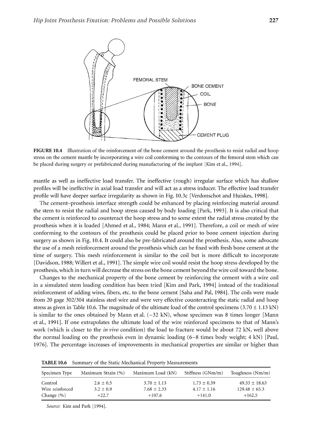
Hip Joint Prosthesis Fixation: Problems and
Possible Solutions Joon B. Park .................................................................................. 219
Index ............................................................................................................................................. 241
1
Metallic Biomaterials
1.1
1.2
1.3
1.4
Introduction............................................................................1
Stainless Steels.........................................................................2
CoCr Alloys.............................................................................3
Ti Alloys ..................................................................................5
1.5
1.6
1.7
Dental Metals........................................................................11
Other Metals .........................................................................12
Corrosion of Metallic Implants...........................................13
Pure Ti and Ti6Al4V • TiNi Alloys
Electrochemical Aspects • Pourbaix Diagrams in Corrosion •
Rate of Corrosion and Polarization Curves • Corrosion of
Available Metals
Joon B. Park
University of Iowa
Young Kon Kim
Inje University
1.8
Manufacturing of Implants .................................................17
Stainless Steels • CoCr Alloys • Ti and Its Alloys
1.1 Introduction
Metals are used as biomaterials due to their excellent electrical and thermal conductivity and mechanical
properties. Since some electrons are independent in metals, they can quickly transfer an electric charge
and thermal energy. The mobile free electrons act as the binding force to hold the positive metal ions
together. This attraction is strong, as evidenced by the closely packed atomic arrangement resulting in
high specific gravity and high melting points of most metals. Since the metallic bond is essentially
nondirectional, the position of the metal ions can be altered without destroying the crystal structure
resulting in a plastically deformable solid.
Some metals are used as passive substitutes for hard tissue replacement such as total hip and knee
joints, for fracture healing aids as bone plates and screws, spinal fixation devices, and dental implants
because of their excellent mechanical properties and corrosion resistance. Some metallic alloys are used
for more active roles in devices such as vascular stents, catheter guide wires, orthodontic archwires, and
cochlea implants.
The first metal alloy developed specifically for human use was the “vanadium steel” which was used
to manufacture bone fracture plates (Sherman plates) and screws. Most metals such as iron (Fe), chromium (Cr), cobalt (Co), nickel (Ni), titanium (Ti), tantalum (Ta), niobium (Nb), molybdenum (Mo),
and tungsten (W) that were used to make alloys for manufacturing implants can only be tolerated by
the body in minute amounts. Sometimes those metallic elements, in naturally occurring forms, are
essential in red blood cell functions (Fe) or synthesis of a vitamin B12 (Co), but cannot be tolerated in
large amounts in the body [Black, 1992]. The biocompatibility of the metallic implant is of considerable
concern because these implants can corrode in an in vivo environment [Williams, 1982]. The consequences of corrosion are the disintegration of the implant material per se, which will weaken the implant,
and the harmful effect of corrosion products on the surrounding tissues and organs.
0-8493-1491-7/03/$0.00+$.50
© 2003 by CRC Press LLC
2
Biomaterials: Principles and Applications
1.2 Stainless Steels
The first stainless steel utilized for implant fabrication was the 18-8 (type 302 in modern classification),
which is stronger and more resistant to corrosion than the vanadium steel. Vanadium steel is no longer
used in implants since its corrosion resistance is inadequate in vivo. Later 18-8sMo stainless steel was
introduced which contains a small percentage of molybdenum to improve the corrosion resistance in
chloride solution (salt water). This alloy became known as type 316 stainless steel. In the 1950s the carbon
content of 316 stainless steel was reduced from 0.08 to a maximum amount of 0.03% (all are weight
percent unless specified) for better corrosion resistance to chloride solution and to minimize the sensitization, and hence became known as type 316L stainless steel. The minimum effective concentration of
chromium is 11% to impart corrosion resistance in stainless steels. The chromium is a reactive element,
but it and its alloys can be passivated by 30% nitric acid to give excellent corrosion resistance.
The austenitic stainless steels, especially types 316 and
316L, are most widely used for implant fabrication. These
TABLE 1.1 Compositions of 316L
cannot be hardened by heat treatment but can be hardened
Stainless Steel [American Society for Testing
by cold-working. This group of stainless steels is nonmagand Materials, F139–86, p.61, 1992]
netic and possesses better corrosion resistance than any
Element
Composition (%)
others. The inclusion of molybdenum enhances resistance
Carbon
0.03 max
to pitting corrosion in salt water. The American Society for
Manganese
2.00 max
Testing and Materials (ASTM) recommends type 316L
Phosphorus
0.03 max
rather than 316 for implant fabrication. The specifications
Sulfur
0.03 max
for 316L stainless steel are given in Table 1.1. The only
Silicon
0.75 max
Chromium
17.00–20.00
difference in composition between the 316L and 316 stainNickel
12.00–14.00
less steel is the maximum content of carbon, i.e., 0.03%
Molybdenum
2.00–4.00
and 0.08%, respectively, as noted earlier.
The nickel stabilizes the austenitic phase [γ, face centered cubic crystal (fcc) structure] at room temperature
and enhances corrosion resistance. The austenitic phase formation can be influenced by both the Ni and
Cr contents as shown in Fig. 1.1 for 0.10% carbon stainless steels. The minimum amount of Ni for
maintaining austenitic phase is approximately 10%.
FIGURE 1.1 The effect of Ni and Cr contents on the austenitic phase of stainless steels containing 0.1% C [Keating,
1956].
3
Metallic Biomaterials
TABLE 1.2 Mechanical Properties of 316L Stainless Steel for Implants [American
Society for Testing and Materials, F139–86, p.61, 1992]
Condition
Annealed
Cold-worked
Ultimate Tensile
Strength, min.
(MPa)
Yield Strength
(0.2% offset), min.
(MPa)
Elongation
2 in. (50.8mm),
min. (%)
Rockwell
Hardness
485
860
172
690
40
12
95 HRB
—
Table 1.2 gives the mechanical properties
of 316L stainless steel. A wide range of properties exists depending on the heat treatment (annealing to obtain softer materials)
or cold working (for greater strength and
hardness). Figure 1.2 shows the effect of
cold working on the yield and ultimate tensile strength of 18-8 stainless steels. The
engineer must consequently be careful when
selecting materials of this type. Even the
316L stainless steels may corrode inside the
body under certain circumstances in a
highly stressed and oxygen depleted region,
such as the contacts under the screws of the
bone fracture plate. Thus, these stainless
steels are suitable for use only in temporary
implant devices such as fracture plates,
screws, and hip nails. Surface modification
methods such as anodization, passivation,
and glow-discharge nitrogen implantation
are widely used in order to improve corrosion resistance, wear resistance, and fatigue
strength of 316L stainless steel [Bordiji
et al., 1996].
FIGURE 1.2 Effect of cold-work on the yield and ultimate
tensile strength of 18-8 stainless steel [ASTM, 1980].
1.3 CoCr Alloys
There are basically two types of cobalt-chromium alloys: (1) the castable CoCrMo alloy and (2) the
CoNiCrMo alloy which is usually wrought by (hot) forging. The castable CoCrMo alloy has been used
for many decades in dentistry and, relatively recently, in making artificial joints. The wrought CoNiCrMo
alloy is relatively new, now used for making the stems of prostheses for heavily loaded joints such as the
knee and hip.
The ASTM lists four types of CoCr alloys which are recommended for surgical implant applications:
(1) cast CoCrMo alloy (F75), (2) wrought CoCrWNi alloy (F90), (3) wrought CoNiCrMo alloy (F562),
and (4) wrought CoNiCrMoWFe alloy (F563). The chemical compositions of each are summarized in
Table 1.3. At the present time only two of the four alloys are used extensively in implant fabrications,
the castable CoCrMo and the wrought CoNiCrMo alloy. As Table 1.3 shows, the compositions are quite
different from each other.
The two basic elements of the CoCr alloys form a solid solution of up to 65% Co. The molybdenum
is added to produce finer grains which results in higher strengths after casting or forging. The chromium
enhances corrosion resistance as well as solid solution strengthening of the alloy.
4
Biomaterials: Principles and Applications
TABLE 1.3 Chemical Compositions of CoCr Alloys [American Society for Testing and
Materials, F75–87, p.42; F90–87, p.47; F562–84, p.150, 1992]
CoCrMo (F75)
CoCrWNi (F90)
CoNiCrMo (F562)
CoNiCrMoWFe (F563)
Element
Min.
Max.
Min.
Max.
Min.
Max.
Min.
Max.
Cr
Mo
Ni
Fe
C
Si
Mn
W
P
S
Ti
Co
27.0
5.0
—
—
—
—
—
—
—
—
—
30.0
7.0
2.5
0.75
0.35
1.00
1.00
—
—
—
—
19.0
—
9.0
—
0.05
—
—
14.0
—
—
—
Balance
21.0
—
11.0
3.0
0.15
1.00
2.00
16.0
—
—
—
19.0
9.0
33.0
—
—
—
—
—
—
—
—
21.0
10.5
37.0
1.0
0.025
0.15
0.15
—
0.015
0.010
1.0
18.00
3.00
15.00
4.00
—
—
—
3.00
—
—
0.50
22.00
4.00
25.00
6.00
0.05
0.50
1.00
4.00
—
0.010
3.50
FIGURE 1.3 Relationship between ultimate tensile strength and the amount of cold-work for CoNiCrMo alloy
[Devine and Wulff, 1975].
The CoNiCrMo alloy originally called MP35N (Standard Pressed Steel Co.) contains approximately
35% Co and Ni each. The alloy is highly corrosion resistant to seawater (containing chloride ions) under
stress. Cold working can increase the strength of the alloy considerably as shown in Fig. 1.3. However,
there is a considerable difficulty of cold working on this alloy, especially when making large devices such
as hip joint stems. Only hot-forging can be used to fabricate a large implant with the alloy.
The abrasive wear properties of the wrought CoNiCrMo alloy are similar to the cast CoCrMo alloy
(about 0.14 mm/yr in joint simulation tests with ultra high molecular weight polyethylene acetabular
cup); however, the former is not recommended for the bearing surfaces of joint prostheses because of its
poor frictional properties with itself or other materials. The superior fatigue and ultimate tensile strength
of the wrought CoNiCrMo alloy make it suitable for the applications which require long service life
without fracture or stress fatigue. Such is the case for the stems of the hip joint prostheses. This advantage
is better appreciated when the implant has to be replaced, since it is quite difficult to remove the failed
piece of implant embedded deep in the femoral medullary canal. Furthermore, the revision arthroplasty
is usually inferior to the primary surgery in terms of its function due to poorer fixation of the implant.
The mechanical properties required for CoCr alloys are given in Table 1.4. As with the other alloys,
the increased strength is accompanied by decreased ductility. Both the cast and wrought alloys have
excellent corrosion resistance.
5
Metallic Biomaterials
TABLE 1.4 Mechanical Property Requirements of CoCr Alloys (ASTM F76, F90, F562)
[American Society for Testing and Materials, F75–87, p.42; F90–87, p.47; F562–84, p.150, 1992]
Property
Tensile strength (MPa)
Yield strength (0.2% offset) (MPa)
Elongation (%)
Reduction of area (%)
Fatigue strength (MPa)a
a
Wrought CoNiCrMo (F562)
Cast CoCrMo
Wrought
CoCrWNi
(F75)
(F90)
Solution
Annealed
Cold-Worked
and Aged
655
450
8
8
310
860
310
10
—
—
793–1000
240–655
50.0
65.0
—
1793 min.
1585
8.0
35.0
—
From Semlitsch [1980].
Experimental determination of the rate of nickel release from the CoNiCrMo alloy and 316L stainless
steel in 37°C Ringer’s solution showed an interesting result. Although the cobalt alloy has more initial
release of nickel ions into the solution, the rate of release was about the same (3 × 10⁻¹⁰ g/cm2/day) for
both alloys [Richards Mfg. Company, 1980]. This is rather surprising since the nickel content of the
CoNiCrMo alloy is about three times that of 316L stainless steel.
The metallic products released from the prosthesis because of wear, corrosion, and fretting may impair
organs and local tissues. In vitro studies have indicated that particulate Co is toxic to human osteoblastlike cell lines and inhibits synthesis of type-I collagen, osteocalcin, and alkaline phosphatase in the culture
medium. However, particulate Cr and CoCr alloys are well tolerated by cell lines with no significant
toxicity. The toxicity of metal extracts in vitro have indicated that Co and Ni extracts at 50% concentration
appear to be highly toxic since all viability parameters were altered after 24 h. However, Cr extract seems
to be less toxic than Ni and Co [Granchi et al., 1996].
The modulus of elasticity for the CoCr alloys does not change with the changes in their ultimate tensile
strength. The values range from 220 to 234 GPa, which are higher than other materials such as stainless
steels. This may have some implications of different load transfer modes to the bone in artificial joint
replacements, although the effect of the increased modulus on the fixation and longevity of implants is
not clear. Low wear (average linear wear on the MeKee-Farrar component was 4.2 µm/yr) has been
recognized as an advantage of metal-on-metal hip articulations because of its hardness and toughness
[Schmalzried et al., 1996].
1.4 Ti Alloys
Pure Ti and Ti6Al4V
Attempts to use titanium for implant fabrication dates to the late
TABLE 1.5 Specific Gravities
1930s. It was found that titanium was tolerated in cat femurs, as
of Some Metallic Implant Alloys
was stainless steel and Vitallium® (CoCrMo alloy). Titanium’s lightAlloys
Density (g/cm3)
ness (4.5 g/cm3; see Table 1.5) and good mechanochemical properties are salient features for implant application.
Ti and its alloys
4.5
316 Stainless steel
7.9
There are four grades of unalloyed commercially pure (cp)
CoCrMo
8.3
titanium for surgical implant applications as given in Table 1.6.
CoNiCrMo
9.2
The impurity contents separate them; oxygen, iron, and nitrogen
NiTi
6.7
should be controlled carefully. Oxygen in particular has a great
influence on the ductility and strength.
One titanium alloy (Ti6Al4V) is widely used to manufacture implants and its chemical requirements
are given in Table 1.7. The main alloying elements of the alloy are aluminum (5.5~6.5%) and vanadium
(3.5~4.5%). The Ti6Al4V alloy has approximately the same fatigue strength (550 MPa) of CoCr alloy
6
Biomaterials: Principles and Applications
TABLE 1.6 Chemical Compositions of Ti and Its Alloy
[American Society for Testing and Materials, F67–89, p.39;
F136–84, p.55, 1992]
Element
Grade 1
Grade 2
Grade 3
Grade 4
Ti6Al4Va
0.03
0.10
0.015
0.20
0.18
0.03
0.10
0.015
0.30
0.25
0.05
0.10
0.015
0.30
0.35
Balance
0.05
0.10
0.015
0.50
0.40
0.05
0.08
0.0125
0.25
0.13
Nitrogen
Carbon
Hydrogen
Iron
Oxygen
Titanium
a Aluminum 6.00% (5.50~6.50), vanadium 4.00% (3.50~4.50), and
other elements 0.1% maximum or 0.4% total. All are maximum allowable weight percent.
TABLE 1.7 Mechanical Properties of Ti and Its Alloys (ASTM F136) [American Society for Testing and
Materials, F67–89, p.39; F136–84, p.55, 1992 and Davidson et al., 1994]
Property
Tensile strength (MPa)
Yield strength (0.2% offset) (MPa)
Elongation (%)
Reduction of area (%)
Grade 1
Grade 2
Grade 3
Grade 4
Ti6Al4V
Ti13Nb13Zr
240
170
24
30
345
275
20
30
450
380
18
30
550
485
15
25
860
795
10
25
1030
900
15
45
after rotary bending fatigue tests [Imam et al., 1983]. Titanium is an allotropic material, which exists as
a hexagonal close packed structure (hcp, α-Ti) up to 882°C and body-centered cubic structure (bcc,
β-Ti) above that temperature. Titanium alloys can be strengthened and mechanical properties varied by
controlled composition and thermomechanical processing techniques. The addition of alloying elements
to titanium enables it to have a wide range of properties: (1) Aluminum tends to stabilize the α-phase,
that is increase the transformation temperature from α- to β-phase (Fig. 1.4); (2) vanadium stabilizes
the β-phase by lowering the temperature of the transformation from α to β.
The α-alloy has a single-phase microstructure (Fig. 1.5a) which promotes good weldability. The
stabilizing effect of the high aluminum content of these groups of alloys makes excellent strength
characteristics and oxidation resistance at high temperature (300~600°C). These alloys cannot be heattreated for precipitation hardening since they are single-phased.
The addition of controlled amounts of β-stabilizers causes the higher strength β-phase to persist below
the transformation temperature which results in the two-phase system. The precipitates of β-phase will
appear by heat treatment in the solid solution temperature and subsequent quenching, followed by aging
at a somewhat lower temperature. The aging cycle causes the coherent precipitation of some fine α
particles from the metastable β; imparting α structure may produce local strain field capable of absorbing
deformation energy. Cracks are stopped or deterred at the α particles, so that the hardness is higher than
for the solid solution (Fig. 1.5b).
The higher percentage of β-stabilizing elements (13%V in Ti13V11Cr3Al alloy) results in a microstructure that is substantially β which can be strengthened by heat treatment (Fig. 1.5c). Another Ti alloy
(Ti13Nb13Zr) with 13% Nb and 13% Zr showed martensite structure after being water quenched and
aged, which showed high corrosion resistance with low modulus (E = 79 MPa) [Davidson et al., 1994].
Formation of plates of martensite induces considerable elastic distortion in the parent crystal structure
and increases strength (Fig. 1.5d).
The mechanical properties of the commercially pure titanium and its alloys are given in Table 1.7.
The modulus of elasticity of these materials is about 110 GPa except for the 13Nb13Zr alloy. From
Table 1.7 one can see that the higher impurity content of the cp-Ti leads to higher strength and reduced
ductility. The strength of the material varies from a value much lower than that of 316 stainless steel or
Metallic Biomaterials
7
FIGURE 1.4 Part of phase diagram of Ti-Al-V at 4 w/o V [Smith and Hughes, 1966].
FIGURE 1.5 Microstructure of Ti alloys (all are 500×) [Hille, 1966]. (a) Annealed α-alloy. (b) Ti6Al4V, α–β alloy,
annealed. (c) β-alloy, annealed. (d) Ti6Al4V, heat-treated at 1650°C and quenched [Imam et al., 1983].
the CoCr alloys to a value about equal to that of annealed 316 stainless steel of the cast CoCrMo alloy.
However, when compared by the specific strength (strength per density) the titanium alloys exceed any
other implant materials as shown in Fig. 1.6. Titanium, nevertheless, has poor shear strength, making it
less desirable for bone screws, plates, and similar applications. It also tends to gall or seize when in sliding
contact with itself or another metal.
Titanium derives its resistance to corrosion by the formation of a solid oxide layer to a depth of 10 nm.
Under in vivo conditions the oxide (TiO2) is the only stable reaction product. However, micromotion at
the cement–prosthesis and cement–bone are inevitable; consequently, titanium oxide and titanium alloy
particles are released in cemented joint prostheses. Sometimes this wear debris accumulates as periprosthetic fluid collects and triggers giant cell response around the implants. This cystic collection continues
8
Biomaterials: Principles and Applications
FIGURE 1.6 Yield strength to density ratio of some implant materials [Hille, 1966].
to enlarge and aspiration reveals “dark” heavily stained fluid containing titanium wear particles and
histiocytic cells. Histological examination of the stained soft tissue showed “fibrin necrotic debris” and
collagenous, fibrous tissue containing a histiocytic and foreign body giant cell infiltrate. The metallosis,
black staining of the periprosthetic tissues, has been implicated in knee implants [Breen and Stoker, 1993].
The titanium implant surface consists of a thin oxide layer and the biological fluid of water molecules,
dissolved ions, and biomolecules (proteins with surrounding water shell) as shown in Fig. 1.7. The
microarchitecture (microgeometry, roughness, etc.) of the surface and its chemical compositions are
important due to the following reasons:
1. Physical nature of the surface either at the atomic, molecular, or higher level relative to the
dimensions of the biological units may cause different contact areas with biomolecules, cells, etc.
The different contact areas, in turn, may produce different perturbations and types of bonding
of the biological units, which may influence their conformation and function.
2. Chemical composition of the surface may produce different types of bonding to the biomolecules,
which may then also affect their properties and function. Metals undergo chemical reactions at
the surface depending on the environment which cause the difficulties of understanding the exact
nature of the interactions.
The surface–tissue interaction is dynamic rather than static, i.e., it will develop into new stages as time
passes, especially during the initial period after implantation. During the initial few seconds after implantation, there will be only water, dissolved ions, and free biomolecules in the closest proximity of the
surface but no cells. The composition of biofluid will then change continuously as inflammatory and
healing processes proceed, which in turn also probably causes changes in the composition of the adsorbed
layer of biomolecules on the implant surface until quasiequilibrium sets in. Eventually, cells and tissues
will approach the surface and, depending on the nature of the adsorbed layer, they will respond in specific
ways that may further modify the adsorbed biomolecules. The type of cells closest to the surface and
their activities will change with time. For example, depending on the type of initial interaction, the final
Metallic Biomaterials
9
FIGURE 1.7 (a) Interface between a titanium implant and bioliquid and (b) the cell surface interaction [Kasemo
and Lausma, 1988].
results may be fibrous capsule formation or tissue integration [Hazan et al., 1993; Kasemo and Lausma,
1988; Takatsuka et al., 1995; Takeshita et al., 1997; Yan et al., 1997].
Osseointegration is defined as direct contact without intervening soft tissue between viable remodeled
bone and an implant. Surface roughness of titanium alloys have a significant effect on the bone apposition
to the implant and on the bone implant interfacial pull out strength. The average roughness increased from
0.5 to 5.9 µm and the interfacial shear strength increased from 0.48 to 3.5 MPa [Feighan et al., 1995].
Highest levels of osteoblast cell attachment are obtained with rough sand blast surfaces where cells differentiated more than those on the smooth surfaces [Keller et al., 1994]. Chemical changes of the titanium
surface following heat treatment are thought to form a TiO2 hydrogel layer on top of the TiO2 layer, as
shown in Fig. 1.8. The TiO2 hydrogel layer may induce the apatite crystal formation [Kim et al., 1996].
In general, on the rougher surfaces there are lower cell numbers, decreased rate of cellular proliferation,
and increased matrix production compared to smooth surfaces. Bone formation appears to be strongly
related to the presence of transforming growth factor β1 in the bone matrix [Kieswetter et al., 1996].
TiNi Alloys
The titanium–nickel alloys show unusual properties i.e., after it is deformed the material can snap back
to its previous shape following heating of the material. This phenomenon is called shape memory effect
(SME). The SME of TiNi alloy was first observed by Buehler and Wiley at the U.S. Naval Ordnance
Laboratory [Buehler et al., 1963]. The equiatomic TiNi or NiTi alloy (Nitinol) exhibits an exceptional
SME near room temperature: if it is plastically deformed below the transformation temperature, it reverts
10
Biomaterials: Principles and Applications
FIGURE 1.8 Chemical change of titanium implant surface of alkali following heat treatment [Kim et al., 1996].
back to its original shape as the temperature is raised. The SME can be generally related to a diffusionless
martensitic phase transformation which is also thermoelastic in nature, the thermoelasticity being attributed to the ordering in the parent and martensitic phases [Wayman and Shimizu, 1972]. Another unusual
property is the superelasticity, which is shown schematically in Fig. 1.9. As can be seen, the stress does
not increase with increased strain after the initial elastic stress region and upon release of the stress or
strain the metal springs back to its original shape in contrast to other metals such as stainless steel. The
superlastic property is utilized in orthodontic archwires since the conventional stainless steel wires are
too stiff and harsh for the tooth. In addition, the shape memory effect can also be utilized.
Some possible applications of shape memory alloys are orthodontic dental archwire, intracranial
aneurysm clip, vena cava filter, contractile artificial muscles for an artificial heart, vascular stent, catheter
guide wire, and orthopedic staple [Duerig et al., 1990].
In order to develop such devices, it is necessary to understand fully the mechanical and thermal
behavior associated with the martensitic phase transformation. A widely known NiTi alloy is 55-Nitinol
(55 weight % or 50 atomic % Ni), which has a single phase and the mechanical memory plus other
properties, for example, high acoustic damping, direct conversion of heat energy into mechanical energy,
good fatigue properties, and low temperature ductility. Deviation from the 55-Nitinol (near stoichiometric NiTi) in the Ni-rich direction yields a second group of alloys which are also completely nonmagnetic but differ from 55-Nitinol in their ability to be thermally hardened to higher hardness levels.
Shape recovery capability decreases and heat treatability increases rapidly as the Ni content approaches
60%. Both 55- and 60-Nitinols have a relatively low modulus of elasticity and can be tougher and more
resilient than stainless steel, NiCr, or CoCr alloys.
Efficiency of 55-Nitinol shape recovery can be controlled by changing the final annealing temperatures
during preparation of the alloy device [Lee et al., 1988]. For the most efficient recovery, the shape is fixed
by constraining the specimen in a desired configuration and heating to 482~510°C. If the annealed wire
is deformed at a temperature below the shape recovery temperature, shape recovery will occur upon
heating, provided the deformation has not exceeded crystallographic strain limits (~8% strain in tension).
The NiTi alloys also exhibit good biocompatibility and corrosion resistance in vivo.
11
Metallic Biomaterials
FIGURE 1.9 Schematic illustration of the stainless steel wire and TiNi SMA wire springs for orthodontic archwire
behavior (modified from [Wayman and Duerig, 1990]).
There is no significant difference between titanium and NiTi
in the inhibition of mitosis in human fibroblasts. NiTi showed
lower percentage bone and bone contact area than titanium
and the Ti6Al4V alloy [Takeshita et al., 1997].
The mechanical properties of NiTi alloys are especially sensitive to the stoichiometry of composition (typical composition
is given in Table 1.8) and the individual thermal and mechanical history. Although much is known about the processing,
mechanical behavior, and properties relating to the shape
memory effect, considerably less is known about the thermomechanical and physical metallurgy of the alloy.
TABLE 1.8 Chemical Composition
of NiTi Alloy Wire
Element
Composition(%)
Ni
Co
Cr
Mn
Fe
Ti
54.01
0.64
0.76
0.64
0.66
Balance
1.5 Dental Metals
Dental amalgam is an alloy made of liquid mercury and other solid metal particulate alloys made of
silver, tin, copper, etc. The solid alloy is mixed with (liquid) mercury in a mechanical vibrating mixer
and the resulting material is packed into the prepared cavity. One of the solid alloys is composed of at
least 65% silver and not more than 29% tin, 6% copper, 2% zinc, and 3% mercury. The reaction during
setting is thought to be
γ + Hg → γ + γ1 + γ2
(1.1)
in which the γ phase is Ag3Sn, the γ1 phase is Ag2Hg3, and the γ2 phase is Sn7Hg. The phase diagram for
the Ag-Sn-Hg system shows that over a wide compositional range all three phases are present. The final
composition of dental amalgams typically contain 45 to 55% mercury, 35 to 45% silver, and about 15%
tin after fully set in about one day.
Gold and gold alloys are useful metals in dentistry as a result of their durability, stability, and corrosion
resistance [Nielsen, 1986]. Gold fillings are introduced by two methods: casting and malleting. Cast
restorations are made by taking a wax impression of the prepared cavity, making a mold from this
12
Biomaterials: Principles and Applications
impression in a material such as gypsum silica, which tolerates high temperature, and casting molten
gold in the mold. The patient is given a temporary filling for the intervening time. Gold alloys are used
for cast restorations, since they have mechanical properties which are superior to those of pure gold.
Corrosion resistance is retained in these alloys provided they contain 75% or more of gold and other
noble metals. Copper alloyed with gold significantly increases its strength. Platinum also improves the
strength, but no more than about 4% can be added, or the melting point of the alloy is elevated
excessively. Silver compensates for the color of copper. A small amount of zinc may be added to lower
the melting point and to scavenge oxides formed during melting. Gold alloys of different composition
are available. Softer alloys containing more than 83% gold are used for inlays which are not subjected
to much stress. Harder alloys containing less gold are chosen for crowns and cusps which are more
heavily stressed.
Malleted restorations are built up in the cavity from layers of pure gold foil. The foils are welded
together by pressure at ambient temperature. In this type of welding, the metal layers are joined by
thermal diffusion of atoms from one layer to the other. Since intimate contact is required in this
procedure, it is particularly important to avoid contamination. The pure gold is relatively soft, so this
type of restoration is limited to areas not subjected to much stress.
1.6 Other Metals
Several other metals have been used for a variety of specialized implant applications. Tantalum has been
subjected to animal implant studies and has been shown very biocompatible. Due to its poor mechanical
properties (Table 1.9) and its high density (16.6 g/cm3) it is restricted to few applications such as wire
sutures for plastic and neurosurgery and as a radioisotope for bladder tumors.
Platinum group metals (PGM) such as Pt, Pd, Rh, Ir, Ru, and Os are extremely corrosion resistant but
have poor mechanical properties [Wynblatt, 1986]. They are mainly used as alloys for electrodes such
as pacemaker tips because of their high resistance to corrosion and low threshold potentials for electrical
conductivity.
Thermoseeds made of 70% Ni and 30% Cu have been produced which possess Curie points in the
therapeutic hyperthermia range, approximately 40 to 50°C [Ferguson et al., 1992]. Upon the application
of an alternating magnetic field, eddy currents are induced, which will provide a continuous heat source
through resistive heating of the material. As the temperature of a ferromagnetic substance nears its Curie
point, however, there is a loss of ferromagnetic properties and a resulting loss of heat output. Thus, selfregulation of temperature is achieved and can be used to deliver a constant hyperthermic temperature
extracorporeally at any time and duration.
Surface modifications of metal alloys such as coatings by plasma spray, physical or chemical vapor
deposition, ion implantaion, and fluidized bed deposition have been used in industry [Smith, 1993].
Coating implants with tissue compatible materials such as hydroxyapatite, oxide ceramics, Bioglass®,
and pyrolytic carbon are typical applications in implants. Such efforts have been largely ineffective if the
implants are permanent and particularly if the implants are subjected to a large loading. The main
problem is the delamination of the coating or eventual wear of the coating. The added cost of coating
or ion implanting hinders the use of such techniques unless the technique shows unequivocal superiority
compared to the non-treated implants.
TABLE 1.9 Mechanical Properties of Tantalum [American
Society for Testing and Materials, F560–86, p.143, 1992]
Property
Tensile strength (MPa)
Yield strength (0.2% offset) (MPa)
Elongation (%)
Young’s modulus (GPa)
Annealed
Cold-Worked
207
138
20–30
—
517
345
2
190
13
Metallic Biomaterials
1.7 Corrosion of Metallic Implants
Corrosion is the unwanted chemical reaction of a
metal with its environment, resulting in its continued degradation to oxides, hydroxides, or other
compounds. Tissue fluid in the human body contains water, dissolved oxygen, proteins, and various
ions such as chloride and hydroxide. As a result, the
human body presents a very aggressive environment for metals used for implantation. Corrosion
resistance of a metallic implant material is consequently an important aspect of its biocompatibility.
Electrochemical Aspects
The lowest free energy state of many metals in an
oxygenated and hydrated environment is that of the
oxide. Corrosion occurs when metal atoms become
FIGURE 1.10 Electrochemical cell.
ionized and go into solution, or combine with oxygen or other species in solution to form a compound which flakes off or dissolves. The body environment is very aggressive in terms of corrosion since
it is not only aqueous but also contains chloride ions and proteins. A variety of chemical reactions occur
when a metal is exposed to an aqueous environment, as shown in Fig. 1.10. The electrolyte, which
contains ions in solution, serves to complete the electric circuit. In the human body, the required ions
are plentiful in the body fluids. Anions are negative ions which migrate toward the anode, and cations
are positive ions which migrate toward the cathode. At the anode, or positive electrode, the metal oxidizes
by losing valence electrons as in the following:
M → M+n + ne–
(1.2)
At the cathode, or negative electrode, the following reduction reactions are important:
M
++
M+n + ne– → M
(1.3)
+ OH + 2e → MOH
(1.4)
–
–
2H3O+ + 2e– → H2↑ + 2H2O
(1.5)
1/2O2 + H2O + 2e– → 2OH–
(1.6)
The tendency of metals to corrode is expressed most simply in the
standard electrochemical series of Nernst potentials, shown in Table 1.10.
These potentials are obtained in electrochemical measurements in which
one electrode is a standard hydrogen electrode formed by bubbling hydrogen through a layer of finely divided platinum black. The potential of this
reference electrode is defined to be zero. Noble metals are those which
have a potential higher than that of a standard hydrogen electrode; base
metals have lower potentials.
If two dissimilar metals are present in the same environment, the one
which is most negative in the galvanic series will become the anode, and
bimetallic (or galvanic) corrosion will occur. Galvanic corrosion can be
much more rapid than the corrosion of a single metal. Consequently,
implantation of dissimilar metals (mixed metals) is to be avoided.
Galvanic action can also result in corrosion within a single metal, if there
is inhomogeneity in the metal or in its environment, as shown in Fig. 1.11.
TABLE 1.10 Standard
Electrochemical Series
Reaction
+
Li↔Li
Na↔Na+
Al↔Al+++
Ti↔Ti+++
Cr↔Cr++
Fe↔Fe++
Cu↔Cu++
Co↔Co++
Ni↔Ni++
H2↔2H+
Ag↔Ag+
Au↔Au+
∆Eo (V)
–3.05
–2.71
–1.66
–1.63
–0.56
–0.44
–0.34
–0.28
–0.23
0.00
+0.80
+1.68
14
Biomaterials: Principles and Applications
FIGURE 1.11 Micro-corrosion cells. (Left) Grain boundaries are anodic with respect to the grain interior.
(Right) Crevice corrosion due to oxygen-deficient zone in metal’s environment.
The potential difference, E, actually observed depends on the concentration of the metal ions in
solution according to the Nernst equation,
(
) [ ]
E = E o + RT nF ln M +n
(1.7)
in which R is the gas constant, Eo is the standard electrochemical potential, T is the absolute temperature,
F is Faraday’s constant (96,487 C/mole), and n is the number of moles of ions.
The order of nobility observed in actual practice may differ from that predicted thermodynamically. The
reasons are that some metals become covered with a passivating film of reaction products which protects
the metal from further attack. The dissolution reaction may be strongly irreversible so that a potential
barrier must be overcome. In this case, corrosion may be inhibited even though it remains energetically
favorable. The kinetics of corrosion reactions are not determined by the thermodynamics alone.
Pourbaix Diagrams in Corrosion
The Pourbaix diagram is a plot of regions of corrosion, passivity, and immunity as they depend on electrode
potential and pH [Pourbaix, 1974]. The Pourbaix diagrams are derived from the Nernst equation and
from the solubility of the degradation products and the equilibrium constants of the reaction. For the
sake of definition, the corrosion region is set arbitrarily at a concentration of greater than 10–6 gram atom/L
(molar) or more of metal in the solution at equilibrium. This corresponds to about 0.06 mg/L for metals
such as iron and copper, and 0.03 mg/L for aluminum. Immunity is defined as equilibrium between
metal and its ions at less than 10–6 molar. In the region of immunity, the corrosion is energetically
impossible. Immunity is also referred to as cathodic protection. In the passivation domain, the stable
solid constituent is an oxide, hydroxide, hydride, or a salt of the metal. Passivity is defined as equilibrium
between a metal and its reaction products (oxides, hydroxides, etc.) at a concentration of 10–6 molar or
less. This situation is useful if reaction products are adherent. In the biomaterials setting, passivity may
or may not be adequate; disruption of a passive layer may cause an increase in corrosion. The equilibrium
state may not occur if reaction products are removed by the tissue fluid. Materials differ in their propensity
to re-establish a passive layer which has been damaged. This layer of material may protect the underlying
metal if it is firmly adherent and nonporous; in that case further corrosion is prevented. Passivation can
also result from a concentration polarization due to a buildup of ions near the electrodes. This is not
likely to occur in the body since the ions are continually replenished. Cathodic depolarization reactions
can aid in the passivation of a metal by virtue of an energy barrier which hinders the kinetics.
Equations (1.5) and (1.6) are examples.
Metallic Biomaterials
15
FIGURE 1.12 Pourbaix diagram for chromium, showing regions associated with various body fluids (modified from
[Black, 1992]).
There are two diagonal lines in the diagrams shown in Fig. 1.12. The top oxygen line represents the
upper limit of the stability of water and is associated with oxygen-rich solutions or electrolytes near
oxidizing materials. In the region above this line, oxygen is evolved according to 2H2O → O2↑ + 4H+ +
4e–. In the human body, saliva, intracellular fluid, and interstitial fluid occupy regions near the oxygen
line, since they are saturated with oxygen. The lower hydrogen diagonal line represents the lower limit
of the stability of water. Hydrogen gas is evolved according to Eq. (1.5). Aqueous corrosion occurs in
the region between these diagonal lines on the Pourbaix diagram. In the human body, urine, bile, the
lower gastrointestinal tract, and secretions of ductless glands occupy a region somewhat above the
hydrogen line.
The significance of the Pourbaix diagram is as follows. Different parts of the body have different pH
values and oxygen concentrations. Consequently, a metal that performs well (is immune or passive) in
one part of the body may suffer an unacceptable amount of corrosion in another part. Moreover, pH can
change dramatically in tissue that has been injured or infected. In particular, normal tissue fluid has a pH
of about 7.4, but in a wound it can be as low as 3.5, and in an infected wound the pH can increase to 9.0.
Pourbaix diagrams are useful, but do not tell the whole story; there are some limitations. Diagrams
are made considering equilibrium among metal, water, and reaction products. The presence of other
ions, e.g., chloride, may result in very much different behavior and large molecules in the body may
also change the situation. Prediction of passivity may in some cases be optimistic, since reaction rates
are not considered.
Rate of Corrosion and Polarization Curves
The regions in the Pourbaix diagram specify whether corrosion will take place, but they do not determine
the rate. The rate, expressed as an electric current density [current per unit area], depends upon electrode
potential as shown in the polarization curves shown in Fig. 1.13. From such curves, it is possible to
calculate the number of ions per unit time liberated into the tissue, as well as the depth of metal removed
by corrosion in a given time. An alternative experiment is one in which the weight loss of a specimen
of metal due to corrosion is measured as a function of time.
The rate of corrosion also depends on the presence of synergistic factors, such as those of mechanical
origin (uneven distribution of mechanical stress). The stressed alloy failures occur due to the propagation
of cracks in corrosive environments. For example, in corrosion fatigue (stress corrosion cracking),
repetitive deformation of a metal in a corrosive environment results in acceleration of both the corrosion
and the fatigue microdamage. Since the body environment involves both repeated mechanical loading
and a chemically aggressive environment, fatigue testing of implant materials should always be performed
16
Biomaterials: Principles and Applications
FIGURE 1.13 Potential-current density curves for some biomaterials [Greener et al., 1972].
under physiological environmental conditions, under Ringer’s solution at body temperature. In fretting
corrosion, rubbing of one part on another disrupts the passivation layer, resulting in accelerated corrosion.
In pitting, the corrosion rate is accelerated in a local region. Stainless steel is vulnerable to pitting.
Localized corrosion can occur if there is inhomogeneity in the metal or in the environment. Grain
boundaries in the metal may be susceptible to the initiation of corrosion, as a result of their higher energy
level. Crevices are also vulnerable to corrosion, since the chemical environment in the crevice may differ
from that in the surrounding medium. The area of contact between a screw and a bone plate, for example,
can suffer crevice corrosion.
Corrosion of Available Metals
Choosing a metal for implantation should take into account the corrosion properties discussed above.
Metals which are in current use as biomaterials include gold, cobalt chromium alloys, type 316 stainless
steel, cp-titanium, titanium alloys, nickel–titanium alloys, and silver–tin–mercury amalgam.
The noble metals are immune to corrosion and would be ideal materials if corrosion resistance were
the only concern. Gold is widely used in dental restorations and in that setting it offers superior
performance and longevity. Gold is not, however, used in orthopedic applications as a result of its high
density, insufficient strength, and high cost.
Titanium is a base metal in the context of the electrochemical series; however, it forms a robust
passivating layer and remains passive under physiological conditions. Corrosion currents in normal saline
are very low: 10–8 A/cm2. Titanium implants remain virtually unchanged in appearance. Ti offers superior
corrosion resistance but is not as stiff or strong as steel or CoCr alloys.
Cobalt–chromium alloys, like titanium, are passive in the human body. They are widely used in
orthopedic applications. They do not exhibit pitting corrosion.
Stainless steels contain enough chromium to confer corrosion resistance by passivity. The passive layer
is not as robust as in the case of titanium or the cobalt chrome alloys. Only the most corrosion resistant
of the stainless steels are suitable for implants. These are the austenitic types—316, 316L, and 317—which
contain molybdenum. Even these types of stainless steel are vulnerable to pitting and to crevice corrosion
around screws.
The phases of dental amalgam are passive at neutral pH, and the transpassive potential for the γ2 phase is
easily exceeded, due to interphase galvanic couples or potentials due to differential aeration under dental
plaque. Amalgam, therefore, often corrodes and is the most active (corrosion prone) material used in dentistry.
Metallic Biomaterials
17
Corrosion of an implant in the clinical setting can result in symptoms such as local pain and swelling
in the region of the implant, with no evidence of infection; cracking or flaking of the implant as seen
on x-ray films; and excretion of excess metal ions. At surgery, gray or black discoloration of the surrounding tissue may be seen and flakes of metal may be found in the tissue. Corrosion also plays a role
in the mechanical failures of orthopedic implants. Most of these failures are due to fatigue, and the
presence of a saline environment certainly exacerbates fatigue. The extent to which corrosion influences
fatigue in the body is not precisely known.
Stress Corrosion Cracking
When an implant is subjected to stress, the corrosion process could be accelerated due to the mechanical
energy. If the mechanical stress is repeated then fatigue stress corrosion takes place such as in the femoral
stem of the hip joint and hip nails made of stainless steels [Dobbs and Scales, 1979; Sloter and Piehler,
1979]. However, other mechanisms of corrosion such as fretting may also be involved at point of contact
such as in the counter-sink of the hip nail or bone fracture plate for the screws.
1.8 Manufacturing of Implants
Stainless Steels
The austenitic stainless steels work-harden very rapidly as shown in Fig. 1.2 and therefore cannot be
cold-worked without intermediate heat treatments. The heat treatments should not induce, however, the
formation of chromium carbide (CCr4) in the grain boundaries; this may cause corrosion. For the same
reason, the austenitic stainless steel implants are not usually welded.
The distortion of components by the heat treatments can occur but this problem can be solved by
controlling the uniformity of heating. Another undesirable effect of the heat treatment is the formation
of surface oxide scales which have to be removed either chemically (acid) or mechanically (sand-blasting).
After the scales are removed the surface of the component is polished to a mirror or mat finish. The
surface is then cleaned, degreased, and passivated in nitric acid (ASTM Standard F86). The component
is washed and cleaned again before packaging and sterilizing.
CoCr Alloys
The CoCrMo alloy is particularly susceptible to work-hardening so that the normal fabrication procedure
used with other metals cannot be employed. Instead, the alloy is cast by a lost wax (or investment casting)
method which involves making a wax pattern of the desired component. The pattern is coated with a
refractory material, first by a thin coating with a slurry (suspension of silica in ethyl silicate solution)
followed by complete investing after drying: (1) the wax is then melted out in a furnace (100~150°C),
(2) the mold is heated to a high temperature burning out any traces of wax or gas-forming materials,
(3) molten alloy is poured with gravitational or centrifugal force, and (4) the mold is broken after cooled.
The mold temperature is about 800~1000°C and the alloy is at 1350~1400°C.
Controlling the mold temperature will have an effect on the grain size of the final cast; coarse ones
formed at higher temperatures will decrease the strength. However, a high processing temperature will
result in larger carbide precipitates with greater distances between them, resulting in a less brittle material.
Again there is a complementary (trade-off) relationship between strength and toughness.
Ti and Its Alloys
Titanium is very reactive at high temperature and burns readily in the presence of oxygen. Therefore, it
requires an inert atmosphere for high temperature processing or is processed by vacuum melting. Oxygen
diffuses readily in titanium and the dissolved oxygen embrittles the metal. As a result, any hot-working or
forging operation should be carried out below 925°C. Machining at room temperature is not the solution
18
Biomaterials: Principles and Applications
to all the problems since the material also tends to gall or seize the cutting tools. Very sharp tools with slow
speeds and large feeds are used to minimize this effect. Electrochemical machining is an attractive means.
Defining Terms
Amalgam: An alloy obtained by mixing silver tin alloy with mercury.
Anode: Positive electrode in an electrochemical cell.
Cathode: Negative electrode in an electrochemical cell.
Corrosion: Unwanted reaction of metal with environment. In a Pourbaix diagram, it is the region in
which the metal ions are present at a concentration of more than 10–6 molar.
Crevice corrosion: A form of localized corrosion in which concentration gradients around pre-existing
crevices in the material drive corrosion processes.
Curie temperature: Transition temperature of a material from ferromagnetic to paramagnetic.
Galvanic corrosion: Dissolution of metal driven by macroscopic differences in electrochemical potential, usually as a result of dissimilar metals in proximity.
Galvanic series: Table of electrochemical potentials (voltage) associated with the ionization of metal
atoms. These are called Nernst potentials.
Hyperthermia: Application of high enough thermal energy (heat) to suppress the cancerous cell
activities. Above 41.5°C (but below 60°C) is needed to have any effect.
Immunity: Resistance to corrosion by an energetic barrier. In a Pourbaix diagram, it is the region in
which the metal is in equilibrium with its ions at a concentration of less than 10–6 molar. Noble
metals resist corrosion by immunity.
Martensite: A metastable structure formed by quenching of the austenite (g) structure in alloys such as steel
and Ti alloys. They are brittle and hard and therefore are further treated with heat to make them tougher.
Nernst potential: Standard electrochemical potential measured with respect to a standard hydrogen
electrode.
Noble: Type of metal with a positive standard electrochemical potential.
Passivation: Production of corrosion resistance by a surface layer of reaction products (normally an
oxide layer that is impervious to gas and water).
Passivity: Resistance to corrosion by a surface layer of reaction products. In a Pourbaix diagram, it is
the region in which the metal is in equilibrium with its reaction products at a concentration of
less than 10–6 molar.
Pitting: A form of localized corrosion in which pits form on the metal surface.
Pourbaix diagram: Plot of electrical potential vs. pH for a material in which the regions of corrosion,
passivity, and immunity are identified.
Shape memory effect (SME): Thermoelastic behavior of some alloys which can revert back to their
original shape when the temperature is greater than the phase transformation temperature of the
alloy.
Superelasticity: Minimal stress increase beyond the initial strain region resulting in very low modulus
in the region for some shape memory alloys.
References
ASTM. (1980). Annual Book of ASTM Standards (Philadelphia, PA: American Society for Testing and Materials).
Black, J. (1992). Biological Performance of Materials, 2nd ed. (New York: Marcel Dekker).
Bordiji, K., Jouzeau, J., Mainard, D., Payan, E., Delagoutte, J., and Netter, P. (1996). Evaluation of the
effect of three surface treatments on the biocompatibility of 316L stainless steel using human
differentiated cells. Biomaterials 17, 491–500.
Breen, D. J. and Stoker, D. J. (1993). Titanium lines: a manifestation of metallosis and tissue response
to titanium alloy megaprostheses at the knee. Clin. Radiol. 43, 274–277.
Buehler, W. J., Gilfrich, J. V., and Wiley, R. C. (1963). Effect of low-temperature phase changes on the
mechanical properties of alloys near composition Ti–Ni. J. Appl. Phys. 34, 1475–1477.
Metallic Biomaterials
19
Davidson, J. A., Mishra, A. K., Kovacs, P., and Poggie, R. A. (1994). New surface hardened, low-modulus,
corrosion-resistant Ti–13Nb–13Zr alloy for total hip arthroplasty. Biomed. Mater. Eng. 4, 231–243.
Devine, T. M. and Wulff, J. (1975). Cast vs. wrought cobalt-chromium surgical implant alloys. J. Biomed.
Mater. Res. 9, 151–167.
Dobbs, H. S. and Scales, J. T. (1979). Fracture and corrosion in stainless steel hip replacement stems. In:
Corrosion and Degradation of Implant Materials, B. C. Syrett and A. Acharya, Eds. (Philadelphia, PA:
American Society for Testing and Materials), pp. 245–258.
Duerig, T. W., Melton, K. N., Stockel, D., and Wayman, C. M. (1990). Engineering Aspects of Shape
Memory Alloys (London: Butterworth-Heinemann).
Feighan, J. E., Goldberg, V. M., Davy, D., Parr, J. A., and Stevenson, S. (1995). The influence of surfaceblasting on the incorporation of titanium-alloy implants in a rabbit intramedullary model. J. Bone
Joint Surg. 77A, 1380–1395.
Ferguson, S. D., Paulus, J. A., Tucker, R. D., Loening, S. A., and Park, J. B. (1992). Effect of thermal
treatment on heating characteristics of Ni–Cu alloy for hyperthermia: preliminary studies. J. Appl.
Biomater. 4, 55–60.
Granchi, D., Ciapetti, G., Savarino, L., Cavedagna, D., Donati, M. E., and Pizzoferrato, A. (1996).
Assessment of metal extract toxicity on human lymphocytes cultured in vitro. J. Biomed. Mater.
Res. 31, 183–191.
Greener, E. H., Harcourt, J. K., and Lautenschlager, E. P. (1972). Materials Science in Dentistry (Baltimore,
MD: Williams & Wilkins).
Hazan, R., Brener, R., and Oron, U. (1993). Bone growth to metal implants is regulated by their surface
chemical properties. Biomaterials 14, 570–574.
Hille, G. H. (1966). Titanium for surgical implants. J. Mater. 1, 373–383.
Imam, M. A., Fraker, A. C., Harris, J. S., and Gilmore, C. M. (1983). Influence of heat treatment on the
fatigue lives of Ti–6Al–4V and Ti–4.5Al–5Mo–1.5CR. In: Titanium Alloys in Surgical Implants,
H. A. Luckey and F. E. Kubli, Eds. (Philadelphia, PA: ASTM Special Technical Publication 796),
pp. 105–119.
Kasemo, B. and Lausma, J. (1988). Biomaterial and implant surface: a surface science approach. Int. J.
Oral Maxillofac Impl. 3, 247–259.
Keating, F. H. (1956). Chromium-Nickel Austenitic Steels (London: Butterworth).
Keller, J. C., Stanford, C. M., Wightman, J. P., Draughn, R. A., and Zaharias, R. (1994). Characterizations
of titanium implant surfaces. III. J. Biomed. Mater. Res. 28, 939–946.
Kieswetter, K., Schwartz, Z., Hummert, T. W., Cochran, D. L., Simpson, J., and Boyan, B. D. (1996).
Surface roughness modulates the local production of growth factors and cytokines by osteoblastlike MG-63 cells. J. Biomed. Mater. Res. 32, 55–63.
Kim, H., Miyaji, F., Kokubo, T., and Nakamura, T. (1996). Preparation of bioactive Ti and its alloys via
simple chemical surface treatment. J. Biomed. Mater. Res. 32, 409–417.
Lee, J. H., Park, J. B., Andreasen, G. F., and Lakes, R. S. (1988). Thermomechanical study of Ni–Ti alloys.
J. Biomed. Mater. Res. 22, 573–588.
Nielsen, J. P. (1986). Dental Noble-Metal Casting Alloys: Composition and Properties. In: Encyclopedia of
Materials Science and Engineering, M. B. Bever, Ed. (Oxford, Cambridge: Pergamon Press),
pp. 1093–1095.
Pourbaix, M. (1974). Atlas of Electrochemical Equilibria in Aqueous Solutions, 2nd ed. (Houston/CEBELCOR, Brussels: NACE).
Richards Mfg. Company. (1980). Biophase Implant Material, technical information publication 3846
(Memphis, TN).
Schmalzried, T. P., Peters, P. C., Maurer, B. T., Bragdon, C. R., and Harris, W. H. (1996). Long-duration
metal-on-metal total hip arthroplasties with low wear of the articulating surfaces. J. Arthroplasty
11, 322–331.
Semlitch, M. (1980). Properties of wrought CoNiCrMo alloy Protasul-10, a highly corrosion and fatigue
resistant implant material for joint endoprostheses. Eng. Med. 9, 201–207.
20
Biomaterials: Principles and Applications
Sloter, L. E. and Piehler, H. R. (1979). Corrosion-fatigue performance of stainless steel hip nails—Jewett
type. In: Corrosion and Degradation of Implant Materials, B. C. Syrett and A. Acharya, Eds. (Philadelphia, PA: American Society for Testing and Materials), pp. 173–195.
Smith, C. J. E. and Hughes, A. N. (1966). The corrosion-fatigue behavior of a titanium–6w/o aluminum–4w/o
vanadium alloy. Eng. Med. 7, 158–171.
Smith, W. F. (1993). Structure and Properties of Engineering Alloys, 2nd ed. (New York: McGraw-Hill).
Takatsuka, K., Yamamuro, T., Nakamura, T., and Kokubo, T. (1995). Bone-bonding behavior of titanium
alloy evaluated mechanically with detaching failure load. J. Biomed. Mater. Res. 29, 157–163.
Takeshita, F., Ayukawa, Y., Iyama, S., Murai, K., and Suetsugu, T. (1997). Long-term evaluation of
bone–titanium interface in rat tibiae using light microscopy, transmission electron microscopy,
and image processing. J. Biomed. Mater. Res. 37, 235–242.
Wayman, C. M. and Duerig, T. W. (1990). An introduction of martensite and shape memory. In:
Engineering Aspects of Shape Memory Alloys, T. W. Duerig, K. N. Melton, D. Stockel, and C. M.
Wayman, Eds. (London: Butterworth-Heinemann), pp. 3–20.
Wayman, C. M. and Shimizu, K. (1972). The shape memory (‘Marmem’) effect in alloys. Metal Sci. J. 6, 175–183.
Williams, D. F. (1982). Biocompatibliity in Clinical Practice (Boca Raton, FL: CRC Press).
Wynblatt, P. (1986). Platinum Group Metals and Alloys. In: Encyclopedia of Materials Science and Engineering, M. B. Bever, Ed. (Oxford, Cambridge: Pergamon Press), pp. 3576–3579.
Yan, W., Nakamura, T., Kobayashi, M., Kim, H., Miyaji, F., and Kokubo, T. (1997). Bonding of chemically
treated titanium implants to bone. J. Biomed. Mater. Res. 37, 267–275.
Further Reading
American Society for Testing and Materials. 1992. Annual Book of ASTM Standards, Vol. 13, Medical
Devices and Services, American Society for Testing and Materials, Philadelphia, PA .
Bardos, D. I. 1977. Stainless steels in medical devices, in Handbook of Stainless Steels. Peckner, D. and
Bernstein, I. M., Eds. pp. 1–10, McGraw-Hill, New York.
Bechtol, C. O., Ferguson, Jr., A. B., and Laing, P. G. 1959. Metals and Engineering in Bone and Joint
Surgery, Williams & Wilkins, Baltimore, MD.
Comte, T. W. 1984. Metallurgical observations of biomaterials, in Contemporary Biomaterials, Boretos,
J. W. and Eden, M., Eds., pp. 66–91, Noyes, Park Ridge, NJ.
Duerig, T. W., Melton, K. N., Stockel, D., and Wayman, C. M., Eds. 1990. Engineering Aspects of Shape
Memory Alloys, Butterworth-Heinemann, London.
Dumbleton, J. H. and Black, J. 1975. An Introduction to Orthopaedic Materials, Charles C Thomas,
Springfield, IL.
Fontana, M. G. and Greene, N. O. 1967. Corrosion Engineering, pp. 163–168, McGraw-Hill, New York.
Greener, E. H., Harcourt, J. K., and Lautenschlager, E. P. 1972. Materials Science in Dentistry, Williams
& Wilkins, Baltimore, MD.
Hildebrand, H. F. and Champy, M., Eds. 1988. Biocompatibility of Co–Cr–Ni Alloys. Plenum Press, New York.
Levine, S. N., Ed. 1968. Materials in Biomedical Engineering, Annals of New York Academy of Science,
Vol. 146. New York.
Luckey, H. A., Ed. 1983. Titanium Alloys in Surgical Implants, ASTM Special Technical Publication 796,
Philadelphia, PA.
Mears, D. C. 1979. Materials and Orthopaedic Surgery, Williams & Wilkins, Baltimore, MD.
Park, J. B. 1984. Biomaterials Science and Engineering, Plenum Press, New York.
Perkins, J., Ed. 1975. Shape Memory Effects in Alloys, Plenum Press, New York.
Puckering, F. B., Ed. 1979. The Metallurgical Evolution of Stainless Steels, 1–42, American Society for
Metals and the Metals Society, Metals Park, OH.
Smith, W. F. 1993. Structure and Properties of Engineering Alloys, 2nd ed., McGraw-Hill, New York.
Weinstein, A., Horowitz, E., and Ruff, A. W., Eds. 1977. Retrieval and Analysis of Orthopaedic Implants,
NBS, U.S. Department of Commerce, Washington, D.C.
Williams, D. F. and Roaf, R. 1973. Implants in Surgery, W.B. Saunders, London.
2
Ceramic Biomaterials
2.1
2.2
Introduction..........................................................................21
Nonabsorbable or Relatively Bioinert Bioceramics ...........21
Relatively Bioinert Ceramics
2.3
Biodegradable or Resorbable Ceramics ..............................27
Calcium Phosphate • Aluminum–Calcium–Phosphate
(ALCAP) Ceramics • Coralline • Tricalcium Phosphate
(TCP) Ceramics • Zinc–Calcium–Phosphorous Oxide
(ZCAP) Ceramics • Zinc–Sulfate–Calcium–Phosphate
(ZSCAP) Ceramics • Ferric–Calcium–Phosphorous–Oxide
(FECAP) Ceramics
2.4
Bioactive or Surface-Reactive Ceramics..............................35
2.5
2.6
Deterioration of Ceramics ...................................................39
Bioceramic Manufacturing Techniques ..............................42
Glass Ceramics • Ceravital
W. G. Billotte
University of Dayton
Hard Tissue Replacement • Tissue Integration
2.1 Introduction
Ceramics are defined as the art and science of making and using solid articles that have as their essential
component inorganic nonmetallic materials [Kingery et al., 1976]. Ceramics are refractory, polycrystalline compounds, usually inorganic, including silicates, metallic oxides, carbides and various refractory
hydrides, sulfides, and selenides. Oxides such as Al2O3, MgO, SiO2, and ZrO2 contain metallic and
nonmetallic elements and ionic salts, such as NaCl, CsCl, and ZnS [Park and Lakes, 1992]. Exceptions
to the preceding include covalently bonded ceramics such as diamond and carbonaceous structures such
as graphite and pyrolized carbons [Park and Lakes, 1992].
Ceramics in the form of pottery have been used by humans for thousands of years. Until recently,
their use was somewhat limited because of their inherent brittleness, susceptibility to notches or microcracks, low tensile strength, and low impact strength. However, within the last 100 years, innovative
techniques for fabricating ceramics have led to their use as “high tech” materials. In recent years, humans
have realized that ceramics and their composites can also be used to augment or replace various parts
of the body, particularly bone. Thus, the ceramics used for the latter purposes are classified as bioceramics.
Their relative inertness to the body fluids, high compressive strength, and aesthetically pleasing appearance led to the use of ceramics in dentistry as dental crowns. Some carbons have found use as implants
especially for blood interfacing applications such as heart valves. Due to their high specific strength as
fibers and their biocompatibility, ceramics are also being used as reinforcing components of composite
implant materials and for tensile loading applications such as artificial tendons and ligaments [Park and
Lakes, 1992].
Unlike metals and polymers, ceramics are difficult to shear plastically due to the (ionic) nature of the
bonding and minimum number of slip systems. These characteristics make the ceramics nonductile and
are responsible for almost zero creep at room temperature [Park and Lakes, 1992]. Consequently, ceramics
0-8493-1491-7/03/$0.00+$.50
© 2003 by CRC Press LLC
22
Biomaterials: Principles and Applications
TABLE 2.1 Desired Properties of Implantable Bioceramics
1.
2.
3.
4.
5.
6.
Should be nontoxic
Should be noncarcinogenic
Should be nonallergic
Should be noninflammatory
Should be biocompatible
Should be biofunctional for its lifetime in the host
are very susceptible to notches or microcracks because instead of undergoing plastic deformation (or
yield) they will fracture elastically on initiation of a crack. At the crack tip the stress could be many times
higher than the stress in the material away from the tip, resulting in a stress concentration which weakens
the material considerably. The latter makes it difficult to predict the tensile strength of the material
(ceramic). This is also the reason ceramics have low tensile strength compared to compressive strength.
If a ceramic is flawless, it is very strong even when subjected to tension. Flawless glass fibers have twice
the tensile strengths of high strength steel (~7 GPa) [Park and Lakes, 1992].
Ceramics are generally hard; in fact, the measurement of hardness is calibrated against ceramic
materials. Diamond is the hardest, with a hardness index of 10 on Mohs scale, and talc (Mg3Si3O10COH)
is the softest ceramic (Mohs hardness 1), while ceramics such as alumina (Al2O3; hardness 9), quartz
(SiO2; hardness 8), and apatite (Ca5P3O12F; hardness 5) are in the middle range. Other characteristics of
ceramic materials are (1) their high melting temperatures and (2) low conductivity of electricity and
heat. These characteristics are due to the chemical bonding within ceramics.
In order to be classified as a bioceramic, the ceramic material must meet or exceed the properties
listed in Table 2.1. The number of specific ceramics currently in use or under investigation cannot be
accounted for in the space available for bioceramics in this book. Thus, this chapter will focus on a
general overview of the relatively bioinert, bioactive or surface reactive ceramics, and biodegradable or
resorbable bioceramics.
Ceramics used in fabricating implants can be classified as nonabsorbable (relatively inert), bioactive
or surface reactive (semi-inert) [Hench, 1991, 1993], and biodegradable or resorbable (non-inert) [Hentrich et al., 1971; Graves et al., 1972]. Alumina, zirconia, silicone nitrides, and carbons are inert bioceramics. Certain glass ceramics and dense hydroxyapatites are semi-inert (bioreactive), and calcium
phosphates and calcium aluminates are resorbable ceramics [Park and Lakes, 1992].
2.2 Nonabsorbable or Relatively Bioinert Bioceramics
Relatively Bioinert Ceramics
Relatively bioinert ceramics maintain their physical and mechanical properties while in the host. They
resist corrosion and wear and have all the properties listed for bioceramics in Table 2.1. Examples of
relatively bioinert ceramics are dense and porous aluminum oxides, zirconia ceramics, and single-phase
calcium aluminates (Table 2.2). Relatively bioinert ceramics are typically used as structural-support
implants. Some of these are bone plates, bone screws, and femoral heads (Table 2.3). Examples of nonstructural support uses are ventilation tubes, sterilization devices [Feenstra and de Groot, 1983] and
drug delivery devices (see Table 2.3).
Alumina (Al2O3)
The main source of high purity alumina (aluminum oxide, Al2O3) is bauxite and native corundum. The
commonly available alumina (alpha, α) can be prepared by calcining alumina trihydrate. The chemical
composition and density of commercially available “pure” calcined alumina are given in Table 2.4. The
American Society for Testing and Materials (ASTM) specifies that alumina for implant use should contain
99.5% pure alumina and less than 0.1% combined SiO2 and alkali oxides (mostly Na2O) [F603-78].
23
Ceramic Biomaterials
TABLE 2.2 Examples of Relatively Bioinert Bioceramics
Type
1. Pyrolitic carbon-coated devices
2. Dense and nonporous aluminum oxides
3. Porous aluminum oxides
4. Zirconia ceramics
5. Dense hydroxyapatites
6. Calcium aluminates
Ref.
Adams and Williams, 1978
Bokros et al., 1972
Bokros, 1972
Chandy and Sharma, 1991
Dellsperger and Chandran, 1991
Kaae, 1971
More and Silver, 1990
Shimm and Haubold, 1980
Shobert, 1964
Hench, 1991
Hentrich et al., 1971
Krainess and Knapp, 1978
Park, 1991
Ritter et al., 1979
Shackelford, 1988
Hench, 1991
Hentrich et al., 1971
Park, 1991
Ritter et al., 1979
Shackelford, 1988
Barinov and Baschenko, 1992
Drennan and Steele, 1991
Hench, 1991
Kumar et al., 1989
Bajpai, 1990
Cotell et al., 1992
Fulmer et al., 1992
Huaxia et al., 1992
Kijima and Tsutsumi, 1979
Knowles et al., 1993
Meenan et al., 1992
Niwa et al., 1980
Posner et al., 1958
Schwartz et al., 1993
Valiathan et al., 1993
Whitehead et al., 1993
Hammer et al., 1972
Hentrich et al., 1971
Hulbert and Klawitter, 1971
Alpha alumina has a rhombohedral crystal structure (a = 4.758 Å and c = 12.991 Å). Natural alumina
is known as sapphire or ruby, depending on the types of impurities which give rise to color. The singlecrystal form of alumina has been used successfully to make implants [Kawahara, 1989; Park 1991]. Singlecrystal alumina can be made by feeding fine alumina powders onto the surface of a seed crystal which
is slowly withdrawn from an electric arc or oxy-hydrogen flame as the fused powder builds up. Single
crystals of alumina up to 10 cm in diameter have been grown by this method [Park and Lakes, 1992].
The strength of polycrystalline alumina depends on its grain size and porosity. Generally, the smaller
the grains, the lower the porosity and the higher the strength [Park and Lakes, 1992]. The ASTM standard
(F603-78) requires a flexural strength greater than 400 MPa and elastic modulus of 380 GPa (Table 2.5).
Aluminum oxide has been used in the area of orthopedics for more than 25 years [Hench, 1991].
Single-crystal alumina has been used in orthopedics and dental surgery for almost 20 years. Alumina is
usually a quite hard material; its hardness varies from 20 to 30 GPa. This high hardness permits its use
as an abrasive (emery) and as bearings for watch movements [Park and Lakes, 1992]. Both polycrystalline
24
Biomaterials: Principles and Applications
TABLE 2.3 Uses of Bioinert Bioceramics
Use
Ref.
1. In reconstruction of acetabular cavities
2. As bone plates and screws
3. In the form of ceramic-ceramic composites
4. In the form of ceramic-polymer composites
5. As drug delivery devices
6. As femoral heads
7.
8.
9.
10.
11.
12.
As middle ear ossicles
In the reconstruction of orbital rims
As components of total and partial hips
In the form of sterilization tubes
As ventilation tubes
In the repair of the cardiovascular area
TABLE 2.4 Chemical Composition of
Calcined Alumina
Chemical
Al2O3
SiO2
Fe2O3
Na2O
Composition (Weight %)
99.6
0.12
0.03
0.04
Source: Park, J. B., and Lakes, R. S. 1992. Ceramic implant
materials. In: Biomaterials — An Introduction, 2nd ed.,
J. B. Park and R. S. Lakes, Eds., p. 121, Plenum Press, New York.
Boutin, 1981
Dorlot et al., 1986
Zimmermann et al., 1991
Boutin, 1981
Chignier et al., 1987
Sedel et al.,1991
Terry et al., 1989
Hulbert, 1992
Buykx et al., 1992
Boutin, 1981
Dörre, 1991
Ohashi et al., 1988
Oonishi, 1992
Grote, 1987
Heimke, 1992
Feenstra and de Groot, 1983
Feenstra and de Groot, 1983
Feenstra and de Groot, 1983
Chignier et al., 1987
Ely and Haubold, 1993
TABLE 2.5 Physical Property Requirements
of Alumina and Partially Stabilized Zirconia
Property
Elastic modulus (GPa)
Flexural strength (GPa)
Hardness, Mohs
Density (g/cm3)
Grain size (µm)
Alumina
Zirconia
380
>0.4
9
3.8–3.9
4.0
190
1.0
6.5
5.95
0.6
Note: Both ceramics contain 3 mole% Y2O3.
Source: J.B. Park, personal communication, 1993.
and single-crystal alumina have been used clinically. The high hardness is accompanied by low friction
and wear and inertness to the in vivo environment. These properties make alumina an ideal material for
use in joint replacements [Park and Lakes, 1992]. Aluminum oxide implants in bones of rhesus monkeys
have shown no signs of rejection or toxicity for 350 days (Graves et al., 1972; Hentrich et al., 1971). One
of the most popular uses for aluminum oxide is in total hip prostheses. Aluminum oxide hip prostheses
with an ultra-high-molecular-weight polyethylene (UHMWPE) socket have been claimed to be a better
device than a metal prosthesis with a UHMWPE socket [Oonishi, 1992]. However, the key for success
of any implant, besides the correct surgical implantation, is the highest possible quality control during
fabrication of the material and the production of the implant [Hench, 1991].
Zirconia (ZrO2)
Pure zirconia can be obtained from chemical conversion of zircon (ZrSiO4), which is an abundant mineral
deposit [Park and Lakes, 1992]. Zirconia has a high melting temperature (Tm = 2953 K) and chemical
stability with a = 5.145 Å, b = 0.521 Å, c = 5.311 Å, and β = 99°14 in [Park and Lakes, 1992]. It undergoes
a large volume change during phase changes at high temperature in pure form; therefore, a dopant oxide
such as Y2O3 is used to stabilize the high temperature (cubic) phase. We have used 6 mole% Y2O3 as
dopant to make zirconia for implantation in bone [Hentrich et al., 1971]. Zirconia produced in this
Ceramic Biomaterials
25
manner is referred to as partially stabilized zirconia [Drennan and Steele, 1991]. However, the physical
properties of zirconia are somewhat inferior to that of alumina (Table 2.5).
High-density zirconia oxide showed excellent compatibility with autogenous rhesus monkey bone and
was completely nonreactive to the body environment for the duration of the 350-day study [Hentrich
et al., 1971]. Zirconia has shown excellent biocompatibility and good wear and friction when combined
with ultra-high-molecular-weight polyethylene [Kumar et al., 1989; Murakami and Ohtsuki, 1989].
Carbons
Carbons can be made in many allotropic forms: crystalline diamond, graphite, noncrystalline glassy carbon, and quasicrystalline pyrolitic carbon. Among
these, only pyrolitic carbon is widely utilized for
implant fabrication; it is normally used as a surface
coating. It is also possible to coat surfaces with diamond. Although the techniques of coating with diamond have the potential to revolutionize medical
device manufacturing, they are not yet commercially
available [Park and Lakes, 1992].
The crystalline structure of carbon, as used in
implants, is similar to the graphite structure shown in FIGURE 2.1 Crystal structure of graphite. (Source:
Fig. 2.1. The planar hexagonal arrays are formed by Shobert E.I. 1964. Carbon and Graphite. New York,
Academic Press.)
strong covalent bonds in which one of the valence
electrons or atoms is free to move, resulting in high
but anisotropic electric conductivity. Since the bonding between the layers is stronger than the van der
Waals force, it has been suggested that the layers are cross-linked. However, the remarkable lubricating
property of graphite cannot be attained unless the cross-links are eliminated [Park and Lakes, 1992].
The poorly crystalline carbons are thought to contain unassociated or unoriented carbon atoms. The
hexagonal layers are not perfectly arranged, as shown in Fig. 2.2. Properties of individual crystallites
seem to be highly anisotropic. However, if the crystallites are randomly dispersed, the aggregate becomes
isotropic [Park and Lakes, 1992].
FIGURE 2.2 Schematic presentation of poorly crystalline carbon. (a) Single-layer plane. (b) Parallel layers in a
crystallite. (c) Unassociated carbon. (d) An aggregate of crystallites, single layers, and unassociated carbon. (Source:
Bokros J. C. 1972. Deposition structure and properties of pyrolitic carbon. In: Chemistry and Physics of Carbon, Vol. 5,
pp. 70–81, Marcel Dekker, New York.)
26
Biomaterials: Principles and Applications
FIGURE 2.3 Fracture stress vs. density for unalloyed LTI pyrolite carbons. (Source: Kaae, J. L. 1971. Structure and
mechanical properties of isotropic pyrolitic carbon deposited below 1600°C. J. Nucl. Mater. 38:42–50.)
FIGURE 2.4 Elastic modulus vs. density for unalloyed
LTI pyrolite carbons. (Source: Kaae, J. L. 1971. Structure
and mechanical properties of isotropic pyrolitic carbon
deposited below 1600°C. J. Nucl. Mater. 38:42–50.)
The mechanical properties of carbon, especially pyrolitic carbon, are largely dependent on its density,
as shown in Figs. 2.3 and 2.4. The increased mechanical properties are directly related to increased density,
which indicates that the properties of pyrolitic carbon depend mainly on the aggregate structure of the
material [Park and Lakes, 1992].
Graphite and glassy carbon have a much lower mechanical strength than pyrolitic carbon (Table 2.6).
However, the average modulus of elasticity is almost the same for all carbons. The strength of pyrolitic
carbon is quite high compared to graphite and glassy carbon. Again, this is due to the fewer number of
flaws and unassociated carbons in the aggregate.
Table 2.6 Properties of Various Types of Carbon
Type of Carbon
Property
Graphite
Glassy
Pyrolitica
Density (g/cm3)
Elastic modulus (GPa)
Compressive strength (MPa)
Toughness (Mn/cm3)b
1.5–1.9
24
138
6.3
1.5
24
172
0.6
1.5–2.0
28
517 (575 a)
4.8
a
1.0 w/o Si-alloyed pyrolitic carbon, Pyrolite™ (Carbomedics, Austin, TX).
1 m-N/cm3 = 1.45 × 10⁻³ in-lb/in3.
Source: Park, J. B. and Lakes, R. S. 1992. Ceramic implant materials. In:
Biomaterials — An Introduction, 2nd ed., J. B. Park and R. S. Laker, Eds.,
p. 133, Plenum Press, New York.
b
27
Ceramic Biomaterials
TABLE 2.7 Mechanical Properties of Carbon Fiber-Reinforced Carbon
Fiber Lay-Up
Property
Flexural modulus (GPa)
Longitudinal
Transverse
Flexural strength (MPa)
Longitudinal
Transverse
Interlaminar shear strength (MPa)
Unidirectional
0-90o Crossply
140
7
60
60
1200
15
18
500
500
18
Source: Adams, D. and Williams, D. F. 1978. Carbon fiber-reinforced carbon
as a potential implant material. J. Biomed. Mater. Res. 12:38.
A composite carbon which is reinforced with carbon fiber has been considered for making implants.
However, the carbon–carbon composite is highly anisotropic, and its density is in the range of 1.4 to
1.45 g/cm3 with a porosity of 35 to 38% (Table 2.7).
Carbons exhibit excellent compatibility with tissue. Compatibility of pyrolitic carbon-coated devices
with blood have resulted in extensive use of these devices for repairing diseased heart valves and blood
vessels (Park and Lakes, 1992).
Pyrolitic carbons can be deposited onto finished implants from hydrocarbon gas in a fluidized bed at
a controlled temperature and pressure. The anisotropy, density, crystallite size, and structure of the
deposited carbon can be controlled by temperature, composition of the fluidized gas, the bed geometry,
and the residence time (velocity) of the gas molecules in the bed. The microstructure of deposited carbon
should be highly controlled, since the formation of growth features associated with uneven crystallization
can result in a weaker material (Fig. 2.5). It is also possible to introduce various elements into the fluidized
gas and co-deposit them with carbon. Usually silicon (10 to 20 w/o) is co-deposited (or alloyed) to
increase hardness for applications requiring resistance to abrasion, such as heart valve discs.
Recently, success was achieved in depositing pyrolitic carbon onto the surfaces of blood vessel implants
made of polymers. This type of carbon is called ultra-low-temperature isotropic (ULTI) carbon instead
of low-temperature isotropic (LTI) carbon. The deposited carbon has excellent compatibility with blood
and is thin enough not to interfere with the flexibility of the grafts [Park and Lakes, 1992].
The vitreous or glassy carbon is made by controlled pyrolysis of polymers such as phenolformaldehyde,
Rayon (cellulose), and polyacrylnitrite at a high temperature in a controlled environment. This process
is particularly useful for making carbon fibers and textiles which can be used alone or as components
of composites.
2.3 Biodegradable or Resorbable Ceramics
Although plaster of Paris was used in 1892 as a bone substitute [Peltier, 1961], the concept of using
synthetic resorbable ceramics as bone substitutes was introduced in 1969 [Hentrich et al., 1969; Graves
et al., 1972]. Resorbable ceramics, as the name implies, degrade upon implantation in the host. The
resorbed material is replaced by endogenous tissues. The rate of degradation varies from material to
material. Almost all bioresorbable ceramics except Biocoral and plaster of Paris (calcium sulfate dihydrate) are variations of calcium phosphate (Table 2.8). Examples of resorbable ceramics are aluminum
calcium phosphate, coralline, plaster of Paris, hydroxyapatite, and tricalcium phosphate (Table 2.8).
Calcium Phosphate
Calcium phosphate has been used in the form of artificial bone. This material has been synthesized and
used for manufacturing various forms of implants, as well as for solid or porous coatings on other
implants (Table 2.9).
28
Biomaterials: Principles and Applications
FIGURE 2.5 Microstructure of carbons deposited in a fluidized bed. (a) A granular carbon with distinct growth
features. (b) An isotropic carbon without growth features. Both under polarized light, 240×. (Source: Bokros, J. C.,
LaGrange, L. D., and Schoen, G. J. 1972. Control of structure of carbon for use in bioengineering, Chem. Phys. Carbon,
9:103–171.)
Calcium phosphate can be crystallized into salts such as hydroxyapatite and β-whitlockite depending
on the Ca:P ratio, presence of water, impurities, and temperature. In a wet environment and at lower
temperatures (<900°C), it is more likely that hydroxyl- or hydroxyapatite will form, while in a dry
atmosphere and at a higher temperature, β-whitlockite will be formed [Park and Lakes, 1992]. Both forms
are very tissue compatible and are used as bone substitutes in a granular form or a solid block. The apatite
form of calcium phosphate is considered to be closely related to the mineral phase of bone and teeth.
29
Ceramic Biomaterials
TABLE 2.8 Examples of Biodegradable/Resorbable Bioceramics
Type
1. Aluminum–calcium–phosphorous oxides
2. Glass fibers and their composites
3. Corals
4. Calcium sulfates, including plaster of Paris
5. Ferric–calcium–phosphorous oxides
6. Hydroxyapatites
7. Tricalcium phosphate
8. Zinc–calcium–phosphorous oxides
9. Zinc–sulfate–calcium–phosphorous oxides
Ref.
Bajpai et al., 1985
Mattie and Bajpai, 1988
Wyatt et al., 1976
Alexander et al., 1987
Zimmermann et al., 1991
Bajpai, 1983
Guillemin et al., 1989
Khavari and Bajpai, 1993
Sartoris et al., 1986
Wolford et al., 1987
Bajpai, 1983
Peltier, 1961
Scheidler and Bajpai, 1992
Fuski et al., 1993
Larrabee et al., 1993
Stricker et al., 1992
Bajpai and Fuchs, 1985
Bajpai, 1983
Jenei et al., 1986
Ricci et al., 1986
Bajpai, 1983
Bajpai et al., 1988
Lemons et al., 1988
Morris and Bajpai, 1989
Arar et al., 1989
Bajpai, U.S. Patent No. 4,778,471
Binzer and Bajpai, 1987
Gromofsky et al., 1988
Scheidler and Bajpai, 1992
TABLE 2.9 Uses of Biodegradable/Resorbable Bioceramics
Use
1. As drug delivery devices
2. For repairing bone damaged due to disease or trauma
3. For filling space vacated by bone screws, donor bone, excised
tumors, and diseased bone loss
4. For repairing and fusion of spinal and lumbo-sacral vertebrae
5. For repairing herniated discs
6. For repairing maxillofacial and dental defects
7. Hydroxyapatite ocular implants
Ref.
Abrams and Bajpai, 1994
Bajpai, 1992
Bajpai, 1994
Benghuzzi et al., 1991
Moldovan and Bajpai, 1994
Nagy and Bajpai, 1994
Bajpai, 1990
Gromofsky et al., 1988
Khavari and Bajpai, 1993
Morris and Bajpai, 1987
Scheidler and Bajpai, 1992
Bajpai and Fuchs, 1985
Ricci et al., 1986
Bajpai et al., 1984
Yamamuro et al., 1988
Bajpai et al., 1984
Freeman et al., 1981
De Potter et al., 1994
Shields et al., 1993
30
Biomaterials: Principles and Applications
FIGURE 2.6 Hydroxyapatite structure projected down the c-axis onto the basal plane. (Source: Posner, A. S., Perloff,
A., and Diorio, A. D. 1958. Refinement of hydroxyapatite structure, Acta. Cryst. 11:308–309.)
The mineral part of bone and teeth is made of a crystalline form of calcium phosphate similar to
hydroxyapatite [Ca10(PO4)6(OH)2]. The apatite family of mineral [A10(BO4)6X2] crystallizes into hexagonal rhombic prisms and has unit cell dimensions a = 9.432 Å and c = 6.881 Å. The atomic structure of
hydroxyapatite projected down the c-axis onto the basal plane is shown in Fig. 2.6. Note that the hydroxyl
ions lie on the corners of the projected basal plane and they occur at equidistant intervals (3.44 Å) along
the columns perpendicular to the basal plane and parallel to the c-axis. Six of the ten calcium ions in
the unit cell are associated with the hydroxyls in these columns, resulting in strong interactions among
them [Park and Lakes, 1992].
The ideal Ca:P ratio of hydroxyapatite is 10:6 and the calculated density is 3.219 g/cm3. Substitution
of OH with fluoride gives the apatite greater chemical stability due to the closer coordination of fluoride
(symmetric shape) as compared to the hydroxyl (asymmetric, two atoms) by the nearest calcium. This
is why fluoridation of drinking water helps in resisting caries of the teeth [Park and Lakes, 1992].
The mechanical properties of synthetic calcium phosphates vary considerably (Table 2.10). The wide
variations in properties of polycrystalline calcium phosphates are due to the variations in the structure
and manufacturing processes. Depending on the final firing conditions, the calcium phosphate can be
calcium hydroxyapatite or β-whitlockite. In many instances, both types of structures exist in the same
final product [Park and Lakes, 1992].
Polycrystalline hydroxyapatite has a high elastic modulus (40 to 117 GPa). Hard tissue such as bone,
dentin, and dental enamel are natural composites which contain hydroxyapatite (or a similar mineral),
as well as protein, other organic materials, and water. Enamel is the stiffest hard tissue, with an elastic
modulus of 74 GPa, and contains the most mineral. Dentin (E = 21 GPa) and compact bone (E = 12 to
18 GPa) contain comparatively less mineral. The Poisson’s ratio for the mineral or synthetic hydroxyapatite is about 0.27, which is close to that of bone (≈0.3) [Park and Lakes, 1992].
31
Ceramic Biomaterials
Table 2.10 Physical Properties of Calcium Phosphate
Property
Elastic modulus (GPa)
Compressive strength (MPa)
Bending strength (MPa)
Hardness (Vickers, GPa)
Poisson’s ratio
Density (theoretical, g/cm3)
Value
4.0–117
294
147
3.43
0.27
3.16
Source: Park, J. B. and Lakes, R. S. 1992. Ceramic implant
materials. In: Biomaterials — An Introduction, 2nd ed., J. B.
Park and R. S. Laker, Eds., p. 125, Plenum Press, New York.
Hontsu et al. (1997) were able to deposit an amorphous HA film on Ti, α-Al2O3, SiO//Si(100), and
SrTiO3 using a pulsed ArF excimer laser. Upon heat treatment the amorphous film was converted to the
crystalline form of HA. The HA film’s electrical properties were measured for the first time (Table 2.14).
Among the most important properties of hydroxyapatite as a biomaterial is its excellent biocomaptibility. Hydroxyapatite appears to form a direct chemical bond with hard tissues [Piattelli and Trisi, 1994].
On implantation of hydroxyapatite particles or porous blocks in bone, new lamellar cancellous bone
forms within 4 to 8 weeks [Bajpai and Fuchs, 1985]. Scanning electron micrograph (500×) of a set and
hardened hydroxyapatite–cysteine composite is shown in Fig. 2.7. The composite sets and hardens on
addition of water.
Many different methods have been developed to make precipitates of hydroxyapatite from an aqueous
solution of Ca(NO3)2 and NaH2PO4. There has been successful use of modifications to Jarcho and
colleagues’ wet precipitation procedure for synthesizing hydroxyapatites for use as bone implants [Jarcho
et al., 1979; Bajpai and Fuchs, 1985] and drug delivery devices [Abrams and Bajpai, 1994; Bajpai, 1992,
1994; Parker and Bajpai, 1993]. The dried, filtered precipitate is placed in a high-temperature furnace
FIGURE 2.7 Scanning electron micrograph (500×) of a set and hardened hydroxyapatite (HA)–cysteine composite.
The small white cysteine particles can be seen on the larger HA particles.
32
Biomaterials: Principles and Applications
and calcined at 1150°C for 1 h. The calcined powder is then ground in a ball mill, and the particles are
separated by an automatic sieve shaker and sieves. The sized particles are then pressed in a die and
sintered at 1200°C for 36 h for making drug delivery devices [Abrams and Bajpai, 1994; Bajpai, 1989,
1992]. Above 1250°C, hydroxyapatite shows a second precipitation phase along the grain boundaries
[Park and Lakes, 1992].
Aluminum–Calcium–Phosphate (ALCAP) Ceramics
Initially we fabricated a calcium aluminate ceramic containing phosphorous pentoxide [Hentrich et al.,
1969, 1971; Graves et al., 1972]. Aluminum–calcium–phosphorous oxide ceramic (ALCAP) was developed later [Bajpai and Graves, 1980]. ALCAP has insulating dielectric properties but no magnetic or
piezoelectric properties [Allaire et al., 1989]. ALCAP ceramics are unique because they provide a multipurpose crystallographic system where one phase of the ceramic on implantation can be more rapidly
resorbed than the others [Bajpai, 1983; Mattie and Bajpai, 1988; Wyatt et al., 1976]. ALCAP is prepared
from stock powders of aluminum oxide, calcium oxide, and phosphorous pentoxide. A ratio of 50:34:16
by weight of AlO2:CaO:P2O5 is used to obtain the starting mixture for calcining at 1350°C in a hightemperature furnace for 12 h. The calcined material is ground in a ball mill and sieved by an automatic
siever to obtain particles of the desired size. The particulate powder is then pressed into solid blocks or
hollow cylinders (green shape) and sintered at 1400°C for 36 h to increase the mechanical strength.
ALCAP ceramic implants have given excellent results in terms of biocompatibility and gradual replacement of the ceramic material with endogenous bone [Bajpai, 1982; Mattie and Bajpai, 1988]. A scanning
electron micrograph (1000×) of sintered porous ALCAP is shown in Fig. 2.8.
Coralline
Coral is a natural substance made by marine invertebrates. According to Holmes et al. [1984], the marine
invertebrates live in the limestone exostructure, or coral. The porous structure of the coral is unique for
each species of marine invertebrate [Holmes et al., 1984]. Corals for use as bone implants are selected
FIGURE 2.8 Scanning electron micrograph (1000×) of sintered porous ALCAP.
Ceramic Biomaterials
33
on the basis of structural similarity to bone [Holmes et al., 1984]. Coral provides an excellent structure
for the ingrowth of bone, and the main component, calcium carbonate, is gradually resorbed by the
body [Khavari and Bajpai, 1993]. Corals can also be converted to hydroxyapatite by a hydrothermal
exchange process. Interpore 200, a coral hydroxyapatite, resembles cancellous bone [Sartoris et al., 1986].
Both pure coral (Biocoral) and coral transformed to hydroxyapatite are currently used to repair traumatized bone, replace diseased bone, and correct various bone defects.
Biocoral is composed of crystalline calcium carbonate or aragonite, the metastable form of calcium
carbonate. The compressive strength of Biocoral varies from 26 (50% porous) to 395 MPa (dense) and
depends on the porosity of the ceramic. Likewise, the modulus of elasticity (Young’s modulus) of Biocoral
varies from 8 (50% porous) to 100 GPa (dense) [Biocoral, 1989].
Tricalcium Phosphate (TCP) Ceramics
A multicrystalline porous form of β-tricalcium phosphate [β-Ca3(PO4)2] has been used successfully to
correct periodontal defects and augment bony contours [Metsger et al., 1982]. X-ray diffraction of
β-tricalcium phosphate shows an average interconnected porosity of over 100 µm [Lemons et al., 1979].
Often tribasic calcium phosphate is mistaken for β-tricalcium phosphate. According to Metsger and
colleagues [1982], tribasic calcium phosphate is a nonstoichiometric compound often bearing the formula of hydroxyapatite [Ca10(PO4)6(OH)2].
β-Tricalcium phosphate is prepared by a wet precipitation procedure from an aqueous solution of
Ca(NO3)2 and NaH2PO4 [Bajpai et al., 1988]. The precipitate is calcined at 1150°C for 1 h, ground, and
sieved to obtain the desired size particles for use as bone substitutes [Bajpai et al., 1988; Bajpai, 1990]
and for making ceramic matrix drug delivery systems [Morris and Bajpai, 1989; Nagy and Bajpai, 1994;
Moldovan and Bajpai, 1994]. These particles are used as such or pressed into cylindrical shapes and
sintered at 1150 to 1200°C for 36 h to achieve the appropriate mechanical strength for use as drug delivery
devices [Bajpai, 1989, 1992, 1994; Benghuzzi et al., 1991]. A scanning electron micrograph (500×) of a
set and hardened TCP-cysteine composite is shown in Fig. 2.9. The composite sets and hardens on the
addition of water. TCP is usually more soluble than synthetic hydroxyapatite and, on implantation, allows
good bone ingrowth and eventually is replaced by endogenous bone.
Zinc–Calcium–Phosphorous Oxide (ZCAP) Ceramics
Zinc is essential for human metabolism and is a component of at least 30 metalloenzymes [Pories and
Strain, 1970]. In addition, zinc may also be involved in the process of wound healing [Pories and Strain,
1970]. Thus zinc–calcium–phosphorous oxide polyphasic (ZCAP) ceramics were synthesized to repair
bone defects and deliver drugs [Binzer and Bajpai, 1987; Bajpai, 1988, 1993; Arar and Bajpai, 1992].
ZCAP is prepared by a thermal mixing of zinc oxide, calcium oxide, and phosphorous pentoxide powders
[Bajpai, 1988]. ZCAP, like ALCAP, has insulating dielectric properties but no magnetic or piezoelectric
properties [Allaire et al., 1989]. Various ratios of these powders have been used to produce the desired
material [Bajpai, 1988]. The oxide powders are mixed in a ball mill and subsequently calcined at 800°C
for 24 h. The calcined ceramic is then ground and sieved to obtain the desired size particles. Scanning
electron micrograph (500×) of a set and hardened ZCAP-cysteine composite is shown in Fig. 2.10. The
composite sets and hardens on addition of water. To date, ZCAP ceramics have been used to repair
experimentally induced defects in bone and for delivering drugs [Binzer and Bajpai, 1987; Bajpai, 1993].
Zinc–Sulfate–Calcium–Phosphate (ZSCAP) Ceramics
Zinc–sulfate–calcium–phosphate polyphasic (ZSCAP) ceramics are prepared from stock powders of zinc
sulfate, zinc oxide, calcium oxide, and phosphorous pentoxide [Bajpai, 1988]. A ratio of 15:30:30:25 by
weight of ZnSO4:ZnO:CaO:P2O5 is mixed in a crucible and allowed to cool for 30 min after the exothermal
reaction has subsided. The cooled mixture is calcined in a crucible at 650°C for 24 h. The calcined ceramic
is ground in a ball mill and the particles of the desired size are separated by sieving in an automatic
34
Biomaterials: Principles and Applications
FIGURE 2.9 Scanning electron micrograph (500×) of a set and hardened TCP–cysteine composite. The small white
cysteine particles can be seen on the larger TCP particles.
FIGURE 2.10 Scanning electron micrograph (500×) of a set and hardened ZCAP–cysteine composite. The small
white cysteine particles have blended with the ZCAP particles.
Ceramic Biomaterials
35
FIGURE 2.11 Scanning electron micrograph (2000×) of a set and hardened ZSCAP particles (45–63 µm). Sulfate
is hardly visible between the cube-shaped ZCAP particles.
siever. Scanning electron micrograph (2000×) of set and hardened ZSCAP particles (45 to 63 µm) is
shown in Fig. 2.11. ZSCAP sets and hardens on addition of water. ZSCAP particles, on implantation in
bone, set and harden on contact with blood and have been used to repair experimentally induced defects
in bone [Scheidler and Bajpai, 1992].
Ferric–Calcium–Phosphorous–Oxide (FECAP) Ceramics
Ferric–calcium–phosphorous–oxide polyphasic (FECAP) ceramic is prepared from powders of ferric
(III) oxide, calcium oxide, and phosphorous pentoxide [Fuski et al., 1993; Larrabee et al., 1993; Stricker
et al., 1992]. The powders are combined in various ratios by weight and mixed in a blender. Blocks of
the mixture are then pressed in a die by means of a hydraulic press and calcined at 1100°C for 12 h. The
calcined ceramic blocks are crushed and ground in a ball mill. The calcined ceramic is ground in a ball
mill and the particles of the desired size are separated by sieving in an automatic siever. A scanning
electron micrograph (1000×) of a set and hardened FECAP-α ketoglutaric acid composite is shown in
Fig. 2.12. The composite sets and hardens on the addition of water. Studies conducted to date suggest
complete resorption of FECAP particles implanted in bone within 60 days [Larrabee et al., 1993]. This
particular ceramic could be used in patients suffering from anemia and similar diseases [Fuski et al., 1993].
2.4 Bioactive or Surface-Reactive Ceramics
Upon implantation in the host, surface-reactive ceramics form strong bonds with adjacent tissue. Examples of surface-reactive ceramics are dense nonporous glasses, Bioglass and Ceravital, and hydroxyapatites
(Table 2.11). One of their many uses is the coating of metal prostheses. This coating provides a stronger
bonding to the adjacent tissues, which is very important for prostheses. A list of the uses of surface-reactive
ceramics is shown in Table 2.12.
36
Biomaterials: Principles and Applications
FIGURE 2.12 Scanning electron micrograph (1000×) of a set and hardened FECAP–α-ketoglutaric acid composite.
Plate-shaped FECAP particles have been aggregated by the acid.
Table 2.11 Examples of Surface-Reactive Bioceramics
Type
1. Bioglass and Ceravital™
2. Dense and nonporous glasses
3. Hydroxyapatite
Ref.
Ducheyne, 1985
Gheyson et al., 1983
Hench, 1991
Hench, 1993
Ogino et al., 1980
Ritter et al., 1979
Andersson et al., 1992
Blencke et al., 1978
Li et al., 1991
Ohtsuki et al., 1992
Ohura et al., 1992
Schepers et al., 1993
Takatsuko et al., 1993
Bagambisa et al., 1993
Bajpai, 1990
Fredette et al., 1989
Huaxia et al., 1992
Knowles and Bonfield, 1993
Niwa et al., 1980
Park and Lakes, 1992
Posner et al., 1958
Schwartz et al., 1993
Whitehead et al., 1993
37
Ceramic Biomaterials
TABLE 2.12 Uses of Surface-Reactive Bioceramics
Use
1. For coating of metal prostheses
2. In reconstruction of dental defects
3. For filling space vacated by bone screws, donor bone, excised tumors,
and diseased bone loss
4. As bone plates and screws
5. As replacements of middle ear ossicles
6. For lengthening of rami
7. For correcting periodontal defects
8. In replacing subperiosteal teeth
Ref.
Cotell et al., 1992
Huaxia et al., 1992
Ritter et al., 1979
Takatsuko et al., 1993
Whitehead et al., 1993
Hulbert et al., 1987
Gheysen et al., 1983
Schepers et al., 1988
Schepers et al., 1989
Hulbert et al., 1987
Schepers et al., 1993
Terry et al., 1989
Doyle, 1990
Ducheyne and McGuckin, 1990
Yamamuro et al., 1988
Feenstra and de Groot, 1983
Grote, 1987
Hench, 1991
Hench, 1993
Reck et al., 1988
Feenstra and de Groot, 1983
Feenstra and de Groot, 1983
Hulbert, 1992
Hulbert, 1992
Glass Ceramics
Several variations of Bioglass and Ceravital glass ceramics have been used by various workers within the
last decade. Glass ceramics used for implantation are silicon-oxide-based systems with or without phosphorous pentoxide.
Glass ceramics are polycrystalline ceramics made by controlled crystallization of glasses developed by
S. D. Stookey of Corning Glass Works in the early 1960s [Park and Lakes, 1992]. Glass ceramics were
first utilized in photosensitive glasses, in which small amounts of copper, silver, and gold are precipitated
by ultraviolet light irradiation. These metallic precipitates help to nucleate and crystallize the glass into
a fine-grained ceramic that possesses excellent mechanical and thermal properties. Both Bioglass and
Ceravital glass ceramics have been used as implants [Yamamuro et al., 1990].
The formation of glass ceramics is influenced by the nucleation and growth of small (<1-µm diameter)
crystals as well as the size distribution of these crystals. It is estimated that about 1012 to 1015 nuclei per
cubic centimeter are required to achieve such small crystals. In addition to the metallic agents already
mentioned, Pt groups, TiO2, ZrO2, and P2O5 are widely used for nucleation and crystallization. The
nucleation of glass is carried out at temperatures much lower than the melting temperature. During
processing the melt viscosity is kept in the range of 1011 and 1012 Poise for 1 to 2 h. In order to obtain
a larger fraction of the microcrystalline phase, the material is further heated to an appropriate temperature
for maximum crystal growth. Deformation of the product, phase transformation within the crystalline
phases, or redissolution of some of the phases should be avoided. The crystallization is usually more
than 90% complete with grain sizes 0.1 to 1 µm. These grains are much smaller than those of conventional
ceramics. Figure 2.13 shows a schematic representation of the temperature–time cycle for a glass ceramic
[Park and Lakes, 1992].
The glass ceramics developed for implantation are SiO2-CaO-Na2O-P2O5 and Li2O-ZnO-SiO2 systems.
Two major groups are experimenting with the SiO2-CaO-Na2O-P2O5 glass ceramic. One group varied
38
Biomaterials: Principles and Applications
FIGURE 2.13 Temperature–time cycle for a glass ceramic. (Source: Kingery, W. D., Bowen, H. K., and Uhlmann,
D. R. 1976. Introduction to Ceramics, 2nd ed., p. 368. John Wiley & Sons, New York.)
TABLE 2.13 Compositions of Bioglass and Ceravital Glass Ceramics
Type
Bioglass
Ceravital
Code
SiO2
CaO
Na2O
P 2O 5
MgO
K 2O
42S5.6
(45S5)46S5.2
49S4.9
52S4.6
55S4.3
60S3.8
Bioactivea
Nonbioactiveb
42.1
46.1
49.1
52.1
55.1
60.1
40–50
30–35
29.0
26.9
25.3
23.8
22.2
19.6
30–35
25–30
26.3
24.4
23.8
21.5
20.1
17.7
5–10
3.5–7.5
2.6
2.6
2.6
2.6
2.6
2.6
10–15
7.5–12
—
—
—
—
—
—
2.5–5
1–2.5
—
—
—
—
—
—
0.5–3
0.5–2
a The Ceravital® composition is in weight % while the Bioglass® compositions are in
mol %.
b In addition, Al O (5.0–15.0), TiO (1.0–5.0), and Ta O (5–15) are added.
2 3
2
2 5
Source: Park, J. B. and Lakes, R. S. 1992. Ceramic implant materials. In: Biomaterials —
An Introduction, 2nd ed., J. B. Park and R. S. Laker, Eds., p. 127. Plenum Press, New York.
the compositions (except for P2O5) in order to obtain the best glass ceramic composition for inducing
direct bonding with bone (Table 2.13). The bonding to bone is related to the simultaneous formation
of a calcium phosphate and SiO2-rich film layer on the surface, as exhibited by the 46S5.2 type Bioglass.
If a SiO2-rich layer forms first and a calcium phosphate film develops later (46 to 55 mol % SiO2 samples)
or no phosphate film is formed (60 mole % SiO2) then direct bonding with bone does not occur [Park
and Lakes, 1992]. The approximate region of the SiO2-CaO-Na2O system for the tissue–glass–ceramic
reaction is shown in Fig. 2.14. As can be seen, the best region (region A) for good tissue bonding is the
composition given for 46S5.2 type Bioglass (see Table 2.13) [Park and Lakes, 1992].
Ceravital
The composition of Ceravital is similar to that of Bioglass in SiO2 content but differs somewhat in other
components (see Table 2.13). In order to control the dissolution rate, Al2O3, TiO2, and Ta2O5 are added in
Ceravital glass ceramic. The mixtures, after melting in a platinum crucible at 1500°C for 3 h, are annealed
and cooled. The nucleation and crystallization temperatures are 680°C and 750°C, respectively, each for
24 h. When the size of crystallites reaches approximately 4 Å and the characteristic needle structure is not
formed, the process is stopped to obtain a fine-grain-structured glass ceramic. [Park and Lakes, 1993]
Glass ceramics have several desirable properties compared to glasses and ceramics. The thermal
coefficient of expansion is very low, typically 10–7 to 10–5°C–1, and in some cases it can even be made
negative. Due to the controlled grain size and improved resistance to surface damage, the tensile strength
of these materials can be increased by at least a factor of two, from about 100 to 200 MPa. The resistance
to scratching and abrasion of glass ceramics is similar to that of sapphire [Park and Lakes, 1992].
Ceramic Biomaterials
39
FIGURE 2.14 Approximate regions of the tissue–glass–ceramic bonding for the SiO2-CaO-Na2O system. (A) Bonding
within 30 days. (B) Nonbonding; reactivity is too low. (C) Nonbonding; reactivity is too high. (D) Bonding does not form
glass. (Source: Hench, L. L. and Ethridge, E. C. 1982. Biomaterials: An Interfacial Approach. p.147, Academic Press, New York.)
A transmission electron micrograph of Bioglass glass ceramic implanted in the femur of rats for
6 weeks showed intimate contacts between the mineralized bone and the Bioglass (Fig. 2.15). The
mechanical strength of the interfacial bond between bone and Bioglass ceramic is on the same order of
magnitude as the strength of the bulk glass ceramic (850 kg/cm2 or 83.3 MPa), which is about three
fourths that of the host bone strength [Park and Lakes, 1992].
A negative characteristic of the glass ceramic is its brittleness. In addition, limitations on the compositions used for producing a biocompatibile (or osteoconductive) glass ceramic hinders the production
of a glass ceramic which has substantially higher mechanical strength. Thus, glass ceramics cannot be
used for making major load-bearing implants such as joint implants. However, they can be used as fillers
for bone cement, dental restorative composites, and coating material (see Table 2.12). A glass ceramic
containing 36 wt% of magnetite in a β-wollastonite- and CaOSiO2-based glassy matrix has been synthesized for treating bone tumors by hyperthermia [Kokubo et al., 1992].
2.5 Deterioration of Ceramics
It is of great interest to know whether the inert ceramics such as alumina undergo significant static or
dynamic fatigue. Even for the biodegradable ceramics, the rate of degradation in vivo is of paramount
importance. Controlled degradation of an implant with time on implantation is desirable. Above a critical
stress level, the fatigue strength of alumina is reduced by the presence of water. This is due to the delayed
crack growth, which is accelerated by the water molecules [Park and Lakes, 1992]. Reduction in strength
occurs if water penetrates the ceramic. Decrease in strength was not observed in samples which did not
show water marks on the fractured surface (Fig. 2.16). The presence of a small amount of silica in one
sample lot may have contributed to the permeation of water molecules that is detrimental to the strength
[Park and Lakes, 1992]. It is not clear whether the static fatigue mechanism operates in single-crystal
alumina. It is reasonable to assume that static fatigue will occur if the ceramic contains flaws or impurities,
because these will act as the source of crack initiation and growth under stress [Park and Lakes, 1992].
Studies of the fatigue behavior of vapor-deposited pyrolitic carbon fibers (4000 to 5000 Å thick) onto
a stainless steel substrate showed that the film does not break unless the substrate undergoes plastic
deformation at 1.3 × 10⁻² strain and up to one million cycles of loading. Therefore, the fatigue is closely
related to the substrate, as shown in Fig. 2.17. Similar substrate–carbon adherence is the basis for the
pyrolitic carbon deposited polymer arterial grafts [Park and Lakes, 1992].
The fatigue life of ceramics can be predicted by assuming that the fatigue fracture is due to the slow
growth of preexisting flaws. Generally, the strength distribution, σi, of ceramics in an inert environment
can be correlated with the probability of failure F by the following equation:
40
Biomaterials: Principles and Applications
FIGURE 2.15 Transmission electron micrograph of well-mineralized bone (b) juxtaposed to the glass-ceramic
(c), which fractured during sectioning (51, 500×). Insert (a) is the diffraction pattern from ceramic area and (b) is
from bone area. (Source: Beckham, C. A., Greenlee, T. K., Jr., Crebo, A. R., 1971. Bone formation at a ceramic implant
interface, Calc. Tiss. Res. 8:165–171.)
si
1
Ln Ln
= m Ln
1− F
so
(2.1)
Both m and so are constants in the equation. Figure 2.18 shows a good fit for Bioglass-coated alumina
[Park and Lakes, 1992].
A minimum service life (tmin) of a specimen can be predicted by means of a proof test wherein it is
subjected to stresses that are greater than those expected in service. Proof tests also eliminate the weaker
pieces. This minimum life can be predicted from the following equation:
t min = B σ PN − 2σ a− N
Here σp is the proof test stress, σa is the applied stress, and B and N are constants.
(2.2)
Ceramic Biomaterials
41
FIGURE 2.16 Flexural strength of dense alumina rods after aging under stress in Ringer’s solution. Lot 1 and 2 are
from different batches of production. (Source: Krainess, F. E. and Knapp, W. J. 1978. Strength of a dense alumina
ceramic after aging in vitro. J. Biomed. Mater. Res. 12:245.)
FIGURE 2.17 Strain vs. number of cycles to failure ( = absence of fatigue cracks in carbon film; ● = fracture of
carbon film due to fatigue failure of substrates; ▫ = data from substrate determined in single-cycle tensile test). (Source:
Shimm, H. S. and Haubold, A. D. 1980. The fatigue behavior of vapor deposited carbon films. Biomater. Med. Dev.
Art. Org. 8:333–344.)
FIGURE 2.18 Plot of Ln Ln [1/(1–F)] vs. Ln s for Bioglass-coated alumina in a tris-hydroxyaminomethane buffer
and liquid nitrogen. F is the probability of failure and S is strength. (Source: Ritter, J. E., Jr., Greenspan, D. C., Palmer,
R. A., and Hench, L. L. 1979. Use of fracture of an alumina and bioglass coated alumina, J. Biomed. Mater. Res. 13:260.)
42
Biomaterials: Principles and Applications
FIGURE 2.19 Plot of Eq. (2.3) for alumina after proof testing. N = 43.85, m = 13.21, and σo = 55728 psi. (Source:
Ritter, J. E., Jr., Greenspan, D. C., Palmer, R. A., and Hench, L. L. 1979. Use of fracture of an alumina and bioglass
coated alumina, J. Biomed. Mater. Res. 13:261.)
Equation (2.2), after rearrangement, reads as follows:
(
t min = σ a2 = B σ P σ a
)
N −2
(2.3)
Figure 2.19 shows a plot of Eq. (2.3) for alumina on a logarithmic scale [Park and Lakes, 1992].
2.6 Bioceramic Manufacturing Techniques
In order to fabricate bioceramics in more and more complex shapes, scientists are investigating the use
of old and new manufacturing techniques. These techniques range from the adaptation of an age-old
pottery technique to the latest manufacturing methods for high-temperature ceramic parts for airplane
engines. No matter where the technique is perfected, the ultimate goal is the fabrication of bioceramic
particles or devices in a desired shape in a consistent manner with the desired properties. The technique
used to fabricate the bioceramic device will depend greatly on the ultimate application of the device,
whether it is for hard-tissue replacement or the integration of the device within the surrounding tissue.
Hard-Tissue Replacement
Hard-tissue replacement implies that the bioceramic device will be used for load-bearing applications.
Although it is desirable to have a device with a sufficient porosity for the surrounding tissue to infiltrate
and attach to the device, the most important and immediate property is the strength of the device.
In order to accomplish this, one must manufacture a bioceramic implant with a density and strength
sufficient to mimic that of bone. However, if the bioceramic part is significantly stronger than the
surrounding bone, one runs into the common problem seen with metals called stress shielding. The
43
Ceramic Biomaterials
TABLE 2.14 Electrical Properties of an HA Film
Dielectric constant (εr)
Loss tangent (tan δ)
Breakdown electric field
5.7 (25°C 1 MHz)
<2%
104 V cm–1
Source: Hontsu et al., 1997.
density of the bioceramic greatly determines its overall strength. As the density increases so does the
overall strength of the bioceramic. Some of the techniques used to manufacture dense bioceramics
are injection molding, gel casting, bicontinuous microemulsion, inverse microemulsion, emulsion,
and additives.
Injection molding is a common technique used to form plastic parts for many commercial applications
such as automobile parts. Briefly, the process involves forcing a heated material into a die and then
ejecting the formed piece from the die. Injection molding allows for making complex shapes. Cihlar and
Trunec (1996) found that by calcining (1273 K, 3 h) and milling the hydroxyapatite (HA) prior to mixing
with a binder, an ethylene vinyl acetate copolymer (EVA)/HA mixture of 63% HA, they achieved 98%
relative density with only 16% shrinkage using injection molding. The maximum flexural strength was
60 MPa for HA products sintered at 1473 K. However, this is still not strong enough for load-bearing
applications. They also observed that HA decomposed to α-TCP at temperatures greater than 1573 K
[Cihlar and Trunec, 1996].
In gel casting, HA is formed using the standard chemical precipitation. The calcium phosphate precipitant (30% w/v) is then mixed with glycerol and filtered. The “gel cake” is sintered at 1200°C for 2 h. This
has yielded a density of >99% and a highly uniform microstructure [Varma and Sivakumar, 1996].
Bicontinuous microemulsion, inverse microemulsion, and emulsion are all wet chemistry based methods to produce nanometer-size HA powders. All three methods yield >97% relative density upon sintering
at 1200°C for 2 h. The biocontinuous and inverse microemulsion resulted in the two smallest HA particle
sizes, 22 and 24 nm, respectively [Lim et al., 1997].
Another strategy to increase the density of ceramics is to use additives or impurities in small weight
percents during sintering. The main disadvantages to this technique include (1) the possible decomposition of the original pure bioceramic and (2) all or portions of the bioceramic being non-biocompatible.
Suchanek et al. (1997) studied the addition of several different additives to HA in 5 wt% amounts.
The additives studied were K2CO3 , Na2CO3 , H3BO3 , KF, CaCl2 , KCl, KH2PO4 , (KPO3)n , Na2Si2O5 ,
Na2P2O7 , Na3PO4 , (NaPO3)n , Na5P3O10 , and β-NaCaPO4 . HA has a fracture toughness of 1 MPa·m1/2,
whereas human bone has a fracture toughness of 2 to 12 MPa·m1/2. One of the ways to improve the
mechanical properties is to improve the densification of HA. Suchanek et al. (1997) found that the
following additives (5 wt.%) did not improve the densification of HA: H3BO3 , CaCl2 , KCl, KH2PO4 ,
(KPO3)n , and Na2Si2O5 . The densification of HA was improved through the addition (5 wt.%) of K2CO3 ,
Na2CO3 , KF, Na2P2O7 , Na3PO4 , (NaPO3)n , Na5P3O10 , and β-NaCaPO4 . However, H3BO3 , CaCl2 , KH2PO4 ,
(KPO3)n , Na2Si2O5 , K2CO3 , Na2CO3 , and KF produced the formation of β-TCP or CaO. The sodium
phosphates used in this study were added to HA without the formation of β-TCP or CaO. The only
compound that improved densification, did not cause formation of β-TCP or CaO, and provided a
weak interface for HA was β-NaCaPO4 .
Another additive that has been investigated to improve the performance of HA is lithium (Li). The
addition of lithium can increase the microhardness and produces a fine microstructure in HA. Fanovich
et al. (1998) found that the addition of 0.2 wt% of Li to HA produced the maximum microhardness
(5.9 GPa). However, the addition of high amounts of Li to HA results in abnormal grain growth and
large pores. Furthermore, Li addition to HA results in the formation of β-TCP upon sintering.
Zirconia has been used as an additive to HA in order to improve its mechanical strength. Kawashima
et al. (1997) found that addition of partially stabilized zirconia (PSZ) to HA can be used to increase the
fracture toughness to 2.8 MPa·m1/2. Bone has a fracture toughness of 2–12 MPa·m1/2 [Suchanek et al.,
1997]. PSZ was added to HA in different percentages (17, 33, 50 wt%) and it was found that 50 wt% PSZ
44
Biomaterials: Principles and Applications
Table 2.15 Bioceramic Manufacturing Techniques for Hard Tissue
Replacement or Tissue Integration
Manufacturing Technique
Ref.
Hard Tissue Replacement
Injection molding
Bicontinuous microemulsion
Inverse microemulsion
Emulsion
Additives
Cihlar and Trunec, 1996
Lim et al., 1997
Fanovich et al., 1998; Kawashima et al.,
1997; Suchanek et al., 1997
Tissue Integration
Drip casting
Starch consolidation
Polymeric sponge method
Foaming method
Organic additives
Gel casting
Slip casting
Direct coagulation consolidation
Hydrolysis-assisted solidification
Freezing
Liu, 1996; Lyckfeldt and Ferreira, 1998
Lyckfeldt and Ferreira, 1998]
had the highest fracture toughness. The surface energy of the PSZ–HA was not significantly different
from HA alone. This suggests that the PSZ–HA composite could be biocompatible because of the
similarity of the surface with HA [Kawashima et al., 1997].
Tissue Integration
The porosity is a critical factor for growth and integration of a tissue into the bioceramic implant. In
particular the open porosity, that which is connected to the outside surface, is critical to the integration
of tissue into the ceramic especially if the bioceramic is inert. Several methods have been developed to
form porous ceramics, two of which are starch consolidation and drip casting.
In starch consolidation (Table 2.15), starch powders of a specific size are mixed with a bioceramic
slurry at a predetermined weight percent. Upon heating, the starch will uptake water from the slurry
mixture and swell. Upon sintering of the starch–bioceramic mixture, the starch is burned out and the
pores are left in their place. Starch consolidation has been used to form complex shapes in alumina with
ultimate porosities between 23 and 70 vol%. By controlling the starch content, one can control the
ultimate porosity and resulting pore sizes. Large pores formed using starch consolidation in alumina
were in the size range 10 to 80 µm whereas small pores varied between 0.5 and 9.5 µm [Lyckfeldt and
Ferreira, 1998].
Liu (1996) used a drip casting technique (Table 2.15) to form porous HA granules with pore sizes from
95 to 400 µm. The granules had a total porosity from 24 to 76 vol%. The HA was made into a slurry using
water and poly(vinyl butyral) powders. The slurry was then dripped onto a spherical mold surface. This
technique is similar to that of drip casting by dripping an HA slurry into a liquid nitrogen bath. In both
instances, calcining and sintering procedures are used to produce the final product [Liu, 1996].
Acknowledgments
The author is grateful to Dr. Joon B. Park for inviting him to write this chapter and for providing the
basic shell from his book to expand upon. The author thanks his wife, Zoe, for her patience and
understanding and Dr. M. C. Hofmann for her support and help.
Ceramic Biomaterials
45
In Memoriam
In memory of Dr. P. K. Bajpai, who left us early in 1998, I would like to share our lab’s recipe for
hydroxyapatite. Dr. Bajpai’s lab and research at the University of Dayton have ended after 30-plus years,
but I felt it would be fitting to share this recipe as a way to encourage other scientists to continue exploring
the possibilities of bioceramics.
Hydroxyapatite Synthesis Method
Prepare the following solutions:
Solution 1: Dissolve 157.6 g calcium nitrate tetrahydrate [Ca(NO3)24H2O] in 500 ml DI water. Bring
the solution to a pH of 11 by adding ≈ 70 ml ammonium hydroxide [NH4OH]. Bring
the solution to 800 ml with DI water.
Solution 2: Dissolve 52.8 g ammonium phosphate dibasic [(NH4)2HPO4] in 500 ml DI water. Bring
the solution to a pH of 11 by adding ≈ 150 ml ammonium hydroxide [NH4OH]. Add
DI water until the precipitate is completely dissolved, 250–350 ml.
Special note: If you use calcium nitrate [Ca(NO3)2nH2O] instead of calcium nitrate tetrahydrate you need
to recalculate the amount of calcium nitrate to add to make Solution 1 on the basis of the absence of
the extra four waters. If you do not, you will have to add a large amount of ammonium hydroxide to
pH the solution.
1.
2.
3.
4.
5.
6.
7.
8.
9.
10.
11.
12.
13.
14.
15.
16.
Add one half of Solution 1 to a 2-L separatory funnel.
Add one half of Solution 2 to a 2-L separatory funnel.
Titrate both solutions into a 4-L beaker with heat and constant stirring.
Boil gently for 30 min.
Repeat steps 1–4 for the rest of Solutions 1 and 2.
Let cool completely, allowing precipitate to settle to bottom of beaker.
Pour contents of beaker into 250-ml polypropylene bottles.
Centrifuge bottles for 10 min at (10,000 rpm) 16,000 g.
Collect precipitate from the six bottles into two and resuspend with DI water.
Fill the four empty bottles with the reaction mixture and centrifuge all six as before.
Collect precipitant from the two bottles that were resuspended with DI water.
Combine remaining four bottles into two bottles and resuspend with DI water.
Repeat steps 10–12 as necessary.
Dry precipitate for 24–48 h at 70°C.
Calcine the precipitate for 1 h at 1140°C.
Grind and sieve product as desired.
Defining Terms
Alumina: Aluminum oxide (Al2O3), which is very hard (Mohs hardness is 9) and strong. Single crystals
are called sapphire or ruby depending on color. Alumina is used to fabricate hip joint socket
components or dental root implants.
Calcium phosphate: A family of calcium phosphate ceramics including aluminum calcium phosphate,
ferric calcium phosphate, hydroxyapatite and tricalcium phosphate (TCP), and zinc calcium phosphate, which are used to substitute or augment bony structures and deliver drugs.
Glass-ceramics: A glass crystallized by heat treatment. Some of those have the ability to form chemical
bonds with hard and soft tissues. Bioglass and Ceravital are well-known examples.
Hydroxyapatite: A calcium phosphate ceramic with a calcium to phosphorus ratio of 5/3 and nominal
composition Ca10(PO4)6(OH)2 . It has good mechanical properties and excellent biocompatibility.
Hydroxyapatite is the mineral constituent of bone.
46
Biomaterials: Principles and Applications
LTI carbon: A silicon alloyed pyrolitic carbon deposited onto a substrate at low temperature with
isotropic crystal morphology. It is highly compatible with blood and used for cardiovascular
implant fabrication such as artificial heart valve.
Maximum radius ratio: The ratio of atomic radii computed by assuming the largest atom or ion which
can be placed in a crystal’s unit cell structure without deforming the structure.
Mohs scale: A hardness scale in which 10 (diamond) is the hardest and 1 (talc) is the softest.
References
Abrams L and Bajpai PK. 1994. Hydroxyapatite ceramics for continuous delivery of heparin. Biomed.
Sci. Instrumen. 30:169–174.
Adams D and Williams DF. 1978. Carbon fiber-reinforced carbon as a potential implant material,
J. Biomed. Mater. Res. 12:35–42.
Alexander H, Parsons JR, Ricci JL, Bajpai PK, and Weiss AB. 1987. Calcium-based ceramics and composites in bone reconstruction. Crit. Rev. 4:43–47.
Allaire M, Reynolds D, and Bajpai PK. 1989. Electrical properties of biocompatible ALCAP and ZCAP
ceramics. Biomed. Sci. Instrumen. 25:163–168.
Andersson OH, Guizhi L, Kangasniemi K, and Juhanoja J. 1992. Evaluation of the acceptance of glass in
bone, J. Mat. Sci.: Mater. Med. 3:145–150.
Annual Book of ASTM Standards, part 46, F603-78, American Society for Testing and Materials, Philadelphia, 1980.
Arar HA and Bajpai PK. 1992. Insulin delivery by zinc calcium phosphate (ZCAP) ceramics. Biomed.
Sci. Instrumen. 28:172–178.
Bagambisa FB, Joos U, and Schilli W. 1993. Mechanisms and structure of the bond between bone and
hydroxyapatite ceramics. J. Biomed. Mater. Res. 27:1047–1055.
Bajpai PK, Fuchs CM, and Strnat MAP. 1985. Development of alumino-calcium phosphorous oxide
(ALCAP) ceramic cements. In: Biomedical Engineering. IV. Recent Developments. Proceedings of
the Fourth Southern Biomedical Engineering Conference, Jackson, MS, B Sauer, Ed., pp. 22–25.
Pergamon Press, New York, pp. 22–25.
Bajpai PK. 1994. Ceramic drug delivery systems. In: Biomedical Materials Research in The Far East (I).
X Zhang and Y Ikada, Eds., pp. 41–42. Kobunshi Kankokai, Kyoto, Japan.
Bajpai PK. 1993. Zinc-based ceramic cysteine composite for repairing vertebral defects. J.I.S. 6:346.
Bajpai PK. 1992. Ceramics: a novel device for sustained long term delivery of drugs. In: Bioceramics,
Vol. 3, JA Hulbert and SF Hulbert, Eds., pp. 87–99. Rose-Hulman Institute of Technology, Terre
Haute, IN.
Bajpai PK. 1990. Ceramic amino acid composites for repairing traumatized hard tissues. In: Handbook
of Bioactive Ceramics, Vol. II: Calcium Phosphate and Hydroxylapatite Ceramics, T Yamamuro, LL
Hench, and J Wilson-Hench, Eds., pp. 255–270. CRC Press, Boca Raton, FL.
Bajpai PK. 1989. Ceramic implantable drug delivery system. Trends Biomater. Artif. Org. 3:203–211.
Bajpai PK. 1988. ZCAP Ceramics. U.S. Patent No. 4,778,471.
Bajpai PK. 1983. Biodegradable scaffolds in orthopedic, oral, and maxillo facial surgery. In: Biomaterials
in Reconstructive Surgery, LR Rubin, Ed., pp. 312–328. C.V. Mosby, St. Louis, MO.
Bajpai PK, Fuchs CM, and McCullum DE. 1988. Development of tricalcium phosphate ceramic cements. In:
Quantitative Characterization and Performance of Porous Implants for Hard Tissue Applications, ASTM
STP 953, JE Lemons, Ed., pp. 377–388. American Society for Testing and Materials, Philadelphia, PA.
Bajpai PK and Fuchs CM. 1985. Development of a hydroxyapatite bone grout. In: Proceedings of the First
Annual Scientific Session of the Academy of Surgical Research, San Antonio, TX, CW Hall, Ed.,
pp. 50–54. Pergamon Press, New York.
Bajpai PK, Graves GA Jr, Wilcox LG, and Freeman MJ. 1984. Use of resorbable alumino–calcium–
phosphorous–oxide ceramics (ALCAP) in health care. Trans. Soc. Biomat. 7:353.
Ceramic Biomaterials
47
Bajpai PK and Graves GA Jr. 1980. Porous Ceramic Carriers for Controlled Release of Proteins, Polypeptide
Hormones and other Substances within Human and/or Mammalian Species. U.S. Patent No. 4,218,255.
Barinov SM and Bashenko YuV. 1992. Application of ceramic composites as implants: result and problem.
In: Bioceramics and the Human Body, A Ravaglioli and A Krajewski, Eds., pp. 206–210. Elsevier
Applied Science, London.
Beckham CA, Greenlee TK Jr, and Crebo AR. 1971. Bone formation at a ceramic implant interface. Calc.
Tiss. Res. 8:165–171.
Benghuzzi HA, Giffin BF, Bajpai PK, and England BG. 1991. Successful antidote of multiple lethal
infections with sustained delivery of difluoromethylornithine by means of tricalcium phosphate
drug delivery devices. Trans. Soc. Biomat. 24:53.
Binzer TJ and Bajpai PK. 1987. The use of zinc–calcium–phosphorous oxide (ZCAP) ceramics in reconstructive bone surgery, Digest of Papers, Sixth Southern Biomedical Engineering Conference. Dallas,
TX, RC Eberhart, Ed., pp. 182–185. McGregor and Werner, Washington, D.C.
Biocoral. 1989. From coral to biocoral, p. 46. Innoteb, Paris, France.
Blencke BA, Bromer H, Deutscher KK. 1978. Compatibility and long-term stability of glass-ceramic
implants. J. Biomed. Mater. Res. 12:307–318.
Bokros JC. 1972. Deposition structure and properties of pyrolitic carbon. Chem. Phys. Carbon. 5:70–81.
Bokros JC, LaGrange LD, and Schoen GJ. 1972. Control of structure of carbon for use in bioengineering.
Chem. Phys. Carbon 9:103–171.
Boutin P. 1981. T.H.R. using alumina–alumina sliding and a metallic stem: 1330 cases and an 11-year
follow-up. In: Orthopaedic Ceramic Implants, Vol. 1, H Oonishi and HY Ooi Eds., Japanese Society
of Orthopaedic Ceramic Implants, Tokyo.
Buykx WJ, Drabarek E, Reeve KD, Anderson N, Mathivanar R, and Skalsky M. 1992. Development of
Porous Ceramics for Drug Release and Other Applications. In: Bioceramics, Vol. 3. JE Hulbert and
SF Hulbert, Eds., pp. 349–354. Rose Hulman Institute of Technology, Terre Haute, IN.
Chandy T and Sharma CP. 1991. Biocomaptibility and toxicological screening of materials. In: Blood
Compatible Materials and Devices, CP Sharma and M Szycher, Eds., pp. 153–166. Technomic,
Lancaster, PA.
Chignier E, Monties JR, Butazzoni B, Dureau G, and Eloy R. 1987. Haemocompatibility and biological
course of carbonaceous composites for cardiovascular devices. Biomaterials. 8:18–23.
Cihlar J and Trunec M. 1996. Injection moulded hydroxyapatite ceramics. Biomaterials 17: 1905–1911.
Cotell CM, Chrisey DB, Grabowski KS, Sprague JA, and Gossett CR. 1992. Pulsed laser deposition of
hydroxyapatite thin films on Ti-6Al-4V, J. Appl. Biomat. 3:87–93.
de Groot K. 1983. Bioceramics of Calcium Phosphate. CRC Press, Boca Raton, FL.
De Potter P, Shields CL, Shields JL, and Singh AD. 1994. Use of the hydroxyapatite ocular implant in the
pediatric population. Arch. Ophthalmol. 112:208–212.
Dellsperger KC and Chandran KB. 1991. Prosthetic heart valves. In: Blood Compatible Materials and
Devices, CP Sharma and M Szycher, Eds., Technomic, Lancaster, PA.
Dorlot JM, Christel P, and Meunier A. 1988. Alumina hip prostheses: long term behaviors. In: Bioceramics,
Proceedings of 1st International Symposium on Ceramics in Medicine, H Oonishi, H Aoki, and
K Sawai, Eds., pp. 236–301. Ishiyaku EuroAmerica, Inc., Tokyo.
Dörre E. 1991. Problems concerning the industrial production of alumina ceramic components for hip
prosthesis. In: Bioceramics and the Human Body, A Ravaglioli and A Krajewski, Eds., pp. 454–460.
Elsevier Applied Science, London.
Doyle C. 1990. Composite bioactive ceramic-metal materials. In: Handbook of Bioactive Ceramics.
T Yamamuro, LL Hench, and J Wilson, Eds., pp. 195–208. CRC Press, Boca Raton, FL.
Drennan J and Steele BCH. 1991. Zirconia and hafnia. In: Concise Encyclopedia of Advanced Ceramic
Materials. RJ Brook, Ed., pp. 525–528. Pergamon Press, Oxford.
Ducheyne P and McGuckin, JF Jr. 1990. Composite bioactive ceramic-metal materials. In: Handbook of
Bioactive Ceramics, T Yamamuro, LL Hench, and J Wilson, Eds., pp. 75–86. CRC Press, Boca Raton, FL.
48
Biomaterials: Principles and Applications
Ducheyne P. 1985. Bioglass coatings and bioglass composites as implant materials. J. Biomed. Mater. Res.
19:273–291.
Ely JL and Haubald AO. 1993. Static fatigue and stress corrosion in pyrolitic carbon. In: Bioceramics,
Vol. 6, P Ducheyne and D Christiansen, Eds., pp. 199–204. Butterworth-Heinemann, Boston, MA.
Fanovich MA, Castro MS, and Porto Lopez JM. 1998. Improvement of the microstructure and microhardness of hydroxyapatite ceramics by addition of lithium. Mat. Lett. 33: 269–272.
Feenstra L and de Groot K. 1983. Medical use of calcium phosphate ceramics. In: Bioceramics of Calcium
Phosphate, K de Groot, Ed., pp. 131–141. CRC Press, Boca Raton, FL.
Freeman MJ, McCullum DE, and Bajpai PK. 1981. Use of ALCAP ceramics for rebuilding maxillo-facial
defects. Trans. Soc. Biomat. 4:109.
Fredette SA, Hanker JS, Terry BC, and Beverly L. 1989. Comparison of dense versus porous hydroxyapatite
(HA) particles for rat mandibular defect repair. Mat. Res. Soc. Symp. Proc. 110:233–238.
Fulmer MT, Martin RI, and Brown PW. 1992. Formation of calcium deficient hydroxyapatite at nearphysiological temperature, J. Mat. Sci.: Mater. Med. 3:299–305.
Fuski MP, Larrabee RA, and Bajpai PK. 1993. Effect of ferric calcium phosphorous oxide ceramic implant
in bone on some parameters of blood. Trends Biomater. Artif. Org. 7:16–19.
Gheysen G, Ducheyne P, Hench LL, and de Meester P. 1983. Bioglass composites: a potential material
for dental application. Biomaterials. 4:81–84.
Graves GA Jr, Hentrich RL Jr, Stein HG, and Bajpai PK. 1972. Resorbable ceramic implants in bioceramics.
In: Engineering and Medicine, Part I, CW Hall, SF Hulbert, SN Levine, and FA Young, Eds.,
pp. 91–115. Wiley-Interscience, New York.
Grenoble DE, Katz JL, Dunn KL, Gilmore RS, and Murty KL. 1972. The elastic properties of hard tissues
and apatites, J. Biomed. Mater. Res. 6:221–233.
Gromofsky JR, Arar H, and Bajpai PK. 1988. Development of zinc calcium phosphorous oxide ceramicorganic acid composites for repairing traumatized hard tissue. In: Digest of Papers, Seventh Southern
Biomedical Engineering Conference, Greenville, SC, DD Moyle, Ed., pp. 20–23. McGregor and
Werner, Washington, D.C.
Grote JJ. 1987. Reconstruction of the ossicular chain with hydroxyapatite prostheses. Am. J. Otol.
8:396–401.
Guillemin G, Meunier A, Dallant P, Christel P, Pouliquen JC, and Sedel L. 1989. Comparison of coral
resorption and bone apposition with two natural corals of different porosities. J. Biomed. Mat.
Res. 23:765–779.
Hammer J III, Reed O, and Greulich R. 1972. Ceramic root implantation in baboons. J. Biomed. Mater.
Res. 6:1–13.
Heimke G. 1992. Use of alumina ceramics in medicine. In: Bioceramics, Vol. 3, JE Hulbert and SF Hulbert,
Eds., pp. 19–30. Rose Hulman Institute of Technology, Terre Haute, IN.
Hench LL. 1991. Bioceramics: from concept to clinic. J. Am. Ceram. Soc. 74:1487–1510.
Hench LL. 1993. Bioceramics: from concept to clinic. Am. Ceram. Soc. Bull., 72:93–98.
Hench LL and Ethridge EC. 1982. Biomaterials: An Interfacial Approach, p. 147. Academic Press, New York.
Hentrich RL Jr, Graves GA Jr, Stein HG, and Bajpai PK. 1971. An evaluation of inert and resorbable
ceramics for future clinical applications. J. Biomed. Mater. Res. 5:25–51.
Hentrich RL Jr, Graves GA Jr, Stein HG, and Bajpai PK. 1969. An evaluation of inert and resorbable
ceramics for future clinical applications. Fall Meeting, Ceramics–Metals Systems, Division of the
American Ceramic Society, Cleveland, OH.
Holmes R, Mooney V, Bucholz R, and Tencer A. 1984. A coralline hydroxyapatite bone graft substitute.
Clin. Orthopaed. Related Res. 188:252–262.
Hontsu S, Matsumoto T, Ishii J, Nakamori M, Tabata H, and Kawai T. 1997. Electrical properties of
hydroxyapatite thin films grown by pulsed laser deposition. Thin Solid Films 295: 214–217.
Huaxia JI, Ponton CB, and Marquis PM. 1992. Microstructural characterization of hydroxyapatite coating
on titanium, J. Mat. Sci.: Mater. Med. 3:283–287.
Ceramic Biomaterials
49
Hulbert SF. 1992. Use of ceramics in medicine. In: Bioceramics, Vol. 3, JE Hulbert and SF Hulbert, Eds.,
pp. 1–18. Rose Hulman Institute of Technology, Terre Haute, IN.
Hulbert SF and Klawitter JJ. 1971. Application of porous ceramics for the development of load-bearing
internal orthopedic applications. Biomed. Mater. Symp. pp. 161–229.
Hulbert SF, Bokros JC, Hench LL, Wilson J, and Heimke G. 1987. Ceramics in clinical applications: past,
present, and future. In: High Tech Ceramics, P Vincezini, Ed., pp. 189–213. Elsevier, Amsterdam.
Jarcho M, Salsbury RL, Thomas MB, and Doremus RH. 1979. Synthesis and fabrication of β-tricalcium
phosphate (whitlockite) ceramics for potential prosthetic applications. J. Mater. Sci. 14:142–150.
Jenei SR, Bajpai PK, and Salsbury RL. Resorbability of commercial hydroxyapatite in lactate buffer. In:
Proceedings of the Second Annual Scientific Session of the Academy of Surgical Research, Clemson,
SC, DN Powers, Ed., pp. 13–16. Clemson University Press, Clemson, SC.
Kaae JL. 1971. Structure and mechanical properties of isotropic pyrolitic carbon deposited below 1600°C.
J. Nucl. Mater. 38:42–50.
Kawahara H, Ed. 1989. Oral Implantology and Biomaterials, Elsevier, Amsterdam.
Kawashima N, Soetanto K, Watanabe K, Ono K, and Matsuno T. 1997. The surface characteristics of the
sintered body of hydroxyapatite–zirconia composite particles. Colloids Surfaces B: Biointerfaces 10: 23–27.
Khavari F and Bajpai PK. 1993. Coralline-sulfate bone substitutes. Biomed. Sci. Instrumen. 29:65–69.
Kijima T and Tsutsumi M. 1979. Preparation and thermal properties of dense polycrystalline oxyhydroxyapatite, J. Am. Cer. Soc. 62:954–960.
Kingery WD, Bowen HK, and Uhlmann DR. 1976. Introduction to Ceramics, 2nd ed., p. 368. Wiley, New York.
Knowles JC and Bonfield W. 1993. Development of a glass reinforced hydroxyapatite with enhanced
mechanical properties: the effect of glass composition on mechanical properties and its relationship
to phase changes, J. Biomed. Mater. Res. 27:1591–1598.
Kokubo T, Kushitani H, Ohtsuki C, Sakka S, and Yamamuro T. 1992. Chemical reaction of bioactive
glass and glass-ceramics with a simulated body fluid. J. Mater. Sci.: Mater. Med. 3:79–83.
Krainess FE and Knapp WJ. 1978. Strength of a dense alumina ceramic after aging in vitro. J. Biomed.
Mater. Res. 12:241–246.
Kumar P, Shimizu K, Oka M, Kotoura Y, Nakayama Y, Yamamuro T, Yanagida T, and Makinouchi K.
1989. Biological reaction of zirconia ceramics. In: Bioceramics, Proceedings of 1st International
Symposium on Ceramics in Medicine, H Oonishi, H Aoki, and K Sawai, Eds., pp. 341–346. Ishiyaku
Euroamerica, Inc., Tokyo.
Larrabee RA, Fuski MP, and Bajpai PK. 1993. A ferric–calcium–phosphorous–oxide ceramic for rebuilding bone. Biomed. Sci. Instrumen. 29:59–64.
Lemons JE, Bajpai PK, Patka P, Bonel G, Starling LB, Rosenstiel T, Muschler G, Kampnier S, and
Timmermans T. 1988. Significance of the porosity and physical chemistry of calcium phosphate
ceramics orthopaedic uses. In: Bioceramics: Material Characteristics Versus in Vivo Behavior. Ann.
N.Y. Acad. Sci. 523:190–197.
Lemons JE and Niemann KMW. 1979. Porous Tricalcium Phosphate Ceramic for Bone Replacement. 25th
Annual ORS Meetings, San Francisco, CA, February 20–22, p. 162.
Li R, Clark AE, and Hench LL. 1991. An investigation of bioactive glass powders by sol-gel processing,
J. Appl. Biomater. 2:231–239.
Lim GK, Wang J, Ng SC, Chew CH, and Gan LM. 1997. Processing of hydroxyapatite via microemulsion
and emulsion routes. Biomaterials 18:1433–1439.
Liu D. 1996. Fabrication and chracterization of porous hydroxyapatite granules. Biomaterials 17:1955–1957.
Lyckfeldt O and Ferreira JMF. 1998. Processing of porous ceramics by ‘starch consolidation.’ J. Eur. Cer.
Soc. 18:131–140.
Mattie DR and Bajpai PK. 1988. Analysis of the biocompatibility of ALCAP ceramics in rat femurs.
J. Biomed. Mater. Res. 22:1101–1126.
Meenen NM, Osborn JF, Dallek M, and Donath K. 1992. Hydroxyapatite–ceramic for juxta-articular
implantation, J. Mater. Sci.: Mater. Med. 3:345–351.
50
Biomaterials: Principles and Applications
Metsger S, Driskell TD, and Paulsrud JR. 1982. Tricalcium phosphate ceramic—a resorbable bone
implant: review and current status. JADA, 105:1035–1038.
Moldovan K and Bajpai PK. 1994. A ceramic system for continuous release of aspirin. Biomed. Sci.
Instrumen. 30:175–180.
More RB and Silver MD. 1990. Pyrolitic carbon prosthetic heart valve occluder wear: in vitro results for
the Bjork–Shiley prosthesis. J. Appl. Biomater. 1:267–278.
Morris LM and Bajpai PK. 1989. Development of a resorbable tricalcium phosphate (TCP) amine
antibiotic composite. Mater. Res. Soc. Symp. 110:293–300.
Murakami T and Ohtsuki N. 1989. Friction and wear characteristics of sliding pairs of bioceramics and
polyethylene. In: Bioceramics, Proceedings of 1st International Symposium on Ceramics in Medicine,
H Oonishi, H Aoki, and K Sawai, Eds., pp. 225–230. Ishiyaku Euroamerica, Inc., Tokyo.
Nagy EA and Bajpai PK. 1994. Development of a ceramic matrix system for continuous delivery of
azidothymidine. Biomed. Sci. Instrumen. 30:181–186.
Niwa S, Sawai K, Takahashie S, Tagai H, Ono M, and Fukuda Y. 1980. Experimental studies on the
implantation of hydroxyapatite in the medullary canal of rabbits. In: Trans. First World Biomaterials
Congress, Baden, Austria. p. 4.10.4.
Ogino M, Ohuchi F, and Hench LL. 1980. Compositional dependence of the formation of calcium
phosphate film on bioglass, J. Biomed. Mater. Res. 12:55–64.
Ohashi T, Inoue S, Kajikawa K, Ibaragi K, Tada T, Oguchi M, Arai T, and Kondo K. 1988. The clinical
wear rate of acetabular component accompanied with alumina ceramic head. In: Bioceramics,
Proceedings of 1st International Symposium on Ceramics in Medicine, H Oonishi, H Aoki, and K
Sawai, Eds., pp. 278–283. Ishiyaku EuroAmerica, Inc., Tokyo.
Ohtsuki C, Kokubo T, and Yamamuro T. 1992. Compositional dependence of bioactivity of glasses in
the system CaO-SiO2-Al2O3: its in vitro evaluation. J. Mater. Sci.: Mater. Med. 3:119—125.
Ohura K, Nakamura T, Yamamuro T, Ebisawa Y, Kokubo T, Kotoura Y, and Oka M. 1992. Bioactivity of
Cao-SiO2 glasses added with various ions, J. Mater. Sci.: Mater. Med. 3:95–100.
Oonishi H. 1992. Bioceramic in orthopaedic surgery—our clinical experiences. In: Bioceramics, Vol. 3,
JE Hulbert and SF Hulbert, Eds., pp. 31–42. Rose Hulman Institute of Technology, Terre Haute, IN.
Park JB and Lakes RS. 1992. Biomaterials—An Introduction, 2nd ed., Plenum Press, New York.
Park JB. 1991. Aluminum oxides: biomedical applications. In: Concise Encyclopedia of Advanced Ceramic
Materials, RJ Brook, Ed., pp. 13–16. Pergamon Press, Oxford.
Parker DR and Bajpai PK. 1993. Effect of locally delivered testosterone on bone healing. Trans. Soc.
Biomat. 26: 293.
Peltier LF. 1961. The use of plaster of Paris to fill defects in bone. Clin. Orthop. 21:1–29.
Piattelli A and Trisi P. 1994. A light and laser scanning microscopy study of bone/hydroxyapatite-coated
titanium implants interface: histochemical evidence of unmineralized material in humans.
J. Biomed. Mater. Res. 28:529–536.
Pories WJ and Strain WH. 1970. Zinc and wound healing. In: Zinc Metabolism, AS Prasad, Ed.,
pp. 378–394. Charles C Thomas, Springfield, IL.
Posner AS, Perloff A, and Diorio AD. 1958. Refinement of hydroxyapatite structure, Acta. Cryst.
11:308–309.
Reck R, Störkel S, and Meyer A. 1988. Bioactive glass-ceramics in middle ear surgery: an eight-year
review. In: Bioceramics: Material Characteristics Versus in Vivo Behavior. Ann. N.Y. Acad. Sci.
523:100–106.
Ricci JL, Bajpai PK, Berkman A, Alexander H, and Parsons JR. 1986. Development of a fast-setting ceramicbased grout material for filling bone defects. In: Biomedical Engineering. V. Recent Developments,
Proceedings of the Fifth Southern Biomedical Engineering Conference, Shreveport, LA. S Saha, Ed.,
pp. 475–481. Pergamon Press, New York.
Ritter JE Jr, Greenspan DC, Palmer RA, and Hench LL. 1979. Use of fracture of an alumina and Bioglass
coated alumina, J. Biomed. Mater. Res. 13:251–263.
Ceramic Biomaterials
51
Sartoris DJ, Gershuni DH, Akeson WH, Holmes RE, and Resnick D. 1986. Coralline hydroxyapatite bone
graft substitutes: preliminary report of radiographic evaluation. Radiology 159:133–137.
Scheidler PA and Bajpai PK. 1992. Zinc sulfate calcium phosphate (ZSCAP) composite for repairing
traumatized bone. Biomed. Sci. Instrumen. 28:183–188.
Schepers E, Ducheyne P, and De Clercq M. 1989. Interfacial analysis of fiber-reinforced bioactive dental
root implants. J. Biomed. Mater. Res. 23:735–752.
Schepers E, De Clercq M, and Ducheyne P. 1988. Interfacial behavior of bulk bioactive glass and fiberreinforced bioactive glass dental root implants. Ann. N.Y. Acad. Sci. 523:178–189.
Schepers EJG, Ducheyne P, Barbier L, and Schepers S. 1993. Bioactive glass particles of narrow size range:
a new material for the repair of bone defects. Impl. Dent. 2:151–156.
Schwartz Z, Braun G, Kohave D, Brooks B, Amir D, Sela J, and Boyan B. 1993. Effects of hydroxyapatite
implants on primary mineralization during rat tibial healing: biochemical and morphometric
analysis. J. Biomed. Mater. Res. 27:1029–1038.
Sedel L, Meunier A, Nizard RS, and Witvoet J. 1991. Ten year survivorship of cemented ceramic-ceramic
total hip replacement. In: Bioceramics, Vol. 4. Proceedings of the 4th International Symposium on
Ceramics in Medicine. W Bonfield, GW Hastings, and KE Tanner, Eds., pp. 27–37. ButterworthHeinemann, London.
Shackelford JF. 1988. Introduction to Materials Science for Engineers, 2nd ed. Macmillan, New York.
Shimm HS and Haubold AD. 1980. The fatigue behavior of vapor deposited carbon films. Biomater.
Med. Dev. Art. Org. 8:333–344.
Shields JA, Shields CL, and De Potter P. 1993. Hydroxyapatite orbital implant after enucleation-experience
with 200 cases. Mayo Clinic Proc. 68:1191–1195.
Shobert EI II. 1964. Carbon and Graphite, Academic Press, New York.
Stricker NJ, Larrabee RA, and Bajpai PK. 1992. Biocompatibility of ferric calcium phosphorous oxide
ceramics. Biomed. Sci. Instrumen. 28:123–128.
Suchanek W, Yashima M, Kakihana M, and Yoshimura M. 1997. Hydroxyapatite ceramics with selected
sintering additives. Biomaterials 18:923–933.
Sudanese A, Toni A, Cattaneo GL, Ciaroni D, Greggi T, Dallart D, Galli G, and Giunti A. 1989. In
Bioceramics. Proceedings of 1st International Symposium on Ceramics in Medicine, H Oonishi,
H Aoki, and K Sawai, Eds., pp. 237–240. Ishiyaku Euroamerica, Inc., Tokyo.
Takatsuko K, Yamamuro T, Kitsugi T, Nakamura T, Shibuya T, and Goto T. 1993. A new bioactive glassceramic as a coating material on titanium alloy. J. Appl. Biomater. 4:317–329.
Terry BC, Baker RD, Tucker MR, and Hanker JS. 1989. Alveolar ridge augmentation with composite
implants of hydroxylapatite and plaster for correction of bony defects, deficiencies and related
contour abnormalities. Mat. Res. Soc. Symp. 110:187–198.
Valiathan A, Randhawa GS, and Randhawa A. 1993. Biomaterial aspects of calcium hydroxyapatite, Trends
Biomater. Artif. Org. 7:1–7.
Varma HK and Sivakumar R. 1996. Dense hydroxyapatite ceramics through gel casting technique. Mat.
Lett. 29:57–61.
Whitehead RY, Lacefield WR, and Lucas LC. 1993. Structure and integrity of a plasma sprayed hydroxyapatite coating on titanium, J. Biomed. Mater. Res. 27:1501–1507.
Wolford LM, Wardrop RW, and Hartog JM. 1987. Coralline porous hydroxylapatite as a bone graft
substitute in orthognathic surgery. J. Oral. Maxillofacial Surg. 45:1034–1042.
Wyatt DF, Bajpai PK, Graves GA Jr, and Stull PA. 1976. Remodelling of calcium aluminate phosphorous
pentoxide ceramic implants in bone. IRCS Med. Sci., 4:421.
Yamamuro T, Hench LL, and Wilson J. 1990. Handbook of Bioactive Ceramics, Vols. I and II. CRC Press,
Boca Raton, FL.
Yamamuro T, Shikata J, Kakutani Y, Yoshii S, Kitsugi T, and Ono K. 1988. Novel methods for clinical
applications of bioactive ceramics. In: Bioceramics: Material Characteristics Versus in Vivo Behavior.
Ann. N.Y. Acad. Sci. 523:107–114.
52
Biomaterials: Principles and Applications
Zimmerman MC, Alexander H, Parsons JR, and Bajpai PK. 1991. The design and analysis of laminated
degradable composite bone plates for fracture fixation. In High-Tech Textiles, TL Vigo and AF Turbak,
Eds., pp. 132–148. ACS Symposium Series 457, American Chemical Society, Washington, D.C.
Further Information
Bajpai PK. 1987. Surgical Cements. U.S. Patent No. 4,668,295.
Bajpai PK. 1988. ZCAP Ceramics. U.S. Patent No. 4,778,471.
Bonfield W, Hastings GW, and Tanner KE. 1991. Bioceramics, Vol. 4. Proceedings of the 4th International
Symposium on Ceramics in Medicine. Butterworth-Heinemann, London.
Brook J. 1991. Concise Encyclopedia of Advanced Ceramic Materials. Pergamon Press, Oxford.
de Groot K. 1983. Bioceramics of Calcium Phosphate. CRC Press, Boca Raton, FL.
Ducheyne P and Lemons JE. 1988. Bioceramics: Material characteristics versus in vivo behavior. Ann. N.Y.
Acad. Sci. 523.
Ducheyne P and Christiansen D. 1993. Bioceramics, Vol. 6. Butterworth-Heinemann, Boston.
Filgueiras MRT, LaTorre G, and Hench LL. 1993. Solution effects on the surface reactions of three
bioactive glass compositions. J. Biomed. Mater. Res. 27:1485–1493.
Frank RM, Wiedemann P, Hemmerle J, and Freymann M. 1991. Pulp capping with synthetic hydroxyapatite in human premolars, J. Appl. Biomater. 2:243–250.
Fulmer MT and Brown PW. 1993. Effects of Na2HPO4 and NaH2PO4 on hydroxyapatite formation.
J. Biomed. Mater. Res. 27:1095–1102.
Garcia R and Doremus RH. 1992. Electron microscopy of the bone-hydroxyapatite interface from a
human dental implant, J. Mater. Sci.: Mater. Med. 3:154–156.
Hall CW, Hulbert SF, Levine SN, and Young FA. 1972. Engineering and Medicine. Wiley-Interscience,
New York.
Hench LL. 1991. Bioceramics: from concept to clinic. J. Am. Ceram. Soc. 74:1487–1510.
Hench LL and Ethridge EC. 1982. Biomaterials: An Interfacial Approach. Academic Press, New York.
Hulbert JA and Hulbert SF. 1992. Bioceramics, Vol. 3. Proceedings of the 3rd International Symposium on
Ceramics in Medicine, Rose Hulman Institute of Technology, Terre Haute, IN.
Kawahara H., Ed. 1989. Oral Implantology and Biomaterials, Elsevier, Amsterdam.
Kingery WD, Bowen HK, and Uhlmann DR. 1976. Introduction to Ceramics, 2nd ed., p. 368. Wiley,
New York.
Lemons JE. 1988. Quantitative Characterization and Performance of Porous Implants for Hard Tissue
Applications, ASTM STP 953. American Society for Testing and Materials, Philadelphia, PA.
Mattie DR and Bajpai PK. 1986. Biocompatibility testing of ALCAP ceramics. IRCS. Med. Sci. 14:641–643.
Neo M, Nakamura T, Ohtsuki C, Kokubo T, and Yamamuro T. 1993. Apatite formation on three kinds
of bioactive material at an early stage in vivo: a comparative study by transmission electron
microscopy. J. Biomed. Mater. Res. 27:999–1006.
Oonishi H, Aoki H, and Sawai K. 1988. Bioceramics, Vol. 1. Proceedings of 1st International Symposium
on Ceramics in Medicine. Ishiyaku EuroAmerica, Inc., Tokyo.
Oonishi H and Ooi Y. 1981. Orthopaedic Ceramic Implants, Vol. I. Proceedings of Japanese Society of
Orthopaedic Ceramic Implants.
Park JB and Lakes RS. 1992. Biomaterials—An Introduction, 2nd ed., Plenum Press, New York.
Ravaglioli A and Krajewski A. 1992. Bioceramics and the Human Body. Elsevier Applied Science, London.
Rubin LR. 1983. Biomaterials in Reconstructive Surgery. C.V. Mosby, St. Louis, MO.
Sharma CP and Szycher M. 1991. Blood Compatible Materials and Devices: Perspectives Toward the
21st Century. Technomic, Lancaster, PA.
Signs SA, Pantano CG, Driskell TD, and Bajpai PK. 1979. In vitro dissolution of synthos ceramics in an
acellular physiological environment. Biomater. Med. Dev. Art. Org., 7:183–190.
Stea S, Tarabusi C Ciapetti G, Pizzoferrato A, Toni A, and Sudanese A. 1992. Microhardness evaluations
of the bone growing into porous implants. J. Mater. Sci.: Mater. Med. 3:252–254.
Ceramic Biomaterials
53
van Blitterswijk CA and Grote JJ. 1989. Biological performance of ceramics during inflammation and
infection. Crit. Rev. Biocompatibility 5:13–43.
Wilson J and Low SB. 1992. Bioactive ceramics for periodontal treatment: comparative studies in the
patus monkey. J. Appl. Biomater. 3:123–129.
Yamamuro T, Hench LL, and Wilson J. 1990. Handbook of Bioactive Ceramics. CRC Press, Boca Raton, FL.
Zhang X and Ikada Y. 1994. Biomedical Materials Research in The Far East (I). Kobunshi Kankokai, Inc.,
Kyoto, Japan.
3
Polymeric Biomaterials
3.1
3.2
Introduction..........................................................................55
Polymerization and Basic Structure....................................55
Polymerization • Basic Structure • Effect of Structural
Modification on Properties
3.3
Polyvinylchloride (PVC) • Polyethylene (PE) • Polypropylene
(PP) • Polymethylmethacrylate (PMMA) • Polystyrene (PS)
and Its Co-Polymers • Polyesters • Polyamides
(Nylons) • Fluorocarbon
Polymers • Rubbers • Polyurethanes • Polyacetal,
Polysulfone, and Polycarbonate • Biodegradable Polymers
Hai Bang Lee
Korea Research Institute of
Chemical Technology
Chonbuk National University
3.4
3.5
Jin Ho Lee
3.6
Gilson Khang
Hannam University
Polymers Used as Biomaterials............................................61
Sterilization ...........................................................................66
Surface Modifications for Improving
Biocompatibility ...................................................................66
Chemogradient Surfaces for Cell and Protein
Interaction.............................................................................68
3.1 Introduction
Synthetic polymeric materials have been widely used in medical disposable supplies, prosthetic materials,
dental materials, implants, dressings, extracorporeal devices, encapsulants, polymeric drug delivery
systems, tissue engineered products, and orthodoses like those of metal and ceramics substituents [Lee,
1989]. The main advantages of the polymeric biomaterials compared to metal or ceramic materials are
ease of manufacturability to produce various shapes (latex, film, sheet, fibers, etc.), ease of secondary
processability, reasonable cost, and availability with desired mechanical and physical properties. The
required properties of polymeric biomaterials are similar to other biomaterials, that is, biocompatibility,
sterilizability, adequate mechanical and physical properties, and manufacturability as given in Table 3.1.
The objectives of this chapter are to review (1) the basic chemical and physical properties of the
synthetic polymers, (2) the sterilization of the polymeric biomaterials, (3) the importance of the surface
treatment for improving biocompatability, and (4) the application of the chemogradient surface for the
study on cell to polymer interactions.
3.2 Polymerization and Basic Structure
Polymerization
In order to link the small molecules one has to force them to lose their electrons by the chemical processes
of condensation and addition. By controlling the reaction temperature, pressure, and time in the presence
of catalyst(s), the degree to which repeating units are put together into chains can be manipulated.
0-8493-1491-7/03/$0.00+$.50
© 2003 by CRC Press LLC
56
Biomaterials: Principles and Applications
TABLE 3.1 Requirements for Biomedical Polymers
Property
Biocompatibility
Sterilizability
Physical property
Manufacturability
Description
Noncarcinogenesis, nonpyrogenicity, nontoxicity, and nonallergic response
Autoclave, dry heating, ethylenoxide gas, and radiation
Strength, elasticity, and durability
Machining, molding, extruding, and fiber forming
Modified from Ikada [1989].
TABLE 3.2 Typical Condensation Polymers
Type
Interunit Linkage
Polyester
O
||
–C–O–
O H
|| |
–C–N–
H OH
|| |
|
–N–C–N–
OH
|| |
–O–C–N–
R|
–Si–O–
|
R
O H
|| |
–C–N–
Polyamide
Polyurea
Polyurethane
Polysiloxane
Protein
Condensation or Step Reaction Polymerization
During condensation polymerization a small molecule such as water will be condensed out by the
chemical reaction. For example:
R -NH2 + R ′COOH → R ′CONHR +
(amine)
(carboxylic acid)
(amide)
H 2O
(condensed molecule)
(3.1)
This particular process is used to make polyamides (nylons). Nylon was the first commercial polymer,
made in the 1930s.
Some typical condensation polymers and their interunit linkages are given in Table 3.2. One major
drawback of condensation polymerization is the tendency for the reaction to cease before the chains
grow to a sufficient length. This is due to the decreased mobility of the chains and reactant chemical
species as polymerization progresses. This results in short chains. However, in the case of nylon the
chains are polymerized to a sufficiently large extent before this occurs and the physical properties of the
polymer are preserved.
Natural polymers, such as polysaccharides and proteins, are also made by condensation polymerization. The condensing molecule is always water (H2O).
Addition or Free Radical Polymerization
Addition polymerization can be achieved by rearranging the bonds within each monomer. Since each
“mer” has to share at least two covalent electrons with other mers the monomer should have at least
one double bond. For example, in the case of ethylene:
57
Polymeric Biomaterials
TABLE 3.3 Monomers for Addition Polymerization and Suitable Processes
Monomer Name
Acrylonitrile
Ethylene
Methacrylate
Methylmethacrylate
Propylene
Styrene
Chemical
Structure
CH 2CH
|
CN
CH2CH2
CH2CH
|
COOCH3
CH2CCH3
|
COOCH3
CH 2CH
|
CH3
CH 2CH
Polymerization Mechanisma
Radical
Cationic
Anionic
Coordination
+
–
+
+
+
+
+
–
–
+
–
+
+
–
+
+
–
–
–
+
+
+
+
+
+
–
–
+
+
–
+
–
|
Vinylchloride
Vinylidenechloride
C6 H5
CH2CH
|
Cl
Cl
|
CH2C
|
Cl
a
+: high polymer formed; –: no reaction or oligomers only.
Modified from Billmeyer [1984].
H H
H H H H
|
|
|
|
|
|
n {CC} → –C –{ C–C –} C–
|
|
|
|
|
|
H H
H H H H
(3.2)
The breaking of a double bond can be done with an initiator. This is usually a free radical such as
benzoyl peroxide (H5C6COO–OOCC6H5). The initiation can be activated by heat, ultraviolet light, and
other chemicals. The free radicals (initiators) can react with monomers and this free radical can react
with another monomer and the process can continue on. This process is called propagation. The propagation process can be terminated by combining two free radicals, by transfer, or by disproportionate
processes. Some of the free radical polymers are given in Table 3.3. There are three more types of initiating
species for addition polymerization besides free radicals: cations, anions, and coordination (stereospecific) catalysts. Some monomers can use two or more of the initiation processes but others can use only
one process as given in Table 3.3.
Basic Structure
Polymers have very long chain molecules which are formed by covalent bonding along the backbone
chain. The long chains are held together either by secondary bonding forces such as van der Waals and
hydrogen bonds or primary covalent bonding forces through cross links between chains. The long chains
are very flexible and can be tangled easily. In addition, each chain can have side groups, branches, and
copolymeric chains or blocks which can also interfere with the long-range ordering of chains. For
example, paraffin wax has the same chemical formula as polyethylene (PE) [(CH2CH2)n], but will
crystallize almost completely because of its much shorter chain lengths. However, when the chains become
extremely long (from 40 to 50 repeating units [–CH2CH2–] to several thousands as in linear PE) they
cannot be crystallized completely (up to 80 to 90% crystallization is possible). Also, branched PE in
which side chains are attached to the main backbone chain at positions normally occupied by a hydrogen
atom will not crystallize easily due to the steric hindrance of side chains resulting in a more noncrystalline
structure. The partially crystallized structure is called semicrystalline which is the most commonly
occurring structure for linear polymers. The semicrystalline structure is represented by disordered
58
Biomaterials: Principles and Applications
FIGURE 3.1 Fringed-micelle model of a linear polymer with semicrystalline structure.
noncrystalline (amorphous) regions and ordered crystalline regions which may contain folded chains as
shown in Fig. 3.1.
The degree of polymerization (DP) is defined as an average number of mers, or repeating units, per
molecule, i.e., chain. Each chain may have a different number of mers depending on the condition of
polymerization. Also, the length of each chain may be different. Therefore, it is assumed there is an
average degree of polymerization or average molecular weight (MW). The relationship between molecular weight and degree of polymerization can be expressed as:
MW of polymer = DP × MW of mer (or repeating unit)
(3.3)
The two average molecular weights most commonly used are defined in terms of the numbers of
molecules, Ni, having molecular weight, Mi; or wi, the weight of species with molecular weights Mi
as follows:
1. The number-average molecular weight, Mn, is defined by the equation,
Mn =
ΣWiMi
Σwi
1
=
= ΣniMi =
ΣNiWi
Σ wi Mi
Σ wi Mi
(
) (
)
(3.4)
2. The weight-average molecular weight, Mw, is defined by the equation,
Mw =
ΣwiMi
ΣNiMi 2
= ΣwiMi =
Σwi
ΣNiMi
(3.5)
An absolute method of measuring the molecular weight is one that depends on theoretical considerations, counting molecules and their weight directly. The relative methods require calibration based on
an absolute method and include intrinsic viscosity and gel permeation chromatography (GPC). Absolute
methods of determining the number-average molecular weight (Mn) include osmometry and other
colligative methods and end group analysis. Light-scattering yields an absolute weight-average molecular
weight (Mw).
As the molecular chains become longer by the progress of polymerization, their relative mobility
decreases. The chain mobility is also related to the physical properties of the final polymer. Generally,
the higher the molecular weight, the less the mobility of chains which results in higher strength and
greater thermal stability. The polymer chains can be arranged in three ways; linear, branched, and a
cross-linked (or three-dimensional) network as shown in Fig. 3.2. Linear polymers such as polyvinyls,
polyamides, and polyesters are much easier to crystallize than the cross-linked or branched polymers.
However, they cannot be crystallized 100% as with metals. Instead they become semicrystalline polymers.
The arrangement of chains in crystalline regions is believed to be a combination of folded and extended
chains. The chain folds, which are seemingly more difficult to form, are necessary to explain observed
single crystal structures in which the crystal thickness is too small to accommodate the length of the
Polymeric Biomaterials
59
FIGURE 3.2 Arrangement of polymer chains into linear, branched, and network structure depending on the functionality of the repeating units.
chain as determined by electron and x-ray diffraction studies. The classical “fringed-micelle” model in
which the amorphous and crystalline regions coexist has been modified to include chain folds in the
crystalline regions. The cross-linked or three-dimensional network polymers such as polyphenolformaldehyde cannot be crystallized at all and they become noncrystalline, amorphous polymers.
Vinyl polymers have a repeating unit –CH2–CHX– where X is some monovalent side group. There
are three possible arrangements of side groups (X): (1) atactic, (2) isotactic, and (3) syndiotactic. In
atactic arrangements the side groups are randomly distributed while in syndiotactic and isotactic arrangements they are either in alternating positions or on one side of the main chain. If side groups are small
like polyethylene (XH) and the chains are linear, the polymer crystallizes easily. However, if the side
groups are large as in polyvinyl chloride (XCl) and polystyrene (XC6H5, benzene ring) and are
randomly distributed along the chains (atactic), then a noncrystalline structure will be formed. The
isotactic and syndiotactic polymers usually crystallize even when the side groups are large.
Copolymerization, in which two or more homopolymers (one type of repeating unit throughout its
structure) are chemically combined, always disrupts the regularity of polymer chains thus promoting
the formation of a noncrystalline structure. Possible arrangement of the different copolymerization is
shown in Fig. 3.3. The addition of plasticizers to prevent crystallization by keeping the chains separated
from one another will result in more flexible polymers, a noncrystalline version of a polymer which
normally crystallizes. An example is celluloid which is normally made of crystalline nitrocellulose
plasticized with camphor. Plasticizers are also used to make rigid noncrystalline polymers like polyvinylchloride (PVC) into a more flexible solid (a good example is Tygon® tubing).
Elastomers, or rubbers, are polymers which exhibit large stretchability at room temperature and can
snap back to their original dimensions when the load is released. The elastomers are noncrystalline
polymers which have an intermediate structure consisting of long chain molecules in three-dimensional
networks (see next section for more details). The chains also have “kinks” or “bends” in them which
straighten when a load is applied. For example, the chains of cis-polyisoprene (natural rubber) are bent
at the double bond due to the methyl group interfering with the neighboring hydrogen in the repeating
unit [–CH2–C(CH3)CH–CH2–]. If the methyl group is on the opposite side of the hydrogen then it
becomes trans-polyisoprene which will crystallize due to the absence of the steric hindrance present in
60
Biomaterials: Principles and Applications
FIGURE 3.3 Possible arrangements of copolymers.
the cis form. The resulting polymer is a very rigid solid called gutta percha which is not an elastomer.
Below the glass transition temperature (Tg ; second order transition temperature between viscous liquid
and solid) natural rubber loses its compliance and becomes a glass-like material. Therefore, to be flexible,
all elastomers should have Tg well below room temperature. What makes the elastomers not behave like
liquids above Tg is in fact due to the cross links between chains which act as pinning points. Without
cross links the polymer would deform permanently. An example is latex, which behaves as a viscous
liquid. Latex can be cross-linked with sulfur (vulcanization) by breaking double bonds (CC) and
forming C–S–S–C bonds between the chains. The more cross links are introduced, the more rigid the
structure becomes. If all the chains are cross-linked together, the material will become a three-dimensional
rigid polymer.
Effect of Structural Modification on Properties
The physical properties of polymers can be affected in many ways. In particular, the chemical composition
and arrangement of chains will have a great effect on the final properties. By such means the polymers
can be tailored to meet the end use.
Effect of Molecular Weight and Composition
The molecular weight and its distribution have a great effect on the properties of a polymer since its
rigidity is primarily due to the immobilization or entanglement of the chains. This is because the chains
are arranged like cooked spaghetti strands in a bowl. By increasing the molecular weight the polymer
chains become longer and less mobile and a more rigid material results as shown in Fig. 3.4. Equally
important is that all chains should be equal in length since if there are short chains they will act as
plasticizers. Another obvious way of changing properties is to change the chemical composition of the
backbone or side chains. Substituting the backbone carbon of a polyethylene with divalent oxygen or
sulfur will decrease the melting and glass transition temperatures since the chain becomes more flexible
61
Polymeric Biomaterials
FIGURE 3.4 Approximate relations among molecular weight, Tg , Tm , and polymer properties.
due to the increased rotational freedom. On the other hand if the backbone chains can be made more
rigid then a stiffer polymer will result.
Effect of Side Chain Substitution, Cross-Linking,
and Branching
Increasing the size of side groups in linear polymers such as polyethylene will decrease the melting temperature due to the lesser perfection
of molecular packing, i.e., decreased crystallinity. This effect is seen
until the side group itself becomes large enough to hinder the movement of the main chain as shown in Table 3.4. Very long side groups
can be thought of as being branches.
Cross-linking of the main chains is in effect similar to the side chain
substitution with a small molecule, i.e., it lowers the melting temperature. This is due to the interference of the cross-linking which causes
decreased mobility of the chains, resulting in further retardation of the
crystallization rate. In fact, a large degree of cross-linking can prevent
crystallization completely. However, when the cross-linking density
increases for a rubber, the material becomes harder and the glass
transition temperature also increases.
TABLE 3.4 Effect of Side
Chain Substitution on Melting
Temperature in Polyethylene
Side Chain
Tm (°C)
–H
–CH3
–CH2CH3
–CH2CH2CH3
–CH2CH2CH2CH3
–CH2CHCH2CH3
CH 3
CH 3
|
–CH2CCH2CH3
|
CH 3
140
165
124
75
–55
196
350
Effect of Temperature on Properties
Amorphous polymers undergo a substantial change in their properties as a function of temperature. The
glass transition temperature, Tg , is a boundary between the glassy region of behavior in which the polymer
is relatively stiff and the rubbery region in which it is very compliant. Tg can also be defined as the
temperature at which the slope of volume change vs. temperature has a discontinuity in slope as shown
in Fig. 3.5. Since polymers are noncrystalline or at most semicrystalline, the value obtained in this
measurement depends on how fast it is taken.
3.3 Polymers Used as Biomaterials
Although hundreds of polymers are easily synthesized and could be used as biomaterials only 10 to
20 polymers are mainly used in medical device fabrications from disposable to long-term implants as
given in Table 3.5. In this section, the general information of the characteristics, properties, and applications of the most commonly used polymers will be discussed [Billmeyer, 1984; Park, 1984; Leininger
and Bigg, 1986; Shalaby, 1988; Brandrup and Immergut, 1989; Sharma and Szycher, 1991; Park and
Lakes, 1992; Dumitriu, 1993; Lee and Lee, 1995; Ratner et al., 1996].
62
Biomaterials: Principles and Applications
FIGURE 3.5 Change of volume vs. temperature of a solid. The glass transition temperature (Tg ) depends on the
rate of cooling and below (Tg ) the material behaves as a solid like a window glass.
TABLE 3.5 Biomedical Application of Polymeric Biomaterials
Synthetic Polymers
Polyvinylchloride (PVC)
Polyethylene (PE)
Polypropylene (PP)
Polymethylmetacrylate (PMMA)
Polystyrene (PS)
Polyethylenterephthalate (PET)
Polytetrafluoroethylene (PTFE)
Polyurethane (PU)
Polyamide (nylon)
Applications
Blood and solution bag, surgical packaging, IV sets, dialysis devices,
catheter bottles, connectors, and cannulae
Pharmaceutical bottle, nonwoven fabric, catheter, pouch, flexible
container, and orthopedic implants
Disposable syringes, blood oxygenator membrane, suture,
nonwoven fabric, and artificial vascular grafts
Blood pump and reservoirs, membrane for blood dialyzer,
implantable ocular lens, and bone cement
Tissue culture flasks, roller bottles, and filterwares
Implantable suture, mesh, artificial vascular grafts, and heart valve
Catheter and artificial vascular grafts
Film, tubing, and components
Packaging film, catheters, sutures, and mold parts
Polyvinylchloride (PVC)
PVC is an amorphous, rigid polymer due to the large side group (Cl, chloride) with a Tg of 75~105°C.
It has a high melt viscosity, hence it is difficult to process. To prevent the thermal degradation of the
polymer (HCl could be released), thermal stabilizers such as metallic soaps or salts are incorporated.
Lubricants are formulated on PVC compounds to prevent adhesion to metal surfaces and facilitate the
melt flow during processing. Plasticizers are used in the range of 10 to 100 parts per 100 parts of PVC
resin to make it flexible. Di-2-ethylhexylphthalate (DEHP or DOP) is used in medical PVC formulation.
However, the plasticizers of trioctyltrimellitate (TOTM), polyester, azelate, and phosphate ester are also
used to prevent extraction by blood, aqueous solution, and hot water during autoclaving sterilization.
PVC sheets and films are used in blood and solution storage bags and surgical packaging. PVC tubing
is commonly used in intravenous (IV) administration, dialysis devices, catheters, and cannulae.
Polyethylene (PE)
PE is available commercially in five major grades: (1) high density (HDPE), (2) low density (LDPE),
(3) linear low density (LLDPE), (4) very low density (VLDPE), and (5) ultra high molecular weight
Polymeric Biomaterials
63
(UHMWPE). HDPE is polymerized in a low temperature (60~80°C), and at a low pressure (~10 kg/cm2)
using metal catalysts. A highly crystalline, linear polymer with a density ranging from 0.94 to 0.965 g/cm3
is obtained. LDPE is derived from a high temperature (150~300°C) and pressures (1000~3000 kg/cm2)
using free radical initiators. A highly branched polymer with lower crystallinity and densities ranging
from 0.915 to 0.935 g/cm3 is obtained. LLDPE (density: 0.91~0.94 g/cm3) and VLDPE (density:
0.88~0.89 g/cm3), which are linear polymers, are polymerized under low pressures and temperatures
using metal catalysts with comonomers such as 1-butene, 1-hexene, or 1-octene to obtain the desired
physical properties and density ranges.
HDPE is used in pharmaceutical bottles, nonwoven fabrics, and caps. LDPE is found in flexible
container applications, nonwoven disposable and laminated (or coextruded with paper) foil, and polymers for packaging. LLDPE is frequently employed in pouches and bags due to its excellent puncture
resistance and VLDPE is used in extruded tubes. UHMWPE (MW > 2 × 10⁶ g/mol) has been used for
orthopedic implant fabrications, especially for load-bearing applications such as an acetabular cup of
total hip and the tibial plateau and patellar surfaces of knee joints. Biocompatability tests for PE are
given by ASTM standards in F981, F639, and F755.
Polypropylene (PP)
PP can be polymerized by a Ziegler–Natta stereospecific catalyst which controls the isotactic position of
the methyl group. Thermal (Tg: –12°C, Tm: 125~167°C), density (0.85~0.98 g/cm3), and physical properties of PP are similar to PE. The average molecular weight of commercial PP ranges from 2.2~7.0 ×
105 g/mol and has a wide molecular weight distribution (polydispersity) which is from 2.6 to 12. Additives
for PP such as antioxidants, light stabilizer, nucleating agents, lubricants, mold release agents, antiblock,
and slip agents are formulated to improve the physical properties and processability. PP has an exceptionally high flex life and excellent environment stress-cracking resistance, hence it had been tried for
finger joint prostheses with an integrally molded hinge design [Park, 1984]. The gas and water vapor
permeability of PP are in-between those of LDPE and HDPE. PP is used to make disposable hypothermic
syringes; blood oxygenator membrane; packaging for devices, solutions, and drugs; suture; artificial
vascular grafts; nonwoven fabrics; etc.
Polymethylmetacrylate (PMMA)
Commercial PMMA is an amorphous (Tg: 105°C and density: 1.15~1.195 g/cm3) material with good
resistance to dilute alkalis and other inorganic solutions. PMMA is best known for its exceptional light
transparency (92% transmission), high refractive index (1.49), and good weathering properties and as
one of the most biocompatible polymers. PMMA can be easily machined with conventional tools,
molded, surface coated, and plasma etched with glow or corona discharge. PMMA is used broadly in
medical applications such as a blood pump and reservoir, an IV system, membranes for blood dialyzer,
and in in vitro diagnostics. It is also found in contact lenses and implantable ocular lenses due to excellent
optical properties, dentures, and maxillofacial prostheses due to good physical and coloring properties,
and bone cement for joint prostheses fixation (ASTM standard F451).
Other acrylic polymers such as polymethylacrylate (PMA), polyhydroxyethyl-methacrylate (PHEMA),
and polyacrylamide (PAAm) are also used in medical applications. PHEMA and PAAm are hydrogels,
lightly cross-linked by ethyleneglycoldimethylacrylate (EGDM) to increase their mechanical strength.
The extended wear soft contact lenses are synthesized from PMMA and N-vinylpyrollidone or PHEMA,
which have high water content (above 70%) and a high oxygen permeability.
Polystyrene (PS) and Its Co-Polymers
PS is polymerized by free radical polymerization and is usually atactic. Three grades are available: unmodified general purpose PS (GPPS, Tg: 100°C), high impact PS (HIPS), and PS foam. GPPS has good
transparency, lack of color, ease of fabrication, thermal stability, low specific gravity (1.04~1.12 g/cm3),
64
Biomaterials: Principles and Applications
and relatively high modulus. HIPS contains a rubbery modifier which forms chemical bonding with the
growing PS chains. Hence, the ductility and impact strength are increased and the resistance to environmental stress cracking is also improved. PS is mainly processed by injection molding at 180~250°C. To
improve processability additives such as stabilizers, lubricants, and mold-releasing agents are formulated.
GPPS is commonly used in tissue culture flasks, roller bottles, vacuum canisters, and filterware.
Acrylonitrile-butadiene-styrene (ABS) copolymers are produced by three monomers; acrylonitrile,
butadiene, and styrene. The desired physical and chemical properties of ABS polymers with a wide range
of functional characteristics can be controlled by changing the ratio of these monomers. They are resistant
to the common inorganic solutions and have good surface properties and dimensional stability. ABS is
used for IV sets, clamps, blood dialyzers, diagnostic test kits, and so on.
Polyesters
Polyesters such as polyethyleneterephthalate (PET) are frequently found in medical applications due to
their unique chemical and physical properties. PET is so far the most important of this group of polymers
in terms of biomedical applications such as artificial vascular graft, sutures, and meshes. It is highly
crystalline with a high melting temperature (Tm: 265°C), hydrophobic, and resistant to hydrolysis in
dilute acids. In addition, PET can be converted by conventional techniques into molded articles such as
Luer filters, check valves, and catheter housings. Polycaprolactone is crystalline and has a low melting
temperature (Tm: 64°C). Its use as a soft matrix or coating for conventional polyester fibers was proposed
by Leininger and Bigg [1986].
Polyamides (Nylons)
Polyamides are known as nylons and are designated by the number of carbon atoms in the repeating
units. Nylons can be polymerized by step reaction (or condensation) and ring scission polymerization.
They have excellent fiber-forming ability due to interchain hydrogen bonding and a high degree of
crystallinity, which increases strength in the fiber direction.
The presence of –CONH– groups in polyamides attracts the chains strongly toward one another by
hydrogen bonding. Since the hydrogen bond plays a major role in determining properties, the number
and distribution of –CONH– groups are important factors. For example, Tg can be decreased by decreasing the number of –CONH– groups. On the other hand, an increase in the number of –CONH– groups
improves physical properties such as strength as one can see that nylon 66 is stronger than nylon 610
and nylon 6 is stronger than nylon 11.
In addition to the higher nylons (610 and 11) there are aromatic polyamides named aramids. One of
them is poly(p-phenylene terephthalate), commonly known as Kevlar®, made by DuPont. This material
can be made into fibers. The specific strength of such fibers is five times that of steel; therefore, it is most
suitable for making composites.
Nylons are hygroscopic and lose their strength in vivo when implanted. The water molecules serve as
plasticizers which attack the amorphous region. Proteolytic enzymes also aid in hydrolyzing by attacking
the amide group. This is probably due to the fact that the proteins also contain the amide group along
their molecular chains which the proteolytic enzymes could attack.
Fluorocarbon Polymers
The best known fluorocarbon polymer is polytetrafluoroethylene (PTFE), commonly known as Teflon®
(DuPont). Other polymers containing fluorine are polytrifluorochloroethylene (PTFCE), polyvinylfluoride (PVF), and fluorinated ethylene propylene (FEP). Only PTFE will be discussed here since the others
have rather inferior chemical and physical properties and are rarely used for implant fabrication.
PTFE is made from tetrafluoroethylene under pressure with a peroxide catalyst in the presence of
excess water for removal of heat. The polymer is highly crystalline (over 94% crystallinity) with an average
molecular weight of 0.5~5 × 10⁶ g/mol. This polymer has a very high density (2.15~2.2 g/cm3) and low
Polymeric Biomaterials
65
modulus of elasticity (0.5 GPa) and tensile strength (14 MPa). It also has a very low surface tension
(18.5 erg/cm2) and friction coefficient (0.1).
Standard specifications for the implantable PTFE are given by ASTM F754. PTFE also has an unusual
property of being able to expand on a microscopic scale into a microporous material which is an excellent
thermal insulator. PTFE cannot be injection molded or melt extruded because of its very high melt
viscosity and it cannot be plasticized. Usually the powders are sintered to above 327°C under pressure
to produce implants.
Rubbers
Silicone, natural, and synthetic rubbers have been used for the fabrication of implants. Natural rubber
is made mostly from the latex of the Hevea brasiliensis tree and the chemical formula is the same as that
of cis-1,4 polyisoprene. Natural rubber was found to be compatible with blood in its pure form. Also,
cross-linking by x-ray and organic peroxides produces rubber with superior blood compatibility compared with rubbers made by the conventional sulfur vulcanization.
Synthetic rubbers were developed to substitute for natural rubber. The Ziegler–Natta types of stereospecific polymerization techniques have made this variety possible. The synthetic rubbers have rarely
been used to make implants. The physical properties vary widely due to the wide variations in preparation
recipes of these rubbers.
Silicone rubber, developed by Dow Corning company, is one of the few polymers developed for medical
use. The repeating unit is dimethyl siloxane which is polymerized by a condensation polymerization.
Low molecular weight polymers have low viscosity and can be cross-linked to make a higher molecular
weight, rubber-like material. Medical grade silicone rubbers contain stannous octate as a catalyst and
can be mixed with a base polymer at the time of implant fabrication.
Polyurethanes
Polyurethanes are usually thermosetting polymers: they are widely used to coat implants. Polyurethane
rubbers are produced by reacting a prepared prepolymer chain with an aromatic di-isocyanate to make
very long chains possessing active isocyanate groups for cross-linking. The polyurethane rubber is quite
strong and has good resistance to oil and chemicals.
Polyacetal, Polysulfone, and Polycarbonate
These polymers have excellent mechanical, thermal, and chemical properties due to their stiffened main
backbone chains. Polyacetals and polysulfones are being tested as implant materials, while polycarbonates
have found their applications in heart/lung assist devices, food packaging, etc.
Polyacetals are produced by reacting formaldehyde. These are also sometimes called polyoxymethylene
(POM) and known widely as Delrin® (DuPont). These polymers have a reasonably high molecular weight
(>2 × 10⁴ g/mol) and have excellent mechanical properties. More importantly, they display an excellent
resistance to most chemicals and to water over wide temperature ranges.
Polysulfones were developed by Union Carbide in the 1960s. These polymers have a high thermal
stability due to the bulky side groups (therefore, they are amorphous) and rigid main backbone chains.
They are also highly stable to most chemicals but are not so stable in the presence of polar organic
solvents such as ketones and chlorinated hydrocarbons.
Polycarbonates are tough, amorphous, and transparent polymers made by reacting bisphenol A and
diphenyl carbonate. It is noted for its excellent mechanical and thermal properties (high Tg: 150°C),
hydrophobicity, and antioxidative properties.
Biodegradable Polymers
Several biodegradable polymers such as polylactide (PLA), polyglycolide (PGA), poly(glycolide-co-lactide)
(PLGA), poly(dioxanone), poly(trimethylene carbonate), poly(carbonate), and so on have been used
66
Biomaterials: Principles and Applications
extensively or tested on a wide range of medical applications due to their good biocompatibility, controllable biodegradability, and relatively good processability [Khang et al., 1997a]. PLA, PGA, and PLGA
are bioresorbable polyesters belonging to the group of poly α-hydroxy acids. These polymers degrade
by nonspecific hydrolytic scission of their ester bonds. The hydrolysis of PLA yields lactic acid, which is
a normal byproduct of anaerobic metabolism in the human body and is incorporated in the tricarboxylic
acid (TCA) cycle to be finally excreted by the body as carbon dioxide and water. PGA biodegrades by a
combination of hydrolytic scission and enzymatic (esterase) action producing glycolic acid which either
can enter the TCA cycle or is excreted in urine and can be eliminated as carbon dioxide and water. The
degradation time of PLGA can be controlled from weeks to over a year by varying the ratio of monomers
and the processing conditions. It might be a suitable biomaterial for use in tissue engineered repair
systems in which cells are implanted within PLGA films or scaffolds and in drug delivery systems in
which drugs are loaded within PLGA microspheres. PGA (Tm: 225–230°C, Tg: 35–40°C) can be melt spun
into fibers which can be converted into bioresorbable sutures, meshes, and surgical products. PLA (Tm:
173–178°C, Tg: 60–65°C) exhibits high tensile strength and low elongation resulting in a high modulus
suitable for load-bearing applications such as in bone fracture fixation. Poly-p-dioxanone (Tm:
107–112°C, Tg: ~10°C) is a bioabsorbable polymer that can be fabricated into flexible monofilament
surgical sutures.
3.4 Sterilization
Sterilizability of biomedical polymers is an important aspect of the properties because polymers have
lower thermal and chemical stability than other materials such as ceramics and metals, consequently,
they are also more difficult to sterilize using conventional techniques. Commonly used sterilization
techniques are dry heat, autoclaving, radiation, and ethylene oxide gas [Block, 1977].
In dry heat sterilization, the temperature varies between 160 and 190°C. This is above the melting
and softening temperatures of many linear polymers such as polyethylene and PMMA. In the case of
polyamide (nylon), oxidation will occur at the dry sterilization temperature although this is below its
melting temperature. The only polymers which can safely be dry sterilized are PTFE and silicone rubber.
Steam sterilization (autoclaving) is performed under high steam pressure at relatively low temperature
(125–130°C). However, if the polymer is subjected to attack by water vapor, this method cannot be
employed. PVC, polyacetals, PE (low-density variety), and polyamides belong to this category.
Chemical agents such as ethylene and propylene oxide gases [Glaser, 1979] and phenolic and hypochloride solutions are widely used for sterilizing polymers since they can be used at low temperatures.
Chemical agents sometimes cause polymer deterioration even when sterilization takes place at room
temperature. However, the time of exposure is relatively short (overnight), and most polymeric implants
can be sterilized with this method.
Radiation sterilization [Sato, 1983] using the isotopic 60Co can also deteriorate polymers since at high
dosage the polymer chains can be dissociated or cross-linked according to the characteristics of the
chemical structures, as shown in Table 3.6. In the case of PE, at high dosage (above 106 Gy) it becomes
a brittle and hard material. This is due to a combination of random chain scission cross-linking. PP
articles will often discolor during irradiation giving the product an undesirable color tint but the more
severe problem is the embrittlement resulting in flange breakage, Luer cracking, and tip breakage. The
physical properties continue to deteriorate with time, following irradiation. These problems of coloration
and changing physical properties are best resolved by avoiding the use of any additives that discolor at
the sterilizing dose of radiation [Khang et al., 1996c].
3.5 Surface Modifications for Improving Biocompatability
Prevention of thrombus formation is important in clinical applications where blood is in contact such
as hemodialysis membranes and tubes, artificial heart and heart–lung machines, prosthetic valves, and
67
Polymeric Biomaterials
TABLE 3.6 Effect of Gamma Irradiation on Polymers
That Could Be Cross-Linked or Degraded
Cross-Linking Polymers
Polyethylene
Polypropylene
Polystyrene
Polyarylates
Polyacrylamide
Polyvinylchloride
Polyamides
Polyesters
Polyvinylpyrrolidone
Polymethacrylamide
Rubbers
Polysiloxanes
Polyvinylalcohol
Polyacroleine
Degradable Polymers
Polyisobutylene
Poly-α−methylstyrene
Polymethylmetacrylate
Polymethacrylamide
Polyvinylidenechloride
Cellulose and derivatives
Polytetrafluoroethylene
Polytrifluorochloroethylene
artificial vascular grafts. In spite of the use of anticoagulants, considerable platelet deposition and
thrombus formation take place on the artificial surfaces [Branger, 1990].
Heparin, one of the complex carbohydrates known as mucopolysaccharides or glycosaminoglycan, is
currently used to prevent formation of clots. In general, heparin is well tolerated and devoid of serious
consequences. However, it allows platelet adhesion to foreign surfaces and may cause hemorrhagic
complications such as subdural hematoma, retroperitoneal hematoma, gastrointestinal bleeding, hemorrage into joints, ocular and retinal bleeding, and bleeding at surgical sites [Lazarus, 1980]. These difficulties give rise to an interest in developing new methods of hemocompatible materials.
Many different groups have studied immobilization of heparin [Kim and Feijen, 1985; Park et al.,
1988] on the polymeric surfaces, heparin analogs and heparin–prostaglandin or heparin–fibrinolytic
enzyme conjugates [Jozefowicz and Jozefowicz, 1985]. The major drawback of these surfaces is that they
are not stable in the blood environment. It has not been firmly established that a slow leakage of heparin
is needed for it to be effective as an immobilized antithrombogenic agent; if not, its effectiveness could
be hindered by being “coated over” with an adsorbed layer of more common proteins such as albumin
and fibrinogen. Fibrinolytic enzymes, urokinase, and various prostaglandins have also been immobilized
by themselves in order to take advantage of their unique fibrin dissolution or antiplatelet aggregation
actions [Ohshiro, 1983].
Albumin-coated surfaces have been studied because surfaces that resisted platelet adhesion in vitro
were noted to adsorb albumin preferentially [Keogh et al., 1992]. Fibronectin coatings have been used
in in vitro endothelial cell seeding to prepare a surface similar to the natural blood vessel lumen [Lee
et al., 1989]. Also, algin-coated surfaces have been studied due to their good biocompatibility and
biodegradability [Lee et al., 1990b; Lee et al., 1997b].
Recently, plasma gas discharge [Khang et al., 1997a] and corona treatment [Khang et al., 1996d] with
reactive groups introduced on the polymeric surfaces have emerged as other ways to modify biomaterial
surfaces [Lee et al., 1991; Lee et al., 1992].
Hydrophobic coatings composed of silicon- and fluorine-containing polymeric materials as well as
polyurethanes have been studied because of the relatively good clinical performances of Silastic®, Teflon®,
and polyurethane polymers in cardiovascular implants and devices. Polymeric fluorocarbon coatings
deposited from a tetrafluoroethylene gas discharge have been found to greatly enhance resistance to both
acute thrombotic occlusion and embolization in small diameter Dacron® grafts.
Hydrophilic coatings have also been popular because of their low interfacial tension in biological
environments [Hoffman, 1981]. Hydrogels as well as various combinations of hydrophilic and hydrophobic monomers have been studied on the premise that there will be an optimum polar-dispersion
force ratio which could be matched on the surfaces of the most passivating proteins. The passive surface
68
Biomaterials: Principles and Applications
TABLE 3.7 Physical and Chemical Surface Modification Methods for Polymeric Biomaterials
To modify blood compatibility
To influence cell adhesion and growth
To control protein adsorption
To improve lubricity
To improve wear resistance and
corrosion resistance
To alter transport properties
To modify electrical characteristics
Octadecyl group attachment to surface
Silicon containing block copolymer additive
Plasma fluoropolymer deposition
Plasma siloxane polymer deposition
Radiation-grafted hydrogels
Chemically modified polystyrene for heparin-like activity
Oxidized polystyrene surface
Ammonia plasma-treated surface
Plasma-deposited acetone or methanol film
Plasma fluoropolymer deposition
Surface with immobilized polyethyelenglycol
Treated ELISA dish surface
Affinity chromatography particulates
Surface cross-linked contact lens
Plasma treatment
Radiation-grafted hydrogels
Interpenetrating polymeric networks
Ion implantation
Diamond deposition
Anodization
Plasma deposition (methane, fluoropolymer, siloxane)
Plasma deposition
Solvent coatings
Parylene coatings
Source: Ratner et al. [1996], p. 106.
may induce less clot formation. Polyethylene oxide coated surfaces have been found to resist protein
adsorption and cell adhesion and have therefore been proposed as potential “blood compatible” coatings
[Lee et al., 1990a]. General physical and chemical methods to modify the surfaces of polymeric biomaterials are listed in Table 3.7 [Ratner et al., 1996].
Another way of making antithrombogenic surfaces is the saline perfusion method, which is designed
to prevent direct contacts between blood and the surface of biomaterials by means of perfusing saline
solution through the porous wall which is in contact with blood [Park and Kim, 1993; Khang et al.,
1996a; Khang et al., 1996b]. It has been demonstrated that the adhesion of the blood cells could be
prevented by the saline perfusion through PE, alumina, sulfonated/nonsulfonated PS/SBR, ePTFE
(expanded polytetrafluoroethylene), and polysulfone porous tubes.
3.6 Chemogradient Surfaces
for Cell and Protein Interaction
The behavior of the adsorption and desorption of blood proteins or adhesion and proliferation of
different types of mammalian cells on polymeric materials depends on the surface characteristics such
as wettability, hydrophilicity/hydrophobicity ratio, bulk chemistry, surface charge and charge distribution, surface roughness, and rigidity.
Many research groups have studied the effect of the surface wettability on the interactions of biological
species with polymeric materials. Some have studied the interactions of different types of cultured cells
or blood proteins with various polymers with different wettabilities to correlate the surface wettability
and blood or tissue compatibility [Baier et al., 1984]. One problem encountered from the study using
different kinds of polymers is that the surfaces were heterogeneous, both chemically and physically
(different surface chemistry, roughness, rigidity, crystallinity, etc.), which caused widely varying results.
Some others have studied the interactions of different types of cells or proteins with a range of methacrylate copolymers with different wettabilities and have the same kind of chemistry but are still physically
Polymeric Biomaterials
69
FIGURE 3.6 Schematic diagram showing corona discharge apparatus for the preparation of wettability chemogradient surfaces.
heterogeneous [van Wachem et al., 1987]. Another methodological problem is that such studies are often
tedious, laborious, and time consuming because a large number of samples must be prepared to characterize the complete range of the desired surface properties.
Many studies have been focused on the preparation of surfaces whose properties are changed gradually
along the material length. Such chemogradient surfaces are of particular interest in basic studies of the
interactions between biological species and synthetic materials surfaces since the affect of a selected
property can be examined in a single experiment on one surface preparation. A chemogradient of methyl
groups was formed by diffusion of dimethyldichlorosilane through xylene on flat hydrophilic siliconedioxide surfaces [Elwing et al., 1989]. The wettability chemogradient surfaces were made to investigate hydrophilicity-induced changes of adsorbed proteins.
Recently, a method for preparing wettability chemogradients on various polymer surfaces was developed [Lee et al., 1989 and 1990; Khang et al., 1997b]. The wettability chemogradients were produced via
radio frequency (RF) and plasma discharge treatment by exposing the polymer sheets continuously to
the plasma [Lee et al., 1991]. The polymer surfaces oxidized gradually along the sample length with
increasing plasma exposure time and thus the wettability chemogradient was created. Another method
for preparing a wettability chemogradient on polymer surfaces using corona discharge treatment has
been developed as shown in Fig. 3.6 [Lee et al., 1992]. The wettability chemogradient was produced by
treating the polymer sheets with corona from a knife-type electrode whose power was gradually changed
along the sample length. The polymer surface gradually oxidized with the increasing power and the
wettability chemogradient was created. Chemogradient surfaces with different functional gruops such as
–COOH, –CH2OH, –CONH2, and –CH2NH2 were produced on PE surfaces by the above corona treatment
followed by vinyl monomer grafting and substitution reactions [Kim et al., 1993; Lee et al.,1994a; Lee
et al.,1994b]. We have also prepared chargeable functional groups [Lee et al., 1997c; Lee et al., 1997d; Lee
et al., 1998a], comb-like polyethyleneoxide (PEO) [Jeong et al., 1996; Lee et al., 1997a], and phospholipid
polymer chemogradient surfaces [Iwasaki et al., 1997] by the corona discharge treatment, followed by
graft copolymerization with subsequent substitution reaction of functional vinyl monomers as acrylic
acid, sodium p-sulfonic styrene, and N, N-dimethyl aminopropyl acrylamide, poly(ethyleneglycol)
mono-methacrylate, and ω-methacryloyloxyalkyl phosphorylcholine (MAPC), respectively.
The water contact angles of the corona-treated PE surfaces gradually decrease along the sample length
with increasing corona power (from about 95° to about 45°) as shown in Fig. 3.7. The decrease in contact
angles, i.e., the increase in wettability along the sample length, was due to the oxygen-based polar
functionalities incorporated on the surface by the corona treatment. It was also confirmed also by Fouriertransform infrared spectroscopy in the attenuated total reflectance mode and electron spectroscopy for
chemical analysis (ESCA).
70
Biomaterials: Principles and Applications
FIGURE 3.7 Changes in water contact angle of corona-treated PE surface along the sample length. Sample number
n = 3.
In order to investigate the interaction of different types of cells in terms of the surface hydrophilicity/
hydrophobicity of polymeric materials, Chinese hamster ovaries (CHOs), fibroblasts, and bovine aortic
endothelial cells (ECs) were cultured for 1 and 2 days on the PE wettability chemogradient surfaces. The
maximum adhesion and growth of the cells appeared around a water contact angle of 50–55° as shown
in Fig. 3.8. The observation of scanning electron microscopy (SEM) also verified that the cells are more
adhered, spread, and grown onto the sections with moderate hydrophilicity as shown in Fig. 3.9.
FIGURE 3.8 CHO, fibroblast, and endothelial cell growth on wettability chemogradient PE surfaces after 2 days of
culture (number of seeded cells, 4 × 10⁴/cm2); n = 3.
Polymeric Biomaterials
71
FIGURE 3.9 SEM microphotographs of CHO, fibroblast, and endothelial cells grown on PE wettability chemogradient surface along the sample length after 2 days culture (original magnification: 400×).
To determine the cell proliferation rates, the migration of fibroblasts on PE wettability chemogradient
surfaces was observed [Khang et al., 1998b]. After the change of culture media at 24 h, cell growth
morphology was recorded for 1- or 2-h intervals at the position of 0.5, 1.5, 2.5, and 4.5 cm for the
counting of grown cells and the observation of cell morphology with a video tape recorder. The proliferation rates of fibroblast cells were calculated from the slopes of Fig. 3.10 as given in Table 3.8. The
proliferation rates on the PE surfaces with wettability chemogradient showed that as the surface wettability increased, the adsorption of nitrogen increased and then decreased (see Fig. 3.11). The maximum
proliferation rate of the cells as 1111 cells/h . cm2 appeared at around the position 2.5 cm.
To observe the effect of serum proteins on the cell adhesion and growth behaviors, fetal bovine serum
(FBS), which contains more than 200 kinds of different proteins, was adsorbed onto the wettability
gradient PE surfaces for 1 h at 37°C. Figure 3.11 shows the relative adsorbed amount of serum proteins
on the wettability gradient surfaces determined by ESCA. The maximum adsorption of the proteins
appeared at around the 2.5-cm position, which is the same trend as the cell adhesion, growth, and
migration behaviors. It can be explained that preferential adsorption of some serum proteins, such as
fibronectin and vitronectin from culture medium, onto the moderately wettable surfaces may be a
reason for better cell adhesion, spreading, and growth. Proteins such as fibronectin and vitronectin are
well known as cell-adhesive proteins. Cells attached on surfaces are spread only when they are compatible
on the surfaces. It seems that surface wettability plays an important role for cell adhesion, spreading,
and migration.
Also investigated were: (1) platelet adhesion on wettability chemogradient [Lee and Lee, 1998], (2) cell
interaction on microgrooved PE surfaces (groove depth, 0.5 µm; groove width, 0.45 µm; and pitch,
0.9 µm) with wettability chemogradient [Khang et al., 1997c], (3) detachment of human endothelial
72
Biomaterials: Principles and Applications
FIGURE 3.10 Fibroblast cell proliferation rates on wettability chemogradient PE surfaces (24- to 60-h culture).
TABLE 3.8. Proliferation Rates of Fibroblast Cells on Wettability Gradient
PE Surfaces
Position (cm)
Contact Angle (°)
Cell Proliferation Rate (cells/h·cm 2)
2.5
4.5
1.5
0.5
55
45
67
85
1,111
924
838
734
Note: 24- to 60-h culture.
FIGURE 3.11 Serum protein adsorption on PE wettability chemogradient surface (1-h adsorption); n = 3.
Polymeric Biomaterials
73
under flow from wettability gradient surface with different functional groups [Ruardy et al., 1997], (4) cell
interaction on microporous polycarbonate membrane with wettability chemogradient [Lee et al., 1999],
and (5) cell interaction on poly(lactide-co-glycolide) surface with wettability chemogradient [Khang
et al., 1998a].
During the last several years, “chemogradient surfaces” have evolved into easier-to-use and more
popular tools for the study of protein adsorption and platelet or cell interactions continuously which
relate to the surface properties such as wettability, chemistry and charge, or dynamics of polymeric
materials. In many studies, different kinds of polymeric materials with widely varying surface chemistries
are used and the explanation of the results is often controversial due to the surface heterogeneity. In
addition, these studies are tedious, laborious, and time consuming, and biological variations are more
likely to occur. The application of chemogradient surfaces for these studies can reduce these discomforts
and problems and eventually save time and money. Also, chemogradient surfaces are valuable in investigating the basic mechanisms by which complicated systems such as proteins or cells interact with
surfaces, since a continuum of selected and controlled physical–chemical properties can be studied in
one experiment on the polymeric surface.
The possible applications of chemogradient surfaces in the near future are: (1) separation devices of
cells and/or biological species by different surface properties, (2) column packing materials for separation,
and (3) biosensoring.
Acknowledgments
This work was supported by grants from the Korea Ministry of Health and Welfare (grant nos. HMP95-G-2-33 and HMP-97-E-0016) and the Korea Ministry of Science and Technology (grant no. 97-N102-05-A-02).
Defining Terms
Acetabulum: The socket portion of the hip joint.
Addition (or free radical) polymerization: Polymerization in which monomers are added to the
growing chains, initiated by free radical agents.
Biocompatibility: Acceptance of an artificial implant by the surrounding tissues and as a whole. The
implant should be compatible with tissues in terms of mechanical, chemical, surface, and pharmacological properties.
Biomaterials: Synthetic materials used to replace part of a living system or to function in intimate
contact with living tissue.
Bone cement: Mixture of polymethylmethacrylate powder and methylmethacrylate monomer liquid
to be used as a grouting material for the fixation of orthopedic joint implants.
Branching: Chains grown from the sides of the main backbone chains.
Chemogradient surface: The surface whose properties such as wettability, surface charge, and hydrophilicity/hydrophobicity ratio are changed gradually along the material length.
Condensation (step reaction) polymerization: Polymerization in which two or more chemicals are
reacted to form a polymer by condensing out small molecules such as water and alcohol.
Copolymers: Polymers made from two or more monomers which can be obtained by grafting, block,
alternating, or random attachment of the other polymer segment.
Covalent bonding: Bonding of atoms or molecules by sharing valence electrons.
Dacron®: Polyethyleneterephthalate polyester that is made into fiber. If the same polymer is made into
a film, it is called Mylar®.
Delrin®: Polyacetal made by Union Carbide.
Elastomers: Rubbery materials. The restoring force comes from uncoiling or unkinking of coiled or
kinked molecular chains. They can be highly stretched.
Embolus: Any foreign matter, as a blood clot or air bubble, carried in the blood stream.
74
Biomaterials: Principles and Applications
Fibrinogen: A plasma protein of high molecular weight that is converted to fibrin through the action
of thrombin. This material is used to make (absorbable) tissue adhesives.
Filler: Materials added as a powder to a rubber to improve its mechanical properties.
Free volume: The difference in volume occupied by the crystalline state (minimum) and noncrystalline
state of a material for a given temperature and a pressure.
Glass transition temperature: Temperature at which solidification without crystallization takes place
from viscous liquid.
Grafts: A transplant.
Heparin: A substance found in various body tissues, especially in the liver, that prevents the clotting
of blood.
Hydrogel: Polymer which can absorb 30% or more of its weight in water.
Hydrogen bonding: A secondary bonding through dipole interactions in which the hydrogen ion is
one of the dipoles.
Hydroquinone: Chemical inhibitor added to the bone cement liquid monomer to prevent accidental
polymerization during storage.
Initiator: Chemical used to initiate the addition polymerization by becoming a free radical which in
turn reacts with a monomer.
Ionic bonding: Bonding of atoms or molecules through electrostatic interaction of positive and
negative ions.
Kevlar®: Aromatic polyamides made by DuPont.
Lexan®: Polycarbonate made by General Electric.
Oxygenator: An apparatus by which oxygen is introduced into blood during circulation outside the
body, as during open-heart surgery.
Plasticizer: Substance made of small molecules, mixed with (amorphous) polymers to make the chains
slide more easily past each other, making the polymer less rigid.
Refractive index: Ratio of speed of light in vacuum to speed of light in a material. It is a measure of
the ability of a material to refract (bend) a beam of light.
Repeating unit: Basic molecular unit that can represent a polymer backbone chain. The average number
of repeating units is called the degree of polymerization.
Semicrystalline solid: Solid which contains both crystalline and noncrystalline regions and usually
occurs in polymers due to their long chain molecules.
Side group: Chemical group attached to the main backbone chain. It is usually shorter than the
branches and exists before polymerization.
Steric hindrance: Geometrical interference which restrains movements of molecular groups such as
side chains and main chains of a polymer.
Suture: Material used in closing a wound with stitches.
Tacticity: Arrangement of asymmetrical side groups along the backbone chain of polymers. Groups
could be distributed at random (atactic), on one side (isotactic), or alternating (syndiotactic).
Teflon®: Polytetrafluoroethylene made by DuPont.
Thrombus: The fibrinous clot attached at the site of thrombosis.
Udel®: Polysulfone made by General Electric.
Valence electrons: The outermost (shell) electrons of an atom.
van der Waals bonding: A secondary bonding arising through the fluctuating dipole–dipole interactions.
Vinyl polymers: Thermoplastic linear polymers synthesized by free radical polymerization of vinyl
monomers having a common structure of CH2CHR.
Vulcanization: Cross-linking of a (natural) rubber by adding sulfur.
Ziegler–Natta catalyst: Organometallic compounds which have the remarkable capacity of polymerizing a wide variety of monomers to linear and stereoregular polymers.
Polymeric Biomaterials
75
References
Baier, R.E., Meyer, A.E., Natiella, J.R., Natiella, R.R., and Carter, J.M. 1984. Surface properties determine
bioadhesive outcomes: methods and results, J. Biomed. Mater. Res., 18:337–355
Billmeyer, F.W. Jr. 1984. Textbook of Polymer Science, 3rd ed., John Wiley & Sons, New York.
Block, S.S., Ed. 1977. Disinfection, Sterilization, and Preservation, 2nd ed., Lea & Febiger, Philadelphia, PA.
Bloch, B. and Hastings, G.W. 1972. Plastic Materials in Surgery, 2nd ed., Charles C Thomas, Springfield, IL.
Brandrup, J. and Immergut, E.H., Eds. 1989. Polymer Handbook, 3rd ed., Wiley-Interscience, New York.
Branger, B., Garreau, M., Baudin, G., and Gris, J.C. 1990. Biocompatibility of blood tubings, Int. J. Artif.
Organs, 13(10):697–703.
Dumitriu, S., Ed. 1993. Polymeric Biomaterials, Marcel Dekker, New York.
Elwing, E., Askendal, A., and Lundstorm, I. 1989. Desorption of fibrinogen and γ-globulin from solid
surfaces induced by a nonionic detergent, J. Colloid Interface Sci., 128:296–300.
Glaser, Z.R. 1979. Ethylene oxide: toxicology review and field study results of hospital use, J. Environ.
Pathol. Toxicol., 2:173–208.
Hoffman, A.S. 1981. Radiation processing in biomaterials: a review, Radiat. Phys. Chem., 18(1):323–340.
Ikada, Y., Ed. 1989. Bioresorbable fibers for medical use. In: High Technology Fiber, Part B, Marcel Dekker,
New York.
Iwasaki, Y., Ishihara, K., Nakabayashi, N., Khang, G., Jeon, J.H., Lee, J.W., and Lee, H.B. 1997. Preparation
of gradient surfaces grafted with phospholipid polymers and evaluation of their blood compatibility. In: Advances in Biomaterials Science, Vol. 1, T. Akaike, T. Okano, M. Akashi, M. Terano, and
N. Yui, Eds., pp. 91–100. CMC, Tokyo.
Jeong, B.J., Lee, J.H., and Lee, H.B. 1996. Preparation and characterization of comb-like PEO gradient
surfaces, J. Colloid Interface Sci., 178:757–763.
Jozefowicz, M. and Jozefowicz, J. 1985. New approaches to anticoagulation: heparin-like biomaterials,
J. Am. Soc. Art. Intern. Org. 8:218–222.
Keogh, J.R., Valender, F.F., and Eaton J.W. 1992. Albumin-binding surfaces for implantable devices,
J. Biomed. Mater. Res., 26:357–372.
Khang, G., Park J.B., and Lee, H.B. 1996a. Prevention of platelet adhesion on the polysulfone porous
catheter by saline perfusion. I. In vitro investigation, Bio-Med. Mater. Eng., 6(1):47–66.
Khang, G., Park, J.B., and Lee, H.B. 1996b. Prevention of platelet adhesion on the polysulfone porous
catheter by saline perfusion. II. Ex vivo and in vivo investigation, Bio-Med. Mater. Eng., 6(2):123–134.
Khang, G., Lee, H.B., and Park, J.B. 1996c. Radiation effects on polypropylene for sterilization, Bio-Med.
Mater. Eng., 6(5):323–334.
Khang, G., Kang, Y.H., Park, J.B., and Lee, H.B. 1996d. Improved bonding strength of polyethylene/polymethylmetacrylate bone cement—a preliminary study, Bio-Med. Mater. Eng., 6(5):335–344.
Khang, G., Jeon, J.H., Lee, J.W., Cho, S.C., and Lee, H.B. 1997a. Cell and platelet adhesion on plasma
glow discharge-treated poly(lactide-co-glycolide), Bio-Med. Mater. Eng., 7(6):357–368.
Khang, G., Lee, J.H., and Lee, H.B. 1997b. Cell and platelet adhesion on gradient surfaces. In: Advances
in Biomaterials Science, Vol. 1, T. Akaike, T. Okano, M. Akashi, Terano, and N. Yui, Eds., pp. 63–70.
CMC, Tokyo.
Khang, G., Lee, J.W., Jeon, J.H., Lee, J.H., and Lee, H.B. 1997c. Interaction of fibroblasts on microgrooved
polyethylene surfaces with wettabililty gradient, Biomater. Res., 1(1):1–6.
Khang, G., Cho, S.Y., Lee, J.H., Rhee, J.M., and Lee, H.B. 1998a. Interactions of fibroblast, osteoblast,
hepatoma, and endothelial cells on poly(lactide-co-glycolide) surface with chemogradient, 2nd Ann.
Meeting Tissue Eng. Soc., Orlando, FL.
Khang, G., Jeon, J.H., and Lee, H.B. 1998b. Fibroblast cell migration on polyethylene wettability chemogradient surfaces, 24th Ann. Meeting Soc. for Biomaterials, San Diego, CA.
76
Biomaterials: Principles and Applications
Kim, H.G., Lee, J .H., Lee, H.B., and Jhon, M.S. 1993. Dissociation behavior of surface-grafted poly(acrylic
acid): effects of surface density and counterion size, J. Colloid Interface Sci., 157(1):82–87.
Kim, S.W. and Feijen, J. 1985. Surface modification of polymers for improved blood biocompatibility,
CRC Crit. Rev. Biocompat., 1(3):229–260.
Lazarus, J.M. 1980. Complications in hemodialysis: an overview, Kidney Int., 18:783–796.
Lee, H.B. 1989. Application of synthetic polymers in implants. In: Frontiers of Macromolecular Science,
T. Seagusa, T., Higashimura, and A. Abe, Eds., pp. 579–584. Blackwell Scientific, Oxford.
Lee, H.B. and Lee, J.H. 1995. Biocompatibility of solid substrates based on surface wettability, In:
Encyclopedic Handbook of Biomaterials and Bioengineering: Materials, Vol. 1, D.L. Wise, D.J. Trantolo, D.E. Altobelli, M.J. Yasemski, J.D. Gresser, and E.R. Schwartz, Eds., pp. 371–398. Marcel
Dekker, New York.
Lee, J.H. and Lee, H.B. 1998. Platelet adhesion onto wettability gradient surfaces in the absence and
presence of plasma protein, J. Biomed. Mater. Res., 41:304–311.
Lee, J.H., Khang, G., Park, K.H., Lee, H.B., and Andrade, J.D. 1989. Polymer surfaces for cell adhesion:
I. Surface modification of polymers and ESCA analysis, J. Korea Soc. Med. Biolog. Eng., 10(1):43–51.
Lee, J.H., Khang, G., Park, J.W., and Lee, H.B. 1990a. Plasma protein adsorption on polyethyleneoxide
gradient surfaces, 33rd IUPAC Inter. Symp. on Macromolecules, July 8–13, Montreal, Canada.
Lee, J.H., Shin, B.C., Khang, G., and Lee, H.B. 1990b. Algin impregnated vascular graft: I. In vitro
investigation, J. Korea Soc. Med. Biolog. Eng., 11(1):97–104.
Lee, J.H., Park, J.W., and Lee, H.B. 1991. Cell adhesion and growth on polymer surfaces with hydroxyl
groups prepared by water vapor plasma treatment, Biomaterials, 12:443–448.
Lee, J.H., Kim, H.G., Khang, G., Lee, H.B., and Jhon, M.S. 1992. Characterization of wettability gradient
surfaces prepared by corona discharge treatment, J. Colloid Interface Sci., 151(2):563–570.
Lee, J.H., Kim, H.W., Pak, P.K., and Lee, H.B. 1994a. Preparation and characterization of functional
group gradient surfaces, J. Polym. Sci., Part A, Polym. Chem., 32:1569–1579.
Lee, J.H., Jung, H.W., Kang, I.K., and Lee, H.B. 1994b. Cell behavior on polymer surfaces with different
functional groups, Biomaterials, 15:705–711.
Lee, J.H., Jeong, B.J., and Lee, H.B. 1997a. Plasma protein adsorption and platelet adhesion onto comblike PEO gradient surface, J. Biomed. Mater. Res., 34:105–114.
Lee, J.H., Kim W.G., Kim, S.S., Lee, J.H., and Lee, H.B. 1997b. Development and characterization of an
alginate-impregnated polyester vascular graft, J. Biomed. Mater. Res., 36:200–208.
Lee, J.H., Khang, G., Lee, J.H., and Lee, H.B. 1997c. Interactions of protein and cells on functional group
gradient surfaces, Macromol. Symp., 118:571–576.
Lee, J.H., Khang, G., Lee, J.H., and Lee, H.B. 1997d. Interactions of cells on chargeable functional group
gradient surfaces, Biomaterials, 18(4):351–358.
Lee, J.H., Khang, G., Lee, J.H., and Lee, H.B. 1998. Platelet adhesion onto chargeable functional group
gradient surfaces, J. Biomed. Mater. Res., 40:180–186.
Lee, J.H., Lee, S.J., Khang, G., and Lee, H.B. 1999. Interactions of cells onto microporous polycarbonate
membrane with wettability gradient surfaces, J. Biomat. Sci., Polm. Edn., 10:283–294.
Leininger, R.I. and Bigg, D.M. 1986. Polymers. In: Handbook of Biomaterials Evaluation, pp. 24–37.
Macmillan, New York.
Oshiro,T. 1983. Thrombosis, antithrombogenic characteristics of immobilized urokinase on synthetic
polymers. In: Biocompatible Polymers, Metals, and Composites, M. Szycher, Ed., pp. 275–299.
Technomic, Lancaster, PA.
Park, J.B. 1984. Biomaterials Science and Engineering, Plenum Press, New York.
Park, J.B. and Kim S.S. 1993. Prevention of mural thrombus in porous inner tube of double-layered tube
by saline perfusion, Bio-Medical Mater. Eng., 3:101–116.
Park, J.B. and Lakes, R. 1992. Biomaterials: An Introduction, 2nd ed., pp. 141–168. Plenum Press, New York.
Park, K.D., Okano, T., Nojiri, C., and Kim S.W. 1988. Heparin immobilized onto segmented polyurethane
effect of hydrophillic spacers, J. Biomed. Mater. Res., 22:977–992.
Polymeric Biomaterials
77
Ratner, B.D., Hoffman, A.S., Schoen, F.J., and Lemons, J.E. 1996. Biomaterials Science: An Introduction
to Materials in Medicine, Academic Press, New York.
Raurdy, T.G., Moorlag, H.E., Schkenraad, J.M., van der Mei, H.C., and Busscher, H.J. 1997. Detachment
of human endothelial under flow from wettability gradient surface with different functional groups,
Cell Mater., 7:123–133.
Sato, K. 1983. Radiation sterilization of medical products, Radioisotopes, 32:431–439.
Shalaby, W.S. 1988. Polymeric materials. In: Encyclopedia of Medical Devices and Instruments, J.G. Webster,
Ed., pp. 2324–2335, Wiley-Interscience, New York.
Sharma, C.P. and Szycher, M. Eds. 1991. Blood Compatible Materials and Devices: Perspectives Toward the
21st Century, Technomic, Lancaster, PA.
van Wachem, P.B., Beugeling. T., Feijen, J., Bantjes, A., Detmers, J.P., and van Aken, W.G. 1985. Interaction
of cultured human endothelial cells with polymeric surfaces of different wettabilities, Biomaterials,
6:403–408.
4
Composite Biomaterials
Roderic S. Lakes
University of Wisconsin-Madison
4.1
4.2
4.3
4.4
4.5
4.6
4.7
Structure................................................................................79
Bounds on Properties...........................................................80
Anisotropy of Composites ...................................................81
Particulate Composites.........................................................82
Fibrous Composites..............................................................85
Porous Materials ...................................................................87
Biocompatibility ...................................................................91
Composite materials are solids which contain two or more distinct constituent materials or phases on a
scale larger than the atomic. The term “composite” is usually reserved for those materials in which the
distinct phases are separated on a scale larger than the atomic, and in which properties such as the elastic
modulus are significantly altered in comparison with those of a homogeneous material. Accordingly,
reinforced plastics such as fiberglass as well as natural materials such as bone are viewed as composite
materials, but alloys such as brass are not. A foam is a composite in which one phase is empty space.
Natural biological materials tend to be composites. Natural composites include bone, wood, dentin,
cartilage, and skin. Natural foams include lung, cancellous bone, and wood. Natural composites often
exhibit hierarchical structures in which particulate, porous, and fibrous structural features are seen on
different micro-scales [Katz, 1980; Lakes, 1993]. In this chapter, composite material fundamentals and
applications in biomaterials [Park and Lakes, 1988] are explored. Composite materials offer a variety of
advantages in comparison with homogeneous materials. These include the ability for the scientist or
engineer to exercise considerable control over material properties. There is the potential for stiff, strong,
lightweight materials as well as for highly resilient and compliant materials. In biomaterials, it is
important that each constituent of the composite be biocompatible. Moreover, the interface between
constituents should not be degraded by the body environment. Some applications of composites in
biomaterial applications are: (1) dental filling composites, (2) reinforced methyl methacrylate bone cement
and ultra-high-molecular-weight polyethylene, and (3) orthopedic implants with porous surfaces.
4.1 Structure
The properties of composite materials depend very much upon structure. Composites differ from
homogeneous materials in that considerable control can be exerted over the larger scale structure, and
hence over the desired properties. In particular, the properties of a composite material depend upon the
shape of the heterogeneities, upon the volume fraction occupied by them, and upon the interface among
the constituents. The shape of the heterogeneities in a composite material is classified as follows. The
principal inclusion shape categories are (1) the particle, with no long dimension; (2) the fiber, with one
long dimension; and (3) the platelet or lamina, with two long dimensions, as shown in Fig. 4.1. The
inclusions may vary in size and shape within a category. For example, particulate inclusions may be
0-8493-1491-7/03/$0.00+$.50
© 2003 by CRC Press LLC
80
Biomaterials: Principles and Applications
FIGURE 4.1 Morphology of basic composite inclusions. (a) particle, (b) fiber, (c) platelet.
spherical, ellipsoidal, polyhedral, or irregular. If one phase consists of voids, filled with air or liquid, the
material is known as a cellular solid. If the cells are polygonal, the material is a honeycomb; if the cells
are polyhedral, it is a foam. It is necessary in the context of biomaterials to distinguish the above structural
cells from biological cells, which occur only in living organisms. In each composite structure, we may
moreover make the distinction between random orientation and preferred orientation.
4.2 Bounds on Properties
Mechanical properties in many composite materials depend on structure in a complex way; however,
for some structures, the prediction of properties is relatively simple. The simplest composite structures
are the idealized Voigt and Reuss models, shown in Fig. 4.2. The dark and light areas in these diagrams
represent the two constituent materials in the composite. In contrast to most composite structures, it is
easy to calculate the stiffness of materials with the Voigt and Reuss structures, since in the Voigt structure
the strain is the same in both constituents; in the Reuss structure the stress is the same. The Young’s
modulus, E, of the Voigt composite is:
[
E = E i Vi + Wm 1 − Vi
]
(4.1)
in which Ei is the Young’s modulus of the inclusions, Vi is the volume fraction of inclusions, and Em is
the Young’s modulus of the matrix. The Voigt relation for the stiffness is referred to as the rule
of mixtures.
FIGURE 4.2 Voigt (a, laminar; b, fibrous) and Reuss (c) composite models, subjected to tension force indicated
by arrows.
81
Composite Biomaterials
FIGURE 4.3 Stiffness vs. volume fraction for Voigt and Reuss models, as well as for dilute isotropic suspensions of
platelets, fibers, and spherical particles embedded in a matrix. Phase moduli are 200 GPa and 3 GPa.
The Reuss stiffness, E:
(
1 − Vi
V
E= i +
Ei
Em
)
−1
(4.2)
is less than that of the Voigt model. The Voigt and Reuss models impose upper and lower bounds,
respectively, upon the stiffness of a composite of arbitrary phase geometry [Paul, 1960]. The bounds are
far apart if, as is commonplace, the phase moduli differ a great deal, as shown in Fig. 4.3. For composite
materials which are isotropic, the more complex relations of Hashin and Shtrikman (1963) provide
tighter bounds upon the moduli (Fig. 4.3); both the Young’s and shear moduli must be known for each
constituent to calculate these bounds.
4.3 Anisotropy of Composites
Observe that the Reuss laminate is identical to the Voigt laminate, except for a rotation with respect to
the direction of load. Therefore, the stiffness of the laminate is anisotropic, that is, dependent on
direction [Agarwal and Broutman, 1980; Nye, 1976; Lekhnitskii, 1963]. Anisotropy is characteristic of
composite materials. The relationship between stress σij and strain εkl in anisotropic materials is given
by the tensorial form of Hooke’s law as follows:
3
σ ij =
3
∑ ∑C
ε
ijkl kl
(4.3)
k =1 l =1
Here, Cijkl is the elastic modulus tensor. It has 34 = 81 elements; however, since the stress and strain are
represented by symmetric matrices with six independent elements each, the number of independent
modulus tensor elements is reduced to 36. An additional reduction to 21 is achieved by considering
elastic materials for which a strain energy function exists. Physically, C2323 represents a shear modulus
82
Biomaterials: Principles and Applications
since it couples a shear stress with a shear strain. C1111 couples axial stress and strain in the 1 or x direction,
but it is not the same as Young’s modulus. The reason is that Young’s modulus is measured with the
lateral strains free to occur via the Poisson effect, while C1111 is the ratio of axial stress to strain when
there is only one non-zero strain value; there is no lateral strain. A modulus tensor with 21 independent
elements describes a triclinic crystal, which is the least symmetric crystal form. The unit cell has three
different oblique angles and three different side lengths. A triclinic composite could be made with groups
of fibers of three different spacings, oriented in three different oblique directions. Triclinic modulus
elements such as C2311, known as cross-coupling constants, have the effect of producing a shear stress in
response to a uniaxial strain; this is undesirable in many applications. An orthorhombic crystal or an
orthotropic composite has a unit cell with orthogonal angles. There are nine independent elastic moduli.
The associated engineering constants are three Young’s moduli, three Poisson’s ratios, and three shear
moduli; the cross-coupling constants are zero when stresses are aligned to the symmetry directions. An
example of such a composite is a unidirectional fibrous material with a rectangular pattern of fibers in
the cross-section. Bovine bone, which has a laminated structure, exhibits orthotropic symmetry, as does
wood. In a material with hexagonal symmetry, out of the nine C elements, there are five independent
elastic constants. For directions in the transverse plane the elastic constants are the same, hence the
alternate name transverse isotropy. A unidirectional fiber composite with a hexagonal or random fiber
pattern has this symmetry, as does human Haversian bone. In cubic symmetry, there are three independent elastic constants, a Young’s modulus, E, a shear modulus, G, and an independent Poisson’s ratio,
ν. Cross-weave fabrics have cubic symmetry. Finally, an isotropic material has the same material properties
in any direction. There are only two independent elastic constants, hence E, G, ν, and also the bulk
modulus B are related in an isotropic material. Isotropic materials include amorphous solids, polycrystalline
metals in which the grains are randomly oriented, and composite materials in which the constituents are
randomly oriented.
Anisotropic composites offer superior strength and stiffness in comparison with isotropic ones. Material properties in one direction are gained at the expense of properties in other directions. It is sensible,
therefore, to use anisotropic composite materials only if the direction of application of the stress is known
in advance.
4.4 Particulate Composites
It is often convenient to stiffen or harden a material, commonly a polymer, by the incorporation of
particulate inclusions. The shape of the particles is important [see, e.g., Christensen, 1979]. In isotropic
systems, stiff platelet (or flake) inclusions are the most effective in creating a stiff composite, followed
by fibers; the least effective geometry for stiff inclusions is the spherical particle, as shown in Fig. 4.3. A
dilute concentration of spherical particulate inclusions of stiffness Ei and volume fraction Vi, in a matrix
(with Poisson’s ratio assumed to be 0.5) denoted by the subscript m, gives rise to a composite with a
stiffness E:
E=
(
)
5 E i − E m Vi
3+2
Ei
+ Em
(4.4)
Em
The stiffness of such a composite is close to the Hashin–Shtrikman lower bound for isotropic composites.
Even if the spherical particles are perfectly rigid compared with the matrix, their stiffening effect at low
concentrations is modest. Conversely, when the inclusions are more compliant than the matrix, spherical
ones reduce the stiffness the least and platelet ones reduce it the most. Indeed, soft platelets are suggestive
of crack-like defects. Soft platelets, therefore, result not only in a compliant composite, but also a weak
Composite Biomaterials
83
FIGURE 4.4 Microstructure of a dental composite, Miradapt® (Johnson & Johnson), 50% by volume; filler: barium
glass and colloidal silica [Park and Lakes, 1992].
one. Soft spherical inclusions are used intentionally as crack stoppers to enhance the toughness of
polymers such as polystyrene [high-impact polystyrene], with a small sacrifice in stiffness.
Particle reinforcement has been used to improve the properties of bone cement. For example,
inclusion of bone particles in PMMA cement somewhat improves the stiffness and improves the fatigue
life considerably [Park et al., 1986]. Moreover, the bone particles at the interface with the patient’s bone
are ultimately resorbed and are replaced by ingrown new bone tissue. This approach is in the experimental stages.
Rubber used in catheters, rubber gloves, etc. is usually reinforced with very fine particles of silica
(SiO2) to make the rubber stronger and tougher.
Teeth with decayed regions have traditionally been restored with metals such as silver amalgam.
Metallic restorations are not considered desirable for anterior teeth for cosmetic reasons. Acrylic resins
and silicate cements had been used for anterior teeth, but their poor material properties led to short
service life and clinical failures. Dental composite resins have virtually replaced these materials and are
very commonly used to restore posterior teeth as well as anterior teeth [Cannon, 1988].
The dental composite resins consist of a polymer matrix and stiff inorganic inclusions [Craig, 1981].
A representative structure is shown in Fig. 4.4. The particles are very angular in shape. The inorganic
inclusions confer a relatively high stiffness and high wear resistance on the material. Moreover, since
they are translucent and their index of refraction is similar to that of dental enamel, they are cosmetically
acceptable. Available dental composite resins use quartz, barium glass, and colloidal silica as fillers. Fillers
have particle size from 0.04 to 13 µm, and concentrations from 33 to 78% by weight. In view of the
greater density of the inorganic filler phase, a 77% weight percent of filler corresponds to a volume
percent of about 55%. The matrix consists of a polymer, typically BIS-GMA. In restoring a cavity, the
dentist mixes several constituents, then places them in the prepared cavity to polymerize. For this
procedure to be successful the viscosity of the mixed paste must be sufficiently low and the polymerization
must be controllable. Low viscosity liquids such as triethylene glycol dimethacrylate are used to lower
84
Biomaterials: Principles and Applications
TABLE 4.1 Properties of Bone, Teeth, and Biomaterials
Young’s
Modulus
E (GPa)
Density ρ
(g/cm3)
Hard tissue
Tooth, bone, human compact bone,
longitudinal direction
17
1.8
130 (tension)
Tooth dentin
Tooth enamel
Polymers
Polyethylene (UHMW)
Polymethyl methacrylate, PMMA
PMMA bone cement
Metals
316L Stainless steel (wrought)
Co–Cr–Mo (cast)
Co–Ni–Cr–Mo (wrought)
Ti6A14V
Composites
Graphite-epoxy (unidirectional fibrous,
high modulus)
Graphite-epoxy (quasi-isotropic fibrous)
Dental composite resins (particulate)
Foams
Polymer foams
18
50
2.1
2.9
138 (compression)
1
3
2
0.94
1.1
1.18
30 (tension)
65 (tension)
30 (tension)
200
230
230
110
7.9
8.3
9.2
4.5
1000 (tension)
660 (tension)
1800 (tension)
900 (tension)
215
1.63
1240 (tension)
Schwartz, 1997
46
10–16
1.55
579 (tension)
170–260 (compression)
10–4–1
0.002–0.8
Schwartz, 1997
Cannon, 1988
Gibson and Ashby,
1988
Material
Strength
(MPa)
Ref.
Craig, and Peyton,
1958; Peters et al.,
1984; Park and Lakes,
1992; Reilly and
Burstein, 1975
Park and Lakes, 1992
Park and Lakes, 1992
0.01–1 (tension)
the viscosity and inhibitors such as BHT (butylated trioxytoluene) are used to prevent premature polymerization. Polymerization can be initiated by a thermochemical initiator such as benzoyl peroxide, or
by a photochemical initiator (benzoin alkyl ether) which generates free radicals when subjected to
ultraviolet light from a lamp used by the dentist.
Dental composites have a Young’s modulus in the range 10 to 16 GPa, and the compressive strength
from 170 to 260 MPa [Cannon, 1988]. As shown in Table 4.1, these composites are still considerably less
stiff than dental enamel, which contains about 99% mineral. Similar high concentrations of mineral
particles in synthetic composites cannot easily be achieved, in part because the particles do not pack
densely. Moreover, an excessive concentration of particles raises the viscosity of the unpolymerized paste.
An excessively high viscosity is problematical since it prevents the dentist from adequately packing the
paste into the prepared cavity; the material will then fill in crevices less effectively.
The thermal expansion of dental composites, as with other dental materials, exceeds that of tooth
structure. Moreover, there is a contraction during polymerization of 1.2 to 1.6%. These effects are thought
to contribute to leakage of saliva, bacteria, etc. at the interface margins. Such leakage in some cases can
cause further decay of the tooth.
Use of colloidal silica in the so-called “microfilled” composites allows these resins to be polished, so
that less wear occurs and less plaque accumulates. It is more difficult, however, to make these with a
high fraction of filler. All the dental composites exhibit creep. The stiffness changes by a factor of 2.5 to
4 (depending on the particular material) over a time period from 10 sec to 3 h under steady load
[Papadogianis et al., 1985]. This creep may result in indentation of the restoration, but wear seems to
be a greater problem.
Dental composite resins have become established as restorative materials for both anterior and posterior teeth. The use of these materials is likely to increase as improved compositions are developed and
in response to concern over long-term toxicity of silver–mercury amalgam fillings.
85
Composite Biomaterials
4.5 Fibrous Composites
Fibers incorporated in a polymer matrix increase the stiffness, strength, fatigue life, and other properties
[Agarwal and Broutman, 1980; Schwartz, 1992]. Fibers are mechanically more effective in achieving a
stiff, strong composite than are particles. Materials can be prepared in fiber form with very few defects
which concentrate stress. Fibers such as graphite are stiff (Young’s modulus is 200 to 800 GPa) and strong
(the tensile strength is 2.7 to 5.5 GPa). Composites made from them can be as strong as steel but much
lighter, as shown in Table 4.1. The stiffness of a composite with aligned fibers, if it is loaded along the
fibers, is equivalent to the Voigt upper bound, Eq. (4.1). Unidirectional fibrous composites, when loaded
along the fibers, can have strengths and stiffnesses comparable to that of steel, but with much less weight
(Table 4.1). However if it is loaded transversly to the fibers, such a composite will be compliant, with a
stiffness not much greater than that of the matrix alone. While unidirectional fiber composites can be
made very strong in the longitudinal direction, they are weaker than the matrix alone when loaded
transversely, as a result of stress concentration around the fibers. If stiffness and strength are needed in
all directions, the fibers may be oriented randomly. For such a three-dimensional isotropic composite,
for a low concentration of fibers,
E=
E i Vi
6
+ Em ,
(4.5)
so the stiffness is reduced by about a factor of six in comparison with an aligned composite as illustrated
in Fig. 4.3. However if the fibers are aligned randomly in a plane, the reduction in stiffness is only a
factor of three. The degree of anisotropy in fibrous composites can be very well controlled by forming
laminates consisting of layers of fibers embedded in a matrix. Each layer can have fibers oriented in a
different direction. One can achieve quasi-isotropic behavior in the laminate plane; such a laminate is
not as strong or as stiff as a unidirectional one, as illustrated in Table 4.1. Strength of composites depends
on such particulars as the brittleness or ductility of the inclusions and the matrix. In fibrous composites
failure may occur by (1) fiber breakage, buckling, or pullout; (2) matrix cracking; or (3) debonding of
fiber from matrix.
Short fiber composites are used in many applications. They are not as stiff or as strong as composites
with continuous fibers, but they can be formed economically by injection molding or by in situ polymerization. Choice of an optimal fiber length can result in improved toughness, due to the predominance
of fiber pull-out as a fracture mechanism.
Carbon fibers have been incorporated in the high-density polyethylene used in total knee replacements
(Fig. 4.5). The standard ultra-high-molecular-weight polyethylene (UHMWPE) used in these implants
is considered adequate for most purposes for implantation in older patients. A longer wear-free implant
lifetime is desirable for use in younger patients. It is considered desirable to improve the resistance to
creep of the polymeric component, since excessive creep results in an indentation of that component
after long-term use. Representative properties of carbon-reinforced, ultra-high-molecular-weight polyethylene are shown in Fig. 4.6 [Sclippa and Piekarski, 1973]. Enhancements of various properties by a
factor of two are feasible.
Polymethyl methacrylate (PMMA) used in bone cement is compliant and weak in comparison with
bone; therefore, several reinforcement methods have been attempted. Metal wires have been used clinically as macroscopic “fibers” to reinforce PMMA cement used in spinal stabilization surgery [Fishbane
and Pond, 1977]. The wires are made of a biocompatible alloy such as cobalt–chromium alloy or stainless
steel. Such wires are not currently used in joint replacements owing to the limited space available.
Graphite fibers have been incorporated in bone cement [Knoell et al., 1975] on an experimental basis.
Significant improvements in the mechanical properties have been achieved. Moreover, the fibers have an
added beneficial effect of reducing the rise in temperature which occurs during the polymerization of
86
Biomaterials: Principles and Applications
FIGURE 4.5 Knee prostheses with polyethylene tibial components reinforced with carbon fiber.
the PMMA in the body. Such high temperature can cause problems such as necrosis of a portion of the
bone into which it is implanted. Thin, short titanium fibers have been embedded in PMMA cement
[Topoleski et al., 1992]; a toughness increase of 51% was observed with a 5% volumetric fiber content.
Fiber reinforcement of PMMA cement has not found much acceptance since the fibers also increase the
viscosity of the unpolymerized material. It is consequently difficult for the surgeon to form and shape
the polymerizing cement during the surgical procedure.
Metals are currently used in bone plates for immobilizing fractures and in the femoral component of
total hip replacements. A problem with currently used implant metals is that they are much stiffer than
bone, so they shield the nearby bone from mechanical stress. Stress shielding results in a kind of disuse
atrophy: the bone resorbs [Engh and Bobyn, 1988]. Therefore, composite materials have been investigated
as alternatives [Bradley et al., 1980; Skinner, 1988]. Fibrous composites can deform to higher strains
(to about 0.01) than metals (0.001 for a mild steel) without damage. This resilience is an attractive
characteristic for more flexible bone plates and femoral stems. Flexible composite bone plates are effective
87
Composite Biomaterials
FIGURE 4.6 Properties of carbon-fiber-reinforced ultra-high-molecular-weight polyethylene. Replotted from
Sclippa and Piekarski [1973].
in promoting healing [Jockish, 1992]. Composite hip replacement prostheses have been made with carbon
fibers in a matrix of polysulfone and polyetherether ketone (PEEK). These prostheses experience heavy
load with a static component. Structural metals such as stainless steel and cobalt–chromium alloys do
not creep significantly at room or body temperature. In composites which contain a polymer constituent,
creep behavior is a matter of concern. The carbon fibers exhibit negligible creep, but polymer constituents
tend to creep. Prototype composite femoral components were found to exhibit fiber dominated creep
of small magnitude and are not expected to limit the life of the implant [Maharaj and Jamison, 1993].
Fibrous composites have also been used in external medical devices such as knee braces [Yeaple, 1989],
in which biocompatibility is not a concern but light weight is crucial.
4.6 Porous Materials
The presence of voids in porous or cellular solids will reduce the stiffness of the material. For some
purposes, that is both acceptable and desirable. Porous solids are used for many purposes: flexible
structures such as (1) seat cushions, (2) thermal insulation, (3) filters, (4) cores for stiff and lightweight
sandwich panels, (5) flotation devices, and (6) to protect objects from mechanical shock and vibration;
and in biomaterials, as coatings to encourage tissue ingrowth. Representative cellular solid structures are
shown in Fig. 4.7.
The stiffness of an open-cell foam is given by Gibson and Ashby [1988]:
[ ]
E = E s Vs
2
(4.6)
in which Es is the Young’s modulus and Vs is the volume fraction of the solid phase of the foam; Vs is
also called the relative density.
The strength for crushing of a brittle foam and the elastic collapse of an elastomeric foam are given,
respectively, by
[ ]
σ crush = 0.65 σ f ,s Vs
3 2
(4.7)
88
Biomaterials: Principles and Applications
FIGURE 4.7 Cellular solids structures, after Gibson and Ashby [1988]. Left: Synthetic cellular solids: (a) open-cell
polyurethane, (b) closed-cell polyethylene, (c) foamed nickel, (d) foamed copper, (e) foamed zirconia, (f) foamed
mullite, (g) foamed glass, (h) polyester foam with both open and closed cells. Right: Natural cellular solids: (a) cork,
(b) balsa wood, (c) sponge, (d) cancellous bone, (e) coral, (f) cuttlefish bone, (g) iris leaf, (h) plant stalk.
[ ]
σ coll = 0.05 E s Vs
2
(4.8)
Here, σf,s is the fracture strength of the solid phase. These strength relations are valid for relatively small
density. Their derivation is based on the concept of bending of the cell ribs and is presented by Gibson
and Ashby [1988]. Most man-made closed cell foams tend to have a concentration of material at the cell
edges, so that they behave mechanically as open cell foams. The salient point in the relations for the
mechanical properties of cellular solids is that the relative density dramatically influences the stiffness
and the strength. As for the relationship between stress and strain, a representative stress strain curve is
shown in Fig. 4.8. The physical mechanism for the deformation mode beyond the elastic limit depends
on the material from which the foam is made. Trabecular bone, for example, is a natural cellular solid,
which tends to fail in compression by crushing. Many kinds of trabecular bone appear to behave
mechanically as an open cell foam. For trabecular bone of unspecified orientation, the stiffness is
proportional to the cube of the density and the strength as the square of the density [Gibson and Ashby,
1988], which indicates behavior dominated by bending of the trabeculae. For bone with oriented trabeculae, both stiffness and strength in the trabecular direction are proportional to the density, a fact which
indicates behavior dominated by axial deformation of the trabeculae.
Porous materials have a high ratio of surface area to volume. When porous materials are used in
biomaterial applications, the demands upon the inertness and biocompatibility are likely to be greater
than for a homogeneous material.
Porous materials, when used in implants, allow tissue ingrowth [Spector et al., 1988a,b]. The ingrowth
is considered desirable in many contexts, since it allows a relatively permanent anchorage of the implant
to the surrounding tissues. There are actually two composites to be considered in porous implants: (1) the
implant prior to ingrowth, in which the pores are filled with tissue fluid which is ordinarily of no
Composite Biomaterials
89
FIGURE 4.8 Representative stress–strain curve for a cellular solid. The plateau region for compression in the case
of elastomeric foam (a rubbery polymer) represents elastic buckling; for an elastic-plastic foam (such as metallic
foam) it represents plastic yield, and for an elastic-brittle foam (such as ceramic) it represents crushing. On the
tension side, point A represents the transition between cell wall bending and cell wall alignment. In elastomeric
foam, the alignment occurs elastically, in elastic plastic foam it occurs plastically, and an elastic-brittle foam fractures
at A.
mechanical consequence; and (2) the implant filled with tissue. In the case of the implant prior to
ingrowth, it must be recognized that the stiffness and strength of the porous solid are much less than in
the case of the solid from which it is derived.
Porous layers are used on bone compatible implants to encourage bony ingrowth [Galante et al., 1971;
Ducheyne, 1984]. The pore size of a cellular solid has no influence on its stiffness or strength (though
it does influence the toughness); however, pore size can be of considerable biological importance.
Specifically, in orthopedic implants with pores larger than about 150 µm, bony ingrowth into the pores
occurs and this is useful to anchor the implant. This minimum pore size is on the order of the diameter
of osteons in normal Haversian bone. It was found experimentally that pores <75 µm in size did not
permit the ingrowth of bone tissue. Moreover, it was difficult to maintain fully viable osteons within
pores in the 75- to 150-µm size range. Representative structure of such a porous surface layer is shown
in Fig. 4.9. Porous coatings are also under study for application in anchoring the artificial roots of dental
implants to the underlying jawbone. Porous hydroxyapatite has been studied for use in repairing large
defects in bone [Holmes et al., 1986; Meffert et al., 1985]. Hydroxyapatite is the mineral constituent of
bone, and it has the nominal composition Ca10(PO4)6(OH)2. Implanted hydroxyapatite is slowly resorbed
by the body over several years and replaced by bone. Tricalcium phosphate is resorbed more quickly and
has been considered as an implant constituent to speed healing.
When a porous material is implanted in bone, the pores become filled first with blood which clots,
then with osteoprogenitor mesenchymal cells, then, after about 4 weeks, with bony trabeculae. The
ingrown bone then becomes remodeled in response to mechanical stress. The bony ingrowth process
depends on a degree of mechanical stability in the early stages of healing. If too much motion occurs,
the ingrown tissue will be collagenous scar tissue, not bone.
Porous materials used in soft tissue applications include polyurethane, polyamide, and polyester
velours used in percutaneous devices. Porous reconstituted collagen has been used in artificial skin, and
braided polypropylene has been used in artificial ligaments. As in the case of bone implants, the porosity
encourages tissue ingrowth which anchors the device.
Blood vessel replacements are made with porous materials which encourage soft tissue to grow in,
eventually forming a new lining, or neointima. The new lining consists of the patient’s own cells. It is a
90
Biomaterials: Principles and Applications
FIGURE 4.9 Irregular pore structure of porous coating in Ti5Al4V alloy for bony ingrowth, from Park and Lakes
[1992]. The top scanning electron microscopic picture is a 5× magnification of the rectangular region of the bottom
picture (200×).
natural nonthrombogenic surface resembling the lining of the original blood vessel. This is a further
example of the biological role of porous materials as contrasted with the mechanical role.
Ingrowth of tissue into implant pores is not always desirable. For example, sponge (polyvinyl alcohol)
implants used in early mammary augmentation surgery underwent ingrowth of fibrous tissue and
contracture and calcification of that tissue, resulting in hardened, calcified breasts. Current mammary
implants make use of a balloon-like nonporous silicone rubber layer enclosing silicone oil or gel, or
perhaps a saline solution in water. A porous layer of polyester felt or velour attached to the balloon is
provided at the back surface of the implant so that limited tissue ingrowth will anchor it to the chest
wall and prevent it from migrating.
Foams are also used externally to protect the human body from injury. Examples include knee pads,
elbow pads, wrestling mats, and wheelchair cushions. Since these foams are only in contact with skin
rather than any internal organs, they are not subject to rigorous biocompatibility requirements. They
are therefore designed based on mechanical considerations. Foam used in sports equipment must have
the correct compliance to limit impact force without bottoming out. Foam used in wheelchair cushions
is intended to prevent pressure sores in people who suffer limited mobility. The properties of cushions
are crucial in reducing illness and suffering in people who are confined to wheelchairs or hospital beds
for long periods. Prolonged pressure on body parts can obstruct circulation in the capillaries. If this lasts
too long it may cause a sore or ulcer called a pressure sore, also called a bed sore. In its most severe
Composite Biomaterials
91
manifestation, a pressure sore can form a deep crater-like ulcer in which underlying muscle or bone is
exposed [Dinsdale, 1974]. A variety of flexible cushion materials have been tried to minimize the
incidence and severity of pressure sores [Garber, 1985]. Viscoelastic foam allows the cushion to progressively conform to the body shape. However, progressive densification of the foam due to creep results
in a stiffer cushion which must be periodically replaced.
Porous materials are produced in a variety of ways. For example, in the case of bone compatible
surfaces they are formed by sintering of beads or wires. Vascular and soft tissue implants are produced
by weaving or braiding fibers as well as by nonwoven “felting” methods. Protective foams for use outside
the body are usually produced by use of a “blowing agent” which is a chemical which evolves gas during
the polymerization of the foam. An interesting approach to producing micro-porous materials is the
replication of structures found in biological materials: the replamineform process [White et al., 1976].
The rationale is that the unique structure of communicating pores is thought to offer advantages in the
induction of tissue ingrowth. The skeletal structure of coral or echinoderms (such as sea urchins) is
replicated by a casting process in metals and polymers; these have been tried in vascular and tracheal
prostheses as well as in bone substitutes.
4.7 Biocompatibility
Carbon itself has been successfully used as a biomaterial. Carbon based fibers used in composites are
known to be inert in aqueous (even seawater) environments; however, they do not have a track record
in the biomaterials setting. In vitro studies by Kovacs [1993] disclose substantial electrochemical activity
of carbon fiber composites in an aqueous environment. If such composites are placed near a metallic
implant, galvanic corrosion is a possibility. Composite materials with a polymer matrix absorb water
when placed in a hydrated environment such as the body. Moisture acts as a plasticizer of the matrix
and shifts the glass transition temperature towards lower values [DeIasi and Whiteside, 1978], hence a
reduction in stiffness and an increase in mechanical damping. Water immersion of a graphite epoxy
cross-ply composite [Gopalan et al., 1989] for 20 days reduced the strength by 13% and the stiffness by
9%. Moisture absorption by polymer constituents also causes swelling. Such swelling can be beneficial
in dental composites since it offsets some of the shrinkage due to polymerization.
Flexible composite bone plates are effective in promoting healing [Jockish, 1992], but particulate debris
from composite bone plates gives rise to a foreign body reaction similar to that caused by ultra-highmolecular-weight polyethylene.
Summary
Composite materials are a relatively recent addition to the class of materials used in structural applications. In the biomaterials field, the ingress of composites has been even more recent. In view of their
potential for high performance, composite materials are likely to find increasing use as biomaterials.
References
Agarwal, A. G. and Broutman, L. J. 1980. Analysis and Performance of Fiber Composites, John Wiley &
Sons, New York.
Bradley, J. S., Hastings, G. W., and Johnson-Hurse, C. 1980. Carbon fiber reinforced epoxy as a high
strength, low modulus material for internal fixation plates, Biomaterials, 1, 38–40.
Cannon, M. L. 1988. Composite resins. In: Encyclopedia of Medical Devices and Instrumentation, J. G.
Webster, Ed., John Wiley & Sons, New York.
Christensen, R. M. 1979. Mechanics of Composite Materials, John Wiley & Sons, New York.
Craig, R. 1981. Chemistry, composition, and properties of composite resins. In: Dental Clinics of North
America, H. Horn, Ed., W.B. Saunders, Philadelphia, PA.
92
Biomaterials: Principles and Applications
Craig, R. G. and Peyton, F. A. 1958. Elastic and mechanical properties of human dentin, J. Dental Res.,
37, 710–718.
DeIasi, R. and Whiteside, J. B. 1978. Effect of moisture on epoxy resins and composites. In: Advanced
Composite Materials—Environmental Effects, J. R. Vinson, Ed., ASTM STP 658, American Society
for Testing and Materials, Philadelphia, PA.
Dinsdale, S. M. 1974. Decubitus ulcers: role of pressure and friction in causation, Arch. Phys. Med. Rehab.,
55, 147–152.
Ducheyne, P. 1984. Biological fixation of implants. In: Functional Behavior of Orthopaedic Biomaterials,
G. W. Hastings and P. Ducheyne, Eds., CRC Press, Boca Raton, FL.
Engh, C. A. and Bobyn, J. D. 1988. Results of porous coated hip replacement using the AML prosthesis.
In: Non-Cemented Total Hip Arthroplasty, Raven Press, New York.
Fishbane, B. M. and Pond, R. B. 1977. Stainless steel fiber reinforcement of polymethylmethacrylate,
Clin. Orthop., 128, 490–498.
Galante, J., Rostoker, W., Lueck, R., and Ray, R. D. 1971. Sintered fiber metal composites as a basis for
attachment of implants to bone, J. Bone Joint Surg., 53A, 101–114.
Garber, S. L. 1985. Wheelchair cushions: a historical review, Am. J. Occup. Ther., 39, 453–459.
Gibson, L.J. and Ashby, M. F. 1988. Cellular Solids, Cambridge, U.K.
Gopalan, R., Somashekar, B. R., and Dattaguru, B. 1989. Environmental effects on fiber-polymer composites, Polymer Degradation Stability, 24, 361–371.
Hashin Z. and Shtrikman, S. 1963. A variational approach to the theory of the elastic behavior of
multiphase materials, J. Mech. Phys. Solids, 11, 127–140.
Holmes, D. E., Bucholz, R. W., and Mooney, V. 1986. Porous hydroxyapatite as a bone graft substitute
in metaphyseal defects, J. Bone Joint Surg., 68, 904–911.
Jockish, K. A., Brown, S. A., Bauer, T. W., and Merritt, K. 1992. Biological response to chopped carbon
reinforced PEEK, J. Biomed. Mater. Res., 26, 133–146.
Katz, J. L. 1980. Anisotropy of Young’s modulus of bone, Nature, 283, 106–107.
Knoell, A., Maxwell, H., and Bechtol, C. 1975. Graphite fiber reinforced bone cement, Ann. Biomed. Eng.,
3, 225–229.
Kovacs, P. 1993. In vitro studies of the electrochemical behavior of carbon-fiber composites. In: Composite
Materials for Implant Applications in the Human Body: Characterization and Testing, R. D. Jamison
and L. N. Gilbertson, Eds., ASTM STP 1178, American Society for Testing and Materials, Philadelphia, PA, pp. 41–52.
Lakes, R. S. 1993. Materials with structural hierarchy, Nature, 361, 511–515.
Lekhniitski, S. 1977. Theory of Elasticity of an Anisotropic Body, Mir Publishers, Moscow.
Maharaj, G. R. and Jamison, R. D. 1993. Creep testing of a composite material human hip prosthesis,
In: Composite Materials for Implant Applications in the Human Body: Characterization and Testing,
R. D. Jamison and L. N. Gilbertson, Eds., ASTM STP 1178, American Society for Testing and
Materials, Philadelphia, PA, 86–97.
Meffert, R. M., Thomas, J. R., Hamilton, K. M., and Brownstein, C. N. 1985. Hydroxylapatite as allopathic
graft in the treatment of periodontal osseous defects, J. Periodontol., 56, 63–73.
Nye, J. F. 1976. Physical Properties of Crystals, Oxford University Press, Oxford.
Papadogianis, Y., Boyer, D. B., and Lakes, R. S. 1985. Creep of posterior dental composites, J. Biomed.
Mater. Res., 19, 85–95.
Park, H. C., Liu, Y. K., and Lakes, R. S. 1986. The material properties of bone-particle impregnated
PMMA, J. Biomech. Eng., 108, 141–148.
Park, J. B. and Lakes, R. S. 1992. Biomaterials, Plenum Press, New York.
Paul, B. 1960. Prediction of elastic constants of multiphase materials, Trans. AIME, 218, 36–41.
Peters, M. C., Poort, H.W., Farah, J. W., and Graig, R. G. 1983. Stress analysis of a tooth restored with
a post and a core, J. Dental Res., 62, 760–763.
Reilly, D. T. and Burstein, A. H. 1975. The elastic and ultimate properties of compact bone tissue,
J. Biomech., 8, 393–405.
Composite Biomaterials
93
Schwartz, M. M. 1992. Composite Materials Handbook, 2nd ed., McGraw-Hill, New York.
Sclippa, E. and Piekarski, K. 1973. Carbon fiber reinforced polyethylene for possible orthopaedic usage,
J. Biomed. Mater. Res., 7, 59–70.
Skinner, H. B. 1988. Composite technology for total hip arthroplasty, Clin. Orthop. Rel. Res., 235, 224–236.
Spector, M., Miller, M., Beals, N. 1988a. Porous materials. In: Encyclopedia of Medical Devices and
Instrumentation, J. G. Webster, Ed., John Wiley & Sons, New York.
Spector, M., Heyligers, I., and Robertson, J. R. 1988b. Porous polymers for biological fixation, Clin.
Orthop. Rel. Res., 235, 207–219.
Topoleski, L. D. T., Ducheyne, P., and Cackler, J. M. 1992. The fracture toughness of titanium fiber
reinforced bone cement, J. Biomed. Mater. Res., 26, 1599–1617.
White, R. A., Weber, J. N., and White, E. W. 1976. Replamineform: a new process for preparing porous
ceramic, metal, and polymer prosthetic materials, Science, 176, 922.
Yeaple, F. 1989. Composite knee brace returns stability to joint, Design News, 46, 116, Oct. 23.
5
Biodegradable
Polymeric Biomaterials:
An Updated Overview
5.1
5.2
Introduction..........................................................................95
Glycolide/Lactide-Based Biodegradable Linear
Aliphatic Polyesters...............................................................97
Glycolide-Based Biodegradable Homopolymer Polyesters •
Glycolide-Based Biodegradable Copolyesters Having Aliphatic
Polyester-Based Co-Monomers • Glycolide-Based
Biodegradable Copolyesters with Non-Aliphatic PolyesterBased Co-Monomers • Glycolide-Derived Biodegradable
Polymers Having Ether Linkage • Lactide Biodegradable
Homopolymers and Copolymers
5.3
5.4
Non-Glycolide/Lactide-Based Linear Aliphatic
Polyesters .............................................................................103
Non-Aliphatic Polyesters Type Biodegradable
Polymers..............................................................................103
Aliphatic and Aromatic Polycarbonates • Poly(alkylene
oxalates) and Copolymers
5.5
Biodegradation Properties of Synthetic
Biodegradable Polymers.....................................................104
Theoretical Modeling of Degradation Properties • The Role
of Free Radicals in Degradation Properties
Chih-Chang Chu
Cornell University
5.6
The Role of Linear Aliphatic Biodegradable Polyesters
in Tissue Engineering and Regeneration ..........................107
5.1 Introduction
The term biodegradation is loosely associated with materials that could be broken down by nature either
through hydrolytic mechanisms without the help of enzymes and/or enzymatic mechanism. Other terms
such as absorbable, erodible, and resorbable have also been used in the literature to indicate biodegradation.
Interest in biodegradable polymeric biomaterials for biomedical engineering use has increased dramatically during the past decade. This is because this class of biomaterials has two major advantages that
non-biodegradable biomaterials do not have. First, they do not elicit permanent chronic foreign-body
reactions due to the fact that they are gradually absorbed by the human body and do not permanently
leave traces of residual in the implantation sites. Second, some of them have recently been found to be
able to regenerate tissues, so-called tissue engineering, through the interaction of their biodegradation
with immunologic cells like macrophages. Hence, surgical implants made from biodegradable biomaterials could be used as a temporary scaffold for tissue regeneration. This approach toward the reconstruction of injured, diseased, or aged tissues is one of the most promising fields in the 21st century.
0-8493-1491-7/03/$0.00+$.50
© 2003 by CRC Press LLC
96
Biomaterials: Principles and Applications
TABLE 5.1 Properties of Commercially Important Synthetic Absorbable Polymers
Fiber
Polymer
PGA
PLLA
PLA
Polyglactin910a
Polydioxanone
Polyglyconateb
Poliglecaprone25d
Crystallinity
Tm
(°C)
Tg
(°C)
Tdec
(°C)
Strength
(MPa)
Modulus
(GPa)
Elongation
(%)
High
High
None
Highc
High
Highc
—
230
170
—
200
106
213
<220
36
56
57
40
<20
<20
–36~15
260
240
—
250
190
260
890
900
—
850
490
550
91,100e
8.4
8.5
—
8.6
2.1
2.4
113,000e
30
25
—
24
35
45
39
a
Glycolide per lactide = 9/1.
Glycolide per trimethylene carbonate = 9/1.
c Depending on the copolymer composition.
d 2/0 size Monocryl (glycolide-ε-caprolactone copolymer).
e PSI unit.
Source: Kimura, Y., 1993. Biodegradable Polymers. In: Biomedical Applications of Polymeric Materials, T. Tsuruta,
T. Hayashi, K. Kataoka, K. Ishihara, and Y. Kimura, Eds., CRC Press, Boca Raton, FL; Chu, C.C., von Fraunhofer,
J.A., and Greisler, H.P., 1996. Wound Closure Biomaterials and Devices. CRC Press, Boca Raton, FL.
b
Although the earliest and most commercially significant biodegradable polymeric biomaterials
originated from linear aliphatic polyesters like polyglycolide and polylactide from poly(α-hydroxyacetic
acids), recent introduction of several new synthetic and natural biodegradable polymeric biomaterials
extends the domain beyond this family of simple polyesters. These new commercially significant
biodegradable polymeric biomaterials include poly(orthoesters), polyanhydrides, polysaccharides,
poly(ester-amides), tyrosine-based polyarylates or polyiminocarbonates or polycarbonates, poly(D,Llactide-urethane), poly(β-hydroxybutyrate), poly(ε-caprolactone), poly[bis(carboxylatophenoxy)
phosphazene], poly(amino acids), pseudo-poly(amino acids), and copolymers derived from amino
acids and non-amino acids.
All the above biodegradable polymeric biomaterials could be generally divided into eight groups based
on their chemical origin: (1) biodegradable linear aliphatic polyesters (e.g., polyglycolide, polylactide,
polycaprolactone, polyhydroxybutyrate) and their copolymers within the aliphatic polyester family like
poly(glycolide-L-lactide) copolymer and poly(glycolide-ε-caprolactone) copolymer; (2) biodegradable
copolymers between linear aliphatic polyesters in group 1 and monomers other than linear aliphatic
polyesters like poly(glycolide-trimethylene carbonate) copolymer, poly(L-lactic acid-L-lysine) copolymer,
Tyrosine-based polyarylates or polyiminocarbonates or polycarbonates, poly(D,L-lactide-urethane), and
poly(ester-amide); (3) polyanhydrides; (4) poly(orthoesters); (5) Poly(ester-ethers) like poly-p-dioxanone;
(6) biodegradable polysaccharides like hyaluronic acid, chitin and chitson; (7) polyamino acids like polyL-glutamic acid and poly-L-lysine; (8) inorganic biodegradable polymers like polyphosphazene and
poly[bis(carboxylatophenoxy)phosphazene] which have a nitrogen-phosphorus backbone instead of ester
linkage. Recently, there is a new approach of making new biodegradable polymers through melt-blending
of highly accepted biodegradable polymers like those of glycolide and lactide base [Shalaby, 1994].
The earliest, most successful, and frequent biomedical applications of biodegradable polymeric biomaterials have been in wound closure [Chu et al., 1996]. All biodegradable wound closure biomaterials
are based upon the glycolide and lactide families. For example, polyglycolide (Dexon from American
Cyanamid), poly(glycolide-L-lactide) random copolymer with 90 to 10 molar ratio (Vicryl from Ethicon),
poly(ester-ether) (PDS from Ethicon), poly(glycolide-trimethylene carbonate) random block copolymer
(Maxon from American Cyanamid), and poly(glycolide-ε-caprolactone) copolymer (Monocryl from
Ethicon). This class of biodegradable polymeric biomaterials is also the one most studied for their
chemical, physical, mechanical, morphological, and biological properties and their changes with degradation time and environment. Some of the above materials like Vicryl have been commercially used as
surgical meshes for repair of a hernia or the body wall.
Biodegradable Polymeric Biomaterials: An Updated Overview
97
The next largest biomedical application of biodegradable polymeric biomaterials that are commercially satisfactory is drug control/release devices. Some well-known examples in this application are
polyanhydrides and poly(ortho-ester). Biodegradable polymeric biomaterials, particularly totally
resorbable composites, have also been experimentally used in the field of orthopedics, mainly as
components for internal bone fracture fixation like PDS pins. However, their wide acceptance in other
parts of orthopedic implants may be limited due to their inherent mechanical properties and their
biodegradation rate. Besides the commercial uses described above, biodegradable polymeric biomaterials have been experimented with as (1) vascular grafts, (2) vascular stents, (3) vascular couplers for
vessel anastomosis, (4) nerve growth conduits, (5) augmentation of defected bone, (6) ligament/tendon
prostheses, (7) intramedullary plug during total hip replacement, (8) anastomosis ring for intestinal
surgery, and (9) stents in ureterostomies for accurate suture placement.
Due to space limitation, the emphasis of this chapter will be on the commercially most significant
and successful biomedical biodegradable polymers based on (1) linear aliphatic polyesters, (2) some very
recent research and development of important classes of synthetic biodegradable polymers, (3) a new
theoretical approach to modeling the hydrolytic degradation of glycolide/lactide-based biodegradable
polymers, (4) the effects of some new extrinsic factors on the degradation of the most commercially
significant biodegradable polymers, and (5) the new biomedical applications of this class of synthetic
biodegradable polymers in tissue engineering and regeneration. The details of the applications of this
family and other biodegradable polymeric biomaterials and their chemical, physical, mechanical, biological, and biodegradation properties can be found in other reviews [Barrows, 1986; Kimura, 1993;
Shalaby, 1994; Chu et al., 1996; Hollinger, 1995; Vert et al., 1992; Park et al., 1993].
5.2 Glycolide/Lactide-Based Biodegradable
Linear Aliphatic Polyesters
This class of biodegradable polymers includes the most successful, important, and commercially widely
used biodegradable biomaterials in surgery. It is also the class of biodegradable biomaterials that were
most extensively studied in terms of degradation mechanisms and structure–property relationships.
Among them, polyglycolide or polyglycolic acid (PGA) is the most important one because most other
biodegradable polymers are derived from PGA either through copolymerization, e.g., poly(glycolide-Llactide) copolymer, or modified glycolide monomer, e.g., poly-p-dioxanone.
Glycolide-Based Biodegradable Homopolymer Polyesters
PGA can be polymerized either directly or indirectly from glycolic acid. The direct polycondensation
produces a polymer of Mn less than 10,000 because of the requirement of a very high degree of dehydration
(99.28% up) and the absence of monofunctional impurities. For PGA of molecular weight higher than
10,000 it is necessary to proceed through the ring-opening polymerization of the cyclic dimers of glycolic
acid. Numerous catalysts are available for this ring-opening polymerization. They include organometallic
compounds and Lewis acids [Chujo et al., 1967; Wise et al., 1979]. For biomedical applications, stannous
chloride dihydrate or trialkyl aluminum are preferred. PGA was found to exhibit an orthorhombic unit
cell with dimensions a = 5.22 Å, b = 6.19 Å, and c (fiber axis) = 7.02 Å. The planar zigzag-chain molecules
form a sheet structure parallel to the ac plane and do not have the polyethylene type arrangement [Chatani
et al., 1968]. The molecules between two adjacent sheets orient in opposite directions. The tight molecular
packing and the close approach of the ester groups might stabilize the crystal lattice and contribute to
the high melting point, Tm, of PGA (224–230°C). The glass transition temperature, Tg, ranges from 36 to
40°C. The specific gravities of PGA are 1.707 for a perfect crystal and 1.50 in a completely amorphous
state [Chujo et al., 1967a]. The heat of fusion of 100% crystallized PGA is reported to be 12 kJ/mole
(45.7 cal/g) [Brandrup et al., 1975]. A recent study of injection-molded PGA disks reveals their IR
spectroscopic characteristics [Chu et al., 1995]. As shown in Fig. 5.1, the four bands at 850, 753, 713,
and 560 cm–1 are associated with the amorphous regions of the PGA disks and could be used to assess
98
Biomaterials: Principles and Applications
FIGURE 5.1 FTIR spectra of polyglycolic acid disks as a function of in vitro hydrolysis time in phosphate buffer of
pH 7.44 at 37°C. (a): 0 day; (b) 55 h; (c) 7 days; (d) 21 days.
the extent of hydrolysis. Peaks associated with the crystalline phase included those at 972, 901, 806, 627,
and 590 cm–1. Two broad, intense peaks at 1142 and 1077 cm–1 can be assigned to C–O stretching modes
in the ester and oxymethylene groups, respectively. These two peaks are associated mainly with ester and
oxymethylene groups originating in the amorphous domains. Hydrolysis could cause both of these C–O
stretching modes to substantially decrease in intensity.
Glycolide-Based Biodegradable Copolyesters Having Aliphatic
Polyester-Based Co-Monomers
Other commercially successful glycolide-based biodegradable polymeric biomaterials are the copolymers
of glycolide with other monomers within linear aliphatic polyesters like lactides, carbonates, and ε-caprolactone. The glycolide-lactide random copolymers are the most studied and have a wide range of
properties and applications, depending on the composition ratio of glycolide to lactide. Figure 5.2
illustrates the dependence of biodegradation rate on the composition of glycolide to lactide in the
copolymer. For wound closure purposes, a high concentration of glycolide monomer is required for
achieving proper mechanical and degradation properties. Vicryl sutures, sometime called polyglactin 910,
contain a 90/10 molar ratio of glycolic to L-lactide and this molar ratio is important for the Vicryl suture
to retain crystalline characteristics. For biomedical use, Lewis acid catalysts are preferred for the copolymers [Wise et al., 1979]. If DL- instead of L-lactide is used as the co-monomer, the U-shape relationship
between the level of crystallinity and glycolide composition disappears. This is because polylactide from
100% DL-lactide composition is totally amorphous. IR bands associated with Vicryl molecules in the
amorphous domains are 560, 710, 850, and 888 cm–1, while 590, 626, 808, 900, and 972 cm–1 are associated
with the crystalline domains [Frederick et al., 1984]. Like PGA, these IR bands could be used to assess
the extent of hydrolysis.
A relatively new block copolymer of glycolide and carbonates, such as trimethylene carbonate, has
been commercialized. Maxon is made from a block copolymer of glycolide and 1,3-dioxan-2-one
(trimethylene carbonate or GTMC) and consists of 32.5% by weight (or 36 mol%) trimethylene carbonate
Biodegradable Polymeric Biomaterials: An Updated Overview
99
FIGURE 5.2 The effect of poly(L-lactide) composition in polyglycolide on the time required for 50% mass loss
implanted under the dorsal skin of rat. (Source: Miller, R.A., Brady, J.M., and Cutright, D.E., 1977. J. Biomed. Mater.
Res., 11(5):711. With permission.)
[Katz et al., 1985; Casey et al., 1984]. Maxon is a poly(ester-carbonate). The polymerization process of
Maxon is divided into two stages. The first stage is the formation of a middle block which is a random
copolymer of glycolide and 1,3-dioxan-2-one. Diethylene glycol is used as an initiator and stannous
chloride dihydrate (SnCl2·2H2O) serves as the catalyst. The polymerization is conducted at about 180°C.
The weight ratio of glycolide to trimethylene carbonate in the middle block is 15:85. After the synthesis
of the middle block, the temperature of the reactive bath is raised to about 220°C to prevent the
crystallization of the copolymer and additional glycolide monomers as the end blocks are added into the
reaction bath to form the final triblock copolymer.
The latest glycolide-based copolymer that has become commercially successful is Monocryl suture. It
is a segmented block copolymer consisting of both soft and hard segments. The purpose of having soft
segments in the copolymer is to provide good handling properties like pliability, while the hard segments
are used to provide adequate strength. The generic copolymerization process between glycolic acid and
ε-caprolactone was reported by Fukuzaki et al. in Japan [1989, 1991]. The resulting copolymers were
low molecular weight biodegradable copolymers of glycolic acid and various lactones for potential drug
delivery purposes. The composition of lactone ranged from as low as 15 to as high as 50 mol% and the
average for molecular weight ranged from 4510 to 16,500. The glass transition temperature ranged from
18 to –43°C, depending on the copolymer composition and molecular weight.
Monocryl is made from two stages of the polymerization process [Bezwada et al., 1995]. In the first
stage, soft segments of prepolymer of glycolide and ε-caprolactone are made. This soft segmented
prepolymer is further polymerized with glycolides to provide hard segments of polyglycolide. Monocryl
has a composition of 75% glycolide and 25% ε-caprolactone and should have a higher molecular weight
than those glycolide/ε-caprolactone copolymers reported by Fukuzaki et al. for adequate mechanical
properties required by sutures. The most unique aspect of Monocryl monofilament suture is its pliability
as claimed by Ethicon [Bezwada et al., 1995]. The force required to bend a 2/0 suture is only about 2.8 ×
104 lb-in.2 for Monocryl, while the same size PDSII and Maxon monofilament sutures require about
3.9 and 11.6 × 10⁴ lb-in.2 force, respectively. This inherent pliability of Monocryl is due to the presence
of soft segments and Tg resulting from the ε-caprolactone co-monomer unit. Its Tg is expected to be
between 15 and –36°C.
100
Biomaterials: Principles and Applications
Glycolide-Based Biodegradable Copolyesters with Non-Aliphatic
Polyester-Based Co-Monomers
In this category, the most important one is the glycolide copolymer consisting of poly(ethylene 1,4phenylene-bis-oxyacetate) (PEPBO) [Jamiokowski and Shalaby, 1991]. The development of this type of
glycolide-based copolymer was initiated because of the adverse effect of γ-irradiation on the mechanical
properties of glycolide-based synthetic absorbable sutures. There is a great desire to develop γ-irradiation
sterilizable, synthetic, absorbable polymers to take advantage of the highly convenient and reliable method
of sterilization. Shalaby et al. recently reported that the incorporation of about 10 mol% of a polymeric
radiostabilizer like PEPBO into PGA backbone chains would make the copolymer sterilizable by γirradiation without a significant accelerated loss of mechanical properties upon hydrolysis when compared with the unirradiated copolymer control (MPG) [Jamiokowski et al., 1991]. The changes in tensile
breaking force of both MPG and PGA sutures implanted intramuscularly and subcutaneously in rats for
various periods show the great advantage of such copolymers. MPG fibers γ-irradiated at 2.89 Mrads did
not show any loss in tensile breaking force during the first 14 days postimplantation when compared
with unimplanted samples. On the contrary, PGA sutures γ-irradiated at 2.75 Mrads lost 62% of the
tensile breaking force of their unimplanted samples. There was no tensile breaking force remaining for
the irradiated PGA at the end of 21 days, while both 2.89 and 5 Mrads irradiated MPG retained 72 and
55% of their corresponding 0 day controls, respectively. The inherent more hydrolytic resistance of MPG
must be attributed to the presence of an aromatic group in the backbone chains. This aromatic polyester
component is also responsible for the observed γ-irradiation stability. It is not known at this time whether
the new γ-irradiation-resistant MPG is biocompatible with biologic tissues due to the lack of published
histologic data.
Glycolide-Derived Biodegradable Polymers Having Ether Linkage
Poly-p-dioxanone (PDS) is derived from the glycolide family with better flexibility. It is polymerized
from ether-containing lactones, 1,4-dioxane-2,5-dione (i.e., p-dioxanone) monomers with a hydroxylic
initiator, and tin catalyst [Shalaby, 1994]. The resulting polymer is semi-crystalline with Tm about 106
to 115°C and Tg –10 to 0°C. The improved flexibility of PDS relative to PGA as evidenced in its lower
Tg is due to the incorporation of an ether segment in the repeating unit which reduces the density of
ester linkages for intermolecular hydrogen bonds. Because of the less dense ester linkages in PDS when
compared with PGA or glycolide-L-lactide copolymers, PDS is expected and has been shown to degrade
at a slower rate in vitro and in vivo. PDS having an inherent viscosity of 2.0 dL/g in hexafluoroisopropanol
is adequate for making monofilament sutures. Recently, an advanced version of PDS, PDSII, was introduced. PDSII was achieved by subjecting the melt-spun fibers to a high temperature (128°C) for a short
period of time. This additional treatment partially melts the outermost surface layer of PDS fibers and
leads to a distinctive skin-core morphology. The heat employed also results in larger crystallites in the
core of the fiber than the untreated PDS fiber. The tensile strength-loss profile of PDSII sutures is better
than that of PDS sutures.
A variety of copolymers having high molar ratios of PDS compared to other monomers within the
same linear aliphatic polyester family have been reported for the purpose of improving the mechanical
and biodegradation properties [Shalaby, 1994]. For example, copolymer of PDS (80%) and PGA (up to
20%) has an absorption profile similar to Dexon and Vicryl sutures but it has compliance similar to PDS.
Copolymer of PDS (85%) and PLLA (up to 15%) results in a more compliant (low modulus) suture
than homopolymer PDS but with absorption profiles similar to PDS [Bezwada et al., 1990].
Copolymer fibers made from PDS and monomers other than linear aliphatic polyester like morpholine2,5-dione (MD) exhibit rather interesting biodegradation properties. This copolymer fiber was absorbed
10 to 25% earlier than PDS. The copolymer, however, retained a tensile breaking strength profile similar
to PDS with a slightly faster strength loss during the earlier stage, i.e., the first 14 days [Shalaby, 1994].
This ability to break the inherent fiber structure–property relationship through copolymerization is a
Biodegradable Polymeric Biomaterials: An Updated Overview
101
major improvement in biodegradation properties of absorbable sutures. It is interesting to recognize that
a small percentage (3%) of MD in the copolymer suture is sufficient to result in a faster mass loss profile
without the expense of its tensile strength-loss profile. The ability to achieve this ideal biodegradation
property might be attributed to both an increasing hydrophilicity of the copolymer and the disruption
of crystalline domains due to MD moiety. As described later, the loss of suture mass is mainly due to
the destruction of crystalline domains, while the loss of tensile breaking strength is chiefly due to the
scission of tie-chain segments located in the amorphous domains. The question is why MD-PDS copolymeric suture retains its strength loss similar to PDS. The possible explanation is that the amide functional
groups in MD could form stronger intermolecular hydrogen bonds than ester functional groups. This
stronger hydrogen bond contributes to the strength retention of the copolymer of PDS and MD during
in vivo biodegradation. The incorporation of MD moiety into PDS also lowers the unknot and knot
strength of unhydrolyzed specimens, but increases elongation at break. This suggests that the copolymer
of PDS and MD should have a lower level of crystallinity than PDS which is consistent with its observed
faster mass loss in vivo.
To improve γ-irradiation stability of PDS, radiostabilizers like PEPBO have been copolymerized with
PDS to form segmented copolymers the same way as PEPBO with glycolide described above [Shabaly,
1994; Koelmel et al., 1991]. The incorporation of 5 to 10% of such stabilizer in PDS has been shown not
only to improve γ-irradiation resistance considerably but also to increase the compliance of the material.
For example, PEPBO–PDS copolymer retained 79, 72, and 57% of its original tensile breaking strength
at 2, 3, and 4 weeks in in vivo implantation, while PDS homopolymer retained only 43, 30, and 25% at
the corresponding periods. It appears that an increasing (CH2) group between the two ester functional
groups of the radiation stabilizers improves the copolymer resistance toward γ-irradiation.
Lactide Biodegradable Homopolymers and Copolymers
Polylactides, particularly poly-L-lactide (PLLA), and copolymers having >50% L- or DL-lactide have been
explored for medical use without much success mainly due to their much slower absorption and difficulty
in melt processing. PLLAs are prepared in solid state through ring-opening polymerization due to their
thermal instability and should be melt-processed at the lowest possible temperature [Shalaby, 1994].
Other methods like solution spinning, particularly for high molecular weight, and suspension polymerization have been reported as better alternatives. PLLA is a semi-crystalline polymer with Tm = 170°C
and Tg = 56°C. This high Tg is mainly responsible for the extremely slow biodegradation rate reported
in the literature. The molecular weight of lactide-based biodegradable polymers suitable for medical use
ranges from 1.5 to 5.0 dL/g inherent viscosity in chloroform. Ultra high molecular weight of polylactides
has been reported [Tunc, 1983; Leenslag et al., 1984]. For example, an intrinsic viscosity as high as 13
dL/g was reported by Leenslag et al. High strength PLLA fibers from this ultra-high-molecular-weight
polylactide was made by hot-drawing fibers from solutions of good solvents. The resulting fibers had
tensile breaking strength close to 1.2 GPa [Gogolewski et al., 1983]. Due to a dissymmetric nature of
lactic acid, the polymer made from the optically inactive racemic mixture of D and L enantiomers, polyDL-lactide, however, is an amorphous polymer.
Lactide-based copolymers having a high percentage of lactide have recently been reported, particularly
those copolymerized with aliphatic polycarbonates like trimethylene carbonate (TMC) or 3,3-dimethyltrimethylene carbonate (DMTMC) [Shieh et al., 1990]. The major advantage of incorporating TMC or
DMTMC units into lactide is that the degradation products from TMC or DMTMC are largely neutral
pH and hence are considered to be advantageous. Both in vitro toxicity and in vivo non-specific foreign
body reactions like sterile sinuses have been reported in orthopedic implants made from PGA and/or
PLLA [Bostman et al., 1990; Daniels et al., 1992; Eitenmuller et al., 1989; Winet et al., 1993; Hofmann,
1992]. Several investigators indicated that the glycolic or lactic-acid rich-degradation products have the
potential to significantly lower the local pH in a closed and less body-fluid-buffered regions surrounded
by bone [Sugnuma et al., 1992]. This is particularly true if the degradation process proceeds with a burst
102
Biomaterials: Principles and Applications
mode (i.e., a sudden and rapid release of degradation products). This acidity tends to cause abnormal
bone resorption and/or demineralization. The resulting environment may be cytotoxic [Daniels et al.,
1992]. Indeed, inflammatory foreign body reactions with a discharging sinus and osteolytic foci visible
on x-ray have been encountered in clinical studies [Eitenmuller et al., 1989]. Hollinger et al. recently
confirmed the problem associated with PGA and/or PLLA orthopedic implants [Winet et al., 1993]. A
rapid degradation of a 50:50 ratio of glycolide-lactide copolymer in bone chambers of rabbit tibias has
been found to inhibit bone regeneration. However, emphasis has been placed on the fact that extrapolation of in vitro toxicity to in vivo biocompatibility must consider microcirculatory capacity. The increase
in the local acidity due to a faster accumulation of the highly acidic degradation products is also known
to lead to an accelerated acid-catalyzed hydrolysis in the immediate vicinity of the biodegradable device.
This acceleration in hydrolysis could lead to a faster loss of mechanical property of the device than we
expect. This finding suggests the need to use components in totally biodegradable composites so that
degradation products with less acidity would be released into the surrounding area. A controlled slow
release rather than a burst release of degradation products at a level that the surrounding tissue could
timely metabolize them would also be helpful in dealing with the acidity problem. Copolymers of
composition ratio of 10DMTMC/90LLA or 10TMC/90LLA appear to be a promising absorbable orthopaedic device. Other applications of this type of copolymers include nerve growth conduits, tendon
prostheses, and coating materials for biodegradable devices.
Another unique example of L-lactide copolymer is the copolymer of L-lactide and 3-(S)[(alkyloxycarbonyl) methyl]-1,4-dioxane-2,5-dione, a cyclic diester [Kimura, 1993]. The most unique aspect of this
new biodegradable copolymer is the carboxyl acid pendant group which obviously would make the new
polymer not only more hydrophilic and lead to faster biodegradation but also more reactive toward
future chemical modification through the pendant carboxyl group. The availability of these carboxylreactive pendant sites could be used to chemically bond antimicrobial agents or other biochemicals like
growth factors for making future wound closure biomaterials having new and important biological
functions. Unfortunately, there are no reported data to evaluate the performance of this new absorbable
polymer for biomedical engineering use up to the present time.
Block copolymers of PLLA with poly(amino acids) have also been reported as a potential controlled
drug delivery system [Nathan et al., 1994]. This new class of copolymers consists of both ester and amide
linkages in the backbone molecules and is sometimes referred as poly(depsipeptides) or poly(estersamides). Poly(depsipeptides) could also be synthesized from ring-opening polymerization of morpholine-2,5-dione and its derivatives [Helder et al., 1986]. Barrows has also made a series of poly(esteramides) from polyesterification of diols that contain preformed amide linkages, such as amidediols
[Barrows, 1994]. Katsarava and Chu et al. reported the synthesis of high-molecular-weight poly(esteramides) of Mw from 24,000 to 167,000 with narrow polydispersity (Mw /Mn = 1.20–1.81) via solution
polycondensation of di-p-toluenesulfonic acid salts of bis-(α-amino acid) α,ω-alkylene diesters and dip-nitrophenyl esters of diacids [Katsarava et al., 1999]. These poly(ester-amide)s consisted of naturally
occurring and non-toxic building blocks and had excellent film forming properties. These polymers were
mostly amorphous materials with Tg from 11 to 59°C. The rationale for making poly(ester-amides) is to
combine the well-known absorbability and biocompatibility of linear aliphatic polyesters with the high
performance and the flexibility of potential chemical reactive sites of amide of polyamides. Poly(esteramides) could be degraded either by enzyme and/or nonenzymatic mechanisms. There is no commercial
use of this class of copolymers at the present time.
The introduction of poly(ethylene oxide) (PEO) into PLLA in order to modulate the hydrophilicity
and degradability of PLLA for drug control/release biomaterials has been reported and an example is the
triblock copolymer of PLA/PEO/PLA [Li et al., 1998a]. Biomaterials having an appropriate PLLA and
PEO block length were found to have a hydrogel property that could deliver hydrophilic drugs as well
as hydrophobic ones like steroids and hormones. Another unique biodegradable biomaterial consisting
of a star-block copolymer of PLLA, PGA, and PEO was also reported for protein drug delivery devices
[Li et al., 1998b]. This star-shaped copolymer has 4 or 8 arms made of PEO, PLLA, and PGA. The glass
Biodegradable Polymeric Biomaterials: An Updated Overview
103
transition temperature and the crystallinity of this star-shaped block copolymer were significantly lower
than the corresponding linear PLLA and PGA.
Because of the characteristic of very slow biodegradation rate of PLLA and the copolymers having a
high composition ratio of PLLA, their biomedical applications have been mainly limited to (1) orthopedic
surgery, (2) drug control/release devices, (3) coating materials for suture, (4) vascular grafts, and
(5) surgical meshes to facilitate wound healing after dental extraction.
5.3 Non-Glycolide/Lactide-Based Linear Aliphatic Polyesters
All glycolide/lactide-based linear aliphatic polyesters are based on poly(α-hydroxy acids). There are two
unique groups of linear aliphatic polyesters based on poly(ω-hydroxy acids): the most famous ones are
poly(ε-caprolactone) [Kimura, 1993], poly(β-hydroxybutyrate) (PHB), poly(β-hydroxyvalerate) (PHV), and
the copolymers of PHB/PHV [Gross, 1994]. Poly(ε-caprolactone) has been used as a co-monomer with a
variety of glycolide/lactide-based linear aliphatic polyesters described earlier. PHB and PHV belong to the
family of poly(hydroxyalkanoates) and are mainly produced by prokaryotic types of microorganisms like
Pseudomonas olevorans or Alcaligenes eutrophus through biotechnology. PHB and PHV are the principal
energy and carbon storage compounds for these microorganisms and are produced when there are excessive
nutrients in the environment. These naturally produced PHB and PHV are stereochemically pure and are
isotactic. They could also be synthesized in labs, but the characteristics of steroregularity is lost.
This family of biodegradable polyesters is considered to be environmentally friendly because they are
produced from propionic acid and glucose and could be completely degraded to water, biogas, biomass,
and humic materials [Gross, 1994]. Their biodegradation requires enzymes. Hence, PHB, PHV, and their
copolymers are probably the most important biodegradable polymers for environmental use. However,
the biodegradability of this class of linear aliphatic polyesters in human or animal tissues has been
questionable. For example, high molecular weight PHB or PHB/PHV fibers do not degrade in tissues or
simulated environments over periods of up to 6 months [Williams, 1990]. The degradability of PHB
could be accelerated by γ-irradiation or copolymerization with PHV.
An interesting derivative of PHB, poly(β-malic acid) (PMA), has been synthesized from β-benzyl
malolactonate followed by catalytic hydrogenolysis. PMA differs from PHB in that the β-(CH3) substituent is replaced by –COOH [Kimura, 1993]. The introduction of pendant carboxylic acid group would
make PMA more hydrophilic and easier to be absorbed.
5.4 Non-Aliphatic Polyesters Type Biodegradable Polymers
Aliphatic and Aromatic Polycarbonates
The most significant aliphatic polycarbonates are based upon DMTMC and TMC. They are made by the
same ring-opening polymerization as glycolide-based biodegradable polyesters. The homopolymers are
biocompatible with a controllable rate of biodegradation. Pellets of poly(ethylene carbonate) were
absorbed completely in 2 weeks in the peritoneal cavity of rats. A slight variation of this polycarbonate,
i.e., poly(propylene carbonate), however, did not show any sign of absorption after 2 months [Barrows,
1986]. Copolymers of DMTMC/ε-caprolactone and DMTMC/TMC have been reported to have adequate
properties for wound closure, tendon prostheses, and vascular grafts. The most important advantage of
aliphatic polycarbonates is the neutral pH of the degradation products.
Poly(BPA-carbonates) made from bisphenol A (BPA) and phosgene is non-biodegradable, but an
analog of poly(BPA-carbonate) like poly(iminocarbonates) has been shown to degrade in about 200 days
[Barrows, 1986]. In general, this class of aromatic polycarbonates takes an undesirably long period to
degrade, presumably due to the presence of an aromatic ring which could protect adjacent ester bonds
to be hydrolyzed by water or enzymes. Different types of degradation products of this polymer under
different pH environments are produced. At pH > 7.0, the degradation products of this polymer are BPA,
and ammonia and CO2, while insoluble poly(BPA-carbonate) oligomers were produced with pH < 7.0
104
Biomaterials: Principles and Applications
[Barrows, 1986]. The polymer had good mechanical properties and acceptable tissue biocompatibility.
Unfortunately, there is currently no commercial use of this class of polymer in surgery.
Poly(alkylene oxalates) and Copolymers
This class of high crystalline biodegradable polymers was initially developed [Shalaby, 1994] for absorbable sutures and their coating. They consist of [–ROOC–COO–]n repeating unit where R is (CH2)x with
x ranging from 4 to 12. R could also be cyclic (1,4-trans-cyclohexanedimethanol) or aromatic (1,4benzene, 1,3-benzene dimethanol) for achieving higher melting temperature. The biodegradation properties depend on the number of (CH2) groups, x, and the type of R group (i.e., acyclic vs. cyclic or
aromatic). In general, a higher number of methylene groups and/or the incorporation of cyclic or
aromatic R groups would retard the biodegradation rate and hence make the polymer be absorbed slower.
For example, there was no mass of the polymer with x = 4 remaining in vivo (rats) after 28 days, while
the polymer with x = 6 retained 80% of its mass after 42 days in vivo. An isomorphic copolyoxalate
consisting of 80% cyclic R group like 1,4-trans-cyclohexanedimethanol and 20% acyclic R group like
1,6-hexanediol retained 56% of its original mass after 180 days in vivo. By varying the ratio of cyclic to
acyclic monomers, copolymers with a wide range of melting temperatures could be made; e.g.,copolymer
of 95/5 ratio of cyclic (i.e., 1,4-trans-cyclohexanedimethanol)/acyclic (i.e., 1,6-hexanediol) monomers
had a Tm = 210°C, while the copolymer with 5/95 ratio had a Tm = 69°C. Poly(alkylene oxalates) with
x = 3 or 6 had been experimented with as drug control/release devices. The tissue reaction to this class
of biodegradable polymers has been minimal.
5.5 Biodegradation Properties of Synthetic
Biodegradable Polymers
The reported biodegradation studies of a variety of biodegradable polymeric biomaterials have mainly
focused on their tissue biocompatibility, the rate of drug release, or loss of strength and mass. The
degradation mechanisms and the effects of intrinsic and extrinsic factors have been reviewed, including
pH [Chu, 1981, 1982], enzymes [Chu et al., 1983; Williams, 1979; Williams et al., 1977, 1984], γ-irradiation
[Chu et al., 1982, 1983; Campbell et al., 1981; Williams et al., 1984; Zhang et al., 1993], electrolytes [Pratt
et al., 1993a], cell medium [Chu et al., 1992], annealing treatment [Chu et al., 1988], plasma surface
treatment [Loh et al., 1992], external stress [Chu, 1985a; Miller et al., 1984], and polymer morphology
[Chu et al., 1989]. A chemical means to examine the degradation of PGA fibers [Chu et al., 1985] has
been systemically examined and the subject has been reviewed [Chu, 1985b, 1991, 1995a, 1995b;
Chu et al., 1996; Hollinger, 1995]. Table 5.2 is an illustration of structural factors of polymers that could
control their degradation [Kimura, 1993]. Besides these series of experimental studies of a variety of
factors that could affect the degradation of biodegradable polymeric biomaterials, two new areas broaden
the above traditional study of biodegradation properties of biodegradable polymers into the frontier of
science: theoretical modeling and the role of free radicals.
TABLE 5.2 Structural Factors To Control the Polymer Degradability
Factor
Chemical structure of main chain and side groups
Aggregation state
Crystalline state
Hydrophilic/hydrophobic balance
Surface area
Shape and morphology
Method of Control
Selection of chemical bonds and functional groups
Processing, copolymerization
Polymer blend
Copolymerization, introduction of functional groups
Micropores
Fiber, film, composite
Source: Kimura, Y., 1993, In: Biomedical Applications of Polymeric Materials, T. Tsuruta, T. Hayashi,
K. Kataoka, K. Ishihara, and Y. Kimura, Eds., pp. 164–190. CRC Press, Boca Raton, FL. With permission.
Biodegradable Polymeric Biomaterials: An Updated Overview
105
Theoretical Modeling of Degradation Properties
The most systematic theoretical modeling study of degradation properties of biodegradable biomaterials
was reported by Pratt and Chu who used computational chemistry to theoretically model the effects of
a variety of substituents which could exert either steric effect and/or inductive effect on the degradation
properties of glycolide/lactide-based biodegradable polymers [Pratt et al., 1993; Pratt and Chu, 1994a
and b]. This new approach could provide scientists with a better understanding of the relationship
between the chemical structure of biodegradable polymers and their degradation behavior at a molecular
level. It also could help the future research and development of this class of polymers through the
intelligent prediction of structure–property relationships. In those studies, Pratt and Chu examined the
affect of various derivatives of linear aliphatic polyester (PGA) and a naturally occurring linear polysaccharide (hyaluronic acid) on their hydrolytic degradation phenomena and mechanisms.
The data showed a decrease in the rate of hydrolysis by about a factor of 106 with isopropyl α-substituents, but nearly a six-fold increase with t-butyl α-substituents [Pratt and Chu, 1993]. The role of electron
donating and electron withdrawing groups on the rate of hydrolytic degradation of linear aliphatic
polyesters was also theoretically modeled by Pratt and Chu [Pratt and Chu, 1994a]. Electron withdrawing
substituents α to the carbonyl group would be expected to stabilize the tetrahedral intermediate resulting
from hydroxide attack, i.e., favoring hydroxide attack but disfavoring alkoxide elimination. Electron
releasing groups would be expected to show the opposite effect. Similarly, electronegative substituents
on the alkyl portion of the ester would stabilize the forming alkoxide ion and favor the elimination step.
Pratt and Chu found that the rate of ester hydrolysis is greatly affected by halogen substituents due
primarily to charge delocalization. The data suggest that the magnitude of the inductive effect on the
hydrolysis of glycolic esters decreases significantly as the location of the substituent is moved further
away from the α-carbon because the inductive effect is very distance sensitive. In all three locations of
substitutions (α, β, and γ), Cl and Br substituents exhibited the largest inductive effect compared to other
halogen elements.
Therefore, Pratt and Chu concluded that the rate of ester hydrolysis is greatly affected by both alkyl
and halogen substituents due primarily to either steric hinderance or charge delocalization. In the steric
effect, alkyl substituents on the glycolic esters cause an increase in activation enthalpies, and a corresponding decrease in reaction rate, up to about three carbon sizes, while bulkier alkyl substituents other
than isopropyl make the rate-determining elimination step more facile. It appears that aliphatic polyesters
containing α isopropyl groups, or slightly larger linear alkyl groups, such as n-butyl, n-pentyl, etc., would
be expected to show a longer strength retention, given the same fiber morphology. In the inductive effect,
α-substituents on the acyl portion of the ester favor the formation of the tetrahedral intermediate through
charge delocalization, with the largest effect seen with Cl substitution, but retard the rate-determining
alkoxide elimination step by stabilizing the tetrahedral intermediate. The largest degree of stabilization
is caused by the very electronegative F substituent.
The Role of Free Radicals in Degradation Properties
Salthouse et al. demonstrated that the biodegradation of synthetic absorbable sutures is closely related
to macrophage activity through the close adhesion of macrophage onto the surface of the absorbable
sutures [Matlaga et al., 1980]. It is also known that inflammatory cells, particularly leukocytes and
macrophages, are able to produce highly reactive oxygen species like superoxide (·O2– ) and hydrogen
peroxide during inflammatory reactions toward foreign materials [Badwey et al., 1980; Devereux et al.,
1991]. These highly reactive oxygen species participate in the biochemical reaction, frequently referred
to as a respiratory burst, which is characterized by the one electron reduction of O2 into superoxide via
either NADPH or NADH oxidase as shown below. The reduction of O2 results in an increase in O2 uptake
and the consumption of glucose:
( NADPH Oxidase)
2O2 + NADPH
→ 2 ⋅ O2− + NADP+ + H+
(5.1)
106
Biomaterials: Principles and Applications
The resulting superoxide radicals are then neutralized to H2O2 via cytoplasmic enzyme superoxide
dismutase (SOD):
(SOD)
2 ⋅ O2− + 2H+
→ H2O2 + O2
(5.2)
Williams et al. suggested that these reactive oxygen species may be harmful to polymeric implant
surfaces through their production of highly reactive, potent, and harmful hydroxyl radicals ·OH in the
presence of metals like iron as shown in the following series of redox reactions [Ali et al., 1993; Zhong
et al., 1994; Williams et al., 1991]:
•O2 + M+ n → O2 + M
H 2O 2 + M
( )
+ n −1
( ) → •OH + HO− + M+ n
+ n −1
(5.3)
(5.4)
The net reaction will be:
•O2− + H2O2 → •OH + HO− + O2
(5.5)
and is often referred to as the metal-catalyzed Haber–Weiss reaction [Haber et al., 1934].
Although the role of free radicals in the hydrolytic degradation of synthetic biodegradable polymers
is largely unknown, a very recent study using absorbable sutures like Vicryl in the presence of an aqueous
free radical solution prepared from H2O2 and ferrous sulfate, FeSO4 , raised the possibility of the role of
free radicals in the biodegradation of synthetic absorbable sutures [Williams et al., 1991; Zhong et al.,
1994]. As shown below, both ·OH radicals and OH– are formed in the process of oxidation of Fe+2 by
H2O2 and could exert some influence on the subsequent hydrolytic degradation of Vicryl sutures:
Fe+2 + H2O2 → Fe+3 + • OH + OH–
SEM results indicated that Vicryl sutures in the presence of free radical solutions exhibited many
irregular surface cracks at both 7 and 14 days in vitro, while the same sutures in the two controls (H2O2
or FeSO4 solutions) did not have these surface cracks. Surprisingly, the presence of surface cracks of
Vicryl sutures treated in the free radical solutions did not accelerate the tensile breaking strength loss as
would be expected. Thermal properties of Vicryl sutures under the free radical and 3% H2O2 media
showed the classical well-known maximum pattern of the change of the level of crystallinity with
hydrolysis time. The level of crystallinity of Vicryl sutures peaked at 7 days in both media (free radical
and 3% H2O2). The time for peak appearance in these two media was considerably earlier than Vicryl
sutures in conventional physiological buffer media. Based on Chu’s suggestion of using the time of the
appearance of the crystallinity peak as an indicator of degradation rate, it appears that these two media
accelerated the degradation of Vicryl sutures when compared with regular physiological buffer solution.
Based on their findings, Williams et al. proposed the possible routes of the role of ·OH radicals in the
hydrolytic degradation of Vicryl sutures [Zhong et al., 1994]. Unfortunately, the possible role of OH–,
one of the byproducts of Fenton reagents (H2O2 /FeSO4 ), was not considered in the interpretation of their
findings. OH– species could be more potent than ·OH toward hydrolytic degradation of synthetic absorbable sutures. This is because hydroxyl anions are the sole species which attack carbonyl carbon of the
ester linkages during alkaline hydrolysis. Since an equal amount of ·OH and OH– are generated in Fenton
reagents, the observed changes in morphological, mechanical, and thermal properties could be partially
attributed to OH– ions as well as ·OH radicals.
Besides hydroxyl radicals, the production of superoxide ions and singlet oxygen during phagocytosis
has been well documented [Babior et al., 1973]. Although the role of superoxide in simple organic ester
hydrolysis has been known since the 1970s [Forrester et al., 1984, 1987; Johnson, 1976; Mango et al.,
Biodegradable Polymeric Biomaterials: An Updated Overview
107
1976; San Fillipo et al., 1976], its role in the hydrolytic degradation of synthetic biodegradable polyesterbased biomaterials has remained largely unknown. Such an understanding of the superoxide ion role
during the biodegradation of foreign materials has become increasing desirable because of the advanced
understanding of how the human immune system reacts to foreign materials and the increasing use of
synthetic biomaterials for human body repair.
Lee and Chu examined the reactivity of the superoxide ion toward biodegradable biomaterials having
an aliphatic polyester structure at different reaction conditions such as temperature, time, and superoxide
ion concentration [Lee and Chu, 1996]. Due to the extreme reactivity of the superoxide ion, it has been
observed that the effect of superoxide ion-induced hydrolytic degradation of PDLLA and PLLA was
significant in terms of changes in molecular weights and thermal properties. The superoxide ion-induced
fragmentation of PDLLA would result in a mixture of various species with different chain lengths. A
combined GPC method with a chemical tagging method revealed that the structure of oligomer species
formed during the superoxide-induced degradation of PDLLA and PLLA was linear. The significant
reduction in molecular weight of PDLLA by superoxide ion was also evident in the change of thermal
properties like Tg. The linear low molecular weight species (oligomer, trimers, and dimers) in the reaction
mixture could act as an internal plasticizer to provide the synergetic effects of lowering Tg by increasing
free volume. The effect of the superoxide ion-induced hydrolytic degradation on molecular weight of
PLLA was similar to PDLLA but with a much smaller magnitude. The mechanism of simple hydrolysis
of ester by superoxide ion proposed by Forrester et al. was subsequently modified to interpret the data
obtained from the synthetic biodegradable polymers.
In addition to the PDLLA and PLLA, superoxide ions also have a significant adverse effect on the
hydrolytic degradation of synthetic absorbable sutures [Lee et al., 1996b]. A significant reduction in
molecular weight has been found along with mechanical and thermal properties of these sutures over a
wide range of superoxide ion concentrations, particularly during the first few hours of contact with
superoxide ions. For example, the PGA suture lost almost all of its mass at the end of 24-h contact with
superoxide ions at 25°C, while the same suture would take at least 50 days in an in vitro buffer for a
complete mass loss. The surface morphology of these sutures was also altered drastically. The exact
mechanism, however, is not fully known yet; Lee et al. suggested the possibility of simultaneous occurrence of several main-chain scissions by three different nucleophilic species.
Lee and Chu also reported that the addition of Fenton agent or hydrogen peroxide to the degradation
medium would retard the well-known adverse effect of the conventional γ-irradiation sterilization of
synthetic absorbable sutures [Lee and Chu, 1996]. They found that these γ-irradiated sutures retained
better tensile breaking strength in the Fenton medium than in the regular buffer media. Chu et al.
postulated that the γ-irradiation-induced α-carbon radicals in these sutures react with the hydroxyl
radicals from the Fenton agent medium and hence neutralize the adverse effect of α-carbon radicals on
the backbone chain scission. This mechanism is supported by the observed gradual loss of ESR signal of
the sutures in the presence of the Fenton agent in the medium.
Instead of the adverse effect of free radicals on the degradation properties of synthetic biodegradable
polyesters, Lee and Chu described an innovative approach of covalent bonding nitroxyl radicals onto these
biodegradable polymers so that the nitroxyl radical attached polymers would have biological functions
similar to nitric oxide [Lee et al., 1996a; Lee and Chu, 1998]. A preliminary in vitro cell culture study of
these new biologically active biodegradable polymers indicated that they could retard the proliferation of
human smooth muscle cells as native nitric oxide. The full potential of this new class of biologically active
biodegradable polymers is currently under investigation by Chu for a variety of therapeutic applications.
5.6 The Role of Linear Aliphatic Biodegradable Polyesters
in Tissue Engineering and Regeneration
The use of biodegradable polymers as the temporary scaffolds either to grow cells/tissues in vitro for tissue
engineering applications or to regenerate tissues in vivo has very recently become a highly important
108
Biomaterials: Principles and Applications
aspect of research and development that broadens this class of biodegradable polymers beyond their
traditional use in wound closure and drug control/release biomaterials. The scaffolds used in either tissue
engineering or regeneration provide support for cellular attachment and subsequent controlled proliferation into a predefined shape or form. Obviously, a biodegradable scaffold would be preferred because
of the elimination of chronic foreign body reaction and the generation of additional volume for regenerated tissues.
Although many other biodegradable polymers of natural origin like alginate [Atala et al., 1994],
hyaluronate [Benedetti et al., 1993; Larsen et al., 1993], collagen [Hirai et al., 1995], and laminin [Dixit,
1994] have been studied for such a purpose, synthetic biodegradable polymers of linear aliphatic
polyesters like PGA, PLA, and their copolymers [Bowald et al., 1979, 1980; Freed et al., 1993; Greisler,
1982, 1988, 1991; Greisler et al., 1985, 1987a and b, 1988a and b; Kim et al., 1998; Mikos et al., 1993;
Mooney et al., 1994, 1995, 1996a, b, and c; Yu et al., 1993, 1994] have received more attention because
of their consistent sources, reproducible properties, means to tailor their properties, and versatility in
manufacturing processes.
Biodegradable polymers must be fabricated into stable textile structures before they can be used as the
scaffold for tissue engineering or regeneration. The stability of the scaffold structure is important during
tissue engineering and regeneration in order to maintain its proper size, shape, or form upon the shear
force imposed by the circulating culture media in a bioreactor, the contractile force imposed by the growing
cells on the scaffold surface, and other forces like the compression from surrounding tissues.
Kim et al. reported that, although ordinary non-woven PGA matrices have very good porosity
(to facilitate diffusion of nutrients) with a high surface to volume ratio (to promote cell attachment and
proliferation) and have been used to engineer dental pulp and smooth muscle tissues having comparable
biological contents as the native tissues [Kim et al., 1998; Mooney et al., 1996c], these non-woven PGA
matrices could not maintain their original structure during tissue engineering due to the relatively weak
non-woven textile structure and stronger contractile force exerted by the attached and proliferated
cells/tissues [Kim and Mooney, 1998a]. This led to deformed engineered tissues that may have undesirable
properties; for example, the smooth muscle engineered on collagen gels exhibited significant contraction
over time [Hirai et al., 1995; Zeigler et al., 1994].
Because of this shortcoming of the existing non-woven PGA matrices, Kim et al. very recently reported
the use of PLLA to stabilize the PGA matrices [Kim et al., 1998]. A 5% w/v PLLA solution in chloroform
was sprayed onto PGA non-woven matrices (made of 12-µm-diameter PGA fibers) of 97% porosity and
either 3- or 0.5-mm thickness. The PLLA-impregnated PGA non-wovens could be subjected to additional
heat treatment at 195°C to enhance their structural stability further. Figure 5.3 shows the morphology
of such a heat-annealed PLLA-impregnated PGA non-woven matrix [Kim et al., 1998]. The PLLA was
deposited mainly on the crosspoints of PGA fibers and hence interlocked the possible sliding of PGA
fibers upon external force. Depending on the amount of PLLA used and subsequent heat treatment, the
resulting PLLA-impregnated PGA non-woven matrices had an increase in compressive modulus of 10- to
35-fold when compared with the original PGA non-woven. The PLLA-impregnated PGA non-woven
matrices also retained their initial volume (101 ± 4%) and about same shape as the original during the
7 weeks in culture, while the untreated PGA non-woven exhibited severe distortion in shape and contracted about 5% of its original volume. Since PLLA is well known to degrade at a much slower rate
than PGA, its presence on the PGA fibers surface would be expected to make the treated PGA non-woven
matrices degrade at a much slower rate than the untreated PGA non-woven. For example, the PLLA
treated PGA non-woven retained about 80% of its initial mass, while the untreated PGA control had
only 10% at the end of the 7-week culture.
Linear aliphatic polyesters like PGA, its lactide copolymer, and poly-p-dioxanone have also been
fabricated into both woven and knitted forms for the in vivo regeneration of blood vessels in animals
[Bowald et al., 1979, 1980; Greisler, 1982; Greisler et al., 1985, 1987a, 1988b, 1991; Yu et al., 1993, 1994].
The published results from a variety of animals like dogs and rabbits indicate that full-wall healing with
pseudo-endothelial lining was observed. This class of synthetic biodegradable polymers are promising
candidates for the regeneration of vascular tissue.
Biodegradable Polymeric Biomaterials: An Updated Overview
109
FIGURE 5.3 Scanning electron micrograph of the exterior of PLLA-impregnated and annealed PGA matrix. (Source:
Kim, B.S. and Mooney, D.J., 1998. J. Biomed. Mater. Res., 41(2):322–332. With permission.)
These encouraging findings were believed to be associated with the intense macrophage/biomaterial
interactions. [Greisler, 1988; Greisler et al., 1989]. This interaction leads to a differential activation of the
macrophage which, in turn, yields different macrophage products being released into the microenvironment [Greisler et al., 1991]. Greisler et al. have documented active stimulatory or inhibitory effects
of various bioresorbable and non-resorbable materials on myofibroblast, vascular smooth muscle cell,
and endothelial cell regeneration and has shown a transinterstitial migration to be their source when
lactide/glycolide copolymeric prostheses are used [Greisler et al., 1988]. The rate of tissue ingrowth
parallels the kinetics of macrophage-mediated prosthetic resorption in all lactide/glycolides studied
[Gresler, 1982; Greisler et al., 1985, 1987a, 1988a]. Macrophage phagocytosis of the prosthetic material
is observed histologically as early as 1 week following implantation of a rapidly resorbed material, such
as PGA or polyglactin 910 (PG910), and is followed by an extensive increase in the myofibroblast
population and neovascularization of the inner capsules [Greisler, 1982; Greisler et al., 1985, 1986].
Autoradiographic analyses using tritiated thymidine demonstrated a significantly increased mitotic index
within these inner capsular cells, that mitotic index paralleling the course of prosthetic resorption
[Greisler, 1991]. Polyglactin 910, for example, resulted in a mitotic index of 20.1 ± 16.6% 3 weeks
following implantation, progressively decreasing to 1.2 ± 1.3% after 12 weeks. The more slowly resorbed
polydioxanone prostheses demonstrated a persistently elevated mitotic index, 7.1 ± 3.8%, 12 weeks after
implantation, a time in which the prosthetic material was still being resorbed. By contrast Dacron never
yielded greater than a 1.2 ± 1.3% mitotic index [Greisler, 1991]. These mitotic indices correlated closely
with the slopes of the inner capsule thickening curves suggesting that myofibroblast proliferation contributed heavily to this tissue deposition.
110
Biomaterials: Principles and Applications
Therefore, the degradation property of synthetic biodegradable polymers somehow relates to macrophage activation which subsequently leads to the macrophage production of the required growth factors
that initiate tissue regeneration. Different degradation properties of synthetic biodegradable polymers
would thus be expected to result in different levels of macrophage activation, i.e., different degrees of
tissue regeneration.
Defining Terms
Biodegradation: Materials that could be broken down by nature through hydrolytic mechanisms
without the help of enzymes and/or enzymatic mechanism. It is loosely associated with absorbable,
erodable, resorbable.
Tissue engineering: The ability to regenerate tissue through the help of artifical materials and devices.
References
Ali, S.A.M., Zhong, S.P., Doherty, P.J., and Williams, D.F., 1993. Mechanisms of polymer degradation in
implantable devices. I. Poly(caprolactone). Biomaterials, 14:648.
Atala, A., Kim, W., Paige, K.T., Vancanti, C.A., and Retil, A., 1994. Endoscopic treatment of vesicoureterall
reflux with a chondrocye-alginate suspension. J. Urol., 152:641–643.
Babior, B.M., Kipnes R.S., and Cumutte, J.T., 1973. Biological defense mechanisms. The production by
leukocytes of superoxide, a potential bactercidal agent. J. Clin. Invest., 52: 741.
Badwey, J.A. and Kamovsky, M.L., 1980. Active oxygen species and the functions of phagocytic leucocytes.
Ann. Rev. Biochem., 49:695.
Barrows, T.H., 1986. Degradable implant materials: a review of synthetic absorbable polymers and their
applications. Clin. Mater., 1:233–257.
Barrows, T.H., 1994. Bioabsorbable Poly(ester-amides). In: Biomedical Polymers: Designed-to-Degrade Systems, S.W. Shalaby, Ed., Hanser, New York, chap. 4.
Benedetti, L., Cortivo, R., Berti, T., Berti, A., and Pea, F., 1993. Biocompatibility and biodegradation of
different hyaluronan derivatives (Hyaff) implanted in rats. Biomaterials, 14:1154–1160.
Bezwada, R.S., Jamiolkowski, D.D., Lee, I.Y., Agarwal, V., Persivale, J., Trenka-Benthin, S., Erneta, M.,
Suryadevara, J., Yang, A., and Liu, S., 1995. Monocryl suture: a new ultra-pliable absorbable
monofilament suture, Biomaterials, 16: 1141–1148.
Bezwada, R.S., Shalaby, S.W., Newman, H.D. Jr., and Kafrawy, A., 1990. Bioabsorbable copolymers of
p-dioxanone and lactide for surgical devices. Trans. Soc. Biomater., 13:194.
Bostman, O., Hirvensalo, E., Vainionpaa, S. et al., 1990. Degradable polyglycolide rods for the internal
fixation of displaced bimalleolar fractures. Intern. Orthop. (Germany), 14(1):1–8.
Bowald, S., Busch, C., and Eriksson, I., 1979. Arterial regeneration following polyglactin 910 suture mesh
grafting, Surgery, 86(5):722–729.
Bowald, S., Busch, C., and Eriksson, I., 1980. Absorbable material in vascular prosthesis. Acta Chir. Scand.,
146: 391–395.
Brandrup, J. and Immergut, E.H., 1975. Polymer Handbook, 2nd ed., Wiley, New York.
Campbell, N.D. and Chu, C.C., 1981. The effect of γ-irradiation on the biodegradation of polyglycolic
acid synthetic sutures, the Tensile Strength Study. 27th International Symposium on Macromolecules,
Abstracts of Communications, Vol. II, pp. 1348–1352, Strasbourg, France, July 6–9.
Casey, D.J. and Roby, M.S., 1984. Synthetic copolymer surgical articles and method of manufacturing
the same. U.S. Patent 4,429,080, American Cyanamid.
Chatani, Y., Suehiro, K., Okita, Y., Tadokoro, H., and Chujo, K., 1968. Structural studies of polyesters, I.
Crystal structure of polyglycolide. Makromol. Chemie, 113:215–229.
Chu, C.C., 1981. The in-vitro degradation of poly(glycolic acid) sutures: effect of pH. J. Biomed. Mater.
Res., 15: 795–804.
Biodegradable Polymeric Biomaterials: An Updated Overview
111
Chu, C.C., 1982. The effect of pH on the in vitro degradation of poly(glycolide lactide) copolymer
absorbable sutures. J. Biomed. Mater. Res., 16:117–124.
Chu, C.C., 1985a. Strain-accelerated hydrolytic degradation of synthetic absorbable sutures. In: Surgical
Research Recent Development, C.W. Hall, Ed., Pergamon Press, San Antonio, TX.
Chu, C.C., 1985b. The degradation and biocompatibility of suture materials. In: CRC Critical Reviews
in Biocompatibility, D.F. Williams, Ed., Vol. 1(3), CRC Press, Boca Raton, FL, pp. 261–322.
Chu, C.C., 1991. Recent advancements in suture fibers for wound closure. In: High-Tech Fibrous Materials:
Composites, Biomedical Materials, Protective Clothing, and Geotextiles, T.L. Vigo and A.F. Turbak,
Eds., ACS Symposium Series No. 457, American Chemical Society, Washington, D.C., pp. 167–213.
Chu, C.C., 1995a. Biodegradable suture materials: intrinsic and extrinsic factors affecting biodegradation
phenomena. In: Handbook of Biomaterials and Applications, D.L. Wise, D.E. Altobelli, E.R.
Schwartz, M. Yszemski, J. D. Gresser, and D.J. Trantolo, Eds., Marcel Dekker, New York.
Chu, C.C. 1995b. Biodegradable suture materials: intrinsic and extrinsic factors affecting biodegradation.
In: Encyclopedic Handbook of Biomaterials and Applications, Part A: Materials, Vol. 1, D.L. Wise,
Ed., Marcel Dekker, chap. 17, pp. 543–688.
Chu, C.C. and Browning, A., 1988. The study of thermal and gross morphologic properties of polyglycolic
acid upon annealing and degradation treatments. J. Biomed. Mater. Res., 22(8):699–712.
Chu, C.C. and Campbell, N.D., 1982. Scanning electron microscope study of the hydrolytic degradation
of poly(glycolic acid) suture. J. Biomed. Mater. Res., 16(4):417–430.
Chu, C.C. and Kizil, Z., 1989. The effect of polymer morphology on the hydrolytic degradation of
synthetic absorbable sutures. 3rd International ITV Conference on Biomaterials—Medical Textiles,
Stuttgart, Germany, June 14–16.
Chu, C.C. and Louie, M., 1985. A chemical means to study the degradation phenomena of polyglycolic
acid absorbable polymer. J. Appl. Polym. Sci., 30:3133–3141.
Chu, C.C. and Williams, D.F., 1983. The effect of γ-irradiation on the enzymatic degradation of polyglycolic acid absorbable sutures. J. Biomed. Mater. Res., 17(6):1029.
Chu, C.C., Hsu, A., Appel, M., and Beth, M. 1992. The effect of macrophage cell media on the in vitro
hydrolytic degradation of synthetic absorbable sutures. 4th World Biomaterials Congress, April
27–May 1, Berlin, Germany.
Chu, C.C., von Fraunhofer, J.A., and Greisler, H.P., 1996. Wound Closure Biomaterials and Devices. CRC
Press, Boca Raton, FL.
Chu, C.C., Zhang, L., and Coyne, L., 1995. Effect of irradiation temperature on hydrolytic degradation
properties of synthetic absorbable sutures and polymers. J. Appl. Polym. Sci., 56:1275–1294.
Chujo, K., Kobayashi, H., Suzuki, J., Tokuhara, S., and Tanabe, M., 1967a. Ring-opening polymerization
of glycolide. Die Makromol. Chemie, 100:262–266.
Chujo, K., Kobayashi, H., Suzuki, J., and Tokuhara, S., 1967b. Physical and chemical characteristics of
polyglycolide. Die Makromol. Chemie, 100:267–270.
Daniels, A.U., Taylor, M.S., Andriano, K.P., and Heller, J., 1992. Toxicity of absorbable polymers proposed
for fracture fixation devices. Trans. 38th Ann. Mtg. Orthop. Res. Soc., 17:88.
Devereux, D.F., O’Connell, S.M., Liesch, J.B., Weinstein, M., and Robertson, F.M., 1991. Induction of
leukocyte activation by meshes surgically implanted in the peritoneal cavity. Am. J. Surg., 162:243.
Dixit, V., 1994. Development of a bioartificial liver using isolated hepatocytes. Artif. Organs, 18:371–384.
Eitenmüller, K.L., Schmickal, G.T., and Muhr, G., 1989. Die Versorgung von Sprunggelenksfrakturen
unter Verwendung von Platten und Schrauben aus resorbierbarem polymer Material. Presented at
Jahrestagung der Deutschen Gesellschaft für Unfallheilkunde, Berlin, November.
Forrester, A.R. and Purushotham, V., 1984. Mechanism of hydrolysis of esters by superoxide. J. Chem.
Soc., Chem. Commun., 1505.
Forrester, A.R. and Purushotham, V., 1987. Reactions of carboxylic acid derivatives with superoxide.
J. Chem. Soc. Perkin Trans. 1,945.
112
Biomaterials: Principles and Applications
Fredericks, R.J., Melveger, A.J., and Dolegiewitz, L.J., 1984. Morphological and structural changes in a
copolymer of glycolide and lactide occurring as a result of hydrolysis. J. Polym. Sci. Phy. Ed.,
22:57–66.
Freed, L.E., Marquis, J.C. Nohia, A., Emmanual, J., Mikos, A.G., and Langer, R., 1993. Neocartilage
formation in vitro and in vivo using cells cultured on synthetic biodegradable polymers. J. Biomed.
Mater. Res., 27:11–23.
Fukuzaki, H., Yoshida, M., Asano, M., Aiba, Y., and Kumakura, M., 1989. Direct copolymerization of
glycolic acid with lactones in the absence of catalysts. Eur. Polym. J., 26:457–461.
Fukuzaki, H., Yoshida, M., Asano, M., Kumakura, M., Mashimo, T., Yuasa, H., Imai, K., Yamandka, H.,
Kawaharada, U., and Suzuki, K., 1991. A new biodegradable copolymer of glycolic acid and lactones
with relatively low molecular weight prepared by direct copolycondensation in the absence of
catalysts. J. Biomed. Mater. Res., 25:315–328.
Gogolewski, S. and Pennings, A.J., 1983. Resorbable materials of poly(L-lactide). II. Fibres spun from
solutions of poly(L-lactide) in good solvents. J. Appl. Polym. Sci., 28:1045–1061.
Greisler, H.P., 1982. Arterial regeneration over absorbable prostheses. Arch. Surg., 117:1425-1431.
Greisler, H.P., 1988. Macrophage-biomaterial interactions with bioresorbable vascular prostheses. Trans.
ASAIO, 34(4):1051–1059.
Greisler, H.P., 1991. Macrophage activation in bioresorbable vascular grafts. In: Vascular Endothelium:
Physiological Basis of Clinical Problems. Catravas, J.D., Callow, A.D., Gillis, C.N., and Ryan, U.,
Eds., Plenum Press, New York, NATO Advanced Study Institute, pp. 253–254.
Greisler, H.P., Kim, D.U., Price, J.B., and Voorhees, A.B., 1985. Arterial regenerative activity after prosthetic
implantation. Arch. Surg., 120: 315–323.
Greisler, H.P., Schwarcz, T.H., Ellinger, J., and Kim, D.U., 1986. Dacron inhibition of arterial regenerative
activity. J. Vasc. Surg., 747–756.
Greisler, H.P., Ellinger, J., Schwarcz, T.H., Golan, J., Raymond, R.M., and Kim, D.U., 1987a. Arterial
regeneration over polydioxanone prostheses in the rabbit. Arch. Surg., 122:715–721.
Greisler, H.P., Kim, D.U., Dennis, J.W., Klosak, J.J., Widerborg, K.A., Endean, E.D., Raymond, R.M., and
Ellinger, J., 1987b. Compound polyglactin 910/polypropylene small vessel prostheses. J. Vasc. Surg.,
5:572–583.
Greisler, H.P., Dennis, J.W., Endean, E.D., and Kim, D.U., 1988a. Derivation of neointima of vascular
grafts. Circ. Suppl. I, 78:I6–I12.
Greisler, H.P., Endean, E.D., Klosak, J.J., Ellinger, J., Dennis, J.W., Buttle, K., and Kim, D.U., 1988b.
Polyglactin 910/polydioxanone bicomponent totally resorbable vascular prostheses. J. Vasc. Surg.,
7:697–705.
Greisler, H.P., Dennis, J.W., Endean, E.D., Ellinger, J., Friesel, R., and Burgess, W., 1989. Macrophage/biomaterial interactions: the stimulation of endotherlialization. J. Vasc. Surg., 9(4):588–593.
Greisler, H.P., Tattersall, C.W., Kloask, J.J. et al., 1991. Partially bioresorbable vascular grafts in dogs.
Surgery, 110(4):645–655.
Gross, R.A., 1994. Bacterial polyesters: structural variability in microbial synthesis. In: Biomedical Polymers: Designed-to-Degrade Systems, S.W. Shalaby, Ed., Hanser, New York, chap. 7.
Haber, F. and Weiss, J., 1934. The catalytic decomposition of hydrogen peroxide by iron salts. Proc. R.
Soc. Lond. A, 147:332.
Helder, J., Feijen, J., Lee, S.J., and Kim, W., 1986. Copolymers of DL-lactic acid and glycine. Makromol.
Chem., Rapid. Commun. 7:193.
Hirai, J. and Matsuda, T., 1995. Self-organized, tubular hybrid vascular tissue composed of vascular cells
and collagen for low pressure-loaded venous system, Cell Transplant, 4:597–608.
Hofmann, G.O., 1992. Biodegradable implants in orthopaedic surgery—a review of the state of the art.
Clin. Mater., 10(1 & 2):75.
Hollinger, J.O., 1995. Biomedical Applications of Synthetic Biodegradable Polymers, CRC Press, Boca
Raton, FL.
Biodegradable Polymeric Biomaterials: An Updated Overview
113
Jamiokowski, D.D., and Shalaby, S.W., 1991. A polymeric radiostabilizer for absorbable polyesters. In:
Radiation Effect of Polymers, R.L. Clough and S.W. Shalaby, Eds., chap. 18, pp. 300–309. ACS
Symposium Series #475, American Chemical Society, Washington, D.C.
Johnson, R.A., 1976. Tetrahedron Lett., 331.
Katsarava, R., Beridze, V., Arabuli, N. Kharadze, D., Chu, C.C., and Won, C.Y., 1999. Amino acid-based
bioanalogous polymers. Synthesis, and study of regular poly(ester amide)s based on bis(α-amino acid)
α, ω-alkylene diesters and aliphatic dicarboxylic acids. J. Polym. Sci. Part A: Polym. Chem., 37(4):391–407.
Katz, A., Mukherjee, D.P., Kaganov, A.L., and Gordon, S., 1985. A new synthetic monofilament absorbable
suture made from polytrimethylene carbonate. Surg. Gynecol. Obstet., 161:213–222.
Kim, B.S. and Mooney, D.J., 1998. Engineering smooth muscle tissue with a predefined structure.
J. Biomed. Mater. Res., 41(2):322.
Kim, B.S., Putman, A.J., Kulik, T.J., and Mooney, D.J., 1998. Optimizing seeding and culture methods to
engineer smooth muscle tissue on biodegradable polymer matrices. Biotechnol. Bioeng., 57:64–54.
Kimura, Y., 1993. Biodegradable polymers. In: Biomedical Applications of Polymeric Materials, T. Tsuruta,
T. Hayashi, K. Kataoka, K. Ishihara, and Y. Kimura, Eds., pp.164–190. CRC Press, Boca Raton, FL.
Koelmel, D.F., Jamiokowski, D.D., Shalaby, S.W., and Bezwada, R.S., 1991. Low modulus radiation
sterilizable monofilament sutures. Polym. Prepr., 32(2):235–236.
Larsen, N.E., Pollak, C.T., Reiner, K., Leshchiner, E., and Balazs, E.A., 1993. Hylan gel biomaterial: dermal
and immunologic compatibility. J. Biomed. Meter. Res., 27:1129–1134.
Lee, K.H. and Chu, C.C., 1996. The role of free radicals in hydrolytic degradation of absorable polymeric
biomaterials. 5th World Biomaterials Congress, Toronto, Canada, May 29–June 2.
Lee, K.H. and Chu, C.C., 1998. Molecular design of biologically active biodegradable polymers for
biomedical applications. Macromol. Symp., 130:71.
Lee, K.H., Chu, C.C., and Fred, J., 1996a. Aminoxyl-containing radical spin in polymers and copolymers.
U.S. Patent 5,516,881.
Lee, K.H., Won, C.Y., and Chu, C.C., 1996b. Hydrolysis of absorable polymeric biomaterials by superoxide. 5th World Biomaterials Congress, Toronto, Canada, May 29–June 2.
Leenslag, J.W. and Pennings, A.J., 1984. Synthesis of high-molecular-weight poly(L-lactide) initiated with
tin 2-ethylhexanoate. Makromol. Chem., 188(8):1809–1814.
Li, S., Anjard, S., Tashkov, I., and Vert, M., 1998a. Hydrolytic degradation of PLA/PEO/PLA triblock
copolymers prepared in the presence of Zn metal or CaH2. Polymer, 39(22):5421–5430.
Li, Y. and Kissel, T., 1998b. Synthesis, characteristics and in vitro degradation of star-block copolymers
consisting of L-lactide, glycolide and branched multi-arm poly(ethylene oxide). Polymer, 39(18):
4421–4427.
Loh, I.H., Chu, C.C., and Lin, H.L., 1992. Plasma surface modification of synthetic absorbable fibers for
wound closure. J. Appl. Biomater., 3(2):131–146.
Magno, F. and Bontempelli, G., 1976. J. Electroanal. Chem., 68: 337.
Matlaga, V.F. and Salthouse, T.N., 1980. Electron microscopic observations of polyglactin 910 suture
sites, In First World Biomaterials Congress Abstr., Baden, Austria, April 8–12, p. 2.
Mikos, A.G., Sarakinos, G., Leite, S.M., Vacanti, J.P., and Langer, R., 1993. Laminated three-dimensional
biodegradable forms for use in tissue engineering. Biomaterials, 14:323–330.
Miller, N.D. and Williams, D.F., 1984. The in vivo and in vitro degradation of poly(glycolic acid) suture
material as a function of applied strain. Biomaterials, 5:365–368.
Mooney, D.J., Organ, G., Vacanti, J.P., and Langer, R., 1994. Design and fabrication of biodegradable
polymer devices to engineer tubular tissue. Cell Transplant, 3:203–210.
Mooney, D.J., Breuer, C., McNamara, K., Vacanti, J.P., and Langer, R., 1995. Fabricating tubular devices
from polymers of lactic and glycolic acid for tissue engineering. Tissue Eng., 1:107–118.
Mooney, D.J., Baldwin, D.F., Vacanti, J.P., and Langer, R., 1996a. Novel approach to fabricate porous
sponges of poly(D,L-lactic-co-glycolic acid) without the use of organic solvents. Biomaterials,
17:1417–1422.
114
Biomaterials: Principles and Applications
Mooney, D.J., Mazzoni, C.L., Breuer, K., McNamara, J.P., Vacanti, J.P., and Langer, R., 1996b. Stabilized
polyglycolic acid fibre-based tubes for tissue engineering. Biomaterials, 17:115–124.
Mooney, D.J, Powell, C., Piana, J., and Rutherford, B., 1996c. Engineering dental pulp-like tissue in vitro.
Biotechnol. Prog., 12:865–868.
Nathan, A. and Kohn, J., 1994. Amino acid derived polymers. In: Biomedical Polymers: Designed-toDegrade Systems, S.W. Shalaby, Ed., chap. 5. Hanser Publishers, New York.
Park, K., Shalaby, W.S.W., and Park. H., 1993. Biodegradable Hydrogels for Drug Delivery, Technomic,
Lancaster, PA.
Pratt, L. and Chu, C.C., 1993. Hydrolytic degradation of α-substituted polyglycolic acid: a semi-empirical
computational study. J. Comp. Chem., 14(7):809–817.
Pratt, L. and Chu, C.C., 1994a. The effect of electron donating and electron withdrawing substituents
on the degradation rate of bioabsorbable polymers: a semi-empirical computational study. J. Molec.
Structure, 304:213–226.
Pratt, L. and Chu, C.C., 1994b. A computational study of the hydrolysis of degradable polysaccharide
biomaterials: substituent effects on the hydrolytic mechanism. J. Comp. Chem., 15:241–248.
Pratt, L., Chu, A., Kim, J., Hsu, A. and Chu, C.C., 1993. The effect of electrolytes on the in vitro hydrolytic
degradation of synthetic biodegradable polymers: mechanical properties, thermodynamics and
molecular modeling. J. Polym. Sci. Chem Ed., 31:1759–1769.
Puelacher, W.C., Mooney, D., Langer, R., Upton, J., Vacanti, J.P., and Vananti, C.A., 1994. Design of
nasoseptal cartilage replacements sunthesized from biodegradable polymers and chondrocytes.
Biomaterials, 15:774–778.
San Fillipo, Jr, J., Romano, L.J., Chem, C.I., and Valentine, J.S., 1976. Cleavage of esters by superoxide.
J. Org. Chem., 4:586.
Shalaby, S.W., Ed., 1994. Biomedical Polymers: Designed-to-Degrade Systems, Hanser Publishers, New York.
Shieh, S.J., Zimmerman, M.C., and Parsons, J.R., 1990. Preliminary characterization of bioresorbable
and nonresorbable synthetic fibers for the repair of soft tissue injuries. J. Biomed. Mater. Res.,
24:789–808.
Sugnuma, J., Alexander, H., Traub, J., and Ricci, J.L., 1992. Biological response of intramedullary bone
to poly-L-lactic acid. In: Tissue-Inducing Biomater, L.G. Cima and E.S. Ron, Eds., Mater. Res. Soc.
Sump. Proc., 252:339–343.
Tunc, D.C., 1983. A high strength absorbable polymer for internal bone fixation. Trans. Soc. Biomater.,
6:47.
Vert, M., Feijen, J., Albertsson, A., Scott, G., and Chiellini, E., 1992. Biodegradable Polymers and Plastics,
Royal Society of Chemistry, Cambridge, England.
Williams, D.F., 1979. Some observations on the role of cellular enzymes in the in vivo degradation of
polymers. ASTM Spec. Tech. Publ., 684:61–75.
Williams, D.F., 1990. Biodegradation of medical polymers. In: Concise Encyclopedia of Medical and Dental
Materials, D.F. Williams, Ed., pp. 69–74. Pergamon Press, New York.
Williams, D.F., and Chu, C.C., 1984. The effects of enzymes and gamma irradiation on the tensile strength
and morphology of poly(p-dioxanone) fibers. J. Appl. Polym. Sci., 29:1865–1877.
Williams, D.F., and Mort, E., 1977. Enzyme-accelerated hydrolysis of polyglycolic acid. J. Bioeng.
1:231–238.
Williams, D.F. and Zhong, S.P., 1991. Are free radicals involved in the biodegradation of implanted
polymers. Adv. Mater., 3:623.
Winet, H. and Hollinger, J.O., 1993. Incorporation of polylactide-polyglycolide in a cortical defect:
neoosteogenesis in a bone chamber. J. Biomed. Mater. Res., 27:667–676.
Wise, D.L., Fellmann, T.D., Sanderson, J.E., and Wentworth, R.L., 1979. Lactic/glycolic acid polymers. In:
Drug Carriers in Biology and Medicine, G. Gregoriadis, Ed., pp. 237–270. Academic Press, New York.
Yu, T.J. and Chu, C.C., 1993. Bicomponent vascular grafts consisting of synthetic biodegradable fibers.
Part I. In vitro study. J. Biomed. Mater. Res., 27:1329–1339.
Biodegradable Polymeric Biomaterials: An Updated Overview
115
Yu, T.J., Ho, D.M., and Chu, C.C., 1994. Bicomponent vascular grafts consisting of synthetic biodegradable fibers. Part II. In vivo healing response. J. Inv. Surg. 7:195–211.
Zhang, L., Loh, I.H., and Chu, C.C., 1993. A combined γ-irradiation and plasma deposition treatment
to achieve the ideal degradation properties of synthetic absorbable polymers. J. Biomed. Mater.
Res., 27:1425–1441.
Zhong, S.P., Doherty, P.J., and Williams, D.F., 1994. A preliminary study on the free radical degradation of
glycolic acid/lactic acid copolymer. Elastics, Rubber and Composites Processing and Application, 21:89.
Ziegler, T. and Nerem, R.M., 1994. Tissue engineering a blood vessel: regulation of vascular biology by
mechanical stress, J. Cell. Biochem., 56:204–209.
Further Information
Several publications provide very comprehensive descriptions of a variety of biodegradable polymeric
biomaterials, their synthesis, and physical, chemical, mechanical, biodegradable, and biological properties.
Barrows, T.H., 1986, Degradable implant materials: a review of synthetic absorbable polymers and their
applications, Clin. Mater., 1:233–257.
Chu, C.C., 1995. Biodegradable suture materials: intrinsic and extrinsic factors affecting biodegradation
phenomena. In: Handbook of Biomaterials and Applications, D.L. Wise, D.E. Altobelli, E.R.
Schwartz, M. Yszemski, J.D. Gresser, and D.J. Trantolo, Eds., Marcel Dekker, New York.
Chu, C.C., von Fraunhofer, J.A., and Greisler, H.P., 1996. Wound Closure Biomaterials and Devices, CRC
Press, Boca Raton, FL.
Hollinger, J.O., Ed., 1995. Biomedical Applications of Synthetic Biodegradable Polymers, CRC Press, Boca
Raton, FL.
Kimura, Y., 1993, Biodegradable polymers. In: Biomedical Applications of Polymeric Materials, T. Tsuruta,
T. Hayashi, K. Kataoka, K. Ishihara, and Y. Kimura, Eds., pp. 164–190. CRC Press, Boca Raton, FL.
Park, K., Shalaby, W.S.W., and Park. H., 1993. Biodegradable Hydrogels for Drug Delivery, Technomic,
Lancaster, PA.
Shalaby, S.W., 1994. Biomedical Polymers: Designed-to-Degrade Systems, Hanser Publishers, New York.
Vert, M., Feijen, J., Albertsson, A., Scott, G., and Chiellini, E., 1992. Biodegradable Polymers and Plastics,
Royal Society of Chemistry, Cambridge, England.
The review by Barrows is brief with an emphasis on their applications and an extensive lists of patents.
The book and chapter by Chu et al. focus on the most successful use of biodegradable polymers in
medicine, namely wound closure biomaterials like sutures, and provide the most comprehensive review
of all aspects of biodegradable wound closure biomaterials with very detailed chemical, physical, mechanical, biodegradable, and biological information. The chapter by Kimura is an overview of the subject
with some interesting new polymers. The chapter includes both enzymatically degradable natural polymers and non-enzymatically degradable synthetic polymers. The biodegradable hydrogel book by Park
et al. is the only book available that focuses on hydrogel. Probably the most broad coverage of biodegradable polymeric biomaterials is the book edited by Shalaby. It has eight chapters and covers almost
all commercially and experimentally available biodegradable polymers. The book edited by Vert et al. is
based on the Proceedings of the 2nd International Scientific Workshop on Biodegradable Polymers and
Plastics held in Montpellier, France in November 1991. The book covers both medical and non-medical
applications of biodegradable polymers. It has broader coverage of biodegradable polymers with far more
chapters than Shalaby’s book, but its chapters are shorter and less comprehensive than Shalaby’s book,
which is far more focused on biomedical use.
Topics of biodegradable polymeric biomaterials can also be found in Journal of Biomedical Materials
Research, Journal of Applied Biomaterials, Biomaterials, Journal of Biomaterials Science: Polymer Ed.,
Journal of Applied Polymer Science, Journal of Materials Science, and Journal Polymer Science.
6
Biologic Biomaterials:
Tissue-Derived
Biomaterials (Collagen)
6.1
Structure and Properties of Collagen and
Collagen-Rich Tissues ........................................................117
6.2
Biotechnology of Collagen.................................................127
Structure of Collagen • Properties of Collagen-Rich Tissues
Isolation and Purification of Collagen • Matrix Fabrication
Technology
6.3
Shu-Tung Li
Collagen Matrix, Inc.
6.4
Design of a Resorbable Collagen-Based
Medical Implant .................................................................129
Tissue Engineering for Tissue and Organ
Regeneration .......................................................................132
6.1 Structure and Properties of Collagen
and Collagen-Rich Tissues
Structure of Collagen
Collagen is a multifunctional family of proteins of unique structural characteristics. It is the most
abundant and ubiquitous protein in the body, its functions ranging from serving crucial biomechanical
functions in bone, skin, tendon, and ligament to controlling cellular gene expressions in development
[Nimni and Harkness, 1988]. Collagen molecules like all proteins are formed in vivo by enzymaticregulated step-wise polymerization reaction between amino and carboxyl groups of amino acids, where
R is a side group of an amino acid residue:
O H H
||
|
|
(–C–N–C–)n
|
(6.1)
R
The simplest amino acid is glycine (Gly) (R = H), where a hypothetical flat sheet organization of
polyglycine molecules can form and be stabilized by intermolecular hydrogen bonds (Fig. 6.1a). However,
when R is a large group as in most other amino acids, the stereochemical constraints frequently force
the polypeptide chain to adopt a less constraining conformation by rotating the bulky R groups away
from the crowded interactions, forming a helix, where the large R groups are directed toward the surface
of the helix (Fig. 6.1b). The hydrogen bonds are allowed to form within a helix between the hydrogen
0-8493-1491-7/03/$0.00+$.50
© 2003 by CRC Press LLC
118
Biomaterials: Principles and Applications
FIGURE 6.1 (a) Hypothetical flat sheet structure of a protein. (b) Helical arrangement of a protein chain.
attached to nitrogen in one amino acid residue and the oxygen attached to a second amino acid residue.
Thus, the final conformation of a protein, which is directly related to its function, is governed primarily
by the amino acid sequence of the particular protein.
Collagen is a protein comprised of three polypeptides (α chains), each having a general amino acid
sequence of (–Gly–X–Y–)n, where X is any other amino acid and is frequently proline (Pro) and Y is any
other amino acid and is frequently hydroxyproline (Hyp). A typical amino acid composition of collagen
is shown in Table 6.1. The application of helical diffraction theory to high-angle collagen x-ray diffraction
pattern [Rich and Crick, 1961] and the stereochemical constraints from the unusual amino acid composition [Eastoe, 1967] led to the initial triple-helical model and subsequent modified triple helix of the
collagen molecule. Thus, collagen can be broadly defined as a protein which has a typical triple helix
extending over the major part of the molecule. Within the triple helix, glycine must be present as every
third amino acid, and proline and hydroxyproline are required to form and stabilize the triple helix.
To date, 19 proteins can be classified as collagen [Fukai et al., 1994]. Among the various collagens,
type I collagen is the most abundant and is the major constituent of bone, skin, ligament, and tendon.
Due to the abundance and ready accessibility of these tissues, they have been frequently used as a source
for the preparation of collagen. This chapter will not review the details of the structure of the different
collagens. The readers are referred to reviews for a more in-depth discussion of this subject [Nimni,
1988; van der Rest et al., 1990; Fukai et al., 1994; Brodsky and Ramshaw, 1997]. It is, however, of particular
relevance to review some salient structural features of the type I collagen in order to facilitate the
subsequent discussions of properties and its relation to biomedical applications.
TABLE 6.1 Amino Acid Content of Collagen
Amino Acid
Gly
Pro
Hyp
Acid polar (Asp, Glu, Asn)
Basic polar (Lys, Arg, His)
Other
Content (Residues/1000 residues a)
334
122
96
124
91
233
a Reported values are average values of 10 different determinations for tendon tissue.
Source: Eastoe [1967].
Biologic Biomaterials: Tissue-Derived Biomaterials (Collagen)
119
FIGURE 6.2 Diagram depicting the formation of collagen, which can be visualized as taking place in several steps:
(a) single-chain left-handed helix; (b) three single chains intertwined into a triple-stranded helix; (c) a collagen
(tropocollagen) molecule; (d) collagen molecules aligned in D staggered fashion in a fibril producing overlap and
hole regions.
A type I collagen molecule (also referred to as tropocollagen) isolated from various tissues has a
molecular weight of about 283,000 daltons. It is comprised of three left-handed helical polypeptide chains
(Figure 6.2a) which are intertwined forming a right-handed helix around a central molecular axis
(Figure 6.2b). Two of the polypeptide chains are identical (α1), having 1056 amino acid residues, and
the third polypeptide chain (α2) has 1029 amino acid residues [Miller, 1984]. The triple-helical structure
has a rise per residue of 0.286 nm and a unit twist of 108°, with 10 residues in three turns and a helical
pitch (repeating distance within a single chain) of 30 residues or 8.68 nm [Fraser et al., 1983]. Over 95%
of the amino acids have the sequence of Gly–X–Y. The remaining 5% of the molecule does not have the
sequence of Gly–X–Y and is therefore not triple helical. These nonhelical portions of the molecule are
located at the N- and C-terminal ends and are referred to as telopeptides (9~26 residues) [Miller, 1984].
The whole molecule has a length of about 280 nm and a diameter of about 1.5 nm and has a conformation
similar to a rigid rod (Fig. 6.2c).
The triple-helical structure of a collagen molecule is stabilized by several factors (Fig. 6.3): (1) a tight
fit of the amino acids within the triple-helix—this geometrical stabilization factor can be appreciated
from a space-filling model constructed from a triple helix with (Gly–Pro–Hyp) sequence (Fig. 6.3); (2) the
interchain hydrogen bond formation between the backbone carbonyl and amino hydrogen interactions;
and (3) the contribution of water molecules to the interchain hydrogen bond formation.
The telopeptides are regions where intermolecular crosslinks are formed in vivo. A common intermolecular crosslink is formed between an allysine (the ε-amino group of lysine or hydroxy-lysine has been
converted to an aldehyde) of one telopeptide of one molecule and an ε-amino group of a lysine or
hydroxylysine in the triple helix or a second molecule (Fig. 6.2). Thus the method commonly used to
solubilize the collagen molecules from crosslinked fibrils with proteolytic enzymes such as pepsin removes
the telopeptides (cleaves the intermolecular crosslinks) from the collagen molecule. The pepsin solubilized collagen is occasionally referred to as atelocollagen [Stenzl, 1974].
120
Biomaterials: Principles and Applications
FIGURE 6.3 A space-filling model of the collagen triple helix, showing all the atoms in a ten-residue segment of
repeating triplet sequence (Gly–Pro–Hyp)n. The arrow shows an interchain hydrogen bond. The arrow heads identify
the hydroxy groups of hydroxyproline in one chain. The circle shows a hydrogen-bonded water molecule. The short
white lines identify the ridge of amino acid chains. The short black lines indicate the supercoil of one chain [Piez, 1984].
OH
|
Pr–CH2–CH2–CH2–CHO
Allysine
+
H2N–CH2–CH–CH2–CH2–Pr
Hydroxylysine
(6.2)
OH
|
→ Pr–CH2–CH2–CH2–CHN–CH2–CH–CH2–CH2–Pr
Dehydrohydroxylysinonorleucine
Since the presence of hydroxyproline is unique in collagen (elastin contains a small amount), the determination of collagen content in a collagen-rich tissue is readily done by assaying the hydroxyproline content.
Collagen does not appear to exist as isolated molecules in the extracellular space in the body. Instead,
collagen molecules aggregate into fibrils. Depending on the tissue and age, a collagen fibril varies from
about 50 nm to about 300 nm in diameter with indeterminate length and can be easily seen under
electron microscopy (Fig. 6.4). The fibrils are important structural building units for large fibers (Fig. 6.5).
Collagen molecules are arranged in specific orders both longitudinally and in cross-section, and the
organization of collagen molecules in a fibril is tissue specific [Katz and Li, 1972; 1973b]. The twodimensional structure (the projection of a three-dimensional structure onto a two-dimensional plane)
of a type I collagen fibril has been unequivocally defined both by an analysis of small-angle x-ray
diffraction pattern along the meridian of a collagenous tissue [Bear, 1944] and by examination of the
transmission electron micrographs of tissues stained with negative or positive stains [Hodge and Petruska,
1963]. In this structure (Fig. 6.2d), the collagen molecules are staggered with respect to one another by
a distance of D (64 nm to 67 nm) or multiple of D, where D is the fundamental repeat distance seen in
the small-angle x-ray diffraction pattern, or the repeating distance seen in the electron micrographs.
Since a collagen molecule has a length of about 4.4 D, this staggering of collagen molecules creates overlap
regions of about 0.4 D and hole or defect regions of about 0.6 D.
121
Biologic Biomaterials: Tissue-Derived Biomaterials (Collagen)
(a)
(b)
(c)
FIGURE 6.4 (a) Scanning electron micrograph of the surface of an adult rabbit bone matrix, showing how the
collagen fibrils branch and interconnect in an intricate, woven pattern (4800×) [Tiffit, 1980]. (b) Transmission electron
micrographs (24,000×) of parallel collagen fibrils in tendon [Fung, 1992]. (c) Transmission electron micrographs
(24,000×) of mesh work of fibrils in skin [Fung, 1993].
122
Biomaterials: Principles and Applications
FIGURE 6.5 Diagram showing the collagen fibers of the connective tissue in general, which are composed of unit
collagen fibrils.
One interesting and important structural aspect of collagen is its approximate equal number of acidic
(aspartic and glutamic acids) and basic (lysines and arginines) side groups. Since these groups are charged
under physiological conditions, the collagen is essentially electrically neutral [Li and Katz, 1976]. The
packing of collagen molecules with a D staggering results in clusters of regions where the charged groups
are located [Hofmann and Kuhn, 1981]. These groups therefore are in close proximity to form intraand intermolecular hydrogen-bonded salt linkages of the form (Pr–COO– +H3N–Pr) [Li et al., 1975]. In
addition, the side groups of many amino acids are nonpolar [alanine (Ala), valine (Val), leucine (Leu),
isoleucine (Ile), proline (Pro), and phenolalanine (Phe)] in character and hence hydrophobic; therefore,
chains with these amino acids avoid contact with water molecules and seek interactions with the nonpolar
chains of amino acids. In fact, the result of molecular packing of collagen in a fibril is such that the
nonpolar groups are also clustered, forming hydrophobic regions within collagen fibrils [Hofmann and
Kuhn, 1981]. Indeed, the packing of the collagen molecules in various tissues is believed to be a result
of intermolecular interactions involving both the electrostatic and hydrophobic interactions [Hofmann
and Kuhn, 1981; Katz and Li, 1981; Li et al., 1975].
The three-dimensional organization of type I collagen molecules within a fibril has been the subject
of extensive research over the past 40 years [Fraser et al., 1983; Katz and Li, 1972, 1973a, 1973b, 1981;
Miller, 1976; Ramachandran, 1967; Yamuchi et al., 1986]. Many structural models have been proposed
based on an analysis of equatorial and off-equatorial x-ray diffraction patterns of rat-tail-tendon collagen
[Miller, 1976; North et al., 1954], intrafibrillar volume determination of various collagenous tissues [Katz
and Li, 1972, 1973a, 1973b], intermolecular side chain interactions [Hofmann and Kuhn, 1981; Katz
and Li, 1981; Li et al., 1981], and intermolecular crosslinking patterns studies [Yamuchi et al., 1986].
The general understanding of the three-dimensional molecular packing in type I collagen fibrils is that
the collagen molecules are arranged in hexagonal or near hexagonal arrays [Katz and Li, 1972, 1981;
Miller, 1976]. Depending on the tissue, the intermolecular distance varies from about 0.15 nm in rat tail
tendon to as large as 0.18 nm in bone and dentin [Katz and Li, 1973b]. The axial staggering of the
molecules by 1~4 D with respect to one another is tissue specific and has not yet been fully elucidated.
Biologic Biomaterials: Tissue-Derived Biomaterials (Collagen)
123
TABLE 6.2 Composition of Collagen-Rich Soft Tissues
Component
Composition (%)
Collagen
Proteoglycans and polysaccharides
Elastin and glycoproteins
Water
75 (dry), 30 (wet)
20 (dry)
<5 (dry)
60–70
Source: Park and Lakes [1992].
There are very few interspecies differences in the structure of type I collagen molecule. The extensive
homology of the structure of type I collagen may explain why this collagen obtained from animal species
is acceptable as a material for human implantation.
Properties of Collagen-Rich Tissue
The function of collagenous tissue is related to its structure and properties. This section reviews some
important properties of collagen-rich tissues.
Physical and Biomechanical Properties
The physical properties of tissues vary according to the amount and structural variations of the collagen
fibers. In general, a collagen-rich tissue contains about 75–90% of collagen on a dry weight basis. Table 6.2
is a typical composition of a collagen-rich soft tissue such as skin. Collagen fibers (bundles of collagen
fibrils) are arranged in different configurations in different tissues for their respective functions at specific
anatomic sites. For example, collagen fibers are arranged in parallel in tendon [Fig. 6.4b] and ligament
for their high-tensile strength requirements, whereas collagen fibers in skin are arranged in random
arrays [Fig. 6.4c] to provide the resiliency of the tissue under stress. Other structure-supporting functions
of collagen such as transparency for the lens of the eye and shaping of the ear or tip of the nose can also
be provided by the collagen fiber. Thus, an important physical property of collagen is the three-dimensional organization of the collagen fibers.
The collagen-rich tissues can be thought of as a composite polymeric material in which the highly
oriented crystalline collagen fibrils are embedded in the amorphous ground substance of noncollagenous
polysaccharides, glycoproteins, and elastin. When the tissue is heated, its specific volume increases, exhibiting a glass transition at about 40°C and a melting of the crystalline collagen fibrils at about 56°C. The
melting temperature of crystalline collagen fibrils is referred to as the denaturation temperature of
collagenous tissues.
The stress–strain curves of a collagenous tissue such as tendon exhibit nonlinear behavior (Fig. 6.6).
This nonlinear behavior of stress–strain of tendon collagen is similar to that observed in synthetic fibers.
The initial toe region represents alignment of fibers in the direction of stress. The steep rise in slope
represents the majority of fibers stretched along their long axes. The decrease in slope following the steep
rise may represent the breaking of individual fibers prior to the final catastrophic failure. Table 6.3
summarizes some mechanical properties of collagen and elastic fibers. The difference in biomechanical
properties between collagen and elastin is a good example of the requirements for these proteins to serve
their specific functions in the body.
Unlike tendon or ligament, skin consists of collagen fibers randomly arranged in layers or lamellae.
Thus, skin tissues show mechanics anisotropy (Fig. 6.7). Another feature of the stress–strain curve of the
skin is its extensibility under small load as compared to tendon. At small load the fibers are straightened
and aligned rather than stretched. Upon further stretching the fibrous lamellae align with respect to each
other and resist further extension. When the skin is highly stretched the modulus of elasticity approaches
that of tendon as expected of the aligned collagen fibers.
Cartilage is another collagen-rich tissue which has two main physiological functions. One is the
maintenance of shape (ear, tip of nose, and rings around the trachea), and the other is to provide
bearing surfaces at joints. It contains very large and diffuse proteoglycan (protein-polysaccharide)
124
Biomaterials: Principles and Applications
FIGURE 6.6 A typical stress–strain curve for tendon [Rigby et al., 1959].
TABLE 6.3 Elastic Properties of Collagen and
Elastic Fibers
Fibers
Collagen
Elastin
Modulus of
Elasticity
(MPa)
Tensile
Strength
(MPa)
Ultimate
Elongation
(%)
1000
0.6
50–100
1
10
100
Source: Park and Lakes [1992].
FIGURE 6.7 Stress–strain curves of human abdominal skin [Daly, 1966].
molecules which form a gel in which the collagen-rich molecules are entangled. They can affect the
mechanical properties of the collagen by hindering the movements through the interstices of the
collagenous matrix network.
125
Biologic Biomaterials: Tissue-Derived Biomaterials (Collagen)
TABLE 6.4 Mechanical Properties of Some
Nonmineralized Human Tissues
Tissue
Skin
Tendon
Elastic cartilage
Heart valves (aortic)
Radial
Circumferential
Aorta
Transverse
Longitudinal
Tensile
Strength (MPa)
7.6
53.0
3.0
Ultimate
Elongation (%)
78.0
9.4
30.0
0.45
2.6
15.3
10.0
1.1
0.07
77.0
81.0
Source: Park and Lakes [1992].
The joint cartilage has a very low coefficient of friction (<0.01). This is largely attributed to the squeezefilm effect between cartilage and synovial fluid. The synovial fluid can be squeezed out through highly
fenestrated cartilage upon compressive loading, and the reverse action will take place in tension. The
lubricating function is carried out in conjunction with glycosaminoglycans (GAG), especially chondroitin
sulfates. The modulus of elasticity (10.3~20.7 MPa) and tensile strength (3.4 MPa) are quite low. However,
wherever high stress is required the cartilage is replaced by purely collagenous tissue. Mechanical properties of some collagen-rich tissues are given in Table 6.4 as a reference.
Physiochemical Properties
Electrostatic Properties. A collagen molecule has a total of approximately 240 ε-amino and guanidino
groups of lysines, hydroxylysines, and arginines and 230 carboxyl groups of aspartic and glutamic acids.
These groups are charged under physiological conditions. In a native fibril, most of these groups interact
either intra- or intermolecularly forming salt-linkages providing significant stabilization energy to the
collagen fibril [Li et al., 1975]. Only a small number of charged groups are free. However, the electrostatic
state within a collagen fibril can be altered by changing the pH of the environment. Since the pK for an
amino group is about 10 and about 4 for a carboxyl group, the electrostatic interactions are significantly
perturbed at a pH below 4 and above 10. The net result of the pH change is a weakening of the intraand intermolecular electrostatic interactions, resulting in a swelling of the fibrils. The fibril swelling can
be prevented by chemically introducing covalent intermolecular crosslinks. Any bifunctional reagent
which reacts with amino, carboxyl, and hydroxyl groups can serve as a crosslinking agent. The introduction of covalent intermolecular crosslinks fixes the physical state of the fibrillar structure and balances
the swelling pressures obtained from any pH changes.
Another way of altering the electrostatic state of a collagen fibril is by chemically modifying the
electrostatic side groups. For example, the positively charged ε-amino groups of lysine and hydroxylysine
can be chemically modified with acetic anhydride, which converts the ε-amino groups to a neutral acetyl
group [Green et al., 1954]. The result of this modification increases the number of the net negative
charges of the fibril. Conversely, the negatively charged carboxyl groups of aspartic and glutamic acid
can be chemically modified to a neutral group by methylation [Fraenkel-Conrat, 1944]. Thus, by adjusting the pH of the solution and applying chemical modification methods, a range of electrostatic properties
of collagen can be obtained.
Ion and Macromolecular Binding Properties. In the native state and under physiological conditions, a
collagen molecule has only about 60 free carboxyl groups [Li et al., 1975]. These groups have the capability
of binding cations such as calcium with a free energy of formation for the protein –COO–Ca++ of about
1.2 Kcal/mol. This energy is not large enough to compete for the hydrogen-bonded salt-linkage interactions, which have a free energy of formation of about –1.6 Kcal/mol. The extent of ion binding, however,
can be enhanced in the presence of lyotropic salts such as KCNS, which breaks the salt linkages, or by
126
Biomaterials: Principles and Applications
shifting the pH away from the isoelectric point of collagen. Macromolecules can bind to collagen via
covalent bonding, cooperative ionic binding, entrapment, entanglement, and a combination of the above.
In addition, binding of charged ions and macromolecules can be significantly increased by modifying
the charge profile of collagen as described previously. For example, a complete N-acetylation of collagen
will eliminate all the positively charged ε-amino groups and, thus, will increase the free negatively charged
groups. The resulting acetylated collagen enhances the binding of positively charged ions and macromolecules. On the other hand, the methylation of collagen will eliminate the negatively charged carboxyl
groups and, thus, will increase the free positively charge moieties. The methylated collagen, therefore,
enhances the binding of negatively charged ions and macromolecules [Li and Katz, 1976].
Fiber-Forming Properties. Native collagen molecules are organized in tissues in specific orders. Polymorphic forms of collagen can be reconstituted from the collagen molecules, obtained either from
enzymatic digestion of collagenous tissues or by extracting the tissues with salt solutions. The formation
of polymorphic aggregates of collagen depends on the environment for reconstitution [Piez, 1984]. Native
arrangement of the collagen molecules is formed under physiological conditions. Various polymorphic
molecular aggregates may be formed by changing the state of intermolecular interactions. For example,
when collagen molecules are aggregated under high concentrations of a neutral salt or under nonaqueous
conditions, the collagen molecules associate into random arrays having no specific regularities detectable
by electron microscopy. The collagen molecules can be induced to aggregate into other polymorphic
forms such as the segment-long-spacing (SLS) form where all heads are aligned in parallel and the fibrouslong-spacing (FLS) form where the molecules are randomly aligned in either a head-to-tail, tail-to-tail,
or head-to-head orientation.
Biologic Properties
Hemostatic Properties. Native collagen aggregates are intrinsically hemostatic. The mechanism of collagen-induced hemostasis has been the subject of numerous investigations [Jaffe and Deykin, 1974; Wang
et al., 1978; Wilner et al., 1968]. The general conclusion from these studies is that platelets first adhere
to a collagen surface. This induces the release of platelet contents, followed by platelet aggregation, leading
to the eventual hemostatic plug. The hemostatic activity of collagen is dependent on the size of the
collagen aggregate and the native organization of the molecules [Wang et al., 1978]. Denatured collagen
(gelatin) is not effective in inducing hemostasis [Jonas et al., 1988].
Cell Interaction Properties. Collagen forms the essential framework of the tissues and organs. Many
cells, such as epithelial and endothelial cells, are found resting on the collagenous surfaces or within a
collagenous matrix such as that of many connective tissue cells. Collagen-cell interactions are essential
features during the development stage and during wound healing and tissue remodeling in adults
[Kleinman et al., 1981; Linbold and Kormos, 1991]. Studying collagen–cell interactions is useful in
developing simulated tissue and organ structures and in investigating cell behavior in the in vivo simulated
systems. Numerous studies have aimed at developing viable tissues and organs in vitro for transplantation
applications [Bell et al., 1981; Montesano et al., 1983; Silbermann, 1990; Bellamkonda and Aebischer,
1994; Hubbel, 1995; Moghe et al., 1996; Sittinger et al., 1996].
Immunologic Properties. Soluble collagen has long been known to be a poor immunogen [Timpl, 1982].
A significant level of antibodies cannot be raised without the use of Freund’s complete adjuvant (a
mixture of mineral oil and heat-killed mycobacteria) which augments antibody response. It is known
that insoluble collagen is even less immunogenic [Stenzel et al., 1974]. Thus, xenogeneic collagenous
tissue devices such as porcine and bovine pericardial heart valves are acceptable for long-term implantation in humans. The reasons for the low antibody response against collagen are not known. It may be
related to the homology of the collagen structure from different species (low level of foreignness) or to
certain structural features associated with collagen [Timpl, 1982].
Biologic Biomaterials: Tissue-Derived Biomaterials (Collagen)
127
6.2 Biotechnology of Collagen
Isolation and Purification of Collagen
There are two distinct ways of isolating and purifying collagen material. One is the molecular technology
and the other is the fibrillar technology. These two technologies are briefly reviewed here.
Isolation and Purification of Soluble Collagen Molecules
The isolation and purification of soluble collagen molecules from a collagenous tissue is achieved by
using a proteolytic enzyme such as pepsin to cleave the telopeptides [Miller and Rhodes, 1982]. Since
telopeptides are the natural crosslinking sites of collagen, the removal of telopeptides renders the collagen
molecules and small collagen aggregates soluble in an aqueous solution. The pepsin-solubilized collagen
can be purified by repetitive precipitation with a neutral salt. Pepsin-solubilized collagen in monomeric
form is generally soluble in a buffer solution at low temperature. The collagen molecules may be
reconstituted into fibrils of various polymorphisms. However, the reconstitution of the pepsin-solubilized
collagen into fibrils of native molecular packing is not as efficient as the intact molecules, since the
telopeptides facilitate fibril formation [Comper and Veis, 1977].
Isolation and Purification of Fibrillar Collagen
The isolation and purification of collagen fibers relies on the removal of noncollagenous materials from
the collagenous tissue. Salt extraction removes the newly synthesized collagen molecules that have not
been covalently incorporated into the collagen fibrils. Salt also removes the noncollagenous materials
that are soluble in aqueous conditions and are bound to collagen fibrils by nonspecific interactions.
Lipids are removed by low-molecular-weight organic solvents such as low-molecular-weight ethers and
alcohols. Acid extraction facilities the removal of acidic proteins and glycosaminoglycans due to
weakening of the interactions between the acidic proteins and collagen fibrils. Alkaline extraction
weakens the interaction between the basic proteins and collagen fibrils and thus facilitates the removal
of basic proteins. In addition, various enzymes other than collagenase can be used to facilitate the
removal of the small amounts of glycoproteins, proteoglycans, and elastins from the tissue. Purified
collagen fibers can be obtained through these sequential extractions and enzymatic digestions from
the collagen-rich tissues.
Matrix Fabrication Technology
The purified collagen materials obtained from either the molecular technology or from the fibrillar
technology are subjected to additional processing to fabricate the materials into useful devices for specific
medical applications. The different matrices and their medical applications are summarized in Table 6.5.
The technologies used in fabricating these matrices are briefly outlined below.
TABLE 6.5 Summary of Different Collagen Matrices and Their Medical Applications
Matrix Form
Membrane (film, sheet)
Porous (sponge, felt, fibers)
Gel
Solution
Filament
Tubular (membrane, sponge)
Composite
Collagen/synthetic polymer
Collagen/biological polymer
Collagen/ceramic
Medical Application
Oral tissue repair; wound dressings; dura repair; patches
Hemostats; wound dressings; cartilage repair; soft-tissue augmentation
Drug and biologically active macromolecule delivery; soft- and hard-tissue augmentation
Soft-tissue augmentation; drug delivery
Tendon and ligament repair; sutures
Nerve repair; vascular repair
Vascular repair; skin repair; wound dressings
Soft-tissue augmentation; skin repair
Hard-tissue repair
128
Biomaterials: Principles and Applications
Membranous Matrix
Collagen membranes can be produced by drying a collagen solution or a fibrillar collagen dispersion
cast on a nonadhesive surface. The thickness of the membrane is governed by the concentration and the
initial thickness of the cast solution or dispersion. In general, membrane thickness of up to 0.5 mm can
be easily obtained by air drying a cast collagen material. Additional chemical crosslinking is required to
stabilize the membrane from dissolution or dissociation. The membrane produced by casting and air
drying does not permit manipulation of the pore structure. Generally, the structure of a cast membrane
is dense and amorphous with minimal permeability to macromolecules [Li et al., 1991]. Porous membranes may be obtained by freeze-drying a cast solution or dispersion of a predetermined density or by
partially compressing a preformed porous matrix to a predetermined density and pore structure.
Porous Matrix
Porous collagen matrices are generally obtained by freeze-drying an aqueous volume of collagen solution
or dispersion. The freeze-dried porous matrix requires chemical crosslinking to stabilize the structure.
A convenient way to stabilize the porous matrix is to crosslink the matrix by vapor using a volatile
crosslinking agent such as formaldehyde or glutaraldehyde. The pore structure of the matrix depends,
to a large extent, on the concentration of the collagen in the solution or dispersion. Other factors that
contribute to the pore structure include the rate of freezing, the size of fibers in the dispersion, and the
presence and absence of other macromolecules. Apparent densities from 0.05 to 0.3 gram matrix per
cubic centimeter matrix volume can be obtained. These porous matrices generally have pores from about
50 µm to as large as 1500 µm.
Gel Matrix
A gel matrix may be defined as a homogeneous phase between a liquid and a solid. As such, a gel may
vary from a simple viscous fluid to a highly concentrated puttylike material. Collagen gels may be formed
by shifting the pH of a dispersion away from its isoelectric point. Alternatively, the collagen material
may be subjected to a chemical modification procedure to change its charge profile to a net positively
charged or a net negatively charged protein before hydrating the material to form a gel matrix. For
example, native fibers dispersed in water at pH 7 will be in the form of two phases. The dispersed fibers
become gel when the pH changes from 7 to 3. Succinylating the primary amino groups of collagen,
which converts the positively charged amino groups to negatively charged carboxyl groups, changes the
isoelectric point of collagen from about 7 to about 4.5. Such a collagen material swells to a gel at a pH of 7.
Solution Matrix
A collagen solution is obtained by dissolving the collagen molecules in an aqueous solution. Collagen
molecules are obtained by digesting the insoluble tissue with pepsin to cleave the crosslinking sites of
collagen (telopeptides) as previously described. The solubility of collagen depends on the pH, the temperature, the ionic strength of the solution, and the molecular weight. Generally, collagen is more soluble
in the cold. Collagen molecules aggregate into fibrils when the temperature of the solution increases to
the body temperature. pH plays an important role in solubilizing collagen. Collagen is more soluble at a
pH away from the isoelectric point of the protein. Collagen is less soluble at higher ionic strength of a
solution. The solubility of collagen decreases with increasing the size of molecular aggregates. Thus,
collagen becomes increasingly less soluble with increasing the extent of crosslinking [Bailey et al., 1970].
Filamentous Matrix
Collagen filaments can be produced by extrusion techniques [Kemp et al., 1995; Li and Stone, 1993;
Schimpf and Rodriquez, 1976]. A collagen solution or dispersion having a concentration in the range of
0.5–1.5% (w/v) is first prepared. Collagen is extruded into a coacervation bath containing a high concentration of a salt or into an aqueous solution at a pH of the isoelectric point of the collagen. Tensile
strength of 30 MPa has been obtained for the reconstituted filaments.
Biologic Biomaterials: Tissue-Derived Biomaterials (Collagen)
129
Tubular Matrix
Tubular matrices may be formed by extrusion through a coaxial cylinder [Stenzl et al., 1974], or by
coating collagen onto a mandrel [Li, 1990]. Different properties of the tubular membranes can be
obtained by controlling the drying properties.
Composite Matrix
Collagen can form a variety of homogeneous composites with other water-soluble materials. Ions,
peptides, proteins, and polysaccharides can all be uniformly incorporated into a collagen matrix. The
methods of homogeneous composite formation include ionic and covalent bonding, entrapment, entanglement, and coprecipitation. A heterogeneous composite can be formed between collagen, ceramics,
and synthetic polymers that have distinct properties for medical applications [Li, 1988].
6.3 Design of a Resorbable
Collagen-Based Medical Implant
Designing a medical implant for tissue or organ repair requires a thorough understanding of the structure
and function of the tissue and organ to be repaired, the structure and properties of the materials used
for repair, and the design requirements. There are at present two schools of thought regarding the design
of an implant, namely the permanent implant and the resorbable implant. The permanent implants
intended to permanently replace the damaged tissues or organs are fabricated from various materials
including metals and natural or synthetic polymers. For example, most of the weight-bearing orthopedic
and oral implants are made of metals or alloys. Non-weight-bearing tissues and organs are generally
replaced with implants that are fabricated either from synthetic or natural materials. Implants for blood
vessel, heart valve, and most soft tissue repair fall into this class. Permanent implants, particularly those
made of synthetic and biological materials, frequently suffer from the long-term effects of material
degradation. Material degradation can result from biological processes such as enzymatic degradation
or environmentally induced degradation from mechanical, metal-catalyzed oxidation, and from the
permeation of body fluids into the polymeric devices [Bruck, 1991]. The material degradation is particularly manifested in applications where there is repetitive stress–strain on the implant, such as artificial
blood vessels and heart valves.
As a result of the lack of suitable materials for long-term implantation, the concept of using a resorbable
template to guide host tissue regeneration (guided tissue regeneration) has received vigorous attention
in recent years. This area of research can be categorized into synthetic and biological templates. Polyglycolic
acid (PGA), polylactic acid (PLA), polyglycolic-polylactic acid copolymers, and polydioxanone are among
the polymers most selected for resorbable medical implant development. Among the biological materials
used for resorbable medical implant development, collagen has been one of the most popular materials
in this category. Collagen-based templates have been developed for skin [Yannas and Burke, 1981],
peripheral nerve [Li et al., 1990; Yannas et al., 1985], oral tissue [Altman and Li, 1990; Blumenthal, 1988],
and meniscal regeneration [Li et al., 1994; Stone et al., 1997]. A variety of other collagen-based templates
are being developed for tissue repair and regeneration applications [Goldstein et al., 1989; Ma et al., 1990;
Li et al., 1997].
The following discussion is useful in designing a template for tissue repair and regeneration applications.
By way of an example, the design parameters listed below are specifically applied to the development of
a resorbable collagen based template for guiding meniscal tissue repair and regeneration in the knee joint.
Menisci are semilunar fibrocartilages that are anatomically located between the femoral condyles and
tibial plateau, providing stability, weight bearing, and shock absorption, and assisting in lubrication of
the knee joint. A major portion of the meniscal tissue is avascular except the peripheral rim, which
comprises about 10–30% of the total width of the structure and which is nourished by the peripheral
vasculature [Arnoczky and Warren, 1982]. Collagen is the major matrix material of the meniscus, and
130
Biomaterials: Principles and Applications
the fibers are oriented primarily in the circumferential direction in the line of stress for mechanical
function. Repair of damaged meniscal tissue in the peripheral vascular rim can be accomplished with
sutures. However, in cases where the injured site is in the avascular region, partial or total removal of
the meniscal tissue is often indicated. This is primarily due to the inadequacy of the fibrochondrocytes
alone to self-repair the damaged meniscal tissue. Studies in animals and humans have shown that removal
of the meniscus is a prelude to degenerative knees manifested by the development of osteoarthritis [Hede
and Sarberg, 1992; Shapiro and Glimcher, 1980]. At present there is no suitable permanent substitute
for meniscal tissue.
Biocompatibility
Biocompatibility of the materials and their degraded products is a prerequisite for resorbable implant
development. Purified collagen materials have been used either as implants or have been extensively
tested in clinical studies as implants without adverse effects. The meniscus template can be fabricated
from purified type I collagen fibers that are further crosslinked chemically to increase the stability and
reduce the immunogenicity in vivo. In addition, small amounts of noncollagenous materials such as
glycosaminoglycans and growth factors can be incorporated into the collagen matrix to improve the
osmotic properties as well as the rate of tissue ingrowth.
Since the primary structure of a collagen molecule from bovine is homologous to human collagen
[Miller, 1984], the in vivo degradation of bovine collagen implant should be similar to the normal host
tissue remodeling process during wound healing. For a resorbable collagen template, the matrix is slowly
degraded by the host over time. It is known that a number of cell types such as polymorphonuclear
leukocytes, fibroblasts, and macrophages, during the wound healing period, are capable of secreting enzyme
collagenases which cleave a collagen molecule at 1/4 position from the C-terminal end of the molecule
[Woolley, 1984]. The enzyme first reduces a collagen molecule to two smaller triple helices which are
not stable at body temperature and are subsequently denatured to random coiled polypeptides. These
polypeptides are further degraded by proteases into amino acids and short peptides that are metabolized
through normal metabolic pathways [Nimni and Harkness, 1988].
Despite the safety record of collagen materials for implantation, during the process of preparing the
collagen template, small amounts of unwanted noncollagenous materials could be incorporated into the
device such as salts and crosslinking agents. Therefore, a series of biocompatibility testing must be
conducted to ensure the residuals of these materials do not cause any safety issues. The FDA has published
a new guideline for biocompatibility testing of implantable devices [Biological Evaluation of Medical
Devices, 1995].
Physical Dimension
The physical dimension of a template defines the boundary of regeneration. Thus, the size of the collagen
template should match the tissue defect to be repaired. A properly sized meniscal substitute has been
found to function better than a substitute which mismatches the physical dimension of the host meniscus
[Rodkey et al., 1999a; Sommerlath et al., 1991]. For a porous, elastic matrix such as the one designed
from collagen for meniscal tissue repair, the shape of the meniscus is further defined in vivo by the space
available between the femoral condyles and tibial plateau within the synovial joint.
Apparent Density
The apparent density is defined as the weight of the dry matrix in a unit volume of matrix. Thus, the
apparent density is a direct measure of the empty space which is not occupied by the matrix material
per se in the dry state. For example, for a collagen matrix of an apparent density 0.2 g/cm3, the empty
space would be 0.86 cm3 for a 1 cm3 total space occupied by the matrix, taking the density of collagen
to be 1.41 g/cm3 [Noda, 1992]. The apparent density is also directly related to the mechanical strength
of a matrix. In weight-bearing applications, the apparent density has to be optimized such that the
mechanical properties are not compromised for the intended function of the resorbable implant as
described in the mechanical properties section.
Biologic Biomaterials: Tissue-Derived Biomaterials (Collagen)
131
Pore Structure
The dimension of a mammalian fibrogenic cell body is on the order of 10–50 µm, depending on the
substrate to which the cell adheres [Folkman et al., 1978]. In order for cells to infiltrate into the interstitial
space of a matrix, the majority of the pores must be significantly larger than the dimension of a cell such
that both the cell and its cellular processes can easily enter the interstitial space. In a number of studies
using collagen-based matrices for tissue regeneration, it has been found that pore size plays an important
role in the effectiveness of the collagen matrix to induce host tissue regeneration [Chvapil, 1982; Dagalailis
et al., 1980; Yannas, 1996]. It was suggested that pore size in the range of 100–400 µm is optimal for
tissue regeneration. Similar observations were also found to be true for porous metal implants in total
hip replacement [Cook et al., 1991]. The question of interconnecting pores may not be a critical issue
in a collagen template as collagenases are synthesized by most inflammatory cells during wound healing
and remodeling processes. The interporous membranes which exist in the noninterconnecting pores
should be digested as part of resorption and wound healing processes.
Mechanical Property
In designing a resorbable collagen implant for weight-bearing applications, not only is the initial mechanical strength important, but the gradual strength reduction of the partially resorbed template has to be
compensated by the strength increase from the regenerated tissue such that at any given time point, the
total mechanical properties of the template are maintained. In order to accomplish this goal, one must
first be certain that the initial mechanical properties are adequate for supporting the weight-bearing
application. For example, compressing the implant with multiple body weights should not cause fraying
of the collagen matrix material. It is also of particular importance to design an implant having an adequate
and consistent suture pullout strength in order to reduce the incidence of detachment of the implant
from the host tissue. The suture pullout strength is also important during surgical procedures as the lack
of suture pull strength may result in retrieval and reimplantation of the template. In meniscal tissue
repair the suture pullout strength of 1 kg has been found to be adequate for arthroscopically assisted
surgery in simulated placement procedures in human cadaver knees, and this suture pullout strength
should be maintained as the minimal strength required for this particular application.
Hydrophilicity
Hydration of an implant facilitates nutrient diffusion. The extent of hydration would also provide
information on the space available for tissue ingrowth. The porous collagen matrix is highly hydrophilic
and therefore facilitates cellular ingrowth. The biomechanical properties of the hydrophilic collagen
matrix such as fluid outflow under stress, fluid inflow in the absence of stress, and the resiliency for
shock absorption are the properties also found in the weight-bearing cartilagenous tissues.
Permeability
The permeability of ions and macromolecules is of primary importance in tissues that do not rely on
vascular transport of nutrients to the end organs. The diffusion of nutrients into the interstitial space
ensures the survival of the cells and their continued ability of growth and synthesis of tissue specific
extracellular matrix. Generally, the permeability of a macromolecule the size of the bovine serum albumin
(MW 67,000) can be used as a guideline for probing accessibility of the interstitial space of a collagen
template [Li et al., 1994].
In Vivo Stability
As stated above, the rate of template resorption and the rate of new tissue regeneration have to be balanced
so that the adequate mechanical properties are maintained at all times. The rate of in vivo resorption of
a collagen-based implant can be controlled by controlling the density of the implant and the extent of
intermolecular crosslinking. The lower the density, the greater the interstitial space and generally the
larger the pores for cell infiltration, leading to a higher rate of matrix degradation. The control of the
extent of intermolecular crosslinking can be accomplished by using bifunctional crosslinking agents
132
Biomaterials: Principles and Applications
under conditions that do not denature the collagen. Glutaraldehyde, formaldehyde, adipyl chloride,
hexamethylene diisocyanate, and carbodiimides are among the many agents used in crosslinking the
collagen-based implants. Crosslinking can also be achieved through vapor phase of a crosslinking agent.
The vapor phase crosslinking is effective using crosslinking agents of high vapor pressures such as
formaldehyde and glutaraldehyde. The vapor crosslinking is particularly useful for thick implants of
vapor permeable dense fibers where crosslinking in solution produces nonuniform crosslinking. In
addition, intermolecular crosslinking can be achieved by heat treatment under high vacuum. This
treatment causes the formation of an amide bond between an amino group of one molecule and the
carboxyl group of an adjacent molecule and has often been referred to in the literature as dehydrothermal
crosslinking.
The shrinkage temperature of the crosslinked matrix has been used as a guide for in vivo stability of
a collagen implant [Li, 1988]. The temperature of shrinkage of collagen fibers measures the transition
of the collagen molecules from the triple helix to a random coil conformation. This temperature depends
on the number of intermolecular crosslinks formed by chemical means. Generally, the higher the number
of intermolecular crosslinks, the higher the thermal shrinkage temperature and more stable the material
in vivo.
A second method of assessing the in vivo stability is to determine the crosslinking density by applying
the theory of rubber elasticity to denatured collagen [Wiederhorn and Beardon, 1952]. Thus, the in vivo
stability can be directly correlated with the number of intermolecular crosslinks introduced by a given
crosslinking agent.
Another method that has been frequently used in assessing the in vivo stability of a collagen-based
implant is to conduct an in vitro collagenase digestion of a collagen implant. Bacterial collagenase is
generally used in this application. The action of bacterial collagenase on collagen is different from that
of mammalian collagenase [Woolley, 1984]. In addition, the enzymatic activity used in in vitro studies
is arbitrarily defined. Thus, the data generated from the bacterial collagenase should be viewed with
caution. The bacterial collagenase digestion studies, however, are useful in comparing a prototype with
a collagen material of known rate of in vivo resorption.
Each of the above parameters should be considered in designing a resorbable implant. The interdependency of the parameters must also be balanced for maximal efficacy of the implant.
6.4 Tissue Engineering for Tissue
and Organ Regeneration
Biomedical applications of collagen have entered a new era in the past decade. The potential use of
collagen materials in medicine has increasingly been appreciated as the science and technology advances.
One major emerging field of biomedical research which has received rigorous attention in recent years
is tissue engineering. Tissue engineering is an interdisciplinary science of biochemistry, cell and molecular
biology, genetics, materials science, biomedical engineering, and medicine to produce innovative threedimensional composites having structure/function properties that can be used either to replace or correct
poorly functioning components in humans and animals or to introduce better functional components
into these living systems. Thus, the field of tissue engineering requires a close collaboration among
various disciplines for success.
Tissue engineering consists primarily of three components: (1) extracellular matrix, (2) cells, and
(3) regulatory signals (e.g., tissue specific growth factors). One of the key elements in tissue engineering
is the extracellular matrix which either provides a scaffolding for cells or acts as a delivery vehicle for
regulatory signals such as growth factors.
Type I collagen is the major component of the extracellular matrix and is intimately associated with
development, wound healing, and regeneration. The development of the type I collagen based matrices
described in this review article will greatly facilitate the future development of tissue engineering products
for tissue and organ repair and regeneration applications.
Biologic Biomaterials: Tissue-Derived Biomaterials (Collagen)
133
TABLE 6.6 Survey of Collagen-Based Medical Products, and Research and Development Activities
Application
Comments
Hemostasis
Commercial products: Sponge, fiber, and felt forms are used in cardiovascular [Abbott and Austin, 1975];
neurosurgical [Rybock and Long, 1977]; dermatological [Larson, 1988]; ob/gyn [Cornell et al., 1985];
orthopedic [Blanche and Chaux, 1988]; oral surgical applications [Stein et al., 1985]
Commercial products: Injectable collagen for soft tissue augmentation [Webster et al., 1984]; collagenbased artificial skins [Bell et al., 1981; Yannas and Burke, 1981]. Research and development: Collagenbased wound dressings [Armstrong et al., 1986]
Commercial products: Collagen-coated and gelatin-coated vascular grafts [Jonas et al., 1988, Li, 1988];
chemically processed human vein graft [Dardik et al., 1974]; bovine arterial grafts [Sawyer et al., 1977];
porcine heart valves [Angell et al., 1982]; bovine pericardial heart valves [Walker et al., 1983]; vascular
puncture hole seal device [Merino et al., 1992]
Research and development: Guiding peripheral nerve regeneration [Archibald et al., 1991; Yannas et al.,
1985]; dura replacement material [Collins et al., 1991]
Research and development: Collagen membranes for periodontal ligament regeneration [Blumenthal,
1988]; resorbable oral tissue wound dressings [Ceravalo and Li, 1988]; collagen/hydroxyapatite for
augmentation of alveolar ridge [Gongloff and Montgomery, 1985]
Commercial products: Collagen corneal shield to facilitate epithelial healing [Ruffini et al., 1989]. Research
and development: Collagen shield for drug delivery to the eye [Reidy et al., 1990]
Commercial products: Collagen with hydroxyapatite and autogenous bone marrow for bone repair
[Hollinger et al., 1989]. Research and development: Collagen matrix for meniscus regeneration [Li et al.,
1994]; collagenous material for replacement and regeneration of Achilles tendon [Kato et al., 1991];
reconstituted collagen template for ACL reconstruction [Li et al., 1997]
Research and development: Drug delivery support [Sorensen et al., 1990]; delivery vehicles for growth
factors and bioactive macromolecules [Deatherage and Miller, 1987; Li et al., 1996]; collagenous matrix
for delivery of cells for tissue and organ regeneration [Bell et al., 1981]
Dermatology
Cardiovascular
surgery and
cardiology
Neurosurgery
Periodontal and
oral surgery
Ophthalmology
Orthopedic
surgery
Other
applications
To date, collagen-based implants have been attempted for many tissue and organ repair and regeneration applications. A complete historical survey of all potential medical applications of collagen is a
formidable task but a selected survey of collagen-based medical products and the research and development activities are summarized in Table 6.6 as a reference.
Defining Terms
Alanine (Ala): One of the amino acids in collagen molecules.
Allysine: The ε-amino group of lysine has been enzymatically modified to an aldehyde group.
Apparent density: Calculated as the weight of the dry collagen matrix per unit volume of matrix.
Arginine (Arg): One of the amino acids in collagen molecules.
Aspartic acid (Asp): One of the amino acids in collagen molecules.
Atelocollagen: A collagen molecule without the telopeptides.
Chondroitin sulfate: Sulfated polysaccharide commonly found in cartilages, bone, corea, tendon, and
skin.
Collagen: A family fibrous insoluble proteins having a triple helical conformation extending over a
major part of the molecule. Glycine is present at every third amino acid in the triple helix and
proline and hydroxyproline are required in the triple helix.
Collagenase: A proteolytic enzyme that specifically catalyzes the degradation of collagen molecules.
Dehydrohydroxylysinonorleucine (deH-HLNL): A covalently crosslinked product between an allysine
and a hydroxylysine residues in collagen fibrils.
D spacing: The repeat distance observed in collagen fibrils by electron microscopic and x-ray diffraction
methods.
Elastin: One of the proteins in connective tissue. It is highly stable at high temperatures and in
chemicals. It also has rubberlike properties.
134
Biomaterials: Principles and Applications
Fiber: A bundled group of collagen fibrils.
Fibril: A self-assembled group of collagen molecules.
Fibroblast: Any cell from which connective tissue is developed.
Fibrochondrocyte: Type of cells that are associated with special types of cartilage tissues such as
meniscus of the knee and intervertebral disc of the spine.
Fibrous long spacing (FLS): One of the polymorphic forms of collagen where the collagen molecules
are randomly aligned in either head-to-tail, tail-to-tail, or head-to-head orientation.
Gelatin: A random coiled form (denatured form) of collagen molecules.
Glutamic acid (Glu): One of the amino acids in collagen molecules.
Glycine (Gly): One of the amino acids in collagen molecules having the simplest structure.
Glycoprotein: A compound consisting of a carbohydrate protein. The carbohydrate is generally hexosamine, an amino sugar.
Glycosaminoglycan (GAG): A polymerized sugar (see polysaccharide) commonly found in various
connective tissues.
Helical pitch: Repeating distance within a single polypeptide chain in a collagen molecule.
Hemostat: Device or medicine which arrests the flow of blood.
Hydrophilicity: The tendency to attract and hold water.
Hydrophobicity: The tendency to repel or avoid contact with water. Substances generally are nonpolar
in character, such as lipids and nonpolar amino acids.
Hydroxylysine (Hyl): One of the amino acids in collagen molecules.
Hydroxyproline (Hyp): One of the amino acids uniquely present in collagen molecules.
Inflammatory cell: Cells associated with the succession of changes which occur in living tissue when
it is injured. These include macrophages, polymorphonuclear leukocytes, and lymphocytes.
Intermolecular crosslink: Covalent bonds formed in vivo between a side group of one molecule and
a side group of another molecule; covalent bonds formed between a side group of one molecule
and one end of a bifunctional agent and between a side group of a second molecule and the other
end of a bifunctional agent.
Intrafibrillar volume: The volume of a fibril excluding the volume occupied by the collagen molecule.
In vitro: In glass, as in a test tube. An in vitro test is one done in the laboratory, usually involving
isolated tissues, organs, or cells.
In vivo: In the living body or organism. A test performed on a living organism.
Isoelectric point: Generally used to refer to a particular pH of a protein solution. At this pH, there is
no net electric charge on the molecule.
Isoleucine (Ile): One of the amino acids in collagen molecules.
Leucine (Leu): One of the amino acids in collagen molecules.
Lipid: Any one of a group of fats or fat-like substances, characterized by their insolubility in water and
solubility in fat solvents such as alcohol, ether, and chloroform.
Lysine (Lys): One of the amino acids in collagen molecules.
Macrophage: Cells of the reticuloendothelial system having the ability to phagocytose particulate
substances and to store vital dyes and other colloidal substances. They are found in loose connective
tissues and various organs of the body.
Meniscus: A C-shaped fibrocartilage anatomically located between the femoral condyles and tibial
plateau providing stability and shock absorption and assisting in lubrication of the knee joint.
Mycobacterium: A genus of acid-fast organisms belonging to the Mycobacteriaceae which includes the
causative organisms of tuberculosis and leprosy. They are slender, nonmotile, gram-positive rods
and do not produce spores or capsules.
Osteoarthritis: A chronic disease involving the joint, especially those bearing the weight, characterized
by destruction of articular cartilage, overgrown of bone with impaired function.
Permeability: The space within a collagen matrix, excluding the space occupied by collagen molecules,
which is accessible to a given size of molecule.
Biologic Biomaterials: Tissue-Derived Biomaterials (Collagen)
135
Pepsin: A proteolytic enzyme commonly found in the gastric juice. It is formed by the chief cells of
gastric glands and produces maximum activity at a pH of 1.5–2.0.
Phenolalanine (Phe): One of the amino acids in collagen molecules.
Platelet: A round or oval disk, 2 to 4 µm in diameter, found in the blood of vertebrates. Platelets
contain no hemoglobin.
Polydioxanone: A synthetic polymer formed from dioxanone monomers which degrades by hydrolysis.
Polyglycolic acid (PGA): A synthetic polymer formed from glycolic acid monomers which degrades
by hydrolysis.
Polylactic acid (PLA): A synthetic polymer formed from lactic acid monomers which degrades by
hydrolysis.
Polymorphism: Different types of aggregated states of the collagen molecules.
Polymorphonuclear leukocyte: A white blood cell which possesses a nucleus composed of two or more
lobes or parts; a granulocyte (neutrophil, eosinophil, basophil).
Polypeptide: Polymerized amino acid molecules formed by enzymatically regulated stepwise polymerization in vivo between the carboxyl group of one amino acid and the amino group of a second
amino acid.
Polysaccharide: Polymerized sugar molecules found in tissues as lubricant (synovial fluid) or cement
(between osteons, tooth root attachment) or complexed with proteins such as glycoproteins or
proteoglycans.
Proline (Pro): One of the amino acids commonly occurring in collagen molecules.
Proteolytic enzyme: Enzymes which catalyze the breakdown of native proteins.
Resorbable collagen: Collagen which can be biodegraded in vivo.
Salt-linkage: An electrostatic bond formed between a negative charge group and a positive charge
group in collagen molecules and fibrils.
Segment-long-spacing (SLS): One of the polymorphic forms of collagen where all heads of collagen
molecules are aligned in parallel.
Soluble collagen: Collagen molecules that can be extracted with salts and dilute acids. Soluble collagen
molecules contain the telopeptides.
Telopeptide: The two short nontriple helical peptide segments located at the ends of collagen molecules.
Valine (Val): One of the amino acids in collagen molecules.
References
Abbott WM, Austin WG. 1975. The effectiveness of mechanism of collagen-induced topical hemostasis.
Surgery 78:723–729.
Altman R, Li ST. 1990. Collagen matrix for oral surgical applications. Int J Oral Implantol 7:75.
Angell WW, Angell JD, Kosek JC. 1982. Twelve year experience with gluteraldehyde preserved porcine
xenografts. J Thorac Cardiovasc Surg 83:493–502.
Archibald SJ, Krarup C, Shefner J, Li ST, Madison R. 1991. Collagen-based nerve conduits are as effective
as nerve grafts to repair transected peripheral nerves in rodents and non-human primates. J Comp
Neurol 306:685–696.
Armstrong RB, Nichols J, Pachance J. 1986. Punch biopsy wounds treated with Monsel’s solution or a
collagen matrix. Arch Dermatol 122:546–549.
Arnoczky SP, Warren RF. 1982. Microvasculature of the human meniscus. Am J Sport Med 10:90–95.
Baily AJ, Rhodes DN. 1964. Irradiation-induced crosslinking of collagen. Radiation Res 22:606–621.
Bear RS. 1952. The structure of collagen fibrils. Adv Prot Chem 7:69–160.
Bell E, Ehrlich HP, Buttle DJ, Nakatsuji T. 1981. Living tissue formed in vitro and accepted as skin
equivalent tissue of full thickness. Science 211:1042–1054.
Bellamkonda R, Aebischer P. 1994. Review: Tissue engineering in the nerve system. Biotechnol Bioeng
43:543–554.
136
Biomaterials: Principles and Applications
Biological Evaluation and Medical Devices. Use of International Standard ISO-10993. Blue Book
Memorandon G95-1, Rockville, MD, FDA, CDRH, Office of Device Evaluation, May 1, 1995.
Blanche C, Chaux A. 1988. The use of absorbable microfibrillation collagen to control sternal bone
marrow bleeding. Joint Surg 73:42–43.
Blumenthal NM. 1988. The use of collagen membranes to guide regeneration of new connective tissue
attachment in dogs. J Periodontol 59(12):830–836.
Brodsky B, Ramshaw JA. 1997. The collagen triple-helix structure. Matrix Biol 15:545–554.
Bruck SD. 1991. Biostability of materials and implants. J Long-Term Effects Med Implants 1(1):89–106.
Ceravolo F, Li ST. 1988. Alveolar ridge augmentation utilizing collagen wound dressing. Int J Oral
Implantol 4:15–18.
Chvapil M. 1982. Considerations on manufacturing principles of a synthetic burn dressing: a review.
J Biomed Mater Res 16:245–263.
Collins RL, Christiansen D, Zazanis GA, Silver FH. 1991. Use of collagen film as a dural substitute:
preliminary animal studies. J Biomed Mater Res 25:267–276.
Comper WD, Veis A. 1977. Characterization of nuclei in vitro collagen fibril formation. Biopolymers
16:2133–2142.
Cook SD, Thomas KA, Dalton JE, Volkman T, Kay JF. 1991. Enhancement of bone ingrowth and fixation
strength by hydroxyapatite coating porous implants. Trans Orthop Res Soc 16:550.
Correll JT, Prentice HR, Wise RC. 1985. Biological investigations of a new absorbable sponge. Surg Gynecol
Obstet 81:585–589.
Dagalailis N, Flink J, Stasikalis P, Burke JF, Yannas IV. 1980. Design of an artificial skin. III. Control of
pore structure. J Biomed Mater Res 14:511–528.
Daly CH. 1966. The biomechanical characteristics of human skin. Ph.D. thesis, University of Strathclyde,
Scotland.
Dardik H, Veith FJ, Spreyregen S, Dardik I. 1974. Arterial reconstruction with a modified collagen tube.
Ann Surg 180:144–146.
Deatherage JR, Miller EJ. 1987. Packaging and delivery of bone induction factors in a collagen implant.
Collagen Rel Res 7:225–231.
Eastoe JE. 1967. Composition of collagen and allied proteins. In Treatise on Collagen, GN Ramachandran,
Ed., pp. 1–72, Academic Press, New York.
Ellis DL, Yannas IV. 1996. Recent advances in tissue synthesis in vivo by use of collagen-glycosaminoglycans copolymers. Biomaterials 17:291–299.
Folkman J, Moscona A. 1978. Role of cell shape in growth control. Nature 273:345–349.
Fraenkel-Conrat H, Olcott HS. 1945. Esterification of proteins with alcohols of low molecular weight.
J Biol Chem 161:259–268.
Fraser RDB, MacRae TP, Miller A, Suzuki E. 1983. Molecular conformation and packing in collagen
fibrils. J Mol Biol 167:497–510.
Fukai N, Apte SS, Olsen BR. 1994. Nonfibrillar collagens. Meth Enzymol 245:3–28.
Fung, YC. 1993. Bioviscoelastic solids. In Biomechanics, Mechanical Properties of Living Tissues, 2nd ed.,
p. 255, Springer-Verlag, New York.
Goldstein JD, Tria AJ, Zawadsky JP, Kato YP, Christiansen D, Silver FH. 1989. Development of a reconstituted
collagen tendon prosthesis. A preliminary implantation study. J Bone Joint Surg 71-A:1183–1191.
Gongloff RK, Whitlow W, Montgomery CK. 1985. Use of collagen tubes for implantation of hydroxylapatite. J Oral Maxillofac Surg 43(8):570–573.
Green RW, Ang KP, Lam LC. 1953. Acetylation of collagen. Biochem J 54:181–187.
Guidon R, Marcean D, Rao TJ, Merhi Y, Roy P, Martin L, Duval M. 1987. In vitro and in vivo characterization of an impervious polyester arterial prosthesis: The Gelseal Triaxial graft. Biomaterials
8:433–441.
Hede A, Larson E, Sanberg H. 1992. The long term outcome of open total and partial meniscectomy
related to the quantity and site of the meniscus removed. Int Orthop 16:122–125.
Biologic Biomaterials: Tissue-Derived Biomaterials (Collagen)
137
Hodge AJ, Petruska JA. 1963. Recent studies with the electron microscope on the ordered aggregates of
the tropocollagen molecule. In Aspects of Proteins Structure, GN Ramachandran, Ed., pp. 289–300,
Academic Press, New York.
Hofmann H, Kuhn K. 1981. Statistical analysis of collagen sequences with regard to fibril assembly and
evolution. In Structural Aspects of Recognition and Assembly in Biological Macromolecules, M.
Balaban, JL Sussman, W. Traub, A. Yonath, Eds., pp. 403–425, Balabann ISS, Rehovot.
Hollinger J, Mark DE, Bach DE, Reddi AH, Seyfer AE. 1989. Calvarial bone regeneration using osteogenin.
J Oral Maxillofac Surg 47:1182–1186.
Hubbell JA. 1995. Biomaterials in tissue engineering. Bio/technology 13:565–576.
Jaffe R, Deykin DJ. 1974. Evidence for a structural requirement for the aggregation of platelet by collagen.
Clin Invest 53:875–883.
Kato YP, Dunn MG, Zawadsky JP, Tria AJ, Silver FH. 1991. Regeneration of Achilles tendon with a collagen
tendon prosthesis. J Bone Joint Surg 73-A:561–574.
Katz EP, Li ST. 1972. The molecular organization of collagen in mineralized and nonmineralized tissues.
Biochem Biophys Res Commun 3:1368–1373.
Katz EP, Li ST. 1973a. The intermolecular space of reconstituted collagen fibrils. J Mol Biol 73:351–369.
Katz EP, Li ST. 1973b. Structure and function of bone collagen fibrils. J Mol Biol 80:1–15.
Katz EP, Li ST. 1981. The molecular packing of type I collagen fibrils. In The Chemistry and Biology of
Mineralized Connective Tissues, A Veis, Ed., pp. 101–105, Elsevier, Amsterdam.
Kemp PD, Cavallaro JF, Hastings DN. 1995. Effects of carbodiimide crosslinking and load environment
on the remodeling of collagen scaffolds. Tissue Eng 1:71–79.
Kleinman HK, Klebe RJ, Martin GR. 1981. Role of collagenous matrices in the adhesion and growth of
cells. J Cell Biol 88:473–485.
Larson PO. 1988. Topical hemostatic agents for dermatologic surgery. J Dermatol Surg Oncol
14(6):623–632.
Li ST. 1988. Collagen and vascular prosthesis. In Collagen, Vol. III, ME Nimni, Ed., pp. 253–271, CRC
Press, Boca Raton, FL.
Li ST. 1990. A multi-layered, semipermeable conduit for nerve regeneration comprised of type I collagen,
its method of manufacture and a method of nerve regeneration using said conduit. U.S. Patent
No. 4,963,146.
Li ST, Katz EP. 1976. An electrostatic model for collagen fibrils: the interaction of reconstituted collagen
with Ca++, Na+, and Cl–. Biopolymers 15:1439–1460.
Li ST, Stone KR. 1993. Prosthetic ligament. U.S. Patent No. 5,263,984.
Li ST, Golub E, Katz EP. 1975. On electrostatic side chain complimentarity in collagen fibrils. J Mol Biol
98:835–839.
Li ST, Sullman S, Katz EP. 1981. Hydrogen bonded salt linkages in collagen. In The Chemistry and Biology
of Mineralized Tissues, A Veis, Ed., pp. 123–127, Elsevier, Amsterdam.
Li ST, Archibald SJ, Krarup C, Madison R. 1990. Semipermeable collagen nerve conduits for peripheral
nerve regeneration. Poly Mater Sci Eng 62:575–582.
Li ST, Archibald SJ, Krarup C, Madison RD. 1991. The development of collagen nerve guiding conduits
that promote peripheral nerve regeneration. In Biotechnology and Polymers, CG Gebelein, Ed.,
pp. 282–293, Plenum Press, New York.
Li ST, Yuen D, Li PC, Rodkey WG, Stone KR. 1994. Collagen as a biomaterial: an application in knee
meniscal fibrocartilage regeneration. Mater Res Soc Symp Proc 331:25–32.
Li ST, Bolton W, Helm G, Gillies G, Frenkel S. 1996. Collagen as a delivery vehicle for bone morphogenetic
protein (BMP). Trans Orthop Res Soc, p. 647.
Li ST, Yuen D, Charoenkul W, Ulreich JB, Speer DP. 1997. A type I collagen ligament for ACL reconstruction. Trans Soc Biomater, p. 407.
Lindblad WJ, Kormos AI. 1991. Collagen: a multifunctional family of proteins. J Reconstructive Microsurg
7:37–43.
138
Biomaterials: Principles and Applications
Ma S, Chen G, Reddi AH. 1990. Collaboration between collagenous matrix and osteoginin is required
for bone induction. Ann NY Acad Sci 580:524–525.
Merino A, Faulkner C, Corvalan A, Sanborn TA. 1992. Percutaneous vascular hemostasis device for
interventional procedures. Catheterization Cardiovas Diag 26:319–322.
Miller A. 1976. Molecular packing in collagen fibrils. In Biochemistry of Collagen, GN Ramachandran,
H Reddi, Eds., pp. 85–136, Plenum Press, New York.
Miller EJ. 1984. Chemistry of the collagens and their distribution. In Extracellular Matrix Biochemistry,
KA Piez, AH Reddi, Eds., pp. 41–82, Elsevier, New York.
Miller EJ, Rhodes RK. 1982. Preparation and characterization of the different types of collagen. Meth
Enzymol 82:33–63.
Moghe PV, Berthiaume F, Ezzell RM, Toner M, Tompkins RC, Yarmush ML. 1996. Culture matrix
configuration and composition in the maintenance of hepatocyte polarity and function. Biomaterials 17:373–385.
Montesano R, Mouron P, Amherdt M, Orci L. 1983. Collagen matrix promotes reorganization of pancreatic endocrine cell monolayers into islet-like organoids. J Cell Biol 97:935–939.
Nimni ME, Ed. 1988. Collagen, Vols. I, II, and III, CRC Press, Boca Raton, FL.
Nimni ME, Harkness RD. 1988. Molecular structures and functions of collagen. In Collagen, Vol. I, ME
Nimni, Ed., pp. 1–78, CRC Press, Boca Raton, FL.
Noda H. 1972. Partial specific volume of collagen. J Biochem 71:699–703.
Park JB, Lakes RS. 1992. Structure-property relationships of biological materials. In Biomaterials: An
Introduction, 2nd ed., pp. 185–222, Plenum Press, New York.
Piez KA. 1984. Molecular and aggregate structures of the collagens. In Extracellular Matrix Biochemistry,
KA Piez, AH Reddi, Eds., p. 5, Elsevier, New York
Ramachandran GN. 1967. Structure of collagen at the molecular level. In Treatise on Collagen, Vol. I,
GN Ramachandran, Ed., pp. 103–183, Academic Press, New York.
Reidy JJ, Limberg M, Kaufman HE. 1990. Delivery of fluorescein to the anterior chamber using the
corneal collagen shield. Ophthalmology 97(9):1201–1203.
Rich A, Crick FHC. 1961. The molecular structure of collagen. J Mol Biol 3:483–505.
Rigby BJ, Hiraci N, Spikes JD, Eyring H. 1959. The mechanical properties of rat tail tendon. J Gen Physiol
43:265–283.
Rodkey WG, Steadman JR, Li ST. 1999a. A clinical study of collagen meniscus implants to restore the
injured meniscus. Clin Orthop Rel Res 367S:S281–S292.
Rodney WG, Steadman JR, Li ST. 1999b. Collagen scaffolds: a new method to preserve and restore the
severely injured meniscus. Sports Med Arthroscopy Rev 7:63–73.
Ruffini JJ, Aquavella JV, LoCascio JA. 1989. Effect of collagen shields on corneal epithelialization following
penetrating keratoplasty. Ophthal Surg 20:21–25.
Rybock JD, Long DM. 1977. Use of microfibrillar collagen as a topical hemostatic agent in brain tissue.
J Neurosurg 46:501–505.
Sawyer PN, Stanczewski B, Kirschenbaum D. 1977. The development of polymeric cardiovascular collagen
prosthesis. Artif Organs 1:83–91.
Schimpf WC, Rodriquez F. 1976. Fibers from regenerated collagen. Ind Eng Chem Prod Res Rev 16:90–92.
Shapiro F, Glimcher MJ. 1980. Induction of osteoarthrosis in the rabbit knee joint: histologic changes
following meniscectomy and meniscal lesions. Clin Orthop 147:287–295.
Silbermann M. 1990. In vitro systems for inducers of cartilage and bone development. Biomaterials
11:47–49.
Sittinger JB, Bugia J, Rotter N, Reitzel D, Minuth WW, Burmester GR. 1996. Tissue engineering and
autologous transplant formation: prectical approaches with resorbable biomaterials and new cell
culture techniques. Biomaterials 17:237–242.
Sommerlath K, Gallino M, Gillquist J. 1991. Biomechanical characteristics of different artificial substitutes
for the rabbit medial meniscus and the effect of prosthesis size on cartilage. Trans Orthop Res Soc
16:375.
Biologic Biomaterials: Tissue-Derived Biomaterials (Collagen)
139
Sorensen TS, Sorensen AI, Merser S. 1990. Rapid release of gentamicin from collagen sponge. Acta Orthop
Scand 61(4):353–356.
Steadman JR, Rodkey WG, Li S. 2000. The collagen meniscus implant: development and clinical trials
of a device to treat meniscus injuries of the knee. Sport Orthop Traumatol 16:173–177.
Stein MD, Salkin LM, Freedman AL, Glushko V. 1985. Collagen sponge as a topical hemostatic agent in
mucogingival surgery. J Periodontol 56:35–38.
Stenzl KH, Miyata T, Rubin AL. 1974. Collagen as a biomaterial. Annu Rev Biophys Bioeng 3:231–253.
Stone KR, Steadman JR, Rodkey WR, Li ST. 1997. Regeneration of meniscal cartilage with the use of a
collagen scaffold. J Bone Joint Surg 79-A:1770–1777.
Tiffit JT. 1980. The organic matrix of bone tissue. In Fundamental and Clinical Bone Physiology, MR
Urist, Ed., p. 51, J.B. Lippincott, Philadelphia, PA.
Timpl R. 1982. Antibodies to collagen and procollagen. Meth Enzymol 82:472–498.
van der Rest M, Dublet B, Champliaud MF. 1990. Fibril-associated collagens. Biomaterials 11:28–31.
Walker WE, Duncan JM, Frazier OH, Liversay JJ, Ott DA, Reul GJ, Cooly DA. 1983. Early experience
with the Ionescu-Shiley pericardial xenograft valve. J Thorac Cardiovasc Surg 86:570-575.
Wang C-L, Miyata T, Weksler B, Rubin A, Stenzel KH. 1978. Collagen-induced platelet aggregation and
release: critical size and structural requirements of collagen. Biochim Biophys Acta 544:568–577.
Webster RC, Kattner MD, Smith RC. 1984. Injectable collagen for augmentation of facial areas. Arch
Otolaryngol 110:652–656.
Wiederhorn N, Beardon GV. 1952. Studies concerned with the structure of collagen: II. Stress–strain
behavior of thermally controlled collagen. J Polymer Sci 9:315–325.
Wilner GD, Nossel HL, Leroy EC. 1968. Activation of Hageman factor by collagen. J Clin Invest
47:2608–2615.
Woolley DE. 1984. Mammalian collagenases. In Extracellular Matrix Biochemistry, KA Piez, AH Reddi,
Eds., pp. 119–151, Elsevier, New York.
Yamuchi M, Katz EP, Mechanic GL. 1986. Intermolecular cross-linking and stereospecific molecular
packing in type I collagen fibrils of the periodontal ligament. Biochemistry 25:4907–4913.
Yannas IV, Burke JF. 1981. Design of an artificial skin. I. Basic design principles. J Biomed Mater Res
14:65–80.
Yannas IV, Orgill DP, Silver J, Norregaad T, Ervas NN, Schoene WC. 1985. Polymeric template facilitates
regeneration of sciatic nerve across a 15 mm gap. Poly Mater Sci Eng 53:216–218.
7
Soft Tissue
Replacements
7.1
Introduction • Heart Valve Prostheses • Total Artificial
Hearts (TAHs) or Ventricular Assist Devices (VADs) • Vascular
Prostheses • Conclusions
K. B. Chandran
University of Iowa
Karen J. L. Burg
Carolinas Medical Center
S. W. Shalaby
Poly-Med, Inc.
Blood-Interfacing Implants ...............................................141
7.2
Non-Blood-Interfacing Implants for Soft Tissues ...........164
Sutures and Allied Augmentation Devices • Percutaneous and
Skin Implants • Maxillofacial Implants • Ear and Eye
Implants • Space-Filling Implants • Fluid-Transfer
Implants • Technologies of Emerging Interest
7.1 Blood-Interfacing Implants
K. B. Chandran
Introduction
Blood comes in contact with foreign materials for a short term in extracorporeal devices such as dialyzers,
blood oxygenators, ventricular assist devices, and catheters. Long-term vascular implants include heart
valve prostheses, vascular grafts, and cardiac pacemakers, among others. In this section, we will be
concerned with development of biomaterials for long-term implants, specifically for heart valve prostheses, total artificial heart (TAH), and vascular grafts. The primary requirements for biomaterials for
long-term implants are biocompatibility, nontoxicity, and durability. Furthermore, the material should
be nonirritating to the tissue, resistant to platelet and thrombus deposition, nondegradable in the physiological environment, and neither absorb blood constituents nor release foreign substances into the blood
stream [Shim and Lenker, 1988]. In addition, design considerations include that the implant should
mimic the function of the organ that it replaces without interfering with the surrounding anatomical
structures and must be of suitable size and weight. The biomaterials chosen must be easily available,
inexpensive, easily machinable, and sterilizable and have a long storage life. The selection of material
will also be dictated by the strength requirement for the implant being made. As an example, an artificial
heart valve prosthesis is required to open and close on an average once every second. The biomaterial
chosen must be such that the valve is durable and will not fail under fatigue stress after implantation in
a patient. As sophisticated measurement techniques and detailed computational analyses become available with the advent of super computers, our knowledge of the complex dynamics of the functioning of
the implants is increasing. Improvements in design based on such knowledge and improvements in
selection and manufacture of biomaterials will minimize problems associated with blood-interfacing
implants and significantly improve the quality of life for patients with implants. We will discuss the
0-8493-1491-7/03/$0.00+$.50
© 2003 by CRC Press LLC
142
Biomaterials: Principles and Applications
TABLE 7.1 Heart Valve Prostheses Developed and Currently Available in the U.S.
Type
Caged ball
Tilting disc
Bileaflet
Porcine bioprostheses
Pericardial bioprostheses
a
Name
Starr–Edwards
Medtronic–Hall
Lillehei–Kaster
Omni–Science
St. Jude Medical
Carbomedics
ATS valvea
On-X valvea
Carpentier–Edwards
Standard
Hancock Standard
Hancock modified orifice
Hancock II
Carpentier–Edwards
Manufacturer
Baxter Health Care, Irvine, CA
Medtronic Blood Systems, Minneapolis, MN
Medical Inc., Inner Grove Heights, MN
St. Jude Medical, Inc., St. Paul, MN
CarboMedics, Austin, TX
ATS Medical, St. Paul, MN
Medical Carbon Research Inst., Austin, TX
Baxter Health Care, Irvine, CA
Medtronic Blood Systems, Santa Ana, CA
Edwards Laboratories, Santa Ana, CA
FDA approval pending
development of biomaterials for the blood-interfacing implants, problems associated with the same, and
future directions in the development of such implants.
Heart Valve Prostheses
Attempts at replacing diseased natural human valves with prostheses began about four decades ago. The
details of the development of heart valve prostheses, design considerations, in vitro functional testing,
and durability testing of valve prototypes can be found in several monographs [Shim and Lenker, 1988;
Chandran, 1992]. The heart valve prostheses can be broadly classified into mechanical prostheses (made
of non-biological material) and bioprostheses (made of biological tissue). Currently available mechanical
and tissue heart valve prostheses in the U.S. are listed in Table 7.1.
Mechanical Heart Valves
Lefrak and Starr [1970] describe the early history of mechanical valve development. The initial designs
of mechanical valves were of centrally occluding caged ball or caged disc type. The Starr–Edwards caged
ball prostheses, commercially available at the present time, was successfully implanted in the mitral
position in 1961. The caged ball prosthesis is made of a polished Co–Cr alloy (Stellite 21®) cage and a
silicone rubber ball (Silastic®) which contains 2% by weight barium sulfate for radiopacity (Fig. 7.1).
The valve sewing rings use a silicone rubber insert under a knitted composite polytetrafluorethylene
(PTFE-Teflon®) and polypropylene cloth. Even though these valves have proven to be durable, the centrally
occluding design of the valve results in a larger pressure drop in flow across the valve and higher turbulent
stresses distal to the valve compared to other designs of mechanical valve prostheses [Yoganathan et al.,
1979a,b; 1986; Chandran et al., 1983]. The relatively large profile design of caged ball or disc construction
also increases the possibility of interference with anatomical structures after implantation. The tilting
disc valves, with improved hemodynamic characteristics, were introduced in the late 1960s. The initial
design consisted of a polyacetal (Delrin®) disc with a Teflon® sewing ring. Delrin acetal resins are
thermoplastic polymers manufactured by the polymerization of formaldehyde [Shim and Lenker, 1988].
Even though Delrin exhibited excellent wear resistance and mechanical strength with satisfactory performance after more than 20 years of implantation, it was also found to swell when exposed to humid
environments such as autoclaving and blood contact. To avoid design and manufacturing difficulties due
to the swelling phenomenon, the Delrin disc was soon replaced by the pyrolytic carbon disc, which has
become the preferred material for mechanical valve prostheses occluders to date. Pyrolytic carbons are
formed in a fluidized bed by pyrolysis of a gaseous hydrocarbon in the range of 1000 to 2400°C. For
biomedical applications, carbon is deposited onto a preformed polycrystalline graphite substrate at
Soft Tissue Replacements
143
FIGURE 7.1 A caged-ball heart valve prosthesis. (Courtesy of Baxter Health Care, Irvine, CA.)
temperatures below 1500°C (low temperature isotropic pyrolytic carbon, LTI Pyrolite®). Increase in
strength and wear resistance is obtained by codepositing silicone (up to 10% by weight) with carbon in
applications for heart valve prostheses. The pyrolytic carbon discs exhibit excellent blood compatibility,
as well as wear and fatigue resistance. The guiding struts of tilting disc valves are made of titanium or
Co–Cr alloys (Haynes 25® and Stellite 21®). The Co–Cr based alloys, along with pure titanium and its
alloy (Ti6A14V) exhibit excellent mechanical properties as well as resistance to corrosion and thrombus
deposition. A typical commercially available tilting disc valve with a pyrolytic carbon disk is shown in
Fig. 7.2a. A tilting disc valve with the leaflet made of ultra-high-molecular-weight polyethylene (Chitra
valve—Fig. 7.2b) is currently marketed in India. The advantages of leaflets with relatively more flexibility
compared to pyrolytic carbon leaflets are discussed in Chandran et al. [1994a]. Another new concept in
a tilting disc valve design introduced by Reul et al. [1995] has an S-shaped leaflet with leading and trailing
edges being parallel to the direction of blood flow. The housing for the valve is nozzle shaped to minimize
FIGURE 7.2a Photograph of a typical tilting disc valve prosthesis. (Courtesy of Medtronic Heart Valves,
Minneapolis, MN.)
144
Biomaterials: Principles and Applications
FIGURE 7.2b Chitra tilting disc valve prosthesis with the occluder made of ultra-high-molecular-weight polyethylene. (Courtesy of Sree Chitra Tirunal Institute for Medical Sciences and Technology, India).
flow separation at the inlet and energy loss in flow across the valve. Results from in vitro evaluation and
animal implantation have been encouraging.
In the late 1970s, a bileaflet design was introduced for mechanical valve prostheses and several different
bileaflet models are being introduced into the market today. The leaflets as well as the housing of the bileaflet
valves are made of pyrolytic carbon and the bileaflet valves show improved hemodynamic characteristics,
especially in smaller sizes, compared to tilting disc valves. A typical bileaflet valve is shown in Fig. 7.3.
Design features to improve the hydrodynamic characteristics of the mechanical valves include the opening
angle of the leaflets [Baldwin et al., 1997] as well as having an open-pivot design in which the pivot area
protrudes into the orifice and is exposed to the washing action of flowing blood [Drogue and Villafana,
1997]. Other design modifications to improve the mechanical valve function include: the use of double
polyester (Dacron®) velour material for the suture ring to encourage rapid and controlled tissue ingrowth,
FIGURE 7.3 A CarboMedics bileaflet valve with pyrolytic carbon leaflets and housing (Courtesy of Sulzer-CarboMedics, Austin, TX.)
Soft Tissue Replacements
145
FIGURE 7.4 Two views of a tri-leaflet heart valve prosthesis under development. (Courtesy of Triflo Medical,
Inc., Costa Mesa, CA.)
and mounting the cuff on a rotation ring which surrounds the orifice ring to protect the cuff mounting
mechanism from deeply placed annulus sutures. A PTFE (Teflon®) insert in the cuff provides pliability
without excessive drag on the sutures. Tungsten (20% by weight) is incorporated into the leaflet substrate
in order to visualize the leaflet motion in vivo.
Another attempt to design a mechanical valve that mimics the geometry and function of the trileaflet aortic valve is that of Lapeyre et al. [1994; Fig. 7.4]. The geometry of the valve affords true
central flow characteristics with reduced backflow. Accelerated fatigue tests have also shown good wear
characteristics for this design and the valve is undergoing further evaluation including animal studies.
Other improvements in the mechanical valves which augment performance include: machining of the
valve housing to fit a disk so as to produce optimal washing and minimal regurgitation [McKenna, 1997];
a supra-annular design so that a larger-sized valve can be inserted in the aortic position in the case of
patients with small aortic annulus [Bell, 1997]; and coating of a titanium alloy ring with a thin, uniform,
and strongly adherent film of high-density turbostratic carbon (Carbofilm™) [Bona et al., 1997] in order
to integrate the structural stability of the metal alloy to the non-thrombogenecity of pyrolytic carbon.
146
Biomaterials: Principles and Applications
Details of contemporary design efforts in mechanical valve design and potential future biomaterials such
as Boralyn® (boron carbide) are discussed in Wieting [1997].
In spite of the desirable characteristics of the biomaterials used in the heart valve prostheses, problems
with thrombo-embolic complications are significant with implanted valves, and patients with mechanical
valves are under long-term anticoagulant therapy. The mechanical stresses induced by the flow of blood
across the valve prostheses have been linked to the lysis and activation of formed elements of blood (red
blood cells, white blood cells, and platelets) resulting in the deposition of thrombi in regions with relative
stasis in the vicinity of the prostheses. Numerous in vitro studies with mechanical valves in pulse duplicators simulating physiological flow have been reported in the literature and have been reviewed by
Chandran [1988] and Dellsperger and Chandran [1991]. Such studies have included measurement of
velocity profiles and turbulent stresses distal to the valve due to flow across the valve. The aim of these
studies has been the correlation of regions prone to thrombus deposition and tissue overgrowth with
explanted valves and the experimentally measured bulk turbulent shear stresses as well as regions of
relative stasis. In spite of improvements in design of the prostheses to afford a centralized flow with
minimal flow disturbances and fluid mechanical stresses, the problems with thrombus deposition
remain significant.
Reports of strut failure, material erosion and leaflet escapes, as well as pitting and erosion of valve
leaflets and housing, have resulted in numerous investigations of the closing dynamics of mechanical
valves. The dynamics of the leaflet motion and its impact with the valve housing or seat stop are very
complex and a number of experimental and numerical studies have appeared recently in the literature.
As the leaflet impacts against the seat stop and comes to rest instantaneously, high positive and negative
pressure transients are present on the outflow and inflow side of the occluder, respectively, at the instant
when the leaflet impacts against the seat stop or the guiding strut [Leuer, 1986; Chandran et al., 1994a].
The negative pressure transients have been shown to reach magnitudes below the liquid vapor pressure
and have been demonstrated to be a function of the loading rate on the leaflet inducing the valve closure.
As the magnitudes of negative pressure transients go below the liquid vapor pressure, cavitation bubbles
are initiated and the subsequent collapse of the cavitation bubbles may also be a factor in the lysis of red
blood cells, platelets, and valvular structures [Chandran et al., 1994a; Lee et al., 1994]. Typical cavitation
bubbles visualized in an in vitro study with tilting disc and bileaflet valves are shown in Fig. 7.5.
A correlation is also observed between the region where cavitation bubbles are present, even though for
a period of time less than a millisecond after valve closure, and sites of pitting and erosion reported in
the pyrolytic carbon material in the valve housing and on the leaflets with explanted valves [Kafesjian,
1994] as well as those used in total artificial hearts [Leuer, 1987]. An electron micrograph of pitting and
erosion observed in the pyrolytic carbon valve housing of an explanted bileaflet mechanical valve is
shown in Fig. 7.6. The pressure transients at valve closure are substantially smaller in mechanical valves
with a flexible occluder and leaflets made of ultra-high-molecular-weight polyethylene (Fig. 7.2b) may
prove to be advantageous based on the closing dynamic analysis [Chandran et al., 1994a]. A correlation
between the average velocity of the leaflet edge and the negative pressure transients in the same region
at the instant of valve closure, as well as the presence of cavitation bubbles, has been reported recently
[Chandran et al., 1997]. This study demonstrated that for the valves of the same geometry (e.g., tilting
disk) and size, the leaflet edge velocity as well as the negative pressure transients were similar. However,
the presence of cavitation bubbles depended on the local interaction between the leaflet and the seat
stop. Hence, it was pointed out that magnitudes of leaflet velocity or presence of pressure transients
below the liquid vapor pressure might not necessarily indicate cavitation inception with mechanical valve
closure. Chandran et al. [1998] have also demonstrated the presence of negative pressure transients in
the atrial chamber with implanted mechanical valves in the mitral position in animals, demonstrating
that the potential for cavitation exists with implanted mechanical valves. Similar to the in vitro results,
the transients were of smaller magnitudes with the Chitra valve made of flexible leaflets, and no pressure
transients were observed with tissue valve implanted in the mitral position in vivo. The demonstration
of the negative pressure transients with mechanical valve closure also shows that this phenomenon is
Soft Tissue Replacements
147
(a)
(b)
FIGURE 7.5 Cavitation bubbles visualized on the inflow side of the valves in vitro [Chandran et al., 1994a]:
(a) Medtronic–Hall tilting disc valve; (b) Edwards–Duromedics bileaflet valve.
localized and the flow chamber or valve holder rigidity with the in vitro experiments will not affect the
valve closing dynamics.
The pressure distribution on the leaflets and impact forces between the leaflets and guiding struts
have also been experimentally measured in order to understand the causes for strut failure [Chandran
et al., 1994b]. The flow through the clearance between the leaflet and the housing at the instant of valve
closure [Lee and Chandran, 1994a,b] and in the fully closed position [Reif, 1991] and the resulting wall
shear stresses within the clearance are also being suggested as responsible for clinically significant hemolysis and thrombus initiation. Detailed analysis of the complex closing dynamics of the leaflets may also
be exploited in improving the design of the mechanical valves to minimize problems with structural
failure [Cheon and Chandran, 1994]. Further improvements in the design of the valves based on the
closing dynamics as well as improvements in material may result in minimizing thrombo-embolic
complications with implanted mechanical valves.
148
Biomaterials: Principles and Applications
(c)
FIGURE 7.5 (continued) Cavitation bubbles visualized on the inflow side of the valves in vitro [Chandran et al.,
1994a]: (c) CarboMedics bileaflet valve.
FIGURE 7.6 Photographs showing pitting on pyrolytic carbon surface of a mechanical heart valve. (Courtesy of
Baxter Health Care, Irvine, CA.)
Biological Heart Valves
The first biological valves implanted were homografts with valves explanted from cadavers within 48 hours
after death. Preservation of the valves included various techniques of sterilization, freeze drying, and
immersing in antibiotic solution. The use of homografts is not popular due to problems with long-term
durability and due to limited availability except in a few centers [Shim and Lenker, 1988; Lee and
Boughner, 1991]. Attempts were also made in the early 1960s in the use of xenografts (valves made from
animal tissue) and porcine bioprostheses became commercially available after the introduction of the
gluteraldehyde (rather than formaldehyde, which was initially used) fixation technique. Gluteraldehyde
reacts with tissue proteins to form crosslinks and results in improved durability [Carpentier et al., 1969].
The valves are harvested from 7- to 12-month-old pigs and attached to supporting stents and preserved.
Soft Tissue Replacements
149
(a)
(b)
FIGURE 7.7 Typical bioprostheses: (a) Hancock porcine bioprosthesis (courtesy of Medtronic Heart Valves, Minneapolis, MN); (b) PhotoFix™ α pericardial prosthesis (courtesy of Sulzer–CarboMedics, Inc., Austin, TX.)
The stent provided support to preserve the valve in the natural shape and to achieve normal opening
and closing. Initial supports were made of metal and subsequently flexible polypropylene stents were
introduced. The flexible stents provided the advantage of ease of assembling the valve and finite element
analyses have demonstrated reduction in stresses at the juncture between the stent and tissue leaflets
resulting in increased durability and increased leaflet coaptation area [Reis et al., 1971; Hamid et al.,
1985]. A typical porcine bioprosthesis is included in Fig. 7.7a.
Fixed bovine pericardial tissue is also used to construct heart valves in which design characteristics
such as orifice area, valve height, and degree of coaptation can be specified and controlled. Thus, the
geometry and flow dynamics past pericardial prostheses mimic those of the natural human aortic valves
more closely. Due to the low profile design of pericardial prostheses and increased orifice area, these valves
are less stenotic compared to porcine bioprostheses, especially in smaller sizes [Chandran et al., 1984]. In
the currently available bioprostheses, the stents are constructed from polypropylene, Acetol® homopolymer, or copolymer, Elgiloy wire, or titanium. A stainless steel radiopaque marker is also introduced to
visualize the valve in vivo. Other biomaterials which have been employed in making the bioprostheses
150
Biomaterials: Principles and Applications
TABLE 7.2 Biomaterial Used in Heart Valve Prostheses
Prosthesis Type
Caged ball
Tilting disc
Bileaflet
Porcine
bioprostheses
Pericardial
bioprostheses
Component
Biomaterial
Ball/occluder
Cage
Suture ring
Leaflet
Silastic
Stellite 21®/Titanium
Silicone rubber insert under knitted composite Teflon®/polypropylene cloth
Delrin®; pyrolytic carbon (carbon deposited on graphite substrate); ultra high
molecular polyethylene (UHMPE)
Haynes 25®/Titanium
Teflon®/Dacron®
Pyrolytic carbon
Pyrolytic carbon
Double velour Dacron® tricot knit polyester
Porcine aortic valve fixed by stabilized gluteraldehyde
Polypropylene stent covered with Dacron®; lightweight Elgiloy wire covered with
porous knitted Teflon® cloth
Dacron®; soft silicone rubber insert covered with porous, seamless Teflon® cloth
Porcine pericardial tissue fixed by stabilized gluteraldehyde before leaflets are sewn
to the valve stents
Polypropylene stent covered with Dacron®; Elgiloy wire and nylon support band
covered with polyester and Teflon® cloth
PTFE fabric over silicone rubber filter
Housing/strut
Suture ring
Leaflets
Housing
Suture ring
Leaflets
Stents
Suture ring
Leaflets
Stents
Suture ring
Source: Shim and Lenker [1988]; Dellsperger and Chandran [1988].
include fascia lata tissue as well as human duramater tissue. The former was prone to deterioration and
hence unsuitable for bioprosthetic application, while the latter lacked commercial availability.
The advantage with bioprostheses is the freedom from thrombo-embolism and hence not requiring
long-term anticoagulant therapy in general. These prostheses are preferable in patients who do not
tolerate anticoagulants. On the other hand, bioprosthetic valves are prone to calcification and leaflet tear
with an average lifetime of about 10 years before replacement is necessary, generally attributed to the
tissue fixation process. Numerous attempts are being made to improve the design as well as fixation in
bioprostheses in order to minimize problems with calcification and increase duration of the function of
the implant. As an example, a bovine pericardial trileaflet valve (Fig. 7.7b) treated with a non-aldehyde
fixation resulting in collagen crosslink formation without a new “foreign” chemical process [Phillips and
Printz, 1997] has been introduced in the European market. A non-aldehyde iodine-based sterilization
process also sterilizes the valve.
Numerous studies linking the mechanical stresses on the leaflets with calcification, focal thinning, and
leaflet failure [Thubrikar et al., 1982a; Sabbah et al., 1985] and design improvements to minimize the
stresses on the leaflets [Thubrikar et al., 1982b] have been reported in the literature. Further details on
the effects of tissue fixation and mechanical effects of fixation on the leaflets are reported elsewhere [Lee
and Boughner, 1991]. Improvements in fixation techniques as well as in design of the bioprostheses are
continually being made in order to minimize problems with calcification of the leaflets and improve the
durability and functional characteristics of bioprosthetic heart valves [Piwnica and Westaby, 1998]. The
biomaterials used in commercially available mechanical and bioprosthetic heart valves are included in
Table 7.2. Table 7.3 includes a summary of the problems associated with implanted artificial heart valves.
Synthetic Heart Valves
Concurrently, efforts have also been made in the development of valve prostheses made of synthetic
material. Several attempts to make bileaflet [Braunwald et al., 1960] and trileaflet valves [Roe et al., 1958;
Hufnagel, 1977; Gerring et al., 1974; Ghista and Reul, 1977] made of polyurethanes, polyester fabrics,
and silicone rubber were not successful due to problems with durability of relatively thin leaflets made
of synthetic material. With the advent of the total artificial hearts (TAHs) and left ventricular assist devices
(LVADs) in the 1980s, an additional impetus on the development of synthetic valves is present. Due to
151
Soft Tissue Replacements
TABLE 7.3 Common Problems with Implanted
Prosthetic Heart Valves
I. Mechanical Valves:
a) Thrombo-embolism
b) Structural failure
c) Red blood cell and platelet destruction
d) Tissue overgrowth
e) Damage to endothelial lining
f) Paravalvular/perivalvular leakage
g) Tearing of sutures
h) Infection
II. Bioprosthetic Valves:
a) Tissue calcification
b) Leaflet rupture
c) Paravalvular/perivalvular leakage
d) Infection
Source: Yoganathan et al. [1979a]; Shim and Lenker
[1988]; Chandran [1992].
problems with thrombus deposition in the vicinity of the mechanical valves used in the TAH and
subsequent stroke episodes in patients with permanent implants, the use of the device is currently
restricted as a bridge to transplantation. In such temporary use before a donor heart becomes available
(on an average of several weeks), the four mechanical prostheses used in the TAH result in substantial
cost. Hence, efforts are being made to replace the mechanical valves with those made with synthetic
material. With vacuum forming or solution casting techniques, synthetic valves can be made at a fraction
of the cost of mechanical valves, provided their function in a TAH environment for several weeks will
be satisfactory. Implantation of synthetic trileaflet valves [Russel et al., 1980; Harold et al., 1987], even
more recently, has resulted in limited success due to leaflet failure and calcification. Hemodynamic
comparison of vacuum formed and solution cast trileaflet valves to currently available bioprostheses have
produced satisfactory results [Chandran et al., 1989a,b]. Finite element analysis of synthetic valves can
be exploited in design improvements similar to those reported for bioprostheses [Chandran et al., 1991a].
Total Artificial Hearts (TAHs) or Ventricular Assist Devices (VADs)
Artificial circulatory support can be broadly classified into two categories. The first category is for those
patients who undergo open heart surgery to correct valvular disorders, ventricular aneurysm, or coronary
artery disease. In several cases, the heart may not recover sufficiently after surgery to take over the
pumping action. In such patients ventricular assist devices are used as extracorporeal devices to maintain
circulation until the heart recovers. Other ventricular assist devices include intra-aortic balloon pumps
as well as cardiopulmonary bypass. Within several days or weeks, when the natural heart has recovered,
these devices are removed. In the second category are patients who have advanced stages of cardiomyopathy and are subjects for heart transplantation. Due to problems in the availability of suitable donor
hearts, not all patients with a failed heart are candidates for heart transplantation. For those patients not
selected for transplantation, the concept of replacing the natural heart with a total artificial heart has
gained considerable attention [Akutsu and Kolff, 1958; Jarvick, 1981; DeVries and Joyce, 1983; Unger,
1989; Kambic and Nose, 1991]. A number of attempts in the permanent implantation of TAHs with
pneumatically powered units were made in the 1980s. However, due to neurological complications as a
result of thrombo-embolism, infection, and hematological and renal complications, permanent implantations are currently suspended. If a suitable donor heart is not readily available, TAHs can be used as
bridges to transplantation for several weeks until a donor heart becomes available. Until recently, most
of the circulatory assist devices were pneumatically driven; a typical pneumatic heart is shown in Fig. 7.8a.
It has two chambers for the left and right ventricle with inlet and outlet valves for each of the chambers.
A line coming from the external pneumatic driver passes through the skin and is attached to the
152
Biomaterials: Principles and Applications
(a)
(b)
FIGURE 7.8 Typical prototype designs of total artificial hearts: (a) pneumatically powered TAH. The right and left
ventricular chambers, inflow and outflow valves, as well as the connector for the pneumatic line are visible in the
photograph; (b) electrically powered TAH. Shown are the external battery pack, transcutaneous energy transmission
system (TETS) primary and secondary coils, implanted electronics, energy converter and the blood pumps, compliance chamber, and the subcutaneous access port. (Courtesy of G. Rosenberg, Pennsylvania State University.)
Soft Tissue Replacements
153
diaphragm housing through the connector shown in the photograph. Thus, the patient is tethered to an
external pneumatic drive. He can move around for a short period of time by attaching the pneumatic
line to a portable driver that he can carry.
Electrically driven blood pumps, which can afford tether-free operation within the body, unlike those
of the pneumatically powered pumps, are currently at various stages of development for long-term use
(of more than two years). The components of such devices include the blood pump in direct contact
with blood, energy converter (from electrical to mechanical energy), variable column compensator,
implantable batteries, transcutaneous energy transmission system, and external batteries. The blood
pump configuration in these devices includes sac, diaphragm, and pusher plate devices. Materials used
in blood-contacting surfaces in these devices are synthetic polymers (polyurethanes, segmented polyurethanes, Biomer®, and others). Segmented polyurethane elastomer used in prosthetic ventricles with
a thromboresistant additive modifying the polymeric surface have resulted in improved blood compatibility and reduced thrombo-embolic risk in animal trials [Farrar et al., 1988]. Design considerations
include reduction of regions of stagnation of blood within the blood chamber and minimizing the
mechanical stresses induced on the formed elements in blood. Apart from the characteristics of these
materials to withstand repetitive high mechanical stresses and minimize failure due to fatigue, surface
interaction with blood is also another crucial factor. An electrically powered total artificial heart intended
for long-term implantation is shown in Fig. 7.8b. The details of the design considerations for the
circulatory assist devices are included in Rosenberg [1995] and details of the evaluation of the electrically
powered heart are included in Rosenberg et al. [1995].
Due to significant problems with thrombo-embolic complications and subsequent neurological problems with long-term implantation of TAHs in humans, attention has been focused on minimizing factors
responsible for thrombus deposition. In order to eliminate crevices formed with the quick connect system,
valves sutured in place at the inflow and outflow orifices were offered as an alternative in the Philadelphia
Heart [Wurzel et al., 1988]. An alternative, quick-connect system using precision machined components
has been demonstrated to reduce valve- and connector-associated thrombus formation substantially
[Holfert et al., 1987]. Several in vitro studies have been reported in the literature in order to assess the
effect of fluid dynamic stresses on thrombus deposition [Phillips et al., 1979; Tarbell et al., 1986; Baldwin
et al., 1990; Jarvis et al., 1991]. These have included flow visualization and laser Doppler anemometry
velocity and turbulence measurements within the ventricular chamber as well as in the vicinity of the
inflow and outflow orifices. The results of such studies indicate that the flow within the chamber generally
has a smooth washout of blood in each pulsatile flow cycle with relatively large turbulent stresses and
regions of stasis found near the valves. The thrombus deposition found with implanted TAHs in the
vicinity of the inflow valves also indicates that the major problem with the working of these devices are
still with the flow dynamics across the mechanical valves. Computational flow dynamic analysis within
the ventricular chamber may also be exploited to improve the design of the valve chambers and the
mechanical valves in order to reduce the turbulent stresses near the vicinity of the inflow and outflow
orifices [Kim et al., 1992]. Structural failure of the mechanical valves initially reported with the TAH
may have been the result of increased load on the valves during closure due to the relatively large dp/dt
(p is pressure, t is time) at which the TAH was operated. Attempts at reducing the dp/dt during closure
of the inflow valves have also been reported with modified designs of the artificial heart driver [Wurzel
et al., 1988]. Due to the relatively large dp/dt at which TAHs are operated, there is increased possibility
of cavitation bubble initiation, and subsequent collapse of the bubbles may also be another important
reason for thrombus deposition near the mechanical valve at the inflow orifice. Introducing synthetic
valves to replace the mechanical valves [Chandran et al., 1991b] may prove to be advantageous with
respect to cavitation initiation and may minimize thrombus formation.
Vascular Prostheses
In advanced stages of vascular diseases such as obstructive atherosclerosis and aneurysmal dilatation,
when other treatment modalities fail, replacement of diseased segments with vascular prostheses is a
common practice. Vascular prostheses can be classified as given in Table 7.4.
154
Biomaterials: Principles and Applications
TABLE 7.4 Classification of Vascular Prostheses
Prosthesis
Comments
Surgically Implanted Biological Grafts
Autograft
Graft transplanted from part of a patient’s body to another.
Example: saphenous vein graft for peripheral bypass.
Homograft. Transplanted vascular graft tissues derived
from the same species as recipient. Example:
glutaraldehyde treated umbilical cord vein graft.
Heterograft. Surgical graft of vascular tissues derived from
one species to a recipient of another species. Example:
modified bovine heterograft.
Allograft
Xenograft
Surgically Implanted Synthetic Grafts
Dacron (polyethylene terephthalate)
PTFE (polytetrafluoroethylene)
Other
Woven, knitted
Expanded, knitted
Nylon, polyurethane
Surgically Implanted Biological Grafts
Arterial homografts, even though initially used in large scale, resulted in aneurysm formation especially
in the proximal suture line [Strandness and Sumner, 1975]. Still, a viable alternative is to use the
saphenous vein graft from the same patient. Vein grafts have a failure rate of about 20% in one year and
up to 30% in five years after implantation. Vein grafts from the same patients are also unavailable or
unsuitable in about 10 to 30% of the patients [Abbott and Bouchier-Hayes, 1978]. Modified bovine
heterografts and gluteraldehyde-treated umbilical cord vein grafts have also been employed as vascular
prostheses with less success compared to autologous vein grafts.
Surgically Implanted Synthetic Grafts
Prostheses made of synthetic material for vascular replacement have been used for over 40 years. Polymeric material currently used as implants include nylon, polyester, polytetrafluoroethylene (PTFE),
polypropylene, polyacrylonitrile, and silicone rubber [Park and Lakes, 1992]. However, Dacron® (polyethylene terephthalate) and PTFE are the more common vascular prostheses materials currently available.
These materials exhibit the essential qualities for implants—they are biocompatible, resilient, flexible,
durable, and resistant to sterilization and biodegradation. Detailed discussion on the properties, manufacturing techniques, and testing of Dacron® prostheses is included in Guidoin and Couture [1992].
Figure 7.9a depicts a Dacron vascular graft having a bifurcated configuration. Figure 7.9b shows expanded
PTFE vascular grafts having a variety of configurations and sizes: straight, straight with external reinforcement rings (to resist external compression), and bifurcated.
Synthetic vascular grafts implanted as large-vessel replacements have resulted in reasonable degrees of
success. However, in medium- and small-diameter prostheses (less than 6 mm in diameter), loss of
patency within several months after implantation is more acute. Graft failure due to thrombosis or intimal
hyperplasia with thrombosis is primarily responsible in failures within 30 days after implantation, and
intimal hyperplasia formation is the reason for failure within 6 months after surgery. Soon after implantation, layers of fibrin and fibrous tissue cover the intimal and outer surface of the prosthesis, respectively.
A layer of fibroblasts replaces the fibrin and is referred to as neointima. In the later stages, neointimal
hyperplasia formation occurs and ultimately results in the occlusion of the vessels in small-diameter
vascular grafts. Attempts are being made to suitably modify the surface characteristics of the prostheses
in order to reduce the problems with loss of patency. Studies are also being performed in order to
understand the mechanical stresses induced at the anastomotic region, which may result in deposits on
the intimal surface and occlusion of the vessels [Chandran and Kim, 1994]. The alterations in mechanical
stresses with the implantation of vascular prostheses in the arterial circulation may include changes in
the deformation and stress concentrations at the anastomotic site. Altered fluid shear stresses at the
Soft Tissue Replacements
155
FIGURE 7.9a Photograph of a Dacron vascular graft having a bifurcated configuration. (Courtesy of W. L. Gore
and Associates, Inc., Flagstaff, AZ.)
FIGURE 7.9b Photograph of expanded PTFE vascular grafts with straight, straight with external reinforcement
rings to resist compression, and bifurcated configurations. (Courtesy of W. L. Gore and Associates, Inc., Flagstaff, AZ.)
intimal surface in the vicinity of the anastomosis has also been suggested as important particularly since
the loss of patency is present more often at the distal anastomosis. The vascular prosthesis should have
the same dynamic response after implantation as the host artery in order to reduce the effect of abnormal
mechanical stresses at the junction. For a replacement graft of the same size as the host artery, mismatch
in compliance may be the most important factor resulting in graft failure [Abbott and Bouchier-Hayes,
1978]. In implanting the prostheses, end-to-end configuration is common in the reconstruction of
peripheral arteries. End-to-side configuration is common in coronary artery bypass where blood will flow
156
Biomaterials: Principles and Applications
from the host artery (aorta) to the prosthesis branching out at the anastomotic site. At the other end,
the graft is attached distal to the occlusion in the host (coronary) vessel to enable perfusion of the vascular
bed downstream from the occlusion. Numerous studies analyzing the abnormal flow dynamics within
the anastomotic geometry and stress distribution within the vascular material at the junction to the
prostheses have been reported in delineating the causes for intimal hyperplasia formation and loss of
patency [Kim and Chandran, 1993; Kim et al., 1993; Ojha et al., 1990; Keynton et al., 1991: Chandran
et al., 1992; Rodgers et al., 1987; Rhee and Tarbell, 1994] and a detailed discussion on the mechanical
aspects of vascular prostheses can be found in Chandran and Kim [1994]. Improvements in the
blood–surface interactions are also being attempted in order to improve the functioning capability of
vascular grafts. Attempts at seeding the grafts with endothelial cells [Hunter et al., 1983], and modifying
the graft material properties by removing the crimping and heat fusing a coil of bendable and dimensionally stable polypropylene at the outer surface to make it kink resistant [Guidoin et al., 1983], and
employing a compliant and biodegradable graft which will promote regeneration of arterial wall in small
caliber vessels [Van der Lei et al., 1985, 1986] are a few examples of such improvements.
Transluminally Placed Endovascular Prostheses (Stent-Grafts)
Endoluminal approaches to treating vascular disease involve the insertion of a prosthetic device into the
vasculature through a small, often percutaneous, access site created in a remote vessel, followed by the
intraluminal delivery and deployment of a prosthesis via transcatheter techniques [Veith et al., 1995]. In
contrast to conventional surgical therapies for vascular disease, transluminally placed endovascular prostheses are distinguished by their “minimally invasive” nature. Because these techniques do not require
extensive surgical intervention, they have the potential to simplify the delivery of vascular therapy, improve
procedural outcomes, decrease procedural costs, reduce morbidity, and broaden the patient population
that may benefit from treatment. Not surprisingly, endoluminal therapies have generated intense interest
within the vascular surgery, interventional radiology, and cardiology communities over recent years.
The feasibility of using transluminally placed endovascular prostheses, or stent-grafts, for the treatment
of traumatic vascular injury [Marin et al., 1994], atherosclerotic obstructions [Cragg and Dake, 1993],
and aneurysmal vascular disease [Parodi et al., 1991; Yusuf et al., 1994; Dake et al., 1994] has been
demonstrated in human beings. Endoluminal stent-grafts continue to evolve to address a number of
cardiovascular pathologies at all levels of the arterial tree. Figure 7.10a depicts endoluminal stent-grafts
having a variety of configurations (straight, bifurcated) and functional diameters (peripheral, aortic)
that are currently under clinical investigation.
Endoluminal stent-grafts are catheter-deliverable endoluminal prostheses comprised of an intravascular stent component and a biocompatible graft component. The function of these devices is to provide
an intraluminal conduit that enables blood flow through pathologic vascular segments without the need
for open surgery. The stent component functions as an arterial attachment mechanism and provides
structural support to both the graft and the treated vascular segment. By design, stents are delivered to
the vasculature in a low profile, small diameter delivery configuration, and can be elastically or plastically
expanded to a secondary, large diameter configuration upon deployment. Vascular attachment is achieved
by the interference fit created when a stent is deployed within the lumen of a vessel having a diameter
smaller than that of the stent. The graft component, on the other hand, is generally constructed from a
biocompatible material such as expanded polytetrafluoroethylene (ePTFE), woven polyester (Dacron),
or polyurethane. The graft component has a number of real and theoretical functions, including: segregating potential thromboemboli or atheroemboli from the bloodstream, presenting a physical barrier to
mass transport between the bloodstream and arterial wall, and mitigating cellular infiltration and the
host inflammatory response. Figure 7.10b shows a stent-graft implant consisting of an ePTFE graft that
is externally supported along its entire length by a self-expanding nitinol stent. The implant is radially
constrained and attached to the leading end of a dual lumen polyethylene delivery catheter that allows
transluminal delivery and deployment. Following introduction into the vascular system, the implant is
positioned fluoroscopically within the diseased segment and released from the delivery system.
Soft Tissue Replacements
157
FIGURE 7.10a Endoluminal stent-grafts of straight and bifurcated configurations and sizes currently under clinical
investigation. (Courtesy of W. L. Gore and Associates, Inc., Flagstaff, AZ.)
FIGURE 7.10b A stent-graft implant consisting of an expanded PTFE graft that is externally supported by a selfexpanding nitinol stent. (Courtesy of W. L. Gore and Associates, Inc., Flagstaff, AZ.)
Mechanical properties play an important role in determining the in vivo performance of an endoluminal stent-graft. Since the graft component typically lacks significant structural integrity, the mechanical behavior of the stent-graft predominantly depends upon the mechanical properties of its stent
component. The type of mechanism required to induce dilatation from the delivery (small diameter)
configuration to the deployed (large diameter) configuration typically classifies stents. Self-expanding
stents are designed to spontaneously dilate (i.e., elastically recover) from the delivery diameter up to a
158
Biomaterials: Principles and Applications
maximal, pre-determined deployed diameter, whereas balloon-expandable stents are designed to be
plastically enlarged over a range of values with the use of appropriately sized and pressurized dilatation
balloons. Consequently, self-expanding stents exert a continuous, radially outward directed force on
periluminal tissues, while balloon-expandable stents assume a fixed diameter that resists recoil of the
surrounding periluminal tissues. Both types of stents exhibit utilitarian features. For example, in comparison to balloon-expandable devices, self-expanding stents can be rapidly deployed without the use of
dilatation balloons, are elastic and therefore less prone to external compression, can radially adapt to
post-deployment vascular remodeling, and retain some of the natural compliance of the vascular tissues.
In contrast, balloon-expandable stents are much more versatile when it comes to conforming to irregular
vascular morphologies because their diameter can be radially adjusted via balloon dilatation. Since the
luminal diameter of self-expanding stents cannot be adjusted (i.e., enlarged) to any appreciable degree,
accurate sizing of the host vessel is critical. A sizing mismatch resulting in oversizing can cause overcompression of the self-expanding stent and obstructive invagination of the stent into the lumen. Undersizing,
in turn, can result in a poor interference fit, inadequate anchoring, device migration, and/or leakage of
blood into the abluminal compartment. In either case, the stent provides a scaffold that structurally
supports the graft material. Ongoing work in the field of biomedical engineering is directed at optimizing
the biomechanical and biological performance of these devices.
Conclusions
In the last four decades, we have observed significant advances in the development of biocompatible
materials to be used in blood-interfacing implants. In the case of mechanical heart valve prostheses,
pyrolytic carbon has become the material of choice for the occluder and the housing. The pyrolytic
carbon is chemically inert and exhibits very little wear even after more than 20 years of use. However,
thrombo-embolic complications still remain significant with mechanical valve implantation. The complex dynamics of valve function and the resulting mechanical stresses on the formed elements of blood
appear to be the main cause for initiation of thrombus. More recent reports of structural failure with
implanted mechanical valves and pitting and erosion observed on the pyrolytic carbon surfaces have
resulted in investigations on cavitation bubble formation during valve closure. Along with further improvements in biomaterials for heart valves, detailed analysis of the closing dynamics and design improvements
to minimize the adverse effects of mechanical stresses may be the key to reducing thrombus deposition.
Improvements on mechanical heart valves or further developments in durable synthetic leaflet valves may
also be vital for the development of TAHs for long-term implantation without neurologic complications.
In the case of vascular grafts, the mismatch of material properties (compliance) between the host
artery and the graft, as well as geometric considerations in end-to-side anastomoses, appear to be
important for the loss of patency within several months after implantation particularly with medium
and small diameter arterial replacement. Most of the vascular grafts are stiffer compared to the host
artery and it has been suggested that the mechanical stresses resulting from the discontinuity at the
junction is the major cause for neointimal hyperplasia formation and subsequent occlusion of the
conduit. Developments with more compliant grafts and in modifying the surface interaction of the graft
with blood (endothelialization or other treatment of the graft material) may result in reducing the
problems with loss of patency. Recent advances in the use of minimally invasive stent-grafts also show
promise in improving the quality of life of patients with vascular disease.
Defining Terms
Acetol: Product of the addition of two moles of alcohol to one of an aldehyde.
Aneurysms: Abnormal bulging or dilatation of a segment of a blood vessel or myocardium.
Artery: Blood vessel transporting blood in a direction away from the heart.
Atherosclerosis: Lipid deposits in the intima of arteries.
ATS valve: A bileaflet mechanical valve made by ATS (Advancing The Standard) Inc.
Autoclaving: Sterilizing by steam under pressure.
Soft Tissue Replacements
159
Biomer®: Segmented polyurethane elastomer.
Bioprostheses: Prosthetic heart valves made of biological tissue.
Blood oxygenators: Extracorporeal devices to oxygenate blood during heart bypass surgery.
Bovine heterograft: Graft material (arterial) transplanted from bovine species.
Calcification: Deposition of insoluble salts of calcium.
Cardiac pacemakers: Prosthesis implanted to stimulate cardiac muscles to contract.
Cardiopulmonary bypass: Connectors bypassing circulation to the heart and the lungs.
Catheters: Hollow cylindrical tubing to be passed through the blood vessels or other canals.
Cavitation bubbles (vapor cavitation): Formation of vapor bubbles due to transient reduction in
pressure to below the liquid vapor pressure.
Closing dynamics: Dynamics during the closing phase of heart valves.
Compliance: A measure of ease with which a structure can be deformed; ratio of volumetric strain to
increase in unit pressure.
Crimping: Creasing of the synthetic vascular grafts in the longitudinal direction to accommodate the
large intermittent flow of blood.
Delrin®: Polyacetal made by Union Carbide.
Dialysers: Devices to filter the blood of waste products taking over the function of the kidney.
dp/dt: Slope of the pressure vs. time curve of the ventricles.
Duramater: A tough fibrous membrane forming the outer cover of the brain and the spinal cord.
Electrohydraulic blood pump: Blood pumps energized by the conversion of electrical to hydraulic
energy.
End-to-end configuration: End of the vascular graft anastamosed to the end of the host artery.
End-to-side configuration: End of the vascular graft anastamosed to the side of the host.
Endothelial cells: A layer of flat cells lining the intimal surface of blood vessels.
Erosion: A state of being worn away.
Fascia lata: A sheet of fibrous tissue enveloping the muscles of the thigh.
Fatigue stress: Level of stress below which the material would not undergo fatigue failure (107 cycles
is used as the normal limit).
Fibrin: An elastic filamentous protein derived from fibrinogen in coagulation of the blood.
Fibroblasts: An elongated cell with cytoplasmic processes present in connective tissue capable of
forming collagen fibers.
Finite element analysis: Structural analysis with the aid of a computer which divides the structure into
finite elements and applies the laws of mechanics on each element.
Formaldehyde: Formic aldehyde, methyl aldehyde, a pungent gas used as antiseptic.
Formed elements in blood: Red blood cells, white blood cells, platelets, and other cells in whole blood.
Haynes 25®: Co–Cr alloy.
Homografts: Transplants (heart valves, arterial segments, etc.) from the same species.
Intra-aortic balloon pumps: A balloon catheter inserted in the descending aorta and alternately
inflated and deflated timed to the EKG in order to assist the ventricular pumping.
Laser Doppler anemometry: A velocity measurement device using the principle of Doppler shifted
frequency of laser light by particles moving with the fluid.
Leaflets: Occluders on valves which open and close to aid blood flow in one direction.
Left ventricular assist devices: Prosthetic devices to assist the left ventricle in pumping blood.
Liquid vapor pressure: Pressure at which liquid vaporizes.
LTI: Low temperature (below 1500°C) isotropic pyrolytic carbon.
Mechanical prostheses: Prostheses made of non-biological material.
Negative pressure transients: Reduction in pressure for a short duration.
Neointima: Newly formed intimal surface.
Neointimal hyperplasia: Growth of new intimal surface formed by fibroblasts.
Nylon: Synthetic polymer with condensation polymerization.
Patency: State of being freely open.
160
Biomaterials: Principles and Applications
Pericardial prostheses: Heart valve prosthesis made with fixed bovine pericardial tissue.
Pitting: Depression or indent on a surface.
Platelet: One of the formed elements of blood responsible for blood coagulation.
Polypropylene: One of the vinyl polymers with good flex life and good environmental stress crack
resistance.
Polytetrafluoroethylene (PTFE): A fluorocarbon polymer known as Teflon®.
Pusher plate devices: Artificial heart devices working with pusher plates moving the blood.
Pyrolytic carbon: Carbon deposited onto preformed polycrystalline graphite substrate.
Radiopacity: Being opaque to x-ray.
Sewing rings: Rings surrounding the housing of artificial heart valves used to sew the valve to the
tissue orifice with suture.
Solution casting: Casting by pouring molten material on dyes to form a structure.
Stellite 21®: Co–Cr alloy.
Stent: A device used to maintain the bodily orifice or cavity.
Strut: A projection in the structure such as guiding struts in heart valves used to guide the leaflets
during opening and closing.
TAH: Total artificial heart replacing a failed natural heart.
Teflon®: See PTFE.
Thrombo-embolic complications: Complications due to breaking away (emboli) of thrombus blocking the distal blood vessels.
Thrombus: A clot in the blood vessels or in the cavities of the heart formed from the constituents of
blood.
Tilting disc valves: Valves with a single leaflet tilting open and shut.
Titanium: Highly reactive metal having low density, good mechanical properties, and biocompatibility
due to tenacious oxide layer formation.
Turbulent stresses: Stresses generated in the fluid due to agitated random motion of particles.
Ultra-high-molecular-weight polyethylene: Linear thermoplastics with very high molecular weight
(>2 × 10⁶ g/mol) used for orthopedic devices such as acetabular cup for hip joint replacement.
Umbilical cord vein grafts: Vascular graft made from umbilical cord veins.
Vacuum forming: A manufacturing technique for thermoplastic polymer in which a sheet is heated
and formed over a mold while a vacuum is present under the sheet.
Valvular disorders: Diseased states of valves such as stenosis.
Valvular structures: Components of valves such as leaflets, struts, etc.
Vascular grafts: Grafts to replace segments of diseased vessels.
Xenografts: Grafts obtained from species other than that of the recipient.
References
Abbott, W.M. and Bouchier-Hayes, D.J. 1978. The role of mechanical properties in graft design. In Graft
Materials in Vascular Surgery, Dardick, H., Ed., Year Book Medical Publishers, Chicago, IL, 59–78.
Akutsu, T. and Kolff, W.J. 1958. Permanent substitutes for valves and hearts. Trans. Amer. Soc. Art. Intern.
Organs (ASAIO) 4:230–235.
Baldwin, J.T., Tarbell, J.M., Deutsch, S., Geselowitz, D.B., and Rosenberg, G. 1988. Hot-film wall shear
probe measurements inside a ventricular assist device. Am. Soc. Mech. Eng. (ASME) J. Biomech.
Eng. 110:326–333.
Baldwin, J.T., Campbell, A., Luck, C., Ogilvie, W., and Sauter, J. 1997. Hydrodynamics of the CarboMedics® aortic kinetic™ prosthetic heart valve. In Surgery for Acquired Aortic Valve Disease.
Piwnica, A. and Westaby, S., Eds., ISIS Medical Media, Oxford, 365–370.
Bell, R.S. 1997. CarboMedics® supra-annular Top Hat™ aortic valve. In Surgery for Acquired Aortic Valve
Disease. Piwnica, A. and Westaby, S., Eds., ISIS Medical Media, Oxford, 371–375.
Soft Tissue Replacements
161
Bona, G., Rinaldi, S., and Vallana, F. 1997. Design characteristics of the BICARBON™ bileaflet heart
valve prosthesis. In Surgery for Acquired Aortic Valve Disease. Piwnica, A. and Westaby, S. Eds., ISIS
Medical Media, Oxford, 392–396.
Braunwald, N.S., Cooper, T., and Morrow, A.G. 1960. Complete replacement of the mitral valve: successful
application of a flexible polyurethane prosthesis. J. Thorac. Cardiovasc. Surg., 40:1–11.
Carpentier, A., Lamaigre, C.G., Robert, L., Carpentier, S., and Dubost, C. 1969. Biological factors affecting
long-term results of valvular heterografts. J. Thorac. Cardiovasc. Surg. 58:467–483.
Chandran, K.B. 1988. Heart valve prostheses: In vitro flow dynamics. In Encyclopedia of Medical Devices
and Instrumentation, Vol. 3, Webster, J.G., Ed., Wiley Interscience, New York, 1475–1483.
Chandran, K.B. 1992. Cardiovascular Biomechanics. New York University Press, New York.
Chandran, K.B. and Aluri, S. 1997. Mechanical valve closing dynamics. Relationship between velocity of
closing, pressure transients, and cavitation initiation. Ann. Biomed. Eng. 25: 926–938.
Chandran, K.B. and Kim, Y.H. 1994. Mechanical aspects of vascular graft-host artery anastomoses. Inst.
Elec. Electr. Engrs. (IEEE) Eng. Med. Bio. Mag. 13: 517–524.
Chandran, K.B., Cabell, G.N., Khalighi, B., and Chen, C.J. 1983. Laser anemometry measurements of
pulsatile flow past aortic valve prostheses. J. Biomech. 16:865–873.
Chandran, K.B., Cabell, G.N., Khalighi, B., and Chen, C.J. 1984. Pulsatile flow past aortic valve bioprostheses in a model human aorta. J. Biomech. 17:609–619.
Chandran, K.B., Fatemi, R., Schoephoerster, R., Wurzel, D., Hansen, G., Pantalos, G., Yu, L-S., and Kolff,
W.J. 1989a. In vitro comparison of velocity profiles and turbulent shear distal to polyurethane
trileaflet and pericardial prosthetic valves. Art. Org. 13:148–154.
Chandran, K.B., Schoephoerster, R.T., Wurzel, D., Hansen, G., Yu, L.-S., Pantalos, G., and Kolff, W.J.
1989b. Hemodynamic comparison of polyurethane trileaflet and bioprosthetic heart valves. Trans.
Amer. Soc. Art. Intern. Organs (ASAIO) 35:132–138.
Chandran, K.B., Kim, S-H., and Han, G. 1991a. Stress distribution on the cusps of a polyurethane trileaflet
heart valve prosthesis in the closed position. J. Biomech. 24:385–395.
Chandran, K.B., Lee, C.S., Shipkowitz, T., Chen, L.D., Yu, L.S. and Wurzel, D. 1991b. In vitro hemodynamic analysis of flexible artificial ventricle. Art. Org. 15:420–426.
Chandran, K.B., Gao, D., Han, G., Baraniewski, H., and Corson, J.D. 1992. Finite element analysis of
arterial anastomosis with vein, Dacron® and PTFE grafts. Med. Biol. Eng. Comp. 30:413–418.
Chandran, K.B., Lee, C.S., and Chen, L.D. 1994a. Pressure field in the vicinity of mechanical valve
occluders at the instant of valve closure: correlation with cavitation initiation. J. Heart Valve Dis.
3 (Suppl. 1):S 65—S 76.
Chandran, K.B., Lee, C.S., Aluri, S., Dellsperger, K.C., Schreck, S., and Wieting, D.W. 1994b. Pressure
distribution near the occluders and impact forces on the outlet struts of Björk-Shiley convexoconcave valves during closing. J. Heart Valve Dis. 5: 199–206.
Chandran, K.B., Dexter, E.U., Aluri, S., and Richenbacher, W.E. 1998. Negative pressure transients with
mechanical heart-valve closure: correlation between in vitro and in vivo results. Ann. Biomed. Eng.
26: 546–556.
Cheon, G.J. and Chandran, K.B. 1994. Transient behavior analysis of a mechanical monoleaflet heart
valve prosthesis in the closing phase. Amer. Soc. Mech. Eng. J. Biomech. Eng. 116: 452–459.
Cragg A.H. and Dake M.D. 1993. Percutaneous femoropoliteal graft placement. Radiology 187:643–648.
Dake M.D., Miller D.C., Semba C.P. et al. 1994. Transluminal placement of endovascular stent-grafts for
the treatment of descending thoracic aortic aneurysms. New Engl. J. Med. 331:1729–1734.
Dellsperger, K.C. and Chandran, K.B. 1991. Prosthetic heart valves. In Blood Compatible Materials and
Devices. Perspectives towards the 21st Century, Sharma, C.P. and Szycher, M., Eds., Technomic,
Lancaster, PA, 153–165.
DeVries, W.C. and Joyce, L.D. 1983. The artificial heart. CIBA Clinical Symposia, 35(6).
Drogue, J. and Villafana, M. 1997. ATS Medical open pivot™ valve. In Surgery for Acquired Aortic Valve
Disease. Piwnica, A. and Westaby, S., Eds., ISIS Medical Media, Oxford, 410–416.
162
Biomaterials: Principles and Applications
Farrar, D.J., Litwak, P., Lawson, J.H., Ward, R.S., White, K.A., Robinson, A.J., Rodvein, R., and Hill, J.D.
1988. In vivo evaluations of a new thromboresistant polyurethane for artificial heart blood pumps.
J. Thorac. Cardiovasc. Surg. 95:191–200.
Gerring, E.L., Bellhouse, B.J., Bellhouse, F.H., and Haworth, F.H. 1974. Long term animal trials of the
Oxford aortic/pulmonary valve prosthesis without anticoagulants. Trans. ASAIO 20:703–708.
Ghista, D.N. and Reul, H. 1977. Optimal prosthetic aortic leaflet valve: design, parametric and longevity
analysis: development of the Avcothane-51 leaflet valve based on the optimal design analysis.
J. Biomech. 10:313–324.
Guidoin, R. and Couture, J. 1991. Polyester prostheses: the outlook for the future. In Blood Compatible
Materials and Devices. Perspectives towards the 21st Century, Sharma, C.P. and Szycher, M., Eds.,
Technomic, Lancaster, PA, 153–165.
Guidoin, R., Gosselin, C., Martin, L., Marios, M., Laroche, F., King, M., Gunasekara, K., Domurado, D.,
and Sigot-Luizard, M.F. 1983. Polyester prostheses as substitutes in the thoracic aorta of dogs. I.
Evaluation of commercial prostheses. J. Biomed. Mat. Res. 17:1049–1077.
Hamid, M.S., Sabbah, H.N., and Stein, P.D. 1985. Finite element evaluation of stresses on closed leaflets
of bioprosthetic heart valves with flexible stents. Finite Elem. Analysis Des. 1:213–225.
Harold, M., Lo, H.B., Reul, H., Muchter, H., Taguchi, K., Gierspien, M., Birkle, G., Hollweg, G., Rau,
G., and Messmer, B.J. 1987. The Helmholtz Institute tri-leaflet polyurethane heart valve prosthesis:
design, manufacturing, and first in vitro and in vivo results. In Polyurethanes in Biomedical Engineering II. Planck, H., Syre, I., and Dauner, M. Eds., Elsevier, Amsterdam, 321–356.
Holfert, J.W., Reibman, J.B., Dew, P.A., De Paulis, R., Burns, G.L., and Olsen, D.B. 1987. A new connector
system for total artificial hearts: preliminary results. Trans. ASAIO 10:151–156.
Hufnagel, C.A. 1977. Reflections on the development of valvular prostheses. Med. Instrum. 11:74–76.
Hunter, G.C., Schmidt, S.P., Sharp, W.V. and Malindzak, G.S. 1983. Controlled flow studies in 4 mm
endothelialized Dacron® grafts. Trans. ASAIO 29:177–182.
Jarvick, R.K. 1981. The total artificial heart. Sci. Amer., 244:66–72.
Jarvis, P., Tarbell, J.M., and Frangos, J.A. 1991. An in vitro evaluation of an artificial heart. Trans. ASAIO,
37:27–32.
Kafesjian, R., Howanec, M., Ward, G.D., Diep, L., Wagstaff, L.S., and Rhee, R. 1994. Cavitation damage
of pyrolytic carbon in mechanical heart valves. J. Heart Valve Dis. 3 (Suppl. 1):S 2–S 7.
Kambic, H.E. and Nose, Y. 1991. Biomaterials for blood pumps. In Blood Compatible Materials and
Devices. Perspectives towards the 21st Century, Sharma, C.P. and Szycher, M., Eds., Technomic,
Lancaster, PA, 141–151.
Keynton, R.S., Rittgers, S.E., and Shu, M.C.S. 1991. The effect of angle and flow rate upon hemodynamics
in distal vascular graft anastomoses: an in vitro model study. ASME J. Biomech. Eng. 113:458–463.
Kim, S.H., Chandran, K.B., and Chen, C.J. 1992. Numerical simulation of steady flow in a two-dimensional total artificial heart model. ASME J. Biomech. Eng., 114:497–503.
Kim, Y.H. and Chandran, K.B. 1993. Steady flow analysis in the vicinity of an end-to-end anastomosis.
Biorheology 30:117–130.
Kim, Y.H., Chandran, K.B., Bower, T.J., and Corson, J.D. 1993. Flow dynamics across end-to-end vascular
bypass graft anastomoses. Ann. Biomed. Eng. 21:311–320.
Lapeyre, D.M., Frazier, O.H., and Conger, J.L. 1994. In vivo evaluation of a trileaflet mechanical heart
valve. ASAIO J. 40:M707–M713.
Lee, C.S. and Chandran, K.B. 1994. Instantaneous backflow through peripheral clearance of Medtronic
Hall valve at the moment of closure. Ann. Biomed. Eng. 22:371–380.
Lee, C.S. and Chandran, K.B. 1995. Numerical simulation of instantaneous backflow through central
clearance of bileaflet mechanical heart valves at the moment of closure: shear stress and pressure
fields within the clearance. Med. Biol. Eng. Comp. 33:257–263.
Lee, C.S., Chandran, K.B., and Chen, L.D. 1994. Cavitation dynamics of mechanical heart valve prostheses. Art. Org. 18:758–767.
Soft Tissue Replacements
163
Lee, J.M. and Boughner, D.R. 1991. Bioprosthetic heart valves: tissue mechanics and implications for
design. In Blood Compatible Materials and Devices. Perspectives towards the 21st Century, Sharma,
C.P. and Szycher, M., Eds., Technomic, Lancaster, PA, 167–188.
Lefrak, E.A. and Starr, A., Eds. 1970. Cardiac Valve Prostheses. Appleton-Century-Crofts, New York.
Leuer, L. 1987. Dynamics of mechanical valves in the artificial heart. Proc. 40th Annu. Conf. Eng. Med.
Biol. (ACEMB), p. 82.
Marin, M.L., Veith, F.J., Panetta, T.F. et al. 1994. Transluminally placed endovascular stented graft repair
for arterial trauma. J. Vasc. Surg. 20:466–473.
McKenna, J. 1997. The Ultracor™ prosthetic heart valve. In Surgery for Acquired Aortic Valve Disease.
Piwnica, A. and Westaby, S., Eds., ISIS Medical Media, Oxford, 337–340.
Ojha, M., Ethier, C.R., Johnston, K.W., and Cobbold, R.S.C. 1990. Steady and pulsatile flow fields in an
end-to-side arterial anastomosis model. J. Vasc. Surg. 12:747–753.
Park, J.B. and Lakes, R.S. 1992. Biomaterials: An Introduction. 2nd ed., Plenum Press, New York.
Parodi, J.C., Palmaz, J.C., and Barone, H.D., 1991. Transfemoral intraluminal graft implantation for
abdominal aortic aneurysms. Ann. Vasc. Surg. 1991; 5:491–499.
Phillips, W.M., Brighton, J.A., and Pierce, W.S. 1979. Laser Doppler anemometer studies in unsteady
ventricular flows. Trans. ASAIO 25:56–60.
Phillips, R.E. and Printz, L.K. 1997. PhotoFix™ α: a pericardial aortic prosthesis. In Surgery for Acquired
Aortic Valve Disease. Piwnica, A. and Westaby, S., Eds., ISIS Medical Media, Oxford, 376–381.
Piwnica, A. and Westaby, S., Eds. 1997. Surgery for Acquired Aortic Valve Disease, ISIS Medical Media,
Oxford.
Reif, T.H. 1991. A numerical analysis of the back flow between the leaflets of a St. Jude Medical cardiac
valve prosthesis. J. Biomech. 24:733–741.
Reis, R.L., Hancock, W.D., Yarbrough, J.W., Glancy, D.L., and Morrow, A.G. 1971. The flexible stent.
J. Thorac. Cardiovasc. Surg. 62:683–691.
Reul, H., Steinseifer, U., Knoch, M., and Rau, G. 1995. Development, manufacturing and validation of
a single leaflet mechanical heart valve prosthesis. J. Heart Valve Dis. 4:513–519.
Rhee, K. and Tarbell, J.M. 1994. A study of wall shear rate distribution near the end-to-end anastomosis
of a rigid graft and a compliant artery. J. Biomech. 27:329–338.
Rodgers, V.G.J., Teodori, M.F., and Borovetz, H.S. 1987. Experimental determination of mechanical shear
stress about an anastomotic junction. J. Biomech. 20:795–803.
Roe, B.B., Owsley, J.W., and Boudoures, P.C. 1958. Experimental results with a prosthetic aortic valve.
J. Thorac. Cardiovasc. Surg. 36:563–570.
Rosenberg, G. 1995. Artificial heart and circulatory assist devices. In The Biomedical Engineering Handbook. Bronzino, J.D., Ed., CRC Press, Boca Raton, FL, 1839–1846.
Rosenberg, G., Snyder, A. J., Weiss, W.J., Sapirstein, J.S., and Pierce, W.S. 1995. In vivo testing of a clinicalsize totally implantable artificial heart. In Assisted Circulation 4, F. Unger, Ed., Springer-Verlag,
Berlin, 235–248.
Russel, F.B., Lederman, D.M., Singh, P.I., Cumming, R.D., Levine, F.H., Austen, W.G., and Buckley, M.J.
1980. Development of seamless trileaflet valves. Trans. ASAIO 26:66–70.
Sabbah, H.N., Hamid, M.S., and Stein, P.D. 1985. Estimation of mechanical stresses on closed cusps of
porcine bioprosthetic valves: effect of stiffening, focal calcium and focal thinning. Am. J. Cardiol.
55:1091–1097.
Shim, H.S. and Lenker, J.A. 1988. Heart valve prostheses. In Encyclopedia of Medical Devices and Instrumentation, Vol. 3, Webster, J.G., Ed., Wiley Interscience, New York, 1457–1474.
Strandness, D.E. and Sumner, D.S. 1975. Grafts and grafting. In Hemodynamics for Surgeons, Grune and
Stratton, New York, 342–395.
Tarbell, J.M., Gunishan, J.P., Geselowitz, D.B., Rosenberg, G., Shung, K.K., and Pierce, W.S. 1986. Pulsed
ultrasonic Doppler velocity measurements inside a left ventricular assist device. ASME J. Biomech.
Eng. 108:232–238.
164
Biomaterials: Principles and Applications
Thubrikar, M.J., Skinner, J.R., and Nolan, S.P. 1982a. Design and stress analysis of bioprosthetic valves
in vivo. In Cardiac Bioprostheses, Cohn, L.H. and Gallucci, V., Eds., Yorke Medical Books, New
York, 445–455.
Thubrikar, M.J., Skinner, J.R., Eppink, T.R., and Nolan, S.P. 1982b. Stress analysis of porcine bioprosthetic
heart valves in vivo. J. Biomed. Mat. Res., 16:811–826.
Unger, F. 1989. Assisted Circulation, Vol. 3, Springer-Verlag, Berlin.
Van der Lei, B., Wildevuur, C.R.H., Niewenhuis, P., Blaauw, E.H., Dijk, F., Hulstaert, C.E., and Molenaar,
I. 1985. Regeneration of the arterial wall in microporous, compliant, biodegradable vascular grafts
after implantation into the rat abdominal aorta. Cell Tissue Res. 242:569–578.
Van der Lei, B., Wildevuur, C.R.H., and Nieuwenhuis, P. 1986. Compliance and biodegradation of vascular
grafts stimulate the regeneration of elastic laminae in neoarterial tissue: an experimental study in
rats. Surgery 99:45–51.
Veith, F.J., Abbott, W.M., Yao, J.S.T. et al. 1995. Guidelines for development and use of transluminally
placed endovascular prosthetic grafts in the arterial system. J. Vasc. Surg. 21:670–685.
Wieting, D.W. 1997. Prosthetic heart valves in the future. In Surgery for Acquired Aortic Valve Disease.
Piwnica, A. and Westaby, S., Eds., ISIS Medical Media, Oxford, 460–478.
Wurzel, D., Kolff, J., Missfeldt, W., Wildevuur, W., Hansen, G., Brownstein, L., Reibman, J., De Paulis,
R., and Kolff, W.J. 1988. Development of the Philadelphia heart system. Art. Org. 12:410–422.
Yoganathan, A.P., Corcoran, W.H., and Harrison, E.C. 1979a. In vitro velocity measurements in the
vicinity of aortic prostheses. J. Biomech. 12:135–152.
Yoganathan, A.P., Corcoran, W.H., and Harrison, E.C. 1979b. Pressure drops across prosthetic aortic
heart valves under steady and pulsatile flow—in vitro measurements. J. Biomech. 12:153–164.
Yoganathan, A.P., Woo, Y.R., and Sung, H.W. 1986. Turbulent shear stress measurements in the vicinity
of aortic heart valve prostheses. J. Biomech. 19:433–442.
Yusef, S.W., Baker, D.M., Chuter, T.A.M. et al. 1994. Transfemoral endoluminal repair of abdominal aortic
aneurysm with bifurcated graft. Lancet 344:650–1.
7.2 Non-Blood-Interfacing Implants for Soft Tissues
Karen J.L. Burg and S.W. Shalaby
Most tissues other than bone and cartilage are of the soft category. Implants do not generally interface
directly with blood; the exceptions are located primarily in the cardiovascular systems. Non-bloodinterfacing soft tissue implants are used to augment or replace natural tissues or to redirect specific
biological functions. The implants can be transient; that is, of short-term function and thus made of
absorbable materials, or they can be long-term implants which are expected to have prolonged functions
and are made of nonabsorbable materials.
Toward the successful development of a new biomedical device or implant, including those used for
soft tissues, the following milestones must be achieved: (1) acquire certain biologic and biomechanic
data about the implant site and its function to aid in the selection of materials and engineering design
of such an implant, to meet carefully developed product requirements; (2) construct a prototype and
evaluate its physical and biologic properties both in vitro and in vivo, using the appropriate animal model;
and (3) conduct a clinical study following a successful battery of animal safety studies depending on
intended application and availability of historical safety and clinical data on the material or design. Extent
of the studies associated with any specific milestone can vary considerably. Although different applications
require different materials with specific properties, minimum requirements for soft-tissue implants
should be met. The implant must (1) exhibit physical properties (e.g., flexibility and texture) which are
equivalent or comparable to those called for in the product profile; (2) maintain the expected physical
properties after implantation for a specific period; (3) elicit no adverse tissue reaction; (4) display no
carcinogenic, toxic, allergenic, and/or immunogenic effect; and (5) achieve assured sterility without
Soft Tissue Replacements
165
compromising the physicochemical properties. In addition to these criteria, a product of potentially
broad applications is expected to (1) be easily mass produced at a reasonable cost; (2) have acceptable
aesthetic quality; (3) be enclosed in durable, properly labeled, easy-access packaging; and (4) have
adequate shelf stability.
The most common types of soft-tissue implants are (1) sutures and allied augmentation devices;
(2) percutaneous and cutaneous systems; (3) maxillofacial devices; (4) ear and eye prostheses; (5) spacefilling articles; and (6) fluid transfer devices.
Sutures and Allied Augmentation Devices
Sutures and staples are the most common types of augmentation devices. In recent years, interest in
using tapes and adhesives has increased and may continue to do so, should new efficacious systems
be developed.
Sutures and Suture Anchors
Sutures are usually packaged as a thread attached to a metallic needle. Although most needles are made
of stainless steel alloys, the thread component can be made of various materials, and the type used
determines the class of the entire suture. In fact, it is common to refer to the thread as the suture.
Presently, most needles are drilled (mechanically or by laser) at one end for thread insertion. Securing
the thread in the needle hole can be achieved by crimping or adhesive attachment. Among the critical
physical properties of sutures are their diameter, in vitro knot strength, needle-holding strength, needle
penetration force, ease of knotting, knot security, and in vitro strength retention profile.
Two types of threads are used in suture manufacturing and are distinguished according to the retention
of their properties in the biologic environment, namely, absorbable and nonabsorbable. These may also
be classified according to their source of raw materials, that is, natural (catgut, silk, and cotton), synthetic
(nylon, polypropylene, polyethylene terephthalate, and polyglycolide and its copolymers), or metallic
(stainless steel and tantalum). Sutures may also be classified according to their physical form, that is,
monofilament and twisted or braided multifilament (or simply braids).
The first known suture, the absorbable catgut, is made primarily of collagen derived from sheep
intestinal submucosa. It is usually treated with a chromic salt to increase its in vivo strength retention
and through imparted crosslinking that retards absorption. Such treatment extends the functional performance of catgut suture from 1 to 2 weeks up to about 3 weeks. The catgut sutures are packaged in a
specially formulated fluid to prevent drying and maintain necessary compliance for surgical handling
and knot formation.
The use of synthetic absorbable sutures exceeded that of catgut over the past two decades. This is
attributed to many factors including (1) higher initial breaking strength and superior handling characteristics; (2) availability of sutures with a broad range of in vivo strength retention profiles; (3) considerably milder tissue reactions and no immunogenic response; and (4) reproducible properties and highly
predictable in vivo performance. Polyglycolide (PG) was the first synthetic absorbable suture to be
introduced, about three decades ago. Because of the high modulus of oriented fibers, PG is made mostly
in the braided form. A typical PG suture braid absorbs in about 4 months and retains partial in vivo
strength after 3 weeks. However, braids made of the 90/10 glycolide/l-lactide copolymer have a comparable or improved strength retention profile and faster absorption rate relative to PG. The copolymeric
sutures absorb in about 3 months and have gained wide acceptance by the surgical community.
As with other types of braided sutures, an absorbable coating which improves suture handling and
knot formation has been added to the absorbable braids. To minimize the risk of infection and tissue
drag that are sometimes associated with braided sutures, four types of monofilament sutures have been
commercialized. The absorbable monofilaments were designed specifically to approach the engineering
compliance of braided sutures, by combining appropriate materials to achieve low moduli, e.g., polydioxanone and copolymers of glycolide with caprolactone or trimethylene carbonate.
166
Biomaterials: Principles and Applications
Members of the nonabsorbable family of sutures include braided silk (a natural protein), nylon, and
polyethylene terephthalate (PET). These braids are used as coated sutures. Although silk sutures have
retained wide acceptance by surgeons, nylon and particularly PET sutures are used for critical procedures
where high strength and predictable long-term performance are required. Meanwhile, the use of cotton
sutures is decreasing constantly because of their low strength and occasional tissue reactivity due to
contaminants. Monofilaments are important forms of nonabsorbable sutures and are made primarily of
polypropylene, nylon, and stainless steel. An interesting application of monofilament sutures is illustrated
in the use of polypropylene loops (or haptics) for intraocular lenses. The polypropylene sutures exhibit
not only the desirable properties of monofilaments but also the biologic inertness reflected in the minimal
tissue reactions associated with their use in almost all surgical sites. With the exception of its natural
tendency to undergo hydrolytic degradation and, hence, continued loss of mechanical strength postoperatively, nylon monofilament has similar attributes to those of polypropylene. Because of their exceptionally high modulus, stainless steel sutures are not used in soft-tissue repair because they can tear these
tissues. All sutures can be sterilized by gamma radiation except those made of synthetic absorbable
polymers, polypropylene, or cotton, which are sterilized by ethylene oxide.
Related to the suture is the tissue suture anchor, used to attach soft tissue to bone. The anchor is
embedded into bone and the suture can be used to reattach the soft tissue. The most common anchor
is polylactide-based and is used in shoulder repair.
Nonsuture Fibrous and Microporous Implants
Woven PET and polypropylene fabrics are commonly used as surgical meshes for abdominal wall repair
and similar surgical procedures where surgical “patching” is required. Braid forms and similar construction made of multifilament PET yarns have been used for repairing tendons and ligaments. Microporous
foams of polytetrafluoroethylene (PTFE) are used as pledgets (to aid in anchoring sutures to soft tissues)
and in repair of tendons and ligaments. Microporous collagen-based foams are used in wound repair to
accelerate healing.
Clips, Staples, and Pins
Ligating clips are most commonly used for temporary or long-term management of the flow in tubular
tissues. Titanium clips are among the oldest and still-versatile types of clips. Thermoplastic polymers
such as nylon can be injection-molded into different forms of ligating clips. These are normally designed
to have a latch and living hinge. Absorbable polymers made of lactide/glycolide copolymers and polydioxanone have been successfully converted to ligating clips with different design features for a broad
range of applications.
Metallic staples were introduced about three decades ago as strong competitors to sutures for wound
augmentation; their use has grown considerably over the past 10 years for everything from skin closure
procedures to a multiplicity of internal surgical applications. Major advantages associated with the use
of staples are ease of application and minimized tissue trauma. Metallic staples can be made of tantalum,
stainless steel, or titanium–nickel alloys. Staples are widely used to facilitate closure of large incisions
produced in procedures such as Caesarean sections and intestinal surgery. Many interesting applications
of small staples have been discovered for ophthalmic and endoscopic use, a fast-growing area of minimally
invasive surgery.
Thermoplastic materials based on lactide/glycolide copolymers have been used to produce absorbable
staples for skin and internal wound closures. These staples consist primarily of two interlocking components, a fastener and receiver. They are advantageous in that they provide a quick means of closure
with comparable infection resistance. They are limited to locations which do not have large tensile loads
and/or thicker or more sensitive tissue.
A new form of ligating device is the subcutaneous pin. This is designed with a unique applicator to
introduce the pin parallel to the axis of the wound. During its application, the linear pin acquires a zigzag-like configuration for stabilized tissue anchoring. The pins are made of lactide/glycolide polymers.
Soft Tissue Replacements
167
Surgical Tapes
Surgical tapes are intended to minimize necrosis, scar tissue formation, problems of stitch abscesses, and
weakened tissues. The problems with surgical tapes are similar to those experienced with traditional skin
tapes. These include (1) misaligned wound edges, (2) poor adhesion due to moisture or dirty wounds,
and (3) late separation of tapes when hematoma or wound drainage occur.
Wound strength and scar formation in skin may depend on the type of incision made. If the subcutaneous muscles in the fatty tissue are cut and the overlying skin is closed with tape, then the muscles
retract. This, in turn, increases the scar area, causing poor cosmetic appearance when compared to a
suture closure. Tapes also have been used successfully for assembling scraps of donor skin for skin graft.
Tissue Adhesives
The constant call for tissue adhesives is particularly justified when dealing with the repair of exceptionally
soft tissues. Such tissues cannot be easily approximated by sutures, because sutures inflict substantial
mechanical damage following the traditional knotting scheme and associated shear stresses. However,
the variable biological environments of soft tissues and their regenerative capacity make the development
of an ideal tissue adhesive a difficult task. Experience indicates that an ideal tissue adhesive should (1) be
able to wet and bond to tissues; (2) be capable of onsite formation by the rapid polymerization of a
liquid monomer without producing excessive heat or toxic byproducts; (3) be absorbable; (4) not interfere
with the normal healing process; and (5) be easily applied during surgery. The two common types of
tissue adhesives currently used are based on alkyl-o-cyanoacrylates and fibrin. The latter is a natural
adhesive derived from fibrinogen, which is one of the clotting components of blood. Although fibrin is
used in Europe, its use in the U.S. has not been approved because of the risk of its contamination with
hepatitis and/or immune disease viruses. Due to its limited mechanical strength (tensile strength and
elastic modulus of 0.1 and 0.15 MPa, respectively), fibrin is used mostly as a sealant and for adjoining
delicate tissues as in nerve anastomoses. Meanwhile, two members of the cyanoacrylate family of adhesives, n-butyl- and iso-butyl-cyano-acrylates, are used in a number of countries as sealants, adhesives,
and blocking agents. They are yet to be approved for use in the U.S. because of the lack of sufficient
safety data. Due to a fast rate of polymerization and some limited manageability in localizing the adhesive
to the specific surgical site, the in vivo performance of cyanoacrylates can be unpredictable. Because of
the low strength of the adhesive joints or sealant films produced on in vivo polymerization of these
cyanoacrylates, their applications generally are limited to use in traumatized fragile tissues (such as spleen,
liver, and kidney) and after extensive surgery on soft lung tissues. A major safety concern of these alkyl
cyanoacrylates is related to their nonabsorbable nature. Hence, a number of investigators have directed
their attention to certain alkoxy-alkyl cyanoacrylates which can be converted to polymeric adhesives with
acceptable absorbable profiles and rheological properties. Methoxypropyl cyanoacrylate, for example,
has demonstrated both the absorbability and high compliance that are advantageous to soft tissue repair.
Percutaneous and Skin Implants
The need for percutaneous (trans or through the skin) implants has been accelerated by the advent of
artificial kidneys and hearts and the need for prolonged injection of drugs and nutrients. Artificial skin
is urgently needed to maintain the body temperature and prevent infection in severely burned patients.
Actual permanent replacement of skin by biomaterials is still a great clinical challenge.
Percutaneous Devices
The problem of obtaining a functional and viable interface between the tissue (skin) and an implant
(percutaneous device) is primarily due to the following factors. First, although initial attachment of the
tissue into the interstices of the implant surface occurs, attachment cannot be maintained for a sustained
time since the dermal tissue cells turn over continuously. Downgrowth of epithelium around the implant
or overgrowth on the implant leads to extrusion or invagination, respectively. Second, any opening near
168
Biomaterials: Principles and Applications
the implant that is large enough for bacteria to penetrate may result in infection, even though initially
there may be a tight seal between skin and implant. Several factors are involved in the development of
percutaneous devices:
1. Type of end use—this may deal with transmission of information (biopotentials, temperature,
pressure, blood flow rate), energy (electrical stimulation, power for heart-assist devices), transfer
of matter (cannula for blood), and load (attachment of a prosthesis);
2. Engineering factors—these may address materials selection (polymers, ceramics, metals, and
composites), design variation (button, tube with and without skirt, porous or smooth surface),
and mechanical stresses (soft and hard interface, porous or smooth interface);
3. Biologic factors—these are determined by the implant host (human, dog, hog, rabbit, sheep), and
implant location (abdominal, dorsal, forearm);
4. Human factors—these can pertain to postsurgical care, implantation technique, and esthetic look.
No percutaneous devices are completely satisfactory. Nevertheless, some researchers believe that
hydroxyapatite may be part of a successful approach. In one experimental trial, a hydroxyapatite-based
percutaneous device was associated with less epidermal downgrowth (1 mm after 17 months vs. 4.6 mm
after 3 months) when compared with a silicone rubber control specimen in the dorsal skin of canines.
Researchers have also investigated coatings such as laminin-5 which has been shown to enhance epithelial
attachment.
Artificial Skins
Artificial skin is another example of a percutaneous implant, and the problems are similar to those
described above. Important for this application is a material which can adhere to a large (burned) surface
and thus prevent the loss of fluids, electrolytes, and other biomolecules until the wound has healed.
In one study on wound-covering materials with controlled physicochemical properties, an artificial
skin was designed with a crosslinked collagen-polysaccharide (chondroitin 6-sulfate) composite membrane. This was specifically chosen to have controlled porosity (5–150 µm in diameter), flexibility (by
varying crosslink density), and moisture flux rate.
Several polymeric materials and reconstituted collagen have also been examined as burn dressings.
Among the synthetic ones are the copolymers of vinyl chloride and vinyl acetate as well as polymethyl
cyanoacrylate (applied as a fast-polymerizing monomer). The latter polymer and/or its monomer were
found to be too brittle and histotoxic for use as a burn dressing. The ingrowth of tissue into the pores
of polyvinyl alcohol sponges and woven fabric (nylon and silicone rubber velour) was also attempted
without much success. Nylon mesh bonded to a silicone rubber membrane, another design attempt,
prevented water evaporation but has not been found to induce fibrovascular growth.
Rapid epithelial layer growth by culturing cells in vitro from the skin of the burn patient for covering
the wound area may offer a practical solution for less severely burned patients. Implantation of an allogenic
fibroblast/polymer construct has proven useful for providing long-term skin replacement. Related to this,
temporary tissue engineered replacements are possible alternatives for burns requiring larger area coverage.
These can be similar to the synthetic dressing, a nylon mesh and silicone rubber component, but
incorporates allogeneic fibroblasts. This temporary covering hopefully will stimulate or allow fibrovascular
growth into the wound bed by providing the appropriate matrix proteins and growth factors.
Maxillofacial Implants
There are two types of maxillofacial implants: extraoral and intraoral. The former deals with the use of
artificial substitutes for reconstructing defective regions in the maxilla, mandible, and face. Useful
polymeric materials for extraoral implants require: (1) match of color and texture with those of the
patient; (2) mechanical and chemical stability (i.e., material should not creep or change color or irritate
skin); and (3) ease of fabrication. Copolymers of vinyl chloride and vinyl acetate (with 5 to 20% acetate),
polymethyl methacrylate, silicones, and polyurethane rubbers are currently used. Intraoral implants are
Soft Tissue Replacements
169
used for repairing maxilla, mandibular, and facial bone defects. Material requirements for the intraoral
implants are similar to those of the extraoral ones. For the latter group of implants, metallic materials
such as tantalum, titanium, and Co–Cr alloys are commonly used. For soft tissues, such as gum and
chin, polymers such as silicone rubber and polymethylmethacrylate are used for augmentation.
Ear and Eye Implants
Implants can be used to restore conductive hearing loss from otosclerosis (a hereditary defect which
involves a change in the bony tissue of the ear) and chronic otitis media (the inflammation of the middle
ear which can cause partial or complete impairment of the ossicular chain). A number of prostheses are
available for correcting these defects. The porous polyethylene total ossicular implant is used to achieve
a firm fixation by tissue ingrowth. The tilt-top implant is designed to retard tissue ingrowth into the
section of the shaft which may diminish sound conduction. Materials used in fabricating these implants
include polymethyl methacrylate, polytetrafluoroethylene, polyethylene, silicone rubber, stainless steel,
and tantalum. More recently, polytetrafluoroethylene-carbon composites, porous polyethylene, and pyrolytic carbon have been described as suitable materials for cochlear (inner ear) implants.
Artificial ear implants capable of processing speech have been developed with electrodes to stimulate
cochlear nerve cells. Cochlear implants also have a speech processor that transforms sound waves into
electrical impulses that can be conducted through coupled external and internal coils. The electrical
impulses can be transmitted directly by means of a percutaneous device.
Eye implants are used to restore the functionality of damaged or diseased corneas and lenses. Usually
the cornea is transplanted from a suitable donor. In cataracts, eye lenses become cloudy and can be
removed surgically. Intraocular lenses (IOL) are implanted surgically to replace the original eye lens and
to restore function. IOL are made from transparent acrylics, particularly polymethyl methacrylate, which
has excellent optical properties. Infection and fixation of the lens to the tissues are frequent concerns,
and a number of measures are being used to address them. Transplantation of retinal pigmented epithelium can be used in the treatment of adult onset blindness; the challenge is developing readily detachable
or absorbable materials on which to culture sheets of these cells.
Space-Filling Implants
Breast implants are common space-filling implants. At one time, the enlargement of breasts was done
with various materials such as paraffin wax and silicone fluids, by direct injection or by enclosure in a
rubber balloon. Several problems have been associated with directly injected implants, including progressive instability and ultimate loss of original shape and texture as well as infection and pain. One of
the early efforts in breast augmentation was to implant a sponge made of polyvinyl alcohol. However,
soft tissues grew into the pores and then calcified with time, and the so-called marble breast resulted.
Although the enlargement or replacement of breasts for cosmetic reasons alone is not recommended,
prostheses have been developed for patients who have undergone radical mastectomy or who have
nonsymmetrical deformities. The development of the tissue-engineered breast is ongoing, where fat or
normal breast tissue may be derived from the patient and combined with an absorbable scaffold for
transplantation. A silicone rubber bag filled with silicone gel and backed with polyester mesh to permit
tissue ingrowth for fixation is a widely used prosthesis, primarily for psychological reasons. The artificial
penis, testicles, and vagina fall into the same category as breast implants, in that they make use of silicones
and are implanted for psychological reasons rather than to improve physical health.
Fluid-Transfer Implants
Fluid transfer implants are required for cases such as hydrocephalus, urinary incontinence, glaucomarelated elevated intraocular pressure, and chronic ear infection. Hydrocephalus, caused by abnormally
high pressure of the cerebrospinal fluid in the brain, can be treated by draining the fluid (essentially an
170
Biomaterials: Principles and Applications
ultrafiltrate of blood) through a cannula. Earlier shunts had two one-way valves at either end. However,
the more recent Ames shunt has simple slits at the discharging end, which opens when enough fluid
pressure is exerted. The Ames shunt empties the fluid in the peritoneum while others drain into the
blood stream through the right internal jugular vein or right atrium of the heart. The simpler peritoneal
shunt shows less incidence of infection.
The use of implants for correcting the urinary system has not been successful because of the difficulty
of adjoining a prosthesis to the living system for achieving fluid tightness. In addition, blockage of the
passage by deposits from urine (salt, for example) and constant danger of infection are major concerns.
Several materials have been used for producing these implants, with limited long-term success; these include
Dacron™, glass, polyvinyl alcohol, polyethylene, rubber, silver, tantalum, Teflon™, and Vitallium™. Tissue
engineered devices also have application in urinary repair; for example, an alginate-chondrocyte system
has been used clinically to treat vesicoureteral reflux. Preliminary results suggest that by transplanting the
hydrogel system as a bulking agent below a refluxing ureter, neocartilage gradually develops to correct the
reflux. Uroepithelial cells, combined with porous, absorbable polyester matrices show promise in the
replacement of urologic tissues.
Drainage tubes, which are impermanent implants for chronic ear infection, can be made from polytetrafluoroethylene (Teflon™). Glaucoma-related elevated intraocular pressure may be relieved by
implanting a tube connecting the anterior eye chamber to the external subconjunctival space in order
to direct aqueous humor. Complications can arise with occlusion of the tube due to wound healing
processes; however, researchers are investigating combining this device with an absorbable drug delivery
plug to regulate flow and deliver drugs to regulate the wound healing process.
Technologies of Emerging Interest
A new process for uniaxial solid-state orientation, using a range of compressive forces and temperatures,
has been developed to produce stock sheets of polyether-ether ketone (PEEK) for machining dental
implants with substantially increased strength and modulus as compared to their unoriented counterparts.
Surface treatment of materials is another emerging interest, a process potentially influencing surface
charge, topography, and conductivity. The former has obvious effects on cell adhesion and integration
of traditional implants with surrounding tissues, and it has a profound effect on the success or failure
of a tissue-engineered device.
Pertinent to the effect of surface chemistry and texture on tissue regeneration/ingrowth, recent studies
on surface-phosphonylation to create hydroxyapatite-like substrates show that (1) surface-microtextured
polypropylene and polyethylene transcortical implants in goat tibia having phosphonate functionalities
(with or without immobilized calcium ions) do induce bone ingrowth, and (2) microtexture and surface
phosphonylated (with and without immobilized calcium ions) rods made of PEEK and similarly treated
rods of carbon fiber-reinforced PEEK induce bone ingrowth when implanted in the toothless region of
the lower jaw of goats. The use of surface-phosphonylated and post-treated (with a bridging agent)
UHMW-PE fibers and fabric do produce high strength and modulus composites at exceptionally low
filler loading. Among these composites are those based on methyl methacrylate matrices, similar to those
used in bone cement.
Conductivity manipulation may be extremely useful in such areas as biosensor design. Surfaceconducting phosphonylated, ultra-high-molecular-weight polyethylene may be formed by exposure to
aqueous pyrole solution. Preliminary results suggest that this is a stable process, yielding no apparent
cytotoxic effects due to the material or leachables. New surface treatments will be instrumental in the
development of the two rapidly expanding areas of biosensor design and tissue engineering, both areas
which encompass non-blood-interfacing soft tissue implants.
Soft Tissue Replacements
171
Further Information
Allan, J., 1993. The molecular binding of inherently conducting polymers to thermoplastic substrates.
M.S. thesis, Clemson University, Clemson, SC.
Allan, J.M., Wrana, J.S., Dooley, R.L., Budsberg, S., and Shalaby, S.W., 1999. Bone ingrowth into surfacephosphonylated polyethylene and polypropylene. Trans. Soc. Biomat. 468.
Allan, J.M., Wrana, J.S., Linden, D.E., Dooley, R.L., Farris, H., Budsberg, S., and Shalaby, S.W., 1999.
Osseointegration of morphologically and chemically modified polymeric dental implants. Trans.
Soc. Biomater. 37.
Allan, J.M., Kline, J.D., Wrana, J.S., Flagle, J.A., Corbett, J.T., and Shalaby, S.W., 1999. Absorbable gelforming sealant/adhesives as a staple adjuvant in wound repair. Trans. Soc. Biomater. 374.
Chvapil, M., 1982. Considerations on manufacturing principles of a synthetic burn dressing: a review.
J. Biomed. Mater. Res. 16:245.
Deng, M., Allan, J.M., Lake, R.A., Gerdes, G.A. and Shalaby, S.W., 1999. Effect of phosphonylation on
UHMW-PE fabric-reinforced composites. Trans. Soc. Biomater. 470.
Deng, M., Wrana, J.S., Allan, J.M., and Shalaby, S.W., 1999. Tailoring mechanical properties of polyetherether ketone for implants using solid-state orientation, Trans. Soc. Biomater. 477.
El-Ghannam, A., Starr, L., and Jones, J. 1998. Laminin-5 coating enhances epithelial cell attachment,
spreading, and hemidesmosome assembly on Ti-6Al-4V implant material in vitro. J. Biomed. Mater.
Res. 41:30.
Gantz, B.J., 1987. Cochlear implants: an overview. Acta Otolaryng. Head Neck Surg. 1:171.
Holder, W.D., Jr., Gruber, H.E., Moore, A.L., Culberson, C.R., Anderson, W., Burg, K.J.L., and Mooney,
D.J. 1998. Cellular ingrowth and thickness changes in poly-L-lactide and polyglycolide matrices
implanted subcutaneously in the rat. J. Biomed. Mater. Res. 41:412-421.
Kablitz, C., Kessler, T., Dew, P.A. et al., 1979. Subcutaneous peritoneal catheter: 1 1/2-years experience.
Artif. Org. 3:210.
Lanza, R.P., Langer, R., and Chick, W.L., Eds., 1997. Principles of Tissue Engineering, Academic Press, San
Diego, CA.
Lynch, W., 1982. Implants: Reconstructing the Human Body. Van Nostrand-Reinhold, New York.
Park, J.B. and Lakes, R.S., 1992. Biomaterials Science and Engineering, 2nd ed., Plenum Press, New York.
Postlethwait, R.W., Schaube, J.F., and Dillan, M.L. et al., 1959. An evaluation of surgical suture material.
Surg. Gyn. Obstet. 108:555.
Shalaby, S.W., 1985. Fibrous materials for biomedical applications. In Lewin, M. and Preston, J., Eds.,
High Technology Fibers: Part A, Marcel Dekker, New York.
Shalaby, S.W., 1988. Bioabsorbable polymers. In Boylan, J.C. and Swarbrick, J., Eds., Encyclopedia of
Pharmaceutical Technology, Vol. 1, Marcel Dekker, New York.
Shalaby, S.W., Ed., 1994. Biomedical Polymers: Designed-To-Degrade Systems, Hanser, New York.
Shall, L.M. and Cawley, P.W., 1994. Soft tissue reconstruction in the shoulder. Comparison of suture
anchors, absorbable staples, and absorbable tacks. Amer. J. Sports Med. 22:715.
VonRecum, A.G. and Park, J.B., 1979. Percutaneous devices. Crit. Rev. Bioeng. 5:37.
Yannas, I.V. and Burke, I.F., 1980. Design of an artificial skin: l. Basic design principles. J. Biomed. Mater.
Res. 14:107.
8
Hard Tissue
Replacements
Sang-Hyun Park
University of California, Los Angeles
Adolfo Llinás
Pontificia Universidad Javeriana
8.1
University of Toledo
John C. Keller
University of Iowa
Bone Repair and Joint Implants........................................173
Long Bone Repair • Joint Replacements
Vijay K. Goel
8.2
Dental Implants: The Relationship of Materials
Characteristics to Biologic Properties...............................195
Effects of Materials Selection • Effects of Surface
Properties • Surface Chemistry
8.1 Bone Repair and Joint Implants
Sang-Hyun Park, Adolfo Llinás, and Vijay K. Goel
The use of biomaterials to restore the function of traumatized or degenerated connective tissues and thus
improve the quality of life of a patient has become widespread. In the past, implants were designed with
insufficient cognizance of biomechanics. Accordingly, the clinical results were not very encouraging. An
upsurge of research activities into the mechanics of joints and biomaterials has resulted in better designs
with better in vivo performance. The improving long-term success of total joint replacements for the
lower limb is testimony to this. As a result, researchers and surgeons have developed and used fixation
devices for the joints, including artificial spine discs. A large number of devices are also available for the
repair of the bone tissue. This chapter provides an overview of the contemporary scientific work related
to the use of biomaterials for the repair of bone (e.g., fracture) and joint replacements ranging from a
hip joint to a spine.
Long Bone Repair
The principal functions of the skeleton are to provide a frame to support the organ-systems, and to
determine the direction and range of body movements. Bone provides an anchoring point (insertion)
for most skeletal muscles and ligaments. When the muscles contract, long bones act as levers, with the
joints functioning as pivots, to cause body movement.
Bone is the only tissue able to undergo spontaneous regeneration and to remodel its micro- and
macro-structure. This is accomplished through a delicate balance between an osteogenic (bone forming)
and osteoclastic (bone removing) process [Brighton, 1984]. Bone can adapt to a new mechanical environment by changing the equilibrium between osteogenesis and osteoclasis. These processes will respond
to changes in the static and dynamic stress applied to bone; that is, if more stress than the physiological
is applied, the equilibrium tilts toward more osteogenic activity. Conversely, if less stress is applied
the equilibrium tilts toward osteoclastic activity (this is known as Wolff ’s law of bone remodeling)
[Wolff, 1986].
0-8493-1491-7/03/$0.00+$.50
© 2003 by CRC Press LLC
174
Biomaterials: Principles and Applications
Nature provides different types of mechanisms to repair fractures in order to be able to cope with
different mechanical environments about a fracture [Hulth, 1989; Schenk,1992]. For example, incomplete
fractures (cracks), which only allow micromotion between the fracture fragments, heal with a small
amount of fracture-line callus, known as primary healing. In contrast, complete fractures which are
unstable, and therefore generate macromotion, heal with a voluminous callus stemming from the sides
of the bone, known as secondary healing [Hulth, 1989; Brighton, 1984].
The goals of fracture treatment are obtaining rapid healing, restoring function, and preserving cosmesis
without general or local complications. Implicit in the selection of the treatment method is the need to
avoid potentially deleterious conditions, for example, the presence of excessive motion between bone
fragments which may delay or prevent fracture healing [Brand and Rubin, 1987; Brighton, 1984].
Each fracture pattern and location results in a unique combination of characteristics (“fracture personality”) that require specific treatment methods. The treatments can be non-surgical or surgical.
Examples of non-surgical treatments are immobilization with casting (plaster or resin) and bracing with
a plastic apparatus. The surgical treatments are divided into external fracture fixation, which does not
require opening the fracture site, or internal fracture fixation, which requires opening the fracture.
With external fracture fixation, the bone fragments are held in alignment by pins placed through the
skin onto the skeleton, structurally supported by external bars. With internal fracture fixation, the bone
fragments are held by wires, screws, plates, and/or intramedullary devices. Figures 8.1a and b show
radiographs of externally and internally fixed fractures.
All the internal fixation devices should meet the general requirement of biomaterials, that is, biocompatability, sufficient strength within dimensional constraints, and corrosion resistance. In addition, the
device should also provide a suitable mechanical environment for fracture healing. From this perspective,
stainless steel, cobalt-chrome alloys, and titanium alloys are most suitable for internal fixation. Detailed
mechanical properties of the metallic alloys are discussed in the chapter on metallic biomaterials. Most
internal fixation devices persist in the body after the fracture has healed, often causing discomfort and
requiring removal. Recently, biodegradable polymers, e.g., polylactic acid (PLA) and polyglycolic acid
(PGA), have been used to treat minimally loaded fractures, thereby eliminating the need for a second
surgery for implant removal. A summary of the basic application of biomaterials in internal fixation is
presented in Table 8.1. A description of the principal failure modes of internal fixation devices is
presented in Table 8.2.
Wires
Surgical wires are used to reattach large fragments of bone, like the greater trochanter, which is often
detached during total hip replacement. They are also used to provide additional stability in long-oblique
or spiral fractures of long bones which have already been stabilized by other means (Fig. 8.1b). Similar
approaches, based on the use of wires, have been employed to restore stability in the lower cervical spine
region and in the lumbar segment as well (Fig. 8.1c).
Twisting and knotting is unavoidable when fastening wires to bone; however, by doing so, the strength
of the wire can be reduced by 25% or more due to stress concentration [Tencer et al., 1993]. This can
be partially overcome by using a thicker wire, since its strength increases directly proportional to its
diameter. The deformed regions of the wire are more prone to corrosion than the un-deformed because
of the higher strain energy. To decrease this problem and ease handling, most wires are annealed to
increase the ductility.
Braided multistrain (multifilament) wire is an attractive alternative because it has a similar tensile
strength than a monofilament wire of equal diameter, but more flexibility and higher fatigue strength
[Taitsman and Saha, 1977]. However, bone often grows into the grooves of the braided multistrain wire,
making it exceedingly difficult to remove, since it prevents the wire from sliding when pulled. When a
wire is used with other metallic implants, the metal alloys should be matched to prevent galvanic
corrosion [Park and Lakes, 1992].
175
Hard Tissue Replacements
(b)
(a)
(c)
FIGURE 8.1 Radiographs of (a) tibial fracture fixed with four pins and an external bar; (b) a total hip joint
replacement in a patient who sustained a femoral fracture and was treated with double bone plates, screws, and
surgical wire (arrows); (c) application of wires, screws, and plates in the spine.
176
Biomaterials: Principles and Applications
TABLE 8.1 Biomaterials Applications in Internal Fixation
Material
Properties
Application
Stainless steel
Low cost, easy fabrication
Ti alloy
High cost
Low density and modulus
Excellent bony contact
High cost
High density and modulus
Difficult fabrication
Resorbable
Weak strength
Non-resorbable plastic
Surgical wire (annealed)
Pin, plate, screw
IM nail
Surgical wire
Plate, screws, IM nails
Co–Cr alloys (wrought)
Polylactic acid
Polyglycolic acid
Nylon
Surgical wire
IM nails
Pin, screw
Cerclage band
TABLE 8.2 Failure Modes of Internal Fixation Devices
Failure Mode
Overload
Fatigue
Failure Location
Bone fracture site
Implant screw hole
Screw thread
Bone fracture site
Implant screw hole
Screw thread
Corrosion
Screw head-plate hole
Bent area
Loosening
Screw
Reasons for Failure
Small size implant
Unstable reduction
Early weight bearing
Early weight bearing
Small size implant
Unstable reduction
Fracture non-union
Different alloy implants
Over-tightening screw
Misalignment of screw
Over-bent
Motion
Wrong choice of screw type
Osteoporotic bone
Pins
Straight wires are called Steinmann pins; however, if the pin diameter is less than 2.38 mm, it is called
Kirschner wire. They are widely used primarily to hold fragments of bones together provisionally or
permanently and to guide large screws during insertion. To facilitate implantation, the pins have different
tip designs which have been optimized for different types of bone (Fig. 8.2). The trochar tip is the most
efficient in cutting; hence, it is often used for cortical bone.
The holding power of the pin comes from elastic deformation of surrounding bone. In order to increase
the holding power to bone, threaded pins are used. Most pins are made of 316L stainless steel; however,
biodegradable pins made of polylactic or polyglycolic acid have been employed for the treatment of
minimally loaded fractures.
The pins can be used as part of elaborate frames designed for external fracture fixation (Fig. 8.1a). In
this application, several pins are placed above and below the fracture, but away from it. After the fracture
fragments are manually approximated (reduced) to resemble the intact bone, the pins are attached to
various bars, which upon assembly will provide stability to the fracture.
Screws
Screws are the most widely used devices for fixation of bone fragments. There are two types of bone
screws: (1) cortical bone screws, which have small threads, and (2) cancellous screws, which have large
threads to get more thread-to-bone contact. They may have either V or buttress threads (Fig. 8.3). The
cortical screws are subclassified further according to their ability to penetrate, into self-tapping and
Hard Tissue Replacements
177
FIGURE 8.2 Types of metallic pin tip: (a) trochar end, and (b) diamond end.
FIGURE 8.3 Bone screws: (a) a self-tapping V-threaded (has a cutting flute), and (b) a non-self-tapping, buttress
threaded screw.
non-self-tapping (Fig. 8.3). The self-tapping screws have cutting flutes which thread the pilot drill-hole
during insertion. In contrast, the non-self-tapping screws require a tapped pilot drill hole for insertion.
The holding power of screws can be affected by the size of the pilot drill hole, the depth of screw
engagement, the outside diameter of the screw, and quality of the bone [Cochran, 1982; DeCoster et al., 1990].
178
Biomaterials: Principles and Applications
Therefore, the selection of the screw type should be based on the assessment of the quality of the bone
at the time of insertion. Under identical conditions, self-tapping screws provide a slightly greater holding
power than non-self-tapping screws [Tencer et al., 1993].
Screw pullout strength varies with time after insertion in vivo, and it depends on the growth of bone into
the screw threads and/or resorption of the surrounding bone [Schatzker et al., 1975]. The bone immediately
adjacent to the screw often undergoes necrosis initially, but if the screw is firmly fixed, when the bone
revascularizes, permanent secure fixation may be achieved. This is particularly true for titanium alloy screws
or screws with a roughened thread surface, with which bone ongrowth results in an increase in removal
torque [Hutzschenreuter and Brümmer, 1980]. When the screw is subject to micro- or macro-movement,
the contacting bone is replaced by a membrane of fibrous tissue, the purchase is diminished, and the
screw loosens.
The two principal applications of bone screws are (1) as interfragmentary fixation devices to “lag” or
fasten bone fragments together, or (2) to attach a metallic plate to bone. Interfragmentary fixation is
used in most fractures involving cancellous bone and in those oblique fractures in cortical bone. In order
to lag the fracture fragments, the head of the screw must engage the cortex on the side of insertion
without gripping the bone, while the threads engage cancellous bone and/or the cortex on the opposing
side. When screws are employed for bone plate fixation, the bone screw threads must engage both cortices.
Screws are also used for the fixation of spine fractures (for plate fixation or compression of bone fragment;
Fig. 8.1c).
Plates
Plates are available in a wide variety of shapes and are intended to facilitate fixation of bone fragments.
They range from the very rigid, intended to produce primary bone healing, to the relatively flexible,
intended to facilitate physiological loading of bone.
The rigidity and strength of a plate in bending depend on the cross-sectional shape (mostly thickness)
and material of which it is made. Consequently, the weakest region in the plate is the screw hole, especially
if the screw hole is left empty, due to a reduction of the cross-sectional area in this region. The effect of
the material on the rigidity of the plate is defined by the elastic modulus of the material for bending,
and by the shear modulus for twisting [Cochran, 1982]. Thus, given the same dimensions, a titanium
alloy plate will be less rigid than a stainless steel plate, since the elastic modulus of each alloy is 110 GPa
and 200 GPa, respectively.
Stiff plates often shield the underlying bone from the physiological loads necessary for its healthful
existence [O’Slullivan et al., 1989; Perren et al., 1988]. Similarly, flat plates closely applied to the bone
prevent blood vessels from nourishing the outer layers of the bone [Perren, 1988]. For these reasons, the
current clinical trend is to use more flexible plates (titanium alloy) to allow micromotion, and lowcontact plates (only a small surface of the plate contacts the bone, LCP) to allow restoration of vascularity
to the bone [Uhthoff and Finnegan, 1984; Claes, 1989]. The underlying goals of this philosophical change
are to increase the fracture healing rate, to decrease the loss of bone mass in the region shielded by the
plate, and consequently to decrease the incidence of re-fractures which occur following plate removal.
The interaction between bone and plate is extremely important since the two are combined into a
composite structure. The stability of the plate-bone composite and the service life of the plate depends
upon accurate fracture reduction. The plate is most resistant in tension; therefore, in fractures of long
bones, the plate is placed along the side of the bone which is typically loaded in tension. Having excellent
apposition of the bone fragments, as well as developing adequate compression between them, is critical
in maintaining the stability of the fixation and preventing the plate from repetitive bending and fatigue
failure. Interfragmentary compression also creates friction at the fracture surface, increasing resistance
to torsional loads [Perren, 1991; Tencer et al., 1993]. On the contrary, too much compression causes
micro fractures and necrosis of contacting bone due to the collapse of vesicular canals.
Compression between the fracture fragments can be achieved with a special type of plate called a
dynamic compression plate (DCP). The dynamic compression plate has elliptic shape screw holes with
Hard Tissue Replacements
179
FIGURE 8.4 Principle of a dynamic compression plate for fracture fixation. During tightening a screw, the screw
head slides down on a ramp in a plate screw hole which results in pushing the plate away from a fracture end and
compressing the bone fragments together.
its long axis oriented parallel to that of the plate. The screw hole has a sliding ramp to the long axis of
the plate. Figure 8.4 explains the principle of the dynamic compression plate.
Bone plates are often contoured in the operating room in order to conform to an irregular bone shape
to achieve maximum contact of the fracture fragments. However, excessive bending decreases the service
life of the plate. The most common failure modes of a bone plate-screw fixation are screw loosening and
plate failure. The latter typically occurs through a screw hole due to fatigue and/or crevice corrosion
[Weinstein et al., 1979].
In the vicinity of the joints, where the diameter of long bones is wider, the cortex thinner, and
cancellous bone abundant, plates are often used as a buttress or retaining wall. A buttress plate applies
force to the bone perpendicular to the surface of the plate, and prevents shearing or sliding at the fracture
site. Buttress plates are designed to fit specific anatomic locations and often incorporate other methods
of fixation besides cortical or cancellous screws, for example, a large lag screw or an I-beam. For the
fusion of vertebral bodies following diskectomy, spinal plates are used along with bone grafts. These
plates are secured to the vertebral bodies using screws (Fig. 8.1c). Similar approaches have been employed
to restore stability in the thoracolumbar and cervical spine region as well. Figure 8.5 illustrates a variety
of types of bone plates.
Intramedullary Nails
Intramedullary devices (IM nails) are used as internal struts to stabilize long bone fractures. IM nails
are also used for fixation of femoral neck or intertrochanteric bone fractures; however, this application
requires the addition of long screws. A gamut of designs are available, going from solid to cylindrical,
with shapes such as cloverleaf, diamond, and “C” (slotted cylinders). Figure 8.6 shows a variety of
intramedullary devices.
Compared to plates, IM nails are better positioned to resist multi-directional bending than a plate or
an external fixator, since they are located in the center of the bone. However, their torsional resistance
is less than that of the plate [Cochran, 1982]. Therefore, when designing or selecting an IM nail, a high
polar moment of inertia is desirable to improve torsional rigidity and strength. The torsional rigidity is
proportional to the elastic modulus and the moment of inertia. For nails with a circular cross-section,
torsional stiffness is proportional to the fourth power of the nail’s radius. The wall thickness of the nail
also affects the stiffness. A slotted, open section nail is more flexible in torsion and bending, and it allows
easy insertion into a curved medullary canal for example, that of the femur [Tencer, 1993]. However, in
bending, a slot is asymmetrical with respect to rigidity and strength. For example, a slotted nail is strongest
when bending is applied so that the slot is near the neutral plane; the nail is weakest when oriented so
that the slot is under tension.
In addition to the need to resist bending and torsion, it is vital for an IM nail to have a large contact
area with the internal cortex of the bone to permit torsional loads to be transmitted and resisted by shear
stress. Two different concepts are used to develop shear stress: (1) a three-point, high pressure contact,
achieved with the insertion of curved pins; and (2) a positive interlocking between the nail and intramedullary canal, to produce a unified structure. Positive interlocking can be enhanced by reaming the
180
Biomaterials: Principles and Applications
FIGURE 8.5 Bone plates: (a) dynamic compression plate, (b) hybrid compression plate (lower part has dynamic
compression screw holes), (c) reconstruction bone plate (easy contouring), (d) buttress bone plate, (e) L-shaped
buttress plate, (f) nail plate (for condylar fracture), and (g) dynamic compression hip screw.
FIGURE 8.6 Intramedullary devices: (a) Gross–Kempf (slotted), (b) Uniflex (Ti alloy, slotted), (c) Kuntscher,
(d) Samson, (e) Harris, (f) Brooker–Wills distal locking pin, and (g) Enders pins.
Hard Tissue Replacements
181
intramedullary canal. Reaming permits a larger, longer, nail-bone contact area and allows the use of a
larger nail, with increased rigidity and strength [Kessler et al., 1986].
The addition of screws through the bone and nail, proximal and distal to the fracture, known as
interlocking, increases torsional stability and prevents shortening of the bone, especially in unstable
fractures [Perren, 1989]. The IM nail which has not been interlocked allows interfragmentary compressive
force due to its low resistance to axial load. Another advantage of IM nails is that they do not require
opening the fracture site, since they can be inserted through a small skin incision, typically located in
one extreme of the bone. The insertion of an intramedullary nail, especially those that require reaming
of the medullary canal, destroys the intramedullary vessels which supply two thirds of the cortex.
However, this is not of clinical significance because revascularization occurs rapidly [Kessler et al., 1986;
O’Slullivan et al., 1989].
Joint Replacements
Our ability to replace damaged joints with prosthetic implants has brought relief to millions of patients
who would otherwise have been severely limited in their most basic activities and doomed to a life in
pain. It is estimated that about 16 million people in the U.S. are affected by osteoarthritis, one of the
various conditions that may cause joint degeneration and may lead a patient to a total joint replacement.
Joint degeneration is the end-stage of a process of destruction of the articular cartilage, which results
in severe pain, loss of motion, and occasionally, an angular deformity of the extremity [Buckwalter et al.,
1993]. Unlike bone, cartilage has a very limited capacity for repair [Salter, 1989]. Therefore, when exposed
to a severe mechanical, chemical, or metabolic injury, the damage is permanent and often progressive.
Under normal conditions, the functions of cartilage are to provide a congruent articulation between
bones, to transmit load across the joint, and to allow low-friction movements between opposing joint
surfaces. The sophisticated way in which these functions are performed becomes evident from some of
the mechanical characteristics of normal cartilage. For example, due to the leverage geometry of the
muscles and the dynamic nature of human activity, the cartilage of the hip is exposed to about eight
times body weight during fast walking [Paul, 1976]. Over a period of 10 years, an active person may
subject the cartilage of the hip to more than 17 million weight bearing cycles [Jeffery, 1994]. From the
point of view of the optimal lubrication provided by synovial fluid, cartilage’s extremely low frictional
resistance makes it 15 times easier to move opposing joint surfaces than to move an ice-skate on ice
[Mow and Hayes, 1991; Jeffery, 1994].
Cartilage functions as a unit with subchondral bone, which contributes to shock absorption by
undergoing viscoelastic deformation of its fine trabecular structure. Although some joints, like the hip,
are intrinsically stable by virtue of their shape, the majority require an elaborate combination of
ligaments, meniscus, tendons, and muscles for stability. Because of the large multidirectional forces
that pass through the joint, its stability is a dynamic process. Receptors within the ligaments fire when
stretched during motion, producing an integrated muscular contraction that provides stability for that
specific displacement. Therefore, the ligaments are not passive joint restraints as once believed. The
extreme complexity and high level of performance of biologic joints determine the standard to be met
by artificial implants.
Total joint replacements are permanent implants, unlike those used to treat fractures, and the extensive
bone and cartilage removed during implantation make this procedure irreversible. Therefore, when faced
with prosthesis failure and the impossibility to reimplant, the patient will face severe shortening of the
extremity, instability or total rigidity of the joint, and difficulty in ambulation and often will be confined
to a wheel chair.
The design of an implant for joint replacement should be based on the kinematics and dynamic load
transfer characteristic of the joint. The material properties, shape, and methods used for fixation of the
implant to the patient determine the load transfer characteristics. This is one of the most important
elements that determines long-term survival of the implant, since bone responds to changes in load
transfer with a remodeling process, mentioned earlier as Wolff ’s law. Overloading the implant–bone
182
Biomaterials: Principles and Applications
TABLE 8.3 Biomaterials for Total Joint Replacements
Material
Application
Co–Cr alloy
(casted or wrought)
Properties
Pure titanium
Tantalum
Stem, head (ball)
Cup, porous coating
Metal backing
Stem, porous coating
Metal backing
Porous coating
Porous structure
Alumina
Ball, cup
Zirconia
Ball
UHMWPE
Cup
PMMA
Bone cement fixation
Ti alloy
Heavy, hard, stiff
High wear resistance
Low stiffness
Low wear resistance
Excellent osseointegration
Excellent osseointegration
Good mechanical strength
Hard, brittle
High wear resistance
Heavy and high toughness
High wear resistance
Low friction, wear debris
Low creep resistance
Brittle, weak in tension
Low fatigue strength
Note: Stem: femoral hip stem/chondylar knee stem; head: femoral head of
the hip stem; cup: acetabular cup of the hip.
TABLE 8.4 Types of Total Joint Replacements
Joint
Type
Hip
Knee
Ball and socket
Hinged, semiconstrained, surface replacement
Unicompartment or bicompartment
Ball and socket
Surface replacement
Hinged, semiconstrained, surface replacement
Ball and socket, space filler
Hinged, space filler
Shoulder
Ankle
Elbow
Wrist
Finger
interface or shielding it from load transfer may result in bone resorption and subsequent loosening of
the implant [Sarmiento et al., 1990]. The articulating surfaces of the joint should function with minimum
friction and produce the least amount of wear products [Charnley, 1973]. The implant should be securely
fixed to the body as early as possible (ideally immediately after implantation); however, removal of the
implant should not require destruction of a large amount of surrounding tissues. Loss of tissue, especially
of bone, makes re-implantation difficult and often shortens the life span of the second joint replacement
[Dupont and Charnley, 1972].
Decades of basic and clinical experimentation have resulted in a vast number of prosthetic designs
and material combinations (Tables 8.3 and 8.4) [Griss, 1984]. In the following section, the most relevant
achievements in fixation methods and prosthetic design for different joints will be discussed at a
conceptual level. Most joints can undergo partial replacement (hemiarthroplasty), that is, reconstruction
of only one side of the joint while retaining the other. This is indicated in selected conditions when
global joint degeneration has not taken place. This section will focus on total joint replacement, since
this allows for a broader discussion of the biomaterials used.
Implant Fixation Method
The development of a permanent fixation mechanism of implants to bone has been one of the most
formidable challenges in the evolution of joint replacement. There are three types of methods of fixation:
(1) mechanical interlock, which is achieved by press-fitting the implant [Cameron, 1994a], by using
polymethylmethacrylate, which is called bone cement, as a grouting agent [Charnley, 1979], or by using
Hard Tissue Replacements
183
threaded components [Albrektsson et al., 1994]; (2) biological fixation, which is achieved by using
textured or porous surfaces, which allow bone to grow into the interstices [Cameron, 1994b]; and
(3) direct chemical bonding between implant and bone, for example, by coating the implant with calcium
hydroxyapatite, which has a mineral composition similar to bone [Morscher, 1992]. Direct bonding with
bone was observed with Bioglass, a glass-ceramic, through selective dissolution of the surface film [Hench,
1994]; however, the likelihood of its clinical application is still under investigation.
Each of the fixation mechanisms has an idiosyncratic behavior, and their load transfer characteristics
as well as the failure mechanisms are different. Further complexity arises from prostheses which combine
two or more of the fixation mechanisms in different regions of the implant. Multiple mechanisms of
fixation are used in an effort to customize load transfer to requirements of different regions of bone in
an effort to preserve bone mass. Loosening, unlocking, or de-bonding between implant and bone
constitute some of the most important mechanisms of prosthetic failure.
Bone Cement Fixation
Fixation of implants with polymethylmethacrylate (PMMA, bone cement) provides immediate stability,
allowing patients to bear all of their weight on the extremity at once. In contrast, implants which depend
on bone ingrowth require the patient to wait about 12 weeks to bear full weight.
Bone cement functions as a grouting material; consequently, its anchoring power depends on its ability
to penetrate between bone trabeculae during the insertion of the prosthesis [Charnley, 1979]. Being a
viscoelastic polymer, it has the ability to function as a shock absorber. It allows loads to be transmitted
uniformly between the implant and bone, reducing localized high-contact stress.
Fixation with bone cement creates bone–cement and cement–implant interfaces, and loosening may
occur at either one. The mechanisms to enhance the stability of the metal–cement interface constitute
an area of controversy in joint replacement. Some investigators have focused their efforts on increasing
the bond between metal and cement by roughening the implant, or pre-coating it with PMMA to prevent
sinking of the prosthesis within the cement mantle, and circulation of debris within the interface [Park
et al., 1978; Barb et al., 1982; Harris, 1988]. In contrast, others polish the implant surfaces and favor
wedge-shaped designs which encourage sinking of the prosthesis within the cement, to profit from the
viscoelastic deformation of the mantle by loading the cement in compression [Ling, 1992].
The problems with bone–cement interface may arise from intrinsic factors, such as the properties of
the PMMA and bone, as well as extrinsic factors such as the cementing technique. Refinements in the
cementing technique, such as pulsatile lavage of the medullary canal, optimal hemostasis of the cancellous
bone, as well as drying of the medullary canal and pressurized insertion of the prosthesis, can result in a
cement–bone interface free of gaps, with maximal interdigitation with cancellous bone [Harris and Davies,
1988]. Despite optimal cementing technique, a thin fibrous membrane may appear in various regions of
the interface, due to various factors such as the toxic effect of free methylmethacrylate monomer, necrosis
of the bone resulting from high polymerization temperatures, or devascularization during preparation of
the canal [Goldring et al., 1983]. Although a fibrous membrane in the bone cement interface may be
present in a well-functioning implant, it may also increase in width over time (most probably as a result
of the accumulation of polyethylene wear debris from the bearing couple), and may result in macromotion, bone loss, and eventual loosening [Ebramzadeh et al., 1994]. Finally, the cement strength itself may
be improved by removing air bubbles by mixing monomer and polymer under vacuum and/or centrifuging it [Harris, 1988]. During implantation, various devices are used to guarantee uniform thickness
of the mantle to minimize risk of fatigue failure of the cement [Oh et al., 1978].
Porous Ingrowth Fixation
Bone ingrowth can occur with inert implants which provide pores larger than 25 µm in diameter, which
is the size required to accommodate an osteon. For the best ingrowth in clinical practice, pore size range
should be 100 to 350 µm and pores should be interconnected with each other with similar size of opening
[Cameron, 1994b]. Implant motion inhibits bony ingrowth and large bone-metal gaps prolong or prevent
the osseointegration [Curtis et al., 1992]. Therefore, precise surgical implantation and prevention of postoperative weight bearing for about 12 weeks are required for implant fixation.
184
Biomaterials: Principles and Applications
FIGURE 8.7 Scanning electron micrographs of four different types of porous structures: (a) plasma sprayed coating
(7×), (b) sintered wire mesh coating (7×), (c) sintered beads coating (20×), and (d) Hedrocell porous tantalum (50×).
The porous coated implants require active participation of the bone in the fixation of the implant, in
contrast to cementation where the bone has a passive role. Therefore, porous coated implants are best
indicated in conditions where the bone mass is near normal. The implant design should allow ingrown
bone to be subjected to continuous loading within a physiologic range in order to prevent loss of bone
mass due to stress shielding. Porous ingrowth prostheses are notoriously difficult to remove, and substantial bone damage often results from the removal process. For this reason, they should be optimized
to provide predictable ingrowth with a minimal area of surgically accessible porous coated surface.
Commercially pure titanium, titanium alloy, tantalum, and calcium hydroxyapatite (HA) are currently
used as porous coating materials. With pure titanium, three different types of porosity can be achieved:
(1) plasma spray coating, (2) sintering of wire mesh, or (3) sintering of beads on an implant surface
(Fig. 8.7) [Morscher, 1992]. Thermal processing of the porous coating may weaken the underlying metal
(implant). Additional problems may result from flaking of the porous coating materials, since loosened
metal particles may cause severe wear when they migrate into the articulation (bearing couple) [Agins
et al., 1988]. A thin calcium hydroxyapatite coating over the porous titanium surface has been used in
an effort to enhance osseointegration; however, it improves only early-stage interfacial strength [Friedman, 1992; Capello and Bauer, 1994]. The long-term degradation and/or resorption of hydroxyapatite
is still under investigation.
Recently, a cellular, structural biomaterial comprised of 15 to 25% tantalum (75 to 85% porous) has
been developed. The average pore size is about 550 µm, and the pores are fully interconnected. The
porous tantalum is a bulk material (i.e., not a coating) and is fabricated via a proprietary chemical vapor
infiltration process in which pure tantalum is uniformly precipitated onto a reticulated vitreous carbon
skeleton. The porous tantalum possesses sufficient compressive strength for most physiological loads,
and tantalum exhibits excellent biocompatibility [Black, 1994]. This porous tantalum can be mechanically
attached or diffusion bonded to substrate materials such as Ti alloy. Current commercial applications
include polyethylene-porous tantalum acetabular components for total hip joint replacement and repair
of defects in the acetabulum.
Hard Tissue Replacements
185
FIGURE 8.8(a) Radiograph of bone cement fixed Charnley hip joint (monolithic femoral and acetabular component, 15-year follow-up).
Total Joint Replacements
Hip Joint Replacement
The prosthesis for total hip replacement consists of a femoral component and an acetabular component
(Fig. 8.8a). The femoral stem is divided into head, neck, and shaft. The femoral stem is made of Ti alloy
or Co–Cr alloy (316L stainless steel was used earlier) and is fixed into a reamed medullary canal by
cementation or press fitting. The femoral head is made of Co–Cr alloy, alumina, or zirconia. Although
Ti alloy heads function well under clean articulating conditions, they have fallen into disuse because of
their low wear resistance to third bodies, e.g., bone or cement particles. The acetabular component is
generally made of ultra-high-molecular-weight polyethylene (UHMWPE).
The prostheses can be monolithic when they consist of one part, or modular when they consist of
two or more parts and require assembly during surgery. Monolithic components are often less expensive,
and less prone to corrosion or disassembly. However, modular components allow customizing of the
implant intraoperatively and during future revision surgeries, for example, modifying the length of an
extremity by using a different femoral neck length after the stem has been cemented in place, or
exchanging a worn polyethylene bearing surface for a new one without removing the well-functioning
part of the prosthesis from the bone. In modular implants (Fig. 8.8b), the femoral head is fitted to the
femoral neck with a Morse taper, which allows changes in head material and size and neck length.
Table 8.5 illustrates the most frequently used combinations of material in total hip replacement.
186
Biomaterials: Principles and Applications
FIGURE 8.8(b) Modular total hip system: head, femoral stem, porous coated proximal wedge, porous coated metal
backing for cup, UHMWPE cup, and fixation screws.
TABLE 8.5 Possible Combination of Total Hip Replacements
Hard Tissue Replacements
187
When the acetabular component is monolithic, it is made of UHMWPE; when it is modular, it consists
of a metallic shell and a UHMWPE insert. The metallic shell seeks to decrease the microdeformation of
the UHMWPE and to provide a porous surface for fixation of the cup [Skinner, 1992]. The metallic shell
allows worn polyethylene liners to be exchanged. In cases of repetitive dislocation of the hip after surgery,
the metallic shell allows replacing the old liner with a more constrained one, to provide additional
stability. Great effort has been placed on developing an effective retaining system for the insert, as well
as on maximizing the congruity between insert and metallic shell (Fig. 8.8b). Dislodgment of the insert
results in dislocation of the hip and damage of the femoral head, since it contacts the metallic shell
directly. Micromotion between insert and shell produces additional polyethylene debris which can
eventually contribute to bone loss [Friedman, 1994].
The hip joint is a ball-and-socket joint, which derives its stability from congruity of the implants,
pelvic muscles, and capsule. The prosthetic hip components are optimized to provide a wide range of
motion without impingement of the neck of the prosthesis on the rim of the acetabular cup to prevent
dislocation. The design characteristics must enable implants to support loads that may reach more than
eight times body weight [Paul, 1976]. Proper femoral neck length and correct restoration of the center
of motion and femoral offset decrease the bending stress on the prosthesis–bone interface. High-stress
concentration or stress shielding may result in bone resorption around the implant. For example, if the
femoral stem is designed with sharp corners (diamond shaped in a cross-section), the bone in contact
with the corners of the implant may necrose and resorb.
Load bearing and motion of the prosthesis produces wear debris from the articulating surface, and
from the interfaces where there is micromotion, e.g., stem–cement interface. Bone chip, cement chip, or
broken porous coating are often entrapped in the articulating space and cause severe polyethylene wear
(third-body wear). The principal source of wear under normal conditions is the UHMWPE bearing
surface in the cup. Approximately 150,000 particles are generated with each step and a large proportion
of these particles are smaller than 1 µm. Cells from the immune system of the host, for example,
macrophages, are able to identify the polyethylene particles as foreign and initiate a complex inflammatory
response. This response may lead to rapid focal bone loss (osteolysis), bone resorption, loosening, and/or
fracture of the bone. Recently, low-wear UHMWPE has been developed using a cross-linking of polyethylene molecular chains. There are several effective methods of cross-linking polyethylene, including
irradiation of cross-linking, peroxide cross-linking, and silane cross-linking [Shen et al., 1996]. However,
none of the cross-linked polyethylene has been clinically tested yet. Numerous efforts are underway to
modify the material properties of articulating materials to harden and improve the surface finish of the
femoral head [Friedman, 1994]. There is growing interest in metal–metal and ceramic–ceramic hip
prostheses as a potential solution to the problem of osteolysis induced by polyethylene wear debris.
Knee Joint Replacements
The prosthesis for total knee joint replacement consists of femoral, tibial, and/or patellar components.
Compared to the hip joint, the knee joint has a more complicated geometry and movement biomechanics,
and it is not intrinsically stable. In a normal knee, the center of movement is controlled by the geometry
of the ligaments. As the knee moves, the ligaments rotate on their bony attachments and the center of
movement also moves. The eccentric movement of the knee helps distribute the load throughout the
entire joint surface [Burstein and Wright, 1993].
The prostheses for total knee replacement (Fig. 8.9) can be divided according to the extent to which
they rely on the ligaments for stability: (1) Constrained: these implants have a hinge articulation, with
a fixed axis of rotation, and are indicated when all of the ligaments are absent, for example in reconstructive procedures for tumoral surgery. (2) Semiconstrained: these implants control posterior displacement of the tibia on the femur and medial-lateral angulation of the knee, but rely on the remaining
ligaments and joint capsule to provide the rest of the constraint. Semiconstrained prostheses are often
used in patients with severe angular deformities of the extremities or in those who require revision
surgery, when moderate ligamentous instability has developed. (3) Nonconstrained: these implants
provide minimal or no constraint. The prosthesis that provides minimal constraint requires resection of
188
Biomaterials: Principles and Applications
FIGURE 8.9 Various types of knee joints: (a) metal hinged, (b) hinged with plastic liner, (c) intramedullary fixed
semiconstrained, (d) surface replacement, (e) uni-compartmental replacement, and (f) bi-compartmental replacement.
the posterior cruciate ligament during implantation, and the prosthetic constraint reproduces that
normally provided by this ligament. The ones that provide no constraint spare the posterior cruciate
ligament. These implants are indicated in patients who have joint degeneration with minimal or no
ligamentous instability. As the degree of constraint increases with knee replacements, the need for the
use of femoral and tibial intramedullary extensions of the prosthesis is greater, since the loads normally
shared with the ligaments are then transferred to the prosthesis–bone interface.
Total knee replacements can be implanted with or without cement, the latter relying on porous coating
for fixation. The femoral components are typically made of Co–Cr alloy and the monolithic tibial
components are made of UHMWPE. In modular components, the tibial polyethylene component assembles onto a titanium alloy tibial tray. The patellar component is made of UHMWPE, and a titanium
alloy back is added to components designed for uncemented use. The relatively small size of the patellar
component compared to the forces that travel through the extensor mechanism, and the small area of
bone available for anchorage of the prosthesis, make the patella vulnerable.
The wear characteristic of the surface of tibial polyethylene is different from that of acetabular
components. The point contact stress and sliding motion of the components result in delamination and
fatigue wear of the UHMWPE [Walker, 1993]. Presumably because of the relatively larger particle size
of polyethylene debris, osteolysis around a total knee joint is less frequent than in a total hip replacement.
Ankle Joint Replacement
Total ankle replacements have not met with as much success as total hip and knee replacements, and
typically loosen within a few years of service [Claridge et al., 1991]. This is mainly due to the high load
transfer demand over the relatively small ankle surface area, and the need to replace three articulating
surfaces (tibial, talar, and fibular). The joint configurations that have been used are cylindrical, reverse
cylindrical, and spherical. The materials used to construct ankle joints are usually Co–Cr alloy and
UHMWPE. Degeneration of the ankle joint is currently treated with fusion of the joint, since prostheses
for total ankle replacement are still considered to be under initial development. Figure 8.10 shows ankle
and other total joint replacements.
Hard Tissue Replacements
189
FIGURE 8.10 Miscellaneous examples of prostheses for total joint replacement: (a) ankle, (b) socket-ball shoulder
joint, (c) hinged elbow joint, and (d) encapsulated finger joint.
Shoulder Joint Replacements
The prostheses for total shoulder replacement consist of a humeral and a glenoid component. Like the
femoral stem, the humeral component can be divided into head, neck, and shaft. Variations in the length
of the neck result in changes in the length of the extremity. Even though the patient’s perception of
length of the upper extremity is not as accurate as that of the lower extremity, the various lengths of the
neck are used to fine-tune the tension of the soft tissues to obtain maximal stability and range of motion.
The shoulder has the largest range of motion in the body, which results from a shallow ball and socket
joint, which allows a combination of rotation and sliding motions between the joint surfaces. To compensate for the compromise in congruity, the shoulder has an elaborate capsular and ligamentous
structure, which provides the basic stabilization. In addition, the muscle girdle of the shoulder provides
additional dynamic stability. A decrease in the radius of curvature of the implant to compensate for soft
tissue instability will result in a decrease in the range of motion [Neer, 1990].
Elbow Joint Replacements
The elbow joint is a hinge-type joint allowing mostly flexion and extension, but having a polycentric
motion [Goel and Blair, 1985]. The elbow joint implants are either hinged, semiconstrained, or unconstrained. These implants, like those of the ankle, have a high failure rate and are not used commonly.
The high loosening rate is the result of high rotational moments, limited bone stock for fixation, and
minimal ligamentous support [Morrey, 1993]. In contrast to fusions of the ankle which function well,
fusions of the elbow result in a moderate degree of incapacitation.
Finger Joint Replacements
Finger joint replacements are divided into three types: (1) hinge, (2) polycentric, and (c) space-filler.
The most widely used are the space-filler type. These are made of high performance silicone rubber
(polydimethylsiloxane) and are stabilized with a passive fixation method. This method depends on the
development of a thin, fibrous membrane between implant and bone, which allows pistoning of the
prosthesis. This fixation can provide only minimal rigidity of the joint [Swanson, 1973]. Implant wear
190
Biomaterials: Principles and Applications
FIGURE 8.11 Experimental artificial discs used to restore function of the degenerated spine disc.
and cold flow associated with erosive cystic changes of adjacent bone have been reported with silicone
implants [Carter et al., 1986; Maistrelli, 1994].
Prosthetic Intervertebral Disk
Because of adjacent-level degeneration and other complications, such as non-fusion, alternatives to
fusions have been proposed. One of the most recent developments for non-fusion treatment alternatives
is replacement of the intervertebral discs [Hedman et al., 1991]. The goal of this treatment alternative is
to restore the original mechanical function of the disc. One of the stipulations of artificial disc replacement
is that remaining osseous spinal and paraspinal soft tissue components are not compromised by pathologic changes. Several artificial disk prostheses have been developed to achieve these goals (Fig. 8.11).
Hard Tissue Replacements
191
FIGURE 8.12 Radiographic appearance (montage) of a modular endoprosthetic replacement. Entire femur, hip
joint, and knee joint of the bone tumor patient were replaced with prostheses for a limb salvage.
Prostheses for Limb Salvage
Prosthetic implant technology has brought new lifestyles to thousands of patients who would lose
their limbs due to bone cancer. In the past, the treatment for primary malignant bone cancer of the
extremities was amputation. Significant advances in bone tumor treatment have taken place during the
last two decades. The major treatment methods for limb reconstruction following bone tumor resection
are resection arthrodesis (fusion of two bones), allograft–endoprosthetic composite, and endoprosthetic
reconstruction. Endoprosthetic reconstruction is an extension of a total joint replacement(s) component
to the resected bone area and is the most popular option due to an advantage of fast postoperative
recovery (Fig. 8.12). Therefore, material and fixation methods for limb salvage endoprostheses are exactly
the same as for total joint replacements. Femur, tibia, humerus, pelvis, and scapular are often resected
and replaced endoprostheses. Similar to total joint replacements, disadvantages of the endoprosthetic
192
Biomaterials: Principles and Applications
reconstruction are prosthesis loosening due to polyethylene wear and cement failure, and mechanical
failure of the prostheses.
Most of the endoprostheses for limb salvage are of the expandable type [Ward et al., 1996]. Expandable
endoprostheses are required for children who have a potential for skeletal growth. Several expandable
prostheses require an open surgical procedure to be lengthened, whereas others have been developed that
can be lengthened by servomechanisims within the endoprosthesis. The modular segmental system is a
new option for expandable endoprosthesis. They can be revised easily to elongate modular components
to gain length over time. The modular segmental system has several advantages over the mechanically
expandable one. The use of the modular system allows intraoperative customization of the endoprosthesis
during surgery. It minimizes discrepancies between custom implants and actual skeletal defects due to the
radiographic magnification and uncertainty of margin of tumor resection. It allows the surgeon to assemble the prosthesis intraoperatively. The cost of the modular system is less than the cost of an expandable
custom endoprosthesis. The modular system allows for simpler and less expensive revision when failures
occur, obviating the need for an entirely new prosthesis when only one part needs to be replaced. On the
other hand, the modular system has a high chance of corrosion failure at the Morse tapers and dislodgment
at the Morse taper fittings. It can be lengthened only in certain increments. The modular component
system has additional applications: metastatic bone disease, failure of internal fixation, severe acute fractures with poor bone quality, and failure of total joints with insufficient bone stock.
Defining Terms
Bone resorption: A type of bone loss due to the greater osteoclastic activity than the osteogenic activity.
Callus: Unorganized meshwork of woven bone which is formed following fracture of bone to achieve
early stability of the fracture.
Fibrous membrane: Thin layer of soft tissue which covers an implant to isolate it from the body.
Necrosis: Cell death caused by enzymes or heat.
Osseointegration: Direct contact of bone tissues to an implant surface without fibrous membrane.
Osteolysis: Dissolution of bone mineral from the bone matrix.
Primary healing: Bone healing in which union occurs directly without forming callus.
Secondary healing: Bone union with a callus formation.
Stress shielding: Bone is protected from stress by the stiff implant.
Wolff ’s law: Bone develops or adapts its structure to that most suited to resist the forces acting upon it.
References
Agins HJ, Alcock NW, Bansal M et al. 1988. Metallic wear in failed titanium-alloy total hip replacements.
A histological and quantitative analysis. J Bone Joint Surg 70-A(3):347.
Albrektsson T, Carlsson LV, Morberg P et al. 1994. Directly bone-anchored implants. In Bone Implant
Interface, Ed. R Hurley, pp. 97–120, Mosby, St. Louis, MO.
Barb W, Park JB, von Recum AF et al. 1982. Intramedullary fixation of artificial hip joints with bone
cement precoated implants: I. Interfacial strengths. J Biomed Mater Res 16:447.
Black J. 1994. Biological performance of tantalum. Clin Mater 16:167.
Brand RA, Rubin, CT. 1987. Fracture healing, In Scientific Basics of Orthopaedics, 2nd ed., Eds. J Albert
and R Brand, pp. 325–340, Appleton & Lange, Norwalk, CT.
Brighton CT. 1984. Principle of fracture healing, In Instructional Course Lectures, Ed. J. Murray,
pp. 60–106, The American Academy of Orthopaedic Surgeons, Northfield, IL.
Buckwalter JA, Woo S et al. 1993. Soft-tissue aging and musculoskeletal function. J Bone Joint Surg
75A(10):1533.
Burstein AH, Wright TH. 1993. Biomechanics. In Surgery of the Knee, 2nd ed., Vol 7, Eds. J Insall,
R Windsor, W Scott et al., pp. 43–62, Churchill Livingstone, New York.
Hard Tissue Replacements
193
Cameron HU. 1994a. Smooth metal-bone interface. In Bone Implant Interface, Ed. R Hurley, pp. 121–144,
Mosby, St. Louis, MO.
Cameron HU. 1994b. The implant-bone interface: porous metals. In Bone Implant Interface, Ed. R Hurley,
pp. 145–168, Mosby, St. Louis, MO.
Capello WN, Bauer TW. 1994. Hydroxyapatite in orthopaedic surgery. In Bone Implant Interface, Ed.
R Hurley, pp. 191–202, Mosby, St. Louis, MO.
Carter P, Benton L, Dysert P. 1986. Silicone rubber carpal implants: a study of the incidence of late
osseous complications, J Hand Surg 11A(5):639.
Charnley J. 1979. Low Friction Arthroplasty of the Hip, Springer-Verlag, Berlin.
Claes L. 1989. The mechanical and morphological properties of bone beneath internal fixation plates of
differing rigidity. J Orthop Res 7:170.
Claridge R J, Hart MB, Jones RA et al. 1991. Replacement arthroplasties of the ankle and foot. In Disorder
of the Foot and Ankle, 2nd ed., Ed. M Jahss, pp. 2647–2664, Saunders, Philadephia, PA.
Cochran GVB. 1982. Biomechanics of orthopaedic structures. In Primer in Orthopaedic Biomechanics,
pp. 143–215, Churchill Livingstone, New York.
Curtis MJ, Jinnah RH, Wilson VD, Hungerford DS. 1992. The initial stability of uncemented acetabular
components. J Bone Joint Surg 74B(3):372.
DeCoster TA, Heetderks DB et al. 1990. Optimizing bone screw pullout force. J Orthop Trauma 4(2):169.
Dupont JA, Charnley J. 1972. Low-friction arthroplasty of the hip for the failures of previous operations.
J Bone Joint Surg 54B(1):77.
Ebramzadeh E, Sarmiento A, McKellop HA et al. 1994. The cement mantle in total hip arthroplasty.
Analysis of long-term radiographic results. J Bone Joint Surg 76A(1):77–87.
Friedman RF, Black J, Galante JO et al. 1994. Current concepts in orthopaedic biomaterials and implant
fixation. In Instructional Course Lectures, Ed. JM Schafer, pp. 233–255, The American Academy of
Orthopaedic Surgeons, Northfield, IL.
Friedman RJ. 1992. Advanced in biomaterials and factors affecting implant fixation. In Instructional
Course Lectures, Ed. RE Eilert, pp. 127–135, The American Academy of Orthopaedic Surgeons,
Northfield, IL.
Goel VK, Blair W. 1985. Biomechanics of the elbow joint. Automedica 6:119.
Goldring SR., Schiller AL, Roelke M et al. 1983. The synovial-like membrane at the bone–cement
interface in loose total hip replacements and its proposed role in bone lysis. J Bone Joint Surg
65A(5):575.
Griss P. 1984. Assessment of clinical status of total joint replacement. In Functional Behavior of Orthopaedic Biomaterials, Eds. P Ducheyne and GW Hastings, pp. 21–48, CRC Press, Boca Raton, FL.
Harris WH, Davies JP.1988. Modern use of modern cement for total hip replacement. Orthop Clin North
Am 19(3):581.
Hedman TP, Kostuik PJ, Fernie GR et al. 1991. Design of an intervertebral disc prosthesis. Spine 16:256.
Hench LL. 1994. Bioactive glasses, ceramics and composites. In Bone Implant Interface, Ed. R Hurley,
pp. 181–190, Mosby, St. Louis, MO.
Hulth A. 1989. Current concepts of fracture healing. Clin Orthop 249:265.
Hutzschenreuter P, Brümmer H. 1980. Screw design and stability. In Current Concepts of Internal Fixation,
Ed. H Uhthoff, pp. 244–250, Springer-Verlag, Berlin.
Jeffery AK. 1994. Articular cartilage and the orthopaedic surgeon. Part 1: Structure and function. Curr
Orthop 8:38.
Kessler SB, Hallfeldt KK, Perren SM et al. 1986. The effects of reaming and intramedullary nailing on
fracture healing. Clin Orthop 212:18.
Ling RS. 1992. The use of a collar and precoating on cemented femoral stems is unnecessary and
detrimental. Clin Orthop 285:73.
Maistrelli GL. 1994. Polymer in orthopaedic surgery, In Bone Implant Interface, Ed. R Hurley, pp. 169–190,
Mosby, St. Louis, MO.
194
Biomaterials: Principles and Applications
McKellop HA, Campbell P, Park SH et al. 1995. The origin of submicron polyethylene wear debris in
total hip arthroplasty. Clin Orthop 311:3.
Morrey BF. 1993. The Elbow and Its Disorders, 2nd ed., Saunders, Philadelphia, PA.
Morscher EW. 1992. Current status of acetabular fixation in primary total hip arthroplasty. Clin. Orthop
274:172.
Mow VC, Hayes WC. 1991. Basic Orthopaedic Biomechanics, Raven Press, New York.
Neer CS. 1990. Shoulder Reconstruction, Saunders, Philadelphia, PA.
Oh I, Carlson CE, Tomford WW et al. 1978. Improved fixation of the femoral component after total hip
replacement using a methacrylate intramedullary plug. J Bone Joint Surg 60A(5):608.
O’Slullivan ME, Chao EYS, Kelly PJ. 1989. Current concepts review: the effects of fixation on fracture
healing. J Bone Joint Surg 71A(2):306.
Park JB, Lakes RS. 1992. Biomaterials: An Introduction, 2nd ed., Plenum Press, London.
Park JB, Malstrom CS, von Recum AF. 1978. Intramedullary fixation of implants precoated with bone
cement: a preliminary study. Biomater Med Dev Artif Org 6(4):361.
Paul JP. 1976. Loading on normal hip and knee joints and joint replacement. In Advances in Hip and
Knee Joint Technology, Eds. M Schaldach and D Hohmann, pp. 53–77, Springer-Verlag, Berlin.
Perren SM, 1989. The biomechnics and biology of internal fixation using plates and nails. Orthopaedics
12(1):21.
Perren SM. 1991. Basic aspects of internal fixation. In Manual of Internal Fixation, 3rd ed., Eds. M Müller,
M Allgöwer, R Schneider, and H Willenegger, pp. 1–112, Springer-Verlag, Berlin.
Salter RB. 1988. The biologic concept of continuous passive motion of synovial joints. The first 18 years
of basic research and its clinical application. Clin Orthop 242:12.
Sarmiento A, Ebramzadeh E, Gogan WJ et al. 1990. Cup containment and orientation in cemented total
hip arthroplasties. J Bone Joint Surg 72B(6):996.
Schatzker J, Sanderson R, Murnaghan JP. 1975. The holding power of orthopaedic screws in vivo. Clin
Orthop 108:115.
Schenk RK. 1992. Biology of fracture repair. In Skeletal Trauma, Eds. B Browner, J Jupitor, A Levine, and
P Trafton, pp. 31–75, Saunders, Philadephia, PA.
Shen FW, McKellop H, Salovey R. 1996. Irradiation of chemically crosslinked ultrahigh molecular weight
polyethylene. J Polymer Sci B: Polymer Phys 34:1063.
Skinner HB. 1992. Current biomaterial problems in implants. In Instructional Course Lectures, Ed.
RE Eilert, pp. 137–144, The American Academy of Orthopaedic Surgeons, Northfield, IL.
Swanson AB. 1973. Concepts of flexible implant design. In Flexible Implant Reconstruction Arthroplasty
in the Hand and Extremity, Ed. A Swanson, pp. 47–59, Mosby, St. Louis, MO.
Taitsman JP, Saha S. 1977. Tensile strength of wire-reinforced bone cement and twisted stainless-steel
wire. J Bone Joint Surg. 59A:419.
Tencer AF, Johnson KD, Kely RF et al. 1993. Biomechanics of fractures and fracture fixation. In Instructional Course Lectures, Ed. JD Heckman, pp. 19–55, The American Academy of Orthopaedic
Surgeons, Northfield, IL.
Uhthoff HK, Finnegan MA. 1984. The role of rigidity in fracture fixation. Arch Orthop Trauma Surg
102:163.
Walker PS. 1993. Design of total knee arthroplasty. In Surgery of the Knee, 2nd ed, Vol 7, Eds. J Insall,
R Windsor, W Scott et al., pp. 723–738, Churchill Livingstone, New York.
Ward WG, Yang RS., Eckart JJ. 1996. Endoprosthetic bone reconstruction following malignant tumor
resection in skeletally immature patients. Orthop Clin North Am 27:493.
Weinstein AM, Spires WP Jr, Klawitter et al. 1979. Orthopaedic implant retrieval and analysis study. In
Corrosion and Degradation of Implant Materials, Eds. BC Syrett, A Acharya, pp. 212–228, American
Society for Testing and Materials Tech. Pub. No. 684, Philadelphia, PA.
Wolff J. 1986. The Law of Bone Remodeling, R Maquet, R Furlong (trans.), Springer-Verlag, Berlin.
195
Hard Tissue Replacements
8.2 Dental Implants: The Relationship of Materials
Characteristics to Biologic Properties
John C. Keller
As dental implants have become an acceptable treatment modality for partially and fully edentulous
patients, it has become increasingly apparent that the interaction of the host tissue with the underlying
implant surface is of critical importance for long-term prognosis [Smith, 1993; Young, 1988]. From the
anatomical viewpoint, it is generally accepted that dental implants must contact and become integrated
with several types of host tissues. Due largely to the work of Branemark and his colleagues [Albrektsson
et al., Branemark, 1983], the importance of developing and maintaining a substantial bone–implant
interface for mechanical retention and transmission of occlusal forces was realized. Despite documented
long-term success of dental implants, longer-term implant failures are noted due to poor integration of
connective and epithelial tissues and subsequent failure to develop a permucosal seal akin to that with
natural tooth structures. From a biologic point of view, the characteristics of the implant substrate which
permit hard and soft tissue integration and prevent adhesion of bacteria and plaque need to be further
understood. It is likely that as a more complete understanding of the basic biologic responses of host
tissues becomes known, refinements in the currently employed materials as well as new and improved
materials will become available for use in the dental implant field.
It is important to realize that the overall biologic response of host tissue to dental implants can be
divided into two distinct but interrelated phases (as given in Table 8.6). Phase I consists of the tissue
responses which occur during the clinical healing phase immediately following implantation of dental
implants. During this healing phase, the initial biologic processes of protein and molecular deposition
on the implant surface are followed by cellular attachment, migration, and differentiation [Stanford and
Keller, 1991]. It is therefore important to understand the characteristics of the implant material which
affect the initial formation of the host tissue–implant interface. The characteristics include materials
selection and the physical and chemical properties of the implant surface. These initial tissue responses
lead to the cellular expression and maturation of extracellular matrix and ultimately to the development
of bony interfaces with the implant material. After the initial healing phase is complete, usually between
3 and 6 months according to the two-stage Branemark implant design, the bone interface remodels under
the occlusal forces placed on the implant during the Phase II functional period [Brunski, 1992; Skalak,
1985]. The overall bioresponses including bone remodeling during the functional phase of implant service
life are then strongly influenced by the characteristics of loading and distribution of stress at the interface
[Brunski, 1992]. The ability of the maturing interface to “remodel” as stresses are placed on the implant
thus depend in large part on the original degree of tissue–implant surface interaction.
TABLE 8.6 Correlation between the Clinical Phases of Implant Service Life with Biologic
Events and Important Implant Materials Characteristics
Clinical Phase
Biological Events
I (healing)
Protein deposition
Cell attachment
Cell migration
Development of extracellular matrix
Bone deposition
II (functional)
Matrix and bone remodeling
Influential Materials
Characteristics
Materials selection
Metals
Ceramics
Chemical and physical characteristics
Topography
Micro
Macro
Surface chemistry
Inert
Dissolution
196
Biomaterials: Principles and Applications
This section focuses on the factors concerning dental implants which affect biologic properties of
currently available dental implant materials. As pertains to each major topic, the influence of the materials
properties on biologic responses will be emphasized.
Effects of Materials Selection
Metals and Alloys
Previously, dental implants have been fabricated from several metallic systems, including stainless steel
and cobalt–chrome alloys as well as from the titanium family of metals. Several studies have reported
on the ability of host bone tissues to “integrate” with various metal implant surfaces [Albrektsson et al.,
1983; Johansson et al., 1989; Katsikeris et al., 1987]. In current paradigms, the term osseointegration refers
to the ability of host tissues to form a functional interface with implant surfaces without an intervening
layer of connective tissue akin to a foreign body tissue capsule observable at the light microscopic level
[Albrektsson et al., 1983; Branemark, 1983]. By this definition, it becomes apparent that several biomedical materials including Ti and Ti alloy fulfill this general criterion. Ultrastructural investigations using
transmission electron microscopy (TEM) approaches have further refined descriptions of the tissue
implant interface, and the early work by Albrektsson and colleagues [1983] has become the descriptive
standard by which other materials interfaces are compared. When bone was allowed to grow on Ti, a
partially calcified amorphous ground substance was deposited in immediate contact with the implant,
followed by a collagenous fibril-based extracellular matrix, osteoblast cell processes, and a more highly
calcified matrix generally 200–300 Å from the implant surface.
However, other metallic materials have fallen from favor for use as dental implants due to widely
differing mechanical properties compared to bone (Table 8.7), which can result in a phenomenon termed
stress shielding [Brunski, 1992; Slalak, 1985], and the propensity for formation of potentially toxic
corrosion products due to insufficient corrosion resistance properties [Lucas et al., 1987; Van Orden,
1985]. Ultrastructurally, the interface between bone and 316L stainless steel was described as consisting
of a multiple-cell layer separating the bone from metal. Inflammatory cells were prominent in this layer,
and a thick proteoglycan noncollagenous coating was present. This histologic appearance resembled that
of a typical foreign body reaction and typifies a nonosseointegration-type response. The poor biologic
response to stainless steel alloys has been reconfirmed by recently conducted in vitro studies which related
the inability of host tissue to attach to the metal surface to the toxicity associated with metal ion release
[Vrouwenvelder et al., 1993].
Due in large measure to the introduction and overall clinical success of the Branemark system, the
range of metallic materials utilized for dental implants has become limited largely to commercially pure
titanium (cpTi > 99.5%) and its major alloy, Ti-6A1-4V [De Porter et al., 1986; Keller et al., 1987].
Controversy remains, largely due to commercial advertising interests, as to which material provides a
more suitable surface for tissue integration. Early work by Johansson and coworkers [1989] reported
that sputtercoated Ti alloy surfaces resulted in wide (5000 Å) amorphous zones devoid of collagen
TABLE 8.7 Approximate Room Temperature Mechanical Properties of Selected Implant
Materials Compared to Bone
316L SS
Annealed
Cold worked
CoCrMo(ASTM-F75)
Ti(ASTM-F67)
Ti-6A1-4V(ASTM-F136)
Cortical bone
Elastic Modulus
(MPa × 103)
Proportional
Limit (MPa)
Ultimate Tensile
Strength (MPa)
Percent
Elongation
200
200
240
100
110
18
240
790
500
520
840
130
550
965
700
620
900
140
50
20
10
18
12
1
Source: Keller and Lautenshlager [1986].
197
Hard Tissue Replacements
TABLE 8.8 Surface Characterizations of cpTi and Ti
Alloy (means ± standard deviations)
Surface roughness (Ra) (µm)
Sandblasted
600 grit polish
Smooth, 1 µm polish
Atomic ratios to Ti
C
O
N
Al
Va
Oxide thickness (Å)
Wetting angles (°)
a
cpTi
Ti-6A1-4V
0.9 ± 0.2
0.2 ± 0.02
0.04 ± 0.01
0.7 ± 0.03
0.1 ± 0.02
0.03 ± 0.01
1.5 ± 0.2
2.8 ± 0.1
0.08 ± 0.01
—
—
32 ± 8
52 ± 2
1.2 ± 0.1
3.1 ± 0.2
0.05 ± 0.01
0.2 ± 0.04
(0.02)a
83 ± 12
56 ± 4
One specimen.
filaments, compared to the thinner 200- to 400-Å collagen-free amorphous zone surrounding cpTi
surfaces. Subsequent studies revealed differences in the oxide characteristics between these sputtercoated
cpTi and Ti alloy surfaces used for histologic and ultrastructural interfacial analyses. Significant surface
contamination and the presence of V was observed in the Ti alloy surface, which led to an overall woven
bone interface compared to the cpTi surface which had a more compact bone interface. Orr and colleagues
[1992] demonstrated a similar ultrastructural morphology for interfaces of bone to Ti and Ti alloy,
respectively. In each case an afibrillar matrix with calcified globular accretions, similar in appearance to
cement lines in Haversian systems, were observed in intimate contact with the oxide surface. Any slight
differences in morphology were attributed to minor differences in surface topography or microtexture
rather than chemical differences between the two surface oxides.
This is an area that is still under investigation, although recent research indicates that the stable oxide
of cpTi and Ti alloy provide suitable surfaces for biologic integration [Keller et al., 1994]. Studies involving
comprehensive surface analyses of prepared bulk cpTi and Ti alloy indicated that although the oxide on
Ti alloy is somewhat thicker following standard surface preparations (polishing, cleaning, and acid
passivation), the overall topography, the chemical characteristics, including presence and concentration
of contaminants, and surface energetics were virtually identical for both materials as given in Table 8.8.
In vitro experiments confirmed that the inherently clean condition of these oxides supports significant
osteoblast cell attachment and migration and provides a hospitable surface to allow in vitro mineralization processes to occur [Orr et al., 1992].
In vitro experiments designed to study the ultrastructural details of bone–implant interfaces made
from cpTi and Ti alloy may provide additional clues as to the histologic and ultrastructural differences
which have been observed with these materials. Since clinical implants made from both materials appear
to be successful [Branemark, 1983; De Porter et al., 1986], it is possible that because of the difference in
mechanical properties between unalloyed and Ti alloy material, the longer-term tissue interface results
from differences in bone remodeling due to the local biomechanical environment surrounding these
materials [Brunski, 1992]. This hypothesis requires continued investigation for more definitive answers.
Ceramics and Ceramic Coatings
The use of single crystal sapphire or Al2O3 ceramic implants has remained an important component in
the dental implant field [Driskell et al., 1973]. Although this material demonstrates excellent biologic
compatibility, implants fabricated from Al2O3 have not reached a high degree of popularity in the United
States. Morphologic analyses of the soft tissue interface with Al2O3 revealed a hemidesmosomal external
lamina attachment adjacent to the junctional epithelium–implant interface [Steflik et al., 1984]. This
ultrastructural description is often used for comparison purposes when determining the extent of softtissue interaction with dental implants. Similarly, in vivo studies of the bone–Al2O3 implant interface
198
Biomaterials: Principles and Applications
reveal high levels of bone-to-implant contact, with areas of intervening fibrous connective tissue.
Although fibrous tissue was present at the interface, the implant remained immobile, and the interface
was consistent with a dynamic support system. More recent ultrastructural studies have demonstrated
a mineralized matrix in immediate apposition to the Al2O3 implants similar to that described for Ti
implants [Steflik et al., 1993].
An approach to enhancing tissue responses at dental implant interfaces has been the introduction of
ceramics like calcium-phosphate-containing (CP) materials as implant devices. The use of calcium-phosphate materials, in bulk or particulate form or as coatings on metal substrates has taken a predominant
position in the biomedical implant area and has been the focus of several recent reviews [Kay, 1992;
Koeneman et al., 1990]. One of the most important uses of CP materials has been as a coating on metallic
(cpTi and Ti alloy) substrates. This approach has taken advantage of thin-film-coating technology to
apply thin coatings of hydroxyapatite (HA) and tricalcium phosphate (TCP) materials to the substrate
in order to enhance bone responses at implant sites. The most popular method of coating has been the
plasma spray process [Herman, 1988]; although this process has some advantages, there are reports of
nonuniform coatings, interfacial porosity, and vaporization of elements in the powder [Cook et al., 1991;
Kay, 1992].
The use of this class of materials is based on the premise that a more natural hydroxyapatite (HA-like)
could act as a scaffold for enhanced bone response—osseointegration—and thereby minimize the
long-term healing periods currently required for uncoated metal implants.
Numerous in vivo investigations have clearly demonstrated that HA-like coatings can enhance bone
responses at implant interfaces [Cook et al., 1991; Jarcho et al., 1997], although the mechanisms responsible for the development of the interface between hard tissue and these ceramic coatings are not well
understood [Jansen et al., 1993]. Histologically, the overall bone-coating interface is similar in appearance
and chronologic development to that reported for uncoated implant surfaces. Initially, an immature,
trabecular, woven bone interface is formed followed by more dense, compact lamellar supporting bone
structure. Ultrastructurally, the interface is reported to consist of a globular, afibrillar matrix directly on
the HA surface, an electron-dense, proteoglycan rich layer (20–60 nm thick) and the presence of a
mineralized collagenous matrix [De Bruijn et al., 1993]. Although the morphologic descriptions of the
HA and Ti interfaces are similar, numerous studies have shown that the bone response to HA coatings
is more rapid than with uncoated Ti surfaces, requiring approximately one-third to one-half the time to
establish a firm osseous bed as uncoated Ti. Likewise, the extent of the bone response to HA coatings is
superior and, according to some studies, leads to a several-fold increase in interfacial strength compared
to uncoated Ti [Cook et al., 1991].
The cellular events which take place and lead to the interfacial ultrastructure with bone tissue and
ceramic surfaces are under current investigation. Based upon preliminary findings, the advantageous
biologic properties of HA coatings do not appear to be related to recruitment of additional cells during
the early attachment phase of healing. Although recent work indicated that bone cells and tissue form
normal cellular focal contacts during attachment to HA coatings, the level of initial in vitro attachment
generally only approximates that observed with Ti [Keller et al., 1992; Puleo et al., 1991]. Rather, the
mechanisms for the enhanced in vitro cell responses appear to be related, to a certain degree, to the
degradation properties and release of Ca+2 and PO–34 ions into the biologic milieu. This surface corrosion
is associated with highly degradable amorphous components of the coating and leads to surface irregularities which may enhance the quality of cell adhesion to these roughened materials [Bowers et al., 1992;
Chehroudi et al., 1992]. Cellular events which occur following attachment may be influenced by the
nature of the ceramic surface. Emerging evidence from a number of laboratories suggests that cellularmediated events, including proliferation, matrix expression, and bone formation are enhanced following
attachment to HA coatings and appear to be related to the gene expression of osteoblasts when cultured
on different ceramic materials. These early cellular events lead to histologic and ultrastructural descriptions of bone healing which take place on these surfaces and are very similar to those reported from
in vivo studies [Orr et al., 1992; Steflik et al., 1993].
Hard Tissue Replacements
199
As determined from in vitro dissolution studies, there is general agreement that the biodegradation
properties of the pertinent CP materials can be summarized as α-TCP > β-TCP >>> HA, whereas
amorphous HA is more prone to biodegradation than crystalline HA [Koeneman et al., 1990]. Considerable attempts to investigate the effects of coating composition (relative percentages of HA, TCP) on
bone integration have been undertaken. Using an orthopedic canine total hip model, Jasty and coworkers
(1992) reported that by 3 weeks, a TCP/HA mixed coating resulted in significantly more woven bone
apposition to the implants than uncoated implants. As determined by x-ray diffraction, the mixed coating
consisted of 60% TCP, 20% crystalline HA, and 20% unknown Ca-PO4 materials. Jansen and colleagues
[1993] reported that, using HA-coated implants (90% HA, 10% amorphous CP), bony apposition was
extensive in a rabbit tibia model by 12 weeks. However, significant loss of the coating occurred as early
as 6 weeks after implantation. Maxian and coworkers [1993] reported that poorly crystallized HA
(60% crystalline) coatings demonstrated significant degradation and poor bone apposition in vivo
compared to amorphous coatings. Both these reports suggest that although considerable bioresorption
of the coating occurred in the cortical bone, there was significant bone apposition (81 ± 2% for
amorphous HA at 12 weeks, 77% for crystalline HA, respectively) which was not significantly affected
by bioresorption.
From these in vivo reports, it is clear that HA coatings with relatively low levels of crystallinity are
capable of significant bone apposition. However, as reported in a 1990 workshop report, the FDA is
strongly urging commercial implant manufacturers to use techniques to increase the postdeposition
crystallinity and to provide adequate adhesion of the coating to the implant substrate [Filiaggi et al.,
1993]. Although the biologic responses to HA coatings are encouraging, other factors regarding HA
coatings continue to lead to clinical questions regarding their efficacy. Although the overall bone
response to HA-coated implants occurs more rapidly than with uncoated devices, with time an equivalent bone contact area is formed for both materials [Jasty et al., 1992]. These results have questioned
the true need for HA-coated implants, especially when there are a number of disadvantages associated
with the coating concept. Clinical difficulties have arisen due to failures within the coating itself and
with continued dissolution of the coating, and to catastrophic failure at the coating–substrate interface
[Koeneman et al., 1988].
Recent progress is reported in terms of the improvements in coating technology. Postdeposition heat
treatments are often utilized to control the crystallinity (and therefore the dissolution characteristics) of
the coatings, although there is still debate as to the relationship between compositional variations
associated with differing crystallinity and optimization of biologic responses. Additional coating-related
properties are also under investigation in regard to their effects on bone. These include coating thickness,
level of acceptable porosity in the coating, and adherence of the coating to the underlying substrate.
However, until answers concerning these variables have been more firmly established, HA coatings used
for dental implants will remain an area of controversy and interest.
Effects of Surface Properties
Surface Topography
The effects of surface topography are different than the overall three-dimensional design or geometry
of the implant, which is related to the interaction of the host tissues with the implant on a macroscopic
scale as shown in Fig. 8.13. This important consideration in overall biologic response to implants is
discussed later in this chapter. In this discussion the concept of surface topography refers to the surface
texture on a microlevel. It is on this microscopic level that the intimate cell and tissue interactions leading
to osseointegration are based as shown in Fig. 8.14.
The effects of surface topography on in vitro and in vivo cell and tissue responses have been a field of
intense study in recent years. The overall goal of these studies is to identify surface topographies which
mimic the natural substrata in order to permit tissue integration and improve clinical performance of
the implant. In terms of cell attachment, the in vitro work by Bowers and colleagues [1992] established
200
Biomaterials: Principles and Applications
FIGURE 8.13 Examples of current dental implant designs, illustrating the variety of macroscopic topographies
which are used to encourage tissue ingrowth. Left to right: Microvent, Corevent, Screw-vent, Swede-vent, Branemark,
IMZ implant.
that levels of short-term osteoblast cell attachment were higher on rough compared to smooth surfaces
and cell morphology was directly related to the nature of the underlying substrate. After initial attachment, in many cases, cells of various origin often take on the morphology of the substrate as shown in
Fig. 8.15. Increased surface roughness, produced by such techniques as sand or grit blasting or by rough
polishing, provided the rugosity necessary for optimum cell behavior.
Work in progress in several laboratories is attempting to relate the nature of the implant surface to
cell morphology, intracellular cytoskeletal organization, and extracellular matrix development. Pioneering work by Chehroudi and coworkers [1992] suggests that microtextured surfaces (via micromachining
or other techniques) could help orchestrate cellular activity and osteoblast mineralization by several
mechanisms including proper orientation of collagen bundles and cell shape and polarity. This concept
is related to the theory of contact guidance and the belief that cell shape will dictate cell differentiation
through gene expression. In Chehroudi’s work, both tapered pitted and grooved surfaces (with specific
orientation and sequence patterns) supported mineralization with ultrastructural morphology similar
in appearance to that observed by Davies and colleagues [1990]. However, mineralization was not
observed on smooth surfaces in which osteoblastlike cells did not have a preferred growth orientation.
Thus the control of surface microtopography by such procedures as micromachining may prove to be a
valuable technology for the control and perhaps optimization of bone formation on implant surfaces.
It is apparent that macroscopic as well as microscopic topography may affect osteoblast differentiation
and mineralization. In a recent study by Groessner-Schrieber and Tuan [1992], osteoblast growth,
differentiation, and synthesis of matrix and mineralized nodules were observed on rough, textured, or
porous coated titanium surfaces. It may be possible therefore, not only to optimize the interactions of
host tissues with implant surfaces during the Phase I tissue responses but also to influence the overall
bone responses to biomechanical forces during the remodeling phase (Phase II) of tissue responses.
Based on these concepts, current implant designs employ microtopographically roughened surfaces
with macroscopic grooves, threads, or porous surfaces to provide sufficient bone ingrowth for mechanical
stabilization and the prevention of detrimental micromotion as shown in Figs. 8.16 and 8.17 [Brunski,
1992; De Porter et al., 1986; Keller et al., 1987; Pilliar et al., 1991].
Hard Tissue Replacements
FIGURE 8.14 Laboratory-prepared cpTi surfaces with
(a–c, top to bottom) smooth (1-µm polish), grooved
(600-grit polish), and rough (sandblasted) surfaces.
201
FIGURE 8.15 Osteoblastlike cell morphology after
2 h attachment on (a–c, top to bottom) smooth,
grooved, and rough cpTi surfaces.
Surface Chemistry
Considerable attention has focused on the properties of the oxide found on titanium implant surfaces
following surface preparation. Sterilization procedures are especially important and are known to affect
not only the oxide condition but also the subsequent in vitro [Stanford et al., 1994; Swart et al., 1992]
and in vivo [Hartman et al., 1989] biologic responses. Interfacial surface analyses and determinations of
surface energetics strongly suggest that steam autoclaving is especially damaging to titanium oxide
surfaces. Depending upon the purity of the autoclave water, contaminants have been observed on the
metal oxide and are correlated with poor tissue responses on a cellular [Keller et al., 1990, 1994] and
tissue [Baier et al., 1984; Hartman et al., 1989; Meenaghan et al., 1979] level.
202
Biomaterials: Principles and Applications
The role of multiple sterilization regimens on the
practice of implant utilization is also under scrutiny.
Many implants and especially bone plate systems are
designed for repackaging if the kit is not exhausted.
However, early evidence indicates that this practice is
faulty and, depending on the method of sterilization,
may affect the integrity of the metal oxide surface chemistry [Vezeau et al., 1991]. In vitro experiments have
verified that multiple-steam-autoclaved and ethyleneoxide-treated implant surfaces adversely affected cellular and morphologic integration. However, the effects
of these treatments on long-term biological responses
including in vivo situations remain to be clarified.
Other more recently introduced techniques such as
radiofrequency argon plasma cleaning treatments have
succeeded in altering metal oxide chemistry and structure [Baier et al., 1984; Swart et al., 1992]. Numerous
studies have demonstrated that PC treatments produce
a relatively contaminant-free surface with improved
surface energy (wettability), but conflicting biologic
results have been reported with these surfaces. Recent
in vitro studies have demonstrated that these highly
energetic surfaces do not necessarily improve cellular
responses such as attachment and cell expression. This
has been confirmed by in vivo studies which indicate
that the overall histologic and ultrastructural morphology of the bone–implant interface is similar for
plasma-cleaned and dry-heat-sterilized implant surfaces [Albrektsson et al., 1983]. Another promising
technique for the sterilization of implant materials is
the exposure of the implant surface to ultraviolet light FIGURE 8.16 Light microscopic photomicro[Singh and Schaff, 1989] or gamma irradiation [Keller graph of a bone–smooth cpTi interface with interet al., 1994]. Both these methods of sterilization pro- vening layer of soft connective tissue. This implant
duce a relatively contaminant-free thin oxide layer was mobile in the surgical site due to lack of tissue
which fosters high levels of cell attachment [Keller ingrowth. (Original magnification, 50×.)
et al., 1994] and inflammatory-free long-term in vivo
responses [Hartman et al., 1989]. Currently, gamma irradiation procedures are widely used for the
sterilization of metallic dental implant devices.
Metallic Corrosion
Throughout the history of the use of metals for biomedical implant applications, electrochemical corrosion with subsequent metal release has been problematic [Galante et al., 1991]. Of the biomedical
metal systems available today, Ti and its major medical alloy, Ti-6A1-4V, are thought to be the most
corrosion resistant; however, Ti metals are not totally inert in vivo [Woodman et al., 1984]. Release of
Ti ions from Ti oxides can occur under relatively passive conditions [Ducheyne, 1988]. Whereas other
factors such as positioning of the implant and subsequent biomechanical forces may play important roles
in the overall tissue response to implants, it is not unreasonable to predict that electrochemical interactions between the implant surface and host tissue may affect the overall response of host bone [Blumenthal and Cosma, 1989]. For example, it has been shown by several groups [De Porter et al., 1986; Keller
et al., 1987] that the percentages of intimate bony contact with the implant is inconsistent, at best, and
generally averages approximately 50% over a 5-year period. Continued studies involving the effects of
Hard Tissue Replacements
203
FIGURE 8.17 Light microscopic photomicrograph of a bone–porous Ti alloy implant interface. Note significant
bone ingrowth in open porosity at the apical end of the implant. (Original magnification, 10×.)
dissolution products on both local and systemic host responses are required in order to more fully
understand the consequences of biologic interaction with metal implants.
Future Considerations for Implant Surfaces
It is clear that future efforts to improve the host tissue responses to implant materials will focus, in large
part, on controlling cell and tissue responses at implant interfaces. This goal will require continued
acquisition of fundamental knowledge of cell behavior and cell response to specific materials’ characteristics. It is likely that a better understanding of the cellular-derived extracellular matrix–implant interface
will offer a mechanism by which biologic response modifiers such as growth and attachment factors or
hormones may be incorporated. Advancements of this type will likely shift the focus of future research
from implant surfaces which as osseoconductive (permissive) to those which are osseoinductive (bioactive).
Defining Terms
Amorphous zone: A region of the tissue-implant interface immediately adjacent to the implant substrate. This zone is of variable thickness (usually <1000 Å), is free of collagen, and is comprised
of proteoglycans of unknown composition.
Calcium phosphate: A family of calcium- and phosphate-containing materials of synthetic or natural
origin which are utilized for implants and bone augmentation purposes. The most prominent
materials are the tricalcium-phosphate- and hydroxyapatite-based materials, although most synthetic implants are a mixture of the various compositions.
Contact guidance: The theory by which cells attach to and migrate on substrates of specific microstructure and topographic orientation. The ability of the cell to attach and migrate on a substrate
is related to the cytoskeletal and attachment molecules present on the cell membrane.
204
Biomaterials: Principles and Applications
Junctional epithelium: The epithelial attachment mechanism which occurs with teeth and has been
observed infrequently with implants by some researchers. Less than 10 cell layers thick, the
hemidesmosomal attachments of the basal cells to the implant surface provide a mechanical
attachment for epithelium and prevent bacterial penetration into the sulcular area.
Osseointegration: A term developed by P.I. Branemark and his colleagues indicating the ability of host
bone tissues to form a functional, mechanically immobile interface with the implant. Originally
described for titanium only, several other materials are capable of forming this interface, which
presumes a lack of connective tissue (foreign body) layer.
Plasma spray: A high-temperature process by which calcium-phosphate-containing materials are
coated onto a suitable implant substrate. Although the target material may be of high purity, the
high-temperature softening process can dramatically affect and alter the resultant composition of
the coating.
References
Albrektsson T, Branemark PI, Hansson HA et al. 1983. The interface zone of inorganic implants in vivo:
titanium implants in bone. Ann Biomed Eng 11:1.
Albrektsson T, Hansson HA, Ivarsson B. 1985. Interface analysis of titanium and zirconium bone
implants. Biomaterials 6:97.
Baier RE, Meyer AE, Natiella JR et al. 1984. Surface properties determine bioadhesive outcomes. J Biomed
Mater Res 18:337.
Blumenthal NC, Cosma V. 1989. Inhibition of appetite formation by titanium and vanadium ions.
J Biomed Mater Res 23(A1):13.
Bowers KT, Keller JC, Michaels CM et al. 1992. Optimization of surface micromorphology for enhanced
osteoblast responses in vitro. Int J Oral Maxillofac Implants 7:302.
Branemark PI. 1983. Osseointegration and its experimental background. J Pros Dent 59(3):399.
Brunski JB. 1992. Biomechanical factors affecting the bone-dental implant interface. Clin Mater 10:153.
Chehroudi B, Ratkay J, Brunette DM. 1992. The role of implant surface geometry on mineralization in vivo
and in vitro: a transmission and scanning electron microscopic study. Cells Mater 2(2):89–104.
Cook SD, Kay JF, Thomas KA et al. 1987. Interface mechanics and histology of titanium and hydroxylapatite coated titanium for dental implant applications. Int J Oral Maxillofac Implants 2(1):15.
Cook SD, Thomas KA, Kay JF. 1991. Experimental coating defects in hydroxylapatite coated implants.
Clin Orthop Rel Res 265:280.
Davies JE, Lowenberg B, Shiga A. 1990. The bone-titanium interface in vitro. J Biomed Mater Res
24:1289–1306.
De Bruijn JD, Flach JS, deGroot K et al. 1993. Analysis of the bony interface with various types of
hydroxyapatite in vitro. Cells Mater 3(2):115.
De Porter DA, Watson PA, Pilliar RM et al. 1986. A histological assessment of the initial healing response
adjacent to porous-surfaced, titanium alloy dental implants in dogs. J Dent Res 65(8):1064.
Driskell TD, Spungenberg HD, Tennery VJ et al. 1973. Current status of high density alumina ceramic
tooth roof structures. J Dent Res 52:123.
Ducheyne P. 1988. Titanium and calcium phosphate ceramic dental implants, surfaces, coatings and
interfaces. J Oral Implantol 19(3):325.
Filiaggi MJ, Pilliar RM, Coombs NA. 1993. Post-plasma spraying heat treatment of the HA coating/Ti6A1-4V implant system. J Biomed Mater Res 27:191.
Galante JO, Lemons J, Spector M et al. 1991. The biologic effects of implant materials. J Orthop Res 9:760.
Groessner-Schreiber B, Tuan RS. 1992. Enhanced extracellular matrix production and mineralization by
osteoblasts cultured on titanium surfaces in vitro. J Cell Sci 101:209.
Hartman LC, Meenaghan MA, Schaaf NG et al. 1989. Effects of pretreatment sterilization and cleaning
methods on materials properties and osseoinductivity of a threaded implant. Int J Oral Maxillofac
Implants 4:11.
Hard Tissue Replacements
205
Herman H. 1988. Plasma spray deposition processes. Mater Res Soc Bull 13:60.
Jansen JA, van der Waerden JPCM, Wolke JGC. 1993. Histological and histomorphometrical evaluation
of the bone reaction to three different titanium alloy and hydroxyapatite coated implants. J Appl
Biomater 4:213.
Jarcho M, Kay JF, Gumaer KI et al. 1977. Tissue, cellular and subcellular events at a bone-ceramic
hydroxylapatite interface. J Bioeng 1:79.
Jasty M, Rubash HE, Paiemont GD et al. 1992. Porous coated uncemented components in experimental
total hip arthroplasty in dogs. Clin Orthop Rel Res 280:300.
Johansson CB, Lausman J, Ask M et al. 1989. Ultrastructural differences of the interface zone between
bone and Ti-6A1-4V or commercially pure titanium. J Biomed Eng 11:3.
Katsikeris N, Listrom RD, Symington JM. 1987. Interface between titanium 6-A1-4V alloy implants and
bone. Int J Oral Maxillofac Surg 16:473.
Kay JF. 1992. Calcium phosphate coatings for dental implants. Dent Clinic N Amer 36(1):1.
Keller JC, Lautenschlager EP. 1986. Metals and alloys. In A Von Recon (Ed.), Handbook of Biomaterials
Evaluation, pp. 3–23, Macmillan, New York.
Keller JC, Young FA, Natiella JR. 1987. Quantitative bone remodeling resulting from the use of porous
dental implants. J Biomed Mater Res 21:305.
Keller JC, Draughn RA, Wightman JP et al. 1990. Characterization of sterilized cp titanium implant
surfaces. Int J Oral Maxillofac Implants 5:360.
Keller JC, Niederauer GG, Lacefield WR et al. 1992. Interaction of osteoblast-like cells with calcium
phosphate ceramic materials. Trans Acad Dent Mater 5(3):107.
Keller JC, Stanford CM, Wightman JP et al. 1994. Characterization of titanium implant surfaces. III.
J Biomed Mater Res 28(8):939.
Koeneman J, Lemons JE, Ducheyne P et al. 1990. Workshop of characterization of calcium phosphate
materials. J Appl Biomater 1:79.
Lucas LC, Lemons JE, Lee J et al. 1987. In vivo corrosion characteristics of Co–Cr–Mu/Ti-6A1-4V-Ti
alloys. In JE Lemons (Ed.), Quantitative Characterization and Performance of Porous Alloys for Hard
Tissue Applications, pp. 124–136, ASTM, Philadelphia.
Maxian SH, Zawadsky JP, Durin MG. 1993. Mechanical and histological evaluation of amorphous calcium
phosphate and poorly crystallized hydroxylapatite coatings on titanium implants. J Biomed Mater
Res 27:717.
Meenaghan MA, Natiella JR, Moresi JC, et al. 1979. Tissue response to surface treated tantalum implants:
preliminary observations in primates. J Biomed Mater Res 13:631.
Orr RD, de Bruijn JD, Davies JE. 1992. Scanning electron microscopy of the bone interface with titanium,
titanium alloy and hydroxyapatite. Cells Mater 2(3):241.
Pilliar RM, DePorter DA, Watson PA et al. 1991. Dental implant design—effect on bone remodeling.
J Biomed Mater Res 25:647.
Puleo DA, Holleran LA, Doremus RH et al. 1991. Osteoblast responses to orthopedic implant materials
in vitro. J Biomed Mater Res 25:711.
Singh S, Schaaf NG. 1989. Dynamic sterilization of titanium implants with ultraviolet light. Int J Oral
Maxillofac Implants 4:139.
Skalak R. 1985. Aspects of biomechanical considerations. In PI Branemark, G Zarb, T Albrektsson (Eds.),
Tissue Integrated Prostheses, pp. 117–128, Quintessence, Chicago.
Smith DC. 1993. Dental implants: materials and design considerations. Int J Prosth 6(2):106.
Stanford CM, Keller JC. 1991. Osseointegration and matrix production at the implant surface. CRC Crit
Rev Oral Biol Med 2:83.
Stanford CM, Keller JC, Solursh M. 1994. Bone cell expression on titanium surfaces is altered by
sterilization treatments. J Dent Res 73(5):1061.
Steflik DE, McKinney RV, Koth DL et al. 1984. Biomaterial-tissue interface: a morphological study
utilizing conventional and alternative ultrastructural modalities. Scanning Electron Microscopy
2:547.
206
Biomaterials: Principles and Applications
Steflik DE, Sisk AL, Parr GR et al. 1993. Osteogenesis at the dental implant interface: high voltage electron
microscopic and conventional transmission electric microscopic observations. J Biomed Mater Res
27:791.
Swart KM, Keller JC, Wightman JP et al. 1992. Short-term plasma cleaning treatments enhance in vitro
osteoblast attachment to titanium. J Oral Implant 18(2):130.
Van Orden A. 1985. Corrosive response of the interface tissue to 316L stainless steel, Ti-based alloy and
cobalt-based alloys. In R McKinney, JE Lemons (Eds.), The Dental Implant, pp. 1–25, PSG, Littleton.
Vezeau PJ, Keller JC, Koorbusch GF. 1991. Effects of multiple sterilization regimens on fibroblast attachment to titanium. J Dent Res 70:530.
Vrouwenvelder WCA, Groot CG, Groot K. 1993. Histological and biochemical evaluation of osteoblasts
cultured on bioactive glass, hydroxylapatite, titanium alloy and stainless steel. J Biomed Mater Res
27:465–475.
Woodman JL, Jacobs JJ, Galante JO et al. 1984. Metal ion release from titanium-based prosthetic
segmental replacements of long bones in baboons: a long-term study. J Orthop Res 1:421–430.
Young FA. 1988. Future directions in dental implant materials research. J Dent Ed 52(12):770.
9
Preservation Techniques
for Biomaterials
Robin Coger
Massachusetts General Hospital,
Harvard University Medical
School, and the Shriners
Burn Institutes
Mehmet Toner
Massachusetts General Hospital,
Harvard University Medical
School, and the Shriners
Burn Institutes
9.1
9.2
9.3
9.4
9.5
9.6
Phase Behavior..........................................................................207
Nonfreezing Storage: Hypothermic.........................................209
Freeze–Thaw Technology .........................................................209
Freeze-Drying............................................................................212
Vitrification ...............................................................................213
Summary ...................................................................................214
Biomaterials—i.e., proteins, cells, tissues, and organs—are used daily to preserve life. Uses such as blood
transfusions, artificial insemination, burn repair, transplantation, and pharmaceuticals rely on their
availability. Natural materials, however, are labile and often deteriorate over time. To counter this effect,
preservation procedures for retarding deterioration rates have been developed. Furthermore, since each
biomaterial is characterized by unique compositional and physical complexities, a variety of storage
techniques exists.
Table 9.1 lists examples of biomaterials that have been preserved successfully using various procedures.
The list, although abbreviated, illustrates the wide range of cells, tissues, organs, and macromolecule
structures that have been stored successfully and demonstrates how, in some cases (e.g., red blood cells),
multiple preservation techniques may be appropriate. In the discussion that follows, four biomaterial
storage procedures—nonfreezing, freeze–thaw, freeze-drying (lyophilization), and vitrification—are
summarized. Nonfreezing techniques enable biomaterial storage by retarding metabolic processes and
chemical reactions during cooling from physiologic to nonfreezing temperatures. With freeze-thaw
techniques, the biomaterial is stored at low temperatures (usually less than –70°C) in crystalline form
and then thawed for actual use. Lyophilized biomaterials are first frozen, then dehydrated by sublimation
for storage at ambient temperature, and finally reconstituted for use. With vitrification, the biomaterials
is cooled to subzero temperature in such a way that it is transformed to an amorphous solid for storage
and then rewarmed for use. Each procedure—i.e., its applications and risks—will be described in more
detail below. This discussion is not a comprehensive review but a general overview of the principles
governing each of these four common biomaterial storage techniques.
9.1 Phase Behavior
As mentioned previously, biomaterials in their naturally occurring forms tend to deteriorate over time.
Hence to achieve safe long-term storage, it is generally necessary to alter the physicochemical state of the
biomaterial. One approach is to promote the transformation of the original substance to a form that can
be stored safely and then, when needed, restored to its original state. These types of transformations can
best be represented using phase diagrams.
0-8493-1491-7/03/$0.00+$.50
© 2003 by CRC Press LLC
208
Biomaterials: Principles and Applications
TABLE 9.1 Some Examples of Biomaterials Stored
Using Various Storage Techniques
Nonfreezing
Freeze–thaw
Lyophilization (freeze-dry)
Vitrification
Liver
Kidney
Heart valves
Protein solutions
Red blood cells
Cartilage
Bone marrow
Skin
Red blood cells
Platelets
Penicillin
Collagen
Liposomes
Embryos
Islets of Langerhans
Corneal tissue
Drosophila melanogaster
FIGURE 9.1 Phase diagram for a hypothetical solute additive. (Adapted from [Fahy et al., 1984].)
Figure 9.1 illustrates a temperature vs. concentration phase diagram, where concentration corresponds
to the quantity of a hypothetical solute additive present in the solution. The diagram is particularly useful
for describing phase transformations in which a thermodynamic phase of reduced energy nucleates
within a parent phase. Crystallization is one example of this type of phase transformation and is a twostep process of nucleation of the new phase and its subsequent growth. If the formation of the new phase
is catalyzed from the surface of foreign particles or a substrate, the growth process is triggered by
heterogeneous nucleation (THET). If, however, the new phase develops from the clustering of individual
water molecules, growth of the new phase occurs from homogeneous nucleation (THOM) [Hobbs, 1974].
The latter type of nucleation requires higher activation energies than heterogeneous nucleation and thus
occurs at lower temperatures. Figure 9.1 also illustrates the relative positions of the melting (TM) and
the glass-transition (TG) temperature curves. The melting-temperature curve shows the melting-point
depression of a crystalline sample relative to solute concentration. The glass-transition curves signifies
the temperatures for which a supercooled solution becomes glassy during cooling. The final curve in
Preservation Techniques for Biomaterials
209
Fig. 9.1 (TD) demonstrates the devitrification temperature profile and illustrates the conditions for which
a substance may experience crystallization damage during warming. For glasslike solids, damage is
incurred as the glass transforms to a crystalline form at TD , while for previously crystalline or partially
vitrified solids, recrystallization (the coalescence of small crystals during warming) produces damage.
The described elements of the phase diagram are relevant because all the biomaterial storage techniques
described in this chapter involve either a phase transformation or its avoidance. Furthermore, if a phase
transformation is improperly controlled, the effects can be detrimental to the biomaterial. Four techniques relevant to biomaterial storage are now described.
9.2 Nonfreezing Storage: Hypothermic
Given the high cost of organ transplantation, longer preservation times are urgently needed to make the
procedure cost-effective [Evans, 1993] and expand the geographic area over which organs can be harvested
and transplanted. Presently, hypothermic storage is the clinically employed organ preservation technique.
There are essentially two techniques for hypothermic preservation of organs for subsequent transplantation. The first is static cold storage by ice immersion at ~4°C—to reduce metabolism as much as possible
without the formation of deleterious ice crystals [Belzer and Southard, 1988]. The second procedure is
continuous cold machine perfusion at ~10°C to provide diminished metabolism and to remove deleterious end products [Southard and Belzer, 1988]. The perfusate used for static cold storage mimics the
intracellular ionic composition of the organ and has impermeant solutes added to prevent cell swelling.
However, for perfusion preservation techniques in general, modified plasma or solutions of plasma-like
composition usually have been preferred. This is presumably due to the slightly higher temperatures
used in perfusion techniques that permit some degree of metabolism to occur during storage.
In most practical instances, simple cold storage is the preservation mode of choice, since the storage
time is only slightly increased by using continuous perfusion. Furthermore, the development of the
University of Wisconsin (UW) solution has dramatically extended the preservation times. In the case of
human liver, for example, the storage time increased from less than 10 to about 30 hours, thus alleviating
the need for continuous-perfusion storage. As a result of extensive studies, it seems that lactobionate is
an essential component of the UW solution, which is believed to act as an effective osmotic agent while
suppressing cell swelling in metabolically depressed cells and tissues [Southard and Belzer, 1993].
Another nonfreezing technique that can be used to retard the chemical reaction rates of a biomaterial is
undercooled storage. During undercooled storage, the biomaterial is exposed to subzero temperatures in the
absence of deleterious ice crystal formation. Such a method may be particularly applicable to the mediumterm (months) storage of proteins. Small droplets of aqueous-based solutions are dispersed in an inert oil
phase, and the final preparation is then put into test tubes for freezer storage at T ≥ –20°C. By keeping the
quantity of aqueous droplets much greater than the number of heterogeneous nucleation sites in the bulk
solution, one can effectively deter heterogeneous nucleation during storage. When needed, the dispersions
are removed from the freezer and warmed to room temperature and reconstituted [Franks, 1988].
Unfortunately, a chief problem in using the undercooled storage technique in biochemical application
lies in the scale-up of the procedure to the larger volumes needed for clinical and commercial applications.
Furthermore, methods for “efficiently” separating the innocuous oil from the biomaterial are a problem
that must be solved if the previously stored protein solutions are to be used in therapeutic applications.
Apparently, it is also difficult to conduct all steps of the undercool procedure under sterile conditions
[Franks, 1988].
9.3 Freeze–Thaw Technology
Freeze–thaw technology is the most commonly used method for storing cells and tissues; hence, it is an
important cryopreservation methodology. When a transplantation emergency arises, the preserved biomaterial can be thawed and used to save lives. In addition, the development of cell and tissue transplantation procedures also benefits the growing field of tissue engineering—where frozen biomaterials are
210
Biomaterials: Principles and Applications
utilized in organ replacement devices (e.g., bioartificial liver) [Borel-Rinkes et al., 1992; Karlsson et al.,
1993]. Even the simple cell, however, is thermophysically complex. Consequently, the design of feasible
cryopreservation protocols must incorporate knowledge from biology, engineering, and medicine to
be successful.
In 1949, Polge and coworkers made an important contribution to biomaterial preservation research.
In work with sperm, they were the first to report the protective effects of additives or cryoprotectant
agents (CPAs), i.e., glycerol, on biomaterials at low temperatures. The mechanisms by which CPAs protect
cells from freeze injury are of fundamental importance but are, unfortunately poorly understood. There
are four major protective actions of these compounds. First, CPAs act to stabilize the proteins of biomaterials under low-temperature conditions. Experimental evidence indicates that for cells, this effect
results from the interaction of sugars with the polar head groups of phospholipids [McGann, 1978].
Recent thermodynamic analyses demonstrate that the preferential exclusion of CPAs from the protein
hydration shell, at low temperatures, results in stabilization [Arakawa et al., 1990]. Second, CPAs lower
the electrolyte concentration of the suspending medium of the cell at a given temperature by altering
the phase relationship during cooling. Third, CPAs reduce the temperature at which cells undergo lethal
intracellular ice formation. Fourth, CPAs promote the formation of the vitreous, rather than crystalline,
phases inside the cell during cooling and help prevent intracellular ice formation (see Fig. 9.1) [Karlsson
et al., 1994].
Unfortunately, the addition and removal of CPAs from the biomaterial introduce a separate set of
problems. In the case of penetrating additives (i.e., dimethyl sulfoxide and glycerol), the permeability of
the cell membrane is typically several orders of magnitude less than the permeability of the membrane
to water [McGrath, 1988]. During the prefreeze addition of these compounds, the biomaterial recognizes
the CPA as another extracellular solute. Hence the cell responds by initiating the rapid transport of water
across the cell membrane and into the extracellular medium. Meanwhile, if the CPA is permeable, it
gradually diffuses into the cell, thus contributing to the state of chemical nonequilibrium experienced
by the cell. These transport processes continue (usually for minutes) until equilibrium is regained, at
which time the volume of the biomaterial returns to normal. If the initial concentration of CPA is too
large, the cell volume variations may be so severe that the biomaterial experiences osmotic stress damage.
The reverse process, of cell swelling and the subsequent return to normal volume, is observed during
the removal of CPAs. Osmotic injury from the addition or removal of penetrating compounds can be
minimized by incrementally increasing or decreasing, respectively, their concentration.
Unfortunately, the benefits of using stepwise CPA addition and removal in reducing osmotic damage
is counterbalanced by the increased risk of toxic damage to the biomaterial from longer exposure times
[Fahy, 1986]. Also, in some cases, a single-step CPA removal process has been shown to be effective
[Friedler et al., 1988]. The balance between these considerations can be optimized if both the permeability
of the biomaterial to CPAs and the effects of the CPA on the biomaterial are known. Methodologies for
measuring these critical parameters are discussed in McGrath [1988].
In the case of impermeable CPAs (i.e., polyvinylpyrrolidone, hydroxyethyl starch), the potentially
injurious effects of exosmosis are also experienced. However, because impermeable CPAs remain in the
extracellular medium, they are relatively easier to remove from the biomaterial than permeable additives.
Their major disadvantage is believed to be their inability to afford direct protection to intracellular
structures during freezing.
Figure 9.2 illustrates extrema observed when cooling biologic substances to subzero temperatures. To
minimize cryoinjury, a suitable CPA is added to the biomaterial before the actual freeze-thaw protocol
is begun. Cooling then proceeds at a controlled rate. As the material is cooled along the freezing path
(Fig. 9.2), ice formation initiates first in the extracellular medium. This phase transformation is initiated
either by external seeding or by heterogeneous nucleation from the walls of the container and is crucial
because it corresponds to the initial temperature at which physicochemical changes occur within the
biomaterial during cooling. The formation of extracellular ice results in a chemical potential gradient
across the cell membrane that can be balanced by exosmosis of the intracellular water. If the freezing
process occurs at slow cooling rates, the intracellular fluid has sufficient time to leave the cell. However,
Preservation Techniques for Biomaterials
211
FIGURE 9.2 Schematic of the physicochemical processes experienced by cells during cryopreservation.
if excessive exosmosis occurs, the result is excessive cell dehydration and shrinkage and subsequent cell
death from the high concentration of solutes remaining within the cell after water diffusion. If the freezing
rate is rapid, however, water entrapped in the cell becomes supercooled. Then, at some subzero temperature, thermodynamic equilibrium is achieved through intracellular ice formation. Unfortunately, intracellular ice formation is usually associated with irreversible cell damage. Although the exact damage
mechanism is not known, mechanical effects and high electrolyte concentrations caused by the crystal
formation are believed to be major modes of cell damage [Mazur, 1984].
Figure 9.3 schematically illustrates the relationship between cell survival and cooling rate during a
freeze-thaw protocol. As shown, cell damage at suboptimal cooling rates is predominantly caused by
“solution” effects (e.g., exposure to high electrolyte concentrations, decreased unfrozen fractions, excessive dehydration), until a range of peak survival is obtained at the optimal cooling rate. Experimental
evidence suggests that the optimal cooling rate for maximum cellular survival is the fastest rate that will
not result in intracellular ice formation. Beyond this peak, cells are exposed to supraoptimal cooling
conditions, in which damage from intracellular ice formation dominates.
Theoretical models have been developed to describe both the kinetics of water loss and the probability
of intracellular ice formation [Mazur, 1984; Pitt, 1992; Muldrew and McGann, 1993]. The value of these
models in designing effective freezing protocols for biomaterial preservation also has been demonstrated
[e.g., Karlsson et al., 1993].
Once a cell or tissue sample has been frozen successfully, it can then be stored in liquid nitrogen in a
–70°C freezer until needed. This step is usually not very crucial, since, as long as the freezer temperature
is kept stable, storage does not cause cell damage.
The next challenge in freeze–thaw technology is to thaw the biomaterial using a warming protocol
that minimizes the risk of recrystallization, or devitrification if applicable, and promotes high survival.
The optimal thawing rate correlates directly with the rate at which the sample was cooled before storage.
If the material was frozen slowly at a suboptimal rate (Fig. 9.3), a wide range of thawing rates usually
can be utilized with negligible effects on survival. If the biomaterial experienced slightly supraoptimal
cooling rates (Fig. 9.3), rapid thawing is almost exclusively required to avoid recrystallization of small
intracellular ice crystals formed during the initial cooling step. The rapid thawing of volumes of appreciable size is particularly difficult because the thermal mass of the specimen dictates the warming rate
that can be achieved.
212
Biomaterials: Principles and Applications
FIGURE 9.3 A diagram illustrating the relationship between cell survival and cooling rate during a freeze–thaw
protocol.
9.4 Freeze-Drying
Freeze-drying, or lyophilization, is a dehydration storage technique that is advantageous because it
produces a final product that can be stored at suprazero temperatures and reconstituted with the addition
of an appropriate solvent. The procedure is commonly applied to protein products (e.g., collagen,
penicillin) and less frequently applied to cells (e.g., platelets, red blood cells) [Doebbler et al., 1966;
Goodrich and Sowemimo-Coker, 1993]. Freeze-drying techniques also have been applied to liposomes—vesicles utilized in drug delivery systems that can trap water-soluble substances within their
lumina. Lyophilization is a dual stage process that consists of rapidly cooling the liquid material to its
solid form and subsequent drying (or removing) of the solidified solvent. The intricacies of the procedures
employed directly influence the shelf life of the final dehydrated product. The drying stage of the process
utilizes vacuum sublimation (transformation of a solid phase directly to the vapor phase) and may itself
consist of multiple steps. The complexities of the drying procedure are determined by the continuity of
the ice phase throughout the frozen specimen [MacKenzie, 1976]. Franks [1982] explains that the quality
of the final lyophilized product partially depends on the freezing protocol experienced by the original
sample, the size and distribution of the resultant ice crystals, the degree of heterogeneity, the presence
or absence of amorphous regions, and the conditions imposed on the sample during drying. As one
might expect, these factors can produce differentiations between the desired goals of the freeze-drying
process and the actual final product.
The effects of the freezing protocol and the size and distribution of the resultant crystals are important
for the reasons discussed previously. It should be mentioned that in the case of protein lyophilization,
carbohydrates are often added for protection, while for cells, glycerol is a common lyoprotectant. The
next two factors—the degree of heterogeneity and presence of amorphous regions—directly relate to the
drying procedure. For simple cases in which large areas of ice (e.g., continuous channels) have formed
in the sample, ice is removed by direct sublimation. However, for the more complex configurations
Preservation Techniques for Biomaterials
213
commonly encountered with biomaterials, sublimation alone is inadequate because the ice crystal formation is discontinuous and amorphous regions are present. The amorphous regions correspond to
pockets of water bound by freeze-concentrated solutes and biomaterial components (e.g., cell membranes). Water bound in this way serves to satisfy the hydration shell requirements of the specimen
[Steinbrecht and Müller, 1987], hence contributing to the stabilization of the biomaterial. It is now
recognized that the formation of amorphous regions is necessary for the successful lyophilization of
biomaterials [Crowe et al., 1993a; Levine and Slade, 1992]. Since material destabilization is one source
of damage during freeze-drying, this is an important area of lyophilization research.
Regardless of the complexity of the frozen matrix, biomaterial injury can occur during drying. Factors
such as the effective drying temperature and the rate of drying are important in determining the degree
of damage incurred. The drying step entails the removal of first the free water and then the bound water.
However, the complete removal of this bound water during freeze-drying can be injurious to biomaterials
and can promote protein denaturation and possibly aggregation into insoluble precipitates. Denaturation
is the disruption of the folded structure of a protein and is affected by variables such as pH, surface
interactions, and thermal and chemical changes [Darby and Creighton, 1993]. It is unfavorable because
the final lyophilized product may no longer resemble the original biomaterial once denaturation occurs.
Hence the avoidance of protein denaturation is crucial to effective biomaterial lyophilization. Investigations with liposomes and proteins reveal that the survival of biomaterials in the dry state is linked to the
stabilizing influence of disaccharides (such as sucrose and trehalose) present in the system [Crowe et al.,
1993b]. However, to minimize denaturation during freeze-drying protocols, lyoprotectants and CPAs
should be used [Cleland et al., 1993]. It should be mentioned that the removal of these additives can be
problematic in the large-scale industrial use of freeze-drying techniques.
Once a biomaterial has been lyophilized successfully, it is stored for future use. For the special case of
protein storage—an area that is of particular interest to the pharmaceutical industry—the stability of the
drug or protein must be guaranteed throughout a reasonable shelf life (the time period, measured in
years, for which the drug maintains its original physical and functional properties). Two means of
biomaterial destabilization during storage are the occurrence of oxidative and chemical reactions after
lyophilization. Oxidation effects can be reduced by the exclusion of oxygen from containers of the dried
materials and the use of antioxidants. The chemical reactions can be inhibited through the maintenance
of low residual moisture levels [Cleland et al., 1993].
The final step, in the use of freeze-drying techniques for biomaterial storage, is the reconstitution of
the lyophilized product. If pure water is used as the rehydration solvent, concentration gradients and
osmotic imbalances can result in severe injury. To counter these effects, biomaterials are commonly
rehydrated using isotonic solutions or media. The effects of using additives in the reconstituting solvent
of biomaterials has recently been addressed. Apparently sugars are also effective in reducing damage
during this rehydration step [Crowe et al., 1993b].
9.5 Vitrification
The hazards of ice crystal formation are significantly reduced by rapidly cooling the biomaterial to low
temperatures at sufficient rates to produce an amorphous solid. This alternative, depicted in Fig. 9.2,
was originally proposed in the 1930s and is called vitrification [Luyet, 1937; Goetz and Goetz, 1938].
Vitrification is the kinetic process by which a liquid solidifies into a glass. It requires the rapid cooling
of the liquid to the glass-transition temperature TG and is most easily achieved in high-viscosity liquids
[Doremus, 1973]. The molecular configuration of the supercooled liquid (T ≥ TG) is the same as that of
the glass (T ≤ TG). Hence, rapid cooling is necessary to prevent the supercooled liquid molecules from
reorganizing into a regular (e.g., lattice) configuration. Vitrification is a second-order phase transition.
Hence, by definition, the specific volumes of both phases (near TG) are identical, although the thermodynamic property values (i.e., heat capacity, coefficient of thermal expansion) are not [Kauzmann, 1948].
214
Biomaterials: Principles and Applications
The difficulty in successfully vitrifying a material lies in reaching its glass transition temperature TG prior
to crystal formation. Hence, reducing the distance between TM and TG by increasing the solute concentration (Fig. 9.1) increases the probability that a given liquid will form a glass. Two alternative ways to
achieve glassy state are (1) to cool biomaterials at ultrarapid rates such that TG is reached before nucleation
can proceed and (2) to increase the pressure of the system such that the intersection of THOM and TG
(Fig. 9.1) occurs at lower CPA concentrations [Fahy et al., 1984; Kanno and Angell, 1977]. Since glass
formation circumvents the deleterious effects of freeze injury during cooling, it is becoming an increasingly important biomaterial storage technique.
We have already mentioned the roles of viscosity and rapid cooling in vitrification. The more viscous
a liquid, the slower it can be cooled to achieve its vitrified form. Fairly large cryoprotectant concentrations
are necessary to obtain the vitrified form of aqueous solutions by slow cooling, and the requirement
increases with specimen volume. This is undesirable, since high concentrations of CPAs are toxic to
biomaterials. Hence, in practical applications of vitrification technology, a balance between the thermodynamic conditions necessary to achieve vitrification and the physicochemical conditions suitable for
survival is crucial.
The most common difficulty encountered in attempts to vitrify biologic materials is their susceptibility
to ice crystal formation. As mentioned previously, the larger the sample volume, the higher the CPA
concentration necessary to reduce the probability of crystallization [Coger et al., 1990]. Drosophila
melanogaster cells, corneal tissue, and pancreatic islets of Langerhans are three examples of biomaterials
that have been vitrified successfully [Steponkus et al., 1990; Bourne, 1986; Jutte et al., 1987]. Of these,
only D. melanogaster has not been preserved previously by the freeze–thaw technique. In fact, the
freeze–thaw technique remains the chief method of cells storage. For many cell and tissue types, the
appropriate combination of effective temperature, cryoprotectant concentration, and cooling and warming rate conditions necessary for their vitrification have yet to be determined. For long-term organ
storage, the freeze–thaw technique is not an alternative, because the mechanical stress and toxic damage
that the organ would incur during freezing would be lethal [Bernard et al., 1988; Fahy et al., 1984]. Organ
vitrification attempts, although unsuccessful, have demonstrated that the CPA toxicity limitation is
especially evident in organ preservation such that toxic death prevention is an unavoidable challenge in
organ vitrification [Fahy, 1986]. With respect to cooling rate, the relatively large volumes of organs require
the use of slow cooling protocols to ensure a uniform thermal history throughout the total volume.
Organs therefore require high-pressure, high-cryoprotectant concentrations and slow cooling conditions
to achieve the vitreous state.
Once a biomaterial has been vitrified successfully, it must be stored at temperatures below TG (Fig. 9.1)
to encourage stability. When restoring the sample to physiologic conditions, special care must be taken
to avoid crystallization during the warming protocol. Crystallization under these circumstances, termed
devitrification, is possible (or even probable) since at temperatures greater than TG the crystalline phase
is more stable than the amorphous solid. If such a transformation occurs, cryoinjury is unavoidable. The
probability of devitrification is significantly reduced by warming the biomaterial at rates equivalent to
those imposed during the original cooling [Fahy, 1988; MacFarlane et al., 1992]. The use of vitrification
as a biomaterial storage technique is an ongoing and important area of cryopreservation research.
Presently, it is the only apparent solution for the long-term storage of organs.
9.6 Summary
Biomaterial storage is an exciting research area whose advances are of value to a variety of fields, including
medicine, biologic research, and drug design. However, the compositional and physical complexities of
the various biosubstances (e.g., proteins, cells, tissues, and organs) require the development of specialized
preservation procedures. In the present discussion, four stage techniques—nonfreezing, freeze–thaw,
lyophilization, and vitrification—and their relevance to specific biomaterial examples have been reviewed.
Although there have been definite advances, important challenges still remain for future investigations.
Preservation Techniques for Biomaterials
215
Defining Terms
Cryopreservation: Techniques utilized to store cells, tissues, and organs under subzero conditions for
future use in clinical applications.
Cryoprotectant: Chemical additive used to protect biomaterials during cooling to low temperatures
by reducing freezing injury.
Devitrification: Crystallization of an amorphous substance during warming.
Freeze-drying: Dehydration of a sample by vacuum sublimation.
Lyoprotectant: Expedients added to lyophilization formulations to protect the biomaterial from the
damaging effects of the process.
Recrystallization: The coalescence of small ice crystals during warming.
Shelf life: Length of time in which the stability of the components of a biomaterial (e.g., pharmaceutical
drugs) is guaranteed during storage.
Vitrification: Solidification process in which an amorphous (glasslike) solid, devoid of crystals, is
formed.
References
Arakawa T, Carpenter JF, Kita YA, Crowe JH. 1990. The basis for toxicity of certain cryoprotectants:
a hypothesis. Cryobiology 27:401.
Belzer FO, Southard JH. 1988. Principles of solid-organ preservation by cold storage. Transplantation
45:673.
Bernard A, McGrath JJ, Fuller BJ et al. 1988. Osmotic response to oocytes using a microscope diffusion
chamber: a preliminary study comparing murine and human ova. Cryobiology 25:945.
Borel-Rinkes IHM, Toner M, Tompkins RG, Yarmush ML. 1993. Long-term functional recovery of hepatocytes after cryopreservation in a three-dimensional culture configuration. Cell Transplant 1:281.
Bourne WM. 1986. Clinical and experimental aspects of corneal cryopreservation. Cryobiology 23:88.
Cleland JL, Powell MF, Shire SJ. 1993. The development of stable protein formulations: a close look at
protein aggregation, deamidation, and oxidation. In S Bruck (Ed), Crit Rev Ther Drug Carrier Syst
10:307.
Coger R, Rubinsky B, Pegg DE. 1990. Dependence of probability of vitrification on time and volume.
Cryo-Letters 11:359.
Crowe JH, Crowe LM, Carpenter JF. 1993a. Preserving dry biomaterials: the water replacement hypothesis, part 1. Biopharm 6:28.
Crowe JH, Crowe LM, Carpenter JF. 1993b. Preserving dry biomaterials: the water replacement hypothesis, part 2. Biopharm 6:40.
Darby NJ, Creighton TE. 1993. Protein Structure. Oxford University Press, Oxford.
Doebbler FG, Rowe AW, Rinfret AP. 1966. Freezing of mammalian blood and its constituents. In HT
Meryman (Ed), Cryobiology, pp. 407–450. Academic Press, London.
Doremus RH. 1973. Glass Science. Wiley, New York.
Evans RW. 1993. A cost-outcome analysis of retransplantation the need for accountability. Transplant
Rev 7:163.
Fahy GM. 1988. Vitrification. In JJ McGrath, KR Diller (Eds), Low Temperature Biotechnology, Vols. 10
and 98, pp. 113–146. ASME, New York.
Fahy GM. 1986. The relevance of cryoprotectant “toxicity” to cryobiology. Cryobiology 23:1.
Fahy GM, MacFarlane DR, Angell CA, Meryman HT. 1984. Vitrification as an approach to cryopreservation. Cryobiology 21:407.
Franks F. 1988. Storage in the undercooled state. In JJ McGrath, KR Diller (Eds), Low Temperature
Biotechnology, Vols. 10 and 98, pp. 107–112. ASME, New York.
Franks F. 1982. The properties of aqueous solutions at subzero temperatures. In F Franks (Ed), Water:
A Comprehensive Treatise, Vol. 7, pp. 215–338. Plenum Press, New York.
216
Biomaterials: Principles and Applications
Friedler S, Giudice L, Lamb E. 1988. Cryopreservation of embryos and ova. Fertil Steril 49:473.
Goetz A, Goetz SS. 1938. Vitrification and crystallization of organic cells at low temperatures. J Appl
Physiol 9:718.
Goodrich RP, Sowemimo-Coker SO. 1993. Freeze drying of red blood cells. In PL Steponkus (Ed),
Advances in Low-Temperature Biology, Vol. 2, pp. 53–99. JAI Press, London.
Hobbs PV. 1974. Ice Physics. Oxford, Oxford University Press.
Jutte NHPM, Heyse P, Jansen HG et al. 1987. Vitrification of human islets of Langerhans. Cryobiology
24:403.
Kanno H, Angell CA. 1977. Homogenous nucleation and glass formation in aqueous alkali halide
solutions at high pressure. J Phys Chem 81(26):2639.
Karlsson JOM, Cravalho EG, Borel-Rinkes IHM et al. 1993. Nucleation and growth of ice crystals inside
cultured hepatocytes during freezing in the presence of dimethyl sulfoxide. Biophys J 65:2524.
Karlsson JOM, Cravalho EG, Toner M. 1994. A model of diffusion-limited ice growth inside biological
cells during freezing. J Appl Physiol 75:4442.
Kauzmann W. 1948. The nature of the glassy state and the behavior of liquids at low temperatures. Chem
Rev. 43:219.
Levine H, Slade L. 1992. Another view of trehalose for drying and stabilizing biological materials.
Biopharm 5:36.
Luyet B. 1937. The vitrification of organic colloids and of protoplasm. Biodynamica 1:1.
MacFarlane DR, Forsyth M, Barton CA. 1992. Vitrification and devitrification in cryopreservation. In
PL Steponkus (Ed), Advances in Low Temperature Biology, Vol. 1, pp. 221–278. London, JAI Press.
MacKenzie AP. 1976. Principles of freeze-drying. Transplant Proc 8(suppl 1):181.
Mazur P. 1984. Freezing of living cells: mechanisms and implications. Am J Physiol 143:C125.
McGann LE. 1978. Differing actions of penetrating and nonpenetrating cryoprotective agents. Cryobiology 15:382.
McGrath JJ. 1988. Membrane transport properties. In JJ McGrath, KR Diller (Eds), Low Temperature
Biotechnology, Vols. 10 and 98, pp. 273–330. New York, ASME.
Muldrew K, McGann LE. 1994. The osmotic rupture hypothesis of intracellular freezing injury.
Biophys J 66:532.
Pitt RE. 1992. Thermodynamics and intracellular ice formation. In PL Steponkus (Ed), Advances in LowTemperature Biology, Vol. 1, pp. 63–99. JAI Press, London.
Polge C, Smith AU, Parkes AS. 1949. Revival of spermatozoa after vitrification and dehydration at low
temperatures. Nature 164:666.
Rall WP, Mazur P, McGrath JJ. 1983. Depression of the ice-nucleation temperature of rapidly cooled
mouse embryos by glycerol and dimethyl sulfoxide. Biophys J 41:1.
Southard JH, Belzer FO. 1993. The University of Wisconsin organ preservation solution: components,
comparisons, and modifications. Transplant Rev 7:176.
Southard JH, Belzer FO. 1988. Kidney preservation by perfusion. In GJ Cerilli (Ed), Organ Transplantation
and Replacement, pp. 296–311. Lippincott, Philadelphia.
Steponkus PL, Myers SP, Lynch DV et al. 1990. Cryopreservation of Drosophila melanogaster embryos.
Nature 345:170.
Steinbrecht RA, Muller M. 1987. Freeze substitution and freeze-drying. In RA Steinbrecht, K Zierold
(Eds), Cryotechniques in Biological Electron Microscopy, pp. 149–172. Springer-Verlag, Berlin.
Further Information
In addition to the review works cited throughout the text, the following publications also may be
of interest.
For more detailed information concerning lyophilization, as applied specifically to proteins, see “The
development of stable protein formulations: a close look at protein aggregation, deamidation, and
oxidation,” by Cleland et al., an especially helpful article (Crit. Rev. Ther. Drug Carrier Syst. 10:307, 1993).
Preservation Techniques for Biomaterials
217
A good introduction to the fields of cryobiology and cryopreservation is presented in The Clinical
Applications of Cryobiology, by B. J. Fuller and B. W. W. Grout (CRC Press, Boca Raton, FL, 1991). For
review work relevant to vitrification and organ preservation, The Biophysics of Organ Cryopreservation,
edited by D. E. Pegg and A. M. Karow, Jr. (Plenum Press, New York, 1987) should be consulted.
For additional information on the physicochemical processes encountered during cooling of biomaterials, refer to Korber’s 1988 review (Q. Rev. Biophys. 21:229). For an overview of bioheat transfer
processes, refer to Diller’s review in Bioengineering Heat Transfer 22:157, 1992. For additional information
on the fundamental principles of intracellular ice formation, consult the 1993 review by Toner (pp. 1–51
in Advances in Low Temperature Biology, Vol. 2, edited by P. L. Steponkus, JAI Press, London).
10
Hip Joint Prosthesis
Fixation: Problems
and Possible Solutions
10.1
10.2
Acetabular Cup.................................................................222
Femoral Stem....................................................................224
Cemented and Uncemented Fixation • Possible Solutions for
Cemented Fixation • Uncemented Fixation
Joon B. Park
The University of Iowa
10.3
Articulating Surface of the Acetabular Cup and
Femoral Head ...................................................................232
Total hip joint replacement (THR) has been very successful mainly due to the introduction of bone
cement for the fixation by Dr. John Charnley on the advice of Dr. Dennis Smith in the late 1950s [Charnley,
1970; Charnley, 1972; Charnley and Cupic, 1973; Eftekhar, 1978; Wroblewski, 1986]. One of the inherent
problems of orthopedic joint prosthesis implantation is the fixation and maintenance of a stable interface
between the device and the host tissue at the cellular and organ levels [Crowninshield, 1988; Ducheyne,
1988; Park, 1992; Park, 1995]. The fixation can be classified into several categories as given in Table 10.1.
Basically, the hip joint can be considered as three parts: (1) acetabular cup, (2) cup–femoral head–articulating surface, and (3) femoral stem (Fig. 10.1). The problems and possible solutions related to each of
the three parts will be examined.
Most frequent fixation problems are related to (1) infection, (2) wear and wear particulate, (3) migration
and failure of implants, and (4) loosening of which the “long-term loosening” of the implant is especially
important [Ducheyne, 1988; Park, 1992]. These problems manifest into osteolysis in the bone bed which
is the major cause of long-term loosening mostly for the femoral stem [Anthony et al., 1990; Harris,
1995; Maloney et al., 1990; Maloney and Smith, 1995]. Some major factors related to (late) loosening
are (1) mismatch of the physical properties between tissues and implant, (2) biocompatibility of the
implant, (3) deterioration of physical properties of implant materials, (4) surgical techniques, (5) design
of the implant, (6) selection of patients, and (7) post surgical care, etc. [Amstutz et al., 1976; Carlsson
et al., 1983; Crowninshield, 1988; Dowd et al., 1995; Gruen et al., 1979; Harris and McGann, 1984; Havelin
et al., 1995; Lu et al., 1993; Mohler et al., 1995; Mulroy and Harris, 1990; Nilsen and Wiig, 1996; RiegelsNielsen et al., 1995; Stromberg et al., 1996]. In this review, recently reported clinical cases based on the
large studies will be examined, especially the Norwegian Arthroplasty Register, which will shed some
light on the cemented vs. uncemented fixation of the total hip arthroplasty. This is mainly due to the fact
that the individuals reporting and their clinical results could be widely varied and biased.
Variables related to the total (hip) joint replacement are (1) materials (Table 10.2), (2) design, and
(3) fixation method (Table 10.3). One should keep in mind that any particular type of prosthesis is made
to have a particular fixation method, e.g., the Charnley prosthesis is designed to be used with bone
0-8493-1491-7/03/$0.00+$.50
© 2003 by CRC Press LLC
220
Biomaterials: Principles and Applications
TABLE 10.1 Summary of Various Methods of Prosthesis Fixation
Methods of Fixation
1. Mechanical fixation
a. Active—use of screws, bolts, nuts, wires, etc.
b. Passive—interference fit and noninterference fit
2. Bone cement fixation
a. Pure cement
b. Modified cement—composite cement
3. Biological fixation
a. Porous ingrowth
b. Modified porous ingrowth—electrical and pulsed
electromagnetic field (PEMF) stimulation
4. Direct (chemical) bonding fixation
a. Osteogenic/inductive-glass-ceramics
b. Osteoconductive hydroxyapatite
Examples
Pre-Charnley implants [Williams and Roaf, 1973]
[Moore, 1952; Mittlemeier, 1975, 1976]
[Charnley, 1970; 1972]
[Dai et al., 1991; Henrich et al., 1993]; resorbable particle
impregnated cement [Liu et al., 1987; Park et al., 1986]
[Klawitter and Hulbert, 1972; Sauer et al., 1974; Hirshhorn
et al., 1972; Homsy et al., 1972; Smith, 1963]
[Park, 1983; Park and Kenner, 1975; Weinstein et al., 1976]
[Blencke et al., 1978; Hench and Paschall, 1973]
[de Groot, 1983; Kay, 1988]
FIGURE 10.1 Schematic diagram showing the three important areas of THR.
cement at both the cup and femoral prosthesis sites while some were designed to be used as uncemented
such as the BIAS® femoral stem prosthesis [Onsten et al., 1995]. Also, sometimes the outcome of the
THR may depend on the type of bone cement used: (1) low vs. high viscosity, (2) plain vs. antibioticsimpregnated, and (3) low vs. high heat of polymerization cement, etc. A more mitigating problem is that
the outcome of the THR could not be clearly attributed to any one specific factor; e.g., the osteolysis may
be due to the particulates which are due to wear and corrosion products which in turn could be initiated
between the articulating surfaces or between the metal backing and polyethylene. However, the critical
stage may be reached due to the accelerated rate of particulate production due to the loosening of the
implant, which causes a larger and unnatural motion of the articulation. Once the lysis starts, the cycle
becomes more vicious—further aggravating the situation.
The design and fixation related variables are summarized in Table 10.3. It is not that uncommon to
find that a prosthesis designed for uncemented fixation is used with cement, making the outcome study
more complicated.
221
Hip Joint Prosthesis Fixation: Problems and Possible Solutions
TABLE 10.2 Physical Properties of Materials Used for Joint Prosthesis and Bone
Materials
UTSa
(MPa)
Elongation
(%)
Density
(g/cm3)
200
230
230
110
1000
660
1800
900
9
8
8
10
7.9
8.3
9.2
4.5
400
200
120
260
200
200
<0.1b
~0.1b
~0.1 b
3.9
2.5b
3.2
Young’s Modulus
(GPa)
Metals
316L S.S. (wrought)
CoCrMo (cast)
CoNiCrMo (wrought)
Ti6Al4V
Ceramics
Alumina (Al2O3, polycrystalline)
Glass-ceramic (Bioglass®)
Calcium Phosphate (Dense Hydroxyapatite)
Polymers
PMMAc(Solid)
PMMA Bone Cement
UHMWd Polyethylene
Polysulfone
Silicone Rubber
Fibers and wires
Aramid (Kevlar)
Carbon
Nylon
Steel (piano wire)
Bone
Femur (compact), long axis
Femur (compact), tangential
Spongy bone
3
2
1
2.5
<0.01
65
30
30
70
6
130
400
5
200
17
12
0.1
5
3
200
50
>350
1.18
1.1
0.94
1.24
1.12
2700
2500
500
2450
2
1
10
1.2
1.45
2
1.07
7.8
130
60
2
3
1
2.5
2.0
2.0
1.0
a UTS: ultimate tensile strength, for ceramics the Young’s modulus and UTS are for the flexural modulus
and bending strength, respectively.
b Estimated values.
c PMMA: poly(methylmethacrylate)
d UHMW: ultra high molecular weight (>2 × 10⁶ g/mole)
Source: Park and Lakes [1992].
TABLE 10.3 List of Design and Fixation Related Variables in THR
Part
Materials Used
Cup
All PE
Metal-backed
Porous-coated
Screw-holed
All ceramic
PE/metal
PE/ceramic
Ceramic/ceramic
Metal/metal
Metal
Composite
Smooth
Textured
Porous-coated
PMMA-coated
HA-coated
Metal
Ceramic
Articulating
surfaces
Femoral stem
Head
Fixation Methods
Cemented
Uncemented (mechanical)
Uncemented (mechanical)
Uncemented (mechanical)
Cemented/uncemented
Cemented/uncemented
Uncemented
Threaded(rare)
Uncemented
Uncemented
Cemented
Uncemented
Fixed
Rotated (trunnion/modular)
PE: Polyethylene (ultra high molecular weight).
222
Biomaterials: Principles and Applications
10.1 Acetabular Cup
The advent of the uncemented acetabular cup necessitated the metal backing of the polyethylene liner
although some use all polyethylene without cement [Ritter, 1995]. Due to the relatively new advocacy of
the so-called “hybrid” THR, where the femoral prosthesis is cemented and the cup is uncemented, there
are fewer cases of comparing the outcome of the cemented vs. uncemented acetabular cup performance.
Havelin et al. compared 11 of the most widely used uncemented cups (4352 cases) [Havelin et al., 1995].
After 5 years, the overall cumulative revision rate was 3.2% but increased drastically to 7.1% after 6 years
with large differences among the designs. Hydroxyapatite and porous (metal) coated cups had a failure
rate of less than 0.1%. It is interesting that all polyethylene cups had a cumulative revision rate of 14%
while threaded uncoated metal-backed cups varied from 0% (PM® cups) to 21% (Ti-Fit®) after 6 years.
They concluded that the coating of the surface is the most important factor for the uncemented cups
for the first 6 years of implantation. As is the case with all tissue ingrowth fixation, the most important
factor for short-term results with uncemented cups is the immediate stability and possibility for the
tissue ingrowth. They also concluded:
It remains to be seen if the results with some uncemented cups, in some groups of patients, are
better than for the best-cemented. Until more is known about their long-term results, uncemented
acetabular components should be used as part of randomized trials.
Of course, the performance of the acetabular cup may be closely interrelated to the femoral stem.
However, Havelin’s study could not detect any outstanding difference with different combinations of the
cup and femoral stem.
Espehaug et al. studied 12,179 hip prostheses comparing 10 different brands reported to the Norwegian
Arthroplasty Register during 1987–1993 [Espehaug et al., 1995]. The overall revision rate after 5 years
was 2.5% while the Charnley prosthesis was 2.9%. Elite cup and Charnley stem combination resulted
in much poorer performance (9.84% after 5 years). However, other combinations gave better results.
The main cause of revision was aseptic loosening after 5 years (1.8%) followed by infection (0.5% after
5 years). In conclusion, they
…observed good overall results of cemented hip prostheses. However, clinically important differences in revision rates were demonstrated among the various cemented total hip prosthesis brands.
Some studied the aseptic loosening of the cemented
cups and concluded that the mechanism of late loosening is biological (osteolysis) not mechanical, which is the
opposite of the femoral stem [Harris, 1995; Schmalzried
et al., 1992]. Therefore, the metal-backed cup which is
designed to reduce the stresses in the bone-bone
cement interface would be ineffective. Some clinical
studies showed that the all polyethylene cup performed
better than the metal-backed cemented cups [Dall
et al., 1993; Harris and Penenberg, 1987; Ritter, 1995;
Ritter et al., 1990].
Malchau and Herberts reported revision and rerevision rates in THR in Sweden. The reasons for revision
were similar to the Norwegian study (Table 10.4), and
are as follows: (1) aseptic loosening, which was the
major factor (72.3%); (2) infection (7.2%); (3) fracture
(4.7%); and (4) dislocation (4.2%), etc. [Malchau and
Herberts, 1998]. The loosening of metal-backed and
TABLE 10.4 Reason for Revision of THR
in Sweden
Reason
Number
Percent (%)
Aseptic loosening
Primary deep infection
Fracture only
Dislocation
Two-stage procedure
Technical error
Implant fracture
Secondary infection
Pain
Polyethylene wear
Miscellaneous
Missing
Total
6965
690
4.7
403
386
372
161
94
37
26
33
13
9634
72.3
7.2
—
4.2
4.0
3.9
1.7
1.0
0.4
0.3
0.3
0.1
100.0
Source: Malchau and Herberts [1998].
223
Hip Joint Prosthesis Fixation: Problems and Possible Solutions
all-polyethylene acetabular cups were compared. Mixed results were obtained, where in one design the
all-poly was clearly better, while in others both performed equally well. One would be tempted to advocate
the use of all-poly since it is a lot less costly (1/2 to 1/3) and equal or better in clinical performance
compared to the metal-backed acetabular cup.
Basically, the Charnley type all polyethylene cup has been the “gold standard” for long-term clinical
results. The metal-backed, either cemented or uncemented polyethylene lined acetabular cup is still
considered as experimental until long-term follow-up studies (more than 10 years) become available
[Malchau and Herberts, 1998]. Also, the benefits of biological fixation due to the lack of long-term followup studies are inconclusive at this time, although some designs gave promising results. Other variations
such as flanged vs. unflanged, elevated vs. conventional cups, etc., should be proven clinically through
long-term trials although the flanged cup performed better in one analysis [Wroblewski, 1993].
In our laboratory we have been developing polymethylmethacrylate pre-coated acetabular cups and
tibial plateau of the total knee replacement (TKR) for cemented fixation [Dowd et al., 1995; Gruen et al.,
1979; Harris and McGann, 1984; Havelin et al.] It is very difficult to adhere bone cement to the surface
of ultra-high-molecular-weight polyethylene (UHMWPE) with PMMA bone cement. Therefore, the
acetabular cup is deeply grooved to make a mechanical bonding and thus causes a weak implant. The
UHMWPE surface is treated with xylene, polymethylmethacrylate, and a methylmethacrylate monomer
for chemical bonding between the two polymers. Preliminary results show that the interface tensile
strength between the UHMWPE and bone cement resulted in about 10 MPa which is about one third
of the tensile strength of bone cement and UHMWPE [Kang, 1998; Kang and Park, 1998; Park and Lakes,
1992]. Recent studies on the UHMWPE powders treated with the methylmethacrylate (MMA) monomers
without the use of xylene showed a high degree of adhesion after sintering at a high temperature (165°C)
and pressure (77.4 MPa) [Park and Park, 1998]. Increased interfacial tensile strength by further treating
the MMA treated powders with “PMMA + MMA” and “PMMA + MMA + BPO” is evidenced as shown
in Table 10.5. The sintering of UHMWPE with a mold is one way of making an acetabular cup and tibial
plateau; therefore, the latest results open the possibility of making a graded composite structure of the
UHMWPE implants from pure PE articulating surface to the pure PMMA surface to which the acrylic
bone cement can be attached directly via chemical bonding as shown in Fig. 10.2 [Park, 1998]. It is also
possible to sinter UHMWPE powers which were cross-linked, which also showed improved wear properties [Gul et al.; Marrs et al., 1998; McKellop et al., 1998; Oonishi et al., 1998]. Glow discharge technique
could be used for the high and low density polyethylene if one chooses to use this material for the cup
as was the case for the early (before the mid-1980s, HDPE) Charnley prostheses [Foerch et al., 1994;
Khang et al., 1996]. However, the interfacial strength is not as high as the present values with the
UHMWPE.
TABLE 10.5 The Tensile Strength for Molded and Original Specimens (Park, 1998)
Sintered Layers
PMMA rod/PMMA
Powder/treated PE
Powder/PMMA
Powder/PMMA rod
PE rod/PE powder/treated PE
Powder/PE powder/PE rod
PE rod/pure PE powder/PE rod
PMMA rod
PE rod
Sintering
Temperature (°C)
PE Powder Treatments
Group
165
MMA only
MMA+MMA/PMMA
MMA+MMA/PMMA+BPO
165M
165PM
165PMB
145
165
185
205
205
—
—
MMA+MMA/PMMA+BPO
MMA+MMA/PMMA+BPO
MMA+MMA/PMMA+BPO
MMA+MMA/PMMA+BPO
—
—
—
145PMB
165PMB
185PMB
205PMB
205PE
PMMA
UHMWPE
Interfacial
Strength (MPa)
2.1 ± 1.6
10.6 ± 3.6
17.7 ± 2.53
12.4 ± 1.67
14.95 ± 0.85
22.6 ± 1.26
22.8 ± 2.5
32.5 ± 1.20
75.9 ± 1.00
36.9 ± 1.90
224
FIGURE 10.2
[Park, 1998].
Biomaterials: Principles and Applications
Schematic diagram showing the graded UHMWPE and PMMA for better fixation and wear
10.2 Femoral Stem
Cemented and Uncemented Fixation
The design of the femoral stem also involves the articulating surface with the acetabular cup which could
be a more important factor for the longevity of the stem function. The fixation of the stem is largely
divided into two categories, i.e., cemented and uncemented. The uncemented can be classified into
interference fit and porous-coated for tissue ingrowth fixation. The porous-coated type can be further
coated with a hydroxyapatite layer to aid tissue ingrowth.
A large study involving 14,009 cases of cemented and 1326 uncemented total hip arthroplasties were
reported [Havelin et al., 1994]. It was found that the cumulative revision rate for the cemented hip was
2.7% after 4.5 years and 6.5% for the uncemented. For the cup, it was 0.6% for the cemented and 1.7%
for the uncemented, and for the femoral components 1.7% and 3.9% after 4.5 years. The results for the
uncemented prostheses were less favorable in young patients. In men and women under 60 the revision
rates were 6 and 3% for the uncemented and cemented respectively. There were large variations in
performance among the individual designs of the uncemented prostheses. However, the early results
warrant further clinical trials for the uncemented implants. Malchau and Herberts reported revision and
re-revision rates in THR in a large Swedish population consisting of 148,359 people. The reasons for
revision were similar to the Norwegian study (Table 10.4): (1) aseptic loosening was the major factor
(72.3%), (2) infection (7.2%), (3) fracture (4.7%), and (4) dislocation (4.2%), etc. [Malchau and Herberts, 1998]. The survival at 17 years (1979–1986) was 81.8% and at 9 years (1987–1996) was 95.5% for
the cemented implants. The survival at 13 years (1979–1986) was 68.9% and at 9 years (1987–1996) was
87.2% for the uncemented implants [Malchau and Herberts, 1998]. Again the results show a definitively
better surgical outcome where cements were used regardless of the various factors involved, such as types
of implants, materials, patients, etc.
Using less stiff materials and filling the bone cavity with a custom-designed prosthesis has not met
researchers’ expectations [Lombardi et al., 1995; Morscher, 1995]. It is believed that the bone reacts to
the presence of implants as if they are part of the supporting member of the body weight. Thus, the
Hip Joint Prosthesis Fixation: Problems and Possible Solutions
225
filling of the femoral cavity would cause a greatly different behavior of the bone since the prosthesis
alters the stress pattern completely. Incorporation of the bony tissue into the interstices of pores would
also alter the stress pattern of the femur. This also complicates the situation. Any stiff material contacting
the surface of the bone will cause bone density change due to the altered stress pattern and bone lysis due
largely to the particulate generated at the articulating surface between the acetabular cup and femoral
head [Maloney et al., 1990; Maloney and Smith, 1995]. Most of the osteolysis is located in the distal and
proximal end of the prosthesis. The osteolysis can be accelerated by the aseptic loosening of the implants,
which in turn causes the accelerated wear of the UHMWPE cup. The initial mode of failure of the femoral
prosthesis is the debonding of the stem/bone cement interface followed by osteolysis at the distal end of
the stem where the particulate may accumulate by gravity [Jasty et al., 1991].
It is interesting to note that the firm fixation of the porous and hydroxyapatite coated implants cause
a great deal of difficulties during revision surgery, sometimes necessitating cutting of the femora [Bhamra
et al., 1996]. This result creates the Catch-22 dilemma for the fixation of implants—to have a stable
implant, it should be firmly embedded into the intramedullary cavity, but when it fails one should be
able to remove it easily.
Possible Solutions for Cemented Fixation
There are many studies concerning the loosening of the femoral stem of the hip joint replacement but
very few facts have been elucidated with respect to the loosening [Amstutz et al., 1976; Carlsson et al.,
1983; Crowninshield et al., 1980; Fowler et al., 1988; Harris, 1992; Hedley et al., 1979; Jasty et al., 1991].
For instance, some believe that the strengthening of bone cement may not be beneficial to the enhancement of fixation due to the unfavorable stress distribution [Crowninshield et al., 1980; Crugnola et al.,
1979]. On the other hand, the bone cement is the weakest link between bone and prosthesis. Failure
of the bone cement itself and interface loosening between cement and stem may be large contributing
factors toward the failure of the fixation of the prosthesis [Amstutz et al., 1976; Carlsson et al., 1983;
Harris, 1992; Lu et al., 1993; Wykman et al., 1991]. Recent reports on the failure rate of the Boneloc®
bone cement implanted prostheses alarmed the European orthopedic community and it was abandoned
[Riegels-Nielsen et al., 1995]. The Boneloc® bone cement was designed to give less exothermic heat
of polymerization but its mechanical properties were compromised [Thanner et al., 1995; Wykman
et al., 1991].
Cement–Prosthesis Interface
Bone cement fixation creates two interfaces: (1) cement–bone and (2) cement–implant. According to an
earlier report [Amstutz et al., 1976] the incidence of loosening for the femoral prostheses were evenly
divided at about 10 and 11% for cement–bone and cement–implant interfaces, respectively. Jasty et al.
reported that the initiation of loosening of the cemented femoral components originates from the
prosthesis–cement interface, especially the pores trapped between them [Jasty et al., 1991]. The
cement–implant interface loosening can be minimized by “pre-coating” with bone cement or polymethylmethacrylate polymer [Ahmed et al., 1984; Barb et al., 1982; Park, 1983; Park et al., 1982; Park et al.,
1978; Raab et al., 1982]. Pre-coating can achieve a good bonding between the “cement” and prosthesis
during the manufacturing process. During surgery, the fresh cement adheres well to the pre-coated
cement [Park et al., 1978; Park et al., 1979].
Mohler et al. reported early loosening of the femoral component at the cement–prosthesis interface
after 1941 THRs performed between 1980 and 1990 [Mohler et al., 1995]. They analyzed 29 failed hips
(27 patients). The femoral stems were matte finished; 20 were PMMA-precoated and 9 were not precoated. Initiation of debonding took place in zone 1 of Gruen between cement and prosthesis followed
by progressive loosening with maintenance of the bone-cement interface. Extensive osteolysis took place
after debonding in many hips (20/29). The average time for revision between the onset of the symptoms
after surgery was 9 months. The authors attributed the progressive loosening to the stem geometry
(a cylindrical shape, distal to the proximal cobra shape) and matted surface finish. The cylindrical shape
226
Biomaterials: Principles and Applications
allowed the rotation of the prosthesis, permitting the matte-finished surface to grind the bone cement.
This results in loosening and osteolysis. It is also not likely that the PMMA-coating would help to avoid
rotation of the prosthesis since it is only applied in the proximal region and the resistance to rotation is
greatly compromised by the cylindrical shaped stem. Shear strength of the PMMA bone cement is about
1/3 of the tensile strength. Therefore, if the bone cement is subjected to shear, such as rotation of the
stem, the cement will not be able to resist the load. It has been suggested that the stem should be more
square with a smooth surface finish.
Malchau and Herberts reported inconclusive results on the question of the matte or polished finish
on the survival of the implants [Malchau and Herberts, 1998]. It would be reasonable to assume that
the matte finish may hold the implants better initially due to the larger surface area but may act to grind
the bone cement when the implant becomes loose.
The high strains or stresses on the cement at the tip of the prosthesis are strong indications that this
location is a likely site for the initial event of failure [O’Connor et al., 1991]. Others reported that high
strains at the proximal and distal tip of the prosthesis appeared to cause debonding between the stem
and cement and was associated with radial crack initiation at the debonded surface of the pores in the
cement surrounding the areas of debonding [Harrigan et al., 1992]. These radial cracks seemed to be
due to stress changes secondary to debonding.
There has been some discussion on the merits of smooth vs. rough finish on the femoral stem surface
with regard to the finish’s effect on the longevity of the implant [Harris, 1992; Ling, 1992]. Recent studies
show that the effect of the surface roughness may depend on the effectiveness of the load transfer from
cement to the stem as shown in Fig. 10.3. The smooth surface will generate local stress peaks in the cement
FIGURE 10.3 Illustration of the von Mises stress patterns in the cement mantle from smooth to the rough surface
finish (right) and corresponding axial load transfer effectiveness [Verdonschot and Huiskes, 1998].
227
Hip Joint Prosthesis Fixation: Problems and Possible Solutions
FIGURE 10.4 Illustration of the reinforcement of the bone cement around the prosthesis to resist radial and hoop
stress on the cement mantle by incorporating a wire coil conforming to the contours of the femoral stem which can
be placed during surgery or prefabricated during manufacturing of the implant [Kim et al., 1994].
mantle as well as ineffective load transfer. The ineffective (rough) irregular surface which has shallow
profiles will be ineffective in axial load transfer and will act as a stress inducer. The effective load transfer
profile will have deeper surface irregularity as shown in Fig. 10.3c [Verdonschot and Huiskes, 1998].
The cement–prosthesis interface strength could be enhanced by placing reinforcing material around
the stem to resist the radial and hoop stress caused by body loading [Park, 1993]. It is also critical that
the cement is reinforced to counteract the hoop stress and to some extent the radial stress created by the
prosthesis when it is loaded [Ahmed et al., 1984; Mann et al., 1991]. Therefore, a coil or mesh of wire
conforming to the contours of the prosthesis could be placed prior to bone cement injection during
surgery as shown in Fig. 10.4. It could also be pre-fabricated around the prosthesis. Also, some advocate
the use of a mesh reinforcement around the prosthesis which can be fixed with fresh bone cement at the
time of surgery. This mesh reinforcement is similar to the coil but is more difficult to incorporate
[Davidson, 1988; Willert et al., 1991]. The simple wire coil would resist the hoop stress developed by the
prosthesis, which in turn will decrease the stress on the bone cement beyond the wire coil toward the bone.
Changes to the mechanical property of the bone cement by reinforcing the cement with a wire coil
in a simulated stem loading condition has been tried [Kim and Park, 1994] instead of the traditional
reinforcement of adding wires, fibers, etc. to the bone cement [Saha and Pal, 1984]. The coils were made
from 20 gage 302/304 stainless steel wire and were very effective counteracting the static radial and hoop
stress as given in Table 10.6. The magnitude of the ultimate load of the control specimens (3.70 ± 1.13 kN)
is similar to the ones obtained by Mann et al. (~32 kN), whose specimen was 8 times longer [Mann
et al., 1991]. If one extrapolates the ultimate load of the wire reinforced specimens to that of Mann’s
work (which is closer to the in vivo condition) the load to fracture would be about 72 kN, well above
the normal loading on the prosthesis even in dynamic loading (6~8 times body weight; 4 kN) [Paul,
1976]. The percentage increases of improvements in mechanical properties are similar or higher than
TABLE 10.6 Summary of the Static Mechanical Property Measurements
Specimen Type
Maximum Strain (%)
Maximum Load (kN)
Stiffness (GNm/m)
Toughness (Nm/m)
Control
Wire reinforced
Change (%)
2.6 ± 0.5
3.2 ± 0.9
+22.7
3.70 ± 1.13
7.68 ± 2.33
+107.6
1.73 ± 0.39
4.17 ± 1.16
+141.0
49.33 ± 18.63
129.48 ± 65.3
+162.5
Source: Kim and Park [1994].
228
Biomaterials: Principles and Applications
other studies although the increases are not as high as predicted by the composite theory [Taitsman and
Saha, 1977; Topoleski et al., 1990].
The fatigue test showed a substantial increase in its cyclic load to failure by the wire coil specimens
[Kim and Park, 1996]. It is believed that the beneficial effects of the wire (fiber) layer lie in its ability to
inhibit the propagation of fatigue cracks [Manley and Stern, 1985; Manley et al., 1987]. At high stress
levels in the cement mantle, fatigue cracks could initiate from defects such as air bubbles and surface
discontinuities, and propagate gradually over a large number of load cycles. The presence of the fiber or
wire coil increases the energy necessary for crack propagation by crack tip blunting, crack deflection,
and the bridging of cracks by intact fibers [Taylor, 1987; Taylor et al., 1989].
Another observation gained from fatigue testing was a subsidence of the stem. The subsidence is due
to the creep of the viscoelastic materials such as bone and bone cement [Park and Lakes, 1992]. The net
effect from the creep would be a continued subsidence of the implant shortening the leg [Kim and Park,
1996; Manley et al., 1987].
All measured mechanical properties show that the wire coil reinforcement significantly enhanced the
strength, fracture strain, stiffness, and toughness over the control [Kim and Park, 1996]. The most
significant increases were in the toughness, indicating that the coil reinforced cement mantle will resist
the load much more than the non-reinforced control. This may result in a prolonged fixation life of the
prosthesis, which is the ultimate goal of all arthroplasties.
Cement–Bone Interface
The problems at the bone–cement interface cannot be easily overcome since these problems arise from
the intrinsic properties of the bone cement as well as extrinsic factors such as cementing technique,
condition of the bone surface, etc. The toxicity of the monomer, inherent weakness of the cement as a
material due to the unavoidable inclusion of the pores (Table 10.7), and blood and tissue debris mixed
during surgery can contribute to the problem of loosening at the bone–cement interface [Park, 1983].
The bone–cement interface strength may be enhanced by growing bone into the cement after fixation.
Bone cement can be used for immediate fixation yet provides tissue ingrowth space later by incorporating
resorbable particles (such as inorganic bone particles) as shown conceptually in Fig. 10.5. Some studies
[Dai et al., 1991; Henrich et al., 1993; Liu et al., 1987; Park et al., 1986] indicate that the concept can be
used effectively, at least in rabbit and canine models [Kwon et al., 1997]. In one study the bone-particle
impregnated bone cement was used to fix femoral stem prostheses in the femora of dogs (one side was
experimental, the other was control) and after a pre-determined time period, the femora were harvested
and sectioned into disks for the push-out test to measure the interfacial strength between the bone and
cement interface [Dai et al., 1991]. The results as shown in Fig. 10.6 indicate that the experimental side
increased in strength for up to five months while the control side decreased slightly. The histology also
showed the integration of tissues into the spaces of the dissolved particles. Of course, care should be
taken to control the amount of particles to balance out the increased viscosity and decreased strength.
Table 10.7 illustrates the relationship between the amount of resorbable particle (inorganic bone particles,
TABLE 10.7 Effect of Inorganic Bone Particle Mixed with Acrylic
Bone Cement on the Pore Size, Porosity, and Tensile Strength
Particle
Amount (%)
Pore Size
(µm)
Porosity
(%)
Tensile Strength
(MPa)
0
10
20
30
154.7 ± 72
160.6 ± 68
172.9 ± 52a
218.0 ± 92a
7.2 ± 2.5
5.0 ± 1.7a
4.9 ± 1.5a
2.4 ± 0.7a
23.2 ± 2.3
22.6 ± 2.0a
20.1 ± 1.1a
19.7 ± 1.1a
Note: 15 specimens for each group.
a Statistically significant vs. control (p < 0.05).
Source: Kim et al. [1994].
Hip Joint Prosthesis Fixation: Problems and Possible Solutions
229
FIGURE 10.5 Basic concept of the bone cement with resorbable particle fixation. Immediate fixation is achieved
as in the ordinary bone cement with the enhanced biological fixation to be achieved later for a prolonged stabilization
of the implant [Park, 1992 and 1995].
FIGURE 10.6 Maximum interfacial shear strength between bone and bone cement vs. implant period when the
femoral stems were implanted with ordinary bone cement and cement with bone particles. In both cases the interfacial
strength was stabilized after 5 months for this canine model [Dai et al., 1991].
100–300 µm) and the porosity and pore size [Kim et al., 1994]. As more particles are incorporated onto
the bone cement, a lesser amount of porosity resulted, however, the average pore size increased. The
tensile strength decreased with an increased amount of bone particles. Fatigue properties improved with
higher particle inclusion; however, it was found that about 30% (by weight) of bone particles can provide
sufficient interconnected porosity for bony ingrowth and yet give reasonable compromises to other
parameters [Liu et al., 1987]. The bone-particle impregnated bone cement has been used clinically but
its long-term success remains to be proven since it has been only 5 years without any failures [Dai, 1991
and 1996].
230
Biomaterials: Principles and Applications
Uncemented Fixation
Efforts to develop a viable interface between the tissue and implants have been made ever since Moore
designed a femoral prosthesis which had a fenestrated large hole in the proximal region [Moore, 1952].
Ironically, the fixation itself is by the passive mechanical fixation technique as discussed earlier. Smith
[1963] tried to develop a bone substitute with porous aluminate ceramic impregnated with an epoxy
resin called Cerocium®. Although the material demonstrated a good adherence to the tissues, the pore
size (average 18 µm in diameter) was too small to allow any bony tissue ingrowth. Later, ceramics
[Klawitter and Hulbert, 1972; Oonishi et al., 1989; Predecki et al., 1972], metals [Hirshhorn et al., 1972;
Niles and Lapitsky, 1975], and polymers [Sauer et al., 1974] were used to test the ingrowth idea. Basically,
any biocompatible material will allow bony tissues to grow into any space large enough to accommodate
osteons. However, to be continuously viable the space must be large enough (more than 75 µm in
diameter for the bony tissues) and contiguous to the surface of bone matrix [Heimke, 1990]. In addition,
Wolff ’s law dictates that the ingrown tissues should be subjected to bodily loading in order to prevent
resorption, even after the initial ingrowth has taken place. The same principle also makes it difficult to
have a uniform tissue ingrowth throughout the implant surface. This is the reason why the tissue
ingrowth takes place where the stress transfer occurs, e.g., in the distal lateral region of the femoral
stem of the artificial hip joint.
Figure 10.7 shows the general trends of the fixation (interfacial) strength variation with implantation
period in animals to be up to six months for metallic implants (Co–Cr alloys, Ti and its alloys, and
stainless steel). A few observations can be made from this data. First, the maximum interfacial shear
strength between bone and porous implant peaked at about 12 to 13 MPa in about 6 to 8 weeks regardless
of the implant material, animal type, or location of the implants (i.e., cortical or cancellous bone and
transcortical or intramedullary canal). Second, the data are widely scattered. (The original data showed
wide variations, therefore, they are not distinguished among the variables). The decrease in interfacial
strength with time after the peak for the metallic implants is somewhat distressing since this may also
be true with human patients. This may be caused by two factors. The first is that of bone resorption
from the initially ingrown area due to the stress shielding. The second is the release of a large number
of metal ions due to the increased surface area by making the implant porous. Porous polymers did not
FIGURE 10.7 Maximum interfacial shear strength between bone and porous metal implants vs. implant of various
metals and animals, data from [Spector, 1982].
Hip Joint Prosthesis Fixation: Problems and Possible Solutions
231
FIGURE 10.8 Maximum interfacial shear strength between bone and porous polymeric implants vs. implant. [Data
from Spector, 1982].
have the decreasing trends as shown in Fig. 10.8 [Spector, 1982]. This may be interpreted as the lack of
stress shielding (after bone is ingrown into the pores) due to the low modulus of the polymers. However,
there are not enough data available to come to a definitive conclusion [Keet and Runne, 1989; Sadr and
Arden, 1987; Spector, 1982; Tullos et al., 1984].
Further problems with biological fixation are: (1) the unforgiving nature of the surgery, (2) the long
immobilization time for tissue ingrowth, (3) the unpredictable time to ambulate, (4) the difficulty in
eradicating infection, and (5) once the interface is destroyed by an accidental overloading, it cannot be
regrown with certainty. Moreover, the porous coating may weaken the underlying prosthesis itself and,
in case of metals, there is an increased danger of corrosion fatigue due to the increased surface area
[Brand, 1987; Morscher, 1984]. Due to these problems and clinical results of porous fixation some
investigators have insisted that the bone cement fixation technique is still the gold standard at this time
[Johnston, 1987; Wroblewski, 1993].
In order to alleviate these problems several modifications have been attempted.
Pre-Coating the Metallic Porous Surface with Ceramics or Carbons
This method has been tried with limited success [Cranin et al., 1972; Thomas et al., 1985]. The problems
of coating deep in the pores and the thermal expansion difference between the metal and ceramic
materials both make a uniform and good adherent coating very difficult. An attractive material for
coating is hydroxyapatite [Ca10(PO4)6(OH)2] ceramic which is similar to bone mineral. It is not yet
conclusive that this material is more beneficial than other ceramics. Some preliminary studies in our
laboratory indicate that during the early period of fixation the bioactive hydroxyapatite coating may
be more beneficial, but the effect may diminish after 3 weeks, as shown in Fig. 10.9. The result is for
the simple cortical bone plug experiment performed on canine femora [Park, 1988]. Others have shown
promising results with the same material system used on rabbits instead of canines as in our study
[Oonishi et al., 1989].
Pre-Coating with Porous Polymeric Materials on Metal Stem
Theoretically, this method has two distinct advantages over the ceramics or carbon coating methods
discussed above [Keet and Runne, 1989; Sadr and Arden, 1987; Spector, 1982; Tullos et al., 1984; Homsy
et al., 1972]. First, the low modulus polymeric material could transfer the load from the implant to the
232
Biomaterials: Principles and Applications
FIGURE 10.9 Maximum interfacial shear strength between bone and bioactive ceramic coated porous plug implants
vs. implant period when the plugs with and without (control) coating were implanted in the cortices of canine femora
[Park, 1988].
bone more gradually and evenly and thus prevent stress-shielding effects on the ingrown tissues. Second,
this method would prevent the metallic-surface ion release, i.e., less corrosion of the metal. One major
problem with this technique is the weak interfacial strength between the polymer and metallic stem,
especially in dynamic loading conditions in vivo.
Enhancement of Porous Ingrowth with Electrical or Electromagnetic Stimulation
This technique combines the porous ingrowth with the stimulating effects of electrical and/or electromagnetic stimulation [Park and Kenner, 1975; Weinstein et al., 1976]. Direct current stimulation can
indeed accelerate tissue ingrowth in the early stages of healing but its effect diminishes over time
[Weinstein et al., 1976]. Direct current stimulation has one distinct problem: the invasive nature of the
power source. The pulsed electromagnetic field stimulation is a better method since the stimulation can
be carried out extracorporeally.
Porous Ingrowth with the Use of Filling Materials
There has been some effort to use filling materials around the porous implant since it is very difficult
to prepare the tissue bed with the exact shape of the prosthesis to eliminate the micro-motion of the
prosthesis after implantation. Bone matrix proteins (BMP) or demineralized bone and hydroxyapatite
crystals can be used for this purpose [Parsons et al., 1987]. The success of this technique has not been
fully documented.
Some glass-ceramics tend to achieve direct bonding with the bone through a selective dissolution of
the surface film [Blencke et al., 1978; Hench and Paschall, 1973; Yamamuro et al., 1990]. Some researchers
have reported a direct bonding of tissues to hydroxyapatites [Geesink et al., 1987; Kay, 1988]. It has been
difficult to coat a metallic surface with these materials due to the large difference in the thermal expansion
coefficient between the coating and base materials although dip-coating can be utilized [West et al.,
1990]. The glass-ceramics have not been used to make load bearing implants due to their brittleness.
10.3 Articulating Surface of the Acetabular Cup
and Femoral Head
Any articulating joint will involve the friction and wear of the two opposing members. Ever since the
total joint replacement has been practiced this subject gave the orthopedic community pause and posed
a considerable problem to the biomedical engineers due to the fact that any material or design can avoid
this subject. The lowest friction coefficient material such as polytetrafluoroethylene (PTFE), best known
Hip Joint Prosthesis Fixation: Problems and Possible Solutions
233
as Teflon®, is not sufficient as a member of a joint as it was proved to be disastrous by Dr. J. Charnley.
Earlier than Charnley, the all metal-metal combinations were used but abandoned. Some researchers
advocate it again [Bohler, 1995; Muller, 1995] claiming that smaller head design resulted in drastically
reduced wear after 10 years of implantation (60, 1330, and 2100 µm for CoCrMo/CoCrMo, Al2O3/UHMWPE, and CoCrNo/UHMWPE, respectively). Saikko reported wear of the UHMWPE cup and five
different Al2O3 ceramic head combinations and found a vastly different wear volume with a different
femoral head design and stem fit [Saikko, 1995]. The head on these implants was attached to the Tialloy stem by taper-fit. The wear particles from the ceramic and head resulted in severe third-body
abrasive wear (3170 mg) compared to minimal wear of others (5.3 to 124 mg) after 26 million cycles.
Obviously there was a loosening between the head and the stem collar of the femoral implant for the
worst case (Protek®) since others had similar taper-fit. In this respect, the trunnion design of the head
and stem should be avoided at all possible costs to eliminate the possibility of third-body wear. Modularity
of the head of the femoral stem is sound in principle since it could reduce inventory while providing
the surgeons with versatility. The full benefits of such flexibility have not been realized in actual usage.
Third body wear of the acetabular cup, increased chance of corrosion, and less than optimal design
(although the optimal design remains elusive) contribute to the problem of the modularity [Chmell
et al., 1995; Jacobs et al., 1995; Salvati et al., 1995].
Similar problems of third-body wear exist for the cemented polyethylene acetabular cup and metalbaked (porous coated) cup. PMMA bone cement particles were found in autopsies for the cemented
cups. Ritter [1995] analyzed uncemented metal-backed vs. a cemented polyethylene cups and found
statistically significant better clinical performance of the cemented cup in terms of the linear wear (0.05 vs.
0.11 mm/yr). There were also differences in the wear between machined and molded cups, indicating that
the molding resulted in better polyethylene powder consolidation than the raw material used in the
machine from rod stocks.
It is also now widely recognized that gamma radiation causes the polyethylene to lose its original
chemical and mechanical properties due to the oxidation about 1 mm below the surface after about
three years of implantation [Li et al., 1995; Sutula et al., 1995]. This increases the density by crystallization
but causes brittleness of the material. Increased localized wear could result. Inert or vacuum sterilization
may minimize the problem unless the sterilization method is changed.
Conclusions
In summary, the wear of the articulating surface in a complex phenomenon like THR could be minimized
by having the most consolidated polyethylene (molded) as a cup material with a small femoral head
(either ceramic or metal) cemented with bone cement. Although some advocate the use of “hybrid”
fixation techniques, i.e., cemented stem and uncemented cup, the final verdict is not yet in. A metalbacked polyethylene lined cup would cause more problems, either cemented or uncemented, due to the
increased complexity and decreased shock absorbing capacity of the cup during walking. The same is
true with modularity of the femoral stem and head.
It is strongly recommended that all nations follow the example of the Norwegian Arthroplasty Register
in obtaining meaningful outcome data of all implantations. Thus, the clinical performance of a particular
implant could be determined and disasters like the Boneloc® bone cement and Christianson prosthesis
could be avoided more quickly [Linder, 1995].
Orthopedic surgeons often suggest that the fixation of implants should not be too strong since it
would be difficult to remove, should it become necessary to have a revision arthroplasty to restore its
function. The two requirements could be mutually exclusive since the interface must be strong enough
to hold the prosthesis in vivo but not so strong that it may impair any remedial measures.
The assessment of success or failure of the prosthesis fixation could be quite difficult clinically as
demonstrated by some researchers. For example, some [Ling, 1992] contend that the relative motion
between the implant and bone cement and subsidence of the prosthesis are not a direct cause of failure
of arthroplasties while others consider it a failure [Harris, 1992].
234
Biomaterials: Principles and Applications
Another problem is related to the more frequent use of the implants for younger patients, which
requires firmer fixation and longer implant life [Park et al., 1995]. The original expectation of uncemented porous ingrowth fixation for the young is tempered somewhat and we need to explore a longer
lasting method of fixation.
Acknowledgments
This work was partially funded by the Biomaterials Research Fund and the University of Iowa Research
Foundation. A major part of this chapter was presented originally as a paper at the International
Symposium on Biomaterials and Drug Delivery Systems held at the Korea Research Institute of Chemical
Technology in Taejon, Korea, July 4–5, 1996.
References
Ahmed, A. M., Raab, S., and Miller, J. E. (1984). Metal/cement interface strength in cemented stem
fixation. J. Orthop. Res. 2, 105–118.
Amstutz, H. C., Markolf, K. L., McNeices, G. M., and Gruen, T. A. W. (1987). Loosening of total hip
components: cause and prevention. In: The Hip, R. A. Brand, Ed. (St. Louis: Mosby), 102–116.
Anthony, P. P., Gie, G. A., Howie, C. R., and Ling, R. S. M. (1990). Localised endosteal bone lysis in relation
to the femoral components of cemented total hip arthroplasties. J. Bone Joint Surg. 72B, 971–979.
Barb, W., Park, J. B., von Recum, A. F., and Kenner, G. H. (1982). Intramedullary fixation of artificial
hip joints with bone cement precoated implants: I. Interfacial strengths. J. Biomed. Mater. Res. 16,
447–458.
Bhamra, M., Rao, G. S., and Robson, M. (1996). Hydroxyapatite-coated hip prostheses: difficulties with
revision in four cases. Acta Orthop. Scand. 67, 49–52.
Blencke, B. A., Bromer, H., and Deutscher, K. K. (1978). Compatibility and long-term stability of glass
ceramic implants. J. Biomed. Mater. Res. 12, 307–316.
Bohler, N. (1995). Metal/metal articulating interfaces. Orthoped. 18, 879–880.
Brand, R. A. (1987). The Hip: Non-Cemented Hip Implants (St. Louis: Mosby).
Carlsson, A. S., Gentz, C. F., and Lindberg, H. O. (1983). Thirty-two noninfected total hip arthroplasties
revised due to stem loosening. Clin. Orthop. Rel. Res. 181, 196–203.
Charnley, J. (1970). Acrylic Cement in Orthopaedic Surgery (Edinburgh: Churchill Livingstone).
Charnley, J. (1972). The long-term results of low-friction arthroplasty of the hip, performed as a primary
intervention. J. Bone Joint Surg. 54B, 61–76.
Charnley, J. and Cupic, Z. (1973). The nine and ten year results of the low-friction arthroplasty of the
hip. Clin. Orthop. Rel. Res. 95, 9–25.
Chmell, M. J., Rispler, D., and Poss, R. (1995). The impact of modularity in total hip arthroplasty. Clin.
Orthop. Rel. Res. 319, 77–84.
Cranin, A. N., Schnitman, P. A., Rabkin, M., Dennison, T., and Onesto, E. J. (1972). Alumina and zirconia
coated Vitallium oral endosteal implants. J. Biomed. Mater. Res. Symp. No. 6, 257–262.
Crowninshield, R. (1988). An overview of prosthetic materials for fixation. Clin. Orthop. Rel. Res. 235,
166–172.
Crowninshield, R. D., Brand, R. A., Johnston, R. C., and Milroy, J. C. (1980). An analysis of femoral
component stem design in total hip arthroplasty. J. Bone Joint Surg. 62A, 68–78.
Crugnola, A., Ellis, E. J., Radin, E. L., and Rose, R. M. (1979). A second generation of acrylic cements.
Trans. Soc. Biomater. 3, 91.
Dai, K. R. (1991 and 1996). Personal communications.
Dai, K. R., Liu, Y. K., Park, J. B., and Zhang, Z. K. (1991). Bone particle impregnated bone cement: an
in vivo weight-bearing study. J. Biomed. Mater. Res. 25, 141–156.
Dall, D. M., Learmonth, I. D., Solomon, M., and Davenport, M. (1993). 811 Charnley hips followed for
3–17 years. Acta Orthop. Scand. 64, 252–256.
Hip Joint Prosthesis Fixation: Problems and Possible Solutions
235
Davidson, J. A. (1988). Bone cement reinforcement and method. U.S. Patent No. 4,735,625.
de Groot, K. (1983). Bioceramics of Calcium Phosphate (Boca Raton, FL: CRC Press).
Dowd, J. E., Schwendeman, L., Macaulay, W., Doyle, J. S., Shanbhag, A. S., Wilson, S., Herndon, J. H.,
and Rubash, H. E. (1995). Aseptic loosening in uncemented total hip arthroplasty in a canine
model. Clin. Orthop. Rel. Res. 319, 106–121.
Ducheyne, P. (1988). Prosthesis fixation for orthopedics. In: Encyclopedia of Medical Devices and Instrumentation, J. G. Webster, Ed. (New York: Wiley-Interscience), 2146–2154.
Eftekhar, N. S. (1978). Principles of Total Hip Arthroplasty (St. Louis: Mosby).
Espehaug, B., Havelin, L. I., Engesaeter, L. B., Vollset, S. E., and Langeland, N. (1995). Early revision
among 12,179 prostheses: a comparison of ten different brands reported to the Norwegian arthroplasty register, 1987–1993. Acta Orthop. Scand. 66, 487–493.
Foerch, R., Kill, G., and Walzak, M. (1994). Plasma surface modification of polymers. In: Plasma Surface
Modification of Polyethylene: Short-Term vs. Long-Term Plasma Treatment, M. Strobel, C. Lyons,
and K. L. Mittal, Eds. (Utrecht, the Netherlands: VSP Press), 99–111.
Fowler, J. L., Gie, G. A., Lee, A. J. C., and Ling, R. S. M. (1988). Experience with Exeter total hip
replacement since 1970. Orthop. Clin. N. Am. 19, 477–489.
Geesink, R. G., de Groot, K., and Klein, C. (1987). Chemical implant fixation using hydroxyaptite
coatings. Clinic. Orthop. Rel. Res. 226, 147–170.
Gruen, T. S., McNeice, G. M., and Amstutz, H. A. (1979). “Modes of failure” of cemented stem-type
femoral components. Clin. Orthop. Rel. Res. 141, 17–27.
Gul, R. M., Muratoglu, O. K., McGarry, F. J., Bragdon, C. R., Jasty, M., and Harris, W. H. (1998). The
effect of the peroxide content on the cross-link density, mechanical properties, and wear behavior
of UHMWPE. In: Orthop Res. Soc. (New Orleans, LA), 99.
Harrigan, T. P., Kareh, J. A., O’Connor, D. O., Burke, D. W., and Harris, W. H. (1992). A finite element
study of the initiation of failure of fixation in cemented femoral total hip components. J. Orthop.
Res. 10, 134–144.
Harris, W. H. (1992). Is it advantageous to strengthen the cement-metal interface and use a collar for
cemented femoral components of total hip replacements? Clin. Orthop. Rel. Res. 285, 67–72.
Harris, W. H. (1995). The problem is osteolysis. Clin. Orthop. Rel. Res. 311, 46–53.
Harris, W. H. and McGann, W. A. (1984). Loosening of the femoral component after use of the medullaryplug cementing technique. J. Bone Joint Surg. 67B, 222–224.
Harris, W. H. and Penenberg, B. L. (1987). Further follow-up on socket fixation using a metal-backed
acetabular component for total hip replacement. A minimum ten year follow-up study. J. Bone
Joint Surg. 69A, 1140–1143.
Havelin, L. I., Espehaug, B., Vollset, S. E., and Engesaeter, L. B. (1994). Early failures among 14,009
cemented and 1,326 uncemented prostheses for primary coarthrosis: The Norwegian Arthroplasty
Register, 1987–1992. Acta Orthop. Scand. 65, 1–6.
Havelin, L. I., Vollset, S. E., and Engesaeter, L. B. (1995). Revision for aseptic loosening of uncemented
cups in 4,352 primary total hip prostheses: a report from the Norwegian arthroplasty register,
1987–1993. Acta Orthop. Scand. 66, 494–500.
Hedley, A. K., Moreland, J., Bloebaum, R. D., Coster, I., Gruen, T., and Clarke, I. (1979). Press-fit,
cemented, and bone ingrowth surface replacement-canine fixation model. Trans. Orthop. Res. Soc.
4, 163.
Heimke, G. E. (1990). Osseo-Integrated Implants, Vols. I and II (Boca Raton, FL: CRC Press).
Hench, L. L. and Paschall, H. A. (1973). Direct chemical bond of bioactive glass-ceramic materials to
bone and muscle. J. Biomed. Mater. Res. Symposium No. 4, 25–43.
Henrich, D. E., Cram, A. E., Park, J. B., Liu, Y. K., and Reddi, H. (1993). Inorganic bone and bone
morphogenetic protein impregnated bone cement: a preliminary in vivo study. J. Biomed. Mater.
Res. 27, 277–280.
Hirshhorn, J. S., McBeath, A. A., and Dustoor, M. R. (1972). Porous titanium surgical implant materials.
J. Biomed. Mater. Res. Symp. No. 2, 49–69.
236
Biomaterials: Principles and Applications
Homsy, C. A., Cain, T. E., Kessler, F. B., Anderson, M. S., and King, J. W. (1972). Porous implant systems
for prosthetic stabilization. Clinic. Orthop. Rel. Res. 89, 220–231.
Jacobs, J. J., Urban, R. M., Gilbert, J. L., Skipor, A. K., Jasty, M., Black, J., and Galante, J. O. (1995). Local
and distant products from modularity. Clin. Orthop. Rel. Res. 319, 94–105.
Jasty, M., Maloney, W. J., Bragdon, C. R., O’Connor, D. O., Haire, T., and Harris, W. H. (1991). The
initiation of failure in cemented femoral components of hip arthroplasties. J. Bone Joint Surg. 73B,
551–558.
Johnston, R. C. (1987). The case for cemented hips. In The Hip, R. A. Brand, Ed. (St. Louis: Mosby),
351–358.
Kang, Y. H. (1998). Pre-coating of ultra-high molecular weight polyethylene (UHMWPE) with polymethylmethacrylate (PMMA). In: Biomedical Engineering (Iowa City: The University of Iowa), 1–160.
Kang, Y. H. and Park, J. B. (1998). Interfacial tensile strength of PMMA pre-coated UHMWPE and bone
cement. J. Biomed. Mat. Res. (Appl. Biomat.) 43, 261–269.
Kay, J. F. (1988). Bioactive surface coatings: cause for encouragement and caution. J. Oral Implant. 16,
43–54.
Keet, G. G. M. and Runne, W. C. (1989). The anaform endoprosthesis: a proplast-coated femoral
endoprosthesis. Orthopaedics 12, 1185–1190.
Khang, G., Kang, Y., Lee, H., and Park, J. (1996). Improved bonding strength of polyethylene/polymethylmethacrylate bone cement: A preliminary study. Biomed. Mater. Eng. 6, 335–344.
Kim, J. K. and Park, J. B. (1994). Reinforcement of bone cement around prostheses by precoated wire
coil: A preliminary study. Biomed. Mater. Eng. 4, 369–380.
Kim, J. K. and Park, J. B. (1996a). Fatigue properties and stem subsidence of wire coil reinforced PMMA
bone cement: An in vitro study. Biomed. Mater. Eng. 6, 453–462.
Kim, J. K. and Park, J. B. (1996b). Reinforcement of bone cement around the femoral prosthesis tip by
pre-coated wire coil: a human cadaver bone study. Biomed. Mater. Eng. 6, 159–164.
Kim, Y. S., Kang, Y. H., Kim, J. K., and Park, J. B. (1994). Effect of bone mineral particles on the porosity
of bone cement. Biomed. Mater. Eng. 4, 1–10.
Klawitter, J. J., and Hulbert, S. F. (1972). Application of porous ceramics for the attachment of load
bearing internal orthopedic applications. J. Biomed. Mater. Res. Symp. No. 2, 161–229.
Kwon, S. Y., Kim, Y. S., Woo, Y. K., Kim, S. S., and Park, J. B. (1997). Hydroxyapatite impregnated bone
cement: In vitro and in vivo studies. Biomed. Mar. Eng. 7, 129–140.
Li, S., Chang, J. D., Barrena, E. G., Furman, B. D., Wright, T. M., and Salvati, E. (1995). Nonconsolidated
polyethylene particles and oxidation in Charnley acetabular cups. Clin. Orthop. Rel. Res. 319, 54–63.
Linder, L. (1995). Boneloc®—the Christiansen experience revisited, editorial. Acta Orthop. Scand. 66,
205–206.
Ling, R. S. M. (1992). The use of a collar and precoating on cemented femoral stems is unnecessary and
detrimental. Clin. Orthop. Rel. Res. 285, 73–83.
Liu, Y. K., Njus, G. O., Park, J. B., and Stienstra, D. (1987). Bone particle impregnated bone cement. I.
In vitro study. J. Biomed. Mater. Res. 21, 247–261.
Lombardi, A. V., Mallory, T. H., Eberle, R. W., Mitchell, M. B., Lefkowitt, M. S., and Williams, J. R.
(1995). Failure of intraoperatively customized non-porous femoral components inserted without
cement in total hip arthroplasty. J. Bone Joint Surg. 77A, 1836–1844.
Lu, Z., Ebramzadeh, E., and Sarmiento, A. (1993). The effect of failure of the cement interfaces on gross
loosening of cemented total hip femoral components. Trans. Orthop. Res. Soc. 18, 519.
Malchau, H. and Herberts, P. (1998). Prognosis of total hip replacement: revision and re-revision rate
in IHR: a revision-risk study of 148,359 primary operations. In 65th Annual Amer. Acad. Orthop.
Surg. (New Orleans, LA).
Maloney, W. J. and Smith, R. L. (1995). Periprosthetic osteolysis in total hip arthroplasty: the role of
particulate wear debris. J. Bone Joint Surg. 77A, 1448–1460.
Maloney, W. J., Jasty, M., Rosenberg, A., and Harris, W. H. (1990). Bone lysis in well-fixed cemented
femoral components. J. Bone Joint Surg. 72B, 966–970.
Hip Joint Prosthesis Fixation: Problems and Possible Solutions
237
Manley, M. T. and Stern, L. S. (1985). The load carrying and fatigue properties of the stem-cement
interface with smooth and porous coated femoral components. J. Biomed. Mater. Res. 19, 563–575.
Manley, M. T., Stern, L. S., Kotzar, G., and Stulberg, B. N. (1987). Femoral component loosening in hip
arthroplasty. Acta Orthop. Scand. 58, 485–490.
Mann, K. A., Bartel, D. L., Wright, T. M., and Ingraffea, A. R. (1991). Mechanical characteristics of
stem–cement interface. J. Orthop. Res., 798–808.
Marrs, H., Barton, D. C., Ward, I. M., Doyle, C., Fisher, J., and Jones, R. A. (1998). Comparative wear
under three different tribological conditions of acetylene crosslinked ultra high molecular weight
polyethylene, Orthop. Res. Soc., 100.
McKellop, H. A., Shen, F. W., and Salovey, R. (1998). Extremely low wear of gamma crosslinked/remelted
UHMW polyethylene acetabular cups. Orthop. Res. Soc. 98.
Mittlemeier, H. (1975). New development of wear-resistant ceramic and metal composite prostheses with
ribbed support shafts for cement-free implantation. Hefte zur Unfallheilkunde: Beiheft zu Monatsschrift
für Unfallheilkunde. Versicherungs, Versorgungs und Verkehrsmedizin 126, 333–336.
Mittlemeier, H. (1976). Anchoring hip endoprosthesis without bone cement. In: Advances in Artificial
Hip and Knee Joint Technology, M. Schaldach and D. Hohmann, Eds. (Berlin: Springer-Verlag),
387–402.
Mohler, C. G., Callaghan, J. J., Collis, D. K., and Johnston, R. C. (1995). Early loosening of the femoral
component at cement-prosthesis interface after total hip replacement. J. Bone Joint Surg. 77A,
1315–1322.
Moore, A. T. (1952). Metal hip joint: a new self-locking Vitallium prosthesis. South. Med. J. 45, 10–15.
Morscher, E. (1984). The Cementless Fixation of Hip Endoprosthesis (Heidelberg: Springer-Verlag).
Morscher, E. W. (1995). The clinical significance of implant stiffness. Orthopedics 18, 795–800.
Muller, M. E. (1995). The benefits of metal-on-metal total hip replacements. Clin. Orthop. Rel. Res. 311,
54–59.
Mulroy, R. D. and Harris, W. H. (1990). The effect of improved cementing techniques on component
loosening in total hip replacement: an eleven year radiographic review. J. Bone Joint Surg. 72B, 757–760.
Niles, J. L. and Lapitsky, M. (1975). Biomechanical investigations of bone-porous carbon and metal
interfaces. Biomed. Mater. Res. Symp. 4, 63–84.
Nilsen, A. R. and Wiig, M. (1996). Total hip arthroplasty with Boneloc®: loosening in 102/157 cases after
0.5–3 years. Acta Orthop. Scand. 67, 57–59.
O’Connor, D. O., Burke, D. W., Sedlacek, R. C., and Harris, W. H. (1991). Peak cement strains in cemented
femoral total hip. Trans. Orthop. Res. Soc. 16, 220.
Onsten, I., Sanzen, L., Carlsson, A., and Besjakov, J. (1995). Migration of uncemented, long-term femoral
components in revision hip arthroplasty: a 2–8 year clinical follow-up of 45 cases and radiostereometric analysis of 13 cases. Acta Orthop. Scand. 66, 220–224.
Oonishi, H., Yamamoto, M., Ishimaru, H., Tsuji, E., Kushitani, S., Aono, M., and Ukon, Y. (1989).
Comparisons of bone ingrowth into porous Ti-6Al-4V beads uncoated and coated with hydroxyapatite. In: Bioceramics, H. Ooonoishi, H. Aoki, and K. Sawai, Eds. (Tokyo: Ishiyaku EuroAmerica,
Inc.), 400–405.
Oonishi, H., Saito, M., and Kadoya, Y. (1998). Wear of high-dose gamma irradiated polyethylene in total
joint replacement. Long-term radiological evaluation. Orthop. Res. Soc., 97.
Park, J. B. (1983a). Acrylic bone cement: in vitro and in vivo property–structure relationship—a selective
review. Annals Biomed. Eng. 11, 297–312.
Park, J. B. (1983b). Implant fixation by pulsed electromagnetic field stimulation. Unpublished study
(Iowa City, IA: The University of Iowa).
Park, J. B. (1988). In vivo evaluation of hydroxyapatite coated implant. Unpublished study (Iowa City:
The University of Iowa).
Park, J. B. (1992). Orthopedic prosthesis fixation. Annals Biomed. Eng. 20, 583–594.
Park, J. B. (1993). Reinforcement of bone cement around prosthesis by pre-coated wire coil/wire mesh.
In Patent Disclosure.
238
Biomaterials: Principles and Applications
Park, J. B. (1995). Orthopedic prosthesis fixation. In: Biomedical Engineering Handbook, J. D. Bronzino,
Ed. (Boca Raton, FL: CRC Press), 704–723.
Park, J. B. (1998). Sintering of pure and cross-linked UHMWPE, MMA, and PMMA treated powders to
create graded total joint implants for better fixation and wear. In Patent Disclosure (USA).
Park, J. B. and Kenner, G. H. (1975). Effect of electrical stimulation on the tensile strength of the porous
implant and bone interface. Biomater. Med. Dev. Artif. Org. 3, 233–243.
Park, J. B. and Lakes, R. S. (1992). Biomaterials: An Introduction, 2nd ed. (New York: Plenum Press).
Park, J. B., Malstrom, C. S., and von Recum, A. F. (1978). Intramedullary fixation of implants pre-coated
with bone cement: a preliminary study. Biomater. Med. Dev. Artif. Org. 6, 361–373.
Park, J. B., von Recum, A. F., and Gratzick, G. E. (1979). Pre-coated orthopedic implants with bone
cement. Med. Dev. Artif. Org. 7, 41–53.
Park, J. B., Barb, W., Kenner, G. H., and von Recum, A. F. (1982). Intramedullary fixation of artificial
hip joints with bone cement precoated implants. II. Density and histological study. J. Biomed.
Mater. Res. 16, 459–469.
Park, J. B., Choi, W. W., Liu, Y. K., and Haugen, T. W. (1986). Bone particle impregnated polymethylmethacrylate: in vitro and in vivo study. In: Tissue Integration in Oral and Facial Reconstruction,
D. Van Steenberghe, Ed. (Amsterdam: Excerpta Medica), 118–124.
Park, K. D. and Park, J. B. (1998). Pre-coating UHMWPE powers with PMMA and sintering (Iowa City:
The University of Iowa).
Park, S.-H., Llinas, A., and Goel, V. K. (1995). Hard tissue replacement. In: Biomedical Engineering
Handbook, J. D. Bronzino, Ed. (Boca Raton, FL: CRC Press), 672–691.
Parsons, J. R., Ricci, J. L., Liebrecht, P., Salsbury, R. L., Patras, A. S., and Alexander, H. (1987). Enhanced
stabilization of orthopedic implants with spherical hydroxylapatite particulate (Dublin, CA: OrthoMatrix, Inc.).
Paul, J. P. (1976). Loading on normal hip and knee joints and joint replacements. In: Advances in Hip
and Knee Joint Technology, M. Schaldach and D. Hohmann, Eds. (Berlin: Springer-Verlag), 53–70.
Predecki, P., Stephan, J. E., Auslander, B. E., Mooney, V. L., and Kirkland, K. (1972). Kinetics of bone
growth into cylindrical channels in aluminum oxide and titanium. J. Biomed. Mater. Res. 6,
375–400.
Raab, S., Ahmed, A. M., and Provan, J. W. (1982). Thin film PMMA precoating for improved implant
bone-cement fixation. J. Biomed. Mater. Res. 16, 679–704.
Riegels-Nielsen, P., Sorensen, L., Andersen, H. M., and Lindequist, S. (1995). Boneloc® cemented total
hip prostheses: loosening in 28/43 cases after 3–38 months. Acta Orthop. Scand. 66, 215–217.
Ritter, M. A. (1995). All polyethylene versus metal backing. Clin. Orthop. Rel. Res. 311, 69–75.
Ritter, M. A., Keating, E. M., Faris, P. M., and Brugo, G. (1990). Metal-backed acetabular cups in total
hip arthroplasty. J. Bone Joint Surg. 72A, 672–677.
Sadr, B. and Arden, G. P. (1987). A comparison of the stability of proplast-coated and cemented Thompson prosthesis in the treatment of subcapital femoral fractures. Injury 8, 234–237.
Saha, S. and Pal, S. (1984). Mechanical properties of bone cement: a review. J. Biomed. Mater. Res. 18,
435–462.
Saikko, V. (1995). Wear of the polyethylene acetabular cup: the effect of head material, head diameter,
and cup thickness studied with a hip simulator. Acta Orthop. Scand. 66, 501–506.
Salvati, E. A., Lieberman, J. R., Huk, O. L., and Evans, B. G. (1995). Complications of femoral and
acetabular modularity. Clin. Orthop. Rel. Res. 319, 85–93.
Sauer, B. W., Weinstein, A. M., Klawitter, J. J., Hulbert, S. F., Leonard, R. B., and Bagwell, J. G. (1974).
The role of porous polymeric materials in prosthesis attachment. J. Biomed. Mater. Res. Symp.
5, 145–156.
Schmalzried, T. P., Kwong, L. M., Sedlacek, R. C., Jasty, M., Haire, T. C., O’Connor, D. O., Bragdon,
C. R., Kabo, J. M., Malcolm, A. J., and Harris, W. H. (1992). The mechanism of loosening of
cemented acetabular components in total hip arthroplasty: analyis of specimens retrieved at
autopsy. Clin. Orthop. Rel. Res. 274, 60–78.
Hip Joint Prosthesis Fixation: Problems and Possible Solutions
239
Smith, L. (1963). Ceramic-plastic material as a bone substitute. Arch. Surg. 87, 653–661.
Spector, M. (1982a). Bone ingrowth into porous metals. In: Biocompatibility of Orthopedic Implants, D. F.
Williams, Ed. (Boca Raton, FL: CRC Press), 55–88.
Spector, M. (1982b). Bone ingrowth into porous polymers. In: Biocompatibility of Orthopedic Implants,
D. F. Williams, Ed. (Boca Raton, FL: CRC Press), 89–128.
Stromberg, C. N., Herberts, P., Palmertz, B., and Garellick, G. (1996). Radiographic risk signs for
loosening after cemented THA: 61 loose stems and 23 loose sockets compared with 42 controls.
Acta Orthop. Scand. 67, 43–48.
Sutula, L. C., Collier, J. P., Saum, K. A., Currier, B. H., Currier, J. H., Sanford, W. M., Mayor, M. B.,
Wooding, R. E., Spering, D. K., Williams, I. R., Kasprzak, D. J., and Sorprenant, V. A. (1995).
Impact of gamma sterilization on clinical performance of polyethylene in the hip. Clin. Orthop.
Rel. Res. 319, 28–40.
Taitsman, J. P. and Saha, S. (1977). Tensile strength of wire-reinforced bone cement and twisted stainlesssteel wire. J. Bone Joint Surg. 59A, 419–425.
Taylor, D. (1987). Fatigue failure in bone cements for hip joint implants. Fatigue 87, 1353.
Taylor, D., Clarke, F., McCormack, B., and Sheehan, J. (1989). Reinforcement of bone cement using metal
meshes. Eng. Med. 203, 49–53.
Thanner, J., Freij-Larsson, C., Karrholm, J., Malchau, H., and Wesslen, B. (1995). Evaluation of Boneloc®:
chemical and mechanical properties, and a randomized clinical study of 30 total hip arthroplasties.
Acta Orthop. Scand. 66, 207–214.
Thomas, K. A., Cook, S. D., Renz, E. A., Anderson, R. C., Haddad, R. J. J., Haubold, A. D., and Yapp, R.
(1985). The effect of surface treatments on the interface mechanics of LTI pyrolytic carbon
implants. J. Biomed. Mater. Res. 19, 145–160.
Topoleski, L. D. T., Ducheyne, P., and Cuckler, J. M. (1990). The fracture toughness of short-titaniumfiber reinforced bone cement. Trans. Soc. Biomat. 13, 107.
Tullos, H. S., McCaskill, B. L., Dickey, R., and Davidson, J. (1984). Total hip arthroplasty with a lowmodulus porous-coated femoral component. J. Bone Joint Surg. 66A, 888–898.
Verdonschot, N., and Huiskes, E. T. (1998). Effects of prosthesis surface roughness on the failure process
of cemented hip implants after stem-cement debonding. J. Biom. Mater. Res. 42, 554–559.
Weinstein, A. M., Klawitter, J. J., Cleveland, T. W., and Amoss, D. C. (1976). Electrical stimulation of
bone growth into porous Al2O3. J. Biomed. Mater. Res. 10, 231–247.
West, J. K., Clark, A. E., Hall, M. B., and Turner, G. F. (1990). In vivo bone-bonding study of Bioglass®coated titanium alloy. In: CRC Handbook of Bioactive Ceramics, Vol I: Bioactive Glasses and GlassCeramics, T. Yamamuro, L. L. Hench, and J. Wilson, Eds. (Boca Raton, FL: CRC Press), 161–166.
Willert, H. G., Koch, R., and Burgi, M. (1991). Reinforcement for a bone cement bed. U.S. Patent No.
5,035,714.
Williams, D. F. and Roaf, R. (1973). Implants in Surgery (London: W.B. Saunders).
Wroblewski, B. M. (1986). 15–21 year results of the charnley low-friction arthroplasty. Clin. Orthop. Rel.
Res. 211, 30–35.
Wroblewski, B. M. (1993). Cementless versus cemented total hip arthroplasty: a scientific controversy?
Orthop. Clin. North Am. 24, 591–597.
Wykman, A. G. M., Olsson, A. E., Axdorph, G., and Goldie, I. (1991). Total hip arthroplasty. A comparison
between cemented and press-fit noncemented fixation. J. Arthoplasty 6, 19–29.
Yamamuro, T., Hench, L. L., and Wilson, J. E. (1990). CRC Handbook of Bioactive Ceramics, Vol I: Bioactive
Glasses and Glass-Ceramics; Vol. II: Calcium Phosphate and Hydroxylapatite Ceramics (Boca Raton,
FL: CRC Press).
Index
A
Acetabular cup
articulating surface of, 232–233
description of, 222–224
Acetol, 158
Acrylonitrile-butadiene-styrene copolymers, 64
Addition polymerization, 56–57, 73
Alanine, 133
Alginate, 108
Aliphatic polycarbonates, 103–104
Allograft, 154
Alloys, see specific alloy
Allysine, 133
Alpha alumina, 23
Alumina, 22–24, 45
Aluminum–calcium–phosphate ceramics, 32
Amalgam, 11, 16
Amino acids, 117
Amorphous zones, 196–197, 203, 213
Aneurysm, 158
Anisotropy, 81–82
Ankle joint replacement, 188
Apparent density, 130, 133
Aramids, 64
Arginine, 133
Aromatic polycarbonates, 103–104
Artery, 158
Artificial skin implants, 168
Aspartic acid, 133
Atelocollagen, 119, 133
Atherosclerosis, 158
ATS valve, 158
Autoclaving, 158
Autograft, 154
B
Bileaflet heart valve prostheses, 142, 144–145
Bioceramics
ceramic classification as, 22
definition of, 21
hard-tissue replacement uses of, 42–43
manufacturing of, 42–45
porosity of, 44
tissue integration of, 44
Biocompatibility
carbons, 91
composites, 91
definition of, 1, 73
Biodegradable ceramics
aluminum–calcium–phosphate, 32
calcium phosphate, see Calcium phosphate
coralline, 32–33
description of, 27
deterioration of, 39
examples of, 29
ferric–calcium–phosphorus–oxide, 35
tricalcium phosphate, 33
use of, 29
zinc–calcium–phosphorus oxide, 33
zinc–sulfate–calcium–phosphorus, 33, 35
Biodegradable polymers
advantages of, 95
biodegradation
free radicals role in, 105–107
properties of, 104–107
theoretical modeling of, 105
biomedical applications of, 96–97
classification of, 96
description of, 65–66
glycolide-based biodegradable copolyesters
with aliphatic polyester-based co-monomers,
98–99
with non-aliphatic polyester-based
co-monomers, 100
glycolide-based homopolymer, 97–98
glycolide-derived, having ether linkage, 100–101
linear aliphatic polyesters, 96, 103
non-aliphatic polyesters, 103–104
orthopedic uses of, 97
Biodegradation
biodegradable polymers, 104–107
definition of, 95
free radicals role in, 105–107
properties of, 104–107
theoretical modeling of, 105
Biomaterials
blood interfacing implants, 141
definition of, 73
description of, 207
heart valve prostheses, 150
hip joint replacement, 221
joint replacement, 182
phase behavior of, 207–209
polymers, 61–66
preservation of, see Preservation
selection of, 141
thawing of, 211
types of, 208
242
Bioprostheses, 159
Blood interfacing implants
biomaterials for, 141
description of, 141
design considerations, 141
heart valve prostheses, see Heart valve prostheses
total artificial hearts, 151–153
vascular prostheses
classification of, 154
description of, 153
grafts, 154–156
stent-grafts, 156–158
synthetic, 154–156
ventricular assist devices, 150–153
Blood oxygenators, 159
Blood pumps, 153
Blood vessel replacements, 89–90
Bone
osteogenesis of, 173
remodeling of, 173, 195
repair of, see Bone repair
resorption of, 182, 192
Bone cement
bone-particle impregnated, 229
description of, 73
implant–bone fixation using, 183, 225–228
stress and strain effect on, 226
wire coil reinforcement of, 227
Bone plates
dynamic compression, 178–180
flexible composite, 86–87
fracture repair using, 178–179
metals used in, 86
rigidity of, 178
strength of, 178
types of, 180
Bone repair
fixation devices, 174
intramedullary nails, 179–181
pins, 175
plates, see Bone plates
screws, 176–178
wires, 174–175
Bovine heterografts, 154, 159
Branching, 73
Breast implants, 169
Butylated trioxytoluene, 84
C
Calcification, 159
Calcium phosphate
apatite form of, 28
biodegradation of, 199
crystallization of, 28
Biomaterials: Principles and Applications
definition of, 45, 203
dental implants, 198
hydroxyapatite, 30
implant use of, 27, 198
properties of, 30–31
Callus, 174, 192
Cancellous screws, 176
Carbons
biocompatibility of, 91
composite, 27
crystalline structure of, 25
forms of, 25
graphite, 26
implant use of, 21
metal porous surfaces coated with, 231
in polyethylene, 85
properties of, 25–27
pyrolytic, 27, 142–143, 146, 160
Cardiopulmonary bypass, 159
Cartilage, 123–124, 181
Catheter, 159
Cavitation bubbles, 159
Cellular solids, 88–89
Celluloid, 59
Cement
bone, see bone cement
bone interface with, 228–229
Ceramics
aluminum–calcium–phosphate, 32
biodegradable, see Biodegradable ceramics
calcium phosphate, see Calcium phosphate
characteristics of, 21–22
classification of, 22
coralline, 32–33
definition of, 21
density of, 43
dental implants, 197–198
description of, 27
deterioration of, 39–42
examples of, 29
fatigue life of, 39
ferric–calcium–phosphorus–oxide, 35
glass, 37–39, 45
hardness of, 22
history of, 21
metal porous surfaces coated with, 231
relatively bioinert
alumina, 22–24
carbons, 25–27
properties of, 22
zirconia, 24–25
stress concentration of, 22
surface-reactive
Ceravital, 38–39
description of, 35
243
Index
glass ceramics, 37–38
types of, 36
uses of, 37
tensile strength of, 22
tricalcium phosphate, 33
use of, 29
zinc–calcium–phosphorus oxide, 33
zinc–sulfate–calcium–phosphorus, 33, 35
Ceravital, 38–39
Chondroitin sulfate, 125, 133
Chromium
description of, 2
in stainless steel, 2, 16
Closing dynamics, 159
Cobalt-chromium alloys
CoNiCrmo, 4
elements of, 3–5
heart valve prosthesis use of, 143
implant uses of, 3, 17
mechanical properties of, 5
modulus of elasticity of, 5
molybdenum in, 3
surgical implant application of, 3
toxicity of, 5
types of, 3
Cochlear implants, 169
Collagen
acidic side groups, 122
amino acid content of, 118
basic side groups, 122
biomedical uses of, 132–133
biotechnology of, 127–129
definition of, 133
denaturation temperature of, 123
fibrils
definition of, 134
description of, 120–122
isolation of, 127
purification of, 127
functions of, 117
implants designed using
apparent density, 130
biocompatibility, 130
description of, 129
hydrophilicity, 131
mechanical properties, 131
permeability, 131
physical dimensions, 130
pore structure, 131
in vivo stability, 131–132
isoelectric point of, 126
matrices, 127–128
organization of, 123–124
polymorphic forms of, 126
polypeptides of, 117–118
properties of
biologic, 126
cell interaction, 126
electrostatic, 125
fiber-forming, 126
hemostatic, 126
immunologic, 126
ion binding, 125–126
macromolecular, 125–126
physical, 123–125
physicochemical, 125–126
resorbable, 135
stress–strain curves of, 123–124
structure of, 117–123
tissue engineering uses of, 132–133
triple-helical structure of, 119–120
type I, 118–119, 132
Collagenase, 133
Compliance, 159
Composite(s)
anisotropy of, 81–82
applications of, 79
biocompatibility of, 91
definition of, 79
dental, 83–84
fibrous, 85–87
flexible, 86–87, 91
foam, 79
heterogeneities in, 79
inclusions, 79–80
microstructure of, 83
particulate, 82–84
porous materials in, 87–91
properties of, 80–81, 84
structure of, 79–80
thermal expansion of, 84
Young’s modulus, 84
Composite carbons, 27
Composite matrix, 129
Condensation polymerization, 56, 73
Conductivity, 170
Contact guidance, 200, 203
Copolymerization, 59
Copolymers
acrylonitrile-butadiene-styrene, 64
definition of, 73
description of, 59–60
lactide-based, 100–102
poly-p-dioxanone, 100
vinyl acetate, 168
vinyl chloride, 168
Coral, 32–33
Coralline, 32–33
Corrosion
definition of, 13
244
electrochemical aspects of, 13–14
factors that affect, 15–16
fretting, 16
galvanic, 13
implant effects, 202–203
passivation, 14
pitting, 16
polarization curves, 15–16
Pourbaix diagrams, 14–15
rate of, 15–16
resistance to
gold alloys, 12, 16
stainless steel, 2, 16
titanium alloys, 7, 16
stress cracking, 17
Cortical screws, 176–177
Covalent bonding, 73
Crevices, 16
Crimping, 159
Crosslinking, 132
Cryopreservation, 209–210, 215
Cryoprotectant agents, 210, 215
Crystallization, 208
Biomaterials: Principles and Applications
Double bond, 57
dp/dt, 159
Dry heat sterilization, 66
D spacing, 133
Dura mater, 159
Dynamic compression plate, 178–180
E
Ear implants, 169
Elastin, 120, 133
Elastomers, 59–60, 73
Elbow joint replacement, 189
Electrochemical cell, 13
Embolus, 73
Enamel, hardness of, 30
Endoprostheses, 191–192
Endothelial cells, 156
End-to-end configuration, 159
End-to-side configuration, 159
Erosion, 159
Eye implants, 169
F
D
Dehydrohydroxylysinonorleucine, 133
Dental implants
alloys for, 196–197
bone–implant interfaces, 197
Branemark system, 195–196
calcium-phosphate-containing materials for, 198
ceramic, 197–198
description of, 195
designs for, 200
history of, 195
host tissue response to, 195
metals for
corrosion of, 202–203
description of, 196
surfaces
chemistry of, 201–203
sterilization regimens effect on, 202
topography of, 199–200
titanium
description of, 197
surfaces of, 201
Dental materials
amalgam, 11, 16
gold alloys, 11–12
malleted restorations, 12
Devitrification, 214–215
Dialysers, 159
3,3-Dimethyltrimethylene carbonate, 101
DMTMC, see 3,3-Dimethyltrimethylene carbonate
Fascia lata, 159
Fatigue stress, 141, 159
FEP, see Fluorinated ethylene propylene
Ferric–calcium–phosphorus–oxide ceramics, 35
Fibrin, 159
Fibrinogen, 74
Fibroblast, 134
Fibroblasts, 159
Fibrochondrocyte, 134
Fibrous composites, 85–87
Fibrous long spacing, 134
Fibrous membrane, 192
Filamentous matrix, 128
Finger joint replacement, 189–190
Finite element analysis, 159
Fixation
bone repair, 174
hip joint replacement
assessment of, 233
bone cement, 220, 225–228
bone growth after fixation, 228
methods of, 219–220
problems associated with, 219
implant–bone, 182–184
polymethylmetacrylate for, 182–183
strength of, 233
Flexible composites, 86–87, 91
Fluid-transfer implants, 169–170
Fluorinated ethylene propylene, 64
Fluorocarbon polymers, 64–65
245
Index
Foam
applications of, 90–91
closed-cell, 88
elastomeric, 87
open-cell, 87
properties of, 79, 84
viscoelastic, 91
Formaldehyde, 159
Fractures
fixation devices for, 174
primary healing of, 174, 192
repair of, 174
secondary healing of, 174, 192
Free radicals, 105–107
Free volume, 74
Freeze–drying, 212–213, 215
Freeze–thaw preservation, 209–212
Fretting corrosion, 16
G
Galvanic corrosion, 13
Gelatin, 134
Gel matrix, 128
Glass ceramics
brittleness of, 39
definition of, 45
properties of, 37–38
Glass transition temperature, 74
Glutamic acid, 134
Glycine, 117, 134
Glycolide-based biodegradable copolyesters, 98–100
Glycolide-based biodegradable homopolymer
polymers, 97–98
Glycolide-derived biodegradable polymers having
ether linkage, 100–101
Glycoprotein, 134
Glycosaminoglycans, 125, 134
Gold alloys, 11–12
Grain boundaries, 16
Gutta percha, 60
H
Hashnin–Shtrikman lower bound, 82
Healing, 174, 192
Heart transplantation, 151
Heart valve prostheses
bileaflet, 142, 144–145
biological, 148–150
biomaterials used in, 150
caged ball, 142–143
cobalt-chromium alloys for, 143
complications of, 146–147
definition of, 159
erosion of, 146
history of, 142
mechanical, 142–148
pericardial, 142, 149–150, 160
pitting of, 146
porcine, 142, 149
pyrolytic carbons, 142–143, 146
strut failure of, 147
synthetic, 150–151
tilting disc, 142–143, 160
tri-leaflet, 145
types of, 142
Helical pitch, 134
Hemostat, 134
Heparin, 67, 74
High-molecular-weight polyethylene, 143
Hip joint replacement
acetabular cup
articulating surface of, 232–233
description of, 222–224
biomaterials for, 221
description of, 185–187, 219
femoral head, 232–233
femoral stem
bone–cement interface, 228–229
cemented fixation of, 224–229
design of, 224
loosening of, 225
reinforcement of, 227
surface characteristics of, 226–227
uncemented fixation of, 230–232
fixation
assessment of, 233
bone cement, 220, 225–228
bone growth after, 228
methods of, 219–220
problems associated with, 219
history of, 219
outcome factors, 220
Homografts, 148, 159
Homopolymers
glycolide-based biodegradable, 97–98
lactide biodegradable, 101–103
Hyaluronate, 108
Hydrocephalus, 169–170
Hydrogel, 74
Hydrogen bonding, 74
Hydrophilicity, 131, 134
Hydrophobicity, 134
Hydroquinone, 74
Hydroxyapatite
additives in, 43
crystallinity of, 199
definition of, 45
dental implants fabricated of, 198
246
Biomaterials: Principles and Applications
lithium added to, 43
manufacturing of, 43
porous coating use of, 184
precipitates of, 31
properties of, 30–31
synthesis method for, 45
zirconia added to, 43
Hydroxyl radicals, 106
Hydroxylysine, 134
Hydroxyproline, 118, 134
Hypothermic preservation, 209
Interlocking
definition of, 181
mechanical, 182
Intermolecular crosslinks, 119, 134
Intervertebral disk prostheses, 190
Intra-aortic balloon pumps, 151, 159
Intrafibrillar volume, 134
Intramedullary nails, 179–181
Ionic bonding, 74
Isoelectric point, 126, 134
Isoleucine, 134
I
J
Ice crystals, 213–214
Immunity, 14
Implants
antithrombogenic surfaces, 68
artificial skin, 168
blood interfacing, see Blood interfacing implants
breast, 169
carbons for, 21
in children, 234
cobalt-chromium alloys, 3, 17
cochlear, 169
collagen for, see Collagen
conductivity manipulation of, 170
dental, see Dental implants
ear, 169
eye, 169
fluid-transfer, 169–170
hydration of, 131
junctional epithelium interface with, 197, 204
ligating clips, 166
manufacturing of, 17–18
maxillofacial, 168–169
osseointegration of, 183, 192, 196, 204
percutaneous, 167–168
pins, 166
porous coated, 88–90, 184
skin, 168
soft tissue, 164–165
space-filling, 169
sponge, 90
stainless steel, 2, 17
staples, 166
stress corrosion cracking of, 17
sutures, see Suture(s)
tissue integration into, 44
titanium for
description of, 5–6, 17–18, 197
surface, 8
Inflammatory cell, 134
Initiators, for double bond breaking, 57, 74
Injection molding, 43
Joint(s)
cartilage functions, 181
degeneration of, 181
Joint cartilage, 125
Joint replacement
ankle, 188
biomaterials for, 182
elbow, 189
finger, 189–190
hip, see Hip joint replacement
implants
bone cement fixation of, 183
design of, 181–182
fixation methods for, 182–184
osseointegration of, 183, 192, 196, 204
porous ingrowth fixation of, 183–184
knee, 187–188
prosthetic intervertebral disk, 190
shoulder, 189
types of, 182
Junctional epithelium, 197, 204
K
Knee joint replacement, 187–188
L
Lactide-based copolymers, 100–102
Lactide biodegradable homopolymers, 101–103
Laminin, 108
Laser Doppler anemometry, 159
Leaflets, 159
Left ventricular assist devices, 150–151, 159
Leucine, 134
Ligating clips, 166
Limb salvage prostheses, 191–192
Linear aliphatic polyesters
properties of, 96, 103
tissue engineering and regeneration role of,
107–110
247
Index
Lipid, 134
Liquid vapor pressure, 159
Lithium, 43
Lyophilization, 212–213
Lyoprotectant, 215
Lysine, 134
M
Macrophage, 134
Malleted restorations, 12
Maxillofacial implants, 168–169
Maximum radius ratio, 46
Maxon, 98–99
Membranous collagen matrice, 128
Menisci, 129, 134
Metal(s)
biocompatibility of, 1
biomaterial uses of, 1
bone plate use of, 86
carbon coating of, 231
ceramic coating of, 231
dental implants fabricated from, 196
grain boundaries in, 16
passivating film of reaction products, 14
passive substitute use of, 1
platinum group, 12
properties of, 84
stress shielding, 42
surface modifications of, 12
Metallic staples, 166
Mohs hardness, 22
Mohs scale, 22, 46
Molecular weight, 58, 60–61
Molybdenum
in cobalt-chromium alloys, 3
in stainless steel, 2
Monocryl suture, 99
Monofilaments, 166
Morpholine-2,5-dione, 100
Mycobacterium, 134
N
Nails, intramedullary, 179–181
Necrosis, 192
Neointima, 154, 159
Nernst equation, 13–14
Nickel, in stainless steel, 2
55-Nitinol, 10
Non-aliphatic polyesters biodegradable polymers,
103–104
Nonfreezing storage, 209
Nylons, see Polyamides
O
Osseointegration, 183, 192, 196, 204
Osteoarthritis, 134
Osteoblasts, 200
Osteogenesis, 173
Osteolysis, 187, 192, 219
Otosclerosis, 169
Oxide, 13
Oxygenator, 74
P
Particulate composites, 82–84
Passivity, 14
Patency, 159
PDLLA, 107
PE, see Polyethylene
PEPBO, see Poly(ethylene 1,4-phenylene-bisoxyacetate)
Pepsin, 119, 135
Percutaneous implants, 167–168
Pericardial prostheses, 142, 149–150, 160
Permeability, 134
Phase behavior, 207–209
Phenolalanine, 135
Pins, 166, 176
Pitting
corrosion caused by, 16
definition of, 160
heart valve prostheses, 146
Plasma spray, 204
Plasticizers, 74
Platelet, 135, 160
Platinum, 12
Platinum group metals, 12
PLLA, see Poly-L-lactide
PMA, see Polymethylacrylate
PMMA, see Polymethylmetacrylate
Polarization curves, 15–16
Poliglecaprone 25, 96
Polyacetals, 65
Polyacrylamide, 63
Poly(alkylene oxalates), 104
Polyamides, 64
Poly(BPA-carbonates), 103
Polycarbonates
aliphatic, 103–104
aromatic, 103–104
properties of, 65
Polycrystalline alumina, 23
Polydioxanone, 96, 135
Polyesters
linear aliphatic
properties of, 96, 103
248
tissue engineering and regeneration role of,
107–110
properties of, 64
Polyetherether ketone, 87, 170
Polyethylene
carbon fibers in, 85
high-molecular-weight, 143
properties of, 62–63
ultra-high-molecular-weight
acetabular joint prosthesis, 185, 187, 223
ankle prosthesis constructed from, 188
characteristics of, 85, 143, 160, 170
tibia prosthesis constructed from, 188
Poly(ethylene oxide), 102
Poly(ethylene 1,4-phenylene-bis-oxyacetate), 100
Polyethylene terephthalate, 64, 166
Polyglactin, 96
Polyglycolic acid, 97–98, 129, 135, 174
Polyglyconate, 96
Poly(β-hydroxybutyrate), 103
Polyhydroxylethyl-metacrylate, 63
Poly(β-hydroxyvalerate), 103
Polylactic acid
fracture treatment using, 174
properties of, 129
Poly-L-lactide
block copolymers of, 102
description of, 101
PGA matrices impregnated with, 108–109
Poly(β-malic acid), 103
Polymer(s)
albumin-coated surfaces of, 67
animal studies of, 70–72
biocompatibility of, 66–68, 73
biodegradable, see Biodegradable polymers
biomaterial uses of, 61–66
chemogradient surfaces, 68–73
degradability of, 104
description of, 55
elastomers, 59–60, 73
fluorocarbon, 64–65
hydrophilic coatings of, 67–68
hydrophobic coatings of, 67
molecular weight of, 58, 60–61
polyacetals, 65
polyamides, 64
polycarbonates, 65
polyesters, see Polyesters
polyethylene, see Polyethylene
polymerization, 55–57
polymethylmetacrylate, see Polymethylmetacrylate
polypropylene, 63
polystyrene, 63–64
polysulfones, 65
polyurethanes, 65
Biomaterials: Principles and Applications
polyvinylchloride, 62
properties of, 60–61, 84
requirements for, 56
semicrystalline structure of, 57–58
side chain substitution effects, 61, 74
sterilization of, 66
structure of, 57–61
surface modifications of, 66–68
surface wettability, 68–69
temperature effects on, 61
vinyl, 59, 74
Polymerization
addition, 56–57, 73
condensation, 56, 73
copolymerization, 59
definition of, 55
degree of, 58
Polymethylacrylate, 63
Polymethylmetacrylate
bone cement use of, 85, 182
bone particles incorporated in, 83
description of, 63
implant–bone fixation using, 182–183
titanium fibers in, 86
Polymorphism, 135
Polymorphonuclear leukocytes, 130, 135
Poly-p-dioxanone, 100, 108
Polypeptides, 117–118, 135
Polypropylene, 63, 160
Polysaccharide, 135
Polystyrene, 63–64
Polysulfones, 65
Polytetrafluoroethylene, 154, 160, 170
Polytrifluorochloroethylene, 64
Polyurethanes, 65
Polyvinylchloride, 62
Polyvinylfluoride, 64
Porous coatings, 184
Porous collagen matrice, 128
Porous ingrowth, for joint replacement fixation
description of, 183–184
filling materials for, 232
Porous materials
blood vessel replacements using, 89–90
description of, 87–88
foam
applications of, 90–91
closed-cell, 88
elastomeric, 87
open-cell, 87
properties of, 79, 84
viscoelastic, 91
implant use of, 89
production of, 91
soft tissue applications of, 89
249
Index
surface-area-to-volume ratio of, 88
tissue ingrowth, 88, 90
Pourbaix diagrams, 14–15
PP, see Polypropylene
Preservation
cryoprotectant agents, 210
freeze–drying, 212–213, 215
freeze–thaw, 209–212
hypothermic, 209
nonfreezing storage, 209
summary overview of, 214
vitrification, 213–215
Primary healing, 174, 192
Proline, 118, 135
Propagation, 57
Prostheses
heart valve, see Heart valve prostheses
hip joint replacement, 185
knee joint replacement, 187–188
limb salvage, 191–192
vascular, see Vascular prostheses
Proteolytic enzyme, 135
PS, see Polystyrene
PVC, see Polyvinylchloride
PVF, see Polyvinylfluoride
Pyrolytic carbons, 27, 142–143, 146, 160
R
Radiation sterilization, 66
Reactive oxygen species, 105
Recrystallization, 215
Refractive index, 74
Repeating unit, 74
Replamineform, 91
Reuss model, 80–81
Rubbers, 65
S
3-(S)[(alkyloxycarbonyl) methyl]-1,4-dioxane-2,5dione, 101
Salt linkage, 135
Screws, for bone repair, 176–178
Secondary healing, 174, 192
Segment-long-spacing, 135
Self-expanding stents, 157–158
Semicrystalline solid, 74
Sewing rings, 160
Shape memory effect, 9–10
Shelf life, 215
Shoulder joint replacement, 189
Side chains, 61, 74
Silicone rubber, 65
Skin implants, 168
Soft tissue implants, 164–165
Solids
cellular, 88–89
porous materials in, 88
semicrystalline, 74
Solution casting, 160
Solution matrix, 128
Space-filling implants, 169
Sponge implants, 90
Stainless steel
austenitic, 2, 16
chromium in, 16
corrosion resistance of, 2, 16
history of, 2
implant use of, 2
mechanical properties of, 3
molybdenum in, 2
nickel in, 2
pitting of, 16
316L, 2–3
Staples, metallic, 166
Steam sterilization, 66
Stent-grafts, 156–158, 160
Steric hindrance, 74
Sterilization
dry heat, 66
polymer, 66
radiation, 66
steam, 66
Stress shielding, 42, 86, 184, 192, 196
Strut, 160
Subchondral bone, 181
Superoxide dismutase, 106
Surgical tape, 167
Suture(s)
absorbable catgut, 165
description of, 74
nonabsorbable, 166
polyethylene terephthalate, 166
synthetic absorbable, 107, 165
threads used, 165
Suture anchors, 166
T
Tacticity, 74
Tantalum, 12, 184
Tape, surgical, 167
Telopeptides, 119, 135
Thermoseeds, 12
Thrombus, 66–67, 74, 141, 160
Tibial polyethylene, 188
Tilting disc valve prostheses, 142–143, 160
Tissue engineering
components of, 132
250
definition of, 95
linear aliphatic polyesters role in, 107–110
preservation technologies, 209–210
tissue and organ regeneration using, 132–133
Tissue ingrowth, 88, 90
Titanium alloys
corrosive resistance, 7, 16, 202
definition of, 160
grades of, 5
implant use of
dental, 197
description of, 5–6, 17–18
surface, 8
mechanical properties of, 6–7, 11
microstructure of, 6
55-Nitinol, 10
oxygen diffusion in, 17
porous coating uses of, 184
pure, 5–9
shape memory effect of, 9–10
shear strength of, 7
β-stabilizers elements added to, 6
strengthening of, 6
surfaces of
description of, 7–8
roughness of, 9
tissue interactions with, 8
Ti6Al4V, 5–9
Titanium–nickel alloys, 9–11
Total artificial hearts, 151–153
Total joint replacement, see Joint replacement
Transluminally placed endovascular prostheses, 156
Tricalcium phosphate ceramic, 33
Tricarboxylic acid, 66
Triethylene glycol dimethacrylate, 83–84
Trimethylene carbonate, 98–99, 101
Trioctyltrimellitate, 62
Tropocollagen, 119
Tubular matrix, 129
Turbulent stresses, 160
U
Ultra-high-molecular-weight polyethylene
acetabular joint prosthesis, 185, 187, 223
ankle prosthesis constructed from, 188
Biomaterials: Principles and Applications
characteristics of, 85, 143, 160, 170
tibia prosthesis constructed from, 188
Umbilical cord vein grafts, 154, 160
Undercooled storage, 209
V
Vacuum forming, 160
Valence electrons, 74
Valine, 135
Vanadium steel, 1
van der Waals bonding, 74
Vascular prostheses
classification of, 154
description of, 153
grafts, 154–156
stent-grafts, 156–158
synthetic, 154–156
Ventricular assist devices, 150–153
Vicryl sutures, 106
Vinyl polymers, 59, 74
Vitrification, 213–215
Voigt model, 80–81
Vulcanization, 74
W
Wire, for bone repair, 174–175
Wolff ’s law, 173, 192
X
Xenografts, 148, 154, 160
Y
Young’s modulus, 82
Z
Ziegler–Natta catalyst, 74
Zinc–calcium–phosphorus oxide ceramics, 33
Zinc–sulfate–calcium–phosphorus ceramics, 33, 35
Zirconia
characteristics of, 24–25
hydroxyapatite addition of, 43
partially stabilized, 43