/


Текст
KIRKOTHMER
ENCYCLOPEDIA OF
CHEMICAL
TECHNOLOGY
evniNQ-i^ wiener
VOLUME 24^
FOURTH EDITION
Thioglycolic Acid to
Vinyl Polymers
CONTENT INDEX (vol 24)
(with hyperlinks)
Edited by http://www.watcherworkl.narod.rii/
THIOGLYCOLIC ACID
THIOLS
THIOPHENE AND THIOPHENE DERIVATIVES
THIOSULFATES
THORIUM AND THORIUM COMPOUNDS
THYROID AND ANTITHYROID PREPARATIONS
TIN AND TIN ALLOYS
TIN COMPOUNDS
TIRE CORD
TITANIUM AND TITANIUM ALLOYS
TITANIUM COMPOUNDS
- INORGANIC
- ORGANIC
TOLUENE
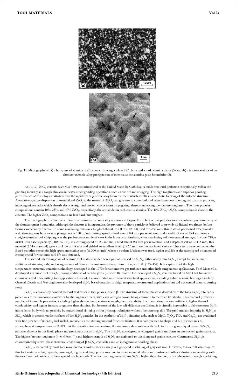
TOOL MATERIALS
TOXICOLOGY
TRACE AND RESIDUE ANALYSIS
TRANSPORTATION
TRIPHENYLMETHANE AND RELATED DYES
TUNGSTEN AND TUNGSTEN ALLOYS
TUNGSTEN COMPOUNDS
ULTRAFILTRATION
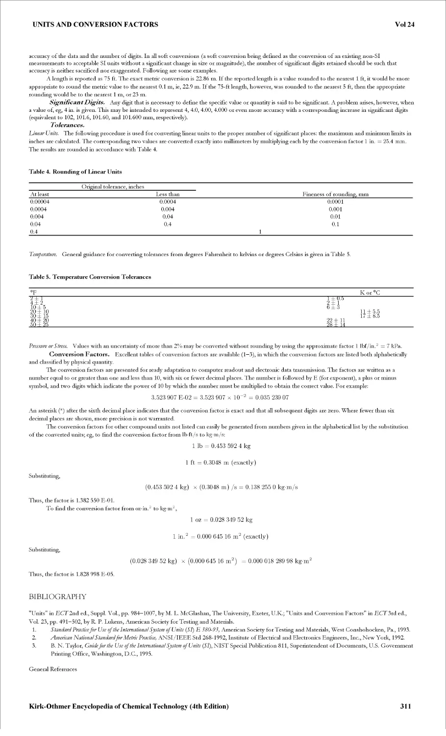
UNITS AND CONVERSION FACTORS
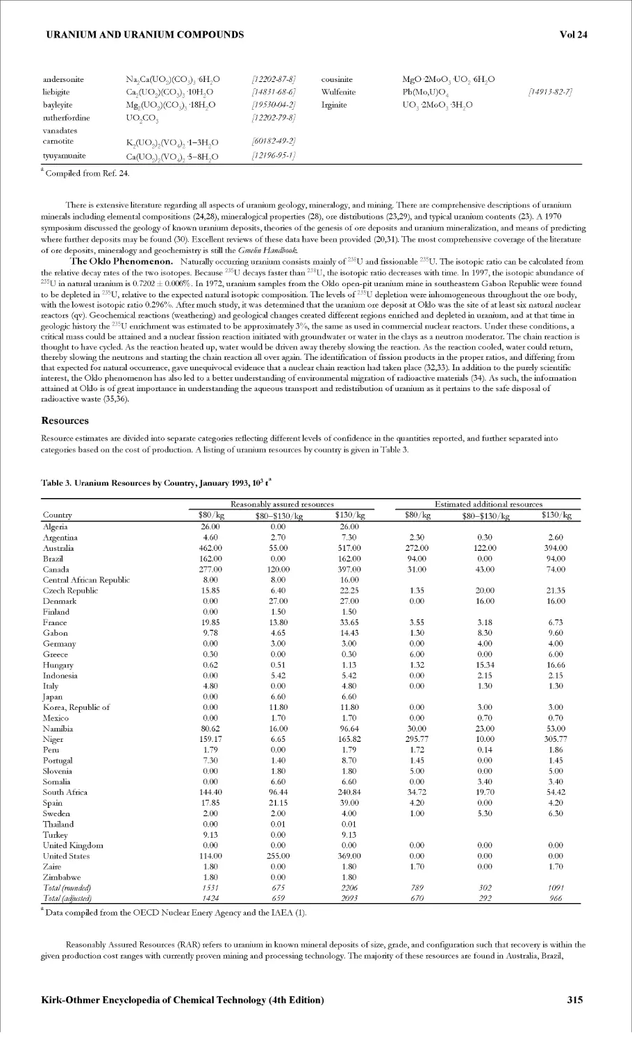
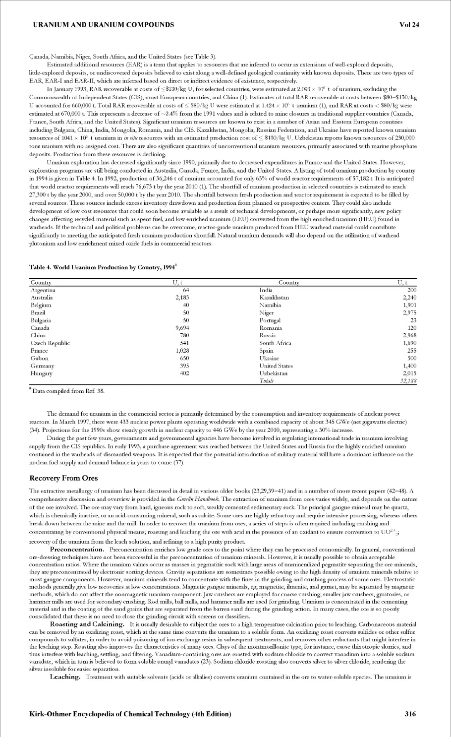
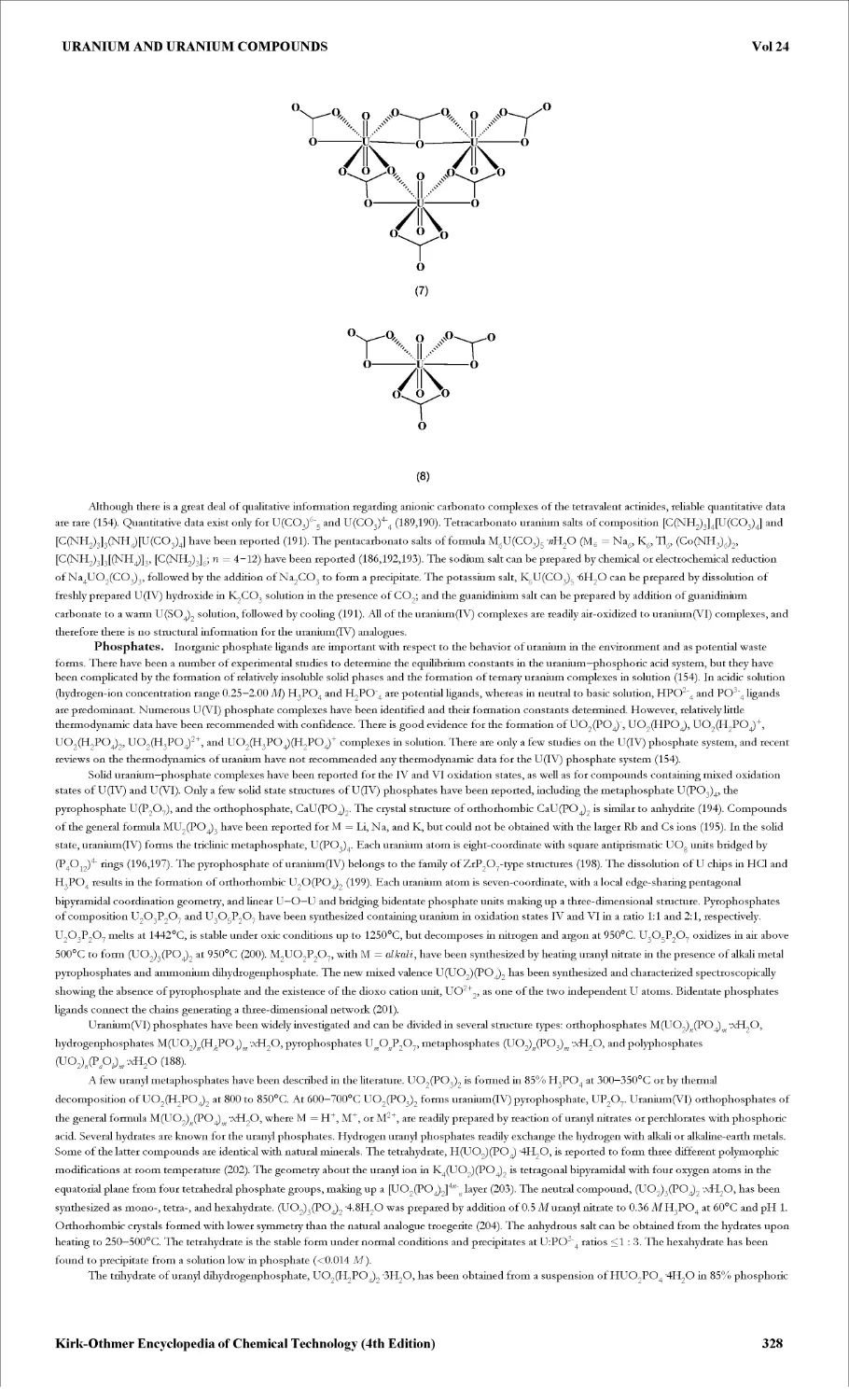
URANIUM AND URANIUM COMPOUNDS
URETHANE POLYMERS
VACCINE TECHNOLOGY
VACUUM TECHNOLOGY
VANADIUM AND VANADIUM ALLOYS
VANADIUM COMPOUNDS
VANILLIN
VETERINARY DRUGS
VINEGAR
VINYL CHLORIDE
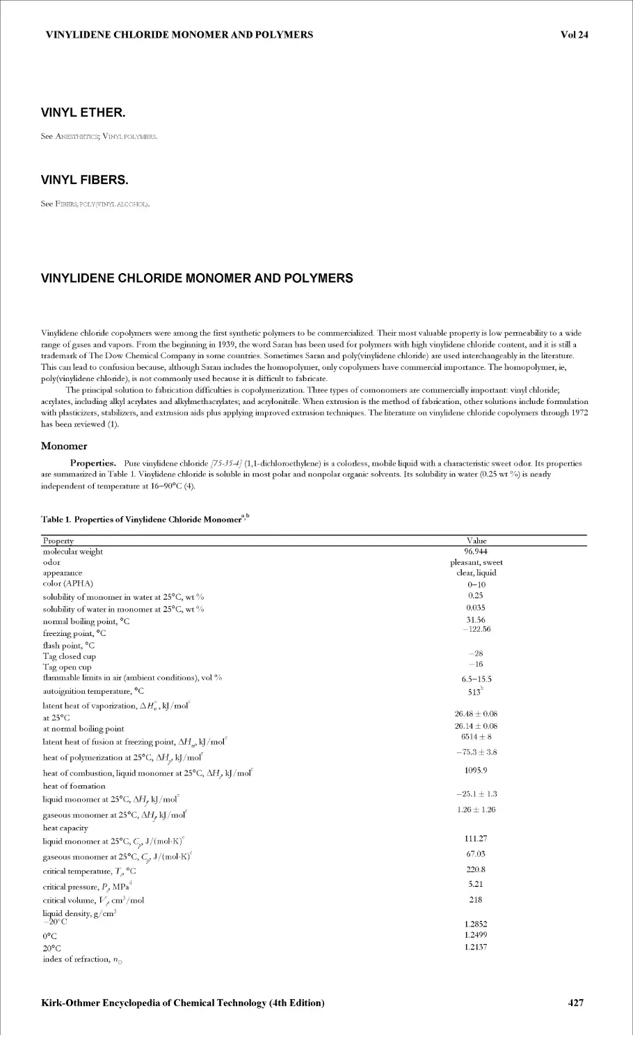
VINYLIDENE CHLORIDE MONOMER AND POLYMERS
VINYL POLYMERS
- VINYL ACETAL POLYMERS
- VINYL ACETATE POLYMERS
- VINYL ALCOHOL POLYMERS
- VINYL CHLORIDE POLYMERS
- VINYL ETHER MONOMERS AND POLYMERS
- N-VINYLAMIDE POLYMERS
hJHtD'JU1£J>hJHOOtDOOOOaU1J>HOtDOOSJaU1J>hJtD'JWHI-4DMffiU1£WNH
THIOGLYCOLIC ACID
Vol 24
THIOGLYCOLIC ACID
Thioglycolic acid (2-mercaptoacetic acid [68-11-1]), HSCH2COOH, molecular weight 92.11, is the first member of the mercaptocarboxylic acids series. It
was prepared and identified in 1862 by Carius (1) and studied around 1900 (2). Thioglycolic acid was first developed commercially in the early 1940s in the
field of cosmetology as an active material for cold wave permanents and depilatories (see Hairpreparations). The advent of the PVC industry in the 1950s
brought thioglycolic acid a significant application as a raw material in the manufacture of organotin stabilizers (see Heat stabilizers; Vinyl polymers). These
stabilizers improved thermal stability and prevented discoloration during polymer processing. As large-scale commercial chemical production grew,
thioglycolic acid began to be used more and more as a raw material in the manufacture of fine and specialty chemicals in the pharmaceutical and agricultural
sectors.
Properties
Pure thioglycolic acid is a water-white Equid that freezes at —16° C and distills under reduced pressure. Reported constants are bp at 3.9 kPa (29 mm Hg),
123°C, bp at 1.33 kPa (10 mm Hg), 96°C (3); d[°, 1.325 g/cm3; viscosity at 20°C, 6.55 mPa-s(=cP); refractive index n30, 1.5030; heat of vaporization, 627.2
J/g (149.9 cal/g); heat of combustion, 1446 kJ/mol (345.6 kcal/mol); electrical conductivity at 20°C, 2 x 10⁶ ({km) 1 ; dielectric constant, 7.4 x 10“30 Gm
(2.25 debye); dipole moment, 7.6 x 10“30 Gm (2.28 debye); flash point in closed cup, 132°C.
Both the carboxyl and the mercapto moieties of thioglycolic acid are acidic. Dissociation constants at 25°C are for pK^, 3.6; pK^, 10.5. Thioglycolic
acid is miscible in water, ether, chloroform, dichloroethane and esters. It is weakly soluble in aliphatic hydrocarbons such as heptane, hexane. Solvents such
as alcohols and ketones can also react with thioglycolic acid.
Reactions
Thioglycolic acid is altered by self-esterification. This alteration depends on temperature and concentration of aqueous solutions. Thioglycolic acid is almost
stable at room temperature in 70 wt % aqueous solution. At room temperature, the loss in assay for pure product under correct storage conditions is about
1% of the initial value in a month. At a lower (5°C) temperature this figure is below 0.3% in a month; at higher temperatures the self-esterification
increases. Under an air atmosphere oxidation to disulfide occurs. Many self-esterification products, called thioglycolides, have been detected by nmr.
Examples are Vmercaptoacetylthioacetic acid [99-68-3]\ HSCH2COSCH2COOH, which represents more than 90% of thioglycolides, some
polythioglycolides, HS(CH2COS) CH2COOH, cyclic thioglycolides such as 1,4-dithioglycolide [48355-2-6], and also solid ortho thioesters such as
tetracarboxylmethylmercapto-l,4-dithiane [52959-43-0]. Formation of the last is promoted by acid species. The self-esterification products can be reversed
in the presence of dilute acids or alkalies, and aged thioglycolic acid can be completely recovered by hydrolysis.
Thioglycolic acid undergoes reactions typical of carboxylic acids, forming salts, esters, amides, and reactions typical of mercaptans, and forming
thioethers with olefins or halogenated compounds, disulfides by oxidation, and metal mercaptides by reaction with metal oxides or metal chlorides.
Thioglycolic acid or its salts in aqueous solutions are rapidly oxidized by air or hydrogen peroxide to the disulfide, dithiodiglycolic acid [505-73-7],
HOOCCH2SSCH2COOH. More vigorous oxidative conditions, eg, with dilute nitric acid, produce sulfoacetic acid [123-43-3] > HO3SCH2COOH.
Thioglycolic acid is a powerful reducing agent in neutral or alkaline solutions. One of the most widely used reactions of thioglycolic acid is the thiol
disulfide interchange reaction, particularly with the disulfide bond of cystine [923-32-0] (1) in protein material, eg, wool and hair, to form the amino acid
cysteine (2). The rate at which equilibrium is established is a function of pH; it is low at pH <6 and rapid at pH 8—10.
2 HSCH2COOH + HOOCCH(NH2) CH2SSCH2CH(NH2) cooh%
(1)
HOOCCH2SSCH2COOH + 2 HOOCCH(NH2) CH2SH
(2)
(1)
Long-chain thioacetic acids are obtained by reaction of primary alkenes with thioglycolic acid, by using uv lamps or radical initiators. This is the case
for do decylthio acetic acid [13753-71 -4]^ C12H24SCH2COOH, prepared from dodecene, or carboxymethylthiosuccinic acid [99-68-3]\
HOOCCH2SCH(CH2COOH)COOH, prepared from maleic acid. Similar products have been described for the reaction of chloroacetic acid [79-11 -8]>
C1CH2COOH, and corresponding mercaptans.
Other products of commercial value, such as laurylthiopropionic acid [1462-52-8]> C12H24SCH2CH2COOH, are produced starting from
3-mercaptopropionic acid [107-96-0]\ HSCH2CH2COOH, and unsaturated products. VAlkylthiocarboxylic acids and their potassium salts have been
described and evaluated as surfactants (qv). They provide excellent thermally stable behavior and good surface activity for their alkaline salts (4).
Because of its two active functions, thioglycolic acid is an ideal reagent for a variety of chemical reactions, including addition, elimination, and
cyclization. The methyl [2365-48-2] and ethyl [623-51-8] esters of thioglycolic acid, HSCH2COOR, have shown promise as raw materials in several fine
chemicals. These block the carboxylic group, leaving the mercapto group free to react. In the presence of bases, the mercapto group becomes a strong
nucleophile able to react with halogenated compounds by a substitution reaction. This property is applied to the manufacture of many valuable
pharmaceutical and agrochemical intermediates, such as ethyl trifluoromethane thioglycolate [75-92-9], F3CSCH2CO2C2H5. The methylene group of
thioglycolic acid esters, having a particular position between a mercapto and an ester function, displays a significant ability to react. Under alkaline
conditions, interesting routes are available to a variety of heterocyclic compounds, such as thiophene, thiazole and other N—S heterocyclic compounds.
Methyl thioglycolate [2365-18-2], HSCH2COOCH3, can be used as the starting material to obtain methyl 3-amino-2-thiophenecarboxylate [22288-785] (3)
by reaction with 2-chloroacrylonitrile [920-37-6]. Compound (3) is a key intermediate to drugs and agrochemicals (5).
ci
HSCH2COOCH3 + CH2 =C\ —-
GN
(3)
(2)
Several kinds of products can be obtained by reaction of thioglycolic acid and its esters with aldehydes to form mercaptals, RCH(SCH2COOH)2, or with
ketones to form thiolketals, RR'C(SCH2COOH)2. Reaction with formaldehyde (qv) yields di-^-butylmethylene-bisthioglycolate [1433882-0] (МВТ ester):
2 HSCH2COOC4H9 + CH2O C4H9OOCCH2SCH2SCH2COOC4H9 +H2o
(3)
Thioglycolic acid forms a multiplicity of stable complexes with metal ions. Depending on the particular metal and on experimental conditions, the
Kirk-Othmer Encyclopedia of Chemical Technology (4th Edition)
1
THIOGLYCOLIC ACID
Vol 24
thioglycolate complexes can be mononuclear or polynuclear and have the structure of carboxylate salts, metal mercaptides, or true chelates. Complexes
studied include various metal and rare-earth metals, mercaptocarboxylic acids, and thiodiglycolic acid [123-93-3], HOOCCH2SCH2COOH. Potentiometric
investigations and structural identifications have been carried out to determine properties and stability (6).
Manufacturing, Processing, and Storage
Thioglycolic acid is manufactured by the reaction of monochloracetic acid [79-11-8] or its salts with alkali hydrosulfides, eg, NaSH or NH4SH, in aqueous
medium, under controlled conditions of pressure, temperature, pH, concentration, to give a higher yield of thioglycolate salt and minimize the formation of
such by-products as thiodiglycolic and dithiodiglycolic acids. The reaction mixture is acidified to liberate thioglycolic acid, which is extracted from the
aqueous solution into an organic solvent, such as an ether, and then purified by vacuum distillation (7) (Fig. 1).
Alkali
hydrosulfide
Reaction Acidification Extraction Solvent
Distillation Hydrolysis
evaporation
Fig. 1. Thioglycolic acid (TGA) manufacture.
Commercial monochloroacetic acid contains many other organic acids, particularly dichloroacetic acid [79-43-6]C12CHCOOH, which has to be
completely converted into sulfur derivatives to avoid residual chlorine compounds which are harmful for cosmetic applications (8). Thioglycolic acid, which
has to meet cosmetic specifications, must be free of metal impurities, and must be pure enough to avoid color and odor problems.
Many other routes to produce thioglycolic acid have been investigated (9). To try to minimize by-products, nucleophilic agents other than alkali
sulfhydrates have been claimed, eg, thiosulfates, sodium disulfides, thiourea, xanthogenic acid derivatives, and sodium trithiocarbonates (10). These
alternative methods, which require reduction of the disulfides or hydrolysis of carboxymethylthio derivatives, seem less competitive than those using alkali
sulfhydrates.
All the processes starting from chloroacetic acid are characterized by the formation of 2 moles of salt per mole of thioglycolic acid produced:
C1CH2COOH + 2 NaSH HSCH2COONa + NaCl + H2S
(4)
HSCH2COONa + HC1 HSCH2COOH + NaCl
(5)
Therefore, manufacture of thioglycolic acid is associated with the production of aqueous salt waste, so problems of waste disposal have to be resolved in
each plant.
Where thioglycolic acid is manufactured mainly as an intermediate for conversion to higher alkyl esters, the alcohol of the ester can be used as
solvent to extract thioglycolic acid. It is also convenient to manufacture the esters of thioglycolic acid direcdy and to use the ester of chloroacetic acid and
alkali sulfhydrates (10) as raw material.
ROOCCH2C1 + NaSH ROOCCH2SH + NaCl
(6)
This is a waste-reducing process in comparison with the classical processes, which proceed by the thioglycolic acid esterification route.
Esters of thioglycolic acid are to a large extent manufactured by conventional esterification processes. Manufacture at a larger scale of 2-ethylhexyl
thioglycolate [7659-86-1] and isooctyl thioglycolate [25103-09-7] by a continuous process (12) gives esters of higher consistency. Thioglycolic acid is
marketed as pure product or at 80—85 wt % aqueous solution. The ammonium salts are available in aqueous solutions containing 50—60 wt % thioglycolic
acid; the monoethanolamine salts are available as solutions containing 40—50 wt % thioglycolic acid. Glycerol monothioglycolate is supplied in anhydrous
form. Calcium thioglycolate is supplied as a crystalline powder. Potassium thioglycolate [34452-51-2] and sodium thioglycolate [367-51-1] are also available
as aqueous solutions.
Thioglycolic acid is stored in reinforced polyethylene or polypropylene tanks or containers. It is advisable to keep thioglycolic acid at low (<10° C)
temperature to slow down self-esterification. The same care must be taken with drums or tank trucks. Drums are made of polyethylene or
polyethylene-lined steel. For transport, thioglycolic acid is classified as a corrosive and toxic liquid. The handling of thioglycolic acid requires the usual
precautions observed for strong acid and corrosive chemicals.
Among other mercaptocarboxylic acids, the mercaptopropionic acids have undergone a promising development. Thiolactic acid or
2-mercaptopropionic acid [79-42-5], HSCH(CH3)COOH, is manufactured by using 2-chloropropionic acid [598-78-7]. 3-Mercaptopropionic acid
[107-96-0], HSCH2CH2COOH, competes with thioglycolic acid in plastic additives or as modifiers in various polymers. Mercaptopropionic acid is
Kirk-Othmer Encyclopedia of Chemical Technology (4th Edition)
2
THIOGLYCOLIC ACID
Vol 24
produced by using acrylic monomers, eg, acrylic acid, acrylonitrile, methyl acrylate, as raw materials (13—19) (Table 1).
Table 1. Mercaptopropionic Acid Syntheses
Process/raw materials Conversion method References
CH2=CHCOOH + HC1 -» C1CH2CH2COOH C1CH2CH2COOH + NaSH acidification 13
ch2=chcooh + H2s 14
CH2=CHCOOH + NaSH + CS2 acidification 15
CH2=CHCOOCH3 + H2s + s reduction hydrolysis 16
CH2=CHCN + NaSH + S CH2=CHCN + NaSH -» NCCH2CH2SCH2CH2CN reduction hydrolysis 17
NCCH2CH2SCH2CH2CN + NaSH + NaOH acidification 18
HOOCCH2CH2SCH2CH2COOH + NaOH + Na2S acidification 19
Economic Aspects
Since its development in cosmetics in the 1940s, thioglycolic acid has become a widespread thio chemical, used all over the world as the acid or in the form
of its salts or esters. Because of the several derivatives of thioglycolic acid used, the market size for this chemical is often expressed in terms of thioglycolic
acid equivalents. In 1994 the total world market was estimated at around 15,000 to 20,000 metric tons of thioglycolic acid equivalents. Some
mercaptocarboxylic acid and esters available are compiled in Table 2.
Table 2. Mercaptocarboxylic Esters Derivatives
Compound CAS Registry Number Structural formula Bp,a °C
methyl thioglycolate [236548-2] HSCH2COOCH3 148
methyl 3-mercaptopropionate [2935-90-2] HSCH2CH2COOCH3 166
ethyl thioglycolate [623-51-8] HSCH2COOC2H5 155
я-butyl thioglycolate [10047-28-6] HSCH2COOC4H9 11053
я-butyl 3-mercaptopropionate [16215-21-7] HSCH2CH2COOC4H9 10116
2-ethylhexyl thioglycolate [7659-86-1] HSCH2COOC8H17 1060,4
2-ethylhexyl 3-mercaptopro-pionate [50448-95-8] 85-870 27
isooctyl thioglycolate [25103-09-7] 107053
isooctyl 3-mercaptopropionate [30774-01-7] 95q.30
ethylene glycol dimercapto-acetate [123-81-9] (CH2OOCCH2SH)2 1370.26
ethylene glycol dimercaptopro-pionate [22504-50-3] (CH2OOCCH2CH2SH)2
pentaerythritol- tetr akis-thioglycolate [10193-994] C(CH2OOCCH2SH)4 b
pentaerythritol-tetrakis-3-mercaptopropionate [7575-23-7] b
di-я-butyl methylene bis thioglycolate [14338-82-0] CH2(SCH2COOC4H9)2 c
thiodiglycolic acid [123-93-3] S(CH2COOH)2 128d
dithio diglycolic acid [505-73-7] S2(CH2COOH)2 100-102d
dithiodipropionic acid [1119-62-6] S2(CH2CH2COOH)2 152-156d
thiodipropionic acid [111-17-1] S(CH2CH2COOH)2 130d
dimethyl thiodipropionate [4131-74-2] S(CH2CH2COOCH3)2 130026
dilauryl thiodipropionate [123-284] S(CH2CH2-COOC12H25)2 40d
distearyl thiodipropionate [693-36-7] S(CH2CH2COOC18H37)2 63-68d
3-mercaptopropionic acid [107-96-0] HSCH2CH2COOH 15.5d 1112
2-mercaptopropionic acid [7942-5] HSCH(CH3)COOH 850.66
thiomalic acid [7049-5] HSCH(CH2COOH)COOH 150d
Pressure other than atmospheric given as subscript in kPa. To convert to mm Hg, multiply by 7.5.
b Material assays at 95%.
C Viscosity at 20°C is 14-18 mPas(=cP).
Value given is melting point.
The worldwide growth of thioglycolic acid and its derivatives is primarily driven by the market growth of PVC, and more particularly by the demand
for the tin stabilizers used in this thermoplastic. The demand for cold wave permanents and chemical depilatories is the second driving force for
production of thioglycolic acid and its derivatives. The progress of thioglycolic acid within this sector is closely linked to local hair fashion, changes in
cultural habits, and the development of average purchasing power. The world market for thioglycolic acid and its derivatives is thought to experience an
average annual growth of 2%.
Manufacturing plants for thioglycolic acid and derivatives are found in Europe, the United States, and Asia. Producers in Europe are B. Bock
(Germany), Elf Atochem (France), and Merck (Germany); in the United States Elf Atochem, Hampshire, and Witco; and in Japan, Daicel. Production
capacity is expected to be sufficient to supply world demand for five years.
Specifications
Table 3 lists some properties and commercial specifications of thioglycolic and its salts.
Kirk-Othmer Encyclopedia of Chemical Technology (4th Edition)
3
THIOGLYCOLIC ACID
Vol 24
Table 3. Specifications for Thioglycolic Acid and Some Derivatives
Property ThioglycoEc acid ThioglycoEc acid Ammonium thioglycolate Glyceryl monothioglvcolate Monoethanolamine thioglycolate Calcium thioglycolate
CAS Registry Number [68-11-1] [68-11-1] [542146-5] [30618-84-9] [126-97-6] [814-71-1]
l'I\l'CS 2006774 2006774 2265409 2502648 2048154
assay as TGA, % 98-99 80.0-80.3 60.0-60.3 75-76 50.0-50.4 50
specific gravity, 20°C 1.32 1.26-1.27 1.205 1.285 1.25
b iron , ppm 0.4 0.3 0.4 2 0.4
pH 7.0-7.2 6.9-7.3 11-12
refractive index, 20°C 1.5030 1.5020-1.5030
appearance water-white water-white clear clear, colorless clear white crystalline
powder
EINECS = European Inventory of Existing Commercial Chemical Substances.
k Value is maximum.
Analytical and Test Methods
Thioglycolic acid can be identified by its ir spectrum or by gas chromatography. Most of the by-products and self-esterification products are also detected
by Equid chromatography, eg, thiodiglycoEc acid, dithio diglycoEc acid, linear dimers, and polymers. Iron content can be assayed by the red sensitive
complex of 1,10-phenanthroline [66-71-7] and ferrous ion of a mineralized sample. Ferric ion turns an aqueous ammonia solution deep red-violet.
Assay. ThioglycoEc acid is determined by its quantitative reaction with iodine. Depending on the storage conditions and time, thioglycoEc acid
tends to form thioglycoEdes with formation of water. This process is reversible by hydrolysis at elevated temperature or by alkalies or acids. ThioglycoEdes
can be completely reconverted to thioglycoEc acid. Therefore, for the assay determination of the initial thioglycoEc acid, it is necessary to carry out
hydrolysis with ammonia prior to iodometric titration.
Titration of thioglycolate esters is also realized by iodine in alcohoEc solution. Titration of thioglycoEc acid (acid number) in thioglycolate esters is
effected by potentiometric titration with potassium hydroxide.
Health and Safety Factors
A safety assessment of ammonium and glyceryl thioglycolates and thioglycoEc acid has been pubEshed (20). Hah products containing ammonium
thioglycolate and glyceryl thioglycolate may be used safely, at infrequent intervals, at concentrations of ammonium thioglycolate and glyceryl thioglycolate
up to 14.5% (as thioglycoEc acid). Hairdressers should avoid skin contact and minimize consumer skin exposure.
Metabolism. Absorption, distribution, metaboEsm, and excretion of thioglycoEc acid have been reviewed (20). In summary, 35VthioglycoEc
acid was absorbed significandy after appEcation to the skin of rabbits. After intravenous injection, the greatest counts of radioactivity were found in the
kidneys, lungs, and spleen of monkey and in the small intestine and kidneys of rat. Most of the radioactivity was rapidly excreted in the urine in the form of
inorganic sulfate and neutral sulfur.
Acute Toxicity. ThioglycoEc acid, its esters and 3-mercaptopropionic acid are considered moderately toxic on the basis of acute toxicity
studies. These are presented in Table 4.
Table 4. Toxicity of Thioglycolic Acid and Derivatives*
Sexb Route Dosing soln, % LD50, mg/kg Clinical signs References
M,F oral 0.2-1 ThioglycoEc acid 73 ptosis, decrease resphatory rate, 21
M oral 2.5 prostaration 114 22
M,F inhalation/4 h (aerosol) q 21c Eritation of the eyes and the lungs 21
d dermal 10 848 23
F oral 10 Methyl thioglycolate 209 22
M,F dermal 100 >2000e no deaths, hypoactivity, piloerection, no 21
F oral 10 cutaneous reaction Ethyl thioglycolate 178 22
M,F oral dermal 100 Isooctyl thioglycolate 348-391 >2000e no deaths, no clinical signs, no cutaneous 24 21
M oral 10 reactions 2-Ethylhexyl thioglycolate 303 21
M,F inhalation / 6 h f 21
M,F dermal 100 >2000 20% mortaEty, hypo-activity, no 21
M,F oral 68 cutaneous reactions Glyceryl thioglycolate >25 <200 sedation, coma, dyspnea, piloerection 21
g oral inhalation /1 h Mercaptopropionic acid 96-400 h 24 21
Tests carried out on rats, unless otherwise noted.
Of animals used. F = female; M = male.
Value is LC50 and units are mg/L.
Rabbits; no sex information given.
Value is LDQ.
Kirk-Othmer Encyclopedia of Chemical Technology (4th Edition)
4
THIOGLYCOLIC ACID
Vol 24
No mortality at 0.51 mg/L.
gMice.
No death at saturated vapor.
Local Effects. Pure thioglycolic acid and 3-mercaptopropionic acid are stronger acids than acetic acid, and they must be handled with
precautions appropriate for strong acids. Application of thioglycolic acid in a single patch test in rabbits resulted in necrosis in 5 min. This was
accompanied by hyperemia and edema (23). 3-Mercaptopropionic acid induced corrosive dermatolysis after 24-h patch on rabbit skin (21). Thioglycolic
acid esters induced at most a moderate irritation after 4-h contact on rabbit skin and are not classified as irritants under European regulations.
Instillation of pure thioglycolic acid into the eyes of a rabbit resulted in severe pain, severe conjunctival inflammation, dense corneal opacity, and
severe iritis. These effects had not improved at the end of 14 d after exposure. Washing immediately after exposure did not modify the response (23).
These kinds of injuries correspond to those observed in one accident in which part of the contents of a botde of concentrated thioglycolic acid were
splashed into the eyes (25). Diluted (10% in water) thioglycolic acid is considered only as irritating according to the European criteria (26).
3-Mercaptopropionic acid induced immediate necrosis of the eye (21). Thioglycolic esters, eg, ethyl, isooctyl, 2-ethylhexyl, and glyceryl, are far less
dangerous to rabbit eyes than free thioglycolic acid. They are not classified as irritants, whereas methyl thioglycolate is classified as an irritant according to
European regulations (21).
Sensitization. The skin irritation and sensitization potentials of 9.0% thioglycolic acid were evaluated using the open epicutaneous test.
Reactions were not observed during the challenge phase. Thioglycolic acid was an irritant, but not a sensitizer (20).
The potential of 3-mercaptopropionic acid and thioglycolic acid esters to induce delayed-contact hypersensitivity following intradermal injection and
cutaneous application was evaluated in guinea pigs according to the maximization method of Magnusson and Kligman. Mercaptopropionic acid and
methyl thioglycolate did not induce sensibilization. Glyceryl thioglycolate is a very weak sensitizer; isooctyl thioglycolate is a weak sensitizer; and
2-ethylhexyl thioglycolate is a moderate sensitizer (21).
Genotoxicity. Thioglycolic acid (27), sodium thioglycolate (28), 2-ethylhexyl thioglycolate (21), isooctyl thioglycolate (21), and glyceryl
thioglycolate (21) were not mutagenic in the Ames test when tested with and without metabolic activation. 3-Mercaptopropionic acid showed mutagenic
activity in the Ames test strain TA1535, both with and without metabolic activation (21). In the sex-linked recessive lethal mutation test, thioglycolic acid
and sodium thioglycolate were not mutagenic (20,28). Thioglycolic acid (21) and sodium thioglycolate (28) also were not clastogenic when evaluated in the
in vitro human lymphocytes chromosomal aberrations assay and the in vivo micronucleus test in bone marrow of mice, respectively.
Carcinogenicity. Very few data are available on the carcinogenic potential of thioglycolic acid and derivatives. There was no evidence of
carcinogenicity in mice and rabbits that received dermal application of 1.0% sodium thioglycolate (in acetone) twice per week throughout the study. Mice
were allowed to die spontaneously, whereas rabbits were killed during the 85th week of treatment (29).
Ecotoxicity. Thioglycolic acid is harmful to fish. The LC50, 96 h for Pimephakspromelas was found to be 30 mg/L. A biodegradation of 21% was
achieved within 28 d in a closed botde test based on the consumption of oxygen (21); thus, thioglycolic acid cannot be considered as readily biodegradable.
But the acid was found to be inherendy biodegradable in a MITI (Japanese) test based on the biological oxygen demand with a biodegradation rate of 70%
after 28 days (30). It is not expected to bioaccumulate, owing to its low (log P = 0.06) я-octanol/water partition coefficient.
In the case of mercaptopropionic acid, biodegradation of 96% was achieved within 28 d in a closed botde test based on the consumption of oxygen.
The pass level of 60% was reached within 10 d of exceeding the 10% level; thus, mercaptopropionic acid can be considered as readily biodegradable. It is
not expected to bioaccumulate, owing to the low (log P = 0.09) я-octanol/water partition coefficient.
2-Ethylhexyl thioglycolate is toxic to fish. The LC5Q, 48 h to Peuciscus idus was found to be 9 mg/L (21). As a biodegradation of 22% was achieved
within 28 d in a closed botde test based on the biological oxygen demand (21), 2-ethylhexyl thioglycolate cannot be considered as readily biodegradable.
From its я-octanol/water partition coefficient, log P — 2.43, low bioaccumulation potential is expected.
Uses
Thioglycolic Acid in Cosmetics. In the 1940s the first patents were issued for the use of mercaptans in cold waving of human hair, and
some time later thioglycolic acid-based formulations were put on the market. Thioglycolic acid rapidly became preferred, and as of the mid-1990s the
thioglycolates continue to be the most commonly used active ingredient in permanent waving, in hair straightening lotions, and in depilatory creams.
The greater part of hair is made of an insoluble protein material, called keratin, composed of amino acids (qv) that form large condensed polymeric
structures by the formation of amide links. The polypeptide chains are cross-linked by the disulfide bond of cystine. The purpose of the reducing step, in
which thioglycolic acid is involved, is the cleavage of the disulfide bond of cystine (see eq. 1), so that hair becomes deformable. In a further step, the bonds
are restored by a neutralizer, and cuds are made permanent. Aqueous and dry neutralizers contain hydrogen peroxide, sodium perborate, and sodium and
potassium bromate; as well as citric, tartaric, or phosphoric acids for pH adjustments; wetting agents, eg, fatty alcohols; protective agents; specifiers; and
perfumes (31). Because the thioglycolates are not effective at low pH, the balance between buffer and ammonium hydroxide to get the right (from 7—9.5)
pH is very important. The maximum thioglycolic acid concentration permitted under European regulations (32) is 8% for home formulations and 11% for
professional use.
The majority of available depilatories are based on mercaptans like thioglycolic acid, which is used in the presence of alkaline reacting material. These
preparations have less odor and are safer on the skin than other sulfides. Like waving lotions, the depilatory creams use various raw materials, thickening
agents, fat compounds, chalk, alkaline salt of thioglycolic acid (2.5—5% as thioglycolic acid), chelating agent, perfume. The maximum concentration
permitted under the European regulations is 5% and the pH must be in the range from 7 to 12.7 (32).
Many attempts have been made to reduce the ammoniacal and sulfurous odor of the standard thioglycolate formulations. As the cosmetics market
is very sensitive to the presence of impurities, odor, and color, various treatments of purification have been claimed to improve the olfactory properties of
thioglycolic acid and its salts, such as distillation (33), stabilization against the formation of H2S using active ingredients (34), extraction with solvents (35),
active carbon (36), and chelate resin treatments (37).
Polymerization Catalysts, Modifiers, and Chain-Transfer Agents. Properties of polymers obtained by free-radical polymerization
depend on their molecular weight and molecular weight distribution, and substances capable of regulating these are called chain transfer agents. Owing to
the thiol function, thioglycolic acid and its esters, or mercaptopropionic acids and their esters, can play such a role. Depending on the purpose for which a
thioglycolate additive is used in polymerization, it is called a catalyst, a promoter, an accelerator, or a chain transfer agent.
Mercaptocarboxylic acids are also an easy means of introducing a polar function into the polymer for a further grafting, to influence the properties
of the final polymer, and sometimes to obtain processing advantages (38). Thioglycolic acid, used as a chain transfer agent in various polymers, is useful for
improving the dispersion properties of pigments and basic fillers in paints (39), or for increasing the affinity of polymer latexes with fillers in coatings for
paper (40). Thioglycolic acid can also be used as a water-soluble chain transfer agent in aqueous solution polymerization, which mainly concerns acrylic and
acrylamide polymerization, as retention agents (flocculants) in paper and water treatments, or as charge dispersants for paper.
Various polymers, such as polythiourethanes, polythioethers, and polythioacrylates, are used to produce resins which are transparent, colorless and
have a high refractive index and good mechanical properties, useful for the production of optical lenses. Higher refractive indices are promoted by sulfur
compounds and especially by esters of mercaptocarboxylic acids and polyols such as pentaerythritol (41) (see Polymers containing sulfur).
The mercaptans are known to be efficient curing agents for epoxy resins for adhesives applications. Esters of thioglycolic acid or mercaptopropionic
acid and polyols (42) are used as epoxy hardeners. They have several advantages such as low temperature curing properties, fast curing rate, lower toxicity
than amines, and excellent color. They are also considered to be coupling agents, improving adhesion between metals and resins (43). 1,2,6-Hexanetriol
trithioglycolate [19759-80-9] is known to exert a chelating action (44).
The stabilizing of halogen resins against the adverse effects of ionizing radiation has been obtained by using an ester of glycerol and thioglycolic acid
Kirk-Othmer Encyclopedia of Chemical Technology (4th Edition)
5
THIOGLYCOLIC ACID
Vol 24
(45).
Tin Stabilizers for Vinyl Chloride Polymers. The most important development of thioglycolic acid, and especially its isooctyl and
2-ethylhexyl esters, concerns its use as raw material for tin stabilizers, to prevent discoloration during thermal processing of PVC, and also to assure good
compatibility and diffusion of the stabilizers through the resins (46). Commercial organotin stabilizers are typically tetravalent tin having one or two alkyl
groups and two or three mercaptides or other basic ligands. The alkyl groups are usually methyl, butyl, or octyl. The choice of type and number depends
largely on the use. Methyl and octyl derivatives are often used in food contact applications, but this varies by local custom and governmental regulations
(FDA approval).
The alkyl group also produces subde changes in the processing of the PVC, the use level and cost of the stabilizer, and in some cases even the final
properties of the article, especially the heat distortion temperature or Vicat softening point. Overall, methyl derivatives are most widely used. Butyls are
second and octyls a distant third.
Mercaptides are unchallenged as the ligand of choice for the other entities bonded to the tin, but carboxylates can also be used. Whereas a variety of
mercaptans are used, the thioglycolic acid derivatives remain the largest single mercaptan. Dibutyltin bis(isooctyl thioglycolate) [25168-24-5] and butyltin
tris(isooctyl thioglycolate) [25852-70-4] are two common examples. These materials are produced by the reaction of the appropriate alkyltin chloride or
oxide, and the mercaptan.
RpSn(Cl) 4_p + (4-p) HSCH2COOR R^Sn(SCH2COOR) 4_p + (4 - p) HC1
0
R^SnO + 2HSCH2COOR^R^Sn(SCH2COOR)2 +H20
(8)
Whereas other metal salts, especially lead stearates and sulfates, or mixtures of Groups 2 and 12 carboxylates (Ba—Cd, Ba—Zn, Ca—Zn) are also used to
stabilize PVC, the tin mercaptides are some of the most efficient materials. This increased efficiency is largely owing to the mercaptans. The principal
mechanism of stabilization of PVC, in which all types of stabilizers participate, is the adsorption of HC1, which is released by the PVC during degradation.
This is important because the acid is a catalyst for the degradation, thus, without neutralization the process is autocatalytic.
However, because PVC is largely composed of alternating CH2 and CH Cl groups, each elimination of HC1 also produces an allylic chlorine (eq. 9).
The allylic chlorine is less stable than the alkyl chlorine, ie, the production of allylic chlorine lowers the overall stability.
(CH2—CHC1—CH2—CHC1—CH2)n (CH2—CH=CH—CHC1—CH2)n+ HC1
(9)
Degradation then continues at adjacent sites to form conjugated olefins. This does not, however, eliminate the allylic chlorine (eq. 10). Rather the sequence
leads to the zipper effect (46), in which long series of conjugated olefins are quickly produced. These series begin to adsorb light in the visible region when
there are about 6 alternating double bonds and thus quickly degrade the appearance of the article.
(CH2—CH=CH—CHC1—CH2—CHCl)n (CH2—CH=CH—CH=CH—CHCl)n +HC1
(10)
Unlike other stabilizers, tin mercaptide, or the mercaptan that is formed after the HC1 reacts with the mercaptide, can react with the allylic chlorine to
produce a sulfide (47), thus eliminating the labile chlorine groups and stopping the unzipping.
€H2 zCH CH2 R SR
HC CH + Sn
I / \
Cl R SR
.CH2/CH/CH2
\h\h
R SR
Sn
(11)
SR
R Cl
The mercaptan or mercaptide can also add direcdy to the olefin to break up or shorten the conjugation.
Additionally, organotin mercaptides can act as antioxidants, as they can sequester free-radical degradation mechanisms (48). The one drawback of
mercaptide-based tin stabilizers is the discoloration of the sulfur after exposure to uv-radiation. Special precautions or formulations need to be developed
for outdoor applications.
The type of stabilizer used is gready influenced by the specifics of the final products and the customs in the region of use. Lead- and tin-based
stabilizers are mostly used in rigid opaque applications such as building materials (see Building materials, plastic). Lead-based stabilizers predominate in
Europe because the PVC formulations are low in uv-blockers (titanium dioxide). However, the higher uv-blocker needed in the US allows the use of tin
mercaptides, eliminating the hazards associated with the handling of the lead-based products and affording a larger processing latitude than that available
with the lead-based materials.
Because of the stringent U.S. requirements on handling lead-based powders, these stabilizers are only found in flexible electrical wire insulation in
the United States because no other stabilizers have been developed which have the low conductivity afforded by these materials.
However, most recendy, mixed metal stabilizers are being introduced into this area. Whereas some mixed metal stabilizers are used in rigid
applications, it is difficult for these newer materials to compete with lead and tin based stabilizers on a cost/efficiency basis. These materials find their
largest applications in flexible compounds, especially those requiring good stability to uv exposure.
Miscellaneous. In the leather industry, dehairing is a specific step in the treatment of animal skins, where the reducing properties of
thioglycolic salts for the disulfide links of keratins are exploited along side those of other reducing agents such as sodium sulfide and sodium hydrosulfide.
Thioglycolic acid formulations have the advantage over simple sodium sulfide formulations regarding process safety issues, better quality of the final
leather, reduction of waste, and recovery of hair (49).
Wool treatment by thioglycolic acid improves elongation, elasticity, and strength properties of fibers; prevents shrinkage; and makes dyeing easier.
These improvements result from the interchange reactions between disulfides and the HS group of thioglycolic acid, observed on the fiber (50).
In wood industries, addition of thioglycolic acid to pulping liquor during alkaline cooking of pinewood led to an increase in the degree of
delignification of wood. Thioglycolic acid has facilitated the cleavage of lignins, gives higher pulp yields, and leads to lower alkali consumption (51).
Thioglycolic acid is recommended as a cocatalyst with strong mineral acid in the manufacture of bisphenol A by the condensation of phenol and
acetone. The effect of the mercapto group (mercaptocarboxylic acid) is attributed to the formation of a more stable carbanion intermediate of the ketone
that can alkylate the phenol ring faster. The total amount of the by-products is considerably reduced (52).
Thioglycolic acid is described in descaling compositions for iron oxide removal. It can also be used as ammonium or ethanolamine salts to remove
rust without attacking the metal substrate (53) (see Metal surface treatments). Thioglycolic acid can modify the fluidity of concretes and cements in a new
class of superplasticizers, where the polymeric melamine structures are grafted with a sulfur atom instead of nitrogen in the case of the well-known
sulfanilic acid [121 -57-3]\ 4-(H2N)C6H4SO3H, (54). This newer way of linking using an S atom modifies the structure of the resin and is responsible to a
great extent for high fluidity values, a water-reducing content in concrete, and an improvement in mechanical properties (see Cement).
In the oil field industry, in drilling activities the sequestering properties of thioglycoic acid for iron are reflected in its use as an iron-controlling agent,
for acidizing in well stimulation, and also as corrosion inhibitors in high density completion fluids (55). The oxazoline derivative of thioglycolic acid has
been claimed, in water-based drilling muds, as a lubricant additive (56). In the catalytic cracking of hydrocarbons, in petroleum refining activities,
mercaptides of thioglycolic acid are effectively added as a heavy metal passivator to counteract the adverse effects of metal (Ni, V, Fe) contaminants on
catalysts. This is the case for antimony tris(2-ethylhexyl thioglycolate) [26888-44-4] or the isooctyl analogue [27288-44-4]. Other antimony, stannous, or
phosphorous derivatives in various combinations have also been used (57).
Kirk-Othmer Encyclopedia of Chemical Technology (4th Edition)
6
THIOGLYCOLIC ACID
Vol 24
In the lightening of petroleum hydrocarbon oil, esters of mercaptocarboxylic acids can modify radical behavior during the distillation step (58).
Thioesters of dialkanol and trialkanolamine have been found to be effective multifunctional antiwear additives for lubricants and fuels (59). Alkanolamine
salts of dithiodipropionic acid [1119-62-6] are available as water-soluble extreme pressure additives in lubricants (60).
Sulfur compounds are traditionally used as rubber and plastic additives. Esters of thioglycoEc acid and various glycols, eg, ethylene glycol, propylene
glycol, pentaerythritol, and particularly the butyl ester of methylene bisthioglycolic acid, (C4H9OOCCH2S)2CH2, are used as a polar plasticizer and softener
for synthetic rubber, especially for nitrile rubber and chloroprene. Do decylthio acetic acid, C12H24SCH2COOH is a viscosity modifier (61). Esters of
thiodipropionic acid [111 -17-1 f (HOOCCH2CH2)2S, and long-chain alcohols, in the C12~C18 range, are largely used as thioester antioxidant additives in
polyolefins and styrene—butadiene latex resins.
The pentaerythritol ester of dodecylthiopropionic acid [1462-52-8]., C12H25SCH2CH2COOH, is marketed for the same purpose.
Thioglycolic acid and esters are used in the manufacture of sulfur dyes (qv), thioindigo pigments, and as additives for dyeing baths (62). Examples
are 2,5-dichlorophenylthioglycolic acid [6274-27-7] (63) for thioindigo pigment and 2-naphtylthioglycolic acid as dyestuff intermediate (64).
Pharmaceuticals and Agrochemicals. Thioglycolic acid and its esters are useful as a raw material to obtain biologically active molecules. In
cephalosporine syntheses, (4-pyridyl)thioacetic acid [10351 -19-8] (65) and trifluoromethane (ethyl) thioglycolate [75-92-9] (66) are used as intermediates.
Methyl-3-amino-2-thiophene carboxylate can be used as intermediate for herbicidal sulfonylureas (67) and various thiophenic structures (68).
Various other cyclic compounds can be built using thioglycoic acid, eg, thiazolidinone, thiazole, isothiazole, and thiazine-type structures, leading to
intermediates for the agricultural and pharmaceutical industries (69). Fungicidal organotin mercaptocarboxylates have also been claimed (70).
BIBLIOGRAPHY
"ThioglycoEc Acid" in ECT 1st ed., Vol. 14, pp. 78—83, by S. D. Gershon and R. M. Rieger, Lever Brothers Co.; in ECT 2nd ed., Vol. 20, pp. 198—204, by
S. D. Gershon, Lever Brothers Co., and R. M. Rieger, Warner Lambert Co.; in ECT 3rd ed., Vol. 22, pp. 933—946, by O. S. Kauder, Argus Chemical Corp.
1. L. Carius, Ann. 124, 43 (1862).
2. P. Kias on and T. Carlson, Ber 39, 732—738 (1906).
3. E. Bilmann, Justus Eiebigs Ann. Chem.., 339—357 (1905).
4. K. Kamio and co-workers,/. Am. OilChem. Soo. 72(7), 805—809 (1995).
5. P. R. Huddleston and J. M. Barker, Synthet. Communica. 9, 731 (1979).
6. H. Matsui and H. Ohtaki, Polyhedron 2(7), 631—633 (1983); J.-D. Joshi and P. K. Bhattacharya,/ Indian Chem. Soc. 57(3), 336—337 (1980); U.S. Pat.
4,208,398 (June 17,1980), T. F. BoUes and D. O. Kubiatowicz (to Hoffmann-LaRoche); A. NapoH, Ga%. Chim. Ital. 102, 273—280 (1972).
7. U.S. Pat. 3,927,085 (Dec. 10,1975), H. G. Zenkel and co-workers (to Akzo); Jpn. Pat. 55,145,663 (Nov. 14,1980), K. Tamashima and S.
Nagasaki (to Denki Kagaku Kogyo); Jpn. Pat. 56,097,264 (Aug. 5, 1981), K. Tamashima and S. Nagasaki (to Denki Kagaku Kogyo); U.S. Pat.
5,023,371 (June 11, 1991), M. E. Tsui and M. B. Sherwin (to W. R. Grace).
8. P. Daries, Y. Labat, and Y. Vallee, Phosphor. Sulfur Silicon., 46(99), 43—45 (1989); Brit. Pat. 2,164,939 (Sept. 28,1984), M. E. Tsui and M. B. Shervin
(to W. R. Grace).
9. G. T. Walker, Seifen Ole Fette Wachse 13, 402-404 (1962); 14, 431 (1962).
10. U.S. Pat. 3,860,641 (Jan. 14, 1975), M. Bergfeld and H. G. Zengel (to Akzo); S. Afr. Pat. 7,404,097 (May 21, 1975), M. F. Wemeke (to American
Cyanamid).
11. R. M. Acheson, J. A. Barltrop, M. Hichens, and R. E. Hichens,/ Chem. Soc., 650—660 (1961); Jpn. Pat. 6,310,755 (Jan. 18,1988), H. Itsuda, M.
Kawanura, K. Kato, and S. Kimura (to Seitetsu Chemicals); Jpn. Pat. 2,304,061 (May 17,1989) (to Nippon Chemical Industries); Fr. Pat.
2,723,737 (Aug. 19, 1994), Y. Labat and J.-P. Muller (to Elf Atochem).
12. Eur. Pat. 421831 (June 16, 1993), Y. Labat, D. Litvine, and J.-P. Muller (to Elf Aquitaine).
13. U.S. Pat. 3,927,085 (Dec. 10,1975), H. G. Zenkel and co-workers (to Akzo).
14. Eur. Pat. 208333 (July 11, 1985), R. J. Scott (to PhiEips Petroleum).
15. U.S. Pat. 4,490,307 (Dec. 25,1984), H. Kienk (to Degussa).
16. Eur. Pat. 485139 (May 13, 1992), D. R. Chisholm and G. A. Seubert (to Witco).
17. Jpn. Pat. 2,121,962 (Apr. 9, 1990) (to Daicel Chemical Industries).
18. U.S. Pat. 5,391,820 (Feb. 21, 1995), R. P. Woodburry and D. Wood (to Hampshire Chemicals).
19. Jpn. Pat. 4,009,363 (Jan. 14, 1992), T. Tetsuzo andT. Tomiaka (to Tomioka).
20. J. Am. Coll. Toxicol. 10(1), 135-192 (1991).
21. Technical data, Elf Atochem, 1976, 1988,1989, 1992,1994, 1995.
22. P. Von Schmidt, G. Fox, K. HoEenbach, and R. Rothe, Eeitsch.f. Gesamte Hygiene Grenygebiete 20, 575—578,1974.
23. Documentation of the Threshold Eimit Values and Biological Exposure Indices., 5th ed., American Conference of Governmental Industrial Hygienists
(ACGIH), Cincinnati, Ohio, 1986.
24. J. G. A. Luijten and O. R. Klimmer, Al Toxicological Evaluation of the Organotin Compounds^ Tin Research Institute, 1973.
25. W. M. Grant, Toxicology of the Eye, 3rd ed., С. C. Thomas, Springfield, IE., 1986.
26. G. A. Jacobs,/Am. Coll. Toxicol. 11(6), 740 (1992).
27. E. Zeiger and co-workers, Environ. Mutagen. 9(Suppl. 9), 1—109 (1987).
28. E. Goeke, M.-T. King, K. Eckhardt, and D. WEd, Mutat. Rt?j. 90, 91-109 (1981).
29. F. G. StenbAck, J. C. Rowland, and L. A. RusseE, Food Cosmet. Toxicol. 15(6), 601—606 (1977).
30. Citi, Chemicals Inspection and Testing Institute, eds., Biodegradation andBioaccumulation Data of Existing Chemicals Based on the CSCE {Chemical
Substance ControlD?^), Japan, Oct. 1992.
31. Eur. Pat. 302265 (Feb. 8, 1989), P. Hartmann, Y. Greiche, and J. Kohler (to WeEa AG).
32. EEC Regulations for Cold Wave Hair Straightening Eotions and Depilatories, Commission Directive 88/233 CEE adapting to Technical Progress CouncE
Directive 76/768/CEE, Mar. 2,1988.
33. Jpn. Pat. 02,072,155 (Mar. 3, 1990), S. Kimura and Y. Harano (to Daicel Chemical Industries).
34. DE 3,243,959 (Aug. 18, 1983), I. Sandler and co-workers (to Merck).
35. Jpn. Pat. 59,027,866 (Feb. 14, 1984), J. Nakayama (to Lion Corp.).
36. Jpn. Pat. 55,064,569 (May 16, 1980), K. Tamashima, C. Fujii, and S. Nagasaki (to Denki Kagaku Kogyo).
37. Jpn. Pat. 55,051,055 (Apr. 15, 1980), K. Tamashima and S. Nagasaki (to Denki Kagaku Kogyo).
38. U.S. Pat. 4,758,626 (July 19, 1988), T. Ishira and N. Boutnio (to General Electric).
39. Jpn. Pat. 58,164,656 (Sept. 29, 1983) (to Toa Gosei Chemical Industries); Jpn. Pat. 05,005,076 (Jan. 14, 1993), Y. Yasutaro, H. Kato, T. Miki, and
S. Kimata (to Nippon Paint).
40. Jpn. Pat. 05,140,207 (May 8,1993) (to Sumitomo Dow KK).
41. Jpn. Pat. 02,036,216 (Feb. 6, 1990) (to Mitsui Toatsu Chemicals); U.S. Pat. 5,059,673 (Oct. 22, 1991), Y. Kanamura and co-workers (to Mitsui
Toatsu); Eur. Pat. 490778 (June 17, 1992), S. Lavault and G. VeEeret (to Rhone-Poulenc); U.S. Pat. 5,236,907 (Aug. 17, 1993), S. Ohkawa and S.
Saito (to Asahi Denka Kygyo); U.S. Pat. 5,424,472 (Oct. 6, 1993), M. Bader, P. Hartmann, and G. Schwinn (to Rohm GmbH); U.S. Pat.
5,422,422 (Oct. 12, 1993), M. Bader and V. Kerscher (to Rohm GmbH).
Kirk-Othmer Encyclopedia of Chemical Technology (4th Edition)
7
THIOGLYCOLIC ACID
Vol 24
42. U.S. Pat. 3,352,810 (1976), A. J. Duke and G. Mclay (to Ciba); U.S. Pat. 4,861,863 (Aug. 29,1989), R. A. Gonzalez and co-woikers (to Henkel).
43. U.S. Pat. 4,812,363 (Mar. 14,1989), J. P. Bell and R. G. Schmidt (to Bell).
44. Can. Pat. 1,006,074 (Jan. 3,1977), R. L. Leroy (to Noranda Mines); Corrosion 34(4), 113—119 (1988).
45. U.S. Pat. 4,412,897 (Nov. 1, 1983), S. Kombaum and J. Y. Chenard (to Elf Atochem Cliimie).
46. H. Andreas, Plastics Additives Handbook-, 3rd ed., Hanser Publishers, New York, 1990, pp. 271—325.
47. W. H. Starnes, I. M. Plitz, Makromol, 9(4) 633—640 (1976); A. H. Frye, R. W. Horst, and M. A. Paliobagis,/. Po/ycn. Sei. PartA-2, 1765 (1964).
48. J. S. Brooks and co-workers, Polj. Deg. Stab. 4, 359—363 (1982).
49. Y. Nakamura and co-workers, Seni Kogyo Shisetsu Hokoku 7, 89—101 (1969).
50. C. Kraniecki and A. Sochacka, Pr^egl. Skoryany 46, (4) 85—88 (1991); U.S. Pat. 4,484,924 (Nov. 27,1984), E. Pfleiderer, T. Taeger, and R.
Monsheimer (to Rohm GmbH).
51. U.S. Pat. 3,490,991 (Jan. 20, 1970), W. E. Fisher and A. S. Hider (to Owens-Illinois).
52. U.S. Pat. 4,822,923 (1989), K. Simon (to Shell Oil Co.); U.S. Pat. 4,931,594 (June 5,1990), J. Knebel, V. Kerscher, and W. Ude (to Rohm
GmbH); Jpn. Pat. 01,157,926 (June 21, 1989), H. Sakemoto and K. Shigemaksu (to Idemitsu Kosan); U.S. Pat. 5,414,152 (Apr. 9, 1995), M. J.
Cipuelo (to General Electric).
53. Jpn. Pat* 05,014,028 (1993), J. leiri, Y. Nagayama, and T. Tsukada (to Mitsubishi); Jpn. Pat. 60,218,488 (Nov. 1, 1985), T. Suzuki and Y.
Hirozawa (to Rinrei); Jpn. Pat. 54,048,643 (Apr. 17, 1979), S. Watamabe.
54. Eur. Pat. 557211 (Feb. 18,1992), A. Sers and co-workers (to Chryso).
55. Fr. Pat. 2,677,074 (Dec. 4, 1992), P. Dejeux, J.-P. Feraud, and H. Perthuis (to Dowell-Schlumberger); U.S. Pat. 4,784,778 (Nov. 15, 1988), C.
Shin (to Great Lakes Chemicals).
56. U.S. Pat. 4,491,524 (Jan. 1, 1985), A. Gutierrez and co-workers (to Exxon).
57. U.S. Pat. 4,830,731 (Apr. 16,1989), F. Kotaroh, W. Toshio, and N. Hitomi (to Sakai Chemical); U.S. Pat. 4,562,167 (Dec. 31, 1985), B. J.
Berthus andD. L. McKay (to Phillips Petroleum); U.S. Pat. 4,324,648 (Apr. 13, 1982), J. S. Roberts and co-workers (to Phillips Petroleum).
58. U.S. Pat. 4,931,170 (June 5,1990), T. Sasaki (to Seibu Oil).
59. U.S. Pat. 5,198,131 (Mar. 30,1993), A. G. Horodysky and co-workers (to Mobil Oil); U.S. Pat. 5,405,545 (Apr. 11, 1995), A. G. Horodysky and
co-workers (to Mobil Oil).
60. U.S. Pat. 4,880,552 (Nov. 14, 1989), P. Guesnet and co-workers (to Elf Aquitaine).
61. U.S. Pat. 5,130,363 (July 4, 1992), U. Eholzer and co-workers (to Bayer); U.S. Pat. 4,395,349 (July 26, 1983), K. Kinoshita (to Osaka Yuki
Kagaku).
62. U.S. Pat. 3,014,654 (Apr. 18,1979) (to Asahi Chem).
63. U.S. Pat. 5,210,291 (Apr. 11, 1993), H. Goda and co-workers (to Sumitomo); U.S. Pat. 4,461,911 (July 24, 1984), D. I. Schvetze (to Bayer).
64. Eur. Pat. 832273 (May 10,1985), W. Bayer (to Cassella).
65. U.S. Pat. 3,644,377 (1971), C. Sapino and P. D. Sleezer (to Bristol Myers-Squibb).
66. U.S. Pat. 4,491,547 (Jan. 1, 1985), T. Tsuji and co-workers (to Shionogi Seyaku).
67. Eur. Pat. 30142 (Nov. 28, 1980), G. Levitt (to E. I. du Pont de Nemours & Co., Inc.).
68. Fr. Pat. 2,689,129 (Oct. 1, 1993), S. Rault and co-workers (to Elf Atochem).
69. U.S. Pat. 4,479,792 (Apr. 12,1983), E. H. Blaine (to Merck); U.S. Pat. 4,346,094 (Aug. 24,1982), J. R. Beck and co-workers (to EH Lilly).
70. Eur. Pat. 91148 (Oct. 12, 1983), P. Tenhaken and S. B. Welle (to Shell International Research); U.S. Pat. 3,846,459 (Nov. 5, 1974), C. Stapfer (to
Cincinnatti Milacron).
Y. Labat
Elf Atochem
Kirk-Othmer Encyclopedia of Chemical Technology (4th Edition)
8
THIOLS
Vol 24
THIOLS
The chemistry of organic sulfur compounds is very rich and organosulfur compounds are incorporated into many molecules. Thiols, or mercaptans as they
were originally called, are essential as feedstocks in the manufacture of many types of rubber (qv) and plastics (qv). They are utilized as intermediates in
agricultural chemicals, pharmaceuticals (qv), in flavors and fragrances, and as animal feed supplements. Many reviews have been undertaken on the
chemistry of the thiols, regarding both their preparation and their reactions (1—7).
Nomenclature
Thiols are still commonly named as mercaptans, although the proper nomenclature is that established by the International Union of Pure and Applied
Chemists (IUPAC). A listing of the IUPAC name, common name, and structure, is shown in Table 1.
Table 1. Nomenclature of Thiols
IUPAC name Common name Structure
methanethiol methyl mercaptan ch3sh
ethanethiol ethyl mercaptan CH3CH2SH
2-propanethiol isopropyl mercaptan CH3CH(SH)CH3
2-butanethiol jw-butyl mercaptan CH3CH(SH)CH2CH3
1-butanethiol я-butyl mercaptan CH3CH2CH2CH2SH
2-methyl-2-propanethiol /-butyl mercaptan (CH3)3CSH
2,4,4-trimethyl-2-pentanethiol tert-octy\ mercaptan (CH3)2C(SH)CH2C(CH3)3
cyclohexanethiol cyclohexyl mercaptan C,H„SH 6 11
benzenethiol thiophenol CIISII 6 5
CC-toluenethiol benzyl mercaptan CKCH.SH 6 b 2
Occurrence
Cysteine [52-90-4] is a thiol-bearing amino acid which is readily isolated from the hydrolysis of protein. There are only small amounts of cysteine and its
disulfide, cystine, in living tissue (7). Glutathione [70-18-8] contains a mercaptomethyl group, HSCH2_, and is a commonly found tripeptide in plants and
animals. Coenzyme A [85-61-0] is another naturally occurring thiol that plays a central role in the synthesis and degradation of fatty acids.
Methanethiol has been found in sewer gases (8,9) and is thought to be produced by the bacterial degradation of methionine. Methanethiol,
1-butanethiol, and 2-methyl-l-propanethiol are produced by the bacterial degradation of blue-green algae. Some yeasts produce ethanethiol, 2-propanethiol
is produced by actively growing Microystisf/osaquae (10). Methanethiol, ethanethiol, 1-propanethiol, 2-propanethiol, 2-methyl-l-propanethiol,
2-methyl-2-propanethiol, and 1-butanethiol are found in the environment near domestic animal pens (11).
Skunks excrete 1-butanethiol and 2-methyl-1-butanethiol [1878-18-8] as a natural defense mechanism (12). Methanethiol is found in cheese, milk,
coffee, and oysters (13—16). It is also found in the kurrin fruit, which is endemic to Southeast Asia.
Physical Properties
The physical characteristic of thiols that most distinguishes them is their odor. Thiols have been used since the late 1800s as malodorants in combustible
gases. In the 1930s the U.S. Bureau of Mines published a series of reports regarding the intensity of odors of warning agents that put this practice on a
scientific basis (17). There have been innumerable studies since that time regarding the odor intensity of thiols, primarily about their role in the odorization
of natural gas and propane gas. All of the definitive studies on thiol threshold odor levels have been brought together and normalized to give a
standardized odor scale (18). Even the heavier mercaptans have a significant odor, particularly when heated.
Thiols range over the gamut of physical properties. Most of the important thiols are Equids, however methanethiol is a gas, and 1-hexadecanethiol
and 1-octadecanethiol are waxy solids. Tables 2 and 3 list a variety of physical properties for the more important thiols.
Table 2. Properties of Thiols
Compound CAS Registry Number Molecular weight Melting point, К Boiling point, К
methanethiol [74-93-1] 48.11 150.18 279.11
ethanethiol [75-08-1] 62.14 125.26 308.15
2-mercaptoethanol [60-24-2] 78.14 200.00 430.90
1,2-ethanedithiol [540-63-6] 94.20 231.95 419.20
mercaptoacetic acid [68-11-1] 92.12 256.65 493.00
1-propanethiol [107-03-9] 76.16 159.95 340.87
2-propanethiol [75-33-2] 76.16 142.61 325.71
3-mercaptopropionic acid [107-96-0] 106.15 290.65 501.00
1-butanethiol [109-79-5] 90.19 157.46 371.61
2-butanethiol [513-53-1] 90.19 133.02 358.13
2-methyl-l-propanethiol [513-44-0] 90.19 128.31 361.64
2-methyl-2-propanethiol [75-66-1] 90.19 274.26 337.37
2,2,-oxybisethanethiol [2150-02-9] 138.26 193.15 490.15
1-pentanethiol [110-66-7] 104.22 197.45 399.79
cyclohexanethiol [1569-69-3] 116.23 189.64 431.95
Kirk-Othmer Encyclopedia of Chemical Technology (4th Edition)
9
THIOLS
Vol 24
1-hexanethiol [111-31-9] 118.24 192.62 425.81
benzenethiol [108-98-5] 110.18 258.26 442.29
1-heptanethiol [1639-094] 132.27 229.92 450.09
CC-toluenethiol [100-53-8] 124.21 243.95 472.03
1-octanethiol [111-88-6] 146.30 223.95 472.19
2,4,4-trimethyl-2-pentanethiol [141-59-3] 146.30 199.00 428.65
1-nonanethiol [1455-21-6] 160.32 253.05 492.95
1-decanethiol [143-10-2] 174.35 247.56 512.35
1-undecanethiol [5332-52-5] 188.38 270.15 530.55
1- do decane thiol [112-55-0] 202.40 265.15 547.75
tert- do decanethiola [25103-58-6] 202.40 515.65
1-hexadecanethiol [2917-25-2] 258 291-293 396-40l007b
1-octadecanethiol [2885-00-9] 286 301 . , . b 461П1
/tVT'-Dodecaiietliiol is a mixture of isomers.
Subscripted value represents pressure in kPa at which boiling point was taken. To convert kPa to mm Hg, multiply by 7.5.
Table 3. Physical Properties of Thiols
Compound Flash point, К Lower flammability limit, % Heat of formation, kJ / mof Gibbs heat of formation, kJ /mol
methanethiol 217 3.9 —22. У -9.8U
ethanethiol 225 2.8 -46.3 -4.81
2-mercaptoethanol 340.15 2.3 -197 -134
1,2-ethanedithiol 317.15 1.9 -9.70 26.7
mercaptoacetic acid 398 3.1 -394 -344
1-propanethiol 253.15 1.8 -67.5 2.58
2-propanethiol 238.15 1.8 -75.9 2.18
3-mercaptopropionic acid 366.15 2.2 —406 -344
1-butanethiol 274.82 1.4 -87.8 11.4
2-butanethiol 250.15 1.4 -96.6 5.12
2-methyl-1-propanethiol 264.15 1.4 -96.9 5.98
2-methyl-2-propanethiol <253 1.4 — 109 1.01
2,2z-oxybis (ethanethiol) 371.15 1.3 -173,000 -59,900
1-pentanethiol 291 1.2 -110 18.0
cyclohexanethiol 316.15 1.1 —96.0 36.7
1-hexanethiol 293.15 1 -129 27.6
benzenethiol 346.15 1.2 112 148
1-heptanethiol 319.15 0.9 -150 36.2
CC-toluenethiol 343.15 1.1 93.3 163
1-octanethiol 341.15 0.8 -170 44.6
2,4,4-trimethyl-2-pentanethiol 304 0.8 -202 31.1
1-nonanethiol 351.15 0.7 -191 52.8
1-decanethiol 371.15 0.6 -211 61.7
1-undecanethiol 382 0.6 -233 69.0
1- do decane thiol 360.15 0.5 -253 77.2
tert- do decane thiol 363.15 0.6 -273 68.2
To gaseous product.
To convert kJ to kcal, divide by 4.814.
The heat capacities and entropies of organic compounds, including many thiols, have been compiled (19,20). The thermochemistry of thiols and
other organosulfur compounds has been extensively reviewed (21).
Preparation of Thiols
Thiols can be prepared by a variety of methods. The most-utilized of these synthetic methods for tertiary and secondary thiols is acid-catalyzed synthesis;
for normal and secondary thiols, the most-utilized methods are free-radical-initiated, alcohol substitution, or halide substitution; for mercaptoalcohols, the
most-utilized method is oxirane addition; and for mercaptoacids and mercaptonitriles, the most-utilized methods are Michael-type additions.
Acid-Catalyzed Synthesis. The acid-catalyzed reaction of alkenes with hydrogen sulfide to prepare thiols can be accomplished using a strong
acid (sulfuric or phosphoric acid) catalyst. Thiols can also be prepared continuously over a variety of solid acid catalysts, such as zeolites, sulfonic
acid-containing resin catalysts, or aluminas (22). The continuous process is utilized commercially to manufacture the more important thiols (23,24). The
acid-catalyzed reaction is commonly classed as a Markownikoff addition. Examples of two important industrial processes are 2-methyl-2-propanethiol and
2-propanethiol, given in equations 1 and 2, respectively.
(CH3) 2C=CH2 + H2S (CH3)3CSH
(1)
CH3CH=CH2 + H2S (CH3)2CH(SH)
(2)
These reactions tend to give few by-products. The main by-product in each case is the sulfide, RSR, which amounts to less than 3—5% of the thiols
produced. Some of the sulfides produced have applications, although they tend to be much smaller-volume requirements than the amounts produced. The
sulfides can be incinerated for disposal, assuming that the incineration facility can handle high sulfur feedstocks.
Free-Radical-Initiated Synthesis. Free-radical-initiated reactions of hydrogen sulfide to alkenes are commonly utilized to prepare primary
thiols. These reactions, where uv light is used to initiate the formation of hydrosulfuryl (HS) radicals, are utilized to prepare thousands of metric tons of
thiols per year. The same reaction can be performed using a radical initiator, but is not as readily controlled as the uv-initiated reaction. These types of
reactions are considered to be anti-Markownikoff addition reactions.
Kirk-Othmer Encyclopedia of Chemical Technology (4th Edition)
10
THIOLS
Vol 24
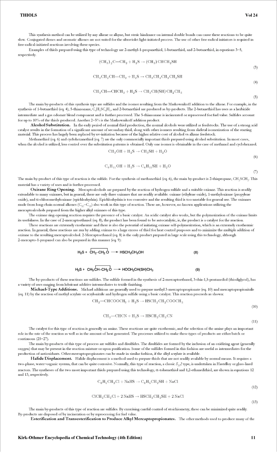
This synthesis method can be utilized by any alkene or alkyne, but steric hindrance on internal double bonds can cause these reactions to be quite
slow. Conjugated dienes and aromatic alkenes are not suited for the ultraviolet light-initiated process. The use of other free-radical initiators is required in
free-radical-initiated reactions involving these species.
Examples of thiols prepared using this type of technology are 2-methyl-l-propanethiol, 1-butanethiol, and 2-butanethiol, in equations 3—5,
respectively.
(CH3) 2C=CH2 % H2S (CH3) CHCH2SH
(3)
CH3CH2CH=CH2 + H2S CH3CH2CH2CH2SH
(4)
CH3CH=CHCH3 + H2S CH3CH(SH) CH2CH3
(5)
The main by-products of this synthesis type are sulfides and the isomer resulting from the Markownikoff addition to the alkene. For example, in the
synthesis of 1-butanethiol (eq. 4), 5-thianonane, C4H9SC4H9, and 2-butanethiol are produced as by-products. The 2-butanethiol has uses as a herbicide
intermediate and a gas odorant blend component and is further processed. The 5-thianonane is incinerated or reprocessed for fuel value. Sulfides account
for up to 10% of the thiols produced. Another 2—5% is the Markownikoff addition product.
Alcohol Substitution. In the early period of normal thiol production, the normal alcohols were utilized as feedstocks. The use of a strong acid
catalyst results in the formation of a significant amount of secondary thiol, along with other isomers resulting from skeletal isomerization of the starting
material. This process has largely been replaced by uv-initiation because of the higher relative cost of alcohol vs alkene feedstock.
Methanethiol (eq. 6) and cyclohexanethiol (eq. 7) are the only commercially important thiols prepared using alcohol substitution. In most cases,
when the alcohol is utilized, less control over the substitution patterns is obtained. Only one isomer is obtainable in the case of methanol and cyclohexanol.
CH3OH + H2s CH3SH + H2O
(6)
C6HUOH + H2S C6HUSH + H2O
0
The main by-product of this type of reaction is the sulfide. For the synthesis of methanethiol (eq. 6), the main by-product is 2-thiapropane, CH3SCH3. This
material has a variety of uses and is further processed.
Oxirane Ring Opening. Mercaptoalcohols are prepared by the reaction of hydrogen sulfide and a suitable oxirane. This reaction is readily
extendable to many oxiranes, but in general, there are only three oxiranes that are readily available: oxirane (ethylene oxide), 1-methyloxirane (propylene
oxide), and CC-chloromethyloxirane (epichlorhydrin). Epichlorhydrin is too corrosive and the resulting thiol is too unstable for general use. The oxiranes
made from long-chain normal alkenes (C1Q—C18) also work in this type of reaction. There are, however, no known applications utilizing the
mercaptoalcohols prepared from the higher alkyl oxiranes of this type.
The oxirane ring-opening reaction requires the presence of a basic catalyst. An acidic catalyst also works, but the polymerization of the oxirane limits
its usefulness. In the case of 2-mercaptoethanol (eq. 8), the product has been found to be autocatalytic, ie, the product is a catalyst for the reaction.
These reactions are extremely exothermic and there is also the potential of initiating oxirane self-polymerization, which is an extremely exothermic
reaction. In general, these reactions are run by adding oxirane to a large excess of thiol for heat control purposes and to minimize the multiple addition of
oxirane to the resulting mercaptoalcohol. 2-Mercaptoethanol (eq. 8) is the only product prepared in large scale using this technology, although
2-mercapto-l-propanol can also be prepared in this manner (eq. 9):
H2S + CH2-CH2 6 —HSCH2CH2OH
H2S+ CH3CH-CH26 —* HOCH2CH(SH)CH3
(8)
(9)
The by-products of these reactions are sulfides. The sulfide formedin the synthesis of 2-mercaptoethanol, 3-thia-l,5-pentanediol (thio diglycol), has
a variety of uses ranging from lubricant additive intermediates to textile finishing.
Michael-Type Additions. Michael additions are generally used to prepare methyl 3-mercaptopropionate (eq. 10) and mercaptopropionitrile
(eq. 11) by the reaction of methyl acrylate or acrylonitrile and hydrogen sulfide using a basic catalyst. This reaction proceeds as shown:
CH2=CHCOOCH3 + H2S HSCH2CH2COOCH3
(10)
ch2=chcn + H2S hsch2ch2cn
(11)
The catalyst for this type of reaction is generally an amine. These reactions are quite exothermic, and the selection of the amine plays an important
role in the rate of the reaction as well as in the amount of heat generated. The processes utilized to make these types of products are either batch or
continuous (25—27).
The main by-products of this type of process are sulfides and disulfides. The disulfides are formed by the inclusion of an oxidizing agent (generally
oxygen) that may be present in the reaction mixture or upon purification. Some of the sulfides formed in this fashion are useful as intermediates for the
production of antioxidants. Other mercaptopropionates can be made in similar fashion, if the alkyl acrylate is available.
Halide Displacement. Halide displacement is a method used to prepare thiols that are not readily available by normal means. It requires a
two-phase, water—organic system, that can be quite corrosive. Normally, this type of reaction, a classic SN2 type, is undertaken in Hastelloy or glass-lined
reactors. The syntheses of the two most important thiols prepared using this technology, CC-toluenethiol and 1,2-ethanedithiol, are shown in equations 12
and 13, respectively.
C6H5CH2C1 + NaHS C6H5CH2SH + NaCl
(12)
C1CH2CH2C1 + 2 NaHS HSCH2CH2SH + 2 NaCl
(13)
The main by-products of this type of reaction are sulfides. By exercising careful control of stoichiometry, these can be minimized quite readily.
By-products are disposed of by incineration or by reprocessing for fuel value.
Esterification and Transesterification to Produce Alkyl Mercaptopropionates. The other methods used to produce many of the
Kirk-Othmer Encyclopedia of Chemical Technology (4th Edition)
11
THIOLS
Vol 24
alkyl mercaptopropionates are either transesterification of methyl 3-mercaptopropionate or esterification of 3-mercaptopropionic acid. The process to
obtain 3-mercaptopropionic acid is shown in equation 14. A transesterification is shown in equation 15 and an esterification in equation 16, both to the
я-butyl 3-mercaptopropionate.
HSCH2CH2CN + H20 HSCH2CH2COOH + NH3
(14)
HSCH2CH2COOCH3 + C4H9OH HSCH2CH2COOC4H9 + CHgOH
(15)
HSCH2CH2COOH + C4H9OH HSCH2CH2COOC4H9 + H20
(16)
These reactions, catalyzed using sulfuric acid or a titanate ester, tend to be free of by-products.
Arenethiols. Most of the chemistry described for alkanethiols is not applicable to benzenethiols and other arenethiols. The synthesis of
benzenethiol is best carried out by reduction of the benzene sulfonyl chloride (eq. 17). Other methods for synthesizing arenethiols are discussed at greater
length in the literature (28).
C6H5SO2C1 +3H2 - C6H5SH + 2 H20 + HC1
(17)
Reactions of Thiols
Oxidation. Disulfides are prepared commercially by two types of reactions. The first is an oxidation reaction utilizing the thiol and a suitable
oxidant as in equation 18 for 2,2,5,5-tetramethyl-3,4-dithiahexane. The most common oxidants are chlorine, oxygen (29), elemental sulfur, or hydrogen
peroxide. Carbon tetrachloride (30) has also been used. This type of reaction is extremely exothermic. Some thiols, notably tertiary thiols and long-chain
thiols, are resistant to oxidation, primarily because of steric hindrance or poor solubility of the oxidant in the thiol. This type of process is used in the
preparation of symmetric disulfides, RSSR. The second type of reaction is the reaction of a sulfenyl halide with a thiol (eq. 19). This process is used to
prepare unsymmetric disulfides, RSSRZ such as 4,4-dimethyl-2,3-dithiahexane. Other methods may be found in the literature (28).
2 (CH3)3CSH + 1/2 O2 (CH3)3CSSC(CH3)3 +H2O
(18)
(CH3) 3CSH + Cl2 (CH3) 3CSC1 + HC1
(CH3)3CSC1 + CH3SH (CH3)3CSSCH3 + HC1
(19)
When oxygen is used as the oxidant, a basic catalyst is required for the lighter thiols (31) and a transition metal co-catalyst may be required for the
heavier thiols (32). Oxidation using sulfur as the oxidant requires a basic catalyst.
Gas-phase oxidation of thiols has been discussed in some depth (33). This review mainly emphasizes atmospheric processes, but a section on
nitrogen oxides and thiols appears to be broadly applicable. The atmospheric oxidation chemistry of thiols is quite different from that of alcohols.
Thiols can be utilized to prepare polysulfides such as 2,2,6,6-tetramethyl-3,4,5-trithiaheptane. These are prepared (eq. 20) using sulfur as the only
oxidant (34,35).
2 (CH3)3CSH + 1/4 S8 (CH3)3CSSSC(CH3)3+ H2S
(20)
Alkyl sulfonic acids are prepared by the oxidation of thiols (36,37). This reaction is not quite as simple as would initially appear, because the reaction
does not readily go to completion. The use of strong oxidants can result in the complete oxidation of the thiol to carbon dioxide, water, and sulfur dioxide.
Formation of Sulfides. Thiols react readily with alkenes under the same types of conditions used to manufacture thiols. In this way, dialkyl
sulfides and mixed alkyl sulfides can be produced. Sulfides are a principal by-product of thiol production. Mixed sulfides can be formed by the reaction of
the thiol using a suitable starting material, as shown in equations 21, 22, and 23. Vinyl sulfides can be produced by the reaction of alkynes with thiols (38).
RSH + r'ch=ch2 rsch2ch2r'
(21)
RSH + R'Cl + NaOH RSR'
(22)
RSH + CH2CH2O RSCH2CH2OH
(23)
Mixed sulfides are prepared in the flavor industry by the reaction of thiols, zinc oxide, and a bromoalkane (39). Some of these mixed sulfides are
constituents of allium, asafetida, coffee, and meat flavors. A representative reaction is represented in equation 24.
RSH + ZnO + R'Br RSR' + ZnBr2
(24)
Reactions with Aldehydes and Ketones. Thiols react with carbonyl compounds to form dithioacetals and thioacetals. The dithioacetals
have been utilized as protecting groups for carbonyl compounds. They generally require stringent conditions to remove the blocking groups. The
thioacetals are not overly stable. At least two thioacetals, 2,2,2-trichloro-l-thioethylethanol (40) and 1-dodecanethiomethanol (41), are stable.
This type of chemistry also functions for hydroxyketones and aldehydes. The process using 1,2-ethanedithiol or 2-mercaptoethanol results in cyclic
structures (eq. 25). The 1,3-ditholenes (X = S) and 1,3-thioxalanes (X = O) resulting from these reactions have been shown to be of interest commercially.
RCH(OH) COR' + HXCH2CH2SH RC=C(R') SCH2CH2X + 2 H2O
(25)
A wide variety of products can be obtained by thio alkylation (42). The reactants are usually an aldehyde, a thiol, and either a phenol, a sulfone, an
amine, or a heterocyclic compound. Phenols primarily react with formaldehyde in a process known as thiomethylation (eq. 26). Other types of reactions are
depicted in equations 27 and 28.
C6H5OH + CH2O + RSH RSCH2C6H4OH
(26)
C6H5SO2CH2C6H5 + RSH + CH2O C6H5SO2CH(SR) c6h5
(27)
Kirk-Othmer Encyclopedia of Chemical Technology (4th Edition)
12
THIOLS
Vol 24
CH3NH2HC1 + C6H5CH2SH + CH2O CH3NHCH2SCH2C6H5HC1
(28)
Decomposition of Thiols. Thiols decompose by two principal paths (r43— r45). These are the carbon—sulfur bond homolysis and the
unimolecular decomposition to alkene and hydrogen sulfide. For methanethiol, the only available route is homolysis, as in reaction 29. For ethanethiol, the
favored route is formation of ethylene and hydrogen sulfide via the unimolecular process, as in reaction 30.
CH3SH CH3 +HS
(29)
C2H5SH C2H4 + H2S
(30)
The preferred route depends upon the availability of a hydrogen atom in the beta-position to the thiol group. In other words, CC-toluenethiol (in
toluene) decomposes to give 1,2-diphenylethane and hydrogen sulfide, via the homolytic route, whereas 2-methyl-2-propanethiol decomposes to give
2-methyl-l-propene and hydrogen sulfide.
Photolysis of Thiols. Thiols undergo photolytic reactions (46—48). These reactions proceed as shown in equations 31 and 32. A secondary
mechanistic pathway is also observed. This is shown in equations 33 and 34.
CH3SH + /iP^CH3S- +H-
(31)
CH3SH + H- CH3S- +H2
(32)
CH3SH + hv CH3 + HS
(33)
CH3SH + CH3 CH4 + CH3S
(34)
A review of the role of thiols as electron donors in photoinduced electron-transfer reactions has been compiled (49).
Thiol—Disulfide Interchange Reactions. The interchange between thiols and disulfides has been reviewed (50). This reaction is
base-catalyzed. It involves the nucleophilic attack of a thiolate ion on a disulfide. This is shown in equations 35, 36, and 37.
RSH RS“ +H +
(35)
liS li'SSli' liSSli' Ii'S
(36)
H+ +R'S- R'SH
(37)
The effect of pH and the pK_ of the thiol has been discussed. This reaction is not of great synthetic interest, primarily because it yields a mixture of
products, but it is of commercial consequence. It is also applicable in polysulfide synthesis, where the presence of small amounts of thiols can cause
significant problems for the stability of the polysulfide (51). A similar reaction between thiols and sulfides has also been described (52). In this instance, the
process is heterogenous and acid-catalyzed.
Metal Ion-Promoted Reactions of Thiols. Metal ion-promoted reactions of thiols have been reviewed (53). The bulk of the coverage
concerns metal ion promoted aspects of sulfur chemistry. The main topics of interest are the formation of sulfenamides, sulfides, and disulfides using
metal-mediated reactions.
Applications of Alkanethiols
The principal impetus behind the synthesis of thiols came from the need to produce synthetic rubber in the early 1940s. These rubbers, styrene—butadiene
rubbers (SBRs), were produced by many companies at that time. Originally, 1-dodecanethiol was utilized, but the most important thiol became
/^-dodecanethiol, which was made from propylene tetramer, using an acid-catalyzed process (54,55).
In rubber production, the thiol acts as a chain transfer agent, in which it functions as a hydrogen atom donor to one rubber chain, effectively
finishing chain growth for that polymer chain. The sulfur-based radical then either terminates with another radical species or initiates another chain. The
thiol is used up in this process. The length of the rubber polymer chain is a function of the thiol concentration. The higher the concentration, the shorter
the rubber chain; and the softer the rubber. An array of thiols have subsequendy been utilized in the production of many different polymers. Some of these
applications are as follow:
_____________________Thiol
1- do decane thiol
tert- do decane thiol
2-mercaptoethanol
alkyl mercaptopropionates
_______________________________Polymer
polybutadiene—acrylonitrile (PBAN)
neoprene
nitrile
acrylic resins
SBR
SBR latex
polyacrylates
polymethacrylates
nitrile rubber
ABS
SB latex
expandable polystyrene
PVC
polyacrylates
polymethacrylates
polyacrylates
polymethacrylates
Kirk-Othmer Encyclopedia of Chemical Technology (4th Edition)
13
THIOLS
Vol 24
In general, rubber manufacturers balance thiol reactivity and odor. The structure of the thiol plays a significant role in its ability to be transported
within the polymer matrix, particularly in emulsion polymerizations, ie, mixed water—monomer emulsion. The odor of light thiols is generally too strong for
most rubber manufacturers, as it is generally hard to remove residual odors from polymers.
Another area in which sulfur compounds have long found use is in the area of agricultural chemicals. Many of these materials had been produced by
the manufacturer of the agricultural chemicals, but difficulties in containing odor and the use of hydrogen sulfide in heavily populated areas again pushed
toward specialization by several companies. A list of agricultural chemicals, and the thiol that is used or has been used in production, follows:
Thiol Agricultural chemical
ethanethiol butylate cycloate demeton disulfoton oxydemeton-methyl oxydeprofos dipropetryn EPTC molinate phenothiol phorate sethoxydim
1-propanethiol ethoprop pebulate profenophos prothiophos sulprofox vernolate
1-butanethiol DEF merphos terbufos
1-octanethiol MGKR-874 pyridate
2-mercaptoethanol Vitavax
1,2-ethanedithiol Harvade
CC-toluenethiol IBP tiocarbazil Londax
methyl 3-mercaptopropionate Kathon
Over the years, a diverse group of products made use of the rather unique chemistry of organosulfur chemicals. These include the following:
Thiol Application
methanethiol DL-methionine
ethanethiol propane odorant
2-methyl-2-propanethiol natural gas odorant components
1-octanethiol water repellants
cyclohexanethiol prevulcanization inhibitor
2-propanethiol flocculent natural gas odorant component
/tVT'-nonanethiol polysulfides for oil additives
tert- do decane thiol polysulfides for oil additives surfactants
2-mercaptoethanol PVC stabilizers solvent for acrylic fibers
Organosulfur chemicals serve a diverse group of industries. In these applications ways have been found to control the odor of the thiols, thus utilizing these compounds effectively in a wide range of products.
Toxicology and Handling
The toxicology and procedures for handling thiols used in gas odorants have been reviewed (56), as have thiols as a whole (57). A partial listing of toxicological results is shown in Table 4.
Table 4. Toxicological Studies of Thiolsa
Species Routeb Concentration, mg/kg LD50, mg/kgC
Metbanetbiol
mice respiratory (4) 1200-2200 1664d Htbanetbiol
rat respiratory (4) rat respiratory (0.25) rat oral rat intraperitoneal mice respiratory (4) 2600-5125 4870d (1) 4420d (15) d 27,000-38,000 210-3360 1034 (15) d 105-1680 450 mg/kg 2600-4812 2770d Propanetbiol
Kirk-Othmer Encyclopedia of Chemical Technology (4th Edition)
14
THIOLS
Vol 24
rat respiratory (4) 3050-11260 7300d
rat oral 1327-3344 2360
rat intraperitoneal Rutanethiol 209-1672 1028
mice respiratory (4) 3050-11260 4950d (24) 4010d (15) d
rat oral 1039-3344 2475 (1) 4020 (15) d
rat intraperitoneal t-Rutanethiol 209-672 2475 (1) 1500 (15) d
rat respiratory (4) 97de
rat oral 8.4f
rabbit dermal Dodecanethiol 20.8f
mice intragas trie 4225
aRefs. 56, 58.
Value in. parentheses is exposure time in hours.
C Value in parentheses is time in days.
Value is LC5Q.
Value is in mg/L.
Value is in g/kg.
A listing of known TLV values and odor thresholds for a variety of thiols is given in Table 5.
Table 5. Odor Threshold Levels and Threshold Limit Values (TLV)
Thiol Odor threshold, ppb TLV, ppm
methanethiol 1.05 0.5
ethanethiol 1.07 0.5
1,2-ethanedithiol 19.50
1-propanethiol 1.26
2-propanethiol 0.35
2-propene- 1-thiol 0.40
1-butanethiol 1.41 0.5
2-butanethiol 0.18 0.5
2-butene-l-thiol 0.13
2-methyl-l-propanethiol 1.12 0.5
2-methyl-2-propanethiol 0.33 0.5
1-pentanethiol 0.12 0.5
2-methyl- 1-butanethiol 0.26
2-methyl-2-butanethiol 0.72
benzenethiol 0.31 0.1
4-methylbenzenethiol 1.70
CC-toluenethiol 1.58
1- do decane thiol 0.25
2-methyl- 1-undecanethiol 190.55
aRef. 18.
b Refs. 59 and 60.
Thiol spills are handled in the same manner that all chemical spills are handled, with the added requirement that the odor be eliminated as rapidly as
possible. In general, the leak should be stopped, the spill should be contained, and then the odor should be reduced. The odor can be reduced by spraying
the spill area with sodium hypochlorite (3% solution), calcium hypochlorite solution (3%), or hydrogen peroxide (3—10% solution). The use of higher
concentrations of oxidant gives strongly exothermic reactions, which increase the amount of thiol in the vapor, as well as pose a safety hazard. The
application of an adsorbent prior to addition of the oxidant can be quite helpful and add to the ease of cleanup.
Thiols interact readily with many rubber-containing materials. For this reason, care should be taken in the selection of gasket and hose materials.
Teflon, Kel-F, Viton, or other suitable fluoroelastomers function as gasket materials. Viton is suitable for hoses. Carbon steel is useful for many thiols,
although some thiols become very discolored when carbon steel is utilized. In these cases, the use of stainless steel is very desirable. Isolation from air and
water also minimizes color formation. 2-Mercaptoethanol and 1,2-ethanedithiol should be storedin stainless steel (61).
Thiols are shipped in every conceivable container size. Drums and cans can be of carbon steel for most thiols, provided color is not a determining
factor. Truck, rail, and isocontainer shipments should be set up to utilize a vapor return line from the tank to the shipping container. This substantially
minimizes the amount of odor that escapes. Phillips Petroleum Company and Atochem North America can supply further information regarding the
handling and properties of many thiols.
BIBLIOGRAPHY
"Mercaptans" in ECT 1st ed., Vol. 8, pp. 858—868, by E. E. Reid, Johns Hopkins University; "Thiols" in ECT 2nd ed., Vol. 20, pp. 205—218, by S. D. Turk,
Phillips Petroleum Co.; in ECT 3rd ed., Vol. 22, pp. 946—964, byj. Norell and R. P. Louthan, Phillips Petroleum Co.
1. E. E. Reid, Organic Chemistry ofRivalent Sulfur; Chemical Publishing Co., Inc., New York, 1958—1962.
2. E. Block, Reactions of Organic Sulfur Compounds, Academic Press, New York, 1978.
3. S. Oae, ed., Organic Chemistry of Sulfur, Plenum Press, New York, 1977.
4. S. Patai, ed., The Chemistry of the Thiol Groups John Wiley & Sons, Ltd., London, 1974.
5. S. Patai, ed., The Chemistry ofRunctionalGroups, SupplementE, John Wiley & Sons, Inc., New York, 1980.
Kirk-Othmer Encyclopedia of Chemical Technology (4th Edition)
15
THIOLS
Vol 24
6.
7.
8.
9.
10.
11.
12.
13.
14.
15.
16.
17.
18.
19.
20.
21.
22.
23.
24.
25.
26.
27.
28.
29.
30.
31.
32.
33.
34.
35.
36.
37.
38.
39.
40.
41.
42.
43.
44.
45.
46.
47.
48.
49.
50.
51.
52.
53.
54.
55.
56.
57.
58.
59.
60.
61.
S. Patai and Z. Rappoport, eds., The Chemistry of Sulphur-ContainingFunctionalGroups, Supplement S ,]ohn Wiley & Sons, Inc., New York, 1993.
P. C. Jocelyn, Biochemistry of the SH Groups, Academic Press, NewYork, 1978,p. 8.
M. Rinken, M. Aydin, S. Sievers, and W. A. Kunig, Tresenius' Anal. Ghent. 318, 27 (1984).
M. Pliol, E. Bock, M. Rinken, M. Aydin, and W. A. Kunig, Z. Natuforsch. Sect. C, Biosciences 39C, 240 (1984).
D. Jenkins, L. L. Medsker, and J. F. Thomas, Environ. Sci. Tech. 1, 731 (1967).
T. Jankowski, J. Gawlik, and S. Zimnal, VDI Ber. (Ver. Dtsch. Ing.) 226, 123 (1975).
E. E. Beach and A. White,/. Biol. Chem. 127, 87 (1939).
L. M. Libbey and E. A. Day,/. Dairy Sci. 46, 859 (1963).
D. B. Emmons, J. A. Elliot, andD. C. Becket,/ Dairy Sci. 49, 1325 (1966).
S. Segall and B. Proctor, FoodTechnol. 13, 679 (1959).
A. P. Ronald and W. A. Thomson,/ Fish. Rc<. Board Can. 21, 1481 (1964).
S. H. Katz and E. J. Talbert, Intensity of Odors andlrritatingEjfects of Warning Agents for Inflammable andPoisonous Gases, Technical Paper 480, U.S.
Department of Commerce, U.S. Government Printing Office, 1930.
M. Devos, F. Patte, J. Rouault, P. Laffort, and L. J. Van Gemert, eds., StandardieyedHuman Olfactory Thresholds, IRE Press, New York, 1990.
E. S. Domalski and E. D. Hearing,/ Phys. Chem. Ref. Data 19, 881 (1990).
E. S. Domalski, W. H. Evans, and E. D. Hearing,/ Phys. Chem. Ref. Data 13(Suppl. 1), 1 (1984).
J. F. Liebman, K. S. K. Crawford, and S. W. Slayden, in Ref. 6, p. 197.
E. Tanaka, Kagaku to Kaya 43, 355 (1990).
W. A. Schlze, J. P. Lyon, and G. H. Short, Ind. Eng. Chem. 40, 2308 (1948).
C. F. Fryling in G. S. Whitby and co-workers, eds., Synthetic Rubber, John Wiley & Sons, Inc., New York, 1954, Chapt. 8.
U.S. Pat. 5,008,432 (Apr. 16, 1991), J. S. Roberts (to Uli ill ips Petroleum Company).
U.S. Pat. 4,433,134 (Feb. 1, 1984), R. P. Louthan (to PI i ill ips Petroleum Company).
J. S. Roberts, A. Pauwels, and P. A. Aegerter, Proceedings of the Chemical Specialties USA 1993 Symposium, Oct. 1993.
L. Field, SulfurRep. 13, 197 (1993).
J. Xan, E. A. Wilson, L. D. Roberts, and N. H. Horton,/ Amer. Chem. Soc. 63, 1130 (1941).
E. Wenschuk, M. Heydenreich, R. Runge, and S. Fischer, SulfurLett. 8, 251 (1988).
U.S. Pat. 4,721,813 (Jan. 26, 1988), H. W. Mark and J. S. Roberts (to Pli ill ips Petroleum Company).
J. D. Hopton, C. J. Swann, and D. L. Trimm, Adv. Chem. Ser, 216 (1986).
J. HeicHen, Rev. Chem. Intermed. 6, 175 (1985).
B. D. Vineyard,/ Org. Chem. 32, 3833 (1967).
U.S. Pat. 2,983,747 (May 9, 1961), P. F. Warner (to PI i ill ips Petroleum Company).
P. Allen and J. W. Brook,/ Org. Chem. 27, 1019 (1962).
W. A. Savige and J. A. Maclaren in J. E. Hesse, ed.,/ Chem. Eng. Data 12, 266 (1967).
N. A. Nedolya and B. A. Trofimov, SulfurReports 15, 237 (1994).
B. Ravindranath, PefumerFlavorist 10, 39 (1985).
R. L. Frank, S. S. Drake, P. V. Smith, Jr., and C. Stevens,/ PolymerSci. 3, 50 (1948).
U.S. Pat. 4,939,302 (July 3, 1990), J. S. Roberts (to Phillips Petroleum Company).
D. J. R. Massy, Synthesis, 589 (1987).
T. Shono in Ref. 5, p. 327.
G. Martin in Ref. 6, p. 395.
I. Safarik and О. P. Strausz, Rev. Chem. Intermed. 6, 143 (1985).
R. L. Failes, J. S. Shapiro, and V. R. Stimson, in Ref. 5, p. 450.
C. von Sonntag, in C. Clialgilialoglu and К-D. Asmus, eds., Sulfur-Centered Reactive Intermediates in Chemistry andBiology, Plenum Press, New York,
1990, p. 359.
C. von Sonntag and H.-P. Schuchmann, in Ref. 5, p. 923.
N. J. Pienta, in M. A. Fox and M. Chanon, eds., PhotoinducedElectron Transfer, Elsevier, Amsterdam, the Netherlands, 1988, p. 421.
R. Singh and G. M. Whitesides, in Ref. 6, p. 633.
Technical data, Phillips Petroleum Company.
U.S. Pat. 4,537,994 (Aug. 27,1985), J. S. Roberts (to Phillips Petroleum Company).
D. P. N. Satchell and R. S. Satchell, in Ref. 6, p. 599.
W. A. Schulze, J. P. Lyon, and G. H. Short, Ind. Eng. Chem. 40, 2308 (1948).
C. F. Fryling, in G. S. Whitby and co-workers, eds., Synthetic Rubber, John Wiley & Sons, Inc., New York, 1954, Chapt. 8.
J. S. Roberts and D. W. Kelly, in G. G. Wilson and A. A. Attari, eds., Odorisation III, Institute of Gas Technology, Chicago, Hl., 1993, p. 29.
P. Jacques, Cah. Med. Trav. 20, 169 (1983).
NIOSH, Criteriafor a recommended standard: Occupational Exposure to nAlkane Monothiols, U.S. Dept, of Health, Education and Welfare, Public Health
Service, Center for Disease Control, National Institute for Occupational Safety and Health, Sept. 1978.
ACGIH, Documentation of the Threshold Eimit Valuesfor Substances in Workroom Air, American Conferences of Governmental Industrial Hygienists,
1977.
ACGIH, TLVs, Threshold Limit Valuesfor Chemical Substances in Workroom Air, American Conferences of Governmental Industrial Hygienists, 1982.
Technical literature, Phillips Petroleum Co., Bardesville, Okla., 1995.
John S. Roberts
Phillips Petroleum Company
CH&A Corporation
Kirk-Othmer Encyclopedia of Chemical Technology (4th Edition)
16
THIOPHENE AND THIOPHENE DERIVATIVES
Vol 24
THIOPHENE AND THIOPHENE DERIVATIVES
Thiophene [110-02-1J and a number of its derivatives are significant in fine chemical industries as intermediates to many products for pharmaceutical,
agrochemical, dyestuffs, and electronic applications. This article concentrates on the industrial, commercial, and economic aspects of the production and
applications of thiophene and thiophene derivatives and details the main synthetic schemes to the parent ring system and simple alkyl and aryl derivatives.
Functionalization of the ring and the synthesis of some functional derivatives that result, not from the parent ring system, but by direct ring cyclization
reactions are also considered. Many good reviews on the chemistry of thiophene and thiophene derivatives are available (1—7).
Nomenclature, Numbering, and Structure
The basic nomenclature of the thiophene ring system and its derivatives is indicated by the following: the sulfur atom is number 1, positions 2 and 5 are
equivalent in the parent ring, as are the 3 and 4 positions.
thiophene
thienyl
thenyl
thenoyl
The structure of the parent ring has been studied by numerous techniques. The precise data from microwave studies (8) on the dimensions and
bond angles is given in Fig. 1.
Fig. 1. Bond lengths and bond angles in thiophene.
In valence bond terms the mesomers indicated by (1—7) reflect the ground-state position of thiophene. Mesomer (1) is the principal contributor to
the ring structure; (2) and (3) are significant; (4—7) contribute in a minor way to the structure.
With its sextet of 7C electrons, thiophene possesses the typical aromatic character of benzene and other similarly related heterocycles. Decreasing
orders of aromaticity have been suggested to reflect the strength of this aromatic character: benzene > thiophene > pyrrole > furan (9); and benzene >
thiophene > selenophene > tellurophene > furan (10).
Kirk-Othmer Encyclopedia of Chemical Technology (4th Edition)
17
THIOPHENE AND THIOPHENE DERIVATIVES
Vol 24
Physical Properties and Spectroscopy
Table 1 indicates the significant physical properties of thiophene and 2- and 3-methylthiophene; Table 2, the toxicological and ecotoxicological properties.
Table 1. Physical Properties of Thiophene and Methylthiophenesa
Property Thiophene 2-Methylthiophene 3-Methylthiophene
CAS Registry Number [110-02-1] [554-14-3] [616-44-4]
freezing point, °C -38.3 -63.4 -68.9
boiling point at 101.3 kPab, °C 84.16 113 115
flash point, °C —7 16 15.5
density, dj, kg/m3 1087.3 1025.0 1025.0
density, dj, kg/m3 1057.3 1014.0 1016.2
refractive index, ri^ 1.52572 1.5174 1.5172
viscosity at 25°C, mPa-s(=cP) 0.621 0.669 0.642
surface tension at 20°C, mN/m( =dyn cmj 31.34 30.95 32.37
. b vapor pressure, kPa , at
o°c 2.86 1.33 at 11°C
20°C 8.36 2.66 at21°C 3.99 at31°C
50.1°C 31.16 10.66 at49.1°C 10.66 at51.5°C
84.16°C 101.3 101.3 at 112.6°C 101.3 at 115.4°C
95.9°C 143.3 133.3 at 122.4°C 133.3 at 125.4°C
119.8°C 270.1 199.9 at 138°C 199.9 at 141°C
critical constants
temperature, °C 306.2 335.8 339.8
pressure, MPa 5.70 4.91 4.91
volume, ml /mol 219 275 276
density, kg/m3 385
heat of vaporization at bp, kJ /mol 31.47 33.90 34.25
heat of formation at 298.16 K,kJ/mold
Equid 81.67 45.44 43.89
gaseous 115.44 84.35 83.43
•ц -2435.2 -3471.3 -3469.0
heat ot combustion at 101.3 kPa and
25°C, kj/mold
dielectric constant at 20°C 2.74
aRef. 11.
To convert kPa to mm Hg, multiply by 7.5.
To convert MPa to psi, multiply by 145.
To convert kj/mol to kcal/mol, divide by 4.184.
Table 2. Toxicological and Ecotoxicological Properties of Thiophene and Methylthiophenes
Property Thiophene 2-Methylthiophene 3-Methylthiophene
Log P o ow 1.81“
LD50, rat (oral), mg/kg 1400 3200 (mouse) 2300b
LDq, rat (dermal), mg/kg >2000
LD50, rabbit (dermal), mg/kg 830 >2000b
LC0, rat (inhalation), 1 h mg/L >27
LC50, mouse (inhalation), 2 h, mg/m3 9500 >2000 (rat, 4h) >2000 (rat, 4h)
skin irritancy irritant i-i • • ь slight rrntant
eye irritancy irritant . . i • • b minimal rrntant
bacterial mutagenicity, Ames negative0 negative . b negative
EC50, Daphnia magna^ mg/kg d 13
LC50, fish (f)ry^as latipesp 48 h, mg/kg 15.6е
biotic degradation minimal
biological accumulation no
U.N. No. 2414 1993 1993
hazard symbol l,T F F
aRef. 12.
b Ref. 13.
C Ref. 14.
d Ref. 15.
' Ref. 16.
Toxic, only if >0.1% benzene is present.
Uv Spectroscopy. The commonly used solution uv spectrum of thiophene consists of a broad band, 220—250 nm (loge = 3.9), caused by an
overlap of transition states and two low intensity bands at 313 and 318 nm. Alkyl derivatives and similarly related +M substituents, at the 2-position, give a
single band; similar 3-substituents give a double peak. Negative, ie, —I, —M, substituents at the 2-position give two absorptions, whereas 3-substituents of
this type give only one band of lower intensity. A useful bathochromic shift is noted for thiophene derivatives compared to benzene analogues, thus
Kirk-Othmer Encyclopedia of Chemical Technology (4th Edition)
18
THIOPHENE AND THIOPHENE DERIVATIVES
Vol 24
making certain thiophene derivatives of significant commercial interest as dyes and optical brightening agents.
Ir Spectroscopy. Significant absorptions can be identified as characteristic of particular substitutions within families of thiophene derivatives.
The most widely studied in this connection are probably the halothiophenes, where absorption bands have been characterized. This is useful for qualitative
analysis, but has also been used quantitatively in association with the standard spectrum of materials of known purity.
Nuclear Magnetic Resonance Spectroscopy. Nmr is a most valuable technique for structure determination in thiophene chemistry,
especially because spectral interpretation is much easier in the thiophene series compared to benzene derivatives. Chemical shifts in proton nmr are well
documented; for thiophene (CDC13), 6 = H2 7.12, H3 7.34, H4 7.34, and H5 7.12 ppm. Coupling constants occur in well-defined ranges: J2-3 = 4.9-5.8;
J 3_4 = 3.45-4.35; J2_4 = 1.25-1.7; and J2_5 = 3.2-3.65 Hz. The technique can be used quantitatively by comparison with standard spectra of materials
of known purity. 13C-nmr spectroscopy of thiophene and thiophene derivatives is also a valuable technique that shows well-defined patterns of spectra. 13C
chemical shifts for thiophene, from tetramethylsilane (TMS), are C2 127.6, C3 125.9, C4 125.9, and C5 127.6 ppm.
Reactions of Thiophene and Alkylthiophenes
Electrophilic substitution of thiophene occurs largely at the 2-position and the reactivity of the ring is greater than that of benzene. 3-Substituted
derivatives are generally prepared by indirect means or through ring cyclization reactions.
Alkylation. Thiophenes can be alkylated in the 2-position using alkyl halides, alcohols, and olefins. Choice of catalyst is important; the weaker
Friedel-Crafts catalysts, eg, ZnCl2 and SnCl4, are preferred. It is often preferable to use the more readily accomplished acylation reactions of thiophene to
give the required alkyl derivatives on reduction. Alternatively, metalation or Grignard reactions, on halothiophenes or halomethylthiophenes, can be
utilized.
Acylation. To achieve acylation of thiophenes, acid anhydrides with phosphoric acid, iodine, or other catalysts have been widely used. Acid
chlorides with A1C13, SnCl4, ZnCl2, and BF3 also give 2-thienylketones. All reactions give between 0.5 and 2.0% of the 3-isomer. There has been much
striving to find catalyst systems that minimize the 3-isomer content attempting to meet to customer specifications. The standard procedure for formylation
is via the Vilsmeier-Haack reaction, using phosphorus oxycliloride A ,A-dimethylfomiamide (POC13/DMF) or A-methylfomianilide.
Halogenation. Many different halogenating reagents have been used to accomplish halogenation of the thiophene ring. Excess of reagent
gives di-, tri-, and even tetrahalogenation of thiophene itself. The bromothiophenes are often the preferred target. Bromine in acetic acid or chloroform has
been the traditional route, but utilizes just one of the atoms of bromine. Addition products are often observed, particularly when proceeding through to di-
and tribromothiophenes.
N-Bromosuccinimide and NJ\T-dibromo-5,5-dimethylhydantoin have also been used successfully, which makes possible recycling of succinimide or
the hydantoin and utilizes all the bromine atoms. A mixture of sodium bromide—sodium bromate in aqueous acid has also been used commercially.
Introduction of a 3-bromosubstituent onto thiophene is accomplished by initial tribromination, followed by reduction of the CC-bromines by
treatment with zinc/acetic acid, thereby utilizing only one of three bromines introduced. The so-called halogen dance sequence of reactions, whereby
bromothiophenes are treated with base, causing proton abstraction and rearrangement of bromine to the produce the most-stable anion, has also been
used to introduce a bromine atom at position 3. The formation of 3-bromothiophene [872-31-1] from this sequence of reactions (17) is an efficient use of
bromine. Vapor-phase techniques have also been proposed to achieve this halogen migration (18), but with less specificity. Table 3 summarizes properties
of some brominated thiophenes.
Table 3. Physical, Toxicological, and Ecotoxicological Properties of 2-Bromothiophene, 3-Bromothiophene, and 2-Bromo-3-Methylthiophene
Property 2-Bromo-thiophe 3-Bromo-thioph 2-Bromo-3-methylthiophene
ne ene
CAS Registry Number [1003-09-4] [872-31-1] [14282-76-9]
description liquid liquid liquid
flash point, °C 60 56
boiling point at 101.3 kPa, °C 150 158 181-182
density at 20°C, kg/m3 1684 1740 1571 (25°C)
refractive index, n][ 1.5860 1.5910 1.5680
LD50, rat (oral), mg/kg 200-250“ 66-160a 1923"
LD50, rabbit (dermal), mg/kg 134a 173-694" >2000b
LC50, 4 h, mg/L 1.04a
skin irritancy irritant slight moderate
irritant . . b rrntant
eye irritancy irritant slight moderate
irritanta . . b rrntant
sensitization a no
Ames test negative negative negative
EC50, Daphnia magna^ 48 h, mg/L 5.0d 0.79d
hazard symbol T,N T Xn, N
TSCA status listed listed not listed
U.N. No. 2810 2810 3082
aRef. 19.
b Ref. 20.
C Ref. 21.
d Ref. 22.
Nitration. It is difficult to control nitration of thiophene, which yields 2-nitrothiophene [609-40-9]. The strongly electrophilic nitronium ion
leads to significant yields (12—15%) of 3-isomer. A preferred procedure is the slow addition of thiophene to an anhydrous mixture of nitric acid, acetic acid,
and acetic anhydride.
Metalation. Direct reaction of thiophene and butyUithium in diethyl ether gives 2-thienylhthium [2786-07-4]\ a valuable intermediate and source
of many further derivatives. Some examples are given in Table 4. Tliienyllitliiums can also be prepared by halogen exchange from bromothiophenes and
butyUithium, but this requires low temperature to avoid any possible proton—lithium exchange, or rearrangement by the halogen dance mechanism. Thienyl
Grignard reagents are also prepared from the bromothiophenes and can be used in reaction schemes to give many other derivatives.
Table 4. Reactions of 2-Thienyllithium
Kirk-Othmer Encyclopedia of Chemical Technology (4th Edition)
19
THIOPHENE AND THIOPHENE DERIVATIVES
Vol 24
Reagent_______________
carbon dioxide
sulfur
N,N- dimethylformamide
__________________Product
2-thiophenecarboxyHc acid
thiophene-2-thiol
2-thiophenecarboxaldehyde
CAS Registry Number of product
[527-72-0]
[7774-74-5]
[98-03-3J
Oxidation. Strong oxidizing agents can rupture the thiophene ring structure, eg, nitric acid gives maleic acid. In the vapor phase, oxidation can
lead to loss of aromaticity, producing thiomaleic anhydride [6007-87-0]. Oxidation of alkylthiophenes can lead to carboxylic acids. A useful reagent for this
is neutral sodium dichromate under autogenous pressure at 270°C (23). Oxidation at the sulfur atom with peroxides and peracids leads to the sulfone. This
material readily undergoes Diels Alder reaction and a dimer has been isolated.
Reduction and Hydrodesulfurization. Reduction of thiophene to 2,3- and 2,5-dihydrothiophene and ultimately tetrahydrothiophene can
be achieved by treatment with sodium metal—alcohol or ammonia. Hydrogen with Pd, Co, Mo, and Rh catalysts also reduces thiophene to
tetrahydrothiophene [110-01-0]., a malodorous material used as a gas odorant.
Rigorous hydrogenating conditions, particularly with Raney Nickel, remove the sulfur atom of thiophenes. With vapor-phase catalysis,
hydrodesulfurization is the technique used to remove sulfur materials from crude oil. Chemically hydrodesulfurization can be a valuable route to alkanes
otherwise difficult to access.
Side-Chain Derivatization. Reaction of thiophene with aqueous formaldehyde solution in concentrated hydrochloric acid gives
2-chloromethylthiophene [765-50-4]. This relatively unstable, lachrymatory material has been used as a commercial source of further derivatives such as
2-thiopheneacetonitrile [20893-30-5] and 2-thiopheneacetic acid [1918-77-0] (24). Similar derivatives can be obtained by peroxide, or light-catalyzed (25)
halogenation of methylthiophenes, eg, N-bromosuccinimide benzoylperoxide on 2-, and 3-methylthiophenes gives the corresponding
bromomethylthiophenes.
Nucleophilic Reactions. Useful nucleophilic substitutions of halothiophenes are readily achieved in copper-mediated reactions. Of particular
note is the ready conversion of 3-bromoderivatives to the corresponding 3-chloroderivatives with copper(I)chloride in hot N,N-dimethylformamide (26).
High yields of alkoxythiophenes are obtained from bromo- and iodothiophenes on reaction with sodium alkoxide in the appropriate alcohol, and catalyzed
by copper(II) oxide, a trace of potassium iodide, and in more recent years a phase-transfer catalyst (27).
Manufacture of Thiophenes
Preparative Methods. The thiophene ring system has been synthesized through numerous reaction types. A systematic review of these has
been made (28) and is based on the number of components utilized in the construction of the ring. Some 19 combinations are possible, utilizing five
method types. Not all combinations have been reported and some would be of only minor benefit.
Manufacture of thiophene on the commercial scale involves reactions of the two component method type wherein a 4-carbon chain molecule reacts
with a source of sulfur over a catalyst which also effects cyclization and aromatization. A range of suitable feedstocks has included butane, «-butanol,
«-butyraldehyde, crotonaldehyde, and furan; the source of sulfur has included sulfur itself, hydrogen sulfide, and carbon disulfide (29—32).
Process Description. Reactors used in the vapor-phase synthesis of thiophene and alkylthiophenes are all multitubular, fixed-bed catalytic
reactors operating at atmospheric pressure, or up to 103 kPa and with hot-air circulation on the shell, or salt bath heating, maintaining reaction
temperatures in the range of 400—500°C. The feedstocks, in the appropriate molar ratio, are vaporized and passed through the catalyst bed. Condensation
gives the crude product mixture; noncondensable vapors are vented to the incinerator.
Reactions tend to deposit carbon on the catalyst, which ultimately leads to loss of activity. At this stage reactions are stopped, the catalyst purged
and regenerated by a controlled oxygenating vapor. All the vapors from the regeneration process are also passed to the incinerator. A catalyst can undergo
many regenerations before replacement becomes necessary.
Distillation System. The crude condensate consists of the desired product, some low boiling constituents, and a smaller quantity of high
boiling tar. Distillation separates the low boiling components, which are invariably incinerated, followed by the product fraction. Tar accumulates in the still
ketdes, from which it is periodically removed, again to incineration. Stills work at atmospheric pressure and are vented to the incinerator.
Releases and Abatements. Organic chemical reactions under conditions as severe as 400—500°C are inherently less than completely selective.
Although the synthesis of thiophene under such conditions is considered the best practical commercial environmental option, it nevertheless produces
waste gases in quantities roughly equal to those of saleable products. It is generally not considered practical to treat the various off-gases individually. The
scale and limited revenue of the process could not support the operation of such an ancillary plant. The incinerator handles all vents. All the components of
the streams are combusted under controlled conditions to give a single discharge, which is readily controlled and monitored. The overall environmental
impact is minimal.
Quality. The plant operated by Synthetic Chemicals Ltd. operates within a quality management system, which complies with British Standard
(BS) 5750 and ISO 9001, Part 1.
Dependent on the C-4 feedstock, the process outlined in Figure 2 gives a product containing low levels of benzene. The Elf Atochem process using
the furan—H2S route to give benzene-free material, but the process has the disadvantage of coproducing small amounts of mercaptans. Raw materials are
not a problem for either process; market demand is the limiting factor in production capacity.
Fig. 2. Schematics of a vapor-phase process that generates thiophene and alkyl thiophenes, where the controlled parameters F = flow and
T = temperature.
Manufacturing Processes for Thiophene Derivatives
Halothiophenes. The bromothiophenes, commercially the most important of the halothiophenes, are readily made and can be further
derivatized. Manufacture of 2-bromothiophene involves the reaction of thiophene with a solution of sodium bromide/sodium bromate in acid solution.
Kirk-Othmer Encyclopedia of Chemical Technology (4th Edition)
20
THIOPHENE AND THIOPHENE DERIVATIVES
Vol 24
Such a reaction is controlled by the rate of addition of the acid. The two-phase system is stirred throughout the reaction; the heavy product layer is
separated and washed thoroughly with water and alkali before distillation (Fig. 3). The alkali treatment is particularly important and serves not just to
remove residual acidity but, more importandy, to remove chemically any addition compounds that may have formed. The washwater must be maintained
alkaline during this procedure. With the introduction of more than one bromine atom, this alkali wash becomes more critical as there is a greater tendency
for addition by-products to form in such reactions. Distillation of material containing residual addition compounds is hazardous, because traces of acid
become self-catalytic, causing decomposition of the still contents and much acid gas evolution. Bromination of alkylthiophenes follows a similar pattern.
Fig. 3. Schematics of a liquid two-phase reactor system for 2-bromothiophene.
The route to 3-bromothiophene utilizes a variation of the halogen dance technology (17). Preferably, 2,5-dibromothiophene [3141-27-3] is added to
a solution of sodamide in thiophene containing the catalyst tris(2-(2-methoxyethoxy)ethyl)amine (l'DA-1) (33) at temperatures marginally below reflux. On
completion, quenching exothermically liberates ammonia gas; the organic phase is separated, washed, and distilled, and forerunning thiophene is recycled.
Material of 97—98% purity is isolated.
Acylthiophenes. Manufacturing methods introducing the carboxaldehyde group into the 2- or 5-positions of thiophene and alkylthiophenes
utilize the Vilsmeier-Haack reaction. To synthesize 2-thiophenecarboxaldehyde (Table 5), a controlled addition of phosphorus oxychloride to thiophene in
%,%-dimethylformamide is carried out, causing the temperature to rise. Completion of the reaction is followed by an aqueous quench, neutralization, and
solvent extraction to isolate the product.
Table 5. Physical, Toxicological, and Ecotoxicological Properties of 2-Thiophenealdehyde and 2-Acetylthiophene
Property 2-Thiophenecarboxaldehyde 2-Acetylthiophene
CAS Registry Number [98-03-3] [88-15-3]
description Equid liquid
melting point, °C 10-11
boiling point, °C 198 214
flash point, °C 77 96
density at 20°C, kg/m3 1215 (21°C) 1171
refractive index, n[] 1.5920 (20°C) 1.5650
LD50, rat (oral), mg/kg 1100 50 (mouse)
LD50, rabbit (dermal), mg/kg >2000 320 (rat)
LC50, rat, 1 h, mg/m3 1460
skin irritancy slight irritant nonirritant
eye irritancy slight irritant slight irritant
sensitization yes
Ames test negative negative
hazard symbol none T
TSCA status listed listed
U.N. No. none 2810
aRef. 34.
3-Thiophenecarboxaldehyde [498-62-4] has been commercially available (35) via carbonylation of 2,5-dimethoxy-2,5-dihydrofuran, followed by
treatment with hydrogen sulfide, which introduces the sulfur atom with loss of methanol, inducing aromaticity and producing 3-thiophenecarboxaldehyde
direcdy.
Manufacture of 2-acetylthiophenes involves direct reaction of thiophene or alkylthiophene with acetic anhydride or acetyl chloride. Preferred systems
use acetic anhydride and have involved iodine or orthophosphoric acid as catalysts. The former catalyst leads to simpler workup, but has the disadvantage
of leading to a higher level of 3-isomer in the product. Processes claiming very low levels of 3-isomer operate with catalysts that are proprietary, though
levels of less than 0.5% are not easily attained.
The need for low levels of 3-isomer in 2-thiophenecarboxylic acid [527-72-0]\ which is produced by oxidation of 2-acetylthiophene [88-15-3] and
used in drug applications, has been the driving force to find improved acylation catalysts. The most widely used oxidant is sodium hypochlorite, which
produces a quantity of chloroform as by-product, a consequence that detracts from its simplicity. Separation of the phases and acidification of the aqueous
phase precipitate the product which is filtered off. Alternative oxidants have included sodium nitrite in acid solution, which has some advantages, but, like
the hypochlorite method, also involves very dilute solutions and low throughput volumes.
The long-standing manufacturing route to 2-thiopheneacetic acid [1918-77-0] has also involved 2-acetylthiophene. Oxidation with potassium
permanganate under controlled conditions leads to 2-thiopheneglyoxylic acid [4075-59-6]y which maybe isolated as ammonium salt. The salt is then carried
Kirk-Othmer Encyclopedia of Chemical Technology (4th Edition)
21
THIOPHENE AND THIOPHENE DERIVATIVES
Vol 24
through a reduction stage involving the Wolff-Kishner reaction in aqueous solution and utilizing hydrazine hydrate. Workup via acidification gives the
unpleasant smelling 2-thiopheneacetic acid.
Methyl 3-aminothiophene-2-carboxylate. Synthesis of this amino ester [22288-78-4] has been variously described in the literature (see
Table 6); it is a key intermediate to both pharmaceutical and agrochemical products. The main synthetic schemes use thioglycollate esters as starting
materials. One reaction (38) employs 2,3-dichloropropionitrile (23DCPN) as the second component in early work, though this material was never
commercialized. 2-Chloroacrylonitrile was available commercially for a time in the 1980s and was used to give this same product (39). This route was later
upscaled by Synthetic Chemicals Ltd. following pharmaceutical and later agrochemical demand.
Cl
, I CH3ONa
CH2 =c—X + HSCH2CO2CH3 ------------
When X = CN, Y = NH2; X = CO2CHy Y = OH.
Table 6. Physical, Toxicological, and Ecotoxicological Properties of Methyl 3-Aminothiophene-2-Carboxylate and Methyl
3-Amino-4-Methylthiophene-2-Carboxylate
Property Methyl 3-aminothiophene-2-carboxylate Methyl 3-amino-4-methvlthiophene-2-carboxylate
CAS Registry Number [22288-78^-] [85006-31-1]
description detached crystals detached crystals
melting point, °C 65 84
boiling point, °C 100—102 at 0.1 mm Hg
flash point, °C >100 >100
bulk density, kg/L 0.4 0.4
solubility in water 0.2% (18°C)
LD50, rat (oral), mg/kg 406a 2300a
LD50, rabbit (dermal), mg/kg >2000a
skin irritancy nonirritant nonirritant
eye irritancy slight mechanical irritant slight mechanical irritant
sensitization a no
bacterial mutagenicity, Ames negative negative
LC50, Daphnia magna^ 48 h, mg/L 18b
LC50, fish (rainbow trout), 96 h, mg/L 43b
biotic degradation nonbio degradable
transport classification nonhazardous nonhazardous
aRef. 36.
b Ref. 37.
Chemical processing is carried out in the liquid phase, in glass-lined, stirred-batch reactors fitted with a heating/cooling jacket. The product is
filtered off and dried. Handling the dry product requires grounded equipment to prevent static charges from building up, a particular hazard with this
crystalline dust.
Economic Aspects
Sales of thiophene in the 1990s amount to hundreds of metric tons per year. Supplies are available worldwide from Synthetic Chemicals Ltd. (SCL) in the
United Kingdom and Elf-Atochem SA in France. There is currendy no U.S. producer of thiophene or the principal thiophene derivatives. At these levels of
demand, material is shipped in 200-liter drums and in bulk quantities. Market price is dependent on the level of off-take. 3-Methylthiophene is also available
from SCL, but demand is low and even lower in the case of 2-methylthiophene; lower production and lower market demand have led to higher prices for
these derivatives.
2-Bromothiophene is produced in Europe by Solvay and SCL, at up to 50 metric tons per year, with a 98%-pure specification and prices
commensurate with production levels. 3-Bromothiophene is still a specialty product as of the mid-1990s, produced in multipurpose plant by SCL in
hundreds of kilos per year, but at this level of market demand and also on account of the complexity of the synthesis, it commands a relatively high price.
The principal source of 2-thiophenecarboxaldehyde is Great Lakes Fine Chemicals Ltd. in the United Kingdom, whereas 2-acetylthiophene is
produced by a number of manufacturers. Some of the 2-acetylthiophene producers continue derivatization to 2-thiophenecarboxylic acid and
2-thiopheneacetic acid.
The intermediates of type (8), wherein G is an electron withdrawing group, which are used in the dyestuffs industry, are usually produced by the user
companies themselves and used direcdy. The type (9) amino ester is another product from the SCL range of thiophene derivatives, produced in metric ton
quantities for specific outlets.
(8)
NH2
s^~cooch3
(9)
Kirk-Othmer Encyclopedia of Chemical Technology (4th Edition)
22
THIOPHENE AND THIOPHENE DERIVATIVES
Vol 24
Transport
Thiophene itself is classified as a highly flammable Equid for transportation, designated by U.N. No. 2414, Class 3, Packaging Group II, Hazard Symbol F.
Classification for use is additionally exacerbated by a low volume of benzene found in commercial material. This is a component of manufacture from a
cracking side reaction over the catalyst system. Although benzene levels are minimized in optimization of the process and in workup, typical product
contains from 0.1 to <0.3% benzene. In Europe this demands the use of a risk phrase, R45: May Cause Cancer, being added to the label and included in
the material safety data sheet. The subsidiary hazard symbol T, for toxic, is then also required. A benzene-free grade is available from Elf Atochem. The
methylthiophenes are also highly flammable liquids; U.N. No. 1993, Flammable liquid, not otherwise specified (NOS) Class 3, Packaging Group II, Hazard
Symbol F is again required. All of these products are regulated by the U.S. Department of Transport.
Bromothiophenes, if not stored and treated correcdy, may decompose, liberate HBr gas, and lead to pressurizing of containers. Prior treatment with
alkali, avoiding metal contaminants, and keeping a cool temperature can avert any problems. Acylthiophenes are transported under U.N. No. 2810, Toxic
Equids, organic, N.O.S., Class 6.1, Packaging Group III.
Toxicity
Thiophene is harmful by inhalation, in contact with skin, or if swallowed; it is also a skin-hritant. Studies (40) indicate acute oral toxicity to rat in the range
1000 < LD50 < 3000 mg/kg, and a dermal toxicity LD0 > 2000 in rats. Thiophene may act as a central nervous system depressant; some evidence for Ever
damage in rats also exists. The methylthiophenes are nutating to skin, eyes, and the resphatory system. Thiophene and the methylthiophenes give a
negative response in the Ames test for bacterial mutagenicity. Reports (41,42) concerning neurotoxicity indicate that thiophene induces cerebeEar
degeneration, mediated via a disturbance of cerebellar blood vessels and hepatic injury. Thiophene is harmful in the aqueous environment and is
nonbio degradable (see Table 2).
Thiophene and 3-methylthiophene are Ested on the TSCA chemical substances inventory. Thiophene is regulated as a hazardous material under
OSHA and also regulated under the Clean Air Act, Section 110, 40 CFR 60.489, but there are no exposure limits or controls set for 3-methylthiophene.
Both materials are regulated under sections 311/312 of the Superfund Amendments and Reauthorization Act, 1986 (SARA), as materials with an acute
health and fire hazard, and under the Resource Conservation and Recovery Act, as ignitable hazardous wastes (D001).
Bromothiophenes are toxic materials by all routes. Inhalation toxicity of 2-bromothiophene is significant. Ecotoxicity is also noted for these
materials, particularly for 2-bromo-3-methylthiophene. 2-Thiophenecarboxaldehyde and the 3-methyl derivative can cause minor nutation to the skin and
eyes of rabbits. The former is a sensitizer to guinea pig skin, the latter is not. 2-Acetylthiophene is toxic in all modes of contact. Severe exposure causes
serious inflammation of the lung, damage to many organs, and depression of the central nervous system.
Uses of Thiophene and Derivatives
Pharmaceuticals. Thiophene and its derivatives find appEcations in the pharmaceutical area over a wide range of drug types (43), which can
be divided into four main groups.
Nonsteroidal Antiinflammatory Rheumatoid and Osteoarthritis Drugs. Of the many drugs in this area on the market, a number
contain the thiophene moiety, and new ones are coming through trials, prior to entering the market. Tenoxicam [59804-37-4] (Hoffmann La Roche) (44), a
cyclooxygenase/ Epoxygenase inhibitor developed as an antiinflammatory, is also used to treat arthritis. Although it has been launched in over 70 countries,
it has not been introduced into the United States. A near relative, Lomoxicam [70374-39-9] (Haflund/Nycomed) (45), is in trials as a nonsteroidal
antiinflammatory (NSAl) analgesic and for the treatment of post-operative pain. Lomoxicam is said to be 10 times more effective than tenoxicam and is to
be marketed to control severe pain (see Analgesics, antipyretics, and antiinflammatory agents).
An estabEshed product, Surgam [33005-95-7] (Roussel UCLAF) (46), is still in production in the 1990s. One of the newer drugs coming into this
area is Tenidap [100599-27-7] (Pfizer) (47), derived from 2-thiophenecarboxyEc acid. The promising trial results of this drug indicate NSAI activity and
disease-modifying effects, which minimizes joint damage by inhibiting the destruction mechanism. Its use would therefore constitute a novel arthritis
treatment, however, continuing trials have indicated side effects and the drug has been withdrawn (Scrip No. 2169, 1996).
Hypertension and Heart Drugs. Heart disease and failure has a number of causes: hypertension, coronary artery disease, congestive heart
failure, and arrhythmia of the heart. There are drugs that assist and control one or more of these conditions: angiotensin-converting enzyme (ACE)
inhibitors, calcium antagonists, diuretics, and beta-blockers, respectively (see Cardiovascularagents). Eprosartan [133040-01 -4] (SB) (48) in phase-three
clinical trials is one of a new class of drugs that can be used to control both congestive heart failure and hypertension. Ticlopidine [55142-85-3]
(Sanofi/Syntex) (49) and Clopidogrel [90055-48-4] (Sanofi/BMS) (50) are both antithrombotic drugs that prevent heart attacks, strokes, and peripheral
arterial disease by acting as platelet aggregation inhibitors. Ticlopidine was the first such drug on the U.S. market following FDA approval in 1990.
Clopidogrel is a similar product for the same purpose, with reported increased potency and fewer side effects. It is expected to have a bright future.
Antibiotics. Cephaloridine and Cephalothin (Glaxo) were early thiophene-containing, cephalosporin antibiotics. They have largely been
replaced by later products, of which Cefoxitin [35607-66-0] (Merck) (51) is the principal thiophene-containing example (see Antibiotics).
Ticarcillin [34787-01-4] (SB) (52) is a significant penicillin antibiotic that incorporates the thiophene ring system. A number of routes to the required
intermediate, 3-thiophenemalonic acid [21080-92-2]y have been used over the years. Those from thiophene-based starting materials have involved
3-methylthiophene and 3-bromothiophene.
Other Pharmaceuticals. Other pharmaceutical products incorporating the thiophene ring include the antiasthmatic drug Ketotifen
[34580-13-7] (Sandoz) (53), which is particularly marketed in Japan. The antifungal drug Tioconazole [65899-73-2] (Pfizer) (54) is based on
2-chloro-3-methylthiophene [14345-97-2]. The antiglaucoma drug Dorzolamide [120279-96-1] is made from a range of fused thiophene derivatives
developed by Merck (55). A group of thiophene-containing drugs from the Japanese pharmaceutical industry includes Tipepidine [5169-78-8] (Tanabe) (56),
an antitussive; Tiquizium Bromide [71731 -58-3] (Hokunku) (57), an antispasmodic; and Timepidium Bromide [35035-05-3] (Tanabe) (58), an
anticholinergic.
Veterinary Products. Principal users of thiophene are the anthelmintics Pyrantel [15686-83-6] and Morantel [20574-50-9] (Pfizer) (59), based
on 2-thiophenecarboxaldehyde and 3-methyl-2-thiophenecarboxaldehyde [5834-16-2]y respectively. Tioconazole, one of a range of fungicidal products
incorporating thiophene, has also found veterinary appEcations.
Agrochemical Products. The principal thiophene derivative in herbicidal protection, one of a range of sulfonylurea herbicides, is Harmony
[79277-27-3] (Du Pont) (60), based on the intermediate methyl 3-aminothiophene-2-carboxylate (9). The product is characterized by a rapid
biodegradabiEty in the soil. Many other thiophene derivatives have been shown to have agrochemical activity, but few of these have been developed to the
commercial level.
Dyestuffs. The use of thiophene-based dyestuffs has been largely the result of the access of 2-amino-3-substituted thiophenes via new
cyclization chemistry techniques (61). Intermediates of type (8) are available from development of this work. Such intermediates act as the azo-component
and, when coupled with pyrazolones, aminopyrazoles, phenols, 2,6-dihydropyridines, etc, have produced numerous monoazo disperse dyes. These dyes
impart yellow—green, red—green, or violet—green colorations to synthetic fibers, with excellent fastness to light as well as to wet- and dry-heat treatments
(62-64).
Conjugated Polythiophenes. Because of then potential electrical conductivity, conjugated polythiophenes, along with other conjugated
polymeric systems, have been extensively studied since the pioneering works in the early 1980s (65,66) (see Electrically conductive polymers).
Poly-3-alkylthiophenes, in particular, have attracted much attention. The use of Ъ-п-alkyl (Сб_12) side chains improves significandy the solubiEty and
processibiEty of these polymers (67—73). Branched-chain-substituted thiophenes are difficult to polymerize and are generally less conductive. It is not
surprising that many variations of the 3-substitution have been studied. In the laboratory this poses no significant problem, as synthetic routes to
3-substituted thiophenes are readily available (74). However, these routes tend to involve multistep syntheses, which add considerably to the cost of such
monomers when scaleup is considered.
AppEcations of polythiophenes being considered utilize either the electrical properties of the doped conducting state with either anionic or cationic
Kirk-Othmer Encyclopedia of Chemical Technology (4th Edition)
23
THIOPHENE AND THIOPHENE DERIVATIVES
Vol 24
species, the electronic properties of the neutral material, or the electrochemical reversibility of the transition between the doped and undoped state of these
materials (71).
The development of polythiophenes since the early 1980s has been extensive. Processible conducting polymers are available and monomer
derivatization has extended the range of electronic and electrochemical properties associated with such materials. Problem areas include the need for
improved conductivity by monomer manipulation, involving more extensive research using structure—activity relationships, and improved synthetic
methods for monomers and polymers alike, which are needed to bring the attractive properties of polythiophenes to fruition on the commercial scale.
Another group of conjugated thiophene molecules for future applications are those being developed as nonlinear optical (NLO) devices (75).
Replacement of benzene rings with thiophene has an enormous effect on the molecular nonlinearity of such molecules. These NLO molecules are able to
switch, route, and modulate light. Technology using such materials should become available by the turn of the twenty-first century.
BIBLIOGRAPHY
"Thiophene" in ECT 1st ed., Vol. 14, pp. 95—102, by D. E. Badertscher and H. E. Rasmussen, Socony Mobil Oil Co., Inc.; in ECT 2nd ed., Vol. 20, pp.
219—226, by O. Meth-Cohn, University of Salford; "Thiophene and Thiophene Derivatives" in ECT 3rd ed., Vol. 22, pp. 965—973, by B. Buchholz,
Pennwalt Corp.
1. S. Gronowitz, ed., Thiophene and Thiophene Derivatives, Vols. 1—4, Wiley-Interscience, New York, 1985.
2. H. D. Hartough, Thiophene and Thiophene Derivatives, Interscience Publishers, New York, 1952.
3. S. Gronowitz, Mdv. Heterocyclic Chem. 1, 1 (1963).
4. S. Gronowitz, Org. Chem. Sulphur Selenium Tellurium, London, 3, 400 (1975); S. Gronowitz, Org. Chem. Sulphur Selenium Tellurium, 4, 244 (1977).
5. O. Meth-Cohn, Comp. Org. Chem. 4, 789 (1979).
6. R. M. Kellog, Comp. Heterocyclic Chem. 4, 713 (1984); S. J. Rajappa, Comp. Heterocyclic Chem. 4, 741 (1984); E. Campaigne, Comp. Heterocyclic Chem. 4,
863 (1984).
7. J. B. Press and R. K. Russell, Prog. Heterocyclic Chem. 2, 50 (1990); 3, 70 (1991); 4, 62 (1992); 5, 82 (1993); 6, 88 (1994); 7, 82 (1995).
8. B. Bak, D. Christensen, and L. H. Nygaard,/. Mol. Spectroscopy, 7, 58 (1961).
9. M. J. Cook, A. R. Katritzky, and P. Linda, Mdv. Heterocyclic Chem. 17, 255 (1974).
10. F. FringueHi and co-workers,/ Chem. Soc. Perkin Trans. II, (4), 332 (1974).
11. Data obtained on-line from Teilstein Handbook of Organic Chemistry, Beilstein Informationssysteme, Frankfurt, Germany.
12. K. Verschueren, Handbook of Environmental Data on Organic Chemicals, 2nd ed., Van Nostrand Reinhold, Co., Inc., New York, 1983, p. 1097.
13. Technical data, Synthetic Chemicals, Ltd., Huntingdon Research Centre Reports, July 1987.
14. Zeiger and co-workers, Environ. Mutagen. 9(Suppl. 9), 1 (1987).
15. Technical data, Synthetic Chemicals Ltd., Binnie Environmental Report ENV161, 1994.
16. Technical data, Elf Atochem, Safety Data Sheet, November 4, 1994.
17. Eur. Pat. 299,586 (July 14, 1987), P. R. Grosvenor and L. S. Fuller (to Inspec Group pic).
18. Austral. Pat. 42,881 (Nov. 28, 1985), K. Eichler and E. I. Leupold (to Hoechst AG).
19. Technical data, Synthetic Chemicals Ltd, Huntingdon Research Centre Reports, 1979, 1986, 1988.
20. Technical data, Synthetic Chemicals Ltd, Safepharm Laboratories Ltd. Reports, 1994.
21. Technical data, Shell Japan Ltd, Hita Research Laboratories Report, T-3554, 1993.
22. Technical data, Synthetic Chemicals Ltd., Binnie Environmental Ltd. Reports, 1994.
23. L. Friedman, D. L. Fishel, andH. Schecter,/ Org. Chem. 30, 1453 (1965).
24. B. F. Crowe and F. F. Nord,/ Org. Chem. 15, 81 (1950).
25. Brit. Pat. 1,483,349 (Aug. 17, 1974), J. A. Clark and O. Meth-Cohn (to Synthetic Chemicals Ltd.).
26. S. Conde and co-workers, Synthesis, (6), 412 (1976).
27. S. Gronowitz, Mrkiv Kemi, 12, 239 (1958).
28. O. Meth-Cohn, Org. Chem. Sulphur Selenium Tellurium, 4, 828 (1979).
29. U.S. Pat. 3,197,483 (July 27, 1965), B. Buchholz, T. E. Deger, and R. H. Goshom (to Pennwalt Corp.).
30. U.S. Pat. 3,822,289 (July 2,1974), Brit. Pat. 1,345,203, (Jan. 30,1974), N. R. Clark and W. E. Webster (to Synthetic Chemicals Ltd.).
31. U.S. Pat. 3,939,179 (Feb. 17,1976), T. R. Bell and P. G. Smith (to Pennwalt Corp.).
32. Brit. Pat. 1,585,647 (Mar. 11, 1981), J. Barrault, L. Lucien, and M. Guisnet (to Societe Nationale, Elf Aquataine).
33. Eur. Pat. 43,303 (July 1, 1980), G. Soula (to Rhone Poulenc Specialties Chimiques); G. Soula,/ Org. Chem. 50, 3717, 1985.
34. Technical data, Synthetic Chemicals Ltd., Huntingdon Research Centre Reports, 1976.
35. Brit. Pat. 1,523,650 (Sept. 6,1978), H. Koenig and U. Ohnsorge (to BASF AG).
36. Technical data, Synthetic Chemicals Ltd., Huntingdon Research Centre Reports, 1987.
37. Technical data, Synthetic Chemicals Ltd., Binnie Environmental Ltd., Reports, 1994.
38. Ger. Pats. 1,055,007 (Aug. 29,1957) and 1,083,830, (Aug. 2, 1958); Brit. Pat. 837,086 (Aug. 29,1958), H. Feisselmann (to Hoechst AG).
39. P. R. Huddleston and J. M. Barker, Synthetic Comm. 9(8), 731 (1979).
40. Elf-Atochem, Springbom Labs. Report No., 3255.14, and 3255.15,1994.
41. F. Mori and co-workers,/ Toxicol Pathol. 5, 21 (1992).
42. F. Mori and co-workers,/ Toxicol Pathol. 6, 213 (1993).
43. L. S. Fuller, J. W. Pratt, and F. S. Yates, Manufactur. Chem. MerosolHews, 49(5), 67 (1978).
44. Ger. Pat. 2,537,070 (Mar. 18, 1976), O. Hromatka and co-workers (to Hofmann La Roche AG).
45. Eur. Pat. 313,935 (May 3, 1989), D. Binder, F. Rovenszky, and H. P. Ferber (to Hafslund Nycomed Pharma AG).
46. Ger. Pat. 2,055,264 (May 19, 1971), F. Clemence and O. Le Martret (to Roussel UCLAF).
47. U.S. Pat. 4,556,672 (Dec. 3,1985), S. B. Kadin (to Pfizer Inc.).
48. Eur. Pat. 403,159 (Dec. 19, 1990), J. A. Finkelstein, R. M. Keenan, and J. Weinstock (to SmithKline Beecham Corp.).
49. U.S. Pat. 4,127,580 (Nov. 28,1978), E. Braye (to Parcor/Sanofi).
50. Eur. Pat. 99,802 (June 13, 1982), D. Aubert, C. Ferrand, andJ.-P. Maffrand (to Parcor/Sanofi).
51. Brit. Pat. 1,348,984 (Mar. 27, 1974), B. G. Christensen and co-workers (to Merck and Co. Inc).
52. Brit. Pat. 1,004,670 (Apr. 23, 1963), E. G. Brain andj. H. Naylor (to Beecham Group Ltd.).
53. Ger. Pat. 2,111,071 (Sept. 23, 1971), J. P. Bourquin, G. Schwarb, and E. Waldvogel (to Sandoz Ltd.).
54. U.S. Pat. 4,062,966 (Dec. 13,1977), G. E. Gymer (to Pfizer Corp.).
55. Eur. Pat. 296,879 (Dec. 28, 1988), J. J. Baldwin, G. S. Ponticello, and M. E. Christy (to Merck and Co. Inc.).
56. Brit. Pat. 924,544 (Apr. 24, 1963), Y. Yamamoto (to Tanabe Seiyaku Co. Ltd.).
57. Belg. Pat. 866,988 (May 17, 1977), H. Kato and co-workers (to Hokuriku Pharmaceutical Co. Ltd.).
58. Brit. Pat. 1,358,446 (July 3, 1974), T. Kanno, S. Saito, and H. Tamaki (to Tanabe Seiyaku Co. Ltd.).
59. Brit. Pat. 1,120,587 (July 17, 1968), W. C. Austin, L. H. Conoverand, and J. W. McFarland (to Pfizer Ltd.).
60. Eur. Pat. 41,404 (Dec. 9,1981), G. Levitt (to E. I. Du Pont de Nemours & Co., Inc.); Proceedings of Meeting of Weed Society ofMmerica, Seatde,
Washington, 1980.
Kirk-Othmer Encyclopedia of Chemical Technology (4th Edition)
24
THIOPHENE AND THIOPHENE DERIVATIVES
Vol 24
61. K. Gewald, Chem. Ber. 98, 3571 (1965); O/g. Chem. Sulphur Selenium Tellurium., 3, 401 (1975).
62. Brit. Pats. 1,394,365, 1,394,367, and 1,394,368 (May 14, 1975), D. B. Baird and co-workers (to ICI Industries Ltd.).
63. Brit. Pat. 1,434,654 (May 5, 1976), W. Groebke and A. Jotterand (to Sandoz AG).
64. Brit. Pat. 1,461,738 (Jan. 19, 1977), D. Von der Brueck and G. Wolfrum (to Bayer AG).
65. A. F. Diaz, Chem. Ser. 17, 142 (1981).
66. G. TouriHon and F. Garnier,/. TLlectroanal. Chem. 135, 173 (1982).
67. M. Sato, S. Tanaka, and K. Kaeriyama,/. Chem. Soc. Chem. Commun. (11), 873 (1986).
68. Fr. Pat. 2,596,566 (Oct. 2, 1987), F. Garnier and co-workers (to Solvay & Cie).
69. S. Hotta and co-workers, Macromolecules., 20, 212 (1987).
70. G. Tourillon, in T. A. Skotheim, ed., Handbook of ConductingBolymers^ Vol. 1, Marcel Dekker, Inc,. New York, 1986, p. 294.
71. J. Roncali, Chem. Rev. 92, 711 (1992).
72. M. Schott and M. Nechtschein, in J.-P. Farges, ed., Organic Conductors^ Marcel Dekker, Inc., New York, 1994, p. 495.
73. M. Schott, in Ref. 72, p. 539.
74. K. Schulz, K. Fahmi, and M. Lemaire, Meros Organics Meta., 1, 10 (1995).
75. K. J. Drost, A. K.-Y. Jen, and V. P. Rao, Chemtech. 25(9), 16 (1995).
Lance S. Fuller
Synthetic Chemicals Limited
Kirk-Othmer Encyclopedia of Chemical Technology (4th Edition)
25
THIOSULFATES
Vol 24
THIOSULFATES
The thiosulfate ion, S2O2 3, is a structural analogue of the sulfate ion where one oxygen atom is replaced by one sulfur atom. The two sulfur atoms of
thiosulfate thus are not equivalent. Indeed, the unique chemistry of the thiosulfate ion is dominated by the sulfide-like sulfur atom which is responsible for
both the reducing properties and complexing abilities. The ability of thiosulfates to dissolve silver halides through complex formation is the basis for their
commercial application in photography (qv).
Physical Properties
Structure. The thiosulfate sulfur atoms have been shown to be nonequivalent by radioactive sulfur exchange studies (1). When a sulfite is
treated with radioactive sulfur and the resulting thiosulfate decomposed to sulfur and sulfite by acids, the radioactivity appears in the sulfur:
35S + SO|- 35SSO|-
35SSO|- ± H+ 35S ± HSO“
When the silver salt of the radioactive thiosulfate [83682-20-6] is decomposed, the radioactivity appears in the sulfide:
Agi5SSO3 +H2o Agi5S + H2SO4
If both sulfur atoms were equivalent, the radioactivity would be equally divided between the two products.
Calculations from binding-force measurements (2) indicate the limiting structural forms of the thiosulfate ion:
s II 0 — s=o - 1 S S S- II II 1 ► о —S—O- - - o=s—O- - - o=s=o II 1 1
0 0 O- O-
(1)
Structure (1) explains the formation of sulfur and sulfite in the presence of acid; structure (2) is consistent with the formation of sulfide and sulfate in the
presence of heavy metals. The bonding in thiosulfate complexes and the chemistry of thiosulfates are normally explained on the basis of (2) (see also
Sulfur compounds).
The thiosulfate ion has tetrahedral C?__ symmetry and the six fundamental modes are both infrared and Raman active. The calculated frequencies (3)
are in good agreement with experimental values (4).
Calculated IV, cm
995
669
435
1123
541
335
Experimental IV, cm
1002
672
451
1125
541
339
The low value of the S—S force constant compared to that of S—О is consistent with the ease of cleavage of the S—S bond. Spectral data indicate that the
structure of the thiosulfate ion in solid thiosulfates is the same as that of the ion in solution.
X-ray crystallographic analysis of the sodium thiosulfate pentahydrate [10102-17-7] crystal indicates a tetrahedral structure for the thiosulfate ion.
The S—S bond distance is 197 pm; the S—О bond distance is 148 pm (5). Neutron diffraction of a barium thiosulfate monohydrate [7787-40-8] crystal
confirms the tetrahedral structure and bond distances for the thiosulfate ion (6).
Thermodynamic Properties. The heat of formation of the thiosulfate ion, —5.75 kJ/g (—1.37 kcal/g), was determined by studying the
equilibrium of the following reaction:
2 Ag ± S2O|“ Ag2S ± SO|“
and by direct calorimetric experiments (7). The standard free energy of formation is —4.58 kJ/g (—1.09 kcal/g). The partial molal entropy is
62.8 ±25.1 J/K (15 ±6 cal/K).
Electrochemical Properties. The oxidation potential for the reaction
2S2O|~ ^S4Oy +2 e-
ranges from 0.2 to 0.4 V in neutral solution, depending on the method of measurement (8). The electrolytic oxidation of thiosulfate solutions yields
tetrathionate, S4O2-3, as the principal product; HSO~3 is the by-product in acid solutions and S3O2-3 is in alkaline solutions. The electrolytic oxidation is
catalyzed by trace amounts of iodide (9).
Electrolytic reduction with a mercury or platinum electrode produces equimolar amounts of sulfide and sulfite:
S2O|- ±2e^S2±SO|-
Chemical Properties
Thiosulfuric Acid. Thiosulfuric acid [14921 -76-7] is relatively unstable and thus cannot be recovered from aqueous solutions. In laboratory
preparation, a lead thiosulfate [26265-65-6] solution is treated with H2S to precipitate PbS, or a concentrated solution of sodium thiosulfate [7772-98-7] is
treated with HC1 and cooled to —10° C to crystallize NaCl. Aqueous solutions of thiosulfuric acid spontaneously decompose to yield sulfur, SO2, and
polythionic acids, H2S^O6. Thiosulfuric acid is a strong acid comparable to sulfuric acid. Dissociation constants, Кг = 0.25, K2 = 0.018, have been
Kirk-Othmer Encyclopedia of Chemical Technology (4th Edition)
26
THIOSULFATES
Vol 24
determined from pH measurements using a glass electrode (10).
Pure thiosulfuric acid has been prepared in Equid CO2 at —50° C (11) or in diethyl ether at —78° C (12). It decomposes at —30° C to H2S3O6
[27621-39-2] and H2S, and rapidly at higher temperatures to H2O, SO2, and sulfur (13).
Thiosulfates. The ammonium, alkali metal, and alkaline-earth thiosulfates are soluble in water. Neutral or slightly alkaline solutions containing
excess base or the corresponding sulfite are more stable than acid solutions. Thiosulfate solutions of other metal ions can be prepared, but their stability
depends on the presence of excess thiosulfate, the formation of complexes, and the prevention of insoluble sulfide precipitates.
Acidification of thiosulfate with strong acid invariably leads to decomposition with the formation of colloidal sulfur and sulfur dioxide. The
mechanism of this reaction is complex and depends on the thiosulfate concentration and the pH (14). The following reaction explains the formation of the
main products:
H+ +S2O|- [HS2O-] ^HSO- +s° SO2 +s° +H2O
By-products are also formed:
3 S2oy 3 II 1 H2S + S4oy + I ISO,
S2oy + h2o ^soy +H2S
5 S2oy + 6 H+ 2 S5oy + 3 H2O
In dilute aqueous solution, the following equilibrium is established (15):
S2oy Il' .IISO, +s К = 0.013 at 11°C
This equilibrium explains the stabilization of thiosulfate solutions using sulfite or bisulfite as one of the components of acid photographic fixing baths.
The existence of anhydrothiosulfuric acid [83682-21-7] has been proposed to explain the apparent stability of thiosulfate in concentrated
hydrochloric acid solution (16):
2H2S2O3 ^H2S4O5 + H2O
Reactions. Catalytic amounts of arsenic, antimony, or tin salts promote the formation of pentathionate (16):
S2oy + H2AsO7 HSO7 + IlAsSOi
S,O~i I IISO, 2II 1 ^2S30y +3H2O
S3Oy + HAsSOy + H+ S4Oy + H2AsO~
S4Oy + HAsSOy + H+ S5Oy + H2AsO~
Mild oxidizing agents such as hydrogen peroxide in acid solutions produce tetrathionates and trithionates (17):
2 S2Oy + H2O2 S4Oy + 2 011
3 S2Oy + 4 H2O2 2 S3Oy + 2 OH" + 3 H2O
The presence of Fe2+ promotes oxidation to the sulfate:
S2Oy + 4 H2O2 ^Fe2~ 2 SOy + 2 H+ + 3 H2O
The reaction with iodine in neutral or slightly acid solution is the basis of a volumetric analytical procedure.
2S20y +I2 S4Oy + 2Г
Stronger oxidizing agents such as chlorine, bromine, permanganate, chromate, or alkaline hydrogen peroxide oxidize thiosulfate quantitatively to
sulfate:
S2Oy + 2 OH" +4H2O2 2SOy+5H2O
Hypochlorite, hypobromite, and hypoiodite are also strong enough to oxidize thiosulfate to sulfate:
S2O|- +4BrO“ + 2 OH“ 2SO4- +4Br“ + H2O
Thiosulfates are reduced to sulfides by metallic copper, zinc, or aluminum:
S2O|- + 2 Cu Cu2S + SO|“
The thiosulfate reaction with cyanide to give thiocyanate is the basis for the use of thiosulfate as an antidote in cyanide poisoning:
S2O|- + CN“ SO|- + SCN-
Thiosulfates form complex ions with a number of metal ions by the coordination of more than one thiosulfate ion. The stability constants for the
lead thiosulfate complexes [Pb(S2O3)2]2- and [Pb(S2O3)3]4- have been determined (18). Mercury forms a thiosulfate complex [83682-22-3]^ K6|Hg(S2O3)4],
by reaction of mercuric oxide and potassium thiosulfate [10294-66-3] (19). The stability of the silver complex thiosulfates [Ag(S2O3)2]3- and [Ag(S2O3)3]5- is
the basis for the use of thiosulfates to dissolve the residual silver chloride in photographic gelatin coatings. The structure of some thiosulfate complexes has
been determined (20).
The addition of thiosulfate to aqueous solutions of silver, lead, and copper precipitates the corresponding thiosulfates, which, on heating,
decompose to the sulfides. In this manner, thiosulfate can be used as a reagent for most metals having insoluble sulfides. Details of the reactions of other
metals with thiosulfate are available (21).
Corrosion. Copper-base alloys are seriously corroded by sodium thiosulfate (22) and ammonium thiosulfate [7783-18-8] (23). Corrosion rates
exceed 10 kg/(m2-yr) at 100°C. High silicon cast iron has reasonable corrosion resistance to thiosulfates, with a corrosion rate <4.4 kg/(m2-yr)) at 100°C.
The preferred material of construction for pumps, piping, reactors, and storage tanks is austenitic stainless steels such as 304, 316, or Alloy 20. The
corrosion rate for stainless steels is <440 g/(m2-yr) at 100°C (see also Corrosion and corrosion control).
Preparation
Thiosulfates are normally prepared by the reaction of sulfur and sulfite in neutral or alkaline solution:
S° +SO|- S2O|-
Kirk-Othmer Encyclopedia of Chemical Technology (4th Edition)
27
THIOSULFATES
Vol 24
Polysulfides react similarly:
Sy +SO|~ ~^S2O|~ +S|Zj
Sulfides react with sulfur dioxide, sulfite, or bisulfite:
2 S- 2 SO2 + 2 HSOZ 3 S2O|~ + H2O
2 S2~ + 3 SO2 + SO|- 3 S2O|-
2 HS" + 4 I ISO , 3 S2Oy + 3 H2O
These three methods are employed commercially. In addition, decomposition of polythionates in alkaline solution or their reaction with sulfide or sulfite
gives thiosulfates:
4S4O2 + 6OH~ ^5S20y +2S30y +3H2O
S3Oy +S2~ 2S2O|-
S3O2~ +SOf- ^S2O1~+S4O2~
The high temperature hydrolysis of sulfur in alkaline solutions also produces thiosulfates:
Ss + 6 OH" 2 Sy + S2oy + 3 H20
Sodium Thiosulfate
Sodium thiosulfate, either the anhydrous salt, Na2S2O3, or the crystalline pentahydrate, is commonly referred to as hypo or crystal hypo. When a
concentrated sodium thiosulfate solution (50—60 wt %) is cooled to <48° C, the pentahydrate, containing 63.7% Na^Oj, crystallizes in monoclinic
transparent prisms as shown in the equilibrium phase diagram (Fig. 1). The monohydrate [55755-19-6] and the heptahydrate [36989-91-0] are also known.
Fig. 1. Equilibrium phase diagram, Na2S2O3 and H2O, where the dashed line is an extension of dihydrate crystal phase (24).
Although 16 different crystalline modifications have been identified (24,25), the CC-pentahydrate is the stable form below 48°C. Solutions of sodium
thiosulfate in the absence of seed crystals can be easily supercooled below their normal crystallization temperatures. The dotted line extension of the
dihydrate phase in Figure 1 is an indication that, if supercooling takes place below this line, solutions normally giving the pentahydrate may form the
dihydrate [36989-90-9] instead.
Selected physical properties of sodium thiosulfate pentahydrate are shown in Table 1. The crystals are relatively stable, efflorescing in warm, dry air
and deliquescing slightly in moist air. They melt in their water of hydration at 48°C and can be completely dehydrated in a vacuum oven at this temperature,
or at atmospheric pressure at 105°C. Anhydrous sodium thiosulfate can also be crystallized direcdy from a 72% solution above 75°C. It decomposes at
233°C:
4 Na2S2O3 3 Na2SO4 + Na2S5
Further heating to 440—500°C gives sodium sulfide and sulfur dioxide (33).
Table 1. Physical Properties of Sodium Thiosulfate Pentahydrate
Property
refractive index, n^°
density, df, g/cm3
heat of solution in water at 25°C, J/g
Value
1.4886
1.750
-187
Reference
27
28
29
Kirk-Othmer Encyclopedia of Chemical Technology (4th Edition)
28
THIOSULFATES
Vol 24
heat of formation, kJ /gb -10.48 30
heat of fusion, J/g 200 31
specific heat J / (g-K)b
solid 1.84 28
molten salt 2.38 28
dissociation pressure, kPa
20°C 0.796
25°C 1.154
30°C 1.679
35°C 2.395
vapor pressure of saturated solutions, kPa 28
33°C 1.33
57°C 5.60
90°C 31.06
120°C 100.4
density of aqueous solutions, , g/cm3 at wt % Na2S2O3 32
1.00 1.0083
10.00 1.0847
20.00 1.1760
30.00 1.2762
40.00 1.3851
Ref. 26 gives a comprehensive summary of the properties of sodium thiosulfate and its aqueous solutions.
To convert J to cal, divide by 4.184.
To convert kPa to mm Hg, multiply by 7.5.
Aqueous sodium thiosulfate solutions are neutral. Under neutral or slightly acidic conditions, decomposition produces sulfite and sulfur. In the
presence of air, alkaline solutions decompose to sulfate and sulfide. Dilute solutions can be stabilized by small amounts of sodium sulfite, sodium
carbonate, or caustic, and by storage at low temperatures away from air and light. Oxidation is inhibited by Hgl2 (10 ppm), amyl alcohol (1%), chloroform
(0.1%), borax (0.05%), or sodium benzoate (0.1%).
Manufacture. Sodium thiosulfate has been produced commercially by the air oxidation of sulfides, hydrosulfides, and polysulfides.
Sodium thiosulfate is a by-product of the manufacture of Sulfur Black and other sulfur dyes (qv), where organic nitro compounds are treated with a
solution of sodium polysulfide to give thiosulfate. The dyes are insoluble and are recovered by filtration. The filtrate is treated with activated carbon and
filtered to obtain a sodium thiosulfate solution. After concentration and crystallization, the final product assays ca 96% Na2S2O3 5H2O (34) (see Dyesand
DYE INTERMEDIATES).
Other commercial processes are based on the reaction of sodium sulfide or hydrogen sulfide with sulfur dioxide, and caustic or soda ash:
2 Na2S + Na2CO3 + 4 SO2 3 Na2S2O3 + CO2
2 Na2S + 3 SO2 2 Na2S2O3 + S°
Excess sulfur is filtered before evaporation and crystallization. In one modification, excess sulfur is preground in the sodium sulfide solution and an
equivalent amount of sodium sulfite added (35).
Another procedure utilizes a slurry of sodium sulfite, produced by the reaction of soda ash with sulfur dioxide, which is digested with excess sulfur
until all of the sulfite is used up:
Na2SO3 + S° Na2S2O3
Cationic surface-active agents promote wetting of the sulfur and thereby increase the reaction rate (36). The quality of the product is improved by using
photographic-grade sodium sulfite or bisulfite. Excess sulfur is filtered before evaporation (qv) and crystallization (qv). Evaporation is energy-intensive;
thus it is important to produce the thiosulfate solution at the highest possible concentration. The purity of the product is typically >99%; sulfite and sulfate
are the main impurities.
Economic Aspects. As of 1995, two manufacturers produced sodium thiosulfate in the United States with an estimated total capacity of
30,000 metric tons. Despite declining volume, prices have increased, reflecting increased raw material, energy, and labor costs. Production outside of the
United States is at least 25% of the U.S. production, mainly in Germany.
Specifications. Sodium thiosulfate pentahydrate and the anhydrous salt are available in various grades, as shown in Tables 2 and 3.
Table 2. Specifications for Sodium Thiosulfate Pentahydrate
Specifications_________________________________________________________________________ACS reagent gradea______________________________________USP gradeb
0/ c assay, % 99.5 99.0
water, % 32-37
insoluble matter, % 0.005
sulfate and sulfite, as SO^ % 0.1
sulfide, as S, ppm 1
pH of 5% solution at 25°C 6.0-8.4
d 3
arsenic, ppm
heavy metals, ppm 20е
nitrogen compounds, as N, % 0.002
aRef. 37.
b Ref. 38.
Value is minimum.
Value is maximum.
Also calcium content must be so as to pass the test.
Kirk-Othmer Encyclopedia of Chemical Technology (4th Edition)
29
THIOSULFATES
Vol 24
Table 3. American National Standard Specifications for Photographic-Grade Sodium Thiosulfate*
Specifications1^ Crystalline pentahydrate Anhydrous
assay, % 99.0c 97.0е
101.0
insoluble matter , % 0.2 0.4
alkalinity, as NaOH, % 0.02 0.06
acidity, as H2SO4, % 0.01 0.01
sulfide, as S, ppm 4 6
heavy metals, as Pb, ppm 10 20
iron, as Fe, ppm 30 50
appearance of solution to pass test to pass test
aRef. 39.
Values are maximum unless otherwise noted.
C Value is minimum.
Including calcium, magnesium, and ammonium hydroxides, ppt.
Analytical and Test Methods. An aqueous solution of sodium thiosulfate forms a white precipitate with hydrochloric acid and evolves
sulfur dioxide gas which is detected by its characteristic odor. The white precipitate turns yellow, indicating the presence of sulfur. The addition of ferric
chloride to sodium thiosulfate solutions produces a dark violet color which quickly disappears.
Sodium thiosulfate is determined by titration with standard iodine solution (37). Sulfate and sulfite are determined together by comparison of the
turbidity produced when barium chloride is added after the iodine oxidation with the turbidity produced by a known quantity of sulfate in the same volume
of solution. The absence of sulfide is indicated when the addition of alkaline lead acetate produces no color within one minute.
Health and Safety Factors. The LD50 of anhydrous sodium thiosulfate for mice is 7.5 ± 0.752 g/kg (40). Because of low toxicity, it can be
safely used in veterinary medicine. Sodium thiosulfate pentahydrate is affirmed as a GRAS indirect and direct human food ingredient under the Federal
Food, Dwg, and Cosmetic Act (41) (see Food additives).
It has been reported that humans can consume up to 12 g sodium thiosulfate orally per day with no effect other than catharsis (42).
Uses. The principal use for sodium thiosulfate continues to be as fixative in photography (qv) to dissolve undeveloped silver halide from
negatives or prints. In applications where rapid processing is required, such as the processing of x-ray film, sodium thiosulfate has been largely replaced by
ammonium thiosulfate.
Sodium thiosulfate is still used in chrome leather tanning as a reducing agent in two-bath processes to reduce dichromate (hexavalent chromium) to
chrome alum (trivalent chromium) (see Leather).
In paper (qv) and textiles (qv) manufacture, sodium thiosulfate removes residual bleach before dyeing. It inhibits fermentation in dyeing baths, and
is a source of sulfur dioxide in the bleaching of wool. It is also used as a dechlorinating agent for waste streams. Sodium thiosulfate reduces the residual
free chlorine in chlorinated potable water to protect the taste of a beverage (43). Both for the dechlorination of potable water and in the various treatments
of textiles sodium thiosulfate is a favored dechlorinating agent. The other widely used reducing agents such as sodium metabisulfite and sodium sulfite
have pHs of 4.3—4.6 and 9.3—9.5, respectively, whereas the ideal pH for sodium thiosulfate is 7.0—8.0. Using sodium thiosulfate with an inadvertent
overdose would not result in the pH being too high or too low.
Minor and potential new uses include flue-gas desulfurization (44,45), silver-cleaning formulations (46), thermal-energy storage (47), cyanide antidote
(48), cement additive (49), aluminum-etching solutions (50), removal of nitrogen dioxide from flue gas (51), concrete-set accelerator (52), stabilizer for
acrylamide polymers (53), extreme pressure additives for lubricants (54), multiple-use heating pads (55), in soap and shampoo compositions (56), and as a
flame retardant in polycarbonate compositions (57). Moreover, precious metals can be recovered from difficult ores using thiosulfates (58). Use of
thiosulfates avoids the environmentally hazardous cyanides.
Ammonium Thiosulfate
Ammonium thiosulfate, (NH4)2S2O3, commonly referred to as ammo hypo, has displaced sodium thiosulfate in photography. It is normally sold in the
United States only as the aqueous solution. In addition, a crystal slurry and anhydrous crystal are available in Europe.
The anhydrous monoclinic crystalline form has a density of 1.679 g/cm3 (59); no hydrates are known. Solubility in water is given in Table 4.
Ammonium thiosulfate solutions decompose slowly below 50°C and more rapidly at higher temperatures. The anhydrous salt decomposes above 100°C to
sulfite and sulfur (60):
(NH4)2S2O3 (NH4)2SO3+S°
At 230—245°C, the ammonium sulfite decomposes.
Table 4. Solubility of Ammonium Thiosulfate
Temperature, °C (NH4)2S2O3 Solubility, wt %
-30“ (J 53.5
-20° C 56.5
-10°C 58.5
o°c 60.5
10°C 62.5
20°C 64.0
30°C 65.5
40°C 67.2
50°C 68.5
60°C 69.6
70°C 70.9
80°C 72.2
Kirk-Othmer Encyclopedia of Chemical Technology (4th Edition)
30
THIOSULFATES
Vol 24
Manufacture. Ammonium thiosulfate has been produced by the reaction of ammonium sulfite with sulfur, sulfides, or polysulfides:
(NH4)2SO3 + (NH4)2S8 (NH4)2S2O3 + (NH4)2S7
(nh4)2so3 + (NH4)2S7 (NH4)2S2O3 + (NH4)2S6
This reaction series continues until the last polysulfide is ammonium sulfide and the process is completed by reaction with sulfur dioxide:
3 so2 + (NH4)2SO3 + 2 (NH4)2S 3 (NH4)2S2O3
Ammonium bisulfite can be used in place of the sulfur dioxide. The solution is treated with activated carbon and filtered to remove traces of sulfur. Excess
ammonia is added and the solution evaporated if the anhydrous crystalline form is desired. The crystals are dried at low temperature in the presence of
ammonia to prevent decomposition (61—63).
Other commercial processes are based on the direct reaction of ammonium sulfite and sulfur (64,65).
(NH4)2SO3 + S^ (nh4)2s203
Both batch and continuous processes employ excess sulfur and operate at 85—110°C. Trace amounts of polysulfides produce a yellow color which indicates
that all the ammonium sulfite has been consumed. Ammonium bisulfite is added to convert the last polysulfide to thiosulfate and the excess ammonia to
ammonium sulfite. Concentrations of at least 70% (NH4)2S2O3 are obtained without evaporation. Excess sulfur is removed by filtration and color is
improved with activated carbon treatment or sodium silicate (66). Upon cooling the aqueous concentrated solution, ammonium thiosulfate crystallizes.
Agricultural grades of ammonium thiosulfate are prepared by similar processes and contain some excess sulfur. The sulfur can be removed by
washing with carbon disulfide. A typical sulfur-free product contains 87% (NH^Oj, 3.4% (NH4)2SO3, and 9.6% (NH4)2SO4 (67).
Ammonium thiosulfate, stable as a solution, is produced in the form of a 56—60% solution from ammonia and solid sulfur or an H2S-rich gas
stream or both solid sulfur and H2S gas streams (68). As a result of availability, only development of solutions for processing x-ray and color film and
prints has been encouraged. The evolution of automatic processors to develop and print color reinforced the trend toward use of solutions. Most x-ray
laboratories and automatic film and print processors require almost immediate results.
Specifications. The specifications for photographic-grade ammonium thiosulfate are shown in Table 5. There are no corresponding
specifications for the agricultural-grade material.
Table 5. American National Standard Specifications for Photographic-Grade Ammonium Thiosulfate Solution
Specifications Aqueous solution Crystalline solid
assay as (NH4)2S2O3, % 56.0-60.0 97.0d
insoluble matter , % 0.2 0.4
alkalinity, as NH4OH, % 0.3-1.5 0.4
sulfide, as S, ppm 20 10
sulfite, as SO3, % 0.70 1.4
heavy metals, as Pb, ppm 10 20
iron, as Fe, ppm 2.5 50
residue after ignition, % 0.1 0.2
specific gravity, at 15/ 15°C 1.310-1.335
Values are maximum unless range is given.
b Ref. 69.
C Ref. 70.
Value is minimum.
Including calcium and magnesium, precipitated by ammonium hydroxide.
Analytical and Test Methods. Analysis and test methods are similar to those for sodium thiosulfate. Sulfite is determined by an indirect
method based on the titration of the acid liberated when both the sulfite and thiosulfate are oxidized with iodine solution (69).
Health and Safety Factors (Toxicology). The toxicological properties of ammonium thiosulfate are generally considered to be the same
as those of sodium thiosulfate and thiosulfates in general (42).
Uses. The use distribution of ammonium thiosulfate in 1995 was estimated to be photography, 48%; agricultural appEcations, 50%; and others,
including dechlorination, 2%.
The principal use of photochemical-grade ammonium thiosulfate continues to be in photography, where is dissolves undeveloped silver halides
from negatives and prints. It reacts considerably faster than sodium thiosulfate, and the fixing solutions can be used about twice as long as sodium
thiosulfate solutions; the washing period to remove residual thiosulfate is shorter.
Agricultural uses for ammonium thiosulfate take advantage of both the sulfur and ammonium content by blending with other nitrogen fertilizers
such as urea (71). Some foliar-spray fertilizers contain ammonium thiosulfate together with other metal micronutrients (72,73). Ammonium thiosulfate or
mixtures with ammonium nitrate can also be used as desiccants and defoliants in crop-bearing plants such as cotton (qv), soybean, alfalfa, rice, and peppers
(74,75).
Minor and potential new uses for ammonium thiosulfate include flue-gas desulfurization (76,77), removal of nitrogen oxides and sulfur dioxide
from flue gases (78,79), converting sulfur in hydrocarbons to a water-soluble form (80), and converting cellulose to hydrocarbons (81,82) (see Sulfur
REMOVAL AND RECOVERY).
Other Thiosulfates
Many other metal thiosulfates, eg, magnesium thiosulfate [10124-53-5] and its hexahydrate [13446-30-5]y have been prepared on a laboratory scale, but with
the exception of the calcium, barium [35112-53-9]> and lead compounds, these are of litde commercial or technical interest. Although thallous [13453-46-8]^
silver, lead, and barium thiosulfates are only slightly soluble, other metal thiosulfates are usually soluble in water. The lead and silver salts are anhydrous; the
others usually form more than one hydrate. Aqueous solutions are stable at low temperatures and in the absence of air. The chemical properties are those
of thiosulfates and the respective cation.
Thiosulfates are generally prepared by treating aqueous solutions of either calcium or barium thiosulfate with the corresponding carbonate or sulfate
of the desired metal. The insoluble calcium or barium sulfates or carbonates are filtered and the thiosulfate recovered from the filtrate by vacuum
evaporation.
Other method thiosulfates have been prepared by reaction of suspensions of the metal sulfide with sulfur dioxide. However, these thiosulfates are
Kirk-Othmer Encyclopedia of Chemical Technology (4th Edition)
31
THIOSULFATES
Vol 24
usually contaminated with polythionates (83).
Some metal thiosulfates are inherently unstable because of the reducing properties of the thiosulfate ion. Ions such as Fe3+ and Cu2+ tend to be
reduced to lower oxidation states, whereas mercury or silver, which form sulfides of low solubility, tend to decompose to the sulfides. The stability of other
metal thiosulfates improves in the presence of excess thiosulfate by virtue of complex thiosulfate formation.
The most common form of calcium thiosulfate is the hexahydrate [10035-02-6], CaS2O3 6H2O, which has triclinic crystals and a density of 1.872
g/cm3 at 16°C (84). Heating, however, does not give the anhydrous salt because of decomposition at 80°C. At lower temperatures, dehydration stops at
the monohydrate [15091-91-5]. The solubility of calcium thiosulfates in water is as follows:
temperature, °C
CaS2O3, wt %
20 30 40
33.0 36.6 40.3
Aqueous solutions decompose on heating as low as 60°C with formation of sulfur.
Calcium thiosulfate has been prepared from calcium sulfite and sulfur at 30—40°C, or from boiling lime and sulfur in the presence of sulfur dioxide
until a colorless solution is obtained. Alternatively, a concentrated solution of sodium thiosulfate is treated with calcium chloride; the crystalline sodium
chloride is removed at low temperature. Concentrated solutions of calcium thiosulfate are prepared from ammonium thiosulfate and lime; the liberated
ammonium ion is recycled to the ammonium thiosulfate process (85).
Calcium thiosulfate is not produced commercially in the United States. Uses include fungicide formulations (86), a noncorrosive concrete-set
accelerator (87), and a catalyst for polyolefin manufacture (88).
Complexes and Organic Thiosulfates
Gold thiosulfate complexes of the form Na3[Au(S2O3)2] 2H2O [19153-98-1] are prepared by addition of gold trichloride to concentrated sodium
thiosulfate solution (89). The gold is completely reduced and some thiosulfate is oxidized to tetrathionate. This complex has been used in the treatment of
rheumatoid arthritis.
Other complex thiosulfates have been prepared to study crystal properties, eg, cadmium ammonium thiosulfates (90), NaAgS2O3 H2O [37954-66-8]
(91), K2Mg(S2O3)2 -6H2O [64153-76-0] (92), and (NH4)9[Ag(S2O3)4]Cl2 [12040-89-0] (93).
Organic thiosulfate salts are usually prepared by the reaction of alkyl chlorides with sodium thiosulfate:
RC1 + Na2S2O3 RSSO3Na + NaCl
Sodium ethyl thiosulfate [26264-37-9] is also known as Bunte's salt after the name of its discoverer. Bunte salts may be thought of as esters of thiosulfuric
acid (94—96). In essentially all of their chemical reactions, the cleavage is between the divalent and hexavalent sulfur atom. For example, acid hydrolysis
produces a thiol and the acid sulfate:
RCH2SSO3Na + H2O RCH2SH + NaHSO4
Bunte salts have bacterial, insecticidal, and fungicidal properties, and are also used as chelating agents (qv) or surfactants (qv) (97,98). Bunte salts
have been tested for preirradiation protection for mammals exposed to lethal radiation doses (99,100) (see Radioprotectiveagents).
BIBLIOGRAPHY
"Thiosulfuric Acid and Thiosulfates" in ECT 1st ed., Vol. 14, pp. 102—115, by R. V. Townend, Allied Chemical Corp.; "Thiosulfates" in ECT 2nd ed., Vol.
20, pp. 227—247, by C. A. Wamser, Allied Chemical Corp.; in ECT 3rd ed., Vol. 22, pp. 974—989, by J. W. Swaine, Jr., Allied Corp.
1. T. Moeller, Inorganic Chemistry, John Wiley & Sons, Inc., New York, 1959, p. 543.
2. H. Siebert, Z Anorg. Allg. Chem. 275, 225 (1954).
3. U. Agarwala, С. E. Rees, and H. G. Thode, Can. J. Chem. 43, 2802 (1965).
4. Y. Y. Kharitonov, N. A. Knyazeva, and L. V. Goeva, Opt. Spektrosk. 24, 639 (1968).
5. P. G. Taylor and C. A. Beevers, Acta Crist. 5, 341 (1952).
6. L. Manojlovic-Muir, Acta Crystallogr. Sect. _B, 135 (1975).
7. H. C. Mel, Z. Z. Hugus, Jr., and W. M. Latimer,/. Am. Chem. Soc. 78, 1822 (1956).
8. GmelinsHandbuch derAnorganischen Chemie, 8th ed., Schwefel, Part B, No. 2, Verlag Chemie, G.m.b.H., Weinheim/Bergstrasse, 1960, p. 868.
9. I. P. Chemobaev andM. A. Loshkarev, Ckr. Khim. Zh. 33, 253 (1967).
10. F. M. Page,/ Chem. Soc., 1719 (1953).
11. J. Piccard and E. Thomas, Helv. Chim. Acta 6, 1032 (1923).
12. M. Schmidt, Z. Anorg. Allg. Chem. 289, 141 (1957).
13. M. Schmidt and G. Talsky, Chem. 70, 312 (1958).
14. Ref. 8, pp. 875-894.
15. F. Foerster and R. Vogel, Z. Anorg. Allg. Chem. 155, 161 (1926).
16. H. Bassett and R. G. Durrant,/ Chem. Soc., 1401 (1927).
17. F. Yokosuka, T. Kurai, A. Okuwaki, and T. Okabe, Nippon Kagaku Kaishi, 1901 (1975).
18. G. M. Vol’dman, Zh. Fi% Khim. 44, 2066 (1970).
19. P. Ray and J. Das-Gupta, / Indian Chem. Soc. 5, 483 (1928).
20. A. N. Freedman and В. P. Straughan, Spectrochim. Acta, Part A 27, 1455 (1971).
21. Ref. 8, pp. 919-947.
22. Metals Section, Corrosion Data Survey, 5th ed., National Association of Corrosion Engineers, Houston, Texas, 1974, pp. 172—173.
23. Ref. 22, pp. 18-19.
24. S. W. Young and W. E. Burke, / Am. Chem. Soc. 26, 1413 (1904); technical data, Allied Chemical Corp., Syracuse, N.Y., 1978.
25. S. W. Young and W. E. Burke,/ Am. Chem. Soc. 28, 315 (1906).
26. GmelinsHandbuch derAnorganischen Chemie, 8th ed., Verlag Chemie, GmbH, Weinheim/Bergstrasse, 1966, pp. 1162—1174.
27. GmelinsHandbuch derAnorganischen Chemie, 8th ed., Verlag Chemie, GmbH, Weinheim/Bergstrasse, Berlin, 1965, p. 614.
28. Ref. 26, p. 1166.
29. Ref. 26, p. 1168.
30. E. W. Washbum, ed., InternationalCriticalTables, Vol. 5, McGraw-Hill Book Co., New York, 1929, p. 201.
31. Ref. 30, p. 131.
32. R. C. Weast, ed., Handbook of Chemistry and Physics, 63rd ed., CRC Press, Boca Raton, Fla., 1982—1983, p. D-268.
33. T. Golgotiu and V. Rotaru, Bui. Inst. Politeh. Iasi, 37 (1972).
Kirk-Othmer Encyclopedia of Chemical Technology (4th Edition)
32
THIOSULFATES
Vol 24
34.
35.
36.
37.
38.
39.
40.
41.
42.
43.
44.
45.
46.
47.
48.
49.
50.
51.
52.
53.
54.
55.
56.
57.
58.
59.
60.
61.
62.
63.
64.
65.
66.
67.
68.
69.
70.
71.
72.
73.
74.
75.
76.
77.
78.
79.
80.
81.
82.
83.
84.
85.
86.
87.
88.
89.
90.
91.
92.
93.
94.
95.
96.
97.
98.
99.
100.
F. A. Lowenlieim and M. K. Moran, Fcnth, Keyes, and Clark's Industrial Chemicals, 4th ed., John Wiley & Sons, Inc., New York, 1975, pp. 769—773.
USSR Pat. 779,297 (Nov. 15,1980), T. G. Akhmetov, A. A. Murav'ev, E. V. Polyakov, and I. N. Smirnov.
U. S. Pat. 2,763,531 (Sept. 18, 1956), G. I. P. Levenson (to Eastman Kodak Co.).
American Chemical Society Specifications—Reagent Chemicals, 6th ed., American Chemical Society, Washington, D.C., 1981, p. 551.
United States Pharmacopeia XX (USP XX-NFXV), United States Pharmacopeia! Convention, Inc., Rockville, Md., 1980, p. 738.
ANSI PH 4.250-1980, American National Standards Institute, New York, Nov. 16, 1979.
G. Plume, Eatv. Eopkopibas Vet. Zinat. Petnieciska Inst. Raksti 24, 73 (1970).
Fed. Regist. 43, 22937 (May 30,1978).
N. I. Sax, Dangerous Properties of Industrial Materials, 5th ed., Van Nostrand Reinhold Company, New York, 1979, pp. 372, 991, 1030.
U.S. Pat. 5,192,571 (Mar. 9, 1993), Ehud Levy.
Ger. Offen. 2,700,549 (July 13,1978), H. Hoelter, H. Gresch, andH. Igelbuescher.
W. I. Nissen and R. S. Madenburg, Inf. Circ. U.S. Bur. Mines, IC 8806,1979, p. 16.
Can. Pat. 926,554 (May 22, 1973), S. Young and K. Mueller (to Pioneer Marketing Associates).
U.S. Pat. 4,280,553 (July 28,1981), S. L. Bean, J. W. Swaine, Jr., and P. R. Crawford (to Allied Chemical Corp.).
U.S. Pat. 4,292,311 (Sept. 30,1981), S. J. Samoff.
USSR Pat. 814,930 (Mar. 23,1981), N. Buchvarov, I. Botev, andN. Teneva.
Australian Pat. 461,061 (June 27,1974), R. Lowe.
Jpn. Kokai 76 03,387 (Jan. 12, 1976), T. Yamada, H. Yamamoto, A. Kita, and T. Iwata (to Osaka Soda Co.).
Fr. Demande 2,222,327 (Oct. 18,1974), A. Binick (to Sociiitii Franaaise Lanco).
U.S. Pat. 3,753,939 (Aug. 21,1973), H. S. Von Euler-Chelpin (to Kemanord AG).
Fr. Pat. 1,555,358 (Jan. 24,1969), L. M. Niebylski (to Ethyl Corporation).
Ger. Offen. 2,917,192 (Nov. 6, 1980), G. Arrhenius (to Kay Laboratories).
U.S. Pat. 4,295,985 (Oct. 20,1981), H. G. Petrow and M. L. Weissman.
U.S. Pat. 4,028,297 (June 7,1977), J. L. Webb (to General Electric Co.).
U.S. Pat. 4,369,061 (Jan. 18,1983), Bernard J. Kerley, Jr.
Y. Elerman, A. Aydin Uraz, N. Armagan, and Y. Aka,/. Appl. Crystallogr. 11(6), 709 (1978).
L. Erdey, S. Gal, and G. Liptay, Falanta 11, 913 (1964).
U.S. Pat. 2,219,258 (Oct. 22,1940), W. H. Hill (to American Cyanamid).
U.S. Pat. 2,412,607 (Dec. 17,1946), H. V. Farr and J. R. Ruhoff (to Mallinckrodt Chemical Co.).
U.S. Pat. 2,586,459 (Feb. 19,1952), H. V. Farr and J. R. Ruhoff (to Mallinckrodt Chemical Co.).
Ger. Offen. 2,635,649 (Feb. 9,1978), К. H. Henke and G. Weiner (to Hoechst AG); Brit. Pat, 1,175,069 (Dec. 23,1969), (to Farbwerke Hoechst
AG).
U.S. Pat. 3,473,891 (Oct. 21,1969), E. Mack (to Th. Goldschmidt AG).
U.S. Pat. 3,890,428 (June 17,1975), M. D. Jayawant (to E. I. du Pont de Nemours & Co., Inc.).
U.S. Pat. 3,524,724 (Aug. 18,1970), R. L. Every and P. F. Cox (to Continental Oil Co.).
U.S. Pat. 4,478,807 (Oct. 23,1984), Clifford J. Ott.
ANSI PH 4.252-1980, American National Standards Institute, New York, Aug. 15, 1980.
ANSI PH 4.253-1960, American National Standards Institute, New York, Dec. 21, 1960.
Brazil Pedido PI 79 00,040 (Aug. 14, 1979), J. E. Sansing andT. M. Parham (to Allied Chemical Corp.).
U.S. Pat. 4,191,550 (Mar. 4,1980), E. F. Hawkins andT. M. Parham (to Allied Chemical Corp.).
U.S. Pat. 4,210,437 (July 1,1980), L. E. Ott and R. J. Windgassen (to Standard Oil Co., Indiana).
U.S. Pat. 3,730,703 (May 1,1973), R. H. Daehnert (to Allied Chemical Corp.).
U.S. Pat. 3,689,246 (Sept. 5,1972), D. C. Young (to Union Oil Co. of California).
A. Zey, S. White, and D. Johnson, Chem. Eng. Prog. 76(10), 76 (1980).
U.S. Pat. 4,163,776 (Aug. 7,1979), M. D. Kulik and E. Gorin (to Conoco, Inc.).
Fr. Demande 2,299,070 (Aug. 27,1976), (to Exxon Research and Engineering Co.).
Can. Pat. 1,022,728 (Dec. 20,1977), A. B. Welty, Jr. (to Exxon Research and Engineering Co.).
U.S. Pat. 4,201,662 (May 6,1980), R. L. Horton (to PIi ill ips Petroleum Co.).
U.S. Pat. 3,864,096 (Feb. 4, 1975), P. Urban (to Universal Oil Products Co.).
U.S. Pat. 3,864,097 (Feb. 4,1975), P. Urban (to Universal Oil Products Co.).
W. E. Henderson and H. B. Weiser,/. Am. Chem. Soc. 35, 239 (1913).
Gmelins Handbuch derAnorganischen Chemie, 8th ed., Part B, No. 3, Vedag Chemie, GmbH, Weinheim/Bergstrasse, 1961, pp. 785—793.
U.S. Pat. 4,105,754 (Aug. 8,1978), J. W. Swaine, Jr., W. W. Low, and S. L. Bean (to Allied Chemical Corp.).
Jpn. Kokai 77 38,018 (Mar. 24,1977), Y. Miyahara (to Sankei Chemicals Co.).
Jpn. Pat. 73 06,039 (Feb. 22,1973), H. Tanaka and S. Nakagawa.
Ger. Offen. 2,364,170 (July 25,1974), M. Galliverti, M. B. Ghirga, and B. Calcagno.
M. Windholtz, ed., Ehe Merck Index, 9th ed., Merck and Co., Rahway, N.J., 1976, pp. 586—587.
Z. Gabelica, Bull. Cl Sci. Acad. R Belg. 59, 1164 (1973).
L. Cavalca, A. Mangia, C. Palmieri, and G. Pelizzi, Inorg. Chim. Acta 4, 299 (1970).
Z. Gabelica, Ren. Chim. Miner. 14, 269 (1977).
F. Bigoli, A. Tiripicchio, andM. Tiripicchio Camellini, Acta Crystallogr. Sect. В 28, 2079 (1972).
В. Milligan and J. M. Swan, Ren. Pure Appl. Chem. 12, 72 (1962).
H. Disder, Angew. Chem. Int. Ed. Engl. 6, 554 (1967).
D. L. Klayman and R. Shine, Quarterly Reports on Sulfur Chemistry, Vol. 3, No. 3, Intra-Science Research Foundation, Santa Monica, Calif., 1968, pp.
191-309.
U.S. Pat. 3,364,247 (Jan. 16, 1968), M. H. GolUs (to Monsanto Co.).
R. D. Wesdand, E. R. Karger, B. Green, and J. R. Dice, / Med. Chem. 11, 84 (1967).
J. Tulecki and co-workers, Ann. Pharrn. (Poznan) 13, 139 (1978).
R. D. Wesdand and co-workers,/ Med. Chem. 11, 1190 (1968).
General References
References 8, 26, 27, and 84 are also general references.
Gmelins Handbuch derAnorganischen Chemie, 8th ed., Natrium, Vedag Chemie, GmbH, Weinheim/Bergstrasse, 1964, pp. 247—252.
S. L. Bean
General Chemical Corporation
Kirk-Othmer Encyclopedia of Chemical Technology (4th Edition)
33
THIOSULFATES
Vol 24
Kirk-Othmer Encyclopedia of Chemical Technology (4th Edition)
34
THORIUM AND THORIUM COMPOUNDS
Vol 24
THORIUM AND THORIUM COMPOUNDS
Thorium [7440-29-1], a naturally occurring radioactive element, atomic number 90, atomic mass 232.0381, is the second element of the actinide (5/) series
(see Actinides and teansactinides; Radioisotopes). Discovered in 1828 in a Norwegian mineral, thorium was first isolated in its oxide form. For the light
actinide elements in the first half of the 5/series, there is a small energy difference between S/Vf2 and 5/' 6<77s electronic configurations. Atomic spectra
of neutral thorium atoms in the gas phase indicate that the Th 6i/levels are lower in energy than the 5/levels, so that neutral thorium atoms have a
diamagnetic electronic ground state of |Rn |6i/ -.i . For actinide elements following Th, the 5/shell appears to be lower in energy than the 61/ shell. Thorium
is, therefore, rather unique, generally having an oxidation state of +4, and thus no 5/valence electrons in any of its compounds.
The chemistry of thorium, dominated by the +4 oxidation state, is similar to that of the lanthanides (qv) and the Group 4 (IVB) elements, Ti, Zr,
and Hf. Compounds containing thorium in lower oxidation states are known, but exceedingly rare in contrast to its lanthanide homologue, cerium.
Reduction of Th(IV) to lower oxidation states is very difficult, especially in solution. Standard potentials of Th(IV) in aqueous solutions have been
estimated based on spectroscopic measurements, or determined indirecdy from thermodynamic data. The electrochemistry of actinide elements has been
reviewed (1), and the data span a wide range. The values most often quoted are those calculated using a modified ionic model to obtain the Gibbs free
energy of formation for the Th(IV) aquo ion (2). The predicted standard electrode potentials from this approach are as follow:
Th4+
Th3+
Th2+
Th3+
Th4+
Th3+
Th2+
Th0
Th0
Th0
-3.0 V
-2.8 V
-0.77 V
-1.44 V
-1.82 V
A full discussion of thorium electrochemistry is available (3). Thorium is generally more acidic than the lanthanides but less acidic than other light actinides,
such as U, Np, and Pu, as expected from the larger Th4+ ionic radius (108 pm).
Twenty-five isotopes of thorium have been observed having masses ranging from 212 to 236. Radioactive half-lives range from 0.1 |_ls for 218Th to
1.405 x 10¹⁰ yr for 232Th. The latter is the predominant isotope in nature. The light thorium isotopes having masses of 212 to 232 decay by emission of
CC-particles; the heavy thorium isotopes, ie, 231 and 233—236, decay by (B-emission. Thorium is a member of all three naturally occurring decay series of the
long-lived isotopes, 232Th, 235U, and 238U, as well as the synthetic Np series. 232Th is the progenitor of the 4n decay series (Fig. 1), which includes 228Th as a
transient. 234Th and 230Th (4n + 2), 231Th and 227Th (4n + 3), and 229Th (4n + 1) are daughters in other decay series. The most commonly used isotopes
after 232Th include 228Th(1.91 yr, a), 230Th(7.54 x 10⁴ yr, a), and 234Th (24.5 d, ₽).
232 -a
90 1.4131O10yr
228 R 228 Ac —_______228 Th —a 224 Ra ~a 220 Rn ~a
88 5.76yr 89 6.13h 90 1.91 yr 88 3.66d 86 55.6s
-100%
0.014%
212 Pb
82 ru
28>
ob
66.3%
33.7%
212 Po
84 r°
208 TI
81 11
208
83
Pb
Fig. 1. The 4n decay series.
Occurrence
Thorium has a wide distribution in nature and is present as a tetravalent oxide in a large number of minerals in minor or trace amounts. Thorium is
significandy more common in nature than uranium, having an average content in the earth's crust of approximately 10 ppm. By comparison, Pb is
approximately 16 ppm. Thorium has a seawater concentration of <0.5 x 10⁻³ g/m3 . Thorium refined from ores free of uranium would be almost
monoisotopic 232Th, ie, the 228 *Th from its own decay chain would be one part in 1010. The presence of uranium in the ore introduces infinitesimal amounts
of short-lived 231Th and 227Th from the decay of 235U, and 234Th from 238U decay. The isotopes 232Th and 228Th occur in thorianite, ThO2, and thorite,
ThSiO4; 234Th and 230Th are present in naturally occurring uranium; 231Th and 227Th occur in uranium minerals as members of the 235U decay chain. The
remaining isotopes are formed upon neutron bombardment of those isotopes discussed, or by charged particle bombardment of various targets.
Thorium isotope concentrations and ratios, as well as parent and daughter isotope concentrations, are used to date and study the formation and
metamorphosis of rocks and sediments. For example, 230Th/234U has been used to date coral reef terraces (4). 238U/230Th disequilibria and 230Th/232Th
ratios are used to determine the source and history of basalts (5). In addition to dating and petrogenetic studies, thorium isotopes are used as magma
source tracers (6).
There are only a few minerals where thorium occurs as a significant constituent. The commercially important ore is the golden-brown, lanthanide
phosphate, monazite [1306-41 -8]LnPO^ where Ln = Ce, La, or Nd, in which thorium is generally present in a 1—15% elemental composition (7,8).
Monazite is widely distributed around the world. Some deposits are quite large. Beach sands from Australia and India contain monazite from which
concentrates of lanthanides, titanium, zirconium, and thorium are produced (7). The Travancore deposits in India are the most famous, and have been
perhaps one of the most significant sources of commercial thorium. Additional information on the occurrence of thorium in minerals can be found in the
literature (7). A review of the mineralogy of thorium is also available (9).
Recovery from Ores
There are a number of minerals in which thorium is found. Thus a number of basic process flow sheets exist for the recovery of thorium from ores (10).
The extraction of monazite from sands is accomplished via the digestion of sand using hot base, which converts the oxide to the hydroxide form. The
hydroxide is then dissolved in hydrochloric acid and the pH adjusted to between 5 and 6, affording the separation of thorium from the less acidic
lanthanides. Thorium hydroxide is dissolved in nitric acid and extracted using methyl isobutyl ketone or tributyl phosphate in kerosene to yield Th(NO3)4,
Kirk-Othmer Encyclopedia of Chemical Technology (4th Edition)
35
THORIUM AND THORIUM COMPOUNDS
Vol 24
which can then be removed from the organic solvent (11). An exhaustive compilation of flow sheets covering caustic soda, sulfuric acid, ammonium
fluoride, chlorination, and other processes can be found in the literature (10).
Uses
Thorium is mainly used in the production of commercial lantern mandes, refractory materials (see Refractories), electronic components, alloys utilized for
components of jet engines, and as a catalyst in the chemical industry. The isotope 232Th is used in nuclear reactor fuels. The oxide finds application in
electrodes for arc welding, in the manufacturing of ceramics, and as a minor component in a catalyst for the production of Equid fuel (12). Over a ton of
thorium is produced annually, approximately half of which is devoted to the production of gas mantles. By 1891, the thoria gas mantle had been perfected
to improve the low luminosity of the coal-gas flames then used for lighting. Fabric of the required shape was soaked in an aqueous metal nitrate solution
and the fiber burned off to convert the nitrates into oxides. A mixture of 99% ThO2 and 1% CeO2 was used and has not since been bettered. The CeO2
catalyzes the combustion of the gas. Apparendy, because of the poor thermal conductivity of the ThO2, particles of CeO2 become hotter, making the flame
brighter than would otherwise be possible. The commercial success of the gas mantle was immense and produced a worldwide search for thorium. In the
process of mining thorium, the lanthanides, found to be more plentiful than had been previously thought, were recovered in large quantities (13).
Thorium is also used industrially in the catalytic production of hydrocarbon mixtures for use as liquid motor fuel (14). Thorium is combined in the
catalyst at a concentration level of 0.1—25 wt % based on the catalyst weight. For direct conversion of synthetic gas to liquid fuels, thorium acts as a
promoter in an Al2O3-supported catalyst to increase olefin and liquid hydrocarbon production (15). A Ni—ThO2/A^C^ catalyst was developed for the
oxidative cracking of hydrocarbons by steam (16). Loading of the alumina carrier with 16.2% thorium resulted in an increased resistance of the catalyst to
inactivation by coking. Thorium supported on dehydroxylated y-alumina is an outstanding heterogeneous catalyst for arene hydrogenation that rivals the
most active platinum metal catalysts in activity (17,18).
In the area of superconductivity, tetravalent thorium is used to replace trivalent lanthanides in я-type doped superconductors, R2_ Tli CuO_3,
where R = Pr, Nd, or Sm, producing a higher T superconductor. Thorium also forms alloys with a wide variety of metals. In particular, thorium is used in
magnesium alloys to extend the temperature range over which structural properties are exhibited that are useful for the aircraft industry. More detailed
discussions on thorium alloys are available (8,19).
By far the most important thorium compound is ThO2 owing to its high chemical and thermal stability. Moreover, this oxide has a high melting
point of nearly 3000°C, the highest for any metal oxide. The inherent radioactivity of 232Th (the most important isotope) and the formation of radioactive
daughter products are important limiting factors in the uses of thorium. The radiological protection and necessary permission required by most countries
to handle large quantities of thorium result in a steadily decreasing usage of thorium on an industrial scale. 232Th has a high neutron reaction yield,
producing the fissile uranium isotope, 233U. Thorium is therefore an excellent breeding material, especially for high temperature reactors. The use of ThO2
and mixed oxide (Th,U)O2 fuels in a nuclear reactor is well understood (12), and a breeder cycle involving 233U and 232Th as its fissile and fertile
components may be summarized as follows:
32 у К _______ +< 233 тъ
90 1 11 90 1 11
-/3 233 ря
i =23.3 min 911 л
233
t =27.4 d 92
This reaction offers the advantage of a superior neutron yield of 233U in a thermal reactor system. The ability to breed fissile 233U from naturally
occurring 232Th allows the world's thorium reserves to be added to its uranium reserves as a potential source of fission power. However, the 232Th/233U
cycle is unlikely to be developed in the 1990s owing both to the more advanced state of the 238U/239Pu cycle and to the availability of uranium. Thorium is
also used in the production of the (A-emitting radiotherapeutic agent, 213Bi, via the production of 229Th and subsequent decay through 225Ac (20).
Thorium Metal
Properties. Pure thorium metal is a dense, bright silvery metal having a very high melting point. The metal exists in two allotropic
modifications. Thorium is a reactive, soft, and ductile metal which tarnishes slowly on exposure to air (12). Having poor mechanical properties, the metal
has no direct structural applications. A survey of the physical properties of thorium is summarized in Table 1. Thorium metal is diamagnetic at room
temperature, but becomes superconducting below 1.3—1.4 K.
Table 1. Physical Properties of Thorium Metals*
crystal structure
fee to 1360°C, t?0, pm 508.42
density, g/cm3 11.724
atoms per unit cell, Z 4
bcc, 1360—1750°C,<?0, pm 411
density, g/cm3 11.10
atoms per unit cell, Z 2
melting point, °C 1750
boiling point, °C ^3800
enthalpy of vaporization, 25°C, kJ /mol 598
enthalpy of fusion, kJ /mol 14
vapor pressure, 1757—1956 К log(j>/atm) = —28,780(T/K)~1 +5.991
thermal conductivity, 25 °C, W/ (cm-K) 0.6
work function, eV 3.49
Hall coefficient, 24°C, cm3/C -11.2 x 1СГ5
elastic constants Young's modulus, kPa 7.2 x 10⁷
shear modulus, kPaC 2.8 x 10⁷
Poisson's ratio 0.265
compressibility, cm2/dyn 17.3 x 1СГ13
aRefs. 21 and 22.
To convert kJ to kcal, divide by 4.184.
To convert kPa to psi, multiply by 0.145.
Thorium metal alloys readily with a large number of metals, including Fe, Co, Ni, Cu, Au, Ag, B, Pt, Mo, W, Ta, Zn, Bi, Pb, Hg, Na, Be, Mg, Si, Se,
and Al. Like many electropositive metals, finely divided thorium metal is pyrophoric in air, and bums to give the oxide. Massive metal, chips, and turnings
Kirk-Othmer Encyclopedia of Chemical Technology (4th Edition)
36
THORIUM AND THORIUM COMPOUNDS
Vol 24
are stable under ambient conditions, although the surface darkens with time as the oxide forms. Hydrogen, nitrogen, halogens, and sulfur all undergo
energetic reactions with thorium at a variety of temperatures.
Most mineral acids react vigorously with thorium metal. Aqueous HC1 attacks thorium metal, but dissolution is not complete. From 12 to 25% of
the metal typically remains undissolved. A small amount of fluoride or fluorosilicate is often used to assist in complete dissolution. Nitric acid passivates
the surface of thorium metal, but small amounts of fluoride or fluorosilicate assists in complete dissolution. Dilute HF, HNO3, or H2SO4, or concentrated
HC1O4 and H3PO4, slowly dissolve thorium metal, accompanied by constant hydrogen gas evolution. Thorium metal does not dissolve in alkaline
hydroxide solutions.
Preparation. Pure thorium metal is very difficult to prepare owing to high reactivity with H2, O2, N2, and C at the high temperatures necessary
for production. Thorium metal can be produced by a variety of reduction techniques, all of which have unique difficulties. The molten salt reduction of
thorium chloride [10026-08-1ThCl4, with Mg or NaHg, or of thorium oxide [1314-20-1ThO2, with Ca, and the thermal decomposition of thorium
iodide [7790-49-0]y Thl4, are examples (8,12). By far, the most advantageous and common method of preparation is the molten salt reduction of thorium
fluoride [13709-56-6]y ThF4, in a blend of Ca and ZnCl2 in a dolomite-lined reactor at 660°C (8). The highly exothermic reaction produces a massive alloy
of Th and Zn that setdes to the bottom of the slag (CaF2~CaCl2—ZnF2). The crude alloy contains 4.1—7.0% Zn. Yields are up to 95%. Distillation of the
Zn finally leads to the production of a high purity thorium sponge.
Thorium Compounds
Oxo Ion Salts. Salts of oxo ions, eg, nitrate, sulfate, perchlorate, hydroxide, iodate, phosphate, and oxalate, are readily obtained from aqueous
solution. Thorium nitrate is readily formed by dissolution of thorium hydroxide in nitric acid from which, depending on the pH of solution, crystalline
Th(NO3)4 ’5H2O [33088-17-Ф] or Th(NO3)4 4H2O [33088-16-3] can be obtained (23). Thorium nitrate is very soluble in water and in a host of
oxygen-containing organic solvents, including alcohols, ethers, esters, and ketones. Hydrated thorium sulfate, Th^SO^ •/?H2O, where n = 9, 8, 6, or 4, is
easily crystallized from thorium and sulfuric acid and can be readily dehydrated by heating to 350—400°C. The crystal structure of the octahydrate has been
determined to be a bicapped square antiprism (24). Thorium perchlorate [16045-17-3] forms upon dissolution of thorium hydroxide in perchloric acid and
crystallizes as 341(0104)4 4H2O.
Coordination Complexes. Hie coordination and organometallic chemistry of thorium is dominated by the extremely stable tetravalent ion.
Except in a few cases where large and sterically demanding ligands are used, lower thorium oxidation states are generally unstable. An example is the
isolation of a molecular 331(111) complex [107040-62-0]\ 33i[T]-C5H3(Si(CH3)3)2]3 (25). Reports (26) on the synthesis of soluble 331(11) complexes, such as
33iI2(NCCH3)2 [85613-74-7], have become suspect (27).
33ie chemistry of 33i(IV) has expanded gready since the mid-1980s (14,28,29). Being a hard metal ion, 33i(IV) has the greatest affinity for hard
donors such as N, O, and light halides such as F- and Cl-. Coordination complexes that are common for the Vblock elements have been studied for
thorium. 33iese complexes exhibit coordination numbers ranging from 4 to 11.
Nitrogen Donors. Tetravalent thorium is a relatively strong Lewis acid, and, as such, forms compounds with a wide variety of ligands
containing nitrogen donors, ranging from neutral mono-, bi-, and polydentate ligands to anionic ligands such as amides and thiocyanates. 33ie most
common coordination number is 8; however, some complexes have been observed to have coordination numbers as low as 4.
Adducts of 33iCl4 with ammonia or primary, secondary, and tertiary amines having coordination numbers ranging from 6 to 8 have been
characterized. Examples include the six-coordinate 33iC14(N(C2H5)3)2 (1), where L = N(C2H5)3, seven-coordinate 33iC14(NH3)3 (2) (30), and
eight-coordinate 33iBr4(C2H5NH2)4 and 33iC14(C6H5(CH3)NH)4. Cationic metal hydrates coordinated with primary, secondary, and tertiary amines have
also been isolated with acetylacetonate, nitrate, or oxalate as counterions. Another common class of ligands for thorium halides are nitriles, RCN
(R = alkyl, aryl). 33iese complexes are predominately eight-coordinate species, eg, 33iC14(CH3CN)4 [17499-62-6] (3), where L = CH3CN. However,
six-coordinate isocyanide complexes are also known.
(1)
H3N^ CKNH3
СГ' *CI
(2)
Cl, >CI
L NhcL
C|// £CI
(3)
Halides, nitrates, and perchlorates of Hi (IV) also bind N-heterocyclic ligands, ie, pyridine (py), substituted pyridines, quinoline, and isoquinoline. In
the case of these heterocyclic ligands, the typical coordination numbers are 6 and 8. An interesting case is HiL(py):. Instead of the 10-coordinate complex,
as indicated by the formula unit, the compound is actually an eight-coordinate salt, [33iI2(py)6]I2. In some other salts of the general formula [331L^(CIO^,
where x = 6, L = 2-H2N-2,6-(CH3)2-pyridine, or x = 8, L = py, the thorium coordination number shows an obvious dependence on the steric bulk of the
ligands.
A broad spectrum of multidentate ligand—Hi (IV) complexes have been isolated and characterized. 33ie simplest bidentate ligands utilized are
diaminoalkanes, H2N(CH2)^NH2, where n = 2-4, eg, ThBr4(H2N(CH2)xNH2)^ • »H2O, where у = 2, x = 3 or 4, or у = 4, x = 3. Diaminoarenes,
diaminobenzene, benzidine, <9-tolidine, and 0-dianisidine have also been found to coordinate to 33i(IV) halides and nitrates. 33ie chlorides have been
isolated with all of the aforementioned ligands in the form of HiCLL2, and the nitrates have been identified as complex salts, eg,
[33i(NO3)2(l,2-diaminobenzene)2](NO3)2.
Classic N-heterocyclic ligands, eg, bipyridyl (bipy), terpyridyl, imidazole, pyrazine, phenanthroline, piperazine (including alkyl- and aryl-substituted
derivatives), and polypyrazol-l-yl-borates (bis, tris, and tetra), have all been found to coordinate 33i(IV) chlorides, perchlorates, and nitrates. 33ie tripodal
hydrotris(pyrazolyl)borates, HBPz3, have been used to stabilize organometallic complexes (31). Bis-porphyrin 33i(IV) "sandwich" complexes have been
Kirk-Othmer Encyclopedia of Chemical Technology (4th Edition)
37
THORIUM AND THORIUM COMPOUNDS
Vol 24
synthesized. These are formally eight-coordinate. Because thorium is electrochemically inactive, these metal compounds serve as structural models for
photosynthetic reaction centers where the particular emphasis is on the porphyrin-based electrochemistry (32).
Thorium compounds of anionic nitrogen-donating species such as (Th(NR2)4]>:., where R = alkyl or silyl, are well-known. The nuclearity is highly
dependent on the steric requirements of R. Amides are extremely reactive, readily undergoing protonation to form amines or insertion reactions with CO2,
COS, CS2, and CSe2 to form carbamates. Tetravalent thorium thiocyanates have been isolated as hydrated species, eg, Th(NCS)4(H2O)4 [17837-16-0] or as
complex salts, eg, M4[Th(NCS)8] xH2O, where M = NH4, Rb, or Cs.
A tripodal ligand that has more recendy gained attention is N(CH2CH2NSi(CH3)2)3. Thorium complexes with this ligand are dramatically more
stable than those of N(Si(CH3)3)2 owing to the combination of the chelate effect and the necessarily facial configuration of the ligand. The dimeric chloro
species, [Th(N(CH2CH2NSi(CH3)2)3)Cl]2, has been prepared. This complex can then serve as a convenient starting material for monomeric
cyclopentadienyl or solvated tetrahydroborate complexes and dimeric alkoxide or tetrahydroborate complexes (33). Another amido ligand that has the
possibility of a tripodal arrangement is ^(СНгСНгР “( / C3H7 )г)2- This ligand forms {ThCl2[N(CH2CH2P “f /-С3Н7 where only one of the
phosphines from each ligand is coordinated to the thorium (34).
Phosphorus Donors. Phosphine coordination complexes of thorium are rare because the hard Th(IV) cation favors harder ligand donor
types. The only stable thorium—phosphine coordination complexes isolated as of the mid-1990s contain the chelating ligand,
l,2-(bis-dimethylphosphino)ethane (DMPE). ThCl4(DMPE) and ThI4(DMPE) have been synthesized directly from the tetrahalides at 80°C and low
temperature, respectively. Attempts to employ other chelating phosphines, eg, l,2-(bis-diphenylphosphino)ethane (DPPE), have failed.
The phosphido complex, Th(PPP)4 [145329-04-0], where PPP = P(CH2CH2P(CH3)2)2, has been prepared and fully characterized (35) and
represents the first actinide complex containing exclusively metal—phosphorus bonds. The x-ray structural analysis indicated 3-3-electron donor phosphides
and 1-1-electron phosphide, suggesting that the complex is formally 22-electron. Similar to the amido system, this phosphido compound is also reactive
toward insertion reactions, especially with CO, which undergoes a double insertion (35,36).
Oxygen Donors. A variety of O-donors have been used to complex thorium. The majority of the complexes have coordination numbers from
6 to 12, depending mosdy on the steric bulk of the ancillary ligands. Owing to the prevalence of О-donating ligands in natural systems, ie, aquo, hydroxo,
carbonate, phosphates, carboxylates, and catecholates, an understanding of the complexation of thorium and other radioactive nuclides is crucial for
environmental and bioinorganic chemistry, as well as for waste processing and storage.
Oxides. Owing to the importance as nuclear fuel material, actinide oxides have been intensively investigated. These are very complicated
compounds because of the formation of nonstoichiometric or polymorphic materials. Actinide oxides are very heat-resistant and ThO2 is the highest
(3390°C) melting of any metal oxide. Thorium dioxide has the cubic fluorite structure where a0 — 558.63(6) pm and d = 10.001 g/cm3 . It can be readily
obtained by ignition of thorium hydroxide, oxalate, carbonate, peroxide, nitrate, and other oxyacid salts. Several binary compounds have been synthesized
by fusing the respective thorium and alkali or alkaline-earth oxides to form double oxides of the form M2ThO3, where M = Na [12058-67-9], K, Rb, or Cs,
and BaThO3 [12230-90-9]. Ternary thorium oxides with lanthanides have been reported, eg, cerium, (ThCe)O2 or (ThCe)O2 [x < 0.25); niobium,
Th.Q25NbO3; tantalum, ThTa^? or Th2Ta2O9; molybdenum, Th^oO^ or ThMo2O8; germanium, ThGeO4; titanium; and vanadium. Superconducting
properties have been observed in the 8-compound Nd2 Th CuCT at x = 0.16. Two thorium tantalum oxides, Th4TalgO53 and TRTa CC , both
representatives of the Jahnberg structural family, have been synthesized (37,38). The formula unit (Th^O^fTa^g^ corresponds to an octahedral layer
arrangement of the Th—О coordination polyhedra in Th4TalgO53. Thorium is eight-coordinate, having a trans-bicapped octahedral geometry. The
quaternary compound, K3NaTh2O6, has also been synthesized (39).
Hydroxides. Thorium(IV) is generally less resistant to hydrolysis than similarly sized lanthanides, and more resistant to hydrolysis than
tetravalent ions of other early actinides, eg, U, Np, and Pu. Many of the thorium(IV) hydrolysis studies indicate stepwise hydrolysis to yield monomeric
products of formula Th(OH)^4-^+ , where n is integral between 1 and 4, in addition to a number of polymeric species (40—43). More recent potentiometric
titration studies indicate that only two of the monomeric species, Th(OH)3+ and thorium hydroxide [13825-36-0], Th(OH)4, are important in dilute
(<10-3 M Th) solutions (43). However, in a ThO2 [1314-20-1] solubility study, the best fit to the experimental data required inclusion of the species.
Th(OH)+3 (44). In more concentrated (>10-3 Af) solutions, polynuclear species have been shown to exist. For example, a more recent model includes the
dimers Th2(OH)6+2 and Th2(OH)4+4, the tetramers Th4(OH)8+8 and Th4(OH)4+12, and two hexamers, Th6(OH)10+14 and Th6(OH)9+15 (43).
Carbonates. There has been a great deal of interest in carbonate complexes of thorium owing to their environmental relevance (45). Solution
studies for thorium have been reported (44,46—48). For example, the solubility of microcrystalline ThO2, examined as a function of pH and CO2 partial
pressure (44), gave results consistent with the presence of the mixed hydroxocarbonatothorium complex, Th(OH)3(CO3)~ [154789-49-8], and
pentacarbonatothorium(IV) [12364-90-8], Th(CO3)6-5 (4). Solids of formula ThO(CO3) [49741-19-7] and Th(OH)2(CO3) 2H2O [12538-65-7] have been
reported, but these materials are not well characterized. The pentacarbonato salts of thorium(IV) and uranium(IV) are the most well studied of the
tetravalent actinide carbonate solids. Salts of the formula M6Th(CO3)5 ’»Н2О, where M = Na, K, or Tl, or M6 = [Co(NH3)6]2, have all been reported
(49—51). These hydrated salts contain bidentate carbonate ligands and no water molecules are bound direcdy to the central metal atom. The only
single-crystal x-ray diffraction studies available are those for salts of (4) (52—54) and the mineral tuliokite [128706-42-3], Na6BaTh(CO3)6 -6H2O], which
contains the unusual Th(CO3)8-3 anion (5) (55).
О
(4)
Kirk-Othmer Encyclopedia of Chemical Technology (4th Edition)
38
THORIUM AND THORIUM COMPOUNDS
Vol 24
Phosphates. Thorium phosphates are of considerable interest because of their potential as radioactive waste forms (56,57) and as xerogel thin
films for light waveguides (58,59). Binary and ternary thorium phosphates have been synthesized having varying ratios of nonthorium metal, thorium, and
phosphate. Binary compounds having ThO2:P2O5 ratios of 1:2, 1:1, 3:2, and 3:1 have been reported (60,61). The 3:2 thorium(IV) phosphate [15578-50-4]^
Th3(PO4)4, has been identified in two allotropic modifications having a transition temperature around 1250°C, and its solubility in low ionic strength waters
has been determined (62). More recendy, two distinct thorium types in Th4(PO4)4(P2O7) [171845-49-1] have been reported: one is eight-coordinate with
oxygen from five phosphate and one diphosphate group around the thorium atom (63). Ternary compounds of the general formula M(I)Th2(PO4)3 and
M(II)Th(PO4)2, where M(I) = alkali metal, TI, Ag, or Cu (64,65), and M(II) = Ca, Sr, Cd, or Pb (61,66), have been studied. In the solid-state structure of
NaTh2(PO4)3, each thorium atom is eight-coordinate, and the local coordination environment can be described as [Th(r| 2-PO4)2('T|1-PO4)4] (6). For
KTh2(PO4)2 [15653-56-2] (7), each Th(IV) ion is nine-coordinate, forming a local coordination environment described as |Th(r|2-PO4)2(r|1-PO4)5] and
having both bridging and bidentate phosphate groups. In Na2Th(PO4)3 [56467-86-8]\ two different thorium atoms are identified as having 8 and 10
neighboring oxygen atoms (67).
oC
O3PO//0 \/ ,нйОРОз
O3PO*^^*OPO3
о о
V
л
(6)
«л
ОзРО,,, \ /
ОзРО^РоРОз
Х/^°ро3
°зро Гг
О б 7
(7)
Limited data on Th(IV) phosphate complexation in aqueous solution are available (68,69). Owing to the low solubility of thorium orthophosphate
at neutral pH, complexation studies have been performed in acidic phosphate media and the results suggest the formation of solution complexes of the
g(‘ii(‘ral lorinula l'lifl I l’O ) /! I l’O ) , \\1к‘Г(‘ m/n = 1/0; 0/1 and 0/2; or 1/1. At neutral pH, H2PO 4 and HPO2 4 are the main complexing ligands
and the complexes ThO(HPO4)3(H2PO4)5- and ThO(HPO4)3(H2PO4)5-2 (pH 6—7) (70), as well as TIi(HPO4/4’2^+ot (m = I-; 3; pH 8—9), have been
shown to form (71). Solubility measurements of microcrystalline ThO2 in phosphate solutions indicate that the phosphate may have an insignificant effect
on the solubility of thorium in most natural waters (69).
Oxygen-Containing Organics. Neutral and anionic oxygen-containing organic molecules form complexes with thorium. Recent work has
focused on alkoxides (72), aryloxides, and carboxylates; however, complexes with alcohols, ethers, esters, ketones, aldehydes, ketoenolates, and carbamates
are also well known.
Carboxylates, Oxalates, and Catecholates. Complexes of Th(IV) with mono-, di-, tri-, and polycarboxylates have been extensively
studied. Monocarboxylates, RCOO-, have been complexed with Th(TV), eg, Th(RCOO)4, where R = H, CH3, CC13, or 2-CH3C6H4; and \Ill 1 (1ICO ./ ,
where x = 1, M = K—Cs, or x = 2, M = Rb, Cs, or NH4. The formate complex, R = H, has been isolated both as the anhydrous species and as a trihydrate
complex. The structural analysis of the latter revealed a bicapped trigonal prism geometry having eight different bridging formate groups.
The simplest dicarboxylate ligand is oxalate, C2O2-4. Thorium oxalate complexes have been used to produce high density fuel pellets, which improve
nuclear fuel processes (73). The stability of oxalate complexes and the relevance to waste disposal have also been studied (74). Many thorium oxalate
complexes are known, ranging from the simple Th/^C// -лН2О to complex salts such as Th/^O/2^-4^, where n = 4, 5, or 6 and where the counterions
can be alkali cations; complex transition-metal cations, eg, Co(NH3)3+6 or Cr(NH3)3+6; and the ammonium ion. Other dicarboxylate thorium complexes are
of the form Th[R(CO2)2]2 -лН2О, where R may be methylene units, CH CH, or aryls. The dicarboxylate complex, Th(PDC)2 where x = 0 or 4 and
PDC = NC5H3-2,6-(CO2)2, also has a 10-coordinate bicapped square antiprism geometry about the thorium atom. The pyridinyl N-atoms occupy the
faces, and the О-atoms of the carboxylates occupy the comers.
The most well known of the tri- and polycarboxylates is the tetracarboxylic acid ethylenediaminetetraacetic acid (EDTA),
Kirk-Othmer Encyclopedia of Chemical Technology (4th Edition)
39
THORIUM AND THORIUM COMPOUNDS
Vol 24
(HOOCCH2)2NCH2CH2N(CH2COOH)2. Examples of thorium—EDTA complexes are Th(EDTA) xH2O, [Th(EDTA)(OH)]_, and [Th(EDTA)F3]3_.
The structure of (CN3H6)3[Th(EDTA)F3] is based on a nine-coordinate distorted capped tetragonal antiprism geometry, having three F-atoms, four
О-atoms (one from each of the carboxylate groups), and two N-atoms (one in the capping position). Two other polycarboxylate ligands, which complex
thorium, are lATlO-tetraazacyclodocedcane-AjA^ATA^-tetraacetic acid (DOTA) and
l,4,7,10,13,16-hexaazacyclooctadecane-N,N',N",N'",Ar[[4pri]];iN[[5pri]]-hexaacetic acid (HEHA) (75). For both Th(DOTA) and Th(HEHA)2 , nmr
studies have led to the assignment of an icosahedral geometry.
Catecholate-type ligands complexing with thorium include catechol (1,2-dihydroxybenzene), resorcinol (1,3-dihydroxybenzene), hydroquinone
(l,4dihydroxybenzene), orcinol (2,5-dihydroxytoluene), and phloroglucinol (1,3,5-trihydroxybenzene). For ligands other than catechol, the only complexes
that have been isolated are ThCl2L. Studies of the catecholates have led to the isolation of ThCl2(C6H4O2), |Th(C6H4O2)J2K 4 xH2O (n = 3, 4), and
[Th3(C6H4O2)7]2’. A structural determination of Na4[Th(C6H4O2)4] 21^0 revealed a trigonal-faced dodecahedral geometry about the thorium atom where
the water molecules produce a hydrogen-bonding network. The use of polycatecholates as sequestering agents for the actinides has also been studied (76).
Alkoxides andAryloxides. Studies of alkoxide and aryloxide ligands have been extended to thorium, focusing on determining which ligand
systems yield crystalline compounds and provide useful starting materials. Oligomerization in thorium alkoxide complexes, as well as many of the solution
properties, is highly dependent on the steric requirements of the alkoxide ligands. In the case of the sterically demanding ligand 0-2,6-/-(C4H9)2C2H3,
monomeric Th(O-2,6-/(C4H9)2C6H3)4 (8) can be readily isolated (77). As the steric bulk of the alkoxide ligand decreases, dimers such as
Th2(OCH(—/-C3H7)2)8 [14068441-9] (9) (78) and Th2(O-/-C4H9)8L (10) (79), trimers such as Th3O(0-/-C4H9)w [147361-65-7] (11) (79), and tetramers such
as Th4(O-/-C3H7)16(py)2 [157440-794], etc, are observed (80).
OR
I
RO"'/\
RO OR
(8)
R
RO О JDR
Th Th--OR
ROV' J\ / к
RO 0 0R
R
(9)
R
RO\
RO'/™
RO
(Ю)
Halides.
Fluorides. Thorium(IV) fluoride [13709-59-6] is widely used as a source of elemental thorium through electrochemical reduction. Anhydrous
ThF4 is insoluble in water and has been isolated a number of ways. One of the first methods involved the dehydration of ThF4 at high temperatures
in atmospheres of either HF or CO2/HF/CC14. More recent techniques have employed the reactions of fluorochlorohydrocarbons with ThO2 [1314-20-1
F2 with thorium carbides and tetrahalides, and HF with thorium hydroxides, oxides, carbonates, and tetrahalides. The isolated hydrates indicate a stability
of ThF4 against hydrolysis at room temperature. This characteristic is not shared by other tetrahalides. Pyrohydrolysis does occur at higher (>700° C)
temperatures, producing first the oxofluoro species, ThOF2 [13597-30-3], and finally ThO2. The oxohalo species, ThOF2, has been produced by direct
interaction of ThF4 and O2. This reactivity has been exploited to remove O2 from thorium metal.
Complex salts of thorium fluorides have been generated by interaction of ThF4 with fluoride salts of alkali or other univalent cations under molten
salt conditions. The general forms of these complexes are [ThF5]_ [15891-02-8], [ThFJ2- [1730048-0], and [ThF7]3_ [56141-64-1], where typical
countercations are Li+, Na+, K+, Cs+, NH+4, and N2H+5. Additional information on thorium fluorides can be found in the literature (81).
Chlorides. Anhydrous ThCl4 [10026-08-1] has usually been prepared by direct interaction of thorium metal, hydride, or carbide with chlorine.
Kirk-Othmer Encyclopedia of Chemical Technology (4th Edition)
40
THORIUM AND THORIUM COMPOUNDS
Vol 24
An alternative to this approach is the reaction of anhydrous HC1 with the metal or the hydride at elevated temperatures (700—900°C). One of the difficulties
of these processes is the production of ThOC^ [13637-74-6] from either residual H2O or O2 in the reactants, but the tetrachloride can be purified by
sublimation.
Complex ions of Th(TV) have been studied and include M2[ThCl6] [21493-66-3], where M = Li—Cs, (CH3)4N, or (C2H5)4N. Under more extreme
conditions, eg, molten KC1 or vapor phase, TIiCI [51340-85-3], ThCl3-7 [51340-84-2], l liС2Г [53565-25-6], and ThCl5’9 are known to be important.
Additional information on thorium chlorides can be found in the literature (81).
Bromides and Iodides. Anhydrous ThBr4 [1345349-1] and Thl4 [779049-0] have been prepared in a similar fashion as the chloride, ie,
interaction of thorium metal or the hydride with the elemental halide of choice, or at high (700—900°C) temperatures with HX, where X is Br or I. Both the
tetrabromide and the tetraiodide are light-sensitive and more readily hydrolyzed or oxidized than the tetrachloride to ThOX2, where X = Br [13596-004] or
I [13841 -21 -9]. The tetrabromide and tetraiodide are polymeric and thus problematic synthetic starting materials. Organic solvent-soluble tetrahalides
ThX4(THF)4, where X = Br [140361-04-2] or I [140361-05-3], have been obtained through the interaction of thorium metal turnings with elemental halides
in THF at 0°C (27). These complexes exhibit distorted dodecahedral coordination geometry. Dissolution of these complexes in the presence of Lewis
bases such as CH3CN, py, and 1,2-dimethoxyethane (DME) results in substitution of the four THF molecules, producing Th\L (X = Br, у = 4, L = py
[79086-83-2], CH3CN [17499-64-8]-, у = 2, L = DME [140361-07-5]-, X = I, у = 4, L = py [140361-064]) (27).
Comparable with the chloride system, complex ions of the form M2|ThX6] (X =Br [44490-064], M = (CH3)4N, (C2H5)4N; X = I [44490-18-8], M =
(C2H5)4N, (CH3)3C6H5N) are known where the metal center is octahedral. Additional information on thorium bromides and iodides can be found in the
literature (81).
Organometallic Complexes. The organometallic chemistry of thorium (14,28,29) has been widely studied owing to potential utility in
homogeneous and heterogeneous catalysis. Activities range from the hydrogenation and polymerization of olefins to the selective activation of alkanes (8).
Although there are no examples of thorium carbonyl complexes, hydrocarbyls, allyls, arenes, cyclooctatetraenyl, and a host of cyclopentadienyl-based ligand
complexes have been reported.
Cyclopentadienyl and Substituted Cyclopentadienyl Complexes. Thorium complexes containing cyclopentadienyl rings (Cp),
C5H-5, and its modified analogues, Cp*, C5(CH3)~5; Cpf, (CH3)3SiC5H~4; Cp$, ((CH3)3Si)2C5H~3; and Cpz, CH3C5H~4, are among the most common
organothorium complexes known. Electron-deficient compounds of the type (r|-ring)ThX3, where X is halogen, are not stable and have only been isolated
as Lewis base adducts, such as CpThX3L^ (12) (n = 2, X = Cl or Br, and L = THF, DME, amides, organonitriles; n = 3, X = Cl, and L = CH3CN
[91947-794]) or Cp*ThX3L2 (X = Cl, Br; L = (C6H5)3PO, THF, and organonitriles). Single-ring complexes can be stabilized through the use of sterically
demanding ancillary ligands, as in the case of Cp'’ThBr?_(OAr) (x = 1, 2), where Ar is an aryl system, and serve as starting materials for the synthesis of
thorium alkyl complexes (82). Three-legged piano stool complexes of the form (r|-ring)ThR3 can also be stabilized by ligands capable of 7t-donation to the
metal center such as amides, allyl, or benzyl ligands to form complexes of the type CpTh(N(C2H5)2)3 [108187-12-8], Cp*Th(C3H5)3, or Cp*Th(C7H7)3
[82511-73-7]. The benzyl analogue exists in a rapid T| 1—T|3 equilibrium in solution, indicating the preference for higher coordination environments.
Whereas Cp2MX2 compounds are ubiquitous in early transition-metal organometallic chemistry, the thorium analogues are rather unstable.
Cp2ThX2 compounds have been stabilized against ligand redistribution by adding ancillary ligands such as the chelating phosphine
l,2-bis-(dimethylphosphino)ethane (DMPE) to form Cp2ThX2(DMPE) (13) for X = Cl [108089-88-9], CH3 [108089-89-0], or CH2C6H5 [108678-62-3].
Stabilization against redistribution has also been achieved through the use of Cp*, sterically demanding X groups, or ligands capable of both СУ- and
7t-donation to the actinide metal center, thereby saturating the metal coordination sphere. For example, treatment of Cp2Th(N(C2H5)2)2 with bulky acidic
ligands gives a variety of stable Cp2ThX2 complexes for X = OC(/-C4H9)3, O-2,6-(CH3)2C6H3, etc. The reaction of Cp*2ThCl2 [67506-88-1] with dialkyl
phosphido lithium reagents yields stable Cp*2Th(PR2)2 complexes for R = C6H5 [93943-04-5], cyclo-CI I [98720-32-2], and C2H5 [98720-31-1]. X-ray
diffraction analysis suggested that there is no Th—P multiple bond character. Complexes of the form, Cp^ThR^, where R = Cl, alkoxide, amide,
phosphide, acyl, alkyl, thiolate, vinyl, phosphorylide, butadiene, etc, have been synthesized and fully characterized. The syntheses of Cp*2Th(C6H^)2
[79301-39-6] and Cp*2ThCl(aryl) have been improved, and the first examples of mixed alkyl—aryl complexes, Cp*2Th(CH3)(aryl), where the aryl is tolyl
[156956-31 -9] or xylyl [156956-32-0], have been isolated (83). These compounds exhibit a host of interesting properties and reactivities, including С—H
activation and migratory insertion reactions. A hydride complex, [Cp*2ThH2]2 [79735-38-9], has also been isolated, which engages in alkene insertion and
migration. Double insertion of CO to produce the first metalloxy ketene complex has been observed for a mixed chloro—silyl complex,
Cp*2ThCl(Si-/-C4H9(C6H5)2) [163851-90-9] (84).
(12)
(13)
Kirk-Othmer Encyclopedia of Chemical Technology (4th Edition)
41
THORIUM AND THORIUM COMPOUNDS
Vol 24
(15)
Similar stability and reactivity have also been observed for bridged-Cp* systems. The catalytically active (CH3)2Si(C5(CH3)4)2ThR2, where R = Cl
[89597-06-8], alkyl, CH2C6H5 [89597-10-4], aryls, or H [89597-11-5]. Similar to Group 4 transition-metal Zeigler-Natta catalysts, stable cationic Th(TV)
species, eg, [Cp*2ThCH3]+ [108834-69-1], have been isolated with a host of noncoordinating/nonreactive anions. Metallacycle formation has also been
, v r v i Cp2Th(CH2Si(CH3)2CH2) ZOC4 n ~ ,
shown to stabilize bis-Cp complexes, eg, (№). lhese complexes are structurally similar to the Group 4 and 6 transition
metallacycle complexes, but show a dramatically reduced reactivity.
In contrast to the instability of simple mono- and bis-Cp complexes, simple systems of the form, (t]-ring)3ThX (ring = Ср, X = F [61288-97-9], Cl
[128482-8], alkyl, allyl; ring = indenyl or alkyl-substituted indenyl, X = Cl [11133-05-4], Br [57034-55-6], I [66775-24^4]) are well known. More recently,
[(RC5H4)3Th]B(C6H5)4, where R = Si(CH3)3 [168024-92-8] or /-С11 [168024-95-1], have been prepared. These compounds react with alkyl lithium
reagents to produce stable (r|-ring)3ThH species (86). A tris-indenyl Th(IV) monohydride species has also been prepared, utilizing the sterically bulky
trimethylsilylindenyl ligand.
The synthesis of the first stable Th(III) organometallic complex, Cp^Th [107040-62-0] (14) was achieved via reduction of Cp^ThCl2 [87654-17-9]
(25). This air-sensitive complex is epr-active, having a 6</ ground-state configuration as opposed to a 5/ ground-state (87).
There is litde known chemistry of tetrakis-Cp thorium complexes. Pseudotetrahedral molecules, (r|-ring)4Th (15), where ring = Cp [1298-75-5] or
Ind [11133-17-6], have a measurable dipole, resulting from deviation of T, symmetry (88). Difference of coordination environments, eg, T|3 in the indenyl
system and T|5 in the Cp system, appears to indicate great steric crowding about the thorium center, which probably limits the reactivity and synthetic
derivatization of these complexes.
Cycloocta tetraenyl Compounds. Sandwich-type complexes of cyclooctatetraene (COT), C8H2-8, are well known. The chemistry of
thorium—COT complexes is similar to that of its Cp analogues in steric number and electronic configurations. Thorocene [12702-09-9], COT2Th, (16), the
simplest of the COT derivatives, has been prepared by the interaction of ThCl4 [10026-08-1] and two equivalents of K^CgHg. Thorocene derivatives with
alkyl-, silyl-, and aryl-substituted COT ligands have also been described. These compounds are thermally stable, air-sensitive, and appear to have substantial
ionic character.
Mono-COT compounds that have been studied include (COT)ThX2(THF)2 (17), where X = Cl [73652-04-7] or BH4 [73643-98-8],
(COT)Th|N(Si(CH3)3)2]2 [117097-70-8], and Cp*(COT)ThCl(THF) [119390-83-9]. The chloro complexes have been used to generate mixed-ring
Cp*/COT complexes, eg, Cp*(COT)ThX, where X = N(Si(CH3)3)2 [119390-81 -7] or CH(Si(CH3)3)2 [119390-80-6], as well as organo/COT complexes
(89). The unsaturated complex, Cp*(COT)Th(CH2Si(CH3)3) (18), is an example of an organo derivative stabilized by an agostic interaction with one of the
methyl groups of the trimethylsilylmethyl ligand.
(16)
.Th.
THF 1 г THF
X X
(17)
Kirk-Othmer Encyclopedia of Chemical Technology (4th Edition)
42
THORIUM AND THORIUM COMPOUNDS
Vol 24
Allyl Complexes. Allyl complexes of thorium have been known since the 1960s and are usually stabilized by cyclopentadienyl ligands. Allyl
complexes can be accessed via the interaction of a thorium halide and an allyl grign a rd. This synthetic method was utilized to obtain a rare example of a
naked allyl complex, Th(r|3-C3H5)4 [144564-74-9]y which decomposes at 0°C. This complex, when supported on dehydroxylated y-alumina, is an
outstanding heterogeneous catalyst for arene hydrogenation and rivals the most active platinum metal catalysts in activity (17,18).
Hydrocarbyl Complexes. Stable homoleptic and heteroleptic thorium hydrocarbyl complexes have been synthesized. Two common
homoleptic species are [Li-TMEDA]3[Th(CH3)7] [92566-18-2] (19), where TMEDA = tetramethyl ethylenediamine, and Th(CH2C6H5)4 [54008-65-8] (20).
The benzylic complex has been synthesized at low temperatures and may owe its stability to possible multihapto coordination, T]1—T|3, of the benzyl ligand.
The methyl complex is stable even up to room temperature. Six of the methyl groups are hydrogen-bonded to the Li atom to stabilize this highly charged
species. This compound is very reactive with H2 and CO. However, there is no concrete structural data for the final products of such reactions.
TMEDA
.Li
Нз Н3СЯ
С, / л'СНз
TMEDALi
хС«^р^СНз
H3 J С—LiTMEDA
н3с Нз
(19)
Comparable to the homoleptic complexes, the heteroleptic systems are dominated by methyl and benzyl groups. Examples of these materials are
ThR3R'(DMPE) (R = CH2C6H5, R/ = CH3; R = R/ = CH3, CH2C6H5) and ThX2(pyr)2 (X = Cl, 2,6-di-/-butylphenoxide, pyr = 2-(6-methylpyridyl).
Interestingly, these compounds coordinate soft chelating phosphine ligands, a rarity for the hard Th(IV) atom.
Another class of heteroleptic complexes contains 7t-donors and is of the form ThR[N(Si(CH3)3)2]3, where R = CH3 [69517-15-7]., H [70605-07-1or
BH4 [69552-06-5]. The methyl compound has exhibited insertion reactivity, including aldehydes, ketones, nitriles, and isocyanides (29). Stable metallacycle
A i i [((CH3)3Si)2N]2Th(CH2Si((CH3)2)NS,i(CH3)3)I , k k . „ i . . . k , ., k .
compounds are also known, eg, t4K Q/Q J 4 * 44 ' о/о/» and can be obtained by pyrolysis or tnamido—hydndo—thonum
complexes (90).
Bimetallic Complexes. There are two types of bimetallic organometallic thorium complexes: those with, and those without, metal—metal
interactions. Examples of species containing metal—metal bonds are complexes with Fe or Ru carbonyl fragments. Cp*ThX(CpRu(CO)2), where X = Cl or
I, and Cpz3Th(CpM(CO)2), where M = Fe or Ru, have both been prepared by interaction of Cp2ThX2 or Cp^ThCl [62156-90-5]\ respectively, with the
anionic metal carbonyl fragment. These complexes contain very polar metal—metal bonds that can be cleaved by alcohols.
The chemistry of nonmetal—metal-bonded species is more extensive, especially with the use of bridging ligands such as phosphido, polyoxo, and
СУ-bonded ferrocenyl groups. Phosphides have been found to bridge thorium fragments with nickel and platinum. The two examples are
Cp*2Th(p,-P(C6H5)2)Ni(CO)2 and Cp*2Th(p,-P(C6H5)2)Pt(P(CH3)3). The polyoxoanions are represented by [N-»-(C4H9)J[Cp3Th(MW5O19)2], where M =
Nb or Ta. Compounds of this type are also known for uranium. A single thorium СУ-bonded ferrocenyl complex, Th(ACAC)3(FcN) [145687-88-1where
ACAC is acetyl acetone and FcN is (dimethylaminomethyl)ferrocenyl, has been isolated. This complex is eight-coordinate, having six oxygens from the
ACAC ligands and two nitrogens from the ferrocenyl group.
Economic Aspects
Total reserves of thorium at commercial price in 1995 was estimated to be >2 x 10⁶ metric tons of ThO2 (11). Thorium is a potential fuel for nuclear
power reactors. It has a 3—4 times higher natural abundance than U and the separation of the product 233U from 232Th is both technically easier and less
expensive than the enrichment of 235U in 238U. However, side-reaction products, such as 232U, and the intense a- and y-active decay products lead to a high
buildup of radioactive products during the nuclear reaction of 232Th.
Health and Safety Factors
Thorium is potentially hazardous. Finely divided thorium metal and hydrides can be explosive or inflammatory hazards with respect to oxygen and
halogens. Finely divided ThO2 and other inorganic salts also present an inhalation and irritation hazard. The use of standard precautions, skin covering,
and a conventional dust respirator should be sufficient for handling thorium materials.
The long half-life of 232Th makes it a minimal radiation hazard. External radiological hazards are generally not of concern because y-rays from
thorium daughter products have low abundance and many are in the x-ray range, ie, <85 keV, where they are absorbed in the source material. There are
some residuals in the 240 and 727 keV energy range that can lead to radiation effects from ton quantities of materials. Such sources merit safety precautions
in terms of distance and shielding.
When inhaled, ingested, or adsorbed through the skin, thorium isotopes are potentially harmful because of ionizing radiation and chemical toxicity.
Kirk-Othmer Encyclopedia of Chemical Technology (4th Edition)
43
THORIUM AND THORIUM COMPOUNDS
Vol 24
If Th(IV) is injected as the soluble nitrate form, it can cause hemolysis. Thorium is generally insoluble in the presence of organic complexing agents and
mainly retained in the bones, lungs, lymph nodes, and parenchymatous tissues. In animal experiments, not more than 10-4 % of thorium was absorbed
from the gastrointestinal tract (91). Prolonged retention of thorium, particularly in a fixed location, allows the possibility of radiation damage by the
energetic CC-particles of some of the short-lived daughter members of the decay chain, of which there are five for every thorium alpha.
Thorotrast (colloidal ThO2) was once used as a radiopaque agent in medicine (see Radiopaques). Its injection in a dose of 2.0—15.0 g caused rises in
body temperature, nausea, and injury to tissues at the injection site, followed by anemia, leukopenia, and impairment of the reticuloendothelial system. After
intravenous administration, thorotrast particles are taken up by reticuloendothelial cells of the liver and spleen. Thorotrast is virtually not eliminated from
the body (91). Between 1947 and 1961, 33 cases of cancer of the liver, larynx, and bronchi and sarcoma of the kidneys, developing from 6 to 24 years after
thorotrast administering, have been described in the literature (92).
Thorium compounds are legally classified as source materials for nuclear energy and thus are regulated by various government agencies, eg, the
Nuclear Regulatory Commission. The relevant regulations cover licensing and safety aspects.
BIBLIOGRAPHY
"Thorium and Thorium Compounds" in ECT 1st ed., Vol. 14, pp. 116—124, by H. E. Kremers, Lindsay Chemical Co.; in ECT 2nd ed., Vol. 20, pp.
248—259, by W. L. Silvemail and J. B. McCoy, American Potash & Chemical Corp.; in ECT 3rd ed., Vol. 22, pp. 989—1002, by L. I. Katzin, Consultant.
1. L. Martinot, in A. J. Bard, ed., Encyclopedia op Electrochemistry of the Elements, Vol. Ill, Marcel Dekker, Inc., New York, 1978, pp. 153.
2. S. G. Bratsch and J. J. Lagowski,/ Phys. Chem. 90, 307 (1986).
3. S. Ahdand and co-workers, eds., Gmelin Handbook of Inorganic Chemistry, Thorium, Suppl. Vol. D1, Properties of Thorium Ions in Solutions, 8th ed.,
Springer-Vedag, Berlin, 1988.
4. G. Faure, Principles of Isotope Geology, 2nd ed., John Wiley & Sons, Inc., New York, 1986, pp. 370—373.
5. C. Gariiipy and B. Duprii, in L. Heaman and J. N. Ludden, eds., Proceedings of the Mineralogical Association of Canada Short Course on Radiogenic Isotope
Systems to Problems in Geology, Toronto, 1991, pp. 191—214.
6. J. B. Gill, R. W. Williams, and D. M. Pyle, in Ref. 5, pp. 310-335.
7. R. Ditz and co-workers, eds., Gmelin Handbook of Inorganic Chemistry, Thorium, Suppl. Vol. A1a, Natural Occurrence, Minerals (^Excluding Silicates},
Springer-Vedag, Berlin, 1990.
8. L. I. Katzin, in J. J. Katz, G. T. Seaborg, and L. R. Morss, eds., The Chemistry of the Actinide Elements, Chapman and Hall, London, 1986.
9. C. Frondel, in Proceedings of International Conference on Peaceful Uses of Atomic Energy, Vol. 6, Geneva, 1955, p. 568.
10. H. W. Kirby and co-workers, eds., Gmelin Handbook of Inorganic Chemistry, Thorium, Suppl. Vol. A2, Histoy, Isotopes, Recovery of Thorium, 8th ed.,
Springer-Vedag, Berlin, 1986.
11. G. Choppin, J. Rydberg, and J. O. Liljenzin, Radiochemistry andNuclear Chemistry, 2nd ed., Butterworth-Heinemann Ltd., Oxford, 1995; J. B. Hedrick
in U.S. Bureau of Mines, Mineral Commodity Summaries, Washington, D.C., Jan. 1995.
12. J. R. Allen and co-workers, eds., Gmelin Handbook of Inorganic Chemistry, Thorium, Suppl. Vol. A3, Technology, Uses, Irradiated Fuel, Reprocessing, 8th ed.,
Springer-Vedag, Berlin, 1988.
13. N. N. Greenwood and A. Earnshaw, Chemistry of the Elements, Pergamon Press, Oxford, 1988.
14. G. Folcher,/ Eess-Comm. Met. 122, 139 (1986).
15. H. W. Pennline and co-workers, Div. Fuel Chem. 28, 164 (1983).
16. S. Licka,J. Macak, andj. Malecha, Technol. Paliv. D40, 113 (1979).
17. M. S. Eisen and T. J. Marks J. Am. Chem. Soc. 114, 10358 (1992).
18. M. S. Eisen and T. J. Marks, Organometallics, 11, 3939 (1992).
19. H. U. Borgstedt and H. Wedemeyer, eds., Gmelin Handbook of Inorganic and Organometallic Chemistry, Thorium, Suppl. Vol. B2, Alloys of Thorium with
Metals of Main Groups I to IV, Springer-Vedag, Berlin, 1992.
20. Eur. Pat. Appl. EP 443479 Al 910828, J. N. C. Van Geel, J. Fuger, and L. Kock.
21. J. F. Smith and co-workers, Thorium: Preparation and Properties, Iowa State University Press, Ames, Iowa, 1975.
22. F. L. Getting, M. H. Rand, and R. J. Ackermann, The ChemicalThermodynamics of Actinide Elements and Compounds, Part 1, The Actinide Elements, IAEA,
Vienna, 1976.
23. J. R. Ferraro, L. I. Katzin, and G. Gibson,/. Am. Chem. Soc. 76, 909 (1954).
24. J. Habash and A. J. Smith, Acta Cystallogr. 29C, 413 (1983).
25. P. C. Blake and co-workers,/ Chem. Soc., Chem. Commun. 15, 1148 (1986).
26. N. Kumar and D. Tuck, Ino/g. Chem. 22, 1951 (1983).
27. D. L. Clark and co-workers, Ino/g. Chem. 31, 1628 (1992).
28. D. L. Clark and A. P. Sattelberger, in R. B. King, ed., Encyclopedia of Inorganic Chemistry, Vol. 1, Wiley-Interscience, New York, 1994, p. 24.
29. M. Ephritikhine, New J. Chem. 16, 451 (1992).
30. M. G. B. Drew and G. R. Willey,/ Chem. Soc., Dalton Trans. 4, 727 (1984).
31. A. Domingos, J. Marcalo, and A. Pires De Matos, Polyhedron 11, 909 (1992).
32. G. S. Girolami and co-workers,/ Coord. Chem. 32, 173 (1994).
33. P. Scott and P. B. Hitchcock,/ Chem. Soc., Dalton Trans. 4, 603 (1995).
34. S. J. Coles and co-workers,/ Chem. Soc., Dalton Trans. 20, 3401 (1995).
35. P. G. Edwards and co-workers,/ Chem. Soc., Chem. Commun. 19, 1469 (1992).
36. P. G. Edwards, J. S. Parry, and P. W. Read, Organometallics, 14, 3649 (1995).
37. J. Busch, R. Hofmann, and R. Z. Gniehn, Anorg. Allg. Chem. 622, 67 (1996).
38. J. Busch and R. Z. Gniehn, Anorg. Allg. Chem. 622, 640 (1996).
39. P. Kroeschell and R. Z. Hoppe, Anorg. Allg. Chem. 509, 127 (1984).
40. C. F. Baes and R. E. Mesmer, The Hydrolysis of Cations,] Axis Wiley & Sons, Inc., New York, 1976.
41. Y. P. Davydov and I. G. Toropov, Dokl. Akad. Nauk Belarusi. 36, 229 (1992).
42. I. Engkvist and Y. Albinsson, Radiochim. Acta, 58/59, 109 (1992).
43. I. Grenthe and B. Lagerman, Acta Chem. Scand. 45, 231 (1991).
44. E. Oesthols,J. Bruno, and I. Grenthe, Geochim. Cosmochim. Acta, 58, 613 (1994).
45. D. L. Clark, D. E. Hobart, and M. P. Neu, Chem. Rev. 95, 25 (1995).
46. J. Bruno and co-workers, Ino/g. Chim. Acta, 140, 299 (1987).
47. A. Joao, S. Bigot, and F. Fromage, Bull. Soc. Chim. France, 1, 42 (1987).
48. A. Joao and co-workers, Radiochim. Acta, 68, 177 (1995).
49. I. I. Chemyaev, V. A. Golovnya, and A. K. Molodkin, Russ. J. Ino/g. Chem. 3, 100 (1958).
50. J. Dervin, J. Faucherre, and P. Herpin, Bull. Soc. Chim. France, 7, 2634 (1973).
51. J. Dervin and J. Faucherre, Bull. Soc. Chim. France, 3, 2930 (1973).
52. P. S. Voliotis and E. A. Rimsky, Acta Cystallogr. B31, 2615 (1975).
53. S. Voliotis and co-workers, Rev. Chim. Minurale, 14, 441 (1977).
Kirk-Othmer Encyclopedia of Chemical Technology (4th Edition)
44
THORIUM AND THORIUM COMPOUNDS
Vol 24
54.
55.
56.
57.
58.
59.
60.
61.
62.
63.
64.
65.
66.
67.
68.
69.
70.
71.
72.
73.
74.
75.
76.
77.
78.
79.
80.
81.
82.
83.
84.
85.
86.
87.
88.
89.
90.
91.
92.
P. S. Vohotis,Mf4? Cystallogr. B35, 2899 (1979).
N. A. Yamnova, D. Y. Pushcharovskii, and A. V. Voloshin, Soc. Phys. Dokl. 35, 12 (1990).
J. A. Fortner and J. K. Bates, Mater. R/j. Soc. Symp. Proc. 412, 205 (1996).
M. Genet and co-workers, Mater. R^r. Soc. Symp. Proc. 353, 799 (1995).
L. Lou and co-workers,/. Now-Cyst. Solids., 171(2), 115 (1994).
L. Lou and co-workers, Proc. SPIE-Int. Soc. Opt. Eng. 1758, 83 (1992).
C. Merigou and co-workers, New J. Chem. 19, 275 (1995).
C. Merigou and co-workers, New J. Chem. 19, 1037 (1995).
N. Baglan and co-workers, New J. Chem. 18, 809 (1994).
P. Benard and co-workers, Chem. Mater. 8, 181 (1996).
M. Louer, R. Brochu, andD. Louer, Acta Cyst. B51, 908 (1995).
B. Matkovic, B. Prodic, and M. Sljukic, Croat. Chem. Acta, 40, 147 (1968).
M. Quarton, M. Zouiri, and W. Freundlich, C. R Acad. Sci. Ser. 2 299, 785 (1984).
N. Galesic and co-workers, Croat. Chem. Acta, 57, 597 (1984).
J. Fuger and co-workers, The Actinide Aqueous Inorganic Complexes, Part 12, International Atomic Energy Agency, Vienna, 1992.
E. Oesthols, Radiochim. Acta, 68, 185 (1995).
B. Fourest and co-workers,/ Alloys Comp. 213/214, 219 (1994).
I. Engkvist and Y. Albinsson, Fourth International Conference on the Chemisty and Migration Behavior of Actinides and Fission Products in the Geosphere, R.
Oldenburg Vedag, Charleston, S.C., 1993; p. 139.
A. P. Sattelberger and W. G. Van der Sluys, Chem. Rev. 90, 1027 (1990).
T. Shiratori and K. Fukuda, / Nucl. Mater. 202, 98 (1993).
H. N. Erten, A. K. Mohammed, and G. R. Choppin, Radiochim. Acta, 66, 123 (1994).
V. Jacques and J. F. Desreux,/ Alloys Comp. 213, 286 (1994).
D. W. Whisenhunt and co-workers, Inotg. Chem., 35, 4128 (1996).
J. M. Berg and co-workers,/. Am. Chem. Soc. 114, 10811 (1992).
D. M. Barnhart and co-workers, Inotg. Chem. 34, 5416 (1995).
D. L. Clark and J. G. Watkin, Inotg. Chem. 32, 1766 (1993).
D. M. Barnhart and co-workers, Inotg. Chem. ЪЪ, 3939 (1994).
N. P. Freestone, H. Geckeis, and J. H. Holloway, eds., Gmelin Handbook of Inorganic and Organometallic Chemisty, Thorium, Suppl. Vol. C4, Compounds
with F, Cl, Br, I, 8th ed., Spring-Vedag, Berlin, 1993.
R. J. Butcher and co-workers, Organometallics, 15, 1488 (1996).
A. F. England, C. J. Bums, and S. L. Buchwald, Organometallics, 13, 3491 (1994).
N. S. Radu and co-workers, / Am. Chem. Soc. 117, 3621 (1995).
E. Ciliberto and co-workers, Organometallics, 11, 1727 (1992).
M. Weydert and co-workers, Organometallics, 14, 3942 (1995).
W. K. Kot and co-workers,/. Am. Chem. Soc. 110, 986 (1988).
R. Maier and co-workers, / Alloys Comp. 190, 269 (1993).
T. M. Gilbert, R. R. Ryan, and A. P. Sattelberger, Organometallics, 8, 857 (1989).
S. J. Simpson, H. W. Turner, and R. A. Andersen, Ino/g. Chem. 20, 2991 (1981).
V. A. Filov, B. A. Ivin, and A. L. Bandman, eds., Harmful Chemical Substances, Vol. 1, Elements in Group I-IV of the Periodic Table and Their Inorganic
Compounds, Ellis Horwood, New York, 1993, pp. 344—350.
N. Y. Tarasenko, Enyclopedia of Occupational Health and Safety, Vol. 2, International Labor Office, Geneva, 1983, p. 2173.
General References
Refs. 3, 7, 8, 11, 12, 13, 19, 21, 28, 29, 40, 45, 72, and 81 are general references.
K. W. Bagnal, in G. Wilkinson, R. D. Gillard, and J. A. McCleverty, eds., Comprehensive Coordination Chemisty: the Synthesis, Reactions, Properties, and Applications
of Coordination Compounds, 1st ed., Pergamon Press, New York, 1987, pp. 1120—1130.
F. T. Edelman, in E. W. Abel, F. G. A. Stone, and G. Wilkinson, eds., Comprehensive Organometallic Chemisty II: A Review of the Eiterature 1982—1994, 1st ed.;
Pergamon Press, New York, 1995, pp. 12—192.
David L. Clark
D. Ww Keogh
Mary P. Neu
Wolfgang Runde
Glenn T. Seaborg Institute for Transactinium Science Los Alamos National Laboratory
Kirk-Othmer Encyclopedia of Chemical Technology (4th Edition)
45
THYROID AND ANTITHYROID PREPARATIONS
Vol 24
THROMBOLYTIC AGENTS.
See Blood coagulants and anticoagulants.
THULIUM.
See Lanthanides.
THYROID AND ANTITHYROID PREPARATIONS
The main role of the human thyroid gland is production of thyroid hormones (iodinated amino acids), essential for adequate growth, development, and
energy metabolism (1—6). Thyroid underfunction is an occurrence that can be treated successfully with thyroid preparations. In addition, the thyroid
secretes calcitonin (also known as thyrocalcitonin), a polypeptide that lowers excessively high calcium blood levels. Thyroid hyperfunction, another
important clinical entity, can be corrected by treatment with a variety of substances known as antithyroid drugs.
Related substances include thyroid-stimulating hormone [9002-71 -5] (TSH) or thyrotropin, secreted by the pituitary gland; thyrotropin-releasing
hormone [24305-27-9[ or thyroliberin (TRH), a hypothalamic tripeptide; D-thyroxine [51-49-0] (dextrothyroxine), the synthetic unnatural enantiomer of one
of the thyroid hormones which has blood-cholesterol lowering activity; various radioactive iodine-containing preparations used to destroy excessive thyroid
tissue or to measure thyroid function; and long-acting thyroid stimulator [9034-48-4] (LATS), an immunoglobulin.
Thyroid Function and Malfunction
Human life without thyroid hormones is possible but of minimal quality. In the fetus, thyroid hormones affect growth and differentiation; in the mature
human, they regulate metabolism. The two principal thyroid hormones, L-thyroxine [51 -48-9] (ь-thyroxine, S^S^S'-tetraiodo-L-thyronine, Tj (1) and
L-triiodothyronine [6893-02-3] (S^S'-triiodo-L-thyronine, T3) (2) are produced by the thyroid gland and secreted into the blood stream. The minute
amounts secreted are regulated by a complex system (Fig. 1) that originates in the central nervous system (CNS) and is amplified by both the hypothalamus
and the anterior pituitary. These amounts can, however, be diminished by feedback loops in which circulating levels of free T3 and T4 repress production of
the pituitary TSH, and perhaps of this hormone itself by inhibiting release in the hypothalamus of its liberating hormone, TRH. In addition, amounts of
hormones reaching the cells to preserve an optimal (euthyroid) condition are regulated by two plasma proteins, ie, thyroid hormone-binding globulin
[9010-34-8] (TBG) and thyroid hormone-binding prealbumin [632-79-1] (ТВPA). Only a small fraction (<0.3%) of the total hormones in circulation is free.
Finally, tissue deiodinases convert T4 (possibly a prohormone) into the fivefold more active T3.
Kirk-Othmer Encyclopedia of Chemical Technology (4th Edition)
46
THYROID AND ANTITHYROID PREPARATIONS
Vol 24
Fig. 1. Mechanisms controlling free thyroid-hormone levels.
Thyroid hormones affect growth and development by stimulating protein synthesis. It is thought that a specific receptor protein that strongly binds
the hormones is present in cell nuclei (7) (Fig. 2). This protein is closely associated with nuclear deoxyribonucleic acid (DNA), a complex involved in DNA
transcription. The binding of the hormones is a specific signal to a DNA template that, when activated, stimulates the synthesis and release of a specific
messenger ribonucleic acid (mRNA). The latter stimulates the synthesis of astructural and functional proteins, eg, enzymes and other hormones, which
then bring about growth and development.
Cell membrane
Fig. 2. Eady events in thyroid-hormone action. Interaction of T3 with cell nuclear receptors (6).
In mature animals, the main action of the thyroid hormones is their calorigenic effect which is caused by an increase in the basal metabolic rate
(BMR). Although many theories have been advanced (8), the mechanism of action of this effect at the molecular level is not understood. Given the
importance of the thyroid hormones in bringing about and then maintaining a normal metabolic state, it is not surprising that malfunctions of the thyroid
gland have grave consequences (2,9).
Thyroid underfunction results in a series of hypothyroid states clinically known as cretinism if present in a fetus or an infant, and myxedema in an
adult. If the hypothyroidism is owing to insufficient iodine intake, it is known as simple goiter, a state characterized by an enlarged but functionally
underactive thyroid gland. Goiter can be avoided by adding iodine to the diet in a convenient form, eg, iodate. In the United States, iodized table salt
contains 100 pg of iodate per gram of NaCl (2) (see Sodium compounds, sodium halides-sodium chloride). Even so, endemic goiter is still an important
health problem in many areas of the world, especially in those where underdevelopment coincides with remoteness from oceans.
Myxedema and goiter are the main conditions for which thyroid preparations are indicated. The treatment of cretinism is difficult because it is
recognized only at or after birth. Even if this disease could be diagnosed in utero, thyroid hormones do not readily cross the placental barrier. In addition,
the fetus, as does a premature infant, rapidly deactivates the thyroid hormones. The halogen-free analogue DIMIT [26384-44-7] (3), which is resistant to
fetal deiodinases, may prove useful for fetal hypothyroidism (cretinism).
Thyronines
Tyrosines
Compound R R' R" R" Compound R R'
(1)T4 I I I I (6) TYR H H
(2)T3 I I I H (7) MIT I H
(3) DIMIT CH3 CH3 /-C3H7 H (8) DIT I I
(4) r-T3 I H I H
(5) 3,3'-T2 I H I I
Fig. 3. Structures of the thyroidal iodinated amino acids and the halogen-free analogue DIMIT (3). Compound (4) is reverse-T3.
Kirk-Othmer Encyclopedia of Chemical Technology (4th Edition)
47
THYROID AND ANTITHYROID PREPARATIONS
Vol 24
Thyroid hyperfunction occurs as diffuse toxic goiter, also known as Graves' disease, seen mainly in young adults and premenopausal women. This
disease is considered to be caused by an immune disorder. It is characterized by protruding eyeballs (exophthalmos). Another form of thyroid
hyperfunction is thyrotoxicosis, ie, a collection of symptoms caused by excessive production of thyroid hormones, including hyperthermia, rapid heart rate,
increased appetite and loss of weight, insomnia, anxiety, etc. Toxic nodular goiter (Plummer's disease) is less common. Severe cases are treated by partial
surgical removal of the thyroid gland or its partial destruction with radioactive iodine. Milder cases are controlled with antithyroid drugs.
Thyromimetic Compounds
Thyroidal Amino Acids. Toward the end of the nineteenth century, it was discovered that the consumption of fresh sheep thyroid glands
was beneficial in hypothyroidism. In an attempt to isolate the active principle, an extract was prepared (10) and commercialized (11). In the course of this
work, it was discovered that thyroid glands were rich in iodine. In 1914, a biologically active pure compound was isolated from thyroid extracts and was
called thyroxin on the mistaken assumption that it had an oxyindole structure. Some years later, the correct structure (1) was established by degradation and
synthesis. About 25 years later two groups simultaneously identified another biologically active compound that is recognized as the main thyroid hormone.
It is the 5z-desiodo analogue of thyroxine, T3 (2). Two more iodinated thyronines have been found in the thyroid (Fig. 3). They are 3,3\5%riiodothyronine
[5817-39-0] (reverse-T3) (4) and 3,3,-diiodothyronine [4604-41 -5] (T2) (5). These compounds are hormonally inactive and are secreted by the thyroid or arise
by partial deiodination of T3 and T4. Their physiological significance is not clear. Some properties of these compounds are listed in Table 1.
Table 1. Thyroidal Iodinated Amino Acids*
Name CAS Registry Number Compound Mol wt I, % PK (OH) Nd
3-iodo-L-tyrosine [70-78-0] (7) 307.1 41.3 8.70 - 4.4b
3,5-diiodo-L-tyrosine [66-024] (8) 433.0 58.6 6.48, 6.36 2.75b
3,5- diio do -L- thyronine [1041-01-6] (9) 525.1 48.3 9.29 26.0е
3,3' - diio do-L- thyronine [460441-5] (5) 525.1 48.3 18.8е
3,5,3' - triio do-L- thyronine [6893-02-3/ (2) 650.9 58.5 8.45 21.5е
3,3', 5' - triio do-L- thyronine [5817-39-0] (4) 650.9 58.5 6.5е 16.7е
3,5,3,,5,-tetraiodo-L-thyronine [5148-9/ (1) 776.8 65.3 6.73, 6.45 17.5е
Data mainly from Refs. 6 and 10. These compounds decompose; their melting points are indistinct.
b In 4.8% HC1.
C In 1 \ I ICI-C I I ( )I I.
Anhydrous Na salt [55-06-7].
Value is estimated.
f Anhydrous Na salt [55-03-8]-, Na salt, 5 H2O [25416-65-3].
For many years it was believed that iodine, or some other halogen, had to be present to endow these compounds with thyromimetic activity. This
was shown to be incorrect when a halogen-free analogue, DIMIT (3), was found to have 20% of the potency of T4 in a variety of in vivo tests (12).
Structure—Activity Relationships. In spite of the considerable synthetic and bioassay effort involved in establishing the thyromimetic
potency of thyroid-hormone analogues, more than 100 compounds have been studied (Table 2). The main structural requirements for thyromimetic
activity can be summarized as follows (6,12—16).
a b
Table 2. Thyromimetic Compounds: Relative Binding Affinities (BA) and Antigoiter Potencies (AG)
CAS Registry Number BA AG
[6893-02-3] 1 1
[58437-19-7] 0.16 0.24
[4299-63-2] 0.04 0.05
[348-94-7] 0.02 ca 0.01
Kirk-Othmer Encyclopedia of Chemical Technology (4th Edition)
48
THYROID AND ANTITHYROID PREPARATIONS
Vol 24
[51-23-0]
[3415-06-3]
[72468-99-6]
[857-98-7]
[2378-96-3]
[51 -48-9]
[2500-09-6]
[4299-64-3]
[3458-12-6]
[75628-30-7]
[75628-294]
[30804-63-8]
0.89 1.42
0.78 0.80
0.24 0.40
0.08 0.22
0.03 0.14
0.14 0.18
0.05 0.02
0.04
0.04
0.12
0.22
0.53
0.01
To solubilized rat hepatic nuclear protein receptor
Affinities and potencies are relative to L-T3 taken as 1 (6).
(7) Two aromatic rings insulated electronically from each other by connecting oxygen, sulfur, or carbon bridges, forming a central lipophilic core in
which the two rings are angled 120°.
(2) Substitution at the 3 and 5 positions with alkyl groups or with halogens large enough to force the diphenyl ether nucleus to adopt a minimum
Kirk-Othmer Encyclopedia of Chemical Technology (4th Edition)
49
THYROID AND ANTITHYROID PREPARATIONS
Vol 24
energy conformation in which the two rings are approximately in mutually perpendicular planes.
(3) At position 1, an acidic side chain two or three carbons long should be present. The natural L-alanyl side chain reduces receptor binding but
enhances in vivo activity by increasing access to the receptor and by retarding metabolism and excretion. The enantiomeric D-analogues retain considerable
activity in contrast to other bioactive substances (17).
(4) The presence of a small substituent capable of forming hydrogen bonds in the T-position. Isosteric groups such as NH2 reduce activity, whereas
any other group that cannot be converted metabolically to a 4'-OH group results in inactive compounds.
(5) The minimal activity residing in the core structure so far described is greatly enhanced by one lipophilic substituent ortho to the 4'-OH group.
High activity imparted by iodine or alkyl groups of similar size, eg, isopropyl. Inspection of structure (1) shows that for T3 two atropisomers (preferred
conformers owing to restricted rotation about single bonds) are possible. In the one shown, the З'-I is distal to the other ring whereas a second one is
obtained by rotating the phenolic ring 180° about the С-1'—О bond, in which the lone iodine is proximal to the other ring. Both atropisomers have been
detected in a variety of compounds by x-ray crystallography (18). In their interaction with biomacromolecules, however, affinity is increased when the
З'-substituent is distal. A second lipophilic group at the other position ortho to the 4'-OH (ie, at C-5') always reduces activity because of steric hindrance at
the binding site. In a variety of in vivo test systems, one synthetic analogue (3,5-diiodo-3,-isopropyl-L-thyronine, see Table 2) has been shown to be more
potent than T3.
Quantitative structure—activity relationships have been established using the Hansch multiparameter approach (14). For rat antigoiter activities (AG),
the following (eq. 1) was found, where, as in statistical regression equations, n = number of compounds, r = regression coefficient, and s = standard
deviation
log AG = 1.3547Г35 + 1.344^3' - 1.324 [(size-3') > I]
- 0.359тг5' - 0.658(73'5' - 0.890 (OCH3-4') - 2.836
r = 0.938 s = 0.304
(1)
of the dependent variable. In equation 1, AG is the relative antigoiter potency, 7C and СУ are lipophilic and electronic substituent parameters, (OCH3-4Z) is a
dummy parameter indicating the presence (1) or absence (0) of this substituent, and (size-3' > I) is a computed estimate of the size of this substituent
beyond that of an iodine atom. This equation does not include a 7t2-term (optimal Hpophilicity), and therefore the substituent pattern is unimportant in the
overall partitioning behavior. Analogous equations have been derived for interactions of thyroid hormone analogues with other systems (TBG, ТВ PA, or
nuclear receptors) (14). Slight but significant differences in the regression constants point to differences in the shape of the recognition site. Nevertheless,
good correlations exist between them and in vivo activities (see Table 2), and they can be used with confidence to predict intact animal activity (19).
Biosynthesis, Distribution, and Metabolism. Although iodine is a trace element in the environment (0.006% in ocean water) and the
diet, the thyroid gland avidly extracts it from the blood as iodide ion via an active transport system. In the thyroid cells it is converted by a peroxidase to a
form capable of iodinating tyrosyl residues present in a large glycoprotein called thyroglobulin [9010-34-8]. It is believed that the resulting mono- and
diiodinated residues react with each other in the protein matrix (possibly by a free-radical coupling mechanism) to form all the possible di-, tri-, and
tetraiodothyronines (20—22). Thyroglobulin is a glycoprotein having several subunits. Its molecular weight is 660,000 (193), and it contains ca 10%
carbohydrate (corresponding to 300 residues) and ca 5500 amino acid residues of which only two to five are thyroxine. Its amino acid composition and
further details of its structure and physical properties are available (23).
The iodinated thyroglobulin is stored as a colloid in thyroidal follicular cells, and T3 and T4 are liberated from it by proteolysis as required. It is
estimated that ca 90 pg of T4 and 6 pg of T3 are secreted daily by the thyroid gland, giving mean plasma concentrations of 80 and 2 pg/L, respectively, of
which only 0.03 and 0.3% are in the free form, ie, not protein bound (21). The half-life of T4 in the body is long (6—7 d) (2); that of T3 is somewhat shorter
(2d).
The biosynthesis and release of the hormones can be interfered with in various ways, which is the basis of action of certain antithyroid preparations.
Only the small amounts of T4 and T3 that are free in the circulation can be metabolized. The main route is deiodination of T4 to T3 and r-T3, and
from these to other inactive thyronines (21). Most of the liberated iodide is reabsorbed in the kidney. Another route is the formation of glucuronide and
sulfate conjugates at the 4'-OH in the Ever. These are then secreted in the bile and excreted in the feces as free phenols after hydrolysis in the lower gut.
Synthesis. In the syntheses of T4 and its congeners, formation of the sterically hindered diaryl ether core is difficult, as is the introduction of the
alanyl side chain (or the preservation of its L (3) absolute configuration) and iodination to the desired degree (T3 or T^).
The most widely employed route is the so-called Glaxo method (24) (Fig. 4). The starting material is tyrosine, which is readily available in the L-form
and accessible in the D-form. Nitration and protection of the side chain give the key intermediate, N-acetyl-3,5-dinitrotyrosine, ethyl ester [29358-99-4]. The
activating effect of the two ortho nitro groups allows the phenolic OH to be displaced readily by pyridine. The resulting quaternary pyridinium adduct, in
turn, displays a high reactivity toward nucleophilic displacement by phenoxides, which is the key factor in the successful formation of the ether Enk in spite
of the formidable steric hindrance presented by the nitro groups. In the original procedure the pyridinium tosylate was isolated and purified (24). A
modification, in which methanesulfonyl chloride is used, obviates this isolation and results in a faster reaction with higher yields (25). The dinitro ether is
then subjected to a Sandmeyer procedure in which the nitro groups are converted to iodines, foEowed by removal of the blocking groups to give
3,5-diiodothyronine. Finally, one or two additional iodines are introduced to give T3 and T4, respectively. In the original procedure, l-T4 was obtained in an
overall yield of 26% based on L-tyrosine (20). By starting with D-tyrosine, D-T4, which is used clinically to reduce high cholesterol blood levels, can be
obtained (26).
Kirk-Othmer Encyclopedia of Chemical Technology (4th Edition)
50
THYROID AND ANTITHYROID PREPARATIONS
Vol 24
[83290-90-8] Pyridinium tosylate [83249-58-5]
1. H2(Pd/C)
2. SO2(OH)ONO
3.13
[83249-56-3]
Hl, CH3COOH
-CH3OH, -C2H3OH, -CH3COOH
(9)
h
C2H5NH2
о
II
R = l-CH2 CH COH
nh2
R = l-CH2 CHCOC2H5
NHCCH3
II
О
Fig. 4. Glaxo synthesis of T3
and T4 where p-TsCl = ^-toluenesulfonyl chloride and Py = pyridine (24).
This versatile synthetic route has been used extensively with a great variety of phenols and thiophenols to establish structure—activity relationships
for thyromimetic activity. Other routes can be summarized as follows (13).
(7) In the first synthesis of T4, the diphenyl ether was formed from^-methoxyphenol and 3,4,5-triiodonitrobenzene. The nitro group was replaced
by a nitril which was then built up into the alanyl side chain by a series of steps (10).
(2) In a biomimetic synthesis, two DIT (8) molecules have been coupled to give T4 (27).
(J) In a procedure known as the iodonium condensation, substituted diaryliodonium compounds react with tyrosines. Thyronines with substituents
other than NO2 or I at the 3 and 5 positions are obtained.
(4) Many other routes have been used to prepare analogues with structures that differ more from T4, eg, a methylene, carbonyl, or no bridge in place
of the ether linkage (13). The halogen-free analogue DIMIT was synthesized by an ingenious route involving the replacement of the iodines at the 3- and
5-positions with cyano groups and their reduction to methyl groups (28).
Chemical Assay. In view of the similarity of their chemical and physical properties (see Table 1) (29), the main problem in the chemical
analysis of the thyroid hormones is their separation. A USP procedure gives the details of a paper chromatographic separation in which T3 is examined for
contamination by T4 and 3,5-diiodothyronine (30). Other systems are also employed (29).
When the purity of the preparation has been ascertained, both T3 and T4 are assayed on the basis of their iodine content after combustion in an
oxygen flask (29,30).
Body fluids are analyzed for T3 and T4 by a variety of radioimmunoassay procedures (31) (see Immunoassays). The important clinical parameter for
estimating thyroid function, the protein-bound iodine (PBI), is measured as described in treatises of clinical chemistry. High performance Equid
chromatographic (hplc) methods have replaced de (32,33).
Bioassay. Although the chemical assays described above have replaced bioassays for the determination of T3 and T4, several in vivo and in vitro
bioassays are used to determine the potency of thyroglobulin preparations and to establish the thyromimetic or antithyroid potency of new compounds.
In Vivo Tests. The rat antigoiter assay is the most common test for thyromimetic activity. Rats are fed an antithyroid compound, eg,
propylthiouracil, for 10 days. At the end of this period, they have developed a goiter of such size that the thyroid weighs ca six times that of control rats. A
group of rats is injected daily with standard doses of T4 (2.5 pg/100 g body wt) or T3 (0.5 pg/100 g body wt) which are sufficient to prevent goiter
formation. Other groups of rats are treated with the appropriate amounts of the thyromimetic compound. Comparison of the equiactive dose with that of
T3 or T4 establishes its relative potency. Putative antagonists are administered concurrendy with T3 or T4 and their activity is assessed from the weight of
the goiter formed. Strictly speaking, this assay is based on the relative efficacy of the analogues in their interaction with a thyroid-hormone receptor found
in anterior pituitary cells which modulates the secretion of TSH (see Fig. 1).
The mouse anoxia or oxygen-consumption test is based on the stimulation of the basal metabolic rate by thyromimetic compounds. Mice or other
small animals are placed in airtight containers of known volume and their survival time is determined (34).
The amphibian metamorphosis test is based on the ability of thyroid hormones to induce precocious transformation of a tadpole into a frog or of
the axolotl into a salamander. It is rarely used because of solubility problems and the difficulty of applying the results to humans.
Kirk-Othmer Encyclopedia of Chemical Technology (4th Edition)
51
THYROID AND ANTITHYROID PREPARATIONS
Vol 24
In Vitro Biological Tests. The inherent complexities, vagaries, and high cost of whole animal assays spurred the development of a series of
in vitro binding assays to various macromolecules that avidly bind thyroid hormones. In general, and allowing for differences in metabolism, excellent
agreement with in vivo assays was found, and studies of thyroid-hormone structure—activity relationships (SAR) have been gready simplified.
Using any of the carrier proteins available in highly purified form, eg, TBG or ТВ PA, a convenient and accurate quantitative determination of T3
and T4 is possible by displacement of radioiodinated T3 or T4. This procedure enables their quick determination at low concentrations even in the presence
of countless other substances that occur in body fluids (31). In a similar fashion, intact cell nuclei or solubilized proteins from rat Ever cell nuclei, which
display high affinities for thyroid hormones, especially T3, have been used to establish relative binding affinities of many thyromimetic compounds (7).
Antithyroid Substances
In principle, antithyroid effects (35—39) can be produced by destroying excess thyroid gland tissue surgically or by treatment with radioiodine; blocking
synthesis of thyroid hormones with goitrogens such as certain thionamides; inhibition of thyroid-hormone release with lithium; inhibition of the peripheral
deiodination of T4 to the more active T3 with thiouracils; increasing excretion of thyroid hormone (#-butyl-3,5-diiodo-4-hydroxybenzoate [51-38-7] as a
result of displacing T3 and T4 from serum proteins; and competitive antagonism at the receptor level (r-T3).
Intrathyroidal Inhibitors.
Iodide and Other Inorganic Anions. When large doses of iodide ion are administered, a transient inhibition of synthesis and release of the
thyroid hormones is brought about by the so-called Wolff-Chaikoff effect.
The selective uptake of iodide ion by the thyroid gland is the basis of radioiodine treatment in hyperthyroidism, mainly with 131I, although various
other radioactive isotopes are also used (40,41). With a half-life of eight days, the decay of this isotope produces high energy P-particles which cause
selective destruction within a 2 mm sphere of their origin. The y-rays also emitted are not absorbed by the thyroid tissue and are employed for external
scanning.
Certain inorganic monovalent anions, similar in size to I, are also taken up by the thyroid gland and competitively inhibit active iodide transport with
the following decreasing potencies:
TcO4 » C1O4 > ReO4 > BF4 > I"
Clinical use of perchlorate salts (Na or K) is limited because of side effects.
Thiocyanate ion, SCN-, inhibits formation of thyroid hormones by inhibiting the iodination of tyrosine residues in thyroglobulin by thyroid
peroxidase. This ion is also responsible for the goitrogenic effect of cassava (manioc, tapioca). Cyanide, CN-, is liberated by hydrolysis from the cyanogenic
glucoside linamarin it contains, which in turn is biodetoxified to SCN.
Thionamides. A large group of compounds incorporating thionamide,
or thiourea,
moieties are potent antithyroid agents. These inhibit the peroxidases which catalyze the iodination of tyrosine residues in thyroglobulin and their coupling.
Although several hundred such compounds are known (42), only four (Fig. 5, Table 3) are used clinically and only two are accepted by the USP XX.
(12)
(10) R = n-C3H7
(11)R=CH3
(13)
H7C3.
и
H2CX +
C
OC2H5
h2n .s
V
I
nh2
1. NaOH, C2H5OH
2. H+
(10)
C2H5O
/СН +
C2H5(J \h2—nh2
CH3
CH3
C2H5O HNX H.
CH /C=S — (12)
C2H5O CH2—NH
C2H5O
CH /СНз + KSCN
C2H5OZ CH2—NH
HCI, H2O
---------* (12)
75-80%
BrCH2
+ KSCN
— (12) C'COC2H5> (13)
py
Fig. 5. Structures and syntheses of the clinically employed thionamides, where py = pyridine.
Table 3. Antithyroidal Thionamides
Kirk-Othmer Encyclopedia of Chemical Technology (4th Edition)
52
THYROID AND ANTITHYROID PREPARATIONS
Vol 24
Name CAS Registry Number Structure Composition Mol wt S, % Mp, °C
6-propyl-2-thiouracil (propylthiouracil, PTU) [51-52-5] (10) c7h10n2os 170.23 18.84 219-221
6-methyl-2-thiouracil [56-04-2] (11) (JI VOS 5 6 2 142.18 22.55 325 dec
l-methyl-2-mercaptoimidazole (methimazole, MMI) [60-56-0] (12) c4h6n2s 114.16 28.09 146-148
3-methyl-l-carbethoxy-2-thio-imidazoli ne (carbimazole) [22232-54-8] (13) C7H1qN2O2S 186.23 17.22 122-125
The imidazoles methimazole [60-56-0] (MMI) (12) and Carbimazole [22232-54-8] (13) act by inhibiting intrathyroidal hormone synthesis, whereas
the thiouracils (10) [51-52-5] and (11) [56-04-2] also inhibit the peripheral deiodination of T4 to T3. Thus, the latter are preferred in the treatment of thyroid
storm (thyrotoxic crisis) where a quick drop in circulating T3 is desired (2,9). In general, the imidazoles are 10 times as active as the thiouracils.
The synthesis of these compounds is shown in Figure 5. Extensive compilations of the chemical, and chromatographic and spectral properties of
compounds (10) and (12) are given in References 43 and 44, respectively.
Although several metabolites of propylthiouracil have been found (36,44), it is mainly excreted in urine as the glucuronide. Its relatively short plasma
half-life requires that it be administered four times daily.
Extensive studies have been carried out on the metabolic fate of compounds (12) and (13) (36). After initial accumulation in the thyroid gland, the
unchanged drugs and various metabolites appear in the urine. The carbethoxy group in carbimazole, which was introduced to mask the bitter taste of
methimazole, is metabolically removed, and therefore carbimazole can be considered a prodrug of methimazole.
Recommended daily maintenance doses are 50—200 mg for PTU, and 5—20 mg (three times per day) for the imidazoles. The incidence of side
effects is low.
It has been known for a long time that some foodstuffs, eg, turnips and rutabaga, are goitrogenic because of the presence of progoitrin. This
substance is hydrolyzed to goitrin, or (3)-5-vinjd-2-oxazoHdinethione [500-12-9] (14), which is goitrogenic when iodine intake is low.
CH=CH2
(14)
Aromatic Amines and Phenols. The discovery that sulfaguanidine [57-67-0] was goitrogenic to rats was serendipitous. Many related
compounds were then examined, and the aniline moiety was usually present (2,6). Such compounds, as well as resorcinol-like phenols, may act as
goitrogens by inhibiting thyroid peroxidases. These are not used clinically.
Lithium. In the lithium carbonate treatment of certain psychotic states, a low incidence (3.6%) of hypothyroidism and goiter production have
been observed as side effects (6,36) (see Psychopharmacologicalagents). It has been proposed that the mechanism of this action is the inhibition of
adenyl cyclase. Lithium salts have not found general acceptance in the treatment of hyperthyroidism (see Lithiumand lithium compounds).
Peripheral Antagonists. The relatively long duration of action of the thyroid hormones makes it desirable to have compounds capable of
blocking them competitively at their site of action. This is desirable in the treatment of thyroid storm where the reduction of circulating hormone levels
brought about by the inhibition of their synthesis is too slow.
A large number of thyroid hormone analogues have been tested for this effect (6). Among others, r-T3 (3) and 3,3Z-T2 (5) and their propionic acid
side-chain analogues decrease oxygen consumption at molar ratios of 50—200:1 of T4. Nevertheless, no potent or clinically useful peripheral antagonists
have been found.
The level of circulating hormones is lowered indirecdy by я-butyl 3,5-diiodo-4-hydroxybenzoate which displaces them from their carriers (TBG and
ТВ PA) and thus accelerates their metabolism and excretion (6).
Calcitonin
Several years ago, it was discovered that the thyroid gland was also the source of a hypocalcemic hormone having effects in general opposition to those of
the parathyroid hormone. This hormone is produced in mammals by the parafollicular C-cells and in other vertebrates by the ultimobrachial bodies (45).
Originally called thyrocalcitonin, it is now referred to as calcitonin (CT).
Calcitonins from several species have been characterized and synthesized. They are all single-chain 32-residue polypeptides (ca 3600 mol wt),
although a disulfide link between the first and seventh cysteine residues results in a cyclic structure that is indispensable for activity (Fig. 6).
H2N-Cy's-Gly-Asn-Leu-Ser-Thr-C ys-Met-Leu-Gly-Thr-Tyr-Thr-GIn-Asp-Phe-
5 10 15
(H) •
Asn-Lys-Phe-His-Thr-Phe-Pro-Gln-Thr-Ala-lle-Gly-Val-Gly-Ala-Pro-CONH2
20 25 30 32
H2N-Cy's-Ser-Asn-Leu-Ser-Thr-C ys-Val-Leu-Ser-Ala-Tyr-Trp-Arg-Asn-Leu-
5 Ю 15
Asn-Asn-Phe-His-Arg-Phe-Ser-Gly-Met-Gly-Phe-Gly-Pro-Glu-Thr-Pro-CONH2
k 20 25 30 32
Fig. 6. Amino acid sequence of human (H) and porcine (P) calcitonins.
Calcitonin is secreted when abnormally high calcium levels occur in plasma. Although plasma concentrations are normally minute (<100 pg/mL),
they increase two- to threefold after calcium infusion. Calcitonin has a short plasma half-life (ca 10 min). Certain thyroid tumors are the result of CT
concentrations 50—500 times normal. The mechanism of action is a direct inhibition of bone resorption. Calcitonin is used clinically in various diseases in
which hypercalcemia is present, eg, Paget's disease (46).
Commercial Preparations
Sodium Levothyroxine. As one of the active principles of the thyroid gland, sodium levothyroxine [55-03-8] (levothyroxine sodium) can be
obtained either from the thyroid glands of domesticated animals (10) or synthetically. It should contain 61.6—65.5% iodine, corresponding to 100 ± 3% of
the pure salt calculated on an anhydrous basis. Its chiral purity must also be ascertained because partial racemization may occur during synthesis and
because d7-T4 is available commercially. Sodium levothyroxine melts with decomposition at ca 235°C. It is prepared as pentahydrate [6106-07-6] from
Kirk-Othmer Encyclopedia of Chemical Technology (4th Edition)
53
THYROID AND ANTITHYROID PREPARATIONS
Vol 24
L-thyroxine and sodium carbonate (47).
Sodium L-thyroxine is a light yellow or buff-colored odorless, tasteless, hygroscopic powder that is stable when dry and protected from light. It is
slighdy soluble in water (1 g/700 mL) and ethanol (1 g/300 mL) and insoluble in most organic solvents. It is soluble in aqueous alkaline solutions (48). The
sodium salt is reported to be better absorbed than the free acid although its bio availability is still low (50%). Its plasma half-life is five days. An extensive
compilation of its chemical, spectroscopic, and chromatographic characteristics is given in Reference 29.
Sodium Liothyronine. Sodium liothyronine [55-06-1] is the sodium salt of L-3,5,3'-triiodothyronine. It is made by the controlled iodination of
L-3,5-diiodothyronine. It may be contaminated by starting material or L-T4. The USP assay (49) describes a chromatographic separation specifying 3,5-T2
2% max and T4 5% max. Iodine content is specified at 95—101%. Chiral purity must also be ascertained. Detailed information on its chromatographic
behavior is available (29).
Thyroglobulin. Thyroglobulin is obtained by fractionating hog thyroid glands until a preparation is obtained containing not less than 0.7% of
organically bound iodine (50). It is a cream- to tan-colored powder with a characteristic odor and taste. It is stable in air but sensitive to light and is
insoluble in water, alcohol, and other organic solvents (51). It is standardized by chemical and biological assay to contain a T4:T3 ratio of 2.5:1.
Thyroid. Glandulae Thyroideae siccatae is the cleaned, dried, and powdered thyroid gland previously deprived of connective tissue and fat from
domesticated animals used for food by humans (52). It contains 0.20 ± 0.03% iodine in organically bound form and is free of inorganic iodine. Batches of
high or low iodine content should be adjusted to the specified concentration by blending or with a suitable diluent. It is dispensed in tablets of various
strengths (15—300 mg).
Calcitonin. Calcitonin is available commercially from pork and salmon extracts (Calcimar, Armour) as well as by synthesis. Preparations are
bioassayed on the basis of their calcium-lowering activity in comparison to the potency of pure pork calcitonin of which ca 4 pg is equivalent to 1 MRC
unit (Medical Research Council, U.K.). For clinical use, vials containing 400 units in 4 mL are available. The recommended daily dosage is 100 units to be
administered subcutaneously or intramuscularly because its plasma half-life is short (4—12 min).
Antithyroid Drugs.
Propylthiouracil. This compound is a white, powdery, crystalline substance of starch-like appearance with a bitter taste. It is slighdy soluble in
water, chloroform, and ethyl ether, sparingly soluble in ethanol, and soluble in aqueous alkaline solutions (53). An extensive compilation of its chemical,
spectral, and chromatographic properties is available (43). It is assayed titrimetrically with NaOH (53).
Methimazole. This compound is a white to pale buff crystalline powder with a faint characteristic odor. It is soluble in water, ethanol, and
chloroform (1 g/5 mL) and only slighdy soluble in other organic solvents. A detailed chemical, analytical, spectral, and chromatographic description is
available (44). It is assayed titrimetrically with NaOH (54).
BIBLIOGRAPHY
"Thyroid and Antithyroid Preparations (Antithyroid Substances)" in ECT 1st ed., Vol. 14, pp. 132—135, by R. G. Jones, EH Lilly and Co.; in ECT 2nd ed.,
Vol. 20, pp. 260—272, by R. G. Jones, EH Lilly and Co., and J. B. Lesh, Armour Pharmaceutical Co.; in ECT 3rd ed., Vol. 23, pp. 1—17, by P. A. Lehmann,
Centro de Investigaciyn у de Estudios Avanzados del IPN.
1. S. C. Werner and S. H. Ingbar, eds., The Thyroid, 4th ed., Harper & Row PubHshers Inc., New York, 1978.
2. R. C. Haynes, Jr. and F. Murad, in A. Goodman Gilman and co-workers, eds., The Pharmacological Basis of Therapeutics, 6th ed., Macmillan PubHshing
Co., New York, 1980, pp. 1397-1419.
3. F. Neuman and B. Schenk, in W. Forth and co-workers, eds., Allgemeine und Spefelle Pharmakologie und Toxikologie, 2nd ed., Wissenschaftsvedag,
Mannheim, Germany, 1977, pp. 349—359.
4. M. A. Greer and D. H. Solomon, Thyroid, Vol. Ill, Section 7 of Handbook of Physiology, American Physiological Society, Washington, D.C., 1974.
5. J. Robbins and L. E. Braverman, eds., Thyroid Research: 7th International Thyroid Conference, Excerpta Medica, Amsterdam, the Netherlands, 1976.
6. E. C. Jorgensen, in M. E. Wolff, ed., Burger's Medicinal Chemistry, Pt. Ill, John Wiley & Sons, Inc., New York, 1981, pp. 103—145.
7. J. D. Baxter and co-workers, Recent Prog Horm. R^r. 35, 97 (1979).
8. P. A. Lehmann F.,/ Med. Chem. 15, 404 (1972).
9. H. F. Conn, ed., Current Therapy 1978, W. B. Saunders Co., Philadelphia, Pa., 1978, pp. 479—501.
10. R. Pitt-Rivers and J. R. Tata, The Thyroid Hormones, Pergamon Press, New York, 1959.
11. C. L. LautenschlAger, 50 Jahre Ar^neimittelforschung, Thieme, Stuttgart, Germany, 1955, pp. 229—238.
12. E. C. Jorgensen, W. J. Murray, and P. Block, Jr.,/. Med. Chem. 17, 434 (1974); the tetramethyl analogue has been shown to have 1—5% activity of T4
byj. A. Pittman and co-workers,/ Med. Chem. 16, 306 (1973).
13. E. C. Jorgensen, in С. H. Li, ed., Hormonal Proteins andPeptides, Vol. VI, Academic Press, Inc., New York, 1978, pp. 57—105,107—204.
14. S. W. Dietrich and co-workers, / Med. Chem. 20, 863 (1977).
15. E. C. Jorgensen, Pharmacol. Ther. В 2, 661 (1976).
16. M. Bolger and E. C. Jorgensen,/ Biol. Chem. 255, 10271 (1980).
17. P. A. Lehmann F., Trends Pharmacol. Sci. 3, 103 (1982).
18. V. Cody, Recent Prog. Horm. Res. 34, 437 (1978).
19. P. L. Ballard and co-workers,/ Clin. Invest. 65, 1407 (1980).
20. H. L. Schwartz andj. H. Oppenheimer, Pharmacol. Ther. В 5, 349 (1978).
21. J. J. DiStefano III and D. A. Fisher, Pharmacol. Ther. В 2, 539 (1976).
22. J. Robbins and co-workers, Recent Prog. Horm. Res. 34, 477 (1978).
23. S. Lissitzky, Pharmacol. Ther. В 2, 219 (1976).
24. J. R. Chalmers and co-workers,/ Chem. Soc., 3424 (1949); U.S. Pat. 2,823,164 (Feb. 11, 1958), R. Pitt-Rivers and J. Gross (to National Research
Development Corp.); Brit. Pat. 671,070 (Apr. 30, 1952), G. T. Dickson (to Glaxo Laboratories, Ltd.).
25. R. I. Meltzer and co-workers,/ Org. Chem. 22, 1577 (1957); 26, 1977 (1961).
26. Ref. 2, p. 844.
27. U.S. Pat. 2,889,363 (June 2, 1959), L. G. Ginger and P. Z. Anthony (to Baxter Laboratories, Inc.).
28. P. J. Block, Jr., and D. H. Coy,/ Chem. Soc. Perkin Trans. 1, 633 (1972).
29. A. Post and R. J. Wagner, in K. Florey, ed., Analytical Profiles on Drug Substances, NcA. 5, Academic Press, Inc., New York, 1976, pp. 225—281.
30. The United States Pharmacopeia XX (USP XX—NF XU), The United States Pharmacopeia! Convention, Inc., Rockville, Md., 1980, p. 412.
31. В. M. Jaffe and H. R. Behrman, eds., Methods of Hormone Radioimmunoassay, 2nd ed., Academic Press, Inc., New York, 1979.
32. B. Hepler and co-workers, Anal. Chim. Acta 113, 269 (1980).
33. B. v. D. Walt and H. J. Cahmann, Proc. Natl. Acad. Sci. USA 79, 1492 (1982).
34. A. Osol and co-eds., Remington's Pharmaceutical Sciences, 16th ed., Mack PubHshing Co., 1980, p. 130.
35. P. Langer and M. A. Greer, Antithyroid Substances and Naturally Occurring Goitrogens, S. Karger, Basel, Switzerland, 1977.
36. B. Marchant, J. F. H. Lees, and W. D. Alexander, Pharmacol. Ther. В 3, 305 (1978).
37. D. H. Solomon, in Ref. 1, p. 814.
38. T. Yamada and co-workers, in Ref. 4, pp. 345—357.
39. W. L. Green, in Ref. 1, p. 77.
Kirk-Othmer Encyclopedia of Chemical Technology (4th Edition)
54
THYROID AND ANTITHYROID PREPARATIONS
Vol 24
40. Ref. 30, pp. 407-411.
41. Ref. 34, pp. 480-481.
42. G. W. Anderson in Medicinal Chemistry, Vol. 1, John Wiley & Sons, Inc., New York, 1951, pp. 1—150.
43. H. Y. About-Enein, in Ref. 29, Vol. 6, 1977, pp. 457-486.
44. H. Y. Aboul-Enein and A. A. Al-Badr, in Ref. 29, Vol. 8, 1979, pp. 351-370.
45. H. Rasmussen and M. Pechet, in H. Rasmussen, ed., International Encyclopedia of Pharmacology andEherapeutics, Vol. 1, Sect. 51, Pergamon Press,
Oxford, U.K., 1970, pp. 237-260.
46. Ref. 2, pp. 1536-1538.
47. Price list, Sigma Chemical Co., St. Louis, Mo., Feb. 1982.
48. Ref. 30, p. 446.
49. Ref. 30, p. 452.
50. Ref. 10, p. 189.
51. Ref. 30, p. 799.
52. Ref. 30, p. 800.
53. Ref. 30, p. 686.
54. Ref. 30, p. 505.
Kirk-Othmer Encyclopedia of Chemical Technology (4th Edition)
55
TIN AND TIN ALLOYS
Vol 24
TIN AND TIN ALLOYS
Tin. [7440-31 -5] is one of the world's most ancient metals. When and where it was discovered is uncertain, but evidence points to tin being used in
3200—3500 вс. Ancient bronze weapons and tools found in Ur contained 10—15 wt % tin. In 79 ad, Pliny described an alloy of tin and lead now commonly
called solder (see Soldersand brazing alloys). The Romans used tinned copper vessels, but tinned iron vessels did not appear until the fourteenth century
in Bohemia. Tinned sheet for metal containers and tole (painted) ware made its appearance in England and Saxony about the middle of the seventeenth
century. Although tinplate was not manufactured in the United States until the early nineteenth century, production increased rapidly and soon outstripped
that in all other countries (1).
In most cases, tin is used on or in a manufactured material in small amounts, much out of proportion to the purpose it serves. Nevertheless, tin in
some form has been associated with the economic and cultural growth of civilization. Food preservation and canning developed rapidly with the invention
of tin-coated steel; transportation and high speed machinery became a reality with the invention of tin-base bearing metals; the casting of type metal was an
important advance in printing technology; bronze alloys became weapons, tools, and architectural objects; tin alloys are used in organ pipes and bells; and
telecommunications and electronic equipment depend upon the tin—lead soldered joint. In modem technology, new uses of tin include the plating of
protective coatings, nuclear energy, plastics and other polymers, agriculture, biochemistry, electronic packaging, and glassmaking.
Of the nine different tin-bearing minerals found in the earth's crust, only cassiterite [1317-45-9], SnO2, is of importance. Over 80% of the world's tin
ore occurs in low grade alluvial or eluvial placer deposits where the tin content of the ore can be as low as 0.015%. Complex tin sulfide minerals such as
stannite [12019-29-3], Cu2S FeS ‘SnS2; teallite [12294-02-9], PbSnS2; cylinderite [59858-98-9], PbSn4FeSb2S14; and canfieldite [12250-27-0], Ag8SnS6, are
found in the lode deposits of Bolivia and Cornwall associated with cassiterite and granitic rock. In the lode mines, the ores often contain 0.8—1 wt % of tin
metal. No workable tin deposits have been found in the United States.
Tin-mining methods depend on the character of the deposit. Primary deposits are embedded in underground granitic rock and recovery methods
are complex. The more important secondary deposits are in the form of an alluvial mud in the stream beds and placers and the recovery is simpler than
lode mining. Cassiterite is recovered from alluvial deposits by dredging, hydraulicking where a head of water permits it, jets and gravel pumps on level
ground, or open-pit mining.
Gravel-pump mining is widely used in southeast Asia and probably accounts for 40% of the world's tin production. Powerful jets of water are
directed onto the mine face to break down the tin-bearing soil, which is allowed to collect in a sump. A gravel pump in the sump elevates the watery mud
to a wooden trough termed a palong in the trade. The palong has a gende slope and as the ore flows down the slope, the tin oxide particles, which are 2.5
times heavier than sand, are trapped behind wooden slats or riffles. Periodically, the preliminary concentrates are collected and transferred to the dressing
shed for final concentration. Hydraulicking and open-pit mining methods also involve gravity separation with water in palongs (see Minerals recovery and
processing).
Dredging is mining with a floating dredge on an artificial pond in a placer. Chain buckets or suction cutters, digging at depths of 46 m, transfer the
tin-bearing mud to revolving screens, hydrocyclons, jigs, shaking tables, classifiers, and similar equipment. The sand and dirt are removed in these
preliminary roughing steps. The mineral is further beneficiated in dressing sheds on shore with modem techniques such as flotation (qv), heavy-media
separation, and electrostatic, magnetic, and spiral separators for the removal of associated minerals (see Separation, magnetic). Final concentrates ready for
direct smelting contain 70—77 wt % tin, which is almost pure cassiterite.
Underground-lode deposits in Bolivia are located at very high altitudes, 4000—5000 m above sea level, whereas the lode deposits in Cornwall are ca
430 m below sea level. Access to the lodes is by shaft sinking or by adits, ie, passages driven into the side of a mountain, depending on the terrain. The ore
is broken from the working face by blasting and drilling. Further crushing and grinding above-ground is necessary to produce the finely divided ore capable
of being concentrated by the various gravity-concentration methods and mechanical separations commonly used for alluvial deposits.
Tin concentrates from the lode deposits are 40—60 wt % tin and must be further upgraded before smelting. Roasting the ore removes sulfur and
arsenic; the sulfides of iron, copper, bismuth, and zinc are converted to oxides and lead sulfide is oxidized to sulfate. When the concentrates contain
considerable quantities of sulfides, the impurities are sometimes removed by a chloridizing roast, followed by leaching. Advances in froth-flotation
methods offer another alternative for the removal of unwanted sulfide minerals. When the concentrates are roasted with 1—5 wt % salt, NaQ, in an
oxidizing atmosphere, sodium sulfate and the chlorides of the metals are formed without attack on the tin oxide. Many chlorides are volatile; bismuth, lead,
arsenic, antimony, and silver may be partially removed in the form of fume; leaching with water removes the remaining chlorides which are readily soluble
(see Tin compounds).
Physical Properties
Physical, mechanical, and thermal constants of tin are shown in Table 1.
Table 1. Physical Properties of Tin’
Property_________________________________
mp, °C
bp, °c
spgr
CC-form (gray tin)
P-form (white tin)
liquid at mp
transformation temp °C
vapor pressure, Pa
at 1000 К
1300 К
1500 К
2000 К
2550 К
surface tension, at mp, mN /m (=dyn/cm)
viscosity, atmp, mPae(=cP)
Value
231.9
2625
5.77
7.29
6.97
13.2
986 x 10-6
1.1
22.6
4.08 x 10³
91 x 103
544
1.85
Kirk-Othmer Encyclopedia of Chemical Technology (4th Edition)
56
TIN AND TIN ALLOYS
Vol 24
specific heat, at 20°C, J/(kg-K)c
latent heat of fusion, kJ / (g-a I on 1/
thermal conductivity, at 20°C, W/(m-K)
coefficient of linear expansion, X 0
at 0°C
100°C
shrinkage on solidification, %
resistivity of white tin, ,"' ''cn
at 0°C
100°C
200°C
mp (solid)
mp (liquid)
volume conductivity, % IACS
Brinell hardness, 10 kg, 5 mm, 180 s
at 20°C
220°C
tensile strength, as cast, MPa
at 15°C
200°C
-40° C
-120° C
latent heat of vaporization, kJ /mol__________
aRef. 2.
To convert Pa to mm Hg, multiply by 0.0075.
To convert J to cal, divide by 4.184.
To convert MPa to psi, multiply by 145.
222
7.08
65
19.9
23.8
2.8
11.0
15.5
20.0
22.0
45.0
15
15
3.9
0.7
14.5
4.5
20.0
87.5
296.4
Although the pure metal has a silvery-white color, in the cast condition it may have a yellowish tinge caused by a thin film of protective oxide on the
surface. When highly polished, it has high light reflectivity. It retains its brightness well during exposure, both outdoors and indoors.
The melting point (232°C) is low compared with those of the common structural metals, whereas the boiling point (2625°C) exceeds that of most
metals except tungsten and the platinum group. Loss by volatilization during melting and alloying with other metals is insignificant. Tin is a soft, pliable
metal easily adaptable to cold working by rolling, extrusion, and spinning. It readily forms alloys with other metals, imparting hardness and strength. Only
small quantities of some metals can be dissolved in pure liquid tin near its melting point. Intermetallic compounds are freely formed, particulady with
metals of high melting point, and some of these compounds are of metallurgical importance. Copper, nickel, silver, and gold are appreciably soluble in
liquid tin. A small amount of tin oxide dispersed in tin has a hardening effect.
Molten tin wets and adheres readily to clean iron, steel, copper, and copper-base alloys, and the coating is bright. It provides protection against
oxidation of the coated metal and aids in subsequent fabrication because it is ductile and solderable. Tin coatings can be applied to most metals by
electrodeposition (see ELECTROPLATING).
Tin exists in two allotropic forms: white tin (P) and gray tin (a). White tin, the form which is most lamiliar, crystallizes in the body-centered
tetragonal system. Gray tin has a diamond cubic structure and may be formed when very high purity tin is exposed to temperatures well below zero. The
allotropic transformation is retarded if the tin contains small amounts of bismuth, antimony, or lead. The spontaneous appearance of gray tin is a rare
occurrence because the initiation of transformation requires, in some cases, years of exposure at —40° C. Inoculation with <7.-1in particles accelerates the
transformation.
Chemical Properties
Tin, at wt 118.69, falls between germanium and lead in Group IV A of the periodic table. It has ten naturally occurring isotopes, which, in order of
abundance, are 120, 118,116, 119, 117,124, 122,112, 114, and 115.
Tin is amphoteric and reacts with strong acids and strong bases, but is relatively resistant to nearly neutral solutions. Distilled water has no effect on
tin. Oxygen gready accelerates corrosion in aqueous solutions. In the absence of oxygen, the high over-potential of tin (0.75 V) causes a film of hydrogen to
be retained on the surface which retards acid attack. The metal is normally covered with a thin protective oxide film which thickens with increasing
temperature.
A reversal of potential of the tin—iron couple occurs when tin-coated steel (tin-plate) is in contact with acid solutions in the absence of air. The tin
coating acts as an anode; it is the tin that is slowly attacked and not the steel. This unique property is the keystone of the canning industry because
dissolved iron affects the flavor and appearance of the product. Thus, the presence of tin protects the appearance and flavor of the product.
Tin does not react directly with nitrogen, hydrogen, carbon dioxide, or gaseous ammonia. Sulfur dioxide, when moist, attacks tin. Chlorine,
bromine, and iodine readily react with tin; with fluorine, the action is slow at room temperature. The halogen acids attack tin, particularly when hot and
concentrated. Hot sulfuric acid dissolves tin, especially in the presence of oxidizers. Although cold nitric acid attacks tin only slowly, hot concentrated nitric
acid converts it to an insoluble hydrated stannic oxide. Sulfurous, chlorosulfuric, and pyrosulfuric acids react rapidly with tin. Phosphoric acid dissolves tin
less readily than the other mineral acids. Organic acids such as lactic, citric, tartaric, and oxalic attack tin slowly in the presence of air or oxidizing
substances.
Dilute solutions of ammonium hydroxide and sodium carbonate have little effect on tin, but strong alkaline solutions of sodium or potassium
hydroxide, cold and dilute, dissolve tin to form stannates.
Neutral aqueous salt solutions react slowly with tin when oxygen is present but oxidizing salt solutions, such as potassium peroxysulfate, ferric
chloride and sulfate, and aluminum and stannic chlorides dissolve tin. Nonaqueous organic solvents, lubricating oils, and gasoline have little effect.
Processing
Smelting. Although the metallurgy of tin is comparatively simple, several complicating factors must be dealt with in tin smelting: The
temperature necessary for the reduction of tin dioxide with carbon is high enough to reduce the oxides of other metals which may be present. Thus,
reduced iron forms troublesome, high melting compounds with tin, the so-called hard head of the tin smelter. Tin at smelting temperatures is more fluid
than mercury at room temperature. It escapes into the most minute openings and soaks into porous refractories. Furthermore, tin reacts with either acid or
basic linings, and the slags produced contain appreciable quantities of tin and silica and must be retreated.
Because of the high tin content of the slag, a primary smelting is used to effect a first separation, followed by a second stage to process the slag and
hardhead from the first smelting plus refinery drosses.
In primary smelting, carbon (in the form of coal or fuel oil) is the reducing agent. During heat-up, carbon monoxide is formed by reaction with
Kirk-Othmer Encyclopedia of Chemical Technology (4th Edition)
57
TIN AND TIN ALLOYS
Vol 24
carbon dioxide of the furnace atmosphere. The carbon monoxide reacts with the solid cassiterite particles to produce tin and carbon dioxide:
2CO + SnO2 Sn + 2 C02
(1)
As the temperature rises, silica (which is present in nearly all concentrates) also reacts with cassiterite under reducing conditions to give stannous silicate:
SnO2 + CO + SiO2 SnSiO3 + C02
(2)
Iron, also present in all concentrates, reacts with silica to form ferrous silicate:
Fe2O3 + CO + 2 SiO2 2 FeSiO3 + C02
(3)
The silicates formed in reactions 2 and 3 fuse with the added fluxes to form a liquid slag at which point carbon monoxide loses its effectiveness as a
reducing agent. Unreacted carbon from the fuel then becomes the predominant reductant in reducing both stannous silicate to tin and ferrous silicate to
iron. The metallic iron, in turn, reduces tin from stannous silicate:
SnSiO3+Fe FeSiO3+Sn
(4)
This is the equilibrium established at the end of each smelting cycle. By this time, a considerable proportion of the tin produced in the heat-up stages has
been drained from the furnace and only the metal remaining in the furnace at the final tapping time comes into equilibrium with the slag (3).
Primary smelting can be carried out in a reverberatory, rotary, or electric furnace. The choice depends more on economic circumstances than on
technical considerations (3). Thus, in the Far East, reverberatory furnaces fired with anthracite coal as the reductant were and still are widely used.
Indonesia and Singapore use slow-speed rotary furnaces. Both Malaysia and Thailand have added new electric-furnace smelting capacity in order to
improve smelting efficiencies. Reverberatory and rotary furnaces are also used in Indonesia. On the other hand, the smelters in Central Africa, including
those in Zaire and Rwanda as well as those in South Africa, which are far away from coal sources, use electric furnaces because of the availability of electric
power.
The development of satisfactory processes for the fuming of tin slags has been one of the greatest contributions to tin smelting in recent years. This
work, stimulated by the need for better metal recoveries, relies on the formation and volatilization of tin as SnO2 in a type of blast furnace (4). The process
requires the addition of pyrites (FeS2) to the tin-rich slag where it reacts to produce FeSiO3 and SnS. The tin sulfide vapor oxidizes to SnO2 and is carried
out in the furnace exhaust gases where it is collected and recycled.
Fuming is also an alternative to roasting in the processing of low grade concentrates (5—25 wt % tin). This procedure yields a tin oxide dust, free of
iron, which is again fed back to a conventional smelting furnace.
Other variations of the fuming process under development by the Commonwealth Scientific and Industrial Research Organization in Clayton,
Australia, promise even greater efficiencies of metal recovery (5).
Refining. The crude tin obtained from slags and by smelting ore concentrates is refined by further heat treatment or sometimes electrolytic
processes.
The conventional he at-treatment refining includes liquidation or sweating and boiling, or tossing.
In liquidation, tin is heated on the sloping hearth of a small reverberatory furnace to just above its melting point. The tin runs into a so-called poling
ketde, and metals that melt sufficiently higher than tin remain in the dross. Most of the iron is removed in this manner. Lead and bismuth remain, but
arsenic, antimony, and copper are pardy removed as dross.
In the final refining step, the molten tin is agitated in the poling kettles with steam, compressed air, or poles of green wood which produce steam.
This process is referred to as boiling. The remaining traces of impurities form a scum which is removed and recirculated through the smelting cycle. The
pure tin is cast in iron molds in the form of 45-kg ingots. Purity is guaranteed to exceed 99.8%.
Iron, copper, arsenic, and antimony can be readily removed by the above pyrometallurgical processes or variations of these (3). However, for the
removal of large quantities of lead or bismuth, either separately or together, conventional electrolysis or a newly developed vacuum-refining process is used.
The latter is now in use in Australia, Bolivia, Mexico, and the CIS (5).
Electrolytic refining is more efficient in regard to both the purity of the product and the ratio of tin to impurities in by-products. However, a large
stock of the crude-tin anodes is tied up in the cells, requiring a high capital investment for equipment. An electrolytic plant working with an acid stannous
salt at ca 108 A/m2 requires ca 25 metric tons of working anodes for every ton of refined tin produced per day. Because of these high costs, fire refining
should be used as much as possible. The by-products containing high lead, bismuth, and other metal impurities can then be treated in a modest electrolytic
plant (6).
An electrorefining plant may operate with either an acid or an alkaline bath. The acid bath contains stannous sulfate, cresolsulfonic or
phenolsulfonic acids (to retard the oxidation of the stannous tin in the solution), and free sulfuric acid with (B-naphthol and glue as addition agents to
prevent tree-like deposits on the cathode which may short-circuit the cells. The concentration of these addition agents must be carefully controlled. The
acid electrolyte operates at room temperature with a current density of ca 86—108 A/m2, cell voltage of 0.3 V, and an efficiency of 85%. Anodes (95 wt %
tin) have a life of 21 d, whereas the cathode sheets have a life of 7 d. Anode slimes may be a problem if the lead content of the anodes is high; the anodes
are removed at frequent intervals and scrubbed with revolving brushes to remove the slime (7).
The alkaline bath contains potassium or sodium stannate and free alkali and operates without addition agents. The solution must, however, be
heated to 82°C. Stannous tin must be absent because it passivates the anodes. The tin dissolves as stannate, SnO2-3, but only if the anodes are initially
coated with a film of yellow-green hydrated oxide, SnO2 -2H2O. This so-called filming is accomplished by passing a high current through the anode after
insertion in the cell; the current density is reduced to normal once the film is formed. Slow insertion of the anode with the current turned on gives the same
result. The advantages of the alkaline electrolyte are ease of operation and the capability of using a lower grade of anode. The disadvantages are that the
solution must be heated and that the current-carrying species is Sn4+, giving an electrochemical equivalent half that of the acid electrolyte. At equilibrium,
the lead plumbite is almost completely precipitated as hydroxide in the slime, but some antimony remains in solution. The spent anode is returned to the
fire-refining process for recovery of lead, antimony, etc. The plated cathode sheets, weighing ca 90 kg, are melted in a holding pot and cast into ingots. Part
of the metal from the holding pots is used to form the starter cathode sheets weighing ca 7.2 kg each.
Secondary Tin. In 1990, >7700 metric tons of tin were recovered in the United States from scrap (14). Sources include bronze rejects and used
parts, solder in the form of dross or sweepings, dross from tinning pots, sludges from tinning lines, babbitt from discarded bearings, type-metal scrap, and
clean tinplate clippings from container manufacturers. High purity tin is recovered by detinning clean tinplate (see Recycling).
Alloy scrap containing tin is handled by secondary smelters as part of their production of primary metals and alloys; lead refineries accept solder, tin
drosses, babbitt, and type metal. This type of scrap is remelted, impurities such as iron, copper, antimony, and zinc are removed, and the scrap is returned
to the market as binary or ternary alloy. The dross obtained by cleaning up the scrap metal is returned to the primary refining process.
Economic Aspects
Tin has long been regarded as a strategic metal because of its importance in canning, electrical, and transportation applications. Accordingly, it is stockpiled
by the General Services Administration (GSA) at various locations in the country. On December 31, 1979, the U.S. Government stocks of pig tin totaled
203,691 metric tons, which included 170,670 metric tons above the goal of 33,021 t (9). On May 2, 1980, the Federal Emergency Agency set the new
Kirk-Othmer Encyclopedia of Chemical Technology (4th Edition)
58
TIN AND TIN ALLOYS
Vol 24
National Defense Stockpile Goal for tin at 42,700 metric tons. On January 2, 1980, the Strategic and Critical Materials Transaction Authorization Act
became effective. This authorizes the President to dispose of materials determined to be excessive to the current needs of the stockpile. This act provides
for the sale of up to 35,600 metric tons of tin, including a contribution of up to 5100 metric tons of tin to the International Tin Council (ITC) buffer stock
(see below). The GSA set up a schedule to offer about 500 metric tons of Grade A tin, for domestic sales and consumption only, every other Tuesday
beginning July 1, 1980. On December 14, 1981, the restrictions on exporting the GSA tin sold were lifted; sales increased immediately. Thus, from July 1,
1980, through December 11, 1981, the total GSA sales were 3170 metric tons. An additional 1815 metric tons were sold soon thereafter, mosdy to traders
(10).
Since the mid 1950s, the price of tin has been subject to an international agreement between producing and consuming nations. Under the
International Tin Agreement (ITA), the ITC seeks to deal effectively with situations where a shortage or surplus of tin arises and prevent excessive price
fluctuations (11). It attempts to ensure that a fair price is paid for tin on the world market and tries to stimulate export earnings from tin, especially for
developing producing countries. To these ends, the ITC establishes floor and ceiling prices for tin. Prices within this range are subject to buffer-stock
management. The floor price is maintained by ITC buffer stock purchases, or by applying export controls on member producing nations. The ceiling price
is maintained through buffer-stock sales. The United States was a member of the Fifth ITA which expired on June 30, 1982. On October 17, 1981, the ITC
price range was the equivalent of $11.92/kg for the floor price and $15.51/kg for the ceiling price (12).
World trading in tin occurs mosdy at Penang, London, and New York. As shown in Table 2, most of the wodd's tin is produced in Southeast Asia,
and generally, the marketing at Penang establishes the wodd tin price. The Penang price is determined daily at two Malaysian smelters by comparing bids
from dealers and consumers with the available metal supply. The London Metal Exchange (LME) and New York market offer cash and forward metal
prices. The LME price is based on the tin smelted in the U.K., whereas the New York price is an average of dealer-quoted prices.
Table 2. World Tin Production, Metric Tonsa
Year World Malaysia Thailand Indonesia Bolivia Brazil Zaire UK
1925b 165,600 57,746 8,335 33,831 37,763 982 2,700
1950 164,800 58,694 10,530 32,617 31,714 183 11,947 904
1960 138,700 52,813 12,275 22,958 20,543 1,581 9,350 1,218
1965 154,400 64,692 19,353 14,935 23,407 1,220 6,311 1,334
1970 185,800 73,794 21,779 19,092 30,100 3,610 6,458 1,722
1975 177,700 64,364 16,406 25,346 28,324 5,000 4,562 3,330
1978 196,900 62,650 30,186 27,410 30,881 6,320 3,450 2,802
1979 200,700 62,995 33,962 29,440 27,781 6,645 3,300 2,374
1980 199,300 61,404 33,685 32,527 27,271 6,756 3,159 3,028
1985 198,000 36,900 16,600 21,800 16,100 26,400 3,100 5,200
1990 210,700 28,500 14,600 31,700 17,300 39,100 1,600 3,400
Tin-in-concentrates (tin content) as compiled by the International Tin Council (13).
b From Ref. 1.
The United States is by far the largest consumer of tin, followed by Japan and Germany. A more detailed breakdown of U.S. tin uses in 1980 and
1990 is given in Table 3. The United States uses ca 6300 t/yr in the form of tin compounds (qv).
Table 3. Distribution of U.S. Tin Consumption, Metric Tons
Product 1980a 1990b
Primary Secondary Primary Secondary
tinplate 16,346 11,750
solder 11,653 3,965 11,567 4,011
babbitt 1,537 843 552 211
bronze and brass 2,147 5,331 1,160 2,003
collapsible tubes and foil 526
tinning 2,531 46 1,707
bar tin and anodes 486 603
tin powder 1,098 563
alloys (misc) 134
white metal 914 1,045
chemicals 6,275
other 7,104 1,701 1,394 1,522
Total 44,342 12,020 36,616 7,747
Grand Total 56,362 44,363
aRef. 15.
b Ref. 14.
Tinplate provides an oudet for over one-third of the primary tin used in the United States. In 1980, ca 3.7 x 10⁶ t of tinplate were produced in U.S.
steel mills. Total world production in 1980 was 13.6 x 10⁶ t. In the United States in 1980, ca 56 x 106 base boxes was used to make food containers (one
base box comprises an area of 202,000 cm2 or ca 31 in.2).
Specifications and Analytical Methods
The ASTM Classification of Pig Tin В 339 lists three grades as shown in Tables 4 and 5 (16).
Table 4. Classification of Pig Tina
ASTM designation Tin, %b c General applications
ultrapure 99.95 analytical standards and research, pharmaceuticals, fine chemicals
A standard 99.85 collapsible tubes, unalloyed (block) tin products, electrotinning, tin-alloyed cast iron, high grade solders
grade A tinplate 99.85 food containers, foil
Kirk-Othmer Encyclopedia of Chemical Technology (4th Edition)
59
TIN AND TIN ALLOYS
Vol 24
aRef. 16.
A more complete description of these grades is given in the full ASTM Standard B339-93.
Percent shown is minimum.
Table 5. Chemical Composition and Impurity Contents of Tin
Element Composition, wt %
Grade A Grade A for the manufacture of tinplate Ultra pure grade
tin 99.85b 99.85b 99.95b
antimony 0.04 0.04 0.005
arsenic 0.05 0.05 0.005
bismuth 0.030 0.030 0.015
cadmium 0.001 0.001 0.001
copper 0.04 0.04 0.005
iron 0.010 0.010 0.010
lead 0.05 0.020 0.001
nickel + cobalt 0.01 0.01 0.010
sulfur 0.01 0.01 0.010
zinc 0.005 0.005 0.005
silver 0.01 0.01 0.010
other impurities 0.010 0.010
Value is maximum unless otherwise noted.
Value is minimum.
Maximum per impurity not listed above.
In the field, cassiterite ore is usually recognized by its high density (7.04 g/cm3), low solubility in acid and alkaline solutions, and extreme hardness.
Tin in solution is detected by the white precipitate formed with mercuric chloride. Stannous tin in solution gives a red precipitate with toluene-3,4-dithiol.
The tin content of ores, concentrates, ingot metal, and other products is determined by fire assay, fusion method, and volumetric wet analysis.
In a fire-assay method used at the smelters, a weighed quantity of concentrate is mixed with sodium cyanide in a clay or porcelain crucible and
heated in a muffle furnace at red heat for 20—25 min. The tin oxide is reduced to metal, which is cleaned and weighed. Preliminary digestion of the
concentrate with hydrochloric and nitric acids to remove impurities normally precedes the sodium cyanide fusion.
Tin ores and concentrates can be brought into solution by fusing at red heat in a nickel crucible with sodium carbonate and sodium peroxide,
leaching in water, acidifying with hydrochloric acid, and digesting with nickel sheet. The solution is cooled in carbon dioxide, and titrated with a standard
potassium iodate—iodide solution using starch as an indicator.
The determination of tin in metals containing over 75 wt % tin (eg, ingot tin) requires a special procedure (17). A 5-g sample is dissolved in
hydrochloric acid, reduced with nickel, and cooled in CO2. A calculated weight of pure potassium iodate (dried at 100°C) and an excess of potassium iodide
(1:3) are dissolved in water and added to the reduced solution to oxidize 96—98 wt % of the stannous chloride present. The reaction is completed by
titration with 0.1 IV KIO3~KI solution to a blue color using starch as the indicator.
Several ASTM methods are available for the determination of tin in tin-containing alloys such as solder, babbitt, and bronze (18).
The purity of commercial tin is under strict control at the smelters. Photometric, chemical, atomic absorption, fluorimetric, and spectrographic
methods are available for the determination of impurities (17).
Health and Safety Factors
Tests have shown that considerable quantities of tin can be consumed without any effect on the human system. Small amounts of tin are present in most
Equid canned products; the permitted limit of tin content in foods is 300 mg/kg in the United States and 250 ppm in the UK, which far exceed the amount
in canned products of good quality (19) (see also Tin compounds).
Uses
Tin is used in various industrial appEcations as cast and wrought forms obtained by rolling, drawing, extrusion, atomizing, and casting; tinplate, ie, low
carbon steel sheet or strip rolled to 0.15—0.25 mm thick and thinly coated with pure tin; tin coatings and tin alloy coatings appEed to fabricated articles (as
opposed to sheet or strip) of steel, cast iron, copper, copper-base alloys, and aluminum; tin alloys; and tin compounds.
Cast and Wrought Forms. Thousands of tons of tin ingots are cast into anodes for plating processes. Tin foil is used for electrical
condensers, botde-cap liners, gun charges, and wrappings for food. Tin wire is used for fuses and safety plugs. Extruded tin pipe and tin-lined brass pipe
are the first choice for conveying distilled water and carbonated beverages. Sheet tin is used to line storage tanks for distilled water. Tin powder is used in
powder metallurgy, the largest use going to tin powder mixtures with copper to form bronze parts. It is also used for coating paper and for solder pastes.
In the float-glass process, adopted by all leading plate-glass manufacturers, the molten glass is allowed to float and soEdify on the surface of a pool of
molten tin which provides an ideally flat surface. The endless glass ribbon has a surface so smooth that cosdy grinding and poEshing are unnecessary.
Tinplate. The development of tinplate was associated with the need for a reEable packaging material for preserving foods. It comprises in one
inexpensive material the strength and formabiEty of steel and the corrosion resistance, solderabiEty, absence of toxicity, and good appearance of tin. The tin
coating is appEed by electroplating in a continuous process or by passing cut sheet through a bath of molten tin. In the United States, tinplate is now made
mainly by the electrolytic process with less than 1% of production from hot-tinning machines.
The electrolytic process is flexible and capable of applying tin coatings from 250 nm to 2.5 pm on each face. A thick coating can be appEed to one
side of the sheet and a thinner coating to the other (differential tinplate) providing a cost savings to the can manufacturer if less protection is needed on the
outside of the can. The thinner coatings usually require a baked enamel coating over the tin, except when packaging dry foods and nonfood products.
In addition to the packaging of foods and beverages in regular containers, a large quantity of tinplate is used in the form of aerosol containers for
cosmetics, paint, insecticides, poEshes, and other products. Decorative trays, Ethographed boxes, and containers of unusual shape are additional oudets for
tinplate.
A tinplate container has an energy advantage over some of the competitive container materials, as shown in Table 6. By virtue of its magnetic
properties, tinplated material is more readily separated by other forms of industrial or domestic waste.
Table 6. Energy Consumption in Container Manufacturing*
Kirk-Othmer Encyclopedia of Chemical Technology (4th Edition)
60
TEN AND TEN ALLOYS
Vol 24
Container type Energy consumed in producing raw material, GJ/1 Number of containers per ton Energy consumed per i A container, k|
tinplate can 49 16,500 3,010
aluminum can 395 44,500 8,660
bimetallic can 77 18,400 4,210
glass bottle
returnable 54.8 2,000 27,540
nonretumable 54.8 4,000 13,770
aRef. 20.
b To convert J to Btu, divide by 1054.
Tin Coatings. The coating may be applied by hot-dipping the fabricated article in liquid tin, by electroplating using either acid or alkaline
electrolytes, and by immersion tinning (see below). The hot-tinned coating is bright. Electrodeposited coatings are normally dull as plated, but may be
flow-brightened by heating momentarily to the melting point by induction or in hot air or oil. Proprietary bright tin-plating processes have been developed
and are in commercial use. These incorporate long-chain organic molecules as brightening and leveling agents in a stannous sulfate electrolyte. Brighteners
for other electrolytes have not been developed.
The coating thickness may range from 0.0025 to 0.05 mm, depending on the type of protection required. Pure tin coatings are used on
food-processing equipment, milk cans, kitchen implements, electronic and electrical components, fasteners, steel and copper wire, pins, automotive
bearings, and pistons.
For articles that require only a very thin film of tin, seldom exceeding 0.8 |lm immersion tin coatings are applied. The process is based on chemical
displacement by immersion in a solution of tin salts. Recendy, a new autocatalytic tin-dep о sition process was developed at the research level. It promises to
be useful to coat any base material including plastics, in addition to providing coatings of any thickness desired (21).
Tin Alloys.
Coatings. Tin-alloy coatings provide harder, brighter, and more corrosion-resistant coatings than tin alone. Tin—copper electrodeposited
coatings (12 wt % tin) have the appearance of 24-carat gold and provide a bronze finish for furniture hardware, trophies, and ornaments (see Coatings).
They also provide a stop-off coating (resist) for nitriding.
Tin—lead coatings (10—60 wt % tin) can be applied by hot-dipping or electrode position to steel and copper fabricated articles and sheet. A special
product is teme plate used for roofing and flashings, automobile fuel tanks and fittings, air filters, mufflers, and general uses such as covers, lids, drawers,
cabinets, consoles for instruments, and for radio and television equipment. Teme plate is low carbon steel, coated by a hot-dip process with an alloy of tin
and lead, commonly about 7—25 wt % tin, remainder lead. Electroplating is another possibility.
Because of the ease with which they can be soldered, electroplated tin—lead coatings of near eutectic composition (62 wt % tin) are extensively used
in the electronics industry for coating printed circuit boards and electrical connectors, lead wires, capacitor and condenser cases, and chassis.
Tin—nickel electrodeposited coatings (65 wt % tin) provide a bright decorative finish with a corrosion resistance that exceeds that of nickel and
copper—nickel—chromium coatings. A new and expanding use for tin—nickel is for printed circuit boards. Such coatings deposited on the copper-clad
boards are etch-resistant and provide protection for the conducting path. The well-established decorative and functional uses are for watch parts, drawing
instruments, scientific apparatus, refrigeration equipment, musical instruments, and handbag frames.
Tin—zinc coatings (75 wt % tin) have application as a solderable coating for radio, television, and electronic components. They also provide galvanic
protection for steel in contact with aluminum.
A ternary tin—copper—lead coating, 2 Cu—8 Sn—90 Pb, is a standard overplate for steel-backed copper—lead automotive bearings.
Tin—cadmium coatings are particularly resistant to marine atmospheres and have applications in the aviation industry.
Solder. Tin and lead combine easily to form a group of alloys known generally as soft solders. The joining of metals with tin-containing solders
can be attributed to several properties. Their low melting point allows simple equipment to be used for melting and joining, the alloys are unsurpassed in
wetting and adhering to clean metal surfaces and flowing into small spaces, and they are relatively cheap. The tin—lead solders have no serious competitors
in the field of low temperature joining (see Soldersand brazing alloys).
Tin is the important constituent in solders because it is the element that wets the base metal, such as copper and steel, by alloying with it. Solders are
used mainly in auto radiators, air conditioners, heat exchangers, plumbing and sheet-metal joining, container seaming, electrical connections in radio and
television, generating equipment, telephone wiring, electronic equipment and computers, and aerospace equipment (see Table 7). Lead-free solder alloys,
where the tin is alloyed individually with antimony, silver, gold, zinc, or indium, are available for special joining applications where properties such as high
strength, absence of toxicity, and special corrosion resistance are required.
Table 7. Solders and Their Uses
Alloy content, wt % Melting range, °C Typical tensile strength of cast solder, MPa Uses
General engineering
60 Sn, 40 Pb 183-188 53 electronics and instruments
50 Sn, 50 Pb 183-212 45 sheet-metal work and light engineering
40 Sn, 60 Pb 183-234 43 general engineering and capillary fittings
30 Sn, 70 Pb 183-255 43 plumbers' solder, cable joining,
automobile radiators
20 Sn, 80 Pb 183-276 42 automobile radiators
40 Sn, 57.8 Pb, 2.2 Sb 185-227 51 similar to 40 Sn, 60 Pb solder
Special purpose
2 Sn, 98 Pb 315-322 28 tinplate can side seams
10 Sn, 90 Pb 267-301 37
5 Sn, 93.5 Pb, 296-301 39 1 cryogenics
1.5 Ag
62 Sn, 36 Pb, 2 Ag 178 43
95 Sn, 5 Sb 236-243 40 1
95 Sn, 5 Ag 221-225 59 creep resistance
98 Sn, 2 Ag 221-235 26 food and beverage containers
100 Sn 232 14
52 Sn, 30 Pb, 18 Cd 145 43 low melting solder
80 Sn, 20 Zn 200-265 70 soldering aluminum
a To convert MPa to psi, multiply by 145.
Kirk-Othmer Encyclopedia of Chemical Technology (4th Edition)
61
TIN AND TIN ALLOYS
Vol 24
Low melting or fusible alloys (mp, 20—176°C) may be loosely described as solders and are employed for sealing and joining materials which may be
damaged in ordinary soldering practice. They have applications in automatic safety devices, foundry patterns, electroforming, tube bending, tempering
baths, molds for plastics, and denture models. Fusible alloys, mosdy eutectic alloys, are usually two-, three-, four-, or even five-component mixtures of
bismuth, tin, lead, cadmium, indium, and gallium.
Bronze. Copper—tin alloys, with or without other modifying elements, are classed under the general name of bronzes. They can be wrought,
sand-cast, or continuously cast into shapes. Binary tin—copper alloys are difficult to cast because they are prone to gassing, which can be alleviated by
additions of phosphorus and zinc. The phosphor bronzes (5—10 wt % tin) are preferred because they have superior elastic properties, excellent resistance to
alternating stress and corrosion fatigue and to corrosive attack by the atmosphere and water, and superior bearing properties. So-called gun metals
containing 1—6 wt % zinc and 5—10 wt % tin are gas-free, pressure-tight alloys used for valves and fittings for water and steam lines. These alloy types may
be further modified with lead to improve machinability and, in the case of the phosphor bronzes, to obtain a more conformable bearing alloy. The 85 Cu—5
Sn—5 Zn—5 Pb alloy is a popular composition. Bronzes are especially applicable to marine and railway engineering pumps, valves and pipe fittings, bearings
and bushings, gears and springs, and ship propellers. Included in special bronze alloys is bell metal, known for its excellent tonal quality, containing 20 wt
% tin, and statuary bronze (see Copper alloys).
Bearing Metals. Metals used for casting or lining bearing shells are classed as white bearing alloys, but are known commercially as babbitt (see
Bearing materials). The term white metal was used by Isaac Babbitt in 1839 in his description of tin-base bearing metals supported by a stronger shell.
Although white metal is a general term for many white-colored alloys of relatively low melting point, the white-metal product mentioned in Table 4 is made
from pewter, britannia, or jeweler's metal (alloys containing ca 90—95 wt % tin, 1—8 wt % antimony and 0.5—3 wt % copper).
The term babbitt includes high tin alloys (substantially lead-free) containing >80 wt % tin, and high lead alloys containing >70 wt % lead and
<12 wt % tin. Both have the characteristic structure of hard compounds in a soft matrix, and although they contain the same or similar types of
compounds, they differ in composition and properties of the matrix.
The common high tin babbitts are all based upon the tin—antimony—copper system. Compositions and properties of the more widely used tin-base
bearing alloys are given in Table 8. Antimony up to 8.0% strengthens the bearing alloy matrix by dissolving in the tin. Above 8.0%, hard particles of
tin—antimony compound (SnSb) are formed which tend to float. Additions of copper secure a uniform distribution of these hard particles in a soft but
rigid bearing matrix.
Table 8. Composition and Properties of ASTM В 23 Bearing Alloys*
Alloy no. Nominal composition, wt % Compressive strength, MPa Brinell hardness
Yield" T T1 • d Ultimate
1 91 Sn, 4.5 Sb, 4.5 Cu 30 89 17.0
2 89 Sn, 7.5 Sb, 3.5 Cu 42 103 24.5
3 84 Sn, 8 Sb, 8 Cu 46 121 27.0
4 75 Sn, 12 Sb, 10 Pb, 3 Cu 38 111 24.5
5 65 Sn, 15 Sb, 18 Pb, 2 Cu 35 104 22.5
aRef. 22.
To convert MPa to psi, multiply by 145.
Determined at a total deformation of 0.125% reduction in gauge length.
Determined from unit load required to produce a 25% deformation of specimen length.
Average of three values using a 10 mm ball and applying a 500-kg load for 30 s.
The lead-base babbitts are based upon the lead—antimony—tin system, and, like the tin-base, have a structure of hard crystals in a relatively soft
matrix. The lead-base alloys are, however, more prone to segregation, have a lower thermal conductivity than the tin-base babbitts, and are employed
generally as an inexpensive substitute for the tin-base alloys. Properly lined, however, they function satisfactorily as bearings under moderate conditions of
load and speed.
Both types of babbitt are easily cast and can be bonded rigidly to cast iron, steel, and bronze backings. They perform satisfactorily when lubricated
against a soft steel shaft, and occasional corrosion problems with lead babbitt can be corrected by increasing the tin content or shifting to high tin babbitt.
Babbitt alloys are suitable for hundreds of types of installations involving the movement of machinery, eg, the main, crankshaft, connecting rod big
end, camshaft, and journal bearings associated with marine propulsion, railroad and automotive transportation, compressors, motors, generators, blowers,
fans, rolling-mill equipment, etc.
The field of bearing metals also includes bronze and aluminum alloys. The aluminum—tin alloys have fatigue properties comparable with white-metal
alloys at ordinary temperatures but at the temperatures encountered in automobile engines (up to 250°C) they are much stronger. An aluminum—tin alloy
containing 6.5 wt % Sn, 1 wt % Cu, and 1 wt % Ni is used in applications such as bushings and solid bearings in aircraft landing gear assemblies subject to
shock loads of 48 MPa (ca 7000 psi), as tracks for vertical boring mills, and as floating bearings in gas-turbine engines, diesel locomotive and tractor
engines, and cold-rolling mills. A modification of this alloy contains also 2.5 wt % silicon. Increasing the tin content of 20 wt % gives a good compromise
between fatigue strength and softness, and such steel-backed aluminum—tin alloys are used for connecting rod and main bearings for passenger cars,
automatic transmission bushings, camshaft bearings, and thrust washers.
Pewter. Modem pewter may have a composition of 90—95 wt % tin, 1—8 wt % antimony, and 0.5—3 wt % copper. Lead should be avoided by
contemporary craftsman because it causes the metal surface to blacken with age. Pewter metal can be compressed, bent, spun, and formed into any shape,
as well as being easily cast. A wide variety of consumer articles are available from domestic and foreign manufacturers. Reproductions of pewter objects
from colonial times, some cast from the original molds, are popular. The annual U.S. production of pewter exceeds 1100 t.
Type Metals. The printing trade still requires some amounts of lead-based alloys containing 10—25 wt % antimony and 3—13 wt % tin. By
varying the tin and antimony content, type suitable for each printing process can be obtained. Linotype machines demand a fluid and mobile metal with a
short freezing range. Casting stereotype plates requires cool metal and a hot box with progressive soHdification from the bottom up. Monotype, with the
higher percentages of tin and antimony, provides a type with a fine face and superior wear resistance. Foundry type is extra hard-wearing and has extra long
life, which reduces the need for recasting for duplicating jobs.
Alloyed Iron. Tin-alloyed flake and nodular cast irons are widely used throughout the world. Estimated 1980 consumption was ca 1,200 t. As
litde as 0.1% tin when added to flake and spheroidal graphite cast irons in the pouring ladle gives the iron a structure that is completely pearlitic.
Tin-inoculated iron has a uniformity of hardness, improved machinability, wear resistance, and better retention of shape on heating. Where pearlitic and
heat-resistant cast irons are required, such as for engine blocks, transmissions, and automotive parts, tin additions may provide a suitable material.
Special Alloys. Alloys of tin with the rarer metals, such as niobium, titanium, and zirconium, have been developed. The single-phase alloy
Nb3Sn [12035-04-0] has the highest transition temperature of any known superconductor (18 K) and appears to keep its superconductivity in magnetic
fields up to at least 17 T (170 kG). Niobium—tin ribbon, therefore, is of practical importance for the construction of high field superconducting solenoid
magnets.
Tin is an important addition to titanium. As a nominal addition (2—4% Sn), tin is a solid-state strengthener, retards interstitial diffusion, and
Kirk-Othmer Encyclopedia of Chemical Technology (4th Edition)
62
TIN AND TIN ALLOYS
Vol 24
promotes plasticity and free-scaling. Some of the more widely used commercial alloys include 92.5 Ti—5 Al—2.5 Sn, 86 Ti—6 Al—6 V—2 Sn, and 86 Ti—6 Al—2
Sn—4 Zn-2 Mo.
Because of its low neutron absorption, zirconium is an attractive structural material and fuel cladding for nuclear power reactors, but it has low
strength and highly variable corrosion behavior. However, Zircalloy-2, with a nominal composition of 1.5 wt % tin, 0.12 wt % iron, 0.05 wt % nickel, 0.10
wt % chromium, and the remainder zirconium, can be used in all nuclear power reactors that employ pressurized water as coolant and moderator (see
N UCLEAR REACTORS).
Dental amalgams, mainly silver—tin—mercury alloys, have been used as fillings for many years (see Dental materials). The most common alloy
contains 12 wt % tin.
Other Uses. The production of finished shapes from iron powder by compacting and sintering utilizes about 100,000 t of iron powder
annually; copper powder (2—10 wt %) is normally added as a sintering aid. Addition of 2% tin powder or equal amounts of tin and copper powder
considerably lowers the sintering temperature and time of sintering at a cost saving. The tin addition also improves dimensional control. Iron powder plus
10 wt % powdered lead—tin metal is pressed and sintered to make pistons for use in automotive hydraulic brake cylinders.
The electronics and aerospace industries have for a number of years used gold-plated printed circuit boards and component leads where highest
reliability is desired. Problems in the use of gold coatings have plagued the industry and the trend is toward the substitution of tin—lead or tin coatings for
the gold coatings. Tin—nickel coatings with a thin flash of tin or gold are also used as a substitute for heavy gold coatings (see Electrical connectors).
BIBLIOGRAPHY
"Tin and Tin Alloys" in ECT 2nd ed., Vol. 20, pp. 273—293, by R. M. Macintosh, Tin Research Institute, Inc.; in ECT 3rd ed., Vol. 23, pp. 18—35, by D. J.
Maykuth, Tin Research Institute, Inc.
1. C. L. Mantell, Tin: Its Mining, Production, Technology, and Applications, 2nd ed., Reinhold Publishing Corp., New York, 1949.
2. C. J. Faulkner, The Properties of Tin, Publication 218, International Tin Research Institute, London, 1965, 55 pp.
3. S. C. Pearce in J. Cigan, T. S. Mackey, and T. O'Keefe, eds., Proceedings of a World Symposium on Metallurgy: andEnvironmental Control at 109th MIME
Annual Meeting, The Metallurgical Society of AIME, Warrendale, Pa., 1980, pp. 754—770.
4. S. M. Kolodin, Vetorit^noe Olova (Secondary Tin), Moscow, 1964, p. 207.
5. T. S. Mackey J. Met. 34, 72 (Apr. 1982).
6. P. A. Wright, Extractive Metallurgy of Tin, American Elsevier Publishing Co., New York, 1966.
7. C. L. Mantell,Met. 15, 152 (1963).
8. U.S. Bureau of Mines, Metal Statistics 1981, American Metal Market Fairchild Publications, New York, 1981, p. 219.
9. J. F. Carlin, Jr., Tin, Bulletin 671, a chapter from Mineralpacts andProblems, 1980 ed., Superintendent of Documents, Washington, D.C., 1980.
10. Am. Met. Mark. 89(248), 2 (Dec. 24,1981).
11. P. M. Dinsdale, A Guide to Tin, Publication No. 540, International Tin Research Institute, London.
12. J. F. Carlin, Jr., Tin in October 1981, Tin Industry Monthly, Mineral Industry Surveys, U.S. Bureau of Mines, Washington, D.C., Dec. 31,1981.
13. Monthly StatisticalBulletin, International Tin Council, London, U.K.
14. Metal Statistics, 1992, 84th ed., American Metal Market, New York, 1992.
15. U.S. Bureau of Mines, Metal Statistics 1982, American Metal Market Fairchild Publications, New York, 1982, p. 211.
16. Monferrous Metals-, Electrodeposition Coatings-, Metal Powders-, Surgical Implants, Part 7, 1972 AnnualBook ofASTM Standards, American Society for Testing
Materials, Philadelphia, Pa., 1972.
17. J. W. Price and R. Smith in W. Fresenius, ed., Handbook of Analytical Chemistry, Part III, Vol. 4a, Springer-Vedag, Berlin, Heidelberg, New York,
1978.
18. Monferrous Metals-, Book of ASTM Standards, Sect. 2, Vol. 2.04, American Society for Testing Materials, Philadelphia, Pa., 1985.
19. G. W. Monier-Williams, Trace Elements in Food, John Wiley & Sons, Inc., New York, 1950, p. 138.
20. Environmental Data Handbook, American Can Company, Technical Information Center, Barrington, Hl.
21. M. E. Warwick and B. J. Shidey, Trans. Inst. Met. Finish. 58, 9 (1980).
22. Metals Handbook, Vol. 1, Properties and Selection of Metals, 8th ed., American Society for Metals, Metals Park, Ohio, 1961, pp. 843—864.
Charles C. Gaver, Jr.
Consultant
Kirk-Othmer Encyclopedia of Chemical Technology (4th Edition)
63
TIN COMPOUNDS
Vol 24
TIN COMPOUNDS
Tin. is between germanium and lead in Group 14(IVA) of the Periodic Table. As a bronze component, tin was used as early as 3500 вс. The pure metal was
not used until 600 вс (see Tin and tin alloys). The history of tin compounds dates to the Copts of Egypt, who reportedly used basic tin citrate [59178-29-9]
in dye preparation. In 1605 stannic chloride was prepared. The alchemists' symbol for tin is 2f.. Tin occurs in the earth's crust to the extent of 40 grams per
metric ton and is present in the form of nine different minerals from two types of deposits. The most commercially significant ore is cassiterite [1317-45-9]
(tinstone), SnO2. The more economically valuable deposits of cassiterite are heavily concentrated in bands and layers of varying thickness, in Malaysia,
Thailand, Indonesia, and the People's Republic of China. Complex sulfidic ores, combinations of the sulfides of base metals and pyrites, are in lode
deposits. These, economically significant only in Bolivia, are stannite [12019-29-3], SnS2 -Cu2S FeS; herzenbergite [14752-27-3], SnS; teallite [12294-02-9],
SnS PbS; franckeite [12294-04-1], 2SnS2 ‘Sb2S3 5PbS; cylindrite [12294-05-0, 59858-98-9], Sn6Pb6Sb2S11; plumbostannite, 2SnS2 2PbS -2(Fe,Zn)S ’Sb2S3; and
canfieldite [12250-27-0], 4Ag2S ,SnS2. The important tin-producing countries are Malaysia, Bolivia, Indonesia, Nigeria, Thailand, Zaire, and the People's
Republic of China. Smaller quantities are produced in the United Kingdom, Burma, Japan, Canada, Portugal, Spain, and Australia. Tin is also normally
present in natural waters, in soil, in marine organisms and animals, in the milk of lactating animals, in meteorites, in the tissues of animals, and in minor
amounts in human organs.
Tin, having valence of +2 and +4, forms stannous (tin(II)) compounds and stannic (tin(IV)) compounds. Tin compounds include inorganic tin(II)
and tin(IV) compounds; complex stannites, MSnX3, and stannates, M2SnX6, and coordination complexes, organic tin salts where the tin is not bonded
through carbon, and organotin compounds, which contain one-to-four carbon atoms bonded direcdy to tin.
Of the large volume of tin compounds reported in the literature, possibly only ca 100 are commercially important. The most commercially
significant inorganic compounds include stannic chloride, stannic oxide, potassium stannate, sodium stannate, stannous chloride, stannous fluoride,
stannous fluoroborate, stannous oxide, stannous pyrophosphate, stannous sulfate, stannous 2-ethylhexanoate, and stannous oxalate. Also important are
organotins of the dimethyltin, dibutyltin, tributyltin, dioctyltin, triphenyltin, and tricyclohexyltin families.
Inorganic Tin Compounds
Because of its amphoteric nature, tin reacts with strong acids and strong bases but remains relatively resistant to neutral solutions. A thin oxide film forms
on tin exposed to oxygen or dry air at ordinary temperatures; heat accelerates this oxide formation. Tin is not attacked by gaseous ammonia even when
heated. Chlorine, bromine, and iodine react with tin at normal temperatures, and fluorine reacts at 100°C, forming the appropriate stannic halides. Tin is
easily attacked by hydrogen iodide and hydrogen bromide, but less readily by hydrogen chloride; it is weakly attacked by gaseous hydrogen fluoride, and it
slowly dissolves in aqueous hydrochloric acid. Hot concentrated sulfuric acid reacts with tin, forming stannous sulfate, whereas dilute sulfuric acid reacts
only slowly with tin at room temperature. Reaction of tin with dilute nitric acid yields soluble tin nitrates; in concentrated nitric acid, tin is oxidized to
insoluble hydrated stannic oxide. No reaction occurs upon direct union of tin with hydrogen, nitrogen, or carbon dioxide.
If tin and sulfur are heated, a vigorous reaction takes place with the formation of tin sulfides. At 100—400°C, hydrogen sulfide reacts with tin,
forming stannous sulfide; however, at ordinary temperatures no reaction occurs. Stannous sulfide also forms from the reaction of tin with an aqueous
solution of sulfur dioxide. Molten tin reacts with phosphorus, forming a phosphide. Aqueous solutions of the hydroxides and carbonates of sodium and
potassium, especially when warm, attack tin. Stannates are produced by the action of strong sodium hydroxide and potassium hydroxide solutions on tin.
Oxidizing agents, eg, sodium or potassium nitrate or nitrite, are used to prevent the formation of stannites and to promote the reactions.
Stannic and stannous chloride are best prepared by the reaction of chlorine with tin metal. Stannous salts are generally prepared by double
decomposition reactions of stannous chloride, stannous oxide, or stannous hydroxide with the appropriate reagents. Metallic stannates are prepared either
by direct double decomposition or by fusion of stannic oxide with the desired metal hydroxide or carbonate. Approximately 80% of inorganic tin chemicals
consumption is accounted for by tin chlorides and tin oxides.
Halides. The tin halides of the greatest commercial importance are stannous chloride, stannic chloride, and stannous fluoride. Tin halides of
less commercial importance are stannic bromide [7789-67-5], stannic iodide [7790-47-8], stannous bromide [10031-24-0], and stannous iodide [10294-70-9]
(1)-
Stannous Chloride. Stannous chloride is available in two forms: anhydrous stannous chloride, SnCl2, and stannous chloride dihydrate
[10025-69-1], SnCl2 2H2O, also called tin crystals or tin salts. These forms are sometimes used interchangeably; however, where stability, concentration, and
adaptability are important, anhydrous stannous chloride is preferred. Even after long storage, changes in the stannous tin content of anhydrous stannous
chloride are extremely low. Physical properties of the tin chlorides are listed in Table 1.
Table 1. Physical Properties of Tin Chlorides
Property SnCL Sn(Jl22H2O SnCl4 SnCl45H2O
mol wt 189.60 225.63 260.50 350.58
mp, °C 246.8 37.7 -33 ca 56 dec
bp, °c 623 114
density, at 25°C, g/cm3 3.95 2.63 2.23a 2.04
aAt20°C.
Anhydrous stannous chloride, a water-soluble white solid, is the most economical source of stannous tin and is especially important in redox and
plating reactions. Preparation of the anhydrous salt may be by direct reaction of chlorine and molten tin, heating tin in hydrogen chloride gas, or reducing
stannic chloride solution with tin metal, followed by dehydration. It is soluble in a number of organic solvents (g/100 g solvent at 23°C): acetone 42.7, ethyl
alcohol 54.4, methyl isobutyl carbinol 10.45, isopropyl alcohol 9.61, methyl ethyl ketone 9.43; isoamyl acetate 3.76, diethyl ether 0.49, and mineral spirits
0.03; it is insoluble in petroleum naphtha and xylene (2).
Solutions of anhydrous stannous chloride are strongly reducing and thus are widely used as reducing agents. Dilute aqueous solutions tend to
hydrolyze and oxidize in air, but addition of dilute hydrochloric acid prevents this hydrolysis; concentrated solutions resist both hydrolysis and oxidation.
Neutralization of tin(II) chloride solutions with caustic causes the precipitation of stannous oxide or its metastable hydrate. Excess addition of caustic
causes the formation of stannites. Numerous complex salts of stannous chloride, known as chlorostannites, have been reported (3). They are generally
prepared by the evaporation of a solution containing the complexing salts.
Kirk-Othmer Encyclopedia of Chemical Technology (4th Edition)
64
TIN COMPOUNDS
Vol 24
Anhydrous stannous chloride is used extensively in the plating industry, eg, in the high speed electrotinning of continuous strip steel by the halogen
process involving an aqueous solution of stannous chloride and alkali—metal fluorides, in a variety of formulations in immersion tinning processes, and in
tin alloy plating (4,5) (see Electroplating). The strongly reducing nature of this chloride has contributed to its commercial development and success.
Established appEcations of this property include its use as an analytical reducing reagent, a reducing agent in inorganic and organic chemicals manufacture
and in the photoleaching of dyes, and as a sensitizing agent for nonconductive surfaces before silver coating or other metallization processes. Originally,
surface sensitization with stannous chloride solutions was used only on glass prior to silvering (6). It has come to be used to sensitize plastics prior to their
electroless coating with metals, eg, nickel or copper (7—9) (see Electroless plating).
Stannous chloride is also used as a food additive, for which use it has FDA GRAS approval (10). Other approvals include its use as a preservative
for canned soda water, a color-retention agent in canned asparagus, and a component in food-packaging materials (10—14). It catalyzes a variety of organic
reactions, eg, condensation, curing of resins and rubbers, esterification, halogenation, hydrogenation, oxidation, polymerization, hydrocarbon conversion,
etc. Minor applications include the use of stannous chloride as an additive to drilling muds, an antisludge agent for oils, in tin coating of sensitized paper,
and to improve the dyeing fastness of synthetic fibers, eg, polyamides (see Petroleum, drilling fluids; Polyamides, fibers).
Stannous Chloride Dihydrate. A white crystalline solid, stannous chloride dihydrate is prepared either by treatment of granulated tin with
hydrochloric acid followed by evaporation and crystallization or by reduction of a stannic chloride solution with a cathode or tin metal followed by
crystallization. It is soluble in methanol, ethyl acetate, glacial acetic acid, sodium hydroxide solution, and dilute or concentrated hydrochloric acid. It is
soluble in less than its own weight of water, but with much water it forms an insoluble basic salt.
Stannic Chloride. Stannic chloride is available commercially as anhydrous stannic chloride, SnCl4 (tin(IV) chloride); stannic chloride
pentahydrate, SnCl4 5H2O; and in proprietary solutions for special applications. Anhydrous stannic chloride, a colorless fuming liquid, fumes only in moist
air, with the subsequent hydrolysis producing finely divided hydrated tin oxide or basic chloride. It is soluble in water, carbon tetrachloride, benzene,
toluene, kerosene, gasoline, methanol, and many other organic solvents. With water, it forms a number of hydrates, of which the most important is the
pentahydrate. Although stannic chloride is an almost perfect electrical insulator, traces of water make it a weak conductor.
Stannic chloride is made by the direct chlorination of tin at 110—115°C. Any stannous chloride formed in the process is separated from the stannic
chloride by volatilization and subsequendy chlorinated to stannic chloride. The latter is inert to steel in the absence of moisture and is shipped in plain steel
drums of special design. Because prolonged contact with the skin causes bums, goggles and protective clothing should be used in the handling of stannic
chloride. Stannic chloride, like stannous chloride, also forms many complexes (3).
The main uses of stannic chloride are as a raw material for the manufacture of other tin compounds, especially organotins, and in the surface
treatment of glass (qv) and other nonconductive materials, whereby deposition of stannic oxide from stannic chloride solutions onto the nonconductive
substrate gives it strength, abrasion-resistance, and conductivity. Very thin stannic oxide films (less than 100 nm thick) are thus used to strengthen
glassware for returnable and nonretumable foodstuff botdes and jars and for restaurant and catering glasses, which are subject to rigorous use (16). Glass
treated in this way can also be made considerably lighter, which is advantageous to packing, shipping, and handling. The process involves passing freshly
formed glassware through an oven maintained in an atmosphere containing stannic chloride vapor. The chloride breaks down, leaving at the glass
temperature a stannic oxide deposit on the glass surface (17,18).
Where electrical conductivity and optical transparency are required, thicker (greater than 1 |lm) films of stannic oxide are necessary. Such treated
glasses are used in low intensity lighting panels and display signs, fluorescent lights, electron-beam control in cathode-ray tubes, and deicing windshields in
aircraft. The deposition of stannic oxide films on glass surfaces is accomplished by the decomposition of stannic chloride vapor at 500—600°C and
depositing it onto the glass surface or by spraying it from aqueous or mixed-organic solutions.
Stannic chloride is also used widely as a catalyst in Friedel-Crafts acylation, alkylation and cyclization reactions, esterifications, halogenations, and
curing and other polymerization reactions. Minor uses are as a stabilizer for colors in soap (19), as a mordant in the dyeing of silks, in the manufacture of
blueprint and other sensitized paper, and as an antistatic agent for synthetic fibers (see Dyes, application and evaluation; Antistatic agents).
Stannic Chloride Pentahydrate. Stannic chloride pentahydrate [10026-06-9] is a white, crystalline, deliquescent solid that is soluble in water
or methanol and stable at 19—56°C. It is used in place of the anhydrous chloride where anhydrous conditions are not mandatory. It is easier to handle than
the fuming anhydrous liquid form. The pentahydrate is prepared by dissolving stannic chloride in hot water, thereby forming the pentahydrate at a
temperature above the melting point and crystallizing by cooling. The cake is broken into small lumps for packaging.
A stannic chloride pentahydrate—ammonium bifluoride formulation for fireproofing wool is commercially available and used in New Zealand and
Australia (20) (see Flal^ retardants for textiles).
Stannous Fluoride. Stannous fluoride [778347-3] (tin(II) fluoride), mol wt 156.7, mp 219.5°C, occurs as opaque, white, lustrous crystals,
which are soluble in potassium hydroxide, fluorides, and water (31 g/100 g H2O at 0°C, 78.5 g/100 g H2O at 106°C) and practically insoluble in methanol,
ether, and chloroform. Dilute aqueous solutions hydrolyze unless stabilized with excess acid. The specific gravity of a saturated aqueous solution at 25°C is
1.51. Commercially, stannous fluoride is produced by the reaction of stannous oxide and aqueous hydrofluoric acid or by dissolving tin in anhydrous or
aqueous hydrofluoric acid.
The principal commercial use of stannous fluoride is in toothpaste formulations and other dental preparations, eg, topical solutions, mouthwash,
chewing gum, etc, for preventing demineralization of teeth (21—23) (see Dentifrices).
Oxides.
Stannous Oxide. Stannous oxide, SnO ((tin(II) oxide), mol wt 134.70, sp gr 6.5) is a stable, blue-black, crystalline product that decomposes at
above 385°C. It is insoluble in water or methanol, but is readily soluble in acids and concentrated alkalies. It is generally prepared from the precipitation of a
stannous oxide hydrate from a solution of stannous chloride with alkali. Treatment at controlled pH in water near the boiling point converts the hydrate to
the oxide. Stannous oxide reacts readily with organic acids and mineral acids, which accounts and for its primary use as an intermediate in the manufacture
of other tin compounds. Minor uses of stannous oxide are in the preparation of gold—tin and copper—tin ruby glass.
Stannous Oxide Hydrate. Stannous oxide hydrate [12026-24-3]SnO H2O (sometimes erroneously called stannous hydroxide or stannous
acid), mol wt 152.7, is obtained as a white amorphous crystalline product on treatment of stannous chloride solutions with alkali. It dissolves in alkali
solutions, forming stannites. The stannite solutions, which decompose readily to alkali-metal stannates and tin, have been used industrially for immersion
tinning.
Stannic Oxide. Stannic oxide tin(IV) oxide, white crystals, mol wt 150.69, mp > 1600° C, sp gr 6.9, is insoluble in water, methanol, or acids but
slowly dissolves in hot, concentrated alkali solutions. In nature, it occurs as the mineral cassiterite. It is prepared industrially by blowing hot air over molten
tin, by atomizing tin with high pressure steam and burning the finely divided metal, or by calcination of the hydrated oxide. Other methods of preparation
include treating stannic chloride at high temperature with steam, treatment of granular tin at room temperature with nitric acid, or neutralization of stannic
chloride with a base.
In the ceramics (qv) and glass industries, stannic oxide is used for the production of opaque glasses; as an opacifier for glazes and, to a lesser extent,
enamels for metals (eg, cast iron) as used in bathtubs, sinks, tile, and other sanitary ware; as a base for certain ceramic colors, eg, chrome—tin pink,
vanadium—tin yellow, and antimony—tin blue; and as a component of ceramic capacitor dielectrics. More than 15 large glass-melting furnaces in the world
use stannic oxide electrodes in the electromelting of lead glass (24).
Other important uses of stannic oxide are as a putty powder for polishing marble, granite, glass, and plastic lenses and as a catalyst. The most widely
used heterogeneous tin catalysts are those based on binary oxide systems with stannic oxide for use in organic oxidation reactions. The tin—antimony oxide
system is particularly selective in the oxidation and ammoxidation of propylene to acrolein, acrylic acid, and acrylonitrile. Research has been conducted for
many years on the catalytic properties of stannic oxide and its effectiveness in catalyzing the oxidation of carbon monoxide at below 150°C has been
described (25).
Transparent electroconductive coatings of stannic oxide are deposited on nonconductive substrates for electrical and strengthening applications.
However, the agents used to deposit the oxide film are actually stannic chloride. More recendy, some organotin compounds have been employed.
Kirk-Othmer Encyclopedia of Chemical Technology (4th Edition)
65
TIN COMPOUNDS
Vol 24
Hydrated Stannic Oxide. Hydrated stannic oxide of variable water content is obtained by the hydrolysis of stannates. Acidification of a
sodium stannate solution precipitates the hydrate as a flocculent white mass. The colloidal solution, which is obtained by washing the mass free of
water-soluble ions and peptization with potassium hydroxide, is stable below 50°C and forms the basis for the patented Tin Sol process for replenishing
tin in stannate tin-plating baths. A similar type of solution (Stannasol A and B) is prepared by the direct electrolysis of concentrated potassium stannate
solutions (26).
Metal Stannates.
Soluble Stannates. Many metal stannates of formula M^Sn(OH)6 are known. The two main commercial products are the soluble sodium and
potassium salts, which are usually obtained by recovery from the alkaline detinning process. They are also produced by the fusion of stannic oxide with
sodium hydroxide or potassium carbonate, respectively, followed by leaching and by direct electrolysis of tin metal in the respective caustic solutions in cells
using cation-exchange membranes (27). Another route is the recovery from plating sludges.
Potassium stannate, K^OH^ (mol wt 298.93), and sodium stannate [12058-66-1Na2Sn(OH)3, mol wt 266.71, are colorless crystals and are
soluble in water. The solubility of potassium stannate in water is 110.5 g/100 mL water at 15°C and that of sodium stannate is 61.5 g/100 mL water at
15°C. The solubility of sodium stannate decreases with increasing temperature, whereas the solubility of potassium stannate increases with increasing
temperature. The solubility of either sodium or potassium stannate decreases as the concentration of the respective free caustic increases. Hydrolysis of
stannates yields hydrated stannic oxides and is the basis of the Tin Sol solution, which is used to replenish tin in stannate tin-plating baths (28,29).
Although sodium stannate formed the basis for the first successful alkaline tin-electroplating bath, both stannates are used in these baths, with
potassium stannate being favored in the United States. Potassium stannate is used for an alkaline tin-electroplating bath yielding higher cathode efficiencies
and higher conductivities than any other alkaline bath. The stannates are also used in immersion tinning, particularly the immersion plating of aluminum
pistons and other parts for the automotive industry, and in the electroplating of alloy coatings, especially tin—zinc and tin—copper alloys from mixed
stannate—cyanide baths. Reviews of the use of stannates in tin plating are given in References 4, 30, and 31.
Other. Insoluble alkaline-earth metal and heavy metal stannates are prepared by the metathetic reaction of a soluble salt of the metal with a
soluble alkali—metal stannate. They are used as additives to ceramic dielectric bodies (32). The use of bismuth stannate [12777-45-6], Bi^SnO^ 5H2O, with
barium titanate produces a ceramic capacitor body of uniform dielectric constant over a substantial temperature range (33). Ceramic and dielectric
properties of individual stannates are given in Reference 34. Other typical commercially available stannates are barium stannate [12009-18-6], BaSnO3;
calcium stannate [120115-6-6, CaSnO3; magnesium stannate [120'12-29-0, MgSnO3; and strontium stannate [12143-34-9], SrSnO3.
Certain anhydrous stannates are effective as smoke suppressants in glass-reinforced polyester, especially NaAnfOH), [12058-66-1] and ZnSnO3
[12036-37-2]. This use has not yet been commercialized (35).
Salts.
Stannous Sulfate. Stannous sulfate (tin(II) sulfate), mol wt 214.75, SnSO4, is a white crystalline powder which decomposes above 360°C.
Because of internal redox reactions and a residue of acid moisture, the commercial product tends to discolor and degrade at ca 60°C. It is soluble in
concentrated sulfuric acid and in water (330 g/L at 25°C). The solubility in sulfuric acid solutions decreases as the concentration of free sulfuric acid
increases. Stannous sulfate can be prepared from the reaction of excess sulfuric acid (specific gravity 1.53) and granulated tin for several days at 100°C until
the reaction has ceased. Stannous sulfate is extracted with water and the aqueous solution evaporates in vacuo. Methanol is used to remove excess acid. It is
also prepared by reaction of stannous oxide and sulfuric acid and by the direct electrolysis of high grade tin metal in sulfuric acid solutions of moderate
strength in cells with anion-exchange membranes (36).
The main use for stannous sulfate is in tin plating. The sulfate bath is widely used commercially for general plating, especially barrel plating.
Significant tin-plating processes involving stannous sulfate baths include flow melting, ie, momentarily melting the coating to attain a bright finish on tin or
tin—lead alloy deposits, which is used primarily in the production of printed circuit boards; bright-acid tin plating, which is used in finishing electrical
contacts, radio chassis, domestic articles, and kitchen utensils; electrotinning steel strip by the vertical acid process, and liquor finishing, ie, immersion
plating of steel wire with tin or copper—tin alloy prior to drawing. All tin-plating and tin-alloy-plating processes are reviewed in Reference 4.
Stannous Fluoroborate. Stannous fluoroborate, Sn(BF4)2, is available only in solution, as the solid form has not been isolated. It is prepared
by dissolving stannous oxide in fluoroboric acid or by direct electrolysis of tin metal in fluoroboric acid in cells with anion-exchange membranes (36). The
commercially available 47-wt % solution is widely used in tin and tin—lead alloy plating, especially in the deposition of tin—lead solder alloys for the
electronics industry (37,38). Stannous fluoroborate solutions are important in plating because of their good throwing and covering power and high
solubility, which promote high rates of deposition. They are used in the tin plating of copper wire, backing of electrotypes, and barrel tin plating of
components for subsequent soldering (4).
Stannous Pyrophosphate. Stannous pyrophosphate [15578-26-4], Sn2P2O7, mol wt 411.32, sp gr 4.009 at 16°C, is an amorphous white
powder, decomposing at above 400°C. It is insoluble in water and soluble in concentrated mineral acids and sodium pyrophosphate. It is prepared from
stannous chloride and sodium pyrophosphate, and used as a caries preventative in toothpaste and as a diagnostic aid in radioactive bone scanning and
red-blood-cell labeling (23,39—41).
Other Inorganic Tin Compounds. Other inorganic tin compounds, which have been used industrially in the past but are not used as of
this writing (ca 1997) or which have limited use, include stannic sulfide [1315-01 -1J as a pigment and bronzing agent, stannous sulfide [1314-95-0] as a
pigment, stannic vanadate [66188-22-5] as an oxidation catalyst and in ceramic pigments, stannic molybdate [34782-17-7] as a source of gamma rays in
Mijssbauer spectroscopy of tin compounds, stannic arsenate [35568-59-3] as an anthelmintic, and tin naphthenate. Stannic phosphate [15142-98-0] gels are
effective ion exchangers.
Toxicology. Inorganic tin and its compounds are generally of a low order of toxicity, largely because of the poor absorption and rapid excretion
from the tissues of the metal (42—49). The acidity and alkalinity of their solutions make assessment of their parenteral toxicity difficult. The oral LIX
values for selected inorganic tin compounds are listed in Table 2. It is estimated that the average U.S. daily intake of tin, which is mosdy from processed
foods, is 4 mg (see Food processing).
Table 2. Acute Oral Toxicity of Selected Inorganic Tin Compounds
Compound CAS Registry Number LD50> "'S N Test animal Reference
stannous chloride [7772-99-8] 700 rat 50
1,200 mouse 50
stannous ethylene glycoxide [68921-71-1] >10,000 rat 51
stannous 2-ethylhexanoate [301-10-0] 5,870 rat 51
stannous fluoride [778347-3] 128.4 mouse 52
188.2 rat 52
stannous oxalate [814-94-8] 3,400 rat 51
stannous oxide [21651-194] >10,000 rat 51
sodium pentafluorostannite [22578-17-2] 595 male mouse 52
221 male rat 52
227 female rat 52
Tin is normally present in animals, including humans. In the human body, it is present in small amounts in nearly all organs (53). Tin is eliminated
Kirk-Othmer Encyclopedia of Chemical Technology (4th Edition)
66
TIN COMPOUNDS
Vol 24
almost completely by the alimentary tract and is scantily absorbed by the alimentary tissues. The output and intake of tin balances during adult life (54). In
human subjects fed packaged C (canned) rations for 22 successive days, all tin ingested was accounted for in fecal excretion (55). Tin may be an essential
trace element for the growth of the mammahan organism (see Mineral nutrients). Many inorganic tin compounds have been approved for human contact
or use by the FDA (56).
The inorganic tin compound that has received the most study from a toxicological viewpoint is stannic oxide. Autopsies performed on workers in
the tin mining and refining industry, who inhaled tin oxide dust for as long as 20 yr, disclosed no pulmonary fibrosis (57). Inhalation for long periods
produces a benign, symptomless pneumoconiosis with no toxic systemic effects (58).
Stannous chloride, an FDA-approved direct food additive with GRAS status, has also been extensively studied (59—62). In three FDA-sponsored
studies, it was determined that stannous chloride is nonmutagenic in rats; when administered orally up to 50 mg/kg to pregnant mice for ten consecutive
days, stannous chloride has no discernible effect on nidation or on maternal or fetal survival; and, when administered orally at 41.5 mg/kg to pregnant
rabbits for 13 consecutive days, it produced no discernible effect on nidation or on maternal or fetal survival (63—65).
Other studies of the toxicity of stannous fluoride, sodium pentafluorostannite, sodium pentachlorostannite, sodium chlorostannate, stannous
sulfide [1314-95-0]) stannous and stannic oxides, stannous pyrophosphate [15578-26-4]) stannous tartrate [815-85-0]) and other inorganic tin compounds
are reviewed in References 63—72. The OSHA TLV standard for inorganic tin compounds is two milligrams of inorganic tin compounds as tin per cubic
meter of air averaged over an eight-hour work shift (47).
Organotin Compounds
In an organotin compound, there is at least one tin—carbon bond. The oxidation state of tin in most organotin compounds is +4, although organotin
compounds having bulky groups bonded to divalent tin have been reported (73). Five classes of organotin compounds are known: R4Sn (tetraorganotins),
R3SnX (triorganotins), I^SnX^ (diorganotins), RSnX3 (monoorganotins), and R6Sn2 (hexaorganoditins). Of commercial importance are those organotins
where Ris methyl, butyl, octyl, cyclohexyl, phenyl, or P-P-dimethylphenethyl (neophyl). The noncarbon-bonded anionic group is commonly halide, oxide,
hydroxide, carboxylate ormercaptide.
It was not until the 1940s that the commercial potential of organotins was realized. Organotins first were used as stabilizers for poly(vinyl chloride),
which is normally processed just below its decomposition temperature (see Heat stabilizers). The high biocidal activity of the triorganotins is one of the
most applied areas of their usefulness. In addition, organotins are widely used as catalysts and curing agents and in the treatment of glass. A number of
organotin subjects, including structural organotin chemistry and industrial applications, are discussed in References 74—78.
Properties. As a member of Group 14(IVA) of the Periodic Table, tin has four valence electrons available for bonding. In its usual tetravalent
state, tin assumes a typical sp3 hydrization and the configuration of its covalent bonds is tetrahedral. In the tin atom, d orbitals are available and are utilized
in the formation of pentacoordinate and hexacoordinate complexes by Lewis bases with organotin halides. These complexes are frequendy trigonal
bipyramidal or octahedral. Tin forms predominately covalent bonds to other elements, but these bonds exhibit a high degree of ionic character, with tin
usually acting as the electropositive member.
Although the mean dissociation energy of tin—carbon bonds is less than that normally associated with carbon—carbon bonds
(DSn_c = 188 — 230 kJ/mol (45—55 kcal/mol), Dc_c = 335 — 380 kJ/mol (80—90 kcal/mol) (75), the difference is not great enough to render the
tin—carbon bond very reactive. The bond is stable to water and atmospheric oxygen at normal temperatures. The tin—carbon bond is also quite stable to
heat and many organotins can be distilled under reduced pressure with little decomposition. Strong acids, halogens, and other electrophilic reagents readily
cleave the tin—carbon bond, although other reactions that are common with other organometallics, eg, Grignard and organolithium reagents, do not occur
with organotins. For example, the tin—carbon bond does not add to the carbonyl group, nor does it react with alcohols.
The ionic nature of organotins leads to dissimilar chemical properties. For example, triorganotin hydroxides behave not as alcohols, but more like
inorganic bases, although strong bases remove the proton in certain triorganotin hydroxides because tin is amphoteric. The bis(triorganotin) oxides,
(R3Sn)2O, are strong bases and react with inorganic and organic acids forming normal saldike but nonconducting and water-insoluble compounds. They
do not in the least resemble organic ethers, though they can occasionally form peroxides. Tin doubly bonded to oxygen, which is analogous to an organic
ketone, does not exist and diorganotin oxides, I^SnO, are polymers, ie, Sn(R2)O )n, usually are highly cross-linked via intermolecular
tin—oxygen bonds. Unlike the halocarbons, organotin halides are reactive compounds and, because of their ionic character, readily enter into metathetical
substitution reactions resembling the inorganic metal halides. Tin—hydrogen bonds are unlike carbon—hydrogen bonds and, although essentially covalent,
their partial ionicity makes them true hydrides with hydrogen as the formal electronegative partner. Organotin hydrides are strong reducing agents and are
similar to lithium aluminum hydride. Many are organic-soluble and easily distilled and are used increasingly in organic syntheses. Unlike carbon, tin shows
much less tendency to catenate, ie, form chains of Sn atoms bonded to each other. Although tin—tin-bonded compounds are known, the tin—tin bond is
easily cleaved by oxygen, halogens, and acids.
Tetraorganotins.
Physical Properties. Physical properties of typical tetraorganotin compounds are shown in Table 3. All tetraorganotin compounds are
insoluble in water but are soluble in many organic solvents.
Table 3. Physical Properties of Typical Tetraorganotin Compounds*
Compound CAS Registry Number Mp, °C Bp, °C P°, g/cm3
(CH3)4Sn [594-274] —1>4 78 1.4415 1.2905b
(C4H9)4Sn [1461-25-2] -97 . c d 127.,, -p ’ 1.3 kPa 1.4727 1.0541
(C8H17)4Sn [3590-84-9] 1.4677d 0.9609d
(C6H5)4Sn [595-904] 228 1.521
(C6Hll)4Sn [1449-554] 261 160-163
(CH2=CH)4Sn [1112-56-7] 70 c ' v0.59 kPa 1.4914b 1.257
(CH3)2(C4H9)2Sn [1528-00-3] 73-75 c 'J /J0.5kPa 1.4640b 1.124b
(C2H5)3(C4H9)Sn [17582-53-5] 1.4736 1.1457
Ref. 79, except where noted.
b At 25°C.
To convert kPa to mm Hg, multiply by 7.5.
d Ref. 80.
Chemical Properties. The most important reactions which tetraorganotins undergo are heterolytic, ie, electrophilic and nucleophilic, cleavage
and Kocheshkov redistribution (81—84). The tin—carbon bond in tetraorganotins is easily cleaved by halogens, hydrogen halides, and mineral acids:
R4Sn lit, • R3SnBr + RBr
Kirk-Othmer Encyclopedia of Chemical Technology (4th Edition)
67
TIN COMPOUNDS
Vol 24
R3SnBr + Br2 R2SnBr2 + RBr
R4Sn + HC1 RgSnCl + RH
RgSnCl + HC1 R2SnCl2 + RH
With tetraaryltin compounds, the reaction can proceed further to the aryltin trihalides:
(C6H5) 2SnBr2 + Br2 C6H5SnBr3 + C6H5Br
[4713-59-1] [7727-17-5]
(CgHg) 2SnCl2 + HC1 CgHgSnClg + CgHg
[1135-99-5] [1124-19-2]
In practice, these cleavage reactions are difficult to control, and usually mixtures of products form, even with stoichiometric quantities of reagents.
Selectivity improves at lower temperatures, higher dilutions, and in the presence of polar solvents, eg, pyridine. This method is not used to prepare the
lower alkylated—arylated organotins outside the laboratory.
The most widely utilized reaction of tetraorganotins is the Kocheshkov redistribution reaction, by which the tri-, di-, and in some cases the
monoorganotin halides can be readily prepared:
R4Sn + SnCl4 2 R2SnCl2
R2SnCl2 + H4Sn 2 RgSnCl
3 R4Sn + SnCl4 4 RgSnCl
R4Sn + 3 SnCl4 4 RSnClg
These reactions proceed rapidly and in good yield with primary alkyl and phenyl organotin compounds at ca 200°C. The reactions proceed at lower
temperatures if anhydrous aluminum chloride is used as a catalyst.
If the reaction temperature is controlled through the use of a low boiling solvent or other means, it is possible to isolate equimolar quantities of
monoalkyltin trichloride and trialkyltin chloride using a 1:1 ratio of tetraorganotin and tin tetrachloride:
R4Sn + SnCl4 -------><100°G RgSnCl + RSnClg
When R is a lower alkyl, the organotin trichloride can be easily separated from the reaction mixture by extraction with dilute aqueous hydrochloric acid, in
which it is soluble. This reaction also works well with unsymmetrical tetraorganotins and has been practiced commercially (85).
With tetraaryltins, the redistribution reaction can be made to proceed to the monoorganotin stage with the proper stoichiometry of reactants:
Ar4Sn + 3 SnCl4 4 ArSnCl3
Preparation. The tetraorganotins, although of litde commercial utility by themselves, are important compounds since they are the starting
materials for many of the industrially important mono-, di-, and triorganotins. Among the most widely used preparations of tetraalkyl- and tetraaryltin
compounds is the reaction of stannic chloride with tetrahydrofuran-based Grignard reagents or organoaluminum compounds:
4 RMgX + SnCl4 --------> ™£2O R4Sn + 4 MgXCl
4 R3A1 + 3 SnCl4 ------> д2О 3 R4Sn + 4 A1C13
Excess alkylating reagent is required if the tetraorganotin is desired as the exclusive product. In commercial practice, the stoichiometry is kept at or below
4:1, since the crude product is usually redistributed to lower organotin chlorides in a subsequent step and an ether is used as the solvent (86). The use of
diethyl ether in the Grignard reaction has been generally replaced with tetrahydrofuran.
Organolithium and organosodium reagents can also be used to prepare tetraorganotins:
4 RLi + SnCl4 R4Sn + 4 LiCl
4 RNa + SnCl4 R4Sn + 4 NaCl
The Wurtz reaction, which relies on in situ formation of an active organosodium species, is also useful for preparing tetraorganotin compounds and is
practiced commercially. Yields are usually only fair and a variety of by-products, including ditins, also form:
SnCl4 + 8 Na + 4 RC1 R4Sn + 8 NaCl
A variant of the Wurtz reaction is the preparation of tetrabutyltin from activated magnesium chips, butyl chloride, and stannic chloride in a hydrocarbon
mixture. Only a small amount of tetrahydrofuran is required for the reaction to proceed in high yield (86).
The use limitations of an active metal organometallic, eg, Grignard or organolithium reagents, allow preparation of only tetraorganotins, which have
no functional groups reactive to the organometallic reagent on the molecule. The preparation of tetraorganotins with functional groups, eg, hydroxyl,
amino, nitrile, etc, bonded to the organic group requires special measures, eg, blocking the functional group with an inert function then deblocking, usually
mildly, after the formation of the tin—carbon bonds. The nitrile derivative, tetrakis(cyanoethyl)tin [15961 -16-7]is prepared in good yield via a unique
electrochemical reaction of tin metal with acrylonitrile (87). Unsymmetrical tetraorganotins can be prepared from the mono-, di-, or triorganotin halides and
the appropriate organometallic reagent of magnesium, Hthium, sodium, or aluminum:
RSnCl3 + 3 R'MgX RRgSn + 3 MgXCl
R2SnCl2 + 2 R'MgX R2R2Sn + 2 MgXCl
RgSnCl + R'MgX RgR'Sn + MgXCl
R2SnCl2 + 2 R'Li R2R2Sn + 2 LiCl
Unsymmetrical functional tetraorganotins are generally prepared by tin hydride addition (hydrostannation) to functional unsaturated organic compounds
(88) (see Hydroboration). The realization that organotin hydrides readily add to aliphatic carbon—carbon double and triple bonds forming tin—carbon
bonds led to a synthetic method which does not rely on reactive organometallic reagents for tin—carbon bond formation and, thus, allows the synthesis of
Kirk-Othmer Encyclopedia of Chemical Technology (4th Edition)
68
TIN COMPOUNDS
Vol 24
organofunctional tetraorganotins containing a wide variety of functional groups. Typical compounds which undergo such a reaction include tributyltin
hydride and triphenyltin hydride, which can be prepared by the reaction of the chlorides with lithium aluminum hydride or sodium borohydride (89,90).
Representative organic substrates include acrylonitrile, acrylate and methacrylate esters, allyl alcohol, vinyl ethers, styrene, and other olefins:
R3SnH+ JX=CHX
—- R3SnCCH2X
Compounds with active halogens, eg, allyl chloride, also undergo reduction. Diorganotin dihydrides, monoorganotin trihydrides, and even stannane
[2406-52-2], SnH4, undergo analogous reactions, but the stability of the organotin hydrides decreases with increasing number of hydride groups, so these
hydrostannation reactions generally proceed in poorer yield with more by-products.
Other methods for preparing tetraorganotin compounds include the use of diorganozinc compounds, halomethylzinc halides, electrolysis of
organoaluminum reagents with a tin anode, and the electrolysis of diethyl sulfate with a zinc cathode and a tin anode (91—94). The latter method probably
involves the in situ generation of an organozinc intermediate.
The reaction of an organotin—lithium, organotin—sodium, or organotin— magnesium reagent is occasionally useful for the preparation of
tetraorganotins in the laboratory (78). These reagents or organostannylanionoids are air- and moisture-sensitive and can be prepared from most
triorganotin halides and some tetraorganotins:
(CH3CH2CH2)3SnCl ------------------->NaTinUqXNHs (CH3CH2CH2) 3SnNa or (Li)
\ О Z Z / о ОГ .Lil in 1 ПГ \ О Z Z / о \ /
[84474-09-9] [84474-08-8]
(CH3CH2CH2) 3SnNa(Li) li.X - (CH3CH2CH2) 3SnR + Na(Li)X
(CH3) 4Sn ------------------------> Na in liquid NH= (CH3) 3SnNa + NaNH2 + CH4
[16643-09-7]
Primary and secondary alkyl halides react well, but tert-alkyl halides are preferentially dehydrohalogenated by the tin reagents.
Uses. The main use for tetraorganotin compounds is as (usually captive) intermediates for the tri-, di-, and monoorganotins. Although there
have been reports in the patent literature of the use of tetraorganotins as components of Ziegler-Natta-type catalysts for the polymerization of olefins,
there is no evidence that such catalysts are used commercially.
Triorganotins. Triorganotins and diorganotins constitute by far the most important classes of organotins.
Physical Properties. Physical properties of some typical triorganotin halides are listed in Table 4 and those of commercially important
triorganotin compounds are listed in Table 5. The triorganotin halides are insoluble in water, except for (CH3)3SnCl which is completely water soluble, but
are soluble in most organic solvents. The fluorides are insoluble in most organic solvents because of their highly associated structure resulting from strong
SnF—Sn interactions.
Table 4. Physical Properties of Typical Triorganotin Halides*
Compound CAS Registry Number Mp, °C Bp, °C P°, g/cm3
(CH3)3SnCl [106645-1] 37.5 154-156
(CH3)3SnBr [106644-0] 26-27 163-165
(C4H9)3SnCl [1461-22-9] 152-156, b 1.9 kPa 1.4930 1.2105
(C4H9)3SnF [1983-104] 218-219 (dec) 1.27c
(C6H5)3SnCl [639-58-7] 106
(C.FLLSnF [379-52-2] 357 (dec)
(C.H,,),SnCl V 6 ll'J [3091-32-5] 129-130
aRef. 110.
To convert kPa to mm Hg, multiply by 7.5.
CAt 25°C.
Table 5. Physical Properties of Commercially Important Triorganotin Compounds
Compound CAS Registry Number Mp, °C Bp, °C P°, g/cm3
[(C4H9)3Sn]2O [56-35-9] < — 4t> 210-214, a 1.3 kPa 1.488 1.17
(C4H9)3SnF [1983-104] 218-219 dec . b 1.27
(C4H9)3SnOCOC6H5 [4342-36-3] 166-168n,,.„ a 0.13 kPa 1.5157 1.1926
(C4H9)3SnOCOCH3 [56-36-0] 80-85 1.27
(C,H3)3SnOH [76-87-9] 118-120 dec 1.552b
(C,H-),SnF '6 V3 [379-52-2] 357 dec 1.53
(C.HASnOCOCH, v 6 V 3 3 [900-95-8] 119-120
(C6Hu)3SnOH [13121-70-5] C
(C6Hu)3SnN3C2H2d [41083-11-8] 218.8
(Neoph3Sn)2O [13356-08-6] 138-139f
To convert kPa to mm Hg, multiply by 7.5.
b At 25°C.
No true melting point; converts to bis-oxide at >120°C.
dN3C2H2 = 1, 2, 4-triazole.
6 Neoph = neophyl = f3,f3 — dimethylphenethyl.
Kirk-Othmer Encyclopedia of Chemical Technology (4th Edition)
69
TIN COMPOUNDS
Vol 24
Technical material.
Reactions. The utility of triorganotin chlorides and their application as starting materials for most other triorganotin compounds results from
the ease of nucleophile displacement, as indicated in Figure 1. The commercially important triorganotin compounds are most frequendy the oxides or
hydroxides, the fluorides, and the carboxylates.
0
II ,
R3SnOCR R3SnOH/(R3Sn)2O
R3SnF R3Snl
Fig. 1. Reactions of triorganotin chlorides (95).
The basic hydrolysis of trialkyltin halides and other salts forms bis(oxide)s since, except for trimethyltin, hydroxides are unstable towards
dehydration at room temperature. With tin aryl, aralkyl, and cycloalkyltin compounds, the hydroxides can be isolated. Although quite stable, they exist in
mobile equilibrium with the bisoxide and water and are easily dehydrated. Trimethyltin hydroxide is exceptionally stable towards dehydration.
Triorganotin oxides and hydroxides are moderately strong bases and react readily with a wide variety of acidic compounds:
R3SnOH + HX R3SnX + H20
(R3Sn) 20 + 2 HX 2 R3SnX + H20
This reaction is useful in the preparation of anionic derivatives from the chlorides when the nucleophilic displacement route is unsatisfactory. Even weak
acids, eg, phenols, mercaptans, and cyclic nitrogen compounds, can be made to undergo reaction with triorganotin hydroxides or bisoxides if the water of
reaction is removed azeotropically as it forms.
Triorganotin compounds of strong acids are generally quite stable to hydrolysis under neutral conditions. Under basic conditions, the hydroxide or
bisoxide forms. Strong acids, halogens, and other electrophiles can cause cleavage of tin—carbon bonds with the formation of diorganotins. The
triorganotin oxides of lower alkyl groups (C.—Cj are sufficiendy basic to react with carbon dioxide in air, resulting in the precipitation of triorganotin
carbonates.
Preparation. Triorganotin chlorides of the general formula R^SnX are the basic starting materials for other triorganotins. They are generally
prepared by Kocheshkov redistribution from the crude tetraorganotin:
4 R4Sn + SnCl4 4 R3SnCl
The stoichiometric reaction of Grignard or alkylaluminum reagents with stannic chloride to give the trialkyltin chloride usually gives a mixture of products.
Only in a very few cases is it possible to alkylate tin tetrachloride direcdy to the triorganotin chloride in good yield with few by-products using a Grignard
reagent. In such cases, the formation of the triorganotin is favored because of steric hindrance (96):
3 C6HnMgCl + SnCl4 (C6Hn) 3SnCl + 3 MgCl2
Acid, hydrogen halide, or halogen cleavage of tetraorganotins is not used except on a laboratory scale because they are wasteful of tin—carbon bonds and
uneconomical on a commercial scale.
Tribenzyltin chloride [3151 -41 -5] is a unique example of a triorganotin chloride that can be prepared direcdy from the organic halide and tin metal:
3 C6H5CH2C1 + 2 Sn ---------(C6H5CH2)3SnCl + SnCl2
This reaction only proceeds in water. In a solvendess system, only organic condensation products of benzyl chloride form, including dibenzyl. In toluene,
dibenzyltin dichloride [3002-01-5] is the principal reaction product (97).
The production of triphenyltin hydroxide [76-87-9] and triphenyltin acetate [900-95-8] start with triphenyltin chloride, which is prepared by the
Kocheshkov redistribution reaction from tetraphenyltin and tin tetrachloride. The hydroxide is prepared from the chloride by hydrolysis with aqueous
sodium hydroxide. The acetate can be made direcdy from the chloride using sodium acetate or from the hydroxide by neutralization with a stoichiometric
quantity of acetic acid.
For the preparation of tricyclohexyltin chloride, the Kocheshkov redistribution reaction is not suitable, since tetracyclohexyltin decomposes in the
presence of stannic chloride at the normal redistribution temperatures. Two alternative routes are practiced for the manufacture of tricyclohexyltin chloride.
The closely controlled reaction of cyclohexylmagnesium chloride and stannic chloride in a three-to-one molar ratio can be made to give the desired product
in a good yield (96). Another method involves two steps for the preparation of tricyclohexyltin chloride (98). In the first step, butyltin trichloride
[1118-46-3] reacts with three moles of cyclohexylmagnesium chloride forming butyltricydohexyltin [7067-44-9]. This tetraorganotin then reacts with stannic
chloride under mild conditions in an inert solvent, cleaving a butyl group and yielding tricyclohexyltin chloride and butyltin trichloride. The latter is
recovered and recycled. The reactions are shown below:
C4H9SnCl3 + 3 C6HnMgCl (C6Hn)3SnC4H9
(C6Hn)3SnC4H9 + SnCl4 (C6Hn)3SnCl + C4H9SnCl3
Tricyclohexyltin chloride is converted to the hydroxide with sodium hydroxide. The triazole can be prepared from the chloride with sodium or potassium
hydroxide and 1,2,4-triazole.
Bis(trineophyltin) oxide [60268-17-4] is prepared from the chloride in the normal manner. The chloride can either be prepared direcdy from the
reaction of three moles of neophylmagnesium chloride and stannic chloride or by the butyl transfer reaction between butyltrineophyltin and stannic
chloride. The hydroxide derivative initially formed on hydrolysis of the chloride is readily dehydrated to the bis(oxide) at ca 100°C.
Uses. Triorganotin compounds are widely used as industrial biocides, agricultural chemicals, wood preservatives, and marine antifoulants.
Although the in vitro fungicidal biological activity of the triorganotins was recognized in the mid-1950s, commercial development was not seriously
Kirk-Othmer Encyclopedia of Chemical Technology (4th Edition)
70
TIN COMPOUNDS
Vol 24
undertaken until the early 1960s (99,100). The triorganotins that are most useful as biological control agents, in general, are the tributyltins, triphenyltins,
and tricyclohexyltins.
The lower trialkyltins from trimethyl to tri-^-pentyl show high biological activity. The trimethyltins are highly insecticidal and the tripropyl-, tributyl-,
and tripentyltin compounds have a high degree of fungicide and bactericide activity. Dialkyltin compounds are less active than the analogous trialkyltins.
The maximum activity towards bacteria and fungi is exhibited by the tripropyl and tributyltin compounds, with the tributyltins providing the optimum
balance between fungicidal and bactericidal activity and mammahan toxicity. Tributyltin compounds, especially the oxide and benzoate, are used as
antimicrobials and slimicides for cooling-water treatment and as hard-surface disinfectants. These and similar compounds have been used as laundry
sanitizers and mildewcides to prevent mildew formation in the dried film of water-based emulsion paints. In most microbiocide appEcations, the tributyltin
compound is used in conjunction with another biocide, usually a quaternary ammonium compound, to complement the activity of the organotin which is
most effective against gram-positive bacteria.
Although the lower trialkyltins show high fungicide activity, they are unlikely candidates for agricultural fungicide use because of their high
phytotoxicity to the host plant. Various attempts have been made to moderate the phytotoxicity of the lower trialkyltins by changing the anion portion of
the molecule. These have not been successful because the nature of the anionic group has litde influence on the spectrum of biological activity, provided
that the anion is not biologically active and it confers a sufficient minimal solubility on the compound.
In the early 1960s, the first organotin-based agricultural fungicide, triphenyltin acetate, was introduced in Europe commercially by Farbwerke
Hoechst AG as Brestan. Brestan, which is a protectant foliar fungicide, was recommended for the control ofphytophthora (late blight) on potatoes and
cercospora on sugar beets at application rates of a few ounces per acre (101). Shordy thereafter, triphenyltin hydroxide was introduced as Du-Ter by
Philips-Duphar, NV, with about the same activity and spectrum of disease control as Brestan. Du-Ter is registered with the EPA in the United States as a
fungicide for potatoes, sugar beets, pecans, and peanuts. Both compounds also exhibit a strong antifeedant effect on some insects and are fly sterilants at
sublethal concentrations. Triphenyltin hydroxide formulations are also supplied by Griffin Corp, in the United States.
Tricyclohexyltin hydroxide was introduced into the U.S. market by the Dow Chemical Company as Plictran. Plictran was originally recommended
for the control of phytophagous (plant-feeding) mites on apples and pears. It is also registered in the United States and in many European and Asian
countries for this use as well as for mite control on citrus, stone fruits, and hops. This product has since been joined in the market by similar-acting,
competitive products marketed by Shell and Bayer. Other triorganotin compounds with significant agricultural uses are tricyclohexyltin hydroxide (Plictran,
Dow Chemical), and hexaneophyldistannoxane (Vendex, Shell U.S.A.; Torque, Shell International Chemical).
Bis (tributyltin) oxide [56-35-9] is widely used in Europe for the preservation of timber, millwork, and wood joinery, eg, window sashes and door
frames. It is applied from organic solution by dipping or vacuum impregnation. It imparts resistance to attack by fungi and insects but is not suitable for
underground use. An advantage of bis (tributyltin) oxide is that it does not interfere with subsequent painting or decorative staining and does not change
the natural color of the wood. Tributyltin phosphate, ((C4H9)3Sn)3PO4, has also been suggested as a wood preservative.
Most surfaces in prolonged contact with seawater and freshwater are susceptible to the attachment of marine growths, eg, algae and barnacles.
The most common method for preventing marine fouling has been to paint the underwater structure of the vessel with an antifouling paint
containing a toxicant. For many years, the antifouling agent of choice was cuprous oxide, but there has been a strong trend towards the use of triorganotin
compounds, both alone and in combination with cuprous oxide (102). Preferred compounds for use in this application are tributyltin fluoride, triphenyltin
hydroxide, and triphenyltin fluoride because they are highly active against a wide range of fouling species. Bis (tributyltin) oxide, tributyltin acetate, and other
tributyltin carboxylates have also been successfully used as antifoulants. Triorganotin compounds offer many advantages over cuprous oxide. Because they
are colorless, they can be used in the preparation of paints of a variety of colors. Unlike cuprous oxide, they do not contribute to galvanic corrosion on steel
or aluminum hulls. The triorganotins are rapidly degraded into lower alkylated species and then to nontoxic inorganic tin once released from the coating.
Inorganic copper, on the other hand, is toxic in all its forms (see Coatings, marine).
There has been much interest in eroding antifouling paints that are based on tributyltin acrylate [13331-52-7] or methacrylate [2155-70-6] copolymers
with various organic acrylate esters as the combined toxicant and paint binder resin (102). Such paints erode in moving seawater because the triorganotin
portion slowly hydrolyzes from the acrylic backbone in normally basic seawater, releasing the active species tributyltin chloride and bis (tributyltin) oxide.
The depleted surface layer of the paint film, containing hydrophilic-free carboxylic acid groups, becomes water-swollen and is easily eroded by moving
seawater. A fresh surface of triorganotin acrylate polymer is thereby exposed and the process repeats. Coatings based on organotin polymers can be
formulated to release the toxicant at a rate which is linear with time. Such coatings are claimed to reduce fuel costs over and above the savings resulting
from a clean hull by providing a surface which becomes smoother with time. M&T Chemicals, Inc., is a worldwide supplier of a variety of tributyltin
methacrylate copolymers with different hydrolysis and erosion rates (bioMeT 300 series antifoulant polymers). Paints based on organotin copolymers are
offered by the principal marine paint companies, including Hempel's Marine Paints (Nauric Modules), International Paint Company, Ltd. (Intersmooth
SPC), Nippon Oil & Fats Company, Ltd., and Jotun Marine Coatings (Takata LLL) (see Coatings, marine).
The advantages claimed for organotin polymer-based antifouling paints include constant toxicant delivery vs time, erosion rate and toxicant delivery
are controllable, no depleted paint residue to remove and dispose, 100% utilization of toxicant, polishing at high erosion rates, surface is self-cleaning, and
function is continuously reactivated.
Triorganotin compounds have also been used experimentally in controlled-release formulations to control the infective snail vector in the
debilitating tropical disease schistosomiasis (bilharzia) and to control mosquitoes in stagnant ponds (103). As yet, the large-scale use of such methods has
litde support in the host third world countries where these problems are most severe. Tributyltin chloride has been used to confer rodent-repellent
properties on wire and cable coatings (104).
Diorganotins.
Physical Properties. Physical properties of some typical diorganotin compounds are shown in Table 6. The diorganotin chlorides, bromides,
and iodides are soluble in many organic solvents and, except for dimethyltin dichloride, are insoluble in water.
Table 6. Physical Properties of Diorganotin Compounds*
Compound CAS Registry Number Mp, °C Bp, °C P°, g/cm3
(CH^SnO, [753-73-1] 107-108 185-190
(C4H9)2SnC12 [683-18-1] 41-42 140-143, b 1.3 kPa
(C4H9)2SnBr2 [996-08-7] 21-22 on_o2 b y%.04kPa 1.5400 1.3913е
(C4H9)2SnI2 [2865-19-2] 145 b xnM).8kPa 1.6042 1.996е
(C.H^SnO, [1135-99-5] 42-44 180-185,7b 0. / kPa
(CHpC^CHjCH^jSnC^ [10175-01-6] 132
(CH3)2Sn(SC4H9)2 [100040^1] oi b O10.013kPa 1.5400 1.280
(C4H9)2Sn(OCH3)2 [1067-55-6] 126-128 b / Pa 1.4880
[(C4H9)2SnS]3 [15220-82-3] 63-69
0 [1067-33-0] 8.5-10 142-145, b 1.3 kPa 1.4706
(C4H9)2Sn(OCCH3)2
Kirk-Othmer Encyclopedia of Chemical Technology (4th Edition)
71
TIN COMPOUNDS
Vol 24
/77-58-7] 22-24 1-4683 1.05
О
II
(C4Hg)2Sn(Cl 1 H23 CO)2
[2781-104] 54-60 215-220n,,pb 1.4653 i.070‘
q 0.3 kPa
II
(C4H9CHCO)2Sn(C4H9)2
C2H5
[74097-03-3] 149.5
S
II
[(C2H5O)2 PS]2Sn(C6H5)2
a Refs. 95 and 105.
To convert kPa to mm Hg, multiply by 7.5.
CAt 25°C.
Commercial grades of diorganotin carboxylates frequendy have wider melting ranges because of the use of less pure grades of carboxylic acids in
their manufacture which, for many applications, permits more facile handling of the liquids.
Reactions. Although there are few industrial applications for the diorganotin halides, these compounds are the basic intermediates for the
preparation of all the commercially important diorganotin derivatives. They are prepared by nucleophilic displacement similar to that used for triorganotin
derivatives (see Fig. 1). Basic hydrolysis of the diorganotin halides gives the diorganotin oxides in high yield. Except in rare cases, dihydroxide derivatives
are unknown. As with the triorganotins, diorganotin oxides are sometimes used as intermediates from which other derivatives can be obtained by
neutralization with strong or weak acids:
R2SnCl2 ---> OH~ R2SnO
R2SnO 2 11Y - R2SnY2 + H2O
Diorganotin dihalides are moderately strong Lewis acids and form stable complexes with ammonia and amines. The commercially important
diorganotin compounds are most frequendy the oxides, carboxylates, and mercaptocarboxylic acid esters. The oxides are amorphous or polycrystalline,
highly polymeric, infusible, and insoluble solids. They are moderately strong bases and react readily with a wide variety of strongly and weakly acidic
compounds. Their insolubility in all nonreactive solvents makes the choice of proper reaction conditions for such a neutralization reaction an important
consideration for optimum yields.
Diorganotin esters of strong acids are relatively stable to hydrolysis under neutral conditions, but generally, diorganotin compounds are more
reactive chemically than the triorganotins. Diorganotin esters of weak acids are somewhat susceptible to hydrolysis, even under neutral conditions, but this
reactivity is moderated somewhat by their hydrophobicity.
On partial hydrolysis, diorganotin halides and carboxylates may form basic salts having a rather complicated structure:
2 R2SnY2 + 2 OH' -R2SnOSnR2 + 2 Y + H2O
Diorganotin sulfides can be prepared from the chlorides or oxides by the exchange of a reactive substituent for sulfur:
R2SnCl2 + S2“ R2SnS + 2 Cl“
R2SnO + CS2 R2SnS + COS
The sulfides are associated like the oxides, but to a lesser degree. They are crystalline, sharp-melting, soluble in many organic solvents, and resistant to
hydrolysis. Most are cyclic trimers (106).
Some diorganotin compounds, eg, the alkoxides, add to heterounsaturated systems, eg, isocyanates. This reaction is believed to occur in stages
(107).
0
RN=C=O RN=C=O II
Bu2Sn(OCH3)2 --------► Bu2SnOCH3 ---------► Bu2Sn(N COCH3)2
RNCOCH3 R
11
0
Preparation. Diorganotin dichlorides are the usual precursors for all other diorganotin compounds; three primary methods of manufacture are
practiced. Dibutyltin dichloride is manufactured by Kocheshkov redistribution from crude tetrabutyltin and stannic chloride and usually is catalyzed with a
few tenths of a percent aluminum trichloride:
(C4H9)4Sn + SnCl4 2 (C4H9)2SnCl2
Yields are almost quantitative and product purity is good with formation of only minute amounts of mono- and tributyltin by-products.
Many organic halides, especially alkyl bromides and iodides, react direcdy with tin metal at elevated temperatures (>150° C). Methyl chloride reacts
with molten tin metal, giving good yields of dimethyltin dichloride, which is an important intermediate in the manufacture of dimethyltin-based PVC
stabilizers. The presence of catalytic metallic impurities, eg, copper and zinc, is necessary to achieve optimum yields (108):
2CH3C1 + Sn ---->AG (CH3)2SnCl2
The reaction of higher alkyl chlorides with tin metal at 235°C is not practical because of the thermal decomposition which occurs before the products can
be removed from the reaction zone. The reaction temperature necessary for the formation of dimethyltin dichloride can be lowered considerably by the use
of certain catalysts. Quaternary ammonium and phosphonium iodides allow the reaction to proceed in good yield at 150—160°C (109). An improvement in
the process involves the use of amine—stannic chloride complexes or mixtures of stannic chloride and a quaternary ammonium or phosphonium
compound (110). Use of these catalysts is claimed to yield dimethyltin dichloride containing less than 0.1 wt % trimethyltin chloride. Catalyzed direct
reactions under pressure are used commercially to manufacture dimethyltin dichloride.
The direct reaction of tin metal with higher haloalkanes is less satisfactory even when catalysts are used, except with alkyl iodides. The reaction of
Kirk-Othmer Encyclopedia of Chemical Technology (4th Edition)
72
TIN COMPOUNDS
Vol 24
butyl iodide with tin. metal is used commercially in Japan to prepare dibutyltin diiodide, from which dibutyltin oxide is obtained on hydrolysis with base:
2 C4H9I + Sn (C4H9)2SnI2 -------->OH~ (C4H9)2SnO + 2Г
The economics of this process depend on near-quantitative recovery and recycle of the iodine to prepare butyl iodide.
Tin metal also reacts direcdy with a number of activated organic halides, including allyl bromide, benzyl chloride, chloromethyl methyl ether, and
P-halocarboxylic esters and nitriles giving fair-to-good yields of diorganotin dihalides (97,111—114).
The facile reaction of metallic tin in the presence of hydrogen chloride with acrylic esters to give high yields of bis( P-alkoxycarbonylethyl)tin
dichlorides is reported in References 115 and 116. This reaction proceeds at atmospheric pressure and room temperature and has been practiced
commercially. Halogenostannanes have been postulated as intermediates (105).
Uses.
Poly (Vinyl Chloride) Stabilisers. The largest single industrial application for organotin compounds is in the stabilization of PVC. Of the estimated 30,000-t
world production of organotins, it is believed that 20,000 t or two thirds of production, is accounted for by PVC stabilization (7). The estimated 1981 U.S.
consumption of organotins as PVC stabilizers was 10,650 t, representing 27% of the market. Organotins are added to PVC to prevent its degradation by
heat (180—200°C) during processing and by long-term exposure to sunlight (117—139).
Dialkyltin compounds are the best general-purpose stabilizers for PVC, especially if colodessness and transparency are required. Commercial
organotin stabilizers include the carboxylates, especially the maleates, laurates, and substituted maleates; the mercaptide, the mercaptoacid, and
mercaptoalcohol ester derivatives; and the estertins, 2-carboalkoxyethyltin derivatives. The common industrial organotin stabilizers are listed in Table 7.
U.S. producers of organotin stabilizers and the trade names of their products are: Argus (Witco), Mark; Cardinal, Cardinal Clear; Thiokol, Carstab; Ferro,
Thermchek and Polychek; Interstab (Akzo), Interstab and Stanclere; M&T Chemicals, Thermolite; Tenneco, Nuostabe; and Synthetic Products (Dart),
Synpron.
Table 7. Typical Commercially Significant Organotin PVC Stabilizers
Compound CAS Registry Number Structure
dibutyltin bis (isooctyl mercaptoacetate) [25168-24-5] (C4H9)2Sn(SCH2CO2C5H17-z)2
dioctyltin bis (isooctyl mercaptoacetate) [26401-97-8] (C-H ) Sn(SCH9CO9C„H17-z)9
dimethyltin bis (isooctyl mercaptoacetate) [26636-01-1] (CH3)2Sn(SCH2CO2C8H17-z)2
bis (2-carbobutoxyethyltin) bis (isooctyl mercaptoacetate) [63397-604] (C.H„OCOCH,CH,),Sn(SCH,CO,-C-H17-z),
dibutyltin sulfide [4253-22-9] (C4H9)2SnS
dibutyltin bis (lauryl mercaptide) [1185-81-5] (C4H9)2Sn(SC12H25)2
dibutyltin P-mercaptopropionate [27380-354] —E-(C4H9)2SnSCH2CH2COO 4y (n=1-3)
dibutyltinbis(mercaptoethyl-decanoate) (also other esters) [28570-24-3] (C^gSn^CHgCHgOCOC^H^
butylthiostannoic acid anhydride [15666-29-2] s II (C4H9Sn)2S
butyltin tris(isooctyl-mercaptoacetate) [25852-704] C4H9Sn(SCH2CO2C8H17-z)3
dibutyltin dilaurate [77-58-7]
dibutyltin maleate (dioctyltin derivative) [32076-99-6]
[16091-18-2] —E-(C4H9)2SnOOCCH =CHCOO-E (n=1-3)
dibutyltinbis(monoisooctyl-maleate) (also other alkyl maleate esters) [25168-21-2] (C4H9)2Sn(OOCCH=CHCOO-C8H17-z)2
Sulfur-containing organotins impart excellent heat stability to PVC, but nonsulfur-containing organotins are used when resistance to light and
weathering are required. The two main markets for organotin stabilizers are in the packaging and building industries. In the packaging industry, certain
organotin stabilizers are used in PVC food packaging and drink containers. In the United States and Germany, dioctyltin maleate [16091 -18-2]> dioctyltin
bis(isooctylmercaptoacetate), and butylthiostannoic acid [26410424] are approved for use in PVC food packaging; in Germany, dimethyltin
bis(isooctylmercaptoacetate), 2-carbobutoxyethyltin tris(isooctylmercaptoacetate) [63438-80-2]^ and bis(2-carbobutoxyethyltin) bis(isooctylmercaptoacetate)
are also approved. These uses reflect the low toxicity of these organotin stabilizers.
In the building industry, rigid PVC is stabilized with diorganotin carboxylates, especially dibutyltin maleate, for use in floorings and light fixture
glazing and with diorganotin mercaptides and mercaptoacid esters for use in sidings, profiles, roofing, fencing, window frames, and piping. The dibutyltin,
dimethyltin, and estertin sulfur-containing derivatives are used for these nonfood applications as well as in PVC potable-water piping.
Polyurethane Foam Catalysts. Eady production of polyurethane foams involved a two-step reaction in which a polyether glycol reacted with toluene
diisocyanate forming a urethane prepolymer having reactive isocyanate end groups. Water was then added to condense the neighboring isocyanate groups
to urethane linkages. In the process, carbon dioxide formed, which acted on the gelling polymer to produce a rigid or elastomeric foam. Inorganic tin
compounds and diorganotin compounds, eg, dibutyltin diacetate [1067-33-0]> dilaurate [77-58-7]> and di(2-ethylhexanoate) [2781-104]., catalyze the
glycol—isocyanate reaction as well as the urethane condensation step and enable the preparation of foams in one step in a semicontinuous process
(140,141). In the United States, dibutyltin compounds are used mosdy in the catalysis of rigid foams and the laurate has been the catalyst of choice (142)
(see Urethane polymers).
Diorganotin compounds have been used increasingly as catalysts for high resiliency foam in automotive seating. In high resiliency foam, diorganotin
mercaptocarboxylates and mercaptides as catalysts improve some key physical properties (143). Some diorganotins, eg, the mercaptocarboxylates and
mercaptides, are stable enough to be used in the preparation of masterbatches containing premixed polyol, water surfactant, amine, and organotin catalyst
which are stored for up to six months (144).
Esterification Catalysts. Dibutyltin compounds as well as monobutyltins are used increasingly as esterification (qv) catalysts for the manufacture of organic
esters used in plasticizers (qv), lubricants, and heat-transfer fluids (see Lubrication and lubricants; Heat-exchange technology). Although esterification
reactions catalyzed by organotins require higher temperatures (200—230°C) than those involving strong acid catalysts, eg,p-toluenesulfonic acid, side
reactions are minimized and the products need no extensive refining to remove acidic ionic catalyst residues. Additionally, equipment corrosion is
Kirk-Othmer Encyclopedia of Chemical Technology (4th Edition)
73
TIN COMPOUNDS
Vol 24
eliminated and the products have better color and odor properties because fewer by-products form (145). Usual catalyst levels are 0.05—0.3 wt % based on
the total reactants charged. Dibutyltin compounds are also useful in catalyzing the transesterification and polycondensation of dimethyl terephthalate to
poly(ethylene terephthalate) for packaging appEcations and in the manufacture of polyester-based alkyd resins (146). Both solid and liquid and insoluble
and soluble organotin-based esterification catalysts are marketed by M&T Chemicals, Inc., as Fascat (see Polyesters).
Other. Dibutyltin dilaurate [77-58-7] has been successfully used for many years as a coccidiostat in the treatment of intestinal worm infections in chickens
and turkeys (see Antiparasitic agents).
In Japan and Europe, dimethyltin dichloride that has been purified to remove all traces of trimethyltin chloride is used to provide a thin coating of
stannic oxide on glass upon thermal decomposition at 500—600°C. Thin deposits of stannic oxide improve the abrasion resistance and bursting strength of
glass botdes. Dimethyltin dichloride is manufactured and marketed as Glahard by Chugoku Toryo Company, Ltd., Shiga, Japan. Electroconductive films
can be formed with thick coatings of tin oxide that are deposited in this manner.
Dibutyltin and dioctyltin diacetate, dilaurate, and di-(2-ethylhexanoate) are used as catalysts for the curing of room-temperature-vulcanized (RTV)
silicone elastomers to produce flexible silicone rubbers used as sealing compounds, insulators, and in a wide variety of other applications. Diorganotin
carboxylates also catalyze the curing of thermosetting silicone resins, which are widely used in paper-release coatings.
In addition, diorganotin compounds are used as transesterification catalysts for the curing of cathodic, electrocoated paints (147). The biological
activity and toxicity of diorganotins are much less than of analogous triorganotins with the same carbon-bonded organic groups.
Monoorganotins.
Physical Properties. Properties of some monoorganotin trihalides are listed in Table 8. The monoorganotin trihalides are hygroscopic, low
melting solids or liquids which are to varying extents hydrolyzed in water or moist air, liberating the hydrogen halides. They are soluble in most organic
solvents and in water that contains enough acid to retard hydrolysis.
Table 8. Physical Properties of Typical Organotin Trihalides
Compound CAS Registry Number Mp, °C Bp, °C "d°
CH3SnCl3 CH3SnBr3 C4H9SnCl3 [993-16-8] 45-46 [993-15-7] 53 211 [1118^6-3] 102-10316tp; 1-5233
C,ELSnCL 6 5 3 [1124-19-2] 142-143,3 tpf 1-5871
a To convert kPa to mm Hg, multiply by 7.5.
Chemical Properties. The monoorganotin trihalides are strong Lewis acids and form complexes with ammonia, amines, and many other
oxygenated organic compounds, eg, ethers. In many ways, they resemble acid chlorides. As with the diorganotin dichlorides, the halogens on the molecule
are easily replaced by a wide variety of nucleophilic reagents, making these trihalides useful intermediates for other monoorganotins. Typical compounds,
which are easily formed by displacement reactions, include tris (alkoxides), tris(carboxylates), tris (mercaptides), and tris(mercaptocarboxylate esters). These
compounds are generally more easily hydrolyzed than the analogous diorganotins.
The oxide monobutyltin oxide [51590-67-1is a sesquioxide, C^HgSnO^^ 5, from which it is difficult to remove the last traces of water. It is an
infusible, insoluble, amorphous white powder that forms when butyltin trichloride is hydrolyzed with base. The partially dehydrated material, butylstannoic
acid [2273-43-0]y is slightly acidic and forms alkali metal salts. These salts, ie, alkali metal alkylstannonates, form when excess alkali is used to hydrolyze the
organotin trichloride:
RSnCl3 + 4NaOH^RSnO2Na+3NaCl+ 2H2O
Partially hydrolyzed products of the form RSn(OH)2Cl are believed to be mixtures in most cases.
When organotin trihalides are treated with alkali metal sulfide, the sesquisulfides form (148):
2 RSnClg + 3 Na2S 2 RSnS 15 + 6 NaCl
At least one, the monobutyl compound, is a tetramer in benzene (148).
Preparation and Manufacture. Monoorganotin halides are the basic raw materials for all other triorganotin compounds and are generally
prepared by Kocheshkov redistribution from the tetraorganotin, eg, tetrabutyltin or the higher organotin halides:
R4Sn + 3 SnCl4 4 RSnClg
R2SnCl2 + SnCl4 2 RSnClg
The oxidative addition of aliphatic organic halides to stannous chloride has long been of interest for the preparation of monoorganotin trihalides:
SnCl2 + RC1 RSnClg
This reaction gives fair-to-good yields of monoorganotin tribromides and trichlorides when quaternary ammonium or phosphonium catalysts are used
(149). Better yields are obtained with organic bromides and stannous bromide than with the chlorides. This reaction is also catalyzed by trialkylantimony
compounds at 100—160°C, bromides are more reactive than chlorides in this preparation (150,151). CC,C0-Dihaloalkanes also react in good yield giving
0)-haloalkyltin trihalides when catalyzed by organoantimony compounds (152).
A significant advance in the synthesis of monoorganotin trihalides was the preparation of P-substituted ethyltin trihalides in good yield from the
reaction of stannous chloride, hydrogen halides, and CC,P-unsaturated carbonyl compounds, eg, acrylic esters, in common solvents at room temperature and
atmospheric pressure (153,154). The reaction is believed to proceed through a solvated trichlorostannane intermediate (155):
SnCI2 + HCI
HSnCI302(C2H5)2O
о
с о
H4°R II
-----► CI3SnCH2CH2 COR
This reaction can be extended to unsaturated nitriles, eg, acrylonitrile, which can give trihalostannyl-functional carboxylic acids, esters, and amides by
the proper choice of solvents and reaction conditions (156).
Uses.
Poly(Cinyl Chloride) Stabilisers. Although generally less effective as PVC stabilizers than dialkyltin derivatives, monoalkyltin compounds added to the
dialkyltin compounds in amounts of 5—20 wt % exert a synergistic effect on stabilizer effectiveness, preventing early yellowing. They supposedly function
by reacting more quickly and at lower processing temperatures than the dialkyltin species, thus preventing the early onset of yellowing; conversely,
diorganotins are more effective in retarding the long-term degradation of the polymer. Butylthiostannoic acid anhydride is used as a sole stabilizer for
certain grades of PVC in Germany, but elsewhere is rarely used alone (157). It is approved in Germany and in the United States for food packaging (158).
Kirk-Othmer Encyclopedia of Chemical Technology (4th Edition)
74
TIN COMPOUNDS
Vol 24
In Germany, the following monoorganotins alone or in mixtures are also approved for this use: butylthiostannoic acid anhydride with either dioctyltin
compounds or 2-carbobutoxyethyltin compounds, 2-carbobutoxyethyltin tris(isooctylmercaptoacetate) alone or mixed with its dicounterpart,
monomethyltin tris (isooctylmercaptoacetate) [56225-49-1] plus its dicounterpart in a 24:76 wt % ratio, and monooctyltin tris [alkyl (C1Q—C1(5, isooctyl)
mercaptoacid esters] with their dicounterparts.
Treatment of Glass. The use of monobutyltin trichloride in the hot-end coating of glass to improve the abrasion resistance and bursting strength of glass
botdes has been patented, and the deposition process variables and product advantages have been described (159—161). Highly efficient utilization of tin is
one of the main benefits.
Compounds with Tin—Tin Bonds. The most important class of catenated tin compounds is the hexaorganoditins. The ditin compounds
are usually prepared by reductive coupling of a triorganotin halide with sodium in Equid ammonia:
2 R3SnCl + 2 Na -------> NH= W R3SnSnR3 + 2 NaCl
This reaction proceeds in stages via an organostannylsodium compound:
R3SnCl + 2 Na R3SnNa + NaCl
R3SnNa + R3SnCl R3SnSnR3 + NaCl
Lithium metal in tetrahydrofuran can also be used as the coupling reagent, and unsymmetrical ditins can be prepared when the reaction is conducted in
stages (162,163).
Hexaorganoditins with short-chain aliphatic groups are colorless liquids, distillable under vacuum, soluble in organic solvents other than the lower
alcohols, and insoluble in water. They are generally unstable in air, undergoing ready oxidation to a mixture of organotin compounds. Hexaarylditins are
usually crystalline solids and are much more stable towards oxidation.
The ditins as of yet are insignificant commercially, although there has been interest in hexamethylditin [661 -69-8] (Pennwalt TD-5032) as an
insecticide (164,165).
Salts. Organic tin salts are tin compounds containing an organic radical in which the tin is bonded with an element other than carbon. The most
common of these are the tin carboxylates, especially the stannous carboxylates. The latter are manufactured by reaction of stannous oxide or chloride with
the appropriate acid. The most commercially significant of the stannous carboxylates is stannous 2-ethylhexanoate [301-10-0]. It is estimated that in 1979,
worldwide annual consumption of tin-based catalysts for polyurethanes was ca 2500 t with stannous 2-ethylhexanoate accounting for 95% of this usage
(140). The second most important industrial organic tin salt is stannous oxalate [814-94-8]. Other commercially available organic tin salts that are of minor
commercial importance are listed in Table 9.
Table 9. Physical Properties of Organic Tin Salts of Minor Commercial Importance
Salt CAS Registry Number Mp, °C Density, g/cm3 Use
stannous acetate [638-39-1] 182.5-183 2.31 promotes dye uptake by fabrics
stannous ethylene glycoxide [68921-71-1] dec >300 2.87 esterification catalyst
stannous formate [2879-85-8] dec >100 catalyst for hydrogenation of liquid fuels
stannous gluconate [35984-19-1] 1.35 silicone catalyst
stannousoleate [1912-84-1] 1.06 silicone catalyst
stannous stearate [6994-59-8] 90; dec 340 1.05 catalyst
stannous tartrate [815-85-0] dec 280 2.6 dyeing and printing of textiles
Stannous 2-Ethylhexanoate. Stannous 2-ethylhexanoate, Sn(CgH15O2)2 (sometimes referred to as stannous octanoate, mol wt 405.1, sp gr
1.26), is a clear, very light yellow, and somewhat viscous liquid that is soluble in most organic solvents and in silicone oils (166). It is prepared by the
reaction of stannous chloride or oxide with 2-ethylhexanoic acid.
The primary use for stannous 2-ethylhexanoate is as a catalyst with certain amines for the manufacture of one-shot polyether urethane foams (167).
Resulting foams exhibit good dry-heat stability over a wide range of catalyst concentrations. Food-grade stannous 2-ethylhexanoate is approved by the
FDA for use in polymers and resins used in food packaging (168). Other industrial applications include its use as a catalyst in silicones, including
room-temperature-vulcanizing (RTV) silicone rubbers and silicone—oil emulsions; in epoxy formulations; and in various urethane coatings and sealants (qv)
(169,170). Proprietary catalyst formulations based on stannous 2-ethylhexanoate are also available.
Stannous Oxalate. Stannous oxalate, Sn(C2O4) (mol wt 206.71, dec 280°C, sp gr 3.56 at 18°C), is a white crystalline powder, is soluble in hot
concentrated hydrochloric acid and mixtures of oxalic acid and ammonium oxalate, and is insoluble in water, toluene, ethyl acetate, dioctyl phthalate, THF,
isomeric heptanes, and acetone (171). It is prepared by precipitation from a solution of stannous chloride and oxalic acid and is stable indefinitely.
Stannous oxalate is used as an esterification and transesterification catalyst for the preparation of alkyds, esters, and polyesters (172,173). In
esterification reactions, it limits the undesirable side reactions responsible for the degradation of esters at preparation temperatures. The U.S. Bureau of
Mines conducted research on the use of stannous oxalate as a catalyst in the hydrogenation of coal (174) (see Coal).
Toxicology. The toxicological properties of organotin compounds are reviewed in References 43, 74—77, and 175. The toxicity of organotin
compounds is a reflection of their biological activity. Thus, the most toxic to mammals, including man, are the lower trialkyltin compounds, ie, trimethyltin
and triethyltin. As with the fungicidal activity, the toxicity seems litde affected by the nature of the anionic group bonded to the trialkyltin moiety. There is
some evidence that triorganotin compounds that are five-coordinate and intramolecularly chelated are less toxic than similar unchelated four-coordinate
compounds (176,177). As a general rule, the toxicity of the trialkyltins decreases with increasing chain length of the alkyl group.
The acute oral mammahan toxicities of typical triorganotin compounds, including some which are not used commercially, are listed in Table 10. In
some cases, two or more substantially different values are reported in the literature for the same test animal. In these cases, both high and low values are
tabulated. The toxicity of triorganotins is strongly dependent on the nature of the organic groups bonded to tin. The toxicity varies from the highly toxic
lower alkyl trimethyl and triethyltins, which are not used in any commercial applications, to the substantially less toxic trineophyl and trioctyl derivatives.
The widely used tributyl-, triphenyl-, and tricyclohexyltin derivatives are intermediate in mammahan oral toxicity. The highest trialkyl and triaryltins are less
toxic when given orally than when given parentally because of their poor absorption from the gastrointestinal tract (180). Uncoupling of oxidative
phosphorylation in cellular mitochondria has been suggested as one of the mechanisms of lower trialkyltin toxicity (181).
Table 10. Acute Oral Toxicities of Triorganotin Compounds
Compound
CAS Registry Number
LD50, mg/kg
Test animal
Reference
[1118-14-5]
rat
178
(CH3)3SnOCCH3
Kirk-Othmer Encyclopedia of Chemical Technology (4th Edition)
75
TIN COMPOUNDS
Vol 24
0 II (СгНбЬЗпОССНз [1907-13-7] 4 rat 178
[3267-78-5] 118 rat 178
0
II
(СзН7)зЗпОССНз
133 rat 175
0
II
(С4Н9)зЗпОССНз
380 rat
[(C4H9)3Sn]2O [56-35-9] ca 200 rat 175
(C4H9)3SnF 200 rat 175
[289746-3] 1,000 rat 178
0
II
(CeH-ishSnOCCHs
[919-28-8] >1,000 rat 178
0
II
(CgH-iyhSnOCCHs
136 rat 175
0
II
(С6Н5)зЗпОССНз
491 rat 175
(C.HASnOH 108 rat 179
209 mouse 179
и j Snon V 6 11'3 540 rat 179
780 guinea pig 179
(Neoph3Sn)2O 1,450 mouse 179
>1,500 dog 179
2,630 rat 179
a Neoph = neophyl = /3,p-dimethylphenethyl.
Most triorganotins that have been studied and all commercial ones are eye and skin irritants. Animal studies have shown that, particularly with
tributyl and triphenyltin compounds, untreated eye contact can result in permanent comeal damage. If allowed to remain in contact with the skin for
prolonged periods, these compounds can produce severe irritation and, in some cases, severe chemical bums (182). Thus, eye and skin protection must be
worn when handling triorganotin compounds. Sometimes the irritant effect is delayed and may not be apparent for several hours. In the event of acute
local dermal contact episodes with tributyltin compounds, pruritis, minor edema, and follicular pustules in hirsute areas occur. Systemic effects are observed
in percutaneous tests of tributyltin iodide, bromide, chloride and bis-oxide in tests with rabbits, so it could be assumed that these compounds are absorbed
through the skin (183). Bis (tributyltin) oxide produces a typical lower trialkyltin response dermally, characterized by redness, swelling, and skin discoloration
in test animals. Its effects on the eyes are serious with damage to the cornea (183).
Among the most widely studied triorganotin compounds are triphenyltin hydroxide, triphenyltin acetate, and tricyclohexyltin hydroxide because of
their use as agricultural chemicals. Triphenyltin hydroxide is a severe eye irritant in rabbits but is nonirritating to dry rabbit skin (184). In contrast,
triphenyltin chloride on rabbits produces erythema and edema with tissue damage. The injuries are worsened by washing with organic solvent (183). In
feeding tests on rats and mice, triphenyltin hydroxide shows no evidence of carcinogenicity (185).
Diorganotin compounds as a class are substantially less toxic than the analogous triorganotins. Some compounds of this class are used as additives
in plastics intended to be in contact with food or potable water or used as PVC stabilizers. The acute oral toxicities of common commercial diorganotin
compounds are given in Table 11. The dialkyltin chlorides and oxides generally show decreasing oral toxicity with increasing length of the alkyl chain. The
toxicity of the lower dialkyltins is believed to be related to their ability to combine with enzymes containing two thiol groups in a suitable stereochemical
conformation and thereby inhibiting the oxidation of CC-ketoacids in the cell (188). 2,3-Dimercapto-l-propanol, HSCH2CH(SH)CH2OH, has been reported
as an effective antidote for lower dialkyltin poisoning (68). The lower dialkyltin halides are somewhat less irritating to the skin than the analogous
triorganotins, but skin contact should be avoided. Other studies of the toxicities of specific diorganotin compounds are reported in References 178, 189,
and 190.
Table 11. Acute Oral Toxicities of Diorganotin Compounds
Compound
(CH3)2SnCl2
О
II
(CH3)2Sn(SCH2 COCgHl7-/)2
(C4H9)2SnC12
(C4H9)2SnO
о
II
(C4Hg)2Sn(O CCi 1 Нгз)2
CAS Registry Number LDso (lat)> mg/kg Reference
74 175
[26636-01-1] 1380 175
126 175
[818-08-6] 600-800 186
175 175
Kirk-Othmer Encyclopedia of Chemical Technology (4th Edition)
76
TIN COMPOUNDS
Vol 24
0 II (C4Hg)2Sn(SCH2 СОС8Н17-/)2 [25168-24-5] 500 175
(C8H17)2SnCl2 [3542-36-7] 5500 175
(C8H17)2SI1O [8763-638-6] 2500 175
[3648-18-8] 6450 175
0 II (C8Hi 7)2Sn(O CCi 1 H23)2 [264631-97-8] 2000 175
0 II (C8H17)2Sn(SCH2 COCgHl7“/)2 2350 187
0 II (ROCCH2CH2)2 SnCI2a
a 1430 187
0 0 II II (ROCCH2CH2)2Sn(SCH2COC8H17-/)2a a
R is undefined; probably C2H5.
Monoorganotin compounds present no special toxicological problems. In general, they show the familiar trend of decreasing toxicity with increasing
alkyl chain length, but of a lower order of toxicity than the diorganotins. As with most organotin compound classes, there are conflicting toxicity data and
exceptions to general rules. Monobutyltin sulfide [15666-29-2] (butylthiostannoic anhydride, BTSA, poly[(l,3-dibutyldistannthiondiyhdene)-l,3-dithiol] is
allowed as a stabilizer in semirigid or rigid PVC used in food packaging. Typical LD5Q values for monoorganotin compounds are
920 mg/kg (rats) (187);
0
II
CH3Sn(SCH2COC8H17-/)3
о
II
C4H9Sn(SCH2 COC8H17-/)3
1063 mg/kg (rats) (187). (C4H9SnS15)^, >20,000 mg/kg (rats) (186);
О
II
C8H17Sn(SCH2 COC8H17-/)3
3400 mg/kg (rats) (187). The lower monoorganotin trihalides can present special problems, however, because of their facile reaction with moisture,
resulting in the liberation of hydrochloric acid.
The toxicity of the tetraorganotins has been little studied. Available literature indicates that tetrabutyltin and the higher tetraalkyltins are substantially
less toxic than triorganotins to mammals if taken orally (175). The high toxicity reported for tetraethyltin (LD50 = 9-16 mg/kg) appears to be caused by its
rapid conversion in the liver to a tnethyltin species.
The inhalation toxicities (50% fatality in rats) of dimethyltin dichlonde, monomethyltin trichloride, and dibutyltin dichloride are 1070, 600, and 73
mg/(L-h) (191).
The current OSHA TLV standard for exposure to all organotin compounds is 0.1 mg of organotin compounds (as tin)/m3 air averaged over an 8-h
work shift (192). NIOSH has recommended a permissible exposure limit of 0.1 mg/m3 of tin averaged over a work shift of up to 10 h/d, 40 h/wk;
Reference 193 should be consulted for more detailed information. Additional information on the health effects of organotin compounds is given in
Reference 48.
Economic Aspects
Commercially available tin compounds having annual production or gross sales of >2.3 metric tons or $5,000.00 are listed in References 194 and 195.
Principal U.S. producers of inorganic tin compounds include M&T Chemicals, Inc., Vulcan Materials Company, and Allied Corporation. M&T Chemicals,
Inc., is the largest U.S. producer of organotin compounds, followed by Carstab Corporation, Witco Chemical Corporation, and Cardinal Chemical
Company; minor producers are Interstab, Synthetic Products Company, Tenneco Chemicals Company, and Ferro Chemical Company
Tin compounds are used in a wide variety of industries as catalysts and stabilizers for many materials, including polymers (see Heat stabilizers); and
as biocidal agents, eg, bactericides, insecticides, wood preservatives, acaricides, and antifouling paints; ceramic opacifiers; textile additives; in metal finishing
operations; as food additives; and in electroconductive coatings (see Catalysis; Coatdigs, marine; Dentifrices; Industrial antimicrobial agents; Insect
CONTROL TECHNOLOGY).
In 1975, the estimated world annual production of tin chemicals represented the consumption of 12,000—14,000 t of tin metal or 5% of total tin
consumption (196). In 1978, ca 20,000 t/yr was consumed worldwide, with equal amounts represented by inorganic tin and organotin compounds (197). It
is established that worldwide production of organotins rose from ca 50 t in 1950 to a possible 30,000—35,000 t in 1980.
Consumptions of primary tin for chemical applications by the five reporting countries from 1975 to 1980 is shown in Table 12. The use of primary
tin in chemical applications increased sharply in the United States and Germany, but declined in the United Kingdom and Italy. In 1979, ca 11% of the total
U.S. demand for tin was accounted for by tin chemicals. In 1977, the tin consumption in tin chemicals production was based on ca 80% primary tin usage
Kirk-Othmer Encyclopedia of Chemical Technology (4th Edition)
77
TIN COMPOUNDS
Vol 24
and 20% secondary tin usage. Since 1979, these statistics have been withheld by the U.S. Bureau of Mines (BOM). The BOM estimates that the use of tin
in tin chemicals in the year 2000 will be 11,000 t. The approximate use of tin chemicals in the Western world has been estimated as follows for inorganic
tins: ca 6000 t including ca 3000 t stannic oxide; 1000 t stannic chloride; 500 t stannous sulfate and sodium and potassium stannates; 200 t stannous
fluoride, fluoroborate, and pyrophosphate; and 1000 t stannous chloride, oxide, and octanoate (200). The approximate use of organotins is ca 30,000 t,
including ca 21,000 t for mono- and diorganotins (representing 20,000 t for PVC stabilizers and 1000 t for homogeneous catalysts) and 9000 t for
triorganotins (representing 1000 t for agricultural fungicides and 8000 t in other uses). More detailed approximate world consumption data of inorganic tin
compounds are reported in Reference 201. Other sources estimate the consumption of stannous octoate as a catalyst in flexible urethane foams at 1000
t/yr, stannic chloride as a perfume stabilizer in soaps at 250 t/yr, and stannic oxide as an opacifier for ceramic glazes and vitreous enamels at 2500 t/yr
(198).
Table 12. Consumption of Primary Tin for Chemical Application, t*
Year France Germany Italy3 U.K.13 United States
Primary Secondary
1975 345 492 650 1210 2735 1263
1976 330 998 700 1463 4718 903
1977 420 1137 650 1468 4655 1072
1978 540 1414 600 1374 4557
1979 590 1894 500 1305 4797
1980 700d 2050d 450d 1282 4800d
aRef. 198.
Includes secondary tin.
Includes tin powder.
d Estimates from Ref. 199.
The most rapidly increasing use for tin is in chemicals, particularly for organotin compounds. In Germany, the amount of tin consumed in
organotin production rose from 6911 in 1973 to 1760 t in 1979 (198). In 1979, organotins accounted for ca 93% of tin consumption in chemicals in
Germany. In 1980, the estimated world production of organotin compounds was 30,000—35,000 t, with 75% used in the manufacture of PVC stabilizers.
The market for PVC stabilizers is large and, depending on the country, organotins represent 10—25% of the market. At the beginning of 1980, the
organotin share of the market for PVC stabilizers was ca 20% in the United States, 15% in Japan, 25% in Germany, and 12% in the rest of Western Europe
(198). The estimated 1981 U.S. consumption of organotins as PVC stabilizers was 10,650 t or 27% of the market (202). The estimated 1981 U.S.
consumption of tin compounds as urethane catalysts was 808 t or 34% of the market (203). The 1978 U.S. market for stannous fluoride in dental
preparations was 186 t valued at $3.72 x 10⁶ (204). An important earlier report with market data on organotins was issued in early 1976 (205).
The price of tin chemicals depends to a large extent on the fluctuating price of tin. The 1982 prices and the CAS Registry Numbers for selected
inorganic tin compounds and organotins are listed in Table 13.
Table 13. Prices of Selected Inorganic Tin and Organotin Compounds, 1982a
Compound CAS Registry Number Price, $ /kg
T • b Inorganic
potassium stannate [12142-33-5] 9.66
stannic chloride, anhydrous [7646-78-8] 9.66
stannic oxide [18282-10-5] 26.40
stannous chloride, anhydrous [7772-99-8] 14.10
stannous fluoroborate [13814-97-6] 5.39
stannous oxide [21651-194] 20.30
stannous sulfate [7488-55-3] 16.13
Organic
bis (tributyltin) oxide [56-35-9] 17.51
dibutyltin dichloride [683-18-1] 11.55
tributyltin acetate [56-36-0] 19.93
tributyltin chloride [1461-22-9] 17.12
tributyltin fluoride [1983-104] 18.44
Based on largest quantity price.
b Ref. 206.
C Ref. 207.
BIBLIOGRAPHY
"Tin Compounds" in ECT 1st ed., Vol. 14, pp. 157—165, by H. Richter, Metal & Thermit Corp.; in ECT 2nd ed., Vol. 20, pp. 304—327, by C. Kenneth
Banks, M&T Chemicals, Inc.; in ECT 3rd ed., Vol. 23, pp. 42—77, by M. N. Giditz and M. K. Moran, M&T Chemicals, Inc.
1. Toxic Substances ControlMet Chemical Substances Inventory^ Vol. 3, U.S. Environmental Protection Agency, Washington, D.C., May 1979, Cumulative
Suppl., July 1980.
2. Stannochlor Compound^ Technical Bulletin 161, M&T Chemicals Inc., Rahway, N.J., 1976.
3. Gmelin Handbuch der Organischen Chemie^ Band 46, Parts C5 and C6, Springer-Vedag, New York, 1977, and 1978.
4. F. A. Lowenheim, ed., Modem Electroplatings 3rd ed., John Wiley & Sons, Inc., New York, 1974, pp. 377—417.
5. U.S. Pat. 2,407,579 (Sept. 10, 1946), E. W. Schweikher (to E. I. du Pont de Nemours & Co., Inc.).
6. S. Wein, Glass Ind.., 367 (1954).
7. C. J. Evans, Tin Its Uses 98, 7 (1973).
8. J. I. Duffy, ed., Electroless and OtherMonelectrolytic Plating Techniques^ Noyes Data Corp., Park Ridge, N.J., 1980.
9. F. A. Domino, Plating on Plastics—Eecent Developments, Noyes Data Corp., Park Ridge, N.J., 1979, p. 108.
Kirk-Othmer Encyclopedia of Chemical Technology (4th Edition)
78
TIN COMPOUNDS
Vol 24
10.
11.
12.
13.
14.
15.
16.
17.
18.
19.
20.
21.
22.
23.
24.
25.
26.
27.
28.
29.
30.
31.
32.
33.
34.
35.
36.
37.
38.
39.
40.
41.
42.
43.
44.
45.
46.
47.
48.
49.
50.
51.
52.
53.
54.
55.
56.
57.
58.
59.
60.
61.
62.
63.
64.
65.
66.
67.
68.
69.
70.
71.
72.
73.
74.
75.
76.
77.
78.
CFR Tide 21, 182.3845, pp. 617, 631 (1977); Fed. Reg. 33, 5619 (Apr. 11, 1968).
Fed. Reg. 34, 12087 (July 18, 1969).
Fed. Reg. 33, 3375 (Feb. 27, 1968); 35, 15372 (Oct. 27,1970).
Fed. Reg. 35, 8552 (June 3, 1970).
U.S. Pat. 2,785,076 (March 12,1957), G. Felton (to Hawaiian Pineapple Co.).
U.S. Pat. 3,414,429 (Dec. 3,1968), H. G. Brass, W. J. Schlientz, and В. E. Wiens (to Owens-Illinois Co.); U.S. Pat. 3,554,787 (Jan. 12,1971), C.
E. Plymale (to Owens-Illinois Co.).
T. Williamson, Tin Its Uses 129, 14 (1981).
U.S. Pat. 3,623,854 (Nov. 20, 1971), C. A. Frank (to Owens-Illinois Co., Inc.).
U.S. Pat. 3,952,118 (April 20,1976), M. A. Novice (to Dart Industries, Inc.).
U.S. Pat. 2,162,255 (June 13,1939), R. F. Heald (to Colgate-Palmolive-Peet Co.).
P. A. Cusack, P. J. Smith, J. S. Brooks, and R. Smith,/. Text Inst. 7, 308 (1979).
J. C. Muhler, W. H. Nebergall, and H. G. Day,/. Dent. Rm. 33, 33 (1954).
U.S. Pat. 2,876,166 (Mar. 3, 1959), W. H. Nebergall (to Indiana University Foundation).
U.S. Pat. 2,946,725 (July 26,1960), P. E. Norris and H. C. Schweizer (to Procter & Gamble Co.).
W. B. Hampshire and C. J. Evans, Tin Its Uses 118, 3 (1978).
M. J. Fuller and M. E. Warwick,/ Catal. 42, 418 (1976).
U.S. Pat. 3,723,273 (Mar. 27,1973), H. P. Wilson (to Vulcan Materials Co.).
U.S. Pat. 4,066,518 (Jan. 3,1978), R. E. Hom (to Pitt Metals and Chemicals, Inc.).
U.S. Pat. 3,346,468 (Oct. 10,1967), J. C. Jongkind (to M&T Chemicals, Inc.).
U.S. Pat. 3,462,373 (Aug. 19, 1969), J. C. Jongkind (to M&T Chemicals, Inc.).
S. Karpel, Tin Its Uses A2A, 3 (1980).
J. C. J ongkind, Metal Finishing Guidebook U° Directory, Metals and Plastics Pub. Inc., Hackensack, N.J., 1982, p. 346.
W. W. Coffeen, / Am. Ceram. Soc. 36, 207, 215 (1953); 37, 480 (1954).
U.S. Pat. 2,658,833 (Nov. 10,1953), W. W. Coffeen andH. W. Richter (to M&T Chemicals, Inc.).
Electronic Ceramic Stannates, Technical Data Sheet CER-322, M&T Chemicals, Inc., Rahway, N.J., 1969.
P. A. Cusack, P. J. Smith, and L. T. Arthur, / Fire Retardant Chem. 7, 9 (1980).
U.S. Pat. 3,795,595 (Mar. 5,1974), H. P. Wilson (to Vulcan Materials Co.).
H. Silman, Prod. Finish. (London) 34(1), 15 (1981).
N.J. Spiliotis, Metal Finishing Guidebook Ur Directory, Metals and Plastics Pub. Inc., Hackensack, N.J., 1982, pp. 333, 338.
U.S. Pat. 4,075,314 (Feb. 21,1978), R. G. Wolfangel andH. A. Anderson (to Mallinckrodt, Inc.).
A. M. Zimmer, Am. J. Hosp. Pharm. 34(3), 264 (1977).
D. G. Pavel, A. M. Zimmer, and V. N. Patterson,/ Nucl. Med. 18, 305 (1977).
R. A. Hiles, Toxicol. Appl. Pharmacol. 27, 366 (1974).
J. M. Bames and H. B. Stoner, Pharmacol. Ren. 11, 211 (1959).
Toxicants OccurringNaturally in Foods, 2nd ed., Natural Academy of Sciences, Washington, D.C., 1973, pp. 63—64.
E. Browning, in Toxicity of Industrial Metals, 2nd ed., Butterworths, London, 1969, pp. 323—330.
H. Cheftel, Tin in Food, Joint FAO/WHO Food Standards Program, 4th Meeting of the Codex Committee on Food Additives, PEPT, 1967, Joint
FAO/WHO Food Standards Branch (Codex Alimentarius), FAO, Rome.
Occupational Health Guidelinesforlnorganic Tin Compounds (as Tin), U.S. Department of Labor, Occupational Safety and Health Administration,
Washington, D.C., Sept. 1978.
Environmental Health Criteria, Vol. 15: Tin and Organotin Compounds: A Preliminary Review, WHO, Geneva, 1980.
H. E. Stokinger in G. D. Clayton and F. F. Clayton, eds., Patty's Industrial Hygiene and!oxicology, 3rd rev. ed., Vol. 2A, Wiley-Interscience, New
York, 1981, p. 1945.
H. O. Calvery, FoodRes. 7, 313 (1942).
Unpublished data, M&T Chemicals, Inc., Rahway, N.J., 1976, 1978.
J. K. Lim, G. J. Renaldo, and P. Chapman, Caries Rm. 12(3), 177 (1978).
R. A. Kehoe and co-workers, / Nutr. 19, 597 (1940); 20, 85 (1940).
H. A. Schroeder, J. J. Balassa, and I. H. Tipton,/ Chronic. Dis. 17, 483 (1964).
D. H. Calloway and J. J. McMullen, Am. J. Clin. Nutr. 18, 1 (1966).
CFR Tide 21,172.180, 175.105,175.300, 176.130,176.170,177.120, 177.1210,177.2600, 178.3910,181.29, 182.3845,1981.
С. C. Dundon and J. P. Hughes, Am. J. Roentgenol. 63, 797 (1950).
G. E. Spencer and W. C. Wycoff,M«A Ind. Elyg. Occup. Med. 10, 295 (1954).
H. A. Schroeder and co-workers,/ Nutr. 96, 37 (1968).
A. P. DeGroot, UW/»^37(2), 87 (1976).
M. Kanisawa and H. A. Schroeder, Cancer Res. 29, 892 (1969).
O. J. Stone and C. J. Willis, Toxicol. Appl. Pharmacol 13, 332 (1968).
Mutagenic Evaluation of CompoundFDA 71-55, Stannous Chloride, PB 245,461, prepared by Litton Bionetics Inc. for the FDA, National Technical
Information Service, Springfield, Va., Dec. 31, 1974.
Teratologic Evaluation of FDA 71-55, Stannous Chloride in Mice, PB 221,780, prepared by Food & Drug Research Labs, for FDA, National Technical
Information Service, Springfield, Va., Oct. 1972.
Teratologic Evaluation of CompoundFDA 71-55, Stannous Chloride in Rabbits, PB 267,192, prepared by Food & Drug Research Labs, for FDA, National
Technical Information Service, Springfield, Va., Sept. 17, 1974.
J. K. J. Lim, G. K. Hensen, and О. H. King, Jr.,/ Dent. Rm. 54, 615 (1975).
R. C. Theuer, A. W. Mahoney, and H. P. Sarett,/ Nutr. 101, 525 (1971).
H. G. Stoner, J. M. Bames, and J. I. Duff, Br. J. Pharm. Chemother. 10(1), 16 (1955).
F. J. C. Roe, E. Boyland, and K. Millican, Food Cosmet. Toxicol. 3, 277 (1965).
M. Walters and F. J. C. Roe, Food Cosmet. Toxicol. 3, 271 (1965).
A. P. DeGroot, V. J. Feron, and H. P. Til, Food Cosmet. Toxicol. 11, 19 (1973).
D. M. Smith and co-workers, A Preliminary Toxicological Study of Silastic 586 Catalyst, Report LA-7367-MS, Los Alamos Scientific Laboratory, Los
Alamos, N.M., June 1978.
M. P. Bigwood, P. J. Corvan, and J. J. Zuckerman,/. Am. Chem. Soc. 103, 7643 (1981).
A. Sawyer, ed., Organotin Compounds, Marcel Dekker, New York, 1971.
R. C. Poller, The Chemistry of Organotin Compounds, Academic Press, New York, 1970.
W. Neumann, The Organic Chemistry of Tin, John Wiley & Sons, Inc., New York, 1970.
A. G. Davies and P. J. Smith, Adv. Inorg. Chem. Radiochem. 23, 1 (1980).
H. G. Kuivila in J. J. Zuckerman, ed., Organotin Compounds—New Chemistry and Applications, Advances in Chemistry Series No. 157, American Chemical
Society, Washington, D.C., 1976, p. 41.
Kirk-Othmer Encyclopedia of Chemical Technology (4th Edition)
79
TEN COMPOUNDS
Vol 24
79. Ref. 75, PP. 19-20.
80. Ref. 74, p. 666.
81. C. Eabom,/ Organomet. Chem. 100, 43 (1975).
82. O. A. Reutov,/. Organomet. Chem. 100, 219 (1975).
83. K. A. Kocheshkov, Ber. 62, 996 (1929).
84. K. A. Kocheshkov and co-workers, Ber. 67, 717,1348 (1934).
85. M. H. Giditz, Ref. 78, p. 169.
86. U.S. Pat. 2,675,398 (Apr. 13, 1954), H. E. Ramsden andH. Davidson (to Metal & Thermit Corp.).
87. A. P. Tomilov and I. N. Brago in A. N. Frumkin and A. B. Ershler, eds., Progress in Electrochemistry of Organic Compounds, Plenum Press, London,
1971.
88. G. J. M. van der Kerk, J. G. A. Luijten, andj. Noltes,/ Appl. Chem. 356 (1957); Chem. 70, 298 (1958).
89. A. F. Finholt, A. C. Bond, Jr., К. E. Wilzbach, and H. J. Slesinger,/ Am. Chem. Soc. 69, 2692 (1947).
90. E. R. Birnbaum and P. H. Javora, Ino/g. Synth. 12, 45 (1970).
91. R. F. Chambers and P. C. Scherer,/ Am. Chem. Soc. 48, 1054 (1926).
92. D. Seyferth and S. B. Andrews,/ Organomet. Chem. 18, P21 (1969).
93. U.S. Pat. 3,028,320 (Apr. 3, 1962), P. Kobetz and R. C. Pinkerton (to Ethyl Corp.).
94. G. Mengoli and S. Daolio,/. Chem. Soc. Chem. Commun., 96 (1976).
95. Ref. 75, p. 59.
96. U.S. Pat. 3,355,468 (Nov. 28, 1967), J. L. Hirshman and J. G. Natoli (to M&T Chemicals, Inc.).
97. K. Sisido, Y. Takeda, and Z. Kinugawa,/ Am. Chem. Soc. 83, 538 (1961).
98. U.S. Pat. 3,607,891 (Sept. 21, 1971), B. G. Kushlefsky, W. J. Considine, G. H. Reifenberg, andj. L. Hirshman (to M&T Chemicals, Inc.).
99. G. J. M. van der Kerk andj. G. A. Luijten,/ Appl. Chem. 4, 314 (1954).
100. Ibid, 6, 56 (1956).
101. K. Hartel, Agric. Vet. Chem. 3, 19 (1962).
102. M. H. Giditz,/ Coat. Fechnol. 53(678), 46 (1981).
103. N. F. Cardarelli, ControlledBelease Pesticide В'ormulations, CRC Press Inc., Boca Raton, Fla., 1976.
104. C. J. Anthony, Jr., andj. R. Tigner, Wire Wire Prod. 43(2), 72 (1968).
105. J. Budey, P. Hope, R. E. Hutton, and C. J. Groenenboom,/ Organomet. Chem. 170, 21 (1979).
106. H. Schumann and M. Schmidt, Angew. Chem. 77, 1049 (1965).
107. A. G. Davies and P. G. Harrison,/ Chem. Soc. C, 298,1313 (1967).
108. U.S. Pat. 2,679,506 (May 25,1954), E. R. Rochow (to M&T Chemicals, Inc.).
109. U.S. Pat. 3,519,665 (July 7, 1970), K. R. Molt and I. Hechenbleikner (to Carlisle Chemical Works, Inc.).
110. U.S. Pat. 3,901,824 (Aug. 26, 1975), V. Knezevic, M. W. Pollock, K.-L. Liauu, and G. Spiegelman (to Witco Chemical Corp.).
111. V. V. Pozdaev and V. E. Gel'fan,/ Gen. Chem. USSR 43(5), 1201 (1973).
112. V. I. Shiryaev, E. I. M. Stepina, and V. F. Mironov, ZA Prikl. Khim. (Leningrad), 45(9), 2124 (1972).
113. S. Matsuda, S. Kikkawa, and I. Omae,/ Organomet. Chem. 18, 95 (1969).
114. U.S. Pat. 3,440,255 (Apr. 22,1969), S. Matsuda and S. Kikkawa.
115. R. E. Hutton and V. Oakes, Ref. 78, p. 123.
116. U.S. Pat. 4,130,573 (Dec. 19,1978), R. E. Hutton andj. Burley (to Akzo, N.V.).
117. В. B. Cooray and G. Scott, Dev. Polym. Stab. 2, 53 (1980).
118. G. Ayrey and R. C. Poller, Dev. Polym. Stab. 2, 1 (1980).
119. H. O. Wirth andH. Andreas, PureAppl. Chem. 49, 627 (1977).
120. L. I. Nass, Enyclopedia of PVC, Vol. 1, Marcel Dekker, New York, 1976, pp. 313—384.
121. P. Klimsch, PlasteRautsch. 24, 380 (1977).
122. U.S. Pat. 4,028,337 (June 7, 1977), W. H. Starnes, Jr. (to Bell Telephone Laboratories, Inc.).
123. K. Figge and W. Findeiss,M/zg^. Makromol. Chem. 47, 141 (1975).
124. W. H. Starnes, Jr., Der. Polym. Degrad. 3, 135 (1981).
125. D. Braun, Dev. Pofm. Degrad. 3, 101 (1981).
126. U.S. Pats. 2,219,463 (Oct. 29, 1940), 2,267,777 (Dec. 30,1941), 2,267,779 (Dec. 20, 1941), and 2,307,092 (Jan. 5, 1943), V. Yngve (to Carbide
& Carbon Chemicals Corp.).
127. U.S. Pat. 2,307,157 (Jan. 5, 1943), W. M. Quatdebaum, Jr., and C. A. Noffsinger (to Carbide and Carbon Chemicals Corp.).
128. U.S. Pat. 2,731,484 (Jan. 17, 1956), С. E. Best (to Firestone Tire & Rubber Co.).
129. U.S. Pat. 2,648,650 (Aug. 11, 1953), E. L. Weinberg and E. W. Johnson (to Metal & Thermit Corp.).
130. J. G. A. Luijten and S. Pezarro, Br. Plast. 30, 183 (1957).
131. Fhermolite 813 PVC Stabiliser, Technical Information Bulletin 273, M&T Chemicals, Inc., Rahway, NJ., Feb. 1979.
132. Fhermolite 831 PVC Stabiliser, Technical Information Bulletin 316, M&T Chemicals, Inc., Rahway, NJ., Feb. 1979.
133. Fed. Regist. 33, 16334 (Nov. 7,1968); 37, 5019 (March 9,1972); 39, 28899 (Aug. 12,1974); 40, 2798 (Jan. 16, 1975).
134. U.S. Pat. 3,424,717 (Jan. 28, 1969), J. B. Gottlieb and W. E. Mayo (to M&T Chemicals, Inc.).
135. U.S. Pat. 3,769,263 (Oct. 30, 1973), W. E. Mayo andj. B. Gottlieb (to M&T Chemicals, Inc.).
136. U.S. Pat. 3,810,868 (May 14, 1974), L. B. Weisfeld and R. C. Witman (to Cincinnati Milacron Chemicals, Inc.).
137. J. W. Budey, Fin Its Uses 111, 10 (1977).
138. D. Lanigan and E. L. Weinberg, ref. 93, p. 134.
139. U.S. Pat. 4,080,363 (Mar. 21,1978), R. E. Hutton andj. W. Budey (to Akzo, N.V.).
140. S. Karpel, Tin Its Uses 125, 1 (1980).
141. F. G. Willeboordse, F. E. Critchfield, and R. L. Meeker,/ Cell. Plast. 1, 3 (1965).
142. L. R. Brecker, Plast. Eng., 39 (Mar. 1977).
143. R. V. Russo,/ Cell. Plast. 12, 203 (1976).
144. J. Kenney, Sr., Plast. Eng., 32 (May 1978).
145. Fascat Esterification Catalysts from M&T, Bulletin Quick Facts No. 45, M&T Chemicals, Inc., Rahway, N.J., 1978.
146. M&TFascat 4201 Organotin Esterification Catalyst, Technical Data Sheet No. 345, M&T Chemicals, Inc., Rahway, NJ., 1978.
147. U.S. Pat. 4,170,579 (Oct. 9, 1979), J. F. Bosso andM. Wismer (to PPG Industries, Inc.).
148. M. Komura and R. Okawara, Inorg. Nucl. Chem. Eett 2, 93 (1966).
149. Brit. Pat. 1,146,435 (Oct. 7,1966), P. A. Hoye (to Albright & Wilson, Ltd.).
150. U.S. Pat. 3,824,264 (July 16, 1974), E. J. Bulten (to Cosan Chemical Corp.).
151. E. J. Bulten,/ Organomet. Chem. 97, 167 (1975).
152. E. J. Bulten, H. F. M. Gruter, and H. F. Martens,/ Organomet. Chem. 117, 329 (1976).
153. J. W. Budey, R. E. Hutton, and V. Oakes,/ Chem. Soc. Chem. Commun., 803 (1976).
154. U.S. Pat. 4,105,684 (Aug. 8,1978), R. E. Hutton, V. Oakes, andj. Budey (to Akzo, NV).
Kirk-Othmer Encyclopedia of Chemical Technology (4th Edition)
80
TIN COMPOUNDS
Vol 24
155. R. E. Hutton, J. W. Burley, and V. Oakes,/. Organomet. Chem. 156, 369 (1978).
156. U.S. Pat. 4,195,029 (Mar. 25,1980), E. Otto, W. Wehner, and H. O. Wirth (to CIBA-GEIGY Corp.).
157. U.S. Pat. 3,021,302 (Feb. 13, 1962), H. H. Frey and C. Dorfelt (to Farbwerke Hoechst A.G.).
158. Fed Regist. 35, 13124 (Aug. 18,1970); 37, 4077 (Feb. 26, 1972).
159. U.S. Pat. 4,130,673 (Dec. 19, 1978), W. Larkin (to M&T Chemicals, Inc.).
160. U.S. Pat. 4,144,362 (Mar. 13, 1979), W. Larkin (to M&T Chemicals, Inc.).
161. G. H. Lindner, Verves Refract. 35, 262 (1981).
162. C. Tamborski, F. E. Ford, and E. J. Soloski,/ Org. Chem. 28, 181 (1963).
163. Ref. 162, p. 237.
164. K. Harrendorf and R. E. Klutts,/. Econ. Entomol. 60, 1471 (1967).
165. K. R. S. Ascher and J. Moscowitz, Int. Pest Control, 17 (Jan.—Feb. 1969).
166. Stannous Octanoate {Stannous 2-Ethylhexanoate), Technical Data Sheet 176, M&T Chemicals, Inc., Rahway, N.J., Dec. 1981.
167. S. L. Axelrood, C. W. Hamilton, and К. C. Frisch, Ind. Eng. Chem. 53, 889 (1961).
168. Fed. Regist. 39, 43390 (Dec. 13,1974).
169. C. J. Evans, Tin Its Uses 89, 5 (1971).
170. U.S. Pat. 3,578,616 (May 11, 1971), L. D. Harry and G. A. Sweeney (to the Dow Chemical Co.).
171. Stannous Oxalate., Technical Data Sheet 227, M&T Chemicals, Inc., Rahway, NJ., 1975.
172. U.S. Pat. 3,153,010 (Oct. 13, 1964), L. L. Jenkins and N. R. Congiundi (to Monsanto Co.).
173. U.S. Pat. 3,194,791 (July 13, 1965), E. W. Wilson andj. E. Hutchins (to Eastman Kodak Co.).
174. Hydrogenation of Coal in the Batch Autoclave, U.S. Bureau of Mines Bulletin 622, U.S. Bureau of Mines, Washington, D.C., 1965.
175. P. J. Smith, Toxicological Data on Organotin Compounds, ITRI Publication No. 538, International Tin Research Institute, Perivale, UK, 1977.
176. Ger. Pat. 63,490 (June 10, 1968), A. Tzschach, E. Reiss, P. Held, and W. Bollmann.
177. W. N. Aldridge, J. E. Casida, R. H. Fish, E. C. Kimmel, and B. W. Street, Biochem. Pharmacol. 26, 1997 (1977).
178. J. M. Bames and H. B. Stoner, Br. J. Ind. Med. 15, 15 (1958).
179. C. R. Worthington, ed., The Pesticide Manual, 6th ed., British Crop Protection Council, Croydon, U.K, 1979, pp. 142, 259, 266, 267.
180. R. D. Kimbrough, Environ. Health Perspectives 14, 51 (1976).
181. H. G. Verschuuren, E. J. Ruitenberg, F. Peetoom, P. W. Helleman, and G. J. Van Esch, Toxicol. Appl. Pharmacol. 16, 400 (1970).
182. Ref. 49, p. 1964.
183. Ref. 49, p. 1962.
184. Ref. 49, p. 1959.
185. Fed. Regist. 43, 49575 (1978).
186. Ref. 76, p. 233.
187. D. Lanigan and E. W. Weinberg, Ref. 78, p. 135.
188. W. N. Aldridge, Ref. 78, p. 189.
189. J. M. Bames and L. Magos, Organometal. Chem. Rev. 3, 137 (1968).
190. Ref. 49, p. 1956.
191. L. B. Weisfeld, Kunststoffe 65, 298 (1975).
192. Occupational Health Guidelinesfor Organic Tin Compounds (as Tin), U.S. Department of Labor, Occupational Safety and Health Administration,
Washington, D.C., 1978.
193. OccupationalExposure to Organotin Compounds, DHEW (NIOSH) Publication No. 77-115, U.S. Department of Health, Education, and Welfare,
National Institute for Occupational Safety and Health, Washington, D.C., Nov. 1976.
194. SRI International, 1981 Directory of Chemical Producers—United States of America, SRI International, Palo Alto, Calif., 1981, pp. 459, 471, 493, 798, 855,
892, 897, 960-962.
195. SRI International, 1981 Directory of Chemical Producers—Western Europe, 4th ed., Vol. 2, SRI International, Palo Alto, Calif., 1981, pp. 1555, 1567, 1636,
1690,1760-1763.
196. M. J. Fuller, Industrial Uses of Inorganic Tin Chemicals, ITRI Publication 499, International Tin Research Institute, Middlesex, UK, 1975.
197. Annual Report 1978, International Tin Research Institute, Middlesex, UK, p. 20.
198. The Economics of Tin, 3rd ed., Roskill Information Services, Ltd., London, July 1981, pp. 110—117, 129—130, 349—354.
199. Annual Review of the World Tin Industry 1981 —1982, Hargreaves & Williamson, London, 1981, pp. 11—12, 15.
200. The World Tin Industry—Supply and Demand, Australian Mineral Economics Pty., Ltd., Sydney, Australia, 1980, pp. 176—180, 202—206.
201. P. A. Cusack and P. J. Smith in R. Thomson, ed., Specialty Inorganic Chemicals, Royal Society of Chemistry, London, 1981, pp. 285—310.
202. Mod. Plast., 70 (Sept. 1981).
203. Mod. Plast., 82 (Sept. 1981).
204. Cosmetic andToiletry Raw Materials, Charies H. Kline & Co., Inc., Fairfield, NJ., 1979, pp. 275—278.
205. T. W. Lapp, The Manufacture and Use of Selected Alkyltin Compounds—Final Report, EPA 5601-6-76-011, U.S. Environmental Protection Agency,
Washington, D.C., 1976, 123 pp.
206. Chem. Mark. Rep., 39 (Jan. 11, 1982).
207. Price lists, M&T Chemicals, Inc., Rahway, NJ.; Bis (tributyltin) oxide, Jan. 4, 1982; Dibutyltin dichloride (solid), Mar. 1, 1981; Tributyltin acetate,
Jan. 4, 1982; Tributyltin chloride, Jan. 4, 1982; Tributyltin fluoride, Jan. 4, 1982.
General References
J. D. Donaldson, A Review of the Chemistry ofTin(II) Compounds, ITRI Publication 348,1964.
Gmelin Handbook of Inorganic Chemistry, System No. 46, Pts. A—D (1971—1978); Pts. 1—8 (1975—1981), Springer-Veriag, New York.
C. L. Mantell, Tin—Its Mining, Production, Technology and Applications, 2nd ed., Hafner Publishing Co., New York, 1970, pp. 407—449.
J. W. Mellor, A Comprehensive Treatise on Inorganic and Theoretical Chemistry, Vol. 7, Longmans, Green & Co., New York, 1937.
Tin Times, International Tin Research Institute, Middlesex, England, Nos. 1—6,1981.
A. F. Trotman-Dickenson, ed., Comprehensive Inorganic Chemistry, Vol. 2, Pergamon Press, Oxford, 1973, pp. 43—104.
J. W. Price and R. Smith in W. Fresenius, ed., Tin, Handbook of Analytical Chemistry, Vol. 4a, Pt. 3, Springer-Veriag, New York, 1978.
Kirk-Othmer Encyclopedia of Chemical Technology (4th Edition)
81
TIRE CORD
Vol 24
TIRE CORD
Since the introduction of the pneumatic tire (1—3) the reinforcing strength or tensile member has been some form of textile or steel fiber, usually in the
form of a cord. Eady tires used fabrics in the form of square woven fabrics; however, this was replaced by a unidirectional arrangement of tire cords
utilizing woven fabric or creel calendering. The development of textile reinforcements for tire cords has been driven by the tire need for better mechanical
properties and therefore better tire performance (4,5). Tire cord development has been paralleled by the emergence of other markets for new fibers (qv) in
the apparel and industrial textile sectors. Thus, tire cords have progressed from natural fibers (cotton), through man-made (rayon) to the present totally
synthetic suite of reinforcement candidates (nylons and polyesters). Furthermore, high performance fibers have found use in specialty areas (aramids and
carbon fiber) and as new fibers are developed, the potential for tire use will be examined. Although each of these fibers is referred to herein as a single type,
there has been and continues to be significant product development associated with each of the man-made or synthetic fibers, leading to stages of product
development. In common with the rest of technology, the time between generations continues to diminish as a result of market pressure and research and
development by the fiber producers and tire manufacturers. The evolution of the various tire cords in terms of annual consumption in North America is
illustrated in Figure 1.
Fig. 1. U.S. reinforcement consumption for tires, where A shows cotton; B, rayon; C, total all-fibers; D, nylon; E, conventional poly(ethylene terephthalate)
(PET); F, steel cord; and G, high modulus low shrink (HMLS) PET (6,7).
Cotton
Cotton (qv) was the first material to be used in mass production of tires. Its relative abundance and well-established handling make the fiber naturally
amenable to industrial usage. Also, the chemical structure of cotton allows for good adhesion to rubber thus facilitating a useful composite structure.
However, as tire usage and performance demands rose, specifically in the areas of strength and fatigue resistance, the need for better reinforcement arose.
This need was met by a number of organic and inorganic tire cords (6,8,9).
Rayon
Introduced commercially in 1938 and developed through generations of product to the present Super III rayon (6), rayon is a man-made regenerated
cellulose fiber derived from wood pulp (qv). The process, which must be rigorously controlled to be environmentally acceptable, involves extraction of
alkali cellulose with carbon disulfide, maturation, and spinning into fibers. The fiber, which also has wide use in textile markets, has outstanding
dimensional stability but only moderate strength-to-weight ratio. Rayon fibers do not possess the intrinsic ability to bond with rubber and thus require
development of suitable adhesive systems in the form of resorcinol—formaldehyde—latex (RFL) dip systems (vide infra). Although in declining use due to the
increased cost associated with environmental aspects of the fiber production, rayon continues to be useful in specialty high performance tires.
Nylon
Nylon, an aliphatic polyamide, was introduced as a commercial tire cord in 1947 and grew in usage to -5.4 billion kg /yr (~2 billion lb/yr) in the 1990s
(10,11). Nylon-reinforced tires use nylon-6 polymer (polycaprolactam) fibers as well as nylon-6,6 (poly(hexamethylenediamine adipamide)) fibers. Nylon tire
cords are characterized by extremely good fatigue resistance in compression and good adhesion to most rubber compounds with simple RFL adhesives.
Polyester
Polyester is the newest of the tire-reinforcement fibers to achieve volume usage of ~-2.7 billion kg (~1 billion lbs) in the form of poly(ethylene
terephthalate) (PET) fiber introduced in 1962 (12). As such, it has developed through several product generations beginning with a so-called standard
modulus product up to the generation of high modulus low shrink (HMLS) or dimensionally stable polyester (DSP) forms of the 1990s (13). With respect
to nylon, polyester fibers display lower thermal shrinkage and higher modulus. More complex adhesive systems tend to be required for polyesters to bond
to rubber. Developers of polyester have explored other monomer types such as the liquid crystal polyesters (14) and the naphthalate-based copolymer with
ethylene (15).
Aramid
Introduced in 1972, the wholly aromatic polyamide, poly ^ш-phenylene teraphthalamide), termed aramid, was the subject of extensive evaluation as a tire
cord in all types of tires (8,14). As of the late 1990s, however, only specialized applications have emerged for aramid tire cord that draw on their high
strength-to-weight ratio to produce tires with lower weight (16).
Glass
Kirk-Othmer Encyclopedia of Chemical Technology (4th Edition)
82
TIRE CORD
Vol 24
Introduced successfully for tires in 1967, glass fibers had properties that made them very attractive for use in tires (5,8). The britdeness of glass fibers,
however, imposed some limitations on the final tire cord properties because of the requirement that each fiber be individually coated with a rubbery
adhesive to avoid interfilament damage during fabrication and use. This additional treatment step is introduced at the fiber manufacturing stage. For several
years fiber glass was used extensively in bias-belted and radial tires, but was ultimately replaced by steel belts in radial tires.
New Fibers
Whenever a new high strength fiber is developed, its potential for tire cord use is always explored because of the commercial attraction of large volumes
available in the tire market. Few materials have emerged to displace the current two major fibers, nylon and polyester (14). Nonetheless, many examples of
fibers offering attractive properties for tire cords have been reported in the literature, eg, polyethylene ketone (17), poly (paraphenylene benzobisoxazole)
(18), acrylics (19), and high strength poly(vinyl alcohol) (20) (see Vinyl polymers).
Fiber Development for Tire Cord Use
The fundamental requirements for a usefill tire cord fiber are high strength and modulus coupled with good dimensional stability (ie, resistance to
deformation under temperature and load), and durability (fatigue and chemical stability) at favorable economics (21—23). The search for new fibers is driven
by a wide array of potential nontire applications such as protective textiles (eg, against fire), ballistic protection, apparel, ropes, netting, geotextiles (qv), boat
sails, and composite reinforcement. For load-bearing applications, the goal is to devise or utilize molecular structures that take full advantage of the
inherendy high strength of the С—C bond (24). One approach includes the area of molecular architecture, ie, polymer chemistry, to control features such as
molecular weight, chain alignment, and chain—chain interactions. The aspects of processing (25) must also be considered when forming a fiber with suitable
properties that will take full advantage of the polymer's potential and maintain viable economics. Although a wide array of reinforcement options appear to
be available based on technical feasibility, the underlying features of cost vs value and the ease of integration into a manufacturer's process will dictate what
is used in mass-produced tires. Thus, the market for organic tire cord remains divided between nylon and polyester fibers and will likely remain so for the
medium-term future.
Fiber Properties
A tire reinforcement's use is dependent on several physical properties (26). Some of the most important are tabulated in Table 1. These properties
effectively screen candidates for use in tires. The secondary features define a fiber's potential for tire use.
Table 1. Mechanical Properties for Reinforcing Fibers*
Name Strength, cN /Texb Modulus, cN /Texb Thermal shrinkage Density T, °C Mp, °C Compression fatigue resistance
rayon(III) 52 1,200 0.2 1.53 210 good
nylon-6 84 300 7.5 1.13 20 220 excellent
nylon-6,6 86.5 400 7.4 1.14 50 254 excellent
standard modulus polyester 90 1,000 13.0 1.38 good
high modulus polyester 70 1,000 3.9 1.38 75 260 good
aramid 200 4,900 0.1 1.44 454е poor
carbon fiber 300-370 33,500-15,250 0.0 1.83 3700е poor
high tensile steel 43.4 2,680 0.0 7.85 1600 good
fiber glass (E-glass) 100 2,200 0.0 2.55 1180 poor
Strength and modulus normalized to linear density (Tex = (g-wt)/km), an appropriate basis for materials of similar density; however, this breaks down for
dense materials (eg, steel) because the basis for tire use is better described by properties per unit cross section (MPa) rather than weight.
To convert cN/Tex to MPa(N-mnT2 ), multiply by density (gem-3 ) by 10.
Decomposition temperature.
A key feature implicidy included in the use of organic fibers for tire reinforcement is the ability to retain strength and modulus characteristics at
elevated temperatures (80—120°C for most tires) sufficient to sustain service demands. Thus, a tire which may appear to be overdesigned at room
temperature is, in many cases, reflecting the changes in properties experienced at operating temperatures.
Fatigue Resistance. Although tensile strength and modulus governs the amount of material required to reinforce a particular tire design, a
critical service parameter is fatigue resistance. The extent of service fatigue (compressive stress) is governed by tire design and service conditions
(5,6,27—29). Thus laboratory fatigue testing performance has a critical impact on materials selection depending on tire design and expected service. For
example, the design of a bias tire imposes more fatigue stress on a tire cord than a typical radial tire. Fatigue testing data are highly dependent on the nature
of the testing geometry, and many different tests exist (see Table 1).
Dimensional Stability. Dimensional stability refers to how a fiber changes length under the influence of load or heat. Conventionally
described in terms of fiber shrinkage (ASTM D885-64) at a defined temperature, the term has also come to mean time dependent length change or creep.
In general, more highly oriented and therefore higher modulus fibers tend to exhibit lower shrinkage and less creep. Creep is an important factor in the
control of tire dimensions during service and in certain aspects of tire appearance (30).
Toughness. Toughness is generally used to describe a fiber's ability to absorb energy before failure, defined as the area under the load vs
elongation curve (energy to break). This parameter is important in controlling how well a tire cord resists impact damage, such as curb or pothole strikes.
Although intrinsic strength controls quasi-static strength, for example, tire burst strength (as affected by the total load exerted on a tire cord) energy is a
more significant parameter for impact damage.
Heat Generation. During tire operation, ie, rolling, reinforcing cords experience cyclic deformations (31). Because textile reinforcements are
not perfecdy elastic, this deformation results in energy loss that is mosdy in the form of heat buildup. This process is known as hysteresis and such losses
contribute to rolling resistance. Excessive heat buildup can accelerate tire cord thermochemical degradation, thus shortening tire lifetime.
Thermal and Chemical Stability. In addition to load-bearing properties, tire reinforcement must be able to resist degradation by chemicals
in cured rubber and heat generation. The most critical degradant depends on the material in use. Most thermoplastic reinforcements are either modified
direcdy or stabilized with additives to offset some, mosdy thermal, degradation (32,33).
Processing
The basis for reinforcement of a pneumatic tire requires placing the strength or tensile member in a preferred direction, depending on the location and cord
function in the tire. An overview of the tire production process, including essential elements of transforming a continuous yam into a useful embodiment
for tire reinforcement, is shown in Figure 2.
Kirk-Othmer Encyclopedia of Chemical Technology (4th Edition)
83
TIRE CORD
Vol 24
Fig. 2. Tire production process.
Linear Density. Linear density is defined as the weight per unit length (usually defined as denier), weight in grams of 9000 m or Tex, gram
weight of 1000 m of yam or cord (26). Tex is often used as dTex (Tex x 10) and is related to denier because dTex = denier x 1.111.
Twist. Twist (23) is measured in numbers of turns per unit original length, turns per inch, cm, or meter.
Construction. Reinforcing cords are normally constructed by combining single bundles of twisted yams (plies) in an operation known as
cabling (23). The final cord is defined by the linear densities of the individual plies and the twist applied during the ply and cabling operations. For example,
a common polyester construction is 1100/1/3 315 x 315. That is, an 1100 dTex yam is twisted 315 turns per meter (tpm), three of which are then cabled
together by twisting in the opposite direction 315 tpm.
Twisting. The function of twisting (23) is to combine individual fiber filaments to improve the tensile properties by the cooperative interactions
between the filaments, and to form into a bundle that is more easily manipulated in manufacturing processes. More importandy, the function of twisting
fibers to form a ply (single) and then a cable or cord is to impart required properties of fatigue resistance and abrasion resistance. Cords are formed by
twisting the fiber bundle into a ply, usually in the Z direction (anticlockwise spiral), then combining two or more plies by twisting together in the S direction
(clockwise spiral). By convention and for ease of manufacture, the numerical values of twist in ply and cable are usually matched. The process of ply
twisting and cabling may be accomplished in two discrete steps or, with modem direct cabling equipment, in a single operation. Proper handling of the
sometimes fragile filaments is critical at the twisting stage, before fibers are transformed into the more robust cord structure. This is especially true of high
modulus fibers such as aramids. In general, as the degree of twist (sometimes characterized by the twist factor index) is increased, the tensile properties of
strength and modulus decrease. In contrast, the fatigue resistance rises as a cord is twisted. The amount of property gain or loss is governed by the fiber
type, linear density, construction, and twist. Therefore, selection of the appropriate twist is a compromised decision guided by the needs of the final
application. Some typical cord constructions are provided in Table 2.
Table 2. Constructions for Tire Cord Use
Name Construction Typical application
polyester (1100 dTex 350 tpm twist) 1100/3350 X 350 radial tire carcass
nylon (1400 dTex 390 tpm twist) 1400/2390 x 390 bias tire carcass
nylon (940 dTex 470 tpm twist) 940/2470 x 470 radial tire overlay
Processing Oils. Individual fibers used for reinforcement purposes are quite small, on the order 10—20 micrometers in diameter, and are
sensitive to damage resulting from abrasion by contact with machine parts during manufacture. Oils are applied during this process and serve to lubricate
the filament bundle and act as wetting agents to assist the spreading and adhesion of coatings applied at later stages of processing (34). As such, processing
oils must be amenable to a wide range of uses. Their formulation is highly proprietary based in general on the use of modified fatty acid esters. Other types
of finish can also act as adhesive activators for later processing.
Weaving. After cord forming, a loose fabric is made by weaving the cords (as the warp) at a density in the range 6 to 12 cords/cm, depending
on the construction using weft or pick cords to hold the fabric together. Pick cords are generally cotton, rayon, or polyester single-ply yams used at
densities of 50—75 threads per meter. Later, the pick cords may be broken to allow the fabric to expand laterally when formed into a tire, thus requiring that
pick cords be relatively weak. Another method used, which avoids the need to break pick cords, is to use high elongation-fill pick cords with low modulus
for ease of stretching. In addition, pick cords should be compatible with all later stages of processing, such as adhesive dipping and tire curing.
Adhesive Application and Heat Treating. This step represents perhaps the most critical phase in preparing a tire cord where a suitably
strong adhesive is applied to bond the fiber to the rubber, thus forming a useful composite (35,36). In addition, the cords are heat treated to impart desired
physical (tensile) characteristics depending on the final tire performance requirements. Adhesive formulations for tire cord use have been developed since
rayon was introduced as a tire cord. The basis of application for almost all types is the so-called resorcinol formaldehyde latex (RFL) system (35—38). Such
adhesives are usually waterborne dispersions and solutions of ingredients designed to form a network or matrix to bond to the reinforcement and the
rubber, and serves to transmit stress from the rubber to the reinforcement. In general, the role of the resin component (RF) is to develop adhesion to the
fiber, and the latex (L) adheres to the rubber. The mechanisms of RFL-to-rubber adhesion are quite complex and have been the subject of many years of
development and manipulation (37). After dipping and fabric/adhesive curing, the coated fabrics become completely dry and develop adhesion to the
rubber during the tire cure cycle. Although basic RFL formulations are similar, many variations have been made to suit particular cord and rubber
requirements. For instance, polyester can be usefully treated with a single RFL formulation or by two discrete formulas (pre-dip and post-dip). An
alternative for polyester is the application of an adhesive-activating material, usually an epoxy, by the fiber producer which enables the tire cord producer to
apply a single, more simple dip system. Furthermore, highly inert materials such as aramid require an additional pre-dip non-RFL adhesive or similar
modification techniques before an RFL-type adhesive can be applied to bond with rubber.
A typical formulation for nylon tire cord adhesives are given in Table 3. Modifications to the formulations can, for example, include the use of
different resin-forming agents, various latexes and mixtures thereof, and different adhesives applied in more than one step. Some processes have been
developed to incorporate a fiber surface modification as part of the adhesive application using surface treatments (39,40). Special adhesive systems have
been developed for fiber glass, using agents to bond to the glass surface and a softer, more rubbery matrix to separate and protect the individual filaments
in a bundle (36,41).
Table 3. RFL Dip System for Nylona,b
Product Value
water 407.7
sodium hydroxide, 10% (aq) solution 8.0
penacolite resin R2170, 75% (aq) solution 26.7
Kirk-Othmer Encyclopedia of Chemical Technology (4th Edition)
84
TIRE CORD
Vol 24
formalin, 37% (aq) solution 20.3
vinylpyridine latex, 40%250.0
aRef. 5.
This system results in a 18% solids by weight dispersion.
Because organic tire cords are mosdy thermoplastic polymers (except rayon and aramids) they can be modified by further heat stretch during
dipping steps (42,43). This is in addition to the principal fiber alignment operation that takes place during the fiber spinning steps. The process conditions
used are highly dependent on fiber properties and therefore are the subject of detailed study and optimization by individual tire cord producers. In addition
to heat setting, process conditions must be suitable for (7) applying the correct amount of adhesive and (2) exposure to the correct temperature for
completion of adhesive curing reactions.
Creel Calendering and Nonconventional Tire Manufacturing. An alternative to the fabric weaving and dipping approach is to
assemble the final in-rubber treatment direcdy from the individual cords. Such processing is known as creel calendering and is commonly used in coating
steel cord with rubber for tire use. An additional complication for organic tire cords over steel involves adhesive and cord processing that must be included
in the calendering process. Although such processing is colloquially referred to as single end, production facilities process many cords or ends (ca 50)
simultaneously. Such processing eliminates any requirement for weaving fabric and the need for and subsequent inclusion of pick cords in tires.
The basic principles and approaches to manufacturing pneumatic tires have been in place for many years, and because of the scale of modem tire
production, radical change is slow. However, developments of new tire production processes continue (44,45) and as new methods take hold, it is likely
that changes in tire cord handling and preparation will be required.
Steel Tire Cord
Steel tire cord provides a unique combination of strength, ductility, dimensional stability, resistance to fatigue, rubber adhesion, and consumer value that
led to a dramatic increase in steel cord consumption for the last decade (46,47).
Materials and Process. The steel chosen for tire cord is a eutectoid carbon steel containing 0.7% carbon, 0.5% manganese, 0.2% silicon, and
a very low amount of sulfur and phosphorus (9,48). The steel rod is cleaned with acid, rinsed, drawn through tungsten carbide dies to reduce its diameter
from 5.5 to -3.0 mm, heat treated (patented) to increase ductility for further drawing to ~1 mm, then patented again.
The patented wire is again cleaned with acid, rinsed, and brass plated just before the second drawing. The brass acts as a drawing lubricant and as
well as an adhesive to rubber. The brass composition is typically 60—70% copper with zinc as the remainder. The patented, brass-plated wire is drawn into
filaments of 0.15—0.38 mm diameter.
Steel Cord Construction. Filaments or wires are twisted into strands and then combined into cords. The lay length is the axial distance
required to make a 360° revolution of any component in a strand or cord and is expressed in millimeters. Direction of lay is the helical disposition of
components of a strand or cord. Strands or cords have an S (left-hand) lay if, when held vertically, the spirals around the central axis of the strands
conform in direction of slope to the central portion of the letter "S". Strands have a Z (right-hand) lay if the spirals conform in direction of slope to the
central portion of the letter "Z" (49). Lay lengths of the strands or cords, ranging from 2.5 to 25.0 mm, are chosen to hold the filaments together and yet
obtain the smallest degree of fretting and the highest fatigue life during tire service. A spiral wrap of a single filament is applied to some large-diameter tire
cords in order to increase the cord's compression resistance and bending rigidity. However, this wrap decreases elasticity and increases fretting of cord
during tire service.
The way the filament, strand, and spiral wrap are assembled, and the filament diameters used (usually in millimeters), determine the cord
construction. The tire industry has adopted an ASTM wire nomenclature. The description of the construction follows the sequence of manufacturing of
the cord, ie, starting with the innermost strand or filament and moving outward. A plus (+) sign separates each layer. If the filament diameters are the same
in two or more components, the diameter is omitted for all but the last component. If a strand is a single filament, the numerical designation "1" is
omitted. The full description of the construction is given by the following formula:
(N xF) x D F (N x F) xDFF x D
(1)
where N = number of strands, F = number of filaments, and D = nominal diameter of filaments, in mm (7,49). The cords can be classified into (7) regular,
(2) Lang's lay, (J) open, (4) compact, and (5) high elongation. The most common cord is the regular cord in which the direction of lay in strands is opposite
to direction of lay in closing the cord. Lang's lay cord is formed such that the direction of lay in the strands is the same as the direction of lay in closing the
cord. Open cords are loosely twisted and movable relative to each other to enable rubber penetration into the cord (49,50). Open cord can be also obtained
by using preformed filaments. Compact cord is bunched so that the filaments have mainly linear contact with each other; rubber penetration can be
promoted by using filaments of different diameters (49,51). High elongation cord is a Lang's lay cord in which the strands are loosely associated and
movable relative to each other, to allow the cord substantial stretchability under load (49). Examples of the various cords used in tires are shown in Figure
3.
2x 3 + 9 + 1 2 + 2 3+6 12X+1 3 + 9+15 + 1
Kirk-Othmer Encyclopedia of Chemical Technology (4th Edition)
85
TIRE CORD
Vol 24
Fig. 3. Cross sections of cords used in tires where © represent inner- and outermost strands (first and/or last number in description).
Adhesion. A thin layer of brass coating on steel cord facilitates adhesion between the metal and rubber compound. The mechanism of
rubber—brass adhesion has been the topic of much speculation and fundamental research. Advanced techniques such as auger electron spectroscopy (aes),
electron spectroscopy for chemical analysis (esca), and scanning transmission electron microscopy (stem) have contributed to a better understanding of
adhesion formation and degradation (52,53). The interfacial reaction products, which consist of Cu S where x ranges from 1.8 to 2.0, depend on copper
and ZnO content of the brass surface. There is a minimum critical thickness of Cu S for maximum adhesion as well as a maximum thickness above which
adhesion begins to drop. In general, adhesion degradation is prevented by a lower copper content or thinner brass layer. Additional elements in
copper—zinc alloy improve adhesion, especially aged adhesion. Additional elements under study include cobalt, nickel, and iron (46,52—54).
Stress in a Cord. Twisting two or more filaments together to form a cord reduces the overall modulus and strength of the construction. The
degree of the reduction depends on the individual filaments (55). If the lay length is significandy higher than the filament diameter, the stress is
<ra = EP/nivd2, under axial loading, and <rb = Ed/D under bending load, where СУа and СУ are axial and bending stresses, respectively; P is axial load; n is the
number of filaments in the cord; E is the modulus; 4is the filament diameter; and D is the diameter of bending. The bending load equation shows that the
smaller the filament, the lower the bending stress of the cord, resulting in increased bending fatigue life (48).
Cord Mechanics
Cord Elasticity. Tire cords, consisting of several yams twisted together, are one-dimensional structural members. The cord properties depend
on yam filament properties and their geometrical organization (56). The filament itself possesses an internal structure at the microscopic level. The way in
which cord properties are related to filament properties, geometries, and other variables is the subject of textile mechanics (21,56). In application to tires,
interest lies in cord properties obtained experimentally without relating to the microstructure in formulation of cord composite properties. Cords, as the
reinforcing member of cord—rubber composite, have certain strength, modulus, and dimensional, thermal, and chemical stability properties. Cords may be
characterized by linear relationship between stress and strain tensors as in the following:
a- = or e- = S-a-i , j = 1, 2 ... 6
(2)
where СУ, 8,^, and S are stress component, strain component, stiffness matrix, and compliant matrix, respectively. In general, cords are considered
transversely isotropic materials, ie, in one plane, mechanical properties are equal in all directions. This application leads to five independent constraints that
characterize cord, namely (7) extensional Young's modulus, (2) extensional Poisson's ratio, (J) transverse Young's modulus, (4) transverse Poisson's ratio,
and (5) shear modulus. However, most applications of cord—rubber composite require only extensional Young's modulus, extensional Poisson's ratio, and
shear modulus. The influence of transverse Young's modulus and transverse Poisson's ratio are negligible.
Cord materials such as nylon, polyester, and steel wire conventionally used in tires are twisted and therefore exhibit a nonlinear stress—strain
relationship. The cord is twisted to provide reduced bending stiffness and achieve high fatigue performance for cord—rubber composite structure. The
detrimental effect of cord twist is reduced tensile strength. Analytical studies on the deformation of twisted cords and steel wire cables are available
(22,56—59). The tensile modulus E of the twisted cord having diameter D and pitchp is expressed as follows (60):
Г7 Ef
Ec = 1 + tan2# = 1
1 p2
(3)
where 9 is the helix angle of the outermost filament and E^is the filament modulus. The Young's modulus of twisted cord Ec decreases with increasing
twist, whereas the Poisson's ratio ^increases with increasing twist, according to equation 4 (60).
p2
v =--------
c ТГ2£>2
(4)
The cord fatigue phenomenon and effect of twist has been discussed (61). Values of Young's modulus of some belt and carcass cords used in passenger
tires are given in Table 4 (62). Poisson's ratio of tire cords is often in excess of 0.5 due to twist; the higher the twist, the larger Poisson's ratio of
cords.
Table 4. Values of Young’s Modulus for Tire Cord*
Cord construction Young's modulus, E^ GPa
belt ply
5 x 1 x 0.025 mm steel 110
1670/2 Kevlar 25
1840/3 rayon 11
body ply
1110/2 polyester 4.0
940/2 nylon 3.4
aRef. 62.
b To convert GPa to psi, multiply by 145,000.
Cord Viscoelasticity. Cords used in tires exhibit time-dependent viscoelastic property. Viscoelasticity means the loss of energy during
stress—strain cycle. This loss of energy is dissipated in the form of heat which affects cord material properties and therefore tire performance. Viscoelastic
behavior of tire cord contributes to the total power loss of the tire and therefore its rolling resistance. When a tire cord is subjected to sinusoidal strain of
small amplitude, the resulting stress—strain curve is elliptical, exhibiting linearly viscoelastic characteristics, and the material properties are represented by real
and imaginary moduli E' and E”, and tan 8 the ratio E" /E'. The properties are dependent on temperature and frequency but independent of strain
amplitude. However, all tire cords, including steel, exhibit nonlinearity, especially when the strain amplitude is relatively large, eg, tire cord operating under
normal tire conditions (63). The stress—strain loop is no longer elliptical. Material properties in the nonlinear region are no longer represented by real and
imaginary moduli, and the viscoelastic properties in this nonlinear region are characterized by effective dynamic modulus and mechanical loss. The most
important aspect of viscoelasticity is that organic cord properties change as cords are processed for adhesive application through the dip unit. Here organic
cord is subjected to tension under high temperature conditions; the organic cords in the new cured tires may have considerably different properties from
that of cord pulled from used tires (64,65). A typical hysteresis loop indicating nonlinear viscoelastic behavior of a tire cord is shown in Figure 4.
Demonstrated approaches of designing tire cords for minimum mechanical loss are available (66).
Kirk-Othmer Encyclopedia of Chemical Technology (4th Edition)
86
TIRE CORD
Vol 24
Fig. 4. Nonlinear elastic and viscoelastic response (66).
Cord—Rubber Composite. The pneumatic tire is a commonly used fiber-reinforced rubber composite product that is subjected to severe
punishment during the course of its life. The main characteristic of fiber-reinforced rubber composites is a low stiffness property ratio of rubber matrix to
that of reinforcing cords. The geometrical and design complexities of tires, along with the heterogeneous, anisotropic material properties and complicated
load application and distribution, necessitate better understanding of these composite properties. Such information is valuable for tire engineering
application, analysis, and performance, as well as continuously increasing requirements for smooth ride, handling, and durability.
The characteristic features of a cord—rubber composite have produced the netting theory (67—70), the cord—inextensible theory (71—80), the classical
lamination theory, and the three-dimensional theory (67,81—83). From structural considerations, the fundamental element of cord—rubber composite is
unidirectionally reinforced cord—rubber lamina as shown in Figure 5. From the principles of micromechanics and orthotropic elasticity laws, engineering
constants of tire T cord composites in terms of constitutive material properties have been expressed (72—79,84). The most commonly used Halpin-Tsai
equations (75,76) for cord—rubber single-ply lamina _L are expressed in equation 5:
El = ECVC + EtVt
, _ Gr[Gc + Gr + (Gc — Gr)Vc]
LT [Gc +Gr — (Gc —Gr)Vc\
VL = VCVC + K(1 - K)
(5)
where Иis the volume fraction of cord (ft/2//)epi (ris the radius of cord, / is the thickness of ply, and epi is cords per inch of ply); И is the volume
fraction of rubber; and i> are Poisson's ratio of cord and rubber, respectively; and G is shear modulus. It is important to realize that the Halpin-Tsai
equations are valid only for small deformations. Attempts to predict effective elastic properties of orthotropic cord—rubber composites from the principle
of virtual work have been made (85—87).
Fig. 5. Calendered unidirectionally reinforced single-ply cord—rubber lamina where 9 is the helix angle, _L is lamina, and Tis tire.
The direction of applied load in the cord rubber composite is not, in general, coincident with the principal axis of the system. The response of such
a system is complicated by the development of shear strains due to off-axis loadings and therefore display complex behavior in terms of coupling between
shear strain and normal stress, and normal strain and shear stress, resulting in generally orthotropic ply behaving as anisotropic lamina. The effect of cord
angle on elastic constants for nylon cord—rubber lamina are shown in Figures 6 and 7 (88).
Kirk-Othmer Encyclopedia of Chemical Technology (4th Edition)
87
TIRE CORD
Vol 24
Fig. 6. Variation of Young's modulus (-) and shear modulus (—), with cord angle 9 for one-ply nylon—rubber system (88).
Cord angle, deg
Fig. 7. Variation of Poisson's ratio, with cord angle 9 for one-ply nylon—rubber system (88).
The tire is a system of laminated composites composed of numbers of orthotropic laminae. The elastic engineering properties of each ply vary due
to material constituents, cord end count, cord angle, and rubber thickness. The stress—strain relations or engineering properties of laminated composites
are complicated by the fact that the tensile load applications cause twisting, bending, and stretching. The derivative of in-plane and out-of-plane
displacements define stretching and bending strains, respectively. The mathematical formulations of stress—strain relations for laminated composites with
application to tires have been discussed (83,89), with some experimental verification.
Inter-ply shear is prominendy featured in cord—rubber composite laminates, and may relate to delamination-induced failures. Studies utilizing
experimental, analytical, and finite element tools, with specific application to tires, are significant in compliant cord—rubber composites (90—95).
Cord Impact on Tire Performance
The major load-bearing member of cord—rubber composites is the cord, which provides strength and many other critical properties essential for tire
performance. Cords in plies form the structural backbone of the tire. The rubber plays the important but secondary role of transmitting load to the cords
via shearing stresses at the cord—rubber interface. Other expected performance characteristics of the tire are due to design and manufacturing processes.
Table 5 (96) identifies several tire performance characteristics and how they are dependent on tire cord properties.
Table 5. Tire Performance Characteristics*
Tire performance and processibility Knowledge of relationship Properties
None Poor Fair Good
burst strength * tensile, uniformity
bruise and cut resistance * high speed, hot tensile modulus, uniformity, toughness
endurance (separation resistance) fatigue resistance, adhesion, ad-hesion degradation resistance in tire environment, dynamic properties (hysteresis), uniformity
for radial high speed * modulus, density
power loss * dynamic properties, density
tire size and shape * dimensional stability, modulus, creep
tire uniformity and flatspotting * dimensional stability (Ip, modulus, creep
tread wear * modulus
tire ride and handling * modulus, density
spring rate * modulus
noise * modulus, density
groove cracking resistance * creep
processibility dimensional stability (T), hot creep and shrinkage, moisture regain, adhesion, environmen-tal degradation resistance, uniformity, stiffness, toughness, moisture swelling and shrink-age, compaction, tensile
aRef. 96.
Burst Strength. The burst strength of the tire is derived from the cord strength and is related by equation 6 (97,98):
IIF (1
burst strength = NtuK =---------------maX-'
sinct
Kirk-Othmer Encyclopedia of Chemical Technology (4th Edition)
88
TIRE CORD
Vol 24
(6)
where IV is total number of cords in a tire, t is average ultimate tensile strength of cord, V is burst pressure, r is radius from the center of rotation to the
crown of tire, is radius from the center of rotation to the maximum section width of a tire, CC is the crown angle between cord path and circumferential
plane through the crown of a tire, and Pis the efficiency factor which depends on the distribution of ultimate cord strength and is always less than one.
Tires are designed with a very high factor of safety, about six for radial medium truck tires and ten or higher for radial passenger tires. The reason
for such a higher factor of safety is that the cord tensile strength is measured at 23°C and 55% relative humidity (ASTM D885-64). However, tires can
reach short-term operating temperatures up to 150°C in some appEcations. At these temperatures some organic tire cord materials can degrade resulting in
loss of strength <50% of room temperature value. Adding 10—20% degradation in cord strength during the life cycle of the tire, drops the effective tire
strength to 150—200% of designed strength, which may be sufficient for burst but may fail to meet several important performance criterias. Therefore,
selecting cords only on burst strength requirements may not be the most desirable approach for overall tire design.
Bruise Resistance. Bruise resistance of a rolling tire describes its ability to resist impact failure. Bruise resistance is tested by measuring the
energy required to break a passenger tire under inflation at room temperature when a 19-mm diameter plunger is pushed through the crown at 51 mm/min
crosshead speed (DOT test 49CFR571-109). The area under the load-deflection curve is measured as bruise energy. Bruise resistance should be measured
at operating temperature conditions of the tire for an accurate prediction of cord contribution because its material properties exhibit different performance
characteristics at elevated temperatures (97,99,100).
Tire Endurance. The interlaminar shear stress and deformation in the composite laminate of tire can produce delamination-induced failures,
especially at the belt edges. The tire composite can be designed to minimize interlaminar shear stress through proper selection of cord properties, cord
orientation, cord end count, and rubber properties. Another separation mechanism can involve cord—rubber adhesion. This adhesion depends on chemical
and mechanical interaction between adhesive-treated cord—rubber surface. Another failure phenomenon is fatigue which is mosdy observed on sidewall
near the shoulder and bead regions due to high temperature and stresses (101—103). To some extent fatigue performance can be controlled through proper
selection of cord material and twist.
High speed performance tires may generate enough heat to cause tread separation. At higher speeds, a tire can go into resonance (standing wave)
which distorts the tire and results in shoulder growth and excessive heat buildup. The onset of resonance for a passenger radial tire generally begins at
speeds of about 120 km/h. This onset speed can be raised through tire design changes such as shorter or stiffer sidewall or through lower belt weight by
selecting lighter cord materials.
Cornering and Ride. The stiffness or modulus properties of cord—rubber composites used in tires strongly influence the ultimate
performance of tires (104). The stiffness of the belt package primarily determines the cornering and ride characteristics of a radial passenger tire. The belt
package in contact with the road is a fairly complex composite consisting of tire components including the innerliner, carcass, belts, and tread. The in-plane
flexural rigidity of the belt package is the most important parameter controlling cornering, whereas out-of-plane flexural rigidity controls ride. Flexural
rigidity, in turn, depends on the stiffness of the belt package. From the principles of composite mechanics, the circumferential modulus or stiffness per unit
area in the hoop direction of a cord—rubber laminate with identical plies at equal and opposite cord angles is expressed as in equation 7 (62,104):
Ex = EcVccos40 + Gr(l - Vc)
(%Vcsin20cos20 + 2Gr(l - Vc)2^
(EcVcsin40 + 4Gr(l - Vc))
0
where E is the circumferential belt modulus, 9 is cord angle with respect to circumference, И is cord volume fraction, G is rubber shear modulus, and E
is cord modulus in tension. Through the analysis of equation 6, it has been shown that, in order of importance, belt modulus depends on rubber modulus,
cord angle, cord volume fraction, and cord modulus (62). However, equation 6 does not take into account the effect of additional stiffening due to internal
pressure, double curvature of belt, and most importandy the presence of body ply or plies in tires, which can significantly affect overall stiffness. Again,
cord properties play an important role in providing necessary stiffness for tire performances.
Treadwear. Treadwear is a complex physical—chemical process driven by the frictional energy developed at the interface between tread pattern
elements and the pavement. The rate of wear is influenced by the loss modulus property of the tread compound, the microstructure (or abrasiveness) of
the pavement, environmental conditions, and vehicle operation (105,106). The wear of passenger tires occurs mainly during cornering maneuvers (104),
where the tread center line distortion in the footprint impacts slippage of the tread rubber relative to road surface mainly in the region at the rear of the
footprint. Belted radial tires experience less slippage than nonbelted tires in cornering. Even at straight driving, ie, at 0° slip angle, the footprint pressure
distribution is much more uniform for radial belted than nonbelted constructions. This difference in performance has been explained by testing the tire
footprint as a laminated anisotropic beam subjected to cornering force at the plane of footprint (83,107). The Gough stiffness, У, which has been shown to
correlate well with actual wear rate of tires (108), can be expressed as in equation 8:
GXEX + C'2Gxy
(8)
where E and Gx are circumferential and shear moduli of the cord—rubber laminate in the tread region (which depend on cord properties and tread
package design), and Cp C2 are constants. However, it should be observed that the loss modulus of tread compound has been demonstrated as a single
property to characterize compound wear characteristics. The loss modulus is dependent on the glass-transition temperature, T, the carbon black level and
morphology, process oil content, and polymer microstructure properties. The proper use of these components opens up the possibility of developing
compounds that can accurately characterize treadwear performance under selected environmental conditions.
Flatspotting. It is generally assumed that the tire cord is primarily responsible for flatspotting (109—114). The mechanism of flatspotting in
tires is based on the viscoelastic behavior of tire cords. Tire cords such as nylon and polyester tend to shrink when heated above their glass-transition
temperature, T, as in the case of a running tire. The cord strain in the footprint is much smaller than in other parts of the tire. When the tire stops rotating,
the cord elements in the footprint cool to ambient temperature because they are under much less strain, and therefore shrink more than the cords in the
remainder of tire which are in considerable tension due to inflation pressure. When the tire starts to rotate again, persistence of this difference causes
flatspot, which remains until the tire is reheated to a temperature at which the flatspot was introduced.
Power Loss on Tire Rolling Resistance. About 95% of rolling resistance or power loss is due to the viscoelastic loss of the tire. However,
the relative contribution of cord and rubber to tire rolling resistance has been the subject of numerous studies (113—119). It is estimated that 20 to 40% of a
tire's power loss is due to the behavior of cords in tires. Tires having carcass constructed with aramid cords have a lower rolling resistance than those
constructed with steel cords (116). Similar findings are quoted for tires constructed with aramid and steel belts. Also, tire design, tire weight, cord
deformation in tire, as well as dynamic properties of cords affect tire rolling resistance. There have been significant changes in tire construction and
materials which have markedly reduced power loss, eg, change from bias to radial tire construction, use of higher inflation pressure, and improved rubber
compounds, specifically tread compounds with better dynamic properties (120). However, the challenge is to understand the exact contribution of cord to
tire power loss in radial tires and to develop cord material with properties that significandy reduce power loss.
Test Methods
Tire cords are characterized for their physical, adhesion, and fatigue properties for use in tires. These characterizations are conducted under normal and
varying test conditions to predict their performance during tire operation. Various test methods used to characterize tire cords are described.
Standard Test Methods for Steel Tire Cord. ASTM standard D2969-92 includes test methods for steel cords that are specifically
designed for use in the reinforcement of pneumatic tires. It describes test methods determining steel cord construction, break strength, elongation at break,
Kirk-Othmer Encyclopedia of Chemical Technology (4th Edition)
89
TIRE CORD
Vol 24
modulus, flare, linear density, straightness, residual torsion, brass coating composition, and mass of steel cords.
Standard Test Method for Adhesion Between Steel Tire Cords and Rubber. Steel cords are vulcanized into a block of rubber and
the force necessary to pull the cords linearly out of the rubber is measured as adhesive force. ASTM method D2229-93a can be used for evaluating rubber
compound performance with respect to adhesion to steel cord. The property measured by this test method indicates whether the adhesion of the steel cord
to the rubber is greater than the cohesion of the rubber, ie, complete rubber coverage of the steel cord or less than the cohesion of rubber (lack of rubber
coverage).
Steel Cord Impact Test. A transverse impact test method for steel cords has been designed to determine the resistance to cutting (puncture
resistance) when used as a tire belt reinforcement (121). The test is a modified charpy test, and the sample consists of a 3-mm diameter rubber cylinder
reinforced in the center with a steel cord. The impact force and total amount of energy absorbed is measured. This test has demonstrated that high
elongation cord possesses greater capacity to absorb energy compared with regular cord. This is one reason why high elongation cord constructions are
used as a protection layer in truck and off-the-road tires.
Rotating Beam Fatigue Test for Steel Cords. The purpose of this test method is to evaluate steel cord for pure bending fatigue (121).
The test sample consists of a 3-mm diameter rubber embedded with steel cord. Different bending stress levels are applied and the time to failure is
recorded. The test stops at 1.44 million cycles. The fatigue limit is calculated from S—N (stress—number of cycles) curve.
Rotoflex Test for Steel Cords. The purpose of this test is to determine the bending fatigue limit as a function of pretension in the carcass
cords of truck tires (121). The test sample consists of rubber strip 5 mm thick, 12 mm wide, and 450 mm long, reinforced with steel cord in the
longitudinal direction. The dead weight determines the pretension in the cord, whereas the mold diameter determines the applied alternating bending stress
in the filaments of the cord. Repeating the procedure for different pretensions leads to the determination of the Smith Goodman diagram, which reveals
differences in cord construction from bending fatigue considerations.
Standard Test Methods for Tire Yarns, Cords, and Woven Fabrics. ASTM standard D885M-94 includes test methods for
characterizing tire cord twist, break strength, elongation at break, modulus, tenacity, work-to-break, toughness, stiffness, growth, and dip pickup for
industrial filament yams made from organic base fibers, cords twisted from such yams, and fabrics woven from these cords that are produced specifically
for use in the manufacture of pneumatic tires. These test methods apply to nylon, polyester, rayon, and aramid yams, tire cords, and woven fabrics.
Standard Test Method for Thermal Shrinkage of Yarn and Cord. ASTM test method D4974-89 is used for measuring thermal
shrinkage of yam and cords with linear density ranging from 20“ 700 x 10-6 kg/m (20—700 tex) using the Testrite thermal shrinkage oven. A relaxed,
conditioned specimen of yam or cord is subjected to a tension of 4.4 ± 0.88 mN/tex to dry heat at a temperature of 177°C for two minutes. The percent
shrinkage is read from a scale on the instrument.
Static Adhesion Tests for Organic-Based Yarns, Cords, and Fabrics. The most commonly used static adhesion tests are the H-test
(ASTM D4776-88), U-test (ASTM D4777-88), T-test (122), I-test (123), and strip—peel test (ASTM D4393-85). These tests derive their name from the
shape of the test specimen. In the H, U, and T tests, adhesion is reported by the force required to pull an embedded cord through and out of the rubber.
The force of adhesion is affected by embedded length of cord, rate of loading, and temperature. In the I-test, both ends of an I-shaped test specimen are
pulled. The force—deflection curve is recorded and adhesion is measured as the second peak force. The strip—peel adhesion test is used to determine peel
adhesion force of reinforcing fabrics bonded to rubber compounds. This method is applicable to either woven or parallel cord textile structures.
Dynamic Adhesion for Organic-Based Yarns, Cords, and Fabrics. Adhesion gradually deteriorates with repeated deformation.
Dynamic adhesion evaluation is characterized by number of cycles of deformation to reach limiting value. Various dynamic adhesion test methods have
been developed based on the type of deformation. The two most commonly used methods are the Goodrich Disk Fatigue test (124) and the Dynamic Flex
Strip Adhesion (ASTM D430-59). In the Goodrich Disk Fatigue test, samples can be subjected to both compression and extensional deformations. In the
Dynamic Flex Strip Adhesion test, a two-ply strip test piece is subjected to compressive fatigue by flexing it over a spindle. Adhesion is estimated by either
comparison of strip adhesion before and after flexing or number of cycles for ply separations.
Fatigue Tests for Organic-Based Tire Cords. Tire cords experience large number of stress—strain cycles which lead to their degradation.
There are a number of laboratory tests used to estimate fatigue life of tire cords (eg, ASTM D885-64). Some of the most commonly used test methods
include the following. (7) In the Firestone Compression Flex test (ASTM D885-64) (125) the test specimen consists of two plies of cords in parallel plane,
one ply of test cords and the other of steel cords. Compressive fatigue is produced by flexing the test piece over a spindle for a certain length of time. The
test cords are then extracted and tested for retained strength. (2) In the Goodrich Disk Fatigue test (ASTMD885-64) (125,126) the test specimen consists
of a rectangular rubber block reinforced with cords parallel to a long axis. The test piece is firmly secured into the periphery of two canopied disks. Cords
are subjected to simple longitudinal extension and compression during testing. Strength loss after a certain number of revolutions is used as a measure of
fatigue life. (J) In the Mallory Tube Fatigue test (ASTM D885-64) (126,127) the test sample consists of a hollow rubber cylinder in which cords are parallel
to each other and parallel to the axis of the test cylinder and have certain ends per inch. The cords in the tube are subjected to alternate compression and
tension. The number of revolutions until failure is the measure of fatigue resistance. (4) In the Dunlop Fatigue test a test specimen is an endless belt made
up of five plies of cords in rubber at certain ends per inch. The second and fifth plies are comprised of cords that are to be tested. The test consists of
running belt for a known time, then extracting cords from two test plies and measuring their retained strength.
Tire Cord Status
As a load-carrying member, the type of tire cord used for a specific tire depends on the use requirements. For example, the requirements for original vehicle
fitment are more extensive than the replacement market. In addition, these requirements also vary with the type of vehicle, eg, passenger, light truck, or
medium truck, vehicle design, and service expectations. One important consideration in selecting tire cord remains value to customer. Therefore, the total
cost of tire from materials to conversion to customer delivery may play a significant role in the final preference for tire cord. It is therefore not surprising
that volume usage of tire cord varies in different regions around the world. To some extent the preference for a tire cord is dictated by tire designs, ie, bias
vs radial. Also, within the same design, the belt cord could be different than carcass cord due to different functionality in these components. The belt
material for radial tires requires high stiffness/modulus vs carcass material requirements of flexibility and fatigue resistance for comfort and durability.
The automotive industry is becoming more global in nature due to various trade pacts and the free market economy push. An apparent change from
globalization is tire design conversion from bias to radial. From a historical perspective, the transition from bias to radial led to relative change in the
volume of tire cord material used in that market. For bias applications, nylon tire cord remains dominant, particularly in heavy tires with high load-carrying
capacity. The use of nylon-6 vs nylon-6,6 follows the basic criteria: value to customer in that market, with the exeptions of the airplane and large
earth-mover tires. In this tires, the wider temperature performance range for nylon-6,6, due to its higher melting temperature, may offer an advantage in
certain applications. Polyester has also been used in bias tires (passenger and light trucks). For radial tires the choice of tire cord for belt application varies
among glass, rayon, and steel. Fiber glass, once a dominant belt material in North America, has not made much headway in Europe and Japan, due to value
glass provided in these regions vs steel, which remains the dominant belt material. Whereas polyester quickly became the choice for carcass material in
passenger tires in North America and Japan, rayon and nylon continued to be used in Europe and Asia. Value to the customer remains a significant factor
in choice of tire cord in specific markets at specific times. In this respect, the total cost structure of tire cord material as influenced by nontire market
requirements and also plays an important role in determining the intrinsic value to the customer.
Requirements for tire cord material will to some extent be driven by new vehicle trends. For example, the clean air emphasis in North America
places lightweight vehicles and materials at a premium. For tire cord the fuel economy or rolling resistance provided by the cord—rubber composite may
shift the pattern of usage. A common requirement for all types of tire cord surfaces is a high strength-to-weight ratio.
For steel cord, to meet the higher strength-to-weight ratio, continuous improvements have been made to increase steel cord strength, including steel
composition, low levels of impurities, controlled nonmetaHic inclusion, minimized segregation during metallurgical soHdification processes, and minimum
surface defects and decarbonization (128), in conjunction with an increase in the total amount of drawing.
A new approach for high strength organic fibers includes polymer compositions capable of forming in the liquid crystalline state (thermotropic and
lyotropic). High modulus, high strength fibers from aromatic polyamides and aromatic copolyesters have been manufactured utilizing conventional dry-jet
wet spinning or melt spinning technology (129).
Kirk-Othmer Encyclopedia of Chemical Technology (4th Edition)
90
TIRE CORD
Vol 24
BIBLIOGRAPHY
"Tire Cords" in ECT 2nd ed., Vol. 20, pp. 328—346, by L. Skolnik, The B. F. Goodrich Co.; in ECT 3rd ed., Vol. 23, pp. 78—97, by L. Skolnik, BF
Goodrich.
1. E. S. Thompkins, Prog. Rubb. Plast. Technol. 6(3), 203 (1990).
2. Tyres & Access (2), 21 (1992).
3. F. J. Kovac, Tire Technology, The Goodyear Tire & Rubber Co., Akron, Ohio, 1978.
4. R. S. Bhakuni, S. K. Mowdood, W. H. Waddell, I. S. Rai, and D. L. Knight, in J. I. Kroschwitz, ed., Encyclopedia ofPolymer Science and Engineering, Vol.
16, John Wiley & Sons, Inc., New York, 1989, p. 834.
5. S. K. Clark, ed., Mechanics of Pneumatic Tires, DOT HS No. 805,952, U.S. Dept, of Transportation, Washington, D.C., 1981.
6. G. Corallo, "Historical Review of Light-Duty Tyre Carcass Reinforcement and the State of Current and Next Generation Technology," Conference
Preprints ACS, Rubber Division, Philadelphia, Pa., May 1995, p. 13.
7. R. M. Shemenski, lEm* J. Int., 70 (Sept. 1994).
8. C. S. Slaybaugh, Tyre Cord, Rubb. Plast. News 18(2), 86 (Aug. 1988).
9. A. G. Causa, D. K. Kim, and R. S. Bhakuni, "Advances In Metallic and Polymeric Fibre Reinforcement For Tyres," International Rubber
Conference, IRC 86, 1986, p. 236.
10. Plast. Technol. 18, 58 (Oct. 1994).
11. R. S. Williams and T. Daniels, Polyamides, Rapra Rev. 3(3), 33/1 (1990).
12. D. Brunnschweiler and J. Heade, Textile Horizons, 12(6), 22 (June 1992).
13. G. S. Rogowski, Ind. Rubb. J. (6), 60 (May 1994).
14. J. Mack, Mat. Edge (16), 15 (Mar. 1990).
15. P. B. Rim, "Properties and Applications of PEN Fibres," Conference Preprints ACS, Rubber Division, Paper 27, Philadelphia, Pa., May 1995, p. 14.
16. E. Dommershuijzen, "Super Single Truck Tyre Carcasses: A Challenge For P-Aramid Fibers," Conference Proceedings ACS, Rubber Division, Orlando,
Fla., Paper 53, Oct. 1993, p. 7.012.
17. U.S. Pats. 5115003-A and 5122565-A, J. H. Coker, E. R. George, J. M. Machado, and L. H. Slaugh (to Shell Research Ltd.).
18. Rus. Pat. 7026029 (1995) (to Yokahama Rubber Co. Ltd.).
19. Rus. Pat. 05272005-A and 931019 (9346), (to Mitsubishi Rayon Co., Ltd.).
20. Rus. Pat. 06212513-A and 940802 (9435), (to Toray Ind. Inc.).
21. "High Performance Polymers: Their Origin and Development," Proceedings of the ACS Symposium, New York, Apr. 15—18, 1986, Elsevier Science
Publishing Co. Inc., New York, 1986.
22. J. W. S. Heade, P. Grosberg, and S. Backer, Structural Mechanics of Fibers Yams <& Fabrics, Wiley Interscience, New York, 1969.
23. J. W. S. Heade and W. E. Morton, Physical Properties of Textile Fibres, Heinemann Ltd., London, 1975.
24. W. B. Adams, R. K. Eby, and D. E. McLemore, eds., Mater. R/x Soc. Symp. Proc., 134 (1989).
25. A. Ziabicki and H. Kawai, eds., High Speed Fiber Spinning—Science and Engineering Aspects,]Am Wiley & Sons, Inc., New York, 1985.
26. Dictionary of Fiber & Textile Technology, Hoechst Celanese Corp., Chadotte, N.C., IZ 503.
27. M. Borowczak and A. G. Causa, "Fatigue Behaviour of Cord-Reinforced Rubber Composites," Conference Proceedings ACS, Rubber Division,
Louisville, Ky., May 1989.
28. B. L. Lee andD. S. Liu,/. Composite Mat. 28(13), 1261 (1994).
29. K. Yabuki, Sen'i Gakkaiishi 42(11), 460 (1986).
30. P. B. Rim, C. J. Nelson, and D. S. Liu, Rubber World, 209 (Oct. 1, 1993).
31. D. C. Prevorsek, S. Murthy, and Y. D. Kown, Rubber Chem. Technol. 60(4), 659 (1987).
32. Nippon Gomu Eyokaishi, 64(4), 260 (1992).
33. H. Hisaki and S. Suzuki, Rubber World, 201(2), 19 and 22 (1989).
34. M. Mayer, Plastic Extrusion Technology, Hanser Publisher, Munich, Germany, 1988, p. 561.
35. R. Iyengar, RubberWorld, 197(2), 24 (Nov. 1987).
36. T. S. Solomon, Rubber Chem. Technol. 58(3), 561 (1985).
37. N. K. Porter,/ CoatedFabrics 23, 34 (July 1993).
38. D. C. Prevorsek and R. K. Sharma, Rubber Chem. Technol. 54(1), 72 (1981).
39. W. H. Waddell, L. R. Evans, J. G. Gillick, andD. Shutdeworth, Rubber Chem. Technol. 65(3), 687, July—Aug. 1992.
40. M. A. Doherty, B. Rijpkema, and W. Weening, Conference Preprints ACS, Rubber Division, Paper 17, Philadelphia, Pa., 12, May 1995.
41. R. F. Seibert, Conference Proceedings ACS, Rubber Division, Paper 52, Odando, Fla., Oct. 1993.
42. C. A. Litzler, Rubber Age 105(3), 37 (Mar. 1973).
43. J. Wagenmakers, H. Stunt, and J. Noordman, Conference Proceedings AFICEP, IntemationalRubber Conference Communications, No. 223-5.012, Pans, June
1990.
44. B. Davis, Rubb. Plast. News 2, 3(17), 8 (June 15, 1992).
45. Rubb. Plast. News 19(18), 21 (Mar. 1990).
46. W. D. Havens and C. L. Laun, lEm* J. Int., 36 (June 1970).
47. D. Chambaere, L. Bourgois, and W. Meersseman, Akron RubberGroup Technical Symposia, FallMeeting, Akron, Ohio, 1988, p. 21.
48. A. Prakash, D. K. Kim, and R. M. Shemenski, International Conference on Fatigue, Corrosion Cracking, Fracture Mechanical andFailure Analysis, ASM
Proceedings, Dec. 1985.
49. Bekaert Steel Cord Catalogue, NV Bekaert SA, Zwevegem/Belgium, 1987.
50. D. Chambaere, Eur. Rubb. J., 41 (Sept. 1995).
51. U.S. Pat. 4,829,760 (May 16,1989), P. Dampre (to NV Bekaert SA).
52. G. Hamers, RubberWorld, 182(6), 26 (1980).
53. W. J. Van Ooij, Rubber Chem. Technol. 57, 421 (1984).
54. U.S. Pat. 4,446,198 (May 1984), R. M. Shemenski, D. K. Kim, and T. W. Starinshak (to The Goodyear Tire & Rubber Co.).
55. G. A. Costello and J. W. Phillips,/. Eng. Meeh. Div. (ASEE), 102, 171 (Feb. 1976).
56. F. Tabaddor, Finite Element Analysis of Tire <& Rubber Products, ContinuingEducation, The University of Akron, Akron, Ohio, 1984, Chapt. VI.
57. S. Ohwada, Rep. Inst. Ind. Sci. Univ. Tokyo, 4(6), 238 (1955).
58. K. Kabe, M. Koishi, and T. Akasaka, "Stress Analysis for Twisted Cord and rubber of FRR," presented at 6th Japan—U.S. Conference on Composite
Materials, Odando, Fla., June 1992.
59. S. Backer, in F. A. McClintock and A. S. Argon, eds., Mechanical Behavior ofMaterials, Addison-Wesley, Reading, Mass., 1966, p. 56.
60. J. O. Wood and G. B. Redmond,/ Textilelnst. 56, T191 (1965).
61. T. Takeyama and J. Matsui, Rubber Chem. Technol. 42, 159 (1969).
62. J. D. Walter, Rubber Chem. Technol. 51, 524 (1978).
63. P. R. Willett and co-workers, / Appl. Polym. Sci. 19, 2005 (1975).
Kirk-Othmer Encyclopedia of Chemical Technology (4th Edition)
91
TIRE CORD
Vol 24
64. P. R. Willett, Rubber Chem. Technol. 46, 425 (1973).
65. Y. D. Kwon, R. K. Sharma, and D. C. Prevorsek, in R. A. Fleming and D. I. Livingston, eds., Tire Reinforcement and Tire Performance, ASTM STP
694, American Society for Testing and Materials, Philadelphia, Pa., 1979, p. 239.
66. D. C. Prevorsek, C. W. Beringer, and Y. D. Kwon, PolymersforFibers andElastomers, Vol. 24, American Chemical Society, Washington, D.C., 1984,
p. 371.
67. T. Akasaka, "Keynote Address," Composite Materials Conference, Orlando, Fla., 1989.
68. R. B. Day and S. D. Gehman, Rubber Chem. Technol. 36(1), 11 (1963).
69. T. Akasaka, K. Kabe, and H. Togawa,/ Jpn. Soc. Comp. Matls. 10(1), 24 (1984).
70. T. Akasaka and S. Yamazaki,/ Soc. Rubb. Indust. Jpn. 59(7), 24 (1986).
71. T. Akasaka, S. Yamazaki, and K. Asano, Trans. Jpn. Soc. Comp. Matls. 10(1), 24 (1984).
72. J. E. Adkins and R. S. Rivlin, Philos. Trans. M. 248, 20 (1955).
73. J. D. Walter and H. P. Patel, Rubber Chem. Technol. 52, 710 (1979).
74. S. K. Clark, Rubber Chem. Technol. 56, 372 (1982).
75. J. C. Halpin and S. W. Tsai, AFME-TR, 67 (June 1969).
76. J. E. Ashton, J. C. Halpin, and P. H. Petit, Primer on Composite Materials, Stamford, Conn., 1969.
77. V. E. Gough, Rubber Chem. Technol. 41, 988 (1968).
78. G. Tangorra, Proc. Int. Rubber Conf. (Moscow) (1971).
79. T. Akasaka and M. Hirano, Fukuggo Zaiyo (Composite Materials) 1, 70 (1972).
80. R. A. Ridha, Rubber Chem. Technol. 53(4), 849 (1980).
81. С. T. Sun and L. Sijian,/ CompMatls. 22(7), 629 (1988).
82. T. Akasaka and K. Kabe,/. Jpn. Soc. Comp. Matls. 3(2), 76 (1977).
83. J. D. Walter, in S. K. Clark, ed., Mechanics of Pneumatic Tires, DOT HS 805 952, U.S. Dept, of Transportation, National Highway Traffic Safety
Administration, Washington, D.C., 1981, p. 123.
84. S. K. Chawla, in H. Brody, ed., SyntheticFibreMaterials, Longman Scientific & Technical, Longman Group U.K. Ltd., London, 1994, p. 203.
85. O. Po'sfalvi, Tire Sci. Tech. 4, 219 (1976).
86. O. Po'sfalvi and P. Szor, Periodica Polytechnica 1, 189 (1973).
87. O. Po'sfalvi and P. Szor, Mus^aki Tudomauy 48, 401 (1974).
88. H. P. Patel, J. L. Turner, and J. D. Walter, Rubber Chem. Technol. 49, 1095 (1976).
89. T. Akasaka, Plenary Eecture, EighthAnnualTire SocietyMeeting, Akron, Ohio, 1989.
90. J. D. Walter, Rubber Chem. Technol. 51, 524 (1978).
91. J. L. Turner and J. L. Ford, Rubber Chem. Technol. 55(4), 1078 (1982).
92. A. Y. C. Lou and J. D. Walter, Rubber Chem. Technol. 52, 792 (1979).
93. D. O. Stalmaker, R. M. Kennedy, and J. L. Ford, Exp. Meeh. 20, 87 (1980).
94. M. Hirano and T. Akasaka, Fukugo Zairyo (Composite Materials) 2(3), 6 (1973).
95. J. DeEskinazi and R. J. Cembrole, Rubber Chem. Technol. 57, 168 (1983).
96. C. Z. Draves and L. Skolnik, in Ref. 65, p. 3.
97. B. D. Coleman,/ Meeh. Phys. Solids!, 60 (1958).
98. E. W. I ollirop, Appl Polym. Symp. 1, 111 (1965).
99. C. Z. Draves, T. P. Kuebler, Jr., and S. F. Vukan, ASTMMatl. Rtx Stand. 10(6), 26 (1970).
100. R. L. Guslister, Tr. Nauchuo-Issled. Inst. ShimoiPromsti. 3, 154 (1957); J. R. Mosely, Rtx Assoc. Brit. Rubb. Manu. (Transl. 817).
101. S. Eccher, Rubber Chem. Technol. 40, 1014 (1967).
102. G. Butterwirth, Chem. Eng. News, 45 (1967).
103. A. G. Causa, in Ref. 65, p. 200.
104. J. D. Walter, Technical Symposium, Akron Rubber Group, Akron, Ohio, 1988, p. 15.
105. A. G. Veith, Polym. Test. 7, 177 (1987).
106. A. Schallamach and K. Grosch, in Ref. 83, p. 365.
107. V. E. Gough and G. R. Shearer, Inst. Meeh. Engr., Pro. Auto. Dir., 171 (1955).
108. V. E. Gough, Rubber Chem. Technol. 41, 988 (1968).
109. В. K. Daniels, SAE Paper, 667A (1973).
110. W. H. Howard and M. L. Williams, Rubber Chem. Technol. 40, 1139 (1967).
111. G. W. Rye and J. E. Martin, Rubber World 149(1), 75 (1963).
112. P. V. Papero, R. C. Wincklhofer, and H. J. Oswald, Rubber Chem. Technol. 38, 999 (1965).
113. W. E. Claxton, M. J. Forster, J. J. Robertson, and G. R. Thurman, Textile Res. J. 36, 903 (1966).
114. J. M. Collins, W. L. Jackson, and P. S. Oubridge, Trans. Inst. Rubber Ind. 40, 239 (1964).
115. P. R. Willett, Rubber Chem. Technol. 46, 425 (1973).
116. J. J. Vorachek, R. J. Dill, and R. J. Montag, V4E Conference Proceedings, No. P-74, 1977, p. 169.
117. P. D. Shepherd, SAE Paper, 770333 (1977).
118. D. J. Shuring, in Ref. 117, p. 31.
119. D. C. Prevorsek, Y. D. Kwon, and R. L. Sharma, in Ref. 117, p. 75.
120. R. L. Sharma, Y. D. Kwon, and D. C. Prevorsek, in Ref. 65, p. 263.
121. L. Bourgois, in Ref. 65, p. 19.
122. G. S. Fielding-Russell, D. I. Livingston, and D. W. Nicholson, Rubber Chem. Technol. 53, 950 (1980).
123. G. M. Doyle, Trans. IRI36, 177 (1960).
124. D. Kenyon, Trans. IRI 40, 67 (1964).
125. M. W. Wilson, Textile Res. J. 21, 47 (1954).
126. D. Kenyon, Proc. IRI 11, 67 (1964).
127. U.S. Pat. 241,524 (1946), G. D. Mallory.
128. K. Benedens and co-workers, Conference Proceedings of the Wire Association International Inc., 63rd Annual Convention, Mar. 1993, p. 55.
129. A. G. Causa, Tire Technol. Int., 28 (1993).
Roop S. Bhakuni
Surendra K. Chawla
D. K. Kim
D. Shuttleworth
The Goodyear Tire & Rubber Company
Kirk-Othmer Encyclopedia of Chemical Technology (4th Edition)
92
TIRE CORD
Vol 24
Kirk-Othmer Encyclopedia of Chemical Technology (4th Edition)
93
TITANIUM AND TITANIUM ALLOYS
Vol 24
TITANIUM AND TITANIUM ALLOYS
Titanium [7440-32-6]> a metal element of Group IVB, has a melting point of 1675°C and an atomic weight of 47.90. Titanium metal has become known as
a space-age metal because of its high strength-to-weight ratio and inertness to many corrosive environments. Its principal use, however, is as TiO2 as paint
filler (see Paint; Pigments). The whiteness and high refractive index of TiO2 are unequaled for whitening paints, paper, rubber, plastics, and other materials.
A small amount of mineral-grade TiO2 is used in fluxes and ceramics.
Titanium is the ninth most abundant element in the earth's crust, at approximately 0.62%, and the fourth most abundant structural element. Its
elemental abundance is about five times less than iron and 100 times greater than copper, yet for structural appEcations titanium's annual use is ca 200
times less than copper and 2000 times less than iron. Metal production began in 1948; its principal use was in military aircraft. Gradually the applications
spread to commercial aircraft, the chemical industry, and, more recendy, consumer goods.
Titanium mineral occurs in nature as ilmenite, FeTiO3; rutile, tetragonal TiO2; anatase, tetragonal TiO2; brookite, rhombic TiO2; perovskite, CaTiO3;
sphene, CaTiSiO5; and geikielite, MgTiO3. Ilmenite is by far the most common, although rutile has been an important source of raw material. Although
some deposits of anatase and perovskite are rich enough to be of commercial interest, the abundance and availability of high grade deposits of ilmenite and
rutile have postponed the development of these minerals.
The principal titanium mineral, ilmenite, is found in either alluvial sands or hard-rock deposits. After concentrating, the titanium ore color is black.
This is the black sand often found concentrated in bands along sandy beaches. The density of this concentrate is ca 4—5 g/cm3. The concentrate is
processed to either pigment-grade TiO2 or metal. The titanium metal is won from the ore in a physical form called sponge, a name derived from its
appearance. The sponge is consolidated to an ingot and further processed to mill products in a manner similar to steel. In metallic form, titanium has a dull
silver luster and an appearance similar to stainless steel.
Titanium was first identified as a constituent of the earth's crust in the late 1700s. In 1790, an English clergyman and mineralogist discovered a black
magnetic sand (ilmenite) which he called menaccanite after his local parish. In 1795, a German chemist found that a Hungarian mineral, rutile, was the
oxide of a new element which he called titan, after the mythical Titans of ancient Greece. In the early 1900s, a sulfate purification process was developed to
obtain commercially high purity TiO2 for the pigment industry, and titanium pigment became available both in the United States and Europe. During this
period, titanium was also used as an alloying element in irons and steels. In 1910, 99.5%-pure titanium metal was produced at General Electric from the
reaction of titanium tetrachloride with sodium in an evacuated steel container (Hunter process). Because the metal did not have the desired high melting
point necessary for incandescent-lamp filaments, further work was discouraged. However, this reaction formed the basis of three commercial sodium
reduction plants that were in operation between the 1950s and 1992. In the 1920s, high purity ductile titanium was prepared using an iodide dissociation
method combined with Hunter's sodium reduction process.
The 1990s reduction process was based on work started in the early 1930s. A magnesium vacuum reduction process was developed for reduction of
titanium tetrachloride to metal. Based on this process, the U.S. Bureau of Mines (BOM) initiated a program in 1940 to develop commercial production.
Some years later, the BOM publicized its work on titanium and made samples available to the industrial community. By 1948, the BOM produced batch
sizes of 104 kg. In the same year, Du Pont announced commercial availability of titanium, thus beginning the modem titanium metals industry (1).
By the mid-1950s, this new metals industry had become well established, including six producers, two other companies having tentative production
plans, and more than 25 institutions engaged in research projects. Titanium, termed the wonder metal, was billed as the successor to aluminum and
stainless steels. When in the late 1950s, the U.S. Department of Defense (DOD) (titanium's most staunch supporter) shifted emphasis from aircraft to
missiles, the demand for titanium sharply declined. None of the original titanium sponge plants are still in use in the 1990s. The Titanium Metals
Corporation of America's plant in Henderson, Nevada, utilizes the original plant only in high demand markets.
Optimism followed by disappointment has characterized the titanium metals industry. In the late 1960s, the future again appeared bright.
Supersonic transports and desalination plants were intended to use large amounts of titanium (see Water, supply and desalination). Oregon Metallurgical
Corporation, a titanium melter, decided at that time to become a fully integrated producer, ie, from raw material to mill products. However, the supersonic
transports and the desalination industry did not grow as expected. Nevertheless, in the late 1970s and early 1980s, the titanium metal demand again
exceeded capacity and companies in both the United States and Japan expanded capacities. This growth was stimulated by greater acceptance of titanium in
the chemical process industry, by requirements of the power industry for seawater cooling, and by commercial and military aircraft demands. However, as a
result of the economic recession of 1981—1983, the demand dropped well below capacity and the industry was again faced with hard times. A large demand
for wide-body commercial aircraft led the industry to a new high in production in the late 1980s. In the early 1990s, the industry suffered another
retrenchment resulting from not only a worldwide recession but also the collapse of the former Soviet Union, which impacted military budgets and opened
the Soviet's large titanium production capability to Western markets. In 1995 the titanium metal industry again rebounded on account of increased demand
for commercial aircraft and new consumer markets such as golf club heads (2).
Titanium ore bodies are uniformly distributed throughout the continents of the world (Table 1). They occur either as hard-rock deposits, magnetic
in origin, or as secondary placer deposits. Titanium processing from placer deposits is shown in Figure 1. The titanium oxide contained in known deposits
of ilmenite is close to 1 billion metric tons, whereas only about 50 million metric tons of titanium oxide in rutile are known to exist. The largest known
reserves of titanium are in Canada and China. However, a significant amount of these reserves may be marginally economical.
Kirk-Othmer Encyclopedia of Chemical Technology (4th Edition)
94
TITANIUM AND TITANIUM ALLOYS
Vol 24
To market
Fig. 1. Typical processes and products of a titanium beach-sand mining and beneficiating operation (4).
Table 1. Ilmenite and Rutile Resources in the World's Major Deposits’
Country Hmeniteb, 106 t Rutile', 1061 % of world Ti resources
Economically exploitable _ d d Other Economically exploitable Otherd
Australasia
Australia 27 3 6.7 0.6 1.5
New Zealand 31 1.1
North America
Canada 75 541 1.8 22.1
Mexico 0.0
United States 19 77 1.5 5.5 3.9
South America
Brazil 24 0.9
Turope
Finland 5 0.2
Italy 6.0 12.0 1.1
Norway 128 4.6
Romania 8 1.7 0.4
CIS 211 118 11.7
Africa
Mozambique 30 2.0 1.2
South Africa 85 50 5.1 2.4 5.3
Sierra Leone 2.5 23.0 1.6
Tanzania 13 0.5
Madagascar 0.0
Asia
Bangladesh 0.0
China 216 910 0.2 40.1
India 58 33 4.2 1.8 3.6
Malaysia 10 0.4
Sri Lanka 2 0.3 0.1
Total 839 1,835 28.3 49.0 100.0
aRef. 3.
Ilmenite includes equivalent titanomagnetite, leucoxene, and perovskite.
Rutile does not include anatase from Brazil.
Kirk-Othmer Encyclopedia of Chemical Technology (4th Edition)
95
TITANIUM AND TITANIUM ALLOYS
Vol 24
Marginally economical, economically exploitable, and subeconomic.
Table 2 shows the TiO2 mineral production in both 1990 and 1994; Table 3, the analyses of selected titanium mineral concentrates. Titanium ore
concentrated from ilmenite ranges from 45% TiO2 in hard-rock and some placer deposits to 64% in some Florida placer deposits. A value of 55% is typical
for ilmenite; for rutile, ca 95%. Some ilmenites, particularly those of lower TiO2 content, are smelted in Norway, Canada, and South Africa to produce pig
iron and a 71% TiO2 slag (Sorel slag). This slag is called titaniferous slag.
Table 2. World Titanium Mineral Production^ b, 1031
Country Rutile Titaniferous slag -П • d Ilmenite
1990 1994 1990 1994 1990 1994
Australia 245 223 1619 1805
Sierra Leone 144 137 55 47
South Africa 64 78 672 744
Ukraine 9 3 430 150
China 150 155
Malaysia 530 116
India and Sri Lanka 16 16 346 360
Norway 814 700
Canada 1050 764
BrazilS 2 2 114 91
Total 480 459 1722 1508 4058 3424
aRef. 5
Includes lecoxene in ilmenite production; data for United States are withheld to avoid disclosing proprietary information.
Slag is also produced in Norway but is not included under slag to avoid duplication. Beginning in 1990, about 25% of Norway's ilmenite production was
used to produce a slag containing 75% TiO2.
Ilmenite is also produced in Canada and in South Africa, but this output is not included here because an estimated 90% of it is duplicated output reported
under slag.
Slag contains 85% TiO2.
Refined Sorel slag contained 80% TiO2 in 1990.
Excludes production of unbeneficiated anatase ore.
Table 3. Analyses of Selected Titanium Mineral Concentrates, Wt %a
Constituent Ilmenite Rutile
Placer Hard rock Sorel slag
Florida Western Australia Sri Lanka Eastern Australia
New York Canada
TiO2 64.10 55.30 53.45 44.40 71.00 96.40
ZrO2 0.10 0.16 0.01 0.30
FeO 4.70 26.70 20.45 36.70 13.00
Fe2O3 25.60 15.40 22.18 4.40 0.25
P2O5 0.21 0.04 0.21 0.07 0.33 0.02
SiO2 0.30 0.20 0.52 3.20 0.56
CiO. 0.10 0.03 0.09 trace 0.20 0.15
A12O3 1.50 0.38 0.58 0.19 5.70 0.17
V2O5 0.13 0.08 0.24 0.59 0.61
MnO 1.35 1.64 0.93 0.35 0.22 trace
CaO 0.13 0.17 1.00 1.00 0.05
MgO 0.35 0.29 1.46 0.80 5.00 0.04
a Refs. 4 and 6.
Future demand for titanium raw materials will continue to depend on the requirements for TiO2 pigments. The pigment industry requires 94% of
the world's mineral production, whereas the metal industry only requires 4% (5). The future supply may be influenced by several factors. Traditionally,
Australia, Canada, and Norway have been the largest exporters of titanium minerals. More recendy, however, newly established exporters such as Sierra
Leone and South Africa are making an impact. Because the mines in the CIS, China, Brazil, and India are government-owned, the viability of these mines
in a free market is uncertain. In particular, Brazil could emerge as a significant producer of titanium-bearing minerals through its vast resources of anatase
(90% TiO2).
Manufacture
Ore-Concentrate Refining. The TiO2 content of ore concentrates determines further processing steps. High grade ore such as rutile,
synthetic rutile, or slag from Richard's Bay is refined to pigment-grade TiO2 via chlorination (Du Pont chlorinates 60% TiO2 concentrate). Lower grade ore
is processed via the sulfate route. The chlorination process, commercialized by Du Pont in the early 1960s, which produces a better quality pigment,
requires less processing energy than the sulfate process (1800 kWh/1 compared to 2500 kWh/1), and has less waste discharge (7—9). The sulfate process
produces approximately six tons of waste per ton of TiO2, whereas only one ton of waste is produced through the chloride process (10). However, high
grade ore is required for the latter process, ie, TiO2 content >70%, with <1% MgO and 0.2% CaO, because ores that have high MgO and CaO can clog the
Kirk-Othmer Encyclopedia of Chemical Technology (4th Edition)
96
TITANIUM AND TITANIUM ALLOYS
Vol 24
chlorinator. Environmental problems have forced the industry either to shut down sulfate plants or to install expensive pollution-control equipment.
Because of the shortage of high grade TiO2 reserves, the pigment industry must adapt the ore to the chloride process. As of this writing (1997), the trend is
toward ore beneficiation. Ore containing 50—60% TiO2 content is beneficiated by partial reduction, then leached with sulfuric or hydrochloric acid to yield a
concentrate containing >90% TiO2, the so-called synthetic rutile (7,11).
Sulfate Process. In the sulfate process (Fig. 2), ilmenite ore is treated with sulfuric acid at 150—180°C:
5H2O + FeTiO3 + 2H2SO4 FeSO47H2O + TiOSO4
The undissolved solids are removed and the liquid is evaporated under vacuum and cooled. The precipitated FeSO4 7H2O is filtered and the filtrate
concentrated to ca 230 g/L. Heating to 90°C hydrolyzes titanyl sulfate to insoluble titanyl hydroxide.
TiOSO4 + 2H2O TiO(OH)2 j, +H2SO4
To ensure the rutile crystal form, seed crystals are added, otherwise anatase is obtained. The precipitate is thoroughly washed using water and sulfuric acid
to remove all traces of discoloring elements, eg, iron, chromium, vanadium, and manganese. The TiO(OH)2 is finally calcined at 1000°C to TiO2 (8).
Ilmenite,
titaniferous slags Sulfuric acid
TiO2 pigment
Fig. 2. The sulfate process (7).
Chloride Process. In the chloride process (Fig. 3), a high grade titanium oxide ore is chlorinated in a fluidized-bed reactor in the presence of
coke at 925-1010°C:
TiO2 + 2 C + 2 Cl2 2 CO + TiCl4 AG1300o c = -125 kJ (30 kcal)
The volatile chlorides are collected and the unreactedsolids and nonvolatile chlorides are discarded. Titanium tetrachloride is separated from the other
chlorides by double distillation (12). Vanadium oxychloride, VOC13, which has a boiling point close to TiCl4, is separated by complexing with mineral oil,
reducing with H2S to VOC^, or complexing with copper. The TiCl4 is finally oxidized at 985°C to TiO2 and the chlorine gas is recycled (8,11) (see also
Titanium compounds; Piga^nts, inorganic).
Kirk-Othmer Encyclopedia of Chemical Technology (4th Edition)
97
TITANIUM AND TITANIUM ALLOYS
Vol 24
Natural and
synthetic rutile Chlorine
Fig. 3. The chloride process.
Metal
Tetrachloride-Reduction Process. Titanium tetrachloride for metal production must be of very high purity. The required purity of
technical-grade TiCl4 for pigment production is compared with that for metal production in Table 4. Titanium tetrachloride for metal production is
prepared by the same process as described above, except that a greater effort is made to remove impurities, especially oxygen- and carbon-containing
compounds.
Table 4. Chemical Composition of Titanium Tetrachloride Grades*, Wt %
Impurity Technical PurifiedC
voci3 0.33 0.0034
A1C13 0.02 0.05
SiCl4 0.4 0.006
S^OCl, 0.04 0.003
FeCl3 0.012 0.0029
cci3coci 0.005 0.0002
cs2 0.01 0.00002
cos 0.009 0.00002
Si3O2Clg 0.007 0.002
coci2 0.5 0.00002
1 d other 0.175 0.001
a Refs. 4 and 11.
Pigment grade.
Sponge grade.
Includes oxychlorides, CO2, Cl2, CC14, and C6C16.
Magnesium-Reduction (Kroll) Process. In the 1990s, nearly all sponge is produced by the magnesium reduction process (Fig. 4).
TiCl4(g) +2Mg(l) Ti(s) +2MgCl2(l) ДС900ос =-301 kJ (-72 kcal)
TiC14(g) is metered into a carbon-steel or 304 stainless-steel reaction vessel that contains liquid magnesium. An excess of 25% magnesium over the
stoichiometric amount ensures that the lower chlorides of titanium (TiCL and TiCl3) are reduced to metal. The highly exothermic reaction
(A/f900oc = —420 kJ/mol( —100 kcal/mol)) is controlled by the feed rate of TiCl4 at ca 900°C. The reaction atmosphere is helium or argon. Molten
magnesium chloride is tapped from the reactor bottom and recycled using conventional magnesium-reduction methods, including L. G. Farben, Alcan, and
USSR VAMI cells. The production is in batches up to 10 metric tons of titanium. The product, the so-called sponge (Fig. 5), is further processed to
remove the unreacted titanium chlorides, magnesium, and residual magnesium chlorides. These impurities, which can be as much as 30 wt %, are removed
by either acid leaching in dilute nitric and hydrochloric acids at low energy requirement of ca 0.3 kWh/kg of sponge but effluent production of 8 L/kg of
sponge; vacuum distillation at 960—1020°C for as much as 60 h; or the argon sweep at 1000°C used by the Oregon Metallurgical Plant. After purification,
the sponge is crushed, screened, dried, and placed in air-tight, 23-kg drums to await consolidation. The energy required to convert TiCl4 to sponge, which is
ready for further processing by the leaching routes, is ca 37 kWh/kg of sponge (9), of which ca 97% is required for magnesium production. The Japanese
have claimed an energy consumption of approaching 15 kWh/kg of sponge using vacuum disillation instead of acid leaching for purification (13). In 1992,
Timet installed in Henderson, Nevada, a new facility adjacent to their original acid leach facility, which utilized Japanese vacuum distillation technology
from Toho Titanium.
Kirk-Othmer Encyclopedia of Chemical Technology (4th Edition)
98
TITANIUM AND TITANIUM ALLOYS
Vol 24
Acid and water
Fig. 4. Flow diagram for titanium sponge production.
Sponge
in 23-kg
drums
Cl2
Fig. 5. Vacuum-dis tilled titanium sponge produced by magnesium reduction at Teledyne Wall Chang (Albany, Oregon).
Sodium-Reduction Process. The sodium-reduction process was employed in Japan, United States, and England for several years as an
alternative to magnesium reduction. The last large production plant was closed in the early 1990s. Although the process was more cosdy than magnesium
reduction, the product contained less metallic impurities, ie, Fe, Cr, and Ni. This product is desirable for a growing titanium market in the electronics
industry. As a result, a small plant having a yearly capacity of 340 metric tons was opened in 1996 by Johnson-Matthey in Salt Lake City.
Comparison of purity of sponge produced by magnesium reduction and acid leach, magnesium reduction and vacuum distillation, and sodium
reduction is given in Table 5. Hardness, indicating the degree of purity, is affected both by the interstitial impurities, ie, oxygen, nitrogen, and carbon, and
by the noninterstitial impurity, ie, iron. Hardness numbers range from 80 to 150 HB units; typical commercial sponge is characterized by 110—120 HB units.
Some developmental processes, eg, electrolysis reduction, produce sponge having 60—90 HB units. Iron impurities in Kroll sponge are difficult to control
because of diffusion into the sponge from the reactor wall. In the sodium-reduction process, the sponge is protected from the wall by sodium chloride.
The other impurities originate from tetrachloride, residual gases in the reactor, helium or argon impurities, and magnesium or sodium residues.
Table 5. Comparison of ASTM Specifications for Titanium Sponge*, Wt % on a Dry Basis
Property ASTM B299 69 Electrolytic
MD 120 type Ab ML 120 type Bc SL 120 type Cd
nitrogen, max 0.015 0.015 0.010 0.003
carbon, max 0.020 0.025 0.020 0.011
sodium, total max 0.190
magnesium, max 0.08 0.50
chlorine, max 0.12 0.20 0.20 0.035
iron, max 0.12 0.10 0.05 0.02
silicon, max 0.04 0.04 0.04
hydrogen, max 0.005 0.03 0.05 0.005
oxygen, max 0.10 0.10 0.10 0.065
all other impurities 0.05 0.05 0.05
titanium balance, nominal 99.3 99.1 99.3
Brinell hardness (HB), max 120 120 120 60-90
a Refs. 14 and 15.
Type A magnesium reduced and finished by vacuum distillation.
C Type В magnesium reduced and finished by acid leaching on inert gas sweep distillation.
Kirk-Othmer Encyclopedia of Chemical Technology (4th Edition)
99
TITANIUM AND TITANIUM ALLOYS
Vol 24
Type C sodium reduced and finished by acid leaching.
Other Reduction Processes. Other methods of producing titanium have been studied in the hope of finding another reduction route (16),
collecting the metal as an ingot instead of as a sponge, and designing a continuous process. The most successful and widely studied noncommercialized
process is the electrolytic reduction of TiCl4. Primary electrical energy reduces TiCl4 to titanium metal at the cathode and chlorine gas at the anode. This
process was first conceived and developed at the U.S. Bureau of Mines in the mid-1950s. Since that time Timet, Dow-Howmet Titanium Company (D-H
Titanium), and RMI Titanium Company have all built large-scale pilot plants to study the commercial feasibility. In all processes, TiCl4 is fed into a
molten-salt electrolyte, which for Timet and RMI is NaCl operated at 830—900°C and for Dow-Howmet KC1—LiCl eutectic operated at 520°C (17). The
feed, which is insoluble in the electrolyte, is immediately reduced to soluble TiCl2 at a feed electrode. The anode is isolated from the bulk of the electrolyte
by a diaphragm, which minimizes reaction of titanium ions by using chlorine to liberate TiCl4. The uniqueness of the cells lies in the design of the
diaphragm (18). The main problem is suppression of reactions of titanium ions using chlorine. Each cell has a capacity of ca 1—2 t per run, which requires
ca 20 kAh. The RMI cell was designed for 140 t/yr (18). The titanium electro dep о sit is transferred from the salt bath into an argon chamber, removed
from the cathode (after cooling by Timet and RMI and hot by D-H Titanium), and finally acid-leached. The energy requirement is considerably lower than
that of other reduction processes at ca 18 kWh/kg of leached sponge equivalent (17). All pilot facilities have been closed, however, as of this writing.
Other methods include hydrogen reduction of TiCl4 to TiCl3 and TiCl2; reduction above the melting point of titanium metal with sodium, which
presents a container problem; plasma reduction, in which titanium is collected as a powder, and ionized and vaporized titanium combine with chlorine gas
to reform TiCL on cool-down; and aluminum reduction, which reduces TiCl4 to lower chlorides (19,20).
Methods that do not utilize TiCl4 include reduction of TiO2 with, for instance, Al, Ca, or C. The problems are the purity of the TiO2, the amount of
reductant remaining in the metal, and the interstitial elements remaining in the metal. Ductile metal has not been produced by direct TiO2 reduction
(21-23) (see Electrochemical processing).
Sponge Consolidation. The next step is the consolidation of the sponge into ingot. The crushed sponge is blended with alloying elements or
other sponge. Consumable electrodes are produced by welding 45—90-kg sponge compactions (electrode compacts) in an inert atmosphere, and then
double-vacuum-arc-remelted (VAR). A portion of the elemental sponge compacts are often replaced with bulk scrap. The ingots are ca 71—91-cm dia and
long enough to weigh 4.5 to 9.0 t. The double melt, included in aerospace specifications, is required for thorough mixing of alloying elements, scrap, and
titanium sponge, and for improving yields because vaporization of volatiles during the first melt leaves a rough, porous surface. The double melt removes
residual volatiles such as Mg, MgCl2, Cl2, and H2. Triple melts are specified for critical applications such as rotating components on gas turbine engines.
The third melt allows more time to dissolve high melting point inclusions that infrequendy occur. This is often referred to as rotating quality titanium.
A two-station VAR furnace for double melting has an annual production capacity of ca 1400—3000 t, depending on product mix, ie, alloy and
number of remelts. The energy requirement is ca 1.1 kWh/kg per single melt. Plasma-hearth melting and electron-beam-hearth melting have been
employed more recently for both consolidation and final melting. Table 6 shows a comparison of these processes and split-crucible induction melting; the
latter process has, as of this writing, not yet been scaled up to large ingots (15). The hearth processes are well suited for utilizing scrap in various shapes and
forms and for avoiding the costly electrode fabrication inherent in consumable vacuum arc melting. In addition, these processes can produce cast metal
into shapes such as slabs. For many industrial applications, a single hearth melt is acceptable. The hearth process can be designed to trap high density
inclusions such as carbide tool bits and nitrogen-rich TiN (Type I inclusions) in the hearth skull.
Table 6. Titanium Melting Processes*
Component Consumable vacuum-arc melt Plasma Plasma cold-hearth Electron-beam cold-hearth melt Induction melt
i ь melt melt
atmosphere vacuum Ar, He Ar, He vacuum Ar, He, vacuum
Operational
rate, kg/h 1200 200 400 300
power, kWh/kg 2.0 2.2 3.0 1.4
cost, $/kg <1.00 <2.00 <2.00 <2.00
degassing of H yes no no yes no / yes
liquid residence time control no no yes yes yes
Material input
scrap input large yes no yes yes
small no yes yes yes yes
sponge input high chlorides yes yes yes no yes
Output quality
ingot structure uniformity no no yes yes no
high density elimination no no yes yes no
nitride elimination no no yes yes no
Al vaporization no no no yes no
aRef. 15.
No hearth.
Small-diameter ingots only.
Alloys
Titanium alloy systems have been extensively studied. A single company evaluated over 3000 compositions in eight years (Rem-Cru sponsored work at
Battelle Memorial Institute). Alloy development has been aimed at elevated-temperature aerospace applications, strength for structural applications,
biocompatibility, and corrosion resistance. The original effort has been in aerospace applications to replace nickel- and cobalt-base alloys in the 250—600°C
range. The useful strength and corrosion-resistance temperature limit is ca 550°C.
In pure titanium, the crystal structure is close-packed hexagonal (a) up to 882°C and body-centered cubic (p) to the melting point. The addition of
alloying elements alters the Ct—P transformation temperature. Elements that raise the transformation temperature are called CC-stabilizers; those that depress
the transformation temperature, P-stabilizers; the latter are divided into P-isomorphous and P-eutectoid types. The P-isomorphous elements have limited
CC-solubility and increasing additions of these elements progressively depresses the transformation temperature. The P-eutectoid elements have restricted
P-solubility and form intermetallic compounds by eutectoid decomposition of the P-phase. The binary phase diagram illustrating these three types of alloy
Kirk-Othmer Encyclopedia of Chemical Technology (4th Edition)
100
TITANIUM AND TITANIUM ALLOYS
Vol 24
systems is shown in Figure 6.
(c)
Fig. 6. Effect of alloying elements on the phase diagram of titanium: (a) CC-stabilized system, (b) (B-isomorphous system, and (c) (3-eutectoid system.
The important (X-stabilizing alloying elements include aluminum, tin, zirconium, and the interstitial alloying elements, ie, elements that do not
occupy lattice positions, oxygen, nitrogen, and carbon. Small quantities of interstitial alloying elements, generally considered to be impurities, are always
present, and have a great effect on strength. In sufficient amounts they can embrittle the titanium at room temperature (24). Oxygen is often used as an
alloying element, ranging from as low as 500 ppm to as high as 3000 ppm, whereas carbon and nitrogen are maintained at their residual level. Oxygen
additions increase strength and serve to identify several commercially pure grades. This strengthening effect diminishes at elevated temperatures. For
cryogenic service, low oxygen content (<1300 ppm) is specified because high concentrations of interstitial impurities increase sensitivity to cracking, cold
brittleness, and fracture toughness. Alloys having low interstitial content are identified as extra-low interstitial (ELI) after the alloy name. Nitrogen has the
greatest effect and commercial alloys specify its limit to be less than 0.05 wt %. It may also be present concentrated as high melting point nitride inclusions
(TiN), referred to as Type 1 defects, which are detrimental to critical aerospace structural applications. Carbon does not affect strength at concentration
above 0.25 wt % because carbides (TiC) are formed. Carbon content is usually specified at 0.08 wt % max (25). The relative effect of these elements on
specific room temperature strength is expressed in terms of an oxygen equivalency, О (26):
%Oe = %O + 2(%N) + 0.67(%C)
The most important CC-stabilizing alloying element is aluminum, which is inexpensive and has an atomic weight less than that of titanium. Hence,
aluminum additions slightly lower the density. The mechanical strength of titanium can be increased considerably by aluminum additions. Even though the
solubility range of aluminum extends to 27 wt %, above 7.5 wt % the alloy becomes too difficult to fabricate and is embrittled. The embrittlement is caused
by a coherently ordered phase based on Ti^Al [12635-69-7]. Other CC-stabilizing elements also cause phase ordering. An empirical relationship (27) that
describes the compositional ranges where ordering does not occur is
[wt % Al] + [wt % Sn] /3 + [wt % ZR] /6 + 10[wt % O] = / <9
The important [3-stabilizing alloying elements are the bcc elements vanadium, molybdenum, tantalum, and niobium of the ^-isomorphous type and
manganese, iron, chromium, cobalt, nickel, copper, and silicon of the (3-eutectoid type. The (3-eutectoid elements, arranged in order of increasing tendency
to form compounds, are shown in Table 7. The elements copper, silicon, nickel, and cobalt are termed active eutectoid formers because of a rapid
decomposition of P to CC and a compound. The other elements in Table 7 are sluggish in their eutectoid reactions and thus it is possible to avoid
compound formation by careful control of heat treatment and composition. The relative (3-stabilizing effects of these elements can be expressed in the
form of a molybdenum equivalency, Mo (29):
% Moe =[% Mo] + [% Nb] /3.6 + [% Ta] /5 + [% W] /2.5 + [% V] /1.5
+ 1.25[% Cr] + 1.25[% Ni] + 1.7[% Mn] + 1.7[% Co] + 2.5[% Fe]
Table 7. /З-Eutectoid Elements in Order of Increasing Tendency to Form Compounds*
Element Eutectoid composition, wt % Eutectoid temperature, °C Composition for [3-retention on quenching, wt %
manganese iron chromium cobalt nickel 20 550 6.5 15 600 4.0 15 675 8.0 9 685 7.0 7 770 8.0
copper silicon 7 790 13.0 0.9 860
aRef. 28.
Alloys of the P~type respond to heat treatment, are characterized by higher density than pure titanium, and are more easily fabricated. The purpose
of alloying to promote the f3-phase is either to form an aU-f3-phase alloy having commercially useful qualities, to form alloys that have duplex a- and
(3-structure to enhance he at-treatment response, ie, changing the CC and |3 volume ratio, or to use (3-eutectoid elements for intermetallic hardening. The
most important commercial [3-alloying element is vanadium.
Kirk-Othmer Encyclopedia of Chemical Technology (4th Edition)
101
TITANIUM AND TITANIUM ALLOYS
Vol 24
Physical Properties
The physical properties of titanium are given in Table 8. The most important physical property of titanium from a commercial viewpoint is the ratio of its
strength (ultimate strength >690 MPa (100,000 psi)) at a density of 4.507 g/cm3. Titanium alloys have a higher yield strength to density rating, between
—200 and 540°C, than either aluminum alloys or steel. Titanium alloys can be made to have strength equivalent to high strength steel, yet having density ca
60% that of iron alloys. At ambient temperatures, titanium's strength-to-weight ratio is equal to that of magnesium, 1.5 times greater than that of
aluminum, two times greater than that of stainless steel, and three times greater than that of nickel. Alloys of titanium have much higher strength-to-weight
ratios than alloys of nickel, aluminum, or magnesium, and stainless steel. Because of its high melting point, titanium can be alloyed to maintain strength
well above the useful limits of magnesium and aluminum alloys. This property gives titanium a unique position in appEcations between 150—550°C when
the strength-to-weight ratio is the sole criterion.
Table 8. Physical Properties of Titanium
Property Value
melting point, °C 1008 ± t>
boiling point, °C 3260
density, g/cm3
Ct-phase at 20°C 4.507
р-phase at 885°C 4.35
allotropic transformation, °C 882.5
latent heat of fusion, kJ /kg 440
latent heat of transition, kJ /kg 91.8
latent heat of vaporization, MJ /kg 9.83
entropy, at 25°C,J/mol 30.3
thermal expansion coefficient, at 20°C, per °C 8.41 x 10⁻⁶
thermal conductivity, at 25°C, W/(m-K) 21.9
emissivity 9.43
electrical resistivity, at 20°C, nQ-m 420
magnetic susceptibility, mks 180 x 10-6
modulus of elasticity, GPa
tension ca 101
compression 103
shear 44
Poisson's ratio -0.41
lattice constants, nm
a, 25°C a0 = 0.29503
c0 = 0.46531
P, 900°C a0 = 0.332
vapor pressure, kPa logFkPa = 5.7904 - 24644/T - 0.000227 T
specific heat, J/(kg-K)d Cv = 669.0 - 0.037188 T - 1.080 x 10⁷/T2
To convert J to cal, divide by 4.184.
To convert GPa to psi, multiply by 145,000.
To convert log P. t, to log P add 2.0056 to the constant,
о kPa о atm’
dT > 298 K.
Solid pure titanium exists in two allotropic crystalline forms. The CC-phase, stable below 882.5°C, is a close-packed hexagonal structure, whereas the
P-phase, a bcc crystalline structure, is stable between 882.5°C and the melting point of 1668°C. The high temperature P-phase can be found at room
temperature when P-stabilizing elements are present as impurities or additions. The a- and ^-phases can be distinguished by examining an unetched
polished mount with polarized light: a is optically active and changes from light to dark as the microscope stage is rotated. The microstructure of titanium
is difficult to interpret without knowledge of the alloy content, working temperature, and thermal treatment (28,30).
The heat-transfer qualities of titanium are characterized by the coefficient of thermal conductivity. Even though the coefficient is low, heat transfer
in service approaches that of admiralty brass (thermal conductivity seven times greater) because titanium's greater strength permits thinner-walled
equipment, relative absence of corrosion scale, erosion—corrosion resistance that allows higher operating velocities, and the inherendy passive film.
Corrosion Resistance. Titanium is immune to corrosion in all naturally occurring environments. It does not corrode in air, even if polluted or
moist with ocean spray. It does not corrode in soil and even the deep salt-mine-type environments where nuclear waste might be buried. It does not
corrode in any naturally occurring water and most industrial wastewater streams. For these reasons, titanium has been termed the metal for the earth, and
20—30% of consumption is used in corrosion-resistance applications (see Corrosion and corrosion inhibitors).
Even though titanium is an active metal, it resists decomposition because of a tenacious protective oxide film.
Ti2+ + 2 e- Ti E° = -1.63 V
TiO. lll' lf . Ti 2ll,0 E° = -0.86 V
The titanium oxide film consists of rutile or anatase (31) and is typically 250-A thick. It is insoluble, repairable, and nonporous in many chemical media and
provides excellent corrosion resistance. The oxide is fully stable in aqueous environments over a range of pH, from highly oxidizing to mildly reducing.
However, when this oxide film is broken, the corrosion rate is very rapid. Usually the presence of a small amount of water is sufficient to repair the
damaged oxide film. In a seawater solution, this film is maintained in the passive region from ca 0.2 to 10 V versus the saturated calomel electrode (32,33).
Titanium is resistant to corrosion attack in oxidizing, neutral, and inhibited reducing conditions. Examples of oxidizing environments are nitric acid,
oxidizing chloride (FeCl3 and CuCl2) solutions, and wet chlorine gas. Neutral conditions include all neutral waters (fresh, salt, and brackish), neutral salt
solutions, and natural soil environments. Examples of inhibited reducing conditions are in hydrochloric or sulfuric acids with oxidizing inhibitors and in
organic acids inhibited with small amounts of water. Corrosion resistances to a variety of media are given in Table 9. Titanium's resistance to aqueous
chloride solutions and chlorine accounts for most of its use in corrosion-resistance applications.
Kirk-Othmer Encyclopedia of Chemical Technology (4th Edition)
102
TITANIUM AND TITANIUM ALLOYS
Vol 24
Table 9. Corrosion Data for ASTM Grade-2 Titanium’
Media Concentration, wt % Temperature, °C Corrosion rate, mm/yr
acetaldehyde 100 149 0.0
acetic acid 5-99.7 124 0.0
adipic acid 67 232 0.0
aluminum chloride, aerated 10 100 0.002
10 150 0.03
20 149 16
25 20 0.001
25 100 6.6
40 121 109
ammonia + 28% urea + 20.5% H2O + 19% CO2 + 0.3% 32.2 182 0.08
inerts + air
ammonium carbamate 50 100 0.0
ammonium perchlorate aerated 20 88 0.0
aniline hydrochloride 20 100 0.0
aqua regia 3:1 RT 0.0
3:1 79 0.9
barium chloride, aerated 5-20 100 <0.003
bromine—water solution RT 0.0
calcium chloride RT 0.0
5 100 0.005
10 100 0.007
20 100 0.02
55 104 0.0005
60 149 <0.003
62 154 0.05-0.4
73 177 2.1
calcium hypochlorite 6 100 0.001
chlorine gas, wet >0.7 H2O RT 0.0
>1.5 H2O 200 0.0
chlorine gas, dry <0.5 H2O RT may react
chlorine dioxide in steam 5 99 0.0
chloracetic acid 100 189 <0.1
chromic acid 50 24 0.01
citric acid 25 100 0.0009
copper sulfate + 2% H2SO4 saturated RT 0.02
cupric chloride, aerated 1-20 100 <0.01
cyclohexane (plus traces of formic acid) 150 0.003
ethylene dichloride 100 boiling 0.005-0.1
ferric chloride 10-30 100 <0.1
formic acid, nonaerated 10 100 2.4
hydrochloric acid, aerated 5 35 0.04
20 35 4.4
HC1, chlorine saturated 5 190 <0.03
HCl + 10% HNO3 5 38 0.0
HC1 + 1% CrO3 5 93 0.03
hydrofluoric acid 1-48 RT rapid
hydrogen peroxide 3 RT <0.1
hydrogen sulfide, steam and 0.077% mercaptans 7.65 93-110 0.0
hypochlorous acid + C12O and Cl2 17 38 0.00003
lactic acid 10 boiling <0.1
manganous chloride, aerated 5-20 100 0.0
magnesium chloride 5-40 boiling 0.0
mercuric chloride, aerated 1 100 0.0003
5 100 0.01
10 100 0.001
55 102 0.0
mercury 100 RT 0.0
nickel chloride, aerated 5-20 100 0.0004
nitric acid 17 boiling 0.08-0.1
70 boiling 0.05-0.9
nitric acid, red fuming <about 2% H2O RT ignition- sensitive
>about 2% H2O RT nonignition-sensitive
oxalic acid 1 37 0.3
oxygen, pure ignition- sensitive
phenol saturated 21 0.1
phosphoric acid 10-30 RT 0.02-0.05
10 boiling 10
potassium chloride saturated 60 <0.0002
potassium dichromate 0.0
potassium hydroxide 50 27 0.01
50 boiling 2.7
seawater, 10-year test 0.0
sodium chlorate saturated boiling 0.0
sodium chloride saturated boiling 0.0
sodium chloride, titanium in contact with Teflon 23 boiling crevice attack
sodium dichromate saturated RT 0.0
sodium hypochlorite + 12-15% 1.5-4 66-93 0.03
Kirk-Othmer Encyclopedia of Chemical Technology (4th Edition)
103
TITANIUM AND TITANIUM ALLOYS
Vol 24
sodium chloride + 1% sodium hydroxide + 1-2% sodium
carbonate
stannic chloride 5 24 100 boiling 0.003 0.04
sulfuric acid 1 boiling 2.5
sulfuric acid + 0.25% CuSO4 5 93 0.0
terephthalic acid 77 218 0.0
urea—ammonia reaction mass elevated temperature and no attack
pressure
zinc chloride 20 104 0.0
50 150 0.0
75 200 0.5
80 200 203
Refs. 34 and 35.
Titanium corrodes very rapidly in acid fluoride environments. It is attacked in boiling HC1 or H2SO4 at acid concentrations of >1% or in ca 10 wt %
acid concentration at room temperature. Titanium is also attacked by hot caustic solutions, phosphoric acid solutions (concentrations >25 wt%), boiling
A1C13 (concentrations >10 wt %), dry chlorine gas, anhydrous ammonia above 150°C, and dry hydrogen—dihydrogen sulfide above 150°C.
Titanium is susceptible to pitting and crevice corrosion in aqueous chloride environments. The area of susceptibility for several alloys is shown in
Figure 7 as a function of temperature and pH. The susceptibility depends on pH. The susceptibility temperature increases parabolically from 65°C as pH is
increased from zero. After the incorporation of noble-metal additions such as in ASTM Grades 7 or 12, crevice corrosion attack is not observed above pH
2 until ca 270°C. Noble alloying elements shift the equilibrium potential into the passive region where a protective film is formed and maintained.
Temperature, °C
Fig. 7. Temperature—pH limits for crevice corrosion of titanium alloys in naturally aerated sodium chloride-rich brines. The shaded areas indicate regions
where alloys are susceptible to attack (36).
Titanium does not stress-crack in environments that cause stress-cracking in other metal alloys, eg, boiling 42% MgCl2, NaOH, sulfides, etc. Some
of the aluminum-rich titanium alloys are susceptible to hot-salt stress-cracking. However, this is a laboratory observation and has not been confirmed in
service. Titanium stress-cracks in methanol containing acid chlorides or sulfates, red fuming nitric acid, nitrogen tetroxide, and trichloroethylene.
Titanium is susceptible to failure by hydrogen embritdement. Hydrogen attack initiates at sites of surface iron contamination or when titanium is
galvanically coupled with iron (37,38). In hydrogen-containing environments, titanium may absorb hydrogen above 10°C or in areas of high stress. The rate
of absorption depends on the alloy and temperature. The alloys containing (B-phase show less embrittlement. If the surface oxide is removed by
vacuum-annealing or abrasion, pure dry hydrogen reacts at lower temperatures. Small amounts of oxygen or water vapor repair the oxide film and prevent
this occurrence. Titanium resists oxidation in air up to 650°C. Noticeable scale forms at temperatures above 650°C. Because oxygen is soluble in both the
СС- and ^-phases, oxygen can gradually diffuse into the metal surface and cause embrittlement. Surface contaminants accelerate oxidation. In the presence
of oxygen, the metal does not react significantly with nitrogen. Spontaneous ignition occurs in gas mixtures containing more than 40% oxygen under
impact loading or abrasion. Ignition occurs in dry halogen gases.
Titanium resists erosion—corrosion by fast-moving sand-laden water. In a high velocity, sand-laden seawater test (8.2 m/s) for a 60-d period,
titanium performed more than 100 times better than 18 Cr—8 Ni stainless steel, Monel, or 70 Cu—30 Ni. Resistance to cavitation, ie, corrosion on surfaces
exposed to high velocity Equids, is better than by most other structural metals (34,35).
In galvanic coupling, titanium is usually the cathode metal and consequendy not attacked. The galvanic potential in flowing seawater in relation to
other metals is shown in Table 10. Because titanium is a cathode metal, hydrogen absorption may be of concern, as it occurs with titanium complexed to
iron (38).
Table 10. Galvanic Series in Flowing Seawater, 4 m/s at 24°Ca
^elnl Potential, Vb
T304 stainless steel, passive 0.08
Monel alloy 0.08
Hastelloy alloy C 0.08
unalloyed titanium 0.10
silver 0.13
T410 stainless steel, passive 0.15
nickel 0.20
T430 stainless steel, passive 0.22
70—30 copper—nickel 0 25
90—10 copper—nickel 0.28
Kirk-Othmer Encyclopedia of Chemical Technology (4th Edition)
104
TITANIUM AND TITANIUM ALLOYS
Vol 24
admiralty brass
G bronze
aluminum brass
copper
naval brass
T410 stainless steel, active
T304 stainless steel, active
T430 stainless steel, active
carbon steel
cast iron
aluminum
zinc
0.29
0.31
0.32
0.36
0.40
0.52
0.53
0.57
0.61
0.61
0.79
1.03
Ref. 37.
Steady-state potential, negative to saturated calomel half-cell.
Casting. Consolidated titanium is cast either by precision castings or investment casting. The metal is melted using a consumable titanium
electrode in a protected atmosphere, usually in a water-cooled copper crucible. In precision casting, rammed graphite molds are used; in investment casting,
ceramic molds. Hot isostatic pressing (HIP) of castings promotes property optimization and porosity closure. Casting companies in the United States
include Titech International, Inc., Tiline Corporation, Oregon Metallurgical Corporation, Howmet Turbine Components Corporation, Precision Cast Parts
Corporation, Wyman Gordon, and Selmet. Because of the popularity of titanium golf club heads, several new casters are serving this market, such as
Ruger, Coastcast, Cast Alloys, and Commercial Ti Castings.
Powder. In the 1940s, powder metallurgy (qv) was investigated before the advent of VAR consumable electrode melting. In the early 1960s, Du
Pont had an extensive program studying powder consolidation. However, the company gave up the program in 1964, pardy because of technical difficulties
associated with sodium and chlorine residues in sponge powder which cause porosity in weldments. The powder fines used were a product of the
sodium-reduction process and were termed elemental powder. Up to one million pounds per year were consumed until all the large sodium-reduction
plants were closed. The appEcations include powder metallurgy parts, pyrotechnic, metal spray coatings, and alloy element for A1-, Ni-, and Fe-base alloys.
The magnesium reduction process does not yield any significant amount of high quality powders. As a result of the closing of the large volume
sodium-reduction plants, the availability of low cost powders has diminished.
Other, but high cost, powder-making processes include the hydride— dehydride process, which gives blocky powder particles that are often cracked;
the electron-beam, rotating-disk method (39); the Crucible Research Center's colt titanium process, which uses hydrogen charged into the metal to
disintegrate the latter when melted; the Battelle Columbus Laboratory's pendent drop process; and the rotating-electrode process from Nuclear Metals, Inc.
Contamination limits the amount of handling and atmospheric exposure the powder can be subjected to before consolidation. The consolidation
method most widely used is cold compaction and sintering.
A principal motive for developing consolidation techniques is to reduce cost by improving yields. For aircraft parts, the so-called buy-to-fly ratio is
ca 6:1. Product yields based on sponge are shown in Figure 8. The potential improvements in yield using powder are obvious. However, reliable, low cost
powder-production techniques have not yet been fully developed as of this writing.
16%
Fig. 8. Titanium metal utilization (6).
Metal Working. The ingots are further processed by the conventional methods of forging, hot-rolling, cold-rolling, extrusion, etc. The mill
product forms include billet, bar, plate, sheet, strip, foil, extrusion, wire, pipe, and welded tubing. Mill practices differ somewhat from those of other metal
products. Minimum heating time at the lowest practical temperatures generally attains the best mechanical properties, minimizes contamination and
oxidation, and avoids excess grain growth. Hydrogen absorption must be minimized because it forms hydrides when the solubility is exceeded (depending
on alloy, ie, ^-content), thus rendering the metal britde. An oxidizing atmosphere minimizes absorption. The furnace must be kept clean to avoid contact
with other metal oxides that can be reduced by titanium, thereby absorbing oxygen and damaging the metal surface. Primary working generally takes place
above the phase-transition temperature (P~transus); secondary working generally below. Typical hot-working temperatures for common titanium alloys are
given in Table 11.
Table 11. Typical Titanium Alloy Processing Temperatures*
Rolling temperature, °C
Alloy p-Transus, °C Ingot forging temperature, °C Bar Plate Sheet
Grades 1—4 887-949 CPTi 950-980 760-815 760-790 705-760
Kirk-Othmer Encyclopedia of Chemical Technology (4th Edition)
105
TITANIUM AND TITANIUM ALLOYS
Vol 24
Ti-5Al-2.5Sn 1038 a- and near-a-alloys 980-1010
1120-1180 1010-1065 980-1040
Ti-6Al-2Sn-4Zr-2Mo 993 1090-1150 955-1010 955-980 925-980
Ti-8Al-lMo-lV 1038 1120-1170 a-fl-alloys 1010-1040 980-1040 980-1040
Ti-6A1-4V 995 1090-1150 955-1010 925-980 900-925
Ti-6Al-6V-2Sn 946 1040-1090 fl-alloys 900-955 870-925 870-900
Ti-3Al-8V-6Cr-4Mo-4Zr 790 1090-1200 955-1065 980-1040 730-900
aRef. 30 and 40.
The surface is conditioned by lathe turning, grit blasting, belt grinding, centerless grinding, and caustic or acid pickling. Although other metals are
similarly treated, in the case titanium, lathe speeds are usually slower, grinding fines is a potential fire hazard, and acid pickling is in 2—4 wt % hydrofluoric
acid, 15—30 wt % nitric acid, and the remainder water. The amount of HF and the temperature determine the pickling rate. Hydrofluoric acid etches
titanium by reacting with the oxide surface to form titanium fluoride complex ions. Nitric acid is added to minimize hydrogen pickup (see Metal surface
treatments).
Sheet, thin plate, welded tubing, and small-diameter bar of commercially pure titanium are manufactured into parts by conventional cold-working
techniques. The formability of titanium, when worked at room temperature, is like that of cold-rolled stainless steel. At 65°C the formability compares with
stainless steel annealed at room temperature. Cold-working may be difficult for some titanium alloys and heat may be required, especially for severe
forming operations. Generally, titanium and its alloys are worked between 200 and 300°C. Lubricants reduce friction and galling. Slow forming speeds at
controlled rates improve workability and are recommended for more difficult operations.
Fabrication. Fabrication of titanium into useful parts, such as tanks, heat exchangers, and pressure vessels, is comparable to the fabrication of
austenitic steel in method, degree of difficulty, and cost. Commercial-grade titanium can be bent 105° without cracking around a radius of 2—2.5 times the
sheet thickness. The bend radius for alloys is as high as five times the sheet thickness. A loss of 15—25 degrees in the included bend angles is normal
because of springback at room temperature related to the low elastic modulus. Heat is required to form most titanium alloy parts. Super plastic forming
(SPF) is used to form complex shapes in Ct—(3-type alloys such as Ti—6A1—4V. The forming is conducted at ca 900°C where the alloy becomes super plastic,
ie, elongates without necking. The process is sometimes combined with diffusion bonding (SPF/DB) to form complex structures (41).
Welding (qv) of titanium requires a protected atmosphere of inert gas. Furthermore, parts and filler wire are cleaned with acetone (trichloroethylene
is not recommended). The pieces to be welded are clamped, not tacked, unless tacks are shielded with inert gas. A test sample should be welded. Coated
electrodes are excluded and higher purity metal (lower oxygen content) is preferred as filler. Titanium cannot be fusion-welded to other metals because of
formation of britde intermetallic phases in the weld zone.
In some applications, a titanium cladding, especially Detaclad, is desirable for cost reduction. In this process, ca 2 mm of ASTM Grade-1 titanium
sheet is explosively bonded to steel plate (see Metallic coatings, explosively clad metals). The cladding is cost effective for wall thicknesses of >1.5 cm.
Another common cladding method is loose lining. Experimental methods include roll cladding and resistance welding (42).
Aerospace Alloys. The alloys of titanium for aerospace use can be divided into three categories: an all-CC structure, a mixed a—P structure, and
an all-P structure. The CC—P-structure alloys are further divided into near-CC alloys (<2% P-stabilizers). Most of the ca 100 commercially available alloys,
including ca 30 in the United States, 40 in the CIS, and 10 in Europe and Japan, are of the CC—P-structure type (4). Some of these, produced in the United
States, are given in Table 12, along with some wrought properties. The most important commercial alloy is Ti—6A1—4V, an Ct—(З-аЛоу having a good
combination of strength and ductility. This alloy represents over 65% of all the titanium alloys produced (44). It can be age-hardened in thin sections and
has both moderate ductility and an excellent record of successful applications. It is mosdy used for compressor blades, fan blades, and rotating disks in
aircraft gas-turbine engines, but also used for rocket motor cases, structural airframe forgings, steam-turbine blades, and cryogenic parts for which ELI
grades are usually specified.
Table 12. Properties of Common Aerospace Titanium Alloys*
Nominal composition, wt % Common name CAS Registry Number p-Content, % ASTM Condition
Mo equivalency B265 Grade
99.5 Ti Ti a-Alloys 0.4 1 annealed
99.2Ti Ti 0.4 2 annealed
99.1Ti Ti 0.4 3 annealed
99.0Ti Ti 0.4 4 annealed
Ti-5Al-2.5Sn Ti-5-2.5 [11109-19-6] 0.4 6 annealed
Ti-5.8Al-4Sn-3.5Zr-0.7Nb-0.5Mo-0.35Si IMI 834 a-fl-Alloys 0.7 annealed
Ti-3A1-2.5V Ti-3-2.5 [11109-23-2] 2.0 9 annealed
Ti-8Al-lMo-lV Ti-811 [39303-55^1] 2.0 annealed
Ti-6 Al-2Sn-4Zr-2Mo-0. ISi Ti-6242S 2.4 annealed
Ti-6A1-4V Ti-6-4 [12743-70-3] 3.1 5 annealed
Ti-6A1-4V 3.1 aged
Ti-4Al-4Mo-2Sn-0.5Si Ti-550 4.4 aged
Ti-6Al-6V-2Sn Ti-662 [12606-77-8] 4.5 annealed
Ti-6Al-6V-2Sn 4.5 aged
Ti-6 Al-2Sn-2Zr-2Mo-2Cr-0. ISi Ti-6-2222S 4.9 aged
Ti—6A1—2Sn—4Zr—6Mo Ti-6246 6.4 aged
Ti-4.5A1-3 V—2Mo—2Fe SP-700 7.0 annealed
Ti-5Al-2Sn-2Zr-4Mo-4Cr Ti-17 7.8 aged
Ti—10V—2Fe—3A1 Ti-10-2-3 fl-Alloys 11.7 aged
Ti-15V-3Cr-3Al-3Sn Ti-15-3 13.8 annealed
Ti-15V-3Cr-3Al-3Sn 13.8 aged
Ti-3Al-8V-6Cr-4Mo-4Zr Beta C 18.4 19 annealed
Ti-3Al-8V-6Cr-4Mo-4Zr 18.4 aged
Kirk-Othmer Encyclopedia of Chemical Technology (4th Edition)
106
TITANIUM AND TITANIUM ALLOYS
Vol 24
Ti-3Al-2.8Nb-15Mo-0.2Si
a Refs. 30 and 43.
b
Room temperature.
Commercially pure.
Beta 21S
20.8
aged
Table 12. (Continued)
i'i . b Average physical properties •i . b Average tensile properties
Young's modulus, E
p-Transus, °C Density, Tensile, 1010 Compres- sive, Shear modulus, G Ultimate 0.2% yield Elonga-tio
g/cc3 N/m2 1010 N/ Ш2 10“ N/m2 tensile strength, 108 n, %
strength, 108 N/m2
N/m2
a-Alloys
887 4.5 10.5 11.0 4.5 2.7 2.1 40.0
912 4.5 10.5 11.0 4.5 4.1 3.3 30.0
921 4.5 10.5 11.0 4.5 4.8 4.1 25.0
949 4.5 10.5 11.0 4.5 6.2 5.5 20.0
1038 4.5 10.9 4.8 8.5 8.0 15.0
a-fl-Alloys
1045 4.5 11.2 10.5 9.3 12.0
935 4.5 10.0 10.3 6.5 6.2 22.0
1038 4.4 12.1 12.4 4.6 10.0 9.3 12.0
993 4.5 10.8 11.1 4.6 10.0 9.3 15.0
995 4.4 11.0 11.1 4.2 9.6 9.0 17.0
995 4.4 11.4 11.4 4.2 11.7 11.0 12.0
975 4.6 11.3 10.2 12.0
946 4.5 11.0 4.5 10.7 10.0 14.0
946 4.5 11.7 12.1 4.5 12.8 12.1 10.0
970 4.6 11.4 12.4 11.2 10.1 14.0
938 4.7 11.4 12.4 12.1 11.4 8.0
900 4.5 11.0 10.1 9.6 14.0
890 4.7 11.2 /3-A.lloys 11.4 10.7 8.0
800 4.6 11.0 11.2 13.0 12.0 7.0
760 4.8 8.3 7.9 7.7 21.0
760 4.8 10.2 12.2 11.2 10.0
790 4.8 8.6 8.7 8.0 14.0
790 4.8 11.5 10.3 4.0 12.4 11.7 7.0
800 4.9 10.0 12.4 11.0 10.0
Other commercially important Ct—P-alloys used in aircraft applications include Ti—3A1—2.5V, Ti—6A1—6V—2Sn, Ti—6A1—2Sn—4Zr—6Mo,
Ti—5A1—2Sn—2Zr—4Mo—4Cr (Ti-17), Ti—6A1—2Sn—2Zr—2Mo—2Cr—0.15S1, and Ti—10V—2Fe— 3A1 (see Table 12). As a group, these alloys have good
combination of strength and ductility. Weldability becomes more difficult as P-constituents increase. Application temperatures are lower than those of the
Ct- or near-CC-alloys. The alloy Ti—3A1—2.5V, called one-half Ti—6A1—4V, is easier to fabricate than Ti—6A1—4V and is used primarily as seamless aircraft
hydraulic tubing. The alloy Ti—10V—2Fe—3A1 is easier to forge at lower temperatures than Ti—6A1—4V because it contains more Р-alloying constituents and
has good fracture toughness. This alloy can be hardened to high strengths, ie, 1.24—1.38 GPa ((1.8-2) x 105 psi), and is used as forgings, primarily in
landing gears for airframe structures to replace steel below about 300°C (45). The alloy Ti— 6A1—2Sn—2Zr—2Mo—2Cr—0.15Si is used in more recent military
aircraft airframe components because of its excellent combination of strength and toughness (46). The P-21S, which has excellent corrosion resistance to
high temperature hydraulic fluid, is used in secluded areas of the structure where hydraulic fluid may leak (45). The alloy Ti—6A1—6V—2Sn is used for some
aircraft forgings because it has a higher strength than Ti—6A1—4V. However, the alloy is not being designed into new airframe components because of the
preference for newer alloys such as Ti— 6A1—2Sn—2Zr—2Mo—2Cr—0.15Si and Ti— 10V—2Fe—3A1.
Besides Ti—6A1—4V, significant quantities of the Ct—P-alloys Ti—6A1—2Sn—4Zr—6Mo and Ti—17 are used in the compressor section of gas turbine
engines. These alloys have higher strength capability than Ti—6A1—4V.
The only CC-alloy of commercial importance is Ti—5A1—2.5Sn. This alloy is weldable, has good elevated temperature stability and good oxidation
resistance to about 600°C, and is used for forgings and sheet-metal parts, such as aircraft engine compressor cases because of its weldability. The ELI
version of this alloy is used in the cryogenic area of rocket engines. However, the alloy is difficult to produce and has not been designed into more recent
aerospace systems.
The commercially important near-CC-alloys used in the United States are Ti—8A1—IMo—IV and Ti—6A1—2Sn—4Zr—2Mo—O.lSi Both of these alloys
exhibit good creep resistance and the excellent weldability and high temperature strength of Ct-alloys; temperature limit is ca 470°C. The Ti—8A1—IMo—IV
alloy has not been designed into more recent applications because of the lack of producibility, and also because of the excellent properties of the newer
Ti—6A1—2Sn—2Zr—2Mo—O.lSi Ti—8A1—IMo—IV is used for compressor blades on account of its high elastic modulus and creep resistance; however, the
alloy may suffer from ordering embritdement. Ti—6A1—2Sn—4Zr—2Mo—0. ISi, also used for blades and disks in aircraft engines, has a service temperature
limit of 470°C, which is ca 70°C higher than that of Ti—8A1— IMo—IV (47). In Europe, a series of alloys developed by IMI in conjunction with Rolls Royce
are used in place of the Ti—6A1—2Sn—4Zr—2Mo—O.lSi. These alloys slightly extend the temperature capability of titanium by another 60°C.
Р-Titanium alloys represent only 1% of the commercial titanium production. Even though the alloys have high strength, up to 1.5 GPa (217,500
psi), the properties of hot-worked product can be variable on account of differences in grain size. These alloys are metallurgically unstable above 290°C.
They are fabricable because of the dominant P-phase. Good welding properties are difficult to achieve but can be accomplished by careful selection of
he at-treatment parameters. This alloy type is used successfully in the cold-drawn or cold-rolled condition, where uniform grain size is achieved, and finds
application in spring manufacture, eg, Ti—3A1—6V—6Cr—4Mo—4Zr (Beta C) (48). Also, the p-21S (Ti—3.0A1—2.8Nb—15Mo—0.2Si) is used in the plug and
nozzle as well as the aft cowl of the Boeing 777 airplane because of its excellent corrosion resistance to areas that may be subject to hot hydraulic oil
exposure (44). There is one commercially available alloy of the P-eutectoid type, ie, Ti—2.5 Cu [37270-40-9]\ that uses a true precipitation-hardening
mechanism to increase strength. The precipitate is T^Cu [12054-13-6]. This alloy is only slightly heat-treatable and is produced and used primarily in
Europe, as an alternative to commercially pure titanium, in engine castings and flanges (49).
Kirk-Othmer Encyclopedia of Chemical Technology (4th Edition)
107
TITANIUM AND TITANIUM ALLOYS
Vol 24
Nonaerospace Alloys. The nonaerospace alloys are used primarily in industrial applications where titanium's corrosion resistance is
important. In order to optimize corrosion resistance, many new alloys and modification of existing alloys have been developed (42,50). The four basic
grades of pure titanium, ie, ASTM Grades 1 through 4, differ primarily in oxygen and iron content (Table 13) and represent about 24% of the titanium
production (44). ASTM Grade 1 has the highest purity and the lowest strength. Modifications of these alloys are available, using Pd or Ru additions to
enhance corrosion resistance in hot aqueous halide and reducing acid services. The CC-alloys in this group are distinguished by excellent weldability,
formability, and corrosion resistance. The strength, however, is not maintained at elevated temperatures. The primary use of alloys in this group is in
industrial processing equipment, eg, tanks, heat exchangers, pumps, and electrodes, though there is also some use in airframes and aircraft engines. The
ASTM Grade 1 is used where higher purity is desired, eg, as weld wire for Grade 2 fabrication and as sheet for explosive bonding to steel. Grade 1 is
manufactured from high purity sponge. ASTM Grade 2 is the most commonly used grade of commercially pure titanium. ASTM Grades 3 and 4 are higher
strength versions of Grade 2. The basic grades of pure titanium (Grades 1—4) have poor elevated temperature strength. Grade 12, Ti-0.3Mo-0.8Ni, has a
room temperature strength similar to Grade 3 but better elevated temperature strength.
Table 13. Commercial Industrial Titanium Alloys
Alloy base Rare-earth addition, % AST M Grade Condition Density, g/cc3 Typical mechanical properties, RT
Ultimate tensile strength, MPa Yield strength, MPa Elongation, % Elastic modulus, GPa
Qk-alloys
99.5Ti 1 annealed 4.5 270 210 40 105
0.15Pd 11 annealed 4.5 270 210 40 105
0.05Pd 17 annealed 4.5 270 210 40 105
O.lORu 27 annealed 4.5 270 210 40 105
99.2Ti 2 annealed 4.5 410 330 30 105
0.15Pd 7 annealed 4.5 410 330 30 105
0.05Pd 16 annealed 4.5 410 330 30 105
O.lORu 26 annealed 4.5 410 330 30 105
99.1Ti 3 annealed 4.5 480 410 25 105
99.0Ti 4 annealed 4.5 620 550 20 105
Ti-0.3Mo-0.8Ni 12 annealed 4.5 550 410 22 106
(X —^-alloys
Ti-3A1-2.5V 9 annealed 4.5 690 550 22 105
0.05Pd 18 annealed 4.5 690 550 22 105
O.lORu 28 annealed 4.5 690 550 22 105
Ti-6A1-4V 5 annealed 4.4 960 900 17 110
0.05Pd 24 annealed 4.4 960 900 17 110
O.lORu 29 annealed 4.4 960 900 17 110
Ti-6A1-4V ELI 23 annealed 4.4 900 815 20 110
alloys
Ti-3Al-8V-6Cr-4Zr-4M 19 aged 4.8 1210 1140 7 110
o 19 annealed 4.8 862 827 18
0.05Pd 20 aged 4.8 1210 1140 7 110
Ti-15Mo-2.7Nb-3Al-0.2 21 aged 4.9 1210 1140 10 100
Si
Ti- 12Mo-6Zr—2Fea annealed 5.0b 1080 1030 20 80
Ti-13Nb-13Z/ aged 5.0b 1005 872 13 82
Ti-15Mo-2.7Nb-0.2Sia annealed 5.0b 989 966 17 83
Ti-i6Nb-9.5Hf“ aged 5.6b 851 736 10 81
Ti-15Moa annealed 4.9b 874 544 21 78
Medical alloys, k Calculated.
The Ct—and (B-alloys are used where higher strengths are required, such as in shafts, oil and gas wells, and medical implants. Again, Pd and Ru
variations of the basic alloys are available where improved corrosion resistance is needed. Several of the listed (B-alloys were developed for implants. These
alloys were designed to be free of aluminum and vanadium, which have created some concern related to potential toxicity when used in implants (50).
Other Alloys. Other alloying ranges include the aluminides, TiAl [12003-96-2] and Ti3Al; the superconducting alloys, Ti—Nb type; the
shape-memory alloys, Ni—Ti type; and the hydrogen storage alloys, Fe—Ti (see Shape-memory alloys). The aluminides TiAl and Ti3Al have excellent high
temperature strengths, comparable to those of nickel- and cobalt-base alloys, but having less than half the density. The Ti3Al-type alloys exhibit ultimate
strengths of 1 GPa (145,000 psi), 800 MPa (116,000 psi) yield, 4—5% elongation, and 7% reduction in area. The TiAl type alloys have lower ductility and
toughness but maintain their strengths to 800—900°C. The modulus of elasticity is high, at 125—165 GPa ((18 - 24) x 106 psi), and oxidation resistance is
good (51). The aluminides are intended for both static and rotating parts in the turbine section of newer gas-turbine aircraft engines.
Titanium alloyed with niobium exhibits superconductivity, and a lack of electrical resistance below 10 K. Composition ranges from 25 to 50 wt % Ti.
These alloys are P-phase alloys having superconducting transitional temperatures at ca 10 K. Their use is of interest for power generation, propulsion
devices, fusion research, and electronic devices (52).
Titanium alloyed with nickel exhibits a memory effect, ie, the metal form switches from one specific shape to another in response to temperature
changes. The group of Ti—Ni alloys (nitinol) was developed by the U.S. Navy in the early 1960s and its first use was for couplings on hydraulic tubing in
F-14 fighter jets. The compositions are typically Ti with 55 wt % Ni. The transition temperature ranges from —10 to >100° C and is controlled by additional
alloying elements. These alloys are of interest for thermostats, recapture of waste heat, pipe joining, etc. The nitinols have not been extensively used
because of high price and fabrication difficulties (53).
Titanium alloyed with iron is a candidate for solid-hydride energy storage material for automotive fuel. The hydride, FeTiH2, absorbs and releases
hydrogen at low temperatures. This hydride stores 0.9 kWh/kg. To provide the energy equivalent to a tank of gasoline would thus require about 800-kg
FeTiH2 (54).
Kirk-Othmer Encyclopedia of Chemical Technology (4th Edition)
108
TITANIUM AND TITANIUM ALLOYS
Vol 24
Specifications, Standards, and Quality Control
The alloys of titanium utilized in. industrial applications have compositional specifications tabulated by ASTM. The ASTM specification number is given in
Table 14 for the commercially important alloys. Military specifications are found under MIL-T-9046 and MIL-T-9047, and aerospace material specifications
for bar, sheet, tubing, and wire under specification numbers 4900—4980. Every large aircraft company has its own set of alloy specifications.
Table 14. Common Name and Typical Specifications for Titanium Alloys
Nominal composition, wt % Common name UNS AMS ASTM Military
Qk-AJloyS
99.5Ti Ti R50250 4591E 1 9046J
99.2Ti Ti R50400 4902E 2 9046J
99.1Ti Ti R5O55O 4900J 3 9046J
99.0Ti Ti R50700 4901L 4 9046J
Ti-5Al-2.5Sn Ti-5-2.5 R54520 4926H 6 9047J
a-P-M/Zep-
Ti-5.8Al-4Sn-3.5Zr-0.7Nb-0.5Mo-0.35Si IMI 834
Ti-3A1-2.5V Ti-3-2.5 R56320 4943D 9 9047G
Ti-8Al-lMo-lV Ti-811 R54810 4972C 9047G
Ti-6 Al-2Sn-4Zr-2Mo-0. ISi Ti-6242S R54620 4976C 9047G
Ti-6A1-4V Ti-6-4 R56400 491 IF 5 9046J
Ti-4Al-4Mo-2Sn-0.5Si Ti-550
Ti-6Al-26V-2Sn Ti-662 R56620 4918F 9046J
Ti-6 Al-2Sn-2Zr-2Mo-2Cr-0. ISi Ti-6-2222S
Ti—6A1—2Sn—4Zr—6Mo Ti-6246 R56260 4981B 9047G
Ti-4.5A1-3 V—2Mo—2Fe SP-700 4899
Ti-5Al-2Sn-2Zr-4Mo-4Cr Ti-17 R58650 4955
p-M//oyf
Ti—10V—2Fe—3A1 Ti-10-2-3 4984
Ti-15V-3Cr-3Al-3Sn Ti-15-3 4914
Ti-3Al-8V-6Cr-4Mo-4Zr Beta C R58640 4957 19 9046J
Ti-3Al-2.8Nb-15Mo-0.2Si Beta 21S R58210
The alloy name in the United States can include a company name or trademark in conjunction with the composition for alloyed titanium or the
strength, ie, ultimate tensile strength for Timet and yield strength for other U.S. producers, for unalloyed titanium. The common alloys and specifications
are shown in Table 14.
Because titanium alloys are used in a variety of appEcations, several different material and quality standards are specified. Among these are ASTM,
ASME, Aerospace Materials Specification (AMS), U.S. military, and a number of proprietary sources. The correct chemistry is basic to obtaining mechanical
and other properties required for a given application. Minor elements controlled by specification include carbon, iron, hydrogen, nitrogen, and oxygen. In
addition, control of thermomechanical processing and subsequent heat treatment is vital to obtaining desired properties. For extremely critical applications,
such as rotating parts in aircraft gas turbines, raw materials, melting parameters, chemistry, thermomechanical processing, heat treatment, testing, and
finishing operations must all be carefully and closely controlled at each step to ensure that required characteristics are present in the products supplied.
Health and Safety Factors
Titanium and its corrosion products are nontoxic. A safety problem does exist with titanium powders, grindings, turnings, and some corrosion products
that are pyrophoric. Powders can ignite at about 250°C and should be handled in small quantities at room temperature in electrically grounded,
nonsparking equipment made from materials, such as monel, aluminum, and stainless steel. Grindings and turnings should be stored in a closed container
and not left on the floor. Smoking must be prohibited in areas where titanium is ground or turned. If a fire occurs, it must be extinguished with a Class-D
extinguisher, specifically used against metal fires. Dry common salt can also be used to smother a fire. Water or other liquids must not be used as they
could react with the titanium and release hydrogen. The larger the surface area, the more pyrophoric the titanium fines. When titanium equipment is being
worked on, all flammable and corrosive products must be removed, and the area well ventilated. A pyrophoric corrosion product has been observed in
environments of dry Cl2 gas and in dry red-fuming nitric acids.
Uses
Titanium is primarily used in the form of high purity titanium oxide as a pigment in surface coatings. Other uses reflect its special properties, which include
high refractory index that inputs good hiding power; high reflectivity that inputs great brightness and brilliant whiteness; chemical inertness that contributes
to excellent color retention; and thermal stability over a wide range of temperatures. Although the principal application of high purity (pigment-grade) TiO2
is in paint pigments, other important uses are in plastics for color in floor-covering products and to help protect plastic products and foodstuffs contained
in plastic bags from uv radiation deterioration; in paper as a filler and whitener; and in rubber (Table 15). Future applications areas could include TiO2
single-crystal electrodes for water decomposition for the production of hydrogen fuel, flue-gas denitrification catalysts, and high purity TiO2 for the
manufacture of barium titanate thermistors.
Table 15. Distribution of TiO2 in U.S. Market**, %
Industry 1978 1995
paint plastics papers other 52 47 12 18 22 24 14 11
a Refs. 55 and 56.
Titanium metal was first used as a material for aerospace. In the late 1970s, new applications developed that utilize the metal's excellent corrosion
Kirk-Othmer Encyclopedia of Chemical Technology (4th Edition)
109
TITANIUM AND TITANIUM ALLOYS
Vol 24
resistance. The Japanese market development goals pursued nonaerospace uses, whereas the former Soviet Union and the U.S. markets were mainly
aerospace and military. Western European markets have been equally divided between aerospace and nonaerospace.
In the United States, the high strength—weight ratio of titanium accounts for ca 70% of its uses. Before 1980, the high strength—weight ratio was the
basis of over 90% of applications, such as engines, where the advantage of light weight is translated to higher flying, faster, and more fuel efficient planes.
Aerospace applications have shaped and controlled the titanium metal industry.
The use of titanium in aircraft is divided about equally between engines and airframes. For engine components, titanium is limited because of
temperature constraints at the compressor area (540°C) where it is used as blades, casings, and disks. In the frame, it is used in bulkheads, firewall, flap
tracks, landing-gear parts, wiring pivot structures, fasteners, hydraulic tubing, and hot-area skins. In the U.S. Air Force F-15 and F-22 fighter jets, titanium
accounts for over 35% of the structural weight. Each new generation of commercial airframes includes more titanium; the Boeing 777 contains nearly 10%
by weight. Titanium has seen increased usage following the introduction of graphite—epoxy composite aircraft structures. These structures galvanically
increase the corrosion of aluminum but are compatible with titanium. Furthermore, the thermal expansion coefficients of these composites are similar to
those of titanium alloys.
The other outstanding property of titanium metal is its corrosion resistance. The largest single application is related to heat-exchanger pipes and
tubing (ca 800 mm or 22 gauge welded) for the power industry, as well as marine and desalination applications, where titanium provides protection against
corrosion by seawater, brackish water, and other estuary waters containing high concentrations of chlorides and industrial wastes (see Heat-exchange
technology).
Titanium metal is especially utilized in environments of wet chlorine gas and bleaching solutions, ie, in the chlor— alkali industry and the pulp and
paper industries, where titanium is used as anodes for chlorine production, chlorine—caustic scrubbers, pulp washers, and Cl2, C1O2, and HC1O4 storage
and piping equipment (see Alkali and chorine products; Paper; Pulp).
In the chemical industry, titanium is used in heat-exchanger tubing for salt production, in the production of ethylene glycol, ethylene oxide,
propylene oxide, and terephthalic acid, and in industrial wastewater treatment. Titanium is used in environments of aqueous chloride salts, eg, ZnC^,
NH4C1, CaC^, and MgCl2; chlorine gas; chlorinated hydrocarbons; and nitric acid.
In metal recovery, titanium is used for ore-leaching solutions and as racks for metal plating. The leaching solutions contain HC1 or H2SO4, with
enough ferric or cupric ions to inhibit the corrosion of titanium. In metal-plating applications, titanium is anodically protected against H2SO4 and
chrome-plating solution corrosion.
In oil and gas refinery applications, titanium is used as protection in environments of H2S, SO2, CO2, NH3, caustic solutions, steam, and cooling
water. It is used in heat-exchanger condensers for the fractional condensation of crude hydrocarbons, NH3, propane, and desulfurization products using
seawater or brackish water for cooling.
In energy extraction, titanium alloys are being used in deep-water hydrocarbon and geothermal wells for risers. Corrosion resistance, high strength,
low modulus (flexible), and low density can result in risers one-fourth the weight and three times the flexibility of steel.
In consumer applications, titanium is used in golf club heads, jewelry, eyeglass frames, and watches. The Japanese have promoted the use of
titanium in roofing and monuments. Other application areas include nuclear-waste storage canisters, pacemaker castings, medical implants, high
performance automotive applications, and ordnance armor.
Economic Aspects
Titanium raw-material utilization can be broken down as illustrated in Figure 9. About 4% of the titanium mined is used as metal, 94% is used as
pigment-grade TiO2, and 2% as ore-grade rutile for fluxes and ceramics. In 1995, the estimated U.S. TiO2 pigment production was valued at $2.6 billion
and was produced by five companies at 11 plants in nine states. About 47% was used in paint, 18% in plastics, 24% in paper, and 18% in other
miscellaneous applications (56).
Fig. 9. U.S. titanium raw material utilization (3,6).
In 1995, titanium sponge was produced in two plants in the United States. The value of the domestic and imported sponge was about $180 million,
assuming a selling price of $4 per pound. Ingot was produced by the two sponge producers and nine other firms in seven states. About 30 companies
produce mill products, forgings, and castings. The mill products manufactured in the United States had a value of about $400 million, assuming an average
selling price of $9 per pound. Approximately 65% was consumed in aerospace applications; the remainder was used in chemical process industry, power
generation, marine, ordinance, and consumer applications.
The principal world producers of pigment-grade TiO2 are the United States, Western Europe, and Japan (Table 16). The growth rate from 1960 to
1973 was ca 8% annually. Consumption decreased sharply after the 1973 oil crisis, from 2 x 10⁶ to 1.5 x 10⁶ t. The demand has since recovered and
growth rates of 5—8% were reported in the early 1990s. Global growth is expected to be between 3 and 4% annually, with Latin America and the
Asia—Pacific areas experiencing slightly higher growth rates (5).
Kirk-Othmer Encyclopedia of Chemical Technology (4th Edition)
110
TITANIUM AND TITANIUM ALLOYS
Vol 24
Table 16. World Sponge and Pigment Capacities*
Country Sponge, 103 t Pigment, 103 t
United States 29.5 1330
Australia 150
Belgium 80
Canada 74
China 7 40
Finland 80
France 230
Germany 350
Italy 80
Japan 25.8 320
Kazakstan 35 1
Russia 35 20
Spain 65
Ukraine 120
United Kingdom 275
other countries 585
Total 152.5 5800
aRef. 56.
The principal sponge producers are United States, Japan, and the CIS countries of Russia and Kazakstan (see Table 16). U.S. metal demand has
been greater than sponge production, which has been supplemented by imports, primarily from Japan, Russia, Kazakstan, and, to a lesser extent, China.
Imports supply ca 25—40% of the U.S. demand. The United States does not supply its own demands because of the closing of capacity in the weak markets
of the early 1990s and the reluctance to add capacity for peak demand periods when capital requirement is large ($22/kg of annual capacity). The price
history of titanium sponge is given in Table 17.
Table 17. Price History of Titanium Sponge
Year
1948-1955
1964-1975
1981
1982
1991-1994
1996
$/kg_________
11.02
2.91
16.86
12.20
8.80
11.00
The U.S. titanium market distribution is shown in Table 18. Before 1970, more than 90% of the titanium produced was used for aerospace, which
fell to ca 70—80% by 1982. Military use has continually decreased from nearly 100% in the early 1950s to 20% in the 1990s. In contrast to the United States,
aerospace uses in Western Europe and Japan account for only 40—50% of the demand (58). The CIS's consumption of titanium metal prior to the breakup
was about one-half of the world consumption. In the 1980s, considerable amounts were used for submarine construction. Since the breakup of the former
Soviet Union, the internal consumption of titanium in the CIS is believed to be a modest fraction of its former capacity, thus leaving a large capacity
available for export. The world production facilities for titanium metal and extraction are given in Table 19.
Table 18. U.S. Titanium Market Distribution*
Market 1955 1961 1966 1975 1979 1990 1995
aerospace, %
military 94 72 74 54 45 27 20
civilian 3 20 19 20 35 50 50
industrial, % 3 6 7 26 20 23 30
Total mill products, t 910 2,940 6,580 7,050 9,750 25,600 19,840
* Refs. 2 and 57.
Table 19. Principal Titanium Metal Producers
Region Company Sponge, 103 t Ingot
Vacuum arc, 103 t Cold hearth, 103 t
United States RMI Titanium Co. 0 16.4 0
Timet 10 12.7 0
Oremet 5.5 7.3 0
Wyman-Gordon 0 1.8 1.4a
Wall Chang 0 0.9 0
Howmet 0 2.3 0
Allvac 0 2.7 1.4a
Lawrence Aviation 0 1.4 0
Axel Johnson 0 0 2.3b
Titanium Hearth Technologies 0 0 9.1
Alta Titanium (Johnson-Matthey) 0.3 0 o.ib
Total 15.8 45.5 14.5
Kirk-Othmer Encyclopedia of Chemical Technology (4th Edition)
111
TITANIUM AND TITANIUM ALLOYS
Vol 24
Japan Suimitomo Sitix Corp. 15 5 0
Toho Titanium 11 6.4 0
Daido 0 0.5 0
Kobe 0 7.3 0
Sumitomo 0 3.7 0
Total 26 22.9 0
Europe IMI (England) 0 5.5 0
Deutsche Titan (Germany) 0 1.4 0
Cezus (France) 0 1.4 0
Total 0 8.3 0
CIS Ust Kamen (Kazakhstan) 36.4 0 0
Avisma (Russia) 25.9 0 0
VSMPO (Russia) 0 100 0
Vils (Russia) 0 5 0
Total 62.3 105 0
China Metals Ministry 2.7 3.6 0
Total world 106.8 185.3 14.3
a Plasma.
Electron beam.
BIBLIOGRAPHY
"Titanium and Titanium Alloys" in ECT 1st ed., Vol. 14, pp. 190—213, by С. H. Winter, Jr., and E. A. Gee, E. I. du Pont de Nemours & Co., Inc.; in ECT
1st ed., 2nd Suppl., pp. 866—873, by H. R. Ogden, Battelle Memorial Institute; in ECT 2nd ed., Vol. 20, pp. 347—379, by H. B. Bomberger, Reactive Metals,
Inc.; in ECT 3rd ed., Vol. 23, pp. 98—130, byD. Knittel, Cabot Corp.
1. S. C. Williams, Report on Titanium, J. W. Edwards, Inc., Ann Arbor, Mich., 1965.
2. S. R. Seagle, Mater. Sci. Eng. M, 213 1 (Aug. 1996).
3. R. Towner, J. Gray, and L. Porter, International Strategic Minerals Inventory Summary Report—Titanium, U.S. Geological Survey Circular 930-G, 1989.
4. R. A. Wood, The Titanium Industy in the Mid-1970s, Battelle Report MCIC-75-26, Battelle Memorial Institute, Columbus, Ohio, 1975.
5. Titanium AnnualReview-1994, Mineral Industry Surveys, U.S. Department of the Interior, Bureau of Mines, Washington, D.C., 1995.
6. L. E. Lynd, in Mineral Commodity Profiles MCP-18, U.S. Department of the Interior, Bureau of Mines, Washington, D.C., 1978.
7. N. Ohta, Chem. Eco. Eng. Rev. 13, 22 (1981).
8. G. E. Haddeland and S. Morikawa, Titanium Dioxide Pigment, Process Economics Program Report No. 117, Stanford Research Institute
International, Menlo Park, Calif., 1978.
9. Eneyy Use Patterns in Metallurgical andNonmetallic Mineral Processing, Report No. PB-246 357, Battelle Columbus Laboratories, U.S. Department of
Commerce, Washington, D.C., 1975.
10. J. A. Slatnick and co-workers, Availability ofiTitanium in Market Economy Countries, IC 9413, Bureau of Mines Information Circular, Washington,
D.C., 1994.
11. W. W. Minkler and E. F. Baroch, The Production ofiTitanium, Zirconium andHafnium, 1981.
12. R. C. Weast, ed., CRC Handbook of Chemistry, 62nd ed., CRC Press, Inc., Boca Raton, Fla., 1982.
13. T. Ikeshima, Proceedings of the 5th International Conference on Titanium Science and Technology, Munich, Germany, 1984, p. 3.
14. ASTM Standard Specification for Titanium Sponge, ANSI—ASTM B265-74. American Society for Testing and Materials, Philadelphia, Pa., 1981.
15. S. R. Seagle and R. L. Fisher, in P. Lacombe, R. Tricot, and G. Beranger, eds., Critical Review: Raw Materials, Sociuth Fransaise de Metallurgie, Cedex
France, 1988, p. 565.
16. J. L. Henry and co-workers, Bureau of Mines Development ofiTitanium Production Technology, Bulletin 690, Washington, D.C., 1984.
17. G. Cobel, J. Fisher, and L. K. Snyder, in R. I. Jaffee and H. Kimura, eds., Titanium '80 Science andTechnology, The Metallurgical Society of AIME,
Warrendale, Pa., 1980, p. 1969.
18. M. V. Ginatta and co-workers, in Ref. 15, p. 753.
19. Brit. Pat. 1,355,433 (June 5, 1974), P. D. Johnson, J. Lawton, and I. M. Parker (to the Electricity Council).
20. Fr. Demande 2,002,771 (Oct. 31,1969), A. G. Halomet.
21. U.S. Pat. 3,429,691 (Feb. 25, 1969), W. J. McLauglin (to Aerojet General Corp.).
22. U.S. Pat. 3,794,482 (Feb. 26, 1974), R. N. Anderson and N. A. D. Padee (to Parlee Anderson Corp.).
23. G. V. Samsonov and V. S. Sinelinikova, in A. T. Dogvinenko, ed., Mealloterm. Protsesy Khim. Met. Masters. Konf, Nauka. Sib Otd., Novosibirsk,
U.S.S.R., 1971, p. 32.
24. A. D. McQuillan and M. K. McQuillan, in H. M. Finniston, ed., Metallurgy of the Rarer Metals, Academic Press, Inc., New York, 1956, p. 335.
25. ASTM Standard Specification for Titanium and Titanium Alloy Strip, Sheet, and Plate, ANSI—ASTM B265-95, American Society for Testing and
Materials, Philadelphia, Pa., 1995.
26. R. I. Jaffee, F. C. Holden, and H. R. Ogden,/. Metals, 6, (Nov. 1954).
27. H. Rosenberg, in R. I. Jaffee and N. E. Promisel, eds., Titanium Alloying in Theory and Practice, Pergamon Press, Oxford, U.K., 1970, p. 851.
28. Pacts About the Metallography ofiTitanium, RMI Company, Nile, Ohio, 1975.
29. M. Molchanova, Phase Diagrams of Titanium Alloys, Israel Program for Scientific Translations, Jerusalem, Israel, 1965.
30. R. Boyer, G. Welsch, and E. Collings, eds., Materials Property Handbook: Titanium Alloys, ASM International, Materials Park, Ohio, 1994.
31. V. V. Andreeva, Corrosion, 20, 35t (1964).
32. T. R. Beck, in R. W. Staehle and co-workers, eds., Eocalfed Corrosion, Vol. NACE-3, National Association of Corrosion Engineers, Houston, Tex.,
1974, p. 644.
33. E. E. Millaway, Mater. Prot. 4, 16 (1965).
34. Titanium for industrial Brine and Sea Water Service, Titanium Metal Corporation of America, Denver, Colo., 1968.
35. L. C. Covington, R. W. Schutz, and I. A. Fronson, Chem. Eng. Prog. 74, 67 (1978).
36. R. W. Schutz, Plat. Metals Rev. 40(2), 54-61 (1996).
37. L. C. Covington and R. W. Schutz, in E. W. Kleefisch, ed., Industrial Applications ofiTitanium and Zirconium, STP 728, American Society for Testing
and Materials, Philadelphia, Pa., 1981, p. 163.
38. G. Venkataram an and A. D. Goolsby, Proceedings of Corrosion Conference '96, No. 554, NACE, Houston, Tex., 1996.
39. R. Ruthardt, H. Stephan, and W. Dietrich, in Ref. 17, p. 2289.
40. M. J. Donachie, Titanium, A Technical Guide, ASM International, Metals Park, Ohio, 1988.
41. J. W. Brooks, P. J. Bridges, and D. Stephen, in F. H. Froes and I. L. Caplan, eds., Titanium '92 Science and Technology, TMS, Warrendale, Pa., 1992,
pp. 1 and 319.
Kirk-Othmer Encyclopedia of Chemical Technology (4th Edition)
112
TITANIUM AND TITANIUM ALLOYS
Vol 24
42. R. W. Schutz, Proceedings of Corrosion Conference '95, No. 244, NACE, Houston, Tex., 1995.
43. Structural Alloys Handbook, 1982 Suppl. Vol., Battelle Memorial Institute, Columbus, Ohio, 1982.
44. P. J. Bania,/ Metals, 16 (July 1994).
45. R. R. Boyer,/. Metals, 20 (July 1994).
46. H. R. Phelps and C. Harberg, Proceedings of Titanium Development Association Conference, San Diego, Calif., 1994.
47. P. A. Blenkinsop, in Ref. 13, p. 2323.
48. S. R. Seagle, C. F. Pepka, and R. Bajoraitis, Proceedings of the 1986 International Conference on Titanium Products and Applications, 1986, p. 523.
49. R. M. Duncan, P. A. Blenkinsop, and R. E. Goosey, in G. W. Meethan, ed., The Development of Gas Turbine Materials, John Wiley & Sons, Inc., New
York, 1981, p. 63.
50. K. Wang, Mater. Sci. Eng. A, 213, 134 (Aug. 1996).
51. M. Yamaguhchi, in Ref. 41, p. 959.
52. E. M. Savitskiy, M. I. Bychkova, and V. V. Baron, in R. I. Jaffee and H. Kimura, eds., Titanium '80 Science and Technology, Metallurgical Society of
AIME, Warrendale, Pa., 1980, p. 735.
53. С. M. Wayman, / Met. 32, 129 (1980).
54. R. I. Jaffee, in Ref. 52, p. 53.
55. H. Schmidt and P. Eggert, Enterschungen uderAngebot undNachfrage Mineralischer Roh Stojfe Titan, Deutsches Institut fur Wirtschaftsforschary, Berlin,
Germany, 1980.
56. Mineral Commodity Summaries, Department of the Interior Geological Survey and Bureau of Mines, Washington, D.C., 1996.
57. W. W. Minkler, sn Assessment of Selected Materials Issues, National Materials Advisory Board, National Academy of Sciences, Washington, D.C., 1981.
58. S. R. Seagle and J. R. Wood, in F. Froes and T. Khan, eds., Synthesis, Processing, and Modeling ofAdvanced Materials, Trans Tech Publications,
Aedermannsdorf, Switzerland, 1993, p. 91.
Stan R. Seagle
Consultant
Kirk-Othmer Encyclopedia of Chemical Technology (4th Edition)
113
TITANIUM COMPOUNDS
Vol 24
Kirk-Othmer Encyclopedia of Chemical Technology (4th Edition)
114
TITANIUM COMPOUNDS
Vol 24
TITANIUM COMPOUNDS
Inorganic,
Organic,
Kirk-Othmer Encyclopedia of Chemical Technology (4th Edition)
115
INORGANIC
Vol 24
INORGANIC
Titanium, Ti, atomic number 22, relative atomic mass 47.90, is the ninth most common element (ca 0.6% by weight) and is widely distributed in the earth's
crust. It is found particularly in the ores rutile, TiO2, and ilmenite, FeTiO3.
Titanium is the first member of the Ablock transition elements. Its electron configuration is [Ar] 4^3^, and successive ionization potentials are 6.83,
13.57, 27.47, and 43.24 eV. Its technologically important chemistry is predominandy that of oxidation states (II), (III), and (IV), in order of increasing
importance. Ti(II) and Ti(III) compounds are readily oxidized to the tetravalent state by air, water, and other oxidizing agents. The energy for the removal
of four electrons is so high that the Ti4+ ion does not itself have a real existence, and compounds of Ti(IV) are generally significantly covalent. Titanium,
capable of utilizing the Zd shell, forms a large group of addition compounds in which the Ti is coordinated by donor atoms such as oxygen, sulfur, or
chlorine.
The titanium compounds of greatest technological importance are titanium dioxide, the predominant white pigment, which sold ca 4 x 10⁶ metric
ton worldwide in 1996 (see Pigments; inorganic); titanium esters, eg, titanium isopropoxide, and derived compounds, which are used for appEcations such
as structuring agents in paint (qv); titanium metal, which has excellent corrosion resistance and a high strength—weight ratio (see Titanium and titanium
alloys); and barium titanate, an important electroceramic (see Advanced ceramics; Ceramics as electrical materials). The general properties and chemistry
of titanium are reviewed elsewhere (1—14).
Thermochemical Data
Data relating to changes of state of selected titanium compounds are listed in Table 1. Heats of formation, free energy of formation, and entropy of a
number of titanium compounds at 298 and 1300 К are collected in Table 2.
Table 1. Thermal Data for Changes of State of Titanium Compounds
Compound CAS Registry Number Changea Temperature, К AH, kJ/mo?
TiCl4 [755045-0] mp 249.05 9.966
bP 408 35.77
TiCl3 [7705-07-9] sublimation 1103.3 166.15
TiCl2 [10049-06-6] sublimation 1580.4 248.5
та4 [7720-834] mp 428 19.83 ± 0.63
bp 651.8 56.48 ± 2.09
tif4 [7783-63-3] sublimation 558.3 97.78 ± 0.42
TiBr4 [7789-68-6] mp 311.4 12.89
bp 503.5 45.19
TiO2 [13463-67-7] anatase to rutile ca — 12.6
TIN [25583-204] mp 3220 ± 50 66.9
TiB2 [12405-63-5] mp 3193 100.4
Melting and sublimation temperatures are generally based on those given in Ref. 15.
To convert kj/mol tokcal/mol, divide by 4.1814.
Table 2. Thermochemical Data for the Formation of Titanium Compounds*
Compound AH, kJ /mol AG, kJ /molC У, J/(mol-K)c
298.15 К 1300 к 298.15 К 1300 К 298.15 К 1300 К
TiO(a) —842.7 -540.3d —613.3 -427.9d 34.8 110.9d
anatase -938.7 -934.1 -883.3 -703.4 49.9 152.2
rutile -944.7 -940.7 -889.4 -709.2 50.3 151.7
TiB2 -279.5 -287.5 -275.3 -257.5 28.5 125.3
Tie -184.1 -188.3 -180.4 -168.8 24.2 92.25
TIN -337.6 -337.6 -308.9 -214.7 30.2 100.8
TiCl2 -515.5 -504.2 -465.8 -310.2 87.4 204.3
TiCl3 -721.7 -706.5 -654.5 -445.4 139.8 290.9
TiCl4e -804.2 - 771.3f -728.1 -573.7f 221.9 400.8f
TiCl4g -763.2 -765.8 -726.8 -606.3 354.9 507.5
TiBr4 -618 -654.8 -590.7 -347 243.6 440.6
TiBr -550.2 -546.5 -525.6 -340.8 176.4 369
TiF4 -1649.3 -1611 -1559.2 -1289.9 134 338.7
та4 -375.7 -453.3 -370.7 -164.6 246.2 486.6
* AH^-and AGrefcr to the formation of the named substances in the specified states at 298.15 and 1300 К from their elements in the standard states of
those elements at these temperatures. Refs. 9 and 15.
In the crystalline state unless otherwise specified.
To convert J to cal, divide by 4.1814.
Values at 1200 K. Above this temperature the CC-form ofTiO transforms to [3.
Kirk-Othmer Encyclopedia of Chemical Technology (4th Edition)
116
INORGANIC
Vol 24
e Liquid.
f Values at 1000 K.
£Gas.
Titanium—Hydrogen System
Titanium metal readily absorbs hydrogen. Absorption rates above 400°C are normally high., but at lower temperatures the rates depend critically on the
cleanliness of the surface. There is, for example, significant inhibition by surface oxides. The hydrogen dissociates prior to absorption. Because the
absorption is a reversible process, there is thus an equilibrium pressure of hydrogen at each temperature and composition. The limiting stoichiometry of the
system is normally accepted as TiH2, although higher hydrides have been reported under special conditions. For example, TiH4 has been reported in the
products formed when mixtures of titanium tetrachloride and hydrogen were irradiated with uv radiation at 254 nm.
A phase diagram, with notation for the titanium—hydrogen system, is available, as is a review of kinetic data and physical properties (16). The phases
may be conveniendy described by reference to pure metallic titanium, which at room temperature and pressure has a hexagonal close-packed (hep)
structure (ct-titanium). At high temperatures, this converts to a body-centered cubic (bcc) structure ( P-titanium). At high pressures, the hep CC-phase
converts to a hexagonally distorted bcc structure, CO. In the titanium—hydrogen system, the CC-phase, ie, the solid solution of H in hep titanium, exists up to
ca 0.12 atom % at 25°C and up to 7.9 atom % (TiH009) between 300 and 600°C. Its formation has negligible effect on the titanium's lattice parameters, but
whether the hydrogen atoms (radius 41 pm) occupy tetragonal (34 pm) or octahedral (62 pm) interstices within the lattice remains unclear. The region of
stability of the (B-phase H solution in bcc titanium extends from 0 atom % H at 882°C to ca 50 atom %, ie, a stoichiometry corresponding to TiH, at ca
300°C. In this case, hydrogen solubility expands the P-titanium lattice and the hydrogens have been shown to occupy tetrahedral sites. An fee 8-phase
exists as a mixture with the Ct or P solid solutions over a wide range of hydrogen concentrations, but only as a single phase region between 57 and 64 atom
% hydrogen (TiH. 5194) at room temperature. Above 64 atom %, and at relatively low temperatures, variously reported as 20—41°C, transformation from
this fee phase to a tetragonally distorted fee structure, the S-phase, takes place in near stoichiometric TiH2. In the S-phase, the H atoms are symmetrically
located in tetrahedral interstices. In addition, a metastable у-phase with a stoichiometry TiH has been identified and is formed when the CC-phase containing
1—3 atom % H is cooled. A phase transition from CC to the hexagonally distorted bcc CO structure occurs under high pressures of hydrogen, eg, 4 GPa (40
kbar) for TiH0 33. By quenching this phase to 90 K, a metastable superconducting phase (Tc = 4.3 K) is formed.
Titanium hydrides are grey powders. Their density decreases with increasing hydrogen content from 4410 kg/m3 for pure titanium metal to ca 3800
kg/m3 for TiH2. The applications of titanium hydrides are related to their ability to store hydrogen reversibly (qv). Their possible use as a hydrogen storage
medium in hydrogen-fueled vehicles has received particular attention (see Hydrogen energy). Titanium hydrides may also be used to purify cylinder
hydrogen or as high purity hydrogen sources for, eg, plasma guns. Suppliers of titanium hydride include Atomergic Chemmetals Corp., Micron Metals,
Morton International, and Noah Technologies in the United States, and Hladik-Skalick VOS in Europe.
Titanium Borides
Five phases of titanium boride have been reported. TiB2 [12405-65-35]^ TiB [12305-68-9]., TiB [12007-08-8, TiB [12447-59-5]., and TiB12 [51311-04-7].
The most important of these is the diboride, TiB2, which has a hexagonal structure and lattice parameters of a = 302.8 pm and c = 322.8 pm. Titanium
diboride is a gray crystalline solid. It is not attacked by cold concentrated hydrochloric or sulfuric acids, but dissolves slowly at boiling temperatures. It
dissolves more readily in nitric acid/hydrogen peroxide or nitric acid/sulfuric acid mixtures. It also decomposes upon fusion with alkali hydroxides,
carbonates, or bisulfates.
Research-grade material may be prepared by reaction of pelleted mixtures of titanium dioxide and boron at 1700°C in a vacuum furnace. Under
these conditions, the oxygen is eliminated as a volatile boron oxide (17). Technical grade (purity > 98%) material may be made by the carbothermal
reduction of titanium dioxide in the presence of boron or boron carbide. The endothermic reaction is carried out by heating briquettes made from a
mixture of the reactants in electric furnaces at 2000°C (11,18,19).
TiO2 + B2O3 + 5 C TiB2 + 5 CO
Titanium diboride, typically 96—98% pure, may also be made by the electrolysis of mineral rutile dissolved in mixed electrolytes,
TiO2/Na2CO3/Na3AlF6/NaCl/Na2B4O, at 1050°C (20). Very fine titanium diboride may be made by a gas-phase plasma process in which titanium
tetrachloride and boron trichloride are reacted in a hydrogen gas heated by a d-c plasma (21).
TiCl4 + 2 BC13 + 5 H2 TiB2 + 10 HC1
This reaction, operated at pilot plant scale, has not as of this writing (ca 1997) been commercialized. The same reaction may be used for chemical vapor
deposition of titanium boride.
The applications of titanium diboride depend on such properties as its hardness, electrical conductivity, and ability to be wetted by metals. The
actual values of these properties attained in sintered bodies depend on the grain structure and degree of densification and, ultimately, on both the
fabrication method and the quality of the starting powder (22). Some typical values are given in Table 3. In monolithic form, sintered titanium diboride can
be used as a strong but lightweight armor. It is an important constituent of cermets, eg, composites based on TiB2~TiC—Fe mixtures show excellent
performance as cutting tools for aluminum alloys. Titanium diboride also shows excellent wettability and stability in liquid metals, eg, liquid aluminum, and
many tons of the powder are used in the production of vacuum metallizing boats, eg, TiB2, AIN, and BN composites. These are resistance-heated to about
1400°C and used for the continuous evaporation of aluminum to produce thin metal films (see Thin films). The use of titanium diboride as an inert solid
cathode, which would replace the molten aluminum cathode in aluminum reduction refining cells, has been proposed.
Table 3. Physical Properties of Titanium Borides, Carbides, and Nitrides*
Compoun d Structure Lattice parameter, pm Density, kg/m3 Melting point, °C Electrical resistivity, Hardness, Mohs' scale Microhardness, GPa
25°C, ftm x 10-8
TiB2 hexagonal a 302.8 4520 2980b 10-30 28.4b 9 2600е
TiC fee (NaCl) 322.8 432.8 4910 3000 50-200 180-250b 9-10 3200d
TiN fee (NaCl) 423.5 5213 2950 20-50 _ л — b 21.7 -31.4 1770е
15-20
Kirk-Othmer Encyclopedia of Chemical Technology (4th Edition)
117
INORGANIC
Vol 24
a Values are indicative only. Precise values depend on sintering conditions and degree of densification.
Figures based on Ref. 22.
Knoop hardness, 1-Nload, Kgf/mm.
Vickers hardness.
Suppliers of titanium diboride include Micron Metals, Atomergic Chemmetals, Cerac, and Noah Technologies, in the United States, and
Elektroschmelzwerk Kempten, Herman C. Starck, and RTZ Chemicals in Europe.
Titanium Carbide
Titanium carbide [12070-08-05]> TiC, has the fee, NaCl structure in which the carbon atoms can be regarded as occupying the octahedral interstices in a
slightly expanded cubic close-packed arrangement of titaniums. The system is stable from TiC . Q to TiC 47 (23,24), ie, ca 50% of the carbon sites can be
vacant. As the carbon content is reduced, the lattice parameter (ft = 432.8 pm (25)) and density decrease. From TiC 47 to TiC Qg, TiC and Ti phases
coexist; below TiC Qg, only the CC-Ti phase is present. Titanium carbide also forms solid solutions with TiO and TiN. Sintered titanium carbide is light gray
when fractured but can be polished to a silver gray. The maximum melting point in the Ti—C system is 3067°C for TiC g, that of TiC . Q is slighdy lower.
The boiling point of titanium carbide is 4800°C. Representative values of physical properties are given in Table 3.
Titanium carbide is resistant to aqueous alkali except in the presence of oxidizing agents. It is resistant to acids except nitric acid, aqua regia, and
mixtures of nitric acid with sulfuric or hydrofluoric acid. In oxygen at 450°C, a nonprotecting anatase coating forms. The reaction
3 CO2 + TiC 4 CO + TiO2
occurs readily at 1200°C, and oxidation by CO also occurs. It is stable to hydrogen to 2400°C, but reacts with nitrogen at 1000°C.
Annual world production of titanium carbide is thousands of metric tons. It is manufactured mainly in-house by cutting-tool manufacturers by the
reduction of titanium dioxide with carbon:
TiO2 + 3 C TiC + 2 CO
An intimate mixture of titanium dioxide is heated to ca 2000°C in an electric-arc furnace or graphite tube in a hydrogen atmosphere. An important mixed
carbide constituent of cemented carbides is made by similarly treating a mixture of tungsten metal, TiO2, and Ta2O5. The product is a carbide powder
having a grain size of 1—5 |lm, depending on the reaction conditions and starting materials (26,27). Suppliers of titanium carbide powder include Cerac and
Adams Carbide in the United States, London and Scandinavian Metallurgical, Treibacher Chemische Werke, and Herman C. Starck in Europe, and Nippon
Soda in Japan (see Carbides, cemented carbides).
A number of high temperature processes for the production of titanium carbide from ores have been reported (28,29). The aim is to manufacture a
titanium carbide that can subsequently be chlorinated to yield titanium tetrachloride. In one process, a titanium-bearing ore is mixed with an alkali-metal
chloride and carbonaceous material and heated to 2000°C to yield, ultimately, a highly pure TiC (28). Production of titanium carbide from ores, eg, ilmenite
[12168-52-1], FeTiO3, and perovskite [12194-71 -7]., CaTiO3, has been described (30). A mixture of perovskite and carbon was heated in an arc furnace at ca
2100°C, ground, and then leached with water to decompose the calcium carbide to acetylene. The TiC was then separated from the aqueous slurry by
elutriation. Approximately 72% of the titanium was recovered as the purified product. In the case of ilmenite, it was necessary to reduce the ilmenite
carbothermally in the presence of lime at ca 1260°C. Molten iron was separated and the remaining CaTiO3 was then processed as perovskite.
Titanium carbide may also be made by the reaction at high temperature of titanium with carbon; titanium tetrachloride with organic compounds
such as methane, chloroform, or poly(vinyl chloride); titanium disulfide [12039-13-3] with carbon; organotitanates with carbon precursor polymers (31);
and titanium tetrachloride with hydrogen and carbon monoxide. Much of this work is directed toward the production of ultrafine (<1 /an) powders. The
reaction of titanium tetrachloride with a hydrocarbon—hydrogen mixture at ca 1000°C is used for the chemical vapor deposition (CVD) of thin carbide
films used in wear-resistant coatings.
The primary commercial applications of titanium carbide are in wear-resistant components and cutting tools. Titanium carbide is added to
alumina-based cutting tools to give improved thermal conductivity and hence improved resistance to thermal shock, as well as mechanical performance,
such as strength, hardness, and toughness, compared with pure alumina ceramics. In cemented carbides, 20—50% of a carbide, typically a mixed
TiC—WC—TaC phase, is bonded by a metal, usually a cobalt, a nickel, or an iron alloy. TiC-based cemented carbides bonded with nickel—molybdenum are
also used. To reduce tool wear, many cemented carbide tool tips used for steel cutting are coated with a 5—10 |lm TiC-containing layer produced by
chemical vapor deposition. There is significant research interest in the production of titanium carbide fibers for composite materials. Manufacturers of
TiC-based hard material include GTE, Greenleaf, and Kennametal in the United States, Sandvik in Europe, and Kyocera, Mitsubishi Metal, and Nippon
Tungsten in Japan.
Titanium—Nitrogen Compounds
Nitrogen dissolves in metallic titanium up to a nitrogen content of 20 atom % (TiN0 23). Above 30 atom % (TiN0 42), a cubic titanium nitride phase is
stable.
Titanium Nitride. Titanium nitride [25583-20-1] has the cubic NaCl structure, but the structure is stable over a wide range of either anion or
cation deficiency (TiN0 42, a = 421 pm; TiN . Q, a = 423.5 pm). The nitride is a better conductor of electricity than titanium metal. It becomes
superconductive at 1.2—1.6 K. Titanium nitride has a density of 5213 kg/m3 and melts at 2950°C. Thermodynamic data are given in Table 2.
The powder, usually described as chocolate-brown, is actually bluish black when sufficiently fine (32). The ease of sintering depends on particle size.
Normal powders require hot pressing at 1800°C or higher, and full density is difficult to achieve. Ultrafine powders (<0.1 /zm) can be pressureless-sintered
at temperatures as low as 1400°C without sintering aids. Sintered titanium nitride is a bronze color and can be polished to a golden lustre. TiN is
thermodynamically unstable with respect to the oxide and, under normal conditions, titanium nitride powder is covered by a layer of chemisorbed oxygen.
When it is heated in air, oxygen, nitric oxide, or carbon dioxide, it rapidly oxidizes. The susceptibility to oxidation depends on the degree of subdivision. It
is resistant to attack by acids except boiling aqua regia, but is decomposed by alkalies with the evolution of ammonia.
Direct synthesis from nitrogen and finely divided titanium metal can be achieved at temperatures of >ca 1200° C (4). Typically, titanium sponge or
powder is heated in an ammonia- or nitrogen-filled furnace and the product is subsequently milled and classified.
2 Ti + N2 (or NH3) 2 TiN (<5H2)
A stoichiometric product can be obtained by repeated grinding and reaction. Alternatively, carbothermal reduction of titanium dioxide can be used (33).
The reaction is carried out in an inert atmosphere at ca 1600°C.
2 TiO2 + 4 C + N2 2 TiN + 4 CO
The resulting titanium nitride forms a sintered mass, which must be subsequently milled to form a powder having a wide size distribution. The powders
produced by these routes are typically 0.5—10 |lm, with a wide size distribution. Very fine powders (0.005—0.5 Цт) have been prepared at pilot-plant scale
Kirk-Othmer Encyclopedia of Chemical Technology (4th Edition)
118
INORGANIC
Vol 24
by the reaction of TiCl4 with a large excess of gaseous ammonia (32).
2 TiCl4 + 4 NH3 2 TiN + 8 HC1 + N2 + 2 H2
The reactants are fed into the tail flame of a d-c nitrogen plasma. The reaction occurs rapidly at temperatures around 1500°C and the HC1 reacts with
excess ammonia to form ammonium chloride. Similar reactions have been carried out using furnaces, lasers, and r-f plasmas (34) as the source of heat.
Other routes using titanium tetrachloride starting material include
2 TiCl4 + N2 + 4 Fe 2 TiN + 4 FeCl2
2 TiCl4 + N2 + 4 H2 2 TiN + 8 HC1
2 TiCl4 + N2 + 8 Na (or 4 Mg) 2 TiN + 8 NaCl (or 4 MgCl2)
A liquid-phase reaction in which TiCl4 is reacted with liquid ammonia at —35° C to form an adduct that is subsequendy calcined at 1000°C has also been
proposed (35). Preparation of titanium nitride and titanium carbonitride by the pyrolysis of titanium-containing polymer precursors has also been reported
(36).
TiN is used in cutting tools and wear parts, often in conjunction with TiC. Thus, the thermal conductivity, strength, toughness, and hardness of
alumina-based cutting tools are improved by adding titanium carbide and titanium nitride at ca 30%. Because of its excellent electrical conductivity, TiN can
be used as an additive to confer electrical conductivity on silicon nitride and sialon ceramic components. As a result, these can be shaped by spark erosion
instead of by cosdy diamond grinding. Surface treatment of metals, often by chemical vapor deposition, as well as tungsten carbide cutting inserts, is widely
employed to form a wear-resistant, low friction, titanium nitride surface layer.
Titanium Nitrate. Titanium nitrate [13860-02-1J, Ti(NO3)4, is a white powder, mp 58°C, in which the titanium achieves a coordination
number of eight by being surrounded by four bidentate nitrate groups. It is stable in a sealed tube at room temperature, is less sensitive to moisture than
titanium tetrachloride, and does not fume in air but reacts vigorously with water, liberating nitrogen oxides. It may be prepared by prolonged reaction of
N2O5 on titanium tetrachloride at —60 to —20° C. This produces an intermediate compound that decomposes on warming in the presence of excess
nitrogen dioxide to form NO2C1 and titanium nitrate.
A more recent patent describes the production of titanyl nitrate by electrolysis of titanium tetrachloride or titanyl chloride (37). Other titanium
nitrogen compounds that have been described include titanous amide [15190-25-9]^ Ti(NH2)3, titanic amide [15792-80-0[y Ti(NH)2, and various products in
which amines have reacted with titanium tetrachloride (38).
Titanium Oxides
The titanium oxygen-phase diagram has been discussed (4). Metallic CC-titanium can dissolve oxygen up to a composition of TiO 42, retaining the
hexagonal structure but showing an increase in the lattice parameters. One consequence of the absorption of oxygen is that the transition temperature from
CC-titanium to the high temperature P-phase increases steeply from ca 900°C at 0 atom % to ca 1750°C at ca 15 atom %. As the oxygen content is increased
above TiO 42, titanium oxides of increasing oxygen content are formed. The electronic structure of titanium oxides has been described (39,40).
Lower Oxides of Titanium. The properties of lower oxides of titanium are summarized in Table 4.
Table 4. Properties of the Lower Oxides of Titanium
Property TiO TiO Ti3O5
color golden yellow violet blue-black
density, kg/m3 4888 4486 421(0)
melting point, °C 1737 2127
structure fee hexagonal monoclinic
lattice parameters, pm
a 417 515.5 975.2
b 515.5 380.2
c 1316.2 944.2
solubility
HFa dissolves rapidly dissolves
IICI slow attack no action
H2SO4b slow attack slow attack
HNO3b surface attack no action
NaOHb slow attack no action
a Hot 40 wt %.
Hot concentrated.
Titanium Monoxide. Titanium monoxide [12137-20-1TiO, has a rock-salt structure but can exist with both oxygen and titanium vacancies.
For stoichiometric TiO, the lattice parameter is 417 pm, but varies from ca 418 pm at 46 atom % to 4162 pm at 54 atom % oxygen. Apparendy,
stoichiometric TiO has ca 15% of the Ti and О sites vacant. At high temperatures (>900° C), these vacancies are randomly distributed; at low temperatures,
they become ordered. Titanium monoxide may be made by heating a stoichiometric mixture of titanium metal and titanium dioxide powders at 1600°C
Ti + TiO2 2 TiO
Alternative methods of production include reduction of TiO2 with magnesium, which yields TiO only. When titanium monoxide is heated in air at
150—200°C, titanium sesquioxide, Т^О3, forms, and at 250—350°C, it changes to Ti3O5.
Titanium Sesquioxide. Ti2O3 has the corundum structure. At room temperature it behaves as a semiconductor having a small (0.2 eV) band
gap. At higher temperatures, however, it becomes metallic. This is associated with marked change in the mean Ti—Ti distance. As with TiO, titanium
sesquioxide, T^O^ may be made by heating a stoichiometric mixture of titanium metal and titanium dioxide powders at 1600°C under vacuum in an
aluminum or molybdenum capsule.
Ti + 3TiO2 2Ti2O3
Trititanium Pentoxide. Trititanium pentoxide, Ti3O5, may be made by the reduction of titanium dioxide by hydrogen at 1300°C. The low
Kirk-Othmer Encyclopedia of Chemical Technology (4th Edition)
119
INORGANIC
Vol 24
temperature form is monoclinic. Above 177°C, Ti3O5 has a distorted pseudobrookite structure, which can be stabilized at lower temperatures by small
amounts of iron.
Crystallographic Shear Structures. As with all oxides, the rutile form of titanium dioxide can lose oxygen from the lattice, eg, when heated
in vacuum at >1000° C. The white oxide becomes first blue-grey and then a very dark blue or blue-black. At all but the very lowest oxygen deficiencies, such
as for x > 0.0005 in TiCL , the resulting point defects (oxygen vacancies) cluster along specific planes in the rutile lattice in such a way that a plane of
oxygen atoms is eliminated. The resulting planar defects, which have replaced the point defects, are called crystallographic shear (CS) planes. Low degrees
of reduction are accommodated on the {132} CS planes and greater degrees of reduction on the {121} CS planes. The transition occurs at compositions
between TiO. 93 and TiO. At higher degrees of reduction, these CS planes become ordered to give the oxide series Ti О sometimes called Magnelli
phases, where n is from 4 to 9 or 10. These phases have been extensively studied in both pure rutile and rutile doped with transition metal ions (39,41—43).
At temperatures above 150 K, Ti4O7 acts as a metallic conductor, and reduction of rutile to oxides such as Ti4O7 gives a conducting ceramic known as
Ebonex, which has been proposed as an electrode material in a wide variety of applications (44).
Hydrated Titanium Oxides. Hydroxides of Ti(II) (black) and Ti(III) (brown) are precipitated when an alkali metal hydroxide is added to a
solution of the corresponding salt. These precipitates, though difficult to purify (45), are powerful reducing agents and readily oxidize in air to form a
hydrated titanium dioxide.
Hydrolysis of solutions of Ti(IV) salts leads to precipitation of a hydrated titanium dioxide. The composition and properties of this product depend
critically on the precipitation conditions, including the reactant concentration, temperature, pH, and choice of the salt (46—49). At room temperature, a
voluminous and gelatinous precipitate forms. This has been referred to as orthotitanic acid [20338-08-3] and has been represented by the nominal formula
TiO2 2H2O (T^OH)^. The gelatinous precipitate either redissolves or peptizes to a colloidal suspension in dilute hydrochloric or nitric acids. If the
suspension is boiled, or if precipitation is from hot solutions, a less-hydrated oxide forms. This has been referred to as metatitanic acid [12026-28-7]y
nominal formula TiO2 H2O (TiO(OH)2). The latter precipitate is more difficult to dissolve in acid and is only soluble in concentrated sulfuric acid or
hydrofluoric acid.
Precipitation of a hydrated titanium oxide by mixing aqueous solutions of titanium chloride with alkali forms the precipitation seeds, which are used
to initiate precipitation in the Mecklenburg (50) variant of the sulfate process for the production of pigmentary titanium dioxide. Hydrolysis of aqueous
solutions of titanium chloride is also used for the preparation of high purity (>99.999%) titanium dioxide for electroceramic applications (see Ceramics). In
addition, hydrated titanium dioxide is used as a pure starting material for the manufacture of other titanium compounds.
The properties of hydrated titanium dioxide as an ion-exchange (qv) medium have been widely studied (51—55). Separations include those of alkali
and alkaline-earth metals, zinc, copper, cobalt, cesium, strontium, and barium. The use of hydrated titanium dioxide to separate uranium from seawater and
also for the treatment of radioactive wastes from nuclear-reactor installations has been proposed (56).
Titanium Dioxide.
Physical and Chemical Properties. Titanium dioxide [13463-67-7] occurs in nature in three crystalline forms: anatase [1317-70-0]\ brookite
[12188-41 -9]\ and rutile [1317-80-2]. These crystals are essentially pure titanium dioxide but contain small amounts of impurities, such as iron, chromium, or
vanadium, which darken them. Rutile is the thermodynamically stable form at all temperatures and is one of the two most important ores of titanium.
Large deposits of anatase-bearing ore occur in Brazil.
Anatase and rutile are produced commercially, whereas brookite has been produced by heating amorphous titanium dioxide, which is prepared from
an alkyl titanate or sodium titanate [12034-34-3] with sodium or potassium hydroxide in an autoclave at 200—600°C for several days. Only rutile has been
synthesized from melts in the form of large single crystals. More recently (57), a new polymorph of titanium dioxide, TiO2(B), has been demonstrated,
which is formed by hydrolysis of K^Ti^O^ to form H2TfO H2O, followed by subsequent calcination/dehydration at 500°C. The relatively open structure
may be considered to be formed by the removal of K^O from K^Ti^O^. In addition, a high pressure polymorph, TiO2(ii), has been made, which possesses
the orthorhombic CC-PbO2 structure and has a density about 2.5% greater than that of rutile. A metastable product has been formed from rutile crystals
shocked to pressures greater than 330 kbar, or by heating rutile at pressures from 40 to 120 kbar at temperatures of 400—1500°C (58,59). The phase has
also been prepared when Ti^C^ is dissolved in sulfuric acid at elevated temperatures (60). The existence of a fluorite or distorted fluorite-type structure at
very high pressures, ie, >20 GPa (200 kbar), has also been postulated (61), and structural parameters of rutile and anatase have been reviewed (62).
Crystallographic information on the different forms of titanium dioxide is summarized in Table 5.
Table 5. Different Forms of Titanium Dioxide
Property TiO2 (B) Anatase Brookite Rutile a-PbO2 form
crystal structure monoclinic tetragonal orthorhombic tetragonal orthorhombic
number of TiO2/unit cell 8 4 8 2 4
space group 141/amd Pbca P42/mnm Pbcm
lattice para-meters, pm
а 1216.4 378.45 917.4 459.37 455(0)
b 373.5 544.9 547(0)
c 651.3 951.43 513.8 295.87 490(0)
volume per TiO2, nm3 0.03527 0.03407 0.03211 0.03122 0.03049
theoretical density, kg/m3 3895 4133 4250 4350
Ti-O 2 at 191, 184-203 4 at 194.4, 4 at 191,
distance, pm 4 at 195 2 at 198.8 2 at 205
hardness, Moh's scale 5.5-6 5.5-6 7-7.5
It is accepted that, at normal pressures, rutile is the thermodynamically stable form of titanium dioxide at all temperatures. Calorimetric studies have
demonstrated that rutile is more stable than anatase and that brookite and TiO2(ii) have intermediate stabilities, although the relative stabilities of brookite
and TiO2(ii) have not yet been defined. The transformation of anatase to rutile is exothermic, eg, 12.6 KJ/mol (9), although lower figures have also been
reported (63). The rate of transformation is critically dependent on the detailed environment and may be either promoted or retarded by the presence of
other substances. For example, phosphorus inhibits the transformation of anatase to rutile (64).
The commercially important anatase and rutile both have tetragonal structures; consequently, the values of physical properties such as refractive
index and electrical conductivity depend on whether these are being measured parallel or perpendicular to the principal, ie, cy axis. However, in most
applications, this distinction is lost because of random orientation of a large number of small crystals. It is thus the mean value that is significant.
Representative physical properties are collected in Table 6.
Table 6. Physical Properties of Anatase and Rutile*
Property
Anatase
Rutile
Kirk-Othmer Encyclopedia of Chemical Technology (4th Edition)
120
INORGANIC
Vol 24
refractive index, 550 nm 2.54b 2.75b
dielectric constant, static static 48b 114b
parallel to c axis 170
perpendicular to c axis 86
high frequency _ _ _b 7.37
parallel to c axis 8.43
perpendicular to c axis 6.84
band gap, eV 3.25 3.05
melting point, °C converts to rutile 1830-1850
electrical conductivity, S /cm 30°C, parallel to c axis 10~13
227°C, parallel to c axis 10-6
30°C, perpendicular to c axis 10~10
227°C, perpendicular to c axis 10 7
breakdown voltage, mV/m 15.2/17.8
hardness, Mohs' scale 5.5-6 7-7.5
aRefs. 5, 7, 65, and 66.
Weighted mean values.
Both anatase and rutile are broad band gap semiconductors in which a filled valence band, derived from the О 2p orbitals, is separated from an
empty conduction band, derived from the Ti Zd orbitals, by a band gap of ca 3 eV. Consequendy the electrical conductivity depends critically on the
presence of impurities and defects such as oxygen vacancies (7). For very pure thin films, prepared by vacuum evaporation of titanium metal and then
oxidation, conductivities of 10-13 S/cm have been reported. For both single-crystal and ceramic samples, the electrical conductivity depends on both the
state of reduction of the TiO2 and on dopant levels. At 300 K, a maximum conductivity of 1 S/cm has been reported at an oxygen deficiency of
1019 cm-3 . Reduction can be brought about by heating under vacuum and is accompanied by a color change through light to dark blue, which is reversed
by heating in air. Partial reduction may also be achieved by heating in very low partial pressures of oxygen. Five valent dopants, such as niobium, are able to
act as electron donors and increase the conductivity of both single-crystal rutile and rutile ceramic at dopant levels of ca 1%. Factors of between 20 and
1000 have been reported, depending on the measurement temperature and sample type. Dopants such as chromium and aluminum reduce the conductivity
by a factor of ca 0.5 (5).
The reactivity of titanium dioxide toward acid is dependent on the temperature to which it has been heated. Freshly precipitated titanium dioxide is
soluble in concentrated hydrochloric acid. However, titanium dioxide that has been heated to 900°C is almost insoluble in acids except hot concentrated
sulfuric, in which the solubility may be further increased by the addition of ammonium sulfate to raise the boiling point of the acid, and hydrofluoric acid.
Similarly, titanium dioxide that has been calcined at 900°C is almost insoluble in aqueous alkalies but dissolves in molten sodium or potassium hydroxide,
carbonates, or borates.
Preparation. Normally, the first stage in the preparation of pure titanium dioxide is repeated distillation of titanium tetrachloride. A number of
different routes may then be followed, the choice depending on the use for which the titanium dioxide is required.
Hydrolysis in aqueous solution precipitates hydrated titanium dioxide which, after washing and drying, can be calcined at 800°C to remove water
and residual Cl. This method has been the basis of producing titanium dioxide of 99.999% purity. If retaining a high specific surface area is important, it
may be convenient to reduce the residual Cl content by Sohxlet extraction rather than calcination. For many electroceramic uses, the millability of the
product is as important as the absolute purity. A number of process variants designed to modify particulate morphology have been described (67).
Titanium dioxide with silica, magnesium, and iron contents as low as 10-5 wt % can be achieved by converting the initial hydrous titanium dioxide
precipitated from TiCl4 into the double oxalate [10580-02-06] (NH4)2[TiO(C2O4)2], recrystallizing this from methanol, and then forming the oxide by
calcination (68). Alternatively, the titanium tetrachloride may be converted into an alkoxide, eg, the often-used titanium isopropoxide [546-89-9] (isopropyl
titanate), which is then hydrolyzed, washed, and dried. The hydrolysis products have a well-defined spherical morphology but may retain considerable
amounts of organic residues (69).
A high purity titanium dioxide of poorly defined crystal form (ca 80% anatase, 20% rutile) is made commercially by flame hydrolysis of titanium
tetrachloride. This product is used extensively for academic photocatalytic studies (70). The gas-phase oxidation of titanium tetrachloride, the basis of the
chloride process for the production of titanium dioxide pigments, can be used for the production of high purity titanium dioxide, but, as with flame
hydrolysis, the product is of poorly defined crystalline form unless special dopants are added to the principal reactants (71).
Nonpigment Uses. Sales of titanium oxide for various nonpigmentary applications are of the order of 100,000 t/yr. The traditional ceramic
applications of titanium dioxide are in vitreous enamels, thread guides for the fibers industry, and electroceramics. In enamels used on steel and cast iron,
titanium dioxide makes up part of the raw-material batch and dissolves during frit smelting. As the enamel cools and fuses to its substrate, the titanium
dioxide recrystallizes and confers both improved opacity and acid resistance. To avoid color effects, elements such as tungsten and niobium must be
carefully controlled. For ease of handling, it is convenient to use a coarse grade of TiO2. Thread guides for the fiber industry are made by firing anatase or
rutile at ca 1300°C to produce a dense ceramic that can be polished to allow easy drawing of the fiber over the guides during spinning. Friction between the
threads and the guides generates static electricity. To dissipate this, the electrical conductivity of the fired pieces is increased by a second firing under
reducing conditions. In a separate application area, reduction of rutile to lower oxides such as Ti4O7 gives a conducting ceramic known as Ebonex, which
has potential as an electrode material (44). The preparation, stability, and properties of titania-based ceramic membranes constitute an area of active
research (72).
Titanium dioxide may be used in varistors, electrical circuit elements for which I = KVa, where а > 1. TiO2 varistors find particular use for low
voltage applications in arc prevention in small motors. Titanium dioxide may also be used as a ceramic sensor for oxygen in automotive exhaust systems.
Feedback from the detector controls the air—fuel ratio to minimize pollution. The basis of the device is the sensitivity of the resistance of titania to the
oxygen partial pressure, because the removal of oxygen from the titania increases the number of electrons in the conduction band. The rapid response time,
about 40 ms, over the full range of oxygen pressures suggests that the measured changes are dominated by surface effects (see Sensors) (73).
The main electroceramic applications of titanium dioxide derive from its high dielectric constant (see Table 6). Rutile itself can be used as a dielectric
in multilayer capacitors, but it is much more common to use TiO2 for the manufacture of alkaline-earth titanates, eg, by the cocalcination of barium
carbonate and anatase. The electrical properties of these dielectrics are extremely sensitive to the presence of small (<20 ppm) quantities of impurities, and
high performance titanates require consistency pure (eg, >99.9%) TiO2. Typical products are made by the hydrolysis of high purity titanium tetrachloride.
Titanium dioxide is also used as an inorganic sunblock (74,75). For this application, the particle size is controlled to minimize the scattering of visible
light, hence the whiteness of the product, and to maximize the scattering and absorption of ultraviolet radiation. This requires particles ca 50 nm in size,
called ultrafine TiO2. A particular advantage of titanium dioxide as a sunblock is that it is a broad-spectrum uv attenuator and therefore allows the
formulation of skin-care products that protect not only from the uv-B radiation, which causes sunbum and erythema, but also from uv-A, which causes
skin wrinkling and aging. Ultrafine titanium dioxide may also be used as a transparent uv barrier in applications such as food packaging, where the
resistance to migration of the inorganic absorber is particularly desirable. Ultrafine titanium dioxide may be made by both aqueous- and gas-phase routes.
Kirk-Othmer Encyclopedia of Chemical Technology (4th Edition)
121
INORGANIC
Vol 24
Titanium dioxide finds limited, specialist application as a catalyst or catalyst support. Vanadia/titania has been used as a selective oxidation catalyst,
eg, for the oxidation of o-xylene to phthalic anhydride (76,77). Tungsten oxide on TiO2 is a preferred catalyst for the selective catalytic reduction of nitrogen
oxides, XO , in the gaseous emissions from power stations (78). Activity for the removal of hydrogen sulfide and carbon disulfide has been claimed (79).
Anatase has received much research interest in the photocatalytic degradation of pollutants, eg, to remove trace amounts of pesticide residues from water
(80,81) (see Photochemical technology, photocatalysis). Academic research on photo-assisted electrochemical splitting of water to form hydrogen, a
nonpolluting fuel, and oxygen (82,83) has waned. However, in 1991, this general area was given a new and different emphasis by the report of a titanium
dioxide-based photovoltaic device capable of quantum efficiencies of ca 10% (84).
Mineral rutile is used as an ingredient of welding-rod coatings, for which impurities such as iron are acceptable. Annual U.S. sales are several
thousand metric tons.
Pigmentary Titanium Dioxide. The most important commercial use of titanium dioxide is as a white pigment in a wide range of products,
including paint (qv), plastics, paper (qv), and inks (qv) (8,85,86). Because of its opacifying properties, TiO2 is used not just in whites but to opacify colored
systems also. Titanium dioxide is the predominant white pigment both because of its high refractive index and because technology has been developed to
allow the right size range and the necessary chemical purity.
In order to appear white, a pigment must have minimal optical absorption at visible wavelengths. For titanium dioxide, this in turn requires high
chemical purity; in particular, transition-metal impurities must be eliminated as far as possible. Because titanium dioxide pigments do not significantly
absorb visible light, their opacity derives from their ability to scatter light. Light scattering by particles depends on their refractive index. A measure of the
effect of refractive index on opacity can be achieved by using a simplified form of an equation introduced by Fresnel, which gives the reflectivity, R, of a
coating by
where n is the refractive index of the pigment and nm the refractive index of the medium in which the pigment is dispersed. This is 1 for air and typically ca
1.5 for an alkyd paint resin. Hence, the higher the value of the pigment refractive index, the higher its potential opacity. Both anatase and rutile are used as
white pigments, and scatter light more efficiently than other oxides (Table 7). Because of its higher refractive index, rutile has a higher opacity than anatase
and is more widely used. Anatase is, however, used for many specialized appEcations, eg, in paper and in fibers, where the lower abrasivity of anatase causes
less wear on thread guides and other spinning equipment. In order to realize the maximum scattering power, the pigment particles must be of the correct
size, ie, light-scattering is a function of <7/X, where d is the diameter of the scattering particle and /. the wavelength in a particular medium of the light.
Maximum scattering of visible (400—700 nm) light occurs for pigment particles of ca 300 nm and the scattering efficiency decreases rapidly as the particle
size varies from the optimum. This decrease is by about 60% for particles twice the optimum size. Therefore careful control of particle size is necessary.
Two further desirable properties are that titanium dioxide is nontoxic and that its density (ca 4000 kg/m3) is sufficiently low as not to cause excessively
rapid settling of the pigment particles in paint. Although titanium dioxide does not absorb visible light, it is a strong absorber of uv radiation. In paints
opacified with titanium dioxide, the pigment protects the organic film-forming molecules from photochemical degradation by solar uv. However,
absorption of uv by TiO2 can lead to the generation of hydroxyl radicals, which cause the pigment to act as a photocatalyst. The net effect of the pigments
on the uv stability, ie, the durability, of a paint is a balance between the protective and photocatalytic effects. In order to ensure that the actual effect is
beneficial, the photocatalytic effect of the pigment is minimized by coating the pigment with hydrous oxides, eg, silica and alumina, during manufacture.
This coating treatment is also applied to facilitate good pigment dispersion in the medium of application. Good dispersion ensures that the pigment
scatters light efficiently and does not contribute to any surface roughness that would otherwise reduce the gloss of, eg, the final paint.
Table 7. Refractive Indexes and Reflectivities of White Pigments
Pigment Refractive index, ”p Reflectivity, R, in air (nm = 1) Reflectivity, R, in alkyd resin (nm = 1.5)
A x 1UU relative to rutile = 100 A x 1UU relative to rutile = 100
rutile 2.72 21.4 100.0 8.36 100.0
anatase 2.55 19.1 89.2 6.72 80.4
antimony oxide 2.20 14.1 65.8 3.58 42.8
zinc oxide 2.01 11.3 52.7 2.11 25.3
lithopone 1.84 8.7 40.9 1.04 12.4
kaolin 1.56 4.8 22.4 0.04 0.5
Two pigment production routes are in commercial use. In the sulfate process, the ore is dissolved in sulfuric acid, the solution is hydrolyzed to
precipitate a microcrystalline titanium dioxide, which in turn is grown by a process of calcination at temperatures of ca 900—1000°C. In the chloride
process, titanium tetrachloride, formed by chlorinating the ore, is purified by distillation and is then oxidized at ca 1400—1600°C to form crystals of the
required size. In both cases, the raw products are finished by coating with a layer of hydrous oxides, typically a mixture of silica, alumina, etc.
A hydrochloric acid process for the manufacture of anatase has been proposed but has not been developed. Other routes include fluoride, bromide,
nitrate, sulfide, and chloroacetate processes (1). None of these, however, has been used successfully on a commercial scale.
Mineral Feedstocks. The titanium-bearing ores ilmenite [12168-52-4]^ natural rutile, andleucoxene [1358-95-8] used in the production of
titanium dioxide pigment occur as mineral sands and massive hard rock in many parts of the world (87). Increasingly, mining companies process these
natural ores to extract iron and other minerals to produce slags, or synthetic rutile having higher TiO2 contents than the original ore. World production of
the various types of titanium ore is summarized in Table 8. About 97% of these TiO2 concentrates were used for pigment production. The choice of ore
depends on the production process used. Ilmenites can be attacked by sulfuric acid, the first step in the sulfate process. Ilmenite is ideally ferrous titanate,
FeTiO3, having an ideal composition of 52.7% TiO2 and 47.3% FeO, but usually includes some ferric iron. It can occur either in massive form, for instance,
in Norway and Finland, or as a constituent of ancient beach sands, which are not necessarily on the present coast line, for example, in Florida, southern
India, and Australia. Ilmenite in sands is often much altered by oxidation and leaching. The ratio of ferric to ferrous iron increases and the total amount of
iron falls. Consequently, the amount of titanium dioxide increases. On further weathering, the form of titanium dioxide also changes, passing through
leucoxene [1358-95-8] and pseudorutile [1310-39-0] stages to rutile. Typical analyses of TiO2 process feedstocks are collated in Table 9. Ilmenites from rock
deposits typically contain 45% TiO2, but beach sand ilmenite deposits, because of oxidation/hydrolysis and expulsion of Fe2O3, can contain more than
55% TiO2. These are widely used in the sulfate process, although extreme weathering (>60% TiO2) can reduce their reactivity in sulfuric acid, and hence
their usefulness. Ores containing high levels of transition-metal impurities are not used because of the deleterious effects of these impurities on color. Strict
limits are imposed on thorium and uranium levels for radiological reasons. Neither leucoxene, pseudorutile, nor rutile are attacked by sulfuric acid under the
conditions normally used for pigment manufacture.
Table 8. Production of Titanium Minerals, t x 103
Kirk-Othmer Encyclopedia of Chemical Technology (4th Edition)
122
INORGANIC
Vol 24
Country 1980 1985 1990 1995 Total 1995 production, %
futile
Australia 294 261 245 246 4.50
CIS 10 10 10 10 0.18
India and Sri Lanka 16 15 17 17 0.31
Sierra Leone 28 145 145 10 0.18
South Africa 48 75 75 110 2.01
United States 25 25 25 25 0.46
Total 421 531 517 418 7.64
Titaniferous slag
Canada 876 845 860 710 12.98
Norway 0 0 40 162 2.96
South Africa 344 700 658 820 14.99
Total 1220 1545 1558 1692 30.94
Synthetic rutile
Australia 40 54 358 515 9.42
India 20 20 60 62 1.13
Japan 46 46 46 12 0.22
United States 80 90 100 125 2.29
Total 186 210 564 714 13.06
Ilmenite
Australia 1203 989 728 768 14.04
Brazil 15 76 145 145 2.65
China 140 140 140 184 3.36
CIS 400 400 300 280 5.12
Finland 159 53 0 0 0.00
India and Sri Lanka 216 223 230 213 3.89
Malaysia 189 300 250 186 3.40
Norway 830 642 678 514 9.40
Sierra Leone 0 0 62 5 0.09
Thailand 5 5 10 10 0.18
United States 340 340 340 340 6.22
Total 3497 3168 2883 2645 48.36
Total world 5324 5454 5522 5469 100.00
Table 9. Analyses of Titanium Dioxide Process Feedstocks
Ilmenite
Component, wt % Massive Norway Beach sand Slag Rutiles Synthetic rutiles
West Australia United States, Florida Canada South Africa West Australia South Africa West Australia West Australia
TiO2 44.3 54.77 64.7 77.5 85.8 95.5 94.5 93 92.3
FeO 34.8 19.27 10.9 10.5
Fe2O3 11.5 21.2 30 0.8
Fe metal 0.5 0.1 0.85
total iron 9 8.3 3 2.48
CiO. 0.075 0.04 0.17 0.17 0.17 0.15 0.14 0.07 0.12
V2O5 0.2 0.14 0.15 0.56 0.44 0.55 0.33 0.3 0.26
SiO2 2.6 0.78 0.45 3 2.1 0.8 2 0.9 1.14
ai2o3 0.6 0.55 0.8 3.5 1.3 0.3 0.6 1.2 1.04
MgO 4.3 0.25 5.3 1 0.03 0.03 0.35 0.46
CaO 0.25 0.01 0.1 0.6 0.15 0.01 0.04 0.01 0.04
MnO 0.3 1.57 1.6 0.25 1.7 0.01 0.01 1 0.87
ZrO2 0.02 0.08 0.13 0.95 1.1 0.5 0.14
Nb2O5 0.01 0.15 0.01 0.35 0.4 0.2 0.25
p2o5 0.018 0.04 0.14 0.02 0.04 0.05 0.02
Tha <10 100 1.2 16 40
ua <10 10 0.7 2 65
Values are ppm.
Although ilmenites and leucoxenes can be used in the chloride process, ores having higher TiO2 contents, eg, mineral rutile, which is not readily
attacked by sulfuric acid, are preferred in order to minimize loss of chlorine in iron chloride by-product.
Both processes also use up-graded ilmenite (slags). About 30% of the world's titanium feedstocks are supplied by titanium slag producers in
Canada, South Africa, and Norway. Slags are formed by the high temperature reduction of ilmenites in electric furnaces. Much of the iron oxide content is
reduced to metallic iron and separated as a saleable by-product. Magnesium and other impurities may also be incorporated in the following equations.
2FeTiO3 + C° FeTi2O5 + Fe° + CO
3 FeTi2O5 + 5 C° 2 Ti3O5 + 3 Fe° + 5 CO
The resultant slag, a complex mixture of titanates, may contain 70—85% TiO2. The slag route is particularly useful when ilmenite is closely associated with
haematite, from which it cannot economically be separated mechanically. Because the iron content of the slag is low, its use reduces the quantity of iron
sulfate in the liquid effluent of sulfate process plants. Slag used as a feedstock for TiCl4 production must be low in magnesium and calcium. A variety of
other ilmenite beneficiation or synthetic rutile processes have been pursued, primarily to provide alternative chloride process feedstocks. Low grade ilmenite
Kirk-Othmer Encyclopedia of Chemical Technology (4th Edition)
123
INORGANIC
Vol 24
is purified mainly by leaching at high temperatures with either sulfuric or hydrochloric acid to remove iron. Typically, synthetic rutile contains about 94%
TiO2.
Manufacture. There are two routes for the manufacture of raw pigmentary titanium dioxide. Both processes provide high quality products
having good color (chemical purity) and opacity (mean particle size and narrow size distribution). Almost all pigments are then finished by coating with
inorganic oxides and phosphates in order to control such properties as dispersion, dispersion stability, gloss, and durability.
The Sulfate Process. A flow diagram for the sulfate process is shown in Figure 1. The strongly exothermic digestion of the dried, milled feedstock in 85—95%
sulfuric acid converts metal oxides into soluble sulfates, primarily titanium and iron.
FeTiO3 + 2 H2SO4 TiOSO4 + FeSO4 + 2 H20
Fe2TiO5 + 4 H2SO4 TiOSO4 + Fe2 (S04) 3 +4H2O
More than stoichiometric amounts of acid are used and approximately 95% of the titanium is extracted. The excess acid stabilizes the resultant titanium
solutions and influences the rate of subsequent hydrolysis. Unreacted ore residues are removed by settling and filtration after any ferric iron in solution has
been reduced to ferrous by treatment with metallic iron, a step that is not necessary for slag-derived liquor. A portion of the iron in solution is then
removed as FeSO4 -7 H2O (copperas) by crystallization and filtration. Subsequent concentration by evaporation yields a clarified liquor of carefully
controlled composition (Ti, Fe, acid, and water). Controlled heating and hydrolysis then initiates precipitation of finely divided titanium dioxide (pulp). In
one variant (Mecklenburg) of the process, this precipitation is seeded with externally prepared nuclei. In another (Blumenfeld) variant, seeds are generated
in situ but further, rutile nuclei are added prior to calcination. In both the Mecklenburg and the Blumenfeld processes, the initial precipitate is
microcrystalline anatase but the nuclei control both crystal growth during calcination and the ultimate crystal form (anatase or rutile) of the product. The
precipitation stage is followed by leaching, filtration, and washing to remove residual metal impurities, eg, to reduce Fe to below 30 ppm. Inorganic salts are
added at this point to modify crystallization, crystal growth, and durability. The additioned pulp is then calcined in large rotary, oil- or gas-fired kilns having
discharge temperature of ca 900°C. Residence times may be 18—24 hours, during which water and adsorbed acid/sulfates are removed, while crystal growth
and, in some cases, crystal transformation to rutile occur. After calcination, the cooled product is milled and may be either coated to improve its application
properties or (decreasingly) packed direcdy. There are some signs that the comparatively slow crystal growth in the sulfate process is able to generate
narrower particle size distributions than the chloride process.
Sulfate process
Chloride process
Ilmenite Slag Mineral rutile (sand)
Refined and coated pigment
Kirk-Othmer Encyclopedia of Chemical Technology (4th Edition)
124
INORGANIC
Vol 24
Fig. 1. Flow diagram for the manufacture of titanium dioxide pigments.
Since 1970, there has been virtually no change in the global sulfate-route pigment production capacity (Table 10). One reason for this is that wastes
from the TiO2 industry have received special and unfavorable attention from environmental and governmental agencies, especially in the United States and
Western Europe. The main manufacturers of TiO2 by the sulfate route have, in the late 1980s and early 1990s, made significant and successful efforts to
introduce a variety of processes to meet the resulting environmental requirements. These have included concentration and recycle of waste acids, roasting
of metal sulfates to recover the SO3 values, and neutralization of waste acid with chalk or lime. Corresponding co-products have included production and
sale of copperas for water treatment and production and sale of white gypsum for, eg, wall boards. As a result of these developments, there is no longer an
inherent difference between the environmental acceptability of the chloride and the sulfate processes.
Table 10. Annual World Capacity for Titanium Dioxide Pigment Production, t x 103
1971 1981 1996
Region Sulfate Chloride Sulfate Chloride Sulfate Chloride
Central and South 34 34 35 50 100
America
Canada and United 497 227 306 705 113 1392
States
European Union 737 103 795 121 812 405
Finland and Eastern 179 264 317
Europe
China 12 15 83
Saudi Arabia 56
Japan and the Pacific 210 258 24 371 155
Rim
Australia 43 68 159
South Africa 22 28 43
Total 1734 330 1768 885 1789 2267
Chloride Process. A flow diagram for the chloride process is shown in Figure 1. The first stage in the process, carbothermal chlorination of the ore to
produce titanium tetrachloride, is carried out in a fluid-bed chlorinator at ca 950°C. If mineral rutile is used as the feedstock, the dominant reaction is
chlorination of titanium dioxide.
2 TiO2 + 4 Cl2 + 3 C° 2 TiCl4 + 2 CO + CO2
The exothermic oxidation reaction is carried out in the gas phase at temperatures of 1200°C or higher. Relevant thermodynamic data are given in Table 11.
TiCl4 (g) + O2 (g) TiO2 (s) + 2 Cl2 (g)
Aluminum chloride is added at this stage to ensure that the product is rutile; in its absence a mixture of anatase and rutile is obtained. Unlike the slow
calcination stage in the sulfate process, the nucleation, growth, and rutilization steps are essentially complete in ca 10 ms. Careful design of the oxidation
burner is critical for preventing excessive growth of product on the reactor walls and for achieving satisfactory control of crystal mean size. The hot gas
stream is cooled and the product is filtered and slurried. Chlorine is recycled to the initial chlorination stage. As with the sulfate process, the raw pigment is
further treated.
Table 11. Energy Changes in the Exothermic Oxidation Reaction*
Temperature, °C AH,kJ/molb AG,kJ/molb
827 — 1'74.7 -HB.U
1027 -174.7 -105.4
1327 -170.9 -90.0
1 TiCl4 (g) + O2 (g) TiO2 (rutile, solid) + 2 Cl2 (g).
To convert kJ to kcal, divide by 4.184.
Since 1970, the global production capacity by the chloride route has increased approximately eightfold, largely because of the lower capital costs
associated with this process. A 1996 trade press report estimated the cost of every additional ton of capacity as $2000—$2500 (88). The process is
continuous and the product normally has a better color than that from the sulfate process. The disadvantages of the chloride process include the need for
high grade feedstocks and the potential hazards associated with large amounts of chlorine and titanium tetrachloride. The chloride process is not able to
produce anatase pigment on a large scale and in certain appEcations the greater abrasivity of chloride pigments can be a disadvantage. Chlorination of low
Ti ores leads to iron chloride wastes that must be disposed of. In the United States, deep wells are often used but this may not always be allowed.
Pigment Finishing. Rutile pigments produced by the chloride and sulfate routes are basically similar and require coating for the same reasons, ie, to optimize
dispersibility, dispersion stability, opacity, gloss, and durability. The coating techniques are essentially common to sulfate and chloride-route base pigments.
Because the treatments are tailored to the requirements of the final application, the details are specific to the needs of the different market sectors, eg,
paints, plastics, and paper. Generally, rutile pigments have between 1 and 15% inorganic coating, the higher coating levels typically used for applications
such as mat emulsion paints. Anatase pigments generally have lower coating levels of 1 to 5%. The first finishing stage is to disperse the base pigment in
water, generally with phosphate, silicate, and/or organic dispersants. The resulting suspensions may then be milled and/or classified to remove oversize
particles. The dispersed particles are then coated by selective precipitation of (usually) small quantities of colorless hydrous oxides, eg, P2O5, $iO2, A12O3,
TiO2, and ZrO2 deposited via controlled changes in pH and temperature. Essentially, the processes are of the type
aluminum salt + alkali hydrated aluminum oxide
silicate + acid hydrated silica
but the detailed chemistry to ensure that deposition occurs on the pigment surface and not as a bulk precipitate is more complex (89) and not completely
understood. Specific examples of coating types are available (90,91). In this way, the pigment surface properties are modified to give the required
Kirk-Othmer Encyclopedia of Chemical Technology (4th Edition)
125
INORGANIC
Vol 24
application properties (92,93). After the coating stage, the pigment that has, perforce, flocculated during the coating process, is filtered, washed, and dried.
It is then milled once more, usually in a steam-fluid-energy mill (micronizer) to break up the flocculates. At the same time, the pigment is additioned with
an organic surface treatment, eg, polyol or alkanolamine on pigments designed for use in paints and printing inks or siloxane on pigments for plastics.
Finally, the pigment is filtered and packed.
Significant effort has been directed toward encapsulating titanium dioxide using an organic polymer surface layer instead of an inorganic coating.
Although there are numerous patents and research papers (94) on this topic, no product has been commercialized as of this writing (1997). Manufacturers
produce many grades of titanium dioxide pigments and their literature should be consulted for recommendations on the grade to be used for any particular
purpose.
Colored Pigments. Colored pigments may be derived from titanium dioxide by substituting some of the titanium in the rutile lattice by small amounts of
transition-metal ions. The most important are a yellow pigment formed by introducing nickel ions, and a buff pigment formed by introducing chromium.
Of lesser importance are cobalt titanate green and iron titanate brown, both of which have the spinel structure (95,96).
For rutile-derived pigments, it is important to maintain charge balance. This is accomplished by adding antimony or niobium, both of which can be
thought of as forming 5+ ions to compensate for the charge deficit that would otherwise result from the replacement of Ti4+ by either Ni2+ or Cr3+. Thus,
a typical composition for nickel titanate yellow is NiO Sb2O5 ЗОТЮ^ for chrome titanate buff, Cr2O3 ,Sb2O5 -31TiO2. The pigments are made by mixing,
either wet or dry, stoichiometric quantities of the oxides, or oxide precursors, calcining at ca 1000°C and then milling. Both pigments have excellent hiding
power but poor tinting strength compared to organic alternatives. The principal advantage of these pigments is the excellent light-fastness, which makes
them particularly suited for use in vinyl sidings. In this application, they have the additional advantage that deterioration of the plastic by weathering does
not cause a change in color. In 1984, world sales of nickel titanate yellows and chrome titanate buffs were ca 1500 and 2000 t/yr, respectively. A number of
peadescent pigments based on mica coated with titanium dioxide have also been manufactured (97).
Production and Shipment. A list of the manufacturers of titanium dioxide pigments and their trade names is given in Table 12, together
with production estimates for the six largest manufacturers: Du Pont, Tioxide, Millenium, Kronos, Kemira, and Ishihara. Collectively, these six accounted
for approximately two-thirds of the 1996 world pigment production, ca 4 x 10⁶ t. The distribution of titanium dioxide pigments among industries in the
United States is shown in Table 13.
Table 12. Manufacturers of Titanium Dioxide Pigment
Manufacturer Trade name Country
Bayer AG Bayertitan Germany, Belgium, Brazil
China Metal & Chemical Co. Tai Pai Taiwan
Cinkama Celje Slovenia
The National Titanium Dioxide Co. Cristal Saudi Arabia
E. I. du Pont de Nemours & Co., Inc. Ti-Pure (730) United States, Taiwan, Mexico, South
Korea
Fuji Titan Kogyo KK Fujititan Japan
Furukawa Kogyo KK Furukawa Japan
Guandong New Technology China
Hankook Titanium Ind. Co. Hankook South Korea
Ishihara Sangyo Kaisha Tipaque (220) Japan, Singapore, Taiwan
Kemira Pigments Oy Finntitan (300)
Finntitan (was Unitane)
Finntitan Finland, United States, the Netherlands
Kerala Minerals and Metals India
Kerr-McGee Chemical Corp. Tronox United States
Kronos Kronos (400) Germany, Canada, Norway, Germany,
Belgium
Louisiana Pigment Co. (Kronos & Tioxide Joint) United States
Millenium Chemicals Inc. (formerly SCM) Tiona (430) United Kingdom, Australia, United States
Precheza AS Pretiox Czech Republic
Rhone-Poulenc Chemicals Tita-France France
Sachdeben Chemie GmbH Hombitan Germany
Sakai Kagaku Kogyo KK Titone Japan
Soyuzkraska CIS
Tayca Corp. Teika Japan
Tioxide Group Ltd. (TCI) Tioxide (600) United Kingdom, France, Italy, Spain,
Malaysia, South Africa, Malaysia
Titan Kogyo KK SunTiox Japan
Tohkem Dia White Japan
Zaklady Chemiczne Police Tytanpol Poland
Values in parentheses represent the approximate 1996 production capacity in thousands of metric tons.
Table 13. Distribution of U.S. Titanium Dioxide Pigment Shipments and Production*
Industry distribution, wt % 1980 1988 1992
paints, varnishes, and lacquers 44.1 48.1 44.7
paper 24.3 24.2 26.2
plastics 10.6 17 17.5
printing inks 1.7
rubber 1.7 1.8
coated fabrics and textiles 0.2 0.3
ceramics 0.4
other, including exports 21 7.1 7.4
Total production y xLO3 605 116,451 1,261,812
aRef. 87.
Excluding floor coverings, vinyl-coated fabrics, and textiles.
Based on gross weight of pigment.
Kirk-Othmer Encyclopedia of Chemical Technology (4th Edition)
126
INORGANIC
Vol 24
Titanium dioxide is traditionally supplied in paper bags containing 25 kg (50 lb) of pigment. Evolutionary developments in packaging have included
palletization, the use of multiple bags, and the addition of shrinkwrapping to prevent excessive moisture pickup during transportation. For specialized
applications, such as papermaking or plastic masterbatch manufacture, pigment is supplied in bags that can be added directly to the processing machinery
without preliminary slitting and emptying. In the United States, titanium dioxide pigment, particularly pigment for paper and latex paints, is often delivered
as an aqueous slurry by rail. By contrast, in Europe and particularly in the United Kingdom, the supply of dry pigment by road tanker has become the
favored route for the delivery of large quantities of titanium dioxide pigment. At an intermediate (1-t) level, semibulk containers (big bags) constructed
from, eg, woven polypropylene, have become increasingly popular in Europe, Japan, and North America. In the period from 1988 to 1992, typical prices of
rutile varied from $2.05 to 2.31/kg; that of anatase, $2.09 to 2.27/kg (87).
Peroxidic Compounds. When hydrogen peroxide is added to a solution of titanium(IV) compounds, an intense, stable, yellow solution is
obtained, which forms the basis of a sensitive method for determining small amounts of titanium. The color probably results from the peroxo complex
[Ti(O2)(OH)(H2O)J+, and crystalline salts such as K2[Ti(O2)(SO4)2] -«H^O can be isolated from alkaline solutions. The peroxo ligand is bidentate; the two
oxygen atoms are equidistant from the titanium (98).
The action of hydrogen peroxide on freshly precipitated hydrated Ti(IV) oxide or the hydrolysis of a peroxide compound such as K2[Ti(O2)(SO4)2]
yields, after drying, a yellow solid, stable below 0°C, of composition TiO3 -2H2O. There is one peroxo group per titanium, but the precise structure is not
known. The yellow solid loses oxygen and water when heated and liberates chlorine from hydrochloric acid. When freshly prepared, it is stable in acid or
alkali, giving peroxy salts.
Inorganic Titanates. Titanium forms a series of mixed oxide compounds with other metals. Only in one of these, Ba^iO^ are there discrete
[TiOJ2- ions (99). Compounds of the general formula M+2TiO3 or M2+TiO3 are known as metatitanates; those having M+4TiO4 and M2+2TiO4 are called
orthotitanates. Metatitanates of the type M2+TiO3 crystallize with the ilmenite (Fe2+TiO3) structure if M and Ti are of similar size. In the ilmenite structure,
the oxygens are octahedrally close-packed. One-third of the octahedral interstices are occupied by M2+ ions and a second third by Ti4+. If M is bigger than
Ti, the perovskite structure is usually adopted (100).
Alkali Metal Titanates. Alkali metatitanates may be prepared by fusion of titanium oxide with the appropriate alkali metal carbonate or
hydroxide. Representative alkali metal titanates are listed in Table 14. The alkali metal titanates tend to be more reactive and less stable than the other
titanates, eg, they dissolve relatively easily in dilute acids.
Table 14. Alkali Metal and Alkaline-Earth Titanates
Compound CAS Registry Number Formula Density, kg/m3 Mp, °C
lithium metatitanate [12031-82-2] EiliO 3418
lithium dititanate [12600-48-5] Li2Ti2O5 350(0)
lithium orthotitanate [12768-28^1] Li4Ti°4
sodium metatitanate [12034-34-3] N a2TiO3 319(0) 1030
sodium dititanate [12164-19-1] Na2Ti2O5 985
sodium trititanate [12034-36-5] Na2Ti3O7 1128
sodium pentatitanate [12034-52-5] 4Na2O '5TiO2
sodium trititanate [12503-05-8] 2Na2O 3TiO2
potassium metatitanate [12030-97-6] iqTio, 806
potassium dititanate [12056-46-1] 980
potassium polytitanate [12056-49^1] I<2Ti4O9
potassium polytitanate [12056-51-8]
High temperature hydrogen reduction of sodium metatitanate, Na^iO^ produces nonstoichiometric titanium bronzes, NaTiCL, where .vis ca 0.2.
These are chemically inert, blue-black metallic in appearance, and electrically conducting. The compounds have the hollandite structure, in which the TiO:
octahedra are linked via their edges to form square cross-section tunnels. A variable population of cations can occupy these tunnels to give the materials
significant composition ranges. Hollandites have received considerable attention as possible host matrices for the storage of radioactive metal ions. The
concept involves trapping radioactive ions in barium/aluminium/titanium hollandite tunnels and then encapsulating the matrix in an inert shell (43). Work
on this material, Synroc, is being developed mainly in Australia (101).
The crystal structure and properties of potassium titanates K^O -«TiO2 depend on the value of n. Those having high (n = 2 or 3) potassium content
have a layer structure and show both an intercalation ability and a catalytic activity (102,103). Those having a low potassium content have a tunnel structure
and exhibit high chemical stability and low thermal conductivity (104). The polytitanates, K^Ti^O^ and K^Ti^O^, are of considerable interest because they
can be manufactured in fibrous form. The fibers have average diameters of ca 1 |lm and may be several millimeters long (105,106), each fiber being made
up of several fibrils that are discrete crystals. They are chemically stable and melt at 1370°C. Production methods include hydrothermal synthesis in which
titanium dioxide reacts with aqueous potassium hydroxide at high (ca 20 MPa (200 atm) and 600—700°C) pressure and temperature. Preparation from alkali
halide melts and, by slow cooling after calcination, has also been described (106,107). The product is produced in the form of lumps, which maybe broken
down under high shear to give a water-dispersed pulp, which in turn may be treated in the same way as paper pulp to give papers, felts, and mats.
Potassium titanate has a high refractive index and a low thermal conductivity. Moreover, its size is in the right range to scatter infrared radiation. Thus it
has potential use as an insulating and ir-reflective material. Other potential applications of potassium titanate include its use as a filtration medium, a
reinforcement material for organic polymers, and an asbestos replacement in friction brakes. Between 1965 and 1972, pigmentary potassium titanate was
manufactured in the United States (108).
Alkaline-Earth Titanates. Some physical properties of representative alkaline-earth titanates are listed in Table 15. The most important
applications of these titanates are in the manufacture of electronic components (109). The most important member of the class is barium titanate, BaTiO3,
which owes its significance to its exceptionally high dielectric constant and its piezoelectric and ferroelectric properties. Further, because barium titanate
easily forms solid solutions with strontium titanate, lead titanate, zirconium oxide, and tin oxide, the electrical properties can be modified within wide limits.
Barium titanate may be made by, eg, cocalcination of barium carbonate and titanium dioxide at ca 1200°C. With the exception of Ba^iC^, barium
orthotitanate, titanates do not contain discrete TiO4-4 ions but are mixed oxides. Ba2TiO4 has the p-I^SC^ structure in which distorted tetrahedral TiO4-4
ions occur.
Table 15. Properties of Alkaline-Earth Titanates
Name
CAS Registry
Number
Formula
Crystal structure Mean refractive Density
index kg/m3
Mp,°C
Kirk-Othmer Encyclopedia of Chemical Technology (4th Edition)
127
INORGANIC
Vol 24
magnesium metatitanatea magnesium orthotitanate [1312-99-8] [12032-52-9] MgTiO, Mg2TiO4 hexagonal cubic 2.19 3840 3530 1565 1840
magnesium dititanate [12032-35-8] Mg2TiO5 orthorhombic 1645
, . . b calcium titanate [12049-50-2] CaTiO3 2.34 4020 1980
barium titanate [12047-27-7] BaTiO3 cubic 2.42 1625
barium titanate BaTiO3 tetragonal 2.3 6000 1625
barium titanate BaTiO3 hexagonal 2.2 1625
strontium titanate [12060-52-9] SrTiO3 cubic 2.41 5120 2080
The mineral geikielite.
The mineral perovskite.
Barium titanate [12047-27-7] has five crystalline modifications. Of these, the tetragonal form is the most important. The structure is based on
comer-linked oxygen octahedra, within which are located the Ti4+ ions. These can be moved from their central positions either spontaneously or in an
applied electric field. Each TiO8-6 octahedron may then be regarded as an electric dipole. If dipoles within a local region, ie, a domain, are oriented parallel
to one another and the orientation of all the dipoles within a domain can be changed by the application of an electric field, the material is said to be
ferroelectric. At ca 130°C, the Curie temperature, the barium titanate structure changes to cubic. The dipoles now behave independently, and the material is
paraelectric (see Ferroelectrics).
The ease with which the titanium ions may be moved from their central positions in the TiO8-6 octahedra results in a very high dielectric constant,
the basis of the use of barium titanate in ceramic capacitors. The dielectric constant is ca 1200 at room temperature but can increase tenfold at the Curie
temperature. By forming solid solutions of barium titanate with, eg, SrTiO3, the Curie temperature can be lowered to room temperature, and in this way the
high dielectric characteristic of the Curie maximum can be exploited. Alternatively, by forming solid solutions with CaTiO3 or rare-earth titanates,
capacitors having a lower dielectric constant but greater temperature stability can be made. When ferroelectric materials are polarized, significant changes in
dimension can result, eg, ca 1% in BaTiO3. This phenomenon is the basis of piezoelectric actuators. The parent material for such devices is normally a solid
solution of lead titanate and lead zirconate.
BaTiO3 is also used for positive temperature coefficient (PTC) resistors, which exploit a large increase of resistivity at the Curie temperature of
ferroelectrics (110). The resistance is the result of barrier layers at the grain boundaries in these sintered ceramics, and is not found in single-crystal material.
The BaTiO3 is made semiconducting by doping, eg, by substituting some of the Ti4+ ions by pentavalent ions, such as Nb5+, and the temperature at which
the resistance change occurs is controlled by forming solid solutions, eg, with SrTiO3, to lower the Curie temperature. Applications include self-regulating
heaters, power controls, and motor starters.
Other alkaline-earth titanates may be synthesized by heating together stoichiometric amounts of the oxide or by decomposing double salts such as
strontium titanium oxalate. The primary use of magnesium, calcium, and strontium titanates is as additives to modify the properties of electroceramic
components. Gems cut from strontium titanate boules have good color and brilliance, as well as a refractive index close to that of diamond. Magnesium
titanate has also been used as a gemstone (see Gemstones). All three titanates are broad-band-gap (ca 3—4 eV) semiconductors. Strontium titanate absorbs
uv wavelengths shorter than ca 395 nm, but magnesium titanate has a band gap of 3.7 eV. Consequently, the absorption of magnesium titanate is
sufficiently far into the ultraviolet that the compound can be used as a pigment in uv-cured systems.
Other Titanates.
Aluminum Titanate. Aluminum titanate, A^TiC^, a white solid, density 3700 kg/m3, mp ca 1860°C, has an orthorhombic, pseudobrookite, structure.
Al2TiO5 may be made by calcination of the stoichiometric amount of oxides at temperatures above 1280°C (111). Below this temperature the compound is
thermodynamically unstable and tends to decompose into alumina and titanium dioxide (112). The uses of aluminum titanate are as alow thermal
expansion ceramic which has a good thermal shock resistance. The thermal expansion coefficients are markedly anisotropic. The coefficient in the a
direction is negative. The consequent stresses produced during the cooling of sintered polycrystalline bodies cause extensive microcracking and the
application of aluminum titanate relies on the control of the consequent microstructure (113). The material finds applications in thermally insulating
exhaust port liners in engine cylinder heads and in burner nozzles and thermocouple sleeves.
Iron Titanates. Ferrous metatitanate [12168-52-4], FeTiO3, mp ca 1470°C, density 472(0), an opaque black solid having a metallic luster, occurs in nature as
the mineral ilmenite. This ore is used extensively as a feedstock for the manufacture of titanium dioxide pigments. Artificial ilmenite may be made by
heating a mixture of ferrous oxide and titanium oxide for several hours at 1200°C or by reducing a titanium dioxide/ferric oxide mixture at 450°C.
Ferrous orthotitanate [12160-20-2], Fe2TiO4, is orthorhombic and opaque. It has been prepared by heating a mixture of ferrous oxide and titanium
dioxide. Ferrous dititanate [12160-10-0], FeT^C^, is orthorhombic and has been prepared by reducing ilmenite with carbon at 1000°C. The metallic ion
formed in the reaction is removed, leaving a composition that is essentially the dititanate. Ferric titanate [1310-39-0] (pseudobrookite), Fe2TiO5, is
orthorhombic and occurs to a limited state in nature. It has been prepared by heating a mixture of ferric oxide and titanium dioxide in a sealed quartz tube
at 1000°C.
Tead Titanate. Lead titanate [12060-00-3], PbTiO3, is a yellow solid having a density of 73(00). It can be made by heating the calculated amounts of the two
oxides together at 400°C. It may also be made by sol-gel routes, which may proceed via an intermediate pyrochlore phase, P^T^C^ (114) (see Sol-gel
technology). Its former use as a pigment has been superseded (115). Like barium titanate, lead titanate is a ferroelectric and the static dielectric constant
shows a strong maximum, at ca 500°C, associated with the phase change from ferroelectric to paraelectric behavior. Lead titanate zirconate [12626-81 -2]
(PZT) is widely used as a piezoelectric ceramic. A typical composition is PbZrQ Ti 4O3. In a typical production process, the oxides, together with minor
amounts of modifying additives, are wet-mixed, dried, prereacted at ca 925°C, and then fabricated by pressing and firing at ca 1300°C (116). PZT is also
used in pyroelectric detectors (109).
QtherTitanates. Nickel titanate [12035-39-1J, NiTiO3, is a canary-yellow solid having a density of 73(00). When a mixture of antimony oxide, nickel
carbonate, and titanium dioxide is heated at 980°C, nickel antimony titanate [8007-18-9] forms, which is used as a yellow pigment (95).
Zinc orthotitanate [12036-69-0], Zr^TiO^ a white solid having a density of 512(0) and a spinel structure, is obtained by heating the calculated
amounts of the two oxides at 1000°C. Zinc orthotitanate forms a series of solid solutions with titanium dioxide, extending to the composition
Zn2TiO4 -1.5TiO2. These solid solutions begin to dissociate at 775°C with the formation of the rutile form of titanium dioxide. The properties of the
rare-earth titanates and their electronic structure are available (117—119).
Titanium Halides
The most important halides and oxyhalides are shown in Table 16. General introductions to the chemistry of the titanium halides are available (10,120).
Thermodynamic data are given in Tables 1 and 2.
Kirk-Othmer Encyclopedia of Chemical Technology (4th Edition)
128
INORGANIC
Vol 24
Table 16. Titanium Halides
Titanium oxidation state Fluoride Chloride Bromide Iodide
Ti(II) TiF2 'liCI TiBr та2
Ti(III) TiF3, TiOF Tidy TiOCl TiBr та3
Ti(IV) TiF4 TiCl4, TiOCl2 TiBr4, TiOBr2 та4, Tioi2
Titanium Fluorides.
Titanium Dlfluonde. Unlike other titanium dihalides, titanium difluoride [13814-20-5] is known only from mass spectra of gases.
Titanium Trifluoride. The trifluoride (121) is a blue crystalline solid, density 2980 kg/m3, in which the titanium atoms are six-coordinate at
the center of a slightly distorted octahedron, where the mean Ti—F distance is 197 pm. Titanium trifluoride [13470-08-1] is stable in air at room temperature
but decomposes to titanium dioxide when heated to 100°C. It is insoluble in water, dilute acid, and alkalies but decomposes in hot concentrated acids. The
compound sublimes under vacuum at ca 900°C but disproportionates to titanium and titanium tetrafluoride [7783-63-3] at higher temperatures.
Titanium trifluoride may be prepared in 90% yield by the reaction of gaseous hydrogen fluoride, in practice in a 1:4 ratio of hydrogen:HF, with either
titanium metal or titanium hydride at 900°C.
2 Ti° + 6 HF 2 TiF3 + 3 H2
The temperature is chosen to maximize reaction rate and to avoid the competitive formation of the tetrafluoride. Alternative preparation methods include
the reaction between TiCl3 and gaseous HF,
TiCl3 + 3 HF TiF3 + 3 HC1
as well as the hydrogen reduction of ammonium hexafluorotitanate.
Titanium Tetrafluoride. Titanium tetrafluoride [7783-63-3] is a white hygroscopic solid, density 2798 kg/m3, that sublimes at 284°C. The
properties suggest that it is a fluorine-bridged polymer in which the titanium is six-coordinate. The preferred method of preparation is by direct
fluorination of titanium sponge at 200°C in a flow system. At this temperature, the product is sufficiently volatile that it does not protect the unreacted
sponge and the reaction proceeds to completion. The reaction of titanium tetrachloride with cooled, anhydrous, liquid hydrogen fluoride may be used if
pure hydrogen fluoride is available.
TiCl4 + 4 HF TiF4 + 4 HC1
A patent (122) for the production of pigment-grade titanium dioxide describes preparation of titanium tetrafluoride by the reaction of SiF4 and ilmenite.
SiF4 + TiO2(ilmenite) TiF4 + SiO2
The impure product is dissolved in methanol. Subsequent reaction with ammonium fluoride forms ammonium hexafluorotitanate. This solid, obtained in
high purity, reacts with water vapor in a stream of air at 250°C to give anatase.
(NH4)2TiF6 + 2H2O TiO2 + 2NH4F + 4 HF
Other preparative methods include direct synthesis from the elements, reaction between gaseous hydrogen fluoride and titanium tetrachloride, and
decomposition of barium hexafluorotitanate [31252-69-6]y BaTiF^, or ammonium, (NH^TiF^.
Fluorotitanates. Anhydrous potassium fluorotitanate [23969-67-7]^ K^TiF^, may be prepared by dissolving titanium dioxide in dilute
hydrofluoric acid to form a clear solution of H.TiF . The exothermic reaction is carried out in agitated, carbon-tiled, rubber-lined, mild steel vessels. The
acid is neutralized with potassium hydroxide solution, through which brilliant white crystals of potassium fluorotitanate are formed (11). Alternatively,
titanium dioxide may be fused with potassium fluoride and the melt extracted with water. The anhydrous salt forms sparingly soluble transparent crystals
(density 3022 kg/m3, mp 780°C), which decompose to titanium dioxide and hydrogen fluoride when heated in air at 500°C. The principal use of potassium
fluorotitanate is as a grain-refining agent for aluminum and its alloys, ie, to promote the production of a small grain size as the molten metal cools and
solidifies. There are minor uses in the preparation of dental fillings and in abrasive grinding wheels.
Titanium Chlorides.
Titanium Dichloride. Titanium dichloride [10049-06-6] is a black crystalline solid (mp > 1035 at 10°C, bp > 1500 at 40°C, density 31(40)
kg/m3). Initial reports that the titanium atoms occupy alternate layers of octahedral interstices between hexagonally close-packed chlorines (analogous to
titanium disulfide) have been disputed (120). TiCl2 reacts vigorously with water to form a solution of titanium trichloride and liberate hydrogen. The
dichloride is difficult to obtain pure because it slowly disproportionates.
2 TiCl2 Ti° + TiCl4
TiCl2 maybe prepared either by the disproportionation of TiCl3 at 475°C in vacuum,
2 TiCl3 TiCl2 +TiCl4
or by passing titanium tetrachloride vapor over titanium metal at a temperature of ca 1100°C, slightly above the titanium dichloride melting point.
TiCl4 + Ti° 2 TiCl2
Alternatively, the TiCl4 may be reduced using hydrogen, sodium, or magnesium. It follows that TiCl2 is the first stage in the Kroll process for the
production of titanium metal from titanium tetrachloride. A process for recovery of scrap titanium involving the reaction of scrap metal with titanium
tetrachloride at >800° C to form titanium dichloride, collected in a molten salt system, and followed by reaction of the dichloride with magnesium to
produce pure titanium metal, has been patented (122,123).
Titanium Trichloride. Titanium trichloride [7705-07-9] exists in four different solid polymorphs that have been much studied because of the
importance of TiCl3 as a catalyst for the stereospecific polymerization of olefins (120,124). The CC-, y-, and 8-forms are all violet and have close-packed
layers of chlorines. The titaniums occupy the octahedral interstices between the layers. The three forms differ in the arrangement of the titaniums among
the available octahedral sites. In Ct-TiCl3, the chlorine sheets are hexagonally close-packed; in y-TiCl3, they are cubic close-packed. The brown (B-form does
not have a layer structure but, instead, consists of linear strands of titaniums, where each titanium is coordinated by three chlorines that act as a bridge to
the next Ti The structural parameters are as follows:
Material Lattice constants, pm a c Ti—Ti distance, pm
a-TiCl3 P-TiCl3 356 587 354 627 582 291
Kirk-Othmer Encyclopedia of Chemical Technology (4th Edition)
129
INORGANIC
Vol 24
y-TiCl3
614
1740
354
The 8-form is produced by grinding either the CC or the y, and the structure is believed to be disordered and intermediate between CC and y.
Titanium trichloride is almost always prepared by the reduction of TiCl4, most commonly by hydrogen. Other reducing agents include titanium,
aluminum, and zinc. Reduction begins at temperatures of ca 500°C and under these conditions (X-TiCL is formed. The product is cooled quickly to below
450°C to avoid disproportionation to the di- and tetrachlorides. P~TiCl3 is prepared by the reduction of titanium tetrachloride with aluminum alkyls at low
(80°C) temperatures; whereas y-TiCl3 is formed if titanium tetrachloride reacts with aluminum alkyls at 150—200°C. At ca 250°C, the (B-form converts to Ct.
8-TiCl3 is made by prolonged grinding of the a- or y-forms.
The primary use of TiCl3 is as a catalyst for the polymerization of hydrocarbons (125—129). In particular, the Ziegler-Natta catalysts used to produce
stereoregular polymers of several olefins and dienes, eg, polypropylene, are based on (X-TiCL and A1(C2H5)3. The mechanism of this reaction has been
described (130). Suppliers of titanium trichloride include Akzo America and Phillips Petroleum in the United States, and Mitsubishi in Japan.
Titanium Trichloride Hexahydrate. Titanium trichloride hexahydrate [19114-57-9] can be prepared by dissolving anhydrous titanium
trichloride in water or by reducing a solution of titanium tetrachloride. Evaporation and crystallization of the solution yield violet crystals of the
hexahydrate. The hydrated salt has had some commercial application as a stripping or bleaching agent in the dyeing industry, particularly where chlorine
must be avoided.
Titanium Tetrachloride. Titanium tetrachloride [7550-45-0] is a clear, colorless Equid, normally made by the chlorination of titanium dioxide
at ca 1000°C in the presence of a reducing agent.
TiO2 + 2 Cl2 + 2 C° TiCl4 + 2 CO
It is the most widely studied of the titanium halides both because of its commercial importance and because of its abilities to participate in substitution
reactions and form addition compounds with a wide range of donor molecules. Its main uses are in the manufacture of titanium dioxide pigments and
titanium metal, as a starting material in the manufacture of a wide range of commercially important titanium organic compounds, which are mosdy
alkoxides rather than true organometallic compounds, and as a starting material in the production of Ziegler-Natta catalysts. In 1996, world production was
ca 6 x 10⁶ t.
Properties. Physical properties of titanium tetrachloride are given in Table 17. In the vapor phase, the titanium tetrachloride molecule is tetrahedral and has a
Ti—Cl bond length of 218 pm. The regular tetrahedral coordination is retained in the solid, although each of the chlorines is crystallographically different in
the monoclinic lattice (131).
Table 17. Physical Properties of Titanium Tetrachloride
Property Value and description
color none
density, 20°C, g/cm3 1.7
freezing point, °C -24.1
heat of fusion, kJ /mol 9.966
boiling point, °C 136.5
vapor pressure, kPa
20°C 1.33
50°C 5.52
100°C 35.47
heat of vaporization, kJ /mol
25°C 41.087
135.8°C 35.98
specific heat, 20°C, J/(k-mol)a 145.21
critical temperature, °C 370
-804 2 A 4 2
heat othquid formation, JVC, kJ/mol
viscosity, mPa-s(=cP) 0.079
refractive index, n 1.6985
magnetic susceptibility -0.287 x 10⁻⁶
dielectric constant, 20°C 2.79
To convert kJ to kcal, divide by 4.184.
To convert kPa to psi, multiply by 0.145.
Titanium tetrachloride is completely miscible with chlorine. The dissolution obeys Henry's law, ie, the mole fraction of chlorine in a solution of
titanium tetrachloride is proportional to the chlorine partial pressure in the vapor phase. The heat of solution is 16.7 kJ/mol (3.99 kcal/mol). The apparent
maximum solubilities of chlorine at 15.45 kPa (116 mm Hg) total pressure follow.
Temperature, °C
----------------
0
20
Cl2, mole fraction
038
0.28
0.155
CL, in 100-g TiCl4
254
14.3
6.85
The system shows a eutectic that solidifies at —108°C at 87.5 atom % Cl.
Titanium tetrachloride's affinity for water is so high that it acts as a desiccating agent. It is readily hydrolyzed by water and fumes strongly when in
contact with moist air. The dense white fumes, consisting of finely divided oxychlorides, are the basis of the use of titanium tetrachloride as white smoke.
Hence TiCl4 is used by the military for smoke screen purposes (see Chemicals in war). At room temperature and below, liquid titanium tetrachloride
dissolves exothermically in water to form clear mixtures that are acid because of hydrolysis. A series of oxychlorides, and ultimately titanium dioxide, are
formed, the precise product depending on conditions of temperature, concentration, and pH. Thus, Raman spectra suggest that complexes of the type
TiC^CI4^ are formed in hydrochloric acid, whereas the hexachlorotitanate anion is reported to be formed in fuming hydrochloric acid (132).
Titanium tetrachloride is also miscible with other common liquids, including organic solvents such as hydrocarbons, carbon tetrachloride, and
Kirk-Othmer Encyclopedia of Chemical Technology (4th Edition)
130
INORGANIC
Vol 24
chlorinated hydrocarbons. With those containing hydroxyl, carboxyl, or diketone (in the enol form) groups, reaction occurs. Substitution products are
formed with the elimination of hydrogen chloride. Thus, with alcohols, alkoxides, also called esters of titanic acid, are formed (see Alkoxides, metal).
TiCl4 + ROH TiCl3OR + HC1 TiCl2 (OR) 2 + HC1
TiCl(OR) 3 + HC1 Ti(OR) 4 + HC1
For the reaction to go to completion, it is necessary to remove the liberated hydrogen chloride, eg, by reaction with ammonia.
Addition compounds form with those organics that contain a donor atom, eg, ketonic oxygen, nitrogen, and sulfur. Thus, adducts form with
amides, amines, and A-heterocycles, as well as acid chlorides and ethers. Addition compounds also form with a number of inorganic compounds, eg,
POC13 (6,120). In many cases, the addition compounds are dimeric, eg, with ethyl acetate, in titanium tetrachloride-rich systems. By using ammonia, a series
of amidodichlorides, TifNH^Cl.^, is formed (133).
Titanium tetrachloride is readily reduced. By using sodium, calcium, or magnesium, reduction to the metal occurs. By using hydrogen, on the other
hand, complete reduction to the metal only occurs at very high temperatures and the resultant metal sponge takes up hydrogen on cooling. However, at
700°C, titanium trichloride is formed and can be collected as a crystalline solid in a receiver held above the boiling point of the tetrachloride.
Manufacture. Titanium chloride is manufactured by the chlorination of titanium compounds (1,134—138). The feedstocks usually used are mineral or
synthetic rutile, beneficiated ilmenite, and leucoxenes. Because these are all oxygen-containing, it is necessary to add carbon as well as coke from either coal
or fuel oil during chlorination to act as a reducing agent. The reaction is normally carried out as a continuous process in a fluid-bed reactor (139). The bed
consists of a mixture of the feedstock and coke. These are fluidized by a stream of chlorine introduced at the base (see Fluidization). The amount of heat
generated in the TiO2 chlorination process depends on the relative proportions of CO2 or CO that are formed (eqs. 1 and 2), and the mechanism that
determines this ratio is not well understood.
TiO2 + 2 Cl2 + C° TiCl4 + CO2 ДЯ = -217.6 kJ/mol at 1100 К
= -221.7 kJ/mol atl300 К
(1)
TiO2 + 2 Cl2 + 2 C° TiCl4 + 2 CO ДЯ = -50.1 kJ/mol at 1100 К
= -54.2 kJ/mol atl300 К
(2)
The second reaction (eq. 2) is relatively more favored as the temperature increases (Д6А = —280 kJ/mol, A GB = —302 kJ/mol at 1100 K;
Д6А = —290.8 kJ/mol, AGB = —305.7 kJ/mol at 1300 K). It follows that the chlorinator temperature depends on the proportion of CO2 and CO
generated; it can be adjusted either by coke oxidation, with oxygen in the Cl2 gas, or by cooling with cold TiCl4.
Under typical chlorination conditions, most elements are chlorinated. Therefore, for every metric ton of titanium tetrachloride produced, lower
grade feedstocks require more chlorine. Minor impurities such as alkaline-earths, where the chlorides are relatively involatile, may either inhibit
bed-fluidization or cause blockages in the equipment and require particular consideration regarding feedstock specification.
If ores having a lower TiO2 content, eg, high grade slags, leucoxene, or ilmenites, are used, the majority of metal (mainly iron) oxides are chlorinated
and exit with the titanium tetrachloride. The reaction products are condensed and impurities are removed by a sequential process involving a solids
separator and a liquid scrubbing system. The crude titanium tetrachloride is further purified by distillation. Vanadium oxychloride that boils at a similar
temperature to titanium tetrachloride may be reduced at this stage and converted into a nonvolatile sludge. Many patents relate to the choice of suitable
reductants. The final distilled product is extremely pure, a key feature in the subsequent production of pigment having good color.
Alternatives to the fluidized-bed method process include the chlorination of titanium slags in chloride melts, chlorination with hydrogen chloride,
and flash chlorination. The last is claimed to be particularly advantageous for minerals having a high impurity content (133—135,140). The option of
chlorinating titanium carbide has also been considered (30).
Producers and Economic Aspects. The main producers of titanium tetrachloride throughout the world are producers of titanium dioxide pigment by the
chloride route. These include Bayer, Du Pont, Ishihara Sangyo Kaisha, Kerr McGee, Kronos Titan, Millenium Chemicals, and the Tioxide Group. Other
suppliers, not necessarily large-scale producers, include Akzo Nobel Chemicals, Aldrich Chemical, Atomergic Chemetals, Cerac, Janssen Chimica, Noah
Technologies, Titanium Metals, and Toth Aluminium.
Mexachlorotitanates. H2TiCL maybe made by dissolving anhydrous hydrogen chlorine in titanium tetrachloride (C13). Ammonium hexachlorotitanate
[21439-26-9/, potassium hexachlorotitanate [16918-46-0f rubidium hexachlorotitanate [16902-24-2]\ and cesium hexachlorotitanate [16918-47-1] are
light-green to yellow crystalline solids. They may be prepared either by direct interaction of the alkali-metal chloride with titanium tetrachloride or by
reaction in fuming HC1. Both the acids and its salts are more susceptible to hydrolysis than the corresponding fluorotitanates. They are also thermally
unstable and decompose to the alkali metal chloride and titanium tetrachloride.
Oxychlorides. Hydrolysis of TiCl4 yields a number of products, the composition of which depends on the hydrolysis conditions. In the TiCl3—HC1—H2O
system, species ranging from Ti(H2O)3+6 through TiCl(H2O)2+5 to TiCl5(H2O)2-, as the acid concentration increases, has been reported (141).
Titanium oxide dichloride [13780-39-8]^ TiOCl2, is a yellow hygroscopic solid that may be prepared by bubbling ozone or chlorine monoxide
through titanium tetrachloride. It is insoluble in nonpolar solvents but forms a large number of adducts with oxygen donors, eg, ether. It decomposes to
titanium tetrachloride and titanium dioxide at temperatures of ca 180°C (136).
A titanium monoxychloride, TiOCl, maybe prepared by the action of TiO2, Fe2O3, or oxygen on TiCl3 (137). For example, at 650°C,
2 TiCl3 + TiO2 2 TiOCl + TiCl4
Titanous oxychloride forms yellow tablets, is inert in mineral acids and water and also stable in air. When heated in air, it gives titanium tetrachloride and
titanium dioxide.
Titanium Bromides.
Titanium Dibromide. Titanium dibromide [13873-04-5]\ a black crystalline solid, density 4310 kg/m3, mp 1025°C, has a cadmium
iodide-type structure and is readily oxidized to trivalent titanium by water. Spontaneously flammable in air (142), it can be prepared by direct synthesis from
the elements, by reaction of the tetrabromide with titanium, or by thermal decomposition of titanium tribromide. This last reaction must be carried out
either at or below 400°C, because at higher temperatures the dibromide itself disproportionates.
2 TiBr3 TiBr2 + TiBr4
Titanium Tribromide. Titanium tribromide [13135-31 -4] crystallizes in two different habits: hexagonal plates or blue-black needles. It can be
prepared by the reaction of TiBr4 with either titanium or hydrogen.
3 TiBr4 Ti" - I TiBr3
or
2 TiBr4 11 , • 2 TiBr3 + 2 HBr
A hexahydrate is also known and may be prepared by the electrolytic reduction of the tetrabromide in hydrobromic acid solution.
Kirk-Othmer Encyclopedia of Chemical Technology (4th Edition)
131
INORGANIC
Vol 24
Titanium Tetrabromide. Titanium tetrabromide [7789-68-6] is an amber-yellow, easily hydrolyzed, crystalline solid, having a density of 3250
kg/m3. The crystal structure depends on temperature. At 20°C, TiBr4 is monoclinic (143) and has a = 1017 pm, b = 709 pm, c = 1041 pm, and /3 = 101.97°
(143). It melts at 39°C and may be purified by vacuum sublimation. The Equid boils at 233°C to give a monomeric vapor in which the Ti—Br distance is 231
pm. Titanium tetrabromide is soluble in dry chloroform, carbon tetrachloride, ether, and alcohol. Like titanium tetrachloride, TiBr4 forms a range of
adducts with molecules such as ammonia, amines, nitrogen heterocycles, esters, and ethers.
Analogous with titanium tetrachloride, the tetrabromide may be made by the carbothermal bromination of titanium dioxide at ca 700°C,
TiO2 + 2 Br2 + C° TiBr4 + CO2
and also by direct bromination of titanium at 300—600°C in a flow system. Halogen exchange among titanium tetrachloride, hydrogen bromide, and boron
tribromide has also been used.
Titanium Iodides.
Titanium Diiodide. Titanium diiodide is a black solid (p = 499(0) kg/m3) that has the cadmium iodide structure. Titaniums occupy
octahedral sites in hexagonally close-packed iodine layers, where a = 411 pm and c = 682 pm (144). Magnetic studies indicate extensive Ti—Ti bonding. Til2
reacts rapidly with water to form a solution of titanous iodide, Til3.
Titanium diiodide may be prepared by direct combination of the elements, the reaction mixture being heated to 440°C to remove the tri- and
tetraiodides (145). It can also be made by either reaction of solid potassium iodide with titanium tetrachloride or reduction of Til4 with silver or mercury.
Titanium Trhodlde. Titanium triiodide is a violet crystalline solid having a hexagonal unit cell (146). The crystals oxidize rapidly in air but are
stable under vacuum up to 300°C; above that temperature, disproportionation to the diiodide and tetraiodide begins (147).
Titanium triiodide can be made by direct combination of the elements or by reducing the tetraiodide with aluminum at 280°C in a sealed tube. Til3
reacts with nitrogen, oxygen, and sulfur donor ligands to give the corresponding adducts (148).
Titanium Tetraiodide. Titanium tetraiodide [7720-83-4] forms reddish-brown crystals, cubic at room temperature, having reported lattice
parameter of either 1200 (149) or 1221 (150) pm. Til4 melts at 150°C, boils at 377°C, and has a density of 440(0) kg/m3. It forms adducts with a number of
donor molecules and undergoes substitution reactions (151). It also hydrolyzes in water and is readily soluble in nonpolar organic solvents.
Titanium tetraiodide can be prepared by direct combination of the elements at 150—200°C; it can be made by reaction of gaseous hydrogen iodide
with a solution of titanium tetrachloride in a suitable solvent; and it can be purified by vacuum sublimation at 200°C. In the van Arkel method for the
preparation of pure titanium metal, the sublimed tetraiodide is decomposed on a tungsten or titanium filament held at ca 1300°C (152). There are frequent
literature references to its use as a catalyst, eg, for the production of ethylene glycol from acetylene (153).
Titanium Silicon Compounds
Titanium Silicides. The titanium—silicon system includes Ti3Si, Ti5Si3, TiSi, and TiSL (154). Physical properties are summarized in Table 18.
Direct synthesis by heating the elements in vacuo or in a protective atmosphere is possible. In the latter case, it is convenient to use titanium hydride instead
of titanium metal. Other preparative methods include high temperature electrolysis of molten salt baths containing titanium dioxide and alkalifluorosilicate
(155); reaction of TiCl4, SiCl4, and H2 at ca 1150°C, using appropriate reactant quantities for both TiSi and TiSL (156); and, for Ti5Si3, reaction between
titanium dioxide and calcium silicide at ca 1200°C, followed by dissolution of excess lime and calcium silicate in acetic acid.
Table 18. Structure and Physical Constants of Titanium Silicides*
Property liSi TiSi Ti5Si3 Ti3Si
CAS Registry Number [12039-83-7] [12039-70-2] [12067-57-1]
Ti, atomic % 33 50 62.5 75
structure orthorhombic rhombic hexagonal
i • ь lattice parameters, nm
a 0.8253 0.654(4) 0.7448 1.039
b 0.4783 0.363(8)
c 0.854 0.499(7) 0.5114 0.517
density, kg/тзЬ 439(0) 434(0) 431(0)
mp, °C ca 1540 1760 2120
hardness, 100-g load, kg/mm 850 1050 1000
resistivity, 123
aRef. 153.
Numbers in parentheses are fourth digit of reduced accuracy.
Titanium disilicide [12039-83-7] is a silvery-gray, crystalline material that oxidizes slowly in air when heated to 700—800°C. It is resistant both to
mineral acids (except hydrofluoric) and to aqueous solutions of alkalies, but reacts with fused borax, sodium hydroxide, and potassium hydroxide. It reacts
explosively with chlorine at high temperatures.
Titanium silicides are used in the preparation of abrasion- and heat-resistant refractories. Compositions based on mixtures of Ti5Si3, TiC, and
diamond have been claimed to make wear-resistant cutting-tool tips (157). Titanium silicide can be used as an electric—resistant material, in electrically
conducting ceramics (158), and in pressure-sensitive elastic resistors, the electric resistance of which varies with pressure (159).
Titanium Silicates. A number of titanium silicate minerals are known (160); examples are listed in Table 19. In most cases, it is convenient to
classify these on the basis of the connectivity of the SiO4 building blocks, eg, isolated tetrahedra, chains, and rings, that are typical of silicates in general. In
some cases, the SiO4 units may be replaced, even if only to a limited extent by TiO4. For example, up to 6% of the SiO4 in the garnet schorlomite can be
replaced by TiO4. In general, replacement of SiO4 by TiO4 building blocks increases the refractive indices of these minerals. Ti has also replaced Si in the
framework of various zeolites. In addition, the catalytic activity of both titanium-substituted ZSM-5 (TS-1) and ZSM-11 (TS-2) has received attention
(161), eg, the selective oxidation of phenol, with hydrogen peroxide, to hydroquinone and catechol over TS-1 has been operated at the 10,000 t/yr scale in
Italy (162).
Table 19. Silicate Minerals
Mineral
Chemical formula
natisite
titanite (or sphene)
Na2TiSiO5
CaTiSiO5
Crystal form, lattice parameters, pm________Structural unit_________
tetragonal; a = 650, c = 507 isolated SiO4 tetrahedra
monoclinic; a = 706.6, b = 870.5, isolated SiO4 tetrahedra
c = 656.1
Kirk-Othmer Encyclopedia of Chemical Technology (4th Edition)
132
INORGANIC
Vol 24
benitoite BaTiSi3O9
schorlomite Ca3(Fe,Ti)2(Si,Ti)3O12
lorenzenite N a^iS^O^
davanite K^TiSigO^
hexagonal
cubic; a = 1212.8
orthorhombic; a = 1449, b = 870, c = 523
triclinic; a = 714, b = 753, c = 693
hexagonal rings of three SiO4
tetrahedra
garnet structure, isolated SiO
tetrahedra
SiO chains
silicate layers
Titanium Phosphorus Compounds
Titanium Phosphides. The titanium phosphides (154) include Ti3P [12037-66-0]Ti5P3, and TiP (163). Titanium monophosphide
[12037-65-9], TiP, can be prepared by heating phosphine with titanium tetrachloride or titanium sponge. Alternatively, titanium metal may be heated with
phosphorus in a sealed tube. The gray metallic TiP is slightly phosphorus-deficient (TiP- 95), has a density of 408(0) kg/m3, and displays considerable
mechanical hardness (700 kg/mm2). It is oxidized on heating in air but is stable when heated to 1100°C in either vacuum or a protective atmosphere; it is
resistant to concentrated acid (except aqua regia) and alkalies; and it is reported to act as a catalyst in polycondensation reactions.
Titanium Phosphates. Titanium(III) phosphate [24704-65-2] (titanous phosphate) is a purple solid, soluble in dilute acid, giving relatively
stable solutions. It can be prepared by adding a soluble phosphate to titanous chloride or sulfate solution and raising the pH until precipitation occurs.
Titanium(IV) phosphate gel [17017-60-6] may be prepared by adding an alkali phosphate to titanium(IV) sulfate or chloride solution, followed by
filtering, leaching, and drying the derived gel. The product is insoluble in dilute sulfuric acid. Titanium phosphate prepared in this way has been used in the
dyeing and leather (qv) tanning industries. Polymeric titanium phosphate compositions for metal activation prior to phosphating have also been claimed
(164). A process for the recovery of titanium phosphate pigment from wastes from the TiO2~sulfate process has been proposed (165,166).
The CC-form of titanium(IV) bis(hydrogen phosphate) dihydrate has a layer structure similar to that of the analogous zirconium compound
(167,168). It is prepared by refluxing the gels in phosphoric acid for long (400 h or more) periods. The degree of crystallinity achieved depends on the acid
concentration and treatment times. The derived compounds can act as ion-exchange materials. The catalytic activity of these compounds for alcohol
dehydration, oxidative dehydrogenation, oxidation, and polymerization has been reviewed (169). Under special conditions, a second, y, form may be
prepared (168). The interlayer distance in the у-form is significandy larger than that in the Ct, which makes у-forms of greater potential use as ion
exchangers. Processes for the removal of K+ from seawater, 42K+ and 37Cs+ from strong mineral acids, and NH+4 and NH3 from waste solutions have
been described (170—172).
Titanium pyrophosphate [13470-09-2]y TiP2O7, a possible uv reflecting pigment, is a white powder that crystallizes in the cubic system and has a
theoretical density of 3106 kg/m3. It is insoluble in water and can be prepared by heating a stoichiometric mixture of hydrous titania and phosphoric acid at
900°C.
Titanium Sulfur Compounds
Titanium Sulfides. The titanium sulfur system has been summarized (4). Titanium subsulfide [1203-08-6]., T^S, forms as a gray solid of
density 4600 kg/m3 when titanium monosulfide [12039-07-5], TiS, is heated at 1000°C with titanium in a sealed tube. It can also be formed by heating a
mixture of the two elements at 800—1000°C. The sulfide, although soluble in concentrated hydrochloric and sulfuric acids, is insoluble in alkalies.
The structures of titanium monosulfide and titanium disulfide [12039-13-3]., TiS2, are both made up of layers of hexagonally stacked sulfur atoms
(43). In TiS, all the octahedral sites between each layer are filled by titanium; in the disulfide, only the sites in alternate layers are filled. Partial occupation of
the remaining octahedral sites in titanium disulfide then results in a series of nonstoichiometric phases, where the nominal formula varies from TigS9
through Ti4S5 to titanium sesquisulfide [12039-16-6]T^S^ and in which the ordering of the additional titaniums depends on the preparation conditions.
Because the outer electrons are delocalized to an appreciable extent, the compounds have pseudometaHic properties. TiS is a dark-brown solid (density
4050 kg/m3), Ti2S3 is a black crystalline solid (density 3520 kg/m3), and TiS2 is a bronze-colored solid (density 3220 kg/m3). Each can be prepared by
direct combination of the elements. Other methods of preparation are also similar:
TiS2+H2 -^TiS + H2S
2TiS2+H2 Ti2S3 + H2S
Titanium disulfide can also be made by pyrolysis of titanium trisulfide at 550°C. A continuous process based on the reaction between titanium
tetrachloride vapor and dry, oxygen-free hydrogen sulfide has been developed at pilot scale (173). The preheated reactants are fed into a tubular reactor at
approximately 500°C. The product particles comprise orthogonally intersecting hexagonal plates or plate segments and have a relatively high surface area
(>4 m2 /g), quite different from the flat platelets produced from the reaction between titanium metal and sulfur vapor. The powder, reported to be stable to
storage for long periods under dry air or nitrogen at or below 20°C, is not attacked by hydrochloric acid but is soluble in both hot and cold sulfuric acid
and also, unlike the other sulfides, in hot sodium hydroxide solution.
Titanium trisulfide [12423-80-2]\ TiS3, a black crystalline solid having a monoclinic structure and a theoretical density of 3230 kg/m3, can be
prepared by reaction between titanium tetrachloride vapor and H2S at 480—540°C. The reaction product is then mixed with sulfur and heated to 600°C in a
sealed tube to remove residual chlorine. Sublimation may be used to separate the trisulfide (390°C) from the disulfide (500°C). Titanium trisulfide, insoluble
in hydrochloric acid but soluble in both hot and cold sulfuric acid, reacts with concentrated nitric acid to form titanium dioxide.
The principal use of titanium sulfides is as a cathode material in high efficiency batteries (11). In these applications, the titanium disulfide acts as a
host material for various alkali or alkaline-earth elements.
a?Li+ + xe~ + TiS2 Ы^ТхБз
The titanium sulfide is able to act as a lithium reservoir. On intercalation with lithium, the titanium lattice expands from ca 570 to 620 pm as the
intercalation proceeds to completion on formation of TiLiS2. Small button cells have been developed, incorporating lithium perchlorate in propylene
carbonate electrolyte, for use in watches and pocket calculators (see Batteries).
Titanium disulfide has been proposed as a solid lubricant. The coefficient of friction between steel surfaces is 0.3, compared to only 0.2 for
molybdenum disulfide. However, because it does not adhere strongly to metal surfaces, TiS2 is generally less effective than molybdenum sulfide.
Titanium Sulfates. Solutions of titanous sulfate [10343-61-0] are readily made by reduction of titanium(IV) sulfate in sulfuric acid solution by
electrolytic or chemical means, eg, by reduction with zinc, zinc amalgam, or chromium(II) chloride. The reaction is the basis of the most used titrimetric
procedure for the determination of titanium. Titanous sulfate solutions are violet and, unless protected, can slowly oxidize in contact with the atmosphere.
If all the titanium has been reduced to the trivalent form and the solution is then evaporated, crystals of an acid sulfate 3 Ti2(SO4)3 H2SO4 '25H2O
[10343-61-0] are produced. This purple salt, stable in air at normal temperatures, dissolves in water to give a stable violet solution. When heated in air, it
decomposes to TiO2, water, sulfuric acid, and sulfur dioxide.
If a solution of the acid sulfate in dilute sulfuric acid is evaporated at 200°C, green crystals of the anhydrous neutral salt form. The anhydrous salt is
Kirk-Othmer Encyclopedia of Chemical Technology (4th Edition)
133
INORGANIC
Vol 24
insoluble in water, alcohol, and concentrated sulfuric acid, but dissolves in dilute sulfuric or hydrochloric acid to give a violet solution. The salt is
isomorphous with chromic sulfate and is used commercially as a reducing agent.
Titanium(IV) sulfate can be prepared by the reaction of titanium tetrachloride with sulfur trioxide dissolved in sulfuryl chloride.
TiCl4 + 6 S03 Ti(SO4) 2 + 2 S2O5C12
It is readily hydrolyzed by moisture and, when heated, changes first to titanyl sulfate [13825-74-6[, TiOSO4, and then to TiO2. Because of the high
charge/radius ratio, normal salts of Ti4+ cannot be prepared from aqueous solutions. Instead, these hydrolyze to form a titanyl species normally written as
[TiO]2+. Ion-exchange studies on aqueous solutions of Ti(TV) in perchloric acid are consistent with the existence of monomeric, doubly charged cationic
species, although it is not clear whether these are [TiO]2+ or [Ti(OH)2]2+ (174,175). Titanyl sulfate is the best known of the derived salts because of its
importance as an intermediate in the manufacture of titanium dioxide pigments by the sulfate process. The white, needle-like powder of the hydrate
[58428-64-1TiOSO4 H2O, is formed when solutions of TiO2 in sulfuric acid are evaporated. However, there is no evidence for the existence of the
[TiO]2+ ion in the solid. Rather, it is believed to contain —Ti—O—Ti—O— chains, where each Ti is octahedrally coordinated by the two bridging oxygens
(Ti—О distance ca 180 pm), a water molecule, and one oxygen from each of the three sulfates. In addition to its role as an intermediate in the production of
titanium dioxide, titanyl sulfate is used for treatment of metals and in the dyeing industry for the preparation of titanous sulfate. Titanyl sulfate may also be
used as a tanning agent for the production of leather (176). In this application, it is often complexed, ie, masked, with, eg, sodium gluconate to prevent
unwanted precipitation of hydrous titania (177). Various double sulfates have also been described. For example, (NH4)2[TiO(SO4)2], which can be prepared
from sulfate liquors of titanium by precipitation with ammonium sulfate and sulfuric acid, is also used as a tanning agent (178).
Analytical Methods
The analytical chemistry of titanium has been reviewed (179—181). Titanium ores can be dissolved by fusion with potassium pyrosulfate, followed by
dissolution of the cooled melt in dilute sulfuric acid. For some ores, even if all of the titanium is dissolved, a small amount of residue may still remain. If a
full analysis is required, the residue may be treated by moistening with sulfuric and hydrofluoric acids and evaporating, to remove silica, and then fused in a
sodium carbonate—borate mixture. Alternatively, fusion in sodium carbonate—borate mixture can be used for ores and a boiling mixture of concentrated
sulfuric acid and ammonium sulfate for titanium dioxide pigments. For trace-element determinations, the preferred method is dissolution in a mixture of
hydrofluoric and hydrochloric acids.
Titrimetric methods based on dissolution of the sample, reduction of the Ti(IV) to Ti(III), and reoxidation to Ti(IV) using a standard oxidizing
agent are widely employed for the determination of significant levels of titanium. Reduction may be by means of either a solution of chromium(II) chloride,
Nakozono, Jones reductors, or aluminum metal. In all cases, the reduced solutions, which must be protected from reoxidation by atmospheric oxidation,
can be titrated using standard ferric iron solutions. Chromium chloride reduction followed by a potentiometric titration is preferred because it is not subject
to interference by chromium or vanadium. For reductions using Nakozono, Jones reductors, or aluminum metal, the end points can be determined either
potentiometrically or by using a potassium thiocyanate indicator but chromium and vanadium interfere. Gravimetric procedures for the determination of
titanium are not widely employed, although precipitation with cupferron from an ammonium acetate-buffered solution containing ethylenediamine
tetraacetic acid (EDTA) can be used.
Wavelength dispersive x-ray fluorescence spectrometric (xrf) methods using the titanium К line at 0.2570 nm may be employed for the
determination of significant levels of titanium only by careful matrix-matching. However, xrf methods can also be used for semiquantitative determination
of titanium in a variety of products, eg, plastics. Xrf is also widely used for the determination of minor components, such as those present in the surface
coating, in titanium dioxide pigments.
Minor levels of titanium are conveniendy measured by spectrophotometry, eg, by the 410-nm absorbance of the yellow-orange peroxide complex
that develops when hydrogen peroxide is added to acidic solutions of titanium.
For trace levels, instrumental methods of analysis are normally used. Flame atomic absorption spectrometry using a reducing nitrous
oxide—acetylene flame typically gives a sensitivity of 2 mg/L for 1% absorption at 364.3 nm. Much greater sensitivity (ca 1 |lg/L) can be obtained using
electrothermal atomic absorption spectrometry using Zeeman background correction, but many interfering elements can lead to the formation of stable
titanium complexes in the furnace. Inductively coupled plasma—atomic emission spectrometry atomizes the titanium more effectively. For the 334.941-nm
line, detection limits of 0.5 pg/L have been reported. Finally, inductively coupled plasma—mass spectrometry can be used to monitor the titanium isotopes
of mass 46, 47, 48, 49, and 50, achieving detection limits in the range of 0.001—0.01 pg/L for the principal ('-'75% abundance) mass 48.
Health and Safety Aspects
The following discussion on health and safety aspects of titanium compounds is concerned only with the behavior of the titanium present in inorganic
compounds and not with the effects of the compounds themselves. For example, titanium tetrachloride must be treated with care because of the effects of
the hydrochloric acid and heat produced when it reacts with water, not because of the possible toxicity of titanium. Apart from very few exceptions, the
inorganic compounds of titanium are generally regarded as having low toxicity. Because of the ubiquitous nature of the element and its compounds,
average concentrations of titanium in blood have been determined at 130—160 pg/L (182—184), with a typical value of 10 pg/L in urine (185).
Titanium metal is frequendy used as a surgical implant, and several titanium compounds have been used in medical, food, food-contact, and
cosmetic products. In the human body, the highest concentrations of titanium are found in the lung (182,186,187), resulting from the slow clearance of
insoluble inhaled particles that accumulate with time. Such particles are typically oxides or complex silicates. Exposures during occupational activities have
been shown to increase the lung burden. For example, miners have reported values of 119 pg/g dry weight titanium in lung, compared with 19 pg/g dry
weight for nonoccupationally exposed people (188).
Much work has been carried out on the toxicology of titanium, mainly as a result of the widespread use of titanium dioxide pigments. Animal
experiments have demonstrated that titanium dioxide is not carcinogenic by the oral route (189), whereas inhalation experiments have demonstrated that
an excess of tumors is formed on high exposure in rats, but not in other species, such as mice (190,191). It is considered that the tumors in rats are an
exaggerated response to lung-overload effects, associated with any insoluble, low toxicity dust, which may be rat-specific. This is corroborated by the fact
that an epidemiological study of pigment production workers did not demonstrate any excess of tumors (192).
Titanium dioxide, because of its insolubility and low toxicity, has been allocated occupational exposure limits by the ACGIH of 10-mg/m3 total
dust, or З-mg/m3 respirable dust averaged over an eight-hour exposure period (193). Guidance on the precautions to be taken while handling titanium
dioxide pigments includes the avoidance of the generation of inhalable dust, preferably by engineering controls or, when necessary, by respiratory
protection (194). Because titanium dioxide has the ability to dry and defat the skin by adsorption, prolonged skin contact should be avoided.
BIBLIOGRAPHY
"Titanium Compounds (Inorganic)" in ECT 1st ed., Vol. 14, pp. 213—237, by L. R. Blair, H. H. Beacham, and W. K. Nelson, National Lead Co.; in ECT
2nd ed., Vol. 20, pp. 380—424, by G. H. J. Neville, British Titan Products Co., Ltd.; in ECT 3rd ed., Vol. 23, pp. 131—176, byj. Whitehead, Tioxide Group
PLC.
1. J. Barksdale, Titanium, Its Occurrence, Chemistry and Technology, 2nd ed., Ronald Press Co., New York, 1966.
2. R. Field and P. L. Crowe, The Organic Chemistry of Titanium, Butterworth & Co., (Publishers) Ltd., London, U.K., 1965.
Kirk-Othmer Encyclopedia of Chemical Technology (4th Edition)
134
INORGANIC
Vol 24
3.
4.
5.
6.
7.
8.
9.
10.
11.
12.
13.
14.
15.
16.
17.
18.
19.
20.
21.
22.
23.
24.
25.
26.
27.
28.
29.
30.
31.
32.
33.
34.
35.
36.
37.
38.
39.
40.
41.
42.
43.
44.
45.
46.
47.
48.
49.
50.
51.
52.
53.
54.
55.
56.
57.
58.
59.
60.
61.
62.
63.
64.
65.
66.
67.
68.
69.
70.
71.
72.
Gmelins Handbuch derAnorganischen Chemie, 8th ed., Springer-Veriag, Berlin, Germany, 1979.
P. Pascal, Nouveau Tdrcnte de Chimie Minerale, Tome IX, Masson et Cie, Paris, France 1963.
F. A. Grant, Rev. Mod. Phys. 31, 646—674 (1959).
R. J. H. Clark, The Chemistry ofTitanium and Vanadium, Elsevier, Amsterdam, The Netherlands, 1968.
J. B. Goodenough and A. Hamnett, in O. Madelung, ed., Eandnlt-Bomstein Semi-conductors, Group 3, Vol. 17, Springer-Vedag, Berlin, Germany, pp.
133-166,1984.
T. A. Egerton and A. Tedow, in R. Thompson, ed., Industrial Inorganic Chemicals: Production and Uses, The Royal Society of Chemistry, Cambridge,
U.K., 1995, Chapt. 13.
JANAF Thermochemical Tables, 3rd ed.,/. Phys. Chem. Ref. Data, 14(Suppl. 1) (1985).
R. J. H. Clark, in A. F. Trotman Dickenson, ed., Comprehensive Inorganic Chemistry, Pergamon, London, U.K., 1973, Chap. 32.
G. F. Eveson, in R. Thompson, ed., Speciality Inorganic Chemicals, The Royal Society of Chemistry, London, U.K, 1980.
P. Ehdich, in G. Brauer, ed., Handbook of Preparative Inorganic Chemistry, 2nd ed., Vol. 2, Academic Press, Inc., New York, 1965.
G. P. Luchinskii, Chemistry ofTitanium, Khimiya, Moscow, Russia, 1971.
Y. G. Goreschenko, Chemistry of Titanium, Nankova Dumka, Kiev, Ukraine, 1970.
О. Knacke, O. Kubaschewski, and K. Hesselmann, Thermochemical Properties of Inorganic Substances, Springer-Vedag, Berlin, Germany, 1991.
I. Lewkowicz, Dijfus. Defect Data, B(49—50), 239—279 (1996).
P. Peshov and G. Bliznakov,/ Tess Common Metals, 14, 23 (1968).
J. E. Hove and W. C. Riley, Modern Ceramics, Some Principles and Concepts, John Wiley & Sons, Inc., New York, 1965.
J. J. Kim and С. H. McMurthy, Ceram. Eng. Sci. Prog. 306—325 (1985).
J. M. Gomes, K. Uchida, and M. M. Wong, U.S. Bureau of Mines, R. I. 8053, Washington, D.C., 1975.
U.S. Pat. 4,022,872, J. F. Edd (to Alcoa).
С. C. Wang and co-workers,/. Mat. Sci. 30, 1627 (1995).
E. K. Storms, The Refractory Carbides, Academic Press, Inc., New York, 1967, pp. 1—17.
E. G. Kendall, in J. E. Hove and W. C. Riley, eds., Intermetallic Materials in Ceramics for Advanced Technologies, John Wiley & Sons, Inc., New York,
1965, p. 143.
J. Hofmann, Pokroky Praskove Metal, 3, 5—18 (1985).
D. H. Jack, in R. Brook, ed., Refractory Carbides in Concise Encyclopedia of Advanced Ceramic Materials, Pergamon, Oxford, U.K, 1991, pp. 391—393.
L.-M. Berger, / Hard. Mat. 3, 3—15 (1992).
U.S. Pat. 3,786,133 (Jan. 15, 1974), S.-T. Chiu (to Quebec Iron and Titanium Corp.).
U.S. Pat. 4,521,385 (Mar. 2,1982) (to Ontario Research Foundation).
G. W. Eiger, Preparation and Chlorination ofTitanium Carbide from Domestic Titaniferous Ores, Report of Investigation 8497, U.S. Department of Interior,
Bureau of Mines, Washington, D.C., 1980.
U.K. Pat. Appl. 2,172,276A (Mar. 4,1986), M. A. Janey (to U.S. Department of Energy).
S. R. Blackbum, T. A. Egerton, and A. G. Jones, Brit. Ceramics Proc. 47, 87 (1991).
A. I. Karasev and co-workers, Vopr. Khim. Khim. Tekhnol. 31, 153 (1973).
G. J. Vogt and L. R. Newkirk, Proc. Electrochem. Soc. 86, 164 (1986).
U.S. Pat. 4,196,178 (1980) T. Iwai, T. Kawahito, andT. Yamada (to Ube).
D. Seyferth and G. Mignani,/ Mat. Sci. Eett. 7, 487 (1988).
Eur. Pat. 0,674,025A (Mar. 26,1994) (to Merck Patent GmbH).
G. W. A. Fowles, Prog. I nay. Chem. 6, 1—36 (1964).
P. A. Cox, Transition Metal Oxides, Oxford University Press, New York, 1995.
E. P. Meagher and G. A. Lager, Canad. Miner. 17, 77 (1979).
C. R. A. Cadow and R. James, in M. W. Roberts andj. M. Thomas, eds., Chemical Physics of S olids and Their Surfaces, Vol. 8, Royal Society of
Chemistry, London, U.K, 1981, p. 108.
R. J. D. Tilley, in M. W. Roberts andj. M. Thomas, eds., Chemical Physics of S olids and Their Surfaces, Vol. 8, Royal Society of Chemistry Specialist
Publications, London, U.K, 1980, p. 121.
R. J. D. Tilley, Defect Crystal Chemistry and Its Applications, Blackie, Glasgow, Scodand, 1987.
Belg. Pat. 890,744 (to IM.I. Marston Ltd.).
Gutbier and co-workers, Z. Anorg. Allgem. Chem. 162, 87 (1927).
C. de Rohden, Chimie Industrie, 75, 287 (1956).
E. Santecesaria and co-workers,/ Coll. Inter. Sci. Ill, 44 (1986).
E. Matijevic, M. Budnik, and L. Meites,/ Coll. Inter. Sci. 61, 302 (1977).
H. Becker, E. Klein, and H. Redman, FarbeEack, 70, 779 (1964).
U.S. Pat. 1,758,528 (1930), Mecklenburg.
Y . Inoue and M. Tsuji,/ Nucl. Sci. Technol. 13, 85 (1976).
Y . Inoue and M. Tsuji, Bull. Chem. Soc. Jpn. 49, 111 (1976).
Y . Inoue and M. Tsuji, Bull. Chem. Soc. Jpn. 51, 479, 794 (1978).
G. R. Doshi and V. N. Sastry, Indian J. Chem. 15Л, 904 (1977).
U.S. Pat. 94,004,271 (Aug. 21, 1992) (to Engelhard Corp.).
A. M. Andrianov and co-workers,/ Appl. Chem. USSR, 51, 1789 (1978).
R. Marchand, L. Brohan, and M. Toumaux, Mat. I\c<. Bull. 15, 1129 (1980).
R. G. McQueen, J. C. Jamieson, and S. P. Marsh, Science, 155, 1404 (1967).
A. Navrotsky, J. C. Jamieson, and O. J. Kleppa, Science, 158, 388 (1967).
I. E. Grey and co-workers, Mater. I\c<. Bull 23, 743 (1988).
K. Kusaba and co-workers, Phys. Chem. Minerals, 154, 238 (1988).
C. J. Howard, T. M. Sabine, and F. Dickson, Acta. Cyst. B, 47, 462 (1991).
T. Mitsuhashi and O. J. Kleppa,/. Am. Ceram. Soc. 62, 356 (1979).
J. Criado and C. Real,/ Chem. Soc. Faraday Trans. I, 79, 2765 (1983).
J. R. De Vote and A. H. J. Pfund,/ Opt. Soc. Am. 37, 826 (1947).
D. C. Cronmeyer, Phys. Rev. 87, 876 (1952).
Eur. Pat. 0,611,039A (Feb. 10,1993), D. G. Meina (to Tioxide Specialties).
W. Piekarczyk, Int. Symp. Reinst. IViss. Tech. Tagungsber. 1, 213 (1966).
J. H. Jean and T. A. Ring, in R. W. Davidge, ed., Novel Ceramic Fabrication Processes and Applications, Institute of Ceramics, Stoke-on-Trent, U.K,
1986, pp. 11-33.
R. I. BicHey and co-workers,/ Solid State Chem. 92, 178 (1991).
S. Vemury and S. Pratsinis,/ Am. Ceram. Soc. 78, 2984 (1995).
K-N. P. Kumar, K. Keizer, and A. J. Burgraff,/ Mater. Chem. 3, 1141 (1993).
Kirk-Othmer Encyclopedia of Chemical Technology (4th Edition)
135
INORGANIC
Vol 24
73. E. M. Logothetis, L. H. Van Vlack, ed., Resistive-Type Sensors in Automotive Sensors, American Ceramic Society, Westerville, Ohio, 1980, pp. 281—301.
74. V. P. S. Judin, Chem. Brit. 29, 503 (1993).
75. Rus. Pat. 07,257,923 (Mar. 22nd, 1994) (to Isliihara Sangyo Kaisha Ltd.).
76. Eur. Pat. 0,539,878В (Oct. 25th, 1991) (to Nippon Shokubai Co. Ltd.).
77. M. S. Wainwright and N. R. Foster, Catal. Rev. Sci. Eng. 19, 211 (1979).
78. Rus. Pat. 04,310,240A (Apr. 8th, 1991) (to Sakai Chemical Industry Co. Ltd.).
79. U.S. Pat. 4,735,788 (Dec. 12th, 1984) (to Societe Nationale Elf Aquitaine).
80. M. R. Hoffman and co-workers, Chem. Rev. 95, 69 (1995).
81. M. Schiavello, ed., Photocatalysis and Environment, Trends and Applications, Vol. 237C, D. Riedel, Dordrecht, Boston, 1984.
82. A. Fujishima and K. Honda, Nature, 38, 238 (1971).
83. M. Schiavello, ed., Photoelectrochemistry, Photocatalysis and Photoreactors, Vol. 146C, D. Riedel, Dordrecht, Boston, 1984.
84. M. Gratzel and B. O'Regan, Nature, 353, 737 (1991).
85. R. R. Blakey and J. E. Hall, in P. A. Lewis, ed., Pigment Handbook, 2nd ed., Vol. 1, John Wiley & Sons, Inc., New York, 1988.
86. D. H. Solomon andD. G. Hawthorne, Chemistry andPigments, John Wiley & Sons, Inc., New York, 1983, Chapt. 2.
87. J. Gambogi, in Minerals Yearbook, Vol. 1, U.S. Department of Interior, Bureau of Mines, Washington, D.C., 1992.
88. Eur. Coatings J. (July/Aug. 1996).
89. P. B. Howard and G. D. Parfitt, Croatica ChemicaActa, 50, 15 (1977).
90. U.S. Pat. 3,437,502 (Apr. 8, 1969), A. J. Wemer (to E. I. du Pont de Nemours & Co., Inc.).
91. U.S. Pat. 405,223 (Nov. 2,1977), P. B. Howard (to Tioxide).
92. M. J. B. Franklin and co-workers,/. Paint. Tech. 42, 551, 740 (1971).
93. M. Cremer, Polym. Paint Colour J. 173, 86 (1983).
94. A. M. van Herk and co-workers, Proc. Organic Coatings Sci. Tech. 19, 219 (1993).
95. J. R. Hackman, in P. E. Lewis, ed., Pigment Handbook, John Wiley & Sons, Inc., New York, 1985, pp. 375, 383, 403.
96. F. Ifund, Angew. Chem. Ind. Ed. 1, 41 (1962).
97. U.S. Pat. 5,456,749 (July 2,1992) (to Merck Patent GmbH).
98. E. Wendling and J. de Lavillandre, Bull. Soc. Chim. France, 2142 (1967).
99. J. A. Bland, Acta Cyst. 14, 875-881 (1961).
100. F. S. Galasso, Structure, Properties and Preparation of Perovskite-Type Compounds, Pergamon, Oxford, U.K., 1969.
101. K. D. Reeve, Mater. Sci. Forum, 34—36, 567 (1988).
102. Y. Fujiki, Y. Komastsu, and T. Sasaki, Ceram. Jpn. 19, 126 (1984).
103. H. Huknnaka and J. Pan, Advanced Structural Materials, Elsevier, Amsterdam, the Netherlands, 1991, p. 45.
104. S. Andersson and A. D. Wadsley, Acta. Cyst. 15, 194 (1962).
105. T. Shimizu, Kagaku Kogyo, 31, 752 (1980).
106. J.-K. Lee, K.-H. Lee, and H. Kim,/ Mat. Sci. 31, 5493 (1996).
107. E. K. Ovechkin and co-workers, Inorg. Mater. 7, 1000 (1968).
108. W. W. Riches, in T. C. Patton, ed., Pigment Handbook, Vol. 1, Wiley-Interscience, New York, 1973, p. 51.
109. D. Kolar, in R. J. Brook, ed., Concise Enyclopedia of Advanced Ceramic Materials, Pergamon, Oxford, 1991, p. 484.
110. B. Huybrechts, K. Ishizaki, and M. Takata,/ Mat. Sci. 30, 2463 (1995).
111. B. Freudenberg and A. Mocellin,/ Amer. Ceram. Soc. 70, 33 (1987).
112. R. A. Slepetys and P. A. Vaughan,/ Phys. Chem. 73, 2157 (1969).
113. B. Freudenberg, in Ref. 109, p. 20.
114. D. Bersani and co-workers,/ Mat. Sci. 13, 3153 (1996).
115. F. H. W. Wachholtz, Chim. Feint. 16, 141 (1953).
116. S. C. Abrahams and K. Nassau, in Ref. 109, p. 351.
117. L. Shcherbakova and co-workers, Usp. Khim. 48, 423 (1979).
118. V. A. Reznichenko and G. A. Menyailova, Synthetic Titanates, Nauka, Russia, 1977, p. 136.
119. P. Ganguly, D. Parkash, and C. N. R. Rao, Phys. Status Solidi, 36, 669 (1976).
120. R. Colton and J. H. Canterford, Halides of the First Row Transition Metals, Wiley-Interscience, New York, 1969.
121. P. Ehrlich and G. Pietzka, Z Anorg Allgem. Chem. 275, 121—140 (1954).
122. U.S. Pat. 5,225,178 (1993), T. A. O'Donnell, D. G. Wood, and T. K. Pong (to University of Melbourne).
123. Rus. Pat. 76,28,599 (Aug. 20,1976), K. Egi.
124. G. Natta, P. Corrodini, and G. Allegra,/. Po/ym. Sci. 51, 399 (1961).
125. Ger. Pat. 2,110,380 (Oct. 7, 1971), J. P. Hermans and P. Henrique (to Solvay et Cie).
126. U.S. Pat. 3,681,256 (Feb. 16, 1972), H. W. Blunt (to Hercules Inc.).
127. Rus. Pat. 74,20,476 (May 24,1974), S. Okndaira (to Toho Titanium Co.).
128. Ger. Pat. 2,600,593 (July 15, 1976), N. Kuroda, T. Shiraishi, and A. Itoh (to Nippon Oil Co.).
129. U.S. Pat. 4,124,532 (Nov. 7, 1978), U. Giannini and co-workers (to Mondedison Spa).
130. J. M. Thomas and W. J. Thomas, Heterogeneous Catalysis, Academic Press, Inc., London, U.K, 1967.
131. P. Brand and H. Sackmann, Z Anorg. Allgem. Chem. 321, 262 (1963).
132. J. E. D. Davies and D. A. Long,/ Chem. Soc. A, 2560 (1968); D. M. Adams and D. C. Newton,/ Chem. Soc. A, 2262 (1968).
133. G. W. A. Fowles and F. H. Pollard,/ Chem. Soc. 258 (1955).
134. Ger. Pat. 1,043,290 (Nov. 13, 1958), R. H. Walsh (to Columbia Southern Chem. Corp.).
135. Nor. Pat. 92,999 (Dec. 8,1958), A. G. Oppegaard, A. Helge, and H. Barth (to Titan Co. А/s).
136. U.S. Pat. 2,962,353 (Nov. 29, 1960), J. N. Haimsohn (to Stauffer Chem. Co.).
137. K. Dehnicke, Angew. Chem. Intern. Ed. Engl. 2, 325 (1963).
138. H. Schafer, E. Weise, and F. Wartenpfuhl, Z anorg, allgem. Chem. 295, 268 (1985).
139. P. L. Vijay, C. Subramanian, and C. S. Rao, Trans. Indian. Inst. Met. 29, 355 (1976); E. C. Perkins and co-workers, Fluidised-Bed Chlorination of Ores and
Slags, U.S. Bureau of Mines Report Investigation 6317, Department of Interior, Washington, D.C., 1963.
140. A. Z. Bezukladnikov,/ Appl. Chem. USSR, 40, 25 (1967).
141. N. M. Karpinskaya and S. N. Andreev, Russ. J. Inorg. Chem. 13, 25 (1968).
142. P. Ehrlich, W. Gutsche, and H. J. Seifert, Z anorg. allgem. Chem. 312, 80 (1961).
143. P. Brand and J. Schmidt, Z Anorg. Allgem. Chem. 348, 257 (1966).
144. W. Klemm and L. Grimun, Z Anorg Allgem. Chem. 249, 198 (1942).
145. L. Hock and W. Knauf, Z Anorg Allgem. Chem. 228, 204 (1936).
146. H. G. Schnering, Naturwissenschaften, 53, 359 (1966).
147. K. Funaki, K. Uchimura, and H. Matsunaga, Kogyo Kagaku Kasshi, 64, 129 (1961).
148. G. W. A. Fowles, T. E. Lester, and B. J. Russ,/ Chem. Soc. A, 805 (1968).
149. O. Hassel and H. Kringstad, Z Phys. Chem. (Eeip^ig), B15, 274 (1932).
Kirk-Othmer Encyclopedia of Chemical Technology (4th Edition)
136
INORGANIC
Vol 24
150. R. F. Rolsten and H. H. Siler J. Am. Chem. Soc. 79, 5891 (1957).
151. M. J. Frazer and B. Rimmer,/. Chem. Soc. A, 69 (1968).
152. I. E. Campbell and co-workers, Trans. Electrochem. Soc. 93, 271 (1948).
153. Rus. Pat. 78,21,107 (Feb. 27, 1978), T. Okano, N. Wada, and Y. Kobayashi (to Mitsubishi Chemical Industries Ltd.).
154. B. Aronsson, T. Lundstrom, and S. Rundqvist, Borides, Silicides and Phosphides, Methuen, London, U.K., 1965.
155. J. Beaudouin, GR Acad. Sci. Paris, Ser. C, 263, 993 (1966); Brit. Pat. 901,402 (July 18,1962) (to E. I. du Pont de Nemours & Co., Inc.).
156. I. V. Petrusevich, L. A. Nisel'sen, and A. I. Belyaev, I^y. Aakd. Pdauk. SSS\\. Metally, 6, 52 (1965).
157. Rus. Pat. 80,62,850 (May 12,1980) (to Mitsubishi Metal Corp.).
158. Ger. Pat. 2,261,523 (June 28, 1973), H. Carbonnel and L. Hamon (to Groupement Atomique Alsacienne Adantique).
159. U.S. Pat. 4,028,276 (June 7, 1977), J. C. Harden and S. V. R. Mastrangelo (to E. I. du Pont de Nemours & Co., Inc.).
160. A. M. Clark, Hays Mineral Index, 3rd ed., Chapman and Hall, London, U.K, 1993.
161. B. Notari, Stud. Surf. Sci. Catal. 37, 413 (1988).
162. B. Notari, in D. D. Eley, W. O. Haag, and B. Gates, eds., Advances in Catalysis, Vol. 41, Academic Press, Inc., New York, 1996, p. 253.
163. M. Knausenberger, G. Brauer, and K. A. Gingerich,/ Hess Common Metals, 8, 136 (1965); K. A. Gingerich, Picture, 200, 877 (1963).
164. Eur. Pat. Appl. 0,339,452A (Apr. 28,1988), (to Henkel Kgaa).
165. Rus. Pat. 815,012 (Mar. 23, 1981), N. Z. Yaramenko and I. P. Dobrovolskii.
166. V. P. Titov and co-workers, I%y. Vyssh. Uchebn. Zaved. Khim. Khim. Tekhnol 23, 64 (1980).
167. A. Clearfield and G. D. Smith, Ino/g. Chem. 8, 431 (1969).
168. A. Clearfield, ed., Inorganic Ion Exchange Materials, CRC Press, Inc., Boca Raton, Fla., 1982.
169. A. Clearfield and D. Thakur, Appl. Catal. 26, 1 (1986).
170. Rus. Pat. 80,51,442 (Apr. 15, 1980), E. Kobayashi and T. Kanamaya (to Agency of Industrial Science and Technology).
171. A. Ludmany, G. Torok, and L. G. Nagy, Kadiochem. Kadioanal. Eett. 45, 387 (1980).
172. G. Alberti and co-workers, / Inorg. Nucl. Chem. 42, 1637 (1980).
173. Brit. Pat. Appli. 53,781/77 (to Laporte Industries Ltd.).
174. J. D. Ellis and A. G. Sykes,/ C. S. Dalton, 537 (1973).
175. C. Baes and J. E. Mesmer, The Hydrolysis of Cations, Wiley- Interscience, New York, 1975.
176. U. Manivel, S. Bangaruswamy, and J. B. Rao, Eeather Science (Madras), 27, 257 (1980).
177. U.S. Pat. 4,731,089 (Mar. 15,1988), A. D. Covington (to Tioxide Group PLC).
178. Brit. Pat. 2,062,596A (May 2,1980), D. L. Motov and co-workers.
179. E. R. Scheffer, in I. M. Kolthoff and P. J. Living, eds., Treatise on Analytical Chemistry, Vol. 5, Pt. II, Interscience Publishers, New York, 1961, pp.
1-60.
180. W. T. Elwell and J. Whitehead, in C. L. and D. L. Wilson, eds., Comprehensive Analytial Chemistry, Vol. lc, Elsevier, Amsterdam, the Netherlands,
1979, pp. 627-636.
181. J. D. Norris, in A. Townshend, ed., Encyclopaedia of Analytical Science, Academic Press, Inc., New York, 1995, pp. 5236—5240.
182. I. H. Tipton and M. J. Cook, Health Phy. 9, 103 (1963).
183. L. C. Maillard and J. E. Horie, Bull. Acad. Med. Paris, 115, 631 (1936).
184. N. P. Timakan and co-workers, Hap. Teor. Khim. Tomsk. Med. Inst., 114 (1967).
185. H. M. Perry, Jr., and E. F. Perry,/ Clin. Invest. 38, 1452 (1959).
186. J. Ferin, Proceedings of an International Symposium, 1970, 3rd ed., Unwin Brothers, Ltd., Old Woking, Surrey, U.K., 1971, pp. 283—292.
187. E. I. Hamilton, M. J. Minski, and J. J. Cleary, Sci. TotalEnviron. 1, 341 (1972).
188. J. V. Crabb and co-workers, Am. Ind. Elyg. Assoc. 28, 8 (1967); 29, 106 (1968).
189. Bioassay ofTitanium Dioxide for Possible Carcinogenicity, National Cancer Institute Technical Report No. 97, U.S. Department of Health, Education and
Welfare, Washington, D.C., 1979.
190. К. P. Lee and co-workers, Tox. App. Pharmacol. 79, 179—192 (1985).
191. U. Heinrich and co-workers, Inhalation Toxicology, 7, 533—556 (1995).
192. J. L. Chen and W. E. Fayerweather,/ Occup. Med. 30, 937—942 (1988).
193. "Threshold Limit Values for Chemical Substances and Physical Agents and Biological Exposure Indexes," Proceedings of American Conference of
Government Hygienists, Cincinnati, Ohio, 1996.
194. Guidance Note EH40/96, Occupational Exposure Limits, Health and Safety Executive, Her Majesty's Stationery Office, London, 1996.
Terry A. Egerton
Tioxide Group Services Limited
Kirk-Othmer Encyclopedia of Chemical Technology (4th Edition)
137
ORGANIC
Vol 24
ORGANIC
Organic titanium compounds are materials having a covalent bond between titanium and another atom that is also bonded to a carbon-based group.
Titanium tetrachloride [755045-0]TiCL, the basic raw material from which organic titanate compounds are made (see Titanium compounds, inorganic), is
readily converted to tetraisopropyl titanate, TYZORTPT [546-68-9]> by the Nelles process. This ester can be converted by alkoxy exchange
(transesterification) to a wide variety of tetraalkyl titanates, sold commercially worldwide. The tetraalkyl titanates react with other ligands and chelating
agents (qv), such as glycols (qv), |3-diketones and ketoesters, CC-hydroxycarboxylic acids, and alkanolamines (qv), to give complexes having properties
significandy different from the starting materials. These complexes are also important items of commerce.
True organometallic compounds having a titanium—carbon bond are prepared from TiCl4 by reaction with main-group organometallics such as
organomagnesium, sodium, or lithium reagents. Most simple C—Ti bonds are very unstable. The predominant exceptions are bis(cyclopentadienyl)titanium
dichloride [1271 -19-8] and its analogues. Many organometallics and complexes of trivalent titanium are stable at room temperature, but most are attacked
by oxygen and moisture. Organic derivatives of divalent titanium are much less common. Titanium(II) and titanium(O) are potent reducing agents.
Titanium alkoxides (titanate esters) are superb catalysts for esterification, transesterification, and cross-linking of ester-containing resins and
epoxides (see Alkoxides, metals; Catalysis). Water-soluble titanium chelates are widely used in cross-linking (gelling) of dilute polysaccharide solutions,
which are used in oil-field fracturing fluid appEcations (see Petroleum). Titanium's great affinity for oxygen atoms is reflected in its bonding to oxide
surfaces, such as glass (qv) and plastic, to yield a scratch-resistant oxide coating (see Coatings). Titanates are also used to cross-link silicone resins and as
curing agents for wire coatings (see Silicones). Titanates disperse pigments (qv) and often help bond resins to fillers and reinforcement agents such as fiber
glass.
Alkoxides
The standard manufacturing method for tetraalkyl titanates, such as TYZOR TPT, or tetra-^-butyl titanate, TYZOR TBT [5593-704]., involves the
addition of TiCl4 to an alcohol. In a series of reversible displacement reactions, the alkoxy substitution products and hydrochloric acid form as follows:
TiCl4 + ROH ROTiCl3 + HC1
ROTiCl3 + ROH (RO) 2TiCl2 + HC1
(RO) 2TiCl2 + ROH (RO) 3TiCl + HC1
(RO) 3TiCl + ROH (RO) 4Ti + HC1
The reaction can be driven to the tetraalkoxide stage by addition of an amine or ammonia to scavenge the liberated hydrochloric acid. The amine or
ammonium hydrochloride that forms can be filtered from the reaction mass and the tetraalkyl titanate purified by distillation. If the reaction is run in the
starting alcohol as solvent, the chloride salts formed are in a finely divided state and difficult to filter. When the reaction is run in the presence of an inert
hydrocarbon solvent such as heptane or toluene, a much more readily filterable salt is obtained. The solution of crude tetraalkyl titanate can be distilled to
remove solvent and give a pure product (1,2).
TYZOR TPT and the tetraethyl titanate, TYZOR ET [3087-36-3]., have also been prepared by direct electrochemical synthesis. The reaction involves
anode dissolution of titanium in the presence of the appropriate alcohol and a conductive admixture (3).
High purity tetraalkyl titanates can be obtained by a process whereby the liquid organic titanate esters are subjected to partial hydrolysis to form a
solid that can be separated from the reaction mass. The remaining liquid is distilled to give a high purity product (4). For example, tetraisopropyl titanate
purified in this manner contains:
______Element, ppm
Fe
Si
Na
V
U
Starting titanate
880
370
480
110
1
Purified titanate
2
1
3
2
<0.001
The partially alkoxylated chlorotitanates, (RO)4 TiCl, can be prepared in high purity by reaction of TiCl4 with an organosilane ester, Si(OR)4 (see
Silicon compounds). The degree of esterification of the titanium can be controlled by the amount of silane ester used. When n is 3 or 4, the addition of the
appropriate alcohol and an amine receptor is required (5).
Higher alkoxides, such as tetra(2-ethylhexyl) titanate, TYZOR TOT [1070-10-6]> can be prepared by alcohol interchange (transesterification) in a
solvent, such as benzene or cyclohexane, to form a volatile azeotrope with the displaced alcohol, or by a solvent-free process involving vacuum removal of
the more volatile displaced alcohol. The affinity of an alcohol for titanium decreases in the order: primary > secondary > tertiary, and
branched > unbranched. Exchange processes are more convenient than direct synthesis of tetraalkoxide from TiCL, an alcohol, and a base because a metal
chloride need not be handled. However, in general, traces of impurities of mixed tetraalkyl titanates can result.
(i-C3H7O) 4Ti + 4 ROH (RO)4Ti + 4 i-C3H7OH
Phenols react readily with tetraalkoxides to give highly colored (yellow to orange) titanium tetraphenoxides (6). TYZOR KTM [83897-99-8] is the
bis-cresyl titanate derived from TYZOR TBT. The tetracresyl titanate [28503-70-0] is also available commercially.
Mixed esters can be prepared from Cl^Ti(OR)4 n and a second alcohol in the presence of a base or by mixing a tetraalkoxide and the second alcohol
in the desired proportions and flash-evaporating the mixed alcohols. Mixing of two pure tetraalkoxides of titanium also leads, via a rapid ester interchange
reaction, to a mixture of all possible combinations of tetraalkyl titanates.
A rarely used preparation involves the reaction of tetraamido titanates, such as tetradimethylamino titanate [3275-24-9], with an alcohol. This
reaction goes to completion because of the greater affinity of titanium for oxygen over nitrogen.
((CH3) 2N) 4Ti + 4 ROH (R0)4Ti + 4 NH(CH3) 2
Kirk-Othmer Encyclopedia of Chemical Technology (4th Edition)
138
ORGANIC
Vol 24
Fluoroalkyl-Substituted Titanates. Tetrahexafluoroisopropyl titanate [21416-30-8] can be prepared by the reaction of TiCl4 and
hexafluoroisopropyl alcohol [920-66-1J, in a process similar to that used for TYZOR TPT (7). Alternatively, it can be prepared by the reaction of sodium
hexafluoroisopropoxide and TiCl4 in excess hexafluoroisopropyl alcohol (8). The fluoroalkyl material is much more volatile than its hydrocarbon
counterpart, TYZOR TPT, and is used to deposit titanium on surfaces by chemical vapor-phase deposition (CVD).
P-Chloroalkoxy Titanates. The reaction of TiCl4 with epoxides, such as ethylene or propylene oxide (qv), gives p-chloroalkyl titanates (8,9).
One example is Ti(OCH2CH2Cl)4 [19600-95-5]. The P-chloroalkoxy titanates can be used to bind refractory powders and in admixture with
diethanolamine to impart thixotropy to emulsion paints (10).
/\
4 RCH—CH2 + TiCI4 —(RCHCICH2O)4Ti
Titanium Complexes of Unsaturated Alcohols. Tetraallyl titanate can be prepared by reaction of TYZOR TPT with allyl alcohol,
followed by removal of the by-product isopropyl alcohol. Ebullioscopic molecular weight determinations support its being the dimeric product,
octaaHoxydititanium. A vinyloxy titanate derivative can be formed by reaction of TYZOR TPT with vinyl alcohol formed by enolization of acetaldehyde
(И):
4 CH3CH=O 4 CH2=CHOH + Ti(OR) 4 Ti(OCH=CH2) 4 + 4 ROH
Properties and Reactions.
Associations. Organic titanates tend to associate (12). Although a titanium (IV) atom strives to achieve a coordination number of 6 by sharing
electron pairs from nearby ester molecules, this tendency may be opposed by stearic crowding. X-ray diffraction (xrd) experiments performed on
tetramethyl and tetraethyl titanate single crystals show that, in the solid state, these are tetramers (13). In benzene solution, however, cryoscopic
measurements suggest that tetraethyl and tetra-^-butyl titanate are trimeric; tetraisopropyl titanate is monomeric in nature (14). Titanium nmr experiments
support a monomeric structure for tetraisopropyl and tetra-/-butyl titanate [3087-39-6] (15). These conclusions are supported by more recent x-ray
absorption studies (xanes-exafs), which indicate only one kind of Ti—О bond distance (1.8 nm) for tetra-/-amyl and tetraisopropyl titanate, whereas there
are bond distances of 18.0 nm and 20.5 nm for tetraethyl and tetra-^-butyl titanate. These latter have been attributed to terminal and bridging groups on
trimeric oligomers, in which each titanium atom is five coordinate (Fig. 1).
Fig. 1. Proposed structures for Ti (OC2H5)4, where • and ° represent titanium and the ethoxy group, respectively.
Increased molecular association increases viscosity. Tetra-/-butyl titanate and tetraisopropyl titanate are mobile Equids at room temperature;
tetra-^-butyl titanate and tetra-^-propyl titanate, TYZOR NPT [3087-37-4]> are thick and syrupy. The boiling points of these materials also reflect
association (Table 1).
Table 1. Titanium(IV) Tetraalkoxides and Tetraaryloxides
Titanate CAS Registry Number Formula Mp, °C вРа, °C Other properties
Titanium [992-92-7] Ti(OCH3)4 Alkoxides 210 170133 sublimes dipole moment 5.37 x 10“30 C-mb
tetra-methoxide Titanium [3087-36-3] Ti(OC2H5)4 10313 »35d 1.5051, 1.107 g/cm3, r]25 44.45
tetra-ethoxide Titanium [5128-21-2] Ti(OCH2CH=CH2)4 141-142133 mPa-s(=cP) »35d 1.5381
tetra- allyloxide Titanium [3087-37^1] Ti(OCH2CH2CH3)4 124133 0.9970 g/cm3, »35D 1.4803, r|25 161.35
tetra- я-prop oxide Titanium [546-68-9] Ti(OCH(CH3)2)4 18.5 49133 mPa-s(=cP) »35d 1.4568, T]25 4.5 mPa-s(=cP), 0.9711 g/cm3
tetra-isopropoxid e Titanium [5593-70^1] Ti(OC4H9)4 ca —50 142133 0.9927 g/cm3, »35D 1.4863, r|25 6 7 тРм(=сР),
tetra- я-butoxide Titanium [7425-80-1] Ti(OCH2CH(CH3)2)4 141133 dipole moment 3.84 x 10“30 C-mb »54d 1.4749, ^°4 0.9601 g/cm3, T]25 97.40
tetra-isobutoxide Titanium [3374-12-7] Ti(OCH3CHC2H5)4 ca —25 81133 mPa-s(=cP) »35d 1.4550, ^54 0.9 1 96 g/cm3
tetra- jw-butoxide Titanium [3087-39-6] Ti(OC(CH3)3)4 107 62—63133 »20d 1.4436, X4 0.8893 g/cm3
tetra- /<?z/-butoxide Titanium [10585-24-7] Ti(OC5Hu)4 158133 T]25 79.24 mPa-s(=cP), X4 0.9735 g/cm3, »35D
tetra- ^-pentoxide Titanium [1517-19-7] Ti(OC5H9)4 45 200-201667 1.4813
tetra-cyclopentylo xide Titanium [7360-52-3] Ti(OC6H13)4 176133 T|25 64.90 mPa-s(=cP), X4 0.9499 g/cm3, »20D
tetra- я-hexylo xide Titanium [6426-39-7] Ti(OC6H12)4 190.5-192133 1.4830, dipole moment 5.54 x 0 ° C-n? X4 1.0589 g/cm3, »35d 1.5155
Kirk-Othmer Encyclopedia of Chemical Technology (4th Edition)
139
ORGANIC
Vol 24
tetra-cyclohexylox
ide
Titanium [103-504] Ti(OCH2C6H5)4 250n,^ dec
tetra-benzyloxide Titanium [306142-5] Ti(OC8H17)4 214133 »20d 1.4810, 2®4 0.9339 g/cm3, dipole moment
tetra- n- octyloxide Titanium [1070-10-6] Ti(OCH2C2H5CHC4- 5.68 x 10~3° cmb <-25 248-2491467 »35d 1.4750
tetra-2-ethylhexyl- oxide Titanium [616742-6] H9)4 Ti(OC9H19)4 264-265200 »20d 1.4785, 4 0.9241 g/cm3, dipole moment
tetra-nonyloxide Titanium Ti(OC10H21)4 5.60 x 10~3° C-mb 68 26527 4?54 0.87 g/cm3, T|25 76.0 mPa-s(=cP)
tetra- n- decyloxide Titanium tetra-isooctyloxid e Titanium tetra-isobomyloxi de Titanium tetra-benzhydrylo xide Titanium [84215-64-5] [84215-65-6] [26291-85-0] Ti(OC8H17)4 Ti(OC10H17)4 Ti(OCH(C6H5)2)4 Ti(OC18H35)4 23513 0.940 Aryloxides 57-59 28813 0.87 g/cm3
tetra- oleyloxide Titanium [2892-89-9] Ti(OC6H5)4 153—154 267'40 orange-red solid
tetra-phenoxide Titanium [22922-754] Ti(OC6H4Cl)4 145.5-147 red solid
tetra-<9-chloro-phe noxide Titanium tetra-yXchlorophe n-о xide Titanium [13438-75-0] [55535-59-6] Ti(OC6H4Cl)4 Ti(OC6H4NO2)4 84-86 154—158 shiny black solid
tetra- <9-nitrophen- oxide Titanium [22922-76-5] Ti(OC6H4NO2)4 97 grayish black solid
tetra-yXnitrophen- oxide Titanium tetra- <9-methylphe n-о xide Titanium [22922-73-2] [22949-88-0] Ti(OC6H4CH3)4 Ti(OC6H4CH3)4 48-51 323—32540 red crystalline solid
tetra-//7-methyl-ph enoxide Titanium tetra- 1-naphthyl- oxide Titanium [84215-66-7] [36452-22-9] Ti(OC10H7)4 Ti(OC10H7)4 60-64
tetra-2-naphthyl- oxide Titanium tetra- re s о rcinylo xi de Titanium tetra- s te arylo xide Titanium [3407540-6] [84215-67-8] Ti(O2C6H4)2 Ti(oc18H37)4 Ti(OC6H2(NO2)3)4 black solid dark-brown solid
tetra-2,4,6-trinitro
-phenoxide
Subscripted values are pressure in Pa. To convert Pa to mm Hg, divide by 133.
b To convert C-m to D, divide by 3.336 x 10“30 .
C Does not distill.
Hydrolysis and Condensation. The rate of hydrolysis of the tetraalkyl titanates is governed by the nature of the alkoxy groups. The lower
titanium alkoxides, with the exception of tetramethyl titanate [992-92-7]\ are rapidly hydrolyzed by moist air or water, giving a series of condensed
titanoxanes, (Ti— O—Ti— O—) (17). As the chain length of the alkyl group increases, the rate of hydrolysis decreases. Titanium methoxides, aryloxides, and
C-10 and higher alkyl titanates are hydrolyzed much more slowly.
In a limited amount of water, the first product of hydrolysis is the monohydroxy ester, which cannot be isolated because it immediately reacts with
another alkyl titanate to give а Ц-охо dimer:
(R0)3Ti—0R + H20 (R0)3Ti—OH
(RO) 3Ti—OH + (RO) 4Ti (RO) 3Ti—O—Ti(OR) 3 + ROH
Further addition of water leads to the stepwise formation of a whole range of condensation polymers. Initially, condensation most likely occurs at the
less-hindered terminal ends forming linear oligomers. For example, TYZOR BTP [9022-96-2] is believed to be a linear C-8 oligomer. It is a viscous liquid
soluble in hydrocarbon and alcohol solvents (18—20). Further condensation most likely leads to branching and the products become insoluble. Ultimately,
hydrous titanium oxides are formed, although complete hydrolysis to TiO2 is difficult to achieve without heating the reaction mixture.
Kirk-Othmer Encyclopedia of Chemical Technology (4th Edition)
140
ORGANIC
Vol 24
The less branched, more associated tetraalkyl titanates are more slowly hydrolyzed because titanium is more fully coordinated. The hydrolysis of
tetraethyl titanate has also been considered in terms of its trimeric form:
2 Ti3 (OC2H5) 12 + 4 H20 Tig (OC2H5) 8 (0) 4Ti3 (OC2H5) n
Several excellent reviews discussing the hydrolysis of tetraalkyl titanates are available (19,21—23).
Higher aliphatic alcohol and phenolic group-containing polytitanates may be prepared by transesterification of TYZOR BTP (24).
OC4H9 OR
I I
(2л + 2) ROH + C4H9 4-OTi-^O —► RO-E-OTi-^OR + (2n + 2)C4H9OH
OC4H9 OR
Titanoxanes can also be prepared by reaction of a tetraalkyl titanate and carboxylic acids (25). If the ratio of carboxylic acid to tetraalkyl titanate is
1:1, a simple polymeric titanate ester is formed. If two or more moles of acid are used per mole of tetraalkyl titanate, the resulting polymeric titanate ester
contains ester carboxylate groups.
OR
z Ti(OR)4 + z R'COOH —- ~[-O—Ti + z RCOOR + z ROH
OR
OR
z Ti(OR)4 + 2z R'COOH —► -[-O—Ti + z RCOOR + 2z ROH
OOCR
OOCR'
г 1 i
x Ti(OR)4 + 3x RCOOH —► R-I7O—Ti^OH + x RCOOR + (3x -1) ROH
OOCR'
Similar ester carboxylate group containing polymeric titanate esters are obtained by the reaction of titanoxanes with carboxylic acids (26), by reaction
of a tetraalkyl titanate with a carboxylic acid and 1—2 moles of water (27), or by reacting a polymeric metal acylate with a higher boiling carboxylic acid and
removing the lower boiling carboxylic acid by distillation (28).
Titanoxanes can also be prepared by pyrolysis of tetraalkyl titanates at 200—250°C. Higher temperatures, however, can lead to thermal
decomp о sition.
2(n-C4H9O) 4Ti (n-C4H9O)3TiOTi(OnC4H9)3 +n-C4H9OH+ C4H8
Oxidation of Ti(III) alkoxides also gives pure dimers (29):
4 (RO)3Ti + O2 2 (RO)3TiOTi(OR)3
Alternatively, titanoxanes can be prepared by reaction of tetraalkyl titanates with carboxylic acid anhydrides (30):
О о
,11 г I . и
л Ti(OR)4 + (л -1) (R С)2О —► R-bOTi(OR)2 A0R + 2(л -1) RCOR
If more than one acid anhydride group per mole of tetraalkyl titanate is used, a polytitanyl acylate is formed:
О OOCR'
л Ti(OR)4 + (2л -1) r(c Y0 —" R-f-O—Ti-^OR + (3л - 2) RCOOR
OR
The polymeric acyl titanate esters are viscous Equids or waxes that are soluble in hydrocarbon solvents and can be used as TiO2-dispersing agents,
water-repellent agents for textile fabrics, and rust inhibitors for steel.
Organic-solvent-soluble, higher molecular weight polytitanoxanes, having a proposed rudder-shaped structure, can be prepared by careful addition
of an alcohol solution of 1.0—1.7 moles of water per mole of tetraalkyl titanate, followed by distillation of the low boiling alcohol components.
Polytitanoxanes having molecular weights up to 20,000 have been prepared by this method (31).
OR OR OR
RO—Ti —O—Ti-O—Ti—OR
I I I
ООО
RO—Ti —O—Ti O—Ti—OR
I I I
OR L OrJ n OR
OR OR OR
RO—Ti —O—Ti----O—Ti —OR
I I I
О О OR
RO—Ti—O—Ti--OR
OR OR
Kirk-Othmer Encyclopedia of Chemical Technology (4th Edition)
141
ORGANIC
Vol 24
Substitution of some of the alkoxy groups on the polytitanoxanes with glycols, JB-diketones or P-ketoesters, fatty acids, diester phosphates or
pyrophosphates, and sulfonic acids gives a group of products that are very effective surface-treating agents for carbon black, graphite, or fibers (32).
Reactions with Alcohols. The tendency of titanium(IV) to reach coordination number six accounts for the rapid exchange of alkoxy groups
with alcohols. Departure of an alkoxy group with the proton is the first step in the ultimate exchange of all four alkoxyls. The four-coordinated monomer
is expected to react
ROH
\ R
(RO)3Tizs Ji(OR)3
'o'
R
R
°
(RO)2Ti; Ji(OR')3 + ROH
'o'
R
more rapidly than the dimer. The process is very fast, as evidenced by nmr studies at room temperature, which show no difference in chemical shift
between free ROH and combined ROTi. At sufficiently lower temperatures, both kinds of alkoxyl can be seen (33).
For preparative purposes, the equilibrium must be shifted either by using an excess of the exchanging alcohol or by distilling the more volatile lower
alcohol. TYZOR TPT is the preferred starting ester because of the low boiling point of isopropyl alcohol. Monohydric alcohols of varying complexity,
diols and polyols, phenols, alkanolamines, and the enolic forms of fB-diketones and (3-ketoesters all react readily with TYZOR TPT. Often all four alkoxy
groups can be interchanged.
Reactions with Esters. Ester interchange catalyzed by titanates is an important industrial reaction (34).
RCOOR' + R"OH RCOOR"+ R'OH
One commercial example is the formation of basic methacrylates from dialkylaminoethanols and methyl methacrylate:
R2NCH2CH2OH + CH3OCOCCH3=CH2 R2NCH2CH2OCOCCH3=CH2 + CH3OH
The same reaction can be used to convert one alkoxide to another by distillation of a lower boiling ester:
Ti(OCH(CH3)2)4 +4 CH3COOC4H9 Ti(OC4H9) 4 + 4 CH3COOCH(CH3) 2
Titanium-catalyzed ester interchange can be used to prepare polyesters from diester and diols as well as from diacids and diols at considerably higher
temperatures. Polymer chains bearing pendant ester and hydroxy functions can be cross-linked with titanates.
Reaction with Lactones. Hydroxycarboxylic acid ester complexes of titanium are formed by reaction of a tetraalkyl titanate with a lactone,
such as P-propiolactone, y-butyrolactone, or valerolactone (35). For example,
4 S + Ti(OR)4 Ti(O(CH2)3COOR)4
A
Reactions with Acids. Organic acids form acylates when heated with tetraalkyl titanates. Best results are obtained using only one or two
moles of acid, as attempts to force the reaction with three or four moles of acid can yield polymers.
n RCOOH + Ti(OR') 4 (RCOO) nTi(OR/) 4_n TnR'OH
n (RCO)2O +Ti(OR')4 (RCOO) nTi(OR/) 4_n RnRCOOR'
With acid anhydrides, the exothermic reaction yields similar products, subject to the limitation on n. For higher anhydride ratios, condensed acylates form.
If n = 3, the result is (R'OTi(OOCR)2)2O; if n = 4, then ((RCOO)3Ti)2O forms. Phthalic anhydride does not give a cyclic product:
Ti(OR)4 +
Reactions with OC-Amlno Acids. On heating two moles of an Ct-amino acid, such as alanine, in the presence of a tetraalkyl titanate and an
alcohol, reaction that gives a 2,5-piperazinedione and an oxytitanate occurs (36).
2 NH2CHRCOOH
Reactions with Sahcylaldehydes. Tetraalkyl titanates react in benzene with salicyl aldehyde in a 1:1 or 1:2 molar ratio to give
sahcylaldehydotrialkoxy and dialkoxy products, which when heated at reflux seem to undergo a Meewein-Ponndorf reaction to give an aldehyde derived
from the alcohol group on the titanate and a reduced titanate complex (37):
Ti(OR) 4 + n C6H4OHCHO (RO) 4_nTi(C6H4OCHO) n + n ROH
n R'CHO + (RO) 4 2nTi(C6H4OCH2O) n
Reactions with Isocyanates. TYZOR TPT catalyzes the trimerization of isocyanates and polyisocyanates to isocyanurates and
polyisocyanurates (38). Titanium alkoxides of the type Cl3TiOR initiate the living polymerization of isocyanates. Polyisocyanates possessing controlled
molecular weights and narrow polydispersities can be synthesized using these catalysts (39):
R—N=C=O + CI3TOR —* —(-C=ONR-)y
Thermolysis. Lower tetraalkyl titanates are reasonably stable and can be distilled quickly at atmospheric pressure. Protracted heating forms
condensation polymers plus, usually, alcohol and alkene. Longer or more branched chains are less stable. Thus, tetra-^-pentyl titanate [10585-24-71 can be
distilled at 314°C and 101.3 kPa (1 atm), whereas tetra-#-hexyl titanate [7360-52-3] must be distilled at below 18.7 kPa (140 mm Hg) and tetra-#-hexadecyl
Kirk-Othmer Encyclopedia of Chemical Technology (4th Edition)
142
ORGANIC
Vol 24
titanate [34729-16-3] cannot be distilled even under high vacuum. Unsaturated groups, as in the allyloxide, also decrease thermal stability.
Thermolysis is used in the coating of glass and other surfaces with a film of titanium dioxide. When a lower alkoxide, eg, TYZOR TPT, vaporizes in
a stream of dry air and is blown onto hot glass botdes above ca 500°C, a thin, transparent protective coating of TiO2 is deposited.
Production and Economic Aspects. The 1995 world production of organic titanates is estimated to be 8000—9000 metric tons, some of
which is for captive use. Principal producers in the United States are Du Pont, Kenrich Petrochemicals, and Akzo Nobel; in the United Kingdom, Tioxide
U.K.; in Japan, Nippon Soda, Matsumoto Trading, and Mitsubishi Gas Chemicals; and in India, Synthochem.
The products offered commercially in the United States include a variety of tetraalkly titanates, chelates thereof, and simple and complex acylates.
Prices of some of these are listed in Table 2.
Table 2. Titanium Alkoxides and Chelates
Products CAS Registry Number
Alkoxides
tetraisopropyl titanate [546-68-9]
tetra- я-butyl titanate [5593-70-4]
tetra-2-ethyIhexyl titanate [1070-10-6]
Chelates
bis-triethanolamine titanate [36673-16-2]
diisopropoxy bis (acetylacetone)titanate [17927-72-9]
bis-ethylacetoacetate titanate [27858-32-8]
bis-lactic acid titanate [65104-06-5]
The alkoxides are manufactured by a modification of the classical Nelles process, in which TiCl4 in an inert solvent, eg, heptane, is treated with a
monohydric lower alcohol (40). If the hydrogen chloride by-product is expelled by heating or by sweeping with dry nitrogen, the product is the
dialkoxydichlorotitanate (41,42). Expulsion of hydrogen chloride is facilitated by adding the required alcohol gradually with continuous sweep (43). An acid
acceptor is required to obtain the tetraalkoxide; ammonia is preferred because of its low cost. In a variation, TiCl4 in an inert solvent is converted to the
ammine TiCl4 8NH3. This ammine reacts with almost any alcohol, yielding the tetraalkoxide. This operation can be performed in a continuous process
(44,45). Higher alkoxides are readily prepared from TYZOR TPT or TYZOR TBT by alcohol interchange (transesterification), with removal of the
by-product isopropyl alcohol or я-butanol by distillation.
Chelated titanates are made simply by mixing the chelating agent with TYZOR TPT or another alkoxide. The liberated alcohol is usually left in the
product to maintain the products fluidity. It may, however, be removed by distillation if desirable. Organic titanates are normally shipped in 208-L drums,
totes, cylinders, or tank trucks. Most titanates are moisture-sensitive and must be handled with care, preferably under dry nitrogen.
Alkoxy Halides
Titanium alkoxy halides have the formula Ti(OR)^X4 , where R may be alkyl, alkenyl, or aryl, and X is F, Cl, or Br, but not I.
Properties. Alkoxytitanium fluorides and chlorides are colorless or pale-yellow solids or viscous liquids that darken on standing, especially in the
light. Bromides are yellow crystalline solids. Aryloxytitanium halides are orange-to-red solids. The alkoxy halides are hygroscopic. Most dissolve in water
without immediate decomposition, but hydrolyze slowly to hydrogen halide, alcohol, alkyl halide, and hydrous titanium dioxide. Using less than one mole
of water, poly(alkoxytitanium) compounds can be prepared if the liberated hydrogen halide is neutralized by ammonia. Primary alkoxy halides are thermally
stable, although they disproportionate on heating. Secondary and tertiary alkoxy halides decompose gradually on standing (more rapidly on heating)
yielding alkyl halides, polymers, and titanium oxychloride. Physical properties of some alkoxytitanium halides are shown in Table 3.
Table 3. Titanium(IV) Alkoxyhalides and Aryloxyhalides
Compound CAS Registry Number Formula Mp, °C Bpa, °C Other properties
Titanium [1524-67-0] TiOC2H5F3 220
ethoxytrifluoride Titanium [3112-67-2] TiOC2H5Cl3 80—81 dec 185-186
ethoxytrichloride Titanium [2489-72-8] TiOC2H5Br3 indefinite
ethoxytribromide Titanium [650-27-1] 'Ii7< )CI Ijl 115
die tho xy diflu о ride Titanium [3582-00-1] 'iirociijd 40-50 i42240
diethoxy dichloride Titanium [3981-88-2] Ti(OC9H^)9Br9 47-50 95-10567 red solid
diethoxy dibromide Titanium [1868-77-5] Ti(OC2H5)3F 75-78 162-16327
triethoxyfluoride Titanium [3712-48-9] Ti(OC2H5)3Cl 17624o dipole moment, 9.57 x 10“30 C-mb
triethoxychloride Titanium [7569-98-4] TiOC3H7Cl3 65—66 83-85
propoxytrichloride Titanium [3981-83-7] TiOC3H7-z-Cl3 78-79 6513
isopropoxytrichloride Titanium [1790-23X Ti(OC3H7)2Cl2 53-57 159 xjy240
dipropoxy dichloride Titanium [37943-35-4] TifOC 11 -4 Br 100-10227 yellow solid
diisopropoxy dibromide Titanium [757-61-9] 'l ift )C I l -/j I 83-85 14O-15Ogo
triisopropoxyfluoride Titanium [24287-17-47 Ti(OC3H7)3Cl 168160 X4 1.1348 g/cm3
tripropoxychloride Titanium [3112-68-3] TiOC4H9Cl3 67.5-70 I24’ i27540-567
butoxytrichloride
Kirk-Othmer Encyclopedia of Chemical Technology (4th Edition)
143
ORGANIC
Vol 24
Titanium [17754-61-9] l i< )C I 1-лС! 81-83 92-94120
isobutoxytrichloride Titanium [1790-25-6] Ti(OC4H9)2Cl2 52-53 146-147133
dibutoxy dichloride Titanium [14180-16-6] Ti(oc4H9-yci2 184213
diisobutoxydichloride Titanium [84215-68-9] Ti(OC4H9)3F 45-48 175-18027
tributoxyfluoride Titanium [4200-76^-] Ti(OC4H9)3Cl 154-15527 /F°d 1.5169, ^°4 1.0985 g/cm3
tributoxychloride Titanium [52027-15-3] Ti(OC4H9-/)Cl 12527 /F°d 1.5158, </°4 1.1043 g/cm3
triisobutoxychloride Titanium [4403-68-3] TiOC.H.Cl, 6 5 3 dark-red crystalline solid; dipole
phenoxytrichloride moment, 9.91 x 10“3° C-n?
Titanium [2234-06-2] Ti(OC6H5)2Cl2 116 reddish brown solid
diphenoxy dichloride Titanium [4401-43-8] Ti(OC6H5)3Cl 26553
triphenoxychloride Titanium [84501-82-6] Ti((CH3)2C6H5O)3Cl 48027
tri- o- xyleno xychlo ride
Subscripted values are pressure in. Pa. To convert Pa to mm Hg, divide by 133.
b To convert C-m to D, divide by 3.336 x 10“30 .
Synthesis. Titanium alkoxy halides are intermediates in the preparation of alkoxides from a titanium tetrahalide (except the fluoride) and an
alcohol or phenol. If TiCl4 is heated with excess primary alcohol, only two chlorine atoms can be replaced and the product is dialkoxydichlorotitanium
alcoholate, (RO)2TiCl2 ’ROH. The yields are poor, and some alcohols, such as allyl, benzyl, and /-butyl alcohols, are converted to chlorides (46). Using
excess TiCl4 at 0°C, the trichloride ROTiCl3 is obtained nearly quantitatively, even from sec- and /^-alcohols (47,48).
For phenols, the number of chlorines replaced depends in part on the acidity of the phenol. Under mild conditions, phenol or z^-nitrophenol
displaces only one chlorine from TiCl4, whereas yXchlorophenol, o-nitrophenol, yXnitrophenol, picric acid, or 2-naphthol gives (ArO)2TiCl2. If the mixtures
are heated sufficiendy, eg, in refluxing phenol, all four chlorines can be displaced (49—52).
Tetraalkoxides can be cleaved by hydrogen chloride or bromide in an inert solvent. Dialkoxytitanium dichloride is obtained as an alcoholate (53):
Ti(OR) 4 + 2 HX Ti(OR) 2X2-ROH + ROH
The same products may be made from primary alkoxides by the violent reaction with elementary chlorine or bromine. A radical mechanism has been
proposed to account for the oxidation of some of the alkoxy groups (54):
Ti(OCH2R)4 X, - [°1 Ti(OCH2R)2X2 RCH2OH + 1/2 RCOOCH2R
More useful than the preceding methods is cleavage of alkoxides by acetyl chloride or bromide. One, two, three, or four alkoxyls can be replaced by
chloride or bromide. Benzoyl chloride gives poor yields, however. The tri- and tetrachlorides, which are stronger Lewis acids than mono- and dichlorides,
coordinate with the alkyl acetate formed and yield distillable complexes (46,55,56).
Ti(OR) 4 + n CH3COX Ti(OR) 4_nXn + n CH3COOR
A very useful method is the proportionation of alkoxides with a stoichiometric quantity of titanium tetrachloride or bromide, preferably in an inert
hydrocarbon solvent (55,57), as follows, where n is 1, 2, or 3:
n Ti(OR) 4 + (4 - n) TiCl4 4 Ti(OR)nCl4_n
Alkoxy fluorides are prepared using acetyl fluoride. Alternatively, antimony trifluoride can be used to replace one alkoxyl by fluorine (58):
3 Ti(OR) 4 + SbF3 3 Ti(OR) 3F + Sb (OR) 3
Titanium tetrafluoride reacts with Ti(OR)4 in a manner similar to TiCL, especially if pyridine is present.
A principal use for the alkoxy halides is their reaction with organoHthium or -magnesium compounds, RZM, in a Wurtz-type reaction to form
compounds having carbon—titanium bonds. For this purpose, it is inconvenient that proportionation is reversible, and that the products Cl2Ti(OR)2 and
ClTi(OR)3 disproportionate on vacuum distillation. This occurs because the alkoxyhalides tend to satisfy their coordination needs through bridge
structures, in which the halogen and alkoxyl readily interchange:
Cl OR
I XI I XI
RO—Ti< +RO—Ti<
OR XI
OR OR
I ,CI\ I X
RO—Ti< 3-Ti<
I xcr xi
OR
CITi(OR)3 + CI3TiOR
This can be prevented by supplying external electron pairs to satisfy the coordination needs of titanium. The strong base piperidine serves well, and a wide
variety of compounds, Ti(OR) Cl4 can be prepared (59). Alcohols and pyridine are also effective.
In a given (ROj l iCI the alkoxy group can be exchanged by a higher alcohol if the resulting lower alcohol is removed by distillation (60). In the
intermediate, HOR departs much more easily than HC1.
Chelates
Titanium chelates are formed from tetraalkyl titanates or halides and bi- or polydentate ligands. One of the functional groups is usually alcoholic or enolic
hydroxyl, which interchanges with an alkoxy group, RO, on titanium to liberate ROH. If the second function is hydroxyl or carboxyl, it may react similarly.
Diols and polyols, CC-hydroxycarboxylic acids and oxalic acid are all examples of this type. p-Keto esters, P-diketones, and alkanolamines are also excellent
chelating ligands for titanium.
Glycol Titanates. Primary diols (HOGOH), such as ethylene glycol and 1,3-propanediol, react by alkoxide interchange at both ends, yielding
insoluble, white solids that are polymeric in nature (18,61—63):
(RO) 4Ti + HOGOH (RO) 3TiOGOTi(OR) 3 (RO) 3TiOGOTi(OR) 2OGOTi(OR) 3
(RO) 3TiOGOROTi(OGOTi(OR) 3) 2 etc
Kirk-Othmer Encyclopedia of Chemical Technology (4th Edition)
144
ORGANIC
Vol 24
The 1:1 molar addition products of a primary diol and a tetraalkyl titanate, Ti(OGO)(OR)2 may react with water to give either Ti(OGO)(OH)2 or
condensed products (Ti(OGO)O)^, which can be used as esterification catalysts (64).
Where the glycol contains one or two secondary or tertiary hydroxyls, the products are more soluble and some are even monomeric cyclic chelates
(65,66). Three compounds are obtained from 2-methylpentane-2,4-diol, depending on the mole ratio (67—70). Structure (3) represents an isolable but labile
alcoholate of (2)
О
(RO)2t/ )g
о
(1)
(2)
О—G
HO—G
(3)
(69). The solvating glycol molecule can be driven off by heating. An alternative structure (1) has both hydroxyls of one HO—G—OH molecule involved in
covalent bonds instead of one hydroxyl from each of two glycol molecules.
Solvent-soluble polymeric products of structures (1—3) can be obtained upon reaction of tetraalkyl titanate, 2-methyl-#-pentane-2,4-diol, and water
in a 2:4:1 molar ratio (71). The tetraprimary glycol titanate complexes have been used as catalysts for the production of polyisocyanurates and
polyoxazolidones (72).
Silanediols, eg, (C6H5)2Si(OH)2 and HOSi(C6H5)2OSi(C6H5)2OH, yield four-and-six-membered rings with titanium alkoxides. Pinacols and 1,2-diols
form chelates rather than polymers. The more branched the diol molecule, the more likely are its titanium derivatives to be soluble and even monomeric.
Reaction of 2,4-diorgano-l,3-diols, such as 2-ethylhexane-l,3-diol, with TYZOR TPT in a 2:1 molar ratio gives the solvent soluble titanate complex,
TYZOR OGT [5575-43-9] (4) (73). If the reaction is conducted in an inert solvent, such as hexane, and the resultant slurry is treated with an excess of
water, an oligomeric hydrolysis product, also solvent-soluble, is obtained (74).
Products similar to (4) are obtained if one starts with TiCl4 instead of a tetraalkyl titanate (75). These products are useful as adhesives (qv), as
textile-treating agents to impart water repellency, and as coatings and sizes for treating paper.
The reaction products of TYZOR TPT with 2—4 moles of 1,3-diols having two to three alkyl substituents, such as 2,2,4-trimethyl-l,3-pentanediol,
gives complexes that could be used as cross-linking agents for hydroxy group containing powdered lacquer resins (76).
Highly cross-linked polyol polytitanates can be prepared by reaction of a tetraalkyl titanate with a polyol, such as pentaerythritol, followed by
removal of the by-product alcohol (77). The isolated solids are high activity catalysts suitable for use in the preparation of plasticizers by esterification
and/or transesterification reactions. The insoluble nature of these complexes facilitates their
(n + 1) Ti(OR)4 + n C(CH2OH)4
removal from the plasticizer resins.
a-Hydroxycarboxylic Acid Complexes. Water-soluble titanium lactate complexes can be prepared by reactions of an aqueous solution of
a titanium salt, such as TiCl4, titanyl sulfate, or titanyl nitrate, with calcium, strontium, or barium lactate. The insoluble metal sulfate is filtered off and the
filtrate neutralized using an alkaline metal hydroxide or carbonate, ammonium hydroxide, amine, or alkanolamine (78,79). Similar solutions of titanium
lactate, malate, tartrate, and citrate can be produced by hydrolyzation of titanium salts, such as TiCl4, in strongly (>pH 10) alkaline water; isolation of the
titanium hydrate produced; and reaction with an aqueous solution of the desired CC-hydroxycarboxylic acid (80).
Solid, water-soluble (X-hydroxycarboxylic acid and oxalic acid titanium complexes can be formed by reaction of the acid and a tetraalkyl titanate in an
inert solvent, such as acetone or heptane. The precipitated complex is filtered, rinsed with solvent, and dried to give an amorphous white solid, which is
water- and alcohol—water-soluble (81,82).
TYZOR LA [65104-06-5] (5), an aqueous solution of the ammonium salt of the titanium bis-lactate complex, is prepared from two equivalents of
lactic acid to one of TYZOR TPT. The by-product isopropyl alcohol is removed by distillation and the resultant solution is neutralized with ammonium
hydroxide.
NH:°yoX°YCH3
H3C^° OH*° VNH?
(5)
Kirk-Othmer Encyclopedia of Chemical Technology (4th Edition)
145
ORGANIC
Vol 24
The structure of these products is uncertain and probably depends on pH and concentrations in solution. The hydroxyl or carboxyl or both are bonded to
the titanium. It is likely that most, if not all, of these products are oligomeric in nature, containing Ti—O—Ti titanoxane bonds (81). Their aqueous solutions
are stable at acidic or neutral pH. However, at pH ranges above 9.0, the solutions readily hydrolyze to form insoluble hydrated oxides of titanium. The
alkaline stability of these complexes can be improved by the addition of a polyol such as glycerol or sorbitol (83). These solutions are useful in the textile,
leather (qv), and cosmetics (qv) industries (see Textiles).
Water-soluble, alkaline-stable ammonium or metal titanium malates and citrates can be formed by adding a tetraalkyl titanate to an aqueous solution
of the ammonium or metal titanium malate or citrate (84). A typical formula is M TiO(citrate) , where M is NH4, Na, K, Ca, or Ba.
The addition of an Ct-hydroxycarboxylic acid to a tetraethylene, propAene, diethylene, or hexylene glycol titanate gives water-soluble complexes
suitable for gelling aqueous solutions of hydroxyl polymers, such as poly(vinyl alcohol) (PVA), or cellulose (qv) derivatives. These are useful as binding
agents for glass fibers, clays (qv), and paper coatings (85).
Oxalic acid behaves as an CC-hydroxy acid, yielding crystalline ammonium or potassium salts from either aqueous titanium(IV) solutions or tetraalkyl
titanates (86). These are written as:
О о
( II II \
O=Ti-^-O—С—С—О—M )
0 ЛН2О
Dicarboxylic acids, eg, succinic or adipic, do not dissolve titanic acid. A phthalate has been prepared by adding acidic titanium sulfate solution to sodium
phthalate solution.
P-Diketone Chelates. P-Diketones, reacting as enols, readily form chelates with titanium alkoxides, liberating in the process one mole of an
alcohol. TYZOR AA [17927-72-9] (6) is the product mixture from TYZOR TPT and two moles of acetylacetone (acac) reacting in the enol form. The
isopropyl alcohol is left in the product (87). The dotted bonds of structure (6) indicate electron
((CH3)2CHO)4Ti + 2
/СНз
но—c;
>H
O=c(
CH3
+ 2(CH3)2CHOH
delocalization. The chelate may be isolated by careful vacuum stripping of the residual isopropyl alcohol, but if the distillation is pushed, an oligomeric
titanoxane (7) forms.
I И
к/
H3C CH3
(7)
The six coordinated titanium(IV) compounds, Ti(acac)2(X)2, where X is methoxy, ethoxy, isopropoxy, ^-butoxy, or chloro, all adopt the
cis-configuration. This is believed to result from the ligand-to-metal 7t-electron donation (88,89).
The orange-red titanium acetylacetone chelates are soluble in common solvents. These compounds are coordinately saturated (coordination number
equals 6) and thus much more resistant to hydrolysis than the parent alkoxides (coordination number 4). The alkoxy groups are the moieties removed by
hydrolysis. The initial product of hydrolysis is believed to be the bis-hydroxy bis-acetylacetone titanate, (HO)2Ti(acac)2, which oligomerizes to a
polytitanaoxane, HO(Ti(acac)2 О "hrH | jv(]ro|vsjs js slowest at capH 4.5 (90,91).
The addition of TYZOR AA to larger quantities of water results in precipitation of the polytitanaoxane as a yellow solid, which can be isolated and
dried (92). The precipitation of this solid can be prevented by diluting the TYZOR AA with an equal volume of 10% aqueous acetic acid and then 13 times
the amount of a 1:1 mixture of isopropyl alcohol and water (93).
Alternatively, a water-stable bis-acetylacetone titanate can be formed by replacing at least one of the alkoxy groups with an alkyloxyalkyleneoxy or
alkyloxypolyalkyleneoxy group (94).
The TYZOR AA, which is a 75% isopropyl alcohol solution, is unstable in cold storage. The titanate complex precipitates from solution and causes
handling difficulties. The addition of small amounts (0.05—0.15 mol water/mol titanate) of water gives a solution, TYZOR AA75, that is stable in
cold-temperature storage (95).
The solvent-free mono-^-butyl, monoisopropyl bis-acetylacetone titanate, TYZOR AA95 [9728-09-9]y is a liquid at room temperature. By carefully
controlling the mixture of alcohols used as solvent, a product, TYZOR GBA can be obtained, which is cold-storage-stable even in the presence of
nucleating agents (96).
P-Ketoester Chelates. p-Ketoesters react in a fashion similar to the p-diketones. TYZOR DC [27858-32-8] is the light-yellow Equid from
TYZOR TPT and two moles of ethyl acetoacetate (eaa) after removal of the isopropyl alcohol. TYZOR BEAT, the bis-ethylacetoacetate [20753-28-0]
derived from the tetra-^-butyl titanate, and TYZOR IBAY [83877-91-2]> the isobutoxy analogue, perform similarly to TYZOR DC. Both, however, have
better cold-storage stability.
((CH3)2CHO)4Ti + 2
/ОС2Н5
O=C\
'ch
II —- ((CH3)2CHO)2Ti(eaa)2 + 2(CH3)2CHOH
zc\
HO XCH3
Beginning with a mixture of tetraalkyl titanates, the resultant bis-ethyl acetoacetate contains a mixture of all possible combinations of alkoxy groups,
resulting in a reduction in viscosity and improved cold-storage stability of the product (97).
Kirk-Othmer Encyclopedia of Chemical Technology (4th Edition)
146
ORGANIC
Vol 24
Partial hydrolysis of TYZOR DC or the monoethylacetoacetate ester chelate, followed by removal of the isopropyl alcohol by-product, gives a
dimeric Ц-охо chelate (8), which also has improved cold-temperature-storage stability (98).
Reaction of TYZOR DC and 1,3-propanediol gives titanium 1,3-propylenedioxide bis(ethyl acetoacetate) [36497-1 7-7/, which can be used as a
noncorrosive curing catalyst for room-temperature-vulcanizing silicone rubber compositions (99). Similar structures could be made, starting with titanium
bis-acetylacetonates, such as that shown in structure (9).
Titanium Phosphorous Containing Chelates. The reaction of a mixture of mono (alkyl) diacid orthophosphate, di(alkyl)monoacid
orthophosphate, and TiCl4 in a high boiling hydrocarbon solvent such as heptane, with nitrogen-assisted evolution of liberated HC1, gives a mixture of
titanium tetra(mixed alkylphosphate)esters, (HO)(RO)O=PO)?Ti(OP=O(OR)2)4 n in heptane solution (100). A similar mixture can be prepared by the
addition of two moles of P2O5 to one mole of TiCl4 in the presence of six moles of alcohol:
2P2O5 + TiCl4 + 6 ROH ((RO)2P=OO)2Ti(OP=O(OH) (OR))2 +4HC1
These mixed phosphate ester titanium complexes or their amine salts are useful as fuel additives to help maintain cleanliness of carburetors and inhibit
surface corrosion. Chloride-free mixed alcohol phosphate esters can be obtained if a tetraalkyl titanate is used (101).
Addition of one mole of P,R-diphenylniethylenediphosphinic acid to tetraisopropyl titanate gives a chelated product, the solutions of which can be
used as a primer coat for metals to enhance the adhesion of topcoats, eg, alkyds, polyalkyl acylates, and other polymeric surface coating products, and
improve the corrosion resistance of the metal to salt water (102).
R\^o
HO—P<
Ti(OR)4 +
CH2
но—p;
R A>
2 R'OH + (RO)2Ti
Alkoxy titanium acylate derivatives coordinated with a phosphite diester (phosphonate diester) can be prepared by reaction of a tetraalkyl titanate
and an equal molar amount of a carboxylic acid, such as methacrylic acid or isostearic acid, and a phosphite or phosphonate diester, such as dibutyl
hydrogen phosphite (103). These materials reduce the viscosity of a composite system, improve
(RO)nTi (OOCR)4_n
I
(HOP(OR")2)m
the dispersion of the filler in the composite system, and improve the mechanical properties of the cured composite system by modification of the surface
of the filler.
Alkanolamine Chelates. Alkanolamine chelates, which are prepared by reaction of tetraalkyl titanates with one or more alkanolamines, are
used primarily in cross-linking water-soluble polymers (qv) (see Alkanolamines) (104). The products are used in thixotropic paint emulsion paints, in
hydraulic fracturing and drilling of oil and gas wells, and in many other fields. The structure of
((CH3)2CHO)4Ti + 2 N(CH2CH2OH)3
((CH3)2CHO)2Ti
+ 2(CH3)2CHOH
(CH2CH2OH)2
2
the product indicates that titanium has received electron pairs from both nitrogens to complete the coordination shell. No role is, however, ascribed to the
four free hydroxyls. If the liberated isopropyl alcohol is left in place, the product is a mobile liquid; if the alcohol is removed, the product is a viscous, sticky,
and doubdess oligomeric oil.
The 1-alkoxytitatranes can be synthesized by the reaction of equimolar amounts of tetraalkyl titanates and triethanolamine (105). X-ray
crystallographic analysis of the solid isolated from the reaction of one mole of triethanolamine and one mole of TYZOR TPT confirms the structure as a
centrosymmetric dimer having a Ti:isopropoxy:nitrilotriethoxy ratio of 1:1:1. The titanium atoms have achieved a coordination number of six via a rather
unsymmetrical titanium—oxygen bridge (106).
Kirk-Othmer Encyclopedia of Chemical Technology (4th Edition)
147
ORGANIC
Vol 24
Mixtures of the monotriethanolamine titanate and polyols, such as fructose and sorbitol, imparted thixotropic properties to polymer-containing
cement (107). A similar reaction of triethanolamine and tetraalkyl titanates previously treated with stearic acid gives the corresponding 1-acyloxytitatranes
(108). Aqueous dispersions of these materials can be used to treat fabrics to impart a high degree of water repellency.
The diisopropoxy-bis-(triethanolamine)-titanate, TYZORTE [36673-16-2]is an excellent cross-linker for aqueous solutions of hydroxyl-containing
polymers. The reaction product of TYZORTPT with a mixture of trialkanolamines and dialkanolamines or monoalkanolamines can be used to cure
polyester-based powder coatings (109). Other ligands of this type include triisopropanolamine [122-20-3]>
and the general class
n4-ch2chch3
OH
R' R'
I I ,
HOCH2CH2N —R—N—R,
where the R and Rz groups are alkyl, hydroxyalkyl, and aminoalkyl (110). The 1:1 molar addition product of TYZORTPT and
tetrakis[hydroxyisopropyl]-ethylenediamine, Quadrol [102-60-3] (10), has been isolated and shown by x-ray crystallography to consist of
[(l,l,,l,,,ln,-(ethylenedinitrilo)tetra-2-propoxy)titanium(IV)] dimers centered on crystallographic inversion centers. The titanium atom is seven-coordinate,
in which one oxygen from each triethanolamine chelate serves to bridge the titanium atoms (111).
(10)
The alkoxy titanate compounds formed by reaction of one mole of tetraalkyl titanate with one mole of a dialkanolamine are excellent esterification
catalysts for the manufacture of phthalate-based plasticizers (112). If a 1:1 molar mixture of alkanolamine and water is used in place of the alkanolamine,
oligomeric titanate complexes are formed, which have high catalyst activity and can be used as thixotropic additives to paints and other aqueous coating
formulations (113).
The mono- and dialkanolamine titanates are water-soluble and slowly hydrolyze at pH 9.0. Lowering the pH increases the rate of hydrolysis, which
is shown by the development of turbidity. Turbidity also occurs above pH 11. The tetrahydroxyalkylethylenediamine titanate complexes form much more
stable water solutions and can be used as dispersing agents for aqueous TiO2 slurries (114).
Addition of secondary chelating agents, eg, polyols such as sorbitol or mannitol and the strongly chelating CC-hydroxycarboxylic acids such as citric
or oxalic, prevents development of turbidity outside the pH range of 9—11 (115—117).
These polyol-stabilized alkanolamine titanate solutions are used in a method to improve the wet strength of paper (115,118). The addition of 1—2
Kirk-Othmer Encyclopedia of Chemical Technology (4th Edition)
148
ORGANIC
Vol 24
moles of a glycol ether, such as methoxyethoxyethanol to TYZOR ТЕ, gives either monoalkoxy-, monoalkoxyalkylenoxy-, bis-triethanolamine titanates, or
bis-alkoxyalkylenoxy- or bis-triethanolamine titanates, which also form stable aqueous solutions (119).
Similarly, the stability of aqueous solutions of mono acetylacetone or monotriethanolamine titanate complexes can be improved by the addition of
glycol ethers (120). These solutions are useful in appEcations in which the catalytic, cross-linking, or film-forrning actions of titanates are desired to take
place in aqueous systems.
The reactions of simpler alkanolamines with tetraalkyl titanates are not completely understood. Ethanolamine reacts with the lower tetraalkyl
titanates to give insoluble white solids. A .A-DiaLhklethanolamines, I^NCH^CH^OH, react with TYZOR TPT and, depending on the mole ratio, yield all
members of the family ((CH3)2CHO)4 ^Ti(OCH2CH2NR2)^, where R = CH3 or C2H5 (121,122). When R = CH3, all products are distillable (121); when
R = C2H5, the products disproportionate on attempted distillation (122). All of these products are monomeric (ebullioscopy in benzene), which suggests
that electron donation from nitrogen completes the coordination sphere of Ti. The compounds derived from CH3NHCH2CH2OH are dimeric crystalline
solids.
Products from aminoalcohols and TYZOR TPT were obtained by azeotroping the isopropyl alcohol with benzene (121,122). From
trimethylethylenediamine, dimethylethanolamine, and dimethyEsopropanolamine with TYZOR TPT, the orange (11), the yellow (12), and the pale-green
(13) were obtained, respectively. The lithium salt of the ligand, derived from C^HLi, combined with (RO)3TiCl in hexane has also been used (123).
CH3
N---
((CH3)2CHO)3Ti [
N---
CH3 Aha
(11)
°—
((CH3)2CHO)3Ti '
N---
CH3 Анз
(12)
((CH3)2CHO)3Ti
N—1
CH3 Снз
3
(13)
Compounds (11), (12), and (13) are all five-coordinated according to spectroscopic data (85,124).
Acylates. Titanium acylates are prepared either from TiCl4 or tetraalkyl titanates. Because it is difficult to obtain titanium tetraacylates, most
compounds reported are either chloro- or alkoxyacylates. Under most conditions, TiCl4 and acetic acid give dichlorotitanium diacetate [4644-35-3]. The
best method involves passing preheated (136—170°C) TiCl4 and acetic acid simultaneously into a heated chamber. The product separates as an H Cl-free
white powder (125):
TiCl4 + 2 HOOCCHg Cl2Ti(OOCCH3) 2 + 2 HC1
Alternatively, TiCl4 reacts with a cold mixture of acetic acid and acetic anhydride. If the mixture is heated, condensation occurs with elimination of acetyl
chloride to yield hexaacetoxydititanoxane [4861 -18-1] (126,127).
ClTi(OOCCH3)3 + Cl2Ti(OOCCH3)2 O(TiCl(OOCCH3)2)2 + CHgCOCl -------------------->2 (ch3go)2o
O(Ti(OOCCH3)3)2 + 2 CHgCOCl
Trichlorotitanium monoacylates form, during thermal decomposition of TiCl4, ester complexes (128):
TiCl4-RCOOR' T1CI3OOCR + R'Cl
Tetraacylates are prepared from titanium tetrabromide and excess carboxylic acid in an inert solvent. After solvent removal, the residue is heated to remove
hydrogen bromide.
TiBr4 + 4 RCOOH Ti(OOCR) 4 + 4 HBr
Tetraacylates have been prepared in this way from stearic, benzoic, cinnamic, and other acids, as well as from diacids such as succinic and adipic acids (14)
(129). In some cases, TiCl4 may also be used.
(14)
The usual products from alkoxides and acids are dialkoxytitanium diacylates (130,131). The third acyl group, but not the fourth, can often be
introduced by azeotroping the lower alcohol with benzene (132). Using acetic anhydride, the same hexaacetoxydititanoxane is prepared from the chloride
forms.
An acylate group is potentially a bidentate ligand. It may bond once or twice to one titanium, or bridge two titanium atoms as shown.
Kirk-Othmer Encyclopedia of Chemical Technology (4th Edition)
149
ORGANIC
Vol 24
Dimeric (ebullioscopy in benzene)
О
II
ТЮС—R
,0
Ti; JCR
о
R
I
Ti--O—C^O--Ti
О
II
(CH3)2CHOTi(O CR)3
has eight-coordinate Ti. If structure (15) is correct, isopropoxy is a better bridging ligand than acylate (132). This saturation of titanium coordination may
explain the difficulty in preparing titanium tetraacylates by mild methods. Dimeric dichloro- and dibromotitanium diacylates exhibit three different carbonyl
frequencies in the ir region, ie, at 1650, 1540, and 1400/cm, associated with three different types of bonding (133).
HC(CH3)2
Я Гя,
7cr
V 'dz
I
HC(CH3)2
(15)
Titanium(IV) Complexes with Other Ligands
The 6%titanium(IV) atom is hard, ie, not very polarizable, and can be expected to form its most stable complexes with hard ligands, eg, fluoride, chloride,
oxygen, and nitrogen. Soft or relatively polarizable ligands containing second- and third-row elements or multiple bonds should give less stable complexes.
The stability depends on the coordination number of titanium, on whether the ligand is mono- or polydentate, and on the mechanism of the reaction used
to measure stability.
A partial list of ligands that bond to titanium(IV) includes sulfinates, —OSOR; sulfonates, —OSO2R; peroxide, O2’2; superoxide, Oy nitro groups,
—NO2; nitrites, —ONO; nitrates, — ONO2; carbonate, CO2“3; phosphate, PO3“4; amide, —NRy acylamido, —NRCOX; Schiff base, —N=CR2; N in a
heterocyclic ring; azo, —N=NR; azido, —N3; isocyanato, —N=C=O; isothiocyanato, —N=C=S; isoselenocyanato, —N=C=Se; alkanethio, —SR; arenethiol,
—SAr; xanthato, — SS=COR; dialkyldithiocarbamato, — SS=CNR2; tetrahydridoborato or borohydride, BH4; trialkylsilyl, —SiR3; and Ge and Sn analogues.
Phosphine, arsine, and stibine ligands, as well as CO and hydride, associate only with lower valent titanium. Carbon ligands, eg, alkyl, aryl, dienyl, and
cyclopentadienyl, give organometallic compounds. Early literature on many of these complexes has been reviewed (134).
Peroxide Titanate Complexes. Titanates may influence reactions of organic peroxides (see Peroxides, organic). For example, /-butyl
hydroperoxide epoxidizes olefins:
OSi(CH3)2-t-C4H9
HOCH2^ RiH ZCH
? CH R
CH 1
CH3 СНз
OSi(CH3)2-t-C4H9
I
hoch2^FN\ /C\
9 CH R
CH 1
CH3 C|_|3
The ratio of у 77-ер о xide (shown above) to ^//-epoxide is 10—25:1 with TYZORTPT catalysis, whereas vanadylacetylacetonate is less selective and
z^-chloroperoxybenzoic acid gives the reverse 1:25 ratio. It is supposed that TYZOR TPT esterifi.es the free hydroxyl, then coordinates with the peroxide to
favor yvoepoxidation (135). This procedure is related to that for enantioselective epoxidation of other allylic alcohols in 9—95% enantiomeric excess (135).
Titanates trigger peroxide-initiated curing of unsaturated polyesters to give products of superior color, compared to conventional cobalt-initiated
/О
Ti<J
curing (see Initiators) (136,137). Titanium coordinated to a porphyrin bonds hydrogen peroxides as О (138).
Hydrogen peroxide (qv) produces an intense yellow color with Ti(IV) in aqueous solution and has long been used as a qualitative test for Ti Solid
inorganic peroxides have been reported. The reaction of TYZOR TPT with a dilute solution of hydrogen peroxide and phosphoric acid generates a soluble
titanate hydrolysis complex, which can be used to coat sheets of wood, paper, metal, glass, or plastics to form an hydrophilic surface (139). These
hydrophilic sheets can be used in the formation of lithographic printing plates or color proofing elements.
Fluorocarbon Group Containing Titanium Complexes. Fluorocarbon groups containing carboxylic acids and alcohols, such as
perfluorooctanoic acid or lH,lH,5H-octafluoropentanol, react with tetraalkyl titanates to give complexes that are useful either in the treatment of fabrics to
render them water-repellent (140,141), or as gasoline additives to minimize deposits and improve performance (142). Reaction of TYZOR TPT with a
mixture of a fatty acid, such as isovaleric acid, and a fluorinated carboxylic acid, such as octafluoro-lH-pentanoic acid, produces a complex that is useful as
a surface-treating agent for fillers used in polymeric composite applications (143).
Reaction of TYZOR TPT with polyperfluoroalkylene ethers containing a carbonyl group produces a complex that is an excellent surface-treating
agent, imparting improved surface wettability and anticorrosion properties to metal surfaces (144). These complexes can be used by themselves, or as
additives to perfluoropolyethers as vacuum pump oils, lubricant oils, or mold release agents.
The compound CgF17CH2CH2O Ti(O-z-C3H7)3 is useful in car polishes to impart water repellency (145).
Chiral Titanium Complexes. Chiral titanium complexes are useful for the enantioselective addition of nucleophiles to carbonyl groups:
О О TiL3 * лт-|
II II I L\ Z0TlL3
C + TiL4 —► ,/C---L —►
R R I- R R"
IX
Kirk-Othmer Encyclopedia of Chemical Technology (4th Edition)
150
ORGANIC
Vol 24
The advantages of titanium complexes over other metallic complexes is high selectivity, which can be readily adjusted by proper selection of ligands.
Moreover, they are relative inert to redox processes. The most common synthesis of chiral titanium complexes involves displacement of chloride or
alkoxide groups on titanium with a chiral ligand, L*:
TiL4+L* -^TiL3L*+L
The chemistry of complexes having achiral ligands is based solely on the geometrical arrangement on titanium. Optically active alcohols are the most
favored monodentate ligands. Cyclopentadienyl is also well suited for chiral modification of titanium complexes.
One of the most famous chiral titanium complexes is the Sharpless catalyst (16), based on a diisopropyl tartarate complex. Nmr studies suggest that
the complex is dimeric in nature (146). An excellent summary of chiral titanium complexes is available (147).
(16)
Other Complexes. The reaction of TYZOR TPT with two equivalents of a semicarbazone produces complex (17), the structure of which has
been assigned the trans-configuration (148):
(17)
Azines form an interesting class of nitrogen donor ligands, which can react in a 1:1 or 2:1 ratio with a tetraalkyl titanate to form complexes of
stereochemical interest (18) (149).
Composite Oxyalkoxides. Composite oxyalkoxides can be prepared by reaction of tetraalkyl titanates and alkaline-earth metal hydroxides.
These oxyalkoxides and their derivatives can be hydrolyzed and thermally decomposed to give alkaline-earth metal titanates such as barium titanate (150).
M(0H)2 +nTi(0R)4 (MTiO2 (OR) 2) n + 2n ROH
Barium titanate thin films can be deposited on various substances by treating with an aqueous solution containing barium salts and an
alkanolamine-modified titanate such as TYZOR ТЕ (151). In a similar fashion, reaction of a tetraalkyl titanate with an alkali metal hydroxide, such as
potassium hydroxide, gives oxyalkoxide derivatives (KTMZ^OR)^, which can be further processed to give alkali metal titanate powders, films, and fibers
(152—155). The fibers can be used as adsorbents for radioactive metals such as cesium, strontium, and uranium (156).
Addition of lithium or sodium alkoxide to TYZOR TPT gives a double alkoxide derivative, MT^OR)^ the structure of which has been proposed
(157) as follows, where M = Na or Li.
Hydrous metal oxide powders, such as sodium titanate, NaT^OjH, can be prepared by treating TYZOR TPT with sodium hydroxide in methanol
solvent to form a soluble intermediate, which is hydrolyzed in acetone—water to form an ion-exchange material useful in treating radioactive waste (158).
Exchange of the sodium ion with an active metal such as Ni, Pt, or Pd gives heterogeneous catalysts useful in olefin polymerization, coal liquification, and
hydrotreating.
Titanium—Vanadium Mixed Metal Alkoxides. Titanium—vanadium mixed metal alkoxides, VO(OTi(OR)3)2, are prepared by reaction of
titanates, eg, TYZOR TBT, with vanadium acetate in a high boiling hydrocarbon solvent. The by-product butyl acetate is distilled off to yield a product
useful as a catalyst for polymerizing olefins, dienes, styrenics, vinyl chloride, acrylate esters, and epoxides (159,160).
Titanium Amides. The reaction of lithium amides, LiNR^ with TiCl4 gives tetrakisdialkylaminotitanates, (lySf^Ti, which can react with
alcohols or other ligands to produce tetraalkyl titanates and chelated derivatives (161,162). The chlorotris(dialkylamino) titanates, TiCl^R^, are useful
initiators for the polymerization of acrylic monomers to living polymers (163).
Schiff Bases. The nitrogen of a Schiff base unit in a polydentate ligand coordinates readily. One example (19) involving a tridentate ONS ligand
is salicylaldehyde dithiocarbazate, which is dimeric through double isopropoxy bridges (67). This compound is readily hydrolyzed. The related TiL2, where
L is salicylaldehyde dithiocarbazate, is monomeric and stable in hot water because the coordination number of Ti is six. The related ONO ligands (20)
Kirk-Othmer Encyclopedia of Chemical Technology (4th Edition)
151
ORGANIC
Vol 24
derived from enol ketones or aldehydes, eg, acetylacetone or salicylaldehyde, and hydroxyamines react similarly with TYZOR TPT. Other products are
analogous, pentacoordinate,
(19)
OH.
пн CH
?н II
H2C /N===C/CH
CH2 |
R
(20)
(21)
dimeric, 1:1 water-sensitive complexes and hexacoordinate, monomeric, 2:1 water-stable complexes. Both 1:1 complexes react with pyridine to become
six-coordinate, and react with 2-methylpentane-2,4-diol by displacing isopropoxy to form pentacoordinate chelates (21), which also add pyridine (164).
Several similar ligands and their five- and six-coordinate complexes with Ti have been reported (165—167). Complexes with 8-hydroxyquinoline are well
known (168,169).
Polymetallocarbosilanes. Polymetallocarbosilanes having a number-average molecular weight of 700—100,000 can be prepared by reaction of
polycarbosilane, ' \ )2 2 )x > where R is H, or lower alkyl, with a tetraalkyl titanate, to give a mono-, di-, tri-, or tetrafunctional polymer
containing at least one Si—O—Ti bond. By firing polytitanocarbosilanes in a vacuum, an inert gas, or a nonoxidizing atmosphere, they can be converted to a
molded article consisting mainly of SiC and TiC and having a higher mechanical strength and better oxidation resistance at higher temperatures than SiC
itself (see Carbides; Tool materials) (170).
Polytitanosiloxane (PTS) polymers containing Si—O—Ti linkages have also been synthesized through hydrolysis—polycondensation or
hydrolysis—polycondensation—pyrolysis reactions involving clear precursor sol solutions consisting of monomeric silanes, TYZOR TET, methanol, water,
and hydrochloric acid (Fig. 2). These PTS polymers could be used to form excellent corrosion protection coatings on aluminum substrates (171).
^/W'Sj-C'/VV'
I I
О H s
I I
X—M—O—Si------R
^w-si—c-^'
I I
I I I
R—Si—О—M—O—Si—R
| । I
* О H >
(b)
(c) (d)
Fig. 2. Polytitanosiloxane polymers, where M is Ti/Zr and X is Cl. (a) Monofunctional, (b) difunctional, (c) trifunctional, and (d) tetrafunctional polymers.
Titanium Silicates
The synthesis of titanium silicate catalysts, such as TS-1, by controlled hydrolysis of a mixture of tetraethylorthosilicate (TEOS) and TYZOR TBT was first
reported in the mid-1980s (172,173). Since that time, several alternative methods of synthesis have been developed. The addition of sodium hydroxide
during formation of the TS-1 precursor gel gives a titanium silicate having fewer acidic sites, which modifies its catalytic activity (174). The use of chelating
agents, such as acetylacetone, during the synthesis avoids formation of insoluble TiO2 during gel/reaction mixture preparation before the formation of
titanium silicate species (109,110,112—116,174). Prehydrolysis of the silicon precursor promotes homogeneous component mixing and minimizes
formation of segregated silica and titania components (175). Titanium silicates are excellent catalysts for the selective oxidation of alkanes to alkenes (176)
and for the hydroxylation of benzene and phenols (177,178). These have also found use as an ester-exchange catalyst in the formation of dimethyl
carbonate from ethylene carbonate (179).
Lower Valent Titanates
Titanium(III) alkoxides can be produced by photoreduction of the tetraalkyl titanates in the presence of a base, such as pyridine (180), and by reduction of
tetraalkyl titanates by organosilicon compounds containing Si—H groups (181).
TYZOR ET is reduced by sodium and ethanol to a dark-blue compound (182). Use of potassium as the reducing agent in the alcohol permits the
isolation and identification of Ti(OC3H7)3 [22922-82-3] and Ti(OC4H9)3 [5058-41 -3] (183,184). The products precipitate as solid alcoholates,
(RO)3Ti 2ROH, which can be dried to solvent-free material. Air oxidation in a radical reaction yields solvent-soluble materials formulated as
(C3H7O)2Ti=O [20644-85-3], mp 100-113°C, and (C4H9O)2Ti=O [30860-71-0], mp 112-115°C, plus СДОН or СДОН and the corresponding
aldehydes. These materials may be oligomers. With potassium in ether, triethoxytitanium [19726-75-1] can be prepared as a pink-lilac compound, which, on
exposure to oxygen, yields (C2H5O)3TiOTi(OC2H5)3 [84215-71 -4] (9). The ethoxy groups in the titanoxane exchange with C3H7OH without breaking the
Ti—O—Ti bond. Table 4 is a list of a few of the organotitanium compounds of valency lower than four.
Kirk-Othmer Encyclopedia of Chemical Technology (4th Edition)
152
ORGANIC
Vol 24
Table 4. Organotitanium Compounds of Lower Valence
Compound CAS Registry Number Type’ Appearance Mp, °C Other properties
Ti(CH3)3 [32835-60-2] Ti(III) trialkyl not isolated; green in THF solution solutions give positive Gilman test; decompose above — 20° C
(C5H5)2TiCl [60955-54-6] Ti(III) Cp2 halide green crystals 279-281
C5H5TiCl2 (CH2=CH)2TiCl (C9H7)2TiCl [31781-62-1] [12113-02-9] Ti(III) Cp halide Ti(III) (divinyl) halide Ti(III) (indenyl) halide violet infusible powder yellowish red sublimes in vacuo at 150 insoluble in hydrocarbons; very sensitive to oxygen; blue solution in acetonitrile
(C5H5)2TiCH2CH=CH2 [12110-59-7] Ti(III) Cp2 allyl purple-blue monomeric; extremely air-sensitive
(C5H5)2TiOOCCH3 [12248-00-9] [56260-60-7] Ti(III) Cp2 carboxylate blue 110 air-sensitive
(C5H5)2TiOOCC9H19 [12248-77-0] blue ca —5 air-sensitive
(C5H5)2TiBH4 [12772-20-2] Ti(III) Cp2 hydroborate black-violet needles solution very sensitive to air
(C5H5)2TiBF4 [83562-93-0] Ti(III) fluorobo-rate light blue very sensitive to air; aqueous alkali —> Ti2O3 (hydrate)
(C5H5)3Ti [39333-58-9] Ti(III) Cp3 green sublimes at 125 extremely air-sensitive; gives (C5H5)2Ti(CO)2 with CO under pressure
Ti(C6H5)2 [14724-88-0] Ti(II) diphenyl black solid pyrophoric; gives phenylmercury chloride with HgCl2
C5H5TiC6H5 [12109-06-7] Ti(II) Cp2 C6H5 black solid sensitive to air and moisture; thermally stable to 170°C
(C5H5)2Ti [1271-29-0] Ti(H) Cp2 dark green 200 pyrophoric; catalyst for polymeri-zation of olefins and acetylenes
a Cp = cyclopentadienyl.
A family of Ti(III) derivatives roughly parallels those of Ti(IV). Titanium(III) chelates are known, eg, titanium trisacetylacetonate [14284-96-9]
prepared in benzene from titanium trichloride, acetylacetone, and ammonia (185). This deep-blue compound is soluble in benzene but insoluble in water.
TiCl4 + 3 Hacac + 3 NH3 Ti(acac)3 + 3 NH4C1
The compound is oxidized by air to orange-red crystals, which are possibly O=Ti(acac)2 or an oligomer. If, however, the mixture is refluxed in the absence
of ammonia, a red dimer is formed (mp 214°C), to which the doubly bridged structure,
(acac)2Ti\ “Ti(acac)2
'Cl
[61436-17-7]', is assigned (186). Titanium(III), P-diketonates can also be prepared by reduction of the Ti(IV) chelates (187).
CC-Hydroxy acids are represented by oxalic acid. A titanous oxalate is prepared in water from TiCl3 and oxalic acid, precipitating upon the addition of
ethyl alcohol as a yellow solid (188). It forms double salts with metal oxalates, MTi(C2O4)2 -2H2O.
A group of violet titanium(III) acylates has been prepared from TiCl3 and alkali carboxylates. All of the acylates are strong reducing agents similar to
TiCl3 (189). Studies of Ti(III) compounds include the reaction (190)
TiCl3 + (RO)3 P=O TiCl2OPO(OR) 2 + RC1 Ti(OPO (OR) 2) 3
where Ris either C2H5 [56170-51-5], C3H7 [56170-52-6], CH2CH=CH2 [56170-53-7], or C4H9 [56170-54-8].
The tris compounds are highly bridged three-dimensional polymers. Photoreduction of aqueous Ti(IV)-containing alcohols or glycols, but not of
ethylene glycol, yields Ti(III) and the aldehyde or ketone corresponding to the alcohol (191,192). A possible mechanism is
^О-/-СзН7
^O-/-C3H7
Ti
/О-/-С3Н7
’•O-/-C3H7
О
II
•O-/-C3H7+ •O-/-C3H7 —► CH3CCH3 + /-C3H7OH
A broad selection of Ti(III) compounds coordinated to CC-hydroxy acids, diboric acids, and 8-hydroxyquinoline has been prepared by the reaction
TiCl3 + n HL --------TiCl3_nLn
The esr has been measured at 77 and 298 K. The compounds are dimers, but the Ti—Ti distances vary with the ligand (193,194).
Exposure of TiCl4 in ethyl, propyl, and butyl alcohols for four weeks results in the precipitation of green octahedral Ti(III) complexes. Similar
products form on irradiating Ti(OR)4 in ROH containing an equivalent of a lithium halide (192).
Among the applications of lower valent titanium, the McMurry reaction, which involves the reductive coupling of carbonyl compounds to produce
alkenes, is the most well known. An excellent review of lower valent titanium reactions is available (195). Titanium(II)-based technology is less well known.
A titanium(II)-based complex has been used to mediate a sterio- and regio-specific reduction of isolated conjugated triple bonds to the corresponding
polyenes (196).
Organometallics
Kirk-Othmer Encyclopedia of Chemical Technology (4th Edition)
153
ORGANIC
Vol 24
Titanium(IV) Organometallics.
In classical organometallic chemistry, Grignard reagents (qv) or organolithium compounds react with
halides of less active metals to form new carbon—metal bonds. This type of reaction with titanium halides invariably failed, until it was realized that many
simple titanium alkyls are extraordinarily unstable thermally as well as to moisture and air. This thermal instability is derived from the presence of unfilled,
low lying 2d orbitals. In titanium metal, the electron configuration is 3v3a3A4v; in simple tetralkyltitaniums, it is 3з23/>(53й^4з2, and may also include hybrid
3d— 4з orbitals. Supplying two extra electron pairs by coordination with, for example, pyridine, diamines, or strong donor ethers, gives stable molecules
having a configuration of 3з23/><53</°4з2 (85,197,198). Another source of instability is the availability of facile decomposition mechanisms, eg, P-elimination:
This can be circumvented by choosing alkyl groups with no J3-H, eg, methyl, neopentyl, trimethylsilylmethyl, phenyl and other aryl groups, and benzyl. The
linear transition state for P-elimination can also be made sterically impossible. The most successful technique for stabilization combines both principles.
The pentahaptocyclopentadienyl ring anion T|5-C5H’5 (Cp) has six Я-electrons available to share with titanium. Biscyclopentadienyltitanium dichloride
[1271 -19-8] (titanocene dichloride), Cp^iC^, melts at 289°C, can be sublimed at 190°C at 267 Pa (2 mm Hg), and can be recovered almost quantitatively
from its solution in boiling dilute hydrochloric acid (pH < 1). The Cp ligand and its substitution products, abbreviated as Cpz, can also stabilize the
otherwise labile Ti—R compounds. Thus, Cp2Ti(C6H5)2 [1273-09-2] is unchanged for several days at room temperature.
Thermal stability is enhanced in chelates; thus dimethyl-2-methylpentane-2,4-dioltitanium [23916-35-0] (22) is muchmore stable than
(CH3)3Ti(OCH(CH3)2)2 (68). The structure of the former has been shown by x-ray diffraction to be dimeric and five-coordinate through oxygen bridges.
The more highly substituted the six-membered ring, the more thermally stable the compound.
(CH3)2Ti
(22)
Covalent Noncyclopentadienyl Compounds. The general synthesis of covalent non-Cp compounds, R^TiX4 , where R = alkyl or aryl
and X = halogen, alkoxyl, or amido, involves a lithium, sodium, or magnesium organometallic with a titanium—halogen compound in an inert atmosphere.
Solvents are usually either ethers, eg, (C2H5)2O, THF, or glyme, or hydrocarbons, eg, hexane or benzene. In addition, a low temperature is required to
compensate for the low thermal stability. Schlenk-tube techniques are commonly used. Grignard reagents and alkylaluminum compounds are reducing
agents; organoalkalies generally give less reduction. The halides may be TiX4 or a readily prepared alkoxytitanium halide X^Ti(OR)4 . Because the R—Ti
bond is generally broken by protic reagents (HA), an alkoxyl cannot be introduced by alcoholysis after the R—Ti bond forms.
An unusual reaction leading to a Ti—C bond is unrelated to those just discussed. Diphenylketene adds Ti(OR)4 (199) as follows:
Ti(OR) 4 + n (C6H5) 2C=C=O (RO)4nTi(C(C6H5)2COOR)
for n = 1, R = C2H5, /78319-02-5]-, n = 1,R = CH(CH3)2, [78319-03-6], n = 2, R = C2H5, [78319-05-8], n = 2, R = CH(CH3)2, [78319-06-9], and n = 1,
R = C6H5, [78319-04-7]. Other heterocumulenes, eg, C6H5N=C=O, react similarly to yield carbamic esters (121,122).
The reaction of ketene itself with tetraalkyl titanates followed by a ketone R1R2C=O gives (B-hydroxy-esters, R1R2COHCH2CO2R. Polyinsertion of
ketene and aldehyde into the Ti—О bond leads to di-, tri-, and tetraesters, eg, HOCR1R2CH2CO2CR1R2CH2CO2R (200).
There are numerous alkyltitaniums, and many of their reactions resemble those of alkylhthiums and alkylmagnesium halides. They are protolyzed by
water and alcohols, R_Ti(Rz)3 + HA —> RH + A-Ti(R')3; they insert oxygen, R_TiRz + O2 —> ROTiRz; and they add to a carbonyl group:
/ /СНз
R— Ti^— +O=cf
\ CH3
\ Т/сНз
—-Ti—ОС.
/ СНз
One reaction, disproportionation, has made it difficult to prepare di- and triaryltitanium alkoxides. It is easy to prepare phenyltitanium trialkoxide,
C6H5Ti(OR)3. However, the reaction
2 C6H5Li+ Cl2TiOCH(CH3)2 (C6H5)2TiOCH(CH3)2
[762-99-2] [84215-72-5]
is followed by disproportionation, doubdess promoted by the intermolecular bridging of alkoxyl groups, which creates a molecule differing only slightly
from a reasonable transition state for phenyl migration. Thermodynamics takes over and the products are C6H5Ti(OR)3 and (C^H^Ti.
The unstable CH3TiCl3 [12747-38-8] from (CH3 )2Zn + TiCl4 forms stable complexes with such donors as (CH3)2NCH2CH2N(CH3)2, THF, and
sparteine, which methylate carbonyl groups stereoselectively. They give 80% of the isomer shown and 20% of the diastereomer; this is considerably more
selective than the more active CH3MgBr (201). Such complexes or CH3Ti(OC3H7 methylate tertiary halides or ethers (202) as follows:
CH3 CH3 H
< CH3TiCI3tfL < Л
н*-с—сно ------------- н*-с—С—СНз
С6Н5 С6Н5 он
in which RjCCl is methylated to R3CCH3; J^CC^ to I^C^CH^. Such reactions can even be performed with (CH3)2Zn and catalytic amounts of TiCl4 at
— 78° C. Gem dialkylation of a ketone has been achieved in a one-pot reaction (203,204).
Grignard reagents and lithium alkyls add to ester groups, but the CH3Ti reagents do not. This selectivity has synthetic value (205). Titanium alkyls
and aryls discriminate between aldehydes and ketones (206). Titanium alkyls minimize side reactions, eg, elimination, rearrangement, and enolization, which
often occur with aluminum alkyls and other active organometallics (204). The solvent is important. Mesityl lithium (MesLi) and TiCl4 in THF yield
LiTiMes4 -4THF [63916-94-1J, but Mes3Zn and TiCl4 in hydrocarbon produces MesTiCl3 [77801-18-4], which reacts with THF to yield TiCl3 (207).
Other RTiX3 (X = Hal or ORZ) compounds are selective at — 20° C. A chiral RZOH, eg, (3)(-)C2H5CH3CHCH2OH, permits asymmetric synthesis. A
98:2 or 99:1 selectivity for aldehyde over ketone has been reported (208—210). The activation energy difference is ca 42 kJ /mol (10 kcal/mol) for RTi, and
Kirk-Othmer Encyclopedia of Chemical Technology (4th Edition)
154
ORGANIC
Vol 24
only 4 kJ/mol (1 kcal/mol) for RLi or RMgX. The kinetic reactivity of RTi(OR')3 decreases in the order of n C3H?O > (CH3)3CHO > CH3CH2CHCH3O
> CI I CI I CII CI ICI l () for R'O; and C.H, > CH, > C,H0 > $ for R-
5 L 5 L ’ 6b 349
Titanium alkyls are prepared simply either as
TiCl4 + 3 TPT ClTi(OCH(CH3) 2) 3
where the product, [20717-86-6]\ is distillable, or as
CH3COCI + TPT ClTi(OCH(CH3)2)3 + CH3COOCH(CH3)2
followed by
RLi + ClTi(OCH(CH3) 2) 3 RTi(OCH(CH3) 2) 3 + LiCl
Titanium alkyls, known as tamed Grignard reagents, do not add to esters, nitriles, epoxides, or nitroalkanes at low temperatures. Rather, they add
exclusively in a 1,2 fashion to unsaturated aldehydes (208—210).
Tetraneopentyltitanium [36945-13-8]y Np4Ti, forms from the reaction of TiCl4 and neopentyUithium in hexane at —80° C in modest yield only
because of extensive reduction of Ti(IV). Tetranorbomyltitanium [36333-76-3] can be prepared similarly. When exposed to oxygen, (NpO)4Ti forms. If it is
boiled in benzene, it decomposes to neopentane. When dissolved in monomers, eg, CC-olefins or dienes, styrene, or methyl methacrylate, it initiates a slow
polymerization (211,212). Results from copolymerization studies indicate a radical mechanism (212). Ultraviolet light increases the rate of dissociation to
CI2Ti/\
radicals. The titanocycle [79953-32-5]^ , is planar and may be an intermediate in some forms of olefin metathesis (213).
Tetraneopentyltitanium and ((CH3)3SiCH2)4Ti [33948-28-6] react with nitric oxide to yield compounds having R groups bonded in two different
ways, as shown by nmr (214). The reactions of NO with R3TiCl and R/TiC^ yield similar products that have Cl instead of the —ONRNO substituent.
However, Cp2TiR,
R
/
R +N
1 / N
I -O N
O=N—N—О 1 /
FGjTi + excess NO —*• /°~Ni -~q
f d/>—N—N=o
+N - I
I R
R
where R is C6H5 or CH2C6H5 and Ti is paramagnetic Ti(III), reacts with NO, resulting in the loss of one Cp and one R group, to form the trinuclear,
compound [76722-03-7] (23).
Cp
>Ti-----o. .NO
of fO /Ti<
Ti--------о Cp
Cp
(23)
Carbometalation, an important reaction of RTi(IV) compounds in which RTi adds to a C=C or СМ2 multiple bond and results in a net R—H
addition, is involved in Ziegler-Natta polymerization as follows:
I I н2о I I
RTi + C =C ----► RC=CTi RC=CH
Solutions of RC triple-bond C—Ti(O-/-C3H7)3 can be prepared by treating acetylenic compounds, such as phenylacetylene, with butyl Hthium and
then Cl-Ti(O-/-C3H7)3. These materials can react with aldehydes and epoxides to give the expected addition products (215).
In the following cases, only those reactions in which there is no chain growth, or at most dimerization, are considered (see Olefin polymers).
Alkyltitanium halides can be prepared from alkylaluminum derivatives. The ring structure imparts regiospecificity to the ensuing carbometalation (216):
CH3
CH2CI2 quench I
C2H5C =CCH2CH2OH + (СН3)зА1 + TiCI4 > -----C2H5C =CHCH2CH2OH
CH3CH2 CH34. The metallocycle [67719-69-1] (24) undergoes an (217). CH3CH2 CH3 . c> - -/T Ti ,CH2 / Yr-J Z'T 1 Al Al /h apparent P-elimination to a carbene-like reagent, which adds regiospecifically to terminal acetylenes
Kirk-Othmer Encyclopedia of Chemical Technology (4th Edition)
155
ORGANIC
Vol 24
„СН2
CpTif /А1(СН3)2 —- CIAI(CH3)2
''Cl I
H2C=^TiCp2
(24)
RC=CH + (СН3)зА1 + Cp2TiCI2
RC=C
CH3
^AI(CH3)2
^TiCp2CI
(25)
The intermediate (25) reacts with ketones (R^CO) to form cumulenes RC(CH3)=C=CR2. The indenyl derivative reacts similarly.
Olefin isomerization is often catalyzed by titanium. An example is the conversion of vinylnorbomene to the comonomer ethylidenenorbomene
(141). The catalyst is a mixture of a sodium suspension, A1C13, and (RO)4Ti or Cp^iC^. Although isomerization is slow, the yield is high. The active
reagent is doubdess a Ti(III) compound.
Complexes of titanium, such as 2,6-(RNCH2)2NC5H3TiCl2, prepared by reaction of TiCl4 with 2,6((CH3)3Si)RNCH2)2NC5H3, can react with various
Grignard reagents to prepare conformationally rigid diamide mono- and dialkyl titanate complexes (218,219).
Cyclopentadienyltitanium Compounds.
Properties. The structure of Cp2TiCl2 has been shown by x-ray diffraction to be a distorted tetrahedron: Ti—Cl = 236.4 Pm, Ti—centroid = 205.8 Pm, and
С—C = 133.9-141.9 Pm (220,221). The compound has also been studied by electron diffraction (222). Changes in the structure are imposed by bridging
the Cp rings with — (CH2) — or other groups (223). In Cp2Ti(C6H5)2, the С—C bonds in the Cp rings have different lengths, as do those in the phenyl rings
(224). Chemical ionization mass spectrometry of Cp^iC^ gives mainly M+(-Cl) (225,226); 13C-nmr results are available (227). The rings of Cp^iC^ spin
rapidly, so the 1H-nmr spectrum produces one peak. Bridging the rings prevents spinning and splitting can be detected (228,229). Electron spectroscopy
for Cp^iX^, where X is halogen, and other CpTi(IV) compounds has been reported (230—232). Infrared and Raman spectra are discussed elsewhere
(233—236) and the photoelectron spectrum has been determined (237). Molecular orbital calculations have been reported for many Cp—Ti compounds
(237—245). Vapor pressure equations for Cp2TiCl2 and TYZOR TBT are available, as are other thermodynamic quantities (246,247). Selected titanium(IV)
cyclopentadienyls and biscyclopentadienyls are given in Tables 5 and 6, respectively.
Table 5. Organotitanium(IV) Compounds Cyclopentadienyls
Compound CAS Registry Number X in C5H5TiX3 Appearance Mpa, °C вРа, °C Other properties
C5H5TiCl3 [1270-98-0] halide orange 140-142 on hydrolysis gives (C5H5Ti-ClO)^
C5H5TiBr3 [1224042-5] orange 163-165
CIIT.I [1224043-6] deep red 185-190
ОДЪВгО, [70568-74-0] orange 165-170
C5H5Ti(OCH3)3 alkoxy 50-52 8820q readily hydrolyzes; darkens on storage
C5H5Ti(OC2H5)3 [128241-3] 106-107400 very sensitive to moisture; monomeric in benzene
C5H5Ti(OC3H7)3 [12242-59-0] 106-107,, very sensitive to moisture; monomeric in benzene
C5H5Ti(OC4H9)3 [84215-74-7] 124.5-125.5,, 6 /-133 »20d 1.5224
C5H5Ti(OC(CH3)3)3 [12148-33-3] 102133 »20d 1.5065
C5H5Ti(OC6H13)3 [12290-79-8] 177-181133 »20d 1.5082
C5H5TiOCH3Cl2 [12192-52-8] alkoxyhalide yellow crystals 93-96
C5H5TiOC2H5Cl2 [1282-32-2] 49
C5H5TiOC3H7Cl2 [70046-23-0] yellow-green 159—16E,7 dec 26 /
C5H5Ti(OCH3)2Cl [84215-75-8]
C5H5Ti(OC2H5)2Cl [1282-38-8] 109-lll133 »20d 1.5818
C5H5Ti(OC3H7)2Cl [84215-76-9] yellow-green 132—145133 dec
C5H5Ti(OC4H9)2Cl [84215-77-0] 145-150267_400
C5H5Ti(OC4H9)2Br [84215-78-1] 36-4510?
C5H5Ti(OC6H5)Cl2 [12288-594] aryloxyhalide very sensitive to moisture
C5H5Ti(OC2H5)2-O [84215-79-2] alkoxyacetate 106-108,,, on heating C5H5Ti(OC2H5)3
occh3 is formed
C5H5Ti5(OOCCH3)3 [1282424] acetate 115-117 hydrolytically and thermally unstable
C5H5Ti(SCH3)3 [84215-80-5] mercapto
C5H5Ti(SCH3)2Cl [84215-81-6] mercaptohalide
C5H5Ti(OSi(CH3)3)3 [57665-25-5] siloxy 138-139133 »20d 1.45824; 2®4 0.9436 g/cm3
CH3C5H4TiCl3 [1282-31-1] halide (substituted cyclopentadiene) 98-99
Kirk-Othmer Encyclopedia of Chemical Technology (4th Edition)
156
ORGANIC
Vol 24
C2H5C5H4TiCl3 [1282-33-3] orange solid 136133 sub crystals liquefy in air
(CH3)5C4TiCl3 [12129-06-5] red solid 225-227
CI 1 С I I Ti( )C-11 [1282-39-9] alko xyhalide (sub - s ti green viscous mass
ci2 tuted
cyclo-pentadiene)
CH3C5H4Ti(OC2-H5 [1282-36-6] alkoxy (substituted 143-145267 easily hydrolyzed in air; #20D
)2C1 cyclopentadiene) 1.5401, 1.0780 g/cm3
CH3C5H4Ti(OC2-H5 [128247-9] 80—81133 easily hydrolyzed; darkens in
)з storage even at —500C
C2H5C5H4Ti(OC2-H [129246-8] 101-102,., 26 / »20d 1.5359; 1.0717 g/cm3
5)3
Subscripted values are pressure in. Pa. To convert Pa to mm Hg, divide by 133.
Table 6. Organotitanium(IV) Compounds Biscyclopentadienyls
Compound, (C5H5)2TiX2 CAS Registry Number X Appearance mp °C Other properties
(qH^TiCl, [1271-19-8] halide vivid-red crystals 289 slightly soluble in water; forms salts with acids
(C^TiBt; [1293-73-8] vivid-red crystals 314 diamagnetic, soluble in nonpolar solvents
(с5н5)2та2 [12152-92-0] purple crystals 319
(c5h5)2tif2 [309-89-7] yellow
(C5H5)2Ti(OC4H9)2 [12303-65-0] alkoxy
(C5H5)2Ti(OC6H5)2 [12246-194] aryloxy yellow 142 thermally stable; hydrolyzed only when heating with concentrated NaOH
(C5H5)2Ti(«-ClC6H4O)2 [123094)6-7] orange-yellow 145-147 thermally stable; hydrolyzed only when heating with concentrated NaOH
(C5H5)2Ti(«-CH3C6H4O)2 [12309-374] yellow 162 thermally stable; hydrolyzed only when heating with concentrated NaOH
(C5H5)2Ti(«-NO2C6H4O)2 [12309-114] red 122-124 thermally stable; hydrolyzed only when heating with concentrated NaOH
(C5H5)2T>C1C6H4O)2 [123094)7-8] yellow 125-127 thermally stable; hydrolyzed only when heating with concentrated NaOH
(C5H5)2TiOC2H5Cl [12129-76-9] alkoxyhalide 91-92
(C5H5)2TiOC3H7Cl [12715-66-1] 57-58
(C.HATiOC.H.Cl V 5 V 2 6 b [626524)1-1] aryloxyhalide 71-73
(C5H5)2Ti(SH)2 [12170-34-2] mercapto 150-160 dec stable to air and water
(C5H5)2Ti(SCH3)2 [12089-78-0] alkylmerc ap 10 deep red 193-197
(C5H5)2Ti(SC2H5)2 [1291-79-8] 107-110
(C5H5)2Ti(SC3H7)2 [12924)7-5] 88-93
(C5H5)2Ti(SC6H5)2 [1292-724] arylmercapto 199-201
(C5H5)2Ti(SCH2C6H5)2 [1292-61-1] 172-174
(C5H5)2Ti(SCH2CH2C6H5)2 [129247-3] 92-94
(C5H5)2Ti(OOCCH3)2 [1282-51-5] acyl orange 126-128
(C5H5)2Ti(OOCC3H7)2 [12290-20-9] red-orange 114-116 readily hydrolyzed and thermally unstable
(C5H5)2Ti(OOCCH2Cl)2 [128244-6] red-orange 98-99 readily hydrolyzed and thermally unstable
(C5H5)2TiOOCCCl3 [12212-37-2] red-orange 192-194 readily hydrolyzed and thermally unstable
(C5H5)2Ti(OOCCF3)2 [128245-7] orange 178-180 soluble in benzene, ethyl acetate, ethyl alcohol; moderately soluble in chloroform; thermally stable
(C5H5)2Ti(OOCC6H5)2 [511784)0-8] benzoyl yellow 188 reacts with aqueous alkali to give benzoic acid
(C5H5)2Ti(OSi(CH3)3)2 [123194)1-6] siloxy /2% 1.4582, 2®4 0.9436 g/cm3
(C5H5)2Ti(OSi(C6H5)3)2 [12321-334] stable in air but not in acidic or basic media
(C5H5)2TiOSi(CH3)3Cl [123194)1-6] siloxyhalide orange 137.5
(C5H5)2TiOSi(C6H5)3Cl [12320-99-9] 210-212 stable in air but not in acidic or basic media
(C5H5)2Ti(CO)2 [12129-51-0] carbonyl dark reddish-brown dec ca 90 extremely air-sensitive
crystals
(C5H5)2Ti(CH3)2 [1271-66-5] alkyl yellow-orange dec ca 100
(C5H5)2TiCH3Cl [1278-83-7] alkylhalide orange-red 168-170 dec
(C5H5)2TiC3H7Cl [12715-66-1] orange 160
Kirk-Othmer Encyclopedia of Chemical Technology (4th Edition)
157
ORGANIC
Vol 24
(C5H5)2Ti(C6H5)2 (C5H5)2Ti(«-CH3C6H4)2 (CsHsW-CH^jy, (C5H5)2Ti-A((CH3)2NC6-H4) [1278-09-2] [12156-57-9] [12156-58-0] [12156-86^1] aryl orange-yellow red yellow-orange maroon 146-148 dec 137-139 133-134 137-139 dec
(C5H5)2Ti^-FC6H4)2 [12155-98-5] orange 120 dec
(C5H5)2Ti^-ClC6H4)2 [12155-97^1] orange 130 dec
(C5H5)2Ti^-BIC6H4)2 [12155-95-2] orange 130 dec
(C5H5)2Ti(«-CF3C6H4)2 [12156-38-6] orange-yellow 145-146
(C5H5)2Ti^-CF3C6H4)2 [12156-39-7] 142-143
(C5H5)2Ti(&CC6H5)2 [12303-93^1] orange-brown 141
crystals
(C5H5)2Ti(C6F5)2 [12155-89^1] fluorophenyl orange needles 228—230 thermally stable in vacuo at 110°C
(C5H5)2TiClC6F5 [50648-18-5] pale-orange needles 201-203
(C5H5)2TiOC2H5C6F5 [84215-82-7] yellow solid 117 stable in dry air; soluble in organic
(C5H5)2TiOHC6F5 [84215-83-8] yellow solid 183—185 dec soluble in organic solvents
(C5H5)2TiC6F5F [84501-83-7] yellow solid 240 dec
Titanium tetrachloride is a Lewis acid having many useful synthetic properties (248). Replacing Cl by OR weakens the acid. Acid—base complexes
having dimethyl sulfoxide (DMSO), dimethylformamide (DMF), dimethylacetamide (DMAc), which are all О-bonded, as well as pyridine and
ethylenediamine, have been reported (249). CpTiCl3 forms stable, sublimable complexes having ditertiary amines or arsines, eg, (CH3)2ECH2CH2E(CH3)2,
where E is N or As. The less-basic analogues, where E is O, S, or P, do not form stable complexes. The monodentates pyridine, (CH3)2S, (CH3)3As, and
[СД/Р also do not form complexes. The bromide and iodide behave similarly (250). Biscyclopentadienyltitanium dichloride is virtually devoid of Lewis
acidity. The properties of ring-substituted Cp derivatives differ from those of the parent Cp derivatives in a manner predictable from the electronic
properties of the substituent.
Synthesis. The discovery of stable cyclopentadienyltitanium compounds, in particular Cp2TiCl2, stimulated the synthesis and study of a host of related
compounds. These include both CpTiX3 and Cp2TiX2.
The basic laboratory synthesis involves a salt of cyclopentadiene, eg, Hthium, sodium, potassium, or magnesium, and a titanium(IV) halide, usually in
an ether solvent (251—253). However, this is probably too expensive for industrial use. Different cyclopentadienyl groups can be introduced in two separate
steps (254). One patent shows that merely heating CpH and TiCl4 in dioxane at 60—80°C in the presence of diethylamine yields Cp2TiCl2 (255). Titanium
alkoxides react with CpMgBr to yield CpTiBr(OR)2 or Cp2TiBr2, depending on the mole ratio (256). Another patent describes the reaction (257)
CpH + Cl2Ti(OR) 2 + (C2H5) 3N (or piperidine ) CpTi(OR) 2C1
The product forms in 80% yield and is distillable. However, no additional amine is necessary for the following reaction (162), where n is 1 or 2:
n CpH + Ti (NR2) 4 CpnTi (NR2) 4 n
For laboratory use, cyclopentadienylthaHium [34822-90-7] reacts cleanly with TiX compounds, where X is halogens (258—264). The cost and toxicity
of thallium compounds are drawbacks to large-scale use. However, Cp2Pb may, in certain cases, be useful (see Lead compounds; Thallium and thallium
compounds) (265).
Monocyclopentadienyl compounds can be prepared by the above techniques with appropriate control of the stoichiometric proportion of reagents
or by use of reagents such as ClTi(OR)3 (266). Biscyclopentadienyltitanium dichloride can be carefully chlorinolyzed with Cl2 or with SO2C12 in refluxing
SOC12 (254,267). A wide variety of ring-substituted cyclopentadienes have been converted to Cpz—Ti compounds. Methyl and other alkyl and aryl groups
and (CH3)3Si— are most common: Pentamethylcyclopentadiene is a popular, although expensive, ligand (268,269). Bridged bis(cyclopentadiene)s, eg,
Cp(CH2) ;Cp and CpSi(CH3)2Cp, have received much attention (228,270). The properties of derivatives have been compared with various length bridges
(271,272). Indene and, to a very limited extent, fluorene function as ligands.
Titanium-containing polyethers have been prepared by the reaction of dicyclopentadienyltitanium dichloride with aromatic and aliphatic diols via an
interfacial and/or aqueous solution polycondensation technique (273).
Cyclopentadienyltitanium Compounds with Other Carbon Titanium Links. Cyclopentadienyltitanium trichloride and,
particularly, Cp2TiCl2 react with RLi or with RAI compounds to form one or more R—Ti bonds. As noted, the Cp groups stabilize the Ti—R bond
considerably against thermal decomposition, although the sensitivity to air and moisture remains. Depending on the temperature, mole ratio, and structure
of R, reduction of Ti(IV) may be a serious side reaction, which often has preparative value for Cp^Ti(III) compounds (268,274,275).
Methyl and aryl groups are most commonly used. Higher alkyltitaniums tend to decompose by P-elimination except when R is CH2Si(CH3)3 or
CH2C(CH3)3 (276). Ring compounds or titanocycles, made from Cp^iC^ and 1,^-diEthioalkanes, Li(CH2/Li, at — 78° C, are quite thermolabile, though
more stable than Cp2Ti(C4H9)2 [52124-69-3; 71297-31 -9]. In the compound where n is 4, P-elimination is suppressed because the Ti—С—С—H dihedral angle
is far from 0°. The compound inserts carbon monoxide to yield a titanoketone, which expels Ti at 25°C. These reactions do not occur when n is 5. Other
titanocene
[52124-67-1]
[52124-68-2]
synthons may undergo similar reactions with CO (277—279). Both vinylic and ethynylic groups can be attached to the Cp2Ti framework. These tend to be
stable thermally and to air and moisture (280).
A rather air-stable titanocycle [76933-94-3; 76933-97-6] has been prepared in meso form only (281):
Kirk-Othmer Encyclopedia of Chemical Technology (4th Edition)
158
ORGANIC
Vol 24
(CH3)3SiCH2 CH2Si(CH3)3
2. CP2TiCI2
1. C4H9Li in TMEDA
Related examples of siKcon-containing titanocycles have also been prepared (282). These compounds are air-stable and not decomposed by methanol.
When CpCp'TiClOAr reacts with Grignard reagents, the aryloxy group is replaced by R, not by Cl (283). Compounds of the formula (Cp2TiR)2O prepared
from (CP2TiCl)2O + RLi, where Ris CH3, C2H5, C6H5,y>-tolyl, CI or CH2=CH, are thermally stable and quite stable to air (283,284).
Alkyl and aryl groups are cleaved by iodine, but Cp groups are not affected (285).
Carbometalation of olefins and acetylenes is a useful reaction. For example, in
Cp2TiCl2 + RnAICl3_n Cp2TiRCbAlRn_1 Cl4_n Cp2TiR+ + AlRn_3 Cl5_n
Cp2TiR + RC =CSi(CH3)3 —►
R< _M
/c=cC
R Si(CH3)3
hz R'v
—► /C=C.
R Si(CH3)3
up to 90% trans-addition is obtained, where M is a complex of Ti and Al. The hydrogen in the product is acquired from the solvent or from elsewhere in
the reaction mixture, because if the mixture is quenched with (C2H5)3N followed by D2O, no deuterium occurs in the olefin. If Rr in the acetylene is phenyl
or 1-cyclohexenyl, equal amounts of cis- and trans-products are obtained. If the unsilylated parent R7 =%f I is exposed to this catalyst system, it is
cyclotrimerized to the 1,3,5-C(.H3R,3. However, this system does not polymerize propylene (286,287).
Other authors disagree with the results of this carbometalation sequence. They find that the initial product results stricdy from cis-carbometalation;
but with a trace of base, H is abstracted from the medium homolytically with loss of stereochemistry (288). They show that M in the above structure must
be Ti, not Al. If the reaction mixture is quenched with D2O containing NaOD, 95 mol % D is incorporated in the olefin.
Alkynols are ethylated by (C2H5)2A1C1 catalyzed by Cp2TiCl2 (289). (CH3Cp)2TiCl2 [1282-40-2] is sometimes preferred because it is more soluble in
nonpolar solvents. Ten-to-fifty percent of the titanium compound is required, because many alkynols rapidly deactivate the titanium. In one example, when
a prereacted mixture of (C2H5)2A1C1 and f [OCf I t J I t =A J I is treated with Cp2TiCl2, a 1:1 mixture of (26) and (27) forms in only 55% yield. Reducing the
amount of Cp2TiCl2 to 10 mol % raises the yield to 80—90%. The corresponding
,CH2CH2OH
C2H6^ H
(26)
/С2Н5
CH2=Ck
CH2CH2OH
(27)
(28)
olefin is also carbometalated by ethylaluminum—titanium combinations. There are marked differences among the titanate esters of the unsaturated alcohol
HOCH2CH2CH=CH2 prepared with TiCl4, Cl2Ti(acac)2, or Cp2TiCl2 (290). Olefin dimerization involves carbometalation. High selectivity (98%) for the
ethylene-to-1-butane dimerization is achieved by adding 10 mol % of Ti(OC4H9)4 and 0.5 mol % of Cp2TiCl2 to the (C2H5)3A1 catalyst (291).
Photolysis has been intensively studied. For example, Cp2Ti(C6H5)2 yields a green polymer fCp I if I) [11136-22-4]. At low temperature in benzene
or THF, a dark-green transient Cp2Ti—solvent species forms and quickly dimerizes. The phenyl groups appear as benzene and biphenyl. In the presence of
CO or CI I. I., Cp2Ti(CO)2 [12159-51-0] or (28) [1317-21-1] forms, respectively (292,293).
Photolysis of Cp Ti \r in benzene solution yields titanocene and a variety of aryl products derived both intra- and intermoleculady (293—297).
Dimethyltitanocene photolyzed in hydrocarbons yields methane, but the hydrogen is derived from the other methyl group and from the cyclopentadienyl
rings, as demonstrated by deuteration. Photolysis in the presence of diphenylacetylene yields the dimeric titanocycle (28) and a titanomethylation product
[65090-11-1].
,CH3
Cp2Ti ______ jJ-CH3
Cp2Ti(CH3)2 + C6H6C ^CCeH5 (28) + /C=C
СеНб C6H5
The fluorinated titanocycle related to (28) is not obtained from C :H4C^ZC T2. Photolysis of Cp2TiX2 always gives first scission of a Cp—Tibond.
In a chlorinated solvent, the place vacated by Cp is assumed by Cl. In the absence of some donor, the radical dimerizes (298—299).
When Cp2Ti(CH3)2 is photolyzed in toluene, two moles of CH4 is produced; but in monomers, only one mole (1.08 mol in styrene, 0.90 mol in
methyl methacrylate) of CH4 is liberated as the monomers polymerize (300). Cp2Ti(CD3)2 [65554-67-8] photolyzed in C6D5CD3 gives CD3H but not CD4,
Kirk-Othmer Encyclopedia of Chemical Technology (4th Edition)
159
ORGANIC
Vol 24
thus ruling out free CD3. In methyl methacrylate, Cp3Ti(14CH3)2 yields a polymer containing 0.8—1.1 14C per polymer chain, but no Ti If tritiated
(Cp-T)2Ti(CH3)2 is used in methyl methacrylate, the polymer contains only traces of tritium. Clearly, the hydrogen for the methane comes from the Cp
groups.
Pryolysis of solid Cp2Ti(CD3)2 yields CD3H but not CD4. Pyrolysis of (C5D5)2Ti(CH3)2 yields CH3D. These results show that the radical attacks the
Cp rings (301,302). Pyrolysis of Cp2Ti(C6H5)2 proceeds via a benzyne intermediate, as shown by trapping experiments involving cyclo additions
(293,303-306).
The detailed mechanism of pyrolysis of Cp^iR^ compounds has been studied (307—313). A useful titanocycle is formed from Cp2TiCl2 and
trimethylaluminum; triethylaluminum gives a different product (314). The titanocycle adds to terminal olefins in the presence of 4-dimethylaminopyridine;
the adduct expels olefin above 0°C to yield a bistitanocyclobutane (315). The titanocycle can also behave like a Wittig reagent, reacting with aldehydes and
ketones to give olefins (314,316).
Displacement Reactions. Cyclopentadienyltitanium halides undergo displacements with a wide variety of nucleophiles. Hydroxylic reagents cleave Ti—R bonds
(317,318):
Cp2TiCH3Cl + H2O CH4 + (Cp2TiCl)2O
Amides are formed with amines, often with strong base assistance (319,320). Occasionally Cp groups are lost (321—332):
Cp2TiCl2 + NaNRAr Cp2TiClNRAr Cp2Ti(NRAr) 2
Cp2TiCl2 + LiN(CH3) 2 (excess) CpTi(NCH3)3
In titanium acylates, the carboxylate ligands are unidentate, not bidentate, as shown by ir studies (333,334). The ligands are generally prepared from
the halide and silver acylate (335). The benzoate is available also from a curious oxidative addition with benzoyl peroxide (335—338):
О О
II II
Cp2Ti&2 + AgO CR —>- Cp2Ti(OCR)2
О О
II II
Cp2Ti(C6H6)2 + (C6H5 CO)2 + 2 (CH3)2CHOH Cp2Ti(OCC6H6)2 + 2 C6H6 + 2 (CH3)2CO
The acylates undergo facile hydrolysis or alcoholysis with loss of one or both Cp groups (335).
A silyl group can be attached to titanium by using Al(Si(CH3)3)3 or KSi(C(5H5)3; LiSi(CH3)3 causes reduction (339,340). Germyl and stannyl groups
can also be attached to titanium (341,342). Organometallic ligands can be attached to titanium by displacement reactions involving Cp2TiCl2. Both
chlorines are displaceable (343—346). Unusual titanocycles are formed from sulfur and phosphorus reagents (241,242,262,347—352).
Reaction of cyclopentadienyltitanium halides and oxygen-bonding reagents is confusing. On the one hand, alcohols cleave one Cp group readily, and
the second more slowly, from Cp2TiCl2. Sodium alkoxides or aryloxides in aprotic solvents give less cleavage (353—364). Silanols and ambident nitrite and
nitrate do not cleave Cp groups (365,366). Several studies have attempted to explain the often facile cleavage by О-bonding reagents, which contrasts with
normal displacement by N- or S-bonding reagents (350,367—388).
On the other hand, Cp2TiCl2 and CpTiCl dissolve in boiling dilute hydrochloric acid, yielding aquo cations that retain the Cp groups, eg,
(Cp2TiOH H2O)+C1-; [11216-84-6] and (Cp2Ti3 H2O)3+ SCI"; [1270-90-0]. These can be isolated as salts (261,389-406).
Insertion into the CpTi—R Bond. Sulfur dioxide yields sulfones and ultimately sulfinates. The latter are available also from RSO2Na, where R is CH3, C2H5,
СII, or C 2 11 , and X is F or Cl.
4 9’ 6b’
О о
II II
XCp2TiR + SO2 —► XCp2TiS R —- XCp2TiOS R
О
Such titanium sulfinates are reported to increase crop yields (407—409). Isocyanides insert to yield imines as follows (410,411):
Cp2Ti(CH3)2 +
Organic isocyanates and isothiocyanates as well as nitric oxide insert similarly (412). Carbon monoxide inserts to yield very stable acyltitaniums (412,413).
Miscellaneous Reactions of CpfD Derivatives. Coupling of fluxional pentadienide ion with allyl bromide is regiospecifically catalyzed by Cp2TiCl2 (414,415). In
contrast, cuprous chloride gives the linear triene:
CpoTiCb
(C6H7)2Mg + BrCH2CH =CH2 --------------
/СИ2
CH
I
ZCH ZCH
CH3 Чсн ^CH2
CH2 ^CH2
CH
Reactions of titanium alkyls with aldehydes and ketones are generally more stereospecific and selective than the corresponding Grignard reactions (416).
Transition-metal-catalyzed polymerizations of JB-propiolactone and CH2=CHOCH2CH2C1 are markedly accelerated by Cp2TiCl2 (417,418).
Formation of dicyclopentadienylmagnesium is promoted by Cp2TiCl2, but not by TiCl4 or CpTiCl3 (419). In olefin metathesis, the potent WC1 and
WOC14 catalysts are tamed sufficiently by CpTiCl2 to permit metathesis with unsaturated esters (420).
Health and Safety Factors
Kirk-Othmer Encyclopedia of Chemical Technology (4th Edition)
160
ORGANIC
Vol 24
Commercial titanates should be handled according to good industrial practice. The tetraalkyl titanates have a low acute oral toxicity, LD50, of 7,500—11,000
mg/kg in rats. Because of their rapid hydrolysis, these titanates can cause severe eye damage. They cause mild-to-moderate irritation of guinea pig skin, but
are not sensitizers. The titanium chelates possess the added toxicity of the chelating agent. For example, the LD50 (rat, oral) of acetylacetonate is 5000
mg/kg. The chelates containing isopropyl alcohol have flash points of 12—27°C. The toxicology of titanium compounds has been reviewed (421).
Uses
Organic titanates perform three important functions for a variety of industrial applications. These are: (7) catalysis, especially polyesterification and olefin
polymerization; (2) polymer cross-linking to enhance performance properties; and (J) Surface modification for adhesion, lubricity, or pigment dispersion.
Glass-Surface Coating. A thin (<100 nm) film of (TiO2/ . is virtually transparent. On glass, these films are bonded by Ti—O—Si bridges. After
application of a lubricant, they impart considerable scratch resistance to glass and consequendy greatly reduce its fragility (422,423). The lower alkoxides,
particularly TYZOR TPT, are preferred for glass treatment. They can be applied undiluted, ie, in a hot process, or in a solvent, which may be hot or cold.
Chelates, usually with TYZOR ТЕ, may be used in water solution and applied hot or cold. Mixtures of TYZOR TPT and chelates, eg, TYZOR ТЕ and
TYZOR AA, are said to give more uniform coatings (40).
The (TiO/.. films are also applied to glass or vitreous enamel for decorative purposes. Thin films enhance brilliance; thicker films impart a
silver-gray luster. Milk glass can be produced by mixing the titanate with a low melting enamel, which sinters when the coating is baked (424).
When the (TiO/.. film is ca 150-nm thick, ie, one-quarter wavelength of average visible light, it is antireflective toward visible light, yet reflective
toward heat-producing infrared radiation. Precisely coated window glass is used in hot countries to reduce solar heating of houses (425). Thicker coatings
pass infrared light for solar cells and are valuable as antireflective coatings for lightwave guides, photodiodes, or semiconductors (426—428). In some of
these applications, mixtures of titanate with a silicate ester are valuable. These protective coatings have been used in liquid-crystal devices and electronic
products and sometimes as mixtures with silicates or zirconates (429—432) (see Liquid crystalline materials). The coatings adhere to
polytetrafluoroethylene (PTFE) (430). In an unusual application, titanoxane—siloxane mixtures, which may contain a borate, are applied to glass or glass
particles that are then fired in an oxidizing atmosphere to yield a crystalline glass (pyroceram) of superior thermal properties (433) (see Glass-ceramics).
The bonding properties of (TiO/.. have been used for size-reinforcing of glass fibers so that they adhere to asphalt or to a PTFE—polysulfide
mixture to impart enhanced flex endurance (434—436). Poly(vinyl alcohol) (PVA) solutions mixed with sucrose can be cross-linked with the lactic acid
chelate and used generally for glass-fiber sizing (437).
Nonemulsion Paints. Heat-resistant paint (up to 500—600°C) can only yield films containing little or no organic residues because most С—C
or С—H bonds are pyrolyzed below those temperatures (see Paint). Pyrolysis of oligomeric titanates, obtained by controlled hydrolysis of TYZOR TBT,
furnishes adherent films of nearly inorganic (TiO2) . These oligomers suspend pigments, particularly aluminum, alumina, and silica. Paints were formulated
from these treated pigments, oligomers, ethylcellulose (to prevent pigment settling), and mineral-spirit solvent. Whereas encouraging results were reported
for these paints on rocket launchers, smokestacks, motor exhaust systems, and fire doors (438,439), scant patent literature on such applications implies that
the needs for heat-resistant paints are met by other formulations (see Paint).
Titanates are valuable in other paint applications. Corrosion-resistant coatings have been described for tinplate, steel, and aluminum (440—444).
Incorporation of phosphoric acid or polyphosphates enhances the corrosion resistance. Because titanates promote hardening of epoxy resins, they are
often used in epoxy-based paint (445). Silicones (polysiloxanes) are often cured by titanates. Pigments, eg, TiO2, SiO2, A12O3, and ZrO2, are frequendy
pretreated with titanates before incorporation into paints (441,446). In these applications, the Ti(OR)4 compounds are often mixed with Si(OR)4, A1(OR)3,
Zr(OR)4, and other metal alkoxides (12).
Titanates react with ester groups in paint vehicles, eg, linseed oil, tuna oil, and alkyds, and with hydroxy groups, eg, in caster oil and some alkyds, to
prevent wrinkling of paint films (104,447).
Adhesives. Tetrafunctional titanates react with hydroxyl, ester, amide, imide, and other functions, and with oxide groups on metals and
nonmetal oxides. Titanates bond such materials together (110). Titanates bond to polyethylene and fluorinated polymers (448). Packaging films, such as
Mylar polyester or aluminized films, are coated with a titanate, then warmed in moist air to hydrolyze and oligomerize the titanate and evaporate volatile
organics (449). The resulting film is not tacky and can be rolled and stored. Subsequently, polyethylene is extruded onto the surface and bonded by
calendering. Printing inks and decorations can also be bonded.
Titanates have been instrumental in the bonding of fluorinated resins to packaging films, poly(hydantoin)—polyester to polyester wire enamel,
polysulfide sealant to polyurethane (a phosphated titanate is recommended), polyethylene to cellophane using a titanated polyethylenimine, and silicone
rubber sealant to metal or plastic support using polysilane (Si—H) plus polysiloxane (Si—OR) and titanate as the adhesive ingredients (450—454). Polyester
film coated first with a titanium alkoxide, then with a poly(vinyl alcohol)—polyethylenimine blend, becomes impermeable to gases (455).
Water Repellents. Titanate—wax compositions have been used for the reproofing of textiles that have been dry-cleaned. Typically, a slowly
hydrolyzable titanate ester from octylene glycol or 3,5,5-trimethyl-l-hexanol is dissolved in a dry-cleaning solvent with wax and applied to the garment
before the final drying stage. Hydrolysis and bonding to the cellulosic textile occur during steam pressing. In a variation of this process, a silicone is applied
with the titanate; the former furnishes repellency, the latter bonds it for durability. Leather waterproofed with silicones possesses improved properties when
the resin is bonded with TYZOR TBT (456) (see Waterproofing and water/oil repellency).
Catalysts. Titanates accelerate many organic reactions and frequendy provide significant advantages in product purity and yield over
conventional catalysts (see Catalysis). Their polyfunctionality permits assembling oxygen-containing reactants at one location in a geometrical, usually
octahedral, arrangement, which permits facile shuffling of groups to yield products.
Olefin Polymerization. Titanates having a carbon—titanium bond are extensively involved in Ziegler-Natta and metallocene polymerization of
olefins.
Esterification. Esterification of an acid and an alcohol can be catalyzed by small quantities of tetraalkyl titanates (see Esterification). Although
the water that forms can hydrolyze and inactivate the titanate, titanoxane oligomers are cleaved by carboxylic acids to bicoordinated monomeric acylates. A
simplified mechanism is illustrated:
((CH3)2CHO)4Ti + ROH —► ((CH3)2CHO)4Ti ---OR' —^(CH3)2CHOH + R'OTi(OHC(CH3)2)3
H
О
RC00H > ((CH3)2CHO)2Ti / JCR + (CH3)2CHOH
—► ((CH3)2CHO)2Ti =0 + RCOR'
RCOOH
ROH
200°C
О
((CH3)2CHO)2Ti JCR+ H2O
| V
OR
In plasticizer manufacture, eg, of phthalates or sebacates, using sulfuric or /)-toluenesulfonic acid catalysts, the temperature (140—150°C) required for
rapid reaction and high conversion may dehydrate or oxidize the alcohol and may yield a dark or foul-smelling product. Neutral titanates do not cause such
side reactions. Although a temperature of 200°C is required, esterifications can easily be forced to over 99% conversion without the formation of odors or
Kirk-Othmer Encyclopedia of Chemical Technology (4th Edition)
161
ORGANIC
Vol 24
discoloration. Preparations include long-chain esters from neopentyl glycol, trimethylolpropane, and pentaerythritol for synthetic lubricants, and
triglycerides from mixed long-chain acids for suppositories (457—459).
In polyester manufacture from dibasic acids and diols, color is particularly important for fiber and film products. Moreover, destruction of diol by
strong acids upsets the stoichiometric balance required for high molecular weight and forms by-products such as diethylene glycol or toxic dioxane from
ethylene glycol or tetrahydrofuran from tetramethylene glycol. Titanate catalysts, eg, MgTi(OR) : and (RO)4Ti, are devoid of these problems (460—463).
Using hydroxyl-terminated prepolymers, chain extension by diisocyanates is also accelerated by titanates (460).
Ester Interchange. Ester interchange is exemplified by the following reactions, all of which are strongly promoted by titanates:
RCOR + R OH RCOR + ROH
RCOR + R'COH R'COR' + RCOH
О О
RCOR' + R'"COR"
RCOR" + R"COR'
The first is the most common synthetically, whereas the third is important in cross-linking polyesters. Classical catalysts, ie, sulfuric acid and NaOR, react
with other functional groups to lower yield and product purity (464). In transesterification, the methyl ester of sebacic or other acid is heated with an
equivalent amount of a long-chain alcohol and titanate (0.1—2.0 mol % of TYZOR TPT) at atmospheric or reduced pressure to distill methanol and drive
the reaction to completion. A solvent, eg, benzene or cyclohexane, which forms alow boiling azeotrope with methyl alcohol, maybe added. Esters
prepared from methyl esters include diaryl carbonates from phenols, long-chain carbamates (urethanes), and diethylaminoethyl methacrylate (465—467). In
the first example, the catalyst is the solid prepared by calcining the precipitate from cohydrolysis of TiCl4 and SiCl4. The third example is typical of the
preparation of a host of methacrylate or acrylate esters from low cost methyl methacrylate (MMA) or ethyl acrylate and other alcohols under
nonpolymerizing conditions. The product methacrylate is often pure enough for subsequent polymerization. To remove the titanate catalyst, if required,
two moles of water should be added to each mole of titanate and the Ti(OCH(CH3)2O [66593-86-0] should be removed by filtration through
diatomaceous earth.
Pofyesterification. High molecular weight linear polyester resins, such as poly(ethylene terephthalate) (PET), poly(propylene terephthalate)
(PPT), and poly(butylene terephthalate) (PBT), can be produced by either transesterification of dimethyl terephthalate (DMT) with an excess of the
corresponding diol or by direct esterification of terephthalic acid (TPA). Tetraalkyl titanates, such as TYZOR TPT or —TYZOR TBT, have been found to
be excellent catalysts for either of these reactions. However, in the case of PET, the residual titanate catalyst reacts with trace quantities of aldehydic
impurities produced in the polymerization process to generate a yellow discoloration of the polymer (468,469). In the case of PPT and PBT, where the
color of polymer is not as critical, organic titanates are the catalyst of choice because of their greater reactivity than antimony or tin (470). Numerous
processing variations have been described in the literature to minimize formation of tetrahydrofuran in the PBT process (471—472).
The organic titanate catalysts are typically used at the 50—300-ppm Ti concentration range based on DMT or TPA. Higher concentrations, which
give a higher polymerization rate, also lead to greater yellow discoloration in the final product. Phosphoric acid or other strong chelating ligands have been
added to the polymerization system in an effort to control color formation. However, these ligands invariably slow down the rate of catalysis so that their
use must be carefully regulated (473—474).
The addition of an alkanolamine, such as diethanolamine, to TYZOR TBT, as well as the use of a less moisture-sensitive alkanolamine titanate
complex such as TYZOR ТЕ, has been reported to prolong catalyst life and minimize haze formation in the polymer (475—476). Several excellent papers
are available that discuss the kinetics and mechanism of titanate-catalyzed esterification and polycondensation reactions (477—484).
Alkyd Resins. Polyesters bearing pendant ester groups react with such groups on adjacent chains, resulting in alkyd resin formation. These reactions are
catalyzed by titanates. Acrylic polymers are cross-linked with glycols or to hydroxyl-containing alkyds (485,486) (see Alkyd resins).
Polycarbonate Resins. Polycarbonate molding resins can be prepared by the titanate-catalyzed transesterification of diphenylcarbonate with a dihydroxy
compound, such as bisphenol A. Polycarbonates can be blended with other polyesters, such as polybutylene terephthalate (PBT), to give molding resins
having improved toughness and ductility. Under the high temperatures required for blending, ester—carbonate interchange reactions can occur, which result
in reduced strength and increased mold cycle times. The use of complexes of tetraalkyl titanates with phosphorus compounds, such as phenylphosphinic
acid or dialkyl- or diarylphosphites, minimizes this interchange reaction (487).
Methyl Esters. The addition product of two moles of TYZOR TPT and one mole of ethylene glycol, GLY—TI, can be used as a transesterification catalyst
for the preparation of methyl esters. The low solubility of tetramethyl titanate has prevented the use of them as a catalyst for methyl ester preparation (488).
2Ti(OC2H5)4 + HO(CH2)2OH^ (C2H5O) 3TiO(CH2) 2OTi(OC2H5) 3 + 2 C2H5OH
EnsaturatedPolyesterReslns. Unsaturated polyester resins are widely used as fiber-reinforced plastics, coating materials, tire cords, films, and casting or
molding resins. Organic titanates such as TYZOR TPT, TYZOR TBT, or TYZOR TOT can be used to catalyze the preparation of the resins, which
involves the polyesterification of a mixture of a- and ^-unsaturated polybasic acids, such as maleic or fumaric acid, and alicyclic polybasic acids, such as
adipic or isophthalic acid with polyhydroxyalcohols (489).
Epo>y Resins. Titanates react with free hydroxy groups in epoxy resins or with the epoxy group itself:
RCH—CH2
Ti(OR)4
RCH—CH2 -
\/
О
Ti(OR')4
RCHCH2OR'
OTi(OR)3
О
Sufficient titanate leads to a fully hardened polymer. Using only enough titanate to react with free hydroxyls, the resin may subsequendy be cured at lower
cost with conventional cross-linking agents. The titanated epoxy resin has a low power factor, which is important in electrical applications, eg, potting
components and insulation (see Embedding). Titanates improve adhesion of metals to epoxies.
Epoxy cross-linking is catalyzed by TYZOR TPT and TYZOR TBT, alone or with piperidine, and by TYZOR ТЕ. The solid condensation product
from 3 TPT:4 TEA (triethanolamine) has also been applied to epoxy curing (490). Titanate curing is accelerated by selected phenolic ethers and esters at
150°C; the mixtures have along pot life at 50°C (491) (see Epoxyresins).
Copper powder suspended in titanate-cured epoxy resin shields electronic apparatus against electromagnetic interference (492). Magnetic particles,
ie, iron, iron oxides, and magnetic alloys, suspended in resin containing a titanate yield a superior recording tape (493,494) (see Information storage
materials). Titanates are very effective in dispersing and suspending particles. Such compositions can be formed into larger magnets (495). Other
titanate-curable resins useful for these purposes include silicones, polyesters, phenolics, polyurethanes, polyamides, and acrylics (495). The combination
(C4H9O)4Ti and (C4H9O)3B provides a fast-curing system suitable for metal coating (475).
Thixotropic Paints. Water-based latex emulsion paints may be made thixotropic or nondrip by the addition of alkanolamine-based titanium
Kirk-Othmer Encyclopedia of Chemical Technology (4th Edition)
162
ORGANIC
Vol 24
chelates. Thixotropic paints are very viscous, yet thin out enough when applied to a surface. They remain thin long enough to allow leveling to occur. Such
easy applicability is the result of shear forces.
It is believed that the thixotropic structure in these systems is produced by hydrogen bonding between the hydroxyl groups on the cellulose ether
colloids present in the paint and the hydroxyl end groups formed by partial hydrolysis of the chelated titanates. This association is reversible and may take
place repeatedly. However, if the alkoxy groups on the titanate undergo chemical reaction with the hydroxyl groups present in the colloid polymer, an
irreversible covalent bond is formed, which in the case of poly(vinyl alcohol) (PVA) polymers can lead to the formation of rubber-like gels. With cellulose
ethers this chemical reaction is somewhat slow and the physical H-bonded structure predominates, leading to the observed thixotropy. As a rule, the more
reactive chelates, such as diethanolamine titanates, give rapid buildup in gel strength. Trialkanolamine titanates, such as TYZOR ТЕ, and chelates based on
use of an alkanolamine in combination with other chelating ligands and/or glycols, are less reactive, giving paints that have excellent thixotropic structure
(496). The stability of the titanium chelates is dependent on the ratio of the total number of moles of glycol, alkanolamine, and other ligands to the number
of moles of titanium metal. The lower this ratio, the stronger the gelling effect on the aqueous emulsion paints (497,498).
Incorporation of an CC-hydroxycarboxylic acid in the formulation slows the rate of metal gelation of the paint, making it possible to fill more
containers during the packing operation before the paint becomes too viscous to flow, and improves the ability to blend the chelated titanate into the paint
without localized areas of gelation (499,500). These paints are also less likely to lose potential gel strength resulting from excessive shearing during the
manufacturing process.
Metal complexes prepared by reacting less than one mole of an alkanolamine with an excess of a polyhydric alcohol, such as polyethylene glycol
200—400 or glycerol, reportedly impart a greater degree of thixotropy to systems containing protective organic colloids (501).
Printing Inks. Organic titanates are useful for reducing the drying time of flexographic and gravure printing inks. In the case of uv-curable
printing inks, tetraalkyl titanates such as TYZOR TPT or TYZOR TBT are believed to catalyze the polymerization of vinyl monomers, such as styrene,
with unsaturated polyesters comprising the ink vehicle to form a hard surface in a matter of seconds (502) (see Inks).
For ink vehicles based on hydroxyl group containing binders such as nitrocellulose and cellulose acetate, the tetraalkyl titanates cross-link the binder
prematurely, limiting the storage stability of the printing ink. Chelated organic titanates such as TYZOR AA and TYZOR ТЕ are preferred for use in these
cases because they only initiate cross-linking when the ink is heated to temperatures above 80°C (503).
The chelated organic titanates also function as adhesion promoters of the ink binder to printed substrates such as plastic films, paper, and aluminum
foil (504). The acetylacetone complexes of titanium are the preferred products for promoting adhesion of printing inks to polypropylene films.
The intense reddish-brown color of the acetylacetone titanium complexes impart a yellow discoloration to white inks. This discoloration is
accentuated when the inks are used to print substrates that contain phenol-based antioxidants. The phenolic compounds react with the organic titanate to
form a highly colored titanium phenolate. Replacement of 0.25 to 0.75 moles of acetylacetone with a malonic acid dialkyl ester, such as diethyl malonate,
gives a titanium complex that maintains the performance advantages of the acetyl acetone titanium complexes, but which is only slightly yellow in color
(505). These complexes still form highly colored titanium phenolates.
Mixtures of a titanium complex of saturated diols, such as TYZOR OGT, and a titanium acylate, such as bis-^-butyl-bis-caproic acid titanate, do not
have a yellowing or discoloring effect on white inks used to print polyolefin surfaces (506). The complexes formed by the reaction of one or two moles of
diethyl citrate with TYZOR TPT have an insignificant color on their own and do not generate color with phenol-based antioxidants (507). The complexes
formed by the addition of a mixture of mono- and dialkyl phosphate esters to TYZOR TBT are also low color-generating, adhesion-promoting additives
for use in printing polyolefin films (508).
The addition of one mole of a diol, such as ethylene glycol, 1,2-propanediol, or 1,4-butanediol, to bis-acetylacetone titanate complexes gives a
complex that is stable on dilution with water and that can be used in aqueous printing inks (509). An excellent review of the use of organic titanates in
printing inks is available (510).
Other Inks. The alkanolamine titanates, such as TYZOR ТЕ, when mixed with a coloring agent used to print fibrous materials such as cotton,
wool, or silk, promote adhesion of the dye molecule to the fiber, thus minimizing bleeding of the printed design (511).
The titanium triethanolamine chelates, such as TYZOR ТЕ, are excellent adhesion promoters for use in water-based laminating inks typically used
to bond two similar or dissimilar plastic films together (512). The use of CC-hydroxycarboxylic acid titanates, such as TYZOR LA, in nonaqueous or
aqueous ink-jet printing ink minimizes premature destruction of bubble-jet printer nozzles by forming a protective coating on the printing head (513). To
improve the de-inking capability of sheet- and web-fed lithographic printing ink systems, tetralinoleic alcohol titanate drying oils may be incorporated in the
alkyd-resin-based inks (514).
Polysiloxane Resin Coatings. Various organopolysiloxane waterproofing compositions have been proposed, which use organic titanates as
catalysts, curing agents, and adhesion-promoting materials. Solutions of TYZOR TPT or TYZOR TBT and a polysiloxane resin in hydrocarbon solvents
have been used to impart water repellency to leather goods (515) and cotton, wool, and synthetic fabrics (516). Water-compatible, chelated organic titanates
such as TYZOR ТЕ, TYZOR AA, or TYZOR LA can be used in aqueous formulations to impart water repellency to fibrous organic materials (517).
These aqueous emulsions can also be used to size paper for improving its water repellency and antiadhesion properties (529). An increased level of organic
titanate can be used to ensure the rapid curing (<5 s) for fast-paced paper or fiber curing operations (519).
Room-Temperature Vulcanizable Silicone Rubber. Organic titanates are incorporated into room-temperature vulcanizable (RTV)
silicone rubber formulations to provide a one-component system that is stable in the absence of moisture, but that also cures spontaneously at room
temperature on exposure to moisture (520,521). Chelated titanates such as TYZOR AA or TYZOR DC can be used to prevent the composition from
curing prematurely and to increase the adhesion of the resulting elastomer (522,523). To avoid thickening during initial mixing of the ingredients and to
provide a more fluid system, glycol complexes of TYZOR AA or TYZOR DC can be used (524).
Coupling Agents for Polymer Composites. Organic titanate esters and their chelates or functionalized derivatives are finding increasing
utility as coupling agents for reinforcing fillers in polymeric resin composites. The main function of a coupling agent is to serve as a molecular bridge at the
interface of two dissimilar surfaces, thereby promoting adhesion of the fillers to the polymer matrix. Fillers treated appropriately with organic titanates
should wet out better and disperse more readily in the polymer matrix, thereby reducing viscosity and improving flow characteristics of the mix. Reduced
water sensitivity at the filler polymer interface aids in maintenance of a composite's flexural and tensile strength.
Titanate coupling agents may be applied to an inorganic filler as a pretreatment, or added to the polymer resin, where they migrate to the interface of
the two substances during mixing and compounding. They may be applied in a liquid or vapor state, or as a solution in a hydrocarbon or alcohol-based
solvent. Amounts required vary between 0.1—5% based on the weight of filler.
The mechanism of titanate coupling is dependent on the type of titanate, substrate, solvent/plasticizer, and binder used. It falls into one or more of
the following categories: alcoholysis (solvolysis), surface chelation; coordination exchange, coordination to salt formation, polymer ligand exchange
catalysis, and organic ligand interaction (525).
Recommended for use as coupling agents are monoalkoxytriacyl titanates, such as isopropoxytriisostearyl titanate, Ken-React KR TTS or TYZOR
ISTT [61417-49-0], which are useful in mineral-filled polyolefin resins (526); chelated titanates, such as di(dioctyl)pyrophosphatooxoethylene titanate,
Ken-React KR 138S, or di(dioctyl)pyrophosphatoethylene titanate, Ken-React KR 238S, which maintain high activity even when applied to fillers
containing free water (527); organophosphite-coordinated titanates, such as tetraiisopropyl di(dioctyl)phosphito titanate, Ken-React KR 41B, which are
useful in PVC resins because they exhibit minimal interaction with the polyester-based plasticizers, and which also exhibit significant viscosity reduction
with epoxy resin formulations without accelerating cure rates (528); quaternized titanate coupling agents, such as Ken-React KR 238T, the triethylamine
adduct of KR 238S, which are water soluble and useful in controlling the viscosity, flow, and conductivity of many filled resin systems (529);
neoalkoxytitanates, such as neopentyl(diallyl)oxy, tri(dioctyl)pyrophosphato titanate, LICA 38, which have improved thermal and/or solvolytic stability
compared to their isopropoxy group containing counterparts and can therefore be used in polymeric systems requiring higher extrusion temperatures (530);
cyclohetero atom type titanates, such as dicylo(dioctyl)pyrophosphato titanate, Ken-React KR OPP2, which have been developed for ultrah igh thermal and
specialty applications; and organic titanates, such as TYZOR TBT, which may be used in combination with silane coupling agents containing ethylenically
unsaturated groups, such as y-methacryloxypropyl, trimethoxysilane to reduce the viscosity of an acrylic ester-based resin formulation containing finely
Kirk-Othmer Encyclopedia of Chemical Technology (4th Edition)
163
ORGANIC
Vol 24
dispersed inorganic fillers (531).
Other Uses.
Cross-Linking of Polyols. Polyols such as natural polysaccharides, eg, cellulose, starch, guar gum and their derivatives, and polyvinyl alcohol
and its derivatives can be cross-linked by organic titanates.
Gelled Explosives. Aqueous solutions of water-dispersible, nonionic, natural hydroxylated polymers, such as galactomannans and their
derivatives, can be cross-linked with organic titanates, such as TYZOR ТЕ, TYZOR AA, and TYZOR LA to give water-bearing gels, which can be used to
form gelled explosives (532—534).
Incorporation of a conductive salt into similar cross-linked gels can be used in preparing a devise to measure and transmit electrical signals (535).
Cellulose. Cellulose or starch xanthate cross-linked by titanates can adsorb uranium from seawater (536). Carboxymethylcellulose cross-linked
with TYZOR ISTT is the bonding agent for clay, talc, wax, and pigments to make colored pencil leads of unusual strength (537).
Paper Sizing. Various materials are added to paper to improve its wet strength and ink acceptance, to make possible clay coating, etc (see
Papermaking additives). Titanic acid precipitation of paper fibers can be controlled (121). Aqueous TYZOR ТЕ, when neutralized, rapidly deposits titanic
acid. Addition of a monosaccharide or derivative delays precipitation for several hours or months, depending on the stereochemistry of the sugar. Glucose,
lacking cis-hydroxyl pairs, is less effective than mannose (2,3-cis-diol) and also lactose. Yet fructose is better than mannose, which indicates that the
hemiketal structure, ie, the furanose ring, furnishes a cis-diol structure. Alditols are better than the corresponding aldose, and mannitol surpasses sorbitol.
Handsheets prepared from semibleached kraft pulp treated with sugar-stabilized TYZOR ТЕ solutions exhibit a considerably higher wet strength than
those from untitanated pulp.
Poly(vinylalcohol). Poly(vinyl alcohol) (PVA) is used extensively as a paper size, alone or in combination with dyes or pigments; it is
rendered insoluble by cross-linking with titanates. A rayon-based paper has been made resistant to boiling water (538,539). A size of PVA and hydroxyethyl
starch cross-linked with titanium citrate or lactate prevents liming in the sizing press (540). A mixed chelate (diol and hydroxyacid) has been recommended
(541). A mixture of PVA and a silicone with TYZOR ТЕ provides a release treatment for papers, though silicones alone or with an epoxyamine also
provide release coatings or waterproofed paper (466,541—545). The patent literature includes many other examples of titanate-cross-linked PVA. A
smokeable sausage casing has been prepared from PVA, hydrolyzed ethylene—vinyl acetate copolymer, and glycerol on paper (546). Poly(vinyl alcohol) and
poly(oxyethylene)sorbitan laurate suspend kaolin in cosmetic mud packs (547). Cross-linked PVA is foamed and then dried to give porous material for an
unspecified medicinal use (548). Cotton textiles sized with cross-linked PVA are wrinkle-resistant (549). Clay or humus soils are stabilized with
PVA—titanate products (550,551). Poly(vinyl alcohol) titanates are used as capsule walls for microencapsulated dyes for copy paper (552). A PVA solution
reinforced with lignin has been recommended as a temporary plug for leaks in equipment containing TiCl4 (553).
Oilfield Hydraulic Fracturing Fluids. Hydraulic fracturing can be used to stimulate production of oil and gas from subterranean
formations. In a typical fracturing operation, a thickened fluid is pumped down the well-bore under sufficient pressure to produce a fracture in the rock
formation. The fluid is required to maintain sufficient viscosity to carry a propping agent, typically sand, into the fracture, where it is deposited once the
fluid breaks down and loses viscosity. A typical fluid consists of an aqueous liquid containing a polysaccharide gelling agent; a borate, an organic titanate, or
a zirconate cross-linking agent; pH buffers; thermal stabilizers (sodium thiosulfate); and, if necessary, an enzyme or peroxygen gel breaker (554).
Water-compatible chelated titanates, such as TYZOR ТЕ, TYZOR LA, and TYZOR AA, are excellent cross-linking agents. However, they also develop
viscosity at too great a rate to allow pumping into the formation before they are shear-degraded. A delay in cross-linking rate can be achieved by the
addition of a retarding agent, such as a polyol or CC-hydroxycarboxylic acid, to the aqueous polymer solution prior to addition of the cross-linker (555—559).
The reaction of a combination of an CC-hydroxycarboxylic acid and a polyol sugar with TiCl4, followed by neutralization with a base, such as sodium
hydroxide, gives a water-soluble titanium complex, which shows a delayed rate of cross-linking (560,561).
Tetraalkyl titanates react with organic borates, B(ORZ)3, to give complexes of the general formula Ti(OR)4:B(ORz)3, which are useful as catalysts and
cross-linking agents (562). Mixtures of chelated organic titanates such as TYZOR ТЕ and TYZOR LA with alkali metal borates, such as borax, or boric
acid can be used to produce shear-stable fracturing fluids (563).
A more complete discussion of the rheology and molecular structure of HP Guar gels used in fracturing fluids has been published (564—566).
Oilfield Drilling Fluids. A fluid-loss reduction agent for oil-based drilling fluids has been prepared by reacting an organic titanate, such as
TYZOR TPT, TYZOR TBT, TYZOR AA, or TYZOR ТЕ, with a fatty acid such as oleic or stearic acid and a metal oxide (567). The reaction product of
an organic titanate, such as TYZOR TOT, TYZOR AA, or TYZOR ТЕ, with an anionic emulsifying agent, such as calcium dodecylbenzene sulfonate, can
be used to stabilize oil-based drilling fluids against inorganic salt contamination (568).
Enhanced Oil Recovery. A hydrocarbon solution of TYZOR TPT, TYZOR TBT, or TYZOR TOT can be pumped into the porous zones
of an oil-bearing formation; upon contact with water, an amorphous, gelatinous TiO2 plug is formed, which allows water to be diverted to less porous
zones (569).
The use of a strong chelating ligand, such as bis-hydroxyethyl glycine, gives a titanate complex, which has an extremely slow cross-linking rate. They
can therefore be used at high temperatures or high pH and still effect cross-linking at acceptable rates (570).
Sol—Gel Technology. The sol—gel process involves conversion of a metal alkoxide or mixture of metal alkoxides, dissolved in an organic
solvent (generally the parent alcohol) into a hydroxooxyalkoxide sol, followed by gelation and sintering to give the desired ceramic material.
The steps involved in formation of the metal oxoalkoxide are hydrolysis, dehydration, and dealkoxylation:
hydrolysis M(0R) n + НОН M (OR) n l + ROH
dehydration (RO) n_xM0H + HOM(OR) n_x (RO) n_xM0M(0R) n_x
dealkoxylation (RO) nlM0H + ROM(OR) n l (RO) n lM0M(OR) n l
Besides direct hydrolysis, heterometallic oxoalkoxides may be produced by ester elimination from a mixture of a metal alkoxide and the acetate of another
metal. In addition to their use in the preparation of ceramic materials, bimetallic oxoalkoxides having the general formula (RO) 1MOM,OM(OR)?? p where
M is Ti or Al, M' is a bivalent metal (such as Mn, Co, Ni, and Zn), n is 3 or 4, and R is Pr or Bu, are being evaluated as catalysts for polymerization of
heterocyclic monomers, such as lactones, oxiranes, and epoxides. An excellent review of metal oxoalkoxides has been published (571).
Spherical, Fine-Particle Titanium Dioxide. Spherical, fine-particle titanium dioxide that has no agglomeration and of mono-dispersion
can be manufactured by carrying out a gas-phase reaction between a tetraalkyl titanate vapor and methanol vapor in a carrier gas to form an initial fine
particle, which can then be hydrolyzed with water or steam (572).
Titanium Dioxide Hollow Fibers. Hollow fibers of titanium dioxide can be manufactured by preparing a solution of a tetraalkyl titanate,
an acid such as HC1, and an alcohol such as isopropyl alcohol, followed by spinning and drying the resultant fiber (573).
Analytical Chemistry
The use of organic titanates in analytical chemistry has been reviewed (389,574—594).
BIBLIOGRAPHY
"Titanium Compounds" in ECT 1st ed., Vol. 14, pp. 213—241, by L. R. Blair, H. H. Beacham, and W. K. Nelson, National Lead Co.; "Titanium
Compounds (Organic)" in ECT 2nd ed., Vol. 20, pp. 424—503, by R. H. Stanley, Titanium Intermediates, Ltd.; in ECT 3rd ed., Vol. 23, pp. 176—245, by C.
S. Rondestvedt, Jr., E. I. du Pont de Nemours & Co., Inc.
Kirk-Othmer Encyclopedia of Chemical Technology (4th Edition)
164
ORGANIC
Vol 24
1.
2.
3.
4.
5.
6.
7.
8.
9.
10.
11.
12.
13.
14.
15.
16.
17.
18.
19.
20.
21.
22.
23.
24.
25.
26.
27.
28.
29.
30.
31.
32.
33.
34.
35.
36.
37.
38.
39.
40.
41.
42.
43.
44.
45.
46.
47.
48.
49.
50.
51.
52.
53.
54.
55.
56.
57.
58.
59.
60.
61.
62.
63.
64.
65.
66.
67.
68.
69.
70.
71.
72.
73.
74.
75.
U.S. Pat. 3,119,852 (Jan. 28,1961), R. T. Gilsdorf (to E. I. du Pont de Nemours & Co., Inc.).
U.S. Pat. 4,789,752 (Dec. 5,1988), H. J. Kotzcli, H. G. Srenby, and H. J. Vehlensieck (to Huels Troisdorf AG).
V. A. Shreider and co-workers, Inorg. Chim. Acta, 53(2), 73—76 (1981).
U.S. Pat. 4,650,895 (Mar. 17,1987), H. Kadokura, H. Umezaki, and Y. Higuchi (to Sumitomo Chemical Co.).
U.S. Pat. 4,824,979 (Apr. 25,1989), H. J. Kotzcli, H. G. Srenby, and H. J. Vehlensieck (to Huels Troisdorf AG).
B. D. Jain and R. Kumar, Proc. Indian Acad. Sci. Sect. A60, 265 (1964); Indian J. Chem. 1, 317 (1963); V. Patrovsky, Cod. Cpech. Chem. Commun. 27, 1824
(1962).
P. N. Kapoor, R. N. Kapoor, and R. C. Mehrotra, Chem. Ind. 39, 1314 (1968).
K. S. Mazdujasni, B. J. Schaper, and L. M. Burr, Inorg. Chem. 10(5), 889—892 (1971).
U.S. Pat. 2,709,174 (May 24,1955), J. B. Rust and L. Spialter (to Montclair Research and Ellis-Foster Co.); U.S. Pat. 2,883,238 (Apr. 21,1959), A.
Pechucas (to Columbia Southern Chemical Co.).
H. G. Emblem and S. E. Maskery,/ Appl. Chem. 20, 183—187 (1970).
P. N. Kapoor, S. K. Mehrotra, and R. C. Mehrotra, Inorg. Chim. Acta, 12(3), 273—276 (1975).
D. C. Bradley, R. C. Mehrotra, and D. P. Gaur, MetalAlkoxides, Academic Press, Inc., New York, 1978.
J. A. Ibers, Nature (London), 197, 686 (1963).
D. C. Bradley and С. E. Holloway,/. Chem. Soc. A2, 1316 (1968).
N. Hao and co-workers,/. Magn. Reson. 50, 50 (1982).
F. Babonneau and co-workers, Inorg. Chem. 27, 3166—3172 (1988).
U.S. Pat. 2,689,858 (Sept. 21,1954), T. Boyd (to Monsanto Chemical Co.).
I. Kraitzer, F. K. McTaggart, and G. Winter,/ Counc. Sci. Ind. Rev. 21, 328 (1948).
T. Boyd,/ Polym. Sci. 7, 591 (1951).
T. Ishino and S. Minami, Tech. Rep. Osaka Univ. 3, 357 (1953).
D. C. Bradley, R. Gaze, and W. Wardlaw,/ Chem. Soc. 1, 468—478 (1957).
D. C. Bradley, R. Gaze, and W. Wardlaw,/ Chem. Soc. 1, 721—728 (1955).
D. C. Bradley, R. Gaze, and W. Wardlaw,/ Chem. Soc. 4, 3973-3982 (1955).
U.S. Pat. 2,614,112 (Oct. 14,1952), T. Boyd (to Monsanto Chemical Co.).
U.S. Pat. 2,621,193 (Dec. 9, 1952), C. Langkammerer (to E. I. du Pont de Nemours & Co., Inc.).
U.S. Pat. 2,666,772 (Jan. 19,1954), T. Boyd (to Monsanto Chemical Co.).
U.S. Pat. 2,621,195 (Dec. 9,1952), J. H. Haslam (to E. I. du Pont de Nemours & Co., Inc.).
U.S. Pat. 2,708,203 (May 10,1955), J. Haslam (to E. I. du Pont de Nemours & Co., Inc.).
A. N. Nesmeyanov, О. V. Nogina, and R. K. Freidlina, Bull. Acad. Sci. USSR Div. Chem. Sci., 355 (1956).
U.S. Pat. 2,980,719 (Apr. 18,1961), J. Haslam (to E. I. du Pont de Nemours & Co., Inc.).
Jpn. Pat. 1129,032 (May 22,1989), A. Mori and co-workers (to Nippon Soda Co. Ltd.).
Jpn. Pat. 1129,031 (May 22,1989), A. Mori and co-workers (to Nippon Soda Co. Ltd.).
Ref. 12, p. 27ff.
D. Seebach and co-workers, Synthesis, 138 (1982).
U.S. Pat. 3,006,941 (Oct. 31, 1961), A. Murdrak and L. Stevick (to Harshaw Chemical Co.).
N. Yoshino and T. Yoshino, Bull. Chem. Soc. Japan, 46(9), 2899—2903 (1973).
R. C. Mehrotra, V. D. Gupta, and P. C. Bharara, Indian J. Chem. 11, 814—816 (1973).
U.S. Pat. 4,568,703 (Feb. 4,1986), K. Ashida (to B.P. Chemicals).
В. M. Novak, S. M. Hoff, and Y. He, Polym. Prep. Am. Chem. Soc. (Div. Poly. Chemi), 34(11), 258—259 (1993).
Brit. Pat. 1,510,587 (May 10,1978), (to St. Gobain Industries).
Ger. Pat. 934,352 (Oct. 20, 1955), D. F. Herman (to Titangesellschaft).
U.S. Pats. 3,091,625 (May 28,1963) and 3,119,852 (Jan. 28,1964), R. T. Gilsdorf (to E. I. du Pont de Nemours & Co., Inc.).
Brit. Pat. 997,892 (July 14,1965), L. J. Lawrence (to British Titan).
U.S. Pat. 2,684,972 (July 27,1954), J. H. Haslam (to E. I. du Pont de Nemours & Co., Inc.).
Brit. Pat. 787,180 (Dec. 4,1957), J. H. Haslam (to E. I. du Pont de Nemours & Co., Inc.).
J. S. Jennings, W. Wardlaw, and W. J. Way,/ Chem. Soc. 1, 637 (1936).
A. N. Nesmeyanov and co-workers, Ipy. Akad. Nauk SSSR Otd Khim. Nauk, 1037 (1952).
G. A. Razuvaev and co-workers, Dokl. Akad. Nauk i'.L'R, 122, 618 (1958).
S. Prasad and J. B. Tripathi,/ Indian Chem. Soc. 35, 177 (1958).
G. P. Luchinskii, 7.h. Obshch. Khim. 7, 2044 (1937).
О. C. Dermer and W. C. Femelius, Z. Anorg. Allg Chem. 221, 83 (1934).
H. Funk and E. Rogler, Z. Anorg. Allg Chem. 252, 323 (1944).
R. C. Mehrotra,/ Indian Chem. Soc. 30, 731 (1953).
A. N. Nesmeyanov, О. V. Nogina, and R. Kh. Freidlina, lyv. Akad. Nauk .Ш1\ Otd. Kihim. Nauk. 518 (1951).
D. C. Bradley, D. C. Hancock, and W. Wardlaw,/ Chem. Soc. 3, 2773 (1952).
I. D. Verma and R. C. Mehrotra,/ Less Common Met. 1, 263 (1959).
A. N. Nesmeyanov, E. M. Brainina, and R. K. Freidlina, Dokl. Akad. Nauk. ,Ш1\, 94, 249 (1954).
A. B. Bruker, R. I. Frenkel, and L. Z. Soborovskii, 'Z.h. Obshch. Kihim. 28, 2413 (1958).
A. N. Nesmeyanov, E. M. Brainina, and R. K. Freidlina, lyv. Akad. Nauk. .Ш1\ Otd. Kihim. Nauk. 987 (1954).
О. V. Nogina, R. K. Freidlina, and A. N. Nesmeyanov, lyv. Akad. Nauk. .Ш1\ Otd. Khim. Nauk. 74 (1952).
D. M. Puri and R. C. Mehrotra, Indian J. Chem. 5, 448 (1967); R. C. Mehrotra and R. K. Mehrotra,/ Indian Chem. Soc. 39, 635 (1962).
R. E. Reeves and L. W. Mazzeno,/ Am. Chem. Soc. 76, 2533 (1954).
U.S. Pat. 2,920,089 (Jan. 5,1980), С. M. Samoui (to Kendall Co.).
Brit. Pat. 1,586,671 (Mar. 25, 1981), M. S. Howarth and B. W. H. Terry (to Imperial Chemical Industries).
N. Baggett, D. S. P. Poolton, and W. B. Jennings,/ Chem. Soc. Dalton Trans. 6, 1128 (1979); J. Chem. Soc. Chem. Commun. 7, 239 (1975).
R. C. Fay and A. F. Lindmark,/ Am. Chem. Soc. 97, 5928 (1975); P. Finocchiaro, J. Am. Chem. Soc. 97, 4443 (1975).
R. V. Singh, R. V. Sharma, and J. P. Tandon, Synth. React. Inorg. Met Org. Chem. 11, 139 (1981).
H. Sugahara and Y. Shuto,/ Organomet. Chem. 24, 709 (1970).
A. Yamamoto and S. Kambara,/ Am. Chem. Soc. 81, 2663 (1959).
A. Yamamoto and S. Kambara,/Arm Chem. Soc. 79, 4344 (1957).
Brit. Pat. 975,452 (Nov. 18,1964), R. Feld (to Laporte Titanium Co.).
U.S. Pat. 4,568,703 (Feb. 4,1986), K. Ashida (to B.P. Chemicals Ltd.).
U.S. Pat. 2,628,171 (Feb. 10,1953), L. Q. Green (to E. I. du Pont de Nemours & Co., Inc.).
U.S. Pat. 2,643,262 (June 23,1953), С. O. Bostwick (to E. I. du Pont de Nemours & Co., Inc.).
U.S. Pat. 3,091,625 (May 28,1963), R. T. Gilsdorf (to E. I. du Pont de Nemours & Co., Inc.).
Kirk-Othmer Encyclopedia of Chemical Technology (4th Edition)
165
ORGANIC
Vol 24
76. U.S. Pat. 4,148,989 (Apr. 10,1979), G. Tews, H. Wilff, and G. Shade (to Dynamit Nobel AG).
77. U.S. Pat. 4,705,714 (Oct. 11, 1987), S. Matsumoto (to Research and Development Corp, of Japan).
78. U.S. Pat. 2,926,183 (Feb. 23,1960), C. A. Russell (to National Lead Co.).
79. Brit. Pat. 811,425 (Apr. 8,1959) and Brit. Pat. 811,426 (Apr. 8,1959), (to National Lead Co.).
80. Jpn. Pat* 81 46,835 (Apr. 28, 1981), I. Kishima and co-workers (to Matsumoto Pharmaceutical Co.).
81. Brit. Pat. 757,190 (Sept. 12, 1956), (to E. I. du Pont de Nemours & Co., Inc.).
82. U.S. Pat. 5,260,466 (Nov. 9, 1993), G. McGibbon (to Tioxide Specialties Ltd.).
83. U.S. Pat. 2,898,356 (Aug. 4,1959), C. A. Russell (to National Lead Co.).
84. Brit. Pat. 1,191,480 (May 13, 1970), R. H. Stanley, D. W. Brock, and L. J. Lawrence (to British Titan Products Co. Ltd.).
85. R. J. H. Clark and A. J. McAlees ,/ Chem. Soc. A2, 2026 (1970).
86. U.S. Pat. 3,699,137 (Oct. 17,1972), E. Termin and O. Bleh (to Dynamit-Nobel A.G.); V. Zatka and O. Hoffman, Analyst (London), 95, 200 (1970).
87. U.S. Pat. 3,682,688 (Aug. 8, 1972), С. T. Hughes and D. A. Paulsen (to E. I. du Pont de Nemours & Co., Inc.).
88. D. C. Bradley and С. E. Holloway,/. Chem. Soc. Al, 282 (1969).
89. N. Serpone and R. C. Fay, Ino/g Chem. 6(10), 1835—1843 (1967).
90. S. Minami, H. Takano, and T. Ishino, J. Chem. Soc. Jpn. 60, 1406 (1957).
91. A. Yamamoto and S. Kambara, J. Am. Chem. Soc. 79, 4344—4348 (1957).
92. Eur. Pat. 122,312 (Oct. 24,1984), G. J. Rummo (to Kay-Fries Inc.).
93. U.S. Pat. 3,017,282 (Jan. 16, 1962), H. C. Brill (to E. I. du Pont de Nemours & Co., Inc.).
94. U.S. Pat. 4,647,680 (Mar. 3, 1987), D. Barfurth and H. Nesder (to Dynamit Nobel AG).
95. U.S. Pat. 4,313,851 (Feb. 2, 1982), D. Barfurth and H. Nesder (to Dynamit Nobel AG).
96. U.S. Pat. 4,551,544 (Nov. 5, 1985), G. B. Robbins (to E. I. du Pont de Nemours & Co., Inc.).
97. U.S. Pat. 4,478,755 (Oct. 23, 1984), G. B. Robbins (to E. I. du Pont de Nemours & Co., Inc.).
98. U.S. Pat. 4,924,016 (May 8, 1990), D. Barfurth and H. Nesder (to Huels Troisdorf AG).
99. Ger. Offen. 2,200,347 (Oct. 25, 1973), S. D. Smith and S. B. Hamilton, Jr. (to General Electric Co.).
100. U.S. Pat. 3,338,935 (Aug. 26, 1967), P. M. Kerschner and F. G. Hess (to Cities Service Oil Co.).
101. U.S. Pat. 3,422,126 (Jan. 14, 1969), C. R. Bauer (to E. I. du Pont de Nemours & Co., Inc.).
102. U.S. Pat. 3,415,762 (Dec. 10, 1968), В. P. Block and G. H. Dahl (to Pennwalt Chemicals).
103. U.S. Pat. 4,999,442 (Mar. 12, 1991), M. Sato and co-workers (to Nippon Soda Co. Ltd.).
104. Brit. Pat. 755,728 (Aug. 27,1956), (to National Lead Co.).
105. M. G. Voronkov and V. P. Baryshok,/ Organomet. Chem. 239, 228 (1982).
106. R. L. Harlow, Ак/я Ch/ystal. Sect. C. Cyst. Struct. Commun. C39(10), 1344—1346 (1983).
107. U.S. Pat. 4,618,435 (Oct. 21, 1986), D. E. Putzig (to E. I. du Pont de Nemours & Co., Inc.).
108. U.S. Pat. 2,845,445 (July 29,1958), C. A. Russell (to National Lead Co.).
109. Brit. Pat. 2,290,795 (Oct. 1, 1996), J. Ridland (to Tioxide Specialties Ltd.).
110. U.S. Pat. 2,935,522 (May 3,1960), С. M. Samour (to Kendall Co.); Brit. Pat. 786,388 (Nov. 20,1957), (to National Lead Co.).
111. Technical data, R. L. Hadow, E. I. du Pont de Nemours & Co., Inc., Wilmington, Del.
112. U.S. Pat. 4,526,725 (July 2,1985), to D. L. Deardorff.
113. U.S. Pat. 4,788,172 (Nov. 29,1988), to D. L. Deardorff.
114. U.S. Pat. 2,524,115 (Feb. 18, 1958), H. H. Beacham and D. F. Herman (to National Lead Co.).
115. P. Lagally and H. Lagally, TAPPI, 39, 747 (1956).
116. U.S. Pat. 2,894,966 (July 14,1959), C. A. Russell (to National Lead Co.).
117. U.S. Pat. 2,950,174 (Aug. 23,1960), to P. Lagally.
118. U.S. Pat. 3,028,297 (Apr. 3, 1962), P. Lagally (to Linden Laboratories Inc.).
119. U.S. Pat. 4,621,148 (Nov. 4, 1986), D. Barfurth and H. Nesder (to Dynamit Nobel AG).
120. U.S. Pat. 4,609,746 (Sept. 2, 1986), D. Barfurth and H. Nesder (to Dynamit Nobel AG).
121. P. C. Bharara, V. D. Gupta, and R. C. Mehrotra, Z. Ano/g. Allg. Chem. 403, 337 (1974).
122. P. C. Bharara, V. D. Gupta, and R. C. Mehrotra,/ Indian Chem. Soc. 51, 859 (1974).
123. E. C. Alyea and P. H. Merrell, Ino/g. Nucl. Chem. Lett. 9, 69 (1973).
124. D. A. Baldwin and G. H. Leigh,/ Chem. Soc. A2, 1432 (1968).
125. U.S. Pat. 2,670,363 (Feb. 23,1954), J. P. Wadington (to National Lead Co.).
126. К. C. Pande and R. C. Mehrotra,/ Prakt. Chem. 5, 101 (1957).
127. К. C. Pande and R. C. Mehrotra, Chem. Ind. 114 (1957).
128. Y. A. Lysenko and O. A. Osipov, Zh. Obshch. Khim. 28, 1724 (1958).
129. S. Prasad and R. C. Srivastava,/ Indian Chem. Soc. 39, 9 (1962).
130. Brit. Pat. 787,180 (Dec. 4, 1957), J. H. Haslam (to E. I. du Pont de Nemours & Co., Inc.).
131. I. D. Varma and R. C. Mehrotra,/ Prakt. Chem. 8, 235 (1959).
132. A. N. Solanki, K. R. Nahar, and A. M. Bhandari, Synth. React. Ino/g. Met. O/g. Chem. 8, 335 (1978).
133. J. Amaudmt, Pull. Soc. Chim. Fr. 7—8(1), 624 (1977); J. Amaudmt, B. Viard, and R. Mercier,/ Chem. R/x Synop. 4, 138 (1979).
134. R. Feld and P. L. Cowe, The Organic Chemistry ofTitanium, Butterworths, London, 1965.
135. M. Isobe and co-workers, Tetrahedron Lett. 23, 221 (1982); В. E. Rossiter, T. Katsuki, and К. B. Sharpless, / Am. Chem. Soc. 102, 5976 (1980); 103,
464 (1981).
136. Rus. Pat. 771,056 (Oct. 15,1980), V. K. Skubin and co-workers.
137. Brit. Pat. 2,051,093 (Jan. 14, 1981) and Ger. Offen. 3,017,887 (May 9, 1979), H. Kamio, Y. Ogina, and K. Nakamura (to Nippon Mining Co.).
138. J. M. Latour, B. Galland, andj. C. Marchon,/ Chem. Soc. Chem. Commun. 13, 570 (1979).
139. U.S. Pat. 3,694,251 (Sept. 26, 1972), J. F. Houle and G. R. VanNorman (to Eastman Kodak Co.).
140. Brit. Pat. 2,085,491 (Oct. 16, 1980), P. S. Collishaw and D. Bird (to Caligen Foam Ltd.).
141. U.S. Pat. 2,628,170 (Feb. 10, 1953), L. Q. Green (to E. I. du Pont de Nemours & Co., Inc.).
142. U.S. Pat. 3,478,088 (Nov. 11, 1969), A. Revukas (to Cities Service Oil Co.).
143. Jpn* Pat* 62 89,690 (Apr. 24, 1987), M. Sato, N. Kobayashi, and M. Aizawa (to Nippon Soda Co. Ltd.).
144. U.S. Pat. 4,978,389 (Dec. 18,1990), M. Sato, A. Mori, and M. Aizawa (to Nippon Soda Co. Ltd.).
145. Jpn* Pat. 5 163,482 (June 29, 1993), A. Mori and H. Kobayashi (to Nippon Soda Co. Ltd.).
146. M. G. Finn and К. B. Sharpless, Assy. Synthesis 5, 247—308 (1985).
147. R. O. Duthaler and A. Hafner, Chem. Rev. 92, 807-832 (1992).
148. R. K. Sharma, R. V. Singh, andj. P. Tandon,/ Pract. Chem. 322(3), 508—516 (1980).
149. R. K. Sharma andj. P. Tandon,/ Pract. Chem. 322(1), 161—168 (1980).
150. U.S. Pat. 4,529,552 (July 16, 1985), I. Kato and co-workers (to Nippon Soda Co. Ltd.).
151. U.S. Pat. 5,328,718 (Sept. 27, 1996), Y. Abe, Y. Hamaji, and Y. Saakabe (to Myrata Manufacturing Co.).
152. Jpn* Pat. 58 77,889 (May 11, 1983), I. Kato and A. T. Sakamura (to Nippon Soda Co. Ltd.).
Kirk-Othmer Encyclopedia of Chemical Technology (4th Edition)
166
ORGANIC
Vol 24
153. Jpn. Pat. 58 81,618 (May 17, 1983), S. Trukamura and I. Kato (to Nippon Soda Co. Ltd.).
154. Jpn. Pat. 58 217,429 (Dec. 17, 1983), S. Trukamura and I. Kato (to Nippon Soda Co. Ltd.).
155. Jpn. Pat. 58 172,395 (Nov. 11, 1983), I. Kato and S. Trukamura (to Nippon Soda Co. Ltd.).
156. Jpn. Pat. 58 156,347 (Sept. 17, 1983), S. Trukamura and I. Kato (to Nippon Soda Co. Ltd.).
157. R. C. Mehrotra and A. Mehrotra, Ino/g. Chem. Acta Rev. 5, 127—136 (1971).
158. U.S. Pat. Appl. 515,844 (Sept. 14,1984), to R. G. Dosch, H. P. Stepens, and F. V. Stohl.
159. U.S. Pat. 4,324,736 (Apr. 13, 1982), W. Josten and H. J. Vehlensieck (to Dynamit Nobel AG).
160. U.S. Pat. 4,387,199 (June 7, 1983), W. Josten and H. J. Vehlensieck (to Dynamit Nobel AG).
161. D. C. Bradley and I. M. Thomas,/. Chem. Soc. 3, 3854 (1960).
162. G. Chandra and M. F. Lappert, Ino/g. Nucl. Chem. Rett. 1(2), 83 (1965); J. Chem. Soc. A2, 1940 (1968).
163. U.S. Pat. 4,728,706 (Mar. 1, 1988), W. Farnham (to E. I. du Pont de Nemours & Co., Inc.).
164. R. K. Sharma, R. V. Singh, and J. P. Tandon, Synth. React. Ino/g. Met. O/g. Chem. 9, 519 (1979).
165. E. C. Alyea, A. Malek, and P. H. Merrell, Trans. Met. Chem. 4, 172 (1979).
166. E. C. Alyea and A. Malek, Ino/g. Nucl. Chem. Rett. 13, 587 (1977).
167. E. C. Alyea, A. Malek, and P. H. Merrell,/ Coord. Chem. 4, 55 (1974).
168. I. R. Unny, S. Gopinathan, and C. Gopinathan, Indian J. Chem. 19A, 598 (1980).
169. J. F. Harrod and K. R. Taylor, Ino/g. Chem. 14, 1541 (1975).
170. U.S. Pat. 4,359,559 (Nov. 16, 1992), S. Yajima and co-workers (to UBE Industries Ltd.).
171. T. Sugama, J. R. Fair, and A. P. Reed,/ Coating Rech. 65(826), 27—36 (1993).
172. U.S. Pat. 4,401,501 (Oct. 18, 1983), M. Taramasso, G. Perego, and B. Notari (SNAM Progetti SpA).
173. U.S. Pat. 4,547,557 (Oct. 15,1985), M. McDaniel (to Phillips Petroleum Co.).
174. J. Weitkamp and co-workers, eds., Zeolite and Related Microprous Materials, State of the Art 1994, Studies in Suface Science and Catalysis, Vol. 84, Elsevier
Science Publishing Co., Inc., New York, 1994, pp. 653—659.
175. J. B. Miller, S. T. Johnston, and E. I. Ko,/ Catal. 150, 310-320 (1994).
176. С. B. Kliouw and co-workers,/ Catal. 149, 195—205 (1995).
177. S. Vetter and co-workers, Chem. Eng. Tech. 17, 348—353 (1994).
178. T. Tatsumi, K. Yuasa, and H. Tominaga,/ Chem. Soc. Chem. Commun. 19, 1446—1447 (1992).
179. T. Tatsumi, Y. Watanabe, and K. A. Koyano,/ Chem. Soc. Chem. Commun. 19, 2281—2282 (1996).
180. Jpn. Kokai Tokkyo Koho 80 139,392 (Oct. 31,1980), I. Kijama.
181. E. Albizatti and co-workers, Ino/g. Chem. Acta, 120(2), 197—203 (1986).
182. D. W. MacCorquodale and H. Adkins, / Am. Chem. Soc. 50, 1938 (1928).
183. A. N. Nesmeyanov, О. V. Nogina, and R. K. Freidlina, Dokl. Akad. Nauk. SSSR, 95, 813 (1954).
184. A. N. Nesmeyanov and co-workers, Bull. Acad. Sci. USSR Div. Chem. Sci. 1117 (1960).
185. B. N. Chakravarti, Naturwissenschaften, 45, 286 (1958).
186. A. Pflugmacher and co-workers, Naturwissenschaften, 45, 490 (1958).
187. Ger. Pat. 1,091,105 (Oct. 20, 1960), A. Gumboldt and W. Herwig (to Hoechst).
188. A. Stahler and H. Wirthwein, Chem. Ber. 38, 2619 (1905).
189. A. Mormier,M««. Chim. Anal. 20, 1 (1915).
190. С. M. Mikulski and co-workers,/ Ino/g. Nucl. Chem. 41, 1671 (1979).
191. F. E. McFadane and G. W. Tindall, Ino/g. Nucl. Chem. Rett. 9, 907 (1973).
192. M. R. Hunt and G. Winter, Ino/g. Nucl. Chem. Rett. 6, 529 (1970).
193. T. D. Smith, T. Lund, and J. R. Pilbrow,/ Chem. Soc. A2, 2786 (1971).
194. A. N. Glebov, P. A. Vasilev, and Y. I. Sal'nikov, R/ш. J. Ino/g. Chem. 26, 140 (1981).
195. A. Furstner and B. Bogdanovic, Angew. Chem. Int. Ed. Eng. 35, 2442—2469 (1996).
196. N. L. Hungerford and W. Kitching,/ Chem. Soc. Chem. Commun. 14, 1697—1698 (1996).
197. R. J. H. Clark and A. J. McAlees, Inorg. Chem. 11, 342 (1972).
198. R. J. H. Clark and A. J. McAlees,/ Chem. Soc. Dalton Trans. 5, 640 (1972).
199. C. Blandy and D. Gervais, Ino/g. Chim. Acta, 47, 197 (1981).
200. R. Hofer, D. Evard, and A. Jacot-Guillarmod, Helv. Chim. Acta, 68(4), 969—974 (1985).
201. M. T. Reetz andj. Westermann, Synth. Commun. 11, 647 (1981).
202. M. T. Reetz, R. Steinbach, and B. Wenderoth, Synth. Commun. 11, 261 (1981).
203. M. T. Reetz, J. Westermann, and R. Steinbach, Angew. Chem. Int. Ed. Engl. 19, 900 (1980).
204. M. T. Reetz, J. Westermann, and R. Steinbach,/ Chem. Soc. Chem. Commun. 5, 237 (1981).
205. M. T. Reetz, J. Westermann, and R. Steinbach, Angew. Chem. Int. Ed. Engl. 19, 901 (1980).
206. M. T. Reetz and co-workers, Angew. Chem. Int. Ed. Engl. 19, 1011 (1980).
207. W. Seidel and E. Riesenberg, Z Chem. 20, 450 (1980).
208. B. Weidmann and co-workers, Helv. Chim. Acta, 64, 357 (1981).
209. A. G. Olivero, B. Weidmann, and D. Seebach, Helv. Chim. Acta, 64, 2485 (1981).
210. B. Weidmann and D. Seebach, Helv. Chim. Acta, 63, 2451 (1980).
211. P. J. Davidson, M. F. Lappert, and R. Pearce,/ Organomet. Chem. 57, 269 (1973).
212. J. C. W. Chien, J. Wu, and M. D. Rausch,/ Am. Chem. Soc. 103, 1180 (1981).
213. A. K. Rappe and W. A. Goddard,/ Am. Chem. Soc. 104, 297 (1982).
214. A. R. Middleton and G. Wilkinson,/ Chem. Soc. Dalton Trans. 10, 1888 (1980).
215. N. Krause and D. Seebach, Chem. Ber. 120(11), 1845-1851 (1987).
216. M. D. Schiavelli, J. J. Plunkett, andD. W. Thompson,/ O/g. Chem. 46, 807 (1981).
217. T. Yoshida and E. Negishi,/ Am. Chem. Soc. 103, 1276 (1981).
218. U.S. Pat. 3,694,517 (Sept. 26,1972), W. Schneider (to B. F. Goodrich); Jpn. Kokai Tokkyo Koho 75 88,059 (July 15,1975) (to Montedison);
Ital. Pat. 932,191 (Nov. 15,1972), (to Montedison).
219. F. Guerin, D. H. McConville, and N. C. Payne, Organometallics, 15, 5085—5089 (1996).
220. A. Clearfield and co-workers, Can. J. Chem. 53, 1622 (1975).
221. V. V. Tkachev and L. O. Atomyan, Zh. Strukt. Khim. 13, 287 (1972).
222. I. A. Ronova and N. V. Alekseev, Zh. Strukt. Khim. 18, 212 (1977).
223. E. F. Epstein and I. Bernal, Ino/g. Chim. Acta, 7, 211 (1973).
224. V. Kocman and co-workers,/ Chem. Soc. Chem. Commun. 21, 1340 (1971).
225. D. F. Hunt, J. W. Russell, and R. L. Torian,/ Organomet. Chem. 43, 175 (1972).
226. A. N. Nesmeyanov and co-workers,/ Organomet. Chem. 61, 225 (1973).
227. A. N. Nesmeyanov and co-workers, Zh. Strukt. Khim. 13, 1033 (1972); 16, 759 (1975).
Kirk-Othmer Encyclopedia of Chemical Technology (4th Edition)
167
ORGANIC
Vol 24
228. M. Hillman and A. J. Weiss,/. Organomet. Chem. 42, 123 (1972).
229. A. N. Nesmeyanov and co-workers, Dokl. Chem. 163, 704 (1965).
230. C. Cauletti and co-workers,/ electron Spectrosc. Relat. Phenom. 18, 61 (1980).
231. A. A. MacDowell and co-workers,/ Chem. Soc. Chem. Commun. 9, 427 (1979).
232. O. S. Roshchupkina and co-workers, Soviet J. Coord. Chem. 1, 1052 (1975).
233. E. Samuel, R. Femer, and M. Bigorgne, Ino/g. Chem. 12, 881 (1973).
234. G. Balducci and co-workers, / MoZ Struct. 64, 163 (1980).
235. M. Spoliti and co-workers, / MoZ Struct. 65, 105 (1980).
236. N. N. Vyshinskii and co-workers, Pr. Khim. Khim. Pekhnol. 64 (1973); 119,123 (1974).
237. G. Condorelh and co-workers,/ Organomet. Chem. 87, 311 (1975).
238. D. W. Clack and K. D. Warren, Pheor. Chim. Acta, 46, 313 (1977); Inorg. Chem. Acta, 24, 35 (1977); 30, 251 (1978); J. Organomet. Chem. 162, 83 (1978).
239. V. E. L'vovskii, Soviet J. Coord. Chem. 4, 1266 (1978).
240. V. E. L'vovskii and G. B. Erusalimskii, Soviet J. Coord. Chem. 2, 934,1221 (1976).
241. E. G. Muller, S. F. Watkins, and L. F. Dahl,/ Organomet. Chem. Ill, 73 (1976).
242. E. G. Muller, J. L. Petersen, and L. F. Dahl,/ Organomet. Chem. Ill, 91 (1976).
243. J. L. Petersen and co-workers, / Am. Chem. Soc. 97, 6433 (1975).
244. A. M. McPherson, G. D. Stucky, and co-workers,/ Am. Chem. Soc. 101, 3425 (1979).
245. V. E. Lvovsky, E. A. Fushman, and F. S. Dyachkovsky, J. Mol. Catal. 10, 43 (1981).
246. T. D. Grabik and co-workers, R/ш. J. Phys. Chem. 52, 894 (1978).
247. V. I. Tel'noi and I. B. Rabinovich, Conf. Int. Phermodyn. Chim. 1, 98 (1975).
248. T. Mukaiyama, Angew. Chem. Int. Ed. Engl. 16, 817 (1977); J. Lange, J. M. Kanabus-Kaminska, and A. Kral, Synth. Commun. 10, 473 (1980); M. T.
Reetz, Chem. Int. Ed. Engl. 21, 96 (1982).
249. R. C. Paul and co-workers, / Eess Common Met. 17, 437 (1969).
250. A. M. Cardoso, R. J. H. Clark, and S. Moorhouse,/ Chem. Soc. Dalton Prans. 7, 1156 (1980).
251. G. Wilkinson and J. M. Birmingham,/ Am. Chem. Soc. 76, 4281 (1954).
252. L. Summers and R. H. Uloth,/ Am. Chem. Soc. 76, 2278 (1954); 77, 3604 (1955).
253. R. B. King, Organometallic Syntheses, Vol. 1, Academic Press, Inc., New York, 1965, pp. 75—78.
254. R. D. Gorsich,/ Am. Chem. Soc. 82, 4211 (1960).
255. Rus. Pat. 825,534 (May 7,1981), Y. A. Sorokin and co-workers (to Scientific Research Institute of Chemistry, Gorko).
256. Brit. Pat. 793,354 (Apr. 16,1958), (to National Lead Co.).
257. Brit. Pat. 798,001 (July 9,1958), (to National Lead Co.).
258. J. A. Marsella, K. G. Moloy, and K. G. Caulton,/ Organomet. Chem. 201, 389 (1980).
259. L. E. Manzer,/ Organomet. Chem. 110, 291 (1976).
260. F. H. Kohler andD. Cozek, Z Matu/forsch. PellB, 33, 1274 (1978).
261. D. Nath, R. K. Sharma, and A. N. Bhat, Ino/g. Chim. Acta, 20, 109 (1976).
262. K. Chandra and co-workers, / Indian Chem. Soc. 58, 10 (1981).
263. R. K. Tull and co-workers, Prans. Met. Chem. 5, 49 (1980).
264. K. Chandra and co-workers, Ino/g. Chim. Acta, 37, 125 (1979).
265. A. K. Holliday and co-workers,/ Organomet. Chem. 57, C45 (1973).
266. A. N. Nesmeyanov and co-workers, Bull. Acad. Sci. USSR Div. Chem. Sci. 777 (1967).
267. K. Chandra and co-workers, Chem. Industry (Eon don), 288 (1980).
268. M. F. Lappert and co-workers,/ Chem. Soc. Dalton Prans. 805 (1981).
269. J. E. Bercaw,/Am. Chem. Soc. 96, 5087 (1974).
270. T. J. Katz, N. Acton, and G. Martin,/ Am. Chem. Soc. 95, 2934 (1973).
271. J. A. Smith and co-workers,/ Organomet. Chem. Y1S, 175 (1979).
272. J. A. Smith and H. H. Brintzinger,/ Organomet. Chem. 218, 159 (1981).
273. С. E. Carraher, Jr. and S. T. Bajah, Brit. Pofm.J. 7(3), 155—159 (1975).
274. J. Jeffery and co-workers,/ Chem. Soc. Dalton Prans. 7, 1593 (1981).
275. G. K. Barker and M. F. Lappert,/ Organomet. Chem. 76, C45 (1974).
276. B. Wozniak, J. D. Ruddick, and G. Wilkinson,/ Chem. Soc. AS, 3116 (1971).
277. J. X. McDermott, M. E. Wilson, and G. M. Whitesides, / Am. Chem. Soc. 98, 6529 (1976).
278. J. X. McDermott and G. M. Whitesides, / Am. Chem. Soc. 96, 947 (1974).
279. N. J. Foulger and B. J. Wakefield,/ Organomet. Chem. 69, 161 (1974).
280. R. Jimenez and co-workers,/ Organomet Chem. 174, 281 (1979).
281. M. F. Lappert and C. L. Raston,/ Chem. Soc. Chem. Commun. 24, 1284 (1980).
282. H. Sakurai and H. Umino,/ Organomet. Chem. 142, C49 (1977); Rus. Pat. 816 437 (Feb. 10, 1981), (to Mitsubishi Chemical Industries KK).
283. S. A. Ciddings, Ino/g. Chem. 3, 684 (1964).
284. H. Surer, S. Claude, and A. Jacot-Guillarmod, Helv. Chim. Acta, 61, 2956 (1978).
285. T. P. Bryukhanova and co-workers, Pr. Khim. Khim. Pekhnol. 101 (1974).
286. J. J. Fisch and R. J. Manfre, Pundam. R/x Homog. Catal. 3, 397 (1978).
287. J. J. Fisch, R. J. Manfre, and D. A. Komar,/ Organomet. Chem. 159, C13 (1978).
288. В. B. Snider andM. Karras,/ Organomet. Chem. 179, C37 (1979).
289. D. C. Brown and co-workers,/ Org. Chem. 44, 3457 (1979).
290. H. E. Tweedy and co-workers, / Mol. Catal. 3, 239 (1977—1978).
291. U.S. Pat. 3,969,429 (July 13,1976), G. P. Belov and co-workers.
292. M. Peng and С. H. Brubaker, Ino/g. Chim. Acta, 26, 231 (1978).
293. M. D. Rausch, W. H. Boon, and E. A. Mintz,/ Organomet. Chem. 160, 81 (1978).
294. M. D. Rausch, W. H. Boon, and H. G. Alt,/. Organomet. Chem. 141, 229 (1977).
295. W. H. Boon and M. D. Rausch,/ Chem. Soc. Chem. Commun. 11, 397 (1977).
296. J. L. Atwood and co-workers, / Am. Chem. Soc. 98, 1454 (1976).
297. H. Alt and M. D. Rausch, / Am. Chem. Soc. 96, 5936 (1974).
298. H. G. Alt and M. D. Rausch, Z Matu/forsch. PeilB, 30, 813 (1975).
299. R. W. Harrigan, G. S. Hammond, and H. B. Gray,/ Organomet. Chem. 81, 79 (1974).
300. С. H. Bamford, R. J. Puddephatt, and D. M. Slater,/ Organomet. Chem. 159, C31 (1978).
301. H. G. Alt and co-workers,/ Organomet. Chem. 107, 257 (1976).
302. G. A. Razuvaev, V. P. Mar'in, and Yu. A. Andrianov,/ Organomet. Chem. 174, 67 (1979); G. A. Razuvaev and co-workers,/ Organomet. Chem. 164, 41
(1979).
303. J. Mattia and co-workers, Ino/g. Chem. Y1, 3257 (1978).
Kirk-Othmer Encyclopedia of Chemical Technology (4th Edition)
168
ORGANIC
Vol 24
304. E. G. Berkovich and co-workers, Chem. Ber. 113, 70 (1980).
305. V. B. Shur and co-workers,/. Organomet. Chem. 78, 127 (1974).
306. M. K. Grigoryan and co-workers, Bull. Acad. Sci. LWVR Div. Chem. Sci. 1024 (1978).
307. M. D. Rausch and H. B. Gordon,/ Organomet. Chem. 74, 85 (1974).
308. G. J. Erskine and co-workers,/ Organomet. Chem. 170, 51 (1979).
309. G. J. Erskine, D. A. Wilson, andj. D. McCowan,/ Organomet. Chem. 114, 119 (1976).
310. J. A. Waters, V. V. Vickroy, and G. A. Mortimer,/ Organomet. Chem. 33, 41 (1971).
311. С. P. Boekel, J. H. Teuben, and H. J. de Liefde Meijer,/ Organomet. Chem. 102, 161 (1975).
312. Ж£,р. 317.
313. С. P. Boekel, J. H. Teuben, and H. J. de Liefde Meijer,/ Organomet. Chem. 81, 371 (1974).
314. F. W. Hartner andj. Schwartz,/Am. Chem. Soc. 103, 4974 (1981).
315. К. C. Ott and R. H. Grubbs,/.Am. Chem. Soc. 103, 5922 (1981); Chem. Eng. News, 34 (Apr. 19, 1982).
316. T. Yoshida and E. I. Negishi,/. Am. Chem. Soc. 103, 1276 (1981).
317. Y. Le Page and co-workers,/ Organomet. Chem. 193, 201 (1980).
318. A. Glivicky andj. D. McCowan, Can. J. Chem. 51, 2609 (1973).
319. L. J. Baye, Synth. Bead. Ino/g. Met. O/g. Chem. 5, 95 (1975).
320. L. J. Baye, Synth. Bead. Ino/g. Met. O/g. Chem. 2, 47 (1972).
321. C. R. Bennett and D. C. Bradley,/ Chem. Soc. Chem. Commun. 1, 29 (1974).
322. R. V. Bynum and co-workers, Ino/g. Chem. 19, 2368 (1980).
323. P. L. Maxfield and E. Lima, Proceedings of the 16th International Conference on Coordination Chemistry, Dublin, Ireland, 1974, p. R58.
324. A. Jensen and co-workers, Acta Chem. Scand. 26, 2898 (1972).
325. J. L. Burmeister and co-workers, Ino/g. Chem. 9, 58 (1970).
326. S. J. Anderson, D. S. Brown, and K. J. Finney,/ Chem. Soc. Dalton Trans. 1, 152 (1979).
327. S. J. Anderson, D. S. Brown, and A. H. Norbury,/ Chem. Soc. Chem. Commun. 23, 996 (1974).
328. J. Besangon and D. Camboli, Compt. Bend. 288C, 121 (1979).
329. A. Chiesi-Villa, A. G. Manfredotti, and C. Guastini, Acta Cyst. B32, 909 (1976).
330. K. Issleib, H. Kohler, and G. Wille, Z. Chem. 13, 347 (1973).
331. D. Camboli, J. Besancon, and B. Trimaille, Compt. Bend. 290C, 365 (1980).
332. J. Besangon and co-workers, Compt. Bend. 287C, 573 (1978).
333. L. Saunders and L. Spirer, Polymer, 6, 635 (1965).
334. R. B. King and R. N. Kapoor,/ Organomet. Chem. 15, 457 (1968).
335. G. A. Razuvaev, V. N. Latyaeva, and L. I. Vyshinskaya, Dokl Chem. 138, 592 (1961).
336. T. S. Kuntsevich and co-workers, Kristallografiya, 21, 80 (1976).
337. V. P. Nistratov and co-workers, Tr. Khim. Khim. Tekhnol. 54 (1975).
338. J. C. G. Calado and co-workers,/ Chem. Soc. Dalton Trans. 1174 (1981).
339. L. Rosch and co-workers,/ Organomet. Chem. 197, 51 (1980).
340. E. Hengge and W. Zimmermann, Angew. Chem. Inti. Ed. 7, 142 (1968).
341. G. A. Razuvaev and co-workers, Bull. Acad. Sci. LWVR Div. Chem. Sci. 2310 (1978).
342. G. A. Razuvaev and co-workers,/ Organomet. Chem. 87, 93 (1975).
343. B. Stutte and co-workers, Chem. Ber. Ill, 1603 (1978).
344. G. Schmid, V. Batzel, andB. Stutte,/ Organomet. Chem. 113, 67 (1976).
345. H. G. Raubenheimer and E. O. Fischer,/ Organomet. Chem. 91, C23 (1975).
346. E. O. Fischer andS. Fontana,/ Organomet. Chem. 40, 159 (1972).
347. H. Kopf and R. Voigdander, Chem. Ber. 114, 2731 (1981).
348. K. Issleib, F. Krech, and E. Lapp, Synth. Bead. Ino/g. Met. O/g. Chem. 7, 253 (1977).
349. K. Issleib, G. Wille, and F. Krech, Angew. Chem. Inti. Ed. 11, 527 (1972).
350. J. M. McCall and A. Shaver,/ Organomet. Chem. 193, C37 (1980).
351. E. Samuel, Bull, Soc. Chim. France, 3548 (1966).
352. J. L. Petersen and L. F. Dahl, / Am. Chem. Soc. 96, 2248 (1974).
353. J. C. LeBlanc, C. Moise, andT. Bounthakna, Compt. Bend. 2H^Q, 973 (1974).
354. M. B. Bert andD. Gervais,/ Organomet. Chem. 165, 209 (1979).
355. G. V. Drozdov, A. L. Klebanskii, and V. A. Bartashev,/ Gen. Chem. USSB, 33, 2362 (1963).
356. M. A. Chaudhari and F. G. A. Stone,/ Chem. Soc. Al, 838 (1966); M. A. Chaudhari, P. M. Treichel, and F. G. Stone,/ Organomet. Chem. 2, 206
(1964).
357. K. Andra,/. Organomet. Chem. 11, 567 (1968).
358. J. C. LeBlanc, C. Moise, andj. Tirouflet, Nouv. J. Chim. 1, 211 (1977).
359. T. Marey and co-workers, Compt. Bend. 284C, 967 (1977).
360. J. Besangon, S. Top, andj. Tirouflet, Compt. Bend. 281C, 135 (1975).
361. J. Besangon, F. Hug, andM. Colette,/ Organomet. Chem. 96, 63 (1975).
362. R. Sharan, G. Gupta, and R. N. Kapoor, Indian J. Chem. 20A, 94 (1981).
363. R. Sharan, G. Gupta, and R. N. Kapoor,/ Eess Common Met. 60, 171 (1978).
364. A. R. Dias, M. S. Salema, andj. A. M. Simoes,/ Organomet. Chem. 222, 69 (1981).
365. H. Suzuki and T. Takiguchi, Bull. Chem. Soc. Jpn. 48, 2460 (1975).
366. R. S. Arora, M. B. Bhalla, and R. K. Multani, Indian J. Chem. 16A, 169 (1978).
367. R. S. P. Coutts and co-workers, Austr. J. Chem. 19, 1377 (1966).
368. M. Sato and T. Yoshida,/ Organomet. Chem. 67, 395 (1974).
369. H. Kopf and M. Schmid, Angew. Chem. Inti. Ed. 4, 953 (1965).
370. A. Kutoglu, Acta Cyst. B29, 2891 (1973).
371. A. Kutoglu, Z. Ano/g. Allgem. Chem. 390, 195 (1972).
372. D. Sen and U. N. Kantak, Indian J. Chem. 13, 72 (1975).
373. S. K. Sengupta, Indian J. Chem. 20A, 515 (1981).
374. R. S. Arora and co-workers,/ Chinese Chem. Soc. (Taipei), 27, 65 (1980).
375. W. L. Steffen, H. K. Chun, and R. C. Fay, Inorg. Chem. 17, 3498 (1978).
376. K. Chandra and co-workers, / Ino/g. Nucl. Chem. 43, 663 (1981).
377. K. Chandra and co-workers, / Ino/g. Nucl. Chem. 43, 29 (1981).
378. K. Chandra and co-workers, Trans. Met. Chem. 5, 209 (1980).
379. N. K. Kaushik, B. Bhushan, and G. R. Chhatwal, Z. Natu/forsch. 34b, 949 (1979).
380. B. Bhushan and co-workers, / Ino/g. Nucl. Chem. 41, 159 (1979).
Kirk-Othmer Encyclopedia of Chemical Technology (4th Edition)
169
ORGANIC
Vol 24
381. N. K. Kausliik, B. Bhushan, and G. R. Chbatwal, Trans. Met. Chem. 3, 215 (1978).
382. N. K. Kausliik, B. Bhushan, and G. R. Chhatwal, Synth. React. Ino/g. Met. O/g. Chem. 8, 467 (1978).
383. P. C. Bharara,/. Organomet. Chem. 121, 199 (1976).
384. O. N. Suvorova, V. V. Sharutin, and G. A. Domrachev, 3rd Mater. Mses Semin. 1977, 132 (1978).
385. G. Fachinetti and co-workers, / Am. Chem. Soc. 100, 1921 (1978).
386. G. G. Dvoryantseva and co-workers, Dokl. Chem. 161, 303 (1965).
387. A. N. Nesmeyanov, О. V. Nogina, and V. A. Dubovitskii, Tull. Acad. Sci. UJGR Div. Chem. Sci. 1395 (1962).
388. A. N. Nesmeyanov, О. V. Nogina, and A. M. Berlin, Tull. Acad. Sci. UJGR Div. Chem. Sci. 743 (1961).
389. G. Wilkinson and J. M. Birmingham,/ Am. Chem. Soc. 76, 4281 (1954).
390. K. Doppert and R. Sanchez,/ Organomet. Chem. 210, C9 (1980).
391. K. Doppert, Makromol. Chem. Rapid Commun. 1, 519 (1980).
392. K. Doppert,/ Organomet. Chem. 178, C3 (1979).
393. K. Chandra, R. K. Tuli, N. K. Bhatia, and B. S. Garg, / Indian Chem. Soc. 58, 122 (1981).
394. D. Pacheco and co-workers, Ino/g. Chim. Acta, 18, L24 (1976).
395. H. Klein and U. Thewalt, Z. Ano/g. Allgem. Chem. 476, 62 (1981).
396. P. M. Druce and co-workers,/ Chem. Soc. A3, 2106 (1969).
397. V. K. Jain and co-workers,/ Indian Chem. Soc. 57, 6 (1980).
398. D. Nath and A. N. Bhat, Indian J. Chem. 14, 281 (1976).
399. С. E. Carraher and J. D. Piersma, Makromol. Chem. 152, 49 (1972).
400. С. E. Carraher and co-workers,/ Macromol. Sci. Chem. A16, 195 (1981).
401. С. E. Carraher and J. L. Lee,/ Macromol. Sci. Chem. A9, 191 (1975).
402. С. E. Carraher and J. L. Lee, Am. Chem. Soc. Div. O/g. Coat. Plast. Chem. Pap. 34, 478 (1974).
403. С. E. Carraher and R. Frary, Tr. Polym.J. 6, 255 (1974).
404. С. E. Carraher and R. A. Frary, Makromol. Chem. 175, 2307 (1974).
405. С. E. Carraher and J. D. Piersma,/ Macromol. Sci. Chem. A7, 913 (1973).
406. С. E. Carraher and L. S. Wang, Angew. Makromol. Chem. 25, 121 (1972).
407. P. C. Wailes, H. Weigold, and A. P. Bell,/ Organomet. Chem. 33, 181 (1971).
408. U.S. Pat. 3,782,917 (Jan. 1, 1974), J. J. Mrowca (to E. I. du Pont de Nemours & Co., Inc.).
409. U.S. Pat. 3,728,365 (Apr. 17, 1973), J. J. Mrowca (to E. I. du Pont de Nemours & Co., Inc.).
410. G. Fachinetti and C. Floriani,/ Organomet. Chem. 71, C5 (1974).
411. G. Fachinetti and C. Floriani,/ Chem. Soc. Chem. Commun. 11, 654 (1972).
412. R. J. H. Clark, J. A. Stockwell, and J. D. Wilkins,/ Chem. Soc. Dalton Trans. 2, 120 (1976).
413. K. W. Chiu and co-workers,/ Chem. Soc. Dalton Trans. 10, 2088 (1981).
414. H. Yasuda and co-workers, Tull. Chem. Soc. Jpn. 53, 1089 (1980).
415. S. Akutagawa and S. Otsuka,/ Am. Chem. Soc. 97, 6870 (1975).
416. F. Sato and co-workers,/ Chem. Soc., Chem. Commun. 21, 1140 (1981).
417. K. Kaeriyama, Makromol. Chem. 175, 2285 (1974).
418. K. Kaeriyama, Makromol. Chem. 153, 229 (1972).
419. T. Saito,/ Chem. Soc. Chem. Commun. T2., 1422 (1971).
420. J. Tsuji and S. Hashiguchi, Tetrahedron Rett. 21, 2955 (1980).
421. D. F. Williams, Syst. Aspects Tiocompat. 1, 169 (1981).
422. U.S. Pat. 4,272,588 (June 9, 1981), В. E. Yoldas, A. M. Filippi, and R. W. Buckman (to Westinghouse Electric Corp.).
423. Brit. Pat. 2,067,540 (July 30, 1981), J. H. Novak and G. L. Smay (to American Glass Research).
424. Jpn. Kokai Tokkyo Koho 81 88,843 (July 18,1981), (to Matusushita Electric Works).
425. U.S. Pat. 3,094,436 (June 18, 1963), H. Schroder (to Jenaer Glaswerk Schott and Gen.).
426. Jpn. Kokai Tokkyo Koho 8160,068 (May 23,1981), (to Tokyo Shibaura Electric, Ltd.).
427. Jpn. Kokai Tokkyo Koho 81114,904 (Sept. 9, 1981), (to Nippon Telegraph and Telephone).
428. Jpn. Kokai Tokkyo Koho 8137,173 (Aug. 29,1981), (to Sharp KK).
429. Jpn. Kokai Tokkyo Koho 81116,015 (Sept. 11,1981), (to Suwa Seikosha KK).
430. Jpn. Kokai Tokkyo Koho 81116,016 (Sept. 11,1981), (to Suwa Seikosha KK).
431. Jpn. Kokai Tokkyo Koho 8163,846 (May 30,1981), (to Suwa Seikosha KK).
432. Jpn. Kokai Tokkyo Koho 8194,651 (July 31,1981), (to Tokyo Denshi Kagaku).
433. U.S. Pat. 4,279,654 (July 21, 1981), S. Yajima and co-workers (to Research Institute for Special Inorganic Materials); S. Yajima and co-workers,/
Mater. Sci. 16, 1349 (1981).
434. U.S. Pat. 4,246,314 (Jan. 20, 1981), A. Marzocchi, M. G. Roberts, and С. E. Bolen (to Owens Corning Fiberglas Corp.).
435. U.S. Pat. 4,269,756 (May 26,1981), T. Y. Su (to Union Carbide).
436. Ger. Offen. 3,026,987 (Feb. 12, 1981), R. G. Adams and S. J. Milletari (to J. P. Stevens and Co.).
437. Rus. Pat. 235,907 (J an. 24, 1969), L. V. Golosova and K. S. Zatsepin.
438. G. Winter,/ Oil Color Chem. Assoc. 36(402), 689 (1953); 34(367), 30 (1951); A. Hancock and R. Sidlow,/ Oil Color Chem. Assoc. 35(379), 28 (1952).
439. G. Pagliara, Pitture Memici, 40, 279 (1964).
440. Jpn. Kokai Tokkyo Koho 80,11,147 (Mar. 22, 1980), (to Kansai Paint Co.).
441. U.S. Pat. 4,224,213 (June 9, 1978), S. D. Johnson (to Cook Paint & Varnish Co.).
442. Jpn. Kokai Tokkyo Koho 80,152,759 (Nov. 28,1980), (to Dainippon Toryo Co.).
443. U.S. Pat. 3,524,799 (Aug. 18,1970), К. H. Dale (to Reynolds Metals Co.).
444. Jpn. Kokai Tokkyo Koho 80,141,573 (Nov. 5,1980), (to Showa Keikinzoku KK).
445. Rus. Pat. 744,014 (June 2,1980), (to Enam Chem. EQP Res.).
446. Jpn. Kokai Tokkyo Koho 81,104,973 (Aug. 21, 1981), (to Toray Industries).
447. Brit. Pat. 786,388 (Nov. 20,1957), (to National Lead Co.).
448. U.S. Pat. 2,888,367 (May 26,1959), W. L. Greyson (to Hitemp Wires, Inc.).
449. U.S. Pat. 3,862,099 (Jan. 21,1975), N. S. Marans (to W. R. Grace).
450. Jpn. Kokai Tokkyo Koho 77,10,322 (Jan. 26,1977), T. Yoshimura and co-workers (to Kaikin Kogyo Co.).
451. Jpn. Kokai Tokkyo Koho 8130,472 (Mar. 27,1981), (to Furukawa Electric Co.).
452. A. M. Usmani and co-workers, Rubber Chem. Technol. 54, 1081 (1981).
453. Jpn. Kokai Tokkyo Koho 77 132,082 (Nov. 5, 1977), I. Sugiyama, H. Doi, and Y. Takaoka (to Matsumoto Seiyaku Kogyo Co.).
454. Belg. Pat. 887,145 (July 20, 1981), (to Toray Silicone Co.).
455. Jpn. Pat* 22,878 (June 30, 1971), I. Honda (to Kuraray Co.).
456. N. V. Vakrameeva and co-workers, Ko^h. Obuvn. Promst. 23, 37, 43 (1981).
457. Brit. Pat. 1,374,263 (Nov. 20, 1974), T. Keating (to Imperial Chemical Industries).
Kirk-Othmer Encyclopedia of Chemical Technology (4th Edition)
170
ORGANIC
Vol 24
458.
459.
460.
461.
462.
463.
464.
465.
466.
467.
468.
469.
470.
471.
472.
473.
474.
475.
476.
477.
478.
479.
480.
481.
482.
483.
484.
485.
486.
487.
488.
489.
490.
491.
492.
493.
494.
495.
496.
497.
498.
499.
500.
501.
502.
503.
504.
505.
506.
507.
508.
509.
510.
511.
512.
513.
514.
515.
516.
517.
518.
519.
520.
521.
522.
523.
524.
525.
526.
527.
528.
529.
530.
531.
532.
U.S. Pat. 4,234,497 (Nov. 18, 1980), M. Honig (to Standard Lubricants).
Ger. Offen. 2,004,098 (Aug. 12,1971), R. Tuma and R. Lebender (to Dynamit Nobel AG).
A. G. Okuneva and co-workers, Plast. Massy, 10 (1981).
U.S. Pat. 4,260,735 (Apr. 7,1981), J. A. Bander, S. D. Lazarus, and I. C. Twilley (to Allied Corp.).
Jpn. Kokai Tokkyo Koho 80 125,120 (Sept. 26,1980), (to Toray Industries, Inc.).
Ger. Offen. 2,751,385 (May 24,1978), S. P. Elliot (to E. I. du Pont de Nemours & Co., Inc.).
Organic Titanium Compounds as Acrylic Ester Alcoholysis Catalysts, Titanium Intermediates, Ltd., London, 1967.
Jpn. Kokai Tokkyo Koho 79,125,617 (Sept. 29,1979), T. Onoda, K. Tano, and Y. Hara (to Mitsubishi Chemical Industries).
Ger. Offen. 2,922,343 (Dec. 4,1980), B. Luthingshauser and C. Lindzus (to Dynamit Nobel AG).
Jpn. Kokai Tokkyo Koho 74,95,918 (Sept. 11,1974), K. Kimura and H. Ito (to Toa Gosei Chemical Industry Co.).
L. H. Buxbaum, Angew. Chem. 80, 225 (1968).
H. Zimmermann and E. Leibnitz, Faserforsh. Text. Tech. 16, 282 (1965).
G. Ratner and co-workers, Akad. Polym. 34, 48—51 (1983).
U.S. Pat. 5,015,759 (May 14,1991), D. J. Lowe (to E. I. du Pont de Nemours & Co., Inc.).
Eur. Pat. 46,670 (Mar. 3,1982), H. K. Hall and A. B. Padias (to Celanese Corp.).
Eur. Pat. 634,435 (Jan. 18, 1995), W. H. F. Borman and T. G. Shannon (to General Electric Corp.).
Jpn. Pat. 5,117,379 (May 14,1993), (to Kuraray Co.).
Jpn. Pat. 62,141,022 (June 24, 1987), (to Toray Industries).
Jpn. Pat. 62,225,523 (Oct. 3,1987), (to Toray Industries).
F. Pilati and co-workers, Polymer, 24(11), 1479—1483 (1983).
F. Pilati and co-workers, Polymer, 26(11), 1745—1748 (1985).
B. Fortunato and co-workers, Polym. Commun. 27(1), 29—31 (1986).
B. Fortunato and co-workers, Polym. Commun. 30(2), 55—77 (1989).
H. L. Traub and co-workers, Angew. Makromol. Chem. 230, 179—187 (1995).
J. Hsu and K. Y. Choi, J. Appl. Poly. Sci. 32(1), 3117-3122 (1986).
Y. Yurramendi, M. J. Barandiaran, and J. M. \siia,/_ Macromol. Sci. Chem. A24(ll), 1357—1367 (1987).
P. Fritzsche, G. Rafler, and K. Tauer, Akta. Polym. Commun. 40(30), 143—160 (1989).
Eur. Pat. 32,587 (July 29,1981), M. J. Keogh (to Union Carbide Corp.).
Jpn. Kokai Tokkyo Koho 79 77,635 (June 21,1979), M. Yoshiaki and co-workers (to Kansai Paint Co.).
U.S. Pat. 5,453,479 (Sept. 26, 1995), W. F. H. Borman and T. G. Shannon (to General Electric Co.).
P. Schnurrenberger, M. Zuger, and D. Seebach, Heir. Chem. Acta, 65(4), 110,1197—2001 (1982).
U.S. Pat. 5,371,172 (Dec. 6,1994), E. Takayama, I. Niikura, andT. Hokari (to ShowaHighpolymer Co.); U.S. Pat. 4,348,498 (Sept. 7,1982), H.
Kamio, Y. Ogino, and K. Nakamura (to Nippon Mining Co.).
Brit. Pat. 994,717 (June 10,1965), (to Dr. Beck and Co.).
U.S. Pats. 4,297,447-4,297,449 (Oct. 27,1981), C. J. Stark (to General Electric Co.).
Ger. Offen. 3,028,114 (Feb. 12, 1981), S. R. Stoelzer and R. E. Wiley (to Acheson Industries, Inc.).
Jpn. Kokai Tokkyo Koho 81,88,471 (July 17,1981), (to Mitsui Toatsu Chem.).
Ger. Offen. 3,038,646 (Apr. 23, 1981), K. Kawasumi, H. Watanabe, and J. Seto (to Sony Corp.).
Jpn. Kokai Tokkyo Koho 81,75,544 (June 22,1981), (to Suwa Seikosha KK).
Brit. Pat. 922,456 (Apr. 3, 1963), G. E. Westwood (to Berger, Jensen, and Nicholson, Ltd.).
U.S. Pat. 3,679,721 (July 25, 1972), D. W. Brook and R. Ward (to British Titan Products Co. Ltd.).
U.S. Pat. 3,694,475 (Sept. 26,1972), D. W. Brook and P. D. Kay (to British Titan Ltd.).
U.S. Pat. 4,874,806 (Aug. 17,1989), P. D. Kay and K. McDonald (to Tioxide Group PLC).
U.S. Pat. 5,076,847 (Dec. 31,1991), P. D. Kay and K. McDonald (to Tioxide Group PLC).
U.S. Pat. 4,159,209 (June 26,1979), P. Womersley (to Manchem., Ltd.).
U.S. Pat. 3,013,895 (Dec. 19,1961), M. S. Agruss (to Miehle-Goss-Dexter, Inc.).
U.S. Pat. 3,682,688 (Aug. 8, 1972), С. T. Hughes and D. O. Paulsen (to E. I. du Pont de Nemours & Co., Inc.).
Jpn. Kokai Tokkyo Koho 47,29,571 (Aug. 3,1972), (to Dainippon Ink and Chemicals, Inc.).
U.S. Pat. 4,617,408 (Oct. 14,1986), H. Nesder and D. Barfiirth (to Dynamit Nobel AG).
U.S. Pat. 4,909,846 (Mar. 20,1990), D. Barfiirth and H. Nesder (to Dynamit Nobel AG).
U.S. Pat. 4,931,094 (June 5,1990), D. Barfiirth, C. Lindzus, and H. Nesder (to Dynamit Nobel AG).
U.S. Pats. 4,659,848 (Apr. 21,1987) and 4,705,568 (Nov. 10,1987), P. D. Kay andM. C. Girot (to Tioxide Group PLC).
U.S. Pat. 5,286,774 (Feb. 15, 1994), G. McGibbon and J. E. Robinson (to Tioxide Specialties Ltd.).
C. Parducci, Pitture Vernici, 56(4), 19—27 (1980); technical bulletin, Titanium and Zirconium Chelates for the Printing Ink Industry, E. I. du Pont de
Nemours & Co., Inc., Wilmington, Del., 1997.
Brit. Pat. 759,570 (Oct. 17, 1956), (to National Lead).
U.S. Pat. 4,483,712 (Nov. 20,1984), P. N. Murphy (to Crown Zellerbach Corp.).
Jpn. Koksai Tokkyo Koho 58,134,164 (Aug. 10,1983), (to Dai Nippon Ink and Chemical Co.).
World Pat. 80,2292 (Oct. 30, 1980), M. L. Barstall and B. D. Podd (to National Research and Development).
U.S. Pat. 2,970,126 (Jan. 31,1961), E. D. Brown Jr. (to General Electric Co.).
U.S. Pat. 2,732,320 (J an. 24, 1956), C. J. Guilhssen (to Union Chimtque Beige).
U.S. Pat. 2,911,324 (Nov. 3, 1959), (to Bradford Dyers Association Ltd.).
Brit. Pat. 1,406,336 (Sept. 17, 1975), M. Camp andj. Dumoulin (to Rhone-Poulenc).
Eur. Pat. 164,470 (Dec. 18, 1985), (to Dow Corning).
U.S. Pat. 3,151,099 (Sept. 29, 1964), P. L. Brown andj. L. Hyde (to Rhone-Poulenc).
U.S. Pat. 3,161,614 (Dec. 15, 1964), L. F. Ceyzeriat and G. L. Pagni (to Dow Corning).
U.S. Pat. 3,378,520 (Apr. 16, 1968), H. Satdeger and co-workers (to Farbenfabriken Bayer).
U.S. Pat. 3,334,067 (Aug. 1, 1967), D. Weyenberg (to Dow Corning).
U.S. Pat. 3,856,839 (Dec. 24, 1974), S. D. Smith and S. Hamilton, Jr. (to General Electric Co.).
S. J. Monte, Ken-React Reference Manual, Titanate, Zirconate and Aluminate Coupling Agents, Kenrich Petrochemicals Inc., Bayonne, N.J., 1993.
U.S. Pat. 4,098,758 (July 4, 1978), S. J. Monte and P. F. Bruins (to Kenrich Petrochemicals Inc.).
U.S. Pat. 4,087,402 (May 2, 1978), S. J. Monte and G. Sugarman (to Kenrich Petrochemicals Inc.).
U.S. Pat. 4,261,913 (Apr. 14, 1981), S. J. Monte and G. Sugarman (to Kenrich Petrochemicals Inc.).
U.S. Pat. 4,277,415 (July 7, 1981), G. Sugarman and S. J. Monte (to Kenrich Petrochemicals Inc.).
U.S. Pat. 4,600,789 (July 15, 1986), G. Sugarman and S. J. Monte (to Kenrich Petrochemicals Inc.).
U.S. Pat. 5,079,286 (Jan. 7, 1992), H. Hanisch and co-workers (to Huels Troisdorf AG).
U.S. Pat. 3,301,723 (Jan. 31, 1967), J. D. Crisp (to E. I. du Pont de Nemours & Co., Inc.).
Kirk-Othmer Encyclopedia of Chemical Technology (4th Edition)
171
ORGANIC
Vol 24
533. U.S. Pat. 3,355,366 (Nov. 28, 1967), W. M. Lyerley (to E. I. du Pont de Nemours & Co., Inc.).
534. U.S. Pat. 3,840,520 (Oct. 8, 1974), R. Nordgren and С. I. Cad (to General Mills Chemicals).
535. U.S. Pat. 4,692,273 (Sept. 8, 1987), K. Lawerence (to Hewlett-Packard).
536. T. Sakaguchi, A. Nakajima, and T. Horikoshi, Nippon Kagaku Kaishi, 788 (1979).
537. Jpn. Kokai Tokkyo Koho 81109,266 (Aug. 29,1981), (to Mitsubishi Pencil Co.).
538. Jpn. Pats. 7112,085 (Mar. 27, 1971), K. Hamahiro, Y. Yoshioka, and H. Sakurai (to Kuraray Co.); 7112,089 (Mar. 27, 1971), Y. Yoshioka, S.
Kurokawa, and K. Hashita (to Kuraray Co.); 71 405 (Jan. 7, 1971), T. Ashikaga and U. Maeda (to Kuraray Co.).
539. Jpn. Pats. 71 38,410 (Nov. 12, 1971), T. Asikaga and S. Higashimori (to Kuraray Co.); 71 38,411 (Nov. 12, 1971), T. Ashikaga and U. Maeda (to
Kuraray Co.).
540. U.S. Pats. 3,941,728—3,941,730 (Mar. 2, 1976), J. C. Solenberger (to E. I. du Pont de Nemours & Co., Inc.).
541. U.S. Pat. 4,113,757 (Sept. 12,1978), P. D. Kay (to Tioxide Group).
542. Rus. Pat. 380,774 (May 15, 1973), A. F. Tishchenko and co-workers.
543. Ger. Offen. 2,326,828 (Nov. 29, 1973), M. Camp andj. Dumoulin (to Rhone-Poulenc S.A.).
544. Czech. Pat. 181,452 (Jan. 15,1980), E. Wurstova.
545. U.S. Pat. 4,288,496 (Sept. 8, 1981), R. E. Reusser and В. E. Jones (to Phillips Petroleum Co.).
546. Jpn. Kokai Tokkyo Koho 78 24,408 (Mar. 7, 1978), T. Noguchi and co-workers (to Kureha Chemical Industry Co.).
547. Jpn. Kokai Tokkyo Koho 80 167,211 (to Matsumoto Seiyaku Kogyo Co.).
548. Rus. Pat. 443,859 (Sept. 25, 1974), T. P. Osipova and A. A. Kasyanova.
549. Jpn. Kokai Tokkyo Koho 74 36,998 (Apr. 5, 1974), M. Komeyama, S. Murakami, and H. Ohnishi (to Kuraray Co.).
550. S. D. Voronkevich, L. K. Zgadzai, and M. T. Kuleev, Plast. Massy, 64 (1973).
551. A. A. Panasevich, S. P. Nichiporenko, and G. M. Nikitina, Tr. Meyhvuy. Konf. Primen. Plastmass Stroit., b, 174 (1970).
552. Ger. Offen. 2,310,820 (Sept. 13, 1973), A. E. Vassiliades, D. N. Vincent, and M. P. Powell (to Champion Paper Co.).
553. Research Disclosure 20402, E. I. du Pont de Nemours & Co., Inc., Wilmington, Del., 1981.
554. U.S. Pat. 3,888,312 (June 10, 1975), R. L. Tiner and co-workers (to Halliburton Co.).
555. U.S. Pat. 4,462,917 (July 31, 1984), M. J. Conway (to Halliburton Services Co.).
556. U.S. Pat. 4,464,270 (Aug. 7, 1984), К. H. Hollenbeak and C. J. Githens (to Halliburton Services Co.).
557. U.S. Pat. 4,470,915 (Sept. 11, 1984), M. J. Conway (to Halliburton Services Co.).
558. U.S. Pat. 4,502,967 (Mar. 5, 1985), M. J. Conway (to Halliburton Services Co.).
559. U.S. Pat. 4,657,080 (Apr. 14, 1987), R. M. Hodge (to Dowell Schlumberger).
560. U.S. Pat. 4,609,479 (Sept. 2, 1986), К. C. Schmeltz (to E. I. du Pont de Nemours & Co., Inc.).
561. Eur. Pat. 195,531 (Sept. 24, 1986), D. E. Putzig and К. C. Schmeltz (to E. I. du Pont de Nemours & Co., Inc.).
562. U.S. Pat. 3,860,622 (Jan. 1,1978), R. C. Wade (to Ventron Corp.).
563. U.S. Pat. 4,514,309 (Apr. 30,1985), S. K. Wadhwa (to Hughes Tool Co.).
564. R. K. Pmd'homme, Polym. Mater. Sci. Eng. 55, 798 (1986).
565. J. Kramer and R. K. Pmd'homme, Polym. Mater. Sci. Eng 57, 376—379 (1988).
566. D. I. Collias and R. J. Pmd'homme J. Rheol. 38(2), 217-230 (1994).
567. U.S. Pat. 3,784,579 (Jan. 8, 1974), R. E. McGlothlin and co-workers (to Dresser Industries).
568. U.S. Pat. 3,878,111 (Apr. 15, 1975), R. E. McGlothin andT. E. Cox (to Dresser Industnes).
569. U.S. Pat. 3,141,503 (July 21,1964), N. Stein (to Secony Mobil Oil Co.).
570. U.S. Pat. 4,996,336 (Feb. 26, 1991), D. E. Putzig (to E. I. du Pont de Nemours & Co., Inc.).
571. R. C. Mehrotra and A. Singh, Chem. Rev. 96(1), 1—13,1996.
572. U.S. Pat. 5,200,167 (Apr. 6, 1993), U. Maeda, T. Imagawa, and M. Noriz (to Nippon Soda Co. Ltd.).
573. Jpn. Pat* 3 76,819 (Apr. 2, 1991), S. Miyama and co-workers (to Nippon Soda Co. Ltd.).
574. T.-C. Chai and C.-M. Wei, Fen Hsi Hua Hsueh, 7, 327 (1979).
575. V. D. Bakalov, V. V. Dunina, and V. M. Potapov, Zh. Anal. Khim. 34, 2138 (1979).
576. G. D. Brykina andT. A. Belyavskaya, Vestn. Mosk. Univ. Khim. 13, 608 (1972).
577. C. G. Macarovici and E. Motin, Stud. Univ. Babes-Bolyai Ser. Chem. 16, 39 (1971).
578. R. M. Dranitskaya, A. I. Gavril'chenko, and L. A. Okhitina, Zh. Anal. Khim. 25, 1740 (1970).
579. Y. I. Tur'yan and co-workers, Zh. Neo/g. Khim. 23, 2061 (1978).
580. Y. K. Tselinskii and V. K. Gadzhun, Soviet J. Coord. Chem. 4, 1028 (1978).
581. E. I. Stepanovskii, G. M. Fofanov, and G. A. Kitaev, Zh. Neo/g. Khim. 24, 941 (1979).
582. F. G. Banica and L. Carlea, Rev. Chim. (Bucharest), 30, 640 (1979).
583. A. Y. Nazarenko and I. V. Pyatnitskii, Zh. Neo/g. Khim. 23, 2655 (1978).
584. A. A. Popel, A. N. Glebov, and Y. I. Saltnikov, Zh. Neo/g. Khim. 24, 2409 (1979).
585. I. V. Pyatnitskii and R. S. Kharchenko, Ukr. Khim. Zh. 33, 734 (1967).
586. V. M. Savostina, F. I. Lobanov, and V. M. Peshkova, Zh. Neo/g. Khim. 12, 2162 (1967).
587. V. K. Zolotokhin, О. M. Gnatishin, and E. I. Senchishin, Uisn. E'uiv. Deryh. Univ. Ser. Khim. 17, 40 (1975).
588. I. V. Pyatnitskii and A. Y. Nazarenko, Zh. Anal. Khim. 32, 853 (1977); Zh. Neo/g. Khim. 22, 1816 (1977).
589. Y. K. Tselinskii, L. Y. Kvyatokovskaya, and V. K. Gadzhun, Zh. Fiy. Khim. 50, 3002 (1976).
590. R. S. Ramakrishna andD. T. A. Seneratyapa,/ Ino/g. Nucl. Chem. 39, 333 (1977).
591. Ger. Offen. 1,811,502 (June 26, 1969), R. H. Stanley, D. W. Brook, and L. L. Lawrence (to British Titan Products Co.).
592. C. G. Macarovici and L. Czegledi, Reu. Roum. Chim. 14, 57 (1969); Stud. Univ. Babes-Bolyai Ser. Chem. 22, 25 (1977).
593. F. I. Lobanov and co-workers, Zh. Neo/g. Khim. 14, 1077 (1969); Vestn. Mosk. Uniu. Khim. 24, 121 (1969).
594. Rus. Pat. 67 26,628 (Dec. 16, 1967), I. Sugiyama, K. Takahashi, and N. Takahashi (to Matsumoto Pharmaceutical Industry Co.).
General References
J. H. Clark, The Chemistry ofTitanium and Vanadium, Elsevier, Amsterdam, the Netherlands, 1968.
R. J. H. Clark, in J. C. Bailar and co-workers, eds., Comprehensive Inorganic Chemistry, Vol. 3, Pergamon Press, London, 1973, pp. 355—417.
P. C. Wailes, R. S. P. Coutts, and H. Weigold, Organometallic Chemistry ofTitanium, Zirconium, and Hafnium, Academic Press, Inc., New York, 1974.
R. J. H. Clark, D. C. Bradley, and P. Thornton, Chemistry ofTitanium, Zirconium, and Hafnium, Pergamon Press, New York, 1975.
R. J. H. Clark, S. Moorhouse, andj. A. Stockwell,/. Organometal. Chem. Eibrary, 3, 223 (1977); literature covered through 1975.
E. Muller, ed., Houben-Weyl's Methods in Organic Chemistry, 4th ed., Vol. 13, Part 7, Georg Thieme, Stuttgart, Germany, 1975.
Gmelin, Handbuch derAnorganischen Chemie, 8th ed., Springer Verlag, Berlin, 1977.
Annual Surveys
K. S. Mazdiyasni, in K. Niedenzu and H. Zimmer, eds., Annual Reports in Inorganic and General Synthesis, Academic Press, Inc., New York, 1972, pp. 73—81;
1973, pp. 137-147.
Kirk-Othmer Encyclopedia of Chemical Technology (4th Edition)
172
ORGANIC
Vol 24
J. J. Alexander, in K. Niedenzu and H. Zimmer, eds., Annual Reports in Inorganic and General Synthesis, Academic Press, Inc., New York, 1974, pp. 130—141;
1975, pp. 138-151; 1976, pp. 151-166.
F. Calderazzo, Organomet. Chem. Rev. B4, 12 (1968); 5, 547 (1969); 6, 1001 (1970); 9, 137 (1972); J. Organomet. Chem. 53, 179 (1973); 89, 193 (1975); surveys
cover the years 1967—1972.
P. C. Wades,/. Organomet. Chem. 79, 201 (1974); 103, 475 (1975); 126, 361 (1977); surveys cover the years 1973—1975.
J. A. LabingerJ. Organomet. Chem. 138, 185 (1977); 167, 19 (1979); 180, 187 (1979); 196, 37 (1980); 227, 341 (1981); surveys cover the years 1976-1980.
R. C. Fay, Coord. Chem. Rev. 37, 9 (1981); covers the literature on titanium for 1979; review for later years may appear subsequendy.
SpecialistPeriodical Reports of the Chemical Society (Rondon), Organometallic Compounds, contain numerous references on titanium compounds which can be located
through the volume indexes.
Titanium Alkoxides, Amides, and Polyalkoxides
D. C. Bradley, in F. G. A. Stone and W. A. Graham, eds., Inorganic Polymers, Academic Press, Inc., New York, 1962, pp. 410—446.
D. C. Bradley, Prep. Ino/g. React. 2, 169 (1965).
D. C. Bradley, Coord. Chem. Rev. 2, 299 (1967).
D. C. Bradley, Ino/g. Macromol. Rev. 1, 141 (1970).
Ziegler-N atta Polymerization
G. Henrici-Olivii and S. Olivh, Chemtech, 746 (1981); a readable overview of this complex topic.
J. Boor, Ziegler-Matta Catalysts andPolymeri^ation, Academic Press, Inc., New York, 1979.
С. E. Schildknecht and I. Skeist, Polymerisation Processes, John Wiley & Sons, Inc., New York, 1977.
J. C. W. Chien, Coordination Polymerisation, Academic Press, Inc., New York, 1975.
H. Sinn and W. Kaminsky, Adv. Organomet. Chem. 18, 99 (1980).
Lower Valent Titanium Compounds
R. S. P. Coutts and P. C. Wades, Adv. Organometal. Chem. 9, 136 (1970).
Donald E. Putzig
Thomas W. Del Pesco
E. I. du Pont de Nemours & Company, Inc.
Kirk-Othmer Encyclopedia of Chemical Technology (4th Edition)
173
TOLUENE
Vol 24
TOBIAS ACID.
See Naphthalenederivatives.
TOCOPHEROLS.
See Vitamins, vitamin e.
TOILET PREPARATIONS.
See Cosmetics.
TOLU BALSAM.
See Perfumes.
TOLUENE
Toluene [108-88-3]> C7Hg, is a colorless, mobile liquid with a distinctive aromatic odor somewhat milder than that of benzene. The name toluene derives
from a natural resin, balsam of Tolu, named for a small town in Colombia, South America. Toluene was discovered among the degradation products
obtained by heating this resin.
Prior to World War I, the main source of toluene was coke ovens. At that time, trinitrotoluene (TNT) was the preferred high explosive and large
quantities of toluene were required for its manufacture (see Explosives and propellants). To augment the supply, toluene was obtained for the first time
from petroleum sources by subjecting narrow-cut naphthas containing relatively small amounts of toluene to thermal cracking. The toluene concentrate so
produced was then purified and used for the manufacture of TNT. Production from petroleum was discontinued shordy after World War I. Petroleum
again became the source for toluene with the advent of catalytic reforming and the need for large quantities of toluene for use in aviation fuel during World
War II. Since then, manufacture of toluene from petroleum sources has continued to increase, and manufacture from coke ovens and coal-tar products has
continued to decrease.
Toluene is generally produced along with benzene, xylenes, and C^-aromatics by the catalytic reforming of C :—C naphthas. The resulting crude
reformate is extracted, most frequently with sulfolane or tetraethylene glycol and a cosolvent, to yield a mixture of benzene, toluene, xylenes, and
C^-aromatics, which are then separated by fractionation. There have been, ca 1997, recent technological developments to produce benzene, toluene, and
xylenes from pyrolysis of light hydrocarbons C2~C5, LPG, and naphthas (see Xylenes and ethylbenzene). About 85—90% of the toluene produced annually
in the United States is not isolated, but is blended direcdy into the gasoline pool as a component of reformate and of pyrolysis gasoline. Capacity exists to
isolate ca 6.1 x 10⁶ metric tons (1.9 x 10⁹ gal) per year, of which about 75—80% is used for chemicals and solvents or exported. The remainder is blended
into gasoline to increase octane number. However, with the Clean Air Act in place, methyl /^-butyl ether (MTBE) and other oxygenates, as of ca 1997, are
beginning to take over the supply of octane and oxygen requirements in Reformulated Gasoline. The use of toluene in gasoline blending is therefore
expected to decline slighdy, exceptin special cases for vapor-pressure fine-tuning (see Btx processing; Gasoline and other motor fuels).
Physical Properties
The physical properties of toluene have been well studied experimentally. Several physical properties are presented in Table 1 (1). Thermodynamic and
transport properties can also be obtained, from other sources (2—7). The vapor pressure of toluene can be calculated as follows (8), where P is in kPa and T
is in K.
InP = 14.01 - r ^°3336 310К <T< 385K
(1)
Thesaturated liquid density can be calculated as follows (7), where p is in g/L and Tis in K.
65 155
p = 12.415 - 0.009548T--------:------ 1797C < T < 4007C
! 606.9 -T ~ ~
(2)
There is a considerable amount of experimentaldata for properties of mixtures wherein toluene is a principal constituent. Compilations and bibliographies
exist for vapor—liquid equilibrium measurements (9,10), liquid—liquid equilibrium measurements (11), and azeotropic data (12,13).
Table 1. Physical Properties of Toluene
Property_______________
molecular weight
melting point, К
normal boiling point, К
critical temperature, К
Value
92.14
178.15
383.75
591.80
Kirk-Othmer Encyclopedia of Chemical Technology (4th Edition)
174
TOLUENE
Vol 24
critical pressure, MPaa critical volume, L/(g-mol) 4.108 0.316
critical compressibility factor 0.264
acentric factor 0.262
flash point, К 278
autoignition temperature, К 809
Gas properties, 298.15 К
Hj> kJ /mol 50.17
G,kJ/molb 122.2
y, J/(mol'K)b 104.7
H , k| iiiol vap’ ' 38.26
H ,, kJ/mol comb’ ' -3734.
viscosity, mPas(=cP) 0.00698
flammability limits, in airC, vol %
lower limit at 1 atm 1.2
upper limit at 1 atm 7.1
Liquid properties, 298.15 К
density, L /mol 9.38
Cp, J/(mol'K)b 156.5
viscosity, mPas(=cP) 0.548
thermal conductivity, W/(m-K) 0.133
surface tension, mNm(=dyn/cm) 27.9
Liquidproperties, 178.15 К
density, L /mol 10.49
Cp, J/(mol'K)b 135.1
viscosity, mPa-s(=cP) 1.47
thermal conductivity, W/(m-K) 0.162
surface tension, mNm(=dyn/cm) 42.8
Solidproperties
density at 93.15 K, L/mol 11.18
C at 178.15 K, J/(molK)b 90.0
heat of fusion at 178.15 K, kj/molb 6.62
To convert MPa to psi, multiply by 145.
To convert J to cal, divide by 4.184.
CAt 101.3 kPa (1 atm).
Chemical Properties
Toluene, an alkylbenzene, has the chemistry typical of each example of this type of compound. However, the typical aromatic ring or alkene reactions are
affected by the presence of the other group as a substituent. Except for hydrogenation and oxidation, the most important reactions involve either
electrophilic substitution in the aromatic ring or free-radical substitution on the methyl group. Addition reactions to the double bonds of the ring and
disproportionation of two toluene molecules to yield one molecule of benzene and one molecule of xylene also occur.
The aromatic ring has high electron density. As a result of this electron density, toluene behaves as a base, not only in aromatic ring substitution
reactions but also in the formation of charge-transfer (ft) complexes and in the formation of complexes with super acids. In this regard, toluene is
intermediate in reactivity between benzene and the xylenes, as illustrated in Table 2.
Table 2. Relative Basicity and Reactivity relative to toluene = 1.00
Electrophile Benzene Toluene Xylene
Ortho Meta Para
Ag+a 0.90 1.00 1.08 1.13 0.98
IIC1 0.66 1.00 1.23 1.37 1.09
TCEc 0.54 1.00 1.89 1.62 2.05
HF-BF3d 1.00 200.00 2000.00 100.00
NOje 0.045 1.00
Cl2f 0.003 1.00 13.1 1250.00 6.3
a Solubility in aqueous Ag+ (14).
Ь К for Ar + HCle^Ar HC1 in ^-heptane at — 78° C (15).
К for association with tetracyanoethylene (TCE) in CH2C12 (16).
Basicity by competitive protonation (17,18).
e CH3COONO2 in (CH3C)OO at 24°C (19).
f ci2 in CH3COOH at 24°C (20).
In the formation of 7t-complexes with electrophiles such as silver ion, hydrogen chloride, and tetracyanoethylene, toluene differs from either
benzene or the xylenes by a factor of less than two in relative basicity. This difference is small because the complex is formed almost entirely with the 7C
electrons of the aromatic ring; the inductive effect of the methyl group provides only minor enhancement. In contrast, with HF or BF3 which form a
sigma-type complex, or in the case of reaction as with nitronium ion or chlorine where formation of the sigma bonds and complexes plays a significant
role, the methyl group participates through hyperconjugation and the relative reactivity of toluene is enhanced by several orders of magnitude compared to
that of benzene. Reactivity of xylenes is enhanced again by several orders of magnitude over that of toluene. Thus, when only the 7C electrons are involved,
Kirk-Othmer Encyclopedia of Chemical Technology (4th Edition)
175
TOLUENE
Vol 24
toluene behaves much like benzene and the xylenes.
When sigma bonds are involved, toluene is a much stronger base than benzene and a much weaker base than the xylenes. The reasons for this
difference are readily shown by contrasting the complexes of toluene with hydrogen chloride in the absence and presence of aluminum chloride. In the
absence of aluminum chloride, hydrogen chloride is loosely attached to the 7t-cloud of electrons above and below the plane of the ring. With aluminum
chloride present, the electrophilicity is gready enhanced and a sigma bond is formed with a specific electron pair; resonance structures involving the methyl
group contribute to the stabilization.
А1СЦ-
For attack at either of the two ortho positions or the para position, three such structures can be written.
Hydrogenation Reactions. Hydrogen over a nickel, platinum, or paladium catalyst can partially or totally saturate the aromatic ring. Thermal
hyrogenolysis of toluene yields benzene, methane, and biphenyl.
Oxidation Reactions. Although benzene and methane are quite unreactive toward the usual oxidizing agents, the benzene ring renders the
methyl group susceptible to oxidation. With oxygen in the liquid phase and particularly in the presence of catalysts, eg, bromine-promoted cobalt and
manganese, very good yields of benzoic acid are obtained.
O2.Br,Co,Mn
50|C
COOH
Partial oxidation of toluene yields stilbene:
(0)
catalyst
+ 2 H2O
Substitution Reactions on the Methyl Group. The reactions that give substitution on the methyl group are generally high temperature
and free-radical reactions. Thus, chlorination at ca 100°C, or in the presence of ultraviolet light and other free-radical initiators, successively gives benzyl
chloride, benzal chloride, and benzotrichloride.
This oxidation reaction which yields benzoic acid is another example of this type of reaction.
In the presence of alkali metals such as potassium and sodium, toluene is alkylated with ethylene on the methyl group to yield, successively, normal
propylbenzene, 3-phenylpentane, and 3-ethri-3-phenylpentane (21).
These reactions occur on the benzylic hydrogens because these hydrogens are much more reactive. Competition experiments show, for example, that at
40°C a benzylic hydrogen of toluene is 3.3 times as reactive toward bromine atoms as the tertiary hydrogen of an alkane and nearly 100 million times as
reactive as a hydrogen of methane.
In the presence of a potassium catalyst dispersed on calcium oxide, toluene reacts with 1,3-butadiene to yield 5-phenyl-2-pentane (22).
C4H6,K,CaO
100jC
CH2CH2CH —CHCH3
When lithium is used as a catalyst in conjunction with a chelating compound such as tetramethylethylenediamine (TMEDA), telomers are generally
obtained from toluene and ethylene (23), where n = 010.
CH2—^C2H4^— CH2CH3
The intermediates in these base-catalyzed reactions are believed to be of the nature of a benzyl cation because the reaction product from toluene and
Kirk-Othmer Encyclopedia of Chemical Technology (4th Edition)
176
TOLUENE
Vol 24
propylene is isobutylbenzene, not я-butylbenzene, and the reaction rate is slower than with ethylene (24).
Substitution Reactions on the Aromatic Ring. To predict the location of electrophilic aromatic ring substitutions, the electrophilic
reactions can be modeled as proceeding through an intermediate step in which a negative and positive charge are separated on the ring. The most stable
intermediates are those in which the positive charge is localized on the carbon containing the methyl group (tertiary carbon). The resonance structures
indicate that substitution will occur at the ortho and para positions but not the meta position because this position cannot be resonance-stabilized by the
carbonium—methyl hyperconjugate structures. The presence of the methyl group is therefore ortho- and para-directing. There is also a steric effect at the
ortho position, as shown by the data in Table 3. These data clearly demonstrate that bulky groups cannot enter easily into the position adjacent to the
methyl group and therefore attack selectively at the para position.
Table 3. Isomer Distributions in the Monoalkylations of Toluene*, %
Entering group Ortho Meta Para
methyl 53.8 17.3 28.8
ethyl 45 30 25
isopropyl 37.5 29.8 32.7
/-butyl 0 7 93
aRef. 25.
Substitution of the ring hydrogen atoms by electrophilic attack occurs with all of the same reagents that react with benzene. Some of the common
groups with which toluene can be substituted direcdy are
О
II
—Cl, —Br, —CCH3, —SO3H, —NO2, —(CnH2n+i), and —CH2CI.
Typical electrophilic reactions are summarized in Tables 3 and 4. The reactivity ratios in Table 4 show that under the same conditions, toluene reacts
more rapidly than benzene and that those reactions that exhibit the highest selectivity to the ortho and para positions also show the most gready enhanced
reactivity relative to benzene. In addition to these reactions, nitration can be performed with HNO3 in H2SO4, sulfonation can be performed with H2SO4
and SO3, alkylation can be performed with RX (X = Cl or Br) with A1C13, and halogenation can be performed with X2 (X = Cl or Br) with FeX3.
Table 4. Isomer Distribution and Reactivity Ratio for Selected Reactions*
Reaction Conditions Isomer distribution Reactivity ratio
Ortho Meta Para
chlorination 0 II Cl2 in HO CCH3 at 24°C 58 <1 42 353
chloromethylation О II CH2O in HO CCH3 at 60°C with HCI and ZnCI2 34.7 1.3 64.0 112
nitration О II 90% HOCCH3 at 45°C 56.5 3.5 40.0 24.5
mercuration О О II II Hg(OCCH3)2 in HOCCH3 with HCIO4 at 25°C 21.0 9.5 69.5 7.9
sulfonylation CH3SO2C1 with A1C13 at 100°C 49 15 36
isopropylation C,H. at 40°C with A1CL 3 6 3 37.0 28.5 33.9 2.1
aRef. 25.
The halogenation reaction conditions can be chosen to direct attack to the methyl group (high temperature or light to form free-radicals) or the
aromatic ring (dark, cold conditions with FeX3 present to form electrophilic conditions).
Toluene itself does not undergo substitution by nucleophilic attack of anions but requires substitution by strongly electronegative groups, such as
nitro groups, before the ring becomes sufficiently electrophilic to react with anions.
Addition Reactions to the Aromatic Ring. Additions to the double bonds in the aromatic ring of toluene result from both free-radical
and catalytic reactions. Chlorination using free-radical initiators at temperatures <0° C saturates the ring. However, this reaction is not entirely selective, for
in addition to saturating the ring to yield hexachlorohexane derivatives, the reaction also effects substitution on the methyl group (26). Hydrogenation with
typical hydrogenation catalysts readily yields methylcyclohexane. However, rates for hydrogenation of toluene are only 60—70% of that for benzene (27).
The commercial technology used for hydrogenating benzene to cyclohexane (28) can be applied direcdy to the manufacture of methylcyclohexane. Both of
these ring-saturating reactions probably proceed stepwise, but since the initial reaction must overcome the high resonance energy of the aromatic ring,
saturation of the second and the third double bond is much more rapid, with the result that partially saturated intermediates are not normally detected (29).
Manufacture and Processing
The principal source of toluene is catalytic reforming of refinery streams. This source accounts for ca 79% of the total toluene produced. An additional
16% is separated from pyrolysis gasoline produced in steam crackers during the manufacture of ethylene (qv) and propylene (qv). Other sources are an
additional 1% recovered as a by-product of styrene manufacture and 4% entering the market via separation from coal tars. The reactions taking place in
catalytic reforming to yield aromatics are dehydrogenation or aromatization of cyclohexanes, dehydroisomerization of substituted cyclopentanes, and the
Kirk-Othmer Encyclopedia of Chemical Technology (4th Edition)
177
TOLUENE
Vol 24
cyclo dehydrogenation of paraffins. The formation of toluene by these reactions is shown.
CH3CH2CH2CH2CH2CH2CH3
Of the main reactions, aromatization takes place most readily and proceeds ca 7 times as fast as the dehydroisomerization reaction and ca 20 times
as fast as the dehydrocyclization. Hence, feeds richest in cycloparaffins are most easily reformed. Hydrocracking to yield paraffins having a lower boiling
point than feedstock proceeds at about the same rate as dehydrocyclization.
In order to obtain pure aromatics, crude reformate is extracted to separate the aromatics from unreacted paraffins and cycloparaffins. The aromatics
are, in turn, separated by simple fractional distillation to yield high purity benzene, toluene, xylenes, and C aromatics.
Catalytic reforming, which was introduced primarily to increase octane values for both aviation and automotive fuels, has since become the main
source of benzene and xylenes as well as of toluene. Before 1940, both fixed-bed and fluidized-bed units, typically using a 10—15% Mo—A12O3 catalyst or
similar catalysts promoted with 0.5—2% cobalt, predominated. Improved operation was obtained in 1940 by the introduction of a 0.3—0.6% Pt—
catalyst. Since ca 1970, further improvement has been obtained by promoting the Pt—A12O3 catalyst with up to 1% chloride, by using bimetallic catalysts
containing 0.3—0.6% of both platinum and rhenium to retard deactivation, and by using molecular sieves as part of the catalyst base to gain activity.
Continuous catalytic reforming was introduced ca 1971.
Because catalytic reforming is an endothermic reaction, most reforming units comprise about three reactors with reheat furnaces in between to
minimize kinetic and thermodynamic limitations caused by decreasing temperature. There are three basic types of operations, ie, semiregenerative, cyclic,
and continuous. In the semiregenerative operation, feedstocks and operating conditions are controlled so that the unit can be maintained on-stream from 6
mo—2 yr before shutdown and catalyst regeneration. In cyclic operation, a swing reactor is employed so that one reactor can be regenerated while the other
three are in operation. Regeneration, which maybe as frequent as every 24 h, permits continuous operation at high severity. Since ca 1970, continuous units
have been used commercially. In this type of operation, the catalyst is continuously withdrawn, regenerated, and fed back to the system. Flow sheets for
representatives of each of the three types of processes, ie, Rheniforming (30), Ultraforming (31), and Platforming (32), are shown in Figures 1, 2, and 3,
respectively.
Rheniformer reactors
Product separator Stabilizer
Desulfurized
naphtha
Start
Net hydrogen to refinery
‘ , ffydrogen to naphtha hydrotreater
reformate
Fig. 1. Chevron Research Co. Rheniforming process (30).
To fuel gas
recovery
Courtesy of Gulf Publishing Co.
Fig. 2. Standard Oil (In) Co. Ultraforming process (31).
Courtesy of Gulf Publishing Co.
Kirk-Othmer Encyclopedia of Chemical Technology (4th Edition)
178
TOLUENE
Vol 24
Reactors Product Net gas - Stabilizer
separator liquid
Regenerated catalyst separator
Fig. 3. Universal Oil Products Platforming process (32).
Courtesy of Gulf Publishing Co.
The predominant feeds for reforming are straight-run naphthas from crude stills. Naphthas from catalyst crackers and naphthas from code stills are
also used. Typical compositions are summarized in Table 5. Typical operating conditions for catalytic reforming are 1.135—3.548 MPa (150—500 psi),
455—549°C, 0.356—1.069 m3 H2/L (2000—6000 ft3/bbl) of liquid feed, and a space velocity (wt feed per wt catalyst) of 1—5 h. Operation of reformers at low
pressure, high temperature, and low hydrogen recycle rates favors the kinetics and the thermodynamics for aromatics production and reduces operating
costs. However, all three of these factors, which tend to increase coking, increase the deactivation rate of the catalyst; therefore, operating conditions are a
compromise. More detailed treatment of the catalysis and chemistry of catalytic reforming is available (33—35). Typical reformate compositions are shown
in Table 6.
Table 5. Composition of Typical 93—204°C Reformer Feeds, Vol %
Source Paraffins Cyclop araffins Aromatics
crude still 40-55 40-30 10-20
catalytic cracker 30-40 15-25 40-50
coking still 50-55 30-35 10-15
Table 6. Composition of Typical Reformate, Vol %
Component Value
paraffins 20-30
cyclop araffins 2-3
aromatics 67-77
c6 2-3
c7 15-20
C8 20-28
C9 15-25
c10 1-10
Toluene, Benzene, and BTX Recovery. The composition of aromatics centers on the C7- and Cg-fraction, depending somewhat on the
boiling range of the feedstock used. Most catalytic reformate is used direcdy in gasoline. That part which is converted to benzene, toluene, and xylenes for
commercial sale is separated from the unreacted paraffins and cycloparaffins or naphthenes by liquid—liquid extraction or by extractive distillation. It is
impossible to separate commercial purity aromatic products from reformates by distillation only because of the presence of azeotropes, although
complicated further by the closeness in boiling points of the aromatics, ryVo-paraffin, and unreacted C^-, C7-, and Cg-parafftns.
Most of the technologies practiced for the recovery of toluene, benzene, and BTX are based on choice of solvent to dissolve the aromatics or
nonaromatics in the case of liquid—liquid extraction, or to enhance the relative volatility of the nonaromatics in the case of extractive distillation. UOP and
Dow Chemical in the 1950s developed the Udex process, which used glycol-based solvents, ie, ethylene glycol (EG), diethylene glycol (DEG), triethylene
glycol (TEG), tetraethylene glycol (TTEG), dipropylene glycol, and diglycoamine, in a combined liquid—liquid extraction and extractive distillation to extract
aromatics from wide boiling range reformates. Next, the Shell-developed sulfolane process also marketed by UOP (Fig. 4) increased the aromatic
separation efficiency by using the solvent tetrahydrothiophene dioxide (sulfolane) in a combined liquid—liquid extraction and extractive distillation to
dissolve the smaller fraction of nonaromatics in the feed mixture.
Kirk-Othmer Encyclopedia of Chemical Technology (4th Edition)
179
TOLUENE
Vol 24
Fig. 4. Shell-UOP's Sulfolane extraction process (35).
Courtesy of Gulf Publishing Co.
In the 1960s, the German engineering company Krupp Koppers used W-formylmorpholine (NFM) to develop two processes. In the first,
morphylex is used to recover all BTX aromatics from a feedstock low in aromatics content. Morphylane, on the other hand, is an extractive distillation
process used for the recovery of single aromatics, eg, toluene, benzene, from appropriate feedstocks. Octenar is a modified morphylane extractive
distillation process used for recovering aromatics from catalytic reformates. Also in the 1960s, Union Carbide developed the Tetra process, using TTEG
solvent (Fig. 5). In 1986, Union Carbide introduced the Carom process. Carom process inherited design improvements over Udex and Tetra processes and
uses TTEG combined with a proprietary cosolvent that enhances the capacity of the solvent system.
Extractor
Stripper
Solvent
regenerator
Fig. 5. Union Carbide Corp. Tetra extraction process (36).
Courtesy of Gulf Publishing Co.
So, Sulfolane and Carom, ca 1997, are two current rival processes. Sulfolane has a slight advantage over Carom in energy consumption, while Carom
has 6—8% less capital for the same capacity Sulfolane unit. In 1995, Exxon (37) commercialized the most recent technology for aromatics recovery when it
used copolymer hollow-fiber membrane in concentration-driven processes, pervaporation and perstraction, for aromatic—paraffin separation. Once the
nonaromatic paraffins and cycloparaffins are removed, fractionation to separate the C: to C aromatics is relatively simple.
Proper choice of feedstocks and use of relatively severe operating conditions in the reformers produce streams high enough in toluene to be direcdy
usable for hydro demethylation to benzene without the need for extraction.
Toluene is recovered from pyrolysis gasoline, usually by mixing the pyrolysis gasoline with reformate and processing the mixture in a typical
aromatics extraction unit. Yields of pyrolysis gasoline and the toluene content depend on the feedstock to the steam-cracking unit, as shown in Table 7.
Pyrolysis gasoline is hydrotreated to eliminate dienes and styrene before processing to recover aromatics.
Table 7. Toluene Content of Pyrolysis Gasoline, C5 to 200°C
Feedstock Wt % to pyrolysis gasoline Wt % toluene in pyrolysis gasoline
C2~C4 paraffin 5-10 7-15
naphthas 15-21 11-22
gas oils 17-20 13-19
Emerging Technologies for the Production of BTX from Light Hydrocarbons. Recent (ca 1997) technological developments have
centered on high temperature pyrolysis of light hydrocarbons C2 to C5, LPG, and naphtha to form aromatics in higher yields. Conversions were
traditionally low because they were accompanied by a high degree of degradation to carbon and hydrogen. Recent improvements include modification of
Kirk-Othmer Encyclopedia of Chemical Technology (4th Edition)
180
TOLUENE
Vol 24
the thermal cracking process to produce higher yields of Equid products rich in aromatics and the extension of the catalytic hydroforming process to
promote oligomerization and dehydrocyclization of the lower olefins. The common core of these developments is the use of shape-selective zeolite
catalysts to promote the various reactions. One example is the commercialization of the Alpha process by Asahi Chemical Industry Company in Tokyo, an
affiliate of Sanyo Petrochemical Company. The Alpha process uses modified ZSM-5 type zeolite catalyst to convert C3~Cg olefins at 490°C to aromatics at
510°C and 5 kg/cm2 pressure (see Molecularsieves). Selectivity for toluene and xylenes peaks at 550°C but continues with increasing temperature for
benzene. The Cyclar process (Fig. 6) developed joindy by BP and UOP uses a spherical, proprietary zeolite catalyst with a nonnoble metallic promoter to
convert C3 or C4 paraffins to aromatics. The drawback to the process economics is the production of fuel gas, alow value by-product. BP operated a
1000-bpd demonstration unit in 1989—1991 in its refinery at Grangemouth, Scotland. UOP has agreement with Saudi Basic Industries Corporation
(SABIC) to use Cyclar process in an aromatics plant at Yanbu, Saudi Arabia, expected on-stream in mid-1998. Mitsubishi Oil and Chiyoda's Z-forming
process (Fig. 7), which has been proven in a demonstration unit, shut down in December 1991 at Mitsubishi Oil's Kawasaki refinery, uses a metallosilicate
zeolite catalyst to promote dehydrogenation of paraffins, followed by oligomerization and dehydrocyclization reactions. Feedstock consists of light
naphtha or LPG. The BTX component of the product is mostly toluene.
Fig. 6. UOP-BP Cyclar process for LPG aromatization (38).
Courtesy of Chem Systems Inc.
product
Stabilizer
|Z-formate
Fig. 7. Z-Forming process flow diagram (38).
Courtesy of Chem Systems Inc.
Mobil Oil has a process (Fig. 8) that uses ZSM-5 zeolite catalyst with palladium and zinc promoters to oligomerize C2 or C3 to cyclohexane, which
in turn is dehydrogenated to toluene, benzene, and xylenes. Similarly to Mobil's process, the KTI's Pyroform process (Fig. 9) uses a shape-selective zeolite
catalyst to convert C2 and C3 paraffins to aromatics. The unique feature of this process is the design of proprietary reactor furnace and the operating
temperature and pressure profiles. IF and Salute are developing the Aroformer process (Fig. 10) to use C3~C5, LPG, and light naphtha feedstocks.
Chevron's Aromax process (Fig. 11) is similar to conventional catalytic reforming process, except that its feedstock has high paraffinicity and it has extra
sulfur-removal facilities to avoid deactivating its L-type zeolite catalyst, which is very sensitive to sulfur.
Kirk-Othmer Encyclopedia of Chemical Technology (4th Edition)
181
TOLUENE
Vol 24
Reactors
Fig. 8. Mobil's process for aromatics from ethane (38). Ref. = refrigeration; CW = cooling water; Stm. = steam.
Courtesy of Chem Systems Inc.
Quench 1st Stage 2nd Stage 3rd Stage
tower compressor compressor compressor
exchanger
Tar to disposal
Water to disposal
__ Heavies
— fractionator
Steam
Sulfolane
C6 - C8 Aromatics
Benzene
raffinate
C3+ Hydrocarbon
Pyrolysis caseline
Recycle
Fig. 9. Pyroform process flow diagram (38). Ref. = refrigeration, CW = cooling water, and BFW = boiling feed water.
Courtesy of Chem Systems Inc.
Kirk-Othmer Encyclopedia of Chemical Technology (4th Edition)
182
TOLUENE
Vol 24
Fig. 10. Atomizing-Aroformer process overall flow plan (38).
Courtesy of Chem Systems Inc.
Paraffinic
C6 feed
from
reformer
splitter
Hydrogen rich
gas to absorber/
deethanizer
CW
Condensers
Reforming
reactors
and
furnaces
Feed/effluent
exchanger
Recycle/make gas
compressor
Recycle gas
drier/sulfur
x trap
Debutanizer
BTX
extraction
C4 and lighter
>- to absorber /
deethanizer
C5 to
-► gasoline blending
(if required)
_ BTX
product
Product > r
separator
Raffinate recycle
Fig. 11. Chevron's Aromax process for paraffins to BTX (38).
Courtesy of Chem Systems Inc.
Table 8 summarizes the Chem Systems' analysis of the cost of production of BTX from these feeds, resulting in a recommendation of the
best-suited technology for each feedstock.
Table 8. Best-Suited Developing Technology for Various Low Hydrocarbon Feedstocks
Feedstock
C2 paraffin (ethane)
C3 paraffin (propane)
C4 paraffin (butane)
LPG
light naphtha
________________________Best-suited technology
Mobil technology
KTl's technology (Pyroform process)
Mitsubishi's Z-Forming process
BP/UOP's Cyclar technology
Chevron's Aromax
Economic Aspects
Table 9 is a summary of world toluene supply and demand for 1996. North America, Asia, and Western Europe dominated the world's toluene business in
1996. The three regions together accounted for over 85% of world production, imports, exports, and actual consumption, respectively. North America led
in production and consumption, while Asia led in imports and exports. Table 10 presents the world toluene supply and demand. The worldwide demand
for toluene increased by 7% from 1993 to 1994 and from 1994 to 1995, consecutively, because of higher hydrodealkylation (HDA) and disproportionation
(TDP) operations, plus strong demand for all other derivatives. Over 70% of toluene is derived from a single source, catalytic reformate.
Table 9. World Toluene Supply and Demand Summary1 for 1996,103 t
Region Capacity Production Imports Exports Actual Consumption
Africa 76 58 15 2 71
Asia 4,538 3,504 537 867 3,174
Eastern Europe 1,806 905 59 237 724
Kirk-Othmer Encyclopedia of Chemical Technology (4th Edition)
183
TOLUENE
Vol 24
Middle East 229 91 84 50 125
North America 6,685 4,927 181 446 4,662
Oceania 28 10 16 26
South and Central America 1,093 664 38 31 651
Western Europe 3,077 2,471 529 650 2,405
World total 17,532 12,609 1,458 2,282 11,837
aRef. 71.
Courtesy of SRI International.
Table 10. World Toluene Supply and Demand*, 1031
1991 1992 1993 1994 1995 1996 1997
capacity reformate 11,536 11,591 Supply 11,254 11,613 11,841 12,466 12,704
coal 72 72 72 72 72 72 72
coke-oven light oil 241 241 265 265 255 255 255
pygas 3,117 3,290 3,444 3,299 3,298 3,332 3,621
unspecified raw material 1,258 1,258 1,255 1,276 1,276 1,276 1,276
styrene plant 76 76 76 109 118 118 118
xylenes isom. plant 13 13 13 13 13 13 13
capacity total 16,313 16,541 16,379 16,647 16,873 17,532 18,059
operating rate, % 65 64 64 69 73 72 72
production reformate 7,507 7,456 7,490 7,984 8,629 8,994 9,275
coal 30 24 24 24 25 25 24
coke-oven light oil 273 261 221 216 229 226 226
pygas 2,466 2,607 2,497 2,923 3,095 3,092 3,186
unspecified raw material 92 73 67 72 75 73 75
styrene plant 166 167 167 201 200 199 199
xylenes isom. plant production total 9 10,543 10,589 10,465 11,419 12,252 12,609 12,984
import total 1,660 1,521 1,573 1,551 1,499 1,458 1,251
supply total 12,203 12,110 12,039 12,970 13,752 14,067 14,235
consumption benzene 4,878 4,710 Demand 4,342 5,047 5,473 5,829 5,897
benzoic acid 68 69 76 92 89 89 91
caprolactam 15 15 15 15 18 18 18
phenol/ acetone 212 277 287 307 323 325 335
solvent 1,799 1,773 1,718 1,771 1,834 1,805 1,806
TDI 653 684 699 761 785 824 831
gasoline 954 962 950 941 937 777 777
other 880 896 1,168 1,345 1,446 1,463 1,447
unspecified 986 894 728 627 662 708 764
consumption total 10,444 10,280 9,983 10,905 11,566 11,837 11,966
export total 1,717 1,820 2,036 1,999 2,243 2,282 2,269
demand total 12,162 12,100 12,019 12,904 13,810 14,119 14,235
inventory change/other 41 10 19 66 -58 -52
trade balance 57 299 463 448 744 824 1018
aRef. 72.
Courtesy of SRI Consulting.
Production of toluene in North America went up by 10% in 1993—1994 and 12% in 1994—1995 because of a large (16%) increase in demand for
xylenes and all derivatives during the same period (Table 11). Main imports were from Europe, South Korea, and Taiwan, while exports went to South
America and Western Europe.
Table 11. Toluene Supply and Demand, North America*, 103 t
1991 1992 1993 1994 1995 1996 1997
capacity reformate 5,952 6,024 Supply 5,945 6,163 6,284 6,347 6,495
coke-oven light oil 26 26 26 26 26 26 26
pygas 309 315 299 299 299 299 299
xylenes isom. plant 13 13 13 13 13 13 13
capacity total 6,300 6,378 6,283 6,501 6,622 6,685 6,833
operating rate, % 65 65 62 66 72 74 73
production reformate 3,766 3,813 3,557 3,792 4,260 4,421 4,509
coke-oven light oil 23 23 22 21 21 20 20
pygas 185 178 174 309 312 322 322
styrene plant 130 130 130 164 164 164 164
xylenes isom. plant production total 9 4,113 4,144 3,883 4,286 4,757 4,927 5,015
import total 309 266 243 249 261 181 141
supply total 4,422 4,410 4,126 4,535 5,018 5,108 5,156
Kirk-Othmer Encyclopedia of Chemical Technology (4th Edition)
184
TOLUENE
Vol 24
Demand
consumption
benzene 2,119 2,129 1,905 2,396 2,763 2,961 3,090
benzoic acid 37 40 45 48 51 51 51
phenol/ acetone 73 49 36 39 39 39 39
solvent 581 561 468 478 517 477 457
TDI 250 267 266 294 290 323 333
gasoline 822 822 822 822 822 658 658
other 157 154 155 151 149 153 147
consumption total 4,039 4,022 3,697 4,228 4,631 4,662 4,775
export total 430 388 429 307 432 446 381
demand total 4,469 4,410 4,126 4,535 5,063 5,108 5,156
inventory change/other -47 -45
trade balance 121 122 186 58 171 265 240
aRef. 72.
Courtesy of SRI Consulting.
A similar trend was observed in the United States, with toluene supply and demand in 1994 and 1995 up from preceding years 12 and 13%,
respectively (Table 12). Historically, most of the toluene produced is used for gasoline blending. Only ca 10—15% is extracted as chemical-grade toluene.
Usually about half of the extracted toluene is used for chemical manufacture, while the rest is returned to the gasoline pool. Chemical (nitration) grade
toluene consumed in 1994—1995 went to either hydrodealkylation (HDA) operations to produce benzene or to disproportionation and Mobil Selective
Toluene Disproportionation (MS 1DP) units to produce benzene and xylenes, or to toluene diisocyanate (I'DI) and other derivatives. The major demand
pull came from para-xylene production in the MS 1DP units, especially in the second quarter of 1995. Despite the high benzene prices, HDA production
levels remained steady, while a plentiful supply of pygas made up the supply of benzene. This is the case because the high percentage of benzene in pygas
makes it easier to extract benzene from pygas, rather than use other processes. Unlike chemical-grade toluene, there was no noticeable increase in toluene
demand for gasoline blending in 1995. The Clean Air Act led to the introduction of Reformulated Gasoline (RFG) in the fall of 1994. Consumption of
RFG rose sharply in January 1995, fell slightly overall during the first quarter of 1995, and stayed flat through the remainder of 1995 and all through 1996.
Consequendy, with MTBE providing most of the octane and oxygen needs for RFG, the historical dependence of gasoline on toluene seems to have
declined slightly. Table 13 summarizes U.S. annual toluene capacities by companies.
Table 12. Toluene Supply and Demand, United States*, 103 t
1991 1992 1993 1994 1995 1996 1997
capacity reformate 4,960 5,032 Supply 4,953 5,171 5,292 5,355 5,503
coke-oven light oil 26 26 26 26 26 26 26
pygas 309 315 299 299 299 299 299
xylenes isom. plant 13 13 13 13 13 13 13
capacity total 5,308 5,386 5,291 5,509 5,630 5,693 5,841
operating rate, % 63 63 62 67 74 75 73
production reformate 3,017 3,041 2,929 3,175 3,671 3,748 3,781
coke-oven light oil 23 23 22 21 21 20 20
pygas 177 178 174 309 312 322 322
styrene plant plant 130 130 130 164 164 164 164
production total 3,347 3,372 3,255 3,669 4,168 4,254 4,287
import total 247 250 233 224 230 66 66
supply total 3,594 3,622 3,488 3,893 4,398 4,320 4,353
consumption benzene 1,737 1,772 Demand 1,585 2,016 2,390 2,433 2,466
HDA 1,473 1,443 1,190 1,361 1,315 1,184 986
TDP 264 329 395 655 1,075 1,249 1,480
benzoic acid 36 39 43 46 49 49 49
phenol/ acetone 33 36 36 39 39 39 39
solvent 427 427 421 411 411 411 411
TDI 237 253 252 280 276 309 319
gasoline 822 822 822 822 822 658 658
other 105 109 112 115 115 115 115
consumption total 3,397 3,458 3,271 3,729 4,102 4,014 4,057
export total 197 164 217 164 296 306 296
demand total 3,594 3,622 3,488 3,893 4,398 4,320 4,353
inventory change/other trade balance -50 -86 -16 -60 66 240 230
product price (U.S. cents/kg) 26 28 23 25 24 23
aRef. 72.
Courtesy of SRI Consulting
Table 13. Toluene Supply and Demand—United States*, 103 t
Company__________________
Mobil Chemical
Oxy Petrochemicals
Phillips Chemicals Company
Shell Chemical
Year-end capacity
378
82
394
100
Kirk-Othmer Encyclopedia of Chemical Technology (4th Edition)
185
TOLUENE
Vol 24
Sun Refining and Marketing 447
Texaco Refining and Marketing 36
Dow Chemical 46
Exxon Chemical 704
Fina Oil and Chemical 171
Hess Oil Virgin Islands 295
Koch Refining 523
Lyondell Petrochemical 254
Marathon Petroleum 66
Amoco Oil 806
Ashland Petroleum 112
Basis Petroleum 46
BP Chemicals America 566
Chevron Chemical 131
Citgo: Corpus Christi 299
Coastal Eagle Point 175
Uno-ven: Lemont 62
Total Country Toluene Capacity 5693
aRef. 72.
Courtesy of SRI Consulting.
Toluene demand in 1996 increased because of the new Amoco and Mobil (Chalmette) disproportionation plants as well as other capacity changes at
Coastal (Eagle Point), Phillips (Sweeney), Gulf Chemicals (Arochem plant, Puerto Rico), Koch, and Texaco (Huntsman, Port Arthur). Dewitt (71)
forecasts continued increase for this application at the rate of about 14% between 1995 and the year 2000. These will have a significant effect on toluene
price and availability in the later 1990s. On the other hand, toluene demand for gasoline blending is expected to decline by about 283 million liters by
1997-1998.
In summary, beginning in 1993, toluene consumption for TDP has been increasing because of^-xylene demand for DMT/РТА, and in turn for
polyester fiber production. This trend is expected to continue in the future and whenever the ^-xylene market is stronger than the benzene market, '1'DP
units will operate, and HDA units will be shut down or converted to '1'DP units.
Tables 14 and 15 show historical U.S. prices for nitration- and commercial-grade toluene, respectively, from 1976 to 1995. The minimum price for
the toluene used in chemicals is set by its value in unleaded gasoline, which is the principal use. The ceiling price is set by the relative values of benzene and
toluene. When the value of benzene is such that the differential between benzene and toluene exceeds the cost of converting toluene to benzene, then the
price of toluene is set by its value for the conversion to benzene. A differential of $91.00/t (ca $0.30/gal) is generally needed to make conversion of toluene
to benzene economically attractive.
Table 14. United States Toluene, Nitration-Grade DCI Historical Prices*
Year Spot, $/Metric Ton Contract, $/Metric Ton
High Low High Low
1995 241.4064 235.1744 248.9760 248.8848
1994 255.6336 247.9120 246.6656 246.2400
1993 233.8672 229.9152 230.9792 230.6752
1992 266.8512 260.6800
1991 284.7872 275.0288
1990 363.0064 348.4752
1989 295.9744 287.2800
1988 275.4544 268.7968
1987 239.4608 235.9344
1986 213.7120 209.4560
1985 333.7920 328.4720
1984 311.9952 306.8880
1983 330.8736 327.3776
1982 369.9376 363.6752
1981 402.0096 396.8416
1980 389.6976 383.7392
1979 359.0544 345.2832
1978 176.6240 173.6448
1977 154.9488 150.8752
1976 167.0784 162.8832
aRef. 39.
Courtesy of Dewitt <& Co., Inc.
Table 15. United States Toluene, Commercial-Grade DCI Historical Prices*
Year Spot, $/Metric Ton Contract, $/Metric Ton
High Low High Low
1995 225.9936 225.0208
1994 247.6080 245.8144 235.5088 236.1168
1993 229.2160 226.9664 228.9728 228.6384
1992 257.5184 253.9312 233.5632 233.5632
1991 278.5248 272.1712
1990 348.2624 334.4304
1989 286.2768 280.5616
1988 272.9008 264.2976
1987 231.6480 227.2096
1986 208.7568 203.6800
Kirk-Othmer Encyclopedia of Chemical Technology (4th Edition)
186
TOLUENE
Vol 24
1985 336.0416 330.9040
1984 309.1680 304.2432
1983 330.4784 326.3136
1982 369.9376 363.6752
1981 402.0096 396.8416
1980 389.6976 383.7392
1979 359.0544 345.2832
1978 176.6240 173.6448
1977 154.9488 150.8752
1976 167.0784 162.8832
aRef. 39.
Courtesy of Dewitt & Co., Inc.
Specifications, Standards, and Quality Control
Toluene is marketed mostly as nitration and industrial grades. The generally accepted quality standards for the grades are given by ASTM D841 and D362,
respectively, which are summarized in Tables 16 and 17, with the appropriate ASTM test method specified for determining the specification properties (40).
Although the actual concentration of toluene in samples is not stipulated by these specifications, the purity is in fact controlled by the specific gravity and
the boiling-range requirements of the method.
Table 16. Specifications for Nitration-Grade Toluene, ASTM D841-8Qa
Property Specification ASTM test method
sp gr, 20°/20°C 0.8690-0.8730 D891
color no darker than 20 (max) on Pt—Co scale D1209
distillation range at 101.3 kPa no more than 1°C including 110.6°C for any one sample D850
paraffins no more than 1.5 wt % D851
acid-wash color no darker than no. 2 color standard D848
acidity no free acid, no evidence of acidity D847
sulfur compound free of H S and SO9 s 2 D853
copper corrosion copper strip shows no iridescence, gray or black deposit, or discoloration D849
aRef. 40.
Table 17. Specifications for Industrial-Grade Toluene, ASTM D362-80a
Property Specification ASTM test method
sp gr, 20°/20°C 0.860-0.874 D891
color no darker than 20 (max) on Pt—Co scale D1209
distillation range at 101.3 kPa no more than 2°C from initial boiling point to dry point, including 110.6°C D850, D1078
odor characteristic aromatic hydrocarbon odor as agreed on by buyer and seller D1296
water insufficient to show turbidity at 20° C
acidity no more than 0.005 wt % (free acid calculated as acetic acid) equivalent to 0.047 mg KOH D847
(0.033 mg NaOH) per g of sample or no free acid; that is, no evidence of acidity
acid-wash color no darker than no. 4 color standard D848
sulfur compounds free of H2 and SO2 D853
corrosion 1/2 h at 100°C copper strip shows no greater discoloration than Class 2 in Method D1616 D1616
solvent power 100 min kauri—butanol value D1113
aRef. 40.
Purity of toluene samples as well as the number, concentration, and identity of other components can be readily determined using standard gas
chromatography techniques (40—42). Toluene content of high purity samples can also be accurately measured by freezing point, as outlined in ASTM
D1016. Toluene exhibits characteristic uv, ir, nmr, and mass spectra, which are useful in many specific control and analytical problems (2,43—45).
Analytical and Test Methods, Handling, Storage
Tables 16 and 17 list the analytical test methods for different properties of interest. The Manufacturing Chemists' Association, Inc. (MCA) has published
the Chemical Safety Data Sheet SD 63, which describes in detail procedures for safe handling of use of toluene (46). The Interstate Commerce
Commission classifies toluene as a flammable Equid. Accordingly, it must be packaged in authorized containers, and shipping must comply with ICC
regulations. Properties related to safe handling are autoignition temperature, 536°C; explosive limits, 1.27—7.0 vol % in air; and flash point 4.4°C, closed
cup.
Health and Safety Factors
Permissible exposure limits established by the U.S. Department of Health and Human Services and the U.S. Department of Labor are summarized below,
with the more restrictive levels proposed by NIOSH (47).
average during 8-h shift (TWA)
not to exceed
except for 10-min average (TLV)
OSHA, mg/m3 (ppm)
752 (200)
1129 (300)
1181 (500)
NIOSH, mg/m3 (ppm)
376 (100)
752 (200)
Kirk-Othmer Encyclopedia of Chemical Technology (4th Edition)
187
TOLUENE
Vol 24
Toluene generally resembles benzene closely in its toxicological properties; however, it is devoid of benzene's chronic negative effects on blood formation
(48). General effects of inhalation are summarized in Table 18. A detailed discussion of physiological response may be found in Reference 48. The odor
threshold for toluene has been determined to be ca 9.5 mg/m3 (2.5 ppm) (49). In the human system, toluene is oxidized to benzoic acid, which in turn
reacts with glycine to form hippuric acid, AT-benzoylglycine, which is excreted in the urine. However, in animals the development of inflammatory and
ulcerous lesions of the penis, prepuce, and scrotum have been demonstrated after inhalation of toluene. This implies that the metabolic processing of
toluene produces irritating metabolites.
Table 18. Physiological Response to Inhaled Toluene*
Level, mg/L (ppm)
0.38 (100)
0.76 (200)
1.52 (400)
2.28 (600)
____________3.03 (800)
aRef. 48.
__________________________________________________________Result_______________________
transient irritation, psychological effects
transitory mild upper respiratory-tract irritation
mild eye irritations, lacrimation, hilarity
lassitude,, hilarity, slight nausea
rapid irritation, nasal secretion, metallic taste, drowsiness, and impaired balance
Uses
It is difficult to estimate the total actual production capacity for toluene because it is dependent on the feedstocks used, the number of units operated, and
the operating conditions of the units. About 85—90% of toluene produced annually in the United States is not isolated but is blended direcdy into the
gasoline pool as a component of reformate and of pyrolysis gasoline. Capacity exists to isolate ca 6.1 x 10⁶ t (1.9 x 10⁹ gal) per year, of which about
75—80% is used for chemicals and solvents or exported. The remainder is blended into gasoline to increase octane number of premium fuels. The largest
use of toluene for chemicals (ca 40% in 1994) is in hydrodealkylation (HDA) operations to produce benzene. However, the period 1994—1995 witnessed a
significant increase in the use of toluene as a result of major demand pull from para- xylene production in the MS 1DP units, especially in the second quarter
of 1995. This trend continued in 1996 and is expected to change the face of toluene, benzene, para-xylene, and mixed xylene industries as new and retrofit
disproportionation plants with high solectivity to paraxylene come on stream. Unlike that for chemical-grade toluene, the level of use of toluene for
gasoline blending is beginning to decline after the introduction of Reformulated Gasoline (RFG) in the fall of 1994 as a result of the Clean Air Act. Methyl
/^-butyl ether (MTBE) and other oxygenates are beginning to take over the supply of octane and oxygen requirements in Reformulated Gasoline.
However, toluene will still be used in special cases for vapor-pressure fine-tuning.
Automotive Fuels. About 90% of the toluene generated by catalytic reforming is blended into gasoline as a component of >C5 reformate.
The octane number (R + 7И/2) of such reformates is typically in the range of 88.9—94.5, depending on severity of the reforming operation. Toluene itself
has a blending octane number of 103—106, which, as shown in Table 19, is exceeded only by oxygenated compounds such as methyl /^-butyl ether,
ethanol, and methanol.
Table 19. Blending Octane Number, (7? + Л7)/2*, for Selected Components in Unleaded Gasoline
Component References
methanol 120,117 46,47
ethanol 119, 113,117 46-48
methyl /^butyl ether 108, 106, 111 46-48
/^-butyl alcohol 97.5, 94.5, 96 46-48
toluene 106, 103.5,102.9 47-49
Cg aromatics 105.5 49
unleaded regular 88.0 50
unleaded premium 93.0 50
a R = Research method octane rating, ASTM D2699; M = motor method octaine rating, ASTM D2700.
Toluene is, therefore, a valuable blending component, particularly in unleaded premium gasolines. Although reformates are not extracted solely for
the purpose of generating a high octane blending stock, the toluene that is co-produced when xylenes and benzene are extracted for use in chemicals, and
that exceeds demands for use in chemicals, has a ready market as a blending component for gasoline.
As a blending component in automotive fuels, toluene has several advantages. First, as shown in Table 19, it has a high octane number compared to
regular and premium unleaded gasoline. Second, its relatively low volatility permits incorporation into gasoline blends of other available and less expensive
materials, eg, ^-butane, with relatively high volatility. Since the principal use of toluene is in gasoline, with only ca 9% or less used in chemicals, there will
always be an available supply for chemicals manufacture at a price essentially fixed by the value of toluene as a blending component in gasoline.
Manufacture of Benzene. Toluene is converted to benzene by hydrodemethylation either under thermal or catalytic conditions. Benzene
produced from this source generally supplies 25—30% of the total benzene demand. Reaction conditions generally range from 600—800°C at 3.55—7.00 MPa
(500—1000 psi), and the reaction is exothermic. Conversion per pass is 60—90% with selectivities to benzene >95%. With catalysts, typically supported
Cr2O3, Mo2O3, and CoO, operating temperatures are lower than in the thermal process and selectivities are higher. These gains, however, are offset by the
need to decoke the catalyst periodically. Losses to by-product formation, particularly biphenyls, are controlled by recycle of these materials to the reaction
zone (50,51). A flow scheme for a typical catalytic process (51) is shown in Figure 12.
Kirk-Othmer Encyclopedia of Chemical Technology (4th Edition)
188
TOLUENE
Vol 24
Fig. 12. Air Products and Chemicals toluene dealkylation (Detol) process (51).
Courtesy of Gulf Publishing Co.
The feedstock is usually extracted toluene, but some reformers are operated under sufficiendy severe conditions or with selected feedstocks to
provide toluene pure enough to be fed direcdy to the dealkylation unit without extraction. In addition to toluene, xylenes can also be fed to a dealkylation
unit to produce benzene. Table 20 lists the producers and their capacities for manufacture of benzene by hydrodealkylation of toluene. Additional
information on hydrodealkylation is available in References 50 and 52.
Table 20. U.S. Producers of Benzene by Hydrodealkylation of Toluene and Their Annual Capacities*
C omp any/Lo c ation 1992 1993 1994 1995 1996 1997 1998 1999 2000 Remarks
American Petrofina (Cosden) Big Spring (89) (89) (89) (89) (89) (89) (89) (89) (89) shut down late 1981
Arochem Penuelas (124) (124) (124) (124) (124) (124) (124) (124) (124)
Ashland Chemical Cadettsburg (92) (92) (92) (92) (92) (92) (92) (92) (92)
BP-Standard Alliance 157 157 157 157 157 157 157 157 157
Lima 257 257 257 257 257 257 257 257 257 started up during first
Chevron Philadelphia (70) (70) (70) (70) (70) (70) (70) (70) (70) quarter of 1985
Port Arthur 134 134 134 134 134 134 134 134 134
Coastal States Corpus Christi 261 261 261 261 261 261 261 261 261
Crown Central Petroleum Houston (60) (60) (60) (60) (60) (60) (60) (60) (60)
Dow Chemical Freeport (134) 0 0 0 0 0 0 0 0
Plaquemine 401 401 401 401 401 401 401 401 401
Huntsman Bayport 50 50 50 50 50 50 50 50 50
Koch Chemical Corpus Christi 204 204 204 204 204 204 204 204 204
Oxychem Chocolate Bayou 134 134 134 134 134 134 134 134 134
Corpus Christi 150 150 150 150 150 150 150 150 150
Phillips Guayama 257 257 257 257 0 0 0 0 0
Quintana Petrochemical Corpus Christi (329) (329) (329) (329) (329) (329) (329) (329) (329)
Shell Chemical Odessa (20) (20) (20) (20) (20) (20) (20) (20) (20)
Sun Petrochemical Toledo (194) (194) (194) (194) (194) (194) (194) (194) (194)
Tulsa 67 (67) (67) (67) (67) (67) (67) (67) (67)
Dotal 2072 2005 2005 2005 1748 1748 1748 1748 1748
aRef. 39.
Courtesy of Dewitt <& Co., Inc.
Use as Solvent. Toluene is more important as a solvent than either benzene or xylene. Solvent use accounts for ca 14% of the total U.S.
toluene demand for chemicals. About two-thirds of the solvent use is in paints and coatings; the remainder is in adhesives, inks, pharmaceuticals, and other
formulated products utilizing a solvent carrier. Use of toluene as solvent in surface coatings has been declining, primarily because of various environmental
and health regulations. It is being replaced by other solvents, such as esters and ketones, and by changing the product formulation to use either fully solid,
systems or water-based emulsion systems.
Potential Uses of Toluene
Because much toluene is demethylated for use as benzene, considerable effort has been expended on developing processes in which toluene can be used in
place of benzene to make direcdy from toluene the same products that are derived from benzene. Such processes both save the cost of demethylation and
utilize the methyl group already on toluene. Most of this effort has been directed toward manufacture of styrene. An alternative approach is the
manufacture of ^ш-methylstyrene by selective ethylation of toluene, followed by dehydrogenation. Resins from this monomer are expected to displace
Kirk-Othmer Encyclopedia of Chemical Technology (4th Edition)
189
TOLUENE
Vol 24
polystyrene because of price and performance advantages. Another approach to developing large-scale uses of toluene is to find a reagent that reacts
selectively in the para position to yield a derivative readily converted to a carboxylic acid. Such a process would provide a feedstock for manufacture of
terephthalic acid and eliminate the need for separation of para- xylene, the traditional feedstock, from mixed Cg aromatics.
Styrene from Toluene. Processes for forming styrene by reaction of methanol with toluene have been reported in both the Japanese and
former USSR literature, and in the United States a patent has been issued to Monsanto (53—56). In the latter case, an X-type faujasite aluminosilicate,
exchanged with cesium and promoted with either boron or phosphoms, was used as the catalyst. Toluene and methanol at a 5:1 mol ratio react at
400—475°C. About half the methanol is converted to an ethylbenzene—styrene mixture and about half is converted to carbon monoxide and hydrogen.
Yields of toluene are very high. Provision must still be made for dehydrogenation of the ethylbenzene in the mixture. The product stream is quite dilute, ca
5%, necessitating large recycles. Because of the generation of carbon monoxide and hydrogen, such a plant would need to operate in conjunction with a
methanol synthesis plant, a significant process disadvantage which may possibly be overcome by catalyst development.
Chem Systems Inc. proposed a process in which benzyl alcohol obtained by an undisclosed direct oxidation of toluene is homologated with
synthesis gas to yield 2-phenylethyl alcohol, which is then readily dehydrated to styrene (57). This process eliminates the intermediate formation of
methanol from synthesis gas but does require the independent production of benzyl alcohol.
A different approach, taken by both Monsanto (58) and Gulf Research and Development Company (59), involved the oxidative coupling of two
molecules of toluene to yield stilbene. The stilbene is then subjected to a metathesis reaction with ethylene to yield two molecules of styrene.
+ CH2=CH2 —2
+ 2 H2O
A significant problem is the dehydrocoupling reaction, which proceeds only at low yields per pass and is accompanied by rapid deactivation of the
catalyst. The metathesis step, although chemically feasible, requires that polar contaminants resulting from partial oxidation be removed so that they will
not deactivate the metathesis catalyst. In addition, apparendy both cis- and trans-stilbenes are obtained; consequently, a means of converting the unreactive
^-stilbene to the more reactive trans isomer must also be provided, thus complicating the process.
None of these potential toluene processes appears to be simple enough to compete with existing technology.
para-Methylstyrene. Mobil Chemical has a process for the manufacture of ^^ш-methylstyrene from toluene (60,61). This monomer is
produced by alkylating toluene with ethylene, using the Mobil ZSM-5 zeolite catalyst. The alkylation is highly selective, reportedly producing the para isomer
with 97% selectivity. Conventional technology, employing a special catalyst to minimize by-products and optimize conversion, is used to dehydrogenate the
Дгш-ethyltoluene to ^ш-methylstyrene.
Vinyltoluene, comprising a mixture of ca 33%para- and 67% ///Az-methylstyrene, has been marketed for ca 45 yr by Dow Chemical Company and
also by Cosden. However, the performance properties of the polymers prepared from the para isomer are not only superior to those of the polymer
prepared from the typical mixed isomers, but are generally superior to those of polystyrene (60). This advantage, coupled with a raw material cost advantage
over styrene, suggests that ^ш-methylstyrene may displace significant amounts of styrene, currently a 3.2 x 10⁶ t/yr domestic market.
Terephthalic Acid from Toluene. Both carbon monoxide and methanol can react with toluene to yield intermediates that can be oxidized
to terephthalic acid. In work conducted mainly by Mitsubishi Gas Chemical Company (62,63), toluene reacts with carbon monoxide and molar excesses of
HF and BF3 to yield a ^ш-tolualdehyde—HF—BF3 complex. Decomposition of this complex under carefully controlled conditions recovers HF and BF3
for recycle and ^ш-tolualdehyde, which can be oxidized in place of para- xylene to yield terephthalic acid. One drawback of the process is the
energy-intensive, and therefore high cost, decomplexing step. The need for corrosion-resistant materials for constmction and the need for extra design
features to handle the relatively hazardous HF and BF3 also add to the cost. This process can be advantageous where toluene is available and xylenes are in
short supply.
A second approach is the selective alkylation of toluene with methanol to yield Cg aromatic mixtures containing 70—90%para-xylene and generally
< 1% of ethylbenzene (64). Such Cg aromatic mixtures are excellent feedstocks for recovery of high purity para- xylene. The high selectivity to para- xylene is
achieved by modifying typical HZMS-5 silica aluminate zeolites (65) with phosphoms and boron. To date, ca 1997, this process is not used commercially,
probably because current feedstock needs for manufacture of terephthalic acid are met by para- xylene from typical reformate, and because conversions of
toluene in the process are relatively low (ca 20% per pass) and significant amounts of methanol are converted to by-products such as HCHO, CO, CO2,
CH4, C^H^ and C3H6 where stoichiometric quantities of methanol are used. Best results are obtained at 4:1 and higher mole ratios of toluene to methanol.
Improved selectivity of the catalyst to permit better utilization of the methanol would enhance the economics of this process.
Derivatives
Toluene Dnsocyanate. Toluene diisocyanate is the basic raw material for production of flexible polyurethane foams. It is produced by the
reaction sequence shown below, in which toluene is dinitrated, the dinitrotoluene is hydrogenated to yield 2,4-diaminotoluene, and this diamine in turn is
treated with phosgene to yield toluene 2,4-diisocyanate.
The nitration step produces two isomers, 2,4-dinitrotoluene and 2,6-dinitrotoluene, the former predominating. Mixtures of the two isomers are
frequendy used, but if single isomers are desired, particularly the 2,4-dinitrotoluene, nitration is stopped at the mono stage and pure^ш-nitrotoluene is
obtained by crystallization. Subsequent nitration of this material yields only 2,4-dinitrotoluene for conversion to the diisocyanate.
Polyurethane foams are formed by reaction with glycerol; with poly(propylene oxide), sometimes capped with poly(ethylene oxide) groups; with a
reaction product of trimethylolpropane and propylene oxide; or with other appropriate polyols. A typical reaction sequence is shown below, in which
HO—R—OH represents the diol. If a triol is used, a cross-linked product is obtained.
Water, in small amount, reacts with the diisocyanate to generate carbon dioxide, and amine and is used most frequendy as the foaming agent.
Polyurethanes have been treated in detail in the literature (66—68).
Kirk-Othmer Encyclopedia of Chemical Technology (4th Edition)
190
TOLUENE
Vol 24
Benzoic Acid. Benzoic acid is manufactured from toluene by oxidation in the liquid phase using air and a cobalt catalyst. Typical conditions are
308—790 kPa (30—100 psi) and 130—160°C. The crude product is purified by distillation, crystallization, or both. Yields are generally >90 mol%, and product
purity is generally >99%. Kalama Chemical Company, the largest producer, converts about half of its production to phenol, but most producers consider
the most economic process for phenol to be peroxidation of cumene. Other uses of benzoic acid are for the manufacture of benzoyl chloride, of
plasticizers such as butyl benzoate, and of sodium benzoate for use in preservatives. In Italy, Snia Viscosa uses benzoic acid as raw material for the
production of caprolactam, and subsequendy nylon-6, by the sequence shown below.
О + CO2 + H2SO4
The Henkel process employing potassium benzoate has been used in Japan for the manufacture of terephthalic acid by the following scheme:
The Henkel process provides a means to convert toluene to benzene and at the same time makes use of the methyl group. Neither of these two
processes is economically attractive for use in the United States.
Benzyl Chloride. Benzyl chloride is manufactured by high temperature free-radical chlorination of toluene. The yield of benzyl chloride is
maximized by use of excess toluene in the feed. More than half of the benzyl chloride produced is converted by butyl benzyl phthalate by reaction with
monosodium butyl phthalate. The remainder is hydrolyzed to benzyl alcohol, which is converted to aliphatic esters for use in soaps, perfume, and flavors.
Benzyl salicylate is used as a sunscreen in lotions and creams. By-product benzal chloride can be converted to benzaldehyde, which is also produced direcdy
by oxidation of toluene and as a by-product during formation of benzoic acid. By-product benzotrichloride is not hydrolyzed to make benzoic acid but is
allowed to react with benzoic acid to yield benzoyl chloride.
Disproportionation to Benzene and Xylenes. With acidic catalysts, toluene can transfer a methyl group to a second molecule of toluene
to yield one molecule of benzene and one molecule of mixed isomers of xylene.
mixed isomers
This disproportionation is an equilibrium reaction for which typical distributions are shown in Table 21. Disproportionation generates benzene from
toluene and at the same time takes full advantage of the methyl group to generate a valuable product, ie, xylene. Economic utility of the process is strongly
dependent on the relative values of toluene, benzene, and the xylenes. This xylene, which contains litde or no ethylbenzene, at one time would have
commanded a premium as a feed for para- xylene units. However, ethylbenzene-free feeds offer litde advantage because the zeolite-based isomerization
catalysts, eg, the Mobil ZSM-5 and the Amoco AMS-1B molecular sieves, very selectively hydro deethylate and disproportionate ethylbenzene as they
isomerize xylenes. Accordingly, toluene disproportionation processes have litde advantage over catalytic reforming for production of xylenes. Two
companies, Adantic Richfield Company and Sun Company, operate disproportionation plants in the United States. Operation of such plants can be
justified only where there is an excess of toluene and where both xylenes and benzene are a desired product. The disproportionation plant can then replace
a toluene demethylation unit. By proper selection of catalysts, the xylene production can be controlled to give high selectivity to the para isomer; however,
in order to accomplish this, catalyst reactivity is gready diminished (70).
Table 21. Equilibrium Distribution for Toluene Disproportionation*, Mol %
Temperature, К Benzene Toluene Xylenes
300 31.3 37.4 31.3
400 28.8 42.4 28.8
500 26.5 47.0 26.5
600 23.9 52.2 23.9
700 21.4 57.2 21.4
800 18.7 62.6 18.7
900 16.2 67.6 16.2
Kirk-Othmer Encyclopedia of Chemical Technology (4th Edition)
191
TOLUENE
Vol 24
1000
13.6
72.8
13.6
aRef. 69.
Vinyltoluene. Vinyltoluene is produced by Dow Chemical Company and is used as a resin modifier in unsaturated polyester resins. Its
manufacture is similar to that of styrene; toluene is alkylated with ethylene, and the resulting ethyltoluene is dehydrogenated to yield vinyltoluene. Annual
production is in the range of 18,000—23,000 t/yr requiring 20,000—25,000 t (6-7.5 x 10⁶ gal) of toluene.
Toluenesulfonic Acid. Toluene reacts readily with fuming sulfuric acid to yield toluene—sulfonic acid. By proper control of conditions,
A/xz-toluenesulfonic acid is obtained. The primary use is for conversion, by fusion with NaOH, to /яга-cresol. The resulting high purity /яга-cresol is then
alkylated with isobutylene to produce 2,6-di-/t77-butyl-/xra-cresol (BHT), which is used as an antioxidant in foods, gasoline, and rubber. Mixed cresols can
be obtained by alkylation of phenol and by isolation from certain petroleum and coal-tar process streams.
The toluenesulfonic acid prepared as an intermediate in the preparation of /яга-cresol also has a modest use as a catalyst for various esterifications
and condensations. Sodium salts of the toluenesulfonic acids are also used in surfactant formulations. Annual use of toluene for sulfonation is ca
100,000-150,000 t (30-45 x 106 gal).
Benzaldehyde. Annual production of benzaldehyde requires ca 6,500—10,000 t (2-3 x 10⁶ gal) of toluene. It is produced mainly as by-product
during oxidation of toluene to benzoic acid, but some is produced by hydrolysis of benzal chloride. The main use of benzaldehyde is as a chemical
intermediate for production of fine chemicals used for food flavoring, pharmaceuticals, herbicides, and dyestuffs.
Toluenesulfonyl Chloride. Toluene reacts with chlorosulfonic acid to yield both ortho- and /яга-toluenesulfonyl chlorides, of which
Monsanto is the only producer. The ortho isomer is converted to saccharin.
SO2NH2
so2nh2
The para isomer is used for preparation of specialty chemicals. Annual toluene requirements are ca 6500 t (2 x 10⁶ gal).
Miscellaneous Derivatives. Other derivatives of toluene, none of which is estimated to consume more than ca 3000 t (106 gal) of toluene
annually, are mono- and dinitrotoluene hydrogenated to amines; benzotrichloride and chlorotoluene, both used as dye intermediates; /^-butylbenzoic acid
from /^-butyltoluene, used as a resin modifier; dodecyltoluene converted to a benzyl quaternary ammonium salt for use as a germicide; and biphenyl,
obtained as by-product during demethylation, used in specialty chemicals. Toluene is also used as a denaturant in specially denatured alcohol (SDA)
formulas 2-B and 12-A.
ACKNOWLEDGMENT
To R. A. Wilsak and M. E. Carrera (Amoco Chemical Co.) and О. C. Okoroafor (Cooper Union for the Advancement of Science and Arts).
BIBLIOGRAPHY
"Toluene" in ECT 1st ed., Vol. 14, pp. 262—273, by M. Lapeyrouse, Esso Research and Engineering Co.; in ECT 2nd ed., Vol. 20, pp. 527—565, by H. E.
Cier, Esso Research and Engineering Co; in ECT 3rd ed., Vol. 23, pp. 246—273, by M. C. Hoff, Amoco Chemicals Corp.
1. Design Institute for Physical Properties Research, Project 801, Data Compilation, 1995; Beilstein Online, Beilstein Institute for Organic Chemistry,
Springer-Veriag, Heidelberg, Germany, 1995.
2. American Petroleum Institute Research Project 44, Thermodynamics Research Center, Texas Engineering Experiment Station, Texas A&M University,
College Station, Tex., 1976.
3. Technical Data Book—Petroleum Refining, 4th ed., Refining Department, American Petroleum Institute, 1983.
4. R. C. Reid, J. M. Prausnitz, and В. E. Poling, The Properties of Gases and Eiquids, 4th ed., McGraw-Hill Book Co., Inc., New York, 1987.
5. D. T. Jamieson, J. B. Irving, andj. S. Tudhope, Eiquid Thermal Conductivity: A Data Survey to 1973, National Engineering Laboratory, Edinburgh,
Scotland, 1975.
6. D. R. Stull, E. F. Westrum, Jr., and G. C. Sinke, The Chemical Thermodynamics of Organic Compounds, Robert E. Krieger Publishing Co., Malabar, Fla.,
1987.
7. B. D. Smith and R. Srivastava, Thermodynamic Data for Pure Compounds: Part A. Hydrocarbons and Ketones, Elsevier, Amsterdam, the Netherlands, 1986.
8. T. Boublik, V. Fried, and E. Hala, The Vapour Pressures of Pure Substances, 2nd ed., Elsevier, Amsterdam, the Netherlands, 1984.
9. H. Knapp, R. Doring, L. Oellrich, U. Plocker, andj. M. Prausnitz, Vapor—Eiquid Equilibriafor Mixtures of Eow Boiling Substances, Chemistry Data
Series, Vol. VI, Dechema, 1982.
10. I. Wichterle, J. Linek, and E. Hala, Vapor—EiquidEquilibrium DataBibliography, Elsevier Scientific Publishing Co., Amsterdam, the Netherlands,
1973, with Suppls. I, II, III, and IV, 1976, 1979,1982, and 1985, respectively.
11. J. Wisniak and A. Tamir, Eiquid-EiquidEquilibrium and Extraction, Elsevier Scientific Publishing Co., Amsterdam, Pt. A, 1980; Pt. B, 1981; Suppl. 1,
1985; Suppl. 2, 1987.
12. L. H. Horsley, Azeotropic Data-Ш, Advances in Chemistry Series, No. 116, American Chemical Society, Washington, D.C., 1973.
13. J. Gmehling, J. Menke, K. Fischer, J. Krafczyk, Azeotropic Data: Part II, VCH Publishers, Inc., New York, 1994.
14. L. J. Andrews and R. M. Keefer J. Am. Chem. Soc. 71, 3644 (1949); 72, 3113 (1950).
15. H. C. Brown andj. D. Brady,/. Am. Chem. Soc. 74, 3570 (1952).
16. R. E. Merrifield and W. D. Phillips,/ Am. Chem. Soc. 80, 2778 (1958).
17. D. A. McCaulay and A. P. Lien,/ Am. Chem. Soc. 73, 2013 (1951).
18. D. A. McCaulay and co-workers, Ind. Eng. Chem. 42, 2103 (1950).
19. С. K. Ingold and co-workers,/ Chem. Soc., 1959 (1931).
20. F. E. Condon, / Am. Chem. Soc. 70, 1963 (1948).
21. H. Pines and co-workers,/ Chem. Soc. 77, 554 (1955).
22. G. G. Eberhardt andH. J. Peterson,/ Org. Chem. 30, 82 (1965).
23. G. G. Eberhardt and W. A. Butte,/ Otg. Chem. 29, 2928 (1964).
24. H. Pines and L. A. Schaap in in Catalysis, Vol. XII, Academic Press, New York, 1960, p. 117.
25. В. T. Brooks and co-workers, The Chemistry of Petroleum Hydrocarbons, Van Nostrand Reinhold Company, New York, 1955, Chapt. 56.
26. M. S. Kharasch and M. J. Berkman,/ Org. Chem. 6, 810 (1941).
27. H. Pines, The Chemistry of Catalysis Hydrocarbon Conversions, Academic Press, Inc., New York, 1981, pp. 173—174.
Kirk-Othmer Encyclopedia of Chemical Technology (4th Edition)
192
TOLUENE
Vol 24
28.
29.
30.
31.
32.
33.
34.
35.
36.
37.
38.
39.
40.
41.
42.
43.
44.
45.
46.
47.
48.
49.
50.
51.
52.
53.
54.
55.
56.
57.
58.
59.
60.
61.
62.
63.
64.
65.
66.
67.
68.
69.
70.
71.
Hydrocarbon Process. 60(11), 147 (1981).
R. T. Morrison and R. N. Boyd, Organic Chemistry, 3rd ed., Allyn & Bacon, Inc., Boston, Mass., 1973, p. 323.
Hydrocarbon Process. 55(5), 75 (May 1976).
R. Coates and co-workers, Proc. API Div. Refin. 53, 251 (1973).
E. A. Sutton, A. R. Greenwood, and F. H. Adams, Oil Gas J. 70(21), 52 (May 22,1972).
Ref. 17, pp. 101-110.
J. H. Gary and G. E. Handwark, Petroleum Refining technology and Economics, Marcel Dekker, Inc., New York, 1975, pp. 65—85.
J. E. Germain, Catalytic Conversion of Hydrocarbons, Academic Press, Inc., New York, 1969.
D. B. Broughton and G. F. Asselin, Proc. Second World Pet. Congr. 4, 65 (1967).
R. C. Schucker, AIChE National Meeting Topical Conference Preprints, Vol. 1, pp. 357—379, Miami Beach, Fla., Nov. 12—17,1995.
1995 PERP Report No. 95-7 onBenyene/ToIuene, ChemSystems Inc., Tarrytown, N.Y., 1995.
1995—96 Toluene—Xylenes Annuals, Dewitt & Company Inc.; Houston, Tex., Nov. 1995.
1992 AnnualBook of ASTM Standards, Sect. 6, Vol. 06.03, American Society for Testing and Materials, Philadelphia, Pa., 1992.
C. L. Stucky,/. Chromatogr. Sci. 7, 177 (1969).
H. M. McNaire and E. J. Bonelli, Basic Gas Chromatography, Varian Aerograph, Walnut Creek, Calif.; R. R. Freeman, ed., High Resolution Gas
Chromatography, 2nd ed., Hewlett-Packard Co., Palo Alto, Calif., 1981.
The Sadtler Standard Spectra, Sadder Research Laboratories, Philadelphia, Pa., 1971.
C. J. Pouchert, The Aldrich Eibrary of Infrared Spectra, 2nd ed., Aldrich Chemical Co., 1975.
J. G. G rasselli, Atlas of Spectral Data and Physical Constants for Organic Compounds, CRC Press, Cleveland, Ohio, 1973.
Chemical Safety Data Sheet SD-63, Toluene, Manufacturing Chemists' Association, Washington, D.C., 1956.
U.S. Department of Health and Human Services, Occupational Health Guidelinesfor Chemical Hazards, DHHS (NIOSH) Pub. No. 81-123, U.S.
Government Printing Office, Washington, D.C., Jan. 1981.
G. D. Clayton and F. E. Clayton, eds., Patty's Industrial Hygiene andToxicology, 3rd ed., Vol. 2B, John Wiley & Sons, Inc., New York, 1981.
С. P. Carpenter and co-workers, Toxicol. Appl. Pharmacol 26, 473 (1976).
K. Weissermel and H. Arpe, Industrial Organic Chemistry, Vedag Chemie, New York, 1978, pp. 288—289.
Hydrocarbon Process. (11), 138 (Nov. 1981).
A. L. Waddams, Chemicalsfrom Petroleum, 4th ed., John Murray, London, 1978, Chapt. 13.
T. Yashima and co-workers,/. Catal. 26, 303 (1972).
H. Itoh and co-workers,/ Catal. 64, 284 (1980).
USSR Pat. 188,958 (Oct. 11, 1965), (to USSR).
U.S. Pat. 4,115,424 (Dec. 22,1976), M. L. Unland and G. E. Barker (to Monsanto Co.).
A. P. Gelbein, Toluene—Synthesis GasBased Routes to Styrene. An Assessment, ACS Petro Chemical Division, New York, Aug. 23—28,1981.
U.S. Pat. 3,965,206 (Dec. 12, 1974), P. D. Montgomery, R. N. Moore, and W. R. Knox (to Monsanto Company).
R. A. Innes and H. E. Swift, Chemtech, 244 (Apr. 1981).
Chem. Week,, 42 (Feb. 17, 1982).
Chem. Eng. Neves, 20 (May 31, 1982).
S. Fujiyama and T. Kashara, Hydrocarbon Process. 11, 147 (1978).
A. Mitsutani, TerephthalicAcidfrom Toluene, R&D Review Report No. 8, Nippon Chemtec Consulting, Inc., Feb. 1978.
W. W. Kaeding and co-workers,/ Catal. 67, 159 (1981).
U.S. Pat. 3,702,886 (Oct. 19, 1969), R. J. Arganer and R. G. Landolt (to Mobil Oil Co.).
H. J. Saunders and co-workers, Polyurethanes: Chemistry andTechnology, Pt. 1, John Wiley & Sons, Inc., 1962, pp. 273—314.
P. F. Bruins, Polyurethane Technology, Wiley-Interscience, New York, 1969, pp. 1—37.
E. N. Doyle, The Development and Use of Polyurethane Products, McGraw-Hill Book Co., Inc., New York, 1971, pp. 233—255.
D. R. Stull and co-workers, ChemicalThermodynamics of Hydrocarbon Compounds, John Wiley & Sons, Inc., New York, 1969, p. 368.
W. W. Kaeding and co-workers,/ Catal. 69, 392 (1981).
1996—97 Toluene—Xylenes Annuals, Dewitt & Co., Inc., Houston, Tex., Jan. 1997.
E. Dickson Ozokwelu
Amoco Chemical Company
Kirk-Othmer Encyclopedia of Chemical Technology (4th Edition)
193
TOOL MATERIALS
Vol 24
TOLUENEDIAMINES.
See Amines, aromatic-diaminotoluenes.
TOOL MATERIALS
Machining of materials using a cutting tool harder than the work material is a common manufacturing operation occurring in the production of a variety of
parts. Geometrically defined, single- or multiple-point cutting tools are used to remove the unwanted material from the work material in the form of chips.
Generally a numerically controlled (NC) machine tool is employed to provide the required relative motions to produce parts of a given shape, size, and
accuracy. A trained operator can produce parts to specifications consistendy and economically on a routine basis. Machining processes include turning,
drilling, milling, boring, threading, tapping, and broaching. Each operates under a different set of machining conditions. Consequently, the requirements of
the tool material differ from one operation to another. The tool materials presented herein are for the most part concerned with cutting operations
involving metals and their alloys. Materials used for grinding, polishing, lapping, etc, that use abrasives where the cutting edges are not geometrically
defined, ie, have random geometry, and where the geometry changes continuously as the process progresses are outside the scope of this article.
As of the mid-1990s, some estimated $300 x 109/yr was spent on labor and overhead costs alone for machining in the United States (1). This sum
does not include the cost of the machine tools and the associated equipment, the cutting tools, the work material, etc. The total cost of the cutting tools
used is only a small (ca 1—2%) fraction of this sum and is negligible when compared to the cost of a machine tool. The cutting tool insert, the lowest priced
single unit in the machine tool system, however, offers the greatest opportunity for productivity improvement and cost reduction (2).
Machining of metals involves extensive plastic deformation (shear strain of ca 2—8) of the work material in a narrow region ahead of the tool. High
tool temperatures (ca 1000°C) and freshly generated, chemically active surfaces (underside of the chip and the machined surface) that interact extensively
with the tool material, result in tool wear. There are also high mechanical and thermal stresses (often cyclic) on the tool (3).
Modes of T ool Wear
The performance and life of a cutting tool depend on the cutting conditions as well as the combination of tool material, work material, and the lubricant
used. Wear on a tool can be in any one of four areas: crater wear on the rake face, flank wear on the clearance face, flank wear on the nose of the tool, and
depth-of-cut line (DCL) notch wear in the machining of certain difficult-to-machine materials such as superalloys using ceramic tools (Fig. 1) (5). In
addition, part of the tool, eg, the nose, may be deformed plastically owing to inadequate strength at high operating temperatures. Moreover, cracks may be
generated on the tool owing to thermal or mechanical cyclic stresses induced during interrupted cutting. A rapid cratering on the rake face of the tool can
result either from high temperatures generated at cutting speeds much higher than recommended ones or from high chemical reactivity between the tool
material and the work material. Flank wear on the clearance face and on the nose is generally a result of inadequate abrasion resistance of the tool material.
Fig. 1. Schematic showing typical wear modes on a cutting tool.
The rapid cratering of the straight cemented tungsten carbide in machining steels in the late 1930s led to the development of cemented carbide tools
containing solid solutions of multicarbide material of W, Ti, and Ta (Nb) for machining steels. Whereas Si3N4 tool can machine gray cast iron at very high
speed (1500 m/min) with very litde wear, and that only on the dank face, the same material when machining steels wears rapidly on the rake face, forming a
deep crater. Detailed knowledge of the mechanism of wear, in this case chemical interactions between steel and Si3N4, can result in significant
improvements in productivity. For example, some success in high speed machining of low carbon steels, malleable cast iron, or nodular cast iron using a
ceramic tool containing about 70% A12O3 and the remaining Si3N4 and minor amounts of sintering aids have been reported (6). This ceramic tool material
was described as a mechanical mixture of A12O3 and Si3N4 and not a single phase. The microstructure of Si3N4, which consists of elongated grains of
P~Si3N4 that form an intedocking grain structure, is expected to provide additional toughness to this material. Similady, SiC whisker-reinforced A^C^ was
found to be an excellent tool material for machining nickel-base superalloys, but this material wears rapidly when used in machining steels. Reaction of the
micrometer-size SiC whiskers with the steel was postulated because in the case of A12O3—Si3N4, the tool did not wear when used in machining steels. Thus
where Si is present in the form of Si3N4 or SiO2, wear does not occur, but where Si is present in the form of SiC whiskers the tool wears rapidly.
Substitution of other whisker materials might then lead to an appropriate tool for machining steels at high cutting speeds.
Tool Materials
A wide range of cutting-tool materials is available. Properties, performance capabilities, and cost vary widely (2,7). Various steels (see Steel); cast cobalt
alloys (see Cobalt and cobalt alloys); cemented, cast, and coated carbides (qv); ceramics (qv), sintered polycrystalline cubic boron nitride (cBN) (see Boron
compounds) and sintered polycrystalline diamond; thin diamond coatings on cemented carbides and ceramics; and single-crystal natural diamond (see
Carbon) are all used as tool materials. Most tool materials used in the 1990s were developed during the twentieth century. The tool materials of the 1990s
Kirk-Othmer Encyclopedia of Chemical Technology (4th Edition)
194
TOOL MATERIALS
Vol 24
will likely become the work materials of the twenty-first century.
The properties affecting performance of a cutting tool in machining a given material and a given cutting process can be described as mechanical,
thermal, physical, or chemical. Chemical properties control the chemical interaction between the tool, the work material, and the environment. Mechanical
properties control the wear, deformation, and fracture resistance. Thermal properties control the heat partition and thermal shock resistance of the tool.
Thus, the hot hardness determines the abrasion resistance as well as hot deformation resistance. Transverse rupture strength (TRS) determines the
toughness of the materials and the ability to withstand the loads applied. Thermal conductivity determines how much of the heat generated at the
chip—tool interface is conducted into the tool versus how much goes into the chip. The product (K x TRS/a) of thermal conductivity, K, and TRS over
the thermal expansion coefficient, Ct, is termed the thermal shock parameter and determines the tool's ability to withstand the thermal shock experienced
during interrupted cutting. The fracture toughness of the tool determines the impact and fracture-resistance of the tool material. The various properties of
cutting tool materials are summarized in Table 1.
Table 1. Summary of Properties for Cutting Tool Materials*
Carbides
Parameter Carbon and low—medium alloy steels High speed steels Cast cobalt alloys Cemented Coated Ceramics Polycrystalline cBN Diamond
hot hardness increasing
toughness decreasing
impact strength decreasing
wear resistance increasing
chipping decreasing
resistance
cutting speed increasing
depth of cut light to light to light to heavy light to heavy light to light to heavy light to heavy very light for
medium heavy heavy single crystal
diamond
finish obtainable rough rough rough good good very good very good excellent
method of wrought wrought, cast and HIP cold pressing CVDb cold pressing high high
processing cast, HIP sintering and sintering PVDC and sinter-ing p re s sure—high p re s sure—high
sintering or HIP tempera-ture tempera-ture
sintering sintering
fabrication machining machining grinding grinding or as grinding grinding and grinding and
and grinding and molded polishing polishing
grinding
thermal shock decreasing
resistance
tool material cost increasing
Overlapping of characteristics exists in many cases. Exceptions to the rule are common. In many classes of tool materials, a wide range of composition
and properties are obtainable.
CVD = chemical vapor deposition.
C PVD = physical vapor deposition.
The cutting tool is an important component of the machining system. Consequendy, tool materials significantly affect machining operation
productivity. Other elements include cutting conditions, tool geometry, and the characteristics of the work material, nature of parts produced, machine
tool, and support system.
The methodology for tool selection is illustrated in Figure 2 (8). Whereas the selection of a particular class of tool material for a given application is
relatively simple, selection of a precise tool grade, shape, geometry, chip groove profile, and size is much more difficult. Many times extensive machining
tests are conducted in-house before any implementation on the shop floor. General guidelines for the selection of tool materials for different work
materials and different machining operations are given in Tables 2 and 3, respectively.
Kirk-Othmer Encyclopedia of Chemical Technology (4th Edition)
195
TOOL MATERIALS
Vol 24
Controls or constraints
Manufacturing practice
Condition and capabilities of available machine tools
Geometry, finish, accuracy, and surface integrity
requirements
Other constrains (availability and delivery
schedule of tools, production schedules)
I
n
P
u
t
s
Work material
(composition and metallurgical state)
Type of cut
(roughing vs finishing;
continuous cut vs intermittent)
Part geometry and size
Lot size
(small batch vs mass production)
Machinability data
Overall part production economics
Tool
selection
methodology
Selected tools
(specific tool material,
grade, shape, and tool geometry)
Optimum cutting conditions
Data from and
technical literature
Experience --------
T
Vendor information
(available materials, their composition,
properties and applications; available
sizes, shapes and geometry; availability,
delivery schedule, cost and performance data)
Fig. 2. Methodology for the selection of tool material, grade, shape, size, and geometry, and cutting conditions for a given application (8).
Table 2. Guidelines for Tool Materials
Tool materials Work materials Machining operation and cutting-speed range Modes of tool wear or failure Limitations
carbon steels low strength, softer materials, nonferrous alloys, plastics tapping, drilling, reaming; low speed buildup, plastic deforma-tion, abrasive wear, microchipping low hot hardness, limited hardenability and wear resistance, low cutting speed, low-strength materials
low—medium alloy low strength—soft materials, tapping, drilling, reaming; low buildup, plastic deforma-tion, low hot hardness, limited
steels nonferrous alloys, plastics speed abrasive wear, microchipping hardenability and wear resistance, low cutting speed, low-strength materials
HSS and TiN-coated HSS all materials of low—medium strength and hardness turning, drilling, milling, broaching; medium speed flank wear, crater wear low hot hardness, limited hardenability and wear resistance, low to medium cutting speed, low- to medium-strength materials
cemented carbide all materials up to medium strength and hardness turning, boring, drilling, milling, broaching; medium speed flank wear, crater wear, nose wear thermal, cracks, deformation, fracture not for low speed because of cold welding of chips and microhipping, not suit-able for low speed application
coated carbides cast iron, alloy steels, stainless steels, superalloys turning; medium to high speed, boring, drilling, milling, threading, grooving, parting flank wear, crater wear nose wear thermal, cracks, deformation, fracture not for low speed because of cold welding of chips and microchipping, not for titanium alloys, not for nonferrous alloys since the coated grades do not offer additional benefits over uncoated
ceramics cast iron, Ni-base superalloys, nonferrous alloys, plastics turning; high speed to very high speed DCL notching, micro-chipping, gross fracture low strength and thermo-mechanical fatigue strength, not for low speed operations or interrupted cutting, not for machin-ing Al, Ti alloys
cBN hardened alloy steels, HSS, Ni-base super-alloys, hardened chill-cast iron, commercially pure nickel turning, milling; medium to high speed DCL notching, chipping, oxidation, graphitization low strength and chemical stability at higher tem-perature, but high strength, hard materials otherwise
diamond pure copper, pure alu-minum, aluminum-Si alloys, cold-pressed cemented carbides, rock, cement, plastics, glass—epoxy composites, nonferrous alloys, hardened high carbon alloy steels (for bur-nishing turning, milling; high to very high speed chipping, oxidation, graphitization low strength and chemical stability at higher tem-perature, not for machin-ing low carbon steels, Co, Ni, Ti, Zr
Kirk-Othmer Encyclopedia of Chemical Technology (4th Edition)
196
TOOL MATERIALS
Vol 24
only)., fibrous composites
HSS = high speed steel; cBN = cubic boron nitride,
k DCL = depth of cut line.
Table 3. Tool Materials for Cutting Operations*
Operation Tool materials Speed range
single-point turning low—medium alloy steels, HSS, cemented carbide, coated carbide, ceramics, cBN, diamond low to very high
drilling low—medium alloy steels, HSS, solid cemented carbide <2.54 cm low
tapping carbon steels, low—medium alloy steels, cemented carbides low
reaming HSS, cemented carbides, diamond low to medium
broaching HSS, cemented carbide low to medium
end milling HSS, solid cemented carbide <2.54 cm, brazed carbides >2.54 cm low to medium
face milling HSS, brazed carbides, cemented carbide inserts, diamond, cBN medium to very high
a Refs. 9 and 10.
cBN = cubic boron nitride; HSS = high speed steel.
Low: 30 m/min; medium: 30—150 m/min; high: 150—300 m/min; very high: 300 m/min.
Limited application.
Measurement of hardness (qv) at room temperature is relatively easy; however, it is the hot hardness at the temperature of cutting that is of
importance for tool materials. Figure 3 shows the variation of hot (microindentation) hardness of various tool materials measured at different
temperatures. The various suppliers of tool materials can be found in References 11—13 and other trade literature.
Fig. 3. Hot-hardness of tool materials as a function of temperatures (7). HRA and HRC are Rockwell A and Rockwell C hardness, respectively (see
Hardness).
Carbon Steels and Low—Medium Alloy Steels. Plain carbon steels, the most common cutting tool materials of the nineteenth century,
were replaced by low—medium alloy steels at the turn of that century because of the need for increased machining productivity in many applications.
Low—medium carbon steels have since then been largely superseded by other tool materials, except for some low speed applications.
Low—medium alloy steels contain elements such as Mo and Cr for hardenability, and W and Mo for wear resistance (Table 4) (7,16,17) (see Steel).
These alloy steels, however, lose their hardness rapidly when heated above 150—340°C (see Fig. 3). Furthermore, because of the low volume fraction of
hard, refractory carbide phase present in these alloys, their abrasion resistance is limited. Hence, low—medium alloy steels are used in relatively inexpensive
tools for certain low speed cutting applications where the heat generated is not high enough to reduce their hardness significandy.
Table 4. Compositions of Carbon and Low-Medium Alloy Steels,* Wt %b
TypeC C Mn Si Cr W Mo
Carbon steels^
W1 0.6-1.4
W2 0.6-1.4е
W3 0.6-1.4 0.5
Cow—medium alloy steels
O1 0.9 1.00 0.5 0.5
02 0.9 1.60
Kirk-Othmer Encyclopedia of Chemical Technology (4th Edition)
197
TOOL MATERIALS
Vol 24
06
07
1.45
1.20
1.00
0.75
1.75
0.25
0.25
aRefs. 8, 14, and 15.
Remainder Fe in all cases.
C W = water-hardening grade.
Available in ranges of 0.1 wt % of carbon content.
e Also contains 0.25 wt % V.
Cold worked.
Low—medium alloy steels are relatively inexpensive and readily available on short notice or for a short run of parts. They can be heat-treated by
simple hardening and tempering using relatively inexpensive equipment. They are easily formed and ground, and are processed in many job shops
fabricating their own tools. However, these alloys have the following limitations in addition to low hot hardness (see Fig. 3): low wear resistance, poor
hardenability, susceptibility to forming quench cracks and grinding cracks, and poor dimensional stability. Choice of a given grade depends on the tool
requirement, availability, cost, and other factors.
High Speed Steels. Toward the latter part of the nineteenth century, a new he at-treatment technique for tool steels was developed in the
United States (3,17) that enabled increased metal removal rates and cutting speeds. This material was termed high speed steel (HSS) because it nearly
doubled the then maximum cutting speeds of carbon—low alloy steels. Cemented carbides and ceramics have since surpassed the cutting speed capabilities
of HSS by 5—15 times.
High speed steels contain significant amounts of W, Mo, Co, V, and Cr in addition to Fe and C (18,19). The presence of these alloying elements
strengthens the matrix beyond the tempering temperature, increasing the hot hardness and wear resistance. The materials are readily available at reasonable
cost and exhibit the following desirable features: through hardenability; higher hardness than carbon steel and low—medium alloy steels; good wear
resistance; high toughness (a feature especially desirable in intermittent cutting); and the ability to alter hardness appropriately by suitable heat treatment.
This last facilitates manufacturing complex tools in the soft annealed condition followed by suitable heat treatment for hardening and grinding of tools and
cutters to final shape. Associated with the advantages are the following limitations: hardness decreases sharply beyond 540°C, limiting these tools to low
speed cutting operations (<30 m/min); wear resistance, chemical stability, and propensity to interact chemically with the chip and the machined surface are
limited; and the chips tend to adhere to the tool.
Tool steels are broadly classified as T-type or M-type depending on whether W or Mo is the principal alloying element (Table 5), (Fig. 4), (7,16—19).
The original HSS were T-type but concern for the shortage of tungsten, a strategic material, lead to an extensive search for its replacement. Molybdenum
was found to serve as an equivalent with additional features in its favor, namely, Mo has half the atomic weight of W, therefore only half as much Mo is
required. The two types T- and M- can be used interchangeably because they possess more or less the same properties and have comparable cutting
performance. However, M-type steels tend to decarburize more during heat treatment, for which the temperature range is narrow, and hence, care should
be exercised during this treatment. In general, M-type tool steels are more popular, representing ca 85% of all tool steels, because they are less expensive by
ca 30% than the corresponding T-type steels.
Table 5. Chemical Composition of High Speed Steels
AISI tool steel type Chemical composition , nominal %
c Cr V W Mo Co w b eq
Tf 0.70 4.0 Tungsten high speed steel 1.0 18.0 18.0
T2C 0.85 4.0 2.0 18.0 18.0
T3 1.00 4.0 3.0 18.0 0.60 19.2
T4 0.75 4.0 1.0 18.0 0.60 5.0 19.2
T5 0.80 4.25 1.0 18.0 0.90 8.0 19.8
T6 0.80 4.25 1.5 20.0 0.90 12.0 21.8
T7 0.80 4.0 2.0 14.0 14.0
T8 0.80 4.0 2.0 14.0 0.90 5.0 15.8
T9 1.20 4.0 4.0 18.0 18.0
T15 1.55 4.50 5.0 12.0 0.60 5.0 13.2
Molybdenum high speed steels
Mf 0.80 4.0 1.00 1.5 8.0 17.5
M2C 0.85 4.0 2.00 6.0 5.0 16.0
М3 1.00 4.0 2.75 6.0 5.0 16.0
M4 1.30 4.0 4.00 5.5 4.5 14.5
M6 0.80 4.0 1.50 4.0 5.0 12.0 14.0
M7C 1.00 4.0 2.00 1.75 8.75 19.25
M8d 0.80 4.0 1.50 5.0 5.0 15.0
M10 0.85 4.0 2.00 8.0 16.0
High hardness (molybdenum base) cobalt high speed steels
M30 0.85 4.0 1.25 2.0 8.0 5.0 18.0
M34 0.85 4.0 2.00 2.0 8.0 8.0 18.0
M35 0.85 4.0 2.00 6.0 5.0 5.0 16.0
M36 0.85 4.0 2.00 6.0 5.0 8.0 16.0
M41 1.10 4.25 2.00 6.75 3.75 5.0 14.25
M42 1.10 3.75 1.15 1.50 9.50 8.25 20.5
M43 1.20 3.75 1.60 2.75 8.00 8.25 18.75
M44 1.15 4.25 2.00 5.25 6.50 12.00 18.25
M45 1.25 4.25 1.60 8.25 5.0 5.50 18.25
M46 1.25 4.00 3.20 2.00 8.25 8.25 18.0
a Normal ranges of manganese, silicon, phosphorus, and sulfur are assumed (see Steel). The balance is Fe in all cases.
b Weq = 2 (% Mo) + % W.
Widely available.
Also contains 1.25% columbium.
Kirk-Othmer Encyclopedia of Chemical Technology (4th Edition)
198
TOOL MATERIALS
Vol 24
(b)
Fig. 4. Microstructure of AISI T15 tool steel (quenched and tempered) produced (a) from particles and (b) by the conventional technique (picral etch). In
(a), the median and maximum carbide sizes are 1.3 and 3.5 mm, respectively; in (b), 6.2 and 34 mm, respectively.
Courtesy of Crucible Steel Company.
High speed steel tools are available in cast, wrought, and sintered forms. Improper processing of both cast and wrought products can lead to
undesirable microstructure, carbide segregation, formation of large carbide particles, significant variation of carbide size, and nonuniform distribution of
carbides in the matrix. Such a material is difficult to shape by grinding and causes wide fluctuations of properties, inconsistent performance, distortion, and
cracking.
A processing technique introduced in the late 1960s involves atomization of the prealloyed molten tool steel alloy into fine powder, followed by
consolidation under hot isostatic pressure (HIP) (20—23). This technique, termed consolidation by powder metallurgy (CPM), when combined with suitable
hardening and tempering, provides a microstructure consisting of a uniform and fine dispersion of carbides in a fine-grained, tempered, martensite matrix.
For example, a mean of 1.3 |±m and a maximum of 3.5 |4m for carbide grain size results from CPM compared to a mean of 6.2 |±m and a maximum of 34
|±m by conventional cast and wrought processes. Tool steels made in this manner grind more easily, especially the highly alloyed tool steels, with grinding
ratios two to three times better; exhibit more uniform properties; and perform more consistendy (24). Also, highly alloyed tool steels that can attain HRC
70 cannot be made by the conventional casting or hot forming processes but can be made by CPM. Because of the fine size of the carbides present in tool
steels made by CPM, tools made of this material have significant edge strength and provide edge sharpness during cutting, such as in end milling.
Consequently, material made by this process is extensively used to produce relatively inexpensive tools, such as drills, milling cutters, and taps, as well as
expensive form tools such as broaches, shaper cutters for gears, and various dies for metal forming applications. Tool steels up to HRA of 70 can be
obtained using high Co (up to 20%) and high vanadium carbide (VC) (also up to 20%). This would, however, be at the expense of significant loss of
toughness. Tool steel technology has matured. Improvements in cleanliness of tool steels, ie, control of the composition of tramp elements, and tighter
tolerances on the chemical composition, etc, are underway, as is improvement in the overall quality of the product.
The he at-treatment procedure generally consists of first preheating the HSS tool steel to 730—840°C, then heating rapidly to 1177—1220°C for 2—5
min to fully austenitize the steel, followed by quenching, initially in a suitable molten salt bath to a certain intermediate temperature (ca 600°C), and then
cooling in air (16,17,19—23,25). This treatment is followed by single or double tempering, where the steel is heated to 540—590°C for ca 1 h and then
air-cooled to produce a tempered martensite structure containing unreacted larger carbides, and to relieve residual stresses.
Shortages and escalating costs of Co in the 1970s prompted tool-steel producers to seek an appropriate substitute. Hot hardness can be maintained
without Co by appropriate increases of Mo—W or V content, or both (26). Higher concentrations of these latter elements in the matrix provide equivalent
solid—solution strengthening at elevated temperatures. The compositions of steel grades with and without Co, yielding similar performance, are given in
Table 6 (26). Micrographs of heat-treated (quenched and tempered) AISI M-42 tool steels with and without Co are shown in Figure 5. Despite heavy
competition from cemented carbide, coated carbide, and ceramic tool materials, as of this writing (ca 1997) HSS accounts for the largest tonnage of tool
materials used because of its unique properties (chiefly the toughness and the fracture resistance), flexibility in fabrication, and the fact that many cutting
operations have to be conducted at a low enough speed range for HSS to perform efficiendy and economically.
Kirk-Othmer Encyclopedia of Chemical Technology (4th Edition)
199
TOOL MATERIALS
Vol 24
Table 6. Chemical Compositions of Equivalent Grades With and Without Cobalt
HSS Type Chemical composition, nominal %
c Cr V W Mo Co w b eq
T15 1.55 4 5 12.25 5 12.25
Со-less T 15 1.08 4 5 12.5 6.5 25.5
M42 1.1 3.75 1.1 1.5 9.5 8 20.5
Со-less M 42 1.3 3.75 2.0 6.25 10.5 27.25
Balance is Fe in all cases.
b Weq = 2 (% Mo) + % W.
Fig. 5. Micrographs of the microstructure of fully hardened and tempered tool steels produced by the powder metallurgy technique, showing uniform
distribution and fine carbide particles in the matrix, (a) M-42 (see Table 6) and (b) cobalt-free AISI T-15 having a higher concentration of fine carbide
particles in the matrix.
HSS tools are used mosdy for low speed, heavy-duty appEcations. Thus built-up edge, adhesion of the chips to the tool, and high friction are the
primary concerns for these tools rather than high tool temperatures. Consequendy, when thin coatings on cemented carbides were developed in the late
1960s, the possible application of such coatings for HSS were considered. In fact, coatings for HSS tools preceded the use of coatings on cemented
carbides (27,28). The chemical vapor deposition (CVD) technique used for coatings on cemented carbide requires the tools to be heated to temperatures
from 950—1050°C. Application of such temperatures would be unsuitable for HSS tools, altering the metallurgical structure and consequently the properties
of the HSS substrate material. Thus alow (450°C) temperature technique, known as physical vapor deposition (PVD) is used to provide a thin (ca 5-|±m)
coating of TiN on HSS. This coating more or less provides both the needed protection against metal buildup on the tool and low frictional conditions.
Consequendy, TiN-coated HSS tools are gaining in popularity in large part because of the improvement in tool life from three to ten times when the tool is
used in the speed range capability of HSS tools. The substrate material of TiN-coated HSS tools will be affected (softened) when the tool is operated at
higher cutting speeds than those recommended. TiN coating also has a golden color that is aesthetically attractive and enables determination of the extent
of tool wear. Thus TiN coatings are considered for wear applications where decorative value is important such as for watch cases. Uncoated HSS tools are
used widely but upward of 40% of HSS tools are coated and this percentage is expected to increase.
A newer tool steel material having a fine grain size of TiC (40—55%) in a steel matrix (45—60%) with several unique characteristics was developed.
Additional Cr (3—17.5%), Mo (0.5—4%), Ni (0.5—12%), Co (5—5.7%), Ti (0.5—0.7%), and C (0.4—0.85%) are made to provide solid solution strengthening as
well as hot hardness of the matrix material (29—31). This material, which combines the hardness (consequendy, the wear resistance) of cemented carbides
with the heat treatability of HSS, responds to heat treatment, such as annealing and quench hardening, and can be machined in the annealed condition. The
material is produced by initially compacting TiC powder in a steel die. The resulting porous compact is sintered at high temperature and subsequendy
infiltrated with molten steel under vacuum. The upper limit of TiC content is determined by the degree of machinability desired in the annealed condition.
The microstructure of this material in the annealed condition shows well rounded carbide grains in a spheroidite steel matrix and in the quenched condition
in a fine martensite matrix. The relatively wide separation between carbide particles in the annealed condition accounts for its good machinability.
Hardness in the annealed condition of the TiC in a steel matrix material is ca 69 HRA and after heat treatment ca 86.5 HRA. By compacting the TiC
powder at higher pressure prior to infiltration, closer spacing and a harder microstructure result. Similarly, higher TiC content also leads to closer spacing.
The transverse rupture strength (TRS) is ca 2068 MPa (300 ksi). The modulus of elasticity is 303 GPa (44 x 106 psi). TiC is also chemically more stable
when machining steels at medium speeds. In the annealed condition this material is soft enough that it can be machined to shape. After heat treatment,
such as austenitizing followed by oil quenching and tempering, tempered martensite structure is formed in the binder phase, resulting in a significant
increase in the hardness of this material. The additional feature of this material is that owing to comparable thermal expansion coefficients, it can be easily
brazed or welded to the steel substrate without any danger of cracking.
Another HSS tool material, similar to the TiC in a steel matrix, is comprised of 30—60% of submicrometer (ca 0.1 Цт) TiN hard phase dispersed in
a heat treatable steel (Coronite) (32). It can be seen that the percentage of hard phase, TiN in this alloy is higher than in HSS but less than the lowest limit
of cemented carbide. It is thus harder than any conventional HSS, but tougher than most cemented carbides. At the same time, the fine grain size of TiN
ensures excellent edge strength especially for milling cutters, drills, etc used in the machining of steels. Because TiN is also chemically more stable when
machining steels, this combined material should fill the gap between HSS and cemented carbide. This material can be heat-treated and ground more easily
than the cemented TiC counterpart. Tools consist of a steel (HSS or spring steel) core on which the TiN—HSS material is pressed using powder metallurgy
technology to comprise about 15% of the diameter. The outer surface can then be coated with TiCN or TiN by PVD.
Cast-Cobalt Alloys. Cast-cobalt alloys were introduced about the same time as HSS for cutting tool applications. Popularly known as Stellite
tools, these materials are Co-rich Cr—W—C cast alloys having properties and applications in the intermediate range between HSS and cemented carbides.
Kirk-Othmer Encyclopedia of Chemical Technology (4th Edition)
200
TOOL MATERIALS
Vol 24
Although comparable in. room-temperature hardness to HSS tools, cast-cobalt alloy tools retain their hardness to a much higher temperature (see Fig. 2)
and hence can be used at higher (25%) cutting speeds than HSS tools. Cast-cobalt alloys contain a primary phase of Co-rich solid solution (instead of Fe in
HSS) strengthened by Cr and W, and dispersion-hardened by complex, hard, refractory carbides of W and Cr (33,34). Unlike HSS, cast-cobalt alloys are
hard as cast, and cannot be softened or hardened by heat treatment. Cast-cobalt alloys have, however, been phased out owing to the high cost of Co, safety
in handling Co-base alloys, and availability difficulties.
Cemented Carbides. Tungsten carbide was first synthesized in the 1890s, but satisfactory methods for fabricating this material in bulk form
with adequate strength in the form of cutting tools, dies, or wear parts were not developed until many years later (35). The main impetus for such a
development was to replace the expensive diamond dies used in the manufacture of tungsten wire for lighting. The first cemented-carbide tool material,
introduced in Germany in the mid-1920s, was an unalloyed tungsten carbide, WC, in a Co binder (36,37). The material was called Widia for wle dlamente^ like
a diamond, and introduced at the Leipzig Trade Fair in 1927 (38). There are some 200 cemented carbide manufacturers worldwide as of the mid-1990s.
Prominent among them are Sandvik, Kennametal, Velerite, Krupp Widia, Carboloy, Carmet, Teledyne Firth Sterling, Stellram, Mitsubishi, Sumitomo,
Toshiba Tungaloy, and Iscar (12).
Cemented carbides are a class of tool material containing a large-volume fraction (>90%) of fine-grain, refractory carbides (WC or solid solutions of
carbides of W, Ti, and Ta or Nb, and TiC) in a metal binder (Co for the first two types and Ni—Mo for TiC) produced by cold pressing followed by
liquid-phase sintering (39—44) (see Carbides, industrial hard carbides). The binder material is chosen so that it wets the carbide to form a good bond thus
enabling the carbide to be sintered into a dense mass. This introduces a ductile component into the microstructure, thereby increasing the material
toughness. Moreover, by varying the amount of the binder phase, cemented carbides tool materials of different toughness values can be obtained. For
metal-forming dies and wear parts the percentage of the binder can be quite high, as much as 25%. In cutting tool applications, the binder is also expected
to provide refractoriness and chemical stability at high temperatures. Some tungsten is deliberately allowed to alloy with Co to provide these features, in
addition to the solid solution strengthening. Where other properties, such as higher conductivity, or more chemical stability, or higher strength are required,
suitable alloying elements can be added to the binder phase (see Carbides, cemented carbides; Refractories).
The function of Co in cemented WC is to act as a medium in which carbide grains can grow together to form a skeletal structure (39), not merely act
as a binder. The carbide particles tend to grow together and may actually bond at several locations in the grain, forming a skeletal structure. Thus the
continuous phase in cemented WC or multicarbide is the carbide phase which accounts for the high modulus, which is significandy higher (ca three times)
than that of HSS.
Cemented carbides differ from HSS in many important respects. They are much harder, chemically more stable, and superior in hot hardness. They
are also generally lower in toughness than HSS. They can be used at cutting speeds three to six times higher than HSS. Carbide is the continuous phase in
cemented carbides just as the metallic phase (FC) is in HSS. As a result, the Young's modulus, E, of cemented carbide is two to three times that of HSS
(414-689 GPa (60-100 x 106 psi)). Consequendy, cemented carbide is two to three times stiffer than HSS. Furthermore, a specific grade of cemented
carbide can be used to machine a specific work material, thus minimizing chemical interaction between the tool and the work material. This is possible in
cemented carbides because the chemistry of the primary (carbide) phase can be altered to provide the needed stability. Cemented carbides have a lesser
tendency for adhesion, except at low speed and heavy loads, but are more brittle and expensive to fabricate and shape than HSS. A wide range of hard
refractory coatings (qv) can be deposited with some reduction in TRS of the substrate in the CVD process. The strategic metals W, Co, and Ta are used
extensively in cemented carbides.
Most cemented-carbide tools are WC-based and have Co as the binder. Other carbide tool materials based on TiC having a Ni—Mo binder were
developed primarily for high (>300“500 m/min) speed finish machining of steels and gray cast irons for automotive applications.
In the machining of cast iron, cemented straight tungsten carbide tool material exhibits a long tool life even at three to six times the cutting speeds
used with HSS. When machining steels, however, cemented WC develops a deep crater on the tool face owing to chemical interactions, thus leading to
rapid wear. Improved stability of solid solutions of multicarbides of W—Ti or W—Ti—Ta over a mechanical mixture of WC, TiC, and TaC or unalloyed WC
in providing considerable resistance to crater wear when machining steels has been observed (45,46). A unique process for the production of solid solution
carbides of two or more refractory carbides has been developed (47—51). Different grades of cemented carbides were obtained by varying the Co content,
the amount of different carbides, and the carbide grain size (see Table 7). The higher Co grades or coarser carbide size grades are tougher but less hard; the
more complex carbides are harder, and chemically more resistant (especially to steels), but weaker than WC—Co alloys. Production of cemented tungsten
carbide is a mature technology. Good control on quality is maintained irrespective of the tool manufacturer.
Table 7. Composition and Properties of Some Representative Grades of Cemented-Carbide Tools*
Grade Composition, wt % Properties
Grain size Density g/cm3 HRAb TRSC, MPad
WC TiC TaC Co
Nonsteel graded
roughing 94 6 coarse 15.0 91 2210
general purpose 94 6 medium 15.0 92 2000
finishing 97 3 fine 92.8 1790
Steel grades
roughing 72 8 11.5 8.5 coarse 12.6 91.1 1720
general purpose 71 12.5 12 4.5 medium 12.0 92.4 690
finishing 64 25.5 4.5 6 medium 9.9 93.0 130
aRef. 8.
Rockwell hardness A scale.
Transverse rupture strength.
To convert MPa to psi, multiply by 145.
e To convert GPa to psi, multiply by 145,000.
f To convert J to ft-lbf, divide by 1.356.
£C-1 to C-4.
h C-5 to C-8.
Table 7. {Continued)
Properties
Elastic Impact modulus E, strength, Jf Compressive strength, Tensile Relative Thermal Thermal expansion, per MPad strength, abrasion conductivity, (°C-1 xlO-6)
Kirk-Othmer Encyclopedia of Chemical Technology (4th Edition)
201
TOOL MATERIALS
Vol 24
GPae MPad resistance, vol loss/cm3 W/(mK)
640 16 5170 Nonsteel graded 1520 15 120 4.3
650 16 5450 1950 35 100 4.5
610 12 5930 1790 60 4.3
560 11 5170 Steel grades 8 50 5.8
570 9 5790 7 35 5.2
460 5 4900 480 5 5.9
Figure 6 contains micrographs of representative nonsteel machining grades of cemented carbides (roughing, general-purpose, and finish-machining
grades, respectively) containing unalloyed WC with decreasing grain size or Co content. Figure 7 contains micrographs of similar grades for steels
containing different amounts of complex multicarbides in a Co binder. Progressing from a roughing to a finishing grade, the hardness increases, toughness
decreases, and resistance to high temperature deformation and wear resistance increases. The variation of hardness, transverse rupture strength, impact
strength, and elastic modulus with percent Co binder content for straight cemented-WC grades are shown in Figure 8 (52). Hardness and elastic modulus
decrease with an increase in Co content; the impact strength and transverse rupture strength increase.
Fig. 6. Micrographs of three representative grades of cemented, unalloyed WC in a Co binder for (a) roughing, (b) general purpose, and (c)
finish-machining of materials other than steels (9).
Kirk-Othmer Encyclopedia of Chemical Technology (4th Edition)
202
TOOL MATERIALS
Vol 24
Fig. 7. Micrographs of representative grades of cemented carbides for steels containing different amounts of solid-solution multicarbides in a Co binder (9).
(a) Roughing, (b) general purpose, and (c) finish-machining grades.
Cobalt, wt %
Fig. 8. Variation with percent Co binder content for cemented WC grades of (a) hardness, where the numbers represent carbide grain size in |4m; (b)
transverse rupture strength (TRS); (c) impact strength; and (d) elastic modulus (52).
Submicrometer grain size (<l-^m and typically in the range of 0.1—0.5-|lm) cemented tungsten carbide tool materials were developed in the late
1960s to increase toughness and edge strength (53,54). Fine dispersions of small amounts (0.5%) of submicrometer chromium carbide restrict grain growth
of WC in this alloy. Because of the fine grain size the grain boundary area of this material is significantly higher than a similar material having larger grain
size. Consequendy, higher binder content can be used without sacrificing hardness, but increasing the toughness. The transverse rupture strength (TRS) of
the submicrometer cemented tungsten carbide can be up to 2757 MPa (400 ksi) which is close to that of HSS. But, the hardness of this carbide is
significandy higher, 91.5 RA, compared to 70 for HSS (53,54).
Sometimes cemented carbide tools are used not only for hardness and wear resistance but also for high modulus or stiffness. For example, in end
mills used in high speed machining of aluminum alloys, the deflection of the tool can affect the performance of the tool considerably. This includes chatter
Kirk-Othmer Encyclopedia of Chemical Technology (4th Edition)
203
TOOL MATERIALS
Vol 24
or vibrations of the tool, tolerance, and finish requirements. In such circumstances, a solid carbide provides nearly three times the stiffness of HSS as well
as providing the wear resistance required at the cutting edge, thus overcoming some of the problems experienced in the shop floor and at the same time
increasing the productivity significandy. A similar situation involves long-boring bars used in steel matching.
There are at least four different classification systems for cemented carbides (7,12). The U.S. system is based on relative performance; the U.K.
system is based on properties, and the former USSR system on composition; the fourth system, widely used in Europe and supported by the ISO, is based
on application and chip form. In this article, the U.S. system and the ISO system are briefly reviewed.
In the United States, the C-classification (C-l to C-8) for cemented carbide tools, used unofficially for machining appEcations, was originally
developed by the automobile industry to obtain a relative performance index of tools made by different tool producers. This is by far the simplest system.
The grades are broadly divided into two classes (C-l to C-4 and C-5 to C-8), according to the type of work material to be machined. Grades C-l to C-4 are
recommended for machining nonsteels, ie, cast iron, nonferrous alloys, and nonmetaHics (nonsteel workmaterials), whereas C-5 to C-8 are recommended
for machining carbon steels and alloy steels. Although the grades to be used for machining other difficult-to-machine materials, eg, the titanium alloys and
Ni-base and Co-base superalloys, have not been specified explicitly in this classification, the nonsteel grades C-l to C-4 are applicable for machining
nonferrous alloys. Many users of this classification system are not familiar with this, as they consider grades C-l to C-4 as cast-iron grades, and not as
grades for machining materials other than steels. In general, the nonsteel grades are straight WC in a Co binder, whereas the steel grades are solid solutions
of multicarbides in a Co binder.
Within each class, ie, C-l to C-4 and C-5 to C-8, each grade is distinguished by the type of machining operation: C-l and C-5 for roughing, C-2 and
C-6 for general purpose, C-3 and C-7 for semifinishing, and C-4 and C-8 for precision-finishing operations. In general, from grades C-l to C-4 or C-5 to
C-8 within each class, the shock resistance decreases, hardness increases, high temperature deformation resistance and wear resistance increase, and the Co
content and carbide grain size decrease. Roughing and general-purpose grades require more toughness to withstand heavy loads, whereas finishing and
semifinishing grades require a high temperature deformation-resistant and a wear-resistant sharp edge. At one time, each tool producer associated one or
more carbide grades with the eight grades in the C-classification. However, this comparison involves competition only of grades identified within each
class, eg, C-l or C-5 by different manufacturers, and hence there is a trend to disassociate from this classification. Individual cemented-carbide producers
deviate from this rule slightly (in the carbide grain size and Co content) to gain a competitive edge.
The ISO classification for cemented-carbide cutting tools is given in Table 8 (12). Some prior knowledge of machining is expected in consulting this
table, which is broadly divided into three categories and, for convenience as well as easy identification, color coded when used on the shop floor. P-grades
(blue) are highly alloyed multicarbides used mainly for machining hard steels and steel castings; M-grades (yellow) are low alloy multicarbide alloys which
are multipurpose nonsteel grades used for machining high temperature alloys, low strength steels, gray cast iron, free machining steels, and nonferrous
metals and their alloys; and К-grades (red) are straight WC grades for machining very hard gray cast iron, chilled castings, nonferrous metals and their
alloys, and nonmetaHics such as plastics, glass, glass—epoxy composites, hard rubber, and cardboard. Details of the work material to be machined, the type
of cutting operation, eg, continuous vs intermittent or roughing vs finishing, and the type of chip formed are included in this classification. There are six
basic categories in the P-type, four in the M-type, and five in the К-type. Carbide grades differing from these basic categories can be designated by
appropriate in-between numbers within each class, eg, between P 01 and P 10. Thus, the coated grades that do not faH under the basic categories can be
placed in these categories. The lower numbers, eg, P 01, M 10, or К 10, are for higher speed, finishing (lighter cut) applications (harder with low Co—finer
carbide grain size), and the higher numbers (P 50, M 40, or К 40) are for lower speed, roughing (heavier cut) applications (tougher with higher Co—coarser
carbide grain size).
Table 8. ISO Classification of Cemented Carbide Tools According to Use*
Main groups of chip removal Groups of application Increase or
decrease in
characteristic
Symbol (color) Categories of material to be machined Designa-t ion Material to be machined Use and working conditions Of cu t Of carbide
P (blue) ferrous metals with long P01 steel, steel castings finish turning and boring; high cutting speeds;
chips P 10 steel, steel castings smaH chip section; accuracy of dimensions and fine finish; vibration-free operation turning, copying, threading, milling; high cutting speeds; smaH or medium chip sections
P20 steel, steel castings, maHeable turning, copying, milling; medium cutting
cast iron with long chips speeds; medium chip sections; planing with smaH chip sections
P30 steel, steel castings, maHeable turning, milling, planing; medium or low cutting
cast iron with long chips speeds; medium or large chip sections; machining in unfavor-able conditions
P40 steel, steel castings with sand turning, planing, slotting; low cutting speeds;
inclusion and cavities large chip sections; possibility of large cutting
angles for machining in unfavorable conditions
and work on automatic machines
Kirk-Othmer Encyclopedia of Chemical Technology (4th Edition)
204
TOOL MATERIALS
Vol 24
P 50 steel, steel castings of medium
or low tensile strength, with
sand inclusion and cavities
for operations demanding very tough carbides;
turning, planing slotting; low cutting speeds;
large chip sections; possibility of large cutting
angles for machining in unfavorable con-ditions
and work on automatic machines
M (yellow) ferrous metals with long or M 10 steel, steel castings, turning; medium or high cutting speeds; small or
short chips and nonferrous manganese steel, gray cast medium chip sections
metals M20 iron, alloy cast iron steel, steel castings, austenitic turning, milling; medium cutting speeds;
or manga-nese steel, gray cast iron medium chip sections
M30 steel, steel castings, austenitic turning, milling, planing; medium cutting speeds;
steel, gray cast iron, high tempera-ture resistant alloys medium or large chip sections
M40 mild free cutting steel, low turning, parting off, particularly on automatic
tensile steel, non-ferrous metals and light alloys machines
К (red) ferrous metals with short KOI very hard gray cast iron, turning, finish turning, boring, milling, scraping
chips, nonfer-rous metals, chilled castings of over 85
and non-metallic materials Shore, high silicon—aluminum alloys, hard-ened steel, highly abrasive plastics, hard cardboard, ceramics
Increasing speed Increasing speed
Decreasing feed __________ __________________________________________ Decreasing feed
Wear resistance Wear resistance
Decreasing toughness Decreasing toughness
К 10 gray cast kon over 220 Brinell,
malleable cast iron with short
chips, hardened steel, silicon
aluminum alloys, copper
alloys, plastics, glass, hard
rubber, hard card-board,
porcelain, stone
К 20 gray cast iron up to 220
Brinell, nonferrous metals
(copper, brass, aluminum)
К 30 low hardness gray cast iron,
low tensile steel, compressed
wood
turning, milling, drilling, boring, broaching,
scraping
turning, milling, planing, boring, broaching,
demanding very tough carbide
turning, milling, planing, slotting, for machining
in unfavorable conditions and with the
possibility of large cutting angles
Kirk-Othmer Encyclopedia of Chemical Technology (4th Edition)
205
TOOL MATERIALS
Vol 24
К 40 soft wood or hard wood,
nonferrous metals
turning, milling, planing, slotting, for machining
in unfavorable conditions and with the
possibility of large cutting angles
aRef. 12.
Raw material or components in shapes which are awkward to machine: casting or forging skins, variable hardness, variable depth of cut, interrupted cut,
work subject to vibrations, etc.
The original objective of the ISO classification was to issue detailed standards for cemented carbides in terms of microstructure, composition, and
properties for quality control and performance reliability. This objective, however, is yet to be realized. Increased emphasis on worldwide implementation
of ISO 9000 standards and globalization of manufacturing, may lead the industry-at-large to adopt the ISO classification.
In selecting a carbide grade for a given application, the following general guidelines should be followed: the grade with the lowest Co content and
the finest grain size consistent with adequate strength to eliminate chipping should be chosen; straight WC grades can be employed if cratering, seizure, or
galling is not experienced and for work materials other than steels; to reduce cratering and abrasive wear when machining steels, TiC grades are preferred;
and for heavy cuts in steel where high temperature and high pressure deform the cutting edge plastically, a multicarbide grade containing W—Ti—Ta(Nb)
with low binder content should be used.
Composition, microstructure, and performance of cemented carbides depend on Co binder content, carbide grain size, and type and composition of
various carbides. With increasing Co content, toughness as reflected by the transverse rupture strength (TRS) and impact strength increase, whereas
hardness, Young's modulus, and thermal conductivity decrease (see Fig. 8) (52). Finer grain size gives a harder product than coarser grain-size carbides.
Multicarbides increase chemical stability and both room-temperature and hot hardness, whereas TiC addition to WC controls crater wear, especially for
machining steels. The proper grade of cemented carbide for a given work material should provide adequate crater-wear resistance, abrasion resistance, and
toughness to prevent microchipping of the cutting edge.
Another type of carbide tool material, developed by the Ford Motor Company in the late 1950s for high speed (>300“400 m/min) finish machining
(low feed) of steels, is based on cemented TiC in a Ni—Mo binder (55—59). According to the ASTM definition, cermet (^/amic—zw/al) is an acronym to
designate a heterogeneous combination of metal(s) or alloy(s) with one or more ceramic phases in which the latter constitutes approximately 15—85% by
volume and in which there is relatively little solubility between the metallic and ceramic phases at the preparation temperature. Whereas cemented tungsten
carbide also comes under this category, the common practice is to consider only TiC materials as cermets. Actually, TiC-based cermets with a Ni binder
were explored in Germany in the 1930s (40,45,46). Because of poor wetting of TiC by Ni, this material was not as strong as cemented WC and hence not
as effective as a cutting tool material.
A breakthrough occurred in the development of cermets when in 1956 (60) additions of Mo to TiC—Ni cermet were shown to improve wetting of
the carbide by forming a mixed carbide shell (Ti,Mo)C around the TiC grains, thereby inhibiting carbide coalescence and grain growth. The resulting
microstructure gives improved hardness and impact resistance. However, this material was not as hard and tough as the cemented multicarbide
counterpart. Because of the wide popularity enjoyed by cemented carbide tools and the initial rather negative reputation gained by cemented TiC for being
relatively brittle and easy to chip or fracture, there was a reluctance to change from the cemented WC tools to cemented TiC tools.
Further advancement of this cermet is based on the following: (7) improvements through the additions of other carbides, such as MoC, TaC, and
WC as well as Co binder; (2) significant additions of TiN to TiC either as separate phases or as titanium carbonitride, TiCN, resulted in TiC—TiN cermets
being widely used commercially, especially in Japan; (3) modification of the composition of the cermet by adding Al to the alloy, which precipitates fine
Ni3Al particles in the binder phase for improving the elevated temperature strength, similar to the strengthening effect found in nickel-base superalloys; and
(4) TiN coating, preferably by physical vapor deposition (PVD), on the cermet tools. With these additions the hot hardness, transverse rupture strength
(TRS), oxidation resistance, and thermal conductivity are significandy increased. Table 9 shows a comparison between the original TiC—Ni—Mo cermet and
the cermet containing TiN, WC, TaC, and Co (61). The higher TRS provides better edge strength and chipping resistance, whereas higher thermal
conductivity provides thermal shock resistance, both of which have limited the application of this material for a long time.
Table 9. A Comparison of Properties of Cermets
Composition of cermet HV/ at 1000°C TRS, 900°C, N/inm2 Oxidation resistance wt gain after 1 h at 1000°C, mg/cm2 Thermal conductivity at 1000°C, W/(K-m)
TiC-16.5% Ni-9% Mo 500 1050 11.8 24.7
TiC-20% TiN-15% WC-10% TaC-5.5% 650 1360 1.66 42.3
Ni-11% Co-9% Mo
HV = Vicker’s hardness.
Compositions and properties of C-5 to C-8 steel grades of cemented TiC are given in Table 10. The TRS of cemented TiC is higher than that of
most ceramics, but lower than that of cemented WC. Furthermore, the Young's modulus of cemented TiC, although double that of HSS, is ca 25% less
than that of cemented WC. Like the cemented WC tools, cemented TiC is processed by cold pressing followed by liquid-phase vacuum sintering. Finishing
steel-grade cemented TiC was originally used for high speed finish turning and boring of steels. The improved grades are used in the high speed milling of
steels and malleable cast irons. Coatings on cemented tungsten carbide are used extensively; those on cemented titanium carbide have begun to be used
Kirk-Othmer Encyclopedia of Chemical Technology (4th Edition)
206
TOOL MATERIALS
Vol 24
more recently (62). Refractory, hard fiber-reinforced, and multilayer-coated cemented TiC are expected to be available for a range of steel and cast iron
machining applications in the future.
Table 10. Composition and Properties of Steel Grades of Cemented Titanium Carbide*
Gradeb Composition, wt % Properties
HRAC TRS, MPad Young's modulus, GPa Density g/cm3
TiC Ni Mo
roughing 67-69 22 9-11 91 1900 413 5.8
general purpose 72-74 17 9-11 92 1620 431 5.6
finishing 77-79 12 9-11 92.8 1380 440 5.5
aRef. 9.
b C-5 to C-8.
Rockwell hardness A scale.
To convert MPa to psi, multiply by 145.
e To convert GPa to psi, multiply by 145,000.
The TiC—TiN cermets or titanium carbonitride cermets, especially those having coatings, cover the machining range between cemented carbides at
one end and ceramics on the other. These have attained a significant degree of prominence in Japan, accounting for some 30% of the cutting tool market,
mosdy for high speed finishing (light cuts) of near net-shaped parts (63). This success is mainly the result of their high hot hardness (and consequendy high
deformation resistance), high wear resistance (both flank and crater wear), high resistance to metal buildup, and higher thermal conductivity and thermal
shock resistance, compared to cemented TiC (64). Consequently, improved surface finish on the part, consistent part tolerances, high speed capability, and
longer tool life result. Different grades of TiC—TiN were developed to cover roughing (ca 12% binder), general purpose (ca 10% binder), and finishing (ca
9% binder). In addition, coated grades having high binder content (ca 18% binder) were developed for interrupted cutting, such as milling. In Europe, the
use of TiC—TiN cermets is growing steadily (ca 5%). In the U.S., however, cermets are a niche market as in the auto industry where productivity gains,
superior part finish, and tolerance are critical and specialized high-speed, high-power precision machine tools are available.
Although cemented-carbide tools can be brazed, most of the carbide tools are available in insert form such as squares, triangles, diamonds, and
rounds. These can be easily clamped on to the tool shank, thereby avoiding the problems and complexities associated with brazing. It is this feature that
widely extended the applications of cemented carbide tools. Many cemented carbide grades are relatively less strong compared to HSS, especially when
machining high strength materials. Thus these grades are used in such a manner that a square insert cuts with all its eight comers successively.
Chip breaking and disposal during cutting was not as serious a problem when manually operated machine tools were used. The clamped chip
breakers, which were adequate to control the chip flow, are not acceptable for numerically controlled (NC) machine tools. Thus built-in (mould-in) chip
grooves of various shapes and complexities have been developed for various applications, such as different work materials, different machining processes,
and for roughing, semifinishing, and finishing. A myriad of chip groove geometries are available. These built-in chip breakers not only break chips but also
facilitate chip disposal during machining. They also reduce the forces involved in machining, thereby improving the efficiency of cutting.
Cemented carbides are not generally recommended for low speed cutting operations because the chips tend to weld to the tool face and cause
microchipping and there is no economic incentive to use them at lower speeds. However, for applications requiring higher stiffness, and higher wear
resistance, such as broaches and shaper cutters, they are used extensively at lower speeds. Thin coatings of TiN made this application even more attractive.
Cemented carbides are especially effective at higher speeds, generally in the 45—180 m/min range. This speed can be much higher (>300 m/min) for
materials that are easier to machine, eg, Al alloys, and much lower (ca 30 m/min) for materials more difficult to machine, eg, Ti alloys. In interrupted
cutting applications, edge chipping is prevented by appropriate choice of cutter geometry and cutter position with respect to the workpiece in such a way as
to transfer the point of application of the load away from the tool tip. Finer grain size and higher Co content improve toughness in straight WC—Co grades
and are considered desirable in materials used for interrupted cutting. Because of the high hardness of cemented carbides, they can be finished only by
diamond grinding. Abusive grinding can lead to thermal cracks and poor performance.
To conserve the strategic materials (W, Co, and Ta) and reduce costs, recycling of used cemented-carbide inserts (so-called disposable or throwaway
inserts) is growing steadily (65). Cobalt can be removed either by chemical leaching or by heating to high temperature (ca 1700—1800°C) in a vacuum to
vaporize some of the Co and embrittle the rest of the material, leaving the carbide particles intact. The mass is then pulverized and screened to produce a
fine powder. Other separation techniques include the zinc reclaim process commercialized in the 1970s (43). Alternatively, the cemented carbide inserts can
be reground for applications where the actual size of the insert is not of critical concern. Several commercial fabricators provide regrinding services on a
regular basis. In the extreme case, to conserve these materials economically, new techniques could be developed wherein the cemented carbide is used only
at and near the cutting tips (65).
Coated Tools
The difficulty of machining many advanced materials presented challenges to the cutting tool industry, leading to the introduction of coated cemented
carbides in the late 1960s (66—71) and coated HSS in the late 1970s. The technique commonly used for coated cemented carbides, chemical vapor
deposition (OVD), requires that the tools be heated to ca 950—1050°C. At these temperatures, the metallurgical structure of HSS can be altered
significandy. Thus, only coatings requiring substrate heating below the HSS transformation temperature (ca 450—500°C) can be applied for HSS. This is
accomplished by a thin coating of TiN on HSS using physical vapor deposition (PVD) processes which are operated at lower temperatures (ca 400—450°C).
Because most HSS tools are used for low speed applications, material buildup and friction on the tool face are the main considerations. TiN coating
provides an acceptable solution to these problems because of its significantly higher hardness than HSS. Although rapid advances in coated
cemented-carbide technology have taken place, coating technology for HSS is still limited to coating of TiN by PVD.
An analysis of the cutting process indicates that the material requirements at or near the surface of the tool are different from those of the tool
body. The clearance surface, to be abrasion-resistant, has to be hard, and the rake face, to prevent chemical interaction, has to be chemically inert. The
weakest link in the case of cemented carbide is the Co binder which is a soft metal and has a lower melting temperature than the carbide. A thin, chemically
stable, hard, refractory binderless coating often satisfies these requirements. If the coating is too thick, it exhibits its bulk qualities, principally the brittleness.
The tool body, by contrast, should have adequate deformation resistance to withstand high temperature plastic deformation of the nose and the body of
the cutting tool under the conditions of cutting. These requirements are somewhat conflicting. Coated tool design is thus considered in terms of
engineered materials. This methodology is also termed surface engineering. A thin (ca 5-|lm) coating of TiC was developed for cemented-carbide tools in
the mid-1960s. Patents were issued in the early 1970s (72—82). Over 200 U.S. patents have been issued to various tool manufacturers worldwide on the
development of coatings on cutting tools as of the mid-1990s.
An effective coating should be hard; refractory; chemically stable; chemically inert to shield the constituents of the tool and the work-material from
interacting chemically under the conditions of cutting; binder free; of fine grain size with no porosity; metallurgically bonded to the substrate with a graded
interface to match the properties of the coating and the substrate; thick enough to prolong tool life but thin enough to prevent brittleness; free of the
Kirk-Othmer Encyclopedia of Chemical Technology (4th Edition)
207
TOOL MATERIALS
Vol 24
tendency of metal chips to adhere to or seize to the tool face; able to provide residual compressive stress; easy to deposit in bulk quantities; and
inexpensive. In addition, coatings should have low friction and exhibit no detrimental effects on the substrate or bulk properties of the tool.
In order for the coating to adhere strongly to the substrate, several factors should be considered (83). These include mechanical, physical, and
chemical compatibilities between the coating and the substrate. Because the tools are subjected to a high intensity of loading during cutting, the substrate
must have adequate hardness and deformation resistance to support the coating without deformation. Otherwise, the coating becomes delaminated from
the substrate owing to the development of interfacial tensile stresses. The stress level is intensified in the coating where the coating is stiffer than the
substrate. These stresses increase with increasing load and with increasing mismatch in the modulus of elasticity. The relative in-plane normal stress levels
in the coating and the substrate are proportional to the ratio of the elastic moduli. Thermal expansion mismatch between the coating and the substrate is
another factor responsible for the incompatibility. Tensile stresses in the coating are most damaging. The stress becomes more tensile with increasing
temperature when the thermal expansion of the substrate is greater than the coating. Alternatively, if the thermal expansion coefficient of the substrate is
lower, then residual compressive stresses are induced which are beneficial to the adhesion of the coating to the substrate.
To avoid failure of the coating at the interface, the strength of the interface should be very high. Where the properties of the coating and the
substrate are significandy different, as in the case of diamond and carbide substrate or alumina and carbide substrate, it is preferable to develop a graded
interface to take into account factors promoting strong bonding. If chemical bonding is not feasible, then mechanical bonding involving intedocking of
asperities should be considered prior to coating deposition. This may be accomplished by mechanical action or chemical etching. To improve adhesion,
many manufacturers develop a graded interface between the coating and the substrate. For example, a graded interface with a carbon-rich layer of TiC or
TiCN adjacent to the substrate followed by a series of varying layers of coating material wherein the content of carbon progressively decreases and nitrogen
progressively increases with the surface layer rich in nitrogen content, TiN, has been developed (84).
Several refractory coatings (qv) have been developed including single coatings of TiC, TiN, A^C^, HfN, or HfC, and multiple coatings of A12O3 or
TiN on top of TiC, generally deposited by CVD. TiC is used as a hard wear-resistant coating at low speeds. Multiple coatings prolong tool life, as the
thickness of the coating can be increased from ca 5 to 10 |lm without inducing brittleness, provide a strong metallurgical bond between the coating and the
substrate by choosing appropriate coatings that would provide graded interface(s), and provide protection for machining a range of work materials. Figure
9 shows representative micrographs of single and double coatings on cemented tungsten carbide. The dark regions between the coating and the substrate
in these figures are the brittle, T|-phase, which should be avoided to improve adhesion and increase the transverse rupture strength (TRS). A very thin (ca
5-|lm) coating effectively reduces crater formation on the tool face by one or two orders of magnitude relative to the uncoated tools. At higher speeds, TiC
oxidizes and loses its effectiveness. Hence A12O3, which has good wear resistance (both flank and crater wear) at high temperatures, is used. Because TiN is
known to provide low friction, it is generally used as the topmost layer. In addition, its lustrous gold color enhances marketability as well as ready
recognition of tool wear. Most of the refractory hard coatings (either single or multiple) including carbides, borides, nitrides, oxides, or their combination,
were patented. The trend is toward multiple coatings of TiC, TiCN, A^C^, and TiN by a combination of high temperature CVD, medium temperature
CVD, and PVD. For example, a multilayer consisting of 10 layers of TiC, TiCN, and TiN and four layers of alumina separated by three layers of TiN has
been used (85). This tool showed considerable improvement in flank wear resistance when machining hot-rolled steel, chilled cast iron (54 Rc), and a
nickel-base superalloy, Inconel 718, over commercial multilayer alumina-coated tool. Similarly an alumina-coated tool having an initial layer of 3-|4m TiC
followed by 19 layers of alumina and 19 layers of TiN to a total thickness of 6 |lm, performed with improved crater and flank wear when machining an
AISI 1060 steel and AISI 1045 steel in both continuous and interrupted cutting (86).
Fig. 9. Representative micrographs of (a) single (TiC) and (b) double (TiN and TiC) coatings on cemented tungsten carbide (9).
Kirk-Othmer Encyclopedia of Chemical Technology (4th Edition)
208
TOOL MATERIALS
Vol 24
In the CVD process, several thousand tools are loaded in a vacuum chamber and are initially heated to a temperature of ca 950—1050°C for a
coating of either TiC or A^C^, or a combination of the two. This initial temperature is generally <900° C for TiN. The high temperatures ensure good
interfacial bonding between the coating and the substrate, provided the material of the substrate is properly tailored for the coating. For a TiC coating,
TiCl4 and CH4 are passed through a reaction chamber containing the tools to be coated in a hydrogen atmosphere at a pressure of ca 101 kPa (1 atm) or
less. TiC deposits on the tool face from the vapor phase and establishes a metallurgical bond with the substrate at high temperatures. Alternatively, TiCl4
and carbon (from the cemented carbide substrate) can react in a hydrogen atmosphere. A coating of ca 5—10 |lm thickness is deposited for optimum
performance, and the process requires ca 8—24 h. In the case of TiC coating, depletion of carbon from the substrate results in the formation of a britde
T|-phase, CoW%, and associated microporosity at the coating—substrate interface. This britde T|-phase can reduce the transverse rupture strength (TRS)
of coated tools by as much as 30% of the substrate's TRS (87), resulting in premature tool failure, especially in interrupted cutting or in roughing. This latter
can be a serious limitation, in that interrupted cutting and hence methods to overcome or to augment the strength through other methods become
essential for the success of the coated tools. Со-enrichment at and near the rake face of the tool, use of a lower temperature PVD technique which
effectively eliminates the formation of the britde T|-phase, and use of a topmost coating of TiN by PVD to introduce residual compressive stresses are
some of the attempts to overcome this deficiency. CVD coating technology has reached a stage wherein turnkey systems are available for coating a variety
of materials.
Some of the eady coated tools were notorious in regard to lack of adhesion of the coating to the substrate, owing to the presence of T|-phase at the
interface, and consequendy exhibited inconsistent performance. This problem has been largely eliminated by a number of process and metallurgical
innovations and technological advances resulting in more uniform coatings, better adhesion of the coating to the substrate with minimal interfacial T|-phase
and associated britdeness. For example, to minimize the affect of T|-phase at the interface on coated tool performance, medium (700—900°C) temperature
CVD coating technology was developed (70,71). Using a mixture of TiCl4, H2, and an organic C—N compound such as acetonitrile, TiCN coatings were
developed. Similady, PVD technology wherein the substrate is not heated above 450°C is applied to cemented carbides to eliminate the interfacial T|-phase.
Because the coating is extremely thin, the edge of a coated tool should be prepared, eg, by honing a radius or providing a small negative rake land, prior to
coating and should not be altered subsequendy. This ensures uniform coating around the edge. Reasons for honing include (7) honing restores some
mechanical strength lost during the CVD process, and (2) having minimizes the tendency of extensive T|-phase formation. Alternatively, application of
coating by the PVD technique overcomes this problem without the need for honing (43). Whenever a sharp cutting edge is required, the latter technique is
used, preferably with a submicrometer carbide substrate.
For a coating of A^C^ on cemented multicarbide tools by the CVD process, a gaseous mixture of hydrogen, water vapor, and an aluminum halide
such as aluminum trichloride is used in the temperature range of 900—1250°C (79). The water vapor is most conveniendy formed by reacting hydrogen with
CO2 in the deposition chamber to form CO and water vapor. H2 is found to be necessary to ensure oxidation of aluminum at the carbide interface and to
form a dense, adherent coating. To enhance adhesion of the coating to the substrate an intedayer of a transition metal which is both a carbide former and
an oxide former, such as Ti, Ta, Hf, Zr, or Nb, is selected (88). For example, the tool is first coated with a thin layer of TiC by the CVD process. It is then
oxidized to form TiO at the surface, to which A12O3 coating is deposited. Intedayers are thus provided for compatibility between oxides and carbides by a
gradual transition or by forming oxi-carbides. In this manner, thermal expansion mismatches and chemical incompatibility are minimized. Similady, TiN
coating is deposited by reacting TiCl4 and N2 or NH3 in a hydrogen atmosphere, and TiCN coating is deposited by reacting TiCl4, methane, and N2 in a
hydrogen atmosphere.
To take full advantage of the coating potential, substrates are carefully matched or appropriately altered to optimize properties, resulting in
significant gains in productivity. For example, various coatings of A12O3 or TiC, or TiN—TiC or A12O3—TiC, combined with different cemented-carbide
substrate materials, provide a range of combination properties of the substrate-coating tailored for different applications. Coated tools with steel-grade
substrates (multiple carbides) are still recommended for machining steels, whereas tools with nonsteel grade substrates are recommended for other
materials. The coated tools can be used at higher speeds or higher removal rates, or for longer life at the prevailing speeds. However, as multilayer coating
process technology advances, the need for large amounts of carbides for steel machining will decrease.
The modes of wear are different on the rake and the clearance faces. Thus coated tool technology has advanced in the direction of selective
compositions and modifications of the substrate in strategic areas to prolong the tool life and to make the coated tool more versatile (89,90). This is
especially true in interrupted cutting or heavy-duty cutting, where wear resistance, edge strength, and deformation resistance are all required. An example of
the approach in this direction is the development of a multiphase (Ti—C—N or Ti—Al—N)-coated tools with a straight WC—Co-enriched layer (ca 25 |lm
thick) on the rake face and a Co-depleted layer on the clearance face of a multicarbide (86% WC, 8% (Ti,Ta,Nb)C, and 6% Co) substrate. The Co-enriched
zone provides impact resistance characteristic of a high Co-cemented WC, while the flank face depleted of Co provides the superior deformation resistance
and high abrasion resistance. This concept was further extended to coatings of TiC—TiCN—TiN on multicarbide with a Co-enriched zone at the rake face,
and Co-depleted zone at the flank face provided superior edge while maintaining the edge and crater wear resistance of the coated layers (Fig. 10). The
technique used for the Со-enrichment of the tool shown in Figure 10 resulted in a zone near the surface having Co content much higher than desired
(200—300% of the bulk binder content instead of 150—200%).
Kirk-Othmer Encyclopedia of Chemical Technology (4th Edition)
209
TOOL MATERIALS
Vol 24
Fig. 10. Optical micrographs of (a) a WC tool, and the areas around the (b) rake face and (c) flank face, showing details of Co enrichment near the rake
face and Co depletion near the flank face for the first generation Co enrichment technique.
The Co enrichment of the surface layers (25—40 |4m) can be achieved either during vacuum sintering or by subsequent heat treatment of the
cemented carbides in certain substrates. The Co-enriched zones are characterized by Type A (diameter of the pores ca 10 |lm) or Type В (diameter of the
pores <40 /zm) porosity in the cemented carbide (35,89,90). Со-enrichment via heat treatment occurs more readily when the alloy contains a W-lean Co
binder with a magnetic saturation in the range of 0.0145—0.0157 Tcm3/g (145—157 G-cm3/g). Additions of small amounts of TiN along with the necessary
carbon to the base powder mix promotes the formation of the required magnetic saturation of the Co binder alloy, which would otherwise be difficult to
achieve. This is accomplished by adding ca 0.5—2% of fine-grain TiN or TiCN to the WC—Co alloys. Because TiN is not completely stable during vacuum
sintering, partial volatilization of nitrogen takes place, resulting in fine A- or В-type porosity in the material. Typically a layer of Co or C is formed on the
surface of the substrate during this process which is removed by grinding prior to coating in order to obtain adherent bonding between the coating and the
substrate. This also ensures the appropriate thickness of the Со-enrichment layer (ca 25 |lm) on the rake face. As this is a surface-enrichment process all
around the insert, the Co enrichment on the flank face of the surface has to be removed by grinding, resulting in the required Co-depleted zone on the
flank face, leaving the Co enrichment zone on the rake face. Using this technique, the peripheral Co-enriched zone (ca 10—25 pm wide) is completely
devoid of solid solution cubic carbides and the distribution of Co is homogeneous and nonstratified, unlike the first-generation coatings. This
development, followed by multilayer coatings of Ti—C—N, or TiC—TiCN—TiN, has enabled users to conduct heavy interrupted machining, such as that
encountered in scaled forgings and castings at low cutting speeds (89—91). Further, the introduction of TiC—A12O3—TiN coating on this substrate material
has enabled improved impact resistance as well as bulk deformation resistance at high temperatures, thus facilitating high speed interrupted machining (92).
A second technique involves heating the cemented tungsten carbide to the solidus—liquidus temperature region of the binder phase in a
decarburizing atmosphere, such as CO2 gas (93). Decarburization occurs at the surface whereby the carbon concentration at the surface is reduced to reach
the solidus line of the binder phase, and the liquid phase solidifies. As a result, the liquid phase is supplied to the inner portion, and this also reaches near
the surface where it is decarburized to reach the solidus line and this again solidifies. This procedure is repeated until Co is enriched in the zone near the
rake face.
A third method is similar to the first one, in that additions of aluminum nitride in sufficient amounts (5—10%) are made, instead of TiN as in the
case of the first method, to the cemented carbide mix and vacuum sintered containing Type Bl porosity. This enhances the surface toughness of the
cemented carbide by promoting binder enrichment and depletion of aluminum nitride near the peripheral surface, obtained by decomposition of aluminum
nitride during sintering (94). The Co-enriched zone is also characterized by the presence of straight tungsten carbide and depletion of multicarbides. Thus
this zone consists of Co-enriched tungsten carbide, and after appropriate coating, the tool would provide the required toughness in interrupted or
heavy-duty cutting.
Physical vapor deposition (PVD) technology includes vapor deposition, various types of sputtering, and ion plating (95) (see Thin films). The mean
free path in PVD is large, and the vapor species arrive at the substrate without extensive gas collision. Consequendy, this is a low temperature, line-of-sight
process. Because of lower substrate temperatures, adhesion of the coating to the substrate can be a problem. Also, the rate of deposition, especially using
straight sputtering, can be low (on the order of nm/min). However, unlike in CVD, the formation of T|-phase is practically eliminated owing to lower
substrate temperatures (91). Also, the PVD process, eg, iron plating, can introduce compressive residual stresses beneficial to the adhesion of coating to the
substrate and the overall performance of the coated tools (87).
Although coated tools have demonstrated significant performance gains over comparable uncoated tools, up to 3—10 times in certain cases, in the
initial stages of their introduction several factors contributed to aless-than-complete acceptance. These include inadequate machine-tool systems (the
significant performance gains possible with coated tools are accomplished at higher speeds, at higher removal rates, and with more rigid, high power
machine tools; most older machine tools are somewhat limited in this respect); nonuniform and inconsistent performance of some earlier coated tools
owing to quality-control problems; limited user knowledge, partly because many small-scale users have less knowledge on the performance and application
of these coated tools, and partly because the technology is advancing rather rapidly; slightly higher cost, which should not be a consideration because the
cost of coated tools is only fractionally higher than that of uncoated tools; larger inventory of different tool grades; and slightly lower toughness reported
with some coated tools.
Coated tools, originally developed exclusively for machining steels, are used for a wide range of materials, including various types of steels, cast iron,
stainless steel, nickel and Co-base superalloys, and titanium alloys. The tool manufacturers often encounter a challenge between developing a
general-purpose grade that covers a wide range of work materials, cutting conditions, and machining operations to reduce the number of grades the user
can stock vs the coatings targeted for niche areas, eg, coatings for machining titanium alloys and coatings for interrupted cutting. Generally, a coating for a
niche area is developed first because of the specific need in that area. Subsequendy its scope is broadened to cover either a class of work materials, a class of
manufacturing operations, or a range of machining conditions. The selection of an appropriate tool material and proper tool geometry, chip groove
Kirk-Othmer Encyclopedia of Chemical Technology (4th Edition)
210
TOOL MATERIALS
Vol 24
geometry, coating, and substrate properties for machining a given material is not a simple selection based on rule of thumb, but rather is a more
sophisticated decision-making process based on detailed knowledge and experimentation. Of the carbide tools used as of the mid-1990s, some 65% are
coated, especially those in the United States, Western Europe, and Japan. This percentage is expected to increase considerably (as high as ca 80%) into the
twenty-first century.
A thin (ca 5-|lm) coating effectively reduces crater formation on the tool face by a factor of two to three relative to uncoated tools. Multiple coatings
enable greater (ca 10—15 Цт) thickness, create a strong metallurgical bond between the coating and the substrate, provide protection for different work
materials, and prolong tool life. Single or multiple coatings of different thicknesses of TiN, TiN—TiCN—TiN, TiN—TiCN, TiN—A^C^—TiC—TiCN,
TiN-TiCN-TiC, TiN-Al^-TiCN, Al2O3-TiC, Al2O3-TiC-TiCN, TiN-Al2O3-TiC, and TiN-Al2O3-TiN-Al2O3-TiN-Al2O3-TiCN engineered on
selected cemented carbide (different Co content and straight WC or multicarbide) as well as Co-enriched substrates exist. In addition, one grade of
TiN—A12O3 on a Si3N4 substrate is also available. These coatings can be combined with suitable chip-groove geometry to result in an optimum level of
performance. Coatings on cutting tools have become customized for various work-materials and cutting appEcations. The trend is toward coating the first
layer of TiN or TiCN on the substrate by PVD to minimize or eliminate the formation of T|-phase /t»WCj, as well as to coat the last layer by PVD to
induce residual compressive stresses on carbide substrates. Although PVD and medium temperature CVD coatings are beginning to appear, the majority
of the coatings on cemented carbides are made by the CVD technology. Technology to coat crystalline A12O3 by PVD is not available as of this writing (ca
1997).
Other coatings, such as TiAlN (96), TiCN, ZrO2, and ZrN (97), and CrN (98) were developed for special applications. The last was developed for
higher speed machining of titanium alloys. Sometimes a coating is developed not for its wear-resistance but for its heat insulation. The case in point is
alumina coating of cBN to reduce the heat conductivity at the surface so that the cBN performance can be enhanced (99).
Multiple Nanolayered Coatings
The refractory hard materials used for coatings on cutting tools are generally britde and hence not tough. The fracture mechanism consists of crack
initiation at stress concentrations and its rapid propagation to failure (see Fracture mechanics). By arresting the propagation of the cracks, it is possible to
increase the toughness of these hard coatings significandy without compromising on hardness. This is accomplished by applying multiple nanolayer
coatings of alternating hard and tough materials (see Nanotechnology (see Supplement)). Investigations have been directed at improving the properties of
materials significandy by reducing the microstructural or spatial scale of a material system to nanometer dimensions (100,101). In this approach, a crack
initiated in any hard layer is stopped when it reaches the tough layer, facilitating higher toughness (100—103). The number of nanolayers can be several
hundred in contrast to the few layers used on cutting tools prepared by CVD techniques.
Nanolayer coatings are generally expected to be harder, tougher, and chemically more stable than coatings of several micrometers or of bulk
materials. For example, B4C or SiC ceramics have high hardness but are not used as cutting tools either in monolithic form or as micrometer-thick coatings
because of the ease of oxidation, reaction with most ferrous materials, and more importandy their inherent britdeness. However, in nanolayer coatings in
multiples (literally hundreds) of layers having alternating hard material and tough ductile metal, the material is no longer britde and even if a layer oxidizes
after performing its cutting action, the next layer is ready to take its place during subsequent contact with the work-material. This case is somewhat similar
to the self-sharpening action of abrasives in grinding, where the abrasives (qv) release new cutting edges by micro cleavage once the previous edges are
worn out.
In addition to coatings of alternating hard and tough materials, multiple nanocoatings can also be developed based on alternating hard and
lubricating materials, such as a carbide/oxide/boride/nitride—MoS2 sequence to improve tool life and at the same time decrease friction at the chip—tool
interface. Multiple coatings of alternate WC (1.2-nm) and Co (0.8-nm) (104), nanolayered coatings of Al—A12O3 (105,106), and Ti—TiN coatings (107) have
been developed, as have multinanolayer composite coatings consisting of alternate solid lubricant and a metal (108,109). Solid lubricant—metal multilayer
nanocoatings have been developed for tribological applications (110,111). TiN-based coatings have been introduced to investigate the in situ solid
lubrication of TiO2 layers, believed to form by the reaction of TiN with water vapor in the air (112), Ti—TiN, Al—AIN nanolayers for tribological and
corrosion protection have been investigated (113). The role of tribology in metal cutting has been discussed (114).
The number of material systems that can be used for nanolayer coatings is virtually unlimited. Any refractory hard material can be used as the hard
material; compatible metal can be used as the tough material. Examples of material systems for nanocoatings include the following:
In situformation of oxidation-protective and low friction layers
hard carbide/hard carbide systems B4C-SiC, HfC-B4C, HfC-SiC
hard carbide/metal со-sputtered or layered systems B4C (HfC, SiC)-W (Al, Cr, Ti, Si, Mg, Zr)
l^ow friction, low stress coatings
layered lattice (solid lubricant)/metal systems MoS2-Mo, MoS2-Ag-Mo, T:iS -T:i, \VS -\V
l^ow friction, hard coatings
hard carbide, oxide, nitride, boride/layered lattice (solid lubricant) systems
Multiple nanolayer coatings are deposited by PVD; chiefly magnetron sputtering using multiple targets is employed. The tool is rotated with respect
to the targets. The tool then sees different sputtering targets alternately. Consequendy, the coatings are endowed with the benefits associated with the PVD
technique, ie, lower substrate temperatures, virtual elimination of the T|-phase in the case of carbide substrates, and residual compressive stresses. The
sputtering rate and the rotational speed of the tool (or duration during which the tool is exposed to a given target material) determines the thickness of
each coating layer. Whereas each layer in the coating is only a few nanometers, the total thickness can be in the range of 2—5 Цт. As of this writing (ca
1997), no commercial nanocoatings for cutting tool applications are available in the marketplace. This technology is expected to become widely used in the
twenty-first century.
Ceramics
Ceramics (qv), one of the newest classes of advanced tool materials, are used on the one hand for high speed finishing operations involving light feeds and
on the other for high removal-rate machining involving low speeds and large depths of cut of some difficult-to-machine steels and cast irons (115—119).
The ceramics used initially were predominandy alumina based, although silicon nitride-based materials (also called nitrogen ceramics) have been found to
be very attractive for high speed machining of gray cast iron (1500 m/min) and nickel-base superalloys (200 m/min or higher) (see Advanced ceramics).
Ceramics, in general, are harder, more wear-resistant, more highly refractory, and chemically more stable than cemented carbides and HSS. Notching at the
depth of cut line (DCL notching), microchipping of the tool edge, chipping owing to thermal or mechanical cyclic stresses during interrupted cutting, and
gross fracture of the tool are the predominant modes of wear experienced with ceramic tools. Because of poor thermal and mechanical shock resistance,
interrupted cutting is especially severe on ceramic tools, owing to repeated entry and exit of the cut. Both the tool and the part to be machined must be
fully supported, and to prolong life, the machine tool must be extremely rigid. Ceramics are machined either dry or with a heavy stream of coolant, because
intermittent application of coolant can cause thermal shock leading to fracture. High speed, high power precision machine tools are desirable to take full
advantage of the potential of ceramic tools.
Kirk-Othmer Encyclopedia of Chemical Technology (4th Edition)
211
TOOL MATERIALS
Vol 24
Although ceramic tools were considered for certain machining applications as early as 1905, transverse rupture strength (TRS) under the conditions
of cutting was inadequate and the performance inconsistent (115,116). In the mid-1950s, ceramic tools were reintroduced for high speed machining of
steels and gray cast iron for the automobile industry, and slow speed, high removal-rate machining of extremely hard (and difficult to machine) chilled cast
iron or forged steel rolls used in the steel industry. These were basically fine-grain (<5 /an), alumina-based materials, alloyed with suboxides of Ti or Cr to
form solid solutions, and contained small amounts of magnesia as a sintering aid (115). Carboloy in the United States developed an alumina—TiO ceramic
(Grade 0-30) that is characterized by a grain size of ca 3 pm and reasonably uniform microstructure. The TiO constitutes ca 10%. A density of ca 90—95%
theoretical, a hardness of ca 93—94 HRA and a TRS >550 MPa (ca 80,000 psi) were achieved with cold-pressing followed by sintering (120,121). Similarly,
the Carborundum Company developed a nearly pure alumina (Stupalox or CCT 707) having minor additions of MgO as a sintering aid and a grain-growth
inhibitor (115). The Vascoloy Ramet/Wesson Corporation manufactured a similar material (VR 97), originally developed by the Norton Company.
Extremely rigid, high powered (up to 450 kW (600 hp)) machine tools were specially designed having high stiffness and high precision, enabling material
removal rates of two to three orders of magnitude higher than for conventional machine tools (122). Similarly, high (up to 5000 rpm) speed machine tools
were specially built for machining gray cast iron using full automation to take advantage of the potential of this tool material.
Several factors have rejuvenated interest in the development and application of ceramic cutting tools (115—119). Applications of advanced ceramics
for structural applications, advances in the ceramic-processing technology; progress in the understanding of the toughening mechanisms in ceramics;
rapidly rising manufacturing costs; the need to use materials that are increasingly more difficult to machine; rapidly increasing costs and decreasing
availability of W, Ta, and Co, which are the principal and strategic raw materials in the manufacture of cemented-carbide tools; and advances in machining
science and technology have all played a role.
A comparison of the physical properties of ceramic tools and carbide tools is given in Table 11. Ceramics are harder (hence, more
abrasion-resistant), have a higher melting temperature (thus are more refractory), and are chemically more stable up to their melting temperatures. Ceramics
are, however, less dense and less tough (lower TRS), have lower thermal conductivity, and have lower thermal expansion coefficients than cemented
carbides. Toughness of ceramics having smaller grain size can be improved by the introduction of a more ductile second phase. Because of lower TRS and
high refractory characteristics, ceramics are generally recommended for higher cutting speed (>300-m/min), a lower rate of material removal, ie, high speed
finish machining, and continuous-cutting applications. Lower fracture toughness (the value for alumina is ca 2.3 МРа-m1^2 ) is the main limitation in the
application of ceramics for heavy or interrupted cutting.
Table 11. Physical Properties of Ceramic and Cemented-Carbide Cutting Tools*
b Property Ceramics Cemented carbide
hardness, HRA 91-95 90-93
__ $ f TRS for alumina-based ceramics, MPa 690-930 1590-2760
melting range, °C ca 2000 ca 1350
density, g/cm3 3.9-4.5 12.0-15.3
modulus of elasticity, E, GPas 410 70-648
grain size, pm 1-3 0.1-6
compressive strength, MPa 2760 3720-5860
tensile strength, MPa 240 1100-1860
thermal conductivity, W/ (m-K) 41.8-125.5
thermal expansion coefficient, 10-6 /° C 7.8 4-6.5
aRef. 9.
The exact properties depend upon the materials used, grain size, binder content, volume fraction of each constituent, and processing method.
Coated carbides are not included.
Rockwell hardness A scale.
Transverse rupture strength.
To convert MPa to psi, multiply by 145.
gTo convert GPa to psi, multiply by 145,000.
The next advancement in alumina-based ceramics is the development of pure alumina and alumina—TiC dispersion-strengthened ceramics (117).
Alumina—TiC-based ceramics contain ca 30 wt % TiC and small amounts of yttria as a sintering agent, resulting in a density close to 99.50% theoretical.
High purity, fine grain size, and elimination of porosity are the principal reasons for the high TRS (700—900 MPa (ca 100—130 ksi)). The slightly more
expensive hot-pressed materials usually have higher TRS and more consistent performance than cold-pressed materials. The fracture toughness of this
material is ca 3.3 (MPa-m)1^2 ). The fracture toughness and TRS are improved through obstruction of the cracks, crack deflection, or crack branching
caused by the dispersed hard TiC particles. The lower thermal expansion coefficient and higher thermal conductivity of the composite compared to straight
alumina increases the thermal shock resistance and thermal shock cycling experienced in interrupted cutting. At temperatures exceeding 800°C, TiC, and
TiN begin to oxidize and lose their strengthening properties. Figure 11a shows a micrograph of a hot-pressed alumina—TiC ceramic. Other Al2O3-based
ceramic tools include A12O3—TiB2, A12O3—ZrO2, and silicon— aluminum—oxygen—nitrogen (Si—Al—O—N). The latter two materials are slightly less hard than
alumina or A12O3—TiC, but significandy tougher. When machining superalloys, hard chill-cast irons, and high strength steels in the medium speed range (ca
150-m/min), longer tool life results because of lower flank wear and, more important, lower DCL notching.
Kirk-Othmer Encyclopedia of Chemical Technology (4th Edition)
212
TOOL MATERIALS
Vol 24
Fig. 11. Micrographs of (a) a hot-pressed alumina—TiC ceramic showing a white TiC phase and a dark alumina phase (3) and (b) a fracture surface of an
alumina—zirconia alloy precipitation of zirconia at the alumina grain boundaries (3).
An Al2O3-ZrO2 ceramic (Cer Max 460) was introduced in the United States by Carboloy. A similar material performs exceptionally well in the
grinding industry as a tough abrasive in heavy-stock grinding operations, such as cut-off and snagging. The high toughness and superior grinding
performance of this alloy are attributed to the rapid freezing of the alloy from the melt, which results in a dendritic freezing of the eutectic structure.
Alternatively, a fine dispersion of unstabilized ZrO2 in the matrix of A^C^ can give rise to stress-induced transformation of tetragonal zirconia particles,
inducing microcracks which absorb elastic energy and prevent cracks from propagating, thereby increasing the fracture toughness. The three popular
compositions contain 10%, 25%, and 40% ZrO2, respectively; the remainder in each case is alumina. The 40% ZrO2~A12O3 composition is close to the
eutectic. The higher ZrO2 compositions are less hard, but tougher.
The micrograph of a fracture surface of an alumina—zirconia alloy is shown in Figure lib. The zirconia particles are concentrated predominandy at
the alumina—grain boundaries. Although the fracture is intergranular, the presence of these particles is believed to provide additional toughness before
failure can occur by fracture. In some machining tests on a tough chill-cast iron (HRC 42—44) used for steel rolls, this material performed exceptionally
well, showing very little wear in plunge cuts at 150 m/min cutting speed, a feed rate of 0.4 mm per revolution, and a width of cut of 25.4 mm over a
straight-alumina tool. Chipping was the predominant mode of wear in the latter case. Similarly, when machining solution-treated and aged Inconel 718, a
nickel—iron base superalloy (HRC 42—44), at a cutting speed of 150 m/min, a feed rate of 0.3 mm per revolution, and a depth of cut of 0.3175 mm, this
material (2.54-cm round) gave a tool life of >8 min and yielded an excellent finish (1—2.5 mm) on the machined surface. These tests were conducted dry.
Based on other successful high speed machining tests (ca 300 m/min) where a coolant-lubricant was used, higher tool life at the same speed or increased
cutting speed for the same tool life was obtained.
The second interesting class of ceramic tool material under development is based on Si3N4, either nearly pure Si3N4 (except for some minor
additions of sintering aids) or having various additions of aluminum oxide, yttrium oxide, and TiC (123—134). It is a spin-off of the high
temperature—structural ceramics technology developed in the 1970s for automotive gas turbines and other high temperature applications. Ford Motor Co.
developed a ceramic tool of Si3N4 having additions of ca 12% yttria (Grade S 8). Norton Co. developed a Si3N4 ceramic based on MgO but has never
commercialized it for cutting tool applications. Instead, it concentrated on advanced structural applications, including hybrid ceramic bearings. Similarly,
General Electric and Westinghouse also developed Si3N4-based ceramics for high temperature—structural applications but did not extend them to cutting
tools.
Si3N4 is a covalendy bonded material that exists in two phases, CC and p. The structure of these phases is derived from the basic Si3N4 tetrahedra
joined in a three-dimensional network by sharing the comers, with each nitrogen comer being common to the three tetrahedra. This material provides a
number of favorable properties, including higher elevated temperature strength, thermal stability, low thermal expansion coefficient, higher thermal
conductivity, and higher fracture toughness than alumina. But because of the low self-diffusion coefficient, it is virtually impossible to fabricate pure Si3N4
into a dense body with no porosity by conventional sintering or hot pressing techniques without the sintering aids. The predominant impurity in SijN4 is
SiO2, which is present on the surfaces of the Si3N4 particles. In the synthesis of sintering aids, such as MgO, Y2O3, TiO, and Cr2O3, are combined
with fine powder of CC-Si3N4, ball-milled, and used as the starting material for consolidation. It is cold-pressed to shape and hot-pressed in a N2
atmosphere at temperatures ca 1600°C. At the densification temperature, the sintering aids combine with SiO2 to form a glassy liquid phase. CC-Si3N4
particles dissolve in this liquid phase and precipitate out as |3-Si3N4. The |3-Si3N4 nuclei grow as elongated grains and form an interlocked grain structure.
The higher fracture toughness (4—6 MPa-mU2 ) and higher strength of Si3N4 are attributed to this elongated grain structure. Commercial Si3N4 is
characterized by a two-phase structure, consisting of crystallites and an intergranular bonding phase.
Si3N4 is marketed by most tool manufacturers and used extensively in high speed machining of gray cast iron. However, to take full advantage of
this tool material at high speeds, more rigid, high speed, high power machine tools are required. Many automotive and other industries are working with
the machine-tool builders of these special machine tools. The fracture toughness of pure Si3N4, higher than alumina, is not adequate for rough machining,
Kirk-Othmer Encyclopedia of Chemical Technology (4th Edition)
213
TOOL MATERIALS
Vol 24
interrupted cutting, or in machining of castings with irregular surfaces or with a scale. To address this problem, GTE developed a ceramic tool of Si3N4
having additions of yttria (ca 6%), alumina (ca 2%), and a fine dispersed phase of TiC (ca 30%) (Grade Quantum 5000). Other additions of the dispersed
phase include TiN, HfC, or a combination of TiN and TiC, which increases the hardness and fracture toughness (via crack interactions with the dispersoid
and crack deflection) of the composite material. Many tool manufacturers have similar grades. Similarly, SiC or Si3N4 whisker-reinforced Si3N4 was
developed to increase the fracture toughness of the base material for interrupted cutting applications.
In the late 1970s Lucas Industries Ltd. of the United Kingdom developed a ceramic tool of Si—Al—O—N with additions of yttria, and marketed
under the trademark SYALON (in the United States this material was marketed initially as KYON by Kennametal Inc. under license; Al2O3-based materials
are sold as KYON as of 1997). Oxygen (O2-) can be substituted for nitrogen (N3-;) in the |3-Si3N4 crystal provided Al3+ is simultaneously substituted for
Si4+ to maintain charge neutrality. SiAlON tools are produced by sintering. The powder charge consists of a mixture of Si3N4, AIN, A12O3, and Y2O3. The
last is added as a sintering aid for full densification. The powder mix is first ball-milled, dried, pressed to shape by cold-pressing, and subsequendy sintered
at a temperature of ca 1800°C under isothermal conditions for ca 1 h before it is allowed to cool slowly. Yttria reacts with |3-Si3N4 to form a silicate which
is a liquid at the sintering temperature. The resulting Si3N4 material thus has a glassy intergranular phase. Some properties of the Sialon material are given in
Table 12 (135).
Table 12. Composition and Properties of Sialon Material*
Parameter
Value
Composition
Si3N4, wt %
A12O3, wt %
Y2O3, wt %
density, g/cm3
hardness, GPa ’ (kgf/mm2)
Young's modulus, GPa
compressive strength, MPa
thermal conductivity, W/ (m-K)
thermal expansion coefficient, 10~6 /° C___
aRef. 135.
b To convert GPa to psi, multiply by 145,000.
C Value is equal to 1800 kgf/mm2.
To convert MPa to psi, multiply by 145.
Properties
77
13
10
17.65
300
>3500
20-25
32
3.2-3.4
Further developments in microstructure and composition may yield an even more refractory material consisting of |3-Si3N4 and an intergranular
phase of yttrium aluminum garnet (YAG) without an intergranular glassy phase. Similar to the alumina—zirconia ceramic, this material offers significant
improvements in tool life, consistency in tool performance (more reliability), and higher removal rates possible at reasonable cutting speeds (90—125
m/min) when machining nickel-base superalloys. With the increasing trend toward computer-controlled machining, consistency and reliability of tool
performance are crucial. Furthermore, the trend toward more than one machine tool per operator is resulting in lower and more manageable but reHable
cutting speeds. SiAlON, alumina—TiC, alumina—zirconia, and straight alumina are some of the tool materials that might meet the needs of these trends.
Because of its high toughness and good thermal shock resistance, test results indicate the possibility of using square-, triangular-, and
diamond-shaped tools of SiAlON for machining superalloys in the intermediate speed range (ca 150 m/min) where only round tools are used currendy
with other ceramics.
Even though Si3N4 and SiAlON tool materials are used extensively for high speed machining of cast iron and machining of nickel-base superalloys,
respectively, they could not be used for machining steels. To take advantage of their improved fracture toughness as well as their ability to machine ductile
C-l, ceramic coatings on Si^N^ SiAlON, and modified compositions of the two were developed. Thin (2—5-|±m) coatings on monoHthic ceramic substrates
have been developed mainly to limit chemical interactions between the tool and the steel work materials. Also, to take advantage of the high temperature
deformation resistance of this material and to minimize chemical interactions when machining steels at high speeds, single (TiC, TiN, AIN, A12O3) or
multiple coatings of TiC—TiN, or A12O3—TiC on silicon nitride, SiAlON, and SiAlON dispersed with TiC substrates were developed that are similar to the
coatings on cemented carbides (136—140) (Fig. 12). Whereas attempts are continuously being made to improve the adhesion between the coating and the
substrate, the problem remains. Even if this problem were to be solved, the extent to which such coated ceramic tools are used vs competing materials for
high speed machining of steels and other materials would depend on the need for them and the economics of machining. The coated ceramics are still in
the experimental stage and (ca 1997) are not available commercially.
Kirk-Othmer Encyclopedia of Chemical Technology (4th Edition)
214
TOOL MATERIALS
Vol 24
(a)
(b)
Fig. 12. (a) A cross section of multiple coatings of TiN on TiC on a silicon nitride-based tool material; (b) multicoatings on a SiAlON-based tool material.
A newer whisker-reinforced ceramic composite (SiC whisker-reinforced alumina) material possessing improved fracture toughness (K1C ca 8.5—9
(MPa-m)1/2 ) has been introduced as a cutting tool for machining of nickel—iron-base superalloys used in aircraft engines (141—154). Single crystal whiskers
of SiC possess very high tensile strength (7 GPa (1 x 10⁶ psi)). SiC also has higher thermal conductivity and higher coefficient of thermal expansion than
alumina. Consequendy, the composite exhibits higher strength, fracture toughness, and thermal shock resistance.
SiC whiskers are commonly made from rice hulls, a waste product of agriculture (150). Rice hulls have a high (15—20%) ash content relatively high in
silica (>95%) and cellulose. Thermal decomposition of this very high surface area material provides intimate contact in the rice hulls and SiC whiskers are
readily formed. In the preparation of the SiC whisker-reinforced composite material, SiC whiskers (0.5—1 |lm in diameter and 10—80 |lm long) about 20%
volume fraction are mixed homogeneously with micrometer-sized fine powder of alumina. The mixture is then hot-pressed to over 99% of the theoretical
density at a pressure in the range of 28—70 MPa and temperature in the range of 1600—1950°C for pressing times varying from about 0.75 to 2.5 h. The
fracture toughness of this SiC whisker-reinforced alumina material is by far the highest among ceramic cutting tools, neady twice that of its closest
ceramics, $уМ4 and Sialon. Details of the micromechanisms for improved fracture toughness of this ceramic composite tool material have not been cleady
established (151,152).
Although monolithic Si3N4 is a reasonably tough ceramic tool material (K1C ca 4.7 MPa-m1//2 ) compared to alumina, its fracture toughness is not
high enough for interrupted cutting (milling or rough turning) of cast iron. Thus a tougher silicon nitride tool reinforced with SiC or Si3N4 whiskers was
developed for this application. For example, a 30 vol % SiC whisker-reinforced Si3N4 showed an increase of 40% in the fracture toughness (K1C of ca
4.7 MPa-m1//2 for Si3N4, compared to ca 6.4 (MPa-m)1/2 for SiC whisker-reinforced material) and 25% increase in strength (TRS) (151). Similady, to
increase the toughness of the matrix material even further, SiC whisker-reinforced A12O3—ZrO2 material was developed (145).
The SiC whisker-reinforced alumina composite, a model for engineered materials, has opened new vistas for tool material development. Whereas
SiC whisker-reinforced alumina is used extensively for the machining of nickel-base superalloys, SiC whiskers react chemically with steel, causing rapid wear
on the rake face. Attempts are underway to replace SiC whiskers with less reactive whiskers such as TiC or TiN.
Ceramic tools are inherendy more britde than cemented carbides, and a tool geometry of —10 deg rake and +10 deg clearance is recommended
instead of —5 deg rake and +5 deg clearance (for cemented carbides). In interrupted cutting, attempts should be made to shift the point of application of
the load away from the cutting edge to minimize chipping. Suitable edge preparation involving honing a small radius or a small negative land on the rake
face is also recommended. The work materials recommended include hardened steels, chill-cast iron, and superalloys (Ni-base and Co-base).
Certain ceramic tools, especially those based on alumina, are not suitable for machining aluminum, titanium, and similar materials because of a
strong tendency to react chemically. They are also not generally suited for low speed and intermittent cutting operations because of failure by chipping,
unless they are used on extremely rigid high precision machine tools. Poor thermal shock resistance prevents the intermittent application of cutting fluids.
Hence either heavy flooding or no coolant at all is recommended for machining with ceramic tools.
Diamond
Kirk-Othmer Encyclopedia of Chemical Technology (4th Edition)
215
TOOL MATERIALS
Vol 24
Diamond is the hardest (Knoop hardness ca 78.5 GPa (ca 8000 kgf/mm2)) of all known materials. Both the natural (single-crystal) and synthetic
(polycrystalline sintered body) forms can be used for cutting-tool applications. Diamond tools exhibit high hardness, good thermal conductivity, ability to
form a sharp edge by cleavage (especially the single-crystal natural diamond), low friction, nonadherence to most work materials, ability to maintain a sharp
edge for a long period of time, especially when machining soft materials like copper and aluminum; and high wear resistance. Sometimes if the surface of a
tool material is somewhat rough, metal may be stuck in the valleys of the tool surface and subsequent buildup can occur between this metal and the chips.
Disadvantages of diamond tools include extensive chemical interaction with metallic elements of Groups (4—10) (IVB—VIII) of the Periodic Table
(diamond wears rapidly when machining or grinding mild steel; it wears less rapidly with high carbon alloy steels than with low carbon steel and is
occasionally employed to machine gray cast iron (high carbon content) with long life); a tendency to revert at higher (ca 700°C) temperatures to graphite
and oxidize in air; extreme britdeness (single-crystal diamond cleaves easily); difficulty in shaping and reshaping after use; and high cost.
Steels account for a significant fraction of the work materials machined. Thus the inability to use diamond for machining steels is a significant
limitation where general machining is concerned. There are, however, other applications where diamond is the ideal material, such as for ultraprecision
machining of aluminum and copper for laser mirror applications where it is almost impossible to use other tool materials to produce such a surface to
provide along tool life economically. Use of a single-crystal diamond as microtome knives is another unique application. High quality, single-crystal
industrial diamonds are the tools of choice for these applications because of longlife and ability to machine accurately (with an extremely sharp edge
formed by cleavage). Lower quality industrial diamonds are extensively used in high speed machining of aluminum—silicon alloys in the automobile
industry; in polymers and glass—epoxy composites in the aircraft industry; in copper commutators in the electrical industry; for machining nonferrous
(brass, bronze) and nonmetallic materials; for cold-pressed sintered—carbide performs for the metal-cutting and metal-forming industries; to shape and cut
stone and concrete; and as dressing tools for alumina grinding wheels. Industrial quality natural diamonds give unreliable performance, caused by easy
cleavage and unknown amounts of impurities and imperfections. Regrinding of these tools is difficult and expensive.
Limited supply, increasing demand, and high cost have led to an intense search for an alternative, dependable source of diamond. This search led to
the high pressure (ca 5 GPa (0.5 x 10⁶ psi)), high temperature (ca 1500°C) (HP—HT) synthesis of diamond from graphite in the mid-1950s (153—155) in
the presence of a catalyst—solvent material, eg, Ni or Fe, and the subsequent development of polycrystalline sintered diamond tools in the late 1960s (156).
The polycrystalline diamond tools consist of a thin layer (ca 0.5—1.5 mm) of fine grain-size particles sintered together and metallurgically bonded to a
cemented-carbide base. The cemented carbide provides the necessary elastic support base for the hard and britde diamond layer above it (Fig. 13a). These
tools are formed by a HP—HT process at conditions close to those used for the synthesis of diamond from graphite. Fine diamond powder (1—30-pm) is
first packed on a support base of cemented carbide in the press. At the appropriate sintering conditions of pressure and temperature (in the diamond-stable
region), complete consolidation and extensive diamond-to-diamond bonding takes place (Fig. 13b). Stress concentration at the sharp comers of the
diamond crystals during sintering subjects these areas to local stresses of perhaps an order of magnitude higher than nominal (ca 50 GPa (5 x 10⁶ psi)). As
a result, individual diamond crystals are work-hardened (154), resulting in a sintered diamond compact which is probably much harder than an undeformed
diamond, and consequendy the abrasion resistance of the tool is increased. In addition to diamond-to-diamond bonding, good metallurgical bonding is
established between the diamond layer and the cemented-carbide support base in this process. However, some of the binder phase and other impurities
from the underlying cemented carbide can diffuse into the diamond layer above it. This can affect the high temperature performance of the polycrystalline
diamond. In order to eliminate this effect, the metallic impurities in the polycrystalline diamond are leached and the resulting diamond layer is subjected to
HP—HT conditions to obtain a much denser, impurity-free material with superior performance (157). The polycrystalline diamond tools are then finished
to shape by laser cutting or electrodischarge machining (EDM), followed by grinding, polishing, and lapping to size, finish, and accuracy.
Fig. 13. (a) Photograph of a polycrystalline diamond tool showing a thin layer (ca 0.5—1.5 mm) of fine-grain size diamond particles sintered together and
metallurgically bonded to a cemented carbide base; (b) micrograph of the polycrystalline diamond tool showing extensive diamond-to-diamond bonding.
Sintered polycrystalline diamond tools of various grain sizes are fabricated in an assortment of shapes (squares, rounds, triangles, and sectors of a
circle of different included angles) and sizes from round blanks. The main advantages of sintered polycrystalline tools over natural single-crystal tools are
better control over inclusions and imperfections, higher quality, and greater toughness and wear resistance (resulting from the random orientation of the
diamond grains and the corresponding lack of simple cleavage planes). In addition, the availability of sintered diamond tools is not dictated by nature or
some artificial control; thus, such tools can be manufactured to meet strategic needs.
Sintered polycrystalline diamond tools are much more expensive than conventional cemented-carbide or ceramic tools because of the high cost of
the processing technique and the finishing methods used. Diamond tools, however, are economical on an overall-cost-per-part basis for certain
applications because of long life and increased productivity.
Sintered diamond tools are used for applications similar to the lower quality industrial diamonds. Because of high reactivity, they are not
recommended for machining soft low carbon steels, titanium, nickel, cobalt, or zirconium. Because they are inherendy brittle, they are used with a negative
rake (—5°) geometry with suitable edge preparation on materials that are difficult to machine, such as pressed and sintered cemented tungsten carbide,
stone, and concrete. For softer materials, eg, Al—Si alloys, aluminum- or copper-front surface mirrors, and motor commutators, a high positive rake (+15°)
geometry is used. Positive rake inserts with polycrystalline diamond tips are among the most commonly used tools for this application. The tips can be
resharpened and are available in cartridges.
Low Pressure Diamond Coatings. In the early 1980s Japanese researchers (158) took earlier Russian findings (159,160) seriously and
developed microwave-assisted chemical vapor deposition of diamond having growth rates reaching nearly 1 pm/h. They used a 2.45-GHz microwave
plasma for the production of diamond films. This method has been used since that time to coat carbide tools and for optical applications, as the films
grown have good quality. Other advantages of this process are its stability, large deposition area, and no metal contamination of the film.
Around the same time a similar technique was independendy developed whereby micrometer sized diamond crystallites were grown (161). What is
required in essence for the low pressure diamond synthesis is a source of carbon (typically a hydrocarbon gas), hydrogen, and a temperature above 2000°C
to convert molecular hydrogen to its atomic state.
In 1988 a technique for diamond synthesis was announced based on an oxy-acetylene combustion flame with a slightly fuel-rich mixture (162). It
uses an oxy-acetylene welding torch yielding high (50—150-pm/h) growth rates. This technique offers a very simple and economical means for diamond
synthesis at growth rates one to two orders of magnitude higher than microwave or hot-filament-assisted CVD diamond techniques, which are typically
Kirk-Othmer Encyclopedia of Chemical Technology (4th Edition)
216
TOOL MATERIALS
Vol 24
1—2-pm/h. Because the diamond growth takes place under atmospheric conditions, expensive vacuum chambers and associated equipment are not needed.
The flame provides its own environment for diamond growth and the quality of the film is dependent on such process variables as the gas flow rates, gas
flow ratios, substrate temperature and its distribution, purity of the gases, distance from the flame to the substrate, etc.
Plasma-jet diamond techniques yield growth rates of about 980 pm/h (163,164). However, the rate of diamond deposition is still one to two orders
of magnitude lower than the HP—HT technology, which is about 10,000 pm/h (165). Diamond deposition rates of ca 1 pm/s have been reported using
laser-assisted techniques (166). This rate is comparable to the HP—HT synthesis.
In the microwave-assisted or hot-filament-assisted CVD of diamond, methane and hydrogen gases (CH4 ca 1—5% and H2 ca 95—99%) are used. In
addition, oxygen is used at times to produce improved diamond coatings. Methane provides the source of carbon. The microwave unit generates plasma in
a stainless steel chamber. The microwave energy is coupled by the Symmetric Plasma Coupler to produce a uniform ball of plasma at, or slightly above, the
substrate surface. The plasma in the case of micro wave and hot tungsten filament at temperatures in excess of 2000°C in the case of hot filament ensures
hydrogen in the atomic state. The purpose of atomic hydrogen is to etch away any graphite or nondiamond carbon from the coating. The CVD chamber is
kept at a pressure of about 6.7 kPa (50 torr), and the substrate temperature is maintained at 950°C. Typical distance between the substrate and a fixed point
of the cavity is ca 20—25 mm. Some of the variables used include the type of substrate material, eg, cutting tool material, substrate preparation, substrate
temperature, microwave power, distance between the substrate and a fixed point of the cavity, pressure inside the reactor, composition of the gases, their
flow rates and flow ratios, and duration of the test. The deposition rate by this technique using CH4~H2 is ca 1 pm/h. Use of hot filament or microwave
CVD has enabled the formation of crystalline diamond coatings with relative ease (Fig. 14). Depending on the processing conditions used, octahedral,
cubic, or cauliflower-like structures can be formed. Whereas the rough surface topography can reduce the friction between the tool rake face and the sliding
chip, it can be the base to which metal may be anchored during cutting of soft material and subsequent metal buildup. In such cases it may be necessary to
polish the rake face. This, of course, adds to the cost of the cutting tool.
(b)
Fig. 14. A scanning electron micrograph of a diamond coating on a silicon nitride cutting tool; (b) at higher magnification, the octahedral growth of
diamond.
Figure 15 shows the variation of diamond deposition rates by various activated CVD techniques as well as the HP—HT technique (165). It can be
seen that the highest growth rate of activated CVD diamond synthesis is still an order of magnitude lower than the HP—HT technique. However, CVD has
the potential to become an alternative for diamond growth in view of the significandy lower cost of activated CVD equipment and lower running and
maintenance costs.
Kirk-Othmer Encyclopedia of Chemical Technology (4th Edition)
217
TOOL MATERIALS
Vol 24
1000
100
a
Hot RF and
S DC plasma,
/ are discharge, —
plasma jets
/ Oxy-acetylene
/ flames
Low pressure
/ microwave plasma, _
’ holt filament
Low pressure DC or
RF glow discharge —
Thermal decomposition
____\_______(______(_______(_______
0.01
1000 2000 3000 4000 5000 6000 7000
Temperature of the CVD gas phase, К
Fig. 15. Variation of diamond deposition rates by various activated CVD techniques as well as the HP—HT technique (165).
The activated CVD diamond techniques can be more attractive in cases where the huge capital investment (several hundred million dollars) required
for the HP—HT technology is not available or where the high level of technical knowledge required for HP—HT synthesis is not available. In addition, most
wear-resistant applications require diamond coatings only of the order of a few micrometers thick. Such coatings can be deposited direcdy on the finished
product without the need for further finishing if CVD techniques are employed.
The low pressure CVD diamond data from various researchers has been summarized (167). Figure 16a is the atomic С—H—О diamond deposition
phase diagram for all diamond CVD methods used. Most of the combustion synthesis experiments were conducted along the acetylene line. Most of the
plasma and hot filament experiments were conducted using highly diluted mixtures of hydrocarbon and hydrogen, sometimes with additional oxygen. The
diamond region is very narow in the hydrogen-rich end of the phase diagram and broadens considerably on the С—О line. This diagram indicates that the
low pressure diamond synthesis is feasible only within a well-defined field of the phase diagram.
and hot XQX = O/(O+C)
filament
Nondiamond .
carbon growth
region V'
No growth region
jq'fi'i'i'iГ i ’ 'I'ri'i'r f i ,|,i,i,i'i, [T,ri,i,j,i,'rTj',ii,i,T[T,i',i,i,j
XQE = O/(O + H)0-05 ол
(b)
Fig. 16a. (a) Atomic С—H—О diamond deposition phase diagram for various CVD diamond methods used showing a definite diamond growth region
(adapted from Ref. 167); (b) enlarged hydrogen-rich region of the phase diagram shown in (a) where most of the plasma and hot filament experiments
were conducted (adapted from Ref. 167); (c) effect of the substrate temperature on the diamond domain in the С—H—О diamond deposition phase
diagram (adapted from Ref. 167).
Kirk-Othmer Encyclopedia of Chemical Technology (4th Edition)
218
TOOL MATERIALS
Vol 24
Fig. 16b. Continued
The effect of the substrate temperature can also be considered (Fig. 16c). As the substrate temperature increases, the triangular diamond domain
region in the С—H—О equilibrium diagram shrinks to almost aline at the highest temperature.
In order to improve adhesion between diamond and the cutting tool substrate, various approaches are being taken. One reason advanced for the
poor bonding in the case of cemented carbide substrates is the presence of Co (168). To overcome this problem, either a low Co cemented carbide grade is
chosen or the surface Co is etched away before diamond coating takes place (169). One of the desirable characteristics for good bonding between the
substrate and the coating is chemical compatibility and good match in crystal structure and lattice parameters between them. An element that comes closest
to meeting these requirements in the case of diamond is silicon. Bonding between polycrystalline diamond films grown on a silicon substrate using the
microwave CVD is very strong. It is therefore possible to deposit a thin film of silicon on the tool substrate before coating with diamond. Another factor
in good bonding is good thermal expansion match between the coating and the substrate. Diamond with the highest thermal conductivity is difficult to
match with most tool materials. However, an interlayer of high conductivity material, in which diamond particles can be cemented may be appropriate. The
coating can, therefore, adhere strongly to the substrate without spalling.
Another approach is to coat the cutting tool material with a carbide former, such as titanium or silicon or their respective carbides by CVD and
deposit diamond on top of it. The carbide layer may serve as an interface between diamond and the cemented carbide, thus promoting good bonding. Yet
another method to obtain adherent diamond coatings is laser-induced microwave CVD. By ablating the surface of the substrate with a laser (typically, ArF
excimer laser) and coating this surface with diamond by microwave CVD, it is possible to improve the adhesion between the tool and the substrate. Partial
success has been achieved in this direction by many of these techniques.
Efforts to deposit diamond coatings on cutting tools are concentrated in the United States (chiefly Crystallume, Norton, Kennametal, and General
Electric), Japan (Sumitomo Electric, Toshiba Tungaloy, Mitsubishi Metal Corporation, and Asahi Diamond Company), and Europe (Sandvik). Two
approaches are generally taken for CVD diamond coatings on cutting tools. One is to grow thick (1—1.5-mm), free-standing polycrystalline diamond slabs
cut to size, and braze them onto a cemented carbide substrate. However, the tools have to be finished before use. Most companies are attempting to
commercialize this type of CVD diamond tool. As of this writing (ca 1997), such tools are available commercially on a limited basis. This tool type, in
concept, is not much different from the polycrystalline diamond made by the HP—HT process.
The other approach is to develop thin (2—5-|lm) coatings on cutting tools. This requires use of the CVD diamond process. Microwave CVD, hot
filament CVD, plasma torch, and combustion synthesis are some of the techniques used either individually or in combination to deposit diamond coatings
on cutting tools. The advantage of this technique is that no subsequent finishing of the tool is required, thus saving considerably on finishing costs. It is
this aspect that made hard, refractory thin (1—10-|lm) coatings on cemented carbide tools attractive and economical.
Adhesion of the diamond coating to the tool substrate is the main problem challenging researchers. Many difficulties have to be overcome before a
good metallurgical bond between diamond coating and the substrate can be developed on cutting tools. Diamond is the most difficult material to bond
with most materials because of its unique characteristics. There is therefore a lack of suitable substrate materials having similar properties. To form a good
metallurgical bond at the interface in a coated tool, the characteristics of the coating and the substrate should be matched as closely as possible. This
includes matching of thermal expansion coefficients, lattice parameters, chemistry, etc. A graded interface having properties of the coating near the
substrate closer to the substrate properties and properties near the coating closer to the coating properties must be used in this case.
Cubic Boron Nitride (cBN)
Cubic boron nitride (cBN), next only to diamond in hardness (Knoop hardness 46.1 GPa (ca 4700 kgf/mm2)), was developed in the late 1960s (153—155).
It is a remarkable material in that it does not exist in nature and is produced by high temperature—high pressure (HP—HT) synthesis in a process similar to
that used to produce diamond from graphite. Hexagonal boron nitride (hBN) is used as the starting material. Alkaline-earth metals and their compounds
(instead of Ni in the case of diamond) are found to be the suitable catalyst—solvent for the production of cBN by the HP—HT process. Cubic boron
nitride, although not as hard as diamond, is less reactive with ferrous materials like hardened steels, hard chill-cast iron, and nickel-base and Co-base
superalloys. It can be used efficiently and economically at higher speed (ca five times), with a higher removal rate (ca five times) than cemented carbide, and
with superior accuracy, finish, and surface integrity. Sintered cBN tools are fabricated in the same manner as sintered diamond tools and are available in the
same sizes and shapes. Their costs are significantly higher than those of either cemented-carbide or ceramic tools because of higher processing and shaping
costs. Like the sintered polycrystalline diamond tools, cBN tools are held on standard tool holders. In order to gain full potential of this material, very rigid
precision machine tools with adequate speed and power capabilities are recommended.
Polycrystalline cBN is used extensively for machining of high hardness steels (Rc > 45), nickel-base superalloys, and alloyed cast iron. However, the
development of other, less expensive tool materials, chiefly ceramics (SiC whisker-reinforced alumina and SiAlON) for machining of nickel-base alloys is
challenging the use of this material. To compete with lower cost advanced tool materials, such as ceramics, coated carbides, newer fabrication technology is
under development. For example, instead of fabricating sintered cBN tools on a cemented-carbide base, tools of ca 1.5 mm thickness are fabricated
without the cemented carbide support base and the tool faces are ground on either side (170). Such a tool can be used on both sides, which roughly
doubles its life. The tool, however, has to be properly supported and clamped during use to prevent premature failure. Polycrystalline cBN tools are very
hard and consequendy somewhat brittle. Also, cBN tools can be cut into segments of a pie and several tools can be made instead of one round tool.
In order to extend applications of cBN to include machining of medium-hardness steels, modifications of the cBN were introduced. An example is
the fabrication of sintered cBN tools by the same HP—HT process, but using binder and second phase (either metallic or nonmetaHic) such as TiN or TiC
to increase toughness (171). In regard to phase distribution, cBN tools resemble cemented-carbide or alumina—TiC ceramic tools, but are tougher and have
greater chemical stability.
The two predominant wear modes of cBN tools are DCL notching and microchipping. Polycrystalline cBN tools exhibit flank wear where alumina
Kirk-Othmer Encyclopedia of Chemical Technology (4th Edition)
219
TOOL MATERIALS
Vol 24
ceramic tools fail catastrophically. These tools have been used successfully for heavy interrupted cutting and for milling white cast iron and hardened steels.
Negative lands and honed cutting edges were used. Like diamond, cBN is thermally unstable at elevated temperatures. The reaction products, however,
when machining materials like steel- or nickel-base alloys, are generally not damaging to the process. cBN tools are not recommended for very low or very
high speed cutting applications. Nevertheless, these tools are capable of very high removal rates when used with machine tools of adequate power and
stiffness. In fact, they perform better with heavier cuts than with lighter cuts. Because they are inherendy brittle, cBN tools are used with a negative rake
(—5°) geometry. Suitable edge preparation, consisting of honing a small radius or a small negative land on the rake face, is also recommended.
Diamond and cBN tools provide significantly higher performance capability, and demands are being placed on the machine tools and
manufacturing practice in order to take full advantage of the potential of these materials. Being extremely hard but brittle, the rigid machine tools must be
used with gentle entry and exit of the cut in order to prevent microchipping by cleavage. High precision machine tools offer the advantage of producing
high finish and accuracy. Use of machine tools with higher power and rigidity enables higher removal rates. A more recent application of cBN is the finish
machining of hardened steels, such as in bearing races. Typically these materials are machined in the annealed condition to remove much of the unwanted
material and subsequendy heat-treated to the desired hardness and ground to the required size, accuracy, and finish. This can be a time-consuming and
expensive operation. Using cBN tools, the bearing steels are obtained in their final hardness condition and are machined to the required size, accuracy, and
finish without the need for subsequent grinding on rigid, high precision machine tools.
Economic Aspects
Machining costs (labor and overhead) in the United States have an estimated value of >$300 x 109/yr. The cost of labor and overhead for machining is
based on the estimated number of total metal-cutting machine tools in various metal-cutting industries (1). This value does not take into account the cost
of raw stock (work material), cutting tools, and many other support facilities. An estimated breakdown of cutting tool costs is given in Table 13 (172).
Because of the competitive nature of these industries, most prefer to keep cost information proprietary.
Table 13. Estimated Breakdown of Cutting Tool Costs
Material Cost, $
high carbon, low alloy, HSS cemented carbides (1-125) x 10° 750 x 106 “
ceramics diamond, cBN 25 x 106 (25-50) x 106
About half is for coated grades.
In 1981, the value of disposable metal-cutting tools shipped to various U.S. manufacturing plants was estimated to be $2.13 x 10⁹ , only 1% of the
total estimated U.S. manufacturing costs. Thus, the cost of cutting tools per se is only a small fraction of the total costs, although the tooling costs may be
significant in a large manufacturing facility. The costs associated with the use of cutting fluids is estimated to be about 16% of the manufacturing costs
(173-175).
High speed steels (HSS) and cemented carbides were the most extensively used tool materials in 1996, accounting for ca $2 x 10⁹ in sales. From
$1-1.25 x 10⁹ were for HSS and the remaining portion for carbides. The market for ceramics is ca $25 x 106 . Although uncoated tools of the HSS and
cemented carbide materials are still used, the trend is toward more extensive (ca 60% in the United States and western Europe) use of coated tools. For
HSS coated tools this percentage has not quite reached 50%. This is pardy because HSS tools are relatively inexpensive and hence some of the customers
have not fully appreciated the tangible benefits of coatings, especially when used in small batches as in small job shops, and also partly because many HSS
tools are reground, ie, they have to be recoated for use as coated tools. Diamond and cubic boron nitride (cBN) are used for special applications where
despite high cost, use is justified because of high hardness. The market for polycrystalline diamond and cBN is in the range of $25 - 50 x 106 . Most of the
cost information is kept confidential by individual companies and not disclosed; the costs given here are, therefore, estimates based on indirect
information. Cast-cobalt alloys are presently phased out because of the high cost of raw materials (Co, Cr, and W), and because of safety problems
encountered in the handling of Co and the increasing availability of alternative materials with superior performance at reduced cost. New ceramics will have
significant impact on future manufacturing productivity, especially as improved fracture toughness and strength and hence the reliability of these materials
occur.
Health and Safety Factors
Threshold limit values for the components of cemented carbides and tool steels are given in Table 14 (176). There is generally no fire or explosion hazard
involved with tool steels, cemented carbides, or other tool materials. Fires can be handled as metal fires, eg, with Type D fire extinguishers. Most
constituents of tool materials do not polymerize.
Table 14. Threshold Limit Values (TLV)
Constituent TLV, mg/m3
tungsten carbide titanium carbide tantalum carbide chromium carbide cobalt nickel 5 na 5 0.5 0.1 1
iron na
tungsten copper 5 1
During machining operations, eye protection is recommended; during grinding operations, NIOSH-approved respirators for metal fumes and dust
are recommended (177). Fine powder of Co is known to cause dermatitis and pulmonary disorders in humans. Most manufacturers supply safety
information with their products (178). These should be followed stricdy for the welfare of the personnel on the shop floor.
Safety is of particular concern in metal-cutting and metal-forming operations (178). Precautions should be taken to ensure protection of personnel
and equipment from potential flying fragments and sharp edges as well as the large volumes of chips produced. Safety devices and protective shields or
screens must be installed on metal-cutting machines. Chips should be handled with some mechanical device, never by hand. In automated machining, chip
handling by effective chip groove geometry should be practiced. Tool overhang must be as short as possible to avoid instances of deflection, resulting in
breakage or chatter. Noise caused by chatter or vibration can be highly objectionable to personnel nearby, in addition to the operator. Corrective measures
should be taken wherever chatter prevails. These include change in the cutting conditions, modification of the tool—work support system to increase its
Kirk-Othmer Encyclopedia of Chemical Technology (4th Edition)
220
TOOL MATERIALS
Vol 24
stiffness, or operating at conditions below or above the natural frequencies of parts of the machine tool that cause chatter.
Some cutting fluids, eg, oils, may present a fire hazard. Some work materials, eg, magnesium, aluminum, titanium (under certain conditions), and
uranium, in finely divided form, also present fire hazards. Very small metal chips or dust may ignite.
Adequate ventilation of grinding operations should be established to comply with existing government regulations, and management should remain
alert to the possibility of symptoms, even in grinders working within established government standards.
The high temperatures generated in machining, especially at high cutting speeds, necessitate the use of a refractory cutting tool that can withstand
the high temperature and provide long tool life. Cutting fluids are needed to absorb the high heat, cool the cutting tool at higher speeds, lubricate at low
speeds and high loads, increase the tool life, improve the surface finish, reduce the cutting forces and power consumption, etc. The physiological effects of
cutting fluids on the operator must be considered. Toxic vapors, unpleasant odors, smoke fumes, skin irritations (dermatitis), or effects from bacteria
cultures from the cutting fluid are all factors. Consumption of cutting fluids has been reduced drastically by using mist lubrication. However, mist in the
industrial environment can have a serious respiratory effect on the operator. Consequendy, standards are being set to minimize this effect. Many
industrialized nations, including Germany, have made commitment to provide a safer working environment and the United States has no option but to
provide a similar manufacturing environment.
Future Outlook
The raw materials used in the cutting tools are currently (ca 1997) made by melting and subsequent size reduction by milling to fine size. Many defects such
as microcracks, voids, etc, are generated during soHdification and the subsequent size-reduction process. The comminution process limits the size of the
crystallites to ca l-|lm. Newer technologies are being developed based on chemical routes, such as the sol—gel technique for the production of ultrafine
materials in nanocrystalline size. These materials are also relatively free from defects and hence tool materials based on nanocrystalline materials may
increasingly be used, especially for lower speed, roughing, or intermittent cutting operations or operations where edge strength is an essential requirement,
as in milling.
In many of the thin coatings on cemented carbide, either single or multiple coatings of single phase materials, such as TiC, are used. It would appear
that extending the use of solid, solutions of multicarbides of W, Ti, and Ta or Nb for coatings may further enhance the performance of the coated carbides.
It would not be difficult to accomplish this either by CVD or PVD techniques.
Even though TiC is much harder than WC at room temperature (3200 kg/mm2 for TiC, vs 1800 kg/mm2 for WC), at higher temperatures, TiC
oxidizes and loses its hardness rapidly. Figure 17 is a plot of the variation of hardness of single crystals of various monocarbides with temperature (44). No
similar data is available for multicarbides or other refractory hard materials, such as nitrides, borides, oxides, or any combination of them.
Fig. 17. Variation of hardness of single crystals of various monocarbides with temperature (44).
It is known that fracture toughness of materials can be increased significandy by transformation toughening as in the case of ZrO2, by applying
crack deflection methods involving fine dispersion of second-phase particles, as in the case of A12O3 + TiC, and whisker pullout in as in the case of
SiC-whisker-reinforced alumina. This approach is expected to find greater use for a range of tool materials where toughness is an important consideration,
eg, in ceramic tools.
Metal cutting research in the 1950s (179) clearly showed that significant reductions in forces can result using an increase in the rake angle (<45°).
Consequently, the energy requirements and heat generated, etc, would also be reduced. For the most part as of 1996 —5° rake and 5° clearance inserts were
used. This is true partly owing to the application of the same insert for a range of work-materials and partly owing to concerns that high positive geometry
might render the tool weak, especially when machining high strength materials.
Use of higher rake angles (ca 45°) would permit higher cutting speed for the same tool life or longer tool life for the same cutting speed, improved
surface finish, lower cutting forces resulting in lower cutting energy and power requirements or higher removal rates, lower thrust forces and consequendy
lower deflections, and reduced tool wear owing to lower interface temperature. However, strength of the cutting edge is rather critical owing to low
included angle of the tool. Submicrometer-grain cemented carbide material or submicrometer-grain TiC or TiN in HSS steels are recommended for such
applications, especially at low cutting speeds. All these approaches lead to increased efficiency and longer tool life.
The implementation of coated tool technology on the shop floor is proceeding at a significant pace. New coating combinations, tailored substrates,
CVD/PVD technologies for different types of engineered coatings for different workmaterials, cutting conditions, machining operations are being
addressed effectively. This effort is expected to continue. Multiple nanolayer coatings which have more recently been developed have improved hardness,
strength, and chemical stability. The practically unlimited choice of coating combinations, ie, alternate hard and tough materials, or alternate hard material
and solid lubricant, etc, should lead to numerous multiple nanolayer coating applications. Nanolayer coatings may be ideal for hard refractory coatings
which have difficulty in bonding with the substrate or other coatings.
SiC whisker-reinforced alumina is a major advance in tool material development, as it provides a means to increase the fracture toughness of the
material via the composite material approach. It is entirely possible that in the next century many new whiskers of refractory, hard materials will be made
Kirk-Othmer Encyclopedia of Chemical Technology (4th Edition)
221
TOOL MATERIALS
Vol 24
available economically for application to cutting tools. One may even consider SiC whisker-reinforced alumina as a model material on the basis of which
many new tool materials may be developed. Tool material for high speed machining of titanium alloys may evolve from this concept as most tool materials
are very reactive with respect to titanium. Some of the intermetallics may be candidate materials for this application.
Another interesting concept, one used in the development of superalloys, is the strengthening of the matrix by orderly precipitation of the
second-phase materials and strengthening by dispersoids, such as A12O3. Strengthening by dispersoid is to some extent already practiced, as in the cases of
TiC in A12O3, and TiN in cemented TiC. However, orderly precipitation by solution treatment and aging can be an attractive approach. For example, one
can consider extensive dispersion of fine precipitates of TiC, TiN, or TlE>2 in a titanium matrix; ZrB2 in a zirconium matrix; or B4C in a boron matrix; or
hot-pressing of B4C in titanium matrix.
Cemented carbides are fairly expensive owing to the use of hard, refractory materials. This is expected to become even more the case as some of the
strategic materials used in these tools become more expensive or newer but more expensive materials such as HfC or HfN come into more common use.
It maybe economical, therefore, to use these materials at or near the cutting edge instead of as the whole insert. The development of tools of TiC
(40—55%) or TiN (30—60%) in a steel matrix on a steel core using powder metallurgy technology suggests a similar approach for cemented carbides as the
need arises.
BIBLIOGRAPHY
"Tool Materials for Machining" in ECT 1st ed., Suppl. 2, pp. 873—882, by Roland B. Fischer, Battelle Memorial Institute; "Tool Materials for Machining" in
ECT 2nd ed., Vol. 20, pp. 566—578, by Roland B. Fischer, The Dow Chemical Company; "Tool Materials" in ECT 3rd ed., Vol. 23, pp. 273—309, by R.
Komanduri andj. D. Desai, General Electric Co.
1. Machinability Data Handbook, 3rd ed., Vols. 1 and 2, Machinability Data Center, Metcut Research Associates, Cincinnati, Ohio, 1980.
2. E. Dow Whitney, ed., Ceramic Cutting Tools, Noyes Publications, Park Ridge, N.J., 1994.
3. R. Komanduri, ASMPEAppl. Meehan. Rev. 46(3), 80—132 (Mar. 1993).
4. E. D. Doyle, personal communication, 1981.
5. V. A. Tipnis, in M. B. Peterson and W. O. Winer, eds., Wear Control Handbook, ASME, New York, 1980, pp. 891—930.
6. U.S. Pat. 4,286,905 (Sept. 1, 1981), S. K. Samanta (to Ford Motor Co.).
7. H. G. Swinehart, ed., Cutting Tool Materials Selection, American Society of Tool and Manufacturing Engineers (now the Society of Manufacturing
Engineers (SME)), Dearborn, Mich., 1968.
8. R. Komanduri, "Cutting Tool Materials" in M. B. Bever, ed., Encyclopedia of Materials Science and Engineering, Pergamon Press, Oxford, U.K., 1983;
GeneralElectric TIS report no. 82CRD176, Schenectady, N.Y., June 1982.
9. R. Komanduri andj. D. Desai, ToolMaterialsforMachining, General Electric TIS report no. 82CRD220, Schenectady, N.Y., Aug. 1982.
10. Machinability Data Handbook, 3rd ed., Vols. 1 and 2, Machinability Data Center, Metcut Research Associates, Cincinnati, Ohio, 1980.
11. Manuf. Eng., 49 (Oct. 1977).
12. K. J. A. Brooks, World Directory and Handbook of Hard Metals, 5th ed., An Engineer's Digest Ltd., U.K., 1992.
13. R. L. Ilatschek, Am. Machinist, 165—176 (May 1981).
14. Properties and Selection of Tool Materials, American Society for Metals, Metals Park, Ohio, 1975.
15. Properties and Selection: Stainless Steels, ToolMaterials and Special-Purpose Metals, NH 3 of Metals Handbook, 9th ed., American Society for Metals, Metals
Park, Ohio, 1979, pp. 421-488.
16. J. T. Berry, "Recent Developments in the Processing of High-Speed Steels" Climax Molybdenum Co., Greenwich, Conn., 1970.
17. Properties and Selection of Tool Materials, American Society for Metals, Metals Park, Ohio, 1962.
18. G. A. Roberts, J. C. Hamaker, and A. R. Johnson, Tool Steels, American Society for Metals, Metals Park, Ohio, 1962.
19. A. M. Bayer and B. A. Beecherer, in ASMHandbook, 9th ed., Vol. 16, Machining, American Society for Metals, Metals Park, Ohio, 1989, pp. 51—59.
20. E. J. Dulis and T. A. Neumeyer, Materialsfor Metal Cutting, ISI Publication P216, The Iron and Steel Institute, U.K, 1970, pp. 112—118.
21. M. G. H. Wells and L. W. Lherbier, eds., Processing and Properties of High Speed Tool Steels, Metallurgical Society of AIME, Warrendale, Pa., 1980.
22. R. W. Stevenson, in ASM Handbook, 9th ed., Vol. 7, Powder Metallurgy, 1984, pp. 784—793.
23. К. E. Pinnow and W. Stasko, in Ref. 19, pp. 60—68.
24. R. Komanduri and M. C. Shaw, Proceedings of the Third iNorth American Metal Working Research Conference (NAMRC-III), May 5—7, 1975, Carnegie Press,
Pittsburgh, Pa., 1975.
25. R. Wilson, Metallurgy and Heat Treatment of Tool Steels, McGraw-Hill Book Co., Inc., New York, 1975.
26. W. T. Haswell, W. Stasko, and F. R. Dax in Ref. 20, pp. 147-158.
27. S. J. Whalen, Vapor Deposition of Titanium Carbide, ASTME Technical Paper No. 690, American Society of Tool and Manufacturing Engineers (now
Society of Manufacturing Engineers (SMF)), Dearborn, Mich., 1965.
28. U.S. Pats. 2,962,388 and 2,962,399 (Nov. 29, 1960), W. Ruppert and G. Schwedler (to MetaUgesellschaft Aktinengesellschaft).
29. M. Epner and E. Gregory, Cermets, Reinhold Publishing Co., New York, 1960, pp. 146—149.
30. J. L. Elks, ToolEng. 38, 103-105 (1957).
31. S. E. Tarkan and M. K. Mai, MetalPwgr. 105, 99-102 (1974).
32. Modem Metal Cutting—A Practical Handbook, Sandvik Coromant, Sweden, 1994, pp. III-41 to III-44.
33. Cobalt Monograph, prep, by Battelle Memorial Institute, Columbus, Ohio for Centre d'Information du Cobalt, Brussels, Belgium, 1960.
34. Technical information brochures, Stellite Division of Cabot Corp., Kokomo, Ind.
35. H. Moissan, The ElectricalEumace, tr. V. Lenher, Chemical Publishing Co., 1904.
36. U.S. Pat. 1,549,615 (Aug. 11,1925), K. Schroter (to GE).
37. U.S. Pat. 1,721,416 (July 16,1929), K. Schroter (to GE).
38. W. J. Loach, MR 71-901 in Ref. 67.
39. W. Dawihl, Handbook ofHardMetals, English transl., Her Majesty's Stationery Office, London, 1955.
40. P. Schwarzkopf and R. Keiffer, Cemented Carbides, The Macmillan Company, New York, 1960, pp. 116—120.
41. H. E. Exner, Int. Met. Rev., (243), 149 (1979).
42. R. W. Stevenson, "Cemented Carbides," in Ref. 22, pp. 773—783.
43. A. T. San th an am, P. Tierney, andj. L. Hunt, in ASM Handbook, 10th ed., Vol. 2, Properties and Selection, American Society for Metals, Metals Park,
Ohio, 1990, pp. 950-977.
44. L. E. Toth, Transition Metal Carbides andiditrides, Academic Press, New York, 1971.
45. U.S. Pat. 2,015,536 (Sept. 24,1935), K. Schroter (to GE).
46. U.S. Pat. 1,925,910 (Sept. 5,1933), P. Schwarzkopf and I. Hirschel (to GE).
47. U.S. Pat. 2,113,353 (Apr. 5, 1938), P. M. McKenna (to Kennametal).
48. U.S. Pat. 2,113,354 (Apr. 5, 1938), P. M. McKenna (to Kennametal).
49. U.S. Pat. 2,113,355 (Apr. 5, 1938), P. M. McKenna (to Kennametal).
50. U.S. Pat. 2,113,356 (Apr. 5, 1938), P. M. McKenna (to Kennametal).
Kirk-Othmer Encyclopedia of Chemical Technology (4th Edition)
222
TOOL MATERIALS
Vol 24
51.
52.
53.
54.
55.
56.
57.
58.
59.
60.
61.
62.
63.
64.
65.
66.
67.
68.
69.
70.
71.
72.
73.
74.
75.
76.
77.
78.
79.
80.
81.
82.
83.
84.
85.
86.
87.
88.
89.
90.
91.
92.
93.
94.
95.
96.
97.
98.
99.
100.
101.
102.
103.
104.
105.
106.
107.
108.
109.
110.
111.
112.
113.
114.
115.
116.
117.
118.
U.S. Pat. 2,124,509 (July 19,1938), P. M. McKenna (to Kennametal).
J. Gudand and P. Bardzil, Trans. AIME, 311 (Feb. 1955).
M. J. Kudetko, (EM 71-937) in Ref. 67.
O. Kasukawa, (EM 71-938) in Ref. 67.
J. E. Mayer, D. Moskowicz, and M. Humenik, Materialsfor Metal Cutting, ISI Special Report No. P126, The Iron and Steel Institute, U.K., 1970, pp.
143-151.
U.S. Pat. 2,967,349 (Jan. 10,1961), M. Humenik andD. Moskowicz (to Ford Motor Co.).
D. Moskowitz and M. Humenik, Jr., Proceedings of the 197'5 International Powder Metallurgy Conference, New York.
W. W. Grass, in Ref. 19, pp. 90-97.
C. G. Goetzel, in Ref. 22, pp. 798—815.
M. Humenik and N. Parikh,/. Am. Cer Soc. 39, 60 (1956).
H. Doi, in S cience of Hard Materials, E. A. Almond, C. A. Brookes, and R. Warren, eds., 1984, pp. 489—523.
U.S. Pat. 4,902,395 (Feb. 20,1990), H. Yoshimura (to Mitsubishi).
C. W. Beeghly, R. V. Godse, and F. B. Battaglia, SME Technical Paper No. MR 90-247, Proceedings of the 3rd Conference on Adv. Machining Technology,
Chicago, Hl., Sept. 4—6, 1990, p. 247.
H. Tanaka, in Cutting Pool Materials: Proceedings of the ASM International Conference, Ft. Mitchell, Ky., ASM International, Metals Park, Ohio, Sept. 1980,
pp. 349-361.
R. Komanduri, Carbide Tool J. 18(4), 33—38 (July/Aug. 1986).
R. Komanduri, Advances in Hard Materials ToolTechnology, Carnegie Press, Pittsburgh, Pa., 1976.
Proceedings from the 1 st International Cemented Carbide Conference, Chicago, III, Feb. 1—3, 1971, Vols. 1 and 2, Cemented Carbide Producers Association
and the Society of Manufacturing Engineers, Dearborn, Mich.
N. P. Suh, И' с/сбг, 1-20 (1980).
N. A. Hodin, Prod. Eng. (Eondon), 153 (1971).
A. T. Santhanam and D. T. Quinto, in ASM Handbook, American Society for Metals, Metals Park, Ohio, 10th ed., Vol. 5, Suf ace Engineering 1994,
pp. 900—908.
H. G. Prengel, W. R. Pfouts, and A. T. Santhanam, SME Manuf. Eng, 82—88 (July 1996).
G. Schuhmacher, "TiC-Coated Hard Metal," MR71-930 in Ref. 67.
U.S. Pat. 3,977,061 (Aug. 31,1976), J. N. Lindstrom and F. J. О. E. Ohlsson (to Sandvik).
U.S. Pat. 3,616,506 (Nov. 2,1971), C. S. G. Ekemar (to Sandvik).
U.S. Pat. 3,836,392 (Sept. 17,1973), B. Lux, R. Funk, H. Schachner, and C. Triquet (to Sandvik AB).
W. Scott Buist, MR71-931 in Ref. 67.
U.S. Pat. 3,642,522 (Feb. 15, 1972), H. Gass and H. E. Hintermann (to Laboratoire Suisse De Recherches Hodogeres).
Y. Ohtsu, FC71-932 in Ref. 67.
U.S. Pat. 3,736,107 (May 29,1973), T. E. Hale (to Carboloy).
M. Lee, R. H. Richman, andj. Stanislao, FC 71-928 in Ref. 67.
U.S. Pat. 3,717,496 (Feb. 20,1973), R. Kieffer.
U.S. Pat. 3,744,979 (July 10,1973), H. S. Kalisli (to Adamas Carbide).
В. M. Kramer, Thin SolidFilms 108, 117—125 (1983).
U.S. Pat. 4,101,703 (July 18, 1978), W. Schindmeister (to Schwarzkopf Development Corp.).
W. Schindmeister, W. Wallgram, J. Kanz, and K. Gigl, U o/rlOO, 153—169 (1984).
Dreyer and co-workers, Development andTool Efe Behavior ofSuper-Wear Resistant Multilayer Coatings on Hard Metals, Book No. 278, Metals Society
(London), 1982, pp. 112-117.
D. T. Quinto, A. T. Santhanam, and P. C. Jindal, Int. J. Refrac. Metals Hard Mater. 8(2), 95—101 (June 1989).
U.S. Pat. 4,463,062 (July 31,1984), T. E. Hale (to Carboloy).
B. J. Nemeth, A. T. Santhanam, and G. P. Grab in H. M. Ortner, ed., Proceedings of the 10th Plansee Seminar on Trends in Refractory Metals and Special
Materials and Their Technology, Metallwerk Plansee, Ruette, Austria, 1981, pp. 613—627.
U.S. Pat. 4,610,931 (Sept. 9, 1986), B. J. Nemeth (to Kennametal).
A. T. Santhanam, G. P. Grab, G. A. Rolka, and P. Tierney, in V. K. Sarin, ed., Proceedings of the High Productivity Machining, American Society for
Metals, Metals Park, Ohio, 1985, pp. 105—112.
U.S. Pat. 4,828,612 (May 9, 1989), W. C. Yohe (to Carboloy).
U.S. Pat. 4,830,930 (May 16, 1989), Y. Taniguchi, K. Sasaki, M. Ueki, and K. Kobori (to Toshiba Tungaloy).
U.S. Pat. 5,372,873 (Dec. 13, 1994), H. Yoshimura, T. Tanaka, A. Osada, and T. Sudo (to Mitsubishi Materials).
S. Ramalingam, in Ref. 5, pp. 385—411.
R. Horsfall and R. Fontana, Cutting ToolEng, 37—42 (Feb. 1993).
J. von Stebul and co-workers, Suf. Coating Technol. 68/69, 762—769 (1994).
Catalog Balzers Tool Coatings, Inc., North Tonawanda, N.Y., 1996.
U.S. Pat. 5,503,913 (Apr. 2,1996), U. Konig and R. Tabersky (to Widia GmbH).
W. J. Clegg, K. Kendall, N. McN. Alford, T. W. Burton, andj. D. Birchall, Mature (Eondon) 347, 455—457 (1991).
P. Anderson, Scripta Metall. Mater. 27, 687—692 (1992).
M. C. Shaw, D. B. Marshall, M. S. Dadkhah, and A. G. Evans, Acta Metall. Mater. 41(11), 3311—3322 (1993).
C. A. Folsom, F. W. Zok, and F. F. Lange,/. Am. Ceramic Soc. 77(3), 689—696 (1994).
U.S. Pat. 4,804,583 (Feb. 14,1989), T. D. Moustakas (to Exxon R&E Co.).
A. T. Alpas, J. D. Embury, D. A. Hardwick, and R. W. Springer,/ Mater. Sci. 25, 1603—1609 (1990).
Y. Ding, Z. Farhat, D. O. Northwood, and A. T. Alpas, Suf. Coatings Technol. 62, 448 (1993).
Y. Ding, Z. Farhat, D. O. Northwood, and A. T. Alpas, Suf. Coatings Technol. 68/69, 459—467 (1994).
U.S. Pat. 4,643,951 (Feb. 17,1987), J. E. Keem andj. D. Flasck (to Ovonic Synthetic Materials).
U.S. Pat. 5,268,216 (Dec. 7, 1993), J. E. Keem and В. M. Kramer (to Ovonic Synthetic Materials).
M. R. Hilton and co-workers, Suf. Coating Technol. 53, 13—23 (1992).
G. Jayaram, L. D. Marks, and M. R. Hilton, Suf. Coating Technol. 76—77, 393—399 (1995).
E. Santner, D. Klaffke, and G. Meier zu Kocher, 1Ю// 190, 204—211 (1995).
R. Hubler and co-workers, Suf. Coating Technol. 60, 561—565 (1993).
R. Komanduri and J. Larsen-Basse, ASME Meehan. Eng. Ill, 74—79 (Jan. 1989).
A. G. King and W. M. Wheildon, Ceramics in MachiningProcesses, Academic Press, Inc., New York, 1966.
F. W. Wilson, ed., Machining with Carbides and Oxides, McGraw-Hill Book Co., Inc., 1962.
E. D. Whitney, SAE Technical Paper No. 810319, Society of Automotive Engineers, International Congress and Exposition, Feb. 23—27, 1981.
R. Komanduri and S. K. Samanta, in Ref. 15, pp. 98—104.
Kirk-Othmer Encyclopedia of Chemical Technology (4th Edition)
223
TOOL MATERIALS
Vol 24
119. R. Komanduri, Int. J. Refract. Metals Hard Mater. 8(2), 125—132 (June 1989).
120. U.S. Pat. 2,873,198 (Feb. 10,1959), E. W. Goliber (to GE/Carbaloy).
121. E. W. Golliber, in Proceedings of the 66th Annual Meeting of the American Ceramic Society (ACS), Westerville, Ohio, 1960.
122. J. Binns, ASTME (now SME) Paper No. 633, Society of Manufacturing Engineers, Dearborn, Mich., 1963, pp. 1—15.
123. К. H. Jack, Metals Technol 9, 297-301 (July 1982).
124. Y. Oyama and O. Kamigaito, Jpn. J. App. Phys. 10, 1637 (1971).
125. К. H. Jack and W. I. Wilson, Mature (London) Phys. Sci. 238, 28—29 (1972).
126. U.S. Pat. 3,992,166 (Nov. 9, 1976), К. H. Jack and W. I. Wilson (to Joseph Lucas Industries Ltd.).
127. U.S. Pat. 3,991,148 (Nov. 9, 1976), R. J. Lumby, R. R. Wills, and R. F. Horsley (to Joseph Lucas Industries, Ltd.).
128. J. G. Baldoni and S. T. Buljan, in E. Dow Whitney, ed., Ceramic Cutting Tools, Noyes Publications, Park Ridge, N.J., 1994.
129. S. K. Bhattacharyya and A. Jawaid, Int. J. Prod. R/j. 19(5), 589—594 (1981).
130. S. K. Bhattacharyya, A. Jawaid, and J. Wallbank, in R. Komanduri, K. Subramanian, and B. F. von Turkovich, Proceedings of the ASME High-Speed
Machining Symposium, New Orleans, La., PED Vol. 12, American Society of Mechanical Engineers, pp. 245—262.
131. U.S. Pat. 4,227,842 (Oct. 4, 1980), S. K. Samanta, S. Subramanian, and A. Ezis (to Ford Motor Co.).
132. U.S. Pat. 4,401,617 (1983), A. Ezia, S. K. Samanta, and K. Subramanian (to Ford Motor Co.).
133. U.S. Pat. 4,401,238 (Feb. 28, 1984), A. Ezia, S. K. Samanta, and K. Subramanian (to Ford Motor Co.).
134. S. K. Samanta and K. Subramanian, Proceedings of the North American Manufacturing Research Conference (NAMRC), University of California,
Berkeley, Calif., 1985.
135. Engineering, 1009 (Sept. 1980).
136. V. K. Sarin and S. T. Buljan, in High Productiv. Machin. Proc. Int. Conf. High Productivity Machining, New Orleans, La., May 7—9, 1985, ASM
International, Metals Park, Ohio, pp. 113—120.
137. U.S. Pat. 4,440,547 (Apr. 1984), V. K. Sarin and S. J. Buljan (to GTE).
138. U.S. Pat. 4,406,668 (Sept. 27,1983), V. K. Sarin and S. J. Buljan (to GTE).
139. U.S. Pat. 4,406,669 (Sept. 27,1983), V. K. Sarin and S. J. Buljan (to GTE).
140. U.S. Pat. 4,406,670 (Sept. 27,1983), V. K. Sarin and S. J. Buljan (to GTE).
141. U.S. Pat. 4,543,345 (Sept. 24,1985), G. C. Wei.
142. К. H. Smith, Carbide Tool J. 18(5), 8—10 (Sept.—Oct. 1986).
143. U.S. Pat. 4,543,345 (Sept. 24, 1985), G. C. Wei (to Oakridge National Laboratories, DOE).
144. U.S. Pat. 4,749,667 (June 7,1988), C. Jun (to Carboloy).
145. S. T. Buljan, J. G. Baldoni, and M. L. Juckabee, Ceram. Pull. 66(2), 347—352 (1987).
146. P. K. Mehrotra, M.P.R, 506-510 (July-Aug. 1987).
147. E. R. Billman, P. K. Mehrotra, L. F. Shuster, and C. W. Deeghly, Ceram. Pull. 67(6), 1016—1019 (1988).
148. S. A. Buljan and S. F. Wayne, Adv. Ceram. Mater. 2(4), 813—816 (1987).
149. J. R. Baldoni and S. T. Buljan, Ceram. Pull. 67(2), 381-387 (1988).
150. J. G. Lee and I. B. Cuder, Ceram. Pull. 54(2) (1975).
151. С. K. Jun and К. H. Smith, in Ref. 3, pp. 86—111.
152. C. F. Lewis, Mater. Eng., 31—35 (July 1986).
153. F. P. Bundy, H. T. Hall, H. M. Strong, and R. H. Wentorf, Jr., Mature 176, 51 (1955).
154. F. P. Bundy, Sci. Am. 231, 62 (Aug. 1974).
155. R. H. Wentorf, Jr., R. C. DeVries, and F. P. Bundy, Science 208, 873 (May 23, 1980).
156. L. E. Hibbs, Jr. and R. H. Wentorf, Jr., High Temp. High Pressure 6, 409 (1974).
157. U.S. Pat. 4,224,380 (Sept. 23,1980), H. P. Bovenkerk and P. D. Gigl (to GE).
158. S. Matsumoto, Y. Sato, M. Tsutsumi, and N. Setaka, / Mater. Sci. 17, 3106 (1982).
159. В. V. Derjaguin and D. V. Fedoseev, J^d. Mauka (Moscow) (1977).
160. В. V. Derjaguin, L. L. Bouilov, and В. V. Spitsyn, Arch. MoukiMater. 7, 111 (1986).
161. T. Anthony, personal communication, 1982.
162. Y. Hirose, S. Amanoma, N. Okoda, and K. Komaki, Abstract, Eirst International Conference on New Diamond S cience andTechnology, Tokyo, Japan, 1988,
p. 38.
163. T. P. Ong and R. P. H. Chang, Appl. Phys. Lett. 55(20), 2063-2065 (1989).
164. J. Suzuki, H. Kawarada, K. Mar, J. Wei, Y. Yokota, and A. Hiraki, Jpn. J. App. Phys. 28(2), L281—L283 (1989).
165. R. Komanduri and S. Nandyal, Int. J. Meeh. Tools Manuf. 33(2), 285—296 (1993).
166. E. E. Sprow, Manuf. Eng., 41—46 (Feb. 1995).
167. P. K. Bechmann, D. Leers, andH. Lydtin, DiamondRelat. Mater. 1, 1—12 (1991).
168. R. Haubner and B. Lux,/. dePhys. C5(5), C5169—C5176 (May 1989).
169. U.S. Pat. 5,236,740 (Aug. 17, 1993), M. G. Peters and R. H. Cummings (to National Center for Manufacturing Sciences (NCMS)).
170. K. S. Redding, ToolProd, 74 (Dec. 1981).
171. N. Tabuchi and co-workers, Sumitomo Elec. Tech. Rev. 18, 57 (Dec. 1978).
172. P. M. Klutznick, 1981 U.S. Industrial Outlook for 200 Industries with Projectionsfor 1985, U.S. Department of Commerce, Washington, D.C., 1981.
173. G. Byme and E. Scholta, Ann. CIRP 42(1), 471-474 (1993).
174. Machinery Prod. Eng., 14—20 (June 3, 1994).
175. R. B. Aronson, Manuf. Eng. 114(1), 33—36 (Jan. 1995).
176. Material safety data sheets, Carboloy Company, Detroit, Mich.
177. M. E. Lichtenstein, F. Bard, and R. T. Pierce, Am. Ind. Hyg. Assoc. J., 879 (Dec. 1975).
178. TumingHandbook of High Efficieny Cutting, GT9-262, Carboloy Systems Business Department, General Electric Company, Detroit, Mich., 1980.
179. J. H. Crawford and M. E. Merchant, Trans. ASME 75, 561—566 (May 1953).
Ranga Komanduri
Oklahoma State University
Kirk-Othmer Encyclopedia of Chemical Technology (4th Edition)
224
TOOL MATERIALS
Vol 24
Kirk-Othmer Encyclopedia of Chemical Technology (4th Edition)
225
TOXICOLOGY
Vol 24
TOOTHPASTE.
See Dentifrices.
TORPEX.
See Explosives and propellants.
TOXAPHENE.
See Insect control technology.
TOXICOLOGY
Natural and synthetic chemicals affect every phase of our daily Eves in both good and noxious manners. The noxious effects of certain substances have
been appreciated since the time of the ancient Greeks. However, it was not until the sixteenth century that certain principles of toxicology became
formulated as a result of the thoughts of Philippus Aureolus Theophrastus Bombastus von Hohenheim-Paracelsus (1493—1541). Among a variety of other
achievements, he embodied the basis for contemporary appreciation of dose—response relationships in his often paraphrased dictum: "Only the dose
makes a poison."
Subsequendy, further concepts of toxicology came from the work and writings of Bonaventura Orfila (1787—1853), a Spanish physician. Among his
most important accomplishments were the delineation of the discipline of toxicology, attempts to correlate chemical nature and toxic effect, and the
establishment of bases for the specialization of forensic toxicology (see Forensic chemistry). The twentieth century has seen significant development of the
discipline of toxicology, and its establishment as a professional activity. This has been at least in part the result of a phenomenal increase in the number of
synthetic industrial and agricultural chemicals and pharmaceutical preparations. Relying particularly on developments in the chemical, physical, and general
biological sciences, toxicologists have made substantial advances in defining the nature and mechanisms of toxic injury, in determining factors which may
influence the expression of a toxic effect, in developing methodologies, and in obtaining information on the toxicity of a multitude of discrete or combined
substances. The historical development of toxicology has been reviewed (1).
There are about as many definitions of toxicology as there exist textbooks on the subject. Although they differ in detail, all good definitions embrace
the concept the toxicology is concerned with the potential of chemicals, or mixtures of them, to produce harmful effects in living organisms. Toxicology is
a study of the interactions between chemicals and biological systems in order to determine quantitatively the potential for such chemicals to produce injury
that results in adverse health effects in intact living organisms, and to investigate the nature, incidence, mechanism of production, and reversibility of such
adverse effects.
In the context of the above definition, adverse health effects are taken to mean those which are detrimental either to the survival or to the normal
functioning of the individual. This definition is intended to highlight the following points with respect to phenomena investigated in toxicology.
Materials that produce harmful effects must come into close structural or functional relationship with the tissue or organ they may affect. As a
result, they can physically or chemically interact with particular biological components in order to effect the toxic response.
Investigations are carried out using a variety of biological systems, including observations on exposed whole animals (in vivo studies) or on
appropriately treated isolated tissues and cells, homogenates of tissues, or cultured lower organisms (in vitro studies).
If possible, there should be measurement of the toxic effect in order quantitatively to relate the observations made to the degree of exposure
(exposure dose). Ideally, there is a need to determine quantitatively the toxic response to several differing exposure doses, in order to determine the
relationship, if any, between exposure dose and the nature and magnitude of any effect. Such dose—response relationship studies are of considerable value
in determining whether an effect is causally related to the exposure material, in assessing the possible practical (in-use) relevance of the exposure conditions,
and to allow the most reasonable estimates of hazard.
A prime consideration in toxicology, and a principal reason behind the need for dose—response relationship information, is the potential for a
material to produce harmful effects. Thus, different materials may produce similar toxic effects, but the exposure doses to produce a just-detectable
(threshold) effect, or a given degree of injury, may vary significandy among the materials. Hence, the magnitude of the injury produced varies for similar
exposure doses to different materials. Also, with a particular material that is known to cause a variety of toxic effects, the individual effects may be
produced only by differing exposure conditions. In assessing the relation of any induced toxic effects to practical situations, and in comparing and
contrasting different materials, potency is clearly a central issue. Toxicity describes the nature of harmful effects produced with respect to the conditions
necessary for their induction; ie, the toxicity of a material is its potential to produce biological injury.
Although studies are carried out by in vitro and in vivo procedures, it is the primary aim of toxicology to determine the potential for harmful effects in
the intact living organism, usually with an ultimate goal of assessing the significance of the findings with respect to humans.
There are four components to a complete risk assessment (2):
(1) Hazard identification involves gathering and evaluating data on the types of health injury or disease that may be produced by a chemical and on the
conditions of exposure under which injury or disease is produced. It may also involve characterization of the behavior of a chemical within the body
and the interactions it undergoes with organs, cells, or even parts of cells. Hazard identification is not risk assessment. It is a scientific determination of
whether observed toxic effects in one setting will occur in other settings.
(2) Dose—response evaluation is used in describing the quantitative relationship between the amount of exposure to a substance and the extent of toxic
injury or disease. Data may be derived from animal studies or from studies in exposed human populations. Dose—response toxicity relationship for a
substance varies under different exposure conditions. The risk of a substance can not be ascertained with any degree of confidence unless
dose—response relations are described.
(3) Human exposure evaluation is used in describing the nature and size of the population exposed to a substance and the magnitude and duration of
their exposure. The evaluation could concern past or current exposures, or exposure anticipated in the future.
Kirk-Othmer Encyclopedia of Chemical Technology (4th Edition)
226
TOXICOLOGY
Vol 24
(4) Risk characterization is defined as the integration of the data and analysis of the above three components to determine the likelihood that humans
will experience any of the various forms of toxicity associated with a substance. When the exposure data are not available, hypothetical risk is
characterized by the integration of hazard identification and dose—response evaluation data.
Ideally, any series of toxicological investigations should attempt to define the following: the nature of the harmfill effects, ie, the basic injury
produced; the incidence and severity of the effects as functions of the exposure dose; the mechanisms by which the effects are produced, ie, the
fundamental biological interactions and consequent biochemical and biophysical aberrations which are responsible for the initiation and maintenance of the
toxic responses; the detection of the effects, ie, the development of methodologies for the specific recognition and quantitation of the toxic effects; and
whether there is reversibility of the toxic injury. This may involve a determination of whether spontaneous resolution of injury, ie, healing, occurs after
cessation of exposure, or if it is possible to induce reversibility of toxic injury by antidotal or other measures, ie, treatment.
Toxicity, the potential to produce harmful effects, is to be clearly differentiated from hazard, which is the likelihood that a particular material will
exhibit its known toxicity under specific conditions of use.
Classification of Toxic Effects
The diagram shown in Figure 1 gives a basis for the classification of toxic effects according to site and degree of exposure. In order to cause tissue injury, a
substance must come into contact with an exposed body surface; this may be skin, eye, or the lining membranes of the respiratory and alimentary tracts.
Toxic effects may be produced where a material comes into contact with a body surface, these being referred to as local effects. However, material may be
absorbed from a contaminated site and disseminated by the circulatory system to various body organs and tissues. As a consequence, toxic injury may be
produced in tissues and organs remote from the site of primary contamination; these are referred to as systemic effects. Systemic effects may be produced
by the parent material that is absorbed, or by conversion products following absorption. They may be restricted to one organ or tissue system, or affect
multiple organs and tissues. Many materials may cause both local and systemic toxicity.
Fig. 1. Schematic representation showing the basis for classification of toxic effects into local and systemic by single or repeated exposures.
The nature of a toxic effect and the probability of its occurring are often related to the number of exposures. The classification of toxic effects, and
descriptions of toxicology tests, may be dictated by the number of exposures that eHeit toxic effects. The following terms are convenient in this respect.
Acute exposures involve a single exposure to the test chemical in order to determine if this is effective in producing immediate, delayed, or persistent
effects.
Short-term repeated exposures involve consecutive daily exposures to the test chemical which are continued over a period of a few days to a few
weeks but usually not more than 5% of the lifespan of the animal. These test conditions are sometimes referred to as subacute, but this is a misleading term
which should be avoided in order to prevent confusion between single and repetitive exposure toxicity.
Subchronic exposures involve consecutive daily exposures to the test material for a period amounting to usually no more than 10—15% of the
lifespan of the test species.
Chronic exposures involve consecutive daily exposure to the test material over the lifespan of the test species, or a great portion of it.
The above terminology is useful in classifying toxic effects with respect to their development as a function of the number of exposures. For
example, acute toxic effects are those resulting from a sufficiently large single challenge to the test chemical, and developing within a short time of that
exposure; in contrast, chronic toxic effects are those resulting from repetitive exposures over a significant proportion of the lifespan.
It is important to remember that some materials of low acute toxicity may have a significant potential for producing harmful effects by repeated
exposure, and vice versa. This stresses the need for a complete overview of the toxicity of a chemical by acute and repeated exposure in the process of
hazard evaluation.
The following additional descriptive terms are also useful for the classification of toxic effects.
Latent effects occur either only after there has been a significant period free of toxic signs following exposure, or after resolution of acutely toxic
effects which appeared immediately following exposure. They are also referred to as delayed-onset effects.
Persistent effects do not resolve, and may even become more severe after removal from the source of exposure. They can occur as a consequence of
acute or repeated-exposure conditions. Thus, the use of the term persistent should be clearly differentiated from the impHcation of the use of the
description of an effect as chronic. It should be noted, however, that some chronic effects may be persistent; an example is malignant neoplasia.
Cumulative effects are those where there is progressive injury and worsening of the toxic effect as a result of repeated-exposure conditions. Each
exposure produces a further increment of injury adding to that already existing. Many materials known to induce a particular type of toxic effect by acute
exposure can also eHeit the same effect by a cumulative procedure from repetitive exposure to a dose less than that causing threshold injury by acute
exposure.
Transient effects are those where there is repair of toxic physical injury or the reversal of induced biochemical aberrations.
Some examples of toxic effects produced by different chemicals, and classified according to the preceding guidelines, are shown in Table 1.
Table 1. Examples of Differing Types of Toxic Effect Classified According to Time Scale for Development and Site Affected
Time scale Site Effect Chemical Reference
acute local lung damage hydrogen chloride 3
Kirk-Othmer Encyclopedia of Chemical Technology (4th Edition)
227
TOXICOLOGY
Vol 24
systemic hemolysis arsine 4
mixed lung damage oxides of nitrogen 5
methemoglobinemia
short-term local sensitization ethylenediamine 6
systemic peripheral neuropathy methyl- я-butyl ketone 7
mixed respiratory irritation pyridine 8
kidney injury
chronic local bronchitis sulfur dioxide 9
systemic liver angiosarcoma vinyl chloride 10
mixed emphysema cadmium 11
kidney damage
latent local pulmonary edema phosgene 12
systemic neuropathy organophosphates 13
lung fibrosis paraquat 14
Depending on the circumstances of exposure, any given material may produce more than one type of toxic effect. Therefore, when describing
toxicity for a particular material, it is necessary to define whether the effect is local, systemic, or mixed; the nature of the injury; the organs and tissues
affected; and the conditions of exposure, including route of exposure, number of exposures, and magnitude of exposure.
The Nature of Toxic Effects
The biological response to chemical insult may take numerous forms, depending on the physicochemical properties of the material and the conditions of
exposure. Listed below are some of the more significant and frequently encountered types of injury or toxic response; they may be defined in terms of
tissue pathology, altered or aberrant biochemical processes, or extreme physiological responses.
Inflammation. This describes the local and immediate biological response to tissue injury (15). There is increased blood flow, leak of blood
plasma into the tissues, and migration of particular blood cells to the affected area; these have protective functions. A process of repair follows. Depending
on the duration of the inflammatory response and the type of cells in the affected tissue, inflammation may be described as acute or chronic. Acute
inflammation is rapid in onset with early and complete healing of the injured area, and is produced by locally irritant chemicals. In chronic inflammation,
there is persistence of the aggravating agent, such as insoluble particles, or continual repetitive exposure to an irritant material. A characteristic of chronic
inflammation is that tissue destruction and the inflammatory process continue at the same time that healing processes are in operation. This may cause the
development of excessive amounts of fibrous tissue (scar tissue), which may be sufficient to impair organ or tissue function; eg, in the lung there may be
chronic progressive fibrotic disease.
Degeneration. This is a generic description for a variety of abnormal changes, visible on microscopy, that occur in tissue cells as a response to
toxic injury. Acutely induced degenerative changes may be reversible, but repetitive exposure can cause progression of the degenerative changes, resulting in
cell malfunction and, ultimately, cell death.
Necrosis. This term is used to describe the circumscribed death of tissue, and may be a consequence of many pathological processes induced
by chemical injury.
Immune-Mediated Hypersensitivity Reaction. The immune system, as one of its primary functions, protects against invasion by
foreign biological and other materials of potential harm. Such materials (antigens) stimulate various immune mechanisms in the host which cause
functional elimination of the antigenic material. In some instances, there is an excess biological reactivity to the antigen, and a state of hypersensitivity
develops (16). In the context of toxicology, the most important of such immune-mediated hypersensitivity reactions occur in skin and lungs. In skin, and
following an appropriate period for the induction of immune defense mechanisms, the hypersensitivity reaction is recognized as an exaggerated
inflammatory response at the site of application of the material; such materials are causes of allergic contact dermatitis (17). There is now an increasing
awareness of the potential for immune-mediated hypersensitivity reactions by the inhalation of antigenic materials. Inhaling such materials results in the
induction of a state of immunity against the antigen, which exhibits itself as a hypersensitivity reaction affecting the respiratory tract, and is clinically
recognized as asthma (18,19). A classic cause of an immune-mediated hypersensitivity reaction affecting the respiratory tract caused by industrial chemicals
is toluene diisocyanate (20).
Immunosuppression. Because a primary function of the immune system is protection against pathogenic foreign materials, any substance
capable of producing a suppression of immune function will have a deleterious effect on such protective mechanisms, including defense against infective
agents. Also, in view of the possible role of immunologic factors in neoplastic cell growth rate and other aspects of carcinogenesis, the influence of
immunosuppressive chemicals in tumorigenesis is always a factor to be considered.
Neoplasia. Neoplasms are abnormal masses of cells in which growth control and divisional mechanism are impaired, resulting in aberrant
proliferation and growth. Neoplasms are basically classified as benign or malignant. Benign neoplasms grow locally and without erosion of surrounding
tissues. Adverse effects produced by benign neoplasms are due either to mechanical compressive effects, or to the liberation of biologically active materials
from the tumor cells. Malignant neoplasms (cancers) may erosively invade surrounding tissues and become disseminated throughout the body, setting up
secondary deposits of malignant-cell proliferation (metastasis). Induction of neoplasia is referred to as tumorigenesis or oncogenesis; the term
carcinogenesis is used to describe the development of malignant neoplasms. The mechanisms of carcinogenesis, as yet incompletely understood, have been
reviewed exhaustively (21—25).
Mutagenesis. Chemically induced mutagenesis involves an interaction between the causative agent and cellular constituents, which produces
deoxyribonucleic acid (DNA) damage that is heritable. Chemically induced mutations can occur in somatic or germ cells, and may be reflected in altered
structure or function of the cell. DNA damage can be classified broadly into that which can be visualized by light microscopic examination of the
chromosomes (cytogenetics), and that which occurs at a strictly molecular level and is not visible by microscopy. The former may be visible as breaks, loss
of chromosomal material, or rearrangement of segments of the chromosomes; this is frequently referred to as clastogenesis. DNA damage which is
restricted to focal molecular lesions is often specifically referred to as mutagenesis. The implications for harmful effects from mutagenic events are multiple.
If mutagenesis occurs in rapidly proliferating tissue, there may be abnormalities in the differentiation and proliferation of cells; should this occur in the
embryo, a teratogenic effect may result. However, a variety of mechanisms may be involved in teratogenesis from differing materials, and a material which
is devoid of mutagenic potential cannot necessarily be regarded as being devoid of teratogenic potential.
It is generally conceded where genotoxic carcinogens are concerned that an early irreversible stage in the complex process of carcinogenesis is likely
to involve a mutagenic event. This has resulted in the use of mutagenicity testing procedures as screening methods for the detection of potentially
carcinogenic materials. With appropriate test procedures, there is usually a reasonable correlation between the mutagenic potential of a material and its
tumorigenicity as demonstrated in conventional chronic toxicity studies. Further, and of current concern, is the possibility that chemically induced
mutations in germ cells could result in heritable alteration of cellular function, some of which might be deleterious to health or survival. Numerous excellent
texts on mutagenesis are available (26—28).
Enzyme Inhibition. Some materials produce toxic effects by inhibition of biologically vital enzyme systems, leading to an impairment of
normal biochemical pathways. The toxic organophosphates, for example, inhibit the cholinesterase group of enzymes. An important factor in their acute
toxicity is the inhibition of acetylocholinesterase at neuromuscular junctions, resulting in an accumulation of the neurotransmitter material acetylcholine and
causing muscle paralysis (29) (see Neuroregulators).
Biochemical Uncoupling. The energy liberated by normal biochemical processes is stored in high energy phosphate molecules, eg,
adenosine triphosphate. Uncoupling agents, such as dinitrophenol, interfere with the synthesis of these high energy phosphate molecules, resulting in the
continual excess liberation of energy as heat.
Lethal Synthesis. This is a process in which the toxic substance has a close structural similarity to normal substrates in biochemical reactions.
As a result, the material may be incorporated into the biochemical pathway and metabolized to an abnormal and toxic product. A classic example is
Kirk-Othmer Encyclopedia of Chemical Technology (4th Edition)
228
TOXICOLOGY
Vol 24
fluoroacetic acid, which is accepted in. place of acetic acid in the Krebs tricarboxylic acid cycle. The result is formation of fluorocitric acid, which is an
inhibitor of aconitase and thus blocks energy production in the citric acid cycle.
Teratogenesis. Teratogenic effects are those resulting in the development of a structural or functional abnormality in the fetus or embryo.
Depending on the nature of the material, teratogenic effects may be produced by a variety of mechanisms; these include mutagenesis, induction of
chromosomal aberrations, interference with nucleic acid and protein synthesis, substrate deficiencies, and enzyme inhibition. With respect to the induction
of structural abnormalities in development, the most critical time for exposure is during the early stage of gestation when the greatest degree of cell
differentiation and definitive organ formation are occurring. However, there is increasing interest and concern about the effects of exposure to foreign
chemicals in the later stages of gestation, which may induce functional, including behavioral, abnormalities. A number of excellent reviews on teratogenesis
are available (30—33).
Sensory Irritation. Although not stricdy a toxic effect, peripheral sensory irritation is important in many occupational health considerations.
Materials described as peripheral sensory irritants are capable of interacting with sensory nerve receptors in body surfaces, producing local discomfort and
related reflex effects. For example, with the eye there is pain, excess lachrymation, and involuntary closure of the eyelids (blepharospasm); inhaled
sensory-irritant materials cause respiratory tract discomfort, increased secretions, and cough. Although these effects may be regarded as protective since
they warn of exposure to a potentially harmful material, they are also distracting and thus likely to predispose to accidents. For this reason, information on
sensory-irritant effects may be used extensively in assessing the suitability of exposure guidelines for workplace environments. A number of excellent review
papers dealing with sensory irritation are available (34,35).
Endocrine System Disruption. The disruption of the endocrine system by certain substances mimicking or blocking the effects of estrogen,
a hormone generated by the ovaries, testes, and adrenal that plays many roles in the body, such as ovulation, blood clotting, bone growth, and modulating
the immune system, is still another toxic response (36—39). In the fetus, estrogen plays a principal role in organ development, including a part in
determining whether the fetus develops male or female sex organs. Thus, endocrine disruption can cause disruption of various reproductive and
development processes and increase the possibility of certain kinds of carcinogenesis.
Endocrine disrupters provide a uniquely different view of toxic substances and pose a great challenge to toxicologists. Dose—response toxicity
evaluations of traditional substances do not hold true for endocrine disrupters. The greatest effects of endocrine disrupters are often observed at the
smallest doses. Current methodology is not adequate to separate the effects caused by synthetic estrogen mimics from the effects caused by estrogen
generated by the body. The Food Quality Protection Act of 1996 mandates development in two years by the U.S. Environmental Protection Agency (EPA)
of a comprehensive strategy to screen and test common chemicals for endocrine disrupter effects, and to implement the testing program a year later.
Factors Influencing Toxicity
During the design, conducting, and evaluation of toxicology studies, there is a constant need to be aware of the numerous factors that may influence the
nature, severity, and probability of induction of toxic injury. Some of the more important are listed below.
Number of Exposures. Some toxic effects are produced in response to a single exposure of sufficient magnitude, while others require
multiple exposures for their development (see Table 1).
Magnitude of Exposure. As discussed in detail later, the magnitude of the exposure will influence both the likelihood of an effect being
produced and its severity.
Species Tested. In addition to the variation in susceptibility to chemically induced toxicity among members within a given population, there
may be marked differences between species with respect to the relative potency of a given material to produce toxic injury. These species differences may
reflect variations in physiological and biochemical systems, differences in distribution and metabolism, and differences in uptake and excretory capacity.
Route of Exposure. As discussed below, the route of uptake may have a significant influence on the metabolism and distribution of a
material. Differences in route of exposure may influence the amount of material absorbed and its subsequent fate. These differences may be reflected in
variation in the nature and magnitude of the toxic effect.
Time of Dosing. The time of day, or day of the year, may influence the toxic response. These changes reflect diurnal and seasonal variations in
biochemical and physiological profiles, which may influence toxicity through a variety of mechanisms.
Formulation. The formulation of a material may have a significant influence on its potential to cause toxic injury. For example, solvents may
facilitate or retard the penetration and absorption of a chemical, resulting in enhancement or suppression of a toxic response, respectively.
Impurities. The presence of impurities may modify the toxic response, particularly if they have high toxicity.
The above are given as but a few examples of the factors which may influence the expression toxicity. The subject has been reviewed in detail
(40,41).
Routes of Exposure
In order to induce a toxic effect, local or systemic, the causative material must first come into contact with an exposed body surface; these are the routes of
exposure. In normal circumstances, and depending on the nature of the material, the practical routes of exposure are by swallowing, inhalation, and skin
and eye contact. In addition, and for therapeutic purposes, it may be necessary to consider intramuscular, intravenous, and subcutaneous injections as
routes of administration.
Swallowing. If it is sufficiently irritant or caustic, a swallowed material may cause local effects on the mouth, pharynx, esophagus, and stomach.
Additionally, carcinogenic materials may induce tumor formation in the alimentary tract. Also, the gastrointestinal tract is an important route by which toxic
materials are absorbed. The sites of absorption and factors regulating absorption have been reviewed (42,43).
Dietary Exposure Estimate. This estimate refers to exposure at the reference dose, ie, an estimate having an uncertainty of one order of
magnitude or more of a lifetime daily dose of a chemical that is likely to be without significant risk to the human population, usually categorized in
subgroups, such as adults, children, pregnant or nursing women, ethnic groups, people in certain geographical sections of the country, etc, of a given
substance in typical human daily diets (44,45).
Skin. The skin may become contaminated accidentally or, in some cases, materials may be deliberately applied. Skin is a principal route of
exposure in the industrial environment. Local effects that are produced include acute or chronic inflammation, allergic reactions, and neoplasia. The skin
may also act as a significant route for the absorption of systemically toxic materials. Factors influencing the amount of material absorbed include the site of
contamination, integrity of the skin, temperature, formulation of the material, and physicochemical characteristics, including charge, molecular weight, and
hydrophilic and lipophilic characteristics. Determinants of percutaneous absorption and toxicity have been reviewed (32—35,42,43,46—49).
Inhalation. The potential for adverse effects from materials dispersed in the atmosphere depends on a variety of factors, including physical
state, concentration, and time and frequency of exposure. Gases and vapors reach the alveoli. However, the solubility in water of a gas or vapor influences
the depth of its penetration into the respiratory tract. Thus, the differences in solubility of chlorine and hydrogen chloride influence the depth of
penetration or location and the irritant action of the two gases. The distribution of particles and fibers is determined by their size. In general, particles of
mass median aerodynamic diameter greater than 50 pm do not enter the respiratory system; those greater than 10 pm are deposited in the upper respiratory
tract; those in the range of 2—10 pm are deposited progressively in the trachea, bronchi, and bronchioles; and only particles of <(1~2) pm reach the alveoli.
It follows that larger respirable particles are more likely to cause local reactions in the upper airway than in the gas-exchanging tissues. The potential for
alveolar involvement is greater with small-diameter particles. Factors governing the deposition of particles in the lung have been reviewed extensively
(50—53). The aerodynamic behavior of fibers is such that those having diameters >3 /xm are unlikely to penetrate into the lung. In general, fibers having a
diameter of <3 /xm and length not greater than 200 pm gain access to the lung. Fibers longer than 10 pm may not be readily removed by the normal
pulmonary clearance mechanisms. Several studies indicate that maximum biological activity is associated with fibers less than 1.5 pm dia and more than 8
Цт in length (54—57).
The likelihood that materials will produce local effects in the respiratory tract depends on their physical and chemical properties, solubility, reactivity
with fluid-lining layers of the respiratory tract, reactivity with local tissue components, and (in the case of particulates) the site of deposition. Depending on
the nature of the material, and the conditions of the exposure, the types of local response produced include acute inflammation and damage, chronic
Kirk-Othmer Encyclopedia of Chemical Technology (4th Edition)
229
TOXICOLOGY
Vol 24
inflammation, immune-mediated hypersensitivity reactions, and neoplasia.
The degree to which inhaled gases, vapors, and particulates are absorbed, and hence their potential to produce systemic toxicity, depends on their
solubility in tissue fluids, any metabolism by lung tissue, diffusion rates, and equilibrium state.
Eye. Adverse effects may be produced by splashes of Equids or solids, and by materials dispersed in the atmosphere. The eye is particularly
sensitive to peripheral sensory irritants in the atmosphere. Toxic effects that may be induced include transient acute inflammation, persistent damage, and,
occasionally, sensitivity reactions. Toxicologically significant amounts of material may be absorbed by the periocular blood vessels in cases of splash
contamination of the eye with materials of high acute toxicity (58).
Multiple Exposures
Although toxicology testing is often performed with only a single material or a material in a relatively inert solvent, in most practical situations there is
simultaneous exposure to multiple chemicals and thus a potential for complex biological interactions. The following descriptive terms are useful in
classifying such effects.
Independent is an effect in which each material exerts its own effect irrespective of the presence of another.
Additive effects involve materials producing similar toxic effects where the magnitude of the response is numerically equal to the sum of the effect
produced by each individual material.
Antagonism is applied to a situation where two chemicals, given together, interfere with each other's action or where one interferes with the action
of the other. The result will usually be a decrease in toxic injury. A special case of antagonism is in studies on antidotal action.
Potentiation is applied to a condition where one material, of relatively low toxicity, enhances the expression of toxicity by another chemical. The
result may be a larger response or more severe injury than that produced by the toxic chemical alone. A particular example is an enhancement of the
absorption of a material of known toxicity by a surface-active material.
Synergism is applied to a situation where the effect of two or more chemicals that have common mechanism of toxicity, given together, is
significantly greater than that expected from considerations on the toxicity of each material alone. This differs from potentiation in that both materials
contribute to the toxic injury, and the net effect is always greater than additive.
Exposure to combinations of chemicals does not always necessarily produce clearly distinguishable interactions. Each situation must be considered
in detail with due regard to all the factors that are required to be analyzed in the process of hazard evaluation (59,60).
Fate of Absorbed Chemicals Relative to Toxicity
The induction of systemic toxicity may involve a variety of complex interrelationships between the absorbed parent material, any conversion products, and
their concentration and distribution in body tissues and fluids. The general pathway that a material may follow after its absorption is shown schematically in
Figure 2.
Fig. 2. Schematic representation of the possible fate of a chemical absorbed from a primary contact site.
Materials may be absorbed by a variety of mechanisms. Depending on the nature of the material and the site of absorption, there may be passive
diffusion, filtration processes, facilitated diffusion, active transport and the formation of microvesicles for the cell membrane (pinocytosis) (61). Following
absorption, materials are transported in the circulation either free or bound to constituents such as plasma proteins or blood cells. The degree of binding of
the absorbed material may influence the availability of the material to tissue, or limit its elimination from the body (excretion). After passing from plasma to
tissues, materials may have a variety of effects and fates, including no effect on the tissue, production of injury, biochemical conversion (metabolized or
biotransformed), or excretion (eg, from liver and kidney).
The metabolism of a material may result in the formation of a transformation product of lower intrinsic toxicity than the parent molecule: ie, a
process of detoxification has occurred. In other cases, the end result is a metabolite, or metabolites, of intrinsically greater toxicity than the parent molecule,
ie, metabolic activation has occurred. Some examples of detoxification and metabolic-activation processes are given in Table 2.
Table 2. Examples of Metabolic Detoxification and Metabolic Activation of Chemicals by Biological Systems
Chemical Transformation Conversion Ref.
cyanide, CN’ detoxification benzoic acid, C,HcCOnH detoxification ’65 2 0 detoxification II n( J)—cnhnh2 isoniazid, S activation II (C2H5O)2PO—J—n°2 parathion, ' f enzyme conversion to less acutely toxic thiocyanate 62 conjugation with glycine to produce less toxic hippuric acid 63 AT-acetylation to less toxic acetyl derivative 64 converted by oxidative desulfura-tion to paraoxon, a potent 65 cholin-terase inhibitor
Kirk-Othmer Encyclopedia of Chemical Technology (4th Edition)
230
TOXICOLOGY
Vol 24
carbon tetrachloride, CC14
2-acetylaminofluorene,
activation microsomal enzyme-mediated metabolic activation to 66
hepato-toxic trichloromethyl radical
activation ЗС-liydroxylation to the more potent carcinogen 67
T-hy dr о xyyace tyl- amin о flu о rene
The kidney is an important organ for the excretion of toxic materials and their metabolites, and measurement of these substances in urine may
provide a convenient basis for monitoring the exposure of an individual to the parent compound in his or her immediate environment. The Ever has as one
of its functions the metabolism of foreign compounds; some pathways result in detoxification and others in metabolic activation. Also, the liver may serve
as a route of elimination of toxic materials by excretion in bile. In addition to the liver (bile) and kidney (urine) as routes of excretion, the lung may act as a
route of elimination for volatile compounds. The excretion of materials in sweat, hair, and nails is usually insignificant.
Parent substances and metabolites may be stored in tissues, such as fat, from which they continue to be released following cessation of exposure to
the parent material. In this way, potentially toxic levels of a material or metabolite may be maintained in the body. However, the relationship between
uptake and release, and the quantitative aspects of partitioning, may be complex and vary between different materials. For example, volatile lipophilic
materials are generally more rapidly cleared than nonvolatile substances, and the half-lives may differ by orders of magnitude. This is exemplified by
comparing halothane and DDT (see Anesthetics; Insectconthol technology).
Both the metabolism of a material and its potential to cause toxic injury may vary with the route of exposure, although the magnitude of the dose
and duration of dosing may influence this relationship. For example, materials that are metabolically activated by the liver are likely to exhibit a
comparatively greater degree of toxicity when given perorally than when absorbed in the lung or across the skin. This is largely related to the anatomical
routes of transport. Thus, the greatest proportion of material absorbed from the gastrointestinal tract passes via the portal vein direcdy to the liver. In
contrast, materials absorbed as a result of respiratory exposure or skin contact initially pass to the lung and then into the systemic circulation, with only a
small fraction of the cardiac output being delivered to the liver through the hepatic artery (Fig. 3). By similar reasoning, materials that are detoxified by the
liver may be significantly less toxic by swallowing than by either inhalation or penetration across the skin. An example of the influence of route on toxicity
is presented in Table 3. When assessing the relevance of metabolism in acute toxicity testing, and particulady when comparing toxicity by different routes
of exposure, both the magnitude of the dose and the time period over which it is given must be considered. For example, when a single large dose (a bolus)
of a metabolically activated material is given by gavage, it may be almost completely metabolized, resulting in the rapid development of acute toxic injury.
When the same material is given orally at a slower rate, eg, by continuous inclusion in the diet, then there is a slow and continual absorption and
metabolism of the material, and in these circumstances the rate of generation of the toxic species may approach that which occurs from the continuous
absorption resulting from persistent exposure to an atmosphere of the material. The influence of dose magnitude—time relationships also apply to the
interpretation of results with materials detoxified by the liver. With such materials, slow continuous peroral administration of the material results in slow
titration to the liver and a high proportion of the material being detoxified. In this instance, the anticipated differential toxic effect between the oral and
inhalation routes of exposure occurs. However, if a bolus of the material is introduced into the stomach, then the endogenous hepatic detoxification
mechanisms may be exceeded, and unmetabolized material may enter the systemic circulation and initiate toxic injury.
Inhalation
Oral
Fig. 3. Schematic representation showing the anatomical basis for differences in the quantitative supply of absorbed material to the liver. By swallowing
(oral route), the main fraction of the absorbed dose is transported direcdy to the liver. Following inhalation or dermal exposure, the material passes to the
pulmonary circulation and thence to the systemic circulation, from which only a portion passes to the liver. This discrepancy in the amount of absorbed
material passing to the liver may account for differences in toxicity of a material by inhalation and skin contact, compared with its toxicity by swallowing, if
metabolism of the material in the liver is significant in its detoxification or metabolic activation.
Table 3. Example of the Influence of Route on the Acute Toxicity of Potassium Cyanide to the Rabbit (Female)
Kirk-Othmer Encyclopedia of Chemical Technology (4th Edition)
231
TOXICOLOGY
Vol 24
Route 111, mg/kg
intravenous intraperitoneal oral 1.89 (1.66-2.13) 3.99 (3.40-4.60) 5.82 (5.50-6.31)
percutaneous 22.3 (20.4-24.0)
a Confidence limits of 95%.
Principal factors that determine the likelihood of toxic effects being produced and their severity include the rates at which the causative substances
(parent molecule, toxic metabolite, or both) reach the tissues and the absolute amounts of materials to which the tissues are exposed. These determine the
dose of material received at the target tissues.
With respect to environmental exposure conditions, the probability of adverse effects occurring depends on many factors; the more important of
these include magnitude, duration, and number of exposures. These conditions determine the amount of material to which an organism is exposed (the
environmental exposure dose), and thus relates to the amount of material available for absorption at the contact site (the absorbed dose). The absorbed
dose is an important factor that determines the amount of material available for distribution to body tissues, the amount of toxic metabolites formed, and
thus the likelihood of inducing a toxic effect. Opposed to the influence of absorption and buildup of metabolites is the elimination of these materials from
the body. Thus, for any given environmental exposure situation, the probability of inducing a toxic effect depends primarily on the dynamic equilibrium
between the rate of absorption of the environmental chemical and the rate of excretion of the absorbed material and its metabolites. This relationship
clearly determines the residence time for materials and metabolites in various body tissues and fluids, their fluctuation in concentration with time, the
potential for storage, and availability for binding with macromolecules and structural cellular components.
The amount of material in contact with the absorbing surface is a principal determinant of the absorbed dose. In general, the higher the
concentration, the greater the absorbed dose. However, when mechanisms other than simple diffusion across a concentration gradient are operating, a
simple proportionate relationship between concentration and absorbed dose may not exist. In such cases, a rate-limiting factor could result in
proportionately smaller increases in absorbed dose for incremental increases in concentration at the contact site. Also, and particularly when an active
transport mechanism is involved in the absorptive process, there may be saturation and a ceiling value for absorption.
It is important to appreciate that the magnitude of the absorbed dose, the relative amounts of bio transformation product, and the distribution and
elimination of metabolites and parent compound seen with a single exposure, may be modified by repeated exposures. For example, repeated exposure
may enhance mechanisms responsible for biotransformation of the absorbed material, and thus modify the relative proportions of the metabolites and
parent molecule, and thus the retention pattern of these materials. Clearly, this could influence the likelihood for target organ toxicity. Additionally, and
particularly when there is a slow excretion rate, repeated exposures may increase the possibility for progressive loading of tissues and body fluids, and hence
the potential for cumulative toxicity.
It is clear from the above considerations that the absorbed dose, and the distribution, excretion, and relative amounts of the absorbed material and
its metabolites may be quantitatively different for acute and repeated exposures. This modifies the potential for the absorbed material to produce adverse
effects by a given route of exposure.
Dose—Response Relationships and Their Toxicological Significance
The importance of determining a relationship between the magnitude of the exposure and the frequency of occurrence of a toxic effect is considered in
detail below.
An observation which is fundamental to the interpretation of toxicology information is the variation in susceptibility to potentially harmful
chemicals of individual members within a given population. Thus, if a group of animals of stated species and strains are exposed to a particular material by
a given route of exposure, then as the exposure dose is increased so does the proportion of animals exhibiting a toxic effect. However, the biological
variability with respect to individual susceptibility of animals to toxic materials is not a simple linear relationship. The most typical response is represented
by a sigmoid curve (Fig. 4), indicating that a very small proportion of the exposed population is more susceptible (hypersensitive) and a few more resistant
(hyposensitive) to the chemical. The majority of the population, however, responds over a defined exposure dose range around an average. This variability
also exists among human populations, and the magnitude of the average response and the existence of a hypersensitive group clearly influences judgments
on the hazards of materials studied.
Fig. 4. Typical sigmoid curve for the response of a biological system to chemical injury.
In addition to the effect of biological variability in group response for a given exposure dose, the magnitude of the dose for any given individual also
determines the severity of the toxic injury. In general, the considerations for dose—response relationship with respect to both the proportion of a
population responding and the severity of the response are similar for local and systemic effects. However, if metabolic activation is a factor in toxicity,
then a saturation level may be reached.
Dose—response relationships are useful for many purposes; in particular, the following: if a positive dose—response relationship exists, then this is
good evidence that exposure to the material under test is causally related to the response; the quantitative information obtained gives an indication of the
spread of sensitivity of the population at risk, and hence influences hazard evaluation; the data may allow assessments of no effects and minimum effects
doses, and hence may be valuable in assessing hazard; and by appropriate considerations of the dose—response data, it is possible to make quantitative
comparisons and contrasts between materials or between species.
A simplistic approach is illustrated in Figure 5 (68). When dosage is plotted against response, a response above the zero dose is considered to be an
Kirk-Othmer Encyclopedia of Chemical Technology (4th Edition)
232
TOXICOLOGY
Vol 24
adverse effect, whereas a response below the zero level is considered to be beneficial.
Dose
Dose
(c)
(d)
Fig. 5. Toxic chemical dose—response curves: (a) no effect; (b) linear effect; (c) no effect at low dose; and (d) beneficial at low dose.
Considerable caution is necessary in making quantitative comparisons between different materials, even when considering the same toxic end point.
This can be conveniendy illustrated using, as an example, death in response to a single exposure, ie, acute lethal toxicity. Studies to determine acute lethal
toxicity by a particular route are usually conducted as described below.
Several groups of animals of a particular species and strain are given different doses of the test material; members within the same group receive
similar doses. The animals are subsequently observed, usually for two weeks, and the number of mortalities noted. In most cases, the dose—mortality curve
has a typical sigmoid form. This may be conveniently converted to a linear form by log—probit plot (Fig. 6). A frequently used numerical means to allow
comparison of the lethal potential of different materials is to quote a particular level of mortality. Since the largest proportion of deaths is distributed
around the 50% mortality level, this forms a convenient reference point, and is referred to as the median lethal dose 5Q (LD50). The LD50 may, therefore, be
defined as the dose, calculated from the dose—mortality data, which will cause the death of half of the population exposed. In view of the multiplicity of
factors that influence toxicity, the LD50 is valid only for the specific conditions of the test. It is, of course, possible to compare other levels of lethality, such
as the LD10 and the LD90; the difference between these limits will give an indication of the range of doses causing lethal toxicity to the majority of the
population studied. They also give an indication of the relationship of hypersensitive and hyposensitive groups to the average response.
Fig. 6. Dose—response regression line for mortality data (represented by x) expressed by log-probit plot.
The LD50 is calculated from data obtained by using small groups of animals and usually for only a few dose levels. Therefore, there is an uncertainty
factor associated with the calculation. This can be defined by determining the 95% confidence limits for the particular levels of mortality of interest (Fig. 7).
The 95% confidence limits give the dose range for which there is only a 5% chance that the LD50 will be outside.
Kirk-Othmer Encyclopedia of Chemical Technology (4th Edition)
233
TOXICOLOGY
Vol 24
Fig. 7. Typical 95% confidence limits for dose—mortality regression data.
In defining acute level toxicity for the purposes of comparing different materials, the LD50 itself is not sufficient; but the LD50 and the 95%
confidence limits should be quoted as a minimum. For example, and as demonstrated in Figure 8, two materials (A and B) with different LD50 values, but
overlapping 95% confidence limits, are to be considered not statistically significandy different with respect to mortality at the 50% level; this it based on the
fact that there is a statistical probability that the LD50 of one material could He in the 95% confidence limits of the other, and vice versa. Conversely, when
there is no overlap in 95% confidence limits, as shown with material C, it may be concluded that the LD50 values are statistically significandy different.
£
о
Dose (log scale)
Fig. 8. Comparison of three materials on the basis of LD50 and 95% confidence internal data. Materials A and В are not statistically significandy different.
Material C, however, has 95% confidence limits at the LD50 level which do not ovedap those of A or B; it is statistically significandy more lethally toxic
than either.
A more complete comparison of the lethal potential of two or more materials requires that attention be paid to the slopes of the dose—response
regression lines. For example, two materials having statistically significandy similar LD50 values (based on 95% confidence limit comparisons) and parallel
dose—response regression lines also have statistically similar LD10 and LD90 values (Fig. 9). In contrast, materials having similar LD50 values (based on
ovedapping 95% confidence limits), but differing slopes for the regression lines, may have widely differing and separated 95% confidence limits at the LD10
and LD90 levels (Fig. 10). Such a significant difference in lethal toxicity at the hypersensitive and hyposensitive regions may markedly influence
considerations with respect to the relative hazards of the two materials. For example, as shown in Figure 10, with the material having the steeper slope it is
clear that once a lethal dose is reached, only a small increase in dose is necessary to affect the whole population. Thus, this material may present significant
problems with respect to acute overexposure situations. In contrast, the material having a shallow dose—response regression line may present problems
with respect to the development of toxic effects in a small hypersensitive group.
Dose (log scale)
Fig. 9. The two materials, A and B, have ovedapping 95% confidence limits at the LD50 level. Because the slopes of the dose—mortality regression lines for
both materials are similar, there is no statistically significant difference in mortality at the LD10 and LD90 levels. Both materials may be assumed to be
lethally equitoxic over a wide range of doses, under the specific conditions of the test.
Kirk-Othmer Encyclopedia of Chemical Technology (4th Edition)
234
TOXICOLOGY
Vol 24
Fig. 10. Two materials, A and B, have statistically similar LD50 values but, because of differences in the slopes of the dose—mortality regression lines, there
are significant differences in mortality at the LD10 and LD90 levels. Material A is likely to present problems with acute overexposure to large numbers of
individuals in an exposed population when lethal levels are reached. With Material B, because of the shallow slope, problems may be encountered at low
doses with hypersensitive individuals in the population.
When making comparisons of lethal toxicity, it must be remembered that different mechanisms may be involved with different materials, and these
need to be taken into account. Also, comparisons of acute toxicity should take note of differences in time to death, since marked differences in times
between dosing and death may influence hazard evaluation procedures and their implications. In a few instances, it may be possible to calculate two LD50
values for mortality; one based on early death due to one mechanism, and a second based on delayed deaths due to a different mechanism (69).
Although acute lethal toxicity has been used as an example, the principles discussed apply in general to other forms of toxicity capable of being
quantitated in terms of dose—response relationships.
For carcinogen pesticides (70,71), animal testings are subject to maximum tolerated doses (M I L)). M I D is the maximum amount of a substance
that can be administered to an experimental animal without causing extreme health consequences, such as death, to occur but while continuing to produce
some measurable toxic effects. Current regulatory theory holds that carcinogen effects do not have a threshold and cannot be related to reference doses.
A substance's carcinogen potency is expressed quantitatively as a Q-star or j2*. The represents the slope of the dose—response curve from animal
studies yielding a positive oncogenic response, expressed in the units of excess tumor incidence/mg of substance exposure/kg of body weight/d.
Mathematical extrapolation from tumor incidents resulting from very high doses administered in animal tests is used to predict the human carcinogenic
potency of a substance in very low doses in human diets. The potency factor does not consider the type, site, or diversity of tumors observed. The EPA
often combines malignant and benign tumors for the potency factor. A high indicates a strong carcinogen response to the administered dose;
consequendy, alow indicates a low response. The values ofj2*s represent the 95% upper-bound confidence limit of tumor induction likely to occur
from a given dose and is considered to be a highly conversative model for quantifying carcinogen potency. Carcinogen risks below 10-6 (one in a million)
are considered to be negligible risks.
Testing Procedures
For descriptive purposes, toxicology testing procedures can be conveniently subdivided into general and specific forms. General toxicology studies are
those in which animals are exposed to a test material under appropriate conditions and then examined for all types of toxic effects that the monitoring
procedures employed allow. Specific toxicological studies are those in which exposed animals are monitored specifically for a defined toxic end point or
effect.
There are many guidelines that need to be followed and which are common to all types of toxicity testing, the most important of which are as
follows:
There should be sufficiendy large numbers of animals to allow a quantitative determination of the average response and the range of responses,
including the demonstration of hypersensitive populations. When objective procedures are undertaken, these should be sufficient to allow valid statistical
comparison to be made between treated and control groups.
Sufficient numbers of control animals should be employed. The use of such controls allows a determination of normal values for features
monitored in the study and background incidence of pathology in the population studied; detection of the onset of adverse conditions, eg, infection, which
are unrelated to, and detrimental to, the conduct of the study; and deviation of monitored features between controls and exposed animals, which may
indicate a treatmentrelated effect.
Vehicle control animals may be necessary to allow an assessment of the possible contribution of the vehicle to any effects observed in exposed
animals.
Exposure should be by the practical route. Other conditions, such as number and magnitude of exposures, should include at least one level
representative of the practical situation; monitoring should be appropriate to the needs for conducting the study; and when practically and economically
possible, pharmacokinetic observations should be undertaken in order to better define the relationship of dose to metabolic thresholds.
Factors in the design and conduct of studies have been published (72—74).
General Toxicology Studies. Studies may be conducted in live specimens (in vivo), or in test tubes (in vitro). For reasons inherent in both the
toxicity assessment procedure and the design of studies, it is usual to proceed in sequence from acute to the various stages of multiple-exposure studies.
Acute studies give information on the type of toxic injury produced by a single exposure, including the effects of massive overexposure. The fact that a
particular type of toxic injury is not produced by an acute exposure does not necessarily imply the absence of potential for that type of injury by the
chemical, since multiple exposures may be necessary to induce the effect. However, effects produced by acute or relatively short-term repeated exposure
may also be produced by longer-term repeated exposures, and at lower concentrations. Hence, in addition to giving information on potential for toxicity,
the acute and short-term repeated studies are used to give guidance on exposure conditions to be followed in longer-term repeated exposure studies. The
type of monitoring to be employed will depend on a variety of considerations, including the chemistry of the material, its known or suspected toxicology,
the degree of exposure, and the reason for conducting the test. In general, since the multiple exposure studies are more likely to produce the widest
spectrum of toxic effects, it is usual to employ the most extensive monitoring in these studies.
The types of monitoring employed to assess the functional status of the living animal and for the detection of injury in dead animals may include the
following.
General Observations. Animals are inspected at frequent intervals in order to discover any departure from normal appearance and function,
the presence of abnormal patterns of behavior, and any other differences from the control animals. Simple observation of the animals may give
information of considerable importance in assessing potential for toxicity and giving preliminary guidance on the nature of any injury.
Body Weight. The detection of a decrease in the rate of gain in body weight, in comparison with controls, may be one of the earliest
Kirk-Othmer Encyclopedia of Chemical Technology (4th Edition)
235
TOXICOLOGY
Vol 24
indications of the onset of toxic effects, particularly if it follows a dose—response relationship. Rarely, a relative increase in body weight may indicate a
metabolic or endocrinological effect.
Food and Water Consumption. Measurement of changes in food and water consumption may indicate a toxic potential, and can give
guidance on the reason for abnormal body weight gains.
Hematology. The functional status of blood and of the blood-forming tissues can be assessed by tests which include red and white blood cell
counts, platelet counts, clotting time, coagulation tests, and examination of bone marrow. Such tests, in addition to detecting abnormalities, may also allow
differentiation between primary and secondary effects on blood and blood-forming tissues (75).
Chemical Pathology. Also referred to as clinical chemistry, this monitoring procedure involves the measurement of the concentration of
certain materials in the blood, or of certain enzyme activities in serum or plasma. A variety of methods exist that allow (to variable degrees of specificity) the
definition of a particular organ or tissue injury, the nature of the injurious process, and the severity of the effect (76).
Urinalysis. Urine is collected at various times and examined with respect to its volume, specific gravity, and the presence of abnormal
constituents. The results may indicate kidney damage or suggest tissue injury at other sites (77).
Pathology. Animals are examined macroscopically at autopsy following death during the study or at planned sacrifice. This may show features
apparent to the naked eye which are abnormal and suggestive of tissue damage (gross pathology). Sections of tissue examined under the light microscope
allow a detailed evaluation of the interrelationships and structural integrity, or otherwise, of cells and intercellular materials. In this way, normality of tissue
maybe confirmed, or a specific pathological diagnosis attached to induced or coincidental tissue injury (histopathology) (78).
Organ Weight Determinations. Measurement of the weight of organs removed at autopsy is an integral part of most toxicology studies.
This information may provide an indication of changes in these organs, although they have to be carefully related to the state of hydration and nutrition of
the animal.
Special Investigations. Existing information on toxicology, or suspicions based on the chemistry of the material, may indicate the possibility
for a particular type of organ toxicity. In such cases, it may be appropriate to incorporate certain special investigational procedures into the general
toxicology study. For example, if there is evidence or suspicion that a material is capable of inducing progressive lung dysfunction, it is of importance that
there be periodic monitoring of animals by respiratory function testing in any subchronic or chronic inhalation study with the material.
Types of Studies. Studies may be conducted in live specimens (in vivo), or in test tubes (in vitro). Studies may be carried out by single exposure
or by repeated exposure over variable periods of time. The design of any one study, including the monitoring procedures, is determined by a large number
of factors, including the nature of the test material, route of exposure, known or suspected toxicity, practical use of the material, and the reason for
conducting the study.
Acute Toxicity Studies. These studies should provide the following information: the nature of any local or systemic adverse effects occurring
as a consequence of a single exposure to the test material; an indication of the exposure conditions producing the adverse effects, in particular, information
on dose—response relationships, including minimum and no-effects exposure levels; and data of use in the design of short-term repeated exposure studies.
Acute toxicity studies are often dominated by consideration of lethality, including calculation of the median lethal dose. By routes other than
inhalation, this is expressed as the LD50 with 95% confidence limits. For inhalation experiments, it is convenient to calculate the atmospheric concentration
of test material producing a 50% mortality over a specified period of time, usually 4 h; ie, the 4-h LC5Q. It is desirable to know the nature, time to onset,
dose—related severity, and reversibility of sublethal toxic effects.
Short-Term Repeated Studies. These studies should give information about the potential for cumulative toxicity and allow the detection of
toxicity, other than neoplasia, not detected in acute studies. Studies are generally carried out by exposing animals by an appropriate route for 5 d/wk for
1—4 wk. At a minimum, the conduct of these tests should include observations for signs of toxicity; measurement of body weight, food intake, and water
consumption; autopsy; and gross pathology. Other monitoring requirements are dictated by the reasons for conducting the test.
Subchronic Studies. Although short-term repeated exposure studies provide valuable information about toxicity over this time span, they
may not be relevant for assessment of hazard over a longer time period. For example, the minimum and no-effects levels determined by short-term
exposure may be significandy lower if exposure to the test material is extended over several months. Also, certain toxic effects may have a latency which
does not allow their expression or detection over a short-term repeated-exposure period; for example, kidney dysfunction or disturbances of the
blood-forming tissues may not become apparent until subchronic exposure studies are undertaken.
Typically, subchronic inhalation studies involve exposing the animals for 6 h/d, 5 d/wk for about 3 months. For feeding studies, the material is
frequendy included in the diet, provided unpalatability is not a problem. As with the shorter-term studies, several dose levels are used, together with a
control group. Because of the potential for a wide spectrum of effects and the cost of conducting the basic test, a significant amount of relevant
monitoring is employed in order to detect the nature, onset, progression, and severity of any toxic effects. Ideally, a small proportion of animals should be
kept for several weeks after the end of the exposure period in order to determine the reversibility of any induced toxic effects. Subchronic exposure
conditions usually detect all potential long-term repeated exposure toxicity, except for neoplasia.
Chronic Toxicity Studies. With the exception of tumorigenesis, most types of repeated exposure toxicity are detected by subchronic
exposure conditions. Therefore, chronic exposure conditions are usually conducted for the following reasons: if there is a need to investigate the
tumorigenic potential of a material; if it is necessary to determine a no-effects or threshold level of toxicity for lifetime exposure to a material; and if there is
reason to suspect that particular forms of toxicity are exhibited only under chronic exposure conditions.
For the above reasons, chronic exposure studies are frequendy designed in such a way that it is possible to combine observations for tumorigenesis
and nonneoplastic tissue injury. Chronic studies are usually extensively monitored. It is common practice to sacrifice animals at intervals during the study in
order to detect the onset of any tissue injury. For two-year exposure studies, it is most meaningful to have interim sacrifices at 12 and 18 months.
Guidelines are available for conducting acute or repeated exposure studies by inhalation (79—81), application to the skin (82,83), or perorally (84,85).
Specific Toxicology Studies. Many procedures, both in vivo and in vitro> are available to detect specific organ toxicity or quantitatively
monitor for particular end points or effects. Although many of these studies are directed at measuring a particular toxic effect for hazard-evaluation
purposes, some are employed as screening or short-term tests to determine the potential of a material to induce chronic toxic effects or those with a long
latency period. In this context, screening means an experimental approach that allows the rapid and cost-effective prediction of the likelihood that a
material exerts a particular type of adverse biological activity. Such approaches should be based on studies showing the method gives a high degree of
correlation with conventional and credible methods for detecting the particular toxic end point. Some of the most commonly employed special toxicology
methods and approaches are listed below.
Primary Irritancy Studies. These studies are employed to determine the potential of materials to cause local inflammatory effects in exposed
body surfaces, notably skin and eye, following acute or short-term repeated exposure. In general, the approach involves applying the test material to the
surface of the skin or eye, and observing for signs of inflammation, their duration, and resolution. Reviews have been written about the conduct of primary
eye irritation (58,86,87) and primary skin irritation studies (88,89).
Studies forImmune-MediatedHypersensitivity. Allergenic materials may produce hypersensitivity reactions by skin contact or by
inhalation. In conventional tests for determining allergenic potential by skin contact, the basic approach involves repeatedly applying test material to the
skin, or under the skin, in order to induce a state of hypersensitivity. After a latent period, the skin is challenged with test material to determine if an
exaggerated local response, typical of delayed hypersensitivity contact dermatitis, has been produced. Details of the test procedures are available (90—92).
Experimental methods for determining the potential of materials to produce hypersensitivity reactions by inhalation use procedures to detect
hyperreactivity of the airways as demonstrated by marked changes in resistance to air flow, and the detection of antibodies in blood serum (93).
Neurological and Behavioral Toxicology. Observations on animals in general toxicology studies may indicate a potential for injury to the
nervous system, particularly if there are abnormalities of movement, gait, and reaction to the environment. Where it is known or suspected that a material
may produce structural or functional damage to the nervous system, special methods should be incorporated into general toxicology studies in order to
determine the nature and extent of any neurological injury. This may include the use of simple observational test batteries in order to better assess the
clinical status of the animal (94,95), more detailed examination of the potentially affected areas of the nervous system by light and electron microscopy
(96,97), and the use of selective biochemical procedures (98).
However, in order to precisely define the nature of a neurotoxic process, its mechanism of production, and the quantitative determinants for the
Kirk-Othmer Encyclopedia of Chemical Technology (4th Edition)
236
TOXICOLOGY
Vol 24
effect, it may be necessary to conduct specific studies. These may involve the use of electrophysiological, pharmacological, tissue culture, and metabolism
techniques (99—102). Special observational methods are available for behavioral studies (103,104).
Sensory Irritation. In view of the ability of peripheral sensory irritants to produce local discomfort with related reflex effects, they may cause
harassment and be a predisposing factor in accidents. Methods for quantitatively assessing the potential of materials to produce sensory irritation by
inhalation (34,105) and contamination of the eye (106,107) are available. Techniques for assessing peripheral sensory irritant potential by inhalation are
based on measuring a reflexly induced decrease in breathing rate. Those for assessing eye irritation are based on blepharospasm (involuntary closure of
eyelids) in animals, and blepharospasm and discomfort in human subjects. The information so obtained may be useful considerations in assigning suitable
exposure guidelines for materials in the workplace atmosphere (108).
Teratology. At present, most studies that are conducted to determine the teratogenicity of materials are aimed primarily at assessing structural
defects of development. Basically, these studies involve administering the test material to the pregnant animal during the period of maximum
organogenesis; for rats, it is usual to expose on days 6—15, and for rabbits on days 6—18. The day before anticipated normal parturition, fetuses are
delivered by Caesarian section, to prevent the cannibalization of any deformed fetuses by the mother. Resorbed and dead fetuses are counted. The viable
fetuses are sexed, weighed, measured (crown—rump length); some are used for examination of the integrity of the skeleton; and the remainder are dissected
to determine the presence of any soft-tissue abnormalities. Additionally, observations are made for pathology in the maternal reproductive system. To
allow for dose—response considerations, several exposure levels are used. Control groups should include animals that are untreated and others given the
vehicle alone. The design and conduct of conventional teratology studies for the detection of structural abnormalities of development have been extensively
reviewed (109—111).
Recendy, there has been increasing interest in the development of test methods to assess the possible adverse functional effects of exposing the
fetus, both early and late in gestation (112,113).
Reproductive Toxicology Tests. In contrast to teratology studies, which are aimed at assessing adverse effects on the developing fetus,
reproductive studies cover a much wider spectrum of developmental biology. They are designed to assess the potential for adverse effects on gonads,
fertility, gestation, fetuses, lactation, and general reproductive performance. Exposure to the chemical may be over one or several generations. Because of
the necessarily comparatively low doses used over these long-term studies, there may be insufficient sensitivity to detect most potentially teratogenic
materials in conventional multigeneration reproduction studies. Tests for reproductive toxicity have been reviewed (114—116).
Metabolism and Pharmacokinetics. Since the potential for systemic toxicity of a material may be highly dependent on its distribution,
residence time, and bioconversion, studies on metabolism and pharmacokinetics can be of fundamental importance with respect to interpretation of the
significance of conventional toxicology studies, determination of mechanisms of toxicity, relation of environmental exposure conditions to target organ
toxicity, selection of dosages, and the design of further toxicology studies (see Pharmacodynamics).
Metabolism is concerned with a determination of the biotransformation of the parent material, the sites at which this occurs, and the mechanism of
the biotransformation.
Pharmacokinetic studies are designed to measure quantitatively the rate of uptake and metabolism of a material and determine the absorbed dose; to
determine the distribution of absorbed material and its metabolites among body fluids and tissues, and their rate of accumulation and efflux from the
tissues and body fluids; to determine the routes and relative rates of excretion of test material and metabolites; and to determine the potential for binding
to macromolecular and cellular structures.
Pharmacokinetic studies should allow an assessment of the relationship between the environmental-exposure conditions and the absorbed dose,
and how these influence the doses of test material and metabolites received by various body tissues and fluids, and the potential for storage. Numerous
texts are available on the design and conduct of metabolism and pharmacokinetic studies (117—119).
Mutagenicity. Studies to determine the potential for materials to produce mutagenic events may be conducted in vitro and in vivo. The most
widely used test system for mutagenic potential has been the Ames procedure (120). This test is based on the ability of mutagenic chemicals to cause
certain bacteria to regain their ability to grow in media deficient in an essential amino acid. Other tests of the in vitro type make use of various end points,
indicating a mutagenic event, in mammahan cells grown in culture. In vivo studies involve the exposure of animals to the test chemical after which cells are
removed, usually from blood or bone marrow, and examined for chromosomal abnormalities or for focal mutagenic events using a biochemical or
morphological marker. The tests for assessing mutagenic potential of chemicals have been extensively reviewed (121—124).
A positive result in a mutagenicity test system is not necessarily a direcdy usable end point in toxicity evaluation. There is general agreement that
materials exhibiting a mutagenic potential, particulady by an in vivo approach, need to be reviewed in particular with respect to their possible genetic,
teratogenic, and direct carcinogenic activity. The relationship between mutagenicity tests, both in vivo and in vitro., and the ability of a chemical to produce
genetically transmitted adverse effects in the progeny of exposed individuals is unclear and the subject of much debate and research. A variety of
mechanisms may be concerned in the induction of teratogenic effects by differing materials, of which one is mutagenicity. Thus, a material that exhibits a
mutagenic potential in appropriate tests should be suspected of being teratogenic, and appropriate laboratory studies may be required. However, it is of the
utmost importance to be aware that many other mechanisms for teratogenesis exist, and a material devoid of mutagenic potential may not necessarily be
devoid of teratogenic potential. Perhaps the most common application of mutagenicity studies is to assess the carcinogenic potential of materials. There are
correlative relations between mammahan carcinogens and mutagens (125). The latest thought is that cancer may result from the sequential or simultaneous
genetic damage to several genes which govern cell growth, death, and maturation (126). Also, there is a considerable body of evidence to indicate that an
early critical and irreversible stage in carcinogenesis is the induction of a mutagenic event in the affected cell line. For these reasons, materials which have
been shown to be mutagens are suspect of being chemical carcinogens and this may necessitate, and assign a priority for, chronic exposure studies.
However, this facet of mutagenicity testing requires considerable caution in its application. There is a need to look at the effect of metabolic activation,
both in vivo and in vitro', the nature of the end point indicating a mutagenic potential; the potency of a material (or metabolite) in inducing events
characteristic of chemical carcinogenesis; the possible influence of route on in vivo tests; and to determine that any response was not due to the presence of
contaminants.
Another challenge to the toxicologists is the existence of significant toxicological differences between adults, and infants and children. A
comprehensive study report (127) reveals some of the differences.
Human infants and children differ from human adults not only in size and body weight, but also in relative immaturity of biochemical and
physiological functions in major body systems; in body composition in terms of proportions of water, fat, protein, and mineral mass, as well as the
chemical constituents of these body components; in the anatomic structure of organs; and in the relative proportions of muscle, bone, solid organ, and
brain. These structural and functional differences between neonates and adults can potentially influence the toxicity of substances, owing to qualitative and
quantitative alteration in the magnitude of systemic adsorption, distribution, metabolism, interaction of the chemical with cellular components of target
organs, and excretion. Without detailed knowledge of all age-related physiological changes and their potential interactions, it is not possible to extrapolate
the impact of different biotic effects from mature to young animals. Therefore, in the experimental setting, the understanding of stage of growth and
development of laboratory animals is essential in evaluating the toxicological effects of substances in infants and children.
Review of Toxicology Studies
The review and interpretation of toxicology studies is a professional matter, requiring experience in both the laboratory conduct of such studies and the
practice of applied toxicology. Although all studies should be reviewed on a case-by-case basis, there are some general considerations to be kept in mind
during the review process, described below.
The reviewer should establish that the laboratory reporting the study has the necessary professional reputation, scientific experience, and expertise in
the area investigated. It should be confirmed that adequate quality-control facilities are in place and good laboratory practices and procedures followed.
The objectives of the study should be precisely stated and the work presented in a clear and coherent matter, with all the detail necessary to allow the
reviewer to make his or her own assessment of the study. It should be confirmed that the overall design of the protocol satisfies the needs of the objectives
of the study.
Kirk-Othmer Encyclopedia of Chemical Technology (4th Edition)
237
TOXICOLOGY
Vol 24
The material tested should be specified, including nature, relative proportions of any impurities, and stability over the test period. All details of the
conduct of the study should be presented. It must be established that the methods employed for exposing and monitoring the animals are appropriate and
sufficiendy specific for the end points or effects planned to be studied.
Attention should be paid to the sufficiency of the study with respect to determining significance and assessing hazard, eg, whether the number of
control and test animals is sufficient to allow detection of biological variability in response and for comparative statistical procedures.
There should be sufficient dose—response information to allow decisions on causal relationships and relevance.
The results of the study should allow decisions on whether injury is a direct result of toxicity or secondary to other events. In addition to confirming
a causal relationship between exposure to the test material and development of an injury, the study should be reviewed in order to assess whether
information is available to determine if the effect is traceable to parent material or metabolite.
In evaluating numerical information, it is important to remember that, although an effect may be statistically significant, this does not necessarily
imply that the effect is of adverse biological significance. Conversely, a change or trend which is determined not to be statistically significant may be of
biological consequence. Quantitative information, particularly when this involves does—response considerations, should be reviewed against the
background of the study as a whole and the perspective of normal biological variations.
Hazard Evaluation Procedures and the Role of Toxicology
Hazard is the likelihood that the known toxicity of a material will be exhibited under specific conditions of use. It follows that the toxicity of a material, ie,
its potential to produce injury, is but one of many considerations to be taken into account in assessment procedures with respect to defining hazard. The
following are equally important factors that need to be considered: physicochemical properties of the material; use pattern of the material and
characteristics of the environment where the material is handled; source of exposure, normal and accidental; control measures used to regulate exposure;
the duration, magnitude, and frequency of exposure; route of exposure and physical nature of exposure conditions, eg, gas, aerosol, or Equid; population
exposed and variability in exposure conditions; and experience with exposed human populations.
Consideration of the above information allows the exposure conditions to be defined and reviewed in the light of the known toxicity of the material
being examined.
Relevance of Toxicology in Hazard Evaluation
Ideally, available information on the toxicology of a material should allow the following to be determined as part of a hazard evaluation procedure: nature
of potential adverse effects; relevance of the conditions of the toxicology studies to the practical in-use situation; the average response, range of responses,
the presence of a hypersensitive group, and an indication of minimal or no-effects levels; identification of factors likely to modify the toxic response; effects
of acute gross overexposure, ie, accident situations; effects of repeated exposures; recognition of adverse effects; assistance in the definition of allowable
and nonallowable exposure conditions; assistance in the definition of monitoring requirements; guidance on the need for personal and collective protection
measures; guidance on first-aid, antidotal, and medical support needs; relevance of toxicity to coincidental disease; and definition of "at risk" individuals, eg,
pregnant and fertile females; genetically susceptible individuals.
Information of the above type can only be obtained from carefully designed studies. In some instances, it may be economically impossible to
conduct a complete spectrum of toxicology testing and, in such circumstances, it is necessary to carefully consider the most appropriate investigational
approaches and their order of conduct for a hazard evaluation of a particular material under its anticipated conditions of use. The relevance and credibility
of a toxicological study can be no better than its study design and conduct allow. It is of the utmost importance that meticulous detail be given in the
planning of a study and preparing the protocol for that study (81).
The cost of toxicology studies varies, for example, from tens of thousands of dollars for simple acute toxicity tests to perhaps several million dollars
for an extensive study. However, the precise costs for particular studies vary with the design and content of the protocol and the laboratory conducting the
study. Those needing toxicology testing of their materials should understand the requirements of the end user and arrange for a careful and critical
independent opinion on the nature of the testing required, and then obtain estimates for the timing and costing of these from several laboratories. Advice
should be sought about the reputation of these laboratories and their ability to conduct particular studies. Sponsors should arrange for an independent
audit of the conduct and reporting of their studies.
BIBLIOGRAPHY
"Industrial Hygiene and Toxicology" in ECT 1st ed., Vol. 7, pp. 847—870, by С. H. Hine, University of California, and L. Lewis, Industrial and Hygiene
Associates; "Industrial Toxicology" in ECT 2nd ed., Vol. 11, pp. 595—610, by D. W. Fassett, Eastman Kodak Co.; "Industrial Hygiene and Toxicology" in
ECT 3rd ed., Vol. 13, pp. 253—277, by G. D. Clayton, Clayton Environmental Consultants, Inc.; "Toxicology" in ECT 3rd ed., Supplement Vol., pp.
894—924, by B. Ballantyne, Union Carbide Corp.
1. L. J. Casarett and M. C. Bruce in J. Doull, C. D. Klaassen, and M. O. Amdur, eds., Casarett and Doull's Toxicology, Macmillan Publishing Co., Inc.,
New York, 1980, Chapt. 1.
2. P. A. Fenner-Crisp, "Risk Assessment Methods for Pesticides in Food and Drinking Water," Office of Pesticide Programs, U.S. Environmental
Protection Agency, presented at the Florida Pesticide Review Council Meeting, July 7, 1989.
3. Medical and Biological Effects of Environmental Pollutants, Chlorine and Hydrogen Chloride, National Academy of Sciences, Washington, D.C., 1976.
4. M. Sittig, Hazardous and Toxic Effects of Industrial Chemicals, Noyes Data Corporation, N.J., 1979, p. 39.
5. R. Morley and S. J. Silk, Ann. Occup. Hyg. 13, 101 (1970).
6. R. L. Baer, D. L. Ramsey, and E. Biondi, Arch. Dermatol 108, 74 (1973).
7. OccupationalExposure to Ketones, Publication No. 78-173, Department of Health, Education, and Welfare, National Institute for Occupational Safety
and Health, Center for Disease Control, Washington, D.C., 1978.
8. E. Browning, Toxicity and Metabolism of Industrial Solvents, Elsevier Publishing Co., Amsterdam, the Netherlands, 1965, p. 304.
9. C. Zenz, ed., Developments in Occupational Medicine, Year Book Medical Publishers, Inc., Chicago, Hl., 1980, p. 403.
10. C. Maltoni, G. Lefemine, A. Ciliberti, G. Cotti, and D. Carretti, Environ. Health Persp. 41, 3 (1981).
11. Ann. Occup. Hygiene 20, 215 (1977).
12. OccupationalExposure to Phosgene, Publication No. 76-137, U.S. Department of Health, Education, and Welfare, National Institute for Occupational
Safety and Health, Center for Disease Control, Washington, D.C., 1976.
13. C. S. Davis and R. J. Richardson in P. S. Spencer and H. H. Schaumburg, eds., Experimental and Clinical Neurotoxicology, Williams and Wilkins,
Baltimore, Md., 1980, Chapt. 36.
14. K. Fletcher in B. Ballantyne, ed., Forensic Toxicology, John Wright & Sons, Ltd., Bristol, U.K., 1974, p. 86.
15. S. L. Robbins and R. S. Cotran, Pathologic Basis of Disease, W. B. Saunders Co., Philadelphia, Pa., 1979, Chapt. 3.
16. J. B. Walter and M. S. Israel, GeneralPathology, Churchill-Livingstone, Edinburgh, U.K, 1979, Chapt. 14.
17. R. Pittelkow in C. Zenz, ed., Occupational Medicine, Year Book Medical Publishers, Inc., Chicago, Hl., 1975, Chapt. 12.
18. W. R. Parkes, OccupationalEungDisorders, Butterworths, London, 1982, Chapt. 12.
19. A. Seaton in W. К. C. Morgan and A. Seaton, eds., OccupationalEungDiseases, W. B. Saunders Co., Philadelphia, Pa., 1975, Chapt. 12.
20. OccupationalExposure to Diisocyanates, Publication No. 78-215, Department of Health, Education, and Welfare, National Institute for Occupational
Safety and Health, Center for Disease Control, Washington, D.C., Sept. 1978.
Kirk-Othmer Encyclopedia of Chemical Technology (4th Edition)
238
TOXICOLOGY
Vol 24
21.
22.
23.
24.
25.
26.
27.
28.
29.
30.
31.
32.
33.
34.
35.
36.
37.
38.
39.
40.
41.
42.
43.
44.
45.
46.
47.
48.
49.
50.
51.
52.
53.
54.
55.
56.
57.
58.
59.
60.
61.
62.
63.
64.
65.
66.
67.
68.
69.
70.
71.
72.
73.
74.
75.
76.
77.
78.
79.
80.
81.
82.
83.
84.
85.
86.
87.
88.
89.
90.
R. E. Kouri, Genetic Differences in Chemical Carcinogenesis, CRC Press Inc., West Palm Beach, Ha., 1980.
M. Sorsa in H. Vainio, M. Sorra, and K. Hemminki, eds., Occupational Cancer and Carcinogenesis, Hemisphere PubHshing Corporation, Washington,
D.C., 1979, p. 57.
J. H. Weisburger and G. M. Withams in Ref. 1, Chapt. 6.
S. H. Yuspa in D. Schottenfeld and J. F. Fraumeni, eds., Cancer Epidemiology and Prevention, W. B. Saunders Co., Philadelphia, Pa., 1982, Chapt. 3.
Science 21%, 975 (Dec. 3, 1982).
D. Brusick, Principles of Genetic Toxicology, Plenum Press, New York, 1980.
W. G. Flamm and M. A. Mehlman, eds., Mutagenesis, Hemisphere PubHshing Corporation, Washington, D.C., 1978.
V. W. Mayer and W. G. Flamm in A. L. Reeves, ed., Toxicology: Principles andPractice, Vol. 1, John Wiley & Sons, Inc., New York, 1981.
J. M. Arena, Poisoning, Chades C. Thomas, Springfield, Hl., 1976, Chapt. 2.
R. H. Schwarz and S. J. Yaffe, eds., Drug and Chemical Risks to the Fetus and Newborn, Alan R. Liss, Inc., New York, 1980.
M. R. Juchau, ed., The Biochemical Basis of ChemicalTeratogenesis, Elsevier/North Holland, New York, 1981.
C. A. Kimmel and J. Beulke-Sam, eds., DevelopmentalToxicology, Raven Press, New York, 1981.
K. S. Khera, Fund. Appl. Тох. 1, 13 (1981).
Y. Alarie, L. Kane, and C. Barrow in Ref. 28, Chapt. 3.
Y. Alarie in B. KJ. Leong, ed., Inhalation Toxicology and Technology, Ann Arbor Science Publishers, Inc., Ann Arbor, Mich., 1981, p. 207.
FoodQuality Protection Act of 1996 (July 23,1996), 104th Congress, 2nd Session Report 104—669 part 2, Sec. 408 (b)(2)(c) Safety to Infants and
Children, Sec. 408 (p) Estrgenic Substance Screen Program.
Environ. Sci. Technol./News 30(12), 540—544 1996.
T. Colbom, D. Dumanoski, and J. P. Myers, Our Stolen Future, E. P. Dutton, New York, 1996.
M. Hill, Environ. Solutions, 9 (Nov. 1996).
G. Zbinden and M. Fluty-Roversi, Arch. Toxicol. 47, 77 (1981).
J. Doull in Ref. 1, Chapt. 5.
C. D. Klaassen in Ref. 1, Chapt. 3.
R. S. Chhabra, Environ. Health Persp. 33, 61 (1979).
W. G. Fong, A. Moye,J. Seiber, andj. Toth, Pesticide Residue Methodology inFoods: Methods, Techniques and Regulations, in progress.
F. J. Francis, Food Safety: The Interpretation of Risk, No. CC-1992-1, Council for Agricultural Science and Technology, Ames, Iowa, April, 1992.
T. A. Loomis in V. A. Drill and P. Lazar, eds., Current Concepts in Cutaneous Toxicity, Academic Press, New York, 1980, p. 153.
D. J. Birmingham in V. A. Drill and P. Lazar, eds., Cutaneous Toxicity, Academic Press, New York, 1977, p. 53.
P. H. Dugard in F. N. Marzulh and H. I. Maibach, eds., Dermatotoxicology andPharmacology, Hemisphere PubHshing Corp., Washington, D.C., 1977,
Chapt. 22.
M. G. Bird, Ann. Occup. Elyg. 24, 235 (1981).
C. N. Davies in B. Ballantyne, ed., Respiratory Protection, Year Book Medical Pubhshers, Inc., Chicago, HL, 1981, Chapt. 4.
Airborne Particles, Committee on Medical and Biological Effects of Environmental Pollutants, National Research Council, University Book Press,
Baltimore, Md., 1979.
W. К. C. Morgan in Ref. 19, Chapt. 3.
W. R. Parkes in Ref. 18, Chapt. 3.
I. M. Asher and P. P. McGrath, eds., Symposium on Electron Microscopy of Microfibers, Proceedings ofi the First FDA Office ofi Science Symposium, Stock No.
017-012-00244-7, Superintendent of Documents, U.S. Government Printing Office, Washington, D.C., 1976.
M. S. Stanton,/. Natl. Cancerlnst. 48, 797 (1972).
M. S. Stanton,/. Natl. Cancerlnst. 67, 965 (1981).
J. S. Harington,/ Natl. Cancerlnst. 67, 977 (1981).
B. Ballantyne in B. Ballantyne, ed., Current Approaches in Toxicology, John Wright and Sons, Ltd., Briston, U.K, 1977, Chapt. 12.
K. J. Freundt, Occup. Health Safety, 10 (Aug. 1982).
E. J. Ariens, A. M. Simonis, and J. Offermeir, Introduction to GeneralToxicology, Academic Press, New York, 1976, Chapt. 7.
F. E. Guthrie in E. Hodgson and F. E. Guthrie, eds., Introduction to BiochemicalToxicology, Elsevier PubHshing Co., New York, 1980, Chapt. 2.
W. B. Jakoby, R. D. Sekura, E. S. Lyon, C. J. Marcus, and J.-L. Wang in W. B. Jakoby, ed., Engymatic Basis of Detoxification, Vol. 2, Academic Press,
New York, 1980, Chapt. 11.
R. G. Killenberg and L. T. Webster, Jr., in Ref. 62, Chapt. 8.
W. W. Weber and I. B. Glowinski in Ref. 62, Chapt. 9.
A. de Bruin, BiochemicalToxicology of Environmental Agents, Elsevier PubHshing Co., Amsterdam, 1976, p. 185.
R. O. Recknagel and L. A. Glende, Crit. Rev. Toxicol. 2, 265 (1973).
J. A. Timbrell, Principles of BiochemicalToxicology, Taylor and Francis, Ltd., London, 1982, Chapt. 7.
F. J. Francis,/ Sci. FoodAgric. 4(1), 10—13 (1986).
R. P. Maickel and D. P. McFadden, Res. Commun. Chem. Pathol. Pharmacol. 26, 75 (1979).
"Testing for Carcinogen," F. J. Francis,/ Sci. FoodAgric. 4(2) (1986).
С. K. Winter, Reg. Toxicol. Pharmacol. 15, 137—150 (1992).
C. L. Galh, S. D. Murphy, and R. Paoletti, eds., The Principles and Methods in Modern Toxicology, Elsevier/North Holland, Amsterdam, 1980.
E. J. Gralla, ed., Scientific Considerations in Monitoring andEvaluating ToxicologicalResearch, Hemisphere PubHshing Corp., Washington, D.C., 1981.
Chem. Eng. News 61(4), 42 (1983).
S. R. M. Bushby in G. E. Paget, ed., Methods in Toxicology, Blackwell Scientific Pubhcations, Oxford, U.K, 1970, Chapt. 13.
A. E. Street in Ref. 75, Chapt. 12.
D. T. Plummer in J. W. Gorrod, ed., Testing for Toxicity, Taylor and Francis, London, 1981, Chapt. 12.
Principles and Methods forEvaluating the Toxicity of Chemicals, Part 1, Environmental Health CriteriaNo. 6, Wodd Health Organization, Geneva,
Switzedand, 1978, Chapt. 5.
D. Poynter in Ref. 58, Chapt. 8.
B. Ballantyne in B. Ballantyne, ed., Respiratory Protection, Chapman and Hall, London, 1981, Chapt. 5.
H. N. MacFadand in W. J. Hayes, ed., Essays in Toxicology, Vol. 7,1976, p. 121.
В. P. McNamara in M. A. Mehlman, R. E. Shapiro, and H. Blumenthal, New Concepts in Safety Evaluations, Vol. 1, Hemisphere PubHshing Corp.,
Washington, D.C., 1976, Part 1, Chapt. 4.
R. P. Giovacchini in Ref. 47, p. 31.
P. S. EHas in Ref. 72, p. 169.
Principles and ProceduresforEvaluating the Toxicity ofHousehold Substances, National Academy of Sciences, Washington, D.C., 1977, Chapt. 2.
R. Heywood in Ref. 77, Chapt. 17.
T. O. McDonald and J. A. Shadduck in Ref. 48, Chapt. 4.
A. M. McCreesh and M. Steinberg in Ref. 48, Chapt. 5.
A. B. Lans down,/ Soc. Cosmet. Chem. 23, 739 (1972).
W. E. Parish in Ref. 77, Chapt. 20.
Kirk-Othmer Encyclopedia of Chemical Technology (4th Edition)
239
TOXICOLOGY
Vol 24
91. F. Marzulh and H. C. Maguire, Jr., Fd. Chem. Toxic. 20, 67 (1982).
92. G. Klecakin Ref. 48, Chapt. 9.
93. M. H. Karol in Ref. 35, p. 233.
94. S. C. Gad,/. Toxicol Environ. Health 9, 691 (1982).
95. H. A. Tilson, P. A. Cabe, and T. A. Bume, in Ref. 13, Chapt. 51.
96. S. Norton, Environ. Health Persp. 26, 21 (1978).
97. P. S. Spencer, M. C. Bischoff, and H. H. Schaumburg in Ref. 13, Chapt. 50.
98. T. Damstra and S. C. Bondy in Ref. 13, Chapt. 56.
99. A. J. Dewar in Ref. 67, Chapt. 15.
100. C. L. Mitchell, ed., Nervous System Toxicology, Raven Press, New York, 1982.
101. L. Manzo, ed., Advances in Neurotoxicology, Pergamon Press, Oxford, U.K., 1980.
102. K. Presad and A. Vemadakis, eds., Mechanisms of Action of Neurotoxic Substances, Raven Press, New York, 1982.
103. I. Geller, W. C. Stebbins, and M. J. Wayner, eds., Test Methodsfor Definition of Effects of Toxic Substances on Behavior andNeuromotorFunction,
NeurobehavioralToxicology, Vol. 1, Suppl. 1, 1979.
104. B. Weiss and V. G. Laties, eds., Behavioural Toxicology, Plenum Press, New York, 1975.
105. B. Ballantyne, M. F. Gazzard, and D. W. Swanston in Ref. 58, Chapt. 11.
106. B. Ballantyne and D. W. Swanston, Meta Pharmacol. Toxicol. 35, 412 (1974).
107. E. J. Owens and C. L. Punte, Am. Ind. Hyg. Assoc. J. 24, 262 (1963).
108. TLls for Chemical Substances in Workroom Nir Adopted by ACGIHfor 1981, Publications Office, American Conference of Governmental Industrial
Hygienists, Cincinnati, Ohio.
109. T. F. X. Collins and E. V. Collins in Ref. 82.
110. J. L. Schardein, Drugs as Teratogens, CRC Press, Cleveland, Ohio, 1976.
111. D. Neubert, H.-J. Merker, and T. E. Kwasigroch, eds., Methods in Prenatal Toxicology, Georg Thieme Publishers, Stutgart, Germany, 1977.
112. H. B. Pace, W. M. Davis, and L. A. Borgen, Ann. N.Y. Acad. Sci. 191, 123 (1971).
113. I. Coyle, M. J. Wagner, and G. Singer, Pharmacol. Biochem. Behav. 4, 191 (1976).
114. K. S. Rau and B. A. Schwetz in L. Breslow, eB., Annual Review of Public Health, Vol. 3,1982, p. 1.
115. J. P. Griffin in Ref. 58, Chapt. 4.
116. I. C. Munro in Ref. 72, p. 125.
117. "Chemobiokinetics and Metabolism," Principles andMethods forEvaluating the Toxicity of Chemicals, Part 1, Environmental Health Criteria No. 6, World
Health Organization, Geneva, 1978, Chapt. 4.
118. D. B. Tuey in E. Hodgson and F. E. Guthrie, eds., Introduction to Biochemical Toxicology, Elsevier Publishing Co., New York, 1980, Chapt. 3.
119. P. J. Gehring, P. G. Watenabe, and G. E. Blau in Ref. 82, Chapt. 8.
120. J. McCann and B. N. Ames in Ref. 27, Chapt. 5.
121. D. Brusick, Principles of Genetic Toxicology, Plenum Press, New York, 1980.
122. F. Vogel and G. Rohrbom, eds., Chemical Mutagenesis in Mammals and Man, Springer-Vedag, Berlin, 1970.
123. B. J. Kilbey, M. Legator, W. Nicols, and C. Ramel, eds., Handbook of Mutagenicity Test Procedures, Elsevier Scientific Publishing Company,
Amsterdam, 1977.
124. A. W. Hsie, J. P. O'Neill, and V. K. McElheney, eds., Mammalian Cell Mutagenesis: The Maturation of Test Systems, Banbury Report No. 2, Cold Spring
Harbor Laboratory, Cold Spring Harbor, New York, 1979.
125. A. Wallace Hays, ed., Principles andMethods of Toxicology, 3rd ed., 1994, pp. 545—546.
126. M. Padak, Env. Sci. Technol. №w31(4), 190A (1997).
127. Pesticides in the Diets of Infants and Children, National Research Council, National Academy Press, Washington, D.C., 1993.
General References
References 1, 4, 67, 77, 78, and 118 are also general references. T. A. Loomis, Essentials of Toxicology, Lea and Febiger, Philadelphia, Pa., 1974.
V. K. Brown, Acute Toxicity in Theory and Practice, John Wiley & Sons, Inc., Chichester, U.K., 1980.
E. Boyland in R. S. F. Schilling, ed., Occupational Health Practice, Butterworths, London, 1981, Chapt. 24.
M. A. Cooke in A. W. Gardner, ed., Current Approaches to Occupational Medicine, J ohn Wright and Sons, Ltd., Bristol, U.K., 1979, Chapt. 9.
C. R. Richmond, P. J. Walsh, and E. C. Copenhaver, eds., Health Risk Analysis, The Franklin Institute Press, Philadelphia, Pa., 1980.
N. H. Proctor and J. P. Hughes, Chemical Hazards of the Workplace, J. B. Lippincott Co., Philadelphia, Pa., 1978.
Registry of the Toxic Effects of Chemical Substances, Publication No. 81-116, Vols. 1 and 2, National Institute for Occupational Safety and Health, Superintendent
of Documents, U.S. Government Printing Office, Washington, D.C., 1980.
G. D. Clayton and F. E. Clayton, eds., Patty's Industrial Hygiene andToxicology, Vols. 2A, 2B, and 2C, John Wiley & Sons, Inc., New York, 1981.
W. M. Grant, Toxicology of the Eye, Chades C. Thomas, Springfield, Hl., 1974.
E. Cronin, Contact Dermatitis, Churchill Livingstone, Edinburgh, U.K., 1980.
I. Fishbein, Potential Industrial Carcinogens andMutagens, Elsevier Scientific Publishing Co., Amsterdam, 1979.
Toxicology Abstracts, Cambridge Scientific Abstracts, Bethesda, Md. (monthly pub.).
Industrial Hygiene Digest, Industrial Health Foundation, Pittsburgh, Pa. (monthly pub.).
V. M. Traina, Medicinal Research Reviews 3(1), 43 (1983).
Bryan Ballantyne
Union Carbide Corporation
WilliamGeorge Fong
Florida Department of Agriculture and Consumer Services
Kirk-Othmer Encyclopedia of Chemical Technology (4th Edition)
240
TRACE AND RESIDUE ANALYSIS
Vol 24
TRACE AND RESIDUE ANALYSIS
Trace analysis is the detection of minute quantities of organic and inorganic materials. The definition of trace analysis continues to evolve. In the 1960s, it
implied determinations under 0.01% of a sample. As of the mid-1990s, trace analysis is generally recognized as those determinations that represent around
0.0001%, ie, at the parts per million (ppm) level, where 1 ppm is equivalent to 1 pg/g (1). Ultratrace analysis, ie, determination below trace analysis,
corresponds to levels below ppm or <pg/g (2—4). Residue analysis is the analysis of material left from an operation, ie, residual. Examples are solvents left
in pharmaceuticals (qv) or pesticides (qv) left in fruits. The nature of the sample and the type of analysis to be performed, dictate methodology used.
Analyses performed at or below ppm level, or those analyses where the actual analyte is at low micrograms level, are discussed herein, as are a variety of
methodologies and some criteria for selection.
There are numerous applications for trace or ultratrace analyses in the chemical process industry. The following two examples highlight the need for
such analyses. Although much controversy still surrounds the nature of its toxicity and possible safe levels, dioxin (2,3,7,8-tetrachlorodibenzo-%dioxin
(TCDD)) is frequendy described as the worst poison known. It has been found to cause abortion in monkeys, even at a level of 200 parts per trillion (ppt)
(5). Allowing for a hundredfold margin of safety for human exposure, the safe food level for TCDD would have to be less than 2 ppt. Polychlorinated
biphenyls (PCBs) at 0.43 parts per billion (ppb) in water have been found to weaken the backbones of trout by interfering in collagen synthesis (6). The
analysis of fish backbones from such water revealed excess calcium levels and a deficiency in collagen and phosphorus. The fish were also deficient in
vitamin C, a cofactor in collagen synthesis. Thus it was concluded that the trout used vitamin C for detoxification of PCBs instead of for skeletal
development.
The U.S. FDA monitors foods for half of the approximately 300 pesticides having official EPA tolerances as well as a number of other pesticides
that have no official tolerances. Multiresidue methods, most of which are based on chromatography protocols, are employed (7). Not all pesticides are
monitored on all foods and sampling (qv) is purposely biased to catch possible problems. The overall incidence of illegal pesticide residue is, however, quite
small: 1% for domestic surveillance samples and 3% for imported foods. The methods employed can usually quantify residues present at 0.01 ppm.
Quantitation limits range from 0.005 to 1 ppm.
Detectability limits are generally either not given in the scientific literature, or when limits are given, the units vary (8). It has been recommended (1)
that grams /grams be used as the unit for data of ultratrace analyses. This would permit comparison of various detectabilities and allow easy calculation into
ppm, ppb, etc. When this information is provided in molar units, the molecular weight should also be given. Moreover, the following important analytical
parameters have been recommended to be reported for each method: amount present in grams in the original sample (APIOS) per mL or g; minimum
amount detected (MAD) in g; minimum amount quantitated (MAQ) in g.
Frontiers of Low Level Detection
Extremely low level detection work is being performed in analytical chemistry laboratories. Detection of rhodamine 6G at 50 yoctomole (50 x 10-24 mol)
has been reported using a sheath flow cuvette for fluorescence detection following capillary electrophoresis (9). This represents 30 molecules of rhodamine,
a highly fluorescent molecule (see Electroseparations, electrophoresis; Spectroscopy, optical).
Claims of single molecule detection in liquid samples have been made by combining the high sensitivity of laser-induced fluorescence (lif) and the
spatial localization and imaging capabilities of optical microscopy (qv) (10). This technique combines confocal microscopy, diffraction-limited laser
excitation, and a high efficiency detector. The probe volume is defined latitudinally by optical diffraction and longitudinally by spherical aberration. Using
an unlimited excitation throughout and a low background level, this technique allows fluorescence detection of single rhodamine molecules at a
signal-to-noise (S /N) ratio of approximately 10 in 1 ms. The use of confocal fluorescence microscopy can be extended to individual, fluorescendy tagged
biomolecules, including deoxynucleotides, whether single-stranded primers or double-stranded deoxyribonucleic acid (DNA).
Analysis of single mammalian cells by capillary electrophoresis has been reported using on-column derivatization and laser-induced fluorescence
detection (11). Dopamine and five amino acids were determined in individual rat pheochromocytoma cells after on-column derivatization.
Radioactive tracers (qv) are powerful tools for trace detection. A method of labeling proteins using 'mTc has been described. The immunoreactivity
of monoclonal antibodies after radiolabeling was demonstrated by radioimmunoimaging of thrombi using a 99mTc-labeled antifibrin monoclonal antibody
(12). Radiotracer imaging agents have been used for mapping sympathetic nerves of the heart (13). The radioiodination of analogues of a calichemicin
constituent have been employed as a possible brain-imaging agent (14) (see Medical imaging technology).
Samples
Sampling. A sample used for trace or ultratrace analysis should always be representative of the bulk material. The principal considerations are
determination of population or the whole from which the sample is to be drawn, procurement of a valid gross sample, and reduction of the gross sample
to a suitable sample for analysis (15) (see Sampling).
The analytical uncertainty should be reduced to one-third or less of sampling uncertainty (16). Poor results obtained because of reagent
contamination, operator errors in procedure or data handling, biased methods, and so on, can be controlled by proper use of blanks, standards, and
reference samples.
Sample Preparation. Sample contamination must be prevented throughout the sampling procedures. Factors that can influence sampling of
an analyte include impinged material, residual solvents, sample preserving method, analyte absorption, and potential contamination from the environment.
The contamination from sample holders or loss to them have to be considered. No significant changes should occur in the sample when it is being held for
analysis. Sample stabilization generally includes storage at low temperatures; however, any stabilization step should be validated. A review of sample
composition and properties is advised. This would include number of compounds present, chemical structures (functionality) of compounds, molecular
weights of compounds, pK_ values of compounds, uv spectra of compounds, nature of sample matrix (solvent, fillers, etc), concentration range of
compounds in samples of interest, and sample solubility. These properties provide the bases for the selection of an extraction solvent, or a disposable
cartridge for sample-extract cleanup such as Supelclean, Quick-Sep, Sep-Pak, or Bond-Elut can be used (2). A detailed discussion of sample preparation
methods is available (2). Table 1 lists some samples analyzed by solid-phase extractions from different matrices.
Table 1. Samples Analyzed by Solid-Phase Extraction
Sample Matrix Solid-phase column Detectability, ng/mL Ref.
3-methoxy-4-hydroxyphenyl glycol plasma alumina 1-10 17
oxytetracycline fish tissue C-8 5-10a 18
doxefazepam plasma C-18 o.ib 19
Kirk-Othmer Encyclopedia of Chemical Technology (4th Edition)
241
TRACE AND RESIDUE ANALYSIS
Vol 24
cortisol urine C-18 20
basic drugs plasma CN therapeutic levels 21
A9-tetrahydrocannabinol plasma C-18 2, 100 pg 22
ibuprofen plasma C-2 b 1.3 23
ranitidine plasma, other fluids CN 2 24
chlorpromazine and metabolites plasma C-8 25
cyclotrimethylenetri-nitramine biological fluids C-18 26
sotalol plasma, urine C-8 10 27
cyclosporin A serum, urine cyanopropyl 28
cyclosporine blood C-18 10 29
growth factors urine C-l 200—1400-fold enrichment 30
carbamazine and metabolites plasma C-18 50 31
Value is in. ng/g.
Value is in Цш/mL.
Frequently, preconcentration of an analyte is necessary because the detector used for quantitation may not have the necessary detectability,
selectivity, or freedom from matrix interferences (32). Significant sample losses can occur during this step because of very small volume losses to glass walls
of the recovery containers, pipets, and other glassware.
Solid-Phase Microextraction. Solid-phase microextraction (SPME), used as a sample introduction technique for high speed gc, utilizes
small-diameter fused-silica fibers coated with polymeric stationary phase for sample extraction and concentration (33). The trapped analyte can be liberated
by thermal desorption. By using a specially designed dedicated injector, the desorption process can be shortened to a fraction of a second, producing an
injection band narrow enough for high speed gc. A modified system has been investigated for the analysis of volatile compounds listed in EPA Method
624. Separation of all 28 compounds by ion trap mass spectrometric detector is achieved in less than 150 seconds.
SPME has been utilized for determination of pollutants in aqueous solution by the adsorption of analyte onto stationary-phase coated fused-silica
fibers, followed by thermal desorption in the injection system of a capillary gas chromatograph (34). Full automation can be achieved using an autosampler.
Fiber coated with 7- and 100-|lm film thickness and a nitrogen—phosphoms flame thermionic detector were used to evaluate the adsorption and
desorption of four j'-triazines. The gc peaks resulting from desorption of fibers were shown to be comparable to those obtained using manual injection.
The 7-|lm fiber, designed for the analysis of semivolatile analytes, was used to investigate the effect of desorption temperature and on-column focusing
temperature on peak response. The desorption temperature was found to be noncritical. An optimum focusing temperature of 40°C was used. Evaluation
of 100-|lm film fiber demonstrated its potential to adsorb greater quantities of analyte from solution. An absorption time of 15 minutes gave an equilibrium
distribution of the solutes between the stationary and Equid phases. For the thicker film fiber the effectiveness of the desorption process was reduced at
temperatures below 140°C. The linear dynamic range of the technique was evaluated over three orders of magnitude. To enhance method sensitivity, the
fiber was used to extract 0.1 ppb solution of herbicide by repeatedly adsorbing and desorbing from the same solution and focusing the combined solutes at
the front of the analytical column prior to elution and analysis.
Supercritical Fluid Extraction. Polycyclic aromatic hydrocarbons (PAHs) have been extracted from contaminated land samples by
supercritical fluid extraction (SFE) with both pure and modified carbon dioxide (35) (see Supercritical fluids). An experimental design approach, based on
central composite design, was used to determine which SFE variable affects the total recovery of 16 PAHs. Four parameters were chosen for evaluation:
pressure, temperature, extraction time, and percentage of methanol modifier addition. Accessible levels of each parameter were dependent on instrumental
constraints. A statistical treatment of the results indicated that extraction time and percentage of modifier addition were the only variables to affect PAH
recovery significandy. The levels of these variables were set at the maximum values while the pressure and temperature were maintained at their midpoint
value in design. These conditions were used in a repeatability study (n = 7), which extracted an average of 458.0 mg/kg total PAHs from the contaminated
land sample with a relative standard deviation (RSD) of 3.1%. Sequential extractions on three of these samples, using identical operating conditions, did not
show the presence of PAHs. The results were compared with the Soxhlet extraction and micro wave-assisted (MAE) extraction of the sample, which
recovered an average of 297.4 (RSD 10.0%) and 422.9 (RSD 2.4%) mg/kg, respectively.
Removing an analyte from a matrix using supercritical fluid extraction (SFE) requires knowledge about the solubility of the solute, the rate of
transfer of the solute from the solid to the solvent phase, and interaction of the solvent phase with the matrix (36). These factors collectively control the
effectiveness of the SFE process, if not of the extraction process in general. The range of samples for which SFE has been applied continues to broaden.
Applications have been in the environment, food, and polymers (37).
Microwave-Assisted Extraction. Sample preparation techniques that prevent or minimize pollution in analytical laboratories, improve
target analyte recoveries, and reduce sample preparation costs were evaluated with regard to the microwave-assisted extraction (MAE) procedure for 187
compounds and four Aroclors listed in EPA Methods 8250, 8081, and 8141A (38) (see Microwave technology). The results indicate that most of these
compounds can be recovered in good yields from the matrices investigated. For example, recoveries ranged from 80 to 120% for 79 of the 95 compounds
listed in Method 8250; 38 of the 45 organochlorine pesticides listed in Method 8081; and 34 of 47 organophosphorus pesticides listed in Method 8141A.
When recoveries from freshly spiked oil samples were compared with those of aged samples, it was found that recoveries usually decreased in the aged
samples. There was more spread in recoveries with increased aging time. For 15 compounds in a reference soil, the recoveries of 14 compounds by MAE
were equal to or better than recoveries obtained by Soxhlet extraction (naphthalene was an exception). For selected organochlorine pesticides, recoveries
from spiked oil samples were at least 7% higher for MAE than for either Soxhlet or sonication extraction.
Comparative studies were performed to evaluate microwave digestion with conventional sample destruction procedures. These included the analysis
of shellfish, meats, rocks, and soils. Generally, comparable accuracy at much shorter digestion time was found for the MAE vs the classical digestion
method (39).
Sample Cleanup. The recoveries from a quick cleanup method for waste solvents based on sample filtration through a Florisil and sodium
sulfate column are given in Table 2 (40). This method offers an alternative for analysts who need to confirm the presence or absence of pesticides or PCBs.
Table 2. Florisil Filtration Recovery Efficiency*
Compound Sample concentration, ppm Recovery, % Standard deviation
aldrin 2 93 9.5
вне 2 86 6.1
lindane 2 92 13.5
chlordane 2 79 4.7
DDD 2 69 16.0
DDE 2 92 11.0
DDT 2 89 7.2
dieldrin 2 88 3.5
endosulfan 2 91 7.6
endrin 2 98 7.6
heptachor 2 97 2.9
toxaphene 3 90 16.5
Kirk-Othmer Encyclopedia of Chemical Technology (4th Edition)
242
TRACE AND RESIDUE ANALYSIS
Vol 24
Arochlor 1016 20 93 2.0
Arochlor 1221 20 95 6.4
Arochlor 1232 20 100 8.2
Arochlor 1242 20 93 8.3
Arochlor 1248 10 95 9.1
Arochlor 1254 10 86 9.7
Arochlor 1260 10 87 12.2
aRef. 40.
Average recovery of triplicate analysis.
Synthetic organic chemicals have been isolated by either resin adsorption or direct methylene chloride Equid—Equid extraction. Analyses for 48
distinct chemical entities in river water from a river located in North Carolina's Piedmont area were carried out. The river was sampled at three locations
several times during a 13-month period (41). Most frequendy included among the 48 chemicals found were atrazine, methyl atraton (triazine herbicides),
dimethyl dioxane, 1,2,4-trichlorobenzene, tributylphosphate, triethylphosphate, trimethylindolinone, and tris (chloropropyl) phosphate. Many of these
chemicals are indigenous to industrial and agricultural activities in Piedmont. The concentrations were in the ng/L to mg/L range.
Method V alidation
Statistically designed studies should be performed to determine accuracy, precision, and selectivity of the methodology used for trace or ultratrace analyses.
The reEabiEty requirements for these studies are that the data generated withstand interlaboratory comparisons.
The foEowing principles should be used to estabEsh a vaEd analytical method (42).
(1) A specific detailed description and protocol should be written (standard operating procedure (SOP)).
(2) Each step in the method should be investigated to determine the extent to which environmental, matrix, material, or procedural variables, from time
of collection of material until the time of analysis and including the time of analysis, may affect the estimation of analyte in the matrix. VariabiEty of the
matrix owing to its physiological nature should be considered.
(3) A method should be vaEdated for its intended use with an acceptable protocol. AU experiments conducted to make claims or draw conclusions about
the vaEdation of the method should be documented in a method vaEdation report.
(4) Wherever possible, the same matrix should be used for vaEdation purposes. The stabiEty of the analyte in the matrix during the coEection process and
the sample-storage period should be assessed, preferably before sample analysis. Accuracy, precision, reproducibiEty, response function, and specificity
of the method, with respect to endogenous substances, metaboEtes, and known degradation products, should be estabEshed with reference to the
biological matrix. With regard to specificity, there should be evidence that the substance being quantitated is the intended analyte.
(5) The concentration range over which the analyte wiE be determined must be defined in the method, on the basis of actual standard samples over the
range (standard curve).
(6) It is necessary to use a sufficient number of standards to adequately define the relationship between concentration and response.
(7) Determination of accuracy and precision should be made by analysis of repEcate sets of analyte samples of known concentration from equivalent
matrix. At least three concentrations representing the entire range of the caEbration should be studied: one near the minimum (MAQ), one near the
middle, and one near the upper limit of the standard curve.
Methodologies
The commonly used methods for ultratrace analyses together with the accepted detection limits are given in Table 3. Mass spectrometry (qv), which
provides coverage for aE elements at sensitivities of 10-12 to 10-15 g, is a sensitive detector for organic molecules and fragments. This technique is
generaEy used in combination with gas or Equid chromatography for ultratrace analysis (see Analytical methods, hyphenated instruments). Derivatization
chromatography can further help improve selectivity and detectabiEty of a number of compounds (3).
Table 3. Ultratrace Analyses Methods*
Method Minimum amount detected, g
mass spectrometry
electron impact 1СГ12
spark source 10~13
ion scattering 1СГ15
flame emission spectrometry 1СГ12
Equid chromatography
ultraviolet detection 1СГ11
fluorescence detection 10~12
gas chromatography
flame ionization 1СГ12 to 1СГ14
electron capture 10~13
combination techniques
Equid chromatography/mass spectrometry 10~12
gas chromatography/mass spectrometry 1СГ12
electron capture (negative)/ionization mass spectrometry 1СГ15
aRef. 3.
Atomic Absorption/Emission Spectrometry. Atomic absorption or emission spectrometric methods are commonly used for inorganic
elements in a variety of matrices. The general principles and appEcations have been reviewed (43). Flame-emission spectrometry aEows detection at low
levels (IO-12 g). It has been claimed that flame methods give better reproducibiEty than electrical excitation methods, owing to better control of several
variables involved in flame excitation. Detection limits for selected elements by flame-emission spectrometry given in Table 4. Inductively coupled plasma
emission spectrometry may also be employed.
Table 4. Elemental Detection Limits by Flame Emission Spectrometry*
Atomizer
Elements
Emission lines,
nm
Nebulizer flame, ng/mL
Rod-in-flame, pg
Particles-in-flame, pg
Kirk-Othmer Encyclopedia of Chemical Technology (4th Edition)
243
TRACE AND RESIDUE ANALYSIS
Vol 24
Ag 328.1 3 5 0.2
Ba 553.6 1 3 0.2
Ca 422.7 1 10 1
Cr 425.4 2 2 0.2
Cs 852.1 5 x 10~3 0.03 10~4
Cu 327.4 1 3 0.2
Eu 459.4 0.3 1 0.1
Ga 417.2 2 3 0.2
In 451.1 0.5 3 0.2
К 766.5 0.1 1 0.01
Li 670.8 10~4 0.003 10~4
Mg 285.2 3 10 1
Mn 403.1 1 1 0.05
Na 589.0 0.1 1 0.01
Rb 794.8 0.005 0.03 0.001
Sr 460.7 0.03 0.1 0.01
n 535.0 1 10 0.5
Yb 398.8 0.3 1 0.1
aRef. 3.
Neutron Activation Analysis. A radiochemical neutron activation analysis technique for determination of 26 elements, including the
emitting elements Th and U and Cu, Fe, K, Na, Ni, and Zn, has been developed (44). The radiochemical separation was performed by anion exchange on
Dowex 1x8 column from HF and HF—NH4F medium, leading to selective removal of the matrix-produced radionuclides 46Sc, 47Sc, 48Sc, and nearly
selective isolation of 239Np and 233Pa, the indicator radionuclides of U and Th, respectively. For K, Na, Th, and U, a limit of detection of 30, 0.05, 0.03, and
0.07 ng/g, respectively, was achieved. For the other elements, the detection limits were between 0.002 ng/g for Ir and 45 ng/g for Zr.
Thin-Layer Chromatography. The most commonly used approach in thin-layer chromatography (de) entails separations on a silica (qv) gel
plate where the silica gel is coated as a thin layer on a glass plate. The plate is developed using the mobile phase of choice after a sample has been applied to
the starting line of the plate. Quantification is achieved direcdy by scanning the plate or indirecdy by scraping and eluting the sample. A de assay, performed
for the determination of rifampicin and its degradation products in drug-excipients interaction studies (45), involved a mobile phase consisting of
chloroform—methanol—water (80:20:2.5). The peaks were quantified by densitometric evaluation of the chromatograms. The method gave a limit of
detection of 10 ng per band and good precision and linearity in the range of 50—3000 ng per band for rifampicin, 3-formylrifamycin SV, rifampicin
A-оxide, and 25-desacetylrifampicin, and 100—350 ng per band of rifampicin quinone.
A rapid de immuno affinity chromatographic method has been reported for quantitation in serum of an acute phase reactant, C-reactive protein
(CRP), which can differentiate between viral and bacterial infections (46). The analysis is based on the sandwich assay format using monoclonal antibodies
directed against two sites of CRP (see Immunoassays). One of the antibodies is covalendy bound to defined zones on a thin-layer immuno affinity
chromatography membrane, while the other antibody is covalendy bound to deeply dyed blue latex particles. After incubation (CRP sample and latex
particles), the CRP—latex immunocomplex is allowed to migrate along the immuno affinity chromatography membrane. In the presence of antigen, a
sandwich is formed between the CRP—latex immunocomplex and membrane-bound antibodies, resulting in the appearance of blue lines on the membrane.
Antibody immobilization on the de membrane is made with a redesigned piezoelectric-driven ink-jet printer. The time required for analysis is less than 10
minutes. Quantitation is achieved either by counting the lines visually, using scanning redectrometry, or using a modified bar-code reader. The limit of
detection was estimated to be in the low femtomolar range by visual detection.
A number of compounds have been quantified by de or high performance thin-layer chromatography (hptlc) using absorption or fluorescence
scanning densitometry (47). An example of trace determination relates gentiopicroside in various biological matrices with 40 ng/spot sensitivity by scanning
at 270 nm (48). Using hpfle gave more consistent data and better precision when compared to hplc and a commercial elisa kit for determination of
aflatoxins in peanut butter (49). Hptlc was combined with a new immunoblot approach called elisagram, to detect and quantify zearalenone and aflatoxin
families at the picogram level (50). Aflatoxins and trichothecenes were separated and identified in submicrogram quantity by 2-D flc/FAB-ms (51). Vitamin
B. was quantified in pharmaceutical products by silica gel hptlc involving post-chromatography derivatization with potassium
hexacyanoferrate(III)—sodium hydroxide reagent (500 pg/spot sensitivity) and fluorodensitometry (52).
Gas Chromatography. Gas chromatography is a technique utilized for separating volatile substances (or those that can be made volatile)
between two phases, one of which is a gas. Purge-and-trap methods are frequently used for trace analysis. Various detectors have been employed in trace
analysis, the most commonly used being flame ionization and electron capture detectors.
On-column gas chromatographic detection of nicotine at low picogram levels has been reported. Nicotine is first subjected to chemical
derivatization with heptafluorobutyric anhydride in the presence of pyridine (53). The high yield reaction results in the opening of the A -methylpyrrolidine
ring of nicotine to concomitant formation of a highly electrophilic A/O-diheptafluorobutyryl derivative. After the extraction of nicotine derivative into
isooctane, it is subjected to splifless capillary gas chromatographic analysis using a 61Ni electron-capture detector and moderately polar fused-silica capillary
column. The nicotine derivative can be detected on-column at levels below 5 pg.
Gas chromatography/tandem mass spectrometry (gc/ms /ms) using selected reaction monitoring was applied to the analysis of urinary metabolites
of sulfur mustard, derived from lyase pathway and from hydrolysis (54). In the case of lyase metabolites, a limit of detection of 0.1 ng/mL was obtained,
compared to 2—5 ng/mL using single-stage gc/ms and selected ion monitoring. The gc/ms/ms methodology was less useful when applied to the analysis
of thiodiglycol bis(pentafluorobenzoate) using negative ion chemical ionization although selected reaction chromatograms were cleaner than selected ion
chromatograms. The advantage of using gc/ms/ms was demonstrated by the detection of low levels of -lyase metabolites in the urine of casualties who
had been exposed to sulfur mustard.
The composition of technical DDT was investigated using achiral and chiral high resolution gas chromatography (hrgc) and electron-ionization
mass spectrometry (ei/ms). 2,4Z-DDT and 2,4-DDD, two important components of technical DDT, were enantiomerically resolved by chiral hrgc using
silylated p-cyclodextrin and by chiral hplc with permethylated y-cyclodextrin as chiral selectors (55) (see Chiral separations (Supplement)). The (+)- and
(—)-enantiomers were assigned by chiral hplc using chiroptical measurements. Enantiopure isolates were then used to identify these enantiomers in chiral
hrgc analyses. Previous data indicated (+)- and (—)-2,4z-DDT to have (3)- and (Reconfiguration, respectively, but the absolute configurations for (+)- and
(—)-2,4-DDD were hitherto unknown. These have been assigned via the reductive dechlorination of individual 2,4Z-DDT enantiomers, which proceeded
stereoselectively to the corresponding 2,4-DDD enantiomers. The results showed (+)- and (—)-2,4-DDD to have (R)- and (^/-configurations, respectively.
The enantiomers of 2,4'-DDD thus have reverse signs of rotation for polarized light compared to the 2,4Z-DDT enantiomers with the same configuration.
The method should be useful for the analysis of environmental and biological samples.
High Pressure Liquid Chromatography. High pressure liquid chromatography (hplc), frequently referred to as simply 1c or as high
performance liquid chromatography, is used in virtually all fields of chemistry. Nonvolatile or thermally labile compounds are best separated by hplc.
Although techniques such as adsorption and ion-exchange chromatography have been used, the technique of choice is reversed-phase liquid
chromatography (rplc). In rplc the stationary phase is nonpolar and the mobile phase is polar and its polarity can be suitably changed.
In hplc, detection and quantitation have been limited by availability of detectors. Using a uv detector set at 254 nm, the lower limit of detection is
3.5 x 10⁻¹¹ g/mL for a compound such as phenanthrene. A fluorescence detector can increase the detectability to 8 x 10-12 g/mL. The same order of
detectability can be achieved using amperometric, electron-capture, or photoionization detectors.
Kirk-Othmer Encyclopedia of Chemical Technology (4th Edition)
244
TRACE AND RESIDUE ANALYSIS
Vol 24
Hplc is capable of routine determination at the nanogram range (3). Using special techniques it is possible to perform analysis even when only a few
nanograms of the analyte is available. Detection limits of a picogram or less have been demonstrated with the state-of-the-art capabilities. Achieving these
low limits depends on the equipment, chromatographic conditions, special techniques, and the individual sample. The use of special techniques such as
on-line derivatization assumes a great significance when only a small quantity of sample is available, since this includes sample enrichment as a means to
improve detectability. To optimize detectability at trace or ultratrace levels, the user needs to have a thorough understanding of separation processes and
various factors that affect them (56).
Equipment can play a significant role. Peak broadening arises from dispersion and mixing phenomena that occur in the injector, column connecting
tubes, and detector cell, as well as from electronic constraints that govern the response speed of the detector and recorder. The quality of an instrument
may therefore be judged by its ability to minimize extra-column band broadening and reproduce retention volumes. The constancy of retention volumes is
primarily a function of solvent delivery system. The independent factors that contribute to extra-column band broadening can be treated as additive in their
second moments or variances (2), according to the following relationship:
Total variance measured from chromatogram = column variance + variance due to instrument volumes + variance due to electronic response time
The assumption that these individual contributions are independent of one another may not be true in practice. For an accurate calculation of instrument
variance, it may be necessary to couple some of the individual contributions.
For an analyte of molecular weight 5000 and good chromatographic conditions, most photometric detectors can be expected to provide detection
limits of 2—5 ng. Improvement into the mid-picogram or lower range normally requires the use of more sensitive detection means such as fluorescence or
electrochemical detectors.
A study was conducted to measure the concentration of D-fenfluramine HC1 (desired product) and L-fenfluramine HC1 (enantiomeric impurity) in
the final pharmaceutical product, in the possible presence of its isomeric variants (57). Sensitivity, stability, and specificity were enhanced by derivatizing the
analyte with 3,5-dinitrophenylisocyanate using a Pirlde chiral recognition approach. Analysis of the calibration curve data and quality assurance samples
showed an overall assay precision of 1.78 and 2.52%, for D-fenfluramine HC1 and L-fenfluramine, with an overall intra-assay precision of 4.75 and 3.67%,
respectively. The minimum quantitation limit was 50 ng/mL, having a minimum signal-to-noise ratio of 10, with relative standard deviations of 2.39 and
3.62% for D-fenfluramine and L-fenfluramine.
A reversed-phase isocratic hplc method has been developed for the determination of AG-331, a novel thymidylate synthase inhibitor, in human
serum and urine (58). The method involves a solid-phase extraction from C-18 cartridges without addition of an internal standard. The methanol eluent is
evaporated under nitrogen at 40°C, and reconstituted in mobile phase, acetonitrile—water (35:65) containing 25 mAf ammonium phosphate. Separation of
AG-331 was obtained on a C-18 column at a flow rate of 1 mL/min. Chromatographic signals were monitored by a photodiode array detector at a primary
wavelength of 457 nm with a bandwidth of 4.8 mm. Standard curves are linear in the range of 22—175 ng/mL in plasma and 44—2175 ng/mL in urine,
respectively. The extraction recovery ranged from 92.9 to 102.4%. Intraday coefficient of variation was less than 9.5%, and interday coefficient of variation
was less than 14.3% for AG-331 concentration of 44 ng/mL. This method can be used to characterize the pharmacokinetics of AG-331 in cancer patients
as part of ongoing phase I trials.
An hplc assay was developed suitable for the analysis of enantiomers of ketoprofen (KT), a 2-arylpropionic acid nonsteroidal antiinflammatory drug
(NSAID), in plasma and urine (59). Following the addition of racemic fenprofen as internal standard (IS), plasma containing the KT enantiomers and IS
was extracted by liquid—liquid extraction at an acidic pH. After evaporation of the organic layer, the drug and IS were reconstituted in the mobile phase and
injected onto the hplc column. The enantiomers were separated at ambient temperature on a commercially available 250 x 4.6 mm amylose
carbamate-packed chiral column (chiral AD) with hexane—isopropyl alcohol—trifluoroacetic acid (80:19.9:0.1) as the mobile phase pumped at 1.0 mL/min.
The enantiomers of KT were quantified by uv detection with the wavelength set at 254 nm. The assay allows direct quantitation of KT enantiomers in
clinical studies in human plasma and urine after administration of therapeutic doses.
Post-column in-line photochemical derivatization permits fluorescence detection of the common aflatoxins Bl, B2, Gl, and G2 (60).
Chromatographic evidence indicates that photolysis causes the hydration of the nonfluorescent Bl and Gl components to B2a and G2a components,
respectively. Analysis of naturally contaminated com samples show no interfering peaks and permits the determination of 1 and 0.25 ppb for Bl and B2,
respectively.
Derivatization is useful for detection of compounds such as amino acids and amines that lack easily detectable groups. For similar reasons,
saccharides, as a class of compound, eHeit much interest. Two derivatization schemes have been reported using benzamide (61) and FMOC—hydrazine (62)
to produce fluorescent products.
An on-line concentration, isolation, and Hquid chromatographic separation method for the analysis of trace organics in natural waters has been
described (63). Concentration and isolation are accompHshed with two precolumns connected in series: the first acts as a filter for removal of interferences;
the second actually concentrates target solutes. The technique is appHcable even if no selective sorbent is available for the specific analyte of interest.
Detection limits of less than 0.1 ppb were achieved for polar herbicides (qv) in the chlorotriazine and phenylurea classes. A novel method for determination
of tetracyclines in animal tissues and fluids was developed with sample extraction and cleanup based on tendency of tetracyclines to chelate with divalent
metal ions (64). The metal chelate affinity precolumn was connected on-line to reversed-phase hplc column, and detection limits for several different
tetracyclines in a variety of matrices were in the 10—50 ppb range.
A new cyanide dye for derivatizing thiols has been reported (65). This thiol label can be used with a visible diode laser and provide a detection limit
of 8 x 10⁻⁶ M of the tested thiol. A highly sensitive laser-induced fluorescence detector for analysis of biogenic amines has been developed that employs a
He—Cd laser (66). The amines are derivatized by naphthalenedicarboxaldehyde in the presence of cyanide ion to produce a cyanobenz[f|isoindole which
absorbs radiation at the output of He—Cd laser (441.6 nm). Optimization of the detection system yielded a detection limit of 2 x 10-12 M.
Primary and secondary alcohols can be tagged using a fluorescence derivative (67). The detection limit for 1-propanol was 70 fmol for a 10-mL
injection volume. Disodium EDTA and calcium chloride have been used as fluorescence intensity for determination of tetracycline antibiotics (68). The
largest fluorescence increasing reagents for tetracycline was produced in a mobile phase when concentrations of EDTA and CaCl2 were 25 and 35 mAf,
respectively, and pH was 6.5. The detection limit of the method ranged from 49 to 190 pg for three different tetracycline compounds. A post-column
on-line immunochemical detection system was utilized for a very selective and sensitive method for determination of digoxin and digoxigenin (69).
Fluorecine-labeled antibodies are used to target the chosen analytes, and the fluorescence detection system provides detection limits of 200 and 50 fmol,
respectively, for digoxin and digoxigenin.
The limits of lifetime detection and resolution in on-the-flight fluorescence lifetime detection in hplc were evaluated for simple, binary systems of
polycydic hydrocarbons (70). Peak homogeneity owing to coelution was clearly indicated for two compounds having fluorescence lifetime ratios as small as
1.2 and the individual peaks could be recovered using predetermined lifetimes of the compounds. Limits of lifetime detection were determined to be 6 and
0.3 pmol for benzo [b]fluoranthene and benzo [k]fluoranthene, respectively.
A protein-binding assay (BA) coupled with hplc provided a highly sensitive post-column reaction detection system for the biologically important
molecule biotin and its derivative biocytin, biotin ethylenediamine, 6-(biotinoylamino) caproic acid, and 6-(biotinoylamino)caproic acid hydrazide (71). This
detection system is selective for the biotin moiety and responds only to the class of compounds that contain biotin in their molecules. In this assay a
conjugate of streptavidin with fluorescamine isothiocyanate (streptavidin—FITC) was employed. Upon binding of the analyte (biotin or biotin derivative) to
streptavidin—FITC, an enhancement in fluorescence intensity results. This enhancement in fluorescence intensity can be direcdy related to the
concentration of the analyte and thus serves as the analytical signal. The hplc/ВА system is more sensitive and selective than either the BA or hplc alone.
With the described system, the detection limits for biotin and biocytin were found to be 97 and 149 pg, respectively.
An ion chromatographic system that included column switching and gradient analysis was used for the determination of cations such as Na+, Ca2+,
Mg2+, K+, and NH+4 and anions such as Cl’, NO’2, NO’3, and SO2’4 in fog water samples (72). Ion-exchange chromatography compares very well with
Kirk-Othmer Encyclopedia of Chemical Technology (4th Edition)
245
TRACE AND RESIDUE ANALYSIS
Vol 24
more generally used spectroscopic techniques for cation determinations. Determination limits range from 6 |lg/L for Na+ to 40 |lg/L for K+. Analysis of
natural fog water samples can be performed at cost and time savings as compared to other techniques. Ion chromatography with self-regenerating
suppression and conductivity detection was used for the simultaneous determination of Na+, NH+4, K+, Mg2+, and Ca2+ in melted snow samples from
high alpine sites (73). In order to determine low concentrations of winter snow samples (<2 g/kg), preconcentration of the sample was applied, resulting in
better detection limits of 0.1—0.4 g/kg, depending on the cation.
Liquid Chromatography/Mass Spectrometry. Increased use of Equid chromatography/mass spectrometry (Ic/ms) for structural
identification and trace analysis has become apparent. Thermospray 1c/ms has been used to identify by-products in phenyl isocyanate precolumn
derivatization reactions (74). Five compounds resulting from the reaction of phenylisocyanate and the reaction medium were identified: two from a reaction
between phenyl isocyanate and methanol, two from the reaction between phenyl isocyanate and water, and one from the polymerization of phenyl
isocyanate. There were also two reports of derivatization to enhance either the response or structural information from thermospray 1c/ms for linoleic acid
lipoxygenase metabolites (75) and for cortisol (76).
A method for Ic/ms of carotenoids has been reported that uses a C-30 reversed-phase column and a gradient solvent system containing
methanol—methyl /^-butyl ether—ammonium acetate at a flow rate of 1.0 mL/min (77). The entire hplc column effluent passes through a photodiode array
absorbance detector and then into the electrospray 1c/ms interface without solvent splitting. In this way maximum sensitivity is achieved for both the diode
array detector, which records the uv/visible spectra of each carotenoid, and mass spectrometer, which measures the molecular ion of each carotenoid.
Molecular ions without evidence of any fragmentation were observed in the electrospray mass spectra of both xanthophylls and carotenes. In order to
enhance the formation of molecular ions, solution-phase carotenoids oxidation was carried out by means of post-column addition of halogenated solvents
to the hplc effluent. Several different halogenated solvents were evaluated, including chloroform, 2,2,3,3,4,4,4-heptafluoro-l-butanol,
2,2,3,3,4,4,4-heptafluorobutyric acid, l,l,l,l,3,3,3-hexafluoro-2-propanol, and trifluoroacetic acid. Among these halogenated solvents,
2,2,3,3,4,4,4-heptafluor-l-butanol at a concentration of 0.1% was found to produce the best combination of carotenoid molecular ion abundance and
reproducibiEty. The limits of detection for lutein and ^-carotene were between 1 and 2 pmol each, which was a hundredfold lower than the detection limit
of the photodiode array detector signal.
The development of methods of analysis of triazines and thek hydroxy metaboEtes in humic soil samples with combined chromatographic and ms
techniques has been described (78). A two-way approach was used for separating interfering humic substances and for performing structural elucidation of
the herbicide traces. Humic samples were extracted by supercritical fluid extraction and analyzed by both hplc/particle beam ms and a new ms/ms method.
The new ms/ms unit was of the tandem sector field-time-of-flight/ms type.
Liquid chromatography/thermospray mass spectrometric characterization of chemical adducts of DNA formed during in vitro reaction has been
proposed as an analytical technique to detect and identify those contaminants in aqueous environmental samples which have a propensity to be genotoxic,
ie, to covalendy bond to DNA (79). The approach for direct acting chemicals includes the in vitro incubation of DNA with contaminated aqueous samples
at 37°C, pH 7.0 for 0.5—6 h, foEowed by enzymatic hydrolysis of the DNA to deoxynucleosides and Ic/ms of the resulting solution. A series of ahyEc
reagents was used to model reactive electrophiles in synthetic aqueous samples to demonstrate that adduct formation was linear with both contaminant
concentration and electrophiEc activity potential. The characterization can also estimate the proportion of bonding to different sites on a base, for instance,
the ratio of oxygen- vs nitrogen-bonding products, which is an important parameter in assessing the genotoxicology of chemicals. Electrospray 1c/ms
interface has been used to study various positive ions, including NH+4, Na+, K+, Cs+, and Ca+, and the protonated BH+ ions of 30 organic nitrogen bases
(B) (80). Detection limits in the subfemtomole to attomole range were achieved. The sensitivity for organic bases is pH-dependent and increase as the
concentration of BH in solution increases. On-line hplc, electrospray ionization (es), and ms have been appEed to the separation and identification of
brevotoxins associated with red tide algae (81). Brevotoxins, toxic polyethers produced by the marine dinoflagellate Gymnodinium breve, are responsible for
fish kills, and pose certain health risks to humans. The Ic/ms method employs reversed-phase microbore hplc on a C-18 column with a mobile phase
consisting of 85:15 methanol—water, a flow rate of 8 |lL/min, and a post-column spEt ratio of 3:1 (uv absorbance detector/ms). A brevotoxin culture
sample was found to contain at least six components, including two well-separated peaks corresponding to brevotoxin PbTx- and PbTx-1, as well as
unknown compounds, including one with a molecular mass of 899 DA (possibly an isomer of PbTx-9). The brevotoxin molecules exhibited a high
tendency to bind to alkaE cations in the positive ion es/ms mode. For standard PbTX-9, PbTx-2, and PbTx-1, brevotoxins analyzed on the Ic/ms system,
the detection limits (employing ms scans of 100 m/z units) were determined to be less than 600 fmol, 1 pmol, and 50 fmol, respectively (S/N = 3).
Using capillary hplc, femtomole amounts of recombinant DNA-derived human growth hormone (rhgh) have been successfully detected from
solutions at nanomolar concentrations (82). A sample of rhgh that was recovered from rat serum was analyzed by capillary reversed-phase hplc, using both
acidic- and neutral-pH mobile phases, as well as by capillary ion-exchange chromatography. Submicrogram amounts of rhgh were also analyzed by tryptic
mapping, using capillary hplc, and the resulting peptides were identified by capillary 1c/ms.
Capillary Electrophoresis. Capillary electrophoresis (ce) is an analytical technique that can achieve rapid high resolution separation of
water-soluble components present in small sample volumes. The separations are generally based on the principle of electrically driven ions in solution.
Selectivity can be varied by the alteration of pH, ionic strength, electrolyte composition, or by incorporation of additives. Typical examples of additives
include organic solvents, surfactants (qv), and complexation agents (see Chelating agents).
The inorganic composition of rat airway surface has been analyzed by ce (83). The pulmonary airways are covered by a layer of airway surface fluid
(ASF), which is typically <30 /xm in thickness. ASF composition is an important factor in the pathogenesis of several lung diseases, including cystic
fibrosis. Because of the very small volume of ASF, it is difficult to determine its composition, particularly for inorganic ions, since sampling by lavage is not
suitable. Using nanoEter injected volumes, capillary electrophoresis is ideally suited to ASF analysis. A novel technique has been developed using separate
sampling and injection capillaries whereby microEter volumes of ASF (typically 100 nL) can be collected from airways and then analyzed by ce. Cations
(Na+, K+, Ca+2, Mg+2), and anions including Cl’ are quantitated (RSD <10%) using indirect uv detection. In healthy rat lungs, ASF was found to be
hypotonic, consistent with observations made in human airways.
A newer precolumn reagent for amino acid determination, 2-(9-anthryl)ethyl chloroformate (AEOC), was introduced to obtain higher sensitivity in
two capillary separation techniques, 1c and ce (84). Replacement of the chromophore in the (9-fluorenyl)-methyl chloroformate (FMOC) reagent by
anthracene resulted in a reagent having very high molar absorptivity (e256 = 180,000 L/(mol-cm)) permitting AEOC-tagged species to be detected at
nanomolar levels using a uv absorbance detection in standard 50 mm ID fused-siEca capillaries. Weaker absorption bands match the uv argon laser lines of
351 and 368 nm, which allows for convenient lif detection. In this mode picomolar limits of detection are obtained.
Two different mixtures of peptides and alkaloids (qv) have been analyzed by ce /uv/ms using sims to determine whether this technique can detect
trace impurities in mixtures (85). The first mixture consisted of two bioactive peptide analogues, which included Lys-bradykinin (kallidin) and
Met-Lys-bradykinin. The presence of 0.1% Lys-bradykinin was detected by sim ce/ms but not by ce/uv at 0.1% level as it migrated from the capillary
column prior to the main component, Met-Lys-bradykinin. The second mixture consisted of two antibacterial alkaloids, berberine and palmitine. The
presence of 0.15% palmitine was detected by ce/uv and sim ce/ms at 0.15% level as it migrated from the capillary column, following the main component
berberine. This technique can provide a complementary technique for trace components in such sample mixtures.
Determination of catecholamines by capillary zone electrophoresis using laser-induced fluorescence detection was performed on low concentration
samples derivatized with naphthalene-2,3-dicarboxaldehyde to give highly fluorescent compounds (86). When the borate concentration in the derivatization
medium was decreased from 130 to 13 mAf, sensitivity for noradrenaline and dopamine was gready enhanced, whereas resolution between the two
compounds decreased. At 50 mAf borate concentration, optimal resolution having high separation efficiency (3.1 million theoretical plates/m for
dopamine) was achieved. The injection of 2.4 nL of a noradrenaline and dopamine solution derivatized at 10-9 M produced peaks with signal-to-noise
ratio of 8:1 and 3:1, respectively, corresponding to 1.8 amol of each catecholamine. This method was used to determine noradrenaline in brain extracellular
fluid: a peak corresponding to a basal level of 5 x 10⁻⁹ M of endogenous noradrenaline was observed in microdialysates from the medial frontal cortex of
the rat, and its nature was confirmed by electrophoretic and pharmacological vaEdations.
Methylmalonic acid (MMA) in serum is an estabEshed marker of cobalamine deficiency. MMA and other short-chain dicarboxyEc acids react with
Kirk-Othmer Encyclopedia of Chemical Technology (4th Edition)
246
TRACE AND RESIDUE ANALYSIS
Vol 24
L-pyrenyldiazomethane to form stable, highly fluorescent L-pyrenylmethyl monoesters (87). These esters have been analyzed in human blood by ce
combined with lif detection. To miminize solute adsorption to the capillary wall, they were coated with polyacrylamide, and hydroxypropyl methylcellulose
and dimethylformami.de were used as buffer additives to achieve reliable separations. Separation was performed in tris-citrate buffer, pH 6.4, under reversed
polarity conditions. The assay was linear for serum MMA concentrations in the range of 0.1—200 pmol/L.
A novel interface to connect a ce system with an inductively coupled plasma mass spectrometric (icpms) detector has been developed (88). The
interface was built using a direct injection nebulizer (din) system. The ce/din/icpms system was evaluated using samples containing selected alkali, alkaline
earths, and heavy-metal ions, as well as selenium (Se(IV) and Se(VI)), and various inorganic and organic arsenic species. The preliminary results show that
the system can be used to determine metal species at ppt to ppb level.
Electrochromatography (ec) has been utilized to separate mixtures of 16 different polycyclic aromatic hydrocarbons (PAHs). Fused-silica capillary
columns ranging in size from 50 to 150 mm ID were packed (20—40 cm sections) with 3 mm octadecylsilica particles (89). A potential of 15—30 kV was
applied across the 30—50 cm total length capillary column to generate electro-osmotic flow that carries the PAHs through the stationary phase. An
intracavity-doubled argon ion laser operating at 257 nm was used to detect PAHs by lif. The limits of detection for individual PAHs range between 10-17
and 10“20 mol.
Supercritical Fluid Chromatography. Supercritical fluid chromatography (sfc) combines the advantages of gc and hplc in that it allows the
use of gc-type detectors when supercritical fluids are used instead of the solvents normally used in hplc. Carbon dioxide, я-petane, and ammonia are
common supercritical fluids (qv). For example, carbon dioxide (qv) employed at 7.38 MPa (72.9 atm) and 31.3°C has a density of 448 g/mL.
Derivatization of primary and secondary amines using 9-fluorenylmethyl chloroformate to form a nonpolar, uv-absorbing derivative has been
reported (90,91). Amphetamine and catecholamine were used as probes to evaluate this procedure. The derivatives were well behaved and allowed
separation in a short time.
The analysis of mefloquine in blood, using packed-column sfc, a mobile phase consisting of ^-pentane modified with 1% methanol and 0.15%
^-butylamine, and electron capture detection has been reported (92). The method compares favorably to a previously published hplc-based procedure
having a detection limit of 7.5 ng/mLin 0.1 mL blood sample.
The sfe of chlorpyrifos methyl from wheat followed by on-line lc/gc/ecd has been investigated (93). Extraction profiles were generated to
determine the maximum analyte recovery and the minimum extraction time. Using pure CO2, a 65% recovery of chlorpyrifos methyl spiked onto wheat at
50 ppb was reported. When 2% methanol was added to the CO2, the recovery from a one gram sample averaged 97.8% (n = 10, 4.0% RSD).
Immunoassays. Immunoassays (qv) maybe simply defined as analytical techniques that use antibodies or antibody-related reagents for
selective determination of sample components (94). These make up some of the most powerful and widespread techniques used in clinical chemistry. The
main advantages of immunoassays are high selectivity, low limits of detection, and adaptability for use in detecting most compounds of clinical interest.
Because of their high selectivity, immunoassays can often be used even for complex samples such as urine or blood, with litde or no sample preparation.
A two-site immunometric assay of undecapeptide substance P (SP) has been developed. This assay is based on the use of two different antibodies
specifically directed against the N- and C-terminal parts of the peptide (95). Affinity-purified polyclonal antibodies raised against the six amino-terminal
residues of the molecule were used as capture antibodies. A monoclonal antibody directed against the carboxy terminal part of substance P (SP), covalendy
coupled to the enzyme acetylcholinesterase, was used as the tracer antibody. The assay is very sensitive, having a detection limit close to 3 pg/mL. The
assay is fully specific for SP because cross-reactivity coefficients between 0.01% were observed with other tachykinins, SP derivatives, and SP fragments.
The assay can be used to measure the SP content of rat brain extracts.
A number of solid-phase automated immunoassay analyzers have been used for performing immunoassays. Table 5 (96) provides useful
information on maximum tests that can be run per hour, as well as the maximum number of analytes per sample. A number of immunoassay methods
have been found useful for environmental analysis (see Automated instrumentation).
Table 5. Solid-Phase Automated Immunoassay Analyzers*
Instalment Manufacturer Tests/h Phase/Sepn „ • b Detection Analytes / run
ACS-180 Ciba-Corning 90-180 magnetic chemi }}Г>13
Access Sanofi Diagnostics 100 magnetic chemi }}$">24
Affinity Becton-Dickinson 20-30 coated cuvet color С
AIA-600 Tosoh-Medics 60 magnetic fluor С
AIA1200DX Tosoh Medics 120 magnetic fluor }}Г>21
Cobas Core Roche Diagnostics 100-150 magnetic color }}Г>10
ES300 Boehringer Man. 120 coated tube color }}Г>12
Immulite Diagnostic Products 120 centrifugation chemi }}Г>12
Immuno 1 Miles /Technicon 120 magnetic color }}Г>16
IMX Abbot Diagnostics 32-48 glass fiber fluor }0}$">1
Luminomaster Sankyo Co. 120 coated tube chemi }}Г>20
Opus PB Diagnostics 50-190 dry reagent fluor С
Opus Magnum PB Diagnostics 50-190 dry reagent fluor >20
Radius Bio-Rad 80-125 coated well color }}Г>12
SRI Serono-Baker 31-60 magnetic color С
Stratus Intelect Baxter Diagnostics 45-72 radial fluor
System 7000 Biotrol 100 magnetic color }}Г>20
Vidas Bio Merieux 36-45 coated tube fluor С
Vista Syva 38-76 magnetic fluor }}Г>15
aRef. 96.
Methods: chemi = chemiluminescence; color = colorimetry; and fluor = fluorescence.
Manual loading.
Applications
Trace or ultratrace and residue analyses are widely used throughout chemical technology. Areas of environmental investigations, explosives, food,
pharmaceuticals, and biotechnology rely particularly on these methodologies.
Environment. Detection of environmental degradation products of nerve agents direcdy from the surface of plant leaves using static
secondary ion mass spectrometry (sims) has been demonstrated (97). Pinacolylmethylphosphonic acid (PMPA), isopropylmethylphosphonic acid (IMPA),
and ethylmethylphosphonic acid (EMPA) were spiked from aqueous samples onto philodendron leaves prior to analysis by static sims. The minimum
detection limits on philodendron leaves were estimated to be between 40 and 0.4 ng/mm2 for PMPA and IMPA and between 40 and 4 ng/mm2 for
EMPA. Sims analyses of IMPA adsorbed on 10 different crop leaves were also performed in order to investigate general applicability of static sims for
Kirk-Othmer Encyclopedia of Chemical Technology (4th Edition)
247
TRACE AND RESIDUE ANALYSIS
Vol 24
detection of alkyhnethylphosphoric acids (AMPAs) on a wide variety of leaves. Interference owing to organophosphorous pesticides were investigated as
well as the effect of AMPA solution pH. The results suggest that static sims is a promising approach for rapid screening of organic surface contaminants
on plant leaves.
The development of new immunosorbents for the selective solid-phase extraction of phenylurea and triazine herbicides from environmental waters
has been presented (98). Silica-based sorbents were shown to be more effective than rigid hydrophilic polymers for covalent coupling of antibodies because
no nonspecific interactions occurred between analytes and silica matrix. Off-line enrichment using a cartridge shows that immunosorbents can trap several
analytes in the same group (9 from a mixture containing 13 phenylurea herbicides; 6 from a mixture containing 9 triazine herbicides). A stepwise elution
using increasing amounts of methanol showed that the analytes had different affinities for the immunosorbents. High selectivity was illustrated by
analyzing Seine River samples spiked with mixtures of phenylurea or triazine herbicides. Isoproturon was easily detected in surface waters at the range of
0.1 pig/L level with no cleanup.
A new chemical sensor based on surface transverse device has been developed (99) (see Sensors). It resembles a surface acoustic wave sensor with
the addition of a metal grating between the tranducer and a different crystal orientation. This sensor operates at 250 mHz and is ideally suited to
measurements of surface-attached mass under fluid immersion. By immobilizing atrazine to the surface of the sensor device, the detection of atrazine in
the range of 0.06 ppb to 10 ppm was demonstrated.
Hplc and high flow pneumatically assisted electrospray mass spectrometry using negative ionization was used for determination of several acidic
herbicides (qv) (100). To achieve good separation, acidification of hplc eluent and subsequent post-column addition of a neutralization buffer are needed to
avoid signal suppression. A combination of an on-line automated Equid extraction step using OSP-2 autosampler containing C-18 cartridges can be used
for the trace determination of herbicides in environmental waters. Only 50 mL of water are required and the limit of detection is between 0.01 and 0.03
Mg/L.
The monocarboxylic dicarboxylic metabolites of the herbicide Dacthal were quantitatively determined in groundwater samples by concentrating the
analytes onto strong anion exchange disks (101) (see Groundwatermonitoring). The metabolites are then eluted and derivatized to their ethyl esters. The
concentrations of monocarboxylic metabolites ranged from 0.02 to 1.04 flg/L in a survey of groundwater wells from eastern Oregon, whereas the
concentration of the dicarboxylic acid metabolites ranged from 0.60 to 18.70 flg/L.
Dissolved nitrite in natural waters was determined at subnanomolar levels by derivatization with 2,4-dinitro-phenylhydrazine followed by hplc (102).
The method has a detection limit of 0.1 nM, with an average precision of 4% RSD at ambient natural water concentrations. Irgasan 300
((2,4-dichlorophenoxy)-phenol) has been determined in the wastewater of a slaughterhouse, using gc/ecd after derivatization with diazomethane (103). The
detection limit was found to be 0.2 ng/L.
Simultaneous quantification of the herbicides atrazine, simazine, terbutylazine, propazine, and prometryne and their principal metabolites has been
reported in natural waters at 3—1500 ng/L concentration (104). The compounds were enriched on graphitized carbon black and analyzed with hplc and a
diode array uv detector.
A multiresidue analytical method based on solid-phase extraction enrichment combined with ce has been reported to isolate, recover, and quantitate
three sulfonylurea herbicides (chlorsulfuron, chlorimuron, and metasulfuron) from soil samples (105). Optimization for ce separation was achieved using
an overlapping resolution map scheme. The recovery of each herbicide was >80% and the limit of detection was 10 ppb (see Soil chemistry of pesticides).
High efficiency denuders that concentrate atmospheric SO2 were coupled to an ion chromatograph to yield detection limits on the order of 0.5 ppt
(106). A newer approach has been introduced for the quantitative collection of aerosol particles to the submicrometer size (107). When interfaced to an
inexpensive ion chromatograph for downstream analysis, the detection limit of the overall system for particulate sulfate, nitrite, and nitrate are 2.2, 0.6, and
5.1 ng/m3, respectively, for an 8-min sample. A two-stage membrane sampling system coupled with an ion trap spectrometer has been utilized for the
direct analysis of volatile compounds in air, with quantitation limits to low ppt levels (108). Toluene, carbon tetrachloride, tricholoroethane, and benzene
were used in these studies. The measurement of nitrogen dioxide at ppb level in a liquid film droplet has been described (109) (see Airpollution). A
number of elements in environmental samples have been determined by thermal ionization ms (Table 6). The detection limit for Pu was as low as 4 fg.
Table 6. Thermal Ionization ms
Sample Elements Reference
precipitates Fe, Mn, Zn, Cu, Ni, Pb 110
aerosol samples Cd, Cu, Pb, Zn 111
lake sediments 240Pu/239Pu 112
marine sediments, tissues Cu, Zn, Cd, Pb 113
aerosol particulates Cr, Fe, Ni, Cu, Zn, Cd, Ti, Pb 114
marine sediments SRM 1941 S 115
reference materials u 116
surface waters Cu, Zn, Cd, Pb 117
Some of the methods used for determination of organic pollutants in the environment follow (118). The most notable are polyaromatic
hydrocarbons (PAHs) and volatile organic compounds (VOCs).
______________________Analytes__________
//-alkanes
VOCs
PAHs
bromoform and other bromine compounds
nitrodibenzopyranone
PCDDs and PCDFs
PAH
chlorinated PAH
nitrated PAH
azaarenes
toluene diisocyanate
dimethyl sulfoxide or sulfone
VOCs
volatile chlorine compounds
formaldehyde
methyl nitrite
VOCs
isocyanate species
benzene
hydrazine
_____________________________________Methods_________
gc/ fid
prefractionation and gc
sample clean up and gc
gc for flame-retardant compounds in air
isomeric separations based ongc
gc/ms
on-line 1c/gc for PAH in air
lc /gc/ms
hplc with electrochemical detection
column chromatography, cleanup, and de
micro lc
atmospheric pressure chemical ionization (APCI) ms
ion trap monitoring
fiber-optic emission sensor-based on AA of chlorine
monitoring tape: hydroxylamine sulfate, methyl yellow
nitrogen oxide-indicating tubes with ir detection
ir-based methods for on-site analysis
chemiluminescent techniques
photoionization detector
coulometric methods
Kirk-Othmer Encyclopedia of Chemical Technology (4th Edition)
248
TRACE AND RESIDUE ANALYSIS
Vol 24
nitrobenzene fluorocarbon perchloroethylene piezoelectric sensors metal oxide sensors quartz balance and calorimetric transducer
A variety of organic and inorganic analytes have been analyzed in air and in water. The organic compounds in air include the following (119):
Analyte Detection
nonmethane HC polar and nonpolar HC alkadienes, alkenes benzene, toluene organobromines halocarbons glycol ethers organic acids carboxylic acids formaldehyde carbonyl compounds PAH, nitro-PAH polyhalogenated dioxins and furans aliphatic amines monoethanolamine aliphatic polyamines alkyl nitrates, halocarbons nitrofluoranthene dimethyl sulfate gc gc/ fid gc /pid and fid differential optical absorption spectroscopy gc/ms gc/ecd multidimensional gc / ms gc/fid or -npd ion chromatography 1c 1c / fluorescence gc/hrms gc/hrms gc-IV-selective; 1c / fluorescence gc/tsd 1c / fluorescence gc/ecd 1c / fluorescence gc/flame photometric
The inorganic compounds in air include the following (120):
Analyte Method
mercury phosphine, arsine plutonium 239 lead indium Zn, Cd, Pb, Cu trace metals chlorine, bromine, bromide ion mobility sulfur hydrogen peroxide AA; ligand exchange sensor conductivity, potentiometric CC-spectra AA; x-ray fluorescence epithermal neutron anodic stripping voltammetry AA (flame, furnace, and electrothermal) ion chromatography scanning electron micoscopy chemiluminescence
In water the inorganic analytes include the following (121):
Analyte Method
Al As Be Co, Mo, V Cu, Pb cio2 Ge Pb trace metals U, Th, Po, Ra spectrofluorometric, neutron activation hplc coupled to icp /aes AAS icp /aes p о tentiome trie ion chromatography preconcentration reaction followed by spectrophotometry preconcentrated as various complexes CC-spectroscopy and liquid scintillation
Organic compounds in water include the following (122):
Sample / technique Method
aromatic hydrocarbons in presence of OH-containing species coated fibers for chlorinated HC PAHs 17 pesticides benzene, chlorobenzene, and dichloroethane ms/ms for chlorodinitrophenol isomers ms /ms used for pesticides and dyes amines surfactants, atrazine electrochemiluminescent sensing evanescent wave spectroscopy fluorescence atmospheric ionization direct insertion membrane electrospray ms electrospray ion trap ms electrospray ion mobility fast-atom bombardment
phenylurea pesticides, acidic, basic and neutral pesticides; C-18 disks used for isolation particle beam ms
Explosives. Explosives can be detected using either radiation- or vapor-based detection. The aim of both methods is to respond specifically to
the properties of the energetic material that distinguish it from harmless material of similar composition. A summary of techniques used is given in Table 7.
These techniques are useful for detecting organic as well as inorganic explosives (see Explosives and propellants).
Kirk-Othmer Encyclopedia of Chemical Technology (4th Edition)
249
TRACE AND RESIDUE ANALYSIS
Vol 24
Table 7. Detection Techniques for the Explosives’*
Technique Type of explosive Basis of detection
Radiation measurements
nmr, esr organic structural information
x-ray absorption inorganic, organic heavy metals, density
x-ray emission inorganic heavy metals
x-ray diffraction soEd, organic/inorganic crystallinity
y-ray absorption organic nitro, inorganic nitrogen density
thermal neutron activation organic nitro, inorganic nitrogen density
fast neutron activation organic nitro, inorganic С, O, N densities
Vapor measurements
ms organic molecular structure
gc/ec organic chromatographic properties
gc / chemluminescence organic, nitro chromatographic properties
aRef. 123.
Procedures for trapping accelerant vapors in the headspace of a closed container on charcoal that is either encased in a porous pouch or
impregnated into a flexible membrane have been described (124). Trace amounts of explosive compounds can be trapped from hplc effluents onto a
porous polymer microcolumn for confirmatory gc examination (125).
An enzyme-linked immunosorbent assay (elisa) has been developed for the detection of residues on hands. As lithe as 50 pg of TNT can be
detected (126). Liquid chromatography/thermospray negative-ion tandem ms has been successfully used to detect picogram levels of explosives in
post-blast debris (127).
Food. Laws and regulations controlling contamination of food were once the province of religious organizations. As far back as the Dark Ages,
government set standards. Significant changes have occurred only relatively recently, since the time analytical chemists could characterize most of the
substances that comprise food and thus more effectively control contaminants in it. The reliability of data regarding medicated feeds (see Feeds and feed
additives), dairy products (see Milk and milk products), seafood, meat products (qv), fruits and vegetables, and beverages has been reviewed (2).
The development of analytical strategies for the regulatory control of drug residues in food-producing animals has also been reviewed (128). Because
of the complexity of biological matrices such as eggs (qv), milk, meat, and drug feeds, well-designed off-line or on-line sample treatment procedures are
essential.
Methylmercury in fish was extracted and cleaned using column chromatography and then determined using flameless atomic absorption (129). The
method gave a reproducibiEty of 18.2% (RSD) at 0.1 ppm level of Hg. Many trace elements, particularly the heavy metals, can be determined in food. For
example, electrothermal atomic absorption has been appEed for the determination of Cd, Co, and Pb in foods (130). Electrothermal AA has been
compared to flame AA spectrophotometry for determination of cobalt (131). Electrothermal AA was more accurate, however, flame AA was more precise.
The detection limits were 1.8 and 2.27 ppb by the electrothermal flame methods, respectively. A rapid and sensitive electrothermal AA spectrophotometric
method using a combination of microwave digestion and palladium as a stabilizer was used for detecting Cd and Pb at sub ppm levels in vegetables and
protein in foodstuffs (132).
The efficient recovery of volatile nitrosamines from frankfurters, followed by gc with chemiluminescence detection, has been described (133).
Recoveries ranged from 84.3 to 104.8% for samples spiked at the 20 ppb level. Methods for herbicide residues and other contaminants that may also relate
to food have been discussed. Inorganic elements in food can be determined by atomic absorption (AA) methods. These methods have been extensively
reviewed. Table 8 Ests methods for the analysis of elements in foods (134).
a b
Table 8. Analysis of Elements in Foods ’
Element Food Reference
As, Pb, Cd Ip atomic emission spectrometry seafood 136
various elements tea 137,138
Al canned cherries 139
Fe, Cu, Zn tinned mussels 140
Al, Ba, Mg, Mn tea leaves 141
various elements honey 142
Co, Cr, Cu, Fe, Pb, Zn BraziEan beer 143
Ca, P, Mg, Fe, Cu, Zn maternal milk 144
As, Cd, Pb Ip mass spectrometry seafood 145
various elements maternal milk 146
various elements foods 147
minor and trace Neutron activation analysis agricultural products 148
Mo edible oils, margarine 149
I human, animal, commercial milk 150
I dates 151
As, Hg, Se, Zn seafood 152
H, B, Cl, K, Na, S, Ca, Cd orange juice 152
various tea 153
Refs. 134 and 135.
k Icp = inductively coupled plasma.
Pharmaceuticals. Examples of trace and ultratrace analyses of various drugs and pharmaceuticals have been provided throughout. The purity
of the active ingredient, its content and availabiEty in dosage form, therapeutic blood levels, deEvery to target areas, elimination (urine, feces, and
metaboEtes), and toxicity are always of importance.
Pharmaceutical Purity. A safety profile of a generic drug can differ from that of the brand-name product because different impurities may
be present in each of the drugs (154). Impurities can arise out of the manufacturing processes and may be responsible for adverse interactions that can
occur. For example, serious adverse reactions (Lyell syndrome) were observed upon the use of isoxicam in 1985. These seemed to have resulted from trace
elements of a manufacturing by-product that was within the manufacturing quaEty control specifications.
The subject of impurity analysis of pharmaceutical compounds has been insufficiently addressed in the scientific Eterature (3,4). Many monographs
Kirk-Othmer Encyclopedia of Chemical Technology (4th Edition)
250
TRACE AND RESIDUE ANALYSIS
Vol 24
in the United States Pharmacopeia have nonspecific assay methods. An attempt has been made to address this problem by focusing on specific methodologies
and delineating origination and concentration of impurities found in pharmaceutical compounds (2). A capsule review of methodologies used for the
following classes of compounds is available (2,3).
alkaloids (qv)
antineoplastic agents
carboxylic acids
local anesthetics
steroids (qv)
vitamins (qv)
antibiotics (qv)
amines (qv)
carbonyl compounds
hydroxy compounds
prostaglandins (qv)
analgesics (see Analgesics, antipyretics, and antiinflammatory
agents)
sulfonamides (see Antibacterial agents, synthetic)
amino acids /peptides
antidepressants, tranquilizers (see Psychopharmacologicalagents)
Chiral separations have become of significant importance because the optical isomer of an active component can be considered an impurity. Optical
isomers can have potentially different therapeutic or toxicological activities. The pharmaceutical literature is trying to address the issues pertaining to these
compounds (155). Frequendy separations can be accomplished by glc, hplc, or ce. For example, separation of R(+) and S{—) pindolol was accomplished on
a reversed-phase cellulose-based chiral column with fluorescence emission (156). The limits of detection were 1.2 ng/mL of R(+) and 4.3 ng/mL of S{—)
pindolol in semm, and 21 and 76 ng/mL in urine, respectively.
Biotechnology. Particular attention must be paid to the detection of DNA in all finished biotechnology products because of the possibility
that such DNA could be incorporated into the human genome and thus become a potential oncogene. The absence of DNA at the picogram-per-dose
level should be demonstrated in order to assure the safety of biotechnology products (157).
The isolation and purification of DNA and ribonucleic acid (RNA) restriction fragments are of great importance in the area of molecular biology
(158). These fragments are the product of site-specific digestion of large pieces of DNA and RNA with enzymes called restriction endonucleases. The
fragments may range in size from a few base pairs to tens of thousands of base pairs. An ion-exchange column can provide DNA and RNA separations
within one hour, giving resolution equivalent to that obtained with gel electrophoresis. Nucleic acid fragments are then visualized, using on-line uv
detection and sample loading from 500 ng to 50 mg.
Molecular biologists are utilizing hplc for characterization and purification of proteins (qv), peptides, and antibodies (159). In fact, rplc is rapidly
becoming the method of choice for resolving complex peptide mixtures from protein cleavage reactions (for example, peptide mapping of CNBr and
tryptic digests), discrimination of homologous proteins from different species, and separation of synthetic diastereioisomeric peptides.
An electrospray ionization source interfaced to an ion trap storage/reflectron time-of-flight mass spectrometer was used as a sensitive detector for
microbore hplc (160). Using the total ion-storage capabilities of the trap over a broad mass range, total ion chromatograms of tryptic digest bovine
cytochrome c and bovine B-casein are obtained, following hplc separations with samples in the low picomole range.
Amino acids (qv) and peptides from both standard solutions and biological samples derivatized with
3-(4-carboxybenzoyl)-2-quinolinecarboxaldehyde at a low sample concentration to form highly fluorescent isoindoles gave minimum detectabilities using ce
and laser-induced fluorescence detection in the low attomole range (161). Indirect fluorescence detection was used to monitor subfemtomolar components
in tryptic digest by ce (162). Dideoxycytidine chain-terminated fragments were separated in gel-filled capillaries (163) and a post-column laser-induced
fluorescence detector provided a mass detection limit below attomole range for fluorescamine-labeled DNA fragments.
Miscellaneous. Trace analyses have been performed for a variety of other materials. Table 9 lists some uses of electrothermal atomic
absorption spectrometry (etaas) for determination of trace amounts of elements in a variety of matrices. The applications of icp /ms to geological and
biological materials include the following (165):
_____________________________________Sample
muscovites, granites
rocks, minerals
geological reference materials
coals
U.S. Geological Survey reference standard
calcites
high purity quartz sand
electronic-grade quartz
automotive catalysts
hplc components
blood semm
blood plasma
urine
rat hair
animal tissue
brain tissue
liver tissue
dietary intake/uptake
milk powder
soil ingestion studies
bone ash
Table 9. Etaas Analysis of Solids and Slurries*
Matrix Element
airborne aerosols Pb
aluminum alloys Ga
biological materials Pd, Pb, Zn, Mn, Cu
bird feathers Cd, Pb
nuclear waste Mo, Ru, Rh, Pd
urinary calculi Cd, PB, Cr, Ni, Hg
rocks, minerals alkali metals
_________________________Analyte
rare-earth elements
rare-earth elements
Os, Ir, Pt, Au
PGE
28 elements
La, Ce, Eu, other REEs
14 elements
U, Th, others
Pd, Rh, Ce, Ni, Fe, Ba
Fe, Cr, Ni, Cd, Mn, Mo, Zn, Pb
various elements
В
Sb, Hg, Cd
63Cu, 65Cu
Pt
39 elements
Th
Zn ratios/Sr ratios
I
Al, Ba, Mn, Si, Ti, V, Y, Zn
U,Th
Comment
Zeeman BC
graphite powder
D2 BC, autoprobe
Zeeman BC
graphite modifier
Zeeman BC
FAES
Kirk-Othmer Encyclopedia of Chemical Technology (4th Edition)
251
TRACE AND RESIDUE ANALYSIS
Vol 24
soils
Pb
fast temperature program
aRef. 164.
Thermal neutron activation analysis has been used for archeological samples, such as amber, coins, ceramics, and glass; biological samples; and
forensic samples (see Forensic chemistry); as well as human tissues, including bile, blood, bone, teeth, and urine; laboratory animals; geological samples,
such as meteorites and ores; and a variety of industrial products (166).
A discussion of methods and applications for trace analysis of cosmetics is available (167). Analyses of elements from Al to Zn by a variety of
methods has also been described recendy (168). Detection techniques for some of the elements of interest follow:
Analyte Technique
Al As В Be Cd Cl Cn Cs Cu Fe Hg In Li Mg Mn Os Pb Po 226Ra Sb Se Tb 230Th Zn solid-phase spectrofluorometry fluorescence azomethine method photothermal spectrometry, fluorescence fluorescence, neutron activation on-wafer fabricated sensor AAS flame emission energy-dispersive x-ray fluorescence; ion selective electrode hplc icpms, AAS, fluorescence, photoacoustic spectrometry neutron activation neutron activation amperometry fluorescence, galvanostatic stripping kinetic spectrophotometry anodic stripping, AA CC-spectrometry Cerenkov counting neutron activation, AA gc/ec, spectrophotometry fluorescence CC-spectrometry fluorescence
BIBLIOGRAPHY
1.
2.
3.
4.
5.
6.
7.
8.
9.
10.
11.
12.
13.
14.
15.
16.
17.
18.
19.
20.
21.
22.
23.
24.
25.
26.
27.
28.
29.
30.
31.
32.
33.
34.
35.
36.
37.
38.
S. Ahuja, CHEMTECH, 11, 702 (1980).
S. Ahuja, Trace and VItratrace Analysis by EIPLC, John Wiley & Sons, Inc., New York, 1992.
S. Ahuja, UItratrace Analysis ojPharmaceuticals and Other Compounds of Interest, John Wiley & Sons, Inc., New York, 1986.
S. Ahuja, Chromatography of Pharmaceuticals, ACS Symposium Series #512, American Chemical Society, Washington, D.C., 1992.
Chem. Eng. \ecs (Aug. 7,1978).
Chem. Eng. News (Sept. 25,1978).
D. Noble, Anal. Chem. 67, 375 R (1995).
E. Johnson, A. Abu-Shumay, and S. R. Abbot,/. Chromatogr. 134, 107 (1977).
D. Chen and N. J. Dovichi,/ Chromatogr. 657, 265 (1994).
S. Nie, D. T. Chiu, and R. N. Zaire, Anal. Chem. 67, 2849 (1995).
S. D. Gilman and A. G. Ewing, Anal. Chem. 67, 58 (1995).
D. Blok, R. Feltsma, M. N. Wasser, W. Nieuwenhuizen, and E. K. Pauwels, Int. J. Rad. Appl. Instrum. (B) 16, 11 (1989).
К. C. Rosenspire, M. S. Haka, M. E. van Dort, D. M. Jewett, D. L. Gildersleeve, M. Scwaiger, and D. M. Wetland,/. Nucl. Med. 31, 1328 (1990).
H. B. Patel, F. Hossain, R. P. Spenser, H. D. Scharf, M. S. Skulski, and A. Jansujwicz, Nucl. Med. Biol 18, 445 (1991).
B. Kratochvil andj. K. Taylor, Anal. Chem. 53, 924A (1981).
W. J. Youden,/. Assoc. Off. Anal. Chem. 50, 1007 (1967).
R. Yang, G. Campbell, H. Cheng, G. K. Tsuboyama, and K. L. Davis,/ Eiq. Chromatogr. 11, 3223 (1988).
A. Rogstad, V. Hormazabal, and M. Yndestad,/ Eiq. Chromatogr. 11, 2337 (1988).
G. Carlucci,/ Eiq. Chromatogr. 11, 1559 (1988).
E. P. Diamandis andM. D'Costa,/ Eiq. Chromatogr. 426, 25 (1988).
G. Musch and D. L. Massart, / Eiq. Chromatogr. 432, 209 (1988).
P. G. M. Zweipfenning, J. A. Lisman, A. Y. N. Van Haren, G. R. Dijkston, andj. J. M. Holthius,/ Eiq. Chromatogr. 456, 83 (1988).
H. T. Kames, K. Rajasekharaih, R. E. Small, andD. Farthing,/ Eiq. Chromatogr. 11, 489 (1988).
H. T. Kames, K. Opong-Mensah, D. Farthing, and L. A. Beightol,/ Eiq. Chromatogr. 422, 165 (1987).
C. S. Smith, S. L. Morgan, S. V. Greene, and R. K. Abramson,/ Eiq. Chromatogr. 423, 207 (1987).
С. P. Turley and M. A. Brewster,/ Eiq. Chromatogr. 421, 430 (1987).
M. J. Bartek, M. Vekshteyn, M. P. Boarmand, and D. G. Gallo,/ Eiq. Chromatogr. 421, 309 (1987).
B. Brossat and co-workers,/. Eiq. Chromatogr. 413, 141 (1987).
P. M. Kabra andj. H. Wall, / Eiq. Chromatogr. 10, 477 (1987).
W. R. Hudgins and K. Stromberg,/ Eiq. Chromatogr. 10, 3329 (1987).
R. Hardey, M. Lucock, W. I. Forsythe, and R. W. Smithells,/ Eiq. Chromatogr. 10, 2393 (1987).
F. W. Karasek, R. E. Clement, andj. A. Sweetman,Anal. Chem. 53, 1050A (1981).
T. Gorecky andj. Pawliszyn, Anal. Chem. 67, 3265 (1995).
I. J. Bambas, J. R. Dean, I. A. Fowlis, and S. P. Owen,/ Chromatogr. 705, 305 (1995).
I. J. Bambas, J. R. Dean, I. A. Fowlis, W. R. Tomlinson, and S. P. Owen, Anal. Chem. 67, 2064 (1995).
M. E. P. McNally, Anal. Chem. 67, 308A (1995).
H. Engelhardt, J. Zapp, and P. Kolla, Chromatographla, 32, 527 (1991).
V. Lopez-Avila, R. Young, J. Benedicto, P. Ho, R. Kim, and W. F. Beckert, Anal. Chem. 67, 2096 (1995).
Kirk-Othmer Encyclopedia of Chemical Technology (4th Edition)
252
TRACE AND RESIDUE ANALYSIS
Vol 24
39. K. W. Jackson andH. (/iao, Anal. Chem. 64, 50R (1992).
40. B. A. Pedersen and G. M. Higgins, _LC-GC, 6, 1016 (1988).
41. A. M. Dietrich, D. S. Millington, and Y. Seo,/. Chromatogr. 436, 229 (1988).
42. V. P. Shah and co-workers, / Pharm. Sci. 81, 309 (1992).
43. K. W. Jackson and G. Chen, Anal. Chem. 68, 231R (1996).
44. D. Wildhagen and V. Krivan, Anal. Chem. 67, 2842 (1995).
45. К. C. Jindal, R. S. Chaudhary, S. S. Gangwal, A. K. Singlaand, S. Khanna,/ Chromatogr. 685, 195 (1994).
46. S. Nilsson, C. Lager, T. Laurell, and S. Birnbaum, Anal. Chem. 67, 3051 (1995).
47. J. Sherma, Anal. Chem. 64, 134R (1992).
48. M. Du, C. Su, G. Han, S. Dai, and L. Lin,/ Planar Chromatogr.-Mod. Tic, 3, 407 (1990).
49. M. P. K. Dell, S. J. Haswell, O. G. Roch, R. D. Coker, V. F. Maedlock, and K. Tomlins, Analyst, 115, 1435 (1990).
50. J. J. Pestka,/ Immunol. Methods, 136, 177 (1991).
51. D. N. Tripathi, L. R. Chuhan, and A. Bhattacharya, Anal. Sci. 7, 423 (1991).
52. W. Funk and P. Durr,/ Planar Chromatogr.-Mod. Tic, 3, 149 (1990).
53. J. M. Moore, D. A. Cooper, T. C. Kram, and R. F. X. Klein,/ Chromatogr. 645, 273 (1993).
54. R. M. Black and R. W. Read,/ Chromatogr. 665, 97 (1995).
55. H. R. Buser and M. D. Muller, Anal. Chem. 67, 2791 (1995).
56. S. Ahuja, Selectivity and Detectability Optimisation in hplc, John Wiley & Sons, Inc., New York, 1989.
57. L. Dou, J. N. Zeng, D. D. Gerochi, M. P. Duda, and H. H. Stating,/ Chromatogr. 679, 367 (1994).
58. M. Qiau, P. J. O'Dwyer, and J. M. Gallo,/ Chromatogr. 666, 307 (1995).
59. R. A. Carr, G. Colle, A. H. Nagoe, and R. T. Foster,/ Chromatogr. 668, 175 (1995).
60. H. Joshua,/ Chromatogr. 654, 247 (1993).
61. A. Coquet, J. L. Veuthy, and W. Herd!,/ Chromatogr. 553, 255 (1991).
62. R. Zhang, Y. Cao, and M. W. I learn, М/лл/ Biochem. 195, 160 (1991).
63. V. Coquart and M. C. Henion,/. Chromatogr. 553, 329 (1991).
64. W. H. H. Farrington, J. Tarbin, J. Bygrave, and G. Shearer, FoodAddit. Contam. 8, 55 (1991).
65. A. J. G. Mank, E. J. Molenaar, H. Lingeman, C. Gooijer, U. A. T. Brinkmann, and N. H. Velthorst, Anal. Chem. 65, 2197 (1993).
66. J. M. Bostick, J. W. Strojek, T. Metcalf, andT. Kwana,M//Z Spectrosc. 46, 1532 (1992).
67. T. Yoshida, Y. Moriyama, and H. Higuchi, Anal. Sci. 8, 355 (1992).
68. K. Iwaki, N. Okumura, and M. Yamazaki,/ Chromatogr. 623, 153 (1992).
69. H. Irth, A. J. Oosterkamp, W. van der Welle, U. R. Tjaden, and J. van der Greef, J. Chromatogr. 633, 65 (1993).
70. M. B. Smalley and L. B. McGown, Anal. Chem. 67, 1371 (1995).
71. N. G. Hentz and L. G. Bachas, Anal. Chem. 67, 1014 (1995).
72. M. A. Chilli, L. Romele, W. Martinotti, and G. Sommariva,/ Chromatogr. 706, 241 (1995).
73. A. Doscher, M. Schwikowski, and H. W. Gaggler,/ Chromatogr. 706, 249 (1995).
74. S. Rakotomanga, A. Ballet, F. Pellerin, and D. Bayloc-Ferrier, Chromatographia, 32, 125 (1991).
75. J. Paulson and C. Lindberg,/ Chromatogr. 554, 149 (1991).
76. С. M. John and B. W. Gibson, Anal. Biochem. 187, 281 (1990).
77. R. B. van Bneemen,Anal Chem. 67, 2004 (1995).
78. S. Schutz,H. E. Hummel, A. Duhr, andH. Wolnik,/ Chromatogr. 683, 141 (1994).
79. D. W. Kuehl, J. Serrano, andS. Naumann,/ Chromatogr. 683, 113 (1994).
80. M. G. Ikonomou, A. T. Blades, and P. Kebade, Anal. Chem. 62, 957 (1990).
81. Y. Hua, W. Lu, M. S. Henry, R. H. Pierce, and R. B. Cole, Anal. Chem. 67, 1815 (1995).
82. J. E. Battersby, A. W. Guzetta, and W. S. Hancock,/ Chromatogr. 662, 335 (1995).
83. J. C. Transfiguracion, C. Dolman, D. H. Eideelman, and D. K. Lloyd, Anal. Chem. 67, 2937 (1995).
84. A. Engstrom, P. E. Anderson, B. Josefesson, and W. D. Pfeffer, Anal. Chem. 67, 3018 (1995).
85. F. Y. L. Hsieh, J. Cai, and J. Henion,/ Chromatogr. 679, 206 (1994).
86. F. Robert, L. Bert, L. Denoroy, and B. Renaud, Anal. Chem. 67, 1838 (1995).
87. J. Schneede and P. M. Ueland, Anal. Chem. 67, 812 (1995).
88. Y. Liu, V. Lopez-Avila, J. J. Zhu, D. R. Wiedrin, and W. F. Beckert, Anal. Chem. 67, 2020 (1995).
89. C. Yau, R. Dadoo, H. Zhao, R. Zare, and D. J. Rakestraw, Anal. Chem. 67, 2026 (1995).
90. J. L. Veuthey and W. J. Haerdi,/ Chromatogr. 515, 385 (1990).
91. A. A. Descombe,J. L. Veuthy, and W. Haerdi,/. Anal. Chem. 339, 480 (1991).
92. D. L. Mount, L. C. Patchen, and F. C. Churchill,/ Chromatogr. 527, 51 (1990).
93. R. M. Campbell, D. M. Meunier, and H. J. Cortes, Microcolumn, 302 (Sept. 1, 1989).
94. D. S. Hage, Anal. Chem. 65, 420R (1993).
95. C. Creminon, O. Dery, Y. Frobert,J-Y. Couraud, P. Pradelles, andj. Grassi, Anal. Chem. 67, 1617 (1995).
96. R. I Lias, М/л/Z Chem. 65, 444R (1993).
97. J. C. Ingram, G. S. Groenewald, A. D. Applehans, J. E. Delmore, and D. A. Dahl, AI/mZ Chem. 67, 187 (1995).
98. V. Pichon, L. Chen, M. C. Henion, R. Daniel, A. Martel, F. Ie Goffic,J. Abian, andD. Barcelo, Anal. Chem. 67, 2451 (1995).
99. M. Tom-Moy, R. L. Baer, D. Spira-Solomon, and T. P. Doherty, Anal. Chem. 67, 1510 (1995).
100. S. Chiron, S. Pappiloud, W. Haerdi, andD. Barcelo, Anal. Chem. 67, 1637 (1995).
101. J. A. Field and K. Monohan, Anal. Chem. 67, 3357 (1995).
102. R. J. Kieber and P. J. Seaton, Anal. Chem. 67,3261 (1995).
103. M. Graovac, M. Todorovic, M. I. Tratanj,M. J. Kopecini, and J. J. Comor,/ Chromatogr. 705, 313 (1995).
104. M. Berg, S. R. Muller, and R. P. Schwarzenbach, Anal. Chem. 67, 1860 (1995).
105. G. Dinelli, A. Vicari, and V. Branolini,/ Chromatogr. 700, 201 (1995).
106. P. K. Simon and P. K. Das Gupta, Anal. Chem. 65, 1134 (1993).
107. Ibid., 67, 71 (1995).
108. M. E. Cisper, C. G. Gill, L. E. Townsend, and P. H. Hemberger, Anal. Chem. 67, 1413 (1995).
109. A. A. Cardoso and P. K. Das Gupta, Anal. Chem. 67, 71 (1995).
110. T. M. Church, A. Veron, С. C. Patterson, D. Setde, Y. Erel, H. R. Maring, and H. R. Flegal, GlobalBiogeochem. Cycles, 4, 431 (1990).
111. A. L. Dick, Geochim. Cosmochim. Acta, 55, 1827 (1991).
112. L. W. Green, F. C. Miller, J. A. Sparling, and S. R. Joshi, / Am. Soc. Mass Spectrom. 2, 240 (1991).
113. K. J. R. Rosman and N. K. Kempt, Geostand. Newslett. 15, 117 (1991).
114. J. Voelkening and K. G. Herman,/ Geophys. Rt?j. 95, 20623 (1990).
115. M. M. Schantz and co-workers, Fresenius J. Anal. Chem. 338, 501 (1990).
116. E. Waldman, K. Hilpert, and M. Stoeppler, Fresenius J. Anal. Chem. 338, 572 (1990).
Kirk-Othmer Encyclopedia of Chemical Technology (4th Edition)
253
TRACE AND RESIDUE ANALYSIS
Vol 24
117. К. H. Coale and A. R. Flegal, Sci. TotalEnviron. 87—88, 297—304 (1989).
118. R. E. Clement, G. A. Eiceman, and C. J. Koester, Anal. Chem. 67, 227R (1995).
119. Ibid., 65, 90R (1993).
120. Ibid., p. 92R.
121. Ibid., 67, 232R (1995).
122. Ibid., p. 237R.
123. P. Kolla, Anal. Chem. 67, 184A (1995).
124. W. R. Dietz,/. ForensicSci. 36, 111 (1991).
125. J. B. F. Lloyd,/ Eneig. Mater. 9, 1 (1991).
126. D. D. Fetteroff, J. L. Mudd, and K. Teten,/ Forensic Sci. 36, 343 (1991).
127. A. M. A. Verweij, P. С. A. M. deBreyn, C. Clioufoer, P. J. L. Lipman, Forensic Sci. Int. 60, 7 (1993).
128. M. M. L. Aerts, A. C. Hoogenboom, U. A. Th. Brinkman,/ Chromatogr. 667, 1 (1995).
129. W. Holak,/ Assoc. Off. Anal. Chem. 72, 926 (1989).
130. R. Berbers, R. Farre, and D. Messado, Nahrung, 35, 683 (1991).
131. R. Berbers, R. Farre, and D. Messado, At. Spectrosc. 9, 6 (1988).
132. D. Litdejohn, J. N. Eglia, R. M. Gosland, U. K. Kunwar, C. Smith, andX. Shan, Anal. Chim. Acta, 250, 71 (1991).
133. R. J. Maxwell, J. W. Pensabene, and W. Fiddler,/ Chromatogr. Sci. 31, 212 (1993).
134. S. К. C. Chang, E. Holm, J. Schwarz, and P. Rayas-Duarte, Anal. Chem. 67, 127R (1995).
135. У. H. M. A., S. R. Ecknagel and co-workers, Z Eebensm. Enters. Forsch. 197, 444 (1993).
136. B. S. Sheppard, D. T. Heitkemper, and С. M. Gaston, Analyst, 119, 1683 (1994).
137. A. M. Syed, M. Qadiruddin, andM. Pak,/ Sci. Ind. Rtx 36, 325 (1993).
138. C. F. Wang, С. H. Ke, andj. Y. Yang,/ Radioanal. Nucl. Chem. 173, 195 (1993).
139. T. Maitani, D. R. Xing, C. Ikeda, Y. Goda, M. Takeda, and K. Yoshihira, Shokuhin Eiseigaku Zasshi, 35, 201 (1994).
140. F. J. Сора-Rodriguez and M. I. Basadre-Pampin, Fresenius J. Anal. Chem. 348, 390 (1994).
141. С. K. Manickum and A. A. Verbeek,/ Anal. At. Spectrom. 9, 227 (1994).
142. P. Fodor and E. Molnar, Mikrchim Acta, 112, 113 (1993).
143. I. Matsuhige and E. Oliveira, Food Chem. 47, 205 (1993).
144. N. Carrion, A. Itriago, M. Murrilo, E. Eljuri, and A. Fernandez,/ Anal. At. Spectrom. 9, 205 (1994).
145. B. S. Shepard, D. T. Heitkemper, and С. M. Gaston, Analyst, 119, 1683 (1994).
146. T. Alkanani, J. K. Friel, S. E. Jackson, and H. P. Longerich,/ Agric. Food Chem. 42, 1965 (1994).
147. G. Steffes, J. Luck, and W. Bloedron, Alimenta, 32, 8 (1993).
148. A. Moauro, L. Triolo, P. Avino, and L. Ferrandi, Dev. Plant Soil Sci. 53, 13 (1993).
149. S. Bajo, L. Tobler, and A. Wyttenbach, Fresenius J. Anal. Chem. 347, 344 (1993).
150. R. R. Rao and A. Chatt, Analyst, 118, 1247 (1993).
151. M. Dermelj, V. Sitbij,J. Stekar, and P. Stegnar, TraceElem. Man.Anim. 7, 22/1—22/2 (1990).
152. D. L. Anderson, W. C. Cunningham, and G. H. Alvarez,/ Radioanal Nucl. Chem. 167, 139 (1992).
153. C. F. Wang, С. H. Ke, andj. Y. Yang, Radioanal. Nucl. Chem. 173, 195 (1993).
154. FDC Report, 8 (Oct. 23, 1968).
155. S. Ahuja, Chiral Separations by hplc, ACS Symposium Series, #471, American Chemical Society, Washington, D.C., 1991.
156. H. Zhang,J. T. Stewart, andM. J. Ujhelyi,/ Chromatogr. 668, 309 (1995).
157. F. Bogdansky, Pharrn. Technol, 72 (Sept. 1987).
158. M. Merrim, W. Warren, C. Stacy, and M. E. Dwyer, Waters Pull.
159. R. H. Guenther, J. Coccuzza, H. D. Gopal, and P. F. Agris, Am. Riotechnol, 22 (Sept.—Oct. 1987).
160. M. G. Qian and D. M. Lubman, Anal. Chem. 67, 2870 (1995).
161. J. Liu, Y. Z. Hsieh, D. Weisler, and M. Novotny, Anal. Chem. 63, 408 (1991).
162. B. L. Hogan and E. S. Yeung,/ Chromatogr. Sci. 28, 15 (1990).
163. H. Swerdlow, S. Wu, H. Harke, and N. J. Dovichi,/ Chromatogr. 516, 61 (1990).
164. K. W. Jackson andH. Qffan>,Anal Chem. 64, 58R (1992).
165. D. W. Koppenaal,M/W Chem. 64, 326R (1992).
166. W. D. Ehmann, J. D. Robertson, and S. W. Yates, Anal. Chem. 64, 4R (1992).
167. Ref. 2, p. 398.
168. R. E. Clement, G. A. Eiceman, and C. J. Koester, Anal. Chem. 67, 236R (1995).
Satinder Ahuja
Ahuja Consulting
Kirk-Othmer Encyclopedia of Chemical Technology (4th Edition)
254
TRANSPORTATION
Vol 24
TRACERS.
See Imaging technology; Radioactive tracers.
TRAGACANTH.
See Gums.
TRANQUILIZERS.
See PSYCHOPHARMACOLOGICALAGENTS.
TRANSISTORS.
See Semiconductors.
TRANSPORTATION
The transportation of chemicals and related products is unusual in that substantial quantities are moved in packages as well as in bulk. Other materials,
such as coal (qv), grain, and ore, are transported in bulk but seldom in packaged form. Moreover, most other bulk commodities, including petroleum and
its products, are limited in the diversity of their chemical and physical characteristics and, therefore, do not require as wide a variety of packaging and bulk
conveyances as is necessary for the movement of chemicals. Virtually all railroad tank cars are supplied by chemical producers rather than railroad
companies, which furnish at least a portion of most other types of equipment used in rail transportation. The multiplicity of chemical and physical
characteristics, as well as resulting variations in product value, density, volume of movement, and other factors, including the type and supply of packaging
and conveyances, tend to complicate transport pricing and relations between chemicals shippers and the many transportation carriers they employ.
Since the late nineteenth century, the U.S. federal government and almost all states have regulated both the supply and pricing of transportation
service, and such regulation has had a profound effect on the chemical industry. Although economic regulation was substantially relaxed by legislation
enacted in the 1970s, 1980s, and early 1990s, such relaxation was accompanied by more intense regulation of hazardous materials transportation. Because
most of the volume that the chemicals industry produces annually is classified as hazardous, transportation safety has become increasingly important to
shippers and carriers of chemicals seeking to comply with a growing body of federal, state, and even local regulations in an effort to avoid civil and criminal
penalties. In an era of increasing litigation and sustained public interest in environmental safety, an additional incentive to such shippers and carriers is the
avoidance of civil liability and more burdensome regulation.
Some of the more significant operational aspects of chemicals transportation in the context of the changing climate of both economic and safety
regulation are discussed herein. The technical nature of safety regulations, especially in connection with hazardous materials and wastes, has necessitated
frequent consultation between industrial distribution and technical personnel in the chemical industry, one of the largest users of commercial transportation
services provided by rail, motor, water, air, and pipeline carriers, including combinations of such carriers as well as proprietary transportation. Shipments of
chemicals are made in a wide variety of containers, such as tank cars and tank trucks, barges, self-propelled vessels, drums, barrels, cylinders, bags, and even
small botdes for samples and laboratory specimens.
The cost of transportation has an important effect on the marketability of chemicals. For that reason, transportation, along with numerous other
factors, is often a significant consideration in determining the location of chemical production facilities. In addition, convenient and economical access to
water and rail transportation and the interstate highway system, as well as proximity to raw materials and markets, may influence the choice of warehouse
and terminal sites for storage and redistribution of chemical products (see Plant location).
Since the 1970s, the concept of transportation management in the chemicals industry has been broadened to include such functions as packaging
(qv), order processing, sales service, warehousing, and scheduling of inbound raw materials. The expanded concept, commonly referred to as logistics or
distribution (or physical distribution, as distinguished from market distribution), is in part a consequence of information technology, which has made it
possible to relate total distribution costs to individual products, customers, and movements. Transportation, however, continues to be a central concern of
most distribution managers in the chemical industry. Table 1 indicates the relative shares of U.S. intercity tonnage, including chemicals, carried by various
modes of transportation.
Table 1. Domestic Intercity t-km Carried by Mode, t x IO6*
Truck
Year Rai ICC truck Non-ICC truck Oil pipeline
Amt % Index Amt % Index Amt % Index Amt % Index
1980 2,318 28.7 100 1,242 15.4 100 1,687 20.9 100 1,402 17.3 60
1983 2,009 26.7 87 1,150 15.3 93 1,646 21.9 98 1,434 19.0 62
1984 2,221 27.1 96 1,265 15.5 102 1,835 22.4 109 1,469 18.0 63
1985 2,116 26.2 91 1,240 15.3 100 1,869 23.1 111 1,487 18.4 64
1986 2,117 25.5 91 1,288 15.5 104 1,974 23.8 117 1,510 18.2 65
1987 2,250 25.9 97 1,360 15.7 110 2,089 24.1 124 1,525 17.6 66
1988 2,369 26.4 102 1,423 15.9 115 2,111 23.6 125 1,557 17.4 67
1989 2,352 25.9 101 1,466 16.1 118 2,244 24.7 133 1,536 16.9 66
Kirk-Othmer Encyclopedia of Chemical Technology (4th Edition)
255
TRANSPORTATION
Vol 24
1990 2,418 26.1 104 1,501 16.2 121 2,276 24.6 135 1,542 16.7 67
1991 2,374 25.6 102 1,547 16.7 125 2,369 25.5 140 1,529 16.5 66
1992 2,402 25.0 104 1,643 17.1 132 2,498 26.0 148 1,560 16.3 67
1993 2,403 24.3 104 1,819 18.4 147 2,647 26.7 157 1,557 15.7 67
Table 1. (Continued)
Year Water Air Total
Great Lakes River / canals Coastwise
Amt % Index Amt % Index Amt % Index Amt % Index Amt Index
1980 168 2.1 100 781 9.7 100 481 6.0 100 6.7 0.1 100 8,086 100
1983 121 1.6 72 711 9.4 91 452 6.0 94 6.9 0.1 102 7,530 93
1984 143 1.7 85 792 9.7 101 449 5.5 93 7.9 0.1 117 8,182 101
1985 134 1.7 80 781 9.7 100 452 5.6 94 8.5 0.1 126 8,087 100
1986 127 1.5 76 817 9.9 105 449 5.4 93 9.2 0.1 137 8,291 103
1987 140 1.6 83 832 9.6 107 473 5.4 98 9.9 0.1 148 8,678 107
1988 160 1.8 96 858 9.6 110 474 5.3 98 10.9 0.1 163 8,964 111
1989 159 1.7 95 884 9.7 113 441 4.8 92 10.7 0.1 159 9,092 112
1990 160 1.7 96 909 9.8 116 436 4.7 91 10.9 0.1 163 9,254 114
1991 150 1.6 90 875 9.4 112 430 4.6 89 10.8 0.1 161 9,285 115
1992 156 1.6 93 906 9.4 116 416 4.3 86 11.5 0.1 172 9,591 119
1993 153 1.5 91 902 9.1 116 403 4.1 84 12.1 0.1 180 9,895 122
aRef. 1.
Transportation Modes
Railroads. Until the 1980s, railroads were almost exclusively common carriers that offered their services to the public as transporters of virtually
all commodities between all points on their lines, which are privately owned, maintained, and operated. In the 1990s, railroads provide a significant volume
of transportation services under privately negotiated contracts with individual shippers, although such contracts were illegal prior to enactment of the
Staggers Rail Act of 1980 (2).
Rail service may be single-line or joint-line. The former refers to movements that originate and terminate on a single railroad, without intermediate
transportation by another rail carrier. Joint-line service occurs when more than one railroad participates in transportation from origin to destination,
generally under agreements among the railroads involved for interchange at specified locations. Even where a single railroad serves both the origin and
destination cities, joint-line service may be necessary or desirable in some situations, as, for example, where one carrier serves the shipper and another the
consignee. In most cases where joint-line service is offered and appropriate routing restrictions are observed by the shipper, joint-line and single-line
movements of the same goods between the same points are charged identically, and the carriers who participate in the joint-line service share in divisions of
the total revenue. In recent years, the trend toward mergers of large railroads serving broad geographical areas has resulted in fewer joint-line movements.
Traditionally, railroads have furnished boxcars of varying sizes and capacities for general-purpose rail movement of packaged freight, including
chemicals and related products, in drums, barrels, bags, and other containers. More recendy, the introduction of energy-absorbing underframes and other
technical innovations has enhanced the ability of boxcars to carry greatly increased loads without excessive damage to the lading.
Railroads generally do not supply tank cars and other special-purpose rail cars such as covered hopper cars for the movement of bulk plastic
materials. Rather, shippers or receivers must furnish such equipment, usually through a purchase or lease arrangement with car manufacturers or lessors.
Car manufacturers and intermediaries offer various forms of rail-car leases, ranging from short-term, full-maintenance rentals to long-term leases requiring
outside financing (3). Many chemical shippers have substantial investments or lease commitments in tank cars and similar rail equipment, including cars
constructed of or lined with special materials for particular products. Other cars may be thermally insulated to prevent excessive heat buildup in transit or
for protection against fire.
At many chemical plants, as well as other manufacturing or receiving facilities dependent on rail transportation, railroad tracks are constructed within
the plant to permit the shipment or receipt of rail cars. Such tracks, usually called industry or private tracks or sidetracks, connect direcdy with the tracks of
the railroad(s) serving the plant. Because the sidetrack must be compatible with the railroad track to permit railroad switch engines and crews to enter the
plant, the industry and railroad enter into a written sidetrack agreement (4), which defines their respective rights and obligations with regard to track
construction, maintenance, and operation. Included in such agreements are provisions pertaining to required lateral and overhead track clearances and
maintenance of hoppers, pits, or other loading or unloading devices.
When private tracks have insufficient capacity for the number of freight cars required to be stored, shippers or receivers of freight may lease
additional trackage from a railroad in the vicinity of the plant (5). Because leased tracks are considered private during the term of the lease, demurrage is not
payable on private cars held on such tracks, although a reasonable rental for the track lease must be paid. Frequendy, tracks located at strategic places
remote from a plant facility may be leased for storage of loaded cars in order to have them available for prompt delivery to customers or distributors in the
vicinity of the track.
When a railroad provides transportation services under a continuing contract, many of these matters are addressed in the contract. Demurrage
charges, in particular, are inapplicable, except to the extent the railroad and shipper agree on the terms of such charges, and the parties may negotiate all
other terms and conditions in the same manner as any other contract would be negotiated. Transportation service provided pursuant to a contract is not
subject to further regulation under the ICC Termination Act of 1995 (6).
Motor Carriage. Since the 1930s, motor carriage has been an essential part of the U.S. transportation system. Initially confined to movements
of small shipments or over short distances, motor carriers took advantage of improved public highways, including the interstate system, to develop a
network of transportation competitive with railroads in both rates and service. Less capital-intensive and, therefore, more numerous than railroads, and
unconfined by the rigidity of tracks, motor carriers demonstrated a flexibility that broke historic patterns of industrial concentration in transportation
centers, thereby contributing to the dispersion of manufacturing and other commercial enterprises to suburban and rural areas.
For both economic and legal reasons, individual motor carriers traditionally have specialized in the type of services offered, either in terms of
commodities carried, areas or locations served, or type of equipment provided. Some truckers restrict services to particular categories of materials, such as
"Chemicals, in bulk," "Acids, in packages," or single commodities, such as "Acetylene, in cylinders," as well as to specified cities, towns, counties, or states.
As federal regulations were relaxed in the 1980s and early 1990s, most legal obstacles disappeared. In the 1990s, if a motor carrier restricts its service to
particular commodities or geographic areas, it is usually an economic choice rather than a limitation imposed under a governmental franchise.
Motor carriage may fall within one of three different categories. Until the 1980s, most motor carriers offered services to the public as common
carriers. All rates, terms, and conditions of common carriers were required to be published in tariffs filed with the Interstate Commerce Commission
(ICC), and carriers could not deviate from these provisions. In 1994, U.S. Congress eliminated most tariff filing requirements for common carriers,
allowing shippers and common carriers to negotiate individually determined rates, terms, and conditions. Tariffs are required for chemicals traffic only if
the shipment moves in noncontiguous domestic trade, ie, transportation from or to Alaska, Hawaii, or a territory or possession of the United States (7).
Kirk-Othmer Encyclopedia of Chemical Technology (4th Edition)
256
TRANSPORTATION
Vol 24
Some limited volume of traffic also may be subject to certain rates, terms, and conditions collectively established by a group of carriers pursuant to an
agreement between such carriers, if approved and exempted from the antitrust laws by the Surface Transportation Board (STB) (8). Whenever any rate
arranged between a shipper and carrier incorporates provisions of such an agreement, a shipper should request confirmation from the carrier that the
carrier is a party to the agreement.
In addition to common carriers, motor contract carriers have been widely used in the chemical industry, in part because relaxation of federal
regulations governing contract carriage resulted in a proliferation of such service in recent years. In practice, the distinction between common and contract
motor carriers has been largely obscured. This has been particularly true since 1994 when tariff filing requirements were virtually eliminated for common
carriers, leaving litde to distinguish an agreement with a common carrier from a contract with a contract carrier. Indeed, the law no longer defines motor
common and motor contract carriers separately and all laws previously applicable to common carriage are applicable to contract carriage (9). However, a
carrier and shipper may waive application of any provision of the ICC Termination Act of 1995 by contract between them, except for provisions governing
carrier registration, insurance, and safety fitness (10).
A third type of motor carriage of considerable importance to many industries, including the chemicals industry, is proprietary or private carriage.
Such transportation is conducted in furtherance of a primary business other than transportation (11). Thus, manufacturers transporting goods that they
have manufactured or processed or that they will use in such manufacturing or processing, or for purposes of bona fide sale or purchase, are engaged in
private carriage. Contrary to common misconception, it is usually immaterial whether a private carrier does or does not have legal tide to the transported
goods. Indeed, when tide to goods is acquired solely in an effort to create an appearance of private carriage, the transportation of such goods is considered
to be for-hire carnage and, therefore, subject to governmental regulation (12). Furthermore, it is generally not required that a company use only vehicles
that it owns rather than leases, or that it direcdy employ the drivers of such vehicles, provided that such company actually controls the transport operation
and bears its characteristic burdens and financial risks (13).
Corporate members of a single group of corporations may lawfully perform such transportation for a parent or subsidiary, or for a sister subsidiary,
provided that the one corporation wholly owns the other or that both are wholly owned by a common parent (14). Although compliance with certain
minimal STB regulations is required (15), such transportation does not require a franchise and is not subject to other regulatory requirements. As a result, it
is possible for many corporations to combine in a single vehicle their freight with that of other members of the same group of corporations, thereby
improving equipment and labor utilization in consolidated private trucking operations.
Motor carriers use a wide variety of highway vehicles, including trucks, tractors, trailers, tank vehicles, hopper vehicles, low-boys, vans, and others.
Unlike railroads, commercial motor carriers of bulk liquids or solids in tank or hopper trucks usually offer shippers both power equipment (tractor) and
freight-carrying trailers, although shippers frequendy supply such trailers under special arrangements. Highway tractors used for long, continuous journeys
are usually equipped with sleeper-cabs to allow one driver to rest while a second driver operates the tractor-trailer.
The development of the interstate highway system and more permissive federal and state legislation have allowed the use of vehicular equipment of
increased length and other dimensions, as well as higher weight-carrying capacity, thereby contributing to more economical motor transportation. Such
legislation, however, has in turn given rise to disputes concerning highway tolls, fuel taxes, registration fees, and similar assessments, against both for-hire
and proprietary truck operators, to permit adequate maintenance of highways. Because both passenger and freight-carrying vehicles use the highways, such
disputes are not readily resolved.
Waterborne Transport. Despite natural limitations, the transportation of chemicals by water has enjoyed substantial growth, especially since
the end of Wodd War II. Assisted by governmental development of the inland waterways system, including locks and other navigational aids, water carriers
transport large quantities of bulk chemicals in barges between inland ports or between such ports and coastal ports. In addition, bulk chemicals are
transported by self-propelled tank vessels between U.S. coastal points, and between U.S. ports and overseas destinations. In 1989, 56.1 million metric tons
(61.9 million short tons) of chemicals were transported in the U.S. domestic waterborne commerce (16).
Although water carriers are sometimes classified as common or contract carriers, such distinctions are frequendy insignificant, because water carriage
of bulk chemicals in the United States is essentially unregulated. In conformity with long-standing practice in the maritime field, such transportation is
often provided under various forms of agreement, such as bareboat charters, time charters, or voyage charters. In a bareboat charter, the owner of a vessel
charters (leases) the vessel without crew; in a time or voyage charter, the vessel is leased with crew for a specified period or for a particular voyage. On U.S.
inland waterways, chemical shippers sometimes engage towboat operators to tow barges that such shippers either own or charter (lease) from others. In
the United States, lithe remains of a once flourishing liner trade in the transportation of packaged freight, although such liners are still engaged in such
transportation to and from foreign ports.
Barges, like other transportation vehicles, are available in a variety of types, sizes, and capacities. On the inland waterways, barges are usually crewless
and without power independent of towboats, which push several barges in a group. In deepwater, or ocean, transportation, barges sometimes carry a crew
and are capable of self-propulsion. Deepwater barges, whether self-propelled or pulled by a hawser (cable) between the barge and towboat, are generally
larger than river barges. Deepwater tows rarely consist of more than one or two barges.
As in the case of highways, considerable contention results from public maintenance of the inland waterways for recreation, flood control, and other
purposes, as well as for the transportation of barges and other freight-carrying vessels. Because barge transportation of chemicals is considered essential to
economical distribution, governmental tolls assessed for such maintenance are of critical interest to the chemicals industry.
Most oceangoing vessels, particularly those used between North America and other continents, are self-propelled. For the movement of packaged
freight in international commerce, ocean transportation in recent years has been dominated by container ships designed to load and carry large, trailer-sized
containers. Because such ships can be loaded and unloaded more quickly than traditional freight-carrying vessels, the amount of time these ships are
docked at port has been greatly reduced, thereby increasing the number of voyages possible in a given period and reducing operating costs. Other types of
ocean vessels include tankers and dry-bulk ships for the transportation of a wide variety of liquid hydrocarbons, chemicals, and materials such as coal, coke,
and ores in large quantities. Chemical tankers tend to be smaller in size than petroleum tankers and usually have several compartments, each designed to
carry one or more products.
Pipelines. The feasibility of pipeline transportation depends on the availability of very large quantities of compatible materials between locations
with sufficient storage facilities. Thus, pipeline transportation is predominantly, but not exclusively, limited to the movement of hydrocarbons, many of
which are raw materials in the production of petrochemicals. Although proprietary pipelines (qv), generally of short distances, are not unusual, commercial
petroleum pipelines are considered to be common carriers available to serve all customers who can tender sufficient quantities of acceptable liquids for
transportation between terminals.
Air Transport. Relatively small quantities of chemicals are transported by air, although availability of such service for the movement of samples,
emergency shipments, and radioactive chemicals with a short half-life is important. Both economic and safety considerations impede the development of
air carriage as a significant means of transporting a substantial volume of chemicals.
Other Services. Domestic freight forwarders, although sometimes treated as common carriers, do not provide any physical transportation
service. Instead, they arrange transportation services for their customers, usually the underlying shipper of goods, and perform related functions such as the
booking of space with a carrier and preparing necessary documentation. One important function commonly performed by freight forwarders is the
consolidation of multiple small shipments into carload or truckload lots, which are forwarded to a central location for subsequent distribution to individual
destinations. In the export and import trade, where transportation is provided in whole or in part by a water carrier, similar services are provided by
commercial operators known as nonvessel operating common carriers (NVOCC). Shipper cooperatives, more commonly known as shippers' associations,
also provide consolidation and distribution services for the purpose of passing on the resulting savings in freight charges to their members. More recently,
with the proliferation of contract carriage, particularly in the domestic transportation markets, many shippers' associations have undertaken the function of
negotiating transportation agreements for the benefit of the members.
The diversity and flexibility of a highly developed transportation structure is demonstrated by intermodal transportation, ie, the combination of two
or more transportation modes. Traditional combinations, such as rail and water or truck and water, are essentially end-to-end arrangements. However,
since the late 1980s there has been substantial growth in combinations of the various transportation modes, such as the piggyback transportation of trucks
Kirk-Othmer Encyclopedia of Chemical Technology (4th Edition)
257
TRANSPORTATION
Vol 24
or trailers on railroad flat cars, and similar loadings of trucks or containers on ships or barges. These methods of transportation are largely deregulated and
have led to substantial economies for both carriers and shippers (17).
Warehouses and Terminals. Warehousing constitutes an integral part of the distribution system of the United States. Although employed
primarily to store inventory, warehouses are also used to assure timely deliveries to customers remote from a production facility. Additionally, warehousing
may facilitate the aggregation of large shipments, thus reducing transportation costs. Warehouses may be owned and operated by individual companies for
their own purposes or they may be available to the public for storage of goods. The chemicals industry makes extensive use of bulk terminals for storage of
Equid- and dry-bulk materials in a wide variety of sizes and types of tanks, silos, bins, and other facilities.
Warehouse and terminal operators, who offer then facilities and services for compensation, are Hable for goods in their custody if they are negligent.
Many operators limit the amount of their Eability by provisions in the warehouse receipt, the customary document issued as evidence of goods held in
storage. Warehouse charges are generally determined by the amount of space occupied by the stored goods and the period of storage, as well as the ease of
handling, hazardous characteristics, and similar considerations.
Shipping
Shipping Terms. Although frequendy referred to as shipping terms, fob, fas, and cif are actually terms of sale because they pertain to the
relationship between vendor and vendee, rather than between shipper and carrier. The term fob, for example, means free on board and usually indicates
that deEvery of the goods to the vendee will occur when the goods, packaged in accordance with the terms of the sales agreement, are deEvered aboard a
vehicle of the type agreed upon at the fob point named. The risk of loss in transit is usually transferred at the point of deEvery. Fob origin means that the
vendee or consignee assumes such risk, whereas fob destination means that the vendor or consignor assumes it. In the absence of a contrary agreement
between vendor and vendee, freight charges are payable by and are for the account of the party who bears the risk of transit loss.
The selection of shipping terms has a material effect on the sales contract. The party with the risk of loss must decide whether or not to insure
against such risk and must prepare and file a claim against the transportation carrier when goods are lost or damaged in transit. Unless otherwise agreed,
that party must also pay transportation charges and file any claims for freight overcharges. In export or import transactions, shipping terms such as fas
(free alongside ship) or cif (cost, insurance, freight) may also determine the party responsible for preparing required documents, obtaining customs
clearances, and similar matters (18).
Shipping Documents. The document most commonly used in both domestic and international transportation is the bill of lading which
serves as a receipt for goods deEvered to a carrier as well as a contract of carriage. Bills of lading may be negotiable documents and as such constitute
evidence of tide or the right to possession of the goods described in the document. The face of the bill of lading identifies the shipper, origin, consignee,
destination, vehicle or car number, routing, commodity, containers, quantity shipped, and other information required for the carrier to properly transport
and invoice the freight. The contract terms, usually on the reverse side of the bill of lading, specify rights and obligations of the shipper, consignee, and
carrier, including most importandy, limitations on carrier EabiEty, methods and time limits for submitting damage claims, payment of freight charges, and
disposition of the goods in case of nondeEvery. The short-form bill of lading does not reproduce ad contract terms on the reverse side, but refers to such
terms as pubEshed elsewhere.
In international trade, the ocean bill of lading serves essentially the same purposes, although it may differ in form and content and is frequendy
negotiated in such a manner that payment by the foreign consignee is required before deEvery of goods by the carrier. Where a shipper's freight occupies
the whole or a substantial portion of a particular vessel, the document used may be a voyage charter, which provides for use of the vessel for a single
voyage. For shipments of bulk chemicals by tanker, a shipper may use a specified tank on a particular vessel under an arrangement referred to as a parcel
charter. Another document commonly used in ocean shipping is a dock receipt, which is evidence that the goods have been deEvered to a dock pending
arrival of the vessel on which they will be loaded for transportation overseas.
A freight bill is an invoice issued by a carrier requesting payment for transportation services. Generally, the freight bill contains the information
shown on the face of the bill of lading, together with the freight rate and charges and the carrier's invoice (pro) number. Carriers usually require submission
of the original paid freight bill as part of a shipper's claim for freight loss, damage or delay, or for overcharge. A paid freight bill may also be required to
prove that the vendor or vendee has paid freight charges, especially in cases where freight is added to or deducted from the merchandise invoice or is
equalized with freight charges from competing shipping points.
A deEvery receipt is a document, frequendy a copy of the freight bill, which has been signed by the consignee as evidence of deEvery of goods by the
carrier. Where no exceptions have been noted on the deEvery receipt, it constitutes prima facie proof of deEvery in full, and in apparent good order and
condition.
Interstate and Intrastate Commerce
The appEcabiEty of various federal and state transportation laws and regulations depends on whether transportation constitutes interstate or intrastate
commerce. The transportation laws and regulations that may apply are both economic (ie, rates and routes) and safety related. Beginning in January 1995,
however, Congress preempted all state economic regulation of intrastate motor carriage, but did not substitute federal regulation for the preempted state
regulations (19). As a result, although limited economic regulation of interstate commerce by motor carrier remains, there is no economic regulation of
intrastate commerce by motor carrier.
Except in rare instances, it can be assumed that transportation requiring physical movement across state boundaries is interstate commerce. On the
other hand, transportation that takes place wholly within the confines of a single state is not necessarily intrastate commerce, because such transportation
may be a portion of a continuous movement in interstate commerce. As a general rule, where there is a "fixed and persisting intent" that transportation be
provided from a point in one state to a point in another state or in another country without coming to rest at an intermediate location, all portions of such
transportation are considered interstate, even though one or more portions may be performed wholly within a single state (20). It is immaterial that
different carriers or even different modes of for-hire transportation may be employed for each portion, or that new bills of lading are issued or separate
freight bills rendered.
Thus, for example, where freight is transported by motor carrier from Springfield, Illinois, to a railroad piggyback ramp in Chicago for movement in
railroad service to a place in New York, the truck service is in interstate commerce although neither the vehicle nor its driver physically leave the state of
Illinois in the course of such transportation. Consequendy, the motor carrier would be subject to federal franchise requirements. Similarly, a shipment from
Albany, New York, to a New York City pier for export to Europe is considered interstate (or foreign) transportation and, therefore, subject to federal
regulation, despite the issuance of a new, export bill of lading at the pier.
However, a shipment transported by motor carrier within New York City to a New York City pier for export, although likewise in interstate
commerce, would generally not be subject to such regulation because a provision of the ICC Termination Act of 1995 exempts interstate motor carriage
within a single municipaEty or commercial zone (21). An additional variation of the general rule occurs when freight is transported by a private carrier from
one state to a second state, where it is given to a for-hire carrier for final deEvery within the second state. In such cases, the ICC and the courts have
concluded (22) that the for-hire portion of such movement is not subject to federal regulation even though the freight actually crossed a state line in the
course of the through transportation. Neither, however, is the movement subject to state regulation because the movement is considered to be in interstate
commerce (23).
Economic Regulation
In the United States, transportation has long been subjected to regulation by both federal and state governments. Generally, such regulation has been
directed at operational safety or toward economic concerns such as discrimination in rates and services or excessive competition. In addition, regulatory
statutes have provided for control of entry into the transportation business, regulation of freight rates and charges, and various finance, accounting, and
insurance requirements, although there are numerous exceptions. Among the exceptions of particular importance to the chemical industry is that afforded
Kirk-Othmer Encyclopedia of Chemical Technology (4th Edition)
258
TRANSPORTATION
Vol 24
to water carriage of liquid and dry-bulk commodities.
At the federal level, the STB, the Federal Maritime Commission (FMC) the Department of Transportation (DOT), and the Federal Energy
Regulatory Commission (FERC) are all concerned with economic regulation of various modes of transportation. The STB regulates interstate railroads,
motor and water carriers, and pipelines (other than water, gas, and oil). The DOT regulates motor carriers and international airlines, and the FMC regulates
water transportation in foreign commerce. The FERC regulates pipeline transportation of oil, natural gas, water, and other energy resources.
There has been a significant trend toward relaxation of many economic regulatory controls since the 1970s which has resulted in substantial change
in the transportation industry. Thus, entry into the motor-carrier business has been gready liberalized resulting in more available carriers and, consequently,
increased competition and reduction in freight rates. In addition, motor carriers are no longer required to publish rates and terms of transportation in
public tariffs for most transportation. Similarly, railroads are no longer required to file tariffs for most transportation and are permitted to enter into
contracts with individual shippers, providing for guaranteed volumes of movement at reduced rates, improved services or car supply, discounts for routing
via specified railroads, and other flexible arrangements previously considered unlawful. Antitrust immunity, which most carriers formerly enjoyed in the
collective establishment of rates, has been removed to a substantial extent and, in general, more reHance has been placed on market competition to achieve
the objectives of economic regulation.
Regulation, however, has not been entirely abandoned and in many respects at least the form of railroad regulation remains essentially intact. Thus,
for example, railroads must obtain STB authority to extend their lines (although few railroads have undertaken to do so) or to abandon existing service,
although such abandonments are more freely allowed. Similarly, but to a much lesser extent, motor carrier regulation also remains intact. For example,
motor carriers must be qualified to provide service by the DOT which issues motor carrier registrations. Registration, however, is based only on safety and
financial fitness and is granted more freely than the operating franchises that were previously issued by the ICC. In most cases, both railroad and
motor-carrier consoHdations or mergers require STB approval.
With respect to freight rates, historic rules requiring that rates be reasonable and prohibiting discrimination or preference as between particular
shippers or geographic areas have been phased out to varying degrees among different modes of transportation. To the extent these historic rules remain at
all, their impact has been largely dissipated by provisions placing increased reHance on competitive forces. In connection with railroad rates, for example,
the STB has lost virtually all of its powers to prescribe maximum reasonable rates, except in cases where railroads exercise market dominance with regard to
particular movements (24). In most cases, however, the STB has tended to make it extremely difficult to prove the existence of such market dominance,
much to the consternation of transportation managers in the chemical industry who contend that a substantial volume of chemicals railroad traffic is
captive to that form of transport. With regard to air freight rates, the DOT has exempted most carriers and forwarders from rate regulations (25). Laws
governing the rates of most motor carriers have been repealed in their entirety.
A significant result of regulatory relaxation is an increase in the authority of the STB to grant administrative exemptions from railroad and
motor-carrier regulation (26). Such authority has been exercised in a variety of ways, including the virtually complete deregulation of most piggyback
transportation (27). Thus, railroads are not treated as regulated carriers when performing piggyback service.
Regulated railroads, when not operating under contracts with shippers, are required to provide a shipper, upon request, its rates and terms for
transportation as a common carrier. A rail common carrier cannot increase a rate or change the terms of service for a shipper who has requested this
information within the previous 12 months unless the carrier provides 20 days prior notice (28). This is a significant change from previous law which
required rail carriers to pubHsh and file with the ICC tariffs or schedules of their rates and charges. Rail carriers were required to stricdy adhere to these
tariffs regardless of errors, conflicting promises or agreements, contrary intent, or other circumstances.
Shippers must bring a lawsuit to recover any overcharges by a railroad and carriers must bring a lawsuit to recover any undercharges within three
years after the claim accrues (29). Transportation performed pursuant to a contract between a shipper and rail carrier is deemed unregulated and the parties
must resolve any contractual disputes among themselves or in the courts, without the aid of the STB. With regard to motor carriers, a claim by a shipper
against a motor carrier or a claim by a motor carrier against a shipper for recovery of freight charges, must be initiated within 18 months of deHvery of the
shipments (30).
Among other aspects of STB regulation that have survived reform are requirements pertaining to time periods for the coHection of freight charges
by common carriers pursuant to the extension of credit (31) and insurance requirements appHcable to motor carriers (32). STB credit regulations require
railroads to coHect all freight charges within five days after issuance of a freight bill, and motor carriers must coHect charges within seven days after billing.
Motor carriers must also maintain certain minimal HabiHty insurance coverage for the protection of the pubHc, as weH as insurance covering carrier HabiHty
for loss of or damage to freight. The latter type of insurance is frequendy beneficial to shippers who have difficulty in coHecting damage claims because a
carrier has become bankrupt.
In the past, many state governments regulated economic activity in intrastate transportation in a manner similar to federal regulation. However,
beginning in 1995, the federal government preempted all state economic regulation of intrastate motor carriage (33), although the federal government did
not supplant state regulation. Instead, the market for intrastate motor carriage was left open to competitive market forces. With respect to railroads, federal
legislation has effectively compeHed the states to adopt federal regulatory requirements or to abandon railroad regulation entirely (34).
Freight Rates and Allowances. The estabHshment of freight rates, ie, a transportation price structure, embraces virtually all articles of
commerce in a multitude of packages and quantities, via numerous routes and between innumerable locations. A variety of intermediate services are also
often included, such as storage or reconsignment in transit and stop-offs to partially load or unload. The classification of freight into various categories or
classes is the result of an effort to systemize the various factors considered in fixing a particular rate. Freight classifications are generally based on freight
density, susceptibiHty to damage or theft, value of the goods, etc.
Freight classification has estabHshed a more or less standard nomenclature to identify the numerous products shipped in commerce. This
standardization faciHtates preparation of shipping documents, determination of freight rates, and free interchange of freight between connecting or
competing carriers. Chemical and freight nomenclatures, however, are frequendy different. Thus, for example, many chemicals may be grouped under the
single freight description "Chemicals, NOIBN," referring to chemicals that are not otherwise indexed (in the freight classification) byname. On the other
hand, a particular product such as acetone maybe specifically Hsted and, therefore, would not qualify for inclusion in the NOIBN category. Misdescription
of freight resulting in misclassification is a frequent source of freight overcharges and undercharges.
An example of a few Hstings in the Uniform Freight Classification for railroads is given in Table 2 (35).
Table 2. Uniform Freight Classification 6000-K
Item Article Carload minimum, kg Carload rating
23260 carbon tetrachloride
in carboys in containers in barrels or boxes 13,608 45
in metal cans completely jacketed, or in bulk in steel barrels, or carload in tank cars 16,330 30
23315 chemicals, phosphoric in boxes: apply only on separately packaged components of 1 Hquid and 1 soHd chemical, nonexplosive prior to mixing, which when in separate shipping boxes are not subject to DOT regulations 18,144 35
In the 1990s, the variety of possible transportation arrangements is virtually without limit, but it may be useful to generally describe the most
Kirk-Othmer Encyclopedia of Chemical Technology (4th Edition)
259
TRANSPORTATION
Vol 24
common types of freight rates and charges. (7) Less-than-cadoad or less than-trucHoad rates are applicable to quantities of particular commodities less
than a specified volume considered to constitute a carload or truckload quantity of such commodities. In most cases, small shipments are also subject to a
minimum charge per shipment. However, almost all railroads have abandoned the transportation of less-than-cadoad freight. (2) Cadoad or truckload rates
are applicable to quantities of a commodity sufficient to constitute a specified minimum cadoad or truckload volume. Such rates, of course, are substantially
lower than less-than-cadoad orless-than-truckload rates. Freight rates are usually stated in dollars per 100 pounds, although rates on some materials such
as coal or gravel may be stated per short ton or similar unit of weight. (3) Multiple car rates are applicable only when a specified number of cadoads is
tendered to a railroad for transportation in a single shipment. For commodities such as coal, which move in large volumes, trainload rates may be provided.
(4) Annual (or periodic) volume rates are applicable to individual shipments that are part of an aggregate tonnage of a particular commodity or
commodities that a shipper has agreed to ship between specified points in a specified period. (5) Accessorial charges are for services that are ancillary to
line-haul transportation, such as switching, demurrage, storage or stopping in transit, reconsignment, and similar services.
For those regulated carriers required to publish tariffs, ie, motor carriage of household goods and domestic offshore water carriers, any payment by
the carrier to the shipper could be constmed as a reduction of tariff charges and, therefore, an illegal rebate. To avoid such rebates, carriers may publish
allowances in their tariffs which they are willing to pay to the shipper, or deduct from the freight bill, for services performed by the shipper in lieu of the
carrier. For example, a carrier who includes loading as part of transportation service may publish an allowance to shippers that perform such loading.
Similarly, motor carriers may publish allowances for shippers who deliver freight to the carrier's terminal rather than requesting pick-up by the carrier.
The mileage (distance) allowances established by railroads for use of tank cars, hopper cars, and other railroad equipment furnished by shippers for
transportation of products are of great importance to the chemical industry. Empty return movements are usually made without charge, provided that
aggregate loaded and empty distances on each railroad are maintained in equilibrium. Such allowances, paid for loaded miles of car movement, represent
large revenues for the industry and are an important consideration in calculating the actual (net) cost of transporting a given shipment. The amount of the
per-mile allowance varies with the fair market value and age of a car, and may be eliminated altogether when freight rates are contractually established "net"
of such allowances.
Freight Loss and Damage. Under the common law of the United States, common carriers by land were Hable for loss of or damage to
goods in their custody, except loss or damage resulting from an act of God, the act of a pubHc enemy (revolution or hostility between governments), an act
of governmental authority (eg, quarantine), inherent vice or defect of the goods, or the fault or negligence of the shipper. In the early 1900s, such HabiHty
was codified in the Interstate Commerce Act for railroads, motor carriers, and freight forwarders and provided that such carriers were Hable for the full,
actual loss of or damage to the goods. This codification is commonly referred to as the Carmack Amendment.
In general, common carriers could not limit their HabiHty for loss or damage except for consideration in the form of a reduced freight rate if the
shipper retains the right to select either full or limited HabiHty. Historically, HabiHty limitations generally required the approval of the ICC, which was
sparingly given. However, because of the enactment of regulatory reform legislation in the early 1980s, approval is no longer required and shippers and
carriers may agree on HabiHty limitations. Freight rates appHcable to shipments subject to limited carrier HabiHty are known as released rates.
Recent amendments to the Carmack Amendment, however, arguably allow rail and motor carriers to unilaterally limit their HabiHty by the
estabHshment of released value rates, without the shipper's knowledge (36). Thus, under the current law, shippers are weH advised to request from the rail
or motor carrier a copy of the appHcable rates, terms, and conditions, including HabiHty limitations, that apply to the transportation service to be provided.
The Act also provides that claims for loss or damage of goods transported via joint through routes may be filed against either the originating or destination
carrier or against an intermediate carrier on whose Hne(s) the goods are known to have been damaged (36). Additionally, the Act provides a minimum time
limit for filing a claim (nine months) and commencing suit (two years) (37). Despite the nine-month minimum for filing claims, shippers are weH advised,
in the case of damage that is not apparent at the time of deHvery, to prompdy notify the deHvering carrier and afford an opportunity for inspection of the
damaged goods.
Carriers generally are Hable only for full actual loss. Thus, for example, a vendor who has prepaid freight charges that are not separately invoiced to
the vendee may not recover both the invoice value of the goods and the freight paid, because such recovery would put the vendor in a more advantageous
position than if the goods had been deHvered undamaged and the vendee had paid the invoice as rendered.
When goods consigned to a shipper's warehouse or terminal are damaged, disputes frequendy arise as to their value. Usually, the carrier contends
that shippers should not earn profit on sales not made, and the shipper contends that it should not be required to produce goods merely to recover its
costs. Such disputes are sometimes resolved by payment of the sales price less costs not incurred, such as the cost of deHvery from the warehouse to the
consignee.
Contract carriers generally are not held to the same standard of HabiHty as common carriers because they are considered ordinary for-hire bailees
and, therefore, are Hable only for their failure to exercise a reasonable degree of care for goods in their custody or possession, although such HabiHty may be
varied by the contract. However, motor carriers providing service under contract are held to the same HabiHty standard appHcable to common carriers
unless the statutory provisions imposing the standard are waived in the contract.
The HabiHty of water carriers is estabHshed under principles of traditional admiralty law, which generally reflect the fundamental concept of HabiHty
for negligence, modified to accommodate risks pecuHar to the long and dangerous voyages in ancient times. Thus, for example, ship owners may limit their
HabiHty to the value of the vessel and cargo after an accident, and cargo jettisoned at sea to save the venture may be compensated by general average
charges against owners of the remaining cargo. Many other variations of water-carrier HabiHty for cargo damage can be found upon examination of the
multipHcity of charters, bills of lading, tariffs, and contracts employed in connection with such transportation.
The HabiHty of common carriers by land for loss of or damage to freight is sometimes referred to as that of an insurer. This characterization is
technically incorrect, however, because carriers are not Hable for the fault or negligence of the shipper as, for example, in using faulty or defective packaging
or in improper loading. Nevertheless, most transit loss or damage is recoverable from the carrier and, as a result, many shippers find it unnecessary to
insure freight transported by land carriers, unless carrier HabiHty has been limited in accordance with the legal principles discussed above. On the other
hand, it is common practice for shippers or receivers to insure cargo transported by water, unless the carrier has contractually agreed to purchase such
insurance. In some cases, as in transportation by air or in highway carriage of household goods, shippers maybe afforded an opportunity to purchase
insurance direcdy from the carrier.
Safety Regulation
Before the creation of the U.S. DOT in 1967, the now defunct ICC was authorized to prescribe rules and regulations for rail, truck, and pipeline safety. The
Federal Aviation Administration (FAA) was responsible for air safety, and the U.S. Coast Guard for safety on the inland and coastal waterways. Upon
estabHshment of DOT in 1967, the FAA and Coast Guard were transferred to the DOT, which assumed the safety functions the ICC formerly
administered.
In general, DOT safety regulations fall into two categories. The first pertains to quaHfications and hours of service of carrier employees and the
safety of transport operations and equipment. The second, of special concern to the chemical industry, pertains to the transportation of hazardous
materials and related commodities.
In connection with motor-carrier safety, DOT has assigned such responsibiHty to the Federal Highway Administration (FHA), which has prescribed
extensive regulations regarding drivers' quaHfications, the maintenance of drivers' logs, required vehicle equipment and inspections, and accident records
and reports (38). Such regulations are appHcable to all interstate carriers by highway, and violations are subject to criminal and civil penalties. The National
Highway Traffic Safety Administration (NHTSA), a part of DOT, issues motor vehicle safety standards including, among others, standards for tires,
brakes and brake fluids, bumper protection, and passenger restraint systems.
DOT's Federal Railroad Administration prescribes similar regulations for railroads, including requirements pertaining to the quaHty of tracks, train
speeds, and freight-car construction. The FAA and Coast Guard continue to regulate safety by air and water, respectively, including aircraft and ship
construction, maintenance, and operation. A separate, independent federal agency, the National Transportation Safety Board, is responsible for
Kirk-Othmer Encyclopedia of Chemical Technology (4th Edition)
260
TRANSPORTATION
Vol 24
investigating serious accidents by all modes of transportation, including pipeline and passenger transportation. This agency makes recommendations to
U.S. Congress and the regulatory agencies with respect to safe transportation practices and regulatory requirements.
Since the end of World War II there has been a substantial increase in the volume of hazardous materials transported domestically and
internationally by all modes of carriage (estimated at 3.628 billion metric tons annually in nearly one-half million daily shipments). According to the
Association of American Railroads, about 1.1 million carloads of hazardous materials were transported by U.S. railroads in 1988 (39). Prompted in part by
such tragic occurrences as those at Bhopal and Chernobyl, increased concern with environmental protection and public safety has generated widespread
interest in the safe transportation of explosives, toxic and radioactive materials, and other products with dangerous potential. Responsive to such concerns,
the Chemical Manufacturers Association and other industrial organizations adopted a broad series of initiatives collectively known as Responsible Care, one
part of which is the Distribution Code of Management Practices.
Federal legislation pertaining to the movement of hazardous materials, however, precedes such concerns. As early as 1866, Congress restricted the
transportation of such products as nitroglycerin and blasting oil. In 1908 and 1909 the ICC was authorized to issue regulations governing railroad
transportation of explosives, and in 1921 such authority was extended to the regulation of flammable Equids and solids, oxidizing materials, corrosive
liquids, compressed gases, and poisonous substances (40). Subsequent amendments to the 1921 legislation further extended ICC jurisdiction to
transportation by contract and private carriers by motor vehicle and certain liquid pipelines, and added etiologic agents and radioactive substances to the
categories of hazardous materials subject to such jurisdiction (see also Explosives and propellants).
Following the initial transfer of safety functions from the ICC, FAA, and Coast Guard to DOT, it became evident that more comprehensive
legislation and better coordinated regulation of all modes was required. Accordingly, in 1974, Congress enacted the Hazardous Materials Transportation
Act (HMTA), and in 1990 amended HMTA with the Hazardous Materials Transportation Uniform Safety Act (HMTUSA) (41). This statute consolidated
the authority of DOT with respect to safety regulation of the various modes, extended its jurisdiction to include manufacturers of containers used for
transportation of hazardous materials, gready increased penalties for violation and provided other enforcement mechanisms, and authorized the regulation
of any substance or material that could create an unreasonable risk to health, safety, or property. Under HMTA, as amended by HMTUSA, authority has
been assigned to DOT's Research and Special Programs Administration (RSPA), except for bulk water movements, which remain subject to the authority
of the Coast Guard. In 1992 an RSPA official asserted that the Administration exercised jurisdiction over 200,000 carriers, shippers, and manufacturers of
hazardous materials (42).
Generally, the purposes of hazardous materials regulation are to assure adequate containment of such goods in transit and to inform carrier
personnel, cargo handlers, police, fire, other emergency personnel, and bystanders of immediate possible hazards in the event of containment failure. Thus,
DOT hazardous materials regulations, published at 49 CFR Parts 171 to 180, prescribe in considerable detail specifications pertaining to the design of
shipping containers, tank cars, tank trucks, and intermediate bulk containers. Also significant is Part 130, pertaining to the prevention of oil spills. To assure
the proper transmission of hazard information, the regulations also require that specified information warning of potential dangers be shown on various
prescribed labels, placards, and shipping documents. The diamond-shaped "red label" signifying the presence of a flammable liquid, for example, is almost
universally recognized as indicating the presence of a possible fire hazard (Fig. 1) (43).
Fig. 1. Label signifying the presence of a flammable liquid. The numeral in the lower comer represents the primary hazard class of the material in the
labeled package.
Many private industrial or professional organizations, eg, ASME, the Compressed Gas Association, the CMA, and the Bureau of Explosives,
publish standards for containers, materials of construction, and tests. Such standards are frequendy incorporated by reference in the DOT regulations. In
1990 and 1991, however, the DOT issued comprehensive regulations (44) adopting international performance-oriented packaging standards for nonbulk
packaging (drums, boxes, etc). Contrary to prior packaging requirements, which included the prescription of package designs in considerable detail,
performance standards rely primarily on package tests intended to simulate the transportation environment, such as drop, stacking, vibration, or pressure
testing to demonstrate package integrity. Simultaneously, the DOT adopted the international system of identifying hazard classes by class or division
numbers. Flammable liquids, for example, are referred to as Class 3 materials, whereas poisonous gases are assigned to Division 2.3. Radioactive materials
are identified as Class 7 materials, and infectious substances (etiologic agents) are in Division 6.2.
Another innovation derived from international regulatory systems was the DOT assignment of Packing Group (PG) designations to many
individual materials, with PG I indicating the highest degree of danger and PG III, the lowest. Thus, for example, a poisonous (toxic) material in Division
6.1, PG I could be lethal when inhaled, and a Division 6.1, PG III material would require only a "Keep away from food" warning while in transportation.
Owing to the extensive nature of revised regulations, the DOT allowed such regulations to be implemented in stages over a five-year period, with the last
significant phase concluded on October 1, 1996 (45).
Although the hazardous materials regulations are frequendy characterized as highly complex, the application is gready facilitated through the use of
the Hazardous Materials Table at 49 CFR §172.101, which alphabetically lists hundreds of hazardous material descriptions by proper shipping names as
prescribed by DOT. Some materials are grouped into not otherwise specified (NOS) categories, which incorporate a variety of products. In addition, the
Table contains the hazard class and a standard four-digit identification number for each listed material, the type or types of label prescribed for application
to packages, the Packing Group number (if any), the required packaging and exceptions thereto, and certain restrictions applicable to shipments via cargo
or passenger aircraft, railcar, and water vessels. International shipments of hazardous materials by water and air are governed by the regulations of the
International Maritime Organization (46) and the International Civil Aviation Organization (47), respectively.
The proper selection of chemical shipping descriptions, and the determination of the hazard class, require chemical expertise and familiarity with
DOT definitions of such classes, which are provided in Part 173 of the hazardous materials regulations. In some cases such definitions are sufficiendy
Kirk-Othmer Encyclopedia of Chemical Technology (4th Edition)
261
TRANSPORTATION
Vol 24
precise to permit objective determination of the classification of a material under consideration. Other definitions, however, may lead to disagreements
among qualified experts as to the appropriate classification of particular products. Proper identification and classification of hazardous materials are critical
prerequisites to compliance with the packaging and communications requirements of DOT regulations. Other materials subject to DOT regulations
include hazardous wastes as defined by the EPA; hazardous substances which, if released in certain quantities, must be reported to the U.S. Coast Guard
National Response Center; marine pollutants; and materials transported at elevated temperatures.
In addition to the package labels specified in the Hazardous Materials Table and in Subpart E of Part 172 of the regulations, packages and vehicles
containing hazardous materials must be marked in accordance with Subpart D of Part 172 of the regulations and vehicles must be placarded in accordance
with Subpart F of Part 172. Subpart D requires that certain packages be marked with the proper shipping name prescribed by DOT, the four-digit
identification number, the name and address of the consignee or consignor, and package orientation markings in the case of certain liquid materials. Other
markings are prescribed for specified materials or vehicles.
Although similar to labels in appearance, placards (Fig. 2) (48), larger and more durable than labels, are affixed to the exterior of rail cars and other
transport vehicles carrying hazardous materials. The regulations require that certain bulk packaging (tank cars, tank trucks, portable tanks) display the
four-digit identification number, which may, except in certain cases, be substituted for the word or words, eg, Flammable or Poison, on a placard (Fig. 3)
(49). In some cases, the identification number is displayed on an orange panel or a plain square-on-point configuration of prescribed specifications.
Generally, bulk and nonbulk packagings that contain the residue of a hazardous material are regulated as if full (50).
Fig. 2. Placard signifying the presence of a flammable gas. The numeral in the lower comer represents the primary hazard class of the material in the
transport vehicle.
Fig. 3. Illustration of an identification number on a placard for acetone. The numeral in the lower comer represents the primary hazard class of the material.
Similar information is provided in a shipping paper prepared by the shipper, which must also contain a certification that the shipment has been
properly classified, described, packaged, marked and labeled in accordance with DOT regulations. Most shippers of hazardous materials have incorporated
DOT documentary requirements into their standard bill of lading. In addition to specific detailed information concerning each hazardous material (hazmat)
in a shipment, the bill of lading or other shipping paper for each hazmat shipment must include a 24-hour emergency response telephone number and
either contain or be accompanied by certain emergency response information (51). For hazardous waste, a hazardous waste manifest must be prepared by
the waste generator (shipper) in accordance with EPA regulations (52).
Except for nonbulk packaging subject to performance-oriented packaging standards, DOT packaging requirements are extremely detailed and
include precise specifications for shipping containers and materials of construction, tests, test reports, and manufacturer's marks (53). 49 CFR Part 178 also
contains specifications for tank trucks and certain other motor vehicles as well as portable tanks and intermediate bulk containers. Tank car specifications
are published in Part 179, and Part 180 provides for continuing qualification and maintenance of certain bulk packaging. The shipper is responsible under
the regulations for selecting a type of container authorized for shipment of the hazardous materials to be transported. Generally, in using individual
containers of the type selected, shippers may accept the package manufacturer's certification of compliance or identification of the package specification as
evidence that such containers conform to DOT requirements for that specification, except for functions, such as closure, required to be completed by the
Kirk-Othmer Encyclopedia of Chemical Technology (4th Edition)
262
TRANSPORTATION
Vol 24
shipper (54). For tank trucks supplied by a carrier, shippers may rely on the manufacturer's identification plate or certification by the carrier.
Parts 174, 175, 176, and 177 contain loading, handling, and operating requirements for carnage of hazardous materials by rail, air, water, and
highway, respectively. Carriers are also subject to the provisions of Part 171 requiring them to report to DOT or other agencies any incidents involving a
release or discharge of hazardous materials or wastes during transportation, or resulting in death, injury, or evacuation. Parts 106 and 107 of 49 CFR
contain the procedural rules of the RSPA, including provisions pertaining to enforcement, preemption, and regulatory exemptions. Enforcement may result
in compliance orders, injunctions, or the assessment of civil or criminal penalties as high as $500,000 and imprisonment for five years for each violation of
the hazardous materials regulations (55). Exemptions are issued for a maximum of two years, but are renewable, and authorize specified deviations from
prescribed packaging, tests, or other requirements, provided that equivalent safety can be demonstrated (see also Packaging, containers forindustrial
materials).
The RPSA adoption of the four-digit United Nations' numbering system for identification of hazardous materials reflects a worldwide effort to
improve response to transportation emergencies. Although accidental release of hazardous materials in transit is relatively rare (56), the potential for
significant harm is of constant concern to the public and industry and is magnified by the fact that many public emergency response agencies have had
litde, if any, training or experience in dealing with chemical emergencies. In an effort to provide immediate and reHable information to carriers and pubHc
officials at the scene of an emergency, the Chemical Manufacturers' Association estabHshed the Chemical Transportation Emergency Center
(CHEMTREC) in Washington, D.C. Since its formation in 1971, CHEMTREC has responded to hundreds of thousands of emergency calls, providing
information from its files containing data on neady 1.5 million chemical products. In 1994 alone, CHEMTREC responded to approximately 217,000 total
(emergency and nonemergency) calls. Similady, the Chlorine Institute has organized a mutual aid program, called CHLOREP, which offers assistance at the
scene of emergencies involving chlorine. Industrial response teams are usually available for assistance in connection with cleanup of spills which may be
hazardous to the pubHc or environment (see Alkali and chlorine products).
Despite its traditional emphasis on product-based regulation, various DOT rules adopted in the eady 1990s were more concerned with regulated
persons than with regulated products. Thus, as mandated by statute, DOT issued new rules in 1992 requiring shippers and carriers of certain materials or
types of shipment to register with DOT and pay an annual registration fee (57). Similady, DOT adopted regulations requiring all hazmat employees to be
periodically trained and tested and to maintain certified records of such training (58).
Outlook
Transportation and distribution costs constitute a substantial portion of the total cost of the chemical industry. Most chemical producers, therefore, can be
expected to pay continuing attention to the control of such costs and to the maintenance and development of more sophisticated distribution methods.
Significant recent changes in the nature and extent of economic regulation in the transportation field promise new challenges to industrial distribution
managers, especially in the areas of railroad and motor-carrier transportation. Rail carriers, armed with the freedom to price their services, to abandon
unprofitable lines, and to merge with other railroads, have already demonstrated a tendency to increase rates on captive chemicals traffic. At the same time,
however, the removal of regulatory restraints on contracts between shippers and railroads has generated a revolution in transport pricing.
In the motor-carrier field, increased competition resulting from the virtual elimination of economic regulatory controls has given motor carriers a
degree of efficiency enabling them to challenge proprietary transportation in both cost and service. The availability of energy resources and the adequacy of
the highway infrastructure may impose the most substantial constraints on the continued growth of motor transportation.
Without a breakthrough in energy usage, the technology of transportation is not expected to change dramatically in the foreseeable future.
Improvement is likely to be concentrated on the transport infrastructure including intelligent transport systems, using electronic technology to increase the
efficient use of highways and vehicles and to enhance traffic safety. Transportation safety will continue to be of concern to government at all levels, but
such concern may be directed less at new regulations and restraints and more on the appHcation of existing computer and communications technology to
more effective emergency response.
BIBLIOGRAPHY
1. Domestic Intercity Tonnage Carried By Mode, Transportation In America, 12th ed., 1st Suppl., ENO Transportation Foundation, Nov., 1994, p. 7. ICC and
Non-ICC refer to transportation formerly or not regulated by the ICC, respectively.
2. Pub. Law 96-448, 94 Stat. 1895.
3. S. Hoffman, Model Legal Forms for SUppers, Transport Law Research, Inc., Mamaroneck, N.Y., 1970, several forms of car leases are shown.
4. Ref. 3, Forms 3—13.
5. Ref. 3, Form 16.
6. 49 U.S.C. §10709(c)(l) (1996).
7. 49 U.S.C. §§13702, 13102(15) (1996).
8. 49 U.S.C. §13703 (1996); in 1996, the Surface Transportation Board (U.S. Dept, of Transportation) replaced the former Interstate Commerce
Commission under provisions of ICC Termination Act of 1995, P.L. 104-88.
9. 49 U.S.C. §13102(4) (1996) for definition of "contract carriage".
10. 49 U.S.C. §14101(b) (1996).
11. 49 U.S.C. §13505 (1996).
12. Wilson-Investigation of Operations, 82 M.C.C. 651, 14 Fed. Carrier Cases, ^|34,886 (1960); Utley Lumber, 94 M.C.C. (motor-carrier cases) 458, 16 Fed.
Carrier Cases Ц35,723 (1964).
13. United States v. Drum, 368 U.S. 370 (U.S. Supreme Ct. 1962).
14. 49 U.S.C. §13505(b) (1996).
15. Code ofFederalRegulations, Title 49, Part 1167 (1995).
16. Statistical Abstract of the United States 1994, 114th ed., U.S. Dept, of Commerce, Corps of Engineers, Waterborne Commerce No. 1065, Washington,
D.C., Sept. 14, 1994.
17. Code of Federal Regulations, Title 49, §1090.2 (1995).
18. International Rulesfor the Interpretation of Trade Terms, ICC Services SARL, Paris, France, 1990, available in the U.S. from ICC PubHshing Corp., Inc.,
New York, for a comprehensive Hsting of shipping terms and explanations.
19. 49 U.S.C. §14501(c) (1996).
20. Policy Statement—Motor Carrierinterstate Transportation: From Out-of-State Through Warehouses to Points in Same State, Ex Parte No. MC-207, 8 I.C.C. 2d
470 (1992).
21. 49 U.S.C. §13506(b)(l) (1996).
22. Pennsylvania RR v. OhioPUC, 298 U.S. 170 f 936)-Motor Trans., 94 M.C.C. 541 (1964), affd., 382 U.S. 373 (1966).
23. United States Dept, of Transportation—Petition for Rulemaking: Single-State Transportation in Interstate or Foreign Commerce, Ex Parte No. MC-182, served
Feb. 12,1987.
24. 49 U.S.C. §10701(d) (1996).
25. 49 C.F.R. §§291.31, 296.10 (1995).
26. 49 U.S.C. §§10502 and 13541 (1996).
27. 1990 ICC LEXIS 1, Ex Parte No. 230 (Sub. 7), Interstate Commerce Commission, Jan. 12, 1990.
Kirk-Othmer Encyclopedia of Chemical Technology (4th Edition)
263
TRANSPORTATION
Vol 24
28. 49 U.S.C. §11101(c) (1996).
29. 49 U.S.C. §11705(a), (b) (1996).
30. 49 U.S.C. §14705(a) and (b) (1996).
31. Code of Federal Regulations, Title 49, Part 1320 (1995).
32. Code of Federal Regulations, Title 49, Part 1043 (1995).
33. 49 U.S.C. §14501 (1996).
34. 49 U.S.C. §11501 (1996).
35. P. M. Boyle, Tariff Publishing Officer, Uniform Freight Classification 6000-K, ICC UFC 6000-K, Chicago, Hl., Mar. 7, 1994.
36. 49 U.S.C. §§11706(a)(l) and 14706(a) (1996).
37. 49 U.S.C. §§11706(e) and 14706(e) (1996).
38. Code of Federal Regulations, Tide 49, Parts 390—397 (1995).
39. Regulatory Review and Development Plan and Schedule of Rulemaking Actions, Materials Transportation Bureau, Washington, D.C., Jan. 1979—Jan. 1980, p.
4; U.S. Congress, Office of Technology Assessment, Transportation of Hazardous Materials, OTA-SET-304, U.S. Government Printing Office,
Washington, D.C., July, 1986; Traffic World, 35 (Apr. 30, 1990).
40. Act of March 4, 1921, c. 172, 41 Stat. 1444, 1445, later codified to 18 U.S.C. §§831-35 (1995).
41. 49 U.S.C. §1801 et seq.;recodified to 49 U.S.C. §5101, et seq.
42. Transport Topics, 14 (Feb. 17, 1992).
43. Code of Federal Regulations, Tide 49, §172.419 (1995).
44. Fed. Reg 55, 52402 (Dec. 21,1990), Fed. Reg. 56, 66124 (Dec. 20,1991), inter alia, DOT Docket No. HM-181, Washington, D.C.
45. Code ofFederalRegulations, Tide 49, §171.14 (1995).
46. International Maritime Dangerous Goods Code, 4 Vols., consol, ed., London, 1994; Code ofFederalRegulations, Tide 49, §171.12(b) (1995).
47. Technical Instructionsfor the Safe Transport of Dangerous Goods by Air, 1995—1996 ed., Doc. 9284-AN /905, International Civil Aviation Organization
(ICAO), Montreal, Quebec, Canada; Dangerous Goods Regulations, 37th ed., IATA, Montreal, Quebec, Canada, effective Jan. 1, 1996; Code of Federal
Regulations, Tide 49, §171.11 (1995).
48. Code ofFederalRegulations, Tide 49, §172.532 (1995).
49. Code ofFederalRegulations, Tide 49, §172.332(d) (1995).
50. Fed. Rtg. 61, 28666 (June 5, 1996).
51. Fed. Reg. 54, 27138 (June 27, 1989); rev. Fed. Reg. 55, 870, 20796, 33707 (effective Dec. 31, 1990); codified at 49 U.S.C. §5110 (1996).
52. Code ofFederalRegulations, Tide 40, §262 (1995).
53. Code ofFederalRegulations, Tide 49, §178.37 (1995); see also Subpart В of §173.
54. Code ofFederalRegulations, Tide 49, §173.22(a)(3), (4) (1995).
55. 49 U.S.C. §§5123, 5124 (1996); 18 U.S.C. §3571 (1996).
56. CMAMews, 5 (Sept. 1, 1982).
57. Fed. Reg. 57, 30620, 33416, 37900; 49 U.S.C. §5108 (1996).
58. Fed. Reg. 57, 20944, 22181; 49 U.S.C. §5107 (1996).
General References
United States Code Annotated, West Publishing Co., St. Paul, Minn. A compilation of U.S. laws of a general and permanent nature consisting of 50 Tides.
Although many provisions of various Tides affect transportation, Tides 49 (Transportation) and 46 (Shipping) are of particular interest. Among other
important statutes included in Tide 49 are the ICC Termination Act of 1995 (§10101 et seqi), the Department of Transportation Act (§101 et seqi), and the Hazardous
Materials Transportation Act (§5101 et seq.). Tide 46 collects various statutes pertaining primarily to water transportation.
Code of Federal Regulations, Office of the Federal Register, National Archives and Records Service, General Services Administration, Washington, D.C. A
codification of rules and regulations published in Fed. R^g. by departments and agencies of the U.S. federal government. The Code is divided into 50 tides
divided into chapters, subchapters, parts, and subparts. Tide 49 contains the rules and regulations of the Surface Transportation Board, the Department of
Transportation, and other federal agencies concerned with transportation.
Federal Register, Office of the Federal Register, National Archives and Records Service, General Services Administration, Washington, D.C., published daily,
Monday through Friday (except official holidays). Provides uniform system for making available to the public U.S. federal regulations, proposed
regulations, and other information.
Interstate Commerce Commission Reports, Superintendent of Documents, U.S. Government Printing Office, Washington, D.C., cited (Volume) ICC (Page). A
series of decisions of the now defunct Interstate Commerce Commission; Vol. 1 was published 1887.
Motor Carrier Cases, Superintendent of Documents, U.S. Government Printing Office, Washington, D.C., cited (Volume) MCC (Page).
Federal Carriers Reporter, Commerce Clearing House, Inc., Chicago, Hl. Loose-leaf service, 4 Vols. of statutes, regulations, forms, and current court and
administrative decisions pertaining to motor and water carriers.
Federal Carrier Cases, Commerce Clearing House, Inc., Chicago, Hl. Continuing series of volumes selectively reporting decisions of ICC and U.S. federal and
state courts pertaining to motor carrier, water carrier, and domestic freight forwarder regulation.
Interstate Commerce Acts Annotated, Interstate Commerce Commission, Washington, D.C.; 22 Vols. plus Advance Bulletins (last published Aug. 1981).
Compilation of Interstate Commerce Act and related U.S. federal laws, with digests of decisions of federal courts and ICC relating to each section of such
Acts.
Hawkins Index-Digest Analysis of Decisions Under the Interstate Commerce Act, Hawkins Publishing Co., Washington, D.C. Loose-leaf service, 10 Vols. collecting
and digesting decisions under Interstate Commerce Act pertaining primarily to railroads.
Hawkins Index-Digest-Analysis of Decisions Under Part II and Part IW of the Interstate Commerce Act, Hawkins Publishing Co., Washington, D.C. Loose-leaf service,
4 Vols. collecting and digesting decisions under the Interstate Commerce Act pertaining to motor carriers and freight forwarders.
Hawkins Index-Digest-Analysis of Federal Maritime Commission Reports, Hawkins Publishing Co., Washington, D.C.
J. Guandolo, Transportation Faw, 3rd ed., Wm. C. Brown Co., Dubuque, Iowa, 1979. Comprehensive review of transportation law and practice, with
emphasis on railroads. Regulatory and legislative developments since 1979 suggest caution in volume use.
M. L. Fair andj. Guandolo, Transportation Regulation, 7th ed., Wm. C. Brown Co., Dubuque, Iowa, 1972. Comprehensive discussion of transport regulation
prior to recent legislative reforms.
G. L. Shinn, Freight Rate Application, Simmons-Boardman Publishing Corp., New York, 1948.
J. C. Colquitt, The Art and Development of Freight Classification, National Motor Freight Traffic Association, Inc., Washington, D.C., 1956.
J. M. Miller, in R. R. Sigmon, ed., Faw of Freight Foss and Damage Claims, 3rd ed., Wm. C. Brown Co., Dubuque, Iowa, 1967.
W. J. Augello, Freight Claims in Plain Fnglish, Shippers National Freight Claim Council, Inc., Huntington, N.Y., 1979.
S. Sorkin, How to Recoverfor Foss or Damage to Goods in Transit, Matthew Bender, New York. Loose-leaf service, 2 Vols.
G. Gilmore and C. L. Black, Jr., The Faw of Admiralty, 2nd ed., The Foundation Press, Inc., Mineola, N.Y., 1975.
W. Poor, American Faw of Charter Parties @ Ocean Bills of Fading, 5th ed., Matthew Bender, New York, 1968.
Journal of Faw, Fogistics and Policy (previously ICC Practitioners' Journal), Association for Transportation Law, Logistics and Policy, Washington, D.C.,
published quarterly.
Traffic World, The Journal of Commerce, Inc., Washington, D.C., published weekly. Widely read news magazine for the transportation industry.
Kirk-Othmer Encyclopedia of Chemical Technology (4th Edition)
264
TRANSPORTATION
Vol 24
I. L. Sharfman, The Interstate Commerce Commission, 5 Vols., The Commenwealth Fund, New York, 1931—1937. Classic and scholarly study, largely of
historical interest.
T. G. Bugan, When Does Title Pass, Wm. C. Brown Co., Dubuque, Iowa, 1951. Valuable and useful discussion of shipping terms.
R. C. Colton and E. S. Ward, Practical Handbook of Industrial Traffic Management, 5th ed., The Traffic Service Corp., Washington, D.C.; С. H. Wager, rev. ed.
1973.
K. R. Feinberg, Deregulation of the Transportation Industry, Practicing Law Institute, Washington, D.C., Mar. 30—31,1981. Course handbook; compilation of
papers on transport deregulation and its effects.
1993 Emergency Response Guidebook, U.S. Dept, of Transportation, Washington, D.C. Guidebook for first responders during initial phase of hazardous
materials incident (multilingual ed. scheduled 1996 publication).
Courier, periodic newsletter of the Hazardous Materials Advisory Council, Washington, D.C.
The Official Railway Guide, North American Freight Service ed., K-III Directory Corp., New York, published bimonthly. Maps of railroads, railroad officers
and executives, lists of railroad stations, interchange points, and other useful railroad information.
United Nations Recommendations on the Transport of Dangerous Goods, 9th rev. ed., 1995. Recommendations of United Nations Committee of Experts on
transport of dangerous goods.
United Nations Recommendations on the Transport of Dangerous Goods, Tests and Criteria, 2nd rev. ed., 1995.
Transport Topics, weekly newspaper of the American Trucking Associations, Inc., Washington, D.C.
Pederal Register Extract Service, Hazardous Materials Advisory Council, Washington, D.C. Extracts of materials originally published in Ted. Rtg. pertaining to
hazardous materials.
D. P. Loddin, Economics of Transportation, 7th ed., Richard D. Irwin, Inc., Homewood, Hl., 1972. Classic textbook on transportation economics, with strong
emphasis on regulation and regulatory history.
C. L. Dearing and W. Owen, NationalTransportation Policy, The Brookings Institution, Washington, D.C., 1949. Eady postwar study of national
transportation policy calling for reform of regulation, which ultimately led to revisions of recent years: the Motor Carrier Met of 1980, Public Law 96-296 (94
Stat. 793), and the Staggers Rail Met of 1980, Public Law 96-448 (94 Stat. 1895).
Hazardous Materials: M Guidefor State and Eocal Officials, U.S. Dept, of Transportation, Washington, D.C., Feb. 1982. Comprehensive guide to DOT
hazardous materials regulations, including discussions of legislative history and regulatory process enforcement.
W. J. Augello and S. Hoffman, Transportation Contracts In Plain English, Transportation Claims and Prevention Council, Inc., Huntington, N.Y., 1991. Review
of laws and regulations pertaining to transportation contracts, with examination of numerous specific contract provisions.
Haymat Transport News, biweekly newsletter, Business Publishers, Inc., Silver Spring, Md.
S. Hoffman, W. Wellman, and W. Kahler, The Complete Shipping Papers Rales, 2nd ed., Chilton Co., Radnor, Pa., 1995.
S. Hoffman, Eines on the Eaw, compilation of articles originally published in Playmat TransportNews (1987—1992), Business Publishers, Inc., Silver Spring,
Md., 1992.
C. R. Bigelow, Hazardous Materials Management in Physical Distribution, Van Nostrand Reinhold, New York, 1994.
J. E. Tyworth, J. L. Cavinato, and C. John Langley, Jr., Traffic Management: Planning, Operations, and Control, Addison-Wesley Publishing Co., Inc., Reading,
Mass., 1987.
S. Hoffman, W. Wellman, and W. G. Kahler, HayMat Shipping Plain English, Road and Rail Edition, Chilton Co., Radnor, Pa., 1995.
L. N. Moses and D. Lindstrom, eds., Transportation of Hayardous Materials, Kluwer Academic Publishers, Boston, Mass., 1993.
Stanley Hoffman
Consultant
Jeffrey O. Moreno
Karyn A. Booth
Antoine P. Cobb
Richard D. Fortin
Donelan, Cleary, Wood & Maser PC
Kirk-Othmer Encyclopedia of Chemical Technology (4th Edition)
265
TRIPHENYLMETHANE AND RELATED DYES
Vol 24
TRANSURANIUM ELEMENTS.
See Actinides and transactinides.
TRIAZINETRIOL.
See Cyanuric and isocyanuric acids.
TRICRESYL PHOSPHATE.
See Plasticizers; Phosphorus compounds.
TRIETHANOLAMINE.
See Alkanolamines.
TRIETHYLENE GLYCOL DINITRATE.
See Explosives and propellants.
TRIMENE BASE.
See Rubber chemicals.
TRIMETHYLOLETHANE.
See Alcohols, polyhsdric.
TRIMETHYLOLETHANE TRINITRATE.
See Explosives and propellants.
TRIMETHYLOLPROPANE.
See Alcohols, polyhsdric.
TRIOXANE.
See Formaldehyde.
TRIPENTAERYTHRITOL.
See Alcohols, polyhsdric.
TRIPHENYLMETHANE AND RELATED DYES
Triphenylmethane dyes comprise one of the oldest classes of synthetic dyes. They are of brilliant hue, exhibit high tinctorial strength, are relatively
inexpensive, and may be applied to a wide range of substrates. However, they are seriously deficient in fastness properties, especially fastness to light and
Kirk-Othmer Encyclopedia of Chemical Technology (4th Edition)
266
TRIPHENYLMETHANE AND RELATED DYES
Vol 24
washing. Consequently, the use of triphenylmethane dyes on textiles such as wool, silk, and cotton has decreased as dyes from other classes with superior
lightfastness and washfastness properties have become available (Dyes and dye intermediates). Interest in this class of dyes was revived with the
introduction of polyacrylonitrile fibers (see Acrylonitrile polymers; Fibers, acrylic). Triphenylmethane dyes are readily adsorbed on this fiber and show
surprisingly high lightfastness and washfastness properties, compared with the same dyes on natural fibers. However, the durability of acrylic fibers created
an even greater demand for fastness properties. Modifications of the classical triphenylmethane dyes intended to improve these properties met with limited
success because they were generally accompanied by a reduction in tinctorial strength. Substitution of one of the aryl groups with a heteroaryl residue or the
introduction of two or four cyanoethyl groups on the amine functionalities generally increases the lightfastness (1). Research has also led to the
development of novel dye types from other chemical classes, such as the pendent cationic dyes, in which the localized positive charge is isolated from the
chromophoric system, dyes which were specially designed to give high lightfastness. Similarly, the diazahemicyanine dyes (2), which offer both brightness
and fastness, gradually replaced triphenylmethane dyes for incorporation onto acrylic fibers (see Cyanine dyes; Polymethinedyes). Consequendy,
triphenylmethane dyes are being used in markets where brightness and cost effectiveness, rather than lightfastness and washfastness, are considered to be
more important. An example is the coloration of paper. However, triarylmethane dyes such as malachite green [569-64-2] and fuchsine [632-99-5]\ owing to
their high tinctorial strength and low cost, are still used on acrylic fibers as mixtures to produce deep colors, eg, black and navy blue.
The triarylmethane dyes are broadly classified into the triphenylmethanes (CI 42000—43875), diphenylnaphthylmethanes (CI 44000—44100), and
miscellaneous triphenylmethane derivatives (CI 44500—44535). The triphenylmethanes are classified further on the basis of substitution in the aromatic
nuclei, as follows: (7) diamino derivatives of triphenylmethane, ie, dyes of the malachite green series (CI 42000—42175); (2) triamino derivatives of
triphenylmethane, ie, dyes of the fuchsine, rosaniline, or magenta series (CI 42500—42800); (J) aminohydroxy derivatives of triphenylmethane (CI
43500—43570); and (4) hydroxy derivatives of triphenylmethane, ie, dyes of the rosolic acid series (CI 43800—43875). Monoaminotriphenylmethanes are
known but they are not included in the classification because they have litde value as dyes.
Chemically, the triarylmethane dyes are monomethine dyes with three terminal aryl systems of which one or more are substituted with primary,
secondary, or tertiary amino groups or hydroxyl groups in the para position to the methine carbon atom. Additional substituents such as carboxyl, sulfonic
acid, halogen, alkyl, and alkoxy groups may be present on the aromatic rings. The number, nature, and position of these substituents determine both the
hue or color of the dye and the application class to which the dye belongs. For instance, the triarylmethane dyes that have one amine substituent on only
one of the terminal aryl groups give pale yellow dyeings on polyacrylonitrile fibers (3). The introduction of alkyl or alkoxy groups into the other
unsubstituted aryl systems can give dyes which produce an orange or red dyeing on polyacrylonitrile fibers (4). Other colors, obtained from the more
important commercial triarylmethane dyes, include vivid reds, violets, blues, greens, and even blacks when used in combination with a red azo dye, eg, CI
Basic Red 18 [14097-03-1] (CI 11085). The application classes include pigments (qv) and basic (cationic), acidic (anionic), solvent, and mordant dyes. If no
acidic groups are present, the dye is cationic or basic. If sulfonic acid groups are present, the dye is anionic or acidic. Carboxylic groups adjacent to hydroxyl
groups in the dye confer mordant-dyeing properties. The free bases or the fatty acid salts of the triarylmethane dyes are used as solvent dyes. Pigments can
be made by combining a cationic triarylmethane dye with an ion of opposite charge derived from the heteropoly acids of phosphorus, silicon,
molybdenum, and tungsten. Pigments can also be made from sulfonated triarylmethane dyes (anionic); the cation is usually barium or calcium.
Structure
The first triarylmethane dyes were synthesized on a stricdy empirical basis in the late 1850s; an example is fuchsine, which was prepared from the reaction
of vinyl chloride with aniline. Their structural relationship to triphenylmethane was established by Otto and Emil Fischer (5) with the identification of
pararosaniline [569-61-9] as 4,4,,4,,-triaminotriphenylmethane and the structural elucidation of fuchsine. Several different structures have been assigned to
the triarylmethane dyes (6—8), but none accounts precisely for the observed spectral characteristics. The triarylmethane dyes are therefore generally
considered to be resonance hybrids. However, for convenience, usually only one hybrid is indicated, as shown for crystal violet [548-62-9]y CI Basic Violet 3
(1), for which Amax = 589 nm.
The ortho hydrogen atoms surrounding the central carbon atom show considerable steric overlap. Therefore, it can be assumed that the three aryl groups
in the dye are not coplanar, but are twisted in such a fashion that the shape of the dye resembles that of a three-bladed propeller (9). Substitution in the
para position of the three aryl groups determines the hue of the dye. When only one amino group is present, as in fuchsonimine hydrochloride
[84215-84-9]Amax = 440 nm (2), the shade is a weak orange-yellow.
However, when at least two or more amino groups are present in different rings, the resonance possibility is gready increased, resulting in a much
greater intensity of absorption and in a strong bathochromic shift to longer wavelengths, eg, Doebner's violet [3442-83-9] (3), Amax = 562 nm, which is a
reddish violet, and pararosaniline (4), Amax = 538 nm, which is a bluish violet. The amino derivatives of commercial value contain two or three amino
groups.
Kirk-Othmer Encyclopedia of Chemical Technology (4th Edition)
267
TRIPHENYLMETHANE AND RELATED DYES
Vol 24
(3)
A further strong bathochromic shift is observed as the basicity of the primary amines is increased by i\-alkylation, eg, malachite green [569-64-2]> CI Basic
Green 4, Amax =621 nm (5).
N(CH3)2+CI ’
(5)
Phenylation of the primary amino groups also produces an increased bathochromic shift in the wavelength of absorption with increasing degree of
phenylation. Only monophenylation of each amino group is possible, eg, as in (6) and (7).
(6)
(7) C6H5
The steric effects of substituents on the color and constitution of triarylmethane dyes have been studied extensively (10—19). Replacement of the
hydrogen atoms ortho to the central carbon atom in crystal violet (Amax = 589 nm) by methyl groups results in a uniform bathochromic shift (ca 8 nm per
methyl group) to the 2,2,,2,,-trimethyl derivative [84282-50-8] (Amax = 614 nm) and reduced absorptivity values (20). These phenomena suggest that the
axial rotational adjustment needed to accommodate the ^-methyl groups is shared uniformly by the three phenyl rings. The 2,6-dimethyl derivative
[117071-61-1] (Amax = 635 nm) (8), however, shows a much larger bathochromic shift per methyl group, and it has been suggested that the
dimethylaminoxylyl ring undergoes most of the rotational twist, relieving steric strain by twisting around the central bond in such a way that the charge is
localized on the other two dimethylaminophenyl rings. Steric hindrance at the central carbon atom of the 2,6-dimethyl derivative of crystal violet is evident
from the fact that the fuchsone derivative [85294-29-7] (Amax = 562 nm) (9) and not the corresponding carbinol is formed by the action of a base on the
dye (8). Thus, the dimethylamino group on the xylyl ring is partially deconjugated from the central carbon atom, making it less susceptible to nucleophilic
displacement; consequendy, the base replaces a terminal dimethylamino group on a phenyl ring with hydroxy. Therefore, steric hindrance facilitates the
nucleophilic replacement of the terminal dimethylamino group by the hydroxyl group of the base (21).
Kirk-Othmer Encyclopedia of Chemical Technology (4th Edition)
268
TRIPHENYLMETHANE AND RELATED DYES
Vol 24
(CH3)2N
Chemical Properties
Dyes in general and triarylmethane dyes in particular are rarely subjected to chemical processing once they have been formed. The introduction of
substituents is usually carried out during the manufacture of the intermediates where the position and number of the groups introduced may be more
precisely controlled. Dyes are sometimes exposed to oxidizing and reducing conditions during application and afterward.
Oxidation. Although many triarylmethane dyes are prepared by the oxidation of leuco bases, they are usually destroyed by strong oxidizing
agents. Careful choice of both the oxidant and the reaction conditions is required to prevent loss of product during this stage of the manufacture.
Overoxidation of malachite green (5) gives a quinone imine (10) identical to that obtained by oxidizing tetramethylbenzidine (11) or Michler's hydrol (12).
Overoxidation may also result in the oxidative cleavage of alkyl groups from the amino substituents. Thus, triarylmethane dyes are destroyed by sodium
hypochlorite, further limiting their use as textile dyes.
(10)
(CH3)2N
"Ok ^N<CH,)2
ch
6h
(12)
The triarylmethane dyes are extremely sensitive to photochemical oxidation, a fact which accounts for their poor lightfastness on natural fibers
(22—31). There are many factors which affect the rate of fading (degradation) of the triarylmethane dyes on natural and synthetic fibers. They include the
type of substrate fiber, the nature of the fiber binding site (eg, a sulfonic acid or a carboxylic acid group) to which the dye is attached, the action of oxygen,
and, to a lesser degree, water. The photodegradation products of malachite green on cellulosic substrates were identified as benzophenone and
4-dimethylaminobenzophenone (22). It has been proposed that decomposition of triarylmethane dyes occurs upon absorption of ultraviolet radiation by
the carbinol form of the dye generated at the dye binding site. The excited carbinol form either undergoes radical fragmentation followed by reaction with
water and oxygen or reacts direcdy with water and oxygen to give the products mentioned above.
Similar degradation products have been identified from the photo-oxidation of crystal violet using singlet oxygen sensitizers (25). In a proposed
mechanism, the attack of singlet oxygen on the dye results in the formation of an unstable dioxetane intermediate (a four-membered ring containing two
adjacent oxygen atoms). Several studies have revealed that IV-dealkylation occurs simultaneously with the cleavage and contributes to the photodegradation.
Introduction of substituents into the phenyl ring of malachite green produced no marked improvement in the lightfastness because of the presence of the
-N-alkyl groups in the molecule (31). Replacement with IV-aryl groups in the analogues of the indolyldiphenylmethane dye, Wool Fast Blue FBL [6661-40-1
however, raised the lightfastness grade by 1—2 points on the 1—8 Gray scale for evaluating color change. Irradiation of IV-alkyl groups in the presence of air
and moisture converts them to aldehydes, eg, formaldehyde or acetaldehyde. Such IV-dealkylation is a general phenomenon in dye photochemistry, insofar
as it has been observed with thiazine dyes (32), rhodamine dyes (33), and A-methylaminoanthraquinones (34).
Reduction. Triarylmethane dyes are reduced readily to leuco bases with a variety of reagents, including sodium hydrosulfite, zinc and acid
(hydrochloric, acetic), zinc dust and ammonia, and titanous chloride in concentrated hydrochloric acid. Reduction with titanium trichloride (Knecht
method) is used for rapidly assaying triarylmethane dyes. The TiCl3 titration is carried out to a colorless end point which is usually very sharp (see Titanium
COMPOUNDS, INORGANIC).
Ar3COH + 2 TiCl3 + 2 HC1 Ar3CH + 2 TiCl4 + H2O
Sulfonation. The direct sulfonation of alkylaminotriphenylmethane dyes gives mixtures of substituted products. Although dyes containing
anilino or benzylamino groups give more selective substitution, a sulfonated intermediate such as 3[(IV-ethyl-IV-phenylaniino)methyl]benzenesulfonic acid
(ethylbenzylanilinesulfonic acid) is the preferred starting material. However, Patent Blue V [3546-49-0], CI Acid Blue 3, was made from
3-hydroxybenzaldehyde and two moles of diethylaniline, followed by sulfonation of the leuco base and oxidation to the dye. FD&C Green 2 [5141 -20-8],
CI Acid Green 5, is still made by trisulfonation of the leuco base using ethylbenzyl aniline and benzaldehyde as starting materials.
Spirit Blue [2152-64-9], CI Solvent Blue 23 (CI 42760), is one of the few dyes sulfonated as the leuco base. The degree of sulfonation depends on
the conditions. Monosulfonated derivatives, commonly referred to as alkali blues, eg, CI Acid Blue 119 [1324-76-1], are used as their barium or calcium salts
in printing inks. Disulfonated compounds, eg, CI Acid Blue 48 [1324-77-2], are employed as their sodium or ammonium salts for blueing paper, whereas
the trisulfonic derivatives or ink blues, eg, CI Acid Blue 93 [28983-56-4] are used in writing inks (qv).
A^Alkylation and Л^-Arylation. Dyes containing highly alkylated amino groups are prepared from highly alkylated intermediates and not by
direct alkylation of dyes carrying primary amino groups. 4,4,,4,,-Triaminotriphenylmethane (pararosaniline) may, however, be IV-phenylated with excess
aniline and benzoic acid to give the greenish blue, IV,N^V ^tdphenylaminotriphenylmethane hydrochloride [2152-64-9], CI Solvent Blue 23 (7),
Amax = 586 nm. Shorter reaction times and use of less benzoic acid give more of a mixture of the reddish blue, mono- and diarylated products.
Pigment Formation. Triarylmethane dyes can be converted into two types of insoluble compounds (35), which are used industrially as
pigments (qv). Both are salts of triarylmethane dyes. Water-soluble cationic dyes are combined with phosphomolybdic acid, phosphotungstomolybdic acid,
copper ferricyanide, and occasionally silicomolybdic acid and phosphotungstic acid to form insoluble complexes. Known as pigment lakes, these complexes
provide clean, brilliant red and violet shades. These pigments are used in printing inks, especially packaging and special printing inks, but their use, ca 1996,
is in decline because of higher production costs compared to other organic pigments that duplicate their color shades. The second type of pigments derived
from triarylmethane dyes are known as alkali blues. These are inner salts of sulfonic acids, and the commercially important pigments are derived from either
diarylated or triarylated rosaniline, eg, Pigment Blue 61 [1324-76-1] (13), CI 42765.1. They can be prepared by either the diphenylmethane base method or
Kirk-Othmer Encyclopedia of Chemical Technology (4th Edition)
269
TRIPHENYLMETHANE AND RELATED DYES
Vol 24
the benzotrichloride method. Concentrated sulfuric acid is required to make the water-insoluble monosulfonates. The main use of the alkali blues is as
shading pigments in inks based on carbon black, where an inexpensive blue component is needed to correct the natural brown tone of the base pigment.
The main area of application is in printing inks, particularly offset, letterpress, and to a lesser extent in aqueous flexographic inks. They are used to color
ribbons for typewriters and also to blue copy paper.
/CeHs
HN
C6H5 C6H5
(13)
Manufacture
The preparation of triarylmethane dyes proceeds through several stages: formation of the colorless leuco base in acid media, conversion to the colorless
carbinol base by using an oxidizing agent, eg, lead dioxide, manganese dioxide, or alkali dichromates, and formation of the dye by treatment with acid (Fig.
1). The oxidation of the leuco base can also be accomplished with atmospheric oxygen in the presence of catalysts.
Leuco base (colorless)
Carbinol base (colorless)
Dye
Fig. 1. Preparation of triarylmethane dyes through the colorless leuco base.
The major products have been available since the late 1890s, and manufacturing processes have remained unchanged for much of this period. Older
syntheses of triarylmethane dyes generally employed the isolation of the leuco base as a filter cake which could be easily washed free of contaminants such
as unreacted aromatic amines. The more modem processes, especially the diphenylmethane base and benzotrichloride methods, utilize excess aromatic
amines as a convenient solvent to prepare the triarylmethane dyes without the need to isolate any of the intermediates. Consequendy, the triarylmethane
dyes are isolated as impure materials. The intermediates, by-products, and aromatic amine remain in the dye, reducing the yield and the tinctorial strength
of the dye. Purification of the dyes usually involves physical processes, eg, membrane filtration, or chemical processes, eg, salting the mother liquors. These
processes reduce the amount of dye isolated, thus adding to the overall cost. Increasingly, there has been a requirement to control effluents and air
pollution in most developed countries as environmental controls have become more stringent. The limits for discharging color, acid, alkali, toxic heavy
metals (eg, mercury, cadmium, lead, and chromium), lipophilic aromatic amines, or polychlorobiphenyls (PCBs) varies from country to country, but
manufacturers have begun to minimize these losses in order to increase the yield of the dye, control the costs, and limit the effluent discharged to the drain.
Manufacturing processes to prepare and purify triarylmethane dyes using alternative reagents and technology have appeared regularly in the patent literature
since the early 1970s to meet the environmental concerns and lower costs (36—49).
Aldehyde Method. This method is generally used for the preparation of diaminotriphenylmethane dyes or hydroxytriphenylmethane dyes.
The central carbon atom is derived from an aromatic aldehyde or a substance capable of generating an aldehyde during the course of the condensation.
Malachite green is prepared by heating benzaldehyde under reflux with a slight excess of dimethyl aniline in aqueous acid (Fig. 2). The reaction mass is made
alkaline and the excess dimethylaniline is removed by steam distillation. The resulting leuco base is oxidized with freshly prepared lead dioxide to the
carbinol base, and the lead is removed by precipitation as the sulfate. Subsequent treatment of the carbinol base with acid produces the dye, which can be
isolated as the chloride, the oxalate [2437-29-8], or the zinc chloride double salt [79118-82-4].
Kirk-Othmer Encyclopedia of Chemical Technology (4th Edition)
270
TRIPHENYLMETHANE AND RELATED DYES
Vol 24
Fig. 2. Preparation of malachite green (5).
The leuco base of malachite green has also been oxidized by air using a cobalt complex (36) or an iron complex (37) with chloranil in a mixture of
glacial acetic acid and chloroform. Palladium (38), copper (39), vanadium, and molybdenum catalysts (40) have also been used to oxidize the leuco bases to
the triphenylmethane dyes. Oxidation of the leuco base to the triarylmethane dye in glacial acetic acid can also be accomplished by treatment with air in the
presence of chloranil and gaseous nitrogen oxides (41), eg, nitrogen monoxide and nitrogen dioxide (but not dinitrogen oxide). Under the acidic reaction
conditions, other catalysts which release these nitrogen oxides can also be used, eg, iron(III) nitrate and sodium nitrite. Oxidative electrolysis has also been
used to convert the leuco base to triarylmethane dyes (48).
The starting materials of the aldehyde method may be sulfonated. For example, CI Acid Blue 9 [2650-18-2]\ CI Food Blue 2 (CI 42090), is
manufactured by condensing (7,-(N-ethyl anilin o)-z#-to1uenesulfonic acid with tf-sulfobenzaldehyde. The leuco base is oxidized with sodium dichromate to
the dye, which is usually isolated as the ammonium salt. In this case, the removal of the excess amine is not necessary. However, this color cannot be used
in the food sector because separation of the chromium compounds from the dye is difficult. An alternative method which gives food-grade CI Acid Blue 9
(14) and dispenses with the use of sodium dichromate employs oxidative electrolysis of the leuco base (49).
NH4O3S
Ketone Method
In the ketone method, the central carbon atom is derived from phosgene (qv). A diarylketone is prepared from phosgene and a tertiary arylamine and then
condenses with another mole of a tertiary arylamine (same or different) in the presence of phosphorus oxychloride or zinc chloride. The dye is produced
direcdy without an oxidation step. Thus, ethyl violet [2390-59-2]y CI Basic Violet 4 (15), is prepared from 4,4,-bis(diethylamino)benzophenone with
diethyl aniline in the presence of phosphorus oxychloride. This reaction is very useful for the preparation of unsymmetrical dyes. Condensation of
4,4'-bis(dimethylamino)benzophenone [90-94-8] (Michler's ketone) with A-phend-l-naphthylamine gives the Victoria Blue В [2580-56-5]CI Basic Blue 26,
which is used for coloring paper and producing ballpoint pen pastes and inks.
(CH3CH2)2N
N(CH2CH3)2
c
cr
N(CH2CH3)2
(15)
The manufacture of crystal violet (1), however, is a special case which does not involve the isolation of the intermediate Michler's ketone (Fig. 3).
Thus, phosgene is treated with excess dimethyl aniline in the presence of zinc chloride. Under these conditions, the highly reactive intermediate "ketone
dichloride" is formed in good yield; this intermediate further condenses with another mole of dimethyl aniline to give the dye.
Kirk-Othmer Encyclopedia of Chemical Technology (4th Edition)
271
TRIPHENYLMETHANE AND RELATED DYES
Vol 24
Michler's ketone
Ketone dichloride
1. c6h5n(ch3)2
2 HCI, H2O
Fig. 3. Manufacture of crystal violet (7).
Diphenylmethane Base Method. In this method, the central carbon atom is derived from formaldehyde, which condenses with two moles
of an arylamine to give a substituted diphenylmethane derivative. The methane base is oxidized with lead dioxide or manganese dioxide to the benzhydrol
derivative. The reactive hydrols condense fairly easily with arylamines, sulfonated arylamines, and sulfonated naphthalenes. The resulting leuco base is
oxidized in the presence of acid (Fig. 4).
2
Methane base
[Q]
PbO^H4
c6h5nr2'
Fig. 4. Diphenylmethane base route to triarylmethane dyes.
In a variation of this method, isolation of the benzhydrol derivative is not required. The methane base undergoes oxidative condensation in the
presence of acid with the same or a different arylamine direcdy to the dye. New fuchsine [3248-91-7], CI Basic Violet 2 (16), is prepared by condensation of
two moles of o-toluidine with formaldehyde in nitrobenzene in the presence of iron salts to give the corresponding substituted diphenylmethane base. This
base is also not isolated, but undergoes an oxidative condensation with another mole of o-toluidine to produce the dye.
o-toluidine
benzhydrol
H2N
nh2
hci, h2o
Ю]
(16)
leuco base
Methyl violet [8004-87-3]\ CI Basic Violet 1 (17), is made by the air oxidation of dimethyl aniline in the presence of salt, phenol, and a copper sulfate
catalyst. Initially, some of the dimethyl aniline is oxidized to formaldehyde and N-methyl aniline under those conditions. The formaldehyde then reacts with
dimethyl aniline to produce Nj-NjIST -tetramethyldiaminodiphenylmethane, which is oxidized to Michler's hydrol [119-58-4]. The hydrol condenses with
Kirk-Othmer Encyclopedia of Chemical Technology (4th Edition)
272
TRIPHENYLMETHANE AND RELATED DYES
Vol 24
N-methyl aniline formed in. the initial step to give the leuco base of methyl violet. Treatment with aqueous acid produces the dye. Because Michler's hydrol
may also react with dimethyl aniline instead of the N-methyl aniline to give crystal violet, commercial-grade methyl violet is usually a mixture. A cobalt
complex has converted 4,4z-dimethylanhnodiphenylmethane and dimethyl aniline in the presence of atmospheric oxygen to crystal violet in one step (50).
(CH3)2N
jaN(CHi)2
CH
Michler's hydrol
1.C6H5NHCH3
2. HCI/H2O
(17)
Benzotrichloride Method. The central carbon atom of the dye is supplied by the trichloromethyl group from^-chlorobenzotrichloride. Both
symmetrical and unsymmetrical triphenylmethane dyes suitable for acrylic fibers are prepared by this method. 4-Chlorobenzotrichloride is condensed with
excess chlorobenzene in the presence of a Lewis acid such as aluminium chloride to produce the intermediate aluminium chloride complex of
4,4,,4,,-tnchlorotriphenylmethyl chloride (18). Stepwise nucleophilic substitution of the chlorine atoms of this intermediate is achieved by successive
reactions with different arylamines to give both symmetrical (51) and unsymmetrical dyes (52), eg, N-(2-chlorophenyl)-4-[(4-chlorophenyl)
[4-[(3-methylphenyl)imino]-2,5-cyclohexadien-l-yhdene]methyl]benzenaminemonohydrochloride [85356-86-1] (19) from /’/7-toluidine and <9-chloroaniline.
(19)
Economic Aspects
Since 1973, the U.S. International Trade Commission has reported the manufacture and sales of dyes by application class only. In 1972, the last year for
which statistics are available by chemical class, 3900 metric tons of triarylmethane dyes were manufactured, which represents approximately 4% of total
dyestuff production in the United States. At that time, there were 185 triarylmethane dyes listed in the Colour index. From the latter half of the 1970s
through the 1980s, annual dye production in the United States, including triarylmethane dyes, changed very litde. In 1981, methyl violet, with an annual
production of 725 t, was the only triarylmethane dye for which production statistics were available. Some triarylmethane dyes were imported, eg, malachite
green (163 t in 1981), methyl violet (40 t), new fuchsine (30 t), and other dyes totalling less than 15 t.
Statistics for the production of basic dyes include those products listed as cationic dyes, eg, cyanines, for dyeing polyacrylonitrile fibers and the
classical triarylmethane dyes, eg, malachite green, for coloring paper and other office appEcations (2,53). Moreover, statistics for triarylmethane dyes are also
hidden in the production figures for acid, solvent, mordant, and food dyes, and also organic pigments. Between 1975 and 1984, the annual production of
basic dyes in the United States varied from 5000—7700 t. However, from 1985—1990, annual production of basic dyes varied from 5000—5700 t, and the
annual sales value increased from $56 to $73 million per year.
Health, Safety, and Environmental Information
In the 1960s, problems were encountered with the interpretation of toxicological studies on animals given triarylmethane dyes used as food colorants (54).
The disagreement between experts largely persuaded certain authorities (U.K. and EEC) to remove Brilliant Blue FCF, CI Food Blue 2 (CI 42090), from
the permitted lists. Although Brilliant Blue FCF was reinstated on the U.K. list, as of 1997 the problem still exists of correlating laboratory tests and actual
human exposure. Conflicting test data have been obtained on various triarylmethane dyes (55). Positive and negative results for the same dye in different
assays have only led to more genotoxic studies. For example, both Fast Green FCF [2353-45-9], CI Food Green 3 (CI 42053), and Green S [3087-16-9], CI
Food Green 4 (CI 44090), have been subjected to many screenings and are permitted in food in several countries. However, other triarylmethane dyes have
been proved genotoxic, eg, Acid Violet 6B [1694-09-3], CI Food Violet 2 (CI 42640), Methyl Violet 2B, CI Basic Violet 1 (CI 42535), and Victoria Blue B,
CI Basic Blue 26 (CI 44045). These dyes are approved for limited use in food in some countries, however in the United States, CI Food Violet 2 was
delisted for use in food, drugs, and cosmetics in 1973. There are triarylmethane dyes which have also been delisted worldwide for use in food, eg, Guinea
Green В [4680-78-8], CI Food Green 1 (CI 42085), and Violet BNP [80539-34-0], CI Food Violet 3.
The triarylmethane dyes of the rosaniline family, eg, fuchsine and crystal violet, show similar toxic responses in assays. They are moderately toxic
after acute exposure, but the effects usually pass within a couple of days. These effects are no cause for alarm as long as the dyes are not permitted for food
use or contact (56). There is evidence that the toxicological effects might be the result of impurities, eg, aromatic amines, or of certain functional groups,
notably amino substituents found in the dyes (55). The metabolic fate of the triarylmethane dyes in humans or animals has also been studied (54,57). Most
dyes show almost quantitative excretion and no detectable coloring in the urine or metabolites in the body fluids. There have been many studies on the
incidence of cancers among dye workers and users. Cancers among workers have declined since the use of the dye intermediates benzidine and
P-naphthylamine were restricted in many developed countries. By the 1970s, it was thought that there was no evidence that human cancers were caused by
Kirk-Othmer Encyclopedia of Chemical Technology (4th Edition)
273
TRIPHENYLMETHANE AND RELATED DYES
Vol 24
dyes or pigments even if they showed animal carcinogenicity (58). There is very litde information about the effects of triarylmethane dyes in products used
by the consumer.
The toxicity of dyes to aquatic organisms has also been investigated (59), with most of the work done on fish. In these studies, over 3000 dyes in
common use were tested, of which 27 dyes had a LC50 around 0.05 mg/L. Ten of these cases had triarylmethane structures. The American Dye
Manufacturers Institute (AMDI) has also actively investigated this area. In their studies, the dye of highest toxicity was CI Basic Violet 1 with a LC50 of 0.05
mg/L (60). Environmental regulations have made it necessary to examine whether the dyes are toxic, biodegradable, accumulate in fish, or persist in such a
way that they could prove hazardous for any downstream uses (see Dyes, environmental chemistry). The Ecological and Toxicological Association of the
Dyestuffs Manufacturing Industry (ETAD) and AMDI have built up a body of knowledge concerning the toxicity and environmental impact of many
dyestuffs, including triarylmethane dyes.
Environmental Concerns
The main route by which dyes enter the environment is via wastewater, both from their manufacture and their use. Accurate data on dyes released into the
environment are not available, although lists of materials released to the environment from the processes operated for the production of some
triarylmethane dyes have been reported (61). However, various estimates and calculations have suggested that 1—2% of a dye is lost at the manufacturing
stage and 1—10% is lost at the user stage (62). One estimate revealed that 2—3% of a basic dye is lost in exhaust and wash liquors. Manufacturers of dyes
have increasingly investigated various technologies for effluent treatment, and some discussion of the treatment of triarylmethane dye waste has appeared
in the literature (63,64).
Uses
Present usage of triarylmethane dyes, ca 1996, is confined mainly to nontextile applications. Substantial quantities are used in the preparation of organic
pigments for printing inks, pastes, and for the paper printing trade, where cost and brilliance of shade are more important than lightfastness.
Triarylmethane dyes and their colorless precursors, eg, carbinols and lactones, are used extensively in heat-, light-, and pressure-sensitive recording materials
for high speed photoduplicating and photoimaging systems and for the production of printing plates and integrated circuits. They are also used for
specialty applications such as tinting automobile antifreeze solutions and toilet sanitary preparations, in the manufacture of carbon paper, in ink for
typewriter ribbons, and ink jet printing for high speed computer printers.
In addition to the dyeing and printing of natural and acrylic fibers, triarylmethane dyes are suitable for the coloration of other substrates such as
paper, ceramics, leather, fur, anodized aluminium, waxes, polishes, soaps, plastics, drugs, and cosmetics. Several triarylmethane dyes are used as food
colorants and are manufactured under stringent processing controls (see Colorants for foods, drugs, cosmetics, and medical devices). They are usually
bright green and blue, but red and violet shades are available for food coloring. Triphenylmethane dyes are also used extensively as microbiological stains.
Some triarylmethane derivatives are very effective mothproofing agents for wool. Their use as antihalation dyes for photographic materials and as
indicators is mentioned in the literature.
Triarylmethane dyes can be used for the coloration of glass. Using water-soluble dyes, eg, CI Acid Blue 83 [6104-59-2] (CI 42660), it is possible to
prepare color filters by photomicrolithography. A red, green, and blue matrix of the three primary colors can be built up on the glass to produce the color
filters. Several Japanese companies are investigating this technology to produce flat screen televisions. Other high technology applications using
triarylmethane dyes include electrophotography and optical data storage. As the number of photocopying machines using selenium has decreased, organic
photoconductors, especially positive charge control agents (CCAs), have become more important. Triarylmethane dyes such as
2V-{4-(bis[4-(phenylamino)phenyl]methylene)-2,5-cyclohexadien-l-yHdene}-3-methyl-benzeneaminesulfate [57877-94-8] (20) have been claimed as positive
CCAs (65). The absorption spectra of the triarylmethane dyes can be extended into the near-infrared region. The use of triarylmethane dyes as infrared
absorbers for optical information recording media (66) and as infrared color formers in carbonless copy paper has been claimed.
(20)
Related Dyes
Diphenylmethane Dyes. The diphenylmethane dyes are usually classed with the triaryhnethane dyes. The dyes of this subclass are ketoimine
derivatives, and only three such dyes are registered in the Colour Index. They are Auramine О [2465-27-2] CI Basic Yellow 2 (CI 41000) (21, R = CH3),
Auramine G [2151 -60-2] CI Basic Yellow 3 (CI 41005) (22), and CI Basic Yellow 37 [6358-36-7] (CI 41001) (21, R = C2H5). These dyes are still used
extensively for the coloration of paper and in the preparation of pigment lakes.
(21)
Kirk-Othmer Encyclopedia of Chemical Technology (4th Edition)
274
TRIPHENYLMETHANE AND RELATED DYES
Vol 24
NHCH3
(22)
Auramine О is manufactured by heating 4,4,-bis(dimethylaminodiphenyl)methane with a mixture of urea, sulfamic acid, and sulfur in ammonia at
175°C. The auramine sulfate [52497-46-8] formed in the reaction may be used direcdy in the dyeing process or can be converted into auramine base
[492-80-8]. Highly concentrated solutions for use in the paper industry can be prepared by dissolving auramine base in formamide containing sodium
bisulfate. The nitrate and nitrite salts exhibit excellent solubility in alcohols, which facilitates their use in lacquers and flexographic printing colors. Alkyl and
halogen derivatives of A-phenyl(leuc auramine) are colorless, stable, crystalline compounds that turn dark blue when in contact with acidic inorganic
compounds such as aluminium sulfate, zinc sulfate, bentonite, or kaolin. They are usefill in the production of colorless transfer sheets that on contact with
an acidic copying sheet yield blue prints.
Phthaleins. Dyes of this class are usually considered to be triarylmethane derivatives. Phenolphthalein [77-09-8] (23, R = CO) and phenol red
[143-74-8] (23, R = SO2) are used extensively as indicators in colorimetric and titrimetric determinations (see Hydrogen-ion activity). These compounds
are prepared by the condensation of phenol with phthalic anhydride or <9-sulfobenzoic anhydride, respectively, in the presence of a dehydrating agent.
(23)
Heteroarylmethane Dyes. Dyes of this class usually have either one or two heteroaryl groups attached to the methane carbon atom.
Trihetarylmethane dyes are known and have been investigated for their pharmacological activity (67—69) as well as their color characteristics. Dyes with only
one heteroaryl substituent are prepared by the condensation of a diarylketone with the heteroaryl, eg, indole or carbazole. These dyes produce blue, green,
and black dyeings on polyacrylonitrile fibers, whereas the dyes with two heteroaryl substituents produce red, violet, and blue dyeings. Dyes with two
heteroaryl groups are prepared similarly, by condensation of an arylhetarylketone with a heteroaryl. These types of triarylmethane dyes and their derivatives
are used as color formers in thermoreactive and pressure-sensitive recording materials (70—73).
Triarylmethane Dyes with Near-Infrared Absorption. The long wavelength absorption bands of triarylmethane dyes can be shifted
into the near-infrared region, but the dyes still remain colored because other absorption bands are shifted to or stay in the visible region. There are two
methods for shifting the absorption into the near-infrared region (74—76). The first method is to extend the chromophore by inserting extra conjugation,
eg, carbon—carbon double (24) or triple bonds (25), or ^phenylene groups, between the methane carbon atom and the aryl groups. The second method
involves linking two of the aryl rings at their 2- and 2z-positions with a direct bond to give a 9-arylfluorene derivative (26, 27). These types of triarylmethane
dyes and their derivatives have been claimed as infrared absorbers for optical information recording media (66) and security devices (77), and as organic
photoconductors for use in lithographic plate production (78) (Fig. 5).
(24)
Fig. 5. Triarylmethane dyes with near-infrared absorption. For (24) [76438-66-9] in acetic acid, A = 770 nm. For (25), if R = H [47544-33-2],
A (CH2C12) = 688 nm and logB = 5.00; if R = N(CH3 )2 [118751-954], A (CH2C12) = 663 nm and logB = 5.12. For the 9-arylfluorenone (26)
[35324-95-9], Amax = 647 and 850 nm; for (27) [127877-25-2], Amax (CH2C12) = 956 nm and logE = 4.18.
Kirk-Othmer Encyclopedia of Chemical Technology (4th Edition)
275
TRIPHENYLMETHANE AND RELATED DYES
Vol 24
BIBLIOGRAPHY
"Triphenylmethane and Diphenylnaphthylmethane Dyes" in ECT 1st ed., Vol. 14, pp. 302—329, by A. J. Cofrancesco, General Aniline & Film Corp.;
"Triphenylmethane and Related Dyes" in ECT 2nd ed., Vol. 20, pp. 672—737, by V. G. Witterholt, E. I. du Pont de Nemours & Co., Inc.; in ECT 3rd ed.,
Vol. 23, pp. 399—412, byD. Bannister andj. Elliott, Ciba-Geigy Corp.
1. Brit. Pat. 1,195,004 (Jan. 12,1968), H. P. Kuelthau and R. Raue (to Bayer); Brit. Pat. 1,191,190 (Mar. 10,1967), U. Blass (to Sandoz).
2. R. Raue, Rev. Prog. Coloration, 14, 187—203 (1984).
3. Fr. Pat. 1,098,497 (Apr. 24,1953) (to Ciba).
4. Ger. Pat. 1,811,652 (Nov. 29,1968), R. Raue, H. P. Kuehlthau, and W. Eifler (to Bayer); see also U.S. Pat. 3,647,349 and U.S. Pat. 4,115,413.
5. O. Fischer and E. Fischer, Ber 11, 1079 (1878).
6. R. Wizinger, Ber. 60, 1377 (1927).
7. C. R. Bury,/. Am. Chem. Soc. 57, 2115 (1935).
8. L. Pauling, Proc. Nat. Acad. Sci. USA, 25, 577 (1939).
9. W. Klyne and P. B. D. de la Mare, Progress in Stereochemistry, Vol. 2, Academic Press, Inc., New York, 1958, p. 42.
10. С. C. Barker, in G. W. Gray, ed., Steric Effects in Conjugated Systems, Butterworths, London, 1958, p. 34.
11. С. C. Barker, G. Hallas, and A. Stamp,/ Chem. Soc. 82, 3790 (1960); С. C. Barker and G. Hallas,/. Chem. Soc. 83, 1529 (1961).
12. G. Hallas,/ Soc. Dyers Colour. 83, 368 (1968).
13. D. E. Grocock, G. Hallas, andj. D. Hepworth,/. Soc. Dyers Colour. 86, 200 (1970); A. S. Ferguson and G. Hallas,/ Soc. Dyers Colour. 87, 187 (1971).
14. A. S. Ferguson and G. Hallas,/ Soc. Dyers Colour. 89, 22 (1973).
15. G. Hallas, K. N. Paskins, D. R. Waring, J. R. Humpston, and A. M. Jones,/ Chem. Soc., Perkin Trans. II, 450 (1977).
16. В. M. Fox, J. D. Hepworth, D. Mason, J. Sawyer, and G. Hallas,/ Soc. Dyers Colour. 98, 10 (1982).
17. G. Hallas and M. M. Mitchell,/ Soc. Dyers Colour. 102, 15 (1986).
18. S. F. Beach and co-workers,/ Chem. Soc. Perkin Trans. II, 1087 (1989).
19. H. Nakazumi, T. Kuriyama, and T. Kitao, Shikfai Tyokaishi, 59, 747 (1986); H. Nakazumi, T. Kuriyama, Y. Shiraishi, and T. Kitao, Shikfai
Kyokaishi, 60, 420 (1987).
20. S. S. Ghandi, G. Hallas, andj. Thomasson,/ Soc. Dyers Colour. 93, 451 (1977).
21. С. C. Barker and G. Hallas,/ Chem. Soc. 83, 2642 (1961).
22. J. J. Porter and S. B. Spears, Text. Chem. Color. 2, 191 (1970).
23. N. S. Allen, J. F. McKellar, and B. Mohajerani, Dyes Pigm. 1, 49 (1980); N. S. Allen, Rev. Prog. Color. Yl, 61 (1987).
24. I. H. Leaver, Photochem. Photobiol. 16, 189 (1972).
25. N. Kuramato and T. Kitao, Dyes Pigm. 3, 49 (1982).
26. K. Iwamoto, Bull. Chem. Soc. jpn. 10, 420 (1935).
27. D. Bitzer and H. J. Brielmaier, Melliand Textilber. 41, 62 (1960).
28. J. Wegmann, MelliandTextilber. 39, 408 (1958).
29. E. D. Owen and R. T. Allen, ]. Pippi. Chem. Biotechnol. T2., 799 (1972).
30. С. H. Giles, C. D. Shah, W. E. Watts, and R. S. Sinclair,/ Soc. Dyers Colour. 88, 433 (1972).
31. N. A. Evans and I. W. Stapleton,/ Soc. Dyers Colour. 89, 208 (1973).
32. H. Obata, Y. Usui, andM. Koizumi, Bull. Chem. Soc. jpn. 34, 1049 (1961).
33. N. A. Evans,/ Soc. Dyers Colour. 89, 332 (1973).
34. С. H. Giles and R. S. Sinclair,/ Soc. Dyers Colour. 88, 109 (1972).
35. W. Herbst and K. Hunger, Industrial Organic Pigments, Production, Properties, Applications, VCH, Weinheim, Germany, 1993, pp. 521—546.
36. Ger. Pat. 2,138,931 (Aug. 4, 1971), H. Kast, H. Baumann, U. Mayer, and A. Obedinner (to BASF); see also U.S. Pat. 3,828,071.
37. Ger. Pat. 2,736,679 (Aug. 16,1977), H. Kast and U. Mayer (to BASF); see also GB Pat. 2,003,096.
38. T. Sakakibara, J. Kotobuki, Y. Dogomori, Chem. Eetts., 25 (1977).
39. Jpn. Pat. 56,057,848 (May 20, 1981), K. Takeo, S. Nobuo, and Y. Hiroyoshi (to Hodogaya Chemical Co).
40. U.S. Pat. 4,321,207 (Mar. 23, 1982), F. F. Cesark (to American Cyanamid).
41. U.S. Pat. 4,330,476 (May 18, 1982), К. H. Hermann (to Bayer).
42. U.S. Pat. 4,477,381 (Oct. 16,1984), U. Mayer, E. Hahn, andj. Jesse (to BASF).
43. U.S. Pat. 4,566,999 Jan. 28, 1986), A. Engelmann (to Hoechst and Cassella).
44. U.S. Pat. 4,678,613 July 7, 1987), R. J. Flores (to PMC Specialties Group Inc.).
45. U.S. Pat. 4,824,610 (Apr. 25,1989), R. J. Sappok, L. R. de Alvare, and F. G. Spence (to BASF).
46. U.S. Pat. 5,013,857 (May 7, 1991), H. Bemeth and R. Raue (to Bayer).
47. U.S. Pat. 5,198,558 (Mar. 30,1993), S. P. Rines and C. J. Zullig (to BASF).
48. Jpn. Pat* 2,194,188 July 31,1990), T. Aizawa (to Nippon Kayaku KK).
49. U.S. Pat. 4,775,451 (Oct. 4, 1988), W. Habermann, U. Mayer, P. Hammes, and B. Landmann (to BASF).
50. Ger. Pat. 2,152,703 (Oct. 22,1971), H. Kast, H. Baumann, U. Mayer, and A. Obedinner (to BASF); see also U.S. Pat. 3,828,071.
51. Ger. Pat. 1,098,652 (Feb. 2, 1961), G. Schafer and F. Quint (to Hoechst).
52. Ger. Pat. 2,753,072 (Nov. 29,1977), M. Haehnke and E. Mundlos (to Hoechst).
53. E. Fox, A., Amer. DystuffRep., 141—154 (1992).
54. J. J.-P. Drake, Toxicology 5, 3 (1975).
55. R. D. Combes and R. B. Haveland-Smith, Mutat. R/x 98, 101—248 (1982).
56. S. Clemmensen, J. C. Jensen, N. J. Jensen, O. Meyer, P. Olsen, and G. Wurtzen,Mr<A Toxicol. 56, 43 (1984).
57. MAFF (1979), Interim Report on the Review of the Colouring Matter in Food Regulations, FAC/REP / 29, Ministry of Agriculture, Fisheries and Food, Food
Additives and Contaminants Committee, HMSO, London, 1973.
58. T. Gadian, Rev. Prog. Coloration 7, 85 (1976).
59. E. A. Clarke and R. Anliker, Rev. Prog. Coloration 14, 84 (1984). M. L. Richardson and A. Waggott, Ecotoxicol. Environmental Safety 5, 424 (1981).
60. Dyes and the Environment, ADMI Reports on Selected Dyes and their Effects, Vol. 1 (Sept. 1973) and Vol. 2 (Sept. 1974), American Dye
Manufacturers Institute.
61. J. E. Gwinn and D. C. Bomberger, Wastes from Manufacture of Dyes andPigments, Vol. 5: Diphenylmethane and Triarylmethane Dyes and Pigments, Report
No. EPA-600/2-84-111E, SRI International, Menlo Park, Calif., 1984.
62. I. G. Laing, Rev. Prog. Coloration 21, 56 (1991).
63. C. Yatome, T. Ogawa, and E. Idaka, Sen-I Gakkaishi 40, T344 (1984).
64. V. V. Solodovnikov, V. M. Zadorskii, G. P. Fedorchenko, and Z. I. Selemeneva, Vopr Khim. Khim. Tekhnol. 72, 117 (1983).
65. Ger. Pat. 3,641,525 (Dec. 5,1986), H.-T. Macholdt and A. Sieber (to Hoechst); see also U.S. Pat. 5,061,585.
66. U.S. Pat. 4,832,992 (May 23,1989), M. Yabe and Y. Inagaki (to Fuji Photo Film KK).
67. E. Akgun and M. Tunali,^4/rA Pharm. 321, 921 (1988).
68. C. de Diego, C. Avendano, andj. Elguero, Chem. Scr. 28, 403 (1988).
Kirk-Othmer Encyclopedia of Chemical Technology (4th Edition)
276
TRIPHENYLMETHANE AND RELATED DYES
Vol 24
69. R. Naef, Dyes Pigm. 6, 233 (1985).
70. U.S. Pat. 4,720,449 (J an. 19, 1988), A. L. Borror and E. W. Ellis (to Polaroid Corp.).
71. U.S. Pat. 5,028,725 (July 2,1991), P. F. King (to Polaroid Corp.).
72. U.S. Pat. 5,094,688 (Mar. 10, 1992), U. Eckstein, H. Psaar, and G. Jabs (to Bayer).
73. U.S. Pat. 5,233,048 (Aug. 3,1993), U. Eckstein and R. Raue (to Bayer).
74. M. Sumitana, Kagaku Kogyo, 379 (1986).
75. S. Akiyama, S. Nakatsuji, K. Nakashima, and M. Watanabe,/. Chem. Soc., Chem. Commun., 710 (1987); S. Akiyama, S. Nakatsuji, K. Nakashima, and
S. Yamasaki, Dyes Pigm. 9, 459 (1988).
76. S. Akiyama, S. Nakatsuji, K. Nakashima, M. Watanabe, and H. Nakazumi,/ Chem. Soc., Perkin Trans. I, 3155 (1988); S. Nakatsuji, K. Nakashima, S.
Akiyama, and H. Nakazumi, Dyes Pigm. 24, 37 (1994).
77. U.K. Pat. 2,173,914 (Oct. 22,1986), P. F. Gordon (to ICI).
78. Jpn. Pat* 63,226,667 (Sept. 21, 1988), J. Yamada andT. Baba (to Mitsubishi Paper Mills).
General References
D. R. Waring and G. Hallas, eds., The Chemistry and Applications of Dyes, Plenum Publishing Corp., New York, 1990.
P. Gregory, High-Technology: Applications of Organic Colorants, Plenum Publishing Corp., New York, 1990.
G. Booth, The Manufacture of Organic Colorants and Intermediates, The Society of Dyers and Colourists, Bradford, U.K., 1988.
P. F. Gordon, P. Gregory, Organic Chemistry in Colour, Springer-Vedag, Berlin, 1983.
G. Hallas, in J. Shore, ed., Colorants and Auxiliaries, Vol. 1, The Society of Dyers and Colourists, Bradford, U.K., 1990, pp. 279—294.
E. N. Abrahart, Dyes and theirlntermediates, 2nd ed., Chemical Publishing, New York, 1977.
R. L. M. Allen, Color Chemistry, Appleton-Century-Crofts, New York, 1971.
K. Ventkataraman, ed., The Chemistry of Synthetic Dyes, Vol. 2, Academic Press Inc., New York, 1952; N. R. Ayyanger and B. D. Tilak, and D. R. Baer in Vol.
4, 1971; J. Lenoir in Vol. 5, 1971; E. Gurr, N. Anand, M. K. Unni, and N. R. Ayyanger in Vol. 7, 1974; N. A. Evans and I. W. Stapleton in Vol. 8, 1978.
P. Bendey and co-workers, Review in Progress of Color and Related Topics, Vol. 5, The Society of Dyers and Colounsts, Bradford, U.K., 1974.
Manufacture of Triphenylmethane Dyestuffs and Intermediates at Ludwigshafen andHoechst, BIOS Final Report 959 (1945); Manufacture of Triphenylmethane Dyestuffs at
Hoechst, Ludwigshafen, andLeverkusen, BIOS Final Report 1433, Bntish Intelligence Objectives Subcommittee (1946); German Dyestuffs and Dyestuff
Intermediates (Field Information Agency, Technical, FIAT) Final Report 1313 (1946).
Colourindex, 3rd ed., The Society of Dyers and Colounsts, Bradford, U.K. and the American Association of Textile Chemists and Colonsts, Research
Tnangle Park, N.C., Vols. 1—6, 1971.
P. Rys and H. Zollinger, Fundamentals of the Chemistry and Applications of Dyes, Wiley-Interscience, New York, 1972.
H. A. Lubs, ed., The Chemistry of Synthetic Dyes and Pigments, American Chemical Society Monograph Senes, Reinhold Publishing Corp., New York, 1955.
K. Venkataraman, ed., The Analytical Chemistry of Synthetic Dyes, Wiley-Interscience, New York, 1977.
J. Fabian and H. Hartmann, Light Absorption of Organic Colorants, Springer-Vedag, Berlin, 1980.
T. E. Funa, ed., Handbook of Food Additives, 2nd ed., CRC Press, Cleveland, Ohio, 1972.
D. M. Marmion, Handbook of U.S. ColorantsforFood, Drugs, and Cosmetics, John Wiley & Sons, New York, 1979.
E. A. Clarke and R. Anliker, in O. Hutzinger, ed., The Handbook ofLnvironmental Chemistry, Vol. 3, Part A, pp. 181—215, Springer-Vedag, Berlin, 1980.
E. Gurr, Synthetic Dyes in Biology, Medicine and Chemistry, Academic Press, London, 1971.
O. Valcl, I. Nemcova, and V. Suk, Handbook of Triarylmethane andHanthene Dyes: Spectrophotometric Determination of Metals, CRC Press, Inc., Boca Raton, Fla.,
1985.
Dean Thetford
Zeneca Specialties
Kirk-Othmer Encyclopedia of Chemical Technology (4th Edition)
277
TUNGSTEN AND TUNGSTEN ALLOYS
Vol 24
TRYPSIN.
See Enzyme applications.
TRYPTOPHAN.
See Amino acids.
TUADS.
See Rubber chemicals.
TUNG OIL.
See Fats and faty oils; Drying oils.
TUNGSTEN AND TUNGSTEN ALLOYS
Tungsten [7440-33-7] (wolfram), atomic number 74, atomic weight 183.85, is a silver-gray metallic element that appears in Group VIB of the Periodic
Table, below chromium and molybdenum. There are 31 isotopes of this element, ranging from 160 to 190; the abundance of the five stable isotopes is
given in Table 1. Tungsten has a very low vapor pressure, the highest melting point (3695 K) of any metal, as well as the highest tensile strength of any
metal above 1650°C.
Table 1. Isotopes of Stable Tungsten*
Isotope CAS Registry Number Abundance, %
180W 182w 183w 1S4W 1S6W [14265-79-3] 0.13 [14265-80-6] 26.30 [14265-81-7] 14.30 [14265-82-8] 30.67 [14265-83-9] 28.60
aRef. 1.
The name tungsten, meaning in Swedish heavy (tun£) stone (sten), was first applied to a tungsten-containing mineral in 1755. The mineral was
subsequently identified by Scheele in 1781 as containing lime and a then-unknown acid which he called tungstic acid. The mineral was then named
scheelite. Metallic tungsten was first produced in 1783 in Spain by the carbon reduction of tungstic acid and termed wolfram (W). This designation became
common usage in Germany. In 1957, the IUPAC chose the English name tungsten and the French name tungstene, reserving wolfram as an alternative.
However, W is still used as the chemical symbol.
During the nineteenth century, tungsten remained a laboratory material. The latter half of the century saw the development of high speed tool steels
containing tungsten, which became the primary use for the metal in the first half of the twentieth century. The pure metal itself was first used as a filament
for electric lamps at the beginning of the twentieth century. After some limited success with paste-extruded tungsten powder, the Coolidge process was
developed in 1908, by which a pressed and sintered tungsten ingot could be worked at high temperatures by swaging and drawing to form a fine-wire
filament. This was a landmark in the development of the incandescent-lamp industry and, later, in the use of tungsten as a welding electrode. In the 1920s,
the search for an alternative to expensive diamond dies required for the drawing of the tungsten wire led to the manufacture of cemented carbides, which
by the end of the twentieth century accounted for over half of the tungsten consumption in the world.
Tungsten is the eighteenth most abundant metal, having an estimated concentration in the earth's crust of 1—1.3 ppm. Of the more than 20
tungsten-bearing minerals, only four are of commercial importance: ferberite (iron tungstate), huebnerite (manganese tungstate), wolframite
(iron—manganese tungstate containing ca 20—80% of each of the pure components), and scheelite (calcium tungstate).
The WO3 content of wolframite minerals varies from 76.3% in FeWO4 to 76.6% in MnWO4. These minerals, commonly called black ores because
their colors range from black to brown, occur as well-defined crystals to irregular masses of bladed crystals. They have a Mohs hardness of 5.0—5.5, a
specific gravity of 7.0—7.5, and tend to be very brittle as well as weakly magnetic. Scheelite, containing 80.6% WO3, is white to brown and strongly
fluorescent in short-wave ultraviolet radiation. Occurring as massive crystals and small grains, Scheelite has a Mohs hardness of 4.5—5.0, a specific gravity of
5.6—6.1, and is very brittle.
Tungsten deposits occur in association with metamorphic rocks and granitic igneous rocks throughout the world (Table 2). Deposits in China
constitute over half of the world reserves and over five times the reserves of the second largest source, Canada.
Table 2. World Tungsten Resources*, 103 t
Kirk-Othmer Encyclopedia of Chemical Technology (4th Edition)
278
TUNGSTEN AND TUNGSTEN ALLOYS
Vol 24
Country Reserves Otherb Total
North America
United States 125 325 450
Canada 270 320 590
Mexico 20 5 25
other 1 2 3
Total' 420 650 1070
South America
Bolivia 39 86 125
Brazil 18 40 58
other 2 2 4
Total' 60 130 190
Europe
Austria 18 55 73
CIS 210 320 530
France 16 2 18
Portugal 24 30 54
United Kingdom 0.5 65 65
other 30 9 39
Total' 300 480 780
Africa
Zimbabwe 5 5 10
other 5 14 19
Total' 10 18 28
Asia
Burma 30 75 105
China 1400 2300 3700
North Korea 110 140 250
South Korea 80 80 160
Malaysia 15 30 45
Thailand 20 20 40
Turkey 75 14 89
other 5 5 10
Total' 1700 2620 4320
Oceania
Australia 110 260 370
other 0.5 2 3
Total' 110 260 370
World total 2600 4200 6800
aRef. 2.
Derived in. collaboration with the U.S. Geological Survey.
Data may not add to totals shown because of independent rounding.
Physical Properties
Some of the physical properties of tungsten are given in Table 3; further property data are available (12—14). For thermodynamic values, References 5,15,
and 16 should be consulted. Two values are given for the melting point. The value of 3660 К was selected as a secondary reference for the 1968
international practical temperature scale. However, since 1961, the four values that have been reported ranged from 3680 to 3695 and averaged 3688 K.
Table 3. Physical Properties of Tungsten
Property Value Reference
crystal structure bcc
lattice constant at 298 K, nm 0.316524
shortest interatomic distance at 298 K, nm 0.2741
density* at 298 K, g/cm3 19.254
melting point, К 3660 3
3695+/-15 4
boiling point, К 5936 5
linear expansion per К 6
293-1395 К 4.226 x 10⁻⁶ (T - 293) + 8.479x lO^10 (T - 293)2 - 1.974x
1395-2495 К Ю-13 (+- 293)3 0.00548 + 5.146 x lO^6 (T - 1395)+
2495-3600 К 1.952 x 10-“ (T - 1395)2 + 4.422x 10~13 (T - 1395)3 0.01226+ 7.451 x 10⁻⁶ (T - 2495)+
specific heat, C at 273—3300 K, J / (mol-K) 1.654 x 15-° (T - 2495)2 + 7.568x lO^14 (T - 2495)3 24.94 f 1 - + 1.674 x 10⁻³ T+ 4.25 x 1O~10 T3 \ L2 J 6
enthalpy, HT — H2QS , J /mol 24.94(jr + -^J +8.372 x 10~4 T2+1.062 x lO^10 T4 -7917.8 6
entropy at 298 K, J/molb 32.66 5
heat of fusion, kJ /mol 46.0 7
heat of sublimation at 298.13 К kJ/molb 859.8 8
45395 d o
vapor pressure at 2600—3100 K, Pa logPpa = — + 12.8767 V
thermal conductivity at K, W/ (cm-K) 0 0.0
10 97.1
Kirk-Othmer Encyclopedia of Chemical Technology (4th Edition)
279
TUNGSTEN AND TUNGSTEN ALLOYS
Vol 24
50
100
500
1000
2000
3400
electrical resistivity, p, at 4—3000 K, nQ m
total emissivity, SH,
1600-2800 К
Determined by x-ray.
To convert J to cal, divide by 4.184.
To convert Pa to mm H multiply by 0.0075.
To convertlog P tologP „ , subtract 2.1225.
о pa о mmHg’
4.28
2.08
1.46
1.18
1.00
0.90
0.04535 T1-2472 - 2.90 x 10~9 T3
1 । 3.442X10⁵
-2.685790 x 10“2 + 1.819696 x 10“4 T4
-2.194616 x 10“8 T2
10
11
Chemical Properties
The oxidation states of tungsten range from +2 to +6; compounds that have zero oxidation state also exist. Above 400°C, tungsten is very susceptible to
oxidation. At 800°C, sublimation of the oxide becomes significant and the oxidation is destructive. Very fine powders are pyrophoric. Above 600°C, the
metal reacts vigorously with water to form oxides. In lamps, in the presence of water vapor, a phenomenon called water cycle occurs, in which the tungsten
is oxidized in the hottest part of the filament and then reduced and deposited on the cooler portion of the filament. Tungsten is stable in nitrogen to over
2300°C. In ammonia, nitrides form at 700°C. Carbon monoxide and hydrocarbons react with tungsten to give tungsten carbide at 900°C. Carbon dioxide
oxidizes tungsten at 1200°C. Fluorine is the most reactive halogen gas and attacks tungsten at room temperature. Chlorine reacts at 250°C, whereas
bromine and iodine require higher temperatures.
Tungsten is resistant to many chemicals. At room temperature, it is rapidly attacked only by a mixture of hydrofluoric and nitric acids. Attack by
aqua regia is slow. Hot sulfuric, nitric, and phosphoric acids also react slowly. Sodium, potassium, and ammonium hydroxide solutions slowly attack
tungsten at room temperature in the presence of an oxidizing agent such as potassium ferricyanide or hydrogen peroxide. Molten sodium and potassium
hydroxide attack tungsten only moderately. The attack is accelerated by the addition of an oxidizer. Tungsten resists attack by many molten metals. The
maximum temperature of stability for various metals is as follows:
metal Mg Hg Al Zn Na Bi Li
temperature, °C 600 600 680 750 900 980 1620
In contact with various refractory materials (qv), tungsten is stable in vacuum. In reducing atmospheres, however, the temperatures are lower.
refractory temperature, °C A12O3 BeO MgO TliO ZrO2 1900 1500 2000 2200 1600
Manufacture
Mining and Beneficiation. Tungsten mines are generally small, producing less than 200 metric tons of raw ore per day. Worldwide, there are
only about 20 mines producing over 300 t/d. Many small mines, limited by the nature of the ore body, are inactive at times, depending on the market price
of tungsten. Mining is almost exclusively by underground methods. Where open-pit mining has been employed, underground methods are used as the
deposit diminishes. Ore deposits usually range from 0.3 to 1.5% WO3, but in exceptional cases can be as high as 4% WO3. Because of the low tungsten
content of the deposits, all mines have beneficiation facilities that produce a concentrate containing 60—75% WO3.
Because scheelite and wolframite are both friable, care must be taken to avoid overgrinding, which can lead to sliming problems. The ores are
crushed and ground in stages, and the fines are removed after each stage. Jawcrushers are employed for the first stage because the tonnages are low. Either
jaw- or cone-type crushers are used for the second stage. In some cases, sizes are further reduced by rod milling. After each stage, the fines are removed
and the coarse fraction is recirculated. Screening is the preferred method for fairly large particle sizes. Mechanical and hydraulic classifiers can also be
used.
Because tungsten minerals have a high specific gravity, they can be beneficiated by gravity separation, usually by tabling. Flotation is used for many
scheelites having a fine liberation size, but not for wolframite ores. Magnetic separators can be used for concentrating wolframite ores or cleaning
scheelites.
Extractive Metallurgy. In extractive metallurgy, a relatively impure ore concentrate is converted into a high purity tungsten compound that
can subsequendy be reduced to metal powder. This is a particularly important step because high purity is required for all uses of tungsten except as a
steel-alloying additive. The two most common intermediate tungsten compounds are tungstic acid, H2WO4, and ammonium paratungstate (APT),
(NH4)1qW12O41 -5H2O (Fig. 1). Most commercial processes in the 1990s use APT. Depending on the source, the impurities in ore concentrates can vary
considerably, but those of most concern are sulfur, phosphorus, arsenic, silicon, tin, lead, boron, and molybdenum compounds.
Kirk-Othmer Encyclopedia of Chemical Technology (4th Edition)
280
TUNGSTEN AND TUNGSTEN ALLOYS
Vol 24
Acid leaching crude
Scheelite
(CaWO4)
Calcination (H2WO4)
Wolframite
([Fe,Mn]WO4)
Calcination
Ыа2СОз
(pressure)
NaOH
(pressure)
Filtration
Leaching
Caustic
digestion
Na2CO4
Purification
Na2 WO4----------r-r*
solution removafof
SiO2, SnO2,
As, P, Mo, etc
Acid leaching
(HCI)
Scheelite
CaCI2
H2WO4
Pure Solvent лрт
Na2WO4 extraction
solution
WO.
(soda ash roasting)
Calcination
H2 or C
reduction
Blue oxide /
WO2.93 /
W (powder)
з
Fig. 1. Production of tungsten materials from ores (17).
The concentrate may first be pretreated by leaching or roasting. In scheelite concentrates, hydrochloric acid leaching reduces phosphorus, arsenic,
and sulfur contents. Roasting of either scheelite or wolframites eliminates sulfur, arsenic, and organic residues left from the flotation process. Next, the
concentrate is digested to extract the tungsten. For lower grade scheelites, the high pressure soda process is commonly employed. The concentrate is first
ground to <100 /xm ( — 150 mesh) size, and then digested in an autoclave with an aqueous sodium carbonate solution at ca 200°C and a pressure of
>1.2 MPa (ca 11.9 atm).
NaCO3 + CaW04 Na2WO4 + CaCO3
The sodium tungstate solution is filtered from the resulting slurry. Similarly, in the alkali roasting process, the concentrate, either scheelite or wolframite, is
heated with sodium carbonate in a rotary kiln at 800°C and then leached using hot water to remove the sodium tungstate. Wolframite ores are also
decomposed by reaction with a sodium hydroxide solution at 100°C.
(Fe, Mn) WO4 + 2NaOH (Fe, Mn) (OH) 2 + Na2 WO4
The insoluble hydroxides are removed by filtration. In another process, scheelite is leached using hydrochloric acid:
CaW04 + 2HC1 CaCl2 + H2WO4
In this case, the tungstic acid is insoluble and is removed by filtration and washed. For purification, it is digested in aqueous ammonia to give an
ammonium tungstate solution. Magnesium oxide is added to precipitate phosphorus and arsenic as magnesium ammonium phosphate and arsenate.
Addition of activated carbon removes colloidal hydroxides and silica, which are filtered. Evaporation of the ammonium tungstate solution gives crystals of
APT. The evaporation is not carried to completion so that most of the impurities still present remain in the mother liquor and are removed.
The sodium tungstate from the soda and caustic processes is purified by first adding aluminum and magnesium sulfates to remove silicon,
phosphorous, and arsenic, then by adding sodium hydrogen sulfide to remove molybdenum and other heavy metals. The pH is controlled and the
impurities are removed by filtration. The sodium tungstate is subsequendy converted to ammonium tungstate by means of a liquid ion-exchange process.
Because this involves the exchange of anions, most of the impurities present as cations are left behind. The ammonium tungstate solution is then
evaporated to a fixed specific gravity under constant agitation to give APT crystals.
Reduction to Metal Powder. The metal powder is obtained from APT by stepwise reduction with carbon or hydrogen. The intermediate
products are the yellow oxide, WO3; blue oxide, W4O1;L (see Tungsten compounds); and brown oxide, WO2. Because carbon introduces impurities,
hydrogen is preferred. The reduction is carried out in either tube furnaces or rotary furnaces, heated by gas or electricity and having three separately
controlled heat zones. A tube furnace consists of multiple tubes 7—9-m long 80—150 mm in diameter. The boats containing the oxide have rectangular or
semicircular cross sections and are 375—450-mm long. Both tubes and boats are made of Inconel or a similar heat-resistant alloy (see High temperature
alloys). The boats are either manually or automatically stoked through the furnaces. Hydrogen is fed through each tube countercurrent to material flow.
The hydrogen is recirculated and is scrubbed, purified, and dried, and new hydrogen is added in each cycle. To avoid a buildup of nitrogen in the
recirculating system, the ammonia present in the APT must be removed. This is achieved in the calcining to WO3 and also in the preparation of the blue
oxide. For environmental and economic reasons, however, it is easier to collect the ammonia in the closed blue oxide furnace. The bulk of tungsten is
produced in the 1990s via the blue-oxide process. A rotary furnace consists of a large tube 3 to >10-m long. It is partitioned into three sections to restrict
powder movement down the tube and has longitudinal vanes to carry the powder. The tube is tilted at a small angle and rotated to provide continuous
flow of powder through the furnace.
Ammonium paratungstate is decomposed to yellow oxide by heating in air at 800—900°C. The blue oxide is obtained by heating APT to about
900°C in a self-generated atmosphere in the absence of air. Metal powder can be made direcdy from APT, but particle size is better controlled by using a
two-stage reduction and regulating temperature, bed depth, and hydrogen how. Because rotary furnaces have effectively a shallow bed, they tend to
produce fine powders, and tube furnaces are preferred for the final reduction. Temperatures of 600—900°C are used to produce particle sizes of 1—8 Ц111.
For the production of lamp-filament wire, aluminum, potassium, and silicon dopants are added to the blue oxide. Some dopants are trapped in the
tungsten particles upon reduction. Excess dopants are then removed by washing the powder in hydrohouric acid. For welding electrodes and some other
applications, thorium nitrate is added to the blue oxide. After reduction, the thorium is present as a finely dispersed thorium oxide.
Consolidation. Because of its high melting point, tungsten is usually processed by powder metallurgy techniques (see Powder metallurgy).
Small quantities of rod are produced by arc or electron-beam melting.
For rod and wire production, ingots ranging in sizes of 12—25-mm2 s by 600—900 mm are mechanically pressed at ca 200 MPa (30,000 psi). The
bars, which are very fragile, are presintered at 1200°C in hydrogen to increase their strength. Sintering is achieved by electric-resistance heating. The ingot is
mounted between two water-cooled contacts inside a water-jacketed vessel containing a hydrogen atmosphere. A current is passed through the ingot,
heating it to about 2900°C. This not only sinters the bar to a density of 17.2— 18.1 g/cm3, but also results in considerable purification by volatilization of
the impurities. Larger billets for forging or rolling are isostatically pressed. The powder is placed in a plastisol bag, sealed tightly, and placed in a fluid in a
high pressure chamber at 200—300 MPa (30,000—45,000 psi). Sintering takes place in an electric-resistance or induction-heated furnace at 2200°C in a
hydrogen atmosphere. Densities after sintering are 17.9—18.1 g/cm3. Small parts are made by mechanically pressing powder to which a lubricant has been
added, followed by sintering at 1800—2100°C. For some applications, the sintering temperature can be lowered to 1500°C by the addition of small amounts
of nickel or palladium. These, however, embrittle the tungsten.
Metalworking. Tungsten is unusual in that its ductility increases with working. As-sintered or after a full recrystallization anneal, it is as britde
as glass at room temperature. For this reason, tungsten is initially worked at very high temperatures, and large reductions are required to achieve ductility.
Furthermore, the low specific heat of tungsten causes it to cool very rapidly. A working operation also requires rapid transfer from furnace to working
Kirk-Othmer Encyclopedia of Chemical Technology (4th Edition)
281
TUNGSTEN AND TUNGSTEN ALLOYS
Vol 24
equipment and frequent reheating during the working operation.
Swaging, the oldest process used for the metalworking of tungsten, is the method used first for the manufacture of lamp wire (Coolidge process).
Swaging temperatures start at 1500—1600°C and decrease to ca 1200°C as the bar is worked. These temperatures are just below the recrystallization
temperature and the working is, therefore, technically cold working. Reductions per pass start as low as 5% but then increase to as high as 40% as the size
decreases. Total reductions of ca 60—80% are typical between anneals. For rod and wire production, rod rolling or, more recendy, Kocks rolling is also
applied, at least in the initial breakdown stages. For rod rolling, oval-to-square sequences are used with reductions of 15—25% per pass. A Kocks mill
consists of 8—12 roll stands in sequence. Each stand consists of three rolls at 120° to each other, producing a hexagonal cross section. The material is rolled
through the stands at very high speeds to avoid cooling problems. Wire drawing starts at ca 4 mm and at temperatures as high as 1000°C, decreasing to
500°C for fine wire. The graphite lubricant required must be replaced after each draw pass. Reduction per pass is 35—40% at the start of drawing and drops
to 7—10% in fine wire. For drawing dies, tungsten carbide is used to a diameter of 0.25 mm; for smaller diameters, diamonds are used.
For larger-diameter rod or plate, rolling is also employed, with temperatures starting at 1600°C. However, when rolling large cross sections, most
equipment is not powerful enough to handle large reductions and, as a result, large center-to-edge variations develop. These variations lead to center
bursting or nonuniform structures after annealing. However, large-total-size reductions can overcome this effect. As the material is worked to larger
reductions, the temperature is gradually lowered to avoid recrystallization during reheating. Once reductions of >95% are achieved, temperatures can be as
low as 300°C.
Forging is also used on tungsten. Hammer forging is generally preferred to press forging because the temperature is better maintained for the higher
rate of deformation. Temperature control is also critical here and even more critical for extrusion. Conventional extrusion of glass-coated billets is
employed. A rather delicate balance between heat loss in the billet and heat generation in the die is required for good results.
Economic Aspects
The price of tungsten has fluctuated over a wide range since the 1950s, essentially driven by a supply-and-demand relationship, with extraneous factors
exaggerating the variations (Table 4). Trading in tungsten ores and intermediates is conducted in units. A unit is one-hundredth of a ton and in countries
using the metric system is known as one metric ton unit (MTU). In the United States this is the short ton unit (STU), to distinguish it from the English
long ton unit (LTU). The weight of a unit refers to that amount of material that contains the equivalent of 1/100 of a ton of tungsten measured as WO3,
regardless of the actual chemical form. Thus, one STU indicates that amount of a material that contains the equivalent of 20 pounds of WO3 (15.86-lb W);
for one MTU, it would be 10 kilograms of WO3 (7.928-Kg W). There is a market for tungsten in England and current prices are quoted in the London Metal
bulletin (LMB).
Table 4. Tungsten Prices**, $/kgb
Year wo3 W
late 1950s 2.42 3.05
1962 0.88 1.10
1977 17.80 22.19
1982 10.63 13.40
1994 4.54 5.65
aRef. 18.
b To convert $/kg to STU, multiply by 9.07. The STU contains 9.07 kg WO3 or 7.19 kg W.
Changes in the stockpiling policies of the General Services Administration (GSA) had a considerable influence on tungsten prices in the past, but
the GSA has essentially reached its objectives with a stockpile level equivalent to about a three-year supply for the United States, so this factor is no longer
a dynamic variable. As shown in Figure 2, there is a wide variation in the price of tungsten over the years. The single most important factor has been the
actions of the Chinese producers and the policies of the Chinese government (18). There was a large increase in the export of concentrates from China,
which depressed world prices. This was followed by marketing of high quality intermediates at very low prices, comparable to the price for concentrates.
The U.S. government reacted by imposing higher import tariffs to control dumping and the Chinese authorities for their part introduced a licensing system
to control mine output. These low prices caused the shutdown of almost all mining activity in North America. More recendy, the countries of the CIS are
exporting intermediates. This trend is helping to stabilize the market, which is still at a level where mines in the United States will remain on a
care-and-maintenance status for the foreseeable future.
160
140
120
g 100
fe 80
о
£ 60
40
20
0
1945 1955 1965 1975 1985 1995
Year
Fig. 2. Mean London MetalЪиНейп price of tungsten concentrate by year.
World production of tungsten is given in Table 5 and salient tungsten statistics in Table 6. The forms of tungsten produced, and the distribution by
industry, are given in Table 7. Tungsten carbide products accounting for >65% of tungsten usage are predicted for a 3.2% annual growth. The main area of
growth is expected to be in cutting, wear-resistant, and hard-facing applications.
Kirk-Othmer Encyclopedia of Chemical Technology (4th Edition)
282
TUNGSTEN AND TUNGSTEN ALLOYS
Vol 24
a b
Table 5. World Tungsten Concentrate Production by Country ’
Country Tungsten content, t
1990 1991 1992 1993 1994
Argentina 6 5R
Australia 1,090 237 159 R 23 R 11 E
Austria 1,380 1,310 1,490 R 104 R
Bolivia 1,010 1,070 851 262 R 450 E
Brazil 316 223 205 245 R 250 E
Burma 443 R 356 R 531 R 524 R 580 E
China 32,000 E 31,800 E 25,000 E 21,600 R 16,500 E
cisf 8,800 E 8,000 E
Czecho Slovakia5 84 E 13 E
India 10 E 11 11 1 R 1 E
Japan 260 279 347 200
Kazakstan 200 R 150 R 100 E
North Korea 1,000 E 1,000 E 1,000 E 1,000 E 900 E
South Korea 1,360 780 247 200
Malaysia 2 3 2
Mexico 183 194 162 160 E 150 E
Mongolia 500 E 300 E 260 E 250 E 250 E
Реш 1,540 1,230 802 398 R 800 E
Portugal 1,410 R 971 R 1,870 R 1,280 RE 1,000 E
Russia 6,500 R 5,000 R 4,000 E
Rwanda 156hE 175 E 175 E 175 E 30 E
Spain 10
Tajikastan 200 E 150 E 100 E
Thailand 290 230 70 18 RE 20 E
Uganda 4E 4E 66‘ E 60 E 60 E
United Kingdom 42 9
Uzekistan 300 E 300 E 300 E
Zaire 17 15 E
Zimbabwe 1 E 1 E
Total 51,900 R 48,200 R 40,400 R 32,000 R 25,500
aRef. 18.
Previously published and 1994 data are rounded off by the U.S. Bureau of Mines to three significant digits and may not add to totals shown. Table
includes data available through July 5, 1995.
E = estimated; R = revised.
Includes content of tin—tungsten concentrate.
e Based on data in the Yearbook of Nonferrous Metals Industry of China in 1992 and 1993.
Dissolved in December 1991.
ё Dissolved in December 1992.
Estimate based on reported gross weight having a content of 54% W and 68% WO^.
Reported figure.
Table 6. Salient Tungsten Statisticsa,b
Use Tungsten content, t
1990 1991 1992 1993 1994
consumption 5,880c U.S. concentrate 5,310c 4,310 2,870d 3,630d
exports 139 21 38 63 44
imports for consumption 6,420 7,840 2,480 1,720 2,960
stocks producer 16 26 44 44 44
consumer 1,080 1,780 702 592 756
production 6,330c APT 5,860° 5,760 4,730° 536f
consumption 8,790 8,900 7,010 6,970 7,080
stocks , consumer and 896 578 333 420 82
producer net production 4,680g Primary products 8,980 8,450 9,410 7,410
consumption 8,500 7,980 6,910 7,580 8,110
stocks producer l,460h l,670h l,510h l,480h l,160h
consumer 793 796 601 716 849
production 51,900 R World concentrate 48,200 R 40,400 R 32,000 R 25,500 E
consumption 45,300 41,900 R 38,500 R 31,800 R 29,800 E
aRef. 18.
Kirk-Othmer Encyclopedia of Chemical Technology (4th Edition)
283
TUNGSTEN AND TUNGSTEN ALLOYS
Vol 24
Previously published and 1994 data are rounded off by the U.S. Bureau of Mines to three significant digits.
Excludes two months of withheld data.
Excludes three months of withheld data.
December 31.
Excludes eleven months of withheld data.
Includes only hydrogen-reduced metal powder and chemicals.
Excludes tungsten carbide, cast and crystalline.
E = estimated; R = revised.
' Based on data received from United Nations Conference on Trade and Development in April 1995.
Table 7. Reported Consumption and Stocks of Tungsten Products by End Use in the United States in 1994*
End use Tungsten content, t
d rerro tungsten Tungsten metal powder Tungsten carbide powder Tungsten e scrap Other tungsten • i f materials Total
steel
stainless and heat resistance 30 5 20
alloy 18 19
tool 529 W w 529
superalloys W w 33 199 w 300
alloysS
cutting and wear-resistant 97 5640 W w 5920
materials
other alloys W W W
mill products made from 1200 1200
powder
chemical and ceramic uses w 1 105 108
miscellaneous w W
Total 582 1330 567C) 388 141 8110
i k consumer stocks 20 22 767’ 40 1 849
aRef. 18.
W = withheld to avoid disclosing company proprietary data, but included in totals.
Previously published; 1994 data are rounded off by the U.S. Bureau of Mines to three significant digits and may not add totals shown.
Includes scheelite, natural and synthetic.
Does not include those used in making primary tungsten products.
Includes tungsten chemicals and others.
Excludes steels and superalloys.
Includes welding and hard-facing rods as well as materials and nonferrous alloys.
Included in tungsten carbide powder cutting and wear-resistant materials.
' Based on reported consumption plus information from a secondary sources on companies not canvassed, including estimates.
k December 31, 1994.
Included in tungsten scrap.
Analytical Methods
Tungsten is usually identified by atomic spectroscopy. Using optical emission spectroscopy, tungsten in ores can be detected at concentrations of
0.05—0.1%, whereas x-ray spectroscopy detects 0.5—1.0%. Scheelite in rock formations can be identified by its luminescence under ultraviolet excitation. In
a wet-chemical identification method, the ore is fired with sodium carbonate and then treated with hydrochloric acid; addition of zinc, aluminum, or tin
produces a beautiful blue color if tungsten is present.
In the classical method for the quantitative analysis of tungsten in ore concentrates, the ore is digested with acid, the tungsten is complexed with
cinchonine, purified, ignited, and weighed. More commonly, x-ray spectrometry is used and its accuracy is enhanced by using tantalum as an internal
standard. Plasma spectroscopy determines concentrations as low as 0.1 ppm in solutions and 10 ppm in solids. Measurement by atomic absorption is a
very rapid method, but not accurate enough for assay-grade analyses. The thiocyanate—tungsten color complex is specific for tungsten and used for
colorometric analyses for concentrations in the 0.1—1% range. However, it is not accurate enough for assaying concentrates.
The industry operates by using standardized procedures for testing and characterizing materials. These procedures are published and updated by the
American Society for Testing Materials in consultation with interested parties in the industry.
Health and Safety Factors
There are no documented cases of tungsten poisoning in humans. However, numerous cases of pneumoconiosis have been reported in the
cemented-carbide industry, but its cause, ie, WC or cobalt, has not been determined. It has been stated that the principal health hazards from tungsten arise
from inhalation of aerosols during mining and milling operations. The principal compounds of tungsten to which workers are exposed are ammonium
paratungstate, oxides of tungsten (WO3, W2O5, WO2), metallic tungsten, and tungsten carbide. In the production and use of tungsten carbide tools for
machining, exposure to the cobalt used as a binder or cementing substance may be the most important hazard to the health of the employees. Because the
cemented tungsten carbide industry uses other metals such as tantalum, titanium, niobium, nickel, chromium, and vanadium in the manufacturing process,
the occupational exposures are generally to mixed dust.
Potential occupational exposures to sodium tungstate are found in the textile industry, where the compound is used as a mordant and fireproofing
agent, and in the production of tungsten from some of its ores, where sodium tungstate in an intermediate product. Potential exposures to tungsten and its
compounds are also found in the ceramics, lubricants, printing inks, paint, and photographic industries.
Kirk-Othmer Encyclopedia of Chemical Technology (4th Edition)
284
TUNGSTEN AND TUNGSTEN ALLOYS
Vol 24
Permissible Exposure Limits in Air. Occupational exposure to insoluble tungsten needs to be controlled so that employees are not
exposed to insoluble tungsten at a concentration greater than 5 mg tungsten/m3 air, determined as a TWA concentration for up to a 10-h workshift in a
40-h workweek. An STEL value of 10 mg/m3 has been set by ACGIH in 1983.
Occupational exposure to soluble tungsten must be controlled so that employees are not exposed to soluble tungsten at a concentration greater than
1 mg tungsten/m3 air, determined as a TWA concentration for up to a 10-h workshift in a 40-h workweek. An STEL value of 3 mg/m3 has been set by
ACGIH in 1983.
Occupational exposure to dust of cemented carbide that contains more than 2% cobalt must be controlled so that employees are not exposed at a
concentration greater than 0.1 mg cobalt/m3 air, determined as a TWA concentration for up to a 10-h workshift in a 40-h workweek.
Occupational exposure to dust of cemented carbide that contains more than 0.3% nickel needs to be controlled so that employees are not exposed
at a concentration greater than 15 pg nickel/m3 air, determined as TWA concentration for up to a 10-h workshift in a 40-h workweek.
Hazards encountered with tungsten may be caused by substances associated with the production and use of tungsten, eg, As, Sb, Pb, and other
impurities in tungsten ores, Co aerosols and dust in the carbide industry, and thoria used in welding electrodes. Lanthanum is being promoted as a
substitute for thoria in this application.
Uses
Tungsten is used in four forms: as tungsten carbide, as an alloy additive, as essentially pure tungsten, and as tungsten chemicals. Tungsten carbide, because
of its high hardness at high temperatures, is used for cutting tools, abrasion-resistant surfaces, and forming tools. This application accounts for ca 65% of
tungsten usage, mosdy in the form of cemented carbides. Tungsten carbide is produced by the reaction of tungsten powder with carbon black at 1500°C.
The tungsten carbide is then milled and blended with 3—25% cobalt and pressed and sintered at ca 1400°C. Addition of tantalum and titanium carbides
improves hardness and cratering resistance in steel-cutting applications. Cemented carbides are used for cutting tools, mining and drilling tools, forming
and drawing dies, bearings, and numerous other wear-resistant applications.
About 16% of tungsten usage is as an alloy additive. Tungsten added to steels forms a dispersed tungsten carbide phase that imparts a finer-grain
structure and increases the high temperature hardness. The finer-grain size improves toughness and produces a more durable cutting edge. For this type of
application, up to 3% tungsten is used, usually with 1—4% chromium. For hot-work tool steels, up to 18% tungsten is added. Such steel, when quenched
from a very high temperature and tempered, retains its hardness up to red heat. Tungsten is also used as an additive to nickel and cobalt-base superalloys.
Here again, tungsten imparts high temperature strength and wear resistance (see High temperature alloys).
Metallic tungsten accounts for 16% of tungsten consumption. Frequendy, tungsten is used because of its high melting point and low vapor pressure.
The best known use is the manufacture of lamp filaments, where potassium, silicon, and aluminum dopants are added to the oxide. After sintering, about
60-ppm potassium is retained in small voids. During working, these voids are stretched into long stringers. After heating, the voids form rows of tiny
bubbles that control grain boundary movement, resulting in grains that are much longer than the wire diameter and whose boundaries are at a small angle
to the wire axis. This structure is very creep-resistant and allows the coil to maintain its shape throughout life. Tungsten is widely employed as an electron
emitter because it can be used at very high temperatures. Thoria is added to reduce the work function and improve emission. It also improves arc stability
and gives longer life to welding electrodes. Tungsten is used as the target in high intensity x-ray tubes. Other high temperature applications include furnace
elements, heat shields, vacuum metallizing coils and boats, glass-melting equipment, and arc-lamp electrodes. Because of its high elastic modulus and wear
resistance, tungsten is used in high modulus and wear-resistance applications as well as in high speed impact printers. Its low thermal expansion makes
tungsten ideal for glass-to-metal seals and as a base for silicon semiconductors. There are few tungsten-base alloys. W—Re alloys are used for thermocouple
wire and for shock-resistant lamp filaments. Alloys of tungsten with various combinations of iron, nickel, and copper are called heavy alloys, which have
the high density of tungsten and are easier to machine. These are used as counterweights, armor-piercing penetrator cores, x-ray shielding, gyroscope
rotors, dart bodies, and other high density applications. A similar material is made by infiltrating porous tungsten with copper or silver. Such alloys are used
as electrical contact materials and rocket nozzles. Composite materials with barium and strontium compounds are used in electron-emitting devices.
Nonmetallurgical uses include brilliant organic tungsten dyes and pigments that can be used in a variety of materials. Tungstates are used as
phosphors in fluorescent lights, cathode-ray tubes, and x-ray screens, whereas tungsten compounds are used as catalysts in petroleum refining.
Recycling. In more recent years, processes that can convert used carbide cutting tools and used tungsten alloy penetrators back into powdered
form that can be used direcdy into new products have been developed. It is estimated that in 1996 ca 25% of cutting inserts used in the United States were
recycled in this way.
Recovery of used carbide tools by immersing them in molten zinc has been proposed in the United Kingdom (19). Cobalt and zinc are mutually
soluble. By penetration of the zinc into cemented carbides, there is an increase in volume. On cooling, the carbides are left dispersed in the Co—Zn alloy.
The carbides are recovered by acid-leaching the Co—Zn. The U.S. Bureau of Mines has demonstrated an improvement on this process by removing the
zinc using vacuum distillation (20). This allows recovery of both carbides and cobalt as fine powders. Initially, the driving incentive for this process was
recovery of high tantalum-containing materials, but later cobalt and tungsten prices increased such that they were of equal importance for recovery.
Residual traces of zinc are released during vacuum sintering of cemented carbides made with recovered powders. This can be troublesome when a buildup
of zinc occurs in the furnace. Teledyne Advanced Materials further developed this process on a commercial basis by achieving zinc levels in the low ppm
range (<30 ppm). The fact that the materials were vacuum-sintered in their original form where certain impurities are removed leads to lower impurity
levels in the recovered powders. There is a slight oxidation or loss of carbon that must be compensated, otherwise the recycled powder is not in any way
inferior to the original.
High density tungsten alloy machine chips are recovered by oxidation at about 850°C, followed by reduction in hydrogen at 700—900°C. Typically,
the resultant powders are about 3-|lm grain size and resinter readily. There can be some pickup of refractory materials used in furnace construction, which
must be controlled. This process is important commercially. For materials that may be contaminated with other metals or impurities, the preferred recovery
process is the wet chemical conversion process used for recovery of tungsten from ores and process wastes. Materials can always be considered for use as
additions in alloy steel melting.
BIBLIOGRAPHY
"Tungsten and Tungsten Alloys" in ECT 1st ed., Vol. 14, pp. 353—362, by B. Kopelman, Sylvania Electric Products, Inc.; "Wolfram" in ECT 2nd ed., Vol.
22, pp. 334—346, by B. Kopelman andj. S. Smith, Sylvania Electric Products, Inc.; "Tungsten and Tungsten Alloys" in ECT 3rd ed., Vol. 23, pp. 413—425,
byj. A. Mullendore, GTE Product Corp.
1. Handbook of Chemistry and Physics, 67th ed., CRC Press, Inc., Boca Raton, Fla., 1987.
2. P. T. Stafford, Tungsten, U.S. Bureau of Mines, Washington, D.C., 1980.
3. Comith International des Poids et Mesures, Metrologia, 5(2), 35 (1969).
4. A. Cezairhyan, High Temp. Sci. 4, 248 (1972).
5. D. R. Stull and H. Prophet, JHNHF Thermochemical Tables, 2nd ed., NBS, Washington, D.C., 1971.
6. Thermophysical Properties of Matter, Vol. 4, ThermalExpansion, Plenum Publishing Corp., New York, 1970.
7. W. Shaner, G. R. Gathers, and C. Minichino, High Temp. High Pressures, 8, 425 (1976).
8. E. R. Plante and A. B. Sessions,/. R/x Nat. Bur. Stand. 77A, 237 (1973).
9. C. Y. Ho, R. W. Powell, and P. E. Liley, J. Phys. Chem. Ref Data, 3, 1 (1974).
10. J. G. Hust, High Temp. High Pressures, 8, 377 (1976).
Kirk-Othmer Encyclopedia of Chemical Technology (4th Edition)
285
TUNGSTEN AND TUNGSTEN ALLOYS
Vol 24
11. R. F. Taylor, High Temp. High Pressures, 4, 59 (1972).
12. G. D. Rieck, Tungsten and Its Compounds, Pergamon Press, London, U.K., 1967.
13. C. J. Smithells, Tungsten, Chemical Publishing Co., New York, 1953.
14. S. W. H. Yih and С. T. Wang, Tungsten, Plenum Publishing Corp., New York, 1979.
15. I. Barin and O. Knacke, Thermochemical Properties of Inorganic Substances, Springer-Vedag, New York, 1973.
16. O. Kubaschewski and С. B. Alcock, MetallurgicalThermochemistry, 5th ed., Pergamon Press, New York, 1979.
17. M. J. Hudson, Chem. Br. 18, 438 (1982).
18. Mineral Industries Surveys, Tungsten MnnualReview, U.S. Department of Interior Bureau of Mines, Washington, D.C., 1994.
19. U.S. Pat. 2,407,752 (1946) (to Trent Powder Alloys Ltd.).
20. U.S. Pat. 3,595,484 (1971) (to Barnard Bureau of Mines).
General References
M. Hoch. High Temp. High Pressures, 1, 531 (1969).
Mineral Commodity Summaries 1981, U.S. Bureau of Mines, Washington, D.C., 1981.
С. C. Clark andj. B. Sudiff, Mm. Metal Market, (Jan. 23,1981).
Handbook of Toxic and Hazardous Chemicals and Carcinogens, 2nd ed., M. Sittig Marshall Publishers, Park Ridge, N.J.
Thomas W. Penrice
Consultant
Kirk-Othmer Encyclopedia of Chemical Technology (4th Edition)
286
TUNGSTEN COMPOUNDS
Vol 24
TUNGSTEN COMPOUNDS
Tungsten is a Group VIB transition element having an atomic number of 74 and a valence state of 0, +2, +3, +4, +5, or +6 in compounds. However,
tungsten alone has not been observed as a cation. Its most stable, and therefore most common, valence state is +6. Tungsten complexes vary widely in
stereochemistry and oxidation states. Complex formation is exemplified by the large number of polytungstates. Simple tungsten compounds, such as the
halides, are also known.
The chemical uses of tungsten have increased substantially in more recent years. Catalysis (qv) of photochemical reactions and newer types of soluble
organometallic complexes for industrially important organic reactions are among the areas of these new appEcations.
Tungsten Hexacarbonyl. Tungsten hexacarbonyl [14040-11-0], W(CO)6, may be prepared in yields >90% by the aluminum reduction of
tungsten hexachloride [1283-01 -7] in anhydrous ether under a pressure of 0.1 MPa (ca 1 atm) of carbon monoxide at 70°C. It is purified by sublimation or
steam distillation. A colorless to white solid, tungsten hexacarbonyl decomposes without melting at ca 150°C, although it sublimes in vacuo. It is a
zero-valent monomeric compound, having a relatively low vapor pressure of 13.3 Pa (0.1 mm Hg) at 20°C and 160 Pa (1.20 mm Hg) at 67°C, and is fairly
stable in air, water, or acid, but is decomposed by strong bases and attacked by halogens. Tungsten carbonyl is slightly soluble in organic solvents but
insoluble in water (see Carbonyls).
Various applications such as lubricant additives, dyes, pigments, and catalysts are under investigation. Tungsten can be deposited from tungsten
hexacarbonyl, but carbide formation and gas-phase nucleation present serious problems (1,2). As a result, tungsten halides are the preferred starting
material.
Tungsten Halides and Oxyhalides. Tungsten forms binary halides for all oxidation states between +2 and +6; oxyhalides are only known
for oxidation states +5 and +6. In general, tungsten halogen compounds are reactive toward water and oxygen in the air and must therefore be handled in
an inert atmosphere. These are all solid, colored compounds at room temperature, except the fluorides, and many decompose on heating before melting.
The hexachloride and hexafluoride [7783-82-6] are commercially available and are particularly suitable starting materials for the chemical vapor deposition
of tungsten, which is an important process technique for coatings and free-standing parts such as thin-walled tubing. The resulting structure is generally
columnar, but more recendy a method has been described for obtaining a fine-grained, noncolumnar tungsten structure (3).
Fluorides. Tungsten hexafluoride [7783-82-6], WF6, is a colorless gas at room temperature, sp gr 12.9 with respect to air. At 17.5°C, it
condenses into a pale-yellow liquid, and at 2.5°C, a white solid is formed. It may be prepared by treating hydrogen fluoride, arsenic trifluoride, or antimony
pentafluoride with tungsten hexachloride or by direct fluoridation of tungsten:
WC16 + 6 HF WF6 + 6 HC1
WC16 + 2 AsF3 WF6 + 2 AsCl3
WC16 + 3 SbF5 WF6 + 3 SbF3Cl2
W + 3 F2 WF6
Direct fluoridation of pure tungsten in a flow system at atmospheric pressure at 350—400°C is the most convenient procedure (4). Tungsten
hexafluoride is extremely unstable in the presence of moisture and hydrolyzes completely to tungstic acid [7783-03-1].
WF6 + 4 H2O H2WO4 + 6 HF
Tungsten hexafluoride dissolves in benzene or cyclohexane to give a bright red color, in dioxane a pale red, and in ether a violet-brown.
Tungsten pentafluoride [19357-83-6], WF5, is prepared by the reduction of the hexafluoride on a hot tungsten filament in almost quantitative yield
(5).
Tungsten tetrafluoride [13766-17-7], WF4, is a nonvolatile, hygroscopic, reddish-brown solid. It has been prepared in low yields by the reduction of
the hexafluoride with phosphoms trifluoride in the presence of liquid anhydrous hydrogen fluoride at room temperature (6).
Tungsten oxytetrafluoride [13520-79-1WOF4, mp 110°C, bp 187.5°C, forms colorless plates. It is prepared by the action of an oxygen—fluorine
mixture on the metal at elevated temperatures (7). The compound is extremely hygroscopic and decomposes to tungstic acid in the presence of water.
Tungsten oxydifluoride [14118-73-1]„ WO2F2, is a white solid prepared by the hydrolysis of WOF4 (8). Its chemistry has not been investigated.
Chlorides. Tungsten hexachloride [13283-01-7], WC16, mp 275°C, bp 346.7°C, is a blue-black crystalline solid. It is prepared by the direct
chlorination of pure tungsten in a flow system at atmospheric pressure at 600°C. Solidification usually occurs without incident, but further cooling may
result in a violent, explosion-like expansion of the solid mass at 168—170°C. This phenomenon may be associated with an n2 —» eq transition. However,
tungsten hexachloride may be safely cooled if it occupies not more than one-half of the containing vessel. In the presence of moisture or oxygen, some
WOC14 is formed as an impurity. Tungsten hexachloride is very soluble in carbon disulfide but decomposes in water to form tungstic acid. The
hexachloride is easily reduced by hydrogen to the lower halides and finally to the metal itself (2).
Tungsten pentachloride [13470-13-8]., WC15, mp 243°C, bp 275.6°C, is a black, crystalline, deliquescent solid. It is only slightly soluble in carbon
disulfide and decomposes in water to the blue oxide, W-C%. Magnetic properties suggest that tungsten pentachloride may contain trinuclear clusters in the
solid state, but this structure has not been defined. Tungsten pentachloride may be prepared by the reduction of the hexachloride with red phosphoms (9).
Tungsten tetrachloride [13470-14-9], WC14, is obtained as a coarse, crystalline, deliquescent solid that decomposes upon heating. It is diamagnetic
and maybe prepared by the thermal-gradient reduction of WC1 with aluminum (10).
Tungsten dichloride [13470-12-7]', WC12, is an amorphous powder. It is a cluster compound and maybe prepared by the reduction of the
hexachloride with aluminum in a sodium tetrachloroaluminate melt (11).
Tungsten oxytetrachloride [13520-78-0], WOC14, mp 211°C, bp 327°C, is a red crystalline solid. It is soluble in carbon disulfide and benzene and is
decomposed to tungstic acid by water. It may be prepared by refluxing sulfurous oxychloride, SOC12, on tungsten trioxide (12) and purified after
evaporation by sublimation.
Tungsten oxydichloride [13520-76-8], WO2C12, a pale-yellow crystalline solid having an mp of 266°C, is soluble in cold water and in alkaline solution,
although partly decomposed by hot water. It is prepared by the action of carbon tetrachloride on tungsten dioxide at 250°C in a bomb (13).
Tungsten oxytrichloride [14249-98-0], WOC13, a green solid, is prepared by the aluminum reduction of WOC14 in a sealed tube at 100—140°C (14).
Bromides. Tungsten hexabromide [13701 -86-5]', WBr6, bluish-black crystals having an mp of 232°C, is formed by metathetical exchange
Kirk-Othmer Encyclopedia of Chemical Technology (4th Edition)
287
TUNGSTEN COMPOUNDS
Vol 24
reaction of BBr3 with tungsten hexachloride (15).
Tungsten pentabromide [13470-11 -6]y WBr5, violet-brown crystals having an mp of 276°C and a bp of 333°C, is extremely sensitive to moisture. It
is prepared by the action of bromine vapor on tungsten at 450—500°C (16).
Tungsten tetrabromide [12045-94-2]y WBr4, black orthorhombic crystals, is formed by the thermal-gradient reduction of WBr5 with aluminum,
similar to the reduction of WC14 (10).
Tungsten tribromide [15163-24-3]> WBr3, prepared by the action of bromine on WBr2, in a sealed tube at 50°C (17), is a thermally unstable black
powder that is insoluble in water.
Tungsten dibromide [13470-10-5]\ WBr2, formed by the partial reduction of the pentabromide with hydrogen, is a black powder that decomposes at
400°C.
Tungsten oxytetrabromide [13520-77-9], WOBr^ black, deliquescent needles having an mp of 277°C and a bp of 327°C, is formed by the action of
carbon tetrabromide on tungsten dioxide at 250°C (13).
Tungsten oxydibromide [13520-75-7], WO2Br2, light-red crystals, is formed by passing a mixture of oxygen and bromine over tungsten at 300°C.
Iodides. Tungsten tetraiodide [14055-84-6]\ WI4, is a black powder that is decomposed by air. It is prepared by the action of concentrated
hydriodic acid on tungsten hexachloride at 100°C.
Tungsten triiodide [15513-69-6]\ WI3, is prepared by the action of iodine on tungsten hexacarbonyl in a sealed tube at 120°C (18).
Tungsten diiodide [13470-17-2]\ WT2, sp gr 6.79, is a brownish crystalline substance. It can be prepared by the reaction between iodine and W(CO)6
in a nitrogen atmosphere. In this reaction, W(CO)6 and iodine gas first form WI , where .vis -3.2 at 250°C. At 600°C, WI and iodine gas form W6I12 (19).
Tungsten oxydiiodide [14447-89-3], WO2I2, is prepared by heating a mixture of tungsten and tungsten trioxide with excess iodine in a 500—700°C
temperature gradient for 36 h (20,21).
Oxides, Acids, and Salts. Tungsten oxides form a series of well-defined ordered phases to which precise stoichiometric formulas can be
assigned (22—29) (Table 1). The composition of the tungsten oxides may vary over a fixed range without change in crystalline structure. Thus, the
homogeneity ranges are represented by WO295_3 0, WO2 gg_2 92 [12165-57-0]., WO2664_2776, and WO. 99.202- Each tungsten atom is octahedrally surrounded
by six oxygen atoms. In WO3, these WO6 units are joined through sharing of comer oxygen atoms only. As the oxygen-to-tungsten ratio decreases,
however, the WO6 units become more intricately joined in combinations of comers, edges, and faces to form chains and slabs. The loss of each oxygen
atom from the oxide lattice means that two electrons are added to the conduction band of the lattice, and it is meaningless to speak of pentavalent and
tetravalent tungsten atoms in such a lattice.
Table 1. Tungsten Oxides
Oxide CAS Registry Number Phase O:W, average Theoretical density, gm/cm3 Color
wo3 [1314-35-8] a 3.00 7.29 yellow
W20°58 [12037-58-0] ₽ 2.90 7.16 blue-violet
W18°49 [12037-57-9] Y 2.72 7.78 reddish-violet
wo2 [12036-22-5] 8 2.00 10.82 brown
w3o [39368-90-6] (/3-W) 0.33 14.4 gray
Tungsten trioxide [1314-35-8]., WO3, is a yellow powder. However, the smallest diminution of oxygen brings about a change in color. Tungsten
trioxide, which is pseudorhombic at room temperature but tetragonal above 700°C, is usually prepared from tungstic acid or tungstates. It is the most
important tungsten oxide and is the starting material for the production of tungsten powder. Tungsten trioxide is reduced to the metal by carbon above
1050°C and by hydrogen as low as 650°C. At lower temperatures, intermediate oxides are formed. Tungsten trioxide is insoluble in water and in all acid
solutions except hydrofluoric, but gives tungstate with strong alkali.
2 NaOH + WO3 Na2WO4 + H2O
When heated in a hydrogen chloride atmosphere, WO3 is completely volatilized at ca 500°C, forming the oxydichloride, WO2C12.
Tungsten dioxide [12036-22-5]^ is a brown powder formed by the reduction of WO3 with hydrogen at 575—600°C. Generally, this oxide is
obtained as an intermediate in the hydrogen reduction of the trioxide to the metal. On reduction, first a blue oxide, then a brown oxide (WO2), is formed.
The composition of the blue oxide was in doubt for a long time. However, it has since been resolved that and W are formed as intermediates,
which may also be prepared by the reaction of tungsten with WO3.
The oxide W3O is regarded as both an oxide and a metal phase. It is gray and has a density of 14.4 g/cm3, and is prepared by the electrolysis of
fused mixtures of WO3 and alkali-metal phosphates. At ca 700°C, it decomposes into W and WO2; ^-tungsten is W3O.
Tungsten Bronze. Tungsten bronzes (30,31) constitute a series of well-defined nonstoichiometric compounds of the general formula
M-l ^WO3, where x is a variable between 0 and 1, and M is some other metal, generally an alkali metal, although many other metals can also be substituted.
The systems most extensively investigated are the sodium tungsten bronzes. These compounds are intensely colored, ranging from golden-yellow to
bluish-black, depending on the value of x, and, in crystalline form, exhibit a metallic sheen. The compounds have a positive temperature coefficient of
resistance for Na:WO3 ratios of >0.3, and a negative temperature coefficient of resistance at lower ratios. Sodium tungsten bronzes are inert to chemical
attack by most acids, but may be dissolved by basic reagents. Sodium tungsten bronzes serve as promoters for the catalytic oxidation of carbon monoxide
and reformer gas in fuel cells (32) (see Batteries, secondary cells). In general, these bronzes form cubic or tetragonal crystals, the lattice constants of
which increase with sodium concentration. They are prepared by electrolytic reduction, vapor-phase deposition, fusion, or solid-state reaction (33,34). The
latter method is the most versatile, in which the reagents are finely ground and heated at 500—850°C in vacuum for prolonged periods of time.
Tungsten Blue. The mild reduction, eg, by Sn (11), of acidified solutions of tungstates, tungsten trioxide, or tungstic acid in solutions gives
intense blue products, which are referred to by the general name of tungsten blues, and which resemble molybdenum blues in many respects. Tungsten
trioxide acquires a bluish tint merely on exposure to underwater ultraviolet radiation. If hydrogen is produced in a tungstate solution by means of zinc and
hydrochloric acid, blue precipitates that are stable in air can form. These are believed to be hydrogen analogues of the tungsten bronzes. These blue
hydrogen tungsten bronzes, H. \VO?, are prepared by the wet reduction of tungstic acid and are structurally related to the alkali tungsten bronzes (35—37).
Tungsten blues have a strong tendency to form colloids.
Tungstic Acid and Tungstates. Tungstic acid [7783-03-1J, H2WO4 or WO3 H2O, is an amorphous yellow powder that is practically
insoluble in water or acid solution, but dissolves readily in a strongly alkaline medium. It may be precipitated from hot tungstate solutions with strong acids.
However, if the tungstate solution is acidified in the cold, a white voluminous precipitate of hydrated tungstic acid forms, which has the formula
WO3 -xH2O, where x is ca 2. This is converted to the yellow form by boiling in an acid medium. Both the yellow and white forms tend to become colloidal
Kirk-Othmer Encyclopedia of Chemical Technology (4th Edition)
288
TUNGSTEN COMPOUNDS
Vol 24
on washing. Tungstic acid forms a series of stable salts of the types AlflyWO^, M(II)WO4, and M(III)2(WO4)3, of which some also exist in the hydrated
form. Except for tungstates of the alkali metals and magnesium, these salts are generally sparingly soluble in water. They are decomposed by hot mineral
acids (except phosphoric) to tungstic acid. The insoluble tungstates are prepared by adding a sodium tungstate solution to a solution of the appropriate
salt. Some properties of these tungstates are given in Table 2.
Table 2. Properties of Normal Tungstates
Compound CAS Registry Number Properties Specific gravity
BaWO4 [778742-0] colorless, tetragonal, а = 0.564 nm, c = 1.270 nm 5.04
CdWO4 [7790-854] yellow, rhombic
CaWO4 [7790-75-2] white, tetragonal, а = 0.524 nm, c = 1.138 nm, nJ0 = 1.9263 6.06
Ce.CWO^ [52345-28-5] yellow, monoclinic, а = 1.151 nm, b = 1.172 nm, c = 0.782 nm, 6.77
/3 = 109°48',mp 1089°C
PbWO4 [7759-01-5] colorless, monoclinic, mp 1123°C 8.46
Ag2WO4 [13465-93-5] pale yellow
Na2WO4 [1347245-2] white, rhombic, mp 698°C 4.179
Na2WO4 '2H2O [10213-10-2] white, rhombic, loses 2 H2O at 100°C 3.245
SrWO4 [13451-05-3] white, tetragonal, а = 0.540 nm, c = 1.190 nm 6.187
Ammonium tungstate [11140-77-5]y (NH^WOcannot be obtained from an aqueous solution because it decomposes when such a solution is
concentrated. It is prepared by the addition of hydrated tungstic acid to Equid ammonia.
Anhydrous sodium tungstate, Na2WO4, is prepared by fusing tungsten trioxide in the proper proportion with sodium hydroxide or sodium
carbonate:
W03 + 2NaOH Na2WO4 + H20
W03 + Na2CO3 Na2WO4 + C02
On crystalliza tion from aqueous solution, the dihydrate is generally obtained. The tungstates are of particular interest in electronic and optical applications,
but are also used for ceramics, catalysts, pigments, corrosion, and as fire inhibitors, etc.
Polytungstates. An important and characteristic feature of the tungstate ion is its ability to form condensed complex ions of isopolytungstates
in acid solution (38). As the acidity increases, the molecular weight of the isopolyanions increases until tungstic acid precipitates. However, the extensive
investigations on these systems have been hampered by lack of well-defined solid derivatives.
The chemistry of tungsten in solution has been studied by chromatography and spectroscopy (39,40). Much of the reported work concerns the
existence of tungstate species in acid solutions, with particular reference to the molar ratio of soluble tungstate species.
If polytungstates are considered as formed by the addition of acid to WO2‘4, then a series of isopolytungstates appears, in which the degree of
aggregation in solution increases with decreasing pH. The relationships of the species, in order of increasing H3O+:WO2’4 ratio, are shown in Table 3.
Table 3. Polytungstates in Order of Increasing Ratio of H3 O+ : WO4
H3O+:WOM Polytungstate CAS Registry Number Common name
0.333 W O2U~ VV 12 ^46 para Z
0.667 w3°n [39898-14-1] tritungstate
H4W3Of3~
1.167 H10w12o“~ [1240149-9] para В
HW6otr [11080-77-6] para A
1.33
1.50 H2w12ot0- [12207-61-3] meta
H3W6Oir [1227348-2] pseudo meta
2.0 WO3U2O(H2WO4) [7783-03-1] tungstic acid
aRef. 41.
Metatungstates of the alkali, alkaline-earth, rare-earth, and transition metals have been reported. However, classical synthesis rarely gives high yields
of the pure compounds. The rare-earth tungstates, eg, La2(H2W12O40) xlrLjO., may be prepared by the action of lanthanide carbonates on metatungstic
acid, H6(H2W12O4Q) [12299-86-4]. Other salts are prepared by the action of carbonates or sulfates of the corresponding metal on metatungstic acid or
metatungstates. Generally, these compounds are heat-sensitive and should be recovered by freeze drying. Alkali metal and ammonium metatungstates,
M6(H2(W3O10)4) -xH2O, maybe prepared by the digestion of hydrated tungsten trioxide with the corresponding base (42—47). These salts are generally
known for their high solubility in water; the most important is ammonium metatungstate [12028-48-7]^ (NH4)6(H2W12O40).
The paratungstates are generally crystallized from slightly basic solutions. By far the most important salt is ammonium paratungstate [1311 -93-9].,
(NH4)1QW12O40 -5H2O, usually known as the heavy form of commercial ammonium paratungstate. It is usually formed by crystallization from a boiling
solution. However, if crystallization is allowed to take place slowly at room temperature, an undecahydrate [12383-34-5]^ (NH4)10W12O40 is formed.
This hydrate is known as the light form of ammonium paratungstate. Both forms are insoluble in water and decompose in acid or alkali. They are reduced
to the metal by heating in a hydrogen atmosphere. Ammonium paratungstate is widely used as a catalyst. Peroxytungstic acid [41486-83-3]^ H2WO2(O2)2,
and peroxytungstates are known but tend to be unstable; the instability increases with increasing ratio of oxygen to tungsten (48).
Heteropoly anions are closely related to the isopoly anions. Over thirty elements are known to function as the heteroatom, with many stoichiometric
ratios between the heteroatom and the anion. Both the acids and the salts are known and are usually hydrated when crystallized from aqueous solutions. As
a class, heteropoly compounds are characterized by a number of properties independent of the heteroatom and the metallic component. Typically
heteropoly tungsten compounds show the following characteristics: high molecular weight, usually >3000; high degree of hydration; unusually high
solubility in water and some organic solvents; strong oxidizing action in aqueous solution; strong acidity in free acid form; decomposition in strongly basic
aqueous solutions to give normal tungstate solutions; and highly colored anions or colored reaction products. Heteropoly anions may be classified
according to the ratio of the number of central atoms to tungsten, as shown in Table 4.
Kirk-Othmer Encyclopedia of Chemical Technology (4th Edition)
289
TUNGSTEN COMPOUNDS
Vol 24
Table 4. Principal Species of Heteropolytungstates
Ratio of hetero atoms to W atoms Principal central atoms, X Typical formulas Structure by x-ray
1:12 P5+ , As5+ , Si4+ , Ge4+ , Ti4+ , Co3+ , Fe3+ , Al3+ , Cr3+ , Ga3+ , Te4+ , B3+ [X"+ (W12OJ(M~ known
1:10 Si4+ , Pt4+ [X"+ (W10OJ(MM- unknown
1:9 Be2+ [X2+ (W9O31)]6- unknown
1:6 series A: Te6+ , I7+ series B: Ni2+ , Ga3+ [X"+ (W6O24)](I2-^- [Xn+ (W6OMH6)](6-*>- isomorphous with six molybdates known
2:18 P5+, As5+ K+ (W^o,,)]'12-’*’- known
2:17 P5+, As5+ [XIJ+ (W17OJ(2,-102-2"p unknown
Ъп-.бт As3+,P3+ [X"+ (W^)]™'24-36-"’- unknown
& m = unknown.
Structures of heteropolytungstate and isopolytungstate compounds have been determined by x-ray diffraction. The anion structures are represented
by polyhedra that share comers and edges with one another. Each W is at the center of an octahedron, and an О atom is located in each vertex of the
octahedron. The central atom is similarly located at the center of an XO4 tetrahedron or XO6 octahedron. Each such polyhedron containing the central
atom is generally surrounded by WO6 octahedra, which share comers, edges, or both with it and with one another. Thus, the correct total number of
oxygen atoms is utilized. Each WO6 octahedron is direcdy attached to a central atom through a shared oxygen atom. In the actual structures, the octahedra
are frequendy distorted. The oxygens are relatively large spheres, and practically all space within the anion structure is taken up by the bulky oxygens that
are close-packed or neady so. When the large heteropolytungstate anions are packed together as units in a crystal, the interstices between the anions are
very large compared to water molecules or most simple cations. In most compounds, there is apparendy no direct linkage between the individual
heteropoly anions, eg, in the structures of K(5CoW12O40 '20H2O [37346-54-6] and K(5P2W18O(52 [60748-58-5]. Instead, the complexes are joined by hydrogen
bonding through some molecules of water of hydration. These principles are illustrated in the crystal structure of H3PW12O40 ‘.vELO [12501 -235], as
determined by x-ray diffraction (49,50).
Heteropoly salts of large cations, eg, cesium, frequendy crystallize as acid salts regardless of the ratio of cations to anions in the mother liquor.
Furthermore, salts of these cations are frequendy less highly hydrated than salts of smaller cations. Apparendy, the larger cations take up so much of the
space between the heteropoly anions that there is less room for water. There is often not enough room for the large cations required to form a normal salt.
Instead, solvated hydrogen ions fill in to balance the negative charge of the anions, and a crystalline acid salt results.
Commercially, heteropolytungstates, particulady the heteropolytungstates, are produced in large quantities as precipitants for basic dyes, with which
they form colored lakes or toners (see also Dyesand dye intermediates). They are also used in catalysis, passivation of steel, etc.
Sulfides. Tungsten disulfide [12138-09-9]., WS2, although found in nature, is usually prepared by heating tungsten powder with sulfur at 900°C.
It is a soft, grayish-black powder, relatively inert and unreactive, with sp gr of 7.5. This disulfide is insoluble in water, hydrochloric acid, alkali, and organic
solvents or oils, and decomposes in hot, strong oxidizing agents, eg, aqua regia, concentrated sulfuric acid, and nitric acid. Heating in air or in the presence
of oxygen yields WO3. However, its thermal stability in air is ca 90°C higher than that of MoS2.
Tungsten disulfide forms adherent, soft, continuous films on a variety of surfaces and exhibits good lubricating properties similar to molybdenum
disulfide and graphite (51) (see also Lubrication and lubricants). Itis also reported to be a semiconductor (qv).
Tungsten trisulfide [12125-19-8], WS3, is a chocolate-brown powder, slightly soluble in cold water, but readily forming a colloidal solution in hot
water. It is prepared by treating an alkali-metal thiotungstate with HC1 (52). Tungsten trisulfide is soluble in alkali carbonates and hydroxides.
Tungsten forms thiotungstates corresponding to the tungstates, but one, two, three, or all of the oxygen atoms are replaced by sulfur. These
compounds form with solutions of the alkali or alkaline-earth tungstates saturated with hydrogen sulfide. They vary in color from pale yellow to yellowish
brown and, in general, crystallize well. Acidifying a solution of these salts precipitates tungsten trisulfide.
Potassium tetrathiotungstate [14293-75-5], K^WS^ forms yellow rhombic crystals that are soluble in water. Ammonium tetrathiotungstate
[13862-78-7], (NH4)2WS4, forms bright orange crystals that exhibit a metallic iridescence. These crystals are stable in dry air and soluble in water.
Ammonium tetrathiotungstate is generally prepared by treating a solution of tungstic acid with excess ammonia and saturating with hydrogen sulfide. It is
readily decomposed in a nonoxidizing atmosphere to WS2, for which it is a convenient source.
Interstitial Compounds. Tungsten forms hard, refractory, and chemically stable interstitial compounds with nonmetals, particularly C, N, B,
and Si. These compounds are used in cutting tools, structural elements of kilns, gas turbines, jet engines, sandblast nozzles, protective coatings, etc (see also
Refractories; Refractory coatings).
Carbides. Tungsten and carbon form two binary compounds, tungsten carbide [12070-12-1], WC, sp gr 15.63, and ditungsten carbide
[12070-13-2], W2C, sp gr 17.15. Both are prepared by heating tungsten and carbon at high temperatures. The presence of hydrogen or a hydrocarbon gas
promotes the reaction. The relative quantities of the reactants and the temperature determine the phase formed. Tungsten carbide may also be prepared
from oxygen-containing compounds of tungsten, but because of the tendency to form oxycarbides, a final heating in vacuum above 1500°C is necessary.
Both carbides melt at ca 2800°C and have a hardness approaching that of diamond. Tungsten carbides are insoluble in water, but are readily attacked by
HNO3~HF. The most important commercial application is in hard metals. Tungsten carbides are britde, but combination with, for example, cobalt
decreases the britdeness. Approximately 67% of tungsten production is for the manufacture of WC (see Carbides).
Nitrides. The nitrides of tungsten are quite similar to the carbides. Although nitrogen does not react direcdy with tungsten, the nitrides can be
prepared by heating tungsten in ammonia. The two phases, ditungsten nitride [12033-72-6], W2N, and tungsten nitride [12058-38-7], WN, have been
extensively studied (see Nitrides) (53,54).
Borides. Ditungsten boride [12007-09-9], W2B, and tungsten boride, WB, are prepared by hot-pressing tungsten and boron. Ditungsten
pentaboride [12007-98-6], W2B5, is prepared by heating tungsten trioxide, graphite, and boron carbide in uacuo. Tungsten borides are extremely hard and
exhibit almost metallic electrical conductivity. More recendy, the formation of tungsten boride phases in the manufacture of boron filaments for structural
composites for space vehicles and aircraft has been reported (55) (see Boron compounds, refractory boron compounds).
Silicides. Tungsten silicides form a protective oxide layer over tungsten to prevent destructive oxidation at elevated temperatures. The layer fails
to protect at lower temperatures, a behavior referred to as disilicide pest. This failure can be explained by the silicon being initially oxidized to SiO2 at the
surface and depleting the surface of Si, forming pentatungsten trisilicide [12039-95-i], W5Si3. At high temperatures, a uniform layer of W5Si3 is formed, but
at lower (pest) temperatures, the attack is not uniform and seems to follow grain boundaries or subgrain boundaries in the disilicide. The next stage is the
rapid growth and penetration of the complex oxide into the disilicide layer. This process ultimately consumes the disilicide, causing oxidation of the
tungsten substrate. The existence of tritungsten disilicide [1250957-6], W?SL, and ditungsten silicide [56730-24-6], W2Si, has been reported (56).
Ditungsten trisilicide [12138-30-6], W2Si3, gray in color and having an sp gr of 10.9, is insoluble in water, acid, or alkaline solutions. It is readily
attacked by HNO ?— HF and fused alkali-metal carbonates and hydroxides.
Kirk-Othmer Encyclopedia of Chemical Technology (4th Edition)
290
TUNGSTEN COMPOUNDS
Vol 24
Tungsten disilicide [12039-88-2]> WSL, forms bluish-gray tetragonal crystals (a = 0.3212 nm, c = 0.7880 nm). It is insoluble in water and melts at
2160°C. The compound is attacked by fluorine, chlorine, fused alkalies, and HNO^-HF. It may be used for high temperature thermocouples in
combination with MOS^ in an oxidizing atmosphere.
Anionic Complexes. Compounds of tungsten with acid anions other than halides and oxyhalides are relatively few in number, and are known
only in the form of complex salts. A number of salts containing hexavalent tungsten are known. Potassium octafluorotungstate [57300-87-5]y K^WFg, can
be prepared by the action of KI on W(CO)6 in an IF5 medium. The addition of tungstates to aqueous hydrofluoric acid gives salts that are mosdy of the
type M(I)2(W’2F4). Similarly, double salts of tungsten oxydichloride are known.
Salts containing pentavalent tungsten may be obtained by the reduction of alkali tungstate in concentrated hydrochloric acid. Salts of types
M(I)2(WOC15) (green), M(I)(WOC14) (brown-yellow), and M(I)(WOC14 H2O) (blue) have been isolated. Thiocyanato and bromo salts are also known.
Salts containing tetravalent tungsten have been prepared by various methods. The most important are the octacyanides, M(I)4(W(CN)8), which form
yellow crystals and are very stable. They are isolated as salts or free acids and can be oxidized by KMnO4 in H2SO4 to compounds containing pentavalent
tungsten, M(I)3(W(CN)8) (yellow).
The only known trivalent tungsten complex is of the type M(I)3(W2C19). It is prepared by the reduction of strong hydrochloric acid solutions of
I^WC^ with tin. If the reduction is not sufficient, a compound containing tetravalent tungsten, ^(WCl^OH)) [84238-10-0]\ is formed (57).
Toxicity
A considerable difference in the toxicity of soluble and insoluble compounds of tungsten has been reported (58). For soluble sodium tungstate,
Na2WO4 2H2O, injected subcutaneously in adult rats, LD5Q is 140—160 mg W/kg. Death results from generalized cellular asphyxiation. Guinea pigs treated
orally or intravenously with Na2WO4 2H2O suffered anorexia, colic, incoordination of movement, trembling, and dyspnea.
Orally in rats, the toxicity of sodium tungstate was highest, tungsten trioxide was intermediate, and ammonium tungstate [15855-70-6] lowest
(59,60). In view of the degree of systemic toxicity of soluble compounds of tungsten, a threshold limit of 1 mg of tungsten per m3 of air is recommended.
A threshold limit of 5 mg of tungsten per m3 of air is recommended for insoluble compounds (61).
Uses
Tungsten compounds, especially the oxides, sulfides, and heteropoly complexes, form stable catalysts for a variety of commercial chemical processes, eg,
petroleum processing (62). The tungsten compounds may function as principal catalysts or as promoters of other catalysts. The blue oxide, VG CG, is an
important catalyst in industrial chemical synthesis involving hydration, dehydration, hydroxylation, and epoxidation (63). The application of tungsten
catalysts is expected to increase gready because many tungsten compounds are commercially available.
Tungsten hexachloride is used for preparing tungsten metathesis catalysts, which are very interesting because they form double and triple bonds
with carbon. It is claimed that these catalysts permit the systematic control of a class of compounds used in the production of petroleum, plastics, synthetic
fibers, and detergents. The improved control is expected to cut costs by providing more efficient use of raw materials (64). Films of tungsten deposited on
various substrates improve the electrical conductivity of transparent tin oxide coatings on aircraft windows and windshields. Other uses include
fire-retardant catalysts and as a fluxing agent in welding.
Tungsten disulfide forms adherent, soft, continuous films on a variety of substrates and exhibits good lubrication under extreme conditions of
temperature, load, and vacuum. Applied as a dry powder, suspension, bonded film, or aerosol, it can be an effective lubricant in wire drawing, metal
forming, valves, gears, bearings, packing materials, etc. Oil-soluble tungsten compounds, such as the ammonium salts of tungstate or tetrathiotungstate, are
reported to be effective lubricating-oil additives.
Sodium tungstate is used in the manufacture of heteropolyacid color lakes, which are used in printing inks, plants, waxes, glasses, and textiles. It is
also used as a fuel-cell electrode material and in cigarette filters. Other uses include the manufacture of tungsten-based catalysts, for fireproofing of textiles,
and as an analytical reagent for the determination of uric acid.
Calcium tungstate is fluorescent when exposed to ultraviolet radiation and is therefore widely used in the manufacture of phosphors. It is also used
in lasers, fluorescent lamps, high voltage sign tubes, and oscilloscopes for high speed photographic processes. Small crystals have been used for injection
into malignant tumors, thus affording by transillumination a means of x-ray treatment. Other uses include screens for x-ray observations and photographs,
luminous paints, and scintillation counters.
Ammonium paratungstate is commercially significant because it is the precursor of high purity tungsten oxides, tungsten, and tungsten carbide
powders. It is slightly soluble in water but reacts with hydrogen peroxide to produce soluble peroxytungsten compounds. Ammonium metatungstate, on
the other hand, is commercially significant because of its high solubility in water. This property as well as its acid characteristics makes it a very desirable
starting material for catalysts and the impregnation of catalyst carriers with alkali-free solutions of tungsten. Other uses include nuclear shielding, corrosion
inhibitors, and the preparation of other tungsten chemicals.
Tungsten trioxide is a principal source of tungsten metal and tungsten carbide powders. Because of its bright yellow color, it is used as a pigment in
oil and water colors (see Pigments). It is also used in a wide variety of catalysts and, more recendy, in the control of air pollution and industrial hygiene.
Tungsten carbides, on the other hand, are widely used in the manufacture of hard carbides for high speed machining tools, wire-drawing dies, wear
surfacing, drills, etc.
Heteropoly tungstic acids are useful in analytical chemistry and biochemistry as reagents; in atomic-energy work as precipitants and inorganic ion
exchangers; in photographic processes as fixing agents and oxidizing agents; in plating processes as additives; in plastics, adhesives, and cements for
imparting water resistance; and in plastics and plastic films as curing or drying agents. An important use for 12-tungstophosphoric acid [12067-99-1] and its
sodium salts is the manufacture of organic pigments. These compounds are also extensively used for the surface treatment of furs. In the textile industry,
the salts are useful as antistatic agents. The acids are used in diverse applications, eg, printing inks, paper coloring, nontoxic paints, and wax pigmentation.
The tungstates and molybdates are good corrosion inhibitors and have been used for some time in antifreeze solutions. In addition, they are used as
laser-host materials, phosphors, and for the flameproofing of textiles.
BIBLIOGRAPHY
"Tungsten Compounds" in ECT 1st ed., Vol. 14, pp. 363—372, by B. Kopelman, Sylvania Electric Products, Inc.; "Wolfram Compounds" in ECT 2nd ed.,
Vol. 22, pp. 346—358, by M. B. Maclnnis, Sylvania Electric Products, Inc.; "Tungsten Compounds" in ECT 3rd ed., Vol. 23, pp. 426—438, by M. B.
Maclnnis andT. K. Kim, GTE Products Corp.
1. J. J. Lander and L. H. Germer, Al/M Inst. MiningMet. Eng Inst. Met. Div. Met. Technol. 14(6), 2259 (1947).
2. C. F. Powell, J. H. Oxley, and J. M. Blocher, Jr., DaporDeposition^ John Wiley & Sons, Inc., New York, 1966.
3. R. L. Landingham and J. H. Austin, I. Eess-Common Met. 18(3), 229 (1969).
4. E. J. Barber and G. H. Cady,/. Phys. Chem. 60, 505 (1956).
5. A. R. D. Peacock,/ Ino/g. Nuel Chem. 35(3), 751 (1973).
6. T. A. O'Donnell and D. F. Stewart, Ino/g. Chem. 5, 1434 (1966).
7. H. Cady and G. B. Hargreaves,/ Chem. Soc. 1568 (1961).
Kirk-Othmer Encyclopedia of Chemical Technology (4th Edition)
291
TUNGSTEN COMPOUNDS
Vol 24
8.
9.
10.
11.
12.
13.
14.
15.
16.
17.
18.
19.
20.
21.
22.
23.
24.
25.
26.
27.
28.
29.
30.
31.
32.
33.
34.
35.
36.
37.
38.
39.
40.
41.
42.
43.
44.
45.
46.
47.
48.
49.
50.
51.
52.
53.
54.
55.
56.
57.
58.
59.
60.
61.
62.
63.
64.
O. Ruff, F. Eisner, and W. Heller, Z. Anorg. Allgem. Chem. 52, 256 (1907).
G. I. Novikoy, N. Y. Andreeva, and O. G. Polyaclienok, Russ. J. Inorg. Chem. 6, 1019 (1961).
R. E. McCarley and T. M. Brown, Inorg. Chem. 3, 1232 (1964).
W. C. Dorman, IS-T-510, National Technical Information Service, Department of Commerce, Washington, D.C., 1972.
R. Colton and I. B. Tomkins, Aust. J. Chem. 18, 447 (1965).
E. R. Epperson and H. Frye, Inorg. Noel. Chem. 'Lett. 2, 223 (1966).
G. W. Fowles andj. L. Frost, Chem. Common., 252 (1966).
P. M. Druce and M. F. Lappert,/. Chem. Soc. Л22, 3595 (1971).
R. Colton and I. B. Tomkins, Aust. J. Chem. 19, 759 (1966).
R. E. McCarley and T. M. Brown,/. Am. Chem. Soc. 84, 3216 (1962).
C. Djordjevic and co-workers,/. Chem. Soc. Inorg. Phys. Theor. 1, 16 (1966).
Schulz and co-workers, / Less Common Met. 22, 136—138 (1970).
J. Tillack, P. Eckerlin, andj. H. Dettingmeijer,Мяуггж Chem. T&, 451 (1966).
A. Bartecki, M. Cieslak, and S. Weglowski,/ Less-Common Met. 26(3), 411 (1972).
E. Gebert and R. J. Ackermann, Inorg. Chem. 5(1), 136 (Jan. 1966).
J. Neugebauer, T. Miller, and L. Imre Tungsram, Techn. Mitteil (2), (Mar. 1961).
G. Hagg and A. Magneli, Rev. Pure Appl. Chem. 4, 235 (1954).
O. Glemser and H. Sauer, Z. Anorg. Chem. 252, 144 (1943).
L. L. Y. Chang and B. Phillips,/ Am. Cer. Soc. 52(10), 527 (1969).
G. Hagg and N. Schonberg, Acta Cyst. 7, 351 (1954).
A. Magneli, Ark. Kemi, 1, 513 (1950).
A. Magneli,/. Inorg. Noel. Chem. 2, 330 (1956).
P. G. Dickens andM. S. Whittingham,/9- ^‘'C. Chem. Soc. 22(1), 30 (1968).
M. J. Sienko, Adv. Chem. Ser. 39, 224 (1963).
L. W. Niedrach and H. I. Zeliger,/ Electrochem. Soc. 116(1), 152 (1969).
J. P. Randin,/ Electrochem. Soc. 120(3), 378 (1973).
V. I. Spitsyn and T. I. Drobasheva, Eh. Inorg. Khim. 21(7), 1787 (1976).
Glemser and C. Naumann, Z. Anorg. Chem. 265, 288 (1951).
P. G. Dickens and R. J. Hurditch, Nature, 215, 1266 (1967).
E. Schwarzmann and R. Birkenberg, Z. Naturforsek. B26(10), 1069 (1971).
D. L. Kepert, Progr. Inorg. Chem. 4, 199 (1962).
P. Tekula-Buxbaum, Acta Tech. Acad. Sci. Hung. 78(3,4), 325 (1974).
H. M. Ortner, Anal. Chem. 47(1), 162 (1975).
T. K. Kim, R. W. Mooney, and V. Chiola, Sep. Sci. 3(5), 467 (1968).
U.S. Pat. 3,175,881 (Mar. 30, 1965), V. Chiola, J. M. Lafferty, Jr., and C. D. Vanderpool (to Sylvania Electric Products, Inc.).
U.S. Pat. 3,591,331 (July 6, 1971), V. Chiola and co-workers (to Sylvania Electric Products, Inc.).
U.S. Pat. 3,857,928 (Dec. 31,1974), T. K. Kim and co-workers (to GTE Sylvania Inc.).
U.S. Pat. 3,857,929 (Dec. 31,1974), L. R. Quatrini and co-workers (to GTE Sylvania Inc.).
U.S. Pat. 3,936,362 (Feb. 3, 1976), C. D. Vanderpool, M. B. Maclnnis, andj. C. Patton, Jr. (to GTE Sylvania Inc.).
U.S. Pat. 3,956,474 (May 11, 1976), J. E. Ritsko (to GTE Sylvania Inc.).
A. Chretien and D. Helgorsky, C. R Acad. Sci. Paris, 252, 742 (1961).
A. J. Bradley andj. W. Illingworth, Proc. Roy. Soc. London Ser. A49(157), 113 (1936).
R. Signer and H. Gross, Helv. Chim. Acta, Y1, 1076 (1934).
V. R. Johnson, M. T. Lavik, and E. E. Vaughn,/ App. Phys. 28, 821 (1957).
O. Glemser, H. Saver, and P. Konig, Z. Inorg. Chem. 257, 241 (1948).
A. G. Mattock and co-workers,/ Chem. Soc. Dalton Trans. 12, 1314 (1974).
L. A. Cherezova and В. P. Kryzhanovskii, Opt. Spektrosk, 34(2), 414 (1973).
A. L. Buryking, Y. V. Dzyrdykevich, and V. V. Gorskii, PoroshkMetall. 2, 74 (1973).
N. N. Matynshenko, L. N. Efimenko, and D. N. Solonikin, Fi% Met Metalloved. 8, 878 (1959).
E. Konig, Inorg. Chem. 2, 1238 (1963).
U.S. DHEW (NIOSH) Publication No. 77-127, U.S. Dept, of Health, Education and Welfare, Washington, D.C., 1977.
F. W. Kinard andj. Van de Erve,Mz». J. Med. Sci. 199, 668 (1940).
V. G. Nadeenko, //iy. Sanit. 31, 197 (1966).
Documentation oj l l A , American Conference of Industrial Hygienists, Cincinnati, Ohio, 1966, Appendix C.
С. H. Kline and V. Kollonitsch, Ind. Eng. Chem. 57(7), 53 (1965).
С. H. Kline and V. Kollonitsch, Ind. Eng. Chem. 57(9), 53 (1965).
D. N. Clark and R. R. Schrock,/ Am. Chem. Soc. 100, 6774 (1978).
General References
S. W. H. Yih and С. T. Wang, Tungsten, Plenum Press, New York, 1979.
G. D. Rieck, Tungsten and Its Compounds, Pergamon Press, London, 1967.
К. C. Li and C. Y. Wang, Tungsten, Reinhold Publishing Corp., New York, 1955.
C. J. Smithells, Tungsten, Chapman and Hall, London, 1952.
J. H. Canterford and R. Colton, Halides of the Transition Elements, John Wiley & Sons, Inc., New York, 1978.
Thomas W. Pentice
Consultant
Kirk-Othmer Encyclopedia of Chemical Technology (4th Edition)
292
ULTRAFILTRATION
Vol 24
TURBIDITY AND NEPHELOMETRY.
See Analytical methods.
TURKEY RED OIL.
See Castor oil.
TURPENTINE.
See Terpenoids.
TYPE METAL.
See Lead alloys.
TYROCIDINE.
See Antibiotics, рертгоез.
TYROTHRICIN.
See Antibiotics, рертгоез.
ULTRAFILTRATION
Ultrafiltration is a pressure-driven filtration separation occurring on a molecular scale (see Dialysis; Filtration; Hollow-fibermembranes; Membrane
technology; Reverse osmosis). Typically, a liquid including small dissolved molecules is forced through a porous membrane. Large dissolved molecules,
colloids, and suspended solids that cannot pass through the pores are retained.
Ultrafiltration separations range from ca 1 to 100 nm. Above ca 50 nm, the process is often known as microfiltration. Transport through
ultrafiltration and microfiltration membranes is described by pore-flow models. Below ca 2 nm, interactions between the membrane material and the solute
and solvent become significant. That process, called reverse osmosis or hyperfiltration, is best described by solution—diffusion mechanisms.
Membrane-retained components are collectively called concentrate or retentate. Materials permeating the membrane are called filtrate, ultrafiltrate, or
permeate. It is the objective of ultrafiltration to recover or concentrate particular species in the retentate (eg, latex concentration, pigment recovery, protein
recovery from cheese and casein wheys, and concentration of proteins for biopharmaceuticals) or to produce a purified permeate (eg, sewage treatment,
production of sterile water or antibiotics, etc). Diafiltration is a specific ultrafiltration process in which the retentate is further purified or the permeable
solids are extracted further by the addition of water or, in the case of proteins, buffer to the retentate.
Membrane filtration has been used in the laboratory for over a century. The earliest membranes were homogeneous structures of purified collagen
or zein. The first synthetic membranes were nitrocellulose (collodion) cast from ether in the 1850s. By the early 1900s, standard graded nitrocellulose
membranes were commercially available (1). Their utility was limited to laboratory research because of low transport rates and susceptibility to internal
plugging. They did, however, serve a useful role in the separation and purification of colloids, proteins, blood sera, enzymes, toxins, bacteria, and viruses
(2).
In the late 1950s and 1960s, a technique was developed that produced highly anisotropic or asymmetric structures, ie, membranes constructed of a
very thin, tight surface skin having a porous substructure. The substructure provided the necessary mechanical support for the skin without the hydraulic
resistance of previous isotropic structures. Flux rates improved by orders of magnitude, and inherent resistance to plugging increased. A molecule entering
a pore through the skin traverses a channel of increasing diameter. Both high flux and plugging resistance are important for achieving an economical
membrane performance in industrial applications.
The subsequent improvement of the physical and chemical characteristics of these membranes, their incorporation into machines, and the
development of procedures to prevent or clean surface-fouling films were the principal areas of significant advancement. By 1990, the industrial
ultrafiltration market had grown to an estimated $(90-100) x 106 .
Media
Most ultrafiltration membranes are porous, asymmetric, polymeric structures produced by phase inversion, ie, the gelation or precipitation of a species
from a soluble phase (see Membrane technology).
Typically, a polymer is first dissolved in a mixture of miscible solvents and nonsolvents. This mixture (lacquer solution) is frequendy a better
polymer solvent than any of the components (3,4). The lacquer solution is dearated and spread as a thin film on a suitable support. The surface of the film
is then placed in contact with a nonsolvent diluent (precipitant) miscible with the solvent. This precipitates or gels the surface almost instantaneously,
Kirk-Othmer Encyclopedia of Chemical Technology (4th Edition)
293
ULTRAFILTRATION
Vol 24
forming a membrane skin.
Macroscopically, the solvent and precipitant are no longer discontinuous at the polymer surface, but diffuse through it. The polymer film is a
continuum with a surface rich in precipitant and poor in solvent. Microscopically, as the precipitant concentration increases, the polymer solution separates
into two interspersed Equid phases: one rich in polymer and the other poor. The polymer concentration must be high enough to allow a continuous
polymer-rich phase but not so high as to preclude a continuous polymer-poor phase.
The skin is highly stressed because of the polymer consolidation. The surface tears at polymer-poor sites, forming cracks or pores that expose a
more fluid internal polymer layer to the precipitant—solvent mixture (5). The pores propagate into so-called fingers by drawing the precipitating polymer
from the bottom to the side of the pore (Fig. 1). Because this process proceeds along a moving boundary into the polymer film, additional pores do not
form on the walls. The polymer solution behind these precipitated walls gels into an open-sponge structure (Fig. 2). The capillary stresses (surface activity)
must be low enough to avoid collapsing the structure. Polymers with high elastic moduli and solvents that do not plasticize the polymer are preferred.
100
13pm
Precipitant diffuses into structure
Solvent diffuses out of structure
Fig. 1. Formation of an ultrafiltration membrane: A, unprecipitated polymer solution; B, polymer solution separating into two phases; C, pore fingers with
precipitant—solvent mixture.
Fig. 2. A series of progressively closer (scanning electron microscope) SEM photographs of the same membrane cross section, clearly showing skin and
substructure.
Membrane structure is a function of the materials used (polymer composition, molecular weight distribution, solvent system, etc) and the mode of
preparation (solution viscosity, evaporation time, humidity, etc). Commonly used polymers include cellulose acetates, polyamides, polysulfones, dynels
(vinyl chloride—acrylonitrile copolymers) and poly (vinylidene fluoride).
Modification of the membranes affects the properties. Cross-linking improves mechanical properties and chemical resistivity. Fixed-charge
membranes are formed by incorporating polyelectrolytes into polymer solution and cross-linking after the membrane is precipitated (6), or by substituting
ionic species onto the polymer chain (eg, sulfonation). Polymer grafting alters surface properties (7). Enzymes are added to react with permeable species
(8—11) and reduce fouling (12,13).
Polyelectrolyte complex membranes are phase-inversion membranes where polymeric anions and cations react during the gelation. The reaction is
suppressed before gelation by incorporating low molecular weight electrolytes or counterions in the solvent system. Both neutral and charged membranes
are formed in this manner (14,15). These membranes have not been exploited commercially because of their lack of resistance to chemicals.
Inorganic ultrafiltration membranes are formed by depositing particles on a porous substrate (16,17). In one form, inorganic particles (alumina,
Zr2SiO2) of two discrete sizes are deposited. The smaller size can pass through the porous support whereas the larger size cannot. The mixture forms a
controlled porosity film at the entrance of the support's pores. These membranes can be removed and regenerated in situ. Alternatively, inorganic or organic
Kirk-Othmer Encyclopedia of Chemical Technology (4th Edition)
294
ULTRAFILTRATION
Vol 24
binders can be added as stabilizers. Inorganic membranes exhibit good thermal and chemical stability.
Dynamic membranes are concentration—polarization layers formed in situ from the ultrafiltration of colloidal material analogous to a precoat in
conventional filter operations. Hydrous zirconia has been thoroughly investigated; other materials include bentonite, poly(acrylic acid), and films deposited
from the materials to be separated (18).
Track-etched membranes are made by exposing thin films (mica, polycarbonate, etc) to fission fragments from a radiation source. The high energy
particles chemically alter material in their path. The material is then dissolved by suitable reagents, leaving nearly cylindrical holes (19).
Process
Pore-flow models most accurately describe ultrafiltration processes. Other membrane transport mechanisms, which may occur simultaneously although
generally at a much lower rate, include dialysis (diffusion), osmosis (solvent by osmotic gradient), anomalous osmosis (osmosis with a charged membrane),
reverse osmosis (solvent by pressure gradient larger and opposite to osmotic gradient), electrodialysis (solute ions by electric field), piezodialysis (solute by
pressure gradient), electroosmosis (solvent in electric field), Dorman effects, Knudsen flow, thermal effects, chemical reactions (including facilitated
diffusion), and active transport.
When pure water is forced through a porous ultrafiltration membrane, Darcy's law states that the flow rate is direcdy proportional to the pressure
gradient:
V К AP
j _________m
At
(1)
where J is permeate dux in units of volume I per membrane area Al, at time t, Km is the membrane hydraulic permeability, Ц is the fluid viscosity, and AP is
the membrane pressure drop between the retentate and permeate.
The membrane hydraulic permeability К is a function of the pore size, tortuosity, and length, and any resistance in the substructure. Because
ultrafiltration membranes are plastic and can yield (compact) or creep under pressure, К is also a function of the pressure history. Dynamic pressure drops
from flow through a membrane and static pressure drops from a force applied on a membrane surface (eg, across a fouling film) can both cause
compaction. Initial compaction occurs rapidly during startup, whereas long-term compaction occurs slowly over the operating life of the membrane.
Swelling agents can sometimes (partially) reverse compaction.
Initial membrane compaction is illustrated by Figure 3. Equation 1 predicts a straight-line response of J to AP, or ]\ at P^. Owing to the compaction,
a lower flux is observed. Once a membrane has been subjected to some pressure (P1), equation 1 is valid for predicting flux up to that pressure (Fig. 3,
curve B). If the membrane is subsequently subjected to higher pressure (P2), the hydraulic permeability constant is changed (Fig. 3, curve D).
Membrane pressure drop AP, Pa
Fig. 3. Water flux versus pressure. Equation 1 predicts the line (-----) having flux ]\ at P^. Actual initial water flux follows curve C to flux at P^.
Subsequent operation at pressure drops less than P^ follows curve В (eq. 1). If pressure is increased above P^ flux follows curve C (additional compaction)
to P2. A new value of К is used in equation 1. Operation at pressure drops less than P2 follows curve D. Flux at P^ is lowered to
The addition of small membrane-permeable solutes to the water affects permeate transport in the following ways. (7) Solute—solvent interactions
change the permeating fluid viscosity. (2) Solute adsorption reduces the apparent membrane-pore diameter (20). Because of high interfacial tension
between water and certain materials, the water phase in the pores can be replaced. Dynel and polysulfone membranes, for example, preferentially extract
partially soluble alcohols from water. Surfactants suppress hydrophobic adsorption. Adsorption of permeate species is characterized by a lag in permeate
concentration as a function of time. (J) The interfacial charge between the membrane-pore wall and the liquid affects permeate transport when the Debye
screening length approaches (ca 10%) the membrane-pore size. Flux declines, rejection increases, and electrolyte is retained. Other electrokinetic
phenomena become pronounced and may influence fouling (21). (4) High surface tension on hydrophobic membranes forces water molecules to form
large clusters in the pores. Water-structuring ions (eg, Na+, Mg2+, and OH ) tend to decrease permeability and increase rejection; destructuring ions (eg, Cl’,
NO’3, and CIO ^) have the opposite effect (22). (5) Solvents, swelling agents, and plasticizers that diffuse into the polymer structure can change the
apparent pore size (K in eq. 1) or increase the rate of long-term compaction. The rejection R of a solute is defined as:
С'г
R=l--^
^bi
?)
where C is the permeate concentration of species i and A. is the concentration of that species in the retentate. There are two components of rejection.
Observed rejection, R_, is based on the concentration of the solute in the bulk solution, C& The intrinsic rejection, R, is based on the concentration of the
solute on the surface of the membrane, C.
Cv Cv
Kirk-Othmer Encyclopedia of Chemical Technology (4th Edition)
295
ULTRAFILTRATION
Vol 24
If the solute size is approximately the (apparent) membrane-pore size, it interferes with the pore dimensions. The solute concentration in the
permeate first increases, then decreases with time. The point of maximum interference is further characterized as a minimum flux. Figure 4 is a plot of
retention and flux versus molecular weight. It shows the minimum flux at ca 60—90% retention.
Fig. 4. Retention and flux versus molecular weight.
If the solute size is greater than the pore dimensions, the solute is retained by mechanical sieving.
Membrane pores are not of uniform size (23). They are not cylindrical, but rather resemble fissures (24) or cracks (5). Similarly, molecules are not
spherical. A long chain of 100,000 mol wt (eg, dextran) may readily pass through a pore which retains a globular protein of 20,000 mol wt. Branching chains
may block or plug pores. Frequently, macromolecules change shape as a function of solution pH or ionic strength. The transition between solute molecular
weight and rejection is therefore gradual and involves conformational considerations (25,26). The slope of the retention curve of Figure 4 is a measure of
the interaction between the pore-size and the solute-size distributions.
Retained species are transported to the membrane surface at the rate:
Л = JCbl
(3)
where J is the permeate flux and is the bulk concentration of the retained species /. They accumulate in a boundary layer at the membrane surface (Fig.
5). This deposit is composed of suspended particles similar to conventional filter cakes, and more importantly, a slime that forms as retained solutes exceed
their solubility. The gel concentration is a function of the feed composition and the membrane-pore size. The gel usually has a much lower hydraulic
permeability and smaller apparent pore size than the underlying membrane (27). The gel layer and the concentration gradient between the gel layer and the
bulk concentration are called the gel-polarization layer.
Membrane
Fig. 5. Concentration polarization: Cw = concentration at membrane wall, Cb = bulk concentration, Cbi = bulk concentration of species i, J = flux, and
Cg = gel concentration.
The concentration boundary layer forms because of the convective transport of solutes toward the membrane due to the viscous drag exerted by the
flux. A diffusive back-transport is produced by the concentration gradient between the membranes surface and the bulk. At equilibrium the two transport
mechanisms are equal to each other. Solving the equations leads to an expression of the flux:
where A is the mass-transfer coefficient, C is the concentration of the solute at the surface of the membrane, and C, is the solute concentration at the bulk.
’ w ’ b
The concentration boundary layer can form a resistance to the flux owing to the formation of a gel, or to the osmotic pressure created by the layer.
Feed—constituent interactions further affect retention (28,29). Dispersing agents and emulsifiers are partially retained because they attach to the
dispersed phase. Small molecules may similarly adsorb onto larger particles.
The gel-layer thickness is limited by mass transport back into the solution bulk at the rate:
,/ Л-Ал
- %v
(4)
where the mass-transfer coefficient К is multiplied by the concentration gradient.
At steady state,
dC
dX
(5)
Kirk-Othmer Encyclopedia of Chemical Technology (4th Edition)
296
ULTRAFILTRATION
Vol 24
where is the bulk concentration of all retained species. Integration gives
(6)
In a static system, the gel-layer thickness rapidly increases and flux drops to uneconomically low values. In equation 6, however, Ris a function of the
system hydrodynamics. Typically, high flux is sustained by moving the solution bulk tangentially to the membrane surface. This action decreases the gel
thickness and increases the overall hydraulic permeability. For any given channel dimension, there is an optimum velocity which maximizes productivity
(flux per energy input).
A number of analytical solutions have been derived for К as a function of channel dimensions and fluid velocity (30). In practice, the fit between
theory and data for К is poor except in idealized cases. Most processes exhibit either higher fluxes, presumably caused by physical disruption of the gel layer
from the nonideal hydrodynamic conditions, or lower fluxes caused by fouling (31). In addition, A is a function of the fluid composition.
Ultrafiltration equipment suppliers derive К empirically for their equipment on specific process fluids. Flux J is plotted versus log C; for a set of
operation conditions in Figure 6; К is the slope, and C. is found by extrapolating to zero flux. Operating at different hydrodynamic conditions yields
differently sloped curves through C .
Fig. 6. Flux versus concentration, illustrating the effect of operating conditions on К and deviations from equation 6.
The gel-polarization layer has an hydraulic permeability of K. Equation 6 states that flux is independent of pressure, and К must therefore decrease
with increasing pressure. Equation 1 becomes
AF
1 1
AF
0
where R and R are the hydraulic resistances of the membrane gel.
m g J &
Flux is independent of pressure when the process flux is much less than the water flux (Kg -C Km). If Kg > Km, the process is limited by the
membrane water flux and flux would flatten out at low concentrations of solids (see Fig. 6).
For very small AP, flux is linear with pressure. Figure 7 shows a graph of flux versus pressure. Curve A is the pure water flux from equation 1, curve
В is the theoretical permeate flux (TPE) for a typical process. As the gel layer forms, the flux deviates from the TPF following equation 7 and curve D
results. Changing the hydrodynamic conditions changes К and results in a different operating curve, curve C.
Membrane pressure drop AP, Pa
Fig. 7. Flux versus membrane AP.
Fouling. If the gel-polarization layer is not in hydrodynamic equilibrium with the fluid bulk, the membrane may be fouled. Fouling is caused
either by adsorption of species on the membrane or on the surface of the pores, or by deposition of particles on the membrane or within the pores. Fouled
systems are characterized as follows: flux is a function of total permeate production when hydrodynamic conditions are constant (see Fig. 6); if
hydrodynamic conditions are changed, hydraulic permeability response of the gel layer is not reversible; and theoretical permeate flux (TPF) changes with
time. A sensitive test for predicting fouling or process instability is to measure change in TPF after subjecting the system to process extremes (eg. high
pressure with no flow).
Kirk-Othmer Encyclopedia of Chemical Technology (4th Edition)
297
ULTRAFILTRATION
Vol 24
Fouling is controlled by selection of proper membrane materials, pretreatment of feed and membrane, and operating conditions. Control and
removal of fouling films is essential for industrial ultrafiltration processes.
Suspensions of oil in water (32), such as lanolin in wool (qv) scouring effluents, are stabilized with emulsifiers to prevent the oil phase from
adsorbing onto the membrane. Polymer latices and electrophoretic paint dispersions are stabilized using surface-active agents to reduce particle
agglomeration in the gel-polarization layer.
Dairy wheys containing complex mixtures of proteins, salts, and microorganisms rapidly foul membranes. Heat treatment and pH adjustment
accelerate the aggregation of (3-lactoglobulin with other whey components (33,34). Otherwise, they would interact within the polarization layer (35,36),
forming sheet-like fouling gels. These methods also reduce microbial fouling and the formation of apatite gels. Other whey pretreatment methods include
demineralization, clarification, and centrifugation (37,38).
Pretreatment of membranes with dynamically formed polarization layers and enzyme precoats have been effective (12,13,39). Pretreatment with
synthetic permeates prevents startup instability with some feed dispersions.
When fouling is present or possible, ultrafiltration is usually operated at high Equid shear rates and low pressure to minimize the thickness of the gel
polarization layer.
Cleaning. Fouling films are removed from the membrane surface by chemical and mechanical methods. Chemicals and procedures vary with
the process, membrane type, system configuration, and materials of construction. The equipment manufacturer recommends cleaning methods for specific
appEcations. A system is considered clean when it has returned to >75% of its original water flux.
In order to develop an effective cleaning method, it is essential to know the fouling constituents and whether the cleaning agents solubilize or
disperse the foulants. Detergents emulsify oils, fats, and grease (40), whereas protein films are dispersed by proteolytic enzymes and alkaline detergents
(38). Acids or alkaEes solubilize inorganic salts; sodium hypochlorite is used as a cleaning agent for organics. If the feed contains a mixture of different
components, several cleaners may be needed. Depending on the process, cleaning agents may be used in combination or sequentially, separated by rinses.
Dissolved fouling material may pass into the membrane pores. Reprecipitation upon rinsing must be avoided. Membrane-swelling agents, such as
hypochlorites, flushout material which may be lodged in the pores.
Cleaning is frequendy aided mechanically. Foam bads scour the center of tubes, and hoEow-filter systems can be back-hushed. HoEow fibers and
membranes attached to rigid supports can be back-pressured, thereby eliminating the pressure drop that holds redispersed films on the membrane surface.
Unless redispersed foulants are completely hushed away before using membrane swelling agents (for sanitizing), they may become entrapped in the
membrane structure. Water hux does not recover and the subsequent process fouls faster than usual. This phenomenon is discontinuous and differs from
a steady reduction in water hux over many cleaning cycles, which indicates a gradual buildup of a fouling component not attacked by the cleaning
composition.
Certain appEcations require that the equipment meet FDA and USDA sanitary requirements. These requirements ensure that the products are not
contaminated by extractables or microorganisms from the equipment. Special considerations are given to the design of such equipment (41—44) (see
Sterilization techniques) .
Practical Aspects
The theoretical models cannot predict hux rates. Plant-design parameters must be obtained from laboratory testing, pilot-plant data, or in the case of
estabEshed appEcations, performance of operating plants.
Flux response to concentration, cross how or shear rate, pressure, and temperature should be determined for the allowable plant excursions. Fouling
must be quantified and cleaning procedures proven. The final design flux should reflect long-range variables such as feed-composition changes, reduction
of membrane performance, long-term compaction, new foulants, and viscosity shifts.
Flux is maximized when the upstream concentration is minimized. For any specific task, therefore, the most efficient (minimum membrane area)
configuration is an open-loop system where retentate is returned to the feed tank (Fig. 8). When the objective is concentration (eg, enzyme), a batch system
is employed. If the object is to produce a constant stream of uniform-quaEty permeate, the system may be operated continuously (eg, electrocoating).
Permeate
Volume = AJ
Fig. 8. Open-loop system.
The upstream concentration C; starts at C, and ends at CL as described by the following relationship:
(8)
Vb = Vo- AJt
where И is the original volume, R is rejection, M is the membrane area, and t is time. Because J is a function of C; (eq. 6), the solution can only be
approximated.
Open-loop systems have inherently long residence times which may be detrimental if the retentate is susceptible to degradation by shear or
microbiological contamination. A feed-bleed or closed-loop configuration is a one-stage continuous membrane system. At steady state, the upstream
concentration is constant at Cj (Fig. 9). For concentration, a single-stage continuous system is the least efficient (maximum membrane area).
Kirk-Othmer Encyclopedia of Chemical Technology (4th Edition)
298
ULTRAFILTRATION
Vol 24
Fig. 9. Closed-loop system (feed bleed).
The single-pass system and the staged cascade (Figs. 10 and 11) have high flux at low residence time. Both trade the concentration dependence of
the batch system on time for concentration dependence on position in the system. Thus, a uniform flux is maintained (assuming no fouling) allowing
continuous process integration. In practice, the single-pass system is difficult to implement, and therefore most commercial systems are multistaged
cascade. The more stages used, the closer the average flux approaches the batch flux. Table 1 compares the flux for batch and staged systems operating on
cheese whey.
Stage 1 Stage 2 Stage 3
Fig. 10. Single-pass system.
Permeate
Concentrate
Fig. 11. Continuous multistage (cascade system).
pump
Table 1. Flux Comparisons Between Batch and Staged Systems Operating on Cheese Whey
Configuration Relative flux, %
batch open loop single-stage feed bleed two-stage cascade three-stage cascade four-stage cascade 100 67 82 87 89
Electroultrafiltration
Electroultrafiltration (EUF) combines forced-flow electrophoresis (see Electroseparations, electrophoresis) with ultrafiltration to control or eliminate the
gel-polarization layer (45—47). Suspended colloidal particles have electrophoretic mobilities measured by a zeta potential (see Colloids; Flotation). Most
naturally occurring suspensoids (eg, clay, PVC latex, and biological systems), emulsions, and protein solutes are negatively charged. Placing an electric field
across an ultrafiltration membrane facilitates transport of retained species away from the membrane surface. Thus, the retention of partially rejected solutes
can be dramatically improved (see Electrodialysis).
Electroultrafiltration has been demonstrated on clay suspensions, electrophoretic paints, protein solutions, oil—water emulsions, and a variety of
other materials. Flux improvement is proportional to the applied electric field E up to some field strength E. where particle movement away from the
membrane is equal to the Equid flow toward the membrane. There is no gel-polarization layer and (in theory) flux equals the theoretical permeate flux. It
Kirk-Othmer Encyclopedia of Chemical Technology (4th Edition)
299
ULTRAFILTRATION
Vol 24
follows, therefore, that E. is proportional to AP.
At electric-field strengths greater than E. flux is proportional to AP up to the critical pressure P where E becomes E (Fig. 12).
AP, Pa
Fig. 12. Electroultrafiltration, flux versus AP.
Anodic deposition is controlled by either fluid shear (cross-flow filtration) (48), similar to gel-polarization control, or by continual anode
replacement (electrodeposited paints) (46). High fluid shear rates can cause deviations from theory when E > Ec (49). The EUF efficiency drops rapidly
with increased fluid conductivity.
Diafiltration
Diafiltration is an ultrafiltration process where water or an aqueous buffer is added to the concentrate and permeate is removed (50). The two steps may be
sequential or simultaneous. Diafiltration improves the degree of separation between retained and permeable species.
Constant-volume batch diafiltration is the most efficient process mode. For species that freely permeate the membrane,
/С \ v
In ( —= — = N = turnover ratio
\ J Vo
(10)
where C, is the permeate concentration at the start of diafiltration, is the instantaneous permeate concentration at time t, V is the constant retentate
volume, and V is the total permeate volume at t, which also equals the added water volume.
The fractional recovery of permeable solids in the retentate is
(11)
where Уis the fractional recovery in the permeate.
For partially retained solutes, equation 10 becomes
= 1 -
(12)
Area—time requirements for a specific diafiltration mission are defined as
NVn
At =
(13)
When flux is independent of C:
A-t =----
CJn
(14)
The optimum concentration for any diafiltration (minimum area time) is the minimum of the plot:
1
T versus Cl
(15)
When fouling is absent, the optimum concentration is 0.37 C. If the permeate solids are of primary value, it is usually preferable to diafilter at the minimum
retentate volume to minimize permeate dilution.
Sequential batch diafiltration is a series of dilution—concentration steps. The concentration of membrane-permeable species is
z~* / V \
(16)
where V is the permeate volume produced in each of n equal operations, and 8 is the rejection of solids. As n —> oo, equation 16 approaches equation 10.
Continuous diafiltration practiced in one or more stages of a cascade system has the same volume turnover relationship for overall recoveries as
Kirk-Othmer Encyclopedia of Chemical Technology (4th Edition)
300
ULTRAFILTRATION
Vol 24
sequential batch diafiltration. The residence time however is dramatically reduced. If recovery of permeable solids is of primary importance, the permeate
from the last stage may be used as diafiltration fluid for the previous stage. This countercurrent diafiltration arrangement results in higher permeate solids
at the expense of increased membrane area.
Membrane Equipment
Commercial industrial ultrafiltration equipment first became available in the late 1960s. Since that time, the industry has focused on five different
configurations.
Parallel-Leaf Cartridge. A parallel-leaf cartridge consists of several flat plates, each having membrane sealed to both sides (Fig. 13). The
plates have raised (2—3 mm) rails along the sides in such a way that, when they are stacked, the feed can flow between them. They are clamped between two
stainless-steel plates with a central tie rod. Permeate from each leaf drains into an annular channel surrounding the tie rod (33).
Fig. 13. Flat-plate membrane element.
Another type has several flat plates manifolded into a plastic header. The surface of the laminate is suitable for dip-casting membranes, whereas the
interior is several orders of magnitude more porous. Permeate collects in the center of the laminate and drains into the header.
Cartridges are inserted in series into plastic or stainless-steel tubular pressure housings of square cross section (Fig. 14). Feed flows parallel to the
leaf surface. A permeate fitting secures each cartridge to the housing wall, which allows permeate egress and facilitates sealing between concentrate,
atmosphere, and permeate channels.
Fig. 14. Flat plate cartridge and housing.
Plate and Frame. Plate-and-frame systems consist of plates (Fig. 15) each with a membrane on both sides. The plates have a frame around
their perimeter which forms flow channels ca 1 mm wide between the plates when they are stacked. The stack is clamped between two end plates, sealing
the frames together.
Kirk-Othmer Encyclopedia of Chemical Technology (4th Edition)
301
ULTRAFILTRATION
Vol 24
Fig. 15. Plate-and-frame ultrafiltration module.
At least one hole near the perimeter of each plate connects the flow channels from one side of the plate to the other. The membrane is sealed
around the hole to isolate the permeate from the concentrate. Permeate collects in a drain grid behind the membrane and exits from a withdrawal port on
the frame perimeter.
Spiral Wound. A spiral-wound cartridge has two flat membrane sheets (skin side out) separated by a flexible, porous permeate drainage
material. The membrane sandwich is adhesively sealed on three sides. The fourth side of one or more sandwiches is separately sealed to a porous or
perforated permeate withdrawal tube. An open-mesh spacer is placed on top of the membrane, and both the mesh and the membrane are wrapped spirally
around the tube (Fig. 16).
Antitelescoping device
Perforated collection tube
Concentrate
Membrane
Permeate flow
Feed
solution
Feed
solution
Feed flow
across feed
channel spacer
Carrier
material
Covering and
controlled '
bypass spacer
Feedchannel
spacer
Fig. 16. Spiral-wound membrane configuration (51).
Spiral-wound cartridges are inserted in series into cylindrical pressure vessels. Feed flows parallel to the membrane surfaces in the channel defined by
the mesh spacer which acts as a turbulence promoter. Permeate flows into the center permeate-withdrawal tube which is sealed through the housing end
caps.
Supported Tube. There are three types of supported tubular membranes: cast in place (integral with the support tube), cast externally and
inserted into the tube (disposable linings), and dynamically formed membranes.
The most common supported tubes are those with membranes cast in place (Fig. 17). These porous tubes are made of resin-impregnated fiber
glass, sintered polyolefins, and similar materials. Typical inside diameters are ca 25 mm. The tubes are most often shrouded to aid in permeate collection
and reduce airborne contamination.
Kirk-Othmer Encyclopedia of Chemical Technology (4th Edition)
302
ULTRAFILTRATION
Vol 24
Fig. 17. Tubular membrane element with membrane cast in place.
Externally cast membranes are first formed on the inside of paper, polyester, or polyolefin tubes. These are then inserted into reusable porous
stainless-steel support tubes; inside diameters are ca 12 mm. The tubes are generally shrouded in bundles to aid in permeate collection.
Tubes for dynamic membranes are usually smaller (ca 6-mm ID). Typically, the tubes are porous carbon or stainless steel with inorganic membranes
(silica, zirconium oxide, etc) formed in place.
Self-Supporting Tubes. Depending on the membrane material and operating pressure, self-supporting tubes are less than 2-mm ID; inside
diameters as small as 0.04 mm are commercially available. Hollow fibers with the skin on the inside are extruded from a set of concentric nozzles.
Membrane casting solution is forced through the outer annulus while diluent nonsolvent is pumped through the center (52).
A large number of fibers are cut to length, and potted in epoxy resin at each end (see Embedding). The fiber bundle is shrouded in a cylinder which
aids in permeate collection, reduces airborne contamination, and allows back pressing of the membrane. Hollow-fiber membranes (qv) have also found
use in ultrafiltration.
Systemization
Each of the membrane devices may be assembled by connecting the modules into combinations of series, parallel-flow paths, or both. These assemblies
are connected to pumps, valves, tanks, heat exchangers, instrumentation, and controls to provide complete systems.
Because of the broad differences between ultrafiltration equipment, the performance of one device cannot be used to predict the performance of
another. Comparisons can only be made on an economic basis and only when the performance of each is known.
Uses
Applications of ultrafiltration are summarized in Table 2.
Table 2. Ultrafiltration Applications
Application Process Kirk-Othmer article Refs.
electrophoretic paint control of properties, recovery of Paint 52-56
dairy wheys solids from rinse systems protein recovery, concentration, Milk and milk products 33-38, 57-59
milk purification, diafiltration cheese and yogurt mfg, 15—20% yield Milk and milk products 38, 60-68
oil—water emulsions improvement, standardization concentration Emulsions 32, 40, 69, 70
effluents of wool and yam lanolin recovery, pollution abatement Textiles; Wool 71, 72
scouring enzymes concentration, purification Enzyme applications 9-12, 73-78
biological reactors antibiotic mfg, alcohol fermentation, Antibiotics; Water, sewage 74, 79-82
vegetable proteins latex concentration production of pure water pulp and paper blood and blood products vaccines biotechnology products sewage treatment ligno sulfonate separation from spent liquor fractionation, purification concentration, purification concentration, purification Fermentation; Foods, nonconventional; Proteins Elastomers, synthetic; Latex technology Water Paper; Pulp; Wood Fractionation, blood Vaccine technology Genetic engineering; Hormones; Insulin AND OTHER ANTIDIABETIC DRUGS 75, 83-85 67 51, 86
Virus-free.
N omenclature Symbol Definition
A C c. b C. bl c ^bR membrane area concentration bulk concentration of all retained species concentration of species i in retentate concentration of bulk of the retentate
Kirk-Othmer Encyclopedia of Chemical Technology (4th Edition)
303
ULTRAFILTRATION
Vol 24
CJ c g c 0 0 ct final concentration gel concentration initial concentration concentration of species i in permeate concentration at time t
c. concentration at membrane wall
E Ec electric field critical field strength
i J Jr К К г species permeate flux on membrane filtration rate flux of retentate toward membrane surface mass-transfer coefficient gel hydraulic permeability coefficient membrane hydraulic permeability coefficient
l> critical pressure
R,R.R ' f 0 R ,R «• i. t V V 0 s rejection hydraulic resistances of membrane gel time volume constant retentate volume total permeate volume distance from membrane
yv Ц AP fractional recovery of permeable solids in permeate fluid viscosity membrane pressure drop
8 rejection of solute
BIBLIOGRAPHY
"Ultrafiltration" in ECT 3rd ed., Vol. 23, pp. 439—461, by P. R. Klinkowski, Dorr-Oliver, Inc.
1. M. C. Porter, AIChE Symp. Ser. 73, 83 (1977).
2. R. E. Kesting, Synthetic Polymeric Membranes, McGraw-Hill, New York, 1971, pp. 8—9.
3. С. M. Hansen, I&EC Product Research and Development 8(1), (Mar. 1969).
4. J. D. Crowley, G. S. Teague, and J. W. Lowe,/ PaintTechnol. 38, 270 (May 1966).
5. H. Strathman, К. Kock, P. Amar, and R. W. Baker, Desalination 16, 179 (1975).
6. H. P. Gregor, in E. Selegny, ed., Charged Gels andMembranes, D. Reidel Publishing Co., Holland, 1976.
7. R. E. Kesting, in Ref. 2, p. 140.
8. Brit. Pat. 147,4594 (May 25, 1977), P. Klinkowski and E. Ondera (to Dorr-Oliver Inc.).
9. H. P. Gregor and P. W. Rauf, Encyme Coupled Ultrafiltration Membranes, work supported by National Science Foundation Grant GI-32497.
10. R. A. Korns and A. C. Olson,/. FoodSci. 42, 258 (1977).
11. U.S. Pat. 4,033,822 (July 5,1977), H. P. Gregor.
12. O. Velicangil and J. A. Howell, Biotechnology and Bioengineering, Vol. 23, John Wiley & Sons, Inc., New York, 1981, pp. 843—854.
13. S. S. Wang, B. Davidson, C. Gillespie, L. R. Harris, and D. S. Lent,/ FoodSci. 45, 700 (1980).
14. A. Michaels, H. Bixler, R. Hausslein, and S. Flemming, OS IF Research Development, Report No. 149, U.S. Government Printing Office, Washington,
D.C., Dec. 1965; Ind. Eng. Chem. 57, 32 (1945).
15. A. Michaels, Ind. Eng. Chem. 57(10), 32 (1965).
16. U.S. Pat. 3,977,967 (Aug. 31, 1976), О. C. Trulson and L. M. Litz (to Union Carbide Corp.).
17. U.S. Pat. 4,060,488 (Nov. 28, 1977), F. W. Hoover and R. K. Her (to E. I. du Pont de Nemours & Co., Inc.).
18. H. Z. Friedlander and L. M. Litz in M. Bier, ed., Membrane Processes in Industry and Biomedicine, Plenum Press, New York, 1971.
19. R. Fleischer, P. B. Price, and E. Symes, Science 143, 249 (1964).
20. C. R. Bennet, R. S. King, and P. J. Petersen, Pressure Effects on Macromolecular—Water Interactions with Synthetic Membranes, ACS 181st National
Meeting, Adanta, Ga., Mar. 1981.
21. G. B. Westermann-Clark, Ph.D. dissertation, Carnegie-Mellon University, Pittsburgh, Pa., 1981.
22. S. Sourirajan, Ind. Eng. Chem. Fundam. 2(1), 51 (1963).
23. S. Jacobs, Filtr. Sep., 525 (Sept.—Oct. 1972).
24. M. P. Freeman, Colloid Interface Sci. 5, 133 (1976).
25. L. Zeman and M. Wales, in A. F. Turbak, ed., Synthetic Membranes, Vol. 2, ACS Symposium Series 154, American Chemical Society, Washington,
D.C., 1980.
26. A. S. Michaels, Sep. Sci. Technol. 15, 1305 (1980).
27. P. Dejmek, "Permeability of the Concentration Polarization Layer in Ultrafiltration of Macro Molecules," Proceedings of the International Symposium,
Separation Processes by Membranes, Paris, Mar. 13—14,1975.
28. Q. T. Nguyen, P. Aptel, andj. Neel,/ Membr. Sci. 6(1), 71 (1980).
29. P. S. Leung, in A. R. Cooper, ed., Ultrafiltration Membranes and Applications, Plenum Press, New York, 1980, pp. 415—421.
30. W. F. Blatt, A. Dravid, A. S. Michaels, and L. Nelson, in J. E. Finn, ed., Membrane Science andTechnology, Plenum Press, New York, 1970, pp. 47—97.
31. R. F. Madsen and W. K. Nielsen, in Ref. 29, pp. 423-438.
32. Brit. Pat. 1,456,304 (Nov. 24,1976) (to Abcor, Inc.).
33. A. C. Epstein and S. R. Korchin, paper presented at 91 st National Meeting^ AIChE, Detroit, Mich., Aug. 1981.
34. M. W. Hickey, R. D. Hill, and B. R. Smith, NZ. J. Daiy Sci. Technol. 15(2), 109 (1980).
35. D. N. Lee and R. L. Merson,/ Dairy Sci. 58, 1423 (1975).
36. D. N. Lee and R. L. Merson,/ FoodSci. 41, 403 (1976); 41, 778 (1976).
37. L. L. Muller and W. J. Harper, / Agric. Food Chem. 27, 662 (1979).
38. W. J. Harper, in Ref. 29, pp. 321-347.
39. J. A. Howell and O. VeHcangil, in Ref. 29, pp. 217—229.
Kirk-Othmer Encyclopedia of Chemical Technology (4th Edition)
304
ULTRAFILTRATION
Vol 24
40.
41.
42.
43.
44.
45.
46.
47.
48.
49.
50.
51.
52.
53.
54.
55.
56.
57.
58.
59.
60.
61.
62.
63.
64.
65.
66.
67.
68.
69.
70.
71.
72.
73.
74.
75.
76.
77.
78.
79.
80.
81.
82.
83.
84.
85.
86.
P. A. Bailey, Filtr. Sep. 14(1), 53 (1977).
F. E. McDonough and R. E. Hargrove,/. MilkFoodTechnol. 35(2), 102 (1972).
R. G. Semerad, "Sanitary Considerations Involved with Membrane Equipment," Proceedings of the W7hey Product Conference, Adantic City, N.J., 1976.
N. C. Beaton,/ Food Protection, 42, 584 (July 1979).
B. S. Horton, N. Z J. Dairy Sci. Technol. 14(2), 93 (1979).
M. Bier, in Ref. 18.
U.S. Pat. 3,945,900 (Mar. 23, 1976), P. R. Klinkowski (to Dorr-Oliver, Inc.).
J. M. Radovich and R. E. Sparks, in Ref. 29, pp. 249—268.
J. D. Henry, Jr., L. Lawler, and С. H. A. Kuo, AIChE J. 23, 851 (1977).
J. D. Henry, Jr., and С. H. A. Kuo, paper presented at The Symposium on Recent Developments in Colloidal Phenomena, AIChE National Meeting, New
Odeans, La., Nov. 1981.
P. R. Klinkowski and N. C. Beaton,/ Sep. Proc. Tech. (1991).
Abcor Sanitay Spiral-Wound Ultrafiltration Modules, Product Bulletin, Abcor, Inc., Wilmington, Mass., 1981.
B. R. Breslau, A. J. Testa, B. A. Milnes, G. Medjanis, in Ref. 29, pp. 109—127.
R. A. Scaddan, Ind. Finish. Suf. Coat. 27, 326 (1975).
G. E. F. Brewer, paper presented at Electrocoat 72, Electrocoating Committee and the National Paint and Coatings Association, Chicago, Hl., Oct.
2-4,1972.
B. J. Weissman, in Ref. 54.
U.S. Pat. 3,663,397 (May 16,1972), L. R. LeBras andj. Ostrowski (to PPG Industries); U.S. Pats. 3,663,398 and 3,663,402-403 (May 16,1972),
R. Christenson and R. R. Twack (to PPG Industries); U.S. Pats. 3,663,399 and 3,663,404 (May 16, 1972), F. M. Loop (to PPG Industries); U.S.
Pats. 3,663,400—401 and 3,663,405 (May 16, 1972), R. Christenson and L. R. LeBras (to PPG Industries); U.S. Pat. 3,633,406 (May 16, 1972), L.
R. LeBras and R. R. Twack (to PPG Industries).
F. E. McDonough, W. A. Mattingly, andj. H. Vestal,/ Daiy Sci. 54, 1406 (1971).
B. S. Horton, R. L. Goldsmith, and R. R. Zall, FoodTechnol. 26(2) (1972).
M. E. Matthews, N. Z J. Daiy Sci. Tech. 14(2), 86 (1979).
F. Lang and A. Lang, Milk Ind. 78(9), 16 (1976).
O. J. Olsen, in Ref. 6, Vol. 2.
J. L. Maubois, "Application of Ultrafiltration to Milk Treatment for Cheese Making," in Ref. 27.
H. R. Covacevich and F. V. Kosikowski,/ FoodSci. 42, 362 (1977).
J. E. Ford, F. A. Glover, and K. J. Scott, Int. Daiy Congress, 1068 (1978).
F. A. Glover, P. J. Skudder, P. H. Stuthart, and E. W. Evans,/ Daiy Res. 45, 291 (1978).
S.Jepsen,/ Cultured Daiy Products 14(1), 5 (1979).
J. L. Maubois, in Ref. 29, pp. 305—318.
P. R. Poulsen,/ Daiy Sci. 61(6), 807 (1978).
R. L. Goldsmith, D. A. Roberts, and D. L. Burre,/ WaterPollut. ControlFed. 46, 2183 (1974).
I. K. Bans al, Ind. WaterEng. 13, 6 (Oct.—Nov. 1976).
N. C. Beaton, Textile Institute andlndusty 13, 361 (Nov. 1975).
J. A. C. Pearson, C. A. Anderson, and G. F. Wood,/ WaterPollut. ControlFed. 48, 945 (1976).
D. I. C. Wang, A. J. Sinskey, and T. A. Butterworth, in Ref. 30.
N. C. Beaton, in Ref. 29, pp. 373—404.
H. S. Olsen andj. Adler-Nissen, in Ref. 25, Vol. 2.
U.S. Pat. 3,720,583 (Mar. 13,1973), E. E. Fisher (to A. E. Staley).
J. Hong, G. T. Tsao, P. C. Wankat, in Ref. 12, pp. 1501-1516.
W. D. Deeslie andM. Cheryan,/ FoodSci. 46 1035 (1981).
J. Gawel and F. V. Kosikowski,/ FoodSci. 43, 1717 (1978).
U.S. Pat. 3,472,765 (Oct. 14,1969), W. E. Budd and R. W. Okey (to Dorr-Oliver, Inc.).
A. G. Fane, C. J. D. Fell, and M. T. Nor, in Ref. 29, pp. 631-658.
A. S. Michaels, C. R. Robertson, and S. N. Cohen, paper presented at The 180th National Meeting ACS, San Francisco, Calif., Aug. 1980.
G. Jackson, M. M. Stawiarski, E. T. Wilhelm, R. L. Goldsmith, and W. Eykamp, AIChE Symp. Ser. 70, 514 (1974).
M. Cheryan, in Ref. 29, pp. 343—325.
J. T. Lawhon, L. J. Manak, and W. E. Lusas, in Ref. 29.
G. Belfort, T. F. Baltutis, and W. F. Blatt, in Ref. 29, pp. 439-474.
General References
Reference 30 is also a general reference.
N. C. Beaton, "Advances in Enzyme and Membrane Technology," Institute of Chemical Engineers Symposium Series No. 51, Institute of Chemical Engineers,
London, 1977, pp. 59—70.
N. C. Beaton and H. Steadly, in N. Li, ed., Recent Developments in Separation Science, Vol. 7, CRC Press, Boca Raton, Fla., 1982, pp. 2—25.
A. R. Cooper, ed., Ultrafiltration Membranes and Applications, Proceedings of 178th National ACS Meeting, Washington, D.C., 1979, Plenum Press, New York,
1980.
R. P. deFillipi and R. L. Goldsmith, in J. E. Flinn, ed., Membrane Science andTechnology, Plenum Press, New York, 1970, pp. 33—46.
R. J. Gross andj. F. Ostede,/ Chem. Phys. 49, 228 (1968).
S. Hwang and K. Kammermeyer, Membranes in Separations, John Wiley & Sons, Inc., New York, 1975; good study of membrane transport phenomenon.
R. E. Kesting, Synthetic Polymeric Membranes, McGraw-Hill, New York, 1971; good bibliographies.
A. S. Michaels, L. Nelson, and M. C. Porter, in M. Bier, ed., Membrane Processes in Industy and Biomedicine, Plenum Press, New York, 1971, pp. 197—232.
U.S. Pat. 3,615,024 (Oct. 26, 1971), A. S. Michaels (to Amicon Corp.).
A. S. Michaels, paper presented at Clemson University Membrane Technology Conference, Mar. 1979; OWRT Contract No. 14-34-0001-8548.
A. S. Michaels, Chem. Technol. 2(1), 37 (Jan. 1981).
A. S. Michaels, Desalination 35, 329 (1980).
L. Mir, W. Eykamp, and R. L. Goldsmith, Ind. WaterEng. 14, (May—June 1977).
M. C. Porter and L. Nelson, in N. N. Li, ed., Recent Developments in Separation Science, Vol. 2, CRC Press, Cleveland, Ohio, 1972, pp. 227—267.
M. C. Porter, Ind. Eng. Chem. Prod. R/x Dev. 2, 234 (1972).
M. C. Porter, in P. A. Schweitzer, ed., Handbook of Separation Techniquesfor Chemical Engineers, McGraw-Hill, New York, 1979.
R. N. RicHes, Membranes, Technology andEconomics, Noyes Development Co., Park Ridge, N.J., 1967.
H. Strathman, К. Kock, P. Amar, and R. W. Baker, Desalination 16, 179 (1975).
A. F. Turbak, ed., Synthetic Membranes, Vols. 1 and 2, ACS Symposium Series 153 and 154, ACS, Washington, D.C., 1981.
Equipment Available for Membrane Processes, Bulletin No. 115, International Dairy Federation, Brussels, p. 1979 (available through Library of Congress or
Kirk-Othmer Encyclopedia of Chemical Technology (4th Edition)
305
ULTRAFILTRATION
Vol 24
Harold Waitress and Associates, Northfield, Hl.).
L. J. Zeman and A. L. Sydney, Microfiltration and UItrafiiltration, Marcel Dekker, Inc., New York, 1996.
Ralf Kuriyel
Millipore Corporation
Kirk-Othmer Encyclopedia of Chemical Technology (4th Edition)
306
UNITS AND CONVERSION FACTORS
Vol 24
ULTRAMARINE.
See Pigments, inorganic.
UMBER.
See Pigments, inorganic.
UNADS.
See Rubber chemicals.
UNDERGROUND STORAGE TANKS.
See Tanks and pressure vessels.
UNITS AND CONVERSION FACTORS
The barleycorn, inch, foot, yard, rod, furlong, mile, league, ell, fathom, and chain are units of length that the North American colonies inherited from the
British. The inch was originally the length of three barleycorns; the yard was the distance from the tip of the nose to the tip of the middle finger on the
outstretched arm of a British king (Henry I); the acre was the amount of land plowed by a yoke of oxen in a day. This system of units is very old and may
be traced back to ancient Egypt.
A jumble of units existed throughout the world even until the late eighteenth century. In 1790, the French National Assembly requested of the
French Academy of Sciences that it work out a system of units suitable for adoption by the whole world. This system was based on the meter as a unit of
length and the gram as a unit of mass. Industry, commerce, and especially the scientific community benefited gready. In 1893, the United States actually
adopted the meter and the kilogram as the fundamental standards of length and mass. Although the spellings metre and litre are preferred by the author
and ASTM, meter and liter are used in the Encyclopedia.
The foundation to international standardization of units was laid with an international treaty, the Meter Convention, which was signed by 17
countries, including the United States, in 1875. This treaty established a permanent International Bureau of Weights and Measures and defined the meter
and the kilogram, from which evolved a set of units for the measurement of length, area, volume, capacity, and mass. Also established was the General
Conference on Weights and Measures (CGPM), which was to meet at regular intervals to consider any needed improvements in the standards. The
National Institute of Standards and Technology (NIST) represents the United States in these activities.
From these early beginnings, several variants of the metric system evolved. With the addition of the second as a unit of time, the
centimeter—gram—second (cgs) system was adopted in 1881. In the early 1900s, practical measurements in metric units began to be based on the
meter—kilogram—second (mks) system. In 1935, the International Electrotechnical Commission adopted a proposal to link the mks system of mechanics
with the electromagnetic system of units by adding the ampere as a base unit and forming the mksA (meter-kilogram— second—ampere) system.
In 1954, the 10th CGPM added the degree Kelvin as the unit of temperature and the candela as the unit of luminous intensity. At the time of the
11th CGPM in 1960, this new system with six base units was formalized with the tide International System of Units. Its abbreviation in all languages is SI,
from the French Ее Systume International d'Unitils.
Since 1960, various refinements to the system have been made, including redefinition of the second based on the atomic frequency of cesium;
change of the name of the unit of temperature from degree Kelvin to the kelvin (symbol K); redefinition of the candela (all in 1967); addition of a seventh
base unit, the mole (mol), as the unit of amount of substance; the pascal (Pa) as a special name for the SI unit of pressure or stress, equal to a newton per
square meter; the siemens (S) as a special name for the unit of electric conductance, equal to the ampere per volt (all in 1971); addition of two SI units for
ionizing radiation, the becquerel (Bq) as the unit of activity, equal to one reciprocal second, and the gray (Gy) as the unit of absorbed dose, equal to one
joule per kilogram; prefixes for 1018, exa (E), and 1015, peta (P) (all in 1975); addition of the sievert (Sv) as the unit of dose equivalent, equal to one joule per
kilogram; further redefinition of the candela; recognition of both 1 and L as symbols for liter (all in 1979); and interpretation of the radian and the steradian
as dimensionless derived units for which the CGPM allows the freedom of use or nonuse in expressions for Si-derived units (1980).
In order to increase the precision of realization of the base unit meter, the definition based on the wavelength of a krypton-86 radiation was replaced
in 1983 by one based on the speed of light. Also added were the prefixes zetta (Z) for 1021, zepto (z) for 10-21 , yotta (Y) for 1024, and yocto (y) for 10“ 24 .
In 1995 the 20th CGPM approved eliminating the class of supplementary units as a separate class in SI. Thus the new SI consists of only two
classes of units: base units and derived units, with the radian and steradian subsumed into the class of derived units of the SI.
Advantages of SI
SI is a decimal system. Fractions have been eliminated, and multiples and submultiples are formed by a system of prefixes ranging from yotta, for 1024, to
yocto, for 10"24 . Calculations, therefore, are gready simplified.
Each physical quantity is expressed in one and only one unit, eg, the meter for length, the kilogram for mass, and the second for time. Derived units
are defined by simple equations relating two or more base units. Some are given special names, such as newton for force and joule for work and energy.
In an energy-conscious wodd, SI provides a direct relationship among mechanical, electric, chemical, thermodynamic, molecular, and solar forms of
energy. All power ratings are given in watts.
The system is coherent. There is no duplication of units for a quantity, and all derived units are obtained by a direct one-to-one relation of base units
or derived units; eg, one newton is the force required to accelerate one kilogram at the rate of one meter per second squared; one joule is the energy
Kirk-Othmer Encyclopedia of Chemical Technology (4th Edition)
307
UNITS AND CONVERSION FACTORS
Vol 24
involved when a force of one newton is displaced one meter in the direction of the force; and one watt is the power that in one second gives rise to the
production of energy of one joule.
The same simplified system of units can be used by the research scientist, the technician, the practicing engineer, and by members of the lay pubHc.
The International System of Units
SI rests on seven base units and a number of derived units, some of which have special names. A Hst of these units is given in the introduction to this
volume.
Base Units.
Meter. The meter is the length of the path traveled by light in a vacuum during a time interval of 1/299 792 458 of a second.
This definition, adopted in 1983 by the 17th CGPM, superseded the definition based on the wavelength of a krypton-86 radiation.
Kilogram. The kilogram is the unit of mass; it is equal to the mass of the international prototype of the kilogram.
This international prototype, adopted by the 1st and 3rd CGPM in 1889 and 1901, is a particular cylinder of platinum—iridium kept at the
International Bureau of Weights and Measures near Paris. It is the only base unit still defined by an artifact.
Second. The second is the duration of 9 192 631 770 periods of the radiation corresponding to the transition between the two hyperfine levels
of the ground state of the cesium-133 atom.
This definition was adopted by the 13th CGPM in 1967 to replace previous definitions based on the mean solar day and, later, the tropical year.
Ampere. The ampere is that constant current which, if maintained in two straight, parallel conductors of infinite length, of negligible circular
cross section, and placed one meter apart in a vacuum, would produce between these conductors a force equal to 2 x 10“ 7 newton per meter of length.
This definition was adopted by the 9th CGPM in 1948. The electrical units for current and resistance had been first introduced by the International
Electrical Congress in 1893. These international units were replaced officially by so-called absolute units by the 9th CGPM.
Kelvin. The kelvin unit of thermodynamic temperature is the fraction 1 /273.16 of the thermodynamic temperature of the triple point of water
(0.01°C).
Before the 13th CGPM in 1967, when this definition was adopted, the unit was called the degree Kelvin (symbol °K, now K).
Mole. The mole is the amount of substance of a system that contains as many elementary entities as there are atoms in 0.012 kilogram of
carbon-12.
When the mole is used, the elementary entities must be specified and may be atoms, molecules, ions, electrons, other particles, or specified groups
of such particles.
This definition was adopted by the 14th CGPM in 1971. Previously, physicists and chemists had based the amount of substance, then called
gram—atom or gram-molecule, on the atomic weight of oxygen (by general agreement taken as 16), but with slight differences depending on the isotope
used. The 1971 agreement assigned the value of 12 to the isotope 12 of carbon to give a unified scale. At its 1980 meeting, the International Committee for
Weights and Measures (CIPM), under the authority of the CGPM, specified that in this definition "it is understood that unbound atoms of carbon-12, at
rest and in their ground state, are referred to."
Candela. The candela is the luminous intensity, in a given direction, of a source that emits monochromatic radiation of frequency
540 x 1012 hertz and that has a radiant intensity in that direction ofi/683 watt per steradian.
This unit, most recendy defined by the 16th CGPM in 1979, replaced the candle and, later, the new candle and a definition of the candela based on
the luminous intensity of a specified projected area of a blackbody emitter at the temperature of freezing platinum.
Derived Units. The largest class of SI units, the derived units, consists of a combination of base and derived units according to the algebraic
relations linking the corresponding quantities. When two or more units expressed in base units are multipHed or divided to obtain derived quantities, the
result is a unit value. The fact that no numerical constant is introduced maintains this coherent system. Special names have been given to 21 derived units.
For example, the joule is the name given to the product of a newton and a meter; the siemens is the name given to the quotient of an ampere divided by a
volt. A Hst of derived SI units is given in the introduction to this volume (pp. xiv—xvi). The SI units with special names and their definitions are given in
Table 1.
Table 1. SI Derived Units with Special Names
Quantity Name Symbol Formula Definition
absorbed dose graya Gy J/kg absorbed dose when energy per unit mass imparted to matter by
activity becquerel Bq 1/s ionizing radiation is one joule per kilogram activity of radionucHde decaying at rate of one spontaneous nuclear
angle plane radian rad transition per second plane angle between two radii of a circle that cut off on the
soHd steradian sr circumference an arc equal in length to the radius soHd angle that, having its vertex in the center of a sphere, cuts off
Celsius temperature degree Celsius °C an area of the surface of the sphere equal to that of a square with sides of length equal to the radius of the sphere equal to kelvin and used in place of kelvin for expressing Celsius
dose equivalent sievert Sv J/kg temperature, t, defined by equation t = T — To> where T is the thermodynamic temperature and To = 273.15 К by definition dose equivalent when absorbed dose of ionizing radiation multipHed
electric capacitance farad F C/V by dimensionless factors Q (quality factor) and IV (product of any other multiplying factors) stipu-lated by the International Commission on Radiological Protection is one joule per kilogram capacitance of a capacitor between plates of which there appears a
electric charge, quantity of coulomb C A-s difference of potential of one volt when charged by a quantity of electricity equal to one coulomb quantity of electricity transported in one second by current nof one
electricity electric conductance siemens S A/V ampere electric conductance of a conductor in which current of one ampere
electric inductance henry H Wb/A is produced by electric potential difference of one volt inductance of a closed circuit in which electromotive force of one
electric potential, potential volt V W/A volt is produced when electric current in circuit varies uniformly at rate of one ampere per second difference of electric potential between two points of con-ductor
difference, electromotive force electric resistance ohm Q V/A carrying constant current of one ampere, when power dissipated between these points is equal to one watt electric resistance between two points of conductor when constant
difference of potential of one volt, appHed between these two points,
Kirk-Othmer Encyclopedia of Chemical Technology (4th Edition)
308
UNITS AND CONVERSION FACTORS
Vol 24
produces in this conductor a current of one ampere, this conductor
energy, work, quantity of joule J N-m not being the source of any electromotive force work done when point of application of force of one newton is
heat force newton N kg-m/s2 displaced a distance of one meter in the direction of force that force which, when applied to a body having mass of one
frequency hertz Hz l/s kilogram, gives it acceleratiion of one meter per second squared frequency of periodic phenomenon of which period is one second
illuminance lux lx lm/m2 illuminance produced by luminous flux of one lumen uniformly
luminous flux lumen Im cd-sr distributed over surface of one square meter luminous flux emitted in a solid angle of one steradian by point
magnetic flux weber Wb V'S source having uniform intensity of one candela magnetic flux which, linking a circuit of one turn, produces in it an
magnetic flux density tesla T Wb/m2 electromotive force of one volt as it is reduced to zero at uniform rate in one second magnetic flux density given by magnetic flux of one weber per square
power, radiant flux watt w J/s meter power which gives rise to the production of energy at rate of one
pressure or stress pascal Pa N/m2 joule per second pressure or stress of one newton per square meter
The gray is also used for the ionizing radiation quantities, specific energy imparted, kerma, and absorbed dose index, which have the SI unit joule per
kilogram.
Prefixes. In SI, 20 prefixes are used and are direcdy attached to form decimal multiples and submultiples of the units (see the introduction to
this volume, p. xvi). Prefixes indicate the order of magnitude, thus eliminating nonsignificant digits and providing an alternative to powers of 10; eg, 45 300
kPa becomes 45.3 MPa and 0.0043 m becomes 4.3 mm.
Preferably, the prefix should be selected in such a way that the resulting value lies between 0.1 and 1000. To minimize variety, it is recommended
that prefixes representing 1000 raised to an integral power be used. For example, lengths can be expressed in micrometers, millimeters, meters, or
kilometers and still meet the 0.1-to-1000 limits. There are three exceptions to these rules: (7) In expressing area and volume, the intermediate prefixes may
be required, eg, hm2, dL, and cm3. (2) In tables of values, for comparison purposes it is generally preferable to use the same multiple throughout, and one
particular multiple is also used in some applications. For example, millimeter is used for linear dimensions in mechanical engineering drawings even when
the values are far outside the range 0.1 to 1000 mm. (3) The centimeter is often used for body-related measurements, eg, clothing.
Compound Units. It is usually recommended that only one prefix be used in forming a multiple of a compound unit, and that it should be
attached to the numerator. An exception is the base unit kilogram, where it appears in the denominator. Multiples of kilogram are formed by attaching the
prefix to the word gram (g). Compound prefixes are not used; eg, 1 pF is correct, not 1 |ipF.
Units Used with SI. A number of non-SI units are used in SI (Table 2).
Table 2. Units in Use with SI
Unit___________________________________________Symbol
minute min
hour h
day d
degree °
minute '
second "
liter L
metric ton t
Value in SI units
1 min = 6U s
1 h = 60 min = 3600 s
1 d = 24 h = 86400 s
1° = (tt/180) rad
1' = (1/60)° = (-tt/10800) rad
1" = (1/60)' = (-tt/648000) rad
1 L = 1 dm3 = 10“3 m3
It = 103 kg
Time. Although the SI unit of time is the second, the minute, hour, day, and other calendar units may be necessary where time relates to
calendar cycles. Automobile velocity is, for example, expressed in kilometers per hour.
Plane Angle. The radian, although the preferred SI unit, is not always convenient, and the use of the degree is permissible. Minute and second
should be reserved for special fields such as cartography.
Volume. The special name liter (L) has been approved for the cubic decimeter, but its use is restricted to volumetric capacity, dry measure, and
measure of fluids (both gases and liquids).
Mass. The metric ton (symbol t), equal to 1000 kg, is used widely in commerce, although the megagram (Mg) is the appropriate SI unit.
Units Used Temporarily with SI. Additional non-SI units are used with SI units until the CIPM considers their use no longer necessary
(Table 3).
Table 3. Units Temporarily in Use with SI
Unit Symbol Value in SI units
nautical mile Inautical mile = 1852 m
knot lnautical mile per hour = (1852/3600) m/s
hectare ha 1 ha = 1 hm2 = 104 m2
kilowatt-hour kWh 1 kWh = 3.6 MJ
bam b 1 b = 10-28 m2
bar bar lbar = 105 Pa
curie Ci 1 Ci = 3.7 X IO10 Bq
roentgen R 1 R = 2.58 x 10⁻⁴ C/kg
rad rd 1 rd = 0.01 Gy
rem rem 1 rem = 0.01 Sv = 10 mSv
Length. The nautical mile is a special unit employed for marine and aerial navigation to express distances. The conventional value was adopted
by the 1st International Extraordinary Hydrographic Conference, Monaco, 1929, under the name International nautical mile.
Area. The SI unit of area is the square meter (m2). The hectare (ha) is a special name for the square hectometer (hm2). Large land or water areas
are generally expressed in hectares or in square kilometers (km2).
Kirk-Othmer Encyclopedia of Chemical Technology (4th Edition)
309
UNITS AND CONVERSION FACTORS
Vol 24
Eneigy. The kilowatthour (kWh) is widely used as a measure of electric energy, but it should eventually be replaced by the megajoule (MJ)
(1 kWh = 3.6 MJ).
Pressure. Although both bar and torr are widely used for pressure, the use of the torr is strongly discouraged in favor of the pascal and its
multiples. The bar, however, is still approved for temporary use. The millibar is widely used in meteorology (1 mbar = 100 Pa).
Radiation Units. Units in use for activity of a radionuclide, ie, the curie, the roentgen (exposure to x and gamma rays), the rad (absorbed
dose), and the rem (dose equivalent), should eventually be replaced by the becquerel (Bq), coulomb per kilogram (C/kg), gray (Gy), and the sievert (Sv),
respectively.
Units to Be Abandoned. Except for the non-SI units referred to in the two preceding sections, a great many other metric units should be
avoided in order to maintain the advantages of using one common coherent system of units, eg, units of the cgs system with special names such as the erg,
dyne, poise, stokes, gauss, oersted, maxwell, stilb, phot, and angstrom. Other unit names to be deprecated are the kilogram-force, calorie, torr, millimeter of
mercury, and the mho (see also pp. xxvi—xxvii in this Bncyclopedld).
Mass, Force, and Weight. Weight is a force: the weight of a body is the product of its mass and the acceleration due to gravity.
The use of the same term for units of force and mass causes confusion. When the non-SI units are used, a distinction should be made between
force and mass, eg, Ibf to denote force in gravimetric engineering units, and lb for mass.
The term load means either mass or force, depending on its use. A load that produces a vertically downward force because of the influence of
gravity acting on a mass may be expressed in mass units. Any other load is expressed in force units.
Temperature. The kelvin is the SI unit of thermodynamic temperature, and is generally used in scientific calculations. Wide use is made of the
degree Celsius (°C) for both temperature and temperature interval. The temperature interval 1°C equals 1 К exacdy. Celsius temperature, t, is related to
thermodynamic temperature, T, by the following equation:
t= T - т.к
The name degree centigrade was dropped in 1948 in favor of the degree Celsius because in some countries the grade has been used as a unit of angular
measure.
Pressure and Vacuum. Pressure is usually designated as gauge pressure, absolute pressure, or, if below ambient, vacuum. Pressures are
expressed in pascals with appropriate prefixes. When the term vacuum is used, it should be made clear whether negative gauge pressure or absolute
pressure is meant. The correct way to express pressure readings is "at a gauge pressure of 13 kPa" or "at an absolute pressure of 13 kPa."
Quantities and Units Used in Rotational Mechanics.
Angle, Angular Velocity, and Angular Acceleration. Their SI units are rad, rad/s, and rad/s2, respectively. Because the radian is here
taken to be dimensionless, the units 1, 1/s, and 1/s2 are also used where appropriate.
Moment of Force (Torque or Bending Moment). Moment of force is force times moment arm (lever arm). Its SI unit is N-m.
Moment of Inertia. Moment of inertia, I, is a property of the mass distribution of a body around an axis (I = Emr2). Its SI unit is kg-m2.
Angular Momentum (Moment of Momentum). Angular momentum is linear momentum (kg-m/s) times moment arm (m). Its SI unit is
kg-m2 /s. For a rotating body the total angular momentum is equal to the moment of inertia I (kg-m2) times the angular velocity CO (rad/s or 1/s).
Rotational Kinetic Energy. Rotational kinetic energy of a rotating body is equal to 1/2 J CO2. Its SI unit is J.
Rotational Work. Rotational work is equal to torque (N-m) times angle of rotation (rad). Its SI unit is J.
Torsional Stiffness (Torsion Constant). Torsional stiffness of a body is applied torque (N-m) divided by angle of twist (rad). Its SI unit is
N-m/rad.
Centripetal Acceleration. Centripetal acceleration, il! r or CO2/; where Ms the tangential linear velocity (m/s), /’the radius (m), and CO the
angular velocity (rad/s), is, like any other linear acceleration, measured in SI units m/s2. Centripetal force, equal to mass times centripetal acceleration, is,
like any force in SI, measured in newtons.
Impact Energy Absorption. This quantity, often incorrecdy called impact resistance or impact strength, is measured in terms of the work
required to break a standard specimen; the proper unit is joule.
Nominal Dimensions. Some dimensions do not have an SI equivalent because their values are nominal, that is, a value is assigned for the
purpose of convenient designation. For example, a 1-in. pipe has no dimension that is 25.4 mm. Another common example is the 2-by-4 piece of lumber,
which is considerably smaller than 50.8 by 101.6 mm in its finished form.
Dimensionless Quantities. Certain quantities, eg, refractive index and relative density (formerly specific gravity), are expressed by pure
numbers. In these cases, the corresponding SI unit is the ratio of the same two SI units, which cancel each other, leaving a dimensionless unit. The SI unit
of dimensionless quantities may be expressed as 1. Units for dimensionless quantities such as percent and parts per million (ppm) may also be used with SI;
in the latter case, it is important to indicate whether the parts per million are by volume or by mass.
Density and Relative Density. Density is mass per unit volume and in SI is normally expressed as kilograms per cubic meter
(density of water = 1000 kg/m3 or 1 g/cm3). The term specific gravity was formerly the accepted dimensionless value describing the ratio of the density of
solids and liquids to the density of water at 4°C or for gases to the density of air at standard conditions. The term specific gravity is being replaced by
relative mass density, a more descriptive term.
Style and Usage. If the advantages of SI are to be realized, everyone must use the system in the same manner. Listed below are a number of
editorial rules that must be followed:
(1) SI symbols are always in roman type, not italics.
(2) A space is required between the number and the unit, eg, 150 mm, not 150mm.
(3) A period is not placed after a symbol unless the symbol is at the end of a sentence.
(4) The plural form of a symbol is the same as the singular. Plurals of unit names are formed by adding an "s", except in henries; hertz, lux, and siemens
are not changed.
(5) Y, Z, E, P, T, G, and M, the prefixes for 106 and above, are capitalized, as are the symbols whose unit names have been derived from proper names,
eg, N for newton (Sir Isaac Newton) and Pa for pascal (Blaise Pascal); an exception is the use of L for liter.
(6) The product of two or more symbols is indicated by a centered dot and the product of unit names preferably by just a space, eg, N-m for newton
meter.
(7) A solidus indicates the quotient of two unit symbols and the word per the division of two unit names: m/s for meter per second. The horizontal line
or negative powers are also permissible. The solidus or the word per is not repeated in the same expression, eg, acceleration as m/s2 for meter per
second squared and thermal conductivity as W/(m-K) for watt per meter kelvin.
(8) An exponent attached to a symbol containing a prefix indicates that the multiple of the unit is raised to the power expressed by the exponent, eg,
1 cm3 = (1СГ2 m)3 = 1СГ6 m3.
(9) Compound prefixes are not used, eg, pF, not |ipF.
(10) Because the comma is used as a decimal marker in many countries, a comma should not be used to separate groups of digits. The digits can be
separated into groups of three to the left and right of the decimal point, and a space separates the groups, eg, 1234567 or 0.123456. If there are only
four digits, the space can be deleted; eg, 1.1234.
(11) Because of the difference in the meaning of the word billion in the United States and most other countries, this term must be avoided; the prefix
giga is unambiguous.
(12) When using powers with a unit name, the modifier squared or cubed is used after the unit name, except for areas and volumes, eg, second squared,
gram cubed, but square millimeter, cubic meter.
Conversion and Rounding. Conversion of quantities should be handled with careful regard to the implied correspondence between the
Kirk-Othmer Encyclopedia of Chemical Technology (4th Edition)
310
UNITS AND CONVERSION FACTORS
Vol 24
accuracy of the data and the number of digits. In all soft conversions (a soft conversion being defined as the conversion of an existing non-SI
measurements to acceptable SI units without a significant change in size or magnitude), the number of significant digits retained should be such that
accuracy is neither sacrificed nor exaggerated. Following are some examples.
A length is reported as 75 ft. The exact metric conversion is 22.86 m. If the reported length is a value rounded to the nearest 1 ft, it would be more
appropriate to round the metric value to the nearest 0.1 m, ie, 22.9 m. If the 75-ft length, however, was rounded to the nearest 5 ft, then the appropriate
rounding would be to the nearest 1 m, or 23 m.
Significant Digits. Any digit that is necessary to define the specific value or quantity is said to be significant. A problem arises, however, when
a value of, eg, 4 in. is given. This may be intended to represent 4, 4.0, 4.00, 4.000 or even more accuracy with a corresponding increase in significant digits
(equivalent to 102, 101.6, 101.60, and 101.600 mm, respectively).
Tolerances.
Linear Units. The following procedure is used for converting linear units to the proper number of significant places: the maximum and minimum limits in
inches are calculated. The corresponding two values are converted exacdy into millimeters by multiplying each by the conversion factor 1 in. = 25.4 mm.
The results are rounded in accordance with Table 4.
Table 4. Rounding of Linear Units
Original tolerance, inches Fineness of rounding, mm
At least Less than
0.00004 0.0004 0.0001
0.0004 0.004 0.001
0.004 0.04 0.01
0.04 0.4 0.1
0.4 1
Temperature. General guidance for converting tolerances from degrees Fahrenheit to kelvins or degrees Celsius is given in Table 5.
Table 5. Temperature Conversion Tolerances
°F К or °C
2 zb 1 1 ± U.5
4±2 2± 1
10 ±5 6±3
20 ± 10 11 ±5.5
30 ± 15 17 ±8.5
40 ±20 22 ± 11
50 ± 25 28 ± 14
Pressure or Stress. Values with an uncertainty of more than 2% may be converted without rounding by using the approximate factor 1 lbf/in.2 = 7 kPa.
Conversion Factors. Excellent tables of conversion factors are available (1—3), in which the conversion factors are listed both alphabetically
and classified by physical quantity.
The conversion factors are presented for ready adaptation to computer readout and electronic data transmission. The factors are written as a
number equal to or greater than one and less than 10, with six or fewer decimal places. The number is followed by E (for exponent), a plus or minus
symbol, and two digits which indicate the power of 10 by which the number must be multiplied to obtain the correct value. For example:
3.523 907 E-02 = 3.523 907 x 0 ~ = 0.035 239 07
An asterisk (*) after the sixth decimal place indicates that the conversion factor is exact and that all subsequent digits are zero. Where fewer than six
decimal places are shown, more precision is not warranted.
The conversion factors for other compound units not listed can easily be generated from numbers given in the alphabetical list by the substitution
of the converted units; eg, to find the conversion factor from lbft/s to kg-m/s:
1 lb = 0.453 592 4 kg
1 ft = 0.3048 m (exactly)
Substituting,
(0.453 592 4 kg) x (0.3048 m) /s = 0.138 255 0 kg-m/s
Thus, the factor is 1.382 550 E-01.
To find the conversion factor from oz-in.2 to kg-m2,
1 oz = 0.028 349 52 kg
1 in.2 = 0.000 645 16 m2 (exactly)
Substituting,
(0.028 349 52 kg) x (0.000 645 16 m2) = 0.000 018 289 98 kg-m2
Thus, the factor is 1.828 998 E-05.
BIBLIOGRAPHY
"Units" in ECT 2nd ed., Suppl. Vol., pp. 984—1007, by M. L. McGlashan, The University, Exeter, U.K.; "Units and Conversion Factors" in ECT 3rd ed.,
Vol. 23, pp. 491—502, by R. P. Lukens, American Society for Testing and Materials.
1. Standard Practicefor Use of the International System of Units (ST) E 380-93, American Society for Testing and Materials, West Conshohocken, Pa., 1993.
2. American National Standardfor Metric Practice, ANSI/IEEE Std 268-1992, Institute of Electrical and Electronics Engineers, Inc., New York, 1992.
3. B. N. Taylor, Guide for the Use of the International System of Units (ST), NIST Special Publication 811, Superintendent of Documents, U.S. Government
Printing Office, Washington, D.C., 1995.
General References
Kirk-Othmer Encyclopedia of Chemical Technology (4th Edition)
311
UNITS AND CONVERSION FACTORS
Vol 24
References 1, 2, and 3 are also General References.
The International System of Units (SI), NIST Special Publication 330, Superintendent of Documents, U.S. Government Printing Office, Washington, D.C.,
1991.
F. D. Rossini, Fundamental Measures and Constants for Science andTechnology, CRC Press, Boca Raton, Fla., 1974.
T. Wildi, Units and Conversion Charts: A Handbook for Engineers and Scientists, Sperika Enterprises, Ltd., Quebec, Canada, 1988.
Robert P. Lukens
American Society for Testing and Materials
Committee E-43 on SI Practice
Kirk-Othmer Encyclopedia of Chemical Technology (4th Edition)
312
URANIUM AND URANIUM COMPOUNDS
Vol 24
UNSATURATED POLYESTERS.
See Polybstbrs, UNSATURATBD.
URANIUM AND URANIUM COMPOUNDS
Uranium [7440-61-1J is a naturally occurring radioactive element with atomic number 92 and atomic mass 238.03. Uranium was discovered in a pitchblende
[1317-75-5] specimen in 1789 by M. H. Klaproth (1) who named the element uranlt after the planet Uranus, which had been recently discovered. For 50
years the material discovered by Klaproth was thought to be metallic uranium. Piiligot showed that the uranit discovered by Klaproth was really uranium
dioxide [1344-57-6]y UO2, and obtained the true elemental uranium as a black powder in 1841 by reduction of UC14 [10026-10-5] with potassium (2).
In 1896, Becquerel discovered that uranium was radioactive (3). Becquerel was studying the fluorescence behavior of potassium uranyl sulfate, and
observed that a photographic plate had been darkened by exposure to the uranyl salt. Further investigation showed that all uranium minerals and metallic
uranium behaved in this same manner, suggesting that this new radioactivity was a property of uranium itself In 1934, Fermi bombarded uranium with
neutrons to produce new radioactive elements (4).
Prior to 1939, uranium played no significant role in technical processes, and was only used as a pigment in glass and ceramics (qv). In 1939, Hahn
and Strassman reported their discovery of nuclear fission which announced the dawn of the nuclear age (5). Following this report, uranium gained
importance as fuel for nuclear reactors and as starting material for the synthesis of plutonium. There are 19 isotopes of uranium with masses 218, 222,
225—240, and 242 and radioactive half-lives ranging from 1 pis (222U) to 4.468 x 10⁹ yr, the latter for the main naturally occurring (99.27%) uranium
isotope, 238U (6).
Uranium is the fourth element of the actinide (5/j series. In the actinide series the 5/electrons are more effectively shielded by the 7s and 7p electrons
relative to the 4f electrons (shielded by 6s, 6p) in the lanthanide (4f) series. Thus, there is a greater spatial extension of 5/orbitals for actinides than 4f orbitals
for lanthanides. This results in a small energy difference between 5^7^ and 5/n-1 6d7s2 electronic configurations, and a wider range of oxidation states is
therefore accessible to the early members of the actinide series (U—Am). Uranium has four common oxidation states, III, IV, V, and VI.
Of the four oxidation states (III, IV, V, and VI), only the IV and VI states are stable enough to be of general importance. Aqueous solutions of
uranium(III) maybe prepared, but they are readily oxidized to the IV state with evolution of hydrogen; and the V state disproportionates into the IV and
VI states in the presence of water or hydrolytic compounds. The ease of alternation between IV and VI states has economic significance. The highly stable
and disseminated grains of uraninite in igneous rock formations are in the IV state, but when altered to the VI state, they are soluble enough to dissolve in
circulating groundwater. The solubility of uranium in the VI state accounts for its wide distribution in seawater, fresh water, and hydrothermal deposits.
Isotopes
Natural uranium is a mixture of three CC-emitting isotopes: 238U (99.274%, half-life = 4.47 x 10⁹ yr, 4.15 MeV a), 235U (0.7202%, half-life = 7.08 x 10⁸ yr,
4.29 MeV a), and 234U (0.0057%, half-life of 2.45 x 10⁵ yr, 4.78 MeV a). Uranium is the progenitor of two naturally occurring decay series, 238U (4n + 2),
shown in Figure 1 and 235U (4n + 3) which terminates at stable 207Pb. The man-made Np series, which ends in 209Bi, includes 233U (7). Two of the isotopes
of the 238U (4n + 2) chain, 226Ra and 222Rn, have significant historical and radiological implications. Natural uranium is not highly radioactive in a relative
sense; for example, 2800 kg of natural uranium have a radioactivity equivalent to that of approximately one g of radium-226 (8).
Fig. 1. Uranium decay scheme (6).
Uranium isotopes and their radioactive decay products, from thorium to lead, are used extensively in determining the geochronology and
geochemistry of a wide variety of minerals, rocks, and geologic formations. In the uranium decay series (^8U parent) eight CC-partid.es are emitted in the
decay from 238U to 206Pb. A mineral can thus be dated once the concentration ratios of 238U and He are known. Another common method of dating
U-minerals is based on considering the distribution of lead isotopes. Lead has four stable isotopes of which three are end products of radioactive decay
series. The fourth isotope, 204Pb, is found in lead minerals in about 1.4% isotopic abundance and has no radiogenic origin (9).
The U/Pb decay schemes have been used to date the oldest known terrestrial rocks (10). The types of samples studied using these methods are
extensive, including but not limited to archaeological deposits, carbonates and other sediments, pebble conglomerates, zircons, volcanic and pyroclastic
rocks, granites, basalts, and uranium ores (11—16). For example, uranium-bearing quartz conglomerates have been used to study uranium ore mineralization
(13). The Greenbushes pegmatite is a giant Archean pegmatite dike with substantial Li—Sn—Ta mineralization, including half the world's Ta resource, and
was dated utilizing imprecise whole-rock Pb—Pb and precise U—Pb zircon techniques (14). Uranium oxide ages have been used to study ore formations and
uranium mineralization (11,12).
Ratios of 234U and 238U to 230Th and 226Ra daughters, combined with differences in chemical reactivity have been used to investigate the formation
and weathering of limestone in karst soils of the Jura Mountains, and of the mountains in the central part of Switzerland. Uranium contained within calcite
is released during weathering, and migrates as stable uranyl(VI) carbonato complexes through the soil. In contrast, the uranium decay products, Th and Ra,
Kirk-Othmer Encyclopedia of Chemical Technology (4th Edition)
313
URANIUM AND URANIUM COMPOUNDS
Vol 24
hydrolyze and are strongly sorbed to soil particles and/or form insoluble compounds that become more and more enriched in the soil as a function of time
(17). It is interesting to note that the ratios of 234U and 238U provide information on weathering, because 234U, as the product of a lattice damaging CC-decay
of238U, is preferentially leached (18).
In addition, uranium and lead transport mechanisms in radioactive minerals have been studied in order to evaluate the suitability of mineral phases
as hosts for radioactive wastes. Zircon is one of the most commonly used geochronometers, as well as a proposed nuclear waste matrix material, and there
are many mechanisms by which uranium and lead can migrate through its structure (19).
Occurrence in Nature
Uranium is widely distributed in nature (20). It is found in significant concentrations in rocks, oceans, lunar rocks, and meteorites. Estimates of the
concentrations of uranium in various geological matrices are given in Table 1. It can be seen in Table 1 that uranium is present at about 2 ppm in the earth's
crust, and is thus more abundant than many other common elements, such as Cd, Ag, Hg, etc. In general, igneous rocks with a high silicate content, such
as granite, contain an above average uranium concentration; whereas basic rocks, such as basalts contain a below average uranium content. Sedimentary
rocks also generally contain below average uranium concentrations. Despite this low uranium content, sedimentary rocks like sandstones and
conglomerates contain approximately 90% of the world's uranium resources.
Table 1. Occurrence of Uranium in Nature
Location U concentration, ppm Reference
igneous rocks
basalts 0.6 21
granites (normal) 4.8 21
ultrabasic rocks 0.03 22
sandstones, shales, limestones 1.2-1.3 23
earth's crust 2.1 21
oceanic 0.64 21
continental 2.8 21
earth's mantle -0.01 21
seawater 0.002-0.003 23
meteorites 0.05 21
chondrites 0.011 21
uraniferous materials
high grade veins (3-8.5) x 105
vein ores (2-10) x 103 23
sandstone ores (0.5-4) x 103 23
gold ores (South Africa) 150-600 23
uraniferous phosphates 50-300 23
uraniferous granites 15-100 23
Chattanooga shale (Tenn., U.S.) 60 23
Uranium resources can be assigned on the basis of their geological setting to fifteen main categories of uranium ore deposit types arranged
according to their approximate economic significance: (7) unconformity-related deposits; (2) sandstone deposits; (J) quartz pebble conglomerate deposits;
(4) vein deposits; (5) breccia complex deposits; (6) intrusive deposits; (7) phosphorite deposits; (0 collapse breccia pipe deposits; (2) volcanic deposits; (70
surficial deposits; (7 7) metasomatite deposits; (72) metamorphite deposits; (75) lignite; (74) black shale deposits; and (75) other deposits (1).
Unconformity-related deposits are found near principal unconformities. Examples include the ore bodies at Cluff Lake, Key Lake, and Rabbit Lake
in northern Saskatchewan, Canada, and in the Alligator Rivers area in northern Australia. Sandstone deposits are contained in rocks that were deposited
under fluvial or marginal marine conditions. The host rocks nearly always contain pyrite and organic plant matter. The sediments are commonly associated
with tuffs. Unoxidized deposits of this type consist of pitchblende and coffinite in arkasoic and quartzitic sandstones. Upon weathering, secondary
minerals such as carnotite, tuyamunite, and uranophane are formed. More information on these and other uranium deposit types is available (1).
Approximately 155 minerals are known that contain uranium as an important, or major constituent, and another 60 that contain minor amounts of
uranium, or contain uranium as an impurity (24). A listing of several representative uranium minerals is given in Table 2. Uranium minerals can be divided
into two mineral classes, primary and secondary. Primary uranium minerals are those that formed during the last stages of magma crystalliza tion, and are
rich in silicates such as quartz and feldspar. Primary uranium minerals include uraninite [1317-99-3], pitchblende [1317-75-5], and a large number of
complex multiple oxides such as uranium-containing lanthanide niobates, tantalates, and titanates (25). Uraninite and pitchblende are very important
uranium minerals with a composition that varies from UO2 to UO2 67 and are found in veins, pegmatites, and unweathered portions of conglomerate and
sandstone ores which contain the bulk of the world's economic uranium deposits. Secondary uranium minerals are produced by hydration, metathesis,
oxidation or possibly transport and redeposition. Primary minerals are generally black and contain uranium in an average oxidation state less than VI, while
secondary minerals are generally yellow, green, or orange, and contain uranium in the hexavalent state. Uraninite can be considered both a primary and
secondary mineral, and there are a wide variety of theories regarding the mechanism of formation of uraninite veins (22,26,27).
Table 2. Selected Uranium Minerals*
Name Chemical composition CAS Registry Number Name Chemical composition CAS Registry Number
oxides silicates
uraninite uo2-uo267 [1317-99-3] uranophane Ca(UO2)2(Si2O?) '6H2O [12195-76-5]
schoepite uo3 2H2O [22972-07-2] coffinite U(SiO4)1_x(OH)4x [1448540-6]
Becquerelite 7UO3 11H2O [12378-67-5] Soddyite (UO2)5(SiO4)4(OH)2 5H2O [12196-99-5]
phosphates arsenates
autunite CafUO^O^ 10-12H2O [16390-74-2] Abemathyite ^(UO^AsO^ -6H2O [12005-93-5]
torbernite Cu(UO2)2(PO4)2 12H2O [26283-21-6] Metakahlerite Fe(UO2)2(AsO4)2 -»H2O [12255-22-0]
natro autunite Na^O^fPO^ -8H2O [161334-19-6] N о vacekite Mg(UO2)(AsO4)2 -8-10H2O [12255-29-1]
meta- ankoleite K2(UO2)2(PO4)2'6H2O [12169-00-5]
parsonsite [12137-574]
carbonates molybdates
Kirk-Othmer Encyclopedia of Chemical Technology (4th Edition)
314
URANIUM AND URANIUM COMPOUNDS
Vol 24
andersonite Na2Ca(UO2)(CO3)3 6H2O [12202-87-8] cousinite MgO '2MoO3 -UO2 '6H2O
liebigite Ca2(UO2)(CO3)3 '10H2O [14831-68-6] Wulfenite Pb(Mo,U)O4 [14913-82-7]
bayleyite Mg2(UO2)(CO3)3 '18H2O [19530-04-2] Irginite UO3 2МоО3 -3H2O
rutherfordine uo2co3 [12202-79-8]
vanadates
carnotite lyjuo^jvo^ 1-зн2о [6018249-2]
tyuyamunite CafUO^tVO^ '5-8H2O [12196-95-1]
a Compiled from Ref. 24.
There is extensive literature regarding all aspects of uranium geology, mineralogy, and mining. There are comprehensive descriptions of uranium
minerals including elemental compositions (24,28), mineralogical properties (28), ore distributions (23,29), and typical uranium contents (23). A 1970
symposium discussed the geology of known uranium deposits, theories of the genesis of ore deposits and uranium mineralization, and means of predicting
where further deposits may be found (30). Excellent reviews of these data have been provided (20,31). The most comprehensive coverage of the literature
of ore deposits, mineralogy and geochemistry is still the Gmelln Handbook.
The Oklo Phenomenon. Naturally occurring uranium consists mainly of 238U and fissionable 235U. The isotopic ratio can be calculated from
the relative decay rates of the two isotopes. Because 235U decays faster than 238U, the isotopic ratio decreases with time. In 1997, the isotopic abundance of
235U in natural uranium is 0.7202 ± 0.006%. In 1972, uranium samples from the OHo open-pit uranium mine in southeastern Gabon Republic were found
to be depleted in 235U, relative to the expected natural isotopic composition. The levels of 235U depletion were inhomogeneous throughout the ore body,
with the lowest isotopic ratio 0.296%. After much study, it was determined that the uranium ore deposit at OHo was the site of at least six natural nuclear
reactors (qv). Geochemical reactions (weathering) and geological changes created different regions enriched and depleted in uranium, and at that time in
geologic history the 235U enrichment was estimated to be approximately 3%, the same as used in commercial nuclear reactors. Under these conditions, a
critical mass could be attained and a nuclear fission reaction initiated with groundwater or water in the clays as a neutron moderator. The chain reaction is
thought to have cycled. As the reaction heated up, water would be driven away thereby slowing the reaction. As the reaction cooled, water could return,
thereby slowing the neutrons and starting the chain reaction all over again. The identification of fission products in the proper ratios, and differing from
that expected for natural occurrence, gave unequivocal evidence that a nuclear chain reaction had taken place (32,33). In addition to the purely scientific
interest, the OHo phenomenon has also led to a better understanding of environmental migration of radioactive materials (34). As such, the information
attained at OHo is of great importance in understanding the aqueous transport and redistribution of uranium as it pertains to the safe disposal of
radioactive waste (35,36).
Resources
Resource estimates are divided into separate categories reflecting different levels of confidence in the quantities reported, and further separated into
categories based on the cost of production. A listing of uranium resources by country is given in Table 3.
Table 3. Uranium Resources by Country, January 1993,103 ta
Reasonably assured resources Estimated additional i resources
Country $80/kg $80-$130/kg $130/kg $80/kg $80-$130/kg $130/kg
Algeria 26.00 0.00 26.00
Argentina 4.60 2.70 7.30 2.30 0.30 2.60
Australia 462.00 55.00 517.00 272.00 122.00 394.00
Brazil 162.00 0.00 162.00 94.00 0.00 94.00
Canada 277.00 120.00 397.00 31.00 43.00 74.00
Central African Republic 8.00 8.00 16.00
Czech Republic 15.85 6.40 22.25 1.35 20.00 21.35
Denmark 0.00 27.00 27.00 0.00 16.00 16.00
Finland 0.00 1.50 1.50
France 19.85 13.80 33.65 3.55 3.18 6.73
Gabon 9.78 4.65 14.43 1.30 8.30 9.60
Germany 0.00 3.00 3.00 0.00 4.00 4.00
Greece 0.30 0.00 0.30 6.00 0.00 6.00
Hungary 0.62 0.51 1.13 1.32 15.34 16.66
Indonesia 0.00 5.42 5.42 0.00 2.15 2.15
Italy 4.80 0.00 4.80 0.00 1.30 1.30
Japan 0.00 6.60 6.60
Korea, Republic of 0.00 11.80 11.80 0.00 3.00 3.00
Mexico 0.00 1.70 1.70 0.00 0.70 0.70
Namibia 80.62 16.00 96.64 30.00 23.00 53.00
Niger 159.17 6.65 165.82 295.77 10.00 305.77
Реш 1.79 0.00 1.79 1.72 0.14 1.86
Portugal 7.30 1.40 8.70 1.45 0.00 1.45
Slovenia 0.00 1.80 1.80 5.00 0.00 5.00
Somalia 0.00 6.60 6.60 0.00 3.40 3.40
South Africa 144.40 96.44 240.84 34.72 19.70 54.42
Spain 17.85 21.15 39.00 4.20 0.00 4.20
Sweden 2.00 2.00 4.00 1.00 5.30 6.30
Thailand 0.00 0.01 0.01
Turkey 9.13 0.00 9.13
United Kingdom 0.00 0.00 0.00 0.00 0.00 0.00
United States 114.00 255.00 369.00 0.00 0.00 0.00
Zaire 1.80 0.00 1.80 1.70 0.00 1.70
Zimbabwe 1.80 0.00 1.80
Total (rounded) 1531 675 2206 789 302 1091
Total (adjusted) 1424 659 2093 670 292 966
Data compiled from the OECD Nuclear Enery Agency and the IAEA (1).
Reasonably Assured Resources (RAR) refers to uranium in known mineral deposits of size, grade, and configuration such that recovery is within the
given production cost ranges with currendy proven mining and processing technology. The majority of these resources are found in Australia, Brazil,
Kirk-Othmer Encyclopedia of Chemical Technology (4th Edition)
315
URANIUM AND URANIUM COMPOUNDS
Vol 24
Canada, Namibia, Niger, South Africa, and the United States (see Table 3).
Estimated additional resources (EAR) is a term that applies to resources that are inferred to occur as extensions of well-explored deposits,
litde-explored deposits, or undiscovered deposits believed to exist along a well-defined geological continuity with known deposits. There are two types of
EAR, EAR-I and EAR-II, which are inferred based on direct or indirect evidence of existence, respectively.
In January 1993, RAR recoverable at costs of <$130/kg U, for selected countries, were estimated at 2.093 x 10⁶ t of uranium, excluding the
Commonwealth of Independent States (CIS), most European countries, and China (1). Estimates of total RAR recoverable at costs between $80—$130/kg
U accounted for 660,000 t. Total RAR recoverable at costs of < $80/kg U were estimated at 1.424 x 10⁶ t uranium (1), and RAR at costs < $80/kg were
estimated at 670,000 t. This represents a decrease of ^2.4% from the 1991 values and is related to mine closures in traditional supplier countries (Canada,
France, South Africa, and the United States). Significant uranium resources are known to exist in a number of Asian and Eastern European countries
including Bulgaria, China, India, Mongolia, Romania, and the CIS. Kazakhstan, Mongolia, Russian Federation, and Ukraine have reported known uranium
resources of 1041 x 106 t uranium in in situ resources with an estimated production cost of < $130/kg U. Uzbekistan reports known resources of 230,000
tons uranium with no assigned cost. There are also significant quantities of unconventional uranium resources, primarily associated with marine phosphate
deposits. Production from these resources is declining.
Uranium exploration has decreased significandy since 1990, primarily due to decreased expenditures in France and the United States. However,
exploration programs are still being conducted in Australia, Canada, France, India, and the United States. A listing of total uranium production by country
in 1994 is given in Table 4. In 1992, production of 36,246 t of uranium accounted for only 63% of wodd reactor requirements of 57,182 t. It is anticipated
that wodd reactor requirements will reach 76,673 t by the year 2010 (1). The shortfall of uranium production in selected countries is estimated to reach
27,300 t by the year 2000, and over 50,000 t by the year 2010. The shortfall between fresh production and reactor requirement is expected to be filled by
several sources. These sources include excess inventory drawdown and production from planned or prospective centers. They could also include
development of low cost resources that could soon become available as a result of technical developments, or perhaps more significandy, new policy
changes affecting recycled material such as spent fuel, and low enriched uranium (LEU) converted from the high enriched uranium (HEU) found in
warheads. If the technical and political problems can be overcome, reactor-grade uranium produced from HEU warhead material could contribute
significandy to meeting the anticipated fresh uranium production shortfall. Natural uranium demands will also depend on the utilization of warhead
plutonium and low enrichment mixed oxide fuels in commercial reactors.
Table 4. World Uranium Production by Country, 1994a
Country u,t Country U, t
Argentina 64 India 200
Australia 2,183 Kazakhstan 2,240
Belgium 40 Namibia 1,901
Brazil 50 Niger 2,975
Bulgaria 50 Portugal 23
Canada 9,694 Romania 120
China 780 Russia 2,968
Czech Republic 541 South Africa 1,690
France 1,028 Spain 255
Gabon 650 Ukraine 500
Germany 395 United States 1,400
Hungary 402 Uzbekistan 2,015
Totals 32,188
Data compiled from Ref. 38.
The demand for uranium in the commercial sector is primarily determined by the consumption and inventory requirements of nuclear power
reactors. In March 1997, there were 433 nuclear power plants operating woddwide with a combined capacity of about 345 GWe (net gigawatts electric)
(34). Projections for the 1990s show steady growth in nuclear capacity to 446 GWe by the year 2010, representing a 30% increase.
During the past few years, governments and governmental agencies have become involved in regulating international trade in uranium involving
supply from the CIS republics. In eady 1993, a purchase agreement was reached between the United States and Russia for the highly enriched uranium
contained in the warheads of dismanded weapons. It is expected that the potential introduction of military material will have a dominant influence on the
nuclear fuel supply and demand balance in years to come (37).
Recovery From Ores
The extractive metallurgy of uranium has been discussed in detail in various older books (23,29,39—41) and in a number of more recent papers (42—48). A
comprehensive discussion and overview is provided in the Gmelin Handbook. The extraction of uranium from ores varies widely, and depends on the nature
of the ore involved. The ore may vary from hard, igneous rock to soft, weakly cemented sedimentary rock. The principal gangue mineral may be quartz,
which is chemically inactive, or an acid-consuming mineral, such as calcite. Some ores are highly refractory and require intensive processing, whereas others
break down between the mine and the mill. In order to recover the uranium from ores, a series of steps is often required including crushing and
concentrating by conventional physical means; roasting and leaching the ore with acid in the presence of an oxidant to ensure conversion to UO2+2;
recovery of the uranium from the leach solution, and refining to a high purity product.
Preconcentration. Preconcentration enriches low grade ores to the point where they can be processed economically. In general, conventional
ore-dressing techniques have not been successful in the preconcentration of uranium minerals. However, it is usually possible to obtain acceptable
concentration ratios. Where the uranium values occur as masses in pegmatitic rock with large areas of unmineralized pegmatite separating the ore minerals,
they are preconcentrated by electronic sorting devices. Gravity separations are sometimes possible owing to the high density of uranium minerals relative to
most gangue components. However, uranium minerals tend to concentrate with the fines in the grinding and crushing process of some ores. Electrostatic
methods generally give low recoveries at low concentrations. Magnetic gangue minerals, eg, magnetite, ilmenite, and garnet, may be separated by magnetic
methods, which do not affect the nonmagnetic uranium component. Jaw crushers are employed for coarse crushing; smaller jaw crushers, gyratories, or
hammer mills are used for secondary crushing. Rod mills, ball mills, and hammer mills are used for grinding. Uranium is concentrated in the cementing
material and in the coating of the sand grains that are separated from the barren sand during the grinding action. In many cases, the ore is so poorly
consolidated that there is no need to close the grinding circuit with screens or classifiers.
Roasting and Calcining. It is usually desirable to subject the ores to a high temperature calcination prior to leaching. Carbonaceous material
can be removed by an oxidizing roast, which at the same time converts the uranium to a soluble form. An oxidizing roast converts sulfides or other sulfur
compounds to sulfates, in order to avoid poisoning of ion-exchange resins in subsequent treatments, and removes other reductants that might interfere in
the leaching step. Roasting also improves the characteristics of many ores. Clays of the montmorillonite type, for instance, cause thixotropic slurries, and
thus interfere with leaching, settling, and filtering. Vanadium-containing ores are roasted with sodium chloride to convert vanadium into a soluble sodium
vanadate, which in turn is believed to form soluble uranyl vanadates (23). Sodium chloride roasting also converts silver to silver chloride, rendering the
silver insoluble for easier separation.
Leaching. Treatment with suitable solvents (acids or alkalies) converts uranium contained in the ore to water-soluble species. The uranium is
Kirk-Othmer Encyclopedia of Chemical Technology (4th Edition)
316
URANIUM AND URANIUM COMPOUNDS
Vol 24
separated by chemical processing, including at least one digestion step with acid or alkaline solution. Most mills use acid leaching, which completely extracts
uranium. Because of its low cost, sulfuric acid is preferred, however, the more corrosive hydrochloric acid is used where it is a by-product of salt roasting.
As a general rule, only uranium(VI) compounds dissolve readily in H2SO4, whereas minerals such as uraninite, pitchblende, or others in which the uranium
has a lower valence, do not. For minerals containing uranium in the lower oxidation state, oxidizing conditions must be provided by addition of suitable
oxidants, such as manganese dioxide or sodium chlorate. Iron must be present in solution as a catalyst in order for either reaction to be effective. Typical
leach reactions are listed in equations 1—5.
2 H2SO4 + MnO2 + U02 UO2SO4 + MnSO4 + 2 H20
(1)
3 H2SO4 + NaC103 + 3 U02 3 UO2SO4 + NaCl + 3 H20
(2)
U02 + 2 Fe3+ U0|+ + 2 Fe2+
(3)
2 Fe2+ +MnO2 +4H+ 2 Fe3+ + Mn2+ + 2H2O
(4)
6 Fe2+ + CIO^ + 6 H+ 6 Fe3+ + Cl~ + 3 H20
(5)
In most ores, sufficient Fe is already present. For some ores, it is necessary to add metallic iron. In practice, the oxidation potential of the solution
can be monitored and controlled using the Fe2+/Fe3+ ratio. Very high leaching efficiencies with H2SO4 are common, eg, 95—98% dissolution yield of
uranium (39). If acid consumption exceeds 68 kg/1 of ore treated, alkaline leaching is preferred. The comparative costs of acid, sodium hydroxide, and
sodium carbonate differ widely in different areas and are the determining factor.
Carbonate leaching is usually carried out using sodium carbonate. The utility of the carbonate process arises owing to the high thermodynamic
stability and solubility of the UO2(CO3)4’3 [24646-13-1] ion in aqueous media at low hydroxide ion concentration. This method takes advantage of the fact
that U(VI) is very soluble in carbonate solution, unlike the majority of other metal ions that form insoluble carbonates and hydroxides under similar
solution conditions. The sodium carbonate leach is therefore inherendy more selective than the sulfuric acid leach process. Minerals containing U(TV)
require the addition of an oxidant to generate the more soluble VI state. Oxygen (as air) or permanganate is typically used to provide the needed oxygen,
and the dissolution of simple uranium oxide follows the reactions shown in equations 6—8. Bicarbonate is typically employed to keep the hydroxide
concentration low and avoid precipitation of uranates according to equation 9. Under proper oxidizing conditions, carbonate extractions yield 90—95% of
the uranium (23). For this process, fine ores are required.
2UO2 + O2 2UO3
(6)
UO3 +3 CO|- +H2O ^иО2(СО3)У + 2OH~
0
OH- + 2 HCO- CO2- + H2O
(8)
2UO2(CO3)3~ +6OH- +2Na+ Na2U2O7 + 6 CO|- +3H2O
(9)
Carbonate leaching under ambient conditions is extremely slow with poor recoveries. Therefore, the ore is typically leached in an autoclave with air
providing most of the needed oxygen. The leach liquor is separated from the solid in a countercurrent—decantation system of thickeners, and the uranium
is precipitated from the clarified sodium carbonate solution with addition of sodium hydroxide (eq. 9) (23).
Recovery of Uranium from Leach Solutions. The uranium can be recovered from leach solutions using a variety of approaches including
ion exchange (qv), solvent extraction, and chemical precipitation. The most common methods in practice are ion exchange and solvent extraction to purify
and concentrate the uranium prior to final product precipitation.
Ion Exchange. The recovery of uranium from leach solutions using ion exchange is a very important process (42). The uranium(VI) is
selectively adsorbed to an anion-exchange resin as either the anionic sulfato or carbonato complexes. In carbonate solutions, the uranyl species is thought
to be the tris carbonato complex, UO2(CO3)4’3 [24646-13-7]., and from sulfate solutions the anion is likely to be UO^SO^2’2" , where n is 3 [56959-61-6] or
2 [27190-85-8]. The uranium is eluted from the resin with a salt or acid solution of 1 MMCI or MNO3 (M = H+, Na+, MU/. The sulfate solution is
acidified and the carbonate solution is kept slightly basic with addition of bicarbonate (23). From this solution, the uranium is precipitated and recovered as
a fairly pure uranium concentrate. The uranium ion-exchange process has been extensively reviewed, and specific flow sheets, processing rates, recycle
methods for reagent conservation, and process equipment are available elsewhere (23,39,42).
Solvent Extraction. Solvent extraction has widespread application for uranium recovery from ores. In contrast to ion exchange, which is a
batch process, solvent extraction can be operated in a continuous countercurrent-flow manner. However, solvent extraction has a large disadvantage,
owing to incomplete phase separation because of solubility and the formation of emulsions. These effects, as well as solvent losses, result in financial losses
and a potential pollution problem inherent in the disposal of spent leach solutions. For leach solutions with a concentration greater than 1 g U/L, solvent
extraction is preferred. For low grade solutions with <1 g U/L and carbonate leach solutions, ion exchange is preferred (23). Solvent extraction has not
proven economically useful for carbonate solutions.
For extraction of uranium from sulfate leach liquors, alkyl phosphoric acids, alkyl phosphates, and secondary and tertiary alkyl amines are used in an
inert diluent such as kerosene. The formation of a third phase is suppressed by addition of modifiers such as long-chain alcohols or neutral phosphate
esters. Such compounds also increase the solubility of the amine salt in the diluent and improve phase separation.
Amine extraction from sulfate solutions is mechanistically similar to anion-exchange separation of uranium from uranyl sulfate solution. Uranyl(VI)
sulfato complexes are extracted by the alkyl ammonium cations at pH 1—2, and the UO2(SO4)4’3 [56959-61-6] complex is the predominant solution species
extracted. The amine structure affects selectivity and affinity. Other anions, such as nitrate or chloride, may interfere with the uranium extraction. Nitrate
interferes with secondary amines and chloride with tertiary amines. The choice of suitable stripping agents depends on such factors, as does the recycling of
solutions. Molybdenum (present in the ore) is extracted more readily than uranium. It builds up as a poison in the amine, and inhibits the process by
precipitation at the aqueous—organic interface. The problem may be solved by including one or more specific molybdenum stripping steps in the process
(23). Vanadium is also extracted to some extent (see Vanadiumand vanadiumalloys). Various other ions function as salting-out agents for uranium, which
is stripped from the organic solvent in their presence. The affinity of nitrate to the amine is so high that the latter has to be scrubbed by means of a
hydroxide or carbonate wash before it can be recycled to another extraction mn. Chloride does not give this complication, except with secondary amines,
which have a high chloride affinity.
Monoalkyl phosphate extractants exhibit good efficiency in the presence of dilute nitrate, sulfate, or chloride, and cause fewer phase-separation
Kirk-Othmer Encyclopedia of Chemical Technology (4th Edition)
317
URANIUM AND URANIUM COMPOUNDS
Vol 24
problems. However, they are less selective, and other cations present in the leach liquor are co-extracted with the uranium from which they must be
separated. The most widely used extractants are di(2-ethylhexyl) phosphate (D2EHPA) and dodecylphosphate (DDPA). The selectivity for uranium is
about equal. Fe(III) interferes and has to be quantitatively reduced to Fe(II) in the feed liquor prior to extraction. DPPA has substantially higher solubility
losses than D2EHPA, and strong acids are required for back-extraction from DPPA. For D2EHPA, sodium carbonate solution is used as the stripping
agent; for DPPA, hydrochloric or hydrofluoric acids are used. The D2EHPA solvent extraction process is generally referred to the DAPEX process (dialkyl
phosphate extraction).
Chemical Precipitation. The product of the extraction processes, whether derived from acid or carbonate leach, is a purified uranium
solution that may or may not have been upgraded by ion exchange or solvent extraction. The uranium in such a solution is concentrated by precipitation
and must be dried before shipment. Solutions resulting from carbonate leaching are usually precipitated direcdy from clarified leach liquors with caustic
soda without a concentration step, as shown in equation 9.
Losses are kept to a minimum by carbonation of the mother liquor with CO2 and recycle of the carbonated product back to the leach system. From
acid solutions, uranium is usually precipitated by neutralization with ammonia or magnesia. Ammonia gives an acceptable precipitate, for which
compositions such as (NH4)2(UO2)2SO4(OH)4 •#H2O were calculated. The ammonium salt is preferred if the product is to be used in the manufacture of
fuel—element material.
A higher uranium content can be obtained by precipitation with magnesia (MgO) to yield yellowcake. The magnesium sulfate formed is
water-soluble, and the uranium compound can be separated by filtration. Yellowcake consists of either ammonium diuranate [7783-22-4] or magnesium
diuranate [13568-61 -1]. The ammonium diuranate in yellowcake is not a stoichiometric compound, but a mixture of compounds ranging in composition
from (NH^UC^ [13597-77-8] to (NH^UgO^, and having the approximate composition (NH4)2U2O7 (49). Sodium uranate [13721 -31 -1 may be the
product from carbonate leach plants.
Refining to a High Purity Product. The normal yellowcake product of uranium milling operations is not generally pure enough for use in
most nuclear applications. Many additional methods have been used to refine the yellowcake into a product of sufficient purity for use in the nuclear
industry. The two most common methods for refining uranium to a high purity product are tributyl phosphate (TBP) extraction from HNO3 solutions, or
distillation of UF6, since this is the feedstock for uranium enrichment plants.
In TBP extraction, the yellowcake is dissolved in nitric acid and extracted with tributyl phosphate in a kerosene or hexane diluent. The uranyl ion
forms the mixed complex UO2(NO3)2(TBP)2 which is extracted into the diluent. The purified uranium is then back-extracted into nitric acid or water, and
concentrated. The uranyl nitrate solution is evaporated to uranyl nitrate hexahydrate [13520-83-7]^ UO2(NO3)2 ‘6H2O. The uranyl nitrate hexahydrate is
dehydrated and denitrated during a pyrolysis step to form uranium trioxide [1344-58-7], UO3, as shown in equation 10. The pyrolysis is most often carried
out in either a batch reactor (Fig. 2) or a fluidized-bed denitrator (Fig. 3). The UO3 is reduced with hydrogen to uranium dioxide [1344-57-6]> UO2 (eq. 11),
and converted to uranium tetrafluoride [10049-14-6]y UF4, with HF at elevated temperatures (eq. 12). The UF4 can be either reduced to uranium metal or
fluorinated to uranium hexafluoride [7783-81-5]> UF6, for isotope enrichment. The chemistry and operating conditions of the TBP refining process, and
conversion to UO3, UO2, and ultimately UF4 have been discussed in detail (40).
UO2 (NO3) 2‘6H2O -^UO3 + 2NO2 + 1/2 O2 +6 H2O
(10)
UO3 +H2 UO2 +H2O
(11)
UO2 Illi- UF4 + 2 H2O
(12)
(b)
Fig. 2. Gas-fired denitration pots for denitration of UO2(NO3)2 -6H2O. (a) The large pot (1.68 M ID, 0.81 m height) is heated by three concentric rings of
small radiant gas burners, (b) The small pot (76 cm ID, 46 cm height) is heated by four gas burners inside a ceramic furnace (40).
Kirk-Othmer Encyclopedia of Chemical Technology (4th Edition)
318
URANIUM AND URANIUM COMPOUNDS
Vol 24
Fig. 3. Pilot-plant fluidized-bed denitrator for denitration of UO2(NO3)2 6H2O where UNH = uranyl nitrate hexahydrate (40).
Uranium Metal
Properties. Uranium metal is a dense, bright silvery, ductile, and malleable metal. Uranium is highly electropositive, resembling magnesium, and
tarnishes rapidly on exposure to air. Even a polished surface becomes coated with a dark-colored oxide layer in a short time upon exposure to air. At
elevated temperatures, uranium metal reacts with most common metals and refractories. Finely divided uranium reacts, even at room temperature, with all
components of the atmosphere except the noble gases. The silvery luster of freshly cleaned uranium metal is rapidly converted first to a golden yellow, and
then to a black oxide—nitride film within three to four days. Powdered uranium is usually pyrophoric, an important safety consideration in the machining of
uranium parts. The corrosion characteristics of uranium have been discussed in detail (28).
In the solid state, uranium metal exists in three allotropic modifications. The transformation temperatures and the enthalpies of transformation are
given in Table 5. The thermodynamic properties of uranium metal have been determined with great accuracy and have been discussed (50).
Table 5. Some Physical Properties of Uranium Metal*
Property__________________________
crystallographic properties
a, orthorhombic, nm,b 298°C
density, g/cm3
atoms per unit cell, Z
P, tetragonal, nm,b 720°C
density, g/cm3
atoms per unit cell, Z
y, body-centered cubic, nm, 805°C
density, g/cm3
atoms per unit cell, Z
melting point, °C
Value
a = 0.28537
19.07
4
a = 1.0763
c = 0.5652
18.11
30
a = 0.3524
18.06
2
1132.4 ±0.8
Kirk-Othmer Encyclopedia of Chemical Technology (4th Edition)
319
URANIUM AND URANIUM COMPOUNDS
Vol 24
enthalpy of vaporization, kJ /mol,C at 25°C
enthalpy of fusion, kJ /mol
enthalpy of sublimation, kJ /mol
vapor pressure
1720-2340 К
1480-2420 К
phase-transformation temperature, °C
о /3
3 -^7.
7 —» liquid
enthalpy of phase transformation, kJ /mol
АЯь(а /3)
ЛЯЬ(^7)
ДНЬ(7~> liquid)
thermal conductivity, W/(cm-K) at 100°C
elastic constants
elastic modulus, kPa
shear modulus, kPa
bulk modulus, kPa
Poisson's ratio
446.7
19.7
487.9
log(F/atm) = -(26,210 ±270)(T)-1 + (5.920 ± 0.135)d
log(F/atm) = -(25,230 ±370)(T)-1 + (5.71 ± 0.17)d
667.8 ± 1.3
774.9 ± 1.6
1132.4 ±0.8
2.791
4.757
9.142
0.263
1758 x 106
73.1 x 10⁶
97.9 x 10⁶
0.20
Data compiled from Ref. 50.
To convert from nm to angstroms, multiply by 10.
To convert from J to cal, divide by 4.184.
T = temperature, P = pressure. 1 atm = 101.3 kPae.
To convert kPa to mm Hg, multiply by 7.5.
Uranium metal is weakly paramagnetic, with a magnetic susceptibility of 1.740 x 10⁻⁵ A/g at 20°C, and 1.804 x 10⁻⁵ A/g (A = 10 emu) at 350°C
(51). Uranium is a relatively poor electrical conductor. Superconductivity has been observed in CC-uranium, with the value of the superconducting
temperature, T, being pressure-dependent. This was shown to be a result of the fact that there are actually three transformations within CC-uranium (37,52).
Uranium metal exhibits three crystalline forms before finally melting at 1132.4°C. The crystallographic parameters have been determined by various
workers, and the relevant values are listed in Table 5. The CC-phase exists at room temperature and consists of cormgated sheets of atoms. The P-phase
exists between 668 and 775°C, and the у-phase is formed at temperatures above 775°C. The a- and P-phases of uranium have rather unique crystalline
structures, and therefore do not form solid solutions with other metals to any great extent. Both phases do form a wide variety of alloys and intermetallic
compounds (U^Fe, UPt2, U2Ga, etc) with other metals, and these have been described in detail (31). Uranium alloys are of interest for many reasons.
Uranium is a relatively weak and extremely reactive metal, and alloys provide improved strength and corrosion resistance. A comprehensive listing and
description of uranium alloys, including phase diagrams is available (28).
Preparation of Uranium Metal. Uranium is a highly electropositive element, and extremely difficult to reduce. As such, elemental uranium
cannot be prepared by reduction with hydrogen. Instead, uranium metal must be prepared using a number of rather forcing conditions. Uranium metal can
be prepared by reduction of uranium oxides (UO2 [1344-59-8] or UO3 [1344-58-7] with strongly electropositive elements (Ca, Mg, Na), reduction of
uranium halides (UC13 [10025-93-1J, UC14 [10026-10-5], UF4 [10049-14-6] with electropositive metals (Li, Na, Mg, Ca, Ba), electrodeposition from molten
salt baths, and decomposition of uranium halides (the van Arkel-de Boer method). Typical reaction stoichiometries are given in equations 13—18. There are
several comprehensive treatments of developments in this field (28,53).
UO3 + 6 Na U(0) + 3 Na20
(13)
UO3 ± 3 Mg U(0) ± 3 MgO
(14)
UO2 ± 2 Ca U(0) ± 2 CaO
(15)
UO2 ± 4 Na U(0) ± 2 Na20
(16)
UC14 ± 2 Ca U(0) ± 2 CaCl2
(17)
UF4 ± 2 Ca U(0) ± 2 CaF2
(18)
A combination of technical considerations makes the reduction of UF4 by Mg or Ca the preferred method for the preparation of uranium metal.
Most important is that the reaction mixture must be fluid for the molten uranium metal to collect into an ingot at the bottom of the reaction vessel. This is
an important safety consideration because finely divided uranium metal is pyrophoric. Because MgF2 and CaF2 have low melting points relative to MgO
and CaO, the reduction of uranium halides generates low melting reaction products, and therefore Mg or Ca reduction of a uranium fluoride is preferred.
The availability of large quantities of magnesium in high purity make it the reagent of choice for most applications. In addition, UF4 is the starting material
of choice because of its greater air and moisture stability.
In practice, uranium ore concentrates are first purified by solvent extraction with tributyl phosphate in kerosene to give uranyl nitrate hexahydrate.
The purified uranyl nitrate is then decomposed thermally to UO3 (eq. 10), which is reduced with H2 to UO2 (eq. 11), which in turn is converted to UF4 by
high temperature hydrofluorination (eq. 12). The UF4 is then converted to uranium metal with Mg (eq. 19).
UF4 + 2 Mg U(0) + 2 MgF2
(19)
Reduction of uranium tetrafluoride by magnesium metal has been described in detail (40,53). It is often referred to as the Ames process, since it was
demonstrated at the Ames Laboratory in early 1942. The reaction is very exothermic and the reduction process is carried out in a sealed bomb due to
Kirk-Othmer Encyclopedia of Chemical Technology (4th Edition)
320
URANIUM AND URANIUM COMPOUNDS
Vol 24
volatility at the temperatures reached in. the reaction (Fig. 4). To avoid reaction between molten uranium and the steel container, and to prevent undue heat
loss from the bomb, a refractory liner of CaO or MgO is placed inside the reactor. The reactor is then lined with MgF2, and filled with a thoroughly mixed
charge of anhydrous UF4 powder and Mg chips. A typical reaction would employ 202 kg UF4, and 32.1 kg of Mg chips. The charge is covered with MgF2
powder and the bomb sealed.
Fig. 4. Bomb reactor for the reduction of UF4 with Mg by the Ames process (capacity 144.2 kg uranium metal): A, steel cover flange with lifting eye; B, bolt
and nut; C, top flange of bomb; D, graphite cover; E, liner of fused dolomitic oxide; F, steel bomb, and G, charge, where И represents steel, □ liner, И
graphite, and 1ПЗ charge.
The heat produced by the reaction is not sufficient to maintain a temperature high enough to ensure fluidity of the mixture. Therefore, the bomb is
typically heated to 700°C to provide sufficient heat to completely liquefy the reaction mixture. Alternatively, another oxidant or reaction booster can be
added to the reaction mixture. During the reaction, uranium setdes to the bottom of the bomb to form a metal button or ingot, which can be recast into a
shape suitable for machining and fuel element fabrication. The average reaction time for a bomb containing a charge of the size given above is
approximately 4.5 h, depending on the purity of UF4. If 98% UF4 is used, the yield may be 97% pure metal, which corresponds to 140 kg of uranium for
the reaction size given above.
A direct ingot (dingot) method has been applied to charges of uranium up to 1540 kg of metal (40). The Equid uranium generated in the reduction
collects as a pool in the bottom of the bomb and solidifies to an ingot with a diameter of about 25 cm and a height of 25 cm. Dingot metal is of high
quality and can be fed directly to a milling machine or to an extrusion press without intermediate recasting. Magnesium is used as the reductant around
1900°C.
A unique problem arises when reducing the fissile isotope 235U. The amount of 235U that can be reduced is limited by its critical mass. In these cases,
where the charge must be kept relatively small, calcium becomes the preferred reductant, and iodine is often used as a reaction booster. This method was
introduced by Baker in 1946 (54). Researchers at Los Alamos National Laboratory have recendy introduced a laser-initiated modification to this reduction
process that offers several advantages (55). A carbon dioxide laser is used to initiate the reaction between UF4 and calcium metal. This new method does
not require induction heating in a closed bomb, nor does it utilize iodine as a booster. This promising technology has been demonstrated on a 200 g scale.
Isotope Enrichment
Uranium-235 Enrichment. The enrichment of uranium is expressed as the weight percent of 235U in uranium. For natural uranium the
enrichment level is 0.72%. Many applications of uranium require enrichment levels above 0.72%, such as nuclear reactor fuel (56,57). Normally for
lightwater nuclear reactors (LWR), the 0.72% natural abundance of 235U is enriched to 2—5% (9,58). There are special cases such as materials-testing
reactors, high flux isotope reactors, compact naval reactors, or nuclear weapons where 235U enrichment of 96—97% is used.
Uranium isotope enrichment can be achieved in a number of ways. At the time of writing, the methods that have been, or are currently in use
include gaseous diffusion, gaseous centrifugation, electromagnetic separation, chemical exchange, laser photoionization and photodissociation, separation
nozzle, and cyclotronic resonance isotope separation. Most of these processes are of historical significance, and have been described (56). The gaseous
diffusion and centrifugation processes (GDP and GDC) are the only methods employed on an industrial scale in the United States and Europe. Vigorous
research programs are under way in the United States (52), France (59), and Japan (60), for a new industrial technique known as atomic-vapor laser isotope
separation (AVLIS, or SILVA in France). The AVLIS process is expected to have a lower cost per separative work unit (SWU) than the diffusion process
for uranium enrichment (57).
Gaseous-Diffusion Process. This process is used for the separation of 235U and 238U on an industrial scale (57,61—64). It is based on the fact
that molecular transport through small pores takes place via Knudsen diffusion, where the speed of transport is inversely proportional to the square root of
the mass of the molecules (65). Highly purified gaseous UF6 is pumped through a barrier tube with porous walls. 235UF6 and 238UF6 diffuse through the
barrier tubes at slightly different rates, based on the mass difference between 235UF6 and 238UF6 molecules. The separation efficiency for this process is very
small because of the small mass difference (theoretical separation factor of 1.0043) between these uranium isotopes. To obtain an enrichment of the natural
235U from 0.72% to 3% necessary for power generation, more than 1000 separation steps are needed. For many applications, the process must be repeated
hundreds of thousands of times to obtain high enrichments of 235U. This is accomplished by coupling many diffuser units in a series referred to as a
cascade or stage (Fig. 5). Approximately 12 stages make up a larger unit known as a cell, and several cells make up a single GDP unit. Gaseous diffusion
plants are enormous in size, often covering hundreds of acres, and requiring huge amounts of electric power to operate. The three U.S. gaseous-diffusion
Kirk-Othmer Encyclopedia of Chemical Technology (4th Edition)
321
URANIUM AND URANIUM COMPOUNDS
Vol 24
plants are in Oak Ridge, Tennessee, Paducah, Kentucky, and Portsmouth, Ohio. The Oak Ridge Plant began operation in 1945 during the Manhattan
Engineering District Project, and had the capability to enrich uranium greater than 90%. The Oak Ridge Plant was permanendy closed in 1987 and the
Portsmouth high enrichment section has been closed since 1992. An excellent discussion of U.S. gas enrichment plants, the plans for their
decontamination and decommissioning, and the ultimate disposition of natural reserves of UF6 has been published by the National Research Council (57).
Fig. 5. Schematic of a gaseous-diffusion stage showing a single converter in center.
CentrifugalIsotope Separation. The high capital cost and large power requirements of gaseous-diffusion plants led to an extensive
investigation into centrifugal separation of 235U and 238U by a number of countries (66—70). The advantage of centrifugal separation over gaseous diffusion
is that the separation factor is not proportional to the square root of the ratio of the masses of 235U and 238U, but instead to the mass difference of
isotopes. Therefore, centrifugal separation is more efficient than gaseous diffusion. However, the atmosphere is highly corrosive, and careful maintenance
is required.
Evaporative current and countercurrent centrifuges with long rotors and ultrahigh speed capability have been extensively studied (66). In these
centrifuges, a hollow rotor is partially filled with the isotope mixture in liquid form. High velocity is attained under temperature and pressure conditions
that favor evaporation. The lighter isotope may be drawn axially from the rotor, whereas the depleted heavier isotope remains in the rotor. A concurrent
type of centrifuge, which does not employ the evaporative principle, has been used experimentally. It is claimed that this device is more efficient than the
evaporative centrifuge. Increases in the abundance ratio of 235U to 238U of as much as 5.6% have been reported with a single centrifugation. An analysis of
market needs for gas centrifuge technology has been reported (71) and centrifuges have been successfully deployed commercially in Europe.
Electromagnetic Separation. The electromagnetic separation method was developed at the University of California (Berkeley) Radiation
Laboratory, and employed on an industrial scale in the electromagnetic separation plant at Oak Ridge (72—74). Because the prototype machines were tested
in the Berkeley cyclotron magnets, the Oak Ridge separators were called calutrons (California University Cyclotron). A comprehensive description of the
calutron process has been given (75). A calutron separator is essentially a 180° mass spectrograph designed for a large throughput of ions. The uranium to
be separated is converted to the tetrachloride and loaded into the charge botde of the calutron, or is generated in the charge botde from UO2 [1344-57-6]
and CC14 vapor. The ions generated from the UC14 vapor in the ion source are accelerated into the magnetic field and deflected through an angle of 180°.
The radius of curvature of the heavy beam (^U) is larger than that of the light beam (235U). Thus, the two beams are focused on two different locations
on the receiver. The receiver, built of graphite, is equipped with pockets in which the beams of the two isotopes are collected. After each mn, the receiver is
dismanded, and the individual isotopes are worked up separately. Electromagnetic separation is therefore an incredibly labor-intensive process.
The electromagnetic separation plant built during World War II at Oak Ridge, involved two types of calutrons, alpha and beta. The larger alpha
calutrons were used for the enrichment of natural uranium, and the beta calutrons were used for the final separation of 235U from the pre-enriched alpha
product. For the electromagnetic separation process, UO3 was converted into UC14 [10026-10-5] with CC14. The UC14 was fed into the calutron for
separation. The calutron technique has been used to separate pure samples of 234U, 236U, and stable isotopes of many other elements. The Y-12 calutron
plant at Oak Ridge was shut down in 1980. There remains a great deal of interest in electromagnetic separation as evidenced by the frequency of new
patents at the time of writing. Electromagnetic separation is used in Russia to produce small quantities of research-grade isotopes of extremely high purity
(76,77), and the International Atomic Energy Agency (IAEA) found evidence that the Iraqi government was using electromagnetic separation of uranium
prior to the 1991 Gulf War (78).
Atomic- Vapor Laser Isotope-Separation. Although the technology has been around since the 1970s, laser isotope separation has only
recendy matured to the point of industrialization. In particular, laser isotope separation for the production of fuel and moderators for nuclear power
generation is on the threshold of pilot-plant demonstrations in several countries. In the atomic vapor laser isotope-separation (AVLIS) process,
vibrationally cooled 235U metal atoms are selectively ionized by means of a high power (1—2 kW) tunable copper vapor or dye laser operated at high (kHz)
repetition rates (51,59,60).
In the U-AVLIS process under development at Lawrence Livermore National Laboratory in California, an electron beam gun produces high energy
electrons that melt and vaporize the uranium metal feed. The electron beam is focused onto the uranium melt using magnetic fields. The uranium melt is
contained in a water-cooled copper crucible, and uranium feed is introduced into the melt in the form of a bar. The uranium atomic vapor produced by
e-beam melting expands into a vacuum and becomes collimated upon cooling. Adiabatic cooling puts most of the uranium atoms in the ground electronic
state. At this point, a high power laser is tuned to ionize 235U atoms selectively, leaving the 238U atoms unaffected. An electromagnetic field is used to strip
the 235U ions from the vapor stream and the unionized 238U atomic vapor stream flows to the roof of the chamber (52).
This process has been proposed to solve the problem of the disposition of 500,000 metric tons of depleted UF6, stored at Paducah, Portsmouth,
Kirk-Othmer Encyclopedia of Chemical Technology (4th Edition)
322
URANIUM AND URANIUM COMPOUNDS
Vol 24
and Oak Ridge (57). In 1992 the DOE announced their intention to build a demonstration enrichment plant, however, as of 1997 no construction has
begun. In France, a pilot plant has been built and is in operation (79).
Other Isotope Separation Methods. A number of other methods for separating uranium isotopes have been developed, but none of these
has been advanced beyond the pilot-plant stage, and many have received litde attention due to the improved economics of gaseous diffusion and
centrifugation, and AVLIS. The Equid thermal-diffusion process was installed in a pilot plant in Oak Ridge at the time of the Manhattan Engineering
District Project (80). Uranium hexafluoride, kept liquid at temperatures above its triple point, is subjected to diffusion in a thermal-diffusion column, the
center of which is kept at 188—286°C, whereas the wall is maintained at 65°C. By thermal diffusion, the 235U is enriched at the top, while 238U migrates to
the bottom of the column. The S-50 plant provided slightly enriched feed material for the calutron plant at Y-12. The S-50 operations were terminated in
Sept. 1945, when the K-25 gaseous-diffusion plant went into operation. In the separation-nozzle method, uranium hexafluoride, UF6, vapor is effused out
of a nozzle (66). During the effusion, the light isotope is enriched in certain parts of the gas jet and may be enriched by stripping those parts away from the
outer parts of the jet. The gas is an H2~UF6 mixture containing 5% UF^. The process has been demonstrated on the pilot-plant scale at the Nuclear
Engineering Institute of the Karlsruhe Nuclear Research Center in Germany.
Analytical Methods for Uranium Determination
The uranium content of a sample can be determined by fluorimetry, CC-spectrometry, neutron activation analysis, x-ray microanalysis with a
scanning-transmission electron (sem) microscope, mass spectrometry, and by cathodic stripping voltammetry (8). In most cases, measurements of
environmental or biological materials require preliminary sample preparations such as ashing and dissolution in acid, followed by either solvent extraction
or ion exchange. For uranium isotope analysis, inductively coupled plasma—mass spectrometry may also be used (81). Another uranium detection technique
that has become very popular within the last few years is x-ray absorption near edge structure (xanes) spectroscopy. This method can provide information
about the oxidation state or local structure of uranium in solution or in the solid state. The approach has recendy been used to show that U(VI) was
reduced to U(IV) by bacteria in uranium wastes (82), to determine the uranium speciation in soils from former U.S. DOE uranium processing facilities
(83,84), and the mode of U(VI) binding to montmorillonite clays (85,86).
Uses and Economic Aspects
Uranium is a synthetic precursor of transuranium elements and the source of the light isotope, 235U. The primary use of 235U, as a source of nuclear energy
for nuclear power generators and nuclear weapons, is well known. The thermal energy generated by fission of 1 g of 235U is equivalent to that released by
burning 2200 L of crude oil or 2.7 t of coal. The predominate species utilized as nuclear fuel in power stations is UO2. However, other uranium compounds
and alloys are being considered for use as nuclear fuels in alternative reactors. Uranium carbide (UC) has been utilized in sodium or lead cooled reactors,
whereas uranium silicides have been proposed as a fuel source in lightwater reactors. Uranium—zirconium and uranium—aluminum alloys are used in
materials and research testing reactors. Uranium—zirconium alloys are also widely used in marine reactors, while the hydrogenated U—Zr alloys (UZrH) are
fuels for spacecraft reactors. The full details of the role of uranium in the nuclear fuel cycle have been presented in previous editions of this Encyclopedia, the
Gmelin Handbook, and 15Itmann's Encyclopedia of Industrial Chemistry.
Depleted uranium (238U), which is about 0.2% 235U, has a density more than twice that of steel. This property has been utilized for military purposes
in the production of armor and armor-piercing projectiles, also known as kinetic energy penetrators (87). Depleted uranium and uranium alloys such as
L’Ti 75 [39460-95-2] are very useful as armor-piercing projectiles (88), and the penetration mechanism has been determined (89). The superior penetration
behavior of depleted uranium penetrators is presently attributed to the ability to self-sharpen during armor penetration by failure along adiabatic shear
bands. This is in contrast to conventional tungsten heavy alloy (WHA) penetrators which form a "mushroom" head that decreases the energy delivered to
the target. The radiological hazard of depleted uranium combined with chemical corrosion during storage has resulted in significant research into
improving the penetration behavior of tungsten alloys (90,91).
The high density of uranium makes it attractive for flywheels, and its density and effectiveness at absorbing gamma-rays also suggests a possible use
for shielding of spent nuclear fuels. Two types of storage canister have been proposed; one made of metallic uranium and one made of UO2-containing
concrete. One of the difficulties in designing metallic uranium shields is the tendency of uranium to corrode in air, forming oxide surfaces. A
corrosion-resistant material can be obtained by alloying uranium with 2—8 wt % molybdenum, and therefore, can be used in medical radiation equipment
shielding and in aircraft trimming weights.
Uranium Compounds
Oxides. Oxides of uranium are some of the most prevalent and technologically important binary uranium compounds known. Numerous oxide
phases have been observed and characterized, including uranium oxide [12035-97-1J, UO, UO2 [1344-57-6]-, U4O9 [12037-15-9]-, U3O7 [1203-04-6]-, U3O8
[1344-59-8]-, UO3 [1344-58-7]-, hydrated species such as UO3 -xHfD and the peroxo complex, UO4 -xH^O; and anionic uranates including [U2O7]2’
[85096-14-2] and [U4O13]2’ [128085-85-8]. Of these oxide phases, UO2, U3Og, and UO3 are extremely important both industrially and in the nuclear energy
cycle. The preparation of some of these most important oxides is given in equations 20—26.
UO3 + H2 ------> 700°G UO2 + H2O
(20)
uo3 + CO-------> 350°G uo2 + co2
(21)
3UO2 + O2 ------> 600°G U3OS
(22)
3UO3 ----->700°G U3Os + l/2 O2
(23)
U3Os+5UO2 --------, sealed tube 2 U4 O9
(24)
4UO2 + 1/2O2 ------,0.1 mm air Qg
(24)
3UO2 + 1/2O2 ----><200°gU3O7
(26)
Uranium dioxide [1344-57-6], UO2, is found in nature as the mineral pitchblende and as a component in uraninite. The crystalline solid melts at 2878°C and
is paramagnetic with a room temperature magnetic moment of 3.2 |Xg. The density has been found to range from 10.79 to 10.95 g/cm3, lower values are
Kirk-Othmer Encyclopedia of Chemical Technology (4th Edition)
323
URANIUM AND URANIUM COMPOUNDS
Vol 24
observed for hyperstoichiometric complexes, UO2+x. Industrially, UO2 is prepared by the decomposition of ammonium uranyl carbonate on the scale of 10
kg/d, using a fluidized-bed furnace (92). In addition to the industrial process, pure UO2 has been synthesized by (7) oxidation of uranium metal, (2)
reduction of higher valent oxides, (3) thermal decomposition of uranyl uranates, (4) oxidation or reduction of uranium halides, (5) decarboxylation of
uranium compounds of carbonic acids, (6) hydrometallurgical preparation, and (7) electrolysis of uranium halides. Single crystals of UO2 have been grown
by a variety of techniques, including vapor or electrolytic deposition from salt melts or vapor deposition on ionic substrates. The nature of the bonding in
UO2 is best described as ionic. The x-ray analysis of the stoichiometric complex reveals a face-centered cubic CaF2 type structure, with the uranium atoms
occupying the face-centered sites. Hyper- and hypostoichiometric, UO2+>r and UO2 , respectively, are also known and have been analyzed by x-ray
crystallography. In the case of the UO2+>? extra oxygen atoms occupy central lattice holes in the normal UO2 structure. For the hypostoichiometric
complex, the structure indicates the presence of layers of UO2 and UO.
The main technological uses for UO2 are found in the nuclear fuel cycle as the principal component for light and heavy water reactor fuels. Uranium
dioxide is also a starting material for the synthesis of UF4 [1004944-6], UF6 [7783-81-5] (both critical for the production of pure uranium metal and
isotopic enrichment), UC14 [10026-10-5], and UO2(NO3)2 6H2O [101024)64]. In order to be useful as a nuclear fuel, the material must have certain physical
and chemical properties in the reactor temperature range, ie, small coefficients of linear and volume expansion, reasonable heat conductivity, and chemical
stability. Uranium dioxide has been found to exhibit a majority of these desirable properties with an average thermal coefficient of expansion of
10.8 x 10“6 (20-946°C), specific heat from 0.237 to 0.338 J/gK (300-1773°C), and a thermal conductivity of 8.281 to 2.353 W/mK (300-1773°C) at 0
atomic % bumup UO2. The sintered complex has also been found to be chemically stable toward air and H2O up to 300°C. The thermodynamic and
transport properties of UO2, including hypo/hyperstoichiometric compounds as well as doped species under reactor conditions, are under investigation
(93-101).
For most nuclear applications, UO2 must be produced as uniform spheres and pellets. Three techniques utilized for microsphere fabrication are
sol-gel, gel-precipitation, and plasma spheroidization (102). Details on the sol-gel and gel-purification processes, the two most popular, can be obtained
from the Gmelin Handbook. The common method for producing UO2 pellets consists of pressing granules in the presence of binding agents and lubricants
with a subsequent sintering, after the organics have been removed. High density spheres without open porosity have been fabricated from soft UO2
microspheres, using a gel pelletization technique (103).
Triuranium octaoxide [1344-59-8], U?CF , is a greenish black material which is also a constituent of pitchblende. This complex has been identified
with a number of different oxygen deficiencies, depending mosdy on the temperature and partial pressure of O2 used in the preparation. From 900 to
1500°C, the oxide decomposes prior to melting or subliming to form gaseous UO3. The material is paramagnetic and epr-active with a room temperature
|leff of 1.32 |Xg. XPS studies of U3Og have indicated the presence of two valences, U(IV) and U(VI), in a 1:2 ratio (104). The density of the stoichiometric
complex has been found to range from 8.16 to 8.41 g/cm3. This density for U3Og is significandy smaller than that of UO2, a property that is problematic
for nuclear fuel cells (vide infra). The preparation of U3Og has been accomplished by a variety of means, including thermal decomposition of (NH4)2U4O13
[129002-73-9], UO4 лН2О [12036-714], and UO2(NO3)2 6H2O [10102-064] at 600°C, the oxidation of UO2 under streaming O2 at 600°C (eq. 22), and
the reduction of UO3 at high temperatures (600—800°C) under streaming oxygen (eq. 23). One of the problems associated with synthesizing stoichiometric
U3Og is the propensity of oxygen loss at elevated temperatures (500—700°C), producing oxygen deficient complexes U3Og . Depending on the partial
pressure of O2 the oxygen deficiency can go as low as UO2 62. In addition to the different U/O ratios, U3Og has been found to exist in at least five different
crystalline modifications. In the CC-form, the uranium atom displays a pentagonal biypyramidal coordination geometry, whereas the P-modification has two
different coordination environments, one pseudo-octahedral and one pentagonal biypyramidal. A full description of the anionic sheets has been reported
(105,106).
Industrially, U3Og has been shown to be active in the decomposition of organics, including benzene and butanes (107,108) and as supports for
methane steam reforming catalysts (109). In the nuclear fuel industry, U3Og is an oxidation product of UO2 (SIMFUEL), and thus, a large component of
spent fuel rods (110,111). As previously mentioned, U3Og is less dense than UO2 and as a result, the production of U3Og in nuclear fuel can lead to the
destruction of the UO2 pellet by pulverization. It is for this reason that many studies of the formation kinetics (111) and the thermal and mechanical
properties of U3Og have been reported. Triuranium octaoxide is not always a destructive force in the fuel cycle, it is actually quite useful in the initial
production of UO2 pellets for fuel (103,112), in the manufacturing of mixed oxide (MOX) pellets (113), as well as being a dispersive nuclear fuel itself (114).
Uranium trioxide [1344-58-7], UO3, is a versatile solid that also has important applications in the nuclear fuel cycle. The trioxide has been isolated in
six well-defined stoichiometric modifications as well as a hypostoichiometric modification, UO29. Similar to U3Og, the trioxide decomposes into lower
oxides prior to melting or subliming. Even though UO3 is formally U(VI), a small temperature-dependent paramagnetism exists with molar magnetic
susceptibility values ranging from 128 to 157 x 10-6 cm3/mol. A general trend has been observed for the densities of uranium oxides; an inverse
proportionality between the O/U ratio and the density of the material. The trioxide does not deviate from this trend with density values ranging from 6.99
to 8.54 g/cm3, depending on the modification. The preparation of UO3 has been accomplished by a variety of means. Industrially, the complex is prepared
by three main routes, thermal decomposition of UO4 -xH^O [12036-714], (NH4)2U4O13 [128085-85-8], or UO2(NO3)2 6H2O [10102-064] under O2. For
the latter complex, the techniques utilized to acomplish the decomposition include batch decomposition, continuous stirred-bed, fluidized bed, and spray
decomposition. The trioxide can also be synthesized by the oxidation of lower oxides, UI3 [13775-18-3] (low temperature), UI4 [13470-22-9] (low
temperature) (115), UC [12070-09-6], or UN [2565843-9] (116) with O2, and by the calcination of (NH^UO^CO^ [17872-00-3] (117,118).
As mentioned above, uranium trioxide exists in six well-defined modifications with colors ranging from yellow to brick-red. Of these phases, the
у-phase has been found to be the most stable, however, other phases, especially CC and P, are also frequendy used and studied. The structure of the
CC-modification is based on sheets of hexagons, whereas the J3-, y-, and S-modifications contain an infinite framework. All of these topologies have been
fully described (105,106). They are CC-brown, hexagonal; P-orange, monoclinic; y-yellow, rhombic; 8-red, cubic; S-brick red, triclinic; and T|-rhombic.
The most important role of UO3 is in the production of UF4 [10049-14-6] and UF6 [7783-81-5], which are used in the isotopic enrichment of
uranium for use in nuclear fuels (119—121). The trioxide also plays a part in the production of UO2 for fuel pellets (122). In addition to these important
synthetic applications, microspheres of UO3 can themselves be used as nuclear fuel. Fabrication of UO3 microspheres has been accomplished using sol-gel
or internal gelation processes (19,123—125). Finally, UO3 is also a support for destructive oxidation catalysts of organics (126,127).
Nitrides. Uranium nitrides are well known and are used in the nuclear fuel cycle. There are three nitrides of exact stoichiometry, uranium nitride
[2565843-9], UN; U2N3 [12033-85-1J; and U4N7 [12266-20-5]. In addition to these, nonstoichiometric complexes, l'N?, where the N/U ratio ranges
from 1.64 to 1.84, have been identified (128). The brown mononitride, which is the only nitride complex stable above 1300°C, melts at 2600°C. Uranium
mononitride is the most dense of the nitrides with a density of 14.31 g/cm3. The magnetic properties of the nitrides are extremely dependent on the phase
and stoichiometry of the complex. The mononitride, CC-U2N3, and P~U2N3 are paramagnetic at room temperature with the former becoming
antiferromagnetic and the latter becoming ferromagnetic at low temperatures. Classically, the different nitrides have been prepared from direct interaction
of the elements under the appropriate conditions. A number of alternatives to this preparation have been investigated, including uranium metal under static
NH3 at 300—350°C to yield U2N3 (129,130), uranium metal or uranium carbides with NH3 or N2 at 600—900°C to produce IN (131,132), uranium
Kirk-Othmer Encyclopedia of Chemical Technology (4th Edition)
324
URANIUM AND URANIUM COMPOUNDS
Vol 24
carbide fuels reacted with N2/H2 to form UN (133), and a self-propagating metathetical reaction, thermolysis at 500°C of UC14 [10026-10-5] with Li3N,
yielding UN and U2N3 (134,135). The structures of some of the nitrides have been determined. The mononitride has a face-centered cubic NaCl type
structure. The sesquinitride complex has two modifications: the CC-phase is found with a body-centered cubic Mn2O3-type structure (128), while the high
temperature (B-phase crystallizes in a hexagonal Mn2O3-type structure. The substoichiometric nitride complex, UN. 9, crystallizes in the hexagonal
CaF2-type lattice.
Uranium and mixed uranium—plutonium nitrides have a potential use as nuclear fuels for lead cooled fast reactors (136—139). Reactors of this type
have been proposed for use in deep-sea research vehicles (136). However, similar to the oxides, in order for these materials to be useful as fuels, the nitrides
must have an appropriate size and shape, ie, spheres. Microspheres of uranium nitrides have been fabricated by internal gelation and carbothermic
reduction (140,141). Another use for uranium nitrides is as a catalyst for the cracking of NH3 at 550°C, which results in high yields of H2 (142).
Carbides. Uranium carbides, UC [12070-09-6], U2C3 [12076-62-9], and UC2 [12071 -33-9] are all dark gray solids with a metallic luster. In
addition to these binary materials, numerous mixed uranium—plutonium and uranium—transition-metal carbides have been prepared and are mainly utilized
in nuclear fuel. The melting points of UC and U2C3 are 2400°C and 2417°C, respectively, and the dicarbide melts at 2475°C and boils at 4370°C (760 mm
Hg). The monocarbide is the most dense of the carbide series with a room temperature density of 13.60 g/cm3, whereas U2C3 and UC2 have densities of
12.85 g/cm3 and 11.69 g/cm3, respectively. The magnetic properties of the carbides are extremely composition dependent. All three materials are
paramagnetic at room temperature, with U2C3 becoming antiferromagnetic at low temperatures. The typical techniques involved in the synthesis of the
carbides include the reaction of carbon or hydrocarbons with uranium metal or UH3 [13598-56-6] at elevated temperature, precipitation from metal melts,
and reduction of uranium halides. Techniques for the synthesis include the carbothermic reduction of UO2 (143) and the direct interaction of uranium and
carbon under highly exothermic conditions (144). The crystal structure of UC is a face-centered cubic NaCl-type lattice, identical to that of UN
[25658-43-9]. The sesquicarbide crystallized with a body-centered cubic Pu2C3-type structure, while two modifications exist for UC2. The CC-phase of UC2 is
a body-centered tetragonal CaC2-type structure and the (B-phase crystallizes in a face-centered cubic KCN-type lattice. It should also be noted that the
CC-modification undergoes a phase transition from a tetragonal to a hexagonal lattice under increased pressure, ie, 17.6 GPa.
As previously stated, uranium carbides are used as nuclear fuel (145). Two of the typical reactors fueled by uranium and mixed metal carbides are
thermionic, which are continually being developed for space power and propulsion systems, and high temperature gas-cooled reactors (83,146,147). In
order to be used as nuclear fuel, carbide microspheres are required. These microspheres have been fabricated by a carbothermic reduction of UO3 and
elemental carbon to form UC (148,149). In addition to these uses, the carbides are also precursors for uranium nitride based fuels.
Oxo Ion Salts. Salts of oxo anions, such as nitrate, sulfate, perchlorate, iodate, hydroxide, carbonate, phosphate, oxalate, etc, are important for
the separation and reprocessing of uranium, hydroxide, carbonate, and phosphate ions are important for the chemical behavior of uranium in the
environment (150—153).
Nitrate complexes are very weak, and the determination of the formation constants for aqueous nitrate solution species is extremely difficult. There
appears to be reHable thermodynamic data only for the formation of UO2(NO3)+ (154). Although determination of the formation constants is compHcated,
there is Htde doubt that under high nitric acid conditions, UO2(NO3)2, and perhaps UO2(NO3)’3 are formed, at least to some extent. SoHd uranyl nitrate
[10102-06-4]^ UO2(NO3)2 -xH2O, is obtained as the orthorhombic hexahydrate from dilute nitric acid solutions, and as the trihydrate from concentrated
acid. The melting point of the hexahydrate is at 118°C. Uranyl nitrate plays an important role in the reprocessing of uranium in spent fuel and in uranium
extraction from aqueous solutions. The preparation of the anhydrous uranyl nitrate by dehydration is extremely difficult. Several molecular structures of
uranyl nitrate complexes have been reported, and all show the common formula unit of UO2(NO3)2(OH2)2 with a local hexagonal bipyramidal
coordination about the central uranyl ion (1) (155—157). The technologically important UO2(NO3)2(TBP)2 complex also displays trans nitrate ligands with
the TBP ligands occupying the same coordination sides as H2O in (1).
О
h2oZ/ О O''" 4)H, о (1) 0 A о. V '2^°\ 0—ъ о o' / \ 0 N I 0 (2) ,() •N I -o N—0
Kirk-Othmer Encyclopedia of Chemical Technology (4th Edition)
325
URANIUM AND URANIUM COMPOUNDS
Vol 24
(3)
There is reasonable evidence for the formation of aqueous U(TV) nitrate complexes of general formula U(NO3)4’Kn where n = 1-4. However, owing
to the inherent weakness of the complexes, quantitative data on the formation constants is only available for U(NO3)3+ and U(NO3)2+2 (154). No neutral
U(IV) nitrates have been obtained from aqueous solution, but a number of anionic complexes of general formula M2[U(NO3)6], where M = NH^ Rb, Cs,
and M[U(NO3)6] 8H2O, where M = Mg, Zn have been isolated and characterized. These solids contain the 12 coordinate anionic U(TV) center shown in
(2) (158). Neutral, U(IV) nitrate complexes of formula U(NO3)4L2 (3) (L = OP(C6H5)3, OP(NC4Hg)3) have also been isolated from aqueous solutions and
structurally characterized (159).
The aqueous uranyl sulfate system has been extensively studied and complexes of formula UO2(SO4)2?z’2n, where n = 0, 1, and 2, are likely to be
formed in solution. Quantitative data only exists for the formation of complexes with n = 0 and 1 (154). UO2(SO4)2 xH2O (x = 1, 2, 2.5, 3, or 4) can be
precipitated from aqueous solutions as the trihydrate. The monohydrate and the anhydrous salt can be obtained by dehydration of the trihydrate. The
fluorosulfate, UO2(SO3F)2 [75357-79-8], is obtained by treating UO2(MeCO2)2 [541-09-3] with HSO3F (160). A large number of ternary U(VI) sulfates of
the general formula (M)^(UO2)QSO[)n -лН2О, where M = monovalent cation, ie, NH4 or alkali metals, M(UO2)QSO[)n xYL^O, where M = bivalent cation,
such as alkaline-earth or transition metals (Mn, Cd, Hg), have been reported. A layered structure is observed for (NH^UO^SO^2 2H2O [12357-71 -0]
with local pentagonal biypyramidal coordination around the U atom, and bridging sulfate groups joining the uranyl polyhedra (161). In K4UO2(SO
[69567-87-9] each uranium in the pentagonal bipyramid is coordinated to five oxygen atoms from four sulfate groups in the equatorial plane (162).
The U(IV) sulfate system has also been studied in strong acid solutions, and quantitative data are only available for U(SO4)2+ and U(SO^2 (154).
Solids of composition U(SO^2 8H2O [14355-39-6] and U(SO^2 4H2O can be precipitated from weak and concentrated sulfuric acid solution, respectively.
In neutral solution the basic salt, UOSO4 2H2O [18902-45-9], is formed. The octahydrate looses four hydration waters at 70°C, the remaining four
molecules of water can be removed at temperatures over 400°C. In U(SO^2 4H2O the uranium atoms are surrounded by a square antiprism of О atoms,
with each U bonded to four molecules of water and linked by bridging sulfate groups to other uranium atoms (163). Several U(IV) fluorosulfates have been
obtained involving mono- and bidentate SO3F’ groups as reported for U(SO3F)4 (160).
Crystals of uranyl perchlorate, UO2(C1O^2 xYL^O [13093-00-0], have been obtained with six and seven hydration water molecules. The uranyl ion is
coordinated with five water molecules (4) in the equatorial plane with a U—O(aquo) distance of 245 nm (2.45 E). The perchlorate anion does not complex
the uranyl center. The unit cells contain two [C1OJ’ and one or two molecules of hydration water held together by hydrogen bonding (164).
Hydroxides. The hydrolysis of uranium has been recendy reviewed (154,165,166), yet as noted in these compilations, studies are ongoing to
continue identifying all of the numerous solution species and solid phases. The very hard uranium(IV) ion hydrolyzes even in fairly strong acid (~0.1 M)
and the hydrolysis is complicated by the precipitation of insoluble hydroxides or oxides. There is reasonably good experimental evidence for the formation
of the initial hydrolysis product, U(OH)3+; however, there is no direct evidence for other hydrolysis products such as U(OH)2+2, U(OH)+3, and U(OH)4 (or
UO2 2HgO). There are substantial amounts of data, particularly from solubility experiments, which are consistent with the neutral species U(OH)4
(154,167). It is unknown whether this species is monomeric or polymeric. A new study under reducing conditions in NaCl solution confirms its importance
and reports that it is monomeric (168). Solubility studies indicate that the anionic species U(OH)’5, if it exists, is only of minor importance (169). There is
limited evidence for polymeric species such as U6(OH)9+15 (154).
The hydrolysis of the uranyl(VI) ion, UO2+2, has been studied extensively and begins at about pH 3. In solutions containing less than 10-4 M
uranium, the first hydrolysis product is the monomeric UO2(OH)+, as confirmed using time-resolved laser induced fluorescence spectroscopy. At higher
uranium concentrations, it is accepted that polymeric U(VI) species are predominant in solution, and the first hydrolysis product is then the dimer,
(UO2)2(OH)2+2 (154,170). Further hydrolysis products include the trimeric uranyl hydroxide complexes (UO2)3(OH)2+4 and (UO2)3(OH)+5 (154). At higher
pH, hydrous uranyl hydroxide precipitate is the stable species (171). In studying the sol-gel UO2-ceramic fuel process, 17O nmr was used to observe the
formation of a trimeric hydrolysis product, ((UO2)3(|13-O)(|12-OH)3)+ which then condenses into polymeric UO2O6/3, layers of a gel based on the
hexagonal structure of CC-UO2(OH)2. In the same process there is a second pathway where a uranyl derivative is treated with excess hydroxide in the
absence of a metal or H-bonding ammonium cations which form insoluble solid uranates. Condensation of the resulting solution of UO2(OH)2'K anions
can then lead to a similar UO2O6/.3 gel (172,173).
A study performed in the nonstandard electrolyte, tetramethylammonium trifluoromethanesulfonate, provided data on additional species,
(UO2)3(OH)’7, (UO2)3(OH)2g, and (UO2)3(OH)410 (174). Solid-state structures of uranyl hydroxides are limited, but are known for the important cations
of formula (UO2)2(OH)2(OH2)2+6 (5) (175), and (UO2)3O(OH)3(OH2)+6, (6) (176).
2+
H2O
(4)
Kirk-Othmer Encyclopedia of Chemical Technology (4th Edition)
326
URANIUM AND URANIUM COMPOUNDS
Vol 24
H20
2+
—0H2
о о
(5)
О о
Н2О
он2
(6)
Carbonates. Actinide carbonate complexes are of interest not only because of their fundamental chemistry and environmental behavior (150),
but also because of extensive industrial appEcations, primarily in uranium recovery from ores and nuclear fuel reprocessing.
The aqueous U(VI) carbonate system has been very thoroughly studied, and there is litde doubt about the compositions of the three monomeric
complexes UO2(CO3), UO2(CO3)2’2, and UO2(CO3)4’3 present under the appropriate conditions (154). There is also a great deal of evidence from emf,
solubility, and spectroscopic data supporting the existence of polymeric solution species of formulas (UO2)3(CO3)6 6, (UO2)2(CO3)(OH)’3,
(UO2)3O(OH)2(HCO3)+, and (UO2)11(CO3)6-(OH)212 which form only under conditions of high metal ion concentration or high ionic strength (154,177).
Determining the formation constant for the triscarbonato uranyl monomer, UO2(CO3)4’3, was complicated because this species is in equilibrium with the
hexakiscarbonato uranyl trimer, (UO2)3(CO3)6’6. Thermal lensing spectroscopy, which is sensitive enough to allow the study of relatively dilute solutions
where the trimer is not favored, has been used to determine the equilibrium constant for the addition of one carbonate to UO2(CO3)2’2 to form
UO2(CO3)4’3, and used to calculate the formation constant, P13 (178).
The trimetallic uranyl cluster (UO2)3(CO3)6 6 has been the subject of a good deal of study, including nmr spectroscopy (179—182) solution x-ray
diffraction (182), potentiometric titration (177,183,184), single crystal x-ray diffraction (180), and exafs spectroscopy in both the solid and solution states
(180). The data in this area have consistendy led to the proposal and verification of a trimeric (UO2)3(CO3)6 6 cluster (181,182,185).
The known uranium(VI) carbonate solids have empirical formulas, UO2(CO3), M2UO2(CO3)2, and M4UO2(CO3)3. The solid of composition
UO2(CO3) is a well-known mineral, rutherfordine, and its structure has been determined from crystals of both the natural mineral and synthetic samples.
Rutherfordine is a layered solid in which the local coordination environment of the uranyl ion consists of a hexagonal bipyramidal arrangement of oxygen
atoms with the uranyl units perpendicular to the orthorhombic plane. Each uranium atom forms six equatorial bonds with the oxygen atoms of four
carbonate ligands, two in a bidentate manner and two in a monodentate manner.
Biscarbonato complexes of uranium(VI) are well-established in solution (154) and there are many reports dating from the late 1940s through the
1960s of solid phases with the general stoichiometry M2UO2(CO3)2, where M is a monovalent cation (Na+, K+, Rb+, Cs+, NH+4, etc). A summary of the
preparative details is available (186), as is a listing of the compounds (187). A careful examination of the more recent literature and a detailed understanding
of the solution chemistry suggests that the claims of some of these early reports on solid M2UO2(CO3)2 compounds should be reinterpreted. It is known
that solids of general composition M2UO2(CO3)2 form trimetallic clusters of molecular formula M6(UO2)3(CO3)6. The trimetallic cluster forms in solution
when high metal ion concentrations are present, and these solutions are relatively unstable unless the pH is kept near 6 and a CO2 atmosphere is
maintained over the solution. A recent single-crystal x-ray diffraction study of [C(NH2)3]3[(UO2)3(CO3)3] ’6.5 H2O revealed that the central (UO2)3(CO3)6 6
anion (7) possesses a D3^ planar structure in which all six carbonate ligands and the three uranium atoms lie within the molecular plane (180). The six uranyl
oxygen atoms are perpendicular to the plane, with three above, and three below the plane. The local coordination geometry about each uranium is
hexagonal bipyramidal.
The triscarbonato solids, M4UO2(CO3)3 (M = monovalent cation) are the most thoroughly studied uranium(VI) carbonate solids. These solid
phases are generally prepared by evaporation of an aqueous solution of the components, or by precipitation of the UO2+2 ion with an excess of carbonate.
Some of these salts can be further purified by dissolution in water and recrystallization by evaporation. Single-crystal x-ray diffraction studies have been
reported for a large number of these uranyl complexes. Detailed lists of complexes that have been characterized by x-ray diffraction are available (187,188).
In the solid state, all monomeric M4AnO2(CO3)3 complexes show the same basic structural features: a hexagonal bipyramidal coordination geometry where
three bidentate carbonate ligands lie in a hexagonal plane (8), and the trans oxo ligands occupy coordination sites above and below the plane. Typical
metrical parameters for these structures have An=O bond distances within the relatively narrow range of 1.7—1.9 E (0.17—0.19 nm), and An—О bonds to
the carbonate ligands in the range 2.4—2.6 E (0.24—0.26 nm).
Kirk-Othmer Encyclopedia of Chemical Technology (4th Edition)
327
URANIUM AND URANIUM COMPOUNDS
Vol 24
(8)
Although there is a great deal of qualitative information regarding anionic carbonato complexes of the tetravalent actinides, reHable quantitative data
are rare (154). Quantitative data exist only for U(CO3)6’5 and U(CO3)4’4 (189,190). Tetracarbonato uranium salts of composition [C(NH2)3]4[U(CO3)4] and
[C(NH2)3]3(NH4)[U(CO3)4] have been reported (191). The pentacarbonato salts of formula M6U(CO3)5 t?H2O (M6 = Na6, K6, Tl6, (Co(NH3)6)2,
[C(NH2)3]3[(NH4)]3, [C(NH2)3]6; n = 4-12) have been reported (186,192,193). The sodium salt can be prepared by chemical or electrochemical reduction
of Na4UO2(CO3)3, followed by the addition of Na2CO3 to form a precipitate. The potassium salt, K6U(CO3)5 6H2O can be prepared by dissolution of
freshly prepared U(IV) hydroxide in IQCC^ solution in the presence of CO2; and the guanidinium salt can be prepared by addition of guanidinium
carbonate to a warm U(SO^2 solution, followed by cooling (191). All of the uranium(IV) complexes are readily air-oxidized to uranium(VI) complexes, and
therefore there is no structural information for the uranium(IV) analogues.
Phosphates. Inorganic phosphate ligands are important with respect to the behavior of uranium in the environment and as potential waste
forms. There have been a number of experimental studies to determine the equilibrium constants in the uranium—phosphoric acid system, but they have
been compHcated by the formation of relatively insoluble soHd phases and the formation of ternary uranium complexes in solution (154). In acidic solution
(hydrogen-ion concentration range 0.25—2.00 M) H3PO4 and H2PO’4 are potential ligands, whereas in neutral to basic solution, HPO2’4 and PO3’4 ligands
are predominant. Numerous U(VI) phosphate complexes have been identified and their formation constants determined. However, relatively Htde
thermodynamic data have been recommended with confidence. There is good evidence for the formation of UO2(POUO2(HPOUO2(H2PO4)+,
UO2(H2PO^2, UO2(H3PO4)2+, and UO2(H3PO4)(H2PO4)+ complexes in solution. There are only a few studies on the U(IV) phosphate system, and recent
reviews on the thermodynamics of uranium have not recommended any thermodynamic data for the U(IV) phosphate system (154).
SoHd uranium—phosphate complexes have been reported for the IV and VI oxidation states, as well as for compounds containing mixed oxidation
states of U(IV) and U(VI). Only a few soHd state structures of U(IV) phosphates have been reported, including the metaphosphate U(PO3)4, the
pyrophosphate U(P2O7), and the orthophosphate, CaU(POThe crystal structure of orthorhombic CaU(PO^2 is similar to anhydrite (194). Compounds
of the general formula MU2(POhave been reported for M = Li, Na, and K, but could not be obtained with the larger Rb and Cs ions (195). In the soHd
state, uranium(IV) forms the triclinic metaphosphate, U(PO3)4. Each uranium atom is eight-coordinate with square antiprismatic UOg units bridged by
(P4O12)4’ rings (196,197). The pyrophosphate of uranium(IV) belongs to the family of ZrP2O7-type structures (198). The dissolution of U chips in HCI and
H3PO4 results in the formation of orthorhombic U2O(PO^2 (199). Each uranium atom is seven-coordinate, with a local edge-sharing pentagonal
bipyramidal coordination geometry, and linear U—O—U and bridging bidentate phosphate units making up a three-dimensional structure. Pyrophosphates
of composition U2O3P2O7 and U3O5P2O7 have been synthesized containing uranium in oxidation states IV and VI in a ratio 1:1 and 2:1, respectively.
U2O3P2O7 melts at 1442°C, is stable under oxic conditions up to 1250°C, but decomposes in nitrogen and argon at 950°C. U3O5P2O7 oxidizes in air above
500°C to form (UO2)3(PO^2 at 950°C (200). M2UO2P2O7, with M = alkali, have been synthesized by heating uranyl nitrate in the presence of alkali metal
pyrophosphates and ammonium dihydrogenphosphate. The new mixed valence U(UO2)(PO^2 has been synthesized and characterized spectroscopically
showing the absence of pyrophosphate and the existence of the dioxo cation unit, UO2+2, as one of the two independent U atoms. Bidentate phosphates
ligands connect the chains generating a three-dimensional network (201).
Uranium(VI) phosphates have been widely investigated and can be divided in several structure types: orthophosphates M(UO2)^(POxYL^O,
hydrogenphosphates MfUO^fH^PO^ xlrL^O, pyrophosphates U O P2O~, metaphosphates (UO2)k(PO3)ot’xH2O, and polyphosphates
VO2)„(PPX^O (188).
A few uranyl metaphosphates have been described in the Hterature. UO2(PO3)2 is formed in 85% H3PO4 at 300—350°C or by thermal
decomposition of UO2(H2POZ))2 at 800 to 850°C. At 600—700°C UO2(PO3)2 forms uranium(IV) pyrophosphate, UP2O7. Uranium(VI) orthophosphates of
the general formula M(UO2)^(POxH^O, where M = H+, M+, or M2+, are readily prepared by reaction of uranyl nitrates or perchlorates with phosphoric
acid. Several hydrates are known for the uranyl phosphates. Hydrogen uranyl phosphates readily exchange the hydrogen with alkali or alkaline-earth metals.
Some of the latter compounds are identical with natural minerals. The tetrahydrate, H(UO2)(PO4H2O, is reported to form three different polymorphic
modifications at room temperature (202). The geometry about the uranyl ion in K4(UO2)(PO^2 is tetragonal bipyramidal with four oxygen atoms in the
equatorial plane from four tetrahedral phosphate groups, making up a [UO2(PO4)2]4\ layer (203). The neutral compound, (UO2)3(PO^2 xH^O, has been
synthesized as mono-, tetra-, and hexahydrate. (UO2)3(PO^2 -4.8H2O was prepared by addition of 0.5 Muranyl nitrate to 0.36 MH3PO4 at 60°C and pH 1.
Orthorhombic crystals formed with lower symmetry than the natural analogue troegerite (204). The anhydrous salt can be obtained from the hydrates upon
heating to 250—500°C. The tetrahydrate is the stable form under normal conditions and precipitates at U:PO3’4 ratios <1:3. The hexahydrate has been
found to precipitate from a solution low in phosphate (<0.014 M).
The trihydrate of uranyl dihydrogenphosphate, UO2(H2PO^2 ’3H2O, has been obtained from a suspension of HUO2PO4 4H2O in 85% phosphoric
Kirk-Othmer Encyclopedia of Chemical Technology (4th Edition)
328
URANIUM AND URANIUM COMPOUNDS
Vol 24
acid after stirring for several days. Uranium(VI) polyphosphates, (UO^fPjO^ were obtained by precipitation of a uranyl solution with Na5P3O1Q.
The dodecahydrate and the hydrate with 21 hydration water molecules were precipitated from a solution 0.06—0.02 M and 0.15—0.25 M, respectively, in
uranyl ion. The U(VI) ultraphosphate, (UO2)2(P6O17)2, was obtained from a phosphate melt with a P:U = ratio of 8:1 at 400—420°C.
Coordination Complexes
The coordination chemistry of uranium continues to be of great interest, and has expanded gready since the 1970s (205—207). Considered "hard" metal
ions, U(III to VI) have the greatest affinity for hard donor atoms such as N, O, and the light halides. Tetravalent and hexavalent uranium coordination
complexes are the most common, however trivalent and pentavalent complexes have been identified with increasing frequency. As with all of the actinides,
the ionic radius of any uranium ion is significantly larger compared to a transition metal ion in an identical oxidation state. The result of this increased ionic
radius is an expansion of the possible coordination environments (3- to 14-coordinate) and electron counts (up to 24 electrons).
Nitrogen Donors. There are numerous IV-donating ligands which have been complexed with uranium. Classic examples range from neutral
mono-, bi-, and polydentate ligands, ie, ammonia, primary, secondary, and tertiary amines, alkyl—aryldiamines (en = ethylenediamine, 1,4-diaminobenzene),
IV-heterocycles (py = pyridine, bipy = bipyridine, terp = terpyridyl), nitriles (CH3CN), to anionic amides |N(C2H5)2, N(Si(CH3)3)’2], thiocyanates, and
polypyrazolylborates. A complete listing of ligands can be found in the general references, Gmelin Handbook and Comprehensive Coordination Chemistry.
Very few U(III) coordination complexes with neutral IV-donor ligands have been identified due in part to the ease of oxidation, examples include
UX3(NH3)^ (X = Cl, n = 1, 3 (9); X = Br, n = 3, 4, 6), UI3py4 (10) UI3(tmed)2, and UC13(CH3CN) [27459-52-1]. Structural details of these complexes are
also limited, however the acetonitrile adduct of UC13 is believed to be polymeric. A tris-silylamido complex, U[N(Si(CH3)3)2]3 (11) [110970-66-6] has been
synthesized and shown to be a useful starting material for the synthesis of other trivalent uranium compounds (208). Polypyrazol-l-yl borates of the form
U(HBpz3 l ,;, (TI II j (m = 1, n = 2 [159438-24-1],m = 2, n = 0 [159438-25-2]) have been synthesized, which are also becoming useful synthons for
stabilizing U(III) organometallic complexes (209). Complexed to U(III), the pyrazolyl borate ligand displays an unusual side-on interaction between the
pyrazolyl borate and the U(III) center in UI[HB(Me2pz)3)2 (12) (210).
(10)
((H3C)2Si)2N
(11)
(12)
IV-Donor coordination complexes of U(IV) are numerous and have been well characterized. Adducts of UX4 (X = halogen, alkoxide) have been
isolated with all of the ligand types described above. The most common coordination environments for U(IV) are 8—12, as exemplified by UX^L [X = Cl,
L = NH3 (n = 1-10), en (n = 4), bipy (n = 2); X = Br, I L = NH3 (n = 4-6), 1,4-diaminobenzene (n = 4); X = alkyl, L = CH3CN (x = 4)]. Lower
coordination environments can be obtained by increasing the steric bulk of the anionic ligand, ie, U(OR)4(NH3)k (R = alkyl, aryl; n = 1, 2). Amido
complexes of U(IV) are important starting materials owing to their highly reactive nature toward insertion reactions and protonation. For example,
[UfNR^J (R = alkyl, aryl) undergoes insertion reactions with CO2, COS, CS2, and CSe2 to form carbamate complexes and reacts with alcohols to form
alkoxide complexes. The structural motif of the amido complexes is highly dependent on the steric bulk of the R group. When R = phenyl, the complex is
Kirk-Othmer Encyclopedia of Chemical Technology (4th Edition)
329
URANIUM AND URANIUM COMPOUNDS
Vol 24
monomeric with a pseudotetrahedral geometry (13), however, when R = ethyl a dimeric species with an equatorial-bridged trigonal bipyramidal geometry is
obtained (14). A tripodal amido complex has also been recendy synthesized, [UCl(N(CH2CH2NSi(CH3)3)3)]2 (15) [15734243-3] with which numerous
metathetical reactions may be performed (211). Cationic complexes have been stablized with amido ligands, ie, [U(N(C2H5)2)3(THF)3]B(C6H5)4
[109622-17-7] (212). The structure of this complex showed a pseudo-octahedral geometry with the amido and THF ligands in a facial configuration.
Polypyrazol-l-yl borate complexes of uranium are important in stabilizing organometallic uranium complexes, however, purely inorganic materials have
been isolated and fully characterized. Examples of these include UC12L2 (L = HBPz3 [559144)6-2], (C6H5)2BPz2 [60459-894], BPz4 [60459-92-9] and UL4
(L = H2BPz2 [55914-08-4], HBPz3 [55914-07-3]). Another N-donor ligand set which has been complexed to U(IV) are porphyrins yielding bisporphyrin
complexes, U(P)2 (P = octaethylporphyrin [149214-28-8], tetra-/)-tolylporphyrin [514923-00-6]). These complexes are useful for studying the electronic
structure and activities of interacting porphyrins (213).
N(C6H5)2
(C6H5)2N """ 7 \
(C6H5)2fT
N(C6H5)2
(13)
N(C2H5)2
N(C2H5)2
(C2h5)2n
(C2H5)2
--------U<C 4^---------------------N(C2H5)2
(C2H5)2
N(C2H5)2 n(C2h5)2
(14)
(15)
As in the case of U(III), coordination chemistry of U(V) N-donor complexes are relatively unexplored owing to disproportionation which yields
U(IV) and U(VI) complexes. Typically, ammonia, secondary amines, pyridines, pyrazines, and nitrile adducts of U(OR)5 and UX5 have been isolated with
coordination numbers ranging from 6—8. Examples of these complexes are given by the following, U(OCH2CF3)5(NH3)^ (n = 6-12), U(O-/-Bu)5(py)
[104577-09-5], [UCl4(bipy)]Cl [30370-04-8], and UBr5(CH3CN)^ (n = 2, 3). Structural details of these complexes are scarce.
The majority of U(VI) coordination chemistry has been explored with the /яжг-dioxo uranyl cation, UO2+2. The simplest complexes are ammonia
adducts, of importance because of the ease of their synthesis and their versatility as starting materials for other complexes. In addition to ammonia, many
of the ligand types mentioned in the introduction have been complexed with U(VI) and usually have coordination numbers of either 6 or 8. As a result of
these coordination environments a majority of the complexes have an octahedral or hexagonal bipyramidal coordination environment. Examples include
UO2X2L?z (X = halide, OR, NO3, RCO2, L = NH3, primary, secondary, and tertiary amines, py; n = 2-4), UO2(NO3)2L (L = en, diaminobenzene; n = 1,
2). The use of thiocyanates has lead to the isolation of typically 6 or 8 coordinate neutral and anionic species, ie, [UO2(NCS)J2xj/H2O (x = 2-5).
Phosphorus Donors. Phosphine coordination complexes of uranium are rare owing to the preference of uranium for hard donor atoms. The
majority of the stable uranium—phosphine coordination complexes isolated contain the chelating ligand, dmpe = l,2-(bis-dimethylphosphino)ethane, ie,
U(BH4)3(dmpe) and UX4(dmpe)2 (X = Cl [80290-55-7], Br [80290-57-9], CH3 [80290-60-4])', however, complexes with monodentate phosphines, ie,
P(CH3)3, have been identified. The benefit of these complexes is their versatility in synthetic uranium organometallic chemistry. Uranium(V) phosphine
complexes have been synthesized, using amido ligands with a phosphine appendage, such as UCl2[N(CH2CH2PPr/2)2]3 [158845-39-7] (214,215).
The phosphido complex, U(PPP)4 [165825-64-9] (PPP = P(CH2CH2P(CH3)2), was prepared and fully characterized (216). This complex was one of
the first actinide complexes containing exclusively metal-phosphorus bonds. The x-ray structural analysis indicated a distorted bicapped triganol prism with
3—3-electron donor phosphides and 1—1-electron phosphide, suggesting a formally 24-electron complex. Similar to the amido system, this phosphido
compound is also reactive toward insertion reactions, especially with CO (216).
Oxygen Donors. A wide variety of O-donors have been used to complex uranium. The predominate oxidation states are IV and VI; however,
complexes with U(III) and U(V) are also known. The majority of the complexes have coordination numbers of 6 to 12, depending mosdy on the steric
bulk of the ancillary ligands. Owing to the prevalence of О-donating ligands in natural systems, ie, aquo, hydroxide, carbonate, phosphate, carboxylate, and
catecholate, understanding the complexation of uranium and other radioactive nuclides is important to environmental, waste processing and storage, and
bioinorganic chemistry. Some of the other О-donating ligands which have been studied are crown ethers (217), Schiff bases (218,219), polyglycols, and
cryptands (220). These ligands have been proposed as actinide sequestering agents (221). A complete listing of the О-donating ligands complexed with
uranium can be found in the general references, Gmelin Handbook and Comprehensive Coordination Chemistry.
Oxygen-Containing Organics. Neutral and anionic oxygen-containing organic molecules form a wide variety of complexes with uranium.
Much work has focused on alkoxides (222), aryloxides and carboxylates; complexes with alcohols, ethers, esters, ketones, aldehydes, ketoenolates, and
carbamates are also well known.
Alkoxides and Aryloxides. Alkoxide and aryloxide ligands have been studied extensively in transition-metal chemistry, and more recendy
these studies have been extended to uranium. These studies have focused on determining which ligand systems yield crystalline compounds and provide
useful starting materials. Oligomerization in uranium alkoxide complexes, as well as many of their solution properties, are highly dependent on the steric
requirements of the alkoxide ligands. In the case of the sterically demanding ligand O-2,6-/-Bu2C6H3, monomeric U(O-2,6-/-(C4H9)2C6H3)4 (16) can be
Kirk-Othmer Encyclopedia of Chemical Technology (4th Edition)
330
URANIUM AND URANIUM COMPOUNDS
Vol 24
readily isolated (223). As the steric bulk of the alkoxide ligand decreases, dimers, U2(O-/-(C4H9)2)8(HO-/-C4H9), (17) or U2(O-z-C3H7)10, (18) and trimers,
U3O(O-/-C4H9)W (19) are usually observed (222).
О Ar
(16)
(17)
(18)
R
(19)
Halides. Uranium halide complexes can be found in all four of the available metal oxidation states, III, IV, V, and VI. In general, fluoride
ligands tend to favor higher oxidation states, and iodide ligands tend to favor the lower oxidation states. As a result of the important industrial applications
of binary fluorides and chlorides (vide infra)., the majority of the halide discussion focuses on the binary systems. A selected listing of physical constants for
the binary uranium halides is provided in Table 6. Halide complexes are extremely useful as starting materials for coordination and organometallic
complexes. Common starting species for these systems are the hydrocarbon soluble UX^(THF).; (rn = 3, 4, 5). The oxohalide complexes of the form,
UOX^ (n = 2, 3) and [UO2X ]4’и (n = 1 to 4), have been isolated and fully characterized. The latter U(VI) dioxohalide complexes have usually been isolated
with ancillary ligands, ie, H2O, phosphine oxides when x < 4. Mixed halide systems are also known, ie, UCIBrI [84370-90-1]. Ternary uranium halides are
well known and are usually isolated with alkali or alkaline-earth metal ions. These halide complexes can be described by the general formulas, Mil' (x = 1,
у = 5, 6, 7; x = 2, у = 6, 7, 8; x = 3, у = 7, 8, 9; x = 4, у = 8), M UCl (x = 1, у = 6; x = 2, у = 5, 6, 7; x = 3, у = 6, 7, 8), Ml'Br (x = 1, 2, у = 6), and
MUL.
6
Table 6. Physical Constants for Selected Uranium Halides
Compound Density, g/mL Melting point, °C Boiling point, °C
UF6 4.68 64.5-64.8 56.2765
UF4 6.70 960
UF3 >1000 dec
uci5 3.81 >300 dec
uci4 4.87 590 79 2760
uci3 5.44 842
UBr4 5.35 516 79 2760
UBr3 6.53 730 volatile
UI4 5.6 506 75 9760
Fluorides. Uranium fluorides play an important role in the nuclear fuel cycle as well as in the production of uranium metal. The dark purple UF3
[13775-06-9] has been prepared by two different methods neither of which neither have been improved. The first involves a direct reaction of UF4
[10049-14-6] and uranium metal under elevated temperatures, while the second consists of the reduction of UF4 [10049-14-6] by UH3 [13598-56-6]. The
local coordination environment of uranium in the trifluoride is pentacapped trigonal prismatic with an 11-coordinate uranium atom. The trifluoride is
Kirk-Othmer Encyclopedia of Chemical Technology (4th Edition)
331
URANIUM AND URANIUM COMPOUNDS
Vol 24
insoluble in H2O but is soluble in strong acids, ie, nitric, hot sulfuric and perchloric.
The tetrafluoride [10049-14-6]> UF4, is a green solid, which can be isolated with high purity and has industrially important properties, ie, high stability
and low volatility. As a result of these properties UF4 is widely used as a starting material in uranium production processes. The solid-state structure of the
tetrafluoride indicates halogen-bridged polymers with the metal center in a distorted square antiprismatic geometry. The preparation of UF4 has been
accomplished by reaction of HF with UO2 [1344-57-6] at elevated temperatures (eq. 12) or by electrolytic reduction of uranyl fluoride in aqueous HF. The
latter process leads to a hydrated species, which may be dehydrated by heating under reduced pressure or flowing N2. Another preparation of UF4 is the
direct fluorination of |3-UO3 [1344-58-7] at 753 К by flowing Freon-12. It has been found that impurities of nitrates or ammonium ions facilitate the
conversion to the tetrafluoride (119). The solubility properties of the tetrafluoride are the following: insoluble in dilute acids and bases, soluble in strong
acids and bases, and very slightly soluble in cold H2O.
Uranium pentafluoride [13775-07-0]^ UF5, has been isolated under different conditions, leading to two different modifications, CC and p. The former
is a grayish white solid, which is synthesized from the interaction of UF6 [7783-81-5] and HBr or by heating UF4 [10049-14-6] and UF6 to 80—100°C. The
yellowish white P-modification is also obtained by reacting UF4 and UF6, but at higher temperatures (150—200°C). The two different modifications of UF5
have both been structurally characterized. The CC-form consists of infinite chains of octahedral UF6 units. The (B-form has eight-coordinate uranium atoms
with the fluorides in a geometry between dodecahedral and square antiprismatic.
Uranium hexafluoride [7783-81-5]., UF6, is an extremely corrosive, colorless, crystalline solid, which sublimes with ease at room temperature and
atmospheric pressure. The complex can be obtained by multiple routes, ie, fluorination of UF4 [10049-14-6] with F2, oxidation of UF4 with O2, or
fluorination of UO3 [1344-58-7] by F2. The hexafluoride is monomeric in nature having an octahedral geometry. UE is soluble in H2O, CC14 and other
chlorinated hydrocarbons, is insoluble in CS2, and decomposes in alcohols and ethers. The importance of UF6 in isotopic enrichment and the subsequent
appEcations of uranium metal cannot be overstated. The U.S. government has approximately 500,000 t of UF6 stockpiled for enrichment or quick
conversion into nuclear weapons had the need arisen (57). With the change in political tides and the downsizing of the nation's nuclear arsenal, debates
over releasing the stockpiles for use in the production of fuel for civilian nuclear reactors continue.
Chlorides. The olive-green trichloride [10025-93-1J, UC13, has been synthesized by chlorination of UH3 [13598-56-6] with HC1. This reaction is
driven by the formation of gaseous H2 as a reaction by-product. The structure of the trichloride has been determined and the central uranium atom
possesses a nine-coordinate tricapped trigonal prismatic coordination geometry. The solubility properties of UC13 are as follows: soluble in H2O, methanol,
glacial acetic acid; insoluble in ethers.
Uranium tetrachloride [10026-10-5]UC14, has been prepared by several methods. The first method, which is probably the best, involves the
reduction/chlorination of UO3 [1344-58-7] with boiling hexachloropropene. The second consists of heating UO2 [1344-57-6] under flowing CC14 or SOC12.
The structure of the dark green tetrachloride is identical to that of Th, Pa, and Np, which all show a dodecahedral geometry of the chlorine atoms about a
central actinide metal atom. The tetrachloride is soluble in H2O, alcohol, and acetic acid, but insoluble in ether, and chloroform. Industrially the
tetrachloride has been used as a charge for calutrons.
The reddish brown pentachloride, uranium pentachloride [13470-21-8]UC15, has been prepared in a similar fashion to UC14 [10026-10-5] by
reduction—chlorination of UO3 [1344-58-7] under flowing CC14, but at a lower temperature. Another synthetic approach which has been used is the
oxidation of UC14 by Cl2. The pentachloride has been structurally characterized and consists of an edge-sharing bioctahedral dimer, U2C11O. The
pentachloride decomposes in H2O and acid, is soluble in anhydrous alcohols, and insoluble in benzene and ethers.
The hexachloride, uranium hexachloride [13763-23-0], UC16, is best prepared by chlorination of UC14 [10026-10-5] with SbCl5. An alternative
preparative approach is the disproportionation UC15 [13470-21 -8] to UC14 and UCL under reduced pressure. The obvious disadvantage of the second
method is contamination by UC14, however, sublimation is a possible purification technique. Isostructural with the hexafluoride, the hexachloride is
monomeric with an octahedral arrangement of the chlorine atoms around the uranium center.
Bromides and Iodides. The red-brown tribromide, UBr3 [13470-19-4]\ and the black triiodide, UI3 [13775-18-3], may both be prepared by
direct interaction of the elements, ie, uranium metal with X2 (X = Br, I). The tribromide has also been prepared by interaction of UH3 and HBr, producing
H2 as a reaction product. The tribromide and triiodide complexes are both polymeric solids with a local bicapped trigonal prismatic coordination geometry.
The tribromide is soluble in H2O and decomposes in alcohols.
The best synthetic approach to isolate UBr4 [13470-20-7] and uranium tetraiodide [13470-22-9], UI4, is by direct interaction of the elements. This is
typically accomplished by heating uranium turnings under flowing nitrogen—halogen gas. The tetrabromide is dark brown and hygroscopic. The black
tetraiodide is unstable, undergoing reduction to uranium triiodide [13775-18-3]., UI3, and I2. Structural details of the tetrabromide and the tetraiodide are
not available. The tetrabromide is soluble in H2O and liquid NH3, but decomposes in alcohols, whereas the tetraiodide is soluble in cold H2O and
acetonitrile, and decomposes in hot H2O.
Uranium pentabromide [13775-16-1UBr5, is unstable toward reduction and the pentaiodide is unknown. Two synthetic methods utilized for the
production of UBr5 involve the oxidation of uranium tetrabromide [13470-20-7], UBr4, by Br2 or by bromination of uranium turnings with Br2 in
acetonitrile. The metastable pentabromide is isostructural with the pentachloride, being dimeric with edge-sharing octahedra U2Br1Q.
Organometallic Complexes
The organometallic chemistry of uranium has grown rapidly since the 1970s. The majority of the organouranium complexes are found with U(IV) centers;
however, there are some examples of higher and lower valent species being isolated. Uranium organometallic compounds have potential uses in
homogeneous and heterogeneous catalysis (206—208) with activities ranging from the hydrogenation and polymerization of olefins to the selective
activation of alkanes (224). In addition to these potentially important industrial uses, uranium complexes are also used as innocuous models for other more
radioactive actinides. A wide range of organic molecules have been complexed with uranium including: hydrocarbyl, allyl, arene, cyclooctatetraenyl, and a
host of cyclopentadienyl-based ligands. More detailed discussion, background material, and extensive references to the primary literature can be found in
excellent reviews in References 206, 225—233.
Cyclopentadienyl and Substituted Cyclopentadienyl Complexes. Uranium complexes containing cyclopentadienyl rings, Cp (C5H’5),
and its modified analogues, Cp* (C5(CH3)’5), Cpf (CH3)3SiC5H’4), Cp$ [((CH3)3Si)2C5H’3], Cpz (CH3C5H’4, are among the most common organouranium
complexes known. Electron-deficient mono-ring U(IV) compounds of general formula (T|-ring)UX3 (X = halogen) are unstable, but can be isolated as
Lewis base adducts of general formula CpUX3L^ (20) (n = 2, X = Cl, Br, L = THF, DME, amides, organonitriles, I^PO; n = 3, X = NCS, L = I^PO), or
with the more sterically demanding permethylcyclopentadienyl ligand as in Cp*UX3L2 (X = Cl, Br; L = R3PO, THF, and organonitriles). The Lewis base
serves the important role of saturating the coordination environment of the U(IV) ion. This is a fairly common theme in mono-ring U(IV) chemistry.
Other examples of this synthetic strategy make use of ligands capable of high uranium coordination numbers such as CpU(HBpz3)Cl2L (L = THF, R3PO).
The trispyrazolylborate ligand (HBpz3) is not only sterically demanding, but occupies three coordination sites, making this system formally nine-coordinate.
Borohydrides, which generally coordinate in a tripodal fashion, have also found use in stabilizing monocyclopentadienyl—uranium systems, ie,
Kirk-Othmer Encyclopedia of Chemical Technology (4th Edition)
332
URANIUM AND URANIUM COMPOUNDS
Vol 24
(r]-ring)U(BH4)3 (ring = Cp [103948-79-4], Cp' [120628-95-7], C5H4P(C6H5)2 [157620-00-3] (234). The borohydride complexes still show a tendency to add
additional ligands to form adducts of formula CpU(BH4)3L2 (L = THF [122651-47-2], 0.5 DME [122651^48-3], (CTI5)3PO [122651-49-4]] Three-legged
piano stool complexes (21) of formula (T|-ring)UR3 can also be stabilized using ligands capable of 7t-donation or multihapto-coordination to the metal
center. Examples of this type of ligand include amides, allyl or benzyl ligands which form stable complexes of the type CpU(N(C4H9)2)3 [88898-38-8],
[Cp*U(N(C2H5)2)2(THF)2]+ [171975-70-5] (212), Cp*U(C3H5)3 [84895-69-2], or (n-ring^CH^H^ (ring = Cp* [82511-74-8], C4((CH3)4)P
[155706-47-1] (235). The benzyl analogue has been shown to exist in a rapid T|1—T|3 equilibrium in solution, indicating the preference for higher
coordination environments. Mono-ring complexes can also be stabilized through the use of sterically demanding ancillary ligands, as in the case of
(t]-ring)UCl(OR)2 (ring = Cp, Cp') and CpUX3 (X = diketo-enolate, alkoxide) (236). Trivalent organouranium complexes are relatively rare; however, the
trivalent species CpUfBH^, Cp*U(BH4)’3, Cp*UI2(THF)3 (22) [120410-81 -3] have been isolated and fully characterized. A pseudo-octahedral
coordination geometry was revealed for the latter compound with a trans-mer arrangement of iodide and THF ligands (208).
(20)
(22)
Both U(III) and U(IV) bis-Cp complexes have been isolated, with the former exhibiting slightly lower stabilities. Dimeric uranium(III) bis-ring
complexes |Cpy l \| (X = Cl [109144-35-6], Br [109192-52-1], I [109168-46-9], aryloxide) are readily cleaved in THF solution to give CpJ2UX(THF),
further indicating the tendency for high coordination numbers to stabilize this oxidation state. There are several other examples of monomeric U(III)
complexes stabilized by Lewis bases or by anionic ligands possible of multiple bonding. Examples include Cp2U(CN) [54006-98-3], Cp'2U(ER) (E = O, S;
R = alkyl), and Cp*2UH(dmpe) [80602-96-6].
Although Cp2MX2 compounds are ubiquitous in early transition-metal organometallic chemistry, the uranium analogues are prone to ligand
redistribution reactions. Thus, attempts to prepare Cp^C^ in dme solution actually provide a mixture of Cp3UCl and CpUCl3(dme). In some cases, these
complexes have been successfully stabilized against ligand redistribution by adding chelating ancillary ligands. Cp^C^ has been stabilized by the chelating
phosphate l,2-bis-(diphenylphosphineoxide)ethane to form Cp2UCl2((C6H5)2P(O)CH2CH2P(O)(C6H5)2) [67588-78-7]. Stabilization against redistribution
has also been achieved through the use of sterically demanding X groups, or ligands capable of both СУ- and 7t-donation to the actinide metal center,
thereby saturating the metal coordination sphere. Treatment of Cp2U(N(C6H5)2)2 [54068-37-0] with bulky acidic ligands gives a variety of stable Cp2U(ER)2
(E = O, S; R = alkyl, aryl) complexes. The amido complex has been shown to react with isocyanides, which insert into the U—N bond. Sterically
demanding ring systems can also help in affording stability. Complexes of the form, Cp^Ul^ (R = halide, alkoxide, thiolate, amide, hydrocarbyl, etc) have
been synthesized and fully characterized all with a monomeric pseudotetrahedral geometry (23). Many of these compounds undergo insertion reactions,
especially with CO. The amides insert CO into the U—N bond to give carbamoyls, whereas the alkyl, aryl, and benzyl analogues insert CO to produce acyl
complexes. High valent uranium organometallic complexes with organoimido and oxo groups have been synthesized, ie, [Cp*2U(NR)xCl2 (R = alkyl,
x = 1, 2) (237). Bis-Ср hydrides and borohydrides have also been stabilized, ie, (r]-ring)2UH2 (ring = Cp, Cp*) and Cp2U(BH4)2 [65888-45-1]. The hydrides
behave like typical transition-metal hydrides, inserting CO and catalyzing homogenous alkene hydrogenation.
(23)
Kirk-Othmer Encyclopedia of Chemical Technology (4th Edition)
333
URANIUM AND URANIUM COMPOUNDS
Vol 24
Metallacycle formation lias also been observed in bis-Cp complexes. Heating Cp*2UR[P(Si(CH3)3)2] (R = Cl [146840-37-1CH3 [146840-39-3])
results in the metallation of the phosphido ligand. These complexes are structurally similar to the group 4 and 6 transition-metal metallacycle complexes,
but show a dramatically reduced reactivity.
Tris-Ср uranium complexes have been isolated with U(III, IV, V) metal centers. The (T|-ring)3U system has been studied with a variety of
substituted ring systems. These complexes form 1:1 adducts with Lewis bases, ie, THF, nitriles, isonitriles, phosphine oxides, etc, all of which show a
pseudotetrahedral geometry (24). The relatively high solubility of the THF adducts make these complexes excellent starting materials. Anionic U(III)
complexes have also been isolated of the general form, [(T|-ring)3UR]’ (R = alkyl, BH4, H). The alkyl derivatives react with terminal alkenes and H2. The
hydrides are dimeric in nature with bridging hydride ligands.
Uranium(TV) ring systems of general formula (r]-ring)3UX (X = halide, CN, РРЦ, N(C2H5)2, BH4, OR, SR, C(CN)3, NO? CIO^) are well known
and have been prepared by metathesis with (T|-ring)3UCl. The crystal structure of Cp3U(SCH3) [174576-68-2] has been determined, showing the common
pseudotetrahedral geometry illustrated in (24) (238). These complexes are highly Lewis acidic and tend to react with neutral ligands to afford adducts of the
form (T|-ring)3UXL (X = anionic ligand, L = neutral 2-electron donor). An oxo-bridged dimer of Cp3U has been isolated, [Cp3U]2O [175608-90-9]. This
complex exhibits a pseudotetrahedral geometry with a linear bridging oxo group (239). The Cp ligand has been found to stabilize the U—C bond in
complexes of the form, Cp3UR (R = alkyl, aryl, vinyl, and allyl). These complexes are all air-sensitive and engage in migratory insertion reactions with CO
(240). Hydride complexes with a tris-Cp uranium backbone are also known, ie, Cp3UH [134097-41 -9] and Cp3U(AlH4) [107633-87-4]. The hydride complex
inserts CO2 and CO into the U—H bond.
Organometallic U(V) complexes are extremely rare. Examples include Cp'3U(NR) (R = C6H5 [94161-46-3], Si(CH3)3 [94202-28-5]) and
Cp3U[CHP(CH3(C6H5)2] [77357-86-9]. In all cases multiple bonding characteristics have been found (U=NR, U=CHR), and they can be considered as
U(V) members of the class of pseudotetrahedral Cp3UX compounds.
Tetrakis-Cp uranium complexes are readily prepared via metathesis of UC14 and KCp in refluxing benzene. These complexes are a relatively rare
example of a pseudotetrahedral complex with four T|5-Cp rings, (T|-ring)4U (25). The Cp derivative has been shown to react with CO and CO2 to give acyl
and carboxylato complexes. This complex also reacts with alkyl halides to afford the U(IV) complex, Cp3UX (X = halide).
Cyclooctatetraenyl Compounds. Sandwich-type complexes of uranium with the cyclooctatetraenyl anion (COT = CgH2’8) are significant in
the history of organouranium chemistry with the synthesis of uranocene, U(COT)2, the first example of an organouranium bis-ring sandwich complex (26).
Uranium(III) complexes of the type [K(solvent)] [(COT)2U] have been isolated as either a lithium or potassium salt with COT and alkyl-substituted COT
rings. The structure of the potassium—diglyme complex has a methylCOT ring bridging the U and potassium atoms (27). Uranocene, (COT)2U
[11079-26-8] (26), the simplest and most prominent of the COT derivatives has been prepared by the interaction of UC14 [10026-10-5] with two equivalents
of K^CgHg. These compounds are thermally stable, but exceeding sensitive to oxygen. Mijssbauer data on the Np analogue suggests appreciable covalency
in the Np(LV)—COT bond.
Mono-COT compounds have been studied, and these are usually stabilized by Lewis basis, ancillary ligands capable of 7t-bonding, or both.
Examples include (COT)UX2(THF)2 (28) (X = Cl [117097-69-5], BH^, [(COI)U(N(C2H5)2)J2-X (x = 2 [152249-41-7], 3 [152249-43-9]),
(COT)U(CH2Si(CH3)3)2(HMPA) [136937-74-1], and [(COT)U(CH2Si(CH3)3)3]“ [130950-94-6]. The chloro and borohydride complexes have been used in
metathetical reactions with a host of anionic ligands, ie, P-diketonates, amides, cyclopentadienyl ring systems, etc, to produce stable compounds. Cationic
uranium COT species have also been generated by protonolysis of amides to form [(COT)U(N(C2H5)2)(THF2)]B(C6H5)4 [152249-47-3] and
[Cp*(COT)U(THF)2]B(C6H5)4 [171975-76-1] (212). The only successful preparation of a mixed ring U(III) complex is illustrated by
[((CH3)3Si)COT|UCp*(THF) (29) and the bipyridine analogue (COT)UCp*(4,4,-(CH3)2-2,2'-bipy) (241).
(26)
Kirk-Othmer Encyclopedia of Chemical Technology (4th Edition)
334
URANIUM AND URANIUM COMPOUNDS
Vol 24
(28)
Allyl Complexes. Allyl complexes of uranium are known and are usually stabilized by cyclopentadienyl ligands. Allyl complexes can be
accessed via the interaction of a uranium halide and an allyl grign a rd reagent. This synthetic method was utilized to obtain a rare example of a "naked"
homoleptic allyl complex, U(r|3-C3H5)4 [12701 -96-1J, which decomposes at 0°C. Other examples, which are more stable than the homoleptic allyl complex
have been synthesized, ie, U (allyl) 2(OR)2 (R = alkyl), U(allyl)3X (X = halide), and U(allyl)(bipy)3.
Hydrocarbyl Complexes. Stable homoleptic and heteroleptic uranium hydrocarbyl complexes have been synthesized. Unlike the thorium
analogues, uranium alkyl complexes are generally thermally unstable due to (B-hydride elimination or reductive elimination processes. A rare example of a
homoleptic uranium complex is U(CH(Si(CH3)3)2)3, the first stable U(III) homoleptic complex to have been isolated. A structural study indicated a triganol
pyramidal geometry with stabilizing y-agostic U—H interactions.
Heteroleptic complexes of uranium can be stabilized by the presence of the ancillary ligands; however, the chemistry is dominated by methyl and
benzyl ligands. Examples of these materials include UR4(dmpe) (R = alkyl, benzyl) and U^enzyl^MgC^. The former compounds coordinate "soft"
chelating phosphine ligands, a rarity for the hard U(TV) atom.
Another class of heteroleptic alkyl complexes contains 7t-donating ancillary ligands such as RU[N(Si(CH3)3)2]3 (R = CH3, H, BH^. The hydride
species can be converted into the methyl species via reaction with BuLi and CH3Br. The methyl compound has exhibited insertion chemistry with small
molecules including aldehydes, ketones, nitriles, and isocyanides (206). Stable metallacycle compounds are also known, ie,
[((CH3)3Si)2N]2U(CH2Si((CH3)2)N(Si(CH3)3)) ~ n n K f ,
l\\ o/o /z jz \ z \\ o/^/ \ \ o/o// (generally, uranium metallacycles are quite reactive inserting a host or organics, ie, CO, secondary
amines, nitriles, isonitriles, aldehydes, ketones, and alcohols.
Bimetallic Complexes. There are two types of bimetallic organometallic uranium complexes, those with, and those without metal—metal
interactions. Examples of species containing metal—metal bonds are complexes with Mo, W, Fe, or Ru carbonyl fragments. Examples of these include
(r]-ring)3U(|J.-OC)(M(CO)2(r]-ring)) M = Mo, W), [N(Si(CH3)3)2]3U(pi-OC){M(CO)2(T]-ring)} (M = Mo, W), and (t]-ring)3U(CpM(CO)2) (M = Fe, Ru).
The chemistry of nonmetal—metal bonded species is more extensive. Diphenylphosphinocyclopentadienyl (CpP) complexes of uranium have been
used to coordinate molybdenum carbonyl fragments, ie, R2U(|l-CpP)2(Mo(CO)4) (R = N(C2H5)2, CpP). Hydrides have also been utilized as a bridging
ligand to rhenium in Cp3UReH6L2 (L = P(C6H5)3, PC6H4F-/>). In this case, the rhenium hydride acts like a borohydride coordinated in a tridentate fashion.
The polyoxoanions are represented by [N-»-(C4H9)4] [Cp3U(MW5O19)2] (M = Nb, Ta); compounds of this type are also known for thorium. All of the Cp
ligands are bound in an T|5-fashion with two polyoxoanions in a trans geometry bound through the oxygen atoms. A single uranium СУ-bonded ferrocenyl
complex, UO2(acac)(FcN) [143687-88-1] FcN = (dimethylaminomethyl) ferrocenyl, has been isolated. This complex is eight-coordinate with two oxo
groups, four oxygens from the acac ligands and two nitrogens from the ferrocenyl group.
Health and Safety Factors
Exposure and Health Effects. Uranium is a general cellular poison which can potentially affect any organ or tissue. Uranium and its
compounds can be damaging due to chemical toxicity and by the injury caused by ionizing radiation. The chemical toxicity of uranium compounds depends
on their solubility in biological media. Highly soluble and therefore highly transportable and toxic compounds include fluorides, chlorides, nitrates, and
carbonates of uranium(VI); moderately transportable compounds include corresponding uranium(IV) compounds; slightly transportable compounds
Kirk-Othmer Encyclopedia of Chemical Technology (4th Edition)
335
URANIUM AND URANIUM COMPOUNDS
Vol 24
include oxides, hydrides, and carbides. In experiments where uranium was administered to laboratory animals, the dose after which 50% of the animals
died on days 14 to 21 (LD50) were as follows: for uranyl fluoride, 2.5 mg/kg for male rats and 1 mg/kg for female rats; and for uranyl nitrate 2.0 and 1.0
mg/kg for male and female rats, respectively (8).
Uranium can enter the human body orally, by inhalation, and through the skin and mucous membranes. Uranium compounds, both soluble and
insoluble, are absorbed most readily from the lungs. In the blood of exposed animals, uranium occurs in two forms in equilibrium with each other: as a
nondiffusible complex with plasma proteins and as a diffusible bicarbonate complex (242).
Studies show that the main sites of uranium deposition are the renal cortex and the Ever (8). Uranium is also stored in bones; deposition in soft
tissues is almost negligible. Uranium(VI) is deposited mosdy in the kidneys and eliminated with the urine; whereas, tetravalent uranium is preferentially
deposited in the liver and eliminated in the feces. The elimination of uranium absorbed into the blood occurs via the kidneys in urine, and most, ^84%, of
it is cleared within 4 to 24 hours (8).
The critical organs for the chemical toxicity of uranium and its soluble compounds are the kidney and the liver. In acute uranium poisoning, kidney
lesions, renal hemorrhage, and liver cell changes were observed. Occupational exposure to uranium usually involves inhalation of aerosols carrying particles
varying in size and density and containing a mixture of uranium compounds with different solubilities. Insoluble particles are deposited in the lungs,
retained there for a long time, and can cause radiation damage of varying degree or silicosis (8).
In the 1940s, an accident was caused by the sudden rupture of a tank containing gaseous UF6 and resulted in the death of two persons, the serious
injury of three others, and minor injury (dispensary treatment) of 13 others. Health effects of the exposed personnel included renal lesions and diffuse
inflammatory changes in the lungs, and gastrointestinal tract effects. The renal damage was thought to be caused by absorbed uranium; skin, eye, and
respiratory effects were presumed to be due to direct action of fluorine.
A study performed in the 1940s, where 31 workers were examined after year-long inhalation exposure to dusts of uranium(VI) oxide, uranium
peroxide, and uranium chlorides (at concentrations that at times reached 155 mg/m3 in terms of uranium), did not reveal any symptoms or signs of chronic
poisoning (243). However, examination of 237 uranium mine workers revealed anemia in 31% of them, marked leukopenia in 23%, and lymphocytosis in
14%. In another similar group of uranium workers employed for about 10 years, reduced body weight and pathological changes in the lungs, kidneys, and
blood were observed and shown to have resulted from radiation exposure. On the other hand, none of the 100 individuals who had been exposed for five
years to slightly soluble uranium compounds exhibited any signs of renal damage nor any pulmonary or blood changes (8).
In another study of workers exposed to UF6, the review of two years of follow-up medical data on 31 workers who had been exposed to
uranium(VI) fluoride and its hydrolysis products following the accidental rupture of a 14-t shipping cylinder in early 1986 indicated that none of the 31
workers sustained any observable health effects from exposure to U; even though an exposure limit of 9.6 mg was exceeded by eight of the workers (244).
Results of extensive studies have demonstrated that the consumption of drinking water containing uranium at elevated levels of 0.04—0.05 mg/L is
not detrimental to human health (8).
Occupational Protection and Radiation Considerations. The main adverse factor during the mining and processing of uranium and
uranium-containing minerals is airborne dust. Personal protection should include respirators, protective clothing, surgical gloves, suitable footwear, use of
wet processes wherever possible, and in operations involving dust formation, face masks, constant ventilation, and glove boxes. Local exhaust ventilation is
necessary since one of the daughter products of U is radioactive radon. Environmental protection measures against radioactive contamination in the
mining and processing of uranium ores has been described in detail (245). In the United States, the hygienic standards for both soluble and insoluble
compounds of natural uranium are, expressed as threshold limit values, 0.2 mg/m3 for an 8-h time weighted average and 0.6 mg/m3 for a short-term
exposure (8). Finely divided uranium metal, some alloys, and uranium hydride are pyrophoric, therefore such materials should be handled in an inert
atmosphere glovebox.
The toxicity of uranium caused by its radiation depends on the isotopes present. Natural uranium does not constitute an external radiation hazard
since it emits mainly low energy CC-radiation. It does, however present an internal radiation hazard if it enters the body by inhalation or ingestion. The
concentration of 1 mg U/g biological tissue corresponds to an absorbed dose of 0.006 Sv per year. Radiation exposure may occur in the mining of uranium
ores, although the inhalation of particulates to which miners are exposed is a greater hazard (8). Isotopes such as 232U, which emit fairly strong y-radiation,
should be handled in a hot cell; 233U, 234U, and 236U should be handled in glove boxes; 235U and 238U because of their soft radiation, can be handled on an
open laboratory bench or in a fume hood. The laboratory should be equipped as an CC-laboratory. In the handling of uranium, as in the case of all
radionuclides, radioactivity due to the progeny, such as Th, Ra, Rn, etc, should be considered.
Large quantities of fissile isotopes, 233U and 235U, should be handled and stored appropriately to avoid a criticality hazard. Clear and relatively simple
precautions, such as dividing quantities so that the minimum critical mass is avoided, following administrative controls, using neutron poisons, and
avoiding critical configurations (or shapes), must be followed to prevent an extremely treacherous explosion (246).
BIBLIOGRAPHY
"Uranium and Uranium Compounds" in ECT 1st ed., Vol. 14, pp. 432—458, byj. J. Katz, Argonne National Laboratory; in ECT 2nd ed., Vol. 21, pp. 1—36,
by V. L. Mattson, Kerr-McGee Corp.; in ECT 3rd ed., Vol. 23, pp. 502—547, by F. Weigel, University of Munich.
1. Cranium, Resources, Production and Demand: ajoint report by the OECD Nuclear Energy Agency and the International Atomic Energy Agency, Organisation for
Economic Cooperation and Development, Nuclear Energy Agency, Paris, France, 1993.
2. E. Phligot, Compt. Rend. 13, 417 (1842).
3. A. H. Becquerel, C R Acad Sci. 128, 771 (1896).
4. E. Fermi, E. Amaldi, O. D'Agostino, R. Rasetti, and E. Segrh, Proc. R Soc. Eondon A146, 483 (1934).
5. O. Hahn and F. Strassman, Naturwissenschaften 27, 11 (1939).
6. N. E. Holden, in D. R. Lide, ed., Handbook of Chemistry and Physics, 76th ed., Chemical Rubber Publishing Co., Boca Raton, Fla., 1997.
7. N. N. Greenwood and A. Earnshaw, Chemistry of the Elements, Pergamon Press, Oxford, U.K, 1988.
8. V. A. Filov and A. L. Ivin, in Harmful Chemical Substances, Hol. 1: Elements in Group I—IN of the Periodic Table and theirlnorganic Compounds, Ellis
Horwood, New York, 1993, pp. 351—373.
9. G. Choppin,J. Rydberg, andj. O. Liljenzin, Radiochemistry andNuclear Chemistry, 2nd ed., Butterworth-Heinemann Ltd., Oxford, U.K, 1995.
10. S. Moorbath, P. N. Taylor, and N. W. Jones, Chem. Geol. 57(1—2), 63—86 (1986).
11. D. S. Bhattacharyya, Precambrian Rtx 58(1—4), 71—83 (1992).
12. K. Bell, Can. Mineral Mag. 44(336), 371-381 (1981).
13. G. R. N. Das, R. V. Viswanath, and S. A. Pandit, Mem.—Geol. Soc. India 9, 29—31 (1988).
14. G. A. Partington, N.J. McNaughton, and I. S. Williams, Econ. Geol. 90(3), 616—635 (1995).
15. R. D. Tucker and W. S. McKerrow, Can. J. Earth Sci. 32(4), 368—379 (1995).
16. Proceedings of the Mineralogical Association of Canada Short Course on Radiogenic Isotope Systems to Problems in Geology, Toronto, 1991.
17. H. R. von Gunten, H. Surbeck, and E. Roessler, Environ. Sci. Technol. 30(4), 1268—1274 (1996).
18. G. Faure, Principles of Isotope Geology, 2nd ed., John Wiley & Sons, Inc., New York, 1986, pp. 370—372.
19. J. K. W. Lee, Australia. Dev. Petrol. 14, 423-446 (1993).
20. B. DeVito, F. Ippolitio, G. Capoldi, and P. R. Simpson, eds., Cranium Geochemistry, Mineralogy, Geology, Exploration and Resources, Institution of
Mining and Metallurgy, London, 1984.
21. K. S. Heier andj. J. W. Rogers, Geochim. Cosmochim. Acta 27, 137 (1963).
Kirk-Othmer Encyclopedia of Chemical Technology (4th Edition)
336
URANIUM AND URANIUM COMPOUNDS
Vol 24
22. S. H. U. Bowie, in IAEA, Vienna, STl/PUB/277,1970, pp. 285-300.
23. R. C. Merritt, The Extractive Metallurgy of Uranium, Colorado School of Mines Research Institute and U.S. AEC, Golden, Colo., 1971.
24. J. W. Frondel, M. Fleischer, and R. S. Jones, Glossary of Uranium and Thorium-BearingMinerals, 4th ed., U.S. Geological Survey Bulletin 1250,
Washington, D.C., 1967.
25. C. Frondel, Systematic Mineralogy of Uranium and Thorium, U.S. Geological Survey Bulletin 1064, Washington, D.C., 1958.
26. J. W. Gabelman, in STl/PUB/277, IAEA, Vienna, 1970, pp. 315-330.
27. D. S. Robertson, in STl/PUB/277, IAEA, Vienna, 1970, pp. 267-284.
28. W. D. Wilkinson, Uranium Metallurgy, Vol. I, Process Metallurgy, Vol. II, Uranium Corrosion and Alloys, Wiley-Interscience, New York, 1962.
29. J. H. Gittus, Uranium, Butterworths, Washington, 1963.
30. IAEA, Vienna, STl/PUB/277, in Vienna, April 13-17, 1970, pp. 285-300.
31. F. Weigel, in J. J. Katz, G. T. Seaborg, and L. R. Morss, eds., The Chemistry of the Actinide Elements, Chapman and Hall, London, 1986.
32. G. A. Cowan, S cientific American 235, 36 (1976).
33. R. West,/. Chem. Ed. 53, 336 (1976).
34. A. Berzero andM. D'Alessandro, Comm. Eur. Communitie [Rep.j Eur. (1990).
35. F. Gauthier-Lafay, P. Holliger, and P.-L. Blanc, Geochim. Cosmochim. Acta 60, 4831—4851 (1996).
36. L. Raimbault, H. Peycelon, and P.-L. Blanc, Radiochim. Acta, 74, 283—287 (1996).
37. R. Bhar, in T. Brewis, J. Chadwick, A. Kennedy, R. Morgan, G. Pearse, J. Schooling, J. Spooner, and M. West, eds., Metals and Minerals Annual
Review, Miningjoumal Ltd., London, 1994.
38. S. Kidd, in T. Brewis, J. Chadwick, D. Clifford, R. Ellis, M. Forest, A. Kennedy, R. Morgan, G. Pearse, N. Rosin, and M. West, eds., Metals and
Minerals Annual Review, Miningjoumal Ltd., London, 1996.
39. J. W. Clegg and D. D. Foley, Uranium Ore Processing, Addison-Wesley PubHshing Co., Reading, Mass., 1958.
40. C. D. Harrington and A. E. Ruehle, Uranium Production Technology, Van Nostrand, Princeton, N.J., 1959.
41. R. G. Bellamy and N. A. Hill, The Extraction andMetallurgy of Uranium, Thorium, andBeryllium, Pergamon Press, Oxford, U.K, 1963.
42. J. P. Bibler, in Recent Dev. Exch. 2, [Proc. Int. Conf. Ion Exch. Processes], 2nd, Elsevier, London, held at Westinghouse Savannah River Co., Aiken, S.C.,
1990, pp. 121-133.
43. J. G. H. Du Preez, Radiat. Prot. Dosim. 26, 7 (1989).
44. N. Petrescu, S. G. Choi, and L. Ganovici, Metalurgia (Bucharest) 40, 88 (1988).
45. J. H. Cavendish, Sci. Technol. Tributyl Phosphate 2(PtA), 1—41 (1987).
46. D. R. Weir, Can. Metall. Q. 23, 353 (1984).
47. H. Geier, in C. Keller and H. Moellinger, eds., Kembrennstoffkreislauf, Huethig, Heidelberg, Germany, Vol. 1,1978, pp. 109—130.
48. S. J. Browning, Aust. Mining 64, 48 (1972).
49. E. H. P. Cordfunke,/. Ino/g. Nucl. Chem. 24, 303 (1962).
50. F. L. Getting, M. H. Rand, and R. J. Ackermann, The ChemicalThermodynamics of Actinide Elements and Compounds, Part 1, The Actinide Elements, IAEA,
Vienna, STI/PUB/424/1,1976.
51. R. H. Hackel and В. E. Warner, Easerlsotope Separation, SPIE Proceedings Series, Vol. 1859, Society of Photo-Optical Instrumentation Engineers,
Bellingham, Wash., 1993.
52. T. M. Anklam, L. V. Berzins, K. G. Hagans, G. W. Karnin, M. A. McClelland, R. D. Scarpetti, and D. W. Shinier, in Ref. 51, p. 277.
53. J. C. Warner, Metallurgy of Uranium, Oak Ridge, Tennessee, Natural Nuclear Energy Series, Div. IV, U.S. AEC Technical Information Service, 1953.
54. R. D. Baker, B. R. Hayward, C. Hull, H. Raich, and A. R. Weiss, Preparation of Uranium Metal by the Bomb Method, LA-472, Los Alamos National
Laboratory, N.M., 1946.
55. M. H. West, M. M. Martinez, J. B. Nielson, D. C. Court, and Q. D. Appert, Synthesis ofUranium Metal Using Easer-Initiated Reduction of Uranium
Tetrafluoride by Calcium Metal, LA-12996-MS, Los Alamos National Laboratory, N.M., 1995.
56. S. Villani, UraniumEnrichment, Springer-Vedag, New York, 1979.
57. National Research Council (U.S.). Committee on Decontamination and Decommissioning of Uranium Enrichment Facilities Affordable Cleanup?:
Opportunities for Cost Reduction in the Decontamination and Decommissioning of the Nation's Uranium EnrichmentEacilities, National Academy Press,
Washington, D.C., 1996.
58. M. Taylor, ed., Uranium andNuclear Energy: 1993; Proceedings of the Eighteenth International Symposium held by the Uranium Institute, The
Uranium Institute, London, 1993.
59. N. Camarcat, A. Lafon, J. P. Pervus, A. Rosengard, and G. Sauzay, in Ref. 51, p. 14.
60. N. Morioka, in Ref. 51, p. 2.
61. Data on New Gaseous Diffusion Plants, U.S. DOE Oak Ridge Operations Office, ORO-685,1972.
62. D. Massignon, Top. Appl. Phys. 35(Uranium Enrich.), 55 (1979).
63. E. Von Halle, AIChE Symp. Ser. 76, 82 (1980).
64. J. F. Petit, Bull. Inf. Sci. Tech., Commis. Ene/g. At. (Er.) 223, 19 (1977).
65. K. Keizer and H. Verweij, Chemtech, 37 (1996).
66. S. Villani, Isotope Separation, American Nuclear Society, La Grange Park, Hl., 1976.
67. E. I. Abbakumov, V. A. Bazhenov, Y. V. Verbin, A. A. Vlasov, A. S. Dorogobed, A. K. Kaliteevskii, V. F. Kornilov, D. M. Levin, E. I. Mikerin,
and co-workers, ЦШ. At. Ene/g. 67, 255 (1989).
68. J. Buist, E. Coester, P. G. T. de Jong, H. Rakhorst, P. H. M. te Riele, and K. Schneider, Synth. Appl. Isot. Eabelled Compd. 1994, Proc. Int. Symp., Wiley,
1995, pp. 263-268.
69. E. M. lisen, V. D. Borisevich, and E. V. Levin, At. Ene/g. 72, 44 (1992).
70. H. Makihara and T. Ito, / Nucl. Sci. Technol. 26, 1023 (1989).
71. P. H. Readle and P. Wilcox, Nucl. Eng. (Inst. Nucl. Eng.) 28, 170 (1987).
72. H. W. Savage, Separation of Isotopes in Calutron Units, Oak Ridge, Tennessee, National Nuclear Energy Series Div. I, Vol. 7, TID-5233, U.S. AEC
Technical Information Service, 1951.
73. G. A. Akin, H. P. Kackenmaster, R. J. Schrader, J. W. Strohecker, and R. E. Tate, Chemical ProcessingPlant Equipment: Electromagnetic Separation Process,
Oak Ridge, Tennessee, National Nuclear Energy Series, Div. I, Vol. 12, TlD-5232, U.S. AEC Technical Information Service, 1950.
74. I. Alexeff, Current Eimitations in Calutrons, Oak Ridge National Laboratory, ORNL-TM-3722, 10 pp.; Avail. Dep. NTlS, 1972.
75. Oak Ridge, Tennessee, National Nuclear Ene/gy Series Div. I, Vols. 1—13, McGraw-Hill Book Co., Inc., New York, and U.S. AEC Technical Information
Service, 1949—1952.
76. S. P. Vesnovskii and V. N. Polynov, Nucl. Instrum. Methods Phys. Res., Sect. В B70, 9 (1992).
77. S. M. Abramychev, N. V. Balashov, S. P. Vesnovskii, V. N. Vyachin, V. G. Lapin, E. A. Nikitin, and V. N. Polynov, Nucl. Instrum. Methods Phys.
Res., Sect. В B70, 5 (1992).
78. D. L. Donohue and R. Zeisler, Anal. Chem. 65, 359A—360A, 364A—368A (1993).
79. B. Lorrain and R. Sobrero, in Ref. 51, p. 154.
80. P. A. Abelson, N. Rosen, and J. I. Hoover, Eiquid Thermal Diffusion, Oak Ridge, Tennessee, National Nuclear Energy Series, Div. IX, Vol. 1,
TlD-5229, U.S. AEC Technical Information Service, 1951.
Kirk-Othmer Encyclopedia of Chemical Technology (4th Edition)
337
URANIUM AND URANIUM COMPOUNDS
Vol 24
81.
82.
83.
84.
85.
86.
87.
88.
89.
90.
91.
92.
93.
94.
95.
96.
97.
98.
99.
100.
101.
102.
103.
104.
105.
106.
107.
108.
109.
110.
111.
112.
113.
114.
115.
116.
117.
118.
119.
120.
121.
122.
123.
124.
125.
126.
127.
128.
129.
130.
131.
132.
133.
134.
135.
136.
137.
138.
139.
140.
141.
142.
143.
144.
145.
146.
147.
148.
149.
W. Burkart, in E. Merian, ed., Metals and Their Compounds in the Environment, Occurrence, Analysis, andBiologicalRelevance, VCH, New York, 1991, pp.
1275-1287.
A. J. Francis, C. J. Dodge, F. Lu, G. P. Halada, and C. R. Clayton, Environ. Sci. Technol. 28, 636 (1994).
D. E. Morris, P. G. Allen, J. M. Berg, C. J. Cliisliolm-Brause, S. D. Conradson, R. J. Donohoe, N. J. Hess, J. A. Musgrave, and C. D. Tait, Environ.
Sci. Technol. 30, 2322-2331 (1996).
P. M. Bertsch, D. B. Hunter, S. R. Sutton, S. Bajt, and M. L. Rivers, Environ. Sci. Technol. 28, 980 (1994).
C. Chisholm-Brause, S. D. Conradson, P. G. Eller, and D. E. Morris, Mat. Rat. Soc., Sci. BasisforNucl IFaste ManagemenfXN, 315 (1992).
C. Chisholm-Brause, S. D. Conradson, С. T. Buscher, P. G. Eller, and D. E. Morris, Geochim. Cosmochim. Acta 58, 3625 (1994).
D. J. Sandstrom, Eos Alamos Sci. 17, 36—50 (1989).
J. W. Hopson, L. W. Hantel, and D. J. Sandstrom, Evaluation of Depleted-Uranium Alloys for Use in Armor-Piercing Pro/ectiles (U), LA-5238, Los Alamos
Scientific Laboratory, N.M., 1973.
P. S. Dunn and В. K. Damkroger, in Tungsten Refract. Met. —1994, Proc. Int. Conf, 2nd (1995), Meeting Date 1994, 199—21 /; Metal Powder Industries
Federation, Princeton, N.J., 1995.
S. Guha, C. KyriacoUjJ. C. Withers, and R. O. Loutfy, Development of a Tungsten Heavy Alloy thatFalls by an Adiabatic Shear Mechanism, Phase 1,
Material Electrochemical Research Corp., Tucson, Ariz., ARL-CR-56, Order No. AD-A265867, 120 pp; Avail., NTIS, 1993.
A. Bose, J. Lankford, and H. Couque, Development and Characterisation of Adiabatic S hear Prone Tungsten Heavy Alloys, Wyman-Gordon Co., Worcester,
Mass., SWRI-06-4601, Order No. AD-A270 477, 81 pp., Avail., NTIS, 1993.
U. C. Gupta, M. Anuradha, and R. Meena, Adv. Chem. Eng. Nucl. Process Inc. (1994).
J. K. Fink, Tables ofThermodynamic andTransport Properties of Uranium Dioxide, 1982.
Y. Arita and T. Matsui, Thermochim. Acta 267, 389—396 (1995).
Y. Arita, S. Hamada, and T. Matsui, Thermochim. Acta 247, 225—236 (1994).
M. Amaya, T. Kubo, andY. Korei,/ Nucl. Sci. Technol. 33, 636—640 (1996).
M. Hoch, J. Nucl. Mater. 130, 94-101 (1985).
P. G. Lucuta, H. J. Matzke, and R. A. Verrall,/ Nucl. Mater. 223, 51—60 (1995).
L. G. Nikiforov, lyv. Akad. Nauk Sssr, Neo/g. Mater, 22 (1986).
S. Peng and G. Griinx all, /. Nucl. Mater. 210, 115—122 (1994).
R. A. Verrall and P. G. Lucuta,/. Nucl. Mater. 228, 251—253 (1996).
I. Amato, P. G. Cappelli, and M. Ravizza, Metall. Ital. 22, 323—327 (1967).
S. Suryanarayana, N. Kumar, Y. R. Bamankar, V. N. Vaidya, and D. D. Sood,/. Nucl. Mater. 230, 140—147 (1996).
S. Liu, K. Guo, Y. Hu, Q. Wang, D. Gu, and Z. Shen, Z. FenxiHuaxue 22, 984—988 (1994).
P. C. Bums, M. L. Miller, and R. C. Ewing, The Canadian Mineralogist 34, 845—880 (1996).
M. L. Miller, R. J. Finch, P. C. Bums, and R. C. Ewing, Mater. Rat. Soc. Symp. Proc. (1996).
G. J. Hutchings, C. S. Heneghan, I. D. Hudson, and S. H. Taylor, ACS Symp. Ser. 638, 58—75 (1996).
Pct Int. Appl. U.S. Pat. WO 9630085 Al 961003, S. H. Taylor, I. Hudson, and G. J. Hutchings.
L. G. Gordeeva, Y. I. Aristov, E. M. Moroz, N. A. Rudina, V. I. Zaikovskii, Y. Y. Tanashev, and V. N. Parmon,/. Nucl. Mater. 218, 202—209
(1995).
G. S. You, K. S. Kim, D. K. Min, S. G. Ro, and E. K. Kim,/ Korean Nucl. Soc. 27, 67-73 (1995).
J. W. Choi, R. J. McEachern, P. Taylor, and D. D. Wood, / Nucl. Mater. 230, 250-258 (1996).
B. G. Kim, K. W. Song, J. W. Lee, К. K. Bae, M. S. Yang, and H. S. Park, Yoop Hakhoechi 32, 471-481 (1995).
Jpn. Kokai Tokkyo Koho, JP 08062363 A2 960308, K. Tokai and A. Ooe.
G. L. Hofrnan andj. L. Snelgrove,Mater. Sci. Technol. (1994).
M. Handa, Bull. Chem. Soc. Jpn. 39 (1966).
R. M. Dell, V. J. Wheeler, and E. J. McIver, Trans. Faraday Soc. 62, 3591—3606 (1966).
E. H. Kim, C. S. Choi, J. H. Park, and I. S. Chang, Yoop Hakhoechi 30, 279—288 (1993).
E. H. Kim, C. S. Choi, J. H. Park, and I. S. Chang, Yoop Hakhoechi 30, 289—298 (1993).
B. S. Girgis and N. H. Rofail, Radiochim. Acta 57, 41—44 (1992).
Fr. Demande, FR 264447 Al 900921, H. R. Cartmell andj. F. Ellis.
J. H. Pashley, Radiochim. Acta 25, 135—138 (1978).
Jpn. Kokai Tokkyo Koho, JP 63279195 A2 881116, T. Ozawa.
A. F. Bishay, H. A. S. Abdel, F. H. Hammad, and A. M. Elaslaby,/ Therm. Anal. 32, 1415—1420 (1987).
A. F. Bishay, H. A. S. Abdel, F. H. Hammad, M. F. Abadir, and A. M. Elaslaby,/ Therm. Anal. 35, 1405—1412 (1989).
S. Yamagishi and Y. Takahashi,/ Nucl. Sci. Technol. 23, 711—721 (1986).
S. Mori and M. Uchiyama, Sekiyu Gakkai Shi 19, 758—762 (1976).
С. V. Cortes, G. Kremenic, and T. L. Gonzalez, React. Kinet. Catal. Eett. 36, 235—240 (1988).
H. Serizawa, K. Fukuda, Y. Ishii, Y. Morii, and M. Katsura, / Nucl. Mater. 208, 128—134 (1994).
H. Serizawa, K. Fukuda, and M. Katsura, / Alloys Compd. 223, 39—44 (1995).
M. Miyake, M. Hirota, S. Matsuyama, and M. Katsura, / Alloys Compd. 213, 444—446 (1994).
M. Katsura, M. Hirota, and M. Miyake, / Alloys Compd. 213, 440—443 (1994).
M. Katsura, Seisan to Gijutsu 47, 37—39 (1995).
K. Ananthasivan, S. Anthonysamy, V. Chandramouli, I. Kaliappan, and R. P. R. Vasudeva,/ Nucl. Mater. 228, 18—23 (1996).
J. C. Fitzmaurice and I. P. Parkin, Nene J. Chem. 18, 825—832 (1994).
I. P. Parkin andj. C. Fitzmaurice,/ Mater. Sci. Lett. 13, 1185—1186 (1994).
A. Otsubo and K. Haga, EmergingNucl. Energy Syst., Int. Conf, 7th, 1994.
H. Sekimoto and Z. Su'ud, Nucl. Technol. 109, 307—313 (1995).
Z. Su'ud and H. Sekimoto,/ Nucl. Sci. Technol. 32, 834—845 (1995).
S. Zaki and H. Sekimoto, Ann. Nucl. Energy 22, 711—722 (1995).
F. Ingold, S. Daumas, S. Pillon, M. Baumann, and G. Ledergerber, Psi Proc. (1995).
G. Ledergerber, Z. Kopajtic, F. Ingold, and R. W. Stratton, / Nucl. Mater. 188, 28—35 (1992).
d. R. S. M. Rizzo, d. A. A. Rodrigues, and A. Abrao, An. Assoc. Bras. Quim. 44, 33—40 (1995).
R. S. Mehrotra, Mater. Ra. Bull. 28, 1193-1199 (1993).
L. L. Wang, H. G. Moore, andj. W. Gladson, Aip Conf. Proc. 1994.
A. S. Gontar, R. Y. Kucherov, N. V. Lapochkin, and Y. V. Nikolaev, Aip Conf. Proc. (1994).
A. G. Lanin, P. V. Zubarev, and К. P. Vlasov, At. Energ. 74, 42—47 (1993).
S. Sahin and E. B. Kennel, Nucl. Technol. 107, 155—184 (1994).
S. K. Mukerjee, G. A. R. Rao, J. V. Dehadraya, V. N. Vaidya, V. Venugopal, D. D. Sood,/ Nucl. Mater. 199, 247—257 (1993).
S. K. Mukerjee, J. V. Dehadraya, V. N. Vaidya, and D. D. Sood,/ Nucl. Mater. 210, 107—114 (1994).
Kirk-Othmer Encyclopedia of Chemical Technology (4th Edition)
338
URANIUM AND URANIUM COMPOUNDS
Vol 24
150. D. L. Clark, D. E. Hobart, and M. P. Neu, Chem. Rev. 95, 25-48 (1995).
151. R. J. Silva and H. Nitsclie, Radiocbim. Acta 70/71, 377 (1995).
152. J. I. Kim, Mat. R&s. Soc. Symp. Proc. 294, 3 (1993).
153. J. I. Kim, in A. J. Freeman and C. Keller, eds., Handbook on the Physics and Chemistry of the Actinides., Elsevier Science Publishers, B.V., 1986; Chapt. 8,
p. 413.
154. I. Grenthe, J. Fuger, R. J. M. Konigs, R. J. Lemire, A. B. Muller, C. Nguyen-Trung, and H. Wanner, ChemicalThermodynamics of Uranium, Vol. 1,
Elsevier Science Publishing Company, Inc., New York, 1992.
155. J. H. Bums and P. L. Ritger, Am. Cyst. Assoc. Ser. 211, 27 (1983).
156. A. Elbasyouny, H. J. Brugge, K. von Deuten, M. Dickel, A. Knochel, K. U. Koch, J. Kopf, D. Melzer, and G. Rudolph,/. Am. Chem. Soc. 105, 6568
(1983).
157. P. G. Eller and R. A. Penneman, Ino/g. Chem. 15, 2439 (1976).
158. J. Rebizant, C. Apostolidas, M. R. Spidet, G. D. Andreeti, and B. Kanellakopulos, Acta Cyst. C 44, 2098 (1988).
159. J. L. M. Dillen, C. A. Strydom, С. P. J. van Vuuren, and P. H. van Rooyen, Acta Cyst. C 44, 1921 (1988).
160. R. C. Paul, S. Singh, and R. D. Verma, / Tluorine Chem. 16, 153 (1980).
161. L. Niinisto,J. Toivonen, andj. Valkonen,/ Acta. Chem. Scand., Ser. A 33, 621 (1977).
162. Y. N. Mikhailov, L. A. Kokh, V. G. Kutznetsov, T. G. Grevtseva, S. K. Sokol, and G. V. Ellert, Sov. J. Coord. Chem. (Engl Transl.) 3, 388 (1977).
163. P. Kierkegaard, Acta. Chem. Scand. 10, 599 (1956).
164. N. W. Alcock and S. Esperas,/ Chem. Soc., Dalton Trans. 9, 893—896 (1977).
165. E. I. Sergeyeva, O. A. Devina, I. L. Khodakovsky, andj. Vernadsky,/ Alloys Compd. 213/214, 125—131 (1994).
166. S. Ahdandin Ref. 153, Chapt. 9.
167. I. Engkvist and Y. Albinsson, Radiochim. Acta. 58/59, 109 (1992).
168. T. Yajima, Y. Kawamura, and S. Ueta, Mater. Rtx Soc. Symp. Proc. 353, 1137—1142 (1995).
169. D. Rai, A. R. Felmy, andj. L. Ryan, Ino/g. Chem. 29, 260 (1990).
170. Y. Kato, G. Meinrath, T. Kimura, and A. Yoshida, Radiochim. Acta. 64(2), 107—111 (1994).
171. C. F. Baes and R. E. Mesmer, The Hydrolysis of Cations, John Wiley & Sons, Inc., New York, 1976.
172. С. M. King, R. B. King, A. R. Garber, M. C. Thompson, and B. R. Buchanan, Mater. Rtx Soc. Symp. Proc. 180, 1075—1082 (1990).
173. С. M. King, R. B. King, and A. R. Garber, Mater. Rtx Soc. Symp. Proc. 180, 1083—1085 (1990).
174. D. A. Palmer and C. Nguyen-Trung,/. Solution Chem. 24(12), 1281—1291 (1995).
175. A. Navaza and F. Villain, Polyhedron 3, 143 (1984).
176. M. Aberg, Acta Chem. Scand., Ser. A A32, 101-107 (1978).
177. I. Grenthe and B. Lagerman, Acta Chem. Scand. 45, 122 (1991).
178. G. Bidoglio, P. CavaHi, I. Grenthe, N. Omenetto, P. Qi, and G. Tanet, Taianta 38, 433 (1991).
179. I. B6nyai, J. Glaser, K. Micskei, I. Tyth, and L. Ziikony, Ino/g. Chem. 34, 3785—3796 (1995).
180. P. G. Allen, J. J. Bucher, D. L. Clark, N. M. Edelstein, S. A. Ekberg, J. W. Gohdes, E. A. Hudson, N. Kaltsoyannis, W. W. Lukens, M. N. Neu, P.
D. Palmer, T. Reich, D. K. Shuh, C. D. Tait, and B. D. Zwick, Ino/g. Chem. 34, 4797—4807 (1995).
181. D. Ferri, J. Glaser, and I. Grenthe, Ino/g. Chim. Acta 148, 133—134 (1988).
182. M. Aberg, D. Ferri, J. Glaser, and I. Grenthe, Ino/g. Chem. 22, 3981 (1983).
183. I. Grenthe, D. Ferri, F. Salvatore, and G. Riccio,/ Chem. Soc. Dalton Trans., 2439 (1984).
184. L. Ciavatta, D. Ferri, M. Grimaldi, R. Palombari, and F. Salvatore, Ino/g. Nucl. Chem. 41, 1175 (1979).
185. L. Ciavatta, D. Ferri, I. Grenthe, and F. Salvatore, Ino/g. Chem. 20, 463—467 (1981).
186. I. I. Chemyaev, V. A. Golovnya, and A. K. Molodkin, Russ. J. Ino/g. Chem. 3, 100 (1958).
187. K. W. Bagnall, in Gmelin Handbook of Inorganic Chemisty, Supplement Vol. C7, 1988, p. 1.
188. F. Weigel, in Ref. 153.
189. L. Ciavatta, D. Ferri, I. Grenthe, F. Salvatore, and K. Spahiu, Ino/g. Chem. 22, 2088 (1983).
190. J. Bruno, I. Grenthe, and P. Robouch, Ino/g. Chim. Acta 158, 221 (1989).
191. V. A. Golovnya and G. T. Bolotova, Russ. J. Ino/g. Chem. 6, 1256 (1961).
192. J. Dervin, J. Faucherre, and P. Herpin, Pull. Soc. Chim. Trance 7, 2634 (1973).
193. J. Dervin andj. Faucherre, Pull. Soc. Chim. Trance'S, 2930 (1973).
194. Y. Dusausoy, N. E. Ghermani, R. Podor, and M. Cuney, Eur. J. Mineral. 8(4), 667—673 (1996).
195. A. A. Bumaeva, Y. F. Volkov, A. I. Kryukova, О. V. Skiba, V. I. Spiryakov, I. A. Korshunov, and T. K. Samoilova, Radiokhim. 29(1), 3—7 (1987).
196. R. Masse andj. C. Grenier, Tr. Pull. Soc. Tr. Mineral Cyst. 95(1), 136—142 (1972).
197. S. A. Linde, Y. E. Gorbunovaz, and A. V. Lavrov, Th. Neorg. Khim. 28(6), 1391—1395 (1983).
198. A. Cabeza, M. A. G. Aranda, F. M. Cantero, D. Lozano, M. Martinez-Lara, and S. Braque,/. Solid State Chem., 181—189 (1996).
199. P. Benard, D. Loueur, N. Dacheux, V. Brandel, and M. Genet, An. Quim. Int. Ed. 92(2), 79—87 (1996).
200. J. M. Schaekers and W. G. Greybe,/ Appl. Cyst. 6(3), 249-250 (1973).
201. N. Dacheux, V. Brandel, and M. Genet, New J. Chem. 19(1), 15—25 (1995).
202. M. G. Shilton and A. T. Howe,/ Solid State Chem. 34(2), 137-147 (1980).
203. S. A. Linde, Y. E. Gorbunova, and A. V. Lavrov, Russ. J. Ino/g. Chem. (Engl. Transl.) 25, 1105 (1980).
204. G. A. Sidorenko, I. G. Zhil'tsova, I. K. Moroz, and A. Valueva, Dokl. Akad. Nauk SSSR 222(2), 444—447 (1975).
205. D. L. Clark, A. P. Sattelberger, W. G. Van der Sluys, andj. G. Watkin,/ Alloys Compd. 180, 303—315 (1992).
206. M. Ephritikhine, New J. Chem. 16, 451—469 (1992).
207. G. Folcher,/ Tess-Сотт. Met. 122, 139-151 (1986).
208. D. L. Clark and A. P. Sattelberger, in R. B. King, ed., Enyclopedia of Inorganic Chemisty, Wiley-Interscience, New York, 1994, Vol. 1, p. 24.
209. R. McDonald, Y. Sun, J. Takats, V. W. Day, and T. A. Eberspracher,/ Alloys Compd. 213, 8—10 (1994).
210. Y. Sun, R. McDonald, J. Takats, V. W. Day, and T. A. Eberspacher, Ino/g. Chem. 33, 4433 (1994).
211. P. Scott and P. B. Hitchcock,/ Chem. Soc., Dalton Trans. 4, 603—609 (1995).
212. J. C. Berthet, C. Boisson, M. Lance, J. Vigner, M. Niedich, andM. Ephritikhine,/ Chem. Soc., Dalton Trans. 18, 3019—3025 (1995).
213. К. M. Kadish, G. Moninot, Y. Hu, D. Dubois, A. Ibnlfassi, J. M. Barbe, and R. Guilard,/ Am. Chem. Soc. 115, 8153—8166 (1993).
214. S. J. Coles, A. A. Danopoulos, P. G. Edwards, M. B. Hursthouse, and P. W. Read,/ Chem. Soc., Dalton Trans. 20, 3401—3408 (1995).
215. S. J. Coles, P. G. Edwards, M. B. Hursthouse, and P. W. Read,/ Chem. Soc., Chem. Commun. 17, 4922—4936 (1994).
216. P. G. Edwards, J. S. Parry, and P. W. Read, Organometallics 14, 3649—3658 (1995).
217. R. D. Rogers, С. B. Bauer, and A. H. Bond,/ Alloys Compds. 213/214, 305-312 (1994).
218. В. T. Thaker, A. Patel, J. Lekhadia, and P. Thaker, Indian J. Chem., Sect. A: Inorg., Pio. Ino/g., Phys., Theor. Anal. Chem. 6, 483—488 (1996).
219. A. Aguiari, N. Brianese, S. Tamburini, and P. A. Vigato, New J. Chem. 19, 627—639 (1995).
220. P. Thuery, N. Keller, M. Lance, J. D. Vigner, and M. Niedich, New J. Chem. 19, 619—625 (1995).
221. D. W. Whisenhunt, Jr., M. P. Neu, Z. Hou, J. Xu, D. C. Hoffman, and K. N. Raymond, Ino/g. Chem. 35, 4128—4136 (1996).
Kirk-Othmer Encyclopedia of Chemical Technology (4th Edition)
339
URANIUM AND URANIUM COMPOUNDS
Vol 24
222. A. P. Sattelberger and W. G. Van der Sluys, Chem. Rev. 90, 1027 (1990).
223. J. M. Berg, D. L. Clark, J. C. Huffman, D. E. Morris, A. P. Sattelberger, W. E. Streib, W. G. Van der Shuys, and J. G. Watkin,/ Am. Chem. Soc. 114,
10811-10821 (1992).
224. M. S. Eisen and T. J. Marks, Organometallics 11, 3939—3941 (1992).
225. T. J. Marks, Science 217, 989 (1982).
226. T. J. Marks and R. D. Ernst, in G. Wikinson, F. G. A. Stone, and E. W. Abel, eds., Comprehensive Organometallic Chemistry, Vol. 3, Pergamon Press,
Oxford, 1982, Chapt. 21.
227. T. J. Marks, in J. J. Katz, G. T. Seaborg, and L. R. Morss, eds., Rhe Chemistry of the Actinide Elements, Chapman and Hall, New York, 1986, Chapt. 23.
228. T. J. Marks, Acc. Chem. R^. 25, 57 (1992).
229. T. J. Marks and A. J. Streitwieser, in Ref. 227, Chapt. 22.
230. J. Takats, in T. J. Marks and I. Fragala, eds., fundamental and TechnologicalAspects of Organo-f-Element Chemistry, Reidel, Dordrecht, 1985, p. 159.
231. I. Santos, P. D. Matos, and A. G. Maddock, Organomet. Chem. 34, 65 (1989).
232. В. E. Bursten and R. J. Strittmatter, Chem. Int. Ed. Engl. 30, 1069 (1991).
233. C. J. Bums and В. E. Bursten, Comments Ino/g. Chem. 9, 61 (1989).
234. D. Baudry, A. Dormond, A. Haftd, and C. Raillard,/. Organomet. Chem. 511, 37—45 (1996).
235. P. Gradoz, D. Baudry, M. Ephritikhine, M. Lance, M. Niedich, and J. Vigner,/. Organomet. Chem. 466, 107—118 (1994).
236. M. S. Gill and V. S. Sagoria, Indian J. Chem., Sect. A: Ino/g. Bio. Ino/g. Phys. Theor. Anal. Chem. 12, 997—999 (1995).
237. D. S. J. Amey and C. J. Bums,/. Am. Chem. Soc. 117, 9448—9460 (1995).
238. P. C. Leverd, M. Ephritikhine, M. Lance, J. Vigner, andM. Niedich,/ Organomet. Chem. 507, 229—237 (1996).
239. M. R. Spidet, J. Rebizant, C. Apostolidis, E. Domberger, B. Kanellakopulos, and B. Powietzka, Polyhedron 15, 1503—1508 (1996).
240. M. Weydert, J. G. Brennan, R. A. Andersen, and R. G. Bergman, Organometallics 14, 3942—3951 (1995).
241. A. R. Schake, L. R. Avens, C. J. Bums, D. L. Clark, A. P. Sattelberger, and W. H. Smith, Organometallics 12, 1497 (1993).
242. M. Berlin and B. Rudell, in L. Friberg and co-eds., Handbook on the Toxicology of Metals, Elsevier Science, Amsterdam, 1979, pp. 647—658.
243. J. W. Howland, in C. Voegdin and H. C. Hodge, eds., Pharmacology: and Toxicology of Cranium Compounds of Cranium Compounds, McGraw-Hill, New
York, 1949.
244. D. R. Fisher, M. J. Swint, and R. L. Kathre, Pacific Northwest National Laboratory, PNL-7328, 1990.
245. O. S. Andreyeva and co-workers, Natural and Enriched Cranium, Atomizdat, Moscow, Russia, 1979.
246. R. D. Carter, G. R. Kiel, and K. R. Ridgway, in Criticality Handbook, 1968, pp. ARH-600, June 30, 1968 and ARH-600, May 23, 1969.
General References
References 1, 6-9, 18, 20, 28, 31, 39-41, 45, 50, 57, 58, 81, 150, 171,187, 188, 208, 222, 226, 227, 229, 230, 232, 243, 246 are good general references.
K. W. Bagnal, in Sir G. Wilkinson, R. D. Gillard, and J. A. McCleverty, eds., Comprehensive Coordination Chemistry: The Synthesis, Reactions, Properties, and
Applications of Coordination Compounds, 1st ed., Pergamon Press, New York, 1987, pp. 1120—1130.
F. T. Edelman, in E. W. Abel, F. G. A. Stone, Sir G. Wilkinson, eds., Comprehensive Organometallic Chemistry II: A Review of the Eiterature 1982—1994, 1st ed.,
Pergamon Press, New York, 1995, pp. 12—192.
M. Peehs, T. Walter, and S. Walter, in B. Elvers and S. Hawkins, eds., Cllmann's Encyclopedia of Industrial Chemistry, VCH, Weinheim, Germany, 1996, p. 281.
David L. Clark
D. Webster Keogh
Mary P. Neu
Wolfgang Runde
Glenn T. Seaborg Institute for Transactinium Science Los Alamos National Laboratory
Kirk-Othmer Encyclopedia of Chemical Technology (4th Edition)
340
URETHANE POLYMERS
Vol 24
UREA-FORMALDEHYDE RESINS.
See Amino resins and plastics.
URETHANE POLYMERS
The addition polymerization of diisocyanates with macroglycols to produce urethane polymers was pioneered in 1937 (1). The rapid formation of high
molecular weight urethane polymers from Equid monomers, which occurs even at ambient temperature, is a unique feature of the polyaddition process,
yielding products that range from cross-linked networks to linear fibers and elastomers. The enormous versatility of the polyaddition process allowed the
manufacture of a myriad of products for a wide variety of applications.
Polyurethanes contain carbamate groups, —NHCOO—, also referred to as urethane groups, in their backbone structure. They are formed in the
reaction of a diisocyanate with a macroglycol, a so-called polyol, or with a combination of a macroglycol and a short-chain diol extender. In the latter case,
segmented block copolymers are generally produced. The macroglycols are based on polyethers (qv), polyesters, or a combination of both. A linear
polyurethane polymer has the structure of (1), whereas a linear segmented copolymer obtained from a diisocyanate, a macroglycol, and a diol extender,
I IO(CI 1) 011, has the structure of (2).
RO—C—NH
(1)
(2)
In addition to the linear thermoplastic polyurethanes obtained from difunctional monomers, branched or cross-linked thermoset polymers are made
with higher functional monomers. Linear polymers have good impact strength, good physical properties, and excellent processibility, but, owing to their
thermoplasticity, limited thermal stability. Thermoset polymers, on the other hand, have higher thermal stability but sometimes lower impact strength (rigid
foams). The higher functionality is obtained with higher functional isocyanates (polymeric isocyanates), or with higher functional polyols (see Isocyanates;
Glycols; Polyesters). Cross-linking is also achieved by secondary reactions. For example, urea groups are generated in the formation of water-blown
flexible foams. An isocyanato group reacts with water to form a carbamic acid, which dissociates into an amine and carbon dioxide, with the latter acting as
a blowing agent. The amine reacts with another isocyanate to form a urea linkage. Further reaction of the urea group with the isocyanate leads to
cross-linking via a biuret group. Water-blown flexible foams contain urethane, urea, and some biuret groups in their network structure (see Foamed
plastics). Urea-modified segmented polyurethanes are manufactured from diisocyanates, macroglycols, and diamine extenders.
Urethane network polymers are also formed by trimerization of part of the isocyanate groups. This approach is used in the formation of rigid
polyurethane-modifiedisocyanurate (PUIR) foams (3).
History
The early German polyurethane products were based on toluene diisocyanate (TDI) and polyester polyols. In addition, a linear fiber, Perlon U, was
produced from the aliphatic 1,6-hexamethylene diisocyanate (HDI) and 1,4-butanediol. Commercial production of flexible polyurethane foam in the United
States began in 1953. In Germany a toluene diisocyanate consisting of an isomeric mixture of 65% 2,4-isomer and 35% 2,6-isomer was used in the
manufacture of flexible foam, whereas in the United States the less expensive 80:20 isomer mixture was used. In 1956, Du Pont introduced
poly (tetramethylene glycol) (PTMG), the first commercial polyether polyol; the less expensive polyalkylene glycols appeared by 1957. The availability of the
lower cost polyether polyols based on both ethylene and propylene oxides provided the foam manufacturers with a broad choice of suitable raw materials,
which in turn afforded flexible foams with a wide range of physical propeties. Polyether polyols provide foams with better hydrolytic stability, whereas
polyester polyols give superior tensile and tear strength. The development of new and superior catalysts, such as Dabco (triethylenediamine) and organotin
compounds, has led to the so-called one-shot process in 1958, which eliminated the need for an intermediate prepolymer step. Prior to this development,
part of the polyol was treated with excess isocyanate to give an isocyanate-terminated prepolymer. Further reaction with water produced a flexible foam.
The late 1950s saw the emergence of cast elastomers, which led to the development of reaction injection molding (RIM) at Bayer AG in Leverkusen,
Germany, in 1964 (see Plastics processing). Also, thermoplastic polyurethane elastomers (TPUs) and Spandex fibers (see Fibers, elastomeric) were
introduced during this time. In addition, urethane-based synthetic leather (see Leather-like materials) was introduced by Du Pont under the trade name
Corfam in 1963.
The late 1950s also witnessed the emergence of a new polymeric isocyanate (PMDI) based on the condensation of aniline with formaldehyde. This
Kirk-Othmer Encyclopedia of Chemical Technology (4th Edition)
341
URETHANE POLYMERS
Vol 24
product was introduced by the Carwin Company (later Upjohn and Dow) in 1960 under the trade name PAPI. Similar products were introduced by Bayer
and ICI in Europe in the early 1960s. The superior heat resistance of rigid foams derived from PMDI prompted its exclusive use in rigid polyurethane
foams. The large-scale production of PMDI made the coproduct 4,T-methylenebis(phenyl isocyanate) (MDI) readily available, which has since been used
almost exclusively in polyurethane elastomer applications. Liquid derivatives of MDI are used in RIM applications, and work has been done since the 1990s
to reinforce polyurethane elastomers with glass, graphite, boron, and aramid fibers, or mica flakes, to increase stiffness and reduce thermal expansion. The
higher modulus thermoset elastomers produced by reinforced reaction injection molding (RRIM) are also used in the automotive industry. In 1969 Bayer
pioneered an all-plastic car having RIM-molded bumpers and fascia; in 1983 the first plastic-body commercial automobile (Pontiac Fiero) was produced in
the United States.
The availability of PMDI also led to the development of polyurethane-modified isocyanurate (PUIR) foams by 1967. The PUIR foams have superior
thermal stability and combustibility characteristics, which extend the use temperature of insulation foams well above 150°C. The PUIR foams are used in
pipe, vessel, and solar panel insulation; glass-fiber-reinforced PUIR roofing panels having superior dimensional stability have also been developed. More
recendy, inexpensive polyester polyols based on residues obtained in the production of dimethyl terephthalate (DMT) have been used in the formulation of
rigid polyurethane and PUIR foams.
One of the trends in polyurethanes is the gradual replacement of 1DI by the less volatile PMDI or MDI in many applications. Elimination of
chlorinated fluorocarbon (CFG) blowing agents and the reduction of emission of volatile organic compounds (VOCs) have been ongoing. Flexible foam
producers have eliminated auxiliary blowing agents, and the rigid foam producers use water-blown formulations in combination with
hydrochlorofluorocarbons (HCFCs), hydrofluorocarbons (HFCs), or hydrocarbons. Adhesives and sealants are reformulated to 100% solid and
water-based systems.
Formation and Properties
Polyurethane Formation. The key to the manufacture of polyurethanes is the unique reactivity of the heterocumulene groups in
diisocyanates toward nucleophilic additions. The polarization of the isocyanate group enhances the addition across the carbon—nitrogen double bond,
which allows rapid formation of addition polymers from diisocyanates and macroglycols.
R—N—C=O RNCO RN=C—O:
The liquid monomers are suitable for bulk polymerization processes. The reaction can be conducted in a mold (casting, reaction injection molding),
continuously on a conveyor (block and panel foam production), or in an extruder (thermoplastic polyurethane elastomers and engineering thermoplastics).
Also, spraying of the monomers onto the surface of suitable substrates provides insulation barriers or cross-linked coatings.
The polyaddition reaction is influenced by the structure and functionality of the monomers, including the location of substituents in proximity to
the reactive isocyanate group (steric hindrance) and the nature of the hydroxyl group (primary or secondary). Impurities also influence the reactivity of the
system; for example, acid impurities in PMDI require partial neutralization or larger amounts of the basic catalysts. The acidity in PMDI can be reduced by
heat or epoxy treatment, which is best conducted in the plant. Addition of small amounts of carboxylic acid chlorides lowers the reactivity of PMDI or
stabilizes isocyanate terminated prepolymers.
The steric effects in isocyanates are best demonstrated by the formation of flexible foams from 1DI. In the 2,4-isomer (4), the initial reaction occurs
at the nonhindered isocyanate group in the 4-position. The unsymmetrically substituted ureas formed in the subsequent reaction with water are more
soluble in the developing polymer matrix. Low density flexible foams are not readily produced from MDI or PMDI; enrichment of PMDI with the
2,4z-isomer of MDI (5) affords a steric environment similar to the one in 1DI, which allows the production of low density flexible foams that have good
physical properties. The use of high performance polyols based on a copolymer polyol allows production of high resiliency (HR) slabstock foam from
either TDI or MDI (2).
The uncatalyzed reaction of diisocyanates with macroglycols is of no significance in the formation of polyurethanes. Tailoring of performance
characteristics to improve processing and properties of polyurethane products requires the selection of efficient catalysts. In flexible foam manufacturing a
combination of tin and tertiary amine catalysts are used in order to balance the gelation reaction (urethane formation) and the blowing reaction (urea
formation). The tin catalysts used include dibutyltin dilaurate, dibutylbis(laurylthio)stannate, dibutyltinbis(isooctylmercapto acetate), and
dibutyltinbis(isooctylmaleate). The principal tertiary amines used are listed in Table 1.
Table 1. Tertiary Amine Catalysts for Flexible Foams
Name CAS Registry Number Structure Activity Application
Dabco gelation catalysts flexible foams
pentamethyldipropylene-tria balanced blow and cold-cure HR foams
mine CH3 (CH3)2N(CH2)3 N(CH2)3N(CH3)2 gelation catalyst
bis (dimethylamino ethyl ether) (CH3)2N (CH2)2O (CH2)2N (CH3)2 blowing catalyst slabstock foam
pentamethyldiethylene- tria blowing catalyst semiflexible foam
Kirk-Othmer Encyclopedia of Chemical Technology (4th Edition)
342
URETHANE POLYMERS
Vol 24
mine
CH3
(CH3)2N —(CH2)2 —N—(CH2)2
DBUa
heat-activated catalyst
molded foam
dimethylcyclohexylamine
[98-96-2]
N(CH3)2
balanced gelation and
blowing catalyst
slabstock foam
a Phenol salt.
Strong bases, such as potassium acetate, potassium 2-ethylhexoate, or amine—epoxide combinations are the most useful trimerization catalysts. Also,
some special tertiary amines, such as 2,4,6-tris(A,A-diniethylaminomethyl)phenol (DMT-30) (6), l,3,5-tris(3-dimethylaminopropyl)hexahydro-3‘-tnazine (7),
and ammonium salts (Dabco TMR) (8) are good trimerization catalysts.
o (CH2)2
A /\n(CH3)2
(CH3)2N(CH2)2N n V
O^N^O
(CH2)2
N(CH3)2
(7)
CH3
CH3r
/c\2
+ CH
I
RCOO-
CH3 CH3
(8)
Hydroxy group containing tertiary amines are also used because they become incorporated into the polymer structure, which eliminates odor formation in
the foam (3). Delayed-action or heat-activated catalysts are of particular interest in molded foam applications. These catalysts show low activity at room
temperature but become active when the exotherm builds up. In addition to the phenol salt of DBU (4), benzoic acid salts of Dabco are also used (5).
Amine catalysts for polyurethane applications are sold by Air Products (Dabco), Abbott (Polycat), Kao Corporation (Kaolizer), Tosoh Corporation
(Toyocat), and Union Carbide (Niax).
For the reaction of TDI with a polyether triol, bismuth or lead compounds can also be used. However, tin catalysts are preferred mainly because of
their slight odor and the low amounts required to achieve high reaction rates. Carboxylic acid salts of calcium, cobalt, lead, manganese, zinc, and zirconium
are employed as cocatalysts with tertiary amines, tin compounds, and tin—amine combinations. Carboxylic acid salts reduce cure time of rigid foam
products. Organic mercury compounds are used in cast elastomers and in RIM systems to extend cream time, ie, the time between mixing of all ingredients
and the onset of creamy appearance.
The formation of cellular products also requires surfactants to facilitate the formation of small bubbles necessary for a fine-cell structure. The most
effective surfactants are polyoxyalkylene—polysiloxane copolymers. The length and ethylene oxide/propylene oxide (EO/PO) ratio of the pendant
polyether chains determine the emulsification and stabilizing properties. In view of the complexity of the interaction of surfactant molecules with the
growing polymer chains in foam production, it is essential to design optimal surfactants for each application. Flexible polyurethane foams require
surfactants that promote improved cell-wall drainage. This allows the cell walls to become more open during the foaming reaction. Also the shift away
from 1DI to MDI in molded high resiliency foams adds new demands on foam surfactants (6).
The physical properties of polyurethanes are derived from their molecular structure and determined by the choice of building blocks as well as the
supramolecular structures caused by atomic interaction between chains. The ability to crystallize, the flexibility of the chains, and spacing of polar groups
are of considerable importance, especially in linear thermoplastic materials. In rigid cross-linked systems, eg, polyurethane foams, other factors such as
density determine the final properties.
Thermoplastic Polyurethanes. The unique properties of polyurethanes are attributed to their long-chain structure. In segmented polyether-
and polyesterurethane elastomers, hydrogen bonds form between —NH— groups (proton donor) and the urethane carbonyl, polyether oxygen, or polyester
carbonyl groups. The symmetrical MDI is more suitable for the preparation of segmented polyurethane elastomers having excellent physical properties.
Segmented polyurethanes are also obtained from 2,6-lDI, but an economically attractive separation process for the TDI isomers has yet to be developed.
The melt viscosity of a thermoplastic polyurethane (TPU) depends on the weight-average molecular weight and is influenced by chain length and
branching. TPUs are viscoelastic materials, which behave like a glassy, britde solid, an elastic rubber, or a viscous liquid, depending on temperature and time
scale of measurement. With increasing temperature, the material becomes rubbery because of the onset of molecular motion. At higher temperatures a
Kirk-Othmer Encyclopedia of Chemical Technology (4th Edition)
343
URETHANE POLYMERS
Vol 24
free-flowing liquid forms.
The melt temperature of a polyurethane is important for processibility. Melting should occur well below the decomposition temperature. Below the
glass-transition temperature the molecular motion is frozen, and the material is only able to undergo small-scale elastic deformations. For amorphous
polyurethane elastomers, the T of the soft segment is ca —50 to —60° C, whereas for the amorphous hard segment, T is in the 20—100°C range. The T and
Tm of the more common macrodiols used in the manufacture of TPU are listed in Table 2.
Table 2. Macrodiols for Thermoplastic Polymethane*
Polyol T °C T,°C
poly(propylene glycol) (PPG) poly (tetramethylene glycol) (PTMG) poly(l,4-butanediol adipate) poly(ethanediol—1,4-butanediol adipate) polycaprolactone polv(l,6-hexanediol carbonate) -73 -WO 32 -71 56 -60 17(37) -72 59 —62 49
aMol wt = 2000.
The choice of macrodiol influences the low temperature performance, whereas the modulus, ie, hardness, stiffness, and load-bearing properties,
increases with increasing hard-segment content.
The pseudocross-links, generated by the hard-segment interactions, are reversed by heating or dissolution. Without the domain crystallinity,
thermoplastic polyurethanes would lack elastic character and be more gum-like in nature. In view of the outlined morphology, it is not surprising that many
products develop their ultimate properties only on curing at elevated temperature, which allows the soft- and hard-phase segments to separate.
Mesogenic diols, such as 4,4z-bis( CO-hydroxyalkoxy)biphenyls, are used with 2,4-lDI or 1,4-diisocyanatobenzene (PPDI) to construct liquid
crystalline polyurethanes (7). Partial replacement of the mesogenic diols by PTMG shows that the use of lower molecular weight flexible spacers form
polymers that have a more stable mesophase and exhibit higher crystallinity (8). Another approach to liquid crystal polyurethanes involves the attachment
of cholesterol to the polyurethane chain utilizing the dual reactivity in 2,4-lDI (9).
Polyurethane ionomers are segmented polymers in which ionic groups are separated by long-chain apolar segments (10). In the presence of water
the ionic centers are hydrated. This effect enables ionomers to form stable dispersions in water, and solvendess polyurethane coatings are formulated in
this manner. The use of N-alkyldiethanolamines or dimethylolpropionic acid as extenders allows incorporation of ionic groups into the polymer backbone.
Also, reaction of — NH— group containing polyurethane chains having 1,3-propane sultone affords ionomers. If the ionic centers are located in the hard
segment, these then align to form a domain morphology. Anionic dispersions have greater stability than cationic dispersions, but cationic polymers show
better adhesion to glass.
Thermoset Polyurethanes. The physical properties of rigid urethane foams are usually a function of foam density. A change in strength
properties requires a change in density. Rigid polyurethane foams that have densities of <0.064 g/cm3 , used primarily for thermal insulation, are expanded
with HCFCs, HFCs, or hydrocarbons (see Insulation, thermal). Often water or a carbodiimide catalyst is added to the formulation to generate carbon
dioxide as a coblowing agent. High density foams are often water-blown. In addition to density, the strength of a rigid foam is influenced by the catalyst,
surfactant, polyol, isocyanate, and the type of mixing. By changing the ingredients, foams can be made that have high modulus, low elongation, and some
britdeness (friability), or relative flexibility and low modulus (see Foamed plastics).
Rigid polyurethane foams generally have an elastic region in which stress is nearly proportional to strain. If a foam is compressed beyond the yield
point, the cell structure is crushed. Compressive strength values of 10 to 280 kPa (1—14 psi) can be obtained using rigid polyurethane foams of 0.032-g/cm3
density. In addition, the elastic modulus, shear strength, flexural strength, and tensile strength all increase with density.
Most low density rigid polyurethane foams have a closed-cell content of >90%. Above 0.032 g/cm3, closed-cell content increases rapidly and is
generally >99% above 0.192 g/cm3. Bun foam, produced under controlled conditions, has a very fine-cell structure, with cell sizes of 150—200 |lm.
The properties of thermoset flexible polyurethane foams are also related to density; load-bearing properties are likewise important. Under normal
service temperatures, flexible foams exhibit rubber-like elasticity to deformations of short duration, but creep under long-term stress. Maximum tensile
strength is obtained at densities of ca 0.024—0.030 g/cm3. The densities are controlled by the amount of water in the formulation and may range from
0.045 to 0.020 g/cm3 by raising the amount of water from 2 to 5%. Auxiliary blowing agents are also used to reduce density and control hardness. The size
and uniformity of the cells are controlled by the efficiency of mixing and the nucleation of the foam mix. Flexible foams are anisotropic and the
load-bearing properties are best when measured in the direction of foam rise. Some of the polyurethane machine suppliers, eg, Bayer/Hennecke and
Cannon, have developed machinery to use liquid carbon dioxide as coblowing agent in the manufacture of water-blown flexible foams.
Hyperbranched polyurethanes are constructed using phenol-blocked trifunctional monomers in combination with 4-methylbenzyl alcohol for end
capping (11). Polyurethane interpenetrating polymer networks (IPNs) are mixtures of two cross-linked polymer networks, prepared by latex blending,
sequential polymerization, or simultaneous polymerization. IPNs have improved mechanical properties, as well as thermal stabilities, compared to the single
cross-linked polymers. In pseudo-IPNs, only one of the involved polymers is cross-linked. Numerous polymers are involved in the formation of
polyurethane-derived IPNs (12).
Raw Materials
Isocyanates. The commodity isocyanates TDI and PMDI are most widely used in the manufacture of urethane polymers (see also Isocyanates,
organic). The former is an 80:20 mixture of 2,4- and 2,6-isomers, respectively; the latter a polymeric isocyanate obtained by phosgenation of
aniline—form aldehyde-derived polyamines. A coproduct in the manufacture of PMDI is 4,4,-methylenebis(phenylisocyanate) (MDI). A 65:35 mixture of
2,4- and 2,6-'lDl, pure 2,4-lDI and MDI enriched in the 2,4z-isomer are also available. The manufacture of 1DI involves the dinitration of toluene,
catalytic hydrogenation to the diamines, and phosgenation. Separation of the undesired 2,3-isomer is necessary because its presence interferes with
polymerization (13).
Polymeric isocyanates or PMDI are crude products that vary in exact composition. The main constituents are 40—60% 4,4Z-MDI; the remainder is
the other isomers of MDI, trimeric species, and higher molecular weight oligomers. Important product variables are functionality and acidity. Rigid
polyurethane foams are mainly manufactured from PMDI. The so-called pure MDI is a low melting solid that is used for high performance polyurethane
elastomers and spandex fibers. Liquid MDI products are used in RIM polyurethane elastomers.
The basic raw materials for the manufacture of PMDI and its coproduct MDI is benzene. Nitration and hydrogenation affords aniline (see Amines,
aromatic). Reaction of aniline with formaldehyde in the presence of hydrochloric acid gives rise to the formation of a mixture of oligomeric amines, which
are phosgenated to yield PMDI. The coproduct, MDI, is obtained by continuous thin-film vacuum distillation. Liquid MDI (Isonate 143-L) is produced by
converting some of the isocyanate groups into carbodiimide groups, which react with the excess isocyanate present to form a small amount of the
trifunctional four-membered ring cycloadduct (9). The presence of (9) lowers the melting point of MDI to give a liquid product.
Kirk-Othmer Encyclopedia of Chemical Technology (4th Edition)
344
URETHANE POLYMERS
Vol 24
Liquid MDI products are also made by reaction of the diisocyanate with small amounts of glycols. These products are called prepolymers.
Several higher priced specialty aromatic diisocyanates are also available, including 1,5-naphthalene diisocyanate (NDI), ^-phenylene diisocyanate
(PPDI), and bitolylene diisocyanate (TODI). These symmetrical, high melting diisocyanates give high melting hard segments in polyurethane elastomers.
Urethanes obtained from aromatic diisocyanates undergo slow oxidation in the presence of air and light, causing discoloration, which is
unacceptable in some applications. Polyurethanes obtained from aliphatic diisocyanates are color-stable, although it is necessary to add antioxidants (qv)
and uv-stabilizers to the formulation to maintain the physical properties with time. The least cosdy aliphatic diisocyanate is hexamethylene diisocyanate
(HDI), which is obtained by phosgenating the nylon intermediate hexamethylenediamine. Because of its low boiling point, HDI is mosdy used in form of
its derivatives, such as biurets, allophanates, dimers, or trimers (14). Isophorone diisocyanate (IPDI) and its derivatives are also used in the formulation of
rigid coatings; hydrogenated MDI (HMDI) and cyclohexane diisocyanate (CHDI) are used in the formulation of flexible coatings and polyurethane
elastomers.
HMDI was originally produced by Du Pont as a coproduct in the manufacture of Qiana fiber. Du Pont subsequendy sold the product to Bayer. In
the 1990s MDA is hydrogenated by Air Products for Bayer (see Amines, aromatic-methylenedianiline). Commercial HMDI is a mixture of three
stereoisomers. Semicommercial aliphatic diisocyanates include /A7/w-cyclohexane-l,4-diisocyanate (CHDI) and z’/7-tetramethylxylylene diisocyanate
(TMXDI). A coproduct in the production of TMXDI is Z7-isopropenyl-CC,CC-dimethylbenzyl isocyanate (TMI), which can be copolymerized with other
olefins to give aliphatic polyisocyanates.
Masked or blocked diisocyanates are used in coatings applications. The blocked diisocyanates are storage-stable, nonvolatile, and easy to use in
powder coatings. Blocked isocyanates are produced by reaction of the diisocyanate with blocking agents such as caprolactam, 3,5-dimethylpyrazole,
phenols, oximes, acetoacetates, or malonates. Upon heating at 120—60°C, the blocked isocyanates dissociate and the generated free isocyanate reacts with
hydroxyl groups available in the formulation to give high molecular weight polyurethanes. In the case of acetoacetates and malonates, the free isocyanates
are not regenerated, but the adducts undergo transesterification reactions with the present polyol upon heating (15). A phenol-blocked methylene
diisocyanate (10) is obtained in the reaction of phenyl carbamate with formaldehyde (16).
2
OCONH2 + CH2O
Since the early 1970s, attempts have been made by the principal global producers of isocyanates to avoid use of the toxic phosgene (qv) in the
manufacture of isocyanates. Attempts to produce 1DI and PMDI by nonphosgene processes have failed, but several aliphatic diisocyanates, eg, CHDI and
TMXDI, have been manufactured using nonphosgene processes. Hbls and BASF have announced plans to use nonphosgene processes for the
manufacture of IPDI in their new plants under construction. In the new, nonphosgene chemistry, isocyanic acid, generated by thermolysis of urea, reacts
with diamines to give a bis-urea derivative. Subsequent reaction with diethylamine affords tri-substituted urea derivatives, which are thermolyzed in an inert
solvent in the presence of an acidic catalyst to give the diisocyanate (17). Gaseous ammonia is the only by-product in this process. Also, reaction of
aliphatic diamines with carbon dioxide, in the presence of triethylamine, affords bis-carbamate salts, which can be dehydrated with phosphoryl chloride to
give the diisocyanate (18). Sterically hindered aromatic diamines can be converted in high yield into diisocyanates at room temperature using di-/-butyl
dicarbonate in the presence of dimethylaminopyridine (19).
The properties and manufacturers of the commercial isocyanates are presented in Table 3. Several 1DI producers, ie, Allied, Du Pont, Union
Carbide, ICI, have stopped the production of 1DI. Although Rhone-Poulenc has sold its 1DI plants in France to SNPE, the company has made
arrangements with Arco to market 1DI.
Table 3. Properties of Commercial Diisocyanates
Name Acronym CAS Registry
Number
Л-plienylene diisocyanate PPDI [104-49-4]
Structure
NCO
NCO
Bp, °CtPaa Mp, °C Producer
110—112 94—96 Akzo, Du Pont
1.6
toluene diisocyanate 1DI
[1321-38-6]
14b
BASF, Bayer,
Eni-chem, Dow, Olin,
Rhone-Poulenc, Mitsui
4,4'-methylenebis-(phen MDI [101-68-8]
171013 39.5 BASF, Bayer, Dow,
Kirk-Othmer Encyclopedia of Chemical Technology (4th Edition)
345
URETHANE POLYMERS
Vol 24
yhsocyanate)
Enichem, ICI, Mitsui
OCN
NCO
p olymethylene
polyphenyl isocyanate
PMDI
[9016-87-9]
NCO
NCO
NCO
BASF, Bayer, Dow,
Enichem, ICI, Mitsui
1,5-naphthalene
diisocyanate
NDI
[5175-72-6]
244
0.017
130-132
Bayer, Mitsui
bitolylene diisocyanate
TODI
[91-97^-]
CH3
OCN
tn-xylylene diisocyanate
[5654-85-1]
ж-tetramethyl- xylylene
TMXDI
[58067-42-8]
NCO
NCO
ch2nco
ch2nco
NCO
CH3—C—CH3
•CH3
NCO
/ЬН3
/ NCO
CH3
160 17Oao66
159-162.
150,
71-72
Nippon-Soda
Takeda
American Cyanamid
liexamethylene
diisocyanate
l,6-diisocyanato-2,2,4,4-t
etra-methylliexane
HDI
TMDI
[822-06-0]
[85748-50-5]
OCN(CH2)6NCO
130173
149.
Bayer, Olin
l,6-diisocyanato-2,4,4-tri
methyl-hexane
TMDI
[15646-96-5]
/пг/лу-cyclohexane-1,4-dii
so cyanate
CHDI
[2556-56-7]
1,3-bis (isocyanato-methy
l)cyclohexane
[58661-72-2]
3-isocyanato-methyl-3,5,
5-trimethylcyclo-hexyl
isocyanate
IPDI
[4098-71-9]
dicyclohexylmethane
HMDI
[5124-50-1]
CH3 CH3
/СН | /CH2 | ^CH2 /NCO
ocnZ ^сн \:h2
ИНфпе Poulenc,
Mitsui, Hbls
CH3
CH3
/CH2 ^CH2 | /CH2 /NCO
ocnZ \н \:h2
CH3 CH3
122-124.
Akzo
NCO
NCO
ch2nco
ch2nco
NCO
98
0.053
Takeda
153.
179
0.12
BASF, Bayer, Hbls,
Olin
Bayer
Kirk-Othmer Encyclopedia of Chemical Technology (4th Edition)
346
URETHANE POLYMERS
Vol 24
diisocyanate
OCN
NCO
To convert kPa to mm Hg, multiply by 7.5.
b Mixture of 80% 2,4-isomer [584-84-9] and 20% 2,6-isomer [91-08-7].
Mixture of stereoisomers.
Polyether Polyols. Polyether polyols are addition products derived from cyclic ethers (Table 4). The alkylene oxide polymerization is usually
initiated by alkali hydroxides, especially potassium hydroxide. In the base-catalyzed polymerization of propylene oxide, some rearrangement occurs to give
allyl alcohol. Further reaction of allyl alcohol with propylene oxide produces a monofunctional alcohol. Therefore, polyether polyols derived from
propylene oxide are not truly difunctional. By using zinc hexacyano cobaltate as catalyst, a more difunctional polyol is obtained (20). Olin has introduced
the difunctional polyether polyols under the trade name POLY-L. Trichlorobutylene oxide-derived polyether polyols are useful as reactive fire retardants.
Poly(tetramethylene glycol) (PTMG) is produced in the acid-catalyzed homopolymerization of tetrahydrofuran. Copolymers derived from tetrahydrofuran
and ethylene oxide are also produced.
Table 4. Commercial Polyether Polyols
Product Nominal functionaEty T . . a Initiator CycEc ether
poly(ethylene glycol) (PEG) 2 water or EG EO
poly(propylene glycol) (PPG) 2 water or PG PO
PPG/PEGC 2 water or PG PO/EO
poly (tetramethylene glycol) 2 water THF
glycerol adduct 3 glycerol PO
trimethylolpropane adduct 3 TMP PO
pentaerythritol adduct 4 pentaerythritol PO
ethylenediamine adduct 4 ethylenediamine PO
phenoEc resin adduct 4 phenoEc resin PO
diethylenetriamine adduct 5 diethylenetriamine PO
sorbitol adduct 6 sorbitol PO/EO
sucrose adduct 8 sucrose PO
aEG = ethylene glycol; PG = propylene glycol.
k EO = ethylene oxide; PO = propylene oxide; THF = tetrahydrofuran.
Random or block copolymer.
Polyether polyols are high molecular weight polymers that range from viscous Equids to waxy soEds, depending on structure and molecular weight.
Most commercial polyether polyols are based on the less expensive ethylene or propylene oxide or on a combination of the two. Block copolymers are
manufactured first by the reaction of propylene glycol with propylene oxide to form a homopolymer. This polymer upon further reaction with ethylene
oxide affords the block copolymer. Because primary hydroxyl groups, resulting from the polymerization of ethylene oxide, are more reactive than secondary
hydroxyl groups, the polyols produced in this manner are more reactive. Random copolymers are obtained by polymerizing mixtures of propylene oxide
and ethylene oxide. The viscosity of polyether polyols increases with hydroxyl equivalent weight. The higher molecular weight polyether polyols are soluble
in organic solvents. Poly(propylene oxide) is soluble in water up to a molecular weight of 760, and copolymerization with ethylene oxide expands the range
of water solubiEty.
With amine initiators the so-called self-catalyzed polyols are obtained, which are used in the formulation of rigid spray foam systems. The rigidity or
stiffness of a foam is increased by aromatic initiators, such as Mannich bases derived from phenol, phenoEc resins, toluenediamine, or methylenedianiline
(MDA).
In the manufacture of highly resident flexible foams and thermoset RIM elastomers, graft or polymer polyols are used. Graft polyols are dispersions
of free-radical-polymerized mixtures of acrylonitrile and styrene partially grafted to a polyol. Polymer polyols are available from BASF, Dow, and Union
Carbide. In situ polyaddition reaction of isocyanates with amines in a polyol substrate produces PHD (polyhamstoff dispersion) polyols, which are
marketed by Bayer (21). In addition, blending of polyether polyols with diethanolamine, followed by reaction with 1DI, also affords a urethane/urea
dispersion. The polymer or PHD-type polyols increase the load bearing properties and stiffness of flexible foams. Interreactive dispersion polyols are also
used in RIM appEcations where elastomers of high modulus, low thermal coefficient of expansion, and improved paintabiEty are needed.
Polyester Polyols. Initially polyester polyols were the preferred raw materials for polyurethanes, but in the 1990s the less expensive polyether
polyols dominate the polyurethane market. Inexpensive aromatic polyester polyols have been introduced for rigid foam appEcations. These are obtained
from residues of terephthaEc acid production or by transesterification of dimethyl terephthalate (DMT) or poly(ethylene terephthalate) (PET) scrap with
glycols.
Polyester polyols are based on saturated aEphatic or aromatic carboxyEc acids and diols or mixtures of diols. The carboxyEc acid of choice is adipic
acid (qv) because of its favorable cost/performance ratio. For elastomers, linear polyester polyols of ca 2000 mol wt are preferred. Branched polyester
polyols, formulated from higher functional glycols, are used for foam and coatings appEcations. Phthalates and terephthalates are also used.
In addition, polyester polyols are made by the reaction of caprolactone with diols. Poly(caprolactone diols) are used in the manufacture of
thermoplastic polyurethane elastomers with improved hydrolytic stabiEty (22). The hydrolytic stabiEty of the poly(caprolactone diol)-derived TPUs is
comparable to TPUs based on the more expensive long-chain diol adipates (23). Polyether/polyester polyol hybrids are synthesized from low molecular
weight polyester diols, which are extended with propylene oxide.
Uses
Flexible Foam. Flexible slab or bun foam is poured by multicomponent machines at rates of >45 kg/min. One-shot pouring from traversing
mixing heads is generally used. A typical formulation for furniture-grade foam having a density of 0.024 g/cm3 includes a polyether triol, mol wt 3000; 1DI;
water; catalysts, ie, stannous octoate in combination with a tertiary amine; and surfactant. Coblowing agents are often used to lower the density of the foam
and to achieve a softer hand. Coblowing agents are methylene chloride, methyl chloroform, acetone, and CFG 11, but the last has been eliminated because
of its ozone-depletion potential. Additive systems (24) and new polyols (25) are being developed to achieve softer low density foams. Higher density (0.045
g/cm3) slab or bun foam, also caked high residency (HR) foam, is similarly produced, using polyether triols having molecular weight of 6000. The use of
polymer polyols improves the load-bearing properties.
Flexible foams are three-dimensional agglomerations of gas bubbles separated from each other by thin sections of polyurethanes and polyureas. The
microstructures observed in 1DI- and MDI-based flexible foams are different. In 1DI foams monodentate urea segments form after 40% conversion,
foEowed by a bidentate urea phase, which is insoluble in the soft segment. As the foam cures, anneaEng of the precipitated discontinuous urea phase
Kirk-Othmer Encyclopedia of Chemical Technology (4th Edition)
347
URETHANE POLYMERS
Vol 24
occurs to optimize alignment through hydrogen bonding (26).
Flame retardants (qv) are incorporated into the formulations in amounts necessary to satisfy existing requirements. Reactive-type diols, such as
N,IV-bis(2-hydroxyethyl)anrinomethylphosphonate (Fyrol 6), are preferred, but nonreactive phosphates (Fyrol CEF, Fyrol FCF) are also used. Often, the
necessary results are achieved using mineral fillers, such as alumina trihydrate or melamine. Melamine melts away from the flame and forms both a
nonflammable gaseous environment and a molten barrier that helps to isolate the combustible polyurethane foam from the flame. Alumina trihydrate
releases water of hydration to cool the flame, forming a noncombustible inorganic protective char at the flame front. Flame-resistant upholstery fabric or
liners are also used (27).
There are four main types of flexible slabstock foam: conventional, high resiliency, filled, and high load-bearing foam. Filled slabstock foams contain
inorganic fillers to increase the foam density and improve the load-bearing characteristics. High load-bearing formulations incorporate a polymer polyol.
Slabstock flexible foam is produced on continuous bun lines. The bun forms while the material moves down a long conveyor. In flat-top bun lines, the
Equid chemicals are dispensed from a stationary mixing head to a manifold at the bottom of a trough. More rectangular foams are produced by several
newer processes such as Draka, Petzetakis, Hennecke, Planiblock, and Econo Foam. However, the most popular rectangular block foam process is the
Maxfoam process. The high outputs require faster and longer conveyors. An exception is the Vertifoam process, in which the reaction mixture is
introduced at the bottom of an enclosed expansion chamber. The chamber is lined with paper or polyethylene film, which is drawn upward at a controlled
rate. Because the Vertifoam machine is much smaller than the horizontal machines, operational savings can be achieved (28). Two newer slabstock foam
manufacturing processes have been developed. The Cannon CarDio process injects Equid carbon dioxide into the foam mix to reduce the density, whereas
the Bayer/Hennecke NovaFlex process is conducted under reduced pressure to lower the density.
A high rate of block foam production (150—220 kg/min) is required in order to obtain large slabs to minimize cutting waste. Bun widths range from
ca 1.43 to 2.2 m, and typical bun heights are 0.77—1.25 m. In a flexible foam plant, scrap can amount to as much as 20%. Most of it is used as carpet
underlay and in pillows and packaging (see Packaging materials). The finished foam blocks are stored in a cooling area for at least 12 h before being
passed to a storage area or to sEtters where the blocks are cut into sheets. In the production plant the fire risk must be minimized. Temperatures of up to
150°C can be reached in the interior of the foam blocks. Blowing of ambient air through the porous foam allows dissipation of the heat generated in the
exothermic reaction (29).
Most flexible foams produced are based on polyether polyols; ca 8—10% (15—20% in Europe) of the total production is based on polyester polyols.
Flexible polyether foams have excellent cushioning properties, are flexible over a wide range of temperatures, and can resist fatigue, aging, chemicals, and
mold growth. Polyester-based foams are superior in resistance to dry cleaning and can be flame-bonded to textiles.
In more recent years, molded flexible foam products are becoming more popular. The bulk of the molded flexible urethane foam is employed in the
transportation industry, where it is highly suitable for the manufacture of seat cushions, back cushions, and bucket-seat padding. TDI prepolymers were
used in flexible foam molding in conjunction with polyether polyols. The introduction of organotin catalysts and efficient siEcone surfactants faciEtates
one-shot foam molding, which is the most economical production method.
The need for heat curing has been eliminated by the development of cold-molded or high resiEency foams. These molded HR foams are produced
from highly reactive polyols and are cured under ambient conditions. The polyether triols used are 4500—6500 mol wt and are high in ethylene oxide
(usually >50% primary hydroxyl content). Reactivity is further enhanced by triethanolamine, Equid aromatic diamines, and aromatic diols. Generally, PMDI,
TDI, or blends of PMDI—TDI are used. Load-bearing characteristics are improved by using polymer polyol. High resiEency foams exhibit relatively high
SAC (support) factors, ie, load ratio; excellent resiEency (ball rebound >60%); and improved flammabiEty properties.
Semiflexible molded polyurethane foams are used in other automotive appEcations, such as instrument panels, dashboards, arm rests, head rests,
door liners, and vibrational control devices. An important property of semiflexible foam is low resiEency and low elasticity, which results in a slow rate of
recovery after deflection. The isocyanate used in the manufacture of semiflexible foams is PMDI, sometimes used in combination with TDI or TDI
prepolymers. Both polyester as well as polyether polyols are used in the production of these water-blown foams. Sometimes integral skin molded foams are
produced.
Semirigid foams are also manufactured. These foams do not fully recover after deformation; they are used in the construction of energy-absorbing
automobile bumpers. Integral skin molded foams have an attached densified water skin, which is produced during manufacture. The preferred isocyanate
for integral skin foams is carbodiinride-modified Equid MDI, which is used with ethylene oxide-capped polyols or polymer polyols. Thicker skins are
obtained by lowering mold temperatures and increasing the percentage of overpack.
Rigid Foams. Rigid polyurethane foam is mainly used for insulation (qv). The configuration of the product determines the method of
production. Rigid polyurethane foam is produced in slab or bun form on continuous lines (Fig. 1), or it is continuously laminated between either asphalt or
tar paper, or aluminum, steel, and fiberboard, or gypsum facings (Fig. 2). Rigid polyurethane products, for the most part, are self-supporting, which makes
them useful as construction insulation panels and as structural elements in construction appEcations. Polyurethane can also be poured or frothed into
suitable cavities, ie, pour-in-place appEcations, or be sprayed on suitable surfaces. Spray-appEed polyurethane foams are produced in densities ranging from
0.021 to 0.048 g/cm3. The lower density foams are used primarily in nonload-bearing appEcations, eg, cavity walls and residential stud-wall insulation,
whereas the higher density foams are used in roofing appEcations. AppEcators can buy formulated systems consisting of the isocyanate component, as well
as the polyol side containing the catalysts, surfactants, and blowing agent.
Fig. 1. Rigid bun foam line: 1, material tank with agitators; 2, metering pump; 3, heat exchanger; 4, bottom paper roll; 5, conveyor; 6, mixing head; 7,
traverse assembly; 8, rising foam; 9, side paper; 10, adjustable side panels; 11, top paper roll; 12, top panels with adjustable height; 13, cutoff saw
(traversing); 14, cut foam bun; 15, roller conveyor; 16, exhaust hood.
Kirk-Othmer Encyclopedia of Chemical Technology (4th Edition)
348
URETHANE POLYMERS
Vol 24
Fig. 2. Rigid foam laminating line: 1, material tank; 2, agitator; 3, metering pump; 4, heat exchanger; 5, bottom facer roll; 6, bottom facer alignment device;
7, top facer roll; 8, top facer alignment device; 9, mixing head; 10, traverse assembly; 11, top nip roll; 12, bottom nip roll; 13, take-up conveyor top belt with
adjustable height; 14, take-up conveyor bottom belt; 15, curing oven; 16, laminate; 17, side-trim saws; 18, cutoff saw (traversing); 19, laminated-panel stack
and packaging.
Almost all rigid polyurethanes are produced from PMDI. Some formulations, particularly those for refrigerator and freezer insulation, are based on
modified TDI (golden TDI) or TDI prepolymers, but these are being replaced by PMDI formulations. The polyols used include propylene oxide adducts
of polyfunctional hydroxy compounds or amines (see Table 4). The amine-derived polyols are used in spray foam formulations where high reaction rates
are required. Crude aromatic polyester diols are often used in combination with the multifunctional polyether polyols. Blending of polyols of different
functionality, molecular weight, and reactivity is used to tailor a polyol for a specific application. Polyether—polyester polyol hybrids are also synthesized
from low mol wt polyesters, which are subsequendy propoxylated. The high functionality of the polyether polyols combined with the higher functionality
of PMDI contributes to the rapid network formation required for rigid polyurethane foams. Reactive or nonreactive fire retardants, containing halogen and
phosphorous, are often added to meet the existing building code requirements. The most commonly used reactive fire retardants are Fyrol 6, chlorendic
anhydride-derived diols, and tetrabromophthalate ester diols (PHT 4-Diol). There is a synergistic effect of nitrogen and phosphoms observed in P—N
compounds. Phosphonates, such as Fryol 6, are effective in char formation, whereas phosphine oxide-derived fire retardants are reactive in the gas phase.
Because the reactive fire retardants are combined with the polyol component, storage stability is important. Nonreactive fire retardants include halogenated
phosphate esters, such as tris(chloroisopropyl) phosphate (TMCP) and tris (chloroethyl) phosphate (TCEP), and phosphonates, such as dimethyl
methylphosphonate (DMMP). Highly halogenated aromatic compounds, borax, and melamine are also used as fire retardants in rigid foams.
Insulation foams are halocarbon-blown. Chlorofluorocarbons, eg, CFC-11 (bp 23.8°C) and CFC-12 (bp — 30° C), were used extensively as blowing
agents in the manufacture of rigid insulation foam. Because of the mandatory phaseout of CFCs by January 1, 1996, it had become necessary to develop
blowing agents that have a minimal effect on the ozone layer. As a short-term solution, two classes of blowing agents are considered:
hydrochlorofluorocarbons (HCFCs) and hydrofluorocarbons (HFCs). For example, HCFC 141b, CH3CC12F (bp 32°C), is a drop-in replacement for
CFC-11, and HFC 134a, CF3CH2F (bp — 26.5° C), was developed to replace CFC-12. HCFC 142b, CH3CC1F2 (bp — 9.2° C), is the blowing agent used in the
1990s. Addition of water or carbodiimide catalysts to the formulation generates carbon dioxide as a coblowing agent. Longer-range environmental
considerations have prompted the use of hydrocarbons such as pentanes and cyclopentane as blowing agents. Pentane blown foams have already been
used in the appliance industry in Europe. Pentane-based formulations are typically used in conjunction with water. Because rigid foams blown with
alternative blowing agents have X-values (m-W/m-K) of about 19.5, as compared to 18.0 for CFC-ll-blown foams, they are thus less efficient in their
insulation performance. In addition, because rigid polyurethane foams at a density of 0.032 g/cm3 are ca 97% gas, the blowing agents determine the
/^-factor (insulation value).
From the onset of creaming to the end of the rise during the expansion process, the gas must be retained completely in the form of bubbles, which
ultimately result in the closed-cell structure. Addition of surfactants facilitates the production of very small uniform bubbles necessary for a fine-cell
structure.
The catalysts used in the manufacture of rigid polyurethane foams include tin and tertiary amine catalysts. Combinations of catalysts are often used
to achieve the necessary balance of reaction rates. This is especially necessary if part of the blowing agent is carbon dioxide, generated in the reaction of the
isocyanate with added water. New surfactants are required for the emerging water-coblown formulations, using pentanes as the main blowing agent (30). A
typical water-coblown rigid polyurethane formulation is shown in Table 5.
Table 5. Typical Rigid Polyurethane Panel Formulation*
Ingredients Parts
PMDI 135.0
polyol 98.0
water 1.9
catalyst 2.0
surfactant 2.0
HFC 134a 17.0
aRef. 31.
During the molding of high density rigid foam parts, the dispensed chemicals have to flow a considerable distance to fill the cavities of the mold. In
the filling period, the viscosity of the reacting mixture increases markedly from the initial low value of the liquid mixture to the high value of the
polymerized foam. If the viscosity increases rapidly, incomplete filling results. Chemical factors that influence flow properties are differential reactivity in the
polyol components and the addition of water to the formulation. Because venting holes allow the escape of air displaced by the rising foam, a moderate
degree of overpacking is often advantageous. Newer high pressure RIM machines have simplified the mold-filling procedure, so filling of intricate molds is
no longer a problem.
Many of the rigid insulation foams produced in the 1990s are urethane-modified isocyanurate (PUIR) foams. In the formulation of poly(urethane
isocyanurate) foams an excess of PMDI is used. The isocyanate index can range from 105 to 300 and higher. PUIR foams have a better thermal stability
than polyurethane foams (32). The cyclotrimerization of the excess isocyanate groups produces heterocyclic triisocyanurate groups, which do not revert to
the starting materials, but rather decompose at much higher temperatures. In the decomposition of the PUIR foams a char is formed, which protects the
foam underneath the char.
The formation of isocyanurates in the presence of polyols occurs via intermediate allophanate formation, ie, the urethane group acts as a cocatalyst
in the trimerization reaction. By combining cyclotrimerization with polyurethane formation, processibility is improved, and the friability of the derived
Kirk-Othmer Encyclopedia of Chemical Technology (4th Edition)
349
URETHANE POLYMERS
Vol 24
foams is reduced. The trimerization reaction proceeds best at 90—100°C. These temperatures can be achieved using a heated conveyor or a RIM machine.
The key to the formation of PUIR foams is catalysis. Strong bases, such as potassium acetate, potassium 2-ethylhexoate, and tertiary amine combinations,
are the most useful trimerization catalyst. A review on the trimerization of isocyanates is available (33).
Modification of cellular polymers by incorporating amide, imide, oxazolidinone, or carbodiimide groups has been attempted but only the
urethane-modified isocyanurate foams are produced in the 1990s. PUIR foams often do not require added fire retardants to meet most regulatory
requirements (34). A typical PUIR foam formulation is shown in Table 6.
Table 6. Typical PUIR Foam Formulation*
Ingredients___________________________________________________________________________________________________________Parts_____
PMDI (250 index) 208.7
Terate 203b 100-°
Dabco K-15 5.2
DabcoTMR30 1.2
surfactant 2.0
HCFC 141b 35.0
aRef. 35.
Crude aromatic polyester diol.
CASE Polyurethanes. CASE is the acronym for coatings, adhesives, sealants, and elastomers. Polyurethane coatings are mainly based on
aliphatic isocyanates and acrylic or polyester polyols because of their outstanding weatherability. For flexible elastomeric coatings, HMDI and IPDI are
used with polyester polyols, whereas higher functional derivatives of HDI and IPDI with acrylic polyols are mainly used in the formulation of rigid
coatings. Plastics coatings, textile coatings, and artificial leather are based on either aliphatic or aromatic isocyanates. For light-stable textile coatings,
combinations of IPDI and IPDA (as chain extender) are used. The poly(urethane urea) coatings are applied either direcdy to the fabric or using transfer
coating techniques. The direct-coating method is applied for rainwear because the microporous coating is permeable to air and water vapor, but not to
liquid water. Microporous polyurethane sheets (poromerics) are used for shoe and textile appEcations. Alcantara is an artificial velour leather used in the
fabrication of fashion wear. Polyurethane binder resins are also used to upgrade natural leather.
Blocked aliphatic isocyanates or their derivatives are used for one-component coating systems. Masked polyols are also used for this application. For
example, polyols capped with vinyl or isopropenyl ethers produce polyacetals, which do not react with isocyanates. Hydrolysis of the acetals with moist air
regenerate the hydroxyl groups, which undergo polyurethane reaction with isocyanate-terminated prepolymers. In addition, substituted oxazolines are used
as masked cross-linkers (36). Ketimine cross-linkers are also utilized in the formulation of one-component coating systems (37). Hydrolysis of ketimines
produces diamines, which undergo a very fast reaction with isocyanate-terminated prepolymers. Blocked isocyanates are also used in the cross-linking of
acrylic resins for automotive coatings. Incorporation of masked diisocyanates into epoxy resins lowers the moisture absorption in the derived coatings (38).
Powder coatings are formulated from the reaction product of trimethylolpropane and IPDI, blocked with caprolactam, and polyester polyols. The
saturated polyester polyols are based on aromatic acid diols, neopentyl glycol, and trimellitic anhydride for further branching. To avoid the release of
caprolactam in the curing reaction, systems based on IPDI dimer diols are used.
Water-borne polyurethane coatings are formulated by incorporating ionic groups into the polymer backbone. These ionomers are dispersed in water
through neutralization. The experimental 1,12-dodecane diisocyanate (C12DI; Du Pont) is especially well suited for the formation of water-borne
polyurethanes because of its hydrophobicity (39). Cationomers are formed from IPDI, W-methA diethanolamine, and poly (tetramethylene adipate diol)
(40); anionic dispersions are obtained from IPDI, PTMG, poly(propylene glycol) (PPG), and dimethylol propionic acid (41). The ionic groups can also be
introduced in the polyol segment. For example, reaction of diesterdiol, obtained from maleic anhydride and 1,4-butanediol, with sodium bisulfite produces
the ionic building block, which on reaction with HDI gives a polyurethane ionomer (42). The weatherability of aliphatic polyurethane coatings is related to
their structures. Polyester polyol-based polyurethanes are more uv-resistant than polyether polyol-based polyurethanes, but the latter offer better hydrolytic
stabiEty.
Ionic polymers are also formulated from 1DI and MDI (43). Poly(urethane urea) and polyurea ionomers are obtained from divalent metal salts of
p-aminobenzoic acid, MDA, dialkylene glycol, and 2,4-lDl (44). In the case of polyureas, the glycol extender is omitted. If 1DI is used in coatings
appEcations, it is usually converted to a derivative to lower the vapor pressure. A typical 1DI prepolymer is the adduct of 1DI with trimethylolpropane
(Desmodur L). Carbodiimide-modified MDI offers advantages in polyester-based systems because of improved hydrolytic stabiEty (45). Moisture cure
systems based on aromatic isocyanates are also available.
Polyurethane adhesives are known for exceEent adhesion, flexibiEty, toughness, high cohesive strength, and fast cure rates. Polyurethane adhesives
rely on the curing of multifunctional isocyanate-terminated prepolymers with moisture or on the reaction with the substrate, eg, wood and ceEulosic fibers.
Two-component adhesives consist of an isocyanate prepolymer, which is cured with low equivalent weight diols, polyols, diamines, or polyamines. Such
systems can be used neat or as solution. The two components are kept separately before appEcation. Two-component polyurethane systems are also used
as hot-melt adhesives.
Water-borne adhesives are preferred because of restrictions on the use of solvents. Low viscosity prepolymers are emulsified in water, foEowed by
chain extension with water-soluble glycols or diamines. As cross-linker PMDI can be used, which has a shelflife of 5 to 6 h in water. Water-borne
polyurethane coatings are used for vacuum forming of PVC sheeting to ABS shells in automotive interior door panels, for the lamination of ABS/PVC
film to treated polypropylene foam for use in automotive instrument panels, as metal primers for steering wheels, in flexible packaging lamination, as shoe
sole adhesive, and as tie coats for polyurethane-coated fabrics. PMDI is also used as a binder for reconstituted wood products and as a foundry core
binder.
Polyurethane sealant formulations use 1DI or MDI prepolymers made from polyether polyols. The sealants contain 30—50% of the prepolymer; the
remainder consists of pigments, fillers, plasticizers, adhesion promoters, and other additives. The curing of the sealant is conducted with atmospheric
moisture. One-component windshield sealants utilize diethyl malonate-blocked MDI prepolymers (46). Several polyurethane hybrid systems, containing
epoxies, siEcones, or polysulfide, are also used.
The largest segment of the CASE family of polyurethanes are elastomers. Cast polyurethane elastomers reached a new dimension when high
pressure impingement mixing led to reaction injection molding (RIM). This technology is used widely in the automotive industry, and reinforced versions
(RRIM) and structural molded parts (SRIM) have been added in more recent years.
Polyurethane elastomers are either thermoplastic or thermoset polymers, depending on the functionaEty of the monomers used. Thermoplastic
polyurethane elastomers are segmented block copolymers, comprising of hard- and soft-segment blocks. The soft-segment blocks are formed from
long-chain polyester or polyether polyols and MDI; the hard segments are formed from short-chain diols, mainly 1,4-butanediol, and MDI. Under ambient
conditions the higher melting hard segments are incompatible with the soft segments, and microphase separation occurs. The hard segments aggregate
into crystalline domains, in which hydrogen bonding of the — NH— groups of the urethane chain bond to neighboring carbonyl groups. Upon melting, the
crystalline domains are disrupted and the polymer can be processed.
Polyester and polyether diols are used with MDI in the manufacture of thermoplastic polyurethane elastomers (TPU). The polyester diols are
obtained from adipic acid and diols, such as ethylene glycol, 1,4-butanediol, or 1,6-hexanediol. The preferred molecular weights are 1,000 to 2,000, and low
acid numbers are essential to ensure optimal hydrolytic stabiEty. Also, caprolactone-derived diols and polycarbonate diols are used. Polyether diols are
Kirk-Othmer Encyclopedia of Chemical Technology (4th Edition)
350
URETHANE POLYMERS
Vol 24
mainly poly (tetramethylene glycol) (PTMG), but polyalkylene oxide-derived diols are also used. TPUs contain wax to aid in mold release and diatomaceous
silica for added slip and as antiblocking agents in films. Antioxidants (hindered phenols or hindered amines) and uv-stabilizers (benzotriazoles) are also
added to improve the environmental resistance.
Thermoset polyurethanes are cross-linked polymers, which are produced by casting or reaction injection molding (RIM). For cast elastomers, TDI
in combination with 3,3,-dichloro-4,4,-diphenylmethanediamine (MOCA) are often used. In the RIM technology, aromatic diamine chain extenders, such
as diethyltoluenediamine (DETDA), are used to produce poly(urethane ureas) (47), and replacement of the polyether polyols with amine-terminated
polyols produces polyureas (48). The aromatic diamines are soluble in the polyol and provide fast reaction rates. In 1985, internal mold release agents based
on zinc stearate compatibilized with primary amines were introduced to the RIM process to minimize mold preparation and scrap from parts tom at
demold. Some physical properties of RIM systems are listed in Table 7.
Table 7. Properties of RIM Systems
Properties Flexural modulus, MPa
0.137-0.517 0.517-1.03 1.37-2.75
elongation at break, % 100-300 50-200 <t>u
Izod impact, J/m 534-801 267-801 <267
impact strength high medium high low
material description elastomer pseudo-plastic plastic
automotive application fascia fender hood or deck lid
To convert MPa to psi, multiply by 145.
b To convert J/m to ft lb/in., divide by 53.38.
Polyurethane engineering thermoplastics are also manufactured from MDI and short-chain glycols (49). These polymers were introduced by
Upjohn/Dow under the trade name Isoplast. The glycols used are 1,6-hexanediol and cyclohexanedimethanol. 1,4-Butanediol is too volatile at the high
processing temperatures used in the reaction extrusion process. Blends of engineering thermoplastics with TPU are also finding uses in many applications
(50).
Segmented elastomeric polyurethane fibers (Spandex fibers) based on MDI have also been developed. Du Pont introduced Lycra in 1962. The
generic name Spandex fibers designates elastomeric fibers, in which the fiber-forming substance is a long-chain polymer consisting of >85% of
polyurethane (see Fibers, elastomeric). Extenders used in Spandex fibers include hydrazine and ethylenediamine. Du Pont uses a dry-spinning process, in
which the polymer solution in dimethylformamide (DMF) is extruded through a spinerette into a column of circulating hot air. Other producers that use
the dry-spinning process include Bayer (Dodastan) and Asahi Chemical Industry (Asahi Kasei Spandex). Wet-spinning processes are also used, in which
isocyanate-terminated prepolymers are extruded into a nonaqueous diamine bath. Globe manufacturing is producing Giospan using this process. Nishin
Spinning Company uses a melt extrusion process to produce Mobilon.
Recycling. The methods proposed for the recycling of polyurethanes include pyrolysis, hydrolysis, and glycolysis. For example, introducing
pyrolysis products obtained from a mixture of plastic products into a refinery could be a viable method for the recycling of mixtures of plastics. Energy
recovery from scrap polyurethanes or mixed plastic waste products by incineration is another useful recycling method. Polyurethane regrind is used
extensively as fillers in a variety of polyurethane applications. For example, flexible foam powder can be used as filler (15—25%) in the molding of
automotive car seats, and up to 20% of reground flexible foam can be added to virgin polyol in the manufacture of slabstock foam. Regrind from
polyurethane RIM elastomers is used as filler in some RIM as well as compression molding applications. The RIM chips are also used in combination with
rubber chips in the construction of athletic fields, tennis courts, and pavement of working roads of golf courses.
The use of rebound flexible foam for carpet underlay and for high load-bearing padding for furniture or for gymnasium mats is already a reality.
Rebound flexible foam can also be used for sound dampening in cars. Rebounding of rigid foam particles with PMDI produces polyurethane particle
boards. These boards are unaffected by water and are therefore used in furniture aboard ships. Rigid foam scrap is also used as filler in the manufacture of
building products.
The most convenient chemical recycling process, pioneered by Upjohn in the 1970s, consists of glycolysis of solid polyurethane products (51).
Heating of polyurethane scrap in a mixture of glycols and diethanolamine converts the cross-linked polymers into linear soluble oligomers via a
transesterification process. Replacement of 10—30% of virgin polyol by glycolysate has been achieved in rigid foam production. In RIM applications only
10—15% of recycled polyol can be used (52).
Economic Aspects
In 1993, a total of over 6 x 10⁶ t of polyurethanes were consumed worldwide (Table 8). The flexible foam market in the United States totaled 932,000 tons
in 1994. Flexible slab foam is used predominandy in furniture, carpet underlay, and bedding; molded foam is used extensively in transportation. Carpet
underlay is manufactured from either virgin or scrap polyurethane foam, which is combined with a binder adhesive. The consumption of flexible
polyurethane foam in the various U.S. markets in 1994 is shown in Table 9.
Table 8. 1993 Total World Consumption of Polyurethanes
Application
flexible foam
rigid foam
RIM elastomers and integral skin foams
TPU
others
Total
Consumption, 103 t
3000
1550
450
200
900
6100
Table 9. 1994 U.S. Flexible Foam Use*
Applications
furniture
transportation
carpet underlay
bedding
packaging
Consumption, 103 t
272
236
210
98
89
Kirk-Othmer Encyclopedia of Chemical Technology (4th Edition)
351
URETHANE POLYMERS
Vol 24
textile laminates
miscellaneous
Total
12
15
932
aRef. 53.
More than 50% of the rigid polyurethane foams manufactured in the United States in 1994 are used in the construction industry (Table 10). About
60% of the total rigid foam is used in laminated boards and insulation panels; about 30% is poured in place. Insulated appliances is another important use
of rigid insulation foam.
Table 10. 1994 U.S. Rigid Foam Consumption**
Application
building and construction
refrigeration
tank and pipe insulation
packaging
transportation
furniture
other
Total_____________________
aRef. 53.
Consumption., 103 t
227
113
48
30
16
6
18
458
The total elastomer consumption in the United States in 1994 accounted for 145,000 t; automotive RIM appEcations account for 63% of the total.
Coatings consumption in the United States in 1994 was 95,000 t, and powder coatings accounted for about 20% of the total. Adhesives and sealants
consumption amounted to another 95,000 t.
The polyurethane industry is dominated by the multinational isocyanate producers. Several of the principal isocyanate producers, including BASF,
Bayer, Dow, ICI, and Olin, also manufacture polyols, the other significant building block for polyurethanes. Annual production capacities of the global
aromatic isocyanate producers are listed in Table 11. Polyols, mainly used for flexible foam production, account for 65 wt % in a flexible foam formulation,
35% in rigid polyurethane foams, and even less in PUIR foams.
Table 11. 1995 Worldwide Aromatic Isocyanate Capacities, 103 t
Company MDI TDI
Western Hemisphere BASF 90 166
Bayer 145“ 110
Bayer de Brasil 20
Bayer, Mexico 12
Dow 163 63b
ICI 136
Olin noc
Pronor, Brazil 53
Total 514 534
Turope BASF 193 35
Bayer 257 189
Borsodchem, Hungary 25
Dow 115
Enichem 55 90
ICI 105d
Poland (Bydgoszi) 15
Rhone-Poulenc 120
Ukraine (Dzerzhinsk) 22 13
Total 710 432
Asia BASF/Hanwha, Korea 40
Baiyin, China 20
Cangzhou, China 20
Chin Yang, Korea 10
Korean Fine Chem. 25
Mitsui-T о atsu, Japan 55 35f
Nippon PU, Japan 31 15
Sumitomo Bayer, Japan 40 13
Taiyuan, China 20
Takeda/B ASF, J ap an 30g 22
Yantai, China 10
Total 206 180
Total world 1512 1176
a A 136,000-t expansion is planned for 1998. A doubling of capacity is planned for 1997. C A 136,000-t expansion is planned for 1997. d A 90,000-t expansion is planned by 1997. Isocyanates are now produced for Rhone-Poulenc by SNPE. A 27,000-t expansion is planned.
Kirk-Othmer Encyclopedia of Chemical Technology (4th Edition)
352
URETHANE POLYMERS
Vol 24
g Distillation plant.
Health and Safety Factors
Fully cured polyurethanes present no health hazard; they are chemically inert and insoluble in water and most organic solvents. However, dust can be
generated in fabrication, and inhalation of the dust should be avoided. Polyether-based polyurethanes are not degraded in the human body, and are
therefore used in biomedical applications.
Some of the chemicals used in the production of polyurethanes, such as the highly reactive isocyanates and tertiary amine catalysts, must be handled
with caution. The other polyurethane ingredients, polyols and surfactants, are relatively inert materials having low toxicity.
Isocyanates. Isocyanates in general are toxic chemicals and require great care in handling. Oral ingestion of substantial quantities of isocyanates
can be tolerated by the human body, but acute symptoms may develop from the inhalation of much smaller amounts. The inhalation of isocyanates
presents a hazard for the people who work with them as well as the people who live in the proximity of an isocyanate plant. Adequate control of exposure
is necessary to achieve a safe working environment. The suppliers Material Safety Data Sheets (MSDS) have to be consulted for the most current
information on the safe handling of isocyanates.
Respiratory effects are the primary toxicological manifestations of repeated overexposure to diisocyanates (54). Once a person is sensitized to
isocyanates, lower concentrations can trigger a response (55). Most of the industrial diisocyanates are also eye and skin irritants. Controlling dermal
exposure is good industrial hygiene practice. The 1997 American Conference of Governmental Industrial Hygienists (ACGIH) exposure guideline for TDI
is 0.005 ppm as a TWA-TLV (an eight-hour time-weighted average concentration); the 1997 TLV for TDI in Japan is 20 ppb.
Overexposure to TDI can cause chemical bronchitis (isocyanate asthma) in sensitized individuals. Transient acute asymptomatic changes in
respiratory function and deterioration of lung function following long-term repeated exposure have also been encountered. Allergic sensitization may occur
within months or after years of exposure to isocyanates. Animal studies using TDI showed no teratologic response at exposure concentrations up to 0.5
ppm. A chronic gavage study indicated tumor formation in the animals, but the study was found to be of doubtful toxicological relevance because of the
method used and the excessively high dose levels. Vapor exposure to MDI is limited by the low vapor pressure, corresponding to a saturated atmosphere
of 0.1 mg/m3 at 25°C. An acute aerosol inhalation study on PMDI using rats indicated that the 4-h LC50 is 490 mg/m3 (56). The current ACGIH TLV for
MDI is 0.051 mg/m3 (0.005 ppm) as a TWA. The OSHA PEL is 0.02 ppm as a ceiling limit.
The toxicity of aliphatic diisocyanates also warrants monitoring exposure to its vapors. HDI has a moderate potential for acute systemic dermal
toxicity; rabbit dermal LD50 is 570 ml/Kg (57). However, HDI is severely irritating to the skin and eyes. Irritation, lacrimation, rhinitis, burning sensation to
throat and chest, and coughing have all been reported in humans following acute inhalation exposure to HDI. HMDI has a low eye and dermal irritation
potential, as well as a low potential for acute toxicity. Exposure to HMDI aerosol can cause dermal sensitization of laboratory animals. IPDI can cause skin
sensitization reactions as well as eye irritation. The acute toxicity of diisocyanates in rats is shown in Table 12.
Table 12. Acute Toxicity of Diisocyanates in Rats’*
Isocyanate LC50> '"S kg LC50, 111, mg/m3 „ • b Concentration, ppm
HDI 710 3ioc 6.8
IPDI >2,500 260 0.34
TDI 5,800 58-66 19.6
MDI >31,600 0.1
NDI >10,000 0.02d
aRef. 58.
k Vapor pressure at STP.
C4h.
Vapor pressure at 50°C.
There are a multitude of governmental requirements for the manufacture and handling of isocyanates. The U.S. Environmental Protection Agency
(EPA) mandates testing and risk management for TDI and MDI under Toxic Substance Control Administration (TSCA). Annual reports on emissions of
both isocyanates are required by the EPA under SARA 313.
Thermal degradation of isocyanates occurs on heating above 100—120°C. This reaction is exothermic, and a runaway reaction can occur at
temperatures >175° C. In view of the heat sensitivity of isocyanates, it is necessary to melt MDI with caution and to follow suppliers' recommendation.
Disposal of empty containers, isocyanate waste materials, and decontamination of spilled isocyanates are best conducted using water or alcohols containing
small amounts of ammonia or detergent. For example, a mixture of 50% ethanol, 2-propanol, or butanol; 45% water, and 5% ammonia can be used to
neutralize isocyanate waste and spills. Spills and leaks of isocyanates should be contained immediately, ie, by dyking with an absorbent material, such as saw
dust.
The total U.S. airborne emission of volatile 1DI is estimated by the International Isocyanate Institute (HI) to be <25 t, or less than 0.005% of the
annual U.S. production. Published data show that 1DI has a 1/3 life of 8 s in air at 25°C and 50% rh, and a 0.5 s to 3 d half-life in water, depending on pH
and agitation. Without agitation, isocyanates sink to the bottom of the water and react slowly at the interface. Because of this reactivity, there is no chance
of bio accumulation.
Tertiary Amine Catalysts. The liquid tertiary aliphatic amines used as catalysts in the manufacture of polyurethanes can cause contact
dermatitis and severe damage to the eye. Inhalation can produce moderate to severe irritation of the upper respiratory tracts and the lungs. Ventilation,
protective clothing, and safety glasses are mandatory when handling these chemicals.
Polyurethanes. These polymers can be considered safe for human use. However, exposure to dust, generated in finishing operations, should
be avoided. Ventilation, dust masks, and eye protection are recommended in foam fabrication operations. Polyurethane or polyisocyanurate dust may
present an explosion risk under certain conditions. Airborne concentrations of 25—30 g/m3 are required before an explosion occurs. Inhalation of thermal
decomposition products of polyurethanes should be avoided because carbon monoxide and hydrogen cyanide are among the many products present.
Because polyurethanes are combustible, they have to be applied in a safe and responsible manner. At no time should exposed foam be used in
building construction. An approved fire-resistive thermal barrier must be applied over foam insulation on interior walls and ceilings. Model U.S. building
codes specify that foam plastic used on interior walls and ceilings must have a flame-spread rating, determined by ASTM E84, of <75, and smoke
generation of <450. The foam plastic must be covered with a fire-resistive thermal barrier either having a finish rating of not less than 15 min or equivalent
to 12.7-mm gypsum board, or having a flame-spread rating of <25, smoke generation of <450 (if covered with approved metal facing), and protection by
automatic sprinklers. Under no circumstances should direct flame or excessive heat be allowed to contact polyurethane or polyisocyanurate foam. The
ASTM numerical flame-spread rating is not intended to reflect hazards presented under actual fire conditions.
Commercial Applications
Kirk-Othmer Encyclopedia of Chemical Technology (4th Edition)
353
URETHANE POLYMERS
Vol 24
Flexible Foam. The largest markets for flexible polyurethane foam are in the furniture, transportation, and bedding industries. Most furniture
cushioning is made of polyurethane foam, predominandy cut from slabs or buns having a density of 0.0192—0.0288 g/cm3. Polyurethane foam core
mattresses are used increasingly in bedding. High resiliency flexible foam having a density of 0.040 g/cm3 is used for seat cushions in higher priced
furniture. Molded flexible polyurethane foam is used in the automotive industry for seating, instrument panels, head rests, and arm rests appEcations.
Semiflexible molded polyurethane foams are used in dashboards and door liners. Semiflexible foams are also formulated for sound and vibrational control
in automotive applications. Other foam uses include carpet underlay, packaging, textile laminates, and interior padding. Specialty applications include
reticulated foams for filtration and foams for such consumer products as sponges, scrubbers, squeegees, and paint applicators.
Rigid Foam. The bulk of the rigid polyurethane and polyisocyanurate foam is used in insulation (qv). More than half (60%) of the rigid foam
consumed in 1994 was in the form of board or laminate; the remainder was used in pour-in-place and spray foam applications. Laminates are used for
residential sheathing and board for flat-deck commercial roofing. Commercial buildings are often covered with polyurethane spray foam. Pour-in-place
foam is typically integrated in large-scale assembly operations, such as aircraft carriers. Insulation of truck trailers, truck bodies, railroad freight cars, and
cargo containers are some of the other spray or pour-in-place applications. Tank and pipe insulation is either spray-applied or cut from bun stock.
Ships transporting liquid natural gas (LNG) are usually insulated with rigid PUIR foam laminates, which provide temperature stabilities from —180
to 150°C. The main fuel tank of the National Aeronautics and Space Administration (NASA) space shutdes is also insulated with PUIR foam. Rigid
polyurethane foam is used in engineered foamed-in-place packaging of industrial or scientific equipment and in the molding of furniture, simulated-wood
ceiling beams, and a variety of decorative and structural furniture components. Rigid foam is also used in movie props, for the repair of river barges, and in
boat flotation applications.
Polyurethane Coatings. Polyurethane surface coatings are used wherever applications require abrasion resistance, skin flexibility, fast curing,
good adhesion, and chemical resistance (see Coatings). The polyaddition process allows formulation of solvent-based or solventless liquid two-component
systems, water-based dispersions, or powder coatings. Aliphatic isocyanates or TDI are mainly used in the formulation of coatings. Water-based coatings,
formulated from polyurethane ionomers, are used for aircraft, appliances, as well as automotive, industrial, and farm machinery applications. For baking
enamels, wire and powder coatings blocked isocyanates are used. Blocking agents include caprolactam, phenol, oximes, malonates, and
3,5-dimethylpyrazole. Unlike the other polyurethane coatings, blocked urethane coatings do not cure below a certain threshold baking temperature.
Catalysts, such as tertiary amines or organometallic tin compounds, are used to lower the curing temperature. Blocked isocyanates are also used in the
formulation of one-component systems.
Synthetic leather products are also produced using a urethane binder. These poromeric materials are produced from textile-length fiber mats
impregnated with DMF solutions of polyurethanes. Permeability to moisture vapor is the key property needed in synthetic leather. In addition to shoe
applications, poromerics are used for handbags, luggage, and apparel (see LEATHER-LIKE materials). Polyurethane films having oxygen and water
permeability are applied in bandages and wound dressings and as artificial skin for bum victims.
Polyurethane Elastomers. Polyurethane elastomers are used in applications where toughness, flexibility, strength, abrasion resistance, and
shock-absorbing qualities are required. Thermoplastic polyurethane elastomers and polyurethane engineering thermoplastics are molded or extruded to
produce elastomeric products used as automobile parts, shoe soles, ski boots, roller skate and skateboard wheels, pond liners, cable jackets, and mechanical
goods. Cast and RIM elastomers are used in auto fascia, bumper and fender extensions, printing and industrial rolls, industrial tires, and industrial and
agricultural parts, such as oil well plugs and grain buckets. Elastomeric spandex fibers are used in hosiery and sock tops, girdles, brassieres, support hose,
and swim wear. The use of spandex fibers in sport clothing is increasing.
BIBLIOGRAPHY
"Urethanes" in ECT 1st ed., Vol. 14, pp. 473—480, byj. A. Garman, Food Machinery and Chemical Corp.; "Urethane Polymers" in ECT 1st ed., Suppl.
Vol., pp. 888—908, byj. H. Saunders and E. E. Hardy, Mobay Chemical Co.; in ECT 2nd ed., Vol. 21, pp. 56—106, by K. A. Pigott, Mobay Chemical Co.; in
ECT 3rd ed., Vol. 23, pp. 576—608, by H. Ulrich, The Upjohn Co.
1. O. Bayer, Angew. Chem. A59, 257 (1947).
2. H. Mispreuve and P. Knaub, Proceedings of Polyurethane World Congress, Vancouver, Canada, 1993, p. 297.
3. N. Malwitz and co-workers,/. Cell. Plast. 23, 461 (1987).
4. F. M. H. Casati, F. W. Arbir, and D. S. Raden,/ Cell. Plast. 19, 11 (1983).
5. K. Diblitz and C. Diblitz, in Ref. 2, p. 619.
6. D. R. Battice and W. J. Lopes,/ Cell. Plast. 23, 158 (1987).
7. J. B. Lee and co-workers, Slacrom. 26, 4989 (1993).
8. B. Szczepaniak and co-workers,/ Polym. Sci. A31, 3223 (1993).
9. M. Tanaka and T. Nakaya,/ Macromol Sci. Chem. A26, 1655 (1989).
10. D. Dietrich, W. Kebede, and H. Witt, Chem. 82, 53 (1970).
11. R. Spindler and J. M. J. Frechet, Macrom. 26, 4809 (1993).
12. L. H. Sperling, D. Klempner, and L. A. Utracki, InterpenetratingPolymerNetworks, American Chemical Society, Washington, D.C., 1994.
13. W. J. Schnabel and E. Kober,/ Org. Chem. 34, 1162 (1969).
14. H. J. Laas, R. Halpaap, and J. Pedain,/ Prakt. Chem. 336, 185 (1994).
15. Z. W. Wicks, Jr., Progr. O/g. Coat. 9, 3 (1981).
16. Z. Wirpsza, Proceedings ofUTECH, 1994.
17. Eur. Pat. Appl. EP 408,277 (1991), E. T. Shawl, J. G. Zajazek, and H. S. Kessling, Jr.
18. T. E. Waldman and W. D. McGhee,/ Chem. Soc. Chem. Commun. 957 (1994).
19. H. J. KnuJker, T. Braxmeier, and G. Schlechtingen, Angew. Chem. Int. Ed. 34, 2497 (1995).
20. С. P. Smith, J. W. Reisch, and J. M. O'Connor,/ Elastom. Plast. 24, 306 (1992).
21. K. G. Spitler and J. J. Lindsey,/ Cell. Plast. 17, 43 (1981).
22. H. W. Bonk and co-workers,/ Elastom. Plast. 3, 157 (1971).
23. C. S. Schollenberger and F. D. Stewart, Advances in Urethane Science and Technology, Vol. 1, Technomics, Stamford, Conn., 1971, p. 65.
24. R. M. Hennington, V. Zellmer, and M. Klincke, Proceedings of SPI3 3rd Annual Conference, 1990, p. 492.
25. J. S. Hicks and A. K. Schrock, in Ref. 24, p. 348.
26. J. V. McClusky and co-workers, in Ref. 2, p. 507.
27. J. Schuhmann and G. Hartzell,/ Fire Sci., 386 (1989).
28. A. С. M. Griffiths and P. Shreeve, Cell. Polym., 195 (1984).
29. C. D. Mcaffe and co-workers, in Ref. 2, p. 279.
30. J. Grimminger and K. Muha, in Ref. 2, p. 609.
31. C. Cecchini, V. Cancellier, and B. Cellarusi, in Ref. 2, p. 354.
32. H. Ulrich,/ Cell. Plast. 17, 31 (1981).
33. A. K. Zhitinkina, N. A. Shibanova, and O. G. Tarakanov, Rus. Chem. Rev. 54, 1104 (1985).
34. H. E. Reymore, R. J. Lockwood, andH. Ulrich,/ Cell. Plast. 14, 95 (1978).
35. T. W. Bodnar, J. J. Koch, and J. D. Thomsberry, Proceedings of Polyurethane World Congress, Nice, France, 1991, p. 191.
36. D. C. Scholl, Proceedings of Water Borne and Higher Solids Conference, New Orleans, La., 1985, p. 120.
37. M. Bock and R. Halpaap,/ Coat. Tech. 59, 755 (1987).
38. S. V. Lonikar and co-workers, / Appl. Polym. Sci. 28, 759 (1990).
Kirk-Othmer Encyclopedia of Chemical Technology (4th Edition)
354
URETHANE POLYMERS
Vol 24
39. R. A. Smiley and co-workers, Proceedings ofUTECH, 1990, p. 205.
40. J. C. Lee and B. Kim,/ Pofm. Sci. A32, 1983 (1994).
41. В. K. Kim, J. C. Lee, and К. H. Lee,/. Macromol. Sci. Chem. A31, 1241 (1994).
42. D. Dietrich, Prog O/g. Coat. 9, 281 (1981).
43. H. A. Al-Salah and co-workers,/ Polym. Sci. B24, 2681 (1986).
44. H. Matsuda and S. Takechi,/ Pofym. Sci. A29, 83 (1991); A28, 1895 (1990).
45. H. W. Bonk, H. Ulrich, and A. A. R. Sayigh,/. Elastom. Plast. 4, 259 (1979).
46. Z. Wicks and B. Kostyk,/ Coat. Tech. 49, 634 (1977).
47. U.S. Pat. 4,219,502 (1980), K. G. Ihrman and M. Brandt.
48. H. G. Schmelzer and co-workers,/ Prakt. Chem. 336, 483 (1994).
49. U.S. Pat. 4,567,236 (1986), D. J. Goldwasser and R. Oertel.
50. H. W. Bonk and co-workers, Proceedings of 43rd SPE conference, New York, 1985, p. 1300.
51. H. Ulrich and co-workers, Polym. Eng. Sci. 18, 844 (1978).
52. H. Ulrich and co-workers, / Elastom. Plast. 11, 208 (1979).
53. End-use market survey on the polyurethane industry, compiled by the Polyurethane Division of SPI, SPI Conference, Chicago, Hl., 1995.
54. A. W. Musk, J. M. Peters, andD. H. \\ eginan,M//7. /. Ind. Medicine, 13, 331 (1988).
55. M. H. Karol, CRC Crit. Rev. Toxicol. 16, 349 (1986).
56. P. G. J. Reuzel, Report to the International Isocyanate Institute, III, New York, 1987 and 1988.
57. R. J. Davies, Clin. Immonol. All. 4, 103 (1984).
58. I. F. Camey, Toxicology oflsoyanates, International Isocyanate Institute, Inc., New Canaan, Conn., 1980.
General References
G. Oertel, Polyurethane Handbook, 2nd ed., Cad Hanser Publishers, Munich, Germany, 1993.
J. K. Backus and co-workers, in H. F. Mark and co-workers, eds., Encyclopedia ofPolymer Science and Engineering, 2nd ed., Vol. 13, John Wiley & Sons, Inc.,
New York, 1988.
G. Woods, The ICI Polyurethanes Book, John Wiley & Sons, Inc., New York, 1987.
R. Herrington and K. Hook, eds., Flexible Polyurethane Foams, Dow Chemical Company, Midland, Mich., 1991.
W. F. Gum, W. Riese, and H. Ulrich, eds., Reaction Polymers, Hanser Gardner Publications, Cincinnati, Ohio, 1992.
H. Ulrich, The Chemistry and Technology of Isocyanates, John Wiley & Sons, Inc., New York, 1996.
Henri Ulrich
Consultant
Kirk-Othmer Encyclopedia of Chemical Technology (4th Edition)
355
VACCINE TECHNOLOGY
Vol 24
VACCINE TECHNOLOGY
A vaccine is a preparation used to prevent a specific infectious disease by inducing immunity in the host against the pathogenic microorganism. The
practice is also called immunization. The first human immunization was performed in 1796 by Edward Jenner in England which led to the discovery of
smallpox vaccine. However, classical vaccinology developed 100 years later, after the work by Louis Pasteur demonstrated that microorganisms are causes
of diseases.
During the early 1900s, vaccines against major human epidemic diseases such as pertussis, diphtheria, tetanus, and tuberculosis were developed.
Vaccines for many animal diseases were also available. In the early 1950s, the development of cell culture techniques byj. E. Enders at Harvard was
followed by another series of major advances in vaccine development. Vaccines against polio, mumps, measles, and rubella were licensed during the 1960s.
However, with the discovery and widespread use of antibiotics, beginning in the 1950s, the interest in vaccine research disappeared. It was
anticipated that infectious diseases would no longer be a threat to human health. In fact, since the licensure of polio in 1963, no other vaccines were
Ecensed for infant primary series immunization until the introduction of Haemophilus influenza type b conjugate vaccine in 1990. The development of
biotechnology and modem immunology created new opportunities for producing new antigens and vaccine research has become a primary focus in recent
years. As a result, several vaccines such as Hepatitis B, Hepatitis A, H influenza, and Varicella have been approved. A new vaccine against pertussis has been
recendy approved in the United States.
Preventive medicine through vaccination continues to be the most cost-effective pubEc health practice, even with the drastic advance in modem
medicine. Mass vaccination programs have eradicated smallpox from the earth. The Wodd Health Organization (WHO) has a major campaign underway
to eradicate poEo by the year 2000. The development of vaccines has saved millions of Eves and prevented many more from suffering. However, there are
still many diseases without effective vaccines, such as malaria. With the recent emergence of antibiotic-resistance strains and exotic viruses, an effective
vaccine development program becomes a top priority of pubEc health poEcy.
Commercial V accines
Vaccines can be roughly categorized into killed vaccines and Eve vaccines. A killed vaccine can be (7) an inactivated, whole microorganism such as pertussis,
(2) an inactivated toxin, caked toxoid, such as diphtheria toxoid, or (J) one or more components of the microorganism commonly referred to as subunit
vaccines. The examples are capsular polysaccharide of Streptococcus pneumoniae and the surface antigen protein for Hepatitis В virus vaccine.
Live vaccines are normally weakened strains that do not cause diseases in the host, but still can stimulate the immune response. A typical example is
the poEo vaccine. The weakening of microorganisms or attenuation of the virus or bacteria can be accompEshed by passage through different substrates
and/or at different temperatures. Modem genetic engineering techniques can also be used to attenuate a virus or bacterium.
Vaccines for human use are regulated by the Food and Drug Administration in the United States and Boards of Health in other countries. The
manufacturing of vaccines requires adherence to strict current good manufacturing practices (cGMPs) and in the United States Ecenses for both the
process and the faciEty where the vaccine is produced are required. The Center for Biologies Evaluation and Research is the branch of the FDA that
regulates vaccines. Basic requirements are described in the Code of Federal Regulations (CFR) (1).
Vaccines are used in either the general population of children or adults or for special groups. Recommendations for vaccine usage are made by the
Advisory Committee on Immunization Practices (ACIP) of the Centers for Disease Control. The Committee on Infectious Diseases of the American
Academy of Pediatrics (Redbook Committee) also makes recommendations for infants through adolescents, and the American Academy of Family
Physicians makes recommendations for adults. An excellent review of vaccine history, development, usage, and related regulatory issues is available (2).
Vaccines for the General Population
Vaccines in this category protect children and adults from poEo, diphtheria, tetanus, pertussis (whooping cough), measles (rubeola), mumps, rubella
(German measles), hepatitis B, and haemophilus disease (meningitis, epiglotitis). The basic schedule is given in Table 1 (3).
Table 1. Recommended U.S. Childhood Immunization Schedule, January 1995*
V accine Birth 2 Months 4 Months 6 Months 12 Months 15 Month s 18 Months 4—6 Years 11-12 Years 14-16 Years
Hep 1
Hepatitis В He P 2 He p 2
Id
diphtheria—tetanus—pertussis (DTP) DTPb DTPb DTPb DIF or DTaP
Haemophilus influenzae type b (Hib) Hib Hib Hib
poEo virus opvc opvc OPV
me asle s —mump s—mb ella (MMR) MMR > MMR
aRef. 3.
As of mid-1996, DTaP can be used.
C As of 1997, IPV can be used.
Poliomyelitis. Two vaccines are Ecensed for the control of poEomyeEtis in the United States. The Eve, attenuated oral poEo virus (OPV)
vaccine can be used for the immunization of normal children. The killed or inactivated vaccine is recommended for immunization of adults at increased
Kirk-Othmer Encyclopedia of Chemical Technology (4th Edition)
356
VACCINE TECHNOLOGY
Vol 24
risk of exposure to poliomyelitis and of immunodeficient patients and their household contacts. Both vaccines protect against the three serotypes of
poliomyelitis that cause disease. A mixed schedule, or immunization with inactivated poliovirus vaccine (IPV) followed by OPV has most recendy been
accepted as an immunization regimen for children.
Composition and Methods of Manufacture. The Eve vaccine is a mixture of three types of the Sabin-attenuated polioviruses that have
been propagated in cultures of monkey kidney cells, human diploid cell lines, or a monkey kidney heteroploid line. The cells are grown in the presence of a
nutrient medium consisting of salts, amino acids, vitamins, dextrose, and sodium bicarbonate. Fetal calf serum is also used to promote growth. Additional
supplements can include a pH indicator such as phenol red and antibiotics. The final vaccine is prepared by diluting the three serotypes to the appropriate
levels in a modified cell culture medium and adding a stabilizer such as sorbitol or magnesium chloride (4).
Preparation of the killed vaccine involves the additional steps of concentrating and purifying the viruses, followed by inactivation with
formaldehyde. The final vaccine is a combination of the three serotypes with a stabilizer such as human serum albumen and possibly a preservative (5). The
development of bioreactor technology suitable for preparing the cell substrates for poliovirus propagation has allowed for greater ease in preparing more
potent and additionally purified inactivated poliovirus vaccines (6).
Standardization and Testing. Requirements for the licensure and release testing in the United States are described in the CFR (1). After
August 1996, requirements were given within the manufacturer's license. Worldwide requirements are described by World Health Organization's Biologicals
Standards Documents or in documents specific to individual BOH country requirements. In general both in vivo (small animals, monkeys) and in vitro (cell
culture) tests are performed at several stages during manufacture of the vaccine to control for safety, potency, and the absence of adventitious agents, eg,
other viruses or microorganisms. Potency of the live vaccine is standardized by calculating the tissue culture infective doses while that of the killed vaccine
is standardized by determining the mass of the active antigenic component (4,5). Passage levels of the attenuated vaccine strains are stricdy controlled to
ensure that the vaccine maintains its attenuated characteristics. The poliovirus genome has been cloned and sequenced, such that is possible to maintain a
cDNA repository, and develop a better understanding of the biology of the vaccine viruses (7,8).
Diphtheria, Tetanus, and Pertussis. These vaccines in combination (DTP) have been routinely used for active immunization of infants
and young children since the 1940s. The recommended schedule calls for immunizations at 2, 4, and 6 months of age with boosters at 18 months and 4—5
years of age. Since 1993 these vaccines have been available in combination with a vaccine that protects against Haemophilus disease, thus providing
protection against four bacterial diseases in one preparation. A booster immunization with diphtheria and tetanus only is recommended once every 10 years
after the fifth dose.
Composition and Methods of Manufacture. The diseases of diphtheria and tetanus are caused by toxins synthesized by the organisms
Covynebacterium diphtheriae and Clostridium tetanic respectively. Diphtheria and tetanus vaccines contain purified toxins that have been inactivated by
formaldehyde to form toxoids.
Tetanus toxin can be obtained by growing Cl tetani in a complex medium specially formulated for production of high yields of toxin. The medium
contains complex nutrients such as an enzymatic digest of casein, dextrose, sodium chloride, and other essential nutrients (9,10). The medium for growth
of the diphtheria organism is also a complex liquid (11). The toxins of these bacteria are liberated into the growth medium and harvested away from intact
cells and debris by filtration. The toxins may then be further purified, then toxoided (or toxoided first) followed by purification. Toxoiding involves
incubation with formaldehyde at specified conditions of time, temperature, and pH. Purification can be accomplished by alcohol (methanol, acid pH)
fractionation (12) or separation by serial ammonium sulfate fractionation from the culture fluid, or by column chromatography (12,13).
The pertussis vaccine consists either of whole, killed bacteria, or selected subunits of the bacteria. Until 1991, only the whole cell vaccine was
available. In 1991, FDA (Center for Biological Evaluation and Research) licensed the first vaccine that contained pertussis subunits (referred to as acellular
pertussis) for use in the last two doses of the five-dose series. In 1996, an acellular vaccine was licensed for use in the first three doses. It is expected that
acellular vaccine will be licensed for all five doses in the near future.
The whole cell pertussis vaccine is prepared by first growing the organism in a complex medium containing casein, minerals, and other growth
factors. The bacteria are collected and concentrated by centrifugation and killed and detoxified by heat and chemicals such as thimerosal, formaldehyde, or
a combination of both (14). The acellular vaccines are prepared by a variety of methods that begin with growth of the bacteria in a complex medium,
followed by chemical extraction and purification of the desired components away from the medium and cell debris. Formaldehyde treatment is used to
inactivate any remaining toxic activity. Acellular pertussis vaccines contain one or more in varying proportions of the following proteins: fimbrial
hemagglutinin, pertussis toxin, pertactin, and agglutinogens 1, 2, and 3 (15,16).
The final vaccine contains the two toxoids, as well as pertussis (whole cell or acellular), a buffer, and an adjuvant, ie, a substance that increases the
response to an antigen when combined with the antigen, eg, aluminum. As noted above, the final vaccine can also contain a component that protects
against Haemophilus disease.
Standardization and Testing. Requirements for DTP have been described (17). Standardization of potency for the toxoids relies on
antigenic and flocculation tests. In principle, the antigenic tests are conducted to measure the ability of the vaccine to induce specific antibodies in guinea
pigs. The flocculation test provides a quantitative estimate of the amount of toxoid in the vaccine.
The U.S. standard pertussis vaccine is used to standardize the potency of the whole cell pertussis vaccine. The number of protective units in the
vaccine is estimated for each lot from the results of simultaneous intracerebral mouse-protection tests of the vaccine being studied and the U.S. reference
standard (14,17). The potency of the acellular vaccines is estimated by their ability to produce antibodies to the proteins in the vaccine in a mouse model.
These vaccines also undergo a series of animal safety tests to ensure that the inactivation and toxoiding steps were carried out correctiy (14,17).
Measles, Mumps, Rubella. Live, attenuated vaccines are used for simultaneous or separate immunization against measles, mumps, and
rubella in children from around 15 months of age to puberty. Two doses, one at 12—15 months of age and the second at 4—6 or 11—12 years are
recommended in the United States.
Composition and Methods of Manufacture. The combined vaccine for simultaneous immunization in the United States is a mixture of
the three live, attenuated viruses: measles (Moraten strain), mumps (Jeryl Lynn strain), and rubella (RA27/3 strain). Other strains of each of these viruses
are used throughout the world. The measles and mumps viruses are propagated in cultures of primary chick embryo cells, whereas the rubella is propagated
in the WI-38 strain or the MRC-5 strain of human diploid cells. In either case the cells are propagated and the viruses grown in a tissue culture medium.
After sufficient viral replication, the fluids are collected, clarified, and mixed together in the proper proportions along with stabilizers such as gelatin,
sorbitol, and amino acids. The vaccine is presented in freeze-dried vials and must be reconstituted with sterile distilled water before injection (18,19).
Standardization and Testing. Potency is determined by titration of the amount of live virus in susceptible tissue culture and is mn in
parallel with a U.S. standard. Both in vivo and in vitro tests are used to assess safety (17).
Haemophilus influenza serotype b. Three vaccines are available for immunizing infants. Two of these vaccines are administered at 2, 4,
and 6 months of age with a booster given at 12—15 months of age, and the third vaccine is administered at 2 and 4 months of age with a booster at 12—15
months of age.
Composition and Methods of Manufacture. The vaccines suitable for immunization of infants are all forms of the capsular
polysaccharide of the H influenza b strain conjugated to a carrier protein. The antibodies generated to the capsule are protective. The carrier proteins are
either CRM197 (a naturally nontoxic variant of diphtheria toxin), tetanus toxoid, or an outer membrane protein from the Neisseria meningitis bacterium.
Manufacturing is accomplished by separate process streams for fermenting, purifying, and inactivating, if necessary, the carrier protein and the capsular
polysaccharide. The polysaccharide may be cleaved into smaller units before conjugation to the carrier protein. Conjugation is accomplished by activating
either the protein or the saccharide and joining with or without a linking agent (20—23). The vaccine can be presented in liquid or freeze-dried form and can
be combined with DTP as a complete liquid vaccine in one case or rehydrated just before injection with a DTP liquid vaccine.
Standardization and Testing. Requirements are generally specified within licenses in the United States, and include a variety of in-process
tests to assess purity, safety, and potency of the individual components and potency and safety of the final product. Potency is standardized by determining
the size of the conjugate and the quantitative amount of saccharide that is bound to the carrier protein. General safety and immunogenicity is assessed in
animals.
Hepatitis B. Although Hepatitis В (Hep B) is not an infant disease, it is recommended for infant immunization to better control spread,
because compliance with vaccine immunization programs is easier to achieve in an infant population. Infants receive immunizations at birth, 1—2 months,
Kirk-Othmer Encyclopedia of Chemical Technology (4th Edition)
357
VACCINE TECHNOLOGY
Vol 24
and a third dose at 6 months. Other schedules are available for immunization of adolescents and adults who have not previously received the vaccine.
Composition and Methods of Manufacture. Hepatitis В vaccines consist predominandy of 22-nm particles of the S antigen of the
Hepatitis В surface antigen. Some vaccines also include varying amounts of pre-Sl and/or pre-S2 antigens that are precursors to the fully matured surface
antigen of this virus. The antigen can be derived from the plasma of chronic carriers using plasma fractionation techniques that ensure purity and
inactivation of any unwanted live agents, or more commonly from recombinant organisms. There are systems using recombinants of yeasts or Chinese
hamster ovary (CHO) cells that can be used to produce the surface antigen on a large scale (24—26).
Standardization and Testing. Potency is determined by quantitating the Hepatitis В antigen by an antibody-binding assay combined with a
determination of the amount of protein. Safety testing typical for cell culture-derived products is also performed, and includes assuring the absence of live
virus.
Varicella. The varicella (chicken pox) vaccine was approved in April 1995 for immunization of children. A single dose at one year of age is
recommended. In the future it may be combined with measles, mumps, and rubella.
Composition and Methods of Manufacture. Vaccine is produced from the Oka attenuated strain. Vaccine is produced in human diploid
cells such as MRC-5. After growth in the cell substrate, the cells themselves are harvested into the growth medium and sonicated to release the
cell-associated virus. Sucrose and buffering salts are generally in the medium to help stabilize the virus. The vaccine is presented in a freeze-dried vial to be
reconstituted with sterile distilled water before injection (27).
Standardization and Testing. Potency is determined by titrating the amount of live virus using a suitable cell substrate. Safety testing is also
performed on seed lots to assure proper attenuation and on vaccine to assure absence of unwanted contaminants.
Vaccines for Special Populations
Vaccines for special populations are listed in Table 2. Two vaccines that are in fairly widespread use in the adult population are vaccines that prevent viral
influenza and pneumococcal pneumonia.
Table 2. Selectively Used Vaccines
Type Composition Use Reference
Viral
rabies inactivated rabies grown in cultures of human diploid cells post-exposure for treatment of animal bites, pre-expo-sure for those at high risk 28-30
yellow fever live, attenuated virus grown in embryonated chicken eggs international travel to high risk areas 31
adenovirus live virus, types 4 and 7 prevention of acute respira-tory disease in military recruits 32
hepatitis A inactivated virus bacterial high risk for exposure 33
meningitis purified capsular polysac-charides of Neisseria meningitidis serogroups A, C, Y, W135 control outbreaks and for military recruits 34,35
cholera inactivated Vibrio cholera strains Inaba and Ogawa international travel to high risk areas 36
typhoid inactivated whole cells, cap-sular polysaccharide, or live attenuated bacteria international travel to high risk areas 37,38
plague inactivated Yersinia pestis high risk of exposure 39
anthrax inactivated cell culture filtrate of Racillus anthracis high risk of exposure 40
tuberculosis mixture of live and killed bacteria, Bacille Calm-ette-Guerin high risk groups 41
Influenza. The ACIP recommends annual influenza vaccination for all persons who are at risk from infections of the lower respiratory tract
and for all older persons. Influenza viruses types A and В are responsible for periodic outbreaks of febrile respiratory disease.
Composition and Methods of Manufacture. Two types of influenza viruses, A and B, are responsible for causing periodic outbreaks of
febrile respiratory disease. The manufacture of an effective vaccine is complicated by antigenic variation or drift, which can occur from year to year within
the two virus types, making the previous year's vaccine less effective. Each year, antigenic characterization is important for selecting the virus strains to be
included in the vaccine.
Vaccines are prepared by growing high yielding strains of influenza viruses in embryonated chicken eggs. The viruses are harvested and purified
from the allantoic fluid and are either inactivated (formalin treatment) as whole virions or split prior to inactivation. Splitting is generally accomplished by
chemical agents to break the virus down into subvirion particles. Chemicals usefill for splitting the virus include triton X-100, Triton N101,
cetyltrimethylammonium bromide, sodium dodecyl sulfate, Tween 80, and tri-я-butyl phosphate (42—46).
Standardization and Testing. The final vaccine is tested for safety, potency, and residual chemicals. Safety includes testing for endotoxin
and sterility. Potency is evaluated by quantitative determination of the amount of hemagglutinin in the vaccine. Antibody to this glycoprotein is associated
with protection. The single radial immunodiffusion (SRID) technique is used to standardize the mass of this protein in comparison to a reference
preparation.
Pneumococcal Polysaccharide.
Indications for Use. Pneumococcal polysaccharide vaccine maybe used for immunization of persons two years of age or older who are at
increased risk of pneumococcal disease.
Composition and Methods of Manufacture. The vaccine consists of a mixture of purified capsular polysaccharides from 23
pneumococcal types that are responsible for over 90% of the serious pneumococcal disease in the world (47,48). Each of the polysaccharide types is
produced separately and treated to remove impurities. The latter is commonly achieved by alcohol fractionation, centrifugation, treatment with cationic
detergents, proteolytic enzymes, nucleases or activated charcoal, diafiltration, and lyophilization (49,50). The vaccine contains 25 micrograms of each of the
types of polysaccharide and a preservative such as phenol or thimerosal.
Standardization and Testing. The Center for Biologies Evaluation and Research has set guidelines for the vaccine which include standards
for size of the individual polysaccharides and specifications for both purity (absence of protein and nucleic acid) and chemical and immunological identity.
Vaccines Being Developed
Despite the tremendous advances since the 1960s in the biomedical fields, including the total eradication of smallpox and reduction of mortality resulting
from various diseases, there remains a large number of diseases that are endemic in many parts of the world. The Third World or developing countries bear
the brunt of several of these, eg, malaria, trypanosomiasis, and schistosomiasis. In developed countries, diseases such as herpes and gonorrhea are
becoming increasingly prevalent. Vaccines for many of the etiological agents that still cause disease have not been manufactured for several reasons. These
include a lack of understanding of how immunity can be artificially induced and an inability to grow sufficient quantities of these agents to produce
vaccines. In 1985, the Institute of Medicine identified the 10 most needed vaccines for the United States and the developing world (51). Some of these
vaccines have been developed and licensed, whereas good progress is advancing in other areas. In the meantime, emerging exotic viruses such as HIV and
Kirk-Othmer Encyclopedia of Chemical Technology (4th Edition)
358
VACCINE TECHNOLOGY
Vol 24
drug-resistant pathogens continue to appear. There is an urgent need to expand vaccine R&D in order to reduce the risk of disease in the future.
Meningitis. Haemophilus influence., type b (Hib), Streptococcus pneumoniae^ and Neisseria meningitidis are the major cause of meningitis in infants.
Vaccines against Hib disease prepared using conjugate technology have been in use worldwide, and have been efficacious in eliminating the disease from
the population (52—54). This same technology is being applied to the development of vaccines for У. pneumoniae and IV. meningitidis (55).
S. pneumoniae has more than 80 sero-types. The current polysaccharide vaccine consists of 23 serotypes and covers about 87% of all pneumococcal
diseases in the United States. Current vaccine development is based on conjugate technology and concentrates on the most prevalent 7—9 serotypes. Three
multivalent vaccine candidates are in clinical trials. All are based on conjugating the polysaccharide to a T-dependent protein carrier. The results of phase I
and II trials in infants have demonstrated the safety and immunogenicity (56—58) of these vaccines. Phase III trials to demonstrate efficacy against
systematic diseases and otitis media are in progress and final approval of this vaccine for infant immunization will be by the year 2000.
IV meningititidis also has several groups and serotypes. Most of the diseases are caused by groups A, B, and C. A multivalent polysaccharide vaccine
consisting of types A, C, Y, and W135 is available. However, like other polysaccharide vaccines, it is not immunogenic in infants. Conjugate vaccines against
groups A and C are being developed, using different protein carries and conjugate chemistries. Clinical trials of these vaccines are in progress (59—61).
The capsular polysaccharide of group В meningococcus is not immunogenic in humans. Thus, a conjugate vaccine of the group В polysaccharide
will not improve its efficacy, and this remains a major challenge in developing the vaccine against group В organisms. One approach to improve the
immunogenicity is to modify the polysaccharide (62). Another approach is to use the outer membrane proteins of the bacteria. Because of the different
serotypes, a multivalent vaccine will be needed, if outer-membrane proteins are to be used as the vaccine (63). The outer-membrane protein preparation is
normally a crude complex mixture or vesicle, or it can be a purified subunit protein. Both approaches have been in clinical trial (64,65). However, it is not
anticipated that this vaccine will be in general use in the near future. Another approach is to use the Up о oligo saccharide (LOS) of the bacteria as the antigen,
which is a component of the bacterial endotoxin and conserved in all serotypes. A conjugate vaccine based on the LOS is being developed (66).
Rotavirus. Rotavirus causes infant diarrhea, a disease which has major socio-economic impact. In developing countries it is the major cause of
death in infants worldwide, causing up to 870,000 deaths per year. In the United States, diarrhea is still a primary cause of physician visits and
hospitalization, although the mortality rate is relatively low. Studies have estimated a substantial cost benefit for a vaccination program in the United States
(67—69). Two membrane proteins (VP4 and VP7) of the virus have been identified as protective epitopes and most vaccine development programs are
based on these two proteins as antigens. Both live attenuated vaccines and subunit vaccines are being developed (68).
By using the technique of viral gene re-assortant, a multivalent live attenuated vaccine for rotavirus has been developed (68). The vaccine candidates
are generated by transferring the VP7 gene from a human rotavirus to Rhesus monkey (or bovine) rotavirus. The re-assortant virus will express human
VP7 protein without causing disease in humans. The expressed VP7 will be able to stimulate an immune response protective against human rotavirus.
Similar approaches have been used for transfer of VP4 or both epitopes to different species of rotavirus. A multivalent Rhesus monkey re-assortant virus
consisting of four serotypes has been in clinical trials. It has been demonstrated to be safe and efficacious. The efficacy of the vaccine is about 50% against
all rotavirus diseases. The protection efficacy for infants from severe disease, especially hospitalization, is about 90% (69). The licensure of this vaccine for
worldwide use will occur during the next few years. A subunit vaccine based on the VP4 and VP7 proteins is also being developed; however, it will be well
into the twenty-first century before a vaccine will be available.
Respiratory Syncytial Virus. Respiratory syncytial virus (RSV) causes severe lower respiratory tract disease in infants. It is the major cause of
hospitalization in the United States (~90,000 events/yr) and it has a high mortality rate in neonates and other high risk populations, such as the geriatric
population (51). Development of an RSV vaccine has always been a major priority, however, earlier attempts have mosdy failed (70).
Both subunit and live, attenuated vaccine approaches are being developed for RSV. A candidate subunit vaccine based on the surface (F —) protein is
being tested. The vaccine is prepared by infecting an appropriate cell substract, such as a vero cell, which then expresses the F-protein on its surface. After
the cells lyse, the protein is purified by chromatography procedures. Clinical trials (71) for both infant and elderly are in progress. Another approach to
protect the infant is passive immunization, through immunization of pregnant women. This maternal immunization of pregnant women with the subunit
vaccine candidate is also being proposed.
Live attenuated vaccines for RSV are also being developed. Most of these vaccine candidates are derived from cold adaptation, by passing the virus
at progressingly lower temperatures than human body temperatures. However, other means of mutagenesis have been used to generate vaccine candidates
(72). Several clinical trials of these vaccines are also in progress (73,74).
Parainfluenza. Parainfluenza viruses (PIV) also causes viral pneumonia in infants. It is similar to RSV, therefore similar approaches are being
used for developing a vaccine. A live attenuated PIV-3 vaccine has been in clinical trial (74).
Otitis Media. Otitis media is thought to be caused by several bacteria (75), significandy S. pneumoniae^ nontypable H. influenza, and M.oraxella
catarrhalis. Viruses such as influenza, RSV, and PIV may also play a role in the disease. The use of a pneumococcal vaccine is the first step in the
development of an otitis media vaccine (76). A clinical trial in Finland to compare two different types of pneumococcal conjugate vaccines will be used to
demonstrate efficacy of these vaccine candidates against otitis media. In the meantime, vaccines against nontypable H. injluew^a and Horaxella are at the
development stages. Both vaccine candidates are derived from the exposed proteins of the bacteria. The proteins are purified by extraction with different
detergents followed by chromatography methods. Due to lack of animal models, efficacy of these subunit vaccines may be difficult to prove (77) without
extensive clinical trials.
Herpes Simplex. There are two types of herpes simplex virus (HSV) that infect humans. Type I causes orofacial lesions and 30% of the U.S.
population suffers from recurrent episodes. Type II is responsible for genital disease and anywhere from 3 x 10⁴ “3 x 10⁷ cases per year (including
recurrent infections) occur. The primary source of neonatal herpes infections, which are severe and often fatal, is the mother infected with type II. In
addition, there is evidence to suggest that cervical carcinoma may be associated with HSV-II infection (78—80).
Vaccine development is hampered by the fact that recurrent disease is common. Thus, natural infection does not provide immunity and the best
method to induce immunity artificially is not clear. The genome of these viruses is also able to cause transformation of normal cells, thus conferring on
them one of the properties attributed to cancerous cells. Vaccine made from herpes viruses must, therefore, be carefully purified and screened to eliminate
the possibility of including any active genetic material.
Vaccine candidates are based on the two viral surface proteins, gD and gB (80). Recombinant methods are used to express the proteins, either in
Chinese hamster ovary (CHO) cells or in baculovirus. The proteins are purified as subunits and formulated with different adjuvants. Clinical trials with
these vaccine candidates have been performed, but the results to date have not been encouraging.
A much better understanding of the pathogenesis of the virus and virus-host interactions are required for the efficient development of the vaccine.
Recendy, DNA immunization is being proposed as a means to stimulate the appropriate Th 1 response which might provide long-term protection (81).
Influenza. Although current influenza vaccine (subunit split vaccine) has been in use yearly for the elderly, it is not recommended for the
general population or infants. Improvements to increase or prolong the immunogenicity, reduce the side-effects (due to egg production procedure), and
provide mass protection are still being pursued. One approach is to use a live, attenuated virus though cold adaptation. A vaccine has been used in Russia
and demonstrated to be safe and efficacious for infants (82). Clinical trials for a similar vaccine are being carried out in the United States (83).
Subunit vaccines based on the surface proteins of virus are also being explored. It has been demonstrated that the two major protective antigens are
haemagglutinin (HA) and neuraminidase (NA). The genes for these antigens have been cloned and expressed in baculovirus in insect cell culture (84).
Production of the virus in a bioreactor reactor, using a continuous cell line, has also been studied (85,86). This will reduce production costs and side
effects. Both Madin-Darby canine kedney (MDCK) and Vero cell lines are being developed for production of the vaccine.
Malaria. Malaria infection occurs in over 30% of the world's population and almost exclusively in developing countries. Approximately
150 x 106 cases occur each year, with one million deaths occurring in African children (87). The majority of the disease in humans is caused by four
different species of the malarial parasite. Vaccine development is problematic for several reasons. First, the parasites have a complex life cycle. They are
spread by insect vectors and go through different stages and forms (intercellular and extracellular; sexual and asexual) as they grow in the blood and tissues
(primarily liver) of their human hosts. In addition, malaria is difficult to grow in large quantities outside the natural host (88). Despite these difficulties,
vaccine development has been pursued for many years. An overview of the state of the art is available (89).
Kirk-Othmer Encyclopedia of Chemical Technology (4th Edition)
359
VACCINE TECHNOLOGY
Vol 24
One of the early vaccine candidates was directed against sporozoites, the form of the parasites that is first injected into the host by a mosquito. With
recent development of recombinant techniques, several circumsporozoite proteins or its related peptides were proposed as the vaccine candidates. Clinical
trials have been carried out. The vaccines were immunogenic, but did not provide sufficient protective efficacy (90,91).
Interest in vaccine development has centered around the asexual erothrocytic stage of the life cycle, especially the merozoite. Several proteins
associated with these stages have been identified and produced by recombinant techniques (92,93). The most prominent is the MSA-1 protein of the
merozoite. A clinical trial with this protein is being planned (93).
The most advanced of all the malaria vaccine candidates is SPf66 (94,95). It is a synthetic polypeptide. The peptide represents several protective
epitopes correlated to several proteins of the pre-erythrocytic and asexual blood stage of Plasmodian falciporum. Extensive clinical trials with this vaccine have
been carried out in South America and Africa (95—97). The efficacy of the vaccine varied in different regions, and generally lower than expected in a
developed country. Consequendy, the general application of the vaccine still generates much debate (98). However, this vaccine represents a major advance
in the development of a malaria vaccine.
Gonorrhea. Gonorrhea, caused by Neisseria gonorrheae., is the most commonly reported communicable disease in the United States.
Approximately 106 cases were reported to the Center for Disease Control (CDC) in 1979, but actual cases could be two to three times higher (99,100). In
addition, an increasing number of strains are becoming resistant to penicillin, the antibiotic that is usually used to treat this disease.
Development of a vaccine is problematic because natural infection does not necessarily provide immunity. Whether this results from a poor
immunological response or to strain differences is not certain. Studies are being carried out on various structural components of the gonococcal bacterium,
including pili, outer membrane proteins, lipopolysaccharide, and the outer capsule, in an effort to develop a vaccine (100). One of the more promising
approaches involves a vaccine made with pili. These structures are responsible for attachment of the gonococci to mucosal surfaces, the first step necessary
for infection to occur. Antisera against pili may prevent disease by preventing this attachment. One method for obtaining pili involves growth of the
gonococci in Equid culture followed by mechanical shearing of the pili from the surface of the bacterium (101). Pili are further purified by differential
centrifugation and ammonium sulfate precipitations. This type of preparation was shown to yield a protein pili vaccine that is immunogenic in human
volunteers (102). Additional human studies indicate that a pili vaccine stimulates antibody formation that is 50—100 times the prevaccination level and is
effective in preventing disease after challenge (103).
Human Immunodeficiency Virus. Human immunodeficiency virus (HIV) causes Acquired Immunodeficiency Syndrome (AIDS), which
has no cure. HIV infects the cells of the human immune system, such as T-lymphocytes, monocytes, and macrophages. After a long period of latency and
persistent infection, it results in the progressive decline of the immune system, and leads to full-blown AIDS, resulting in death.
Since the discovery of HIV-1 as a causative agent for AIDS, the development of vaccine against HIV-1 has been a top priority of the national public
health agencies and medical research institutes. After 20 years of extensive research, there is much better understanding of the physiology and pathogenesis
of the virus and host-virus interactions and responses. However, the effort in developing a vaccine has not been as successful as expected. The main
problem is the tremendous antigenic variability of the virus (104). An antigen derived from the cultured strain might not be the same as the clinical strain.
Another problem is the fact that the virus infects the cells of the human immune system, making the design of the vaccine more complex. It will require
certain combinations of immune responses to provide long-term protection or eliminate the virus from the host. So far, the proper immune mechanism for
achieving this goal has not been identified, although it is generally agreed that a cell-mediated immune response (CMI) is essential.
Up to the 1990s, most of the vaccine candidates have been derived from the surface proteins of the virus. HIV-1 envelope glycoproteins gpl20 and
gpl60 have been extensively studied. Peptides or polypeptides related to these proteins are also being studied. Although these candidates all show
immunogenicity and are protective in animal models, clinical studies of these proteins have not been able to demonstrate protection against the disease
(105—107). With the disappointing outcomes from several clinical trials, the National Institute of Allergy and Infection Diseases (NIAID) has decided to
stop planning for any further Phase III trials of any candidate vaccines (108). However, efforts in development of the vaccine are being continued in the
public and private research institutes.
Other Vaccines
There are many other diseases which do not have effective vaccines. These diseases are mosdy regional in nature, epidemic in the developing world.
Vaccines against parasites are also becoming critical to public health. Vaccines are being developed for Lyme disease, dengue, Helicobacter pylori^ Japanese
encephalitis, Equine encephalitis, Tick-bome encephalitis, cholera, shigellas, schistosomiasis, group В streptococcus, and other sexually transmitted
diseases.
Future T echnology
Vaccines for many diseases are unavailable because of an inability to determine the appropriate method for vaccination or difficulty in obtaining large
quantities of antigens. Advances in medical science and immunology have substantially improved the understanding of the design and delivery of antigens.
Genetic engineering offers further advances in providing the techniques for construction and production of large quantities of antigens. Development of
these fields has been responsible for the rapid advances of vaccinology. Development of new vaccines also requires different process technology for the
production of antigens and preparation of delivery system for vaccines.
Immunology
Immunology is the basis of vaccine technology. Only through the better understanding of the function of the human immune system can better antigens as
vaccine candidates be designed. For example, the discovery of the functions of T- and B-lymphocytes led to the development of capsular
saccharide—protein conjugate vaccines. Discovery of the different Th 1 and Th 2 immune responses also generated great interest in designing a vaccine that
can stimulate a specific immune response, which may be critical for some viral vaccines. Cell-mediated immunity (CMI) has also been demonstrated to be
critical for a successful vaccine. Several vaccine candidates, especially for viral vaccines, have been based on this approach. The mucosal and secretory
immune system has also been studied extensively. This area will lead to the better design of vaccines for oral delivery or intranasal delivery of vaccine, which
may be more efficacious for diseases originating in the mucosal system.
Genetic Engineering
Genetic engineering (recombinant-DNA technology) has been reviewed (62,109—113). It involves preparation of DNA fragments (passengers) coding for
the substance of interest, inserting the DNA fragments into vectors (cloning vehicles), and introducing the recombinant vectors into living host cells where
the passenger DNA fragments replicate and are expressed, ie, transcribed and translated, to yield the desired substance. The passenger DNA fragments can
be obtained from natural DNA molecules by treatment with restriction endonucleases (enzymes that cut DNA at specific sites) or by mechanical shearing
(114,115). They can also be synthesized either from messenger RNA (mRNA), through the actions of reverse transcriptase and DNA polymerase, or by
pure chemical methods (116—122). The vectors are autonomously replicating DNA molecules (replicons), eg, plasmids, bacteriophages, and animal viruses.
Small plasmids and bacteriophages are the most suitable vectors because their maintenance does not require integration into the host genome and their
DNA can be isolated readily in an intact form (113). Many plasmid and bacteriophage vectors of improved qualities have been constructed by addition to
and deletion of some of their genetic elements. Insertion of passenger DNA fragments into cloning vehicles can be carried out by one of three methods:
ligation of cohesive ends produced by restriction endonuclease, homopolymer tailing, and blunt-end ligation. Escherichia coli has been exclusively used as the
host cells for cloning. However, other microorganisms, eg, Pacillus subtilis and Saccharomyces cerevisiae^ have also been used successfully (123,124). Introduction
of the recombinant vectors into host cells (transformation) can be accomplished by different methods, depending on the vector—host cell system used. A
calcium heat-shock treatment has been used exclusively in the plasmid—E. coli system (125). Successfully transformed host cells can be selected from the
Kirk-Othmer Encyclopedia of Chemical Technology (4th Edition)
360
VACCINE TECHNOLOGY
Vol 24
whole population using the drug resistance and nutritional markers carried by plasmid vectors, the plaque-forming abilities of phage vectors,
immunochemical methods by means of antibodies directed to the substance of interest, or nucleic acid hybridization methods (126,127).
Since the 1970s, genetic engineering has evolved to become the most powerful and routine tool in the study of immunology and the development of
new vaccines. It offers new, and in some instances safer and more effective methods for production of vaccines of higher quality. It has allowed an efficient
way for the study of construction of new attenuated live viral or bacterial vaccines. It can also be used to study the pathogenicity and immunology of
viruses or bacteria. Recendy, direct injection of DNA as a means of vaccination is also being developed. Extensive reviews on the application of genetic
engineering in vaccinology are available (128,129).
Recombinant hepatitis В vaccine is the first approved human vaccine based on a genetic engineering technique. The viral antigen is produced by a
yeast-expressing system. A newer version of the vaccine is being tested. It is produced in cell culture, using chicken embryo cells as the substance. Almost
all new protein antigens being developed such as HIV-1, herpes, rotavirus, and malaria are derived from genetic engineering techniques.
The genetic engineering techniques can also be used to reduce the virulence of a pathogen which can then be used to produce vaccines. Thus a
mutant of pertussis has been constructed which will produce a cross-reactive material of the pertussis toxin (130). It has none of the toxicity associated
with pertussis toxin, but still produces all the immunological properties of the antigen. This vaccine has been shown to be effective and is approved for use
in several countries. A similar technique is being used for developing other vaccine candidates (131). Vaccine candidates for Salmonella typhl have been
generated (131,132) by deleting the genes in the aromatic amino acid pathway. This vaccine candidate can be used to protect against typhoid. Similar
vaccines are being developed for shigella and cholera (131).
Live vectors (131,133) are another application of genetic engineering. In this case, the genes from a pathogen are inserted into a vaccine vector, such
as salmonella or vaccinia. In the case of salmonella, it will be possible to develop an oral vaccine. Vectors for this application include salmonella, BCG,
polio, adenovirus, and vaccinia.
The use of naked DNA as a vaccine is the most recent development in this field. Since the demonstration of the possibility of genetic immune
response by direct injection of DNA into muscle cells, the field is developing rapidly (134). Not only does it allow for large-scale production of vaccine, the
use of naked DNA also has the advantage of stimulating the desirable Thl response (135). The main obstacle for this approach is the low uptake rate of
the injected DNA. Thus, the recent developments in this field are the different approaches in preparing DNA and injection techniques for improving the
immune response (136). Clinical trials for influenza (137), hepatitis (138), HIV-1, and herpes simplex are being initiated.
Adjuvants
Adjuvants are substances which can modify the immune response of an antigen (139,140). With better understanding of the functions of different arms of
the immune system, it is possible to explore the effects of an adjuvant, such that the protective efficacy of a vaccine can be improved. At present, aluminum
salt is the only adjuvant approved for use in human vaccines. New adjuvants such as QS-21, 3D-MPL, MF-59, and other liposome preparations are being
evaluated. Several of these adjuvants have been in clinical trial, but none have been approved for human use. IL-12 has been proposed as an adjuvant which
can specifically promote T-helper 1 cell response, and can be a very promising adjuvant for future vaccine development.
Peptide Vaccines
Development of a peptide vaccine is derived from the identification of the immunodominant epitope of an antigen (141). A polypeptide based on the
amino acid sequence of the epitope can then be synthesized. Preparation of a peptide vaccine has the advantage of allowing for large-scale production of a
vaccine at relatively low cost. It also allows for selecting the appropriate T- or В-cell epitopes to be included in the vaccine, which may be advantageous in
some cases. Several vaccines based on peptide approaches, such as SPf66 (95) for malaria and an HIV-1 peptide (142) have been in clinical trials. No
peptide vaccines are licensed as yet.
Other Developments
With the advance of immunology, the scope of vaccinology is also expanding. The technology can be applied into developing vaccines against cancer,
allergies, and autoimmune diseases. Rapid progression in these areas have been documented in recent years.
Process Technology
In the preparation of classical killed or toxoid vaccines, simple process technology was used. With the advance of new vaccines, far more sophisticated
process technologies are needed. The desire to reduce side effects of vaccination requires processes which will yield antigens of extreme purity. The new
regulation in cGMP requires consistent production procedures, and global competition also demands that the most efficient process technology be applied.
The basic process technology in vaccine production consists of fermentation for the production of antigen, purification of antigen, and formulation
of the final vaccine. In bacterial fermentation, technology is well established. For viral vaccines, cell culture is the standard procedure. Different variations of
cell line and process system are in use. For most of the live viral vaccine and other subunit vaccines, production is by direct infection of a cell substrate with
the virus.
Alternatively, some subunit viral vaccines can be generated by rDNA techniques and expressed in a continuous cell line or insect cells. Recent
advances in bioreactor design and operation have improved the successful production of IPV in large-scale bioreactors. However, roller botdes or flasks are
still used for most current vaccine production. Development of insect cell culture will allow for very large-scale liquid suspension culture (143). Several
vaccine candidates such as gpl60 for HIV and gD protein for herpes have been demonstrated in the insect cell culture system. However, no vaccine has
been approved for human use.
The purification of an antigen normally utilizes the most advanced technology available, due to the high value of the product. The antigens are
mostly protein or polysaccharide which can degrade easily. To avoid the degradation of these products, more drastic purification procedures cannot be
used. The most common separation procedures are ultrafiltration (qv) and chromatography. The chromatography methods are ion exchange, gel
permeation, and hydroxyapatite. Affinity chromatography can also be used, but requires extensive regulatory reviews. Classical separation procedures such
as salting out or solvent precipitation are also used.
Development of conjugate and peptide vaccines requires the typical organic synthesis process and purification. This is a new area for vaccine
technologists. Again, the main concern is to maintain the immunogenicity of the vaccine candidate during the chemical reaction and purification steps.
Most of these procedures are proprietary. Formulation development is also becoming more complex for preparation and delivery of new vaccines. The
classical vaccines are mosdy prepared as injectable solutions. Aseptic techniques are required in the design and operation of the facilities.
To take advantage of the advance in immunology and adjuvants, future vaccines will be formulated to target a specific part of the immune system.
The desire of combining several antigens to reduce the number of injections will require a detailed study of the vaccine formulation. Oral and intranasal
delivery may also become common practice. All of these will need different technology for the preparation of the final vaccine dosage form and will present
new challenges in vaccine technology.
Economic Aspects
The worldwide market is approximately $3.0 billion in sales, with the pediatric portion accounting for about 35%. Basic, required childhood vaccines (DTP,
polio, measles/MMR, BCG, and TT) account for 3640 x 106 doses of this global market. In the United States doses distributed in the pediatric sector have
risen from around 45 x 106 in 1982, covering basic, childhood vaccines, to around 75 x 106 in 1993 due primarily to the addition of vaccines for
Haemophilus disease, hepatitis B, and a second dose of MMR to the recommended childhood series (144). The majority of vaccines for the U.S. market are
Kirk-Othmer Encyclopedia of Chemical Technology (4th Edition)
361
VACCINE TECHNOLOGY
Vol 24
produced by Merck, Wyeth-Lederle, Pasteur-Merieux Connaught, and SmithKline Beecham.
Costs of vaccine manufacture vary according to the type of vaccine produced and how it is supplied. Live virus vaccines are generally less expensive
because the quantitative mass to be given to the recipient is less than an inactivated or subunit vaccine. The purification process and yield and the number
of strains or components in any given vaccine also affect the cost of manufacture. New vaccines often have a royalty cost, in addition to manufacturing and
testing costs. Because of the requirement for specialized facilities and training of personnel, there is a large fixed cost burden to the manufacturing process,
making production volumes a key factor in overall cost per dose. Filling and packaging is often the most expensive part of the manufacturing process and
the cost varies by how many doses are filled and packed into one unit. Average estimated costs for vaccines used and produced in the United States in the
1990s range from approximately $0.50 to $2.50 per dose (144).
In addition to covering the cost of goods, the price of vaccines to the consumer must also be able to cover sales, marketing, and distribution costs
(including a cold chain, a vaccine shipping and storage temperature requirement), and research and facilities for new products. The setting for
immunization will affect the cost to the consumer. Slightly more than half of the vaccines used in the United States for pediatric immunization are
purchased in large volumes by the government and administered in the public sector environment, while the remainder are administered in the private
practice sector. An excise tax on vaccines, used to cover adverse reaction events, is also included in the price. Full immunization in the public sector was
estimated at $111 and in the private sector at $238 per child in 1993 (144).
Another important aspect of vaccine technology is the cost—benefit relationship between prevention vaccination and disease treatment. Generally
the cost savings are high. For the early period of polio immunization (1955—1961), the net savings as a result of immunization were calculated to be
$32 7 x 10⁶ . If loss of income were added the savings would amount to ~ $1 billion. Measles vaccination was estimated to have saved $100 x 106 in
medical and lost work costs from 1963—1967 (145). Studies of the cost effectiveness of immunization of children against diphtheria, tetanus, and pertussis
disease have yielded a benefit-to-cost ratio of 6.2:1 for direct costs and 20.1:1 when indirect costs are included (146,147). Projected savings from a rotavirus
immunization program (vaccine not yet licensed) have also been calculated. A partially protective vaccine would yield an average savings of $78 x 106 per
year in the United States in health care costs, and $466 x 106 when overall costs to society were considered (67). Direct and indirect savings for commonly
used childhood vaccines as studied by the CDC are given in Table 3.
Table 3. Benefit—Cost Analysis of Commonly Used Vaccines’*
V accine Direct medical savings, $ Direct and indirect savings , $
DTP 6.0 29.1
MMR 16.3 21.3
OPV 3.4 6.1
integrated schedule (DTP, MMR, OPV combined) 7.4 25.5
H. influensae type b 1.4 2.2
V aricella 0.9 5.4
Savings per dollar invested.
Indirect savings include work loss, death,and disability
Cost—benefit analyses for adult immunizations have also been performed. Influenza immunization during the period from 1971 to 1977 resulted in
over 13 million more years of life at a cost of only $63 per year of life gained. Productivity gains were estimated to have a value of $250 x 106 (148).
Projected costs of pneumonia have been calculated at 3.6 times the cost of vaccination, or a savings of $141 per person is achieved among those at risk for
developing pneumonia or over the age of 50 years (149).
Liability for adverse reaction events associated in time with immunization have also played a principal role in vaccine economics. Prior to 1988,
compensation for any adverse reaction associated in time with vaccination required that the vaccine recipient bring suit against the manufacturer or the
health care provider that administered the vaccine. The uncertainty of numbers and costs associated with lawsuits contributed to the decline in the number
of providers of routine childhood vaccines during the late 1970s and 1980s. Lawsuits peaked for the DTP vaccine in 1986 leading to the enactment in 1988
of the National Vaccine Injury Compensation Program. This program, as well as the National Childhood Vaccine Injury Act of 1986, was provided as a
nonfault alternative to the tort system for resolving claims resulting from adverse reactions to mandated childhood vaccines, and has achieved its goal of
providing compensation to those injured by rare adverse events associated with vaccination and providing some stability for the vaccine market.
BIBLIOGRAPHY
"Vaccine Technology" in ECT 3rd ed., Vol. 23, pp. 628—643, V. A. Jegede and co-workers, Lederle Laboratories, American Cynamid Co.
1. Code ofFederal Regulations, Tide 21, Parts 200 and 600.
2. S. A. Plotkin and E. A. Mortimer, Vaccines, 2nd ed., W. B. Saunders Co., Philadelphia, Pa., 1994.
3. Mobidity andMortality Weekly Report (MMWR), Vol. 44, RR 5, Centers for Disease Control, Adanta, Ga., June 1993.
4. M. B. Ritchey, Nineteenth Immunisation Conference Proceedings., 1984, p. 75.
5. A. L. VanWezel, G. VanSteenis, P. VanderMarck, and A. Osierhair, Rev. Infect. Dis. 6(Suppl.), 5335 (1984).
6. B. Montagnon, B. Fanget, andj-С. Vincent-Falquet, Rev. Infect. Dis. 6, 5341 (1984).
7. M. Koham, S. Abe, S. Kuge, and co-workers, Virology, 151, 21 (1986).
8. V. R. Racaniello andD. Baltimore, Science, 214, 915 (1981).
9. J. H. Mueller and P. A. Miller, J. Immunol. 56, 143 (1947).
10. L. Weinstein, N. Eng. J. Med. 289, 1293 (1973).
11. D. W. Stainer and M. J. Scholte, Biotechnol. Bioeng. Symp. 4, 283 (1973).
12. L. Pillemer, D. B. Grossberg, and R. G. Wittier,/. Immunol. 54, 213 (1946).
13. Diphtheria and Tetanus Toxoids and Pertussis Vaccine Adsorbed, USP Package Insert, Connaught Laboratories, Surftuster, Pa., revised 1994.
14. Ref. 4, p. 87.
15. E. M. Edwards, B. D. Meade, and M. D. Dechs, Pediatr. R/j. 4(12), 91A (1992).
16. H. S. Schmitt and S. Wagner, Eu. J. Pediatr. 162, 402 (1993).
17. Ref. 1, Part 610.
18. A. Y. Elliott, Nineteenth Immunisation Conference Proceedings, 1984, p. 79.
19. U.S. Pat. 4,147,772 (Apr. 3, 1979), U. J. McAleen and H. Z. Markus (to Merck and Co., Inc.).
20. L. K. Gorden, in R. M. Chanock and R. A. Learner, eds., Modem Approaches to Vaccines, Cold Spring Harbor, N.Y., 1984.
21. P. Anderson, Infect. Immunol. 39, 233 (1983).
22. C. Y. Chu and co-workers, Infect. Immunol. 40, 245 (1983).
23. PedVax Hib product circular, PDR 50 (1996).
24. P. Valenzuela, A. Medina, W. J. Rultz, and co-workers, Nature, 298, 347 (1982).
25. W. J. McAleer, E. B. Bugnak, R. Z. Margeths, and co-workers, Nature, 307, 178 (1984).
Kirk-Othmer Encyclopedia of Chemical Technology (4th Edition)
362
VACCINE TECHNOLOGY
Vol 24
26.
27.
28.
29.
30.
31.
32.
33.
34.
35.
36.
37.
38.
39.
40.
41.
42.
43.
44.
45.
46.
47.
48.
49.
50.
51.
52.
53.
54.
55.
56.
57.
58.
59.
60.
61.
62.
63.
64.
65.
66.
67.
68.
69.
70.
71.
72.
73.
74.
75.
76.
77.
78.
79.
80.
81.
82.
83.
84.
85.
86.
87.
88.
89.
90.
91.
92.
93.
94.
95.
96.
97.
98.
A. Siddiqui, in G. Papaevangelou and W. Hermersu, eds., Developmental Biological Studies of Standardization in Immunophylaxis of Infections bp Hepatic
Viruses, Vol. 54, S. Karger, Basel, 1983, p. 19.
Varivax Package Insert, Merck and Co., Rahway, N.J., 1995.
Morbid. Mortal. Weekly Rep. 29, 265 (1980).
S. A. Plotkin and T. J. Wiktor,Am. Rev. Med. 29, 583 (1978).
M. Bahmanyer, A. Fagaz, S. Nour-Saleki, M. Mahammadi, and H. Koperski, JAMA, 236, 2751 (1976).
United States Pharmacopeia XXII, Mack Publishing Co., Easton, Pa., 1989, p. 1461.
F. H. Top, Jr., Yale J. Biol. Med. 48, 185 (1975).
F. E. Andre, A. Hepburn, and E. D. Hondt, in J. L. Melnick, ed., Prog. Med. Virol Basel (Karger) 72 (1990).
J. Armand, F. Arminym, M. C. Mynard, and C. Lafai,/ Biol. Stand. 10, 335 (1982).
W. P. McKenny and G. P. Bannar,JAMA, 260(5), 638 (1988).
Cholera Vaccine, USP Package Insert, Wyeth Laboratories, Marietta, Pa., 1994.
Typhoid Vaccine, USP Package Insert, Wyeth Laboratories, Marietta, Pa., 1994.
S. J. Cryz, Jr., E. Fust, L. S. Baron, K. F. Noon, F. A. Rubin, and D. J. Kopus, Infect. Immun. 57, 3863 (1989).
Morbid. Mortal. Weekly Rep. 27, 255 (1978).
В. E. Ivins and S. L. Welkes, Eu. J. Epidemiol. 4, 12 (1988).
M. Gheorghiu,/. Biol. Stand. 15, 15 (1988).
U.S. Pats. 4,064,232 (Dec. 20,1977), and 4,140,762 (Feb. 20,1979), H. Backmayer and G. Schmidt (to Sandoz, Ltd.).
U.S. Pat. 4,029,763 (June 14, 1977), E. D. Kilbourne (to Mt. Sinai School of Medicine of the City University of New York).
U.S. Pat. 4,158,054 (June 12, 1979), I. G. S. Furminger and M. I. Brady (to Duncan Flockart and Co., Ltd.).
U.S. Pat. 4,000,257 (Dec. 28,1976), F. R. Cano (to American Cyanamid Co.).
U.S. Pat. 3,962,421 (June 8, 1976), A. R. Neurston (to American Home Products Corp.).
D. S. Fedson, S. A. Plotkin, and E. A. Mortimer, Jr., eds., Vaccines, 1st ed., W. B. Saunders Co., Philadelphia, Pa., 1988, p. 271.
J. B. Robbins, R. Austran, C. J. Lee, and co-workers,/. Inf. Dis. 148, 1136 (1983).
U.S. Pat. 4,242,501 (Dec. 30,1980), F. R. Cano andj. S. C. Kuo (to American Cyanamid Co.).
Eur. Pat. 0002,404Al (June 13,1971), D. C. Cado, К. H. Nolstadt, T. H. Stoudt, R. B. Walton, andj. Y. Zeitner (to Merck and Co.).
P. J. Baker, ed., National Institute of Allergy and Infectious Diseases, The Jordan Report, Accelerated Development of Vaccines, 1993, NIH, Bethesda, Md.
H. R. Shinefiled and S. Black, Pediatr. Infect. Dis. J. 14, 978 (1995).
CDC, "Progress Toward Elimination of Haemophilus influenzae Type b Disease Among Infants and Children—United States, 1993—1994," MMWR,
44(29) (1995).
D. C. Madore, Infect. Agents Dis. 5, 8 (1996).
R. Eby, in M. Powell and M. Newman, eds., Vaccine Design: The Subunit and Adjuvant Approach, Plenum Press, New York, 1995, Chapt. 31.
S. Black, H. Shinefield, P. Ray, and co-workers, Pediatr. Rer. 34, 39(4), 167A, Abs. 986 (1996).
K. Zangquill, D. Greenberg, K. Wong, and co-workers, Pediatr. Rer. 39(4), 188A, Abs. 1116 (1996).
E. L. Anderson, D. J. Kennedy, К. M. Geldmacher, J. Donnelly, and P. M. Mendelman,/. Pediatr. 128(5), 649 (1996).
M. Rennals, K. Edwards, H. Keyserling, and co-workers, Pediatr. Rat. 39(4), 183A, Abs. 1083 (1996).
J. M. Lieberman and co-workers, JAMA, 275(19), 1499 (1996).
P. Costantino, S. Viti, A. Podda, M. Velmonte, L. Nenicioni, and R. Rappuoli, Vaccine, 10, 691 (1992).
R. P. Novick, Sci. Am. 243(6), 102 (1980).
H. J. Jennis, R. Roy, and A. Bamian,/ Immunol. 37, 1708 (1986).
J. T. Poolman, Infect. Agents Dis. 4, 13 (1995); G. Bjune, E. Hoiby, J. Gronnesby, and O. Amesen, Eancet, 338, 1093 (1991).
L. Milagres, A. Lemos, and co-workers, Brit. J. Med. Biol Rat. 28, 981 (1995).
X. Gu and C. Tsai, Infect. Immun. 61, 1873 (1993).
J. Smith, A. Haddix, S. Teutsch, and R. Glass, Pediatr. 96, 609 (1995).
K. Midthan and A. Z. Kapikian, Clin. Microbiol Rev. 9(3), 423 (1996).
M. B. Rennels, R. L. Ward, M. E. Mack, and E. T. Zito, / Infect. Dis. 173(2), 306 (1996).
G. L. Toms, Archiv. Dis. Childhood, 72, 1 (1995).
P. A. Piedra and co-workers, Pediatr. Infect. Dis. J. 15, 23 (1996).
J. Crowe, P. Bui, W. Lond, A. Davis, P. Hung, R. Chanock, and B. Murphy, Vaccine, 12 (1994).
B. R. Murphy, S. Hall, A. Kulkami, J. Crowe, P. Collins, M. Connors, R. Karron, and R. Chanock, Virus Rer. 32, 13 (1994).
R. Karron, P. Wright, and co-workers, / Infect. Dis. 172, 1445 (1995).
P. H. Karma, H. Bakaletz, G. Giehink, B. Mugi, and B. Rynnel-Dag, Int. J. Pediatr. Otorhinocoyngol 32(Suppl.), S127 (1995).
S. Giebink, J. Meier, and co-workers,/ Infect. Dis. 173, 119 (1996).
L. Alphen, / Infect. Dis. 165, 177 (1992).
A. L. Notkins, R. A. Bartkowski, and S. Baron,/ Infect. Dis. 127, 117 (1973).
F. Rapp, Conn. Med. 44(3), 131 (1980).
R. L. Burke, Virology 4, 187 (1993).
N. Bourne, L. Stanberry, D. Bernstein, andD. Lew,/ Infect. Dis. 173, 800 (1996).
A. S. Skhan and co-workers, / Infect. Dis. 173, 453 (1996).
W. Gruber and co-workers,/. Infect. Dis. 173, 1313 (1996).
J. Treanor, R. Betts, G. Smith, E. Anderson, C. Hackett, B. Wilkinson, B. Belshe, andD. Powers,/ Infect. Dis. 173, 1467 (1996).
J. Robertson, P. Cook, A. Attwell, and S. Williams, Ежгаж 13, 1583 (1995).
E. Govorkova, N. Kaverin, V. Gubareua, M. Meignier, and R. Webster, / Infect. Dis. 172, 250 (1995).
D. Starchier, Parasitol. Today 5, 39 (1989).
A. Mizrah, I. Hertman, M. A. Klingberg, and A. Kohn, eds., Progress in Clinical and Biological Research, Vol. 47, Alan R. Liss, Inc., New York, 1980.
M. F. Good, A. Saul, and P. Graves, "Malaria Vaccines," in R. Ellis, ed., Vaccines, Mew Approaches to Immunological Problems, Butterworth-Heinmann,
Boston, Mass., 1992.
J. A. Sherwood, R. Copeland, K. Taylor, and co-workers, Ежгаж 14, 817 (1996).
L. F. Fries, D. Schneider, and co-workers, Infantlmmun. 60, 1534 (1992).
T. Hodder, P. Crewther, M. Lett, and co-workers, "Apical Membrane Antigen 1: A potential Malaria Vaccine Candidate," 7th Malaria Meeting of
British Socieiy ofParasilolgy, London, Sept. 19—21, 1995.
W. Huber, S. Steiger, and co-workers, "A Pilot Study of Genotyping of MSA1 and 2 During a Trial of Spf66 Vaccine in Tenzania," in Ref. 92.
G. J. Jennings, A. Belkum, L. van Boom, and M. Wiser, "Analysis of Variability of the Merozoite Surfact Protein of Plasmodian berghei," 44th
Annual Meeting of the American Socieiy of Tropical Medicine and Hygiene, San Antonio, Tex., Nov. 17—21,1995.
R. Amador andj. Patarroyo,/ Clin. Immunol. 16, 183 (1996).
P. L. Alonso, T. Smith, and co-workers, EancetTAA, 1175 (1994).
U. D'Alexandro, A. Leach, C. Drakeley, and co-workers, Eancet 462 (1995).
M. P. Tanner and P. Alonso, Schqueiyersche Mediyinische Wochenschift, 126, 1210 (1996).
Kirk-Othmer Encyclopedia of Chemical Technology (4th Edition)
363
VACCINE TECHNOLOGY
Vol 24
99.
100.
101.
102.
103.
104.
105.
106.
107.
108.
109.
110.
111.
112.
113.
114.
115.
116.
117.
118.
119.
120.
121.
122.
123.
124.
125.
126.
127.
128.
129.
130.
131.
132.
133.
134.
135.
136.
137.
138.
139.
140.
141.
142.
143.
144.
145.
146.
147.
148.
149.
J. I. Ito, Jr., Arise Med. 38, 626 (1981).
G. Schoolnik and T. Mietzner, "Vaccines Against Gonococcal Infection," in G. Woodrow and M. Levin, eds., New Generation Vaccines, Marcel
Dekker, New York, 1990.
В. T. M. Buchanan, Jr., Exper. Med. 141, 1470 (1975).
J. D. Nelson and C. Grasi, eds., Current Chemotherapy andlnfiectious Disease, ASM, Washington, D.C., 1980, p. 1239.
New Drug Commentary 8, 17 (1981).
F. E. Mccutchan, A. Artenstein, E. Sandersbuell, and co-workers,/. Virol. 70, 3331 (1996).
J. Mascola, S. Synder, O. Weislow, and co-workers,/. Infect. Dis. 173, 340 (1996).
F. Valentine, S. Kundu, P. Haslett, and co-workers,/ Infect. Dis. 137, 1136 (1996).
G. Gorse, M. Keefer, B. Belsha, and co-workers,/ Infect. Dis. 137, 330 (1996).
Science, 271, 1227 (Mar. 1, 1996).
S. N. Cohen, Sci. Am. 233(1), 24 (July 1975).
R. L. Sinsheimer, Annu. Ren. Biochem. 46, 415 (1977).
W. Gilbert and L. Villa-Komaroff, Sci. Am. 243(4) (1980).
P. Chambon, Sci. Am. 244(5), 60 (1981).
N. G. Carr and co-workers, eds., Principles of Gene Manipulation: An Introduction to Genetic Engineering, University of California Press, Berkeley, Calif.,
1980.
P. C. Wensink and co-workers, Cell'S, 315 (1974).
L. Clarke and J. Carbon, C.ellf 91 (1976).
E. Y. Friendman and M. Rosabash, Nucleic Acids Rat. 4, 3455 (1977).
G. N. Buell and co-workers,/ Biol. Chem. 253, 471 (1978).
M. P. Wickens and co-workers,/ Biol. Chem. 253, 2483 (1978).
K. Itakura and co-workers, Science 190, 1056 (1977).
D. V. Goeddel and co-workers, Proc. Natl. Acad. Sci. USA 76, 106 (1979).
H. G. Khorana, Science 203, 614 (1979).
K. Itakura and A. D. Riggs, Science 209, 1041 (1981).
P. S. Lovett and К. M. Keggins, Methods Encymol. 68, 342 (1979).
A. Hinnen and co-workers, Proc. Natl. Acad. Sci. USA 75, 1929 (1978).
M. Mandel and A. Higa, / Mol. Biol. 63, 159 (1970).
S. Broome and W. Gilbert, Proc. Natl. Acad. Sci. USA 75, 2246 (1978).
M. Grunstein and D. S. Hogness, Proc. Natl. Acad. Sci. USA 72, 3961 (1975).
G. Woodrow, "An Overview of Biotechnology as Applied to Vaccine Development," in G. Woodrow and M. Levine, eds., New Generation
Vaccines, Marcel Dekker, New York, 1990.
R. I llis, "The Application of rDNA Technology to Vaccines," in S. A. Plotkin and B. Fantini, eds., Vaccinia, Vaccination and Vaccinology, Elsevier,
Paris, 1996.
R. Rappuoli, G. Douce, and M. Pizza, Int. Arch. Allergy Immunol. 108, 327 (1995).
A. Lindberg, Dev. Biolog. Stand. 84, 211 (1995).
M. Levin, J. Galen, E. Barry, and co-workers, / Biotechnol. 44, 193 (1996).
F. Schodel and F. Curtiss, Dev. Biolog. Stand. 84, 248 (1995).
J. Wolff, R. Malone, P. Williams, and co-workers, Science 247, 1465 (1990).
M. Liu, J. Donnelly, T. Fu, M. Cawlfield, and J. Ulmer, "DNA V accines: Mechanism of Antigen Presentation from feneration of MHC Class I
Restricted Cytotoxic T-Lymphocyte Responses," Biomedicine '96: Medical Research from Bench to Bedside, Washington, D.C., May 3—6, 1996.
H. Hofland and co-workers, Proc. Nat. Acad. Sci. 14, 7305 (1996).
J. Donnelly, A. Friedman, D. Montgomery, and co-workers, "Polynucleotide Vaccination Against Influenza," in E. Nerrby, F. Brown, B. Chanock,
and H. Ginsberg, eds., Modem Approaches to New Vaccines including Preventing AIDS, Lab Press, Cold Spring Harbor, New York, 1994, p. 55.
H. Davis, M. Mancin, M. Michel, and R. Whalen, Vaccine 14, 910 (1996).
R. Gupta and G. Siber, Vaccine 13, 1263 (1995).
J. Bliss, V. VanCleave, and co-workers,/ Immunol. 156, 887 (1996).
A. Saul and H. Geysen, in G. Woodrow and M. Levine, eds., Identification ofiEpitopes through Peptide Technology in New Generation Vaccines, Marcel
Dekker, New York, 1990.
World Pat. 9529700-Al (1995), B. F. Haynes and T. J. Palker, "New Peptide Corresponding to HIV Sequences Used for Inducing Protective
Immunity to HIV and in the Treatment of e.g. Auto-Immune Disease Infectious Diseases and Tumors" (to Duke University).
J. Vlak and R. Keus, "Baculovirus Expression Vector System for Production of Viral Vaccines," in A. Mizrahi, ed., Viral Vaccines, Wiley-Liss, New
York, 1990.
Mercer Management Consulting Report on the U.S. Vaccine Industry to the U.S. Dept. Elealth andlluman Services, Washington, D.C., June 14, 1995.
H. H. Fudenberg,/ Eab. Clin. Med. 79, 353 (1972).
Battelle (MEDTAP) Final Report, A Cost Benefit Analysis ofiDTP Vaccine to the U.S. Dept. Elealth andlluman Services, Washington, D.C., Mar. 4, 1994.
Technical data, Centers for Disease Control, Adanta, Ga.
J. Perez Tirse and P. A. Gross, Pharmaco. Economics, 2(3), 198 (1992).
С. B. Gable, S. S. Holzer, L. Engehardt, and co-workers, JAMA, 264, 2910 (1990).
Chia-Lung Hsieh
Mary B. Ritchey
Wyeth-Lederle Vaccine and Pediatrics
Kirk-Othmer Encyclopedia of Chemical Technology (4th Edition)
364
VACUUM TECHNOLOGY
Vol 24
VACUUM TECHNOLOGY
Vacuum technology concerns the means to predict, effect, and control sub atmospheric pressure environments (vacuum) (1). Increasingly, each vacuum
environment must be not only safe and cost-, energy-, and materials-effective, but also tailored to serve each use profitably. However, as of this writing
(1997), the likely interactions between a dynamic endeavor and a potentially profitably serving vacuum environment may still not be straightforward. A
learning experience is likely. Adequate results can depend on luck in choosing and following recipes, cut-and-dry methods, guessing, and intuition, rather
than understanding traceable to scientific first principles.
Vacuum production was essential in the early steam-actuated pumps used for pumping water (qv). In these engines, steam pressure raised a piston
against atmospheric pressure. The work stroke in the engine was created by condensing the steam, which allows atmospheric pressure to perform the
output of the engine. These vacuum-force-type engines were replaced by the steam engine of James Watt. Philosophical notions of void and vacuum
developed over centuries turned out to be more realistic than the idea that sub atmospheric pressure in a gas characterizes a vacuum.
The vacuum environment offers a great range and diversity of uses (Table 1). The host of parameters are set by the USE and may not include gas
pressure except heuristically. Construction and control represent a challenge to the engineers and technicians. Vacuum environments can be grouped into
the following operational levels: crude (CR), rough (R), controlled (C), highly controlled (HC), and ultracontrolled (UC) (2). In some instances, these
correspond to the traditional categories where vacuum is referred to as low, medium, high, ultrahigh, and beyond ultrahigh. The traditional categorization
focuses on the magnitude of pressure rather than on the parameters and their magnitudes that are essential to a given use. The degree of control of a
vacuum environment demonstrated by the base pressure of the system is regarded as a balance between the rate at which molecules enter the gas phase and
the rate at which molecules are pumped away. There is no explicit recognition of the types of molecules present, and the base pressure of a system at room
temperature is not sufficient information for predicting the behavior of the system when a dynamic process or experiment is attempted in the chamber.
Regarding vacuum as a molecular environment from the beginning can help to keep in view the importance of any possible consequence between the
process and vacuum systems in part and/or as a whole.
Table 1. Vacuum Applications
TT • a V acuum environment category Gas pressure, 17) Pump Use
C, HC <103 A, B,D aneroid barometers
all all all annealing
HC, UC <1CT3 D arc circuit breakers and switches
CR, R, C <1 A, B,D arc furnaces
HC <1CT4 D betatrons
C 3 В blood-plasma dehydration
CR, R, C 103 A, D capacitors
CR, R all A, D casting
R, C 60 A citrus-juice dehydration
CR 5 x 10⁴ A cleaning
C A coffee packing
CR 5 x 10⁴ A concrete casting
all all all cooling
R, C 1СГ5 cryo cryogenic wind tunnels
R, C 3 в dehydration of antibiotics
R, C 3 в distillation of plasticizers
C, HC <1CT2 D electron- and ion-beam lithography
C <1CT2 D electron-beam furnaces
C CIO5 A, B,D electron-beam welding
HC, UC CIO-3 D electron-diffraction cameras
HC, UC CIO-3 D electron and ion linear accelerators
C, HC, UC CIO-2 D electron microscopes
C 50 A essential-oil distillation
CR, R, C 103 A filtration
C <2 x 10⁻² D fluorescent lights
R, C 2 A, B,D freeze-drying foods and pharmaceuticals
C, HC, UC CIO-2 A, B,D fusing analysis
HC, UC CIO-1 D fusion power research
HC <5 x 10⁻³ D geiger-counter tubes
C, HC, UC io-2 D helium-leak detectors
CR, R 20 A impregnation of cables
CR, R 20 A impregnation of capacitors
CR, R 50 A impregnation of castings
CR, R 10 A impregnation of wood
C <1 B,D incandescent lamps
all C10-1 B,D induction melting
R, C C10-1 A, D infrared spectrometers
C, HC, UC C10-4 D isotope separators
C, HC, UC CIO-2 D mass spectrometers
HC, UC 2 A, B,D mercury switches
C, HC 2 A, В mercury thermometers
CR, R io-1 A, В metalizing capacitor paper
all CIO-2 D metal evaporation
C, HC C10-1 B,D metal sputtering (triode)
R, C, HC, UC 10-1 A, B,D molecular distillation
C, HC, UC CIO-2 A, D molecular, ion, and electron beams
CR 5 x 10⁴ A milking machines
Kirk-Othmer Encyclopedia of Chemical Technology (4th Edition)
365
VACUUM TECHNOLOGY
Vol 24
R, C 1СГ2 D neon signs
R, C 103 A oil deodorizers
C <1CT2 D optics coating
CR 104 A papermill equipment
CR, R 104 A petroleum distillation
C, HC 1СГ4 D photoelectric cells
C, HC, UC <1CT5 D photomultiplier tubes
C, HC 2 B,D radio-receiving tubes
C, HC, UC <1CT3 D ratio-transmitting tubes
C, HC 3 B,D radiofrequency diode sputtering
R, C 3 A, В refrigeration units
C, HC 1 B,D relays
C, HC, UC 1 B,D sealed resistors
C 5 В semm ampules
all С1СГ1 D sintering
R 10 A solvent recovery
CR, R 5 В smelting
all all all space simulation
R, C СКГ1 all spectrophotometers
CR, R 2 x 10³ A steam-turbine exhaust
CR, R, C 50 A steel degassing
HC, UC <1CT8 D storage-ring and colliding-beam machines
CR, R 104 A sugar-evaporating pans
R, C <50 A, cryo supersonic wind tunnels
C, HC, UC <1CT3 D synchrotrons for electron, ion
R, C 2 x 1СГ3 D thermocouples
C 2 x 1СГ2 D thermos bottles
C 5 x 1СГ5 D television tubes
HC, UC <1CT5 D thin-film circuits
CR 50 A transformer-oil drying
CR, R <1CT2 D ultracentrifuge
C, HC <10~2 D ultraviolet instruments
C 2 B,D vaccines
C, HC <1 B,D vapor lamps
CR 5 x 10⁴ A vehicular transportation, brakes, engines, etc
CR, R, C <104 A, B,D wind tunnels
HC, UC <10~4 D x-ray tubes
CR represents crude; R, rough; C, controlled; HC, highly controlled; UC, ultracontrolled.
To convert Pa to torr, divide by 133.3.
A represents mechanical pump or steam ejector; B, booster pump; D, cryo, turbomolecular, sorption, ion, or trapped diffusion pumps.
Within vessels, vacuum environments comprise gaseous molecular phase(s) in contact but not necessarily in equilibrium with condensed molecular
phases (2). The condensed phases consist of desirable, undesirable, and tolerable aggregations of molecules and structures such as grain boundaries,
dislocations, vacancies, and defects. Typically, these are found in configurations that include undifferentiated bulk at interfacial, thin-film, and surface
locations. The gaseous phase, especially under extreme dynamic conditions, may include neutral, excited, metastable, and electrically charged cluster, as well
as particulate species that can consist of beneficial, tolerable, and deleterious molecular species, eg, contamination can be good or benign as well as bad.
Nonmolecular species, including radiant quanta, electrons, holes, and phonons, may interact with the molecular environment. In some cases, the
electronic environment (3), in a film for example, may be improved by doping with impurities (4). Contamination by undesirable species must at the same
time be limited. In general, depending primarily on temperature, molecular transport occurs in and between phases (5), but it is unlikely that the
concentration ratios of molecular species is uniform from one phase to another or that, within one phase, all partial concentrations or their ratios are
uniform. Molecular concentrations and species that are anathema in one application may be tolerable or even desirable in another. Toxic and other types of
dangerous gases are handled or generated in vacuum systems. Safety procedures have been discussed (6,7).
Through its committees, divisions, and chapters, the American Vacuum Society has produced a nearly complete bibliography (to 1996) (8), a
dictionary of terms (9), a monograph series, and a number of other useful publications (10). Another source of information is the Association of Vacuum
Equipment Manufacturers. A history of vacuum ideas and technology development from the Middle Ages to Newton has been given (11).
Vacuum Dynamics
Units and Concentration. In the gaseous as well as the condensed phases, molecular concentration by molecular species is of prime
importance. By convention, total pressure in a Maxwellian gas is used as though it indicates the quality of the vacuum and as though Maxwellian gases were
the rule rather than the exception (12). In general, in dynamic systems, gas pressure (or its partial pressure components) is neither isotropic nor an adequate
indicator of molecular significance.
For a Maxwellian gas in steady state, one standard atmosphere is defined as being equal to 101,323.2 N/m2; 1 N/m2 = 1 pascal (Pa) — 2.6 IO20
molecules per cubic meter; 1 torr = 133.32 Pa = 1 mm Hg = 1000 micrometers; 1 millibar = 100 Pa; 1 in. Hg = 3386.33 Pa; and 1 lb/in.2 = 6895.3 Pa
(see Pressure a^asure^nt).
Condensed-Phase vs Surface-Phase Concentration. There are ca 4 x 10¹⁸ molecules/m2 in a monolayer on the surface of a plane,
depending on substrate and adsorbed species. At bulk impurities of 10-6 and a bulk thickness of 1 mm, ca 7 x 10¹⁹ molecules/m2 can diffuse to the
surface as a function of temperature and time. Thus, in a vessel of 1 m3 at 100 |lPa (7.5 x 10“ 7 mm Hg) and 300 K, the reservoir of molecules in the gas
phase is 2.6 x 10¹⁶ , whereas surface and bulk are apt to hold ca 2 x 10¹⁹ and >4 x IO20 impurity molecules, respectively.
Interaction between Gaseous and Condensed Phases. In a closed vessel of volume К containing a nonionized, unexcited molecular
gas having total number of molecules N, the change in the pressure P in the gas can often be predicted if the steady-state absolute temperature Tis
changed to another steady, constant level:
PV = NkT
(1)
where k is the Boltzmann constant, relating the steady-state absolute temperature T and the equilibrium pressure Pin the gas.
However, it is not practical to set the gas temperature in steady state without equally setting the temperature of the surface and bulk phases
bounding the gas. Consideration of the response of the system as a vacuum environment can then provide a sufficiendy precise prediction of the pressure
P and the surface coverage 9 at temperature T for molecules of a known species in a known state on a known surface. For example, an isotherm is
established between the surface of the condensed and the gaseous phases, depending, eg, on the heat of desorption For submonolayer coverage on a
Kirk-Othmer Encyclopedia of Chemical Technology (4th Edition)
366
VACUUM TECHNOLOGY
Vol 24
known surface, the pressure P is likely to be an exponential function of T. Among several isotherms, the Temkin isotherm (13) may be used to predict a
specific pressure:
P = Cexp- (Qo/RT)
(2)
where Cis a constant. Changing the temperature can follow or significandy depart from equation 1, the kinetic formula predicting the dependency of P on
T.
An example would be a cubical chamber (1000 cm3) at 298 К constructed of metal, ceramic, or glass that is evacuated (pumped down) and then
filled with hydrogen to a pressure of ca 13 mPa (9.75 x 10⁻⁵ torr). On cooling to 77 K, the H2 pressure drops to ca 77/298 x 1.3 x 10“2 = 3.4 mPa
(25.5 x 10⁻⁴ torr), in agreement with the kinetic theory. If a clean tungsten surface is deposited by evaporating tungsten, and then enough H2 gas is
admitted intermittently to give a nonvarying gas-phase pressure at 298 К of ca 13 mPa (9.75 x 10⁻⁵ torr), a concentration of = 3 x 10¹⁵ is obtained.
Then the tungsten surface (projected area only) would have absorbed ca 5.6 x 10¹⁸ hydrogen molecules/m2, or >3.4 x 10¹⁷ molecules (100 times the total
in the gas phase). If the chamber is again cooled to 77 K, the hydrogen partial pressure in the gas phase falls to <10 fPa (<75 x 10-18 torr), as predicted by
the Temkin isotherm (13).
Kinetics Modified by Dynamic Interaction. The kinetic theory of gases is a valuable tool for vacuum technology. The unmodified kinetic
theory must not be applied when the gas interacts significandy with itself or with the molecular phases that bound it. When interaction occurs, as it does
for many molecular species in the systems considered here, the kinetic predictions must be modified by dynamic considerations. The condensed phase
dominates the behavior of the gaseous phase in almost every respect under free molecular conditions. In general, measuring vacuum is not equivalent to
measuring any single parameter (1).
Partial Concentration. The sum of the partial concentrations (pressures) in a free molecular gas is equal to the total concentration (pressure).
However, all gaseous components, at the same partial pressure or absolute pressure or ratios thereof, are not likely to have the same significance to any or
all vacuum applications. The significance of the condensed-phase concentrations must therefore be considered.
Essential Parameters. Traditionally, all vacuum environments are characterized in terms of one parameter, ie, pressure in the gaseous phase.
However, when costs, energy, safety, hazardous wastes, and other requirements are taken into account, each system must be characterized by a host of
parameters. Their magnitudes must be determined in order to judge system performance.
The role of a component as a function of position, use, history, and time may change. For example, a gas-pumping system is always a source of
contamination, which may be negligible when the system is in good condition. The significance of a given component in a system at a given time must be
taken into account. The following are examples of vacuum environments.
Electrical Breakdown. The electrical breakdown between parallel planar vacuum electrodes is seen to be a function of gas species and
pressure (14,15). Markedly higher a-c and d-c voltages can be held off at gas pressures of 100 |lPa to 1 Pa (7.5 x 10⁻⁷ to 7.5 x 10⁻³ torr) (Fig. 1). The
composition of the surface molecular phase is a key factor.
Gas pressure, Pa
Fig. 1. Currents are d-c (dashed lines and empty symbols) and peak a-c (solid lines and solid symbols) breakdown voltage vs gas pressure in nickel for the
various gaps, dy noted by values x 10-3 m on the curves (16). To convert Pa to torr, divide by 133.3.
Zinc Coating1 of Capacitors. In the zinc coating of paper strip for capacitors, the paper strip is fed from air through locks into a vacuum
environment. There, it is coated by thermally evaporated zinc. The rate of evaporation is so high that contamination of the zinc vapor is excluded. The
paper is fed at the maximum rate permitted by its own strength.
Electron Phenomena. Deleterious electron (r-f) phenomena are erased in electron linacs by an improved vacuum environment. Before the
development of the 3000-m-long Stanford linear accelerator (SLAC), electron linacs were plagued by so-called multipactoring because secondary electrons
were trapped in the r-f cavities of the accelerator when voltage was first applied. No beam could be accelerated through the linac until these cavities were
conditioned. The vacuum achieved was thought not to contribute to multipactoring. The vacuum thought to be satisfactory for the accelerator was based
on the prevention of beam interaction with the residual gas. This mean-free-path consideration is species-dependent, but by custom the vacuum was
specified in terms of total pressure in the gas phase only. When the SLAC was planned, each klystron r-f power tube was to be open to the accelerator
vacuum because reHable r-f windows transmitting the power required had not yet been developed. Thus, SLAC was built to have a vacuum good enough
for a klystron tube. However, r-f windows were developed but the accelerator vacuum environment was kept clean as a klystron. When a beam was first
attempted at SLAC, no multipactoring occurred, and the beam passed through from electron source to target the first time r-f voltage was appHed.
Film Contamination from Bulk Phase. The contamination of an epitaxial film of GaAs from an oven charge can be corrected by doping
(4).
Oil Contamination of Helium Gas. For more than 20 years, heHum gas has been used in a variety of nuclear experiments to collect, carry,
and concentrate fission-recoil fragments and other nuclear reaction products. Reaction products, often isotropically distributed, come to rest in heHum at
atmospheric concentration by collisional energy exchange. The heHum is then allowed to flow through a capillary and then through a pinhole into a much
higher vacuum. The heHum thus collects, carries, and concentrates products that are much heavier than itself, electrically charged or neutral, onto a detector
Kirk-Othmer Encyclopedia of Chemical Technology (4th Edition)
367
VACUUM TECHNOLOGY
Vol 24
that may be a photographic emulsion. If the helium is contaminated with pump oil, the efficiency of delivery to the detector is markedly increased. Oil
contamination, anathema in some systems, is desirable for this purpose.
Field Emission of Electrons. Nonthermionic emission from Spindt-type arrays of cold cathode tips is affected by gas-phase concentration
and species (Fig. 2) (17). The time response of emission at constant voltage to changes, and reverse, from negligible to significant concentrations of water,
hydrogen, and oxygen indicates that this emission may depend on diffusion rates into and out of the bulk phase in addition to cathode surface
adsorption—desorption. Emission from Spindt-type tips was also increased by other active gases tested, eg, NH3, CH4, and H2S (not O2), but was
unchanged by corresponding concentrations of He, Ne, or Ar. The bulk and surface phases of the anode receiving the electron emission must be degassed
at ca 1200 К in order to avoid electrical breakdown.
0 30 60 90 120 150 180 210 240 270 300 330 360
Time, min
(a)
UHV
133 /Pa
UHV
________I______I_______I_______I______I_______I_______I______I_______Ц
0 30 60 90 120 150 180 210 240 270
Time, min
870 900 1020
Time, min
(c)
Fig. 2. Behavior of electron-field emission at room temperature from Spindt-type arrays of 5000 tips per mm2, beginning and ending with ultrahigh vacuum
(UHV), eg, ultracontrol (UC): (a) water; (b) hydrogen; and (c) oxygen, where the dashed line indicates noise. To convert Pa to torr, divide by 133.3.
Action of Vacuum on Spacecraft Materials. For service beyond the atmosphere, the vacuum environment allows materials to evaporate
or decompose under the action of various forces encountered (1,18,19). These forces include the photons from the sun, charged particles from solar wind,
and dust. The action of space environment on materials and spacecraft can be simulated by a source—sink relationship in a vacuum environment. Thus, for
example, the lifetime of a solar panel in space operation may be tested (see Photovoltaic cells).
A vacuum system can be constructed that includes a solar panel, ie, a leak-tight, instrumented vessel having a hole through which a gas vacuum
pump operates. An approximate steady-state base pressure is established without test parts. It is assumed that the vessel with the test parts can be pumped
down to the base pressure. The chamber is said to have an altitude potential corresponding to the height from the surface of the earth where the gas
concentration is estimated to have the same approximate value as the base pressure of the clean, dry, and empty vacuum vessel.
In general, the test object cannot be heated above its operating temperature in space. As free molecular conditions are obtained around the object, it
outgases and, if solar-spectrum photons impinge on the object, increases the release of gas. Because the object is in a vessel and the area of the hole leading
to the gas pump is small compared with the projected interior area of the vessel, molecules originating from the test object can return to the test object
provided that they do not interact in some manner with the vessel walls and the other components of the molecular environment. The object inside the
vessel establishes an entirely different system than the clean, dry, and empty vacuum vessel. The new system no longer has the capability to reach the clean,
dry, and empty base pressure within a reasonable time.
This simulation can be achieved in terms of a source—sink relationship. Rather than use the gas concentration around the test object as a target
parameter, the test object can be surrounded by a sink of ca 2-JC solid angle. The solar panel is then maintained at its maximum operating temperature and
irradiated by appropriate fluxes, such as those of photons. Molecules leaving the solar panel strike the sink and are not likely to come back to the panel. If
some molecules return to the panel, proper instrumentation can determine this return as well as their departure rates from the panel as a function of
location. The system may be considered in terms of sets of probabilities associated with rates of change on surfaces and in bulk materials.
Electronic Vacuum Tube. In special electronic vacuum diode tubes, with spacing between the cathode and anode of 10 pm, high gas
concentrations of some types are beneficial to the operation of the tube under proper control.
Kirk-Othmer Encyclopedia of Chemical Technology (4th Edition)
368
VACUUM TECHNOLOGY
Vol 24
Pump Down
Many problems encountered in producing a highly controlled vacuum result from the system's design, history, contents, use, and maintenance.
Initially, the vessel is filled with ambient air. Any given macrosample of air may contain at least 1600 substances that have been identified (20).
Among these are the gases and vapors listed in Table 2. Most important is usually water; others include viable and nonviable particulates (21), aerosols (21),
and cluster species of molecules that can be in states of excitation or ionization. Aerosols originate from both anthropomorphic and natural sources; in
urban air, the former far outweigh the latter. Typical contaminants include cigarette smoke, lead (qv), and asbestos (qv). Gasoline and diesel fuel contribute
significandy to contamination. Effluents and exudates are present, including skin particles, hair, and innumerable other substances from human sources
(see Air pollution).
Table 2. Typical Average Diurnal Concentrations of Molecular Species in Nonpolluted Ambient Air*
Species Concentration, molecules / m3
More chemically reactive and surface adsorbing
o2 5 x 1024
H2o ca 2.5 x 10²³
°3 ca 1 x 10¹⁸
NO ca 1.5 x 10¹⁷
ho2 ca 6.5 x 10¹⁴
HO ca 4 x 10¹¹
Cl ca 2 x IO10
n2o ca 5 x 10¹⁹
h2 ca 5 x 10¹⁹
Less chemically reactive and surface adsorbing
n2 2.1 x 1025
co2 8.9 x 10²¹
CH4 ca 5 x 10¹⁹
Chemically inert but slightly adsorbing
Ar 2.5 x 10²³
Ne 4.9 x 10²°
He 1.4 x 10²°
Ki 3.0 x 10¹⁹
Xe 2.3 x 10¹⁸
Ra 2 x 10⁴
aRef. 20.
Microstructure on Surfaces. Gross cracks and voids are usually lined with microstructure, as indicated by Figure 3. As the depth—width,
Df IE, ratio of a crack is held constant but the dimensions approach molecular dimensions, the crack becomes more retentive. At room temperature,
gaseous molecules can enter such a crack directly and by two-dimensional diffusion processes. The amount of work necessary to remove completely the
water from the pores of an artificial zeolite can be as high as 400 kJ/mol (95.6 kcal/mol). The reason is that the water molecule can make up to six H-bond
attachments to the walls of a pore when the pore size is only slightly larger. In comparison, the heat of vaporization of bulk water is 42 kJ /mol (10
kcal/mol), and the heat of desorption of submonolayer water molecules on a plane, solid substrate is up to 59 kJ /mol (14.1 kcal/mol). The heat of
desorption appears as a exponential in the equation correlating desorption rate and temperature (see Molecularsieves).
Fig. 3. Crack of width IE and depth // ratio D/W = constant (22).
Turbulent Gas Flow (Rough Pumping). An oil-sealed mechanical pump in good condition, having vented or trapped exhaust, is gas
purged by running for several hours. A liquid-nitrogen (LN) trap is between pump and vessel. It can consist of a U-shaped tube of thin-walled stainless
steel clad externally with heavy-wall copper along its vertical legs (23). In each riser leg of the U-trap, a twisted piece of copper of width d> ie, the ID of
tube, is inserted to ensure that under contaminated flow conditions, oil cannot pass without encountering a liquid-nitrogen-cooled surface. An in-line, hot
(450 K), all-metal valve on the system side of the trap is connected in the line above the copper-clad leg by a 0.02-m-long stainless-steel neck (2.5 x 10⁻⁴ -m
wall thickness). Thus, the rate of boil-off of the liquid nitrogen from the trap is kept reasonable. The trap can be filled automatically from a local reservoir,
from a built-in LN supply line, or by hand. By keeping the all-metal valve always at 450 K, it is possible to close it, allow the trap to warm up when needed,
refill the trap, and reopen the valve. This arrangement provides satisfactory control of contamination from an oil-sealed mechanical pump (23).
Using absorbent material is time-consuming and expensive, and can contribute minute, solid pieces of the sorbent into the system. Metallic bonded,
high surface area materials can be used instead.
With valves open, the air in the vessel is exhausted through the U-trap by the oil-sealed pump. As the pressure falls, the composition of the gas in
the vessel begins to change. At a pressure of ca 13 Pa (0.097 mm Hg), water is the dominant species in the gas phase. The surface phases then change
appreciably, although initially water was the dominant species on the surfaces. The bulk phase is unlikely to contain any water molecules as such, except in
voids and gross defects. Water is desorbed from glass as a result of OH radicals changing to H2O at the surface.
Diffusion Pump System. After the pump line and trap have been shut off, a large valve is opened slowly enough that the mass flow of gas
from the chamber through the valve into the oil-diffusion pump system does not disrupt the top jet of the diffusion pump (DP) (Fig. 4). When the liquid
nitrogen is replenished after the trap has been operated for some time, release of previously trapped gas must be avoided. The so-called ionization-gauge
response pips at the start of the liquid-nitrogen replenishment are an indication of trap ineffectiveness.
Kirk-Othmer Encyclopedia of Chemical Technology (4th Edition)
369
VACUUM TECHNOLOGY
Vol 24
Finned
plate
(b)
Fig. 4. (a) Multistage diffusion pump; (b) insert A, jet spray, where closed circles indicate gas molecules and open circles indicate vapor-jet molecules P^.
Pb is boiler pressure (23).
The trap fill line is separated from the high vacuum region by an overhanging copper skirt, ie, the creep barrier, which also serves to keep the interior
surface exposed to the working environment at a temperature independent of the Equid level in the trap. Oil creepage in two dimensions along surfaces is
effectively inhibited at <200 K. Contribution to creepage by the liquid-nitrogen trap is usually small compared with the contamination delivered during the
filling of the trap and reduction of LN level.
DP Speed Factor. Pumping-speed efficiency depends on trap, valve, and system design. For gases having velocities close to the molecular
velocity of the DP top jet, system-area utilization factors of 0.24 are the maximum that can be anticipated: eg, less than one quarter of the molecules
entering the system can be pumped away where the entrance area is the same as the cross-sectional area above the top jet (see Fig. 4). The system speed
factor can be quoted together with the rate of contamination from the pump set. Utilization factors of <0.1 for N2 are common.
The rate of contamination from the pump set is <109 molecule/(m2 -s) for molecular weights >44 (23). This is the maximum contamination rate for
routine service for a well-designed system that is used constandy and subject to automatic liquid-nitrogen filling and routine maintenance.
A fraction of gas, depending on species, is pumped by the diffusion pump or trapped on the cold surfaces of the LN trap; for example, 0.05 for H2
and 0.9 for H2O, respectively, have been measured. With enough flow, multilayers of gas can build up on the liquid-nitrogen-cooled surface, thereby
evaporating at the bulk vapor pressure of the gas at LN temperature. To cope with such buildups, a well-designed valve is required immediately between
the system and the LN-cooled surface. Designs incorporating this valve within the LN trap itself are available. The valve can be closed and the trap warmed
sufficiently to purge accumulated gases such as carbon dioxide. Furthermore, the trap can be allowed to warm to room temperature without delivering
contamination into crannies and surfaces of the valve exposed to the chamber when the valve is open.
Leaks
A vacuum system can be stalled by gas leaks (4,6,24). Traditionally, leaks are categorized as real or virtual. A real leak refers to permeation processes or
cracks or holes that allow external gas (air) to seep into the vacuum environment. Atmospheric gases such as helium and hydrogen permeate glass
equipment, especially at elevated temperature. The noble gases do not permeate metals, but hydrogen does. Virtual leaks refer to gases that originate from
within, eg, from trapped volumes, the gauges, pumps and the bulk and surface-phase species. For example, carbon in bulk stainless steel may precipitate
along grain boundaries and then combine with surface oxygen to give CO, which is then desorbed into the gas phase (25). Proper instruments readily
distinguish real leaks from virtual leaks.
In practice, it is often necessary to take readings from hot-filament ionization gauges or other devices. Figure 5 gives pump-down curves for six
different types of pumping equipment on the same vacuum chamber (23). The shape of curve 1 indicates that a real leak could be responsible for the zero
slope demonstrated by the Bayard-Alpert gauge (BAG). The shape of the other curves could result from a combination of real and virtual leaks.
Kirk-Othmer Encyclopedia of Chemical Technology (4th Edition)
370
VACUUM TECHNOLOGY
Vol 24
Time, h
Fig. 5. Plots of pump-down performance for pumps operating on 0.1-m-dia x 0.43-m-long stainless-steel tubing. Curves 1—4 are sputter-ion pumps of
different makes; curve 5 is Orbitron type; and curve 6, LN-trapped oil DP. Pressure is measured using Bayard-Alpert gauge (BAG) (26). To convert Pa to
torr, divide by 133.3.
In fact, the leveling-off slope of curve 1 was entirely owing to gas issuing from the pumping equipment itself, and there were no other sources of
leakage. Curves 2—6 all resulted from combinations of virtual and real leakage. Most of the leakage in curves 2—4 originated in the pumping equipment. This
was also true for the early part of curve 5. The phenomenology of the early stage of curve 6 resulted from chamber-wall outgassing. The latter stages of
curve 6 show a combination of wall outgassing and a small leakage from the pump itself.
Figure 6 is instructive regarding the magnitude of leakage from pump 5, shown in Figure 5, after ca 5 h of pumping. Pump 5 was a commercial
Orbitron made by the National Research Corporation. After ca 4 h from the start of the pump down, the electric power to the pump was turned off,
whereas the power to the BAG remained on. The total pressure in the system rose very rapidly, and this response is recorded in Figure 6. Within a short
time, however, this rise reached a maximum and assumed a small slope downward. After ca 200 s, the reading on the BAG was close to the reading
achieved before the Orbitron power had been turned off. It remained essentially constant for two months after the initial pump down.
Fig. 6. Bayard-Alpert gauge response vs time upon cutting off power to Orbitron pump (27). To convert Pa to torr, divide by 133.3.
Figure 6 can be interpreted as follows. The Orbitron pump is delivering a virtual leak back into the vacuum environment. As with many other
pumps, this quantity of gas is significant. The operational speed of the Orbitron just before the electric power was turned off was zero. Thus, an
equilibrium was established between the source—sink properties of the vacuum environment. When the Orbitron power is turned off, a slug of
electron-bombarded, evaporating titanium remains hot for some time and continues to outgas. As the slug cools down sufficiently, however, the BAG
intrinsic speed is sufficient to balance the decreasing rate of gas evolved. The intrinsic steady speed for the BAG is known to be ca 100 cm3/s. Thus, after
ca 4 min from the time the electric power was switched off to the Orbitron, the operational speed of the system is provided by the ionization gauge and the
sorption properties of the system. The ionization gauge is thus able to provide almost the same equilibrium base pressure provided by pump 5, which has a
rated speed nearly 4000 times greater than that of the BAG. The significance of equilibrium base pressure is use-dependent. The category virtual leak must
include evolution from the pumping system and the condensed phases, as well as from atmospheric air and gas trapped in cracks and voids. The question
of virtual leak vs real leak may be important in every system.
Molecular T ransport
Molecular transport concerns the mass motion of molecules in condensed and gaseous phases. The mass motions are driven primarily by temperature. As
time progresses, the initial mass motion results in concentration gradients. In the condensed phase, flow along concentration gradients is described by
Fick's law.
Kirk-Othmer Encyclopedia of Chemical Technology (4th Edition)
371
VACUUM TECHNOLOGY
Vol 24
Standard texts may be consulted on the topic of diffusion in solids (6,12,13). Some generalizations, however, are possible. No noble gas permeates a
metal. Metals are, however, permeated readily by hydrogen. Stainless steel, for example, can be permeated by hydrogen from concentrations likely in air.
The least permeable material for hydrogen is carbon. Glasses are permeable, especially by the light noble gases at elevated temperatures.
After a bake-out of 600—700 K, the bulk phase is likely to far exceed the surface phase as a source of atomic (molecular) impurities that desorb into
the gas phase (28). Bake-out at 1300 К gready reduces bulk-phase impurities.
Gas Transport. Initially, in a vessel containing air at atmospheric pressure, mass motion takes place when temperature differences exist and
especially when a valve is opened to a gas pump. Initial how in practical systems has been discussed (29), as have Monte Cado methods to treat shockwave,
turbulent, and viscous flow phenomena under transient and steady-state conditions (5).
Viscous Transport. Low velocity viscous laminar flow in gas pipes is commonplace. Practical gas flow can be based on pressure drops of
<50% for low velocity laminar flow in pipes whose length-to-diameter ratio may be as high as several thousand. Under laminar flow, bends and fittings add
to the frictional loss, as do abrupt transitions.
Free Molecular Transport. The free molecular gas regime is illustrated by Figure 7. A duct of maximum transverse dimension D and length
L connects two chambers, each of minimum interior dimension >>D. Free molecular transport (Knudsen flow) is often sufficiently approximate when
A > D. For a right circular cylinder of length L = D, the diameter, the internal pressure drop in free molecular flow is ca 50% (Figs. 8—10). In free molecular
flow at steady state (Fig. 7), the temperature of the gas entering a duct determines the rate of passage through the duct, not the temperature (other than
zero) of the duct itself. Volumetrically, Knudsen flow is proportional to gas entering velocity only; it is constant, independent of gas concentration or
gradient. Free molecular flow can be described in terms of a statistically valid number of molecules interacting with the surfaces of a duct, provided that the
entering spatial and ongoing reflection distributions from the walls by the molecules are known.
Fig. 7. Duct connecting two volumes of dimension where M. is the area of end 1;M2, that of end 2.
Fig. 8. Conical ducts having length L, small end of radius, R, and half angle 9 (30). (-) represents Monte Carlo method (29,31); (- •- •-), long-tube
asymptote. The divergence of solid and dashed lines results from an error in maintaining the sample size during the Monte Carlo method (30,31).
Fig. 9. Molecular-transmission probability: (a) for a cylindrical tube; and (b) as a function of the ratio of length to radius, L,/R The conductance is
(7 = 1/4 ). The solid curve is from Clausing's calculation; the dashed curve corresponds to the approximation W = 1/(1 + (3L/8R)') (32).
Kirk-Othmer Encyclopedia of Chemical Technology (4th Edition)
372
VACUUM TECHNOLOGY
Vol 24
L/R
(a)
Fig. 10. Molecular-transmission probability (a) for circular cylinder (b) having two restricted ends where the solid line represents fraction transmitted
without wall encounter; and the dashed line, prediction of this fraction by the formula R2c/L2 vs Е/R. (R/Rq)2: 1, oo; 2, 3; 3, 2; 4, 1.5; 5, 1.0. (O), Argon,
(7?/7?0)2 = 2; and (A), nitrogen, (7?/7?0)2 = 2 (33).
If a Maxwellian gas at steady state is entering end 1 in Figure 8, then the duct conductance, C, is
C = l/4
where i> is the average velocity of the Knudsen Maxwellian gas entering end 1 (before wall encounter)y4. is the area of end 1; and the transmission
probability of a Maxwellian gas (typically reflecting from the walls by a cosine distribution) is — number number in end 1 per number out through
end 2.
Under isothermal conditions where energy is not added or removed from the system, the second law of thermodynamics obtains, and
= ^2W2^1
Thus, the probabilityof transmission must be directional for Аг A2, but the conductance cannot be directional (see Thermodynamics). If Cis directional,
energy must be supplied from external sources and C is a pumping speed. Thus, work is performed by pumping but not by conductance. Under free
molecular flow, the volumetric rates of transport in the gas phase are independent of the pumps being on or off; bends in a duct litde alter the probability
of passage over a straight duct having the same axial length. The intuitive idea that the walls of transition sections must be fared in (smooth how) does not
apply in free molecular how. For example, conical transitions (see Fig. 9) (30) and the area above the top jet in Figure 4 always have smaller transmission
probabilities than right circular cylinders having one restricted end where diameters and length are the same as in a given conic frustum. A right circular
cylinder without a restricted end has a free molecular conductance that is greater than that of the conic frustum. However, there can be other reasons than
conductance for using conical transitions in a given instance.
Wall Geometries. Rougher-than-rough wall geometries can reduce transmission probabilities in Knudsen how by as much as 25% compared
to the so-called rough-wall cosine reflection (34,35). For this and other reasons, conductance calculations that claim accuracy beyond a few percent may not
be realistic.
In free molecular flow, if gaseous conductance were not independent of the flow direction, a perpetual-motion machine could be constructed by
connecting two large volumes by a pair of identical ducts having a turbine in front of one of the ducts. A duct that has asymmetrically shaped grooves on
its wall surface could alter the probability of molecular passage in such a way that for a tube of equal entrance and exit areas, the probability of passage
would be made directional.
On purely kinetic grounds, however, the term random must be used carefully in describing a Maxwellian gas. The probability of a Maxwellian gas
entering a duct is not a random function. This probability is proportional to the cosine of the angle between the molecular trajectory and the normal to the
entrance plane of the duct. The latter assumption is consistent with the second law of thermodynamics, whereas assuming a random distribution entry is
not.
The probability of passage is independent of the entrance velocity of free molecules and the subsequent velocity (у 0) of these molecules within
the tube, but depends on the entering angular and wall-reflection distributions of the molecules. It is difficult to predict the distribution functions of
molecules reflecting from single-crystal surfaces (31,34—36) and thus also from engineering surfaces. For engineering surfaces and gases at room
temperature, reasonable results within ±10 percent are obtained by assuming that a statistical number of molecules impinging on a surface exhibits a cosine
distribution upon reflection from the surface. Some engineering surfaces maybe classed as rougher than rough, however, and the distribution of reflected
molecules from an element of surface shows a maximum near the normal to the wall of the tube (34) rather than the spherical shape predicted by the
cosine law. Thus, cooling or heating a structure such as a trap does not alter the probability of molecular passage through the structure. This statement
assumes that the spatial distribution of molecules reflecting from the walls of the trap is not a function of temperature and that a Maxwellian gas in steady
state is entering the trap. In actuality, arranging constant temperature differences in steady-state flow can work on a free molecular gas and cause a pumping
effect. This pumping effect is distinguished from gaseous conductance because net work is performed on the free molecular gas. In other words, in special
cases, series arrays of ducts can be caused to pump when temperature differences are maintained in the arrays. These constant temperature differences are
maintained because energy is supplied to the system from external sources to maintain the temperature differences. This energy from the external sources
keeps the system operating at steady state at an end-to-end pressure (concentration) difference.
In free molecular flow, all tubes of a geometrically similar shape have the same free molecular probability of passage for the same entering gas
distribution. When dealing with Maxwellian gases, therefore, the probability of passage through a duct can be plotted and this probability can be used to
calculate the conductance for all pipes of that shape (Figs. 8—12). Under free molecular flow, bends in the tube of equal entrance and exit areas little alter
the probability of molecular passage compared to a straight tube having the same axial length. In a few cases, the probability of passage through a duct can
be obtained by inspection. For example, through a thin orifice, the probability is 1; through a large box that has a pinhole entrance and a pinhole exit, it is
0.5. If a small plate is placed in the box and obscures the line of sight between the pinholes, the probability of passage is still 0.5.
Kirk-Othmer Encyclopedia of Chemical Technology (4th Edition)
373
VACUUM TECHNOLOGY
Vol 24
H-------L---------H
(b)
L/R
(a)
Fig. 11. Molecular-transmission probability (a) of a round pipe (b) with (-) and without (---) blocking plate and restricted entrance and exit
apertures. (R/Rq)2: 1, oo; 2, oo; 3, 3; 4, 2; 5, 2.25; 6, 1.5; 7, 2.0; 8, 1.5; and 9, 1.25 (37).
Probability,
2.00 0.32
1.33 0.27
2.00 0.38
1.66 0.35
1.33 0.31
With Chevron (L/D = 5)
Fig. 12. Transmission probability for bulged-elbow geometries (31).
Combining Conductances. Combining short conductances may be difficult because, if a free molecular gas that is Maxwellian in steady state
enters conductance 1 (length 0), the gaseous distribution is no longer Maxwellian at exit 1. This corresponds to the so-called beaming effect. The overall
conductance can be estimated if the probabilities of passage of the individual components are known and if the juxtaposed components do not vary more
than about a factor of two in cross-sectional areas (6,33). In general, exact methods of calculating conductance depend on knowing the spatial distribution
of molecules encountering and reflecting from real surfaces.
Pumping Speed. If the standard formulas for gas flow in vacuum are applied, eg, pumping speed S = Q/P, where Q = mass of gas
transported and P = pressure, it is assumed that a Maxwellian free molecular gas is entering the pump. The pump must be used on a chamber having a
cross-sectional area much larger than that of the cross-sectional entrance of the pump. The gas concentration is then sufficiendy uniform in the chamber
and across the entrance to the pump. As the chamber is made smaller, finally coinciding with the pumps' entrance area, the gaseous distribution entering
the pump is increasingly non-Maxwellian. This does not present a problem, however, provided that this fact is taken into account when assessing the
system. For example, the behavior of a free molecular gas from point to point can be predicted mathematically, whether it is Maxwellian or not (5). The
calculations can be augmented by experimental measurement. When using only experimental measurements, the data are treated like those obtained with
Maxwellian gases. Calculating the probability of passage and pumping speed for more complex shapes may require high speed computers, but once a code
is obtained, only a limited amount of machine time may be needed (5). Similar codes have been worked out for neutron and radiation problems.
Instead of calculations, practical work can be done with scale models (33). In any case, calculations should be checked wherever possible by
experimental methods. Using a Monte Cado method, for example, on a shape that was not measured experimentally, the sample size in the computation
was allowed to degrade in such a way that the results of the computation were inaccurate (see Fig. 8) (30,31). Reversing the computation or augmenting the
sample size as the calculation proceeds can reveal or eliminate this source of error.
System Pumping Speed. The operational speed of the pump is a systems effect. All current pumps perform more than one function in the
system. Pumps are sinks and at the same time sources for molecules. Pumping speed relates to work on the gas phase. Each type of pumping system
occupies a projected area on the vacuum vessel wall. This area may be a hole in the wall, a surface that getters gas, or a cold surface that condenses gas. In
the case of cryogenic or gettering surfaces, there can be some advantage in making the actual area of the surface larger than its projected area. If the primary
interest is to increase the pumping speed of the system as distinct from the molecular handling capacity, the speed can be increased for molecular species
Kirk-Othmer Encyclopedia of Chemical Technology (4th Edition)
374
VACUUM TECHNOLOGY
Vol 24
having sticking coefficients of <0.3.
Increasing the specific area of a solid surface that retains the molecules that strike it impedes a free molecular gas in reaching more deeply into the
extended surface area. This conductance effect is geometrical and thus nearly independent of the dimensions of the increased area. However, depending on
temperatures and species, when molecular-size pores such as encountered in sorbent material are used, molecules that arrive at the pores initially can plug
the pores and prevent subsequent molecules from entering. Furthermore, depending on the temperature of the surface and the molecular species, some
two-dimensional adjustment can take place where molecules can penetrate into higher specific-area regions by two-dimensional flow along surfaces. The
system pumping speed for holes cut in the side of a vacuum system can be evaluated in terms of efficiency and cost for this pumping. For Maxwellian
gases in free molecular flow, the chance of molecules being pumped through a hole is independent of the concentration. This pumping probability has
been incorrectly called the Ho coefficient for the system (6). The probability of a molecule exiting from a system through a hole and not returning is
equivalent to the Clausing factor for Maxwellian free molecular gases. Pumping systems, whether based on turbomolecular, ionic, getter, cryogenic, or
diffusion-pump principles, have yet been unable to utilize holes fully and be of reasonable size and cost. If the area of a hole in the vessel is equal to the
cross-sectional entrance area of a pump operating on that hole for the light gases hydrogen and helium, the system pumping probability is ca 1:10. Thus,
theoretically, another pump could be placed on the same hole and deliver 10 times the pumping speed available. This inability to utilize holes and still keep
the cost of a pump within reasonable bounds stems from several difficulties.
Diffusion pumps, whether of oil or mercury, require a trap to prevent the working fluid of the pump from contaminating the vacuum environment.
Liquid-nitrogen traps are usually employed. Their temperature, however, is not low enough to condense any hydrogen or helium gas even on sorbents of
large specific area. In addition to the trap, a valve is often essential in the system. Analytical estimates of the maximum system probability realizable for a
diffusion pump showed it to be less than 3:10 for molecular species having velocities near to or less than the molecular velocity of the top jet of the
diffusion pump (Fig. 4). It thus appears impractical to increase the molecular velocity of the top jet. The pumping of light gases such as hydrogen and
helium is fundamentally limited by the velocity of working fluid molecules in the top jet. From a user's point of view, there should be a sizeable market for
pumping equipment that could utilize the potential of wall area better without increasing the system cost.
Turbomolecular pumps operating on holes are faced with the same fundamental problem as the diffusion pump. The tip speed of the turbine rotor
in commercial pumps, because of the strength-to-density ratio of the turbine blade material, is limited to <6 x 10² m/s. The average velocity for helium at
room temperature is ca 1 x 10³ m/s; for hydrogen, 2 x 10³ m/s. Patents have been filed related to a novel vacuum pump (38). Magnetically suspended
self-balancing rotating arrays of fibers permitting tip speeds of ca 3 x 10³ m/s are self-cutting and of low mass (light weight).
Instrumental Measurement
Especially important under dynamic conditions, the role of a system and of each component can be disclosed by appropriate measurements. Thus, it can
be established when the system environment is ready for a dynamic use, eg, if the pump is likely to perform as a molecular sink, a source, or some
combination of these.
Gauges. Because there is no way to measure and/or distinguish molecular vacuum environment except in terms of its use, readings related to
gas-phase concentration are provided by diaphragm, McCleod, thermocouple, Pirani gauges, and hot and cold cathode ionization gauges (manometers).
Ionization gauges (IG) do not give pressure in the gaseous phase but are set to provide readings proportional to the concentration of molecules in
the gaseous and, to a lesser extent, the condensed phases. These concentrations are translated to units of gaseous pressure. The hot and cold cathode
ionization gauges, such as those shown in Figures 13 and 14, provide information about vacuum environment as a host of parameters. Perhaps largely by
trial and error, selection of a gauge readout indicates when to begin the process or experiment. Turning the gauge off and on provides the so-called
flash-filament gauge response. When the filament is turned off, it cools, and molecules from the gaseous environment impinge and stick to the surface of
the cooling filament. When the filament is turned on again and its temperature rises to incandescence, these molecules are desorbed. Sufficient electrons are
provided by the filament to indicate the gas-phase concentration increase from this desorbed material. An abruptly rising pip having a longer decaying tail
can be recorded from the output of the gauge. The area under this desorption peak is a measure of the integrated pumping effect of the cold bare filament.
The filament is bombarded by the free molecular gas over a ca 2- 7C solid angle. The flux of particles striking the filament is given by n-~, where n is the
molecular concentration in the gas phase and vl is the average velocity of this Maxwellian gas. By changing the power supplied to the filament in its heating
phase and varying the time interval when the filament is left cold, approximate but useful information can be obtained (13).
Fig. 13. The introduction of a modulator electrode in a Bayard-Alpert gauge permits the pressure range to be lowered by a factor of 10 1 to 133 pPa
(10“12 torr) (39).
Kirk-Othmer Encyclopedia of Chemical Technology (4th Edition)
375
VACUUM TECHNOLOGY
Vol 24
Fig. 14. Geometry of a single cell of a penning gauge. Space charge of the trapped, circulating electrons equalizes the axis potential with that of the cathode.
Thus, the electric field is radial. Electron density is at a maximum a short distance from the anode. Electrons progress radially toward the anode only as
they lose kinetic energy, mainly through inelastic (ionizing) collisions with molecules (40).
Residual Gas Analyzers. A gaseous molecular phase is analyzed using a mass spectrometer (41) (see Analytical methods). The surface and
bulk phases of the vacuum environment can be probed for appropriate uses. Desorbed species, neutrals, and metastable, positive, and negative ions can all
be read by the residual gas analyzer (RGA) through its ion source and/or by its electron multiplier (13). If heat is delivered to the condensed phase or if
electrons are caused to strike its surface, molecular desorption provides a signal for the mass spectrometer analysis. Direct electron desorption does not
involve heating. For contaminated surfaces, the probability of a molecule being desorbed per incident electron can be as high as 10-3 . For submonolayer
coverage of some species, this probability may decrease to <10-7 . These probabilities are large enough to allow a significant signal from the mass
spectrometer. The electron current delivered to the surface can be raised to deliver intense heat, providing information about the bulk phase near the
surface. Photons desorb molecules direcdy from surfaces (except for water vapor).
Ultrasound frequencies can be introduced into the walls of the vacuum system. If a source of ultrasound is placed on the wall of an ultrahigh
vacuum system, a large hydrogen peak is observed. Related phenomena, presumably from frictional effects, are observed if the side of a vacuum system is
tapped with a hammer; a desorption peak can be seen. Mechanical scraping of one part on another also produces desorption.
Vacuum Systems and Equipment
Wall Materials. Glass (qv) is often the material of choice for small laboratory systems and sealed systems in commercial practice. Glass has a
wide range of useful properties, including high compressive strength but relatively low tensile strength, requiring careful selection of the glass and design.
Evacuated glass tubes, such as photomultiplier tubes, are exposed to temperatures as high as 720 K. In some appEcations, glass has been displaced by high
alumina ceramic. Borosilicate glasses, in the form of industrial glass pipe, have been used in large experimental systems that frequendy require demountable
joints.
Industrial glass pipe and other wall materials are connected to other materials that have demountable seals made of elastomers or soft metal wire, eg,
lead, indium, tin and their alloys. The soft-wire seals, however, have led to difficulties. High temperature bake-out must be avoided, and glow-discharge
cleaning must not reach the gasket. Furthermore, the gasket material can creep under load and admit a leak, except in the case of indium, which creeps but
does not usually leak (see also Рас king materials).
The choice of metals for vacuum walls is largely based on the ease of fabrication of the metal, machining, cleaning (26), welding, etc. Aluminum
alloys are the material of choice for out-gassing at room temperature.
Demountable joints are commercially available in great variety in stainless steel, but less so in aluminum alloy or related materials. Experimental
joints have been made in which aluminum flanges employ aluminum foil as gasket material.
Vacuum Brazing Furnace. The cross sections of a vacuum brazing furnace of the bell-jar type are shown in Figures 15 and 16.
Contamination is very low even when rapidly cycled from one work load to the next. The bell jar can serve on one hearth while another hearth is being
loaded for the next operation.
Kirk-Othmer Encyclopedia of Chemical Technology (4th Edition)
376
VACUUM TECHNOLOGY
Vol 24
Fig. 15. A low contamination vacuum brazing furnace for brazing large metal-to-ceramic joints: 1, valve, open (—) and shut (-); 2, LN trap; 3,
water-cooled baffle; 4, valve actuator feedthroughs for lowering the bottom heat shields; 5, diffusion pump oil, 1.25-cm dia; 6, creep barrier; 7, flange
separation for opening the furnace; 8, electrical feedthroughs for lowering the bottom heat shields; 9, seal for raising and lowering of the furnace (42).
Fig. 16. Schematic representation of the vacuum furnace shown in Figure 15, where 1 is electrical feedthrough; 2, viewport; 3, vacuum-gauge hot-filament
ionization; 4, air valve; 5, valve; 6, thermocouple vacuum gauge; 7, thimble trap; 8, demountable coupling; 9, flexible line; 10, two-stage liquid-sealed
mechanical pump; 11, DP; 12, water-cooled baffle; 13, pneumatic valve having sealed bellows; 14, linear motion feedthrough having sealed bellows; and 15,
blind-flange port (43). The graphic symbols used are among those contained in the American Vacuum Society Standard 7.1. IG = ionization gauge.
Rapid cool-down by helium heat transfer is made possible at an interior of ca 100 Pa (0.1 atm). A convective fan transfers heat efficiendy from the
interior hot surfaces of the furnace to water-cooled base and wall parts.
During startup, the baseplate heat shields are lowered, thereby allowing pump-down through a large gap. The heat shields can then be raised to
produce a narrow gap when maximum temperature is required.
Offset design gives ready access along the axis of the hot zone. This design permits routine operation and cycling of the furnace without sacrificing
control of contamination, access, and speed for condensables or noncondensables.
An optimized relationship is obtained between the bell jar, 60° swing-leaf valve, LN trap, baffle for the oil, and the plane of action for the diffusion
pump (DP) top jet. The valve open area equals 0.38 of the cross-sectional area of the inside diameter of the furnace. The volumetric speed factor for water
vapor is thus 0.38 x 0.9 ~ 0.34, where 0.9 is the Clausing factor.
No gas pips occur during the filling of the LN trap, and the temperature of the trap surfaces does not vary more than 0.01 К with the
liquid-nitrogen level variation in the reservoir. The high conductance water-cooled baffle provides a minimum restriction of flow to the DP, yet returns
back-streamed pump oil along the walls of the pump attached at its room temperature edge only. A thin, stainless-steel, anticreep barrier, cooled by
radiation to the LN-chilled annulus, prevents surface migra tion of pump oil to the furnace. The bottom heat shields may be lowered by a rod during the
warming of the furnace to provide high conductance from the hot zone to the trap inlet. A hot-zone temperature of >1500 К has been achieved.
Liquid-Nitrogen Traps. The principal reason that cold traps are frequendy ineffective in preventing the passage of oil or mercury is the
warming of the trap and its internal filling lines when LN is added and/or as LN depletes. However, some designs have eliminated this problem (Fig. 15).
A liquid-nitrogen trap need not have an active chemical surface, but in some cases, it is advantageous to cool a chemically active surface to liquid-nitrogen
temperature in order to obtain effective trapping of methane and other low molecular weight species. This method, however, has a predictable finite life
Kirk-Othmer Encyclopedia of Chemical Technology (4th Edition)
377
VACUUM TECHNOLOGY
Vol 24
determined by the formation of monolayers on the chemically active surface. A plain metal surface cooled to liquid-nitrogen temperature in a trap has two
primary functions, namely, to act as a cryopump for water vapor and to prevent contamination from DP working fluid from reaching a given vacuum
environment. A well-designed LN trap can provide a pumping speed of at least 102 m3/s per m2 pf of system entrance area for water vapor (at room
temperature, under free molecular conditions) and confine oil contamination to negligible levels. Measurements have shown that oil molecules and
cracked-oil products having molecular weights of >60 pass through a particular design at rate of <109 molecules/(m2 -s) (23). These rates correspond to a
vapor pressure at room temperature of less than ca 0.1 pPa (7.5 x 10⁻¹⁶ mm Hg).
Typically, a baffle condenses a vapor flow to a liquid in such a way that liquid can drain off for recycle. A well-designed and useful trap, on the other
hand, catches and retains condensables such as water and the higher vapor pressure fraction of the working fluid of a pump. Although the terms baffle and
trap seem to describe the same type of function, namely, to slow down but not prevent the rate at which some species of molecules pass through, traps can
completely stop some molecular species (23).
Molecules arrive at the surfaces of traps and baffles by volume flow and surface creep. Molecules are trapped in vacuum systems by binding with
energies much greater than kT of the surface, where k is Boltzmann's constant and T the absolute temperature, or by lowering the temperature of the
surface in such a way that kT is less than the heat of physisorption of a molecular species on a surface.
If a trap is placed direcdy over a DP top jet (Fig. 4) without baffling action, all of the working fluid is caught by the trap in the time predicted by the
rate at which the fringe of the top jets feeds the working fluid to the trap. This rate may be many orders of magnitude greater than the rate predicted from
the equilibrium vapor pressure of the working fluid at DP wall temperature.
Valve, trap, and baffle can be combined in such a manner that elastomers can be used in the valve and contamination is controlled from the
valve-actuator mechanisms and from the gasket of the valve-plate seal (Fig. 15) (42).
The role, design, and maintenance of creepproof barriers in traps, especially those in oil DPs, remain to be fully explored. In general, uncracked oil
from a DP is completely inhibited from creeping by a surface temperature of <223 K. On the other hand, a cold trap, to perform effectively in an ordinary
vacuum system, must be <173 К because of the vapor pressure of water, and <78 К because of the vapor pressure of CO2. For ultracontrolled vacuum
environments, LN temperature or lower is required. CO2 accumulation on the trap surface must be less than one monolayer. The effectiveness of a LN
trap can be observed by the absence of pressure pips on an ionization gauge when LN is replenished in the reservoir.
DP systems can be shut down when not in use to conserve energy. If a liquid-nitrogen trap is incorporated, the manner in which this trap is warmed
up and the DP is cooled down should be determined by the presence or absence of a valve between the chamber and the liquid-nitrogen trap. In critical
systems, this head valve can be included in order to permit rapid shutdown and rapid return to operation. The assertion that dry nitrogen gas can be used
to sweep contamination from traps and pumps in such manner that oil contamination is prevented from running counter to the nitrogen-sweeping flow
direction is questionable. Proper placement of valves can eliminate the need of a sweep gas.
Process Equipment
A good survey of process equipment widely used in chemical engineering is available (44). The pressure in the gaseous phase characterizes the likely vacuum
process environment. Rough vacuum ranges from 101 kPa to ca 100 Pa (760 to 0.75 torr); medium vacuum ranges from 100 Pa to ca 0.1 Pa (0.75 to
0.00075 torr). The chemical engineer is likely to work in the rough vacuum region in which distillation, evaporation, drying, and filtration are normally
conducted. The medium vacuum range is employed in molten-metal degassing, molecular distillation, and freeze drying.
Vacuum equipment requires strength to withstand the pressure of the surrounding atmosphere. The full load is ca 101.3 kPa when the internal gas
pressure in the system is sufficiently reduced (see Pumps).
Steam Ejectors. Ejectors are simple vacuum pumps. They have no moving parts but can accomplish compression through fluid-momentum
transfer. A high pressure motive fluid enters the ejector and expands through the converging and diverging section of the nozzle. The initial pressure
energy is converted to velocity. This increase in velocity entrains the load to be handled, which enters through the suction inlet. The motive and suction
fluids are then mixed and recompressed through the defuser, which discharges this mixture into a higher intermediate pressure. By convention, an ejector
represents a single-point design and is most efficient at a single set of conditions. Ejectors are either single-stage or multistage, depending on the suction
pressures required. A practical compression ratio for single-stage ejectors is ca 6:1 when discharging to atmospheric pressure. This compression ratio can
be as high as 106:l for six-stage ejectors. Multistage steam ejectors are usually equipped with direct-contact or surface-type condensors between stages in
order to prevent contamination of cooling fluid. When designing a multistage steam ejector, condensables and noncondensables in the intake must be
distinguished. Booster stages followed by a condenser are used to handle large quantities of condensables. Intercondensers are sized for both the motive
steam from the booster and the process vapors. Thus, the load to the ejector stages downstream is significandy reduced. Such an ejector system uses
considerably less steam, and purchase and installation costs are lower than those of a system designed to handle process vapors as condensables.
Liquid-Ring Pumps. In a liquid-ring pump, the rotor is the only moving part. The liquid ring performs all the functions normally done by
mechanical pistons or vanes. There are a number of variations of this design, but all operate on the principle that before startup the pump casing is partially
filled with a sealant liquid. When the rotating impeller is turned on, the liquid is caused to contact the periphery of the casing centrifugally. Thus, a liquid
ring is formed that seals off the cylindrical pump body. Because the rotor axis is offset from the body axis, a piston action is established as the liquid fills
and then almost empties each of the chambers between the rotor blades. Compression ratios as high as 10:1 can be achieved when discharging to
atmospheric pressure for a single-stage pump. Because of the apparent difficulty in rating a liquid-ring pump on the basis of swept volume, it is classed as
an isothermal machine rather than a true positive displacement compressor. The liquid ring acts as a heat sink to maintain constant-temperature operation.
Assuming a normal sealing-liquid flow, a temperature rise in compressing air from ca 26.6 to 101.3 kPa (ca 0.25 to 1 atm) is ca 3—6 K. For comparison, an
uncooled adiabatic compressor can cause a temperature rise exceeding ca 90 K. In sizing the pump, both evaporative and condensing effects must be
considered. Evaporative cooling takes place whenever dry gases are introduced at temperatures higher than those of the sealed liquid. Condensation occurs
when pumping gas that is saturated with vapor, ie, when the pump behaves like a direct-contact condenser.
Rotary-Piston Pumps. Positive-displacement, oil-sealed machines that compress a specific volume of gas with each revolution, and compress
and exhaust it to the atmosphere, are the rotary-piston pumps. The oil-sealed piston traps the aspirated gas ahead of it by closing the inlet port. The gas is
compressed, the discharge valve opens, and the gas is exhausted to the atmosphere. Compression ratios can be as high as more than 106:l for a single-stage
pump. These pumps operate in an internal oil bath which lubricates the pump and seals against backstreaming from the exhaust into the intake. The rate of
flow and the distribution of oil through the pump are the important features of the design. The piston must be sufficiently lubricated to prevent failure.
Failures are often caused by breakdowns of the oil distribution systems.
Rotary-piston pumps are frequendy stalled by condensation of process vapors in the lubricating fluid. In addition, condensate can accumulate in the
pump oil, resulting in mechanical failure and permanent damage. Water vapor, a persistent source of oil contamination, is almost always present in
vacuum-processing operations. Higher alcohols and other solvents normally encountered also have a tendency to condense in the lubricating oil during
compression. A number of techniques have been developed to prevent condensation of process vapors in oil-sealed pumps. Gas ballast, the most common
technique, involves drilling a hole in the head of the pump to admit air or other gas into the cylinder during the latter portion of the compression stroke.
Ballasting takes effect while the gas being compressed is sealed off from the intake by the piston. The ballasting method reduces the partial pressure of the
condensible vapor and thus reduces or eliminates condensation within the oil. The introduction of gas-ballast air into the pump increases the pressure
differential across the seals between intake and exhaust. Ballasting results in increased leakage past the seals, which can significandy reduce the capacity of
rotary-piston pumps operating below ca 100 Pa (ca 0.1 atm). However, the effect on pump capacity is negligible in most processing applications. Below the
processing range, however, ballasting when handling the water in ordinary atmospheric air is not needed.
Rotary-Vane Pumps. Rotary-vane pumps are positive-displacement machines having spring-loaded vanes that contact the inside of the pump
casing. Gas entering the pump is trapped between adjacent blades, compressed, and forced out to the atmosphere through the discharge point.
Maintenance requirements have severely limited the use of these pumps in process applications. Rotary-vane pumps are still found in laboratory
applications and can achieve compression ratios well above 106:l for discharge directly into the atmosphere. Oil contamination by process fluids causes a
deterioration in the pump performance and can necessitate frequent cleaning and reassembly of the pump.
Rotary-Blower Pumps. This type of pump employs two interlocking rotors to trap and compress gases. The rotors are prevented from
Kirk-Othmer Encyclopedia of Chemical Technology (4th Edition)
378
VACUUM TECHNOLOGY
Vol 24
touching one another, and there is no sealing Equid in the pump. The gears and rotor bearings are lubricated with oil, but are external to the rotors.
Clearance between the rotors is generally 25—100 |lm. Typically, these pumps operate at high speeds of 3000—4000 rpm. Because there is no positive seal
between the rotors, the rotary blower is limited to small compression ratios, though it can also be designed for higher throughput than any other
mechanical pump. In process and most other applications, the rotary blower is limited to operation in conjunction with other mechanical pumps.
Inherendy, rotary blowers are potentially subject to overheating because of the lack of a discharge valve separating the heated gas. As a result, the
compression ratio of single-stage blowers is limited to ca 2.3:1. However, if the rotary blower discharges into a rotary-piston, oil-sealed pump, the
combination can exceed 106:l. When operating below 133 Pa (1 torr), overheating need not be a consideration because the work done in compressing the
process load is small.
Economic Aspects
Vacuum systems, largely for the semiconductor industry, are the main source of sales (see Semiconductors). The sales of all vacuum equipment, pumps
(qv), valves, sensors (qv), etc, in the United States, including applications not in vacuum systems, generally exceed $500 x 106 /yr. A reasonably
comprehensive list of high vacuum manufacturers is supplied by the American Vacuum Society's exhibitor's list. In Europe, a special issue of the journal
Vacuum serves similarly.
Capital investment, capital costs, operating costs, return on investment, and energy conservation have all been discussed (6). In the economic
analysis, the speed of each type of pump considered is normalized to 1 m3/s as a common basis.
With regard to fixed amortized investment (45), utilization of the wall area of the chamber to be evacuated using a given pumping method must be
considered. Depending on the process, it may or may not be possible to expose gettering or cryogenic pumping surfaces direcdy. Many uses would
contribute dynamically to a gettering or cryogenic surface, making it uneconomic to handle the energy dux, sputtering processes, etc, which direct exposure
might entail (see also Cryogenics).
Energy costs are not direcdy related to the energy efficiency of the process (6,42). Even if the thermal efficiency of a steam ejector, for example, is
less than that of mechanical equipment mn by an electric motor, the overall cost of the energy to mn the steam ejector may still be less.
BIBLIOGRAPHY
"Vacuum Technique" in ECT 1st ed., Vol. 14, pp. 503—536, by В. B. Dayton, Consolidated Vacuum Corp.; "Vacuum Technology" in ECT 2nd ed., Vol.
21, pp. 123—157, by В. B. Dayton, The Bendix Corp.; in ECT 3rd ed., Vol. 23, pp. 644—673, N. Milleron, EMR Photoelectric.
1. N. Milleron, in F. J. Clauss, ed., Surface Effects on Space Craft Materials, 1st Symposium 1959, John Wiley & Sons, Inc., New York, 1960, pp. 260, 303,
325-342.
2. N. Milleron, in J. A. Dillon, Jr., and V. J. Harwood, eds., Experimental Vacuum Science andTechnology, Marcel Dekker, Inc., New York, 1973.
3. J. D. Dow and co-workers,/. Vac. Sci. Technol. 19, 502 (1981).
4. P. D. Kirchner and co-workers,/ Vac. Sci. Technol 19, 604 (1981).
5. G. A. Bird, Molecular Gas Dynamics, Oxford University Press, Oxford, U.K., 1976.
6. J. F. O'Hanlon, A User's Guide to Vacuum Technology, Wiley-Interscience, New York, 1980.
7. L. C. Beavis, V. J. Harwood, and M. T. Thomas, Vacuum Hazards Manual, American Vacuum Society, New York, 1975.
8. P. Holloway, Vacuum Book Bibliography, American Vacuum Society, New York, 1982.
9. M. S. Kaminsky and J. J. Lafferty, Dictionary of Terms for Vacuum Science and Technology, Suf ace Science, Thin-Pilm Technology, Vacuum Metallurgy and
Electronic Materials, American Vacuum Society, New York, 1980.
10. J. L. Vossen, Bibliography on Metallisation Materials and Techniquesfor Silicon Devices, Vols. 6 (1980), 7 (1981), and 8 (1982), American Vacuum Society,
New York.
11. E. Grant, Much Ado About Nothing Theories of Space and Vacuum from the Middle Ages to the Scientific Revolution, Cambridge University Press, New York,
1981.
12. G. L. Weissler and R. W. Cadson, eds., Vacuum Physics and Technology, Academic Press, Inc., New York, 1979, p. 4.
13. P. A. Redhead, J. P. Hobson, and E. V. Komelsen, The Physical Basis of Ultra High Vacuum, Chapman and Hall, London, 1968.
14. R. V. Latham, High Voltage Insulation, Academic Press, Inc., New York, 1981.
15. J. M. Lafferty, ed., Vacuum Arcs Theory and Application, John Wiley & Sons, Inc., New York, 1980.
16. R. Hackam and L. Altcheh,/. Appl. Phys. 46(2), 631 (1975).
17. C. A. Spindt, Development Program on a Cold Cathode Electron Gun, NASA CR 159570, Stanford Research Institute, Menlo Park, Calif., 1979, pp.
37-38.
18. I. J. Scialdone, NASA TN D-7250, Goddard Space Flight Center, Greenbelt, Md., 1972.
19. N. Milleron, Res. Dev. Ila, 44 (Jan. 1964).
20. T. E. Graedel, Chemical Compounds in the Atmosphere, Academic Press, Inc., New York, 1978.
21. A. D. Zimon, A dhesion of Dust and Powder, Consultants Bureau, New York, 1982.
22. Ref. 12, p. 425.
23. N. Milleron, IEEE Trans. Nucl. Sci. 14(3), 794 (1967).
24. N. G. Wilson and L. C. Beavis, Handbook of Vacuum Eeak Detection, American Vacuum Society, New York, 1976.
25. D. J. Mattox, Suface Cleaning in Thin-Pilm Technology, American Vacuum Society, New York, 1975.
26. Ref. 23, p. 800.
27. Ref. 23, p. 801.
28. L. C. Beavis,/ Vac. Sci. Technol. 20, 972 (1982).
29. D. S. Miller, Internalplow, Cranfield British Hydro Mechanical Research Association, 1971.
30. E. M. Sparrow and V. K. Jansson, Al A A J. 1(5), 1081 (1963).
31. D. H. Davis, L. L. Levenson, and N. Milleron, in L. Talbot, ed., Rarified Gas Dynamics, Academic Press, Inc., New York, 1961, p. 99.
32. Ref. 12, p. 19.
33. L. L. Levenson, N. Milleron, and D. H. Davis, Transactions of the American Vacuum Society, Pergamon Press, Inc., Elmsford, N.Y., 1961.
34. D. Davis, L. L. Levenson, and N. Milleron, / Appl. Phys. 35, 529 (1964).
35. F. O. Goodman and H. Y. Wachman, Dynamics of Gas Suf ace Scattering, Academic Press, Inc., New York, 1976.
36. R. H. Edwards, Eow Density plows through Tubes andNo^gles, Vol. 51, Pt. 1, American Institute of Aeronautics and Astronomy, New York, 1977.
37. D. H. Davis,/ Appl. Phys. 31, 1169 (1960).
38. N. Milleron and D. N. Frank,/ Vac. Sci. Technol. 20, 1052 (Apr. 1982).
39. Ref. 12, p. 71.
40. Ref. 12, p. 219.
41. M. J. Drinkwine and D. Lichtman, Partial Pressure Analysis, American Vacuum Society, New York, 1977.
42. Ref. 12, p. 277.
43. Ref. 12, p. 278.
44. J. L. Ryans and S. Croll, Chem. Eng. 73 (Dec. 14,1981).
45. E. P. De Garmo, J. R. Canada, and W. G. Sullivan, EngineeringEconomy, 6th ed., Macmillan-Collier, New York, 1979.
Kirk-Othmer Encyclopedia of Chemical Technology (4th Edition)
379
VACUUM TECHNOLOGY
Vol 24
General References
A. Berman, Vacuum Engineering Calculations, Eormulas, and Solved Exercises, Academic Press, Inc., New York, 1992.
A Greenwood, Vacuum Switchgear, Institution of Electrical Engineers, 1994.
R. V. Latham, ed., High Voltage Vacuum Insulation: Basic Concepts and Technological Practice, Academic Press, Inc., New York, 1995.
D. Konig, Proceedings of the 15th International Symposium on Discharges and Electrical Insulation in Vacuum, Darmstadt, Germany, 1992.
G. A. Mesyats, Proceedings of the 16th International Symposium on Discharges and Electrical Insulation in Vacuum, Moscow, CIS, 1994.
Proceedings of the 6th International Vacuum Microelectronics Conference, Newport, R.I., 1993.
J. P. Looney and S. Tison,/. R/j. 100, 75 (Jan./Feb. 1995).
P. A. Redhead, Vacuum Science and Technology: Pioneers of the 20th Century, Histoy of Vacuum Science and Technology, Vol. 2, AIP Press for the American Vacuum
Society, New York, 1994.
G. L. Saksaganskii, MokcularElow in Complex Vacuum Systems, Gordon & Breach, New York, 1988.
Norman Milleron
SEN Vac Services
Kirk-Othmer Encyclopedia of Chemical Technology (4th Edition)
380
VANADIUM AND VANADIUM ALLOYS
Vol 24
VANADIUM AND VANADIUM ALLOYS
Vanadium
Vanadium [7440-62-2]> V, (at. no. 23, at. wt 50.942) is a member of Group 5 (VB) of the Periodic Table. It is a gray body-centered-cubic metal in the first
transition series (electronic configuration 4^3^). When highly pure, it is very soft and dutile. Because of its high melting point, vanadium is referred to as a
refractory metal, as are niobium, tantalum, chromium, molybdenum, and tungsten (see Refractories). The principal use of vanadium is as an alloying
addition to iron (qv) and steel (qv), particularly in high strength steels and, to a lesser extent, in tool steels and castings (see Tool materials). Vanadium is
also an important beta-stabilizer for titanium alloys (see Titaniumand titanium alloys). Interest has been shown in the intermetallic compound V3Ga
[12024-15-6] for superconductor appEcations.
Vanadium was first discovered in 1801 by del Rio while he was examining a lead ore obtained from Zimapan, Mexico. The ore contained a new
element and, because of the red color imparted to its salts on heating, it was named erythronium (redness). The identification of the element vanadium did
not occur until 1830 when it was isolated from cast iron processed from an ore from mines near Taberg, Sweden. It was given the name vanadium after
Vanadis, the Norse goddess of beauty. Shortly after this discovery, vanadium was shown to be identical to the erythronium that del Rio had found several
years earlier.
Occurrence. Vanadium is widely distributed throughout the earth but in low abundance, ranking 22 among the elements of the earth's crust.
The lithosphere contains ca 0.07 wt % vanadium and few deposits contain more than 1—2 wt %. Vanadium occurs in uranium-bearing minerals of
Colorado, in the copper, lead, and zinc vanadates of Africa, and with certain phosphatic shales and phosphate rocks in the western United States. It is a
constituent of titaniferous magnetites, which are widely distributed with large deposits in Russia, South Africa, Finland, the People's Republic of China,
eastern and western United States, and Australia. At one time, the largest and most important vanadium deposits were the sulfide and vanadate ores from
the Peruvian Andes, but these are depleted. Most of the vanadium reserves are in deposits in which the vanadium would be a by-product or coproduct with
other minerals, including iron, titanium, phosphate, and petroleum.
Trace amounts of vanadium have been found in meteorites and seawater, and it has been identified in the spectrum of many stars including the
earth's sun. The occurrence of vanadium in oak and beech trees and some forms of aquatic sea life indicates its biological importance.
There are over 65 known vanadium-bearing minerals, some of the more important are listed in Table 1. Patronite, bravoite, sulvanite, davidite, and
roscoelite are classified as primary minerals, whereas all of the others are secondary products which form in the oxidizing zone of the upper lithosphere.
The carnotite and roscoelite ores in the sandstones of the Colorado Plateau have been important sources of vanadium as well as of uranium.
Table 1. Important Minerals of Vanadium
Mineral CAS Registry Number Color Formula Location
patronite [12188-60-2] greenish black V2s +nS Реш
bravoite [12172-92-8] brass (Fe,Ni,V)S2 Реш
sulvanite [15117-74-5] bronze-yello w 3Cu .S V0S, 2 2 6 Australia, United States (Utah)
davidite [12173-20-5] black titanate of Fe, U, V, Cr, and rare earths Australia
roscoelite [1227144-2] brown 2K <) 2Al2O3(Mg,Fe)O --3V2O5 -10SiO2 • 4H2O United States (Colorado, Utah)
carnotite [1318-26-9] yellow iqo -2u2o3, v2o5 -зн2о southwest United States
vanadinite [1307-08-0] reddish brown Pb5(VO4)3Cl Mexico, United States, Argentina
descloizite [19004-61-6] cherry-red 4(Cu,Pb,Zn)O 'V2O5 H2o Namibia, Mexico, United States
cuprodescloizite vanadiferous phosphate rock titaniferous magnetite [12325-36-9] greenish brown 5(Cu,Pb)O -(V,As)2O5 -2H2O Ca5(PO4)3(F,Cl,OH); VO4 ions replace some PO4 ions FeO TiO2-FeO (Fe,V)O2 Namibia United States (Montana) Russia, People's Republic of China, Finland, Union of South Africa
The metallic vanadates of lead, copper, and zinc, which occur in Namibia (southwest Africa) and Zambia, are also a large resource of
vanadium-bearing ores, as are the phosphatic shales and rocks of the phosphoria formation in Idaho and Wyoming. Vanadium salts are obtained as
by-products of the phosphoric acid and fertilizer industries (see Fertilizers). Large reserves of vanadium in Arkansas and Canada and the titaniferous
magnetite ores will probably become increasingly significant as sources of production. Certain petroleum crude oils, especially those from South America,
contain varying amounts of vanadium compounds. These accrue as fly ash or boiler residues upon combustion of the crude oils and they can be reclaimed
(see Airpollution control ^ihods).
Physical Properties. Vanadium is a soft, ductile metal in pure form, but it is hardened and embrittled by oxygen, nitrogen, carbon, and
hydrogen (1,2). Selected metal additions lead to higher strength alloys which maintain a reasonable level of ductility (3). Its thermal conductivity is
significantly lower than that of copper. Important physical properties of vanadium are listed in Table 2. Some of these properties depend on the purity of
the material used for the determinations. Although a purity level of 99.99% has been achieved experimentally, such high purity material has not been used
for all of the determinations listed (7).
Table 2. Physical Properties of Vanadium MetaP
Kirk-Othmer Encyclopedia of Chemical Technology (4th Edition)
381
VANADIUM AND VANADIUM ALLOYS
Vol 24
Property Value
melting point, °C 1691) ± 1U
boiling point, °C 3380
vapor pressure, from 1393—1609°C, kPab -RlnF = 5.123 x 10~4 T ± 38.3
crystal structure bcc
lattice constant, nm 0.3026
density, g/cm3 6.11
specific heat, 20—100°C, J/g 0.50
latent heat of fusion, kJ /mol 16.02
latent heat of vaporization, kJ /molC 458.6
enthalpy, at 25°C, kJ/molC 5.27
entropy, at 25°C, kJ/(mol-° C)c 29.5
thermal conductivity, at 100°C, W/(cm-K) 0.31
electrical resistance, at 20°C, /Ahem 24.8-26.0
temperature coefficient of resistance, at 0—100°C, (д9'Сш)/°С 0.0034
magnetic susceptibility, m3/mol 0.11
superconductivity transition, К 5.13
coefficient of linear thermal expansion, °C-1
at 20-720°C (x-ray) (9.7 ±0.3) x 10~6
200-1000°C (dilatometer) 8.95 x 10~6
thermal expansion, at 23—100°C, x 10-6 /° C 8.3
recrystallization temperature, °C 800-1000
modulus of elasticity, MPa (1.2-1.3) x 105
shear modulus, MPa 4.64 x 10⁴
Poisson ratio 0.36
thermal neutron absorption, m2/at. (4.7 ±0.02) x 10-28
capture cross section for fast (1 MeV) neutrons, m2/at. 3 x 10-31
aRefs. 4—6.
To convert kPa to atm, divide by 101.3. In this, the Antoine equation, R = gas constant, Tis temperature in K, and P is pressure in kPa.
To convert J to cal, divide by 4.184.
To convert m3/mol to cgs units, multiply by 4тг X 10-6 .
To convert MPa to psi, multiply by 145.
To convert m2 to bams, multiply by 1 X 1028 .
Chemical Properties. Vanadium has oxidation states of +2, +3, +4, and +5. When heated in air at different temperatures, it oxidizes to a
brownish black trioxide, a blue-black tetroxide, or a reddish orange pentoxide. It reacts readily with chlorine at fairly low temperatures (180°C) forming
VC14 and with carbon and nitrogen at high temperatures forming VC and VN, respectively. The pure metal in massive form is relatively inert toward
oxygen, nitrogen, and hydrogen at room temperature.
Vanadium is resistant to attack by hydrochloric or dilute sulfuric acid and to alkali solutions. It is also quite resistant to corrosion by seawater but is
reactive toward nitric, hydrofluoric, or concentrated sulfuric acids. Galvanic corrosion tests mn in simulated seawater indicate that vanadium is anodic with
respect to stainless steel and copper but cathodic to aluminum and magnesium. Vanadium exhibits corrosion resistance to liquid metals, eg, bismuth and
low oxygen sodium.
Manufacture
Ore Processing. Vanadium is recovered domestically as a principal mine product, as a coproduct or by-product from uranium—vanadium ores,
and from ferrophosphorus as a by-product in the production of elemental phosphoms. In Canada, it is recovered from crude-oil residues and in the
Republic of South Africa as a by-product of titaniferous magnetite. Whatever the source, however, the first stage in ore processing is the production of an
oxide concentrate.
The principal vanadium-bearing ores are generally cmshed, ground, screened, and mixed with a sodium salt, eg, NaCl or Na^C^. This mixture is
roasted at ca 850°C and the oxides are converted to water-soluble sodium metavanadate, NaVO3. The vanadium is extracted by leaching with water and
precipitates at pH 2—3 as sodium hexavanadate, Na4V6O17, a red cake, by the addition of sulfuric acid. This is then fused at 700°C to yield a dense black
product which is sold as technical-grade vanadium pentoxide. This product contains a minimum of 86 wt % V2O5 and a maximum of 6—10 wt % Na2O.
The red cake can be further purified by dissolving it in an aqueous solution of Na^C^. The iron, aluminum, and silicon impurities precipitate from
the solution upon pH adjustment. Ammonium metavanadate then precipitates upon the addition of NH4C1 and is calcined to give vanadium pentoxide of
greater than 99.8% purity.
Vanadium and uranium are extracted from carnotite by direct leaching of the raw ore with sulfuric acid. An alternative method is roasting the ore
followed by successive leaching with H2O and dilute HC1 or H2SO4. In some cases, the first leach is with a Na2CO3 solution. The uranium and vanadium
are then separated from the pregnant liquor by liquid—liquid extraction techniques involving careful control of the oxidation states and pH during
extraction and stripping.
In the Republic of South Africa, the recovery of high vanadium slags from titaniferous magnetites has been achieved on a large scale (8). The ore,
containing about 1.75 wt % V2O5, is partially reduced with coal in large rotary kilns. The hot ore is then fed to an enclosed, submerged-arc electric smelting
furnace which produces a slag containing substantial amounts of titania and pig iron containing most of the vanadium that was in the ore. After tapping
from the furnace and separation of the waste slag, the molten pig iron is blown with oxygen to form a slag containing up to 25 wt % V2O5. The slag is
separated from the metal and may then be used as a high raw material in the usual roast—leach process.
Solvent extraction following roasting and leaching is a promising processing method for dolomitic shale from Nevada (9).
Ferrovanadium. The steel industry accounts for the majority of the world's consumption of vanadium as an additive to steel. It is added in the
steelmaking process as a ferrovanadium alloy [12604-58-9]> which is produced commercially by the reduction of vanadium ore, slag, or technical-grade
oxide with carbon, ferrosilicon, or aluminum. The product grades, which may contain 35—80 wt % vanadium, are classified according to their vanadium
content. The consumer use and grade desired dictate the choice of reductant.
Carbon Reduction. The production of ferrovanadium by reduction of vanadium concentrates with carbon has been supplanted by other
methods. An important development has been the use of vanadium carbide as a replacement for ferrovanadium as the vanadium additive in steelmaking. A
Kirk-Othmer Encyclopedia of Chemical Technology (4th Edition)
382
VANADIUM AND VANADIUM ALLOYS
Vol 24
product containing ca 85 wt % vanadium, 12 wt % carbon, and 2 wt % iron is produced by the solid-state reduction of vanadium oxide with carbon in a
vacuum furnace.
Silicon Reduction. The preparation of ferrovanadium by the reduction of vanadium concentrates with ferrosilicon has been used but not
extensively. It involves a two-stage process in which technical-grade vanadium pentoxide, ferrosilicon, lime, and fluorspar are heated in an electric furnace
to reduce the oxide; an iron alloy containing ca 30 wt % vanadium but undesirable amounts of silicon is produced. The silicon content of the alloy is then
decreased by the addition of more V2O5 and lime to effect the extraction of most of the silicon into the slag phase. An alternative process involves the
formation of a vanadium—silicon alloy by the reaction of V2O5, silica, and coke in the presence of a flux in an arc furnace. The primary metal then reacts
with V2O5 yielding ferrovanadium.
A silicon process has been developed by the Foote Mineral Company and has been used commercially to produce tonnage quantities of
ferrovanadium (10). A vanadium silicide alloy containing less than 20 wt % silicon is produced in a submerged-arc electric furnace by reaction of
vanadium-bearing slags with silica, flux, and a carbonaceous reducer followed by refinement with vanadium oxide. This then reacts with a molten
vanadiferous slag in the presence of lime yielding a ferrovanadium alloy (Solvan) containing ca 28 wt % vanadium, 3.5 wt % silicon, 3.8 wt % manganese,
2.8 wt % chromium, 1.25 wt % nickel, 0.1 wt % carbon, and the remainder iron. A unique feature of this process is its applicability to the pyrometallurgical
process of vanadium-bearing slags of the type described in the preceding section.
Aluminum Reduction. The aluminothermic process for preparing a ferrovanadium alloy differs from the carbon and silicon reduction
processes in that the reaction is highly exothermic. A mixture of technical-grade vanadium oxide, aluminum, iron scrap, and a flux are charged into an
electric furnace and the reaction between aluminum and vanadium pentoxide is initiated by the arc. The temperature of the reaction is controlled by
adjusting the size of the particles and the feed rate of the charge by using partially reduced material or by replacing some of the aluminum with a milder
reductant, eg, calcium carbide, silicon, or carbon. Ferrovanadium containing as much as 80 wt % vanadium is produced in this way.
Ferrovanadium can also be prepared by the thermite reaction, in which vanadium and iron oxides are co-reduced by aluminum granules in a
magnesite-lined steel vessel or in a water-cooled copper crucible (11) (see Aluminumand aluminum alloys). The reaction is initiated by a barium
peroxide—aluminum ignition charge. This method is also used to prepare vanadium—aluminum master alloys for the titanium industry.
Pure Vanadium. Vanadium, like its sister Group 5 (VB) elements, dissolves significant quantities of oxygen, nitrogen, hydrogen, and carbon
interstitially into its lattice. In so doing, a severe loss of ductility results. Formation of a ductile pure metal or alloy requires that contamination by these
elements is carefully controlled. Generally, small quantities of some or all of these elements, particularly oxygen, are tolerated in a compromise between
increased strength and loss of ductility. The production method for pure vanadium and vanadium-based alloys must be tailored with this need for high
purity and for economic and engineering considerations in mind. Most reduction processes suffer from inabilities to reduce the amount of all impurities
simultaneously to the desired level. Consequendy, one or more purification methods are used to overcome the limitations of the original reduction.
Vanadium metal can be prepared either by the reduction of vanadium chloride with hydrogen or magnesium or by the reduction of vanadium oxide
with calcium, aluminum, or carbon. The oldest and most commonly used method for producing vanadium metal on a commercial scale is the reduction of
V2O5 with calcium. Recently, a two-step process involving the aluminothermic reduction of vanadium oxide combined with electron-beam melting has
been developed. This method makes possible the production of a purer grade of vanadium metal, ie, of the quality required for nuclear reactors (qv).
Calcium Reduction. High purity vanadium pentoxide is reduced with calcium to produce vanadium metal of ca 99.5% purity. The exothermic
reaction is carried out adiabatically in a sealed vessel or bomb. In the original process, calcium chloride was added as a flux for the CaO slag (12). The
vanadium metal was recovered in the form of droplets or beads. A massive ingot or regulus has been obtained by replacing the calcium chloride flux with
iodine (13). This latter reaction became the basis of the first large-scale commercial process for producing vanadium. The reaction is initiated either by
preheating the charged bomb or by internal heating with a fuse wire embedded in the charge. Calcium iodide formed by the reaction of calcium with iodine
serves both as a flux and as a thermal booster. Thus, sufficient heat is generated by the combined reactions to yield liquid metal and slag products. The
resulting metal contains ca 0.2 wt % carbon, 0.02—0.8 wt % oxygen, 0.01—0.05 wt % nitrogen, and 0.002—0.01 wt % hydrogen. Two factors that contribute
to the relative inefficiency of this process are the rather low metal yields (75—80%) and the required amount of calcium reductant (50—60% excess of
stoichiometric quantity).
Vanadium powder can be prepared by substituting V2O3 for the V2O5 as the vanadium source. The heat generated during the reduction of the
trioxide is considerably less than for the pentoxide, so that only solid products are obtained. The powder is recovered from the product by leaching the slag
with dilute acid.
Aluminothermic Process. In the development of the liquid-metal fast-breeder reactor, vanadium has been considered for use as a
fuel-element cladding material (see Nuclearreactors). Difficulty was encountered in the fabrication of alloys prepared from the calcium-reduced metal, a
factor attributable to the high interstitial impurity content. An aluminothermic process was developed by the AEC (now the NRC) in order to meet the
more stringent purity requirements for this application (14). In this process, vanadium pentoxide reacts with high purity aluminum in a bomb to form a
massive vanadium—aluminum alloy. Use of proprietary additions to either increase the reaction temperature, decrease the melting point of the slag or metal,
or increase the fluidity of the two phases leads to formation of a solid metallic regulus that is relatively free of slag. The alloyed aluminum and dissolved
oxygen are subsequendy removed in a high temperature, high vacuum processing step to yield metal of greater than 99.9% purity.
Purified V2O5 powder and high purity aluminum granules are charged into an alumina-lined steel crucible. The vessel is flushed with an inert gas to
minimize atmospheric contamination and then is sealed. The reaction is initiated by a vanadium fuse wire. Sufficient heat is generated by the chemical
reaction to produce a molten alloy of vanadium containing ca 15 wt % aluminum; a fused aluminum oxide slag also forms. The liquid alloy separates from
the alumina slag and settles to the bottom of the crucible as a massive product. The feasibility of carrying this reaction out in a water-cooled copper
crucible, thus eliminating the alumina liner which is a source of some contamination, has been demonstrated.
Examination of the metallic product (regulus) of such aluminothermically produced vanadium metal reveals the presence of oxide phases in the
metal matrix. This suggests that there is a decreasing solubility for aluminum and oxygen below the melting point. To date, no purification processes have
been developed that take advantage of the purification potential of this phenomenon.
The vanadium alloy is purified and consolidated by one of two procedures, as shown in the flow diagram of the entire aluminothermic reduction
process presented in Figure 1. In one procedure, the britde alloy is crushed and heated in a vacuum at 1790°C to sublime most of the aluminum, oxygen,
and other impurities. The aluminum facilitates removal of the oxygen, which is the feature that makes this process superior to the calcium process. Further
purification and consolidation of the metal is accomplished by electron-beam melting of pressed compacts of the vanadium sponge.
Kirk-Othmer Encyclopedia of Chemical Technology (4th Edition)
383
VANADIUM AND VANADIUM ALLOYS
Vol 24
Fig. 1. Flow diagram for aluminothermic process showing alternative methods of aluminum removal from alloy regulus.
The alternative procedure involves direct electron-beam melting of the vanadium—aluminum alloy regulus. Two or more melting steps are required
to achieve the desired levels of aluminum and oxygen in the final ingot. Chemical analyses of two ingots of vanadium metal prepared from the identical
vanadium—aluminum alloy and processed by the two methods described above are presented in Table 3. Comparable purities are obtained by these
procedures. Ingots weighing up to 454 kg have been prepared by this process involving direct electron-beam melting of the alloy.
Table 3. Vanadium Prepared by Dealuminization with Vacuum Heating*
Impurity By dealuminization, ppm By direct melting, ppm
Sponge Electron-beam melted ingot First melt Second melt
c 100 100 100 100
о 50 60 200 150
N 40 45 40 50
H <1 <1 <1 <1
Al >1000 300 ca 1000 100
Ca <10 <10 <10 <10
Cu <20 <20 <20 <20
Fe 70 70 60 60
Mg <20 <20 <20 <20
Mn <20 <20 <20 <20
Ni 60 60 60 60
Si 300 300 300 300
Compared to that prepared by cirect electron-beam melting of vanadium alloy containing 15 wt % aluminum.
Refining of Vanadium. In addition to the purification methods described above, vanadium can be purified by any of three methods: iodide
refining (van Arkel-deBoer process), electrolytic refining in a fused salt, and electrotransport.
Metal of greater than 99.95% purity has been prepared by the iodide-refining method (15). In this process, an impure grade of vanadium metal
reacts with iodine at 800—900°C forming vanadium diiodide and the volatilized iodide is thermally decomposed and deposited on a hot filament at ca
1300°C. The refining step is carried out in an evacuated and sealed tube. The main impurities removed in the process are the gaseous elements and those
metals that form stable or nonvolatile iodides. Vanadium metal containing 5 ppm nitrogen, 150 ppm carbon, and 50 ppm oxygen has been prepared in this
way.
An electrolytic process for purifying crude vanadium has been developed at the U.S. Bureau of Mines (16). It involves the cathodic deposition of
vanadium from an electrolyte consisting of a solution of VC12 in a fused KC1—LiCl eutectic. The vanadium content of the mixture is 2—5 wt % and the
operating temperature of the cell is 650—675°C. Metal crystals or flakes of up to 99.995% purity have been obtained by this method.
The highest purity vanadium reported has been purified by an electrotransport technique (17). A high density current is passed through a small rod
of electrolytically refined metal, heating it to 1700—1850°C. Under these conditions, interstitial solute atoms, eg, carbon, oxygen, and nitrogen, migrate to
the negative end of the bar, which results in a high degree of purification along the remainder of the rod. Small amounts of vanadium containing less than
10 ppm of carbon, oxygen, and nitrogen and having a resistance ratio, R300 K:R42 k? greater than 1100 have been prepared by this technique.
Consolidation, Fabrication, and Properties
Because no process has been developed for selectively removing impurities in vanadium and vanadium alloys in the metallic state, it is essential that all
starting materials, in aggregate, be pure enough to meet final product purity requirements. In addition, the consolidation method must be one that prevents
contamination through reaction with air or with the mold or container material.
Consolidation. Consolidation by the consumable-electrode electric-arc melting technique is ideally suited for vanadium and is used extensively
Kirk-Othmer Encyclopedia of Chemical Technology (4th Edition)
384
VANADIUM AND VANADIUM ALLOYS
Vol 24
for preparation of ingots of most of the reactive and refractory metals (18,19). An electrode consisting of carefully weighed portions of each alloy
constituent is prepared by combining various sizes and shapes of starting materials. For example, an alloy composed of vanadium plus 15 wt % titanium
and 7.5 wt % chromium might consist of an electron-beam purified vanadium ingot to which has been welded high purity titanium plat and electrolytically
produced chromium granules. Welding is performed either in a vacuum or under an inert gas, eg, argon, helium, or a mix of the two.
The electrode is attached mechanically and electrically to a system that feeds it downward as well as in all horizontal directions so as to center the
electrode in the crucible. The electrode is then placed in a water-cooled copper crucible whose internal diameter is 2.5—7.6 cm greater than the circle
circumscribing the electrode. Chips or blocks of vanadium or of the alloy to be melted are placed in the bottom of the crucible, forming a starter pad for
the arc melting. The furnace assembly is sealed and the chamber evacuated and then backfilled with a pressure of helium and argon, which varies from
between a few millipascals (10-5 mm Hg) to nearly 101.3 kPa ( = 1 atm). An arc is struck between the electrode and the starter pad; voltage and amperage
are varied to control the energy input and, thus, the rate at which the electrode is melted and consumed to form the alloy ingot.
Multiple-arc melting for a minimum of two melts is conventionally used to ensure a homogeneous ingot. Although conventional arc-melt practice
involves a negative electrode, improved alloying is achieved with a positive electrode for at least one of the several melts and usually the first melt.
The as-cast ingot generally exhibits a rough side wall because of entrapment of porosity as the molten metal contacts the water-cooled copper
crucible. Also, a shrinkage cavity usually forms near the top of the ingot as a result of volumetric changes during soHdification. Both of these artifacts are
normally removed prior to fabrication, because most vanadium alloys exhibit only limited ductility in the as-cast condition, and the porosity, if not
removed, would lead to cracking. Machining is the conventional surface-conditioning method.
Fabrication. Primary or initial fabrication is generally performed by either forging or extrusion at 1000—1200°C (19). Because the alloy oxidizes
quite rapidly at elevated temperatures and because the pentoxide melts at 690°C, the machined ingot is clad and sealed in a mild-steel container. Following
the initial hot-working sequences, subsequent working can be performed at RT to 500°C, depending on the alloy and the stage of processing. Intermediate
and final recrystallization annealing are performed at 650—1000°C. Annealing is done in a vacuum or inert gas to reduce metal loss and contamination of
the metal which would occur if heating were done in air.
The fabrication of most vanadium alloys is difficult because of increased strength and decreased ductility, especially at low temperatures. Generally,
higher temperatures are used for each step of fabrication. Also, processes, eg, extrusion in which the forces are largely compressive, are used for the initial
ingot breakdown.
Properties. Most of the alloys developed to date were intended for service as fuel cladding and other structural components in
liquid-metal-cooled fast-breeder reactors. Alloy selection was based primarily on the following criteria: corrosion resistance in liquid metals, including
lithium, sodium, and NaK, and a mixture of sodium and potassium; strength; ductility, including fabricability; and neutron considerations, including low
absorption of fast neutrons as well as irradiation embritdement and dimensional-variation effects. Alloys of greatest interest include V 80, Cr 15, Ti 5
[39308-80-0]-, V 80, Ti 20 [12611-15-3]-, V 77.5, Ti 15, Cr 7.5 [51880-37-6]-, and V 86.65, Cr 9, Fe 3, Zr 1.3, C 0.05 [84215-85-0].
Based on considerations of economics, fabricability, and performance, reasonable allowable levels of interstitial elements are as follows:
Element
carbon
nitrogen
oxygen
hydrogen
Allowable level, ppm wt
200
100
300
100
Because of the effects of impurity content and processing history, the mechanical properties of vanadium and vanadium alloys vary widely. The
typical RT properties for pure vanadium and some of its alloys are listed in Table 4. The effects of alloy additions on the mechanical properties of
vanadium have been studied and some alloys that exhibit room-temperature tensile strengths of 1.2 GPa (175,000 psi) have strengths of up to ca 1000 MPa
(145,000 psi) at 600°C. Beyond this temperature, most alloys lose tensile strength rapidly.
Table 4. Typical Room Temperature Properties of Vanadium and Vanadium Alloys*
Metal Tensile strength, MPa Yield strength, MPab Elongation, %
pure vanadium annealed or hot-worked 380-550 410-480 20-27
cold-worked 910 760 2-7
alloys V 87.5, Ti 15, Cr 7.5 annealed 730 620 30
V 80, Cr 15, Ti 5 annealed 600 500 28
various high strength alloys, warm rolled 1210 2-5
Refs. 3 and 20.
To convert MPa to psi, multiply by 145.
As in the case of many metal—alloy systems, weld ductility is not as good as that of the base metal. Satisfactory welds can be made in vanadium
alloys provided the fusion zone and the heat-affected zone (HAZ) are protected from contamination during welding. Satisfactory welds can be made by a
variety of weld methods, including electron-beam and tungsten-inert-gas (TIG) methods. It is also likely that satisfactory welds can be made by advanced
methods, eg, laser and plasma techniques (see Lasers; Plasma technology).
Economic Aspects
The United States dominated world vanadium production for all uses until the late 1960s when several countries, notably the former USSR, expanded
production significandy. At about the same time, the United States shifted from being a net exporter to a net importer; this situation continues. In 1978,
the United States supplied 15% of the total wodd production but consumed 23%. Wodd production values and anticipated capacities are shown in Table 5
(21); U.S. production and demand, as well as forecasts, are shown in Table 6 (21).
Table 5. World Vanadium Production (1978) and Capacity (1978, 1979, and 1985), t
Capacity
Country Production 1978 1978 1979 1985
North America United States 4721a 7,711 7,983 10,886
South America Chile ca 689 1,087 1,087 1,087
Kirk-Othmer Encyclopedia of Chemical Technology (4th Edition)
385
VANADIUM AND VANADIUM ALLOYS
Vol 24
Europe
Finland 2,805 3,131 3,131 3,131
Norway ca 463 1,179 1,179 1,179
Russia ca 9,526 14,518 14,518 17,282
Total 12,794 18,828 18,828 21,592
Africa
Republic of South Africa ca 11,249 12,955 14,225 17,237
Nambia (South- west Africa) 440 726 726 726
Total 11,689 13,681 14,951 17,963
Asia
People's Republic of China ca 1,996 2,631 8,709 8,709
Oceania
Australia 635 3,084
World Total 31,889 43,938 52,193 63,321
Recovered vanadium.
Table 6. Comparison of U.S. Vanadium Production and Demand: 1958—2000, t
Year U.S. primary demand U.S. primary production
1958 1,270 2,532
1961 2,315 5,277
1964 4,280 4,580
1967 5,523 5,372
1970 6,410 5,075
1973 7,756 4,413
1976 8,872 5,622
1979 7,755 5,224
1990 11,521 estd 8,437 estd"
2000 16,692 estd 8,800 estd"
21-year trend.
Usually vanadium is produced as a coproduct or by-product of other materials, including uranium, phosphorus, iron, crude oil, or tars. As such,
pricing and availability depends on the aggregate supply—demand relationships of several other commodities. In 1979, the price for vanadium oxide was ca
$13.90/kg of contained vanadium. The price for high purity vanadium metal ingot in 1997 is ca $661/kg, but this could decrease markedly if consumption
were to increase. U.S. import duties vary from 3% for unwrought, ie, cast or unworked, alloys to 45% for wrought metals, depending on the
most-favored-nation status.
Because of the strategic nature of many of the uses, vanadium is one of the materials designated in the National Defense Stockpile Inventory. The
goals for 1980 for vanadium-containing materials was 907 metric tons of contained vanadium in ferrovanadium, and 6985 t of contained vanadium in
vanadium pentoxide. As of March 1981, the inventory consisted of 4911 of contained vanadium in vanadium pentoxide; there was no ferrovanadium in the
inventory (22).
Health and Safety Factors, Toxicology
In the consolidated form, vanadium metal and its alloys pose no particular health or safety hazard. However, they do react violendy with certain materials,
including BrF3, chlorine, lithium, and some strong acids (23). As is true with many metals, there is a moderate fire hazard in the form of dust or fine
powder or when the metal is exposed to heat or flame. Since vanadium reacts with oxygen and nitrogen in air, control of such fires normally involves
smothering the burning material with a salt.
Vanadium compounds, including those which may be involved in the production, processing, and use of vanadium and vanadium alloys, are
irritants chiefly to the conjuctivae and respiratory tract. Prolonged exposure may lead to pulmonary complications. However, responses are acute, never
chronic. Toxic effects vary with the vanadium compound involved. For example, LD50 (oral) of vanadium pentoxide dust in rats is 23 mg/kg of body
weight (24).
The toxicity of vanadium alloys may depend on other components in the alloy. For example, the V3Ga alloy requires precautions related to both
vanadium and gallium, and gallium is highly toxic. Similarly, alloys with chromium may require precautions associated with that metal.
The adopted values for TWAs for airborne vanadium, including oxide and metal dusts of vanadium, is 0.5 mg/m3; the values for fumes of
vanadium compounds is 0.05 mg/m3. These limits are for normal 8-h workday and 40-h work-week exposures. The short-term exposure limit (STEL) is
1.5 mg/m3 for dusts (25). A description of health hazards, including symptoms, first aid, and organ involvement, personal protection, and respirator use
has been published (26).
The ammonium salts of vanadic acid and vanadium pentoxide have been listed as toxic constituents in solid wastes under the Resource
Conservation and Recovery Act (27).
Uses
The most important use of vanadium is as an alloying element in the steel industry where it is added to produce grain refinement and hardenability in steels.
Vanadium is a strong carbide former, which causes carbide particles to form in the steel, thus restricting the movement of grain boundaries during heat
treatment. This produces a fine-grained steel which exhibits greater toughness and impact resistance than a coarse-grained steel and which is more resistant
to cracking during quenching. In addition, the carbide dispersion confers wear resistance, weldability, and good high temperature strength. Vanadium steels
are used in dies or taps because of their deep-hardening characteristics and for cutting tools because of their wear resistance. They are also used as
constructional steel in light and heavy sections; for heavy iron and steel castings; forged parts, eg, shafts and turbine motors; automobile parts, eg, gears
and axles; and springs and ball bearings. Vanadium is an important component of ferrous alloys used in jet-aircraft engines and turbine blades where high
temperature creep resistance is a basic requirement (see High temperature alloys).
The principal application of vanadium in nonferrous alloys is the titanium 6—4 alloy (6 wt % Al—4 wt % V), which is becoming increasingly
important in supersonic aircraft where strength-to-weight ratio is a primary consideration. Vanadium and aluminum impart high temperature strength to
titanium, a property that is essential in jet engines, high speed air frames, and rocket-motor cases. Vanadium foil can be used as a bonding material in the
cladding of titanium to steel. Vanadium is added to copper-based alloys to control gas content and microstructure. Small amounts of vanadium are added
to aluminum alloys to be used in pistons of internal combustion engines to enhance the alloy's strength and reduce their thermal expansion coefficients.
Kirk-Othmer Encyclopedia of Chemical Technology (4th Edition)
386
VANADIUM AND VANADIUM ALLOYS
Vol 24
Because of its low capture cross section for fast neutrons as well as its resistance to corrosion by liquid sodium and its good high temperature creep
strength, vanadium alloys are receiving considerable attention as a fuel-element cladding for fast-breeder reactors. Vanadium is a component in several
permanent-magnet alloys containing cobalt, iron, sometimes nickel, and vanadium. The vanadium content in the most common of these alloys is 2—13 wt
% (see Magnetic materials). Vanadium and several vanadium compounds are also used as catalysts in certain chemical and petrochemical reactions.
Liquid-Metal Systems. The liquid-metal fast-breeder reactor (LMFBR) program in the United States and corresponding fast-reactor
programs in other countries have considered the use of vanadium as a fuel cladding since its neutron economy, high temperature strength, and corrosion
resistance in liquid metals promises higher operating temperatures than stainless steel, which is the reference cladding material.
Interstitial mass transfer is the dominant mechanism of corrosion in vanadium-based alloy—liquid alkali metal systems, eg, lithium or sodium, at
500—650°C (28). Vanadium loses oxygen but absorbs carbon and nitrogen when in contact with lithium at these temperatures; in sodium, vanadium
absorbs all three elements. Because varying absorption and loss mechanisms exist for the liquid metals in contact with other structural metals in a system,
these effects can be quite severe. Since all three elements contribute to vanadium's strength and ductility, large changes in properties can occur. Alloy
additions to vanadium do not change the direction of interstitial transfer but can alter the rate of transfer as well as the morphology of the resultant
structure. Formation of surface layers or intermetallic compounds can lead to spalling.
Specific restraints of use in the LMFBR program precluded consideration of all alloy systems. Accordingly, it is reasonable to expect that a much
broader range of property improvements is possible through a broader use of alloying additions. No significant programs aimed at achieving these
properties have been reported, largely since no commercially attractive results are anticipated.
Superconductivity. One potential future use of vanadium is in the field of superconductivity. The compound V3Ga exhibits a critical current
at 20 T (20 x 104 G), which is one of the highest of any known material. Although niobium—zirconium and Nb3Sn have received more attention, especially
in the United States, the vanadium compound is being studied for possible future application in this field since V3Ga exhibits a critical temperature of 15.4
К as opposed to 18.3 К for Nb3Sn.
Like Nb3Sn, V3Ga has a Type A15 structure, which exhibits low ductility. Consequendy, efforts at producing the compound in fine-grained fibrous
structures have involved unique processing techniques (29). One method consists of forming a billet consisting of vanadium rods surrounded by a Cu—Ga
bronze alloy. The billet is fabricated to wire by conventional extrusion, rod-rolling, or swagging and wire-drawing techniques. Following production of a
wire, a heat treatment is performed which leads to diffusion of Ga to the fine V filaments, thereby forming the V3Ga intermetallic compound.
Another technique, developed originally for Cu—Nb alloys, begins by rapidly chilling a liquid Cu—V alloy. During solidification, a fine dispersion of
primary vanadium grains form in the matrix of the Cu—V alloy. The cast billet is fabricated by the methods described above. Following formation of the
wire, gallium is plated on it and thermally diffuses, forming the V3Ga which is in long, thin platelets ca 0.01—0.1 |lm dia.
Fusion Reactors. The development of fusion reactors requires a material exhibiting high temperature mechanical strength, resistance to
radiation-induced swelling and embritdement, and compatibility with hydrogen, lithium and various coolants. One alloy system that shows promise in this
application, as well as for steam-turbine blades and other applications in nonoxidizing atmospheres, is based on the composition (Fe,Co,Ni)3V (30).
Through control of an ordered—disordered transformation, the yield strength of these alloys increases at elevated temperatures above the
room-temperature yield strength. One composition, for example, exhibits a yield strength of 480 MPa (70,000 psi) at ca 750°C compared to its room
temperature value of 345 MPa (50,000 psi). The alloys also show good resistance to radiation-induced swelling (see Fusion energy). These alloys can be
fabricated, eg, by rolling, at 1000—1100°C and are then heat-treated at 800—1100°C.
BIBLIOGRAPHY
"Vanadium and Vanadium Alloys" in ECT 1st ed., Vol. 14, p. 583, byj. Strauss, Vanadium Corp, of America; in ECT 2nd ed., Vol. 21, pp. 157—167, by O.
N. Carlson and E. R. Stevens, Ames Laboratory of the U.S. Atomic Energy Commission; in ECT 3rd ed., Vol. 23, pp. 673—687, E. F. Baroch, International
Titanium, Inc.
1. S. A. Bradford and O. N. Carlson,ASM Trans. Q. 55, 493 (1962).
2. R. W. Thompson and O. N. Carlson,/. Eess-CommonMet. 9, 354 (1965).
3. D. L. Harrod and R. E. Gold, International Metals Reviews, 163 (1980).
4. C. A. Hampel, ed., The Encyclopedia of the Chemical Elements, Reinhold Publishing Corp., New York, 1968, p. 790.
5. C. A. Hampel, ed., Rare Metals Handbook, 2nd ed., Reinhold Publishing Corp., New York, 1961, p. 634.
6. Metals Handbook, 9th ed., Vol. 2, American Society for Metals, Metals Park, Ohio, 1979, p. 822.
7. O. N. Carlson in H. Y. Sohn, O. N. Carlson, andj. T. Smith, eds., Extractive Metallurgy of Refractory Metals, The Metallurgical Society of AIME,
Warrendale, Pa., 1980, p. 191.
8. T. J. McLeer, Foote Mineral Co., Exton, Pa., personal communication, July 1969.
9. P. T. Brooks and G. M. Potter, Recovering Vanadium from Dolomitic Nevada Shale, Bureau of Mines RI 7932, U.S. Bureau of Mines, Washington, D.C.,
1974, 20 pp.
10. U.S. Pat. 3,420,659 (Oct. 11, 1967), H. W. Rathmann and R. T. C. Rasmussen (to Foote Mineral Co.).
11. F. H. Perfect, Trans. Metall. Soc.AIME 239, 1282 (1967).
12. J. W. Marden and M. N. Rich, Ind. Eng. Chem. 19, 786 (1927).
13. R. K. McKechnie and A. U. Seybolt, J. Electrochem. Soc. 97, 311 (1950).
14. O. N. Carlson, F. A. Schmidt, and W. E. Krupp J. Met. 18, 320 (1966).
15. O. N. Carlson and С. V. Owen,/ Electrochem. Soc. 108, 88 (1961).
16. T. A. Sullivan,/ Met. 17, 45 (1965).
17. F. A. Schmidt andj. C. Warner,/ Eess-CommonMet. 13, 493 (1967).
18. R. W. Huber and I. R. Lane, Jr., Consumable-Electrode Arc Meltingof Titanium andlts Allops, Bureau of Mines R.I. 5311, U.S. Bureau of Mines,
Washington, D.C., 1957, 36 pp.
19. R. W. Buchman, Jr., International Metals Reviews., 158 (1980).
20. Ref. 6,pp. 822-823.
21. G. A. Morgan, "Vanadium" in MineralFacts andProblems, Bureau of Mines Bulletin 671, U.S. Bureau of Mines, Washington, D. C., 1980,10 pp.
22. L. O. Giuffrida, Stockpile Report to the Congress, October 1980—March 1981, P&P-l, Federal Emergency Management Agency, Washington, D.C., Nov.
1981, 30 pp.
23. N. I. Sax, Dangerous Properties of Industrial Materials, 5th ed., Van Nostrand Reinhold Co., New York, 1979, p. 1082.
24. Ref. 23, p. 1083.
25. Threshold Eimit Values for Chemical Substances in Workroom Air adopted Bp ACGIHfor 1981, American Conference of Governmental Industrial
Hygienists, Cincinnati, Ohio, 1981.
26. NIOSH/ OS HA Pocket Guide to Chemical Hazards, American Optical Corporation, Southbridge, Mass., 1978, pp. 108—109.
27. Fed. Reg. 45, 33121, 33133 (May 19, 1980).
28. R. L. Ammion, International Metals Reviews, 255 (1980).
29. B. N. Das, J. E. Cox, R. W. Huber, and P. A. Meussner, Metall. Trans. 8A, 541 (1977).
30. С. T. Liu,/ Nucl. Mat. 85/86, 907 (1979).
Kirk-Othmer Encyclopedia of Chemical Technology (4th Edition)
387
VANADIUM AND VANADIUM ALLOYS
Vol 24
General References
R. Rostoker, The Metallurgy of'Vanadium, John Wiley & Sons, Inc., New York, 1965.
T. E. Dietz andj. W. Wilson, Behavior and Properties of Refractory Metals, Stanford University Press, Stanford, Calif., 1965.
M. E. Weeks, Discovery of the Elements, 6th ed., Mack Printing Co., Easton, Pa., 1956.
C. A. Hampel, ed., Rare Metals Handbook, 2nd ed., Reinhold Publishing Corp., New York, 1961, p. 634.
Economic Analysis of the Vanadium Industries, U.S. Dept, of Commerce Document PB-176 471, U.S. Dept, of Commerce, Washington, D.C., June 1967.
D. R. Spink, G. L. Rempel, and C. O. Gomez-Bueno, in H. Y. Sohn, O. N. Carlson, andj. T. Smith, eds., Extractive Metallurgy of Refractory Metals, The
Metallurgical Society of AIME, Warrendale, Pa., 1980, p. 147.
G. Gabra and I. Malinsky, in H. Y. Sohn, O. N. Carlson, andj. T. Smith, eds., Extractive Metallurgy of Refractory Metals, The Metallurgical Society of AIME,
Warrendale, Pa., 1980, p. 167.
Economic Analysis of the Vanadium Industries, U.S. Dept, of Commerce Document PB-176 471, U.S. Dept, of Commerce, Washington, D.C., June 1967, p. 70.
R. C. Svedberg and R. W. Buchman, Jr., International Metals Reviews, 223 (1980).
R. E. Gold and D. L. Harrod, Int. Metals Rev., 232 (1980).
U.S. Pat. 4,002,504 (Jan. 11,1977), D. G. Howe.
D. G. Howe, T. L. Francavilla, and D. U. Gubser, IEEE Trans. Magn. 13, 815 (Jan. 1977).
Kirk-Othmer Encyclopedia of Chemical Technology (4th Edition)
388
VANADIUM COMPOUNDS
Vol 24
VANADIUM COMPOUNDS
Vanadium is widely dispersed in the earth's crust at an average concentration of ca 150 ppm. Deposits of ore-grade minable vanadium are rare. Vanadium
is ordinarily recovered from its raw materials in the form of the pentoxide, but sometimes as sodium and ammonium vanadates. These initial compounds
have catalytic and other chemical uses (see Catalysis). For such uses and for conversion to other vanadium chemicals, granular V2O5 usually is made by
decomposing ammonium metavanadate. For metallurgical uses, which represent ca 90% of vanadium consumption, some oxides are prepared for
conversion to master alloys by fusion and flaking to form glassy chips. The preparation and application of alloying materials are described elsewhere (see
Vanadiumand vanadium alloys). Vanadium—aluminum master alloy is made for alloying with titanium metal. A part of such vanadium-rich raw materials as
slags, ash, and residues is smelted directly to master alloys or to alloy steels. Figure 1 shows the prevailing process route (1).
Source
Vanadium product
from primary process
Vanadium Vanadium product
recovery process recovered
Reduction
process
Vanadium additives
Fig. 1. Generalized flow sheet of minerals processing to vanadium products (1).
Possibly because of price and performance competition from chromium, titanium, and other transition elements, only about a dozen vanadium
compounds are commercially significant; of these, vanadium pentoxide is dominant.
Physical Properties
Some properties of selected vanadium compounds are listed in Table 1. Detailed solubility data are available (3), as are physical constants of other
vanadium compounds (4). Included are the lattice energy of several metavanadates and the magnetic susceptibility of vanadium bromides, chlorides,
fluorides, oxides, and sulfides (5).
Table 1. Physical Properties of Some Industrial and Other Selected Vanadium Compounds*
Compound CAS Registry Number Formula Appearance Mol wt Density, g/cm3 Mp, °C Bp, °c Solubility
vanadic acid, meta [13470-24-1] hvo3 yellow scales 99.95 soluble in acid and alkali
ammonium [7803-55-6] nh4vo3 white—yellowish or 116.98 2.326 200 dec slightly soluble in H2O
metavanadate colorless crystals
potassium metavanadate [1376943-2] kvo3 colorless crystals 134.04 soluble in hot H2O
sodium metavanadate [13718-26-8] NaVO3 colorless, mono-clinic prisms 121.93 630 soluble in H2O
sodium orthovanadate [13721-39-6] Na3VO4 colorless, 183.94 850-856 soluble in H2O
hex-agonal prisms
sodium pyro vanadate [13517-26-5] Na4V2O7 colorless, hexa-gonal prisms 305.84 632-654 soluble in H2O
vanadium carbide [12070-10-9] VC black cubic 62.95 5.77 2810 3900 insoluble in H2O; soluble in HNO3 with decomposition
vanadium nitride [24646-85-3] VN black cubic 64.95 6.13 2320 soluble in aqua regia
vanadium (III) [7718-98-1] vci3 pink crystals, 157.30 3.00 dec soluble (deliquescent) in
Kirk-Othmer Encyclopedia of Chemical Technology (4th Edition)
389
VANADIUM COMPOUNDS
Vol 24
trichloride vanadium (IV) [7'632-51-1] vci4 deliquescent red-brown liquid 1 192.75 1.816 28 ±2 148.5 H2O; soluble in methanol and ether soluble (deliquescent) in
tetrachloride vanadium(V) [7727-18-6] voci3 yellow liquid 173.30 1.829 -77 ±2 126.7 H2O; soluble in methanol, ether, and chloroform soluble (deliquescent) in
oxytrichloride vanadium(II) oxide [126735-98-2] VO light green crystals 66.95 5.758 ignites H2O; soluble in methanol, ether, acetone, and acid soluble in acid
vanadium(III) oxide [1314-34-7] V2O3 blue crystals 149.88 4.87 1970 soluble in HNO3, HF, and
vanadium(IV) oxide [12036-214] vo2 blue crystals 82.94 4.339 1967 alkali in presence of oxide soluble in acid and alkali
vanadium(V) oxide [1314-62-1] V2O5 yellow-red 181.88 3.357 690 1750 slightly soluble in H2O;
vanadium(IV) disilicide vanadium (III) [12(739-87-1] [13476-99-8] VSi, V(C5H7O2) rhombohedra metallic prisms brown crystals 107.11 348.27 4.42 0.9-1.2 178-190 dec soluble in acid and alkali soluble in HF soluble in methanol,
acetylacetonate biscyclopentadienyl-vana dium chloride [12(783-18-6] 3 (C5H5)2VC1 2 pale green crystals 252.04 <250 dec acetone, benzene, and chloroform soluble in methanol and chloroform
aRef. 2.
Vanadium, a typical transition element, displays well-characterized valence states of 2—5 in solid compounds and in solutions. Valence states of —1
and 0 may occur in solid compounds, eg, the carbonyl and certain complexes. In oxidation state 5, vanadium is diamagnetic and forms colorless, pale
yellow, or red compounds. In lower oxidation states, the presence of one or more 3d electrons, usually unpaired, results in paramagnetic and colored
compounds. All compounds of vanadium having unpaired electrons are colored, but because the absorption spectra may be complex, a specific color does
not necessarily correspond to a particular oxidation state. As an illustration, vanadium(IV) oxy salts are generally blue, whereas vanadium(IV) chloride is
deep red. Differences over the valence range of 2—5 are shown in Table 2. The structure of vanadium compounds has been discussed (6,7).
Table 2. Magnetism and Color of Vanadium Compounds
Compound CAS Registry Number V anadium valence No. of d electrons Magnetic moment, J/T x ICT23" Color
voci3 [7727-18-6] 5 0 0 yellow
VOSO4-5H2O [12439-96-2] 4 1 1.60 blue
(NH4)V(S04)2'12H20 [29932-01-2] 3 2 2.60 blue
VSO.-7H20 4 z [3690742-3] 2 3 3.47 violet
aTo convert J/T to J.L., divide by 9.274 x 10 24 .
Chemical Properties
The chemistry of vanadium compounds is related to the oxidation state of the vanadium. Thus, V2O5 is acidic and weakly basic, VO2 is basic and weakly
acidic, and V2O3 and VO are basic. Vanadium in an aqueous solution of vanadate salt occurs as the anion, eg, (VO3)’ or (V3O9)3’, but in strongly acid
solution, the cation (VO2)+ prevails. Vanadium(IV) forms both oxyanions ((V4O9)2’ and oxycations (VO)2+. Compounds of vanadium(III) and (II) in
solution contain the hydrated ions [V(H2O)6]3+ and [V(H2O)6]2+, respectively.
Coordination compounds of vanadium are mainly based on six coordination, in which vanadium has a pseudooctahedral structure. Coordination
number four is typical of many vanadates. Coordination numbers five and eight also are known for vanadium compounds, but numbers less than four
have not been reported. The coordination chemistry of vanadium has been extensively reviewed (8—12) (see Coordination compounds).
Aqueous pentavalent vanadium is readily reduced to the tetravalent state by iron powder or by SO2 gas. A stronger reducing agent, eg, zinc
amalgam, is needed to yield divalent vanadium. Divalent and trivalent vanadium compounds are reducing agents and require storage under an inert
atmosphere to avoid oxidation by air.
Interstitial and Intermetallic Compounds. In common with certain other metals, eg, Hf, Nb, Ti, Zr, Mo, W, and Ta, vanadium is
capable of taking atoms of nonmetals into its lattice. Such uptake is accompanied by a change in the packing pattern to a cubic close-packed structure.
Carbides, hydrides, and nitrides so formed are called interstitial compounds. Their composition is determined by geometrical packing arrangements rather
than by valence bonding. As all possible vacant lattice sites need not be filled, the compositions display a range of nonmetal content up to the theoretical
limit. A range for the vanadium nitride compound is VNq71-i ocr Compounds corresponding to V2C [12012-17-8]\ VC, and W. g [12713-06-3] have been
formed. Vanadium borides also are known. In VB [12045-27-1the boron atoms form a zigzag chain; whereas, in VB2 [12007-37-3]y the interstitial boron
atoms are linked in a layer of hexagons.
Large-atomed nonmetals, eg, Si, Ge, P, As, Se, and Те, form compounds with vanadium that are intermediate between being interstitial and
intermetallic. The interstitial and intermetallic vanadium compounds are very hard crystalline solids (9—10 on Mohs' scale), have high melting points
(2000—3000°C), and generally are resistant to attack by mineral acids. Except for carbides that are used in impure form, eg, in making alloy steels, this group
of compounds is little used. Vanadium disilicide, VS^, which is made by the reaction of vanadium pentoxide with silicon metal at ca 1200°C, has limited
use as a refractory material (see Refractories). Preparation of vanadium nitride from the reaction of vanadium oxides with ammonia was investigated by
the U.S. Bureau of Mines (13). In subsequent studies, the nitrides were to be converted to vanadium metal.
Vanadium Oxides. Vanadium pentoxide (V2O5) is intermediate in behavior and stability between the highest oxides of titanium, ie, TiO2, and
of chromium, ie, CrO3. It is thus less stable to heat than TiO2 and more heat-stable than CrO3. Also, V2O5 is more acidic and a stronger oxidant than
TiO2, but less so than CrO3. An excess of aluminum is capable of reducing V2O5 to a V—Al alloy, but only calcium can reduce the oxide to vanadium metal.
Solubility in water is 0.1—0.8 g/100 g H2O and is lowest for crystals solidified from the molten state. The pentoxide readily dissolves in both acids and
alkalies. In strongly alkaline solutions (pH >13), simple mononuclear vanadate ions are present. In strongly acid solutions, the main species is the
dioxyvanadium(V) cation (VO2)+. More complex ions are present in solutions of intermediate strength alkali or acid; these include (VO3)’, (HVO^2’,
(V3°9)34 (V4O12)4-, (V10O28)6-, and others.
Kirk-Othmer Encyclopedia of Chemical Technology (4th Edition)
390
VANADIUM COMPOUNDS
Vol 24
Vanadium(IV) Oxide. Vanadium(IV) oxide (vanadium dioxide, VO2) is a blue-black solid, having a distorted rutile (TiO2) structure. It can be
prepared from the reaction of V2O5 at the melting point with sulfur or carbonaceous reductants such as sugar or oxalic acid. The dioxide slowly oxidizes in
air. Vanadium dioxide dissolves in acids to give the stable (VO)2+ ions and in hot alkalies to yield vanadate(IV) species, eg, (HV2O5)’.
Vanadium(III) Oxide. Vanadium(III) oxide (vanadium sesquioxide, V2O3) is a black solid, having the corundum (A^O^ structure. It can be
prepared by reduction of the pentoxide by hydrogen or carbon. Air oxidation proceeds slowly at ambient temperatures, but oxidation by chlorine at
elevated temperatures to give VOC13 and V2O5 is rapid.
Vanadium (II) Oxide. Vanadium(II) oxide is a nonstoichiometric material with a gray-black color, metallic luster, and metallic-type electrical
conductivity. Metal—metal bonding increases as the oxygen content decreases, until an essentially metal phase containing dissolved oxygen is obtained (14).
Vanadates. Ammonium metavanadate and, to a lesser extent, potassium and sodium metavanadates, are the main vanadates of commercial
interest. The pure compounds are colorless crystals. Vanadates(V) are identified as the meta (MVO3), ortho (М^ОД and pyro (M4V2O7) compounds, and
the nomenclature commonly used is that applied to the phosphates (M is univalent). Orthovanadates contain discrete tetrahedral (VO^)3’ anions. The
pyrovanadates also contain discrete ions (V2O7)4’ and have two VO4 tetrahedra sharing a comer. The metavanadate structure is different for the anhydrous
and hydrated salts. In the anhydrous salts KVO3 and NH4VO3, the vanadium atoms are four-coordinate, with VO4 tetrahedra linking through two oxygen
atoms. In the hydrated form, KVO3 H2O, the vanadium atoms are five-coordinate, with three shared oxygen atoms per vanadium and two terminal
oxygen atoms.
Vanadium Halides and Oxyhalides. Known halides and oxyhalides of vanadium, their valences, and their colors are listed in Table 3.
Only vanadium(V) oxytrichloride (VOC13) and the tetrachloride (VCl^) have appreciable commercial importance. The trichloride (VCl3) is of minor
commercial interest. The absence of pentavalent vanadium halides, other than the fluoride, is attributed to the relative weakness of the fluoride—fluoride
bond compared with analogous bonds in other halides. Even VC14 is somewhat unstable, and VBr4 decomposes at —23° C. The halides and oxyhalides
have been well-characterized (6).
Table 3. Vanadium Halides and Oxyhalides
V anadium valence Formula CAS Registry Number Appearance
V vf5 Halides [7783-72-4] white
IV VF4 [10049-16-8] green
VC14 [7632-51 -1] red-brown liquid
VBr4b [13595-30-7] magenta
III VF3 [10049-12^1] green
vci3 [7718-98-1] red-violet
VBr3 [13470-26-3] gray
vi3 [15513-94-7] dark brown
II vf2 [13842-80-3] blue
vci2 [10580-52-6] pale green
VBr2 [14890-41-6] orange-brown
VI2 [15513-84-5] red
V VOF3 Oxyhalides [13709-31-4] pale yellow
VOC13 [7729-18-6] yellow liquid
VOBr3 [13520-90-6] deep red liquid
vo2f [14259-82-6] brown
vo2ci [13759-30-3] orange
IV vof2 [13814-83-0] yellow
voci2 [10213-09-9] green
VOBr2 [13520-89-3] yellow-brown
III VOC1 [13520-87-1] brown
VOBr [13520-88-2] violet
a At room temperature; solid unless identified as liquid.
Decomposes at — 23°C.
Vanadium(V) Oxytrichloride. Vanadium(V) oxytrichloride (VOC13) is readily hydrolyzed and forms coordination compounds with simple
donor molecules, eg, ethers, but is reduced by reaction with sulfur-containing ligands and molecules. It is completely miscible with many hydrocarbons and
nonpolar metal halides, eg, TiCl4, and it dissolves sulfur.
Vanadium (IV) Chloride. Vanadium(IV) chloride (vanadium tetrachloride, VCl^ is a red-brown Equid, is readily hydrolyzed, forms addition
compounds with donor solvents such as pyridine, and is reduced by such molecules to trivalent vanadium compounds. Vanadium tetrachloride dissociates
slowly at room temperature and rapidly at higher temperatures, yielding VC13 and Cl2. Decomposition also is induced catalytically and photochemically.
This instability reflects the difficulty in storing and transporting it for industrial use.
Vanadium(III) Chloride. Vanadium(III) chloride (vanadium trichloride, VC13) is a pink-violet solid, is readily hydrolyzed, and is insoluble in
nonpolar solvents but dissolves in donor solvents, eg, acetonitrile, to form coordination compounds. Chemical behavior of the tribromide (VBr3) is similar
to that of VC13.
Vanadium Sulfates. Sulfate solutions derived from sulfuric acid leaching of vanadium ores are industrially important in the recovery of
vanadium from its raw materials. Vanadium in quadrivalent form may be solvent-extracted from leach solutions as the oxycation complex (VO)2+.
Alternatively, the vanadium can be oxidized to the pentavalent form and solvent-extracted as an oxyanion, eg, (V3O9)3’. Pentavalent vanadium does not
form simple sulfate salts.
Vanadium(IV) Oxysulfate. Vanadium(IV) oxysulfate pentahydrate (vanadyl sulfate), VOSO4 -5H2O) is an ethereal blue solid and is readily
soluble in water. It forms from the reduction of V2O5 by SO2 in sulfuric acid solution. Vanadium(III) sulfate [13701 -70-7] (V2(SO^3) is a powerful
reducing agent and has been prepared in both hydrated and anhydrous forms. The anhydrous form is insoluble in either water or sulfuric acid.
Vanadium(II) sulfate heptahydrate (VSO4 ’7H2O) is a light red-violet crystalline powder that can be prepared by electrolytic reduction of VOSO4. The
powder is oxidized by air and dissolves in water to give a red-violet solution.
Kirk-Othmer Encyclopedia of Chemical Technology (4th Edition)
391
VANADIUM COMPOUNDS
Vol 24
Manufacture
Primary industrial compounds produced direcdy from vanadium raw materials are principally 98 wt % fused pentoxide, air-dried (technical-grade)
pentoxide, and technical-grade ammonium metavanadate (NH4VO3). Much of the fused and air-dried pentoxides produced at the millsite is made by
thermal decomposition of ammonium vanadates. Prior to 1960, the main vanadium mill products were fused technical-grade pentoxide (black cake)
containing 86—92 wt % V2O5 and air-dried technical-grade pentoxide (red cake) containing 83—86 wt % V2O5, both being high in alkali content. An
historical review of the manufacture of vanadium compounds until 1960 is available (15). Some milling practices for the production of primary vanadium
compounds from ores have been reviewed (16).
Vanadium raw materials are processed to produce vanadium chemicals, eg, the pentoxide and ammonium metavanadate (AMV) primary
compounds, by salt roasting or acid leaching. Interlocking circuits, in which unfinished or scavenged material from one process is diverted to the other, are
sometimes used. Such interlocking to enhance vanadium recovery and product grade became more feasible in the late 1950s with the advent of solvent
extraction.
Salt Roasting. Iron ore concentrate, uranium—vanadium ores, ferrophosphorus from manufacture of elemental phosphorus, vanadiferous
shale, and assorted slag, ash, fumes, residues, and depleted catalysts, singly or in combination, are suitable feed for the salt-roast process. Sometimes,
substitution of sodium carbonate for part or all of the salt results in improved vanadium recovery. The presence of calcium and magnesium carbonates is
deleterious, because these form vanadates that are insoluble in water. Interference from calcium carbonate can be ameliorated by acidulating the ore with
sulfuric acid before roasting or by adding pyrite to the charge, which results in formation of calcium sulfate which is innocuous in salt roasting. Calcium
vanadates, present in a salt-roast calcine, can be dissolved by acid leaching the calcine. Limestone of low magnesium content must be added to the charge
when salt roasting ferrophosphorus to combine with the phosphate that forms.
The ore is ordinarily ground to pass through a ca 1.2-mm (14-mesh) screen, mixed with 8—10 wt % NaCl and other reactants that may be needed,
and roasted under oxidizing conditions in a multiple-hearth furnace or rotary kiln at 800—850°C for 1—2 h. Temperature control is critical because
conversion of vanadium to vanadates slows markedly at ca 800°C, and the formation of liquid phases at ca 850°C interferes with access of air to the
mineral particles. During roasting, a reaction of sodium chloride with hydrous silicates, which often are present in the ore feed, yields HCI gas. This is
scrubbed from the roaster off-gas and neutralized for pollution control, or used in acid-leaching processes at the mill site.
Hot calcine from the kiln is water-quenched or cooled in air before being lightly ground and leached. Air cooling allows back reactions, which
adversely affect vanadium extraction for some ores. Leaching and washing of the residue is by percolation in vats or by agitation and filtration. Extraction
of vanadium is 65—85%. Vanadium solution from water leaching of the calcine has a pH of 7—8 and a vanadium content of ca 30—50 g V2O5/L. If the
water-leach residue is leached subsequendy with sulfuric acid solution, as for uranium extraction, as much as 10—15 wt % more vanadium may dissolve.
Originally, such acid-leached vanadium precipitated from the uranium solvent extraction raffinate as an impure sludge that was recycled to the salt-roast
kiln. The vanadium generally is recovered from the uranium raffinate by solvent extraction (see Uraniumand uranium compounds).
Recovery of Vanadium from Salt-Roast Leach Solution. When recovery of vanadium as sodium red cake was practiced, the leach
solution pH was adjusted to 2.7 by adding sulfuric acid. Any vanadium not already in the pentavalent form was oxidized by addition of sodium chlorate,
and the solution was boiled for 2—8 h to precipitate substantially all of the vanadium as shotlike particles of sodium red cake. Although melting and flaking
converted the highly alkaline red cake to black cake suitable for most metallurgical uses, extensive purification, usually by conversion to ammonium
metavanadate, was required to prepare compounds for catalytic and chemical use. The process routes favored for recovering vanadium from the leach
solution are solvent extraction and precipitation of ammonium vanadates or vanadic acid. Sometimes both solvent extraction and direct precipitation are
used in integrated circuits.
For solvent extraction of pentavalent vanadium as a decavanadate anion, the leach solution is acidified to ca pH 3 by addition of sulfuric acid.
Vanadium is extracted in about four countercurrent mixer—setder stages by a 3—5 wt % solution of a tertiary alkyl amine in kerosene. The organic solvent is
stripped by a soda-ash or ammonium hydroxide solution, and addition of ammoniacal salts to the rich vanadium strip liquor yields ammonium
metavanadate. A small part of the metavanadate is marketed in that form and some is decomposed at a carefully controlled low temperature to make
air-dried or fine granular pentoxide, but most is converted to fused pentoxide by thermal decomposition at ca 450°C, melting at 900°C, then chilling and
flaking.
For solvent extraction of a tetravalent vanadium oxyvanadium cation, the leach solution is acidified to ca pH 1.6—2.0 by addition of sulfuric acid, and
the redox potential is adjusted to —250 mV by heating and reaction with iron powder. Vanadium is extracted from the blue solution in ca six
countercurrent mixer—setder stages by a kerosene solution of 5—6 wt % di-2-ethylhexyl phosphoric acid (EHPA) and 3 wt % tributyl phosphate (TBP). The
organic solvent is stripped by a 15 wt % sulfuric acid solution. The rich strip liquor containing ca 50—65 g V2O5/L is oxidized batchwise initially at pH 0.3
by addition of sodium chlorate; then it is heated to 70°C and agitated during the addition of NH3 to raise the pH to 0.6. Vanadium pentoxide of 98—99%
grade precipitates, is removed by filtration, and then is fused and Baked.
For direct precipitation of vanadium from the salt-roast leach liquor, acidulation to ca pH 1 without the addition of ammonia salts yields an impure
vanadic acid; when ammonium salts are added, ammonium polyvanadate precipitates. The impure vanadic acid ordinarily is redissolved in sodium
carbonate solution, and ammonium metavanadate precipitates upon addition of ammonium salts. Fusion of the direcdy precipitated ammonium salts can
yield high purity V2O5 for the chemical industry. Amine solvent extraction is sometimes used to recover 1—3 g/L of residual V2O5 from the direcdy
precipitated tail liquors.
Other Developments. Recovery of vanadium from a dolomitic shale by salt roasting, acid leaching, and amine solvent extraction has been
reported (17). A patent was issued for recovery of vanadium-bearing solution from silica containing titaniferous magnetic ore by roasting a mixture of ore,
a sodium salt, and cryolite at <1350°C for 30 min to 2 h and then leaching the calcine (18). Roasting of iron ores with limestone to form calcium vanadate
[14100-64-2] and leaching of the vanadate with ammonium carbonate or bicarbonate solution have also been patented (19). A patent was granted for
heating a mixture of slag and sodium carbonate in a converter at 600—800°C in the presence of oxygen to solubilize the vanadium, leach with water, and
recover vanadium from the leach solution (20). Another patent for vanadium recovery from slag calls for an oxidizing roast, followed by leaching of the
calcine with phosphoric acid to dissolve the vanadium, and recovery of vanadium from the leach solution (21).
Acid Leaching. Direct acid leaching for vanadium recovery is used mainly for vanadium—uranium ores and less extensively for processing
spent catalyst, fly ash, and boiler residues. Although V2O5 in spent catalysts dissolves readily in acid solutions, the dissolution of vanadium from ores and
other feed materials requires leaching for ca 14—24 h in strong, hot, oxidizing sulfuric acid solutions. Ore is ground to ca 0.60 mm (28 mesh) and is leached
at 50—55 wt % solids and 75°C in a series of about four agitated tanks. Enough sulfuric acid and sodium chlorate are added to the first tank in the series to
maintain ca 70 g/L of free acid in the second tank and a terminal redox potential of at least —430 mV. Such intensive leaching conditions dissolve ca 75%
of the vanadium and 95% of the uranium. Excess acid in the leach liquor, after liquid—solids separation, is neutralized by reaction with fresh ore. A second
liquid—solids separation produces a clarified leach liquor of ca pH 1 for solvent extraction. Vanadium is recovered from the uranium solvent-extraction
raffinate.
For vanadium solvent extraction, iron powder can be added to reduce pentavalent vanadium to quadrivalent and trivalent iron to divalent at a redox
potential of —150 mV. The pH is adjusted to 2 by addition of NH3, and an oxyvanadium cation is extracted in four countercurrent stages of mixer—setders
by a diesel oil solution of EHPA. Vanadium is stripped from the organic solvent with a 15 wt % sulfuric acid solution in four countercurrent stages.
Addition of NH3, steam, and sodium chlorate to the strip liquor results in the precipitation of vanadium oxides, which are filtered, dried, fused, and flaked
(22). Vanadium can also be extracted from oxidized uranium raffinate by solvent extraction with a tertiary amine, and ammonium metavanadate is
produced from the soda-ash strip liquor. Fused and flaked pentoxide is made from the ammonium metavanadate (23).
Australian Vanadium—Uranium Ore. A calcareous carnotite ore at Yeelirrie, Australia, is ill-suited for salt roasting and acid leaching.
Dissolution of vanadium and uranium by leaching in sodium carbonate solution at elevated temperature and pressure has been tested on a pilot-plant scale
Kirk-Othmer Encyclopedia of Chemical Technology (4th Edition)
392
VANADIUM COMPOUNDS
Vol 24
(24). .
Halides and Oxyhalides. Vanadium(V) oxytrichloride is prepared by chlorination of V2O5 mixed with charcoal at red heat. The tetrachloride
(VCl^) is prepared by chlorinating crude metal at 300°C and freeing the Equid from dissolved chlorine by repeated freezing and evacuation. It now is made
by chlorinating V2O5 or VOC13 in the presence of carbon at ca 800°C. Vanadium trichloride (VCl3) can be prepared by heating VC14 in a stream of CO2 or
by reaction of vanadium metal with HC1.
Production
The bulk of world vanadium production is derived as a by-product or coproduct in processing iron, titanium, and uranium ores, and, to a lesser extent,
from phosphate, bauxite, and chromium ores and the ash, fume, or coke from burning or refining petroleum. Total world production of V2O5 was ca
131 x 106 lbs in 1996.
Most U.S. production (20 x 106 lbs in 1996) of primary vanadium compounds has been as by-products or coproducts of uranium and of
ferrophosphorus derived from smelting Idaho phosphates. Most of this processing was from leaching acids, residues, and spent catalysts. The only
domestic commercially mined ore, for its sole production of vanadium, is Arkansas brookite. It has contributed significandy to domestic supply since ca
1969, however, it has not been mined since 1992 (25).
Most foreign vanadium is obtained as a coproduct of iron and titanium. South Africa, Norway, and Finland are suppliers. Chile produces slag from
an iron operation. Australia's first vanadium operation started producing fused pentoxide hake from a vanadium mine in 1980. Russia and the People's
Republic of china produce slag and pentoxide from iron—titanium ores.
Economic Aspects and Specifications
Prices are only published in the l^ondonM.eta^ulktln. In June 1997, the following equivalent prices per kilogram of FeV and V2O5, respectively, were
reported (26): $18.40—18.90, on the basis of metals containing 70—80% V, and $3.75—$3.80, based on minimum oxide of 98% V2O5.
Product data issued by a producer of vanadium catalysts include the following specifications. Vanadium(III) acetylacetonate, V(C5H7O2)3 98.0 wt %
min, VO(C5H?O2)2 2 wt % max, must be maintained under inert atmosphere (nitrogen containing <10 ppm O2 is recommended). Vanadium
oxytrichloride, VOC13 95.0 wt % min, V5+ 28.5 wt % min, Cl 60.5—61.5 wt % Fe 0.06 wt % max, must be maintained under inert atmosphere (N2
containing <10 ppm O2); exposure to moisture in air results in formation of HC1 and HVO3. Vanadium tetrachloride, vanadium(IV) 22.5 wt % min,
vanadium(V) 3.0 wt % max, free Cl2 ca 3.0 wt %, chloride 73.0 wt %; store under inert atmosphere and away from heat; reacts vigorously with water.
Energy Use in the Manufacture of Fused Pentoxide. The energy required to produce fused pentoxide from a vanadium—uranium ore
containing 1.3 wt % V2O5 and 0.20 wt % U3O8 is ca 360 MJ /kg (155,000 Btu/lb) (27). Treatment is assumed to be by salt roasting, water and acid leaching,
uranium and vanadium solvent extraction, and production of fused pentoxide. Vanadium recovery from ore is ca 80%. The hypothetical carnotite ore
selected for the energy estimation is relatively rich in vanadium and uranium. Processing of lower grade feed would require more energy per unit of product.
Imports and Exports. The United States has long been a significant importer of vanadium slags, but imports of pentoxide were negligible
until they rose quickly to 850 metric tons in 1974, and 2000 t in 1975 (mosdy from the Republic of South Africa). Pentoxide imports then declined to 1400 t
in 1980 with Finland being the main and South Africa the minor suppliers. In recent years, U.S. imports of ammonium and potassium vanadates and of
other vanadium compounds have been 100—200 t/yr, mainly from the U.K., Germany, and the Republic of South Africa.
Annual U.S. exports of the pentoxide and other compounds were 1300— 1400 t in 1978 and declined to 800—900 t in 1979 and 1980. The anhydrous
pentoxide accounted for roughly three-fourths of the compounds exported.
U.S. Stockpile. A U.S. government stockpile goal for vanadium pentoxide of 6985 t contained vanadium was announced on May 1, 1980. This
is equivalent to 12,470 t of V2O5. At the time of the announcement, the stockpile contained only 4911 of vanadium in the form of the pentoxide (28).
Physical requirements are that V2O5 be supplied as broken flake, all of a size to pass a 2.54-cm screen and not more than 5 wt % to pass a 4.7-mm screen.
Packaging in polyethylene film inside 208-L steel drums and marking of the drums has been described in detail (29).
Analytical and Test Methods
A delicate qualitative test for the presence of vanadium is the formation of brownish red pervanadic acid upon addition of hydrogen peroxide to a solution
of a vanadate. Although titanium reacts similarly, its color disappears when fluoride or phosphate ions are added (30). Quantitative determinations over a
wide range of vanadium content are readily performed by atomic absorption spectroscopy. Acetylene or nitrous oxide flames are ordinarily used. A highly
sensitive atomic-absorption technique involving a carbon-filament atom reservoir has a detection Emit of 100 pg V in a 1-pt/L sample. Volumetric,
colorimetric, and spectrographic methods for vanadium are weE-developed (31). Conversely, gravimetric methods are seldom used. X-ray absorption
spectroscopy is a convenient means for identifying traces of vanadium in coal (32).
Health, Safety, and Environmental Considerations
The effect of vanadium compounds in the workplace and in ambient ай on human health and safety has been extensively reviewed (33). In humans, toxic
effects have been observed from occupational exposure to akbome concentrations of vanadium compounds that were probably several milligrams or more
per cubic meter of ай. Dkect kritation of the bronchial passageways results from such exposure and is accompanied by coughing, spitting, wheezing, and
eye, nose, and throat kritation. Some workers exhibit weakness, neurasthenia, and sEght anemia, which suggests chronic toxic effect from vanadium
absorption. Threshold Emits for V2O5 in the ak of the workplace have been estabEshed by OSHA as 0.5 mg V/m3 for dust and 0.05 mg V/m3 for fumes.
Oral vanadium toxicity in humans is minimal. Ingestion of 4.5 mg/d of vanadium has been without effect, but higher doses produce gastrointestinal
distress and the greentongue associated with excessive inhalation of vanadium (34). The concentration of vanadium in vegetation varies from undetectable
to 4 ppm in alfalfa and in animal tissues from 0.25 to slighdy over 1 ppm. Drinking water contains up to 220 ppb (parts per bilEon (109)) of vanadium.
Although contamination of water suppEes by seepage from vanadium processing wastes seems possible, evidence of such contamination has not been
found. Postulated to be an essential trace element for human weE-being, the function of vanadium and its Emiting concentrations have yet to be estabEshed
(35).
In the United States, the largest concentration of atmospheric vanadium occurs over Eastern seaboard cities where residual fuels of high vanadium
content from Venezuela are burned in utility boilers. Coal ash in the atmosphere also contains vanadium (36). Ambient ak samples from New York and
Boston contain as much as 600—1300 ng V/m3, whereas ak samples from Los Angeles and Honolulu contained 1—12 ng V/m3. Adverse pubEc health
effects attributable to vanadium in the ambient ak have not been determined. Increased emphasis by industry on controlling all plant emissions may have
resulted in more internal reclamation and recycle of vanadium catalysts. An apparent drop in consumption of vanadium chemicals in the United States
since 1974 may be attributed, in part, to such reclamation activities.
Uses
Conversion of fused pentoxide to alloy additives is by far the largest use of vanadium compounds. Ak-dried pentoxide, ammonium vanadate, and some
fused pentoxide, representing ca 10% of primary vanadium production, are used as such, purified, or converted to other forms for catalytic, chemical,
ceramic, or specialty appEcations. The dominant single use of vanadium chemicals is in catalysts (see Catalysis). Much less is consumed in ceramics and
electronic gear, which are the other significant uses (see Batteries). Many of the numerous uses reported in the Eterature are speculative, proposed,
Kirk-Othmer Encyclopedia of Chemical Technology (4th Edition)
393
VANADIUM COMPOUNDS
Vol 24
obsolete, or in. such small quantities as to be generally reported under such consolidated headings as miscellaneous or other.
The NRC Committee's estimates of catalyst use for 1972, 1974, and 1975 were 40—80% higher than the BOM's, and the former's estimates for
overall use, including ceramics, electronics, and unspecified uses, were 3—39% higher. Data published by the BOM through 1980 show a precipitous decline
in total annual use from ca 311 tin 1974 to ca 82 t in 1980. The decline appears to have been caused mainly by unfavorable business conditions and
conservation efforts, but part of the apparent decline may stem from incomplete collection of data.
Catalytic uses result in litde consumption or loss of vanadium. The need to increase conversion efficiency for pollution control from sulfuric acid
plants, which require more catalyst, and expanded fertilizer needs, which require more acid plants, were factors in the growth of vanadium catalyst
requirements during the mid-1970s. Use was about evenly divided between initial charges to new plants and replacements or addition to existing plants.
Minor uses of vanadium chemicals are preparation of vanadium metal from refined pentoxide or vanadium tetrachloride; liquid-phase organic
oxidation reactions, eg, production of aniline black dyes for textile use and printing inks; color modifiers in mercury-vapor lamps; vanadyl fatty acids as
driers in paints and varnish; and ammonium or sodium vanadates as corrosion inhibitors in flue-gas scrubbers.
Uses reported in the early literature, but which were insignificant in recent years at least in the United States, include refractories. V2O3 for coloring
glass green, and V2O5 for ultraviolet screening in glass. Other developments include an expanded role as catalyst in such appEcations as vapor-phase
polymerizations of ethylene and propylene, ammoxidations to form acrylonitrile and terephthalonitrile, and hydrodesulfurization of crude oils; V3Ga
[12024-15-6] as a superconductor; VO2 as a thermal or light-activated resistor—conductor; vanadate glasses as electrooptical switches; rare-earth vanadites
as magnetic materials; and addition of ca 5 wt % V2O5 to silicon carbide refractories for increased oxidation resistance at high temperatures; the latter is
reportedly being practiced in Germany (37).
BIBLIOGRAPHY
"Vanadium Compounds" in ECT 1st ed., Vol. 14, pp. 594—602, by H. E. Dunn and С. M. Cosman, Vanadium Corp, of America; in ECT 2nd ed., Vol. 21,
pp. 167—180, by G. W. A. Fowles, University of Reading, Reading, England; in ECT 3rd ed., Vol. 23, pp. 688—704, byj. B. Rosenbaum, Consultant.
1. Vanadium Supply and Demand Outlook, Report No. NMAB-346, National Research Council, Washington, D.C., 1978, 125 pp.
2. R. C. Weast, ed., ELandbook of Chemistry andPhysics, 62nd ed., CRC Press, Inc., Boca Raton, Fla., 1981—1982.
3. Seidell, Solubilities—Inorganic and Metal-Organic Compounds, 4th ed., Vol. 2, American Chemical Society, Washington, D.C., 1965.
4. Ref. 2, pp. B-162 and C-689.
5. Ref. 2, pp. D-84 and D-123.
6. R. J. H. Clark, The Chemistry ofTitanium and Vanadium, Elsevier Publishing Co., Amsterdam, the Netherlands, 1968.
7. Transition Metal Compounds, Vol. 4, of A. F. Trotman-Dickenson, ed., Comprehensive Inorganic Chemistry, Pergamon Press, Ltd., Oxford, U.K., 1973.
8. D. Nichols, Chem. Rev. 1, 379 (1966).
9. S. F. Ashcroft and С. T. Mortimer, Thermochemistry of Transition Metal Complexes, Academic Press, Inc., New York, 1970.
10. A. E. Martel, ed., Coordination Chemistry, Vol. 1, ACS Monograph 168, Van Nostrand Reinhold Co., New York, 1971.
11. R. G. Wilkins, The Study ofKinetics and Mechanisms ofReactions of Transition Metal Complexes, Allyn and Bacon, Inc., Boston, Mass., 1974.
12. A. E. Martel, ed., Coordination Chemistry, vol. 2, ACS Monograph 174, American Chemical Society, Washington, D.C., 1978.
13. R. A. Guidotti, G. B. Atkinson, and D. G. Kesterke, Nitride Intermediates in the Preparation of Columbium, Vanadium, and Tantalum Metals, Pt. I,
RI-8079, U.S. Bureau of Mines, Washington, D.C., 1975, 25 pp.
14. Ref. 7, p. 352.
15. P. M. Busch, Vanadium, IC-8060, U.S. Bureau of Mines, Washington, D.C., 1961, 95 pp.
16. J. B. Rosenbaum, Vanadium Ore Processing, Meeting of High Temperature Metal Committee, preprint A71-52, AIME, New York, 1971,14 pp.
17. P. T. Brooks and G. M. Potter, Recovering Vanadium from Dolomitic Nevada Shale, RI-7932, U.S. Bureau of Mines, Washington, D.C., 1974, 20 pp.
18. U.S. Pat. 3,733,193 (May 15, 1973), J. S. Fox and W. H. Dresher (to Union Carbide Corp.).
19. U.S. Pat. 3,853,982 (Dec. 10, 1974), С. B. Bore andj. W. PasquaE (to Bethlehem Steel Corp.).
20. U.S. Pat. 3,929,460 (Dec. 30, 1975), F. J. W. M. Peters, S. MiddeUiolk, and A. Rijkelboer (to Bilhton Research, BV).
21. U.S. Pat. 4,039,614 (Aug. 2,1977), N. P. Slotvinsky-Sidak and N. V. Grinberg.
22. L. White, Eng. Min. J., 87 (Jan. 1976).
23. С. E. Baker and D. K. Sparling, Min. Eng., 382 (Apr. 1981).
24. Eng. Min. J., 105 (Feb. 1979).
25. I. R. Taylor, Min. Eng., 82 (Apr. 1969).
26. Eondon Metal Bulletin, 43 (June 16, 1997).
27. Enetgy Use Patterns in Metallurgical and Non-Metallic Mineral Processing, Phase 6—Eow Priority Commodities, final report to U.S. Bureau of Mines, BatteEe
Columbus Laboratory, Columbus, Ohio, July 1976.
28. Met. Week 51(18), 5,10 (May 1980).
29. National Stockpile Purchase Specifications, P-58-R-2, U.S. Dept, of Commerce with approval of the Federal Emergency Management Agency,
Washington, D.C.,June 25, 1981, 4 pp.
30. H. H. WiEard and H. Diehl, Advance Quantitative Analysis, D. Van Nostrand Company, New York, 1943, p. 239.
31. W. J. WilEams, Handbook of Anion Determination, Butterworth & Co., London, 1979, pp. 251—261.
32. D. H. Maylotte, J. Wong, R. L. St. Peters, F. W. Lytle, and R. B. Greegor, 5%т^214, 554 (Oct. 1981).
33. Medical and Biological Effects of Environmental Pollutants—Vanadium, National Academy of Sciences, Washington, D.C., 1974,117 pp.
34. V. W. Oehme, Toxicity of Heaiy Metals in the Environment, Pt. 2, Marcel Dekker, Inc., New York, 1979.
35. W. Mertz, Science 213, 1332 (Sept. 18,1981).
36. R. D. Smith, J. A. CampbeU, and W. D. Felix, Min. Eng., 1603 (Nov. 1980).
37. Ref. l,p. 115.
General References
Vanadium, WMineralFacts andProblems, Bull. 671, U.S. Bureau of Mines, Washington, D.C., 1980.
Mike Woolery
U.S. Vanadium
Kirk-Othmer Encyclopedia of Chemical Technology (4th Edition)
394
VANADIUM COMPOUNDS
Vol 24
Kirk-Othmer Encyclopedia of Chemical Technology (4th Edition)
395
VANILLIN
Vol 24
VANILLIN
Vanillin [121 -33-5], a natural product, can be found as a glucoside (glucovanillin) in vanilla beans, at concentrations of about 2%. It can be extracted with
water, alcohol, or other organic solvents. Approximately 250 by-products have been identified in natural vanilla, out of which 26 are present at levels in
excess of 1 ppm. The balance of all these products contributes to the subde taste of vanilla beans. The vanilla bean contains about 2% vanillin, but the 10%
extract prepared from beans has several times the strength of a solution of 2% vanillin. For this reason, the U.S. Food and Drug Administration (FDA)
regulations state that one part of vanilla beans is equivalent to 0.07 parts vanillin in flavor strength. The best known natural source of vanillin is the vanilla
plant, Vanillaplanljblla A., which belongs to the orchid family. It is cultivated mainly in Mexico, Madagascar, Reunion, Java, and Tahiti.
The long and expensive process of extracting vanillin from vanilla beans yields a product that has an inconsistent quality. The demand for this
universally popular flavoring cannot be satisfied by vanilla beans alone. For technological and economic reasons, the consumption of naturally occurring
vanilla has gradually given way to synthetic vanillin. Synthetic vanillin is identical to that contained in the pod, but differs in smell and flavor from natural
vanillin as a result of the various compounds in the natural extract that do not exist in artificial vanillin. These other compounds represent only 2% of the
extract; the remaining 98% is vanillin. Vanillin is the common name for 3-methoxy-4-hydroxy-benzaldehyde [121 -33-5] (1).
CHO
(1)
Production
Vanillin was observed long before it was reported in chemical literature, as it crystallizes on the surface of vanilla beans after harvesting, processing, and
storage. The first report in the literature was probably made by Bucholtz in 1816. Some years later, Bley referred to vanillin as vanilla camphor. In 1858,
Gobley crystallized out vanillin from alcoholic solutions of vanilla bean extract and succeeded in obtaining it in a relatively pure form. He reported its
composition to be C1QH6O2. Its correct analysis, CgHgO2, was established in 1872 by Carles, who also gave its correct melting point, 81°C (177.8°F).
In 1874, Tiemann and Haarmann examined the structure of vanillin and reported it to be 3-methoxy-4-hydroxybenzaldehyde. This was not a
difficult task because, on treatment with potassium hydroxide, vanillin (1) gave protocatechaic acid [99-50-3] (2), which, in turn, was decarboxylated to
catechol [120-80-9] (3) by dry distillation (eq. 1). As both compounds were known at that time, the position of the substituent groups in vanillin was
established. Finally, Reimer synthesized vanillin from guaiacol [90-05-1] and thus proved the identity of its structure. In 1894 Ш1фпе-Рои1епс began
producing vanillin on an industrial scale. Since then, many other producers have entered into vanillin production, often only to leave it behind.
(1) (2) (3)
(1)
The manufacture of vanillin shows the progress made in the chemistry and chemical engineering of the substance. Most commercial vanillin is
synthesized from guaiacol; the remainder is obtained by processing waste sulfite liquors. Preparation by oxidation of isoeugenol is of historical interest
only.
Preparation from Guaiacol and Glyoxylic Acid. Several methods can be used to introduce an aldehyde group into an aromatic ring.
Condensation of guaiacol (4) with glyoxylic acid (5), followed by oxidation of the resulting mandelic acid (6) to the corresponding phenylglyoxylic acid (7)
and decarboxylation continues to be a competitive industrial process for vanillin synthesis (eq. 2).
(6) OH (7)
(1) (2)
In the 1990s, guaiacol is synthesized from catechol, which is prepared by acid-catalyzed hydroxylation of phenol with hydrogen peroxide (see
Hydroquinone, resorcinol, and catechol). Glyoxylic acid is obtained as a by-product in the synthesis of glyoxal from acetaldehyde (qv), and it can also be
produced by oxidation of glyoxal with nitric acid. Condensation of guaiacol with glyoxylic acid proceeds smoothly in alkaline media. Crude vanillin is
obtained by acidification and simultaneous decarboxylation of the 4-hydroxy-3-methoxyphenyl glyoxylic acid solution. Commercial grades are obtained by
vacuum distillation and subsequent recrystallization.
This process has the advantage that, under the reaction conditions, the glyoxyl radical enters the aromatic guaiacol ring almost exclusively para to the
phenolic hydroxyl group. Tedious separation procedures are thus avoided.
Preparation from Waste Sulfite Liquors. The starting material for vanillin production can also be the lignin (qv) present in sulfite wastes
from the cellulose industry. The concentrated mother liquors are treated with alkali at elevated temperature and pressure in the presence of oxidants. The
vanillin formed is separated from the by-products, particularly acetovaniHone, 4-hydroxy-3-methoxyacetophenone, by extraction, distillation, and
crystallization.
A large number of patents describe various procedures for the mainly continuous hydrolysis and oxidation processes, as well as for the purification
steps required to obtain high grade vanillin. Lignin is degraded either with sodium hydroxide or with calcium hydroxide solution and simultaneously
Kirk-Othmer Encyclopedia of Chemical Technology (4th Edition)
396
VANILLIN
Vol 24
oxidized in. air in. the presence of catalysts. When the reaction is completed, the solid wastes are removed. Vanillin is extracted from the acidified solution
with a solvent, eg, butanol or benzene, and reextracted with sodium hydrogen sulfite solution. Reacidification with sulfuric acid followed by vacuum
distillation yields technical-grade vanillin, which must be recrystallized several times to obtain food-grade vanillin. Water, associated with small amounts of
ethanol, is used as the solvent in the last crystallization step.
The process starting from lignin has faced serious problems, such as reduced availability and environmental impact. The availability is reduced
because the new process for making paper paste yields less liquor. As a result, it is likely that the larger companies will not reinvest in new factories to
process liquors to meet demand. The process's environmental impact is also problematic because over 160 t of caustic waste are produced for every ton of
vanillin manufactured.
Many impurities are present in vanillin produced by the lignin process, principally 5-fonnyl vanillin, jtam-coumaric acid,^7^7-hydroxybenzaldehyde,
syringic aldehyde and syringic acid, and acetovanillone (4-h.ydroxy-3-meth.oxy-acetophenone). The last-mentioned is the main impurity present in vanillin
from lignin. It can be found, although only rarely, at levels of up to 1000 ppm. Its relatively strong odor is responsible for the typical odor of the head space
observed in lignin vanillin samples.
In contrast to vanillin from lignin, the principal impurity found in vanillin from guaiacol is 5-methyl vanillin, typically present at levels of about 100
ppm in Rhovanil Extra Pure (Ш1фпе-Рои1епс), although levels as high as 3000 ppm have been found in samples from other producers. This impurity is
completely odorless.
No residual guaiacol can be found in vanillin produced by the guaiacol process. In contrast to vanillin from lignin, vanillin from guaiacol is extremely
consistent in quality owing to the consistency of the supply source, and shows no variation in taste, odor, or color.
Specifications
The physical properties of Rhovanil Extra Pure vanillin of Ш1фпе-Рои1епс, the leading company in this area, are shown in Table 1.
Table 1. Physical Properties of Rhovanila Extra Pure Vanillin
Property__________________________
white to off-white nonhygroscopic
crystalline powder
melting point, capillary, °C
assay, %
bulk density
flash point, °C
boiling point, °C
at 101.3 kPab
10 mm Hg
sublimation , °C
Value
81-83
99.96 min
0.6
153
284-285
154
70
Trademark of Ш1фпе-Рои1епс.
To convert kPa to mm Hg, multiply by 7.5.
At normal pressure.
Solubility. Solubility in water is less than 2%; the solubility in ethanol is given by the ratio one part vanillin to two parts alcohol. Certain
manufacturing processes require that the product be in liquid form. Depending on the application, the solvent must be chosen in accordance with the
manufacturing process and regulation requirements.
The solubility of the Rhovanil vanillin in water—ethanol, water—propylene glycol, and water—glycerol solutions are shown in Figure 1. In addition, the
influence of temperature and solvent concentration are important in maximizing the vanillin concentration.
5 15 25 50 70
Ethanol, %
Fig. 1. Solubility of vanillin in (a) ethanol solutions, (b) propylene glycol solutions, and (c) glycerol solutions, where A is 40°C; B, 30°C; C, 20°C; D, 10°C;
and E, 0°C.
Particle-Size Distribution. Particle size, crystal shape, and distribution of vanillin are important and gready affect parameters such as taste,
Kirk-Othmer Encyclopedia of Chemical Technology (4th Edition)
397
VANILLIN
Vol 24
flavor, solubility, ease of dispersion in solvent, flowability of the powder, caking effect, and production of dust (Fig. 2).
Fig. 2. Particle size distribution of crystallized Rhovanil Extra Pure vanillin.
The particle size distribution of Rhovanil Extra Pure vanillin shows a less narrow profile than other standard mesh grades available on the market.
The product shows an improved mixability in blending operations, allowing shorter blending time of compounds or food mixes, and better homogeneity
of vanillin content, especially in low content vanillin blends.
Taste and Flavor. The taste effect is generally sweet, but depends strongly on the base of preparation. For tasting purposes, vanillin is often
evaluated in ice-cold milk with about 12% sugar. A concentration of 50 ppm in this medium is clearly perceptible. Vanilla is undoubtedly one of the most
popular flavors; its consumption in the form of either vanilla extracts or vanillin is almost universal.
The food flavor industry is the largest user of vanillin, an indispensable ingredient in chocolate, candy, bakery products, and ice cream. Commercial
vanilla extracts are made by macerating one part of vanilla beans with ten parts of 40—50% alcohol. Although vanillin is the primary active ingredient of
vanilla beans, the full flavor of vanilla extract is the result of the presence of not only vanillin but also other ingredients, especially little-known resinous
materials which contribute greatly to the quality of the flavor.
It is easy to smell a difference in the quality of vanillins from different origins, but it is normally difficult to taste the same difference, provided the
various samples are of good quality. Vanillin is sensitive to contamination with other crystalline odor chemicals. Adherent or absorbed odor on the crystals
perceptibly affects the odor of vanillin from a fiber-drum or other large containers.
So far, several blind-test studies have been conducted to detect possible differences in odor and taste (retroolfaction) of vanillin from lignin and
guaiacol, respectively. In none of these trials did the taste panel observe significant differences between lignin and guaiacol vanillin. However, a difference in
odor can be observed in the head space of pure vanillin containers, ie, top note. But no difference in top note is observed between vanillin from lignin and
vanillin from guaiacol after acetovanillone is added to the latter, at the level present in the lignin vanillin. In fact, guaiacol-based vanillin has the real,
unadulterated odor of pure vanillin, in contrast to lignin-based vanillin, whose odor is influenced by the presence of acetovanillone at variable levels.
Available Grades. Rhovanil Extra Pure is the trade name of the food-grade vanillin of Ш1фпе-Рои1епс, worldwide leader in the diphenols
area. The following grades are commercially available: Rhovanil Extra Pure crystallized, Rhovanil Fine Mesh, Rhovanil Free Flow, and Rhovanil Liquid.
Rhovanil Extra Pure is the standard mesh, multipurpose quality of food-grade extra pure vanillin. Its broad particle-size distribution shows a
versatile granulometry, compatible with a wide range of granulometric profiles from any other ingredients, and allows a homogeneous powder mixability,
even at low content in a given blend.
Rhovanil Fine Mesh, a specially calibrated extra pure vanillin that avoids demixing with other very fine dry ingredients such as sucrose, flour, and
dextrose, provides a faster dissolution rate at lower stirring, at lower temperature, in low acidity medium, or in viscous liquids.
Rhovanil Free Flow is obtained by adding an anticaking agent (0.5% max) to the extra pure vanillin. The flowability is increased, making it
particularly suitable for self-dispensing equipment (instant beverage), while both mixability and dispersion/dissolution ratios remain as good as the
standard Rhovanil Extra Pure vanillin.
Two different grades of Rhovanil liquid are also available. They are prepared with Rhovanil Extra Pure crystallized vanillin diluted in food-grade
ethanol or monopropylene glycol, acting both as carriers. There are other producers of vanillin from guaiacol, in Japan (UBE Industries), China, and
Norway for example, but Ш1фпе-Рои1епс is the only company with a broad range of vanillin grades. Competitors of Ш1фпе-Рои1епс generally have only
one standard quality at their disposal.
Chemical Properties
Vanillin is a compound that possesses both a phenolic and an aldehydic group. It is capable of undergoing a number of different types of chemical
reactions. Addition reactions are possible owing to the reactivity of the aromatic nucleus.
On distillation at atmospheric pressure, vanillin undergoes partial decomposition with the formation of pyrocatechol. This reaction was one of the
first to be studied and contributed to the elucidation of its structure. Exposure to air causes vanillin to oxidize slowly to vanillic acid. When vanillin is
exposed to light in an alcoholic solution, a slow dimerization takes place with the formation of dehydrodivanillin. This compound is also formed in other
solvents. When fused with alkali (eq. 3), vanillin (1) undergoes oxidation and/or demethylation, yielding vanillic acid [121 -34-6] (8) and/or protocatechaic
acid (2).
(1) (8) (2)
(3)
Reduction of vanillin by means of platinum black in the presence of ferric chloride gives vanillin alcohol in excellent yields. In 1875, Tiemann
reported the reduction of vanillin to vanillin alcohol by using sodium amalgam in water. The yields were poor, however, and there were a number of
by-products. High yields of vanillin alcohol have been obtained by electrolytic reduction.
Because vanillin is a phenol aldehyde, it is stable to autooxidation and does not undergo the Cannizzarro reaction. Numerous derivatives can be
prepared by etherification or esterification of the hydroxy group and by aldol condensation at the aldehyde group. All three functional groups in vanillin are
Kirk-Othmer Encyclopedia of Chemical Technology (4th Edition)
398
VANILLIN
Vol 24
highly reactive. The hydroxy group can be methylated and acetylated. Acetals and mercaptals have also been prepared.
Applications
In flavor formulations, vanillin is used widely either as a sweetener or as a flavor enhancer, not only in imitation vanilla flavor, but also in butter, chocolate,
and all types of fruit flavors, root beer, cream soda, etc. It is widely acceptable at different concentrations; 50—1000 ppm is quite normal in these types of
finished products. Concentrations up to 20,000 ppm, ie, one part in fifty parts of finished goods, are also used for direct consumption such as toppings
and icings. Ice cream and chocolate are among the largest oudets for vanillin in the food and confectionery industries, and their consumption is many times
greater than that of the perfume and fragrance industry.
Vanillin, being an aldehyde, is able to form acetals and hemiacetals. Therefore, in flavor formulations using high concentrations of vanillin in
conjunction with carriers such as propylene glycol, a glc analysis often shows a reduced vanillin peak after storage of the compounded flavor, and the
presence of new peaks indicating acetal formation. Addition of about 0.5% of water to the formula reverses the reaction, ie, there is a reduction of acetal,
and the reappearance of vanillin peaks.
Food Flavoring Compounds. When vanillin is not used as a single flavoring ingredient, it is a key part of flavor compounding. At least 30%
of food-grade vanillin consumed in the world is through flavoring compounds. Flavor compounding requires expertise to develop well-balanced, complex
flavors, such as fruit flavors, by mergers of multiples and different single flavors. Single flavors can be classified according to the stage of flavor perception,
incorporating both direct olfaction and retronasal olfaction at 35°C. Head note describes the first fugacious impression; intermediary note, a more
sustained impression when the food is in front of the nose; body note, an impression more solid or dense when the food is in the mouth; and queue or
long-lasting note, the feelings or sensations after deglutition. These four principal notes correspond to various components (Table 2).
Table 2. Classification of Food Flavors Depending on Perception of Main Aromatic Note*
Heat notes Intermediary notes Body notes Queue notes
amyl acetate aldehydes Co, Cn, (%, and C., S’ У’ 11’ 12 aldehydes C: and Cg amines
geranyl acetate cinnamyl acetate ethyl vanillin cocoa infusion
lemon zest citronellol ionones fruit juice concentrate
linalool terpineol terpenic components vanilla extract
thyme vanillin
aRef. 1.
The work of several flavors always corresponds to an optimized work of assembling these four notes into a given direction, starting with a basis or a
body note. Vanillin and ethyl vanillin belong to the category of body notes. Vanilla extracts, owing to more than 200 minor components in addition to
vanillin, are considered a queue note.
Baking. In the industrial production of dry cookies, cakes, and pastries, the vanillin content ranges between 20 and 50 g per 100 kg of dough.
Often, vanillin is added at the dry stage of dough preparation as the flour and sugar are being mixed. In fact, it is better to take advantage of the properties
of fatty ingredients that are excellent at retaining flavor. Better results can be obtained by incorporating vanillin into the fatty ingredients, as is the case, for
example, during creaming or topping.
In fat-free recipes where this method cannot be practiced, it is possible to add and mix vanillin powder with eggs. An alternative to vanillin powder
for highly mechanized processes is to use a vanillin solution or liquid flavor; the solvent used is either ethanol- or monopropylene glycol-based.
Chocolate. Vanillin is added during the manufacturing process, in powder form, in average amounts of 20 g per 100 kg of the finished product.
However, this amount varies according to the quality of the chocolate being made. Chocolate having a high melting point, eg, the type of chocolate used in
icing, is more strongly flavored, around 25 g/100 kg of mixture. Chocolate with a low melting point is less strongly flavored, around 15 g/100 kg of
mixture.
Vanillin can be added either in the first stage of production during crushing and before conching, or just before conching, or in the last steps of
conching. In the first two cases, some flavor may be lost if the temperature is raised to over 80°C. An example of the last case is by dissolving the vanillin
in cocoa butter, which is added to adjust the product's melting point.
Although the vanillin concentration is a matter of taste depending on different factors in each individual case, the following concentrations are
generally accepted:
Vanillin flavoring
dark chocolate
milk chocolate
s/100kS
15-60
5-30
Confections. Main applications are sugared almonds, caramel, nougat, and sweets. For sugared almonds and caramel, vanillin is mixed into the
sugar in the dry phase of the recipe. For nougat, Vanillin is added during the liquid phase of manufacturing. In sweets, vanillin is added in the form of a
10% ethanol solution.
The appropriate concentration of vanillin depends on the nature of the finished product and the flavor desired. Therefore, in caramel for which
vanillin is used to give a pleasant but not pronounced taste, 15 g of vanillin is sufficient for 100 kg of confectionery. However, if a pronounced taste is
required, at least 40 g of vanillin is required for 100 kg of the finished product. The vanillin flavoring can be incorporated either in liquid extract form or in
the form of vanillin-fl a voted sugar, or even by mixing the required amount of a special finer mesh grade such as Rhovanil Fine Mesh (Ш1фпе-Рои1епс)
with a litde sugar and adding this to the rest of the ingredients. If the process requires the mixture to be oven-baked, the vanillin should only be added at
the end of the cooking to avoid losses caused by evaporation. Although the concentration may be different in individual cases, the following may serve as a
rough guide:
Vanillin flavoring
soft-center sweets
other sweets
caramel
chewing gum
nougat
s/100kS
5-15
15-30
15-55
15-45
40-55
Vanillin is used in flavored milk, desserts, yogurts, sorbets, and ice cream. Generally, vanillin is used in liquid form either in ethanol solution with a
vanillin concentration up to 400 g/L or in monopropylene glycol with a vanillin concentration to 300 g/L. Both concentrations are given for a temperature
of 20°C to avoid recrystallization problems.
Kirk-Othmer Encyclopedia of Chemical Technology (4th Edition)
399
VANILLIN
Vol 24
The content of vanillin., in relation to the product to be flavored, is around 5 g/100 kg of the finished product. Flavoring is carried out by adding the
appropriate quantity of vanillin solution during one of the product's mixing stages. To obtain an even distribution of the flavoring in the product, it is best
to add the flavoring solution as early as possible during the manufacturing process.
Vanillin Sugar. This product is prepared by dry mixing or impregnating the sugar with a vanillin alcohol solution and evaporating the alcohol.
However, modem techniques increasingly involve grinding the sucrose and vanillin mixture very finely.
Vanillin sugar can also be prepared by mixing 20 g of vanillin with 980 g of sieved sugar to remove any lumps and then placing the mixture in an
air-tight container for the amount of time necessary for the synthetic vanillin aroma and taste to develop. This method of preparation is used for smaller
volumes or household needs. Vanillin sugar can be used for flavoring all dry preparations. This method of dry flavoring can also be used for dispersing
agents other than sugar, eg, flour, com starch, or any other suitable ingredient used in the food industry.
Beverages. Vanillin confers a pleasant note to liqueur flavoring and improves the flavor of fortified wines by giving them a gready enhanced
bouquet. For example, vanillin is used for flavoring grenadine as well as chocolate-flavored drinks.
Animal Feed. Vanillin is used as a palatability enhancer to make animal feed more appetizing by flavor-masking minerals with off-taste.
Approximately 5 g of vanillin /100 kg of feed is added when preparing feed for lambs and pigs in order to increase feed intake and stimulate the growth of
the animals. Vanillin is added during the manufacturing process either by mixing into the dry ingredients or in its liquid form. Increasingly, vanillin is also
used as a substitute for aniseed.
Perfumes and Cosmetics. Vanillin, a crystal, is the main constituent of the vanilla bean. Its importance can be illustrated by the fact that
human preferences in fragrances and in flavors, as determined by various studies, comprise three main smells or tastes: rose, vanilla, and strawberry.
In addition, vanillin was among the three or four aroma chemicals that helped perfumers of the past to imagine a new generation of fragrance
combinations. The work done in organic chemistry by chemical companies has helped perfumers who had been restrained in their creation by the
availability of raw materials, which include natural oils and extracts made by the enfleurage process, ie, the property of perfumes to stick on fat and greases.
Those extracts were weak, flat, and unpleasant.
The perfumers of the early twentieth century were delighted to be able to use a perfectly vanilla-like product in their compounds, but one that was at
least a hundred times stronger than vanilla. Thus began what was subsequently called sophisticated perfumery. For many years a perfumery culture and
language based on the experience and subjectivity of a few individual experts has developed and thrived (see Perfumes).
The denomination of odors was schematically related to two separate domains, both related to the memory stimulus of an event concomitant with
the perception of the odor. One domain was based on an actual reference point that contains the odor vectors; the other was associated with an odor
stimulus based on imagination, ie, what image is evoked by the stimulus. With such a system, the final descriptive terminology used would more often than
not be expressed in esoteric language, causing confusion and even communication breakdown. The work of Jaubert (1) was the origin of a more
standardized descriptive system in the field of aroma description.
The model developed, which has been in use for many years both for the training of professionals and specialists and the preliminary education of
nonspecialists, leads toward a universal language for odor relationships, and is named the spectrum or field of odor. This spatial model has been based on
42 reference odorants, including vanillin, and is becoming the methodological reference for describing odors (see Odormodification).
The uses of vanillin in international perfumery are many. In aldehydic perfumes, vanillin provides the powdery impression given by the background
smell, usually up to 2% in the perfume concentrate. In fruity notes, vanillin enhances the various fruity constituents (0.1—0.5% in pears; up to 2% in
peaches); for instance, a peach note is not fully peach without vanillin. When vanillin is combined with some floral notes, such as heliotrope and orchid,
which actually contain strong vanilla impressions, amounts of 2—5% are possible. However, with notes such as rose, orange flower, and jonquil, the
addition of 0.1—2% vanillin can bring warmth and elegance. In woody families such as fougure and chypre, and also in spicy perfumes, the harsh
impression also needs the fine, smooth aroma provided by vanillin traces.
In some cases, especially when the family is directed more toward Oriental fragrances, the use of vanillin can be up to 5%. These types of perfumes
include Spanish fougure, sweet or fruity chypres, woody Oriental, or spicy Oriental notes. All the perfumes based on the sweet, warm, and powdery
impressions brought by vanillin belong to the great family of the Oriental notes and of the amber notes. Vanillin, when used together with coumarin and
nitro-musks, can have a concentration of up to 10%.
In detergent perfumes, the stabiEty of vanillin is not always certain. It depends on the association made with other raw materials, eg, with patchouli,
frankincense, cloves, most of the animal notes, and such chemicals as amyl salicylate, methyl ionones, heliotropin, gamma undecalactone, linalool, methyl
anthranilate, benzyl acetate, phenyl ethyl alcohol, cedar wood derivatives, oak mosses, coumarin, benzoin, Реш balsam, and cistus derivatives. In some
cases, these mixtures can cause discoloration effects.
In cosmetics, as in bath products, most of the problems arising with the use of vanillin are related to the soap perfumery problems. However,
because the amount of perfume concentrate used in bath products is usually lower than that used in fine fragrances, the problems should be studied
separately.
The use of high concentrations of vanillin in soap perfumery can cause discoloring effects; over time, dark or black spots appear on the soap and
foaming power is reduced. In some cases, however, the use of Rhodiarome ethylvanillin is possible, because ethylvanillin [121 -32-4] does not cause the
same discoloration problems and, being at least three times more powerful than vanillin, can be used alone. Some surprising cases show that with oak or
tree mosses and large amounts of methyl ionones, the soap perfume may look fine and have a low discoloration, and yet over time vanillin crystals can
appear on the soap itself.
Flavor-Masking Deodorant. In addition to its use as a constituent of perfume compositions, vanillin is also useful as a deodorant to mask
the unpleasant odor of many manufactured goods. As a masking agent for numerous types of ill-smelling mass-produced industrial products, particularly
those of synthetic rubber, plastics, fiber glass, inks, etc, vanillin finds extensive use. It is often the most inexpensive material for the amount of masking
effect it provides. Only traces are required for this purpose as the odor of vanillin is perceptible in dilutions of 2 x 10“ 7 mg/m3 of air. Crude vanillin is
acceptable for such purposes.
Pharmaceutical Products. К11фпе-Рои1епс offers a flaked technical-grade vanillin, Vaniltek, to be used in pharmaceutical appEcations. The
single largest use for vanillin is as a starting material for the manufacture of an antihypertensive drug having the chemical name of Methyldopa or
L-3-(3,4-dihydroxyphenyl)-2-methylalanine.
L-Dopa and Trimethoprim are two other drugs that can be made from vanillin. ь-Dopa is used for the treatment of Parkinson's disease;
Trimethoprim is an antiinfective agent used mainly for urinary tract infections and certain venereal diseases. Also, Mebeverine, an antispasmodic agent, and
Verazide, a generic antitubercular agent, are drugs that can be made from vanillin or its derivatives.
Papaverine, used to treat heart diseases as a vasodilator, is a drug that was originally made from vanillin but has since been made from veratrole and
<9/7^<9-l,2-dimethoxybenzene. Vanillin is also used as a pharmaceutical excipient.
Antimicrobial Effect. Vanillin itself has some bacteriostatic properties and therefore has been used in formulations to treat dermatitis. More
specifically, it has been reported that, at dosages between 500 and 1000 ppm, vanillin and to a lesser extent ethyl vanillin, showed clear antimicrobial effects.
Both compounds are more effective against fungi and nonlactic gram-positive than against gram-negative bacteria. Effectiveness was greater at pH 6 than
at pH 8, which suggests that such antimicrobial activity is reinforced in foods with unfavorable pH conditions, osmotic pressure, and growth of
temperature (cf acid foods).
Agrochemical Products. Hydrazones of vanillin have been shown to have a herbicidal action similar to that of 2,4-D, and the zinc salts of
dithiovanillic acid. Made by the reaction of vanillin and ammonium polysulfi.de in alcohoEc hydrochloric acid, dithiovanillic acid is a vulcanization inhibitor.
5-HydroxymercurivaniHin, 5- a cetoxym erci iri va n ill in, and 5-chlorornercurivanillin have been prepared and found to have disinfectant properties.
Ripening Agent. A new potential use for vanillin is as a ripening agent to increase the yield of sucrose in sugarcane by the treatment of the
cane crop a few weeks before harvest.
Industrial Applications. The antiultraviolet protection properties of vanillin have been patented and look promising for the plastics and
cosmetics (suncreams) industries.
Kirk-Othmer Encyclopedia of Chemical Technology (4th Edition)
400
VANILLIN
Vol 24
Other uses for vanillin include the prevention of foaming in lubricating oils, as a brightener in zinc coating baths, as an activator for electroplating of
zinc, as an aid to the oxidation of linseed oil, as an attractant in insecticides, as an agent to prevent mouth roughness caused by smoking tobacco, in the
preparation of syntans for tanning, as a solubilizing agent for riboflavin, and as a catalyst to polymerize methyl methacrylate.
Analysis
Identification. When a solution of ferric chloride is added to a cold, saturated vanillin solution, a blue color appears that changes to brown
upon warming to 20°C for a few minutes. On cooling, a white to off-white precipitate (dehydrodivanillin) of silky needles is formed. Vanillin can also be
identified by the white to slightly yellow precipitate formed by the addition of lead acetate to a cold aqueous solution of vanillin.
Determination. Various classical techniques are used for the analysis of vanillin, including colorimetric, gravimetric, spectrophotometric, and
chromatographic (de, gc, and hplc) methods. The Food Chemical's Codex (FCC) prescribes infrared spectrophotometry for identifying and testing vanillin.
However, more vanillin analyses are made by either gc or hplc.
Gas chromatography is a widely used method for analyzing vanillin products, vanilla extracts, and compounded flavors. It can also be used to
monitor the vanillin manufacturing process. It is ideal for detecting many trace impurities associated with manufacturing either lignin vanillin or guaiacol
vanillin. It can determine the levels (ppm) of impurities in the vanillin finished product. Many commercial chromatographic column packings are available
for analyzing vanillin.
In the 1990s hplc has become widely used in the flavor and fragrance industry to measure vanillin and other phenolic compounds. Routine methods
have been developed that are particularly adapted to thermosensitive products, such as vanillin and its derivative products, with elution gradient and uv
detection at given wavelengths. Certain critical impurities can thus routinely be traced to very low (10 ppm) concentrations.
Health and Safety Factors
Vanillin is listed in the Code of Federal Regulations by the FDA as a Generally Recognized As Safe (GRAS) substance. The Council of Europe and the
FAO/WHO Joint Expert Committee on Food Additives have both given vanillin an unconditional Acceptable Daily Intake (ADI) of 10 mg/kg.
Vanillin has a low potential for acute and chronic toxicity, with a reported oral LD50 in rats of 1580—3300 mg/kg. Dietary doses up to 20,000 ppm
administered to rats for two years resulted in no adverse toxicologic or carcinogenic effects. Vanillin is classified as a GRAS substance by FEMA.
Consequendy, at levels normally found in the human diet, vanillin would present no significant health or carcinogenic risk to humans.
Vanillin is known to cause allergic reactions in people previously sensitized to balsam of Реш, benzoic acid, orange peel, cinnamon, and clove, but
vanillin itself is not an allergic sensitizer.
Vanillin has been reported to be a bio antimutagen, demonstrating the ability to protect against mutagenic effects by enhancement of an error-free
post-replication repair pathway. Vanillin has been reported to be nonmutagenic in bacterial systems, but conflicting results in mammahan systems leave no
clear indication of the SCE-inducing potential of vanillin.
Vanillin was reported to be nonteratogenic in chicks. No mammahan teratology studies were found in the literature. One study of the influence of
vanillin on MNNG teratogenicity indicated that vanillin could enhance or reduce MNNG teratogenicity, depending on the specific endpoint examined and
the teratogenic mechanism involved.
BIBLIOGRAPHY
"Vanillin" in ECT 1st ed., Vol. 14, pp. 603—611, by D. M. C. Reilly, Food Machinery and Chemical Corp.; in ECT 2nd ed., Vol. 21, pp. 180—196, by D. G.
Diddams, Sterling Dwg Inc., andj. К. Krum, The R. T. French Co.; in ECT 3rd ed., Vol. 23, pp. 704—717, byj. H. Van Ness, Monsanto Co.
1. J.-N. Jaubert, C. Tapiero, and J.-C. Dore, Perfum. Flavor. 20 (May—June 1995).
General References
K. Bauer, in D. Garbe, ed., Common Fragrance and Flavor Materials: Preparation, Properties and Uses, VCH, Weinheim, Germany, 1985.
P. Z. Bedoukian, ed., Perfumery and Flavoring Synthetics, Allured Publishing Corp.
S. Arctander, ed., Perfume and Flavor Chemicals {Aroma Chemicals), Montclair, N.J., 1969.
Ullmann's Encyclopedia of Industrial Chemistry, 5th ed., Vol. A 11, VCH, Weinheim, Germany, 1988, pp. 199—200.
G. S. Clark, Perfum. Flavor. 15 (Mar.—Apr. 1990).
J. M. Jay and G. M. Rivers,/. Food Safety 6, 129—139 (1984).
Lawrence J. Esposito
K. Formanek
G. Kientz
F. Mauger
V. Maureaux
G. Robert
F. Truchet
Rhcpne-Poulenc
Kirk-Othmer Encyclopedia of Chemical Technology (4th Edition)
401
VETERINARY DRUGS
Vol 24
VAPOR-LIQUID EQUILIBRIA.
See Absorption; Distillation.
VARNISH.
See Insulation, electric -properties and materials; Resins, natural.
VEGETABLE FIBERS.
See Fibers, vegetable.
VELVETEX.
See Surfactants; Detergency.
VERMICULITE.
See Insulation, thermal.
VERMILION.
See Pigments, inorganic.
VETERINARY DRUGS
The use of pharmaceuticals (qv) in. the treatment and prevention of animal diseases has expanded gready since the 1960s. The modem veterinarian,
whether in companion-animal practice, equine service, feedlot medicine, swine and poultry dairy work, zoo management, or any animal medical or surgical
specialty, has a wide range of products from which to choose. These products may generally be classified as one of the following: antimicrobial agents (see
Antibacterial agents, synthetic; Antibiotics; Growth regulators-animal); antiinflammatory agents (see Analgesics, antipyretics, and antiinflammatory
agents); parasiticides (see Antiparasitic agents); hormones (qv); anesthetics (qv) and tranquilizers (see Hypnotics, sedatives, anticonvulsants, and
anxiolytics); cancer chemotherapeutics (see Chemotherapeutic agents, anticancer); or production enhancers (eg, BGT), reproductive hormones, and
growth promoters (eg, steroids).
All drugs used for veterinary purposes are subject to governmental regulations. In the United States, pharmaceuticals are regulated by the Center for
Veterinary Medicine of the FDA. Vaccines and many immunotherapeutics are classified as biologicals, and thus, are regulated by the USDA. Topical
insecticides and growth regulators are regulated by the EPA.
Governmental Regulations
The exact requirements for regulatory approval of a given product for veterinary purposes, whether prescription or over-the-counter, vary from country to
country. Product development often takes a minimum of eight to ten years and usually requires large (>$10 x 106 ) sums of money.
In general, the following information must be provided:
Acute toxicity in laboratory animals and target species, including eye and skin irritation and toxicity.
Subacute toxicity in laboratory animals by 28- and 90-day feedings.
Chronic toxicity in laboratory animals by two-year or lifetime feedings in two species of laboratory animals, multiple-generation teratogenicity, and, not
always required, one-year feeding of dogs.
Specialized in vitro mutagenicity tests.
Overdose or extended treatment studies in the target species.
Efficacy to justify label claims.
Drug stability studies to determine rate of compound degradation and incompatibilities with other compounds or feed ingredients according to the
anticipated conditions of use.
Metabolism studies to identify site of metabolism and principal metabolites.
Tissue residues in food-producing animals to document persistence in edible tissues.
Manufacturing methods to assure product consistency and the safety of personnel exposed to the drug or process intermediates.
Environmental effects, including effect on methanogenic and nitrifying bacteria, persistence in the environment, and projections of possible liability to
relevant ecosystems.
Comprehensive labeling and directions.
Kirk-Othmer Encyclopedia of Chemical Technology (4th Edition)
402
VETERINARY DRUGS
Vol 24
Antimicrobial Agents
The use of drugs to control infection is considerably older than the recognition of the causes of infection or the complex physiological responses to the
infectious agent. Historically such unlikely and diverse agents as vinegar (qv) (wine), copper salts, and honey, not to mention various natural plant products,
were used to combat a recognized infection. The discoveries of sulfanilamide and penicillin in the 1930s and 1940s, however, ushered in the golden age of
antimicrobial therapy, in which the use of antimicrobial agents came to be based on the knowledge of specific causative organisms and their corresponding
activities.
The selection of the most appropriate antimicrobial agent depends on an accurate diagnosis and identification of the offending organism. In vitro
culture and sensitivity testing of isolated organisms are routine methods for determining the antimicrobial of choice. The spectrum of activity of most
antibiotics is broadly described in terms of activity against gram-positive or gram-negative organisms. This classification is based on staining characteristics
with a blue primary stain of crystal violet with iodine and a red counterstain, usually safranin. The biochemical foundation for an organism retaining the
blue, gram-positive color or not is related to the physical and chemical characteristics of the cell wall or cytoplasmic membrane. Empirically, the functional
activity of many antibacterials correlates to some degree with the gram-staining reaction. The medical trend is toward use of relatively narrow-spectrum
therapeutics having strong activity against specific organisms, as opposed to use of broad-spectrum agents without the supporting diagnostics. When the
time factor is critical, as in life-threatening conditions, therapy using a broad-spectrum agent may be started before the culture and sensitivity testing. In
addition to organism identification, consideration is given to whether an agent kills or inhibits the organism or its growth. The route of administration,
dosage rate, frequency of treatment, and overall duration of treatment must also be considered. Microbes are constandy undergoing genetic change. Some
variant strains have the ability to deactivate certain antimicrobials or grow in the presence of antimicrobials to which earlier generations were sensitive.
Under antimicrobial therapy, the resistant strains may survive and render the agent less effective. Because of this phenomenon of selection, several agents
representative of structurally different antimicrobial families may be used consecutively or, less often, concurrently for an evolving microbial population.
Antimicrobial agents are also used as prophylactics during surgery or at generally lower levels of administration to promote an animal's ability to
withstand pathogenic challenge when under stress. In addition to the various families of drugs discussed herein, antimicrobial agents include carbadox
[6804-07-5], the cephalosporins, nitrofurans, oxytetracycline [79-57-2], cefluofor, tilmecosen, trimethoprim sulfa, florfenicol [73231-34-2], [76639-94-6], and
tylosin [1401-69-0].
Sulfonamides. The sulfonamides (sulfas) are derivatives cApara-aminobenzenesulfonamide [63-74-1]. These agents are active against abroad
spectrum of gram-positive and gram-negative organisms. Their mode of action is by competitive antagonism of para- aminobenzoic acid (PABA), a folic
acid precursor. Because mammahan cells do not synthesize folic acid, as do the bacteria that are sensitive to the sulfas, mammalian toxicity is low. The
antibacterial activity of the sulfas can be augmented by concurrent use of trimethoprim [738-70-5], which blocks another step in folic acid synthesis.
Although the antibacterial spectrum is similar for many of the sulfas, chemical modifications of the parent molecule have produced compounds with
a variety of absorption, metabolism, tissue distribution, and excretion characteristics. Administration is typically oral or by injection. When absorbed, they
tend to distribute widely in the body, be metabolized by the Ever, and excreted in the urine. Toxic reactions or untoward side effects have been
characterized as blood dyscrasias; crystal deposition in the kidneys, especially with insufficient urinary output; and allergic sensitization. Selection of
organisms resistant to the sulfonamides has been observed, but has not been correlated with cross-resistance to other antibiotic families (see Antibacterial
AGENTS, SYNTHETIC—SULFONAMIDES).
Penicillins. Since the discovery of penicillin in 1928 as an antibacterial elaborated by a mold, Penicillium notatum, the global search for better
antibiotic-producing organism species, radiation-induced mutation, and culture-media modifications have been used to maximize production of the
compound. These efforts have resulted in the discovery of a variety of natural penicillins differing in side chains from the basic molecule,
6-aminopenicillanic acid [551-16-6]. These chemical variations have produced an assortment of drugs having diverse pharmacokinetic and antibacterial
characteristics (see Antibiotics, P-lactams).
The mechanism of antibacterial activity is through inhibition of gram-positive bacterial cell-wall synthesis; thus, the penicillins are most effective
against actively multiplying organisms. Because mammahan cells do not have a definitive cell-wall structure as do bacteria, the mammalian toxicity of the
penicillins is low. Allergic phenomena in patients following sensitization may occur.
The penicillins as natural and semisynthetic agents are used primarily against susceptible Pasteurella sp., staphylococci, streptococci, clostridia, and
Corynebacterium sp. Penicillin is widely used for therapeutic purposes against these organisms and in animal feeds as a growth promoter. The latter effect is
considered to be a result of subde and reversible effects on the gastrointestinal microflora.
Aminoglycosides. The aminoglycosides, such as streptomycin [128-46-1], neomycin [119-04-0], kanamycin [59-01-8], and gentamycin
[1403-66-3], have a hexose nucleus joined to two or more amino sugars (see Antibiotics, aminoglycosides). These all tend to be poorly absorbed from the
gastrointestinal tract but are absorbed well following parenteral administration. They are rapidly bactericidal by inhibiting intracellular protein synthesis. The
active transport mechanism which allows intracellular access strongly depends on pH, divalent cations, osmolality, and oxygen tension. The latter renders
many anaerobes resistant to the aminoglycosides, which typically have very broad activity spectra, with greater activity against gram-negative bacteria. For
this reason, a penicillin may be complementary to an aminoglycoside and provide, overall, a broader spectrum. Toxicity following exaggerated or prolonged
dosage schedules is characterized by renal failure or damage to the eighth cranial nerve (auditory) with auditory- or vestibular-balance dysfunction.
Tetracyclines. The tetracyclines, including chlortetracycline [57-62-5] and oxytetracycline [79-57-2], are produced as fermentation products (see
Antibiotics, tetracyclines). These have a broad antibacterial spectrum including gram-positive and gram-negative organisms, rickettsiae, Chlamydia sp., and
Mycoplasma sp. In addition, the tetracyclines are commonly employed at low dosages as growth promoters in the main food-producing species. Most
tetracyclines are incompletely absorbed following oral administration and are antagonized through chelatin primarily with divalent cations. The mechanism
of action is, like the aminoglycosides, by intracellular inhibition of protein synthesis. Toxicity is rare. Although seldom of clinical significance, the
tetracyclines are incorporated into metabolically active calcified tissues, resulting in discoloration. This phenomenon is most prominent in rapidly growing
bone, eg, fetal or juvenile skeletal and dental systems.
Growth Promoters. The tetracyclines and penicillin, when administered to food-producing species (poultry, swine, and catde) during active
growth, improve the rate of weight gain and efficiency of feed utilization significandy (see Feeds and feed additives). Other antibacterials are also used for
this purpose, including avoparcin [37332-99-3], monensin [17090-79-8], bacitracins, virginiamycin [11006-76-1], lincomycin [154-21 -2], tylosin, and
flavomycin [11015-37-5]. These effects are not related specifically to prevention or treatment of bacterial diseases, but to subde shifts in enteric processes
(1) (see Growth regulators, animal).
Antifungal Agents. Fungi and related organisms are encountered most commonly in superficial infections of the skin, and less commonly as
systemic or deep mycoses affecting internal organs (see Antiparasitic agents—antimycotics). Superficial lesions may range from minor hair loss (ringworm)
to severe, generalized hair loss and marked pathological changes in the skin, with secondary bacterial infections. The systemic diseases are typically
refractory to most therapeutics and are frequendy fatal. Many of the mycotic infections have, to some highly variable degree, zoonotic potential. Because
they tend to be spore-forming organisms, mycoses also tend to be periodically recurrent or persistent in a given environment.
Favorable responses of the superficial infections have been observed following exposure to sunlight or administration of vitamin A [68-26-8] (qv).
Some infections remit spontaneously as a young animal matures. More often, topical application of an antifungal such as nystatin [34786-70-4] or
cuprimyxin [28069-65-0] or systemic griseofulvin [126-07-8] over six to 12 weeks is justified. The systemic mycoses are sensitive to very few therapeutic
agents. Some, such as actinomycosis and actinobacillosis of catde, respond to sulfa therapy, but others (cryptococcosis, blastomycosis, etc) may show
response only to amphotericin В [1397-89-3], a relatively toxic antibiotic, or itraconazole [84625-61-6] (dogs and cats). Animals having systemic infections
are frequendy euthanized because of the history of limited therapeutic success and the zoonotic disease potential.
Parasiticides
Parasiticides can be roughly divided according to parasites, host species, or chemical classification (see Antiparasitic agents—anthelmintics; Antiparasitic
agents—antiprotozoals). By any classification, these are ubiquitous in the management and control of parasites of both companion and food-producing
animals (2,3).
Kirk-Othmer Encyclopedia of Chemical Technology (4th Edition)
403
VETERINARY DRUGS
Vol 24
Organophosphates and Carbamates. The main pharmacologic action of organophosphates and carbamates is the inhibition of the
cholinesterase enzymes, primarily acetylcholinesterase (AChE) (see Enzyme inhibitors). Generally, acetylcholine (ACh) is responsible for transmission of
neutral impulses at voluntary neuromuscular junctions, at the sympathetic ganglia synapses, and throughout the parasympathetic system (see Choline).
Under normal conditions, it is rapidly hydrolyzed and inactivated by AChE. In the presence of AChE inhibitors, the enzyme is phosphorylated, with the
consequent pharmacologic and toxic actions produced by excessive accumulations of ACh. Because ACh is an integral part of insect and helminth
physiology, the antiparasitic utility spectrum of the drug family is immense.
Organophosphates and carbamates are typically lipid-soluble and are, as a consequence, rapidly absorbed following inhalation or oral, parenteral, or
topical administration. Once absorbed, metabolism is primarily by hepatic hydrolysis or oxidation. Various organophosphates (O—Ps) and carbamates are
used against virtually all animal parasites. The use of O—Ps and carbamates is widespread, both as animal antiparasiticides and as agricultural and home-use
pesticides (see Insect control technology). In addition, concurrent exposure to more than one agent results in cumulative physiologic effect, and therefore
the incidence of toxic effect is relatively high. Atropine is an excellent antidote by virtue of its blocking the action of ACh within the parasympathetic
nervous system. It is neither a complete antagonist nor does it modify the rate at which the enzyme is regenerated. Pralidoxime chloride is another antidote
frequendy used as an adjunct to atropine specifically for О—P toxicity. It acts by regenerating the enzyme throughout the system, but may exacerbate
toxicity in cases of reversible carbamate—esterase bonding.
Avermectins. The avermectins [65195-52-0, 65195-58-6] are fermentation products derived from Streptomyces avermitilis (see Antiparasitic
agents, avermectins). They are macrocyclic lactones having a very broad spectrum of insecticidal and anthelmintic activity. First commercially available in
1981, abamectin [71751 -41 -2] (avermectin and ivermectin [70288-86-7] are highly active at doses of ca 0.2 mg/kg body weight against the internal
parasites of catde and horses, respectively, as well as against Hee, internally migrating By larvae (warbles), and mites. They are active in dogs against larval
stages of heartworm disease and intestinal parasites, with the exception of tapeworms. Milbemycin, sulfar, and metronidazole [443-48-1] are used in
small-animal practice.
Levamisole. The racemic mixture of the d and /isomers of tetramisole [6649-23-6] was first described in 1966. It is used as an anthelmintic
against a wide variety of nematodes, including lungworms, of ruminants, swine, horses, dogs, and poultry. Anthelmintic activity resides in the /-isomer,
levamisole [14769-73-4], the form used.
Benzimidazoles. The benzimidazoles include alarge family of anthelmintics, eg, thiabendazole [148-79-8], albendazole [54965-21 -8],
cambendazole [26097-80-3], fenbendazole [43210-67-9], mebendazole [31431-39-7], oxfendazole [53716-50-0], and oxibendazole [20559-55-1].
Administration is oral, and the spectrum of activity is broad against nematode parasites of the intestinal tract. The usual dosage of thiabendazole is 50—110
mg/kg body weight. Dosage of other benzimidazoles are 2—30 mg/kg. The activity of the individual compound varies against specific parasite species;
none, however, is effective against lungworms. Benzimidazoles have the advantage of a low mammalian toxicity, ca 10—30 times the recommended dosage.
Absorption is rapid, parent compound and metabolites are excreted in the urine. There has been some indication of teratogenic effects with use of
albendazole and cambedazole.
Other Parasiticides. The parasiticides described below have a relatively limited usage owing to a narrow spectrum of antiparasitic activity or
because of the introduction of inherendy safer or more effective products.
Immiticide (melarsonine hydrochloride) is now the drug of choice in dogs against the adult stage of heartworm infection.
Carbon disulfide (qv) is used, in combination with other orally administered anthelmintics, by stomach tube for bots (Gastrophllus sp. larvae) and
ascarids (roundworms) of horses.
Goccidiosis. Coccidiosis, caused by protozoans of the genera Eimeria and Isospora, may be present in any domesticated animal species but is
ubiquitous in the poultry industry, with serious consequences (see Antiparasitic agents, antiprotozoals). The life cycle involves both asexual and sexual
intracellular parasitic stages characterized by a rapid development and multiplication of infective stages with consequent destruction of, primarily, the
intestinal lining of the host. This leads to growth retardation and, when severe, a high mortality. Anticoccidial agents are added routinely as feed
components through the life of broiler chickens. A partial Hst of additives includes amprolium [121 -25-5], ethopabate [59-06-3], robenidine [25875-50-7],
arprinocid [55779-18-5], monensin, lasalocid [25999-31-9], chlortetracycline [57-62-5], and the sulfa compounds. The most widely used additives are
representatives of the ionophore antibiotics, ie, monensin and lasalocid. Historically, the appearance of resistance by the coccidia to anticoccidial agents has
been rapid, frustrating efforts aimed at control. This resistance has not yet been observed to any notable degree with the ionophores even after more than a
decade of extensive use. A program of rotation, where anticoccidials with differing modes of action are used in succession minimizes the impact of
resistance.
Diethylcarbamazine [98-89-1J is a piperazine derivative which is given daily as a prophylactic for canine heartworm disease [Diroji/aria immitis) or as a
therapeutic for roundworms. D. immltls is transmitted only by mosquitoes, and therefore the period of administration varies geographically, depending on
temperatures and humidity which regulate the mosquito life cycle.
Phenothiazine [58-37-7] (thiodiphenylamine) is used orally against intestinal nematodes of ruminants and horses. It is used with occasional
gastrointestinal upset, hemolytic processes, and photosensitivity. It is used routinely at low concentrations on horse farms to suppress the egg production
of intestinal parasites (strongyles) and thus limit pasture contamination and transmission (4).
Hexachloroethane [67-72-1] has, like carbon tetrachloride [56-23-5], been used to remove Ever flukes from ruminants. Also used are albenzadole,
previously mentioned as a benzimidazole, and clioxanide [144327-41-3], oxychozanide [2277-92-1], or rafoxanide [22662-39-1]. Ciba's Ivomect is used for
fluke control in Europe.
Niclosamide [50-65-7] (2/5-dichloro-4'-nitrosalicylanilide) has been commonly used against tapeworms in small animals (5). Although tapeworms
(cestodes) are frequendy refractory to anthelmintics highly active against other intestinal parasites, they are sensitive to niclosamide as well as praziquantel
[55268-74-1] and epsirantel. Pyrantel pamoate [22204-24-6] is probably the most common animal wormer used in the 1990s.
Antiinflammatory Agents
InHammation is a defense mechanism of the body that plays a key role in righting disease and initiating wound healing. It is clinically characterized by local
redness, swelling, pain, and heat. Because of these symptoms, inflammation can be more detrimental than beneficial to normal body function and at such
times the practitioner chooses to slow it down. This group of compounds is used on an individual animal basis and tends to be used more in the
companion-animal and equine specialities (4) (see Analgesics, antipyretics, and antiinflammatory agents).
The classic example of an antiinflammatory drug is aspirin [50-78-2], aceto salicylic acid, an effective analgesic for many years. It is well tolerated by
the dog and the horse, but is relatively toxic to cats. Under the proper clinical circumstances, it can be used for prolonged therapy in chronic inflammatory
diseases such as arthritis. Rimadyl is presently used.
Pyrazolone derivatives, specifically phenylbutazone [50-33-9] and, for limited conditions, dipyrone [5907-38-0], are very popular with equine
practitioners and are particularly useful in managing cases of lameness and controlling inflammation after trauma or surgery (4). Dipyrone is an analgesic
for cases of equine colic. Phenylbutazone is an effective antiinflammatory drug, but is more toxic than the salicylates, which limits its long-term use. For
short-term usage, its ease of administration as injectable or oral preparations makes it a popular product for the equine or small-animal specialist. However,
ketoprofen [22071 -15-4] is anew drug of choice.
The most widely used group of antiinflammatory drugs are the corticosteroids and their synthetic analogues. This group of compounds has several
physiologic actions, including effects on sodium retention and liver glycogen deposition as well as inhibitory effects on wound healing and, more recently
recognized, proliferation of cancer cells.
The natural compounds cortisol [50-23-7], cortisone [53-06-5], and corticosterone [50-22-6] vary only slightly in structures and pharmacologic
properties (see Steroids). The synthetic analogues inmore modem practice, prednisolone [52438-85-4], dexamethasone [50-02-2], triamcinolone [124-94-7],
and betamethasone have greater antiinflammatory potency, and their effects on sodium retention tend to be less severe.
The uses of corticosteroid antiinflammatory drugs in veterinary medicine are many and varied. In the intact animal, the glucocorticoids and
mineralcorticoids are produced in the adrenal glands. Exogenous compounds are, therefore, used for their glucogenic physiologic effect in cases where the
Kirk-Othmer Encyclopedia of Chemical Technology (4th Edition)
404
VETERINARY DRUGS
Vol 24
animal is unable to produce sufficient quantities of these compounds. When given at pharmacologic dosage, their effects include antiinflammatory aspects
useful in controlling healing and inflammation following trauma or surgery; controlling inflammation in severe dermatologic cases, thereby improving
effective treatment of the cause of the problem; and in helping to control allergic reactions. On a cellular level, these compounds exert less well-defined
effect in helping to preserve cell-membrane integrity and improve cellular metabolism. These effects, in addition to the effects on the microcirculation, are
the basis for corticosteroid use in shock-syndrome therapy, which is, however, controversial.
Hormones
Hormones (qv) as naturally occurring, semisynthetic, or synthetic compounds are used to regulate reproductive cycles, gestation, and parturition. They are
also used as therapeutics for hormonal imbalances and responsive physical or physiological abnormalities, or as growth promoters in ruminants (see
Growth regulators, animal). The application of other than sex-related hormones is not as complex as in human therapy because of the relatively short life
spans of animals and high cost.
Hormones can either delay or induce estrus. The therapeutic manipulations of normal, or abnormal, estrus sequences are based on the intricate
biological feedback relationship between the pituitary gland and the gonads. In broad terms, folUcle-stimulating hormone [9034-38-2] releases estrogens.
The estrogens cause a decrease in FSH and an increase in luteinizing hormone [9002-67-9] (LH) which causes ovulation and formation of an ovarian
corpus luteum (CL). The CL releases natural progesterone, the level of which either helps maintain pregnancy or, at some point, reinitiates the cycle. The
therapeutic applications are based on adjusting or creating the normal sequence of events. Administration of progesterone [57-83-0] or progestogens
(mibolerone [3704-09-4] or megestrol acetate [3562-63-8]) simulates the hormonal action of the corpus luteum and, in so doing, delays the onset of an
estrus. Estrus can be terminated with progesterone, LH, or some prostaglandins (qv), with a resulting fertile ovulation. Stilbestrol is used in female dogs for
estrogen-responsive incontinence. An artificial estrus, which does not produce a fertile ovulation, can be induced by exogenous estrogens such as
diethylstilbestrol [56-53-1]. Pregnant mare serum, a functional gonadotrophin, the chorionic gonadotrophins and FHS create superovulation with an
increased number of developed ova. The estrogens are frequendy used to prevent zygote implantation and thus pregnancy, when given shortly after an
unintended mating. Estradiol cypronate is used for mismating in dogs. Oxytocin [50-56-6] of pituitary origin stimulates sensitive uterine muscle at
parturition. Oxytocin and prolactin [12585-34-1] facilitate milk production and let-down in lactating animals. For fertility control and estrus
synchronization, the following are used: prostaglandins as lukeolytic agent (PGF2a;, both natural and synthetic) in cattle; GNRH (aptorellin and Factrel) in
catde; FSH for superovulation in cattle and sheep and in embryo-transfer work; and anabolic steriods, eg, Winstrol-V (stanozolal). Cases of enlarged
prostate glands in males are frequendy responsive to estrogen therapy. The progestins, notably megestrol acetate, have been used successfully in the
management of a variety of dermatitides and behavioral problems in small animals, and discrete clinical syndromes are associated with estrogen and
testosterone imbalances in both males and females. Medical therapy, in light of the multisystem effects of these compounds, is always conservative, and
adverse effects related to feminization of males or aggressive masculinization of females is frequent. Therapy is often an adjunct to surgical ovariectomy or
castration.
Estrogens, testosterone [58-22-0]\ or compounds such as zeranol [26538-44-3] or trenbolone [10161 -33-8] which can mimic their effects, have
shown utility in accelerating the rate of weight gains and decreasing the amount of feed required to produce these gains in food-producing animals (6). The
potential for human consumption of these compounds via the food supply has come under severe regulatory scrutiny and most of the drugs used for this
purpose are administered as an implant or pellet in a part of the body, usually the ear, which is discarded at the time of slaughter. Extended withdrawal
periods between the time of administration and the allowable date of slaughter depend on the release characteristics of the implant and may range from
zero to one year. Dosages are relatively low, allowing drug release of 2—5 mg/d (see Controlled release technology; Drug delivery systems).
Tranquilizers and Anesthetics
Tranquilizers find their niche in veterinary medicine in the management of excitement in individual animals (7) (see Psychopharmacologicalagents). This
group of compounds allows the practitioner to examine the frightened or injured patient with less chance of further damage or injury to the animal, the
owner, and the veterinarian. Tranquilizers are also useful in the management of stress to avoid injury during the shipping of animals (see also Anesthetics;
Hypnotics, sedatives, anticonvulsantsand anxiolytics).
Acepromazine [61 -00-7]> a phenothiazine, is used in most animal species in both oral and injectable forms. It can be used at varying dosages to
provide the state of tranquilization desired by the veterinarian. The product has a good margin of safety and has been used successfully by the veterinary
profession for many years. Xylazine hydrochloride [23076-35-9] is another product used for both large and small animals. A thiazine compound unrelated
to the phenothiazines, it acts primarily as a sedative. This compound is especially useful in examining fractious horses under field conditions (4). Both
acepromazine and xylazine can be combined with other anesthetics for varying degrees of anesthesia or tranquilization. Detonimide is more potent than
tylazine.
Tranquilizers are employed for restraint in minor surgical procedures. The cardiovascular system, respiratory system, and blood chemistry are all
gready altered by general anesthesia. In larger animals, such as catde and horses, the weight of the animal's body alone resting on its side can be a
physiologically adverse stress on the heart and lower lung field that the veterinarian would prefer to avoid. If the surgery is of a confined or local nature,
such as the repair of a superficial laceration, the animal can be tranquilized and analgesics provided to the wound area by use of a specific nerve block or by
infiltrating the area around the site with a local anesthetic. The latter are synthetic nonnarcotic substitutes for cocaine, the first anesthetic ever used. The
synthetic substitutes include procaine hydrochloride [51 -05-8]y tetracaine hydrochloride [136-47-0]\ lidocaine [137-58-6]y and mepivacaine hydrochloride
[1722-62-9]. Lidocaine is preferred in veterinary medicine.
These agents are often combined with a vasoconstrictant such as epinephrine [51-43-4]. By using such a combination, the local anesthetic is held in
the area for a longer period of time and its effect extended; hemorrhage is minimized, blood loss prevented, and a better surgical repair obtained.
A drug combination in popular use in dogs is a mixture of fentanyl [437-38-7]\ a narcotic analgesic, and droperidol [548-73-2]., a butyrophenone
tranquilizer. This combination produces a state of neuroleptanalgesia in which sedation and analgesia are achieved. The mixture is sold commercially and
can be administered by both subcutaneous and intramuscular injection. Because the combination contains a narcotic, it has the advantage of being rapidly
reversible with narcotic antagonists such as naloxone [465-65-6] and nalorphine [62-67-9] once the effects are no longer needed.
Another injectable anesthetic widely used in feline and primate practice is ketamine hydrochloride [1867-66-9]. Ketamine, a derivative of
phencyclidine, can be chemically classified as a cyclohexamine and pharmacologically as a dissociative agent. Analgesia is produced along with a state that
resembles anesthesia but in humans has been associated with hallucinations and confusion. For these reasons, ketamine is often combined with a
tranquilizer. The product is safe when used in accordance with label directions, but the recovery period may be as long as 12—24 h.
Another group of anesthetics is comprised of barbiturates. By substituting various side chains on the basic structure, anesthetic activity can be
gready altered with regard to onset and duration of action. Short-acting barbiturates, such as thiopental [77-27-0]\ often provide only a few minutes of
sedation. These products are useful for induction to other types of general anesthesia, trachea intubation, and minor manipulations, examinations, and
procedures. Pentobarbital [57-33-0] is longer-acting and can be useful in more extensive or time-consuming surgery or in procedures requiring an extended
sedation. Long-acting barbiturates, such as barbital and phenobarbital, have a prolonged effect in the animal, but also have a delayed onset of activity.
These have generally been replaced in veterinary medicine by inhalation anesthetics. Phenobarbital [50-06-6]> phenytan [57-41 -0]> and primidone [125-33-7]
are used as anticonvulsants.
In veterinary medicine, the list of inhalation anesthetics generally includes only two agents, halothane [151 -67-7] and methoxyflurane [76-38-0].
Although ether (ethyl ether) is used extensively in experimental work with laboratory animals, the risks associated with its use and the advantages of
halothane and methoxyflurane have removed ether from general use by the practitioner.
Halothane and methoxyflurane are volatile and are used in a vaporizer and delivered to the animal via an oxygen carrier. Both agents can be
delivered with nitrous oxide [14522-82-8], a mild anesthetic that when combined with halothane or methoxyflurane can induce anesthesia faster than
Kirk-Othmer Encyclopedia of Chemical Technology (4th Edition)
405
VETERINARY DRUGS
Vol 24
halothane or methoxyflurane alone. The recovery is faster because of the low solubility of nitrous oxide in the blood. Nitrous oxide can also be used alone,
but must be supplemented with a barbiturate or a narcotic. At present, isoflurane [26675-46-7] is the most commonly used and preferred gas anesthetic in
veterinary medicine.
It must be remembered that all anesthetics and tranquilizers are used by the practitioner following a risk—benefit evaluation. General anesthesia, even
being administered by an experienced practitioner, can result in death through cardiac or respiratory depression. The veterinarian is acutely aware of these
risks and chooses the drug and method of administration considering the patient's health status, the nature of and need for the procedure, and the
likelihood of success.
Cancer Chemotherapy
In the veterinary as in the human patient, neoplasms are often metastatic and widely disseminated throughout the body. Surgery and irradiation are limited
in use to well-defined neoplastic areas and, therefore, chemotherapy is becoming more prevalent in the management of the veterinary cancer victim (see
Chemotherapeutics, anticancer). Because of the expense and time involved, such management must be restricted to individual animals for which a
favorable risk—benefit evaluation can be made and treatment seems appropriate to the practitioner and the owner. In general, treatment must be viewed not
as curative, but as palliative.
The purpose of cancer chemotherapy, most briefly put, is to kill specific cells. The compounds are most active against rapidly growing and dividing
cells, ideally the neoplastic cells, but all dividing cells can be attacked. For this reason, toxic signs such as alopecia, anemias and leukopenias, anorexia,
vomiting, and other gastrointestinal signs may be indicative of undesirable effects of therapy. Periods of rest are often built into the treatment regimen to
allow the animal's body a chance to recover and reestablish normal function.
Chemotherapeutic agents are grouped by cytotoxic mechanism. The alkylating agents, such as cyclophosphamide [50-18-0] and melphalan
[148-82-3], interfere with normal cellular activity by alkylation deoxyribonucleic acid (DNA). Antimetabolites, interfering with complex metabolic pathways
in the cell, include methotrexate [59-05-2], 5-fluorouracil [51-21-8], and cytosine arabinoside hydrochloride [69-74-9]. Antibiotics such as bleomycin
[11056-06-7] and doxorubicin [23214-92-8] have been used, as have the plant alkaloids vincristine [57-22-7] and vinblastine [865-21-4].
These compounds vary in their specific mechanism of action and often have different effects on the individual patients. Thus, they are generally
used in combinations, eg, corticosteroids with an alkylating agent, or an antimetabolite with a plant alkaloid in a rotating schedule.
Immunostimulation
The body's immune mechanism, both humoral and cell-mediated, affords a primary defense against invasion by foreign substances, ie, exogenous entities
that the body may encounter, including viruses, bacteria, chemicals, drugs, grafts, and transplants. The reaction by the immune system kills, neutralizes, or
rejects the entity. The mechanisms involved in this complex system are under intense investigation, and a better understanding of the immune system will,
in the future, permit the control of disease by means only speculated about today.
Human and veterinary practitioners have been manipulating the immune system for many years with bacterins and virus vaccines, in order to induce
a response in the immune system. The animal forms antibodies which destroy the antigen. When the same or similar antigen is encountered again, as
during exposure to the disease organism, the immune system is activated more quickly through an anamnestic response, thereby preventing the disease.
Vaccines and bacterins are widely used in veterinary medicine for most domestic and exotic species (8) (see Immunotherapeutic agents; Vaccine
technology).
The prophylactic stimulation of the immune system using vaccines and bacterins is time-consuming. Of even greater value would be the ability to
activate the system to combat a disease attack already underway, or to be able to increase the response to abnormal cells and neutralize neoplasia in any
organ of the body. Several compounds, some unique entities and some already in use for other purposes, have shown potential utility as such nonspecific
immune stimulants.
In 1971, levamisole, an anthelmintic compound widely used in catde and swine, was shown to improve the effects of an experimental Frucella abortus
vaccine in mice. Since that time, the veterinarians and physicians have explored the effects of levamisole in such diverse areas as arthritis, lupus
erythematosis, cancer therapy, respiratory diseases, Newcasde disease, foot-and-mouth disease, mastitis, and vaccine potentiation. Although the exact
mechanism of action has as yet not been determined there is substantial evidence that, under defined circumstances, levamisole can augment the animal's
natural immune response (9). New immunostimulants include Staph Eysate acemannon, MAB-31.
Discovered in 1957, a group of natural substances called interferons has been the subject of therapeutic interest. Interferons are glycoproteins
synthesized by cells that are under attack by a virus. Interferon seems to be an integral part of the body's basic defense mechanism, but more recent work
indicates broad therapeutic activity and the possibility of cross-species efficacy. Human interferons are used in cats with FIV and FetV. Feline interferon
has been approved. In Japan, cyclosporine [59865-13-3] is used in organ transplantation. Prednisone [53-03-2] is approved for topical application in
treatment of autoimmune ocular disease. The emergence of recombinant DNA technology might allow sufficient quantities of interferon to be produced at
a reasonable cost and thus may make interferon therapy a practical reality (see Genetic engineering, animals).
BIBLIOGRAPHY
"Veterinary Drugs" in ECT 2nd ed., Vol. 21, pp. 241—254, by A. L. Shor and R. J. Magee, American Cyanamid Co.; in ECT 3rd ed., Vol. 23, pp. 742—753,
by D. M. Petrick and R. B. Dougherty, American Cyanamid Co.
1. Feed Additive Compendium, Miller Publishing Co., Minneapolis, Minn., 1982, published annually.
2. О. H. Siegmund, The Merck Veterinary Manual, 5th ed., Merck and Co., Inc., Rahway, N.J., 1979.
3. J. R. Georgi, Parasitologyfor Veterinarians, 3rd ed., W. B. Saunders Co., Philadelphia, Pa., 1980.
4. E. J. Catcott andj. F. Smithcors, Equine Medicine and Surgery, 2nd ed., American Veterinary Publications, Inc., Wheaton, HL, 1972.
5. R. W. Kirk, Current Veterinary Therapy, SmallAnimal Practice, 7th ed., W. B. Saunders Co., Philadelphia, Pa., 1980.
6. J. L. Howard, Current Veterinary Therapy, Food Animal Practice, W. B. Saunders Co., Philadelphia, Pa., 1981.
7. L. R. Soma, Textbook of Veterinary Anesthesia, The Williams and Wilkins Co., Baltimore, Md., 1971.
8. S. Krakowka, Mod. Vet. Pract. 62, 447 (1981).
9. J. Symoens andM. Rosenthal, J. Eeticuloendothel. Soc. 21, 175 (1977).
Kirk-Othmer Encyclopedia of Chemical Technology (4th Edition)
406
VINEGAR
Vol 24
VETIVER.
See Oils, essential.
VINEGAR
Vinegar is the liquid condiment or food flavoring used to give a sharp or sour taste to foods. It is also used as a preservative in pickling and as the sour
component in many different sauces, dressings, and gravies. Asian-style sweet—sour sauces and so-called health beverages are also based on vinegars (1,2).
The word vinegar is derived from Latin via the old French vinaigre, meaning eager wine. In old English and old French the word eager (aigre) meant sour or
sharp. Thus, vinegar is a sharp or sour wine (3) and, as such, consists principally of water, acetic acid, mineral salts, and the organic constituents of the
natural organic starting material.
Vinegar results from the action of the enzymes of bacteria of the genus Mcetobacter and some others on dilute solutions of ethyl alcohol such as cider,
wine, beer, or diluted distilled alcohol (see Ethanol). Most vinegars for table use, eg, in the dressing of salads, derive from the acetic acid—bacterial
fermentation of wine or cider (see Acetic acid). These latter, in turn, are produced by alcoholic fermentation (see Fermentation) of dilute sugar solutions
such as grape juice, apple juice, or malt. Saccharomyces cerevisiae is the yeast involved most frequendy in alcoholic fermentation, ie, in the enzymatic conversion
of fermentable sugars to dilute alcoholic solutions (see Yeasts). Although fruits and honey are used most frequendy as sources of fermentable sugar for
vinegar production, badey malt and, in the Orient, rice, after hydrolysis of starch, serve as primary sources (see Food processing; Fruit juices). Some raw
materials used for vinegar production are listed in Table 1.
Table 1. Raw Materials Used to Make Vinegar
Raw material Reference Raw material Reference
Mainly sugary Mainly starchy
jujube 4 potato, com flour 22
sweet potato 5 soybean 23
dates 6,7 seaweed 24
citrus 8,9 rice 25
persimmon 10,11 grain starch 26
pear 12
sugar cane 13 Various
plum 14 onions 27
tomato 15 bamboo grass 28
kiwi fruit 016 wood 29
pineapple 17 whey 30
molasses 18 coconut water 31
honey 19 vinasse (distillation residue) 32
palm sap 20
muscavado (brown sugar) 21
In the United States, standards of identity for vinegar date back to the Federal Food and Drug Act of 1906, in which six types of vinegar are defined
as follows: "Vinegar, cider vinegar, apple vinegar, is the product made by the alcoholic and subsequent acetous fermentations of the juice of apples, and
contains, in 100 cubic centimeters (20°C), not less than 4 grams of acetic acid" (33). The other five types of vinegar are defined in the same terms, except
that cider vinegar is replaced by wine vinegar, malt vinegar, sugar vinegar, glucose vinegar, or spirit vinegar. In the case of the malt vinegar, the sugar of a
hydrolyzed starch solution is fermented to ethanol. This solution, known as dilute beer, is immediately oxidized by Mcetobacter to vinegar (see Beer). The
quantity of 4 g in 100 cm3 of the quoted federal regulation (33) is equivalent to 40 g/L acetic acid, or 40-grain strength in the terms used by vinegar
producers (see Beverage spirits, distilled). The United States Federal Register carries regulatory announcements concerning vinegar production at frequent
intervals. Table 2 lists published figures for vinegar production in the United States and for interstate trade among members of the European Economic
Community and Asia.
Table 2. Vinegar Production, 1000 m3a
Year Fermented, 4% Distilled, 10%b Total
United States
1972 202.9 282.4 485.3
1982 199.1 509.1 708.2
1987 126.4 581.4 707.8
1992 202.5 592.0 794.5
European Economic Community
1990 180 270 450
T e Japan
1989 381.1
1992 391.2
South Korea
1990 21.2 1.48 22.7
1994 33.6 0.58 34.2
Msia (other than Japan, Korea, and Chlnaf
Kirk-Othmer Encyclopedia of Chemical Technology (4th Edition)
407
VINEGAR
Vol 24
1989 392.9
1992 482.5
To convert m3 to U.S. gallons, multiply by 264.
b _ • • i
Percent acetic acid.
C Ref. 34.
d Ref. 35.
e Ref. 36.
fRef. 37.
A number of factors govern the composition of vinegar: the nature of the raw material, the substances added to promote alcoholic fermentation
and the growth and activity of Acetobacter, the procedure used for the acetification, and finally the aging, stabilization, and bottling operations. Vinegars are
made from natural solutions containing fermentable sugars, such as fruit juices and honey; solutions in which the sugars are produced by hydrolysis of
starch, such as beers and sake; and solutions of distilled ethyl alcohol. Distilled alcohol, in turn, can be derived from the sugars of fruits or that from
hydrolysis of starch, or from synthetic processes such as the hydration of ethylene from petroleum. Most countries distinguish between fermentation
vinegars and synthetic vinegars. Mediterranean countries usually permit only fermentation vinegars (some only wine vinegar) as foods, whereas in some
northern European countries even dilute solutions of synthetic acetic acid are acceptable.
Grape and apple juices usually contain all of the trace nutrients required by Saccharomyces for fermentation of sugars to alcohol. Other fruit and
diluted honey, as well as barley malt and rice extract, frequendy need additions of nitrogen, phosphorus, and potassium compounds, together with some
autolyzed yeast to facilitate the yeast growth necessary for fermentation. Stimulation of Acetobacter growth frequendy requires the addition of autolyzed
yeast, vitamin В complex (see Vitamins) and phosphates. The character and composition of vinegar is influenced greatly by the method used for the
acetification and the subsequent processing steps.
Manufacture
Primitive people very likely encountered vinegar-like liquids in hollows in rocks or downed timber into which berries or fruit had fallen. Wild yeasts and
bacteria would convert the natural sugars to alcohol and acetic acid. Later, when eady peoples had learned to make wines and beers, they certainly would
have found that these liquids, unprotected from air, would turn to vinegar. One can postulate that such eady vinegars were frequendy sweet, because the
fruit sugars would have been acted on simultaneously by both bacteria and yeast. Only since the middle 1800s has it been known that yeast and bacteria are
the cause of fermentation and vinegar formation.
Starch Hydrolysis and Alcoholic Fermentation. In general, because yeasts cannot utilize starch direcdy as a carbon source, the starch
must first be hydrolyzed to sugar. Malt vinegars, commonly used as table vinegar in the United Kingdom, are made from malted badey or a mixture of
malted badey with other starchy grains. Malt enzymes convert starch to sugars readily fermentable by Saccharomyces yeasts. In Japan, where vinegars are
made from rice, a mixture of hydrolyzing enzymes produced by the fungus Aspergillus oryyae converts rice starches to sugars. A small amount of cooked rice
cultured with the fungus is added to a larger quantity of cooled steamed rice. Frequendy, the yeast that converts the sugar to alcohol is added at the same
time, resulting in a dilute alcoholic solution rather than a dilute sugar solution. For the alcoholic fermentation itself, strains of Saccharomyces cerevisiae are most
frequendy used. The malt alcoholic solutions usually contain 5—10 vol % of ethanol; rice-derived alcoholic solutions, ie, sake, may contain 15—20%. These
alcoholic solutions usually are converted immediately to vinegar but, if they are to be stored, the pH should be low enough to discourage growth of
undesirable organisms. In particular, lactic bacteria can cause problems at higher pH values. Addition of 20—30 mg SO2/L of vinegar helps to prevent
undesirable bacterial activity during storage.
Alcoholic fermentation, according to the Gay-Lussac equation,
C6H12O6 2 co2 + 2 C2H5OH
yieldsO.5114 g alcohol for each 1 g of sugar used. The theoretical yield is never obtained because of side reactions, volatilization of alcohol with the evolving
carbon dioxide, competition from other organisms, and other factors (38). Yields of 88—94% are considered good commercial practice (see Fermentation).
The alcoholic fermentation is frequendy conducted in two phases, although in a modem vinegar plant it can be conducted in one. The first phase is
a vigorous fermentation during which the rapid evolution of carbon dioxide protects the alcoholic solution from air. The second or slower phase is
fermentation of the residual sugar at a lower rate, during which, again, protection from air is required. In the first phase, 50—100 mg SO2/L of
sugar-containing mash is added, followed after approximately 1 h by 1—3% of an actively fermenting, pure-culture starter of Saccharomyces cerevisiae. The
fermentation process is monitored for disappearance of sugar and increase in temperature. Rates of alcoholic fermentation are highest at ca 25—30°C;
higher temperatures tend to damage enzyme systems. The decrease in sugar content is measured hydrometrically and usually is expressed in degree Brix
(the weight percentage of sucrose in a sucrose—water mixture). However, the sugar content of fruit juice of corresponding density is only slightly less than
the equivalent percentage of glucose and fructose. Some error is introduced by the presence of nonsugar solids. Alcohol produced during the fermentation
has a density less than that of water, causing the degree Brix reading to decrease more than it would from the loss of the sugar alone. Temperatures during
the fermentation are controlled by cooling when necessary. Cooling jackets or internally mounted coils are used, although in older installations the
fermenting medium is pumped from the tank through an external heat exchanger and returned to the tank. Near the end of the vigorous fermentation
(about 0°Brix), the wine or beer is siphoned off and placed in another tank for final fermentation. Equipped to permit escape of CO2 but prevent entry of
air, this tank is used for fermentation of residual sugar. In a modem plant, the complete fermentation can be conducted in a single closed stainless steel
tank. When all the sugar has been fermented (negative °Brix readings and <1 g/L reducing sugars), the wine or beer may be acetified immediately or stored
protected from air. For prolonged storage, addition of 50 mg/L SO2 helps to prevent growth of lactic organisms.
Both the fermentation of hexose sugars to ethanol and carbon dioxide and the oxidation of ethanol to acetic acid are exothermic (heat yielding)
processes (see Sugar). The first reaction is expressed as follows:
180 g C6H12O6 92 g C2H5OH + 88 g CO2 + 234 kJ (55.6 kcal)
The yeast enzymes capture ca 92 kJ (22 kcal) of thisenergy for the formation of adenosine triphosphate (ATP), and the actual waste heat per 180 g (mol wt)
of sugar fermented is ca 142 kJ (33.9 kcal). Depending upon the size of the fermenter and the rates of fermentation and aeration, loss of waste heat is
apportioned among radiation, conduction, and vaporization of water and ethanol plus carbon dioxide. Although small fermenters may require no cooling,
large ones require more cooling than occurs through natural radiation and conductance.
Wines have alow sodium and high potassium content and also contain tartaric, mafic, and succinic acids, a wide spectrum of amino acids, phenolic
materials, and trace quantities of vitamins and growth factors. These substances are found also in wine vinegar. Vinegar materials from other fruits, honey,
and sugar-containing natural materials also contain a wide spectrum of nutrients from the base material. Distilled alcohol solutions, in contrast, do not
contain nonvolatiles. Growth of acetobacter in these substrates requires addition of nitrogen, potassium, and phosphorus salts, trace amounts of other
elements, and some organic growth factors.
Acetic Acid. Ethyl alcohol is converted to acetic acid by air oxidation catalyzed by the enzymes within bacteria of the genus Acetobacter.
46 g C2H5OH + 32 g O2 60 g CH3COOH + 18 g H2O + 487.2 kJ (116.4 kcal)
One gram of ethanol should yield 1.304 g acetic acid.Practical yields are 77—85%. To avoid killing bacteria, excess heat must be removed during the course
Kirk-Othmer Encyclopedia of Chemical Technology (4th Edition)
408
VINEGAR
Vol 24
of the oxidation. For example, oxidation of 1 m3 (264 gal) of a solution of ethanol (10% by volume) yields 836.7 MJ (ca 2 x 10⁵ kcal). If this oxidation
occurs over a 4-d period, and the heat is liberated at a uniform rate, heat production amounts of 2.42 kW.
In contrast with the well-known Embden-Meyerhof-Pamass glycolysis pathway for the conversion of hexose sugars to alcohol, the steps in
conversion of ethanol to acetic acid remain in some doubt. Likely, ethanol is first oxidized to acetaldehyde and water (39). For further oxidation, two
alternative routes are proposed: more likely, hydration of the acetaldehyde gives CH3CH(OH)2, which is oxidized to acetic acid. An alternative is the
Cannizzaro-type disproportionation of two molecules of acetaldehyde to one molecule of ethanol and one molecule of acetic acid. Possibly ^.cetobacter
initiates both reactions (40). The disproportionation reaction is favored by slightly alkaline pH values, whereas the dehydrogenation more readily occurs
under acidic conditions. In slightly acid media such as wine and beer, dehydrogenation seems more likely than disproportionation.
Orleans Process. Eady mention of vinegar is found in the Talmud, in accounts of wine and beer turning to vinegar (41). The Babylonians, ca
5000 вс, made and used vinegar as a flavor enhancer and as a pickling agent or preservative. Production of vinegar by the Greeks and Romans is described
in numerous writings, but it was not until the fourteenth century that there are records of vinegar-making, in Modena, Italy, and near Odeans, France. In
the Odeans process, the wine oxidizes slowly in a barrel where it is covered with a film of Acetobacter. Holes that are covered with screens to exclude insects
are bored in each barrel head to permit access to air. Wine is added through the bung hole with a long-stemmed funnel below the surface of the bacterial
film and without disturbing the film. In operation, vinegar is removed through a spigot mounted near the bottom of the barrel head and is replaced with an
equivalent quantity of wine through the funnel. Wines with 10—12% ethanol give vinegars of 8—10% acetic acid concentration. Odeans vinegars are
characterized by a relatively high concentration of ethyl acetate, detected by its pleasandy strong fruity odor. Although Odeans process wine vinegar is
much preferred for table use, its production is slow and relatively cosdy and has been replaced for processing vinegars. Furthermore, the vinegar in the
Odeans process barrels tends to become slimy from the production of exocellular bactenal cellulose generated by Acetobacteryylinum. This slimy cellulose,
called mother of vinegar, encapsulates the bactenal cells and dramatically slows the rate of production. Significant amounts of red wine vinegar are
produced in Europe by the Pasteur modification of the Odeans process. A wooden grating is placed at the surface of the liquid in the partially filled barrels
or in shallow tanks to support the film of vinegar bacteria.
In 1973, a multistage surface-fermentation process was patented in Japan for the production of acetic acid (42); eight surface fermenters were
connected in senes and arranged in such a way that the mash passed slowly through the senes without disturbing the film of ^.cetobacter on the surface of
the medium. This equipment is reported to produce vinegar of 5% acidity and 0.22% alcohol with a mean residency time in the tanks of 22 h.
Modena-Style or Balsamic Vinegar Process. Balsamic vinegars are made in and around the city of Modena in central Italy and consist of
two general types: "Aceto Balsamico Tradizionale di Modena о di Reggio Emilia" and "Aceto Balsamico di Modena" (43). The traditional product is made
from juice of the Trebbiano grape concentrated to about 40% sugar by direct flame heating of the container. The concentrate is added to the first
(youngest) barrel of a series which is operated as a fractional blending system, the product removed from the oldest barrel being replaced by that from the
one next older, and so forth through the system. The barrels are made of many different woods and vary considerably in size. Zygosaccharomyces., S accharomyces
cerevisiae., and Gluconobacter'm the barrels convert the sugars to ethyl alcohol and gluconic acid as principal products. The ethyl alcohol is converted to acetic
acid by the Acetobacter and Gluconobacter. Subsequent chemical and bacterial reactions result in the formation of many other flavor and odor substances,
among the more important of which is the ester ethyl acetate. Years of age as the product passes through the blending system create a condiment
exhibiting a harmonious balance of sweetness and tartness. Analysis of 99 aliquots from ten different Aceto Balsamico Traditionale systems of barrels
showed increases of heavy metal cations (Cr, Ni, Cu, Zn, Cd, and Pb) with age (44). This indicates that evaporation of volatiles concentrated the
nonvolatile metal salts in the product as it progressed through the system. Another analysis of product from each barrel of 13 systems showed increasing
concentrations of gluconic acid with barrel age in about half of the systems and that gluconic acid concentration was significandy greater in Aceto
Balsamico Traditionale than in Aceto Balsamico di Modena, wine and cider vinegars (43). Aceto Balsamico di Modena differs from the traditional product
in that wine vinegar is blended into the grape juice concentrate and the age of the product is usually less.
Generator Process. References to quick or generator processes for vinegar production are found as eady as the seventeenth century (45).
Usually, generators are packed with shavings of beech wood, which tend to cud and thus provide packing that does not consolidate but allows open spaces
for the free flow of liquid and air. In addition, beech wood does not contribute undesirable flavors or impurities to the vinegar. In the modem generator, a
recirculating pump transfers the partially acetified alcoholic mixture from the bottom section of the generator to a distributing system at the top of the
packed section. Air is measured into the upper part of the storage section below the packed section of the vat and exhaust air is vented from the top of the
packed section to the outside, although in some generators it is recirculated (46). Cooling coils may be located in the packed section, but more frequently
are placed at the bottom of the receiver section or are incorporated in the line for recirculating the liquid. Some packing materials other than the traditional
beech wood shavings are coke, grape twigs, rattan bundles, com cobs, or unglazed ceramic saddles. A pilot-plant Frings generator makes vinegar at a rate
of20.4/igL-1 s-1 (47).
Various species and many strains of Acetobacter are used in vinegar production (48,49). Aeration rates, optimum temperatures and nutrient
requirements vary with individual strains. In general, fermentation alcohol substrates require minimal nutrient supplementation while their addition is
necessary for distilled alcohol substrates.
Submerged-Culture Generators. Adaptation of the surface-film growth procedure for producing antibiotics to an aerated
submerged-culture process has been successful in making vinegar. A mechanical system keeps the bacteria in suspension in the liquid in the tank, in
intimate contact with fine bubbles of air. The excess heat must be removed and the foam, which accumulates at the top of the tank, must be destroyed.
The most widely used submerged-culture oxidizer is the Frings acetator (50). It uses a bottom-driven hollow rotor turning in a field of stationary vanes
arranged in such a way that the air which is drawn in is intimately mixed with the liquid throughout the whole bottom area of the tank (51,52). In the
United States, continuous cavitator units are used widely for cider-vinegar production.
A strain of thermophilic Acetobacter was patented in Japan for oxidizing ethanol in a submerged culture oxidizer at temperatures as high as 37°C with
considerable savings in cooling water. Another thermophilic strain of Acetobacter maintained full activity at 35°C, and 45% of its maximum activity at 38°C.
A Frings acetator consisting of a 48-m3 (12,700-gal) tank produces 12 m3 (3,200 gal) of 10% acetic acid vinegar/d. It required 2.2 L of cooling
water/s at 15°C and an energy input of ca 36 MW (8600 kcal/s) (39). Thus, the submerged-culture oxidizer is capable of producing vinegar at nearly twice
the rate of the best generator. Furthermore, submerged culture oxidizers are smaller for a given amount of production and, most important, they are more
flexible in their operation. It is possible to change from one vinegar type to another with different feed-alcohol concentrations and nutrient requirements
more quickly than with a generator.
Submerged-culture oxidizers are usually operated on a semicontinuous basis. In most cases, ca half the liquid in the tank is removed every 1—2 d,
when the alcohol concentration has dropped to 0.1—0.2 vol %. The removed vinegar is replaced with wine or mash of richer ethanol and lower acetic acid
concentration, giving a mixture in the tank of 5—6 vol % ethanol and 6—8 vol % of acetic acid. These are the optimum conditions for Acetobacter growth.
Fermentation alcohol substrates do not require the addition of nutrients, but diluted distilled alcohol solutions need about 10—15 g of inorganic substances
such as diammonium acid phosphate, potassium chloride, and traces of other metals and 30—50 g of organic materials such as glucose, autolyzed yeast,
citric acid, and powdered whey per liter of alcohol. The pH of the fermenter mixture should be 3.9—5.0, the ideal temperature between 28 and 31°C. Since
the new charge of mash or wine to the oxidizers lowers the temperature, cooling may be interrupted until the temperature again reaches 28—31°C. The rate
of aeration depends on the surface of contact between air and liquid and is an inverse function of the bubble size. At optimum aeration rate, 50 mmol
O2/h is introduced into the solution per liter of mash, ie, 1870 cm3 air/s/ m3 of mash. The maximum value for aeration recommended in Reference 39 is
1100 cm3/s/m3 mash.
Foam production is most troublesome under conditions adverse to bacterial growth and thus can be minimized by keeping nutrient, ethanol, and
acetic acid concentrations in the optimum ranges (see Defoamers). Temperature and aeration rate are also critical. Dead or dying cells seem to promote
foam formation. Even under optimum conditions, some type of foam breaker mounted in the top of the oxidizer is needed; the foam is usually broken
down by centrifugal force, but food-grade silicone antifoaming agents may be employed.
Submerged culture oxidizers can also be operated on a continuous basis. Continuous monitoring of ethanol and acetic acid concentrations,
temperature, and aeration rates permit control of feed and withdrawal streams. Optimum production, however, is achieved by semicontinuous operation
because the composition of vinegar desired in the withdrawal stream is so low in ethanol that vigorous bacterial growth is impeded. Bacterial
Kirk-Othmer Encyclopedia of Chemical Technology (4th Edition)
409
VINEGAR
Vol 24
concentrations up to 100 x 106 cells/cm3 have been reported in generators making about 20% vinegars.
A submerged-culture oxidizer with instrumentation to control the oxygen concentration of the mash accurately and with a heat-transfer system that
efficiendy controls the temperature is described in Reference 40. Clear vinegar may be withdrawn from the oxidizer by use of tangential filters which retain
the bacteria in the system. Blinding of the filter is precluded by the rapid flow of Equid across the filter surface (53,54). The clear vinegar is removed from
the system and the bacterial cells are retained to continue their work. Glycerol catalyzes the production of vinegar from the alcoholic solution obtained
from malt wort (55), and its degradation pathways have been elucidated. Certain strains of Saccharomyces cerevisiae produce enough SO2 to slow the start of
oxidation by Acetobacter (56). A scrubber has been patented which greatly increases the efficiency of vinegar production by recycling ethanol and acetic acid
vapors normally lost with the exhaust air stream (57).
Fluidized-Bed Vinegar Reactors. Intimate contact of air with Acetobacter cells is achieved in fluidized-bed or tower-type systems. Air
introduced through perforations in the bottom of each unit suspends the mixture of liquid and microorganisms within the unit. Air bubbles penetrating the
bottom plate keep Acetobacter in. suspension and active for the ethanol oxidation in the liquid phase. Addition of a carrier for the bacterial cells to the liquid
suspension is reported to improve the performance (58—60).
Vinegars with High Concentrations of Acetic Acid. The U.S. regulations require at least 4 g acetic acid/100 cm3 vinegar. Commercial
vinegar and many quality table vinegars are significandy more concentrated. Submerged-culture oxidizers easily give acetic acid concentrations of 10—13
g/cm3. Production rate is somewhat less than for lower acetic acid concentrations. Submerged-culture oxidizer techniques that produce vinegars with acetic
acid concentrations ranging from 15—20% are now in commercial use (61—63). Continuous aeration, careful stepwise addition of ethanol as it is oxidized
and careful control of temperature seem to be the keys to successful operation. The increased oxidation rate is the result of a greater cell mass per unit
volume and of the selection of bacteria more tolerant of ethanol and of acetic acid (64—66).
In order to obtain ever higher acetic acid concentrations, water is removed after the generation step by freezing (67—70). Ice crystals are removed
from the slush by filtration or centrifugation. Concentrated vinegars are of particular value in the pickling industry where dilution of the vinegary, spiced
mixture by the water from the cucumbers is a serious and cosdy problem (40). Concentrated wine vinegar is stabilized with bentonite, silica gel, or
K4Fe(CN)6. In another process, water is removed by formation of a hydrate of trichlorofluoromethane. The solid hydrate is separated from the
concentrated vinegar and the fluorocarbon is recovered and recycled (71) (see Inclusion compounds). In another suggested process, vinegar acetic acid is
neutralized with Na2CO3 and the water is removed by reduced-pressure distillation. H2SO4 is then added to liberate the acetic acid, which is removed by
low pressure distillation (72). Production of a very high acetic acid (40%) vinegar by extraction of normal (15%) vinegar with liquid CO2 under pressure is
describedin a Japanese patent application (73).
Vinegar Eels and Mother of Vinegar. The nematode Anguilla aceti grows readily in packed-tank vinegar generators. Although it is
esthetically undesirable, it is not harmful. These nematodes, known as vinegar eels, may actually be of some assistance in consuming dead bacteria from the
surface of the packing material in the tank, and thus may aid in prolonging the operation of the system. Vinegar eels may also make nutrients more readily
available to Acetobacter (74). Vinegar eels are removed from the raw vinegar by filtration and pasteurization before the vinegar is sold or used further in
pickling or other processes.
Mother of vinegar is the term given to the cellulosic slime that coats the bacterial cells and is produced by a strain of Acetobacter cylinium. Different
strains and different medium compositions result in different consistencies and crystalline forms of the cellulosic slime. Although it does not cause any
problems in submerged-culture oxidizers, the slime can effectively block the passageways in packed-tank generators. High concentrations of acetic acid in
the vinegar and the generator discourage the production of mother of vinegar slime.
Processing and Preparation for Marketing
Clarification. Raw vinegars as removed from the production unit vary widely in stability, depending upon the raw material and the type of
generator or oxidizer employed. Table vinegars produced from wine, cider, malt, or other natural materials frequendy contain unstable phenolic materials,
pectins, and traces of proteins which form clouds or deposits. Vinegars from distilled alcohol are more stable, but still might contain traces of unstable
materials. Generator vinegars are relatively free of Acetobacter cells, in contrast to the submerged-culture vinegars, which carry a high and cloudy suspension
of bacterial cells. Clarification and stabilization of vinegars generally follow the standard practices of beverage industries. Bentonite is used as clarifier and,
occasionally a proprietary formulation of potassium ferrocyanide is used to remove traces of heavy metals. Submerged-culture vinegar is clarified with
mixed suspensions of bentonite and alginic acid (75); treatment with bentonite prepared with NaHCO3 has been patented (76). Japanese patents describe
vinegar stabilization with alumina or silica gels (77) or poly(vinylpyrrolidinone), cellulose, and Dowex A-l for the same purpose. A Polish patent application
describes vinegar clarification by foaming. Aeration is interrupted momentarily and then resumed vigorously for 5 min, creating a layer of foam amounting
to ~1% of the tank volume. The clearer liquid from the bottom portion of the tank is reported to remain clear and stable (78). Activated carbon adsorbs
some compounds causing clouding or precipitates in botded vinegars. Vinegars are usually given a rough filtration on plate-and-frame or leaf filters with
pads coated with diatomaceous earth. Immediately before bottling, the vinegar is filtered through more retentive pads or possibly membranes of pore size
small enough to exclude all yeasts cells and bacteria. Membrane filtration can be combined with aseptic bottling to provide a vinegar free of all
microorganisms, but the process is expensive and not essential to the stability of bottled vinegars. A membrane can be used for continuous microfiltration
of cloudy vinegar (79,80). The surface is kept clean with a vigorous flow of liquid across the membrane parallel to its surface. This method has been
successful in both laboratory and pilot plant.
Sterilizing and Packing. Many vinegars bottled for table use or pickling are pasteurized before shipment. In the low strength vinegars, the
cellulose-producing acetic bacteria and certain strains of lactic bacteria may create problems. The former cause clouding, whereas the latter alter the flavor.
Small amounts of sulfur dioxide are frequendy added to minimize lactic-organisms' growth. Sterile filtration through very tight pads or through membranes
followed by aseptic bottling is possible but difficult in the case of bacterial contaminants. For pasteurization, vinegar maybe heated in bulk to 65—70°C,
filled hot into botdes, sealed, and cooled slowly, or filled and sealed botdes may be pasteurized by heating to 65—70°C. Steriliza tion of many
submerged-culture vinegars with high bacterial cell concentrations requires a pasteurization temperature of 77—80°C. The vinegar must be protected from
exposure to bacterial or yeast contaminants and iron or copper in all processing steps following stabilization, ie, the filling equipment must be of stainless
steel, plastic, or glass (see Sterilization techniques).
Analyses of Vinegars
Because there is a considerable difference in cost between vinegar derived from petroleum-based or other synthetic ethanols and that derived from
present-day biogenic sources such as grapes, apples, badey, or rice, there has always been need for analytical methods to detect blending. The presence of
14C and 3H in the methyl group of vinegar acetic acid is evidence of recent biogenic origin. Vinegar from petroleum alcohol has none of these unstable
carbon and hydrogen isotopes (81,82). Some success has been attained in differentiating among biogenic vinegars on the basis of 13C/12C and 2H/31H
isotopic ratios in the methyl group of the acetic acid of the vinegar (83—90) and by statistical studies of concentrations of minor compounds which differ
with different sugar sources (91,92).
BIBLIOGRAPHY
"Vinegar" in ECT 1st ed., Vol. 14, pp. 675—686, by M. A. Joslyn, University of California; in ECT 2nd ed., Vol. 21, pp. 254—269, by M. A. Joslyn, University
of California; in ECT 3rd ed., Vol. 23, pp. 753—763, by A. D. Webb, University of California, Davis.
1. K. Yamauchi, K. Sakata, C. Iwata, A. Yagi, and K. Ina, Nippon Shokuhin Kogyo Gakkaishi 41(9), 600—605 (1994).
2. Chin. Pat. Appl. CN 93-105989 (May 20, 1993), K. Shan (to Aixin Health Beverage Factory).
3. Oxford English Dictionary., Compact Ed., Vol. II, Oxford University Press, Oxford, U.K., 1971, p. 3633.
Kirk-Othmer Encyclopedia of Chemical Technology (4th Edition)
410
VINEGAR
Vol 24
4.
5.
6.
7.
8.
9.
10.
11.
12.
13.
14.
15.
16.
17.
18.
19.
20.
21.
22.
23.
24.
25.
26.
27.
28.
29.
30.
31.
32.
33.
34.
35.
36.
37.
38.
39.
40.
41.
42.
43.
44.
45.
46.
47.
48.
49.
50.
51.
52.
53.
54.
55.
56.
57.
58.
59.
60.
61.
62.
63.
64.
65.
66.
67.
68.
69.
70.
71.
72.
73.
74.
75.
76.
77.
78.
Chin. Pat. Appl. CN 92-113596 (Nov. 28,1992), Y. Fan, H. Cui, and H. Wang.
Jpn. Pat. Appl. JP 93-124951 (Apr. 27,1993), Takayuki Nakano.
M. A. Qadeer, M. Y. Chaudhry, M. A. Shah, R. Ahmad, and F. H. Shah, Pak. J. Biochem. 25(1,2), 77—83 (1992).
M. A. Mehaia andM. Cheryan, Enzyme Microb. Technol. 13(3), 257—261 (1991).
M. Shiga, Koryo 179, 105-109, (1993).
Rus. Pat. Appl. JP 90-324931 (Nov. 26,1990) Z. Seike, Akamatsu and Imai.
H. Suenaga and co-workers, Nippon Shokuhin Kogyo Gakkaisbi 40(4), 275—277 (1993).
H. Noda, K. Nakamichi, and M. Tada, Kagawa-ken Nogyo Shikenjo Kenkyu Elokoku 42, 27—32 (1991).
Y. J. Oh, /lan'guk Yongyang Siklyongllakhoechi 21(4), 377—380 (1992).
H. K. Tewari, S. S. Marwaha, A. Gupta, and P. K. Khanna,/. [’o.< (Punjab Agric. Univ.) 28(1), 77—84 (1991).
H. S. Grewal and H. K. Tewari,/. (Punjab Agric. Univ.) 27(2), 272—275 (1990).
Rus. Pat. Appl. JP 88-94914 (Apr. 18,1988), T. Kuroshima, N. Suzuki, and T. Kanamori.
Rus. Pat. Appl. JP 87-85280 (Apr. 7,1987), Iwao Kikuhara.
G. Joseph and M. Mahadeviah, Indian Food Packer 42(1), 46—58 (1988).
Rus. Pat. Appl. JP 86-187979 (Aug. 11, 1986), Y. Hayano.
Ind. Pat. Appl. IN 83-MA231 (Nov. 28,1983), S. M. Chakalakkal and J. A. Chemmarappally.
J. A. Ekundayo, Brit. Mycol. Soc. Symp. Ser. 3 (FungalBiotechnol.), 243—271,1980.
Jpn. Pat. Appl. JP 78-78534 (June 30,1978), Y. Awakuni.
L. Qui, H. Wu, S. Liu, TPongguo Niangyao 6, 19—21 (1993).
Jpn. Pat. Appl. JP 91-35594 (Feb. 4,1991), M. Toda, S. Yamashoji, and S. Ooonishi.
Jpn. Pat. Appl. JP 88-106934 (Apr. 27,1988), S. Kitahara.
A. Saeki, Nippon Shokuhin Kogyo Gakkaisbi 36(9), 726—31 (1989).
Jpn. Pat. Appl. JP 86-213963 (Sept. 12,1986), J. Osuge, K. Umemoto, N. Nakamura, and A. Mori.
Jpn. Pat. Appl. JP 92-288979 (Oct. 27,1992), M. Ukon.
Jpn. Pat. Appl. JP 92-91887 (Mar. 17,1992), S. Itoku.
S. Jodai, S. Yano, and T. Uehara, Mokuyai Gakkaisbi 35(6), 555—563 (1989).
E. Sobczak and E. Konieczna, Acta Aliment. Pol. 13(4), 351—358 (1987).
P. C. Sanchez, S. l ilial, C. L. Gerpacio, and H. Lapitan, Philipp. Agric. 68(4), 439—448 (1985).
A. G. Korotaev, T. A. Nacheva, and N. K. Strelnikova, Vinodel. Vinograd. .7.7.71’ 1, 42—44 (1984).
"Pure Food and Drug Act," C. 3915, June 30, 1906, 52 United States Statutes at Large,p. 1040.
Census of Manufacturers, Industry S eries, U.S. Department of Commerce, Table 6a, 1992 and 1987.
A. Camacini and V. Gerbi, Wein-Wiss. 47(6), 216—225 (1992).
United Nations Industrial Commodity Statistics.
Vinegar Institute 1995Annual Meeting Ottogi Foods Co., Korea.
M. A. Amerine and co-workers, Technology of Wine Making, 4th ed., AVI, Westport, Conn., 1980.
G. Keszthelyi, Mitt. Hoeher. Bundesl. Versuchsanst. Wein Obstbau Klosterneuburg 24, 445 (1974).
H. A. Conner and R. J. AUgeier, Adv. Appl. Microbiol 20, 81 (1976).
E. Huber, Dtsch. Essigind. 31(1), 12 (1927); 31(2), 28 (1927).
Brit. Pat. 1,305,868 (Feb. 7,1973), (to Kewpie Jozo Kabushiki Kaisha).
P. Guidici, Ind. Bevande, 22(124), 123-125 (1993).
F. Corradini, L. Marcheselli, A. Marchetti, and C. Prete,/ AOACInt. 77(3), 714—717 (1994).
C. A. Mitchell, E/mgaz: Its Manufacture andExamination, 2nd ed., Griffin, London, 1926.
J. M. Gomez, L. E. Romero, I. Caro, andD. Cantero, Biotechnol. Lech. 8(10), 711—716 (1994).
R. J. AUgeier, R. T. Wisthoff, and F. M. Hildebrandt, Ind. Eng. Chem. 44, 669 (1952); 45, 489 (1953); 46, 2023 (1954).
J. B. Nickol in H. J. Peppier and D. Perlman, eds., MicrobialTechnology, 2nd ed., Vol. 2, Academic Press, New York, 1979, pp. 5—72.
M. Fukaya, Bioprocess Technol. 19, 529—542 (1994).
O. Hromatka and H. Ebner, Enyymologia 13, 369 (1949).
U.S. Pat. 2,997,424 (Aug. 22,1961), J. E. Mayer (to Hunt Foods and Industries); E. Mayer, FoodTechnol. 17, 582 (1963).
U.S. Pat. 2,913,343 (Nov. 17, 1959), A. C. Richardson (to California Packing Corp.).
H. Ebner, Chem. Ing. Tech. 53(1), 25—31 (1981).
G. Meglioli, Ind. Bevande 23(131), 243-246 (1994).
Ger. Offen. 2,215,456 (Oct. 4,1973), R. N. Greenshields and D. D. Jones.
C. Zambonelli, M. E. Guerzoni, M. Nanni, and G. Gianstefani, Riv. Vitic. Enol. 25, 214 (1972).
Rus. Pat. Appl. JP 75-76508 (June 24, 1975), Hiroshi Masai, Hirotake Yamada, and Mikio Nishimura.
A. Mori, Bioprocess Technol. 16, 291—313 (1993).
J. F. Kennedy, Enyyme Eng. 4, 323 (1978).
J. F. Kennedy, J. D. Humphreys, S. A. Barker, and R. N. Greenshields, Enyyme Microb. Technol 2, 209 (1980).
Y. C. Lee and co-workers, SanopMisaengmulHakhoechi 21(5), 511—512 (1993).
Y. C. Lee and co-workers, SanopMasaengmulIIakhoechi'IWf), 663—667 (1992).
A. Saeki, Nippon Shokuhin Kagyo Gakkaisbi 37(3), 191—198 (1990).
M. Kittelmann, W. W. Stamm, H. Foilman, and H. G. Trueper, Appl. Microbiol. Biotechnol. 30(1), 47—52 (1989).
M. Fukaya, Bioprocess Technol. 19, 529—142 (1994).
M. Fukaya and co-workers, Agric. Biol. Chem. 53(9), 2435—2440 (1989).
F. K. Lawler, FoodEng. 23, 68, 82 (1961).
J. R. Dooley and D. D. Lineberry, in Symposium on New Developments in Bioengineering—Minneapolis, preprint, American Institute of Chemical
Engineering, New York, 1965, 12 pp.
Jpn. Pat. Appl. JP 92-313034 (Nov. 24,1992).
L. C. Dickey and J. C. Craig, Jr., Phys. Chem. FoodProcesses 2, 542—553 (1993).
Brit. Pat. GB 75-36629 (Sept. 5, 1975).
Jpn. Pat. Appl. JP 86-285227 (Nov. 28,1986).
Jpn. Pat. Appl. JP 85-44573 (Mar. 8,1985).
R. C. Zalkan and F. W. Fabian, FoodTechnol. 7, 453 (1953).
Jpn. KokaiTokkyo Koho 74 108,295 (Oct. 15, 1974), H. Masai and K. Yamada (to Nakano Vinegar Co., Ltd.).
Czech. Pat. 151,118 (Nov. 15,1973), J. Vyslouzil.
Jpn. Kokai Tokkyo Koho 8111,430 and 8111,431 (Mar. 14,1981), (to Nisshin Flour Milling co., Ltd.).
Pol. Pat. Appl. PL 88-276725 (Dec. 22,1988).
Kirk-Othmer Encyclopedia of Chemical Technology (4th Edition)
411
VINEGAR
Vol 24
79. G. Meglioli, Ind. Bevande 23(131), 243-246 (1994).
80. H. C. Van der Horst andj. H. Hanemaaiajer, Desalination 77 235—258 (1990).
81. E. R. Schmid and I. Fogy, Emaehrung (Vienna) 2(4), 187—190 (1978).
82. G. Volonterio and P. Resmini, Riv. Vitic. Enol. 37(12), 671—681 (1984).
83. E. R. Schmid and co-workers, Biomed. Mass Spectrom. 8(10), 496—499 (1981).
84. D. A. Krueger and H. A. Krueger, Biomed. Mass Spectrom. 11(9), 472—474 (1984).
85. D. A. Krueger and H. W. Krueger,/. Assoc. Off. Anal. Chem. 68(3), 449—452 (1985).
86. K. Kanno, Y. Kawamura, and K. Kato, Nippon Nogei Kagaku Kaishi 63(7), 1207—1211 (1989).
87. K. Kanno and co-workers, Nippon Nogei Kagaku Kaishi 64(4), 897—899 (1990).
88. C. Nubling and co-workers, Ann. Falsif. Expert Chim. Toxicol. 82(880), 385—392 (1989).
89. G. Remand, Fresenius J. Anal Chem. 342(4—5), 457—461 (1992).
90. D. A. Krueger,/ AOACInt. 75(4), 725-728 (1992).
91. M. I. Guerro, F. J. Heredia, and A. M. Troncoso,/ Sci. FoodAgric. 66(2), 209—212 (1994).
92. K. Yamauchi and co-workers, Nippon Shokuhin Kogyo Gakkaishi 41(9), 600—605 (1994).
General References
A. D. Webb, in J. Robinson, ed., The Oxford Companion to Winey Oxford University Press, Oxford, U.K., 1994, p. 1032.
M. Fukaya, Bioprocess Technol. 19, 529—542 (1994).
J. Nieto and co-workers, Dev. FoodSci. 32, 469—500 (1993).
L. R. Partin and W. H. Heise, Chem. Ind. 49, 3-13 (1993).
A. Camacini and V. Gerbi, Ind. Bevande 21(122), 465—477, 483 (1992).
B. Zhu, Khong-guo Tiaoweipin 5, 1—6 (1990) (Chinese).
M. Ameyama and S. Otsuka, eds., Science of Vinegar, Asakura Publishing Co., Ltd., Tokyo, 1990, 224 pp.
A. Kuriyama, New Food Ind. 32(3), 17—26 (1990) (Japanese).
A. Mori, Biseibutsu 4(4), 329—342 (1988) (Japanese).
H. Masai, Kagaku Kogaku 50(12), 879—886 (1986) (Japanese).
H. Ebner and H. Follmann, in G. Reed, ed., Biotechnology, Vol. 5, Vedag Chemie, Weinheim, Germany, 1983, pp. 425—446.
E. Levonen and C. Llaguno, Sem. Vitivinic. 36 (1821-1822), 2525, 2527, 2529-2531, 2533-2535 (1981) (Spanish).
M.-H. Lai, W. T. H. Chang, and B. S. Luh, in B. S. Luh, eds., Rice: Production and Utilisation, AVI, Westport, Conn., 1980, pp. 712—735.
A. Dinsmoor Webb
University of California, Davis
Kirk-Othmer Encyclopedia of Chemical Technology (4th Edition)
412
VINYL CHLORIDE
Vol 24
VINYLBENZENE.
See Styrene.
VINYL CHLORIDE
Vinyl chloride [75-01 -4]> CH2=CHC1, by virtue of the wide range of application for its polymers in both flexible and rigid forms, is one of the largest
dollar-volume commodity chemicals in the United States and is an important item of international commerce. Growth in vinyl chloride production is
direcdy related to demand for its polymers and, on an energy-equivalent basis, rigid poly(vinyl chloride) (PVC) [9002-86-2] is one of the most
energy-efficient construction materials available. Initial development of the vinyl chloride industry in the 1930s stemmed from the discovery that, with
plasticizers, PVC can be readily processed and converted into a rubbery product (1). However, it was not until after Wodd War II that vinyl chloride
production grew rapidly as a result of the increased volume of PVC products for the consumer market.
The eady history of vinyl chloride has been documented (2—6). Justus von Liebig at the University of Giessen, Germany, won the distinction of
being the first person to synthesize vinyl chloride when, in the 1830s, he reacted the so-called oil of the Dutch chemists, dichloroethane [1300-21-6]with
alcoholic potash to make vinyl chloride. Liebig's student, Victor Regnault, confirmed his discovery and was allowed to publish it as sole author in 1835 (7).
In 1872, E. Baumann observed that white flakes precipitated from vinyl chloride upon prolonged exposure to sunlight in a sealed tube (8). This material
was further investigated in the eady 1900s by Ivan Ostromislensky, who named it Yiauprenchlojrid (cauprene chloride), and gave it the empirical formula
(C2H3C1)16 (9). However, vinyl chloride was of litde commercial interest until Waldo Semon's work with plasticized PVC for the B. F. Goodrich Company
beginning in 1926 (10). Some years eadier, Fritz Klatte had developed the first practical route to vinyl chloride while looking to find uses for acetylene
[74-86-2] for Chemische Fabrik Griesheim-Elektron. This process, in which hydrogen chloride [7647-01 -0]> HC1, is added to acetylene over a mercuric
chloride [7487-94-7] catalyst, was patented in 1912 (11). By 1926, Griesheim-Elektron had concluded that the patent held no commercial value and allowed
it to lapse. Klatte’s process eventually formed the basis of the vinyl chloride industry for many years from its beginnings in the 1930s, but it was ultimately
supplanted by a balanced process from ethylene [74-85-1] and chlorine [7782-50-5] in which vinyl chloride is made by pyrolysis of 1,2-dichloroethane
[107-06-2] (ethylene dichloride (EDC)).
Vinyl chloride (also known as chloroethylene or chloroethene) is a colorless gas at normal temperature and pressure, but is typically handled as the
liquid (bp —13.4° C). However, no human contact with the liquid is permissible. Vinyl chloride is an OSHA-regulated material.
Physical Properties
The physical properties of vinyl chloride are listed in Table 1 (12). Vinyl chloride and water [7732-18-5] are nearly immiscible. The equilibrium concentration
of vinyl chloride at 1 atm partial pressure in water is 0.276 wt % at 25°C, whereas the solubility of water in vinyl chloride is 0.0983 wt % at 25°C and
saturated pressure (13). Vinyl chloride is soluble in hydrocarbons, oil, alcohol, chlorinated solvents, and most common organic liquids.
Table 1. Physical Properties of Vinyl Chloride*
Property Value
molecular weight 62.4985
melting point (1 atm), К 119.36
boiling point (1 atm), К 259.25
heat capacity at constant pressure, J/(mol-K)
vapor at 20°C 53.1
liquid at 20°C 84.3
critical temperature, К 432
critical pressure, MPa 5.67
critical volume, cm3/mol 179
critical compressibility 0.283
acentric factor 0.100107
dipole moment, C-m 4.84 x 10⁻³⁰
enthalpy of fusion (melting point), kJ/mol 4.744
enthalpy of vaporization (298.15 K), kJ /molb 20.11
enthalpy of formation (298.15 K), kJ/molb 28.45
Gibbs energy of formation (298.15 K), kJ/molb 41.95
vapor pressure, kPa
-30° c 49.3
-20° C 78.4
-10°C 119
o°c 175
viscosity, mPa-s
-40° C 0.345
-30° C 0.305
-20° C 0.272
-10°C 0.244
explosive limits in air, vol %
lower limit 3.6
upper limit 33
autoignition temperature, К 745
Kirk-Othmer Encyclopedia of Chemical Technology (4th Edition)
413
VINYL CHLORIDE
Vol 24
aRef. 12.
To convert J to cal, divide by 4.184.
To convert MPa to psi, multiply by 145.
Reactions
Polymerization. The most important reaction of vinyl chloride is its polymerization and copolymerization in the presence of a
radical-generating initiator.
Substitution at the Carbon—Chlorine Bond. Vinyl chloride is generally considered inert to nucleophilic replacement compared to other
alkyl halides. However, the chlorine atom can be exchanged under nucleophilic conditions in the presence of palladium [7440-05-3], Pd, and certain other
metal chlorides and salts. Vinyl alcoholates, esters, and ethers can be readily produced from these reactions.
Use of alcohol as a solvent for carbonylation with reduced Pd catalysts gives vinyl esters. A variety of acrylamides can be made through oxidative
addition of carbon monoxide [630-08-0], QC), and various amines to vinyl chloride in the presence of phosphine complexes of Pd or other precious metals
as catalyst (14).
Reaction of vinyl chloride with butylhthium [109-72-8] and then with carbon dioxide [124-38-9], QC)^ in diethyl ether [60-29-7] at low temperatures
gives high yields of Ct, ^-unsaturated carboxyEc acids.
Vinylmagnesium chloride [3536-96-7] (Grignard reagent) can be prepared from vinyl chloride (15) and then used to make a variety of useful end
products or intermediates by adding a vinyl anion to organic functional groups (16—22). For instance, the vinylmagnesium compounds can be coupled with
cuprous chloride [7758-89-6], CuCl, at —60° C to give 1,3-butadiene [106-99-0], while vinyl ketones and alcohols can be prepared by the addition of
vinylmagnesium chloride to organic acids.
Vinyl chloride similarly undergoes Grignard reactions with other organomagnesium haEde compounds. For example, cross-coupling with 1- or
2-phenylethylmagnesium bromide [41745-02-2 or 3277-89-2] yields 4- or 3-phenyl-l-butene [768-56-9 or 934-10-1]„ respectively (23,24), whereas
4-(3-methyl-2-butenyl)styrene [85964-33-6] (Z?-prenylstyrene) is obtained by coupling 4- (3-methyl-2-butenyl)phenylmagnesium chloride [106364-41-4] with
vinyl chloride (25).
VinyUithium [917-57-7] can be formed direcdy from vinyl chloride by means of a Ethium [7439-93-2] dispersion containing 2 wt % sodium
[7440-23-5] at 0—10°C. This compound is a reactive intermediate for the formation of vinyl alcohols from aldehydes, vinyl ketones from organic acids, vinyl
sulfides from disulfides, and monosubstituted alkenes from organic haEdes. It can also be converted to vinylcopper [37616-22-1] or divinylcopper Ethium
[22903-99-7], which can then be used to introduce a vinyl group stereoselectively into a variety of Ct, ^-unsaturated systems (26), or simply add a vinyl
group to other Ct, P-unsaturated compounds to give y, 8-unsaturated compounds. VinyUithium reagents can also be converted to secondary alcohols with
trialkylb о r ane s.
Vinyl chloride reacts with sulfides, thiols, alcohols, and oximes in basic media. Reaction with hydrated sodium sulfide [1313-82-2] in a mixture of
dimethyl sulfoxide [67-68-5] (DMSO) and potassium hydroxide [1310-58-3], KOH, yields divinyl sulfide [627-51-0] and sulfur-containing heterocycles (27).
Various vinyl sulfides can be obtained by reacting vinyl chloride with thiols in the presence of base (28). Vinyl ethers are produced in similar fashion, from
the reaction of vinyl chloride with alcohols in the presence of a strong base (29,30). A variety of pyrroles and indoles have also been prepared by reacting
vinyl chloride with different ketoximes or oximes in a mixture of DMSO and KOH (31).
The carbon—chlorine bond can also be activated at high temperatures. Vinyl chloride reacts with alkanethiols, and with dialkyl sulfides and disulfides
at 400°C to form vinyl sulfide compounds in low yields (32). Aryl and thienyl vinyl sulfides can be prepared in similar fashion, reacting aryl and thienyl
thiols with vinyl chloride in a quartz tube at 380—440°C (33). Thiophene [110-02-1] and its substituted forms can be obtained by heterocyclization of vinyl
chloride with hydrogen sulfide [7783-06-4] in the presence of an acetylenic reagent at 500—550°C (34) (see Thiophene and thiophene derivatives). Reaction
of vinyl chloride with germanium tetrachloride [10038-98-9] and trichlorosilane [10025-78-2] in a tubular reactor at 600—700°C gives vinyltrichlorogermane
[4109-83-5] in moderate yield (35). Vinyltrichlorosilane [75-94-5] is obtained at yields of up to 77% by reacting vinyl chloride with trichlorosilane at
400—750°C in a tubular reactor (36), while vinylsilanes can be made from mono-, di-, or trisilane [7803-62-5, 1590-87-0, or 7783-26-8] and vinyl chloride in a
tubular reactor at 100—650°C (37).
Finally, the reaction of vinyl chloride with hydrogen fluoride [7664-39-3], HF, over a chromia [1308-38-9], on-alumina [1344-28-1], ALO ? ,
catalyst at 380°C yields vinyl fluoride [75-02-5] (38).
Oxidation. The chlorine atom [22537-15-1J-initiated, gas-phase oxidation of vinyl chloride yields 74% formyl chloride [2565-30-2] and 25% CO
at high oxygen [7782-44-7], O2, to Cl2 ratios; it is unique among the chloro olefin oxidations because CO is a major initial product and because the reaction
proceeds by a nonchain path at high O2/C12 ratios. The rate of the gas-phase reaction of chlorine atoms with vinyl chloride has been measured (39).
The oxidation of vinyl chloride with oxygen in the gas phase proceeds by a nonradical path which, again, is unique among the chloro olefins. No C2
carbonyl compounds are made; the main products are formyl chloride, CO, HCI, and formic acid [64-18-6]. Complete oxidation of vinyl chloride with
oxygen in the gas phase can be achieved using a cobalt chromite [12016-69-2] catalyst (40). At —15 to —20° C, vinyl chloride reacts with oxygen, with
ultraviolet (uv) light initiation, to give a peroxide, reported as [OCH2CHC1O]2. On heating to 35°C, this peroxide decomposes to formaldehyde [50-00-0],
CO, and HCI.
Reaction with triplet oxygen O(3P) atoms [17778-80-2] gives high yields of CO and chloroacetaldehyde [107-20-0], with smaller amounts of acetyl
chloride [75-36-5], HCI, methane [74-82-8], and polymer. The rate of the gas-phase reaction of vinyl chloride with O(3P) atoms has also been reported (41).
Oxidation of vinyl chloride with ozone [10028-15-6] in either the Equid or the gas phase gives formic acid and formyl chloride. The ozone reaction
with vinyl chloride can be used to remove it from gas streams in vinyl chloride production plants.
Vinyl chloride can be completely oxidized to CO2 and HCI using potassium permanganate [7722-64-7] in an aqueous solution at pH 10. This
reaction can be used for wastewater purification, as can ozonolysis, peroxide oxidation, and uv irradiation (42). The aqueous phase oxidation of vinyl
chloride with chlorine yields chloroacetaldehyde (43).
The combustion of vinyl chloride in air at 510—795°C produces mainly CO2 and HCI along with CO. A trace of phosgene [75-44-5] also forms.
Addition. Chlorine adds to vinyl chloride to form 1,1,2-trichloroethane [79-00-5] (44—46). Chlorination can proceed by either an ionic or a
radical path. In the Equid phase and in the dark, 1,1,2-trichloroethane forms by an ionic path when a transition-metal catalyst such as ferric chloride
[7705-08-0], FeCl3, is used. The same product forms in radical reactions up to 250°C. Photochemically initiated chlorination also produces
1,1,2-trichloroethane by a radical path (47). Above 250°C, the chlorination of vinyl chloride gives unsaturated chloroethylenes produced by
dehydrochlorination of 1,1,2-trichloroethane. The presence of small amounts of oxygen gready accelerates the rate of the radical-chain chlorination reaction
at temperatures above 250—300°C (48). Other halogens can be added to vinyl chloride to form similar 1,2-addition products but these reactions have not
been thoroughly studied. Vinyl chloride can be halofluorinated in the sulfur tetrafluoride [7783-60-0]—HF—CI2 system (49).
Hydrogen haEde addition to vinyl chloride in general yields the 1,1-adduct (50—52). The reactions of HCI and hydrogen iodide [10034-85-2], HI,
with vinyl chloride proceed by an ionic mechanism, while the addition of hydrogen bromide [10035-10-6], HBr, involves a chain reaction in which a
bromine atom [10097-32-2] is the chain carrier (52). In the absence of a transition-metal catalyst or antioxidants, HBr forms the 1,2-adduct with vinyl
chloride (52). HF reacts with vinyl chloride in the presence of stannic chloride [7646-78-8], SnCl4, to form 1,1-difluoroethane [75-37-6] (53).
Various vinyl chloride adducts can be formed under acid-catalyzed Friedel-Crafts conditions. Vinyl chloride can add tertiary alkyl haEdes (54). It can
Kirk-Othmer Encyclopedia of Chemical Technology (4th Edition)
414
VINYL CHLORIDE
Vol 24
be condensed with ethyl chloride [75-00-3] to yield 1,1,3-trichlorobutane [13279-87-3] and 1,1-dichloroethane [75-34-3] (55). The reaction of
2-chloropropane [75-29-6] with vinyl chloride yields l,l-dichloro-3-methylbutane [625-66-1] (55). At 0—5°C, vinyl chloride reacts with benzene [71-43-2],
resulting in a mixture of 1-chloroethylbenzene [672-65-1] and 1,1-diphenylethane [612-00-0] (56). Reaction with toluene (qv) [108-88-3] leads to
1,1-ditolylethane 29036-13-3], whereas reaction with anisole [100-66-3] (methoxybenzene) gives 1,1-di-й-anisylethane [10543-21-2]. Phenol [108-95-2] also
reacts to give ^-vinylphenol [2628-17-3].
Vinyl chloride forms a photo [2 + 2] cycloadduct with 1-isoquinolone [491-30-5] and its A-methyl derivative (57).
Condensation of vinyl chloride with formaldehyde and HC1 (Prins reaction) yields 3,3-dichloro-l-propanol [83682-72-8] and
2,3-dichloro-l-propanol [616-23-9]. The 1,1-addition of chloroform [67-66-3] as well as the addition of other polyhalogen compounds to vinyl chloride are
catalyzed by transition-metal complexes (58). In the presence of iron pentacarbonyl [13463-40-6], both bromoform [75-25-2], CHBr3, and iodoform
[75-47-8], CHI3, add to vinyl chloride (59,60). Other useful products of vinyl chloride addition reactions include 2,2-difluoro-4-chloro-l,3-dioxolane
[162970-83-4] (61), 2-chloro-l-propanol [78-89-7] (62), 2-chloropropionaldehyde [683-50-1] (63), 4-nitrophenyl-p,p-dichloroethyl ketone [31689-13-1] (64),
and p,p-dichloroethyl phenyl sulfone [3123-10-2] (65).
Sodium P-chloroethanesulfonate [15484-44-3] can be obtained by reacting vinyl chloride with sodium bisulfite [7631-90-5] (66). Reaction with
nitronium tetrafluoroborate [13826-86-3] yields l-chloro-l-fluoro-2-nitroethane [461-70-1] (67).
Vinyl chloride reacts with ammonium chloride [12125-02-9] and oxygen in the vapor phase at 325°C over a cupric chloride [7447-39-4], CuCL,
catalyst to make 1,1,2-trichloroethane and ammonia (68).
Vinyl chloride can be hydrogenated over a 0.5% platinum [7440-06-4], Pt, on alumina catalyst to ethyl chloride and ethane [74-84-0]. This reaction is
zero order in vinyl chloride and first order in hydrogen.
Photochemistry. Vinyl chloride is subject to photodissociation. Photexcitation at 193 nm results in the elimination of HC1 molecules and Cl
atoms in an approximately 1.1:1 ratio (69). Both vinylidene (3B2) [2143-69-3] and acetylene have been observed as photolysis products (70), as have H2
molecules (71) and H atoms [12385-13-6] (72). HC1 and vinylidene appear to be formed via a concerted 1,1 elimination from excited vinyl chloride (70). An
adiabatic recoil mechanism seems likely for Cl atom elimination (73). As expected from the relative stabilities of the 1- and 2-chlorovinyl radicals
[50663-45-1 and 57095-76-8], H atoms are preferentially produced by detachment from the P carbon (72). Finally, a migration mechanism appears to play a
significant role in H2 elimination (71).
Pyrolysis. Vinyl chloride is more stable than saturated chloroalkanes to thermal pyrolysis, which is why nearly all vinyl chloride made
commercially comes from thermal dehydrochlorination of EDC. When vinyl chloride is heated to 450°C, only small amounts of acetylene form. Litde
conversion of vinyl chloride occurs, even at 525—575°C, and the main products are chloroprene [126-99-8] and acetylene. The presence of HC1 lowers the
amount of chloroprene formed.
Decomposition of vinyl chloride begins at approximately 550°C, and increases with increasing temperature. Acetylene, HC1, chloroprene, and
vinylacetylene [689-97-4] are formed in about 35% total yield at 680°C (74). At higher temperatures, tar and soot formation becomes increasingly
important. Vinyl chloride pyrolysis is a free-radical chain process, in which Cl atoms are important carriers. Abstraction of H atoms from vinyl chloride by
Cl atoms leads to 2-chlorovinyl and 1-chlorovinyl radicals, respectively. The former lose Cl atoms to form acetylene, while the latter add to vinyl chloride,
ultimately resulting in chloroprene. Addition of HC1 increases the acetylene—chloroprene product ratio, probably owing to reversal of the reaction leading to
the 1-chlorovinyl radical through H atom transfer from HC1 (74).
When dry and in contact with metals, vinyl chloride does not decompose below 450°C. However, if water is present, vinyl chloride can corrode iron,
steel, and aluminum because of the presence of trace amounts of HC1. This HC1 may result from the hydrolysis of the peroxide formed between oxygen
and vinyl chloride.
Manufacture
Vinyl chloride monomer was first produced commercially in the 1930s from the reaction of HC1 with acetylene derived from calcium carbide [75-20-7]. As
demand for vinyl chloride increased, more economical feedstocks were sought. After ethylene became plentiful in the early 1950s, commercial processes
were developed to produce vinyl chloride from ethylene and chlorine. These processes included direct chlorination of ethylene to form EDC, followed by
pyrolysis of EDC to make vinyl chloride. However, because the EDC cracking process also produced HC1 as a co-product, the industry did not expand
immediately, except in conjunction with acetylene-based technology. The development of ethylene oxyclorination technology in the late 1950s encouraged
new growth in the vinyl chloride industry. In this process, ethylene reacts with HC1 and oxygen to form EDC. Combining the component processes of
direct chlorination, EDC pyrolysis, and oxychlorination provided the so-called balanced process for production of vinyl chloride from ethylene and
chlorine, with no net consumption or production of HC1.
Although a small fraction of the world's vinyl chloride capacity is still based on acetylene or mixed actylene—ethylene feedstocks, nearly all
production is conducted by the balanced process based on ethylene and chlorine (75). The reactions for each of the component processes are shown in
equations 1—3 and the overall reaction is given by equation 4:
Dir ectchlorination CH2=CH2 + Cl2 C1CH2CH2C1 (1)
EDC pyrolysis 2 C1CH2CH2C1 2 CH2=CHC1 + 2 HC1 (2)
Oxychlorination CH2=CH2 + 2 HC1 + 1/2 O2 C1CH2CH2C1 + H2O (3)
Overall reaction 2 CH2=CH2 + Cl2 + 1/2 O2 2 CH2=CHC1 + H2O (4)
In a typical balanced plant producing vinyl chloride from EDC, all the HC1 produced in EDC pyrolysis is used as the feed for oxychlorination. On
this basis, EDC production is about evenly split between direct chlorination and oxychlorination, and there is no net production or consumption of HC1.
The three principal operating steps used in the balanced process for ethylene-based vinyl chloride production are shown in the block flow diagram in
Figure 1, and a schematic of the overall process for a conventional plant is shown in Figure 2 (76). A typical material balance for this process is given in
Table 2.
Kirk-Othmer Encyclopedia of Chemical Technology (4th Edition)
415
VINYL CHLORIDE
Vol 24
HCI recycle
Fig. 1. Principal steps in a balanced vinyl chloride process.
Oxychlorination reactor Oxychlorination hot quench
Wet crude EDC
decanter
EDC light ends
separation
Hydrogenation
reactor
Catalytic oxidation
(Catoxid) reactor
Table 2. Typical Material Balance for Vinyl Chloride Production by the Air-Based Balanced Ethylene Process
Components, kg Raw materials Vent streams Interme- By-prod Aqueous Direct Oxychlori- Distillation Product diates ucts streams chlori- nation columns nation3
C2H4 0.4656 Cl2 0.5871 N2 0.5782 O2 0.1537 0.0025 0.0001 0.0001 0.5779 0.0003 0.0214
Kirk-Othmer Encyclopedia of Chemical Technology (4th Edition)
416
VINYL CHLORIDE
Vol 24
co2 co 0.0003 0.0116 0.0032
C1CH2CH2C1 1.6370b 0.0029 0.0016 0.0017 0.0045
HC1 0.6036
H2o 0.0171 0.1438 0.1196 0.0413
NaOH 0.0008
NaCl 0.0014
lights 0.0029 0.0003 0.0025
heavies 0.0023
CH2=CHC1 0.0008 0.0001 0.0012 0.0024 1.0000
Total, kg/kg vinyl 1.8020 2.2406 0.1527 0.1218 0.0046 0.6608 0.0073 1.0000
chloride
Inerts present in chlorine feed are emitted in this vent stream.
Represents EDC necessary for a stoichiometric balance, including that converted to by-products, but no recycled EDC.
Direct Chlorination of Ethylene. Direct chlorination of ethylene is generally conducted in Equid EDC in a bubble column reactor. Ethylene
and chlorine dissolve in the liquid phase and combine in a homogeneous catalytic reaction to form EDC. Under typical process conditions, the reaction
rate is controlled by mass transfer, with absorption of ethylene as the limiting factor (77). Ferric chloride is a highly selective and efficient catalyst for this
reaction, and is widely used commercially (78). Ferric chloride and sodium chloride [7647-14-5] mixtures have also been utilized for the catalyst (79), as have
tetrachloro ferrate compounds, eg, ammonium tetrachloroferrate [24411-12-9]\ NH4FeCl4 (80). The reaction most likely proceeds through an electrophilic
addition mechanism, in which the catalyst first polarizes chlorine, as shown in equation 5. The polarized chlorine molecule then acts as an electrophilic
reagent to attack the double bond of ethylene, thereby facilitating chlorine addition (eq. 6):
FeCl3 + Cl2 FeCl4 - Cl+
(5)
FeCl4 - C1+ + CH2=CH2 FeCl3 + C1CH2CH2C1
(6)
The direct chlorination process may be mn with a slight excess of either ethylene or chlorine, depending on how effluent gases from the reactor are
subsequendy processed. For example, the noncondensables could easily be routed to an oxychlorination process in the case of excess ethylene (81).
Conversion of the limiting component is essentially 100%, and selectivity to EDC is greater than 99% (78). The main by-product is 1,1,2-trichloroethane,
which most likely forms through radical reactions beginning with homolytic dissociation of a small fraction of the chlorine. However, oxygen, which is
frequently present as an impurity in chlorine, tends to increase selectivity to EDC by inhibition of free-radical reactions that produce, 1,1,2-trichloroethane.
Consequently, oxygen is often added to a level of about 0.5% of the chlorine feed. Amides, eg, %%-dimethylformamide [68-12-2]\ also increase selectivity
to EDC, as do aromatic hydrocarbons and phenols (82).
The direct chlorination reaction is very exothermic (AH = —180 kJ/mol for eq. 1, Ref. 83) and requires heat removal for temperature control. Eady
direct chlorination reactors were operated at moderate temperatures of 50—65°C to take advantage of lower by-product formation, and utilized
conventional water cooling for heat removal. As energy costs became more significant, various schemes for recovering the heat of reaction were devised. A
widely used method involves operating the reactor at the boiling point of EDC, allowing the pure product to vaporize, and then either recovering heat
from the condensing vapor, or replacing one or more EDC fractionation column reboilers with the reactor itself (84—86). An alternative method entails
operation of the reactor at higher pressure to raise the boiling point of EDC; in this case, the reactor operates without boiling, but at higher temperatures
(75—200°C) to allow more efficient heat transfer to some other part of the process (87,88). For reactors equipped with liquid product removal, the EDC is
usually treated to remove ferric chloride. The latter, which would lead to rapid fouling of the EDC cracking reactor, can be removed by washing with water
or by adsorption on a solid. With dry feedstocks (<10 ppm water) and good temperature control, carbon steel can be used in direct chlorination reactors
operating at low temperature and in auxiliary equipment. Higher temperature operation generally requires materials that are more resistant to
erosion—corrosion in the reactor, eg, hard alloy cladding below the liquid level and nickel alloy feed spargers.
Oxychlonnation of Ethylene. When compared with direct chlorination, the oxychlorination process is characterized by higher capital
investment, higher operating costs, and slightly less pure EDC product. However, use of the oxychlorination process is dictated by the need to consume
the HC1 generated in EDC pyrolysis.
In oxychlorination, ethylene reacts with dry HC1 and either air or pure oxygen to produce EDC and water. Various commercial oxychlorination
processes differ from one another to some extent because they were developed independendy by several different vinyl chloride producers (78,83), but in
each case the reaction is carried out in the vapor phase in either a fixed- or fluidized-bed reactor containing a modified Deacon catalyst. Unlike the Deacon
process for chlorine production, oxychlorination of ethylene occurs readily at temperatures well below those required for HC1 oxidation.
Oxychlorination catalysts typically contain cupric chloride as the primary active ingredient, impregnated on a porous support, eg, alumina,
silica—alumina [37287-16-4]^ diatomaceous earth [7631-86-9]> etc, and may also contain numerous additives (89—91). Although the detailed catalytic
mechanism is not known, CuCl2 is widely recognized as the active chlorinating agent. The CuCl produced during the ethylene chlorination step is rapidly
reconverted to CuCl2 under reaction conditions, and the presence of some CuCl is thought to be advantageous because it readily complexes with ethylene,
bringing it into contact with CuCl2 long enough for chlorination to occur (78). A very simple representation of this heterogeneous catalytic cycle is given in
equation 7—9, and the overall, net reaction is given in equation 3.
CH2=CH2 + 2 CuCl2 2 CuCl + C1CH2CH2C1
0
1/2 O2 + 2 CuCl CuOCuCl2
(8)
2 HC1 + CuOCuCl2 2 CuCl2 + H2O
(9)
Other mechanisms, involving initial formation of ethylene oxide [75-21-8] as the possible rate-limiting step, complexation of CuCl2 with HC1 (92), and Cl2
as the chlorinating agent (93) have been suggested.
Because commercial oxychlorination processes differ with respect to catalysts in terms of their composition, morphology, and physical properties,
with respect to the catalyst contacting method (fluidized- or fixed-bed reactor), and with respect to oxygen source (air or pure oxygen feed), the operating
conditions, feed ratios, conversions, and yields also vary, depending on the particular combination used and on the methods employed for secondary
recovery of feedstock and product. For any particular combination of reactor type and oxygen source, however, good temperatures control of this highly
exothermic reaction (AH = —239 kJ/mol for eq. 3, Ref. 83) is essential for efficient production of EDC. Increasing reactor temperatures lead to increased
by-product formation, mainly through increased oxidation of ethylene to carbon oxides and increased cracking of EDC. Cracking, ie, dehydrochlorination
Kirk-Othmer Encyclopedia of Chemical Technology (4th Edition)
417
VINYL CHLORIDE
Vol 24
of EDC, results in. the formation of vinyl chloride, and subsequent oxychlorination and cracking steps lead progressively to by-products with higher levels
of chlorine substitution. High temperatures (>300° C) can also cause catalyst deactivation through increased sublimation of CuCl2.
Fluidized-bed reactors typically are vertical cylindrical vessels equipped with a support grid/feed sparger system for adequate fluidization and feed
distribution, internal cooling coils for heat removal, and either external or internal cyclones to minimize catalyst carryover. Fluidization of the catalyst
assures intimate contact between feed and product vapors, catalyst, and heat-transfer surfaces, and results in a uniform temperature within the reactor (78).
Reaction heat can be removed by the generation of steam within the cooling coils or by some other heat-transfer medium. An operating temperature of
220—245°C and reactor gauge pressures of 150—500 kPa (22—73 psig) are typical for oxychlorination with a fluidized catalyst. Given these operating
conditions, fluidized-bed reactors can be constructed with a carbon steel shell and with internal parts made from a corrosion-resistant alloy.
While fluidized-bed oxychlorination reactors are generally well-behaved and operate predictably, under certain (usually upset) conditions, they are
subject to a phenomenon known, appropriately, as catalyst stickiness. This can be described as catalyst particle agglomeration, which is characterized by
declining fluidization quality and, in severe cases, can result in a slumped or collapsed bed. Oxychlorination catalyst stickiness is brought on by adverse
operating conditions that promote the formation of dendritic growths of cupric chloride on the surface of individual catalyst particles, which leads to
increasing interparticle interactions and agglomeration. All fluidized-bed oxychlorination catalysts normally exhibit some level of catalyst particle
agglomeration/deagglomeration dynamics, and the severity of stickiness depends on catalyst characteristics as well as process operating conditions.
Stickiness can be largely avoided by using catalyst formulations that exhibit excellent fluidization characteristics over a wide range of operating conditions
(91)-
Fixed-bed reactors resemble multitube heat exchangers, with the catalyst packed in vertical tubes held in a tubesheet at top and bottom. Uniform
packing of catalyst within the tubes is important to ensure uniform pressure drop, flow, and residence time through each tube. Reaction heat can be
removed by the generation of steam on the shell side of the reactor or by some other heat-transfer fluid. However, temperature control is more difficult in
a fixed-bed than in a fluidized-bed reactor because localized hot spots tend to develop in the tubes. The tendency to develop hot spots can be minimized
by packing the reactor tubes with active catalyst and inert diluent mixtures in proportions that vary along the length of the tubes, so that there is low
catalyst activity at the inlet, but the activity steadily increases to a maximum at the oudet (78). Another method for minimizing hot spots is to pack the
tubes with catalysts having a progressively higher loading of CuCl2 so as to provide an activity gradient along the length of the tubes. Multiple reactors are
also used in fixed bed oxychlorination, primarily to control heat release by staging the air or oxygen feed. Each successive reactor may also contain catalyst
with a progressively higher loading of CuC^. These methods of staging the air or oxygen feed and of grading the catalyst activity tend to flatten the
temperature profile and allow improved temperature control. Compared with the fluidized-bed process, fixed-bed oxychlorination generally operates at
higher temperatures (230—300°C) and gauge pressures (150—1400 kPa (22—203 psig)). Given these operating conditions, a corrosion-resistant alloy is
needed for the reactor tubes, and steel tubesheets and reactor heads need to be clad with nickel, whereas the reactor shell itself can be constructed of
carbon steel.
In the air-based oxychlorination process with either a fluidized- or fixed-bed reactor, ethylene and air are fed in slight excess of stoichiometric
requirements to ensure high conversion of HCI and to minimize losses of excess ethylene that remains in the vent gas after product condensation. Under
these conditions, typical feedstock conversions are 94—99% for ethylene and 98—99.5% for HCI with EDC selectivities of 94—97%. Downstream product
recovery involves cooling the reactor exit gases by either direct quench or with a heat exchanger, and condensation of the EDC and water, which are then
separated by decantation (see Fig. 2). The remaining gases still contain 1—5 vol % EDC and hence are further processed in a secondary recovery system
involving either solvent absorption or a refrigerated condenser. In air-based processes operating at high ethylene conversion, the dilute ethylene remaining
in the vent is generally incinerated, but in those operating at lower conversion, various schemes are first used to recover unconverted ethylene, usually by
direct chlorination to EDC (94—96).
The use of oxygen instead of air in the oxychlorination process with either a fixed- or fluidized-bed reactor permits operation at lower temperatures
and results in improved operating efficiency and product yield (97). Unlike the air-based process, ethylene is generally fed in somewhat larger excess over
stoichiometric requirements. The reactor exit gas is cooled, purified from traces of unconverted HCI, separated from EDC and water by condensation,
recompressed to the reactor inlet pressure, reheated, and recycled to the oxychlorination reactor. Recycle of the effluent gas permits lower ethylene
conversion per pass through the reactor with minimal loss in overall ethylene yield. A small amount of reactor off-gas, typically 2—5 vol %, is continuously
purged from the system to prevent accumulation of impurities, eg, carbon oxides, nitrogen, argon, and unreacted hydrocarbons, which either form in the
oxychlorination reactor or enter the process as impurities in the feed streams. An important advantage of oxygen-based oxychlorination technology over
air-based operation is the drastic reduction in volume of the vent gas discharge. Since nitrogen is no longer present in the reactor feed streams, only a small
amount of purge gas is vented. On a volume comparison, the reduced purge gas stream typically amounts to only 2—5% of the vent gas volume for
air-based operation. Air-based processes release significant quantities of vent gases to the atmosphere, generally after treatment by incineration and
scrubbing. Typically, for every kilogram of EDC produced by oxychlorination, ca 0.7—1.0 kg of vent gas is emitted from the air-based process (see Table 2).
Therefore, for an air-based, balanced vinyl chloride plant with a rated capacity of 450,000 metric tons of vinyl chloride per year, the total vent gas volume
released to the atmosphere would be 70—100 m3/s (2,450—3,530 ft3/s). However, the vent gas consists mainly of nitrogen, some unconverted oxygen, and
small amounts of carbon oxides. Depending on the type of oxychlorination process involved, however, there are differing levels of undesirable impurities,
ethylene, and chlorinated hydrocarbons in the oxychlorination vent gas.
Chlorinated by-products of ethylene oxychlorination typically include 1,1,2-trichloroethane; chloral [75-87-6] (trichloroacetaldehyde);
trichloroethylene [7901-6]-, 1,1-dichloroethane; cis- and //;7/A<-l,2-dicliloroethylenes [156-59-2 and 156-60-5]-, 1,1-dichloroethylene [75-35-4] (vinylidene
chloride); 2-chloroethanol [107-07-3]-, ethyl chloride; vinyl chloride; mono-, di-, tri-, and tetrachloromethanes (methyl chloride [74-87-3], methylene chloride
[75-09-2], chloroform, and carbon tetrachloride [56-23-5])-, and higher boiling compounds. The production of these compounds should be minimized to
lower raw material costs, lessen the task of EDC purification, prevent fouling in the pyrolysis reactor, and minimize by-product handling and disposal. Of
particular concern is chloral, because it polymerizes in the presence of strong acids. Chloral must be removed to prevent the formation of solids which can
foul and clog operating lines and controls (78).
Oxychlorination reactor feed purity can also contribute to by-product formation, although the problem usually is only with low levels of acetylene
which are normally present in HCI from the EDC cracking process. Since any acetylene fed to the oxychlorination reactor will be converted to highly
chlorinated C2 by-products, selective hydrogenation of this acetylene to ethylene and ethane is widely used as a preventive measure (78,98—102).
Purification of Ethylene Dichloride for Pyrolysis. By-products contained in EDC from the three main processes must be largely
removed prior to pyrolysis. These include by-products from direct chlorination and oxychlorination, and in the recovered, unreacted EDC from the
cracking process. EDC used for pyrolysis to vinyl chloride must be of high purity, typically greater than 99.5 wt %, because the cracking process is highly
susceptible to inhibition and fouling by trace quantities of impurities (78). It must also be dry (less than 10 ppm water) to prevent excessive corrosion
downstream. Inadvertent moisture pickup, however, is always possible. In such cases, the corrosion of steel equipment tends to be greatest in reboilers, the
bottom section of distillation columns, bubble caps, plates, condensers, water separators, valves, pumps, and fittings.
Direct chlorination usually produces EDC with a purity greater than 99.5 wt %, so that, except for removal of the FeCl3, litde further purification is
necessary. Ferric chloride can be removed by adsorption of a solid, or the EDC can be distilled from the FeCl3 in a boiling reactor, as noted above.
Alternatively, the FeCl3 can be removed by washing with water, usually in conjunction with EDC from the oxychlorination process.
EDC from the oxychlorination process is less pure than EDC from direct chlorination and requires purification by distillation. It is usually first
washed with water and then with caustic solution to remove chloral and other water-extractable impurities (103). Subsequendy, water and low boiling
impurities are taken overhead in a first (light ends or heads) distillation column, and finally, pure, dry EDC is taken overhead in a second (heavy ends or
product) column (see Fig. 2).
Unreacted EDC recovered from the pyrolysis product stream contains a variety of cracking by-products. A number of these, eg, trichloroethylene,
chloroprene, and benzene, are not easily removed by simple distillation and require additional treatment (78). Chloroprene can build up in the light ends
Kirk-Othmer Encyclopedia of Chemical Technology (4th Edition)
418
VINYL CHLORIDE
Vol 24
column where it can polymerize and cause serious fouling. Benzene boils very close to EDC, as does trichloroethylene, which also forms an azeotrope with
EDC. If allowed to accumulate in the recovered EDC, these by-products can inhibit the cracking reaction and increase coking rates. Because they are all
unsaturated, they can be converted to higher boiling compounds for easy separation by subjecting the recovered EDC stream to chlorination prior to
distillation (104—107). Chloroprene can also be removed by treatment with HC1 and by hydrogenation.
Ethylene Dichloride Pyrolysis to Vinyl Chloride. Thermal pyrolysis or cracking of EDC to vinyl chloride and HC1 occurs as a
homogenous, first-order, free-radical chain reaction. The accepted general mechanism involves the four steps shown in equations 10—13:
Initiation
Propagation
C1CH2CH2C1 C1CH2C-H2 + Ch
(10)
Cb + C1CH2CH2C1 C1CH2C-HC1 + HC1
Termination
C1CH2C-HC1 CH2=CHC1 + Cb
Cb + ClCH2CbH2 C1CH=CH2 + HC1
(И)
(12)
(13)
The overall, net reaction is given in equation 2. Reactions 11 and 12 are the chain propagation steps, because each elementary step consumes one of the two
chain carriers and simultaneously produces the other. The net effect of reactions 11 and 12 is continuation of the chain by conversion of EDC to vinyl
chloride. Thus, the two chain carriers are chlorine atoms and 1,2-dichloroethyl radicals [23273-86-1]. In general, anything that consumes a chain carrier is an
EDC cracking inhibitor, and anything that produces a chain carrier is a promoter. Therefore, any molecular or radical species that consumes a chain carrier
without simultaneously producing either 1,2-dichloroethyl radicals or chlorine atoms is an EDC cracking inhibitor, eg, propylene [115-07-1]. The allylic
hydrogen atoms of propylene can be easily abstracted by one of the chain carriers, either 1,2-dichloroethyl radicals or chlorine atoms. The resulting allyl
radical can then combine with a chlorine atom forming allyl chloride [107-05-1]. Because the same sequence can occur two more times, one molecule of
propylene can consume up to six chain carriers. Reaction initiators or accelerators include carbon tetrachloride, chlorine, bromine [7726-95-6], iodine
[7553-56-2], or oxygen, although exclusion of oxygen is claimed to result in considerably less fouling on the pyrolysis tube walls. Carbon tetrachloride, a
minor by-product of the oxychlorination process, is often controlled in the EDC purification step to allow a small amount to enter the EDC feed as a
cracking promoter in the pyrolysis process.
The endothermic cracking of EDC (ДЯ = 71 kJ/mol EDC reacted for eq. 2, Ref. 83) is relatively clean at atmospheric pressure and at temperatures
of 425—550°C. Commercial pyrolysis units, however, generally operate at gauge pressures of 1.4—3.0 MPa (200—435 psig) and at temperatures of
475—525°C to provide for better heat transfer and reduced equipment size, and to allow separation of HC1 from vinyl chloride by fractional distillation at
noncryogenic temperatures. EDC conversion per pass through the pyrolysis reactor is normally maintained at 53—63%, with a residence time of 2—30 s.
Cracking reaction selectivity to vinyl chloride of >99% can be achieved at these conditions. Increasing cracking severity beyond this level gives progressively
smaller increases in EDC conversion, with progressively lower selectivity to vinyl chloride, since some of the by-products generated during pyrolysis act as
cracking inhibitors. Higher conversion also increases pyrolysis tube coking rates and causes problems with downstream product purification. To minimize
coke formation, it is necessary to quench or cool the pyrolysis reactor effluent quickly. Substantial yield losses to heavy ends and tars can occur if cooling is
done too slowly. Therefore, the hot effluent gases are normally quenched and partially condensed by direct contact with cold EDC in a quench tower.
Alternatively, the pyrolysis effluent gases can first be cooled by heat exchange with cold Equid EDC furnace feed in a transfer line exchanger (TLE) prior to
quenching in the quench tower. In this case, application of a TLE to preheat and vaporize incoming EDC furnace feed saves energy by decreasing the
amount of fuel gas required to fire the cracking furnace and/or steam needed to vaporize the feed.
Although there are minor differences in the HC1—vinyl chloride recovery section from one vinyl chloride producer to another, in general, the quench
column effluent is distilled to remove first HC1 and then vinyl chloride (see Fig. 2). The vinyl chloride is usually further treated to produce specification
product, recovered HC1 is sent to the oxychlorination process, and unconverted EDC is purified for removal of light and heavy ends before it is recycled to
the cracking furnace. The light and heavy ends are either further processed, disposed of by incineration or other methods, or completely recycled by
catalytic oxidation with heat recovery followed by chlorine recovery as EDC (76).
By-products from EDC pyrolysis typically include acetylene, ethylene, methyl chloride, ethyl chloride, 1,3-butadiene, vinylacetylene, benzene,
chloroprene, vinylidene chloride, 1,1-dichloroethane, chloroform, carbon tetrachloride, 1,1,1-trichloroethane [71-55-6], and other chlorinated hydrocarbons
(78). Most of these impurities remain with the unconverted EDC, and are subsequendy removed in EDC purification as light and heavy ends. The lightest
compounds, ethylene and acetylene, are taken off with the HC1 and end up in the oxychlorination reactor feed. The acetylene can be selectively
hydrogenated to ethylene. The compounds that have boiling points near that of vinyl chloride, ie, methyl chloride and 1,3-butadiene, will codistill with the
vinyl chloride product. Chlorine or carbon tetrachloride addition to the pyrolysis reactor feed has been used to suppress methyl chloride formation,
whereas 1,3-butadiene, which interferes with PVC polymerization, can be removed by treatment with chlorine or HC1, or by selective hydrogenation.
By-Product Disposal. By-product disposal from vinyl chloride manufacturing plants is complicated by the need to process a variety of
gaseous, organic liquid, aqueous, and solid streams, while ensuring that no chlorinated organic compounds are inadvertendy released. Each class of
by-product streams poses its own treatment and disposal challenges.
Gaseous vent streams from the different unit operations may contain traces (or more) of HC1, CO, methane, ethylene, chlorine, and vinyl chloride.
These can sometimes be treated chemically, or a specific chemical value can be recovered by scrubbing, sorption, or other method when economically
justified. For objectionable components in the vent streams, however, the common treatment method is either incineration or catalytic combustion,
followed by removal of HC1 from the effluent gas.
Organic liquid streams include the light and heavy ends from EDC purification (see Fig. 2 and Table 2). The light ends typically consist of ethyl
chloride, cis- and /ra/w-l,2-dichloroethylene, chloroform, and carbon tetrachloride. The heavy ends are mainly composed of 1,1,2-trichloroethane, lesser
amounts of tetrachloroethanes, chlorinated butanes, and chlorinated aromatics, and many other chlorinated compounds present at small concentrations. If
there is economic justification, these streams can be fractionated to recover specific, useful components, and the remainder subsequendy incinerated and
scrubbed to remove HC1. An alternative method involves combining all liquid by-product streams and passing them along with air or oxygen-enriched air
into a fluidized bed, catalytic oxidation reactor (76). The resulting combustion product stream, consisting essentially of HC1, CO2, H2O, O2, and N2, is fed
direcdy into an oxychlorination reactor where the HC1 content is recovered as EDC. Furthermore, the heat of combustion is recovered as high pressure
steam in a manner similar to that in fluidized-bed oxychlorination processes. In addition, there is no direct vent to the atmosphere, and any unconverted
chlorinated organic material is recovered in the crude EDC from the oxychlorination process and ultimately recycled back to the catalytic oxidation unit.
Minor drawbacks to this process include increased inerts loading and the potential for carryover of entrained oxidation catalyst into the oxychlorination
reactor.
Process water streams from vinyl chloride manufacture are typically steam-stripped to remove volatile organics, neutralized, and then treated in an
activated sludge system to remove any nonvolatile organics. If fluidized-bed oxychlorination is used, the process wastewater may also contain suspended
catalyst fines and dissolved metals. The former can easily be removed by sedimentation, and the latter by precipitation. Depending on the specific catalyst
formulation and outfall limitations, tertiary treatment may be needed to reduce dissolved metals to acceptable levels.
Solid by-products include sludge from wastewater treatment, spent catalyst, and coke from the EDC pyrolysis process. These need to be disposed
of in an environmentally sound manner, eg, by sludge digestion, incineration, landfill, etc.
Kirk-Othmer Encyclopedia of Chemical Technology (4th Edition)
419
VINYL CHLORIDE
Vol 24
Economic Aspects
Yearly U.S. production volumes and prices of vinyl chloride are listed in Table 3 (75,108—110). The most recent increase in price (between 1992 and 1995)
was brought on by a tight chlorine supply, which raised chlorine prices. Contract prices for vinyl chloride monomer in the United States are largely
determined by the prices of the two raw materials, ethylene and chlorine, and by the price of the end product, PVC. The interplay of these components,
which fluctuate monthly, results in relatively stable monomer prices. In general, the price is high enough to allow monomer producers to make a profit, yet
low enough so as not to place nonintegrated PVC producers at a significant competitive disadvantage (75). The lower relative cost of PVC has allowed it to
compete effectively with metals in the construction and automobile industries.
Table 3. U.S. Vinyl Chloride Production and Prices**
Year Production, 103 t Contract price, ^/kg
1955 240 22
1960 470 26
1965 907 18
1970 1,833 11
1975 1,903 24
1980 2,933 49
1985 3,527 36.5
1990 4,678 43.3
1991 5,031 32.6
1992 5,374 30.3
1993 5,496 36.7
1994 6,020 46.5
1995 6,316 52.0
1996 6,487 44.0
a Ref. 108 for 1955-1980, Ref. 109 for 1985, Ref. 75 for 1990-1994, and Ref. 110 for 1995-1996.
U.S production capacities are listed in Table 4 (110). Worldwide production capacity of each country for vinyl chloride is listed in Table 5 (110). The
United States is the world's largest exporter of EDC, vinyl chloride, and PVC owing primarily to excess capacity relative to domestic demand, and regional
shortages in the international market that keep export prices attractively high. The fastest-growing markets for vinyl products are in the Asia/Pacific region.
Worldwide demand for PVC is expected to grow at nearly 5% annually, which will require significant increases in vinyl chloride production capacity (75).
Table 4. U.S. Producers of Vinyl Chloride Monomer*
Company Capacity, 103 t/yrb Remarks
Borden, Inc. (Borden Chemicals & Plastics 426
Limited Partnership) Geismar, La. Condea Vista Co. Lake Charles, La. 413 name changed from Vista Chemical Co., Inc. in
The Dow Chemical Co., Inc. Oyster Creek, Tex. 862 1996
Plaquemine, La. 635
Formosa Plastics Corp., USA Baton Rouge, La. 560
Point Comfort, Tex. 363
The Geon Company LaPorte, Tex. 938 formerly a division of BF Goodrich, separated from
Georgia Gulf Corp. Plaquemine, La 574 it in 1993
Oxymar Corpus Christi, Tex. 635 joint venture between Occidental Petroleum Corp.
Oxy Chemical Corp. Deer Park, Tex. 510 and Marubeni Corp. (Japan)
PPG Industries, Inc. Lake Charles, La. 349
Wesdake Chemical Corp. (Westlake Monomers 476 purchased BF Goodrich Calvert City plant in 1990
Corp.) Calvert City, Ky. Total 6,741
aRef. 110.
Average annual capacity for calendar year 1996.
Table 5. World Wide Vinyl Chloride Capacity as of January 1997**
Country Capacity, 103 t/yrb
North America Canada Mexico United States Total Europe Western Europe Belgium France Germany Italy Netherlands Norway 374 270 6,741 7,385 1,010 1,205 1,710 620 520 470
Kirk-Othmer Encyclopedia of Chemical Technology (4th Edition)
420
VINYL CHLORIDE
Vol 24
Spain
Sweden
United Kingdom
Total
Eastern Europe
Commonwealth of Independent States
Czech Republic and Slovakia
former Yugoslavia
Hungary
Poland
Romania
Total
South America
Argentina
Brazil
Venezuela
Total
Asia
Far East
China
India
Indonesia
Japan
Korea (North)
Korea (South)
Pakistan
Philippines
Taiwan
Thailand
Total
Middle East
Iran
Israel
Saudi Arabia
Turkey
Total
Africa
Algeria
Egypt
Libya
Morocco
South Africa
Total
Australia
Grand total
399
115
360
6,409
1,085
217
260
185
325
270
2,342
160
540
180
880
1,356
610
150
2,965
24
755
5
10
1,030
240
7,145
213
110
360
179
862
40
100
62
38
165
405
36
25,464
Ref. 110.
b Average annual capacity for calendar year 1996.
Environmental Considerations
Since the eady 1980s, there has been much debate among environmental activist organizations, industry, and government about the impact of chlorine
chemistry on the environment (111,112). One aspect of this debate involves the incidental manufacture and release of trace amounts of hazardous
compounds such as polychlorinated dibenzodioxins, dibenzofurans, and biphenyls (PCDDs, PCDFs, and PCBs, respectively, but often referred to
collectively as dioxins) during the production of chlorinated compounds like vinyl chloride. Initial concerns were prompted by the acute animal toxicity of
2,3,7,8-tetrachlorodibenzodioxin [1746-01 -6] (TCDD) and 2,3,7,8-tetrachlorodibenzofuran [51207-31 -9] (TCDF). More recendy, the focus has shifted to
the reported estrogen mimic capabilities of dioxins (111). In 1994, the EPA released a review draft of its reassessment of the impact of dioxins in the
environment on human health, which prompted speculation as to the amount of dioxins that might be attributed to chlorine-based industrial processes
(113). The U.S. vinyl industry responded to this document by committing to a voluntary characterization of dioxin levels in its products and in emissions
from its facilities to the environment. The results of this study to date support the vinyl industry's position that it is a minor source of dioxins in the
environment (114). Furthermore, a recent process model analysis of a vinyl chloride purification distillation unit demonstrated that, owing to the roughly
500°C boiling point difference between vinyl chloride and TCDD, any incidentally manufactured TCDD would be quantitatively removed from the vinyl
chloride product (115). In addition, a global benchmark study released recendy by the American Society of Mechanical Engineers found no relationship
between the chlorine content of waste and dioxin emissions from combustion processes (116). Reviews of this issue and other environmental
considerations related to vinyl chloride production are available (111,112,117).
Because of the toxicity of vinyl chloride, the EPA in 1975 proposed the following emission standards for vinyl chloride manufacture: (7) emissions
from all point sources except oxychlorination would be limited to 10 ppm vinyl chloride; (2) emissions from the oxychlorination process would be limited
to 0.02 kg vinyl chloride per 100 kg EDC produced by oxychlorination; (J) no preventable relief valve discharges would be allowed; and (4) fugitive
emissions would be minimized by enclosing emission sources and collecting all emissions (118). This proposal was subsequendy enacted as EPA
Regulation 40 CFR 61, Subpart F (119). Compliance testing began in 1978. Additional EPA and state actions were initiated in 1977 to reduce hydrocarbon
emissions from vinyl chloride plants in nonattainment regions. These were aimed primarily at lowering the ethylene content of vent streams from air-based
oxychlorination units (78).
Environmental concerns and government regulations have prompted a major increase in the amount of add-on technology used in U.S. vinyl
chloride production plants. Primary and redundant incineration facilities for all vinyl chloride point source and collected fugitive emissions are needed to
ensure compliance. The incinerators are typically equipped with HC1 scrubbing and neutralization or recovery units. Process sewers and sewage collection
systems are closed. Larger and/or redundant strippers are used to remove trace organics from wastewater. Dual mechanical seals on pumps and agitators
are required. Other common emissions control and reduction measures include vinyl chloride and EDC leak-detection systems and portable monitors,
enclosed sampling and analytical systems, and vapor recovery systems for vinyl chloride loading and unloading and equipment cleaning (78).
T echnology T rends
Kirk-Othmer Encyclopedia of Chemical Technology (4th Edition)
421
VINYL CHLORIDE
Vol 24
The ethylene-based, balanced vinyl chloride process, which accounts for nearly all capacity worldwide, has been practiced by a variety of vinyl chloride
producers since the mid-1950s. The technology is mature, so that the probability of significant changes is low. New developments in production
technology will likely be based on incremental improvements in raw material and energy efficiency, environmental impact, safety, and process reliability.
More recent trends include widespread implementation of oxygen-based oxychlorination, further development of new catalyst formulations, a
broader range of energy recovery appEcations, a continuing search for ways to improve conversion and minimize by-product formation during EDC
pyrolysis, and chlorine source flexibility. In addition, the application of computer model-based process control and optimization is growing as a way to
achieve even higher levels of feedstock and energy efficiency and plant process reliability.
Nearly all oxychlorination processes built since 1990 are oxygen-based, and many existing, air-based units are being retrofitted for pure oxygen feed.
This is the result of significant advantages of oxygen- over air-based operation, described above. The greatest benefit is drastic reduction (over 95%) in the
volume of vent gas discharged by the process, making destruction of any environmentally objectionable compounds in this stream more manageable.
Savings in ethylene and chlorine feedstock, incineration, and air compression costs can more than offset the oxygen raw material cost. For existing,
air-based plants, the decision whether to convert to oxygen depends on local emission standards, oxygen availability and cost, electrical energy cost, and the
viability of alternative, add-on processes for cleaning the vent stream, eg, catalytic oxidation or sorption methods.
New catalyst developments have steadily progressed, especially for ethylene oxychlorination (91), so that the remaining potential increases in reactor
productivity and feedstock efficiency keep shrinking. Nevertheless, there is still room for further catalyst improvements. Direct chlorination, for example,
would benefit from a catalyst that provides increased reaction selectivity to EDC and minimizes by-product formation at the higher temperatures required
for boiling reactors. A catalyst that is more resistant to poisoning by the metals content of by-product streams, eg, iron from direct chlorination, sodium
from caustic washing, tramp metals from corrosion, etc, would improve the performance of catalytic hydrogenation and oxidation processes.
In order to take advantage of the heat released by the reaction, most direct chlorination processes built since the eady 1980s use boiling reactors with
energy recovery. Some alternative designs that also utilize the heat of reaction, but without boiling, have likewise been developed (87,88). More recendy,
EDC pyrolysis furnaces are being built with TLEs, which use the thermal energy of the product stream to vaporize the EDC furnace feed or make steam
(120—122), and with air preheaters, which preheat the furnace air feed by exchange with the flue gas, to reduce the energy requirements for pyrolysis.
Further design modifications to improve energy efficiency are likely, particulady if the cost of energy should increase significandy.
The search for new EDC cracking promoters and by-product inhibitors (123—126) and for improved feed purification methods is expected to
continue. Since current cracking technology limits EDC conversion to 55—65%, considerable energy and cost savings would be realized if conversion could
be increased without concurrent loss of EDC to undesirable side reactions and coking. Laser-induced EDC cracking has been studied as a way to promote
thermal cracking (127—130). At temperatures comparable to those used in commercial pyrolysis reactors, laser-induced cracking is claimed to increase
conversion while decreasing by-product formation. However, commercial application at the current state of development appears unlikely. Periodic furnace
decoking is still normally accomplished thermally by controlled air/stream oxidation. However, shot peen and catalytic decoking are two more recent
alternative methods aimed at faster turnaround times and less thermal stress on the cracking furnaces.
The recent (since 1993) tightness of the chlorine market, which was accompanied by rising chlorine prices, sparked interest in alternative sources of
chlorine, ie, HCI and EDC, where these are available. Some plants no longer operate in a stricdy balanced mode, but instead operate with more than half of
their EDC made from oxychlorination (owing to importation of HCI or EDC as a chlorine source, thus bypassing direct chlorination). The ideal situation
is one in which the plant can adapt to any feed combination, allowing operation at the optimum mix of feedstocks as determined by minimization of the
sum of raw material and operating costs.
Alternatives to oxychlorination have also been proposed as part of a balanced VCM plant. In the past, many vinyl chloride manufacturers used a
balanced ethylene—acetylene process for a brief period prior to the commercialization of oxychlorination technology. Addition of HCI to acetylene was used
instead of ethylene oxychlorination to consume the HCI made in EDC pyrolysis. Since the 1950s, the relative costs of ethylene and acetylene have made
this route economically unattractive. Another alternative is HCI oxidation to chlorine, which can subsequendy be used in direct chlorination (131). The
Shell-Deacon (132), KeLChlor (133), and MT-Chlor (134) processes, as well as a process recently developed at the University of Southern California (135)
are among the available commercial HCI oxidation technologies. Each has had very limited industrial application, perhaps because the equilibrium reaction
is incomplete and the mixture of HCI, O2, Cl2, and water presents very challenging separation, purification, and handling requirements. HCI oxidation does
not compare favorably with oxychlorination because it also requires twice the direct chlorination capacity for a balanced vinyl chloride plant. Consequently,
it is doubtful that it will ever displace oxychlorination in the production of vinyl chloride by the balanced ethylene process.
If the production of vinyl chloride could be reduced to a single step, such as direct chlorine substitution for hydrogen in ethylene or
oxychlorination/cracking of ethylene to vinyl chloride, a major improvement over the traditional balanced process would be realized. The literature is filled
with a variety of catalysts and processes for single-step manufacture of vinyl chloride (136—138). None has been commercialized because of the high
temperatures, corrosive environments, and insufficient reaction selectivities so far encountered. Substitution of lower cost ethane or methane for ethylene
in the manufacture of vinyl chloride has also been investigated. The Lummus-Transcat process (139), for instance, proposes a molten oxychlorination
catalyst at 450—500°C to react ethane with chlorine to make vinyl chloride direcdy. However, ethane conversion and selectivity to vinyl chloride are too low
(30% and less than 40%, respectively) to make this process competitive. Numerous other catalysts and processes have been patented as well, but none has
been commercialized owing to problems with temperature, corrosion, and/or product selectivity (140—144). Because of the potential payback, however,
this is a very active area of research.
Specifications
Polymerization-grade vinyl chloride should not contain more than the amounts of impurities listed in Table 6 (145).
Table 6. Typical Impurity Levels in Monomer Grade Vinyl Chloride*
Impurity Maximum level, ppm
acetylene acidity, as HCI, by wt acetaldehyde alkalinity, as NaOH, by wt 1,3-butadiene ethyl chloride EDC iron, as Fe, by wt methyl chloride vinyl acetylene water nonvolatiles total C4 unsaturates oxygen in vapor space after loading vinyl chloride, wt % 0.5-2.0 0.1-1.0 0.4-1.0 0.25 8-12 35 10 0.15-0.4 60-75 10 100 25-50 40 200-1,000 99.96-99.98b
Kirk-Othmer Encyclopedia of Chemical Technology (4th Edition)
422
VINYL CHLORIDE
Vol 24
aRef. 145.
Minimum vinyl chloride content.
Health and Safety Factors
Vinyl chloride is an OSHA-regulated substance (146). Current OSHA regulations impose a permissible exposure limit (PEL) to vinyl chloride vapors of no
more than 1.0 ppm averaged over any 8-h period. Short-term exposure is limited to 5.0 ppm averaged over any 15-min period. Contact with Equid vinyl
chloride is prohibited. Monitoring is required at all facilities where vinyl chloride is produced or PVC is processed. OSHA regulations also define an action
level of 0.5 ppm, 8-h time-weighted average. Employers must demonstrate that monitoring results show exposure below the action level of 0.5 ppm on
subsequent readings taken not less than five working days apart in order to discontinue monitoring. Where concentrations cannot be lowered below the
1.0-ppm PEL, the employer must establish a regulated area with controlled access, a respirator program conforming to paragraph g of the OSHA standard
(146), and a written plan to reduce vinyl chloride levels. OSHA regulations require facilities that handle vinyl chloride to develop a medical surveillance
program with annual physical examinations and blood semm analyses for all employees exposed at levels above the action level. Surveillance frequency
increases to semiannually for these employees when they attain 10 or more years of service in the manufacture of vinyl chloride.
While the current OSHA limitations for EDC exposure are not as restrictive as those for vinyl chloride, a new regulation similarly limiting EDC
exposure is expected to be issued in 1997.
Contact with liquid vinyl chloride can cause frostbite. Chronic exposure to vinyl chloride at concentrations of 100 ppm or more is reported to have
produced Raynaud's syndrome, lysis of the distal bones of the fingers, and a fibrosing dermatitis. However, these effects are probably related to continuous
intimate contact with the skin. Chronic exposure is also reported to have produced a rare cancer of the liver (angiosarcoma) in a small number of workers
after continued exposure for many years to large amounts of vinyl chloride gas (147). Consequendy, the vinyl industry worked in conjunction with
government regulatory agencies to develop the much more stringent hygiene standards that exist. Toxicology data on vinyl chloride, eg, TCLo (human),
TCLo (rat), LD50 (rat), and threshold limit values, are reported in Reference 148. Vinyl chloride monomer is listed as a cancer-suspect agent by OSHA (146).
The American Conference of Governmental Industrial Hygienists (ACGIH) calls it a confirmed human carcinogen, while the National Toxicology
Program (NTP) and the International Agency for Research on Cancer (IARC) both regard it as a human carcinogen (149).
Vinyl chloride also poses a significant fire and explosion hazard. It has a wide flammability range, from 3.6 to 33.0% by volume in air (150). Large
fires of the compound are very difficult to extinguish, while vapors represent a severe explosion hazard. Vapors are more than twice as dense as air and
tend to collect in low lying areas, increasing the risk of fire. Workers entering these low lying areas risk suffocation, which can occur at levels above 18,000
ppm. The mild, sweet odor of vinyl chloride becomes detectable around 260 ppm (151).
Vinyl chloride is generally transported via pipeline, and in railroad tank cars and tanker ships. Containers of vinyl chloride must be labeled "vinyl
chloride," "extremely flammable gas under pressure," and "cancer-suspect agent" (146). Because hazardous peroxides can form on standing in air, especially
in the presence of iron impurities, vinyl chloride should be handled and transported under an inert atmosphere. The presence of peroxide from vinyl
chloride and air can initiate polymerization of stored vinyl chloride; however, stabilizer can be added to prevent polymerization. Inhibitors such as
hydroquinone [123-31-9J are often added, particularly when shipping long distances in warmer climates.
Vinyl chloride is listed as "ethene, chloro-" on the Toxic Substances Control Act (TSCA) inventory and on the Canadian Domestic Substances List
(DSL). It is listed as "chloroethylene" on the European Inventory of Existing Commercial Chemical Substances (EINECS), bearing the identification
number 2008 310 (149).
Uses
Vinyl chloride has gained worldwide importance because of its industrial use as the precursor to PVC. It is also used in a wide variety of copolymers. The
inherent flame-retardant properties, wide range of plasticized compounds, and low cost of polymers from vinyl chloride have made it a major industrial
chemical. About 95% of current vinyl chloride production worldwide ends up in polymer or copolymer applications (83). Vinyl chloride also serves as a
starting material for the synthesis of a variety of industrial compounds, as suggested by the number of reactions in which it can participate, although none
of these applications will likely ever come anywhere near PVC in terms of volume. The primary nonpolymeric uses of vinyl chloride are in the manufacture
of vinylidene chloride and tri- and tetrachloroethylene [127-18-4] (83).
BIBLIOGRAPHY
"Vinyl Chloride" under "Chlorine Compounds, Organic" in ECT 1st ed., Vol. 3, p. 786, by J. Wemer, General Aniline & Film Corp., General Aniline
Works Division; "Vinyl Chloride" under "Vinyl Compounds" in ECT 1st ed., Vol. 14, pp. 723—726, by С. H. Alexander and G. F. Cohan, B. F. Goodrich
Chemical Co.; "Vinyl Chloride" under "Chlorocarbons and Chlorohydrocarbons" in ECT 2nd ed., Vol. 5, pp. 171—178, by D. W. F. Hardie, Imperial
Chemical Industries, Ltd.; "Vinyl Chloride" under "Vinyl Polymers" in ECT 3rd ed., Vol. 23, pp. 865—885, byj. A. Cowfer and A. J. Magistro, B. F.
Goodrich Co.
1. U. S. Pats. 2,188,396 (Jan. 30,1940) and 1,929,453 (Oct. 10,1933), W. L. Semon (to the B. F. Goodrich Co.).
2. С. E. Schildknecht, Vinyl and Eelated Polymers: Their Preparations, Properties, and Applications in Eubbers, Plastics, Fibers, and in Medical and IndustrialArts,
John Wiley & Sons, Inc., New York, 1952, pp. 387—388.
3. M. Kaufman, The Chemistry and Industrial Production of Polyvinyl Chloride: The His toy of PVC, Gordon and Breach Science Publishers Inc., New York,
1969, pp. 387-388.
4. W. L. Semon and G. A. Stahl,/. Macromol. Sci., Chem. A15, 199 (1981).
5. C&ENm 62(25), 38 (1984).
6. R. B. Seymour, ed., Pioneers in Polymer Science, Kluwer Academic Publishers, Dordrecht, the Netherlands, 1989, p. 119.
7. V. Regnault, Ann. Chim. Phys. 58, 301 (1835).
8. E. Baumann, Ann. Chem. Pharm. 163, 308 (1872).
9. I. I. Ostromislensky,/ R/ш. Phys. Chem. Soc. 48, 1132 (1916).
10. E. M. Smith, ed., Waldo Eonsbury Semon, A Man of Ideas: The Inventor of Plasticised Polyvinyl Chloride, The Geon Co., Cleveland, Ohio, 1993.
11. Ger. Pat. 278,249 (Oct. 11, 1912) (to Chemische Fabrik Griesheim-Elektron).
12. DIPPRData Compilation File (STN International online service), Design Institute for Physical Property Data, Pennsylvania State University,
University Park, Pa., Aug. 1994.
13. A. L. Horvath, Halogenated Hydrocarbons: Solubility-Miscibility With Water, Marcel Dekker, Inc., New York, 1982, pp. 494, 550.
14. U.S. Pat. 5,312,984 (May 17, 1994) and Eur. Pat. 185,350 (June 25, 1986), P. P. Nicholas (to the B. F. Goodrich Co.); P. P. Nicholas,/ Org. Chem.
52, 5266 (1987).
15. E. Ger. Pat. 260,276 (Sept. 21, 1988), U. Thust and co-workers, (to VEB Chemiekombinat Bitterfeld).
16. Jpn. Pat* 56 139,434 (Oct. 30, 1981), T. Keiichi and co-workers (to T. Hasegawa Co., Ltd.).
17. N. F. Cherepennikova and V. V. Semonov, ZA Obshch. Khim. 59, 965 (1989).
18. V. I. Zhun, M. K. Ten, and V. D. Sheludyakov, Khim. Prom-st. (Moscow), 15 (1989).
Kirk-Othmer Encyclopedia of Chemical Technology (4th Edition)
423
VINYL CHLORIDE
Vol 24
19.
20.
21.
22.
23.
24.
25.
26.
27.
28.
29.
30.
31.
32.
33.
34.
35.
36.
37.
38.
39.
40.
41.
42.
43.
44.
45.
46.
47.
48.
49.
50.
51.
52.
53.
54.
55.
56.
57.
58.
59.
60.
61.
62.
63.
64.
65.
66.
67.
68.
69.
70.
71.
72.
73.
74.
75.
76.
77.
78.
79.
80.
81.
82.
83.
84.
85.
86.
87.
88.
89.
Jpn. Pat. 58 103,328 (June 20, 1983), A. Takehiro and co-workers (to Taisho Pharmaceutical Co., Ltd.).
D. Amould and co-workers, Bull Soc. Chim. Fr, 130 (1985).
Ger. Pat. 3,126,022 (Jan. 13,1983), H. Sauter and co-workers (to BASF AG).
Ger. Pat. 2,918,801 (Nov. 20, 1980), B. Zeeh, E. Ammermann, and E. H. Pommer (to BASF AG).
A. Indolese and G. Consiglio,/. Organomet. Chem. 463, 23 (1993).
S. Nunomoto, Y. Kawakami, and Y. Yamashita, Toyama Kogyo Koto Senmon Gakko Kiyo 20, 45 (1986).
T. Amano and co-workers, Bull Chem. Soc. Jap. 59, 1656 (1986).
E. J. Corey and R. L. Carney,/. Mm. Chem. Soc. 93, 7318 (1971); E. J. Corey and co-workers,/ Mm. Chem. Soc. 94, 4395 (1972).
B. A. Trofimov and co-workers, ZA Org. Khim. 21, 2324 (1985); 17, 1098 (1981), B. A. Trofimov and co-workers, SuljurEett. 2, 99 (1984); Russ.
Pat. 852,862 (Aug. 7, 1981), B. A. Trofimov and co-workers, (to Irkutsk Institute of Organic Chemistry and ’’Karbolit” Kemerovo
Scientific-Industrial Enterprises).
Jpn. Pat. 03 287,572 (Dec. 18, 1991), T. Nishitake and S. Matsuoka (to Tokuyama Soda Co., Ltd.).
B. A. Trofimov and co-workers, ZA Org. Khim. 26, 725 (1990).
Brit. Pat. 332,605 (Mar. 22, 1929), (to I. G. Farbenindustrie AG).
I. A. Aliev and co-workers, Khim. Geterotsikl Soedin. 1320 (1991); 1337 (1990); 1359 (1984); ZA Org. Khim. 24, 2436 (1988); 22, 489 (1986); I. A. Aliev,
A. I. Mikhaleva, and M. V. Sigalov, SuljurEett. 2, 55 (1984); S. E. Korostova and co-workers, ZA Org. Khim. 20, 1960 (1984); A. I. Mikhaleva and
co-workers, ZA Org. Khim. 18, 2229 (1982); U.S.S.R. Pat. 840,038 (June 23, 1981), B. A. Trofimov, A. I. Mikhaleva, and A. N. Vasilev (to Irkutsk
Institute of Organic Chemistry).
M. A. Kuznetsova, E. N. Deryagina, and M. G. Voronkov, ZA Org. Khim. 21, 2331 (1985).
M. G. Voronkov, E. N. Deryagina, and M. A. Kuznetsova, ZA Org. Khim. 16, 1776 (1980).
Russ. Pat. 1,776,655 (Nov. 23,1992), N. D. Ivanova and co-workers (to Irkutsk Institute of Organic Chemistry).
V. V. Shcherbinin and co-workers, ZA Obshch. Khim. 63, 1915 (1993).
Eur. Pat. 456,901 (Nov. 21, 1991), W. Hange and co-workers, (to Hbls AG).
Eur. Pat. 383,566 (Aug. 22, 1990), M. Itoh and co-workers (to Mitsui Toatsu Chemicals, Inc.).
A. Akramkhodzhaev, T. S. Sidibaev, and Kh. U. Usmanov, U^A Khim. Zh., 29 (1980).
R. Atkinson and S. M. Aschmann, Int. J. Chem. Kinet. 19, 1097 (1987).
О. V. Konopatsky, O. G. Chemitsky, and V. M. Vlasenko, Teor. Eksp. Khim. 29, 462 (1993); Ekotekhnol Resursosbereeyhenie (5), 13 (1993); О. V.
Konopatsky, V. M. Vlasenko, and O. G. Chemitsky, Teor. Eksp. Khim. 28, 202 (1992).
J. Hranisavljevic and co-workers, Combust. Sci. Technol. 101, 231 (1994).
U.S. Pat. 4,849,114 (July 18, 1989), J. D. Zeff and E. Leitis (to Ultrox International).
V. V. Popov and co-workers, Khim.-Farm. Zh. 23, 629 (1989); 19, 988 (1985).
U.S. Pat. 5,315,052 (May 24, 1994), T. G. Taylor and co-workers (to PPG Industries, Inc.).
E. Huang, Z. Xu, and S. Wang, Huaxue Fanping Gongcheng Yu Gongyi 4, 60 (1988).
U.S.S.R. Pat. 910,573 (Mar. 7,1982), O. A. Zaidman and co-workers, (to U.S.S.R.).
F. S. Dainton, D. A. Lomax, andM. Weston, Trans. Faraday Soc. 58, 308 (1962); P. B. Ayscough and co-workers, Trans. Faraday Soc. 58, 318 (1962).
G. D. Ivanyk and Yu. A. Pazderskii, Khim. Prom-st. (Moscow), 333 (1984).
V. B. Kunshenko and co-workers, ZA Org. Khim. 28, 672 (1992).
U.S. Pat. 5,345,018 (Sept. 6, 1994), P. L. Bak and co-workers, (to the Geon Co.).
Jpn. Pat. 59 044,290 (Oct. 29,1984), (to Tokuyama Soda Co., Ltd.).
M. S. Kharasch and C. W. Hannum,/ Mm. Chem. Soc. 56, 712 (1934).
Chin. Pat. 1,069,019 (Feb. 17, 1993), G. Yan, X. Guo, and M. Liu (to Chemical Industry Institute, Zhejiang Province).
Eur. Pat. 380,052 (Aug. 1, 1990), M. Yamamoto and co-workers, (to Sumitomo Chemical Co., Ltd.).
L. Schmerling,/Mm. Chem. Soc. 68, 1650 (1946).
J. M. Davidson and A. Lowy,/. Mm. Chem. Soc. 51, 2978 (1929).
T. Chiba and co-workers, Chem. Pharrn. Bull 38, 3317 (1990).
M. Kotora and M. Hajek,/ Mol Catal 77, 51 (1992); React. Kinet. Catal Eett. 44, 415 (1991).
R. A. Amriev and co-workers, I%v. Mkad. Mauk SSSR, Ser. Khim., 2626 (1984).
R. Kh. Freidlina, F. K. Velichko, and R. A. Amriev, C1 Mol Chem. 1, 193 (1985).
W. Navarrini and co-workers,/ Fluorine Chem. 71, 111 (1995).
Jpn. Pat. 06 100,481 (Apr. 12, 1994), Y. Watabe and F. Hayakawa (to Mitsui Toatsu Chemicals, Inc.).
Jpn. Pat. 05 194,301 (Aug. 3, 1993), T. Saeki, N. Arashiba, and S. Kyono (to Mitsui Toatsu Chemicals, Inc.); Jpn. Pat. 01121,233 (May 12, 1989),
H. Ono, T. Kasuga, and S. Kyono (to Mitsui Toatsu Chemicals, Inc.).
Jpn. Pat. 63 303,969 (Dec. 12,1988), M. Sasaki and co-workers, (to Dainippon Ink and Chemicals, Inc.).
Pol. Pat. 146,123 (Dec. 31, 1988), S. Stefaniak (to Zaklady Chemiczne "Organika-Zachem").
Jpn. Pat. 07 082,237 (Mar. 28, 1995), T. Matsuoka (to Tosoh Corp.).
A. G. Talybov et al., Iyy. Mkad. Mauk SSSR, Ser. Khim., 654 (1982).
Jpn. Pat. 56 057,720 (May 20, 1981), (to Asahi-Dow Ltd.).
M. Umemoto and co-workers,/ Chem. Phys. 83, 1657 (1985).
A. Fahr and A. H. Laufer,/. Phys. Chem. 89, 2906 (1985).
G. He and co-workers,/ Chem. Phys. 103, 5488 (1995).
Y. Huang and co-workers,/ Chem. Phys. 99, 2752 (1993).
P. T. A. Reilly, Y. Xie, and R. J. Gordon, Chem. Phys. Eett. 178, 511 (1991).
J. A. Manion and R. Louw, Reel Trav. Chim. Pcys-Bas 105, 442 (1986).
1995 World Vinyls Mnalysis, Chemical Market Associates, Inc., Houston, Tex., Jan. 1996.
Hydrocarbon Process. 74(3), 148 (1995).
S. Wachi and H. Morikawa,/ Chem. Eng. Jpn. 19, 598 (1986).
R. W. McPherson, С. M. Starks, and G. J. Fryar, Hydrocarbon Process. 58(3), 75 (1979).
Ger. Pat. 4,318,609 (July 28, 1994), J. Eichler and co-workers, (to Hoechst AG).
Ger. Pat. 3,245,366 (June 14, 1984), J. Hundeck, H. Scholz, and H. Hennen (to Hoechst AG).
Eur. Pat. 260,650 (Mar. 23, 1988), J. A. Cowfer (to the B. F. Goodrich Co.).
World Pat. 82/02,197 (July 8, 1982), T. Akiyama and co-workers (to Ryo-Nichi Co., Ltd.).
K. Weissermel and H.-J. Arpe, Industrial Organic Chemistry, 2nd ed., VCH Publishers, Inc., New York, 1993, pp. 215—218.
E. Lundberg, Kem. Tidskr. 96, 34 (1984).
Ger. Pat. 3,604,968 (Aug. 21, 1986), S. Wachi, Y. Ariki, and H. Oshima (to Kanegafuchi Chemical Industry Co., Ltd.).
M. G. Avetyan and co-workers, Khim. Prom-st. (Moscow), 323 (1991).
Eur. Pat. 471,987 (Feb. 26, 1992), G. Rechmeier (to Hoechst AG).
Ger. Pat. 4,133,810 (Apr. 15, 1993), H. Perkow, M. Winhold, and F. Seidelbach (to Hoechst AG).
Jpn. Pats. 56 158,148 (Dec. 5, 1981) and 57 2,224 (Jan. 7, 1982), T. Toshiyuki and M. Masataka (to Tokuyama Soda KK).
Kirk-Othmer Encyclopedia of Chemical Technology (4th Edition)
424
VINYL CHLORIDE
Vol 24
90. U.S. Pat. 5,166,120 (Nov. 24, 1992), K. Deller and co-workers, (to Degussa AG and Wacker-Chemie GmbH).
91. U.S. Pat. 4,446,249 (May 1, 1984), J. S. Eden (to the B. F. Goodrich Co.); U.S. Pat. 4,849,393 (July 18, 1989), J. S. Eden and J. A. Cowfer (to the
B. F. Goodrich Co.); U.S. Pat. 5,292,703 (Mar. 8, 1994), G. H. Young, J. A. Cowfer, and V. J. Johnston (to the Geon Co.); U.S. Pat. 5,600,043
(Feb. 4, 1997); J. A. Cowfer and V. J. Johnston (to the Geon Co.).
92. Yu. M. Bakshi and co-workers, Rinet. Ratal. 32, 740 (1991).
93. A. J. Ruoco, Applied Catal A: Gen. 117, 139 (1994).
94. Jpn. Pat* 54 55,502 (May 2, 1979), Y. Yoshito and co-workers (to Mitsui Toatsu Chemicals, Inc.).
95. U.S. Pat. 4,754,088 (June 28, 1988), L. Schmidhammer and co-workers (to Wacker-Chemie GmbH).
96. Jpn. Pat* 63 201,136 (Aug. 19, 1988), H. Tejima and T. Kawaguchi (to Tosoh Corp.).
97. R. G. Markeloff, Hydrocarbon Process. 63(11), 91 (1984).
98. Brit. Pat. 1,090,499 (Nov. 8, 1967), R. T. Carroll (to the B. F. Goodrich Co.).
99. Ger. Pat. 2,353,437 (May 15, 1975), P. R. Laurer, G. De Beuchelaer, andj. Langens (to BASF AG).
100. Ger. Pat. 2,438,153 (Feb. 19, 1976), G. Vollheim and co-workers (to Degussa AG).
101. U.S. Pat. 4,668,833 (May 26, 1987), H. Ohshima and O. Kakimoto (to Kanegafuchi Chemical Industry Co., Ltd.).
102. U.S. Pat. 4,839,153 (June 13, 1989), L. Schmidhammer and co-workers, (Wacker-Chemie GmbH).
103. U.S. Pat. 3,996,300 (Dec. 7, 1976), R. C. Ahlstrom, Jr. (to The Dow Chemical Co.).
104. Eur. Pat. 452,909 (Oct. 23, 1991). L. Schmidhammer and co-workers, (to Wacker-Chemie GmbH).
105. Ger. Pat. 3,441,045 (May 15, 1986), G. Dummer and co-workers, (to Wacker-Chemie GmbH).
106. Brit. Pat. 2,054,574 (Feb. 18, 1981), J. Riedl, W. Froehlich, and E. M. Maier (to Hoechst AG).
107. Ger. Pat. 1,917,933 (Dec. 3, 1970), A. Jacobowsky and co-workers, (to Knapsack AG).
108. Chemical Economics Handbook, Marketing Research Report, Vinyl Chloride Monomer (VCM), SRI International, Menlo Park, Calif., Oct. 1990.
109. 1988 World Vinyls Analysis, Chemical Market Associates, Inc., Houston, Tex., Oct. 1988.
110. 1996/97 World Vinyls Analysis, Chemical Market Associates, Inc., Houston, Tex., Jan. 1997.
111. B. Hileman, J. R. Long, and E. M. Kirschner, CeAE News 72(47), 12 (1994).
112. B. Hileman, C&E News 71(16), 11 (1993).
113. U.S. Environmental Protection Agency Report Nos. ЕРА/600/6-88/005Ca, b, and c;EPA/600/BP-92 /001a, b, and c, U.S. Environmental Protection
Agency, Washington, D.C., June 1994.
114. The Vinyl Industry's Dioxin Testing Program: Background and Status Report, The Vinyl Institute, Morristown, N.J., Dec. 1995; 1995AnnualReport, The
Geon Co., Avon Lake, Ohio, 1996.
115. Technical data, The Geon Co., Avon Lake, Ohio, 1997.
116. H. G. Rigo, A. J. Chandler, and W. S. Lanier, The Relationship Between Chlorine in Waste Streams and Dioxin Emissions From Waste Combustor Stacks, The
American Society of Mechanical Engineers, New York, 1995.
117. N. R. Kamsveg and J. Baldwin, PVC and the Environment, Norsk Hydro, as, Oslo, Norway, Sept. 1992.
118. U.S. Environmental Protection Agency Report No. ЕРА-450/2-75-009, Environmental Protection Agency, Research Triangle Park, N.C., Oct. 1975.
119. EPA Regulations, 40 CFR 61, Subpart F—National Emission Standard for Vinyl Chloride, Aug. 27, 1993.
120. K. Shirai, Ragaku Rogaku 59, 268 (1995).
121. E. Ger. Pat. 298,236 (Feb. 13, 1992), W. Richert and co-workers, (to Buna AG).
122. Eur. Pat. 270,007 (June 8, 1988), Y. Teshima and S. Onishi (to Tosoh Corp.).
123. Jpn. Pats. 01 052,731 (Feb. 28, 1989) and 63 156,734 (June 29, 1988), Y. Murata and co-workers, (to Mitsubishi Kasei Corp.).
124. U.S. Pat. 4,590,318 (May 20, 1986), D. A. Longhini (to PPG Industries, Inc.).
125. Jpn. Pat* 58 110,528 (July 1, 1983), O. Hiroshi and T. Yuzuru (to Kanegafuchi Chemical Industry Co., Ltd.).
126. Brz. Pat. 81 03,277 (Feb. 16, 1982), Y. Uemura and co-workers, (to Mitsui Toatsu Chemicals, Inc.).
127. P. Ma and co-workers,/. Chem. Soc., Faraday Trans. 89, 4171 (1993); J. Liu, P. Ma, and G. Chen, Chin. Chem. Eett. 1, 29 (1990); P. Ma, J. Liu, and G.
Chen, Spectrochim. Acta, Part A 46A, 577 (1990).
128. P. E. Dyer and co-workers,/ Chem. Soc., Faraday Trans. 87, 2151 (1991).
129. M. Schneider and J. Wolfnim, Ber. Bunsen-Ges. Phys. Chem. 90, 1058 (1986); Proc. SPIE-Int. Soc. Opt. Eng. 669, 110 (1986); J. Wolfnim, Umschau 84,
480 (1984);J. Wolfnim and M. Schneider, Proc. SPIE-Int. Soc. Opt. Eng. 458, 46 (1984); K. Kleinermanns andj. Wolfnim, EaserChem. 2, 339 (1983);
M. Schneider, ReportNo. MPIS-21 /1981, Max-Planck-Inst. Strijmungsforsch., Gijttingen, Germany, 1981; Ger. Pat. 2,938,353 (Apr. 2, 1981), J.
Wolfrum, M. Kneba, and P. N. Clough (to Max-Planck-Gess. zur Ецг. der Wiss.); Eur. Pat. 27,554 (Apr. 29, 1981), J. Wolfrum and co-workers,
(to Max-Planck-Gess. zur Ецг. der Wiss.).
130. J. B. Clark, J. C. Stevens, and D. J. Perettie, Proc. SPIE-Int. Soc. Opt. Eng. 458, 82 (1984).
131. E. W. Wong and co-workers, Hydrocarbon Process. 71(8), 129 (1992).
132. S. Polet, Chem. Tech. (Amsterdam) 23, 617 (1968).
133. W. C. Schreiner and co-workers, Hydrocarbon Process. 53(11), 151 (1974).
134. T. Mitani, Ragaku Rogaku 54, 422 (1990).
135. Chem. Eng. Progress 89(4), 16 (1993).
136. Brit. Pat. 2,036,718 (July 2, 1980), O. A. Zaidman and co-workers (to U.S.S.R.).
137. Yu. A. Treger and co-workers, Rhim. Prom-st. (Moscow), 67 (1988).
138. G. K. Shestakov, L. A. Zakharova, and O. N. Ternkin, Rinet. Ratal 29, 371 (1988).
139. H. D. Riegel, H. Schindler, and M. C. Sze, AIChE Symp. Ser. 69(135), 96 (1973).
140. Yu. A. Treger and co-workers, Rhim. Prom-st. (Moscow), 12 (1985).
141. Yu. A. Treger and co-workers, Rhim. Prom-st. (Moscow), 3 (1988).
142. S. C. Che and co-workers, ReportNo. GRIS 7/0004 Kinetic Technology International Corp., Monrovia, Calif., 1987.
143. World Pat. 92/10,447 (June 25, 1992), K. Viswanathan, H. С. B. Chen, and S. W. Benson (to Occidental Chemical Corp.); World Pat. 92/12,946
(Aug. 6, 1992), S. W. Benson and M. A. Weissman (to Univ, of South. Calif.).
144. World Pats. 95/07,249, 95/07,251, and 95/07,252 (Mar. 16, 1995), I. M. Clegg and R. Hardman (to EVC Technology AG).
145. J. P. Allison, The Geon Co., personal communication, Apr. 1, 1996; generally accepted, industry-wide specifications.
146. OSHA Regualtions, 29 CFR 1910.1017, Mar. 11, 1983.
147. Prudent Practices for Handling Hazardous Chemicals in laboratories, National Academy Press, Washington, D.C., 1981, pp. 150—152.
148. N. I. Sax, Dangerous Properties of Industrial Chemicals, CD-ROM ed., Van Nostrand Reinhold Co., New York, 1994.
149. ICRMS (^International Chemical Regulatory Monitoring System), Ariel Research Corp., Bethesda, Md., 1996.
150. Vinyl Chloride, Material safety data sheet, The Geon Co., June 1995.
151. P. C. Conlon, Emergency Action Guides, Association of American Railroads, 1984.
Joseph A. Cowfer
Maximilian B. Gorensek
The Geon Company
Kirk-Othmer Encyclopedia of Chemical Technology (4th Edition)
425
VINYL CHLORIDE
Vol 24
Kirk-Othmer Encyclopedia of Chemical Technology (4th Edition)
426
VINYLIDENE CHLORIDE MONOMER AND POLYMERS
Vol 24
VINYL ETHER.
See Anesthetics; Vinylpolymers.
VINYL FIBERS.
See Fibers,poly(vinyl alcohol).
VINYLIDENE CHLORIDE MONOMER AND POLYMERS
Vinylidene chloride copolymers were among the first synthetic polymers to be commercialized. Their most valuable property is low permeability to a wide
range of gases and vapors. From the beginning in 1939, the word Saran has been used for polymers with high vinylidene chloride content, and it is still a
trademark of The Dow Chemical Company in some countries. Sometimes Saran and poly (vinylidene chloride) are used interchangeably in the literature.
This can lead to confusion because, although Saran includes the homopolymer, only copolymers have commercial importance. The homopolymer, ie,
poly (vinylidene chloride), is not commonly used because it is difficult to fabricate.
The principal solution to fabrication difficulties is copolymerization. Three types of comonomers are commercially important: vinyl chloride;
acrylates, including alkyl acrylates and alkylmethacrylates; and acrylonitrile. When extrusion is the method of fabrication, other solutions include formulation
with plasticizers, stabilizers, and extrusion aids plus applying improved extrusion techniques. The literature on vinylidene chloride copolymers through 1972
has been reviewed (1).
Monomer
Properties. Pure vinylidene chloride [75-35-4] (1,1-dichloroethylene) is a colorless, mobile liquid with a characteristic sweet odor. Its properties
are summarized in Table 1. Vinylidene chloride is soluble in most polar and nonpolar organic solvents. Its solubility in water (0.25 wt %) is nearly
independent of temperature at 16—90°C (4).
Table 1. Properties of Vinylidene Chloride Monomer6
Property Value
molecular weight odor appearance color (APHA) solubility of monomer in water at 25°C, wt % solubility of water in monomer at 25°C, wt % normal boiling point, °C freezing point, °C flash point, °C Tag closed cup Tag open cup flammable limits in air (ambient conditions), vol % autoignition temperature, °C latent heat of vaporization, ДЯ(. , kJ / mol at 25°C at normal boiling point latent heat of fusion at freezing point, AH, kJ/mol heat of polymerization at 25°C, AH. kJ /mol heat of combustion, liquid monomer at 25°C, AH, kJ /mol heat of formation liquid monomer at 25°C, AH, kJ/mol gaseous monomer at 25°C, AH, kJ/mol heat capacity liquid monomer at 25°C, J/(mol-K)c gaseous monomer at 25°C, J/(mol-K) critical temperature, T, °C critical pressure, //. MPa critical volume, И, cm3/mol liquid density, g/cm3 -20° C 96.944 pleasant, sweet clear, liquid 0-10 0.25 0.035 31.56 -122.56 -28 -16 6.5-15.5 - л »b 513 26.48 ± 0.08 26.14 ±0.08 6514 ±8 -75.3 ±3.8 1095.9 -25.1 ± 1.3 1.26 ± 1.26 111.27 67.03 220.8 5.21 218 1.2852
o°c 20°C index of refraction, nD 1.2499 1.2137
Kirk-Othmer Encyclopedia of Chemical Technology (4th Edition)
427
VINYLIDENE CHLORIDE MONOMER AND POLYMERS
Vol 24
io°c
15°C
1.43062
1.42777
20°C
1.42468
absolute viscosity, mPa-s(=cP)
-20° C
0°C
0.4478
0.3939
20°C
vapor pressure , T, °C
0.3302
logFkPa = 6.1070 — 1104.29/(7" + 237.697)
Refs. 2 and 3.
k Inhibited with methyl ether of hydroquinone.
To convert J to cal, divide by 4.184.
To convert MPa to atm, divide by 0.101.
P measured from 6.7—104.7 kPa. To convert kPa to mm Hg, multiply by 7.5 (add 0.875 to the constant to convert logkPa to l°gm.,p Q.
Manufacture. Vinylidene chloride monomer can be conveniendy prepared in the laboratory by the reaction of 1,1,2-trichloroethane [79-00-5]
with aqueous alkali:
2 CH2C1CHC12 + Ca(OH)2 2 CH2=CC12 + CaCl2 + 2H2O
Other methods are based on bromochloroethane [25620-54-6]y trichloroethyl acetate [625-24-1tetrachloroethane [79-34-5]y and catalytic cracking of
trichloroethane (5). Catalytic processes produce as by-product HC1, rather than less valuable salts, but yields of vinylidene chloride have been too low for
commercial use of these processes. However, good results have been reported with metal-salt catalysts (6—8).
Vinylidene chloride (VDC) is prepared commercially by the dehydrochlorination of 1,1,2-trichloroethane with lime or caustic in slight excess
(2—10%) (3,9). A continuous liquid-phase reaction at 98—99°C yields ^90% VDC. Caustic gives better results than lime. Vinylidene chloride is purified by
washing with water, drying, and fractional distillation. It forms an azeotrope with 6 wt % methanol (10). Purification can be achieved by distillation of the
azeotrope, followed by extraction of the methanol with water; an inhibitor is usually added at this point. Commercial grades contain 200 ppm of the
monomethyl ether of hydroquinone (MEHQ). Many other inhibitors for the polymerization of vinylidene chloride have been described in patents, but
MEHQ is the one most often used. The inhibitor can be removed by distillation or by washing with 25 wt % aqueous caustic under an inert atmosphere at
low temperatures.
For many polymerizations, MEHQ need not be removed; instead, polymerization initiators are added. Vinylidene chloride from which the inhibitor
has been removed should be refrigerated in the dark at —10° C, under a nitrogen atmosphere, and in a nickel-lined or baked phenolic-lined storage tank. If
not used within one day, it should be reinhibited.
Health and Safety Factors. Vinylidene chloride is highly volatile and, when free of decomposition products, has a mild, sweet odor. Its
warning properties are ordinarily inadequate to prevent excessive exposure. Inhalation of vapor presents a hazard, which is readily controlled by observance
of precautions commonly taken in the chemical industry (2). A single, brief exposure to a high concentration of vinylidene chloride vapor, eg, 2000 ppm,
rapidly causes intoxication, which may progress to unconsciousness on prolonged exposure. The LC50/4 h in rats is 6350 ppm. However, prompt and
complete recovery from the anesthetic effects occurs when the exposure is for short duration. A single, prolonged exposure and repeated short-term
exposures can be dangerous, even when the concentrations of the vapor are too low to cause an anesthetic effect. They may produce organic injury to the
kidneys and Ever. For repeated exposures, the vapor concentration of vinylidene chloride should be much lower. The American Conference of
Governmental Industrial Hygienists (ACGIH) threshold limit value (TLV) of 5 ppm and short-term exposure level (STEL) of 20 ppm have been
established to provide an adequate margin of safety. Investigations of vinylidene chloride exposure have been reviewed (11,12).
Vinylidene chloride is hepatotoxic, but does not appear to be a carcinogen (13—18). Pharmacokinetic studies indicate that the behavior of vinyl
chloride and vinylidene chloride in rats and mice is substantially different (19). No unusual health problems have been observed in workers exposed to
vinylidene chloride monomer over varying periods (20). Because vinylidene chloride degrades rapidly in the atmosphere, air pollution is not likely to be a
problem (21). Worker exposure is the main concern. Sampling techniques for monitoring worker exposure to vinylidene chloride vapor are being developed
(22).
The liquid is irritating to the skin after only a few minutes of contact. The inhibitor MEHQ may be pardy responsible for this irritation. Inhibited
vinylidene chloride is moderately irritating to the eyes. Contact causes pain and conjunctival irritation, and possibly some transient corneal injury and iritis.
Permanent damage, however, is not likely.
Peroxide Formation. In the presence of air or oxygen, uninhibited vinylidene chloride forms a violently explosive complex peroxide at
temperatures as low as 40°C. Decomposition products of vinylidene chloride products are formaldehyde, phosgene, and hydrochloric acid. A sharp, acrid
odor indicates oxygen exposure and probable presence of peroxides. This is confirmed by the liberation of iodine from a slightly acidified dilute potassium
iodide solution. Formation of insoluble polymer may also indicate peroxide formation. The peroxide adsorbs on the precipitated polymer, and separation
of the polymer may result in an explosive composition. Any dry composition containing more than ~15 wt % peroxide detonates from a slight mechanical
shock or from heat. Vinylidene chloride containing peroxides may be purified by being washed several times, either with 10 wt % sodium hydroxide at
25°C or with a fresh 5 wt % sodium bisulfite solution. Residues in vinylidene chloride containers should be handled with great care, and the peroxides
should be destroyed with water at room temperature.
Copper, aluminum, and their alloys should not be used in handling vinylidene chloride. Copper can react with acetylenic impurities to form copper
acetylides, whereas aluminum can react with the vinylidene chloride to form aluminum chloralkyls. Both compounds are extremely reactive and potentially
hazardous.
Polymerization
Vinylidene chloride polymerizes by both ionic and free-radical reactions. Processes based on the latter are far more common (23). Vinylidene chloride is of
average reactivity when compared with other unsaturated monomers. The chlorine substituents stabilize radicals in the intermediate state of an addition
reaction. Because they are also strongly electron-withdrawing, they polarize the double bond, making it susceptible to anionic attack. For the same reason, a
carbonium ion intermediate is not favored.
The 1,1-disubstitution of chlorine atoms causes steric interactions in the polymer, as is evident from the heat of polymerization (see Table 1) (24).
When corrected for the heat of fusion, it is significandy less than the theoretical value of —83.7 kJ/mol (—20 kcal/mol) for the process of converting a
double bond to two single bonds. The steric strain apparendy is not important in the addition step, because VDC polymerizes easily. Nor is it sufficient to
favor depolymerization; the estimated ceiling temperature for poly (vinylidene chloride) (PVDC) is about 400°C.
HomopolymeriZation. The free-radical polymerization of VDC has been carried out by solution, slurry, suspension, and emulsion methods.
Solution polymerization in a medium that dissolves both monomer and polymer has been investigated (25). The kinetic measurements lead to
activation energies and frequency factors in the normal range for free-radical polymerizations of olefinic monomers. The kinetic behavior of VDC is
abnormal when the polymerization is heterogeneous (26). Slurry polymerizations are usually used only in the laboratory. They can be carried out in bulk or
in common solvents, eg, benzene. Poly(vinylidene chloride) is insoluble in these media and separates from the liquid phase as a crystalline powder. The
heterogeneity of the reaction makes stirring and heat transfer difficult; consequendy, these reactions cannot be easily controlled on a large scale. Aqueous
emulsion or suspension reactions are preferred for large-scale operations. Slurry reactions are usually initiated by the thermal decomposition of organic
Kirk-Othmer Encyclopedia of Chemical Technology (4th Edition)
428
VINYLIDENE CHLORIDE MONOMER AND POLYMERS
Vol 24
peroxides or azo compounds. Purely thermal initiation can occur, but rates are very slow (27).
Bulk Polymerization. The spontaneous polymerization of VDC, so often observed when the monomer is stored at room temperature, is
caused by peroxides formed from the reaction of VDC with oxygen. Very pure monomer does not polymerize under these conditions. Irradiation by either
uv or y-rays (26,28) also induces polymerization of VDC.
The heterogeneous nature of the bulk polymerization of VDC is apparent from the rapid development of turbidity in the reaction medium
following initiation. The turbidity results from the presence of minute PVDC crystals. As the reaction progresses, the crystalline phase grows and the Equid
phase diminishes. Eventually, a point is reached where the liquid slurry solidifies into a solid mass. A typical conversion-time curve is shown in Figure 1 for
a mass polymerization catalyzed by benzoyl peroxide. The first stage of the reaction is characterized by rapidly increasing rate, which levels off in the
second stage to a fairly constant value. This is often called the steady-state region. Throughout the first two stages, monomer concentration remains
constant because the polymer separates into another phase. In the third stage, there is a gradual decrease in rate to zero as the monomer supply is depleted.
Because the mass solidifies while monomer is still present (usually at conversions below 20%), further polymerization generates void space. The final solid,
therefore, is opaque and quite porous. A similar pattern of behavior is observed when vinylidene chloride is polymerized in solvents, eg, benzene, that do
not dissolve or swell the polymer. In this case, however, the reaction mixture may not solidify if the monomer concentration is low.
Fig. 1. Bulk polymerization of vinylidene chloride at 45°C, with 0.5 wt % benzoyl peroxide as initiator (29).
Heterogeneous polymerization is characteristic of a number of monomers, including vinyl chloride and acrylonitrile. A completely satisfactory
mechanism for these reactions has not been determined. This is true for VDC also. Earlier studies have not been broad enough to elucidate the mechanism
(26,30,31). Morphologies of as-polymerized poly(vinyl chloride) (PVC) and polyacrylonitrile (PAN) are similar, suggesting a similar mechanism.
The morphology of as-polymerized PVDC is quite different (31). Nearly spherical aggregates form in the PVC and PAN systems, whereas
anisotropic growth takes place in the PVDC case. The differences in morphologies may be a consequence of the relative rates of polymerization and
crystallization. PVDC is unique because polymerization and crystallization probably occur nearly simultaneously. It has been reported that the average
lifetime of a growing radical (г,) is between 0.1 and 10 s (32). The half-times for crystallization of PVDC copolymers in monomer were measured to
be about 1 s at 60°C and about 0.01 s at 90°C (33). This information is important for developing an understanding of a mechanism that includes a
contribution from a surface reaction which has the potential for auto acceleration.
Emulsion Polymerization. Emulsion and suspension reactions are doubly heterogeneous; the polymer is insoluble in the monomer and
both are insoluble in water. Suspension reactions are similar in behavior to slurry reactors. Oil-soluble initiators are used, so the monomer—polymer droplet
is like a small mass reaction. Emulsion polymerizations are more complex. Because the monomer is insoluble in the polymer particle, the simple
Smith-Ewart theory does not apply (34).
A kinetic model for the particle growth stage for continuous-addition emulsion polymerization has been proposed (35). Below the monomer
saturation point, the steady-state rate of polymerization, I\. depends on the rate of monomer addition, R. according to the following reciprocal
relationship:
1/Rp = 1/K + 1/Ra
where К dependson the number of particles and the propagation rate constant. A later study explored the kinetics of emulsion polymerization of
nonswelling and swellable latex particles to define the locus of polymerization (36). There are no significant differences between the behavior of swelling
and nonswelling emulsion particles and neither follows Smith-Ewart kinetics. The results indicate strongly that polymerization takes place at the
particle—water interface or in a surface layer on the polymer particle.
Redox initiator systems are normally used in the emulsion polymerization of VDC to develop high rates at low temperatures. Reactions must be
carried out below ^80° C to prevent degradation of the polymer. Poly(vinylidene chloride) in emulsion is also attacked by aqueous base. Therefore,
reactions should be carried out at low pH.
Ionic Mechanisms. The instability of PVDC is one of the reasons why ionic initiation of VDC polymerization has not been used extensively.
Many of the common catalysts either react with the polymer or catalyze its degradation. For example, butyllithium polymerizes VDC by an anionic
mechanism, but the product is a low molecular weight, discolored polymer having a low chlorine content (37). Cationic polymerization of VDC seems
unlikely in view of its structure (38). Some available data, however, suggest the possibility. In the low temperature, radiation-induced copolymerization of
VDC with isobutylene, reactivity ratios vary markedly with temperature, indicating a change from a free-radical mechanism (39). Coordination complex
catalysts may also polymerize VDC by a nonradical mechanism. Again, this speculation is based on copolymerization studies. Poly(vinylidene chloride)
telomers can be prepared by using chlorine as the initiator and chain-transfer agent (40,41). Plasma polymerization of VDC in a radio-frequency glow
discharge yields cross-linked polymer, which is partially degraded (42).
Copolymerization. The importance of VDC as a monomer results from its ability to copolymerize with other vinyl monomers. Its Rvalue
equals 0.22 and its e value equals 0.36. It most easily copolymerizes with acrylates, but it also reacts, more slowly, with other monomers, eg, styrene, that
form highly resonance-stabilized radicals. Reactivity ratios (/^ and r2) with various monomers are listed in Table 2. Many other copolymers have been
prepared from monomers for which the reactivity ratios are not known. The commercially important copolymers include those with vinyl chloride (VC),
Kirk-Othmer Encyclopedia of Chemical Technology (4th Edition)
429
VINYLIDENE CHLORIDE MONOMER AND POLYMERS
Vol 24
acrylonitrile (AN), or various alkyl acrylates, but many commercial polymers contain three or more components, of which VDC is the principal one. Usually
one component is introduced to improve the processibility or solubility of the polymer; the others are added to modify specific use properties. Most of
these compositions have been described in the patent literature, and a list of various combinations has been compiled (44). A typical terpolymer might
contain 90 wt % VDC, with the remainder made up of acrylonitrile and an acrylate or methacrylate monomer.
Table 2. Reactivity of Vinylidene Chloride (z^) with Important Monomers (r2)a
Monomer q ri
styrene 0.14 2.0
vinyl chloride 3.2 0.3
acrylonitrile 0.37 0.91
methyl acrylate 1.0 1.0
methyl methacrylate 0.24 2.53
vinyl acetate 6 0.1
aRef. 43.
Bulk copolymerizations yielding high VDC-content copolymers are normally heterogeneous. Two of the most important pairs, VDC—VC and
VDC—AN, are heterogeneous over most of the composition range. In both cases and at either composition extreme, the product separates initially in a
powdery form; however, for intermediate compositions, the reaction mixture may only gel. Copolymers in this composition range are swollen but not
completely dissolved by the monomer mixture at normal polymerization temperatures. Copolymers containing more than 15 mol % acrylate are normally
soluble in the monomers. These reactions are therefore homogeneous and, if carried to completion, yield clear, solid castings of the copolymer. Most
copolymerizations can be carried out in solution because of the greater solubility of the copolymers in common solvents.
During copolymerization, one monomer may add to the copolymer more rapidly than the other. Except for the unusual case of equal reactivity
ratios, batch reactions carried to completion yield polymers of broad composition distribution. More often than not, this is an undesirable result.
Vinylidene chloride copolymerizes randomly with methyl acrylate and nearly so with other acrylates. Very severe composition drift occurs, however,
in copolymerizations with vinyl chloride or methacrylates. Several methods have been developed to produce homogeneous copolymers regardless of the
reactivity ratio (43). These methods are applicable mainly to emulsion and suspension processes where adequate stirring can be maintained.
Copolymerization rates of VDC with small amounts of a second monomer are normally lower than its rate of homopolymerization. The kinetics of the
copolymerization of VDC and VC have been studied (45—48).
Studies of the copolymerization of VDC with methyl acrylate (MA) over a composition range of 0—16 wt % showed that near the intermediate
composition (8 wt %), the polymerization rates nearly followed normal solution polymerization kinetics (49). However, at the two extremes (0 and 16 wt %
MA), copolymerization showed significant auto acceleration. The observations are important because they show the significant complexities in these
copolymerizations. The auto acceleration for the homopolymerization, ie, 0 wt % MA, is probably the result of a surface polymerization phenomenon. On
the other hand, the auto acceleration for the 16 wt % MA copolymerization could be the result of Trommsdorff and Norrish-Smith effects.
Copolymers of VDC can also be prepared by methods other than conventional free-radical polymerization. Copolymers have been formed by
irradiation and with various organometallic and coordination complex catalysts (28,44,50—53). Graft copolymers have also been described (54—58).
Polymer Structure and Properties
Chain Structure. The chemical composition of poly (vinylidene chloride) has been confirmed by various techniques, including elemental
analysis, x-ray diffraction analysis, degradation studies, and ir, Raman, and nmr spectroscopy. The polymer chain is made up of vinylidene chloride units
added head-to-tail:
—CH2CC12—CH2CC12—CH2CC12—
Because the repeat unit is symmetrical, no possibility exists for stereoisomerism. Variations in structure can occur only by head-to-head addition,
branching, or degradation reactions that do not cause chain scission, including such reactions as thermal dehydrochlorination, which creates double bonds
in the structure to give, for example, —CH2CC12CH=CC1CH2CC12— and a variety of ill-defined oxidation and hydrolysis reactions that generate carbonyl
groups.
The infrared spectra of PVDC often show traces of unsaturation and carbonyl groups. The slighdy yellow tinge of many of these polymers comes
from the same source; the pure polymer is colodess. Elemental analyses for chlorine are normally slightly lower than the theoretical value of 73.2%.
The high crystallinity of PVDC indicates that no significant amounts of head-to-head addition or branching can be present. This has been
confirmed by nmr spectra (59). Studies of well-characterized oligomers having degrees of polymerization (DP) of 2—10 offer further nmr evidence (40), ie, a
single peak from the methylene hydrogens. Either branching or another mode of addition would produce nonequivalent hydrogens and a more
complicated spectrum. However, nmr cannot detect small amounts of such structures. The ir and Raman spectra can also be interpreted in terms of the
simple head-to-tail structure (60,61).
Molecular weights of PVDC can be determined direcdy by dilute solution measurements in good solvents (62). Viscosity studies indicate that
polymers having degrees of polymerization from 100 to more than 10,000 are easily obtained. Dimers and polymers having DP < 100 can be prepared by
special procedures (40). Copolymers can be more easily studied because of their solubility in common solvents. Gel-permeation chromatography studies
indicate that molecular weight distributions are typical of vinyl copolymers.
Crystal Structure. The crystal structure of PVDC is faidy well established. Several unit cells have been proposed (63). The unit cell contains
four monomer units with two monomer units per repeat distance. The calculated density, 1.96 g/cm3, is higher than the experimental values, which are
1.80—1.94 g/cm3 at 25°C, depending on the sample. This is usually the case with crystalline polymers because samples of 100% crystallinity usually cannot
be obtained. A direct calculation of the polymer density from volume changes during polymerization yields a value of 1.97 g/cm3 (64). If this value is
correct, the unit cell densities may be low.
The repeat distance along the chain axis (0.468 nm) is significandy less than that calculated for a planar zigzag structure. Therefore, the polymer
must be in some other conformation (65—67). Based on ir and Raman studies of PVDC single crystals and normal vibration analysis, the best
conformation appears to be qfyf'., where the skeletal angle, is 120°, and the torsional angley(/vof opposite sign) is 32.5°. This conformation is in
agreement with theoretical predictions (68).
The melting temperature, T , of PVDC is independent of molecular weight above DP = 100. However, as shown in Figure 2, it drops sharply at
lower molecular weights. Below the hexamer, the products are noncrystalline liquids.
Kirk-Othmer Encyclopedia of Chemical Technology (4th Edition)
430
VINYLIDENE CHLORIDE MONOMER AND POLYMERS
Vol 24
Fig. 2. Crystalline melting temperatures of poly (vinylidene chloride) (40).
The properties of PVDC (Table 3) are usually modified by copolymerization. Copolymers of high VDC content have lower melting temperatures
than PVDC. Copolymers containing more than ~15 mol % acrylate or methacrylate are amorphous. Substantially more acrylonitrile (25%) or vinyl chloride
(45%) is required to destroy crystallinity completely.
Table 3. Properties of Poly(vinylidene chloride)
Property Best value Reported values
T,, °C 202 198-205
T,°C -17 -19 to -11
transition between T and T, °C 80
density at 25°C, g/cm3
amorphous 1.775 1.67-1.775
unit cell 1.96 1.949-1.96
crystalline 1.80-1.97
refractive index (crystalline), nD 1.63
heat of fusion (Af% ), J/mola 6275 4600-7950
To convert J to cal, divide by 4.184.
The effect of different types of comonomers on T varies. VDC—MA copolymers more closely obey Flory's melting-point depression theory than
do copolymers with VC or AN. Studies have shown that, for the copolymers of VDC with MA, Flory's theory needs modification to include both lamella
thickness and surface free energy (69). The VDC—VC and VDC—AN copolymers typically have severe composition drift, therefore most of the
comonomer units do not belong to crystallizing chains. Hence, they neither enter the crystal as defects nor cause lamellar thickness to decrease, so the
depression of the melting temperature is less than expected.
The glass-transition temperatures, T, of vinylidene chloride copolymers have been studied extensively (70,71). The effect of various comonomers
on the glass-transition temperature is shown in Figure 3. In every case, T increases with the comonomer content at low comonomer levels, even in cases
where the T of the other homopolymer is lower. The phenomenon has been observed in several other copolymer systems as well (73). In these cases, a
maximum T is observed at intermediate compositions. In others, where the T of the other homopolymer is much higher than the T of PVDC, the
glass-transition temperatures of the copolymers increase over the entire composition range. The glass-transition temperature increases most rapidly at low
acrylonitrile levels but changes the slowest at low vinyl chloride levels. This suggests that polar interactions affect the former, but the increase in T in the
VDC—VC copolymers may simply result from loss of chain symmetry. Because of these effects, the temperature range in which copolymers can crystallize
is drastically narrowed. Crystallization induction times are prolonged, and subsequent crystallization takes place at a low rate over a long period of time.
Plasticization, which lowers T, decreases crystallization induction times significantly. Copolymers having lower glass-transition temperatures also tend to
crystallize more rapidly (74).
Kirk-Othmer Encyclopedia of Chemical Technology (4th Edition)
431
VINYLIDENE CHLORIDE MONOMER AND POLYMERS
Vol 24
Fig. 3. Effect of comonomer structure on the glass-transition temperature of VDC copolymers (72), where A represents acrylonitrile; B, methyl acrylate;
and C, ethyl acrylate.
Crystallization curves have been determined for 10 mol % acrylate copolymers of varying side-chain length. Among the acrylate copolymers, the
butyl acrylate copolymer has a T of 8°C; the octyl acrylate, —3°C; and the octadecyl acrylate, —16° C. The rates of crystallization of these copolymers are
inversely related to the glass-transition temperatures. Apparendy, the long alkyl side chains act as internal plasticizers, lowering the melt viscosity of the
copolymer even though the acrylate group acts to stiffen the backbone.
The maximum rates of crystallization of the more common crystalline copolymers occur at 80—120°C. In many cases, these copolymers have broad
composition distributions containing both fractions of high VDC content that crystallize rapidly and other fractions that do not crystallize at all.
Poly(vinyHdene chloride) probably crystallizes at a maximum rate at 140—150°C, but the process is difficult to follow because of severe polymer
degradation. The copolymers may remain amorphous for a considerable period of time if quenched to room temperature. The induction time before the
onset of crystallization depends on both the type and amount of comonomer; PVDC crystallizes within minutes at 25°C.
Recrystallization of a copolymer having 15 wt % VC has been found to be nucleated by material that survives the melting process plus new nuclei
(74). The maximum crystallization rate occurred at 373 K; the maximum nucleation rate at 283 K. Attempts to melt all the polymer led to degradation that
interfered with recrystallization.
Orientation or mechanical working accelerates crystallization and has a pronounced effect on morphology. Crystals of uniaxially oriented filaments
are oriented along the fiber axis (63). The long period (lamellar thickness), as determined by small-angle x-ray scattering, is 7.6 nm and decreases with
comonomer content. The fiber is 43% crystalline and has a melting temperature of 195°C and an average crystal thickness of 4.5 nm. The crystal size is not
gready affected by comonomer content, but both crystallinity and melting temperature decrease with increasing comonomer.
Copolymerization also affects morphology under other crystallization conditions. Copolymers in the form of cast or molded sheets are much more
transparent because of the small spherulite size. In extreme cases, crystallinity cannot be detected optically, but its effect on mechanical properties is
pronounced. Before crystallization, films are soft and rubbery, with low modulus and high elongation. After crystallization, they are leathery and tough,
with higher modulus and lower elongation.
Copolymers of vinylidene chloride and methyl acrylate have been studied by x-ray techniques (75). For example, the long period (lamellar thickness)
for an 8.5 wt % methyl acrylate copolymer was found to be 9.2 nm by small-angle x-ray scattering. The unit cell is monoclinic, with a = 0.686 and
c = 1.247 nm by wide-angle x-ray scattering.
Significant amounts of comonomer also reduce the ability of the polymer to form lamellar crystals from solution. In some cases, the polymer merely
gels the solution as it precipitates rather than forming distinct crystals. At somewhat higher VDC content, it may precipitate in the form of aggregated,
ill-defined particles and clusters.
Morphology and Transitions. The highly crystalline particles of PVDC precipitated during polymerization are aggregates of thin lamellar
crystals (76). The substructures are 5—10-nm thick and 100 or more times larger in other dimensions. In some respects, they resemble the lamellar crystals
grown from dilute solution (77—79). The single crystals are better characterized than the as-polymerized particles. They are highly branched, with branching
angles of 65—70°; the angle appears to be associated with a twin plane in the crystal (80).
Melting temperatures of as-polymerized powders are high, ie, 198—205°C as measured by differential thermal analysis (dta) or hot-stage microscopy
(76). Two peaks are usually observed in dta curves: a small lower temperature peak and the main melting peak. The small peak seems to be related to
polymer crystallized by precipitation rather than during polymerization.
As-polymerized PVDC does not have a well-defined glass-transition temperature because of its high crystallinity. However, a sample can be melted
at 210°C and quenched rapidly to an amorphous state at <—20° C. The amorphous polymer has a glass-transition temperature of —17° C as shown by
dilatometry (70). Glass-transition temperature values of —19 to —11° C, depending on both method of measurement and sample preparation, have been
determined.
Once melted, PVDC does not regain its as-polymerized morphology when subsequendy crystallized. The polymer recrystallizes in a spherulitic
habit. Spherulites between crossed polarizing plates show the usual Maltese cross and are positively birefringent. The size and number of spherulites can be
controlled. Quenching and low temperature annealing generate many small nuclei that, on heating, grow rapidly into small spherulites. Slow crystallization
at higher temperatures produces fewer but much larger spherulites. The melting temperature and degree of crystallinity of recrystallized PVDC also depend
on crystallization conditions. The melting temperature increases with crystallization temperature, but the as-polymerized value cannot be achieved. There is
no reason to believe that even these values indicate the true melting point of PVDC; it maybe as high as 220°C. Slow, high temperature recrystallization
and annealing experiments are not feasible because of the thermal instability of the polymer (81). Other transitions in PVDC have been observed by
dynamic mechanical methods.
Solubility and Solution Properties. Poly(vinylidene chloride), like many high melting polymers, does not dissolve in most common
solvents at ambient temperatures. Copolymers, particularly those of low crystallinity, are much more soluble. However, one of the outstanding
characteristics of vinylidene chloride polymers is resistance to a wide range of solvents and chemical reagents. The insolubility of PVDC results less from its
Kirk-Othmer Encyclopedia of Chemical Technology (4th Edition)
432
VINYLIDENE CHLORIDE MONOMER AND POLYMERS
Vol 24
polarity than from its high melting temperature. It dissolves readily in a wide variety of solvents above 130°C (81).
The polarity of the polymer is important only in mixtures having specific polar aprotic solvents. Many solvents of this general class solvate PVDC
strongly enough to depress the melting temperature by more than 100°C. Solubility is normally correlated with cohesive energy densities or solubility
parameters. For PVDC, a value of 20 ± 0.6 (J/cm3 )1,/2 (10 ± 0.3 (cal/cm3 )1,/2 ) has been estimated from solubility studies in nonpolar solvents. The value
calculated from Small's relationship is 20.96 (J/cm3 )^2 (10.25 (cal/cm3 )^2 ). The use of the solubility parameter scheme for polar crystalline polymers
such as PVDC has limited value. A typical nonpolar solvent of matching solubility parameter is tetrahydronaphthalene. The lowest temperature at which
PVDC dissolves in this solvent is 140°C. Specific solvents, however, dissolve PVDC at much lower temperatures. A list of good solvents is given in Table
4. The relative solvent activity is characterized by the temperature at which a 1 wt % mixture of polymer in solvent becomes homogeneous when heated
rapidly.
Table 4. Solvents for Poly(vinylidene chloride)*
Solvents X, °c
Nonpolar
1,3-dibromopropane 126
bromobenzene 129
1-chloronaphthalene 134
2-methylnaphthalene 134
0- dichlorobenzene 135
Polar aprotic
hexamethylphosphoramide -7.2
tetramethylene sulfoxide 28
N-acetylpiperidine 34
N-methylpyrrolidinone 42
N-formylhexamethyleneimine 44
trimethylene sulfide 74
N- «-butylpyrrolidinone 75
diisopropyl sulfoxide 79
N-formylpiperidine 80
N- acetylpyrrolidinone 86
tetrahydrothiophene 87
N,N- dimethylacetamide 87
cyclooctanone 90
cycloheptanone 96
di-я-butyl sulfoxide 98
aRef. 81.
Temperature at which a 1 wt % mixture of polymer in sol-vent becomes homogeneous.
Poly(vinylidene chloride) also dissolves readily in certain solvent mixtures (82). One component must be a sulfoxide or N,N-diaLhdamide. Effective
cosolvents are less polar and have cyclic structures. They include aliphatic and aromatic hydrocarbons, ethers, sulfides, and ketones. Acidic or
hydrogen-bonding solvents have an opposite effect, rendering the polar aprotic component less effective. Both hydrocarbons and strong
hydrogen-bonding solvents are nonsolvents for PVDC.
As-polymerized PVDC is not in its most stable state; annealing and recrystallization can raise the temperature at which it dissolves (78). Low
crystallinity polymers dissolve at a lower temperature, forming metastable solutions. However, on standing at the dissolving temperature, they gel or
become turbid, indicating recrystallization into a more stable form.
Copolymers having enough vinylidene chloride content to be quite crystalline behave much like PVDC. They are more soluble, however, because of
their lower melting temperatures. The solubility of amorphous copolymers is much higher. The selection of solvents in either case varies somewhat with
the type of comonomer. Some of the more common types are listed in Table 5. Solvents that dissolve PVDC also dissolve the copolymers at lower
temperatures. The identification of solvents that dissolve PVDC at low temperatures makes possible the study of dilute solution properties. Both
light-scattering and intrinsic-viscosity studies have been reported (62). Intrinsic viscosity—molecular weight relationships for the three solvents investigated
([T|] in dL/g) are [77] = 1.31 x 1СГ4 69 for N-methylpyrrolidinone (MP); 1.39 x 1СГ4 69 for tetramethylene sulfoxide (TMSO); and 2.58 x 1СГ4 65
for hexamethylphosphoramide (HMPA). The relative solvent power (HMPA > TMSO > MP) agrees with solution-temperature measurements. The
characteristic ratio C is about 8 ± 1, which is slightly larger than that of a similar polymer, polyisobutylene.
Table 5. Common Solvents for Vinylidene Chloride Copolymers
Solvents Copolymer type Temperature, °C
tetrahydrofuran all <6U
2-butanone low crystallinity <80
1,4-dioxane all 50-100
cyclohexanone all 50-100
cyclopentanone all 50-100
ethyl acetate low crystallinity <80
chlorobenzene all 100-130
dichlorobenzene all 100-140
dimethvlformamide high acrylonitrile <100
The dilute solution properties of copolymers are similar to those of the homopolymer. The intrinsic viscosity—molecular weight relationship for a
VDC—AN copolymer (9 wt % AN) is [77] = 1.06 x 10⁻⁴ 72 (83). The characteristic ratio is 8.8 for this copolymer.
An extensive investigation of the dilute solution properties of several acrylate copolymers has been reported (80). The behavior is typical of
flexible-backbone vinyl polymers. The length of the acrylate ester side chain has litde effect on properties.
Intrinsic viscosity—molecular weight relationships have been obtained for copolymers in methyl ethyl ketone. The value for a 15 wt % ethyl acrylate
(EA) copolymer is [77] = 2.88 x 10“4M9'6 .
In eady literature, the molecular weights of PVDC and VDC copolymers were characterized by the absolute viscosity of a 2 wt % solution in
<9-dichlorobenzene at 140°C. The exact correlation between this viscosity value and molecular weight is not known. Gel-permeation chromatography is the
Kirk-Othmer Encyclopedia of Chemical Technology (4th Edition)
433
VINYLIDENE CHLORIDE MONOMER AND POLYMERS
Vol 24
preferred method for characterizing molecular weight; studies of copolymers have been reported (84,85).
Mechanical Properties. Because PVDC is difficult to fabricate into suitable test specimens, very few direct measurements of its mechanical
properties have been made. In many cases, however, the properties of copolymers have been studied as functions of composition, and the properties of
PVDC can be estimated by extrapolation. Some characteristic properties of high VDC content, unplasticized copolymers are listed in Table 6. The
performance of a given specimen is sensitive to morphology, including the amount and kind of crystallinity, as well as orientation. Tensile strength
increases with crystallinity, whereas toughness and elongation decrease. Orientation, however, improves all three properties. The effect of stretch ratio
applied during orientation on properties of VDC—VC monofilaments is shown in Table 7.
Table 6. Mechanical Properties of High Vinylidene Chloride Copolymers
Property Range
tensile strength, MPa
unoriented 34.5-69.0
oriented 207-414
elongation, % unoriented 10-20
oriented 15-40
softening range (heat distortion), °C 100-150
flow temperature, °C >185
britde temperature, °C -10 to 10
impact strength, J/m 26.7-53.4
To convert MPa to psi, multiply by 145.
bTo convertj/m to ftlbf/in., divide by 53.38 (see ASTMD256).
a b
Table 7. Effect of Stretch Ratio on Tensile Strength and Elongation of a VDC—VC Copolymer ’
Stretch ratio Tensile strength, MPa Elongation, %
2.50:1 235 23.2
2.75:1 234 21.7
3.00:1 303 26.3
3.25:1 268 33.1
3.50:1 316 19.2
3.75:1 330 21.8
4.00:1 320 19.7
4.19:1 314 16.2
aRef. 86.
Average of five determinations, using the Instron test at 5 cm/min.
To convert MPa to psi, multiply by 145.
The dynamic mechanical properties of VDC—VC copolymers have been studied in detail. The incorporation of VC units in the polymer results in a
drop in dynamic modulus because of the reduction in crystallinity. However, the glass-transition temperature is raised; therefore, the softening effect
observed at room temperature is accompanied by increased britdeness at lower temperatures. These copolymers are normally plasticized in order to avoid
this. Small amounts of plasticizer (2—10 wt %) depress T significantly without loss of strength at room temperature. At higher levels of VC, the T of the
copolymer is above room temperature and the modulus rises again. A minimum in modulus or maximum in softness is usually observed in copolymers in
which T is above room temperature. A thermomechanical analysis of VDC—AN (acrylonitrile) and VDC—MMA (methyl methacrylate) copolymer systems
shows a minimum in softening point at 79.4 and 68.1 mol % VDC, respectively (86).
In cases where the copolymers have substantially lower glass-transition temperatures, the modulus decreases with increasing comonomer content.
This results from a drop in crystallinity and in glass-transition temperature. The loss in modulus in these systems is therefore accompanied by an
improvement in low temperature performance. However, at low acrylate levels (< 10 wt %), T increases with comonomer content. The brittle points in this
range may therefore be higher than that of PVDC.
The long side chains of the acrylate ester group can apparently act as internal plasticizers. Substitution of a carboxyl group on the polymer chain
increases brittleness. A more polar substituent, eg, an N-alkyl amide group, is even less desirable. Copolymers of VDC with N-alkylacrylamides are more
brittle than the corresponding acrylates even when the side chains are long (87). Side-chain crystallization may be a contributing factor.
Barrier Properties. Vinylidene chloride polymers are more impermeable to a wider variety of gases and Equids than other polymers. This is a
consequence of the combination of high density and high crystallinity in the polymer. An increase in either tends to reduce permeability. A more subde
factor may be the symmetry of the polymer structure. It has been shown that both polyisobutylene and PVDC have unusually low permeabilities to water
compared to their monosubstituted counterparts, polypropylene and PVC (88). The values listed in Table 8 include estimates for the completely
amorphous polymers. The estimated value for highly crystalline PVDC was obtained by extrapolating data for copolymers.
Table 8. Comparison of the Permeabilities of Various Polymers to Water Vapor*
Polymer Density, g/mL Permeability
Amorphous Crystalline Amorphous Crystalline
ethylene 0.85 1.00 200-220 10-40
propylene 0.85 0.94 420
isobutylene 0.915 0.94 90
vinyl chloride 1.41 1.52 300 90-115
vinylidene chloride 1.77 1.96 30 4-6
a Refs. 43, 88, and 89.
b In g/(11100 m2) at 7.1 kPa (53 mm Hg) pressure differential and 39.5°C for a film 25.4-Цш (1-mil) thick.
Kirk-Othmer Encyclopedia of Chemical Technology (4th Edition)
434
VINYLIDENE CHLORIDE MONOMER AND POLYMERS
Vol 24
The effect of copolymer composition on gas permeability is shown in Table 9. The inherent barrier in VDC copolymers can best be exploited by
using films containing little or no plasticizers and as much VDC as possible. However, the permeability of even completely amorphous copolymers, for
example, 60% VDC—40% AN or 50% VDC—50% VC, is low compared to that of other polymers. The primary reason is that diffusion coefficients of
molecules in VDC copolymers are very low. This factor, together with the low solubility of many gases in VDC copolymers and the high crystallinity,
results in very low permeability. Permeability is affected by the kind and amounts of comonomer as well as crystallinity. A change from PVDC to 50 wt %
VC or 40 wt % AN increases permeability 10-fold, but has litde effect on the solubility coefficient.
Table 9. Effect of Composition on the Permeability of Various Gases Through VDC Copolymers*
Polymer Gas T, °C p nmol b J’m-s-GPa.
PVDC °2 25 <0.1)4
n2 25 <0.02
co2 25 <0.10
90/10 VC He 25 2.23
h2 25 2.54
°2 25 0.14
n2 25 0.03
co2 25 0.98
H2s 30 0.10
85/15 VC He 34 10
°2 25 0.40
co2 20 2.0
70/30 VC °2 25 0.36
50/50 VC °2 25 1.2
80/20 AN °2 25 0.14
n2 25 0.02
co2 25 0.35
60/40 AN °2 25 0.71
n2 25 0.09
co2 25 1.6
aRef. 90.
b __ nird cm3-cm
To convert---“TP— to-------TV;—, divide by 4.46 x 10¹² .
m-s-GFa cm^-s-kFa’ 7
A more polar comonomer, eg, an AN comonomer, increases the water-vapor transmission more than VC when other factors are constant. For the
same reason, AN copolymers are more resistant to penetrants of low cohesive energy density. All VDC copolymers, however, are very impermeable to
aliphatic hydrocarbons. Comonomers that lower T and increase the free volume in the amorphous phase increase permeability more than the polar
comonomers; higher acrylates are an example. Plasticizers increase permeability for similar reasons.
The effect of plasticizers and temperature on the permeability of small molecules in a typical vinylidene chloride copolymer has been studied
thoroughly. The oxygen permeability doubles with the addition of about 1.7 parts per hundred resin (phr) of common plasticizers, or a temperature
increase of 8°C (91). The effects of temperature and plasticizer on the permeability are shown in Figure 4. The moisture (water) vapor transmission rate
(MVTR or WVTR) doubles with the addition of about 3.5 phr of common plasticizers (92). The dependence of the WVTR on temperature is a litde more
complicated. WVTR is commonly reported at a constant difference in relative humidity and not at a constant partial pressure difference. WVTR is a mixed
term that increases with increasing temperature because both the fundamental permeability and the fundamental partial pressure at constant relative
humidity increase. Carbon dioxide permeability doubles with the addition of about 1.8 phr of common plasticizers, or a temperature increase of 7°C (93).
Fig. 4. Oxygen permeability in a vinylidene chloride copolymer film at selected levels of plasticizer (Citrodex A-4). Plasticizer level in parts per hundred resin
Kirk-Othmer Encyclopedia of Chemical Technology (4th Edition)
435
VINYLIDENE CHLORIDE MONOMER AND POLYMERS
Vol 24
(phi): •, 7.2 phi; , 4.9 phi; ▲, 2.7 phi; and o, 0.5 phi. To convert nmol/(m-s-GPa) to cm3 -cm/(cm2 -s-kPa), divide by 4.46 x 10¹² .
Table 10 compares the permeabilities of small molecules for several common polymers. The oxygen permeability is an important property for food
packaging. In this application, humidity is an important consideration. The oxygen permeability is not affected by humidity for vinylidene chloride
copolymers, nitrile barrier resins, poly(vinyl chloride), polystyrene, and polyolefins. Hence, for these polymers, the data in Table 10 are useful. The oxygen
permeabilities of most nylons are increased modesdy by increasing humidity, and the oxygen permeability of polyethylene terephthalate) is decreased
modesdy by increasing humidity. In contrast, the ethylene—vinyl alcohol copolymers (EVOH) are very sensitive to humidity. At low humidities, the oxygen
permeabilities of EVOH are quite low. However, at the high humidities that contact food packages, the oxygen permeabilities of EVOH copolymers are
much higher. Small changes in humidity can cause large changes in the oxygen permeabilities. Hence, data from tables are not as useful for EVOH.
Table 10. Barrier Properties of Polymers*
Polymer Gas permeability at 23 C, . .. . P L__ ’ m -s-GPa
°2 n2 co2
high barrier vinylidene chloride copolymers 0.04-0.3 0.01-0.1 0.1-0.5 0.02-0.1
nitrile barrier resin 1.6 6 1.0-1.2
nylon-6,6; nylon-6 2-5 3-9 1.5-5.5
p olypropylene 300 60 1200 0.06-0.2
poly(ethylene tereph-thalate) (PET) 10-18 2-4 30-50 0.4—0.7
rigid poly(vinyl chloride) 10-40 40-100 0.2-1.3
high density polyethylene 300 1200 0.1
low density polyethylene 500-700 200-400 2000-4000 0.2-0.4
polystyrene 600-800 40-50 2000-3000 0.5-3.0
ethylene vinyl alcohol
32 mol % ethylene
0% rh 0.02 0.002 0.09 0.9е
100% rh 2.3
44 mol % ethylene
0% rh 0.18 0.015 0.8 0.3е
100% rh 1.3
a Refs. 94 and 95.
b nmol cc-mil .. . . . _ 1 о convert пт> Loinn. 9 , . , divide by 2. m-s-GPa 100 in. 2-d-atm ’ '
C WVTR = water vapor transmission rate at 90% rh and 38°C.
d To convert nmol/(m s) to g mil/(100 in.2 d), multiply by 4.
e 40°C.
The permeation of flavor/aroma compounds has become more important. This is a consequence of more sophisticated food packaging
appEcations. The permeation of flavor/aroma molecules differs from the permeation of small molecules in some important ways. The diffusion
coefficients, D, for flavor/aroma compounds are typically 102—105 times smaller. This is a direct result of the larger permeant size. The solubility
coefficients, S, for flavor/aroma compounds are typically 102—106 times larger. This is pardy related to higher boiling points. Table 11 compares the D and
S of large and small molecules in several polymers. A low D and a high S mean that loss of flavor/aroma molecules into a polymer package wall can be
more than the loss of flavor/aroma molecules through a polymer package.
Table 11. Diffusion Coefficients and Solubility Coefficients of Selected Penetrants in Polymers at 25°С*
Penetrant Polymer D, m2/s % kg/(m3Pa)
oxygen poly (ethylene terephthalate) 3 x 10-13 9.8 x 10⁻⁷
oxygen high density polyethylene 1.7 x 10-n 6.6 x 10⁻⁷
oxygen VDC copolymer 1.5 x 10~14 3.5 x 10⁻⁷
co2 acrylonitrile copolymer 1.0 x 10~13 1.6 x 10⁻⁶
co2 poly(vinyl chloride) 8.9 x 10~13 3.4 x 10⁻⁶
co2 VDC copolymer 1.4 x 10~14 1.1 x 10⁻⁶
Alimonene high density polyethylene 7.0 x 10~14 0.3
Alimonene VDC copolymer 3.0 x 10⁻¹⁸ 0.6
methyl salicylate nylon-6 2.1 x 10⁻¹⁷ 0.9
methyl salicylate VDC copolymer 5.8 x 10⁻¹⁶ 0.3
aRef. 96.
Humidity does not affect the permeability, diffusion coefficient, or solubility coefficient of flavor/aroma compounds in vinylidene chloride
copolymer films. Studies based on /яжг-2-hexenal and D-limonene from 0 to 100% rh showed no difference in these transport properties (97,98). The
permeabilities and diffusion coefficients of /яжг-2-hexenal in two barrier polymers are compared in Table 12. Humidity does not affect the vinylidene
chloride copolymer. In contrast, transport in an EVOH film is strongly plasticized by humidity.
Table 12. Transport of fran^-2-Hexenal in Barrier Films at 75°C
Film Condition Permeability, Diffusivity, 0 m2/s
VDC copolymerb dry VDC copolymer qq/qc EVOHd dry 460 44 420 39 230 160
Kirk-Othmer Encyclopedia of Chemical Technology (4th Edition)
436
VINYLIDENE CHLORIDE MONOMER AND POLYMERS
Vol 24
EVOH 90/0c
3
a __ nmo cm -cm
To convert---77B— to----2—77;—, divide by 4.46 x 10¹² .
m-s-GFa cm^-s-kFa’ 7
Dow experimental resin XU32024.13.
90% rh on the upstream side, 0% rh on the downstream side.
d 44 mol % ethylene.
10,000
7,200
Degradation Chemistry
Vinylidene chloride polymers are highly resistant to oxidation, permeation of small molecules, and biodegradation, which makes them extremely durable
under most use conditions. However, these materials are thermally unstable and, when heated above about 120°C, undergo degradative
dehydrochlorination. For this reason, the superior characteristics of the homopolymer cannot be exploited. Furthermore, it degrades with rapid evolution
of hydrogen chloride within a few degrees of its melting temperature (200°C). As a consequence, the copolymers of VDC with vinyl chloride, alkyl acrylates
or methacrylates, acrylonitrile or methacrylonitrile, rather than the homopolymer, have come to commercial prominence. Such copolymers have often
served as substrates for a study of the degradation reaction (99—102). The thermal degradation of vinylidene chloride copolymers occurs in two distinct
steps. The first involves degradative dehydrochlorination via a chain process to generate poly(chloroacetylene) sequences (101,103). Subsequent
Diels-Alder-type condensation between conjugated sequences affords a highly cross-linked network, which, upon further dehydrochlorination, leads to the
formation of a large surface area, highly absorptive carbon (1). The initial dehydrochlorination occurs at moderate temperatures and is a typical chain
process involving distinct initiation, propagation, and termination phases (104,105). Initiation is thought to occur via carbon—chlorine bond scission
promoted by a defect structure within the polymer. An effective defect site in these polymers is unsaturation (100). Introduction of a random double bond
produces an allylic dichloromethylene unit activated for carbon—chlorine bond scission. Initiation by the thermally induced cleavage of this bond, followed
by propagation by successive dehydrochlorination along the chain, ie, the so-called unzipping reaction, can then proceed readily. The thermal stability of
these polymers is decreased by pretreatment with ultraviolet irradiation (106), electron-beam irradiation (107), and basic solvents or reagents (108,109); by
an atmosphere of oxygen (106,110) or nitric oxide (106); and by the presence of either peroxide linkages within the polymer (110,111), residues of
emulsifying agents (110), organometallic initiator residues (110), ash from a previous decomposition (110), peroxide initiator residues (106—115), or metal
ions (116). All the foregoing are sufficient to introduce random double bonds into the polymer structure. This can be demonstrated by examination of the
treated sample by ultraviolet and infrared spectroscopic methods (107). Prolonged treatment of the polymer with basic reagents leads to more extensive
dehydrohalogenation (116—121); x- or y-irradiation promotes carbon—carbon bond scission (106). The principal steps in the thermal degradation of VDC
polymer are formation of a conjugated polyene sequence followed by carbonization.
(CH2—CCl2)n (CH=CCl)n + n HC1 ----------------> zyn2zation (CH=CCl)n
2n С + n HC1
On being heated, the polymer gradually changes color from yellow to brown and finally to black. Eady in the reaction, the polymer becomes
insoluble, which indicates that cross-linking has occurred. The temperature of melting decreases, and the presence of unsaturation may be detected by
spectroscopic (ultraviolet, infrared, nuclear magnetic resonance) methods. The polymer eventually becomes infusible, and the crystal structure as detected
by x-ray diffraction disappears even though the gross morphology is retained (122). The presence of carbon radicals can be detected by electron spin
resonance (esr) measurements. If the temperature is raised substantially above 200°C, aromatic structures are formed. Finally, at very high temperatures
(>700°C), complete carbonization occurs.
The first of these reactions, ie, the loss of the first mole of hydrogen chloride, has had the greatest impact on the end use of VDC polymers and has
been most studied and well characterized. The propensity of these polymers to undergo degradation is influenced by a wide variety of factors, including
physical changes in the solid (annealing effects) and the method of preparation and purity of the polymer. The most stable polymers are those produced by
bulk polymerization at low temperature using a nonoxygen initiator. In general, the stability of the polymer reflects the method of preparation, with
bulk > solution > suspension emulsion. In the absence of elevated temperatures, suspending agents, polar solvents, redox initiators, etc, a more perfect
polymer structure is formed, ie, one containing a minimum level of unsaturation.
The impact of a less defective structure may be seen in Figure 5, which depicts hydrogen chloride evolution for the thermal degradation of a typical
vinylidene chloride polymer. Initiation of degradation occurs at activated allylic sites within the polymer, but initiation does not occur simultaneously at ah
sites. Therefore, eady in the reaction, hydrogen chloride evolution increases as a function of time as initiation occurs at more and more sites. In other
words, unzipping is started in an increasing number of chain segments. This gives rise to the acceleratory induction period characteristic of VDC
copolymer degradation. When a greater number of initiation sites are present within the polymer, ie, at higher levels of unsaturation, the rate of hydrogen
chloride evolution during the initiation phase of the degradation is greater. After unzipping has begun in ah chains containing defect structures, hydrogen
chloride production is essentially first order until termination by completion or other means becomes a prominent reaction. Undoubtedly, some random
double-bond initiation continues to occur during propagation. However, during this period termination is roughly in balance with initiation. As the rate of
termination significandy exceeds that of initiation, deceleration of degradation is observed (103,105,106). An accurate representation of the
dehydrochlorination reaction over the entire range of degradation may be achieved using a kinetic expression containing two constants (104,123).
Fig. 5. Hydrogen chloride evolution for the thermal degradation of a typical vinylidene chloride polymer.
Much evidence has been accumulated to establish the radical nature of the degradation reaction (1). Prominent components of this include slight
inhibition of the reaction by certain radical scavengers and changes in the electron spin resonance spectrum of a sample undergoing degradation (124,125).
Both suggest that radical intermediates are generated during the degradation. The exact nature of the chain-carrying species is made more apparent from
the results of degradation in bibenzyl solution (101,103). Bibenzyl is an efficient radical scavenger that is converted to stilbene on interaction with a radical.
Stilbene can be readily quantitated by gas—liquid partition chromatography. For the degradation of typical VDC polymers, the ratio of hydrogen chloride
Kirk-Othmer Encyclopedia of Chemical Technology (4th Edition)
437
VINYLIDENE CHLORIDE MONOMER AND POLYMERS
Vol 24
evolved to stilbene produced is approximately 35:1 (101,103). This is in sharp contrast to the 2:1 ratio expected for trapping of chlorine atoms with perfect
efficiency and suggests that the propagating species is a radical pair that does not dissociate appreciably. Thus propagation most probably occurs by a
radical chain process in which the chain-carrying species is a radical pair that decomposes to alkene and hydrogen chloride without dissociation.
To some extent, the stability of VDC polymers is dependent on the nature of the comonomer present. Copolymers with acrylates degrade slowly.
Apparent degradation propagation rates decrease somewhat as the acrylate content of the copolymer increases (126). The polyene sequences generated by
dehydrochlorination are limited in size by the level of acrylate incorporation; that is, the acrylate molecules act as stopper units for the unzipping reaction.
The impact of this chain-stopping is that the termination rate for higher acrylate content polymers is greater than for those containing smaller amounts of
acrylate. Therefore initiation and termination rates are in balance for a shorter portion of the overall reaction period.
Copolymers with acrylonitrile or methacrylate undergo degradation more readily. In addition, the degradation is more complex than that observed
for acrylate copolymers. Acrylonitrile copolymers release hydrogen cyanide as well as hydrogen chloride; products of thermal degradation of methyl
methacrylate copolymers contain methyl chloride in addition to hydrogen chloride (100,102,127,128). In both cases, degradation apparendy begins in VDC
units adjacent to comonomer units (127,128).
The degradation of VDC polymers in nonpolar solvents is comparable to degradation in the solid state (101,125,129,130). However, these polymers
are unstable in many polar solvents (131). The rate of dehydrochlorination increases markedly with solvent polarity. In strongly polar aprotic solvents, eg,
hexamethylphosphoramide, dehydrochlorination proceeds readily (129,132). This reaction is cleady unlike thermal degradation and may well involve the
generation of ionic species as intermediates.
Polymers of high VDC content are reactive toward strong bases to yield elimination products and toward nucleophiles to yield substitution
products. Agents capable of functioning as both a base and a nucleophile react with these polymers to generate a mixture of products (119,133,134).
Weakly basic agents such as ammonia, amines, or polar aprotic solvents accelerate the decomposition of VDC copolymers. Amines function as bases to
remove hydrogen chloride and introduce unsaturation along the polymer main chain which may serve as initiation sites for thermal degradation. The overall
effectiveness of a particular amine for dehydrohalogenation may be dependent on several factors, including inherent basicity, degree of steric hindrance at
nitrogen, and compatibility with the polymer (135). Phosphines are more nucleophilic but less basic than amines. However, phosphines also promote
dehydrohalogenation rather than displacement of allylic chlorine (136).
Amines can also swell the polymer, leading to very rapid reactions. Pyridine, for example, would be a fairly good solvent for a VDC copolymer if it
did not attack the polymer chemically. However, when pyridine is part of a solvent mixture that does not dissolve the polymer, pyridine does not penetrate
into the polymer phase (108). Studies of single crystals indicate that pyridine removes hydrogen chloride only from the surface. Kinetic studies and product
characterizations suggest that the reaction of two units in each chain-fold can easily take place; further reaction is gready retarded either by the inability of
pyridine to diffuse into the crystal or by steric factors.
Aqueous bases or nucleophiles have little impact on VDC polymers, primarily because the polymer is not wetted or swollen by water. However,
these polymers do slowly degrade in hot concentrated aqueous sodium hydroxide solution (116).
Lewis acids, particularly transition-metal salts, strongly promote the thermal degradation of VDC polymer (116,125,137—147). The rate of initiation
of degradation is greatly enhanced in the presence of metal ions (140). The metal ion (or other Lewis acid) coordinates chlorine atoms, making them much
better leaving groups. This facilitates the introduction of initial double bonds, which act as defect sites from which degradative dehydrohalogenation may
propagate. Care must be taken to avoid metal ions, particularly precursors of iron chloride, during the preparation and processing of VDC polymers.
Copolymers of VDC that are free of impurities do not degrade at an appreciable rate in the absence of light below 100°C. However, when exposed
to ultraviolet light, these polymers discolor (148). Again, the primary reaction seems to be dehydrochlorination. Hydrogen chloride is evolved and
cross-linking occurs (106). Polyene sequences of narrow sequence length distribution are formed (149,150). These function as initiation sites for subsequent
thermal degradation (106). Other photodegradation processes, eg, hydroperoxide formation at the methylene groups, probably also occur but are less
important for these polymers than is polyene formation (139).
Stabilization. The stabilization of VDC polymers toward degradation is a highly developed art and is responsible for the widespread
commercial use of these materials. Although the mode of action is often not understood, some general principles of effective stabilization have been
established (151). The ideal stabilizer system should (7) absorb or combine with evolved hydrogen chloride irreversibly under conditions of use, but not
strip hydrogen chloride from the polymer chain; (2) act as a selective uv absorber; (J) contain a reactive dienophilic moiety capable of preventing
discoloration by reacting with and disrupting the color-producing conjugated polymer sequences; (4) possess nucleophilicity sufficient for reaction with
allylic dichloromethylene units; (5) possess antioxidant activity so as to prevent the formation of carbonyl groups and other chlorine-labilizing structures;
(6) be able to scavenge chlorine atoms and other free radicals efficiently; and (7) chelate metals, eg, iron, to prevent chlorine coordination and the formation
of metal chlorides.
Acid acceptors are of two general types: alkaline-earth and heavy-metal oxides or salts of weak acids, such as barium or calcium fatty acid salts; and
epoxy compounds, such as epoxidized soybean oil or glycidyl ethers and esters. Epoxidized oils are less effective for the stabilization of VDC polymers
than for other halogenated polymers in similar processes (141). The function of these materials as plasticizers and processing lubricants is probably
responsible for modest improvements in processing stability. Effective light stabilizers have a chemical configuration that leads to hydrogen bonding and
chelation, showing exceptional conjugative stability and very good uv absorption properties. The principal compounds of commercial interest are
derivatives of salicylic acid, resorcylic acid, benzophenone, and benz о triaz ole. Examples of dienophiles that have been used are maleic anhydride and
dibasic lead maleate.
Antioxidants are generally of two types: those that react with a free radical to stop a radical chain, that is, to scavenge chlorine atoms or peroxy
radicals; and those that reduce hydroperoxides to alcohols. Phenolic antioxidants, eg, 2,6-di-/^-butyl-4-methylphenol and substituted bisphenols, are of the
first type. Because the chain-carrying species for the degradative dehydrochlorination is a tight chlorine-atom carbon-radical pair that does not dissociate
appreciably during the reaction, the effectiveness of these agents is limited (142). The second type is exemplified by organic sulfur compounds and organic
phosphites. The phosphites, ethylenediaminetetraacetic acid [60-00-4] (EDTA), citric acid [77-92-9]\ and citrates, can chelate metals. The ability of organic
phosphites to function as antioxidants and as chelating agents illustrates the dual role of many stabilizer compounds. It is common practice to use a
combination of stabilizing compounds to achieve optimum results (148). In addition, stabilization packages usually contain lubricants and other processing
aids that enhance the effectiveness of the stabilizing compounds. The presence of these agents is particularly important to minimize the shearing
component of degradation during extrusion and other processing steps (143).
Metal carboxylates have been considered as nucleophilic agents capable of removing allylic chlorine and thereby affording stabilization (143). Typical
PVC stabilizers, eg, tin, lead, or cadmium esters, actually promote the degradation of VDC polymers. The metal cations in these compounds are much too
acidic to be used with VDC polymers. An effective carboxylate stabilizer must contain a metal cation sufficiendy acidic to interact with allylic chlorine and
to facilitate its displacement by the carboxylate anion, but at the same time not acidic enough to strip chlorine from the polymer main chain (144).
Vinylidene chloride polymers containing stabilizing features have been prepared. In general, these have been polymers containing comonomer units
with functionality that can consume evolved hydrogen chloride and do so in such a manner that good radical scavenging sites are exposed (145,146).
Commercial Methods of Polymerization and Processing
Processes that are essentially modifications of laboratory methods and that allow operation on a larger scale are used for commercial preparation of
vinylidene chloride polymers. The intended use dictates the polymer characteristics and, to some extent, the method of manufacture. Emulsion
polymerization and suspension polymerization are the preferred industrial processes. Either process is carried out in a closed, stirred reactor, which should
be glass-lined and jacketed for heating and cooling. The reactor must be purged of oxygen, and the water and monomer must be free of metallic impurities
to prevent an adverse effect on the thermal stability of the polymer.
Emulsion Polymerization. Emulsion polymerization is used commercially to make vinylidene chloride copolymers. In some applications, the
resulting latex is used direcdy, usually with additional stabilizing ingredients, as a coating vehicle to apply the polymer to various substrates. In other
Kirk-Othmer Encyclopedia of Chemical Technology (4th Edition)
438
VINYLIDENE CHLORIDE MONOMER AND POLYMERS
Vol 24
applications, the polymer is first isolated from the latex before use. When the polymer is not used in latex form, the emulsion/coagulation process is
chosen over alternative methods. The polymer is recovered in dry powder form, usually by coagulating the latex with an electrolyte, followed by washing
and drying. The principal advantages of emulsion polymerization are twofold. First, high molecular weight polymers can be produced in reasonable
reaction times, especially copolymers with vinyl chloride. The initiation and propagation steps can be controlled more independendy than in the suspension
process. Second, monomer can be added during the polymerization to maintain copolymer composition control. The disadvantages of emulsion
polymerization result from the relatively high concentration of additives in the recipe. The water-soluble initiators, activators, and surface-active agents
generally cause the polymer to have greater water sensitivity, poorer electrical properties, and poorer heat and light stability. Recovery of the polymer by
coagulation, washing, and drying to some extent improves these properties over those of the polymer deposited in latex form.
A typical recipe for batch emulsion polymerization is shown in Table 13. A reaction time of 7—8 h at 30°C is required for 95—98% conversion. A
latex is produced with an average particle diameter of 100—150 nm. Other modifying ingredients may be present, eg, other colloidal protective agents such
as gelatin or carboxymethylcellulose, initiator activators such as redox types, chelates, plasticizers, stabilizers, and chain-transfer agents.
Table 13. Recipe for Batch Emulsion Polymerization*
Ingredient______________
vinylidene chloride
vinyl chloride
water
potassium peroxysulfate
sodium bisulfite
Aerosol MAb, 80 wt %
nitric acid, 69 wt %
Parts by wt
78
22
180
0.22
0.11
3.58
0.07
Ref. 152.
k Aerosol MA (American Cyanamid Co.) = dihexyl sodium sulfosuccinate.
Commercial surfactants are generally anionic emulsifiers, alone or in combination with nonionic types. Representative anionic emulsifiers are the
sodium alkylaryl sulfonates, the alkyl esters of sodium sulfosuccinic acid, and the sodium salts of fatty alcohol sulfates. Nonionic emulsifiers are of the
ethoxylated alkylphenol type. Free-radical sources other than peroxysulfates may be used, eg, hydrogen peroxide, organic hydroperoxides, peroxyborates,
and peroxycarbonates. Many of these are used in redox pairs, in which an activator promotes the decomposition of the peroxy compound. Examples are
peroxysulfate or perchlorate activated with bisulfite, hydrogen peroxide with metallic ions, and organic hydroperoxides with sodium formaldehyde
sulfoxylate. The use of activators causes the decomposition of the initiator to occur at lower reaction temperatures, which allows the preparation of a
higher molecular weight polymer within reasonable reaction times. This is an advantage, particularly for copolymers of vinylidene chloride with vinyl
chloride. Oil-soluble initiators are usually effective only when activated by water-soluble activators or reducing agents.
To ensure constant composition, the method of emulsion polymerization by continuous addition is employed. One or more components are
metered continuously into the reaction. If the system is properly balanced, a steady state is reached in which a copolymer of uniform composition is
produced (153). A process of this type can be used for the copolymerization of VDC with a variety of monomers. A flow diagram of the apparatus is
shown in Figure 6; a typical recipe is shown in Table 14. The monomers are charged to the weigh tank A, which is kept under a nitrogen blanket. The
emulsifiers, initiator, and part of the water are charged to tank B; the reducing agent and some water to tank C. The remaining water is charged to the
reactor D, and the system is sealed and purged. The temperature is raised to 40°C and one-tenth of the monomer and initiator charges is added, then
one-tenth of the activator is pumped in. Once the reaction begins, as indicated by an exotherm and pressure drop, feeds of A, B, and C are started at
programmed rates that begin slowly and gradually increase. The emulsion is maintained at a constant temperature during the mn by cooling water that is
pumped through the jacket. When all components are in the reactor and the exotherm begins to subside, a final addition of initiator and reducing agent
completes the reaction.
Fig. 6. Apparatus for continuous-addition emulsion polymerization of a VDC-acrylate mixture (153).
Table 14. Recipe for Emulsion Polymerization by Continuous Addition*
Ingredient_________
vinylidene chloride
comonomer
emulsifiers
Tergitolb NP 35
Parts by wt
468
52
12
Kirk-Othmer Encyclopedia of Chemical Technology (4th Edition)
439
VINYLIDENE CHLORIDE MONOMER AND POLYMERS
Vol 24
sodium lauryl sulfate, 25 wt %
initiator ammonium peroxysulfate
sodium metabisulfite (Na^O^, 5 wt %
water
12
10
10
436
aRef. 153.
Nonionic wetting agent produced by Union Carbide.
Suspension Polymerization. Suspension polymerization of vinylidene chloride is used commercially to make molding and extrusion resins.
The principal advantage of the suspension process over the emulsion process is the use of fewer ingredients that might detract from the polymer
properties. StabiEty is improved and water sensitivity is decreased. Extended reaction times and the difficult preparation of higher molecular weight
polymers are disadvantages of the suspension process compared to the emulsion process, particularly for copolymers containing vinyl chloride.
A typical recipe for suspension polymerization is shown in Table 15. At a reaction temperature of 60°C, the polymerization proceeds to 85—90%
conversion in 30—60 h. Unreacted monomer is removed by vacuum stripping, then it is condensed and reused after processing. The polymer is obtained in
the form of small (150—600 |lm (30—100 mesh)) beads, which are dewatered by filtration or centrifugation and then dried in a flash dryer or fluid-bed dryer.
Suspension polymerization involves monomer-soluble initiators, and polymerization occurs inside suspended monomer droplets, which form by the
shearing action of the agitator and are prevented from coalescence by the protective colloid. It is important that the initiator be uniformly dissolved in the
monomer before droplet formation. Unequal distribution of initiator causes some droplets to polymerize faster than others, leading to monomer diffusion
from slow-polymerizing to fast-polymerizing droplets. The fast-polymerizing droplets form polymer beads that are dense, hard, glassy, and extremely
difficult to fabricate because of their inabflity to accept stabilizers and plasticizers. Common protective colloids that prevent droplet coalescence and control
particle size are poly(vinyl alcohol), gelatin, and methylcellulose. Organic peroxides, peroxycarbonates, and azo compounds are used as initiators for
vinyEdene chloride suspension polymerization.
Table 15. Recipe for Suspension Polymerization*
Ingredient___________________________________
vinyEdene chloride
vinyl chloride
deionized water
400 mPa-s(=cP) methylhydroxypropylcellulose
lauroyl peroxide_____________________________
aRef. 154.
Parts by wt
85
15
200
0.05
0.3
The batch-suspension process does not compensate for composition drift, whereas constant-composition processes have been designed for
emulsion or suspension reactions. It is more difficult to design controlled-composition processes by suspension methods. In one approach (155), the less
reactive component is removed continuously from the reaction to keep the unreacted monomer composition constant. This method has been used
effectively in VDC—VC copolymerization, where the slower reacting component is a volatile and can be released during the reaction to maintain constant
pressure. In many other cases, no practical way is known for removing the slower reacting component.
Economic Aspects
VinyEdene chloride monomer is produced commercially in the United States by The Dow Chemical Company and PPG Industries. The monomer is
produced in Europe by Imperial Chemical Industries, Ltd., in the United Kingdom; Badische Anilin und Soda Fabrik and Chemische Werk Hbls in
Germany; Solvay S.A. and Amaco et Compagnie in France; and The Dow Chemical Company in the Netherlands. The monomer is produced in Japan by
the Asahi Chemical Company, Kureha Chemical Industries, and Kanto Denka Kogyo Company.
Although Saran is a generic name for VDC copolymers in the United States, it is a Dow trademark in most foreign countries. Other trade names
include Daran (Hampshire Chemical Corporation) and Serfene (Morton Chemical) in the United States, and Haloflex (Zeneca Resins), Diofan (BASF),
Ixan (Solvay SA), and Polyidene (Scott-Bader) in Europe. The monomer is of particular economic interest because it is only 27 wt % hydrocarbon. In
addition, B. F. Goodrich Chemicals (GEON) supply non-barrier VDC copolymers.
Applications
Molding Resins. VinyEdene chloride—vinyl chloride copolymers were originally developed for thermoplastic molding appEcations, and small
amounts are still used for this purpose. The resins, when properly formulated with plasticizers and heat stabilizers, can be fabricated by common methods,
eg, injection, compression, or transfer molding. Conventional or dielectric heating can be used to melt the polymers. Rapid hardening is achieved by
forming in heated molds to induce rapid crystallization. Cold molds result in supercooling of the polymer. Because the interior of the molded part remains
soft and amorphous, the part cannot be easily removed from the mold without distortion. Mold temperatures of up to 100°C allow rapid removal of
dimensionally stable parts. The range of molding temperatures is rather narrow because of the crystalline nature of the resin and thermal sensitivity. AH
crystaUites must be melted to obtain low polymer melt viscosity, but prolonged or excessive heating must be avoided to prevent dehydrochlorination.
Thermal degradation is a problem even when the resin is formulated with the very best stabilizers. Molding equipment is designed to aHeviate this
problem by having aH passages through the heating cylinder streamlined to prevent plastic buildup. Any plastic that remains in the heating cylinder for
longer than a few minutes decomposes, releasing HCI and forming carbon. The carbon may build up or break off and contaminate molded parts with
black specks. It is especiaHy important that an injection-molding heating cylinder not be shut down when loaded with molten resin. The cylinder must be
purged with a more stable resin, eg, polystyrene.
The metal parts of the injection molder, ie, the liner, torpedo, and nozzle, that contact the hot molten resin must be of the noncatalytic type to
prevent accelerated decomposition of the polymer. In addition, they must be resistant to corrosion by HCI. Iron, copper, and zinc are catalytic to the
decomposition and cannot be used, even as components of aHoys. Magnesium is noncatalytic but is subject to corrosive attack, as is chromium when used
as plating. Nickel aHoys such as Duranickel, HasteUoy B, and HasteUoy C are recommended as construction materials for injection-molding metal parts.
These and pure nickel are noncatalytic and corrosion-resistant; however, pure nickel is rather soft and is not recommended.
The injection mold need not be made of noncatalytic metals; any high grade tool steel may be used because the plastic cools in the mold and
undergoes Etde decomposition. However, the mold requires good venting to aHow the passage of smaH amounts of acid gas as weU as air. Vents tend to
become clogged by corrosion and must be cleaned periodicaHy.
Molded parts of vinyEdene chloride copolymer plastics are used to satisfy the industrial requirements of chemical resistance and extended service
life. They are used in such items as gasoline filters, valves, pipe fittings, containers, and chemical process equipment. Complex articles are constructed from
molded parts by welding; hot-air welding at 200—260°C is a suitable method. Molded parts have good physical properties but lower tensHe strength than
films or fibers, because crystallization is random in molded parts. Higher strength is developed by orientation in films and fibers. Physical properties of a
typical molded vinyEdene chloride copolymer plastic are Ested in Table 16.
Kirk-Othmer Encyclopedia of Chemical Technology (4th Edition)
440
VINYLIDENE CHLORIDE MONOMER AND POLYMERS
Vol 24
Table 16. Properties of Resin for Injection-Molding Applications*
Typical resin properties Test method Value
ultimate tensile strength, MPa ASTM D638 24.1-34.5
yield tensile strength, MPab ASTM D638 19.3-26.2
ultimate elongation, % ASTM D638 160-240
modulus of elasticity in tension, MPa 345-552
Izod impact strength, J/m of notch ASTM D256 21.35-53.38
density, g/cm3 ASTM D792 1.65-1.72
hardness, Rockwell M ASTM D785 50-65
water absorption, % in 24 h ASTM D570 0.1
mold shrinkage, cm/cm (injection-molded) ASTM D955 0.005-0.025
limiting oxygen index, % ASTM D2863 60.0d
UL 94 UL 94 Test v-od
aRef. 156.
To convert MPa to psi, multiply by 145.
C To convert J/m to ft • Ibf/in. of notch, divide by 53.38.
The results of small-scale flammability tests are not intended to reflect the hazards of this or any other material under actual fire conditions.
Extrusion Resins. Extrusion of VDC—VC copolymers is the main fabrication technique for filaments, films, rods, and tubing or pipe, and
involves the same concerns for thermal degradation, streamlined flow, and noncatalytic materials of construction as described for injection-molding resins
(84,122). The plastic leaves the extrusion die in a completely amorphous condition and is maintained in this state by quenching in a water bath to about
10°C, thereby inhibiting recrystallization. In this state, the plastic is soft, weak, and pliable. If it is allowed to remain at room temperature, it hardens
gradually and recrystallizes partially at a slow rate with a random crystal arrangement. Heat treatment can be used to recrystallize at controlled rates.
Crystal orientation is developed in the supercooled extrudate by plastic deformation and heat treatment. In the manufacture of filaments, stretching
produces orientation in a single direction and develops unidirectional properties of high tensile strength, flexibility, long fatigue life, and good elasticity. The
filaments are removed from the supercooling tank, wrapped several times around smooth takeoff rolls, and then wrapped several times around orienting
rolls, which have a linear speed about four times that of the takeoff rolls. The difference in roll speeds produces mechanical stretching and causes
orientation of crystallites along the longitudinal axis while the polymer is crystallizing. Heat treatment maybe used during or after stretching to affect the
degree of crystallization and control the physical properties of the oriented filaments.
A variation of the preceding process is used to produce oriented vinylidene chloride copolymer films. The plastic is extruded into tube form and
then is supercooled and subsequently biaxially oriented in a continuous bubble process. The supercooled tube is flattened and passed through two sets of
pinch rolls, which are arranged so that the second set of rolls travels faster than the first set. Between the two sets, air is injected into the tube to create a
bubble that is entrapped by the pinch rolls. The entrapped air bubble remains stationary while the extruded tube is oriented as it passes around the bubble.
Orientation is produced in the transverse and the longitudinal directions, creating excellent tensile strength, elongation, and flexibility in the film. The
commercial procedure has been described (157).
Unoriented film can be formed by extruding through a slit die. The temperature must be controlled to promote crystallization before winding on a
roll. Extruded monofilaments in diameters of 0.13—0.38 mm have been widely used in the textile field as furniture and automobile upholstery, drapery
fabric, outdoor furniture, Venetian blind tape, filter cloths, etc. Chemically resistant tubing and pipe liners are extruded. The pipe liner is inserted into an
oversized steel pipe, which is swaged to size, and lengths are connected by flanged joints and vinylidene chloride copolymer gaskets. Pipe fittings are lined
with injection-molded liners.
The biaxially oriented extruded films are used in packaging applications where their excellent resistance to water vapor and most gases makes them
ideal transparent barriers. Because they are highly oriented, these films exhibit some shrinkage when exposed to higher than normal temperatures.
Preshrinking or heat-setting can be performed to minimize residual shrink, or the shrinkage may be used to advantage in the heat-shrinking of overwraps
on packaged items. Shrink bags made from high shrink film are used in the packaging of cuts of fresh red meat. Films for packaging are used in tube form
or as flat film for overwraps or conversion to film bags on modified bag-making machinery. The electronic or dielectric seal is the most satisfactory type for
sealing the film to itself, although hot-plate sealers or cement-type seals produce an air-tight seal on overwraps without fusing of the material.
Multilayer Film. A significant application for vinylidene chloride copolymer resins is in the construction of multilayer film and sheet (158,159).
This permits the design of a packaging material with a combination of properties not obtainable in any single material. A VDC copolymer layer is
incorporated into multilayer film for perishable food packaging because it provides a barrier to oxygen. A special high barrier resin is supplied specifically
for this application. Typically, multilayer packaging films contain outer layers of a tough, low cost polymer such as high density polyethylene (HDPE) with
VDC copolymer as the core layer. The film is made in a special coextrusion process. The properties of a 0.05-mm multilayer film are listed in Table 17.
Table 17. Physical Properties* of a Multilayer Barrier Filmb and a Polyethylene Filmc
d Property Multilayer film Polyethylene film Test method
yield tensile strength, MPa MD 14 12.1 ASTMD882-61T
TD 13 9.7
ultimate tensile strength, MPa MD 24 20.0 ASTMD882-61T
TD 17 17
tensile modulus, MPa MD 170 180 ASTMD882-61T
TD 150 180
elongation, % MD 400 325 ASTMD882-61T
TD 400 550
Elmenford tear strength, g MD 800 325 ASTMD1922
TD 650 250
* ллоо nmol f gas transmission at 24 C, 2 s y;pa oxygen 3.8 x 10⁴ 1.6 x 10⁷ ASTMD1434-63
Kirk-Othmer Encyclopedia of Chemical Technology (4th Edition)
441
VINYLIDENE CHLORIDE MONOMER AND POLYMERS
Vol 24
carbon dioxide 12.0 x 10⁴ 10.0 x 10⁷
nitrogen 0-8 x Ю4 0.8 x 10⁷
water vapor transmission at 95% rh and 38°C, nm°^ ' 3200 6400
aRef. 158.
0.05-inm total thickness with layers of polyethylene, adhesive, and vinylidene chloride copolymer.
0.05-mm polyethylene, 0.921 g/cm3 density.
MD is machine direction; TD is transverse direction.
To convert MPa to psi, multiply by 145.
f To convert —— to ————------------------- divide by 7.9 x 10⁴ .
m* 2-s-GPa 100 in. 2d-atm ’ '
g T-, nmol _________g_____ л-li - - ,-,4
1 о convert —?— to ,—— multiply by I x 10 .
m 2 -s 100 in. 2 -d ’ r J J
ASTM E96-63T
Rigid Barrier Containers. Rigid containers for food packaging can be made from coextruded sheet that contains a layer of a barrier polymer.
A simple example is a sheet with five layers that has a total thickness of about 1.3 mm (50 mil). The outermost layers might be polypropylene, polyethylene,
polystyrene, high impact polystyrene (HIPS), or other nonbarrier polymer having good mechanical properties. The innermost barrier layer is about 125 |lm
(5 mil) of a vinylidene chloride copolymer. Adhesive layers connect the outer layers and the barrier layer. This coextruded sheet can be formed into
containers by any of several techniques, including solid-phase pressure forming (SPPF) and melt-phase forming (MPF). The final container has a total wall
thickness of about 500 mm and a barrier layer that is about 50 mm thick. Such a container is capable of protecting oxygen-sensitive foods at ambient
temperatures for a year or more. These containers are lightweight, microwavable, nonbreakable, and attractive. More sophisticated containers may have
more than five layers and improved economics by including a layer of scrap or recycled polymers in the structure.
Lacquer Resins. Vinylidene chloride polymers have several properties that are valuable in the coatings industry: excellent resistance to gas and
moisture vapor transmission, good resistance to attack by solvents and by fats and oils, high strength, and the ability to be heat-sealed (160,161). These
characteristics result from the highly crystalline nature of the very high vinylidene chloride content of the polymer, which ranges from ~-80 to 90 wt %.
Minor constituents in these copolymers generally are vinyl chloride, alkyl acrylates, alkyl methacrylates, acrylonitrile, methacrylonitrile, and vinyl acetate.
Small concentrations of vinylcarb о xylic acids, eg, acrylic acid, methacrylic acid, or itaconic acid, are sometimes included to enhance adhesion of the polymer
to the substrate. The ability to crystallize and the extent of crystallization are reduced with increasing concentration of the comonomers; some commercial
polymers do not crystallize. The most common lacquer resins are terpolymers of VDC—methyl methacrylate—acrylonitrile (162,163). The VDC level and the
methyl methacrylate—acrylonitrile ratio are adjusted for the best balance of solubility and permeability. These polymers exhibit a unique combination of high
solubility, low permeability, and rapid crystallization (164).
Acetone, methyl ethyl ketone, methyl isobutyl ketone, dimethylformamide, ethyl acetate, and tetrahydrofuran are solvents for vinylidene chloride
polymers used in lacquer coatings; methyl ethyl ketone and tetrahydrofuran are most extensively employed. Toluene is used as a diluent for either. Lacquers
prepared at 10—20 wt % polymer solids in a solvent blend of two parts ketone and one part toluene have a viscosity of 20—1000 mPa-s (=cP). Lacquers can
be prepared from polymers of very high vinylidene chloride content in tetrahydrofuran—toluene mixtures and stored at room temperature. Methyl ethyl
ketone lacquers must be prepared and maintained at 60—70°C or the lacquer forms a solid gel. It is critical in the manufacture of polymers for a lacquer
application to maintain a fairly narrow compositional distribution in the polymer to achieve good dissolution properties.
The lacquers are applied commercially by roller coating, doctor and dip coating, knife coating, and spraying. Spraying is useful only with lower
viscosity lacquers, and solvent balance is important to avoid webbing from the spray gun. Solvent removal is difficult from heavy coatings, and multiple
coatings are recommended where a heavy film is desired. Sufficient time must be allowed between coats to avoid lifting of the previous coat by the solvent.
In the machine coating of flexible substrates, eg, paper and plastic films, the solvent is removed by infrared heating or forced-air drying at 90—140°C.
Temperatures of 60—95°C promote the recrystallization of the polymer after the solvent has been removed. Failure to recrystallize the polymer leaves a soft,
amorphous coating that blocks or adheres between concentric layers in a rewound roll. A recrystallized coating can be rewound without blocking. Handling
properties of the coated film are improved with small additions of wax as a slip agent and of talc or silica as an antiblock agent to the lacquer system. The
concentration of additives is kept low to prevent any serious detraction from the vapor transmission properties of the vinylidene chloride copolymer
coating. For this reason, plasticizers are seldom, if ever, used.
A primary use of vinylidene chloride copolymer lacquers is the coating of films made from regenerated cellulose or of board or paper coated with
polyamide, polyester, polypropylene, poly(vinyl chloride), and polyethylene. The lacquer imparts resistance to fats, oils, oxygen, and water vapor (165).
These coated products are used mainly in the packaging of foodstuffs, where the additional features of inertness, lack of odor or taste, and nontoxicity are
required. Vinylidene chloride copolymers have been used extensively as interior coatings for ship tanks, railroad tank cars, and fuel storage tanks, and for
coating of steel piles and structures (166,167). The excellent chemical resistance and good adhesion result in excellent long-term performance of the
coating. Brushing and spraying are suitable methods of application.
The excellent adhesion to primed films of polyester combined with good dielectric properties and good surface properties makes the vinylidene
chloride copolymers very suitable as binders for iron oxide pigmented coatings for magnetic tapes (168—170). They perform very well in audio, video, and
computer tapes.
Vinylidene Chloride Copolymer Latex. Vinylidene chloride polymers are often made in emulsion, but usually are isolated, dried, and used
as conventional resins. Stable latices have been prepared and can be used direcdy for coatings (171—176). The principal applications for these materials are
as barrier coatings on paper products and, more recendy, on plastic films. The heat-seal characteristics of VDC copolymer coatings are equally valuable in
many applications. They are also used as binders for paints and nonwoven fabrics (177). The use of special VDC copolymer latices for barrier laminating
adhesives is growing, and the use of vinylidene chloride copolymers in flame-resistant carpet backing is well known (178—181). VDC latices can also be
used to coat poly(ethylene terephthalate) (PET) bottles to retain carbon dioxide (182).
Poly(vinylidene chloride) latices can be easily prepared by the same methods but have few uses because they do not form films. Copolymers of high
VDC content are film-forming when freshly prepared but soon crystallize and lose this desirable characteristic. Because crystallinity in the final product is
very often desirable, eg, in barrier coatings, a significant developmental problem has been to prevent crystallization in the latex during storage and to induce
rapid crystallization of the polymer after coating. This has been accomplished by using the proper combination of comonomers with VDC.
Most vinylidene chloride copolymer latices are made with varying amounts of acrylates, methacrylates, and acrylonitrile, as well as minor amounts of
vinylcarb о xylic acids, eg, itaconic and acrylic acids. Low foam latices having high surface tension are prepared with copolymerizable sulfonate monomers
(179,181—183). The total amount of comonomer ranges from about 8 wt % for barrier latices to as high as 60 wt % for binder and paint latices. The
properties of a typical barrier latex used for paper coating are listed in Table 18. Barrier latices are usually formulated with antiblock, slip, and wetting
agents. They can be deposited by conventional coating processes, eg, with an air knife (184,185).
Table 18. Properties of a Typical Barrier Latex
Properties______________________
total solids, wt %
viscosity at 25°C, mPa-s( =cP)
pH
color
Value
54-56
25
2
creamy white
Kirk-Othmer Encyclopedia of Chemical Technology (4th Edition)
442
VINYLIDENE CHLORIDE MONOMER AND POLYMERS
Vol 24
particle size, nm
density, g/cm3
mechanical stability
storage stability
chemical stability
ca 250
1.30
excellent
excellent
not stable to di- or trivalent ions
Coating speeds in excess of 305 m/min can be attained. The latex coating can be dried in forced-air or radiant-heat ovens (186,187). Multiple coats
are applied, particularly in paper coating, to reduce pinholing (188). A precoat is often used on porous substances to reduce the quantity of the more
expensive VDC copolymer latex needed for covering (189). The properties of a typical coating are listed in Table 19.
Table 19. Film Properties of Vinylidene Chloride Copolymer Latex
Property Value
water vapor transmission at 38°C and 95% rh, 0.012b
grease resistance excellent
scorabiEty and fold resistance moderate
oxygen pemieabiEty at 25 C, Gpa 0.07
heat sealabiEty good
light stabiEty fair
density, g/cm3 1.60
color watery white
clarity excellent
gloss excellent
odor none
a — nmol g-mil i • i i л 1 о convert m s to 100 in 2 d , multiply by 4.
b Values 0.37 g/(24 h 100 in.2) for 0.5 mils.
c nmol cc-mil v • i i r, 1 о convert Loinn • 9 , . , divide by 2. m-s-GPa 100 in. 2-d-atm ’ '
Face-to-face.
Vinylidene Chloride Copolymer Foams. Low density, fine-celled VDC copolymer foams can be made by extrusion of a mixture of
vinyEdene chloride copolymer and a blowing agent at 120—150°C (190). The formulation must contain heat stabilizers, and the extrusion equipment must
be made of noncatalytic metals to prevent accelerated decomposition of the polymer. The low melt viscosity of the VDC copolymer formulation limits the
size of the foam sheet that can be extruded.
Expandable VDC copolymer microspheres are prepared by a microsuspension process (191). The expanded microspheres are used in reinforced
polyesters, blocking multipair cable, and in composites for furniture, marble, and marine appEcations (192—195). VinyEdene chloride copolymer
microspheres are also used in printing inks and paper manufacture (196).
Vinylidene Chloride Copolymer Ignition Resistance. The role of halogen-containing compounds in ignition and flame suppression
has been studied for many years (197—202). VinyEdene chloride copolymers are an abundant source of organic chlorine, eg, often above 70 wt %.
VinyEdene chloride emulsion copolymers are used in a variety of ignition-resistant binding appEcations (203,204). Powders dispersible in nonsolvent
organic polymer intermediates, eg, polyols, are used for both reinforcement and ignition resistance in polyurethane foams. VDC copolymer powder is also
used as an ignition-resistant binder for cotton batt (205—207).
The halogenated polymers generate significandy more smoke than polymers that have aEphatic backbones, even though the presence of the halogen
does increase the limiting oxygen index. Heavy-metal salts retard smoke generation in halogenated polymers (207,208). A VDC emulsion copolymer having
a high acrylonitrile graft can be used to make ignition-resistant acrylic fibers (209). A rubber-modified VDC copolymer combines good ignition resistance
with good low temperature flexibiEty (210,211). The rubber-modified VDC copolymer has been evaluated in wire coating where better ignition resistance
and lower smoke generation are needed.
Materials are also blended with VDC copolymers to improve toughness (211—214). VinyEdene chloride copolymer blended with ethylene—vinyl
acetate copolymers improves toughness and lowers heat-seal temperatures (215,216). Adhesion of a VDC copolymer coating to polyester can be achieved
by blending the copolymer with a linear polyester resin (217).
BIBLIOGRAPHY
"VinyEdene Polymers (Chloride)" in ECT 2nd ed., Vol. 21, pp. 275—303, by R. Wessling and F. G. Edwards, The Dow Chemical Co.; "VinyEdene Chloride
and Poly(VinyEdene Chloride)" in ECT 3rd ed., Vol. 23, pp. 764—798, by D. S. Gibbs and R. A. Wessling, Dow Chemical U.S.A.
1. R. A. Wessling, Poly vinylidene Chloride, Gordon & Breach, New York, 1977.
2. Vinylidene Chloride Monomer Safe dandling Guide, No. 00-6339-88-SAI, The Dow Chemical Co., Midland, Mich., 1988.
3. L. G. Shelton, D. E. Hamilton, and R. H. Fisackedy, in E. C. Leonard, ed., Vinyl and Diene Monomers, High Polymers, Vol. 24, Wiley-Interscience,
New York, 1971, pp. 1205-1282.
4. P. T. DeLassus and D. D. Schmidt,/. Chem. Eng Data, 26, 274 (1981).
5. U.S. Pat. 2,238,020 (Apr. 8, 1947), A. W. Hanson and W. C. Goggin (to The Dow Chemical Co.).
6. U.S. Pat. 3,760,015 (Sept. 18,1973), S. Berkowitz (to FMC Corp.).
7. U.S. Pat. 3,870,762 (Mar. 11, 1975), M. H. Stacey and T. D. Tribbeck (to Imperial Chemical Industries, Ltd.).
8. U.S. Pat. 4,225,519 (Sept. 30,1980), A. E. Reinhardt III (to PPG Industries).
9. P. W. Sherwood, Ind. Eng. Chem. 54, 29 (1962).
10. U.S. Pat. 2,293,317 (Aug. 18, 1942), F. L. Taylor and L. H. Horsley (to The Dow Chemical Co.).
11. T. J. Haley, Clin. Toxicol. 8, 633 (1975).
12. H. S. Warren and В. E. Ricci, Oak Ridge HationalEabCPox Information Response CenterReport, No. 77/3, NITS, Washington, D.C., 1978.
13. P. L. Viola and A. Caputo, Environ. Elealth Perspect. 21, 45 (1977).
14. С. C. Lee and co-workers,/ Toxicol. Environ. Health, 4, 15 (1978).
15. V. Ponomarkov and L. Tomatis, Oncology, 37, 136 (1980).
16. R. D. Short and co-workers, EPM Report, No. PB281713, Environmental Protection Agency, Washington, D.C., 1977.
17. T. R. Blackwood, D. R. Tierney, and M. R. Piana, EPM Report, No. PB80-146442, Environmental Protection Agency, Washington, D.C., 1979.
18. J. M. Norris, personal communication, The Dow Chemical Co., Midland, Mich., 1982.
Kirk-Othmer Encyclopedia of Chemical Technology (4th Edition)
443
VINYLIDENE CHLORIDE MONOMER AND POLYMERS
Vol 24
19.
20.
21.
22.
23.
24.
25.
26.
27.
28.
29.
30.
31.
32.
33.
34.
35.
36.
37.
38.
39.
40.
41.
42.
43.
44.
45.
46.
47.
48.
49.
50.
51.
52.
53.
54.
55.
56.
57.
58.
59.
60.
61.
62.
63.
64.
65.
66.
67.
68.
69.
70.
71.
72.
73.
74.
75.
76.
77.
78.
79.
80.
81.
82.
83.
84.
85.
86.
87.
88.
89.
90.
91.
92.
93.
94.
95.
M. J. McKenna, P. G. Watanabe, and P. J. Gehring, Environ. Elealth Perspect. 21, 99 (1977).
M. G. Ott and co-workers,/. Occup. Med. 18, 735 (1976).
J. Hushon and M. Kornreich, EPA Report, No. PB280624, Environmental Protection Agency, Washington, D.C., 1978.
D. Foerst, Am. Ind. Hyg.Assoc.J. 40, 888 (1979).
G. Talamini and E. Peggion, in G. E. Ham, ed., VinylPolymeriyation, Vol. 1, Marcel Dekker, Inc., New York, 1967, Part 1, Chapt. 5.
P. J. Flory, Principles opPolymer Chemistry, Cornell University Press, Ithaca, N.Y., 1953, Chapt. 6.
W. H. Stockmayer, K. Matsuo, and G. W. Nelb, Macromolecules, 10, 654 (1977).
J. D. Burnett and H. W. Melville, Trans. Faraday Soc. 46, 976 (1950).
С. E. Bawn, T. P. Hobin, and W. J. McGarry,/. Chem. Phys. 56, 791 (1959).
W. J. Budant and D. H. Green,/ Polym. Sci. 31, 227 (1958).
R. C. Reinhardt, Ind. Eng. Chem. 35, 422 (1943).
W. I. Bengough and R. G. W. Norrish, Proc. R Soc. Eondon Ser. A, 218, 149 (1953).
R. A. Wessling and I. R. Harrison,/ Polym. Sci. PartA-l, 9, 3471 (1971).
G. Odian, Principles opPolymerisation, John Wiley & Sons, Inc., New York, 1981, Chapt. 3.
В. E. Obi and co-workers,/ Polym. Sci: PartB: Polym. Phys. 33, 2019—2032 (1995).
J. L. Gardon, in С. E. Schildknecht, ed., Polymerisation Processes, John Wiley & Sons, Inc., New York, 1977, Chapt. 6.
R. A. Wessling,/ Appl. Polym. Sci. 12, 309 (1968).
R. A. Wessling and D. S. Gibbs,/ Macromol. Sci. Chem. A7, 647 (1973).
A. Konishi, Bull. Chem. Soc. Jpn. 35, 197 (1962).
Ibid., p. 193.
A. P. Sheniker and co-workers, Dokl. Akad. Nauk .VU R, 124, 632 (1959).
D. R. Roberts and R. H. Beaver,/ Polym. Sci. Polym. Eett. Ed. 17(3), 155 (1979).
B. A. Howell, A. M. Kelly-Rowley, and P. B. Smith,/ Vinyl. Tech. 11, 159 (1989).
A. R. Westwood, Eur. Popm.J. 1, 377 (1971).
J. Brandrup and E. H. Immergut, eds., PolymerElandbook, 2nd ed., John Wiley & Sons, Inc., New York, 1975.
J. F. Gabbett and W. Mayo Smith, in G. E. Ham, ed., Copolymeriyation, John Wiley & Sons, Inc., New York, 1964, Chapt. 10.
K. Matsuo and W. H. Stockmayer, Macromolecules, 10, 658 (1977).
W. I. Bengough and R. G. W. Norrish, Proc. R Soc. Eondon Ser. A, 218, 155 (1953).
C. Pichot, Q. T. Pham, andj. Guillot,/ Macromol. Sci. Chem. 12, 1211 (1978).
C. Pichot and Q. T. Pham, Eur. Polym. J. 15, 833 (1979).
Technical data, В. E. Obi, The Dow Chemical Company, Midland, Mich., 1995.
N. Yamazaki and co-workers, Polym. Prepr. Am. Chem. Soc. Div. Polym. Chem. 5, 667 (1964).
A. Konishi, Bull. Chem. Soc. Jpn. 35, 395 (1962).
B. L. Erusalimskii and co-workers, Dokl. Akad. Nauk .S'.S .S'R, 169, 114 (1966).
Brit. Pat. 1,119,746 (July 10,1968) (to Chisso Corp.).
Can. Pat. 798,905 (Nov. 12,1968), R. Buning and W. Pungs (to Dynamit Nobel Corp.).
U.S. Pat. 3,366,709 (Jan. 30,1968), M. Baer (to Monsanto Co.).
U.S. Pat. 3,509,236 (Apr. 28, 1970), H. G. Siegler, R. B. Obedar, and W. Pungs (to Dynamit Nobel Aktiengeselfichaft Co.).
U.S. Pat. 3,655,553 (Apr. 11,1972), R. C. DeWald (to Firestone Tire and Rubber Co.).
M. Pegoraro, E. Beati, andj. Bilalov, Chim. Ind. Milan, 54, 18 (1972).
T. Fisher, J. B. Kinsinger, and C. W. Wilson, Polym. Eett. 5, 285 (1967).
M. Meeks andj. L. Koenig,/ Polym. Sci. PartA-1, 9, 717 (1971).
S. Krimm, Fortschr. Ilochpolym. Forsch. 2, 51 (1960).
K. Matsuo and W. H. Stockmayer, Macromokcules, 8, 660 (1975).
K. Oknda,/ Polym. Sci. Part A, 2, 1749 (1964).
E. J. Arlman and W. M. Wagner, Trans. Faraday Soc. 49, 832 (1953).
M. M. Coleman and co-workers,/ Macromol. Sci. Phys. 15, 463 (1987).
M. S. Wu and co-workers,/ Polym. Sci. Polym. Phys. Ed. 18, 95 (1980).
Ibid., p. 111.
R. H. Boyd and L. Kesner,/ Polym. Sci. Polym. Phys. Ed. 19, 393 (1981).
В. E. Obi, P. T. DeLassus, and E. A. Grulke, Macromokcules, 27, 5491—5497 (1994).
R. F. Boyer and R. S. Spencer, / Appl. Phys. 15, 398 (1944).
К. H. Diets, KolloidT.. 190, 16 (1963).
R. A. Wessling and co-workers, Appl. Polym. Symp. 25, 83 (1974).
N. W. Johnston, Rev. Macromol. Chem. C14, 215 (1976).
G. R. Riser and L. P. Witnauer, Polym. Prepr. Am. Chem. Soc. Div. Polym. Chem. 2, 218 (1961).
B. G. Landes, P. T. DeLassus, and I. R. Harrison,/ Macromol. Sci. B22, 735 (1983—1984).
R. A. Wessling, J. H. Oswald, and I. R. Harrison,/ Polym. Sci. Polym. Phys. Ed. 11, 875 (1973).
I. R. Harrison and E. Baer,/ Colloidinterface Sci. 31, 176 (1969).
R. A. Wessling, D. R. Carter, and D. L. Ahr,/ Appl. Polym. Sci. 17, 737 (1973).
A. F. Burmester and R. A. Wessling, Bull. Am. Phys. Soc. 18, 317 (1973).
M. Asahina, M. Sato, and T. Kobayashi, Bull. Chem. Soc. Jpn. 35, 630 (1962).
R. A. Wessling,/ Appl. Polym. Sci. 14, 1531 (1970).
Ibid., p. 2263.
M. L. Wallach, Polym. Prepr. Am. Chem. Soc. Div. Polym. Chem. 10, 1248 (1969).
A. Revillion, B. Dumont, and A. Guyot,/ Polym. Sci. Polym. Chem. Ed. 14, 2263 (1976).
A. Revillion,/. Eiq. Chromatogr. 3, 1137 (1980).
G. S. Kolesnikov and co-workers, lyu. Akad. Nauk SSSR Otd Khim. Nauk, 731 (1959).
E. F. Jordan and co-workers, J. Appl. Polym. Sci. 13, 1777 (1969).
S. W. Lasoski,/ Appl. Polym. Sci. 4, 118 (1960).
S. W. Lasoski and W. H. Cobbs,/ Polym. Sci. 36, 21 (1959).
H. J. Bixler and O. S. Sweeting, in O. J. Sweeting, ed., The Science and Technology of PolymerFilms, Vol. 2, Wiley-Interscience, New York, 1971, Chapt.
1.
P. T. DeLassus,/ VinylTechnol. 1, 14 (1979).
P. T. DeLassus and D. J. Grieser,/ VinylTechnol. 2, 195 (1980).
P. T. DeLassus,/ VinylTechnol. 3, 240 (1981).
Introduction to BarrierPolymerPerformance, No. 190-333-1084, The Dow Chemical Co., Midland, Mich., 1984.
Kuraray EVAE Resin, No. 6-1000-605, Kuraray Co., Ltd., Osaka, Japan, 1986.
Kirk-Othmer Encyclopedia of Chemical Technology (4th Edition)
444
VINYLIDENE CHLORIDE MONOMER AND POLYMERS
Vol 24
96. P. T. DeLassus, Proceedings of COEX America, Scotland, 1986, p. 187.
97. P. T. DeLassus and co-workers, inj. H. Hotchkiss, ed., Food and Packaginginteractions, American Chemical Society, Washington, D.C., 1987, Chapt.
2.
98. P. T. DeLassus, G. Strandburg, and B. A. Howell, Tappi J. 71(12), 152 (1988).
99. R. F. Boyer,/. Pips. Colloid Chem. 51, 80 (1947).
100. G. M. Burnett, R. A. Haldon, andj. N. Hay, Eur. Poty.J. 4, 83 (1968).
101. B. A. Howell and P. T. DeLassus,/ Polym. Sci. Potymer. Chem. Ed. 25, 1967 (1987).
102. U.S. Pat. 3,321,417 (May 23,1967) (to Union Carbide Corp.); N. L. Zutty and F. J. Welch, J. Polym. Sci. Part А, 1, 2289 (1963).
103. B. A. Howell, / Polym. Sci. Polym. Chem. Ed. 25, 1981 (1987), and references cited therein.
104. J. D. Danforth, Polym. Prepr. 21,140 (1980).
105. J. D. Danforth, in P. O. Klemchuk, ed., Polymer Stabilisation and Degradation, American Chemical Society, Washington, D.C., 1985, Chapt. 20, and
references cited therein.
106. D. H. Everett and D. J. Taylor, Trans. Faraday Soc. 67, 402 (1971).
107. D. Vesely, Cltramicroscopy, 14, 279 (1984).
108. I. R. Harrison and E. Baer,/ Colloid Interface Sci. 31, 176 (1969).
109. D. R. Roberts and A. L. Gatzke,/. Polym. Sci. Polym. Chem. Ed. 16, 1211 (1978).
110. B. Dolezel, M. Pegoraro, and E. Beati, Eur. Polym. J. 6, 1411 (1970).
111. P. Pendleton, B. Vincent, and M. L. Hair,/ Colloid Interface Sci. 80, 512 (1981).
112. R. D. Bohme and R. A. Wessling,/ Appl. Polym. Sci. 16, 1961 (1972).
113. A. Crovato-Amaldi and co-workers,/ Appl. Polym. Sci. 8, 747 (1964).
114. G. M. Burnett, R. A. Haldon, andj. N. Hay, Eur. Polym. J. 3, 449 (1967).
115. D. H. Davies, D. H. Everett, and D. J. Taylor, Trans. Faraday Soc. 67, 382 (1971).
116. R. A. Wessling, Am. Chem. Soc. Div. Org. Coat. Plast. Chem. Pap. 34, 380 (1976).
117. F. F. He and H. Kise,/ Polym. Sci. Polym. Chem. Ed. 21, 1972 (1983).
118. D. H. Davies,/ Chem. Soc. Faraday Trans. 1, 72, 2390 (1976).
119. E. Tsuchido and co-workers,/ Polym. Sci. Part A, 2, 3347 (1964).
120. S. S. Barton and co-workers, Trans. Faraday Soc. 67, 3534 (1971).
121. S. S. Barton, J. R. Dacey, and В. H. Harrison, Am. Chem. Soc. Div. Org. Coat. Plast. Chem. Pap. 31, 768 (1971).
122. A. Bailey and D. H. Everett, / Polym. Sci. PartA-2, 7, 87 (1969).
123. R. Simon, Polym. Degr. Stab. 43, 125 (1994).
124. G. M. Burnett, R. A. Haldon, andj. N. Hay, Eur. Polym. J. 3, 449 (1967).
125. D. E. Agostini and A. L. Gatzke,/ Polym. Sci. Polym. Chem. Ed. 11, 649 (1973).
126. B. A. Howell, P. T. DeLassus, and C. Gerig, Polym. Prepr. 28(1), 278 (1987).
127. P. L. Kumler and co-workers, Macromolecules, 2994 (1989).
128. V. Rossbach and co-workers, Angew. Slakromol. Chem. 40—41, 291 (1974).
129. D. H. Grant, Polymer, 11, 581 (1970).
130. D. L. C. Jackson and W. S. Reid, Mature, 162, 29 (1948).
131. B. A. Howell and P. B. Smith,/ Polym. Sci. Polym. Phys. Ed. 26, 1287 (1988).
132. D. H. Davies and P. M. Henheffer, Trans. Faraday Soc. 66, 2329 (1970).
133. E. Tsuchida and co-workers, / Polym. Sci. Part A, 2, 3347 (1964).
134. S. S. Barton and co-workers, Trans. Faraday Soc. 67, 3534 (1971).
135. B. A. Howell andH. Liu, Thermochim. Acta, 212, 1 (1992).
136. B. A. Howell and В. B. S. Sastry, Proceedings of 22nd Morth American Thermal Analysis Society Sleeting, 1993, pp. 122—127.
137. U.S. Pat. 3,852,223 (Dec. 3, 1974), R. D. Bohme and R. A. Wessling (to The Dow Chemical Co.).
138. A. Ballistreri and co-workers, Polymer, 131 (1981).
139. S. Gopalkrishnan and W. H. Starnes, Jr., Polym. Prepr. 30(2), 201 (1989).
140. B. A. Howell andj. R. Keeley, Proceedings of 23rd Morth American Thermal Analysis Society Sleeting, 1994, pp. 672—677.
141. B. A. Howell and co-workers, Thermochim. Acta, 166, 207 (1990).
142. B. A. Howell, M. F. Debney, and С. V. Rajaram, Thermochim. Acta, 212, 115 (1992).
143. S. R. Betso and co-workers, / Appl. Polym. Sci. 51, 781 (1994).
144. B. A. Howell and С. V. Rajaram,/ VinylTech. 15, 202 (1993).
145. B. A. Howell and co-workers, Polym. Adv. Tech. 5, 485 (1994).
146. B. A. Howell and co-workers, in Ref. 140, pp. 185—190.
147. J. Ozaki, T. Watanabe, and Y. Nishiyama,/. Phys. Chem. 97, 1400 (1983).
148. L. A. Matheson and R. F. Boyer, Ind. Eng. Chem. 44, 867 (1952).
149. G. Oster, G. K. Oster, andM. Kryszewski, J. Polym. Sci. 57, 937 (1962).
150. M. Kryszewski and M. Mucha, Bull. Acad. Pol. Sci. Ser. Sci. Chim. Geol. Geogr. 13, 53 (1965).
151. U.S. Pat. 4,418,168 (Nov. 29, 1983), E. H. Johnson (to the Dow Chemical Co.).
152. U.S. Pat. 3,033,812 (May 8, 1962), P. K. Isacs and A. Trofimow (to W. R. Grace & Co.).
153. D. M. Woodford, Chem. Ind. (Eondon), 8, 316 (1966).
154. U.S. Pat. 2,968,651 (Jan. 17, 1961), L. C. Friedrich, Jr., J. W. Peters, andM. R. Rector (to The Dow Chemical Co.).
155. U.S. Pat. 2,482,771 (Sept. 27, 1944), J. Heerema (to The Dow Chemical Co.).
156. Saran Resins, No. 190-289-79, The Dow Chemical Co., Midland, Mich., 1979.
157. Ref. 90, Chapt. 6.
158. D. L. Roodvoets, in P. F. В min, ed., Packaging with Plastics, Gordon & Breach, New York, 1974, p. 85.
159. SARAMEXFilms, The Dow Chemical Co., Midland, Mich., 1979.
160. S. F. Roth, M/mw# Chemical Society Chemical SlarketingEconomic Div. Symposium (N. Y), American Chemical Society, Washington, D.C., 1976, p. 29.
161. Saran F Resin, Technical Bulletin, The Dow Chemical Co., Horgen, Switzerland, 1969.
162. U.S. Pat. 3,817,780 (June 18, 1974), P. E. Hinkamp and D. F. Foye (to The Dow Chemical Co.).
163. U.S. Pat. 3,879,359 (Apr. 22, 1975), P. E. Hinkamp and D. F. Foye (to The Dow Chemical Co.).
164. U.S. Pat. 4,097,433 (June 27, 1978), W. P. Kane (to E. I. du Pont de Nemours & Co., Inc.).
165. U.S. Pat. 2,462,185 (Feb. 22, 1949), P. M. Hauser (to E. I. du Pont de Nemours & Co., Inc.).
166. W. W. Cranmer, Corrosion Houston, 8(6), 195 (1952).
167. R. L. Alumbaugh, Slater. Prot. 3(7), 34, 39 (1964).
168. U.S. Pat. 3,144,352 (Aug. 11,1964), J. P. Talley (to Ampex Corp.).
169. U.S. Pat. 3,865,741 (Feb. 11, 1975), F. J. Sischka (to Memorex Corp.).
170. U.S. Pat. 3,894,306 (July 1, 1975), F. J. Sischka (to Memorex Corp.).
171. L. J. Wood, Slod. Packag. 33, 125 (1960).
Kirk-Othmer Encyclopedia of Chemical Technology (4th Edition)
445
VINYLIDENE CHLORIDE MONOMER AND POLYMERS
Vol 24
172. R. F. Avery, Tappi J. 45, 356 (1962).
173. A. D. Jordan, Tappi J. 45, 865 (1962).
174. B. J. Sauntson and G. Brown, Rep. Prog. Appl. Chem. 56, 55 (1972).
175. P. S. Bryant, European FlexographicTechnicalAssociation Barrier Coatings and Eaminations Seminar, Vol. 1, Manchester, U.K., 1977, p. 7.
176. G. H. Elschnig and co-workers, Pop. Plast. 17(2), 19 (1972).
177. U.S. Pat. 3,787,232 (Jan. 22,1974), В. K. Mikofalvy and D. P. Knechtges (to B. F. Goodrich Co.).
178. R. G. Jahn, Adhes. Age, 20(6), 37 (1977).
179. U.S. Pat. 3,946,139 (Mar. 23, 1976), M. Bleyle and co-workers (to W. R. Grace & Co.).
180. U.S. Pat. 3,850,726 (Nov. 26,1974), D. R. Smith and H. Peterson (to A. E. Staley Co.).
181. U.S. Pat. 3,617,368 (Nov. 2, 1971), D. S. Gibbs and R. A. Wessling (to The Dow Chemical Co.).
182. P. T. DeLassus, D. L. Clarke, and T. Cosse, Mod. Plast. 86 (Jan. 1983).
183. Brit. Pat. 1,233,078 (May 26, 1971), H. Gould andj. A. Zaslowsky (to Alcolac Chemical Co.).
184. G. H. Elschnig and A. F. Schmid, Pop. Plast. 17(3), 36 (1972).
185. Ibid., (4), p. 17.
186. Idib., (6), p. 17.
187. G. H. Elschnig and A. F. Schmid, Paintindia, 22(6), 22 (1972).
188. F. C. Caruso, Proceedings of Test. Pap. Synth. Conference, TAPPI, Adanta, Ga., 1974, p. 167.
189. E. A. Chirokas, TAPPIJ. 50, 59A (1967).
190. U.S. Pat. 3,983,080 (Sept. 28, 1976), K. S. Suh, R. E. Skochdopole, andM. E. Luduc (to The Dow Chemical Co.).
191. U.S. Pat. 3,615,972 (Oct. 26, 1971), D. S. Morehouse and R. J. Tetreault (to The Dow Chemical Co.).
192. D. S. Morehouse and H. A. Walters, SPE J. 25, 45 (1969).
193. T. E. Cravens, Am. Chem. Soc. Div. Org. Coat. Plast. Chem. Pap. 33, 74 (1973).
194. R. C. Mildner and co-workers, Mod. Plast. 47(5), 98 (1970).
195. T. F. Anderson, H. A. Walters, and C. W. Glesner J. Cell. Plast. 6(4), 171 (1970).
196. Mater. Plast. Elastomer. 10, 468 (Oct. 1980).
197. D. L. Chamberlain, in W. C. Kuryla and A. J. Papa, eds., Plame Retardany of Polymeric Materials, Vol. 2, Marcel Dekker, Inc., New York, 1973, pp.
109-168.
198. D. W. Van Krevelen, Polymer, 16, 615 (1975).
199. L. G. Imhoff and К. C. Stueben, Polym. Eng. Sci. 13, 146 (1973).
200. E. R. Larsen,/. FireFlamm. Fire Ret. Chem. 1, 4 (1974).
201. Ibid., pp. 2 and 5.
202. R. C. Kidder, Proceedings of Fire Retardant Chemicals Association Semi-Annual Meeting, 1977, pp. 45—51.
203. J. Knighdy and J. C. Bax, Proceedings of the European Conference on Flammability Fire Retardance, 1979, pp. 75—83.
204. J. R. Goots and D. P. Knechtges, Potym. Plast. Technol. Eng. 5, 131 (1975).
205. С. V. Neywick, R. E. Yoerger, and R. F. Peterson,/ Cell. Plast. 16, 171 (1980).
206. U.S. Pat. 4,232,129 (Nov. 4, 1980), D. S. Gibbs, J. H. Benson, and R. T. Fernandez (to The Dow Chemical Co.).
207. U.S. Pat. 4,002,597 (Jan. 11,1977), E. D. Dickens (to B. F. Goodrich Co.).
208. U.S. Pat. 4,055,538 (Oct. 25,1977), W. J. Kronke (to B. F. Goodrich Co.).
209. U.S. Pat. 4,186,156 (Jan. 29,1980), D. S. Gibbs (to The Dow Chemical Co.).
210. Plast. Technol. 26(1), 13 (1980).
211. U.S. Pat. 4,206,105 (June 3, 1980), O. L. Stafford (to The Dow Chemical Co.).
212. U.S. Pat. 4,239,799 (Dec. 16,1980), A. S. Weinberg (to W. R. Grace & Co.).
213. U.S. Pat. 3,840,620 (Oct. 8, 1974), R. Gallagher (to Stauffer Chemical Co.).
214. U.S. Pat. 3,513,226 (May 19, 1970), T. Hotta (to Kureha Kagaku Kogyo Kabushiki Kalsha Co.).
215. U.S. Pat. 3,565,975 (Feb. 23, 1971), F. V. Goff, F. Stevenson, and W. H. Wineland (to The Dow Chemical Co.).
216. U.S. Pat. 3,558,542 (Jan. 26, 1971), J. W. McDonald (to E. I. du Pont de Nemours & Co., Inc.).
217. U.S. Pat. 3,896,066 (July 22, 1975), R. O. Ranck (to E. I. du Pont de Nemours & Co., Inc.).
R. A. Wessling
D. S. Gibbs
P. T. DeLassus
В. E. Obi
The Dow Chemical Company
B. A. Howell
Central Michigan University
Kirk-Othmer Encyclopedia of Chemical Technology (4th Edition)
446
Vol 24
VINYLIDENE POLYMERS, POLY(VINYLIDENE FLUORIDE) ELASTOMERS.
See Fluorine compounds, organic.
Kirk-Othmer Encyclopedia of Chemical Technology (4th Edition)
447
VINYL POLYMERS
Vol 24
VINYL POLYMERS
Vinyl acetal polymers,
Vinyl acetate polymers,
Vinyl alcohol polymers,
Vinyl chloride polymers,
Vinyl ether monomers and polymers,
IV-Vinylamide polymers,
Kirk-Othmer Encyclopedia of Chemical Technology (4th Edition)
448
VINYL ACETAL POLYMERS
Vol 24
VINYL ACETAL POLYMERS
Vinyl acetal polymers are made by the acid-catalyzed acetalization of poly(vinyl alcohol) [9002-89-5] with aldehydes (1).
H R
Analogously, poly(vinyl ketals) can be prepared from ketones, but since poly(vinyl ketals) are not commercially important, they are not discussed here. The
acetalization reaction strongly favors formation of the 1,3-dioxane ring, which is a characteristic feature of this class of resins. The first of this family,
poly(vinyl benzal), was prepared in 1924 by the reaction of poly(vinyl alcohol) with benzaldehyde in concentrated hydrochloric acid (2). Although many
members of this class of resins have been made since then, only poly(vinyl formal) [9003-33-2] (PVF) and poly(vinyl butyral) [63148-65-2] (PVB) continue
to be made in significant commercial quantities.
Commercialization of PVF and PVB began during the 1930s and 1940s following development efforts by a number of companies, including Union
Carbide, DuPont, Shawinigan Chemicals (now Monsanto Chemical), Wacker-Chemie, and LG. Farben Industrie (now BASF) (3—12). One incentive for
this activity was the discovery that safety windshields made with plasticized PVB interlayer offered significant advantages over windshields made with
plasticized cellulose acetate, which was then in general use (13,14).
PVB accounts for about 90% of the poly(vinyl acetal) resin made in the 1990s. Most PVB is plasticized and made into interlayer for vehicle and
architectural safety glass, and the remainder is used as an ingredient in a variety of coating, binding, printing, and adhesive appEcations. PVF accounts for
the remaining 10% of the poly(vinyl acetal) made. PVF's primary use is for wire and cable insulation. In this application, PVF is combined with other
reactive resins and cured to form tough, chemical- and abrasion-resistant coatings (see Insulation, electric). Applications for PVF and PVB resins make
use of the toughness, resilience, optical clarity, high pigment/filler binding capacity, and high adhesion the resins can provide when appropriately
formulated.
The poly(vinyl acetal) prepared from acetaldehyde was developed in the early 1940s by Shawinigan Chemicals, Ltd., of Canada and sold under the
trade name Alvar. Eady uses included injection-molded articles, coatings for paper and textiles, and replacement for shellac. Production peaked in the eady
1950s and then decreased as a result of competition from less expensive resins such as poly(vinyl chloride) (see Vinyl polymers, poly(vinyl chloride)).
Alvar is no longer manufactured.
Synthesis and Structure
Poly(vinyl alcohol) used to manufacture the poly(vinyl acetal)s is made from poly(vinyl acetate) homopolymer (see Vinyl polymers, vinyl alcohol polymers;
Vinyl polymers, vinyl acetate polymers). Hydrolysis of poly(vinyl acetate) homopolymer produces a polyol with predominandy 1,3-glycol units. The polyol
also contains up to 2 wt % 1,2-glycol units that come from head-to-head bonding during the polymerization of vinyl acetate monomer. Poly(vinyl acetate)
hydrolysis is seldom complete, and for some applications, not desired. For example, commercial PVF resins may contain up to 13 wt % unhydrolyzed
poly(vinyl acetate). Residual vinyl acetate units on the polymer help improve resin solubility and processibility (15). On the other hand, the poly(vinyl
alcohol) preferred for commercial PVB resins has less than 3 wt % residual poly(vinyl acetate) units on the polymer chain.
Poly(vinyl acetals) are made from poly(vinyl alcohol) and aldehydes by acid-catalyzed addition—dehydration. The mechanism of acetalization has
been proposed (16,17). The degree of acetalization and the conditions used during the reaction significandy affect product properties. Batch and
continuous processes in both aqueous and organic media are used during manufacturing. In single-stage batch processes, hydrolysis of poly(vinyl acetate)
and acetalization of the poly(vinyl alcohol) hydrolysis product are carried out in the same ketde at the same time. In two-stage batch processes, hydrolysis
and acetalization take place in separate ketdes.
Assuming that acetalization is irreversible and that both 1,3- and 1,2-glycol units are present in poly(vinyl alcohol), the highest degree of acetalization
that can be expected on a statistical basis is 81.6% (18). However, acetalization is reversible (19), and even higher degrees of acetalization are possible
(7,20,21). For most applications, complete acetalization is not needed, and would be difficult to achieve on a commercial scale without a significant amount
of intermolecular acetalization.
Commercial poly(vinyl acetal)s are terpolymers with varying amounts of vinyl acetate and vinyl alcohol units remaining on the backbone after
acetalization. The class can be represented by the following structure, showing acetal (1), vinyl alcohol (2), and vinyl acetate (3) units.
The physical properties of the resin can be modified over a wide range of values because resin properties are a function of the relative amounts of
the three monomeric units, average molecular weight, molecular weight distribution, aldehyde chain length, and the stereochemistry of the backbone
pendent groups, all of which can be manipulated during manufacturing. Aldehyde blends have also been used to achieve unique properties (22).
Both intramolecular and intermolecular acetalization can occur, although intramolecular acetalization predominates during early stages of the
reaction. Late in the reaction intermolecular acetalization begins to take place when isolated hydroxyl groups from two different polymer chains form acetal
linkages. As the level of intermolecular acetalization increases, the resin becomes more difficult to process and gel particles form as cross-linked networks
begin to build.
Kirk-Othmer Encyclopedia of Chemical Technology (4th Edition)
449
VINYL ACETAL POLYMERS
Vol 24
For commercial applications, a small degree of intermolecular acetalization is tolerated and, to a limited extent, it can be manipulated to control the
molecular weight distribution of the resin. This in turn affects the solubility and rheological properties of the resin. Other than the possibility of
cross-linking, hydrolysis and acetalization do not significandy alter the resin's chain length. Thus the molecular weight of an acetylated resin is largely
determined by that of the poly(vinyl acetate) from which it is derived.
The poly(vinyl alcohol) made for commercial acetalization processes is atactic and a mixture of cis- and /яжг-1,3-сЕохапе stereoisomers is formed
during acetalization. The precise cis/trans ratio depends strongly on process kinetics (16,17) and small quantities of other system components (23). During
formylation of poly(vinyl alcohol), for example, tvTacetalization is more rapid than /ra/w-acetalization (24). In addition, the rate of hydrolysis of the
trans-acetal is faster than for the rif-acetal (25). Because hydrolysis competes with acetalization during acetal synthesis, a high cis/trans ratio is favored. The
stereochemistry of PVF and PVB resins has been studied by proton and carbon nmr spectroscopy (26—29).
The resin's unacetalated hydroxyl groups take part in both intramolecular and intermolecular hydrogen bonding. Intermolecular hydrogen bonding
helps bind individual polymer molecules together, making it more difficult for polymer chains to untangle and slip by each other. Resin glass-transition
temperature (Ip, viscosity, modulus, and tensile strength increase as the hydroxyl level increases. Simultaneously, processibility and resiliency are reduced.
Backbone hydroxyl groups also can form hydrogen and covalent bonds to the surface of polar substrates and are largely responsible for the adhesion
characteristics of this resin class (30).
Physical Properties
The thermal glass-transition temperatures of poly(vinyl acetal)s can be determined by dynamic mechanical analysis, differential scanning calorimetry, and
nmr techniques (31). The thermal glass-transition temperature of poly(vinyl acetal) resins prepared from aliphatic aldehydes can be estimated from
empirical relationships such as equation 1 where OH and OAc are the weight percent of vinyl alcohol and vinyl acetate units and C is the number of
carbons in the chain derived from the aldehyde. The symbols with subscripts are the corresponding values for a standard (s) resin with known parameters
(32). The formula accurately predicts that resin T increases as vinyl alcohol content increases, and decreases as vinyl acetate content and aldehyde carbon
chain length increases.
Tg = Tgs + L26(OH - О Hs) - 0.6(OAc - OAcs) + 461n(Cs/C)
(1)
Unformulated poly(vinyl acetal) resins form hard, unpliable materials which are difficult to process without using solvents or plasticizers. The
solubility parameter ranges for some commercially available PVF and PVB resins are listed in Table 1. Plasticizers not only aid resin processing but also
lower the glass-transition temperature, T, and can profoundly change other physical properties of the resins. For example, the mechanical glass-transition
temperature of a poly(vinyl acetal) plasticized with dibutyl phthalate is reduced by 1.3°C per part of plasticizer added to 100 parts resin (34). Acetalization
with longer chain aldehydes (35) and aldehydes with polyalkylene oxide chains (36) provides a degree of internal plasticization. Long-chain acetal ends tend
to reduce T without relying exclusively on liquid plasticizers (37).
Table 1. Solubility Parameter Ranges for Some Commercial PVF and PVB Resins*
Resin Low hydrogen bonding solvents Medium hydrogen bonding solvents High hydrogen bonding solvents
PVF
low acetate 9.3-10.0 9.7-10.4 9.9-11.8
PVB
hydroxyl (9—13%) 9.0-9.8 8.4-12.9 9.7-12.9
hydroxyl (17—21%) b 9.9-12.9 9.7-14.3
aRef. 33.
Insoluble.
Poly(vinyl acetal)s can be formulated with other thermoplastic resins and with a variety of multifunctional cross-linkers. Examples of resins that are
at least partially compatible with PVF or PVB resins include some types of polyurethanes (38), polyvinylpyrroEdinone (39), cellulose triacetate (40),
nitrocelluloses, poly(vinyl chloride) (41,42), epoxies, isocyanates, phenolics, silicones, and urea—formaldehyde resins. During the curing step with
cross-linkers, which is usually carried out at elevated temperatures, covalent bonds are formed between hydroxyl groups on the poly(vinyl acetal) backbone
and the reactive centers on the cross-linker. When cross-linking takes place the resin becomes thermoset. Thermosetting generally increases thermal
stabiEty, rigidity, and abrasion resistance, and improves resistance to solvents and to acids and bases. It also severely limits processibility by making the
resin insoluble and impossible to extrude.
Although they lack commercial importance, many other poly(vinyl acetal)s have been synthesized. These include acetals made from vinyl acetate
copolymerized with ethylene (43—46), propylene (47), isobutylene (47), acrylonitrile (48), acrolein (49), acrylates (50,47), allyl ether (51), divinyl ether (52),
maleates (53,54), vinyl chloride (55), diallyl phthalate (56), and starch (graft copolymer) (47).
Resins with ionomeric pendent groups have also been prepared by acetalating with an aldehyde containing ionic functionaEty (57—60). At moderate
temperatures the ionic groups cluster to form crystalline-like domains which make the resin stiffer than conventional PVB resins (61). At higher processing
temperatures, the crystalline-like domains melt out, resulting in sharper drops in resin viscosity. This reduces stickiness and increases resistance to blocking
at ambient temperatures, and lowers melt viscosity and improves flow during higher temperature extrusion and laminating steps compared to conventional
PVB resins (62).
Health and Safety Factors
Representative unformulated PVB and PVF resins are practically nontoxic orally (rats) and no more than slightly toxic after skin appEcation (rabbits). No
mortaEties were produced in rats exposed by single inhalation for four hours and no allergic skin reactions were observed in controlled skin contact studies
with human volunteers. More specifically, a representative PVB resin is practically nontoxic by single-dose oral ingestion (LD50 > 10.0 g/kg) or by single
dermal appEcations (LD50 > 7.9 g/kg), and it is only slightly irritating to the eyes (2.8 on a scale of 0—110) and nonirritating (0 on a scale of 0—8) to the skin
Kirk-Othmer Encyclopedia of Chemical Technology (4th Edition)
450
VINYL ACETAL POLYMERS
Vol 24
of rabbits tested in. standard FHSA tests for irritation (63). Unformulated, the resins appear to have no acute toxicological properties that would require
special handling other than good hygienic practices. The highest purity grades of PVB can be formulated to meet the extractibiUty requirements of the
FDA, and some can be used in accordance with CFR regulations as ingredients for can enamels, adhesives, and components for paper and paperboard in
contact with aqueous and fatty foods (33).
OSHA and ACGIH have not estabEshed specific airborne exposure limits for PVB and PVF resins; however, some products may contain sufficient
fines to be considered nuisance dust and present dust explosion potential if sufficient quantities are dispersed in air. Unformulated PVB and PVF resins
have flash points above 370°C. The lower explosive limit (lei) for PVB dust in air is about 20 g/m2.
Many grades of PVB and PVF resins are made, and most are eventually compounded and used as multicomponent products. Individual product
MSDSs need to be consulted prior to handling and each product should be handled appropriately and in accordance with good industrial hygiene and
safety practices, which include appropriate skin, respiratory, and eye protection.
Poly(vinyl butyral)
Monsanto, DuPont, Hoechst, Sekisui, and Wacker Chemie are major manufacturers of PVB resins. Several grades are available that differ primarily in
residual vinyl alcohol content and molecular weight. Both variables strongly affect solution viscosity, melt flow characteristics, and other physical properties.
The physical, mechanical, and thermal properties of various grades of Monsanto's Butvar resins are listed in Tables 2—4, respectively. In general, resin melt
and solution viscosity increase with increasing molecular weight and vinyl alcohol content, whereas the tensile strength of materials made from PVB
increases with vinyl alcohol content for a given molecular weight.
Table 2. Physical Properties of Butvar Resins
Property Method B-72 B-74 B-76 B-90 B-98
molecular mass x 103 (avg) a 170-250 120-250 90-120 70-100 40-70
viscosity 15 wt %, Pa-sb c 7-14 3-7 0.5-1 0.6-1.2 0.2-0.4
viscosity 10 wt %, Pa-sb d 1.6-2.5 0.8-1.3 0.2-0.45 0.2-0.4 0.07-0.2
Ostwald soln viscosity, mPa-s e 170-260 40-50 18-28 13-17 6-9
(=cP)
specific gravity, 23°C/23°C ASTM D792-50 1.100 1.100 1.083 1.100 1.100
refractive index ASTM D542-50 1.490 1.490 1.485 1.490 1.490
vinyl alcohol content, wt % 17-20 17-20 11-13 18-20 18-20
vinyl acetate content, wt % 0-2.5 0-2.5 0-1.5 0-1.5 0-2.5
Determined by size exclusion chromatography in tetrahydrofuran with low angle light scattering.
To convert Pa-s to P, multiply by 10.
Measured in 60:40 toluene:ethanol at 25°C using a Brookfield viscometer.
Measured in 95% ethanol at 25°C using an Ostwald-Cannon-Fenske viscometer.
e B-72 in 7.5 wt % anhydrous methanol at 20°C; B-76 and B-79 in 5.0 wt % SD 29 ethanol at 25°C; B-74, B-90, and B-98 in 6.0 wt % anhydrous methanol
at 20°C, all using an Ostwald-Cannon-Fenske viscometer.
Table 3. Mechanical Properties of Butvar Resins
Property ASTM method B-72 B-74 B-76 B-90 B-98
tensile strength, MPa yield D638-58T 47-54 47-54 40-47 43-50 43-50
break 48-55 48-55 32-39 39-46 39-46
elongation, % yield D638-58T 8 8 8 8 8
break 70 75 110 110 110
modulus of elasticity, GPa 2.28-2.34 2.28-2.34 1.93-2.0 2.07-2.14 2.14-2.21
flexural strength yield, MPaa D790-59T 83-90 83-90 72-79 76-83 76-83
hardness, Rockwell M D785-57 115 115 100 115 110
E 20 20 5 20 20
impact strength, J/m D256-56d 58.7 58.7 42.7 48 37.4
To convert MPa to psi, multiply by 145.
b To convert GPa to psi, multiply by 145,000.
C To convert J/m to ft lb /in., divide by 53.38.
d Notched Izod (1.27 x 1.27 cm (0.5 x 0.5 in.)).
Table 4. Thermal Properties of Butvar Resins
Property Method B-72 B-74 B-76 B-90 B-98
flow temperature, °C, 6.9 MPa ASTM D569-59 145-155 135-145 110-115 125-130 105-110
T,°C £ b 72-78 72-78 62-72 72-78 72-78
heat distortion temperature, °C ASTM D648-56 56-60 56-60 50-54 52-56 45-55
heat sealing temperature, °C C 220 220 200 205 200
a6.9 MPa = 1000 psi.
By differential scanning calorimetry from 30 to 100°C on dried resin.
Dried film (0.025 mm) on paper cast from 10 wt % resin in 60:40 toluene:ethanol; heat sealer dwell time, 1.5 s at 0.4 MPa (60 psi).
Kirk-Othmer Encyclopedia of Chemical Technology (4th Edition)
451
VINYL ACETAL POLYMERS
Vol 24
Commercially available PVB resins are generally soluble in lower molecular weight alcohols, glycol ethers, and certain mixtures of polar and nonpolar
solvents. A representative list is found in Table 5. Grades with lower vinyl alcohol content are soluble in a wider variety of solvents. A common solvent for
all of the Butvar resins is a combination of 60 parts of toluene and 40 parts of ethanol (95%) by weight.
Table 5. Solubility of Butvar Resins*
Solvent B-72; B-74b B-76; B-79c B-90; B-98c
acetic acid (glacial) S S s
acetone I s SW
butyl acetate I s PS
Л-butyl alcohol S s s
butyl cellosolve s s s
cyclohexanone s s s
diacetone alcohol PS s s
diisobutyl ketone I SW I
N,N- dimethylacetamide s s s
N,N- dimethylformamide s s s
dimethylsulfoxide s s s
ethyl acetate (99%) I s PS
ethyl alcohol (95%; anhydrous) s s s
ethylene dichloride SW s SW
ethylene glycol I I I
isophorone PS s s
isopropyl alcohol (95%; anhydrous) s s s
isopropyl acetate I s I
methyl acetate I s PS
methyl alcohol s SW s
methyl ethyl ketone SW s PS
methylene chloride PS s s
methyl isobutyl ketone I s I
naphtha (light) I SW I
IV-methjl-2-pyrroEdinone s s s
propylene dichloride SW s SW
tetrachloroethylene SW SW SW
tetrahydrofuran s s s
toluene I PS SW
toluene:ethanol, 95% (60:40 by wt) s s s
1,1,1 - trichlo г о ethane SW s SW
xylene I PS SW
S, soluble; PS, partially soluble; I, insoluble; and SW, swells.
Employed 5% solids mixture agitated for 24 h at ambient temperature.
Employed 10% solids mixture agitated for 24 h at ambient temperature.
PVB resins are also compatible with a limited number of plasticizers and resins. Plasticizers (qv) improve processibility, lower T, and increase
flexibility and resiEency over a broad temperature range. Useful plasticizers include dibutyl and butyl benzyl phthalates, tricresyl and 2-ethylhexyl diphenyl
phosphates, butyl ricinoleate, dibutyl sebacate, dihexyl adipate, triethylene glycol di-2-ethylbutyrate, tetraethylene glycol diheptanoate, castor oil, and others
(64-73).
PVB combinations with the thermoplastic resins nitrocellulose or shellac have been used as sealers for wood finishing. In these appEcations the
PVB component adds flexibiEty and adhesion. Tough, optically clear blends have been made with aEphatic polyurethanes (74). Conducting polyacetylene
exhibits enhanced stabiEty under ambient conditions when blended with PVB (75). Thermosets are prepared with cross-linkers that form covalent bonds
with hydroxyl groups. Cross-linking resins include select isocyanate, phenoEc, and epoxy resins. Lower molecular weight organic cross-linkers include
dialdehydes, isocyanates, and etherified melamines. Inorganics that can function as cross-linkers include chromic, boric, and phosphoric acid and their
derivatives (76).
Manufacture. PVBs are manufactured by a variety of two-stage heterogeneous processes. In one of these an alcohol solution of poly(vinyl
acetate) and an acid catalyst are heated to 60—80°C with strong agitation. As the poly(vinyl alcohol) forms, it precipitates from solution (77). Ethyl acetate,
the principle by-product, is stripped off and sold. The precipitated poly(vinyl alcohol) is washed to remove by-products and excess acid. The poly(vinyl
alcohol) is then suspended in a mixture of ethyl alcohol, butyraldehyde, and mineral acid at temperatures above 70°C. As the reaction approaches
completion the reactants go into solution. When the reaction is complete, the catalyst is neutralized and the PVB is precipitated from solution with water,
washed, centrifuged, and dried. Resin from this process has very low residual vinyl acetate and very low levels of gel from intermolecular acetalization.
In the second stage of a representative aqueous process, an aqueous solution of poly(vinyl alcohol) is heated with butyraldehyde [123-72-8] and an
acid catalyst (78,79). PVB precipitates from solution as it forms. After 2—3 h at a temperature of about 90°C, when the reaction is complete, the acid is
neutralized and the resin is washed, filtered, and dried. While the cost of solvent handling is minimal in this process, it is offset somewhat by the need for
separate hydrolysis and acetalization faciEties. Because PVB resin precipitates early in the reaction there is a tendency toward high levels of intermolecular
acetalization. Cross-linking can be minimized by adding emulsifiers to control particle size (80—84) or substances like ammonium thiocyanate (85), or urea
(86) to improve the solubiEty of PVB in the aqueous phase. To increase the average molecular weight of the resin small quantities of a dialdehyde like
glutaraldehyde can be added during the acetalization step (87).
Applications. During 1994, about 68,000 t of unplasticized PVB was manufactured worldwide. Of this, the overwhelming majority, about
66,000 t, was plasticized and extruded into sheet for use in laminated safety glass. Only about 2,300 t of unplasticized PVB was used for nonintedayer
appEcations.
Laminated Glass. About 1.5 x 10⁸ m2 of safety glazing interlayer was manufactured worldwide in 1994. About 75% of this was used for
vehicle windshields and most of the rest was used for laminated architectural glazing (88,89) and a variety of security glass appEcations (90). Major
producers of interlayer for laminated glass are Monsanto (Saflex), the largest producer, followed by DuPont (Butacite), Sekisui (S’Lec) and Hbls (Trosofoil).
Plasticized PVB is uniquely suited for safety and security glazing appEcations. It is easily extruded into sheet. The laminated sheet exhibits high
adhesion to glass, optical clarity, stabiEty to sunlight, and high tear strength and impact-absorbing characteristics, all of which are demanded for safety
glazing use. In windshields, for example, the interlayer serves several potentially life-saving functions. It adheres to glass shards after a glass-breaking
impact, thereby helping to reduce injury from flying glass. After the glass is broken during an impact, the interlayer's high tear strength and resiEency acts
Kirk-Othmer Encyclopedia of Chemical Technology (4th Edition)
452
VINYL ACETAL POLYMERS
Vol 24
like a safety net by absorbing enough energy to resist penetration by a projectile or a vehicle occupant's head (91). In addition to its safety features,
laminated glass in architectural appEcations adds sound attenuation, heat insulation, and break-in security, and also blocks uv radiation.
Most laminated safety glazings are glass—PVB—glass trilayer composites, but bullet- and projectile-resistant laminates. Laminates for other specialty
uses maybe made with more than three layers. In addition to glass, poly(ethylene terephthalate) (PET), acrylic, and polycarbonate structural components
(92) are used in specialty laminated glazing products.
Many grades of interlayer are produced to meet specific length, width, adhesion, stiffness, surface roughness, color (93,94), and other requirements
of the laminator and end use. Sheet can be supplied with vinyl alcohol content from 15 to about 23 wt %, depending on the supplier and application. A
common interlayer thickness for automobile windshields is 0.76 mm, but interlayer used for architectural or aircraft glazing applications, for example, may
be much thinner or thicker. There are also special grades to bond rear-view mirrors to windshields (95,96) and to adhere the components of solar cells
(97,98). Multilayer coextruded sheet, each component of which provides a separate property not possible in monolithic sheet, can also be made (99—101).
Adhesion of plasticized PVB to clean glass is very high. It is postulated that both hydrogen bonds and silyl alkyl ether covalent bonds are formed
between resin hydroxyl groups and silanol groups at the interlayer—glass interface (30) (Fig. 1). However, the surface chemistry of float glass is complex,
and both moisture and low concentrations of ionic substances at the interlayer—glass interface affect adhesion. Thus, interlayer—glass adhesive strength
depends not only on the interlayer's formulation and moisture content, but also on the type, age, and condition of the surface of the glass. Salts and
moisture are thought to reduce adhesion by competing with resin hydroxyls for bonding sites on the glass surface.
(a) (b) (c)
Fig. 1. Hydrogen and covalent bonds can form between the resin's hydroxyl groups and the surface of glass: (a) a hydrogen bond to a silanol group; (b) a
hydrogen bond to a silyl ether oxygen; and (c) an ether-type covalent bond.
Because there is an inverse relationship between interlayer—glass adhesive strength and laminate penetration resistance, adhesion must be carefully
controlled in safety glass applications. If adhesion is too low, glass retention during an impact will be sacrificed even though the interlayer is not penetrated.
If adhesion is too high, a projectile can easily penetrate the laminate because cracks made in the glass propagate through the interlayer. In order for the
interlayer to cushion an impact, enough debonding must take place in the laminate to allow the interlayer to expand after the glass is cracked.
One measure of impact resistance is the laminate's mean break height (MBH) (102). In the standard test, there is a 50% probability that a five-pound
(2.27-kg) ball will not fall through a laminate if the ball is dropped at the MBH. Typical MBHs for 12 in. (^30 cm) square laminates prepared with 30 mil
(0.76 mm) thick interlayer are 10 ft (~3 m) at 0°F (—18°C) and 15 ft (~4.6 m) at 70°F (21°C). Figure 2 shows a relationship between adhesion and falling
ball penetration resistance measured at 21°C.
Fig. 2. Typical impact energy vs adhesion (10 is high, 0 is no adhesion) curve obtained from the mean break height test carried out at 21°C with a 2.27 kg
ball on 30-cm square laminates. Mean break height dramatically declines when adhesion is at high levels.
To maximize penetration resistance without danger of delamination during impact or aging, adhesion to glass is reduced from inherendy high levels
(10, in Fig. 2) to intermediate levels (3—7, in Fig. 2) by adding parts per million quantities of Group la or Ila alkanoate salts (103—113) or surfactants (114)
to the resin. It is not clear how these additives influence adhesion, but they also strongly affect the product's moisture sensitivity and some other
performance attributes. Often adhesion fine tuning is carried out on the interlayer after it is extruded by adjusting the interlayer moisture level to between
0.2 and 1%.
Plasticized PVB interlayer is hygroscopic. In addition, Ts are in the neighborhood of 30°C; thus, interlayer tends to adhere to itself, or block, when
rolls or stacks of cut blanks are stored at ambient conditions. For these reasons handling and shipping must be carried out under controlled humidity and
at temperatures well below the sheet's T. Precut interlayer blanks and rolls are usually stored or shipped refrigerated (3—10°C), and when rolls need to be
stored or shipped at ambient conditions, the sheet is interleaved with a thin sheet of nonadhering plastic such as polyethylene.
To help prevent air from being trapped between glass and interlayer surfaces during lamination, the interlayer surface is textured during manufacture
(115—120). The textured surface provides pathways for air to escape. Several methods are used to de-air during lamination. In one, the sheet is positioned
between two pieces of glass and the prelaminate is tacked together by nipping the sheet between large rubber rolls at about 38°C. The sandwich is then
heated to about 50—75°C and subjected to an additional nipping step to eliminate most of the remaining air and seal the edges. Excess sheet at the edges is
trimmed with a trimming tool. Finally, the laminate is autoclaved at 135—150°C for 30—120 min in pressurized air, 1.3—1.8 MPa (13 to 18 kg/cm2), or in
sealed bags under vacuum (121). During lamination, full adhesion and optical clarity are attained as the softened interlayer flows and wets the glass. Any
remaining trapped air dissolves into the sheet.
Interlayer with various widths of gradient color bands are made for automobile windshields (122—124). The band is added by printing the interlayer
Kirk-Othmer Encyclopedia of Chemical Technology (4th Edition)
453
VINYL ACETAL POLYMERS
Vol 24
surface or by coextruding previously mixed dyed or pigmented resin. Before laminating, gradient interlayer is often shaped to accommodate the curvature
of the windshield. This is accomplished by differentially stretching sheet heated at about 85—100°C over a tapered shaping drum. The hot sheet is then
cooled with cold air, cut into blanks, and stacked prior to laminating.
Noninterlayer Applications. Some categories of nonglazing uses for PVB are as follows:
Phenolic/adhesives
adhesives / sealants / gaskets
abrasives and break pad binders
printed circuit boards
structural composites /laminates
Metal/glass binders
metal oxide binders
retroreflective coatings
glass optical coatings
Hard copy printing
inks
toners
photoimaging
reprographics
Coatings / additives
wash primers
wood coatings
paint and varnish additives
maintenance, metal, and industrial coatings
wire enamels
can coatings
foil coatings
nail polish
Others
pest strips
powder coatings
miscellaneous
For most of these, the resin serves as a film-forming additive, an adhesive, and/or as a binder for pigments, fillers, metal oxides, ceramics, and other
materials. The resin provides toughness and flexibility and adheres strongly to additive particles and to glass or other polar surfaces. For example, PVB
binds the glass beads used in retroreflective films for licence plates, decals, and road signs. It also helps bind the retroreflective films to the surfaces of
which they are applied. PVB is used to bind metal oxide particles during the fabrication of certain glasses, ceramics (125—127), and superconductors (128).
PVB resin is also used to make membranes for fuel cells (129), gas—liquid separators (130), and ultrafiltration devices (131).
PVB is used as a film-forming component in corrosion-inhibiting primers for metals called wash primers or metal conditioners. The primers have
good adhesion to ferrous metal surfaces and form a good foundation for various types of topcoats. The primers act by stabilizing the metal oxide surface
and by continuously supplying corrosion-inhibiting ions such as chromate (132). Formulations containing nontoxic corrosion-inhibiting ions have also
been made (133,134). Wash primers are used on storage tanks, bridges, ships, highway guard rails, and on submerged structures (76,135).
Aqueous dispersions of plasticized PVB are used for many coating applications (136,137). The dispersions are manufactured by intensive kneading
of the resin in the presence of a plasticizer, surfactant, and water (138—140). Generally, the dispersions are about 50% solids, including about 40 parts of
plasticizer per 100 parts of resin. Cast, air-dried films are tough and transparent and adhere to many materials. They are resistant to water and grease, which
makes them useful as coatings for grease-proof washable wallpaper, window shades, and packaging materials. Properly formulated, they can be used for
strippable or temporary protective coatings.
PVB dispersions are widely used in the textile industry to impart abrasion resistance, durability, and fiber strength. They have been used for finishing
nylon webbing for parachute harnesses and seat belts. They can be applied to textiles by spraying, from a dilute bath by impregnation on a padder, or from
a thickened dispersion by coating on spreading equipment. The dried dispersion imparts a soft, full-bodied finish to rayon, cotton, or nylon and helps
prevent raveling of filament yams. PVB dispersions have been used to finish curtain and drapery fabrics and upholstery goods, to join fabric to fabric and
other materials, and as a component in transparent mg backings.
Poly(vinyl formal)
Estimated worldwide production of poly(vinyl formal) resin was about 2700 t in 1994. PVF resins are currently manufactured by Wacker Chemie
(Pioloform F) in Germany and by Chisso (Vinylec) in Japan. Chisso purchased Monsanto's PVF (Formvar) business in 1992. The Vinylec resins are
free-flowing white powders with a poly(vinyl formal) content of about 81 wt %. The properties of representative grades are listed in Table 6. Chemical
resistance of Vinylec to acids, bases, and aliphatic hydrocarbons is excellent, and chemical resistance to alcohols, aromatic hydrocarbons, esters, and
ketones is good; however, chemical resistance to chlorinated solvents is rated poor (141). Residual vinyl acetate and vinyl alcohol component levels are 9—13
wt % and about 5 wt %, respectively. Grades are available with average molecular weights from about 25,000 to 100,000.
Table 6. Properties of Vinylec Poly(vinyl formal) Resins*
Property Value
specific gravity tensile strength, MPa flexural strength, MPa hardness, Shore flow temperature, °C heat distortion temperature, °C dielectric strength, kV/mm dielectric constant, 60 Hz volume resistivity, Q-cm dissipation factor, 60 Hz 1.1-1.3 49-78 108-127 70-80 140-150 84-93 26-39 3.0-3.7 1014-1016 0.006-0.015
aRef. 141.
To convert MPa to psi, multiply by 145.
In general, PVF resins are soluble in a limited number of solvents and in certain mixtures of alcohols and aromatic hydrocarbons.
The solubility of representative poly(vinyl formal) resins is as follows in single solvents, where S = soluble and I = insoluble:
acetic acid (glacial) s chloroform s
monochloro acetic acid s ethylene dichloride s
benzyl alcohol s acetone I
dioxane s carbon disulfide I
cresol s ethyl alcohol I
tetrahydrofuran s ethyl acetate I
Kirk-Othmer Encyclopedia of Chemical Technology (4th Edition)
454
VINYL ACETAL POLYMERS
Vol 24
dimethyl sulfoxide s butyl acetate I
methyl benzoate s methyl ethyl ketone I
N,N- dimethylformamide s cyclohexanone I
N,N- dimethylacetamide s nitropropane I
xylenol s hydrocarbons
furfural s aEphatic I
pyridine s aromatic I
For mixed solvents, PVF is soluble in toluene:ethyl alcohol (95%) (60:40 wt %) and xylene:methyl alcohol (60:40 wt %), but insoluble in toluene:butyl
alcohol (60:40 wt %) and xylene:butyl alcohol (60:40 wt %). The solubility of PVF resins in polar solvents increases with increasing proportions of residual
vinyl acetate content. Increasing vinyl acetate content also reduces resin stiffness and tensile and impact strength. Solution viscosity increases with
increasing vinyl alcohol content and with the average molecular weight of the resin. Although moderate increases in the average molecular weight of the
various commercial grades do not substantially affect tensile strength, modulus, and some other physical properties of the unmodified resins, they strongly
increase solution viscosity.
PVF resins are generally compatible with phthalate, phosphate, adipate, and dibenzoate plasticizers, and with phenolic, melamine—formaldehyde,
urea—formaldehyde, unsaturated polyester, epoxy, polyurethane, and cellulose acetate butylate resins. They are incompatible with polyamide, ethyl cellulose,
and poly(vinyl chloride) resins (141).
Commercial PVF is manufactured by a single-stage batch process in acetic acid (142—144). In the single-stage process, hydrolysis and formalization
take place concurrendy. In one process, poly(vinyl acetate) is dissolved in an aqueous mixture of acetic acid and formaldehyde. Sulfuric acid catalyst is
added and the mixture is maintained at 75—85°C for about 6—8 h or until the reactions are completed. The average molecular weight of the product is
largely determined by the average molecular weight of the poly(vinyl acetate) charge. The ratio of vinyl acetate and vinyl alcohol components in the acetal
product is controlled by the ratio of acetic acid, water, and formaldehyde used. When the reaction is complete, the mineral acid is neutralized. As water is
added to the agitated mixture, PVF resin precipitates as fine, off-white granules. Color can be improved by adding antioxidants during formalization (145).
The resin is centrifuged and dried after washing with water to remove salt and organic by-products. In this process, hydrolysis of poly(vinyl acetate) is the
rate-controlling step.
Applications. PVF resins are used almost exclusively to make electric and magnetic wire insulation. In these appEcations the PVF resin
component helps provide toughness, as well as abrasion and thermal resistance. The resin is combined with phenolic, epoxy, melamine, or other resins
capable of cross-linking with hydroxyl groups in suitable vehicles to produce formulations called wire enamels (146—149). A typical wire enamel consists of
100 parts of PVF and 50 parts of a cresol—formaldehyde resin dissolved in a mixture of cresylic acid and naphtha solvent (150). The enamels are coated on
copper or aluminum wire and cured in ovens at elevated temperatures to form thermoset coatings with good thermal stabiEty, insulating properties, and
abrasion and chemical resistance (151). Magnetic whe insulation made with PVF whe enamels performs weE on high speed motor winding equipment and
maintains good insulating properties at the elevated temperatures generated during motor overloads.
PVF resins have also been used in a variety of other appEcations, including conductive films (152), electrophotographic binders (153), as a
component for inks (154), and in membranes (155,156), photoimaging (157), solder masks (158), and reprographic toners (159).
BIBLIOGRAPHY
"Poly(vinyl acetals)" in ECT 2nd ed., Vol. 21, pp. 304—317, by G. O. Morrison, Technical Consultant; in ECT 3rd ed., Vol. 23, pp. 798—816, by E. Lavin
andj. A. Snelgrove, Monsanto Co.
1. C. A. Finch, PolyvinylAlcohol, Properties and ApplicationsWiley & Sons, Inc., New York, 1973.
2. Ger. Pat. 480,866 (July 20, 1924); Ger. Pat. 507,962 (Apr. 30, 1927), W. O. Herrmann and W. Haehnel (to Consortium fbr Elektrochemische
Industrie).
3. Ger. Pat. 507,962 (Apr. 30, 1927), W. Haehnel and W. O. Herrmann (to Consortium fbr Elektrochemische Industrie).
4. U.S. Pat. 2,036,092 (Mar. 31, 1936), reissue 20,430 (June 29, 1937), G. O. Morrison, F. W. Skirrow, and K. G. Blaikie (to Canadian Electro
Products).
5. U.S. Pat. 2,114,877 (Apr. 19,1938), R. W. Hall (to General Electric).
6. U.S. Pat. 2,167,678 (June 13, 1939), H. F. Robertson (to Carbide and Carbon Chemical Corp.).
7. U.S. Pat. 2,168,827 (Aug. 8, 1939), G. O. Morrison and A. F. Price (to Shawinigan Chemicals Ltd.).
8. U.S. Pat. 2,258,410 (Oct. 7, 1941), J. Dahle (to Monsanto Chemical Co.).
9. U.S. Pat. 2,396,209 (Mar. 5, 1946), W. H. Sharkey (to E. I. du Pont de Nemours & Co., Inc.).
10. U.S. Pat. 2,397,548 (Apr. 2, 1946), W. O. Kenyon and W. F. Fowler, Jr. (to Eastman Kodak Co.).
11. U.S. Pat. 2,496,480 (Feb. 7, 1950), E. Lavin, A. T. Marinaro, and W. R. Richard (to Shawinigan Resins Corp.).
12. U.S. Pat. 2,307,063 (Jan. 5, 1943), E. H. Jackson and R. W. Hall (to General Electric Co.).
13. U.S. Pat. 2,162,678 (June 13, 1939); 2,162,680 (June 13, 1939), H. F. Robertson (to Carbide and Carbon Chemical Corp.).
14. R. H. Fariss, Chemtech^ 38 (Sept. 1993).
15. A. F. Fitzhugh, E. Lavin, and G. O. Morrison,/. Electrochem. Soc. 100, 8 (1953).
16. Y. Ogata,M. Okano, andT. Ganke,/ Am. Chem. Soc. 78, 2962 (1956).
17. G. Smets and B. Petit, Makromol. Chem. 33, 41 (1959).
18. P. H. Flory,/ Am. Chem. Soc. 61, 1518 (1939).
19. Ibid. 72, 5052 (1950).
20. U.S. Pat. 2,179,051 (Nov. 7, 1939), G. O. Morrison and A. F. Price (to Shawinigan Resins Corp.).
21. P. Raghavendrachar and M. Chanda, Eur. Polym. J. 19, 391 (1983).
22. Jpn. Kokai 4317443 (Nov. 9, 1992), K. Ashina, N. Ueda, and H. Omura; 4325503 (Nov. 13, 1992), K. Ashina, N. Ueda, and H. Omura (to Sekisui
Chem. Ind.).
23. Eur. Pat. 402,213 (Sept. 21, 1994), D. Dages and D. Klock (to Saint Gobain and DuPont).
24. K. Shibatani, K. FujE, Y. Oyanagi, J. Ukida, and M. Matsumoto,/ Polym. Sci. Part C 23(Pt. 2), 647 (1968).
25. K. FujE, J. Ukida, and M. Matsumoto, Macromol. Chem. 65, 86 (1963).
26. K. FujE and co-workers, / Polym. Sci. Polym. Eett. Ed. 4, 787 (1966).
27. M. D. Bruch andj. K. Bonesteel,Macromolecules 19, 1622 (1986).
28. B. Lebek, K. Schlothauer, A. Krause, and H. Marschner, Acta Polym. 40, 92 (1989).
29. P. A. Berger, E. E. Remsen, G. C. Leo, and D. J. David, Macromolecules 24, 2189 (1991).
30. D. H. David, Proceedings-. Polymer-Solid Interfaces, First International Conference, Namur, Belgium, 1992, p. 133.
31. A. A. Parker, D. P. Hedrick, and W. M. Ritchey,/ Appl. Polym. Sci. 46, 295 (1992).
32. Technical data, Monsanto Co., Springfield, Mass., 1987.
33. Futvar^ PolylfCinylTutyral) andFormvar, PolylfCnylForrnalp Technical Bulletin No. 6070E, Monsanto Co., St. Louis, Mo., June 1980.
34. A. F. Fitzhugh and R. N. Crozier,/ PolymerSci. 8, 225 (1952).
35. Jpn. Kokai 62,278,148 (Dec. 3, 1987), K. Morita and T. li (to Sekisui Chemical Industries).
Kirk-Othmer Encyclopedia of Chemical Technology (4th Edition)
455
VINYL ACETAL POLYMERS
Vol 24
36.
37.
38.
39.
40.
41.
42.
43.
44.
45.
46.
47.
48.
49.
50.
51.
52.
53.
54.
55.
56.
57.
58.
59.
60.
61.
62.
63.
64.
65.
66.
67.
68.
69.
70.
71.
72.
73.
74.
75.
76.
77.
78.
79.
80.
81.
82.
83.
84.
85.
86.
87.
88.
89.
90.
91.
92.
93.
94.
95.
96.
97.
98.
99.
100.
101.
102.
103.
104.
105.
106.
107.
Eur. Pat. 394,884 (May 11,1994), M. Gutweiler, R. K. Driscoll, and E. I. Leupold (to Hoechst AG).
U.S. Pat. 5,137,954 (Aug. 11,1992), A. M. DasGupta, D. J. David, and R. J. Tetreault (to Monsanto).
U.S. Pat. 5,028,658 (July 2,1991), D. J. David and T. F. Sincock (to Monsanto).
J. R. Isasi, L. Cesteros, and I. Katime, Polymer ЪА, 2374 (1993).
A. V. Varlamov, D. V. Novikov, I. V. Sidorova, and S. S. Mnatsakanov, ZA Prikl. Khim. 64, 1735 (1991).
S. N. Ivanishchuk and co-workers, Plast. Massy 9, 59 (1990).
S. N. Ivanishchuk, N. A. Vordyuk, S. Yu Lipatov, and B. S. Koupaev, Vysokomol Soedin. 32, 1224 (1990).
K. Yoezu, N. Tokoh, A. Aoyama, and T. Okya, Chem. Express 2(10), 651 (1987).
Jpn. Kokai 62,121,738 (June 3, 1987), T. Sato, J. Yamauchi, and T. Okaya (to Kuraray Co. Ltd.).
Jpn. Pat. 94,025,005 (Apr. 6, 1994), H. Maruyama, A. Aoyama, T. Moriya, K. Yonezu, andj. Yamauchi (to Kuraray Co. Ltd.).
Jpn. Kokai 63,079,741 (Apr. 9, 1988), H. Maruyama, A. Aoyama, T. Moriya, K. Yonezu, andj. Yamauchi (to Kuraray Co. Ltd.).
Jpn. Kokai 61,130,349 (June 18, 1986), T. Sato, J. Yamauchi, and T. Okaya (to Kuraray Co. Ltd.).
Ger. Pat. 912,399 (1941), G. F. D'Alelio (to AUgemeine Elektrizitat Gesellschaft).
E. Imoto and R. Motoyama, Kobunshi Kagaku 11, 251 (1954).
Ger. Pat. 690,332 (1941), W. O. Hermann (to Chemische Forschung GmbH).
Jpn. Kokai 60,101,126 (June 5, 1985), K. Maruhaslii, T. Oislii, and T. Kawabata (to Nippon Synthetic Chemical Industrial Co., Ltd.).
Ital. Pat. 394,607 (1941) (to Compagnia Generale di Electricita).
Ger. Pat. 592,233 (1934), A. Voss, E. Dickhauser, and W. Starck (to I. G. Farben Industrie, AG).
Jpn. Kokai 57,167,329 (Oct. 15, 1982), Y. Onishi (to Nippon Synthetic Chemical Industries, Inc.).
Ger. Pat. 929,643 (1952), H. Bauer, J. Heckmaier, H. Reinecke, and E. Bergmeister (to Wacker Chemie).
Ital. Pat. 395,170 (1941) (to Compagnia Generale di Electricita).
A. M. DasGupta, D. J. David, and A. Misra, Pront. Polym. R/x 1, 571 (1991).
A. M. DasGupta, D. J. David, and A. Misra,/. Appl Polym. Sci. 44, 1213 (1992).
A. M. DasGupta, D. J. David, P. A. Berger, and E. E. Remsen, Polym. Prepr. 32, 68 (1991).
U.S. Pat. 5,030,688 (July 9, 1991), D. J. David, A. M. DasGupta, and A. Misra (to Monsanto).
A. M. DasGupta, D. J. David, and A. Misra, Polym. Bull. 25, 657 (1991).
U.S. Pat. 4,968,744 (Nov. 6, 1990), D. J. David, A. M. DasGupta, and A. Misra (to Monsanto).
Butvar^ PolytVinylButyral) andPormvar, PolyfPinylPormvar)^ Technical Bulletin No. 6070D, Monsanto Co., St. Louis, Mo., June 1977. See also,
individual product MSDSs.
Butvar^ PolytyVinylButyral), Pormvar^ PolytfCnylPormaly Technical Bulletin No. 6070F, Monsanto Chemical Co., St. Louis, Mo., 1984.
U.S. Pat. 3,920,876 (Nov. 18, 1975), R. H. Fariss andj. A. Snelgrove (to Monsanto Co.).
U.S. Pat. 4,144,217 (Mar. 13, 1979), J. A. Snelgrove andD. I. Christensen (to Monsanto Co.).
U.S. Pat. 3,841,955 (Oct. 15, 1974), A. W. M. Coaker, J. R. Darby, and T. C. Mathis (to Monsanto Co.).
U.S. Pat. 4,230,771 (Oct. 28, 1980), T. R. Phillips (to E. I. du Pont de Nemours & Co., Inc.).
Rus. Pat. 71 42,901 (Dec. 18, 1971), K. Takaura, T. Misaka, and S. Ando (to Sekisui Chemical Co. Ltd.).
U.S. Pat. 4,128,694 (Dec. 5, 1978), D. A. Fabel, J. A. Snelgrove, and R. H. Fariss (to Monsanto Co.).
Eur. Pat. 513,470 (Mar. 17, 1993), D. J. David, R. H. Farriss, D. C. Knowles, and R. T. Tetreault (to Monsanto Co.).
A. F. Fitzhugh and R. N. Crozier,/ Potym. Sci. 8, 225 (1952).
A. F. Fitzhugh and R. N. Crozier,/ Potym. Sci. 9, 96 (1952).
T. F. Sincock and D. J. David, PotymerSS, 4515 (1992).
N. S. Sariciftci and co-workers, Synth. Met. 53, 161 (1993).
Butvar^ PolyvinylButyralBesin^ Technical Bulletin No. 8084A, Monsanto Chemical Co., St. Louis, Mo., 1991.
U.S. Pat. 2,496,480 (Feb. 7, 1950), E. Lavin, A. T. Marinaro, and W. R. Richard (to Shawinigan Resins Corp.).
U.S. Pat. 2,400,957 (May 28,1946); 2,422,754 (June 24, 1947), G. S. Stamatoff (to E. I. du Pont de Nemours & Co., Inc.).
U.S. Pat. 3,153,009 (Oct. 13, 1964), L. H. Rombach (to E. I. du Pont de Nemours & Co., Inc.).
Ger. Pat. 3,526,314 (1986), R. Degeilh (to Saint Gobain Vitrage).
Rom. Pat. 64,627 (1978), A. Chifor, V. Dumitrascu, and I. Manu (to Intr Chemica Risnov).
Ger. Pat. 2,383,025 (Sept. 10, 1979), P. Dauvergne (to St. Gobain Industrie, SA).
Jpn. Kokai 58,067,701 (Apr. 22,1983); 57,195,706 (Dec. 1,1982); 57,030,706 (Feb. 19,1982), S. Nomura, M. Miyagawa, and K. Asahina (to
Sekisui Chemical Co. Ltd.).
U.S. Pat. 5,349,014 (Sept. 28, 1994), R. Degeilh (to Saint Gobain Vitrage and Du Pont).
Pol. Pat. 96,247 (May 31, 1978), H. Pietkiewicz, M. Knypl, and A. Madeja.
L. N. Verkhotina, L. S. Gembitskie, E. N. Gubenkova, L. S. Sev'yants, and A. M. Sarkis'yan, Plast. Massey (7), 35 (1977).
U.S. Pat. 4,902,464 (Feb. 20,1990); 4,874,814 (Oct. 17,1989); 4,814,529 (Mar. 21,1989), G. E. Cartier (to Monsanto Co.); 4,654,179 (Mar. 31,
1987) (to Monsanto Co.).
Jpn. Kokai 62,005,849 (Jan. 12,1987), K. Suzuki and M. Suzuki (to Teijin, Ltd.).
U.S. Pat. 3,523,847 (Aug. 11, 1970), J. W. Edwards (to Monsanto Co.).
Ger. Pat. 2,903,115 (Mar. 13, 1980), H. Rodeman, H. D. Funk, and G. Breitenberger (to BSF Glassgroup).
J. A. Snelgrove, Nippon Setchaku Pyokaishi 21, 489 (1985).
Jpn. Kokai 6,155,681 (June 3, 1994), H. Yatani (to Asahi Kasei Kogyo).
Jpn. Kokai 6,246,814 (Sept. 6,1994), T. Yamani and A. Nakajima (to Sekisui Chemical Industries).
Jpn. Kokai 6,263,489 (Sept. 20, 1994), J. Miyai (to Sekisui Chemical Industries).
U.S. Pat. 5,322,875 (June 21, 1994), D. Dages (to Saint Gobain Vitrage).
U.S. Pat. 5,187,217 (Feb. 16, 1993), R. Degeilh and D. Dages (to Saint Gobain Vitrage).
K. J. Lewis, in C. G. Gebelein, D. J. Williams, and R. D. Deanin, eds., Polymers in SolarPnergy Utilisation^ ACS Symposium Series, American
Chemical Society, Washington, D.C., 1983, Vol. 220, Chapt. 23, pp. 367—385.
Jpn. Kokai 59,144,178 (Aug. 18, 1984), S. Yamazaki (to Semiconductor Energy Research Instrument Co., Ltd.).
Jpn. Kokai 6,139,748 (May 17,1994), T. Hattori; 6,115,979 (Apr. 26,1994), Y. Miyake andT. Masaoka; 6,115,980 (Apr. 26,1994), N. Ueda, K.
Asahina, H. Minamino, H. Omura, andj. Miyai; 6,115,981 (Apr. 26, 1994), H. Minamino and M. Suzuki (to Sekiui Chimical Industries).
Jpn. Kokai 5,310,449 (Nov. 22, 1993), T. Hattori (to Sekisui Chemical Industries).
U.S. Pat. 5,340,654 (Aug. 23, 1994), N. Ueda, K. Asahina, H. Omura, andj. Miyai (to Sekisui Chemical Industries).
American National Standards Institute, Safety Codefor Safety GlasyingMaterials for Motor Vehicles Operating on Land Highways., No. Z26.1—1983, SDO,
New York, 1983.
U.S. Pat. 3,262,837 (July 26, 1966), E. Lavin, G. E. Mont, and A. F. Price (to Monsanto Co.).
U.S. Pat. 3,249,487 (May 3, 1966), F. T. Buckley andj. S. Nelson (to Monsanto Co.).
Rus. Pat. 75,121,311 (Sept. 23, 1975), I. Karasudani, T. Takashima, and Y. Honda (to Sekisui Chemical Co., Ltd.).
Ger. Pat. 2,410,153 (Sept. 4, 1975), R. Beckmann and W. Knackstedt (to Dynamit Nobel, AG).
U.S. Pat. 3,718,516 (Feb. 27, 1973), F. T. Buckley, R. F. Riek, andD. I. Christensen (to Monsanto Chemical Co.).
Kirk-Othmer Encyclopedia of Chemical Technology (4th Edition)
456
VINYL ACETAL POLYMERS
Vol 24
108.
109.
110.
111.
112.
113.
114.
115.
116.
117.
118.
119.
120.
121.
122.
123.
124.
125.
126.
127.
128.
129.
130.
131.
132.
133.
134.
135.
136.
137.
138.
139.
140.
141.
142.
143.
144.
145.
146.
147.
148.
149.
150.
151.
152.
153.
154.
155.
156.
157.
158.
159.
Ger. Pat. 2,904,043 (Aug. 9, 1979), H. K. Inskip (to E. I. Du Pont de Nemours & Co., Inc.).
Ger. Pat. 2,646,280 (Apr. 20,1978), H. D. Hermann andj. Ebigt (to Hoechst, AG).
Jpn. Kokai 6,228,227 (Aug. 16, 1994), H. Minamino (to Sekisui Chemical Industries).
Eur. Pat. Appl. 617,078 (Sept. 28,1994), H. Fischer (to Hoechst, AG).
U.S. Pat. 4,600,655 (July 15, 1986), H. Hermann, K. Fock, K. Kriftel, andj. Ebigt (to Hoechst, AG).
U.S. Pat. 4,663,235 (May 5,1987), K. Fock, H. Hermann, K. Kriftel, andj. Ebigt (to Hoechst, AG).
Jpn. Kokai 6,256,043 (Sept. 13,1994), T. Yoshioka; 6,211,920 (Aug. 2,1994), T. Kori and K. Nishimura; 6,211,549 (Aug. 2,1994), T. Yoshioka;
6,127,982 (May 10, 1994), H. Minamino and M. Suzuki (to Sekisui Chemical Industries).
U.S. Pat. 3,534,778 (Aug. 18,1970), W. Jensch, H-G. Groeblinghoff, and R. Beckman (to Dynamit Nobel, AG).
Jpn. Kokai 6,127,983 (May 10,1994), M. Murashima; 6,198,809 (July 19,1994), M. Murashima and T. Sonaka; 6,210,729 (Aug. 2,1994), T. Sonaka
and M. Murashima (to Sekisui Chemical Industries).
U.S. 5,151,234 (Sept. 29, 1992), H. Hori, M. Ishihara, K. Kiminami, S. Takeshita, S. Tatsu, and M. Wakabayashi (to Sekisui Chemical Industries).
U.S. Pat. 4,925,725 (May 15, 1990), G. Endo, H. Tateishi, Y. Kawata, I. Karasudani, and H. Omura (to Sekisui Chemical Industries).
Eur. Pat. 215,976 (Oct. 19, 1994), G. Endo, I. Karasudani, Y. Kawata, H. Omura, and H. Tateishi (to Sekisui Chemical Industries).
U.S. Pat. 4,654,179 (May 31, 1987), G. E. Cartier and P. H. Farmer (to Monsanto).
Rus. Pat. 93,083,590 (Nov. 26, 1993), (to Bridgestone Tire).
U.S. Pat. 3,982,984 (Sept. 28,1976), D. B. Baldridge (to Monsanto Co.).
U.S. Pat. 3,973,058 (Aug. 3, 1976), J. L. Grover and W. H. Power (to Monsanto Co.).
Ger. Pat. 2,841,287 (Apr. 3,1980), D. S. Postupack (to PPG Industries, Inc.).
J. A. Lewis, A. L. Ogden, D. Schroeder, and K. J. Duchow, Mater. Rat. Soc. Symp. Proc. 289, 117 (1993).
J. A. Lewis and M. J. Cima, Mater. Rat. Soc. Symp. Proc. 249, 363 (1992).
Jpn. Kokai 5,295,016 (Nov. 9, 1993), Y. Miyake and T. Masaoka (to Sekisui Chemical Industries).
О. M. Prakash and co-workers, Bull. Mater. Sci. 14, 1145 (1991).
U.S. Pat. 4,478,776 (Oct. 23,1984), D. L. Maricle, G. C. Putnam, and R. C. Stewart, Jr.
U.S. Pat. 4,444,571 (Apr. 24,1984), S. L. Matson (to Bend Research, Inc.).
M. Gotoh, D. Tamiya, and I. Karube,/ Appl. Polym. Sci. 48, 67 (1993).
J. D. Scandebury and F. H. Karman, Corns. Sci. 35, 1305 (1993).
J. L. Nogueira, Corns. Prot. Mater. 11, 11 (1992).
T. Foster, G. N. Blenkinsop, P. Blatder, andM. Szandorowski,/ Coat. Pecbnol. 63, 91 (1991).
Military specifications: DOD-P-15328D and MIL-C-8514C (ASG), Information Handling Services (IHS), Englewood, Colo.
Butvar, Disperson BR Resin Technical Bulletin, Publication No. 6019-D, Monsanto Chemical Co., St. Louis, Mo., 1989.
Ger. Pat. Appl. 4,235,151 (Apr. 21,1994), M. Kroggel and H. Schindler (to Hoechst AG).
U.S. Pat. 3,234,161 (Feb. 8, 1966), J. A. Snellgrove and W. Whitney (to Monsanto Chemical Co.).
U.S. Pat. 2,455,402 (Dec. 7,1948), U.S. Pat. 2,532,223 (May 28,1950), W. H. Bromley, Jr. (to Shawinigan Resins Corp.).
Brit. Pat. 233,370 (May 7,1925), W. B. Pratt.
Vinylec, PolyvinylPormalResins, Technical Bulletin, Chisso America Corp., New York, 1994.
S. Matsuzawa, T. Imoto, and K. Ogasawara, Kobunshi Kagaku, 25, 173 (1968).
A. F. Fitzhugh, E. Lavin, and G. O. Morrison,/. Electrochem. Soc. 100, 351 (1953).
S. Matsuzawa, Kobunshi Kako 18(3), 35 (1969) (a review of manufacturing methods, in Japanese).
Ger. Pat. 1,071,343 (1957), E. Bergmeister, J. Heckmaier, and H. Zoebelein (to Wacker Chemie, GmbH).
U.S. Pat. 2,114,877 (Apr. 19,1938), R. W. Hall (to General Electric Co.).
E. Lavin, A. H. Markhart, and R. W. Ross, Insulation Libertyville, 111. 8(4), 25 (1967).
U.S. Pat. 2,154,057 (Apr. 11, 1939), R. W. Thielking (to Schenectady Varnish Co.).
U.S. Pat. 2,307,063 (Jan. 5, 1943), E. H. Jackson and R. W. Hall (to General Electric Co.).
U.S. Pat. 2,307,588 (Jan. 5,1943), E. H. Jackson and R. W. Hall (to General Electric Co.).
P. H. Farmer and B. A. Jemmott, in I. Skeist, ed., Handbook of Adhesives, 3rd ed., Van Nostrand Reinhold, New York, 1990, p. 433.
V. V. R. Rao, R. Narashima, T. S. Rao, and N. N. Das,/. Phys. Chem. Solids 47, 33 (1986).
Rus. Pat. 60 202,448 (Oct. 12,1985), A. Kojima, J. Hashimoto, and H. Tamura (to Ricoh Co., Ltd.).
U.S. Pat. 4,303,718 (Dec. 1, 1981), J. A. Snelgrove (to Monsanto Chemical Co.).
T. Uragami, M. Yoshimura, and M. Sugihara, Pecbnol. Rep. Kansai Univ. 21, 119 (1980).
E. Ruckenstein and F. Sun,/ Membr. Sci. 95, 207 (1994).
U.S. Pat. 4,286,043 (Aug. 25,1981), H. W. Taylor, Jr. (to Du Pont).
Jpn. Pat. 46 33,770 (1971), H. Fujii (to Tokyo Shibaura Electric Co., Ltd.).
Jpn. Pat. 55 159,454 (Dec. 11,1980), T. Kazunori and O. Izumi (to Hitachi Metals).
General References
T. P. Blomstrom in J. I. Kroschwitz, ed., Encyclopedia of Polymer S tience and Engineering, Vol. 17, Wiley-Interscience, New York, 1989, pp. 136—167.
P. H. Farmer and B. A. Jemmott, in I. Skeist, ed., Handbook of Adhesives, 3rd ed., Van Nostrand Reinhold, New York, 1990, pp. 423—436.
Jerome W. Knapczyk
Monsanto Company
Kirk-Othmer Encyclopedia of Chemical Technology (4th Edition)
457
VINYL ACE TATE POLYMERS
Vol 24
VINYL ACETATE POLYMERS
Vinyl acetate [108-05-4]> (VAc), CH2=CHOOCCH3, the ethenyl ester of acetic acid, is primarily use for the manufacture of poly(vinyl acetate) [9003-20-7]
(PVAc) and vinyl acetate copolymers. Poly(vinyl acetate) homo- and copolymers are found as components in coatings, paints and sealants, binders
(adhesives, nonwovens, construction products, and carpet-backing), and miscellaneous uses such as chewing gum and tablet coatings. AppEcations have
grown over the years in a number of areas (1—4).
Vinyl acetate is a colorless, flammable liquid having an initially pleasant odor which quickly becomes sharp and irritating. Table 1 lists the physical
properties of the monomer. Information on properties, safety, and handling of vinyl acetate has been published (5—9). The vapor pressure, heat of
vaporization, vapor heat capacity, liquid heat capacity, liquid density, vapor viscosity, liquid viscosity, surface tension, vapor thermal conductivity, and liquid
thermal conductivity profile over temperature ranges have also been published (10). Table 2 (11) lists the solubility information for vinyl acetate. Unlike
monomers such as styrene, vinyl acetate has a significant level of solubility in water which contributes to unique polymerization behavior. Vinyl acetate
forms azeotropic mixtures (Table 3) (12).
Table 1. Properties and Characteristics of Vinyl Acetate
Property Value
formula weight 86.09
physical state Equid
flammable limits in air (101.3 kPa3), vol % LEL 2.6, UEL 13.4
flash point, °C
Tag closed cup (ASTM D56) -8
Tag open cup (ASTM D1310) —4
autoignition temperature, °C 426.9
boiling point at 101.3 kPa3, °C 72.7
relative evaporation rate (n-butyl acetate = 1) 8.9
vapor pressure, kPa
at 60°C 64.9
40°C 29.5
20°C 11.8
Antoine equation coefficients logP = A - (B/(T + C))
log = baselO, T = °C, P = kPa’ range = 10_83° C
Л 7.51868
В 1452.058
c 240.588
critical temperature, °C 246
critical pressure, kPa 3950
color clear and colorless
specific gravity, 20/20°C 0.934
vapor density (air = 1.00) 2.97
viscosity at 20°C 0.43 cps
freezing point, °C -92.8
heat of combustion at 25°C —495.0 kcal/mol
heat of vaporization (1 atm) 87.6 cal/g
349 4
heat of formation (Equid at 25°C), kJ/mol
heat of polarization, kJ /mol 89.1
specific heat at 20°C (Equid) 0.46 cal/g °C
odor not unpleasant, sweetish smeE in small quantities
reactivity reactive with self and variety of other chemicals; stable
when property stored and inhibited
Eght sensitivity Eght promotes polymerization
electrical conductivity at 23°C 2.6 x 10⁴ pS/m (1 S = 1 mho)
refractive index, #20D 1.3953
surface tension at 20°C, mN/m(= dyn/cm) 23.6
coefficient of cubical expansion 0.00137/°C at 20°C
To convert kPa to mm Hg, multiply by 7.5.
To convert kPa to atm, divide by 101.3.
CTo convert kJ/mol tokcal/mol, divide by 4.184.
Table 2. Solubilities of Vinyl Acetate*
Solubility of
water in vinyl acetate
vinyl acetate in water
Temperature, °C Concentration, %
20 2.0-2.4
50 2.1-2.5
20 0.9-1.0
Kirk-Othmer Encyclopedia of Chemical Technology (4th Edition)
458
VINYL ACE TATE POLYMERS
Vol 24
2.0 wt % solution of sodium lauryl sulfate
organic liquids____________________________
aRef. 11.
50
30
2
4.0
soluble
Table 3. Azeotropes of Vinyl Acetate3
Second component Azeotropic boiling point, °C Vinyl acetate, wt %
water methanol 2-propanol cyclohexane heptane 66.0 92.7 58.9 63.4 70.8 77.6 67.4 61.3 72.0 83.5
aRef. 12.
The most important chemical reaction of vinyl acetate is free-radical polymerization (13,14). The reaction is summarized as follows:
О
II
nCH2=CHOCCH3 ----► -f-CH2— CH-^
o—C—CH3
II
о
Polymerization can be initiated by organic and inorganic peroxides, azo compounds, redox systems, light, and high energy radiation. Polymerization
is inhibited or strongly retarded by aromatic hydroxyl, nitro, or amine compounds and by oxygen, quinone, crotonaldehyde, copper salts, sulfur, conjugated
polyolefins, and enynes. Tabulations of quantitative information, eg, polymerization-rate constants, chain-transfer constants, and activation energies for the
polymerization reactions of vinyl acetate, are available (13,14). Vinyl acetate has been polymerized by bulk, suspension, solution, and emulsion methods. It
copolymerizes readily with some monomers but not with others. Some reactivity ratios are presented in Table 4 for common comonomers. The Q
(monomer reactivity factor) and e (electronic factor) values are 0.026 and —0.22, respectively (14).
Table 4. Copolymerization Parameters of Vinyl Acetate (Mj) and Comonomers (M2)
Comonomer (M2) q ri Temperature, °C
acrylamide 0.07 7.5 50
acrylic acid 0.01 ± 0.003 10.0 ± 1 70
я-butyl acrylate 0.388 5.529 50
crotonic acid 0.33 ± 0.05 0.01 ± 0.01 68
diethyl maleate 0.17 ±0.01 0.043 ± 0.005 60
ethylene 1.02 ± 0.02 0.97 ± 0.02 120
2-ethylhexyl acrylate 0.04 7.5 60
maleic anhydride 0.072 0.010
methyl acrylate 0.029 ± 0.011 6.7 ±2.2 60
sodium acrylate 0.01 2.0 70
styrene 0.01 ± 0.01 55 ±10 60
vinyl benzoate 0.6 1.3 60
vinyl chloride 0.6 ±0.2 1.8 ±0.6 40
vinylidene chloride 0.0 ± 0.03 3.6 ±0.5 60
vinylidene cyanide 0.0054 0.11 45
vinyl formate 1.41 0.68 50
vinyl laurate 1.4 0.7 60
vinyl pivalate 0.75 ± 0.04 0.43 ± 0.05 60
A-vinylpyrrolidinone 0.205 ± 0.015 3.30 ±0.15 50
vinyl stearate 0.90 0.73 70
vinyl Versatate W9 0.93 0.90 60
vinyl Versatate W10 0.99 0.92 60
Hydrolysis of vinyl acetate is catalyzed by acidic and basic catalysts to form acetic acid and vinyl alcohol which rapidly tautomerizes to acetaldehyde.
This rate of hydrolysis of vinyl acetate is 1000 times that of its saturated analogue, ethyl acetate, in alkaline media (15). The rate of hydrolysis is minimal at
pH 4.44 (16). Other chemical reactions which vinyl acetate may undergo are addition across the double bond, transesterification to other vinyl esters, and
oxidation (15—21).
World production of vinyl acetate (VAc) has increased steadily since around 1950 to approximately 3.2 million t (7.1 billion lbs) of VAc in 1994 from
plants which had a total capacity of 3.5 million tons (3). Figure 1 summarizes U.S. vinyl acetate capacity and operating rates from 1984 through 1994 along
with list prices for the monomer. Other significant VAc-producing regions are Western Europe and Japan, with 19% and 16% of total world capacity,
respectively. Table 5 lists principal worldwide producers of vinyl acetate. U.S. demand for VAc was estimated at 2.3 billion lbs in 1994. Figure 2 summarizes
historical U.S. demand for VAc in each of the primary polymer applications. Poly(vinyl acetate) (PVAc) is the dominant use of vinyl acetate in the United
States, accounting for 61% of consumption. VAc consumption patterns are similar in Western Europe. Products that retain their character as poly(vinyl
acetate) account for 55—62% of monomer production. Most of this use is in emulsion polymerization processes. Poly(vinyl alcohol) requires 18—20% of the
monomer produced, the poly(vinyl acetal)s ca 8%, and vinyl chloride copolymers ca 8%. Ethylene—vinyl acetate copolymers are a small use but are growing
at 5%/yr. Additional quantities are used in polymeric lube-oil additives and in acrylonitrile copolymers for acrylic fibers (see Lubrication and lubricants).
Kirk-Othmer Encyclopedia of Chemical Technology (4th Edition)
459
VINYL ACE TATE POLYMERS
Vol 24
Year
Fig. 1. U.S. production, capacity, and price of vinyl acetate, where A shows total capacity; B, total production; and C, list price.
Year
Fig. 2. U.S. consumption of vinyl acetate, where ♦ represents PVAc; H, poly(vinyl alcohol) (PVA); A, ethylene—vinyl acetate (EVA); O, PVB; *, EVOH; •,
VAM; </, other, and □, total (2).
Table 5. Worldwide Producers of Vinyl Acetate*
Country or region Capacity, 1000 t/yr
Asia Eastern Europe Canada Mexico United States South America Western Europe World total 953 116 75 100 1500 100 655 3499
aAs ofjan. 1995.
Vinyl acetate monomer is supplied in three grades, which differ in the amount of inhibitor they contain but otherwise have identical specifications. A
low ^-hydroquinone grade, containing 3—7 ppm ^-hydroquinone, is preferred if it is expected to be used within two months of deEvery. For monomer
stored up to four months before polymerization, the grade containing 12—17 ppm ^-hydroquinone is used. When indefinite storage is anticipated, a grade
containing 200—300 ppm diphenylamine is supplied. Typical manufacturers' specifications are given in Table 6 (5—9).
Kirk-Othmer Encyclopedia of Chemical Technology (4th Edition)
460
VINYL ACE TATE POLYMERS
Vol 24
Table 6. Typical Manufacturers’ Specifications for Vinyl Acetate
Specification_________________________
vinyl acetate, wt %, min
boiling point, °C
acidity as acetic acid, wt %, max
carbonyls as acetaldehyde, wt %, max
water, wt %, max
color, APHA system
suspended matter
Value
978
72.0-73.0
0.007
0.013
0.04
0.5
none
In storage vinyl acetate should be kept away from ignition sources. It should be stored in a cool environment away from heat, direct sunlight,
oxidizing materials, and free-radical generating chemicals to avoid rapid uncontrolled polymerization. Bulk storage should be blanketed with dry nitrogen.
The monomer is actually more stable at a lower oxygen concentration (22). In the presence of oxygen, there is a tendency to form polyperoxides which
could lead to polymerization. Using dry gas helps avoid the potential for hydrolysis to acetic acid and acetaldehyde. Additional information concerning the
safe handling and transportation of vinyl acetate is provided in the Material Safety Data Sheet (MSDS) for vinyl acetate (5,23).
Gas chromatography is an excellent method to determine vinyl acetate and its volatile contaminants. If wet chemical techniques are used, vinyl
acetate is assayed by adding excess bromide to an aliquot of material, followed by addition of excess potassium iodide and titration with standard sodium
thiosulfate. Acidity is determined by direct titration in methanol solution with a standard caustic solution, aldehydes are determined by the addition of
excess sodium bisulfite followed by titration with standard iodine solution, and water is determined by the Karl Fischer method. ^-Hydroquinone and
diphenylamine can be determined by standard titration techniques, or spectrophotometrically in the uv region after evaporation of vinyl acetate. Several
companies describe in their product brochures empirical procedures for determining the polymerization activity of the monomer. In these tests, a given
amount of monomer is polymerized under standard conditions and the rate of temperature increase or volume shrinkage and induction period are
measured. Appropriate ASTM specifications and test procedures are D2190, D2191, D2193, and D2083.
NIOSH recommends a ceiling limit of 4 ppm for 15 minutes of exposure to vinyl acetate vapor. The ACGIH recommends an 8-hour TLV Time
Weighted Average of 10 ppm and a 15 minute short-term exposure limit of 15 ppm to its vapor. Vinyl acetate is a severe eye and skin irritant, forming
blisters on the skin, and redness, swelling, or corneal bums on the eyes. The vapor is irritating to the nose and throat, and high levels of exposure may
result in pulmonary edema. Nausea, headache, or weakness may result with inhalation of mists. Good industrial hygiene practices should be followed and
adequate ventilation provided. Repeated or prolonged exposure should be avoided. The ACGIH has designated vinyl acetate as an A3 Animal Carcinogen.
This designation refers to an agent which is carcinogenic in experimental animals at a relatively high dose. The International Agency for Research on
Cancer (IARC) has evaluated vinyl acetate as a Group 2B material (24). This evaluates VAc as probably carcinogenic to humans based on the sufficient
evidence of the carcinogenicity of acetaldehyde in experimental animals. Both VAc and acetaldehyde were found to induce nasal tumors in rats on
inhalation. VAc was also found to be genotoxic to human cells in vitro and to animal cells in vivo.
Vinyl acetate has moderate acute toxicity if ingested. The LD50 for oral ingestion in rats is 2.9 g/kg body weight; for absorption through the skin,
the LD50 in rats is more than 5 mL/kg in 24 h. First-aid procedures to be followed in the event of overexposure to vinyl acetate are as follow:
Type of exposure
ingestion
inhalation
skin contact
eye contact
Treatment
do not induce vomiting; drink large quantities of milk
provide fresh air; keep victim warm and quiet; apply artifical respiration if necessary
wash with water
flush with water for 15 minutes; contact physician immediately
Vinyl Acetate Polymers
Properties. Poly(vinyl acetate) (PVAc) polymer resins are manufactured in a variety of molecular weights. Some physical properties of the
polymer are listed in Table 7 (25—27). With increasing molecular weight, properties vary from viscous liquids to low melting solids to tough, homy
materials. They are neutral, water-white to stray-colored, tasteless, odorless, and nontoxic. The resins have no sharply defined melting points but become
softer with increasing temperature. Due to their solubility parameter, they are soluble in organic solvents, eg, esters, ketones, aromatics, halogenated
hydrocarbons, carboxylic acids, etc, but are insoluble in the lower alcohols (excluding methanol), glycols, water, and nonpolar liquids such as ether, carbon
disulfide, aliphatic hydrocarbons, oils, and fats. Alcohols, eg, ethyl, propyl, and butyl, containing 5—10 wt % water dissolve PVAc; butyl alcohol or xylene,
both of which only swell the polymer at normal temperatures, dissolve it when heated. The electrical properties are strongly affected by the ability of
poly(vinyl acetate) to absorb water. Whereas dried resin has a dielectric constant 8 of 3.3 and a loss factor Sz of 0.08 ± 0.02 at 35°C and 60 Hz, after
exposure to 100% relative humidity the numbers become 10 and 0.7, respectively (28,29).
Table 7. Physical Constants for Poly(vinyl acetate)
Property_____________________________________________________________________________________________________________________Value
absorption of water at 20°C for 24—144 h, % 3—6
coefficient of thermal expansion, A-1
cubic 6.7 x 10 4
linear, below T 7 x 10 5
above T 22 x 10 5
cohesive energy density, (MJ/m3)1^ 18.6—19.09
compressibility, cm3/(g-kPa)b 17.8x10
decomposition temperature, °C 150
density, g/cm3
at 20°C 1191
25°C 119
50°C 1-17
120°C 111
200°C 105
dielectric constant at 2 MHz
at 50°C 3.5
Kirk-Othmer Encyclopedia of Chemical Technology (4th Edition)
461
VINYL ACE TATE POLYMERS
Vol 24
150°C 8.3
dielectric dissipation factor, at 2 MHz, tan 8
at 50°C 150
120°C 260
dielectric strength, V/L
at 30°C 0-394
6°C 0.307
dipole moment, C-m per monomer unit
at 20°C 2.30
150°C 1-77
dynamic mechanical loss peak at 100 Hz, °C 70
elongation at break, at 20°C and 0% rh, % 10—20
glass-transition temperature, T, °C 28—31
pressure dependence, °C/100 MPad 0-^2
hardness, at 20°C, Shore units 80—85
heat capacity, at 30°C, J/g 1.465
heat distortion point, °C 50
heat of polymerization, kJ/mol ^7.5
refraction index, nD
at20.7°C 14669
30.8°C 1.4657
52.1°C 1.4600
80°C 1-4800
142°C
interfacial tension, mN /m (= dyn /cm)
at 20°C with polyethylene 14-5
20°C with polydimethylsiloxane 8.4
20°C with polyisobutylene 9.9
20°C with polystyrene 4.2
internal pressure, MJ/m3
at 0°C 255
28°C 397.8
60°C 418.7
20°C 284.7
40°C 431.3
modulus of elasticity, GPad 1.275—2.256
notched impact strength, J/m 102.4
softening temperature, °C 35—50
specific volume, L/kg
at t = 100-200°C 0.823+ (6.4 x 10“4)t
t = 28°C(lp 0.84
surface resistance (ohm/cm) 5 x 10
surface tension, mN /m(= dyn /cm)
at 20°C 36.5
140°C 28.6
180°C 25.9
tensile strength, MPad 29.4—49.0
thermal conductivity, mW/(m-K) 159
Young's modulus, MPad 600
To convert J to cal, divide by 4.184.
To convert kPa to atm, divide by 101.3.
C To convert C-m to debye, divide by 3.336 x 10“30 .
To convert MPa to psi, multiply by 145; GPa to psi, multiply by 145,000.
To convert J /m to lbf/in., divide by 53.38.
As with many thermoplastic resins (qv), strength properties increase with molecular weight; tensile strengths up to 50.3 MPa (7300 psi) may be
obtained. The softening point, as determined by the ring-and-ball method or by the Kraemer and Samow method, also increases with molecular weight, as
shown in Table 8 (30,31). Poly(vinyl acetate) resin is commercially available in pure, dry form as beads, granules, or lumps and is graded according to
viscosity at 20°C of a 1 M solution in benzene (86.09 g or one mole of repeating units of the resin dissolved in benzene to make one liter). In Europe, the
Fikentscher К value, also derived from viscosity measurements, is used to characterize commercial resins.
Table 8. Softening Points and Molecular Weights of Commercial Poly(vinyl acetate)a,b
Softening point, °C
Grade viscosity, mPa-s (=cP) Fikentsher К value Kraemer and Samow Ring-and-ball Mol weight
1.5 13 65 75 11,000
2.5 19 81 90 18,000
7 32 106 116 45,000
15 42 131 139 90,000
25 38 153 163 140,000
60 58 196 300,000
Kirk-Othmer Encyclopedia of Chemical Technology (4th Edition)
462
VINYL ACE TATE POLYMERS
Vol 24
100 62 230 500,000
800 79 1,500,000
Refs. 30 and 31.
b A 1 M solution in benzene at 20°C.
On cooling below room temperature, poly(vinyl acetate)s become brittle. The brittle point may be lowered by plasticization or copolymerization.
When heated above room temperature and above the polymer glass-transition temperature (30°C), all viscosity grades become very flexible, and at 50°C
become limp. The glass-transition temperature of PVAc is depressed by the incorporation of moisture causing the polymer to be more flexible under
humid conditions. Poly(vinyl acetate) can be heated at 125°C for hours without changing, but at 150°C it gradually darkens, and at over 225°C it liberates
acetic acid forming a brown insoluble resin which carbonizes at a much higher temperature. The products of thermal decomposition of PVAc are at
150—200°C acetic acid, and at 300—350°C aromatic compounds, ie, benzene, toluene, naphthalene, etc (32). PVAc resists oxidation and degradation by uv
and vis radiation, therefore its aging qualities are excellent.
The nmr spectrum of PVAc in carbon tetrachloride solution at 110°C shows absorptions at 4.86 8 (pentad) of the methine proton; 1.78 8 (triad) of
the methylene group; and 1.98 8, 1.96 8, and 1.94 8, which are the resonances of the acetate methyls in isotactic, heterotactic, and syndiotactic triads,
respectively. Poly(vinyl acetate) produced by normal free-radical polymerization is completely atactic and noncrystalline. The nmr spectra of ethylene vinyl
acetate copolymers have also been obtained (33). The ir spectra of the copolymers of vinyl acetate differ from that of the homopolymer depending on the
identity of the comonomers and their proportion.
The chemical properties of PVAc are those of an aliphatic ester. Thus, acidic or basic hydrolysis produces poly(vinyl alcohol) and acetic acid or the
acetate of the basic cation. Industrially, poly(vinyl alcohol) is produced by a base-catalyzed ester interchange with methanol, where methyl acetate forms in
addition to the polymeric product. The chemical properties of PVAc can be modified by copolymerization. When a comonomer having a carboxylic acid
group or a sulfuric acid group is used, the copolymer becomes soluble in dilute aqueous alkali or ammonia. These copolymers also adhere better to metals
than homopolymers or neutral copolymers because of the interaction between the acid groups and the metal surface. Copolymerization with monomers
such as butyl acrylate can improve flexibility and provide specific adhesion to surfaces. Monomers such as ^-methylol acrylamide copolymerized with vinyl
acetate provide sites for cross-linking either during polymerization reaction or in use. Other comonomers such as vinyl Versatate (vinyl neodecanoate)
reduce the potential for hydrolytic breakdown of the polymer chain by shielding the VAc group from attack.
In poly(vinyl acetate) copolymer emulsions, the properties are significandy affected by the composition of the aqueous phase and by the stabilizers
and buffers used in the preparation of these materials, along with the process conditions (eg, monomer concentrations, pH, agitation, and temperature).
The emulsions are milk-white liquids containing ca 55 wt % PVAc, the balance being water and small quantities of wetting agents or protective colloids.
The use of poly(vinyl acetate) or copolymer emulsions eliminates the need for expensive, flammable, odorous, or toxic solvents and the need for the
recovery of such solvents. They are easy to apply and the equipment is easy to clean with water, if done promptly. Emulsions also offer the advantage of
high solids content with fluidity, since the viscosity of emulsions are independent of the molecular weight of the resin in the particles.
The specific gravity at 20°C for all poly(vinyl acetate) emulsions is about 1.1. There generally is a slight odor of residual monomer in standard
materials but if this is removed by some means, such as steam stripping or further reaction, the emulsions are virtually odorless. Traces of acetic acid can be
neutralized with a base, eg, ammonia, sodium bicarbonate, or triethanolamine, and when the free monomer has been removed, the pH of the resulting
emulsion can be adjusted to remain constant at ca 7. The product developer can choose from ingredient and process options to develop properties for the
intended end use. These properties include particle size and molecular weight distributions, pH, emulsion viscosity, particle charge, environmental
resistance (solvent, moisture, temperature, anduv), film characteristics (modulus, elongation, toughness), and stability to storage, freezing, dilution,
mechanical action, and compounding.
Poly(vinyl acetate) polymer and copolymer properties may be modified through the addition of plasticizers and fillers. Cross-linking agents react
with copolymers of vinyl acetate containing a cross-linkable group. The material properties can be altered to allow improved flow, rigidity, and toughness.
Various resins, plasticizers, thickening agents, solvents, pigments, extenders, and some dyes maybe added. Plasticizers are often added to provide increased
flexibility to the dried film, but these usually are not incorporated before the final formulation is made because their presence may adversely affect stability,
particularly in cold weather.
When the emulsion is applied to a surface, water is lost by evaporation and absorption if the surface is porous. The particles stick together and
eventually coalesce to form a tough and somewhat clear continuous coating. Clarity is often improved by the presence of plasticizer, which also enhances
the film's resistance to water. This may be due to the improvement in coalescence of the films. Films from most emulsions containing poly(vinyl alcohol)
as the protective colloid are likely to re-emulsify on contact with water, unless they contain relatively large quantities of plasticizer or solvent or are
costabilized with a surfactant which helps plasticize the polymer. The films are unaffected by light, oxygen, chlorine in moderation, and dilute solutions of
acids, alkalies, and salts. The films are also inert to oils, fats, waxes, and greases, unless these are mosdy aromatic. Some solvents, namely acetone, alcohol,
ethyl acetate, benzene, and toluene, dissolve or at least swell the film. The extent of dissolution depends on the branching in the chain.
Poly(vinyl acetate) emulsion films adhere well to most surfaces that have relatively high surface energy, (eg, wood, paper, glass, and metal), and have
good binding capacity for pigments (qv) and fillers (qv). The ability to bond to other surfaces may be enhanced with the use of comonomers. Ethylene
copolymers have shown good adhesion to PVC. Elasticized films are strong and flexible at ordinary temperatures.
An important property of a PVAc film is its permeability to water vapor. The permeability to saturated water vapor at 40°C is 2.1 g/(h-m2) for a
film 0.025-mm thick. This allows the film to be laid down on a damp surface with trapped moisture gradually passing through the film without lifting or
blistering it.
Poly(vinyl acetate) polymers are environmentally friendly because they easily biodegrade. Poly(vinyl acetate) may be hydrolyzed to poly(vinyl alcohol)
which is then assimilated by naturally occurring organisms. In the use of emulsion polymers, the associated components (stabilizers, initiators, etc) should
be scrutinized for their effect on the environment. Poly(vinyl acetate) is nontoxic and is approved by the U.S. FDA for food-packaging (qv) applications
(CFR 176.170, 175.105). Components in the emulsion polymer system which may migrate from the film into the food may impact the approval of the total
package. In food applications the impact on odor and taste of residual low molecular weight components may be important in the selection of a product
for use.
Polymerization Processes. Vinyl acetate has been polymerized industrially by bulk, solution, suspension, and emulsion processes (34).
Perhaps 90% of the material identified as poly(vinyl acetate) or copolymers that are predominantly vinyl acetate are made by emulsion techniques. Detailed
information is in patent and scientific literature and in procedures available in the brochures from monomer producing companies (15,34).
Emulsion Polymerization. Poly(vinyl acetate)-based emulsion polymers are produced by the polymerization of an emulsified monomer
through free-radicals generated by an initiator system. Descriptions of the technology may be found in several references (35—39).
Recipe. An emulsion recipe, in general, contains monomer, water, protective colloid or surfactant, initiator, buffer, and perhaps a molecular
weight regulator. The recipe may contain 30—70% monomer, but most commercially available emulsions contain ca 55 wt % solids, although copolymer
emulsions have been commercially introduced which have greater than 70% solids content. Several monomers are copolymerized commercially with vinyl
acetate in emulsion polymerization and numerous others have been copolymerized on a laboratory scale. Among the comonomers most commonly used
industrially in emulsion copolymerization with vinyl acetate are ethylene, dibutyl maleate, bis(2-ethylhexyl) maleate, ethyl-, butyl-, and 2-ethylhexyl acrylates,
vinyl laurate, and vinyl neodecanoate (13,15). Vinyl hydrogen maleate and vinyl hydrogen fumarate have also been used as comonomers, as have acrylic
acid, maleic anhydride, and sodium ethylenesulfonate, in order to incorporate an acidic or ionic group in the polymer. The neutral comonomers are added
primarily to decrease the britde temperature of the polymer below commonly encountered ambient temperatures, since many uses of PVAc require some
degree of flexibility in service. They may also improve the compatibility of the polymer with surfaces of different compositions and energies. The
monomers that contain acidic groups are added primarily to make the copolymer soluble in basic media, eg, aqueous ammonia. They also help improve
Kirk-Othmer Encyclopedia of Chemical Technology (4th Edition)
463
VINYL ACE TATE POLYMERS
Vol 24
adhesion to metallic surfaces. Copolymerization with monomers which lower the glass-transition temperature, gives a polymer which is innately and
permanendy flexible. In comparison, the lowering of the brittle point accomplished by addition of plasticizers such as dibutyl phthalate, tricresyl phosphate,
etc, to the preformed polymer may be lost with the migration of the plasticizer out of the film. The most efficient plasticizing comonomer on a weight or
price basis is ethylene. Copolymerization of vinyl acetate with ethylene is the most significant in the adhesive market (40).
Many different combinations of surfactant and protective colloid are used in emulsion polymerizations of vinyl acetate as stabilizers. The properties
of the emulsion and the polymeric film depend to a large extent on the identity and quantity of the stabilizers. The choice of stabilizer affects the mean and
distribution of particle size which affects the rheology and film formation. The stabilizer system also impacts the stabiEty of the emulsion to mechanical
shear, temperature change, and compounding. Characteristics of the coalesced resin affected by the stabilizer include tack, smoothness, opacity, water
resistance, and film strength (41,42).
Poly(vinyl acetate) emulsions can be made with a surfactant alone or with a protective colloid alone, but the usual practice is to use a combination of
the two. Normally, up to 3 wt % stabilizers may be included in the recipe, but when water sensitivity or tack of the wet film is desired, as in some adhesives,
more may be included. The most commonly used surfactants are the anionic sulfates and sulfonates, but cationic emulsifiers and nonionics are also
suitable. Indeed, some emulsion compounding formulas require the use of cationic or nonionic surfactants for stable formulations. The most commonly
used protective colloids are poly(vinyl alcohol) and hydroxyethyl cellulose, but there are many others, natural and synthetic, which are usable if not
preferable for a given appEcation.
Issues to be considered in selecting the best stabilizing system are polymeric chain branching which increases with high temperature and the
presence of some stabilizers, polydispersity of the particles produced, and grafting copolymerization, which may occur because of the reaction of vinyl
acetate with emulsifiers such as poly(vinyl alcohol) (43,44).
In general, the greater the quantity of stabilizers in a recipe, the smaller the particle size of the emulsion. At the higher emulsifier levels (>1 wt%)
used for emulsion polymerization the polymer forms tiny particles that do not setde but remain indefinitely suspended. Particle sizes resulting from high
surface-active-agent-to-low-protective-colloid ratios may be 0.005—1 |lm; such emulsions contain lower soEds and have lower viscosities. Commercial
poly(vinyl acetate) emulsions used in adhesives usually are made with higher ratios of protective colloids in the recipes and usually contain ca 55 wt %
soEds. Average particle sizes are 0.2—10 |4m and the viscosity of the emulsion is 400—5000 mPas (= cP). These latter compositions, ie, with higher ratios of
protective colloids, are occasionally described as stable dispersions rather than true emulsions (45—49). The term latex is also used to denote these products,
particularly those with small, ie, <0.2 pm, particle size.
The initiators used in vinyl acetate polymerizations are the famiEar free-radical types, eg, hydrogen peroxide, peroxysulfates, benzoyl peroxide, /-butyl
hydroperoxide, lauryl peroxide, and redox combinations. In redox combinations reducing agents such as sodium metabisulfite, sodium formaldehyde
sulfoxylate, and ascorbic acid are among those commonly used along with transition-metal salts such as ferrous sulfate. Emulsion polymerizations are
usually conducted with water-soluble initiators; benzoyl peroxide has been used in emulsion polymerizations with water-soluble initiators, especially where
monomer has been added continuously during the reaction. Radiation-induced initiation has been explored because the activation energy is lower (29
kJ/mol), allowing polymerization to take place at lower temperatures (50).
Buffers are frequendy added to emulsion recipes and serve two main purposes. The rate of hydrolysis of vinyl acetate and some comonomers is
pH-sensitive. Hydrolysis of monomer produces acetic acid, which can affect the initiator, and acetaldehyde which as a chain-transfer agent may lower the
molecular weight of the polymer undesirably. The rates of decomposition of some initiators are affected by pH and the buffer is added to stabilize those
rates, since decomposition of the initiator frequendy changes the pH in an unbuffered system. Vinyl acetate emulsion polymerization recipes are usually
buffered to pH 4—5, eg, with phosphate or acetate, but buffering at neutral pH with bicarbonate also gives excellent results. The pH of most commercially
available emulsions is 4—6.
Often a chain-transfer agent is added to vinyl acetate polymerizations, whether emulsion, suspension, solution, or bulk, to control the polymer
molecular weight. Aldehydes, thiols, carbon tetrachloride, etc, have been added. Some emulsion procedures call for the recipe to include a quantity of
preformed PVAc emulsion and sometimes antifoamers must be added (see Foams).
Process. A polymerization process may consist of simply charging all ingredients to the reactor, heating to redux, and stirring until the reaction
is over while controlling the heat removal at the reaction temperature using cooling systems. However, this simple procedure is seldom followed. Typically,
only a portion of the monomer and catalyst is initially charged and the remainder is added during the course of the reaction. Better control of the rate of
polymerization can be maintained in this fashion, which is particulady important in industrial-scale operations where large quantities of material are
involved and heat-transfer capacity may be limited. Continuous monomer addition in emulsion polymerization usually leads to smaller particle size and a
more stable dispersion. On the molecular level, monomer fed over the course of the reaction results in more branches in the polymer chain, if the
monomer content of the reaction mix is held low. Consequendy, the rate of monomer addition has an effect on final film properties. Copolymerizations
usually must be conducted with a continuous monomer feed to obtain homogeneous polymer compositions, especially if there is a significant disparity in
the reactivities of the two monomers. Emulsifiers also may be added in increments to help stabilize growing particle populations. In a Kuraray comparison
of batch to semicontinuous systems (51), films from emulsions made batchwise were found to have better tensile strength than films made from
semicontinuous emulsions.
Various finishing techniques are used to reduce the residual monomer in the emulsion polymer. These include raising the temperature, adding a
more concentrated initiator, or using mechanical means, such as stripping. Industrially, polymerizations are carried out to over 99% conversion and thus
there is no need to reduce the unreacted monomer unless very low levels are required to meet regulatory, product, or workplace requirements. Most
poly(vinyl acetate) emulsions contain less than 0.5 wt % unreacted vinyl acetate, which minimizes development of acetic acid and acetaldehyde by monomer
hydrolysis on long storage. Rohm and Haas has patented an ultrafiltration (qv) process for recovering and recycling polymer emulsions from dilute
wastewater (52).
AH of these processes are operated in conventional glass-lined or stainless steel kettles or reactors. The pressure rating of the reactors depends on
the volatility of the monomers used. In the homopolymerization of the vinyl acetate and its copolymerization with monomers of low vapor pressure, the
use of vessels with a pressure rating close to atmospheric pressure is sufficient. The ethylene—vinyl acetate copolymer (EVA) processes must of necessity be
operated under high pressure (40). Agitation design in these systems is important, taking into consideration the need to blend aH the ingredients without
zones of high concentration and remove the heat from the reaction mass while avoiding subjecting the reaction mixture to conditions of high shear which
could destabilize the material. Heat removal in atmospheric pressure reactions, especiaHy those carried out close to or higher than the boiling point of the
vinyl acetate uses reflux condensers. In vinyl acetate polymerizations where low temperatures are maintained to avoid chain transfer, which results in
lowering the average molecular weight, internal coils, jackets on the reactors, and external heat exchangers are used.
Control of the process is important to ensure reproducibiEty of the product. Methods have been developed to control the composition of
copolymers and their molecular weight (53,54). Calorimetric methods have been described to estimate conversion and provide the basis for control of the
reaction. Other properties such as density and particle size can also be monitored to gauge the reaction progress and development of the product
properties (55—57). Agitator design is important in controlling particle size and can influence the kinetics, molecular weight, and coagulum formation (58).
Continuous emulsion copolymerization processes for vinyl acetate and vinyl acetate—ethylene copolymer have been reported (59—64). CycEc
variations in the number of particles, conversion, and particle-size distribution have been studied. Control of these variations based on on-line
measurements and the use of preformed latex seed particles has been discussed (61,62).
Continuous polymerization systems offer the possibiEty of several advantages including better heat transfer and cooling capacity, reduction in
downtime, more uniform products, and less raw material handling (59,60). In some continuous emulsion homopolymerization processes, materials are
added continuously to a first kettle and partiaHy polymerized, then passed into a second reactor where, with additional initiator, the reaction is concluded.
Continuous emulsion copolymerizations of vinyl acetate with ethylene have been described (61—64). Recirculating loop reactors which have high
heat-transfer rates have found use for the manufacture of latexes for paint appEcations (59).
Mini-emulsion processes have been developed where the monomer is emulsified under high energy with either a long-chain alcohol or a polymer
producing very smaH droplets. The long-chain alcohol retards the diffusion of the monomer out of the droplets (65). Polymerization takes place primarily
Kirk-Othmer Encyclopedia of Chemical Technology (4th Edition)
464
VINYL ACE TATE POLYMERS
Vol 24
in. the droplets, allowing the development of fine, narrow particle size distributions (66). The proceedings of a symposium on the emulsion polymerization
of vinyl acetate is available (67).
Bulk Polymerizations. In the bulk polymerization of vinyl acetate the viscosity increases significandy as the polymer forms making it difficult
to remove heat from the process. Low molecular weight polymers have been made in this fashion. Continuous processes are known to be used for bulk
polymerizations (68).
Suspension Polymerization. At very low levels of stabilizer, eg, 0.1 wt %, the polymer does not form a creamy dispersion that stays
indefinitely suspended in the aqueous phase but forms small beads that setde and may be easily separated by filtration (qv) (69). This suspension or pead
polymerization process has been used to prepare polymers for adhesive and coating applications and for conversion to poly(vinyl alcohol). Products in
bead form are available from several commercial suppliers of PVAc resins. Suspension polymerizations are carried out with monomer-soluble initiators
predominandy, with low levels of stabilizers. Suspension copolymerization processes for the production of vinyl acetate—ethylene bead products have been
described and the properties of the copolymers determined (70). Continuous tubular polymerization of vinyl acetate in suspension (71,72) yields stable
dispersions of beads with narrow particle size distributions at high yields.
Solution Polymerization. Solution polymerization of vinyl acetate is carried out mainly as an intermediate step to the manufacture of
poly(vinyl alcohol). A small amount of solution-polymerized vinyl acetate is prepared for the merchant market. When solution polymerization is carried out,
the solvent acts as a chain-transfer agent, and depending on its transfer constant, has an effect on the molecular weight of the product. The rate of
polymerization is also affected by the solvent but not in the same way as the degree of polymerization. The reactivity of the solvent-derived radical plays an
important part. Chain-transfer constants for solvents in vinyl acetate polymerizations have been tabulated (13). Continuous solution polymers of poly(vinyl
acetate) in tubular reactors have been prepared at high yield and throughput (73,74).
Mechanisms. Because of its considerable industrial importance as well as its intrinsic interest, emulsion polymerization of vinyl acetate in the
presence of surfactants has been extensively studied (75—77). The Smith-Ewart theory, which describes emulsion polymerization of monomers such as
styrene, does not apply to vinyl acetate. Reasons for this are the substantial water solubility of vinyl acetate monomer, and the different reactivities of the
vinyl acetate and styrene radicals; the chain transfer to monomer is much higher for vinyl acetate. The kinetics of the polymerization of vinyl acetate has
been studied and mechanisms have been proposed (78—82).
Initiation. Radicals formed from the initiator species, or generated by chain transfer, initiate the dissolved monomer in the water phase as well
as in the micelles (aggregates of stabilizer molecules). Homogeneous nucleation, applies to moderately soluble monomers like vinyl acetate (75,77,83). In
homogeneous nucleation, oligomers grow from monomers in the water phase. After reaching the solubility limit, they precipitate and partially stabilized
primary particles are formed. The particles grow by absorbing and converting monomer to polymer and also by coagulation. Where PVOH is used as a
protective colloid, grafting may occur onto the PVOH backbone and the growing polymer may maintain its solubility in water to a higher degree of
polymerization (84). The efficiency of the initiator system may be dependent on the stabilizer used. The presence of oxygen may be inhibitory in nature,
probably due to the high chain-transfer constant of the oxygen—vinyl acetate adduct (Table 9). pH is also important as the initiator efficiency may be
affected, especially in redox systems.
Table 9. Chain-Transfer Constants
Compound C, x 104 °C
я-heptane 17.0 50
toluene 20.75 60
methanol 6 60
ethanol 25 60
/^-butyl alcohol 1.3 60
acetone 1.5 60
acetaldehyde 530 45
propionaldehyde 1000 60
crotonaldehyde 1800 60
methyl acetate 2.5 60
я-butyl mercaptan (48 ± 14) x 104 60
acetic acid 10 60
lauroyl peroxide 1.0 x 10³ 60
oxygen—vinyl acetate adduct 2.6 x 10³ 60
poly(vinyl alcohol) 3.5 x 10~3 60
poly(vinyl chloride) 2.1 x 10⁻¹ 60
polystyrene 1.5 x 10~3 60
1.9 x 10~3 75
poly (methyl methacrylate) 2.1 x 10~3 60
2.6 x 10~3 75
polv(vinyl acetate) 1.5 x 10~4 60
Propagation. The rate of emulsion polymerization has been found to depend on initiator, monomer, and emulsifier concentrations. In a
system of vinyl acetate, sodium lauryl sulfate, and potassium persulfate, the following relationship for the rate of polymerization has been suggested (85):
Rp = kp[M]0o3i[E]0o13[I]0o5
where R = g.icm5 of H2O) in seconds; [M]o = monomer concentration; [E]o = emulsifier concentration; and [I]o = initiator concentration. The
polymerization rate is constant during the period when monomer conversion is between 15 and 80%. The number of particles per unit volume of aqueous
phase is given by the following equation:
МСЖ”4
The Smith-Ewart theory predicts R = К [I]° 4 . The rate of polymerization of vinyl acetate is virtually independent of emulsifier concentration,
depending on the study, whereas the Smith-Ewart theory predicts the rate to be proportional to the 0.6 power of the emulsifier concentration for
monomers such as styrene. This may be due to the high chain transfer to the vinyl acetate monomer. The resulting small radical size has higher mobility,
allowing diffusion out of the particle into the aqueous phase and causing reinitiation there. This has a significant effect in lowering the molecular weight of
the polymer and increasing the overall rate. At high conversions where monomer concentrations are low (due to either a low feed rate of monomer or in
later stages of the reaction), the transfer to polymer becomes important, leading to branched chains. Transfer can also occur to the stabilizing species
resulting in permanent incorporation into the polymer matrix. An assessment of the best values of the rate constants for propagation and termination is
given below (21):
Propagation &p[L/(mol-s) ] = 3.2 x 10⁷exp[—3150/T]
T ermination
kt [L/(mol-s) ] = 3.7 x 10⁹exp[-1600/T]
Kirk-Othmer Encyclopedia of Chemical Technology (4th Edition)
465
VINYL ACE TATE POLYMERS
Vol 24
For example, at 60°C, kp = 2300 and kt = 2.9 x 10⁷ . An estimate of kinetic chain lifetime, ie, the time from initiation to termination by reaction with
another radical, is 1—2 s at 50°C and 4% per hour rate of polymerization. If there are five chain-transfer steps in the course of the kinetic chain, then a
PVAc molecule forms in 0.2—0.4 s. Faster rates of conversion give shorter kinetic chain lifetimes in inverse proportion, but an increased percentage of
conversion leads to longer chain lifetimes. At 75% conversion and at 60°C, the radical lifetime is ca 10 s.
Vinyl acetate polymerizes chiefly in the usual head-to-tail fashion, but some of the monomers orient head-to-head and tail-to-tail as the chain grows.
The fraction of heat-to-head addition increases with temperature. For example, a 1.15 mol % head-to-head structure and a 1.86 mol % structure were
determined at 15°C and 110°C, respectively (86).
In vinyl acetate polymerizations, the molecular weights of the products increase with the extent of conversion: the ratio of
weight-to-number-average-degree-of-polymerization also changes, becoming larger at higher conversions (87,88). The dilute solution viscosity of poly(vinyl
acetate) can be related to the molecular weight by the following equations (28):
7/ = 0.0102 M0'72 dL/g in acetone solvent at 30° C
[77] = 0.314 M0'60 dL/g in methanol solvent at 30° C
These equations apply to linear polymers of Mw /Mn = 2.0.
Chain Transfer. At the molecular scale, vinyl acetate polymerizations generally are understood as free-radical polymerizations, but are
characterized in particular by a relatively large amount of chain transfer (13). This high reactivity of the PVAc growing chain radical is attributed to its low
degree of resonance stabilization. The high reactivity of the vinyl acetate radical also contributes to the high rate constant for propagation in vinyl acetate
polymerization compared to styrene, the acrylates, and the methacrylates. Chain transfer to monomer is an extremely important factor controlling the
molecular weight (13). Several determinations of the transfer constant to monomer Cm, ie, the ratio of rate constants of the transfer reaction and the
propagation step kJJ show that Cm increases from 1 x 10⁴ to 3 x 10⁴ from 0 to 75°C (13,89,90).
Chain transfer to monomer and to other small molecules leads to lower molecular weight products, but when polymerization occurs in the relative
absence of monomer and other transfer agents, such as solvents, chain transfer to polymer becomes more important. As a result, toward the end of
batch-suspension or batch-emulsion polymerization reactions, branched polymer chains tend to form. In suspension and emulsion processes where
monomer is fed continuously, the products tend to be more branched than when polymerizations are carried out in the presence of a plentiful supply of
monomer.
Chain transfer also occurs to the emulsifying agents, leading to their permanent incorporation into the product. Chain transfer to aldehydes, which
may be formed as a result of the hydrolysis of the vinyl acetate monomer, tends to lower the molecular weight and slow the polymerization rate because of
the lower activity of the radical that is formed. Thus, the presence of acetaldehyde condensates as a poly(vinyl alcohol) impurity strongly retards
polymerization (91). Some of the initiators such as lauryl peroxide are also chain-transfer agents and lower the molecular weight of the product.
Investigation has shown that chain transfer to polymer occurs predominandy on the acetate methyl group in preference to the chain backbone; one
estimate of the magnitude of the predominance is 40-fold (92,93). The number of branches per molecule of poly(vinyl acetate) polymerized at 60°C is ca 3,
at 80% conversion. It rises rapidly thereafter and is ca 15 at 95% conversion and 1-2 x 10⁴ number-average degrees of polymerization.
Grafting and Stabilizers. The degree of grafting of poly(vinyl acetate) (PVAc) on poly(vinyl alcohol) (PVA) and other stabilizers during
emulsion polymerization strongly affects latex properties such as viscosity, rheology, and polymer solubility (94). The composition and structure of
poly(vinyl alcohol) significantly affects the emulsion polymerization of vinyl acetate. The chain distribution of residual acetate groups in poly(vinyl alcohol)
is important to successful vinyl acetate emulsion polymerization. A block-like distribution is preferred over a random distribution (95—98). The structure of
poly(vinyl acetate-tw-vinyl alcohol) emulsion particles has been determined by electron microscopy. The latex particle is formed of a great many smaller
particles packed together by flocculation processes (99,100).
An extensive series of papers (101—109) have been published on the grafting of vinyl acetate and styrene on poly(vinyl alcohol) studying the effects
of type and concentration of the poly(vinyl alcohol), initiator, and reaction temperature. The partially acetylated poly(vinyl alcohol) was the superior grafting
base because of the attachment of the poly(vinyl acetate) segments to the polymerizing particle. The resulting latices with the anchored poly(vinyl alcohol)
chains had superior stability. The methine hydrogen atom of the poly(vinyl alcohol) was proposed to be a grafting site in all cases as opposed to the acetyl
groups. In mixed systems of poly(vinyl alcohol) and ethoxylated cetyl alcohol both benzene-soluble and water-soluble fractions of graft copolymer were
identified, with their ratio dependent on the ratio of initially charged-to-delay fed stabilizer and the stirring speed (110).
Emulsion polymerizations of vinyl acetate in the presence of ethylene oxide- or propylene oxide-based surfactants and protective colloids also are
characterized by the formation of graft copolymers of vinyl acetate on these materials. This was also observed in mixed systems of hydroxyethyl cellulose
and nonylphenol ethoxylates. The oxyethylene chain groups supply the specific site of transfer (111). The concentration of insoluble (grafted) polymer
decreases with increase in surfactant ratio, and R (max) is observed at an ethoxylation degree of 8 (112).
Porous membranes with selective permeability to organic solvents have been prepared by the extraction of latex films prepared with moderate ratios
of PVA—PVAc graft copolymer fractions. The extracted films are made up of a composite of spherical cells of PVA, PVAc microgel, and PVA—PVAc graft
copolymers (113).
Poly(vinyl acetate) chains are also stabilized as aqueous-soluble anionic species by complexation with a surfactant. The charge on the water-soluble
species prevents their absorption into the particle (114).
The kinetics of vinyl acetate emulsion polymerization in the presence of alkyl phenyl ethoxylate surfactants of various chain lengths indicate that part
of the emulsion polymerization occurs in the aqueous phase and part in the particles (115). A study of the emulsion polymerization of vinyl acetate in the
presence of sodium lauryl sulfate reveals that a water-soluble poly(vinyl acetate)—sodium dodecyl sulfate polyelectrolyte complex forms, and that latex
stability, polymer hydrolysis, and molecular weight are controlled by this phenomenon (116).
Problems with grafting and morphological changes in the particles are reviewed (117). Vinyl acetate has been grafted onto atactic polypropylene
(118) and casein (119).
Copolymers. The effects of emulsion polymerization process type or latex and polymer properties have been studied. Vinyl acetate
copolymerizes easily with a few monomers, eg, ethylene, vinyl chloride, and vinyl neodecanoate, which have reactivity ratios close to its own (see Table 4).
The kinetics and the effect of process parameters on the copolymerization of vinyl acetate with ethylene have been studied (120,121). With some
monomers, eg, maleic anhydride, it tends to form alternating copolymers. Other monomers with high л and low r^, eg, alkyl acrylates, tend to form
copolymers much leaner in vinyl acetate than the initial charge composition with near homopolymer formed by the faster reacting comonomer. A process
is required in which the faster reacting monomer is kept at a low concentration relative to the vinyl acetate, preferably by adding it over the course of the
reaction. Studies have been carried out to design processes that result in copolymers which have narrow composition distributions (53,54). The
morphology of the polymer particle depends on the monomer characteristic and the process. Thus, emulsion copolymerization of vinyl acetate—butyl
acrylate comonomer systems by a delayed monomer addition process yields a core-shell structure particle, in which poly(butyl acrylate)-rich copolymer
forms the core and vinyl acetate-rich copolymers form the shell (122).
Block copolymers of vinyl acetate with methyl methacrylate, acrylic acid, acrylonitrile, and vinyl pyrrolidinone have been prepared by
copolymerization in viscous conditions, with solvents that are poor solvents for the vinyl acetate macroradical (123). Similarly, the copolymerization of vinyl
acetate with methyl methacrylate is enhanced by the solvents acetonitrile and acetone and is decreased by propanol (124). Copolymers of vinyl acetate
containing cyclic functional groups in the polymer chain have been prepared by copolymerization of vinyl acetate with A,A-diallyl cyan amide and
.\,.\-(liallylainiii(‘ (125,126).
Alternating equimolar copolymers of vinyl acetate and ethylene and alternating copolymers of vinyl acetate and acrylonitrile have been reported
(127,128). Vinyl acetate and certain copolymers can be produced direcdy as films on certain metallic substrates by electroinitiation processes in which the
substrate functions as one electrode (129).
Kirk-Othmer Encyclopedia of Chemical Technology (4th Edition)
466
VINYL ACE TATE POLYMERS
Vol 24
New terpolymers of vinyl acetate with ethylene and carbon monoxide have been prepared and their uses as additives to improve the curing and
flexibility of coating resins, eg, nitrocellulose, asphalt, phenolics, and polystyrene, have been described (130—132). Vinyl acetate and vinylidene cyanide form
highly alternating copolymers.
The low vinyl acetate ethylene—vinyl acetate copolymers, ie, those containing 10—40 wt % vinyl acetate, are made by processes similar to those used
to make low density polyethylene for which pressures are usually > 103 MPa (15,000 psi). A medium, ie, 45 wt % vinyl acetate copolymer with rubber-like
properties is made by solution polymerization in /-butyl alcohol at 34.5 MPa (5000 psi). The 70—95 wt % vinyl acetate emulsion copolymers are made in
emulsion processes under ethylene pressures of 2.07—10.4 MPa (300—1500 psi).
Blends. Latex film properties are commonly modified through the blending of latexes, eg, a "soft" polymer is made slightly harder by blending
with a "hard" latex.
Poly(ethyl methacrylate) (РЕМА) yields truly compatible blends with poly(vinyl acetate) up to 20% РЕМА concentration (133). Synergistic
improvement in material properties was observed. Poly(ethylene oxide) forms compatible homogeneous blends with poly(vinyl acetate) (134). The T of the
blends and the crystallizability of the PEO depend on the composition. The miscibility window of poly(vinyl acetate) and its copolymers with alkyl acrylates
can be broadened through the incorporation of acrylic acid as a third component (135). A description of compatible and incompatible blends of poly(vinyl
acetate) and other copolymers has been compiled (136). Blends of poly(vinyl acetate) copolymers with urethanes can provide improved heat resistance to
the product providing reduced creep rates in adhesives used for vinyl laminating (137).
Economic Aspects. Prices for PVAc polymers depend on the form of the polymer, ie, whether it is resin or emulsion, homopolymer or
copolymer, as well as on the specific product. As of 1994, emulsion prices were $0.57—$0.86/wet kg of resin. Prices of VAE copolymer emulsions tend to
be higher than those of the homopolymer priced at $0.97—$1.43/wet kg. Vinyl acrylic copolymers listed for $0.66—$0.88/wet kg of 55% solids emulsion
(138). Specialty copolymers generally have a premium price. These price ranges are for large shipments.
Growth in PVAc consumption is illustrated in Figure 3. The emulsions continue to dominate the adhesives and paint markets. It also shows the
distribution of PVAc and copolymer usage by market. The companies listed in Table 10 are among the principal suppliers of poly(vinyl acetate)s and vinyl
acetate copolymers, but there are numerous other suppliers. Many other companies produce these polymers and consume them internally in the
formulation of products.
Year
Fig. 3. U.S. consumption of poly(vinyl acetate), where A represents paints; B, adhesives; C, paper coatings; D, textiles; E, other; and F, total.
Table 10. Suppliers of Poly(vinyl acetate)
Country Company Product types
United States Air Products adhesives, paint, paper, nonwovens W. R. Grace adhesives, textile treatment Monsanto laminating adhesives, paint National Starch and Chemical paper, adhesives, textiles, nonwovens Reichhold Chemical paint, adhesives, paper Union Carbide Corp. paint, adhesives, textiles Rohm & Haas adhesives, paint, paper, textile binders Sequa textile treatments and paper coating
Japan Kobunshi Chem Nippon Carbide Nippon Gosei Sekisui Showa Denko Sumitomo
Europe Imperial Chemical Industries, Ltd. Revertex Unilever Farbwerke Hoechst Wacker Chemie
Kirk-Othmer Encyclopedia of Chemical Technology (4th Edition)
467
VINYL ACE TATE POLYMERS
Vol 24
Ebnoether
Lonza
КЬфпе-Poulenc
Specifications and Standards. Typical specifications of the commercially available emulsions are tabulated in Table 11. However, there are
exceptions to the ranges given. For example, most emulsions contain 55—56 wt % solids but some are available at 46—47 wt % with viscosities of
10“ 15 mPa-s( =cP), and others at 59 wt % solids with viscosities of 200“4500 mPa-s. Specialty copolymer emulsions are available containing 72 wt %
solids and viscosities under 2000 mPa-s (139).
Table 11. Poly(vinyl acetate) Emulsion Specifications
Property Range Method
soEds, wt % 4-72 moisture balance or oven
viscosity, mPa-s( = cP) 200-4500 viscometer
pH 4 pH meter
residual monomer, % max 0.5 titration or gas chromatography
particle size 0.1-3.0
particle charge neutral or negative
density at 25°C, g/cm3 0.92 pyknometer
borax stabiEty stable or unstable stable to borax addition
mechanical stabiEty good or excellent maintain stabiEty for set period in high speed high shear blender
freeze—thaw stabiEty passes 0—5 cycles remains fluid after multiple cycles of freezing and thawing
accelerated sedimentation, % < 4 sediment after centrifuging diluted sample
coagulum < 50 GMs on 100-mesh screen filter through a screen or stacked screens
T (glass-transition temperature), °C DS calorimetry
Borax stabiEty is an important property in adhesives, paper (qv), and textile appEcations where borax is a frequendy encountered substance. This is a
function of poly(vinyl alcohol) used for stabilization of the product. Other emulsion properties tabulated by manufacturers include tolerance to specific
solvents, surface tension, minimum film-forming temperature, dilution stabiEty, freeze—thaw stabiEty, percent soluble polymer, and molecular weight.
Properties of films cast from the emulsions are also sometimes Ested, including clarity, gloss, light stabiEty, water resistance, flexibiEty, heat-sealing
temperature, specific gravity, and bond strength. Homopolymer resin specifications usually include viscosity grade (1.0 molar solution in toluene at 20°C),
1.5-800 mPa-s (=cP) ~10%; volatiles, 1—2 wt %; acidity as acetic acid, 0.1—0.3 wt %; and softening point. Data are also given on heat-sealing temperature,
tensile strength, elongation, and abrasion resistance. For alkaE-soluble resins, the solubiEty in ammonia and its viscosity are Ested (see Table 11).
Poly(vinyl acetate) and its copolymers with ethylene are available as spray-dried emulsion soEds with average particle sizes of 2—20 |lm; the product
can be reconstituted to an emulsion by addition of water or it can be added direcdy to formulations, eg, concrete. The powders may be used to raise soEds
of a lower soEds latex. Solutions of resin in methyl and ethyl alcohol at 2—50 wt % soEds are also available.
Emulsions are shipped in 19 L pails, 209 L drums, 11.0—18.9 m3 (3000— 5000 gal) tank trucks, and 38—76 m3 (10,000—20,000 gal) railroad tank cars.
During storage and handling, care should be taken not to destabilize or otherwise alter the character of the product. Storage tanks must be maintained
clean and free from microbial contamination. Latices must not be put into a tank which contains a material with which it is incompatible. Routine cleaning
is scheduled to remove skins or other accumulations of dried latex. Some of the large particle size latices may setde if stored for a long time and may need
to be agitated to retain consistency. Latices corrode ordinary steel (qv) and must be stored in tanks with stainless steel, glass, plastic, or coated surfaces.
Suitable coatings are baked phenoEc, epoxy phenoEc, or PVC. Storage should be at around room temperature, because excessive exposure to high or low
temperatures may cause phase separation. Large shipments are insulated against cold. Precautions should be taken to avoid the formation of foam during
unloading. If containers are not full during shipment, foam may be generated due to sloshing. Containers should be closed to prevent evaporation of water,
which leads to skin formation. Diaphragm pumps and screw pumps are preferred to centrifugal pumps (qv). High shear pumps such as centrifugal pumps
may destabilize the latex causing the formation of grit or coagulum. In the case of colloid-protected latices an irreversible reduction of viscosity may occur.
Latices are susceptible to biocontamination, largely due to the stabilizer systems. In handling the latices care should be taken to avoid exposure to microbial
sources. Producers add microbicidal agents to protect the material against a moderate level of incident contamination. Biocontamination can result in the
generation of foul odor, discoloration, and destabilization of the latex. Dry resins should be stored at or below room temperature to prevent caking.
Uses.
Adhesives. The uses of poly(vinyl acetate) adhesive are packaging (qv) and wood gluing (140,141). Table 12 (142) Ests characteristics of
poly(vinyl acetate) (PVAc) emulsions important to adhesive appEcations. PVAc copolymer adhesives are finding appEcation in more diverse areas such as
construction and adhesion to more difficult to bond surfaces because of the range of adhesion and the flexibiEty that may be built into the polymer. The
emulsion form of PVAc is especially suitable for adhesives because of several properties that are peculiar to emulsion systems. The stabiEty of PVAc
emulsions allows them to accept many types of modifying additives without being damaged. For example, solvents, plasticizers, tackifying resins, and filers
can be added direcdy to homopolymer and copolymer emulsions without requiring pre-emulsification, unlike the elastomeric adhesive latexes.
Homopolymer emulsions containing partially hydrolyzed poly(vinyl acetate) as a protective colloid can accept greater amounts of these modifying additives
than any other type of emulsion without coagulating.
Table 12. Characterization of Emulsion Polymers*
Compound Properties
emulsion surface tension foaming tendency stabiEty (dilution, mechanical, shear, freeze—thaw, heat, bacterial) compatibiEty (plasticizers, thickeners, pigments, extenders, coalescing agents) rheological character
polymer T £ molecular weight distribution rheological behavior solubiEty infrared spectra
film blocking flex
Kirk-Othmer Encyclopedia of Chemical Technology (4th Edition)
468
VINYL ACE TATE POLYMERS
Vol 24
tensile / elongation
hardness
water and chemical resistance
adhesive heat seal temperature
bond strength (miscellaneous substrates)
tack
peel
______________________________creep_________________________________________________________________________________________________________________
aRef. 142.
The stabiEty of the emulsions further permits them to be compounded in simple Equid-blending vessels by means of agitators, eg, marine-type
propellers, paddles, or turbines. The adhesives can be adapted to any type of machine appEcation, ie, from spray guns to rollers to extruder-type devices.
Different appEcators are fairly specific in their viscosity requirements, as are the various substrates receiving the adhesive.
Poly(vinyl acetate) emulsions can be used in high speed gluing equipment. In contrast to aqueous solutions of natural or synthetic products which
lose water slowly, the emulsions quickly lose water and invert and set rapidly into a bond.
Poly(vinyl acetate) homopolymers adhere well to porous or cellulosic surfaces, eg, wood, paper, cloth, leather (qv), and ceramics (qv). Homopolymer
films tend to creep less than copolymer or terpolymer films. They are especially suitable in adhesives for high speed packaging operations.
Copolymers wet and adhere well to nonporous surfaces, such as plastics and metals. They form soft, flexible films, in contrast to the tough, homy
films formed by homopolymers, and are more water-resistant. As the ratio of comonomer to vinyl acetate increases, the variety of plastics to which the
copolymer adheres also increases. Comonomers containing functional groups often adhere to specific surfaces; for example, carboxyl containing polymers
adhere well to metals.
Plasticization, whether internal (by copolymerization) or external (with additives), is also extremely important for proper performance at the time of
appEcation. The ease of coalescence and the wetting characteristics of the polymer emulsion particles are related to their softness and the chemical nature
of the plasticizer.
New vinyl acetate—acrylate (VAA) emulsion copolymers stabilized with poly(vinyl alcohol) have been developed. The acryEc component of the
VAAs contributes to improved compatibiEty with tackifiers (143).
Cross-linked polymer emulsions accept water-miscible solvents better than straight-chain emulsions. In the film state, the former resist water and
organic solvents better and tend to have higher heat-sealing temperatures, which signify a greater resistance to blocking and cold flow. Straight-chain
polymers can have high molecular weights, which contribute to high heat-sealing temperatures. Varying the conditions of polymerization results in either
straight-chain or cross-linked polymer emulsions. The incorporation of functional monomers such as ^-methylol acrylamide or acryEc acid into the polymer
provides the abiEty to cross-link the product in the appEcation either through heat, catalysis, or by a curing agent. In these cases, the polymer flows onto
the substrate surface, then develops its strength on curing. Wood glues which can withstand boiling water immersion have been prepared in this fashion
(144).
Tack enables an adhesive to form an immediate bond between contacting surfaces when they are brought together. It permits the alignment of an
assembly and prevents the adherends from separating before the adhesive sets. Tack is differentiated into two types: (7) wet tack, also caked grab or initial
tack, is the tack of an adhesive before the Equid carrier, ie, organic solvent or water, has fully evaporated; (2) dry tack, also caked residual tack or pressure
sensitivity, is the tack remaining after the Equid carrier has evaporated. Wet tack is often necessary in paper-converting operations. AppEcators with Ettle or
no pressure on the combining section require emulsion adhesives with enough wet tack to bond strongly at the slightest touch. Emulsions containing
poly(vinyl alcohol) as a protective cohoid have stronger wet tack than those protected with a cehulose derivative. If more wet tack is required of the
poly(vinyl alcohol)-protected adhesive, both a solvent and a plasticizer can be added and the soEds content can be increased. Dry tack is needed where two
nonporous surfaces are to be bonded. The nature of the adherends does not permit the water in the adhesive to escape by penetration or evaporation, so
the adhesive must dry before the adherends are joined, yet stih retain enough tack to form a permanent bond. FUm-to-film and film-to-foil laminations are
good examples of appEcations requiring dry tack.
The setting speed of an adhesive is the time during which the bond formed by the adhesive becomes permanent. Before the setting of an emulsion
adhesive can occur, inversion of the emulsion must take place; that is, it must change from a dispersion of discrete polymer particles in an aqueous
continuous phase to a continuous polymer film containing discrete particles of water. The point at which the adhesive has actuahy set is that point at which
an assembly, whether joint or lamination, can no longer be disassembled without damaging one or more of the adherends. Rapid setting speeds are
necessary in many types of packaging adhesives intended for use with high speed gluing equipment. The rapid inversion possible with PVAc emulsions and
their low viscosities ahow them to be compounded into adhesives that not only set rapidly but also machine easily at high speeds. This machinabiEty
permits their appEcation by practicahy any means, including glue guns, rohers, and spray guns.
Increases in setting speed can be achieved by increasing the dispersed phase content; that is, by increasing the amount of water-insoluble substances
contained in the emulsions. This crowds the aqueous phase of the emulsion, hastening inversion and setting. Adding tackifying resins is one way to crowd
the emulsion; adding plasticizers and solvents is another, but these additives mainly increase the setting speed by softening the polymer particles and
hastening their coalescence. Surface-active agents also increase setting speed by helping the water in an adhesive to penetrate porous surfaces more rapidly;
they can also retard it by stabilizing the emulsion. The usual way to prepare a high speed adhesive is to add both a solvent and a plasticizer to the base
emulsion.
Poly(vinyl acetate) emulsions are excehent bases for water-resistant paper adhesives destined for use in manufacturing bags, tubes, and cartons.
Glue-lap adhesives, which require moderate-to-high resistance to water, exemplify this type. When routine water resistance is required, a homopolymer
vinyl acetate emulsion containing a cehulosic protective cohoid is effective for most purposes. Next effective are emulsions containing fully hydrolyzed
poly(vinyl alcohol) as a protective cohoid, fohowed by those containing partially hydrolyzed poly(vinyl acetate).
When more than routine water resistance is required, a copolymer vinyl acetate emulsion can be used. The plasticizing comonomer in the polymer
particles increases their intrinsic coalescing abiEty; thus, they can coalesce more readily than homopolymer particles to a film that has a higher resistance to
water. This resistance to water does not extend to the organic solvents, however, which are better resisted by homopolymer films. The soft copolymers
have lower solubiEty parameters than homopolymers and are more readily attacked by solvents of low polarity, eg, hydrocarbons.
Despite their high resistance to water, copolymer emulsions are seldom chosen to bond paper to paper, as the less expensive homopolymer
emulsions are effective enough. When copolymers are used in paper adhesives, it is done so chiefly to join coated or uncoated papers to films so as to take
advantage of the lower critical surface tension required for wetting the copolymers. Because most packaging adhesives must be able to form strong
paper-to-paper bonds, homopolymer vinyl acetate emulsions containing cehulosic protective cohoids are always the first choice. The water resistance of any
emulsion can be increased by improving its coalescence into a film either by adding solvents and plasticizers to it or by adding specific coalescing agents, eg,
diethylene glycol monoethyl ether or diethylene glycol monoethyl ether acetate. Emulsions containing completely hydrolyzed poly(vinyl alcohol) can also be
incorporated with cross-linking agents, which further insolubilize them. Cross-linking agents, however, can make a formulation unstable, so that it must
often be used within a few hours after it has been compounded.
For any adhesive to be effective, it must first thoroughly wet the surface to be bonded; hence, it must be fluid at the time it is appEed. Fluidity is not
a problem with emulsion adhesives; wetting, however, can be problematic, especiahy when sEck or coated surfaces are to be joined. An example is the
manufacture of high gloss, clay-coated cartons, or the adhering of waxed papers. Copolymer emulsions tend to wet sEck surfaces better than homopolymer
emulsions because of the extra mobiEty and softness given to the polymer particles by the plasticizing comonomer. Their dried films also tend to conform
better with this type of substrate. Homopolymer emulsions containing poly(vinyl alcohol) as a protective cohoid wet paper surfaces web and are the first
Kirk-Othmer Encyclopedia of Chemical Technology (4th Edition)
469
VINYL ACE TATE POLYMERS
Vol 24
choice for paper-to-paper packaging adhesives. The setting ability of these emulsions can be increased by incorporating either nonionic wetting agents or
partially hydrolyzed poly(vinyl acetate), or both. Small amounts of partially hydrolyzed poly(vinyl acetate) present in an adhesive also help it to wet lightly
waxed papers.
The viscosity of an adhesive directly influences its penetration into a substrate; as the viscosity increases, the penetrating power decreases. It also
determines the amount of mileage or spread that can be obtained. An optimum viscosity exists for each substrate and each set of machine conditions and
must be achieved in order to manufacture an efficient adhesive. Poly(vinyl acetate) emulsions are frequently too low in viscosity to be metered efficiently or
to perform well as adhesives by themselves. They must be bodied to working viscosities, eg, by adding thickeners.
Blocking and cold flow are undesirable properties. Blocking refers to dried adhesive surfaces that become sticky, causing unwanted bonding. Cold
flow occurs with a polymer having a low softening point; if the temperature of the adhesive assembly warms to the softening range of the polymer, the
bond slips. The temperature at which a dried adhesive film forms an instantaneous bond between two surfaces when heat is applied is its heat-sealing
temperature. This property is closely related to the blocking temperature and to the temperature at which cold flow or creep can occur.
The heat-sealing temperature of an emulsion is related to the thermoplasticity of the poly(vinyl acetate) particles dispersed in it. Thermoplastic
polymers are softened by heat; those of relatively high molecular weight or those that are cross-linked soften at higher temperatures than those of low
molecular weight. In addition, poly(vinyl acetate) homopolymers soften at higher temperatures than do copolymers (with monomers that lower the
glass-transition temperature) which have similar molecular weight. Another factor which affects the heat-sealing temperature of an emulsion is the amount
of poly(vinyl alcohol) in it, if any, since poly(vinyl alcohol) has a high melting point. High heat-sealing temperatures, which are desirable in an emulsion
adhesive because they indicate resistance to blocking and cold flow, are usually attainable with emulsions containing large amounts of poly(vinyl alcohol) as
a protective colloid.
Fillers are added to emulsion adhesives to build the total solids content, to reduce penetration into a porous substrate, and to lower costs.
Plasticizers are added to emulsion adhesives to modify several properties of both the emulsion and the finished adhesive film. By softening the polymer
particles dispersed in the emulsion and increasing their mobility, plasticizers cause them to flow together more easily. This usually increases the viscosity of
the emulsion and tends to destabilize it for faster breaking and setting speeds at the time it is applied. In addition, the increased softness and mobility help
the emulsion to wet smooth, nonporous surfaces, eg, films, foils, and coated papers, thereby increasing its adhesion to them. Also, the softened polymer
particles coalesce more rapidly and at a lower temperature than is possible with the unplasticized emulsion. This improved coalescence increases the water
resistance of the adhesive film. Plasticizers are usually high boiling esters, eg, phthalates. Phosphate esters are useful as fire-retardant plasticizers.
Solvents are frequently used to perform several functions in emulsion adhesives. Solvents promote adhesion to solvent-sensitive surfaces, they
increase the viscosity of the emulsion and intensify the tack of the wet adhesive, and they improve the coalescing properties of the film. Low boiling
solvents impart only wet tack to the adhesive film, whereas high boiling solvents confer both dry and wet tack and lower the heat-sealing temperature. The
solvent can impart the necessary speed to the wet adhesive but, because it evaporates, it does not cause the dried bond to creep, which often happens with
a plasticized film that ages under stress. Solvents promote adhesion to solvent-sensitive adherends by softening and partially dissolving them, thus allowing
the adhesive to wet or penetrate the surface or both. Due to the increasing regulatory pressure on solvent emissions, there is a need to develop these
properties without volatile materials.
Tackifiers are used to increase the tackiness and the setting speed of adhesives. They increase tackiness by softening the poly(vinyl acetate) polymer
in the wet and the dry adhesive film. Tackifiers are usually rosin or its derivatives or phenolic resins. Other additives frequently needed for specific
application and service conditions are antifoams, biocides, wetting agents, and humectants.
Specialized copolymer latices, which are inherently and permanently tacky, are available as pressure-sensitive emulsions. They are mechanically stable
and have excellent machinability. They are compatible with many other PVAc latices and, therefore, can be easily blended with other resins for modification
of surface tack, peel strength, and creep.
Poly(vinyl acetate) dry resins and ethylene—vinyl acetate (EVA) copolymers are used in solvent adhesives, which can be applied by total industrial
techniques, eg, brushing, knife-coating, roller-coating, spraying, or dipping. Proper allowances must be made for evaporation of solvent during or before
bonding. Poly(vinyl acetate) resins and EVA copolymers containing 21—30 wt % vinyl acetate are widely used in hot-melt adhesive applications.
Homopolymers are compounded with 25—35 wt % plasticizer and 25—30 wt % extender resins. These additives increase fluidity and adhesion as well as
reduce cost. Ethylene—vinyl acetate resins are mixed with waxes, rubbers, and resin to make the hot-melt adhesive compound. Hot-melt adhesive
application processes may be extremely rapid both in application and setting speed, cause no problems resulting from solvent or water evaporation, and
provide bonds of high water resistance. The adhesive materials have indefinite shelf fives. Hot-melts are largely used in packaging, laminating, and
bookbinding. For the last application, alkali-soluble copolymers are frequendy used to facilitate the reclamation of scrap paper.
Film and foil adhesives based on internally plasticized copolymer adhesives have been suggested. For instance, vinyl acetate—ethylene or vinyl
acetate—acrylate copolymers may be used for adhesion of films to porous surfaces. For metallic foil adhesion, copolymers containing carboxylate
functionality are suggested.
Spray-dried powders find application in adhesives to build solids, increase viscosity, improve tack, and decrease drying time (145). A primary use is
in joint compounds with other applications in mastics and grouts, and patching compounds (146).
Paints. Paints (qv) prepared from poly(vinyl acetate) and its copolymers form flexible, durable films with good adhesion to clean surfaces,
including wood, plaster, concrete, stone, brick, cinder blocks, asbestos board, asphalt, tar paper, wallboards, aluminum, and galvanized iron (147).
Adherence is also good on painted surfaces if the surfaces are free from dirt, grease, and rust. Developments in emulsion polymerization for paint latices
have been reviewed (148).
Poly(vinyl acetate) latex paints are the first choice for interior use (149). Their ability to protect and decorate is reinforced by several advantages
belonging exclusively to latex paints: they do not contain solvents so that physiological harm and fire hazards are eliminated; they are odorless; they are easy
to apply with spray gun, roller-coater, or brush; and they dry rapidly. The paint can be thinned with water, and brushes or coaters can be cleaned with soap
and tepid water. The paint is usually dry in 20 minutes to two hours, and two coats may be applied the same day.
Poly(vinyl acetate) latex paints are also widely used as exterior paints. Their durability, particularly their resistance to chalking, far surpasses that of
any conventional oleoresinous paints, which chalk soon after application. The good nonchalking properties of PVAc paints result from their resistance to
degradation by uv light. Latex paints that are correctly formulated from quality PVAc latices develop litde or no chalk, thus giving maximum tint retention,
and they last along time before repainting becomes necessary. The blister resistance of PVAc paints is another important advantage for their exterior use.
Latex paint films are permeable enough to permit water vapor to penetrate them, which prevents blistering and peeling. Their film formation is not
impaired if they are painted on damp surfaces or are applied under very humid conditions.
Several types of plasticizing comonomers can be copolymerized with vinyl acetate to produce latices suitable for manufacturing paints. The older,
less common comonomers are the alkyl maleates and fumarates, eg, dibutyl maleate and dibutyl fumarate. Acrylic esters, eg, butyl acrylate and 2-ethylhexyl
acrylate, as well as ethylene, are the most widely used comonomers in the 1990s. The chief reason for using a comonomer in vinyl acetate polymers is to
increase the deformability of the paint film permanently, thus permitting it to expand and contract as the dimensions of the substrate change with changes
in temperature. The plasticizing comonomer also softens the polymer particles. For a film to form from a latex paint, the polymer particles must deform
and fuse to form a continuous film. This coalescing ability is direcdy related to the amount of comonomer present. In both interior and exterior paints, the
improvement in coalescence that is obtainable by using high comonomer levels results in a general improvement in all the properties necessary for interior
and exterior paints. High levels of comonomers, such as ethylene or butyl acrylate, must be added with care. If high comonomer levels are used with low
molecular weight polymers, the resulting paint film suffers from excessive dirt pickup at high temperatures because it becomes soft and tacky. It is required,
therefore, that high molecular weight polymers be prepared, because only with these is a sufficient amount of comonomer incorporated to give the tint
retention without dirt pickup required in exterior paints.
The strength of a polymer increases with its molecular weight; consequently, the toughest paint films are formed from latex polymers having the
highest molecular weights. For exterior paints, there is a federal specification of a minimum intrinsic viscosity of 0.45 dL/g. The minimum intrinsic
Kirk-Othmer Encyclopedia of Chemical Technology (4th Edition)
470
VINYL ACE TATE POLYMERS
Vol 24
viscosity of commercial paint polymers usually is 0.60—1.0 dL/g and above.
Special vinyl acetate copolymer paints have been developed with gready improved resistance to blistering or peeling when immersed in water. This
property allows better cleaning and use in very humid environments. These lattices exhibit the water resistance of higher priced acrylic resins (150). VAc,
vinyl chloride—ethylene terpolymers have been developed which provide the exterior resistance properties of vinyl chloride with the flexibility of the
ethylene for exterior paint vehicles (151).
The critical pigment volume concentration (CPVC) of vinyl acetate paints is 48—60%. Generally, the smaller and softer the polymer particles, the
higher the CPVC and the greater the pigment-binding capacity of the latex. The most widely used white pigment is titanium dioxide in the form of rutile or
of anastase. The color pigments used in latex paints are of two types: the organic pigments (see Pigments, organic), which are usually hydrophobic, and the
inorganic pigments (see Pigments, inorganic), which are usually hydrophilic. The hydrophilic pigments are relatively easy to incorporate into water-base
paints. The hydrophobic pigments are more difficult to incorporate, but this can be overcome by choosing the correct blend of surfactants for a particular
pigment. The organic colorants commonly used are toluidine red, Hansa yellow, phthalocyanine blue and green, pigment green B, and carbon black, among
others. Examples of acceptable inorganic colorants are iron oxide red, brown, yellow, black, and chrome oxide green. Colorants that should not be used are
those that are reactive, partially water-soluble, or sensitive to pH changes.
In addition to latex and pigment, paint formulations contain dispersants and wetting agents (both surfactants), defoamers, thickeners and protective
colloids, freeze—thaw stabilizers, coalescing agents, and biocides. The coalescing agents used in the paint formulations tend to be volatile. In order to
reduce the odor levels and reduce solvent emissions, some paint producers are researching latex bases which require less or no solvent to aid in coalescence
and yet provide a durable, glossy surface (152). Copolymers are potentially useful in meeting this requirement (153,154).
Paper. Poly(vinyl acetate) emulsions and resins have been used as the binder in coatings for paper and paperboard since 1955 (155—157). The
coatings may be clear, colored, or pigmented, and are glossy, odorless, tasteless, greaseproof, nonyellowing, and heat-sealable. Conventional paper-coating
equipment is used; formulations normally contain 60—65 wt % solids with a pigment-to-binder ratio of 1:5. Printing quality and ink-pick resistance are
excellent. In papermaking, emulsions applied as wet-end additions to the furnish improve the strength and durability of the final product. Plasticized
emulsions maybe used to give the product toughness and flexibility.
Emulsions used in paper coatings must meet special requirements: the particle size must be small (ca 0.1 |lm) and its distribution rather narrow.
These properties provide good pigment binding efficiency and high gloss. They must have exceptionally good mechanical stabiEty and freedom from
off-sized latex particles or grit, and must exhibit no trace of dilatant flow in a pigment slurry. These properties are required for modem high speed
paper-coating applications. They should also be compatible with starch and alginate natural resins frequendy used as cobinders (158).
Non woven Binders and Textiles. The use of vinyl acetate copolymers as binding agents for nonwoven fabrics has grown rapidly. Vinyl
acetate—ethylene copolymer latices have been particularly successful in part because of their low cost but also because of their excellent adhesion to a wide
range of substrates, their water and alkali resistance, and their low flammability (159—162). Products made from these binders include paper towels, wipes,
and personal hygiene articles. Self-cross-linking polymers are available as are polymers requiring external curing agents. Many of the self-cross-linking
polymers release formaldehyde (qv) as part of the reaction. Because formaldehyde has been listed as a potential carcinogen, alternative chemistries have
been developed to reduce or eliminate formaldehyde content in the products.
Poly(vinyl acetate) emulsions are widely used as textile finishes because of their low cost and good adhesion to natural and synthetic fibers. In textile
piece goods finishing, dispersions diluted with water to 1—3 wt % resin are most often used to obtain a stiff or crisp hand on woven cotton fabrics.
Concentrations of 2—20 wt % emulsion are recommended for bodying, stiffening, and bonding. Principal applications include the stiffening of felts.
Finishes to improve snag resistance and body or hand of nylon hosiery are based on PVAc emulsions.
Poly(vinyl acetate) emulsions are used to prime-coat fabrics to improve the adhesion of subsequent coatings or to make them adhere better to
plastic film. Plasticized emulsions are applied, generally by roller-coating, to the backs of finished mgs and carpets to bind the tufts in place and to impart
stiffness and hand. For upholstery fabrics woven from colored yams, PVAc emulsions may be used to bind the tufts of pile fabrics or to prevent slippage
of synthetic yams.
The emulsion formulations are generally applied to cloth by padding from a bath and squeezing off the excess. Modifying a formulation in the pad
box, eg, to increase or decrease firmness, can be easily done by adding an emulsion or softener. The alkali-soluble vinyl acetate copolymers previously
mentioned can be used as warp sizes during weaving.
Concrete Additives. Poly(vinyl acetate) was first used in concrete in the 1940s as a thermoplastic polymer to strengthen the concrete matrix.
In contrast to other polymers the resistance to water permeation is low due to the hydrolysis of the poly(vinyl acetate) (163,164). Ethylene copolymers have
been developed which have improved water resistance and waterproofness. The polymer can be used in the latex form or in a spray-dried form which can
be preblended in with the cement (qv) in the proper proportion. The compressive and tensile strength of concrete is improved by addition of PVAc
emulsions to the water before mixing. A polymer-solids-to-total-solids ratio of ca 10:90 is best. The emulsions also aid adhesion between new and old
concrete when patching or resurfacing.
Other. Vinyl acetate resins are useful as antishrinking agents for glass fiber-reinforced polyester molding resins (165). Poly(vinyl acetate)s are also
used as binders for numerous materials, eg, fibers, leather (qv), asbestos, sawdust, sand, clay, etc, to form compositions that can be shaped with heat and
pressure. Joint cements, taping compounds, caulks, and fillers are other uses.
Emulsions containing added poly(vinyl alcohol) and dichromate are used to make light-sensitive stencil screens for textile printing and ceramic
decoration. The resins are used in printing inks, nitrocellulose lacquers, and special high gloss coatings. Inks made with PVAc and metallic pigments look
like foil because the formulations have a high leafing power, do not induce tarnish, and contribute no unwanted color or aging.
Vinyl acetate polymers have long been used as chewing gum bases. They have been studied as controlled release agents for programmed
administration of drugs and as a base for antifouling marine paints (166,167).
BIBLIOGRAPHY
"Vinyl Acetate" under "Vinyl Compounds," in ECT 1st ed., Vol. 14, pp. 686—691, by T. P. G. Shaw, pp. 691—698, by K. G. Blaihie and T. P. G. Shaw, pp.
699—709, by К. B. Blaikie and M. S. W. Small, Shawinigan Chemicals, Ltd., "Poly(Vinyl Acetate)" under "Vinyl Polymers," in ECT 2nd ed., Vol. 21, pp.
317—353, by D. Rhum, Air Reduction Co.; in ECT 3rd ed., Vol. 23, pp. 817—847, by W. E. Daniels, Air Products and Chemical Inc.
1. C. A. Schildknecht, Vinyl and RelatedPolymersffAvri. Wiley & Sons, Inc., New York, 1952, p. 323.
2. Chemical Economics Handbook Marketing Research Report, "Vinyl Acetate," (July 1993).
3. C. Sumner andj. R. Zoeller, Chem. Ind., 49, 225—240 (1993).
4. Plast. Ind. News, 41(4), 2 (Apr. 1995).
5. Vinyl Acetate, A Guide to Safety and Handling, compiled by E. I. duPont de Nemours and Co., Inc., Hoechst Celanese Chemical Group, Inc.,
Quantum Chemical Co., and Union Carbide Corp., 1995.
6. Vinyl Acetate, Bulletin No. S-56-3, Celanese Chemical Co., New York, 1969.
7. Vinyl Acetate MonomerF-41519, Union Carbide Corp., New York, June 1967.
8. Vinyl Acetate Monomer BC-6, Borden Chemical Co., New York, 1969.
9. Vinyl Acetate Monomer, Air Reduction Co., New York, 1969.
10. R. W. Gallant, Hydrocarbon Process. 47(10), 115 (1968).
11. S. Okamura and I. Motoyama,/. Polym. Sci. 58, 221 (1962).
12. L. H. Horsley, Azeotropic Data, II, Advances in Chemistry Series, No. 35, American Chemical Society, Washington, D.C., 1962.
13. M. K. Lindemann, in G. E. Ham, ed., VinylPolymerization, Vol. 1, Marcel Dekker, Inc., New York, 1967, Part 1, Chapt. 4.
Kirk-Othmer Encyclopedia of Chemical Technology (4th Edition)
471
VINYL ACE TATE POLYMERS
Vol 24
14.
15.
16.
17.
18.
19.
20.
21.
22.
23.
24.
25.
26.
27.
28.
29.
30.
31.
32.
33.
34.
35.
36.
37.
38.
39.
40.
41.
42.
43.
44.
45.
46.
47.
48.
49.
50.
51.
52.
53.
54.
55.
56.
57.
58.
59.
60.
61.
62.
63.
64.
65.
66.
67.
68.
69.
70.
71.
72.
73.
74.
75.
76.
77.
78.
79.
80.
81.
82.
83.
84.
85.
86.
87.
J. Brandmp and E. H. Immergut, eds., Polymer Handbook, Interscience Publishers, a division of John Wiley & Sons, Inc., New York, 1966.
M. K. Lindemann, in N. M. Bikales, ed., Encyclopedia of Polymer S cience andTechnology, Vol. 15, John Wiley & Sons, Inc., New York, 1971, p. 636.
G. O. Morrison and T. P. G. Shaw, Trans. Electrochem. Soc. 63, 425 (1933).
D. Swem and E. F. Jordan, Jr., in N. Rabjohn, ed., Organic Syntheses, collective Vol. 4, John Wiley & Sons, Inc., New York, 1963, p. 977.
H. Hopff and M. A. Osman, Tetrahedron 24, 2205 (1968).
C. F. Kohli and R. van Helden, Rec. Trav. Chim. 86, 193 (1967).
H. E. Simmons and R. D. Smith,/.Am. Chem. Soc. 81, 4256 (1959).
C. Walling, Free Radicals in So!ution,\Cw\ Wiley & Sons, Inc., New York, 1957, Chapt. 6.
L. B. Levy, Process Safety Progr. 12(1), 47—48 (Jan. 1993).
D. W. Butcher and H. M. Sharpe, MariCbem, 5th ed., 1984, pp. 189—192.
The Evaluation of Carcinogenic Risks to Humans; Dry Cleaning Some Chlorinated Solvents and Otherlndustrial Chemicals, L4RC Monographs, 63 (Feb. 1995).
R. VanHelden and co-workers, Rev. Trav. Chim. 87, 961 (1968).
Petr. Refiner, 38, 304 (1959).
H. C. Volger, Rev. Trav. Chim. 87, 501 (1968).
D. N. Mead and R. M. Fuoss,/Am. Chem. Soc. 63, 2832 (1941).
S. O. Morgan and Y. A. Yager, Ind. Eng. Chem. 32, 1519 (1940).
H. Fikentscher, Cellul. Chem. 13, 71 (1932).
E. O. Kraemer, Ind. Eng. Chem. 30, 1200 (1938).
A. Ballisteri and co-workers,/. Polym. Sci. Polym. Chem. Ed. 18, 1147 (1980).
T. Okada, Polym. J. 9, 121 (1977).
H. Bard, in E. Muller, ed., Methods of Organic Chemistry (Houben-IVeyl), Macromolecular Materials, Part 1, Georg Thieme Vedag, Stuttgart, Germany,
1961, pp. 905-918.
D. R. Bassett and A. E. Hamielec, eds., Emulsion Polymers andEmulsion Polymerisation, W Symposium Series No. 165, American Chemical Society,
Washington, D.C., 1981.
I. Piirma, ed., Emulsion Polymerisation, Academic Press, New York, 1982.
R. D. Athey, Emulsion Polymer Technology, Marcel Dekker, New York, 1991.
Q. Wang and co-workers, Prog. Polym. Sci. 19(4), 703—753 (1994).
D. C. Blackley, Emulsion Polymerisation Theory and Practice, John Wiley & Sons, Inc., New York, 1975.
M. K. Lindemann, PaintManuf. 38(9), 30 (1968).
E. Levine, W. Lindlaw, andj. Vona,/ PaintTechnol. 41, 531 (1969).
C. Chellappa, Mod. Paint Coat. 85(13), 28—32 (Dec. 1995).
A. S. Badran and co-workers,/ Appl. Polym. Sci. 49(2), (1993), 187—96.
N. J. Earhart, The Grafting Reactions ofPoly(vinyl alcohol) During theEmulsion Copolymerisation of Poly(vinyl acetate—со-butyl acrylate), Ph.D. dissertation.
Product List, Air Reduction Co., New York, 1968.
Elvacet Poly (Vinyl Acetate) Brochure, E. I. Du Pont de Nemours & Co., Inc., Wilmington, Del., 1968.
Thermoplastics Division Product Directory, Borden Chemical Co., New York, 1968.
GelvaPoly(Vinyl Acetate) Technical Bulletin, Publication No. 6103, Monanto Chemical Co., St. Louis, Mo., 1969.
E. Tromsdorff and С. E. Schildknecht, in С. E. Schildknecht, ed., Polymer Processes, Interscience Publishers, Inc., New York, 1956, pp. 105—109.
V. T. Stannett and co-workers, Prog. Polym. Process. 3, Radial. Process. Polym., 289—317 (1992).
T. Okaya and co-workers,/ Appl. Polym. Sci. 50(5), 745—751 (1993).
U.S. Pat. 5,171,767 (Dec. 15,1992), R. G. Buckley and co-workers (to Rohm and Haas).
J. Dimitratos and co-workers, VIIChE J. 40(12) (Dec. 1994).
A. Urretabizkaia and co-workers,/ Polym. Sci. Part A—Polym. Chem. 31(12), 2907—2913 (1993).
L. M. Gugliotta and co-workers, Polymer, 36(10), 2019—2023.
S. Canegallo and co-workers, J. Appl. Polym. Sci. 47(6), 961—979 (1993).
P. D. Gossen andj. F. Macgregor,/ Coll. Interface Sci. 160(1), 24—38 (1993).
W. Baade and co-workers,/ Appl. Sci. 27, 2249—2267 (1982).
P. Bataille and co-workers,/ Appl. Polym. Sci. 38(12), 2237—2244 (1989).
A. labbadene and co-workers,/ Appl. Polym. Sci. 51(3), 503—511 (1994).
U.S. Pat. 4,164,489 (Aug. 14, 1979), W. E. Lenney and W. E. Daniels (to Air Products and Chemicals, Inc.).
C. Kipparissides, J. F. MacGregor, and A. E. Hamiliec, Can. J. Chem. Eng. 58(1), 48 (1980).
R. K. Greene, Continuous Emulsion Polymerisation of VinylAcetate, Ph.D. dissertation, 1976.
U.S. Pat. 4,035,329 (Nov. 19, 1975), H. Wiest and co-workers (to Wacker Chemie, GmbH).
P. L. Tang, SemicontinuousPolymerisation VsingMiniemulsions, M. S. Report, 1989.
J. Delgado, Miniemulsion Copolymerisation of Vinyl Acetate and n-ButylAcrylate, Ph.D. dissertation, 1986.
M. S. El-Aasser andj. W. Vanderhoff, eds., Emulsion Polymerisation of Vinyl Acetate, Applied Science Publishers, Inc., Englewood, N.J., 1981.
R. D. Dunlop and F. E. Reese, Ind. Eng. Chem. 40, 654 (1948).
G. Kalfas, H. Yuan, and W. H. Ray, Ind. Eng. Chem. IG. 32(9), 1831-1838 (1993).
V. T. Shiriniyan and co-workers, 7.h. Prikl. Khim. (Leningrad) 44, 1345 (1977).
К. H. Reichert and H. V. Moritz,/ Appl. Polym. Sci. Polym. Symp. 36, 151 (1981).
H. V. Moritz and К. H. Reichert, Chem. Eng. Tech. 53(5), 386 (1981).
J. W. Harter and W. H. Ray, Chem. Eng. Sci. 41(72), 3083 (1986).
Ibid., 3095 (1986).
R. G. Gilbert, Emulsion Polymerisation. A Mechanistic Approach, Academic Press, Inc., New York, 1995.
E. Daniels and co-authors, eds., PolymerLatexes'. Preparation, Characterisation, and Applications, ACS Symposium Series American Chemical Society,
Washington, D.C., 1992, p. 492.
B. S. Casey, B. R. Morrison, and R. G. Gilbert, Progr. Polym. Sci. 18(6), 1041—1096 (1993).
N. Friis and L. Nyhagen,/ Appl. Polym. Sci. 17(8), 2311—2327 (1973).
A. Perdidis, J. F. MacGregor, and A. E. Hamielec, Polym. Process Eng. 3(3), 185—218 (1985).
M. S. El-Aaser and co-workers,/ Polym. Sci., Polym. Chem. Ed. 21(8), 2363—2382 (1983).
J. W. Breitenbach, H. Edelhauser, and R. Hochrainer, Monatsh. Chem. 99, 625 (1968).
С. E. Schildknecht and I. Skeist, Polymerisation Processes, John Wiley & Sons, Inc., New York, 1977.
J. Meuldijk and co-workers, Chem. Eng. Sci. 47(9—11) 2603—2608 (1992).
С. M. Gilmore and co-workers,/ Appl. Polym. Sci. 48(8), 1449—1460 (1993).
M. Nomura and K. Fujita, Makromol. Chem. Suppl. 10/11, 25—42 (1985).
P. J. Flory and F. S. Leutner,/ Polym. Sci. 3, 880 (1948); 5, 267 (1950).
D. Stein, Makromol. Chem. 76, 170 (1964).
Kirk-Othmer Encyclopedia of Chemical Technology (4th Edition)
472
VINYL ACE TATE POLYMERS
Vol 24
88. M. Matsumoto and I. Ohyang,/ Polym. Sci. 46, 441 (1960).
89. S. P. Pontis and A. M. Deshpande, Makromol. Chem. 125, 48 (1969).
90. W. W. Graessley, W. C. Uy, and A. Gandhi, Ind. Eng. Chem. Fundam. 8, 697 (1969).
91. V. T. Shiriniyan and co-workers, Plast. Massy 8, 15 (1974).
92. S. Imoto, J. Ukida, and T. Kominami, Kobunshi Kagaku 14, 101 (1957).
93. D. Stein and G. V. Schultz, Makromol. Chem. 52, 249 (1962).
94. I. Gavat, V. Dimonie, and D. Donescu,/ Polym. Sci. Polym. Symp. 64, 125 (1978).
95. K. Noro, Br. Polym. J. 2, 128 (1970).
96. M. Shiraishi, Br. Polym. J. 2, 135 (1970).
97. S. S. Mnatskanov and co-workers, Vysokmol. Soyed. A14, 4,851 (1972).
98. V. T. Shirininyan and co-workers, Vysokmol. Soyed. A17, 1,182 (1975).
99. M. Furuta,/ Polym. Sci. Polym. Eett. Ed. 11, 113 (1973).
100. Ibid, 12, 459 (1974).
101. H. Meissner and G. Heublein, Meta Polym. 34(6), 379 (1983).
102. H. Meissner and co-workers, Meta Polym. 35(3), 250 (1984).
103. G. Heublein and H. Meta Polym. 35(12), 744 (1984).
104. Ibid., 36(5), 245 (1985).
105. Ibid., (6), 343 (1985).
106. H. Meissner, P. Hartschansky, and G. Heublein, Meta Polym. 36(6), 345 (1985).
107. Ibid., 36(12), 699 (1985).
108. H. Meissner and G. Heublein, Meta Polym. 37(5), 323 (1986).
109. Ibid, 38(1), 75 (1987).
110. D. Donescu and co-workers,/. Macromol. Sci. Chem. 22(5—7), 931 (1985).
111. D. Donescu, Rev. Roum. Chem. 24(9), 1399 (1979).
112. D. Donescu and co-workers, Rev. Roum. Chem. 19(6), 483 (1984).
113. S. Hayashi and co-workers,/ Mppl. Polym. Sci. 27(5), 1607 (1982).
114. V. T. Stannett, Proc. RMust. Chem. Inst. 42, 232 (1975).
115. G. F. Lundardon, G. P. Talamini, and V. Grosso, Eur. Polym. J. 11, 437 (1975).
116. P. K. Isaacs and H. A. Edelhauser,/ Mppl. Polym. Sci. 10, 171 (1966).
117. H. Warson, Chem. Ind. Eondon 6, 220 (1983).
118. J. Schellenberg and co-workers, Mngew. Makromol. Chem. 130, 99 (1985).
119. D. Mohan and co-workers,/ Polym. Sci. Polym. Chem. Ed. 21, 3041 (1983).
120. P. J. Scott, A. Penlidis and G. L. Rempel,/ Polym. Sci. PartM-Polym. Chemistry, 31(9), 1993, 2205—2230.
121. P. J. Scott, A. Penlidis and G. L. Rempel, Journal of Polymer Science Part M-Polymer Chem. 31(2), 403—426 (1993).
122. J. W. Vanderhoff, J. Polym. Sci. Eett. Ed. 17, 567 (1979).
123. R. B. Seymour and G. A. Stahl,/ Macromol. Sci. Chem. 11(1), 53 (1977).
124. W. K. Busfield and R. B. Low, Eur. Polym. J. 11, 309 (1975).
125. A. G. Sayadyan and D. A. Simonyan, Mrm. Khim. Zh. 21, 1041 (1968).
126. U.S. Pat. 4,260,533 (Apr. 7, 1981), J. G. lacoviello and W. E. Daniels (to Air Products and Chemicals, Inc.).
127. T. Yatsu, S. Moriuchi, andH. Fuji, Makromolecules, 10, 243 (1977).
128. С. H. Chen, / Polym. Sci. 14, 2109 (1976).
129. B. Tidswell and A. W. Train, Br. Polym. J. 7, 409 (1975).
130. U.S. Pat. 4,137,382 (Jan. 30, 1979), C. J. Vetters (to National Distillers and Chemical Corp.).
131. U.S. Pat. 4,172,939 (Oct. 30, 1979), G. J. Hoh (to E. I du Pont de Nemours & Co., Inc.).
132. Research Disclosure #73816, Industrial Opportunities, Ltd., Hampshire, U.K., Oct. 1975.
133. J. Y. Olayemi and M. K. Ibiyeve,/. Mppl. Polym. Sci. 31(1), 237 (1986).
134. F. Le and co-workers,/ Polym. Eng. 7(2), 113 (1987).
135. R. H. Bott, J. A. Kuphal, L. M. Robeson andD. J. Mppl. Polym. Sci. 58(9), 1593-1605 (1995).
136. D. R. Paul and co-workers, PolymerBlends, Vol. 1, Academic Press, New York, 1978, pp. 71—74.
137. W. R. Fudan, MdhesivesMge 37(2), 20-22 (Feb. 1994).
138. R. M. Holmes and co-workers, CEHMarketing Research Report—PolyvinylMcetate (Feb. 1993).
139. M. L. Hausman and co-workers, MdhesivesMge 38(11), 49—60 (Oct. 1995).
140. Working with VinylMcetate Based Polymers, Mn Mdhesives Manual, 3rd ed., Air Products and Chemicals, Inc., Allentown, Pa., 1996.
141. R. A. Weidener, in R. L. Patrick, ed., Treatise onMdhesion andMdhesives, Vol. 2, Marcel Dekker, Inc., New York, 1969, Chapt. 10, pp. 432—447,
467-471.
142. I. Skeist, ed., Handbook ofMdhesives, Van Nostrand Reinhold Co., New York, 1990, p. 468.
143. F. P. Hoenisch and M. C. Bricker, MdhesivesMge, 36(8), 20—23 (July 1993).
144. U.S. Pat. 5185308 (1993), J. G. lacoviello and D. W. Horwat (to Air Products and Chemicals, Inc.).
145. K. W. Rizzi, MdhesivesMge 38(8), 24—26 (July 1995).
146. I. Skeist, ed., Handbook ofMdhesives, Van Nostrand Reinhold Co., New York, 1990, p. 472.
147. Paint Handbook, Air Products and Chemicals, Inc., New York, 1969.
148. H. Warson, Polym. Paint Colour J. 180, 473—486 (July 1990).
149. Mm. Paint J. 53, 7, 58 (1968).
150. Mm. Paint/CoatingJ., 66 (Nov. 13, 1978).
151. D. B. Farmer and M. H. Edser, Chem. Ind., 228—235 (Mar. 21, 1983).
152. Chem. Week, 43 (Aug. 1995).
153. B. Currie, Mod. Paint Coatings, 83(8), 34—40 (Aug. 1993).
154. U.S. Pat. 5,346,948 (1994), F. L. Floyd and G. P. Craun (to Glidden).
155. D. K. Stinebaugh, Tappi Notes, 1990 Blade Coating Seminar, Tappi Press, Adanta, Ga., 1990.
156. J. W. Ramp, Tappi Notes, 1990 CoatingBinders Short Course, Tappi Press, Atlanta, Ga., 1990.
157. T. F. Walsh and L. A. Gaspar, TMPPIMonograph Series 37, 1975, Tappi Press, Atlanta, Ga., Chapt. 5.
158. U.S. Pat. 4,228,047 (July 31, 1981), W. E. Daniels and W. H. Pippen (to Air Products and Chemicals, Inc.).
159. J. R. Halker, Formed Fabric Industry, 26 (June 1976).
160. P. L. Rosamilia, Tappi Paper Synth. Proc., 251 (1979).
161. С. C. Chappelow, P. L. Rosamilia, and M. J. Taylor, INDEX 81 Congress Papers, Session 2, Washington, D.C.
162. D. A. Brighton, Non-Wovens Yearbook, 24—29 (1982).
163. S. Chandra and Y. Ohama, Polymers in Concrete CRC Press, Boca Raton, Fla., 1994.
Kirk-Othmer Encyclopedia of Chemical Technology (4th Edition)
473
VINYL ACE TATE POLYMERS
Vol 24
164. L. Holloway, Polymers and Polymer Composites in Construction^ T. Telford, London, 1990.
165. К. E. Atkins and B. W. Lipinsky, Auk. Offentliche Jahrestagung Der. 13 Int. Tagung^ Freudenstadt., 39/1—4 (Oct. 1976).
166. H. Leeper and H. Benson, SPE 2nd Ann. Conf., Seattle., Wash.., Aug. 1976, pp. 141—149.
167. U.S. Pat. 4,143,015 (Jan. 21,1977), E. Soeterik.
Cajetan F. Cordeiro
Air Products and Chemicals, Inc.
Kirk-Othmer Encyclopedia of Chemical Technology (4th Edition)
474
VINYL ALCOHOL POLYMERS
Vol 24
VINYL ALCOHOL POLYMERS
Poly(vinyl alcohol) (PVA), a polyhydroxy polymer, is the largest-volume synthetic, water-soluble resin produced in the world. It is commercially
manufactured by the hydrolysis of poly(vinyl acetate), because monomeric vinyl alcohol cannot be obtained in quantities and purity that makes
polymerization to poly(vinyl alcohol) feasible (1—3).
Poly(vinyl alcohol) [9002-89-5] was discovered through the addition of alkali to a clear alcoholic solution of poly(vinyl acetate), which resulted in the
ivory-colored poly(vinyl alcohol) (4). The same discovery has been made by studying the reversible transformation between poly(vinyl alcohol) and
poly(vinyl acetate) via esterification and saponification (5). The first scientific reports on poly(vinyl alcohol) were published in 1927 (6,7).
The excellent chemical resistance and physical properties of PVA resins have resulted in broad industrial use. The polymer is an excellent adhesive
and possesses solvent-, oil-, and grease-resistant properties matched by few other polymers. Poly(vinyl alcohol) films exhibit high tensile strength, abrasion
resistance, and oxygen barrier properties which, under dry conditions, are superior to those of any other known polymer. The polymer's low surface
tension provides for excellent emulsification and protective colloid properties.
The main uses of PVA are in textile sizing, adhesives, protective colloids for emulsion polymerization, fibers, production of poly(vinyl butyral), and
paper sizing. Significant volumes are also used in the production of concrete additives and joint cements for building construction and water-soluble films
for containment bags for hospital laundry, pesticides, herbicides, and fertilizers. Smaller volumes are consumed as emulsifiers for cosmetics, temporary
protective film coatings, soil binding to control erosion, and photoprinting plates.
Physical Properties
The physical properties of poly(vinyl alcohol) are highly correlated with the method of preparation. The final properties are affected by the polymerization
conditions of the parent poly(vinyl acetate), the hydrolysis conditions, drying, and grinding. Further, the term poly(vinyl alcohol) refers to an array of
products that can be considered copolymers of vinyl acetate and vinyl alcohol.
The effect of hydrolysis and molecular weight is illustrated in Figure 1. The variations in properties with molecular weight are for a constant degree
of hydrolysis (mol %) (8) and the effect of hydrolysis is at a constant molecular weight. Representative properties are shown in Table 1.
Increased flexibility
Increased water sensitivity
Increased ease of solvation
Increased viscosity
Increased block resistance
Increased tensile strength
Increased water resistance
Increased adhesive strength
Increased solvent resistance
Increased dispersing power
Molecular weight
Decreasing -<---------------------------------► Increasing
% Hydrolysis
Increased flexibility Increased dispersing power Increased water sensitivity Increased adhesion to hydrophobic surfaces Increased water resistance Increased tensile strength Increased block resistance Increased solvent resistance Increased adhesion to hydrophilic surfaces
Fig. 1. Effect of molecular weight and hydrolysis on the properties of poly(vinyl alcohol) (8).
Courtesy of Air Products and Chemicals, Inc.
Table 1. Physical Properties of Poly(Vinyl Alcohol)
Property Value Comments
appearance white to ivory-white granular powder
specific gravity 1.27-1.31 increases with degree of crystallinity
tensile strength, MPaa 67-110b increases with degree of crystallinity (heat treat-ment) and molecular weight; decreases with increasing humidity
tensile strength, MPa 24-79c increases with molecular weight; decreases with increasing humidity
elongation, % 0-300 increases with increasing humidity
thermal coefficient of expansion x 10-5 per °C 7-12
specific heat, J/(g-K)d 1.67
thermal conductivity, W/(m-K) 0.2
glass-transition temperature, К 358 98—99% hydrolyzed
331 87—89% hydrolyzed
melting point, К 503 98—99% hydrolyzed
453 87—89% hydrolyzed
electrical resistivity, Q-cm (3.1-3.8) x 107
thermal stability gradual discoloration above 100°C; darkens rapidly above 150°C; rapid decomposition above 200°C
refractive index, n[] 1.55
degree of crystallinity 0-0.54 increases with heat treat-ment and degree of
hydrolysis
Kirk-Othmer Encyclopedia of Chemical Technology (4th Edition)
475
VINYL ALCOHOL POLYMERS
Vol 24
storage stability (solid)
flammability
stability in sunlight
To convert MPa to psi, multiply by 145.
b 98—99% hydrolyzed.
C 87—89% hydrolyzed.
To convert J to cal, divide by 4.184.
indefinite when pro-tected from moisture
bums similarly to paper
excellent
Crystallization and Melting Point. The ability of PVA to crystallize is the single most important physical property of PVA as it controls
water solubility, water sensitivity, tensile strength, oxygen barrier properties, and thermoplastic properties. Thus, this feature has been and continues to be a
focal point of academic and industrial research (9—50). The degree of crystallinity as measured by x-ray diffraction can be direcdy correlated to the density
of the material or the swelling characteristic of the insoluble part (Fig. 2).
Fig. 2. Relationship between swelling and crystallinity, where □ represents DP 304; A, DP 708; O, DP 1288; O, DP 2317; and x, DP 4570.
The size of the crystals determines the melting point. Reported values for the melting point of poly(vinyl alcohol) range between 220 and 267°C for
fully hydrolyzed PVA (51—55). Exact determination of the crystalline melting point using normal dta techniques is difficult as decomposition takes place
above 140°C. The divergence in reported values may be ascribed to decomposition or prior treatment history. The melting point of poly(vinyl alcohol)
containing an appropriate amount of diluent or comonomer is less influenced by decomposition. Thus, the melting point of fully hydrolyzed PVA can be
determined by the extrapolation of the measured values to 0% diluent. A more reHable melting point is obtained in this manner. The melting points
determined by the diluent method are 255—267°C for commercial superhydrolyzed PVA (greater than 99% hydrolysis). The melting point determined by
melting point depression caused by noncrystallizing comonomer units assumes, as a first approximation, that the vinyl acetate units are randomly
distributed. This assumption usually does not apply to commercial PVA. The extrapolated values of heat of fusion and melting point obtained with this
method are therefore highly dependent on the manufacturing method and the resulting blockiness (Fig. 3). The heat of fusion, determined by either of the
above methods, has been calculated as 6.82 ±2.1 kJ/mol (56—58).
Fig. 3. Influence of vinyl alcohol—vinyl acetate copolymer composition on melting temperature (56), where A represents block copolymers; B, blocky
copolymers; and C, random copolymers.
Glass-Transition Temperatures. The glass-transition temperature, T, of fully hydrolyzed PVA has been determined to be 85°C for high
molecular weight material. The glass transition in case of 87—89% hydrolyzed PVA varies according to the following formula (59):
Tg = 58 - (2.0 x 10“3/DP) °C
Solubility. Poly(vinyl alcohol) is only soluble in highly polar solvents, such as water, dimethyl sulfoxide, acetamide, glycols, and
dimethylformamide. The solubility in water is a function of degree of polymerization (DP) and hydrolysis (Fig. 4). Fully hydrolyzed poly(vinyl alcohol) is
only completely soluble in hot to boiling water. However, once in solution, it remains soluble even at room temperature. Partially hydrolyzed grades are
soluble at room temperature, although grades with a hydrolysis of 70—80% are only soluble at water temperatures of 10—40°C. Above 40°C, the solution
first becomes cloudy (cloud point), followed by precipitation of poly(vinyl alcohol).
Kirk-Othmer Encyclopedia of Chemical Technology (4th Edition)
476
VINYL ALCOHOL POLYMERS
Vol 24
Temperature, °C
Fig. 4. Water solubility of poly(vinyl alcohol) grades, where A represents 78—81 mol % hydrolyzed, DP = 2000-2100; B, 87—89 mol % hydrolyzed,
DP = 500-600; C, 98-99 mol % hydrolyzed, DP = 500-600; and D, 98-99 mol % hydrolyzed, DP = 1700-1800 (60).
The hydroxyl groups in poly(vinyl alcohol) contribute to strong hydrogen bonding both intra- and intermoleculady, which reduces solubility in
water. The presence of the residual acetate groups in partially hydrolyzed poly(vinyl alcohol) weakens these hydrogen bonds and allow solubility at lower
temperatures.
The hydrophobic nature of the acetate groups results in a negative heat of solution (61—64), which increases as the number of acetate groups is
increased. This means that the critical temperature or the 9 temperature is lower, ie, the solubility decreases as the temperature is increased.
Heat treatment of a few minutes increases the crystallinity and gready reduces solubility and water sensitivity (Fig. 5). Prolonged heat treatment does
not further increase crystallinity. The heat treatment melts the smaller crystals, allowing for diffusion and reformation of crystals with a melting point higher
than that of the treatment temperature. The presence of acetate groups reduces the extent of crystallinity; thus heat treatment has litde or no influence on
low hydrolysis grades. The influence of heat treatment is desirable in applications such as adhesives and paper coatings, where a greater degree of water
resistance is needed, but is highly undesirable in textile warp sizing, where the polymer must be removed after a drying cycle. Poly(vinyl alcohol) solutions
also exhibit high tolerance toward many electrolytes (Table 2).
Fig. 5. Influence of heat treatment on solubility at 40°C; DP = 1700, 98—99 mol % hydrolyzed.
a b
Table 2. Minimum Salt Concentration for Precipitation of a 5% Poly(Vinyl Alcohol) Solution ’
Salt______
(NH^SO,
Na2SO4
KSO4
ZnSO4
CaSO4
Fe2(SO4)3
MgSO4
Al^SO^
KAICSO^
nh4no3
NaNO3
KNO3
A1(NO3)3
NaCl
KC1
Na3PO4
K2CrO4
£/L____
66
50
61
113
112
105
60
57
58
490
324
264
255
210
194
77
136
aRef. 59.
Kirk-Othmer Encyclopedia of Chemical Technology (4th Edition)
477
VINYL ALCOHOL POLYMERS
Vol 24
b 98% hydrolyzed; DP = 1700-1800.
Solution Viscosity. The viscosities of PVA solutions are mainly dependent on molecular weight and solution concentration (Fig. 6). The
viscosity increases with increasing degree of hydrolysis and decreases with increasing temperature. Materials with a high degree of hydrolysis tend to show
an increase in viscosity on standing and may even gel (60,65—70). The rate of increase depends on dissolution temperature, concentration, and storage
temperature. The lower the storage and dissolution temperature and the higher the concentration, the higher the rate of the viscosity increase (Fig. 7). The
viscosity can be stabilized to a certain degree by adding small amounts of lower molecular weight aliphatic alcohols (71), urea, or salts such as thiocyanates.
The solution viscosity of partially hydrolyzed PVA grades exhibits a greater degree of stability.
Concentration in water, wt %
Fig. 6. Solution viscosity of 87—89 mol % hydrolyzed poly(vinyl alcohol) at 20°C. DP for A is 2200; for B, 1500; for C, 550; and for D, 220.
Fig. 7. Effect of aging on solution vicosity of poly(vinyl alcohol) (60), where A represents DP = 1500, 98—99 mol % hydrolyzed; and B, DP = 1500, 87—89
mol % hydrolyzed.
Mechanical Properties. The tensile strength of unplasticized PVA depends on degree of hydrolysis, molecular weight, and relative humidity
(Fig. 8). Heat treatment and molecular alignment resulting from drawing increase the tensile strength; plasticizers reduce tensile strength disproportionately,
on account of increased water sensitivity.
Kirk-Othmer Encyclopedia of Chemical Technology (4th Edition)
478
VINYL ALCOHOL POLYMERS
Vol 24
Fig. 8. Tensile strength as a function of relative humidity for fully hydrolyzed poly(vinyl alcohol) films, where A represents DP = 2400; B, DP = 1700; and
C, DP = 500 (72). To convert MPa to psi, multiply by 145.
Tensile elongation of PVA is extremely sensitive to humidity and ranges from < 10% when completely dry to 300—400% at 80% rh. Addition of
plasticizer can double these values. Elongation is independent of degree of hydrolysis but proportional to the molecular weight. Tear strength increases
with increasing relative humidity or with the addition of small amounts of plasticizer.
Solvent Resistance. Poly(vinyl alcohol) is virtually unaffected by hydrocarbons, chlorinated hydrocarbons, carboxylic acid esters, greases, and
animal or vegetable oils. Resistance to organic solvents increases with increasing hydrolysis. This resistance has promoted the use of PVA in the
manufacture of gloves for use when handling organic solvents (73).
Gas-Barner Properties. The oxygen-barrier properties of PVA at low humidity are the best of any synthetic resin. However, barrier
performance deteriorates above 60% rh (Fig. 9). No additives or chemical modifiers are known that can effectively reduce moisture sensitivity. The
gas-barrier performance is affected by the degree of hydrolysis and rapidly diminishes as the hydrolysis is decreased below 98%.
Fig. 9. Oxygen permeability of poly(vinyl alcohol) as a function of humidity, where DP = 1750, 99.9 mol % hydrolyzed (72). See Barrier polymers for a
discussion of permeability units.
Surface Tension. The surface tension of aqueous solutions of PVA varies with concentration (Fig. 10), temperature, degree of hydrolysis, and
acetate distribution on the PVA backbone. Random distribution of acetyl groups in the polymer results in solutions having higher surface tension
compared to those of polymers in which blocks of acetyl groups are present (74—77). Surface tension decreases slightly as the molecular weight is reduced
(Fig. 11).
Kirk-Othmer Encyclopedia of Chemical Technology (4th Edition)
479
VINYL ALCOHOL POLYMERS
Vol 24
80
75
'ё'
f 70
Ъ 65
i 60
I 55
<z> d J
Й
о
8 50
wl
и 45
40
0.00 0.10 0.20 0.30 0.40 0.50
Concentration, wt %
Fig. 10. Surface tension of aqueous poly(vinyl alcohol) solutions at 20°C and DP of 1700, where A represents 98—99 mol % hydrolyzed; B, 87—89 mol %
hydrolyzed; and C, 78—81 mol % hydrolyzed.
80
75
70
65
60
55
50
45
40
0.00 0.10 0.20 0.30 0.40 0.50
Concentration, wt %
Fig. 11. Surface tension dependence on molecular weight at 20°C and hydrolysis of 87—89 mol %, where A represents DP = 1700 and B, DP = 550.
Intrinsic Viscosity and Molecular Weights. The relationship between the intrinsic viscosity and molecular weight changes with degree of
hydrolysis of the polymer (Table 3). Methods for determining molecular weight and molecular weight distribution using gpc and low angle laser light
scattering detection have been developed and utilized (79,80). These methods show a polydispersity of 2.0 or less, which indicates the presence of few
long-chain branches. No long-chain branches are found in poly(vinyl alcohol) samples that have a degree of hydrolysis higher than 80 mol %. The number
of short-chain branches that can be found is identical to the mol % of short-chain branches generated during the formation of the poly(vinyl acetate), in
the range of 0.12—0.17 mol % (81).
a . I
Table 3. Intrinsic Viscosity—Viscosity Average Molecular Weight Relationship as a Function of Hydrolysis
Hydrolysis, %
8h8
93.5
96.4
100.0
8.0 x 10~4
7.4 x 10~4 M„°-60
6.9 x 10~4 <61
5.95 x 10~4 M,™
1 Mark-Houwink relationship, |= К.
b Ref. 78.
Chemical Properties
Poly(vinyl alcohol) participates in chemical reactions in a manner similar to other secondary polyhydric alcohols (82—84). Of greatest commercial
importance are reactions with aldehydes to form acetals, such as poly(vinyl butyral) and poly(vinyl formal).
Esterification.
Inorganic Esters. Boric acid and borax form cyclic esters with poly(vinyl alcohol) (85—100). The reaction is markedly sensitive to pH, boric
acid concentration, and the cation-to-boron ratio. An insoluble gel is formed at pH above 4.5—5.0:
H2C
/СНОН
H2C\ + Na2B4O7 10H2O
\hoh
h2cz
Kirk-Othmer Encyclopedia of Chemical Technology (4th Edition)
480
VINYL ALCOHOL POLYMERS
Vol 24
Similar complexes are formed between poly(vinyl alcohol) and titanium lactate (96,101), titanyl sulfate (102), or vanadyl compounds (103).
Poly(vinyl nitrate) has been prepared and studied for use in explosives and rocket fuel (104,105). Poly(vinyl alcohol) and sulfur trioxide react to
produce poly(vinyl sulfate) (106—111). Poly(vinyl alkane sulfonate)s have been prepared from poly(vinyl alcohol) and alkanesulfonyl chlorides (112—114). In
the presence of urea, poly(vinyl alcohol) and phosphorus pentoxide (115) or phosphoric acid (116,117) yield poly(vinyl phosphate)s.
Organic Esters. An unlimited number of organic esters can be prepared by reactions of poly(vinyl alcohol) employing standard synthesis
(82,84). Chloroformate esters react with poly(vinyl alcohol) to yield poly(vinyl carbonates) (118).
—CH2—CH— + CICOOR
OH
——CH2—CH— + HCI
OCOR
11
Poly(acrylic acid), poly (methacrylic acid), and maleic anhydride containing polymers reacts with poly(vinyl alcohol) to form insoluble gels (119—122), which
are useful as absorbents for water, blood, urine, etc.
Urea and poly(vinyl alcohol) form a polymeric carbamate ester (123—126):
—CH2—CH— + h2n —c—nh2 ---CH2 —CH— + NH3
ОН О о
I
c=o
I
nh2
Reaction between poly(vinyl alcohol) and isocyanates yields substituted carbamate esters (127—134):
—CH2—CH— + OCNR
OH
—CH2—CH
О
I
c=o
I
RNH
Etherification. Ethers of poly(vinyl alcohol) are easily formed. Insoluble internal ethers are formed by the elimination of water, a reaction
catalyzed by mineral acids and alkali.
Ethylene oxide reacts with poly(vinyl alcohol) under normal ethoxylation conditions (135—142). The resulting products have properties that make
them useful as cold-water-soluble films.
Cationic poly(vinyl alcohol) has been prepared by the reaction of IV-(3-chloro-2-hydroxypropyl)-IV,IV,IV-trimethylammonium chloride, PVA, and
sodium hydroxide (143). Reactions between alkylidene epoxide and PVA in particulate, free-flowing form in an alkaline environment have been reported
(144).
Poly(vinyl alcohol) undergoes Michaels addition with compounds containing activated double bonds, including acrylonitrile (145—150), acrylamide
(151—153), -N-methylolacrylamide (154—156), methyl vinyl ketone (157,158), acrolein (157), and sodium 2-acrylamido-2-methylpropanesulfonate (159). The
reactions have been carried out under conditions spanning from homogeneous reactions in solvent to heterogeneous reactions occurring in the swollen
powder or fiber.
Poly(vinyl alcohol) also reacts with monochloroacetates to yield glycolic acid ethers (160):
—CH2—CH— + CICH2COOR —- —CH2—CH— + HCI
OH och2coor
Acetalization. Poly(vinyl alcohol) and aldehydes form compounds of industrial importance. Intramolecular acetall^ation
H2
zc
—CH2—CH—CH2—CH2 +RCHO —► "CHj—CH CH—CH2-/VV'
ОН ОН О ZO
CH
I
R
Intermolecular acetah^ation
—CH2—CH—CH2—CH2 +RCHO —-—CH2— CH—CH2—CH—
он он он о
I
R—CH
I
он о
I I
—CH2—CH—CH2—CH—
Poly(vinyl butyral), prepared by reacting poly(vinyl alcohol) with ^-butyraldehyde, finds wide application as the interlayer in safety glass and as an adhesive
for hydrophilic surfaces (161). Another example is the reaction of poly(vinyl alcohol) with formaldehyde to form poly(vinyl formal), used in the production
of synthetic fibers and sponges (162).
Poly(vinyl alcohol) is readily cross-linked with low molecular weight dialdehydes such as glutaraldehyde or glyoxal (163). Alkanol sulfonic acid and
poly(vinyl alcohol) yield a sulfonic acid-modified product (164).
Other Reactions. Poly(vinyl alcohol) forms complexes with copper in neutral or slightly basic solutions (165). Sodium hydroxide or potassium
hydroxide forms an intermolecular complex with PVA (166,167), causing gelation of the aqueous solution.
Certain organic compounds form reversible gels with poly(vinyl alcohol). Congo red, for example, yields a red gel that melts sharply at about 40°C.
Other organic compounds that form temperature-reversible complexes with PVA include azo dyes, resorcinol, catechol, and gallic acid (168—170).
Fully hydrolyzed poly(vinyl alcohol) and iodine form a complex that exhibits a characteristic blue color similar to that formed by iodine and starch
(171—173). The color of the complex can be enhanced by the addition of boric acid to the solution consisting of iodine and potassium iodide. This affords
a good calorimetric method for the determination of poly(vinyl alcohol). Color intensity of the complex is effected by molecular weight, degree of
Kirk-Othmer Encyclopedia of Chemical Technology (4th Edition)
481
VINYL ALCOHOL POLYMERS
Vol 24
hydrolysis, extent of branching, stereoregularity, 1,2-glycol content, and reagent composition. The higher the 1,2-glycol content and the lower the molecular
weight, the weaker the color (174—176). Partially hydrolyzed PVA and iodine form a red complex, which is sensitive to the sequence distribution of the
remaining acetate groups. The color intensity increases with increasing blockiness (177—184).
Cross-Linking. Poly(vinyl alcohol) can be readily cross-linked using a multifunctional compound that reacts with hydroxyl groups. These types
of reactions are of significant industrial importance as they provide ways to obtain improved water resistance of the poly(vinyl alcohol) or to increase the
viscosity rapidly. The most commonly used cross-linking agents include glyoxal, glutaraldehyde, urea—formaldehyde, melamine—formaldehyde,
trimethylolmelamine sodium borate or boric acid, and isocyanates. Most of the reactions are either acid- or base-catalyzed.
Strongly chelating metal salts of copper and nickel, eg, cupric ammonium complexes, chromium complexes, and organic titanates and dichromates,
can be effective insolubilizers for PVA. Heat treatment during drying of the PVA film or coating is generally sufficient to accomplish the cross-linking
reaction. The dichromate reaction is catalyzed by ultraviolet light.
Poly(vinyl alcohol), even when insolubilized by cross-linking, swells in water and loses strength on extended exposure. Complete water insensitivity
cannot be achieved.
Thermal Decomposition. The thermal decomposition of poly(vinyl alcohol) in the absence of oxygen occurs in two stages. The first stage
begins at about 200°C and is mainly dehydration, accompanied by the formation of volatile products (185—191). The residue is predominandy
macromolecules of polyene structure (185,192,193). Further heating to 400—500°C yields carbon and hydrocarbons (185,191). The available data on the
nature of the decomposition products show some disagreement (185—190). Differences in manufacturing conditions of the PVA can significantly impact
the thermal stabiEty of the PVA, as both molecular structure and the presence of catalyst residues are known sources for decreased thermal stabiEty. The
most common decomposition products of vinyl alcohol-vinyl acetate copolymers are shown in Table 4. The formation rate of volatile vapors from PVA
pyrolyzed at 185—350°C can be described using a first-order rate equation (192).
Table 4. Thermal Decomposition Products of Vinyl Alcohol—Vinyl Acetate Copolymers*, %
Product Hydrolysis, %
0 33 50 68 75 84 98
water 14.10 16 20.30 43.57 60.24 59.98 73.88
methanol 1.05 2.0 2.20 7.53 3.80 1.32 0.56
acetone 4.20 2.1 8.90 4.35 2.62 2.62 0.85
ethanol 7.00 6 2.30 1.13 0.43 0.61 1.25
1-propanol 1.10 1.40 1.50 1.0 0.48 1.39 traces
crotonaldehyde 3.05 2.30 traces traces 0.67 traces
acetic acid 74.00 79.00 59.03 35.13 26.30 26.68 6.98
unidentified compounds 1.98 3.01 1.6 1.83 traces 8.03
benzene 5 traces
aRef. 188.
The thermal degradation of poly(vinyl alcohol) in the presence of oxygen can be described by the same decomposition scheme as in the absence of
oxygen with one modification. Oxidation of the unsaturated polymeric residue from the dehydration introduces ketone groups in the polymer chain. These
groups promote the dehydration of the neighboring vinyl units, producing conjugated unsaturated ketone structures (194). Cross-linking under these
conditions has also been observed (195). The first-stage degradation is similar to that obtained during vacuum pyrolysis (193). Above 250°C in the presence
of oxygen, induced decomposition with self-ignition may take place (196).
Biodegradation. Poly(vinyl alcohol) is one of the few truly biodegradable synthetic polymers; the degradation products are water and carbon
dioxide. At least 55 species or varieties of microorganisms have been shown to degrade or participate in the degradation of PVA, including (197): for
bacterium, Acinetobacter (two species), Agrobacterium radiobacter^ Escherichia coliy Enterobacterium (one species), Proteus mirabilis^ Pseudomonas (19 species), Pacilius
HcheniformSy Pacterium cadaveris^ Previbacterium (two species), Aerobacter (three species), Alcaligenes viacolatis^Alkalegenes (one species), Arthrobacter oxydan^
Coryneform (one species), Plavobacterium (one species), Pusarium liniy Microccusglutamicus, Neisseria (one species), Sarcina (two species), and Nanthomonas (one
species); and for yeast and mold, Aspergillus niger, Endomycesfibuliger, Saccharomyces (three species), Nadsonia julvescens^ Pichiapolymorphia^ Phodotorulaglutinis^
Eipomyces lipoferus^ Prichosporon cutaneung and Tygosaccharomyces major.
Most of these microbes occur in soil, compost, or activated sludge. Poly(vinyl alcohol)-degrading organisms consist not only of 20 different genera
of bacteria, but molds, yeast, and fungi as well. The microorganisms that degrade PVA exist in most environments, including activated sludge, facultative
ponds, anaerobic digesters, septic systems, compost, aquatic systems, soil, and landfills. The time period for PVA to degrade is dependent on the physical
properties of the polymer, the form in which the product exists, and the environment in which it is degraded. PVA is rapidly degraded by activated sludge,
especially if the sludge has already been adapted to the PVA molecule (197—201). Many of the microorganisms that degrade PVA can be isolated from soil
(202-206).
The mechanism of poly(vinyl alcohol) degradation consists of a random oxidation of a hydroxyl group to a ketone through the influence of a
secondary alcohol oxidase (SAO). The random oxidation is continued until a P-diketone is formed. This group is cleaved by an extracellular hydrolase,
leading to a reduction in molecular weight and the formation of a carboxyEc end group as well as a methyl ketone end group. Continued degradation
eventually leads to the formation of acetic acid, which in turn is converted into carbon dioxide and water. The degradation is normally accompEshed by
means of symbiotic organisms. Symbiotic bacterial paris known to degrade poly(vinyl alcohol) include, for Type I, Pseudomonasputida VM 15A, P. vesicularas
Va., P. porolyticus PH, and P. alkaligenes-, and for Type II, P. Sp. VM15C, P. vesicularis XL, P. vesicularis XL, and P. vesicularis PD. More recent studies have
shown that isotactic blocks in PVA molecule are more readily biodegraded than those having an atactic structure (207,208). The biological oxygen demand
(BOD) for degradation of a 0.1% PVA solution is approximately 5 ppm (203).
Manufacture
Poly(vinyl alcohol) can be derived from the hydrolysis of a variety of poly(vinyl esters), such as poly(vinyl acetate), poly(vinyl formate), and poly(vinyl
benzoate), and of poly(vinyl ethers). However, all commercially produced poly(vinyl alcohol) is manufactured by the hydrolysis of poly(vinyl acetate). The
manufacturing process can be viewed as one segment that deals with the polymerization of vinyl acetate and another that handles the hydrolysis of
poly(vinyl acetate) to poly(vinyl alcohol).
Poly(vinyl acetate) Manufacturing.
Chemistry. Vinyl acetate is polymerized commercially using free-radical polymerization in either methanol or, in some circumstances, ethanol.
Suitable thermal initiators include organic peroxides such as butyl peroxypivalate, di(2-ethylhexyl) peroxydicarbonate, butyl peroxyneodecanoate, benzoyl
peroxide, and lauroyl peroxide, and diazo compounds such as 2,2,-azobisisobutyronitrile (205—215). The temperatures of commercial interest range from
55 to 85°C (209,210).
Propagation of the polymerization occurs nearly exclusively by head-to-tail reactions, with only a smaH fraction of head-to-head reactions. The
relative ratio of these two reactions is only a function of temperature and has been found to be independent of molecular weight, polymerization solvent,
and method of polymerization. The head-to-head addition yields a 1,2-glycol structure in the resulting poly(vinyl alcohol), which in turn influences the
degree of crystallinity, strength, solubiEty, and thermal stabiEty.
Termination reaction with vinyl acetate is nearly exclusively by disproportionation (216), although there are reports that recombination increases in
Kirk-Othmer Encyclopedia of Chemical Technology (4th Edition)
482
VINYL ALCOHOL POLYMERS
Vol 24
importance at lower temperatures (217). Termination by disproportionation produces a double bond at the end of the one molecule and a saturated bond
at the other. The presence of the unsaturated bond results in an aldehyde end group once the associated acetate group is hydrolyzed (218—220). The
resulting aldehyde group decreases the thermal stability of the poly(vinyl alcohol), because the activation energy for splitting off water is reduced on account
of the increased ability for formation of conjugated double bonds. The higher color level, observed in lower molecular weight commercial poly(vinyl
alcohol) grades, is a result of this reaction.
Chain transfer to monomer is important during vinyl acetate polymerization (217,221—224). The reaction is an abstraction of the hydrogen on the
acetyl group of the vinyl acetate (225—227). The growing radical is transferred to the vinyl acetate monomer, which then reinitiates the polymerization. The
reaction results in an unsaturated end group, which is still polymerizable. The inclusion of this terminal end group in a growing chain leads to a trifunctional
branch point with the incorporation of the entire polymer molecule as a long-chain branch (221,222,224—230).
Chain transfer to polymer is considerable in vinyl acetate polymerization. The intermolecular transfer of a growing radical to a polymer molecule
results in a branch point. Several studies have determined the fraction of branch points generated through the acetate group compared to those generated
directly on the main chain (229,231—234). The results reported in the literature have been highly variable, ranging from over 0.95 to less than 0.5 at 60°C.
The main distinction between branches generated through the acetoxy group and those connected directly to the main chain is that the former is cleavable
upon hydrolysis; the latter is not.
It has been shown that intramolecular chain transfer to polymer occurs during the polymerization of vinyl acetate, leading to short-chain branching
(81,235—238). The number of short-chain branches has been estimated by nmr to be in the range of 0.12—1.7 mol % (81). The number of short-chain
branches increases significantly at low monomer concentration.
Chain transfer to low molecular weight alcohols occurs readily. However, the resulting end groups are not known to affect the physical or chemical
properties of the resulting poly(vinyl alcohol). Chain transfer to aldehydes results in the incorporation of a ketone end group. Acetaldehyde is a result of the
transesterification between vinyl acetate and the added alcohol solvent. A small amount of an acid (2—50 ppm) may be added to the vinyl acetate in order to
limit the transesterification (210,211,239—245). Suitable acids include phosphorous acid, oxalic acid, citric acid, and tartaric acid. The presence of the ketone
end group in the resulting poly(vinyl alcohol) facilitates the formation of conjugated double bonds and leads to color.
Commercial Polymerization Processes.
Continuous Polymerization. A typical continuous flow diagram for the vinyl acetate polymerization is shown in Figure 12. The vinyl acetate
is fed to the first reactor vessel, in which the mixture is purged with an inert gas such as nitrogen. Alternatively, the feed may be purged before being
introduced to the reactor (209). A methanol solution containing the free-radical initiator is combined with the above stream and passed directly and
continuously into the first reactor from which a stream of the polymerization mixture is continuously withdrawn and passed to subsequent reactors. More
initiator can be added to these reactors to further increase the conversion.
Fig. 12. Typical polymerization flow diagram for the continuous polymerization of vinyl acetate (246).
The polymerization temperatures can range from 45 to 130°C; the preferred range is 55—85°C, which results in operating pressures of 0.1—0.5 MPa
(1—5 atm). The heat of reaction is removed by condensing monomer and solvent vapors. Cooling coils are not effective because of the low heat transfer
coefficient of the highly viscous material. Viscosity during polymerization can range from 10 to 500 poise. Molecular weight is controlled by the residence
time in the reactors, monomer feed rate, solvent concentration, initiator concentration, and the polymerization temperature.
A stripping column is used to remove unpolymerized vinyl acetate from the poly(vinyl acetate) solution leaving the last reactor (Fig. 13). Methanol
vapors are used to strip vinyl acetate from the solution (247,248). An inhibitor such as hydrazine, hydroquinone, sulfur, or quinone can be added to the
solution leaving the last reactor in order to prevent the polymerization of unreacted vinyl acetate in the stripping column (209). The overhead fraction from
the stripping column consisting of solvent and vinyl acetate may be passed to a recovery system or directly recycled to the reactor. Vinyl acetate and
methanol not recycled to the reactor must be separated and purified. Extractive distillation is normally used because methanol and vinyl acetate form an
azeotrope. Suitable solvents include water and ethylene glycol. The vinyl acetate content in the bottom effluent from the stripping column is reduced to less
than 0.07 wt %. Higher concentrations of vinyl acetate can lead to yellowing on account of acetaldehyde formation and subsequent aldol condensation
during the hydrolysis reaction.
Kirk-Othmer Encyclopedia of Chemical Technology (4th Edition)
483
VINYL ALCOHOL POLYMERS
Vol 24
polymer
solution
Fig. 13. Typical scheme for monomer stripping (247).
Batch and Semibatch Polymerization. The reactor is normally operated in a semicontinuous mode by delaying vinyl acetate, solvent, and
initiator. The same reactor can be used for stripping the poly(vinyl acetate) solution, provided that careful addition of methanol is used in order to prevent
the viscosity in the reactor from becoming excessive (249). The disadvantages of batch polymerization are lack of product consistency and unsatisfactory
economics in large scale production (250,251). The true batch reaction, where all the reactants are added to the reactor at time zero, yields a product having
a very broad molecular weight distribution of limited commercial value.
Poly(vinyl alcohol) Manufacturing.
Chemistry. Poly(vinyl acetate) can be converted to poly(vinyl alcohol) by transesterification, hydrolysis, or aminolysis. Industrially, the most
important reaction is that of transesterification, where a small amount of acid or base is added in catalytic amounts to promote the ester exchange.
The catalysts most often described in the literature (209—211,252) are sodium or potassium hydroxide, methoxide, or ethoxide. The reported ratio of
alkali metal hydroxides or metal alcoholates to that of poly(vinyl acetate) needed for conversion ranges from 0.2 to 4.0 wt % (211). Acid catalysts are
normally strong mineral acids such as sulfuric or hydrochloric acid (252—254). Acid-catalyzed hydrolysis is much slower than that of the alkaline-catalyzed
hydrolysis, a fact that has limited the commercial use of these catalysts.
The solution of poly(vinyl acetate) generated during the stripping operation is normally passed direcdy through to the alcoholysis system. This has
limited the available solvents to methanol and ethanol (209,210). Substituting the alcohol used as solvent with the generated ester limits the hydrolysis and
gready affects how the remaining acetyl groups are distributed on the poly(vinyl alcohol) chain (255—257). This distribution is often referred to as the
blockiness of the poly(vinyl alcohol). The higher the methyl acetate concentration, the higher the degree of blockiness.
The presence of catalyst residues, such as alkali hydroxide or alkali acetate, a by-product of the hydrolysis reaction, is known to decrease the thermal
stability of poly(vinyl alcohol). Transforming these compounds into more inert compounds and removal through washing are both methods that have
been pursued. The use of mineral acids such as sulfuric acid (258), phosphoric acid (259), and <9/7$<9-phosphoric acid (260) has been reported as means for
achieving increased thermal stability of the resulting poly(vinyl alcohol).
Commercial Hydrolysis Process. The process of converting poly(vinyl acetate) to poly(vinyl alcohol) on a commercial scale is complicated
on account of the significant physical changes that accompany the conversion. The viscosity of the poly(vinyl acetate) solution increases rapidly as the
conversion proceeds, because the resulting poly(vinyl alcohol) is insoluble in the most common solvents used for the polymerization of vinyl acetate. The
outcome is the formation of a gel swollen with the resulting acetic acid ester and the alcohol used to effect the transesterification.
Continuous Saponification. There are several types of continuous processes, each with benefits and drawbacks. The basic premise is that
continuous mixing is not required after the poly(vinyl acetate) and the caustic is mixed (261). Several designs for the high intensity mixing unit have been
suggested in order to obtain efficient mixing and minimize fouling (262,263). Further handling of the reaction mixture on an industrial scale employs such
techniques as the belt process, the slurry process, and the screw conveyor process.
In the belt process, the mixture is cast onto the belt or conveyor (high temperature polyethylene (264)) where gelling occurs (261,265). The gel is
removed from the surface before syneresis, cut into smaller particles, and passed to a holding or washing tank (Fig. 14). The liquid is removed from the
precipitate using common chemical deliquefying methods, and the resulting particles are dried in a continuous dryer.
Kirk-Othmer Encyclopedia of Chemical Technology (4th Edition)
484
VINYL ALCOHOL POLYMERS
Vol 24
Poly(vinyl ester) alcohol
Alcoholic alkali
Fig. 14. The belt saponification process as used in the production of poly(vinyl alcohol) (265).
In the slurry process, the hydrolysis is accomplished using two stirred-tank reactors in series (266). Solutions of poly(vinyl acetate) and catalyst are
continuously added to the first reactor, where 90% of the conversion occur, and then transferred to the second reactor to reach full conversion. Alkyl
acetate and alcohols are continuously distilled off in order to drive the equilibrium of the reaction. The resulting poly(vinyl alcohol) particles tend to be very
fine, resulting in a dusty product. The process has been modified to yield a less dusty product through process changes (267,268) and the use of additives
(269). Partially hydrolyzed products having a narrow hydrolysis distribution cannot be prepared by this method.
In the screw conveyor process, solutions of poly(vinyl acetate) and catalyst are mixed in a high intensity mixer and continuously introduced to a
screw-type saponification and conveyor system (270). Downstream details are similar to those found in the belt process.
Other methods also exist for handling the reaction mixture. For instance, self-wiping, twin-screw extruder using an intermeshing has been proposed
(271). The advantages claimed include higher saponification temperature (less catalyst), increased water solubiEty (271), and fewer impurities (272).
Batch Saponification. Batch saponification, the oldest PVA manufacturing method (252), is mainly used in the 1990s for the production of
specialty products. The process uses a kneader in which the hydrolysis, washing, and drying operations are performed. This is the simplest method of
saponification, but the production rates are low, and producing the product quality needed by many end uses is difficult.
Drying and Solids Separation. Separation of the polymer gel from the methanol/methyl acetate Equid is an important step, accompEshed
by using standard pieces of equipment such as filters, screw presses, or centrifuges.
Drying of the poly(vinyl alcohol) is critical to both the color and solubiEty of the final product. Excessive drying temperatures result in high product
color and an increase in the crystallinity, which in turn reduces the solubiEty of the product. Drying is initially subjected to a flash regime, where the solvent
not contained within the particles is flashed off. This first phase is followed by a period where the rate is controlled by the diffusion rate of solvent from
the poly(vinyl alcohol) particles. Because the diffusion rate falls as the material dries, complete drying is not practical. The polymer is therefore generally
sold at a specification of 95% soEds.
Solvent Recovery. A mixture of methanol and methyl acetate is obtained after saponification. The methyl acetate can be sold as a solvent or
converted back into acetic acid and methanol using a cationic-exchange resin such as a cross-linked styrene—sulfonic acid gel (273—276). The methyl acetate
and methanol mixture is separated by extractive distillation using water or ethylene glycol (277—281). Water is preferred if the methyl acetate is to be
hydrolyzed to acetic acid. The resulting acetic acid solution is concentrated by extraction or azeotropic distillation.
Copolymers
Numerous vinyl alcohol copolymers have been prepared (282). Copolymers with ethylene and methacrylate are the only copolymers that have found sizable
commercial utiEty. Ethylene—vinyl alcohol (EVOH) copolymers containing 20—30 mol % ethylene are used as an oxygen barrier in food packaging.
However, a five-layer coextruded structure with polyolefins is needed in order to protect EVOH from moisture. Vinyl alcohol—methyl methacrylate
copolymers are used as sizing agents in the textile industry. The presence of the methacrylate unit disrupts the crystallinity, making the product easier to
remove during the desizing operation. The product is especially useful as an alkaline-resistant textile size.
Economic Aspects
The capacity of PVA in 1995 was greater than 550,000 t. Several manufacturers have added capacity since 1987. Air Products & Chemicals added 40,000 t
of new capacity; Chang-Chun, Nippon Gohsei, and Hoechst all debotdenecked their plants; and a new small plant was built in Korea by Oriental Chemical
Industries (10,000 t).
Approximately two-thirds of capacity are located in Japan, China, and Taiwan, with the remainder in the United States and Europe. Approximately
50,000 t of the Japanese and alarge portion of the Chinese production is captively consumed for fiber production. The principal PVA producers in the
world (capacity >30,000 t/yr) are shown in Table 5.
Table 5. Principal Poly(Vinyl Alcohol) Producers
Kirk-Othmer Encyclopedia of Chemical Technology (4th Edition)
485
VINYL ALCOHOL POLYMERS
Vol 24
Producer Country Trade name Capacity, 103 t/yr
Air Products and Chemicals, Inc. United States Airvol 90
Chang Chun Taiwan CCP 55
Chin-Shan Petrochemical China 33
du Pont United States Elvanol 68
Hoechst Germany Mowiol 50
Kuraray Japan Poval 124
Nippon Goshei Japan Gohsenol 65
Shi-Shan Vinylon China 45
The PVA process is highly capital-intensive, as separate facilities are required for the production of poly(vinyl acetate), its saponification to PVA, the
recovery of unreacted monomer, and the production of acetic acid from the ester formed during alcoholysis. Capital costs are far in excess of those
associated with the traditional production of other vinyl resins.
The PVA price has historically reflected the cost of ethylene, acetic acid, and energy. The price history for a medium molecular weight, fully
hydrolyzed grade is $0.77/kgin 1970, $2.20/kgin 1980, $2.75/kgin 1988, and $2.65/kgin 1995.
Specifications and Standards
The important commercial grades of PVA are distinguished by the degree of hydrolysis and molecular weight. The resins are most often categorized by
degree of hydrolysis, ie, mole percent of alcohol groups in the resin (Table 6). Poly(vinyl alcohol)s having other degrees of hydrolysis are also produced, but
maintain a much smaller market share than those shown in Table 6.
Table 6. Hydrolysis of Principal Commercial Poly(Vinyl Alcohol) Grades
Grade
super
fully
intermediate
partially
low
Hydrolysis, mol %
—tor----------
98.0-98.8
95.9-97.0
87.0-89.0
79.0-81.0
Poly(vinyl alcohol) is produced mainly in five molecular weight ranges (Table 7). Several other molecular weight resins are available, but their market
shares are relatively low. Industry practice expresses the molecular weight of a particular grade in terms of the viscosity of a 4% aqueous solution. An
unlimited number of viscosities can be generated by blending the available molecular weights. Products having different degree of hydrolysis can also be
blended to obtain a particular performance characteristic. However, blended products have a broad distribution with respect to molecular weight and, in
some cases, hydrolysis, which are undesirable in many applications.
Table 7. Viscosity and DP of Principal Commercial Poly(Vinyl Alcohol) Grades
Grade Nominal DP Viscosity of 4%solution, mPa-s( =cP)
low—low 220 low 550 3-4 5-7
intermediate 900 13-16
medium 1500 28-32
high 2200 55-65
Poly(vinyl alcohol) is an innocuous material having unlimited storage stability. It is most commonly supplied in 20-kg, 22.7-kg (50-lb), and 25-kg
bags equipped with a moisture barrier to prevent caking. PVA is also available in bulk or in super sacks. The FDA regulations governing the use of PVA are
shown in Table 8. Poly(vinyl alcohol) maintains an exemption for tolerance from the EPA.
Table 8. FDA Regulations for Poly(Vinyl Alcohol) in Food Applications
Regulation Description
181.30 175.105 176.170 176.180 177.1200 177.1670 177.2260 177.2600 175.200 175.320 177.2800 178.3910 manufacture of paper and paperboard products used in packaging of fatty foods adhesives; no limitations components of paper and paperboard in contact with aqueous and fatty food; extractive limitations components of paper and paperboard in contact with dry food; no limitations cellophane coating; no limitations poly(vinyl alcohol) film filters, resin-bonded where fiber is cellulose filters, extractables must be less than 0.08 mg/cm2 resinous and polymeric coating resinous and polymeric coatings for polyolefin film; net extractable less than 0.08 mg/cm2 textiles and textile fibers; for dry foods only surface lubricants in the manufacture of metallic articles
Analytical and Test Methods
The important analytical test methods are those related to the determination of degree of hydrolysis, pH, viscosity, ash, and volatiles. Percent hydrolysis of
the PVA is measured by placing the material in a mixture of water and methanol, adding a predetermined quantity of sodium hydroxide, and boiling under
reflux to hydrolyze residual acetate groups. The moles of sodium hydroxide consumed are equivalent to the number of hydrolyzable acetate groups and
determined by back-titration with strong acid. The degree of hydrolysis is calculated by means of the moles of hydroxide consumed (MHC) and the initial
Kirk-Othmer Encyclopedia of Chemical Technology (4th Edition)
486
VINYL ALCOHOL POLYMERS
Vol 24
sample weight as follows:
degree of hydrolysis = (grams PVA — 86 x MHC) /(42 x MHC + grams PVA)
The pH is measured using a 4% aqueous solution. Viscosity is normally measured using Brookfield viscometer. Alternatively, a capillary-type viscometer or
falling ball such as Hxppler may be employed. The type of viscometer used must always be noted.
Ash is a measure of residual sodium acetate. A simple method consists of dissolving the PVA in water, diluting to a known concentration of about
0.5 wt %, and measuring the electrical conductivity of the solution at 30°C. The amount of sodium acetate is established by comparing the result to a
calibration curve. A more lengthy method involves the extraction of the PVA with methanol using a Soxhlet extractor. The methanol is evaporated and
water is added. The solution is titrated using hydrochloric acid in order to determine the amount of sodium acetate.
Volatiles such as residual methanol, methyl acetate, and water are determined as the loss in mass when the polymer is dried at 105 ± 2° C until
constant mass is attained. Higher drying temperatures may cause decomposition and related additional weight loss.
Health and Safety Factors
Poly(vinyl alcohol) is a nonhazardous material according to the American Standard for Precautionary Labeling of Hazardous Industrial Chemicals (ANSI
2129.1-1976). Extensive tests indicate a very low order of toxicity when it is administered orally to laboratory animals (203). No toxicity was detected by
oral administration of the maximum amount of 1500 mg/kg of two types of PVA (DP 1400, 99.5% hydrolyzed; and DP 1700, 86.8% hydrolyzed) or by
subcutaneous injection of 3000 mg/kg to mice. PVA injected under the skin or into the lungs is not broken down and remains as a foreign body. The
increase in growth and weight of mice given 1000 mg/kg every day during a three-month chronic toxicity test was about the same as that of the
control-group animals. No histopathologic tensions were observed.
Poly(vinyl alcohol) has a low oral toxicity rating. The oral LD50 is higher than 10,000 mg/kg (rats). Concentrations of up to 10,000 mg/L in water
were tested for toxicity to bluegill sunfish. No mortality or response indicative of intoxication was observed (283).
Short-term inhalation of PVA dust has no known health significance, but can cause discomfort and should be avoided in accordance with industry
standards for exposure to nuisance dust. The dust is mildly irritating to the eyes. There are no known dermal effects arising from short-term exposure to
either solid PVA or its aqueous solutions.
During transport and handling, granular PVA may form an explosive mixture with air, which shows a low severity rating (Bureau of Mines Rating)
of 0.1 on a scale in which coal dust has a rating of 1.0 (284). However, the explosive hazard depends on particle size, and extremely fine dust has a higher
explosive rating of 1.0—2.0. Residual methanol and methyl acetate can accumulate in the air space of bulk storage tanks; this is especially true at elevated
temperatures. Precautions should be taken to ventilate the air space in large vessels and eliminate spark-producing equipment in the area. The issue of
residual organic volatiles has been addressed by a few PVA producers, who have proactively implemented manufacturing specifications aimed at obtaining
less than 1 wt % organic volatiles in the final product (285).
Processing
Poly(vinyl alcohol) is not considered a thermoplastic polymer because the degradation temperature is below that of the melting point. Thus, industrial
applications of poly(vinyl alcohol) are based on and limited by the use of water solutions.
Solution Preparation and Handling. Poly(vinyl alcohol) should be completely dispersed in water at room temperature or lower before
heating is commenced. Good agitation is important to prevent lumping during the addition of solid PVA to water. A large diameter, low speed agitator is
preferred for providing good mixing at the surface without excessive air entrainment. Agitation requirements increase with solution concentration and with
decreasing hydrolysis; the latter is associated with greater solubility in cold water and a tendency to lump.
The temperature of the slurry must be increased to 79—90°C in order to solubilize the poly(vinyl alcohol) fully. Ways to increase the temperature
include direct steam injection, jet cooking, or heating with jacket or coil. Aqueous solutions of PVA are stable on storage but must be protected from
bacterial growth. An increase in viscosity is commonly observed when storing fully hydrolyzed poly(vinyl alcohol) solutions. Stainless steel or plastic
containers are recommended for long-term storage. Many biocides are effective, including FDA-approved compounds (284).
Prolonged heating of the PVA solution has negligible effect on its properties. However, the addition of strong acid or base to solutions of partially
hydrolyzed PVA can increase the degree of hydrolysis.
Extrusion. Several attempts to introduce and produce extrudable PVA resins have been made (286—300). However, these types of products
have not achieved any significant commercial success. The main obstacles are thermal stabiEty during extrusion and gels in the final product. A wide variety
of high boiling water-soluble organic compounds containing hydroxyl groups have been used as plasticizers in order to lower the melt temperature and
avoid decomposition. Glycerol and low molecular weight poly(ethylene glycol)s are most widely used. Water is an excellent plasticizer for PVA, although
extrusion temperatures below 100°C are required in order to avoid the formation of foam at the extruder oudet.
Uses
The main appEcations for PVA are in textile sizing, adhesives, polymerization stabilizers, paper coating, poly(vinyl butyral), and PVA fibers. In terms of
percentage, and omitting the production of PVA not isolated prior to conversion into poly(vinyl butyral), the principal appEcations are textile sizes, at 30%;
adhesives, including use as a protective cohoid, at 25%; fibers, at 15%; paper sizes, at 15%, poly(vinyl butyral), at 10%; and others, at 5%, which include
water-soluble films, nonwoven fabric binders, thickeners, slow-release binders for fertilizer, photoprinting plates, sponges for cosmetic, and health care
appEcations.
Textile and Warp Sizing. Warps are sized to obtain increased abrasion resistance and strength in order to avoid breakage when passing
through the loom. Yam breakage during the weaving process reduces weaving efficiency and detracts from the quaEty of the finished cloth. The sizing
material must aEow for both easy spEtting of the warp yams after sizing and rapid desizing once the weaving process is complete. The typical sizing process
consists of a size appEcation box, squeeze roEs to remove excess size, drying drums, yam spEtting rods, and beam winding equipment.
Poly(vinyl alcohol) is an exceEent textile warp size because of superior strength, adhesion, flexibiEty, and film-forming properties. The adhesion of
PVA to natural or synthetic fibers or fiber blends depends on the degree of hydrolysis. Adhesion to such hydrophobic fibers as polyester is enhanced as the
degree of hydrolysis is reduced (Fig. 15). FuEy hydrolyzed grades adhere weE to cotton and other hydrophiEc fibers and impart the highest tensEe strength
for equivalent amounts added. However, there continues to be a trend away from fuEy hydrolyzed PVA because of its poor adhesion to synthetic fibers
and the difficulty encountered when desizing heat-set fabric (209,301,302). The best hydrolysis grade for warp sizing is specific to each manufacturing
operation and is controEed by factors such as yam quaEty, yam construction, and speed and type of loom.
Kirk-Othmer Encyclopedia of Chemical Technology (4th Edition)
487
VINYL ALCOHOL POLYMERS
Vol 24
Degree of hydrolysis, %
Fig. 15. Adhesion expressed as peel strength of poly(vinyl alcohol) film on polyester film (8). To convert N/m to ppi, divide by 175.
The highest molecular weight grades provide the best protection at equivalent concentration for spun yams. However, low solids sizing solutions are
needed to maintain a manageable viscosity; this increases drying cost and limits production. Desizing of the fabric is difficult because of the lower solubility
rate of these grades. Thus, the commonly used warp size grades for spun yams are the medium to lower molecular weight resins because they balance
strength, solution viscosity, and ease of desizing to yield the best possible economics. The best size for filament yams are those PVA grades that have a low
degree of polymerization.
Typical size formulations contain a lubricating wax, starch, and other processing aids. The role of these materials is to provide easy splitting of the
yams after drying, to decrease the sticking tendency of PVA to the drying drums, and to provide lubricity during the weaving process. The additives must
to a large degree be incompatible with the dried poly(vinyl alcohol) film to provide the desired function. However, a large degree of incompatibility can
result in decreased encapsulation of the yam and increased shedding during the weaving operation. Poly(vinyl alcohol) is normally used in 3—10 wt %
concentrations in the aqueous size solution. Amount of size needed depends on both fabric and loom type, but is usually in the 5—10% range.
The fabric is desized after the weaving operation and then passed through a heated water bath to remove all the size. The rate at which this
operation can be accomplished depends to a great degree on solubility rate of the poly(vinyl alcohol). Difficulties encountered in completely removing the
lubricating wax, usually tallow wax, has led to the development of several wax-free size compositions (303—311). The main component contained in these
blends is PVA in combination with a small amount of a synthetic water-soluble lubricant.
Poly(vinyl alcohol) can be recovered from the desizing Equid by means of commercial ultrafiltration equipment. Recovery rates and effluent losses
are inversely proportional to the PVA solution viscosity and independent of the degree of hydrolysis.
Adhesives. Poly(vinyl alcohol) is used as a component in a wide variety of general-purpose adhesives to bond cellulosic materials, such as paper
and paperboard, wood textiles, some metal foils, and porous ceramic surfaces, to each other. It is also an effective binder for pigments and other finely
divided powders. Both fully and partially hydrolyzed grades are used. Sensitivity to water increases with decreasing degree of hydrolysis and the addition of
plasticizer. Poly(vinyl alcohol) in many applications is employed as an additive to other polymer systems to improve the cohesive strength, film flexibiEty,
moisture resistance, and other properties. It is incorporated into a wide variety of adhesives through its use as a protective coEoid in emulsion
p olymerization.
Adhesives for paper tubes, paperboard, cormgated paperboard, and laminated fiber board are made from dispersions of clays suspended with fully
hydrolyzed poly(vinyl alcohol). Addition of boric acid improves wet tack and reduces penetration into porous surfaces (312,313). The tackified grades have
higher solution viscosity than unmodified PVA and must be maintained at pH 4.6—4.9 for optimum wet adhesion.
Poly(vinyl alcohol) is employed as a modifier of thermosetting resins used as adhesives in plywood and particle board manufacture (314,315). The
polymer is added to urea—formaldehyde or urea—melamine—formaldehyde resins to improve initial grab, to increase viscosity, and, in general, to improve
the characteristics of the board.
Poly(vinyl alcohol)s are used as components in vinyl acetate emulsions both as a protective colloid and as a means for improving adhesive
properties. Post-addition of PVA to the resulting emulsions is commonly employed to modify viscosity, flow properties, and the rate of formation of the
adhesive bond as well as the quaEty. High addition rates of partially hydrolyzed PVA can be used to prepare remoistenable adhesive formulations. AU PVA
grades promote the acceptance of starch and clay fillers into a formulation, which in turn prevents excessive adhesive penetration into porous surfaces. The
poly(vinyl alcohol) also offers reactive sites that can be used to cross-link the adhesive and improve the water resistance. Cross-linking is accompEshed by
means of either N-methylolacrylamide, copolymerized with the vinyl acetate (316,317), or other commonly used cross-linking agents, such as glyoxal. The
performance of PVA-based wood glues is to a great degree dependent on the presence of PVA to provide both the cohesive and the adhesive properties.
Emulsion Polymerization. Poly(vinyl acetate) and poly(vinyl acetate) copolymer latexes prepared in the presence of PVA find wide
appEcations in adhesives, paints, textile finishes, and coatings. The emulsions show exceEent stabiEty to mechanical shear as weE as to the addition of
electrolytes, and possess exceEent machining characteristics.
PartiaEy hydrolyzed poly(vinyl alcohol) grades are preferred because they have a hydrophobic/hydrophiEc balance that make them uniquely suited
for emulsion polymerization. The compatibiEty of the residual acetate units with the poly(vinyl acetate) latex particles pardy explains the observed
stabilization effect. The amount of PVA employed is normaEy 4—10% on the weight of vinyl acetate monomer. The viscosity of the resulting latex increases
with increasing molecular weight and decreasing hydrolysis of the PVA (318).
Paper Coating. The unique binding properties of PVA has made it a primary contributor to the development of higher quaEty, specialized
paper products. Its use spans a great variety of grades, including siEcone-coated release liners, greaseproof and glassine packaging papers, food-grade
boards, carbonless grades, currency and banknote grades, offset printing papers, high brightness printing and writing grades, offset masters, ink-jet and
thermal printing papers, and cigarette filter tip papers.
Poly(vinyl alcohol) is utilized principaEy as a surface-treating agent, as in clear sizing, pigmented sizing, and pigmented coating. Exceptions include
its use as a creping aid in tissue and towel manufacturing, in dye encapsulation for carbonless papers, and in some wet end addition appEcations. Poly(vinyl
alcohol) imparts exceptional strength and outstanding resistance to oEs, greases, and organic solvents, and is widely recognized as the strongest paper
binder available (Table 9) (319).
Table 9. Relative Strength of Paper Binders
Binder_____________________________________________________________________________________________________Parts for equal strength_________________
poly(vinyl alcohol) 1
styrene—butadiene 2—2.5
Kirk-Othmer Encyclopedia of Chemical Technology (4th Edition)
488
VINYL ALCOHOL POLYMERS
Vol 24
poly (vinyl acetate)
soy protein
casein
starch
2-3
2.5-3
2.5-3
3-4
The resistance of the polymer to oils and organic solvents can be directly attributed to the hydroxyl functionality and the film-forming properties of
the polymer. Treated paper substrates display a significant amount of oil resistance, which make them valuable for packing papers and food-grade
paperboard containers. This performance improvement is achieved despite the fact that the 1—3 wt % add-on level, typical of size press applications, is too
low to provide a continuous poly(vinyl alcohol) film.
The fully and super hydrolyzed PVA grades are preferred by the paper industry for their superior strength, greater adhesion to cellulose, better water
resistance, and better foaming characteristics. However, the intermediate and partially hydrolyzed grades provide better surface filming characteristics on
many paper and paperboard substrates.
Poly(vinyl alcohol) is used as a carrier for fluorochemical sizing agents on oil-resistant papers and paperboard. These highly effective, but very
expensive, fluoropolymers are used on bags, wrappers, cartons, and trays to prevent oil penetration and wicking. When carried with poly(vinyl alcohol), less
amount of fluorochemical can be used to achieve an equivalent performance level. Poly(vinyl alcohol) is widely used on release liners for silicone topcoat
holdout, a large and rapidly growing application. The wide diversity in performance requirements of the various release liners has resulted in
recommendation for add-on ranging from 1.5—2.0 (320) to 10 g/m2. Ultimately, the characteristics of the base paper itself, as well as the level of release
required of the finished sheet, determine the best add-on level of the PVA.
The role of poly(vinyl alcohol) in ink-jet printing papers is described in numerous patents. The market is relatively small but the growth rate appears
high. Most of the technology has been developed in Japan, which by 1985 had filed 75% of the 400 issued patents (321). Requirements call for a
hydrophilic, high porosity surface capable of absorbing ink-jet droplets quickly, with lithe spreading, wicking, or dye penetration. The coating on the base
sheet primarily consists of silica powder, which uses PVA as the binder of choice (322).
Building Products. Poly(vinyl alcohol) is widely used in connection with spray drying of emulsions, in particular ethylene—vinyl acetate
copolymer emulsions. The PVA is added both as a protective colloid during the polymerization and as a redispersion aid prior to the actual spray drying for
a total amount of 2—15 wt % (323—326). The poly(vinyl alcohol) contained in these products greatly enhances the adhesion to cementitious materials,
improves water retention, and increases strength. The powder, when added to tile grouts, joint compounds, textured compounds, and cementitious repair
mortars, improves the bond strength, abrasion resistance, and flexibility of the final construction.
Poly(vinyl alcohol) is used as an additive to dry-wall joint cements and stucco finish compounds. Rapid cold-water solubility, which can be achieved
with finely ground PVA, is important in many dry mixed products. Partially hydrolyzed grades are commercially available in fine-particle size under the
name S-grades. The main purpose of the poly(vinyl alcohol) is to improve adhesion and act as a water-retention aid.
Fibers. Poly(vinyl alcohol) fibers possess excellent strength characteristics and provide a pleasant feel in fabrics. The fiber is usually spun by a
wet process employing a concentrated aqueous solution of sodium sulfate as the coagulating bath. Water insolubility, even in boiling water, can be obtained
by combining stretching, heat treatment, and acetalization with formaldehyde. Super hydrolyzed PVA is the preferred material for fiber production.
PVA fibers have found wide spread industrial use in cement as replacement for asbestos in cement products, reinforcement of rubber material such
as conveyor belts and hydraulic rubber hoses used in cars, ropes, fishing nets, etc. Only a small amount of fibers is used in the production of textiles.
Several patents (327—329) have been issued that claim processes for production of ultrahigh tensile strength PVA fibers, which have a tensile strength
comparable to that of Kevlar.
Other Applications. Poly(vinyl alcohol) film can be produced by solution casting or extrusion. Film casting is most common, as unplasticized
films of all molecular weights and extents of hydrolysis can readily be produced. Water solubility of the film can be controlled by selection of the proper
degree of hydrolysis. These films can be used for packaging of detergents, insecticides, and other materials that are to be dissolved in water. Hospital
laundry bags produced from PVA eliminate the need for handling contaminated linen when it is placed in the washing machine.
Poly(vinyl alcohol) is useful as a temporary protective coating for metals, plastics, and ceramics. The coating reduces damage from mechanical or
chemical agents during manufacturing, transport, and storage. The protective film can be removed by peeling or washing with water.
Ultraviolet cross-linking of PVA with dichromates is the basis for its use in photoengraving, screen printing, printed circuit manufacture, and
color-television tube manufacture.
Partially hydrolyzed grades are used in many cosmetic applications for their emulsifying, thickening, and film-forming properties. Poly(vinyl alcohol)
is also used as a viscosity builder for aqueous solutions and dispersions.
BIBLIOGRAPHY
"Polyvinyl Alcohol" in ECT 1st ed., Vol. 14, pp. 710—715, by T. P. G. Shaw and L. M. Germain, Shawinigan Chemicals, Ltd.; "Poly(Vinyl Alcohol)" in ECT
2nd ed., Vol. 21, pp. 353—368, by M. Leeds, Air Reduction Co., Ltd.; in ECT 3rd ed., Vol. 23, pp. 848—865, by D. L. Cincera, Air Products and Chemicals,
Inc.
1. J. M. Hay and D. Lyon, Nature, 216, 790 (1967).
2. B. Capon, D. S. Watson, and C. Zucco, / Am. Chem. Soc. 103, 1761 (1987).
3. B. N. Novak and A. K. Cederstav,/ Am. Chem. Soc. 116, 4073 (1994).
4. Ger. Pat. 450,286 (1924), W. Haehnel and W. O. Herrmann (to Consort, f. elecktrochem, GmbH).
5. H. Staudinger, Arbeitserinnerungen, Dr. Alfred Hutig Vedag GmbH, Heidelberg, Germany, 1961, p. 196.
6. W. O. Hermann and W. Haehnel, Ber. Dtsch. Chem. Ges. 60, 1658 (1927).
7. H. Staudinger, K. Frey, and W. Stark, Ber. Dtsch. Chem. Ges. 60, 1782 (1927).
8. Ninol Product Handbook, Air Product and Chemicals, Inc., Allentown, Pa., 1980.
9. K. Tsuboi and T. Mochizuki, Kobunshi Kagaku, 23, 636 (1966).
10. Ibid, p. 640.
11. Ibid, p. 645.
12. K. Tsuboi and T. Mochizuki, Kobunshi Kagaku, 24, 224 (1967).
13. Ibid, p. 241.
14. Ibid, p. 245.
15. K. Tsuboi, K. Fujii, and T. Mochizuki, Kobunshi Kagaku, 24, 361 (1967).
16. K. Tsuboi and T. Mochizuki, Kobunshi Kagaku, 24, 366 (1967).
17. K. Monobe and Y. Fujiwara, Kobunshi Kagaku, 21, 179 (1964).
18. K. Tsuboi and T. Mochizuki,/. Poym. Sci. Polym. Eett. Ed. 1, 531 (1963).
19. E. N. Gubenkova and co-workers, Nysokomol. Soedin. B9, 550 (1967).
20. K. Tsuboi and T. Mochizuki, Kobunshi Kagaku, 24, 433 (1967).
21. A. Packter and M. S. Nerurkar, J. Polym. Sci. Polym. Eett. Ed. 7, 761 (1969).
22. C. W. Bunn, Nature, 161, 929 (1948).
23. M. I. Bressonov and A. P. Rudakov, Fi% Tverd. Tela, 6, 1041 (1964).
Kirk-Othmer Encyclopedia of Chemical Technology (4th Edition)
489
VINYL ALCOHOL POLYMERS
Vol 24
24. N. A. Peppas and P. J. Hansen,/. Appl. Polym. Sci. 27, 4787 (1982).
25. N. A. Peppas and E. W. Merrill,/ Polym. Sci. Polym. Chem. Ed. 14, 441 (1976).
26. N. A. Peppas and E. W. Merrill,/ Appl. Polym. Sci. 20, 1457 (1976).
27. N. A. Peppas, / Appl. Polym. Sci. 20, 1715 (1976).
28. N. A. Peppas, Eur. Polym.J. 12, 495 (1976).
29. K. Fujii,/ Pofym. Sci. DI, 431 (1972).
30. S. Matsuzawa and co-workers, Makromol. Chem. 180, 2009 (1979).
31. J. F. Kenney and G. W. Willcockson,/ Polym. Sci. A4, 679 (1966).
32. Y. Sone, K. Hirabayaslii, and I. Sakiirada, Kabunshi Kagaku, 10, 1 (1953).
33. I. Sakiirada, Y. Nukusliina, and Y. Sone, Kabunshi Kagaku, 12, 506 (1955).
34. I. Sakiirada, Y. Nukusliina, and Y. Sone, Ric. Sci. 25A, 715 (1955).
35. Y. Sone and I. Sakiirada, Kobunshi Kagaku, 14, 92 (1957).
36. Y. Ikada and co-workers, Radiat. Phys. Chem. 9, 633 (1977).
37. A. Packter and M. S. Nerurkar, Eur. Polym. J. 4, 685 (1968).
38. A. Packter and M. S. Nerurkar, Coll. Polym. Sci. 253, 916 (1975).
39. S. Imoto, Kogyo Kagaku Zasshi, 64, 1671 (1961).
40. S. P. Papkov and co-workers, Vysokomol Soyed. A8, 1035 (1966).
41. V. N. Lebedeva, G. I. Disder, and Y. I. Kortukova, Vysokomol. Soyed. A9, 2076 (1967).
42. S. H. Hyon, H. D. Chu, and R. Kitamaru, Bull. Inst. Chem. R/x Kyoto Univ. 53, 367 (1975).
43. Y. Nakanishi,/ Polym. Sci. Chem. Ed. 13, 1223 (1975).
44. A. Booth andj. N. Hay, Polymer, 12, 365 (1971).
45. A. Booth andj. N. Hay, Br. Polym.J. 4, 18 (1972).
46. J. N. Hay, Br. Polym. J. 9, 72 (1977).
47. E. Riande andj. M. Fatou, Polymer, Yl, 795 (1976).
48. T. Yamaguchi and M. Amagasa, Kobunshi Kagaku, 18, 653 (1961).
49. N. A. Peppas, Makromol. Chem. 178, 595 (1977).
50. N. A. Peppas and R. E. Benner,/ Biomaterials, 1, 158 (1980).
51. T. Osugi, Man-Made Fibers, Vol. 3, Wiley-Interscience, New York, 1968, p. 258.
52. R. K. Tubbs and T. K. Wu, in C. A. Finch, ed., Polyvinyl Alcohol, John Wiley & Sons, New York, 1973, p. 169.
53. I. Sakiirada, A. Nakajima, and H. Takida, Kobunshi Kagaku, 12, 21 (1955).
54. J. Brandrup and E. H. Immergut, PolymerFLandbook, 2nd ed., John Wiley & Sons, Inc., New York, 1975.
55. F. Hamada and A. Nakajima, Kobunshi Kagaku, 23, 395 (1966).
56. R. K. Tubbs, / Polym. Sci. AS, 4181 (1965).
57. R. K. Tubbs, H. K. Inskip, and P. M. Subramanian, Properties and Applications op Polyvinyl Alcohol, Society of Chemical Industry, London, 1968, p. 88.
58. K. Kikukawa, S. Nozakura, and S. Murahashi, Kobunshi Kagaku, 25, 19 (1968).
59. Technical data, Air Products & Chemicals, Allentown, Pa.
60. K. Toyoshima, in Ref. 52, p. 40.
61. I. Sakiirada, Y. Sakaguchi, and Y. Ito, Kobunshi Kagaku, 14, 141 (1957).
62. S. N. Timasheff, J. Amer. Chem. Soc. 73, 289 (1951).
63. K. Satake, Kobunshi Kagaku, 12, 122 (1955).
64. I. Sakiirada and M. Hosono, Kobunshi Kagaku, 2, 151 (1945).
65. K. Amaya and R. Fujishiro, Bull. Chem. Soc. Jpn. 29, 361 (1956).
66. E. Prokopova, P. Stem, and O. Quadrat, Coll. Polym. Sci. 263, 899 (1985).
67. P. Stem, E. Prokopova, and O. Quadrat, Coll. Polym. Sci. 265, 234 (1987).
68. E. Prokopova, P. Stem, and О Quadrat, Coll. Polym. Sci. 265, 903 (1987).
69. F. F. Vercauteren and co-workers, Eur. Polym. J. 23, 711 (1987).
70. S. Fujishige,/. Coll. Interface Sci. 13, 193 (1958).
71. D. Eagland and co-workers, Eur. Polym. J. 22, 351 (1986).
72. K. Toyoshima, in Ref. 52, p. 339.
73. A. D. Schwope and co-workers, Am. Ind. ELyg. Assoc. J. 53, 352 (1992).
74. K. Noro, Br. Polym. J. 2, 128 (1970).
75. S. Hayashi, C. Nakano, and T. Motoyama, Kobunshi Kagaku, 20, 303 (1963).
76. S. Hayashi, C. Nakano, and T. Motoyama, Kobunshi Kagaku, 21, 300 (1964).
77. M. Matsumoto and Ohyanagi,/ Polym. Sci. 31, 225 (1958).
78. A. Beresniewicz,/ Polym. Sci. 39, 63 (1959).
79. D. J. Nagy, / Polym. Sci. Part C, 24, 87 (1986).
80. D. C. Bugada and A. Rudin, / Appl. Polym. Sci. 30, 4137 (1985).
81. Y. Morishima and S. Nozakura,/ Polym. Sci. Chem. Ed. 14, 1277 (1976).
82. S. Noma, Polyvinyl Alcohol, First Osaka Symposium, Kobunshi Gakkai, Tokyo, Japan, 1955, pp. 81—103.
83. F. Kainer, Polyvinylalkohole, F. Enke, Stuttgart, Germany, 1949, pp. 55—92.
84. C. A. Finch, in Ref. 52, pp. 183-202.
85. Ger. Pat. 606,440, A. Voss and W. Starck (to I. G. Farben).
86. J. P. Lorand andj. O. Edwards,/ Org. Chem. 24, 769 (1959).
87. U.S. Pat. 2,607,765 (Aug. 19, 1952), E. P. Czerwin and L. P. Martin (to E. I. du Pont de Nemours & Co., Inc.).
88. G. L. Roy, A. L. Laferrie, andj. O. Edwards, / Ino/g. Nuclear Chem. 4, 106 (1957).
89. S. Saito and co-workers, Koll. Z. 144, 41 (1955).
90. H. Deuel and H. Neukom, Makromol. Chem. 3, 13 (1949).
91. H. Thiele and H. Lamp, KolloidZ. 173, 63 (1960).
92. E. P. Irany, Ind. Eng. Chem. 35, 90 (1943).
93. N. Okada and I. Sakiirada, Bull. Inst. Chem. R/x Kyoto Univ. 26, 94 (1951).
94. R. K. Schultz and R. R. Myers, Macromol. 2, 281 (1969).
95. U.S. Pat. 2,720,468 (Oct. 11, 1955), C. D. ShacHett (to E. I. du Pont de Nemours & Co., Inc.).
96. U.S. Pat. 3,668,166 (1972), T. G. Kane and W. D. Robinson (to E. I. du Pont de Nemours & Co., Inc.).
97. U.S. Pat. 3,135,648 (June 2, 1964), R. L. Hawkins (to Air Products & Chemicals).
98. Ger. Pat. 529,863 (July 1975) (to Hoechst Aktiengesellschaft).
99. M. Shibayama and co-workers, Polymer, 29, 336 (1988).
100. U.S. Pat. 4,331,781 (May 25, 1982), W. Zimmermann and G. Pospich (to Hoechst Aktiengesellschaft).
101. J. H. Haslam, Adv. Chem. 23, 272 (1950).
Kirk-Othmer Encyclopedia of Chemical Technology (4th Edition)
490
VINYL ALCOHOL POLYMERS
Vol 24
102. U.S. Pat. 2,518,193 (Aug. 8, 1950), F. K. Signaigo (to E. I. du Pont de Nemours & Co., Inc.).
103. U.S. Pat. 3,518,242 (June 30, 1970), J. D. Crisp (to E. I. du Pont de Nemours & Co., Inc.).
104. W. Diepold, Explosivstoffe, 17, 2 (1970).
105. K. Noma, S. Oya, and K. Nakamura, Kobunshi Kagaku, 4, 112 (1947).
106. A. Takahashi, M. Nagasawa, and I. Kagawa, Kogyo Kagaku Zasshi, 61, 1614 (1958).
107. R. Asami and W. Tokura, Kogyo Kagaku Zasshi, 62, 1593 (1959).
108. U.S. Pat. 2,623,037 (Dec. 23, 1952), R. V. Jones (to Phillips Petroleum Co.).
109. Ger. Pat. 745,683 (Dec. 16, 1943), W. Heuer and W. Starck (to I. G. Farben).
110. I. M. Finganz and co-workers,/. Polym. Sci. 56, 245 (1962).
111. Jpn. Pat. 12,538 (Aug. 31, 1958), I. Sakurada, Y. Noma, and K. En (to Daiichi Kogyo Seiyaku Co.).
112. D. D. Reynolds and W. O. Kenyon,/ Am. Chem. Soc. 72, 1584 (1950).
113. J. R. Williams andD. G. Borden,Makromol. Chem. 73, 203 (1964).
114. U.S. Pat. 2,395,347 (1942), W. H. Sharkey (to E. I. Du Pont de Nemours & Co., Inc.).
115. R. E. Ferrel, H. S. Olcott, and H. Frenkel-Conrat,/ Am. Chem. Soc. 70, 2101 (1948).
116. G. C. Daul, J. D. Reid, and R. M. Reinhardt, Ind. Ing. Chem. 46, 1042 (1954).
117. Brit. Pat. 995,489 (1965) (to Wacker Chemie).
118. U.S. Pat. 2,592,058 (Apr. 8, 1952), I. E. Muskat and F. Strain (to Columbia-Southern Chemical Co.).
119. U.S. Pat. 2,169,250 (1939), E. F. Izard (to E. I. du Pont de Nemours & Co., Inc.).
120. Jpn. Pat. 059,419 (May 17,1978) (Sumitomo Chem. Ind. KK).
121. D. Graiver, S. Hyon, and Y. Ikada,/ Appl Polym. Sci. 57, 1299 (1995).
122. Eur. Pat. Appl. EP-366968 (May 9, 1990), G. Haeubl and W. Scheuchenstuhl (to Chemie Linz GmbH).
123. A. M. Paquin, Z Naturforsch. 1, 518 (1946).
124. U.S. Pat. 3,193,534 (Feb. 26, 1961), K. Matsubayashi andM. Matsumoto (to Kurashiki Rayon Co.).
125. I. Sakurada, A. Nakajima, and K. Shibatani,/ Polym. Sci. PartA2, 3545 (1964).
126. G. O. Yahya and co-workers, / Appl. Polym. Sci. 57, 343 (1995).
127. U.S. Pat. 4,340,686 (July 20, 1982), R. P. Foss (to E. I. du Pont de Nemours & Co., Inc.).
128. U.S. Pat. 3,776,889 (Dec. 4, 1973), К. C. Pande and S. E. Kallenbach (to Powers Chemco, Inc.).
129. F. Masuo, T. Nakano, and Y. Kimura, Kogyo Kagaku Zasshi, 57, 365 (1954).
130. S. Petersen, Ann. 562, 205 (1949).
131. U.S. Pat. 2,728,745 (Dec. 27,1955), A. C. Smith and С. C. Unmh (to Eastman Kodak).
132. U.S. Pat. 2,887,469 (May 19, 1959), С. C. Unmh andD. A. Smith (to Eastman Kodak).
133. Ger. Pat. 1,063,802 (1954), W. D. Schellenberg and co-workers (to Bayer).
134. Ger. Pat. 1,067,219 (1955), W. D. Schellenberg and Bard (to Bayer).
135. U.S. Pat. 3,125,556 (Jan. 2, 1964), J. C. Lukman (to The Borden Co.).
136. S. G. Cohen, H. C. Haas, andH. Slotnick,/ Polym. Sci. 11, 193 (1953).
137. U.S. Pat. 1,971,662 (Aug. 28,1934), A. Schmidt, G. Bake, and K. Eisfeld (to I. G. Farben).
138. U.S. Pat. 2,844,570 (July 22, 1958), R. E. Broderick (to Union Carbide).
139. U.S. Pat. 2,990,398 (June 27, 1961), H. K. Inskip and W. Klabunde (to E. I. du Pont de Nemours & Co., Inc.).
140. U.S. Pat. 2,434,179 (Jan. 6, 1948), W. H. Sharkey (to E. I. du Pont de Nemours & Co., Inc.).
141. U.S. Pat. 3,052,652 (Sept. 4,1962), B. D. Halpern and В. O. Krueger.
142. U.S. Pat. 2,844,571 (July 22, 1958), A. E. Broderick (to Union Carbide).
143. U.S. Pat. 4,775,715 (Oct. 4, 1988), A. Beresniewicz and T. Hassall, Jr. (to E. I. du Pont de Nemours & Co., Inc.).
144. U.S. Pat. 4,822,851 (Apr. 18, 1989), R. Stober, E. Kohn, andD. Bischoff (to Degussa Aktiengesellschaft).
145. R. W. Roth, L. J. Patella, and B. L. Williams,/. Appl. Polym. Sci. 9, 1083 (1965).
146. L. Alexandru, M. Opris, and Ciocanel,/ Polym. Sci. 59, 129 (1962).
147. U.S. Pat. 3,194,798 (July 13, 1965), L. W. Frost (to Westinghouse Electric Co.).
148. U.S. Pat. 2,341,553 (Feb. 15, 1944), R. C. Houtz (to E. I. du Pont de Nemours & Co., Inc.).
149. F. Ide, S. Nakano, and K. Nakatsuka, Kobunshi Kagaku., 24, 549 (1967).
150. F. Arranz, M. Sanchez-Chaves, and M. M. Gallego, Angew. Makromol. Chem. 218, 183 (1994).
151. U.S. Pat. 3,505,303 (Apr. 7, 1970), M. K. Lindemann (to Air Reduction Co.).
152. H. Ito, Kogyo Kagaku Zasshi, 63, 338 (1960).
153. U.S. Pat. 5,104,933 (Apr. 14,1992), P. Shu (to Mobil Oil Corp.).
154. Y. Nakamura and M. Negishi, Kogyo Kagaku Zasshi, 68, 1762 (1965).
155. Y. Nakamura and M. Negishi, Kogyo Kagaku Zasshi, 70, 774 (1967).
156. Y. Nakamura, M. Negishi, and Y. Takekawa, Kogyo Kagaku Zasshi, 68, 1766 (1965).
157. Ger. Pat. 738,869 (July 29,1943), K. Billig (to I. G. Farben).
158. M. Tsunooka and co-workers, Kobunshi Kagaku, 23, 451 (1966).
159. U.S. Pat. 5,350,801 (Sept. 27, 1994), A. Famili, L. A. Vratsanos, and F. L. Marten (to Air Products & Chemicals, Inc.).
160. M. Hida, Kogyo Kagaku Zasshi, 55, 275 (1952).
161. K. Asahina, in C. A. Finch, ed., Polyvinyl Alcohol) Developments, John Wiley & Sons, Inc., New York, 1992, pp. 673—688.
162. I. Sakurada, Polyvinyl Alcohol) Fibers, Marcel Dekker, Inc., New York, 1985.
163. B. Gebben, H. W. A. van den Berg, and D. Bargeman, Polymer, 26 (1985).
164. Ger. Pat. DE 3,316,948 (Nov. 15, 1984), W. Zimmerman and W. Eichhorn (to Hoechst AG).
165. Y. Mori, H. Yokoi, and Y. Fujise, Polym. J. 3, 271 (1995).
166. M. Nagano and Y. Yoshioka, Kobunshi Kagaku, 9, 19 (1952).
167. T. Uragami and M. Sugihara, Ang. Makrom. Chem. 57, 123 (1977).
168. C. Dittmar and W. J. Priest, / Polym. Sci. 18, 275 (1955).
169. R. C. Schulz andj. A. Trisnadi, Makromol. Chem. 177, 1771 (1976).
170. M. Shibayama and co-workers, Macromolecules, 27, 1738 (1994).
171. M. M. Zwick,/ Appl. Polym. Sci. 9, 2393 (1965).
172. M. M. Zwick,/ Polym. Sci. Part At, 4, 1642 (1966).
173. Y. Choi and K. Miyasaka,/ Appl. Polym. Sci. 48, 313 (1993).
174. K. Shibatini, M. Nakamura, and Y. Oyanagi, Kobunshi Kagaku, 26, 118 (1969).
175. Y. Morishima, K. Fujisawa, and S. Nozakura, Polymer J. 10, 281 (1978).
176. K. Kikukawa, S. Nozakura, and S. Murahashi, PolymerJ. 2, 212 (1971).
177. T. Hirai, A. Okazaki, and S. Hayashi,/ Appl. Polym. Sci. У1, 3919 (1986).
178. S. S. Mnatsakanov and co-workers, Popm. Sci. U.S.S.R. 14, 946 (1972).
179. B. J. R. Scholtens and В. H. Bijsterbosch,/ Popm. Sci. Popm. Phys. Ed. 17, 1771 (1979).
Kirk-Othmer Encyclopedia of Chemical Technology (4th Edition)
491
VINYL ALCOHOL POLYMERS
Vol 24
180. S. Hayashi, C. Nakano, and T. Moyoyama, Kobunshi Kagaku, 20, 303 (1963).
181. S. Hayashi and co-workers,/. Polym. Sci. Polym. Lett. Ed 20, 69 (1982).
182. S. Hayashi and co-workers, / Polym. Sci. Polym. Chem. Ed. 20, 839 (1982).
183. S. Hayashi and co-workers, Makromol Chem. 176, 3221 (1975).
184. T. Hirai and co-workers, / Polym. Sci. Polym. Lett. Ed. 26, 299 (1988).
185. Y. Tsuchiya and K. Sumi,/ Polym. Sci. PartAI, 7, 3151 (1969).
186. C. Vasile, C. N. Cascaval, and P. Barbu,/ Polym. Sci. Polym. Chem. Ed. 19, 907 (1981).
187. C. Vasile, S. F. Patachia, and V. Dumitrascu,/ Polym. Sci. Polym. Chem. Ed. 21, 329 (1983).
188. C. Vasile and co-workers,/ Polym. Sci. Polym. Chem. Ed. 23, 2579 (1985).
189. B. Kaesche-Krischer and H. J. Heinrich, Z. Physik. Chem. 23, 292 (1960).
190. K. Ettre and P. F. Viridi, М/лл/ Chem. 35, 69 (1963).
191. H. Fischer, Z. Naturforsch. 19a, 866 (1964).
192. H. Futama and H. Tanaka, / Phys. Soc. Jpn. 12, 433 (1957).
193. T. Yamaguchi and M. Amagasa, Kobunshi Kagaku, 18, 645 (1961).
194. A. S. Dunn, R. L. Coley, and B. Duncalf, in Properties and Applications of Polyvinyl Alcohol, Society of Chemical Industry, London, U.K., 1968, p. 208.
195. B. Duncalf and A. S. Dunn, Gordon & Breach, New York, 1967, p. 162.
196. B. Kaesche-Krischer andH. J. Heinrich, Chem. Ing. Tech. 32, 740 (1960).
197. R. J. Axelrod andj. H. Phillips, Proceedings of Plastic Waste Management Workshop, New Orleans, La., 1991.
198. J. P. Casey and D. G. Manley, Proceedings of 3rd International Biodegradation Symposium, Applied Science Publishing, Ltd., London, U.K.
199. W. Schefer and K. Romanin, Z. Wasser-Abwasser-Eorsch. 22, 157 (1989).
200. K. Fischer, Melliand Text. Rep. 65, 269-274, 340-345 (1984).
201. U.S. Pat. 3,926,796 (Dec. 16, 1975), Y. Fujita, I. Kawasaki, and H. Nishikawa (to Nippon Gohsei Kagaku Kogyo Kabushiki Kaisha).
202. T. Suzuki and co-workers, Agr. Biol. Chem. 37, 747 (1973).
203. N. Nishikawa and Y. Fujita, Chem. Econ. Eng. Rev. 7, 33 (1975).
204. M. Morita and co-workers, Agr. Biol. Chem. 43, 1225 (1979).
205. K. Sakai and co-workers, Agr. Biol. Chem. 45, 63 (1981).
206. K. Sakai, N. Hamada, and Y. Watanabe, Agr. Biol. Chem. 48, 1093 (1984).
207. R. Fukae and co-workers, Polym. J. 26, 1381 (1994).
208. S. Matsumura, Y. Shimura, and K. Toshima, Macromol. Chem. Phys. 196, 3437 (1995).
209. U.S. Pat. 3,689,469 (Sept. 5, 1972), H. K. Inskip and R. L. Adelman (to E. I. du Pont de Nemours & Co., Inc.).
210. U.S. Pat. 4,618,648 (Oct. 22, 1986), F. L. Marten (to Air Products & Chemicals, Inc.).
211. U.S. Pat. 4,772,663 (Sept. 20, 1988), F. L. Marten, A. Famili, and D. K. Mohanty (to Air Products & Chemicals, Inc.).
212. E. Ger. Pat. DD-134109-A (Feb. 7, 1979), G. Buech, L. Krahnert, and I. Opitz (to VEB Chemische Werke Buna).
213. Jpn. Pat* 63 18,542 (Sept. 17, 1963), K. Noro, G. Morimoto, and E. Uemura (to Nippon Gohsei Co.).
214. W. Baade, H. U. Moritz, and К. H. Reichert, / Appl. Polym. Sci. 27, 2249 (1982).
215. U.S. Pat. 3,121,705 (Feb. 18, 1964), A. I. Lowell and O. L. Magell (to Wallace and Tieman Co.).
216. B. L. Funt and W. Pasika, Can. J. Chem. 38, 1865 (1960).
217. С. H. Bamford, R. W. Dyson, and G. C. Eastmond, Polymer 10, 885 (1969).
218. U.S. Pat. 3,679,648 (July 25, 1972), J. E. Bristol (to E. I. du Pont de Nemours & Co., Inc.).
219. U.S. Pat. 3,679,646 (July 25, 1972), J. E. Bristol (to E. I. du Pont de Nemours & Co., Inc.).
220. Brit. Pat. 808,108 (Jan. 28,1959) (to Celanese Corp.).
221. N. Friis and A. E. Hamielec,/ Appl. Polym. Sci. 19, 97 (1975).
222. N. Friis and co-workers, / Appl. Polym. Sci. 18, 1247 (1974).
223. I. Sakurada and O. Yoshizaki, Kobunshi Kagaku., 14, 284 (1957).
224. Ibid., 339.
225. H. N. Friedlander, H. E. Harris, andj. G. Pritchard,/ Polym. Sci. 4, 649 (1966).
226. S. Nozakura, Y. Morishima, and S. Murahashi,/ Polym. Sci. Chem. Ed. 10, 2853 (1972).
227. J. T. Clarke, R. O. Howard, and W. H. Stockmeyer, Makromol. Chem. 44—46, 427 (1961).
228. W. W. Graessley andH. M. Mittelhauser,/ Polym. Sci. PartA2, 5, 431 (1967).
229. W. W. Graessley, R. D. Hartung and W. C. Uy,/ Polym. Sci. PartA2, 7, 1919 (1969).
230. K. Nagasubramanian and W. W. Graessley, Chem. Eng. Sci. 25, 1559 (1970).
231. S. Nozakura, Y. Morishima, and S. Murahashi,/ Polym. Sci. Part A1, 10, 2767 (1972).
232. Ibid, p. 2781.
233. Ibid, p. 2853.
234. Ibid, p. 2867.
235. S. Nozakura and co-workers,/ Polym. Sci. Chem. Ed. 14, 759 (1976).
236. Y. Morishima and co-workers, / Polym. Sci. Chem. Ed. 14, 1269 (1976).
237. Y. Morishima and S. Nozakura,/ Polym. Sci. Chem. Ed. 14, 1277 (1976).
238. Y. Morishima and co-workers, / Polym. Sci. Lett. 13, 157 (1975).
239. Jpn. Pat* 6116,446 (Sept. 15, 1961), S. Otsuka, Y. Ono, and S. Masuda (to Denki Kagaku Kogyo Co. Ltd.).
240. Jpn. Pat* 63 14,711 (Aug. 13, 1963), Y. Kotani (to Nippon Gohsei Co. Ltd.).
241. Jpn. Pat* 72 24,533 (July 6, 1972), J. Fujitani (to Denki Kagaku Kogyo Co. Ltd.).
242. Jpn. Pat* 7114,649 (Apr. 20, 1972), T. Wakasugi and I. Niida (to Kurera Co. Ltd.).
243. Brit. Pat. 917,811 (Feb. 6, 1963) (to Nippon Gohsei Co. Ltd.).
244. J. H. Oak and S. N. Park, ITwahak Kwa ITwahak Kongop, 5, 239 (1971).
245. U.S. Pat. 4,708,999 (Nov. 24, 1987), F. L. Marten (to Air Products & Chemicals, Inc.).
246. Jpn. Pat* 20,745 (1961) (to Kurashiki Rayon Co.).
247. Brit. Pat. 811,535 (1957) (to E. I. du Pont de Nemours & Co., Inc.).
248. U.S. Pat. 2,878,168 (Mar. 17, 1959) (to E. I. du Pont de Nemours & Co., Inc.).
249. E. Ger. Pat. (Jan. 28, 1987) (to VEB Chemische Werke Buna).
250. Ger. Pat. 1,962,986 (June 9, 1970), R. T. Bouchard and co-workers (to Borden Inc.).
251. U.S. Pat. 2,878,168 (Mar. 17, 1959), W. B. Tanner andj. R. Wesel (to E. I. du Pont de Nemours & Co., Inc.).
252. E. Hackel, Properties and Applications of Polyvinyl Alcohol, Society of Chemical Industry, London, U.K, 1968, p. 1.
253. U.S. Pat. 2,642,420 (June 16, 1953), W. O. Kenyon, G. P. Waugh, and E. W. Taylor (to Eastman Kodak).
254. U.S. Pat. 2,668,810 (Dec. 9, 1954), E. Bergmeister, W. Gruber, andj. Heckmaier (to Wacker Chemie GmbH).
255. K. Noro, Brit. Polym. J. 2, 128 (1970).
256. F. Gregor and E. Engel, Chem. Prumysl. 10, 53 (1960).
257. U.S. Pat. 3,156,678 (Nov. 10, 1964), H. Dexheimer and co-workers (to Farbwerke Hoechst).
Kirk-Othmer Encyclopedia of Chemical Technology (4th Edition)
492
VINYL ALCOHOL POLYMERS
Vol 24
258.
259.
260.
261.
262.
263.
264.
265.
266.
267.
268.
269.
270.
271.
272.
273.
274.
275.
276.
277.
278.
279.
280.
281.
282.
283.
284.
285.
286.
287.
288.
289.
290.
291.
292.
293.
294.
295.
296.
297.
298.
299.
300.
301.
302.
303.
304.
305.
306.
307.
308.
309.
310.
311.
312.
313.
314.
315.
316.
317.
318.
319.
320.
321.
322.
323.
324.
325.
326.
327.
328.
329.
Jpn. Pat. 52,026,589 (Aug. 27,1975) (to Electro Chemical Industry К. K).
U.S. Pat. 3,156,667 (1964) (to Shawinigan Resins Corp.).
Rus. Pat. 211,091 (May 7, 1965), L. E. De-Millo, T. V. Kyazeva, and V. A. Kuznetsova.
U.S. Pat. 2,643,994 (June 30, 1953), L. M. Germain (to Shawinigan Chemicals Ltd.).
Jpn. Pat. 13,141 (1960), (Nippon Gohsei Co.).
S. Yamane, in K. Nagano, S. Yamane, and K. Toyoshima, eds., Poval, Kobunshi Kankokai, Kyoto, Japan, 1981, p. 114.
Brit. Pat. 1,168,757 (Feb. 2, 1969), H. A. Eilers and co-workers (to Farbwerke Hoechst AG).
U.S. Pat. 2,642,419 (June 16, 1953), G. P. Waugh and W. O. Kenyon (to Eastman Kodak).
U.S. Pat. 2,734,048 (Feb. 7, 1956), J. E. Bristol and W. B. Tanner (to E. I. du Pont de Nemours & Co., Inc.).
U.S. Pat. 3,296,236 (1967), W. B. Tanner (to E. I. du Pont de Nemours & Co., Inc.).
U.S. Pat. 3,487,060 (Dec. 30,1969), J. E. Bristol (to E. I. du Pont de Nemours & Co., Inc.).
U.S. Pat. 4,389,506 (June 21, 1983), T. Hassall, Jr. (to E. I. du Pont de Nemours & Co., Inc.).
U.S. Pat. 3,278,505 (Sept. 10,1966), T. Kominami (to Kurashiki Rayon Co. Ltd.).
U.S. Pat. 4,338,405 (July 6,1982), R. I. Saxton (to E. I. du Pont de Nemours & Co., Inc.).
U.S. Pat. 4,401,790 (Aug. 30, 1983), H. Jung, L. Reihs, and G. Roh (to Hoechst Aktiengesellschaft).
U.S. Pat. 4,352,949 (Oct. 10,1982), R. L. Adelman and R. Segars (to E. I. du Pont de Nemours & Co., Inc.).
L. Alexandra, F. Butaciu, and I. Balint,/. Prakt. Chem. 16, 125 (1962).
Ger. Pat. 1,211,622 (Mar. 3, 1966), G. Kuensde and H. Siegl (to Wacker Chemie AG).
A. Nakumura, Kogyo Kagaku Zasshi, 72, 626 (1969).
U.S. Pat. 2,671,052 (Mar. 2,1954), R. L. Mitchell andj. W. Walker (to Celanese Corp.).
U.S. Pat. 2,636,050 (Apr. 21, 1953), R. L. Hoaglin and W. M. Frankenberger (to Union Carbide Corp.).
U.S. Pat. 2,650,249 (Mar. 25, 1953), M. Mention andj. Mercier (to Les Usines de Melle).
U.S. Pat. 3,011,954 (Dec. 5, 1961), D. B. Halpern and B. O. Kreuger (to Borden Co.).
U.S. Pat. 3,239,572 (Mar. 8, 1966), C. A. Zinsstag (to Lonza Ltd.).
T. Okaya, in Ref. 161, pp. 79—103.
Elvanol Safe Handling Information, E. I. du Pont de Nemours & Co., Inc., Wilmington, Del.
Airvol Product Handbook, Air Products and Chemicals, Inc., Allentown, Pa., 1990.
Material Safety Data SheetforPolylfZinylAlcohol) Ilow Volatiles, Air Products & Chemicals, Inc., Allentown, Pa., 1995.
U.S. Pat. 4,611,019 (Sept. 9, 1986), H. H. Lutzmann and G. W. Miller.
U.S. Pat. 4,215,169 (July 29,1980), R. D. Wysong (to E. I. du Pont de Nemours & Co., Inc.).
U.S. Pat. 4,206,101 (June 3, 1980), R. D. Wysong (to E. I. du Pont de Nemours & Co., Inc.).
U.S. Pat. 4,267,145 (May 12,1981), R. D. Wysong (to E. I. du Pont de Nemours & Co., Inc.).
U.S. Pat. 4,156,047 (May 22,1979), R. D. Wysong (to E. I. du Pont de Nemours & Co., Inc.).
U.S. Pat. 4,155,971 (May 22,1979), R. D. Wysong (to E. I. du Pont de Nemours & Co., Inc.).
U.S. Pat. 4,119,604 (Oct. 10,1978), R. D. Wysong (to E. I. du Pont de Nemours & Co., Inc.).
Jpn. Pat. J 51,089,562 (Aug. 5, 1976) (to Unitika KK).
U.S. Pat. 4,672,087 (June 9,1987), G. W. Miller andH. Lutzmann.
U.S. Pat. 4,369,281 (Jan. 18, 1983), W. Zimmerman and A. Harreus (to Hoechst AG).
U.S. Pat. 4,529,666 (July 16, 1985), F. Kleiner, K. Reinking and H. Salzburg (to Bayer AG).
U.S. Pat. 3,607,812 (Sept. 9, 1971), T. Hayashi and co-workers (to Denki Kagaku Kogyo).
U.S. Pat. 4,469,837 (Sept. 4,1984), P. Cattaneo.
U.S. Pat. 5,051,222 (Sept. 24, 1991), F. L. Marten, A. lamili, andj. F. Nangeroni (to Air Products & Chemicals, Inc.).
U.S. Pat. 5,137,969 (Sept. 24, 1991), F. L. Marten, A. l amili, andj. F. Nangeroni (to Air Products & Chemicals, Inc.).
J. E. Mooreland, Text. Chem. Color. 12(4), 21 (1980).
D. L. Nehrenberg, Proceedings ofAATCC RA73 Research Committee Warp Six Symposium, Adanta, Ga., 1981.
U.S. Pat. 4,844,709 (July 4, 1989), F. L. Marten (to Air Products and Chemicals, Inc.).
U.S. Pat. 4,845,140 (July 4, 1989), F. L. Marten (to Air Products and Chemicals, Inc.).
Jpn. Pat. 47 45,634 (Nov. 17,1972), M. Yamamoto and co-workers (to Unichika Co., Ltd.).
U.S. Pat. 4,640,946 (Feb. 3,1987), D. A. Vasallo and D. W. Zunker (to E. I. du Pont de Nemours & Co., Inc.).
U.S. Pat. 4,383,063 (May 10,1983), R. W. Rees (to E. I. du Pont de Nemours & Co., Inc.).
U.S. Pat. 4,399,245 (Aug. 16, 1983), R. Kleber andH. Stuhler (to Hoechst Aktiengesellschaft).
U.S. Pat. 4,222,922 (Sept. 16,1980), R. W. Rees (to E. I. du Pont de Nemours & Co., Inc.).
U.S. Pat. 4,309,510 (Jan. 5, 1982), R. Kleber (to Hoechst Aktiengesellschaft).
U.S. Pat. 4,251,403 (Feb. 17,1981), R. W. Rees (to E. I. du Pont de Nemours & Co., Inc.).
U.S. Pat. 3,135,648 (June 2, 1964), R. L. Hawkins (to Air Products and Chemicals, Inc.).
Eur. Pat. Appl. 306,250 (July 15,1987), R. M. Marshall and P. L. Krankkala (to H. B. Fuller Co.).
Jpn. Pat. 49 12,590 (Mar. 23, 1974), M. Kurata, Y. Hase, andj. Ichimura (to Sugiyama Industrial Chemical Institute).
Jpn. Pat. 46 27,256 (Aug. 7, 1971), N. Kobakashi, M. Nomura, and Y. Yamitaki (to Dainippon Ink and Chemicals Inc.).
U.S. Pat. 3,941,735 (Mar. 2, 1975), M. K. Lindemann (to Chas. S. Tanner Co.).
U.S. Pat. 4,001,160 (Jan. 4, 1977), M. K. Lindemann (to Chas. S. Tanner Co.).
M. Shiraishi, Brit. Polym. J. 2, 135 (1970).
Synthetic Binders in Paper Coatings, Technical Association of the Pulp and Paper Industry, 1975.
D. Wolf, KunstharyfKachr. 17, 34 (1981).
M. B. Lyne andj. S. Aspler, TAPPIJ., 106 (May, 1985).
Jpn. Pat. 88 118,286 (May 23,1988) (to Asahi Glass Co. Ltd.).
U.S. Pat. 3,784,648 (Jan. 8, 1974), E. Bergmeister, P. G. Kirst, andH. Winkler (to Wacker Chemie GmbH).
U.S. Pat. 5,118,751 (June 2, 1992), J. Schulze, H. Herold, andj. HinterwinHer (to Wacker Chemie GmbH).
U.S. Pat. 3,883,489 (May 13, 1975), K. Matschke and co-workers (to Hoechst Aktiengesellschaft).
U.S. Pat. 5,519,084 (May 21, 1996), H. Pak-Harvey and C. L. Mao (to Air Products and Chemicals, Inc.).
U.S. Pat. 4,440,711 (Apr. 3,1984), Y. D. Kwon, S. Kavesh, and D. C. Prevorsek (to Allied Corp.).
U.S. Pat. 4,603,083 (July 29, 1986), H. Tanaka and F. Ueda (to Toray Industries, Inc.).
U.S. Pat. 4,551,296 (Nov. 5, 1985), S. Kavesh and D. C. Prevorsek (to Allied Corp.).
General References
C. A. Finch, ed., PolyvinylAlcohol Developments, John Wiley & Sons, Inc., New York, 1992.
I. Sakurada, PolylfZinylAlcohol) Fibers, Marcel Dekker, Inc., New York, 1985.
M. K. Lindeman, in N. M. Bikales, ed., Fnyclopedia of PolymerScience andTechnology, Vol. 14, John Wiley & Sons, Inc., New York, 1971.
Kirk-Othmer Encyclopedia of Chemical Technology (4th Edition)
493
VINYL ALCOHOL POLYMERS
Vol 24
C. A. Finch, ed., Polyvinyl Alcohol, John Wiley & Sons, Inc., New York, 1973.
Properties and Applications ojPolyvinylAlcohol), Society of the Chemical Industry, London, U.K., 1968.
J. G. Pritchard, Polyvinyl Alcohol) Basic Properties and Uses, Gordon & Breach, Inc., New York, 1970.
F. Lennart Marten
Air Products and Chemicals, Inc.
Kirk-Othmer Encyclopedia of Chemical Technology (4th Edition)
494
VINYL CHLORIDE POLYMERS
Vol 24
VINYL CHLORIDE POLYMERS
Poly(vinyl chloride) [9002-86-2] (PVC), commanding large and broad uses in commerce, is second in volume only to polyethylene, having a volume sales in
North America in 1995 of 6.2 x 10⁹ kg (13.7 x 10⁹ lb) (Table 1). This large volume of sales can be attributed to several unique properties. Vinyl
compounds usually contain close to 50% chlorine, which not only provides no fuel, but acts to inhibit combustion in the gas phase, thus supplying the
vinyl with a high level of combustion resistance, useful in many building as well as electrical housings and electrical insulation appEcations.
Table 1. 1995 Sales Volume in North America, 109 kga
Polymer United States Canada Mexico North American Total
PVC 5.36 0.45 0.40 6.22
high density polyethylene 5.29 0.73 0.18 6.20
linear low density polyethylene 2.70 2.70
low density polyethylene 3.38 1.31 0.30 4.99
p olypropylene 4.84 0.26 0.22 5.32
polystyrene 2.68 0.14 2.81
acrylonitrile—butadiene—styrene 0.66 0.66
thermoplastic polyester 1.78 1.78
polycarbonate 0.34 0.34
acetal 0.15 0.15
acrylic 0.25 0.25
nylon 0.47 0.47
aRef. 1.
PVC has a unique ability to be compounded with a wide variety of additives, making it possible to produce materials that range from flexible
elastomers to rigid compounds, that are virtually unbreakable with a notched Izod impact greater than 0.5 J/mm at —40 C, that are weatherable with good
property retention for over 30 years, as well as compounds that have stiff melts and litde elastic recovery for outstanding dimensional control in profile
extrusion, and also low viscosity melts for thin-walled injection molding.
Produced by free radical polymerization, PVC has the structure of ( CH2CHCI )n , where the degree of polymerization, », ranges from 500 to
3500. The first discovery of PVC was in 1872, when it was found that exposure of vinyl chloride to sunlight produced a white solid that resisted attack by
potassium hydroxide or water and melted with degradation at above 130°C (2,3). From 1912 to 1926, German workers at Chemische Fabrik
Griesheim-Electron tried but failed to build machinery that could process PVC and overcome its instability (3). In 1926, a researcher at BFGoodrich, while
looking for an adhesive to bond rubber to metal for tank liners, found that boiling PVC in tricresyl phosphate or dibutyl phthalate made it highly elastic (3),
thus inventing the first thermoplastic elastomer.
Physical Properties
Morphology as Polymerized. The principal type of polymerization of PVC is the suspension polymerization route. The morphology formed
during polymerization strongly influences the processibility and physical properties. Mass-polymerized PVC has a similar morphology to suspension PVC.
In the suspension polymerization of PVC, droplets of monomer 30—150 Ц111 in diameter are dispersed in water by agitation. A thin membrane is
formed at the water—monomer interface by dispersants such as poly(vinyl alcohol) or methyl cellulose. This membrane, isolated by dissolving the PVC in
tetrahydrofuran and measured at 0.01—0.02-|lm thick, has been found to be a graft copolymer of polyvinyl chloride and poly(vinyl alcohol) (4,5). Eady in
the polymerization, particles of PVC deposit onto the membrane from both the monomer and the water sides, forming a skin 0.5—5-|lm thick that can be
observed on grains sectioned after polymerization (4,6). Primary particles, 1 Ц111 in diameter, deposit onto the membrane from the monomer side (Fig. 1),
whereas water-phase polymer, 0.1 Ц111 in diameter, deposits onto the skin from the water side of the membrane (Fig. 2) (4). These domain-sized
water-phase particles may be one source of the observed domain structure (7).
Kirk-Othmer Encyclopedia of Chemical Technology (4th Edition)
495
VINYL CHLORIDE POLYMERS
Vol 24
Fig. 1. A grain of (a) suspension PVC and (b) its cross-section showing the skin and primary particles.
Fig. 2. Skin of a suspension PVC grain showing 0.1-|lm dia particles deposited from the water phase.
Mass-polymerized PVC also has a skin of compacted PVC primary particles very similar in thickness and appearance to the suspension-polymerized
PVC skin, compared in Figure 3. However, mass PVC does not contain the thin-block copolymer membrane (7).
Kirk-Othmer Encyclopedia of Chemical Technology (4th Edition)
496
VINYL CHLORIDE POLYMERS
Vol 24
Fig. 3. Cross-sections of PVC grains from (a) suspension and (b) mass PVC grains showing similar morphologies.
In suspension PVC polymerization, droplets of polymerizing PVC, 30—150-|lm dia agglomerate to form grains at 100—200-|lm dia (8). With one
droplet per grain, the shape is quite spherical. With several droplets making up the grain, the shape can be quite irregular and knobby (9). The grain shape
plays an important role in determining grain packing and bulk density of a powder (9).
For both suspension and mass polymerizations at less than 2% conversion, PVC precipitates from its monomer as stable primary particles, slightly
below l-|lm dia (4,10—12). These primary particles are stabilized by a negative chloride charge (4,13). Above 2% conversion, these primary particles
agglomerate. Sectioning the PVC grains of either suspension or mass resins readily shows the skins: primary particles at l-|lm dia, and agglomerates of
primary particles at 3—10-pm dia (4,7,8,14).
These primary particles also contain smaller internal structures. Electron microscopy reveals a domain structure at about 0.1-|lm dia (8,15,16). The
origin and consequences of this structure is not well understood. PVC polymerized in the water phase and deposited on the skin may be the source of
some of the domain-sized structures. Also, domain-sized flow units may be generated by certain unusual and severe processing conditions, such as high
temperature melting at 205°C followed by lower temperature mechanical work at 140—150°C (17), which break down the primary particles further.
On an even smaller scale is the microdomain structure at 0.01-|Дт spacing. Small-angle x-ray scattering reveals a scattering peak (Fig. 4)
corresponding to density fluctuations spaced at about 0.01 Цт (18—20). When PVC is swelled by plasticizer or with a poor solvent such as acetone,
swelling reaches a limit after which the PVC can no longer absorb plasticizer or acetone (21). This data suggest a structure where the crystallites of about
O.Ol-Цт spacing are tied together by molecules in the amorphous regions. Plasticizer or acetone only swells the amorphous regions without dissolving the
crystallites. Also, electron microscopy shows a spacing in plasticized PVC of 0.01 Цт (22).
Fig. 4. Small-angle x-ray scattering pattern from PVC plasticized with 20 parts per hundred resin of dioctyl phthalate (18).
Hierarchical Structure of PVC. PVC has structure that is built upon structure which is, in turn, built upon even more structure. These many
layers of structure are all important to performance and are interrelated. A summary of these structures is listed in Table 2; Figure 5 examines a model of
these hierarchies on three scales.
Table 2. Summary of Poly(vinyl chloride) Morphology
Feature Size Description
droplets 30—150 |lm dia dispersed monomer during suspension polymerization
membranes 0.01—0.02 |lm thick membrane at monomer—water interface in suspension PVC (usually graft copolymer of PVC and dispersant, such as poly(vinyl alcohol))
grains 100—200 |lm dia after polymerization, free-flowing powder usually made up of agglomerated droplets; in mass polymerization, it is free-flowing powder
skins 0.5—5 |lm thick shell on grains made up of PVC deposited onto membrane during suspension polymerization; in mass polymerization, it is PVC compacted on grain surface
primary particles 1 Цт dia formed as single polymerization site in both suspension and mass polymerization by precipitation of polymer from monomer; made up of over a billion molecules, it is often melt flow unit estabEshed during melt processing (in emulsion polymeri-zation, it is emulsion particle)
agglomerates of primary particles 3—10 |lm dia formed during polymerization by merging of primary particles
domains 0.1 Цт dia formed under special conditions such as high temperature melting (205°C) followed by lower temperature mechanical work (140—150°C); water-phase polymerization also produces domain-sized structure
micro domains 0.01 Цт spacing crystallite spacing
secondary crystallinity 0.01 Цт spacing crystallinity reformed from amorphous melt and responsible for fusion (gelation)
Kirk-Othmer Encyclopedia of Chemical Technology (4th Edition)
497
VINYL CHLORIDE POLYMERS
Vol 24
From monomer droplet, 30-150- m jdia
Water-phase domain, 0.1- njudia
Skin, 0.5-5 щ thick
Membrane, 0.01-0.02- m^hick
Primary particle, 1- rp dia
Tie molecules
Amorphous PVC
Plasticizer (if used)
Crystallites, 0.01- qm spacing
Fig. 5. The hierarchical structure of PVC.
PVC grain, 100-200- npdia
Agglomerates of primary
particles, 3-10- rrpdia
Morphology during Processing. The first step in processing is usually powder mixing in a high speed, intensive mixer. PVC resin,
stabilizers, plasticizers, lubricants, processing aids, fillers, and pigments are added to the powder blend for distributive mixing. For both suspension and
mass PVC resins, intensive mixing above the glass-transition temperature results in a progressive increase in apparent bulk density as mixing temperature
rises (23). This increase in apparent bulk density results from the smoothing and rounding of the irregular surface. However, the grains of PVC are largely
unchanged; they are neither grossly deformed nor broken down to smaller particles (23).
In plasticized PVC, liquid plasticizers first fill the voids or pores in the PVC grains fairly rapidly during powder mixing. If a large amount of
plasticizer is added, the excess plasticizer beyond the capacity of the pores initially remains on the surface of the grains, making the powder somewhat wet
and sticky. Continued heating increases the diffusion rate of plasticizer into the PVC mass where the excess liquid is eventually absorbed and the powder
dries.
PVC powder compounds are heated, sheared, and deformed during melt processing. During this process, the grains of PVC are broken down. First
the skin is tom, exposing the PVC grain's internal structures (24). Subsequendy the grains are broken down to agglomerates of primary particles, then to
primary particles as the melt flow units. The primary particles seem to be persistent and fairly stable structures in the melt (25—32). This processing window
of stable primary particles exists even with continued melt processing. The primary particle is about a billion molecules of PVC held together by a structure
of crystallites and tie molecules (21).
The PVC crystallites are small, average 0.7 nm (3 monomer units), in the PVC chain direction, and are packed laterally to a somewhat greater extent
(4.1 nm) (21,33). A model of the crystallite is shown in Figure 6. The crystalline structure of PVC is found to be an orthorhombic system, made of
syndiotactic structures, having two monomer units per unit cell and 1.44—1.53 specific gravity (34—37).
4.1 nm
Fig. 6. The crystallite structure of PVC.
PVC Fusion (Gelation). The PVC primary particle flow units (billion molecule bundles) can partially melt, freeing some molecules of PVC
Kirk-Othmer Encyclopedia of Chemical Technology (4th Edition)
498
VINYL CHLORIDE POLYMERS
Vol 24
that can entangle at the flow unit boundary. These entangled molecules can recrystallize upon cooling, forming secondary crystallites, and tie the flow units
together into a large three-dimensional structure (21,38). This process is known as fusion or gelation.
The strength created by the fusion process is strongly dependent on the previous processing temperature and the molecular weight of the PVC
(38—44). The degree of fusion or gelation is measured in several ways. The entrance pressure in capillary rheometry is often used as a measure of the fusion
strength (40,42,45—63). Differential scanning calorimetry is also often used as an indication of previous melt temperature and the amount of crystallinity
melted and reformed as secondary crystallinity (54,55). X-ray diffraction has been used to measure gelation (55). Acetone or methylene chloride swelling
and observation of structural breakdown is widely used as a qualitative measure of fusion (44,56—59). Sometimes the acetone-swollen specimens are
sheared between glass slides to further establish the strength of the three-dimensional structure (59). Fusion has also been assessed based on scanning
electron microscopy of fractured surfaces (29,30,46), and inverse gas chromatographic measurements have also been useful in accessing the degree of
fusion of PVC (60).
The strength of this large three-dimensional fused (gelled) structure has been shown to be critical in determining Izod impact, creep rupture
strength, and even flow in rigid injection molding. In these cases, both the melt temperature during processing and the PVC molecular weight play a large
role in the Izod and creep rupture (38—41). In plasticized PVC, this large three-dimensional structure, which is also dependent on molecular weight and
previous processing temperature, determines tensile strength, creep, and cut resistance. A model for accounting for molecular weight effects and processing
temperature effects on PVC fusion is presented in Figure 7.
(a) (b)
(d)
Fig. 7. Model for PVC fusion, accounting for molecular weight effects and processing temperature effects: (a) unfused PVC primary particles; (b) partially
melted PVC primary particles; (c) partially melted then recrystallized high molecular weight PVC, showing strong three-dimensional structure; and (d)
partially melted then recrystallized low molecular weight PVC, showing weak three-dimensional structure.
PVC normally improves in properties with increasing fusion (or increasing melt temperature); however, some observations show a falling off in
impact properties with higher melt temperatures (42,56). This has been shown to be caused by melt fracture, when PVC fuses and flows as large melt flow
units of multiple primary particles (61). These flow units of fused multiple primary particles can lead to surface roughness during extrusion, in both rigid
and plasticized PVC (44,56,62); they can also be responsible for roughness when improperly handling regrind (63).
Plasticized PVC Morphology. Although most of the discussion has been on rigid PVC, plasticized PVC has the same structures as rigid
PVC, except that plasticizer enters the amorphous phase of PVC and makes the tie molecules elastomeric. The grains break down to l-|lm primary
particles which become the melt flow units (44). The crystallites are not destroyed by plasticizer (21). Partial melting allows entanglement at the flow unit
boundaries, followed by recrystallization upon cooling to form a strong three-dimensional elastomeric structure (38,45). Table 3 provides a list of the PVC
physical parameters.
Table 3. PVC Physical Parameters
PVC property Value Reference
crystallographic data orthorhombic, two monomer units /cell
a b c
commercial PVC, nm 1.06 0.54 0.51 34
single crystal, nm 1.024 0.524 0.508 37
crystallinity, %
as polymerized 19
from melt 4.9 64
density (uncompounded), g/cc
whole 1.39 65
crystallites 1.53 37
oxygen permeability, cc/(cm-s)cm2 cm Hg 238 e~13-3/RT 66
Poisson ratio (rigid PVC) 0.41
refractive index 1.54 67
glass-transition temperature, °C 83
coefficient of linear thermal expansion (unplasticized), °C 7 x 10 5
temp, °C value, J/g °Ca
specific heat rigid PVC 23 0.92 68
Kirk-Othmer Encyclopedia of Chemical Technology (4th Edition)
499
VINYL CHLORIDE POLYMERS
Vol 24
50 1.05
80 1.45
120 1.63
plasticized PVC (50 phr DOP) 23 1.54 68
50 1.67
80 1.75
120 1.88
thermal conductivity (unplasticized), J/(cm-s)°C 17.5 x 10~4 69
dielectric strength
kV/mil 0.5
kV /mm 20
solubility parameter, (J/cm3)0,5 40.7 (av) 70
To convert J to cal, divide by 4.184.
Chemical Properties
Molecular Structure and Monomer Addition Orientation. The addition of vinyl monomer to a growing PVC chain can be considered
to add in a head-to-tail fashion, resulting in a chlorine atom on every other carbon atom, ie,
-(-CH2CHCICH2CHCICH2CHCICH2CHC1 -4
or in a head-to-head, tail-to-tail fashion, resulting in chlorine atoms on adjacent carbon atoms, ie,
-(-CH2CHCICHCICH2CH2CHCICHCICH2 4?
Dechlorination of head-to-head, tail-to-tail structure can be expected to go to 100% completion. If dechlorination of head-to-tail structure starts at
random positions, then 13.5% of the chlorine should remain at the end of reaction. Dilute solutions of PVC treated with zinc removes 87% of the chlorine,
proving the head-to-tail structure of PVC (71).
End Groups and Branching. Both saturated and unsaturated end groups can be formed during polymerization by chain transfer to
monomer or polymer and by disproportionation. Some of the possible chain end groups are
—CH3
—CH2C1
—CHC12
—CH2CHC1CH=CHC1
—CH2CHC1CC1=CH2
—CH2CHC1CH=CH2
PVC polymerization has a high chain-transfer activity to monomer; about 60% of the chains have unsaturated chain ends (72) and the percentage of
chain ends containing initiator fragments is low (73). Chain transfer to polymer leads to branching. Branching in PVC has been measured by hydrogenating
PVC, removing chlorine with lithium aluminum hydride. The ratio of methyl to methylene groups is measured by infrared spectroscopy using bands at
1378 and 1350, or 1370 and 1386/cm. Conventional PVC resins, made by mass or suspension polymerization at 50—90°C, contain 0.2 to 2 branches per
100 carbon atoms (65,73).
Stereoregularity. The addition of monomer fixes the tacticity of the previous monomer unit. Syndiotactic structure has the adjacent chlorine
atoms oriented to opposite sides of the carbon—carbon—carbon plane, whereas isotactic structure has the adjacent chlorine atoms oriented to same side of
the carbon—carbon—carbon plane. The potential energy for syndiotactic conformation is 4.2—8.4 kJ/mol (1—2 kcal/mol) lower than for isotactic
conformation (74,75). Thus the ratio of propagation rates for syndiotactic to isotactic, kJk? must increase with decreasing temperature. Consequently, with
decreasing polymerization temperature, the degree of syndiotacticity in PVC should increase. Measured amounts of syndiotacticity are illustrated in Figure 8
(76,77).
Fig. 8. The syndiotactic structure of PVC (76,77).
Polymerization Kinetics of Mass and Suspension PVC. The polymerization kinetics of mass and suspension PVC are considered
together because a droplet of monomer in suspension polymerization can be considered to be a mass polymerization in a very tiny reactor. During
polymerization, the polymer precipitates from the monomer when the chain size reaches 10—20 monomer units. The precipitated polymer remains swollen
with monomer, but has a reduced radical termination rate. This leads to a higher concentration of radicals in the polymer gel and an increased
polymerization rate at higher polymerization conversion.
Reactions in the liquid phase proceed as follows:
Initiation
Kirk-Othmer Encyclopedia of Chemical Technology (4th Edition)
500
VINYL CHLORIDE POLYMERS
Vol 24
Propagation
R C M^k?R(M)
Chain transfer to monomer
T ermination
and reactions in the polymer gel are
Propagation
R CM PC M'
R + R^k*P
(R) CM (R(M)")
Chain transfer to monomer (R) CM (F) CM'
Termination (R) + (R) (F)
where R is a polymer chain radical in Equid monomer; (F), a polymer chain radical in the polymer gel phase; M, a monomer molecule; (M)> a monomer
molecule in the polymer gel phase; P, polymer in monomer; (P), polymer gel; and and are reaction rate coefficients for initiation, propagation, and
termination, respectively. Values for k and kt at 60°C are 1.23 X 10⁵ and 2.3 X IO10 L/(mobs), respectively (78).
Polymerization in two phases, the liquid monomer phase and the swollen polymer gel phase, forms the basis for kinetic descriptions of PVC
polymerization (79—81). The polymerization rate is slower in the liquid monomer phase than in the swollen polymer gel phase on account of the greater
mobility in liquid monomer, which allows for greater termination efficiency. The lack of mobility in the polymer gel phase reduces termination and creates a
higher concentration of radicals, thus creating a higher polymerization rate. Thus the polymerization rate increases with conversion to polymer.
Chain transfer to monomer is the main reaction controlling molecular weight and molecular weight distribution. The chain-transfer constant to
monomer, C , is the ratio of the rate coefficient for transfer to monomer to that of chain propagation. This constant has a value of 6.25 x 10⁻⁴ at 30°C
and 2.38 x 10 3 at 70°C and a general expression of 5.78 e 2768/T . At 30°C, chain transfer to monomer happens once in every 1600 monomer
propagation reactions; at 70°C, chain transfer happens once every 420 monomer additions (80,82—84). Thus temperature of polymerization strongly
influences PVC molecular weight, ie, the molecular weight increases with lower polymerization temperature (Fig. 9).
Fig. 9. PVC molecular weight as influenced by polymerization temperature.
PVC molecular weights are usually determined in the United States using inherent viscosity or relative viscosity measured according to ASTM
D1243: 0.2 g/100 mL of cyclohexanone at 30°C. In Europe, К values are used, measured at 0.5% in cyclohexanone. The relationship among inherent
viscosity, V value, number-average molecular weight (M ), and weight-average molecular weight (Mf) for commercial grades of PVC is shown in Table 4.
Table 4. Commercial PVC Molecular Weights*
Inherent viscosity, ASTM D1234 Relative viscosity, ASTM D1234 К value, (DIN 53726) Mn x 10~3 Mw x 10~3
0.42 1.09 45.0 15.0 30.0
0.47 1.10 47.1 18.0 36.0
0.52 1.11 49.3 20.0 40.0
0.57 1.12 51.3 22.5 45.0
0.62 1.13 53.6 25.0 50.0
0.67 1.14 56.1 27.5 55.0
0.73 1.16 58.2 30.5 61.0
0.78 1.17 60.5 33.0 67.0
0.83 1.18 62.9 36.0 72.0
0.88 1.19 64.9 38.5 78.0
0.92 1.20 67.1 41.0 82.5
0.98 1.22 69.2 44.0 89.5
1.03 1.23 71.5 47.0 95.0
1.08 1.24 73.3 50.0 101.0
1.13 1.25 74.9 52.5 107.5
1.21 1.27 77.5 57.0 117.0
1.30 1.30 80.7 62.5 128.5
1.40 1.32 83.8 68.5 141.0
1.60 1.38 90.8 81.0 168.0
1.80 1.43 96.7 93.5 195.0
aRef. 85.
PVC Resin Manufacturing Processes
Mass Polymerization. Mass or bulk polymerization of PVC is normally difficult. At high conversions the mixture becomes extremely viscous,
impeding agitation and heat removal, causing a high polymerization temperature and broad molecular weight distribution (86). A two-stage process that
overcomes these problems was originally developed by Saint Gobain (France). The first stage of the process, which forms a skeleton seed grain for
Kirk-Othmer Encyclopedia of Chemical Technology (4th Edition)
501
VINYL CHLORIDE POLYMERS
Vol 24
polymerization in a second stage, is carried out in a prepolymerizer with flat blade agitator and baffles to about 7—10% conversion. The number of grains
remain constant throughout this polymerization (87).
In the second-stage polymerizer, a larger horizontal vessel and more monomer and initiator are added. This vessel is equipped with a slow-moving
agitator blade running close to the vessel wall. The reaction proceeds through the Equid stage and at about 25% conversion becomes a powder. Heat
removal is achieved, 30% by the jacket, 60% by a condenser, and 10% by the cooled agitator shaft (88). Unreacted monomer is removed by vacuum.
Although the mass process saves drying energy, it has remained a minor process when compared to the suspension process.
Suspension Polymerization. Suspension polymerization is carried out in small droplets of monomer suspended in water. The monomer is
first finely dispersed in water by vigorous agitation. Suspension stabilizers act to minimize coalescence of droplets by forming a coating at the
monomer—water interface. The hydrophobic—hydrophilic properties of the suspension stabilizers are key to resin properties and grain agglomeration (89).
Kinetics of suspension PVC are identical to the kinetics of mass PVC, both increasing in rate with conversion (90). After polymerization to about
80—90% conversion, excess monomer is recovered, the slurry is steam-stripped in a column to a residual monomer level of about 0.0001% (10 ppm), excess
water is centrifuged off, and the resin is dried with hot air.
Emulsion Polymerization. Emulsion polymerization takes place in a soap micelle where a small amount of monomer dissolves in the
micelle. The initiator is water-soluble. Polymerization takes place when the radical enters the monomer-swollen micelle (91,92). Additional monomer is
supplied by diffusion through the water phase. Termination takes place in the growing micelle by the usual radical—radical interactions. A theory for true
emulsion polymerization postulates that the rate is proportional to the number of particles [IV]. IV depends on the 0.6 power of the soap concentration [5]
and the 0.4 power of initiator concentration [1]; the average number of radicals per particle is 0.5 (93).
However, the kinetics of PVC emulsion does not follow the above theory. The rate shows the same increasing behavior with conversion as mass
polymerization (94,95). [IV| depends on [3], but the relationship varies with the emulsifier type (96,97). However, the rate is nearly independent of [IV] (95).
The average number of radicals per particle is low, 0.0005 to 0.1 (95). The high solubility of vinyl chloride in water, 0.6 wt %, accounts for a strong
deviation from true emulsion behavior. Also, PVC's insolubility in its own monomer accounts for such behavior as a rate dependence on conversion.
Emulsions of up to 0.2-|lm dia are sold in liquid form for water-based paints, printing inks, and finishes for paper and fabric. Other versions,
0.3-10-|lm dia and dried by spray-drying or coagulation, are used as plastisol resins. Plastisols are dispersions of PVC in plasticizer. Heat allows fast
diffusion of plasticizer into the PVC particle, followed by fusion (gelation), to produce a physically cross-linked elastomer, where the physical cross-links
are PVC crystallites.
Microsuspension Polymerization. Whereas emulsion polymerization uses a water-soluble initiator, microsuspension polymerization uses a
monomer-soluble initiator. The monomer is homogenized in water along with emulsifiers or suspending agents to control the particle sizes.
Microsuspension paste resins at 0.3—l-Цт dia are used to make plastisols for flooring, seals, barriers, etc. These plastisols are also dispersions of PVC in
liquid plasticizer and are cured by heating. Heating allows plasticizer to diffuse uniformly into the PVC particles; at higher temperatures, the plasticized
particles fuse. Microsuspension blending resins at 10—100-|lm dia are used as extenders to paste resins in plastisols (98).
Solution Polymerization. In solution polymerization, a solvent for the monomer is often used to obtain very uniform copolymers.
Polymerization rates are normally slower than those for suspension or emulsion PVC. For example, vinyl chloride, vinyl acetate, and sometimes maleic acid
are polymerized in a solvent where the resulting polymer is insoluble in the solvent. This makes a uniform copolymer, free of suspending agents, that is
used in solution coatings (99).
Copolymerization. Vinyl chloride can be copolymerized with a variety of monomers. Vinyl acetate [9003-22-9]., the most important
commercial comonomer, is used to reduce crystallinity, which aids fusion and allows lower processing temperatures. Copolymers are used in flooring and
coatings. This copolymer sometimes contains maleic acid or vinyl alcohol (hydrolyzed from the poly(vinyl acetate)) to improve the coating's adhesion to
other materials, including metals. Copolymers with vinylidene chloride are used as barrier films and coatings. Copolymers of vinyl chloride with maleates or
fumerates are used to raise heat deflection temperature. Copolymers of vinyl chloride with acrylic esters in latex form are used as film formers in paint,
nonwoven fabric binders, adhesives, and coatings. Copolymers with olefins improve thermal stabiEty and melt flow, but at some loss of heat-deflection
temperature (100). Copolymerization parameters are Ested in Table 5.
Table 5. Copolymerization Parameters of Vinyl Chloride
M2 q Г2 e Q Temperature, °C Ref.
acryEc acid 0.107 6.8 0.77 1.15 60°C 101
acrylonitrile 0.04 2.7 1.20 0.60 60°C 102
butadiene 0.035 8.8 -1.05 2.39 50°C 103
butene 3.4 0.21 104
я-butyl acrylate 0.07 4.4 1.06 0.50 45°C 101,105
diethyl fumarate 0.12 0.47 1.25 0.61 60°C 106
dimethyl itaconate 0.053 5.0 1.34 1.03 50°C 107
diethyl maleate 0.77 0.009 104
ethylene 3.21 0.21 -0.20 0.015 50°C 108
ethylhexyl acrylate 0.16 4.15 104
isobutylene 2.05 0.08 —0.96 0.033 60°C 109,110
isoprene -1.22 3.33
maleic anhydride 0.296 0.008 2.25 0.23 75°C 111
methacryEc acid 0.034 23.8 0.65 2.34 60°C 101
methacrylonitrile 0.68 0.86 60°C 112
methyl acrylate 0.12 4.4 0.60 0.42 50°C 113
methyl methacrylate 0.1 10 0.4 0.74 68°C 114
octyl acrylate 0.12 4.8 1.07 0.35 45°C 105
propylene 2.27 0.3 -0.78 0.002 115,110
styrene 0.02 17 -0.80 1.0 60°C 116
vinyl acetate 1.68 0.23 -0.22 0.026 60°C 117
IV-vinylc arb az ole 0.17 4.8 -1.40 0.41 50°C 118
vinyl chloride 0.20 0.044
vinyl laurate 7.4 0.2 104
vinyEdene chloride 0.3 3.3 0.36 0.22 60°C 119
vinyl isobutyl ether 2.0 0.02 50°C 120
IV-vinylpyrroEdone 0.53 0.38 -1.14 0.14 50°C 121
Compounding
The additives found in PVC help make it one of the most versatile, cost-efficient materials in the wodd. Without additives, literally hundreds of commonly
Kirk-Othmer Encyclopedia of Chemical Technology (4th Edition)
502
VINYL CHLORIDE POLYMERS
Vol 24
used PVC products would not exist. Many materials are useless until they undergo a similar modification process. Steel, for instance, contains among other
things chromium, nickel, and molybdenum. PVCs are tailored to the requirements using sophisticated additives technology.
Stabilizers. Lead stabilizers, particularly tribasic lead sulfate, is commonly used in plasticized wire and cable compounds because of its good
nonconducting electrical properties (122).
Organotin stabilizers are commonly used for rigid PVC, including pipe, fittings, windows, siding profiles, packaging, and injection-molded parts.
These repair unstable sites on PVC, removing unstable chlorine and replacing it with a ligand from the tin stabilizer molecule (123—125). This produces
stabiEty at least an order of magnitude better than without stabilizer. Examples of effective tin compounds are dialkyl tin dilaurate and mono- and dialkyl
tin diisooctylthioglycolate. Certain grades of methyl tins and octyl tins are used in food contact appEcations.
Antimony tris(isooctylthioglycolate) has found use in pipe formulations at low levels. Its disadvantage is that it cross-stains with sulfide-based tin
stabilizers (122). Barium—zinc stabilizers have found use in plasticized compounds, replacing barium—cadmium stabilizers. These are used in moldings,
profiles, and wire coatings. Cadmium use has decreased because of environmental concerns surrounding certain heavy metals.
Calcium—zinc stabilizers are used in both plasticized PVC and rigid PVC for food contact where it is desired to minimize taste and odor
characteristics. AppEcations include meat wrap, water botdes, and medical uses.
Many stabilizers require costabilizers. Several organic costabilizers are quite useful with barium—zinc and calcium—zinc stabilizers, eg, fB-diketones,
epoxies, organophosphites, hindered phenols, and polyols (122).
Impact Modifiers. In the eady days of plastics, many unplasticized PVC products were britde. This gave plastics a cheap reputation. It was
therefore quite desirable to develop technology to produce tough plastics. In the eady 1950s, The Geon company (then a part of BFGoodrich) began
adding rubbery polymers to PVC to improve toughness (126). Rubbery particles act as stress concentrators or multiple weak points, leading to crazing or
shear-banding under impact load (127). This can result in cavitation and/or cold drawing, thus allowing the PVC to absorb large amounts of energy.
Impact modifier choices are Ested in Table 6.
a b
Table 6. Impact Modifiers Used for PVC Applications ’
Use acr m-acr ABS CPE EVA MBS MABS
siding
windows + + + +
gutters + + + +
pipe and conduit + + + + + + +
irrigation pipe + + + +
fittings + + + + + + +
interior trim + + + + + + +
foam +
interior profiles + + + + + + +
clear film + + +
clear botties + + +
credit cards + + + + + + +
furniture + + + +
appEances + + +
housings + + +
aRef. 128.
acr = all acrylic; m-acr = modified acrylic; ABS = acrylonitrile—butadiene—styrene; CPE = chlorinated polyethylene; EVA = ethylene—vinyl acetate;
MBS = methyl methacrylate—butadiene—styrene; and MABS = methacrylate—acrylonitrile—butadiene—styrene.
Processing Aids. PVC often flows in the form of bilEons of molecule primary particles. Processing aids glue these particles together before the
PVC melts, thus acting as a fusion promoter. Processing aids also modify melt rheology by increasing melt elasticity and die swell; some by reducing melt
viscosity and melt fracture. Some processing aids affect dispersion of fillers, impact modifiers, and pigments (129); others lubricate to reduce PVC sticking
to metal. The most common processing aids are high molecular weight acrylics based primarily on polymethylmethacrylate copolymers.
Lubricants. Lubricants are often classified as internal or external (130—134). Internal lubricants were considered either to be soluble in PVC, to
have Ettie effect on fusion, or to be capable of reducing melt viscosity; external lubricants were considered to retard fusion or to promote metal release (see
Lubrication and lubricants). This system of classifying lubricants has too many conflicting measurements to be consistent and useful. Others have shown
classifications based on synergy between various lubricants (135,136) but did not explain the nature of that synergy. A model for the lubrication mechanism
has been developed that explains synergy between certain lubricants (62). This model treats lubricants as surface-active agents. Thus, some lubricants have
polar ends that are attracted to other polar ends and to polar PVC flow units and to polar metal surfaces. These also have nonpolar ends that are repelled
by the polar groups. Synergy happens when nonpolar lubricants are added, which are attracted to the nonpolar ends and act as a sEp layer. This model is
shown in Figure 10.
Kirk-Othmer Encyclopedia of Chemical Technology (4th Edition)
503
VINYL CHLORIDE POLYMERS
Vol 24
Fig. 10. A model of PVC lubrication mechanism showing (a) PVC adhesion to metal without lubricant; (b) surface activity of calcium stearate; (c) nonmetal
releasing character of paraffin only; and (d) synergy between calcium stearate and paraffin (62).
Plasticizers. It was found in 1926 that solutions of PVC, prepared at elevated temperatures with high boiling solvents, possessed unusual
elastic properties when cooled to room temperature (137). Such solutions are flexible, elastic, and exhibit a high degree of chemical inertness and solvent
resistance.
This unusual behavior results from unsolvated crystalline regions in the PVC that act as physical cross-links. These allow the PVC to accept large
amounts of solvent (plasticizers) in the amorphous regions, lowering its T to well below room temperature, thus making it rubbery. PVC was, as a result,
the first thermoplastic elastomer (TPE). This rubber-like material has stable properties over a wide temperature range (32,138—140).
A few plasticizers impart specific properties for particular applications. For example, citrate esters are used in food contact applications, benzoates
are used for stain resistance, and chlorinated hydrocarbons impart flame resistance and good electrical properties. Aliphatic diesters offer good low
temperature flexibility; linear alcohol-based phthalates offer good low temperature flexibility and also have reduced volatility; phosphates improve flame
resistance; trimellitates have low volatility, are used for high temperature applications, and also have good low temperature properties. Polymeric
plasticizers do not migrate easily but suffer from poor low temperature flexibility. Epoxy plasticizers are also good plasticizers that have low volatility and
act as costabilizers, improving the thermal stability of PVC. Commonly used PVC plasticizers include the following.
Plasticizer Abbreviation
aliphatic ester di(2-ethylhexyl) adipate di(2-ethylhexyl) azelate di(2-ethylhexyl) sebacate phthalate di(2-ethylhexyl) diiso octyl diiso decyl butylbenzyl butyloctyl diisononyl ditridecyl diundecyl linear C7-C11 di(2-ethylhexyl) terephthalate phosphates trioctyl cresyl diphenyl tricresyl triphenyl tri(2-ethylhexyl) trimellitates tris (2-ethylhexyl) triisooctyl epoxies epoxidized soybean oil epoxidized linseed oil epoxy stearate 2-ethylhexyl epoxytallate DOA DOP or DEHP DIOP DIDP BBP BOP DINP DTDP DUP 711 phthalate DOTP TOP CDP TCP TEHP TOTM TIOTM ESO
Plasticizers and stabilizers in particular have been researched at length to determine their potential impact on human health and the environment.
DEHP (di-2-ethylhexylphthalate) has been used worldwide in applications such as blood bags, saline solutions, meat wraps, and other highly credible uses.
However, there has been much debate over that impact because of the differing methods used to evaluate them. Although the U.S. National Toxicology
Program and the International Agency for Research on Cancer have classified the plasticizer DEHP as a possible human carcinogen, their methodologies
have been criticized for potentially inaccurately ascribing results obtained with rodents to humans (141,142). Mechanistic studies indicate that the
carcinogenic response which DEHP produces in rodents is direcdy related to physiologic and metabolic changes that are specific to that species. Because
Kirk-Othmer Encyclopedia of Chemical Technology (4th Edition)
504
VINYL CHLORIDE POLYMERS
Vol 24
the evidence indicates the response is an artifact to that species and not a true indication of human hazard, a number of regulatory bodies do not consider
DEHP to pose a hazard to humans. The Specialized Experts Working Group of the European Commission, for instance, has concluded that there is no
evidence to warrant the classification of DEHP as a carcinogen (143). DEHP is not regulated as a carcinogen by the U.S. Food and Drug Administration,
which has long governed the plasticizer's use in medical devices and in food contact appEcations. DEHP-plasticized PVC is used in medical applications
like blood bags where it is known to protect red blood cells from deterioration. Flexible PVC film is considered the most desirable material for wrapping
meats, because it is oxygen-permeable, maintains the bright red color needed to make meats salable to consumers, and extends the shelflife of meats.
Fillers. Fillers are used to improve strength and stiffness, to lower cost, and to control gloss. The most common filler is calcium carbonate,
which ranges in size from 0.07 to well over 50 |±m. Some forms are treated with a stearic acid coating. Clay fillers, such as calcined clay, improve electrical
properties. Glass fibers, talc, and mica improve tensile strength and stiffness, but at a loss in ductility.
Pigments. A variety of pigments are added to PVC to give color, including titanium dioxide and carbon black.
Ultraviolet Light Stabilizers. One form of stabilization is to absorb the ultraviolet light. Both titanium dioxide and carbon black are strong
ultraviolet light absorbers and effective in protecting the PVC. Carbon black is a stronger absorber than titanium dioxide and can therefore be used at lower
levels in PVC for protection. For ultraviolet light absorption in transparent PVC or for improvement of pigmented systems, various derivatives of
benzotriazole are used, such as 2-(2,-hydroxy-3,,5,-(di-/-butyl)phenyl)benzotriazole. Where tin carboxylate stabilizers are used instead of tin mercaptide
stabilizers, hindered amine light stabilizers, particularly with ultraviolet absorbers, are effective (144).
Biocides. Although PVC itself and rigid PVC compounds are resistant to attack by microorganisms, plasticized PVC, in specific applications
such as flashing and sealing boots on roofs, shower curtains, and swimming pools, may need protection. Many biocides, often containing arsenic
compounds, are available for a balance of stabiEty, compatibiEty, weatherabiEty, and biocidal effectiveness.
Flame Retardants. Because PVC contains nearly half its weight of chlorine, it is inherendy flame-retardant. Not only is chlorine not a fuel, but
it acts chemically to inhibit the fast oxidation in the gas phase in a flame. When PVC is diluted with combustible materials, the compound combustibiEty is
also increased. For example, plasticized PVC with > 30% plasticizer may require a flame retardant such as antimony oxide, a phosphate-type plasticizer, or
chlorinated or brominated hydrocarbons (145,146).
Foaming or Blowing Agents. CeEular PVC can be made by a variety of techniques, such as whipping ah into a plastisol, incorporating a gas
under pressure, incorporating a physical blowing agent into the melt, or using a chemical blowing agent which releases a gas when it decomposes with heat.
The most common chemical blowing agent is LT-azobisdicarbonamide, which decomposes with heat to release nitrogen gas. Typically, the
closed-ceE foams of rigid PVC range down to a density of 0.4 g/cc. Physical blowing agents, such as chlorofluorocarbons, which volatilize without changes
in the chemical bonds, are capable of producing foams at down to 0.03 g/cc when used with a copolymer PVC. Because of the damage to the ozone layer
in the stratosphere, not all chlorofluorocarbons are acceptable. Newer types of physical blowing agents are becoming available that can minimize ozone
depletion.
Economic Aspects
Compound Manufacture. AU PVC must be compounded before used. For the wide variety of requirements where PVC performs, it is
usually not feasible to maintain a technical compounding knowledge at the user level. Often processors and original equipment manufacturers (OEMs)
purchase compound already balanced to meet the range of properties required and to do the best job economically. Some resin manufacturers are
integrated to supply these compounds.
SuppEers of merchant compound sold in North America, as weE as then approximate 1995 market share, are as follows (147): Geon, at 24%;
Technor Apex, at 10%; Synergistics, at 9%; Georgia Gulf, at 9%; К-Bin, at 8%; Oxychem, at 7%; Vista, at 6%; AlphaGary, at 6%; N. American, at 6%; and
eighteen other companies, at 15%. Geon, Georgia Gulf, К-Bin, Oxychem, and Vista are all integrated PVC resin and compound manufacturers. The total
volume is not pubEcly available. These compounds are available in bulk railcars containing 72 metric tons (160,000 lb), in bulk trucks containing 20 t (44,000
lb), in boxes containing 600 kg (1300 lb), or in bags containing 23 kg (50 lb).
For businesses specializing in a large market with a limited product line, it can be economical to streamline the process, from compound
manufacture to melt extrusion, to such an extent that compounding can be integrated into the process. Pipe and siding manufacturing are such processes
where compounding is integrated in with the extrusion process. Other businesses that integrate compounding to some extent are window manufacturing,
barrier and packaging film manufacturing, and wEe and cable manufacturing.
PVC Resin Manufacture. PVC resins are manufactured and sold for a wide variety of appEcations. About 6.5 x 10⁶ tons (14.5 x 10⁹ lb) of
resin are manufactured in North America and 24 x 106 tons (53 x 109 lb) worldwide. The 1995 North American PVC resin capacity (1,147,148), at
2.0 x 10⁶ tons (4.5 x 10⁹ lb), is made up of SHINTECH, at 19%; Geon, at 16%: FPC, at 14%; Oxychem, at 10%; Borden, at 9%; Georgia Gulf, at 8%;
Vista, at 7%; Westlake, at 4%; Primex, at 3%; Esso, at 2%; PoEcyd, at 2%; Goodyear, at 1%; and six others, at 5%. The 1995 world capacity (1,147,148), at
7.4 x 10⁶ tons (16.4 x 10⁹ lb), is comprised of Asia, at 30%; North America, at 27%; Western Europe, at 24%; Eastern Europe, at 9%; South America, at
4%; the Middle East, at 3%; Africa, at 2%; and AustraEa, at 1%. PVC resins are available in bulk railcars containing 72 tons (160,000 lb), in bulk trucks
containing 20 tons (44,000 lb), in boxes containing 600 kg (1300 lb), or in bags containing 23 kg (50 lb).
World demand is 22 x 106 tons (49 X 10° lb) in 1995, with the growth accelerating (Fig. 11). Per-capita demand for PVC is high in Canada, United
States, Japan, and Western Europe, and shows lots of room for growth in Africa, the Middle East, Asia, Mexico, South America, and Eastern Europe (Fig.
12).
Fig. 11. Wodd demand for PVC (1,147,148).
Kirk-Othmer Encyclopedia of Chemical Technology (4th Edition)
505
VINYL CHLORIDE POLYMERS
Vol 24
Fig. 12. Per-capita demand for PVC by region (1,147,148).
PVC Resin Price. PVC resin prices tend to be more stable than other plastics' prices, pardy because only about half the molecule is based on
hydrocarbon raw material sources. Figure 13 compares PVC prices to other plastics' prices; Figure 14 illustrates PVC prices over several years.
Quarter
Fig. 13. PVC prices compared to other plastics' prices (147,148).
Fig. 14. PVC prices from 1989 to 1996 (147,149).
Uses
Numerous specifications and standards are used to define PVC resins and compounds. Table 7 summarizes a few of these standards.
Kirk-Othmer Encyclopedia of Chemical Technology (4th Edition)
506
VINYL CHLORIDE POLYMERS
Vol 24
Table 7. Specifications and Standards for PVC Resins and Compounds
Standard Description
ASTMD1755 ASTMD1784 ASTMD1785 ASTM D2287 ASTM D2464 ASTM D2466 ASTM D2467 ASTM D2665 ASTM D2729 ASTM D2740 ASTM D2846 ASTM D2949 ASTM D3033 ASTM D3034 ASTM D4216 NSF 14 UL 62 UL 83 UL444 UL719 UL 758 UL 1272 PVC resin cell classification PVC rigid compound cell classification PVC pipe, schedule 40, 80, 120 PVC nonrigid (plasticized) compound cell classification PVC THR fittings PVC socket fittings, schedule 40 PVC socket fittings, schedule 80 DWV pipe and fittings PVC sewer pipe and fittings PVC tubing CPVC hot water distribution system PVC DWV 7.62 cm (3 in.) thin wall PVC PSP sewer pipe and fittings PVC PSM sewer pipe and fittings PVC rigid building products compounds PVC potable water, fittings PVC wire insulation PVC T, TW, THW, THWN, THHN wire insulation PVC telecommunications wire insulation jacket PVC NM jacket PVC AWM wire insulation PVC TC cable jacket
PVC is so versatile that it can be compounded for a wide range of properties and used in a wide variety of markets. Most of the products are
durable goods and have long life spans. Its use in short-term, one-time-use products is limited. A list of all principal uses is found in Table 8.
Table 8. U.S. Markets, 1995a
Market______
construction
flooring
pipe and conduit
wire and cable
siding
windows and doors
extrusions
packaging
botdes
extrusions
calendering
custom moldings
paste processes
textiles and coating
exports and resale
other
Total
Metric tons
120,000
2,070,000
180,000
640,000
140,000
240,000
80,000
160,000
390,000
50,000
100,000
70,000
850,000
60,000
5,360,000
aRef. 1.
Pipe and Fittings. Pipe and fittings, a principal market for PVC, are a prime example of PVC as an engineering thermoplastic. These
appEcations are designed with PVC for long-term satisfactory performance and are highly optimized for efficient production at high rates and minimal
costs. Pipe manufacturing uses powder compounds, twin-screw extruders, and vacuum sizing/cooling. Because of the volume of products, the process is
highly developed. The products, designed to meet appropriate ASTM standards, include pressure pipe of various sizes and drain, waste, and vent
applications.
Chlorinated PVC (CPVC) is used in higher temperature applications such as hot-water piping. Because of its superior creep resistance, CPVC is also
used in automated fire-safety sprinkler systems.
Weatherable Siding, Windows, and Doors. PVC is accepted commercially as an excellent weathering material. Plastic materials are
damaged by the sun, particularly by ultraviolet light. PVC's chemical response to weathering is well understood so that compounds and products can be
designed for satisfactory outdoor performance. The mechanism of degradation starts by absorbing the sun's damaging ultraviolet light. Because this
absorption is affected by PVC's previous thermal degradation during processing (150,151), it is important to avoid thermal damage to PVC during
processing. The absorbed light breaks bonds and forms free radicals, which leads to loss of hydrogen chloride, yellowing, and, at the same time, oxidative
bleaching (removal of yellowing). With a proper level of titanium dioxide to protect the PVC from the absorption of ultraviolet light (152), the right choice
of the type of titanium dioxide to control the rate of the oxidation and bleaching process, and a correct use of other weather-stable ingredients, a
well-designed PVC formulation can be very durable to the weather.
As with pipe, siding manufacturing is highly optimized for efficient production at high rates and minimal costs. Siding uses powder compounds,
twin-screw extruders, and vacuum sizing/cooling.
Other products, such as windows, may or may not use the powder compound, twin-screw extruder, and vacuum-sizing approach. For windows,
this is a much more complex operation than for pipe, requiring large investments to develop and operate the process. Cubed compound, where the PVC
grains are already broken down, can be mn faster on simpler single-screw extruders because lower melt temperatures are typical. Because elastic swell is
reduced at lower melt temperatures, die design is simpler. Either vacuum sizing or air sizing/cooling is possible. The products are designed to meet
appropriate ASTM standards. Products include siding, soffits, gutters and down spouts, windows (including all-vinyl windows and vinyl-protected wood
windows), and door-glazing applications and garage doors.
Profiles. Complex profiles require specialty manufacturing skills to build, maintain, and operate extrusion dies as well as cooling and sizing
equipment to deliver the exact dimensions required. Cubed compound, where the PVC grains are already broken down, can be mn faster on simple
single-screw extmders on account of the typical low melt temperatures. Because elastic swell is reduced at lower melt temperatures, die design is simpler
and is often the same dimensions as the desired profile. Either vacuum sizing or air sizing/cooling is possible.
The low elastic swell, unique to PVC, results from the presence of the billion molecule flow units. Other plastics have higher die swell, which
Kirk-Othmer Encyclopedia of Chemical Technology (4th Edition)
507
VINYL CHLORIDE POLYMERS
Vol 24
increases at lower melt temperatures (153). These plastics thus pose much more difficulty in designing dies and in maintaining a process to hold
dimensions.
Wire and Cable. PVC has been used in wire and cable applications since World War II, when the U.S. Navy demanded lower combustibility
materials in construction. These products are manufactured by cross-head extrusion, usually from pellet compounds on single-screw extruders. Some line
speeds are 1524 m (5000 ft) per minute (60 mph). The compounds are optimized for the requirements, including low temperature flexibility, high use
temperature, especially low combustibility, weatherability, and high resistance to cutthrough.
Injection-Molded Products. Numerous housings, electrical enclosures, and cabinets are injection-molded from rigid PVC. These take
advantage of PVC's outstanding UL flammability ratings and easy molding into thin-walled parts. PVC has developed melt flow capabilities to the point
where it competes with essentially any other flame-retarded engineering thermoplastic and molds easier than most.
Pipe fittings require quite high tensile and creep resistance; they are thus molded from compounds that have less melt flow than for thin-walled
housings. Plasticized compounds are injection-molded into a variety of parts requiring elastomeric properties.
Health and Safety Factors and Toxicology
There are no significant health hazards arising from exposure to poly(vinyl chloride) at ambient temperature (154—158). However, a British study has found
a small decrease in breathing capacity for workers who smoked and were exposed to vinyl resin dust (159). This decrease was about one-seventh of that
caused by normal aging and about equal to that expected with a one-pack-a-day cigarette smoker.
Because routine inhalation of dust of any kind should be avoided, reduction of exposure to poly(vinyl chloride) dust may be accomplished through
the utilization of care when dumping bags, sweeping, mixing, or performing other tasks that can create dust. The use of an approved dust respirator is
recommended where adequate ventilation may be unavailable.
At processing temperatures, most polymers emit fumes and vapors that may be irritating to the respiratory tract. This is also true for PVC and its
additives. Such irritation may extend to the skin and eyes of sensitive people. Processing emissions exposure can also be greatly reduced or eliminated by
the use of properly designed and maintained exhaust ventilation.
Decomposition of plastics, eg, through greatly elevated temperatures above normal operating temperatures, can result in personnel exposure to
decomposition or combustion products. In the case of PVC compounds, such decomposition involves hydrogen chloride, which causes irritation of the
respiratory tract, eyes, and skin. Depending on the severity of exposure, physiological response can be coughing, pain, or inflammation of the respiratory
tract. Fortunately, the pungent odor of hydrogen chloride provides an excellent warning signal, causing exposed personnel to be driven from the area which
prohibits long-term exposure. The odor of hydrogen chloride is detectable as low as 1—5 ppm.
Fire and Explosion. Poly(vinyl chloride) resin has a flash point of approximately 391°C (735°F) and a self-ignition temperature of
approximately 454°C (850°F) (ASTM D1929). In general, PVC bums with difficulty because a substantial amount of energy is required to break down the
polymer into smaller fragments that can sustain combustion in the gas phase, principally as a consequence of the action of the halogen content of the
material. Consequently, PVC is difficult to ignite. Fires tend to extinguish naturally in the absence of a substantial external source of heat or flame. Because
hydrogen chloride is generated during combustion, this action serves as a flame-quencher in the vapor phase. Poly(vinyl chloride) releases less heat than
many other combustible materials. Precautions should be taken similar to those for other combustible materials, eg, wood or other plastics.
Poly(vinyl chloride) powder has a very low tendency to explode. The minimum ignition energy for explosion is much higher than that of natural
materials such as com starch and flour and also exceeds those of other plastic materials. However, as with any powder materials, care should be taken in
addressing ignition sources in working and handling areas if dusting should occur. In addition, walkways and floors should be cleared of PVC dust to
prevent slippery footing.
In firefighting where PVC is involved, water, ABC dry chemical, or protein-type air foams should be used as extinguishing media. Carbon dioxide
may be ineffective on larger fires because of lack of cooling capacity, which may result in reignition. Firefighters should utilize a self-contained breathing
apparatus (SCBA) in positive-pressure mode. In addition, for an enclosed or poorly ventilated area, an SCBA should be worn during cleanup immediately
after a fire as well as during the attack phase of firefighting operations.
PVC should not be melt-mixed with acetal polymers. These polymers are chemically incompatible; mixing could cause rapid decomposition and gas
evolution.
Toxicology. Toxicology studies have shown poly(vinyl chloride) to be equivocally tumorigenic through oral and implant studies. The
International Agency for Research on Cancer (IARC) shows inadequate evidence that poly(vinyl chloride) is carcinogenic in animals or humans and has an
overall evaluation of 3 (not classifiable). The United States has no occupational exposure limits for PVC except as particulates not otherwise classified
(PNOC). For PNOCs, the American Conference of Governmental Industrial Hygienists (ACGIH) has a threshold limit value (TLV) of 10 mg/m3 for
inhalable and 3 mg/m3 for respirable, whereas the Occupational Safety and Health Act (OSHA) permissible exposure limits (PELs) are 15 mg/m3 for total
dust and 5 mg/m3 for the respirable fraction.
Poly(vinyl chloride) is listed on the TSCA inventory and the Canadian Domestic Substances List (DSL) as ethene, chloro-, homopolymer
[9002-86-2]. Because polymers do not appear on the European Community Commercial Chemical Substances listing or EINECS, poly(vinyl chloride) is
listed through its monomer, vinyl chloride [75-01-4]. In the United States, poly(vinyl chloride) is an EPA hazardous air pollutant under the Clean Air Act
Section 112 (40 CFR 61) and is covered under the New Jersey Community Right-to-Know Survey: N.J. Environmental Hazardous Substances (EHS) List
as "chloroethylene, polymer" with a reporting threshold of 225 kg (500 lb).
Environmental Considerations and Recycling
Chlorine. Chlorine, the material used to make PVC, is the 20th most common element on earth, found virtually everywhere, in rocks, oceans,
plants, animals, and human bodies. It is also essential to human life. Free chlorine is produced geothermally within the earth, and occasionally finds its way
to the earth's surface in its elemental state. More usually, however, it reacts with water vapor to form hydrochloric acid. Hydrochloric acid reacts quickly
with other elements and compounds, forming stable compounds (usually chloride) such as sodium chloride (common salt), magnesium chloride, and
potassium chloride, all found in large quantities in seawater.
The chlorides found in common salt water are an essential element in all body fluids and, in this form, make up about 0.15% of total body weight. A
large number of complex organic chlorides and organochlorines are naturally produced chemicals, widely present in nature, and play many essential roles
(160—163). Chlorine is also an essential element of naturally occurring antibacterial and antifungal agents such as chlortetracycline, chloramphenicol, and
griseofulvin, which have revolutionized the treatment of human bacterial and fungal infections.
Even more complex cyclic organochlorines, including dioxins and furans, are produced from burning wood and other vegetable matter, and are
natural by-products of forest fires (164,165). Chlorine-based chemicals are everywhere, and have been so since before the existence of mankind. Both
dioxins and furans have been found in lake sediments dating back to 1860 (166), and samples taken from ice cores in Greenland dating back to 1869
showed definite spikes in chlorine content correlating with volcanic activity (167). Given the fact that chlorine compounds are naturally produced in such
vast quantities, and so widely distributed in the natural world, banning production of chlorine to keep chlorine compounds out of the environment would
be futile, extremely costly, and would deprive the world of hundreds of products critical to society's health and well-being. And the environment would be
worse off.
Over 30% of the chlorine produced on a global basis goes to make PVC. Not only is chlorine essential to the chemical composition of PVC, it
provides a number of unique properties that give this versatile plastic a distinct advantage in product applications and the marketplace. It makes PVC
inherently flame-retardant. PVC is the world's leading electrical material, with over 250 x 103 t (500 x 106 lb) used annually for wire and cable insulation
and sheathing, electrical conduit, boxes, and components. PVC is over 50% chlorine and, as a result, one of the most energy-efficient polymers. Chlorine
makes PVC far more environmentally acceptable than other materials that are totally dependent on petrochemical feedstocks. In addition, recycling PVC is
easier because the chlorine in PVC acts as a marker, enabling automated equipment to sort PVC containers from other plastics in the waste stream (168).
Kirk-Othmer Encyclopedia of Chemical Technology (4th Edition)
508
VINYL CHLORIDE POLYMERS
Vol 24
Vinyl Solid Waste and Recycling. Although vinyl is the world's second most widely used plastic, less than one-half percent by weight is
found in the municipal solid waste stream. Most of that consists of vinyl packaging, botdes, blister packaging, and flexible film. This is because most vinyl
appEcations are long-term uses, such as pipe and house siding, and are not disposed of quickly. Vinyl wastes are handled by all conventional disposal
methods, ie, recycling, landfilling, and incineration (including waste-to-energy).
Vinyl is recycled by at least 170 recyclers in the United States and Canada. In 1994, about 2.9 x 10³ t (6.5 x 10⁶ lb) of post-consumer vinyl were
recycled in the United States. An estimated additional 135 x 103 t (300 x 106 lb) of vinyl post-industrial scrap was diverted from landfills and recycled into
second-generation products. More than 3500 communities accept vinyl products in their recycling programs, which is about 25% of all communities that
recycle.
In landfills, vinyl wastes, like all plastics, are extremely resistant to decomposition. In fact, high technology landfills are often lined with thick-gauge
vinyl and use PVC pipe to handle liquid leachate and methane gas for environmental protection.
Vinyl compares favorably to other packaging materials. In 1992, a lifecycle assessment comparison of specific packages made from glass,
paperboard, paper, and selected plastics concluded that vinyl was the material that has the lowest production energy and carbon dioxide emissions, as well
as the lowest fossil fuel and raw material requirements of the plastics studied (169). Vinyl saves more than 34 million Btu per 1000 pounds manufactured
compared to the highest energy-consuming plastic (170).
Incinerating PVC Wastes. A study (171) sponsored by the American Society of Mechanical Engineers (ASME), involving the analysis of
over 1700 test results from 155 large-scale, commercial incinerator facilities throughout the world, found no relationship between the chlorine content of
waste and dioxin emissions from combustion processes. Instead, the study stated, the scientific literature is clear that the operating conditions of
combustors are the critical factor in dioxin generation. This work includes and confirms a number of other studies, most notably, the work conducted in
1987 by the New York Energy Research and Development Authority (172). Those tests revealed that the presence or absence of PVC had no effect on the
amount of dioxin produced during the incineration process.
Incinerator scrubbing systems can remove about 99% of the hydrogen chloride generated by incinerating vinyl plastics and other chlorine-containing
compounds and materials (173). New requirements from the U.S. Environmental Protection Agency make scrubbers mandatory on all incinerators so that
they can neutralize a range of acid gases, including sulfur dioxide and nitrogen oxide, which are produced by a variety of materials. Because acid generated
in incinerators comes from a variety of sources, including table salt and paper products, scrubbers are necessary whether or not PVC is present in the waste
feed (174). A more recent study, conducted by Midwest Research Institute and published by the ASME, concluded that removing vinyl from the waste
stream would not eliminate the need for air pollution control devices and monitoring equipment, nor would it influence the choice of incineration
equipment (175).
Municipal incinerators are often targeted as a primary cause of acid rain. In fact, power plants burning fossil fuels, which produce sulfur dioxide and
nitrogen oxide, are actually the leading cause of acid rain, along with automotive exhaust (176,177). In Europe and Japan, studies show that only about
0.02% of all acid rain can be traced to incineration of PVC (178).
There are many common misconceptions about vinyl. For example, the idea that vinyl is not recycled is untrue. Industrial scrap vinyl has been
recycled for years, but in more recent years, post-consumer vinyl recycling is growing, too, with about 3.25 x 10³ tons (6.5 x 10⁶ lb) of post-consumer
vinyl (primarily botdes) being recycled in the 1990s. When the Council for Solid Waste Solutions (now the American Plastics Council) conducted a
nationwide survey in 1991, it found that there were an estimated 1100 municipal recycling programs in place or planned in the United States that include
vinyl.
Nor is it true that there is no market for recycled vinyl. In 1989, the University of Toledo identified neady 100 uses for recycled vinyl. Overall, the
potential demand for recycled vinyl is estimated to be over twice the potential supply of all vinyl botdes produced in the United States each year
(247 x 103 tons needed vs 103.5 x 10³ tons available via recycling of botdes). A more recent directory published by the Vinyl Institute lists neady 50
companies that make commercial products out of recycled vinyl (179).
It is not true either that vinyl is the problem in municipal recycling because it contaminates other resins. Contamination occurs whether or not vinyl
is present. Other resins are just as much a contamination problem as vinyl. Except for commingled plastics applications, different plastic materials cannot
be mixed successfully in most recycled products applications. This is why it is crucial to separate efficiently one plastic from another. Because of the
chlorine that is present in it, vinyl lends itself very well to automated sorting technology.
Nor is it true that poly(ethylene terephthalate) (PET) and high density polyethylene (HDPE) packaging are listed as 1 and 2 in the Society of the
Plastics Industry (SPI) recycling coding system because they are the most recyclable. The numbers assigned to each plastic in the SPI coding system are
purely arbitrary and do not reflect the material's recyclability.
The misconception that vinyl gives off dioxin when it is incinerated is misleading. A study conducted by ASME in 1995 (162) found that the
presence, or absence, of chlorine-containing wastes in incinerators had no effect on the levels of dioxin produced. Rather, it was found that incinerator
operating conditions (primarily temperature) were the key to controlling dioxin formation. More recently, German officials examined the issue of
incinerating vinyl waste and decided there was no cause for concern (180).
Misleading also is the idea that vinyl should be banned from incinerators because it contains heavy-metal additives. This is an evolving issue. Most
vinyl products do not contain heavy metals and vinyl is a small fraction in feed to incinerators. Reformulation to replace heavy metals is in progress but
some use is likely to continue. Banning vinyl from incinerators does not eliminate this problem. Rather, regulations should specify that incinerator residues
(ash) be disposed of appropriately.
Furthermore, it is not true that European packagers, grocery stores, and regulators have banned vinyl. There is only one ban on vinyl packaging in
Europe, and that is on the use of vinyl-bottled mineral water in Switzerland, a commercial ploy to block the sale of French mineral water in that country.
There is a voluntary agreement in Denmark by industry to substitute alternatives to vinyl packaging when feasible. Some municipalities in Germany have
restricted the use of certain vinyl products in municipally funded building projects. Industry is working to change those restrictions with several notable
reversals, including Berlin and Bielefeld. Government studies on PVC in Belgium and the Netherlands have concluded that there should be no bias against
the use of PVC (181—183). Elsewhere in Europe, vinyl packaging continues to be widely used. In Britain, one of the leading retailers, Marks & Spencer, has
chosen vinyl over other materials as the chain's most environmentally friendly polymer. In Switzerland, retailer Migros has stated that its whole attitude
toward vinyl will change when incinerator scrubber technology is fully employed. The late-1990s trend in Europe, led by the Germans, is to take a
comprehensive look at waste reduction and make industry a partner in that process. This involves all industries, not just the vinyl industry. Overall, Europe
remains a larger consumer of vinyl packaging than the United States.
It is also not true that vinyl plastics decompose in landfills and give off vinyl chloride monomer, because like all plastics, vinyl is an extremely stable
landfill material. It resists chemical attack and degradation, and is so resistant to the conditions present in landfills that it is often used to make landfill
liners. On those occasions when vinyl chloride monomer is detected in landfills, it typically can be traced to the presence of other chemicals and solvents.
Furthermore, it is not true that other plastics are more environmentally friendly than vinyl. A more recent study compared vinyl to a number of
other packaging materials and found that vinyl consumed the least amount of energy, used the lowest level of fossil fuels, consumed the least amount of
raw materials, and produced the lowest levels of carbon dioxide of any of the plastics studied (184). In fact, the Norwegian environmental group Bellona
has concluded that a generally reduced use of vinyl plastics can lead to a worsening of the environmental situation (185).
Lastly, it is not true that in a fire, vinyl is unusually hazardous and damaging. The real hazards in a fire are carbon monoxide and heat; these are
especially a problem with other materials that readily bum. Because vinyl products contain chlorine, they are inherently flame-retardant and resist ignition.
When it does bum, however, vinyl produces carbon monoxide, carbon dioxide, and hydrogen chloride. Of these, the most hazardous is carbon monoxide.
Hydrogen chloride is an irritant gas that can be lethal at extremely high levels. However, research indicates that those levels are never reached or even
approached in real fires. All organic materials, when burned, release a lengthy list of chemical by-products. For instance, when wood bums, as many as 175
different fire gases may be produced, including benzene and acrolein (186). Burning wool produces hydrogen cyanide. Even the simple act of barbecuing a
steak or smoking a cigarette can produce dioxin (187). More importantly, virtually all burning materials produce carbon monoxide, which is by far
Kirk-Othmer Encyclopedia of Chemical Technology (4th Edition)
509
VINYL CHLORIDE POLYMERS
Vol 24
considered the greatest toxic hazard in fires because of the abundant levels produced and the low levels that can cause death (188).
The fire death rate in the United States is decreasing, dropping from a rate of 76 per million in the 1940s, when most construction and decorative
products were made of natural materials, to 29 per million in the 1980s, by which time, PVC had replaced natural materials in numerous appEcations (189).
This downward trend can be attributed in large part to improved building codes and the broader use of sprinkler systems and smoke detectors. However,
the increased use of more fire-resistant materials, such as PVC, deserves part of the credit for this improvement.
Hydrogen chloride is produced when PVC bums. A series of tests for the Federal Aviation Administration studied this issue. In those studies, test
animals were able to survive exposures to hydrogen chloride reaching 10,000 ppm (190). More recent studies indicate less of a potential for delayed effects
on lung function than expected (191). In a typical fire, hydrogen chloride levels rarely exceed 300 ppm, a fact confirmed by the Boston Fire Department
and Harvard University (192). In hundreds of autopsies conducted on fire victims in the United States, not one death has been linked to the presence of
PVC.
Bell Laboratories studied wire and cable compounds made of PVC or other halogen-based compounds vs halogen-free compounds and found that
neither type of material presented a clearcut advantage in a fire, and that the halogenated compounds sometimes outperformed the nonhalogenated
products in terms of creating less corrosion (193).
BIBLIOGRAPHY
"Vinyl Chloride and Poly(Vinyl Chloride)" in ECT 1st ed., Vol. 14, pp. 723—735, by С. H. Alexander and G. F. Cohen, The B. F. Goodrich Chemical Co.;
"Poly(Vinyl Chloride)" in ECT 2nd ed., Vol. 21, pp. 369—412, by M. J. R. Cantau, Air Reduction Co., Inc.; in ECT 3rd ed., pp. 886—936, by J. A. Davidson
and K. L. Gardner, BFGoodrich Co.
1. Mod Plast. 7(1), 70-78 (1996).
2. E. Baumann, Mm 163, 308 (1872).
3. Chem. Eng. News, 62(25), 38 (1984).
4. J. A. Davidson and D. E. Witenhafer, J. Polym. Sci.: Polym. Phys. Ed. 18, 51 (1980).
5. R. Tregan and A. Bonnemayre, Rev. Plast. Mod. 23, 7 (1970).
6. J. W. Summers and E. B. Rabinovitch, J. Macromol. Sci.—Phys. B29(2), 219 (1981).
7. J. W. Summers,/ VinylTechnol. 2(1), 2 (1980).
8. G. R. Johnson, SPE Technical Papers, XXVI, 379 (1995).
9. P. R. Schwaegede,/ VinylTechnol. 8(1), 32 (1986).
10. N. D. Bort, V. G. Marinin, A. Y. Kalinin, and V. A. Kargin, Vysokomol. Soedin. 10, 2574 (1968).
11. G. Palma, G. Talamini, M. Tavan, andM. Carenza,/ Polym. Sci.—Phys. 15, 1537 (1977).
12. M. Carenza, G. Palma, G. Talamini, andM. Tavan,/. Macromol. Sci.—Chem. All, 1235 (1977).
13. J. C. Wilson and E. L. Zichy, Polymer, 20, 264 (1979).
14. F. R. Kulas and N. P. Thorshang,/ Appl. Polym. Sci. 23, 1781 (1979).
15. P. H. Geil, J. Macromol. Sci.—Chem. All, 1271 (1977).
16. G. Menges and N. Bemdtsen, Kunststoffe, 66(1966), 11, 9 (1976).
17. F. N. Cogswell, Pure Appl. Chem. 52, 2031 (1980).
18. C. J. Singleton, T. Stephenson, J. Isner, P. H. Geil, and E. A. Collins, / Macromol. Sci.—Phys. B14, 29 (1977).
19. W. Wenig,/ Pofm. Sci.—Phys. 16, 1635 (1978).
20. D. J. Blundell, Pofymer, 20, 934 (1979).
21. J. W. Summers,/ VinylTechnol. 3(2), 107 (1981).
22. T. Hattori, K. Tanaka, and M. Matsuo, Polym. Eng. Sci. 12, 199 (1972).
23. E. M. Katchy,/ Appl. Polym. Sci. 28, 1847 (1983).
24. E. B. Rabinovitch,/ VinylTechnol. 4(2), 62 (1982).
25. F. R. Kulas and N. P. Thorshaug,/ Appl. Polym. Sci. 23, 1781 (1979).
26. H. Munstedt,/ Macromol. Sci.—Phys. B14, 195 (1977).
27. P. G. Faulkner,/ Macromol. Sci.—Phys. Bll, 251 (1975).
28. A. R. Berens and V. L. Folt, Polym. Engr. Sci. 8, 5 (1968).
29. A. R. Berens and V. L. Folt, Trans. Soc. Rheol 11(1), 95 (1967).
30. E. B. Rabinovitch andj. W. Summers,/ VinylTechnol. 2(3), 165 (1980).
31. G. Menges and N. Bemdtsen, Kunststoffe, 66(11), 9 (1976).
32. C. Singleton, J. Isner, D. M. Gezovich, P. К. C. Tsou, P. H. Geil, and E. A. Collins, Polym. Eng. Sci. 14, 371 (1974).
33. W. Wenig, / Pofm. Sci.—Phys. 16, 1635 (1978).
34. G. Natta and P. Corradini,/ Polym. Sci. 20, 251 (1956).
35. G. Natta, I. W. Gassi, and P. Corradini, Rend. Accad. Na% Eincei. 31(1.2), 1 (1961).
36. A. Nakajima and S. Hayashi, Kolloid Z. U. A. Polymere, 229(1), 12 (1969).
37. С. E. Wilkes, V. L. Folt, and S. Krimm, Macromolecules, 6(2), 235 (1973).
38. J. W. Summers and E. B. Rabinovitch,/ VinylTechnol. 13(1), 54 (1991).
39. L. G. Shaw and A. R. DiLuciano,/. VinylTechnol. 5, 100 (1983).
40. D. E. Marshall, R. P. Higgs, and О. P. Obande, Plast. Rubber Proc. Appl. 3, 353 (1983).
41. P. J. F. VanderHeuval, 5th International Conference on Plastics andPipes, Paper No. 20, 1982.
42. P. Benjamin,/ VinylTechnol. 2, 254 (1980).
43. К. V. Gotham and M. J. Hitch, Rrit. Polym. J. 10, 47 (1978).
44. T. F. Chapman,J. D. Isner, andj. W. Summers,/ VinylTechnol. 1(3), 131 (1979).
45. J. W. Summers, E. B. Rabinovitch, and P. C. Booth,/ VinylTechnol. 8(1), 2 (1986).
46. R. J. Krzewki and E. A. Collins,/ Macromol. Sci.—Phys. B20(4), 443 (1981).
47. Ibid., p. 465.
48. A. Gonze, Plastica, 24(2), 49 (1971).
49. A. Gonze, Chim. Ind., Genie Chim. 104(4—5), 422 (1971).
50. M. Lamberty, Plast. Mod. Elastomers, 26(10), 82, 87 (1974).
51. A. Gray, PVCProcessing, International Conference, Paper No. 10, Plastics/Rubber Institute, London, 1978.
52. J. Parey and E. Kruger, Kunststoffe, 74, 1 (1984).
53. C. L. Sieglaff, Pure Appl. Chem. 53, 509 (1981).
54. M. Gilbert andj. C. Vyvoda, Polymer, T2., 1135 (1981).
55. M. Gilbert, D. A. Hemsley, and A. Miadonye, Plast. Rubber Process. Appl. 3(4), 343 (1983).
56. J. W. Summers, E. B. Rabinovitch, andj. G. Quisenberry,/ VinylTechnol. 4(2), 67 (1982).
57. J. W. Summers, J. D. Isner, and E. B. Rabinovitch, Polym. Engr. Sci. 20(2), 155 (1980).
Kirk-Othmer Encyclopedia of Chemical Technology (4th Edition)
510
VINYL CHLORIDE POLYMERS
Vol 24
58. M. F. Marx,/. VinylTechnol. 3(1), 56 (1981).
59. J. W. Summers and E. B. Rabinovitch, J. Macromol Sci.—Phys. B20(2), 219 (1981).
60. R. Qin, H. P. Schreiber, and A. Rudin,/ Appl Polym. Sci. 56, 51 (1995).
61. J. W. Summers, E. B. Rabinovitch, andj. C. Quisenberry,/ VinylTechnol. 7(1), 32 (1985).
62. E. B. Rabinovitch, E. Lacatus, andj. W. Summers,/ Vinyl. Technol. 6(3), 98 (1984).
63. E. B. Rabinovitch and P. C. Booth,/ VinylTechnol. 12(1), 43 (1990).
64. S. H. Maron and F. E. Fihsko,/ Macromol Sci., Part В—Phys. B6(2), 413 (1972).
65. A. Nakajima, H. Hamada, and S. Hayashi, Makromol. Chem. 95, 40 (1966).
66. В. P. Takhomirov, H. B. Hopfenberg, V. Starmett, andj. L. Williams, Macromol. Chem. 118, 117 (1968).
67. R. M. Ogorkiewicz, Engineering Properties of Thermoplastics, John Wiley & Sons, Inc., New York, 1970, p. 251.
68. R. Hoffman and W. Knappe, Kolloid /. U. Z. Polymere, 240, 784 (1970).
69. R. P. Sheldon and K. Lane, Polymer, 6, 77 (1965).
70. E. A. Grulke, in J. Brandrup and E. H. Immergut, eds., PolymerHandbook, 3rd ed., John Wiley & Sons, Inc., New York, 1989, pp. VII, 554.
71. C. S. Marvel, J. H. Sample, and M. F. Roy,/ Am. Chem. Soc. 61, 3241 (1939).
72. B. Baum and L. H. Wartman, / Polym. Sci. 28, 537 (1959).
73. G. Bier and H. Kraemer, Kiinststofe, 46, 498 (1956).
74. J. W. L. Fordham,/ Polym. Sci. 39, 321 (1959).
75. Y. V. Glazkovskii and Y. G. Papulov, VysokomolSoedin. A10, 492 (1968).
76. H. Germar, К. H. Hellwege, and K. Johnson, Makromol. Chem. 60, 106 (1963).
77. О. C. Bockman, Brit. Plast., 364 (June 1965).
78. G. M. Burnett and W. W. Wright, Proc. Roy Soc. (Eondon), Ser. A 200, 301 (1950).
79. J- Ugelstad, P. C. Mork, and F. K. Hansen, Pure Appl. Chem. 53, 323 (1981).
80. A. H. Abdel-Alim and A. E. Hamielec,/ Appl. Polym. Sci. 16, 783 (1972).
81. Ibid., 18, 1603 (1974).
82. J. W. Breitenbach, Makromol. Chem. 8, 147 (1952).
83. F. Danusso, G. Pajaro, and D. Sianesi, Chim. Ind. (Milan), 37, 278 (1955).
84. Ibid., 41, 1170 (1959).
85. D. E. Skillicom, G. A. Perkins, A. Slark, andj. V. Dawkins,/ VinylTechnol. 15(2), 105 (1993).
86. С. E. Schildknecht, ed., Polymer Processes, Interscience Publishers, Inc., New York, 1956, Chapt. 2.
87. D. N. Bort, Y. Y. Rylov, N. A. OHadnov, and V. A. Kargin, Polym. Sci. USSR, 9(2), 334 (1967).
88. N. Fisher and L. Gioran, Hydrocarbon Process. 60(5), 143 (1981).
89. M. H. Lewis and G. R. Johnson,/ VinylTechnol. 3(2), 102 (1981).
90. A. Crosato-Amaldi, P. Gasparini, and G. Talamini, Macromol. Chem. 117, 140 (1868).
91. H. Fikentscher and G. Hagen, Angew. Chem. 51, 433 (1938).
92. W. D. Harkins, / Am. Chem. Soc. 69, 1428 (1947).
93. W. V. Smith and R. H. Ewart,/ Chem. Phys. 16, 592 (1948).
94. G. Talamini and E. Peggion, in G. E. Ham, ed., VinylPolymeruyation, Vol. 1, Part 1, Marcel Dekker, Inc., New York, 1967, Chapt. 5.
95. J. Ugelstad, P. C. Mork, P. Dahl, and P. Rangnes,/ Polym. Sci. C27, 49 (1969).
96. J. T. Lazor,/ Appl. Polym. Sci. 1, 11 (1959).
97. E. Peggion, F. Testa, and G. Talamini, Makromol. Chem. 71, 173 (1964).
98. H. A. Savetnick, Polyvinyl Chloride, Van Nostrand Reinhold Co., New York, 1969, pp. 59—63.
99. Ibid., p. 47.
100. Ibid., pp. 24-27.
101. Brit. Pat. 444,257 (Mar. 17, 1936), A. Renfrew, J. W. Walter, and W. E. F. Gates (to Imperial Chemical Industries, Ltd.).
102. U.S. Pat. 2,300,566 (Nov. 3, 1940), H. J. Hahn and E. Brown (to General Aniline & Film Corp.).
103. U.S. Pat. 2,450,000 (Sept. 28, 1948), B. W. Howk and F. L. Johnson (to E. I. du Pont de Nemours & Co., Inc.).
104. P. V. Smallwood, in H. F. Mark and co-workers, eds., Encyclopedia ofPolymer Science and Engineering, Vol. 17, John Wiley & Sons, Inc., New York, p.
321.
105. U.S. Pat. 2,440,808 (May 4, 1948), H. T. Neher and F. J. Glavis (to Rohm & Haas Co.).
106. U.S. Pat. 2,524,627 (Oct. 3, 1950), W. P. Hohenstein (to Polytechnic Institute of Brooklyn).
107. U.S. Pat. 2,486,855 (Nov. 1, 1949), E. Lavin and C. L. Boyce (to Shawinigan Resins Corp.).
108. U.S. Pat. 2,476,474 (July 19, 1949), M. Baer (to Monsanto Chemical Co.).
109. U.S. Pat. 2,543,094 (Feb. 27, 1951), C. A. Brighton andj. J. P. Staudinger (to The Distillers Co.).
110. A. R. Cain, Polym. Preprints, 11(1), 312 (1970).
111. U.S. Pat. 2,546,207 (Mar. 27, 1951), D. Bandel (to Mathieson Chemical Co.).
112. R. Z. Greenley, in Ref. 70, pp. II, 274.
113. Brit. Pat. 1,275,395 (May 24,1972) (to Borden Inc.).
114. Brit. Pat. 1,391,597 (Apr. 23, 1975), G. J. Gammon and P. Lewis (to B.P. Chemicals).
115. Brit. Pat. 1,391,598 (Apr. 23, 1975), G. J. Gammon and P. Lewis (to B.P. Chemicals).
116. Ger. Pat. 2,165,369 (July 27, 1972), J. Desilles (to Aquitane-Organico).
117. Brit. Pat. 1,396,703 (June 4, 1975), G. J. Gammon and P. Lewis (to B.P. Chemicals).
118. Brit. Pat. 1,298,636 (Dec. 6, 1972), G. J. Gammon and P. Lewis (to B.P. Chemicals).
119. U.S. Pat. 3,813,373 (May 28, 1974), I. Ito, T. Sekihara, and T. Emura (to Sumitomo Chemical Co.).
120. F. H. Winslow and W. Matreyek, Ind. Engr. Chem. 43, 1108 (1951).
121. E. Farber and M. Koral, Polym. Engr. Sci. 8(1), 11 (1968).
122. R. D. Dworkin,/ VinylTechnol. 11(1), 15 (1989).
123. A. H. Frye, R. W. Horst, and M. A. Paliobagis,/. Polym. Sci. A2, 1765 (1964).
124. Ibid., p. 1785.
125. Ibid., p. 1801.
126. J. T. Lutz, Jr. and D. L. Dunkelberger, Impact Modifiersfor PVC; The Histoy and Practice, John Wiley & Sons, Inc., New York, 1992, p. 34.
127. Ibid., p. 10.
128. Ibid., p. 54.
129. Encyclopedia of Polymer Science <& Engineering, 2nd ed., Index Vol., John Wiley & Sons, Inc., New York, 1990, p. 307.
130. D. Bower, Plast. Compound. 2(1), 64 (1979).
131. G. Ullman, SPE J. 71 (June 1967).
132. B. Pukansky and co-workers, Muanyagosuestatek harai Rutatasa (MRE), 33(11), 575.
133. M. C. McMurrer, Plast. Compound. 5(4), 74 (1982).
134. L. F. King and F. Noel, Polym. Engr. Sci. 12(2), 112 (1972).
Kirk-Othmer Encyclopedia of Chemical Technology (4th Edition)
511
VINYL CHLORIDE POLYMERS
Vol 24
135.
136.
137.
138.
139.
140.
141.
142.
143.
144.
145.
146.
147.
148.
149.
150.
151.
152.
153.
154.
155.
156.
157.
158.
159.
160.
161.
162.
163.
164.
165.
166.
167.
168.
169.
170.
171.
172.
173.
174.
175.
176.
177.
178.
179.
180.
181.
182.
183.
184.
185.
186.
187.
188.
189.
190.
191.
192.
193.
J. E. Hartitz, SPE Tech. Papers XIX, 362 (1973).
D. W. Riley, SPE Tech. Papers, XXIX, 890 (1983).
W. L. Semon and G. A. Stahl,/. Macromol. Sci, Chem. A18, 2 (1973).
T. Alfrey, J. Wiederhom, R. Stein, and A. V. Tobolsky, J. ColloidSci. 4, 221 (1949).
D. L. Tabb andj. L. Koenig, Macromolecules, 8, 929 (1975).
D. M. Gizovich and P. H. Geil, Int. J. Polym. Notes, 1, 223 (1972).
Environmental Profile: Facts About the Safety of PVCAdditives, rev. bull. The Vinyl Institute, a Division of The Society of The Plastics Industry, Inc.,
Morristown, N.J., July 1993.
D. F. Cadogan, Plasticisers: A Consideration ofTheirlmpacton Health and the Environment, Plasticizers Sector Group, CEFIC, Brussels, Belgium, 1992.
Specialized Experts Working Group of the European Commission, OfficialJ. Eur. Commun. (No. C 94/9) (1992).
G. Capocci, in E. J. Wickson, ed., Handbook of Polyvinyl Chloride Formulating,ffVcs Wiley & Sons, Inc., New York, 1993, p. 358.
M. L. Dannis and F. L. Ramp, in L. I. Nass, ed., Encyclopedia of PVC, Vol. 1, Marcel Dekker, Inc., New York, 1976, Chapt. 6, p. 225.
D. P. Miller, Modem Plastics Encyclopedia, Vol. 57, McGraw-Hill, Inc., New York, 1981—1982, p. 199.
L. Liu and R. Roman, personal communication, The Geon Co., Avon Lake, Ohio, 1996.
1994 World Vinyls Analysis, CMAI, Chemical Market Associates, Inc., Houston, Tex., 1995.
Technical data, Chem Data, Inc., Houston, Tex., 1995.
J. D. Isner andj. W. Summers, Polym. Engr. Sci. 18(11), 905 (1978).
J. W. Summers and E. B. Rabinovitch,/ VinylTechnol. 5(3), 91 (1983).
J. W. Summers,/ VinylTechnol. 5(2), 43 (1983).
E. B. Rabinovitch, J. W. Summers, and P. C. Booth,/ VinylTechnol. 14(1), 20 (1992).
M. Hross, personal communication, The Geon Co., Avon Lake, Ohio, 1996.
Poly(Vinyl Chloride), Material safety data sheets, The Geon Co., Avon Lake, Ohio, 1996.
Registry of Toxic Effects of Chemical Substances, NIOSH, U.S. Dept, of Health and Public Services, Public Health Service, Centers for Disease Control,
Cincinnati, Ohio, (CCINFO disc as format), 1995.
ICRMS North American Database, Version 4, Ariel Research Corp., Bethesda, Md., 1996.
Guide to Occupational Exposure Values—1995, American Conference of Governmental Industrial Hygienists, Inc., Cincinnati, Ohio, 1995.
M. H. Lloyd, S. Gauld, and C. A. Souter, Brit. J. Ind. Med. 41, 328 (1984).
S. L. Niedleman andj. Geigen, Biohalogenation: Principles, Basic Roles and Applications, Ellis Horwood Ltd./John Wiley & Sons, Inc., New York, 1986.
T. Leisinger, Experientia, 39, 1183 (1983).
O. Hutzinger, ed., Handbook of Environmental Chemistry, Vol. 1, Part A, Springer-Vedag, Berlin, 1991, pp. 229—254.
W. Fenical, Marine O/g. Chem. 31, 373 (1981).
R. Clement and C. Tashiro,Mto?7tA, Dioxin, 91, S34 (1991).
G. Mariani, Chemosphere, 24(11), 1545 (1992).
R. M. Smith and co-workers, Chemosphere, 25, 95 (1992).
P. A. Mayewski, Science 232(4753), 975 (May 1986).
J. W. Summers, В. K. Mikofalvy, andS. Litde,/ VinylTechnol. 12(3), 161 (1990).
Vinyl Products Eifeycle Assessment, Chem Systems, Inc., Tarrytown, N.Y., Mar. 1992.
Comparative Energy Evaluation of Plastic Products and Their Alternatives for The Building and Construction and Transportation Industries, Franklin Associates,
Prairie Village, Kans., Mar. 1991.
H. G. Rigo, A. J. Chandler, and W. S. Lanier, The Relationship Between Chlorine In Waste Streams and Dioxin Emissions From Waste Combustor Stacks,
CR1D, Vol. 36, The American Society of Mechanical Engineers, United Engineering Center, New York, 1995.
Results of the Combustion and Emissions Research Project at the Vicon IncineratorFacility in Pittsfield, Massachusetts, final report, Midwest Research Institute
for the New York State Energy Research and Development Authority, New York, June 1987.
Air Emission Tests at Commerce Refuse to Energy Facility, May 26—June 5, 1987, Vol. I, ESA 20522 449, Energy Systems Associates, Pittsburgh, Pa., July
1987.
K. L. Chumey, A. E. Ledford, S. S. Bruce, and E. S. Domalski, The Chlorine Content of Municipal Solid Waste from Baltimore County, Maryland and
Brooklyn, New York, National Bureau of Standards, Gaithersburg, Md., Apr. 1985.
D. Randall and B. Suzanne Shoraka-Blair, An Evaluation of the Cost of Incinerating Wastes Containing PVC, The American Society of Mechanical
Engineers, New York, 1994.
"PVC is a Good Bet to Survive Its Global Environmental Travails," Mod. Plast. (June 1990).
R. S. Magee, Plastics in Municipal Solid Waste Incineration: A Eiterature Study, Hazardous Substance Management Research Center, New Jersey Institute
of Technology, Mar. 1989.
P. Lightowlers andj. N. Cape, "Does PVC Waste Incineration Contribute to Acid Rain?" Chem. Ind. (June 1987).
Directory of Companies Involved in the Recycling of Vinyl (PVC) Plastics, 3rd ed., The Vinyl Institute, a Division of The Society of the Plastics Industry,
Inc., Morristown, N.J., May 1994.
W. Lohrer and W. Plehn, Staub. Reinhalt. Euft. 47(7 /8), 190 (1987).
Chem. Week (EuropeIMideastNews) (Dec. 14,1994).
Persbericht, Nededandse Federatie voor Kunststoffen, June 25, 1993, p. w.
Executive Newsline, 2 (Dec. 26, 1995).
Vinyl Products Eife Cycle Assessment, Chem Systems, Inc., Tarrytown, N.Y., Mar. 1992.
B. Bergfald, PVC, Bellona Institute Oslo, Norway, May 11, 1990.
N. W. Hurst and T. A. Jones, Fire Mater. 9, 1 (1985).
World Environment and PVC, Vinyl Chloride Industry Association, Tokyo, Japan.
G. L. Nelson, D. V. Canfield, andj. B. Larsen, "Carbon Monoxide—Study of Toxicity in Man," 11th International Conference on Fire Safety, San
Francisco, Calif., Jan. 13—17, 1986.
Technical data, The National Fire Protection Association, Quincy, Mass., 1990.
H. L. Kaplan and co-workers,/ Fire Sci. 3, 228 (1985).
H. L. Kaplan, A. Auzeuto, W. G. Switizer, and R. K. Hinderer,/ Toxicol. Environ. Health, 23, 473 (1988).
W. A. Burgess, R. D. Treitman, and A. Gold, Air Contaminants in Structural Firefighting, NFPCA Grant 7X008, Harvard School of Public Health,
Cambridge, Mass., 1979.
P. R. Dickinson, "Evolving Fire Retardant Materials Issues: A Cable Manufacturer's Perspective," Fire Technol. (Nov. 1992).
General References
The following references are useful for information on environmental considerations and recycling. PVC's Environmental Profile: Fallacy vs. Fact, The Vinyl
Institute, a Division of The Society of the Plastics Industry, Inc., Morristown, N.J., July 1995.
Environmental Profile: Facts About Chlorine, The Material Used to Make PVC, The Vinyl Institute, Morristown, N.J., Mar. 1993.
Environmental Profile: Facts About the Economics, Efe Cycle Efficiencies, and Performance Benefits, The Vinyl Institute, Morristown, N.J., July 1993.
Kirk-Othmer Encyclopedia of Chemical Technology (4th Edition)
512
VINYL CHLORIDE POLYMERS
Vol 24
Environmental Profile: Pacts About Safety of Incinerating PVC Wastes, The Vinyl Institute, Morristown, N.J., July 1995.
Environmental Profile: Pacts About EecyclingPVC, The Vinyl Institute, Morristown, N.J., July 1995.
D. Wisner and F. E. Krause, technical data, The Geon Co., Avon Lake, Ohio, 1996.
James W. Summers
The Geon Company
Kirk-Othmer Encyclopedia of Chemical Technology (4th Edition)
513
VINYL ETHER MONOMERS AND POLYMERS
Vol 24
VINYL ETHER MONOMERS AND POLYMERS
Because of the strong electron-donating oxygen, the polymerization of vinyl ethers (VE) can be readily accomplished using cationic initiators, resulting in
polymers and copolymers that have the potential for significant variety. However, only poly(methyl vinyl ether) (PMVE)) achieved commercial success
among the homopolymers, and its commercial importance has faded (1). Divinyl ethers are emerging as important ingredients in radiation-cured coatings
(2), whereas copolymers of methyl vinyl ether (MVE) and maleic anhydride, easily prepared by free-radical initiation, continue to be valued as ingredients in
personal care and pharmaceutical products (3).
The observation in 1949 (4) that isobutyl vinyl ether (IBVE) can be polymerized with stereoregularity ushered in the stereochemical study of
polymers, eventually leading to the development of stereoregular polypropylene. In fact, vinyl ethers were key monomers in the eady polymer literature. For
example, ethyl vinyl ether (EVE) was first polymerized in the presence of iodine in 1878 and the overall polymerization was systematically studied during
the 1920s (5). There has been much academic interest in living cationic polymerization of vinyl ethers and in the unusual compatibility of poly(MVE) with
polystyrene.
Monomers
The most general commercial process for the manufacture of mono- and divinyl ethers, developed by Reppe in the 1930s at BASF, is by treating alcohols
with acetylene under pressure of >6.8 atm (100 psi) at temperatures of 120—180°C in the presence of catalytic amounts of the corresponding metal
alcoholate. Although this is a simple reaction to visualize, the danger of handling acetylene under pressure in concentrated form requires sophisticated
equipment and should only be attempted experimentally in an appropriately barricaded high pressure autoclave (6).
lift'll ROM (ROCH = CHM) ROM ROCH = CH2 + ROM
Alternatively, thermal cracking of acetals or metal-catalyzed transvinylation can be employed. Vinyl acetate or MVE can be employed for
transvinylation and several references illustrate the preparation especially of higher vinyl ethers by such laboratory techniques. Special catalysts and
conditions are required for the synthesis of the phenol vinyl ethers to avoid resinous condensation products (6,7). Direct reaction of ethylene with alcohols
has also been investigated (8).
Monomer Properties. Some physical properties of the lower homologues of vinyl ether are presented in Table 1.
Table 1. Physical Properties of the Lower Vinyl Ethers*
Methyl vinyl ether Ethyl vinyl ether Isopropyl vinyl ether я-Butyl vinyl ether Isobutyl vinyl ether
CAS Registry Number [107-25-5] [109-92-2] [926-65-8] [111-34-2]
odor sweet, pleasant pleasant pleasant pleasant pleasant
boiling point, °C 5.5 35.6 55-56 94.3 83
freezing point, °C -122 -115.3 -140 -112.7 -132.3
specific gravity at 20/4°C 0.7511 0.753 0.753 0.778 0.767
refractive index, ri^ 1.3947 1.3734 1.3829 1.3997 1.3946
solubility in water at 20°C, wt % 0.97 0.039 0.6 0.1 0.1
flash point, °C - 56b - 18c 0.55 -9.4
heat of vaporization at 101.3 kPa 367 316 323
aRef. 6.
Cleveland open cup.
C Tag open cup (ASTM D1310).
Reactions of Vinyl Ethers. Vinyl ethers undergo the typical reactions of activated carbon—carbon double bonds. A key reaction of VEs is
acid-catalyzed hydrolysis to the corresponding alcohol and acetaldehyde, ie, addition of water followed by decomposition of the hemiacetal. For example,
for MVE, the reaction is
СНзОСН =CH2 + H2O CH3O—CH—СНз CH3OH + CH3CHO
OH
To avoid this reaction during storage, VEs are often stabilized using small amounts of bases such as triethanol amine.
MVE is a reactive flammable gas and must be handled safely. A detailed review of VE handling issues is available (6).
The principal reaction of vinyl ethers to be considered in this article is cationic polymerization.
Homopolymerization
VEs such as MVE polymerize slowly in the presence of free-radical initiators to form low mol wt products of no commercial importance (9). Examples of
anionic polymerization are unknown, whereas cationic initiation promotes rapid polymerization to high mol wt polymers in excellent yield and has been
extensively studied (10).
A typical cationic polymerization is conducted with highly purified monomer free of moisture and residual alcohol, both of which act as inhibitors,
in a suitably dry unreactive solvent such as toluene with a Friedel-Crafts catalyst, eg, boron trifluoride, aluminum trichloride, and stannic chloride. Usually
low temperatures (—40 to — 70° C) are favored in order to prevent chain-transfer or sidereactions.
Complexation of the initiator and/or modification with cocatalysts or activators affords greater polymerization activity (11). Many of the patented
processes for commercially available polymers such as poly(MVE) employ BF3 etherate (12), although vinyl ethers can be polymerized with a variety of
acidic compounds, even those unable to initiate other cationic polymerizations of less reactive monomers such as isobutene. Examples are protonic acids
(13), Ziegler-Natta catalysts (14), and actinic radiation (15,16).
Initiation is an electrophilic addition of a cation across the double bond, but because of the poor nucleophilicity of the initiator's counterion,
Kirk-Othmer Encyclopedia of Chemical Technology (4th Edition)
514
VINYL ETHER MONOMERS AND POLYMERS
Vol 24
propagation is favored over termination. Chain transfer to more nucleophilic species such as fortuitous moisture or impurities such as alcohols either limits
propagation or, if such impurities are present in sufficient quantities, totally inhibits polymerization. As the temperature of a particular polymerization is
increased, molecular weight drops off quickly because the propagating carbocation can transfer its (3-proton to the counterion or to fresh monomer. This
results in terminal unsaturation or acetal end groups. The mechanism can be illustrated as follows:
Initiation
M+X+CH2 =CH —► M—CH2—ch+x-
OR OR
Propagation
M—CH2—CH+X- + CH2 =CH M—(CH2CH)nCH2CH+X-
OR OR OR OR
Chain-transfer termination
M—(CH2CH)„CH2CHCH2CH+B-
OR OR OR
M—CH2CHCH2CHCH =CH + HB
OR OR OR
—*- acetal end groups + HB
CH2CH(OR)2
In the presence of cationic initiators, the possibility for loss of pendant ether groups to form free alcohol is another side reaction that usually results
in color formation because of the highly conjugated products formed.
... ... , several steps-HOR
poly(vmyl ether) --------- —(CH=CH)n—CH=CH
OR
This reaction is favored by higher reaction temperatures and polar solvents. Another degradation reaction common to ethers is oxidation, especially when
the CC-carbon is branched (17). Polymeric ethers of all types must not be exposed to oxygen, especially in the presence of transition metals because
formation of peroxides can become significant.
Monomer Reactivity. The nature of the side chain R group exerts considerable influence on the reactivity of vinyl ethers toward cationic
polymerization. The rate is fastest when the alkyl substituent is branched and electron-donating. Aromatic vinyl ethers are inherently less reactive and
susceptible to side reactions. These observations are shown in Table 2.
Table 2. VE Monomer Reactivity
Monomer CAS Registry Number Relative reactivity Formula
Alkyl vinyl ethers
ethyl vinyl ether [109-92-2] 1.00 CH3CH2OCH=CH2
/-butyl vinyl ether [926-02-3] 12.5 (CH3)3COCH=CH2
isopropyl vinyl ether [926-65-8] 5.4 (CH3)2CHOCH=CH2
2-chloroethyl vinyl ether [110-75-8] . . . . . b Mry/ vinyl ethers 0.44 C1CH2CH2OCH=CH2
phenyl vinyl ether [766-94-9] 1.00 OCH=CH2
^-methoxyphenyl vinyl ether [4024-19-5] 2.38 CH3O hQaoch=ch2
^-methylphenyl vinyl ether [1005-62-5] 1.82 CH3—OCH=CH2
^-chlorophenyl vinyl ether [1074-56-2] 0.278 Cl—OCH=CH2
aRef. 18.
b Ref. 19.
The same order of reactivity is also found for reactions such as
acid-catalyzed hydrolysis; a closer look at the structure of these vinyl ether
homologues suggests the reason.
H H
zc=c\
H /O
CH3
syn
H H
)c=c( CH3
н и
anti
Kirk-Othmer Encyclopedia of Chemical Technology (4th Edition)
515
VINYL ETHER MONOMERS AND POLYMERS
Vol 24
Syn- and anti-orientations are possible and there is evidence that the anti-orientation does not favor orbital overlap; such an orientation is favored with
larger branched-chain substituents. A 13C-nmr study found that the 7t-electron density on the vinyl P-carbon is lower as the reactivity of the monomer
increases (20). Methyl vinyl ether exists almost entirely in the syn-structure, a favorable orbital overlap situation, and MVE for this reason is less reactive to
both polymerization and hydrolysis (21).
This is a puzzling situation because it is expected that a higher electron density on the P-carbon would lead to greater reactivity toward an
approaching carbocation. Obviously the reactivity of the carbocation terminus toward an approaching vinyl ether monomer is another factor in
determining the reactivity of a particular vinyl ether during cationic polymerization. Most models designed to explain why low electron density on the
P-vinyl carbon produces a more reactive vinyl ether suggest that a cyclic 7t-complex transition state is involved. Such an intermediate allows the CC-carbon to
benefit from the higher level of electron density as the new carbocation terminus forms (10).
Stereoregular Polymerization. Chemists at GAF Corporation were first to suggest that stereoregularity or the lack thereof is responsible for
both nontacky and crystalline or tacky and amorphous polymers generated from IBVE with BF3:O(C2H5)2, depending on the reaction conditions (22,23).
In addition, it was shown that the crystalline polymer is actually isotactic (24). Subsequendy, the reaction conditions necessary to form such polymers have
not only been demonstrated, but the stereoregular polymerization has been extended to other monomers, such as methyl vinyl ether (25,26).
In order to generate stereoregular (usually isotactic) polymers, the polymerization is conducted at low temperatures in nonpolar solvents. A variety
of soluble initiators can produce isotactic polymers, but there are some initiators, eg, SnCl4, that produce atactic polymers under isotactic conditions (26).
The nature of the pendant group can influence tacticity; for example, large, bulky groups are somewhat sensitive to solvent polarity and can promote more
crystallinity (14,27).
The low temperature limitation of homogeneous catalysis has been overcome with heterogeneous catalysts such as modified Ziegler-Natta (28)
solid-supported protonic acids (29,30) and metal oxides (31). Temperatures as high as 80°C in toluene can be employed to yield, for example, crystalline
poly(IBVE) with Cr2O3 (31).
It has been suggested that the mechanism of stereoregular vinyl ether polymerization heavily depends on the degree of association of the counterion
with the growing terminal carbocation (32,33). Figure 1 illustrates the predicted most-stable configuration of the ultimate and penultimate units of a
growing chain. It indicates how an incoming monomer can approach the carbocation terminus from either the front- or back-side attack, which attack is
prevalent depends on the tightness of the growing ion pair and the steric requirements of the particular vinyl ether monomer. Front-side attack is favored
by a loose ion pair associated with polar solvents, whereas a back-side attack is favored by nonpolar solvents where a tight ion pair prevails.
Conformation
reorganization
Fig. 1. Effect of ion pairing on stereochemistry of propagation for alkyl vinyl ethers, where L is large substituent; S, small substituent.
Living Polymerization
Ever since the demonstration that the initiation system of hydrogen iodide and molecular iodine (HI/I2) induces living polymerization of VE monomers
(34), numerous studies have been performed to extend the scope of this type of VE polymerization. Living polymerization is characterized by an increasing
number-average molecular weight as the monomer is consumed. The rate of M increase is inversely proportional to the initial concentration of hydrogen
iodide, not iodine, and the molecular weight distribution (MWD) of the polymer is very narrow throughout the course of the polymerization
(Mw / Mn < 1.1). Thus, this type of polymerization can be stopped and started by consumption or addition of fresh monomer. It is similar to ethylene
oxide/propylene oxide (EO/РО) anionic polymerization in this regard, but the initiation system is longer lived (see Polyethers).
The mechanism proposed (35) consists of the reaction of HI across the double bond, followed by activation with molecular iodine. This weakens
the С—I bond, making the CC-carbon cationic enough to insert monomer and propagate polymerization. However, without fresh monomer, the
polymerization stops, but without termination. The stabiEty of the terminus of the polymer suppresses side reactions such as chain transfer and
termination. The iodine is a weak Lewis acid, but because of the nucleophilicity of the iodide, the carbon—iodide bond remains intact. Other weak Lewis
acids can perform the same function; for example, the Hl/Zn^ system (36) and the C2H5A1C12/ester and ether systems (37—39) afford living
polymerization at higher temperatures and rates. An overview of the design of initiating systems has been published (40).
Living VE polymerization is usually terminated by addition of alcohols, phenols, amines, etc, that can replace iodide. Without some base present to
neutralize generated HI, an aldehyde end group forms if moisture is present because of acid-catalyzed hydrolysis (41).
Details of the mechanism of living polymerization have been refined continually (42), and a dormant species has been shown to be crucial for such
polymerization. The dormant species is in equilibrium with the active species and the ratio can determine MWD and hence the quality of the living process
(43).
The living polymerization process offers enormous flexibility in the design of polymers (40). It is possible to control terminal functional groups,
pendant groups, monomer sequencing along the main chain (including the order of addition and blockiness), steric structure, and spatial shape.
More recent examples include end-functionalized multiarmed poly(vinyl ether) (44), MVE/styrene block copolymers (45), and star-shaped polymers
(46—48). With this remarkable control over polymer architecture, the growth of future commercial appEcations seems entirely likely.
Homopolymer Properties
Physical properties, which depend on molecular weight, the nature of the alkyl group, the nature of the initiator, stereospecificity, and crystallinity, range
from viscous Equids, through sticky Equids and rubbery soEds, to brittle soEds. Polyethers with long alkyl side chains are waxy, however, as the alkyl group
in such cases dominates physical properties.
As shown in Table 3, the glass-transition temperatures of the amorphous straight-chain alkyl vinyl ether homopolymers decrease with increasing
length of the side chain. Also, the melting points of the semicrystalline poly(alkyl vinyl ether)s increase with increasing side-chain branching.
Kirk-Othmer Encyclopedia of Chemical Technology (4th Edition)
516
VINYL ETHER MONOMERS AND POLYMERS
Vol 24
Table 3. Glass-Transition Temperature of Amorphous Poly(Vinyl Ether)s and Melting Points of Crystalline Poly(Vinyl Ether)sa
Poly(alkyl vinyl ether) CAS Registry Number Vе Mp, °C
poly (methyl vinyl ether) [34465-52-6] -34 144
poly (ethyl vinyl ether) [25104-37-4] -42
poly(isopropyl vinyl ether) [25585-49-3] -3 191
poly (я-butyl vinyl ether) [25232-87-5] -55
poly (isobutyl vinyl ether) [9003^14-5] -19 170
poly(2-ethylhexyl vinyl ether) [29160-05-2] -66
poly(#-pentyl vinyl ether) -66
poly (я-hexyl vinyl ether) [25232-88-6] -77
ро1у(я-ос7у1 vinyl ether) [25232-89-7] -80
poly(/-butyl vinyl ether) [25655-00-9] 238
aRef. 6.
Poly(methyl vinyl ether) [34465-52-6]\ because of its water solubility, continues to generate commercial interest. It is soluble in all proportions and
exhibits a well-defined cloud point of 33°C. Like other polybases, ie, polymers capable of accepting acidic protons, such as polyethylene oxide) and
poly(vinyl pyrrolidone), each monomer unit can accept a proton in the presence of large anions, such as anionic surfactants, HI3, or polyacids, to form a
wide variety of complexes.
Commercial Aspects
Although no longer of significant commercial interest, the characteristics of some of the amorphous homopolymers commercially available at one time or
another are illustrated in Table 4. No crystalline polymers are known to have been commercialized. This lack of commercial success results from the
economically competitive situation concerning vinyl ether polymers versus other, more readily available polymers such as those based on acrylic and vinyl
ester monomers.
a b
Table 4. Commercial Vinyl Ether Homopolymers ’
Vinyl ether Physical form Specific viscosity, T] Trademark Manufacturer Uses
methyl viscous liquid, balsam-like 0.68 Lutonal M BASF plasticizer for coatings; aqueous tackifier
viscous liquid, balsam-like 0.3-0.5 Gantrez M ISP plasticizer for coatings; aqueous tackifier
ethyl viscous liquid 1.0 Lutonal A BASF plasticizer for cellulose nitrate and natural-resin lacquers
elastomeric solid PVEEC Union Carbide pressure-sensitive adhesive base
isobutyl high polymer viscous liquid 1.0 Lutanol I BASF tackifier for adhesives
viscous liquid 0.1-0.5 Gantrez В ISP tackifier for adhesives
elastomeric solid 2-6 Oppanol C BASF pressure-sensitive adhesive base
octadecyl waxy solid V-Wax BASF polishes and waxes
a Refs. 12 and 49.
k Some viscous—liquid polymers are also supplied as high solids solutions, eg, 70% in toluene.
Solid and solutions supplied.
Low degree of polymerization, mp 50°C.
The commercial situation in the late-1990s is surprising, considering the inherendy inexpensive cost of the monomer raw materials, the apparent
simplicity of manufacture, and the wide variety of vinyl ether monomers possible from the vast assortment of commercially available alcohols. Several
bright spots in this technology have emerged, however; the field of radiation-curable coating formulations based on vinyl ether monomers is being actively
pursued, and living cationic polymerization and polymer—polymer compatibility, especially of PMVE and polystyrene, are intensively studied.
Copolymerization
VEs do not readily enter into copolymerization by simple cationic polymerization techniques; instead, they can be mixed randomly or in blocks with the aid
of living polymerization methods. This is on account of the differences in reactivity, resulting in significant rate differentials. Consequently, reactivity ratios
must be taken into account if random copolymers, instead of mixtures of homopolymers, are to be obtained by standard cationic polymerization (50,51).
Table 5 illustrates this situation for butyl vinyl ether (BVE) copolymerized with other VEs. The rate constants of polymerization (kp) can differ by one or
two orders of magnitude, resulting in homopolymerization of each monomer or incorporation of the faster monomer, followed by the slower (assuming
no chain transfer).
a b
Table 5. Reactivity Ratios in the Copolymerization of n-Butyl Vinyl Ether (У ) with Another Vinyl Ether (M,) ’
M, CH,=CH—OR z z ri Г2 1/q log 1/q
ch3 5.67 ± U.U2 (J.47 ± U.U2 0.18 —U±4t>
C4H6 2.17 ±0.15 0.24 ±0.17 0.46 -0.337
C2H6 2.05 ± 0.05 0.75 ± 0.02 0.49 -0.310
я-С3Н7 1.35 ±0.15 0.99 ±0.10 0.74 -0.131
»-c4H9 1.00 1.00 1.00 0.00
я-СбН13 0.95 ± 0.02 1.38 ± 0.03 1.05 0.021
AC II 0.73 ±0.15 1.48 ±0.10 1.37 0.137
C6H5CH2 0.72 ± 0.05 1.61 ± 0.08 1.40 0.146
z-C3H7 0.38 ± 0.07 2.77 ±0.10 2.63 0.420
СЛи 0.29 ± 0.02 3.80 ± 0.02 3.44 0.537
Kirk-Othmer Encyclopedia of Chemical Technology (4th Edition)
517
VINYL ETHER MONOMERS AND POLYMERS
Vol 24
C6H5CHCH3 0.38 ±0.10 1.40 ±0.10 2.63
AC II 0.19 ±0.02 9.67 ±0.05 5,26
aRef. 51.
Total monomer, 20 mmol; C2H5A1C12, 0.05 mmol; total volume of the reaction mixture, 23 mL in toluene at — 78°C
0.420
0.721
VEs can also copolymerize by free-radical initiation with a variety of comonomers. According to thejC and rvalues of 0.023 and —1.77 (isobutyl
vinyl ether), VEs are expected to form ideal copolymers with monomers of similar and e values or alternating copolymers with monomers such as maleic
anhydride (MAN) that have high values of opposite sign (Q = 0.23; e = +2.25).
For bulk copolymerization of methyl, octyl, dodecyl, and octadecyl vinyl ethers using benzoyl peroxide as initiators at 40—100°C with the following
comonomers (Af?), where is 0 in all cases (6), the values of r1 are
acrylonitrile
butyl maleate
maleic anhydride
methyl acrylate
methyl methacrylate
styrene
vinyl acetate
vinyl chloride
vinyldene chloride
C
0.8-1
0-0.1
}0}Г>0.0
2.7-3
}}Г>ю
>50
3.4-3.7
1.7-2.2
1.3-1.5
Both MAN and VE do not readily homopolymerize by themselves by a free-radical mechanism. If each by itself is initiated with significant
quantities of initiator at high temperature and with neat monomer, high yields of oligomer or low mol wt polymer is possible under these extreme
conditions. However, when mixed together, the mixture can polymerize explosively even without initiation to high mol wt polymers (52). Early on, workers
interested in this alternating polymerization recognized that the resulting polymer, even with varying ratios of monomer, remained 1:1 in monomer ratio,
and that the rate of polymerization was at maximum when the monomers were polymerized at a 1:1 mole ratio. In fact, MAN and VE formed a
charge-transfer complex (CTC) whose concentration could be measured in the uv. This species is found to be at a maximum when the monomers are at a
1:1 ratio. Hence the idea is that the CTC of MAN + VE is the active in situ monomer and this accounts for the complete alternating tendency found in the
polymer regardless of monomer feed composition.
Evidence against this idea has fueled along-enduring controversy. Several detailed review articles have appeared concerning this subject (53—55).
However, in trapping experiments in the presence of donor and acceptor monomers that are known to form CTC, no evidence can be found for the
concerted addition of the CTC (56,57). This suggests that the mechanism for alternation results from the interaction of an electron-acceptor terminal
radical and an electron-donor monomer or the reverse, an electron-donor terminal radical and an electron-acceptor monomer, because of a decrease in the
activation energy of cross-propagation (58). Alternatively, a convincing argument has been presented for the formation of diradicals or zwitterionic C4
intermediates depending on substituents and conditions instead of a CTC (59). The current evidence supports a definite intermediate such as the CTC or
C4 diradical (60). Furthermore, the reality is that such alternating polymerizations can be reliably carried out with monomers such as vinyl ethers and
electron-withdrawing monomers such as maleic anhydride, regardless of the actual mechanism. The alternating copolymers of MVE and MAN have
achieved commercial success.
MVE/MAN Copolymers. Various mol wt grades of poly(methyl vinyl ether-tw-maleic anhydride) (PMVEMA) are available from
International Specialty Products, Inc. (formerly GAF Corp.), under the trade name of Gantrez. Table 6 illustrates the M and MWD found for
commercially available polymers. As can be seen, high molecular weights are readily achieved.
Table 6. Absolute Molecular Weights and Molecular Weight Distributions of Gantrez AN (PMVEMA)a,b
Gantrez sample Mw Mn M>Mn
AN-119 AN-139 AN-149 AN-169 AN-179 2.16 x 10⁵ 7.98 x 10⁴ 2.71 1.08 x 10⁶ 3.11 x 10⁵ 3.47 1.25 x 10⁶ 4.85 x 10⁵ 2.58 1.98 x 10⁶ 9.60 x 10⁵ 2.06 2.40 x 10⁶ 1.13 x 10⁶ 2.12
Refs. 61 and 62. Samples from size-exclusion chromatog raphy/low angle laser light scattering (sec/lalls).
PMVEMA, supplied as a white, fluffy powder, is soluble in ketones, esters, pyridine, lactams, and aldehydes, and insoluble in aliphatic, aromatic, or
halogenated hydrocarbons, as well as in ethyl ether and nitroparaffins. When the copolymer dissolves in water or alcohols, the anhydride group is cleaved,
forming the polymers in free acid form or the half-esters of the corresponding alcohol, respectively. Table 7 illustrates the commercially available alternating
copolymers and derivatives.
Table 7. Commercially Available Alternating Copolymers
Polymer CAS Registry Number Trade name Supplier Application
poly (methyl vinyl ether- tw-maleic anhydride- co- decadiene) Stabileze ISP cosmetic/pharmaceutical thickener
poly (methyl vinyl ether- tw-maleic anhydride (PMVEMA) [9011-16-9] Gantrez AN ISP adhesives, coatings, pharmaceutical tablet binder
butyl half-ester [54578-91-5] Gantrez ES-425 ISP hairspray fixatives
ethyl half-ester [50953-57-4] Gantrez ES-225 ISP hairspray fixatives
isopropyl half-ester [31307-95-6] Gantrez ES-335 ISP hairspray fixatives
hydrolyzed (free acid) [25153^10-6] Gantrez S-95, S-97 ISP thickener, protective colloid, dispersant
Kirk-Othmer Encyclopedia of Chemical Technology (4th Edition)
518
VINYL ETHER MONOMERS AND POLYMERS
Vol 24
disodium salt [9019-25^-] Gantrez DS-1935; Sokalan CP-2 ISP; BASF phosphate replacement in detergents (sequestrant)
mixed Ca and Na salts MS-955 ISP denture adhesive
poly (isobutyl vinyl ether- co- vinyl [25154-85-2] Caroflex MP-45 BASF marine paints (film former)
chloride) poly (isobutyl vinyl ether- tw-methyl Acronal 430D BASF polymer additive
acrylate- ^-acrylonitrile) poly(octadecyl vinyl ether-tw-maleic [28214-64^1] Gantrez AN-8194 ISP release coatings
anhydride
When hydrolyzed in water, the resulting diacid exhibits two pVs (~3 and 8); the half ester as expected has one pK_ typical of polycarboxylic acids. A
cross-linked version of this polymer, referred to as Stabileze, thickens a variety of formulations by expanding its hydrodynamic volume when neutralized.
Because of the low pK_ of the vicinal diacids, Stabileze acquires a negative charge at lower pH than competitive cross-linked polyacrylic acids (carbomers).
This allows for efficient thickening at lower pHs similar to that found on moist skin, which in turn allows products to perform at optimum pH as desired
by skin-care product formulators (63).
The effect of varying the degree of polymer neutralization on the conformations assumed by the poly(alkyl vinyl ether-tw-maleic acid)s has been
studied (64—66). The polyacids of this family with methoxy or ethoxy groups are random coils at all degrees of neutralization. The polyacids with
intermediate-size alkoxy, ie, butoxy through octoxy, undergo at a particular degree of neutralization a conformational transition from a compact state,
stabilized by hydrophobic forces, to a random coil. With small side groups such as methyl or ethyl, the potential for interaction is minimal. Consequendy,
as neutralization proceeds even to a small extent, repulsive forces predominate. However, when the pendant groups are hydrophobic, they can interact with
each other in the same manner as surfactants, and this energy is sufficient to overcome charge repulsion but only to the point where repulsive forces
overcome such hydrophobic interactions. Once this threshold is reached, the polymer uncoils to produce, ultimately, a polyelectrolyte with maximum
charge separation.
International Specialty Products (ISP) supplies ethyl, isopropyl, and я-butyl half-esters of PMVEMA as 50% solutions in ethanol or 2-propanol.
Typical properties are shown in Table 8. These half-esters do not dissolve in water but are soluble in dilute aqueous alkali and in aqueous alcoholic amine
solutions. The main appEcation for the half-esters is in hairsprays where they combine excellent hair-holding properties at high humidity without making
the hair stiff or harsh. These half-esters are easily removed during shampooing, have a very low order of toxicity, and form tack-free films that exhibit good
gloss, luster, and sheen (see Hair preparations).
Table 8. Typical Properties of Alcohol Solutions of the Half-Esters of PMVEMA
Property Gantrez ES/225; SP/215 Gantrez ES-335-I Gantrez ES-425 A-425 Gantrez ES-435
alkyl group of monoester ethyl isopropyl butyl butyl
physical form clear, viscous liquid clear, viscous liquid clear, viscous liquid clear, viscous liquid
activity, % solids 50 ±2 50 ±2 50 ±2 50 ±2
solvent ethanol 2-propanol ethanol 2-propanol
acid number, 100% solids 275-300 255-285 245-275 245-275
density, g/cm3 0.983 0.957 0.977 0.962
Health and Safety Factors
Poly(methyl vinyl ether-tw-maleic anhydride) and their monoalkyl ester derivatives have been shown on rabbits to be neither primary irritants nor primary
sensitizers to skin and eyes. The acute oral toxicities on white rats of the two copolymers are, respectively, 29 g/kg and 25 g/kg body weight.
Applications
Radiation-Curable Coatings. The discovery and utilization of onium salt photoinitiators made possible the 1990s enthusiastic commercial
interest in cationic radiation-curable vinyl ether coatings (49). The advantage over the older acrylic formulations is insensitivity to air (oxygen), fast cure, and
excellent adhesion to metal and wood. In addition, the cationic mechanism allows both vinyl ether and epoxy monomers and oligomers to cure together.
Although vinyl ethers are faster than epoxies, they accelerate the rate of overall polymerization even though an interpenetrating network of the two
polymers is most likely the end result (67).
A wide variety of monovinyl and divinyl ethers are commercially available for this application, which allows the formulator greater latitude. For
example, triethylene glycol divinyl ether [76-12-8] (DVE-3) and 1,4-cyclohexanedimethanol divinyl ether [17351-75-6] (CHVE) can be combined as reactive
diluents, with each contributing quite different properties to the subsequendy cured coating. CHVE offers hard britde films, whereas DVE-3 produces
films that have greater flexibility. DVE-3 is also a good solvent for the photoinitiator. More recently, the propenyl ether of propylene carbonate
[130221-78-2] (PEPC) has been commercialized and specifically developed as a solubilizer for such initiators (68). Combinations of both divinyl ethers offer
superior coatings that have controllable levels of flexibility, hardness, and solvent resistance (69). Their trade names are Rapi-Cure DVE-3, CHVE, PEPC,
etc.
Vinyl ethers can also be formulated with acrylic and unsaturated polyesters containing maleate or fumarate functionality. Because of their ability to
form alternating copolymers by a free-radical polymerization mechanism, such formulations can be cured using free-radical photoinitiators. With acrylic
monomers and oligomers, a hybrid approach has been taken using both simultaneous cationic and free-radical initiation. A summary of these approaches
can be found in Table 9.
Table 9. Properties of Vinyl Ether-Based Formulations for Radiation-Curing Coating*
Property Cationic Radical Hybrid
monomer type vinyl ether vinyl ether vinyl ether
oligomer type epoxy and vinyl ether maleate acrylate
cure speed in
air fast slow fast
n2 fast moderate fast
adhesion to
metal excellent poor poor
wood excellent excellent excellent
post-cure slight none observed none observed
formulation latitude moderate moderate wide
Kirk-Othmer Encyclopedia of Chemical Technology (4th Edition)
519
VINYL ETHER MONOMERS AND POLYMERS
Vol 24
aRef. 67.
International Specialty Products has been especially active in promoting and developing this technology. Success with the development of such
coatings requires significant help with formulation details and the reader is referred to the appropriate trade literature for greater detail (70).
Polymer—Polymer Compatibility. Frequendy when polymers are mixed together they are immiscible because the combinatorial entropy of
mixing is too small to overcome the enthalpy changes, which are usually positive. This small entropy of mixing is a result of the high mol wt nature of the
component polymers. If the component polymers exhibit a specific interaction such as hydrogen bonding, Van der Waals, or electrostatic, etc, then
miscibility can occur (71). In the case of PMVE—polystyrene, the blend presents a lower critical solution temperature (LCST) and the miscibility region
depends on the molecular weight of the polymers. The interaction in this case is between the electrons of the ether groups and the aromatic polystyrene
ring. In fact, PMVE can function as a diluent for isotactic polystyrene enhancing spherulite formation (72). Depending on the molecular weight and
tacticity of the PMVE employed, separated regions of crystallized PMVE can function as reinforcement for polystyrene blends and offer improved plastic
properties (73).
Derivatives of styrene such as poly (о-methylstyrene) results in immiscibility with PMVE. Only when hydrogen-bonding sites are incorporated into
the poly( CC-methylstyrene) can miscibility be re-established (74). Such hydrogen-bonding monomers, eg, vinyl phenol, can be incorporated in a variety of
incompatible copolymers, resulting in modified copolymers now miscible with PMVE (75). Small-molecule polymer analogues have been employed with
inverse gas chromatography to predict polymer compatibility with PMVE. This predictive technique shows that PMVE is compatible with poly(vinyl
propionate) and poly(vinyl butyrate), but not with poly(vinyl acetate) (76). Obviously, small-polymer structural changes can have significant impact on
compatibility because small energy differences are involved.
Another mechanism of compatibility is hydrogen bonding. Numerous examples illustrate that homogeneous polymer blends are possible when the
polymers can interact by an acid—base mechanism. An interesting example of such interactions can be found in solution. For example, the interaction of
strong hydrogen-bonding polymers such as poly(acrylic acid) with polybases such as PMVE or PVP in aqueous solution is strongly influenced by the
degree of polyacrylic acid (PAA) neutralization (pH). This is because a certain level of cooperativity is required to form a stable complex. Such complexes
can be insoluble in water (and homogeneous upon dry-down) even though each polymer by itself is soluble. When such insoluble complexes are titrated
with base, a point is reached where the level of interaction is insufficient to counter electrostatic charge repulsion and the complex dissociates and dissolves.
Neutralization therefore disrupts this situation of cooperativity, thus accounting for resolubilization of the precipitated complex. Interestingly, only a few
anionic groups are necessary for this effect to take place (77—79).
The strong polybase behavior of PMVE is well documented, and interest in this polymer, especially from academic workers, suggests eventual
interest industrially. This feature of PMVE cannot be found in acrylates or other inexpensive polymers but is inherent in PMVE polymers.
BIBLIOGRAPHY
"Reppe Chemistry" in ECT 1st ed., Vol. 11, p. 651, byj. M. Wilkinson, Jr., J. Wemer, H. B. Haas, and H. Beller, GAF; "Vinyl Ether Monomers and
Polymers" in ECT 2nd ed., Vol. 21, pp. 412—426, by С. E. Schildknecht, Gettysburg College; "Vinyl Polymers (Vinyl Ether Monomers and Polymers)" in
ECT 3rd ed., Vol. 23, pp. 937—960, by E. V. Hort and R. C. Gasman, GAF Corp.
1. Bulletins concerning the Gantrez M Line (ISP) and the Lutonal M (BASF) are no longer available; if interested in archival information, however,
the reader can contact the prior manufacturers direcdy.
2. Rapi-Cure Bulletin (VE monomers for Radp-Cure); several bulletins are available, contact ISP Corp., Wayne, N.J.
3. Gantrez ES&S product line brochures; several bulletins are available, contact ISP Corp., Wayne, N.J.
4. С. E. Schildnecht, A. O. Zoss, and F. Grosser, Ind. Eng. Chem. 41, 2891 (1949).
5. J. Wislicenus, Justus Eeibigs Ann. Chem. 192, 106 (1878).
6. N. D. Field and D. H. Lorenz, in E. C. Leonard, ed., Vinyl and Diene Monomer, Part I, John Wiley & Sons, Inc., 1970, p. 365.
7. Jpn. Kokai Tokkyo Koho 80,02,416 (Jan. 19,1980), K. Tagaki and C. Motobashi (to Sumitomo).
8. U.S. Pat. 4,057,575 (Nov. 8,1977), D. L. Klass (to Union Oil of California); U.S. Pat. 4,161,610 (July 17,1979), D. L. Klass (to Union Oil of
California).
9. R. E. Pasquali and F. Rodriguez,/. Polym. Sci. Part A, 27, 2093 (1989).
10. T. Higashimura and M. Sawamoto, in G. Allen andj. Bevington, eds., Comprehensive Polymer Science Pergamon, Oxford, U.K., 1989, p. 673.
11. H. Imai, T. Saegusa, andj. Furukawa, Makromol Chem. 61, 92 (1965).
12. G. Schroder, in Cllmann's Encyclopedia of Industrial Chemistry, Vol. A22, VCH Publishers, Weinheim, Germany, 1993.
13. F. Bolza and F. E. Treloar, Makromol. Chem. 181, 83 (1980).
14. M. Delfini and co-workers, Macromolecules, 16, 1212 (1983).
15. K. Hayashi, K. Hayashi, and S. Okamura, J. Polym. Sci. Part A, 9, 2305 (1971).
16. A. Deffieux and co-workers, Polymer, 24, 573 (1983).
17. H. Park, E. M. Pearce, and T. K. Kwei, Macromolecules, 23, 434 (1990).
18. A. Ledwith and H. J. Woods,/ Chem. Soc. B, 310 (1970).
19. T. Fueno and co-workers, / Polym. Sci. Part A, 17, 1447 (1969).
20. H. Yuki and co-workers, Polym. J. 1, 269 (1970).
21. N. L. Owen andH. Shepard, Trans. Faraday Soc. 60, 634 (1964).
22. С. E. Schildknecht, A. O. Zoss, and C. McKinley, Ind. Eng. Chem. 39, 180 (1947).
23. С. E. Schildknecht and co-workers, Ind. Eng. Chem. 40, 2104 (1948).
24. G. Natta, I. Bassi, and P. Corradini, Makromol. Chem. 18/19, 455 (1956).
25. S. Okamura, T. Higashimura, and H. Yamamoto,/ Polym. Sci. 33, 510 (1958).
26. S. Okamura, T. Higashimura, and H. Yamamoto,/ Polym. Sci. 39, 507 (1959).
27. K. Hatada and co-workers, Poly. J. 15, 719 (1983).
28. E. J. Vandenberg,/ Polym. Sci. Part С, 1, 207 (1963).
29. S. Aoki, K. Nakamura, andT. Otsu, Makromol. Chem. 115, 282 (1968).
30. S. Okamura, T. Higashimura, and T. Watanabe, Makromol. Chem. 50, 137 (1961).
31. K. Iwasaki, J Polym. Sci. 56, 27 (1962).
32. T. Kunitake and K. Takarabe, Makromol. Chem. 182, 817 (1981).
33. S. Murahashi and co-workers, / Polymer Sci. PartB, 4, 59, 65; 3, 245 (1965).
34. M. Miyamoto, M. Sawamoto, and T. Higashimura, Macromolecules, 17, 265 (1984).
35. T. Higashimura, M. Miyamoto, and M. Sawamoto, Macromolecules, 18, 611 (1985).
36. M. Sawamoto, C. Okamoto, and T. Higashimura, Macromolecules, 20, 2045 (1987).
37. S. Aoshima and T. Higashimura, Poly. Bull. (Berlin), 15, 417 (1986).
38. Y. Kishimoto, S. Aoshima, and T. Higashimura, Macromolecules, У&П (1989).
39. T. Higashimura, Y. Kishimoto, and S. Aoshima, Poly. Bull. (Berlin), 18, 111 (1987).
40. M. Sawamoto andT. Higashimura,Makromol. Chem. Macromol. Symp. 131 (1990).
Kirk-Othmer Encyclopedia of Chemical Technology (4th Edition)
520
VINYL ETHER MONOMERS AND POLYMERS
Vol 24
41.
42.
43.
44.
45.
46.
47.
48.
49.
50.
51.
52.
53.
54.
55.
56.
57.
58.
59.
60.
61.
62.
63.
64.
65.
66.
67.
68.
69.
70.
71.
72.
73.
74.
75.
76.
77.
78.
79.
T. Loontjens, F. Derks, and E. Kleuskens, Polym. Bull (Berlin), 28, 519 (1992).
M. Kamigaito and co-workers, Macromolecules, 25, 6400 (1992).
M. Kamigaito and co-workers, Macromolecules, 26, 1643 (1993).
H. Fukui, M. Sawamoto, and T. Higashimura, J. Polym. Sci. Part A: Polym. Chem. 2699 (1994).
T. Ohmura, M. Sawamoto, and T. Higashimura, Macromolecules, 27, 3714 (1994).
S. Kanaoka and co-workers, Macromolecules, 25, 6407 (1992).
S. Kanaoka, M. Sawamoto, and T. Higashimura, Macromolecules, 25, 6414 (1992).
S. Kanaoka and co-workers,/. Polym. Sci. PartB: Polym. Physics, S3, 527 (1995).
M. Biswas, A. Mazumdar, and P. Mitra, in H. F. Mark and co-workers, eds., The Encyclopedia of Polymer Science and Engineering, 2nd ed., Vol. 17,
Wiley-Interscience, New York, 1989, p. 446.
J. P. Kennedy and E. Marechai, CarbocationicPolymeruyation, John Wiley & Sons, Inc., N.Y., 1982, Chapt. 5.
H. Yuki, K. Hatada, and M. Takeshita, J. Poly. Sci. Part A, 7, 667 (1969).
M. L. Hallensleben, Makromol. Chem. 144, 267 (1970).
J. M. G. Cowie, Alternating Copolymers, Plenum Publishing Corp., New York, 1985.
J. M. G. Cowie, in G. Allen andj. Bevington, eds., Comprehensive Polymer Science, Pergamon Press, Oxford, U.K, 1989, Chapt. 22.
J. Furukawa, in Ref. 49, Vol. 4, p. 233.
S. A. Jones and D. A. Tirrell, Macromolecules, 19, 2080 (1986).
S. A. Jones and D. A. Tirrell,/ Pofm, Sci. Pofm. Chem. 25, 3177 (1987).
С. C. Price, / Polym. Sci. 3, 772 (1948).
H. K. Hall, Jr., and A. B. Padias, Macromol. Symp. 84, 15 (1994).
G. B. Kharas andH. Ajbani,/ Pofm. Sci. Part A, 31, 2295 (1993).
C. S. Wu, L. Senak, and E. G. Malawer,/ Eiq. Chrom. 12(15), 2901 (1989).
Ibid., p. 2919.
S. Kopolow, Y. T. Kwak, and M. Helioff, Cosmetics Toiletries (May, 1993).
U. P. Strauss, B. W. Barbieri, and G. Wong, / Phys. Chem. 83, 2840 (1979).
P. J. Martin and U. P. Strauss, Biophys. Chem. 11, 397 (1980).
U. P. Strauss andM. S. Schlesinger,/ Phys. Chem. 82, 571 (1978).
J. A. Dougherty and co-workers, Paint and Ink International, FMJ International Publishing, Ltd, Surrey, U.K, 1994.
J. Plotkin and co-workers, Proceedings ofRadtech 1992 Conference, Boston, Mass., 1992.
J. A. Dougherty and F. J. Vara, Proceedings ofRadtech 8 8-North Americal Conference, New Orleans, La., 1988.
Technical bulletins, ISP, Wayne, NJ., and BASF, Parsippany, NJ., 1997.
T. Shiomi and co-workers, Macromolecules, 23, 229 (1990).
L. Amelino and co-workers, Polymer, 31, 1051 (1990).
G. Beaucage and R. S. Stein, Polymer, 35, 2716 (1994).
J. M. G. Cowie and A. Reilly, Polymer, 33, 4814 (1992).
Y. Yu and co-workers, Macromol. Symp. 84, 307 (1994).
S. Dutta and co-workers, Polymer, 34(16), 3500 (1993).
I. Hiopoulis and R. Audebert, Eur. Pofm.J. 24(2), 171 (1988).
I. Hiopoulis, J. L. Halary, and R. Andebert,/ Polym. Sci. Part A, 26, 275 (1988).
Ibid., p. 2093.
General References
ISP Corp. Bulletin 2302-108, ISP Corp., Wayne, N.J.
D. M. Jones andN. F. Woods,/ Chem. Soc. 5400 (1964).
A. Ledwith andj. J. Woods,/ Chem. Soc. B, 753 (1966).
J. V. Crivello, Adv. Polym. Sci. 62, 1 (1984).
Robert B. Login
Sybron Chemicals Inc.
Kirk-Othmer Encyclopedia of Chemical Technology (4th Edition)
521
N-VIWI.AMIDI POLYMERS
Vol 24
/V-VINYLAMIDE POLYMERS
АГ-Vinylamide-based polymers, especially the AT-vinyllactams, such as poly(N-vinyl-2-pyrroEdinone) [9003-39-8] or simply polyvinylpyrroEdinone (PVP),
continue to be of major importance to formulators of personal-care, pharmaceutical, agricultural, and industrial products because of desirable performance
attributes and very low toxicity profiles. Because of hydrogen bonding of water to the amide group, many of the A-vinylamide homopolymers are
water-soluble or dispersible. Like proteins, they contain repeating (but pendant) amide (lactam) linkages and share several protein-like characteristics (1).
Many studies have actually employed PVP as a substitute for proteins, eg, in simplifying the chemistry of the effects of radiation on polymers (2). Proteins
are extremely complicated molecules with not only sequence distribution but tertiary bonding and structural complexity and it is an oversimplification to
compare them to PVP, but the effects of radiation on PVP can be more readily studied. PVP can even be considered as a uniform synthetic protein-like
analogue. By itself it does not enter into intermolecular hydrogen bonding, thus affording low viscosity concentrates, and also, unlike the proteins, PVP is
soluble in polar solvents like alcohol. But even given these differences, the chemistry of PVP, the most commercially successful polymer of the class, is in
many respects similar to that of proteins because of amide linkages sharing with them complexation to large anions such as polyphenols, anionic dyes, and
surfactants. In addition to the abiEty to complex, PVP and its analogues along with a large assortment of copolymers are excellent film-formers. They
exhibit the abiEty to interact with a variety of surfaces by hydrogen or electrostatic bonding, resulting in protective coatings and adhesive appEcations of
commercial significance such as hair-spray fixatives, tablet binders, disintegrants, iodophors, antidye redeposition agents in detergents, protective colloids,
dispersants, and solubilizers, among many others.
Monomers
АГ-Vinylamides and AT-vinylimides can be prepared by reaction of amides and imides with acetylene (3), by dehydration of hydroxyethyl derivatives (4), by
pyrolysis of ethyEdenebisamides (5), or by vinyl exchange (6), among other methods; the monomers are stable when properly stored.
о CH3
II I
CH3CNHCH3 + HC =CH —- CH3CONCH =CH
H CH CH=CH2
H0 XCH3
о /СНСНз
CH3CNH
о о
II II
—- CH3CNHCH =CH2 + CH3CNH2
Only IV-vinyl-2-pyrroEdinone (VP) [88-12-0] is of significant commercial importance and hence is the principal focus of this article. Vinylcaprolactam is
available (BASF) and is growing in importance, and vinyl formamide is available as a developmental monomer (Air Products). Some physical properties are
given in Table 1.
Table 1. Physical Properties of Selected Vinylamides and Vinylimides
Compound CAS Registry Number Bp, °c„a -L ’ kPa Mp, °C
A-vinylacetamide [5202-78-8] 107-109
A, A-methHvinylacetamide [3195-78-6] 7013
A-vniylacetaniEde [4091-14-9] 102-105013 52
A-vinyl-2-piperidinone [4370-23^-] 125-12633 45
Al-vinylcaprolactam [2235-00-9] 129-13027 34.5
A-vniylphthaEmide [3485-84-5] 128-13033 86.5
A-vinyl-2-oxazoEdinone [4271-26-5] 77-780Ю67
A-vinyl-5-methyl-2-oxazoEdinone [3395-98-0] 1О5-1О8озз
a To convert kPa to mm Hg, multiply by 7.5. Pressure = 101.3 kPa (760 mmHg) if not shown.
JWinyl-2-Pyrrolidinone. Commonly caked vinylpyrroEdinone or VP, A-vinyl-2-pyrroEdinone was developed in Germany at the beginning
of World War II. It is a clear, colorless Equid that is miscible in all proportions with water and most organic solvents. It can polymerize slowly by itself but
can be easily inhibited by small amounts of ammonia, sodium hydroxide (caustic pellets), or antioxidants such as N,N-di-^-butyl-^-phenylenediamine. It
Kirk-Othmer Encyclopedia of Chemical Technology (4th Edition)
522
N-VIWI.AMIDI POLYMERS
Vol 24
is stable in. neutral or basic aqueous solution but readily hydrolyzed in the presence of acid to form 2-pyrrolidinone and acetaldehyde. Properties are given in
Table 2.
1 + H2O
CH=CH2
_нс/ XCH3
Commercially available VP is usually over 99% pure but does contain several methyl-substituted homologues and 2-pyrrolidinone. Even at this high level of
purity, further purification is required if reHable kinetic data concerning rates of polymerization are desired. This can be accompEshed only by
recrystallization, because distillation will not separate methyl-substituted isomers (7).
Table 2. Properties of jWinyl-2-Pyrrolidinone (Commercial Production)
Property Value
mol wt assay, % moisture content, % color (APHA) 111 98.5a 0.2b ioob
vapor pressure, Pa at 17°C 24°C 45°C 54°C 64°C 77°C boiling point at 400 mm Hg freezing point flash point (open cup) fire point viscosity at 25°C, mPa-s( =cP) specific gravity (25/4°C) refractive index, #25D solubiEty 6.7 13.3 67 133 266 667 193 13.5 98.4 100.5 2.07 1.04 1.511 completely miscible in water and most organic solvents, including methanol, ethyl acetate, methylene chloride, ethyl ether, and hydro-carbons in general
ultraviolet spectrum no significant absorption at wavelengths longer than 220 nm
a Value is minimum.
Value is maximum.
To convert Pa to mm Hg, multiply by 0.0075.
Manufacture. The principal manufacturers of IV-vinyl-2-pyrroEdinone are ISP and BASF. Both consume most of their production captively as
a monomer for the manufacture of PVP and copolymers. The vinylation of 2-pyrroEdinone is carried out under alkaline catalysis analogous to the
vinylation of alcohols. 2-PyrroEdinone is treated with ca 5% potassium hydroxide, then water and some pyrroEdinone are distilled at reduced pressure. A ca
1:1 mixture (by vol) of acetylene and nitrogen is heated at 150—160°C and ca 2 MPa (22 atm). Fresh 2-pyrroEdinone and catalyst are added continuously
while product is withdrawn. Conversion is limited to ca 60% to avoid excessive formation of by-products. The IV-vinyl-2-pyrroEdinone is distilled at
70-85°C at 670 Pa (5 mm Hg) and the yield is 70-80% (8).
Shipment and Storage; Specifications. IV-Vinyl-2-pyrroEdinone is available in tank cars and tank trailers and in drums of various sizes.
Shipping containers are normally steel or stainless steel. Tank cars are provided with heating coils to facilitate unloading in cold weather. Rubber, epoxy,
and epoxy—phenoEc coatings are attacked and must be avoided. Carbon steel has been successfully used for storage tanks, but stainless steel preserves
product quality better. Aluminum and certain phenoEc coatings are also satisfactory.
Toxicity Data on N- Vinyl-2-Pyrrohdinone. Results of a chronic inhalation study in rats warrant a review of industrial hygiene practices to
assure that VP vapor concentrations are maintained at a safe level. One of the manufacturers, ISP, recommends that an appropriate workplace exposure
limit be set at 0.1 ppm (vapor) (9). Additionally, normal hygienic practices and precautions are recommended, such as prompt removal from skin and
avoidance of ingestion. In case of accidental eye contact, immediately flush with water for at least 15 minutes and seek medical attention. Refer to the
manufacturers' Material Safety Data Sheets for more detailed information. Table 3 provides some toxicity data.
Table 3. Summary of Toxicity Data for TV-Vinyl-2-Pyrrolidinone
Test Result
acute oral LD50 acute dermal LD50 acute inhalation LC50 eye irritation primary irritation index (PII) Skin Repeated Insult Patch Test subacute inhalation 1.5 mL/kg (rats) 0.56 g/kg (rabbits) 700 ± 100 ppm (rats) severe (rabbits) 0.38 (rabbits) not a primary irritant or sensitizer (humans) no gross or clinical abnormal effects; sub acute/chronic inflammation of respiratory tract at 16.5 and 66 ppm (rats)
subchronic inhalation chronic inhalation evidence of Ever damage at 15, 45, and 120 ppm; no evidence of toxicity at 1 ppm (rats) benign and malignant tumors of the nasal mucosa at the 10 and 20 ppm levels; Ever tumors noted at 20 ppm
mutagenicity negative in a battery of five assays
Kirk-Othmer Encyclopedia of Chemical Technology (4th Edition)
523
N -VINYLAMIDE POLYMERS
Vol 24
Homopolymerization of A^-Vinyl-2-Pyrrolidinone
VP was originally polymerized in. bulk by heating in the presence of small amounts of hydrogen peroxide. This neat polymerization was a difficult process
to work up, requiring crushing of the solidified polymer mass and extraction with ether to remove unreacted monomer and by-products. However, it was
important to the original application as a blood substitute because it afforded low molecular weight (10,11). Low molecular weight is necessary for
excretion from the kidneys (12). Bulk polymerization favors the tendency of VP to undergo chain transfer to monomer. Neat VP polymerized with
di-/-butyl peroxalate in the presence of a nitroxide scavenger that exclusively traps carbon centered radicals generates considerable nonvinyl radicals by
chain transfer (13,14). VP (and presumably PVP) can, under the right circumstances, undergo chain transfer, and this route is more prevalent as the
concentration of monomer is increased.
Because VP and PVP are soluble in water, eady workers realized that polymerization could be more easily controlled in such a high heat capacity
solvent. In the presence of acid, VP readily hydrolyzes, and when initiated with hydrogen peroxide, the pH drops quickly into the acidic range. The problem
this presents was solved by buffering with bases. Of all of the bases tried by the eady German chemists, ammonia not only prevented hydrolysis by
neutralizing acidic by-products, it accelerated the polymerization. The eady workers found that with an optimized concentration of monomer and ammonia
level, the molecular weight was reproducibly controlled by the hydrogen peroxide level. Even relatively high molecular weight could be achieved by small
amounts of hydrogen peroxide, but such levels might easily be compromised by unproductive side reactions. High molecular weight homopolymers are
more reliably produced by initiation with organic peroxides and azo initiators.
Ammonia H2O2 Initiation. The lower molecular weight grades (K-15 and K-30) ofPVP are prepared industrially with an ammonia/H2O2
initiation system. Such products are the standards for the pharmaceutical industry and conform to the various national pharmacopeias. Several papers have
appeared concerning the mechanism of this polymerization (15).
The proposed rate expression for the ammonia/H2O2 process is as follows:
Bp = MH2O2]1/2 [NH3]1/4[VP]3/2
(1)
Comparing this to the theoretical expression based on the steady state approximation suggests that the mechanism is not straightforward:
p , Гм1(/М1])1/2
Rp = Vм!—kt—
(2)
Higher than first order for monomer, such as the 3/2 power suggests that VP is involved in initiation (17). If the efficiency of initiation is a function of the
monomer concentration, then f = f1 [M], and substituting in equation 2 gives
3/9 (.ТИШ 1/2
Rp = ум]3/2 —
(3)
The [I]1/2 is reflected in [H2O2]: 2 but |NH3]1/4 can be explained by the finding (16) that the rate of polymerization is proportional to |NH+J1/2. If the
equilibrium expression for NH3/[NH+4] is solved for [NH+4] and this expression substituted, the quarter power for ammonia is apparent.
Several papers (6,18) have appeared that attempt to reconcile the ability of H2O2 to act as a rather strong transfer agent (hydrogen donor),
generating the weakly initiating species HOO •, with its ability to act as a source of HO • hydroxy radicals that are known to be active vinyl initiators. Such
studies demonstrate that HO • generated by photolysis behaves classically as an initiator for PVP (the rate is, as expected, first-order in VP and half-order in
H2O2). Polymerization with 2,2,-azobisisobutyronitrile (AIBN) in the presence of H2O2 demonstrates that H2O2 in this case acts as a proton donor,
reducing molecular weight, suggesting it also functions similarly during NH3/H2O2 initiation. Even with other water-soluble initiators, VP behaves
classically, with the rate expression being first-order in monomer and half-order in initiator (19,20). This would indicate that VP is a vinyl monomer with
normal behavior and hence the H2O2/NH3 initiation system is unusual. The evidence clearly demonstrates that it is a redox initiator system requiring trace
amounts of cuprous or ferrous salt (21). Other bases such as NaOH or KOH can be employed to replace NH3 if precautions are taken to sequester these
metal ions, preventing them from being deactivated in the redox complex (22).
In one of the few published studies of H2O2-initiation, it is shown that in the case of methacrylamide, the monomer participates in its own initiation
by reacting with H2O2, forming an intermediate hydroperoxide (23). Subsequendy, this hydroperoxide generates hydroxyl radicals capable of initiation. Like
that of methacrylamide, VP polymerization is very sensitive to molecular oxygen reacting faster with it than propagation to polymer (18), and a similar
reaction might be at work with VP that would be expected to generate an intermediate hydroperoxide capable of entering into a redox initiation system.
The proposed mechanism would also explain the formation of 2-pyrrolidinone as a consequence of redox polymerization, dispelling the previous belief
that 2-pyrrolidinone was a result of primary radical termination caused by reaction of hydroxyl radicals with the growing chain, followed by hydrolysis of
the hemiacetal (24,25) subsequently formed. Hydroxyl radicals afford PVP with one hydroxyl per chain, correlating well with a mechanism that relies on
hydroxyl radical initiation and strong H2O2 chain transfer (26). In this case, one end of the polymer is not an aldehyde but rather a hydroxyl group, and no
evidence for other than proton termination could be found, producing a methylene terminus at the other end of the polymer chain. Figure 1 illustrates the
proposed mechanism and explains the formation of acidic by-products responsible for the acidic pH drift during polymerization.
Organic Peroxides and Azo Initiation. The H2O2/ammonia initiation system is not employed commercially in the manufacture of higher
molecular weight homologues; they are prepared with organic initiators. Such polymerizations follow simple chain theory and are usually performed in
water commercially (27). The rate of polymerization is at a maximum in aqueous media at pH 8—10 and at 75 wt % monomer (28,29). Polymerization rates
follow the polarity and hydrogen bonding capability of the solvent (30). One possible explanation for this fact is that water is most capable of reducing the
apparent negative charge on the beta carbon VP's vinyl group by hydrogen bonding to the pyrrolidinone carbonyl and polar interactions. Such a reduction
permits the electron-rich radical terminus to more easily approach another VP and hence allows the acceleration (30). Alternatively, PVP may be somewhat
more hydrophobic than VP forming associates ("micelles") capable of enhancing the rate of polymerization by concentrating monomer close to the
reacting polymer terminus. This is the reason why even in relatively dilute aqueous solutions the rate can be substantial. The hydrophobic effect accounts
for a higher VP concentration at the reactive polymer terminus (31).
Kirk-Othmer Encyclopedia of Chemical Technology (4th Edition)
524
N-VIWI AMIDI POLYMERS
Vol 24
NH4/NH3
Cu+ + H2O2 ------------- Cu++ + OH' + 0OH
NH4/NH3
Cu++ + 0O2H ------------- Cu+ + H+ + 02
HOCH2CHOOH —► By-products + £OH
HO£ + VP —► R£ + VP —► Rn+1*
(a)
HOCH2CH-------f-CH2CH VH
(b)
HOCH2CH0(Cage) HOCH2CH —OOH HOCH2C =0 + £0H
Base
-----HOCH2CO2 + 2-pyrrolidinone + CH2O + HCO2
Fig. 1. Mechanism of NH3/H2O2 polymerization of VP: (a) initiation; (b) end groups; (c) 2-pyrrolidinone generation.
Cationic Polymerization. VP polymerizes to low molecular weight (oligomers) with typical cationic initiators, such as boron trifloride
etherate (32). This reaction requires high concentrations, if not neat, of monomer and scrupulously anhydrous conditions for high yields; VP will readily
hydrolyze to 2-pyrrolidinone and acetaldehyde even in the presence of trace moisture when catalyzed by strongly acidic reagents. Pyrrolidinone derivatives
apparendy complex and deactivate cationic polymerization catalysts and generally present an unfavorable environment for polymerization (33). Thus,
initiating species are relatively short-lived and readily deactivated, or undergo chain transfer; hence, more than catalytic amounts of initiator are required for
high yields.
Interest has been rekindled in cationic polymerization by the discovery that carboxyEc acid groups trapped in insoluble matrices like activated carbon
or poly(glutamic acid) can generate higher mol wt polymers (34—36). Additionally, oxoaminium salts (37) derived from 2,2,6,6-tetramethylpiperidine-l-oxyl
(TEMPO) or anodic polymerization (38) on platinum electrode surfaces will also afford higher molecular weight polymers. Such cationically generated
polymers would be expected to afford microstructure and greater tacticity because of the higher activation energy for inversion associated with a growing
cationic terminus vs a growing free-radical terminus. Unfortunately, none of the above references present detailed polymer structural characterizations.
Microstructure. Interest in PVP microstructure and the potential for tacticity has been reviewed (39,40). PVP generated by free radicals has
been shown to be atactic except when polymerization is conducted in water. In this case some syndiotacticity is observed (40). In the presence of
syndiotactic templates of poly(methacryEc acid) (or poly(MAA)), VP will apparendy polymerize with syndiotactic microstructure, although proof is lacking
(41—45). The reverse, polymerization of MAA in the presence of PVP, affords, as expected, atactic poly(MAA) (46,47).
Advances in VP cationic polymerization hold out the possibility of tacticity, and the study of this route to crystalline homologues continues to be of
interest.
Proliferous Polymerization. Eady attempts to polymerize VP anionically resulted in proliferous or "popcorn" polymerization (48). This was
found to be a special form of free-radical addition polymerization, and not an example of anionic polymerization, as originally thought. VP contains a
relatively acidic proton alpha to the pyrroEdinone carbonyl. In the presence of strong base such as sodium hydroxide, VP forms cross-linkers in situ.,
probably by the following mechanism:
CH3
EBVP (ethyldiene-bis-vinylpyrrolidinone)
Kirk-Othmer Encyclopedia of Chemical Technology (4th Edition)
525
N-VIWI AMIDI POLYMERS
Vol 24
Both ethylidene vinyl pyrroEdinone (EVP) and ethylidene-bis-vinylpyrrolidinone (EBVP) are generated in about a 10:1 ratio, respectively (24). At the
temperature required to generate these cross-linkers and when their concentration reaches some minimum level, usually a few percent, proliferous
polymerization begins (49). The same situation can be reached by the addition of a suitable cross-linker (50). Although no initiator is required, the
polymerization can be prevented in the presence of typical free-radical inhibitors or initiated by very small amounts of AIBN. Reviews indicate that the rate
of polymerization accelerates because the initially formed cross-linked seeds swell to generate active sites by bond homolysis and that growing chains resist
termination because of the rigid cross-linked structure. Very high conversions can be achieved and the resulting product, a granular "popcorn" mass, can be
freed of residual monomer/soluble polymer by careful washing. Drying results in a free-flowing white powder (51).
Crospovidones are produced commercially by these two processes, ie, in situ generation of cross-linker or addition of divinylimidazoline, and they
are indistinguishable by ir. Both types exhibit a T of 190—195°C, which is not that much above the 175°C of high molecular weight, soluble PVP (24).
Proliferous polymers prepared with easily hydrolyzed cross-linker containing an imine linkage do not further swell even when the cross-links are hydrolyzed
(50). In order to reach the low swell volume typical of these resins with a typical VP/cross-linker polymerized with free-radical initiator, sizeable amounts of
cross-linker are actually required, resulting in much higher (240°C) Ts. The crospovidones are therefore unusually high molecular weight, highly
chain-entangled polymers having covalent cross-links that most likely retard the termination reaction during polymerization and are not entirely responsible
for the resulting mechanical properties, such as swell ratio. Even hydrolyzing such cross-links is not sufficient to cause dissolution.
The crospovidones are easily compressed when anhydrous but readily regain their form upon exposure to moisture. This is an ideal situation for use
in pharmaceutical tablet disintegration and they have found commercial appEcation in this technology. PVP strongly interacts with polyphenols, the
crospovidones can readily remove them from beer, preventing subsequent interaction with beer proteins and the resulting formation of haze. The resin can
be recovered and regenerated with dilute caustic.
PVP Hydrogels
Cross-linked versions of water-soluble polymers swollen in aqueous media are broadly referred to as hydrogels (52) and have a growing commercial utility
in such applications as oxygen-permeable soft contact lenses (qv) (53) (Table 4) and controlled-release pharmaceutical drug delivery devices (54).
Cross-linked PVP and selected copolymers fit this definition and are of interest because of the following structure/performance characteristics:
Structure
nonionic
pyrrolidinone
ethylene backbone
cross-links
Performance
compatibility with other ingredients
low toxicity
complexation—actives / O2
high T
hydrolytic stabiEty
nonbio degradable, hydrolytic stabiEty
sweE volume / viscosity
__________________________Benefit
stable formulation
nonirritating/nonthrombogenic
controlled release-transport
mechanical stabiEty
storage-stable
resists biocontamination storage-stable
mechanical stabiEty/diffusion control
Table 4. Generic Names of Polymeric Compositions Used in Soft Contact Lenses
US AN Generic Name Polymer composition Water, % Trademarks Manufacturer
Droxifilcon-A copolymer of HEMA and MA modified with p oly (2-vinyl-pyrroEdone) 47 Accugel Stricter Labs
Lidofilcon-B copolymer of MMA and 2-vinylpyrro-Edone (VP) 79 Sauflon PW American Medical Optics
Surfilcon-A copolymer of MMA, VP, and other methacrylates 74 Permaflex Cooper Vision, Inc.
Tetrafilcon-A terpolymer of HEMA, MMA, and VP cross-linked with divinylbenzene 42.5 Ao s oftAquaflex American Optical Corp.Cooper Vision, Inc.
Vifilcon-A copolymer of HEMA and MA with PVP cross-linked with EGDM 55 Softcon American Optical Corp.
HEMA = Hydroxyethylmethacrylate; EGDM = ethyleneglycoldimethacrylate.
Cross-linked PVP can be prepared by several routes other than proliferous polymerization PPVP (crospovidones). Although a hydrogel, the swell
volume of this type of polymer cannot be controlled over a large increment because the granular particles cannot be formed into larger uniform assembEes.
These limitations can be overcome by the polymerization of VP in the presence of a few percent of suitable cross-linker utilizing standard free-radical
initiation by, for example, AIBN (55—57) or actinic radiation (gamma rays) (58,59). This results in a lightly cross-linked PVP. If the polymerization is carried
out incorrecdy, significant amounts of uncross-linked soluble polymer may be present that must be removed before a meaningful physical analysis such as
swell ratio can be accompEshed. The solution to this problem is to balance the reactivity ratios of the cross-linker and other comonomers with those of VP
to obtain uniform copolymerization and cross-linking (60,61). Not only does this reduce the level of soluble uncross-linked polymer but affords
crystal-clear hydrogels so important for use in contact lenses. Allyl-substituted sugars used to generate cross-linked polyacryEc acid gels, carbomers,
employed as thickeners in pharmaceutical formulations, have been shown to work well with VP (62).
Cross-linked PVP can also be obtained by cross-linking the preformed polymer chemically (with persulfates, hydrazine, or peroxides) or with actinic
radiation (63). This approach requires a source of free radicals capable of hydrogen abstraction from one or another of the labile hydrogens attached alpha
to the pyrroEdone carbonyl or lactam nitrogen. The subsequendy formed PVP radical can combine with another such radical to form a cross-link or
undergo side reactions such as scission or cyclization (64,65), thus:
$H—CH2 —
Kirk-Othmer Encyclopedia of Chemical Technology (4th Edition)
526
N -VINYLAMIDE POLYMERS
Vol 24
n = 2 or 3
If the starting PVP homopolymer is too low in molecular weight or too dilute, cyclization or cleavage is preferred (65,66). However, because of the
high T of PVP, the backbone is sufficiently rigid to avoid reorientation during bond homolysis so that the same bond has a good chance of reforming;
hence, PVP yields cross-linked structures in preference to cleavage (67) and PVP hydrogels formed by E-beam have become commercially important for
use as conductive electrodes for medical applications (68).
Poly (W-V inyl-2-Pyrrolidinone)
Poly (A-vinyl-2-pyrrolidinone) (PVP) is undoubtedly the best-characterized and most widely studied IV-vinyl polymer. It derives its commercial success
from its biological compatibility, low toxicity, film-forming and adhesive characteristics, unusual complexing ability, relatively inert behavior toward salts
and acids, and thermal and hydrolytic stability.
First developed in Germany by I. G. Farben (W. Reppe) during the 1930s, PVP was subsequently widely used in Germany as a blood-plasma
substitute and extender during World War II (69). In the United States, it has been manufactured since 1956 by ISP, and more recently by BASF.
Molecular Weight and К-Value. PoIy(W-vinyl-2-pyrrolidinone) is described in the United States Pharmacopeia (70) as consisting of linear
W-vinyl-2-pyrrolidinone groups of varying degrees of polymerization. The molecular weights of PVP samples are determined by size exclusion
chromatography (sec), osmometry, ultracentrifugation, light-scattering, and solution viscosity techniques. The most frequently employed method of
determining and reporting the molecular weight of PVP samples utilizes the sec/low angle light scattering (lalls) technique (71,72).
A frequently used and commonly recognized method of distinguishing between different molecular weight grades of PVP is the R value. Its
nomenclature is accepted by the USP, FDA, and other authoritative bodies worldwide. The Pharmacopeia (USP) specifies that for very low molecular weight,
a 5% solution whereas for very high molecular weight, a 0.1% solution be measured. All other molecular weights employ a 1% solution. The relative
viscosity is obtained with an Ostwald-Fenske or Cannon-Fenske capillary viscometer, and the R value is derived from Fikentscher's equation (73).
_ 75 Kj
c 1 + 1.5Koc °
where К = 1000 Ko 7/rel = relative viscosity, and c = concentration of the solution in g/100 mL. Solving directly for K, the Fikentscher equation is
converted to:
K= 300c logZ + (c+1.5c logZ) 2 + 1.5c logZ - c / (0.15c + 0.0003c2)
where Z = T]re]_. Table 5 illustrates a correlation chart where the К value is simply read off from a knowledge of T| r
Table 5. Kq Value vs Relative Viscosity at 1% Concentration (wt/vol)a
К Value Relative viscosity К Value Relative viscosity
20 1.120 60 2.031
25 1.175 65 2.258
30 1.243 70 2.527
35 1.325 75 2.846
40 1.423 80 3.225
45 1.539 85 3.678
50 1.677 90 4.219
55 1.839 95 4.870
aRef. 71.
The intrinsic viscosity [ T|] may be approximated from the Fikentscher equation by:
[77] = 2.303 (0.001 К + 0.0000 75 К2)
where [rj] = intrinsic viscosity and К = К value of sample.
Utilizing the Mark-Houwink equation (74)
M = KMav
it is possible to relate the viscosity-average molecular weight (Af) to the К value.
For commercial grades of unfractionated PVP prepared by similar means (presumed to exhibit similar molecular weight distribution (MWD) and
degree of branching), the following regression formula can be employed (71):
log mol wt = 2.82 logJf + 0.594
Table 6 indicates mol wt vs К value obtained by this technique. Table 7 lists M obtained by osmometry methods. The specifications for Technical and
Pharmaceutical grades are given in Tables 8 and 9.
Table 6. AWalue Vs Weight-Average Molecular Weight for PVPa
К Value AD, amu К Value AD, amu
10 2,600 70 626,900
15 8,100 75 761,500
20 18,300 80 913,500
25 34,400 85 1,084,000
30 57,500 90 1,273,000
35 88,800 95 1.483,000
Kirk-Othmer Encyclopedia of Chemical Technology (4th Edition)
527
N -VINYLAMIDE POLYMERS
Vol 24
40 129,300 100 1,714,000
45 180,300 105 1,967,000
50 242,700 110 2,242,000
55 317,600 115 2,542,000
60 405,900 120 2,866,000
65 508,600
aRef. 71.
Table 7. Osmometry Molecular Weights for PVPa
Sample Technique M
K-90 K-60 K-30 K-15 membrane osmometry 37,4000 membrane osmometry 67,500 vapor pressure osmometry 8,430 vapor pressure osmometry 5,170
aRef. 72.
Table 8. Specifications of Technical PVP Grades
Designation Form К Range Water, % max Ash, % max M„(xl0-3)a
K-15 powder 13-19 5 0.02 10
K-15 aqueous solution 13-19 72 10
K-30 powder 26-34 5 0.02 40
K-60 aqueous solution 50-62 55 0.02 220
K-90 aqueous solution 80-100 80 0.02 630
K-90 powder 88-100 5 0.02 630
K-120 powder 115-125 5 0.02 1,450
a Performed at 25°C, in H2O, using Mark-Houwink constants of К = 1.4 x 10 4 and a = 0.7.
Table 9. Specifications of Pharmaceutical PVP Grades (Povidone)
Assay
Valuea
Rvalue
10-15
16-90
moisture, %
pHb
residue on ignition, %
aldehydes, %c
A-vinyl-2-pyrrolidinone, %
lead, ppm
arsenic, ppm
nitrogen, %
a All single values are maximum.
Ь Of a 5% solution in distilled water.
Calculated as acetaldehyde.
85—115% of stated supplier's value
90—107% of stated supplier's value
5
3.0-7.0
0.02
0.02
0.20
10
1
11.5-12.8
Glass-Transition Temperature. The T of PVP is sensitive to residual moisture (75) and unreacted monomer. It is even sensitive to how
the polymer was prepared, suggesting that MWD, branching, and cross-linking may play a part (76). Polymers presumably with the same molecular weight
prepared by bulk polymerization exhibit lower T s compared to samples prepared by aqueous solution polymerization, lending credence to an example, in
this case, of branching caused by chain-transfer to monomer.
Molecular weight also plays a significant role in T, which increases to a limiting value of 180°C for high purity samples above K-90 in molecular
weight. The following equation applies:
zn x 9685
%c) =175-^T
and Table 10 illustrates this relationship with commercially available samples.
Table 10. Glass-Transition Temperatures of PVP
Samplea Measured К value T °Q
Plasdone K-15 PVP K-15 Plasdone K-25 PVP K-30 Plasdone K-29/32 14.0 126 14.9 130 22.5 160 27.5 163 28.7 164
Kirk-Othmer Encyclopedia of Chemical Technology (4th Edition)
528
N-VIWI.AMIDI POLYMERS
Vol 24
PVP K-60
PVP K-90
Courtesy of ISP Corp.
55.5
89.6
170
174
Solubility. One of PVP's more outstanding attributes is its solubility in both water and a variety of organic solvents. PVP is soluble in alcohols,
acids, ethyl lactate, chlorinated hydrocarbons, amines, glycols, lactams, and nitroparaffins. Solubility means a minimum of 10 wt % PVP dissolves at room
temperature (moisture content of PVP can influence solubility). PVP is insoluble in hydrocarbons, ethers, ethyl acetate, AtY-butyl-4-acetate, 2-butanone,
acetone, cyclohexanone, and chlorobenzene. Both solvent polarity and H-bonding strongly influence solubility (77).
Swelling Behavior. One way to visualize the interaction of solvents with PVP is to examine the effect the former have on lightly cross-linked
PVP, as a model for the linear polymer (78).
Such gels can be prepared from a minimum of diallyl cross-linker and VP to afford products that are mechanically stable and easy to handle as
hydrogels. Such samples must be extracted because soluble polymer competes for solvent, affording lower swell volumes than those expected. The
extracted and dried samples are swollen to equilibrium in a variety of solvents (Table 11). Three groups of solvents can be distinguished: the first includes
those in which the cross-linked polymer swells 15—25 times. VP, H2O, CH3OH, C2H5OH, benzylamine, and chloroform are examples. Swelling drops off
with longer-chain-length alcohols. Aromatic derivatives like benzyl alcohol and aniline afford similar swelling ratios to each other and to aliphatic analogues.
This indicates that simple aromatic groups do not interact. When comparing volume instead of weight, water actually causes a 0.36% shrinkage of the gel.
Water can therefore cross-link by hydrogen bonding to a limited but measurable extent. The second group consists of acetone, MEK, and dioxane solvents
that not only increase the swell ratio (to a much lesser extent) but also increase the swell volume by 60—100%. The third group consists of hydrocarbons,
benzene, carbon tetrachloride, isopropyl ether, and triethyl amine. In this case they have litde or no effect on swelling. The hallmark of this group is lack of
hydrogen-bonding capability.
Table 11. Swelling of Cross-linked Polyvinylpyrrolidone in Various Liquids at 20°C
Liquid Degree of swelling Liquid Degree of swelling
1-propanol 25.6 chloroform 16.7
ethanol 24.8 ethylenediamine 15.6
isoamyl alcohol 24.8 acetone 2.1
methanol 24.0 methyl ethyl ketone 2.0
water 19.7 cyclohexanone 1.9
benzyl alcohol 19.5 dioxane 1.6
^-octanol 19.1 trimethylamine 1.07
benzylamine 17.1 carbon tetrachloride 1.03
prim-phenyl ethyl alcohol 16.9 benzene 1.02
isopropyl ether 1.0
aRef. 78.
In water, the swell ratio actually decreases with temperature at a constant rate of —0.12% per degree C. PVP gels therefore swell exothermically in
water, and, as expected, heat reverses the process. Cooling back to a lower temperature results in the expected higher swell ratio being reestablished.
Alcohols and other hydrogen bonding solvents cause the same effect but to a lesser extent. Nonhydrogen-bonding solvents actually cause an increase in
swelling with temperature (Table 12).
Table 12. Temperature-Dependence of Degree of Swelling in Four Liquids*
Liquid Temperature, °C Degree of swelling
dioxane 20 1.57
50 2.34
methyl ethyl ketone 20 1.69
50 2.86
ethanol 20 18.3
50 17.3
chloroform 20 24.6
50 24.0
aRef. 78.
Rheology. PVP solubility in water is limited only by the viscosity of the resulting solution. The heat of solution is
— 16.61 kJ /mol (—3.97 kcal/mol) (79); aqueous solutions are slighdy acidic (pH 4—5). Figure 2 illustrates the kinematic viscosity of PVP in aqueous
solution. The kinematic viscosity of PVP K-30 in various organic solvents is given in Table 13.
Kirk-Othmer Encyclopedia of Chemical Technology (4th Edition)
529
N-VIWI AMIDI POLYMERS
Vol 24
Fig. 2. Kinematic viscosity of PVP in. aqueous solution.
Table 13. Kinematic Viscosity of PVP K-30 in Organic Solvents
Solvent Kinematic viscosity, mm2/s(=cSt)
2% PVP 10% PVP
acetic acid (glacial) 2 12
1,4-butanediol 101 425
butyrolactone 2 8
cyclohexanol 80 376
diacetone alcohol 5 22
diethylene glycol 39 165
ethanol (absolute) 2 6
ethyl lactate 4 18
ethylene glycol 24 95
ethylene glycol monoethyl ether 3 12
glycerol 1,480 2,046
2-propanol 4 12
methyl cyclohexanone 3 10
W-methyl-2-pyrrolidone 2 8
methylene dichloride 1 3
monoethanolamine 27 83
nitroethane 1 3
nonylphenol 3,300
propylene glycol 66 261
triethanolamine 156 666
a Kinematic viscosity = absolute viscosity/density.
Aqueous Solutions of PVP. Although it is soluble in a variety of polar solvents, PVP has generated significant interest because of its aqueous
solubility. Water can readily hydrogen-bond to the polar, negatively charged pyrrolidinone carbonyl oxygen because pyrrolidinone, a five-membered planar
lactam, affords maximum 7C, 7t-orbital overlap. The canonical resonance forms highlight the potential for a partial negative charge to form on oxygen:
R
The partial charge on nitrogen is sterically shielded by the polymer backbone and the surrounding pyrrolidinone methylenes. Because of high dipole
moment and polarity, PVP has a noticeable effect on water structure and various methods have been proposed to measure bound water (80). One study
even illustrates the different categories of water generated by freezing aqueous PVP solutions (81). The results are summarized in Figure 3, and, as can be
seen, PVP is hydrated with bound water that will not freeze (concentrated solutions >57% will not freeze). PVP is therefore used as a protectorate in
cryobiology (82).
Kirk-Othmer Encyclopedia of Chemical Technology (4th Edition)
530
N-VIWI AMIDI POLYMERS
Vol 24
PVP, C wt %
Fig. 3. Phase diagram for the three kinds of water in PVP aqueous solutions (81). A, freezable water; B, bound, nonfreezable water (six per repeat unit); C,
nonfreezable water.
The actual amount and structure of this "bound" water has been the subject of debate (83), but the key factor is that in water, PVP and related
polymers are water structure organizers, which is a lower entropy situation (84). Therefore, it is not unexpected that water would play a significant role in
the homopolymerization of VP, because the polymer and its reactive terminus are more rigidly constrained in this solvent and termination k is reduced
(85).
Complexation
The combination of electrostatic interaction (induced dipole—dipole interaction) with an increase in entropy resulting from the discharge of bound water is
fundamental to PVP's ability to complex with a variety of large anions.
Other factors that can stabilize such a forming complex are hydrophobic bonding by a variety of mechanisms (Van der Waals, Debye, ion-dipole,
charge-transfer, etc). Such forces complement the stronger hydrogen-bonding and electrostatic interactions.
Approximately a minimum MI of 1 to 5,000 is required before complexation is no longer dependent on molecular weight for small anions such as
KI3 and 1-anilin onaph th aline-8-sulfon ate (ANS) (86,87). The latter anion is a fluorescent probe that, when bound in hydrophobic environments, will
display increased fluorescence and, as expected, shows this effect in the presence of aqueous PVP. PVP, when complexed with HI3, shrinks in size as it
loses hydrodynamic volume, possibly because of interchain complexation. ANS, on the other hand, causes the polymer to swell by charge repulsion
because it behaves like a typical polyelectrolyte (88).
Adsorption Isotherms. Equilibrium dialysis studies indicate around 10 repeat VP units (base moles) are required to form favorable complexes
(89,90). This figure can rise to several hundred for methyl orange and other anions depending on structure (91,92).
Although hydrophobic bonding is well established as a significant force stabilizing such complexes, some work suggests that such generalizations do
not apply to every case (92). However, a study of the complexes of PVP with tetraanionic porphyrins has shown that the reaction of porphyrin with cupric
ion is slowed dramatically in the presence of PVP. This is interpreted as demonstrating the existence of hydrophobic pockets preventing a reaction that is
clearly favored if both species are in aqueous environments (93). Hydrophobic bonding has been illustrated by comparing competitive binding of butyl
orange (BO) with l-amino-4-methylamino anthraquinone-2-sulfonate (AQ) (94). The thermodynamic data for BO shows that the binding process is
athermal and stabilized entirely by the entropy term. On the other hand, AQ exhibits a large enthalpy and small entropy value and its binding is by the
stronger and energetic interaction caused by hydrogen bonding (NH groups of AQ) and hydrophobic interaction of the polynuclear aromatic AQ; both
structural features are missing from BO (94).
Iodine Complexes. The small molecule/PVP complex between iodine and PVP is probably the best-known example (95) and can be
represented as follows:
It is widely employed as a disinfectant in medicine (Povidone-iodine) because of its mildness, low toxicity, and water solubiEty. In actuality, the
complex is based on HI3 since HI is formed in situ from iodine during the manufacturing process (96). According to the U.S. Pharmacopeia., Povidone-iodine
is a free-flowing, brown powder that contains from 9—12% available iodine. It is soluble in water and lower alcohols. When dissolved in water, the
uncomplexed free iodine level is very low (Fig. 4) (97); however, the complexed iodine acts as a reservoir and by equilibrium replenishes the free iodine to
the equilibrium level. This prevents free iodine from being deactivated because the free form is continually available at effective biocidal levels from this
large reservoh (98). The structure of the complex has been studied and in essence is similar to the representation above (98,99). PVP will interact with other
small anions and resembles serum albumin and other proteins in this regard (100). It can be "salted in" with anions such as NaSCN or "out" with Na2SO4
much like water-soluble proteins (101).
Kirk-Othmer Encyclopedia of Chemical Technology (4th Edition)
531
N-VIWI.AMIDI POLYMERS
Vol 24
Phenolics. PVP readily complexes phenolics of all types to some degree, the actual extent depending on structural features such as number and
orientation of hydroxyls and electron density of the associated aromatic system. A model has been proposed (102). Complexation with phenolics can result
in reduced PVP viscosity and even polymer-complex precipitation (103).
One practical result of this strong interaction is the employment of PVP to remove unwanted phenolics such as bitter tanins from beer and wine.
This process is more easily carried out with insoluble crospovidone, which can be regenerated for reuse with dilute base (104). Soluble PVP has been
employed to prevent photoyellowing of paper by complexing free phenolic hydroxyl groups in lignin (105).
Dyes. PVP is currendy (ca 1997) employed in a variety of antidye redeposition detergents as a result of its strong interaction with fugitive anionic
dyes (106,107). This interaction depends on the structure of the dye. Cationic dyes complex only if they also contain hydrogen-bonding functionality.
Anionic dyes complex more easily, depending on the number of anionic groups, size of the aromatic nucleolus, and number and orientation of phenolic
hydroxyl groups, etc.
Anionic Surfactants. PVP also interacts with anionic detergents, another class of large anions (108). This interaction has generated
considerable interest because addition of PVP results in the formation of micelles at lower concentration than the critical micelle concentration (CMC) of
the free surfactant the mechanism is described as a "necklace" of hemimicelles along the polymer chain, the hemimicelles being surrounded to some extent
with PVP (109). The effective lowering of the CMC increases the surfactant's apparent activity at interfaces. PVP will increase foaming of anionic
surfactants for this reason.
Because of this interaction, PVP has found application in surfactant formulations, where it functions as a steric stabilizer for example to generate
uniform particle-size polystyrene emulsions (110—112). In a variety of formulations, a surfactant's ability to emulsify is augmented by PVP's ability to
stabilize colloids sterically and to control rheology.
Polymer/Polymer Complexes. PVP complexes with other polymers capable of interacting by hydrogen-bonding, ion-dipole, or dispersion
forces. For example mixing of PVP with poly(acrylic acid) (PAA) in aqueous solution results in immediate precipitation of an insoluble complex (113).
Addition of base results in disruption of hydrogen bonding and dissolution (114—116). Complexes with a variety of poly-acids (117) and polyphenols (118)
have been reported. The interest in compatibility on a molecular level, an interesting phenomenon rarely found to exist between dissimilar polymers, is
favored by the ability of PVP to form polymer/polymer complexes.
Practical applications have been reported for PVP/cellulosics (108,119,120) and PVP/polysulfones (121,122) in membrane separation technology,
eg, in the manufacture of dialysis membranes. Electrically conductive polymers of polyaniline are rendered more soluble and hence easier to process by
complexation with PVP (123). Addition of small amounts of PVP to nylon 66 and 610 causes significant morphological changes, resulting in fewer but
more regular spherulites (124).
Copolymerization
The Q and e values of VP are 0.088 and —1.62, respectively (125). This indicates resonance interaction of the double bond of the vinyl group with the
electrons of the lactam nitrogen, whence the electronegative nature. With high e+ monomers such as maleic anhydride, VP forms alternating copolymers,
much as expected (126). With other monomers between these Q and e extremes a wide variety of possibilities exist. Table 14 lists reactivity ratios for
important comonomers.
Table 14. VP Copolymerization Parameters*
Comonomer (M2) q ri Reference
-N-vinyl caprolactam 2.80 1.70 128
maleic anhydride -0.027 0.074 129
methyl methacrylate 0.01 4.04 130
styrene 0.057 17.2 131
vinyl acetate 0.04 14.6 88
acrylic acid 3.40 0.195 131
methacrylic acid 0.100 0.880 132
dimethylaminoethylmethacrylate 0.07 4.7 133
0.69 11.16 134
aRef. 127.
Copolymerizations can be conveniendy carried out in aqueous solution or in a variety of solvents, depending on monomer/polymer solubilities.
Various strategies have been employed to compensate for the divergence in reactivity ratios in order to form uniform (statistical) copolymers such as
semibatch or mixed monomer feeds, the goal being to add the more reactive monomer at the rate at which it is being consumed (135). Clearly, if the
difference in reactivity is too great, then the amount of more reactive monomer that can be uniformly incorporated is significantly reduced. Of the
monomers listed, styrene fits this category (136).
Poly^Vinylpyrrolidinone-coVinyl Acetate). The first commercially successful class of VP copolymers, poly(vinylpyrroHdinone-co-vinyl
acetate) is currently manufactured in sizeable quantities by both ISP and BASF. A wide variety of compositions and molecular weights are available as
powders or as solutions in ethanol, isopropanol, or water (if soluble). Properties of some examples of this class of copolymers are listed in Table 15.
Table 15. Properties of PVP/VA Copolymers*
___________________________________PVP—VA copolymer_____________________________________
E-735 E-635 E-535 E-335 1-735 1-535 1-335
Kirk-Othmer Encyclopedia of Chemical Technology (4th Edition)
532
N-VIWI.AMIDI POLYMERS
Vol 24
physical form at 25°C < clear liquid light yellow liquid
solvent solids after infrared drying, % SDA-40 anhydrous ethanol 50 ± 2 50 ±2 50 ±2 50 ±2 2-propanol 50±2 50 ±2
vinylpyrrolidinone—vinyl acetate ratio 70:30 60:40 50:50 30:70 70:30 50:50 30:70
К value of 1% ethanol solution 30-50 30-50 30-50 25-35 30-40 25-35 20-30
moisture as is, Kad Fischer, % max 0.5 0.5 0.5 0.5 0.5 0.5 0.5
nitrogen, dry basis, Kjeldahl, % 8-9 7-8 5.8-6.8 3.1-4.1 8-9 5.9-6.9 3.9-4.9
Kjeldahl, % specific gravity at 25°C — —0.955 ±0.01— —
aRef. 137.
Although reactivity ratios indicate that VP is the more reactive monomer, reaction conditions such as solvent polarity, initiator type, percent
conversion, and molecular weight of the growing radical can alter these ratios (138). Therefore, depending on polymerization conditions, copolymers
produced by one manufacturer may not be identical to those of another, especially if the end use appEcation of the resin is sensitive to monomer sequence
distribution and MWD.
An important reason for the ongoing interest in these copolymers is that vinyl acetate reduces hydrophilicity so that applications that require less
moisture-sensitive films such as those employed to set hair are less prone to plasticize and become tacky under high humidity conditions (139) (Fig. 5).
Fig. 5. Hydrophilicity of three wt % monomer ratios of PVP/VA: (------), 70/30; (—;), 50/50; (“•“•), 30/70.
As shown in Figure 6, desirable fixative properties superior to PVP homopolymer can be specified by judicious selection of the amount of vinyl
acetate. Hair sprays are limited in the molecular weight of the resin because if they are too high the resulting viscosity of the formulation will result in a poor
(coarse) spray pattern. Increasing the VP/VA ratio causes properties to increase in the direction shown by the arrows.
Increasing Hardness
VP/VA ratio of dry film
Water tolerance
in solution
Substanitivity Aerosol
to propellant
hair tolerance
Flexibility
of dry film
Humidity Hair
resistance hold (high RH)
Fig. 6. Effect of VP/VA monomer ratio on properties of VP/VA copolymers.
Other applications for VP/VA copolymers are uses as water-soluble or remoistenable hot melt adhesives (140), pharmaceutical tablet coatings,
binders, and controlled-release substrates.
Tertiary Amine-Containing Copolymers. Copolymers based on DMAEMA (dimethylaminoethyl methacrylate) in either free amine form
or quatemized with diethyl sulfate or methyl chloride have achieved commercial significance as fixatives in hair-styling formulations, especially in the
well-publicized "mousses" or as hair-conditioning shampoo additives. This success has occurred because the cationic charge affords substantive resins that
strongly adhere to the hair (141).
The most successful of these products contain high ratios of VP to DMAEMA and are partially quatemized with diethyl sulfate (Polyquaternium
11) (142—144). They afford very hard, clear, lustrous, nonflaking films on the hair that are easily removed by shampooing. More recently, copolymers with
methylvinylimidazolium chloride (Polyquaternium 16) (145) or MAPTAC (methacrylamidopropyltrimethyl ammonium chloride) (Polyquaternium 28) have
been introduced. Replacement of the ester group in DMAEMA with an amide analog as in Polyquaternium 28 results in a resin resistant to alkaline
hydrolysis and hence greater utility in alkaline permanent-wave and bleach formulations (see Quaternary ammonium compounds).
Unquatemized DMAEMA copolymers afford resins that are mildly cationic and less hydroscopic. They provide more moisture-resistant fixatives
(146). Further refinements have been accomplished by adding a third comonomer such as W-vinylcaprolactam (VCl). In this case, replacement of VP with
VC1 results in a terpolymer (VP/VC1/DMAEMA) with even greater high humidity moisture resistance and cud. retention.
Copolymers Containing Carboxylic Groups. A newline of VP/acrylic acid copolymers in powdered form prepared by precipitation
polymerization (147) from heptane have been introduced commercially (148). A wide variety of compositions and molecular weights are available, from
Kirk-Othmer Encyclopedia of Chemical Technology (4th Edition)
533
N-VIWI.AMIDI POLYMERS
Vol 24
75/25 to 25/75 wt % VP/AA and from 20 x 103 to 250 x 103 molecular weights.
The copolymers are insoluble in water unless they are neutralized to some extent with base. They are soluble, however, in various ratios of alcohol
and water, suggesting appEcations where delivery from hydroalcoholic solutions (149) but subsequent insolubility in water is desired, such as in low volatile
organic compound (VОС) hair-fixative formulations or tablet coatings. Urmeutralized, their Ts are higher than expected, indicating interchain hydrogen
bonding (150).
Miscellaneous Copolymers. VP has been employed as a termonomer with various acrylic monomer—monomer combinations, especially to
afford resins useful as hair fixatives. Because of major differences in reactivity, VP can be copolymerized with alpha-olefins, but the products are actually
PVP grafted with olefin or olefin oligomers (151,152). Likewise styrene can be polymerized in the presence of PVP and the resulting dispersion is unusually
stable, suggesting that this added resistance to separation is caused by some grafting of styrene onto PVP (153). The literature contains innumerable
references to other copolymers but at present (ca 1997), those reviewed in this article are the only ones known to have commercial significance.
Applications
An overview of the various product categories is given in Table 16.
Table 16. Properties and Applications of Commercial PVPs
Polymer Mfr/Trade name Grades Properties / applications
PVP ISP/PVP, Plasdone TLomopolymers K-15 to K-120 K-12 to K-90 film former, adhesive, binder, com-plexant,
proliferous polymerization BASF/Luviskol, Kollidon ISP/Polyclar, Cross-linked various (by particle stabilizer, crystallization inhibitor, dye scavenger, detoxi-cant, viscosity modifier pharmaceutical tablet disintegrant,
PolyplasdoneBASF/Divergan size)various (by particle size) adsorbent for polyphenols (tanins), beverage
PVP/VA Copolymers BASF/ISP/PVP-VA copolymers various monomer ratiosin clarification film forming adhesives for hairsprays,
PVP/DMAEMA ISP / copolymer ethanol, IPA or waterin ethanol, IPA or water 845/937/958 mousses, gels, shampoos, styling lotions, bio-adhesives, water-remoist-enable or removable adhesives mildly cationic, hair styling aids and
PVP/DMAEMA DES quaternary ISP / GafquatBASF/Luviquat 755N/734PQ11 conditioners, with strong hold; sub-stantive, lustrous film-formers strongly cationic, substantive, mousse and
PVP/imidazolinum quaternary PVP / styrene BASF/Luviquat FC ISP/Polectron 430 30% VP gel hair fixative ingredients opacifier for personal care products; very
PVP/alpha-olefinsa ISP/Ganex various (olefin chain length stable styrene emulsion surface active film formers; waterproofing
VP/VCl/DMAEMA ISP/Gaffix VC-713 and monomer ratios) Terpolymers VC-713 of sunscreens cationic water-soluble hair styling aid
VP/tBMA/MA BASF/Luviflex various hair fixatives
a Graft copolymers.
The Chemical Abstracts Services Registry Number and IUPAC nomenclature for PVP are [9003-39-8] and l-ethenyl-2-pyrrolidinone homopolymer,
respectively; however, it is known by a variety of approved names by foreign and domestic regulatory authorities. For example:
Name
povidone
polyvidone
polyvidon
polyvidonum
Chemical name
poly(N-vinyl-2-pyrrolidinone)
p oly (N-vinylbutyrolactam)
poly(l-vinyl-2-pyrrolidinone)
l-vinyl-2-pyrrolidinone polymer
p oly {1-(2-oxo -1 -pyrr olinyl) ethylene }
Trade names for nonpharmaceutical grades are PVP, Peregal ST, Albigen A, and Luviskol; for pharmaceutical grades, Plasdone and Kollidon. The
insoluble or crospovidones likewise exist as two grades: nonpharmaceutical are Polyclar and Divergan; pharmaceutical, Polyplasdone XL and Kollidon Cl.
With the current prevalence of computer literature searching, it is relatively easy to accomplish patent searches, especially in ChemicalAbstracts (CAS).
In lieu of what would be an extensive list of patent references to the many applications for VP homo- and copolymers, a list of the major categories and
the number of patents granted in each of them during the period 1989—1995 is given in Table 17. More detail concerning the patents is provided in
Reference 27.
Table 17. Patent References to VP Homo- and Copolymers 1989-June 1995
Percent Count Category
30.80 13.24 11.08 10.96 10.49 8.04 4.91 4.57 3.26 728 pharmaceuticals 313 radiation, photographic, and photochemistry, and other reprographic processes 262 personal care and cosmetics 259 plastics fabrication and uses 248 coatings, inks, and related products 190 biochemical methods 116 chemistry of synthetic high polymers 108 plastics manufacture and processing 77 electric phenomena
Kirk-Othmer Encyclopedia of Chemical Technology (4th Edition)
534
N-VIM1AMIDI POLYMERS
Vol 24
3.05 72 agrochemical, bioregulators
3.00 71 surface-active agents and detergents
2.41 57 pharmacology
2.41 57 food and feed chemistry
1.95 46 textiles
1.95 46 ceramics
1.52 36 cellulose, lignin, paper, and other wood products
1.44 34 inorganic analytical chemistry
1.44 34 fossil fuels, derivatives, and related products
1.23 29 nonferrous metals and alloys
1.10 26 electrochemical, radiational, and thermal energy technology
1.06 25 immuno chemis try
BIBLIOGRAPHY
"Polyvinylpyrrolidone" in ECT 1st ed., Vol. 10, pp. 759—764; "Polyvinylpyrrolidone" under "Vinyl Polymers" in ECT 2nd ed., Vol. 21, pp. 427—440, by A.
S. Wood, GAF Corp.; "\-\in\i Monomers and Polymers" under "Vinyl Polymers" in ECT 3rd ed., Vol. 23, pp. 960—979, by E. V. Hort and В. H.
Waxman, GAF Corp.
1. P. Molyneux, in G. Stamsby, ed., The Chemistry and Rheology of Water-Soluble Gums and Colloids, S.C.I. Monograph No. 24, Society of Chemical
Industries, London, 1966, p. 91.
2. A. Chadesby, Radial Phys. Chem. V18(l—2), 59 (1981).
3. W. Reppe and co-workers, Justus Eeibig's Ann. Chem. 601, 134 (1956).
4. J. Falbe andH. J. Schulze-Steinem,Brennst. Chem. 48, 136 (1967).
5. D. J. Dawson, R. D. Gless, and R. E. Wingard, Jr. JACS 98, 5996 (1976).
6. T. M. Karaputudze and co-workers, Vysokomol Soedin., Ser B., 24(4), 305 (1982).
7. C. Bramford, E. Schofield, and D. Michael, Polymer, 26, 946 (1985).
8. S. A. Miller, Acetylene, Its Properties, Manufacture, and Uses, Vol. 2, Academic Press, New York, 1965, pp. 338—339.
9. Vinylpyrrolidone (VP) Toxicity, Update No. 2303-222R' 2M-292, ISP Corp., Wayne, NJ., 1992.
10. G. M. Kline, Mod Plastics 22, 157 (1945).
11. J. W. Copenhaver and M. H. Bigelow, Acetylene and Carbon Monoxide Chemistry, Reinhold Publishing Corp., New York, 1949.
12. В. V. Robinson and co-workers, PVP, A Critical Review of the Kinetics and Toxicology ofPoty vinylpyrrolidone (Povidone), Lewis, Chelsea, Mich., 1990.
13. J. W. Breitenbach, J. Polym. Sci. 23, 949 (1957).
14. S. Botde and co-workers, Eur. Pop. J. 23(7/8), 671 (1989).
15. Y. E. Kirsh, Pofim. Sci. 35(2), 98 (1993).
16. R. T. Woodhams, Ph.D. Dissertation, Polytechnic Institute of Brooklyn, Brooklyn, N.Y., 1954.
17. G. Odian, Principles of Polymerisation, 3rd ed., Wiley-Interscience, p. 217,1991.
18. V. Shtamm and co-workers, ZA Fi% Khim. 55(9), 2289 (1981).
19. M. V. Encinas, E. A. Lissit, andj. Quiroz, Eur. Pofim.J. 28(5), 471 (1992).
20. К. C. Gupta, J. Appl. Polym. Sci. 53, 71 (1994).
21. W. Kem and H. Cherdron, in FLouben Weyl, Methoden der Organische Chemie, 4th ed., Vol. 14, Vedag, Stuttgart, Germany, 1961, p. 1106.
22. Ger. Pat. DE 3,532,747 (1987), A. Nuber and co-workers, (to BASF).
23. S. C. Ng, Eur. Polm.J. 18, 917 (1982).
24. F. Haaf, A. Sanner, F. Straub, Pofym. J. 17(1), 143 (1985).
25. V. V. Kopeikin, Y. G. Santuryan, M. Y. Danilova, Khim. Farm. Zh. 22(10), 1253 (1988).
26. I. G. Gulis and co-workers, Khim. Farm. Zh. 25(9), 82 (1991).
27. E. Barabas, in J. I. Kroschwitz, ed., Encyclopedia ofPolymer Science and Engineering, Vol. 17, Wiley-Interscience, New York, 1989.
28. E. Senogles and R. Thomas, J. Polym. Sci. Polym. Symp. 49, 203 (1975).
29. Ibid, J. Polym. Sci. Polym. Eett. Ed. 16, 555 (1978).
30. T. M. Karaputadze, V. I. Shumskii, and Y. E. Kirsh, Vysokomol. Soedin. Ser. A, 20(8), 1854 (1978).
31. V. R. Gromov and co-workers, Eur. Pop. J. 27(6), 505 (1991).
32. M. Biswas and P. K. Mishra, Pofimer 16, 621 (1970).
33. G. D. Jones, in P. H. Plesch, ed., The Chemistry of Cationic Polymerisation, Macmillan, New York, 1963, Chapt. 14, p. 554.
34. N. Tsubokawa, N. Takeda, and A. Kanamaru, J. Pop. Sci. Pofim. Eett. Ed. 18, 625 (1980).
35. N. Tsubokawa, H. Maruyama, and Y. Sone, J. Macromol. Sci. Chem. A25(2), 171 (1988).
36. N. Tsubokawa and co-workers, J. Polym. Sci. Polym. Chem. Ed. 31, 3193 (1993).
37. E. Yoshida and co-workers, J. Poly. Sci. Polym. Chem. Ed. 31, 1505 (1993).
38. E. Leonard-Stibbe and co-workers, J. Poly. Sci. Polym. Chem. Ed. 32, 1551 (1994).
39. H. N. Cheng, T. E. Smith, and D. M. Vitus, J. Polym. Sci. Polym. Eett. Ed. 19, 29 (1981).
40. J. R. Ebdon, T. N. Hackerby, and E. Senogles, Polymer2A, 339 (1983).
41. T. Bartels, Y. Y. Tan, and G. Challa, J. Polym. Sci. 15, 341 (1977).
42. D. W. Koetsier, G. Challa, and Y. Y. Tan, Polymer, 1709 (1980).
43. D. W. Koetsier, Y. Y. Tan, and G. Challa, J. Polym. Sci. 18, 1933 (1980).
44. G. O. R. Alberda van Ekenstein, D. W. Koetsie, and Y. Y. Tan, Eur. Pofim.J. 17, 845 (1981).
45. V. S. Rajan andj. Ferguson, Eur. Pofim.J. 18, 633 (1982).
46. I. V. Kodyarskii and co-workers, Vysokomol. Soedin. Ser. A 31(9), 1893 (1989).
47. J. Matuszewska-Czerwik and S. Polowinski, Eur. Polym.J. 26(5), 549 (1990).
48. U.S. Pat. 2,938,017 (1960), F. Grosser (to GAF).
49. U.S. Pat. 5,286,826 (Feb. 15,1994), J. S. Shih and S. Y. Tseng (to ISP).
50. J. W. Breitenbach and H. Axmann, in N. Platzer, ed., Polymerisation Kinetics and Technology, Chapt. 7 (Advances in chemistry senes 128, ACS, 1973).
51. E. Barabas and C. Adeyeye, "Crospovidone," Anal. Profiles Drug Subst. Excipients, 24, 87—163 (1996).
52. V. Kudela, in J. I. Kroschwitz, ed., Encyclopedia ofPolymer Science and Engineering, Vol. 7,1989, pp. 783—807.
53. M. F. ReFogo, inj. I. Kroschwitz, ed., Encyclopedia ofPolymer Science and Engineering, Vol. 6, Wiley-Interscience, New York, 1989, pp. 720—742.
54. В. I. Da Silveira, Eur. Polym. J. 29(8), 1095 (1993).
55. J. W. Breitenbach, J. Polym. Sci. 23, 949 (1957).
56. J. W. Breitenbach and E. Wolf, Makromol. Chem. 18/19, 217 (1956).
57. J. W. Breitenbach and A. Schmidt, hAonatsh. Chem. 85(1), 52 (1954).
Kirk-Othmer Encyclopedia of Chemical Technology (4th Edition)
535
N-VIWI.AMIDI POLYMERS
Vol 24
58. T. P. Davis and M. B. Huglin, Makromol. Chem. 191, 331 (1990).
59. O. Guven and M. Sen, Polymer., 32(13), 2491 (1991).
60. M. B. Huglin and M. Zakaria, Polymer, 25, 797 (1984).
61. T. Davis, M. Huglin, D. Yip, Potymer2S, 701 (1988).
62. J. Sliili, J. C. Chuang, and R. B. Login, Polym. Mater. Sci. Eng., 72, 374 (1995).
63. С. C. Anderson, F. Rodriguez, D. A. Thurston,/. Mppl. Polym. Sci. 23, 2453 (1979).
64. H. Tenhu and F. Sundholm, Makromol. Chem. 185, 2011 (1984).
65. P. Alexander and A. Chadesby,/ Polym. Sci. 23, 355 (1957).
66. A. Chapiro and C. Legris, Eur. Polym. J. 25(3), 305 (1989).
67. J. E. Davis andE. Senogles, Must. J. Chem. 34, 1413 (1981).
68. U.S. Pat. 4,699,146 (Oct. 13,1987), D. L. Sieverding (to Valley Lab).
69. J. W. Copenhaver and M. H. Bigelow, Mcetylene and Carbon Monoxide Chemistry, Reinhold Publishing Corp., New York, 1969, pp. 67—74.
70. USP 23, The United States Pharmacopeia! Convention, Inc., Rockville, Md., 1995.
71. C. Wu, in C. Wu, ed., Handbook of Siye Exclusion Chromatography, Marcel Dekker, Inc., New York, 1995, Chapt. 12.
72. L. Senak, C. Wu, and E. Malawer, J. Eiq. Chrom. 10(6), 1127 (1987).
73. H. Fikentscher and K. Herde, Mod. Plast. 23, 157, 212, 214, 216, 218 (1945).
74. J. Brandrup and E. H. Immergut, eds., PofmerHandbook, 3rd ed., Interscience Publishers, a division of John Wiley & Sons, Inc., New York, p. VII
18.
75. Y. Y. Tan and G. Chaka, PolymerVl, 739 (1976).
76. D. T. Turner and A. Schartz, Pofymer2(s, 757 (1985).
77. P. Molyneux, in F. Franks, ed., Water. M Comprehensive Treatise, Vol. 4, New York, 1975, Chapt. 7, pp. 569—801.
78. J. W. Breitenbach and E. Wolf, Makromol. Chem. 18/19, 217 (1956).
79. R. Meza and L. Gargallo, Eur. PolymerJ. 13, 235 (1977).
80. Y. E. Kirsh, Prog. Polym. Sci. 18, 519-542 (1993).
81. N. Shinyashiki and co-workers,/ Phys. Chem. 98, 13612 (1994).
82. S. K. Jain and G. P. Johan,/ Phys. Chem. 92, 5851 (1988).
83. M. J. Blandamer andj. R. Membrey,/ Chem. Soc. Perkin II, 1400 (1974).
84. V. V. Kobyakov and co-workers, Uysokomol. Soedin. Ser. M 23(1), 150 (1981).
85. D. A. Topchiev, personal communication, 1995.
86. Y. E. Kirsh and co-workers, Eur. PolymerJ. 15, 223 (1979).
87. Y. E. Kirsh and co-workers, Eur. PolymerJ. 18(7), 639 (1983).
88. E. Killmann and R. Bitder,/ Polym. Sci. Part C, 39, 247 (1972).
89. В. P. Molyneux and H. P. Frank,/ Mm. Chem. Soc. 83, 3169 (1961).
90. H. P. Frank, S. Barkin, and F. R. Eirich,/ Mm. Chem. Soc. 61, 1375 (1957).
91. W. Scholtan, Makromol. Chem. 11, 131 (1953).
92. R. L. Reeves, S. A. Harkaway, and A. R. Sochor,/ Pofm. Sci. 19, 2427 (1981).
93. F. M. El Torki and co-workers,/ Phys. Chem. 91, 3686 (1987).
94. T. Takagishi and co-workers,/ PolymerSci. 22, 185 (1984).
95. W. Gottardi, in S. Block, ed., Disinfection, Sterilisation and Preservation, Lea & Febiger, 1991, Chapt. 8.
96. H. Schenck, P. Simak, and E. Haedicke,/ Pharm. Sci. 68(12), 1505 (1979).
97. J. L. Zamora, Mm. J. Surg. 151(3), 400 (1986).
98. D. Hom and W. Ditter, in G. Hierholzer and G. Gortz, eds., PWP-Iodine in SurgicalMedicine, Springer-Vedag, New York, 1984.
99. H. N. Cheng, T. E. Smith, and D. M. Vitus,/ Polym. Sci. Polym. Phys. Ed. 23, 461 (1985).
100. L. Turker and co-workers, ColloidPolym. Sci. 268, 337 (1990).
101. A. Guner and M. Ataman, ColloidPolym. Sci. 272, 175 (1994).
102. P. Molyneuz and S. Vekavakaynondha,/ Chem. Soc., Faraday Trans. 1 82, 291 (1986).
103. Ibid., 82, 635 (1986).
104. D. Oechsle and B. Fussnegger, Brauwelt M, 1780 (1990).
105. M. Ratto and co-workers, Tappi 7 6(f)), 67 (1993).
106. J. C. Homby, Tappi, 88 (Jan. 1995).
107. H. U. Jager and W. Denzinger, Tenside 6, 428 (1991).
108. M. Paillet and co-workers, ColloidPofym. Sci. 271, 311 (1993).
109. Y. J. Nikas and Blankschtein, Eangmuir, 10, 3512 (1994).
110. Y. Almog, S. Reich, and M. Levy, Brit. Polym. J. 14, 131 (1982).
111. A. J. Paine,/ Polym. Sci. Polym. Chem. Ed. 28, 2485 (1990).
112. С. M. Tseng and co-workers,/ Pofm. Sci. Pofm. Chem. Ed. 28, 2569 (1990).
113. H. L. Chen andH. Morawetz, Eur. Pofm.J. 19(10/11), 923 (1983).
114. I. Ihopoulos and R. Audebert,/ Pofm. Sci. Pofm. Eett. Ed. 26, 2093 (1988).
115. I. Ihopoulos, J. L. Halary, and R. Audebert,/ Pofm. Sci. Pofm. Chem. Ed. 26, 275 (1988).
116. I. Ihopoulos and R. Audebert, Eur. Pofm.J. 24(2), 171 (1988).
117. K. R. Shah, Pofmer, 28, 1212 (1987).
118. M. J. Femandez-Berridi and co-workers, Polymer, 31(1), 38 (1993).
119. M. T. Qurashi, H. S. Blair, and S. J. Allen,/ Mppl. Polym. Sci. 46, 255, 263 (1992).
120. J. F. Masson and R. St. John Manley, Macromolecules 24, 6670 (1991).
121. С. M. Tam, M. Dal-Cin, and M. D. Guiver,/ Membrane Sci. 78, 123 (1993).
122. С. M. Tam and co-workers, Desalination 89, 275 (1993).
123. W. B. Stockton and M. F. Rubner, Polym. Preprints 19, 319.
124. H. D. Keith, F. J. Padden, Jr., and T. P. Russell, Macromolecules 22, 666 (1989).
125. R. Z. Greenley, in J. Brandrup and E. H. Immergut, eds., PofmerHandbook, Interscience Publishers, a division of John Wiley & Sons, Inc., New
York, Chapt. II, p. 267.
126. G. Georgiev, C. Konstantinov, and V. Kabaivanov, Macromolecules 25, 6302 (1992).
127. Ref. 125, p. 153.
128. E. E. Skorikova and co-workers, Uysokomol. Soedin., Ser. В 27(11), 869 (1985).
129. W. M. Culbertson, inj. I. Kroschwitz, ed., Encyclopedia ofPolymer Science and Engineering, Vol. 9, 1987.
130. M. Orbay, R. Laible, and L. Dulog, Makromol. Chem. 47, 183 (1982).
131. J. F. Bork and L. E. Coleman,/ Pofm. Sci. 43, 413 (1960).
132. Van Paesschen and G. Smets, Bull. Soc. Chem. Belg. 64, 173 (1955).
133. A. Chapiro and L. D. Trung, Eur. Pofm.J. 10, 1103 (1974).
Kirk-Othmer Encyclopedia of Chemical Technology (4th Edition)
536
N-VIWI AMIDI POLYMERS
Vol 24
134. K. Deboudt, M. Delporte, and C. Loucheux, Macromol. Chem. Phys. 196, 279 (1995).
135. K. Y. Choi J. App. Polym. Sci. 37, 1429 (1989).
136. M. B. Huglin and K. S. Khairou, Eur. Polym. J. 24(3), 239 (1988).
137. PVP/VA brochure No. 2302-194, ISP, 1990.
138. Yu. D. Semchikov and co-workers, Eur. Poly J. 26(8), 889 (1990).
139. R. Y. Lochhead, Cosmet. Eoiletries 103, 23 (1988).
140. G. Russell, Eur. Adhes. Sealants (June 1989).
141. J. Jachowicz, M. Berthiaume, and M. Garcia, ColloidPolym. Sci. 263, 847 (1985).
142. U.S. Pat. 3,910,862 (1975), E. S. Barabas and M. M. Fem (to GAF).
143. U.S. Pat. 3,914,403 (1975), K. Valan (to GAF).
144. Bulletin No. QO394, International Specialty Products, 1994.
145. Ger. Pat. 4,138,763 (1991), H. Meyer and A. Sanner (BASF).
146. U.S. Pat. 4,223,009 (1980), P. M. Chakrabarti (to GAF).
147. U.S. Pat. 5,015,708 (1991), J. S. Shih, T. E. Smith, and R. B. Login (to GAF).
148. J. S. Shih, J. C. Chuang, and R. B. Login, American Chemical Society, Division of Polymeric Materials, 67, 226 (Fall 1992).
149. U.S. Pat. 5,219,906 (1993), J. S. Shih andT. E. Smith (to ISP).
150. J. C. Homby, J. D. Pelesko, and D. Jon, Soap I Cosmet. Specialt. (June 1993).
151. S. L. Kopolow, R. B. Login, and M. Tazi, in C. G. Gebelein, T. C. Cheng, and U. C. Yang, eds., Cosmetic and Pharmaceutical Application of Polymers,
Plenum Publishing Co., New York, 1991.
152. Ganex Pulletin (2302-191 5M-989), ISP Corp., 1989.
153. Polectron Emulsion Copolymers Pulletin (2302-104), GAF Corp., 1984.
Robert B. Login
Sybron Chemicals Inc.
Kirk-Othmer Encyclopedia of Chemical Technology (4th Edition)
537
Vol 24
VINYL POLYMERS, POLY(VINYL FLUORIDE).
See Fluorine compounds, organic.
VINYLTOLUENE.
See Styrene.
VIRAL INFECTIONS, CHEMOTHERAPY.
See Antiviral agents.
Kirk-Othmer Encyclopedia of Chemical Technology (4th Edition)
538