/


Текст
Modern
Guns and Gunnery,
1910.
A PRACTICAL MANUAL
for Officers of the
HORSE, FIELD and MOUNTAIN ARTILLERY.
By BREVET-COLONEL H. A. BETHELL,
Royal Field Artillery.
Entirely re-written, with numerous additional Plates
and Illustrations.
Woolwich :
F. J. CATTERMOLE,
WELLINGTON STREET.
1910.
ДЫ. RIGHTS RBSBRVRPi
GIFT
PREFACE TO FIRST EDITION.
The Official Text Book is probably the most perfect treatise on
Gunnery now existing in any language. Many officers are, however,
deterred from studying it by the real or imaginary terrors of the mathe-
matical demonstrations with which its pages bristle.
For officers whose business it is to design and to make guns, carriages
and ammunition, an exact mathematical knowledge of the science of
Gunnery is indispensable; but for officers who have to use the gun it is
sufficient to have a clear understanding of the principles of Gunnery, in
order that they may be able to apply these principles to to the best ad-
vantage in handling their guns.
Thus, it is not necessary that a Field Battery Commander should
know how to calculate the strains in the buffers of bis guns, but it is most
desirable that he should know that his shrapnel bullets cover a wider
front at a long range than at a short one, if burst at the same distance
from the target, and why this is so.
This book is intended to serve two purposes : first, as an easily un-
derstood manual forthose whose daily duty leaves them no time to attack
and thoroughly master such a difficult science as Gunnery; and secondly,
it is intended as an introduction to the study of more advanced books.
Many of the facts stated in this elementary manual have to be accepted
without proof, as, for instance, Barlow's Law ; and it is hoped that many
readers will be dissatisfied with such unsupported statements and will be
at the trouble to read up the demonstration of them in more scientific
books.
The general scheme of this book differs in one respect from that of
previous treatises on the same subject. Hitherto the science of Gunnery
has been held to include only theoretical ballistics and the theory of gun
construction. But with the advent of the Q.F. gun the principles of the
design of the carriage and of the ammunition have assumed an import-
ance at least equal to those governing the design of the gun ; and a sound
knowledge of these principles is indispensable both to the officer who
designs the equipment and to his comrade who has to use it.
Aldbrshot, H, A. B,
i.12.04.
PREFACE TO THIRD EDITION.
Only three years have passed since the last edition of this book was
issued, yet the changes which have taken taken place have rendered it
necessary to re-write the book throughout. Even the theoretical portion
has had to be altered ; we have now more perfect ballistic tables; Siacci’s
Beta function enables us to solve trajectories in one arc; and some of
the older theories, such as that of the persistence of the spin of a rifled
projectile, have been modified by recent experience.
The section on the design of guns, carriages and ammunition has
been brought up to date. The subject of gun-construction has been
dealt with as fully as is possible in an elementary work. The chapter on
Indirect Laying has been condensed, and several pretty but useless
theoretical demonstrations have been omitted. A new chapter on guns
for the attack of air-ships has been added.
Later information has enabled the description of foreign Q.F. equip-
ments to be amplified; and several new equipments are illustrated and
described.
In conclusion, I have to express my obligations to Sir George Green-
hill, F.R.S.; Major Phipps of the Ordnance College ; Captain Maitland
Addison ; Captain Craig, and other officers who have kindly assisted me
in writing or revising several chapters of this book ; also to many officers
whose ideas I have appropriated and published as my own.
Woolwich, H. A. B.
1.3.1910.
CONTENTS
PART 1.
THEORETICAL GUNNERY.
CHAPTER I.
Internal Ballistics.
Gunnery.—The Gun.—Capacity and Length.—The Chamber.—Work
done by Powder.—Pressure in the Bore.—Pressure Curves.—Crusher
Gauges.—The Chronoscope.—The Chronograph.—The Velocimeter.—
The Buffer-gauge.
CHAPTER II.
The Unimpeded Motion of a Projectile. \
Flight in vacuo.—The Trajectory.—Shell fired vertically.—Elevation.
—Greatest Height.—Flatness of Trajectory.—High Velocity.—Angle of
Descent.—Greatest possible range.
CHAPTER III.
The Motion of a Projectile in Air. /
Table of Air-Resistance.—Shape of Head.—Smoothness.—Steadiness.
—Taper-base shell.—Density of Air.—Temperature.
CHAPTER IV.
Ballistic Tables and their Use. , о
Ballistic Tables, 1909.—Unit projectile.—Description of Tables.—
Notation.—Formulae used with Tables.—The Ballistic Coefficient.—
Determination of tenuity factor.—Siacci’s Beta Function.—Table of Beta
Function.—The Pseudo-Velocity.— Spherical Projectiles.—Application
of the Ballistic Formulae.—Examples, 15 pr. Q.F., German gun, Austrian
gun, Russian gun, French gun, French shrapnel bullets, 18 pr. Q.F.—
Values of sigma for foreign guns.— Range tables.—Example, 13 pr. Q.F.
—Application of tables to howitzer fire.—Example, 6" Q.F. Howitzer.—
Example, 3.5" Mountain Howitzer.—Example, gun tor armament of
balloons.
CHAPTER V.
Accuracy of Fire.
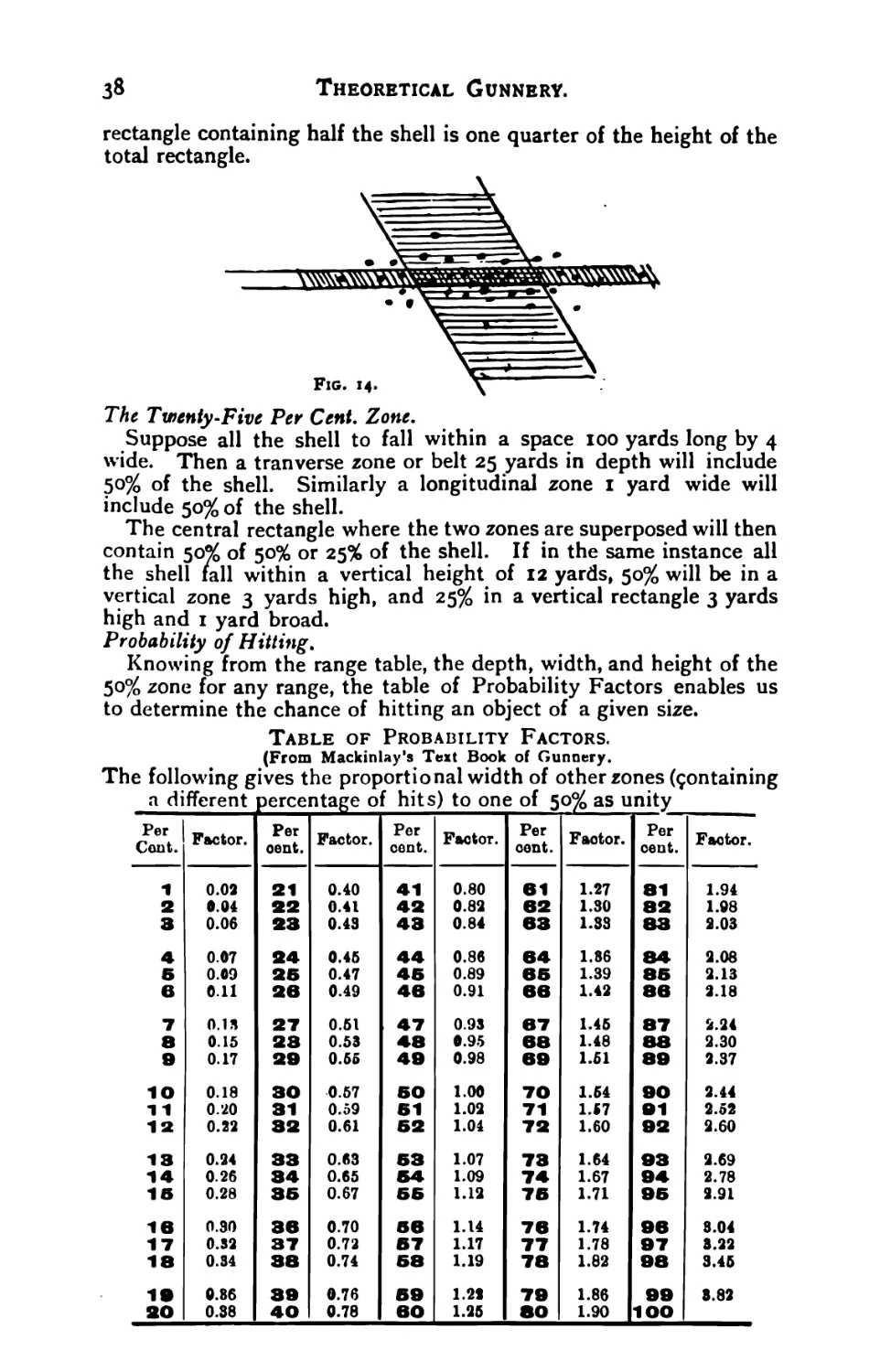
Causes of inaccuracy.—Sheaf of fire.—Total rectangle.—Vertical rec-
tangle.—Battery rectangle.—Fifty per cent zone.—Twenty-five per cent
zone.—Probability of Hitting.—Examples, 18 pr.—Examples, French
gun.—‘Probability of hitting the wagon.
УШ.
Contents.
CHAPTER VI.
Deflection of Projectiles by Wind.
Sir George Greenhill’s method.—Example, 15 pr. Q.F. gun.—Hard-
castle’s chart.—Examples.
CHAPTER VII.
Recoil.
Recoil velocity.—Recoil energy.—Theory of Q.F. gun.—Weight of
charge.—Example, 15 pr. Q.F. gun.—Example, 18 pr. —Period at which
shell leaves the innzzle.—Stability of the carriage.—Diagram of Steadi-
ness.—Curve of buffer-resistance.—Running-up pressure.—Steadiness
during the run-up.—Adjustment of stability. >
PART II.
PRINCIPLES OF CONSTRUCTION OF GUNS,
CARRIAGES, AND AMMUNITION.
CHAPTER VIII.
Ordnance Materials. S ~
Steel—Hardening.—Tempering.—Natures of steel.—Gun steel.—
Carriage steel.—Spring steel.—Shell steel.—Shield steel. - Composition
of steel.-Steel a>lo)s.—Steel tests.—Static and dynamic tests.—Self-
registering testing machines.—Treatment and tests.—Erosion.—Bronzes.
— fable of Gun steels.
CHAPTER IX.
Principles of Construction of Guns, г -
Interior dimensions.— Work done by powder.—Example, design of
high-velocitv field gun.—Muzzle energy.—Pressures in bore.—Practical
methods.—Thickness of metal.—Elasticity.—Barlow’s Law.—Solid-
block gun.—The Barlow Curve.—Summation of Barlow Curve.—Two-
layer gun.—Diagram of Stresses.—Weight of two-layer gun.—Wire-
wound gun.—Diagiam of Stresses.—Partial wire-winding.—The Jacket.
— Weight of wne-wound gun.— Shrinkage.—Longitudinal tensions.—
Ehihardt system.
CHAPTER X.
Rifling. 1 г
System of rifling.—Object of rifling.—Advantages gained.—Twist of
rifling.—Minimum twist. —Uniform and increasing twist.— Position of
driving band. - Forward steadying band.—French band.—Drift. - Theory
of drift.—Persistence of spin.—Flight of a howitzer shell.—Kiting,
Contents.
ix.
CHAPTER XI.
Sights. ‘ !
Theory of sights.—Deflection Drift.—Level of wheels.—Scott’s sight.
Reciprocation.—Modem Q.F. sights.—Arc sight.—Fuze corrector.—
Deflection scale.— Reciprocating sights.—Krupp arc sight.—Telescopic
sights.—The rocking bar sight.—Ehrhardt traversing foresight.—The
dial sight.—The pedestal sight.—The collimateur.—The Ghost sight.—
The Goerz panorama sight.—The Zeiss ziz-zag sight.—The independent
line of sight.—Scott’s automatic sight.—Krupp’s sights.—Clinometers.—
The director.—The field plotter. —Combined plotter and director.—
The Baumann plotter.— Rangefinding with the director.
CHAPTER XII.
Breech Actions. g
The interrupted screw.—The conical breech-screw —The ogival
breech-screw.—The Welin screw.—The Bethlehem screw.—The single
motion cylindrical screw.—Pitch of screw.—The Wedge.— Details of
wedge.—The Ehrhardt wedge.—The eccentric screw.—The falling block.
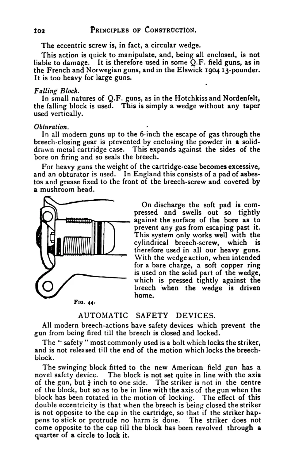
Obturation.—Automatic safety devices.—The eccentric block.—Firing
gear.—Semi-automatic breech mechanisms.—The Krupp automatic
breech action.—Relative merits of different breech actions.
CHAPTER XIII.
Principles of Construction of Carriages. ' a t
Duti s required of carriage.—The trail.—The axletree.—Cranked
axletree.—The wheels.—Clearance.—Second limber hook.—Detach-
ments.—Weight on wheels—Balance.—Ammunition.—Materials of
limbers and wagons.—Draught.—Springs.—Spring draught.—Spring
limber hook.
CHAPTER XIV.
The Gun-Recoil Carriage.
General principles.—Action on recoil.—Cross strains.—Various types
of carriage.—Top-buffer carriages.—Effect of wear.—Attachment of
buffer.—Position of buffer.— Height of wheels.—Trail angle.—Modern
requirements as regards steadiness.— Recoil gear.—The cradle.—The
hydraulic buffer.—Different patterns of buffer.—Air-spacing.—Pneumatic
attachment of piston rod.—The check buffer.—The Russian buffer.—
The French buffer.—The pneumatic buffer.—The running-up valve.—
The running-up springs.—Reduced spring-stroke—German springs.—
Krupp springs.—Telescopic springs. —Breakage of springs.—Waves of
compression.—Internal springs.— Compressed air running-up gear.—
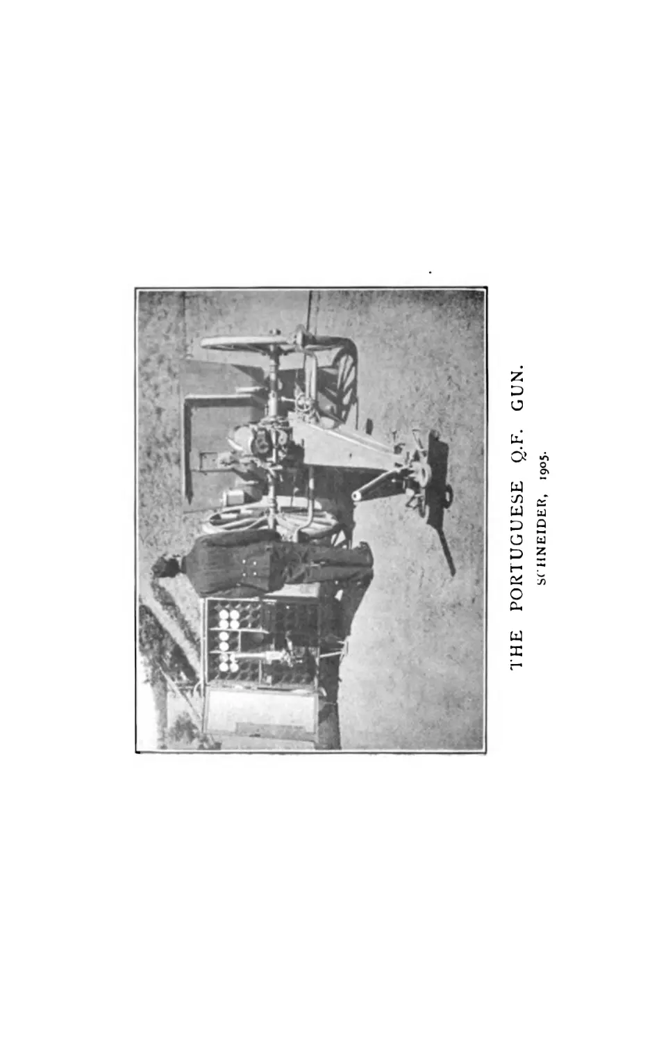
Hydro-pneumatic recoil gear.—The Schneider gear.—Later patterns of
Schneider gear.—Serviceability of compressed air gear.—The brakes and
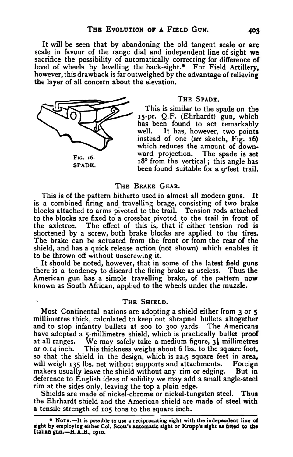
spade.—American, German and French brakes.—The spade.
Contents.
CHAPTER XV.
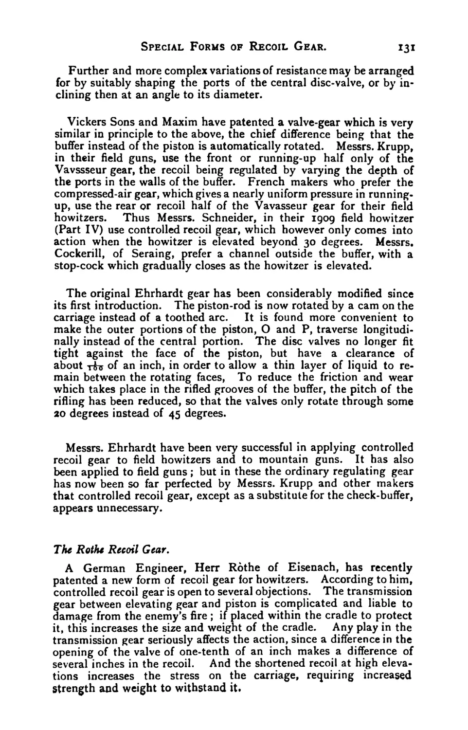
Special Forms of Recoil Gear.
Controlled recoil.—The Vavasseur valve.—The Ehrhardt-Vavasseur
gear.—Krupp and Vickers Maxim gear.—Modified Ehrhardt gear.—The
Rothe recoil gear.—Differential recoil.—Theory of differential gear.—
Practical objections. —Instances of its application.—The Deport pneu-
matic gear.—Details of Deport buffer.—Curved recoil.—Swinging re-
coil.
CHAPTER XVI.
Elevating and Traversing Gbar. j 7
Limits of elevation and traverse.—The telescopic elevating screw.—
The Krupp super-elevation gear.—The Schneider cranked axletree.—
Traversing gear.—The upper carriage.—The Krupp saddle.—The axle-
tree pivot.—The swinging pivot.—The traversing screw.—The French
axle-traversing gear.—Relative merits of different systems.
CHAPTER XVII.
The Shibld. z 3
Object of shield.—Table of penetration, S. bullet.—Height of shield.—
Slope of shield.—Shields for axle-traversing equipments.-—Visibility.—
The wagon shield.—Shell versus shield.—Armour-piercing bullets.—
CHAPTER XVIII.
Principles of Construction of Ammunition. ' "
Fixed ammunition.—The powder.—Cordite.—Ballistite.—Tubular
powder.—Tape and strip powder.—Disc powder.—Tablet powder.—
Ammonia powder.—Continental powders.—Detonation.—Partial detona-
tion.—Action of smokeless powder.—Sizes of smokeless powder.—
Primers.—Effect of temperature on ballistics.—Keeping qualities.—High
Explosives.— Lyddite. —Melinite. —Shimos6. — Ammonal. — Ammonal
powders.—Schneiderite —Trinitrotoluol.—Trotyl.— Triplastite.—Cresy-
lite.—Trinitro cresol.—Pertite.—Ecrasite.—Nitro-guanidin.—Continent-
al shell powders.—The shell.—Shrapnel.—Details of construction.—
Bullets.—Useful weight.—Cordite shrapnel.—Smoke composition.—
The Wille shrapnel.—High-explosive shell.—Thick-walled shell.—Mine
shell.—Progressive detonation.—Combined shrapnel and H.E. shell.—
French experiments.—The Ehrhardt H.E. shrapnel.—The Ehrhardt
scatter shell.—The Krupp H.E. shrapnel.—Pointed shell.—The driving
band.—Effect on ammunition boxes.—Incendiary effect.—Fuzes.—The
double-banked fuze.—The French time fuze.—Fuzes for H.E. shell.—
The Bofors fuze.—Mechanical fuzes.—The Berdan fuze.—The flag
fuze.—The gyroscope fuze.—The Semple tracer.
&>NTENT$.
XI.
CHAPTER XIX.
The Q.F. Field Howitzer. j 7
Definition.—Tactical employment.—Construction.—Calibre.—Rifling.
—Breech mechanism.—Sights.—Firing gear.—The carriage.—Steadi-
ness.—Length of recoil.—Controlled recoil.—Rear trunnions.—Travers-
ing gear.—Elevating gear.—Buffer and springs.—Compressed air gear.
The spade.—The limber.—The wagon.—The high-angle howitzer.—The
mountain howitzer.— Ammunition.— Shrapnel.—Driving charge.—
Weight of bullets.—High-explosive shell.—Fuzes.—Cartridges.—Divi-
ded charges.—Powder.—Driving band.—Probability of hitting.
CHAPTER XX.
Tub Q.F. Mountain Gun. ; C-
Weight and^dimensions.—Mule loads.—Limits of weight and length.
—Power of gun.—Jointed guns.—The Krupp sleigh.—Number of loads.—
Calibre.—Construction.—Sights.—Cranked axletree.—Cradle.—Trail.—
Spade.—Wheels.—Elevating and traversing gear.—Shafts.—Shield.—
Saddles.—The mountain howitzer.—Ballistics.—Jointed howitzer.—
Methods of finding space for recoil.
CHAPTER XXI.
Thb Q.F. Balloon Gun. t K
Employment of dirigibles and aeroplanes.—Design of guns to be carried
by air-ships.—Ammunition.—Air-ship mountings.
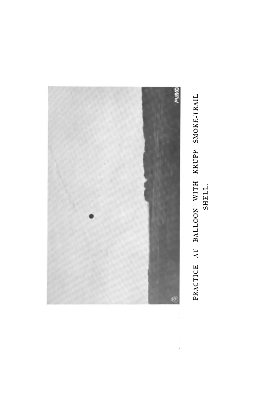
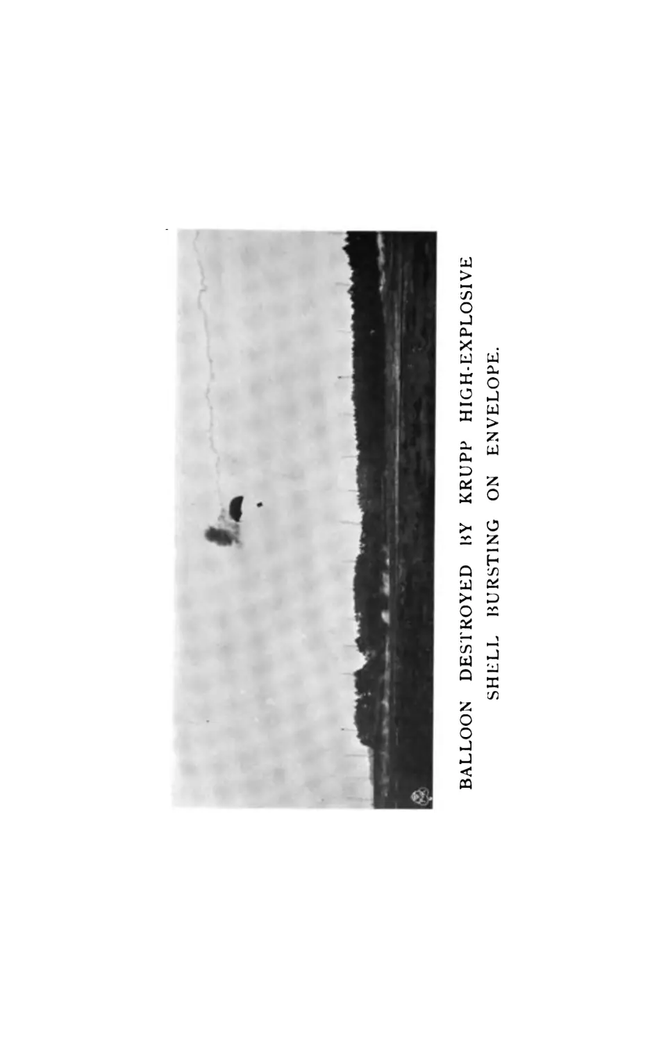
Guns for the attack of air-ships.—Nature of target.—Effect of shrap-
nel.—Smoke-trail shell.— Incendiary shell.—High-explosive shell.—
Effect on balloons and aeroplanes.—Sensitive fuzes.—Types of fuze.—
Probability of hitting.—The Krupp balloon guns.—The Ehrhardt
balloon guns.—Sights.—Correcting gear.—French experiments.—Dan-
ger to our own troops.
PART III.
PRACTICAL GUNNERY.
CHAPTER XXII.
The Choice of a Position. / Q3
Good and bad position.—Forward crest.—Rear crest.—Cover for lim-
bers and wagons.—Field entrenchments.—Dummy Entrenchments.—
Concealment of flash.—Positions for indirect fire.—Forward and retired
covered positions.—Command of the foreground.—The observing position.
л
Xll.
content’s.
CHAPTER XXIII
The Occupation of a Position.
Intervals.—Types of position.—Cover from view.—Direct occupa-
tion.—Special method.—Selection and distribution of target.—Concent-
ration.—Cross fire.
CHAPTER XXIV.
Shrapnel Fire.
Angle of Opening.—Velocity of bullets.—Distribution of bullets.—
Air resistance.—Effect of range on angle of opening.—Minimum angle.—
The bullet-cage.
Weight of Bullets.
Disabling energy.—Stopping power.—German and English estimates.
— Effective distance.—Ballistic coefficient of bullets.—Minimum weight.
—Japanese and Swiss bullets.—Special bullets.—Pressing-in bullets.
The Bullet Cone.
Comparison of English and French guns.—Density.—Angle of descent
High versus low velocity. — Length of cone.—Angle of cone.—Raising
the trajectory.—Light versus heavy shell.—Correct proportion of
weight to velocity.—Searching power with flat trajectory.
CHAPTER XXV.
Indirect Laying.
General Remarks.—Fire from behind cover.—Theory of angle of sight.
Aiming points.—Observing position.— Measuring the range.—Finding
the line.—Use of director.—The compass.—Parallel lines of fire.—Dis-
tribution and concentration.—Switching.—Laying by map and the sun.
Laying on a search-light.—Practical application of principles.—Duties
of battery leader.—Preliminary line.—Normal procedure in coming into
action.
CHAPTER XXVI.
Ranging.
Theory of ranging.—Practical rules—Creeping.—Ranging traps.—
Study of ground.—Selection of ranging point.—The kite.—Ranging with
time shrapnel.—Crossed bursts.—French method.
Finding the Fuze.
Continental and English methods.—The fuze echelon.—Principles of
fuzing.— Height of burst.—Deep and shallow targets.—Raising the
point of burst.—Shielded guns.—Distance of burst.—Area of targets.—
Practical rules.—Velocity of sound.—Searching and sweeping.—Regis-
tered areas.
CONTENTS.
xiii.
CHAPTER XXVII.
Field Howitzer Fire.
General principles.—Choice and occupation of position.—Ranging.—
Selection of charge.—Height of burst.—Craters.—Observation and
correction of fire.—Siege work.
CHAPTER XXVIII.
The French System of Fire-Discipline.
The French equipment.—Fire discipline.—Rafales.—Preparation.—
Ranging.—Tir progressif et fauchant.—Echelonnement.—Change of
target.—Moving targets. —Deliberate methods.—Registered areas.—
Close support of infantry.—Merits and demerits of system.—Duties of
battery commander.—Duties of gunners.—Effect produced by tir pro-
gressif.
CHAPTER XXIX.
Visibility.
Appearance of natural objects.—Immobility.—Sky-line.—Symmetry
of shape and order.—Time of exposure.—Application of principles.—
Visibility of guns and wagons.—Smokeless powder.—Visibility of
flash.—Dust.—Artificial cover.
CHAPTER XXX.
The Analysis of Practice Reports.
Specimen report.—Analysis.—Mean range found by the guns.—Error
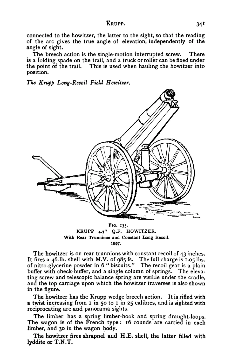
of individual guns.—Analysis of fuzes.
PART IV.
MODERN Q.F. EQUIPMENTS.
CHAPTER XXXI.
Modern Q.F. Firing Guns.
Weight of gun and carriage.—Muzzle energy.—Weight of shell.—
Recoil gear.—Traversing gear.—Sights.—Wheels.—Springs.—Shields.
—H.E. shell.—Shrapnel bullets.—Organization.
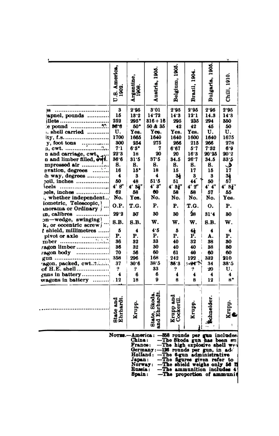
CHAPTER XXXII.
Q.F. Equipments of Different Nations.
England.— France.— Germany.— Austria.— Russia.— Switzerland.—
I taly.—Spain.- - Portugal.—G reece. —Turkey. —Morocco. —Bulgaria.—
Servia.—Montenegro.— Roumania.—Norway. —Sweden. — Denmark.—
Holland.—Belgium.—Persia.—China.—Japan.—United States.—Mexi-
co.—Brazil.—Argentine Republic.—Chili.—Peru.—Uruguay,
xtv. CONTENTS.
CHAPTER XXXIII.
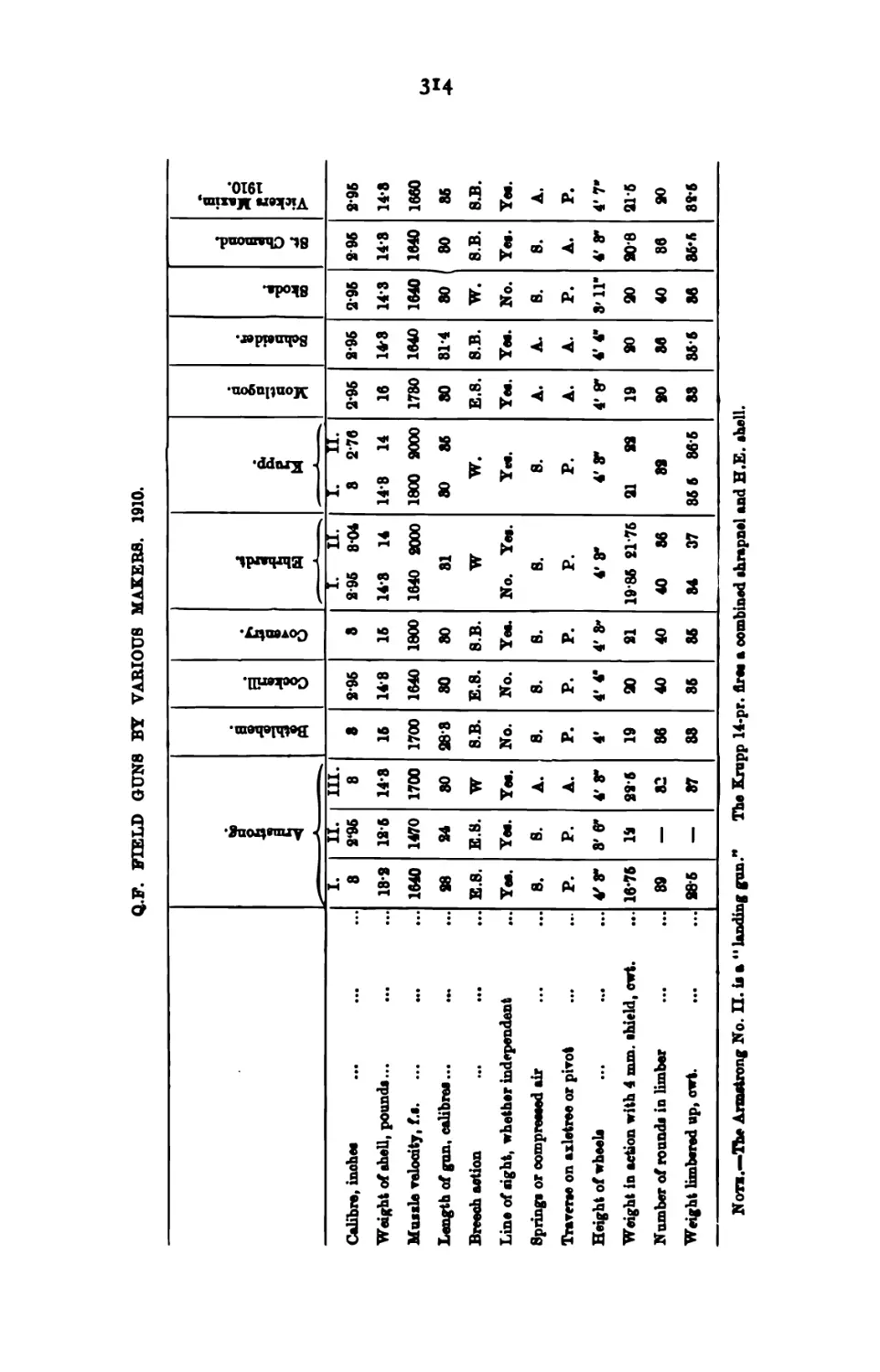
Q.F. Field Gun Equipments by Different Makers.
Armstrong.—Vickers Maxim.—Coventry.—Schneider.—MontluQon.—
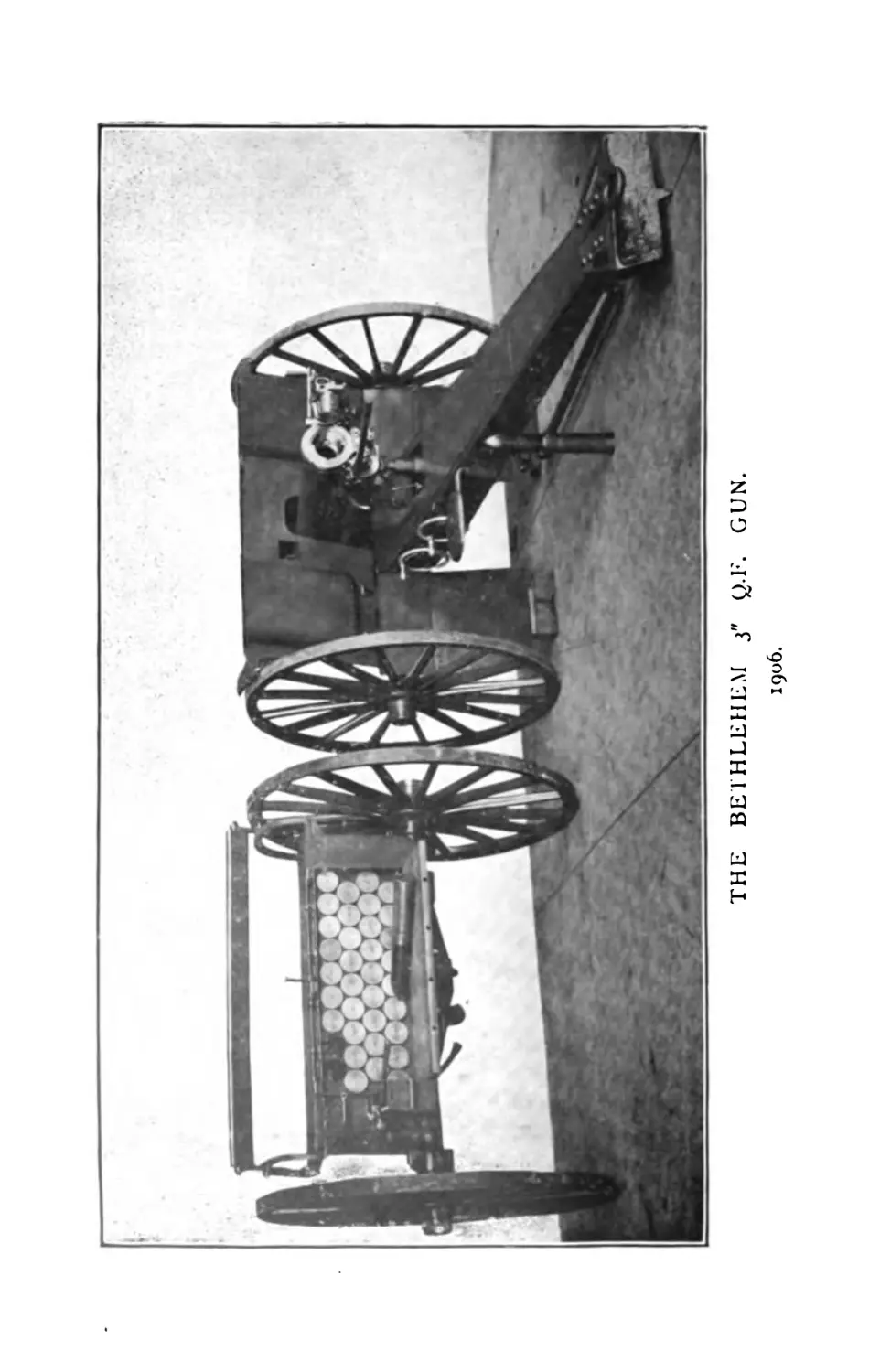
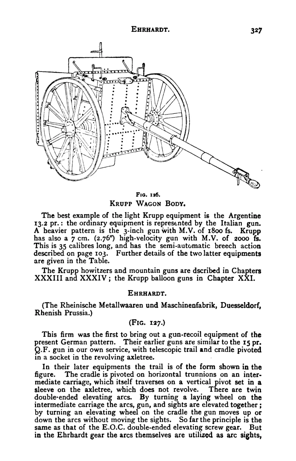
St. Chamond.—Bethlehem.—Cockerill.—Krupp.—Ehrhardt.—Skoda.
CHAPTER XXXIV.
Q.F. Field Howitzer Equipments
Controlled recoil.—Rear trunnion.—Cranked axletree.—Differential
recoil.—Compressed air.—Krupp and Schneider H.P. gear.—Vickers
Maxim.—Coventry.—Schneider.—Krupp.—Ehrhardt.—Cockerill.—Sko-
da.—St. Chamond.
Howitzer Equipments of Different Nations.
England.—France.—Germany.— Russia.—Italy.—Austria.— Switzer-
land.—Spain.—Belgium.
CHAPTER XXXV.
Q.F. Mountain Equipments.
General remarks.—Power of gun.—Vickers Maxim.—Montlufon.—
Schneider.—Krupp.—Krupp semi-automatic.—Krupp differential recoil.
Krupp sights.—Ehrhardt.—Skoda.—Bethlehem.
The Q.F. Mountain Howitzer.
General remarks.—Krupp.—Vickers Maxim.—Coventry.
Q.F. Mountain Equipments of Different Nations.
France.—Germany.—Austria.—Russia.—Italy.— Spain.—Portugal.—
Japan.
CHAPTER XXXVI.
Ballistics of Modern Guns.
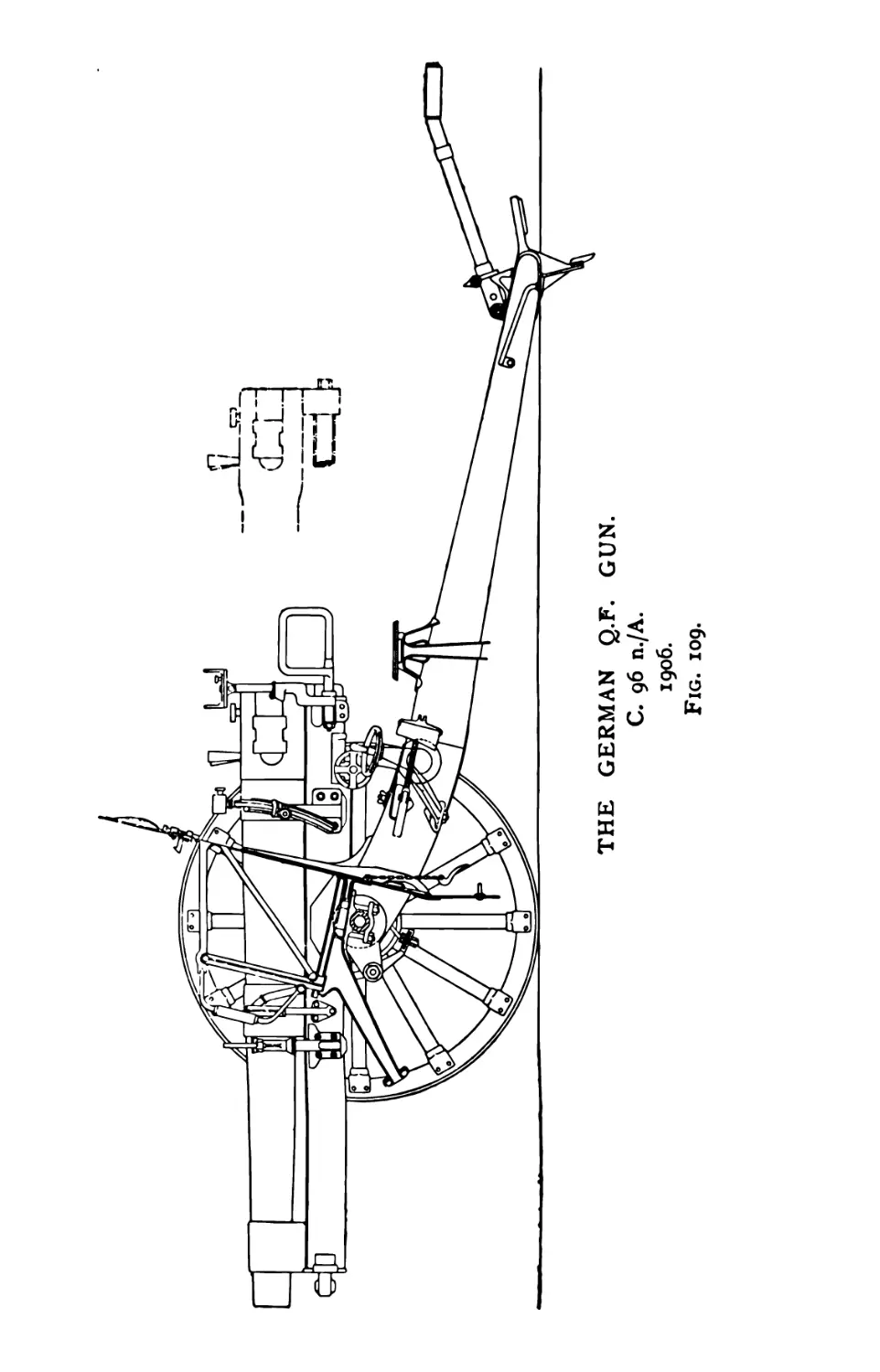
15 Pr- QF-—French 75 mm.—German C 96 n/A.—Krupp 76.2 mm.—
Krupp 75 mm.—Schneider 75 mm.—Russian 1903 gun.—Swiss gun.—
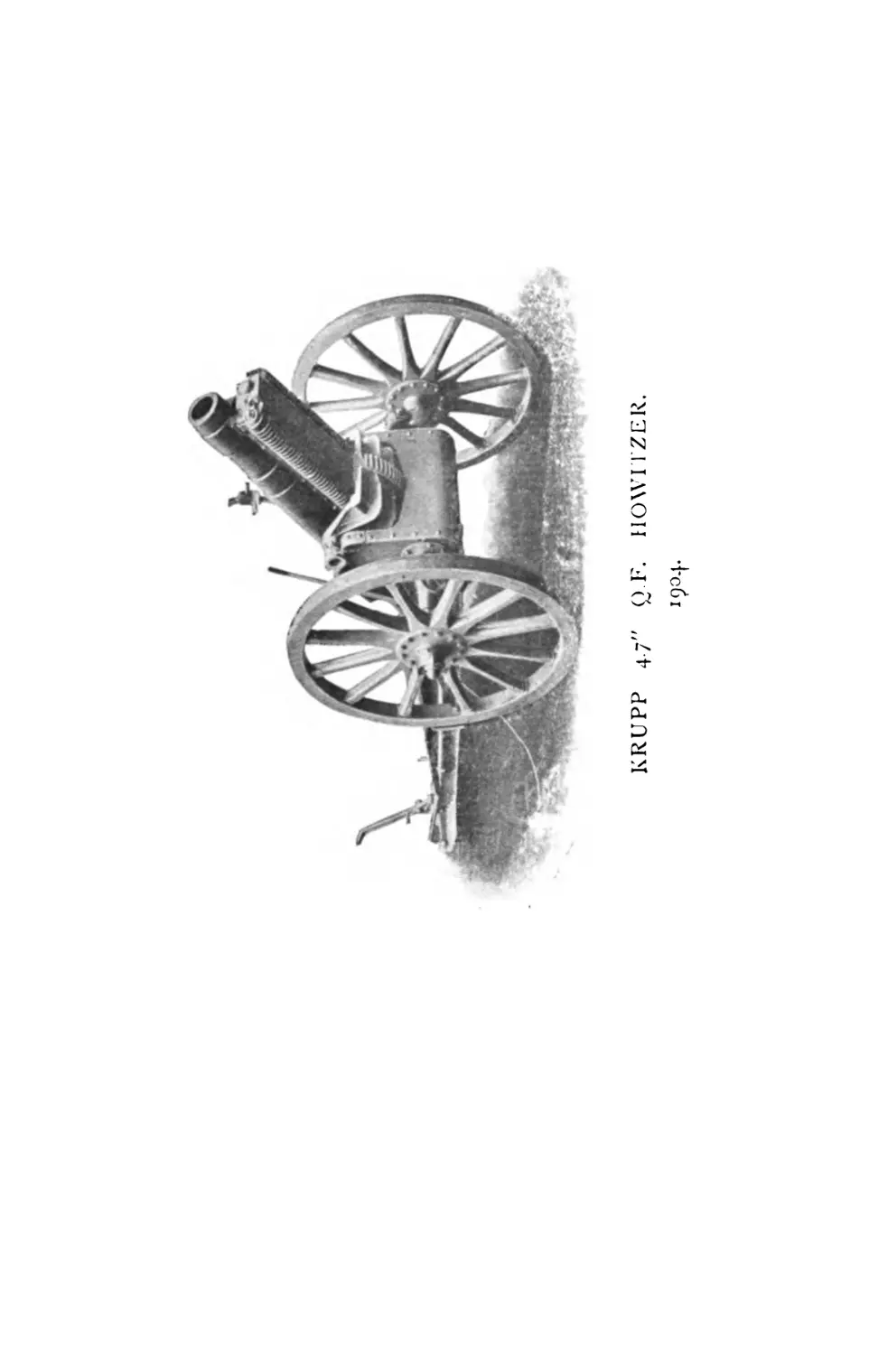
American gun.—Guns at Argentine trials.—Dutch gun.—Krupp 4.7*
Howitzer.—Italian Krupp gun.—Italian mountain gun.—Krupp gun and
howitzer.
PART V.
GUNNERY CALCULATIONS.
CHAPTER XXXVII.
The plotting chart.—Use in compiling range table. Graphic method.
Trigonometrical tables.—Mensuration —Logarithms.—The slide rule.
APPENDIX.
The Evolution of a Field Gun.
TABLES.
Weight and Strength of Materials.
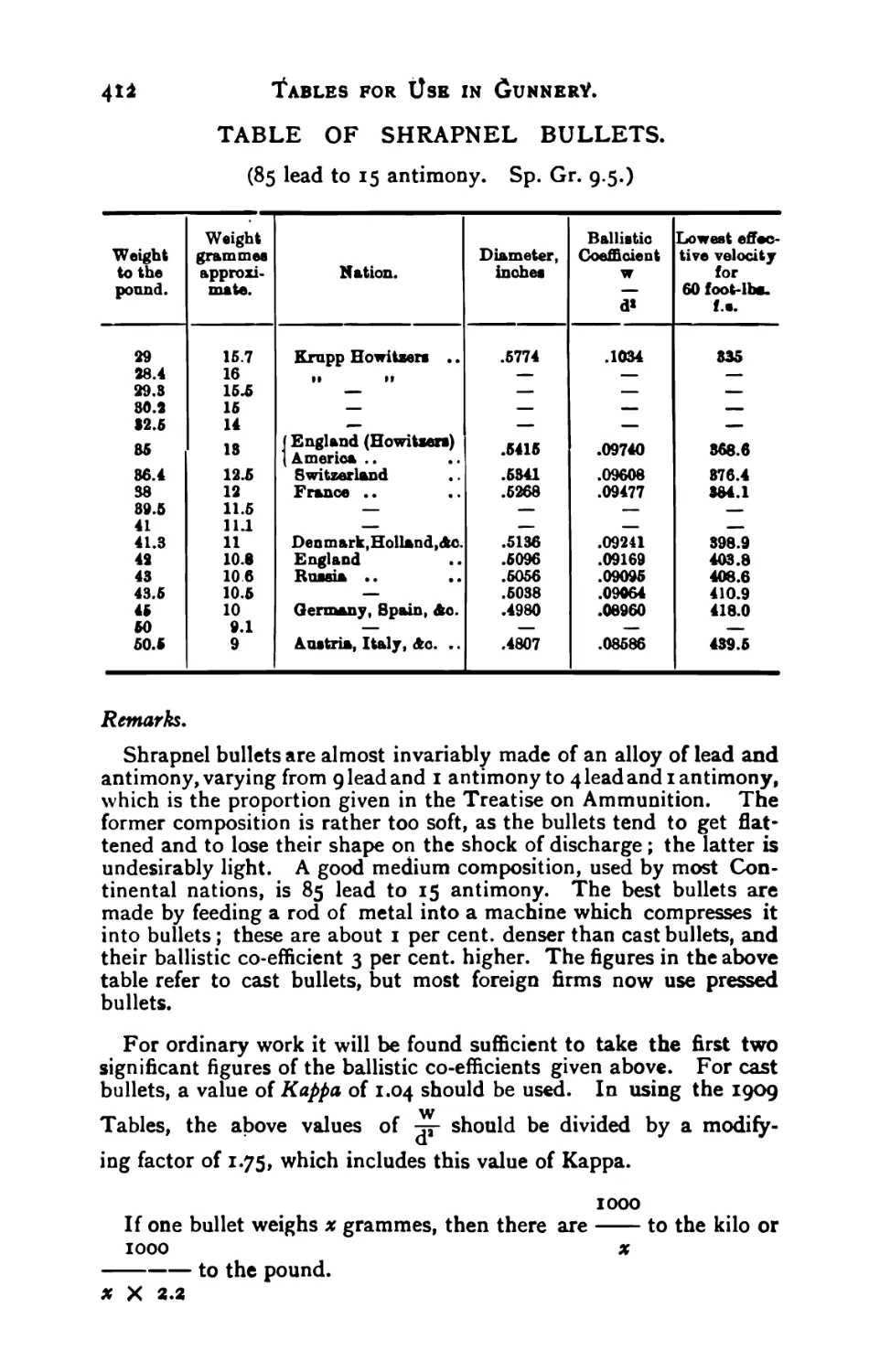
Shrapnel bullets.—Angles expressed by the relation of height to base.
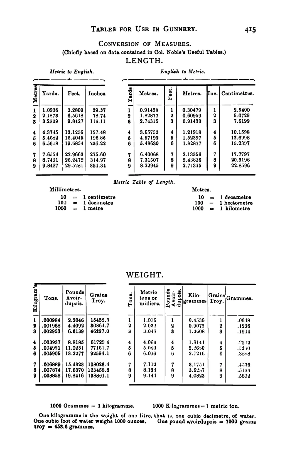
Slopes and angles.—Metric tables.—Four-figure logarithms,
Part 1.
THEORETICAL GUNNERY.
I
CHAPTER I.
INTERNAL BALLISTICS.
Gunnery.
Gunnery is the science of directing a projectile so that it will strike
a given target.
To master the science, it is necessary to understand the general
construction of the gun and carriage and the cartridge which jointly
impart the motion to the projectile, and the working of the laws
which govern this motion.
The Gun.
The gun serves two purposes. First, to confine the powder-gases
so as to allow them to act upon the base of the shell; and second, to
give the shell the proper direction.
As the powder charge burns, it is converted into gas of greatly
increased volume. This gas, in its endeavour to expand, presses
upon the base of the shell and drives it up the bore. So long as it
continues to exert a forward pressure upon the base of the shell, it
continues to accelerate the motion of the shell, and the velocity of
the latter goes on increasing until it passes out of the muzzle, and
the pressure on its base ceases.
Capacity of Gun.
We should get the greatest possible effect out of a charge of
powder if the gun were made long enough to contain the whole of
the powder gases, so that the forward pressure on the base of the
shell would cease just as the shell reached the muzzle. Such a gun
would however be unwieldy, and in practice we cut the gun short
and allow a good deal of the gas-pressure to go to waste out of the
muzzle.
Length of Gun.
The length of a gun is expressed by the number of calibres in its
total external length. A Q.F. field gun is from 27 to 35 calibres long.
A calibre is the diameter of the bore measured between opposite ribs
of the rifling. Generally speaking, the bore is measured from the face
of the breech-block to the muzzle»
в
2
Theoretical Gunnery.
Chamber of Gun.
The bore of a gun is divided, for the purpose of internal ballistics
only, into two parts, the chamber and the bore proper. The powder
does not completely fill the chamber, nor is it a solid mass; if a
charge of cordite were compressed into a solid block it would be
found to fill only about one-third of the chamber. On ignition the
powder-gases first fill the chamber, and more and more gas is gener-
ted by the burning of the charge until the pressure in the chamber
overcomes the resistance of the driving band, and the shell begins to
move. This, in a field gun, occurs when the pressure rises to about
tons to the square inch. Henceforward the powder-pressure acts
as an accelerating force upon the shell till the latter leaves the
muzzle.
Work done by the Powder.
Powder, when ignited, acts in two ways. In the first place it is
converted it into a volume of gas greater than that of the powder: in
the second place the heat of the explosion further increases the
volume of this gas, and so its pressure. Up to the point when the
shell moves, the powder-gases only expand so as to nil the chamber,
and do no work on the shell; during their expansion from the volume
of the chamber to the volume of the whole of the inside of the gun
they expend their energy, or part of it, on increasing the velocity of
the shell. Hence, to find the amount of work done by the charge of
powder on the shell, we find, by comparison writh a standard arrived
at by experiment, the amount of energy developed in expanding to
the full capacity of the gun, including the chamber, and deduct from
this the energy developed in expanding to the capacity of the chamber
alone.
Pressure in Bore.
Forty years ago the only explosive used in guns was coarse black
powder. The whole of the charge was converted into gas almost
immediately on ignition, thus developing a very heavy pressure in
the powder-chamber, w hich rapidly fell as the shell moved up the
bore. Guns of this period were therefore made of a very pronounced
bottle shape, enormously thick at the breech.
As an improvement on this, pebble powder was devised. This
consisted of cubical grains of from | inch to if inches. These burnt
more slowly, giving a less pressure at the start and a better-main-
tained pressure as the shell travelled up the bore. Guns were then
made thinner at the breech and thicker towards the muzzle.
Prismatic powder, pressed into large six-sided prisms, was the next
step; this was followed by slow-burning brown powder, known as
cocoa powder.
Now we have smokeless powder, in thick cords, tubes or tapes for
long guns and fine strings for short ones. This has enabled us to
adjust the pressures in the bore so as to get the maximum of work
out of the gun w ith the minimum of metal.
Internal Ballistics.
3
A simple and convenient means of showing graphically the pressure
in any gun is by the use of pressure curves.
Fig. i gives the curve for the 12* R.M.L. gun, using black powder.
Here the height of the curve represents the pressure in tons at that
particular point in the bore. We note how the pressure rises from
о to 24 tons per square inch before the shell begins to move, and
runs up to 25 tons before the shell has travelled half its length. The
pressure then rapidly falls, till at the muzzle it is only 3 tons per
square inch.
Fig. 2.
As a contrast to this, the curve for the 6 inch Q.F. gun (Fig 2)
shows a pressure which nowhere exceeds 15 tons on the square inch
and which diminishes gradually towards the muzzle. We may also
note how in each gun the shape or profile of the gun corresponds
with the curve of powder-pressure.
4 Theoretical Gunnery.
Crusher Gauges.
To discover the amount of the pressure at different points in the
bore by practical experiment, crusher-gauges are used.
An experimental gun is bored with holes say a foot apart all the
way down, extending through into the bore. Into each hole is
screwed a crusher-gauge, consisting essentially of a piston with a soft
copper plug behind it. As the shell travels up the bore, each piston
in turn is exposed to the pressure of the gases and forced back,
compressing the plug behind it. By measuring the amount of the
compression of each plug, the pressure to which it was exposed can
be determined with remarkable accuracy.
Noble's Chronoscope.
The crusher-gauges affords a means of measuring the pressure at
any point in the Ьюге. To measure the velocity, the chronoscope
is used.
Instead of the crusher-gauges, cutter plugs are inserted into the
holes in the gun. Each plug has an electric wire passing through*
it, and a knife, of which the back projects into the bore. When the
shell passes the plug, it forces in the knife and cuts the wire. This
interruption of the circuit causes an electric spark to pass at another
point in the circuit.
О To record the instant at which
this takes place, a brass disc
some 30 inches in circumference
is revolved at a great speed. The
edge of the disc is smoked.
"P Each interruption of current as
A the shell passes a cutter-plug
3 causes a spark to pass between
I the point P and the disc, burning
3 a hole in the coating of smoke-
black. The velocity of rotation
of the disc being known, it is
Fig. 3. only necessary to measure the
distance between the marks left by the sparks to know the time that
elapsed between them.
To avoid confusion, a row of discs fixed on the same axle, one for
each cutter-plug, is used.
The Explosion Vessel.
The powder-pressure at any point within a gun may be determined
by the use of crusher-gauges and cutter-plugs. But the explosion
vessel enables the pressures to be determined more conveniently and
with greater accuracy. It consists of a steel cylinder, bound with
wire to strengthen it, closed by a screw plug. A given charge of cor-
dite is placed in this and ignited electrically. The resulting explosion
occupies an an appreciable time—say of a second—before the
cordite is all consumed. A pressure-gauge is connected with the
vessel, which records the rise of pressure during the time of explosion
on a drum, in the same manner as a self-registering barometer. The
Internal Ballistics.
5
curve obtained on the drum is about 100 millimetres long, and can
be read to i millimetre or less, giving the pressure for every of
a second. Knowing the capacity of the vessel, the rise of pressure
in a gun of given calibre, the capacity of which alters as tne shell
travels up the bore, can be calculated mathematically.
Since the time which cordite takes to burn, at a given temperature
and pressure, varies according to the thickness of the cord, it is
possible to deduce, from results obtained with cordite of a given size,
the size of cordite which will give suitable pressures in a certain gun.
This method of determining internal ballistics is due to Major
J. H. Mansell, R.A. <
The Boulenge Chronograph.
This instrument is used for measuring the velocity of the shell
after leaving the muzzle. Two screens are placed one behind the
other in the path of the shell, say 80 feet apart, and sufficiently far
off to be clear of the blast of the gun. Each screen has an electric
wire stretched backward and forwards across it so that when the
shell passes through the screen the circuit is broken.
Let R be a rod suspended
from an electro-magnet. When
the shell passes the first screen
the circuit is broken and the
rod begins to fall. When the
shell passes through the second
screen the break of circuit re-
leases the knife K, which makes
a nick N on the falling rod.
Since the force of gravity does
not vary, the rod falls at the
same speed every time, and it
is only necessary to measure
the distance of the nick up the
rod with a suitable scale in order
to know the time taken by the
shell to travel from one screen
to the other.
Disjunctor.
To allow for the time taken
N* for the knife to act after the
К circuit is broken at the second
screen, the disjunctor is used.
This is simply a contrivance for
I (J breaking both screen-circuits
Fig. 4. simultaneously. The rod then
falls a short distance before the knife has time to act, making a nick
at N'. The distance NN' is thus the true measure of the time taken
by the shell between the two screens. The distance up the rod
of the nick N' is known as the disjunctor reading.
6 Theoretical Gunnery.
Sebert's Velocimeter.
This is a simple apparatus for measuring the velocity of recoil of a
gun. A bristle fixed to a vibrating tuning-fork is made to brush
against the smoked surface of a strip of steel attached to the gun.
When the ^un recoils, the bristle traces a wavy line on the smoked
surface. Since we know the rate of vibration of the tuning-fork, it
is only necessary to count the waves to determine the speed of recoil.
Thus if the wavy line be four feet long, it shows that the gun has
recoiled through that distance. If the tuning-fork used vibrates 500
times per second, and 100 waves are counted on the smoked surface,
then the gun took two-tenths of a second to recoil; if ten waves are
counted on the first six inches of the line, then the recoil-velocity
over the first six inches was 25 feet per second.
The Buffer-gauge.
The hydraulic buffer of a long-recoil gun is designed to produce a
perfectly regulated resistance throughout the recoil. For the purpose
of adjusting the pressure in the buffer, which constitutes the resist-
ance to recoil, the buffer-gauge is used.
This consists in principle of a pressure-gauge in which an indicator
is forced upwards against a spring. A special hollow piston-rod is
inserted in the buffer and the gauge screwed on to the outer end of
it. A long strip of smoked sheet metal is attached to the gun, so
that as the gun recoils the indicator traces a line upon it. If the
pressure is uniform during recoil, the indicator remains at the same
height, and traces a straight horizontal line; if the pressure is
irregular the indicator goes up and down, producing a wavy line. If
this is found to be the case, the buffer must be regulated by altering
the windage between buffer and piston at different points till the
indicator traces a curve corresponding to the graduated pressure
required. This, in practice, is effected by altering the depth of the
channels or grooves in the inner walls of the buffer (called ports)
through which the liquid flows past the piston.
A difference of ris inch in the depth of the ports is found to pro-
duce a marked difference in the steadiness of the gun.
7
CHAPTER II.
THE UNIMPEDED MOTION OF A PROJECTILE.
Suppose a shell to be fired in vacuo in a horizontal direction with
a velocity of 1000 feet per second. Then its path will be determined
by the two forces acting on it, namely, the impetus of the shell, which
tends to carry it forward in the direction in whict it started; and
the force of gravity, which tends to pull it down to the earth.
We know that a falling body drops (neglecting decimals), i g<’, or—
16 : *....................
16 ;
16 :
16 :
16 ;
and so on.
X
X
X
X
X
i’ = 16 feet by the end of the first second.
2’ = 64
3’ = 144
4 = 256
5’ = 400
second
third
fourth
fifth
Then by the end of the first second, the shell will have travelled
1000 feet forwards and have dropped 16 feet downwards, so that its
position will be at A.
Fie. 6.
8
Theoretical Gunnery.
At the end of the next second it will have travelled another 1000
feet forward, and will have dropped altogether 64 feet, and its position
will be at В; and so on.
The path А, В, C of the shell is called the trajectory.
If the shell could be fired in a vacuum, as is imagined in the pre-
ceding paragraphs, the curve of the trajectory would be a parabola.
But in practice, as will be explained hereafter, the shape of the tra-
jectory is considerably modified by the resistance of the air.
Shell find vertically.
If a shell be fired straight up into the air, at a velocity of 1000 feet
per second, it will continue to fly upwards until the ever-increasing
downward velocity due to gravity exceeds 1000 feet per second, when
it will begin to fall.
To work this out practically we must use the formula.
Where V is the velocity, g the acceleration due to gravity, and t the
time in seconds. Now g is always the same, since the force of gravity
does not vary, and is equal to 32 feet (strictly 32.2 feet) per second.
Some confusion may arise in the learner’s mind between the 32
feet of acceleration due to gravity, and the 16 feet through which
a body drops in the first second.
Now if a body falls from rest, it falls faster and faster, until at the
end of the first second it is travelling at the rate of 32 feet per second.
This acceleration of velocity from о to 32 feet per second is “g,” and
every unsupported body gets an extra velocity of 32 feet imparted to
it by gravity every second. If the body be supported, then the effect
of gravity is to cause a continuous stress on the support.
It will be apparent on consideration that the distance through
which a body falls in the first second is not 32 feet, since the body
only attains that velocity at the end of the second. The distance
corresponds to the mean velocity of the body during that second,
which is half-way between о and 32, or 16 feet.
To return to the question of the shell fired vertically upwards.
As we have stated, V = gt, that is, for every second that the shell is
in the air it acquires an increasing downward velocity of 32 feet. At
the end of 10 seconds it will have acquired 320 feet per second down-
ward velocity; but since its impetus continues to drive it upwards at
1000 feet per second, its actual remaining upward velocity will be 680
feet per second.
At the end of 30 seconds its downward velocity will be 960 feet,
and at the end of 32 seconds, 1024; so that at some time in the
32nd second (actually at 31! seconds) the upward velocity will balance
the downward velocity, and the shell will begin to fall again. Thence-
forward the velocity will increase at 32 feet per second until the shell
eracbes the earth again.
The Unimpeded Motion of a Projectile. g
Its velocity on reaching the earth will be 3if X 32, or 1000 feet
per second, which we see is equal to that with which it started.
Elevation.
Since a shell is falling during the whole time of flight, then in order
to reach the target it must be directed at a point above the target.
The height of this point must be equal to the distance through which
the shell falls during the time of flight.
Thus if the shell be fired at an object 3000 feet distant with a velo-
city of 1000 feet per second, it will take 3 seconds to reach the target.
And since in 3 seconds the shell will fall 16 X 3’ = 144 feet,
therefore it must be directed at a point 144 feet above the target.
Since the parabola which a shell describes in vacuo is a regular
curve, with its ascending and descending branches alike, the greatest
height attained by the shell will be at a point half-way down the
range.
For simplicity, we will take the case of a shell with a M.V. of 1000
feet and a time of flight of 4 seconds. Then point A at which the
shell is aimed will be 16 X 4’ = 256 feet above the target, and point
C in the centre of the range will be 128 feet high. Half-way down
the range the shell will have been falling two seconds, and will be 64
feet below C, or 128—64=64 feet high. This is one-quarter of the
height of A, and this proposition holds good for any shell describing
to Theoretical Gunnery.
Since the height of A in feet is sixteen times the square of the time
of flight, therefore the greatest height attained by the shell is four
times the square of the time of flight, or
H = 4T.
This formula is given here because it is practically useful. At
medium ranges the first half of the trajectory of a field gun fired
under ordinary conditions is not very different from a parabola, and
the formula is sufficiently near the truth for practical purposes. The
time of flight is always known either from the range table or the fuze
scale, and this give us a ready means of determining the height of
the trajectory.
A shell which travels high above the earth to reach the target is
clearly ineffective against an enemy standing anywhere except at the
exact point where the shell pitches. On the other hand, a shell which
flies along comparatively close to the ground will strike a six-foot
man standing anywhere between the place where the shell pitches
and the point where the trajectory comes within six feet of the ground.
This space over which an enemy is liable to be struck by a projectile
fired at a given point is called the dangerous zone, and it is tne object
of the gun-designer to make this dangerous zone as deep as possible;
not so much on account of the shell as on account of the shrapnel
bullets which issue from it. This is secured by flatness of trajectory—
that is, by projecting the shell so that the height above the earth
which it reaches is as small as possible.
High Velocity.
Now we have seen that it is necessary to project a shell to a certain
height in order to reach a target in a given number of seconds. And
no human power can alter the height through which a shell falls in
a given time. To obtain a flat trajectory, therefore, all that we can
do is to reduce the time of flight as much as possible.
If in the foregoing example the velocity of the shell were 3000 feet
instead of 1000 feet per second, it would reach the target in one
second, and the greatest height, 4T1, would be 4 feet. If the velocity
were 1500 fs. the time of flight would be 2 seconds, and the greatest
height 16 feet, giving a dangerous zone of about 200 yards in front
of the target.
Thus we see that to procure a flat trajectory and deep dangerous
zone we must have a high velocity, enabling us to use a small angle
of elevation. When we consider the motion of projectiles in air we
The Unimpeded Motion of a Projectile.
ii
shall find that another important consideration is a high proportion
of weight of shell to cross section, which enables the shell to keep up
a high velocity in spite of the resistance of the air.
Angle of Descent.
Flatness of trajectory is estimated in practice by the smallness of
the angle of descent. The field gunner’s object is to burst his shrap-
nel so that the bullets do not pitch straight downwards into the
ground, but sweep along it, so as to produce good effect in spite of
inevitable errors of range. For this he requires a small angle of
descent, which is only possible with a high muzzle velocity.
Figure io shews the trajectory of the Russian 1900 gun, firing a
shell of 14.48 lbs. with M.V. 1930 fs., compared with that of the
Swiss gun, shell 14 lbs. and M.V. 1590 fs. Figure 9 shews the
effect of high and low muzzle velocity upon the trajectory for equal
times of flight.
Greatest Possible Range.
The greatest possible range in vacuo is obtained when the angle of
elevation is 45 degrees. When fired in air the angle giving the
greatest range is not materially different, being between 40 and 43
degrees. Little is gained in range by increasing the angle of eleva-
tion beyond 350.
12
CHAPTER III.
THE MOTION OF A PROJECTILE IN AIR.
A projectile travelling through the air experiences a certain resis-
tance, which shortens the distance of its flight and alters the shape
of the trajectory. This resistance is greater at high than at low
velocities, but the rate of increase does not follow any simple rule.
The Motion of a Projectile in Air. 13
Up to about 800 feet per second it increases as the square of the
velocity ; that is, a shell travelling at 300 feet per second experiences
9 times as much resistance as one travelling at 100 feet per second.
Above 800 fs. the resistance increases in a higher ratio. For veloci-
ties between 1000 and 2500 feet per second the resistance may be
said to increase roughly as the cube of the velocity.
The accompanying Table shows the resistance in pounds which
the air offers to a projectile one inch in diameter, travelling at speeds
from о to 2800 feet per second.
It will be observed that the increase of resistance is by no means
regular. There is a marked kink in the curve between 1000 and
1150 fs., which latter figure happens to be the velocity of sound; and
another remarkable kink about 2413 fs., the velocity at which air
rushes into a vacuum. No scientific explanation of these phenomena
is as yet forthcoming. It may be noted that if the shell is travelling
at more than 2413 fs. it forms a vacuum behind it.
It will be readily understood that the resistance is in direct pro-
portion to the surface offered to the air, that is to the cross section
of the projectile. This is apparent, since two projectiles side by side,
each one square inch in cross section, will experience twice as much
resistance as one such projectile.
Shape of Head.
The resistance is affected in a marked decree by the shape of the
head of the shell. It is found that in a shell of the usual form the
shape of the shoulders is more important than that of the actual
point. It is suggested as an explanation of this that as the air
streams outward from the point to pass ever the shoulders of the
shell it leaves a partial vacuum in front of the point, while the main
air pressure comes near the shoulder. But when a shell with an
ogive of 5 or 6 calibres radius is used, the shape of the point becomes
important, as determining the stream lines, or direction of the
currents of air w hich flow over the shoulders of the shell.
14 Theoretical Gunnery.
Taking the resistance offered to a shell with hemispherical head at
i pound, it is found to be 0.83 lb. for No. 2, with a head struck with
a radius of 1 diameter. 0.78 lb. for No. 3, radius 2 diameters, and the
same for No. 4, which is No. 3 with the point rounded off. With
No. 5, the flat-headed shell, the resistance is nearly double, or 1.53
lbs. The curve of resistance given in the table was obtained with
the service shell of 35 years ago, having an ogival head struck with
a radius of diameter.
Very remarkable results have recently been obtained with so-called
pointed bullets and pointed shell, in which the cylindrical portion is
reduced to a minimum and the projectile is nearly all point. It is
Eossible by using very long points to reduce the resistance of the air
у as much as 50 per cent. The reasons why this form has not been
adopted for field shell are given in the chapter on Ammunition.
Smoothness.
It is also found that a modern smooth steel shell with driving-band
meets with less resistance than the old cast-iron studded shell which
were used in the 1879 experiments upon which our modern tables of
resistance are founded. This requires a modification in the tabular
figures for each different nature of shell.
Steadiness.
If a shell wobbles and travels shoulder first, its Cross section is
naturally larger, and the resistance it meets with greater, than if it
travelled point first. Modern Q.F. shell are steadier in flight than
B.L. and the old R.M.L., and another correction is required on this
account.
Taper-base shell.
The ideal shape of a shell intended to travel through the air with
the minimum of resistance is that of a Whitehead torpedo, with a
long tapering “ tail.” Theoretically, the shape of the base is more
important than that of the head—just as, in ship designing, a fine
run is found even more conducive to speed than a sharp entrance.
The flat sawed-off bottom of the service shell is objectionable for
several reasons. It forms a partial vacuum, behind it, causing an
unbalanced air-pressure on the head of the shell, and the air rusning
into this vacuum forms eddies which tend to unsteady the shell. It
would therefore appear desirable to introduce a more scientific form
of projectile. This idea was carried out successfully in the original
Whitworth solid shot, which was the first accurate artillery projectile
ever invented, But modern experiments have given less favourable
results. The Zalinski torpedo shell, fired from an air-gun, had a
habit of pitching in unexpected places. And at a trial carried out in
Switzerland in 1903 it was found that although the taper-base shell
ranged further than the ordinary pattern, they were decidedly in-
accurate in flight. It would, however, be a mistake to condemn a
theoretically sound design on the strength of a single experimental
series. The failure of the Swiss experiments only showed that
something was wrong—probably the twist of the rifling was unsuited
to these particular shell. It is to be hoped therefore, thatr in spite
The Motion of a Projectile in Air. 15
of the obvious manufacturing difficulties, modem science may evolve
a better shape of projectile than that of the cylindro-ogival shell
which forms our present equipment.
Density of Air.
When the barometer is high, the air is compressed and is denser
that when it is low; on the other hand, when the thermometer is
high the air expands and is less dense than when the temperature is
low. Since the resistance to a projectile is greater when the air is
denser, the pressure and temperature must be taken into account in
all accurate work, such as practice for range and accuracy.
Temperature.
Besides the effect of the temperature on the density of the air, it
has another and practically much more important action, namely its
effect upon the powder. All modern smokeless powders are com-
paratively sensitive to changes in temperature, and a rise in the
thermometer usually means an increase of muzzle velocity. The
amount of such increase varies for each particular size and sample of
fiowder, and cannot well be tabulated.* For this reason in practice
or range and accuracy at Shoeburyness the powder charges are
carefully heated or cooled to a uniform temperature of 6o° Fahrenheit.
• Nora.—For effect of temperature on cordite, size 5, as used in field guns, see
chapter 00 Ammunition.
гб
CHAPTER IV.
BALLISTIC TABLES AND THEIR USE*
In the foregoing chapter we have given a brief account of the in-
fluences which affect the flight of the shell through the air. In the
present chapter we will show how the effect of these influences is
calculated, in order to determine the path of the shell after leaving
the gun. This knowledge is required in order to know the elevation
and deflection which must be given to the gun in order to strike a
given mark ; or, conversely, in order to design a gun which will fulfil
certain ballistic conditions, such as a given striking velocity, angle of
descent, &c., at a given range.
In the Text Book of Gunnery will be found a set of eleven ballistic
tables, by means of which any ordinary problem in gunnery may be
readily solved. The use of these tables requires only the most
elementary knowledge of mathematics. It is advisable however to
use either the slide rule or the table of common four-figure logarithms
in working out results, as otherwise the labour of multiplying and
dividing will be found somewhat tedious.
The tables in the 1907 Text Book have now been replaced by
“ Ballistic Tables, 1909,” which are published separately. The new
tables are compiled from the result of recent experiments carried out
by the Ordnance Board, and are more accurate and more complete
than the old ones. They will be embodied in future editions of the
Text Book. These are the tables to which reference is made
throughout this Chapter.
It would be impossible to provide ballistic tables for every sort and
size of shell. Accordingly the tables are all made out for a unit
projectile, namely a shell weighing one pound, one inch in diameter,
and with an ogival head struck with a radius of two diameters. By
multiplying the results given by the tables by the ballistic coefficient
referred to below, which is a sort of figure of merit of the shell, the
tables can be made applicable to any projectile.
Table I gives the resistance of the air to the unit projectile,
moving at any velocity.
Tables II to V are based upon Table I. They give respectively
the time taken by the shell to drop from one velocity to a lower one,
owing to the resistance of the air; the horizontal space through
which it travels in so doing; the angle which its axis make with the
horizontal plane; and its height above the ground at any point of
the trajectory.
Table VI does not enter into the scope of this chapter.
Table VII is new, and is used in calculating the density of the air.
The method of using it is described below.
•I have to express my thanks for the invaluable assistance afforded to me by Captain
Maitland-Addison, Ballistic Officer, Royal Arsenal, in the compilation of this Chapter.
H.A.B.
Ballistic Tables and their Use. 17
Table VIII is compiled from Tables III, IV and V, and is a double-
entry table. It is most useful for finding the elevation when the
range is known, or vice versa.
To apply these tables, certain simple formulae are used, which are
given below. Unfortunately our gunnery notation is just now
in a stage of transition. Thus in the 1907 text book the formula
used with the table for finding the range is written
s = C (Sv - So )
in the 1909 tables it is written
s = C [S (V) - S (v)]
while in the notation which is now generally used it becomes
x = C { Sv - SB j
Since the latter notation is employed in foreign text books, and
will be employed in future English text books, it' has been adopted
in this chapter.
The symbols are as follows : —
x = the range in feet.
t = the time of flight in seconds.
Ф = the inclination in degrees of the trajectory at the begin-
ning of the arc to the line of sight.
0 = the inclination in degrees of the trajectory at the end of
the arc to the line of sight.
(If the line of sight be horizontal, and if there is no
jump, Ф is the angle of elevation and 0 the
angle of descent.)
у = the height of the trajectory in feet at the point to which
the range is x.
C = the ballistic coefficient.
u = v cos 0 sec ф = the pseudo-velocity at the end of the arc.
v = the real velocity at the end of the arc.
v = the muzzle velocity, either real or pseudo-velocity,
because cos Ф sec Ф equals unity, and therefore v =
v cos Ф sec Ф = v.
The formulae used with the tables are as follows :—
Table II ... t = C sec Ф {Tv - Тш }
Table III ,. x = C {Sv - S„ }
Table IV ... tan 0 = tan ф-----------г- ] ly — I« ?
cos Ф ( J
_ ., v C f -r Av — AM )
Table V ... - = tan ф--------] ly — r----------r
x cos Ф bv — )
Pseudo Velocity и = v cos 0 sec ф
The method of using these formulae is described below,
c
i8 Theoretical Gunnery.
The Ballistic Coefficient.
Before the Tables can be applied to determine the trajectory of any
particular shell, it is necessary to work out the ballistic coefficient.
It has been shown in the last chapter that the power of overcoming
resistance of the shell is inversely proportional to its cross section,
that is to the square of its diameter, and we have no difficulty in un-
derstanding that it is directly proportional to its weight. Hence the
power of the shell is well expressed by and w and d are the prin-
cipal factors in the ballistic coefficient.
The power of the shell is also affected by its shape and smoothness,
represented by the symbol к (kappa), and by its steadiness in flight,
represented by <r (sigma). Hence the figure of merit of the shell be-
comes w . For convenience of calculation, two other factors
d .K.<r
which have nothing to do with the shell are embodied in the ballistic
coefficient; these are т (tau) the correction for the tenuity of the air,
both for the height above sea-level and the average height at which
the shell travels; and/?,known as Siacci’s Beta function, which is acor-
rection for certain inherent inaccuracies in the simplified formulae
with which the Tables are intended to be used.
Thus the complete ballistic coefficient becomes:
d’.K.cr.T./?
The factor of shape, kappa, is unity for a modern Q.F. shell with
driving-band and with ogival head struck with a radius of two dia-
meters, commonly referred to as a two-diameter or two-calibre head,
which is the shape of the unit projectile for which the Tables are cal-
culated. If the radius of the ogive be greater than two diameters,
the resistance is diminished, and к is less than unity. For example,
к is 0.72 for a shell with 4-calibre head, and 0.5 for an 8-calibre head.
For a flat head к is about 2.7, and about 2 fora proof cylinder, which
has a flat head with radiused shoulders.
The factor of steadiness,* sigma, is practically unity for a modern
gun so long as the trajectory is flat. At elevations over 20 degrees
the trajectory becomes curved, and the shell has a tendency to become
unsteady in the descending branch of the trajectory, requiring an in-
crease in the value given to sigma. At very high angles of elevation,
such as 450 and over, the shell, from the vertex downwards, travels at
angle of some 20° to the trajectory, and gradually settles down into
the tangent to the trajectory, so that it reaches the ground point first.
If the shell loses the spin which keeps it steady, as explained in the
chapter on Rifling, it may even turn over and fall sideways, enor-
mously increasing the value of sigma. A good value for trajectories
over 30° is about 1.2 for low-velocity high-angle guns such as field
howitzers.
"It would be more logical to call this the factor of unsteadiness. But here, as else-
where, current nomenclature is adhered to.
Ballistic Tables and their Use.
19
The factor of tenuity, tau, is inserted to allow for the varying re-
sistance of the air. The denser the air, the greater the resistance
which it opposes to the shell. The density of the air is affected by
the barometric pressure at the place from which the gun is fired,
which depends partly on the weather, partly on the height above sea-
level ; by the average height of the trajectory, which in practice is
always taken at two-thirds of the greatest height; by the temperature
of the air, as shown by the wet and dry bulb thermometers ; and by
the amount of moisture in the air. The standard density, at whicn
tau is unity, is that existing when the barometer stands at 30 inches
and the thermometer at 60 degrees Fahrenheit, the air being J satu-
rated with moisture. Under these conditions the air weighs 534.22
grains per cubic foot. The factor tau expi esses the relation between
the actual and the standard density ; that is, if at a certain place and
on a certain day the density of the air, at two-thirds of the greatest
height of the trajectory, is nine-tenths of the standard density, then
tau must be taken at 0.9.
Suppose for instance, the barometer stands at 28 inches, dry bulb
thermometer 6i° and wet bulb 550. Then from Table VII, on look-
ing opposite dry bulb 6i°, and wet bulb 550, we see that the weight
of the air, for barometer 29 inches, is 515.2. Deduct the proportional
part for 1 inch of barometer, taken from the same column of the inset
table, and we have
515.3 - 18.1 = 497.1
Then, on the ground level,
T= 497>i
534-22
= 0.9305
Suppose the time of flight 15 seconds ; then the greatest height of
the trajectory, 4t2, is 900 feet, and the average height 600 feet. Then
to find the value af т for a height of 600 feet, we use the formula
ть = тв (1—.00003 h)
*600 = .9305 (* “ 00003 X 600)
= 9305 (i “ -<>i8)
= -9305 X .982
= -9*4
This formula gives accurate results up to 3000 feet. Instead of
using it we may calculate r for 600 feet directly, remembering that
the barometer falls I inch for every 1000 feet of height, and the ther-
mometer, on the average, falls i° below the ground temperature for
every 300 feet of height.*
Then at 600 feet above the ground we have: Barometer 27.4, dry
bulb 59, wet bulb 53. From Table VII, the weight of the air is 488
grains, and r is .914 as before.
♦The mcmoria tichniw for ibis 1$ “ 3 to t bar one,”
20
Theoretical Gunnery.
It may be imagined that too much importance has been attached
to the exact determination of the tenuity factor. But it will be seen
that in the above example the diminished air-resistance makes a
difference of 8.6 per cent in the ballistic coefficient. This is an
amount which is too large to be neglected.
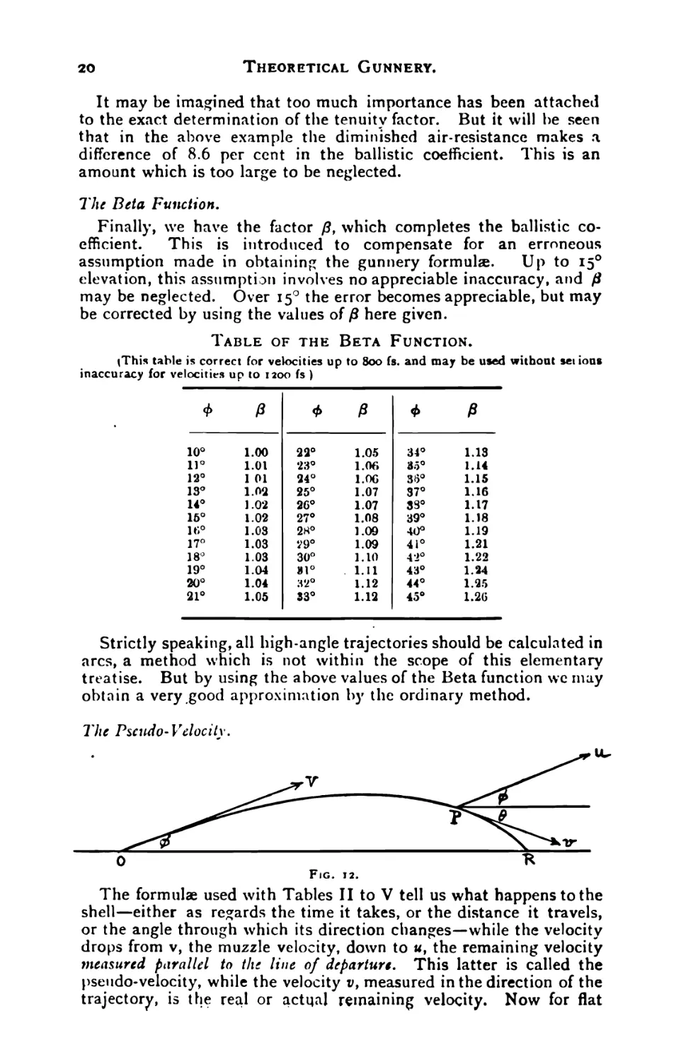
The Beta Function.
Finally, we have the factor /3, which completes the ballistic co-
efficient. This is introduced to compensate for an erroneous
assumption made in obtaining the gunnery formula. Up to 150
elevation, this assumption involves no appreciable inaccuracy, and fl
may be neglected. Over 150 the error becomes appreciable, but may
be corrected by using the values of fl here given.
Table of the Beta Function.
<This table is correct for velocities up to 800 fs. and may be used witboat sei ioas
inaccuracy for velocities up to 1200 fs )
p Ф p ф p
10° 1.00 22° 1.05 34° 1.13
n° 1.01 23° 1.06 35° 1.14
12° 1 01 24° 1.06 36° 1.15
13° 1.02 25° 1.07 37° 1.16
14° 1.02 26° 1.07 33° 1.17
16° 1.02 27° 1.08 39° 1.18
16° 1.03 28° 1.09 40° 1.19
17° 1.03 29° 1.09 41° 1.21
18° 1.03 30° 1.10 4*2° 1.22
19° 1.04 31° 1.11 43° 1.24
20° 1.04 32° 1.12 44° 1.25
21° 1.05 33° 1.12 45° 1.26
Strictly speaking, all high-angle trajectories should be calculated in
arcs, a method which is not within the scope of this elementary
treatise. But by using the above values of the Beta function we may
obtain a very good approximation by the ordinary method.
The formulae used with Tables II to V tell us what happens to the
shell—either as regards the time it takes, or the distance it travels,
or the angle through which its direction changes—while the velocity
drops from v, the muzzle velocity, down to u, the remaining velocity
measured parallel to the line of departure. This latter is called the
pseudo-velocity, while the velocity v, measured in the direction of the
trajectory, is the real or actual remaining velocity. Now for flat
Ballistic Tables and their Use.
21
trajectories up to 3000 yards or so there is no very great difference
between the real remaining velocity, as given in the range table, and
the pseudo-velocity. Accordingly for rough calculations at short
ranges we have merely to take the remaining velocity from the range
table and insert it in place of (v) in the formulae given at the head of
the Tables. But for long ranges and curved or high-angle trajectories
we must use more accurate methods.
From Fig. 12, by elementary trigonometry, we have:
и cos Ф = v cos в.
or и = v cos 6 sec Ф.
In dealing with the muzzle velocity, we have no pseudo-velocity to
consider, since the real muzzle velocity is of course equal to the
muzzle velocity measured parallel to itself. But for every point of
the trajectory except the muzzle we must use u, not v, in our calcula-
tions.
Example.
ф = io° 6 = 150 v = 1000 fs.
и = iooo cos 150 sec io°
= 980.7 fs.
There is one important formula which can be deduced from the
altitude formula already given for use with Table V. If in this we
put у = o, and represent the function 2 | I?— j by the
symbol ° a,” we get
Sin 2ф = Ca.
Which is the formula used with Table VIII, which gives us the
elevation required for any range. It is evident that when y, the
height of the trajectory, is zero, the shell is either at thebeginning or
at the end of its flight. Consequently Table VIII gives us a direct
connection between the angle of elevation and the range, without
reference to the time of flight or remaining velocity.
Spherical Projectiles.
The table given in the Text Book of Gunnery, 1907, for spherical
p-o’ertPcs, (Table IX) has not been replaced by a new one, and is
still used for calculating the ballistics of shrapnel bullets. But the
new tables may be used with a suitable modifying factor. Thus if
w
we take C = -^ in the old table, then for the new tables
w
d’x 1.68
C =
will give approximately the same result.
It is found
in practice that cast bullets, especially with resin adhering to them,
require a value of kappa of about 1.04, which brings the modifying
factor up to 1.75 nearly. Therefore the values of ~ given in
the Table at the end of this Look should be divided by 1.04 for the
old table or by 1.75 for the new tables.
22
Theoretical Gunnery.
Application of the Ballistic Formula.
For ordinary rough calculations, the ballistic formulae already given
can in many cases be considerably simplified. Thus for angles of
elevation up to 15° the cosine and secant of ф and 0 are very near to
unity, and we may use the real velocity v in place of the pseudo-
velocity u. The Beta function may be also taken as unity up to 150.
And for angles of elevation up to 50 the tenuity correction is negligi-
ble.
Example. Compute the ballistic coefficient for the 15 pr. Q.F.
gun firing the original German ammunition, for an angle of elevation
of 15 degrees.
We have
d = 3 inches w = 14.3 lbs.
к = 1.00 (since the shell has a 2-diameter head)
o- = 1.15, (to allow for some unsteadiness towards the end of
the trajectory.)
ft = 1.02 by the table already given.
We have then only to calculate r, the tenuity factor. Suppose
that at the gun the barometer stands at 30", dry bulb thermometer
6o°, wet bulb 550, giving the normal atmospheric density. From the
range table, the time of flight is about 20 seconds, greatest height
1600 feet, and mean height 1066 feet. At this height the barometer
will stand at 29 inches, dry bulb 570, wet bulb 520, and, from Table
VII, the weight of the air will be 519.3 grains per cubic foot.
Then T = UM
534-22
= -9725
Then C = ,, W „
d л.о-.т./з
_ _____________Ц-3______________
9 X i X 1.15 X .97 X 1.02
= 1’395-
(Note that the value of C given for the 15 pr. in earlier editions of
this book referred to the old ballistic tables.)
For the same gun, at 3000 yards, *, <r, r and ft may, for rough cal-
culations, be taken at unity, and we have
c
9
= 1-59-
Examplt.
Compute the ballistic coefficient for the same gun firing Mark VI
shell.
From the range table at the end of this book, we have
w = 14.1875 lbs. d = 3 inches.
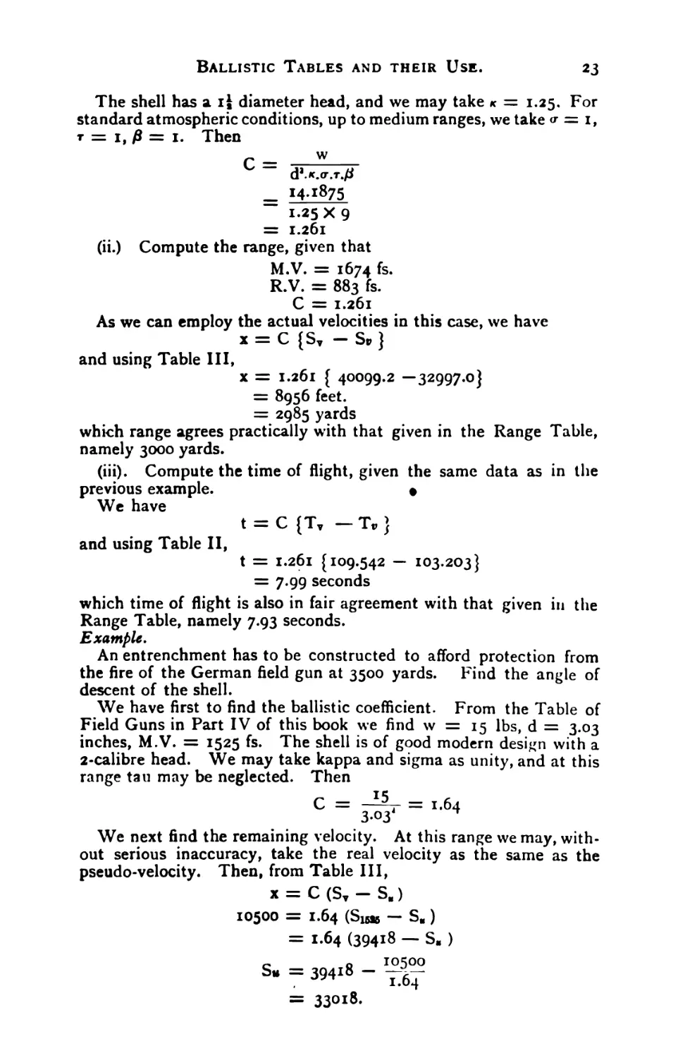
Ballistic Tables and their Use. 23
The shell has a ij diameter head, and we may take к = 1.25. For
standard atmospheric conditions, up to medium ranges, we take <r = 1,
т = 1, p = 1. Then
C- ______™_____
“ d’.K.<r.T./a
_ 141875
1.25 X 9
= 1.261
(ii.) Compute the range, given that
M.V. = 1674 fs.
R.V. = 883 fs.
C = 1.261
As we can employ the actual velocities in this case, we have
x = C {Sv — Sv }
and using Table III,
x = 1.261 { 40099.2 —32997.0}
= 8956 feet.
= 2985 yards
which range agrees practically with that given in the Range Table,
namely 3000 yards.
(iii). Compute the time of flight, given the same data as in the
previous example. •
We have
t = C {Tv — Tv }
and using Table II,
t = 1.261 {109.542 — 103.203}
= 7.99 seconds
which time of flight is also in fair agreement with that given in the
Range Table, namely 7.93 seconds.
Example.
An entrenchment has to be constructed to afford protection from
the fire of the German field gun at 3500 yards. Find the angle of
descent of the shell.
We have first to find the ballistic coefficient. From the Table of
Field Guns in Part IV of this book we find w = 15 lbs, d = 3.03
inches, M.V. = 1525 fs. The shell is of good modern design with a
2-calibre head. We may take kappa and sigma as unity, and at this
range tau may be neglected. Then
We next find the remaining velocity. At this range we may, with-
out serious inaccuracy, take the real velocity as the same as the
pseudo-velocity. Then, from Table III,
x — C (Sy — S,)
10500 = 1.64 (Sias — S.)
= 1.64 (39418 — SM )
s- = 39418 -
= 33018.
«4
Theoretical Gunnery.
By inspection of Table III,
м = 884 fs.
We have next to find the angle of elevation from Table VIII.
We have R = 3500 yards (not feet,) C = 1.64
R A
c = 2136
In Table VIII, look up 2100 in the top line, and 1520 in the left
hand column. Under 2100, and opposite 1520, we find the number
14648. Under 2200 we find 15626, difference 978 ; thbn for 2136 the
number is 14648 + 9.78 X 36 = 15000. Similarly opposite 1530 we
get 14866; the number required is half-way between the two, or 14933.
This number is the function “ a.” Then we have
Sin 2ф = Ca
= 1.64 X 14933
= 24500
Then from the Table of Natural Sines in the log book :
2 ф = 140 11
* = 7° 5' 30"
Or from the Table of Logarithmic Sines in the Text-Book of
Gunnery :
£og sin 2Ф = log 24500
= 4-3892
2ф = I40 12'
Ф = 7° 6'
We can now calculate the angle of descent from Table IV. We
can use either of the formulae at the head of the table, or the more
accurate formula given at the beginning of this chapter. For our
present purpose we will take the simplest formula, namely :—
tan Ф — tan 0 = C (Iv — Iu)
tan 0 = tan 70 6' — 1.64 (I1525— 1884)
= .12456 - 1.64 (.95354 “ -77542)
= .12456 — .292
= " -16744
The minus sign shows that the angle is a negative or downward
one.
From the table of natural tangents,
0 = 9° 30'
If we add to this the semi-angle of opening of the shrapnel, then
the angle of descent of the lowest bullets will be about 8° 4- 90 30'
or 170 30'.
So that if we have to provide cover from shrapnel bullets for a 6-
foot man standing 3 yards behind the parapet, the height of the crest
will have to be
6 + 9 tan 170 30'
or 6 + 9 X .315
or 8.8 feet.
Ballistic Tables and their Use.
*5
Example.
An Austrian gun has been captured, but the sights have been re-
moved and it his to be layed by clinometer. Construct a range table
for it.
From the table of field guns in Part IV, we find that the shell
weighs 14.72 lbs, the calibre is 3.01 inches, and the M.V. is 1625 fs.
The simplest method is to calculate the elevation for ranges of
2000, 3000, 4000 and 5000 yards, plot these elevations on a curve,
and thence measure the intermediate ranges and elevations.
Kappa, for a 2-diameter head, is unity; sigma (see p. 28) is 0.9 ;
and at 2000 yards we may neglect tau, so that the ballistic coefficient is
w ____ 14*72
d4 “ 3.014 X 0.9
= 1.805
Then, by Table VIII,
R_ _ 2000
C “ 1.805
= 1110
a = 5130
C a = 9260
2ф = 50 18'
</> — 2° 39'
Similarly for 3000 yards,
Ф = 4° 59'
At 4000 yards we ought to decrease the ballistic coefficient to allow
forsome unsteadiness, and at 5000 yards the tenuity of the atmosphere,
owing to the height of the trajectory’, begins to affect the range.
However for a field range table, used only as a basis for ranging, we
may neglect these refinements. Adhering to the elementary formula,
we get
Ф4000 = 7° 33'
</>5000 = IO° 35'
Which gives us all the information necessary to use the gun against
the enemy.
Example.
The time of flight of a shell fired from a Russian field gun, from
flash to impact, is observed to be 9 seconds. Find the range.
From the Table of Field Guns,
w = 14.41 lbs, d = 3 inches, v = 1930 fs.
The shell has a 2.75 diameter head, and kappa may be taken at
0.87.
• Then the ballistic coefficient is
C = -3±4i = l8
9 X 0.87 *
Now there is no formula directly connecting the time of flight with
the range. We have first to find the remaining velocity. We may
neglect the secant of the angle of elevation, as being practically unity,
and we may take the real velocity for the pseudo-velocity, since the
trajectory of the Russian gun at this range is very flat.
2б
Theoretical Gunnery.
Then from Table II :
t — С (T v Tv)
12 = 1.84 (T1930— Tv)
~ 12
T” = IIO,I34 ~ щ
v = 982 fs.
From Table III:
x = C (Sv — Sv)
= 1.84 (Sigao — Sgea)
= 1.84 (41164 — 34902)
= 11500 feet
= 3833 yards.
Example.
The captain of a French field battery is ordered to open
fire at a hostile battery 4000 metres distant. There is an intervening
hill 175 metres high, half way down the range. Will his shell clear
it ?
Here we have w = 15.95 lbs, d = 2.95 inches, and v = 1740 fs.
The French shell has a 2-diameter head, so we may take к = i.
There will be no serious unsteadiness at 4400 yards, and the tenuity
coefficient may be neglected at this range for a gun with such a flat
trajectory.
Then C = W
2-95’
= 1.83
To find the height of the trajectory, we must first find the remain-
ing velocity, and thence the time of flight.
From the Tables,
x = C (ST —Sv)
3 X 4400 = I.83 (S17W — S„)
c _ c 13200
3p — 31740 — _ o,
I.83
= 40,386 — 7220
= зздбб
v = 891 fs.
Then from Table II,
t = C (T, — TB)
— 1-83 (Ti74o — Тем)
= 11.56 seconds.
Then greatest height of trajectory is
h = 4t’
= 535 feet
= 163 metres
Ballistic Tables AMD their Use.
27
Therefore the shell will not clear the hill, and the French captain
must shift his battery to the rear so as to get a longer range, a more
curved trajectory, and a sharper angle of descent.
If he shifts back 200 metres, his time of flight will be roughly in
proportion, namely 12.1 seconds, and greatest height 17З melius, at
a point 100 metres nearer with respect to the crest; this is cutting it
rather fine, and he will do better to shift 300 metres back, and make
certain of clearing the hill comfortably.
Example.
A French shrapnel bullet has a remaining velocity of 1000 fs.
What will its velocity be at 300 metres from point of burst ?
From the table at the end of this book, w/d2 = .095. The French
bullets are smooth, and we may take < = 1.02. Then
C= -^95
1.02
= -093
Sv = S1000 —
From Table IX, Text Book of Gunnery,
e 990
S, = 12424 - —
= 12424 — 10625
= 1800 nearly
v = 352 fs.
Or if we use the new Tables, we have
r _ *°95
1.02 X 1.68
= -0554
s* = 35,207 — 17,890
v = 349 fe.
The difference of 3 fs. between the results obtained shows that the
modifying factor 1.68 is not strictly correct for all velocities.
Example.
Calculate the angle of elevation of the 18 pr. Q.F. for 3000 yards
with Mark I shell.*
Given Barometer 30 inches ) T = x 00
Thermometer 6o° Fah. )
к for 11 calibre
radius of head =1.15
o- = .90
w = 18.5 lbs.
d = 3.3 inches
•Nori.—Throughout this book the figures referring to the ballistics of the 18 pr. are
taken from the old rauge tables, compiled for Mark I shell. 1 he present ammunition
gives considerably better results.
28
Theoretical Gunnery.
(The value of 0.9 assigned to the sigma factor requires explanation.
It must not be supposed that a value of unity for sigma implies perfect
steadiness. The guns on the firing of which the new ballistic tables
were based gave good results as regards steadiness, and for these guns
a value of unity was assigned to the sigma factor. But the 18 pr.
shell was afterwards found to be still steadier in flight, and to require
a sigma factor of less than unity. This also applies to several of the
newer foreign guns. In the absence of any exact information, it is
advisable to take sigma as 0.9 for such guns as the Spanish and Port-
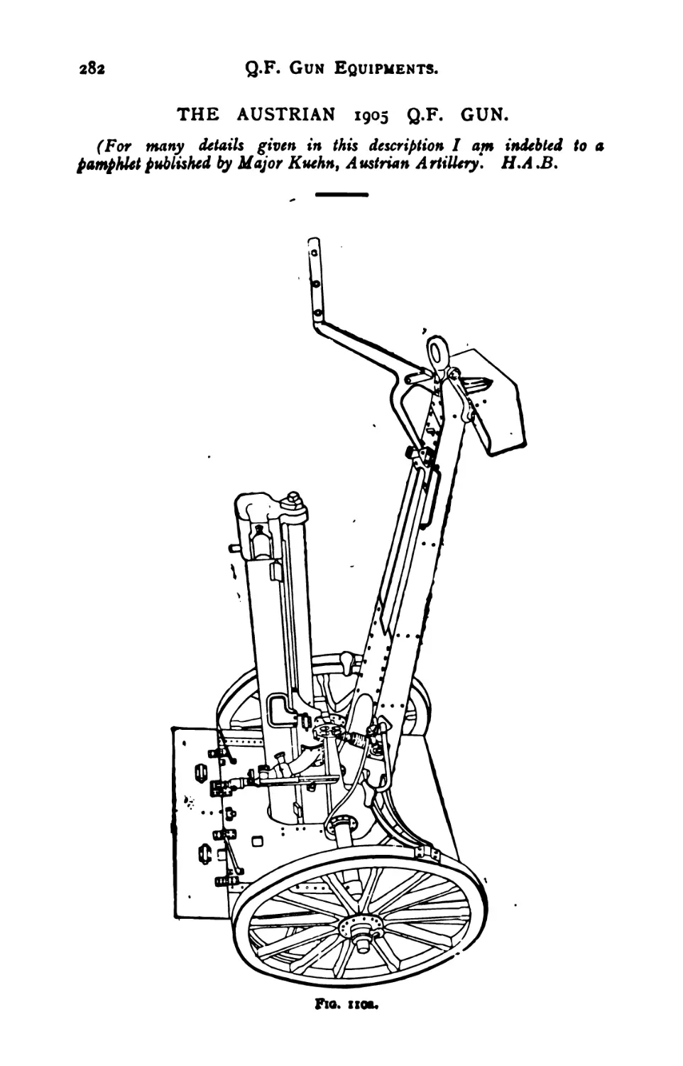
uguese Schneider guns, the Austrian gun, and the Italian Krupp.)
For such a flat trajectory ft is unity.
Then C = - , 18 5 v----
3-3 X 1.15 X .90
= 1.642
R 3000 o
-~ = £— = l83°
C 1.642 J
From Table VIII, along the line, V = 1590 fs.
11087
aieoo =
1195 г
aisoo =-------
866
aieao = 11087 + 865 = 11346
Sin 2<t> = Ca = 18630
2$ = io° 44' Official Range Table
Ф = 50 22' 5° 22'
To calculate the remaining velocity
x = C {SM — Stt }
or S„ = s¥ —
From Table III,
Siwo = 39721.4
x 9000
~ = 549O.O = ^-7----
C 1.642
s. = 342314
v = и = 945 fs.
To calculate the angle of descent
C ( )
tan 0 = tan —rr / I* — I* c
cos<p )
From Table IV
11600 = -95757 •
Ims = .82244
Official Range Table
912 fs.
•I35I3
C {!„ — !„} _ 1.642 X .135*3
cos Ф (-995)1
= .22384
tan </> = .09394
tan 6 = — .12990 Official Range Table
0 = - 7° 24' 70 36'
Ballistic Tables and their Use. 29
The negative sign shows that we are dealing with the descending
branch of the trajectory.
To calculate the time of flight,
t = C sec Ф {Tv — Tu}
From Table III
Tif.90 = Ю9.3О9
Тад = 104.561
ДТ 4.748
C sec ф {ДТ} = 1.642 X 1.004 * 4-748
Official Range Table
Л t = 7.80 secs. 7.88 secs.
To find the greatest height of the trajectory, a very good formula
for flat trajectories is
У = 4t’
Hence у = 4 X 7.8’ = 264 feet.
To find the velocity at the highest point of the trajectory :
At the summit the velocity is horizontal, so that 0 = o°
C ( )
Hence tan 0 = —r-] Iv — IMn >
cos1 Ф C °)
or sin 2ф = 2C [ I* “ I*o]
or
luo = I
Sin 2ф
”2C~
11590 = .95757
Sin 2ф = .1862
2 C = 2 X I.642
I«o = .90087
Mo = IIIO fs.
Range Tables.
The official range tables are calculated from additional ballistic
tables not given in the Text Book of Gunnery, as they are too bulky.
These extra tables greatly facilitate calculation. Exactly the same
results may be arrived at with the published Tables, but with more
labour. As an example we give here the complete calculation for the
13 pr. Q.F. with the 14! lb. shell. As will be seen, the calculations
have to be repeated until no change in the results is obtained.
In the official range tables all the calculations are very rigidly per-
formed, to ensure great accuracy.
Example.
13 pr. Q.F.
Given V = 1560 fs.
Ф = 8° 30'
w = 14.5 lbs.
Calculate
a = I.04.
i. The range
ii. Remaining velocity
iii. Angle of descent
iv. Time of flight.
30
Theoretical Gunnery
We must first of all work out the problem, ignoring the correction
for altitude, and then, having found the height, find the value of ть and
re-calculate.*
i. The formula to be used with Table VIII is
Sin 2Ф = Ca
In this case we have rt = i.oo fl = i.oo к = i.oo
_ M-5
1.04 X 9
= i-55
Also Ф = 8° 30'
2</> = 170
L Sin 2Ф = 9.46593
log C = 0.19033
log a = 9.27560
a = .18863
In Table VIII, opposite V = 1560 fs, we find :
a = 18,100
R
c = 2500
, R
a = 19,156 = 2600
V
Hence for A = 18863, we have
R . 763
= 2500 + -z—L .100
C J 1056
72.3
= 2572.3
. R
log £ = 3.41032
log C = 0.19033
log R = 3.60065
R = 3987 yards or
x = 11961 feet.
ii. To find the remaining velocity
x = C - Su*
or S« = Sv — *-
•It is hardly necessary to say that rg means the tenuity at the ground level, and Тц
(he tenuity at the mean height of (he trajectory,
Ballistic Tables and their Use.
31
log x = 4.07777
log C = 0.19033
3-88744
-J- = 7716.9
Simo = 39582.5
Su = 31865.6
и = 833 fs.
iii. To find the time of flight :
t = C sec <f> {Tv - Tu }
We can put sec 8° 30' = unity;
Tu® = iog.221
Том — 101.882
AT = 7-339
log 7-339 = 0.86564
log C = 0.19033
log t = 1.05597
t = 11.37 seconds
To find the greatest height, we should find the velocity at the ver-
tex by means of Table III, calculate the range to this point by Table
IV., and then calculate у by Table V.
But for flat trajectories the formula :
У = 4t3
gives very accurate results.
Hence у = 4 x 11.37’
= 517 feet.
To find rh, we have
Th = тй (1 — .00003 h)
= тй (1 — .00002 y)
since the average height is $ of the greatest height;
Th = 1 - .01034
= .98966 = .99
And this value should be inserted in the denominator of the ballis-
tic coefficient and the problem worked out again.
The second calculation will be found to give a range of close on
4000 yards, which agrees with the range table.
iii. The angle of descent works out to 12° 5' (Range table value.)
iv. The time of flight works out to 11.49 seconds, inserting the
value of sec <t> (which was previously omitted) in the formula
t = C sec ф {Tv — Tw}
32
Theoretical Gunnery.
Application of Ballistic Tables to Howitzer Fire.
Problems in howitzer fire can be solved in exactly the same way
as those in direct fire, by the formulae already given. Strictly
speaking all such trajectories, as also those above I5°elevation, should be
calculated by arcs, but the labour involved is great, and good accuracy
can be obtained by a calculation in one arc, with the use of the co-
efficient P, which is very accurate for low velocities. The example
given below shows how such calculations may be carried out.
Example,
Compute the ranges for the 6" B.L. Howitzer, too lb. shell.
Elevation = 40°
M.V. = 690 fs.
Tg = 1.00
<r =1.00
к =1.00
The value of Д required is 1.19 (vide Table.)
For the purpose of getting rh we may, without much error, take an
approximation to the parabolic height. This is given by :
v3 sin2 ф
у = 2—~
log sin 40° = 9.80807 log 2 = .30103
log v = 2.83885 log g = 1.50773
2.64692 1.80876
2
5.29384
1.80876
log у = 3-48508
у = 3°56 feet
Hence we may take 2800 feet as fairly near the the correct
height, and thus
ть = Tg (1 — .00002 y).
= 1 — .056
= -944
Therefore, computing C, we have
d2. к. <r. ть
1.19 X .944 X 36
Now Sin 2ф = Ca.
(Since Ф = 40°), L Sin 2Ф = 9.99335
log C = .39445
log a = 9.59890
» ?= .3971Q
Ballistic Tables and their Use.
33
For M.V. 690 fc., Table VIII:
R
tt = 1600 a = 39146
R
f-v-= 1700 a = 42125
100 2979
Hence 7г- = 1600 + >IOO
C 2979
18.9
1618.9
log = 3.20922
log c = >39445
log R = 3.60367
R = 4015 yds.
Range Table gives about 4080 yds.
As there is only a difference of 100 yds. in range for a difference
of 50 from 350 to 40°, the above calculation is a very fair estimate of
the range. By making an approximation to у by the parabolic
theory, a very near value to rh is obtained, and thus the labour of re-
peating all calculations is avoided.
The time of flight, remaining velocity, etc., etc., can be found as
shown in the previous examples of direct fire, but as the actual re-
maining velocity will differ considerably from the pseudo-velocity,
care must be taken to use the latter.
Example.
Find the M.V. required with a 3.5 inch mountain gun firing a pro-
jectile 22.5 lbs. in weight, to obtain a range of 5000 yards, with an
elevation of 380.
It is interesting here to calculate what M.V. would be required in
vacuo to give the range. It further serves the purpose of getting the
approximate correction to r, for the altitude of the trajectory.
The velocity in vacuo is given by
v-= -5^-
sin аФ
and v = 705 fs.
To find the height of the parabolic trajectory, we have
v1 sin’4>
У —
giving у = 2930 fs.
Hence we can take about 2700 feet for the height in the air.
Taking r, as unity, we get
r. = rg (1 — .00002 y)
= i - .054
= .946
34
Theoretical Gunnery.
зУ
Now fi for 380 = 1.17. Taking к = 1.0 and <r = 1.0, we have
C = w
Д <. «r. r„. d’
_ ___________22.5
1.17 X .946 x
= 1.67
We now proceed to calculate “a” from
R
knowing “a” and we ?et the required
Table VIII.
L Sin 2Ф = 9.98690
log C = .22272
Sin 2ф = Ca, and then,
M.V. from inspection of
log R = 3.69897
log C = .22272
log a = 9.76418 log = 3.47625
о R
a = .58100 £ = 2994
By inspection, we find that the required M.V. is about 833 fs.
Assuming that the mountain gun had been bred from a height of 2000
feet above sea level, the barometer, neglecting local variations, would
have gone down about 2 inches, and would be about 28 inches. The
temperature would not necessarily have fallen, since this is affected
by the height above the ground, not the height above sea-level.
_ 28 _ ____________1000_______
* 30 ~ 1000 4- 2 (T — 60)
= -933
And = .933 (1 — .00002 y)
= -933 (I — -054)
= -933 X .946
= .881
22 <5
50 ,hat C = 1.17 x .88. x 3.5- = ‘ ^S
This, working on the same principle as before, gives the requisite M.V.
as 822 fs. approximately.
It will be noticed that Table VHI does not cover velocities below
500 fs., but, with very fair accuracy, we can put
Sin 2</> = Ca
for velocities below 500 fs.
Example. Calculate the range for a gun whose complete ballistic co-
efficient is 2, M.V. = 300 fs., Ф = 25°.
Here a»
С \50o/
L sin 2ф = 9.88425 log C = ,30103
2 log 300 = 4.95424 2 log 500 = 5-39794
4.83849 5-69897
569897
log a = 9.13952
a = .13789
Ballistic Tables and their Use. 35
From Table VIII: Д = 341.6
(opposite v » 500) R = 341.6 X 2
= 683 yards.
By the parabolic theory, the range would be 714 yards. This
shows the near approximation at low velocities.
Without involving much error the value of P given in the table on
p. 20 can be used for velocities up to about 1200 fs.
For high angle fire at velocities above this point, the trajectory
should be calculated in arcs, putting p = sec </>, when ф is the eleva-
tion at the beginning of each arc.
But even putting P = unity, a very fair approximation can be made in
one arc.
зб
CHAPTER V.
ACCURACY OF FIRE.
However perfectly a gun may be layed, we never get two successive
rounds to fall in the same place. This is due to several causes.
In the first place, the muzzle velocity varies from round to round,
owing to irregularities in the burning of the cordite and the resist-
ance of the driving band. Next, the varying jump of the gun and
carriage causes errors in elevation. And if the carriage be on a
lateral slope, or if one wheel be on bad ground, the jump causes
errors of direction as well.
In the next place, the shell rarely comes out of the muzzle quite
straight, but usually with its nose pointing somewhat away from the
line of departure, and revolving round it. This causes the shell to
describe a preliminary helix or corkscrew curve round the mean tra-
jectory. The amplitude of this helix tends to decrease under the
influence of the resistance of the air, till at about 1000 yards the shell
begins to settle down to a regular curve. In the same way a spinning
top, after a first period of wobbling, “ goes to sleep,” and remains
steady till its spin is insufficient to overcome the overturning moment
due to the irregular frictional resistance of its point.
A further important cause of inaccuracy is defective manufacture.
If the wall of the shell be thicker at one side than the other, the cen-
tre of gravity will not be in the axis of the shell, and its rotation will
cause the shell to describe a helix of increasing diameter, which the
resistance of the air will do nothing to check.
Besides these sources of error, the flight of the shell will be affected
by the varying wind which it happens to encounter.
The practical result is that the trajectories of a number of shell
fired from the same gun at the Same elevation form a bent cone,
which is called the sheaf of fire.
Fig. 13.
The intersection of the surface of the ground with the sheaf of fire
forms an ellipse, of which the breadth is equal to the diameter of the
cone, while the length increases with the smallness of the angle of
nd, and read off the
Accuracy of Fire.
37
descent. If the cone were circular in section, then at an angle of
descent of 30 degrees the length of the ellipse would be twice the
breadth, while at/50 45* it would be just ten times the breadth. Since
however the disturbing influences which affect the range (such as the
variable jump of the carriage) are greater than those affecting the
direction, the ellipse is usually found to be longer in proportion to its
breadth than it would be if the vertical and horizontal errors were
equal. The actual dimensions of this ellipse for each gun and for
each range are determined by “ practice for range and accuracy ” at
Shoeburyness. This practice is conducted with the utmost care, and
all disturbing elements are as far as possible eliminated or corrected.
Each shell and cartridge are weighed, the powder is kept at a uniform
temperature, and the force and direction of wind noted for each
round. The result is to give the dimensions of the area of ground
upon which all shell fired at a given elevation and direction should
fall.
Total Rectangle. For convenience it is usual to express this area
in terms of the circumscribed rectangle. Thus instead of saying that
all rounds fired from the 18 pr. Q.F. at 3000 yards are contained in
an ellipse 80 yards long by 5} yards wide, we say that the total
rectangle is 80 yards long and 5! yards broad.
Vertical Rectangle. Knowing the horizontal rectangle, it is easy
to determine the dimensions of the vertical rectangle which all shots
should strike. The height of this is approximately equal to the
length of the total horizontal rectangle multiplied by the tangent
of the mean angle of descent.
Battery Rectangle. When six guns are firing at the same target,
they always make a bigger rectangle than one gun. For we have
now to contend with additional sources of error, the principal being
the different sighting of the six guns and the different personal error
of the six layers. In practice, when the target is clearly defined, the
total error should not be more than 25% greater than that obtained
at Shoeburyness. If the rectangle be twice as long, it shows bad
laying or neglected equipment.
The Fifty Per Cent. Zone.
If we direct a shower of shells from a gun, or a shower of pebbles
from the hand, at a given mark, it will be found that these are not
uniformly distributed over a space of ground, but lie more thickly
towards the centre of the space. It can be demonstrated by the
Theory of Probability that if the whole of the shell fall in a space
100 yards lone, half of them will (on the average) be found within
one quarter of that length, or 25 yards. Exactly the same result will
be obtained if we measure the distance of each shell from the central
one of the group, and multiply the average distance by the factor
1.69, which depends on the Theory of Probabilities.
Similarly, the width of the rectangle containing half the shell is
one quarter of the width of the total rectangle, and the height of the
Theoretical Gunnery.
rectangle containing half the shell is one quarter of the height of the
total rectangle.
The Twenty-Five Per Cent. Zone.
Suppose all the shell to fall within a space 100 yards long by 4
wide. Then a tranverse zone or belt 25 yards in depth will include
50% of the shell. Similarly a longitudinal zone 1 yard wide will
include 50% of the shell.
The central rectangle where the two zones are superposed will then
contain 50% of 50% or 25% of the shell. If in the same instance all
the shell fall within a vertical height of 12 yards, 50% will be in a
vertical zone 3 yards high, and 25% in a vertical rectangle 3 yards
high and 1 yard broad.
Probability of Hitting.
Knowing from the range table, the depth, width, and height of the
50% zone for any range, the table of Probability Factors enables us
to determine the chance of hitting an object of a given size.
Table of Probability Factors.
(From Mackinlay’s Text Book of Gunnery.
The following gives the proportional width of other zones (containing
a different percentage of hits) to one of 50% as unity____________
Per Cont. Factor. Per oent. Factor. Per cent. Factor. Per oent. Factor. Per oent. Factor.
1 0.02 21 0.40 41 0.80 61 1.27 81 1.94
2 0.04 22 0.41 42 0.82 62 1.30 82 1.98
3 0.06 23 0.43 43 0.84 63 1.83 88 3.03
4 0.07 24 0.45 44 0.86 64 1.86 84 2.08
5 0.09 25 0.47 45 0.89 65 1.39 85 2.13
6 0.11 28 0.49 48 0.91 66 1.42 86 2.18
0.13 27 0.51 47 0.93 67 1.45 87 2.24
8 0.15 28 0.53 48 0.95 68 1.48 88 2.30
9 0.17 29 0.55 49 0.98 69 1.51 89 2.37
1O 0.18 30 0.57 50 1.00 70 1.54 90 2.44
11 0.20 31 0.59 51 1.02 71 1.57 91 2.52
12 0.22 82 0.61 52 1.04 72 1.60 92 2.60
18 0.24 33 0.63 53 1.07 73 1.64 93 2.69
14 0.26 84 0.65 54 1.09 74 1.67 94 2.78
15 0.28 85 0.67 55 1.12 75 1.71 95 2.91
18 0.30 36 0.70 56 1.14 76 1.74 96 8.04
17 0.S2 37 0.72 57 1.17 77 1.78 97 3.22
18 0.34 88 0.74 58 1.19 78 1.82 98 3.45
19 0.86 89 0.76 59 1.21 79 1.86 99 8.82
20 0.88 40 0.78 60 1.25 80 1.90 1OO
Accuracy of Fire.
39
Example 1.
Suppose we are firing with the 18 pr. Q.F. at 3000 yards; what is
the chance of hitting a shielded gun 5' high and 6' wide ?
From the Range Table,
50% of rounds should fall in 1.44 yards breadth, and 20 yards
length. At an angle of descent of 70 36', or 1 in 7}, 7} yards
horizontal corresponds to 1 yard vertical, or 20 yards of length
to т*тг or 2.667 yards of height.
Here the width of the target is two yards, or 1.4 times 1.44 yards.
In the table, the factor nearest to 1.4 is 1.39, which we find
opposite 65 per cent. That is, 65 per cent, of the shots will be
correct for line.
The height of the target is 5 feet, or 0.625 times 4.7 yards. Factor
0.63 is opposite 33 per cent: therefore 33 per cent, of the shots will
be correct for elevation.
33 per cent, of 65 per cent, is 21.66 per cent., that k. it will
Page 39.—With the present ammunition the shooting of the 18 pr.
is better than in the examples given. The gun will now make 16%
of hits on a gun-shield 4 ft. 6 ins. high, by 5 ft. wide at 3000 yards.
Example 2.
What is the chance of dropping a shell into a rectangular gun em-
placement 3 yards wide and 5 yards from front to rear, with the 18-pr.
Q.F. at 3500 yards ?
Assume the parapet revetted vertical, and 3' high. Then since
angle of descent (from range table) is about 1 in 6, a parapet 1 yard
high will cover 6 yards to the rear, and it will be impossible to get a
shell into the emplacement without going through the parapet.
Suppose that a shell striking the superior slope within one yard of
the crest will penetrate the parapet, then our target is reduced to a
surface 3 yards wide by one yard from front to rear.
Now the 50% rectangle of the 18 pr. Q.F. at 3500 yards is 1.75
yards wide; 3 yards over 1.75 yards is 1.7, which factor we find
opposite 75% in the Table, so that 75% of the shots will be correct
for line.
Again, the 50% rectangle of the 18 pr. Q.F. at 3500 yards is 26
yards long; 1 over 26 is .038, or just short of factor .04 in the table,
so that 2% of the shots will be correct for elevation ;
2% of 75% is x-57o nearly.
So that in 100 shots, under ideal conditions, we may expect to put
1.5 effective shell into the emplacement.
Example 3.
The battery is being fired at by the 75 mm. French gun at 4200
yards. Is the wagon less likely to be struck if placed alongside the
gun or if placed behind it ?
Fig. 15.
Theoretical Gunnery.
For the French gun, at this range, the 50% zones may be taken
as under—
Longitudinal ... 32 yards
Lateral ... 1.5 „
Vertical ... 5.3 „
Consider first the chance of hitting the wagon alongside the gun.
Suppose the enemy’s fire directed at the gun. Then the wagon
extends to a distance of about 9 feet from the centre line of the gun ;
if there were a wagon on each side the total width of the target would
be 18 feet or 6 yards. This is just four times the 50% lateral
zone, so that all the shell would be correct for line. The proportion
which would hit one wagon alongside the gun is half the total less
half the number which would hit the gun. The latter number cor-
responds to the probability factor or 1.33, obtained by dividing the
width of the gun by that of the 50% zone, and is found by the table
to be 63%, Therefore the percentage which would hit the wagon, as
far as line goes, is or i8|%. Next for the elevation. The angle
of descent being т in 6, we find by graphical construction that the
effective height of a wagon limbered up is about 6 feet. That is, if
a screen & high were placed in front 01 the wagon limber, any shell
passing through the screen would either hit the wagon limber or the
wagon body or the ground underneath. Now suppose the range ac-
curately found, so that the mean point of impact corresponds with
the point of aim, that is, the ground line of the target. Then the
50% zone being 5.3 yards high, or 2.65 yards above and below' the
mean point of impact, the probability factor is or .755 and the
percentage opposite to it is 39, so that 39% of the shots above the
ground line, or 19!% of the whole, would be correct for elevation as
regards the wagon. of i8|% is 3.61% which is the percentage of
shots which would hit the wragon.
The above calculation is useful as a theoretical example, but is not
practical. On service the gun-layer would naturally aim not at the
gun but at the centre of the ground line of the group formed by gun
and wagon. Taking the total width at 12 feet, it follows by a similar
calculation that V = 4^1% of the shots would be correct for line as
regards the wagon; multiplying this by i9i°/o as before we get9.i°/o
as the percentage of shots which would strike the wagon. But in
this case the percentage which would strike the gun, which is only
5' high measured at right angles to the trajectory, is less than half of
the total hits, roughly in the proportion of 5 to 6, giving 7.6% only.
Next we take the case of the wagon placed behind the gun. In
i»-
L.
Fig. 164
Accuracy of Fire.
41
Fig. 16, which is drawn to scale, the wagon is shewn in the old regu-
lation position with the point of the pole 3 yards from the trail eye.
Take the mean point of impact at О; then by measurement OA=
10.25 feet, and AA' == 21.5 feet. The 50 °/o zone being 5.3 yards high,
or 5.3 X 3 feet, the probability factor is 5 y x5- or 1.35, which, by
the table, corresponds to 64%. Of these 64%, half w ill be grazes short
and the other half, 32%, will (if the line be correct) be hits upon the
gun or wagon.
To find the percentage of hits upon the wagon alone, we must
deduct the hits on the gun. BB' being 10 feet, the factor is
or .63, and the probable percentage 33%, of which i6|°/0 will be grazes
short and 164% hits on the gun. Therefore the hits on the wagon
(subject to correction for line) will be 32% — i6i°/o or I5i°/O«
But since a proportion of these shots, though correct for elevation,
will be wide, we must multiply by the probable percentage of shots
correct for line. The gun and wagon are each two yards wide and
the lateral 50% zone 1.5 yards; the factor is T*T or 1.33, and the
probable percentage 63%. Multiply by this and we have 10.4% for
the gun and 9.8 °/o for the wagon.
That is to say, that if 100 shots be fired at a gun and wagon, then,
if the wagon be alongside the gun, the gun will receive 7.6 direct
hits and the wagon 9.1 hits. But if the wagon be in the old regu-
lation position behind the gun, then the gun will receive 10.4 hits
and the wagon 9.8 hits. ’
The reason why the wagon receives fewer hits than the gun in the
second case, although it offers a larger target than the gun, will be
evident from the figure, which shows that with an angle of descent
of 1 in 6 the gun masks a portion of the wagon. But it should be
remembered that some of the hits on the gun will probably be effect-
ive on the wagon behind it.
Besides the reduced probability of being hit, the position of the
wagon alongside the gun has other advantages, which will be dis-
cussed in Part III.
Note.—In the first edition of this book the slope of descent of the
French shell was taken at 1 in 6 for 3000 yards. According
to later information this is incorrect, and it is only at 4200
yards that the slope of descent increases to 1 in 6. The
problem has been revised accordingly.
&
CHAPTER VI.
DEFLECTION OF PROJECTILES BY WIND.
This seems at first sight a simple matter to calculate. It would
seem that we have only to calculate the lateral pressure of the wind
on the shell, and thence the lateral velocity imparted to it. Unfor-
tunately the results obtained by this method are very far from corres-
ponding with those actually observed, the actual deflection being two
or three times as great as the calculated deflection.
Gveenhill's Method.
A more scientific method due to Sir George Greenhill, is given
in the Text Book of Gunnery’, 1907. The formula is
Deflection in feet = W
Where W is the velocity of the wind in feet per second across the
range, t the time of flight in seconds, R the range in yards, and V the
muzzle velocity in feet per second. All these figures can be taken
from the range table.
Example.
A i5pr. Q.F. gun is fired at a target distant 3000 yards. The wind
is blowing from the right front with a velocity of 30 f.s. How many
feet to the left of the target will the shell strike ?
The wind velocity across the range is 30 sin 450 = 21 f.s. From
the range table at the end of this book,
t = 7.93 seconds
3R= 9000 feet
V = 1674 f.s.
Deflection = 21 (7.93 —
= 53-65 feet.
Captain Hardcastle’s wind chart (which is here reprinted by
permission) gives a good working approximation to the deflection
required for a given force and direction of wind. It differs from other
charts previously published in that it takes into account the fact that
at the highest point of its trajectory the shell is exposed to a wind
much stronger than that blowing on the ground level. Accordingly
the scale of allowances is graduated for the known rate of increase of
wind with altitude, as determined by meteorological experiments.
To use this chart, follow the circle marked with the speed of the
wind till it cuts the “ o’clock ” of the wind. Read off vertically
under the point so found the wind deflection in minutes on the scale
marked with the range.
Deflection of Projectiles by Wind. 43
The words used to describe the strength of the wind are those used
in the daily weather forecasts.
Examples of Use of Chart,
Range 3000, wind II o’clock, fresh.
Defection 18 minutes right.
Range 4200, wind V o’clock, strong.
Deflection 22 minutes right.
Range 4500, wind VIII o’clock, moderate.
Deflection 24 minutes left.
44
CHAPTER VII.
RECOIL.
The question of recoil is of extreme importance to the design of a
modern field-gun, and merits careful study.
Recoil Velocity.
When a gun is fired, the shell and the gun fly in opposite directions
with velocities inversely proportional to their weights; that is, if we
neglect the weight of the powder, which will be considered hereafter.
If a shell weighing io lbs. be fired from a gun weighing 1000 lbs.,
then if the shell starts at 1000 feet per second the gun will recoil at
io feet per second.
Let W be the weight of the gun, w of the shell: U the recoil
velocity of the gun, v the velocity of the shelL
'Tk W - v
Then — — TT
w U
Recoil Energy.
The force of the powder is expended partly in propelling the shell
forw ards, partly in propelling the gun backwards. If the gun weighed
no more than the shell, they w'ould fly apart with equal velocities,
and the work done upon each w ould be equal. If the weight of the
gun were infinite, it w ould not move at all; the work done upon it
(neglecting heating) would be nil, and the whole force of the powder
would be expended on the shell. This is at first sight inconsistent
with the truth that action and reaction are equal and opposite. This
axiom however only means that the force exerted by the powder is
equal in both directions. And since the work done by a force upon
a body is proportional to the distance through which it acts, then the
shell, which is acted upon for the whole length of the bore, must get
more work done on it than the gun, which is only acted upon for the
short distance through which it moves before the shell leaves the
muzzle.
a 15 lb. shell travelling at 1640 fs.
= 624>8°° foot pounds or
The work done upon a moving body, or the energy imparted to it
(which amounts to the same thing) is expressed by the formula:
E=
2g
for the proof of which the student must refer to a treatise on
Elementary Dynamics. Thus
has stored up in it an energy of
15 X 1640’ , A x
= 279.7 foot-tons.
64.4X2240
Suppose this shell fired from a gun mounted on a rigid carriage,
weighing altogether 1 ton ; then the recoil velocity of the gun and
carriage would be X 1640 fs. = 10.98 fs. and the recoil energy
of the gun and carriage would be * 10-98 _ foot-tons.
04.4 X 2240
800 X 30 75*
64.4 x 2240
Recoil. 45
This would be enough to lift the gun and carriage, if stopped from
recoiling, 1.873 feet into the air.
Next suppose the same shell fired with the same velocity from a
modem Q.F. gun. (This would require more powder, since irt this
case, as will be seen, more work is done on the gun and less in
proportion on the shell). The weight of the recoiling parts, namely
gun and buffer, would be about 800 Tbs.; therefore the recoil velocity
is now X 1640 = 30.75 fs., and the recoil energy
= 5 365 foot tons, or some three times as much as before.
How is it, then, that a Q.F. gun, which develops 3 times the
recoil-energy of a B.L. gun, contrives to stand steady on firing? The
answer is to be found in the arrangement of the buffer. As we know,
a hydraulic buffer consists of a long cylinder filled with a viscous
material such as glycerine or Rangoon oil. In this cylinder works a
piston, which nearly fits it. The cylinder is attached to the gun, the
piston-rod to the carriage. Then on recoil the cylinder moves back-
wards, drawing out the piston-rod; the oil or glycerine has to pass
through the narrow space or windage between piston and cylinder,
opposing a strong resistance as it does so. In a well-designed buffer
the windage is so adjusted, by varying the depth of the ports in the
walls of the cylinder, that the resistance opposed by the liquid bears
a uniform ratio to the stability of the carriage throughout the recoil.
Now suppose that the gun and buffer recoil 4 feet before coming
to a standstill. Then the recoil-energy of 5.365 tons has been expen-
ded in pulling out the piston 4 feet against a certain resistance. If
we consider the resistance to be a weight, then we shall have expen-
ded 5.365 foot tons of energy in lifting that weight 4 feet; therefore
the amount of the weight, or average resistance, must be -
4
= 1.341 tons.
Under the assumed conditions the effect of firing a Q.F. gun will
be to produce a steady pull upon the carriage averaging 1.341 tons,
acting through the line of motion of the centre of gravity of the recoil-
ing parts. Since this force is greater than the weight of the gun and
carriage, why does the carriage not overturn ?
46 Theoretical Gunnery.
The reason will be apparent on considering the above figure.
Suppose the carriage hinged to the ground at the point of the trail;
then the pull of the piston-rod tends to revolve the carriage back-
wards about the fulcrum. The moment of the pull about the fulcrum
is equal to its amount multiplied by the vertical distance of the C.G.
of the recoiling parts from the fulcrum, which is about 3 feet.
Similarly the weight of the gun-carriage, tending to keep the wheels
on the ground, acts vertically downwards through the centre of
gravity of the system, and its moment about the fulcrum is equal to
the weight, about one ton, multiplied by the horizontal distance from
the fulcrum, say 7 feet.
Then the overturning force of 1.341 x 3 = 4.023 tons is resisted
by the downward force, 1x7 = 7 tons 5 therefore the wheels will
not lift from the ground, and the carriage will remain steady.
Strictly speaking, the fulcrum should not be taken as the point of
the trail, but rather as the centre of the area of the spade. In bad
ground the fulcrum is still lower, since the spade then holds prin-
cipally by its point.
Weight of Powder Charge.
In order to simplify the question, we have so far left out of account
the weight of the powder-charge. This must however be reckoned
with, as it adds materially to the recoil-energy.
In old text-books it was customary to consider the powder-charge
as igniting from the middle, one half going forwards w'ith the shell,
and the other half backwards w ith the gun. In calculating recoil-
velocities half the weight of the charge was added to the w eight of
the shell, the other half to the weight of the gun. This is how’ever
unsound, since the whole charge is propelled out of the gun before
the latter has finished recoiling. And besides this, the explosion of
the charge takes more effect upon the gun than it does upon the
shell. For the forward impulse communicated to the latter by the
expanding gases ceases when it has gone a yard or so from the
muzzle, whereas the burning gases still continue to issue from the
gun, producing a strong unbalanced pressure upon the breech, when
the shell is already a hundred yards distant on its way. Accordingly
Sebert’s velocimeter (referred to in Chapter I.) shows that the
maximum recoil-velocity is not attained till an appreciable time after
the shell has left the muzzle.
We have then to modify our formula
W=
w u
, . W v
and write —r—~; = 77-
w + Cw' U
where wz is the weight of the charge, and C, know n as the “ muzzle
blast factor,” varies from 1 in long guns to 2 in short ones. For or-
dinary Q.F. field guns we may take C as 1.5. That is, instead of
reckoning merely the weight of the shell we must add i| times the
weight of the charge of cordite or other smokeless powder.
As an example, we will calculate the recoil-velocity of the 15 pr.
Q,F. gun by the amended formula.
.. 5--With modern powder it is better to use a value of 2 for
the blast factor in calculating the recoil of a 30-calibre field gun.
Recoil.
47
The shell weighs 14.3 lbs., the charge 1 lb. nearly; therefore
w + 1.5 X w* = 15.8 lbs. The gun and buffer weigh together about
850 pounds. The muzzle velocity with ballistite is 1640 fs.
is 8
Then recoil-velocity = X 1640 = 30.49 fs.
Recoil energy =
= 5.479 foot-tons.
Similarly, for the 18 pr. Q.F. gun,
W = 1175 lbs. (including half weight of springs)
w = 18.5
w' = 1.44
Recoil velocity = X 1x 159°
= 27.96 fs.
D 1 ”75 X 27.96’
Recoil-energy = x
= 6.368 foot-tons.
Period of Recoil at which the Shell leaves the Muxxle.
This is an important point, influencing the accuracy of the shoot-
ing. Taking the 15 pr. Q.F. gun, the length of the rifling is6| feet,
and the average velocity of the shell up the bore is or 820 fs.;
therefore the shell takes = .007927 seconds to reach the muzzle.
The recoil-velocity when the shell leaves the muzzle is something
less than 30.49 fs.; we may guess it at 29 fs. Then the average
recoil-velocity up to the time the shell leaves the muzzle is half that
or 14.5 fs. Then while the shell is travelling up the bore, the gun
recoils .007927 X 14.5 = .1141 feet or 1.37 inches.
Taking the 18 pr. Q.F. gun, the average velocity up the bore is
or 795 fs., therefore the shell takes /Л = 00945 seconds to reach
the muzzle. Taking the recoil-velocity at 28 fs., the average recoil-
velocity from rest is 14 fs. Therefore while the shell is travelling up
the bore the gun recoils .00945 X 14 = .1323 feet or 1.59 inches.
Therefore if we can so construct the buffer and carriage that the
gun recoils smoothly for the first 1} inch, any subsequent jerk or
vibration will not affect the shooting.
This is the real reason why the Q.F. guns shoot so much better
than the old B.L. equipment.
Stability of the Carriage.
We have so far assumed that the steadying moment, namely the
weight of the gun and carriage multiplied by the distance of its cen-
tre of gravity from the spade, is constant throughout the recoil.
This however is not the case, since the gun shifts some four feet to
the rear during the recoil. We will now examine the question
somewhat more closely. The following method of investigation is
due to Sir George Greenhill.
48
Theoretical Gunnery.
Diagram of Steadiness.
Let the conditions be as follows—
Length of trail measured horizontally from centre of
axletree to centre of spade
Height of centre of gravity of recoiling parts above
centre of spade
Weight of gun and recoiling parts
Weight of carriage on w'heels
Ditto on spade...
Axis of gun, horizontal.
For simplicity, suppose that in the firing position
100 inches
40 inches
IO cwt.
IO cwt.
I cwt.
, the centre of
gravity of the ^un and recoiling parts is exactly over the axle; then
if the gun be shifted forward io inches it will balance the spade, and
the whole weight, 21 cwt, will be balanced on the wheels. Then
the distance from C.G. of gun and recoiling parts to spade will be
110" horizontally.
Also suppose that the gun can be shifted back to a distance of 100
inches beyond the spade; then this will balance the weight on the
wheels, and the whole weight will be on the spade. The distance
between these two extreme positions of the gun will then be 210
inches.
We can now draw' the diagram.
Draw O1O2 representing 210*, and O1W1 upwards representing 21
cwt.
Then in the position Oi the whole weight, 21 cwl., will be on the
w’heels ; in the position O2 the whole weight w ill be on the spade, and
that on the wheels w ill be nil.
Join WiOs. Then at any point of recoil, if the C.G. of gun and
recoiling parts be say at D, the weight on wheels will be DW.
Now on firing, the weight of gun and the weight on wheels,
together 20 cwt., acts downwards at a distance from the centre of
the spade of 100 inches, while the horizontal line in which the C.G,
of the recoiling parts moves is 40 inches above the centre of the
spade; therefore the weight which keeps the wheels down acts
against the recoil which tends to lift the wheels at a mechanical
advantage of 100 to 40.
Increase O1W1 to O>Ti in the ratio of 100 to 40, that is, make
O1T1 represent 21 X 100/40 or 52.5 cwt., and join TiO2.
Then in any position of recoil D, TD represents the maximum
pull on the carriage that will not lift the wheels from the ground.
Since the successive positions of T during recoil are all on the
straight line TiO2, then, if the buffer-pull were the only resistance to
recoil, the correct curve of buffer-resistance would be a portion of
Diagram of Steadiness.
Recoil.
4x
о
5o Theoretical Gunnery.
the straight line TiOg. If the length of recoil allowed be 50 inches,
from A to B, then the curve of buffer-resistance would be the straight
line aibi. But we have also to consider the compression of the
springs. This must be sufficient, at any point of the run-up, to
support the gun on a slope of about 1 in 2|, besides about I cwt. of
surplus compression to overcome the buffer-resistance. Therefore
the initial compression of the springs must be at least 5 cwt. The
maximum compression at full recoil depends upon the length of the
recoil as compared to the length of the spring-column, and cannot
be stated in general terms. Take it at 13 cwt. Since this spring-
resistance must be deducted from the total resistance to get the
correct buffer-resistance, draw bib downwards equal to 13 cwt, and
aid downwards equal to 5 cwt. Then ab represents the correct
theoretical buffer-resistance during recoil; that is, the resistance
which just fails to make the wheels lift from the ground.
As a matter of fact ab is not a straight line, but a curve as shewn
in the Plate, since the resistance of the spring does not increase in
direct proportion to its linear compression, but in a higher ratio.
In getting out an experimental design, the draughtsman starts wdth
the curve abt and modifies it by allowing a reduced resistance at the
start, in order to allow free recoil till the shell has left the bore. He
then further modifies the curve to give a reduced resistance throughout
the recoil, in order to allow a surplus of steadiness under unfavour-
able conditions, such as ground sloping to the rear. From this
corrected curve, the graduated depth of the buffer-ports is w’orked
out from empirical data, and corrected by the buffer-gauge described
in Chapter I.
Attempts have been made to calculate the area of buffer-ports for
different resistances. But the results are subject to so many correct-
ions for the shape of the apertures, and of the spaces through which
the liquid obtains access to them and emerges from them, as to be
of little practical value.
In order to bring the gun to a standstill, the length of AB of recoil
must be such that the area of the curve ab above the line AB, repre-
senting the total resistance to recoil, is equal to the area, drawn to
the same scale, representing the total recoil-energy. Therefore if the
draughtsman starts with the area A ab B, exactly equivalent to the
recoil-energy, then, when he has cut down the curve, he must increase
AB, the length of recoil, in order to maintain the same area, represen-
ting the total resistance to recoil. This is shown in the following
figure.
Fig. x8.
Recoil
5i
It must be remembered that if at any point of the recoil the wheels
begin to lift, this at once increases the height of the centre of gravity
of the recoiling parts above the point of the trail, and so increases
the overturning moment. The lifting will then continue until the
energy expended in raising the weight of the gun and carriage is
equal to the surplus recoil- energy unbalanced by the buffer-resistance.
Thus the total recoil-energy of a field gun weighing one ton is about
5 foot-tons; if only t of this be absorbed by the buffer and springs and
by the compression of the earth behind the spade, the weight of the
gun and carriage will be raised 1 foot when the gun is fired, which
means that the wheels will be lifted more than one foot from the
ground.
Running- Up Pressure.
During running-up the springs exert a backward pressure on the
rear plate of the cradle, tending to press the spade into the ground,
and a forward pressure on the buffer-cylinder. The latter is com-
municated through the buffer-piston to the front of the cradle and so
to the carriage, and tends to lift the spade out of the ground. So
long as the gun and buffer continue to give way to this latter pressure,
and to move forward, the parts are not in a condition of static
equilibrium, so that it is less than the pressure on the base-plate of
the cradle, and there is no tendency to shift the carriage forward or
to lift the spade. But if the buffer-resistance is insufficient to bring
the gun to rest in the firing position, the gun runs up against the
stops at the front of the cradle, producing a dynamic jerk which may
be sufficient to lift the spade. If the gun when it strikes the stops has
still a forward velocity of gfs., then if (as assumed) the weight of the
gun and recoiling parts is 10 cwt. as against 11 cwt. for the lower
carriage, then the effect of the impact will be to impart a momentary
velocity of nearly 5 fs. to the carriage till again checked by the
springs; while the gun rebounds from the stops and comes to rest.
If the carriage be prevented from moving forward by the wheel-
brakes, then it will tend to overturn forwards, lifting the spade out
of the ground.
It is therefore necessary that the buffer-resistance to running-up
should be sufficient to absorb all (or nearly all) of the work done by
the springs.
In the figure the work of the buffer-resistance is denoted by the
area АВлб, and the work done by the springs by the are abaibi. It
will be seen that in the case of a gun the latter is much less than the
former. But in the case of a howitzer, powerful springs have to be
used to lift it at 45° elevation, and it may be necessary to increase the
buffer-resistance in running up at low angles of elevation, as by the
use of the Vavasseur gear, to prevent the carriage from overturning.
We have so far considered the gun in the horizontal position only.
When the gun is fired with any elevation, the distance of the line of
motion of the recoiling parts from the fulcrum (Fig. 17) is less, and
so the overturning moment is reduced. Therefore if the gun is steady
point-blank it will be steady at any angle of elevation.
52
Theoretical Gunnery.
On the other hand, if the gun is fired with depression it will require
a surplus of stability to keep the wheels from lifting.
Similarly, if the gun be fired from a reverse slope without elevation,
or if the slope be steeper than the angle of elevation, the point of the
trail will be lower, the overturning moment will be greater, and
there will be a tendency to unsteadiness.
Adjustment of Stability.
Suppose that it is required to design a stable carriage for a gun ot
given muzzle energy.
Then the first condition to be satisfied is that the total resistance
to recoil must be equal to the recoil energy ; if it be less, the gun will
recoil off its carriage. Thus if the recoit-energy be five foot-tons,
we must have (neglecting the springs) a buffer 5 feet long with an
average resistance of 1 ton, or 2 J feet long with a resistance of 2 tons,
or in like proportion. Now the recoil-energy itself may be modified
by the design ; since the recoil velocity is inversely proportional to
the weight of the recoiling parts, or nearly so,* we may reduce it by
increasing the weight of the gun. This is a most unscientific method,
since the horses will have to pull a quantity of dead weight which
might be saved by a proper design of the carriage. Therefore in a
well-designed field equipment the weight of the gun should be as low
as it can be brought without danger of bursting. This fixes the recoil-
energy.
The weight of the carriage must also be the minimum required to
carry the gun and to stand the recoil without breaking. But as re-
gards the latter point, the stress on the carriage on firing is propor-
tional to the buffer-resistance which is transmitted to it by the cradle,
so that if we reduce the maximum (not the total) resistance we may
be able to lighten the carriage.
Now there is only one available way of reducing either the maxi-
mum or the average buffer-resistance, while still keeping the same
total. This is to lengthen the buffer, and to allow a longer recoil.
After a certain point, however, the increased weight of the buffer,
springs, cradle, and guides sets a limit to the application of this
method ; moreover if the recoil be too long, the gun will strike the
trail or the ground when fired at high elevations.
Suppose that we have increased the length of recoil till nothing
further is gained thereby, and that the carriage is still unstable, we
can still increase the mechanical advantage of the steadying weight
over the overturning force. If we increase the length of the trail
we increase the leverage of the steadying weight. Here, however,
there is a limit, since the trail, if made longer, has also to be made
stouter and heavier in order to stand the same amount of thrust on
firing. Finally, we may reduce the height of the axis of the gun—
or rather of the centre of gravity of the recoiling parts. In our own
service this is effected by putting the buffer on top of the gun, so as
to get the gun, which is much heavier than the buffer, right down on
the axletree. In the Russian gun the same object is effected by cranking
"Not exactly so, since a reduction in recoil velocity means a slight increase in muzzle
velocity, and so alters the terms of the recoil equation,
Recoil. 53
the axletree downwards in the centre. This however increases the
weight of the axletree and reduces the clearance under the gun,
which is undesirable when rough ground has to be traversed. In the
French equipment, the wheels have been reduced to 4' jFin diameter,
with the same object in view; but we in England consider these
wheels too small for mobility. The lowest gun of all is the Japanese
semi-quick-firer used in the Manchurian War, which has the trunnions
of the gun extended so as to form the axletree arms.
In a well-designed equipment the above features are combined so
as to get a stable gun of maximum power and minimum weight.
Two other methods of obtaining increased stability, namely differ-
ential recoil and curved recoil, will be considered in Chapter XV.
Part II
PRINCIPLES OF CONSTRUCTION
OP
GUNS, CARRIAGES, AND AMMUNITION.
57
CHAPTER VIII.
ORDNANCE MATERIALS.
STEEL.
Steel is the only material now used in gun-making.* There are
many different kinds of steel, ranging from high steel (that is, con-
taining a high percentage of carbon) of which razors are made, down
to the mild steel used for boiler-plates. High steel is harder, stronger,
and more elastic than mild steel, but it is also more brittle. When
steel guns were first made only the softest and toughest of mild steel
was used, principally because it was then impossible to obtain large
ingots of high steel of good quality. With improvements in steel we
are now getting to use much higher steel than before. A few years
ago the steel used at Woolwich was specified as 30 tons tenacity;
that is, that a bar of steel an inch square would stand a pull of 30 tons
before breaking. At present there is no difficulty in obtaining bo-
ton steel.
Hardening. Both high and low steel are improved by hardening
and tempering. Hardening consists in heating to a red heat and
quenching in oil or water ; tempering consists in re-heating to modify
the effect of the hardening. Mild steel does not harden to anything
like the same extent as high steel, but it gains in strength and elas-
ticity thereby.
Natures of Steel.
Steels of different quality are used for making guns, carriages,
gun-springs, shells, and shields.
Gun-steels are usually low in carbon, and may be classed as mild
steels rather than high steels. The steel used for heavy guns has
usually a tenacity of from 40 to 45 tons per square inch, untreated,
while steel with tenacity up to 60 tons is used for field guns.
Carriage steel is still milder than gun steel, as it is required to be
tough rather than elastic. Two qualities are generally used, namely
30-ton steel for trails and fittings, and 50-ton steel, with a high elastic
limit, for axletrees.
Spring steel, besides high elasticity, has to possess great power of
withstanding fatigue due to repeated sudden flexion. It is considered
that one pound of spring should be capable of repeatedly absorbing
and giving out 40 foot-pounds of work.
Shell steel comprises cast steel for thick-walled armour-piercing
shell, and forged steel for shrapnel. The former has to be exceeding-
ly hard, otherwise it sets up on impact instead of penetrating.
Shrapnel steel requires to be tough as well as hard, since the walls of
the shell are thin, and there is a risk of breaking up as well as of setting
up in the bore. A breaking strain of 55 to 60 tons per square inch,
with elongation of 8 to 10 per cent, is generally considered suitable.
•Except in Austria, where, for reasons connected with economy and local facilities of
manufacture, forged bronze is still used, ‘ibis, however, involves a material increase
of weight.
Page 57.—In 1912 the Austrians decided to abandon the use of
bronze for all guns to be built in future.
58
Principles of Construction.
Steel for gun-shields is used in plates 1/8" to 1/4" thick. It is re-
quired to resist penetration by rifle bullets at short ranges. It has to
be exceedingly hard, and must be tough enough not to break when
struck. The breaking strain is usually about 100 tons per square inch.
Composition of Steel.
Carbon is necessary to obtain sufficient hardness and tenacity.
But the modern tendency is to use the minimum of carbon necessary
to produce the required tenacity, in order to make the metal as tough
as possible. Thus nickel steel with only 0.3 per cent of carbon is
now used where formerly ordinary steel with 0.5 per cent of carbon
would have been employed.
Nickel considerably increases the strength and elasticity of steel.
English makers use about 3 per cent, German makers as much as 6
per cent. It is frequently used in combination with chromium and
tungsten.
Chromium up to one-half per cent increases the strength and hard-
ness of the steel. Up to 1.5 per cent is used for armour plates.
Chrome gun-steel must be comparatively free from manganese,
otherwise it cracks when treated. It is improved by the addition of
a small percentage of molybdenum.
Tungsten or Wolfram increases the hardness and density of steel,
and is used for gun shields in proportions not exceeding one-half
per cent. High-speed tool steel contains up to 25 per cent of tung-
sten. If the proportion be as much as 16 per cent, the steel is nearly
as heavy as lead, and is suitable for shrapnel bullets intended to
pierce gun-shields. The quantity of tungsten commercially available
is however to small to allow of its use on an extended scale.
Vanadium increases the strength and elasticity of steel. From 0.1
to 0.2 per cent is used, ordinarily in conjunction with chromium up
to 1 per cent. Vanadium steel has not been tried for guns.
. Molybdenum fe said to make good spring steel if used in proportions
up to 0.1 per cent.
Manganese is present in most gun-steels. In ordinary gun steel as
much as 1 per cent may be present without doing any harm, but the
proportion should not exceed 0.4 per cent for chrome steel oro.i per
cent for tungsten steel.
Copper is present in a few steels, such as some of Krupp’s steels, in
proportions up to 0.12 per cent. It is supposed to contribute to
toughness.
Silicon makes good fluid steel for castings, which may contain as
much as 1 per cent; but for forgings the percentage does not usually
exceed 0.5. Up to 3 per cent silicon is used for spring steel.
Sulphur, phosphorus and arsenic are deleterious and are eliminated
as far as possible. Aluminium is sometimes used in casting, to pro-
duce fluid metal. It is supposed to rise to the top of the dead-head
with the impurities. Its use except in minute quantities is forbidden
by most Governments, as if any remains in the steel it makes rotten
spots.
Ordnance Materials.
59
Steel Tests.
These are of two kinds, namely static and dynamic tests. In the
former the steel is slowly stretched or compressed; in the latter
it is subjected to a sudden blow. It must be clearly understood
that the results obtained in a static testing machine are not directly
applicable to steel stressed by a force suddenly applied, as when a
gun is fired. Thus the A tube of a gun is frequently found to stretch,
although subjected to a stress well below its static elastic limit. No
serious attempt has yet been made to reproduce firing conditions in a
testing machine, although this would not seem to be impossible. The
gun-maker is guided principally by the static tests, the relation be-
tween the static results and those obtained in the gun being
determined by experience with the steel in question.
The meaning of the terms used in static testing may be illustrated
as follows:
Suppose a bar of steel 100 inches long and I square inch in cross
section stretched in a testing machine. Then it a pull of 50 tons
were required to break it, its tenacity would be 50 tons per square
inch, and it would be referred to as 50-ton steel. Suppose its length
just before breaking were 120 inches, it would have an elongation of
20 per cent. Suppose that at tensions up to 30 tons the bar returned
to its original length when released, and that over 30 tons it began to
yield, or stretch permanently, its elastic limit, or yield point, would
be 30 tons per square inch.
Static tests are usually taken on a piece of steel turned to I*
diameter and 2" long between shoulders. It is not likely that tests
taken on such a piece would be found to apply to a bar 100 inches
long, unless the metal were of exceptionally uniform quality.
German gun-makers use a self-registering hydraulic testing
machine, in which the tension applied and the extension of the test
piece are recorded on a drum. The drum is connected to the move-
able jaw holding the test piece so that it revolves as the piece
stretches, at the rate of 100 millimetres for every millimetre of
extension. The indicator which traces the curve on the drum is
connected by a pipe to the cylinder of the hydraulic ram, so that it
rises as the force applied increases. The yield point, at which the
piece begins to stretch permanently, is shown by a break in the
curve.
Various dynamic testing machines are used. The simplest is the
pendulum machine. The bar of steel to be tested is notched to a
given section, and set vertically in a vice. A heavy pendulum is
arranged so as to strike the bar in its swing. The energy of the
blow is determined by the height to which the pendulum is raised
before it is released, and the energy remaining in the pendulum is
measured by the height to which it swings after breaking the bar.
The following extract is taken from a most valuable article by
Colonel Holden, R.A., to which students are referred for further in-
formation.*
• Times Engineering Supplement, March 3 and March 10, 1909.
Page 59.—The Charpy dynamic testing machine has a heavy
pendulum into which the test piece is fixed tangentially. A cross
piece fixed on the end of the test piece is arrested as the pendulum
swings through a gate, so that the piece is broken by shock tension.
6о
Principles of Construction.
Treatment and Tests.
Whilst wrought iron, which is the nearest commercial approach to
pure iron, can be very roughly used, so far as heating, forging, and
cooling are concerned, without affecting its character after such treat*
ment such is not the case with steel containing anything over 0.3 or
even 0.25 per cent, of carbon. There is no doubt that the introduction
of steel for general purposes was kept back for years owing to the
want of appreciation of this fact. The alloy steels, however, are
many times more sensitive to ill-treatment, and some of them are so
delicate in this respect, that it is often a wise policy on the part of the
manufacturer not to attempt to treat the parts he has machined, but
to leave this to the steel-maker, who should thoroughly understand not
only how to treat but also the why and wherefore of the treatment of
his own steel. The testing of steel is a much more complicated
matter than it was a few years ago, when users were content with a
tensile test and perhaps a bending test, the former being carried out
very frequently with a bar some five inches in length, turned down
for some 2.5 inches to a diameter corresponding to a sectional area of
.25 square inch, and marked with points two inches apart for the
purpose of ascertaining the yield point, elastic limit, and percentage
of elongation. This test piece is then held in the jaws of a testing
machine, in which the stress can be gradually increased until the
specimen breaks, the yield point and elastic limit being observed
during the process, and the elongation being generally measured after-
wards. Apart from the figures thus obtained, the appearance of the
fracture is of a considerable value in indicating whether the steelisin
good or bad condition. The bending test consists in bending a rec-
tangular bar of the material to be tested around a cylindrical former,
having a definite diameter as compared to the piece under test. A
good piece of material should be capable of being bent into U form,
that is, through an angle of 180 degrees, not only without breaking, but
without showing any sign of cracking on its exterior surface.
Modern science, however, demands more information than can be
gathered directly from such tests as these. It is necessary to know
how a steel will' behave under shock, under continuous as well as in-
termittent stress in one direction, and under stresses alternating in
direction ; what its intrinsic hardness is, and also the molecular con-
dition of the material as shown by the microscope. The •• shock ”
test, as it is called, is generally applied to a rectangular bar, which
has a V-shaped notch cut across it to give it a determined line of
weakness, by dropping a weight from a certain height upon the un-
supported end and measuring the amount of energy remaining in the
weight after the bar has been broken. The energy absorbed in
breaking the bar can thus be deduced. The stress tests are made in
machines which apply a load, in the manner required, either continu-
ously, intermittently, or alternately in either direction, until the test
piece fails by cracking or breaking, or shows signs of fatigue.
The test almost universally applied for hardness is made in the
following manner. A steel ball such as is used for ball-bearings,
10 millimetres in diameter, is placed on the surface of the material to
be tested, and is subjected to a definite pressure for a few seconds. The
diameter of the crater thus produced in the material under test is
measured, and is a function of the hardness of the material.
Ordnance Materials. 6i
Erosion.
When a gun is fired, the temperature in the bore is considerably
higher than the melting point of steel. The layer of the metal next
to the powder is heated red hot and is scored and channelled by the
rush of the gases. This erosion does not occur to any serious extent
in field guns, but materially shortens the life of a heavy gun. Experi-
ments have been carried out to determine the relative resistance of
different natures of steel to erosion. An explosion vessel was fitted
with a perforated plug through which the powder gases had to escape,
and the plug was weighed before and after each explosion. Plugs of
various natures of steel were used. Contrary to expectation, it was
found that high-speed tungsten tool steel was eroded much more than
ordinary steel. Nickel gun-steel did fairly well, but simple mild car-
bon steel suffered least of all. It is claimed for vanadium steel and
molybdenum steel that these resist erosion well, but the assertion has
not yet been put to any practical test. Generally speaking, it has
been found that any alloy erodes more than a pure metal.
Bronzes.
In addition to steel, various bronzes are used in the construction
of gun-carriages. Manganese bronze is used for castings of compli-
cated shape, such as the i8pr. cradle. Phosphor bronze is hard and
close-grained, and is use for pipe-boxes. The composition and tests
of these bronzes are given in the table at the end of this book.
The specification of the forged bronze used for the Austrian field
gun is as follows :
A tube, elastic limit 19.27 tons, tenacity 36.39 tons
Jacket, „ „ 15.5 „ „ 27.5 „
TABLE OF GUN STEELS.
Unless otherwise stated, these figures refer to untreated steel,
neither hardened nor tempered. The tests were taken on test pieces
cut from large forgings under the conditions approved by the English
and foreign Governments, except in the case of the Schneider tests,
which are taken on test pieces 4" between shoulders, cut across the
forging, which is a severe test. Fancy results may be obtained from
small experimental forgings, but these are unreliable.
1. Simple open-hearth steel, Messrs. Firth, Sheffield. Carbon 0.48, Mo. 0.87, Sil 0.17, Phos 0.028, Sul. 0.035 per cent .. Yield | Break tons per square inch. Stretch 7.
28 48 12
9. Ehrhardt nickel gun steel, oil tempered. Nickel 6.0, Tungsten 0.5, Carbon 0.26, Sil 0.5, Mn. 0.25, Sul. 0.02, Phos. 0.02 30 67 19
3. Armstrong nickel gun steel, treated 40 49.4 24.5
4. Firth’s ditto 35 54 20
6. German ditto, 5°/o nickel 33.7 504 21.5
бз
Principles of Construction.
TABLE OF GUN 8TEEL8-Con»in««d.
Yield I tons square 1 Break per jinch. Stretch %
6. Bethlehem. U.S.A., nickel gun steel, treated. Nickel 3.33, Carbon 0.36, Mn. 0.81, Sil. 0.032, Phos. 0.026. Sul. 0.034 — 60 16
7. Schneider, Creusdt, nickel gun steel for 12" A tubes, untreated. Nickel 2, Carbon 0.4, Mn. 0.06, Sil. 0.2, Phos. 0.025, Sul. 0.025 28.5 44 19
8. Krupp's nickel gun steel for 11" A tubes, untreated 25 45 15
9. Hadfield's special gun steel, oil-tempered 49.5 60 23.5
10. Armstrong nickel-chrome gun steel, treated 59 63.5 18.5
11. Schneider chrome steel for field guns, untreated. Car- bon 0.3, Chromium 0.5, Mn., Sil., Ac., as above.. 24 38 22
12. Armstrong ditto, treated •. • • 65 87.4 12.5
13. Firth's nickel-chrome axletreo steel, untreated 43 55 25
11. Ditto, oil-tempered 51 62 22
15. Ehrhardt's nickel steel for axletrees, untreated 47.7 50.4 23
16. Krupp's spring steel, tempered 89 137 —
17. Ehrhardt's ditto .. 1 120 142 3
19. Cammell Laird's ditto, said to contain molybdenum 107 123 2
19. Ehrhardt nickel-tungsten shield steel, untreated 80 105 5.5
20. Bethlehem ditto. Carbon 0.29, Tungsten 3, Mn. 0.09, Sil. 0.035, Phos. 0.012, Sul. 0.05 — — —
21. Schneider steel for shrapnel bodies, water-hardened and tempered 47 63.5 8.5
22, Schneider nickel-chrome steel for armour plates, un- treated. Carbon, 0.5, Nickel 2.5, Chromium 1.0, Mn, 0.06, Sil. 0.2, Phos. 0.025, Sul. 0.025 — — —
бз
CHAPTER IX.
PRINCIPLES OF CONSTRUCTION OF GUNS.
In designing a gun to fulfil a given task, we have first to determine
its interior dimensions, then the material, the exterior dimensions,
and the method of construction.
The interior dimensions are arrived at by knowing how much use-
ful work is produced when a given weight of powder is ignited and
expanded to a given volume. This is tabulated for cordite M.D. on
page 126 of the 1907 Text Book of Gunnery.*
As an example, we will supposed that it is desired to produce a
field gun to fire a 20 lb. shrapnel with M.V. of 2000 fs. We have first
to determine the calibre. Since the 18 pr. has a calibre of 3.3 ins.,
we may try 3.5 ins. for our gun. The powder being cordite M.D., we
will try a charge of 2 lbs. By comparison with the 18 pr., this will
require a chamber of 135 cubic inches. Now the amount of useful
1 • £ 1 20 2000’ r f .
work we require from the powder is X or 025 foot-tons.
As explained in Chapter I, the useful work is calculated by deducting
the work done by the powder in expanding to the volume of the
chamber, 135 cubic inches, from that done in expanding to the
volume of the whole of the bore, including the chamber. Try
a 3-5* gun which the shot-travel (not the whole gun) is 40 calibres.!
Then the volume of the bore without the chamber will be { т d’ X I
= «7854 X (3.5V X 40 X 3.5 or 1340 cubic inches, and that of the
bore and chamber 1475 cubic inches. Then, using the formula on
page 127 of the Text Book of Gunnery :
E (Vq).= 219 E (Vi) = 641
Multiply the difference by the weight of the charge, and we have
(641 — 219) X2 = 844 foot-tons.
•This table may be used for cordite M.D.T. if allowance be made for the increased
efficiency of this powder, which gives about 5 fool-tons per pound more than cordite
M.D. It is not suitable for cordite.
f Note.—Generally speaking, a gun is measured by its total external length in cali.
bres. Thus a 30-calibre 3-inch gun is 90 inches long over all. The bore is measured
from the face of the breech block to the muzzle. In internal ballistics guns are com-
pared with reference to the number of calibres which the shot travels, and the shot-
travel, that is the distance from the front of the powder chamber to the muzzle, is
sometimes referred to as the bore.
64 Principles of Construction.
We have next to multiply by the factor /. Now the efficiency of
the charge, as calculated from the foregoing table, is subject to cer-
tain deductions. Besides imparting the forwatd velocity to the shell,
the powder has to impart the velocity of rotation, and to overcome
the resistance of the driving band and the friction in the bore. Also,
as shown in Chapter VII, part of the energy is expended in causing
the gun to recoil. In a gun of which the shot-travel is 25 calibres,
it is found that only about six-tenths of the energy given in the table
is realized in the shape of muzzle energy. In the present gun, the
waste is less, for the following reason : A large part of the wasted
energy is expended, in forcing the driving band into the rifling, which
takes some 6 or 7 tons of pressure per square inch. This waste is the
same whatever the length of the gun, and hence bears a larger pro-
portion to the whole energy developed in a short gun than in a long
one. By comparing our gun with others of approximately similar
proportions, we may estimate that we shall realize rather more than
seven-tenths of the energy as determined from the table. J
We therefore take factor/ as 0.725. Then
844 X .725 = 612 foot-tons.
which is 13 foot-tons short cf the muzzle energy which we require.
Try the effect of increasing the calibre to 3.75 inches, while keeping
the same length. This gives us slightly too much; try 3.65. Then
the chamber capacity remains the same, while that of the bore is
1340 X = *46° cubic inches.
and that of the bore and chamber 1460 + 135 or 1595 cubic inches.
Then Vi = 28.75 E (VO = 651.25 E (Vo) = 219.
difference = 432.25
Then total work will be 2 X 432.25 or 864.5 foot-tons, and work
effective on shell 864.5 X^.25 = 626 foot-tons, which is 1 foot-ton
more than is required. < •:/
Since we have increased the calibre of the gun without increasing
its length, the shot-travel will now be somewhat less than 40 calibres,
namely 40 X or 38J calibres, and the total length of the gun
will be about 444 calibres or 13.5 feet.
The same muzzle velocity might be obtained with a shorter gun if
more powder were used; but this would mean higher pressures in the
bore and a thicker and heavier gun.
The next step in the design of the gun is to calculate the pressures
at various points of the chamber and bore, in order to determine the
proper thickness of the metal at each point. Unfortunately this is
not a mere matter of arithmetic. The rate of burning of the cordite,
and the consequent pressure developed at various points, follows a
somewhat obscure law. We know, however, that fine cordite gives
t Note.—Io the actual design of guns al Woolwich the table on page 126 of the Text
Book of Gunnery is not used. The Woolwich authorities use an empirical curve
plotted from the results of many thousands of ronnds fired from different guns, which
gives a very close approximation to the actual muscle energy which will be developed
by a given charge in a given guq.
Principles of Construction of Guns. 65
high pressures at the breech and lower ones at the muzzle, while
coarser cordite gives more uniform pressures up the bore. If it be
desired to get the gun as light as possible, the maximum pressure
should be as low as possible; hence it is in this respect desirable to
use the coarsest size of cordite that will be completely consumed be-
fore the shell leaves the muzzle, allowing a certain latitude for the
different behaviour of cordite at different temperatures. In a gun
with the shot-travel 40 calibres long the size of the cordite should be
such that it is all consumed by the time the shell has travelled about
30 calibres.
But the calculation of the correct size of cordite is a complicated
matter, involving problems which cannot be dealt with in an element-
ary work such as the present one. Practical experience enters
largely into the matter.
A combination of several methods is used in gun-designing. The
gun fitted with cutter-plugs described in Chapter I, used in conjunction
with the chronoscope, has given valuable results, but the expense of
constructing such a gun for every calibre in the service would be pro-
hibi ive. More generally-applicable results are obtained from the
explosion vessel described on page 4. Broadly speaking, however,
the methods of calculating powder-pressures now at the disposal of
gun-constructors bnly give tne results to be expected when known
condi ions are modified to a moderate extent. For instance, if
Krupp and Armstrong were each called upon to designa 15-inch gun
firing an entirely new propellant, the two designs would probably differ
considerably, and it would be difficult to predict which would prove
the better of the two.
We will suppose that the charge and size of cordite is so adjusted
as to give a pressure of 12 tons at the point of maximum pressure,
decreasing in a curve similar to that in Fig. 2 to 3 tons at the muzzle.
The next thing is to determine the thickness of metal required to re-
sist this pressure at each point.
Take, for example, a point at which the pressure is 10 tons per
square inch, and consider a transverse slice of the gun 1 inch thick.
Imagine the gun divided by a vertical partition as in the figure,
and consider either side of the gun. The inward pressure on the
partition (the diameter being 3.75 inches)* will be 3.75 X 10 tons,
and the outward pressure, tending to tear the metal apart at a a and
•Ordinarily speaking, the calibre (in this gun 3.65 ins.) is measured between the
lands. But in calculations dealing with the strength of the gun, the greatest diameter
of the bore, that is, the calibre to the bottom of the grooves, has to be taken. Since
the grooves will be .05 inch deep, this makes the full diameter of the bvrc 3-7$ inches.
66 Principles of Construction.
so burst the gun, will be equal and opposite to the inward pressure.
Therefore the two sections of metal at a a will between them have to
stand a pull of 37.5 tons. Taking a factor of safety of 2, they will
have to be strong enough to stand a pull of 75 tons together, or 37.5
tons each.
It would, therefore, at first sight appear that if we use, say, 50-ton
steel, we have only to make the metal 37.5 4- 50 or 0.75 inch thick.
This however is not the case. It would be so if the gun were made
of absolutely rigid inelastic material. But since no such substance
exists in Nature, we have to use an elastic material such as gun steel,
which is more perfectly elastic than india-rubber, although its limits
of extension are not so great. Now it requires no mathematics to
shew that if an elastic ring be expanded by pressure from the inside
the stress on the inner layers, next to the pressure, is greater than
that on the outer or more distant ones. The subject is treated
mathematically in the Text Book of Gunnery, 1907. It was shewn
by the late Mr. Peter Barlow that the stress on the metal is not uni-
form throughout, but varies inversely as the square of the distance
from the centre, that is, from the axis of the gun. This formula,
known as “ Barlow’s Law,” is not quite accurate, but can be made
so by using a modifying factor which is a constant for any particular
size of gun. This is equivalent to sliding the curve sideways. For
our present purpose “ Barlow’s Law ” is near enough to the truth.
But in actual gun-designing the modifying factor is too important to
be neglected.!
In this case the -external radius of the gun to the bottom of the
grooves is 1.875 inches, and the outer radius, if the metal were 0.75
inches thick, would be 2.625 inches. So that if the outer layers be
stressed to the breaking point, namely 50 tons per square inch, the
stress on the inner layer, at the surface of the bore, would be
(1 875У X 5° = 97-5 tons Per square inch, so that the gun would
certainly burst when fired.
Moreover we must remember that though our (pin steel will stand
50 tons to the square inch before breaking, it will begin to stretch
permanently at about 25 tons. For although the static elastic limit
for 50 ton steel is over 30 tons, the dynamic yield point, which is
what we must consider in gun construction, is consideraby lower (see
Gun Steels.) We have therefore to solve the following problem :
Assuming for the sake of safety that our gun has to stand double
the normal calculated powder-pressure, we have to construct it so
that the resulting stress on the metal does not exceed 25 tons per
square inch at any point.
(This is considerably in excess of the limits allowed in our service.
See Text Book of Gunner}’, 1907, page 155. In this case we have
t Mathematically, the equation to the Barlow curve is : —
/ = A -4
1 V2
where a is a constant depending on the strength of the metal, and b is arrived at by
experience. The constant b (which may be positive or negative in value) is always
much smaller than a. In the present chapter we have simplified matters by omitting
Principles of Construction of Guns. 67
assumed that 50-ton steel of very high quality, with an exceptionally
high yield point, is used.)
This problem may be solved in several different ways. We will
first suppose that the gun is to be made of a single block of steel,
and we will calculate the thickness of the metal at a point where the
normal calculated*powder-pressure is 10 tons per square inch. For
the sake of safety we have to assume that a pressure of double this
amount may possibly occur. This, as has been shown above, means
that the metal on each side of the bore will be subjected to a pull of
37,5 tons. We have then to make the gun so thick that themetai at
the surface of the bore, where the stress is greatest, is not stressed
beyond 25 tons to the square inch.
Take a piece of squared paper, and draw a circle 3.75" in diameter
for the bore; draw a horizontal diameter, and at one end of it erect
a perpendicular 25* high (or to any suitable scale) representing the
stress per square inch on the inner layer of the metal. Then, since
the stress is inversely proportional to the square of the distance from
the centre, at a point 2 inches from the centre it will be
X 2 5 °Г 21 *97 tons, at 2} inches from the centre it will
be X 25 or tons, at 2 J inches 11.62 tons, and so on.
Erect perpendiculars of these heights at these distances from the
centre, and draw a curve through their tops. This gives the curve
shewn in Figure 20, known as the “ Barlow Curve.” If perpendicu-
lars be drawn up to this curve, say inch apart, and measured, these
Fig. 20.
The “ Barlow Curve,
68
Principles of Construction.
TABLE A. wiH give the stress on each successive layer of metal,
ts inch thick, outwards from the surface of the bore.
2 Thus we find that if the inmost layer of metal is
1*86 stressed 25 tons to the square inch, or 2 j tons on T1^ inch,
1*70 then the next layer is stressed 2.25 tons, the; next 2.04
J the next 1.86, and so on. We have to Йм/а sufficient
1.38 number of layers in order that the stress borne by the
1-23 whole of them may equal 37.5 tons. This calculation
Щmay be quickly performed by the Integral Calculus.
0’99 But for the present purpose we will confine ourselves to
0.93 simple arithmetic.* We have only to make a list of the
O-87 stresses for each inch and to add it up till we get a
total of 37.5 tons.
0.73
0.6Ч
0.65
0.62 8.13
0.59
0.56
0.53
0.50
0.48
0.46
0.44
0.42
0.40
0.38 4.76
0.37
0.36
0.34
0.33
0.32
0.30
0.29
0.28
0.27
0.26 3.12
0.25
0 24
0.23
0.23
0.22
0.21
0.21
0.20
0.19
0.19 2 17
0.18
0.18
0.18
0.17
0.17
0.17
0.16
0.16
0.16
0.15 1.68
Total 36.90
From this list (Table A) we see that even if we
make the metal 6 inches thick we shall only get a total
of 36.9 tons. The weight of a gun of this thickness
would be prohibitive.
It will have been noted that the stress borne by the
different T\ inch layers diminishes from 2.5 tons on the
inner layer down to 0.15 tons on the last. Each suc-
cessive layer adds less and less to the strength of the
gun, so that even if an infinite number of layers were
added the strength would not be increased beyond a
certain point. That is, in a gun bored from a solid
block of steel a large proportion of the metal is nearly
useless. This construction is therefore never used ex-
cept for small mountain guns in which the powder
pressure is comparatively low. Some coast defence
guns, cast solid, are still in use in Sweden but these are
not only enormously heavy in proportion to their
ballistics, but they are far less powerful than guns of
similar calibre in our own service.
In order to make the outer portion of the metal do
its share of work, it is necessary to build the gun in two
or more layers, each shrunk on to the one inside it.
Suppose a gun made in two layers, each an inch thick,
the outer being shrunk on with a tension of 5 tons per
square inch. Then it is clear that the inner layer will
be 5 tons stronger than if uncompressed, while the outer
will be 5 tons weaker; the inner layer will have borrow-
ed strength from the outer, which can well afford it,
since, as we have seen, the stress on the outer layer due
to the powder pressure is much smaller than that on the
inner. This construction enables us to distribute the
stresses throughout the gun, so that every part of the
metal is stressed to the same extent. This, at least,
would be the case if a large number of thin layers were
• Noth—In practice, instead of summing the Barlow curve arithmetically, we take
advantage of the fact that its area is equal to a rectangle on the same base and of the
mean height of the curve. The mean height is the height at the geometrical mean be-
tween the inner and outer radii. Thus in a tube whose inner radius is 2 inches, and
outer radius 4 inches, the mean height of the Barlow curve is the height at a point dis-
tant V 2 x 4 = 2.83 inches from the centre of the tube,
Principles of Construction of Guns. 69
used. For the stress within each layer must still remain unequal,
the inside of the layer being stressed more than the outside. Some
of the older guns were on this account built up of numerous layers,
the shrinkage of each being regulated so that all were equally stressed.
The 12-inch gun of 25 tons, for instance had six superposed layers.
Guns on this system have, however, been superseded to a great ex-
tent in this country by wire-wound guns, which will be described later.
We will next consider what sort of a gun we shall obtain if we
build it in two layers. From the “ Barlow curve ” already drawn we
obtain the stress on each layer of metal inch thick in a solid block
gun. When the inner layer is stressed to the (unusually high) limit
which we have fixed, namely, 25 tons per square inch, or 2.5 tons on this
layer, the stresses on the successive inch layers will be as in
Table A. Now suppose that we make the gun with an inner tube, or
A tube, and an outer tube called the jacket, each one inch thick, the
latter being shrunk on with a tension of 10 tons per square inch.
Then, since, the stress on the A tube is reduced by 10 tons, we can
now make the thickness of the metal such that the original stress on
it would have been 35 tons per square inch on the inner layer if un-
supported, instead of 25 tons. Then from table A, the total stress
о c
on the A tube will be 17.04 X — 10 tons, or 14 tons, and that
on the jacket will be 8.13 X + 10 tons or 21.4 tons, total 35.4
tons. This is below the 37.5 tons which wc require. A shrinkage of
12 tons would give a total of exactly 37.5 tons; but in this case the
stress on the inner layer of the jacket would be 1.06 X +1.2
= 2.77 tons, or 27.7 tons per square inch, which is beyond our 25-
ton limit. Try making the A Tube 1.2 inches thick and jacket 1 inch,
with shrinkage of 11 tons. Then the dimensions may be such that
the unsupported stress would be 36 tons per square inch instead of
25. We have now, taking the first twelve and second ten figures
from Table A: Sum of stresses = 19.09 x ----------n + 7-23 X
36
+ 11 = 37.9 which is slightly more than we require. The
greatest stress, namely at the inner inch layer of the jacket, will
be 0.93 X + 1.1 = 2.44 or 24.4 tons per square inch, which is
within our limit.
The nature of the process we have performed will be evident from
Fig. 21. To simplify the drawing, we will take our first attempt at
the solution, in which the A tube and jacket are each 1 inch thick.
Start the “ Barlow curve ” at 35 tons, and take the first inch of it,
AB, of which the area represents 17.04 X 35/25 or 24 tons of stress.
Cut off CB representing 10 tons from the bottom of the area; then
the remainder AD represents 14 tons of stress. Now take the next
inch of the same curve, EF, representing 8.13 x 35/25 or 11.4 tons
of stress ; add GH representing 10 tons, and the sum, EH, represents
21.4 tons of stress.
70 Principles of Construction.
The maximum stress at any point is 25 tons per square inch on the
inner layer of the A tube, AC, and 24.4 tons per square inch on the
inner layer of the jacket, ED.
Therefore a gun built
up in 2 layers will be suf-
ficiently strong for our
requirements. The thick-
ness of the metal is calcu-
lated for say 10 points in
the length of the gun, the
results plotted, and curves
drawn through them which
gives the thickness of the
A tube and jacket at any
point. For instance, at
the muzzle the normal
powder pressure is 3 tons
per square inch, therefore
the gun must be able to
stand 6 tons. Then, as
before, the circumferential
stress tending to burst the
gun, will be 37.5 X 3/10 or
11.25 tons, and the total
permissible stress on the
two layers must be not less
than this amount. Try 0.3 inch for the A tube, and the same for the
jacket, with a shrinkage of 1 ton. (Note that the shrinkage may be
varied as required at different points.) Then the sum of the stresses
on the A tube, from Table A, is
26
(2.50 4- 2.25 + 2.04) X — — i = 6.05 tons.
while the sum of those on the jacket is
26
(1.86 + 1.70 + 1.56) x — + I = 6.32 tons.
Total 12.37 tons.
The stress on the inner 1/10" layer of the jacket is
nr 26 ,
1.86 x У5 + 0.1 = 2 03 tons
or 20.3 tons per square inch, which is within our 25-ton limit.
It need hardly be said that gun-makers do not proceed by such a
ver}r elementary process as reckoning the stress for every 1/10 inch
of metal, adding up the results, and then taking enough 1/10 inch
layers to give the desired total. 1 hey use the gun-maker’s formula,
which enables the calculation to be performed more accurately and
with less labour. But the simple arithmetical method is given here
in order to show that there is really no mystery underlying the
formidable-looking formulae given in the Text Book of Gunnery.
These are plain arithmetical truths expressed in a general form
convenient for calculation. The same results could be arrived at
equally well by patience and the multiplication table.
Principles of Construction of Guns. 71
Weight of the Gun.
If we take our gun as a frustum of a cone from the muzzle to the
point where the highest pressure occurs, say a foot down the bore,
and thence as a cylinder to the breech, then by the mensuration for-
mulaeatthe end of this booktheweight w orks out at 11.85 cwt. Roughly
speaking, the guides and the breech-block will nearly balance the
hollow due to the inward curve of the chase, so that the weight will
be about n cwt. This is decidedly on the heavy side for a field gun,
since the two heaviest field guns, the French and the English, weigh
only 9 cwt. each. We will therefore see what reduction can be ob-
tained by the wire-wround construction.
Wire-Wound Guns.
It would be possible to build up an excellent field gun, of minimum
weight, by making it in say four {-inch layers, shrunk on so as to
distribute the stress on firing equally throughout the four layers.
Such a gun, however, would be very expensive. The same result can
be arrived at more cheaply and more efficiently by the wire-winding
system, invented by Mr. James Longridge. A steel ribbon n" thick
and I" wide is wound on to the A tube in successive layers with
gradually decreasing tension.
It would first appear that the tension ought to be an increasing one
to produce equal stresses throughout. But this is not so, chiefly be-
cause each successive layer compresses those below it as it is wound
on, thus making the inner layers looser and the outer layers tighter.
The relative amount of tension in each layer depends upon the
elasticity, or compressibility, of the steel used, and is worked out
mathematically in the Text Book of Gunner}’, 1907, page 176.
Since a large number of layers are used, this system gives an ideal
distribution of stresses throughout the layers of wire. Moreover the
tensile strength of steel ribbon is over 100 tons per square inch, while
that of the strongest gun-steel ordinarily used does not exceed 50
tons. Hence a wire-wound gun can be made lighter for the same
strength than a built-up gun.
In the presence instance, suppose the gun is made of an A tube
wound with wire. We will assume that the maximum stress on the
A tube on firing is to be 25 tons per square inch, and that on the wire
6o tons per square inch. The wire is to be wound on so as to give a
total supporting stress on the A tube of 20 tons. The total stress
on firing on the A tube and wire, at the point where the powder
pressure is 10 tons per square inch, is to be 37.5 tons as before.
Try an A tube 0.7" thick (in addition to the lands of the rifling.)
Now a supporting tension of 20 tons on 0.7" is 28.57 tons Per square
inch. Therefore we may make the thickness of the gun such that
the stress at the surface of the bore would be 28.57 tons per square
inch more than our 25-ton limit if the A tube were unsupported.
Therefore we can start the “ Barlow curve ” at 25 + 28.57 = 53-37
tons. Multiply the figures in Table A by and we have :
1*
PRiNciPLbs of Construction.
TABLE B* Then total stress on A tube is 28.59 — 20 = 8.59
636 tons.
4.82
<53 Now the wire is to be wound on with tension such
I that the stress on firing throughout the wire is the
3.34 same, namely, that of its inner layer, or, from the ac-
3.07 98.59 companying table, 2.85 tons on 1/10 inch. We have
2 already 8.59 tons on the A tube, and the whole of the
' wire is to provide 20 tons of supporting tension, leaving
8.91 tons to be added. Each 1/10" layer of wire adds
2.85 tons, so that if we put on five 1/10" layers of wire we shall have
more than we require.
Then if the total stress on the wall of the gun on firing be 37.5
tons (which, it will be remembered, is double the stress for the nor-
mal powder pressure) we shall have 20 + 8.91 tons on $ inch of wire
or 57.82 tons per square inch on the wire, which is within the 60-ton
limit which we have laid down.
E
Tomi
L-
F1O. 32.
The construction at
which we have arrived
is shown graphically in Fig.
22. We start the “ Bar-
low’ curve ” at 53.57 tons, and
take the first 7/10 of an inch
of it, AB, of which the area
represents 28.59 tonsof stress.
Cut off CB representing 20
tons from the bottom of the
area; then the remainder AD
represents 8.59 tonsof stress.
Now’ take the rectangle EF,
I inch wide, representing 5
X 2.15 or 14.25 tons of stress;
add on GH equal to CB re-
presenting 20 tons, and the
sum EH, represents 24.25
tons of stress. The actual
firing stress on the wire will
be only 8.25 tons (represented
by PF) besides the support-
ing tension, not 14.25 as
above, but we have had to
take i inch of wire, as other-
wise the supporting tension,
together w ith the firing stress,
would have been over the
6o-ton limit.
When the wire is all on, the tensions on the different layers of wire,
which make the stresses on firing equal throughout, are if we
disregard the initial tension which supports the A tube, inversely
proportional to the stresses given by the “ Barlow’ curve.” Since the
stiess produced by firing is less on the outer layer of wire than on
the inner layer, the tension of the outer layer has to be greater in
Principles of Construction of Curts.
order to support the inner layers and so do its fair share of the work.
But, as already explained, the original winding tension with which
the wire is put on is less on the outer layer.
Therefore, as regards resistance to bursting, our wire-wound gun
will be strong enough if made 0.7 + 0.5 = 1.2 inch thick at the
point where the powder-pressure is 10 tons per square inch, instead
of 2.2 inches as before. This, if it could be carried out, would re-
1.2
duce the weight of the gun to п X cwt or 6.0 cwt. Unfortu-
nately this is not a practical construction. The A tube would be
only 7/10 X 0.3 or 0.21" thick at the muzzle, and would be so de-
ficient in stiffness as to vibrate considerably,causing inaccurate shooting.
In practice it is always found necessary to put a jacket over the wire,
partly to protect it but principally to stiffen the gun. Since however
in a field gun the support afforded to the A tube at the muzzle by
the jacket is quite sufficient without any wire, the wire is not carried
as far as the muzzle. Thus in the 18 pr. the wire is only carried
forward about a third of the length from the breech. That is, a wire-
wound field gun is built up as a two-layer gun for the greater part of
its length, and as a jacketed wire-wound gun for the remainder. It
is not easy to shrink the jacket over the wire within accurate limits
of shrinkage, and therefore the part of the jacket over the wire is not
relied upon to contribute to the strength of the gun. It must
however be thick enough to stiffen the gun, to support the guides
and horn for attachment of the buffer, and (in the 18 pr.) to take the
breech-piece which carries the breech block.
In our present gun we will take A Tube and jacket each 0.3" thick
at the muzzle, besides the muzzle swell, which is added principally to
prevent damage if the muzzle strikes the ground in travelling. At
the point where the powder-pressure is 10 tons per square inch the
jacket may be | inch thick, so that we shall have a total thickness of
metal of 1.7 inch instead of 2.2 iuches in the two-layer gun. This
reduces the weight previously calculated by slightly more than 1 cwt.,
so that our wire-wound gun will weight 10 cwt.
This is about as light as it is possible to get a 20 pr. with M.V. of
2000 fs., and this light weight has only been attained by making the
gun inordinately long, so as to get nigh efficiency out of a small
powder charge, and by using stresses on the metal higher than are
allowed in our service.
Shrinkage.
To afford the necessary support, the jacket is made smaller inside
than the outside diameter of the A tube; it is then expanded by heat,
slipped on, and cooled from one end, so that it grips progressively
from one end to the other. In some field guns the A tube and jacket
are tapered and the jacket is forced on cold by pressure applied to
one end. The difference between the internal diameter of the jacket
and the external diameter of the A tube is arrived at by knowing the
amount to which the metal of the jacket will stretch, and that of the
A tube be compressed, under a given stress. This may be calculated
by the formula given on page 168 of the Text Book of Gunnery, but
it is usually arrived at by experience.
74 Principles of Construction.
Longitudinal Tensions.
These are of no great importance, since if the metal be strong
enough to resist the pressure tending to burst the gun it is amply
strong enough to resist that which tends to pull it apart endways.
For instance, in the gun which we have been describing, the A tube
is 0.7" thick at the point where the powder-pressure is 10 tons per
square inch. Then the longitudinal pull is
io X * or 110 toQS,
while the strength of the A Tube, up to the yield point of 25 tons per
square inch, is
25 X { ж + 0.7)2 — ’(^5)2 J
or 244 tons.
so that there is a considerable margin to spare on the A Tube alone.
Ehrhardt System.
The three methods of gun-construction above described are the
only ones used in our own service. There is, however, another
method, known as the Ehrhardt system. In this the A tube and
jacket are each formed from a solid ingot into which a mandril is
forced when red-hot. This process leaves the inner layers of the metal
in a state of initial compression, and so, to some extent, serves the
purpose of the wire-winding system. This process is not applicable
to heavy or medium guns. The only example of it in our own
service is the 15 pr. Q.F. gun, made by Messrs. Ehrhardt.
75
CHAPTER X.
RIFLING.
Rifling is a means of imparting rotation to the shell. In all
modern guns this is effected by cutting helical grooves down the bore,
leaving raised libs called 44 lands ° between them. A band of soft
copper is secured round the shell near the base. On discharge the
shell with its copper driving-band is projected up the bore ; the ribs
cut into the soft copper and force the shell to follow their helical
course and to rotate. This rotation continues, somewhat diminished
by the friction of the air, to the end of the shell’s flight.
Other means of making the shell rotate have been used, such as
the tail with spiral vanes which rotated the torpedo shell fired from
the Zalinski dynamite gun.
The only method of rifling now in use is. however, the polygroove
system (so called from the large number of small grooves) and the
copper driving-band.
Object of Rifling.
Any rapidly-rotating body tends to preserve the direction of its
axis of rotation—that is, to keep in the same direction in which it
pointed when first made to rotate. A familiar instance of this is the
spinning top.
Not only does a spinning body tend to preserve the direction of its
axis of rotation when left alone, but it actively resists any attempt to
change that direction.
Thus, if we attempt to upset a spinning top by striking it with a
ruler, we shall find some difficulty in doing so. Instead of over-
turning, the top will fly off sideways, still keeping vertical.
This property of rotating bodies is turned to account to make the
shell travel point first during its flight. But for the spin given to the
shell it would soon turn over and fly sideways, when its direction
would become erratic and its range would be much reduced.
The object of rifling may, then, be said to be to enable a gun to
fire an elongated projectile with accuracy.
A dvantages of Elongated Projectiles.
Since a shell three calibres long has a cross-section only one third
of that of a spherical shell of the same weight, it can be fired from a
much smaller and lighter gun. And since it only opposes to the air
a resistance one-third of that of the spherical shell, it ranges much
further. And moreover since in penetrating an obstacle it makes a
hole only one-third the size of that made by a spherical shell, it will
penetrate more readily.
7&
Principles of Construction.
These advantages may be said to be due to rifling, which renders
it possible to use the elongated shell.
Twist of Rifling.
A spinning top is acted on by its weight, which constantly tends
to make it fall flat, and its energy of rotation, which keeps it vertical.
When, owing to the friction of the peg of the top, the energy of
rotation is sufficiently diminished, the top overbalances.
Now, with a shell, the force tending to overturn it is the pressure
due to the resistance of the air, and that tending to keep it straight
is the rotation due to the rifling. The former tends to constantly
diminish as the shell expends its velocity in overcoming the resistance
of the air ; but the spin is affected only by the surface-friction between
the shell and the air, and reduced is to a less extent. For flat tra-
jectories, it follows, then, that if we give the shell enough spin to
keep it straight at starting, this will suffice to keep it point foremost
to the end of its flight.
Minimum Twist.
The longer the shell in proportion to its diameter, the greater the
amount of spin required. It will be afterwards seen that it is desir-
able not to allow an undue amount, as this increases the lateral
curvature of the path of the shell.
A table of minimum twist of rifling required to keep steady a shell
of any given length will be found on page 187 of the Text Book of
Gunnery, 1907. As an instance, it may be noted that a shell 3^
calibres long requires a twist of at least one turn in 36 calibres to
keep it steady.
Uniform and Increasing Twist.
It will be readily understood that if a heavy shell has a high
velocity of rotation suddenly forced upon it, this must cause a severe
strain both on the shell and on the gun. To avoid this, the grooves
of the rifling are made to run at first straight down the gun, gradually
increasing in inclination or " pitch ” till the full velocity of rotation
is attained. This is known as an “ increasing twist,” in contra-
distinction to the older “ uniform twist,” in which the pitch of the
rifling was the same all down the bore.
The increasing twist has, however, the disadvantage of causing
greater friction in the bore and consequent loss of velocity. For the
indents made by the lands in the driving-band have to be forcibly
displaced as the shell travels down the bore and the inclination of
the land alters. For this reason the uniform twist has been adopted
in the 18 pr. and 13 pr. guns, and in the French service field gun.
Foreign nations mostly use the increasing twist, because the reduced
stress on the shell enables the walls to be made thinner, thus increas-
ing the bullet-capacity. The Krupp and Ehrhardt field shrapnel
contain 50 per cent of bullets.
As a good example of modern increasing-twist rifling, we may take
the 15 pr. Q.F. gun, the rifling of which is officially described as
follows—
Rifling.
77
System—Polygroove.
Twist—Increasing from i turn in 60 calibres at breech to I turn
in 25 calibres at 5.8 inches from muzzle; remainder uniform,
1 turn in 25 calibres.
Length—77.67 inches.
Position of the Driving-band.
At first sight it would seem desirable to put the driving-band as
near the centre of gravity of the shell as possible, but in practice this
is not the case. The walls are too thin at the centre of the shell to
carry the driving-band. Moreover the body of the shell can never be
a close fit in the bore, and after the driving-band had emerged from
the muzzle it would be followed by some 6 inches of ill-fitting body,
with the powder-gases escaping past one side of it, which would un-
steady the shell. Accordingly the driving-band is always set as far
back as possible, leaving only sufficient metal behind it to afford a
grip for the cartridge case.
Forward steadying- band.
The unsteadiness or oscillation of the shell in the bore, due to its
imperfect fit, is a serious cause of inaccurate shooting. Attempts
have been made to overcome this by fitting a forward band in addition
to the driving-band. It is said that the new Austrian field shell has
a steading band of this nature. The subject is beset with diffi-
culties. If an increasing twist is used, the forward band must on no
account take the rifling. If the forward band is to be a good fit in
the bore, then the lands must be eased at the breech in order to en-
able the shell to be rammed home. The walls have to be thickened
at the shoulder to take the band. In spite of these difficulties, it
would seem worth while to try the steadying band in field guns with
uniform twist of rifling, in order to obtain increased accuracy for fire
at shielded guns. The Armstrong 12 pr. R.B.L. field gun with lead-
coated projectile was a far more accurate weapon than the 9 pr. with
studded shell which succeeded it.
The French 75 mm. field gun, which is rifled with uniform twist,
has a shell with 3 separate driving-bands about 1 inch apart. This
is said to give good shooting.
Drift.
This is a very difficult and complicated subject. We know that
the service shell tends to deviate from the line of fire in a curve to
the right, but we do not fully understand the laws governing this
motion.
Fig. 23.
7*
Principles of Construction.
Although the effect of the resistance of the air tends to keep the
shell pointing in the direction of its motion, yet the spin of the shell
constantly resists this tendency, and tries to keep the shell parallel
to its original direction, as in the above figure. The result is a
compromise, and the shell travels with its nose cocked in the air,
well above the line of the trajectory. It will be apparent from the
figure that the full pressure of the resistance of the air comes below
the point of the shell.
Now if we remember that the shell, viewed from behind, is spinning
in the direction of the hands of a clock, then it will be evident that
its friction against the air resistance, which takes it below the centre,
must tend to make the shell gradually deviate to the right. And
since the spin of the shell diminishes more slowly than the forward
velocity, therefore the path of the shell curves more and more to the
right.
Thus if we suppose that the spin of the shell carries it ten feet to
the right every second, then in the first second the shell will travel
say 1500 feet forwards and 10 feet sideways, and will have acquired
a side velocity, at right angles to the line of fire, of 20 feet per
second. During the next second this side velocity will increase to
40 feet per second, during the next to 60 feet, and so on ; while all
the time the forward velocity will be decreasing. It is quite con-
conceivable that if the range were long enough and the twist sharp
enough the shell would end by drifting almost square across the line
of fire.
A good distance of drift is the behaviour of a sliced golfball. Here
we have a projectile roughened so that the effect of the twist makes
itself fully felt, a comparatively low velocity, and a sharp spin ; and
the result is often that the ball pitches nearly as far off the course as
it carries from the tee.
It must not be supposed that the above is either a full account or
a mathematically correct statement of the behaviour of a rifled
projectile. It merely furnishes a working hypothesis sufficiently
near the truth for the purposes of the practical gunner. Students
desiring fuller information are referred to the Text Book of Gunnery.
Persistence of Spin.
It was formerly supposed that the spin of the shell was but little
affected by the air-resistance, and that, for flat trajectories, the spin
continued almost undiminished to the end of the shell’s flight. Re-
cent experiments with mechanical fuzes depending for their action on
the spin of the shell have caused this view to be modified. It is
found that a Q.F. field shell loses about 10 per cent of its spin at
3000 yards, and about 20 per cent at 5000 yards.
The reasons for this are as follows:
(i.) Part of the spin is expended in overcoming the surface
friction of the shell against the air. It must be remembered
that the shell is constantly passing through a wave of air com-
pressed by its own forward motion. As may be seen from
spark photographs, thi§ wave pf compression extends beyond
7'^at?X2°Ti7lth^ 18 P' S'11 Л its spin at 1000 >'aids’
i’t’iooo ya’dt 3”°’ 4 /”‘ |”00’ ,6!%al 5°°o, and .9»/o
Rifling.
79
the shoulders of the shell and a considerable distance down the
body. The friction caused by the shell rotating in this com-
pressed air is much greater than it would be in air at the
normal pressure.
(ii.) Part of the spin is expended in giving the lateral drift to
the shell. Suppose a shell drifts two degrees at 4000 yards, it
will have moved 400 feet laterally in 10 seconds, its mean
lateral velocity will be 40 fs., and its final lateral velocity 80
fs. If the shell weighs 15 lbs, the energy consumed in giving
it a lateral velocity of 80 fs. will be or nearly 1500
foot-pounds. How much of this is at the expense of the for-
ward velocity, and how much at the expense of the spin, it is
difficult to say.
(iii.) When the shell rotates eccentrically, and is noisy in flight,
the spin has to do a considerable amount of work in setting
air-waves in motion. Theoretically, therefore, a noisy shell
should drift less than a steady one, since it loses its spin
earlier. But the flight of a noisy shell is usually so erratic as
to render it difficult to test this point.
(iv.) If a shell were fired in vacuo, it would maintain its
original angle to the horizontal all the way, and would come
down on one edge of its base, since there is nothing to make
it change its direction. When it is fired in air, its cylindro-
conical shape keeps it more or less point first all the way, at
least for flat trajectories. Now it requiies a considerable
effort to change the direction of the axis of a rotating body,
and this effort is exerted partly by the forward motion of the
shell, partly by its spin, re-acting on the cushion of compressed
air surrounding the shell. It is therefore not surprising to find
that a howitzer shell fired at a high elevation and long range
has but little spin left at the end of its flight, since if fired at
45 degrees the axis of rotation has been deflected through
more than a right angle.
Flight of a Howitzer Shell.
It is sometimes possible to observe the flight of a howitzer shell,
fired at full elevation, through a telescope. The following action is
observed to take place : At the vertex of the trajectory, the shell has
but little forward velocity left, while the spin is still considerable.
The shell is then pointing upwards at about 20 degrees to the hori-
zontal. It is probable that at this period a great deal of drift takes
place. As the shell begins to descend the velocity increases, and the
shell begins to point downwards. It does not however immediately
settle down to the tangent to the trajectory, but there is a period of
unsteadiness during which the shell oscillates through as much as 15
degrees above and below the trajectory.
As the downward velocity increases the shell becomes steady
again, until on impact it is usually pointing some 5 degrees above the
trajectory. The period of oscillation is very noticeable in star shell
fired from howitzers; when the shell are burst high, the stars issue
in unexpected directions, no two rounds alike,
8о
Principles of Construction.
Kiting.
It is frequently found that shells range further than they should do,
according to the most careful calculations. If throughout its flight
the shell is pointing above the trajectory, as in Fig. 23, it is clear
that the effect must be the same as when the lifting plane of an air-
ship is inclined upwards, that is, to produce a gliding action tending
to keep the shell off the ground. The discrepancy between the act usd
and calculated flight is therefore usually ascribed to kiting.
KRUPP DIAL SIGH l
CHAPTER XI.
SIGHTS.
*
The theory of the action of sights is simple enough, especially when
applied to the arc sight which has superseded the old tangent scale.
Thus, in the figure, the elevation A above the target which is given
to the gun in order to enable the shell to reach the target is eaual to
the angle A' measured on the arc sight. In this instance the line of
sight, when the back-sight is down, is on a level with the axis of the
piece; but if any other position for the sights is more convenient,
these may be set higher or lower, further to the front or further to
rear, if only the line of sight with back-sight at zero is parallel to
the axis of the piece. It is, in fact, usual to set the sights as high as
conveniently possible in order that the line of sight may clear inter-
vening cover high enough to partially conceal the gun.
Deflection.
Suppose that the shot, owing to the wind or other causes, has
fallen to the left of the target, then the gun must be pointed to the
right of the target in order to shift the point of impact to the right.
Then, if the gun be looked down upon from above, as in the figure,
Fig, 25*
the line of sight, with the deflection leaf in the middle, will pass to
the right of the target. To bring the line of sight on to the target
we have to shift the moveable leaf, with the notch in it, over to the
right. This is called “ giving right deflection.”
О
82
Principles of Construction.
The amount of deflection is arrived at by estimating the lateral
distance to the left of the target at which the shot fell, and expressing
this in degrees and minutes. To do this we use the gunner’s
rule, which is nearly correct for small angles, that u a minute is
equal to an inch at 100 yards; ” that is, that one yard of error
requires 36 minutes to correct it at 100 yards, or 3.6 minutes at 1000
yards. This is expressed in the rule “ Reduce the error to inches
and divide by the number of hundreds of yards in the range.”
Deflection for Drift.
We know that the effect of the rotation of the shell is to make it
deviate more and more to the right of its original direction as it flies
down the range. The greater the range, therefore, the more we
must aim to the left of the target to make a hit; that is, the more
left deflection we must put on.
This is conveniently effected by setting the
back-sight at an angle in the gun, so that
П А/ f \ \ when right down it gives no deflection, but
ни/ V| the higher it is raised the greater the distance
\ J ^e notch to the left of the original line of
I \\ Xy J1 sight.
il Since the amount of drift is not in pro-
11 1Л tl portion to the range, but is greater at long
t Ц й M ranges than short ones, this method of correct-
\QJJJ ing for drift by inclining a straight back-sight
is not accurate. At most we can only give an
Fig. 26. average correction in this way, which is too
great at short ranges and too small at long ones. If the back-sight
could be curved sideways a closer approximation might be attained, but
for a field gun this refinement would not be worth the additional
complication.
In some Q.F. equipments an average correction for drift is given
by raising the right trunnion of the cradle above the left. Take an
extreme case and suppose the right trunnion six inches higher than
the left and the gun elevated from zero to 45 degrees; then it will be
plain, on consideration, that the more the gun is elevated the more it
will point to the left of its original line.
Difference of Level of Wheels.
Suppose the back-sight raised one foot and the gun on sloping
ground so that the right wheel is much higher than the left. Then
the effect of the difference of level will be to tilt the sight over to the
left, so that the notch is considerably to the left of its position when
the back-sight is down. We shall unconsciously, in fact, be giving
left deflection and the shell will pitch to the left of the target. To
correct this it is necessary to give right deflection. The gunner’s
rule for this, which is sufficiently accurate for practical purposes, is :
“ Multiply the number of inches difference of level of wheels
by the number of degrees of elevation, and give that number of
minute? of deflection towards the higher wheel,”
Sights.
83
Instead of taking the number of inches of difference of level we
may set the clinometer crosswise on the breech and measure the
inclination in degrees. This, multiplied by the degrees of elevation,
will give the required deflection.
By taking an extreme case it will be seen that the shell will tend
to go to the side of the lower wheel; for if the back-sight be raised
to io degrees and the gun turned over on its side with the right
wheel on top, then the gun, if previously layed on the target, will now
be pointing io degrees to the left of it.
In some B.L. Mountain Battery equipments, intended to be used
on rough ground, this error was obviated by setting the straight
tangent scale in a socket pivoted parallel to the axis of the piece, and
putting a heavy knob of metal on the end of it, so that, seen from
behind, it always hung straight up and down.
Theory of Scott's Sight.
Col. Scott’s telescopic sight has for many years done good service
in the Horse and Field, Now, however, that the sights are attached
to the non-recoiling portions of the carriage, we are able to fix the
telescope directly to the arc sight or rocking bar, and a separate
telescopic sight is not required. The constructional principles
involved are however of importance, especially on account of their
application in the Dial Sight.
Scott’s Sight consists of a telescope mounted in a steel frame.
This frame has longitudinal trunnions fitted into Vs on the gun.
These Vs are so arranged that the axis of the trunnions of the sight-
frame is exactly parallel to the axis of the gun. By means of a cross
level, the frame can be so adjusted that the cross axis on which the
telescope is mounted is truly horizontal.
This at once eliminates any error due to the sights being tilted
owing to difference of level of wheels, since once the sight-frame is
levelled the telescope moves up and down in a vertical plane. It also
eliminates any error due to one trunnion of the gun being higher
than the other; for, suppose the sight set and levelled, and the gun
elevated till the telescope points at the target, and then suppose the
sight immoveably suspended in the air in that position ; then, since
the axis of the gun must always remain parallel to the longitudinal
axis of the sight-frame, the gun and carriage might be revolved about
the trunnions of the sight-frame without altering the quadrant eleva-
tian of the axis.
Modern Q.F. Sights.
The improvements in the accuracy and rate of fire of modern field-
guns have led to the introduction of more perfect sights. In all of
these the object of the improvements is to facilitate the layer’s work
so as to make laying easier, quicker, and more accurate, and to avoid
As far as possible the chance of mistakes*
84
Principles of Construction.
I
The Arc Sight.
With the advent of the Q.F. gun, the straight tangent scale was
superseded by the arc sight, invented by Major Corrodi of the
Italian Artillery. The bar of this sight is a portion of a circle struck
from the tip of the foresight, A longitudinal level is fixed at right
angles to the top of the bar, that is, on a radius of the above circle.
Then if the sight-bar be drawn out of its socket till an arc of io de-
grees is exposed, the level will have been tilted through the same
angle. This enables the arc sight to be used as sight-bar and clino-
meter in one. Besides this movement, the longitudinal level is
capable of being elevated or depressed with reference to the sight-bar,
the angle through which it is moved being recorded by a micrometer
or helical drum. This motion is used from laying behind cover.
Suppose that it is desired to fire at a target invisible from the battery
and on a higher level, so that the angle of sight from the gun to the
target is + 3 degrees. Then if the longitudinal level be set to + 3
degrees, and the arc sight to the range—say 3000 yards—and the gun
elevated till the bubble is centred, the effect will be to give to the gun
an elevation of 3 degrees plus the elevation required to carry the
shell 3000 yards on the level.
The longitudinal level may be fixed to any part of the sight-bar,
and in modern equipments it is usually set low down, so that the
layer can look down upon it without shifting his position. See Fig. 28.
The sight-bar is raised and lowered in its socket by a pinion
engaging with a rack formed upon it. This pinion can be disen-
gaged when it is desired to quickly raise or lower the sight. In some
equipments a drum is attached to the pinion, and the ranges in
yards are marked on it in a helix ; this gives a greater length of scale
and more open graduations than if the ranges were marked only on
the bar. The Krupp sights (see Plate) have an inclined non-
slipping pinion. The end, not the side, of the pinion engages with
the rack, and one turn of spiral thread is cut on it which engages with
the curved teeth of the rack. Owing to the inclination of the pinion,
only the lower part of the spiral thread engages with the teeth. The
effect is to raise the bar one tooth for every turn of the pinion.
Shifting Zero.
In Germany, the fuze is corrected by shifting the trajectory,
although the sights continue to be set to the same range. (See
Chapter XXIV.) For this purpose German arc sights are provided
with a shifting zero. The sight-socket is fitted with an inner socket,
which carries the index by which the sight is set, and which can be
raised and lowered by a separate pinion. This may be noticed in the
illustration of the Krupp sights. (See Fig. 28.)
Sights.
85
Deflection.
In order to shift the point of aim laterally to correct for difference
of level of wheels or for wind, the notch of the back-sight is formed
in a piece of bronze capable of sliding laterally along a scale. Its
motion is controlled by a traversing screw with micrometer head.
Reciprocating Sights.
The principle of Scott’s sight, already explained, can be applied to
the arc sight by pivoting the sight-socket parallel to the axis of the
gun. By means of a transverse level (called the “ cross level ”) and
a tangent screw, the socket can be revolved about its pivot so that the
arc sight is brought into a vertical plane, whatever the difference of
level of the wheels. This device is used in several equipments, such
as the Austrian Q.F. field gun. It is used with all the forms of
sight described below, except in those carriages with independent line
of sight in which the sight is on the intermediate carriage, or its
equivalent. In these, the longitudinal pivot^ of the socket is not
parallel to the axis of the gun, except when layed point-blank, so
that the reciprocating principle is not applicable*
66 Principles of Construction.
The Telescopic Sight.
Except in the panorama sight, which is a special form of telescope,
this is merely a sighting telescope attached to the open sight and
moving with it. We, in England, use a plain straight telescope;
other nations mostly use a prismatic telescope, similar to one barrel
of a Zeiss field glass. In the Plate of the Krupp arc sight, a second
eyepiece will be seen ; this is the finder, and consists of one barrel of
an ordinary non-prismatic field-glass, magnifying about 2 diameters.
Cross-wires in the finder were found unnecessary. In Fig. 28, which
represents an older pattern, the finder is an open tube with cross-wires.
The usual power of the sighting telescope is about X 4. There is
some difference of opinion as to the best form of cross-wires. A pair
of pointers, vertical and horizontal, is good, and Messrs. Goerz have
a good pattern with interrupted cross lines leaving a clear space in
the centre.
The Rocking Bar Sight.
A convenient means of constructing a telescopic sight is to connect
the foresight and the back-sight by a straight bar upon which the
telescope is fixed. A further step in advance is to attach the fore-
sight and the back-sight notch to the bar and mount the bar on a
horizontal pivot near the centre. This constitutes a “ rocking bar.’’
These sights are convenient to use with a shielded field gun, where
the space behind the shield is limited.
An excellent form of rocking bar, made by Messrs. Ehrhardt, is
shown in attached sketch (Fig. 29). The bar is pivoted upon the
trunnion of the cradle (which does not recoil) and is elevated and
depressed by a worm wheel or pinion engaging witn its curved base.
When used with a telescope, the rocking bar has the advantage of
dispensing with the small screw-gear and minute graduations used
with a telescopic sight of the old pattern, and thus forms a serviceable
and accurate military machine.
In carriages which have not the independent line of sight, the
cross pivot of the rocking bar is itself set on a pivot parallel to the
axis of the piece and fixed to the cradle trunnion. The bar then
takes the place of the telescope of the Scott’s sight, andean be cross-
levelled to eliminate difference of level of wheels in the same
manner.
Sights.
87
To give deflection, a second bar, traversing on a vertical pivot, is
set immediately above the main bar. It is to this traversing bar that
the foresight, back-sight notch, and telescope are attached.
Ehrhardt Traversing Foresight.
Messrs. Ehrhardt have a rocking-bar sight which has no traversing
bar. In place of this, the foresight is on a transverse slide on the
main bar. This slide is controlled by a cam on the side of the cradle,
against which it is pressed by a spring, so that when the rear end of
the bar is raised with respect to the cradle in order to lay with eleva-
tion, the foresight moves over to the right, which is equivalent to
putting on left deflection.
By suitably cutting the cam, the true drift correction for any ele-
vation is given, instead of the mean correction abtained by inclining
the sight or the cradle trunnions. A similar correction may be applied
to the traversing bar by making its vertical pivot eccentric and con-
trolling the rotation of the pivot by a cam, or by setting the vertical
pivot, instead of the foresight, on a lateral slide.
The Dial Sight.
In order to lay a gun from behind cover, it is necessary to have a
sight which enables the gun to be layed for direction on an aiming
point in flank or in rear.
The distinctive feature of the dial sight is the circulal&i^graduated
base-plate, on which a short telescope or sighted ruler is pivoted so
that it can be turned in any direction. Besides the main graduations
on the base-plate there is a separate deflection scale on which
corrections of line for each individual gun can be set.
The base-plate can be mounted on an arc sight as in Fig. 28, or
on a rocking bar, or on a separate pedestal as in the German Q.F.
gun. (See Part IV.)
The best method is to mount it on the reciprocating principle, as in
Scott’s sight. The base-plate is attached to a pedestal on the cradle
by a binge accurately parallel to the axis of the gun ; above this
there is a second hinge at right angles to the first. Then whatever be
the difference of level of the wheels, the vertical plane passing through
the zero line of the scale is always parallel to that passing through
the axis of the gun. And when the base-plate is levelled the tele-
scope or sight-vanes will enable us to measure the true horizontal
angle between the line of departure and the aiming-point.
And since the levelled base-plate affords a true horizontal plane
from which to measure the quadrant angle of the gun, then if to the
transverse hinge we apply a device for measuring angles, such as a
helically-graduated drum or a tangent screw, we have a means of
laying the gun also for quadrant elevation.
The Pedestal Sight. (Fig. 30.)
This is a special form of the dial sight, and is used only
with the u independent line of sight ” described below.
Principles of Construction.
to
It consists of a standard or pedestal attached to the “ intermediate
carriage/* and supporting a telescope fixed at right angles to it.
The telescope is mounted on a graduated circular table on top of the
pedestal, and can be traversed horizontally through a complete circle.
This sight can be used either for aiming directly at the target or
for aiming at an auxiliary mark to right, left or behind the gun.
When used for direct laying, the telescope remains fixed at right
angles to the pedestal, the inclination due to the angle of sight being
given by elevating or depressing the intermediate carriage to which
the pedestal is attached; when the sight is directed at an aiming
point to a flank, the telescope itself is elevated or depressed by a
tangent screw. In the latter case the gun elevation is given by
clinometer.
One advantage of this sight is that by lengthening the pedestal it
can be used for direct fire by a layer standing erect, or even standing
on the limber, while the gun is kept back behind the crest of a hill
so as to be concealed from view.
In the French pedestal sight no telescope is used, but the sight is
directed on to the target by using the collimateur. This instrument
consists of a block of clear glass about 2} inches long by |zz square.
The front face is blackened, except for a cross of clear glass (Fig. 31)
while the rear face is ground like a lens. The effect of this is that
when the eye is placed about a foot behind the sight, and in the
optical axis of the lens, the layer sees before him a white cross on a
black ground. The apparent distance of the cross is one metre, so
that the collimateur gives a sighting radius equivalent to that of a
rocking-bar one metre long. This is known as an optical, in contra-
distinction to a real, line of sight.
FRENCH PEDESTAL. SIGHT.
Fig. 30.
To use the collimateur, the layer
keeps his eye about a foot behind
the eye-piece, looks alternately at
the object and the cross, and works
his elevating and traversing wheels
till he brings first the horizontal
line and then the vertical line to
coincide with the object.
The collimateur is rarely used
for laying for elevation. As a rule
the gun is layed for elevation by
clinometer, and for line by a con-
spicuous auxiliary mark. The
relative direction of the mark is
measured by the battery comman-
der with a telescope mounted on a
graduated stand.
The necessarily small scale of the
pedestal sight entails small grad-
uations! leading to errors in setting.
Sights.
$9
The Ghost Sight. (Fig. 32.)
Suppose a rectangular box as in the diagram, closed in front and rear
by glass plates. The lower half of the rear glass plate is silvered
inside. An inclined tube is fixed into the top of the box ; it is closed
at the upper end by a ground glass plate with a cross cut upon it.
A lens in the tube (not shown) throws the image of the cross upon
the mirror surface of the rear glass plate, whence it is reflected to the
front glass plate and thence back to the eye. The front glass plate
is covered with a barely perceptible layer of some semi-transparent
material, such as galena, which ensures the reflection of the image of
the cross, while it allows the light from the target to pass in. The
effect is that the layer sees the landscape before him with the image
or ghost of a cross in the centre of the field. Since the cross appears
to be at the same distance as the target, it is an easy matter for the
layer to make cross and target coincide by working the hand-wheels.
From its compactness the ghost sight is well adapted to use as a
pedestal sight. But it absorbs a good deal of light and is liable to
derangement from dust getting on the mirror surfaces. It is usually
fitted with a telescopic eye-piece.
To avoid the possibility of dust getting on the reflecting surfaces,
the ghost sight is sometimes made of a single block of clear glass.
This, however, absorbs more light than is desirable.
The Goerx Panorama Sight. (Figs. 33 & 34.)
Supposing it were possible to point the object-glass of a telescope
in any direction without moving the eye-piece, this would afford a
view in any desired direction without shifting the eye.
90
Principles of Construction.
GOERZ PANORAMA SIGHT.
Fig. 33.
This is effected by the Goerz Panorama Sight. It consists of a
short telescope bent at right angles
and surmounted by a moveable head. ____
The head is fixed on a horizontal
graduated table and is capable of‘; b
being turned in any direction by a
tangent screw. The object-glass is
in the vertical tube and the light is
reflected to the eye by two prisms or
mirrors inclined at 450, one in the
moveable head and one at the angle
of the telescope.
These two prisms would not suffice
to give an erect image, as if the head
were turned round the image would
appear more and more inclined, until
at 1800 it would appear inverted. A
rectifying prism “ R” as shown in
the second figure is therefore intro-
duced. This is connected by gearing
with the moveable head so as to re-
volve with it, but at only half the rate
of angular revolution. This gives an
erect image in whatever direction the
head is turned.
The magnifying power is 4, the
field io°.
the
The sight may be mount-
ed either on an arc, a
rocking bar, or a pedestal.
It serves both as an ordi-
nary telescopic sight and
as a dial sight for laying at
an auxiliary mark. It has
the advantage of enabling
the layer to see over the
top of the gun-shield with-
out exposing himself, and
of giving a high line of
Fig m sight, enabling the gun to
be kept well back under
cover. It is liable to the objection common to all prismatic optical
appliances, that it is put out of action by dust on the faces of the
prisms.
Page 90.— I he Goerz panorama sight has now been adopted for
field guns and howitzers by all the principal nations of the world,
except France, which adheres to the collimateur, and Spain, which
has introduced the Zeiss zig-zag sight. Germany has the panorama
sight for the field howitzer, but has as yet only the laying plane for
the field gun. For use with balloon guns, the panorama telescope
is turned over on its side, so that the moveable head traverses in a
vertical instead of in a horizontal plane.
Sights.
The Zeiss Zig-zag Sight.
This has lately appeared as a rival of the panorama sight. It en-
ables the layer to lay all round the circle without shift ing his position
or moving his head more than a few inches. It consists of a short
straight telescope which can be traversed so that it commands the
angles from 6o° right to 6o° left. A reflecting prism can be folded
down in front of the object glass, and turned either to right or left.
This prism reflects the light through an angle of 120°, so that when
turned to the right of the object glass the telescope commands the
angles from 6o° to 1800 right—that is, to the right rear—and when
turned to the left it commands the angles to the left rear. Thus the
telescope commands the whole circle, with a traverse of only 6o° to
either side. As a matter of fact it traverses 65 degrees, and gives an
overlap of about 10 degrees, including the field of the telescope, when
changing from one position of the prism to another. The motion of
turning the prism into position covers up the original index arrow and
exposes a fresh one corresponding to the altered reading of the scale,
so that the layer does not have to add or subtract 120 degrees when
he shifts the prism.
This sight is simpler and more compact than the panorama sight.
It is subject to the disadvantage that the layer's head is on a level
with the object glass, and is not covered by the shield as in the Goerz
instrument.
THE INDEPENDENT LINE OF SIGHT.
This device for quick and easy laying was first brought out by the
French in their Q.F. field equipment. It is now used by the leading
French and English makers, but has not found favour in Germany
for field guns, although both Krupp and Ehrhardt have brought out
carriages with sights of this type.
The theory of the invention is as follows :—(Fig. 35.)
Fig. 35.
Let the gun in its cradle be mounted on an intermediate carriage,
elevated and depressed by the screw “ A.” The telescopic or ordinary
sight is fixed to this intermediate carriage. The gun and cradle are
elevated and depressed by the screw “ B.”
To lay the gun, the layer works the laying screw “ A ” until the
telescope points at the target; the gun also, if no elevation has been
put on, is then pointing straight at the target. To give the gun the
elevation necessary for the range, the elevating number on the right
Principles of Construction.
of the gun now works the elevating screw “ В ” till the gun is
sufficiently elevated, the amount given being shown in yards on a drum
fixed to the cradle, and connected by gearing with the intermediate
carriage, so that it records the angular movement of the gun with
respect to the intermediate carriage.
This motion given to the gun does not disturb the intermediate
carriage with the telescope attached to it, and the telescope still
remains layed on the target.
Once the sights are layed on the target, the elevation of the gun
may be changed in a moment by a turn of the elevating wheel, with-
out disturbing the laying. The layer does not have to concern
himself about the elevation ; he has only to keep his sights on the
target while the other numbers continue the service of the gun.
This device is especially valuable when firing at moving objects,
when the range and the laying have to be altered simultaneously.
The same result may also be obtained by other mechanical devices
without the use of the intermediate carriage. Suppose a long eleva-
ting screw, with the sight connected to its centre, the lower end
passing through a nut at the side of the trail, the upper end through
a nut at the side of the cradle. Then if the lower nut be turned by
the laying wheel, the screw, the sight and the gun will go up or down
together; if the upper nut be turned by the elevating wheel, the gun
will go up or down the screw without moving the sights.
Scott’s Automatic Independent Line of Sight.
Since the introduction of the shrapnel-proof shielded gun it has be-
come important to obtain direct hits on it with percussion shell.
This requires great accuracy of direction. Now it has already
been shown that if one wheel of the gun is higher than the other,
this causes the shell to deviate to the side of the lower wheel. And
if we have six guns all with their wheels at different levels, and these
varying from round to round, “ pin-point ” shooting becomes im-
possible, unless the guns are fitted with reciprocating sights. Now
these must be attached to the cradle in order that the longitudinal
pivot may be parallel to the axis of the gun at all elevations. With
the ordinary form of independent line of sight, in which the sight is
fixed to the intermediate carriage or its equivalent, the pivot cannot
always be parallel to the gun, and when the wheels are much out of
level a serious degree of lateral error results.
In Colonel Scott’s patent automatic sight the sight is fixed to the
cradle, and is a true reciprocating sight. But since it is an essential
feature of the independent line of sight that the sight shall not move
when the gun is elevated, a special device has to be introduced to
counteract the movement of the cradle. This is effected by support-
ing the sight on a cam connected to the intermediate carriage.
Suppose the sight layed on the target, and the gun then elevated io
degrees, the cradle, with the sight attached, will be pointing io degrees
above the target. But at the same time the revolution of the cradle
trunnion in its bearing on the intermediate carriage will actuate the
cam, and will depress the telescope through io degrees, so that it
Sights.
93
will still be pointing at the target. This device is readily applicable
to any form of sight, whether arc sight, rocking bar, or pedestal.
Suppose, for instance, the rear end of the rocking bar supported on a
spiral or “snail” cam, pivoted on the cradle; then if a circular portion
of this cam be made to gear into a toothed arc fixed to the intermediate
carriage concentrically with the cradle trunnion, then when the gun
is elevated the cam will revolve and will raise the rear of the bar, so
that it will remain directed on the target.
Fig. 36.
Krupp's Independent Line of Sight.
More recently, Messrs. Krupp have introduced a device on the
same principle as Colonel Scott’s.
In Fig. 36, which show's the Krupp gear, the arc sight, carrying a
panorama telescope, is pivoted, so as to reciprocate correctly, on a
bracket attached to the breech end of the cradle. The outer
telescopic screw (the end of which is just visible in the figure above
the socket) is turned by the laying wheel on the left, and elevates the
gun and sight together, so as to enable the sight to be directed on
the target. The inner telescopic screw is turned by the elevating
wheel on the right, and elevates the gun while at the same time it
depresses the sight to the same extent, so that the sights remain steady
on the target. For the elevating wheel is connected to the sight by
the connecting spindle shown in the figure so that as the gun is
screwed up the sight is screwed down, and remains in the same place.
94
Principles of Construction.
The connecting spindle is telescopic and has two universal joints,
which enables the sight to be revolved about a pivot parallel to the
axis of the gun in order to cross-level it.
The Krupp Triple Elevating Screw.
In another Krupp design there are three telescopic elevating screws,
one within another. The rear end of the rocking-bar sight is support-
ed by a connecting-rod attached to the second screw of the three,
which does not revolve. This arrangement is mechanically equivalent
to our double-ended screw, the outermost and innermost screws, each
turned by its own wheel, replacing the nuts on the carriage and on
the cradle. The Krupp arrangement has the advantage in that it is
set centrally under the breech instead of at one side. This gear does
not allow of the use of a reciprocating sight.
Clinometers.
A clinometer is usually a spirit-level mounted in a frame so as to be
capable of any desired amount of inclination to the horizontal plane.
In the Watkin clinometer the level is mounted on trunnions at one
end, the height of the other end being controlled by a drum working
on a screw. This drum is graduated helically in degrees and minutes.
This form of clinometer is now-a-days being superseded by the
simpler arc clinometer.
Fig. 37.
The upper block which carries the level, and the lower block,
which is flat at the bottom, are capable of sliding on one another,
the surfaces in contact being circular curves, The upper block is
traversed by a tangent screw with micrometer head divided into
minutes ; the degrees are marked on the face.
It is immaterial whether the circular arc is fitted vertically or
horizontally. In the arc sight already described the level is simply
fixed to the head of the aic and the necessary inclination is given to
the level by raising or lowing the arc through the requisite number
of degrees. In this case the arc is so large as to afford plenty of
room for small sub-divisions, and a micrometer screw becomes
unnecessary. In the latest equipments the clinometer is fixed to the
side of the arc, low down, so that the layer can see the bubble
without rising from his seat.
The Battery Director.
Under the heading of sighting appliances we may also class the
battery director and the plotter.
The director consists of a small telescope, or sighted ruler, mounted
upon a tripod stand. On top of the stand is fixed the base plate.
Sights.
95
graduated in degrees from о to 180, right and left. On the base
plate is pivoted the upper plate, carrying the index arrow, and on
this again is pivoted the socket which carries the telescope or ruler.
The upper plate can be clamped to the base plate, or the socket to
the upper plate, when desired. This appliance enables the battery
commander to measure horizontal angles. The method of using it
is explained in Part III.
It is a vexed question whether the director and dial sight should be
graduated right and left, as in our own service, or continuously round
the circle. The latter system involves the use of higher numbers,
which are not convenient for signalling, but avoids the possible con-
fusion due to the terms ° right ” and “ left.” In most foreign sights and
directors the circle is graduated in mils, or thousandths of the range.
Besides its use for measuring horizontal angles, the director can
also be used for measuring vertical angles such as the angle of sight.
For this purpose the telescope socket is pivoted horizontally, and a
small clinometer is attached to it. This clinometer is also used for
levelling the base-plate when horizontal angles are required to be
measured accurately.
The Field Plotter.
This instrument is invaluable in indirect laying. It enables the
battery commander, from a distant observing station, to determine
the horizontal angle, with reference to a given aiming point, at which
a gun must be layed to strike a target invisible from the battery, and
also to determine the range from gun to target. Its use in conjunction
with the range-finder is described in Part III. The present form of
the instrument is due to Colonel Guthrie-Smith, R.F.A. It consists
of two arms graduated in yards, each pivoted on a semi-circular arc
Fig. j8.
9б
Principles of Construction.
In principle the plotter is an instrument for solving a triangle,
having given two sides and the included angle. The distance from
the observing station to the gun is set off on the sliding base-bar, and
one arm set and clamped to the angle between the gun and the target,
as measured from the observing station with the director. The
pivoted clamp is then slid along the arm to the graduation correspond-
ing to the distance from the observing station to the target. On
turning over the instrument, the graduation at which the second arm
stands gives the angle at the gun between the observing position and
the target, and that at which the pivoted clamp stands gives the range
from gun to target. Since all the figures referring to the data are on
one side of the instrument, and all those referring to the solution on
the other, it is practically impossible to make a mistake in reading it.
Combined Plotter and Director.
It has frequently been proposed to set the plotter on a stand, and
to make it fulfil the functions of both plotter and director. An in-
strument on this principle, devised by Captain Baumann, is in use
in the Austrian army. The combined instrument has several
theoretical advantages. Instead of measuring angles, the base-bar is
directed at the battery, and one arm at the target; the gun angle
and the gun range can then be read off on the other arm.
The Baumann plotter, and others of the same type, have another
important property, in that the gun angle of sight can be determined
from a distant station. Let the battery be called B, the target T,
and the observing station O, and let the three points T О В be at
different levels. Then by aligning the base-bar on the battery and
one arm on the target the plotter is brought into the plane of these
three points ; the two arms and the base-bar form a triangle similar
to the triangle T О B, and in the same plane, and the second arm of
the plotter is parallel to the line ВТ. Therefore by applying a
clinometer to the second arm we can measure the inclination to the
horizontal of the line ВТ, that is, the gun angle of sight.
The practical objection to combining the director and plotter
is that if the plotter is made of the ordinary size, with open gradu-
ations, it is a clumsy instrument to use on top of a tripod; while if
made smaller it requires a vernier on each scale. What is required
is an instrument which, when set, will not only perform the calcu-
lations automatically, but will show the three results—the gun angle,
the gun range, and thegun angle of sight—appearing in figures through
holes in a dial.
The gun angle of sight can be found with the ordinary director,
if the base plate be set so that it is in the plane of the three points
TOB. If the telescope be then set to the gun angle, TBO, as de-
termined by the plotter, it will be parallel to the side ТВ, and its
inclination to the horizontal can be read on the clinometer attached
to it,
Sights.
97
Rangefinding with the Director.
The French and German director telescopes have graticules in the
field. By turning the telescope, the graticule can be set either hori-
zontally or vertically. If the angle subtended by an object of known
diameter or height (such as a gun wheel, a picket, or the rangetaker's
cord) be observed, this gives the range from the director to the object.
This method is most useful for measuring short distances, such as the
base from the director to the gun. The same object can be achieved
without a graticule, by measuring the angle subtended by a sub-base
on the graduated base-plate. To give accurate results, the length of
the sub-base should, in this case, be not less than io per cent of the
base.
Я
98
CHAPTER XII.
BREECH ACTIONS.
Three principal methods of closing the breech are in use in England
and on the Continent, namely :—
The interrupted screw, otherwise called the swinging block.
The wedge.
The eccentric screw.
The Interrupted Screw.
If we take a screw fitting into a nut, and cut away the threads of
the screw all down the right side, and the threads of the nut all down
the left side, then the screw may be pushed straight into the nut.
And if the screw be now given half a turn, the remaining threads will
engage with the remaining threads of the nut, and the screw will be
firmly held.
This would be a lop-sided arrangement, so in practice the breech
screw is cut away for every alternate quarter of the circumference,
and the nut—that is, the screwed breech of the gun—is cut away to
match. Only one quarter of a turn is then required to lock the screw.
The breech screw is supported by a frame called the carrier, pivoted
to the breech of the gun at one side.
The Conical Breech-screw.
If the breech-screw be cylindrical, then, unless the arrangement
described below is adopted, it must, after turning it to disengage it,
be pulled straight out before it can be swung round on the carrier
clear of the breech. But if it be made conical, it can be swung
clear as soon as it is turned round. The only condition is that the
surface of the cone must fall within a circle described from the hinge-
pin of the carrier. This is known as a single-motion breech action.
It is applied to guns with which metallic cartridge-cases are used.
Breech Actions.
99
Fig. 39.
Fig* 39 gives a top
view of the curved con-
ical, or rather ogival,
breech-screw used in the
I5pr. Q.F. gun, the ro-
tating gear and firing
gear being omitted.
The carrier and the ex-
tractor are shaded. The
same action is shown
in the Plate of the
Ehrhardt ogival breech-
screw. On pulling the
lever seen at the top of
the Plate, the effect is
first to revolve the
breech-screw till the
plain part is opposite
the threads in the gun,
and then to swing it
round to the right.
On account of this swinging motion, breech actions of this
type are known as swinging block actions. It will be noted that on
throwing open the breech the projection A on the carrier strikes the
tail, B, of the extractor, causing it to forcibly eject the empty
cartridge-case.
Fig. 40.
The Welin Screw.
This differs from the ordinary pattern in that the screw is stepped,
giving an increased bearing surface. It will be observed that in
Fig. 40, which represents a cylindrical Welin screw, only two of the
six segments are plain, the others being threaded.
ТОО
Principles of Construction.
The Bethlehem Screw.
This is known as a “conical interrupted involute screw” and is
developed from the Welin by running the steps into one another.
It is a very strong form, and gives a locking surface extending over
240 degrees of the circle.
The Single-motion Cylindrical Breech-Screw,
If the projecting screw threads
are cut away at top and bottom to
the form shown in the sketch, and
if the hinge of the carrier is placed
at some distance to one side, as at
A A, then it is found possible to
make a cylindrical breech-block
which can be swung straight out
without first withdrawing it by a
straight pull. This is done by
deepening the recess in the breech-
piece at В so as to clear the corner F|G- 41*
of the block as it swings. By this method it is even found possible
to produce a breech-screw coned in the reverse direction—that is,
with the threaded portion of larger diameter at the fore end of the
breech-screw than at the rear end. This form gives a great increase
of strength.
This action is more compact than the conical screw, and its only
disadvantage is the extra metal required to strengthen the breech-
piece to make up for the recess at B. It is used in our own Q.F.
field equipment and in the American gun. A good example, made
by Messrs. Krupp, is shown on the left of the Plate.
Pitch of Screw.
In the ogival screw described above, the block revolves in a plain
circular recess in the carrier. This prevents the screw from advanc-
ing when it is turned to lock it, as the block has no end-play in the
carrier. The screw is therefore made without any pitch, so that the
screw threads are merely circular ribs. In other actions, such as our
own, the recess in the carrier is threaded to the same pitch as the
screw.
The Wedge.
К wedge of slight taper slides in a slot across the breech. There is
a hole in the thinner end of the wedge, or rather, the thin end of the
wedge is cut away semi-circularly, so that when it is pulled out the
hole corresponds with the bore, and the shell and cartridge can be in-
serted. When the wedge is pushed home, the solid part of the wedge
comes opposite the bore, and so closes the breech. This action is
still a favourite in Germany. Its merits are strength and simplicity.
A good example is the Krupp wedge seen in the Plate of the Krupp arc
sight, and the Ehrhardt wedge in the Plate of the Ehrhardt actions.
Note how the left of the breech is cut away to facilitate loading.
The plate seen to the left of the breech is a guard to prevent the
layer from getting his arm in the way of the recoiling gun.
KRUPP BREECH ACTIONS.
Ёиеесн Actions.
lOI
The details of the wedge mechanism are shown in Fig. 42, which
represents an Ehrhardt action.
Fig. 42.
The lever, seen at the right of the figure, swings about a vertical
pivot. The quadrant-shaped extension of the lever carries a roller
which engages in the curved slot in the upper face of the wedge, so
that as the handle of the lever is pulled from front to rear the wedge
is traversed to the right. The forked extractor is shown on the left.
It lies in a recess in the breech. As the wedge slides to the right, a
tripper on its front face catches the projection on the extractor and
presses it to the front, causing the extractor to rock on the curved
surface of its shoulder so that its jaws are forced to the rear, ejecting
the cartridge case.
The Eccentric Screw,
Suppose the breech-screw made larger than the gun, and having’a
hole bored down it at one side of the centre. Then if the screw be
given half a turn, the hole will coincide with the bore; if it be turned
back again, as in the figure, the solid part of the screw will come
opposite the bore and so close the breech.
Fig. 42.
102
Principles of Construction.
The eccentric screw is, in fact, a circular wedge.
This action is quick to manipulate, and, being all enclosed, is not
liable to damage. It is therefore used in some Q.F. field guns, as in
the French and Norwegian guns, and in the Elswick 1904 13-pounder.
It is too heavy for large guns.
Falling Bloch.
In small natures of Q.F. guns, as in the Hotchkiss and Nordenfelt,
the falling block is used. This is simply a wedge without any taper
used vertically.
Obturation.
In all modern guns up to the 6-inch the escape of gas through the
breech-closing gear is prevented by enclosing the powder in a solid-
drawn metal cartridge case. This expands against the sides of the
bore on firing and so seals the breech.
For heavy guns the weight of the cartridge-case becomes excessive,
and an obturator is used. In England this consists of a pad of asbes-
tos and grease fixed to the front of the breech-screw and covered by
a mushroom head.
On discharge the soft pad is com-
pressed and swells out so tightly
against the surface of the bore as to
prevent any gas from escaping past it.
This system only works well with the
cylindrical breech-screw, which is
therefore used in all our heavy guns.
With the wedge action, when intended
for a bare charge, a soft copper ring
is used on the solid part of the wedge,
which is pressed tightly against the
breech when the wedge is driven
home.
AUTOMATIC SAFETY DEVICES.
All modern breech-actions have safety devices which prevent the
gun from being fired till the breech is closed and locked.
The •• safety ” most commonly used is a bolt which locks the striker,
and is not released till the end of the motion which locks the breech-
block.
The swinging block fitted to the new American field gun has a
novel safety device. The block is not set quite in line with the axis
of the gun, but J inch to one side. The striker is not in the centre
of the block, but so as to be in line with the axis of the gun when the
block has been rotated in the motion of locking. The effect of this
double eccentricity is that when the breech is being closed the striker
is not opposite to the cap in the cartridge, so that if the striker hap-
pens to stick or protrude no harm is done. The striker does not
come opposite to the cap till the block has been revolved through a
quarter of a circle to lock it.
SINGLE-MOTION OGIVAL BREECH SCREW.
I.HIUIARDT.
Breech Actions. 103
This action is known as the eccentric block, and must not be con-
founded with the eccentric screw described above.
Firing Gear.
AH Q.F. field guns have percussion locks. These are usually
“trip-locks” which do not require to be cocked; the pull of the
firing lever first draws back the striker, compressing the mainspring,
and then releases it. This action can be repeated in case of a miss-
fire. There is some difference of opinion as to whether the layer or
the elevating number should fire, but the former arrangement would
appear to be best, since the layer is likely to lay more steadily if he
knows that the gun cannot go off till he is ready for it.
In the Plate of the Ehrhardt wedge, the firing handle is seen hang-
ing to the right of the breech. The firing number pulls this out-
wards, and as the gun recoils it is drawn out of his hand. The same
firing action is used in the German gun. The details of the firing
mechanism, lever, and extractor are shown in Fig. 42.
Semi-automatic breech mechanisms.
The principle of these is as follows:—In wedge and swinging block
mechanisms the breech is opened and closed by the rotation of a
spindle, actuated by the motion of a hand-lever fixed to it. In semi-
automatic mechanisms this spindle is set parallel to the axis of the
gun, and is extended forward to a length somewhat greater than that
of the recoil stroke. A screw with a pitch of about one turn in 6
feet is formed on the spindle, which passes through a nut fixed to
the cradle. During recoil the nut revolves freely ; during the run-up
the nut is held by a ratchet, and the spindle is rotated, throwing the
breech open and ejecting the empty cartridge case. When the gun
returns to the firing position the ratchet is thrown out of gear, and
the breech would then be free to close under the pressure of a spring
provided for this purpose, but that it is held in the open position by
a catch connected with the extractor. When the next round of
ammunition is inserted the extractor is pressed home, releasing the
catch, and the breech closes under the action of the spring. An
alternative method is to set the spindle in the usual vertical position,
with a pinion on its lower end engaging with a rack formed on a rod
attached to the gun and extending alongside the cradle. During re-
coil the rod is drawn back with the gun, and the pinion is not rotated ;
during the run-up the rod is held by a tripper on the cradle, the rack
rotates the pinion, and the breech is thrown open. When the gun
returns to the firing position the tripper is pressed down, freeing the
rack, and the breech is held open by the catch as before. Several
equivalent mechanical devices are used. In all semi-automatic gears
the breech is made to open during the run-up, since if opened dur-
ing recoil the cartridge case would be thrown out so violently as to
endanger the men behind the gun. In the Krupp semi-automatic
guns the breech-block is set vertically, so that the loading opening
is at the top instead of the side of the breech. These guns are easily
capable of firing thirty rounds per minute, as againit twenty with
non-automatic gear.
io4 Principles of Construction.
The Krupp automatic breech action.
This gear is intended primarily for anti-torpedo boat guns, but is
also applicable to field guns It is a further development of the
Krupp semi-automatic action. A magazine containing 8 cartridges
is fixed to the cradle, so that it is above the breech when the gun is
in the firing position. When the gun runs up, a cartridge rolls down
into the breech and is pressed home by an upward projection on a
chain rammer which works below the breech. When the cartridge
reaches the extractor, and presses it forward, the breech closes and
the gun is ready to fire. Or if the trigger of the pistol-grip be held
back the gun will fire continuously. The Krupp automatic 12 pr.,
on field carriage, will fire 40 rounds a minute. But these high rates
of fire cannot be continued for long, as the gun gets overheated.
When this occurs, the first thing to happen, with any Q.F. gun, is
that the oil on the guides burns, and the gun refuses to run up. If
this did not occur the gun would get so hot as to explode the cart-
ridge while being loaded.
RELATIVE MERITS OF DIFFERENT BREECH ACTIONS.
The strongest and simplest action is the wedge, which also lends
itself to simple and efficient percussion firing gear, Next in order of
simplicity comes the eccentric screw, which is however somewhat
heavier than the wedge. The swinging block, when made as a single-
motion action, is far more complicated than either of the above. It
has however two advantages which more than make up for its defects.
In the first place, it serves as a rammer to drive the cartridge home.
Instead of the gunner having to push the cartridge right home into
the breech—which is sometimes no easy matter when the chamber is
foul—he has only to launch it in, when the swinging block, as it
closes, completes the loading.
In the second place, the swinging block gives a far more powerful
extractor than either of the other actions. With the eccentric screw
the extractor is worked by a cam groove, with the wedge by a tripper
on the front face of the wedge. But with the swinging block the
° tail ” of the extractor is made to project outside the gun, so that
the block at the end of its backward swing strikes it like a hammer
and forcibly ejects the cartridge case.
The provision of an efficient extractor is a matter of great impor-
tance, since in war-time numbers of hastily-manufactured cartridge
cases would have to be used, which might not all be true to gauge.
It is therefore desirable to have a powerful action capable of dealing
with inferior ammunition without liability to jam.
The semi-automatic gear has the advantage of requiring one man
less at the gun when firing. This is important with a mountain gun,
where the amount of cover behind the shield is very limited. It
is less important in a field gun, since six men (including the No. 1
and the ammunition numbers) have to be up in the firing line to
handle the gun quickly.
The rate of fire afforded by the automatic gear would only be re-
quired on very rare occasions, and it is not worth while to carry about
a mass of complicated mechanism to provide for such eventualities.
г
THE ITALIAN Q.F. GUN, i9oj
KKUF’P.
CHAPTER XIII.
PRINCIPLES OF CONSTRUCTION OF CARRIAGES.
The manufacturing details of carriage construction are beyond the
scope of this book. The theoretical considerations on which the
design of the carriage is based are, however, just as important from
a gunnery point of view as those governing the design of the gun.
A gun-carriage is required to perform two principal duties—
First, to carry the gun and gun-shield across country without
breaking down.
Secondly, to stand steady while the gun is being fired.
Considered as a travelling support for the gun, the carriage may
be divided into three principal parts, the trail, axletree, and wheels.
TAd Trail.
The trail is merely a draw-bar, coupled to the limber by an eye-
joint which allows of free lateral and twisting movement. It is this
flexible connection which constitutes the difference between a gun-
carriage and a four-wheeled carriage such as a G.S. wagon, and
enables the former to travel easily over rough ground. The flexible
connection has the disadvantage that the weight of the pole is not
supported by the structure of the carriage, but must be borne by the
horses. The portion of the weight carried by the horses varies
according to the balance of the carriage, which is liable to be con-
stantly disturbed by the movements of the men on the limber or by
accidents of ground. For this reason a G.S. wagon travels better
along the smooth surface of a road than a gun-carriage or an
ammunition wagon.
Accordingly we find, in modern equipments, that all ammunition
and stores except such as are required to be constantly present in
the fighting-line with the guns are carried in G.S. wagons.
The Axletree.
This, in most modern guns, is a drawn steel tube tapered at the
ends to receive the wheels. It presents no constructional features
of interest.
In the Russian gun, and in many howitzer equipments, the axle-
tree is not a tube but a forging, cranked downwards in the centre in
order to reduce the height of the gun. These cranked axletrees are
lightened by making the axletree arms hollow, but even so they are
about twice as heavy as straight axletrees of the same strength.
io6 Principles of Construction.
Th Whds.
The design of the wheels is of the greatest importance to the
mobility of the carriage.
In the first place, a wheel should be as large as possible, in order
to travel easily over small irregularities. A six-inch wheel drawn
over a piece of corrugated iron would drop into each corrugation and
have to be pulled up each succeeding slope, while a 6o-inch wheel
would run over the tops of the corrugations without any perceptible
drop between them.
Of still greater importance is the distance to which the small
wheel sinks into the ground as compared with the large one. Sup-
pose the ground is such that a pressure of 56 pounds on the square
inch compresses it to a depth of 1 inch, and compare a 3 ft. and 5 ft.
wheel, each 3* broad, under these conditions. Suppose the weight
on each wheel to be 10 cwt., then each wheel will sink into the
ground till the total resistance of the ground to crushing is equal to
10 cwt. Suppose this resistance to increase uniformly, which is
practically the case for small depths; then in each case the amount
of the upward pressure of io cwt. will be represented by the area of
the segment below the ground surface. In other words, the wheel
may be considered as a transverse slice of a ship floating in water.
Let us assume that the “ immersed section ” of each wheel is 10
square inches, which is about the case with a gun-wheel on moder-
ately soft turf, and let us compare a three-foot wheel with a five-foot
one. With the assistance of the trigonometry book and table of log,
sines we determine that the width of the immersed segment is 13" for
the 3 ft. wheel and 15.5* for the 5 ft. one; the depths are 1.20* and
1.05* respectively. That is, the small wheel sinks only 0.15* deeper
than the large one. This is a small matter so long as the wheel is at
rest, But when it begins to advance the difference becomes a
serious one.
Since the effect of the wheel in crushing the earth is represented
by the area of the “ immersed segment,” and the area of a segment
(or any other figure) of definite shape varies as the square of its
dimensions, this is equivalent to stating that the work done by the
SKODA WAGON BODY.
Principles of Construction of Carriages. 107
wheel is proportional to the square of the depth of the rut. The
effect of the work done by the horses is to make a rut 1.05" deep for
the large wheel as against 1.20" for the small one. That is, the work
is as (1.05*) for the large wheel to (1.20’) for the small one, or as
1.103 to 1.44. The difference is .337, or 30.6 per cent, of 1.105.
That is, in this case the small wheel requires 30.6 per cent, more
power to pull it than the large one.
It is hardly necessary to say that the above investigation does not
give a complete account of the facts. For instance, the compression
of the earth has been assumed to take place indefinitely slowly.
Now’ we know from the theory of dynamics that more power is
required to shift the particles of earth quickly than to do so slowly.
Therefore the amount of power wasted by the small wheel increases
as the speed increases. This is the reason why vehicles required to
travel at speed have larger wheels than slow-moving ones, as in the
case of a hansom and a four-wheeler.
Another fact which further handicaps the small wheel is that, from
the sharper curve of the tire, it tends to throw up a wave of mud or
soft eartn in front of it, over which it has to travel.
From the point of view of the battery horse and his Major it there-
fore follows that the wheel should be as large as possible. In
practice the diameter of the wheel is limited by the increase of its
weight and of the weight of the extra long trail required to preserve
the same trail-angle.
The diameter of the modern English gun wheel has been fixed at
4 feet 8 inches. Most foreign nations use 4 feet 4 inch wheels: these
differ from the English pattern in that the spokes have no tongues,
but are set in metal spoke-shoes fixed to the felloes. The Austrian
pattern is an excellent one; it has 4 felloes connected by 4 spoke-
shoes in which the feet of 4 of the spokes are set, thus supporting
the joints of the felloes. The remaining 8 spokes have tongues.
Clearance.
In our own service we require a clearance of 18 inches between
the ground and the lowest part of the limber or carriage when
limbered up. The clearance is reduced by the use of a cranked
axletree, and is only 13 inches in the Russian gun. This gives
rise to difficulties when crossing rough ground.
It is not easy to secure sufficient clearance between the point of
the spade, when limbered up, and the ground, and in foreign equip-
ments with small wheels the position of the limber hook has had to
be raised on this account.
Second Limber Hook.
The Bethlehem (U.S A.) Ordnance Works were the first to in-
troduce a second limber hook, fixed at the back of the wagon body,
and this has been adopted in the American Q.F. equipment. It is
most useful in that it enables the gun and the wagon body to be
taken into action together, if a horse in either team is shot, and it
also enables the guns to be taken out of action without bringing up
the gun limbers.
io6 Principles of Construction.
Detachments.
Besides the gun and ammunition, the men have to be carried into
action. In most foreign equipments two men are carried on axle-
tree seats, and either two or three on the limber. But the French
in 1902 introduced the plan of carrying three numbers on the gun
limber and three on the wagon limber, abolishing the axletree seats,
and this has been imitated in our own Q.F. equipment. This plan
would seem to be sound, since 3 men and the No. 1 are quite sufficient
to work the gun for a short time when separated from its wagon,
which will rarely be the case.
Weight on Wheels.
For ease of draught, it is found that the weight on the limber
wheels should be less than that on the gun wheels in proportion of
about 5 to 6. This is partly because the limber wheel has to travel
over a rougher surface than that which it leaves for the gun wheel.
In designing for a given distribution of weight, the detachments
are not taken into account. For it is considered that under war
conditions of horse-flesh the men will have to walk for nine-tenths
of the distance covered during a campaign.
Balance.
A flexible limbered vehicle has to be carefully balanced to avoid
straining and galling the horses, and to prevent the pole from flying
about.
Having fixed the weight of the gun and limber, the next point to
consider is the position of the limber hook, and the weight on the
limber wheels. In heavy field equipments it is necessary, in order
to distribute the weight, to carry the gun in a travelling position,
several feet in the rear of the firing position, so that a large propor-
tion of its weight comes on the limber wheels. But in ordinary
field equipments this is not attempted. The weight of the trail on
the limber hook must be sufficient to keep the trail steady, and not
too much for the detachment to lift when limbering up. It is usually
from 40 to 50 pounds.
The limber hook should be as close in to the axletree as possible.
If it be far out, the jumping of the carriage as it passes over rough
ground will exert considerable leverage on the limber, and will make
the point of the pole fly up. On the other hand, the hook must
project sufficiently to prevent the corner of the spade from jamming
against the axletree when wheeling about. The hook must be high
enough to give the necessary clearance between the ground and the
point of the spade. In some equipments this necessitates cutting a
hole in the rear door of the limber to allow it to open downwards to
a horizontal position. In equipments in which the door is used as a
hanging shield, a large hole nas to be cut in it to clear the limber
hook. An alternative method is to use two hanging doors, one on
each side.
The weight at the point of the pole should be sufficient to keep it
steady, without putting too much weight on the horses’ necks. The
present tendency is to reduce this weight, and about 10 lbs is con-
sidered quite sufficient. In the German gun there is no weight at
the point of the pole when in draught.
EHRHARDT WAGON BODY.
Principles of Construction of Carriages.
109
The seats for the detachment on the limber, and the position and
slope of the footboard, should if possible be so adjusted that the
weight at the point of the pole is the same whether the gunners are
mounted or dismounted. If it is found that the pole rises when the
men are mounted, this can be rectified by extending the top of the
limber box to the front, so that the men have to sit more forward.
The correct height of the seat above the platform board for men of
ordinary height is 16 inches. In some equipments (such as the
Austrian) the limber box is considerably higher than this, and the
correct height of the seat is obtained by fitting a flat store box on the
platform board, the cover of which forms the footboard. In German
equipments back-rests are fitted to the ammunition boxes on which
the men sit. This however has two disadvantages; in the first place
the high back makes the limber unduly conspicuous when the limbered-
up wagon is unhooked beside the gun in action, and in the second
place the men have to mount from the front, which is often incon-
venient.
A mmunitioii.
Two methods of carrying ammunition are in use. In the German
equipment the ammunition box is divided into compartments, each
taking a basket with 3 rounds, or 2 rounds for field howitzers. In
other equipments, such as the American, each round is contained in
a separate tube of bronze or basket work fixed in the ammunition
box. It is essential that the ammunition, when up at the gun, should
be carried in a horizontal position to admit of quick handling. In
the French and other equipments (detailed in Part IV) the wagon
body is made like a tip-cart, so that it can be tilted into a vertical
position beside the gun. This entails carrying the ammunition
vertically when travelling.
It is generally considered that a limber should carry an amount
equal to its own weight of ammunition and stores, and a wagon
body times its own weight, besides the men.
Material of Limbers and Wagons.
Limbers and wagons are made entirely of steel, with the exception
of the wheels and poles. Steel wheels have often been tried. A
good pattern of doubled-spoked steel wheel is shown in the Plate of
the Ehrhardt shielded gun (see Gun Shields.) They are stronger
than wooden wheels of the same weight, but they are less elastic and
cause more wear on the carriage in travelling. The best poles are
made of hickory, which is superior to ash. Hollow steel poles are
extensively used on the Continent; they are liable to double up if
bruised or indented. Wooden footboards, as used in England, are
more comfortable, but most foreign equipments have footboards of
roughened steel.
Generally speaking, tubular steelwork for perches and similar
purposes makes a strong and light construction, especially when sup-
ported by a core of compressed wood. The wood has to be soaked
in a preservative such as mineral wax to prevent corrosion of the steel,
Но
Principles of Construction.
DRAUGHT.
For a gun and limber weighing, with detachment, 2 tons, running
on 4' 8" service wheels, the draught may be approximately estimated
as follows—
Hard dry macadam 80 lbs
Good but gravelly macadam IOO „
Unmetalled road, fair condition 150 »
Ditto, bad condition 200 „
Stiff muddy clay road 5°0 »
Sand road 70° »
The above figures represent the pull required to keep the carriage
going at a walk. On a good hard road, the draught at a trot is but
little greater than a walk; but on bad roads the draught is heavier
at a trot. It may be noted that Messrs. Hancock & Gurney, road
coach proprietors, found that their coaches ran better above four
miles an hour than below that speed.
SPRINGS.
It is generally estimated that on ordinary roads the horse-power
required to draw a carriage mounted on springs is only half that for
a carriage without springs. The saving is greatest when the road is
rough and gritty, so as to keep the sprmgless vehicle in a constant
state of jarring vibration. On deep heavy roads, springs make little
difference.
Since nine-tenths of Artillery work on service is done on ordinary
roads, it wouldtherefore be an advantage to mount guns, limbers,
and wagons onsprings. This would enable the present six-horse
team to be replaced by four-horse teams, keeping one pair spare for
heavy roads. It is not improbable that we shall see this reform
carried out before many years have passed—even if, by that time, the
battery horse has been replaced by a motor-tractor. But, so far as
the writer is aware, no attempt has yet been made to mount the gun-
carriage on springs.
Several experimental equipments have been brought out, in which
the ammunition boxes are supported on springs. But the Russian
army, after its experience in Manchuria, has taken the lead in
introducing a spring-supported equipment. The limber and wagon*
boxes are carried on india-rubber block springs, and the limber-hook,
pole, and draught loops are all set in india-rubber blocks. The
Russians have certainly more experience, and more recent experience,
than any other nation m marching artillery for long distances under
war conditions, and their opinion in this matter is entitled to respect.
Spring Draught.
Before the general introduction of swingletree draught, spring
draught-loops on the splinter-bar were used with great success, and
w'ere found to save collar-galls, especially on the wheelers. This
purpose is now to a great extent served by the swingletree, and it is
not usually thought worth while to incur the extra weight and com-
plication of a spring attachment for the swingletree. This has
however been adopted in some of the more recent Q.F. equipments,
such as the Russian and the Spanish)
Principles of Construction of Carriages. it:
Spring Limber Hook.
A spring connection between gun and limber has often been
advocated, and is actually used in some equipments of French design.
The French contend that the extra weight of the spring attachment
is more than compensated for by the weight which can be saved io
the limber owing to reduction of travelling strains.
The general view hitherto taken of the matter by most Artillery
authorities is that all these spring contrivances for reducing draught
are unnecessary on good roads—since the draught is then well withiq
the power of the team—and worse than useless on very bad roads, or
across country. It has not been considered worth while to provide
them for the sake of relieving the horses on indifferent roads.
Should a great Continental war break out, in which the guns have
to traverse ereat distances, it is possible that the heavy expenditure
of horseflesh may cause the above opinion to be modified, as has
happened in Russia.
XI2
CHAPTER XIV.
THE GUN-RECOIL CARRIAGE.
General Principles.
A modern carriage is expected to stand steady on firing, so that in
the first place it requires no running up, and in the second place it
maintains the direction of the gun so that only a slight correction in
elevation and direction is required after each round. The carriage is
maintained in position by the spade, which sinks into the ground,
and by the friction of the wheels upon the ground. If however the
force of the recoiling gun were communicated directly to the anchored
carriage, the effect would be tohiake it jump violently, which would
not only disturb the laying but prevent the layer and elevating num-
ber from sitting on their seats. The hydraulic buffer is therefore
interposed between gun and carriage. If the gun were rigidly attached
to the carriage, the latter would be forced back perhaps half an inch
at each round, and the whole of the recoil-energy would have to be
absorbed in that half inch of motion. Instead of this, the gun alone
is allowed to recoil through four feet or so, and though the recoil-
energy is in this case greater than it would be if gun and carriage
recoiled together, yet it is so gradually communicated to the carriage
that instead of a violent jerk we have a steady graduated pull, the
only effect of which is to slightly compress the earth behind the spade
In a well-designed equipment, the amount of this pull is always less
than that required to lift the wheels off the ground by tilting the
carriage about the fulcrum, namely the spade.
The only motion of the carriage which takes place is therefore that
due to the elastic bending and rebound of its parts under the cross
strains set up on discharge. These strains are inevitable, since the
direction of recoil cannot always be exactly in the line of the resist-
ance of the earth behind the spade. One ideal form of carriage would
be to have the trail hollow and the gun recoiling inside it; the
elevation would then be given by raising and lowering the front of the
carriage. Such a form is impossible if only because the layer would
have to raise the whole weight of gun and carriage when giving
elevation. Instead of this we have to be content with so adjusting
the proportions of the carriage that at ordinary elevations the line of
motion of the centre of gravity of the recoiling parts falls as nearly as
practicable in the centre of the spade.
The Gun-Rbcqil Carriage.
A ciion on recoil.
The above figure shows diagrammatically the arrangement of the
original German Q.F. carriage, being taken from the Ehrhardt 1899
equipment. The buffer is made to recoil with the gun, because, as
explained in the chapter on Recoil, the greater the weight of the re-
coiling parts the less the recoil-energy which has to be absorbed. The
action which takes place on recoil may be thus brieflly described:
The average velocity of the shell up the bore being foot-seconds
and the recoil-velocity imparted to the gun being 30 foot-seconds,
then before the shell has left the muzzle the gun will have recoiled,
roughly speaking, some inches. (It will really have recoiled for a
less distance, since it does not attain its full recoil-velocity till after
the shell has left the muzzle.) It is the behaviour of the gun during
those first 1J inches of recoil which affects the accuracy of the shooting.
Now when the buffer-cylinder is drawn back from the piston the first
thing that happens is that the air at A in the front of the buffer is
compressed, so that for the first couple of inches the resistance to re-
coil is slight, and the gun moves back freely without feeling any
resistance tending to alter its direction. When the air is fully
compressed, the glycerine in the buffer begins to be forced past the
piston through the grooves or ports in the walls of the buffer-cylinder,
encountering a strong resistance in doing so. The amount of this
resistance depends on the windage or difference of cross section be-
tween piston and cylinder, that is, on the area of the ports. By
varying the depths of the ports at different points as required it is
Eossible to adjust the resistance so as to be proportional to the sta-
ility throughout the whole recoil of the gun. The principles here
involved have already been discussed in Chapter VII.
Fig. 47.
Cross Strains.
In an ideal equipment there would be two buffers, one on each side
of the gun. This however would mean an increase of weight, and it
would be difficult to balance the resistance in the two buffers, even if
they communicated by a cross tube. At the present time all field
guns are made with a single buffer.
X
Principles of Construction.
114
Since the axis of the buffer must be at some distance from the axis
of the gun, the resistance of the buffer is equal but not opposite to the
force exerted by the gun ; the two forces form a couple, as indicated
by the arrows in the above figure, tending to revolve the gun clock-
wise, raising the muzzle and depressing the breech.
And again, in this particular form of carriage the connection be-
tween the buffer and the axletree, namely the vertical trunnion on the
cradle, is not in line with the axis of the buffer, but some inches below
it. Here we have another couple, also tending to raise the muzzle
and depress the breech.
The fact that both these couples act in the same direction, tending
to press on the head of the elevating screw and so bend the trail
downwards, is in one sense an advantage. For owing to the prepon-
derance the cradle presses firmly on the elevating screw, ana owing
to its weight the gun presses firmly on the cradle, hence there is no
play or lost motion, and no risk of the downward pressure being
converted into a blow.
On the other hand, the downward bending strain on the trail is
undesirably heavy. For the whole system of gun, buffer, and cradle
turns about the axletree, and the buffer is interposed between gun
and axletree, rendering the distance between the gun and the pivot
upon which it turns, unduly great. That is to say that the force of
the recoiling gun acts at the end of a comparative long lever
tending to break or bend the trail, which has to be made stiff and
heavy in order to stand the strain.
Hence we find the tubular trail, once popular, being replaced, in
equipments of this description, by trails of box or girder section. The
tubular trail is strongest all round, but since the strength is principally
required to resist a vertical bending strain it is found better to use a
form giving more vertical and less lateral stiffness. In the Ehrhardt
1903 equipment, for instance, the original cylindrical trail is replaced
by one of U section. But it is now found that the trail can be made
stronger and lighter if made of the box or girder shape shown in the
Plates of foreign guns.
We will now consider another type of carriage, illustrated in the
annexed figure.
Top-buffer Carriages.
In this case the gun is between the buffer and the axletree. The
recoil of the gun being resisted by the pull of the buffer, a couple is
formed tending to raise the breech and depress the muzzle of the
gun. On the other hand, since the buffer is attached to the top of
The Gun-Recoil Carriage.
the cradle, the pull of the buffer tends to revolve the cradle (contain-
ing the gun) about its trunnions in the opposite direction, raising the
muzzle and depressing the breech. Since the trunnions of the cradle
are on a level with the axis of the gun, these two couples are equal,
so that the only strain on the elevating screw should be that due to
the weight of the gun when in the recoil position.
Effect of Wear.
One objection to the top-buffer system is the irregular action which
takes place as soon as the bearing surfaces begin to wear. When
the guide-ribs supporting the gun in the cradle, or the surfaces on
which they rest, get worn, then the gun lies loosely in the cradle.
Since it is held back from recoiling by the horn on the top of the
breech attached to the buffer, the first motion of the gun on firing is
to tip up, the breech jerking upwards and the muzzle down.
If there is also play at the trunnions of the cradle, the effect is
here to jerk the muzzle upwards. Whether these two opposite
actions take place simultaneously or no is a matter dependent on the
friction between the surfaces, which is a variable quantity. Hence
it is impossible to predict whether the upward or downward jerk will
Eredominate. The actual displacement may only be a matter of
undredths of an inch, but this makes a good deal of difference at
the target end of the range.
Attachment of Buffer.
It is found in practice that the point of attachment of the buffer
the carriage has considerable effect on the steadiness. This point
should be as low as possible, and should be in line with the prolong-
tion of the trail. This saves cross strains and bending strains and
reduces the elastic rebound of the carriage.
Position of Buffer.
The buffer may be either above or below the gun. The former
construction, which is adopted in England, enables the gun to be 6
inches lower on the carriage, and so reduces the overturning moment.
On the other hand, the position of the attachment of the buffer to
the carriage is unfavourable to steadiness, and the accuracy of the gun
is liable to be affected by wear of the guides, as already pointed out.
The construction with buffer under the gun is used by all American
and Continental gunmakers, who claim for it strength, simplicity,
and a higher degree of steadiness than is attained by the English
makers. Certainly the 1909 Krupp, Ehrhardt and Schneider guns,
which have the buffer in a cradle under the gun, leave nothing to be
desired on the score of steadiness in action.
Height of Wheels.
To give the greatest mechanical advantage in resisting the over-
turning pull of the buffer, the trail should be as long and the wheels
as low as possible. The relative proportion of these two dimensions
gives the angle of the trail.
In the French equipment, for instance, the wheels are 4 feet in
in diameter and the trail 8 feet long on the ground line. The
116
Principles of Construction.
proportion is therefore as 24* (the height of the centre of the
axletree) to 96" (the length of the trail measured on the ground
line.) This gives a trail angle of 1 in 4. Assuming that
the French angle is correct, it will be seen that any
increase in height of the wheel makes a four-fold increase in the
length of the trail. Not only is this so, but the weight of the trail
increases, not only in proportion to the extra length, but as the
square of the length. For to maintain the same strength the long
trail must be made stouter than the short one.
This is the reason why Continental manufacturers, who are obliged
by the requirements of their customers to produce a perfectly steady
gun weigning less than one ton, have cut the wheel down to the
lowest possible dimensions.
Modern Requirements as Regards Steadiness.
On the Continent, steadiness is all the fashion now-a-days. That
is to say that other and possibly more useful qualities are sacrificed
in order to obtain such a degree of steadiness of the gun and carriage
as will enable six or more rounds to be fired without its being neces-
sary to re-lay the gun. Thus in the Swiss 1903 competitive trials
one of the principal ° events ” was a series of 12 rounds fired without
re-laying, and the success of the Krupp gun in this series was one of
the chief reasons assigned by the committee for its selection as the
Swiss Field Artillery weapon.
The French Field Artillery gun, which was the pioneer of all Q.F.
field-guns, was and is perfectly steady in firing; but it weighs nearly
23 cwt. unlimbered, and its brake gear and recoil gear are decidedly
cumbrous. In more recent guns the object of the makers has been
to secure steadiness equal to that of the French gun combined with
greater simplicity and less weight.
Recoil Gear.
The mechanism which absorbs the recoil of the gun is intimately
connected with that which returns it to the firing position. It will
therefore be convenient to consider the two together.
In the ordinary recoil-gear the recoil-energy of the gun (see Chap-
ter on Recoil) is converted into heat, produced by the friction of
liquid forced through narrow orifices. This heat is conducted away
through the metal of the recoil gear, and is radiated into the air.
The recoil-gear consists of the cradle, the buffer, the check-buffer,
and the running-up gear. It may also be held to include the spade,
and, in some cases, the wheel-brakes.
The Cradle.
The cradle is that portion of the carriage in or upon which the gun
slides in recoiling. In England we use a ring cradle, surrounding the
gun, with the buffer and springs on top. All foreign armies
use a cradle under the gun, containing the buffer and springs.
This cradle may be box-shaped, as in the German equipment; of
closed U shape, as in the Ehrhardt guns; or cylindrical, as in the
Austrian gun. With a short cradle, such as that of the 18 pr., the
guides upon which the gun slides are formed on the gun itself; with
The Gun-Recoil Carriage.
a long cradle the guides are on top of the cradle, and guide blocks
about 2 feet apart are formed on the gun. The means of elevating
and traversing the cradle, and with it the gun, are described in
Chapter XVI.
Fig. 49.
Diagram of Cradlb and Buffbr.
A. gun ; B, cradle; C, buffer ; D, piston; E, piston rod ; F, check buffer plunger ;
G, springs. The ports are not shown.
The Hydraulic Buffer.
This consists of a steel cylinder about 2.75" in external diameter,
fixed to a horn projecting from the breech of the gun. In this
cylinder works a piston ; the piston rod passes through a gland at
the front end of the cylinder, and is fixed to the front of the cradle.
The cylinder is nearly filled with oil or glycerine. On recoil, the
cylinder is drawn back with the gun, while the piston remains fixed,
so that the liquid has to pass from one side of the piston to the other
through the windage, or space between the piston and the walls of
the cylinder. This passage of the liquid through the windage pro-
duces the friction necessary to stop the gun.
This frictional resistance must decrease gradually, as the centre of
gravity of the recoiling gun comes further to the rear, reducing the
stability of the carriage. (See Chapter VII.) In the earlier buffers
this graduated resistance was obtained by varying the diameter of the
cylinder at different points. This method is however only suited to
small buffers with short and stiff piston rods as in the 15 pr. B.L.
Mark II equipment. The next step was to make the piston a close
fit, and to obtain the windage by cutting channels of varying depths,
called ports, in the inner walls of the cylinder. These ports are open
channels, like the grooves of an old-fashioned rifled gun, but are
straight. They are usually about 0.4" broad and 0.05" deep, but the
depth varies at different points, and the width is increased at the
commencement of the recoil-stroke. This is the system now gener-
ally used. An alternative method is to make notches in the piston
which are partly filled up by ribs of varying section projecting from
the inner walls of the cylinder. (See illustration of the Rothe gear.)
In the Russian buffer, described below, the area through which the
liquid escapes past the piston is regulated by a tapering plunger.
Principles of Construction.
116
Yet another method, used in the controlled recoil equipments de-
scribed in the next chapter, is to form the ports in the piston itself.
These are partly closed by a disc valve which is rotated as the gun
recoils by rifled grooves formed in the inside of the buffer.
In some equipments, for convenience of construction, the buffer is
fixed to the cradle while the piston recoils with the gun. This is not
a desirable form of recoil gear. For, as shown in the chapter on Re-
coil, the greater the weight of the recoiling parts the less the recoil-
energy which has to be absorbed. And since the buffer and liquid
together weigh about 85 lbs, this constitutes a substantial addition to
the weight of the gun. The effective length of the buffer is about
one inch greater than the length required to absorb the recoil-energy.
The gun should never be allowed to recoil till the buffer comes
“ metal to metal.”
A ir-spacing.
On recoil the piston is drawn out of the buffer, causing a vacuum
within. There is then a tendency to suck in air during firing. No
air can get in during recoil, owing to the back pressure of the buffer-
liquid against the gland; in fact the vacuum formed is at the other
side of the piston. But during the beginning of the run-up, if the
gland be not air-tight, a certain amount of air gets in. And though
the gland may be oil-tight, it is not always possible to keep it air-
tight, especially when the grease in the packing is frozen. If air gets
in at every round, it will accumulate in the buffer in sufficient
quantity to prevent the gun from fully running up. Thus the Rus-
sian equipment has an air valve through which the accumulated air
can be let off.
It might be supposed that the air which enters would all be ex-
pelled in the recoil stroke. This is however not the case, because
the air, during the run-up, gets mixed up with the liquid to a froth
which does not escape through the gland.
For this reason it is desirable not to fill the buffer with liquid, but
to allow from 5 to 10 per cent of air space. On recoil the air in this
space expands and partly fills the vacuum. It also serves two other
important purposes. It the buffer be completely filled with liquid,
then at the commencement of recoil, in spite of enlarged ports, there
is something approaching to a hydraulic blow, which causes vibration
of the carriage and variable jump. This is avoided by air-spacing, as
already explained under General Principles. Finally, it is necessary
to leave a certain amount of air-space, because the buffer-liquid be-
comes exceedingly hot during rapid firing, and expands so that it
would prevent the piston rod from going completely home unless an
air-space were were provided to take up the increased volume of the
liquid.
In howitzer equipments the question of air-spacing presents special
difficulties, since the air all gets to the top of the buffer, under the
gland.
The Gun-Recoil Carriage.
ug
Pneumatic attachment of Piston Rod.
Fig. 49.
The objection to air-spacing is the irregular buffer resistance pro-
duced, according as the air is more or less thoroughly mixed with the
buffer-liquid. The annexed diagram shows a device patented by the
writer to overcome this difficulty. The intention is to obtain the
principal advantage of air-spacing, namely a free recoil until the
shell has left the bore, while leaving only sufficient air in the buffer
to allow of the expansion of the liquid.
A small piston (Fig. 49) is formed on the end of the buffer piston
rod, working in an air-cylinder on the front cap of the cradle or spring
case. When the gun recoils, the buffer is drawn back with it, and the
piston rod is also drawn back until the compression of the air in the
air-cylinder balances the buffer-resistance, and the buffer-liquid begins
to flow through the ports. But by this time the shell has escaped
from the muzzle, and the subsequent vibration of the carriage due to
the buffer-resistance does not affect its flight.
During the run-up, the pressure of the buffer-liquid on the rear
face of the piston returns the piston rod to its original position. The
device shown on the right of the figure is a felt pad against which
the end of the check-buffer plunger presses to prevent the piston-rod
from creeping back by its own weight if the gun is left elevated. In
a howitzer it would be necessary to fit a strong spring for the same
purpose. But if the piston were to creep back no harm would be
done, except that the advantages of the device would be lost for the
next round.
The pneumatic attachment might, instead, be fitted to the buffer-
cylinder where inserted into the horn on the gun. This would give
still greater initial freedom of recoil. Or, on the same principle, the
piston might be made capable of longitudinal motion on the piston
rod, and held back by a spring. The latter does not seem a practical
arrangement, since the spring would have to be small and would
probably break under a pressure of ton, and the buffer would have
to be dismounted in order to obtain access to it.
fio Principles of Construction.
The objection to the pneumatic attachment is that the first two
inches of recoil, before the air-cushion is fully compressed, is nearly
ineffective in stopping the gun, and consequently an extra two inches
of recoil has to be provided for.
The Check Buffer.
When the gun is returned to the firing position by the springs
afterwards described, it would run up with a jerk unless some means
were provided of checking it. During the greater part of the run-up
the gun is checked by the frictional resistance of the buffer-liquid as
it returns past the piston through the ports. But at the end of the
run-up, the piston is at the same point as at the beginning of recoil,
and at this point the ports are enlarged so as to ease the recoil at its
commencement, and they therefore offer little resistance to running
up. Some additional resistance is required to bring the gun gently
to a standstill. This is provided by the check-buffer shown in the
diagram of the hydraulic buffer. The piston rod is made hollow, and
a tapering plunger is fixed to the bottom of the buffer cylinder. As
the gun runs up, the plunger enters the hollow, displacing the liquid
therein. Owing to the taper of the plunger, the annular aperture
through which the liquid has to escape decreases gradually in area,
and the increasing resistance brings the gun to a standstill.
The Russian Buffer.
This buffer, which has also been adopted by Schneider of Creus6t,
is described and illustrated in Part IV. The resistance is obtained
by the use of a plunger on the same principle as in the check-buffer.
There are no ports, and the piston is a close fit in the cylinder.
Holes are cut in the piston rod close to the piston, through which the
liquid escapes on recoil into the hollow piston rod and so to the other
side of the piston. The hollow of the piston rod is partly filled up
by a tapering plunger fixed to the bottom of the buffer-cylinder. The
taper of the plunger is graduated so as to suitably vary the area of
the annular space through which the liquid must escape past the
plunger, and so regulates the resistance to recoil. A check buffer
and a running-up valve are also fitted. The object of the latter
appliance is described below.
The French Buffer.
This is described and illustrated in Part IV. It differs from all
other buffers in that the liquid does not pass from one side of the
piston to the other during recoil. Instead of this, it is forced through
a narrow channel into a reservoir containing compressed air. On
completion of the recoil, the compressed air drives the liquid back
again, and so runs the gun up. In this system the resistance to re-
coil depends upon the fixed dimensions of the channel through which
the liquid passes, and there is no means of regulating it.
The Pneumatic Buffer.
This is described and illustrated in Chapter XV. It contains com-
pressed air in place of liquid, and the resistance is obtained by
forcing the air through a system of narrow channels. In this, as in
The Gun-Recoil Carriage. Ш
the French gun, the buffer-piston also serves to run the gun up. The
objection to the pneumatic buffer is the difficulty of keeping it tight.
The Running-Up Valve.
As we have seen, the resistance of the buffer towards the end of the
run-up is insufficient to stop the gun. On the other hand, the resist-
ance during the early part of the run-up is undesirably great, and,
unless strong springs are fitted, the gun takes several seconds to
return to the firing position. On this account most foreign buffers
are fitted with a running-up valve in the piston, which allows the
liquid to pass more freely during the run-up. This valve is pressed
down by a spring, the strength of which is adjusted so as to give the
required resistance to the passage of the liquid. In the Krupp
buffers the opening of the valve is controlled by rifled grooves formed
in the buffer-cylinder. This control enables the check-buffer to be
dispensed w’ith, since, with the comparatively weak running-up
springs, the forward impetus of the gun is nearly absorbed by the
time the piston reaches the enlarged portion of the buffer-ports.
The Running-Up Springs.
In the diagram of the hydraulic buffer it will be seen that the
buffer-cylinder is surrounded by a column of helical springs. On re-
coil, these are compressed between the shoulder of the buffer and the
rear plate of the cradle. When the gun has been brought to a
standstill, the expansion of the springs returns the gun to the firing
position.
Simple as this construction seems, great difficulties have had to be
overcome to bring it to perfection. The first difficulty encountered
was the crushing of the springs. Suppose the working length of the
spring-column to be 6 feet, and the recoil 4 feet. Then in order to
get enough initial compression to run the gun up at full elevation, and
to overcome the resistance in the buffer, the column of springs, un-
compressed, has to be about 8 feet long. That is, at every round 8
feet of spring have to be compressed into a length of 2 feet, which is
severe treatment.
Various appliances were tried to reduce the stroke of the springs
in proportion to the recoil-stroke. One device had a wire-rope
attached at one end of the rear end of the cradle, and at the other to
the gun, passing over a pulley on a moveable block in front of the
springs. Thus when the gun recoiled 4 feet the springs were pressed
back only half that distance.
The German makers got over the difficulty by the introduction of
the running-up valve, which enables the strength of the springs to be
reduced to a minimum. They use slender springs of flat section,
made of very high-grade material (see Steel) which can be compressed
metal to metal without permanent deformation. The springs are
made in lengths of about 2 feet, separated by parting-plates. In
some equipments (as the Russian) the lengths of spring are alternately
right-handed and left-handed, to prevent the column from twisting
when compressed. .
Page 121.—Messrs. Krupp, in some of their later equipments, have
reverted to the check-buffer, to avoid the complications of the
revolving running-up valve. In their Dutch Colonial equipment they
use both a check buffer and a spring-loaded valve in the piston.
1Й
Principles of Construction.
The German makers* rule is that the initial compression of the
springs should be from 60 to 70 per cent of the weight of the gun,
and the final compression about double the initial compression.
It is considered that, after making all practical deductions, one
pound of spring should be capable of repeatedly absorbing and giving
out 40 foot-pounds of work.
Krupp Springs.
A good example of modern German practice is afforded by the
Krupp arrangement of springs.
Fig. 50.
In this we have a single column of springs surrounding the buffer,
and compressed between a collar on the front of the buffer and the
rear plate of the cradle. There are three parting-plates, and the
column of springs is compressed into a space between a third and a
quarter of its length, so that its coils are almost touching. The
spring is of wire, of flattened section, and has to be of excellent man-
ufacture to stand this severe treatment. Messrs. Krupp are fully
satisfied with the performance of this system, and have embodied in
it all their new equipments, including those made for Italy and the
Argentine Republic.
Note in the figure the vertical trunnion by which the cradle is
attached to the lower carriage, also the method of lightening the
cradle by cutting away portions of it, leaving the springs exposed.
The screw at the rear end of the buffer is for the purpose of putting
the initial compression on the springs.
Telescopic Springs.
The tendency of the springs to become crushed by firing has been
avoided in England by the use of the Armstrong telescopic spring-
case, illustrated in the annexed diagrams. The outer spnng is
compressed between the shoulder on the outer spring-case and that
on the inner spring-case; the inner spring between the shoulders on
Page 122. Exposed running-up springs are no longer used.
The Gun-Recoil Сакшасё.
the inner spring-case and on the buffer. Suppose that each spring
is 5 feet long, and that the gun recoils 4 feet. Then on recoil the
inner spring-case will be drawn out 2 feet, or until the compression
of the inner springs balances that of the outer.
Thus each spring will be compressed only from 5 feet to 3 feet, or
into J of its working length. If a single 6-foot column of springs
were used, without telescopic gear, a recoil of 4 feet would compress
it into I of its working length.
Several mechanical equivalents of the telescopic spring-case have
been proposed.
Thus Messrs. Cockerill use a slide interposed between the gun and
cradle. One spring, in tension, is between gun and slide, and the
second set, in compression, between slide and cradle. On recoil the
slide moves only half the distance that the gun moves, thus halving
the strain on the springs.
Breakage of Springs.
Even the best springs, such as those made by Krupp and Ehrhardt,
occasionally break during firing without apparent cause. This is not
due to direct compression, since one of these springs might be
pressed flat in a hydraulic press without breaking it. The breakage
is ascribed to waves of compression.
1Ж1И
Fig- S3-
When a gun begins begins to recoil, the spring, owing to its inertia,
does not yield simultaneously throughout its whole length. The
front coils are first sharply compressed, and then expand again, com-
pressing the coils behind them. The result is that a wave of
compression passes down the spring. When this wave reaches the
rear end of the spring, which is supported by the rear plate of the
cradle, it rebounds and returns up the spring, meeting a fresh wave
which in the mean time has been started by the pressure of the re-
coiling gun. Now the effect of compressing a spring is to alter the
inclination of its coils, that is, to bend the metal. And when two
w'aves of compression meet, the result is to produce a shorter and
more violent bend. Thus at sea, when waves from different direct-
ions meet, the long regular swell is broken into short and choppy
seas. It is supposed, therefore, that the complicated bending stresses
set up by the meeting (or possibly overtaking) waves are in some
I$4 Principles of Construction.
cases such as to break the spring. In guns which recoil slowly, such
as the 15 pr. Q.F., the pulsations during recoil are plainly perceptible
when sitting on the layer’s seat.
In running up, the reverse action takes place, except that the
period of the pulsation is much longer, so that the gun often runs up
in a series of visible jerks. This shows that the length of the wave
(or rather of the dominant wave) is greater than that of the com-
pressed spring-column.
When a spring breaks, it does not usually disable the gun, unless
a broken end pierces the spring-case or indents the buffer. The
broken ends of the spring screw themselves into one another, and the
?;un behaves much as before, except that the run-up is slow and
eeble.
Internal Springs,
In some of the Armstrong equipments, and in the field guns of the
Bethlehem Co., U.S.A., the springs are placed inside the buffer. It
is claimed for this practice that working the springs in oil or glycerine
deadens the vibrations referred to above, and reduces the liability to
fracture. Also, in equipments in which the buffer recoils with the gun,
the oil escapes past the piston at the rear or stationary end of the
spring, and the oil remaining between the coils at the front or
moving end presents these coils from being suddenly compressed metal
to metal. The only objection to this system is that the buffer has to
be large and heavy to contain a column of sufficient power.
Compressed Air Running-Up Gear.
The difficulties experienced with running-up springs led the
French to take up the use of compressed air. It was first used in
combination with the hydraulic buffer, as in the French gun already
referred to. But about 1903 a simpler and more efficient gear was
introduced by Messrs. Schneider of Creus6t.
In the Schneider gear the buffer-cylinder is of the ordinary pattern
already described, and the running-up cylinder is entirely separate
from it, and has a separate piston.
This construction, with hydraulic buffer and compressed air
running-up cylinder, is known as the hydro-pneumatic recoil gear.
The running-up cylinder is filled with glycerine, which, on recoil,
is forced into the compressed-air reservoir. When the hydraulic
buffer has absorbed the recoil and stopped the gun, the compressed
air forces the glycerine back into the running-up cylinder, drives the
running-up piston out, and so runs the gun up. The glycerine soon
mixes to a froth with the air in the reservoir, but this is immaterial,
since the froth is not in the buffer, when it would produce irregular
resistances, but only in the reservoir and running-up cylinder.
The Gun-Recoil Carriage.
125
co
О
ti
W
0
О
Q
И
Я
H
UJ
z
Q
The Schneider gear as applied to field howitzers is shown in Fig. 54.
The field gun pattern differs from it in that there are two smaller
reservoir cylinders instead of one large one.
In the figure, A is the hydraulic buffer-cylinder, with piston,
hollow piston-rod, and check-buffer plunger. The packing of th§
12$
Principles of Construction.
gland is kept tight by a strong helical spring. В is the running-up
cylinder, filled with glycerine, with packed piston. It communicates
by the channel shown with the compressed air reservoir C, which
contains air at a pressure of 180 lbs. to the square inch. The com-
municating passage is so placed that the gland of the running-up
cylinder is always covered by liquid (or at least by the denser portion
of the froth) whether in the firing or travelling position.
In the field howitzer, the 3 cylinders form part of the cradle, and
do not recoil. (See Plate of Schneider howitzer in Part IV.) But
in the field gun, the 4 cylinders (including the second reservoir-
cylinder) are combined with one forging, which is fixed to the gun,
thus materially increasing the recoiling weight and reducing the
recoil-energy- The ends of these cylinders may be seen under the
breech in tne Plates of the Schneider guns.
In a later construction, Messrs. Schneider have replaced the plain
buffer shown in the figure by a buffer of the type used with the
Russian gun. They consider that this gives a more perfectly regula-
ted resistance to recoil, and so enables them to reduce the weight of
the carriage.
The behaviour of a Schneider hydro-pneumatic gun in action pre-
sents a marked contrast to that of a gun with running-up springs.
There is no jumping or vibration; the motions of recoil and run-up
are smooth and easy, and the gun appears to “ go to sleep.”
The objection to the hydro-pneumatic system, which has stood in
the way of its general adoption, is the supposed liability of the com-
pressed-air gear to leak under service conditions. It is one thing to
keep packings tight in peace time, but this is another matter in war,
especially if the guns have to stand out all night in a hard frost. This
prejudice is now being gradually overcome. The Portuguese, for
instance, have had the Schneider gun since 1904, and find it a very
serviceable equipment. There is practically no loss of air, but there
is a loss of glycerine in firing, at the rate of about one litre for every
2000 rounds. This is due to the film of glycerine adherent to the
piston rod when it emerges, which is wiped off again when it re-
enters the gland. The glycerine is easily replaced by pumping in a
corresponding quantity with a pump resembling a bicycle pump.
The Spanish Schneider gun is now being tried on active service at
Melilla, but no reports as to its behaviour have yet been received.
The French service gun has now been issued 12 years, and its re-
coil gear has given no trouble. One French battery was present at
the relief of Pekin.
With the above exceptions, no hydro-pneumatic gun has been tried
on active service; and none has been exposed to the trials of a winter
campaign.
In the absence of direct evidence, it would appear that the hydro-
pneumatic gun is likely to prove not less efficient than its rival under
active service conditions.
The Brakes and Spade.
These may be considered as forming part of the recoil gear,
although in some equipments the brake is not used when firing,
Page 126.—The Spanish Schneider gun did remarkably well at
Melilla, and the Servian and Greek Schneider guns, with compressed
air run-up, appear to have done well in the recent Balkan campaign.
It is probable that compressed air running-up gear will be used in
most future field equipments.
The 6un-Recoil Carriage.
127
Ordinarily the brake is applied to the tyre, and consists of a brake-
block, on a pivoted arm, applied to each wheel by a brake-screw.
The two brake-arms are connected by tension-rods to a transverse
bar pivoted under the breast of the carriage, so that if one tension-
rod is shortened by the brake-screw both blocks are pulled on to the
tyres.
In the American gun the brake-blocks are at the ends of a trans-
verse bar as in our G.S. wagons, placed at the firing front of the
wheels.
In the German gun, the Lemoine rope-brake is used. This is in*
tended for travelling only. It is shown in the rear view of the
German gun, Part IV. A flat braided wire rope, faced with leather,
is attached to the brake-arm close to the brake-block. This rope takes
one turn round a drum on the inner flange of the nave. When the
loose end of the rope is tightened by a lever worked from the axletree
seat, the wire rope grips on the drum, and the wheel as it revolves
pulls the brake-block hard against the tire.
The French service gun has a brake which, in different positions, is
used both for travelling and for firing. The gear consists of a nair л
ground by a stout steel bar driven down by a hammer. *
__________________ u longitudinal fin which sinks into
the ground, to prevent lateral movement of the carriage.
When the ordinary pattern of brake is applied to guns which
traverse on the axle, the brake-blocks are made wider than usual, as
shown in the Plates of the Schneider guns. The brake has then to
be slacked off to traverse the gun. ‘ An alternative method is to attach
the blocks to a transverse brake-bar fixed to the axletree so that it
does not traverse with the carriage.
In some equipments, as in the 18 pr., the brake arms form the
supports for the seats of the laying and loading numbers.
The Spade.
Guns which traverse on the axle tree have a deep narrow spade,
such as may be seen in the small sketch of the French gun in Part
IV. Other guns have a wide spade with a sharp point which assists
it to grip on hard ground.
The greater the depth of the spade, the greater the difficulty in
getting sufficient elevation for the first round, before the spade has
buried itself. This is especially the case on a forward slope. The
point or long downward projection of the spade has, therefore, been
reduced to the smallest dimensions, as at “A,” and is sometimes
duplicated at at “ B.” (Fig. 55.)
iz8 Principles of Construction.
With a 9 foot trail, it is found that, in order to grip well, the point
of the spade should be inclined to the rear at about 18 degrees to the
vertical.
Various forms of spade are shown in the illustrations of the differ-
ent guns described in Part IV. The Krupp form of spade with a
horizontal plate in addition to the vertical one, as in the German gun,
is the most favoured on the Continent, as this form does not tend to
bury itself, On certain natures of ground, however, this form grips
badly, as the pile of loose earth which forms under the horizontal
plate tends to lift the spade out of the ground. The swallow-tail
spade of the Deport gun gives good results with an akie-traversing
carriage.
Х29
CHAPTER XV.
SPECIAL FORMS OF RECOIL GEAR.
Controlled Recoil.
The object of controlling, as opposed to permanently regulating,
the recoil, is to vary the length of recoil at different elevations. This
system is principally applicable to howitzers, in which it is difficult
to find room at high elevations for the normal length of recoil with-
out the breech striking the ground.
This is effected by the use of the Vavasseur duplex valve, as modi-
fied by Messrs. Ehrhardt, Krupp, and Vickers Maxim.
We will first consider the original Vavasseur gear, which was
intended to regulate, not to control, the recoil and the run-up.
The Vavasseur valve is shewn diagrammatically in the accom-
panying figures.
The recoil gear, Fig. r,
is of the type in which the
buffer is fixed to the gun
and recoils with it, while
the piston-rod is attached
to the cradle, and does not
recoil.
The piston, Fig. 2, is
divided into two parts,
О and P, with a loose
disc-valve between them.
During recoil and during
running up the glycerine
in the buffer has to pass
through ports in these
three pieces.
The disc-valve is free to traverse from right to left, and free to re-
volve upon the piston-rod. The latter motion is controlled by two
projections upon its circumference which fit in to rifled grooves in
the buffer, causing it to turn through (say) a quarter of a circle during
recoil, and to turn back again through the same angle while the gun
is running up.
Now in a field gun it is desirable that the buffer resistance should
diminish during recoil, as the centre of gravity of the gun and carriage
shifts to the rear, and the stability diminishes. A further reduction
of resistance has to be made to allow for the increased resistance of
the running-up springs as they approach full compression. This
graduated resistance is obtained by the shape of the ports in the
piston-head P, Fig. 3.
J
Principles of Construction.
130
As the gun recoils, the glycerine in the cylinder has to force its way
past the piston from front to rear. The disc-valve immediately closes
against the face P, so that the only passage left is the area of the
curved ports in P exposed by the straight ports in the disc-valve.
As the latter revolves this area first increases and finally diminishes
to nothing, bringing the gun to a standstill,
The resistance during running-up should at fist be as low as
possible in order to relieve the running-up springs of all unnecessary
work, and to enable them to be kept as light and slender as possible.
For thick heavy springs will not stand compression beyond about 50
per cent of their length without injury. As the gun approaches its
original position the resistance has to be increased to bring the gun
to rest without a jerk, which would lift the spade out of the ground.
This is provided for by the ports shewn at O, Fig. 3. The disc-
valve now closes tight against the face O, and the glycerine passes
freely through the whole area of the ports in P, and through the
whole radial width of the ports in О exposed by the straight ports in
the disc-valve. As the width of the curved ports diminishes, the re-
sistance brings the gun smoothly to rest in the firing position.
In a field howitzer the problem to be solved is somewhat different.
When fired at 45 degrees of elevation the howitzer can only recoil for
a limited distance without striking the ground; while if fired at a low
elevation with this short recoil the wheels would lift and the carriage
would be unsteady. The buffer resistance has therefore to be auto-
matically adjusted so as to vary the recoil according to the elevation.
This is effected by Messrs. Ehrhardt’s invention. The piston-rod
has a bevel wheel at its forward end, gearing into a toothed segment
fixed to the carriage. The effect of this is to rotate the piston-rod
and piston through a portion of a circle as the howitzer is elevated.
A In Fig. 4 the piston-head
S ''ч P has been rotated through
Fig, 4, S \ a quarter of a circle to the
A s' \ A left. Then during recoil
ZjX the port in the disc-valve
\ Сtravel ^гот B>and
ЯИ 0 Ш] ( О ) (a W will expose a smaller area
\ V J ^e curved port than if
P had not been rotated. In
/ P engineering parlance, the
cut-off takes place earlier in the recoil-stroke.
Howitzer running-up springs have to be powerful in order to lift
the weight of the howitzer, with the recoiling parts attached to it, at
an angle of 45 degrees. If the howitzer were fired at a low elevation
without any resistance to running-up, the strong springs would drive
the howitzer forward so violently as to upset it on to its muzzle.
Therefore the buffer-resistance to running-up must be automatically
increased at low elevations and reduced at high ones.
Thus, in Fig. 4, О is the forward piston-head, rotated for 45 degrees
of elevation. The ports of the central valve, in running up, travel
from В to A, exposing a larger area of the curved port than if the
piston had not been rotated.
Special Forms of Recoil Gear. 131
Further and more complex variations of resistance may be arranged
for by suitably shaping the ports of the central disc-valve, or by in-
clining then at an angle to its diameter.
Vickers Sons and Maxim have patented a valve-gear which is very
similar in principle to the above, the chief difference being that the
buffer instead of the piston is automatically rotated. Messrs. Krupp,
in their field guns, use the front or running-up half only of the
Vavssseur gear, the recoil being regulated by varying the depth of
the ports in the walls of the buffer. French makers who prefer the
compressed-air gear, which gives a nearly uniform pressure in running-
up, use the rear or recoil half of the Vavasseur gear for their field
howitzers. Thus Messrs. Schneider, in their 1909 field howitzer
(Part IV) use controlled recoil gear, which however only comes into
action when the howitzer is elevated beyond 30 degrees. Messrs.
Cockerill, of Seraing, prefer a channel outside the buffer, with a
stop-cock which gradually closes as the howitzer is elevated.
The original Ehrhardt gear has been considerably modified since
its first introduction. The piston-rod is now rotated by a cam on the
carriage instead of a toothed arc. It is found more convenient to
make the outer portions of the piston, О and P, traverse longitudi-
nally instead of the central portion. The disc valves no longer fit
tight against the face of the piston, but have a clearance of
about rta of an inch, in order to allow a thin layer of liquid to re-
main between the rotating faces, To reduce the friction and wear
which takes place in the rifled grooves of the buffer, the pitch of the
rifling has been reduced, so that the valves only rotate through some
20 degrees instead of 45 degrees.
Messrs. Ehrhardt have been very successful in applying controlled
recoil gear to field howitzers and to mountain guns. It has also
been applied to field guns ; but in these the ordinary regulating gear
has now been so far perfected by Messrs. Krupp and other makers
that controlled recoil gear, except as a substitute for the check-buffer,
appears unnecessary.
The Rothe Recoil Gear.
A German Engineer, Herr Rothe of Eisenach, has recently
patented a new form of recoil gear for howitzers. According to him,
controlled recoil gear is open to several objections. The transmission
gear between elevating gear and piston is complicated and liable to
damage from the enemy’s fire ; if placed within the cradle to protect
it, this increases the size and weight of the cradle. Any play in the
transmission gear seriously affects the action, since a difference in the
opening of the valve of one-tenth of an inch makes a difference of
several inches in the recoil. And the shortened recoil at high eleva-
tions increases the stress on the carriage, requiring increased
Strength and weight to withstand it.
132
Principles of Construction.
The running-up springs have to be strong enough to lift the
howitzer smartly at full elevation , hence at low elevations a consider-
able amount of waste spring-power has to be absorbed by the control
valves, tending to run the carriage forward and to pull the spade out
of the ground.
Fig. 56.
The new Rothe recoil gear is intended to overcome the above
difficulties. There are no valves, but recoil is controlled by making
the windage of the buffer cylinder less towards the muzzle, and
shifting the piston into the narrower part of the cylinder, by shorten-
ing the piston rod, as the elevation is increased. Further, the com-
pression of the springs is only sufficient to run up the howitzer at
low elevations ; as the howitzer is elevated, the spnng-compression is
increased by screwing up a movable diaphragm against which the
springs abut.
The construction of the buffer is shown diagrammatically in
Fig. 56. The buffer is longer than it would have to be if the
piston were always in the same position. The solid piston is made
with three notches, which are partly filled up by three tapering ribs
inside the buffer cylinder. When the piston is near the muzzle end
of the cylinder, the notches are nearly filled up and the resistance to
recoil is considerably increased. When the howitzer is fired point-
blank, the piston, before firing, is at the breech end of the cylinder,
and the resistance to recoil is slight, allowingta recoil of say 40
inches. When the howitzer is fired at full elevation the piston is half
way up the cylinder before firing, and the resistance is increased so
as to shorten the recoil to 20 inches. In the former case the buffer
cylinder, which recoils with the howitzer, moves, with regard to the
fixed piston, from A to В; in the latter case from C to D.
The piston is shifted, as the howitzer is elevated, by revolving the
buffer cylinder, which causes the hollow piston rod to screw itself
further up the fixed screw E. An alternative method is to revolve
the screw instead of the buffer.
Special Forms of Recoil Gear. 133
It will be seen from the figure that at high elevations, when the
piston is forward, the check-buffer F does not enter the hollow in the
rear end of the piston rod to the same extent as when the piston is
in the rear position ; this reduces the resistance to running up at high
elevations, when the springs have to lift the weight of the howitzer.
Besides this action, the effect of elevating the howitzer is to screw
up the moveable diaphragm behind the springs, thus increasing their
compression in proportion to the increased weight to be lifted. The
inventor does not specify the exact arrangement of the gear which
transmits the motion of the elevating wheel to the buffer and dia-
phragm ; but the figure which is merely diagrammatic, will serve to
explain the idea.
The spindle G is connected by bevel gearing to the trunnion-
bearing, so that it revolves as the howitzer is elevated. The toothed
wheel H then revolves the toothed wheel I, through the centre of which
the externally-ribbed buffer slides. This revolves the buffer and piston
and causes the piston rod to screw itself up the screw E.
Since the ribbed buffer passes through the centre of the diaphragm
J, this also revolves with the buffer, and screws itself up the internal
screw thread cut in the inner wall of the cradle, thus increasing the
compression of the springs. The effort requited for this is compen-
sated by giving the howitzer a sufficient breech preponderance.
The object of Herr Rothe’s invention is to increase the efficiency
of the howitzer with respect to the weight to be transported. Its
success depends upon the suitable and practical arrangement of the
transmission gear between the elevating wheel and the working parts.
Differential Recoil*
This system is intended to decrease the recoil energy of a Q.F. gun
or howitzer, and so enable a stable carriage to be obtained with less
weight, or a gun of greater power to be fired from the same carriage
without unsteadiness. Before firing the gun for the first time, it is
hauled back by a winch against the springs to the extreme recoil
position, loaded, layed, and released. The gun then flies forward
under the action of the springs, and is fired by a tripper as it reaches
the forward position. The resultant recoil velocity is then equal to
the difference between the normal recoil velocity and the forward
velocity imparted by the springs. On recoil the gun is held in the
rear position by a catch, and is ready to fire again. If the whole of
the recoil be taken on the springs, eliminating the hydraulic buffer
altogether, the recoil energy—neglecting loss of efficiency from
friction—is reduced to one-quarter of the normal amount. The ex-
planation of this is as follows:—In a field gun of ordinary Q.F.
•Reprinted by permission from “The Engineer/1 of 25.6.00.
Page 133.— The Rothe recoil gear has since been improved. It has
now a fixed buffer, and the screw E is made to revolve. The piston
rod carries a crosshead connected by two rods to a diaphragm behind
the springs, so that drawing the piston rod to the front increases the
compression of the springs. See British patent 24826/09.
134 Principles of Construction.
construction the powder pressure acts on the gun, driving it back-
wards, until the pressure is relieved by the shell leaving the muzzle,
which takes place after about .008 of a second. The acceleration
due to the powder-pressure produces a recoil velocity of, say, 30 foot-
seconds during this period, or 15 foot-seconds in half the period,
namely, .004 second. Now, let the gun, before firing, be drawn back
against the springs, so that the spring pressure is sufficient to impart
a forward velocity of 15 foot-seconds to it, and let it then be released
and allowed to fire. Then for the last .004 second of run-up the
the powder-pressure will be overcoming the forward velocity of 15
foot-seconds, and for the first .004 second of recoil it will be impart-
ing a rearward velocity of 15 foot-seconds to the gun, so that the gun
will recoil to the point from which it started. If the weight of the
30’
gun be 10 cwt., then the normal recoil energy will be 2 2 1 or ?
• i
foot-tons, and the recoil energy with differential gear will be g -
or 1.75 foot-tons.
Following the rule that one pound of spring is capable of absorbing
and giving out 40 foot-pounds of energy, to take the whole of this
recoil on the springs we shall require a spring-column weighing 1.75
X 2240 4- 40 = 98 pounds, which is a moderate amount.
The objections to the differential gear are, first, that if the gun
misses fire it will overturn on to its muzzle; secondly, that the vibra-
tion due to the action of the springs during the run-up affects the
accuracy of the shooting. The first may be got over by keeping the
gun low down on the axletree, or using a cranked axletree, and pro-
viding a forward buffer to stop the gun ; the second objection appears
insuperable so long as springs are used, and practically limits the
system to compressed air equipments. A further practical objection
is that when the gun is in the rear position the weight upon the point
of the trail and upon the elevating gear is so great as to render the
gun unhandy, and difficult to elevate and traverse.
Most of the foreign makers have constructed experimental guns on
this system, in which more or less successful attempts have been made
to overcome the above objections. Thus Messrs. Schneider claim
that their gun, with compressed air running-up gear, can be fired
from the forward position at the first round without danger and with-
out serious unsteadiness; and that in case of a misfire the gun only
runs forward, without lifting the trail. But the only differential re-
coil guns which have actually appeared are the Deeport mountain
gun illustrated in Part IV; the French Ducrest mountain gun,
successfully tried in 1907; a Krupp mountain gun, and the Krupp
balloon gun described in Chapter XXI.
The differential recoil system is known by several different names.
In England it is styled the dynamic cradle; in France, the canon lance;
and in Germany, the Vorlaufgeschueix.
Special Forms of Recoil Gear.
135
The Deport Pneumatic Recoil Gear.\
Colonel Deport, the inventor of
the differential recoil gear, has lately
produced a gun in which the hydraul-
ic buffer is replaced by a compressed
air buffer, which also serves to run
the gun up. Provided that the
orifices through which the air has to
flow during the recoil stroke are
suitably narrowed, there is no reason
why compressed air should not be
employed instead of oil or glycer-
ine. _
The action of the Deport buffer
is illustrated in Fig. 57. It
consists of a cylinder A, containing
air at 35 atmospheres, into which the
piston В is forced on recoil. The
and piston is a sliding fit in the cylinder,
on recoil the air has to pass from one
side of the piston to the other through
the hole L in the plunger F, thence
through the hollow of the plunger to
the interior of the hollow piston-rod
C, thence down the outside of the
plunger by the groove F—Fig. 58—
and so through the channel H to the
other side of the piston.
When the recoil is completed, the
pressure of the air on either side of
the piston will be equal, and the force
tending to drive the piston out, and
so return the gun to the firing position,
will be that due to the unbalanced
area of the piston rod.
During the run-up the air has to
return to the other side of the piston.
Since, however, the run-up must be
kept comparatively slow in order not
to displace the carriage by the gun
running up too violently, a separate
channel I—Fig. 58—and groove G
are provided for the return of the air.
r
Fig. 57»
The channel H is closed
during the run-up by the valve J, which is pressed against the mouth
of the channel partly by the air pressure and partly by its own inertia.
An inherent defect of compressed air recoil gear—not running-up
f;ear—lies in the variable resistance. For the air in the cylinder, un-
ike the oil or glycerine in a hydraulic buffer, yields at first by elastic
compression, and the piston has to travel a certain distance before
the opposing air pressure balances the thrust due to the recoiling gun,
and has to be relieved by the air escaping through the air channels in
fReprinted by permission, with illustrations, from “ The Engineer " of 25.6.09.
13б
Frinciplbs of Construction.
the piston. Hence a buffer on this system has to be from 6in. to
I2in. longer than a hydraulic buffer, according to its sectional area,
and to the initial compression of the air. On the other hand, the
preliminary period of slight resistance makes the action of the gear
smooth and easy, and allows the shell to escape from the muzzle be-
fore the vibration of the carriage, under the thrust of the buffer piston,
begins to make itself felt.
Fig. 59.
In the Deport gun it was found necessary, for the above reason, to
Ijrovide for a recoil of 5 feet. A piston-rod, in compression, of this
ength would, however, be liable to bend unless made unduly massive,
and the buffer has accordingly been made double-ended, as in Fig. 59,
the stroke of each piston being 2|ft. The right-hand end of one
piston is attached to the gun under the muzzle, and the left-hand end
of the other piston to the rear of the cradle. The body of the
buffer recoils on guides within the cradle to a distance equal to half
Page 136.—The latest pattern of Deport gun has a compound hy-
draulic buffer. The gun recoils 14 ins. on the upper cradle, which
is pivoted on a sleigh recoiling 40 ins. on the lower cradle. The
carriage has a “ scissors ” trail, the two halves being opened at an
angle of 6o° when the gun is in action, and the points nailed to the
ground (see above.) The gun has the semi-automatic breech action,
and is capable of 50° of elevation and 250 traverse each way. It is a
14.3 pr. and weighs 20.4 cwt. in action. This gun was tried in
England in 1911 and did well; it has since been adopted in Italy.
The principle advantage of the Deport gear is the lightness of
the carriage. Thus the Deport gun exhibited by the Forges de
ChAtillon at the Franco-British Exhibition in 1908 weighed only 19.5
cwt. with shield, though of the same power as the 18 pr., which is
4! cwt. heavier.
Special Forms of Recoil Gear.
137
Curved Recoil.
Suppose that the cradle guides, instead of being straight, are curved
so that, starting with the axis of the gun horizontal, at the end of
recoil the breech of the gun will be pointing io° upwards. This
construction allows increased space for the gun to recoil at high ele-
vations without striking the trail or the ground. And further, it
assists the steadiness of the carriage at low elevations. For if the
curve be struck from a point above and slightly in rear of the centre
of gravity of the recoiling parts, then the first motion of the gun on
recoil will be slightly downwards, and the upward velocity will sub-
sequently be gradually communicated to the gun during recoil. That
is, instead of a downward blow upon the carriage followed by a re-
bound, we shall have a steady downward pressure on the carriage
throughout the whole length of recoil.
The calculation of the correct curve of the guides for maximum
stability Qf the carriage under given conditions is a complex one.
slides, but this co/struItbiTbs^ever Ьевп^ёре^е?116'8 *nStead °f
which entails a construction too elaborate for field artillery.
A semi-Q.F. equipment with curved guides, on the Du Bange-
Piffard system, was made for Uruguay about 1897. There was no
hydraulic buffer, but recoil was checked by allowing the gun to run
back up the guides. But, so far as the writer is aware, the system of
recoil upon curved guides has not been applied to Q.F. guns. Apart
from manufacturing difficulties, the objections to it are apparent. The
buffer-cylinder and buffer-rod must have pivoted attachments ; and if
the sigh ts be connected to the cradle, then, unless the gun returns
exactly to the same point on the curved guides after each round,
errors of elevation will result. The idea is now put forward because
it is becoming manifest that the power obtainable from an equipment
of given weight, with straight recoil, has about reached its limit. And
since the cry is still for more power and less weight, it is important
to investigate any theoretical construction which promises higher
efficiency.
In the Q.F. mountain howitzer especially it is exceedingly difficult
to get room for a straight recoil ot sufficient length to steady the
carriage. It is possible that recoil upon curved guides may enable
the difficulty to be overcome.
хзб Principles of Construction.
Swinging Rtcoil.
Messrs. Armstrong have patented a device for obtaining full recoil
in howitzers at all angles oi elevation. The principle is the same as
that of curved guides (which may be considered to give a swinging re-
coil about an imaginary pivot) but the construction is different. The
cradle has the ordinary straight guides, but the cradle trunnions are
set high up, well above the hne of motion of the C.G. of the recoiling
parts, in which line the force of recoil acts. The cradle is so con-
structed that it is disconnected from the elevating gear after the gun
has recoiled some three inches, and is then free to swing about its
trunnions. The result is that at 450 elevation the gun, instead of
striking the ground, swings backwards and upwards with the cradle,
and comes to rest after recoil in a horizontal position, ready for re-
loading. When loaded, the weight of the shell depresses the breech,
the cradle comes down on the elevating screw and again engages
with it, and the gun is ready to fire again.
Owing to the unusually great height of the cradle trunnions, this
system presumably requires a careful adjustment of balance and re-
sistances to prevent the trail from lifting at the end of the run-up.
But it gets over many of the disadvantages and complications to
which other forms of howitzer recoil gear are subject, and would seem
to have a future before it. So far as the writer is aware, this invent-
ion has not been carried beyond the experimental stage.
139
CHAPTER XVI.
ELEVATING AND TRAVERSING GEAR.
A field gun requires about 170 of elevation and 30 of depression, or
a total of about 20 degrees. A howitzer requires about 450 of eleva-
tion and 30 of depression, total 48 degrees. Both gun and howitzer
require a lateral traverse on the carriage of about 3 degrees each way,
since the spade, when once embedded, cannot be shifted without
lifting it out of the ground. In nearly all gun equipments, elevation
is given by an elevating screw under the breech end of the cradle.
Howitzers have usually a tooth arc attached to the cradle, gearing
into a pinion on the carriage.
The Telescopic Elevating Screw.
In most carriages a plain screw long enough to give 20 degrees of
elevation would project below the trail when in the travelling position,
and would be liable to damage. A telescopic or Chinese screw is
therefore used. This may be seen in the Plates of the various Q.F.
guns. It consists of two screws, one within the other, with opposite
pitches. When the outer screw is turned it rises through its nut,
while at the same time it causes the inner screw to rise from within
it. Thus a telescopic screw which is only one foot long when closed
up is two feet long when fully extended. The outer screw is turned
by a bevel wheel through which it passes, and which is capable of
sliding upon it; a projection on the wheel enters a longitudinal
channel in the screw, so that both turn together. The bevel wheel
gears into another bevel wheel on the spindle of the elevating wheel.
In some cases a second pair of bevel wheels is inserted so as to
change the direction of the spindle and to bring the elevating wheel
into a more convenient position.
The Krupp Super-Elevation Gear.
It has so far been assumed that the cradle guides must always be
parallel to the axis of the gun. This however is not necessarily the
the case. By giving the gun permanent elevation above its cradle,
it is possible, at the expense of increased friction in the guides, to ob-
tain more room for recoil at high elevations, so that the breech of the
recoiling gun does not strike the trail or the ground.
In the Krupp mountain equipments the following arrangement is
adopted:
The gun is not mounted directly upon the cradle, but upon an in-
termediate bed called a sleigh. This sleigh slides on top of the cradle,
and is never separated from it. On coming into action, instead of
connecting up the gun with the cradle and recoil gear, it is simply
dropped into its place on the sleigh and secured by a keyed lug.
With this arrangement, it is a simple matter to give the gun super-
elevation above the sleigh by inserting a block of suitable thickness
Page 139, first para., and page 169.—The latest field howitzers are
capable of elevation up to 70° in order to give a steep angle of
descent at short ranges.
140 Principles of Construction.
under the chase. Krupp uses a rectangular block, which can be
inserted flat or on edge, giving 5 or 10 degrees of super-elevation
respectively.
Effect of Super-Elevation on Steadiness.
It has been proposed (not by Messrs. Krupp) to give permanent
super-elevation to field guns, in order to obtain greater steadiness.
The idea is that it causes a downward pressure on the carriage which
assists to keep the wheels on the ground.
We will briefly investigate the truth of this assertion.
Take the case of a gun fitted with super-elevation gear so that the
axis of the gun makes an angle of io° with the cradle guides, and
suppose the gun fired with the axis horizontal. Then the gun will
recoil up the guides. Let the actual recoil-velocity be 3ofs.; then
the gun will acquire a vertical velocity of 30 sin io°fs. or 5fs., and a
horizontal velocity of 30 cos io°fs. This upward velocity of sfs. is
balanced by a corresponding downward stress on the carriage, tending
to keep the wheels on the ground.
Now the gun attains its full recoil-velocity after about inches of
recoil, or 1/240 second; therefore the sfs. of upward velocity is im-
parted to it in 1/240 second and the downward stress upon the carriage
fasts only for the same time. This practically amounts to a down-
ward blow upon the carriage, followed by a rebound from the earth.
Suppose the weight of recoiling parts 10 cwt., and weight on wheels
20 cwt., then if the ground be supposed hard and the axletree perfectly
elastic, the downward stress upon the carriage will be converted
on rebound into an upward velocity of 5V2 or 3.5 fs. imparted
to the gun and carriage.
That is, under the above conditions super-elevation will be pre-
judicial to steadiness.
For this reason, in the Krupp equipments, we find that the super-
elevation gear is not fixed, but is so arranged that it can be applied
only when required. It is intended to be used only at high elevations,
when the line of recoil falls within the base formed by the spade and
wheels, and the question of steadiness does not arise.
The Schneider cranked axletree.
The cranked axletree has already been referred to as a means of
keeping the gun down, and obtaining increased steadiness. But
Messrs. Schneider use it in combination with the elevating gear in
howitzers and mountain guns. Suppose the axletree normally cranked
down 5 inches; then if it be rotated so that the crank is upwards this
will raise the breast of the carriage 10 inches above its former position,
thus giving increased elevation. Besides reducing the length of the
elevating screw or arc, this gives additional space under the carriage,
and affords room for the howitzer to recoil at high elevations without
striking the ground. This gear is rather too heavy for a field howit-
zer, but finds a useful application in mountain gun and howitzer
equipments.
Elevating and Traversing Gear. 141
Traversing Gear.
The Upper Carriage.
In some guns, such as the 18 pr., the cradle and elevating gear are
mounted on an upper carriage, pivoted vertically to the axletree or
trail, so that the cradle and elevating screw are traversed together.
The cradle is then pivoted on horizontal trunnions in the sides of the
upper carriage.
The Krupp Saddle.
In all German guns the cradle is provided with a single vertical
trunnion upon which it traverses. In the Krupp equipments this
trunnion enters a socket in a transverse saddle, which is pivoted on
horizontal trunnions in the trail brackets. The saddle is extended to
the rear to form the traversing bed. This is supported by the head
of the elevating screw, while the cradle, on its vertical pivot, traverses
on the upper surface of the bed.
In the German service gun the arrangement is similar in principle,
but the traversing bed, instead of having cross trunnions, has a collar
which encircles the central portion of the axletree, and turns about it.
The Axletree Pivot.
In the original Ehrhardt guns the vertical trunnion on the cradle
was set directly in a socket in the axletree, so that when the gun was
elevated the axletree itself revolved. It is difficult to get a good
balance of the carriage with this gear. To obtain the breech prepon-
derance necessary to eliminate play in the elevating gear, the centre
of gravity of the gun and cradle must be behind the horizontal pivot,
that is, the axletree. With the Krupp saddle, the horizontal
trunnions can be set forward of the axletree, so that the weight of
the gun partly balances that of the trail. Carriages on the axletree
pivot system are no longer made.
The Swinging Pivot.
The single vertical trunnion on the cradle is known as the swinging
pivot. It is open to the objection that when the gun is elevated the
pivot is no longer vertical, so that traversing the gun alters the eleva-
tion. Moreover when the gun is traversed about the inclined pivot
the sights are tilted over to one side, causing errors in direction. It
will be seen that this does not apply to our 18 pr. equipment, in
which the pivot of the upper carriage is vertical (or nearly so) at all
angles of elevation, provided that the gun is on level ground.
The Traversing Screw.
The actual means of traversing is usually very simple. In
our own equipment it consists of an endless screw gearing into a
toothed arc at the rear of the upper carriage. In the German guns
a screw on the traversing bed engages with a nut at the rear end of
the cradle.
The French Axle-Traversing Gear.
All French guns are traversed on the axletree. The spade, which
IS narrow and pointed, prevents the point of the trail from moving
142
Principles of Construction.
laterally, while the front end of the trail, with the gun, cradle, shield,
and all attached gear, is shifted along the axletree so that it moves
about the point of the trail as a pivot. This arrangement enables the
carriage to be considerably simplified. It has also the advantage
that the vertical plane of recoil always passes through the centre of
the spade, whereas in cradle-traversing equipments it falls near the
edge of the spade when the gun is at extreme traverse. The result is
that the French type of carriage does not tend to shift sideways is
firing.
On the other hand, the axle-traversing system has several disad-
vantages. In order to act as a pivot, the spade must be narrow;
therefore in order to obtain sufficient area to hold the gun, it must be
deep. This means difficulty in getting sufficient elevation at the first
round, and also in getting sufficient clearance under the spade when
travelling. Until the spade is embedded, the traversing gear cannot
be used. The whole weight of the gun, cradle, and shield has to be
shifted along the axletree when traversing, causing considerable fric-
tion and possible jams. If the traverse be 5 inches each way, then 5
inches has to be cut off each side of the shield to keep it clear of the
wheels.
It is not easy to fix the shield to the axletree, as there is then no
support for the stays; but it has been proposed to fix small wing
shields to the axletree, overlapping the sides of the main shield fixed
to the trail. (See Chapter XVII.)
A further difficulty is that since the carriage is traversed about a
fixed pivot along a straight axletree, one wheel has to move forward
and the other back, creating additional resistance to traversing.
The necessity for using wide brake blocks, if the brake arms are
attached to the trail, has already been referred to.
In spite of the above objections, there is no doubt that the axle-
traversing system gives a stronger, lighter and more simple carriage
than the cradle-traversing system. There are fewer joints, and less
play and vibration. And if the difficulty about the shield can be
overcome by a suitable design of divided and overlapping shield, its
advantages appear to the present writer to outweigh its defects.
EHRHARDT GUN \\T TH SIDE SHIELDS.
1904.
М3
CHAPTER XVII.
THE SHIELD.
The introduction of the Q.F. gun and of the long range magazine
rifle have so increased the volume of Are to which a field gun is
exposed in action as to render it imperative to provide cover for the
detachment. This requirement has been met by the gun shield.
Prior to the introduction of guns recoiling on the carriage, several
attempts were made to provide shields for the detachments. It was
however found that the shield was of little use for protection, since
the gunners had to step clear of it on firing. With the introduction of
the Q.F. equipment this difficulty disappeared, and the size and
thickness of the shield aie limited only by its weight. Every ounce
of weight in a well-designed equipment has to serve a useful purpose,
and it is the business of the designer to distribute the weight to the
best advantage between defensive armour and offensive power.
The best distribution of weight is not easy to arrive at. It is
possible to equip a gun with a shield which will keep out both infantry
and shrapnel bullets at the shortest ranges. Such a shield with its
attachments, 56'' high and 5' wide, weighs about 2 cwt. Its thickness
would be about 6 mm., or nearly
The Swiss have adopted a shield mm. or 0.167" thick; the
German shield is said to be 4mm. or 0.1575" thick; while the American
shield is 5 mm. or 0.2" thick. The latest equipments have shields of
from 3} to 4 millimetres. The thicknesses adopted by the different
armies are given in the Table of Field Guns, Part IV.
The resisting power of shields, against the German S bullet, is
about as follows:
Thickness Weight Greatest range at
mm. lbs. per which bullet will
•q. foot. penetrate, yards.
6 985 5
5 8.2 80
4i 736 140
41 6.96 180
4 6.56 230
31 572 350
3 4.92 600
This assumes that the bullet strikes at right angles to the surface
of the shield. The penetration of the French D bullet is somewhat
greater than the above.
The 3 mm. thickness (approximately one-eighth of an inch) is the
least that can be relied upon to keep out shrapnel bullets (41 to the
pound) at short ranges, when the shell is burst close up.
Page 143. At the Chilian experiments in 1910, it was found that
the Krupp 4-millimetre shield was proof against the German S bullet
at 250 metres, and the Ehrhardt 5.2-millimetre shield was proof at
100 metres.
144
Principles of Construction.
With a 4r 8* wheel, a shield coming up to the level of the top of
the wheels and hanging within 4 inches of the ground is 20 square
feet in area, so that if made 3 millimetres thick it would weigh 98.5
lbs., besides about 20 lbs. for stays and attachments.
The height of the shield depends in some measure on the method
of ammunition supply. If the wagon is to be behind the gun, the
shield should be 6' nigh, to give cover to men bringing up ammunition
from the rear; if the wagon is to be close alongside the gun, the shield
need not be more than 4? 6м high, which is sufficient to protect men
kneeling immediately behind it.
The shield is set as far back as possible, and the upper portion is
sloped back to give additional protection. Our own shield is in two
portions, the lower portion folding up for travelling. The German
shield has in addition a top flap, which is kept down (for the sake of
invisibility) till the gun is actually under fire, and is then raised,
giving a total height of 5J feet. The top flap of the Austrian shield
can be folded back horizontally, giving a certain amount of overhead
cover.
Shields for axle-traversing equipments.
Fig. 61.
With a gun which traverses on the axletree for 5 inches either way,
the edge of the shield must
be 6 inches clear of the
wheel, leaving an unpro-
tected space on either side.
For the
fixed to
there is
attaching shield-stays to
the axletree. This diffi-
culty may be got over by
fixing small wing-shields
to the axletree, overlapping
the main shield and sup-
ported by it. The pro-
posed arrangement is
shown in the above figure.
The overlap increases the area of the shield by about 2 feet.
shield must be
the trail, since
no means of
Visibility.
A flat square gun shield makes a conspicuous target and must be
painted a dull colour and mottled or clouded to reduce its visibility.
Even so it is apt to show up when it catches the light. It will
probably be found necessary to break the flat surface of the front of
the shield by carrying small stores on it.
Covering the front of the shield with sheepskin with the wool on
makes it less conspicuous. At Spion Kop the Boers covered the
shields of their poms-poms with sacks to prevent us from locating
them.
Shields are usually made of hard nickel or nickel-tungsten steel.
Messrs. Ehrhardt use steel with a tensile strength of 105 tons per
square inch.
144. The latest axle-traversing equipments have hinged
flaps to the shield to close the gaps between shield and wheels.
EHRHARDT FULLY-SHIELDED GUN.
1903.
The Shield.
45
THE wagon shield.
Since the normal method of coming into action is “ wagon supply,”
with the wagon and limber, or wagon body, close beside the gun, the
wagon shield is no less important than the gun shield ; for in a Q.F.
equipment three men are employed in preparing and supplying
ammunition, while only the same number, including the No. i, are
employed in the service of the gun.
In the French equipment, in which the wagon body is up-ended
alongside the gun, the bottom of the wagon body is armoured and
the bullet-proof doors open outwards, giving a wide protected area.
In equipments in which the wagon and limber are placed alongside
the gun, the wagon body opens to the rear and the door hangs down
to the ground, so that men kneeling behind the wagon are completely
protected.
Shell versus Shield.
A high-explosive shell which strikes a gun-shield explodes in the
act of passing through, tearing a large hole in the shield and damaging
the vulnerable parts of the gun and carriage. The effect of the
splinters is not only to kill every man at the gun but also the men at
the wagon alongside. As against the H.E. shell, then, the shield
does not contribute to the safety of the detachment but decidedly the
reverse. It has therefore been proposed to make the shield hinged
so that it can be folded up when desired. An example of this
construction is shown in the annexed Plate, which represents one of
Messrs. Ehrhardt’s designs. Side shields, as in the Plate, have been
proposed, both to protect the detachment from diagonal fire and to
limit the effects of the burst of a shell. Both hinged shields and side
shields have many advantages, the principal objection being the in-
crease of weight.
When attacked by percussion shrapnel the disadvantages of the
shield are less marked. All attempts to make a shrapnel burst in the
act of passing through a shield have so far proved failures, except
when dangerously-sensitive fuzes were used. It is found in practice
that the shrapnel punches a clean hole in the shield, and bursts from
one to two yards behind it.
Usually the man at the handspike is killed by the bullets, but
none of the numbers are struck unless they are in the path of the
shell.
Against percussion shell of both kinds, therefore, the protection
afforded by the shield may be considered to be a negative quantity ;
but this disadvantage is far outweighed by the practically complete
protection of the detachment against rifle bullets down to short
ranges, and against time shrapnel at all ranges and distances of burst.
Armour-piercing bullets.
The figures so far given regarding penetration apply to pointed rifle
bullets, either of lead cased in nickel, like the German S bullet, or of
solid bronze like the French D bullet. But when these bullets are
made of steel, or even with steel cores or tips, their penetration is
considerably greater.
К
146
Principles of Construction.
A pointed steel Mannlicher bullet will penetrate a 5 mm. shield at
about 400 yards, and a steel shrapnel bullet, if the shell be burst close
up, will penetrate a 3 mm. (0.118") shield at medium ranges.
Thus Messrs. Krupp in 1902 succeeded in getting 10-gramme steel
bullets (45 to the pound) through a 3 mm. shield at 3500 metres.
Only a small proportion of bullets penetrated, and these were pro-
bably from shell burst close up to the shield. On the other hand
Messrs. Ehrhardt found that a 4 mm. shield (0.157") kept out the
steel bullets even at short ranges.
This being so, there would appear to be no object in adopting steel
shrapnel bullets unless one’s opponent were known to be equipped
with gun shields of less than this thickness ; and even then the use
of steel bullets would entail a loss of efficiency against infantry, for
the steel bullets, being less dense than the ordinary mixed metal bullets
in the proportion of 8 to 9, do not carry so far and are less effective
against troops in the open ; and, to add to these disadvantages, the
larger size of the steel bullets sensibly reduces the number that can be
packed in a shell.
Thus Messrs. Krupp found that their field shrapnel which normally
held 300 mixed metal bullets of 11 grammes (41 to the pound) would
only hold 265 steel bullets of 10 grammes (45 to the pound).
The Austrians are experimenting with a steel rifle bullet weighted
with a lead mantle which extends over the base and body of the bullet
as far as the shoulder. This again is covered with a nickel-silver en-
velope extending from the point to the base of the bullet. The idea
is that on impact upon a shield the steel core will pass through it,
leaving the lead mantle behind.
41
CHAPTER XVIII.
Fig. 6a.
PRINCIPLES OF CONSTRUCTION OF AMMUNITION.
We cannot here afford space to go into the details of ammunition
manufacture. But the design of ammunition is at least as important
as the design of the gun or carriage, and requires careful study.*
Fixed Ammunition.
All modern field guns now use fixed ammunition,
the powder being contained in a brass or bronze
cartridge case similar to that of a rifle-cartridge.
The shell, which is always carried fuzed, fits tightly
into the front of this case.
The principle advantages of fixed ammunition are
rapidity of handling, and the abolition of a separate
friction tube and lanyard. Another important advan-
tage is that no asbestos pad or obturator is required
on the breech-screw, since the metallic cartridge
expands on discharge so as to prevent any escape of
gas to the rear. Difficulties of packing have been
overcome by the introduction of honeycomb ammu-
nition boxes, opening to the rear, in which each
round of ammunition fits into a separate tube. A
removable dip on the base of the cartridge facilitates
its withdrawal from the tube, and at the same time
protects the cap from accidental blows.
The Powder.
Smokeless powder is of two principal types, called
^un-cotton powder or nitro-glycerine powder, accord-
ing as one or other of these ingredients predominates
in its composition.
Generally speaking, nitro-glycerine powder is both
more powerful and more uniform in action than gun-
cotton powder. The principal objection to it is the
very high temperature developed on explosion, which,
, when large charges are employed, is above the melt-
* ing point of steel. For this reason its use materially
shortens the life of heavy guns.
Gun-cotton powder is free from this disadvantage, but requires to
be used in larger quantities, necessitating a large powder chamber
and corresponding increase of weight in gun._____________________
•Notb. The design of ammunition with reference to the firing stresses to which it
is subjected has been ably dealt with by Captain Freeth, R.G.A., in theR.A. Journal,
9. ХХХЦ and x. ХХХШ.
148
Principles of Construction.
Cordite.
For the purposes of the English Army, which has to fight under
extreme conditions of heat, cold, dryness, and moisture, the best
powder is found to be a mixture of nitro-glycerine and gun-cotton.
The composition of cordite is given in theTreatise on Ammunition as :
58 parts nitro-glycerine.
37 „ gun-cotton.
5 „ vaseline.
the last-named ingredient serving to render it waterproof and to
increase its keeping qualities.
A new powder called “ Cordite M.D.” has lately been introduced
both for field and heavy guns; this contains a larger proportion of
gun-cotton, namely, 30 parts nitro-glycerine, 65 gun-cotton, and 5
vaseline, and gives lower temperatures in the bore.
Ballistite.
This powder consist of equal parts of nitro-glycerine and gun-
cotton, with some camphor added. It is more powerful than cordite,
giving about 10 per cent, higher velocities. Its keeping qualities are
however inferior to those of cordite, and it is not used in the English
Army.
Tubular Powder.
Both cordite and ballistite are now frequently made in the form of
tubes instead of cords. The internal diameter of a tube is more
constant than the area of the interstices between the cords, so that
the tubular form affords more regular ignition and more complete
combustion of the powder.
Tape or Strip Powder.
As a substitute for tubular powder, tape powder, or powder con-
sisting of strips of flat, waved, or girder section, is sometimes used.
Fig. 63.
Disc Powder.
Krupp has lately introduced powder in the form of slightly cupped
discs with a central hole. It is claimed that this gives remarkably
regular pressures.
Principles of Construction of Ammunition.
149
Tablet powder.
Id Austria, gun-cotton powder is made in tablets or lozenges
pressed bard. The idea is that soft powder like tubular cordite is
crushed together by the pressure developed by the part of the charge
first ignited, whereas with tablet powder the interstices remain open.
German N.G. powder is made in cubes of 1 cm. side, partly for the
above reason, partly to give slower combustion.
Ammonia Powder.
These powders are safe, powerful, and regular in action. The
only objection to them is that they absorb water from the air, which
necessitates their being kept in air-tight cases.
Continental Powders.
Germany, Austria and Russia use gun-cotton powder, usually in the
form of leaves, for field guns. But for field howitzers it is found that
nitro-glycerine powder in dice (more recently, in leaves) produces
better results, giving more regular ignition with low charges. These
nations therefore use two natures of powder, G.C. for field guns and
N.G. for field howitzers. The French and American powders are
practically pure gun-cotton, and do not keep well. The Americans
now tint their powder pink with rosanilin, which fades when the pow-
der begins to decompose, thus affording an index of its condition.
The Italians use ballistite in sheets, rolled to fit into the cartridge;
this is called filite. Other nations use French or German powders,
according as their equipment is made in one or the other of those
countries.
Detonation.
Explosion may take place in two ways, by burning or by detona-
tion. In the first case the flame from the exploding charge is quickly
communicated to all the exposed surfaces of the cords or tubes of
powder, and each cord burns with a rapidity proportional to its
exposed surface. In the second case, when the explosive substance
detonates^ the initial force of the explosion is sufficient to break down
the structure of the cords, etc., of powder so that the flame is not
only communicated to the surfaces exposed but reaches every particle
of the mass. This instantaneous ignition is called detonation.
Some substances are more easily detonated than others, the most
sensitive ones being known as fulminates.
Detonating substances are useless as propellants, since the force is
generated so rapidly as to expend itself on destroying substances in
contact with it instead of projecting them to a distance. In the
same way, it will be found difficult, for instance, to close an open
door by a sudden blow. A violent kick might break a panel and yet
hardly move the door, while a steady push with the finger would
close it at once.
Partial Detonation.
When a high-explosive substance is ignited (not detonated) in
a closed vessel, then it may happen that before the walls of the vessel
give way the pressure rises high enough to break down the structure
150 Principles of Construction.
of the still unburnt portion of the explosive, and cause it to detonate.
This frequently happens with a H.E. shell with a weak detonator or
weak primer.
Similarly, when large masses of gun-cotton, cordite, etc., are burnt
unconfined, the temperature and pressure may rise high enough in
the interior of the pile to produce partial detonation.
Action of Smokeless Powder.
All smokeless powders are of gelatinous or horny structure. The
object of this is to prevent the instantaneous penetration of the
burning gases to every particle of the powder, and so to allow the
powder to burn steadily instead of detonating. All smokeless pow-
ders are liable to detonate if sufficient violence be used; thus, if a
gun-cotton primer and detonator, as used for demolitions, were
inserted into a cordite charge before firing, the effect would probably
be to destroy the gun. Even a strong fulminate percussion cap is
sufficient to produce partial detonation and excessive pressure in the
powder chamber. When smokeless sporting powders were first in-
troduced, owners of high-priced breech-loaders occasionally discovered
this to their cost. Accordingly with smokeless cartridges a cap
consisting of chlorate of potash, sulphide of antimony, and ground
glass is used. With the service ammunition detonation of the charge
in the bore is considered to be impossible.
Sixes of Smokeless Powder.
The more finely the powder is subdivided the more rapidly is the
flash promulgated through the cartridge. Powder is accordingly
made up in leaves, grains, cubes, cords, or (more recently) tubes, and
the size of the cords, &c., is regulated so as to provide as far as
possible for the combustion of the whole of the powder before the
shell leaves the muzzle—or rather, by the time the shell has travelled
two-thirds of the way up the bore—without giving rise to an unduly
high pressure in the powder chamber. This description of cordite
used in field guns is known as “ size 5.”
Primers.
Smokeless powder is difficult to ignite in a cartridge without the use
of a primer to convey the flash from the cap. Formerly black pow-
der was used for this, giving a considerable amount of smoke at the
muzzle. Primers of specially manufactured smokeless powder are
now used, as primers of ordinary E.C. or Schultz were found to give
high and irregular pressures. Krupp uses ° powder-cloth,” or cloth
woven from gun-cotton yarn. But a thoroughly satisfactory primer,
giving perfect freedom from smoke, good and regular ignition, and of
good keeping qualities, has yet to be discovered. As regards the two
latter points, black powder is so far unequalled. The French use
compressed black powder, moistened witn soluble gun-cotton, and
claim that a relatively small quantity of this gives good ignition.
It may here been noted that a good deal of the smoke which is
produced on the discharge of a gun firing smokeless powder is due to
the ignition of abraded particles of the copper driving band.
Principles of Construction of Ammunition.
151
Effect of Temperature on Ballistics.
It has been found by experiment that in field guns each degree of
temperature of the charge above or below 8o° F. makes a difference
of plus or minus 2.5 fs. in muzzle velocity. At practice for range and
accuracy, from which range tables are compiled, the cordite cartridges
are kept at a uniform temperature of 6o° F. Thus, if the M.V. of a
gun be given in the Range Table as 1580 fs., then with the thermo-
meter at 750 the M.V. should be 1580 + 15 X 2.5 = 1618 fs. and,
with the thermometer at 350, 1580 - 25 X 2.5 = 1517 fs.
Therefore fuzes will tend to burn long on a hot day. This may be
kept in mind by the alliterative line—
“ Shorten your shrapnel fuze in sweltering summer.”
Keeping Qualities of Cordite.
Cordite is found to deteriorate or partially decompose when exposed
for long to temperatures above 1250 F. Under very trying conditions,
as on service in India, ammunition boxes should therefore be protected
with blankets. The temperature in cordite magazines should not ex-
ceed ioo° F. When cordite is frozen, the nitro-glycerine is apt to
sweat out, and the cordite is then dangerous to handle. The nitro-
glycerine will be re-absorbed when the temperature rises to 450.
Cordite is unaffected by damp, and cartridges may be safely fired
after immersion in water.
High Explosives.
Lyddite.
This is the Service burster for high-explosive shell, and is stated in
the Treatise on Ammunition to consist of picric acid, melted and
poured into the shell, where it solidifies. It is then a yellow mass of
about the consistence of roll sulphur. Picric acid is one of the safest
of known explosives, having been used in manufacture for many years
* before its explosive qualities were discovered. It requires a primer
-cotton or picric powder (ammonium picrate) to detonate it e
as a
se
Pages 151 75? 97 л T _________
“ <SM.bu,s£ 7/s г“.-ть7ТЗ
n i,y * —
,XP“ “ °f l’°"'dered picric acid,0 jeSto"e
The results obtained from uiu □ . o
lyddite shell, in S. Africa are thus described—
“ Usually the effect of the burst is to produce a small crater from
which the green and yellow fumes of burning lyddite arise. Fre-
quently the shell breaks across, the front half being found in the
bole; the bulk of the fragments are found lying within a radius of
20 yards.”
A mmonal.
This consists of 75% ammonium nitrate, 5% carbon, and 20%
metallic aluminium. Various similar compositions are used, in some
of which the carbon is replaced by a hydro-carbon such as heavy oil,
while others contain chlorate of potash to make the composition more
H.E shell contains
claimed to be perfectly safe A L d Ь °ck’ ,n whlch form it is
the fulminate from exploding during th^pressing * f° prevent
other
countries
yo longer use melmi^
of 40°/
No. 2’"
a ted by a
a
Principles of Construction.
lively. The later forms of ammonal contain a portion of trinitoluol.
Ammonal is not easy to detonate without fulminate, but it can be
made to explode with great violence by the use of a primer of am-
monia powder. The violence of the explosion is due to the very high
temperature generated by the burning of the aluminium dust.
Ammonal powders.
These are intended for use as explosives, not propellants. They are
all deliquescent. A few of the various compositions are :
Roth, of Felixdorf, Austria:
Nitrate of ammonia 84.5
Nitrate of potash ... 1.5
Carbon ... 8.0
Aluminium ... 5.5
Nitrate of barium ... 0.5
100.0
Mays, of Felixdorf, Austria :
Commercial nitrate of toluene 30
Nitrate of ammonia 47
Aluminium ... 20
Carbon .. 3
100
The same maker:
Trinitrotoluene ... 22.2
Binitrotoluene ... 8.3
Nitrate of ammonia 46
Aluminium ... 16.8
Wood charcoal ... 4.7
Sawdust ... 2
100.0
This powder melts at 750 C. and deflagrates at 202° C.
Schneiderite is a form of ammonal used by Schneider of Creusdt for
H.E. shell bursters. It consists of 88% ammonium nitrate, 11%
binitrate of napthaline, and 1% resin.
All varieties of ammonal, including Schneiderite and the new
Spanish shell powder, are strongly hygroscopic, and liquefy when ex-
posed to the air. They are useless unless kept inside a shell under a
metallic seal.
Trinitrotoluol.
This substance, otherwise known as trinitrotoluene or T.N.T., is a
coal-tar derivative analogous to benzene, and is represented by the
formula СвН8 (NOa)e CH8. It is a yellow crystalline body of specific
gravity 1.5, and melting point 82° C. It does not produce poisonous
fumes, and it does not form explosive salts when in contact with
metals. When ignited it burns slowly with a sooty flame. It is
comparatively insensitive to blows. When detonated it explodes
with about the same force as picric acid.
T.N.T. is a very safe explosive, and the only objection to it is the
difficulty in getting it to detonate without a strong fulminate primer.
It can however be detonated by a relatively small primer of 2 gramm es
(30 grains) of fulminate of mercury, by using an exploder of loose
Page 152— Macarite is used in Belgium for filling field H.E. shell
It consists of 28 parts T.N.T. and 72 parts nitrate of lead.
Principles of Construction of Ammunition. 153
T.N.T. crystals. Progressive detonation (see below) enables the ful-
minate pnmer to be still further reduced; it is stated that fulminate
can be dispensed with altogether, but this is doubtful.
T.N.T. is poured into the shell melted, and allowed to solidify.
By subjecting it to compressed-air pressure while cooling it
can be brought up to a specific gravity of 1.65, or rather higher than
lyddite.
A mixture of 95% T.N.T. and 5% napthalene is still more sluggish,
and is warranted to go through an armour plate without exploding
till it gets inside.
Trotyl is the German name for T.N.T.
Triplastite.
This is a gelatine of binitrotoluol and gun-cotton. It is very
sluggish. Its advantage lies in its small bulk ; thus 25% more T.P.T.
than lyddite can be got into a shell.
Cresylite.
This is nitrated cresol; it is a safe explosive, easy to detonate, and
of moderate power.
Trinitrocresol.
This is similar in its properties to picric acid, but is less sluggish.
Pertite.
This is used in Italy. It is pure picric acid.
Ecrasite. 'X
This has been tried in Austria for shells, and abandoned in favour
of ammonal. It consists principally of picric acid.
Nitro-guanidin.
This consists of gun-cotton powder with which finely-divided car-
bon is mechanically incorporated. It is claimed that it gives low
temperatures in the bore. It has not been tried on any extended
scale.
Continental Shell Powders.
On account of the difficulty of getting lyddite to detonate in a field
shell, there was a tendency, some years ago, to abandon it in favour of
gun-cotton. It was found, however, that gun-cotton powder did not
keep well, even in a shell. The Krupp method of progressive deto-
nation described below has to a great extent overcome the difficulty
experienced with lyddite, and all the nations which have Krupp
equipments (except Switzerland) now use this explosive. The
French use melinite, which is picric acid with the addition of
a little mineral oil. The Germans have abandoned picric acid (C/88)
in favour of C/98, which consists of specially-manufactured gun-
cotton powder. It is stated that the Russians use the same. The
Swiss use the same gun-cotton powder in the shell as in the charge.
Austria, and the nations which have purchased Schneider equipments,
use ammonal. The Italians use picric acid in their new Krupp shells.
The United States have tried picric acid and various compositions with
indifferent success: one of these, Dunnite, consists of picric acid,
dinitrobenzol and vaseline. The Japanese, during the war, used
Shimos6, which is pure picric acid, with a strong fulminate primer; the
nature of their present explosive is doubtful. Krupp now supplies
H'E. shell loaded either with Trotyl (T.N.T.) or picric acid.
»54
Principles of Construction.
THE SHELL.
Field Artillery projectiles are either
shrapnel or high * explosive shell.
Common shell and case-shot may
now be considered as obsolete.
Shrapnel.
The annexed figure gives a section
of a modern shrapnel without the
bullets. The action and general
construction of a shrapnel shell being
zwell known, it is only necessary to
describe the peculiarities of this
particular design which affect the
shooting.
In the first place, the shrapnel
body is intended not to break up on
explosion, but to act as a short gun
and to propel the bullets forward with
the maximum attainable velocity.
For this purpose the shell has a large
al ж ' ~ powder chamber, intended to contain
f и a driving charge of 3 oz. of fine-
Il gained black powder. Messrs.
I II Ehrhardt, the makers of this particu-
l I I lar shell, have found by experiment
I that the driving-charge gives an in-
I creased velocity of 350 fs. to some at
Fig. 64> least of the bullets. But it is con-
EHRHARDT 75mm. shrapnel, sidered probable that the average
1904 Pattern. extra velocity imparted to the bullets
Thlc ebrapael wcifbs 1L1 Iba fused with alumlalum is ПО1 ШОГв than 200 fs., aS mOSt of
them escape centrifugally before the
full force of the charge is developed.
(See Chapter on Shrapnel Fire.)
The walls of the shell are made as thin as possible, in order to get
in the greatest possible weight of bullets. For this reason the shell
is made of hard and tough nickel steel, pressed hot from the ingot
and afterwards drawn out hot by passing through successive dies.
It will be observed that the body of the shell is contracted at the
shoulder. The object of this “choke-boring” is to get a closer
pattern with the bullets, the idea being that the outer ring of bullets
get an inward impulse from the incurved shoulders of the shell which
reduces their centrifugal velocity. The soundness of this theory has
not been conclusively proved. This form of body, however, gives
facilities for getting the greatest number of bullets into the shell, and
the makers consider this a sufficient reason for adopting it.
The diaphragm separating the powder from the bullets is a steel
drop-forging, and is flat instead of conical so as to give the minimum
dispersive effect on the bullets. It is supported by a shoulder in the
wall of the shell, into which it fits tightly. There is no tin cup to
Principles of Construction of Ammunition. T55
contain the burster, but the powder-chamber has a smooth internal
coating of lacquer.
The curve of the head and shoulder of the shell is struck with a
radius of 2.3 diameters, this shape of shell being found to keep up its
velocity much better than one with a head of only i| diameters.
The latest pattern of Russian shrapnel has a head struck with a
radius of no less than 2.75 diameters, and the St. Chamond shell
shown in the Plate have 3-diameter heads.
The principal objection to these extra long heads is the loss of bullet
capacity which results from their use. It is estimated that a 15-pr.
shell with 2-diameter head holds 8 more bullets (42 to the lb.) than a
shell of the same total weight with head struck with 3-diameter radius.
A smoke-producing charge of 1} oz.of coarse black powder is poured
in among the bottom bullets, and the bullets are consolidated by
pressure, a dead-weight pressure of 10 tons being applied three times
during the filling of the shell. The object of this is first to prevent
E rematures, due to the grinding of the smoke-producer between the
ullets on discharge, by consolidating the bullets so that they cannot
move; and in the second place, to get the maximum number of
bullets into the shell.
The bullets are further secured by pouring melted resin into the
interstices.
Another form of field shrapnel, specially
devised to contain a large proportion of
bullets and to give a regular dispersion of the
bullets, is the old Darmancier shrapnel
shewn in Fig. 65. It will be noted that
the diaphragm and central tube are in one
piece, so as to prevent the powder-gases
from penetrating among the bullets and
scattering them irregularly. The bullets
are flattened so as to have a firm regular
bearing upon each other. These shrapnel
used to give very good results.
Obus i billes
systems Dannanaer
Coupe delenvdoppe
Coupe du tube coitral
Fig. 65.
156
Principles of Construction.
Proportion of Weight of Bullets to Weight of Shell.
In the above-mentioned Ehrhardt shrapnel, fuzed with an alumi-
nium fuze, the weight of bullets is 51 per cent, of the weight of the
shell. The Armstrong field shrapnel (1904) contains no less than 53
per cent, of bullets, but the powder chamber is smaller than in the
Ehrhardt shell.
Taking the best size of bullet as 39 to the pound, this gives 300
bullets in a 14.5 lb. shell. The same shell would hold 315 bullets of
41 to the pound, or 346 of 45 to the pound.
Cordite Shrapnel.
On inspecting the illustration already given of a field shrapnel, it
will be noticed that a large proportion of the available space is taken
up by the driving charge of 30Z. black powder. Now since smokeless
powder occupies a much smaller space than an equivalent charge of
black powder, it would appear desirable to use cordite or ballistite in
the powder chamber of a shrapnel shell. If the powder chamber
could be cut down to half its height a considerable saving in weight
would be effected, which could be utilized in providing an increased
number of bullets. The smoke-producer would then occupy the
interstices between the bullets, so that no space would be wasted.
Several attempts have been made to realise this ideal, but the
results have not so far been encouraging. The trouble is that the
smokeless powder, when closely confined in a chamber at the bottom
of a shell, detonates or partly detonates instead of burning quietly.
The effect is occasionally to blow off the base of the shell, but usually
to break up the shell violently, scattering the bullets in all directions.
The idea is however perfectly sound in theory, and only awaits the
introduction of an explosive powerful in proportion to its bulk, and
warranted not to detonate, to become a practical fact.
In the Krupp high-explosive shrapnel (Fig. 70) the driving charge,
to save space, is in the form of a pellet of compressed black powder
behind the diaphragm. But experience with compressed-powder
bursters is so far unsatisfactory.
Smoke Composition.
Most modern shrapnel contain smoke composition to make the burst
more visible. This is also important for another reason. The rapid
fire of a Q.F. battery with smoke-producing shrapnel makes a dense
cloud of smoke in front of the enemy’s line, which, on a moderately
still day, is sufficient to prevent him from taking effective aim.
Thus we read that at the battle of Liao-Yang, on the 30th August
1904, the Japanese artillery positions were enveloped in dense clouds
ot smoke, caused by the continuous explosion of the Russian shells,
which prevented the Japanese gunners from taking aim.
Various smoke compositions are used, but the simplest and probably
the best is coarse black powder, of which about two ounces is poured
among the bottom bullets before the hot resin which fixes them is
introduced. These shell at first gave rise to prematures, owing to the
grinding together of the bullets on discharge. This has now been
ST. CHAMOND
Q.F. AMMUNITION.
Principles of Construction of Ammunition.
157
overcome by consolidating the bullets by pressure. This method has
also the advantage of increasing by about 10% the number of bullets
that can be packed into a shell.
Messrs. Ehrhardt have lately introduced a new form of smoke-
producer. This consists of coarse-grain black powder which has
been stirred up in melted resin, so that each grain is coated with
resin. This is claimed to be perfectly safe from prematures.
The favourite smoke-composition on the Continent is a mixture of
equal parts of black powder and red amorphous phosphorus in fine
dust. Phosphorised antimony, a mixture of red phosphorus and
sulphide of antimony, is also used. Yellow phosphorus gives good
results but is less sate than red phosphorus. It is also objected to
as liable to cause poisoned wounds should any of the composition re-
main adhering to a bullet. Napthaline has been tried and discarded;
it is difficult to ignite.
Trinitrotoluol, melted and poured in amongst the bullets, has been
successfully tried in Germany. It combines the functions of a pack-
ing for the bullets and a smoke-producer. It is quite safe against
prematures, and gives a conspicuous cloud of smoke.
The Wille Shrapnel.
General Wille proposes to use elongated rifle bullets instead of
spherical bullets in field shrapnel. These bullets are to be given ro-
tation either by being strung on rifled spindles or by being enclosed in
rifled barrels. In the second type the shell becomes a bundle of pistol
barrels, each containing some 16 bullets, with a common driving
charge behind them. General Wille expects to get over 50% of useful
weight with hardened lead bullets, or nearly 60% with tungsten steel
bullets. The advantages of this proposal lie in the greatly increased
range of the bullets from the point of burst, and the improved pene-
tration. Thus even the elongated lead bullets would pierce an
ordinary “shrapnel-proof” gun shield at 3000 yards if burst within
100 yards, while the tungsten steel bullets would render gun-shields
practically ineffective at all ranges. The objections to the proposal
are, first, the expense; secondly, the difficulty of so adjusting the
driving charge that it will drive out a column of 16 bullets without
their setting up and jamming, and without blowing out the base of the
shell. In view of the realization of General Wille’s predictions in
his book “ The Field Gun of the Future ” (1891) his present proposal
should not be lightly dismissed as impracticable.
HIGH-EXPLOSIVE SHELL.
These are of two kinds, namely thick-walled man-killing shell and
thin-walled “ mine ” or “ torpedo ” shell.
Mine shell are now rarely used in field gun equipments, since the
difference of length between a shell filled with lyddite, specific gravity
1.6, and a shrapnel of the same weight, filled with bullets, is such that
the two shells cannot be made to snoot alike, and a separate range-
table has to be used for each shell. Mine shell are moreover danger-
ous, since they contain a quantity of explosive sufficient to destroy the
gun if burst in the bore. They are however used in field howitzers,
which require a powerful shell ipr attacking field entrenchments.
158 Principles of Construction.
Thick-walled H.E. shell are intended for the attack of materiel and
of troops behind steep cover, where they cannot be reached by shrap-
nel. They are of hard brittle steel, and the gun-cotton burster is only
large enough to break up the shell into a sufficient number of man-
killing fragments. The original German Sprenggranate was of this
type, and was intended principally for use with a time fuze. The
idea was that when burst in air over the crest of a parapet the splinters
would strike vertically downwards, killing the men behind the
parapet. But after several years of experience the Germans found
that with this nature of fire the expenditure of shell required to
produce a number of hits sufficient to dislodge the defenders was
greater than when percussion shrapnel were used to cut down the
crest of the parapet. High-explosive shell are therefore now used
principally with percussion fuzes.
High-explosive shell are nearly useless against infantry in the open,
as the effect is very local and the men are safe at a comparatively
short distance from the point of burst.
A thin-walled “ mine” shell of 2.95" calibre contains from 12 to id
oz. of high explosive, whereas the charge for a thick-walled shell
is from 4 to 7 ounces, besides the smoke-producing charge.
A thick-walled H.E. shell does not differ very much in length from
a shrapnel of the same weight, and it is possible, by modifying the
shape of the heads of the two projectiles, to get them to shoot
practically alike.
Steel Cylinder.
Krupp H.E. Shell.
Fig. ft
Principles of Construction of Ammunition.
159
Progressive Detonation.
Fig. 66 represents the latest design of Krupp H.E. shell. The
shell is of hard steel, and is filled with picric acid or T.N.T., with a
central cavity for the detonating primer (called in our service the
exploder) consisting of ammonium picrate or T.N.T. crystals respect-
ively. Between this and the fuze is the detonating cylinder. This is
of hard steel, about 1 inch in diameter and thick, and is filled
with special fine-grain nitro-glycerine powder. The cylinder is closed
except for a fire-hole opposite the fuze, and the small perforations at
the bottom. On discharge, the flash from the fuze ignites the fine-grain
powder; the cylinder bursts with great violence, and partially deto-
nates the primer, instead of merely igniting it. The primer in turn
completely detonates the bursting charge.
The bursting charge is contained in a millboard cylinder, which is
inserted into the shell, the cavity around it being filled with melted
pitch, or paraffin wax and resin.
Messrs. Krupp have supplied H.E. shell on this principle to
Holland and other nations, and these have given very good results.
Combined Shrapnel and High Explosive Shell.
When the detonator of a H.E. shell fails to act with sufficient sharp-
ness, the effect is that the picric acid or other H.E. charge does not
detonate, but simply takes fire and burns. It has been proposed to
take advantage of this fact to make a shell which shall be effective
both as a shrapnel and as a H.E. shell.
Suppose a shrapnel shell with the bullets packed in, say,
ammonal or T.N.T. (Lyddite would not do, since in contact with
lead it forms picrate of lead, a sensitive and dangerous explosive.)
Suppose the T. & P. fuze such as to explode the powder charge in
the ordinary way when burst in air, but to detonate the high explosive
among the bullets, by means of a detonating primer, when the per-
cussion arrangement acts on impact. Then in the first case the high
explosive would merely burn and act as a smoke-producer when the
shell opened; in the second case the shrapnel would become an
effective high-explosive shell.
The experiments with shells of this nature carried out by the French
and German governments proved, at first, unsatisfactory. It was
found that when the shell was burst in flight the heat produced by the
burning of the high explosive (ammonal) was such as to melt the bullets,
while when burst on impact the detonation reduced the bullets to
powder.
But more recent experiments, in which the bullets were packed in
T.N.T., gave better results, as this explosive, when burnt, produces a
much lower temperature than ammonal. The best shell of this
nature so far produced is the Ehrhardt shell described below. But
the problem of the ° universal projectile ” cannot yet be said to be
completely solved*
i6o
Principles of Construction.
The Ehrhardt High-Explosive Shrapnel.
Fig. 67.
itself, the detonation of the H.E.
ted to the T.N.T., and the shell
This shell has been tried
on an extensive scale, and
a number have been or-
dered by the German
government.
It consists of an ordinary
shrapnel body with a high-
explosive head. When
burst in air, the flash from
• the fuze passes round the
high-explosive burster to
the driving charge in the
base. The bullets, which
are packed in T.N.T., are
blown out in the usual way
and the head goes on and
detonates on impact, afford-
ing a valuable means of
observing and correcting
the trajectory of the shell.
When burst as a percussion
shrapnel the high explosive
in the head detonates and
the bullets and fragments
are blown out laterally.
The T.N.T. among the
bullets merely explodes;
but if the shell strikes any
solid object such as the gun
er in the head is communica-
as a mine shell. The head
burster also serves to keep the bullets off the ground, and renders the
projectile more effective when burst on graze than the ordinary
shrapnel.
The primi-facie objection to this form of field H.E. shrapnel is the
loss of bullet capacity; but the makers claim to get 47% of bullets
into them besides the high-explosive burst^nwhich weighs 3! ozs.,
^nd besides 7 oz. of trinitrotoluol among
Pages 160—162,— High explosive shrapnel are now called
“ universal shell.” The Ehrhardt pattern shown in Fig. 67 has been
adopted for the German 4.2" Q.F. howitzer. The latest pattern
Ehrhardt 14.3 pr. universal shell contains 2.82 oz. T.N.T. in the
head, 5 oz. among the bullets, and the bullets constitute 42% of the
weight of the fuzed shell. The Krupp pattern shown in Fig. 70 has
Ehrhardt, but dwith aT/aTInstead similar to the
channel connecting the fuze to the ЬазГьиг^^^^ and with the
The front half of the axial burst»? «• r burster set out of centre
the shell is burst as a til “ SS f°?vard the head
6.85 oz. T.N.T. and 44.70/ of hS; T\e,14'3 ,b-shell contains
universal shell is very similar to the EhrhaJdt S-thne,dei: 4-3 pr.
1 .N.T. in the head, 6.56 oz amonrr tko к nardt ’ !t COntains 4.7 Oz
n hlSrt ^rms,ronS have also a universal S‘h ??>, °f bu”eta’
published. These shells have now Ьаап я but details are not
States and Holland for field euns and h r ado?ted ЬУ the United
snitiuL£e2iJ1?Xvjtzej;s. ’ /Germany, Austria and Italy
shield.
The angle of opening, as regards the segments
in front of the cup, is 240 at medium ranges.
This relatively small angle of opening is secured
by enclosing the mass of segments in a leaden
envelope which reduces the dispersion on the
principle of the bullet-cage used in our 15-pr.
B.L. shrapnel. The segments in rear of the
burster fly out at an angle of about 120°.
This projectile cannot be expected to be
effective against infantry targets. But it seems
well adapted for the attack of shielded guns.
For the probability of hitting a shield with a
time-shell giving a 24-degree cone of segments
is much greater than that of making a direct
hit on it with a percussion H.E. shell.
Fio. 69.
The Krupp High-Explosive Shrapnel,
The front portion of this is an ordinary shrapnel with time and
percussion fuze. The driving charge of compressed powder is seen
immediately behind the diaphragm ; it is said to give the bullets an
additional forward velocity of 200 fs.
The rear portion is completely separated from the front portion by
a partition formed in the metal of the body. It contains a charge
of if oz. high explosive, inserted from the base, and a percussion
fuze. The shell weighs 14.3 lbs. and contains 300 bullets of 50 to
the pound, or 42 per cent, of bullets.
Pointed Shell.
All the principal military nations have introduced, or are now
introducing, pointed rifle bullets, that is, bullets with only a short
cylindrical portion, the remainder forming a point of some 10
calibres radius. The great improvement in flatness of trajectory and
increase of remaining velocity obtained with these bullets have
attracted the attention of artillerists, and the question has arisen
whether anything was to be gained by making field shell of this shape.
The answer has so far been in the negative. A field shrapnel is only a
device for transporting a mass of bullets to within bullet range of the
enemy. Any marked departure from the cylindrical shape means a
considerable loss of bullet capacity. If the pointed shell were of the
same weight as the ordinary shell, it would have to be considerably
longer, and the walls would have to be thicker to prevent setting up.
This means a reduction of useful weight. Moreover the rifling of ex-
L
162
Principles of Construction.
isting guns would not be suitable to the
long shell, and the existing limber boxes
would be too short for them. As regards
H.E. shell, there is no object in making
these pointed unless the shrapnel are ot
the same shape, since the two projectiles
should range alike.
So far, therefore, no nation has adopted
the pointed shell for field artillery, and
nothing longer than a 2.75-calibre head
(that of the Russian shell) is at present in
use. But it is quite possible that in the
next new field equipment (which will be
that of the French field artillery) we may
see 3-calibre or 4-calibre heads used.
Fig. 70.
The Driving Band.
Independently of its function in rotating
the shell, the driving band serves
to hold the shell from moving
forward until the cartridge is fully
ignited. Its thickness and hard-
ness are found to be of consider-
able importance as affecting the
regularity of the shooting. If
too small, it allows the shell to get
away too soon ; if too large or too
hard, it gives irregular frictional
resistances towards the muzzle,
where the powder-pressure is low,
and so causes variations in the
muzzle velocity. These, however,
are matters which have to be determined by experience.
In a howitzer shell the driving band has other functions which will
be referred to later.
Effect on Ammunition Boxes.
It has been found experimentally that a direct hit, either with high-
explosive shell or shrapnel, on a cellular or honeycomb ammunition
box does not usually explode the whole of its contents. Only the
shell actually struck is exploded ; the cartridges may or may not be
ignited, and the effect is usually only to wreck the limber or wagon
without much danger to men standing near it.
Incendiary Effect.
German experiments with H.E. shell have led to the conclusion that
these are of little use for setting fire to buildings. But percussion
shrapnel containing large driving charges of black powder are found
to have considerable incendiary effect.
Principles of Construction of Ammunition.
163
Fig 71.
Fig. 72.
say one inch to the left, the fire has to burn round the upper ring
from A to B, and then back again round the lower ring from В to
C, a distance of two inches, or double the distance to which the
lower ring was moved. Triple-banked and quadruple-banked fuzes
on the same principle have been designed, but have not at present
been introduced.
For the sake of lightness, Q.F. fuzes are made of aluminium or
aluminium alloy. Since however this metal is injuriously affected by
the fuze composition, the composition channels are preferably lined
with brass.
The French Time Fuxe.
In this fuze the composition is contained in a sealed tube of pure
tin, which is wound spirally round the head of the fuze. Inside the
head is the ignition arrangement. To set the fuze it is placed in the
fuze-setting machine, when by forcing down a handle a piercing point
per-
and
FUZES.
The general action of
cussion fuzes and time
percussion fuzes is well known.
The type of fuze now adopted
in all Q F. equipments (except
the French) is the double-
banked fuze shown in the next
illustration.
The advantage of the double
ring of composition is to give a
greater length of composition,and
more accurate burning. This is
explained by the diagram an-
nexed, which represents a por-
tion of the two composition
rings.
Let A be the channel convey-
ing the igniting flash to the
upper ring, В the channel from
the upper to the lower ring, and
C the channel leading to the
[)owder-chamber. Then if the
ower ring be shifted from zero
164
Principles of Construction.
is thrust through the tube of composition into the interior space of
the head, as at P. On discharge, the flash from the igniter passes
through the hole and ignites the composition. The fuze is shown in
Fig* 73’ The head is covered by a cap with holes for the piercing
Fig. 73,
point. The whole cap can be shifted round for a short distance and
set by the corrector scale at a. The projection at b is a steel stud
which engages in a recess in the fuze-setting machine.
Fuzes for High Explosive Shell.
One percussion fuze which merits special description is the air-space
fuze, which is intended for use with H.E. shell. 1 he construction
of this is shown diagrammatically in the annexed figure. The fuze
is patented by Messrs. Ehrhardt.
(See Fig. 74.)
Let A be the fulminate of mercury detonator, В a cylindrical primer
of picric acid, protected by a stout metal diaphragm on top. Until
the moment of impact В is at the bottom of the fuze, leaving an air-
space round the detonator, so that if the latter goes off nothing
further happens—it does not even set fire to the primer, much less
detonate it. On impact the primer sets forward so as to surround
the detonator, and the needle carried by the primer strikes the cap
C. This fires the fulminate detonator, which detonates the primer,
which in turn detonates the bursting charge of the shell.
Principles of Construction of Ammunition. 165
c
The Bofors Fuze.
The Bofors Company, Sweden, have a
base fuze on a new principle. The fuze
is practically a short gun inserted in the
base of the shell. On impact the fuze
ignites a magazine of powder: this fires a
hammer with great violence against a
picric powder cap, which detonates, thus
securing complete detonation of the burst-
er. This fuze is intended to give a slight
delay action and is more suitable for
howitzers than for field guns.
Mechanical Fuzes.
In this age of science, the measurement
of time by burning fuze-composition would
appear almost as antiquated as King
Alfred’s candle-clock. Many attempts
have accordingly been made to arrive at a
direct mechanical system of measurement
of the distance from the gun at which the
fuze is to act.
General Hiram Berdan, of the American
Army, is the original patentee of the
“ distance fuze.” A hanging weight sus-
pended from a Spindle pivoted in the axis
of the shell was made to impart motion
to worm gearing as the shell revolved about
it, and, af:er a certain number of revolu-
F10. 74. tions, to explode the shell. The distance
at which this happened depended on the twist of the rifling and the
velocity of the shell, and did not vary so long as the mechanism worked
as intended. Many inventors have taken up this idea, and it still turns
up from time to time at the War Office. But no one has yet suc-
ceeded in overcoming the tendency of the weight to take up the
rotation of the shell instead of hanging straight down from its
spindle.
The following are the principal types of fuze which have been
tried:—
1. Fuzes in which a weight is hung from pivots in the
axis of the shell while the shell rotates about it.
2. Wind-vanes fuzes, in which a vane or ° flag ” on the nose of
the fuze is held from turning by the air-pressure, while the shell
rotates.
3. Turbine fuzes, in which a turbine wheel set in the head of
the shell is rotated by the air which enter the open nose of the
shell.
166
Principles of Construction.
4. Air-pressure fuzes, in which the air slowly presses in a disc
in the head of the fuze.
5. Clockwork fuzes with spring or recoil escapement.
6. Brake fuzes, in which the velocity of a clockwork train is
regulated by a centrifugal brake.
7. Powder-pressure fuzes, in which a train of wheels is set in
motion by the pressure of the powder-gases.
8. Centrifugal water fuzes, in which the water is driven out
from a central chamber, through a hole of given diameter, by the
centrifugal force due to the rotation of the shell. The rate at
which the water escapes is supposed to be uniform, and to afford a
measure of the number of the rotations of the shell, that is, of the
distance travelled. As the water escapes a spring plunger descends,
and when the plunger gets to the bottom of the water-space a
trigger is released and the shell exploded.
Personally I am of opinion that success is most likely to be
achieved by substituting a gyroscope for the hanging weight. If a
heavy fly-wheel be pivoted at right angles to the shell, hung in a
frame pivoted in the axis of the shell, and if the wheel be revolved by
a strong spring wound up before loading and released on discharge,
then the wheel will actively—not passively, as in the case of a
weight—resist any attempt to make the frame take up the rotation
of the shell. If this be combined with a train of wheels arranged
to release the striker after a certain number of revolutions of the shell,
we shall have a theoretically perfect mechanical fuze. The practical
difficulty is to make the pivots small enough to turn easily and yet
strong enough to stand the shock of discharge.
Many mechanical fuzes have been invented, but so far no efficient
substitute for the composition fuze has been discovered. Yet the
composition fuze has many defects, and a serviceable mechanical
fuze would double the efficiency of the gun. It is to be hoped, there-
fore, that there will arise in the Regiment some mechanical genius
who will supply this long-felt want.
A good specimen of the mechanical fuze is the following:
Meig's and G a th matin's Fuze.
American Patent, 772470 of 1904. Fig. 75.
In this fuze a spindle is kept from rotating with the shell by a
double flag, N, and this relative motion allows a spring to unwind.
This spring turns a setting plate, which after a given portion of a
revolution releases a safety bolt and allows a striker actuated by
a spiral spring to fire the fuze.
Page 166.—The Krupp mechanical fuze is a clockwork fuze with
an extra rapid cylinder escapement making 30 beats to the second.
It is stated to be 20% more accurate than composition fuzes. It has
not been generally adopted.
Principles of Construction of Ammunition.
167
Fig. 75.
with the latter. It
of the vane that the dome
К is the spindle, stepped upon
a plug P which carries the
needle N. The endless screw
on the spindle engages with the
worm wheel L. The axle of
this wheel carries the worm J
carrying one turn of thread.
The worm J engages with teeth
inside the dome, which can be
turned to set the fuze. A coiled
spring D is fixed at one end to
the fuze, at the other to the
dome, and tends to revolve the
dome on its seat. The dome is
held down, yet so as to be free
to turn, by the setting ring C.
The ring has ratchet teeth inside
so that it can only be turned in
one direction, namely that tend-
ing to wind up the coil spring.
The striker F, which carries
the cap, is in the stem of the
fuze ; it is actuated by the spiral
spring surrounding it. It is held
down by the locking-bolt V,
actuated by the spring W, which
tends to withdraw it outwards.
The locking-bolt is prevented
from moving outwards and un-
locking the striker by the wall
of the setting-ring, against which
it abuts; when the hole О comes
opposite the locking bolt the
latter is free to fly out, allowing
the striker to fire the fuze.
Before loading, the hole О is
closed by the milled-headed
screw S.
The spring constantly tends
to unwind and revolve the dome,
but is prevented from doing so
by the worm J which engages
is only as this worm turns under the action
is allowed to revolve.
Thus in this fuze the action of the mechanism is assisted by the
coiled spring.
To set the fuze, the dome and setting-ring are turned in the
direction allowed by the ratchet till the hole О is at a given distance
(corresponding to a given number of turns of the shell in flight) from
the locking bolt.
i68
Principles of Construction.
During flight the worm rotates and allows the dome to turn back
again till the hole comes opposite the locking bolt and the fuze fires.
The Semple Tracer.
For some years past the American artillery have been using
“ tracers” with all coast defence shell, and they have now ordered io
per cent of their field shell to be fitted with them. The tracer may
now therefore be said to have invaded the domain of field artillery.
Fio. 76. w
It consists simply of a metal-cased firework, about 2 inches long by
I inch in diameter, screwed on to the base of the shell. This burns
during flight, so that when firing at night the trajectory of the shell is
plainly marked by a luminous trace. This enables the batteiy
commander to see where the shell has gone to, and to distinguish his
own shell from those of other batteries. Therefore so long as the
target is visible the battery commander will be able to range on it at
night. This may conceivably be of great use under certain conditions,
as in the deliberate attack of an entrenched position, when the
enemy’s works are lighted up by projectors or star shell. The tracer
does not betray the position of the battery from which it is fired, as
the small point of light given by the illuminating composition is in-
visible from the front, being concealed by the body of the shell.
Attempts have been made to manufacture smoke tracers for use by
daylight, but the amount of composition required to give a good trail
of smoke is so large as to constitute a serious addition to the weight
of the shell.
The tracer is a small and inexpensive addition to afield shell, and,
in view of the increased tendency to carry out attacks on positions by
night, necessitated by the power of the modern rifle, it is quite
possible that it may be extensively adopted for field artillery.
KRUPP 47" Q.F. HOWITZER.
I?0
Principles of Construction.
THE HOWITZER.
Construction.
The charge of smokeless powder employed in a howitzer rarely ex-
ceeds one pound, and the pressure in the chamber does not rise above
io tons. The strain upon the metal is therefore not very severe
Moreover, the length of recoil possible in a howitzer is limited to
about 40", as otherwise the breech would strike the ground when firing
at high angles. It is therefore necessary to keep down the recoil-
energy by putting as much weight as is available into the howitzer
itself. (See Chapter on Recoil.) A field howitzer is therefore as a
rule heavier than is necessary to stand the strain of explosion, and has
a considerable surplus of strength in hand. This does not apply to
rear-trunnion howitzers, with which a longer recoil is obtained.
Calibre.
The weight of the howitzer and carriage is, broadly speaking pro-
portional to the muzzle energy. Now, if the muzzle energy be
determined by fixing the weight and extreme range of the shell, the
calibre may vary accordingly as a long slender shell or a short stumpy
one is adopted. If the weight of the shell is to be 35 lbs., the calibre
may be anything between 4" and 4.7". The 4* shell will range
further with the same muzzle energy, but, being longer, it will be more
difficult to keep steady than the 4.7* shell, and it will require a sharper
twist of rifling. The best calibre for a 35 lb. shell has still to be de-
termined. But hitherto it has been found that in most cases a short
thick shell shoots better than a long thin one, and this is a considera-
tion which has to be balanced against the longer range of the 4"
shell.
Rifling.
The accuracy of fire of a howitzer depends to a great extent upon
the rifling and the driving band. Very little is definitely known as
to the determination of the best possible angle and shape of groove
for a given projectile, and the design of the rifling of a new howitzer
is largely empirical. The difficulty lies in the fact that the shell has
to change direction in flight through a large angle, since the sum of
the angle of elevation and the angle of descent often exceeds a right
angle. If therefore the twist of the rifling is excessive, having regard
to the length of the shell, then the shell will tend, after passing the
vertex of the trajectory, still to keep its original position with the
nose pointing upwards, and will come down more or less sideways.
If, on the other hand, the twist be insufficient, then as the velocity
increases during the fall of the shell from the vertex, the shell will
become unsteady and wobble or even turn over.
It is therefore of great importance that the twist of the rifling be
such as exactly to suit the design of the shell.
Of the two evils, too much or too little twist, the consequences of
the latter must at all costs be avoided. We therefore find that
howitzers are usually rifled with a sharper twist in proportion to
length of shell than guns.
CHAPTER XIX.
THE Q.F. FIELD HOWITZER.
Definition.
A field howitzer is a gun capable of throwing a heavy shell at
angles of elevation up to 45%, and capable of being drawn at a trot by
a six-horse team. - <7 c to / ъ 0
In practice these requirements, as worked out by the leading gun-
makers, are satisfied by the following conditions:—
Weight of howitzer and limber, without gunners... 35 to 40 cwt.
Weight of shrapnel or H.E. shell ... 35 to 45 lbs.
Maximum muzzle velocity ... ... 1000 fs.
Calibre ... ... ... 4.2" to 4.7"
Rate of fire ... ... 4 rounds per minute.
Recoil of howitzer on carriage ... 3 to a feet.
Length of howitzer ... ... 12 to 15 calibres.
Besides the field howitzer proper, there is also in existence a type
known as the heavy field howitzer, with a calibre of about 6 inches,
weighing some 60 cwt. behind the team. This is not a true field gun,
but rather a siege gun or gun of position. A good specimen of this
type is the Schneider-Canet howitzer described in Part IV.
Tactical Employment of the Field Howitzer.
The special features of the field howitzer, which differentiate it from
the field gun, have been developed to suit the purpose which it is in-
tended to fulfil.
A field howitzer serves two purposes—
1. To convey a heavy shell, charged with high explosive, to a
given distant point.
2. To deliver a shower of effective shrapnel bullets, striking
downwards at a steep angle of descent into an enemy's
entrenchments or behind his gun-shields.
As regards the first point, the striking velocity of the H.E. shell is
a matter of minor importance. The great thing is to get the shell to
the desired point with as little effort as possible. And this is effected
with a short gun and a small charge by using angles of elevation up
to 45°-
As regards the second point, the question is more complicated.
The striking energy of the bullets must not be below the 60
foot-pounds limit fixed in Chapter XXIV. Yet the muzzle velocity
obtained from a short howitzer is low, and the striking velocity lower
still. The difficulty is met by artificially increasing the bullet velocity
by the use of a heavy driving charge in the shrapnel, and by using
heavier bullets than are employed in field guns. This will be further
considered under the heading of Howitzer Shrapnel Fire.
The Q.F. Field Howitzer. 171
Breech Mechanism.
Extreme rapidity of action is not essential, as the heavy ammunition
cannot be handled as quickly as that of a field gun. The principal
object of the designer is therefore to produce a strong and simple
breech mechanism occupying little lateral space between the brackets
of the carriage. The eccentric screw becomes rather cumbrous when
applied to a large calibre, and the choice lies between the wedge and
the swinging block, the former being usually preferred on the score
of simplicity.
Sights.
The howitzer sight proper is the dial sight described in Chapter
XI., which is in effect a theodolite mounted on a pedestal attached to
the cradle. This sight enables the howitzer to be layed for direction
by the use of a distant aiming point, and for elevation by a clinometer
which is embodied in the sight. It also automatically corrects the
error due to difference of level of wheels.
Besides the dial sight, a howitzer is fitted with plain open sights,
usually of the arc pattern, for direct laying on emergency.
Firing Gear.
This is of the ordinary percussion type, of simple pattern. A trip-
lock is usually preferred. In this lock the main-spring is not in
tension till the firing-lever is pulled; the effect of pulling the lever is
first to draw back the striker against the spring and then to release
it. The lock does not require to be cocked, and can be fired again
after a mis-fire by a fresh pull of the lever.
THE CARRIAGE.
Owing to the great weight of the shell as compared to the howitzer,
the recoil energy is greater than that of a field gun, requiring a heavy
carriage to stand up to it. Thus if we suppose a howitzer firing a 40
lb. shell with a M.V. of 1000 fs., then on calculating the recoil-energy
we find that this is over 10 foot-tons, or double that of a Q.F. field
gun. And if the permissible recoil of the howitzer on its carriage be
3 feet, then the average pull on the piston rod of the buffer is 3.3 tons.
To resist these severe strains the carriage of a howitzer requires to be
considerably stronger than that of a gun.
Steadiness.
It is now generally recognized a shielded field howitzer must be
capable of being employed on emergency as a gun; that is,
of coming into action in the open and using direct fire. Accordingly,
it should be steady when firing point-blank with full charge. In
view of the high recoil-energy, this condition is not easy to realize,
and field howitzers are sometimes designed to be steady point-blank
with the second charge only. This compromise saves the weight of
a long trail, and so renders the howitzer more efficient when used for
its own proper work.
i?2 Principles of Construction.
Length of Recoil.
The difficulty of applying the long-recoil principle to howitzers lies
in the short distance between the breech and the ground.
If the howitzer is suspended in the ordinary way, with the cradle
trunnions at or near the centre of gravity, then at high elevations the
space under the breech available for recoil does not exceed 18 inches.
This means that the force of recoil, say io ft.-tons, has to be absorbed
in a recoil of ii feet, producing a pull on the carriage of 6| tons. At
low elevations this pull is sufficient to lift the wheels off the ground.
Controlled Recoil.
There are several ways of getting over this difficulty. The method
used by Messrs. Ehrhardt and others is known as controlled recoil.
This has been fully discussed in Chapter XV.
Controlled recoil secures perfect steadiness of the carriage in firing.
The objection to it is the heavy downward strain upon the carriage
at high elevations, which has to be met by a proportionate increase
of strength and weight of the carriage.
Rear Trunnions.
It is not possible to get increased length of recoil by setting the
howitzer very high up, as this would render it unsafe to travel. But
by setting the trunnions at the rear of the cradle we at any rate pre-
vent the breech from coming nearer to the ground when the howitzer
is elevated. With a 4 ft. 8-inch wheel and straight axletree the
height of the axis cannot well be less than 3 ft., probably more.
This in practice allows of a recoil of 48 inches, giving a strain on the
carriage of 2 } tons only. This length of recoil, with a 9 ft. trail is
sufficient to keep the carriage steady on firing.
There are several drawbacks to the rear-trunnion method. The
total weight of howitzer and cradle is say 10 cwt. If this is supported
on trunnions at one end and elevated at the other, then the elevating
number has to lift a weight of 5 cwt. by turning a hand-wheel. This
would require a powerful and therefore a very slow gear. To relieve
the gunner of some part of this heavy labour a balance spring is fitted
under the front of the cradle, which takes most of the weight. But
this is not a very satisfactory arrangement, since the higher the how-
itzer is elevated the weaker the spring becomes. To make the spring
take any considerable part of the weight at high elevations, it must
take more than the weight of the howitzer at low elevations, so that
the howitzer is then pressed upwards against the elevating gear by
the spring. That is, when the howitzer is fired at a low elevation its
weight is resting on the spring, which gives to the shock of discharge,
allows the muzzle to dip, and so affects the accuracy of the shooting.
There are several other objections to the rear-trunnion method.
At full elevation the weight of the howitzer is as high as the top of the
wheels, and there is a risk of overturning when firing on bad ground.
The rear trunnions do not give the same lateral steadiness as trunnions
in the ordinary position, and errors of direction are liable to result.
Moreover at mgn elevations the trail lift is considerably increased.
SCHNEIDER 4.2* FIELD HOWITZER.
1909.
The Q.F. Field Howitzer. 173
Messrs. Krupp have adopted the rear trunnion system with recoil
of 48 inches and claim to get very fair shooting with it. Their 4.7"
howitzer on this system has been adopted by several foreign powers.
Messrs Ehrhardt and Schneider prefer the controlled recoil method,
and Messrs. Cockerill use a combination of rear trunnions and con-
trolled recoil. But none of these methods can be considered entirely
satisfactory. Differential recoil, swinging recoil, and the revolving
cranked axletree (page 140) have yet to be tried before the question
of the best form of howitzer carriage can be finally settled.
Traversing Gear.
Here the difficulties to be overcome are the same as in the Q.F. field
gun-carriage, with an important additional complication. In the field
gun-carriage the gun traverses above the trail; in the howitzer
carriage the howitzer must traverse between the trail brackets. That
is, we must find room between the brackets for the howitzer to traverse
not only in the firing position but in the extreme position of recoil,
some 48" behind the firing position. The swinging pivot (page 141)
is particularly objectionable in a howitzer. The French system of
traversing the whole trail and howitzer along the axletree, pivoting
about the point of the trail, is objected to on account of the weight
to be moved; but this, in combination with a buffer and compressed
air running-up gear under the howitzer, is perhaps the lightest form of
carriage as yet devised.
Elevating Gear.
The large angle through which the howitzer has to be elevated pre-
vents the application of the tangent elevating screw. In the English
5" howitzer elevation is given by a screw working on a bell-crank
lever attached to a trunnion. But with a Q.F. howitzer this would
only be admissible if two buffers were disposed symmetrically on
either side of the howitzer so that the pull on the cradle would take
place in the plane of the trunnions, thus preventing any torsional strain
on the trunnion on recoil. The gear usually fitted is a toothed arc
under the gun with which a worm wheel on the elevating spindle en-
gages. All modern howitzers have a quick-motion elevating lever or
gear by which the howitzer can be swung into a horizontal position
for loading and then returned to its former elevation.
Buffer and Springs.
These have to be large and strong, in order to take up the high recoil
energy in the short limits of recoil which can be allowed. The springs
must moreover be strong enough to lift the weight of the howitzer to
the firing position at extreme angles of elevation, The return to the
firing position is facilitated by fitting a controlled running-up valve
in the piston, which allows the liquid in the buffer to pass more freely
during running up. The hydro-pneumatic running-up gear has
recently come into favour; a successful instance of its application is
the Creusdt howitzer described in Part IV.
The Spade.
This must be of large area in order to hold the carriage against the
severe recoil. It is made as wide and as shallow as possible. There
174
Principles of Construction.
is never any difficulty about a howitzer spade gripping, as the strong
downward pressure forces it into the ground at the first round.
The Shield,
To enable a field howitzer to be used as a gun on emergency, it is
usually fitted with a shield, the 3 J mm. shrapnel-proof thickness being
preferred. In some equipments a supplementary shield is fixed to
the cradle to close the large opening in the shield which is necessary
to allow the howitzer to be elevated to 45 degrees.
THE LIMBER.
Supposing that the total weight behind the team without gunners
is not to exceed 40 cwt., and that the weight of the howitzer in
action is to be 24 cwt., this leaves only 16 cwt. for the limber and
ammunition. Even supposing that 3 rounds of ammunition weighs
only 1 cwt., which is a low estimate, then 18 rounds will weigh 6 cwt.,
which is as much as we can expect a 9 cwt., (empty) limber to carry
when weighted in addition with 3 gunners, kits, and stores.
THE WAGON.
Taking the necessary supply of ammunition for one fighting day at
120 rounds for a Q.F. howitzer, then each howitzer mnst have 102
rounds following it in wagons. Suppose each wagon to carry half its
total weight of ammunition, besides gunners, and we have a total of
10 wagons per battery. Or if the wagons are to weigh only 38 cwt.,
then 12 wagons will be required.
And, in view of the limited supply of ammunition and small num-
ber of gunners carried by the gun-limber, six at least (if not all) of
these wagons should be capable of keeping pace with the howitzer
and accompanying it in action.
The High-Angle Howitzer.
Some R.M.L. howitzers were constructed ro fire at all angles of
elevation up to 70 degrees.
The power of firing shrapnel at these high angles is very useful;
the bullets descend vertically, and the spread due to the angle of
opening even enables them to take walls and parapets in reverse.
The complication entailed by the use of varying charges can be got
rid of, and fixed ammunition can be used.
There are two objections to high-angle howitzers. One is the extra
weight of the carriage, w'hich has to be strong to takeup the short re-
coil. For the length of recoil is limited by the space between the
breech and the ground when the howitzer is in the firing position.
The other objection is the extreme difficulty of getting a high-angle
howitzer to shoot accurately. From what has been said about the
difficulty of suiting the rifling to the shell for an ordinary howitzer,
it will be understood that the difficulty in this case is much increased.
For as the shell rises to the vertex of the trajectory its forward velo-
city falls off almost to nothing, w hile the spinning velocity of the shell
is but little diminished. This mean that the shell does not turn over
at the vertex, but begins to fall base first- But for its being flat at one
The Q.F. Field Howitzer.
175
end and pointed at the other it might continue to fall in this fashion
and come down in the same position in which it ascended. As it is,
however, the shell overbalances at some moment during its descent,
as the velocity increases and the air resistance becomes sufficient to
overcome the gyroscopic effect of the spin. If this over-balancing
always took place at the same moment, it would not affect the accuracy
of the shooting. But the exact moment of overbalance is dependent
on minute causes which cannot be estimated exactly, and the practical
result has hitherto been that it is no more possible to predict where
a high-angle shell will fall than to say in which direction a spinning
top will roll when it runs down.
It is possible that the overbalancing difficulty may be got rid of by
the use of special forms of shell, such as a “ tadpole ” shell with
heavy’ head and long taper base. Up to the present, however, nothing
has been effected in this direction. And even if the ballistic difficul-
ty be got over, we have still a source of error which it is impossible
to contend with, namely, the wind-deflection to which a shell rising
high into the air is exposed.
These considerations have led to the high angle howitzer being for
the present abandoned.
The Mountain Howitzer,
This will be described under the heading of Mountain Guns.
AMMUNITION.
Though a howitzer fires both high-explosive and shrapnel shell, it
is most desirable that the shooting with the two different projectiles
should be the same. Supposing the range found with H.E. shell, it
would be a serious disadvantage to have to range over again on
changing to shrapnel.
Now the ideal shrapnel is a case containing the maximum weight of
bullets in proportion to the total weight of the shell, while the ideal
H.E. shell is a thin case—a “ mine ” or ° torpedo ” shell—containing
the maximum weight of high explosive. As the specific gravity
of lyddite, for instance, is 1.6, while that of mixed metal is 9, it is
clear that two shells of the same weight, one filled with lyddite and
the other with bullets, must be of very different dimensions, and must
shoot very differently.
Next comes the question whether the high explosive or the shrap-
nel shell is to be considered the more important nature of ammunition
For the field howitzer, preference is usually given to the shrapnel.
Accordingly, the H.E. shell is made to conform as nearly as possible
to the shape of the shrapnel. The thin-walled mine shell, containing
perhaps 10 lbs. of T.N.T. or lyddite, has to give place to a thick-
walled heavily-built shell, affording space for only 1 or 2 lbs. of
explosive. Even so it is hardly possible to make the H.E. shell as
short as the shrapnel, and the shooting has to be adjusted by making
the shells with heads of different shapes, using a longer ogive for the
long shell, so as to make the two shoot as nearly as possible alike.
176
Principles of Construction.
Howitxer Shrapnel.
К field gun shrapnel must have a small angle of opening, so as to
sweep the greatest possible depth of ground. But a howitzer shrapnel
comes down at a sharp angle, so that the sweeping effect hardly enters
into the question. The object is rather to make bullets strike as
nearly as possible vertically downwards than to cover a large area of
ground. Accordingly a howitzer shrapnel is designed to give a wide
angle of opening. Suppose the angle of descent 50° and the angle
of opening 240, then the lowest bullets of the cone will strike down-
wards at 620, or only 28° from the vertical. The wide angle is secured
by putting a proportion of the bursting charge in the central tube, by
putting a liberal allowance of coarse smoke-producing powder among
the bullets, and by coning the diaphragm so as to spread the bullets
outwards.
Driving Charge.
A howitzer shell, even with full charge, travels at a low velocity, and
this is further reduced when the smaller charges are used. In order
to make the bullets effective it is therefore necessary to increase their
velocity by the use of a heavy driving charging behind them, as much
as Jib. of powder being used.
Owing to the long time of flight, the effect of any irregularity in the
burning of the fuzes is to give a greater error in the point of burst of
the shell than is the case with field guns. To compensate in some
measure for this, howitzer shrapnel bullets are usually made heavier
than those used in field gun shrapnel.
Weight of Howitxer Shrapnel Bullets.
The following sizes are given by General Rohne—
German Light Field Howitzer 48 to the pound.
Krupp 4.1"
. Krupp 4.3"
Krupp 4.7"
Krupp 5.8'
English 5" B.L.
35 or 29
29 „
34 or 29 „
35 or 29 „
16 and 50 „
The present tendency is to increase the weight of the bullets, and
16 grammes or 29 to the pound seems to be the favourite size.
Howitxer High-Explosive Shell.
As already explained, the walls of the shell have to be made very thick
in order to bring up the weight without unduly lengthening the shell.
It is further desirable to make the shell of hard and somewhat brittle
steel, of high tensile strength. 1 he object of this is in the first place
to develop as high a pressure as possible inside the shell before it
bursts (thus ensuring complete detonation of the burster) and in the
second place to provide a large number of effective man-killing frag-
ments. The harder the metal the less force is wasted in local action,
that is to say in tearing the metal into small useless splinters which
only fly a few yards. A shell of soft copper would, if detonated
properly, be broken up into minute fragments.
Howitxer Fuxes.
The time fuze for shrapnel must be as accurate as it can be made,
the object of t^e practice being to burst the shell above the target.
COCKERILL 4.7" HOWITZER.
1904.
The Q.F. Field Howitzer. 177
This is necessitated by the wide angle of opening. The ignition
arrangement further requires to be sensitive, otherwise it will not
be set in action when the shell is fired with a reduced charge. Quick
setting is not so essential as in a gun fuze, and a safety pin to secure
the ignition arrangement when travelling is therefore admissible.
The two types of fuze best adapted to overcome the difficulty as to
sensitive ignition are the centrifugal fuze and the bolt fuze. In the
latter the fuze is unlocked by a piston in the base of the shell, which
is driven in by the pressure of the powder-gases. Fuzes of both these
types are already in the Service, and are described in the Treatise on
Ammunition.
The percussion fuze is easier to design, since with a sharp angle of
descent the check of velocity on impact is sudden and violent. The
difficulty is not so much in the fuze proper as in the cap or detonator
which is to communicate the explosion to the lyddite. Progressive
detonation (page 159) would appear to be the most suitable method
A fulminate fuze is dangerous both on account of its liability to
explode in the limber, and of its tendency to explode prematurely
with the shock of discharge. The first objection can be got over by
carrying the detonator separately and only inserting it just before
loading; but the second is more difficult to overcome. The most
promising device for this is the air-space fuze, described in the
chapter on Field Gun Ammunition, in which the primer is kept
separate from the fulminate detonator till the instant of impact.
In some Continental equipments this difficulty has been avoided by
discarding picric acid as a burster and substituting ammonal or gun-
cotton powder, which can be detonated without a fulminate primer.
The efficiency of high-explosive shell in destroying cover is much
increased by the addition of a delay action to the fuze, which enables
the shell to penetrat^for some distance before bursting.
Howitxer Cartridges.
Case ammunition is always employed in Q.F. howitzers, not only
on account of quicker loading but because it secures more regular
ignition of the charge and dispenses with the complications of obtu-
ration and of firing by friction tube. The cartridge case has a remova-
ble cover (usually of papier machd) and contains a charge of smoke-
less powder made up in four or more portions of different weights.
The reason for using different charges is as follows—
Supposing that with a full charge and elevation of 450 the range is
7000 yards, then if it be required to fire at at 3000 the elevation will
be only some 150 and the angle of descent 180 or so, which is in-
sufficient for searching entrenchments. But if a | charge be used
the angle of elevation will be 40° and the angle of descent 450. To
get a sharp angle of descent at all ranges between 2500 and 7000 yds.
it is therefore necessary to have at least 4 different charges, each giving
a different muzzle velocity and requiring a separate range table of its
own. The Krupp field howitzers, for instance, have 6 charges.
Gun-cotton powder is found unsuitable for howitzers, as it gives
very irregular pressures when a small charge is burnt in a large
chamber. Continental nations which use gun-cotton powder for guns
have therefore adopted nitro-glycerine powder for howitzers.
M
178
Principles of Construction.
Driving Band.
Since separate case ammunition is used, the case cannot be relied
upon to determine the position of the shell in the chamber, as in a
field gun. The driving band has therefore to be made with a long
cone, so that it will stick in the rifling when rammed home, and will
not drop back even when the howitzer is elevated to 45 degrees.
Probability of Hitting.
A howitzer range table gives the dimensions of the 50% length,
breadth, and height zones in the same manner as for a gun, and the
probability table is used in the same way.
Example.
How many rounds of lyddite shell from the 5 inch B.L. howitzer
with full charge will be required to make one hit on a field casemate
20 yards wide and 10 yards deep at 3500 yards, presuming the range
and line already found ?
From the range table, the breadth of the 50% zone is 4.74 yards,
depth 32.6 yards. Then the 100 per cent, zones are 4 times as large.
4 times 4.74 is 18.96; therefore all the shell will be correct for line.
As regards depth, y¥°K = .3 nearly; opposite to factor .3 in the
probability table we find 16 per cent. Therefore all the shell will be
correct for line, and 16 per cent, of them correct for range.
Therefore, after range and line have been correctly found to the
centre of the target, we may expect to obtain 16 per cent, of hits, or
1 hit every 6 rounds.
This assumes ideal conditions for practice, and absence of wind or
other disturbing factor.
KRUPP MULE EQUIPMENT.
1904.
179
CHAPTER XX.
THE Q.F. MOUNTAIN GUN.
The duty required of a mountain gun is to support the infantry in
attack, defence, or encounter over ground inaccessible to field guns.
It is merely a field gun sufficiently mobile for mountain transport.
Weight and Dimensions.
The weight and dimensions of the mountain gun are restricted by
the following considerations:—
i. The whole equipment has to be carried on pack mules.
2. The average load which an ordinary mountain battery mule
is able to carry is about 280 pounds, including 65 pounds
of saddle and equipment. A few specially*selected gun
mules can carry about 40 pounds more, or 320 pounds.
In Spain and Italy, where exceptionally fine mules are
available, some of the mountain battery loads amount to
375 pounds.
3. For work on a hillside, the loads must be short, the length
being limited by that of the neck of a mule. If possible, no
part of the equipment should be more than 4' 6" long.
4. The equipment must therefore be subdivided into component
parts such that no part weighs more than 320 — 65 or
255 pounds, and these parts must be so designed as to be
quickly assembled.
5. The number of parts into which the equipment may be sub*
divided is either 4 or 5. Our British mountain batteries
have 5 gun and carriage mules, and yet they pride them-
selves on coming into action and firing the first round
within one minute. Continental nations however mostly
prefer to divide the equipment into 4 parts only, and they
use rather heavier loads than we consider consistent with
activity on the hillside.
Power oj Gun.
If this were only limited by the total weight of the equipment, we
should be able to obtain a gun half as powerful as a field gun. On a
5-mule basis the total weight of gun and carriage carried amounts to
io| cwt., or more than half the weight of a field gun. But the power
obtainable is limited in practice by the weight of the gun itself. In
B.L. mountain equipments the difficulty has been got over by
carrying the gun in two parts which are screwed together on coming
into action.
i8o
Principles of Construction.
Jointed Guns.
The 7 pr. of 400 lbs.—the original “ screw-gun ”—and the 10 pr.
B.L. were two thoroughly serviceable equipments, and demonstrated
the perfect practicability of carrying the gun in two pieces. But
when it comes to making a trunnionless Q.F. gun, with guides to slide
in a cradle, in two parts, practical difficulties arise. The solution now
generally adopted is to divide the gun at the base of the cartridge,
not half way down the bore. The breech-ring and breech-block are
carried separately, thus reducing the gun-load. Two modern guns
on this principle, the Vickers Makim and the Schneider-Danglis, are
described in Part IV. The latter gun fires a 14.3 lb. shell with M.V.
of 1150 fs., giving a muzzle energy of 130 foot-tons. The same gun
would fire a 12 lb. shell with M.V. of 1350 fs.
The Krupp Sleigh.
The difficulty about the guides is got over by the use of the Krupp
u sleigh.” This is, in effect, a sliding cover to the U cradle. The
sleigh, not the gun, slides on the cradle guides, and the gun, when put
together, is dropped into recessed blocks on the sleigh and secured by
a lug and transverse key. The sleigh is never separated from the
cradle, and serves to protect the guides when travelling.
Subdivision of Equipment.
When the gun is in two pieces the equipment naturally divides
itself into five parts, namely the two gun-loads, the cradle, trail, and
axletree and wheels. When a very long jointed trail is used, as in the
Krupp Q.F. mountain equipment, the point of the trail is carried with
the wheels, which form a light load. In addition to this the folding
shield, with one box (or rather two half-boxes) of ammunition forms
a sixth load. The shield need not however be brought up till after
the gun has opened fire.
Calibre.
To get good ballistics, the calibre of a mountain gun ought to be
reduced proportionately to the reduced weight of the shell. But here
the limitation of length steps in—the length of the gun without the
breech-ring may not exceed 4 ft. 6 in., therefore the calibre must be
large to give the necessary amount of pressure on the base of the shell.
Hence all Q.F. mountain gun equipments are made to the 75 mm. or
2.95 in. calibre.
Construction of Gun.
The maximum length of each gun-load should not exceed 4 ft. 6 in.
To get the maximum power out of this short length, the gun is made
with an enlarged chamber to take a coned or bottle-necked cartridge,
and for the same reason the conical or ogival swinging breech-block
is preferred. The Norden felt eccentric screw also gives a short and
well-protected breech action.
Sights.
The sights must be of simple pattern, that will not be disabled when
a mule rolls down the khud. Pedestal sights, rocking bars, and in-
dependent line of sight are practically out of the question. A .plain
bar or arc-sight, with a panoramic attachment, is therefore preferable.
KRUPP 75mm. MOUNTAIN GUN.
1904.
The Q.F. NIountain Gun. 1Й1
At the same time, since it is the exception to find a level emplacement
available, it is most desirable that the sight-socket should be capable
of being cross-levelled to compensate for difference of level of
wheels.
The Krupp all-round sight for mountain guns is described in
Part IV.
Cranked Axletree Arms,
It is suggested that the difficulty of fitting a mountain gun with
reciprocating (that is, cross-levelling) sights may be evaded by tilting
the whole carriage.
j Thus in the accompanying
V diagram the left axletree arm is
1 cranked up and the right arm
\ down, so that the carriage stands
— , r level on a left-to-right slope.
I '— Now if the axletree be revolved
I by worm gear through i8o°, the
_ carriage will stand level on
* —.. a right-to-left slope; and the
carriage may be levelled, by
turning the axletree, for any slop ebetween these two extremes. On
level ground the axletree will be revolved through 90° from the
position shown ; both wheels will then be level, but one will be some
inches in advance of the other. This device has not yet been applied
in practice.
Construction of Cradle.
In the original Vickers-Maxim equipment the cradle surrounds the
gun, which is slipped into it on coming into action. In the Krupp and
Ehrhardt equipments the cradle is a closed trough or box under the
gun, with vertical trunnion, containing the buffer and running-up
springs as in the field gun equipments, but with the addition of the
sleigh already described.
The Trail.
To keep a light mountain gun steady, the trail must be fairly long,
Three patterns are in existence. The Vickers-Maxim trail (1908
pattern) folds into three ; the Krupp trail is in two pieces, carried
separately; and the Ehrhardt trail is Y shaped, the stem of the'Y
being hinged to fold up for transport. All these trails are about 7
feet long, and with two big mountain gunners kneeling on the seats
(which are close to the ground) give an absolutely steady carriage.
The Spade.
This is similar to that used on field guns, but proportionately small
in size. It is sometimes made folding, so that it need not be used
on rocky ground.
The Wheels.
These are usually of wood, and from 2Z 8" to 3' 4" in diameter.
i8i
Principles of Construction.
Elevating Gear.
This is a plain screw, set near the horizontal axis so as to reduce
its length as far as possible.
Traversing Gear.
The cradle traverses on its vertical pivot through about 3
degrees each way.
Shafi Draught.
On the Continent a mountain battery expects to do most of its
travelling on roads. A light pair of shafts are carried which can be
attached to the trail so that one mule, or two mules tandem, can pull
the gun instead of carrying it.
Thus the mountain guns which General Kuroki took with him on
his march from the Yalu across the mountains to Liao Yane travelled
for the most part in draught. His mules and ponies were far inferior
to the sturdy animals used in our service, and most of them would
probably have succumbed if they had had to carry their loads all the
way. As it was, they got through without much difficulty.
Shield.
A shield high enough to give cover to the detachment kneeling,
and bullet-proof up to short ranges, weighs from 80 lbs. to 1 cwt.
It is hinged to fold up for convenience of carrying. The ordinary
pattern of gun-shield, which merely fills up the space between the
wheels, affords insufficient protection, and a shield extending above
and outside the wheels is preferable. A separate shield for the am-
munition numbers is usually provided. See Part IV.
The Saddle.
As stated above, the average weight of the saddle and equipment
is, in our service, about 65 lbs. Gun-makers, whose experience of
mules is limited, sometimes try to save weight by using a light
saddle. This is however false economy, as if the saddle is too small
or too short it rocks under a top load, and is much harder on the
mule than a full-sized saddle.
The lower the load can be carried, the better it travels ; thus am-
munition loads, which are carried below the level of the arch of the
saddle, may be as much as 50 lbs. heavier than top loads.
Attempts have frequently been made to construct a universal
saddle, so that anv portion of the equipment may be loaded on any
mule. This ideal is very difficult to realize, owing to the varied shape
of the loads, and the result is usually a saddle which fails to carry
any load to the satisfaction of the animal beneath it.
Existing Q.F. Equipments.
Three principal equipments are in use, namely the Vickers-Maxim,
the Krupp, and the Ehrhardt. Besides these, all the principal gun-
makers nave mountain equipments of their own. These are described
in Part IV.
SCHNEIDER 75mm. MOUNTAIN GUN.
The Q.F. Mountain Gun. 183
The Mountain Howitzer.
There has arisen of late a demand for a howitzer which shall fulfil
the conditions laid down for a mountain gun, and shall be capable of
throwing a shell weighing 20 to 25 lbs. with a steep angle of descent.
The construction of such a howitzer involves a new and interesting
problem.
Let it be supposed that the weight of the shell has been fixed at
22.5 lbs. and the maximum range, with full charge, at 5000 yards.
This will require a calibre of about 3.5 inches.
The calculation for the muzzle velocity is worked out on page 33.
We find that a M.V. of 822 fs. will carry the shell 5000 yards with
380 of elevation. The energy will be 105 foot-tons.
If now we start with a howitzer in one piece weighing 210 lbs.,
this makes the weight of recoiling parts, including a sleigh, about 280
lbs., and the recoil energy 9.25 foot-tons. Taking the weight in
action at 4 ton, and the trail length such as to give a 4 to 1 mechani-
cal advantage, then, if the howitzer is to stand steady when fired
without elevation, the recoil allowed must be 4.62 feet, which is
impossible.
If we try a jointed howitzer weighing 420 lbs., then we get a recoil
energy of about 5.3 foot-tons, requiring a recoil of 2.7 feet to keep it
steady point blank. This is within practical limits.
The next difficulty is the impossibility of finding space for long
recoil under a low mountain howitzer. Controlled recoil alone
will not help us here; we must have rear trunnions and controlled
recoil as well. Other alternatives are the revolving cranked axletree
described on page 140, the differential recoil gear (page 133) and curved
or swinging recoil (page 137.) Of these, the revolving cranked axle-
tree would appear to offer the simplest and most practical solution.
Fortunately in the case of a mountain howitzer there is no such difficulty
in applying this principle as arises in the case of a field howitzer
weighing 9 cwt. A Schneider mountain equipment on this system
is described in Part IV.
184
CHAPTER XXL
THE Q.F. BALLOON GUN.
Dirigible balloons are capable of making journeys of 500 miles and
over without replenishing fuel. They will be used in war for
strategical reconnaissance—that is, for discovering the positions of the
enemy’s armies and fleets—and also, to a less extent, for tactical
reconnaissance. But this latter duty will be discharged principally by
aeroplanes, which, unlike the great dirigibles, can easily be transported
with an army in the field, and do not require a balloon-shed to shelter
them.
It is important, then, to consider the means of fighting dirigible
balloons and aeroplanes.
In the first place, we may attack them with air-ships of our own.
There can hardly be any question of ramming or boarding, since this
would involve the destruction of both parties. The attack must be
made with projectiles, either dropped from above by the more agile
ship, or fired from a gun. The gun must be of small calibre, since
the explosion of a heavy charge would probably burst the balloon or
rip up the planes of an aeroplane. It is considered that the danger
from fire would be no greater than with the explosion engines already
used. It has been suggested that compressed air or compressed
hydrogen might be used as a propellant; but this, with the cylinders
for carrying it, would weigh much more than an equivalent number of
cartridges. The gun will only be used at short ranges, probably not ex-
ceeding 100 yards, since the ammunition supply is necessarily limited,
and the chance of hitting at longer ranges, when both air-ships are in
rapid motion, is small. A muzzle velocity of 300 fs., which would
enable the shell to traverse the intervening space of 100 yards in little
more than one second, will probably suffice. Roughly speaking, the
shell must weigh not less than 3 lbs. if it is to be provided with a fuze
and is to carry bullets or a high-explosive burster. That is, the
muzzle energy of the gun will be 1.872 foot-tons. If the gun weighs
i cwt., the recoil-velocity will be about 8 fs., and the recoil-energy
foot-ton, which is not too much even for a two-seated aeroplane.
If the gun be mounted without free recoil on a pivot fixed to the car
of a dirigible balloon, the recoil-energy will be less, as the weight of
the car will take up the recoil. It would seem possible to provide a
gun of this type, complete with mounting, and 30 rounds of ammu-
nition, at a total weight of 3 cwt. This is only the weight of two
men, and a dirigible the size of the Patrie carries 12 men, while the
latest Zeppelin can carry 24.
There is therefore no difficulty in arming a dirigible balloon with
an efficient gun. But as regards the aeroplane the conditions are
different: a second man must be carried to work the gun, and a
KRUPP i2-pr. BALLOON GUN ON TRAVELLING
MOUNTING, 1909.
The Q.F. Balloon Gun. 185
weight of 3 cwt. in addition would be more than the present type of
aeroplane could carry. A larger type would have to be constructed,
and this would be difficult to transport and to shelter, and difficult to
start. It would seem that for the present the aeropianist will have
to be contented with a repeating rifle.
In the next place, we will consider the means of attacking air-ships
from the ground. The ordinary field gun is practically useless for the
purpose, since it is only capable of some 150 of elevation, and the
trajectory, even at extreme range, does not rise above 1600 feet. The
field howitzer, with its curved trajectory, is not suitable for hitting
moving objects. A high-angle, high-velocity gun is required.
The weight and power of such a gun are limited by the conditions
of its employment. Thus we shall have guns on permanent mount-
ings for the defence of fortresses and dockyards, guns on naval pivots
for use on ship-board, and mobile guns for use in the field. The two
former types are beyond the scope of this book.
The weight of a field balloon gun is determined by that of the
ammunition employed, and this depends upon the target and method
of fire.
Dirigible balloons are of two types. The rigid type, such as the
Zeppelin, consists of a framework of wood or aluminium, covered
with an envelope, and containing separate chambers of hydrogen.
The non-rigid or Parseval type is a gas-bag, possibly in three or more
compartments, with an interior balloon called a ballonette. Each
has a car suspended below it containing the engines and crew. An
aeroplane is a light framework on which textile material is stretched,
and to which the engine is attached. In firing at a balloon, the attack
is directed principally at the gas-chambers or gas-bag, since the
chance of hitting the framework or the car is small. The gas-chambers
may be destroyed in three ways ; by perforating them, bursting them
by concussion, or setting them on fire.
Perforating a balloon by shrapnel fire is most unsatisfactory work.
It is exceedingly difficult to get an effective burst, not only owing to
the rapid motion of the balloon, but on account of the difficulty of
locating the shrapnel burst with reference to it. And this difficulty
is increased by the fact that the shrapnel must be burst so that it
appears to be above the balloon ; if the burst covers the balloon, un-
less close up, the bullets will all be below it. Cross observation is
too slow, except at a captive balloon. Even when hits on the envelope
are obtained, the gas escapes very slowly through the small punctures.
Some years ago a spherical captive balloon was fired at with field
shrapnel. An effective round was obtained, which gave 16 punctures
in the envelope, caused by 8 bullets. The balloon took a quarter of
an hour to sink to the ground from a height of 300 metres.
More recently, a larger captive balloon was fired at by German in-
fantry with the new pointed bullet. It did not appear to suffer at all,
but when it was hauled down it was found to have 76 punctures in it,
which had practically closed up owing to the contraction of the
fabric.
i86
Principles of Construction.
Perforating a balloon by a direct hit with an ordinary shell is
almost impossible, on account of the difficulty of hitting it. The
shell disappears when fired, and the gunner has no means of knowing
where it has gone with reference to the balloon. The only means so
far devised of hitting a balloon is to use a shell which leaves a visible
trail behind it, such as the Krupp shell shown in the Plates. And if
such a hit can be obtained, it is preferable to take advantage of it to
burst the balloon or set it on fire.
Two kinds of smoke-trail shell have been devised ; the Krupp in-
cendiary shell, and the Semple tracer attachment. The latter is
described in the chapter on Ammunition.
The Krupp incendiary shell is filled with smoke composition, which
is ignited by a fuze on discharge and bums through holes in the
shoulder of the shell. It can produce no effect whilst passing through
the balloon, since there is no air to combine with the hydrogen; but
as it passes out it sets fire to the escaping gas. This is the intention ;
but it is doubtful whether Messrs. Krupp or anyone else have succeed-
ed in setting fire to a balloon in this way.
The Semple tracer (page 168) which can be attached to the base
of any shell, serves the same purpose as the composition in the Krupp
shell. But it would have to be made extra large—say J the weight
of the shell—to give a good smoke trail over a long range. Whether
it would set fire to a balloon has yet to be determined.
The Krupp high-explosive balloon shell is the same as the incendi-
ary shell, with the addition of a high-explosive charge in the head and
a sensitive fuze. There can be no doubt that the detonation of this
shell upon the envelope of a balloon, of whatever type, would destroy
it. The difficulty is to provide^a-fiM^nh^"1 111
Kn’PP senskive iuze b- » P-
iecting contact-pin, I1’'1' “? J'-’4' ,.n,|s press upon the pin while
centrifugal levers^ot wInch the p,„ ,5 pressed rn
the outer ends tend to ou . --ww VU VAJ11-
it releases the striker uuwever doubtful whether this would act
quickly enough. The trigger fuze is actuated by a spring wound up
before firing, and released on impact by a touch on a projecting
trigger. The electric fuze contains a dry battery and electric detona-
tor, which acts when contact is made by pressure on a projecting con-
tact pin. It would seem by no means an easy matter to make a safe
and reliable fuze of any one of these types. This is a difficulty which
will have to be overcome, since the high-explosive shell is the only
one which is of any use for attacking an aeroplane.
Aeroplanes are practically invulnerable to shrapnel bullets, since
the planes might be riddled with bullets without doing much harm,
while the chance of hitting the aviator or the framework is small.
Neither would incendiary shell affect them ; but the detonation of a
high-explosive shell would probably rip the planes and smash the
framework.
From the foregoing we may infer that the size of the shell is deter-
mined by the amount of smoke composition which it has to contain;
and this depends on the range at which the shell has to be used.
KRUPP 12 pr. BALLOON GUN,
ON TRANSPORTABLE PLATFORM.
Л\195?
PRACTICE AT BALLOON WITH KRUPP SMOKE-TRAIL
SHELL.
The Q.F. Balloon Gun. 187
Now Count Zeppelin has laid down that a dirigible balloon will never
rise higher than 5000 feet, unless on extreme emergency; and it
seems at present unlikely that aeroplanes will reach this altitude.
Hence the vertical range is very limited. The horizontal range de-
pends on the distance at which there will be a fair prospect of hitting
an air-ship. The Zeppelin IV, for instance, is 446 feet long by 43
feet high, and the 50% vertical rectangle of a modem field gun is
about 40 feet high at 5000 yards, so that the dirigible would be easy
to hit at that range if we could get a sitting shot. When moving at
40 miles an hour the Zeppelin would not be such an easy target; but
we may take it for granted that fire would certainly be opened on an
nir
Page 187.—In 1912, the Comte airship attained a height of 9900
feet with 6 persons, and the Zeppelin II, with 12 persons, rose to
5400 feet. The airman Legagneux ascended to a height of 18,635
feet in a monoplane, taking 40 minutes to do so.
It has been suggested that a delay-action fuze might be employed
which, when firing at a distant balloon, would be set so as not to ig-
nite the smoke composition till the shell had travelled some 2000
yards, thus saving composition and leaving more room for the high
explosive. But, in view of the rapid rate of fire which will be
required, this complication appears undesirable.
Messrs. Krupp, who are the pioneers in this subject, consider that
a 12-lb. shell is the smallest size which it is advisable to use, while for
balloon guns on permanent mountings they recommend a 40-lb. shell.
It will be difficult, even with a good one-man rangefinder, to de-
termine the range of a rapidly-moving dirigible with any approach to
accuracy, and hence a high-velocity gun, giving a flat trajectory, is
required. It must be mounted so as to be capable of at least 750 of
elevation, and must be capable of being rapidly traversed through a
considerable arc. Practically, this combination of requirements ren-
ders it impossible to construct the balloon gun as a field gun of the
ordinary type.
The solution at which Messrs. Krupp have arrived is illustrated by
the annexed Plates.
The gun is a 12 pr., 35 calibres long, firing high-explosive smoke-
trail shell with M.V. of 2050 fs. It is mounted on a pivot, and is
capable of all-round traverse and of elevation up to 75°< The
greatest height of the trajectory at 750 is 6000 metres. It is mounted
on a travelling platform, either drawn by a motor or forming part of
a motor wagon. In order to reduce the recoil-energy, the gun is mount-
ed on the differential recoil system, with compressed air running-up
gear, and no buffer. In order to render the breech easily accessible
at all elevations, the cradle is on rear trunnions. The motor wagon
is capable of 30 miles an hour on the level, and has an independent
drive to each of its four wheels to enable it to travel off the road. But
there is no idea of chasing an air-ship across country; the motor is
provided because the gun and pivot alone weigh 22 cwt., and this,
with the platform, ammunition, and detachment, constitutes a load
too heavy for a team of horses. The total weight of the motor wagon
with gun and ammunition but without detachment in 4! tons.
i88
Principles of Construction.
Messrs. Krupp have also a horse-drawn 9 pr. equipment, intended
for countries unsuitable to motor transport, but this cannot compare
in efficiency with the 12 pr. The wheels of the gun are pivoted like
the front wheels of a motor car, so that they can be turned at right
angles to the trail for traversing. The muzzle velocity is 2035 fe.; the
gun is 35 calibres long, and is capable of 70° elevation. It has a
buffer and running-up springs, and is on rear trunnions. The weight
in action is 18 cwt.
The annexed Plate shows a balloon struck by a high-explosive
shell from the Krupp 12 pr. The explosion has destroyed the lower
part of the envelope, and blown off the top portion, which is seen
slowly sinking. The smoke trail left by the shell is plainly visible.
The black cloud is due to the dispersion of the unexpended smoke
composition by the detonation of the head of the shell.
Sights for Balloon Guns.
The ordinary sight for a balloon gun is a low-power telescope,
magnifying about 3 diameters, with the eye-piece set at a right angle
to the axis. There is however a complication involved. The princi-
ple of the rigidity of the trajectory does not hold good at high
elevations, and the angle of elevation to a balloon distant 5000 yards
and 5000 feet high will be less than to the balloon at the same range
when 500 feet high, while if the balloon be vertically over the gun
the angle of elevation will be nil. The relation between the angle of
sight and the angle of elevation can be expressed in the form of a
curve, and a cam can be cut to introduce the corresponding correction.
This cam can be applied in different ways. If the gun be mounted
on the independent line of sight system, then the cam may be applied
to the sight and actuated by the laying wheel, so that the angle
which the telescope makes with the intermediate carriage is altered as
the angle of sight is increased. This amounts to applying the
correction to the angle of sight. The Krupp balloon guns are not
mounted with the independent line of sight. The elevating wheel
has two functions; in the first place, it elevates the gun and sight;
in the second place, by means of a cam attachment, it shifts the in-
dex by which the sight (which is in the form of a drum) is set. This
amounts to applying the correction to the angle of elevation. In
either case the accuracy of the correction depends upon the platform
being truly horizontal. But the total amount of the correction is
small, and an error of a couple of degrees in the level of the platform
makes no great difference to the result.
Correcting Gear.
As regards the construction of the corrector cam, it must be borne
in mind that the amount of the correction depends upon the angle of
sight, that is the angle which the axis of the sighting telescope makes
with the horizontal plane, not upon the quadrant angle of the gun.
If the correction be given by shifting the index of the range drum,
the cam controlling the index must be fixed to the mounting and ac-
tuated by the movement of the sighting telescope with reference to
the mounting; this movement may be due to setting the sight for
elevation, or elevatingethe gun to bring the telescope on to the balloon,
BALLOON DESTROYED BY KRUPP HIGH-EXPLOSIVE
SHELL BURSTING ON ENVELOPE.
The Q.F. Balloon Gun. 189
or both. The practical effect will be that every time the sighting
elevation is altered, or the gun is elevated or depressed, the index will
shift. The elevating number will have to be “ hunting his index ”—
that is, keeping the elevation ordered opposite to the shifting index—
so long as the target is in motion. It is possible to use a fixed index
and shifting scale, but this means a considerable increase of compli-
cation. In practice it is found quite easy to give elevation by
the shifting index, since it does not move far enough or fast enough
to give any trouble.
French Experiments.
The French Government carried out firing trials at balloons at
Bourges in 1908. The only result arrived at was that field guns and
field howitzers are altogether ineffective at a free balloon, but that
with a well-arranged system of cross observation a captive balloon, at
heights up to 500 metres, can be quickly disabled. Accordingly the
construction of a high-angle gun for attacking dirigible balloons was
ordered. No details have been published, but it is stated that the gun
is generally similar to the Krupp 12 pr. equipment.
The Ehrhardt balloon gun.
Messrs. Ehrhardt have approached the problem from a different
point of view from Krupp. They mount a comparatively small and
light gun—a high-velocity 6 pr.— on a fast motor car, with the object
01 chasing the balloon and destroying it by rapid fire at short range.
The feasibility of this idea is doubtful. The roads in the theatre of
war would probably be too encumbered to admit of fast travelling,
and the balloon, when chased or attacked, could escape by turning
downwind. The Ehrhardt balloon gun fires a high-explosive shell with
sensitive fuze. The fuze is locked by centrifugal bolts, connected to
serrated wings which project outwards from the shoulders of the shell
in flight; these are intended to tear the envelope of the balloon.
Messrs. Ehrhardt have also brought out a 9 pr. for attacking
balloons. This is to fire the combined shrapnel and high-explosive
shell described under Ammunition, and has a time and percussion
fuze warranted to act on impact on the envelope of a balloon. The
fuze also contains a column of smoke composition which burns during
flight, leaving a visible trail.
More recently, the same firm have brought out a 14.3 pr. balloon gun.
This is 35 calibres long, M.V. 2135 fs., and is capable of 750 eleva-
tion.
Danger to our own Troops.
It has been objected to balloon guns in general that our own troops
will be endangered by the shells falling on their heads. This object-
ion is, however, unsound ; even if the balloon is attacked by a rival
dirigible or aeroplane, it has to be destroyed by projectiles of some
sort. And it matters little to the soldier below whether a shell which
falls on his head from a height of 5000 feet weighs one pound or
twelve. Moreover the Krupp 12 pr., for instance, ranges some
8 miles at 450 elevation, so that at any rate the troops in the vicinity
of the gun would not suffer. Finally, since the object in view is to
bring down some tons of balloon or some hundredweight of aeroplane
from the sky, the incidental fall of a few 12 pr. shell would appear to
be a minor matter.
Part III.
PRACTICAL GUNNERY
193
CHAPTER XXII.
PRACTICAL GUNNERY.
The Choice of a Position.
An artillery ° position” does not necessarily mean a defensible
feature of the ground. It merely means the place where the guns
come into action, and may be anything from a hollow road or a corn
field to a commanding ridge.
It is most desirable that the guns should stand on firm and level
ground, free from large stones. Unless the ground is firm the spade
will not take hold properly, and the gun will tend to move sideways
during firing. For howitzers, a sound platform is especially import-
ant.
If the ground slopes down to the front it is often impossible to get
sufficient elevation at the first round, before the spade is embedded,
especially when (as is frequently the case in hilly country) the target
is above the gun.
If the gun be on a steep reverse slope, firing at a low angle of
elevation, then the axis of the piece will make a large angle with the
trail and the gun will jump instead of remaining steady on firing.
Large boulders in the ground prevent the spade from taking a fair
bearing, and make the gun exceedingly difficult to traverse.
Whenever the ground is bad, it will be found to save time if the
section commanders and layers are fallen out before coming into
action, to select emplacements for their guns.
Since guns must have a good view of the battlefield, they are
usually posted on high ground. The choice of position, for direct
fire, will as a rule lie between the forward crest and the rear crest.
The forward crest position gives a better view, and the guns, being
below the sky-line, are difficult for the enemy to locate, so long as
the men keep still. There is a position on Salisbury Plain with a
low irregular gorse-covert behind the guns, which are fully exposed
to view in front of it. A battery in this position is most difficult to
make out, provided that its fire discipline is good and that there is
no unnecessary running about.
N
194
Practical Gunnery.
On the other hand, the forward position renders ammunition supply
difficult. And with a quick-firing gun, which has a long trail with a
large spade at the end of it, it is often impossible, on a forward slope,
to get sufficient elevation for the first round without digging in the
spade. When this happens it is sometimes advisable to fire off the
ranging section guns with as much elevation as can be got, even if
insufficient to reach the target. This will bury the spades and give
another two or three degrees of elevation.
As a rule, the forward crest position makes it easier for the enemy
to range, since plus rounds can be observed.
The rear crest position has the serious drawback that the guns
must stand up above the sky-line, and also that the field of view is in-
ferior to that obtained from the forward crest. The former disadvan-
tage may be minimised by keeping the guns run back till required
to open fire ; the latter, by keeping look-out men with glasses in front
of each flank.
Cover for Limbers and Wagons.
The slope of descent of a field shell at 3000 yards is about 1 in 6 ;
that of the lower bullets of a shrapnel is about 1 in 5. Now a hill
with a slope as steep as 1 in 5 from top to bottom is rarely to be met
with. It follows that it is practically impossible to obtain cover for
the limbers and wagons by posting them at the foot of the hill close
behind the guns.
Since many of the shell fired at the guns will burst quite 200 yards
over, and since the shrapnel bullets are effective 300 yards beyond the
point of burst, it follows that the line of limbers and teams must be
at least 500 yards in rear of the guns, or still further if the range is a
short one. It is sufficiently obvious that it is not desirable to
place the limbers and teams directly behind the battery if this can be
avoided.
Field Entrenchments.
This question will only be touched upon in so far as gunnery
questions are involved.
In entrenching a gun, the first thing to see to is that the gun can
be turned upon any target which it may be required to fire upon. If
an embrasure is used, the space inside the gun-pit or entrenchment
must therefore be large enough to allow full traverse for the gun.
Protection for the detachment is the next consideration. This is
best provided by digging deep trenches on either side of the gun, in
which the men, when not actually serving the gun, can sit with their
backs to the parapet, their heads being at least a foot below the crest,
which must be thick and solid. It must be remembered that the
angle of descent of shrapnel bullets, at medium ranges, is about 1 in
5, so that protection is only obtainable close under the parapet, un-
less overhead cover can be constructed.
A liberal supply of ammunition must be provided for.
The best position for the gun-entrenchments is usually the forward
crest; on no account must they be on the sky-line.
The Choice of a Position. 195
Shelters for the battery commander and section commanders must
be provided.
It- is hardly necessary to say that gun-pits should not be so con-
structed as to afford targets for the enemy. When possible, they
should be combined with natural features of the ground.
With ten gunners digging, and three drivers cutting sods, it takes
from three to four hours to provide good cover for a gun, or double
the time to construct overhead cover, provided that timber is handy.
If dummy entrenchments are used, these should be at such a dis-
tance from the real ones that the latter will be well outside the total
rectangle of shots fired at the dummies. Under service conditions,
at medium ranges, the total rectangle may be taken at 500 yards X
100 yards.
Concealment of Flaih.
Practical experience shews that the broad white flash from the
muzzle of a field gun firing smokeless powder is visible w hen the gun
is behind cover, unless the muzzle is at least ten feet below the
covering crest. This means that the gun must be placed at a point
of the reverse slope which is at least 13 feet below the crest, otherwise
the enemy will be able to locate it when it opens fire.
A field howitzer firing full charge will probably require 20 feet of
cover above the muzzle.
Position for Indirect Fire.
Fig. 78.
For a field gun, the angle of descent of a shell is about one-third
greater than the angle of elevation. If a battery be firing at 3600
yards, which corresponds to about 6 degrees of elevation, then the
angle of descent of its shell will be 8 degrees. If, therefore, two batt-
eries of similar guns are firing at each other, both being under cover
so that their shell barely clear the covering crests, each will be able
to hit the other. In other words, when engaging a hostile battery it
is impossible to obtain natural cover from its fire. The advantage of
the covered position is solely due to concealment from the enemy’s
view. It follows, therefore, that the cover afforded by trees, houses,
hedges, etc., is just as good as that afforded by a rise of ground. A
practical exception to this rule is that the cover must not be of such
a nature as to act as a penetrable screen to burst the enemy’s shrap-
nel within effective distance of the battery.
196
Practical Gunner?.
Forward and Retired Covered Positions.
Suppose the reverse slope of a hill to average 40, or 1 in 15, and
the angle of elevation, for 2500 yards, to be 30 40'. Then to clear the
crest the gun must either be posted back from the foot of the hill, or
upon the more gentle slope near the top of the hill. The latter is in
many ways the better position; it admits of greater quickness in taking
up the position and in changing target, and easier observation ; it
also renders it possible to run the gun up to the “ rear crest ” position
if required to change to direct fire. But it must be borne in mind
that unless the gun is 10 feet below the crest the flash will be visible
as soon as the I attery opens fire, enabling the enemy to locate each
gun. The forward covered position is then dangerous if the enemy’s
artillery is in superior force.
The rear covered position requires the crest of the hill in front of it
to be kept clear for a distance equal to the front of the battery, plus
a distance on either side equal to that of the battery from the crest.
This is necessary in order not to infringe on the ° danger angle ” of
450 from the muzzles of the flank guns.
Fig. 80.
That is, if the battery is 100 yards in rear of the crest, it will require
the crest to be kept clear of other troops and other guns for 300
yards ; if 200 yards in rear, the battery will require 500 yards of crest
to itself. Further, if the battery commander observes from the crest
he will need to be, in the latter case, 200 yards to the flank.
Command of the Foreground.
The flat trajectory of a modern field gun imposes certain limitations
on it, which must be borne in mind when selecting a covered position.
Thus the angle of elevation of the 18 pr. is only 30 5' for 2000 yards
and 50 21' for 3000 yards. Therefore if the covered position be such
as to require 3 degrees of elevation to clear the crest, the whole of the
foreground within 2000 yards of the guns will be dead ground.
Therefore, on the defensive, guns in covered positions will have to be
content with the minimum of cover necessary to screen them from
view» The bottom of a deep valley will be useless as a covered
Page 196.—Command of the Foreground. If the shrapnel from a
battery in the concealed position be fired so as to clear the covering
crest, and to burst just beyond it, the droop of the bullet-cone will
cause the bullets to sweep the exterior qlnno
The Choice of a Position.
197
position, and the guns will have to be placed either well back from
the covering crest or close up to it. In the attack, the knowledge of
this limitation may be of use in locating concealed guns.
The Observing Position.
This is even more important than that of the guns. On the one
hand, it must command a good view of the field of fire ; on the other
hand, it should not be unduly conspicuous, since well-marked
features will form targets for the enemy. It is desirable that the
position should be near the guns, but this is of less importance than
a good view. It is not necessary that the guns should be visible from
the O.P., provided that a director set up near them can be seen.
ig8
CHAPTER XXIII.
THE OCCUPATION OF A POSITION.
Intervals.
A most important matter, from a gunnery point of view, is the
necessity of maintaining the full interval of 20 yards between the
guns.
It will be readily understood that if this interval be reduced an
enemy’s shrapnel may take effect upon two gun detachments instead
of one, doubling the number of casualties. The mathematical calcu-
lations bearing on this point depend upon the Theory of Probabilities,
and must be studied in more advanced works than the present one.
But it may be pointed out that the 20-yards interval has not been
accepted without good reason by all civilised nations. The practical
gunner may safely take it for granted that if he halves his gun
intervals he will double the number of his casualties, and so in like
proportion.
On the other band, there is no direct gain from the use of unduly wide
intervals. It requires no mathematics to show that if the interval be
greater than the ordinary spread of shrapnel bullets—say 30 yards—
one shrapnel cannot possibly hit two guns. Guns 50 yards apart are
therefore no safer than if 30 yards apart. Nor is there much to be
hoped for from shrapnel passing clear between two guns without
hitting either. For, if widely dispersed, each gun will form a separate
aiming-point for the enemy, and his gunnery must be very poor if he
cannot get his line within ten yards.
Method of Occupation.
The tactical details of the occupation of a position are beyond the
scope of this book. From a gunnery point of view there are four
types of position. In the first, or direct position, the layers can see
and lay on the target. In the second, or semi-covered position, the
guns are posted just behind the crest, so that the layers, standing
erect, can see to lay for line while giving elevation by clinometer.
This is the favourite French position. In the third or advanced
covered position the guns are near the crest, so that an officer stand-
ing behind the gun on a limber, or on the observation ladder, can see
the target and direct an aiming post to be placed in line with it.
In the fourth, or fully covered position, the guns are so far below
the crest that the target cannot be seen from the neighbourhood of
the guns.
Neither the semi-covered nor the advanced covered position gives
concealment from the enemy when once the guns have opened fire.
For the flash of the gun is visible over the covering crest unless the
muzzle is at least 10 feet vertically below it for field guns, or probably
20 feet for howitzers.
The Occupation of a Position.
19g
Except in the case of howitzers, which may be able to get close
behind a steep covering mass, none of the four positions affords cover
from the enemy’s gun-fire. For, as explained above on page 195), if
the shell from the battery can clear the crest, the enemy’s shell can
also do so. Covered positions would in fact be more correctly de-
scribed as concealed positions. Theoretically, therefore, the best
covered position is the one best adapted to keep the enemy ignorant
of the position of the battery.
This condition, as will be seen, is fulfilled only by the retired or
fully-covered position. It may however be necessary on tactical grounds
to use the semi-covered or the advanced covered position. These
have no advantage on the score of quickness in opening fire, since a
battery equipped with dial sights can come into action behind
a hill and get its line in much less time than it would take to man-
handle the guns into position on the slope near the crest. But when
it is anticipated that it will be necessary to run the guns up to sup-
port or to repel an attack by direct fire, then they should usually be
posted near the crest to avoid the necessity of bringing up the teams
under fire.
The method of directing the fire of guns from a covered position
will be dealt with in Chapter XXV.
Direct Occupation of a Position,
The ordinary methods of occupying a position are fully described
in F.A. Training, and involve no special points of gunnery. There
is, however, one method which is occasionally useful and merits con-
sideration.
Suppose that a Q.F. brigade has to engage another Q.F. brigade
already in position, and that on tactical grounds it is not desired to
use indirect fire. Then the following method may be applied—
Run up a single gun by hand on to the position, or, preferably, to
another point at the same distance from the enemy. It will usually
be possible to find cover for this gun so that it will take the enemy
some time to locate it. Range and find fuze with this single gun,
and let the rest of the brigade load, set sights, and prepare fuzes.
Then let the whole brigade come into action direct and open rapid
fire at once.*
Allowing one minute for laying and pointing out target, in the
second minute the brigade should be able to fire from 200 to 250
rounds of time shrapnel. The suddenness and vigour of the attack,
if properly carried out, should at least neutralise the advantage en-
joyed by the enemy of being already in position.
Selection and Distribution of Target.
In selecting the target, tactical considerations are paramount.
The increased rate of fire obtainable from modern guns must, however,
inevitably lead to a departure from older methods. 1 bus if several
targets present themselves simultaneously to a batter}’—such as
three different bodies of infantry—the maximum effect will usually
4 Not a.—I am indebted for this suggestion to General Lindsay, D.S.O., R.F.A.
206
Practical Gunnery.
be obtained by assigning one to each section. A well-trained section,
after completing its ranging, should be able to fire 100 rounds of
time shrapnel in five minutes. Supposing that at a favourable target,
under service conditions, only one hit per shell is obtained, this still
represents a considerable—probably a decisive—result. If the whole
battery were turned on to one target, the other two bodies of infantry
would escape for ten minutes at least, and possibly get off scot free.
Opportunities of engaging favourable artillery targets are fleeting,
and when such occur the Battery Commander should not hesitate to
utilize the full power of his guns to take advantage of them.
Distribution of Target.
In ordinary cases the simplest and best method is for each battery
and each section to engage the portion of the target opposite to it.
The rule is, however, subject to modification.
Thus, suppose a F.A. brigade engaging a hostile F.A. brigade.
The C.O. finds that his fire, though effective, is not sufficient to silence
the enemy. His best course is to concentrate the fire of his whole
brigade, less two sections, upon each of the enemy’s batteries in turn.
The two remaining sections, by sweeping and increasing their rate of
fire, can maintain the fire upon the two remaining hostile batteries.
There are two reasons why this concentrated fire is especially effect-
ive. The first is the moral effect, which is of the highest importance,
but is not a matter of exact science. The second is, that while it is
often possible for a man to obtain cover from bullets coming only
from one direction, this is less easy when the bullets come in from
three directions at once.
Cross Fire.
At medium ranges, when observation is easy, cross fire may some-
times be employed. Thus if a F.A. brigade is engaging a line of en-
trenchments a quarter of a mile long at 3000 yards range, it may be
advisable to order the Eastern battery to fire on the Western end of
the enemy’s line, and vice versS. This is because a trench or a
parapet affordls less protection from oblique than from frontal fire,
and none from enfilade fire. Suppose the angle of descent of shrapnel
bullets 1 in 6, then a man kneeling 3 ft. 6 in. high would be safe
against frontal fire if he knelt 1 yard in rear of a 4 foot parapet. But
a bullet coming over the parapet at an angle of 450 from a flank
would take the man 6( V 2 — 1) or 3.5 inches below the top of his
head.
201
CHAPTER XXIV.
SHRAPNEL FIRE.
The construction of a shrapnel shell has already been described.
We know that it consists of a steel envelope containing bullets,
which are blown out forwards by a bursting charge, or rather driving
charge, in the base of the shell when this charge is exploded by the
action of the time fuze.
Fig. 8i.
The Angle of Opening.
Take first the outer ring of bullets, namely those lying against the
inner wall of the envelope. Before the shell bursts, each of these is
travelling round and round the centre of the shell at a velocity
determined by the twist of the rifling and the M.V. of the shell.
This velocity may be calculated as follows—
Take the shrapnel of the 15 pr. B.L, gun.
Here the shell makes 1 turn in 28 calibres, or 28 X 3 inches, or
2& feet. The M.V. of the shell being 1581 feet per second, it
travels 1 foot in —5- seconds,or------- feet in----—----3- seconds,
1581 12 12 X 1581 ’
or ttt second; that is, the shell makes 223 turns per second.
It was formerly supposed that the velocity of rotation of the shell
remained much the same to the end of its flight. Recent experi-
ments, mentioned in the chapter on Rifling, have however caused this
view to be modified, and it is now considered that the 15 pr. shell
loses 20% of its velocity of rotation at 3000 yards, and 30% at 5000
yards. Shell which are steadier in flight and of larger calibre, such
as the 18 pr., lose their velocity of rotation at about half this rate.
202
Practical Gunnery.
For the 15 pr. B.L. at 3000 yards, we may therefore take the ve-
locity of rotation of the shell at the point of burst at 179 turns per
second.
Next use the diagram of the shrapnel shell in the official hand-
book, and measure the distance of the centre of one of the outer
bullets from the centre of the shell; we find that the distance is a
trifle under one inch, and that the circumference of the circle passing
through the centres of the outer bullets is 6 inches exactly.
Therefore, as the shell rotates, each bullet travels a distance of
6 inches 179 times per second, or say 90 feet per second.
If now the bullets be suddenly released from thecontaining envelope,
it is clear that in the figure (in which the shell is looked at from be-
hind) the top bullet will fly in the direction of the arrow with a
velocity of 90 feet per second, and similarly for the rest of the bullets
in the outer ring. This velocity is called the tangential or centrifugal
velocity.
But the bullets, and the envelope containing them, are also
travelling forwards at a rate varying with the range.
For 3000 yards, for instance, we find from the range table that the
remaining velocity is 819 feet per second.
To this velocity we may add the forward velocity due to the burst-
ing charge of 1J oz. of R.F.G. (rifle fine grained powder) which blows
the bullets forward out of the envelope.
This velocity is found by experiment to average about 100 feet per
second for this gun.
We may take it, then, that at the instant of burst each bullet is
travelling forwards at the rate of 919 feet per second. At the end of
one second after burst the top bullet in the drawing will have flown
(neglecting for the present the resistance of the air) 919 feet forward
and 90 feet to the right; the bottom bullet will have flown 919 feet
forward and 90 feet to the left.
The angle between the directions taken by the outermost bullets is
called the angle of opening. In the above instance it is n° 40', or
about 1 in 5.
Distribution of Bullets.
So far we have not taken into account the inner bullets of the
shrapnel shell. It is evident, however, that the centrifugal velocity of
the inner bullets must be less than that of the outer ones, while the
forward velocity is the same. The inner bullets will therefore diverge
at a less angle than the outer ones, and will all fall within the cone
formed by the outer bullets. The exact distribution of the bullets is
Shrapnel Fire.
203
governed to a great extent by the details of the interior arrangement
of the shell, such as the shape of the diaphragm ; and it is the object
of the designer of ammunition, like that of the gun-maker, to get as
good a “ pattern ” as possible.
Air Resistance,
In calculating the angle of opening it has been assumed that the
velocity of the bullets remains equal to the remaining velocity of the
shell (plus that due to the forward impulse of the burster) up to the
end of the first second.
But although this is not the case, the velocity being reduced by
the resistance of the air, this reduction does not affect the angle of
opening. For each bullet assumes its new direction as soon as it
issues from the shell, and the resistance of the air is opposite to this
new direction, and does not tend to make the bullet deviate from the
straight line. The effect of the air-resistance is therefore to shorten
the cone without affecting its angle. At the end of the first second
the bullet will therefore not have travelled 919 feet forward and 90
feet sideways, but 640 feet forward and 63 feet sideways.
Effect of Range upon Angle of Opening,
With the 15 pr. shell, the loss in rotational velocity between 3000
yards and 5000 yards is in nearly the same proportion as the loss of
forward velocity, so that, allowing for the constant addition of bullet
velocity due to the burster, the angle of opening is but little affected.
With the 18 pr., and with other Q.F. shell which are equally steady
in flight, the velocity of rotation falls off more slowly in proportion
to the forward velocity, so that for the 18 pr. the theoretical minimum
angle of opening (taking the increased velocity due to the burster at
133 fs.) increases from 8° 2' at the muzzle to n° 48' at 3000 yards
and 120 34' at 5000 yards.
Similarly, the angles of opening given in the official range table for
the Dutch 13.2 pr. Krupp gun show the following increase as the
range lengthens:
Range, metres: 1000 2000 3000 4000 5000
Angle of opening 70 30' 90 30' n° 30' 120 30' 130 30х
It is not stated w hether these are calculated or experimental results.
With a howitzer fired at 450 elevation, there is little rotational ve-
locity left at the end of the shell’s flight, and the angle of opening is
principally that due to the gases from the burster getting among
the bullets,
Minimum Angle of Opening,
The angle of n° 40' above determined is the minimum angle which
the bullets of this shrapnel can assume under the conditions stated.
But this angle is invariably exceeded. This is due to the bullets
colliding among themselves and rebounding outwards,* and to the
• Notb.—In Messrs. Krupp’s experiments with armour-piercing steel shrapnel
bullets it was found that, owing to the elastic rebound of the bullets, the angle of
opening was from 2 to 3 degrees greater than that obtained with mixed metal bullets.
204
Practical Gunnery.
lateral expansion of the burning gases which issue with the bullets from
the shell. This latter action is especially marked if the central tube
is burst or torn from the diaphragm on explosion, allowing the gases
from the charge to penetrate into the centre of the mass of bullets.
The smoke-producing charge, consisting usually of coarse black
powder introduced among the bullets, also helps to increase the
dispersion.
The effect of these various disturbing factors is not easy to deter-
mine. But in practice we may take it that they increase the angle
of opening by about 30 per cent.
This would make the angle of opening of the 15 pr. B.L. shrapnel
at 3000 yards about 15 degrees 30 minutes.
The Bullet-Cage.
For reasons which will presently be apparent, this angle was con-
sidered too large by the authorities, and a cage of perforated tinplate
(in the earlier marks, of wire) was added to keep the bullets together.
The effect of the cage is difficult to estimate theoretically. But in
practice it may be taken as reducing the angle of opening of 15 pr.
B.L. shrapnel at 3000 yards to 14°, or 1 in 4.
WEIGHT OF BULLETS.
Having determined the angle of the bullet-cone, we have next to
consider the flight of the individual bullets. This depends upon their
initial direction, their weight, and their cross section.
Disabling Energy.
For any given remaining velocity, the minimum weight of a bullet
is that which is sufficient to produce a disabling wound upon man or
horse. It is desirable to have the bullets as small as possible, in
order that we may pack the greatest possible number into a shell.
We must therefore so adjust the weight of the bullet that at the
longest range at which the gun is to be used, and at a distance from
the point of burst sufficient to cover inevitable errors in ranging, the
weight and velocity of the bullet, taken together, will suffice to render
it an effective projectile.
Stopping Power.
The most convenient way to estimate the “ stopping power” of a
bullet is by means of its energy, or the power stored up in it, which
is equal to the weight of the bullet multiplied by the square of its
velocity. Now the energy of a bullet is, from the point of view of
the man hit, by no means an infallible measure of its disabling effect.
Thus a large bullet travelling comparatively slowly would probably
do more damage to a man than a small one flying at a high velocity.
Still, as between bullets which do not differ much in weight, the
striking energy may be taken as a rough basis of comparison.
German and English Estimates.
The minimum disabling striking energy is a matter of more or less
empirical estimate. Experiments carried out in Germany have led
to its being fixed by German writers at s81bs. In England we prefer
Shrapnel Fire.
205
a slightly higher energy, possibly in consequence of the greater
vitality of the uncivilized enemies against whom we are accustomed
to use our shrapnel. Taking into consideration the fact that the
average conscript is only too glad of an excuse to be carried to the
rear by two comrades, we shall probably be safe in fixing the mini-
mum disabling energy of a shrapnel bullet at 60 foot-pounds.
Effective Distance.
Next we consider the distance from the point of burst at which the
bullet is required to be effective. We can hardly expect a bullet to
be effective at a quarter of a mile from the point of burst at extreme
ranges of 6000 yards or so. Even if such a bullet were introduced,
its energy would be wasted, since the angle of descent at such a range
is so sharp that the central bullets of the cone strike the ground at a
distance less than double the height of burst, while even the upper
bullets of the cone do not ordinarily carry mote than 100 yards.
Suppose, then, that we take 3500 yards as our ordinary artillery
distance—and we should only rarely get a longer range in an enclosed
country7—and 300 yards as a distance from point of burst sufficient
to cover ranging errors and to sweep a fair depth of ground behind
the target.
At this range the remaining velocity of a modern Q.F. shrapnel is
about 900 fs. To this we may add 100 fs. for the forward impulse
given by the bursting charge, so that the bullets start with a
velocity of 1000 fs. Theoretically the forward impulse should be
fgreater, and so it is in the case of the rear bullets, which get the full
orce of the charge. The front bullets, however, escape centrifugally
beyond the edges of the shrapnel body before the full force of the
burster is developed, so that in practice we cannot reckon on an
average impulse of more than 100 fs.
Starting with a velocity of 1000 fs., we have then to determine the
minimum weight of the bullets so as to have an energy of 60 foot-
pounds remaining at 300 yards.
Ballistic Coefficient of Bullets.
Here the problem is complicated, by the relative weight and size of
the bullets, which constitute their Ballistic Coefficient. It is plainly
desirable to have the bullets as dense as possible, in order that their
diameter may be small and that they may meet with little resistance
from the air. Pure lead is the heaviest metal commercially available,
but this is so soft that the bullets become flattened and distorted by
the shock of discharge, spoiling their shape for flight. The lead has
therefore to be alloyed with antimony to harden it, in proportions
varying from 10 to 20 per cent, of antimony. The former composi-
tion, which is rather soft, has a specific gravity of 10, the latter of 9—
we may take 9.5 as a fair medium.
Minimum Weight.
The direct calculation of the minimum weight from these premises
is not a simple one. The easiest way is to take bullets of different
weights and calculate their performance from the Gunnery Tables
until we get one which satisfies the conditions»
20б
Practical Gunnery.
Remaining Velocity.
395 fs.
388 „
378 „
370
Striking Energy.
69.2 foot-pounds
61.51
52.83
47-24
With a starting velocity of 1000 fs. we find from the Tables that
the velocity and energy of the different bullets, after flying 300 yards,
are as follows :•
Weight of bullet.
35 to the pound
3^ „
42 »
45 » »
If, then, we accept the assumption that at 3500 yards fhe bullet
should have a striking energy of 60 foot-pounds 300 yards from the
point of burst, it appears from the above table that the correct weight
for the bullets is about 39 to the pound. But this is a point on
which great diversity of views prevails. It is noticeable that the
nations armed with low-velocity 14.3 pr. guns, with M.V. of only 500
m/sec. (1640 fs.), which gives a sharp angle of descent, have mostly
adopted the light bullet of 45 to the pound. The French, with their
flat-trajectory gun, use the heavy bullet of 38 to the pound. The
Germans endeavour to compensate for the deficient range of their
bullets by firing at several elevations; thus a German battery com-
mander, having found the range to a firing line at 3000 metres,
continues to fire at 2950, 3000, 3050, 3000, 2950 and so on, firing one
round of battery fire at each elevation.
The Japanese, after their experience in the Manchurian War, in-
creased the weight of their bullets from 42 to 36.5 to the pound. The
Americans have done the same. But the boldest alteration is that
made by the Swiss artillery.
The Swiss 1903 Q.F. equipment has a M.V. of 1590 fs. with a 14 lb.
shell, giving only moderate remaining velocities, and sharp angles of
descent, at medium ranges. The original shrapnel issued with the
gun contained 300 bullets of 43 to the pound. These have now been
replaced by a pattern containing only 215 bullets of 36.5 to the
pound, with a driving charge of no less than 3! oz. of powder.
The Swiss artillerists evidently lean rather towards French than
towards German methods, and their object seems to be to obtain
a bullet-swept area not far short of that given by the heavier and
more powerful French Q.F. gun. Provided that their shrapnel with
3^ oz. driving charge gives a good pattern, the sacrifice of 85 bullets
out of 300 is probably warranted by the greatly increased area of
beaten ground.
In these days of formations extended not only in breadth but in
depth, a definite standing target, on w hich precise ranging is possible,
will probably be the exception. Moreover the inconspicuous uniforms
now adopted will increase the difficulty of distinguishing the enemy’s
troops, so that it will often happen that the only target is an area of
ground in front of our own infantry, where nothing but rifle-flashes
can be made out. In the writer’s opinion it is therefore undesirable
to reduce the w eight of the bullet below the limit of 39 to the pound,
which, at 3500 yards, gives a bullet-swept area extending to 300 yards
from the point of burst. And the remaining velocity of the bullets
should be increased by the use of a driving charge as large as it is
possible to put into the shell without breaking it up.___________________
•This refers to smooth machine-made bullets, Cast bullets offer a slightly greater
resistance to the air. See page at.
Shrapnel Fire.
207
Special Bullets.
In spite of the above practical considerations, designers of ammu-
nition are strongly tempted to increase the number of bullets in the
shrapnel even at the expense of their individual efficiency. With a
view to reconciling the antagonistic condition of the problem,
attempts are constantly being made to increase the density of the
bullets, so as to produce a small bullet, heavy for its size, which will
keep up its velocity and so be effective at the same distance as a
larger one of lighter metal. Tungsten or Wolfram has been frequently
proposed for this purpose—it has a specific gravity 64 per cent,
greater than lead. It has not, however, been produced as a homo-
geneous metal, and would have to be used in the shape of a powder
enclosed in steel capsules. A better metal is steel alloyed with 16%
of tungsten, which is nearly as heavy as lead. But the supply at
present available is so small as to render its extensive employment
practically impossible. An alloy of lead and mercury is heavier than
pure lead, but is softer than the ordinary antimony alloy. The only
practical way of increasing the density of bullets at present known
is to form them by compression in a machine from a rod of metal,
in the same way that rifle bullets are made. This gives an increase
of density of some 3 per cent, over the cast bullets, and a smoother
surface.
The Wille shooting shrapnel, designed to increase the range from
the point of burst by the use of rifled bullets, has been described in
Chapter XVIII. But this is still in the experimental stage.
Pressing-in Bullets.
One way of getting more bullets into a shell, without reducing
their size, is to press them together before introducing the resin,
sulphur, or trinitrotoluol which fills up the interstices. The pressure
is repeated three times during the filling of the shell, a dead-weight
pressure of 10 tons being employed. This has the effect of pressing
facets on the bullets where they touch, and so possibly slightly in-
creases the resistance which they offer to the air in flight. On the
whole, however, the balance of efficiency would seem to be in favour
of the pressing system.
The Bullet-Cone.
We have now determined the elements of the bullet-cone, namely
the angle of opening and the weight of the bullets constituting it,
while the range table gives us the initial direction of the axis of the
cone. Remembering that a bullet under the influence of gravity falls
16.1 feet in the first second and 64.4 to the end of the next, we can
now draw the profile of the cone.
Diagram A shows the bullet-cone of the 15 pr. B.L., while Diagram
B, obtained by a similar calculation, represents that of the French
shrapnel, burst at the same range of 3000 yards at the “hauteur
type ” or of the range.*
•The data for the Fiench gun are: Rifling 1 turn in 25 calibres, R.V. 1075 fs., and
angle of descent 1 in to. The practical angle of opening is 16 degrees: the bullets
weigh 38 to the pound.
EXPLANATION OF FIGURE. DIAGRAM A.—Fig. 82.
The upper figure represents the cone of bullets of the 15 pr. B.L. shrapnel at a range of 3000 yards, seen from the side of the range.
АА/ is a horizontal line. A 1-1 is the cone up to the end of first second. A 2-2 the cone up to the end of the next second. LL is the limit of
effective velocity, beyond which the bullets are harmless.
AX is the path of the central bullet of the cone.
AD is the prolongation of the trajectory of the shell before bursting, descending at an angle of 1 in 6}.
Gi is the ground surface drawn or 27 feet below A, the point of burst; Ga is the ground surface drawn 60 feet below A ; Gj is 65 feet below
A, at the limit at which all bullets are still effective; G< is 100 feet below A.
Bi Bj 8< represent in plan the beaten ground corresponding to each of the above heights of burst; that is, the section of the oone by the surface
of the ground.
15 Pr. B.L. Shrapnel.
DIAGRAM В.—Fig. 83.
EXPLANATION OF FIGURE.
The upper figure represents the cone of bullets of the French Q.F. field shrapnel at a range of 3000 yards, seen from the side of the range.
A A* is a horizontal line. A 1-1 is the cone up to the end of the first second, A 2-2 is the cone up to the end of the next second. LL is the limit of
effective velocity, beyond which the bullets are harmless.
AX is the path of the central bullet of the cone.
AD is the prolongation of the path of the shell before bursting, descending at an angle of 1 in 10.
Gi is the ground surface drawn тт/тяг 27 f®®t below A ; Ga is 100 below A.
Si Sj represent in plan the beaten ground corresponding to each of ths above heights of burst; that is, the section of the cone by the surface of th*
gr< Had.
French Shrapnel.
210
Practical Gunnery.
On con\ ^ring the diagram for the French shrapnel with that for
the old 15 pr., we note several points of importance.
Length of the Cone.
Owing to the high remaining velocity and to the comparatively
heavy bullet of 38 to the pound, the bullets at this range carry up to
330 yards or 300 metres nearly before losing their effective velocity.
This is of great importance in connection with the French system of
searching “ registered ” areas with time shrapnel.
Angle of Descent.
The high velocity gives a very flat trajectory with an angle of de-
scent at 3000 yards of only 1 in 10. The effect of this small angle of
descent is to keep the upper bullets of the cone off the ground till they
have exhausted their effective velocity, thus giving a larger area swept
by effective bullets, utilising the energy of the bullets to the best ad-
vantage instead of dropping them into the ground while still
travelling fast enough to be effective.
Angle of Opening.
It will be observed that the bullets at the extreme top of the cone are
ineffective at this range, as they do not descend to within 6 feet of the
ground till they have lost their effective velocity. To obtain the
maximum number of useful bullets the semi-angle of opening should
not greatly exceed the angle of descent.
Distribution of Bullets.
Provided that the trajectory passes through the foot of the target,
then the axis of the cone must fall short of the target, and more than
half of the bullets will pitch in the small portion of the ellipse in front
of the target. Over the rest of the beaten ground the proportion of
bullets per square yard decreases with the distance from the target,
till at 330 yards the only effective bullets are those in the small seg-
ment af the circular section of the bullet-cone cut off by the ground-
line, as in Fig. 83, E. Even from these must be deducted the number
which do not fall within 6 feet of the ground before losing their
effective velocity. From this we learn that it is not sufficient to trust
to the depth of the bullet-cone to sweep the ground thoroughly.
Even when the range is correctly found at least half of the bullets
must be short and therefore ineffective. For shrapnel bullets do not
ricochet to any useful purpose ; owing to their spherical shape they
rise sharply after graze, and when they come down they are travelling
so slowly as to be harmless. And supposing that the range is not
correctly found, but is short of the target, then the number of bullets
striking in the portion of the ellipse at and beyond the target will be
only a small fraction of the whole.
Raising the Trajectory.
Supposing that the trajectory be raised by increasing the elevation
without altering the fuze, then the distribution in depth will be im-
proved, a larger number of bullets pitching over the target. This
proceeding is occasionally permissible, as when the target consists not ~
Shrapnel Fire.
211
of a line of troops, but of troops scattered over a deep area of ground.
This is equivalent to ranging not on the near side of the target but
on a point beyond the edge, and then using a short fuze. But when
the principal portion of the target is the front edge or front line of
troops, this method is inadmissible. For the trajectories of a number
of shrapnel shell fired at a target do not coincide, but form a sheaf of
fire, some being over and some short. If the mean trajectory passes
through the front line of the target then the half which (if they did
not burst) would pitch over are wasted, or nearly so, as far as the
front line is concerned, and onlv the shorter half of the sheaf can be
reckoned on for effect. And it we raise the trajectory so that three-
quarters would pitch over, then the only shell effective on the front
line will be the remaining quarter, which, if they did not burst, would
pitch at the target or short of it.
Further, raising the trajectory reduces the width of the front line
of the target covered. Taking the target as a six-foot sone drawn
across the circular section of the bullet-cone, as in E, Fig. 80, then
the number of bullets intercepted by the six-foot zone will be greatest
when its centre coincides with the centre of the circle, and will de*
crease as the centre of the circle is raised above the target.
Density.
The question of the density of the bullet-cone in relation to the
area of each individual unit of target is discussed in the chapter on
Ranging.
The Angle of Descent.
This has already been referred to on page 210. But the practical
effect of a small angle of descent will be more clearly seen on com-
paring the diagram of the shrapnel cones of the 15 pr. B.L. and the
French gun.
In spite of the higher velocity and heavier bullet of the latter, the
difference in the length of the cone is not very marked, the distances
at which the bullets are effective being 330 yards and 280 yards
respectively. This is due to the rapid falling-off in velocity of shrap-
nel bullets, most of the extra initial velocity being soon expended in
overcoming the resistance of the air. But on comparing the depth
of ° beaten ground " we find that when both the shell are burst at
the typical height, JL of the range, the French shrapnel covers 280
yards in depth as against 120 yards for the 15 pounder B.L. This
astonishing discrepancy is principally due to the difference in the
angles of descent, which are 1 in 10 and 1 in 6| respectively. This
comparison is however unfair to the 15 pr., as a better figure is
obtained by bursting its shell 50 feet high instead of 27. But even
in this case the depth is only 170 yards as compared with the
French 280.
High versus Low Velocity.
In the French gun the angle of descent is flat enough to carry at least
the top bullets of the shrapnel cone to the limit of their effective ve-
locity before they strike the ground, whereas the 15 pr. bullets are
212
Practical Gunnery.
stopped with much of their effective velocity unexpended. And this
leads us to a most important modern question, namely high versus
low velocity. From a gun of given power and calibre we may either
fire a heavy shell with a curved trajectory, or a light shell, like an
express bullet, with a flat one. In the former case we get a large
number of bullets, in the latter a small number; in the low-velocity
gun we get more remaining energy in proportion to the strain on the
gun, while in the other the high velocity soon dies away owing to
the increased air-resistance and to the want of staying power of the
light shell.
What, then, do we gain by increasing velocity at the expense of
shell power ?
We secure a small angle of descent, giving a deep dangerous zone
and far-reaching shrapnel bullets. We facilitate ranging and mini-
mize the effect of errors in range and fuze. And at deep targets we
get a better distribution of bullets over the beaten area.
As against this, we lose a percentage of bullets proportional to the
reduced weight of the shell. Say we lose 30 per cent, of bullets, we
shall have to put 30 per cent, more guns in line to produce a given
effect in the same time, provided that the guns are firing at their
highest rate of fire. It is true that this rate is rarely attained on
service; still, in battle it is the critical moments which count, and,
other things being equal, it is not desirable to reduce the volume of
fire which can be delivered on an emergency, as will be the case if
we reduce the number of bullets.
Light versus Heavy Shell.
The effect of increasing velocity and reducing weight of shell will
be best seen by comparing two extreme instances. Take a gun firing
a 2olb. shell with a M.V. of 1500 fs. The muzzle energy is 20 * х5°°
J bJ 2g X 2240
or 312 foot-tons. Take another gun of the same calibre with a M.V.
of 2000 fs., firing a shell of n| lbs. The muzzle energy is 312 foot-
tons, the same as before, and the gun and carriage will be of the same
weight as in the first case. That is, we shall have sacrificed 43.75
per cent, of bullets to get the extra 500 fs. velocity. In this case it is
evident that the gain is not worth the sacrifice.
Correct Proportion of Weight to Velocity.
The muzzle energy, which is determined by the weight of the
equipment, being the product of the weight of the shell and the
square of its velocity, we have to decide on the best proportional
value of these factors. Unfortunately, this is not a matter of exact
science, but a question of tactics. For deliberate shooting at a
standing target the powerful shell is to be preferred ; for rapid shoot-
ing at a scattered or moving target the flat trajectory and far-reaching
bullet-cone will give better results. In the European equipments
introduced since 1904 there is a surprising uniformity in this respect,
all being 14.3 prs. with M.V. of about 500 m/sec. But this may
possibly be due to their being all supplied by only two firms, Messrs.
JCrupp and Messrs. Schpeider,
Shrapnel Fire. 213
Searching Power with Flat Trajectory.
It is sometimes urged as an objection to high-velocity guns that
the trajectory is so flat as to pass clear over a crest line without
searching the reverse slope. This statement however will not stand
the test of arithmetic. For however flat the trajectory we shall
hardly get an angle of descent of less than 50 at medium ranges, and
few reverse slopes so steep as this are to be met with on service.
And if we add to the angle of descent the semi-angle of opening,
between 7 and 8 degrees, we get a “ searching angle ” of 120 to 130,
which corresponds to a slope which men would have to climb almost
on their hands and knees. The maximum searching power is obtained
when the angle of descent is equal to the mean reverse slope—say
from 2 to 3 degrees, according to the country—and the flatter the
trajectory the nearer we approach to this ideal.
214
CHAPTER XXV.
INDIRECT LAYING.
General Remarks.
The term indirect laying is applied to the methods of laying guns
or howitzers in which they are not layed upon the target to be attack-
ed by direct vision.
In this nature of fire the four principal methods of directing the
gun are—
i. By an auxiliary mark, usually called an aiming point, for line,
and by clinometer for elevation.
2. By direct vision for line, and by clinometer for elevation.
3. By an aiming point both for line and elevation.
4. By direct vision for elevation and by aiming point for line.
In the French Artillery indirect laying is normally used, even if the
target happens to be visible from the guns. This latter method is
sometimes but rarely applied in our service.
For instance, let the target be a battery on a hillside, visible but
too indistinct to lay upon lor elevation, and with a well-defined sky-
line above it. Then the simplest procedure will be to order the
battery to lay on the sky-line, deducting from the estimated range
elevation the number of degrees by which the target is below the sky-
line, which is measured by the Battery Commander with his scale
held vertically at arm’s length. The further procedure as regards
ranging and fuzing is explained in the section on the Angle of Sight.
Or again, let the target be a long trench of which a portion only is
clearly visible. Then the best results will be ensured by laying all
guns on the portion visible and giving such deflection as will distribute
the fire over the whole trench.
But in the great majority of cases where indirect fire is used the
battery will be posted behind cover so that the target cannot be seen
from the guns.
Fire from Behind Cover.
As a typical case, suppose the battery in action behind a hill, trees,
houses, or other cover from view. The Battery Commander is posted
sufficiently far to the front to see the target, and sufficiently far to a
flank to be safe from prematures from his own guns and to allow the
fire of the battery to be “switched ” on to any probable target with-
out obliging him to shift his post. From this point, known as the
observing position, the Battery Commander commands his battery, either
by telephone or by semaphore code.
Indirect Laying.
2*5
The Battery Commander reaches his post about io minutes before
the battery arrives. Before the battery opens fire, the Battery Com-
mander has to determine the angle of sight, the range elevation, and
the line. He should be able to complete these operations before the
battery arrives, so as to enable it to open fire at once.
In many cases on service the Battery Commander will have time
to calculate with deliberate accuracy the elevation and direction of
his guns, so as to open fire without any error other than that due to
weather variations, known as the error of the day. But these are not
the typical conditions under which a battery comes into action.
The Battery Commander must be able, when necessary, to form a
rapid estimate of the initial elevation and direction to be given to his
guns, in order to pitch his opening rounds close enough to the target
to enable him at once to make the necessary corrections from actual
observation. To make this rapid estimate with confidence and
success it is absolutely necessary that the Battery Commander must
understand the principles governing the determination of the initial
angles of elevation and direction. When working with other troops,
for instance, a vague guess at the displacement angle is likely to be
as dangerous to friend as to foe. But if the B.C. thoroughly under-
stands the process of measuring his angles, then this knowledge
enables him not only, when necessary, to shorten the calculation by
working in round numbers, but, which is more important, it teaches
him which corrections may be neglected in any particular case, and
which must be taken into account.
We will accordingly first discuss the theoretical considerations
upon which the determination of the initial angles of elevation and
direction—or, as they are styled in French, the “ 616ments du tir ”—
are based, and we will afterwards consider their practical application.
Theory of the Angle of Sight.
The use of the angle of sight in ranging a battery is a simple
matter, which however is the source of more mistakes than arise over
any other detail of practical gunnery.
When the battery is firing with clinometer elevation from behind
cover at a target on a higher level, then the quadrant elevation which
has to be given to the guns is the sum of the elevation required for
the range and of the elevation of the target above the gun, or angle
of sight. And when the correct elevation has been found, then the
fuze corresponds, not to the corrected quadrant elevation, but to the
elevation due to the range—that is, the corrected quadrant elevation
less angle of sight.
For instance, suppose a battery with old pattern sights in action
behind cover at a target distant about 3000 yards, and 450 feet higher
than the battery. Then the angle of sight is about 3 degrees. The
elevation for 3000 yards, according to the range table, is 30 45'. This
elevation would carry the shell to a point 3000 yards from the gun,
and on the same level. To reach a point 30 higher we must give 30
more elevation, making 70 45' clinometer elevation.
Suppose that the Battery Commander ranges as follows—
7°3o'(—) ••• 8°io'(+)
7°4</(—) ... 8° (+)
2l6
Practical Gunnery.
Then the probable elevation is about 70 50'.
But 30 of this is angle of sight, and only 40 50' range elevation ;
therefore the fuze will be that corresponding to 40 50'.
Next suppose that the range takers give the range as 4200 yards,
and that the angle of sight is 2 degrees depression. The elevation
corresponding to 4200 yards is 70 45'. 70 45' clinometer elevation
would carry the shell to a point A 4200 yards distant and on a level
with the gun.
To reach point T we require 2° less elevation; therefore the
clinometer elevation is 50 45', and the Battery Commander ranges as
follows:—
5° 3°z (—) ... 6° (+)
50 40х (-) ... 5° 50' (+)
Then the probable clinometer elevation is 50 Z5', and the elevation
due to the range 2° more, or 70 55'; therefore the fuze will be that
corresponding to 70 55'.
The above examples refer to the old pattern equipment, in which
clinometer elevation cannot be given on the ordinary sights. They
are given here because it is necessary for the proper handling of
modern sights that the officers using them should understand the prin-
ciple on which the design of these sights is based.
With the Q.F. sight, in which the yard scale and clinometer are
combined on the same sight-bar, and with the independent line of
sight, the Battery Commander is saved the trouble of adding and
subtracting the angle of sight. Thus, in the first instance he would
simply order “ Angle of sight 30 elevation, 2900, 3200, Echelon
corrector 170, increase 10,” and, having found range 3100, “ Echelon
3100.”
The effect of the Battery Commander’s order, ° Angle of Sight 30
elevation,” is that the adjustable level of the sight is set at 30 eleva-
tion ; the laying number then elevates the gun and sights 3 degrees,
till the bubble is centred, and the elevating number gives the eleva-
tion for 3100 yards in addition to the 3 degrees.
Aiming Points.
When a gun is layed direct at an aiming point above or below the
target instead of on the target itself, the question of the angle of sight
again arises.
Thus, suppose that an enemy’s battery can be made out on a hill-
side with glasses, but is not clear enough to lay on, and that there is
a clearly defined tree on the sky-line above it. The Battery Com-
Indirect Laying.
mander measures the vertical angle between the tree and the target
with the director, or with a scale held at arm’s length, or simply with
his knuckles. (Every officer should know the angles subtended by
his own knuckles.) He then directs his layers to set the angle of
sight on the adjustable sight-level and lay by clinometer elevation,
using the tree only for line.
But with the old pattern sights, the Battery Commander would
have to use open sights and direct laying on the aiming point, and,
having found his range, would have to make allowance for angle of
sight when ordering the fuze.
The Measurement of the Angle of Sight.
When a contoured map is available upon which the position of the
target and of the battery can be located, the angle should be measured
directly from the map. Thus, Battery } of the way down the slope
between the 400 and the 350 contours; target on the 600 contour
distant 4500 yards. “ Reduce the error to inches and divide by the
number of hundreds of yards in the range; ” then
A , 225 X 12
Angle =
45 X 5 X 12
45
= 60 minutes elevation.
Where no map is available, the angle of sight is measured from
the observing point with the level on the director.
-B *40
Fig. 85.
With old-fashioued directors this had to be found by calculating
the relative heights of the target T and the battery В with respect
to the observing station O, as in Fig. 85. With a modern instrument
it is merely necessary to incline the base-plate of the director so that
it is in the plane of the three points TOB, set the director telescope
21Й Practical Gunnery.
to the angle TBO, and read off the gun angle of sight on the level
attached to the telescope. The angle TBO, known as the battery
angle, is found with the plotter as afterwards described.
Choice of Observing Position.
This has already been referred to on page 197. It is desirable to
choose an observing position on the same level as the guns, in order to
Thus in the figure the Commanding Officer is posted on the
shoulder of the hill, on a level with the battery and at the same dis-
tance from the target. By standing on a wagon he is able to see
over the ridge in front.
Measuring the Range.
The distance from gun to target is found by direct measurement
from the map, or by measuring the distance from the observing position
to the target and to the battery with the range finder, and combining
the results with the field plotter, described on page 95.
Say that the distance from observing point to battery is found to
be 370 yards, and that from observing point to target 3400 yards, the
included angle, measured with the director, being 120°, Set the base
scale at 370; set one arm at 120°, and slide the screw clamp which
connects it to the other arm to 3400. Then the length of the other
arm will give the range from battery to target, and the angle of the
other arm the angle from the battery between observing point and
target. For simplicity these graduations are marked on the reverse
side; therefore, having set it, turn it over and read off the range and
the angle. This ingenious arrangement is useful in avoiding mistakes.
Finding the Line.
If the ° forward covered position ” is selected, the line is best ob-
tained by standing on a wagon limber behind the gun, or upon the
gun itself, and laying out one aiming post in front. If the “ retired
covered position ” is selected, as will usually be the case, there are
several methods of getting the line. The principal are:
Indirect Laying.
(a.) Director.
(b.) Two aiming posts and director.
(c.) Two directors.
___frfj Gnmnafifo ,
Pages 219 and 221.—It is now laid down that the director is always
to be set up with the zero towards the target. This simplifies the
procedure, and renders it unnecessary for the В. C. to trouble about
______oec up tne director witn iov
towards the guns, clamp it at zero, and lay on the target. Order
“All guns lay on director.” Unclamp the director and align it on
each gun in turn, and call out (or write down) the reading of the
arrow head, as Fig. 87. When the guns are layed on the director
at these angles, they will all be parallel.
i2d
Practical GunnErV.
If the director is outside the flank of the battery, the guns will be
off the target, as in Fig. 88. If the ground is such that the distance
of the director right or left of the centre of the battery can be
measured or estimated with approximate accuracy, then the error can
be eliminated by laying the director an equal distance off the target
when originally set up; thus if the director be 200 yards right of
No. 3 gun, lay it on a point 200 yards right of the centre of the
target, and then point it at the guns and give out the angles. But
Indirect Laying.
221
practical experience shows that guessing the distance right or left of
an invisible line of fire is a method subject to considerable error, and
that when the conditions are at all difficult it saves time and ammu-
nition to use two directors and the plotter, as in (c).
(b.) Two Aiming Posts and Director.
Instead of setting up the director in sight of the target, mark the
line to the target, from a point as near as possible to the battery, with
two aiming posts; set up the director in prolongation of this line,
and proceed as in (a). This method is tactically sound, as entailing
the minimum of exposure.
(c.) Two Directors.
At a practice camp the covering crest is usually a bare ridge over
which it is easy to lay out a line of fire. On service the cover is
more likely to consist of trees, houses, or ground over which the view
is obstructed by hedges or enclosures. It is then necessary to give
the line from a point which may be half a mile from the guns. The
procedure is as follows: Set up the first director at point O, with
the i8o° towards the target. (It may be either in view of the target
or, better, in line with two aiming posts.) Set up the second director
at a point B, near the guns and visible from O. Work out the battery
angle TBO with the plotter: signal this to В ; set the second director
to the battery angle, and lay it on the first director. Then when un-
clamped and turned to zero the second director will be pointing at the
target, and the line is given to each gun as in (a). If the second
director is in front of the guns, it should be layed back on the first
director, or else set at the supplement of the battery angle, in order
to bring the i8o° towards the guns.*
If for any reason the plotter is not used, the second director may
be set at the angle TOB (which would bring them both parallel) less
the displacement angle. This is the angle due to the lateral distance
of the first director from the line of fire, and is obtained from the
following table:
Displacement Table.
Distance of Director from Line of Fire.
ioo" at 2000 yards range = 30
>» » 3000 ,» »> = 2°
» 4°oo ,, „ — 1J0
,, ,, 5000 M T9 =
„ „ 6OOO „ „ = 1°
•It is not sound for the В. C. to send down the supplement of the battery angle.
For if he cannot see the guns, he cannot be certain whether the second director is in
front of them or behind them. He should confine himself to sending down the battery
angle, and leave the rest to the battery leader,
222
Practical Gunnery.
An instance of the use of two
shown in Fig. 89.
directors in cramped ground is
Fig. 89.
The displacement being only 300 yards, the plotter is not used, but
the first director is pointed 300 yards left of the target, and the
second director set up parallel to it. This enables the line to be laid
out without waiting for the rangetakers, who would probably be de-
layed by the difficult ground.
(d.) The Compass.
Every modern director is fitted with a compass needle which enables
it to be oriented. If two directors be both set up with the zero to
the North, and if both be then set to the same angle, they will be
parallel. The displacement correction can be given as in (c). The
compass is most useful in woodland country and for night work.
Use of the Dial Sight.
It must be remembered that the dial or panorama sight is a direct-
or in itself andean be used to replace the battery director. Thus
in (bjt one gun may be run into line with the aiming posts, and is
then available to give the line to the other guns. Or if one gun is
out of sight of the director, it can always get its line from the next.
Thus if No. 1 gun has the line, the layer of No. 1 lays back on the
dial sight of No. 2, and calls out the angle; No. 2 gun lays at this
angle on the dial sight of No. 1, and is then pointing at the target
Indirect Laying. 223
The Aiming Point.
There are two distinct ways of using an aiming point; first, to get
the line, and, second, to keep it. Thus, suppose that the director
is visible from one gun only, while all can see a steeple to the left.
Then it may be convenient to measure the battery angle to the steeple
instead of to the director, and to give this angle to the guns. This
may be done with the plotter, as afterwards described, or with the
displacement table. But it must be remembered that if all the guns
be layed at the same angle on the steeple, they will not be parallel
unless the steeple is square to a flank.
Fie. 90.
If the steeple be on the circumference of a circle having its centre
in the line of fire and passing through the battery and the target, as
at A, Fig. 90, then the lines of fire will converge at the target. This
follows from the geometrical proposition that angles in the same
segment of a circle are equal. If it be without this circle, the lines
of fire will converge beyond the target; if within it, they will cross
at a point short of the target.
Since it tends to confuse observation of fire if the shell from the
right gun are pitching on the left of the target, and vice vers&, the
aiming point should when possible be chosen outside the above-
mentioned circle. And the battery commander must remember that
if his aiming-point be distant in comparison to^the target, or if it be
square to a flank, the effect will be to distribute fire from the first
round. This must be taken into account in ordering deflection.
It will rarely be desirable to choose an aiming point in rear of the
battery, except at a very wide target, since such an aiming point
gives diverging lines of fire.
Practical Gunnery.
224
To obtain parallel lines of fire with an aiming point which is not
square to a Rank, one of two methods may be used.
_* л17 * —1—: ~ .
Page 224.—When using the plotter as in (a), the angle should,
strictly speaking, be worked out for the centre of each flank section.
In the Table it is assumed that the front of the battery is at right
angles to the line of fire. The true correction is that due to the
angle between the aiming point and the perpendicular to the front of
the battery.
Angle between target
and aiming point.
Correction in minutes for each section,
for an aiming point distant yards:
Degrees. 2000 3000 4000 5000 6000 7000
Correct Outwards. 0 Correct Inwards. 180 72 48 36 29 24 21
10 170 70 47 35 28 23 20
20 160 68 45 34 27 22 19
30 150 62 41 3i 25 20 l8
40 140 55 37 27 22 l8 l6
50 130 46 30 23 l8 15 13
60 120 36 24 18 Ч 12 10
70 no 25 16 12 10 8 7
80 IOO 13 8 6 5 4 3
90 90 0 0 0 0 0 0
For instance, if the Right Section be the ranging section, and the
aiming point be 50 degrees from the right hand end of the target
and distant 3000 yards, the order to the Battery would be:
“ Aiming point Church steeple.”
° Right Section line of fire 50 degrees left.”
“ Centre „ „ 50 „ 30 minutes left.”
“ Left „ „ 51 „ left.”
Between 8o° and ioo° the correction is so small as to be negligible,
and endeavours should always be made to obtain an aiming point
within these limits.
It must be remembered that the accuracy of these corrections is
dependent upon the guns being at correct intervals and in dressing.
The latter is especially important when the Battery Leader is obliged
to use an A.P. within 2000 yards of the battery.
Next as regards the method of using an aiming point to keep the
line when already obtained by the director.
Even with a panorama sight, the director may not always be the
most convenient point to lay on at each round. Or the B.C., having
•The geometrical demonstration of the formula on which this table is based was
given in the last edition of this book. It is now omitted, as being of no special interest.
Any officer can work it out for himself, remembering that angles in the same segment
{Ие equal,
Indirect Laying.
225
given the line to the euns, may find it necessary to remove himself
and his director to a better position for observing. It is therefore
a good plan to train the layers to pick up a conspicuous distant aim-
ing point themselves as soon as they have got the line, and to record
the angle to this point in chalk on the shield. Aiming posts may
have to be used if the aiming point is liable to be obscured; but they
are less accurate, since even an anchored gun is liable to shift during
firing so as to throw out the line.
Distribution of Fire.
The guns being normally layed parallel, then if the target be wider
than the front of the battery it is necessary to open out the lines of
fire of the guns or of the sections to cover it. This is best done by
direct observation. A formula for this, with a table based upon it,
was given in the last edition of this book. It is however undesirable
to carry about tables to work problems which an officer can solve by
looking over his knuckles, and the table has therefore been omitted.
Concentration of Fire.
It is sometimes desirable to concentrate the fire of all the guns on
one point of the target for ranging or for demolition. This is done
by ordering, for instance, “Concentrate 20 minutes on No. 1.” Then
No. 2 gives 20 minutes more right, No. 3 gives 40 minutes, and so on.
The amount of the concentration angle is the angle subtended by 20
yards (the gun interval) at the target. This may be calculated by
the gunner’s rule, or may be obtained from the displacement table;
thus 100 yards subtends 2 degrees at 3000 yards, therefore 20 yards
subtends 24 minutes.
Switching.
The quick and accurate switching of the fire of a battery from one
target to another, when firing from the covered position, is a matter
of great importance.
Suppose that a new target appears; the battery commander, from
his observing station, turns his director on it, and finds it to be 30
degrees right of the old one. Then it does not follow that “ all guns
30° more right ” will bring them on to the target.
In Fig. 91, let T be the old target, U the new one. Then it has
been demonstrated by Major G. H. Geddes that T В U, the switch
angle, is eoual toTOU + OUB-OTB. In other words, the
switch angle is obtained by taking the angle between the two targets
from the observing position, adding the apex angle U at the new
target, and subtracting the apex angle T at the old one. (If the new
target be on the far side of the battery with respect to the observing
position, then T must be added and U subtracted.)
The practical difficulty in using this method is the determination
of the apex angle. The displacement of О with respect to the lines
of fire В T and В U has first to be estimated, and these estimates
are subject to considerable error. In most cases it will be found best
to work out a fresh line to the new target with the plotter. Under
P
226
Practical Gunnery.
easy conditions, the switch angle may be obtained by laying the
director off the new target by the amount of the estimated displace-
ment.
Thus in Fig. 91 the director is first layed on T' to get the battery
angle to the old target, and then on U' to get the battery’ angle to the
new target; the difference is the switch angle.
Methods of Using the Plotter*
We have already described the use of the plotter as a range-finder.
An even more important application of it is its use for finding the
line.
Fig. 92.
The battery being posted as in Fig. 92, the plotter may be used in
any of the following different ways:
(a) Solve the triangle TO В; this gives the angle TBO, which
fixes the line from the battery to the target with reference to the
observing position, O.
‘Note.—Lieut. Sebag-Montefiore’s plotter card is a compact table for the solution
of the triangle TOB, based on the ratio of the range ОТ to the base OB. It is quicker
to use than the plotter, but not so simple. It can be obtained from the publishers of
this book,
Indirect Laying.
227
(6) Solve triangles TOB, POB ; then the sum of the angles
TBO, PBO, is the angle TBP, which fixes the line from the battery
to the target with reference to the aiming point, P.
(c) To save the trouble of taking the range to P, the angle PBO
may be observed from the battery and sent up by telephone.
(d) To find the angular width of the target TT from the battery,
solve the triangles TOB, T'OB : the difference between the angles
TBO, TBO is the angular width required.
(e) To switch on a fresh target U, solve the triangle UOB;
the difference between the angle UBO and the battery angle TBO
already found is the true switching angle.
(/) To engage a wide target oblique to the line of fire, find the
range and line to each end with the plotter.
The plotter may be used without a rangefinder with considerable
accuracy. Suppose the range 4250, base 610, and angle 120°; then
if the range be judged 3800 and base 550 (both too short) the error
in the battery angle will be less than } degree. If the range be judged
4500 and base 700 (both too long) the error will be under | degree.
And if the range be judged 4500 and base 550 (one too long and the
other too short) the error will still be only if degrees.
Laying by Map.
This is an excellent method when a large-scale ordnance map is
available, as would be the case in home defence. The practical diffi-
culty lies in locating the three points TOB on a small-scale map such
as would be used on service.
Laying by the Sun.
This method was found useful by the Russian batteries in Man-
churia, when in action among high crops. It may occasionally be
useful when it is neither possible to see the guns nor the battery
leader’s director from the observing station.
Set the director at zero, and align it on the target. Unclamp,
traverse the sight-bar till the shadow of the fore-sight falls in line
with the back-sight, and read the angle. Send down this angle, minus
the displacement correction, to the guns, and let the guns lay on the
sun by the shadow of the fore-sight of the dial sight in the same way
and at the given angle.
Then the guns w ill be pointing at the target. Each gun can now
pick up an aiming point. The guns must be ready to lay at once
when the angle is sent down, as the sun moves i degree per minute.
This method can only be used when the sun is fairly low in the sky.
The moon or a bright star can be used as an aiming point in the same
way. It is as well to repeat the process in order to ensure accuracy.
Laying on a Search Light.
This is easy if a piece of thin paper be held close in front of the
back-sight notch. The shadow of the fore sight is visible through
the paper,
228
Practical Gunnery.
Practical Application of the Principles of
Indirect Laying.
In the foregoing paragraphs we have discussed a variety of methods
of laying for line and elevation from the covered position. An
officer fully conversant with these will be able to direct the fire of
his battery even in the most awkward situation. But the officer’s
skill and judgment should be directed rather to avoiding awkward
situations than to coping with them. Since a fault in any one link
of a chain of operations may spoil the whole, it is as well to make
the chain as short as possible.
In any given situation the B.C. should select the simplest and
easiest way of directing the fire of his guns. When his observing
position is within speaking distance of the battery, his best method is to
give each pin the line with his own director. When farther distant,
it will be found that in most cases the two-director method is the
best. The battery leader then gives each gun its line as soon as it
is unlimbered, and the layers select their own aiming points. If the
guns are up before the B.C. has completed his calculations, he should
give them an approximate line of fire to go on with.
Displacement is best given with the plotter ; under exceptionally
easy conditions the method of laying the director off the target may
be used.
Under difficult conditions the B.C. can always fall back on the
compass. Thus if he has to observe from the front of a thick wood,
with the battery behind it, or from a window of a house, the compass,
the map, and the sun will be the only possible means of laying out
the line.
It usually saves trouble to send the battery staff horseholders to
mark the flanks of the covered position. And when the ground is
bad, it is invariably sound to fall out the section commanders and
Nos. i to select emplacements for their guns. This applies especially
to howitzers, whose shooting is affected by bad platforms.
It must be clearly understood that when the battery is in action
under cover and the Major observing from a point 800 yards to
the right front, the Major always retains command of the battery,
and never subsides into a mere observing officer. He gives all ex-
ecutive orders just as if he were standing beside the battery.
The fact of the Major observing does not preclude the use of an
additional observing party to the right or left front, whose duty, if
employed, is to keep the Major informed of the effect of his fire. If
the tactical conditions permit of the establishment of such a party in
a position where they have a good view of the target they may be of
the greatest use.
F.A.T., 1908 also allows an alternative method, in which the Major
remains under cover with his battery while a junior officer ranges it.
Put the cases which would justify the Major in abandoning direct
Indirect Laying. 229
personal touch with the battle, and delegating his most important
duty—the observation of the course of the combat, and corresponding
control of his fire—to a subordinate, must be considered exceptional.
Duties of Battery Leader.
Except when the Major gives the line to each gun himself, he must
rely on the battery leader to give him parallel lines of fire. Starting
with these, the Major can give the necessary orders for concentration
or distribution. The Battery Leader, being on the spot, must be left
to select the best method of giving the line to individual guns. The
Major merely sends him down the battery angle ; the Battery Leader
may give the line to each gun, or to one gun which gives it to the
others; or he may order an aiming point, giving corrections for
parallelism by the table; he may even have to lay out his line with
aiming posts, and then shift his director to a more suitable place in
the same line. Provided that the guns can reach the enemy, no
technical difficulties should stand in the way of their being layed on
him.
DISTRIBUTION OF BATTERY AND STAFF DURING ADVANCE INTO ACTION. OPEN COUNTRY.
Pages 230, 231, Plates.—The В. C. is now accompanied in his ad-
vance by a section commander and by the two look-out men. The
battery staff follow as a closed body. In action in the concealed
position, the normal position of the B. L. is in rear of the centre of
Practical Gunnery.
Preliminary Line.
This is sometimes termed a datum line. When no target is visible,
the line is laid out to a conspicuous feature (datum point) in the pre-
sumed direction of the enemy. A rough panorama sketch which
need consist only of 3 or 4 lines is then made; the angle of sinht.
в--
°' ‘"'be BbCS>0 ГоЙ SedWn or the enemy.
I. Battery Commander receives his orders, reads them to officers,
battery staff, and Nos. 1. and informs them where he intends to go.
2. He advances with Staff as in Fig. 93Л
3. He arrives at his position, reconnoitres the enemy, selects his
observing position, the position for the battery, and the general
direction of position for limbers.
4. He proceeds to the observing position, where the rangetakers
have in the meantime set up the director and are taking the range.
He sends the horseholders to mark for the Banks of the battery.
5. The two signallers lay out the telephone wire from the obser-
ving position to the position of the battery, working from the centre
outwards.
6. The battery leader gallops up, followed by his signaller; the
B.C. points out to him the position of the battery and the direction
of the target.
7. The battery leader brings the battery into action as in Fig. 94
The limbers proceed towards the position selected by the Battery
Commander.
8. In the meantime the B.C. measures the angle of sight and
sends it down to the battery. He also sends down the approximate
battery angle.
9. The rangetakers having in the meantime taken the range to
the target and to the battery, the B.C. works out the battery angle
and the range with the plotter. He sends down the correction to the
approximate battery angle (“all guns ij° more Right.”)
10. The B.C. orders the ranging section, the nature of shell, and
the corrector, and sends down the two elevations to the ranging
section.
11. The ranging rounds are fired, and the B.C. holding his de-
flection scale at arm’s length, measures the angle of the fall of the
shots right or left of the target. He sends down the deflection cor-
rection and orders a fresh elevation or elevations. (“All guns 30* more
right. 4500-4600.”)
The Staff now follow as a closed body. See F.A.T., 1908, page 186.
Indirect Laying.
«33
12. The B.C. orders a further deflection correction if necessary,
and a fresh elevation. If the target is bracketed he orders a fuze
echelon.
13. On the result of the echelon the B.C. gives the corrector
setting and the final elevation, and orders the method and rate of fire.
14. Should the target be visible guns, the B.C. orders “corrector
— one round battery fire 10 seconds.” He notes the error of each
gun, which is recorded by the signaller. He sends down the six
corrections thus: “Number 1, line. Number 2, 10 minutes more
left. Number 3, 30 minutes more left. Number 4,doubtful. Num-
bers 5 and 6, line. Fire Number 4 again.”
15. Number 4 gun having been fired again, the B.C. gives “ Num-
ber 4, 50 minutes more right. Section fire 10 seconds.”
16. To switch on to a fresh target, the B.C. orders “ Empty guns.
Angle of sight i° elevation. All guns 70 more right. Ranging sec-
tion 3800-4100.”
The procedure is then as before, except that, the error of the day
of the fuze having been determined, there is no necessity to fire a
fuze echelon.
The above procedure may appear complicated. But if every detail
of it has been so thoroughly practised as to make it a matter of
routine, like harnessing up a horse, the whole operation will go off
smoothly and with less mental strain to all concerned than one of our
old drill evolutions, such as “ change front right back on number 4.”
There is one point which should not be forgotten, and that is the
concealment of the B.C. and his Staff—the “brain of the battery.”
Under ordinary tactical conditions the enemy will probably be able
to locate the battery, though invisible, within, say, a quarter of a mile.
Then enemy will keep a bright look out for the B.C. and will fire on
any likely observing point. It is therefore advisable for the B.C. not
only to keep under cover, but to avoid selecting any conspicuous ob-
serving position. It by no means follows that the point at which the
director is set up is the best position to observe from.
Pages 233, 34.—The present method of ranging in our own
service is described in amendment below, relating to F.A.T., 1913.
In Germany, the normal method is now section ranging, with a
fuze such as to give 50% of bursts on graze. Fire for effect is com-
menced at 3 elevations.
^34
CHAPTER XXVI.
RANGING.
_________________________________
FIELD ARTILLERY TRAINING, 1913.
(Provisional).
Material. The 18 pr. time fuze is now considerably more accurate,
the error being now only 48 yards at 2000 yards instead of 77 yards
with earlier patterns. The effective points of burst are therefore as
follows :
2000 yards - 80 yards short.
3000 ,, - 70 ,, ,,
4000 ,, - 60 ,, ,,
5000 „ - 55 .. ..
6000 ,, - 50 ,, ,,
The new straight-bar fuze indicator, when set to “corrector 150,’*
gives these distances of burst under normal conditions. These
correspond to an angular height of burst of 10 minutes. The spread
of 18-pr. shrapnel bullets is about 40 per cent of the distance of
burst.
The new director can be inclined so that the base-plate is in the
plane of the three points TOB (see page 96). This enables the gun
angle of sight to be measured without calculation.
Fire Discipline. The normal method of ranging the 18-pr., now
called collective ranging,” is with time shrapnel, fired by “ half-
battery triplets.” The right half-battery is loaded and layed at (say)
3000, with a corrector such as to give low bursts. The three rounds
are fired in rapid succession, and, if “short,” the left half-battery is
loaded and fired at 3300. This being “over,” the next triplet is fired
at 3200 ; if “ short,” this gives the 100 yards’ bracket; if “ over,” the
3000-3200 bracket thus obtained is subdivided by a fourth triplet.
Fire for effect is then at once commenced at the mean of the 100
yards’ bracket, as the corrector setting for effective height of burst
will have been obtained in the process of ranging. If it is necessary
to fire a fuze echelon to find the corrector, this is to be done before
ranging is commenced.
In four-gun batteries, the 3 right guns are fired at the same elevation
and fuze.
Ranging by a single gun, by a section, and by all guns, may be
employed at the battery commander’s discretion.
rne length ot the total rectangle 01 tne gun. x
B. Never trust a bracketing series of which only one round
is plus or only one round round minus.
Ranging.
^35
With regard to “ A,” it must be remembered that under service
conditions the total rectangle will probably be twice as long as the
theoretical total rectangle of the gun. This is due to inevitable
small errors in laying, and to difficulty in distinguishing the target.
F.A. Training therefore wisely ordains that under ordinary circum-
stances the interval between the first two ranging rounds is to be
300 yards.
With regard to “ B,” we have seen that it is advisable to repeat a
single plus round or single minus round, even if clearly observed,
before finally accepting the result of a bracketing series. This is
absolutely necessary when observation is at all indistinct. It is a
common error to suppose that any mistake in the long bracket will
necessarily be discovered when the two verifying rounds are fired.
At a service target, such as an irregular line of infantry lying in the
grass, it is extremely difficult to determine whether a group of verify-
ing rounds, pitching near the target, is under or over, and the con-
sciousness of this difficulty is apt to make a Battery Commander
assume, against his better judgment, that his verifying series is
successful, though the soundness of his long bracket may be more
than doubtful. Of two evils it is better to expend time and ammu-
nition on retting a thorougly reliable long bracket, and then to
“jump ” th^ range and fuze, than to hastily assume the accuracy of
the long bracket and have to expend twenty rounds in correcting it.
The latter procedure is by no means uncommon at practice camps,
when it is passed over with a few pungent remarks from the camp
staff; on service it might lead to the loss of a battle.
Creeping.
Suppose the Battery Commander orders “ both guns 2300,” and
observes both rounds a long way short; if he then proceeds succes-
sively to 2600, 2900, 3200, 3500 (over), 3400, 3200 and 3250, this is
called creeping.
Creeping is less common since F.A. Training, 1903, has laid down
that the normal interval between the original ranging rounds is to be
at least 300 yards. It involves a great w aste of time and ammunition.
In the above case the B.C. would have done much better to make a
1000 yards bracket, proceeding to 3300, 3000, 3300 (repeated), 3100,
3200, and 3250.
When one round of the long bracket is clearly observed to fall
close to the target, it saves time to make a 100 yards bracket, repeat-
ing that round. This is laid down in F.A.T. Thus if 2900 is observed
just over, the next two rounds should be 2800—2900. Or if 3000 is
observed just short, the next two should be 3000—3100.
Special Conditions.
It very frequently happens that all shell which fall (say) over the
target are lost to view. This would happen, for instance, in firing at
guns at the edge of a wood. In such a case there is nothing for it
but to get a reliable pair of rounds short, u creep ” forward till the
shell again begin to disappear, and then verify.
Practical Gunnery.
236
Ranging Traps.
These are of many kinds. But the commonest and most dangerous
trap is a deep hollow in front of the target. By the time the smoke
of the bursting shell has risen to the level of the line of sight it is so
thin that the target shows through it, and the appearance is very
much as if the shell had burst over.
Another common trap is a ridge rising to the level of the target,
say 200 yards in front of it, with an intervening hollow. Shells
which fall into this hollow disappear and are judged over, while shells
bursting on the ridge appear to be “ range.”
No “dodge” has ever been invented to avoid such traps. There
is nothing for it but patient and conscientious adherence to the
greatest of all ranging rules, which may be thus stated—
DO NOT ATTEMPT TO OPEN FIRE FOR EFFECT TILL YOU HAVE
ESTABLISHED A THOROUGHLY RELIABLE LONG BRACKET.
F1G. 95.
Study of Ground.
Although there is no ° dodge 99 which gets over the difficulty of
ranging on a deceptive target, it is often possible to infer the existence
of a trap from an intelligent study of the ground. Thus, in the
annexed rough sketch, it is obvious that a hollow runs behind the
ridge with the pine trees on it. An old hand at ranging would
immediately recognise the possibility of the guns being on the distant
ridge instead of the nearer one. He would range upon the right-
hand gun (because the hollow is presumably shallower there); he
would see that the subaltern of the ranging section got his line
accurately; and he would require at least two verifying rounds
distinctly observed “ over ” before going to time shrapnel. In a case
like this, if ranging with the right section, it would not be amiss to
send the left section subaltern out to the flank to observe, and so
check the battery commander’s observation.
Selection of Ranging Point.
When giving the line to the battery, it is not always desirable to
give it the line to the target. It frequently occurs that the enemy
has selected a position for (say) his guns in which they are not easy
to range upon, because many of the shells fired at them will be lost
to view. In such a case the B.C. should look out for a piece of easy
ground near the target, within say 5 degrees either side of it, or for
a slope beyond the target or short of it, and should endeavour to
pitch his first shell into the centre of this area. Having got the line
and approximate range, he then shifts the line on to the target
Ranging.
*37
The Kite.
When observation is difficult, it is sometimes advisable to fire a
time shrapnel with short fuze at the first round, even when it is in-
tended to range with percussion. This is commonly called a “ kite.”
It is useless for finding the range, but enables the line to be corrected
at once.
Ranging with Time Shrapnel.
This is only applicable to equipments in which the setting of the
fuze is always that due to the range, as modified by the corrector
described below.
If, in Fig. 98, the corrector be lengthened till all the fuzes burst on
a plane about 10 feet from the ground, then the lower edge of each
cloud of smoke will either obscure the target or be obscured by it,
thus enabling unders and overs to be distinguished even more readily
than when the shell are burst on graze.
This can only be done with fuzes which burn regularly, since high
bursts are useless for observation. Time-shrapnel ranging with a
bad fuze would entail a great waste of time and ammunition.
An inherent defect of the system is that the appearance of the
burst gives no clue to the actual distance over or short of the target,
unless the strikes of the bullets or the body can be distinguished,
since two bursts in air 500 and 50 yards short look much the same.
On the other hand, ranging with time shrapnel does away with all
complications due to the nature of the ground at the target, such
as the “ ranging traps ” already referred to. It is especially useful
where the ground falls away steeply behind the target, rendering
grazes over difficult to observe, and, which is most important, it gives
a certain amount of effect on the target during the process of ranging.
It has been pointed out by General Rohne that when ranging with
percussion the B.C. may not be able to see grazes short without
going forward to observe, and getting shot; whereas when ranging
with time shrapnel bursts over and bursts short are equally visible,
being all on the same plane.
After several years’ experience, ranging with time shrapnel has
been adopted by the French artillery as their normal method ; and
in this the French have been imitated by several other nations w hich
have lately re-armed w ith quick-firing guns. The Germans, like our-
selves, have wisely avoided the adoption of either time or percussion
ranging as the standard method, but use whichever is best suited to
the case.
Crossed Bursts.
There is one peculiar method of time shrapnel ranging, which is
frequently used in the French army.
F»g. &
238
Practical Gunnery.
Suppose the two flank guns of a battery’ firing time shrapnel, each
being accurately layed on the same point of the target, and let them
be fired at 5 seconds interval. Then if the range be too long, the
lines of fire will cross at the target, so that, if No. 1 gun be fired first,
then the first cloud of smoke to appear will be on the left of the
target, and the second, from No. 6 gun, on the right of the target. If the
bursts are short of the target, No. 1 will appear on the right and No.
6 on the left, while if the bursts are directly over the target they
should coincide.
The normal French method of ranging is to fire one round of
battery fire at 3 seconds interval with the same elevation and fuze,
followed by a second round of battery fire at an increased elevation
and fuze. There are four guns in the battery.
Fig. 97.
Then if the first four bursts are short, they appear in succession
from the right, as at A ; if the second four bursts are over they ap-
pear in succession from the left, as at B, and the target is bracketed.
The above method has been suggested for firing at balloons (Captain
Aizier, in the Revue d’ Artillerie.)
A variation of this method was tried by the French Artillery at
Chalons in 1908. If, instead of keeping to one fuze, each round of
battery fire is fixed with “ corrector increase 2,” then if the range is
too short the line of bursts will slope downwards from right to left,
if too long it will slope downwards from left to right.
This method was found to answer w ell for night firing. The wider
the front of the battery, the easier it is to observe. A bracket of at
least 400 yards is necessary.
Finding The Fuze.
Continental Methods.
In Continental field equipments each nature of gun has a
special fuze, graduated in metres of range. When changing to time
fuze, the fuze is simply set to the range, and corrected if necessary
by a device called a “ corrector ” which alters the apparent reading
of the sight without affecting the elevation given. A somewhat
similar system has been adopted in England.
The German method is however different. The German corrector
alters the elevation, not the fuze. Thus at 3000 metres, if the fuzes
are bursting on graze, the B.C. orders “corrector 2 up.” The socket
of the back sight (see figure 28, page 85) is raised 2 divisions, so
that when the gun is re-layed the trajectory’ is raised above the target,
though the sight is still set at 3000. The fuzes, which are still set
Ranging.
239
at 3000 (or rather 30) will now burst in air, but beyond the target.
To make them effective, the range, and with it the fuze, will have to
shortened to 2900. This procedure appears to us most cumbrous ;
and it is rendered worse by the fact that one division of corrector
corresponds to a different number of metres of range at each elevation,
so that if more than 2 divisions of corrector are given (or 1 division
for time H.E. shell) the range has to be verified afresh. The only
advantage is that the fuze-setting number goes on setting to whatever
range is ordered, and has not to concern himself about the corrector.
English Method,
The range indicator upon which the elevation gives to the gun is
shown has an inner ring, called the fuze indicator, upon which the
length of fuze for each range is marked. The inner ring can be
shifted with respect to the outer so as to alter the reading of the fuze
‘ ‘ the inner ring is shifted is
rmal
Page 239 Th ——
»WartXaLfere,Jceelt0«^i,bm <?f ibVllme oflgj'
carried on the crIIn r u *7e an^e °f elevation ° distance,
When once tne bciJ.™ !.nd On the vv<igon body.”*6 lnd,Cators are
of fuze for any given range has been determined, tnen, .
atmospheric conditions remain the same, the same setting will give
the correct length for any other range.
The Fuze Echelon.
After detailing the ranging section, the Battery Commander orders
the remaining 4 guns to set their corrector scales at lengths increas-
ing by ten divisions, giving 4 fuzes of different lengths. When the
100 yards bracket has been found, these 4 fuzes are set and the guns
are fired, usually at the lower elevation of the bracket. From these
four fuzes the B.C. selects the most suitable, thus obtaining the
corrector setting for the whole battery.
In changing on to a fresh target at direct fire there is no necessity
to fire a fresh fuze-echelon, since the corrector setting bnldc Mr—
Page 239.—The fuze echelon is now fired at the mean of the 100
yards bracket. See note to page 237.
Principles of Fuzing.
Whatever be the special method adopted, certain fundamental
principles of fuzing must be borne in mind. The chief of these is
that, unless the bullet-strikes are visible, it is never safe to accept a
fuze as correct without “ going forward for a graze.” If the fuzes
are all bursting in air, it may mean that the range is short and that
the shell are bursting hundreds of yards short of the target, where
they are quite ineffective. By lengthening the fuze till a couple of
grazes are obtained, any error in range will be detected, and the fuze
may then be shortened again till it gives only 10 per cent, of grazes.
It is not necessary to increase the fuze for the whole battery, as this
would make the fire temporarily ineffective. The ranging section, or
even a single ranging gun, is sufficient to verify the fuze»
240
Practical Gunnery.
Fig. 98.
Typical Height of Burst.
The next principle is, that provided the range has been correctly
found the height of a shell burst at the proper distance from the
target corresponds to a given angle above the line of sight, equal to
about тдннг or n minutes of elevation. The approximate truth of
this may be proved mathematically, but it is sufficiently evident on
inspecting Fig. 98. Thus, at a range of 5000 yards the slope of
decent of the 18 pr. is 1 in 3, so that a shrapnel bursting 50 yards
short would be 50 feet high. The height given by the -пппг rule is
45 feet, corresponding to a burst 45 yards short of the target.
Similarly at 3000 yards the height by rule is 9 yards, which, with an
angle of descent of 1 in 8, gives a burst 72 yards short of the target.
In the French telescope a horizontal line across the field marks
the ПЯУ7Г angle, so that it can be seen at once whether the shrapnel
are bursting correctly ; if not, they are regulated by the “ corrector.”
In our equipment the height of Ьц^ be_observed bv elevating
Page 240.—With the 18 pr., a height of burst of 10 minutes is
found to give the best results. About 30 minutes is suitable for a
field howitzer.
It is sometimes supposed that it is correct to burst shrapnel extra
short when the target is thin and wide, as a line of extended infantry.
This, however, is hardly borne out by arithmetic. Suppose a line of
skirmishers advancing at 3000 yards, the vulnerable surface of each
man being 1J yards high and | yard wide, or .75 yard, which is a
liberal estimate. Then the most economical effect will be produced
if the dispersion of the bullets is such as to allow one bullet to each
man. The “typical height of burst,” 72 yards short, gives 1.35
bullets to each man ; to get 1 bullet per man the shell should burst
84.75 yards short. For a line of men kneeling, each presenting .375
yards of front, the shell should burst 58.8 yards short. At shallow
targets, it is only when firing at men erect and fully exposed that the
best distance of burst exceeds that corresponding to a height of тЛту
of the range, and such instances are of rare occurrence.
Deep Targets.
A target which frequently occurs on service is a space of ground,
say 400 yards deep, irregularly covered with advancing infantry.
Independently of searching for depth by varying the elevation, it is
necessary to sweep the ground with bullets as thoroughly as possible.
In order to do this we must burst the shrapnel high enough to keep
the bullets—or some of the bullets—off the ground till their effective
velocity is expended. This will be better understood on referring
back to the two illustrations of the shrapnel cone. Fig. 82, represent-
ing the burst of the 15 pr. B.L. shrapnel at 3000 yards, may be taken
Ranging. 24T
roughly to represent also the burst of Q.F. shrapnel at 4000 yards.
When burst at a height of as at Sb we do do not get the full
advantage of the depth of the cone; the maximum depth of ground
swept is obtained by shortening the fuze till the burst is 65 feet high,
as at S8, after which the depth falls off again.
In Fig. 83, representing the burst of a modern high-velocity
shrapnel at 3000 yards, we see that, thanks to the flatness of the
trajectory, the “ hauteur type ” of nnns is sufficient to give full effect
to the depth of the bullet-cone. In this case nothing is gained in
depth by shortening the fuze to raise the point of burst, and when
raised to 100 feet, which corresponds to 330 yards short, the bullets
lose their effective velocity before reaching the target.
Raising the Point of Burst.
It is also possible to gain increased depth of effect by raising the
point of burst without shortening the fuze—in other words, by giving
increased elevation. Thus in Fig. 83, after having found the fuze
for the ТТ61У height of burst, the trajectory might be raised 30 feet or
12 minutes, causing } of the bullets to fall over the target and | short.
This expedient is a dangerous one and should not be adopted unless
the strikes of the bullets can be observed. Moreover the increased
effect can only be obtained at the expense of the effect on the front
line of skirmishers fired at, which effect is a maximum when the
trajectory (or rather the axis of the bullet-cone) passes through the
target.
Shielded Guns.
The object is to sweep the ground behind and around the guns
with bullets, so as to prevent any movement in the battery, and at
the same time to get as many direct hits as possible. The range and
line for each gun must be carefully corrected and the fuze lengthened
till about 75 per cent, of shell burst on impact. It must be remem-
bered that a percussion shrapnel which bursts as it passes through
a gun-shield will appear to be over.
If the observing conditions are such as to prevent precise gun-for-
gun shooting, then little effect is to be expected from direct shrapnel
fire. Recourse must then be had to oblique or cross fire, or to
howitzer shrapnel fire.
The best tactical method of attacking shielded guns is by the con-
centration of the fire of dispersed batteries. For though a shielded
gun may withstand frontal fire for a long time, the detachment will
stand a poor chance when the shells begin to come in from three
directions at once. Another method which may be adopted by the
stronger party is to push forward single sections to within close range,
in the hope of knocking out the enemy’s guns by direct hits, while
the remainder of the artillery covers the advance of these sections
and keeps the enemy fully employed.
The Distance of Burst.
The correct distance of burst is directly proportional to the density
of the bullet-cone and to the vulnerable surface exposed by each man
of the enemy.
Page 241, last para.—Mathematically, the density varies inversely
as the square of the distance of burst.
242 Practical Gunnery.
This is shown as follows :—
Take a typical shrapnel, giving at 3000 yards a bullet-cone con-
taining 300 bullets, with an angle of opening of 1 in 5. The
“ hauteur type ” of rota of the range gives a burst 72 yards short;
then the cross-section of the cone, at 72 yards from the burst, will be
14.5 yards in diameter, with an area of 165 square yards, and a
“density ” of 1.8 bullet per square yard.
Let this shrapnel be burst 72 yards short of a line of skirmishers
(interval immaterial) of which each man presents a vulnerable surface
i| yards high by | yard wide, or .75 square yard. (This, as will be
seen, is a liberal estimate.) Then if the shrapnel gives a good
pattern—that is, if the bullets are uniformly distributed over the
cross-section of the cone—each skirmisher will be hit by 1.8 X .75
or 1.35 bullets on the average, which is a waste of 35 per cent, of
bullets. Supposing the skirmishers closed to one man per yard, then
14.5 skirmishers will be hit by 20 bullets.
Now let the shell be burst 84.75 yards short instead of 72 yards;
then the cross-section of the cone will be 225 square yards, with a
density of 1 bullet to .75 yard. The diameter of the cone will be 17
yards nearly, providing one bullet apiece for 17 men, instead of 1.35
bullets apiece for 14.5 men as before.
Page, 212.—This calculation assumes that the distribution of the
bullets is uniform, which of course is never the case. If the distri-
bution is haphazard, then it may be proved mathematically that the
probable number of men killed will be greatest when the distance of
burst is such as to give an average of 1.24 bullets to each man. The
minimum distance of burst is limited by the number of shrapnel
wasted by bursting on graze, owing to the error of the fuze.
Maximum Effect,
The above is the maximum theoretical result which can be ob-
tained by suiting the point of burst to the given conditions, which
require a density of 1 bullet to .75 square yard. It will be observed
that this maximum result is nothing like 35 per cent, better than the
72 yards result, in which 35 per cent, of bullets were wasted by
putting more than one bullet into each man. The reason for this is
shown by Fig. 99. In the left-hand figure, representing the cross-
section of the cone at 72 yards, we have a band i| yards high
extending across a circle 14.5 yards in diameter, and occupying 0.13
of the area of the circle; in the second figure we have a band of the
same height, across a circle 17 yards in diameter, occupping only 0.1
of the area. In the second instance we therefore utilize a less num-
ber of the bullets contained in the shrapnel, namely, 17 as against
20, although we apply them more economically.
Ranging.
243
When firing at a target of no depth, such as a single line of
infantry, the proportion of effective bullets falls off rapidly as the
distance of burst required to produce the required density is exceeded.
It is therefore usually advisable to burst the shrapnel too close to the
target rather than too far from it.
Area of Targets.
The following figures are given by Gen. Langlois as representing
the vulnerable area of a soldier, not including his clothing or equip-
ment :—
Infantry soldier, standing, front view ... 0.57 square yard.
„ „ „ side view .. 0.33
,, „ kneeling, front view ... 0.38 „ „
,, ,, lying down, front view 0.19 „ „
Horse, front view ... ... ... 1.0 „ „
„ side view ... ... ... 1.90 „ „
Cavalry soldier, front view ... ... 1.35 ,, ,,
„ „ side view ... ... 2.16 „ „
Practical Rules for Fuzing.
We may now enunciate some simple practical rules for fuzing :—
1. Start the fuze-echelon at a corrector setting at least 200 yards
short of the fuze laid down for the range. No effect, and no infor-
mation as to the proper length of fuze, is obtainable from an echelon
of fuzes all bursting on graze.
2. Open section fire with the last fuze of the echelon which bursts
in air.
Page 243, 3rd para.—The corrector is now graduated to give the
effective fuze. With our present fuze, 10% of grazes corresponds to
an average height of burst of 10 minutes.
...... 1000
4. At a deep target set the fuze to burst 50 yards shorter than
the normal setting as above determined.
5. At shielded guns lengthen the fuze till it gives 75 per cent, of
bursts on graze.
6. At a scattered target such as an extended line of skirmishers,
do not attempt to cover an in increased front by shortening the fuze,
but burst your shell at the most effective distance—namely, close
up—and obtain increased lateral spread by sweeping combined with
increased rate of fire.
7. At scattered targets and at shielded guns only a small propor-
tion of men hit per shell can be expected. Therefore do not hesitate
to use the full power of the Q.F. gun, and put in a number of shell
sufficient to secure the desired result.
Velocity of Sound.
It may be occasionally useful to know that the report of a gun
travels at about 400 yards per second. If it be possible to observe
the number of seconds between the flash and report of an enemy’s
gun, this number multiplied by 4 will give the range in hundreds of
yards.
Practical Gunnery.
^4
Similarly, if another battery be firing at the enemy’s infantry, the
time between the report of the gun and the visible burst of the
shrapnel will give the fuze the battery is using, and the time between
the smoke and report of the shrapnel will give the distance.
The above rule rather over-estimates the range.
If a pendulum 11.41 inches long be hung from the director tripod,
then each single oscillation counted between flash and report will
correspond to 200 yards of range. Similarly, a pendulum 2.85 inches
long will beat once for every 100 yards of range. The length of the
pendulum is measured from the point of support to the centre of
gravity of the pendulum.
As might be expected, the velocity of sound is considerably modi-
fied by wind, and the above methods are only to be trusted on a
moderately still day.
Wide Targets,
When the target is considerably wider than the battery, special
methods of ranging may have to be employed. At a wide target
parallel to the front of the battery, and on the same level throughout,
it will suffice to range with parallel lines of fire on the central por-
tion, and then to open out the lines of fire and sweep as laid down in
F.A.T.
Thus if the target be 300 yards wide, it is divided into 3 portions
each 100 yards wide; each section is directed on the centre of the
opposite portion, and sweeps so as to cover a front of 100 yards.
Theoretically the lines of fire of the two guns of each section should
be inclined outwards before sweeping is ordered. If this be done,
then the outward deflection and sweep are given by the section com-
mander’s sweeping rule :*
“ Multiply the front of the target in degrees by ten, and give this
amount of deflection and sweep in minutes to each gun.”
Thus for a target of 3 degrees front, at any range, the order to a
section would be:
“ No. 1, 30 minutes more right deflection.”
“ No. 2, 30 minutes more left deflection.”
“ Sweep i degree right and left.”
Where the target is both oblique and on a lateral slope, ranging on
the centre and giving outward corrections is unsatisfactory. The
best method is to range with the right and left sections on the ends
of the target, and halve the difference for the centre.
Searching.
This is equivalent to distribution in depth. There are two methods,
both laid down in F.A.T.; the ordinary method consists of giving
successive alterations of elevation to the whole battery; the other
method, known as section searching, is to give each section a differ-
ent elevation and let each sweep so as to cover the whole front ot the
target. The latter method has the advantage of bringing the whole
• I am indebted for tliis rule to Major C, BaUitcpmbe, R.F.A,
Ranging. 245
area under fire simultaneously. Also the laying and fuze-setting are
likely to be mote regular, since each section maintains the same ele-
vation and corrector setting, whereas with the first method, unless
the target is on level ground, either the angle of sight or the corrector
setting has to be altered at each round of battery fire.
Registered A reas.
It will often be advisable to expend a few rounds in ranging on
points at which the enemy may be expected to appear, or on im-
portant defiles such as bridges. This is regularly carried out in the
French Artillery. See Chapter XXVIII.
246
CHAPTER XXVII.
FIELD HOWITZER FIRE.
General Principles.
The object of the existence of a field howitzer is to engage a
standing target such that field guns cannot reach it. The target
may be a position held by troops keeping under cover, or by troops
entrenched, or by troops in field-works with overhead cover. Or the
target may be shielded artillery, with detachments protected against
direct shrapnel fire. In none of these cases is any advantage to be
gained by coming into action in the open, and we may therefore
safely say that the normal method of opening fire for howitzers is
from a covered position.
^^^Jj^except ional cases field howitzers may be called upon to act as
p 7 1 - "nnrl ад attack by direct fire, to engage moving tar-
each charge, so that th £are graduated in m facilitate
,s ,0 ee’even whe"
cover from fire to a field gun, since ~ o
enemy’s shell is greater than the angle of elevation of our own. dui
this does not apply to howitzers. A howitzer with an angle of ele-
vation of 450 can fire from behind a “ covering mass ” so steep that
the enemy’s bullets which clear the crest pass harmlessly overhead.
Such covering parapets are rarely to be found in nature. But a row
of houses, a high wall, or a railway embankment may sometimes be
found, affording perfect protection against anything but high-angle fire
From a gunnery point of view, therefore, the object of the howitzer
battery should be to get as close as possible behind steep cover.
Such a position has the further advantage that the battery is close
up to the observing position on the crest from which its fire is
regulated.
The Occupation of a Position.
The gunnery points involved have already been considered in
Chapter XXIII. In the case of howitzers additional stress must be
laid upon one point, namely, the necessity of having the wagons
alongside of the guns. A howitzer shell weighing 35 to 40 lbs. is
not a handy load for a man to double 20 yards with. Moreover,
when firing from a covered position the shallower the target the less
becomes the likelihood of the enemy’s shell finding it.
» Гее. of
Field Howitzer Fire.
247
Attention has already been drawn to the importance of sound plat-
forms, and care exercised in this respect will be found to expedite the
opening of effective fire.
In other respects it is much easier to find positions for howitzers
than for guns; they have no danger angle, no dead ground in front
of them, and no trouble in clearing the crest.
Ranging.
Howitzer shell are too valuable to be lightly thrown away, and
rounds should therefore be economised in ranging. Thus when a
long bracket is formed at 3000—3400 of say one shot 100 short and
one 300 over, the next two rounds should not be 3100—3300 as with
a field gun, but 3050—3150, probably saving two rounds at the
expense of a little extra calculation. Such economy is the more
necessary that the range must be determined with more accuracy
than is required for a field gun, since the shrapnel bullets, owing to
their low velocity and sharp angle of descent, only search a small
area of ground.
Time shrapnel ranging is rarely employed with a howitzer. Owing
to the comparatively long time of flight and to the steep angle of de-
scent, the vertical dispersion of the fuzes is much greater than with
a gun, and it is not easy to get good bursts for observation. More-
over the large howitzer shell, when burst on graze, are much easier
to observe than gun shell.
Selection of Charge.
As already explained in the Chapter on Ammunition, a Q.F.
howitzer has usually 6 different charges. The smallest charge that
will carry the shell to the target is selected, in order to obtain the
steepest angle of descent. An exception is when the howitzer is em-
ployed for direct demolition, as when firing lyddite shell at a
building. In such cases the full charge is used, partly on account
of the greater accuracy obtained. This is because the time of flight
is shorter, and the shell is exposed for a shorter period to the wind.
Height of Burst.
A howitzer shrapnel requires to be burst at a greater height than a
gun shrapnel. The maximum effective height is that at which the
bullets have still a striking energy of 60 foot-pounds on impact; the
best height, within this limit, is that which gives a bullet-cone which
provides one bullet per man of the enemy.
The maximum effective height for any howitzer and for any angle
of descent may be readily worked out by the ballistic table. (See
page 21, and example, page 27.) For instance, the maximum effect-
ive height for the 5" B.L. howitzer at 4000 yards is about 330 feet.
But the best height of burst is considerably less. Taking the area
of a man, measured at right angles to the trajectory, as J square yard,
the distribution should be such as to give 2 bullets per square yard.
There are 623 bullets, and the angle of opening is 1 in 3 ; therefore
the cross section of the cone at the target should be 312 square yards,
which makes its diameter 20 yards, and the height of the cone (that is,
the distance from base to apex) 60 yards, which, with an angle of
descent of 30 degrees, corresponds to a burst 90 feet high.
248 Practical Gunnery.
Howitxer Craters.
There is one special application of field howitzer fire which merits
notice. A lyddite shell bursting in stiff soil such as clay makes
a crater some 3 feet deep, which serves as an efficient rifle pit. Thus
the Japanese were assisted in their attacks on the Port Arthur forts
by the shelter afforded by the craters made in the glacis by their own
howitzers.
Observation and Correction of Fire.
When a field work has to be searched with shrapnel, or a field
casemate breached with H.E. shell, accurate observation and correct-
ion of fire is required, otherwise the expenditure oi time and ammu-
nition will be very great.
Although this is really siege work, a field howitzer battery must be
able to undertake this nature of fire when necessary.
Siege Method.
This consists in observing the fall of each shot with two telescopes
placed at least 500 yards apart and connected with the battery by
telephone. Each telescope has a graticule or series of lines ruled in
the field, each line corresponding to say one minute of angle.* Sup-
Fig. too.
• rhe new director is sufficiently accurate to replace the graticule telescope for this
purpose.
Field Howitzer Fire. 249
Fig. 100 shows a chart of this kind. The range is 3600 yards, so
that the natural tangent of 1 minute is 1 yard. Let T be the target,
A and В the two observing stations. Then the plotting officer
draws line h parallel to TA and 8 yards (to scale) from it; he draws
line I2 parallel to ТВ and 3 yards from it, and find the lines intersect
at t. Then by measurement t is 63 yards over and 12 yards to the
right of T, and the next round is corrected accordingly.
This method is only adopted for deliberate work. Once the obser-
ving stations established and plotting chart made out it is remarkably
quick. But the practical delay is in measuring the distance between
the observing stations, solving the triangle, and setting off the angle
ATB on the chart.
When the siege method is not practicable, the method of “ com-
bined observation ” laid down in F.A.T. must be used.
In fire of this nature, which is practically siege work, the elevation
for each gun and for each round is corrected by the mean range found
by that gun (see Chapter XXX) as determined by the three last
rounds fired from it. Thus the correction keeps pace with the in-
fluences affecting the flight of the shell, such as rising wind or falling
temperature.
i$0
CHAPTER XXVIII.
THE FRENCH SYSTEM OF FIRE-DISCIPLINE.
Non.—Office» are recommended Io study General Rohne's pamphlet on this
subject. A copy of the English translation by Lieut.-Col. Crowe, R.F.A., was issued
officially in 1903 to Artillery Brigades.
Following the introduction of the 1898 Q.F. field equipment, the
French Artillery have adopted a novel system of fire-discipline inten-
ded to utilise the power of the new gun in the fullest possible manner.
This system has now been adopted, in principle, by most of the
nations which have re-armed with Q.F. guns, and it has exerted a
marked influence even upon the regulations of those Powers which
have not adopted it, such as Germany, Russia, Austria and England.
It merits careful study by all officers of the Horse and Field.
The French Equipment.
The details of this are given in Part IV. The French battery con-
sists of 4 guns and 12 wagons. Each gun in action has an armoured
wagon body unlimbered and up-ended alongside of it; two other
wagon bodies are also brought up, behind one of which, on a flank,
the battery commander takes shelter.
The gun is a shielded Q.F. gun with steady carriage; it has a high
velocity and flat trajectory. The ammunition consists of shrapnel
with a proportion of H.E. shell; the fuze is set to the gun range by
a machine on the wagon, and corrected if necessary by an adjustable
scale on the machine.
Fire Discipline.
The main principles of the French system are as follows: Great
importance is attached to opening effective fire on the enemy in the
shortest possible time after coming into action* in order to render his
return fire ineffective. With this object in view, the range is nor-
mally found with time shrapnel, and at soon as a long bracket has
been obtained it is searched from end to end by the rapid fire of all
the guns, each gun increasing the elevation and fuze after every two
rounds.
When the target is a wide one, each gun sweeps or distributes
laterally as well as searching. In the first case each gun fires two
rounds at each of 4 elevations; in the second, 3 rounds at each.
After this opening burst of fire the range and fuze are corrected and
accurate fire proceeded with until the target is completely destroyed.
Rajales.
A “ rafale ” or storm of fire consists of several rounds of rapid fire
Page 250 — In ordinary cases, the French no longer fire a rafale of
ir progressij as soon as the long bracket is found. The present
- gulations restrict this method to fleeting targets. The bracket is
duced to 200 metres, or 100 metres if possible, and searched by
iccessive salvoes.
The French System of Fire-Discipline.
251
have been found the battery proceeds to slow fire (during which fuzes
are prepared) alternated with rafales timed to take advantage of any
movement of the enemy or to check any signs of recovery on his part.
Preparation for Opening Fire.
This is not to be confounded with preparation for action. The
battery usually comes into action under cover (the forward covered
position being preferred) and the line is obtained with the battery
telescope and dial sights. Even when the battery comes into action
in view of the target, laying is preferably by aiming-point for line and
by clinometer for elevation. The target is allotted to each gun, and
the “corrector” of the fuze-punching machine set so as to give
Page 251.—The French artillery have now been equipped with
telephones, and the fully-covered position is coming more into
fashion.
Ranging.
Two elevations differing by 400 metres, or less at short ranges, are
ordered, and a “ salvo ” (corresponding to the English “ one round
battery fire 3 seconds ”) is fired at each elevation.
The French regulations lay down that if only one burst out of each
salvo can be observed, and if the results concur, the bracket may be
accepted. If time permits, the bracket is subdivided by another
salvo, giving a bracket of 200 metres.
Tir Progressif.
Starting with an elevation 100 metres less than the lower elevation
of the 200 metres bracket, the B.C. orders “ tir progressif.” Each
gun then fires two rounds of time shrapnel, fuzed to burst at a height
of JL of the range, at that elevation, followed by two more at an
elevation and fuze increased by 100 metres, and so on till each gun
has fired 8 rounds in quick succession. Thus if the bracket be
3400—3600, the successive elevations will be 3300, 3400, 3500, and
3600. The B.C. may if he chooses order intervals of 50 metres
instead of 100 between the different elevations. It is stated that the
32 rounds of “tir progressif” can be fired in one minute, without
setting fuzes beforehand.
Tir Fauchant. u
The normal width covered by the fire of a 4-gun battery is 100
metres; if it is desired to double this width, then at the order
° Fauchez ” (sweep) each gun, after the first round, gives successively
3 turns of the traversing wheel left, 3 more turns left, back again to
centre, 3 turns right, 3 more right, back again to centre, and so on.
This procedure enables a single gun to cover a target 50 metres wide
at 2500 metres.
Tir Progressif et Fauchant.
Each gun fires 3 rounds at each of four different elevations. The
first three rounds are: centre, three turns left, three more left; the
next are centre, three right, three more right; and so on, making
12 rounds per gun. It is stated that the 48 rounds can be fired in
li minutes, without setting fuzes beforehand.
Practical Gunnery.
252
Echelonnement.
To distribute the fire over a target each gun requires to be layed
at a different angle on the aiming-point. The increment for each
gun is calculated by the B.C. Suppose he makes it 5 (thousandths)
for each gun ; then he gives the direction to the flank gun, and orders
“ echelonnez de 5,” when each gun gives 5 thousandths more deflection
than the last. Thus if the deflection for the right gun is 80 on the
base-plate, then No. 2 gun gives 85, No. 3 90, and No. 4 95.
Change of Target.
Since the layers do not aim at the target but at a conspicuous
aiming-point, and since elevation is given by clinometer, it is un-
necessary to point out the new target to them. The B.C. measures
the angle from the’, aiming-point to the new target, and simply orders
a fresh direction and a fresh clinometer elevation.
Fire at Moving Targets.
In the case of a small rapidly-moving target it may be necessary
to lay direct on it. But the normal procedure is to search the ground
over which the target is advancing with “ tir progressif.”
Deliberate Methods.
When immediate effect upon the target is not required, and when
accurate ranging is of consequence, the older methods are followed.
The target is bracketed and the bracket subdivided to 50 metres and
checked by verifying salvoes. Either percussion shrapnel or, prefer-
ably, time shrapnel with fuzes set to burst close to the ground is
used. Of the two, time shrapnel is considered the more easy to
observe.
Registered Areas.
During any pauses in the action, ranging rounds are fired at spaces
of ground on which troops may appear, and the direction, elevation,
and fuze for such areas are recorded or *• registered.” On the large
scale, batteries (batteries de surveillance) or even brigades are told off
to watch suspected areas, ready to search the ground with rafales
should an enemy appear. Such batteries are usually kept ready in
action in the “ forward covered ” position, just behind the crest line
or other cover from view.
Close Support of Infantry.
Single batteries (batteries de combat) are sent forward to short range
in support of the infantry. Sometimes batteries d' accompagnement
are handed over to infantry brigades for a similar purpose.
MERITS AND DEMERITS OF THE FRENCH SYSTEM.
The leading idea of the French system is to throw all the head-work
on the highly-trained battery commander, and to give the gunner
nothing to do but to obey simple orders. The apparently complicated
“ tir progressif et fauchant ” is not an exception to this rule, as the
gunner’s procedure is purely mechanical, requiring no reasoning, and
The French System of Fire-Discipline.
253
even if he makes a few mistakes it is of no great consequence. And
this system is carried out so thoroughly that even when the target is
visible the gunner is not allowed to lay on it, but has to lay on an
auxiliary mark at an angle ordered by the battery commander.
This method is not without good points, especially in view of the
excitability of the French gunner and the shortness of his service
with the colours. But, in war, emergencies must arise on which the
gunner has to think and act for himself. And if he is converted into
a mere machine he will be helpless when no longer animated by the
the directing intelligence of his officer.
Duties of the Battery Commander.
The captain commanding a French battery, whether he comes into
action in the open or under cover, has to go through the same pro-
cess of geometrical calculation as is required of his English confrere
before the latter can open fire from the covered position—a tactical
method which we have ceased to look upon as the normal one.
But, as in our own service, most of the B.C.’s preliminary work
can be done before the battery comes up, so that if he rides a mile
ahead of his battery he has ten minutes to make his calculations.
The French captain’s means of communicating with his battery,
as regards both the equipment and the training of the battery
communication staff, are far inferior to those existing in our own
service.
The French battery commander has several points in his favour as
compared with his English opposite number—
His battery of four guns is much easier to handle and control than
a six-gun battery.
The flat trajectory of the French gun minimises the effect of errors
in ranging.
Errors in clinometer laying are less frequent than those which
occur with open sights; the latter are principally due to the layers
failing to locate the target.
Duties of the Gunners.
The French gun-layer has to handle a complicated pedestal sight.
But apart from this his duties are simpler than those of the English
gunner, and afford less scope for making mistakes. The French gun
is less handy than our own, and the process of abatage is an awkward
one. On the other, fuze-setting is rendered easier by the use of the
machine.
French Method of Opening Fire.
A series of Hr progressif el fauchant consists of 48 shrapnel, each
containing say 260 effective bullets out of 300. The effective depth
of the bullet-cone being 300 metres, these 12,480 bullets are dis-
tributed over a space 600 metres long by 200 wide, the bullets being
thickest in the centre of this area. This gives .104 bullets per square
metre of ground. The angle of descent of the shell being 1 in 10, or
nearly 6 degrees, then the mean angle of descent of the bullets will
be about 8 degrees or 1 in 7! (vide illustration of French shrapnel
*54
Practical Gunnery.
cone). Therefore the number of hits on a vertical surface i metre
square will be 7.25 X .104 or 0.75. Taking the average surface of a
man alternately lying and advancing at i square metre, this gives
.188 bullets per man or about 1 bullet to 5 men. That is, of any
troops, not under cover, in the area covered by the tir progressif one
man in 5, or 19 per cent., will be hit. If there are any horses in the
area, then 75 per cent, of the horses will be hit. This is on the
assumption that the bullets are evenly distributed, and that none are
wasted by putting two bullets into one man. But even at the lowest
estimate the probable percentage of hits represents a crushing effect
upon any troops other than shielded artillery within the fire-swept
area. And if the artillery be caught coming into action, or limbering
up, the effect will certainly be to put the battery out of action for
some time.
Conclusion.
To a gunner accustomed to other methods, unbiassed criticism of
the French system is exceedingly difficult. It is believed however
that the following conclusions will be accepted as safe by most
officers of the Horse and Field :—
1. Good or bad, the French special methods do not preclude the
use of the older and slower systems of ranging. They invest the
Battery Commander with additional powers, to be used or not as he
thinks fit. Therefore the French ranging methods should be em-
bodied in all systems of fire discipline.
2. Tir progressif and tir fauchant, Anglicd searching and sweeping,
are reduced to a mechanical drill requiring no thinking on the part
of the gunners, so that the B.C. can apply either or both combined
by a single word of command. This has now been done in our own
service.
3. Most English officers will agree that direct laying, especially
when assisted by a telescope, is preferable to clinometer and aiming-
point for the support—especially the close support—of the infantry
attack. i
4. Finally, there can be no doubt that the practice of registering
the range and fuze of all probable targets is thoroughly sound. And
it may be added that it will frequently be desirable to detail one gun
of the battery to carry this out, even while engaging another target,
provided the proper tactical rate of fire can be kept up with the re-
mainder of the battery.
255
CHAPTER XXIX.
VISIBILITY.
(Officers are recommended to study General Baden-Powell's book on “ Scouting.")
The keynote of a landscape is confusion of detail. All natural
objects are irregular in shape and complex in outline. Any symme-
trical object, such as a gun-carriage, tends to catch the eye at once.
In Nature there are no straight lines (except the surface of water,)
no circles, and no squares.
Again, there are no sharp contrasts in nature ; the colour and tone
of all natural objects are infinitely varied. For this reason any
object of uniform colour, such as the side of a house or the flat
surface of a gun-shield, attracts attention immediately.
Lastly, natural objects do not move about. So long as a man or
a horse keeps still he often escapes notice. The hunter who sits for
hours waiting for a shot knows this well; he also knows that the
erect figure of a man is unlike anything in nature, and carefully
avoids the upright position. It was a standing order in Natal that
when men were seen erect on the sky-line the troops were on no
account to fire on them, as they could not possibly be Boers.
The most conspicuous feature of a landscape is invariably the sky-
line. Not only does any movement or any artificial-looking object
catch the eye at once, but the sky-line forms the natural point of aim
for all infantry. Accordingly it is especially important for guns to
avoid it, since artillery in action are more stationary than any other
troops, and have to remain longer under fire.
Not only symmetry of form but symmetry of order or arrangement
makes for visibility. A single gun might escape notice, but six guns
at regular intervals, though individually barely visible, form a group
unlike anything in Nature, and arouse suspicion accordingly.
Time of Exposure.
It takes a certain period of time for a visible but inconspicuous
object to catch the eye of observers. It is therefore sound to reduce
the period of exposure to a minimum, even at the expense of additional
momentary visibility. Thus, if it be necessary to cross a ridge in
view of the enemy, the best way is to form line under cover and let
every carriage cross as nearly as possible simultaneously. If the
opposite plan be adopted, and it be attempted to steal over in column
of route, then the first battery may possibly get over before the
enemy realises what is happening, but the batteries following are
likely to suffer severely.
In pushing forward guns in close support of the infantry, it would
be foolish to trot a section across the open within 1500 yards of a
25б
Practical Gunnery.
position, with every gun and rifle ready to open on it. But when the
defenders are busy repelling an assault, their attention will be fully
engaged at close quarters. It takes time to perceive a more distant
object, and more time to get the men on to it and to open fire; and
a section exposed for 2 minutes while trotting across 600 yards of
open ground will have an excellent chance of getting through un-
scathed.
Application of Principles.
We will now consider the application of the above principles to
service conditions. Take first the peace-time preparations. We
have already, in the English pattern khaki uniform, an admirably
inconspicuous dress. Most of the flashing metal work which we used
to display has disappeared with the old pattern harness. The colour
of our guns and carriages still however leaves much to be desired,
being too dark and too uniform in tint. (I refer to the “ Service
Dress ” tint, which is practically the same as the old lead colour.)
It must be recognised that guns are meant for war and not for peace,
and they must be mottled, clouded, or chequered, even at the expense
of smartness of appearance on a ceremonial parade. Further, the
under sides of guns and carriages, being in shadow and therefore
darker than the rest of them, form the most visible features of the
equipment; to compensate for this all under surfaces should be
shaded off to a lighter tint.*
The flat front of a gun-shield forms a reflecting surface which no
amount of paint can hide. The only resource left is to break the
surface by hanging gun-buckets, drag-ropes, and miscellaneous stores
upon it.
In other respects the gun-shield does not on the whole add to the
visibility of the gun. We all know the distinctive appearance of a
gun on a sky-line, with a wheel sticking up on each side and the
muzzle in the middle.
Fig. 101.
When the space between the top of the wheels is filled up by the
shield, it tends to reduce rather than to increase the conspicuousness
of the gun, especially if the top of the shield is humped or curved.
Moreover, the shield hides any movement of the detachment, which
movement often enables the gun to be located.
Visibility of the Wagon.
There is unfortunately no doubt that a wagon placed alongside the
gun is more visible than a wagon down the slope behind it. This
position of the wagon is however necessitated by modern conditions,
• Note.—“ Animals are usually dark above and light beneath, because this arrange-
ment is exactly the opposite of what happens when light falls upon a solid body which
need not be concealed. A normally-coloured animal in its normal surroundings will
therefore not seem to be solid and will be practically indistinguishable at a short
distance against a background of colour and of pattern similar to its own.”
—Theodore A. Cook,
Visibility.
257
and must be accepted in spite of its disadvantages. On the other
hand, it has been shown in the chapter on “ Accuracy of Fire ” that
the wagon is less likely to be struck when placed alongside the gun
than when behind it. (See page 38.)
But the real reason why the wagon must be placed alongside the
gun is that under fire from a Q.F. battery the casualties among the
numbers supplying ammunition, if they had to come out from behind
their shields to bring ammunition up to the gun, would be so heavy
as to stop the fire of the battery.
Smokeless Powder.
Modern nitro-powder gives very little smoke. But the broad white
flash from the muzzle is conspicuously visible, especially against a
dark background, which should accordingly be avoided when prac-
ticable. It has been found by experiment in France and Germany
that the flash is visible over a crest when the gun is not more than 3
metres, or 13 feet, below the crest. Field howitzers firing full charge
require about 20 feet of cover. The only means of concealing the
flash of the guns at direct fire is by placing them behind a screen,
such as a row of thinly growing trees, which permits the layers to
see through while hiding the flash from the enemy. It is however
the exception to find such a natural feature available.
It has been proposed to fix a shield to the gun, about 2 feet in front
of the muzzle, with a hole in it for the projectile to pass through.
The impact of the gases on this shield would help to check the recoil,
while the visible flash would be materially reduced. But the idea
has not as yet assumed a practical form.
Dust.
Both when moving into position and when the guns are in action
the dust thrown up often betrays the presence of the battery. On
the defensive, when there is plenty of time for preparations, it is
desirable to water the ground in front of the gun-muzzle.
Artificial Cover from View.
The provision of such cover can rarely be attempted except on the
defensive. It may take the shape of a thin irregular screen of brush-
wood either in front of the guns or behind them. Bushing up a gun
by sticking bushes in the wheels is difficult to do artistically and
usually makes it more conspicuous than before.
R
258
CHAPTER XXX.
THE ANALYSIS OF PRACTICE REPORTS.
This should be systematically carried out after every day of prac-
tice, the results obtained being of great use in discovering defects of
materiel and bad laying or fuze setting. The layers and fuze-setters
will certainly do their work more carefully if they know that they
will be brought to book for any errors they may make.
We will select for analysis a series fired at a shielded battery in the
open, under somewhat difficult conditions of observation. The series
chosen is by no means an ideal one, being marred by several mistakes
on the part of the battery commander and others.
(See Extract from Practice Report.)
In the first place, the B.C., believing in his range-takers, began at
a range more than 600 yards short of the real distance. He was
fortunate not to lose rounds 1 and 2 altogether. Having observed
them very short, he should have made a bolder bracket than 300
yards, to 4000 or even to 4500 yards, and so have saved time and
ammunition, instead of uselessly repeating 3800 and 4100. Next, at
round 7, he was unlucky in getting one round barely over, at the
extreme limit of the “ sheaf of fire,” and made things worse by
wrongly observing round 10, which he took to be over instead of
short. Rounds 9 to 14 show the pernicious influence of badly-
conducted battery gun-drill. It is so easy when firing without
ammunition to assume that each shot falls at the spot intended, and
is always correctly observed. Evidently the B.C., after round 7,
jumped to the conclusion that he had got his bracket, and rounds 9
and 10 are merely a formality to satisfy his conscience.
It is not till round 13 and 14, the two last of the fuzing series,
that the B.C. realises that his range is short. Instead of using the
ranging section, he orders a fresh echelon of fuzes at 4300, hoping
to get his two grazes and possibly to produce some effect on the
target. This is all right as far as it goes, though he would have had
time for two more rounds at 4300 from the ranging section while the
fuzes were being set. The B.C.’s further procedure is sound ; he
opens section fire at 4250 with rather a long corrector, hoping to get
some more grazes ; he does get them, and corrects to 4225 and
corrector 180, which is a fairly good elevation. As he was engaging
shielded guns, the B.C. should have lengthened his corrector to give
75% of bursts on graze.
The next step is to analyze the figures of the practice report.
The Analysis of Practice Reports. 259
Take the first round, layed at 3500 and marked 700 yards short ;
if it had had 700 yards more elevation it would have reached the
target; therefore, according to this, the correct range should be 4200
yards. Write down the corrected range for each shot that grazes,
and we have the following list:—
ANALYSIS OF PRACTICE REPORT.
No. of Rounds. No. of Gun. Elevation. Judged by Range Party. Corrected Range. Error.
I 2 3500 — 700 (4200) 4- 40
2- 1 3800 — 500 (4300) — 60
3 2 3800 — 400 4200 4- 40
4 1 4100 — 200 4300 — 60
5 2 4100 - 150 4250 — 10
6 1 4400 4- 100 4300 — 60
7 2 4200 4- 10 4190 4- 50
8 1 4300 4- 80 4220 4- 20
9 2 4100 — 120 4220 4- 20
IO 1 4200 — IO 4220 4- 20
14 6 4100 — 3°o (4400) - 150
17 5 4300 4- 60 4240 — 30
18 6 4300 4- 30 4270 0
19 1 4250 4- 10 4240 0
22 6 4250 4- 100 (4150) 4- 90
23 3 4250 4- 10 4240 0
27 6 4250 — 130 (4355) - 115
Mean range 4240 yards.
The 50% rectangle for the 18 pr. Q.F. gun at this range is 35 yards
long; therefore the 100% rectangle, into which all well-laved rounds
should fall, is 140 yards long. Any of the above rounds which cannot
be fitted into this rectangle must be struck out as unreliable. We
may discard Nos. 1 and 2 as being too short for the range party to
judge accurately. Of the remainder all but Nos. 14, 22, and 27 will
fit into the rectangle. Eliminating these, we have 12 rounds left.
Take the mean of these by adding together and dividing by 12, and
we have 4240 yards, showing that the B.C. finally found the true
range within 15 yards.
This range of 4240 yards is styled the mean range as found by the
guns.
2б0
Practical Gunnery.
On comparing this with the corrected range it will at once be noticed
that round 14 was badly layed. Further, we see that No. 6 gun was
shooting differently from the others, the errors being — 160, + o,
+ 90, and — 115. This is very irregular shooting. The left section
subaltern accordingly proceeds to test his guns before gun-park
inspection the same evening. Both being carefully layed on a distant
object, he applies the clinometer and finds that No. 6 gun is pointing
17 minutes higher than the other. This, on examination, is found
to be due to the drum having slipped, and is soon set right. But
this does not exonerate the White layer, who is very properly wheeled
into line and told that he will be sent back to the wagon if he lays
so badly again. He admits to a circle of friends in the Canteen
afterwards that “ he knew the old girl was throwing a bit high, and
tried to keep her nose down! ”
Next for the fuzes.
Taking the rounds fired at 4225, corrector 180, we have :—
Round. No. of Gun. Position of Burst. Error.
25 2 — 40 A + 6
26 1 — 55 A — 9
27 6 (-130 G) ?
28 3 — 45 A + i
29 4 — 30 A +16
30 5 — 60 A —И
31 1 — 5° A — 4
32 2 — 5° A — 4
33 6 (+ 7° A) (+ 116)
34 3 — 40 A + 6
Eliminating rounds 27 and 33 as irregular, we have 8 rounds left
to go upon. The mean point of burst is 46 yards short, and the
average error only 74 yards, which shows that the fuze-setting was
good, in spite of one badly-set fuze (again) at No. 6 gun. The last
error is a very natural one: the No. 1 was puzzled by the queer
shooting of his gun, and his anxiety infected the detachment, with
the result that the fuze-setting number began to lose his head and
the fire-discipline slackened. All the trouble would have been avoided
if the Section Commander had tested his sights on the previous
evening.
Part IV
MODERN Q.F. EQUIPMENTS.
U.S. America, 1902. Argentine, 1908. Austria, 1905. Belgium, 1905. Brazil, 1904. Bulgaria, 1905. Chili, 1910.
3 2’95 3’01 2’95 2’95 2’95 2’95
>apnel, pounds 15 18’2 14’72 14’3 12’1 14.3 14’3
Illets 252 295* 816 + 16 295 235 294 350
;e pound ??.. oe-o 50* 50 & 35 42 42 45 50
shell carried u. Yes. Yes. Yes. Yes. U. U.
Ity, f.S 1700 1665 1640 1640 1600 1640 1675
y, foot tons 300 254 275 266 215 266 278
a, cwt .'. X 71 6’5* 7 6’67 5’7 7’52 6’9
u and carriage, cwt. ... 22’3 18 20 20 16’3 20*25 20’2
n and limber filled, ewi. 36*6 31’5 37’5 34.5 26’7 34.5 33’^
impressed air .✓.. S. S. S. 8. S. S.
eration, degrees 16 15* 18 15 17 15 17
th way, degrees 4 3 4 3} 3 3 34
poll, inches 50 48 51’5 51 44“ ‘ 50 57
feels „. 4' Г 4' 3J" 4' 3" 4' 3F 4' 4' Г 4’ W
dels, inches ..... 62 58 60 58 58 57 55
i, whether independent..1 No. Yes. No. No. No. No. Yes.
lometric, Telescopic,) morama or Ordinary j ’” O.P. T.G. P. P. T.G. O. P.
in, calibres 29’2 30 30 30 $8 31’4 30
on—wedge, swinging) k, or eccentric screw/ 8.B. 8.B. W. w. W. 8.B. w.
f shield, millimetres 5 4 4’5 5 44 4 4
pivot or axle P. P. P. P. p. 1 A. P.
mber 36 32 33 40 32 I 38 30
ragon limber 36 32 30 40 40 i 38 80
ragon body 70 56 60 61 40 । 60 60
gun 358 296 168 242 192 J 332 210
^agon, packed, cwt. of H.E. shell 37 30’6 38’5 85’3 34 33’5
? ? 33 ? ? 20 U.
guns in battery 4 6 6 4 4 । 4 4
wagons in battery .12 18 9 8 12 8*
State and Ehrhardt. Krupp. State, Skoda, and Ehrhardt. Krupp and — Cock er ill. Krupp. ' ’Schneider. Krupp.
Not».—America: —358 rounds per фш include*
China: —The Skoda gun пае been su
France: —The high explosive shell wei
Germany:—126 rounds per pin, in ad<
Holland: —The 6-gun administrative
Japan: —The figures given refer to
Norway: —The shield weighs only 56 П
Russia: —The ammunition includes 4
Spain: —The proportion of ammunif
263
CHAPTER XXXI.
MODERN QUICK-FIRING GUNS.
Weight of Gun and Carriage.
Two types of field-gun are in existence, a heavy and a light one.
In both types the total weight of gun limbered up, with detachment,
is kept within the power of a six-horse team. The proper load for
such a team is variously estimated at from 40 to 43 cwt But in the
heavy type of gun the available weight is utilized in providing a gun
of maximum power, with a small and light limber carrying com-
paratively few rounds; while in the light type the weight on the
limber wheels is approximately equal to that on the gun wheels, and
some 40 rounds of ammunition are carried.
The theory of the matter is as follows:—The advocates of the
heavy and powerful gun hold that a Q.F. field-gun, to be of any use,
must have a large supply of ammunition close at hand. That is to
say that in action the gun must have a wagon holding say 100 rounds
either close behind it or alongside it. Therefore the gun must always
be accompanied by a wagon. This being so, the weight of the gun
may be increased proportionally to the increased number of men
available to handle it, namely, the men carried on the gun and the
men carried on the wagon. If a detachment of five men can handle
a gun weighing 18J cwt., then seven men should be able to handle a
gun of I X 18.5 = 25.9 cwt., with equal ease.
On the other hand, the advocates of the lighter type hold that a
gun which is dependent for efficiency upon the constant presence of
its wagon is not wholly serviceable, and further that the unequal
distribution of the weight upon gun wheels and limber wheels makes
the draught considerably heavier.
The latter objection can be partly got over by carrying 3 gunners
on the limber and none on the axletree seats, which are abolished.
But it must be remembered that probably nine-tenths of the work on
service will be done with the detachments dismounted. Opinions
differ as to the best distribution of weight between the gun and limber
wheels; but it is agreed that with the detachment mounted the
weight on the limber wheels should not greatly exceed the weight on
the gun wheels. Most authorities hold that for ease of draught the
load on the leading wheels should be about four-fifths of that on the
following wheels.
264
Modbrn Q.F. Equipments.
Muzzle Energy.
The proportion of muzzle energy to weight of gun and carriage
varies considerably, as is shown by the following table Weight of gon In action. cwte. Muzzle energy foot tone.
France (1902) 22.4 333
Russia (1903) 20.75 373
Switzerland (Krupp, 1903) ... 1975 245
America (Ehrhardt, 1903) 21 300
England (1904) 24-75 324
Spain (Schneider, 1905) 20.4 267
It will be noted that the Russian gun is far more powerful in pro-
portion to its weight than the rest. Of the remainder, the French
gun easily surpasses the others. Even allowing for a saving of 1 cwt.
by the use of the compressed air gear, the figures show that other
nations have still something to learn from the French designers.
Weight of Shell.
There is a further division of opinion among the advocates of the
heavy powerful gun as to the weight of the shell.
A gun of given weight can fire either a light shell with a high velocity
or a neavy shell with a lower velocity. The former has the advantage
of a flat trajectory, tending to neutralise the errors in ranging and
fuzing which much necessarily occur on service ; the latter contains
a larger number of bullets per shell. Since however the number of
light shell which can be carried is proportionately greater than that
of the heavier shell, the high velocity gun can put the same number
of shrapnel bullets—and those more effective, owing to the flatter
trajectory—on the target as the low velocity gun. But it will take a
larger number of rounds, that is, more time, to do so.
Thus we see that the advantage of the heavy shell lies in concentra-
tion of effect. It is this undoubted advantage which has secured the
adoption of the magazine rifle, which does not really fire any faster
than the single-loader, but is capable of developing an intense fire-
effect for a short period.
Whether in the case of the field gun this advantage counterbalances
that of the flat trajectory is still an open question.
Two other arguments are urged in favour of the light shell. First,
that since a large number of shell must be wasted in ranging, it is
better to waste light shell than heavy ones. And second, that the
most important duty of artillery is to attack shielded guns by making
direct hits on them with high-explosive shell. Now a small H.E.
shell, if it hits a gun, will disable the detachment as effectively as a
large one, and the probability of hitting increases with the number of
rounds fired. Therefore in this nature of fire the gun firing a large
number of light shell has the advantage of the gun firing a lesser
number of heavy ones.
Modern Q.F. Guns. 265
So difficult is it to estimate the relative values of these conflicting
considerations, that we find the three typical heavy field-guns which
have so far been produced differing widely in ballistics. The French
field gun, which was first in the field, fires a 15.96 lb. shell with M.V.
of 1736 fs. The English gun fires an 18.5 lb. shell, M.V. 1590 fs.;
and the Russian gun a 14.41 lb. shell, M.V. 1930 fs.
Where artillery scientists differ so widely, who is to decide ? The
question is rendered more difficult by the fact that most of the nations
now re-arming have adopted a different nature of gun altogether—
namely a light field gun, weighing not more than one ton unlimbered
and 01 only moderate power. Thus Austria, Italy, Switzerland, Nor-
way, Sweden, Denmark, Spain and Portugal—to say nothing of
smaller states such as Roumania and Mexico—have all selected guns
firing shell of from 5 to 6.5 kilos. (13.2 to 14.3 lbs.) with a velocity of
about 500 metres, or 1640 fs.
Recoil Gear.
The German type of carriage, with hydraulic buffer and spring
running-up gear, has held its own for several years. But lately the
modern French type, with hydraulic buffer and compressed air
running-up gear, has come into favour. Besides the French service
gun, several hydropneumatic equipments such as the Portuguese
gun, made by Messrs. Schneider, have now been in use long enough
to prove their serviceability. The compressed air gear is certainly
smoother in its action than springs, and is somewhat lighter. Pro-
vided that it can be relied upon on service, it would appear to be the
better of the two. This view is confirmed by the good performance
of the Spanish Schneider guns at Melilla.
Traversing Gear.
The axle-traversing gear, first introduced in the French service
gun, was long regarded with suspicion. Possibly this was because it
was associated with the admittedly clumsy method of abaiage. But
it appears to work very well in modern French equipments, and cer-
tainly gives a stronger and simpler carriage than the pivoted cradle.
Sights.
The Goerz panorama sight has been almost universally adopted.
Opinions differ as to the advantages of the independent line of sight,
and the difficulty of fitting reciprocating sights to carriages of this
type has militated against its introduction.
Wheels.
England and America are the only Powers which use a 4ft. 8in.
wheel. The Americans have been unable to reduce the height of
their wheels on account of the badness of their roads. We cling to
the large wheel because great mobility in a tradition in our service.
All other nations have had to adopt wheels about 4 ft. 4 in. in dia-
meter, in order to reduce the weight of their equipments.
Modern Q.F. Equipments.
266
Springs.
The Russians, after their Manchurian campaign, have led the way
by putting their ammunition boxes on springs and introducing spring
limber-hooks and draught-loops. It is probable that other nations
will follow their example.
Shields.
It has now been recognized that it is impossible, within service
limits of weight, to carry shields capable of resisting the new pointed
bullets at ranges under 100 yards. The latest shields are therefore
merely shrapnel-proof at all ranges, and bullet-proof over 500 yards.
There is howevor a tendency to more extensive protection, and shields
affording a certain amount of overhead cover (such as the Austrian
shield) are now generally preferred.
High-Explosive Shell.
England now stands almost alone in refusing to adopt H.E. shell
for field artillery. Other nations consider these necessary for the
attack of shielded guns, upon which shrapnel produce little effect.
Explosives of the ammonal type are generally preferred, as having
better keeping qualities than gun-cotton and being less sluggish than
picric acid. Trinitrotoluol promises well. Combined shrapnel and
H.E. shell are still in the experimental stage.
Shrapnel Bullets.
The modern tendency in Europe is to reduce the weight of the
bullet in order to get more into the shell. It is considered that even
a slight wound is enough to disable a civilized soldier. Thus Italy,
for instance, has reduced the w eight to 9 grammes or 50 to the pound.
Most other nations prefer 45 to the pound ; but France, in view of
the special ranging tactics adopted, uses heavy bullets weighing 38 to
the pound. On the other hand, the Japanese, after the war, increased
the w eight of their bullets from 43 to the pound to 36.4 to the pound,
and the Americans have done the same.
Organization.
The question of 6-gun batteries has again been raised in France, on
economical grounds, but French experiments carried out during the
last three years have shown conclusively the superior efficiency of the
4-gun organization, which has been adopted by the great majority of
foreign powers.
The Germans steadfastly refuse to allow more than one wagon per
gun with the battery ; they hold that all ammunition, beyond that in
the limbers and one wagon-load per gun, should be carried by the
light ammunition column, where it interferes less with the move-
ments of the fighting troops.
267
CHAPTER XXXII.
Q.F. GUN EQUIPMENTS OF DIFFERENT NATIONS.
THE 1903 ENGLISH Q.F. HORSE AND FIELD
EQUIPMENT.
The 18 pr. Q.F Gun.
This gun is illustrated in the annexed Plates.
The Gun.
The gun is a wire-wound nickel-steel gun of 3.3 inches calibre. It
has two guide-ribs extending for nearly its whole length. It recoils
in a bronze ring cradle pivoted on the lower carriage. The cradle
trunnions are set at an angle to the horizontal to compensate for the
mean angle of drift.
Recoil is checked by a hydraulic buffer placed above the gun,
surrounded by a set of telescopic running-up springs. (See page 123.)
The Breech Action.
This is of the cylindrical single-motion screw type described on
page 100. On pulling the breech lever from left to right the effect is
first to turn the breech screw through a quarter of a circle and then
to withdraw it, the screw and carrier swinging round to the right.
As the carrier swings, a cam on the hinge-pin engages the outer end
of the extractor, which projects outside the breech; it first prises the
cartridge case out of its seat, and then, with a sharper movement,
ejects it to the rear.
The Firing Gear.
This is a repeating trip-lock. The striker is central, and rebounds
within the face of the breech-screw after striking the cap. It is
actuated by a tripper projecting from the left-hand side of the breech
of the gun. When the breech is closed, the tripper enters a recess in
the face of the carrier. The tripper is connected to a firing-lever
placed conveniently to the layer's right hand. When the lever is
pulled, the tripper first draws back the striker, compressing the main-
spring, and then releases it.
The Elevating Gear.
A long elevating screw is set on the left-hand side of the trail.
The lower end passes through a nut on the top carriage, the upper
end through a nut on the cradle.
г68
Q.F. Gun Equipments.
The Sighting Gear.
The gun has the independent line of sight (see page 91.) The
sight is a rocking-bar pivoted on the left cradle trunnion, carrying a
telescope and open sight. It is capable of traversing for deflection.
The rear end of the bar is connected to a pivot in the centre of the
elevating screw. When the lower nut through which the elevating
screw passes is turned by the laying wheel, the gun, the screw, and
the sight go up or down together; when the upper nut is turned by
the elevating wheel, the gun goes up or down the screw without
moving the sights. The angular movement of the gun with respect
to the sight-bar is recorded on a range drum at the right-hand side
of the cradle. To alter the elevation say from 4000 to 4300 yards,
the elevating number merely turns the elevating wheel till the yard
scale ring reads 4300, without disturbing the laying.
For laying on an auxiliary mark an all-round laying plane is fitted.
This is a horizontal graduated circular plate fixed to the top of the
shield, with a straight-edge and open sights. The graduations are
similar to those on the battery telescope stand.
The clinometer is of the arc type, described on page 94.
Traversing Gear.
The gun and cradle are mounted on a small top carriage. This
has circular flanges at bottom and traverses on a circular traversing-
bed fixed to the axletree.
The top carriage is traversed by an endless screw engaging with
its rear flange.
The Clamping Gear.
For travelling, the gun is clamped to the top carriage by an eccen-
tric jamming clutch, so that there is no strain upon the elevating gear.
The Trail.
This is a straight steel tube secured under the axletree by stee
loops. At the rear end is a fixed spade.
The Axletree.
l^his is a hollow steel forging, square in the centre.
The Wheels.
These are of the double-strutted pattern with 14 spokes, 4' 8" in
diameter. There is a cap to keep dust out of the pipe-box.
The Brake.
This consists of two arms carrying brake-blocks. The arms are
hinged on the trail and are connected by tension-rods and bell-crank
levers to a cross connecting-piece in front, so that if one tension-rod
is shortened by a screw and hand-wheel both brake-blocks are pulled
against the wheel. There is an eccentric link in the left tension-rod
which allows the brake to be thrown out of gear if it is desired to
shift the gun in action.
i8 pr. QF. GUN.
1903.
England.
269
The Shield.
This is of hard steel plate and is buEet-proof up to short ranges.
The upper portion is curved backwards to give additional protection.
The lower portion is hinged for travelling.
The Limber.
This is a steel box limber very similar to the E.O.C. limber illust-
rated in the next chapter, but without the high guard-irons. It is
divided into nine horizontal compartments; the central one contains
tools and spare parts, and each of the others contains three basket-
work tubes each holding a round of fixed ammunition. The door
opens to the rear and hangs down to the ground, forming a shield for
men working behind it.
The Wagon Body.
This consists practically of two limbers, the rear one having a perch
instead of a pole. Each carries 38 rounds. The wagon, limbered up,
is placed beside the gun in action, and the ammunition is handed
straight from the wagon to the loading number. On top of the rear
box is set the range dial, which is similar to the range drum on the
an w»/™ rli’nl ic *кжа Гну*» ч/kirk ran ckifbd
Page 269, 3rd para.—The fuze indicator is no longer within the
range dial, but is carried separately on each wagon and limber, so as
to be in front of the fuze-setting numbers when at work
about the length 0/ fuze, but simply orders ° Corrector (say) 200,” the
fuze indicators are set accordingly, and the fuzes set at the graduation
which appears opposite to the range ordered.
Ammunition.
Fixed ammunition is used; it is always carried fuzed, and is simi-
lar in appearance to that shown in Plate opposite to page 157.
Shrapnel only is carried. The fuze is on the same principle as that
shown on page 162.
The 13 Pr. Q.F. Gun.
No separate description of this is required; the construction is
similar throughout to that of the 18 pr. Details of weights, &c., are
given in the Table.
Performance of the New Equipment.
The new guns are steady on firing and can be fired at the rate of
20 rounds (aimed) per minute. They are remarkably accurate, being
much superior to the 15 pr. Q.F., which is considered a good-shooting
gun. The powerful 18 pr. shrapnel gives good distribution of bullets
over a depth of 300 yards at medium ranges, and .is effective up to
6500 yards. The sighting arrangements are excellent and the inde-
pendent line of sight enables the ranging to be conducted far more
quickly than with the old materiel. Altogether the new guns may be
considered at least equal to those of any foreign power.
The 15 Pr. B.L. Converted Gun.
Fig. 102.
France.
271
The 15 pr. B.L. Converted Gun,
No details regarding the conversion of this gun have been pub-
lished in England. The following description and sketch are taken
from Roskoten’s “ Heutige Feld-Artillerie.” Their accuracy cannot
be guaranteed.
The gun has been made to recoil on the carriage by suspending it
by guide-blocks from the guides of a ring cradle. This cradle has
cross trunnions which are directly supported by the trail brackets.
The gun is traversed by shifting the point of the trail laterally along
the spade, which remains fixed in the ground. This is effected by the
traversing lever, which is pivoted as shewn in the figure. The breech
action and the ammunition are the same as before, and the carriage
has been fitted with a shield, presumably similar to that of the 18-pr.
and 13 pr.
The converted 15 pr. is a very serviceable gun, and is equal in
power to the present German field gun.
Fig. 103.
The French 1899 Q.F. Equipment.
This was the pioneer of all modern Q.F. equipments, and still
maintains its superiority in many respects over later designs.
The French gun is especially designed to give a far-reaching zone
of shrapnel effect, which is required by the French system of fire-
tactics. (See Chapter XXVIII.) It has therefore a flat trajectory,
due to a high muzzle velocity and to a shell with high ballistic co-
efficient. It is a high-velocity 16-pr. of approximately the same
power as our 18-pr. Q.F. gun. The shrapnel bullets (38 to the
pound) are heavier than those used by any other European nation
except Switzerland.
To obtain the high velocity of 1740 fs., the gun has been made of
the unusual length of 36 calibres ; and to keep it steady with the high
muzzle energy resulting from this velocity, the diameter of the wheels
has been reduced to 4 feet,
noX2/d« KX" ,he ‘"'° ShieldS °‘,he Fre"c!l has
Fig. 104.
THE FRENCH Q.F. FIELD GUN.
France.
273
The gun recoils on its carriage for a distance of 48 inches. The
recoil is checked by a hydraulic buffer, and the gun is returned to the
firing position by compressed air, acting on the buffer piston, at a
pressure of 177 lbs. to the souare inch. The carriage is perfectly
steady during firing, and is held by a narrow pointed spade and by
tire brakes which are dropped under the wheels so as to form drag-
shoes. These brake-blocks have fins on the ground surface to prevent
lateral movement.
The small projections seen below the muzzle in the figure fit under
the cradle guides, and so support the gun in the extreme position of
recoil.
The breech action is the Nordenfelt eccentric screw described on
page 101. The gun is rifled with uniform twist, and the shell has a
triple driving band (page 77.)
chamber of the French buffer, except the valve-spring which regulates
the resistance to the flow of the liquid. The air-chamber is in pro-
longation of the buffer, not under it as in the figure.
1 he exact details of the recoil gear are kept secret, but it is under-
stood that the arrangement is in principle as shown in the above
diagram. On recoil the piston P is drawn out of the buffer cylinder,
forcing the glycerine through a narrow channel into the reservoir R.
This reservoir is divided by a moveable piston M, the space in front
of which is filled with compressed air, so that as the glycerine enters
the reservoir the piston M is pressed forward, further compressing the
air. On completion of recoil the air expands again, presses piston M
back, and forces the glycerine back into the buffer cylinder. This
forces the piston P to the front and so returns the gun to the firing
position.
Since the gun was first designed, a helical spring has been added
in the air-space to the right of the piston M. This has enabled the
air-pressure to be reduced from 340 to 177 lbs. per square inch.
Since the diameter of the air-cylinder is larger than that of the buffer,
the travel of the spring is much less than the length of the recoil-
stroke, and it is not liable to be crushed by firing. This system is
known as “ hydraulic reduction of the spring-stroke.”
The gun recoils on rollers on the cradle guides; when in the firing
position these rollers drop into inclined recesses in the guides, so that
the gun then rests on the guides. This necessitates a jointed connect-
ion between the gun and the piston rod.
To traverse the gun, the gun and trail together are shifted laterally
along the axletree by a nut engaging with a screw formed on the
axletree.
s
274 Q.F. Gun Equipments.
In order to bring the gun into action, or to shift on to a fresh target,
the trail has to be raised shoulder high to allow the brake-blocks to
drop under the wheels; the trail is tnen dropped so as to bring the
gun into the line of fire. This operation is called abatagc. In other
Q.F. guns the spade can be shifted laterally before the first round has
been fired ; but with the French gun the spade, once dropped, cannot
be shifted. If, therefore, the gun is not pointing within 3 degrees of
the target (the limit of the traversing gear) the operation of abaiagt
has to be repeated. This undoubted disadvantage had led most other
nations to choose guns with pivoted cradles or pivoted intermediate
carriages in preference to those on the axle-traversing system. But
it should be noted that axle-traversing guns of more recent construct-
ion, such as the Russian 1902 gun, do not require abatagt.
Fig. 106.
The gun has the independ-
ent line of sight, the pedestal
sight being supported by a
radius bar pivoted on the
same horizontal axis as the
cradle. The elevating screw
is stepped on the rear end of
the bar, and a toothed arc
attached to the bar actuates
the range dial on the cradle,
which thus always marks the
true elevation above the line
of sight. There is no fore-
sight, and the pedestal sight
is used principally for direct-
ion, elevation being given by
clinometer in metres of range.
In 1902 a shield was added, calculated to keep out infantry bullets
at 400 yards. To compensate for the increased weight the axletree
seats were removed, 3 gunners being carried on the gun-limber and 3
on the wagon-limber.
The shield is however admittedly unsatisfactory, affording no pro-
tection from oblique fire. It is proposed shortly to replace it by a
shield of thinner metal (3.5 mm. against 5 mm.) but of greater area,
and giving a certain amount of overhead protection as in the German
and Austrian guns.
The French gun fires shrapnel and high-explosive shell, the latter
filled with melinite, which is picric acid with the addition of a little
mineral oil. It is detonated by an exploder of picrate of ammonia
and saltpetre, enclosed in a stout metal tube or gaiue projecting into
the melinite; the exploder is started by a detonate of fulminate of
mercury. The H.E. shell weighs 11.65 lbs. only: it is of the thin-
France.
175
Fig. 107.
black powder moistened with s
weighs 3 grammes.
In view of the experience of
walled or " mine ” type, and is
said to contain 3.7 lbs. of meli-
nite. The shrapnel fuse is
illustrated on page 164. The
fuze-punching machine is shown
in the annexed figure. It may
be seen behind the wagon in
Fig. 103 with two shell inverted
Y in it. The circular scale is
graduated to the gun range;
the arc scale is the corrector for
adjusting the height of burst.
The shrapnel bullet alloy is
85 lead, 7.5 tin, and 7.5 anti-
mony, specific gravity of pressed
bullets 9.5.
The powder is pure eun-
, cotton, 50% soluble and 50% in-
soluble, in strips. It is not
very regular and does not keep
well. The primer is a dome of
>le gun-cotton and compressed ; it
Manchurian War the French have
largely increased their reserve of ammunition.
The French mountain gun is described in Chapter XXXV. The
Pare 27 V Jiowitzer; the heavy
AS' ' r'n'h h’™ * 4.3" and a 47" field
Organization.
The French battery consists of 4 guns and 12 wagons; 6 wagon
bodies are unlimbered with the battery in action. The other 6 wagons
follow about a mile behind. This makes a total of 312 rounds per
gun, of which 11.5% are high-explosive. In addition, the following
rounds per gun are available: 188 in Army Corps’ Ammunition
Column, 500 in Grand Park, and 500 in Depots, making a total of
1500 rounds per gun. But, as stated above, the number of rounds in
the depdts has of late been increased, probably to 1000 per gun.
France has now 20 army corps, each with 92 field guns and 28,704
rounds, or 3.3 guns per 1,000 rifles, against, in Germany, 23 army
corps, each with 144 field guns and 34,401 rounds, or 5.2 guns per
1,000 rifles. It is urgently necessary to increase the French artillery
to make up this disparity. It has accordingly been decided to add
174 field batteries of four guns, besides 21 batteriesof 6 -inch Rimail-
ho howitzers. As against this, 36 out of the 52 horse artillery
batteries will be reduced. This increase will necessitate a reduction
of the personnel of each battery from 5 officers and 103 men to 3
officers and 90 men. There will also be 120 nucleus field batteries,
to be raised to full strength on mobilization.
These are called batteries de renforcement; the 30 batteries of an
army corps have between them to form and train 6 nucleus batteries,
making a total of 36 batteries with the army corps in war.
276
Q.F. Gun Equipments.
The total strength of the French Artillery is to be the following:—
64 regiments with 619 field, 14 mountain, 16 horse and 21 howitzer
batteries in France, plus 15 field and 4 mountain batteries in Africa,
and plus the 120 batteries de renforcement.
The re-organisation is to be completed by March, 1911.
The principal details of the equipment are given in the Table of
Field Guns. The following additional details have been published :—
Total length of gun ... ... 8 ft. lojin.
Number of grooves ... ... 24
Depth of grooves ... ... 0.5 mm.
Width ... ... ... 8 mm.
Height of axis ... ... ... 3 ft. 6 in.
Rate of fire per minute, about ... 15 rounds.
Height of shield ... ... ... 4 ft. 6 in.
Colour ... ... ... Grey
Horse Artilleiy.
The French horse artillery are at present armed with the same gun
as the field artillery. The weight has been somewhat reduced by re-
moving the brake-blocks and gear, but the gun is still too heavy.
Experiments have been carried out with the object of obtaining an
Fig. 108.
The German Q.F. Gun, 1906.
-----pZZ;277.—The new French horse artillery gun will shortly be
issued. It is of the same calibre as the field gun, and fires the same
ammunition, but the muzzle velocity is reduced to by re-
moving a portion of the powder from the cartridge. Generally
speaking, it is a smaller edition of the field gun, weighing i8, cwt. in
• action arid 27 cwt. behind the team. The buffer is of the Schneider
pattern. The gun requires no abalagc.
r ----—---------- — >$’* • *—>$**** 1 •
The German 1896 gun was a 15-pr. with spring spade, almost
exactly equal in power to our 15-pr. B.L. gun.
In the new equipment, the old gun has been retained, and the gun
has been mounted on a gun-recoil shielded carriage. It is now
styled M. 96 n/A.
The Gun.
This has been altered by removing the vertical trunnion, shrinking
on two chase-rings with guide pieces to slide on the cradle guides,
and adding a horn to connect the gun with the buffer. The gun has
been turned down and its weight reduced by no lbs. It is rifled
with a twist increasing from 1 in 50 to 1 in 25 near the muzzle.
The Breech Action.
This is very similar to the Ehrhardt single-motion wedge shown
On page 101. It is known as the Spandau action.
The Firing Gear.
The gun is loaded and fired from the right-hand side. A short
padded pull is attached to the trigger of the repeating trip-lock; this
is pulled out of the firing number’s hand when the gun recoils.
The gun has three sights and a clinometer.
(a.) Ordinary open sights of the arc type, with an inner bar
which draws out to make the fuze agree with the gun elevation (see
page 85.)
(b.) On top of the arc sight is fitted a single-barrelled Zeiss pris-
matic telescope, set with the tubes side by side. This telescope has
cross lines and gives a so-called optical line of sight, independently of
the foresight.
(c.) The laying plane is on the left of the gun, and consists of
a graduated circle with sight-vanes and clamp. It is mounted on a
standard to which a lengthening bar can be fitted in order to raise the
laying plane so that the line of sight clears the top of the shield. This
laying-plane cannot be cross-levelled, and is used for laying for direct-
ion only.
The gun has not the independent line of sight.
(d.) The clinometer is of the arc type, and is set on the bar of the
arc sight, low down. The elevation given by it is read on the arc
sight. The graduations on the face of the clinometer itself are for
setting the angle of sight.
The Recoil Gear.
The buffer is of plain construction, without valves, and with a
check-buffer plunger, as in Fig. 49.
THE GERMAN Q.F. GUN.
C. 96 n./A.
1906.
Fig. 109.
Germany. 279
The recoil is 44 inches; this compresses the single column of
running-up springs to only about half of their working length.
The Cradle.
This is a steel trough closed by a top plate, the upper edges form-
ing guides for the gun. It has a socket underneath, which fits over
a vertical trunnion fixed to a sleeve surrounding the axletree and
capable of revolving about it.
The Traversing Bed.
This is supported on the elevating screw, and is attached by two
stays to the axletree.
The Elevating Screw.
This is of the ordinary double-screw pattern. The spindle is pro-
longed so as to bring the elevating wheel in front of the layer’s seat,
so that he can use both hands to it. This seems to indicate a heavy
preponderance.
Traversing Gear.
This is of simple pattern as seen in the figure. There is apparently
no clamping gear for travelling.
The Trail.
This is a plain box trail, partly open on top to allow of i6J° eleva-
tion being given. It is slightly bent to give room for the elevating
gear. The clearance under lowest point when limbered up is about
18 inches. The trail appears to be about 8' 4" long on the ground
line. With the low muzzle energy (241.7 foot-tons) and 44-inch
recoil, this gives a large excess of stability, and the carriage is perfect-
ly steady in firing.
The Axletree.
This is straight and of tubular form. The central portion has
annular ribs over which the sleeve carrying the vertical trunnion
is fitted, so that it is free to turn about the axletree.
The Wheels.
These are the same as in the old equipment, namely 12-spoke wooden
wheels, single strut, with spoke-shoes. A new pattern with spokes of
hour-glass section is being introduced.
Brakes.
These are used for travelling only, and are applied from the off axle-
tree seat. A flat braided wire rope, faced with leather, is attached to
the brake-arm close to the brake-block. The rope takes one turn
round a drum on the inner flange of the nave. When the loose end
of the rope is tightened by a lever alongside the axletree seat, the
wire rope grips on the drum, and the wheel as it revolves pulls the
brake-block hard against the tire.
a8o Q.F. Gun Equipments.
ТЫ Shield.
This is in three pieces, hinged horizontally, as shewn. It is set far
back behind the axletree, partly for additional protection, partly to
give room for the axletree seats. The height with top flap raised is
5 ft. 6 ins., and the area about 23 square feet.
The latest accounts state that the shield is 4 mm. or 0.1584 inch
thick. This gives a weight of about 154 lbs.
Ammunition.
Fixed ammunition is used, consisting of shrapnel and H.E. shell,
the latter filled with nitro powder. Both are fuzed with a T. and P.
fuze which burns up to 5,000 metres. The cartridge contains 1.25
lbs. of tubular nitro powder. Three rounds of ammunition are
packed in a basket.
The German authorities are experimenting with an Einheitsgeschoss
or universal projectile which is to replace both shrapnel and H.E.
shell. It is stated that the Government have ordered a large number
of the Ehrhardt combined shell described on page 160.
Limber.
This is seated for three gunners. The figure shows the old patt-
ern ; the interior arrangements have now been altered to suit the new
fixed ammunition. It is so balanced that there is no weight at the
point of the pole when in draught.
Fig. no.
THE LIMBER.
Germany.
281
Wagon.
It is stated that the present wagon body is to be fitted with shields
in rear similar to those of our 18-pr. equipment. The wagon body
is not tipped, but is unhooked beside the gun.
Organisation..
The battery consists of six guns and wagons. Five gunners are
carried on the gun and 2 on the wagon.
Each battery is commanded by a captain ; there are 3 batteries to a
brigade (A btheilung) and 2 brigades to a regiment. Each brigade has
a light ammunition column attached to it, and each regiment an “ ar-
tillery ” ammunition column. Including light field howitzers, a
German army corps has 5.76 guns per 1000 rifles, besides 16 heavy
howitzers.
Ammunition Carried.
Each limber contains 36 rounds, and each wagon body 54 rounds.
Thus with the fighting battery there are 756 rounds when limbered
up, or 324 rounds when in action. Besides this, 36 high explosive
shell are carried in the store wagon.
The light ammunition column carries 366 shrapnel and 264 high-
explosive shell for each battery.
The artillery ammunition columns, of which there are eight in an
army corps, one to each regiment of field artillery, including field
howitzers, carry 691 shrapnel and 154 high explosive shell for each
battery.
Thus a German battery takes into the field, including the ammu-
nition carried in ammunition columns, 2267 rounds, or 378 rounds
per gun, of which 80 per cent, are shrapnel and 20 per cent, high-
explosive shell.
Weights and Dimensions.
These are given in the Table.
The following details have also been published :
Height of axis
Weight behind the team with 5 gunners
N umber of grooves
Depth ,, ,, ... ...
Angle of opening of shrapnel, average
H.E. burster (gun-cotton powder)
Charge, tubular gun-cotton powder
37.75 inches
43.25 cwt.
32
0.75 mm.
16 degrees
5-45 oz.
1.25 lb.
Horse Artillery.
This is the same equipment, lightened by removing the axletree
seats. The weight of the H.A. gun in action is given as 173 cwt.
Miscellaneous.
The equipment is now painted a brownish grey. Carbines have
been issued to the gunners. It is in contemplation to substitute
breast harness for collar harness.
282
Q.F. Gun Equipments.
THE AUSTRIAN 1905 Q.F. GUN.
(For many details given in this description I ajn indebted to a
Pamphlet published by Major Kuehn, Austrian Artillery. H.A .B.
Fla. им.
THE AUSTRIAN Q.F. FIELD GUN, 1905
WITH GOE4Z PANORAMA SIGHT.
Austria.
«83
This gun is remarkably similar to the Ehrhardt gun. The chief
differences between the Austrian gun and the Ehrhardt 15 pr. in our
own service are, that the gun is of bronze with a wedge breech and
that a shield and panorama sight are fitted. It fires a 14.72 lb. shell
with M.V. of 1640 fs.
The Gun.
This is of hard-drawn bronze, calibre 3.01 inches, rifled with 30
grooves, twist increasing from 1 in 45 calibres to 1 in 25. The
breech action is very similar to the Ehrhardt action illustrated on
page 101, but the lever is flattened and extended so as to form a cover
protecting the recess in the upper face of the wedge from dust. The
firing gear and extractor are the same as that described on page 103.
The gun is fired from the right-hand side.
The sight is an arc sight similar to that on our 15 pr. Q.F. except
that the sight-socket is pivoted parallel to the gun-axis and can be
cross-levelled. The prolongation of the axis on which the sight pivots
passes through the top of the foresight. For all-round laying a pano-
rama sight is fixed on top of the arc sight.
The Cradle.
This is made by Ehrhardt, and is a steel tube of circular section
with guides formed on top, along which the gun recoils. It has a
vertical trunnion for traversing. This trunnion fits into a recess in a
saddle pivoted on horizontal trunnions between the trail brackets;
the rearward extension of the saddle forms the traversing bed, as in
the Krupp guns.
The Buffer and Springs.
These are contained in the cradle, and are practically identical with
those of our 15 pr. Q.F. The buffer is connected to the gun by a horn
at the breech end and recoils with it. It is of plain construction,
with ports and check-buffer; there is no running-up valve or Vavasseur
valve. The check-buffer plunger has a small axial hole through
which the liquid escapes when running up. The (single) spring-
column consists of 5 springs, right and left-handed, without parting
plates. The working length of the column is 74.5", and it is com-
pressed at full recoil (Si-S") to 23 inches, or less than one-third. This
is a higher degree of compression than the German authorities have
ventured upon, and is only possible with the best quality of springs,
especially since these have to be stout enough to lift the gun at 170
elevation.
The Traversing Gear is the same as that of the German gun. See
page 279. It gives 70 thousandths, or 4 degrees, right and left.
The Elevating Gear is an ordinary double screw, set centrally. The
gun has not the independent line of sight.
The Trail is of box pattern, partly open on top. It carries a fold-
ing spade of unusual size, namely 0.25" deep and 32* wide. When
the lar^e spade is turned up there remains a small spur 3.5" deep
which is used on frozen or rocky ground.
Page 283.—The. Austrians are experimenting with a half-char^
their guns, with the object of sweeping the front slope from
concealed position.
tor
the
284 Q.F. Gun Equipments.
The Axletree is straight, with hollow arms.
The Wheels are of wood, slightly dished, plain metal naves. There
are 12 spoke, single strut, of which 4 only (those at the junctions of
the felloes) have spoke-shoes; the remainder have tongues. The
wheel is 4' 3" in diameter.
The Brake Gear consists of two brake-blocks on pivoted arms, con-
nected by tension rods with a cross-head in front. It is identical
with the Ehrhardt gear on our 15 pr. Q.F.
The Axletree Seats are of sheet steel, perforated for lightness.
The Shield is practically the same as the German shield (page 280).
But the top flap does not fold right down, but, when down, projects
horizontally to the rear, giving a certain amount of over-head cover.
It is 4! millimetres thick, of special hard steel.
The Limber is much the same as that of our 15 pr. Q.F. It has 12
compartments, of which 11 contain each 3 rounds of fixed ammunition
in a carrier. The door opens to the rear, forming a fuze-setting table.
There is a large box on the foot-board for stores ; kits are carried as
on the German limber (page 280.) The most remarkable feature
about the limber is the spring limber hook ; this is on springs which
allow it to move vertically, not fore-and-aft as in other equipments.
This construction is adopted for the following reasons: The limber
hook has to project some distance to the rear, in order to allow
sufficient lock with a spade 32" wide. The weight of the trail there-
fore exerts considerable leverage, and the play of the trail eye causes
a corresponding play of the point of the pole. The spring which is
interposed renders the motion of the point of the pole less jerky.—
The swingle-trees are attached to spring draught loops.
The Wagon.
The limber is similar to the gun limber. The wagon body is of the
high type, having 5 superposed row s of 4 compartments, each contain-
ing 3 rounds. The door hangs down to the ground, and there are,
besides, two flap doors opening sideways, forming additional shields.
The brake is of the South African pattern. The wagon body is un-
limbered, not tipped, beside the gun ; it has front and rear props. A
spare wrheel is carried on the perch.
Detachment.
Three men are carried on the gun limber, two on the axletree
seats, and two on the wagon limber. There are no seats on the
wagon body, which has a rail at top, and carries stores.
A mmunition.
Fixed ammunition is used ; both shrapnel and high-explosive shell
are carried. The former is similar to the Ehrhardt shrapnel illust-
• rated on page 154; it contains a 3 oz. driving charge, 316 bullets at
50 to the pound and 16 at 35 to the pound. The fuze is similar to
Austria.
Fig. hi.
THE AUSTRIAN AMMUNITION WAGON.
286 Q.F. Gun Equipments.—Russia.
the Ehrhardt fuze (page 163.) The high-explosive shell is of the same
weight as the shrapnel, namely 14.72 lbs., and ranges the same. It
contains 7.5 oz. ammonal, and is fuzed with a T. and P. fuze.
Both shrapnel and H.E. shell have 2-diameter heads, and both have
a forward copper centreing band as well as the usual driving band.
The cartridge case is coned, and is similar to that of our 18 pr. The
charge consists of 1.185 lbs. of tubular nitro-glycerine powder.
There is an automatic fuze-key, but no fuze-setting machine.
General Remarks.
This appears to be a simple and serviceable equipment of moderate
power. Although fully shielded, the gun weighs only 1 ton in action.
Eight numbers, besides the coverer, constitutes an unusually strong
detachment; the object is presumably to be able to run the gun up
to the crest when it is required to support the infantry by direct fire.
Page 286.—4\\e Austrian shell has a long conical head, not an
ogival head.
This was designed by General Engelhardt, and manufactured at
Putiloff, Russia, in 1900.
This gun had a very high muzzle velocity, believed to be 1930 fs.,
and a shell of 14.41 lbs. The head of the shell was struck with an
exceptionally long radius, namely 2.75 diameters. The gun fired
fixed ammunition.
The Russian 1900 gun had no shield, the whole of the available
weight being utilized in power. The arrangements for checking
recoil were peculiar. The gun was mounted on a pedestal, which was
arranged to ride upon the trail, and to slide down the trail in recoil-
ing. The length of recoil was 3 feet. The trail was tubular, with a
longitudinal slit in the upper surface. The buffer-cylinder was inside
the trail, and the trail also contained the running-up springs, which
were discs of india-rubber threaded on a spindie and separated by
washers. The carriage was anchored by a spade and tire brakes. The
breech action was a cylindrical interrupted screw, Schneider type,
single motion. The sights were on the gun and recoiled with it.
The gun could be fired with the brake-cylinder empty, but was then
unsteady.
The 1902-3 Russian Q.F. Equipment.
The 1900 pattern Q.F. gun, used in the Russo-Japanese War, was
a very powerful weapon, and its shooting gave great satisfaction.
The equipment was however open to the following objections ;—
(a) The gun was unsteady, requiring re-laying after every round.
(b) The sights recoiled with the gun.
(c) The india-rubber running-up springs gave trouble.
(rf) The gun was too heavy for the country.
(e) It had ПО shield.
THE RUSSIAN I9°° FIELD GU”
Fig. ii2-
288 Q.F. Gun Equipments.
It was accordingly determined to bring out a fresh design, pre-
serving the high ballistics of the old gun (1930 fs. with a shell weigh-
ing 14.41 lbs.) and free from the objections to which the older gun
was liable. The gun was known as the 1902 pattern.
In 1903 this equipment was again modified by removing the axle-
tree seats and adding a shield and a panorama sight.
No drawings of the 1903 equipment are yet available, but it is
identical, except as regards the above modifications, with the 1902
pattern, a description of which has been published by Captain
Alexandrovitch of the Russian Staff.
The accompanying plate represents the 1902 gun. (Fig. 113.)
The Gun.
The gun is of nickel steel, calibre 3", 32 calibres long. It is rifled
with uniform twist, 1 turn in 30 calibres. It consists of an “ A ”
tube and jacket, secured at its forward end, 56.4" from the muzzle,
by a locking ring. The guides, which are under the gun, are contin-
uous, and are formed partly on the jacket, partly on a guide-piece,
both ends of which are formed into rings shrunk on to the chase.
The rear end of the breech-piece is extended downwards, forming a
horn into which the buffer-cylinder is fixed. The breech-action is a
single-motion cylindrical interrupted screw, generally similar to that
of our 18-pr. Q.F., actuated by a hand-lever on top. It is intended
for fixed ammunition. The firing gear is a repeating trip lock of very
simple design. By pulling the tripper straight to the rear with a lan-
yard the striker is first pulled back and then released. The forked
extractor is actuated by the carrier, which strikes it at the end of its
swing, as in our 15-pr. Q.F.
The Sights.
The arc sight is much the same as that on our 15-pr. Q.F.; the
foresight is hooded. The clinometer level is attached to the left-
hand side of the arc sight, low down.
The sights and fuze are graduated in divisions, each representing
20 sag£nes (140 feet) of range.
The dial sight is a simple circular laying-plane which can be set on
top of the arc sight. It has two sight-vanes and a separate deflection
scale. It does not correct for difference of level of wheels. In the
1903 equipment this laying-plane has been replaced or supplemented
by a Goerz panorama sight which can be fixed on top of the arc
sight.
The Cradle.
This is a steel tube, carrying guides for the gun on its upper surface.
It has no traversing movement, but is mounted on horizontal trun-
nions on the trail. Traversing is effected by shifting the whole trail
right or left along the axle. The cradle contains the buffer and
running-up springs.
Fig. 1.13.
THE RUSSIAN 1902 Q.F. GUN.
Russia;
290
Q.F. Gun Equipments.
The Buffer.
This is of novel construction. In ordinary buffers the graduated
resistance to recoil is obtained by allowing the liquid to flow past
the piston through channels or ports of varying depth formed in the
inner surface of the buffer-cylinder. But in this equipment the piston
is a close fit in the cylinder, and the liquid has to flow through holes
in the hollow piston-rod formed just forward of the piston.
The hollow of the piston-rod is partly filled up by a tapered plunger
fixed to the bottom, or rear end, of the cylinder,
The graduated resistance to recoil is obtained by varying the
diameter of the plunger at different points, so as to alter the area of
the annular channel through which the liquid has to flow. The
buffer recoils w ith the gun ; the piston rod is fixed to the cradle.
The action of the buffer is shown in the accompanying diagram.
As the gun recoils, and the stability of the carriages decreases, the
annular space at a increases in area, so that the resistance to recoil,
and consequently the overturning pull on the carriage, is reduced.
Fig. 114.
The Check Buffer.
To stop the gun at the end of the run-up, the rear end of the piston
is prolonged to form a check-buffer, which enters a bell-mouthed tube
fixed to the bottom of the cylinder.
With this recoil gear it was found that when the plunger was made
to such a taper as to give the required graduated resistance to recoil,
the annular space at a was too large to check the run-up properly.
Accordingly the following arrangement (not shown in the diagram)
was adopted:
The plunger is made stouter, and has an axial hollow through
which part of the oil escapes during recoil. The oil obtains access to
this hollow through three holes near the point of the plunger, closed
during the run-up by a collar valve encircling the plunger and cover-
ing the holes. During the run-up the pressure of the liquid closes
the collar-valve and the whole of the oil has to pass through
the annular space a. At the end of the run-up the collar-valve nearly
fills up the hollow in the piston rod, and brings the gun to a standstill.
During recoil the pressure of the liquid on the collar-valve is re-
lieved, and it is opened by a spring.
The buffer-liquid is light-gravity petroleum, which is said to alter
but little in viscosity at low temperatures. The length of recoil
allowed is 42.5 inches.
Russia.
291
The buffer being completely filled with oil, there is a tendency to
suck in air during firing, which prevents the gun from running-up (see
page 118.) A stop-cock is accordingly provided at the stuffing-box
end of the buffer cylinder, through which the air can be let off. The
buffer is filled through the axial channel in the piston rod.
The Russian recoil gear, with the above modification, has been
adopted by Messrs. Schneider of Creusdt, and is used in their new
hydro-pneumatic equipment.
The Running-up Gear.
This consists of a single column of six helical springs of flat section.
The springs are alternately right-handed and left-handed, and are
separated by parting plates riding on the buffer. The spring column
is 6' 3" long, and the springs are compressed on recoil into a space of
3 feet, or to rather less than half of their working length. The initial
compression is about 5 cwt.
The Elevating Gear.
This is of peculiar design, and difficult to explain without a diagram.
It consists of an inner screw hinged to the rear end of the cradle, an
outer screw surrounding the inner screw, and a nut surrounding the
outer screw. The nut is contained in a box pivoted between the
trail brackets. The two screws are not, as usual, right and left-
handed, but both right-handed. When the nut is turned the outer
screw turns with it, since the friction between screw and nut is greater
than between the two screws. The inner screw is screwed out as far
as it will go, when the outer screw can turn no farther. As the nut
continues to turn, the outer screw, now fixed, is then screwed out as
far as it can go.
Should it happen that the friction between the screws is greater
than that between the outer screw and nut, then the outer screw is
first screwed out as far as it will go, and then the inner one.
This arrangement has the advantage of enabling screws with
coarser pitch and stouter threads to be used for the same ratio of
gearing. It is not otherwise attractive.
The gear allows of about 170 elevation and 6° depression.
The Traversing Gear.
This is simply a transverse screw fixed at one end to a projection on
the axle, and turning in a nut attached to the trail. It gives about
2f degrees of traverse each way.
The Trail.
This is a box trail about 9' long on the ground line, of the Krupp
bent pattern. It carries a large fixed spade, a folding handspike, and
seats for the layer and breech-closing number on arms which fold
forward alongside of the trail. The front end of the trail carries the
cradle trunnion-holes above and the axletree bed below. The latter
is lined with bronze and slides on the rectangular axletree.
Q.F. Gun Equipments.
292
The Axletree.
This is a solid steel forging, cranked 4* downwards in the centre
in order to allow the gun and cradle to be set as low as possible.
The Wheels.
These are of wood, with 7 felloes and 14 spokes, dished, with
bronze naves. They are 4' 5'' high.
Dragshoes.
There are no brakes on the wheels. Two dragshoes attached by
chains to eyes 2Z 6" from the trail eye are used both for firing and
travelling.
Shield.
The exact dimensions are uncertain, but the shield is in 3 parts,
either 4} mm. or 5 mm. thick, and about 4' 6" high. The axletree
seats have been removed.
The Limber and Wagon.
Russia, after her experience of draught conditions in Manchuria,
has adopted springs on an extensive scale. All ammunition boxes
are now supported on india-rubber block springs ; spring limber-hooks
and draught-loops have been fitted; and even the poles are bedded in
rubber blocks. The seats on the limber and wagon are separate
Elatforms formed of strips of wood, with india-rubber tubes interposed
etween them and the top of the boxes.
In action, the wagon body is unlimbered (not tipped) on the left
of the gun, and somewhat behind it. The perch is to the front. The
door forms a hanging shield. The ammunition is packed by fours
in portable magazines. At present only 4 wagons are brought up into
the battery for the 8 guns.
The Ammunition.
The gun fires fixed ammunition, shrapnel and high-explosive shell.
The exact weight of the shell is still doubtful; it is probably about
14.41 lbs. It has a sharp head, said to be of 2.75 calibres radius.
The shrapnel contains only 260 bullets of 42.5 to the pound, besides
a driving charge of 3 oz. black powder and a smoke-producer of 1.34
oz., consisting of 45 parts magnesium and 55 parts phosphorised an-
timony. It is reported that 30 per cent of the shrapnel bodies
break up when burst in flight, which is an excessive proportion. The
bullet composition is 80 parts lead to 20 antimony.
The Russian fuze is similar in principle to the double-banked fuze
illustrated on page 163, but the gases escape at the point of the fuze,
which is hooded to protect the escape-holes from the air-pressure in
flight. This precaution is very necessary in view of the high velocity
of the shell. The fuze is covered with a tin cap luted to the shell,
which is removed before loading.
The present high-explosive shell is similar to the French shell,
which contains picric acid with a fulminate primer. A new pattern
THE SWISS ().F. GUN, 1503.
KRUPP.
Russia.
293
containing trotyl (T.N.T.) is under trial. The charge consists of
2.3 lbs. of pyro-collodion powder in strips. This powder is a nitro-
cellulose intermediate between gun-cotton and collodion, and con-
taining 12.5% of nitrogen.
Stability of Gun in Action.
Taking the values in the Table:—
Recoil velocity ... ... ... 34.4 fs.
Recoil energy ... ... ... 7.803 ft.-tons
Average pull on carriage ... ... 2.366 tons
Height of C.G. of recoiling parts above centre
of spade ... ... ... 36"
Overturning moment, average ... ... 7.1 ft.-tons
Steadying moment, average ... ... 7.65 ft.-tons
Therefore the gun has a small amount of stability in hand at point
blank elevation.
When the spade is sunk, and holding principally by its point, the
height of the C.G. of recoiling parts above the fulcrum is increased,
and it is not surprising to learn that the small amount of surplus
stability allowed is insufficient to keep the wheels from lifting at low
elevations.
The weights and dimensions are given in the Table.
The following details have also been published :
Height of axis
Trail lift
Weight of gun and recoiling parts ...
Height of top of shield above ground
Height of lower edge above ground ...
Trail lift
Clearance under gun
33 inches
116 lbs.
10.06 cwt.
4-5 ^et
1 foot
116 lbs.
13 inches
General Remarks.
Except the new high-velocity Krupp gun, the 1903 Russian gun is the
most powerful field gun in existence. It is somewhat heavy, but the
design seems simple and serviceable. No great rapidity of fire is to
be expected from it. According to Captain Alexandrovitch it recoils
about 1 foot at the first round, and about 1 inch at each succeeding
round.
The buffer, being completely filled with oil, tends to suck in air
through the gland on recoil; this prevents the gun from fully running
up, and the air has occasionally to be run off by a screw-plug fitted
for the purpose.
Dragshoes are cumbrous things to use.
By using a cranked axletree the designers have succeeded in
keeping the gun low, and in securing a fair degree of steadiness in
spite of the high muzzle energy and comparatively short recoil. But
some trouble has been experienced over the insufficient clearance
under the gun, which is only 13 inches.
Altogether the design seems a good one, presenting several points
worthy of imitation.
294 Q-F- Gun Equipments.—Switzerland.
Horse Artillery.
The H.A. gun is the same as the F.A. gun except that the shield
is smaller and thinner, so that the carriage is 45 lbs. lighter. The
H.A. wagon and limber weigh less than those of the field gun and
carry fewer rounds, namely 20 rounds in the gun limber and 24 in the
wagon limber, as against 36 and 40, so that the weight behind the
H.A. team is 32.7 cwt. as against 38.5 for the F.A.
Organization.
A Russian battery consists of 8 guns and 16 wagons, carrying 212
rounds per gun. Besides this, 600 rounds per gun are carried in the
Mobile Park, and 200 in the Local Park, making a total of 1012
rounds per gun.
Switzerland.
The Swiss Q.F. equipment was the first made by Krupp, and has
proved an excellent one, though it is now hardly up to the modern
standard of powder. The shell weighs T41bs, and the M.V. is 1590
fs. In order to obtain good shrapnel effect it has been necessary to
increase the weight of the bullets from 43 to 36 to the pound. (See
page 206.)
The general appearance of the gun is shown in the annexed Plate’
It differs from other equipments in that the track is narrower, being,
for instance, 7 inches less than that of the 18 pr. This is in order to
make the gun suitable for the Swiss mountain roads. There is no
room for axletree seats, but two gunners can be carried standing on
foot-rests. The gun is sighted with the Krupp dial sight illustrated
on page 85. It has a folding spade with small fixed spur for use
on rocky ground. The shield is hooded where it fits over the gun
like that of the Roumanian equipment.
The high-explosive shell is filled with the same nitro-powder as is
used in the cartridge.
The following details have been published in addition to those
given in the Table:
Height of axis of gun ... ... 39 in.
Track ... ... ... 55 in.
Width of tire ... .. 2J in.
Weight of carriage with accessories 13 cwt.
Pressure of trail on ground ... 154 lbs.
Weight of limber ... ... 15} cwt.
Shield, area of, square feet ... 20.5
Shield, weight of ... ... 167 lbs.
Italy-
Re-armament with the Krupp 14.3 pr. Q.F. gun is proceeding.
Up to February, 1909, Krupp had delivered 642 guns. 430 more
have been ordered to be delivered by November, 1911, of which 230
are to be completed, and 200 to be finished in Italy. Fourteen 4-gun
batteries of heavy field howitzers of 149 mm. calibre have been ordered
for the same date. The ammunition is to be made in Italy.
Page 294.—In addition to the Krupp guns already in the service,
the Italians are manufacturing 600 Deport guns, to take the same
ammunition. These are of the pattern described in amendment to
f lire 136.
'Г т I
KRUPP.
The new gun is shown in the annexed Plate. It has the in-
dependent line of sight, with the Krupp reciprocating sight illustrated
on page 93. The panorama sight is on top of the arc sight. The
fuze-setting machine, when in use, is attached to the flap seen at
the bottom of the wagon. The curved shield between the gun and
the wagon is an observing shelter, with a step for the officer to stand
on.
The carriage is of the ordinary Krupp construction with the cradle
pivoted in a saddle on cross trunnions; these are inclined to com-
Page 295.—The following additional details regarding the Italian
Krupp equipment are now available The saddle on which the cradle
is pivoted has a collar surrounding the axle as in the German gun.
There is no foresight, but a collimateur, which also acts as a finder, is
attached to the panorama sight. The gun can be fired either by a
firing lever on the left-hand side or by a handle on the right-hand
side as in the German gun. The upper portion of the gun-shield
folds over to the front. The observer’s shield shown in the Plate has
not at present been introduced. The fuze-setting machine has a
special arrangement by which, when a knob is drawn out, each
successive fuze is set one graduation longer than the last; this is used
when progressive fire is ordered. The limber has spring draught-
loops and a spring limber hook ; the latter is of the keyless pattern,
the trail eye being held by a spring catch. The limber box is set low,
the pole and axletree both passing through it instead of under it; the
shell are carried vertically. The clearance under the box is about 14
inches. To open the box, the lid, with back-rest attached, is folded
over to the front. The kits are carried as on the German limber.
The wagon limber is the same as the gun limber. Steel poles have
been issued, but it is intended to replace them by ash.
The project for converting the old 75/A guns to Q.F. has been
abandoned, and 600 new Deport guns are being manufactured to
replace them. See amendments to pages 136 and 294.
The Spanish gun is a good type of the Schneider equipments
described in Chapter XXxIII. It is a 14.3 pr., M.V. 1640 fs.,
weighing 20.4 cwt. in action. It has a hydraulic buffer and com-
pressed air running-up gear, and traverses on the axle. The general
appearance of the gun is shown in the annexed Plate. It has the
independent line of sight, with French collimateur (page 88) for all-
round laying. The gun is rifled with A twist increasing from 1 turn
in 130 calibres to 1 turn in 25. The charge is 1.475 lbs. of tubular
gun-cotton powder No. 3. The high explosive shell is filled with
trilite, which is the same as T.N.T.
The limber is fitted with spring draught loops and a spring limber
hook.
Like all the Schneider guns, the Spanish gun is remarkably steady
in action. Under peace conditions, no trouble has been experienced
with the compressed air gear. Seven batteries of these guns are now
at Melilla, and by all accounts these have done remarbably well.
The gun is handy, perfectly steady when firing, and the mechanism
has given no trouble whatever.
Fig. 114a.
Spanish Schneider Q.F. Field Gun at Melilla, 1909.
Q.F. Gun Equipments.—Spain.
THE SPANISH y.F. GUN.
SCHNI-.IhBK, 1906.
Fig. 114b. Spanish Schnbidbk Q.F. Field Gun at Melilla, 1909.
►PAIN
298 Q.F. Gun Equipments.—Portugal.
Fig. XT5.
The Spanish High-Explosive Shell.
This is illustrated in Fig. 115. It is a stout steel shell carrying
10.5 oz. of trilite, which is the same as T.N.T. The charge is
detonated progressively ; the percussion fuze fires the column of black
powder seen in the figure, giving a slight delay action. This ignites
the detonator, consisting of 5.5
grains fulminate of mercury and 1
grain chlorate of potash. This
detonates the first exploder, consist-
ing of 7 grains of T.N.T. crystals.
The detonator and first exploderare
contained in the central copper
tube seen in the figure. The
detonation, thus started, is com-
municated to the second exploder,
consisting of 1.5 oz. pressed am-
monal, contained in a stout steel
tube or gaine. The detonation of
the exploder is communicated to
to the main bursting charge.
Portugal.
The Portuguese gun is similar
to the Spanish but is slightly
longer, and is rifled with uniform
twist of 1 in 30 calibres. The gun
and wagon are somewhat heavier.
This equipment was selected in
1904 after a severe competitive
trial with the Krupp gun. Except that the wheels had to be
strengthened after the trials, this gun has proved remarkably service-
able. The buffers of the guns of the experimental battery were
opened up for the first time after the guns had been two years in use,
during which period they had fired an average of 1200 rounds each,
and the gear was found in perfect condition, except that one packing
required renewal. There is no loss of compressed air, but glycerine is
lost during firing at the rate of one pint per 1000 rounds; this can be
quickly replaced with a small force-pump.
An essential defect of the collimateur sight, used in this and in the
Spanish gun, is that when an aiming point in flank or in rear is used
the layer has to go outside the shield. It is probable that in course
of time both of these equipments will be fitted with the panorama
sight, which is free from this defect. But at present the heavy
expense of providing these sights (the optical portion alone costs £25)
stands in the way.
All graduations are in thousandths, and the battery telescope has
owing thousandths of range. The sight has a lengthen-
1 linaaised for laying from behind a crest.
Page 298.^sDnin h _
battery, containing "as now added a -------—-A&-ioJhe_French
be »aso„ 4° «Г
Kuu-«.--- "I the timber and a g
4° Ш
Pa^e 298.—The Spanish artillery have adopted the Zeiss zig-zag
sight described on page 91.
Portugal.—Greece.—Turkey. 299
The gun has not the shoes under the wheels which characterise
the French gun. These shoes are replaced by an ordinary travelling
brake, which must however be slackened for traversing. The gun
therefore requires no abatage. Presumably this simplification is
rendered possible by the fact that the muzzle energy is much less
than in the French gun, namely 266 foot-tons as against 333.
The carriage has axletree seats, but these are small and only inten-
ded to be used on emergency, the idea being to carry 3 gunners on
the limber.
The limber has both spring draught-loops and a spring limber
hook.
The weights of the equipment as submitted to the Portuguese
Committee are given in the Table. But it is stated that these have
since been somewhat increased, as the carriage and limber (especially
as regards the wheels) were found too light for the Portuguese roads.
In addition to the ordinary fittings, the following are carried : an
air-pump, a glycerine pump, (similar to a bicycle pump) and a
pressure-gauge.
The gun fires fixed ammunition, including shrapnel and high-
explosive shell. The latter contains a burster of about 1.25 lb.,
Schneiderite, which is a form of ammonal. The fuze is on the same
principle as the Krupp fuze illustrated in the chapter on Ammunition,
and is set by a fuze-setting machine. The gun is capable of firing
25 rounds in one minute with fuzes set beforehand, or 18.5 rounds
per minute of searching and sweeping without setting fuzes before-
hand.
The following details have been published in addition to those
given in the Table :—
Length of rifling ... ... ... 77 inches
Number of grooves 24
Twist, uniform right-handed 1 in 30
Weight of breech action 26.8 lbs.
Height of axis ... ... 37.5 inches
Height of line of sight ... ... 44.5 inches
Trail lift ... ... ... 1.72 cwt.
Weight of one round 18 lbs.
Weight of shrapnel burster... ... ... 2.8 oz.
Pressure in bore, maximum 12.7 tons
Greece.
A competition was held at Athens in 1907, in which Krupp,
Schneider, Ehrhardt, and Armstrong took part. The Schneider gun
was selected on account of its steadiness and smoothness of action.
It has compressed-air running-up gear and is generally similar to the
Portuguese gun. Details are given in the Table. The Armstrong
gun did best in the demolition trials, and the order for H.E. shell was
given to that firm.
Turkey.
The gun is a Krupp 14 pounder, generally similar to the Swiss gun.
The Turkish authorities required the gun to be fitted with plain arc
sights only ; there are no dial sights, and no means of laying the gun
behind cover. It is stated, however, that a panorama sight is to be
Page 299.—The details of the Turkish gun are given in the Table;
see also amendment to page 263. Turkey has 63 Q.F. batteries of
these guns, 67 batteries of Krupp B.L. guns dating from 1873, and
52 Schneider guns intercepted en route to Servia in 1912. On the
other hand, the Balkan Allies claim to have captured over 200 Turkish
guns during the war.
зоо Q.F. Gun Equipments.
Morocco.—Bulgaria.—Servia.—Montenegro.—Roumania.
The following details are given in addition to those in the Table:
Trail lift ... ... ... 124 lbs.
Shrapnel bursting charge ... ... 2.65 oz.
Powder, Rottweil D.F.P. ... ... 75 x i|
Morocco has bought 16 guns from Schneider, similar to the Greek
gun.
Bulgaria.
This is a 14.3 pr. Schneider gun, M.V. 1640 fs. The Bulgarians
specially ordered a gun with springs. But after their experience with
this gun they ordered compressed-air gear for their field howitzer and
mountain gun equipments. Accordingly in January, 1909, they
ordered nine 4-gun mountain batteries and nine 4-gun batteries of
10.5 mm. howitzers, of the regular Schneider pattern.
The field gun is much the same as the Portuguese gun, but has
twin spring columns under the gun, on either side of the buffer,
upy less vertical space than a single column and so allow
lower down on the axletree.
jfuns'n I9Zr
°'v many o/
ut they decided > ^Ition to those in the Table :
these (if anv\ Q to °rder сЛ d °uly
'’3) were deliverJ°° ГОге- Vi? Schr>e'der
Weigin o. _ d before the Ua not kr>o\Vn
Weight of charge, Ь.гм. Var-
Weight of shrapnel burster ...
Weight of H.E. shell burster, Schneiderite
4 oz.
Servia.
This is practically the same as the Portuguese
has supplied 45 four-gun field batteries and two horse batteries.
750 rounds pur gun were originally ordered, but the supply has since
been considerably increased. The old_Du *
Г/ —The Servians ordered r6o more guns, >60 howitzers,
.a„d',r;.ooo shrapne1 Iro. Sehoe.der, ,o
guns
pa„e 300.—Montenegro has also 24 B.L. field guns purchased from
Russia.
gun. Schneider
(otc figures //o ana H7.)
This is a characteristic Krupp gun, being a 75 mm. 14.3 pounder,
M.V. 1640 fs.
The gun is of nickel steel, 30 calibres long, increasing twist, and
has the Krupp single-motion wedge breech action. In this case it has
no fore sight, but the Ghenea pedestal sight is used both for direct
and for indirect laying. The gun has not the independent line of
sight.
Roumania.
301
The Ghenea sight is peculiar in that the pedestal itself is mounted
on a transverse horizontal pivot, to which the drum on which the
elevation is set is attached. The pedestal itself is always perpendic-
ular to the line of sight. The longitudinal level is just over the eye
piece of the panorama sight; it is capable of adjustment for angle of
sight. It is to be presumed that the saddle trunnions are inclined to
compensate for drift, but there is apparently no means of compensa-
ting for difference of level of wheels.
The shield is a remarkable feature of the gun. It is 4 millimetres
thick, and stands 5' 9" from the ground. Notice in the figures the
conical hood projecting forward from the shield. The object of this
forward projection is to keep the shield well back for protection and
yet to bring the aperture through which the gun passes as near
as possible to the horizontal and vertical trunnions on which the gun
pivots, so as to reduce the opening to a minimum. Notice also the
large shuttered window in the shield for convenience of laying. The
lower shield is in two separate portions, one on either side of the trail.
The shield is supported by two stays fixed to the front prolongation
of the trail.
The brakes are of the ordinary pattern, but the handle is on the
muzzle side ; they are apparently intended for travelling only. There
are no axletree seats.
The limber is seated for three; the weight of gun limbered up is
only 33.8 cwt. without men or kits.
The wagon body is tipped beside the gun in action.
An observation ladder weighing 55 lbs. is carried on one of the
w'agons.
The shrapnel contains exactly 50% of bullets besides a burster of
2.65 oz. and a smoke-producing charge.
The high-explosive shell is a plain thick-walled shell with a central
primer surrounded by a bursting charge of 4.93 oz. nitro powder; this
again is surrounded by a layer of smoke composition. The double-
banked T. and P. fuze weighs 13.8 oz. and the percussion fuze used
with the H.E. shell weighs 12 oz.
The following particulars are given in addition to those in the
Table—
Total length of gun Twist, increasing from 1 in 50 to 1 in 30 7.37 feet
Track, centre to centre ... 4.85 feet
Trail lift 154 lbs.
Thickness of gun-shield ... 4 mm.
Thickness of wagon shields 3 mm.
Weight of one round 18.75 lbs.
Length of shrapnel 3.5 calibres
Weight of 295 11-gramme bullets ... 7.15 lbs.
Roumania has now 102 4-gun batteries of these guns. 11 batteries,
and one battery of 6 field howitzers, are allotted to each infantry
division.
1904.
Roumania.
о
304 Q.F. Gun Equipments.—Norway.—Sweden.—Denmark.
Norway.
This gun is made by Messrs. Ehrhardt, and is practically the same
as the 15-pr. Q.F. gun supplied by the same firm to England, the
chief difference being that the breech action is the Nordenfelt
eccentric screw instead of the interrupted screw. The gun has been
a folding shield 4' 6" high, and 3$ mm. or 0.14 in. thick,
nrp ctill 6 guns in a battery.
Page 304— Norway has introduced the 4-gun organization, with 10
wagons per battery.
This gun is manufactured by Krupp, and is a somewhat lighter
edition of the Danish gun described below.
The Swedes have adopted the leading features of the French sys-
tem of fire discipline, namely ranging with time fuze, Hr progressif
et jauchant, and the rafale. They claim to be able to fire a series of
48 rounds of Hr progress*/ et jauchant in i| minutes, without setting
fuzes beforehand.
Denmark.
This is a 75 mm. gun, of Krupp’s 1902 model, as illustrated in the
Plate. It is more powerful than the Swiss and Dutch Krupp guns,
firing a shell of 14.85 lbs. with M.V. 1640 fs. The gun is mounted on
the usual Krupp cradle, pivoted for traversing on a vertical pivot set
in a saddle between the trail brackets. The cradle contains the
buffer, which recoils with the gun, and is surrounded by a single
column of springs. The breech action is the single-motion wedg_.
The gun is sighted with the Krupp telescopic sight illustrated on page
85. The elevating gear is a plain double screw under the traversing
plate, which is a rearward continuation of the saddle. The firing
gear is a repeating trip-lock ; the gun fires fixed ammunition.
The shield consists of an upper and a lower portion. The upper
portion may be removed and carried on the wagon for travelling; the
lower portion is hung from the axletree. It is not continuous, but is
in two parts, one on either side, which can be folded up backwards
for travelling. The shield is 6 mm. or 0.236" thick.
The wheels are 4' 3" in diameter. Axletree seats are provided, but
three men can be carried on the limber. The limber is divided into
12 compartments, of which 11 contain baskets with 4 rounds; the
12th compartment contains tools and an automatic fuze-key. The
wagon limber is similar, but carries 12 baskets. The wagon body is
of the French type and is tipped alongside the gun in action. The
bottom of the wagon is armoured with a 6 mm. plate, the doors with
3 mm. plate.
A pyramidal observation ladder can be mounted on the wagon.
It weighs 48 lbs. and raises the height of the observer’s eye to 10 ft.
The weight behind the team, without gunners, is 36.6 cwt. for the
gun and 39.4 cwt. for the wagon. This is unusually high.
The following details are given in addition to those in the Table :
Height of axis ... ... 39.5 inches
Height of line of sight ... 49 inches
Weight of wheels ... 143 lbs.
Holland.—Belgium. 305
Holland.
This is a Krupp field gun of very moderate power. It is of the
characteristic Krupp construction described in the next chapter.
The shell weighs only 13.2 lb., and the M.V. is 1640 fs., giving a
muzzle energy of 245 foot-tons, or slightly more than the 15-pr. B.L.
gun. The equipment is not specially light, weighing 34^ cwt. behind
the gun team without kits and without gunners. The Committee
who selected it were impressed by the steadiness of the carriage in
firing. Considering the low muzzle energy, it if not surprising that
a high degree of steadiness was attained.
There is practically no advantage in having the carriage absolutely
steady during firing so as not to require any re-laying. All that is
really necessary is that the amount of motion should be so small that
the layer is able to correct it in the 3 or 4 seconds available before
the next round is fired.
Organixation.
Holland has 30 six-gun batteries.
*^ncioal details of the Dutch gun are given in the Table.
30j, IZr-----r—
colonial artillery "P??as Applied jo ,, ,------
ЛК "P <»o
battery. A proportion of universal shell is now^arded?5 3'gUn
n published:
Belgium.
This gun is a Krupp 14.3 pounder, M.V. 1640 fs. It is intermediate
in weight and power between the Krupp guns made for Switzerland
and for Denmark. It is of the ordinary Krupp build with buffer and
single spring column under the gun. It is fully shielded with a 5 mm.
shield. It has a panorama sight, but not the independent line of
sight. The Belgians have imitated the Austrians in adopting the
small shrapnel bullet, 50 to the pound. The idea is presumably that
even a slight wound is sufficient to temporarily disable a civilized
soldier, when he becomes a greater encumbrance to his side than if
he were killed outright.
The gun fires fixed ammunition; the powder is Coopall’s leaf
powder.
The wagon is shielded, and is unhooked, not unlimbered, beside
the gun in action. In addition to the rear door of the ammunition
box, which hangs down to the ground, the box has two side doors
opening outwards which give additional shield protection.
Details are given in the Table.
Зоб Q.F. Gun Equipments.—Persia.—China.—Japan.
Persia has bought 8 four-gun batteries of field guns and 4 horse
batteries from Schneider. This gun is understood to be a 13.2 pr.,
M.V. 1575 fs., weighing 18.5 cwt. in action and 31 cwt. behind the
team. It ranges 6600 yards and is capable of firing 25 rounds
a minute.
China.
China has bought 36 75-millimetre field guns and 184 mountain
guns from Krupp, 36 field and 18 mountain guns from Schneider of
Creus6t, and no guns from Japan. These are some of the light
Arisaka guns used in the war. The Krupp gun selected is said to
be similar to the Brazilian gun.
Japan.
The gun used during the war was designed by Col. Arisaka, and
manufactured partly by Krupp, partly at Osaka, in Japan.
It is a light 75 mm. gun, adapted to be drawn by Japanese ponies
It is not quick-firing, but the recoil is checked by large dragshoes and
a spring brake.
The breech-closing mechanism is of the interrupted screw type,
the breech-block being pivoted horizontally, so that it opens back-
wards and downwards.
Separate brass case ammunition is used, fired by a percussion lock.
The weight is kept very low; the axletree is in one piece with the
gun, the trunnions being extended to form the axletree arms. In
view of the rough ground on which the gun has to be used, the
carriage is designed to allow a range of elevation and depression of
25 degrees.
The recoil is checked by large wedge-shaped dragshoes under the
wheels ; to these are attached wire ropes passing round drums inside
the naves of the wheels and connected to a strong spring between the
brackets of the trail. On recoil the wheels revolve backwards and
the spring is extended; after recoil the spring contracts and rotates
the wheels forward, tending to run the gun up again.
At the beginning of the Manchurian war the Japanese gun had no
shield. But after the battle of Liao-Yang some at least of the
Japanese batteries were fitted with gun-shields of boiler-plate. These
shields may be noticed in photographs of the Japanese artillery on
the Sha-Ho.
The ammunition consists of shrapnel and high-explosive shell; the
latter has a bursting charge of picric acid, and a base percussion fuze
with centrifugal safety. The fuze has a detonator of 40 grains of
fulminate composition, and a primer of 2 oz. picric powder.
The gun is a 13 pr. with M.V. of 1500 fs. The weight in action is
17 cwt.
The Japanese 1905 Q.F. Equipment.
The Japanese were dissatisfied with their light 1901 gun, the shoot-
ing of which compared badly with that of the powerful Russian gun
to which it was opposed. Their new equipment is made to their own
Fig. 118.
THE JAPANESE 1901 FIELD GUN.
Japan.
3o8 Q.F. Gun Equipments.—America.
design; it is a 14.3 pr. with M.V. of 1706 fs., generally similar to the
Italian Krupp. The Krupp design has been lightened by omitting
the axletree seats ; the limber is of light pattern carrying 36 rounds.
The track is narrower than that of the European guns, and is about
4' 6*. The gun has a shrapnel-proof shield.
It is notable that after their war experience the Japanese have
adopted a high-velocity gun and a heavy shrapnel bullet
The present Japanese 14.3 pr. is to be superseded in time by a
later pattern, which has compressed air running-up gear on the
Schneider system in place of springs. It is of approximately the
same power and weight as the present gun. Its issue has been de-
ferred on financial grounds.
America.
This is a modernised version of the Ehrhardt gun as supplied to
England. It has the Ehrhardt buffer and cradle with vertical trun-
nion set in a sleeve on the axletree, and a non-telescopic box trail 10
feet long. The buffer is peculiar in that the resistance is regulated
Fig. X19.
by tapering ribs fitting into notches in the piston, instead of the usual
ports. The gun is rifled with twist increasing from о to 1 turn in 25
calibres at 10* from the muzzle, thence uniform. The breech action
is the Gerdom single motion interrupted screw, with 4 screwed and
4 plain sections. It has a percussion lock which is attached to the
carrier, not to the breech-block. The breech-block is set 0.3* eccen-
tric, so that the striker cannot emerge from the block till the latter
has been rotated to lock it. The extractor is in two pieces ; the por-
tion which ejects the cartridge moves in guides parallel to the axis of
the gun; ths portion is actuated by the extractor lever, which is
struck by the breech block as in the Ehrhardt action illustrated on
page 99. This device seems unnecessarily complicated. The gun is
fired by a firing-lever on the right-hand side of the cradle, which,
when the gun is fully run up, engages with an arm projecting from
the carrier. The gun can also be fired by a lanyard hooked into a
ring on this arm.__________________
Pa-c 308.—U.S. America. The panorama sight is divided into
6400 ми/s, and is illuminated for night work. The fuze setter has a
corrector which alters height of burst in mils (thousandths of the
range). The wagon boJy has now a door opening upwards, besides
a hanging shield. Each battery has 3 telephones and hand reels,
and each regiment of 6 batteries has 2 telephones and a horse reel
(telephone wagon). A proportion of universal shell are being issued.
America.
309
Fig. 120.
The elevating gear is the ordinary double screw.
The gun is sighted with an arc sight with a panorama telescope
mounted on it. It has not the independent line of sight, but a device
has been added which is intended to fulfil the same purpose. This
consists of a quadrant graduated in yards on the right-hand side of
the gun; a clinometer level can be shifted along this quadrant to the
graduation correspondng to any desired range. When the layer
has layed on the target, the clinometer, which is already set to the
range, is inclined by a screw till the bubble is centred. The same
lay can then be repeated (so far as elevation goes) by elevating or
depressing the gun till the bubble is centred; or, if it be desired to
alter the elevation, this can be done by shifting the clinometer along
the quadrant scale before centreing the bubble. The quadrant is
fitted with a cross-level, and can be revolved about an axis parallel
to that of the gun to eliminate difference of level of wheels. A second
elevating wheel is fitted for the use of the elevating number. Thus,
after the first round, the layer lays for line while the elevating number
lays for elevation by clinometer. The correct action of this device
depends on the accuracy of the original lay. It is said to answer
very well, and to give more regular laying than when the giyi is
layed by direct vision at each round.
Fxg. 121.
зхо Q.F. Gun Equipments.—Mexico.
The brakes are of the ordinary pattern, but are applied to the
firing front of the wheels. Ordinarily they are used for travelling
only.
The shield is of special hard nickel tungsten steel, and resists pene-
tration by the powerful American rifle at 100 yards. It is 5 milli-
metres or 1/5 of an inch thich, and has a folding flap at top which
when erected stands 1 foot above the level of the wheels, which are
4ft. 8in. in diameter.
Four rounds are carried in steel tubes under the axletree seats.
The limber is of honeycomb construction, seated for 3 gunners.
The wagon body is unlimbered, not tipped, beside the gun ; it has a
second limber hook in rear, to which the gun, or a second wagon
body, can be limbered up on emergency. The latest pattern of wagon
body differs from that shown in the figure in that the door opens
upwards, forming an inclined overhead shield. There is a second
shield which hangs down from the axle nearly to the ground. A
simple fuze-setting machine, to set one shell at a time, is carried in
rear of the wagon.
The wheels are 4' 8* in diameter; they have had to be strengthened
since they were introduced, as the felloes proved too light.
The ammunition consists of shrapnel and high-explosive shell. It
is noteworthy that the Americans have increased the weight of their
shrapnel bullets ; the original Ehrhardt shell had 315 bullets of 42
to the pound, while the present shell has 252 of 36.5 to the pound.
The high-explosive shell contains 13 oz. of explosive. (See page 152).
Ten per cent, of the shell are now fitted with Semple tracers (page 168).
The powder is cotton nitro-cellulose of 12.65% nitration, 99%
soluble in ether alcohol. It is said to deteriorate after two years in
store. It is now stained pink with rosanilin, which betrays incipient
decomposition by changing colour.
The following particulars are given in addition to those in the
Table:
Extreme range with shrapnel ... ... 6500 yards.
Weight of one round ... ... ... i8J lbs.
Weight of limber empty ... ... ... 8| cwt.
Weight of wagon empty ... ... ... 18 cwt.
Weight of gun behind team with 3 gunners... 42 cwt.
Weight of wagon behind team with 6 gunners 44 cwt.
The above particulars refer to the 1905 model, but several batteries
are still armed with earlier types of the same gun.
Mexico.
(See Plate.)
This is a high-velocity 13 pr. partly designed by Col. Mondragon
of the Mexican Army, and manufactured by St. Chamond. It is a
semi-automatic gun; that is, the breech opens automatically during
running-up and ejects the empty cartridge case. The breech then
remains open till the gun is loaded ; when the extractor is pressed
home in the act of loading the breech closes automatically by a
spring, The action is similar to that of the Krupp semi-automatic
mountain gun afterwards described.
ARMSTRONG 14.3 pr. LIGHT EQUIPMENT.
1906.
Mexico.—Brazil.—Argentine. 31 i
The semi-automatic action has been applied to light naval guns by
Elswick, Vickers-Maxim, and the Coventry Ordnance Works in
England, and by most of the great Continental firms. But the
Mondragon gun is the only instance of its application to field artillery,
with the exception of the Krupp and Deport mountain guns. It
enables one of the men at the gun (the breech-closing number) to be
dispensed with.
(It may here be noted that the French field artillery gun is
practically semi-automatic. The gun recoils so that the breech is
within reach of the “ chef de pi£ce,” standing at the point of the
trail, and it is customary, though not regulation, for him to throw
up the lever of the eccentric screw, so that the gun when it returns
to the firing position is ready for loading.)
The Mexican gun is fully shielded with 5 mm. shields of chrome-
nickel steel. The gun is run up by springs, not by compressed air.
The peculiar method of attachment of the gun to the buffer, as seen
in the photograph, is a St. Chamond speciality, and increases the
effective length of the spring-column. The gun has a long box-trail,
bent near the point, so as to allow of 160 of elevation being given.
The spade is narrow and pointed, as in the French gun. The gun
traverses on a central pivot. It is sighted with a panorama sight,
and fires fixed ammunition.
The details are given in the Table.
The old Mexican 80 mm. (3.15") B.L. guns have also been conver-
ted to quick-firers by the St. Chamond firm.
Brazil.
This is a light 13 pr. equipment made by Krupp. The gun in
action weighs only 16 cwt., and the wagon only 24 cwt. The gun
and wagon have 4J millimetre shields. The gun is of moderate
power; it fires fixed ammunition, and has not the independent line
of sight. The breech action is the Krupp wedge.
Brazil has altogether 232 Q.F. Krupp field guns.
Details are given in the Table.
Argentine Republic.
This is a Krupp 13.2 pr., M.V. 1665 fs. It was selected in 1907
after a competition in which Krupp, Schneider, Ehrhardt, Armstrong,
and Vickers Maxim took part. The three latter were 14.3 pr. equip-
ments, and were considered too heavy for the country. The Committee
reported both the Krupp and the Schneider 13.2 prs. suitable, with
a preference for the latter. As however the guns already in the service
were Krupp guns, the Government decided to adhere to the same
pattern.
Several interesting points were noted during the trials. Thus the
guns were originally about equally accurate, but after a severe
travelling trial the Krupp and Schneider guns showed a marked
superiority over the others. The Ehrhardt fuzes were the most
regular. The Schneider gun was 2 cwt. lighter behind the team
than the Krupp, but the wheels proved weak; the Ehrhardt wheels
3ia Q.F. Gun Equipments.—Chili.—Peru.—Uruguay.
were considered the best. The cordite used by Armstrong gave
more regular velocities than the gun-cotton powder used by Krupp and
Schneider, or the ballistite used by Ehrhardt. The highest rate of
fire (26.8 rounds pei minute) was obtained with the Schneider gun.
The following details are given in addition to those in the Table:
A fuze-setting machine with corrector is provided.
The wagon body is provided with shields.
Weight of H.E. shell burster ... 2 lbs.
Track ... ... ... 4 ft. 5 in.
Weight of limber packed .. ... 13.5 cwt.
Trail lift ... ... ... 210 lbs.
The re-armament is to be completed by December, 1911.
Chili.
The following conditions have been laid down for the new equip-
ment J /
Calibre ... ... 2.95 inches
\ Weight of shell ... ... 14.3 lbs.
, Muzzle velocity ... ... 1640 fs.
’’ ’v Weight behind team ... 31.5 cwt.
,j Height of wheel... ... 4 ft. 5 ins.
The new gun will probably be a Krupp, very similar to the Italian
gun, but somewhat lighter, and with only 24 rounds in the limber.
Pent has purchased two 4-gun batteries from Schneider.
Uruguay has an old semi-quick-firer recoiling on curved guides on
the du Bange and Piffard system. Trials, in which Krupp and
Schneider are taking part, are now proceeding.
THE ARMSTRONG NAVAL LANDING GUN.
1910.
Horse Artillery Guns.
313
HORSE ARTILLERY GUNS.
Most nations consider that the difficulty of supplying two different
natures of ammunition on the battlefield is a bar to the introduction
of a special Horse Artillery gun. Accordingly the H.A. gun is usually
the same as the field gun, lightened by removing the axletree seats
and using a special light limber containing only about 24 rounds.
In France attempts have been made to lighten the 75 mm. field
gun for use with the cavalry by removing the special brake-shoes
under the wheels and the gear connected with them, and one Cavalry
Division has been equipped with these lightened guns. But the
result is considered far from satisfactory, and a lighter gun is desired.
Accordingly the French have been trying a 70 mm. (2.76") H.A. gun
on the same system as the F.A. gun, but requiring no abaiagt. It is
considered that the weight should not exceed 1500 kilos. (29.5 cwt.)
behind the team, without gunners; this, with a light limber, leaves
about 18 cwt. for the gun, which will be a light 13 pr. It is to fire
only one kind of projectile, namely a combined H.E. and shrapnel
shell.
But in view of the reduction of the Horse Artillery, (page 275) the
French have for the present postponed the introduction of a new
H.A. gum
Q.F. FIELD GUNS BY VARIOUS MAKERS. 1910.
•Яиодгаиу . Bethlehem. CockeriD. Coventry. - Ehrhardt. ё Д Montlugon. Schneider. Skoda. St. Chamond. Vicker. Muim, 1910.
I. II. Ш. I. U. I. П.
Calibre, inches ... 8 2*95 8 8 2-95 8 295 8-04 8 2*76 2-95 295 2*95 296 2-95
Weight of shell, pounds... ... 18*2 12*5 14*8 15 148 15 14-8 14 14*8 14 16 14*8 143 14-8 14*8
Mussle Telocity, f.s. ... 1840 1470 1700 1700 1640 1800 1640 9000 1800 9000 1780 1640 1640 1640 1660
Length of gun, calibres... ... 98 24 80 28*8 80 80 81 80 85 80 81*4 80 80 85
Breech action ... E.8. E.S. W 8.B. E.S. 8.B. W w. E.S. 8.B. W. 8.B. SB.
Line of right, whether independent ... Yeo. Yeo. Yeo. No. No. Yeo. No. Yes. Yeo. Yeo. Yeo. No. Yes. Yeo.
Springs or compressed air ... 8. 8. A. 8. 8. 8. 8. 8. A. A. 8. 8. A.
Traverse on axletree or pivot ... P. P. A. P. P. P. P. P. A. A. P. A. P.
Height of wheels ... iff 8*6* 4* 8* 4* 4* 4* 4* 8* 4*8* 4* Г 4* 8Г 4' 4* 8* 11* 4* 8* 4* 7*
Weight in action with 4 mm. shield, cwt. ... 16*78 19 29-5 19 20 21 19*85 21*75 21 99 19 20 20 20*8 21*5
Number of rounds in limber ... 89 — 82 88 40 40 40 86 89 90 86 40 86 90
Weight limbered up, cwt. ... 288 — 87 88 85 85 84 37 85 5 86*5 88 85*5 86 85*5 82-5
Non.—The Armstrong No. П. is a “ landing gun.** The Krupp 14-pr. fires a combined shrapnel and H.E. shell.
THE ARMSTRONG 14.3 pr. Q.F. GUN.
WITH COMPRESSED AIR RUNNING-UP GEAR.
19Ю.
315
CHAPTER XXXIII.
Q.F. FIELD GUN EQUIPMENTS BY VARIOUS MAKERS.
Armstrong.
(The Elswick Ordnance Company, Newcastle-on-Tyne.)
(See Plate.)
This firm have always taken the lead in England in the manu-
facture of field guns. After the trials in Greece and the Argentine,
in which they competed against the Schneider guns, they have
become converts to the hydro-pneumatic axle-traversing system, and
have been the first English firm to bring out an equipment of this
type.
Their 1910 equipment is a 14.3 pr., M.V. 1700 fs., with compressed
air running-up gear. This gun is absolutely steady in action, and is
remarkable for the great accuracy obtained. Thus at 6000 metres
the mean error in range is only 7.87 metres.
The gun is of 3 inch calibre, of wire-wound construction, and is
30 calibres long. The breech action is the single-motion wedge,
with a hang-fire bolt which prevents the breech from being opened
until the gun has recoiled, unless the bolt be first withdrawn. It
has the independent line of sight, and is sighted with ordinary and
panorama sights.
The recoil gear is over the gun, which enables the weight to be
kept low. It consists of a hydraulic buffer of the ordinary Elswick
construction, and a separate running up cylinder filled with liquid,
which is forced on recoil into a cylindrical reservoir filled partly with
liquid and partly with compressed air, which surrounds the buffer
and running up cylinder. The connecting channel is so arranged
that the compressed air cannot obtain access to the gland in any
position of the gun.
The gun traverses on the axletree, thus avoiding the complications
of a pivoted upper carriage. Experience with the numerous axle-
traversing equipments now in use on the Continent has proved that
this system is fully serviceable, while it gives a strong and simple
construction.
The gun is efficiently shielded ; the upper portion of the shield can
be inclined back to give overhead cover.
<л>
м
О*
Fig. 122.
THE ARMSTRONG 14.3 pr. Q.F. GUN,
With Compressed Air Running-Up Gear.
1910.
Q.F. Gun Equipments.—Armstrong.
THE VICKERS MAXIM 14.3 FIELD GUN
WITH COMPRESSED AIR RUNNING-UP GEAR.
IQIO.
Vickers Maxim.
34
The weight in action with shield is 22.5 cwt. This is slightly
higher than that of most 14.3 pr. equipments. But the makers have
avoided cutting down weights to a minimum, and have preferred to
make every part of the carriage so stout as to give perfect steadiness
and freedom from vibration, which is essential to accurate shooting.
Now that batteries are protected by shrapnel-proof shields, the value
of an accurate weapon, which will make a direct hit on an enemy’s
gun at 3000 yards almost at every shot, cannot be over-estimated.
The Elswick firm have also a 13.2 pr. equipment suitable for
Horse Artillery, or for countries where heavy horses are not available.
This equipment is remarkable for its extreme lightness, the gun
weighing only 15 75 cwt. in action without shield. It has a top
buffer and telescopic spring-case. The gun is light and comparatively
short (28 calibres) ; the muzzle velocity is obtained by using a large
cordite charge, which the wire-wound gun is easily able to withstand.
The breech action is the Nordenfeldt eccentric screw. The gun has
the independent line of sight and is sighted both for direct and for
all-round laying. The elevating gear is the E.O.C. dou ole-ended
screw already noticed in the description of the 18 pr. Q.F. gun.
The wagon and limber are shielded and are intended to be placed
beside the gun in action. Fixed ammunition of the ordinary type is
used, and each round is carried in a separate tube.
The E.O.C. have recently brought out a “ landing gun.” The
peculiarity of this equipment is that it is divisible into loads not ex-
ceeding 200 kilos (440 lbs.) so that it can be easily handled on board
ships and can be landed in a boat. It can be quickly put together
on shore, and is then a very powerful little gun.
Further details of the above equipments are given in the Table.
Vickers Maxim.
(Messrs. Vickers Sons and Maxim, Sheffield.)
This firm have a new 75 mm. 14.3 pr. equipment, M.V. 1660 fs.,
with compressed air running-up gear. The gun, which is 35 calibres
long, recoils on a cradle containing the buffer and compressed air
gear. The cradle is mounted on an upper carriage, traversing on a
vertical pivot. The gun has the independent line of sight; the
elevating gear is a telescopic screw of which the upper portion is
rotated for giving elevation to the gun, while the lower portion is
raised or lowered, together with the gun and the sights, by rotating
a nut on the upper carriage through which it passes. The panorama
sight is on a pedestal which can be raised to clear the shield. The
breech action is the single-motion interrupted screw.
The recoil gear consists of :—
(a) . The hydraulic buffer is of the Vickers’ pattern with piston in
3 parts. The liquid has to pass through ports in the piston. The
area of these ports is controlled by revolving the piston, by means of
rifled grooves in the buffer, so as to secure uniform stability during
recoil and a smooth run-up at all elevations. There is no external
transmission gear as in guns with variable recoil, and the whole of
the gear is simple and compact.
Uo
м
00
Q.F. Gun Equipments.—Vickers Maxim.
With Compressed Air Running-Up Gear.
1910.
fin: VICKERS-MAXIM O.E. 1 IEEI) GIN.
WITH COMPRESSED AIR RUNNIXG-UP GEAR.
igiO.
Coventry.—Schneider.
319
(b) . The running-up cylinder is filled with liquid ; it is fixed to
the gun, and, on recoil, is drawn off from the piston, which is attached
to the cradle, forcing the liquid into the reservoir of compressed air.
On completion of recoil the liquid is forced back into the cylinder
by the expansion of the air, thus running the gun up. The reservoir
is cylindrical and is in rear of and in prolongation of the running-up
cylinder ; this gives a very neat construction. To prevent the liquid
from mixing with the air, a loose or “ floating ” piston is fitted, an
arrangement which has given very good results in the French service
gun.
The whole of the gear, except the buffer-piston and running-up
piston, recoils with the gun, thus increasing the recoiling weight.
The result is that the gun is absolutely steady in action, even at
angles of depression.
With 4 feet 7 inch wheels, the gun, with shield, weighs only 21.5
cwt. in action. With 4 feet 3 inch wheels, as in use on the Con-
tinent, the weight would be about 1 ton.
Coventry.
(The Coventry Ordnance Works, Coventry, England.)
This is a comparatively new firm, and none of their equipments
have yet been exhibited on the Continent.
Their standard field gun fires a shell of 6.8 kilo (15 lbs.) with M.V,
of 550 m/sec. (1800 fs.), and muzzle energy nearly equal to that of
the French service gun. In spite of its power and flat trajectory,
the gun weighs only 21 cwt. in action with shield. It has the in-
dependent line of sight, with sights automatically corrected for drift
and capable of being levelled to compensate for difference of level of
wheels. The breech action is similar to that of the 18 pr., and the
general construction of the carriage is much the same as in the latest
Krupp models. Altogether the gun would appear to be an improve-
ment on the Krupp 7.62 cm. pattern, firing a heavier shell with the
same muzzle velocity and the same weight in action.
The Coventry howitzer and mountain equipments are described in
Chapter XXXIV and XXXV.
Schneider.
(Schneider, Canet, et Cie., Le Creusdt, France.)
This firm have long been well known as makers of heavy guns, and
in the last few years they have come to the front as makers of field
guns with compressed air running-up gear. These have been
successful in several recent competitive trials.
Unlike the German makers, Messrs. Schneider have now only one
pattern of field gun*. This is a 14.3 pr., 31.4 calibres long, with
M.V. of 1640 fs., weighing about 20 cwt. in action. It is rifled with
uniform twist, and has a breech action very similar to that of the
"The spring equipment made for Bulgaria was specially demanded, and the
Bulgarians have since ordered compressed air gear for (heir howitzers and mountain
guns.
о
I
Fig. 124.
THE COVENTRY ORDNANCE WORKS
High-Velocity Q.F. Gun.
1910.
Q.F. Gun Equipments.—Coventry.
THE PORTUGUESE Q.F. GUN.
SCHNEIDER, 1905.
THE DEPORT Q.F. GUN.
1909.
Schneider.—Montluqon. 321
18 pr. The firing gear is a Schneider speciality. The axial striker
projects into a recess in the rear face of the breech screw. The firing
lever actuates a swinging hammer hanging from the rear end of the
cradle, so that it flies up against the projecting end of the striker.
Before the hammer can touch the striker, the stem of the hammer
must enter a radial recess in the rear face of the breech block ; unless
the breech block is closed and locked, the recess is not opposite the
the stem of the hammer, and the gun cannot be fired. This mechan-
ism is remarkably simple and efficient.
The hydraulic buffer is similar to that of the Russian gun (page 290.)
The running-up cylinder (page 124) is entirely independent of the
buffer; it contains glycerine, which on recoil is forced into the com-
pressed air reservoir. On completion of recoil the compressed air
forces the glycerine back again, and so runs the gun up. The air-
pressure before firing is 24 atmospheres.
The buffer, running-up cylinder, and the two compressed air
reservoirs all recoil with the gun. These are not separate cylinders,
but are holes bored in a crescent-shaped forging which is fixed to the
gun, increasing the recoiling weight to 8.4 cwt. This forging is only
one-third the height of the ordinary buffer and spring column, and
enables the cradle to be made much shallower than usual, getting
the gun well down on the axletree. The cradle is much shorter than
in spring equipments, being little longer than the recoil-stroke. To
support thegun in the extreme recoil position there are two projections
below the muzzle, as in the French gun ; these engage under the
overhanging edges of the cradle guides.
All the Schneider guns traverse on the axletree. The traversing
gear is simple and efficient; it consists of an endless screw on the
carriage engaging with a rack on the axletree.
The Schneider guns have the independent line of sight. The dial
sight, with collimateur or panorama telescope, is not on top of the
arc sight as in the German equipments, It is on a separate pedestal
as in the French service gun, mounted on a bar actuated by the lay-
ing wheel* independently of the elevating wheel. This gear is
illustrated on page 274. The pedestal has an extension bar which
enables the dial sight to be raised above the top of the shield ; with
the panorama telescope this is not required.
The shield has no folding top ; it extends 6 inches above the top
of the wheels, which are 4' 4V in diameter. It traverses with the
gun, leaving an unprotected space 6 inches wide on either side.
The wagons are of the pattern seen in the Plates. The fuze-setting
machine is on the wagon body; it is of very simple construction,
without corrector.
Messrs. Schneider now fit spring draught loops and either spring
limber hook or spring trail eye to all their carriages.
Further details are given in the Table (page 313) under the heading
of the Greek gun.
MONTLUfON^-
(Compagnie des Forges de ChAtillon, Montlu?on, Allier, France.) -
This firm have recently attracted attention as manufacturers of
field guns, by the gun shown by them at the Franco-British exhibition
322 Q.F. Gun Equipments.—Montluqon.—St. Chamond.
of 1908. This gun, the latest pattern of which is illustrated in the
Plate annexed, is the invention of Colonel Deport, the principal
designer of the French service gun. It is remarkable for its lightness
with respect to its power. Although the wheels are 4 feet 8 inches
in diameter, and the gun fires a 16 lb. shell with M.V. of 1730 fs.,
it weighs, with shield, 19.5 cwt.; when limbered up, with 20 rounds
in the limber, it weighs only 30 cwt. behind the team. This remark-
able result is attained by the use of the Deport compressed-air buffer
described on page 135.
The gun itself is of ordinary construction, except that the recoil
guides are above and below the gun instead of at the sides. It is
considered that this reduces the vertical vibration of the muzzle and
conduces to accurate shooting. The breech action is the eccentric
screw (page 101) with semi-automatic action (page 103). The gun
traverses on the axletree, and has the independent line of sight, with
ordinary and panorama sights.
Instead of a spade, there is a strong serrated spike at the end of
the trail, which is driven into the ground with a hammer. This is
said to answer well, and to prevent any forward motion of the gun
during the run-up. It is however doubtful whether the spike would
answer well on soft ground, and the swallow-tail spade shown in the
Plate of the earlier pattern (Chapter XV) would appear preferable.
The semi-automatic breech action appreciably increases the rate
of fire, since there is no delay in closing the breech. But, in guns
with the independent line of sight, it does not save a man at the gun,
since there has to be a gunner at the right of the breech in order to
look after the elevation.
The Montluyon firm are now bringing out their 1910 field gun. This
is of the same power as the gun already described, but is even lighter.
It has the differential recoil gear described under the heading of the
Deport mountain gun (Chapter XXXV.) This enables the recoil to
be shortened so that the gun can be fired at angles of elevation up to
75°, enabling it to be used as a howitzer or as a balloon gun. The
details of this equipment have not yet appeared.
St. Chamond.
(Compagnie des Forges d’Hom6court, St. Chamond, Loire.)
(See Plate.)
The standard gun made by this firm is a 75 mm. 14.3 pounder,
M.V. 1640 fs.
The gun is of special steel, 30 calibres long. It has an interrupted
screw breech-block with repeating trip-lock. It is sighted on the
cradle with a panorama sight, and has the independent line of sight.
The gun is mounted on a sleigh of which the transverse section is the
arc of a circle. This sleigh rides on the cylindrical cradle. The
cradle contains the buffer and single column of springs. The buffer
recoils with the gun ; it is of the ordinary construction, with check-
buffer* The gun traverses on the axletree; it requires no abatage.
THE MEXICAN Q.F. GUN.
ST. CHAMOND, 1901.
THE BETHLEHEM 3" Q.E. GUN.
1906.
Bethlehem.
З23
The limber and wagon are remarkable in that all the ammunition
boxes are on springs, and that spring draught-loops and spring
limber-hooks are fitted. The (fixed) ammunition is carried vertically.
The wagon body is tipped beside the gun in action, and has an auto-
matic fuze-setting machine.
The gun fires 25 rounds a minute, and the sights and elevating
and traversing gear are specially designed for fire from behind cover
and for searching and sweeping. Both gun and wagon are fully
shielded.
For further details, see the Mexican gun.
Bethlehem.
(The Bethlehem Steel Company, Pennsylvania, U.S.A,)
(See Plate.)
This firm makes a speciality of powerful field guns. Their No. 6
(No. 1 in the Table) is a 3" gun firing a shell of 15 lbs, M.V. 1700 fs.
The makers claim that with 5-millimetre shield it weighs only 19
cwt. in action. Steadiness is ensured by using wheels only 4 feet in
diameter.
The gun is 89 inches long, and weighs 6.75 cwt. It has a conical
interrupted involute screw breech-block on the Bethlehem system,
giving a locking surface extending over 240 degrees of the circle. It
has a self-cocking percussion lock, not a trip-lock.
The recoil gear is a Bethlehem speciality. There are twin hydraulic
buffers under the gun, with the running-up springs inside the buffers.
These buffers are nearly as long as the gun. Taking the effective
length of the buffers at 8o", this means that the springs are compressed
from a length of 80" to a length of 35" on recoil. This degree of
compression is moderate for good springs.
Several practical advantages are gained by putting the springs in-
side the buffers. The springs require no parting-plates ; they are
well lubricated and always work smoothly ; and working them in oil
instead of in air reduces the vibration and consequently the liability
to fracture.
The cradle traverses on a vertical pivot set in a socket which is
fixed to a sleeve surrounding the axletree, so that the axletree, al-
though it forms the horizontal pivot, does not turn when the gun is
elevated.
The trail is of box pattern with a spade inclined at a sharp angle.
The elevating gear is of the double screw type. The straight axle-
tree is hollow, with the arms screwed in. The brake-bar is on the
muzzle side of the wheels. The gun has ordinary and panorama
sights, and is fully shielded.
The Bethlehem gun limbers, wagon limbers, and wagon bodies are
all interchangeable. The wagon body has a limber-hook in rear, and
the perch is removable so that a pole can be inserted instead. All
the ammunitions boxes are removable, and any limber can be made
into a wagon body by placing a second ammunition box on top of
the first, the stancheons fitting into the guard-iron sockets. This
interchangeability of equipment is a great advantage.
324 Q.F. Gun Equipments,—Cockerill.—Krupp.
The Bethlehem No. 5 equipment (No. II in the Table) differs from
the last-described in that it is a controlled-recoil equipment. The
length of recoil is automatically reduced from 6oz to 50" as the
elevation is increased. This gun has a single buffer with twin
spring-columns on either side of it.
Cocke rill.
(Messrs. John Cockerill, Seraing, Belgium.)
(See Plate.)
The standard field gun made by this firm is a 14.3 pounder, M.V.
1640 fs. It differs in several respects from the ordinary construction.
Between the gun and the cradle is a sleigh ; the gun slides on the
sleigh, and the sleigh on the cradle. There is a tension spring be-
tween the gun and sleigh, and a compression spring between the
sleigh and the cradle. Since the sleigh only recoils for half the dis-
tance that the gun recoils, this arrangement serves the same purpose
as the telescopic spring-case. It is claimed for these tension springs
that it is practically impossible to break them. The sleigh also
serves the purpose of supporting the gun in the extreme position of
recoil, and thus enables the cradle to be kept much shorter than
usual, saving about 1 cwt. of weight.
The recoil and run-up are regulated at all angles of elevation by a
stop-cock which automatically constricts the channel through which
the buffer-liquid flows. This gear is described in the chapter on
Controlled Recoil.
The Cockerill 1905 gun has not the independent line of sight. The
makers object to this as it renders it impossible to correct the sight
for difference of level of wheels. (This does not apply to the Krupp
sight illustrated on page 93, nor to Col. Scott’s “ Automatic line of
sight.”) They therefore prefer an arc sight of which the socket is
pivoted parallel to the axis of the piece, on Col. Scott’s reciprocating
system, so that it can be cross-levelled for all-round laying. A pan-
orama telescope is mounted on the arc sight.
Another peculiarity of the Cockerill gun is the care taken to pro-
tect the working parts both from the enemy’s fire and from dirt.
Note in the Plate the bellows casing round the elevating screw.
The gun is efficiently shielded. The shield is set far back, and the
upper part can be sloped back to give overhead protection to the
gunners.
The breech action is the eccentric screw.
Krupp.
(Messrs. F. Krupp, Essen, Rhenish Prussia.)
The equipments made by this famous firm are so widely known as
to need little description. The following points may be noted:
Messrs. Krupp make 4 different types of field gun, namely a 13.2
pr. weighing 18 cwt. in action ; a 14.3 pr., M.V. 1640 fs., weighing
19.5 cwt.; a 14.3 pr., M.V. 1800 fs., weighing 21 cwt., and a high-
THE COCKERILL 75mm. Q.F. GUN.
I9O5-
Fig. 125.
DETAIL OF KRUPP BUFFER AND SPRINGS.
Krupp.
326 Q.F. Gun Equipments.—Krupp.
velocity 14 pr. weighing 22 cwt. Any of these can be fitted with
either semi-automatic or fully-automatic wedge breech mechanism.
ТЬеъе equipments have the following points in common ;
The cradle, containing the buffer and springs (Fig. 125) is of rect-
angular shape and is under the gun. It pivots on a vertical trunnion
in a saddle, which is supported on cross trunnions between the trail
brackets ; these trunnions are inclined to compensate for drift. The
saddle is prolonged to the rear to form the traversing bed. The
hydraulic buffer is attached to the gun by a screw (Fig. 125) which
also serves to put the initial compression on the springs.
Messrs. Krupp make two patterns of buffer. In one, the run-up
is controlled by a Vavasseur valve, as described on page 129. But
in their latest constructions Messrs. Krupp have reverted to the
check-buffer.
The check-buffer plunger has an axial channel through which the
glycerine flows into the hollow piston rod during recoil; during the
run-up this channel is closed by a valve inside the enlarged breach
end of the plunger, which shuts under the pressure of the liquid :
the glycerine in the hollow of the piston rod has then to escape down
the outside of the plunger, through ports formed in its outer surface.
The valve is necessary, since otherwise a vacuum would be formed
in the hollow piston rod during recoil, and the gun would run-up
with a jerk. Theoretically, this check-buffer construction affords
less perfect control of the run-up than the Vavasseur valve; it is
however simpler, and Messrs. Krupp by long experience have been
able to adjust the dimensions of the channels through which the
liquid has to flow so as to get a very smooth run-up.
The Krupp springs are of well-known excellence. The firm use a
single column of springs, in 4 lengths, coiled alternately right and
left-handed: there are no parting plates, and the whole column
weighs only 44 lbs. The springs are of wire, of flat section with
rounded edges.
The Krupp single-motion wedge breech action is very similar to
the Ehrhardt wedge illustrated on page .101, and has much the same
extractor and repeating trip-lock. A hang-fire bolt is sometimes
fitted; this locks the breech as soon as it is closed, but is disengaged
automatically by the recoil. To open the breech before the gun has
been fired, the bolt must first be withdrawn.
The later Krupp guns have the independent line of sight, and are
fitted with the reciprocating sight illustrated on page 93, with
panorama attachment.
The Krupp limbers and wagons are of steel throughout, including
the poles. Most nations prefer the tilting pattern of wagon body as
shown in Fig. 126. The later Krupp carriages have spring draught
and spring limber hooks: the latter are keyless, the trail eye being
dropped in and held by a catch. A fuze-setting machine is fitted to
the wagon, and an observing ladder is provided if desired.
The Krupp ammunition has already been described,
Ehrhardt.
327
Fig. 126.
Krupp Wagon Body.
The best example of the light Krupp equipment is the Argentine
13.2 pr.: the ordinary equipment is represented by the Italian gun.
A heavier pattern is the 3-inch gun with M.V. of 1800 fs. Krupp
has also a 7 cm. (2.76") high-velocity gun with M.V. of 2000 fs.
This is 35 calibres long, and has the semi-automatic breech action
described on page 103. Further details of the two latter equipments
are given in the Table.
The Krupp howitzers and mountain guns are dscribed in Chapters
XXXIII and XXXIV; the Krupp balloon guns in Chapter XXI.
Ehrhardt.
(The Rheinische MetalIwaaren und Maschinenfabrik, Duesseldorf,
Rhenish Prussia.)
(Fig. 127.)
This firm was the first to bring out a gun-recoil equipment of the
present German pattern. Their earlier guns are similar to the 15 pr.
p.F. gun in our own service, with telescopic trail and cradle pivoted
in a socket in the revolving axletree.
In their later equipments the trail is of the form shown in the
figure. The cradle is pivoted on horizontal trunnions on an inter-
mediate carriage, which itself traverses on a vertical pivot set in a
sleeve on the axletree, which does not revolve. There are twin
double-ended elevating arcs. By turning a laying wheel on the
intermediate carriage the arcs, gun, and sights are elevated together;
by turning an elevating wheel on the cradle the gun moves up or
down the arcs without moving the sights. So far the principle is the
same as that of the E.O.C. double-ended elevating screw gear. But
in the Ehrhardt gear the arcs themselves are utilized as arc sights,
328 Q.F. Gun Equipments.—Ehrhardt.
being struck with the cradle-trunnion as centre, and the panorama
sight is mounted directly on top of the left-hand arc. The clinometer
level is fixed to the side of the same arc.
For direct laying a rocking-bar sight is used as an alternative to
the panorama telescope. The rocking-bar is an integral portion of
the left-hand arc ; it passes through the axis of the cradle trunnions
and is continued to the front so as to give a sighting radius of I
metre. The foresight is capable of lateral movement, and is governed
by a cam on the side of the cradle, which moves it to the right as the
gun is elevated. This gives the true correction for drift at all angles
of elevation.
The latest Ehrhardt gear differs from that just described in that
the arcs are single-ended. They are continued downwards only as far
as the intermediate carriage, to which they are fixed. The inter-
mediate carriage is elevated and depressed by the laying screw, which
is a central screw of the ordinary pattern.
The Ehrhardt wedge breech action is illustrated on page 101.
The gun itself is made by the special Ehrhardt process described on
page 74; it is of nickel steel, rifled with increasing twist.
Messrs. Ehrhardt are the original inventors of the Ehihardt-
Vavasseur controlled recoil system described in Chapter XV, which
is now extensively used for howitzers and mountain guns. But they
do not consider it necessary to use this gear in field guns, and their
recoil gear, which is remarkably efficient, is much the same as in
the later Krupp equipments.
In the original equipment three concentric columns of springs
were used, but since the adoption of the running-up valve these have
been replaced by a single column of light springs. The initial com-
pression is given to these springs by an inner sleeve with a shoulder
against which the springs abut; this sleeve, which is about 2 feet
long, is screwed on to the buffer cylinder, which is threaded to receive
it, till the necessary compression is obtained. This enables the
springs to be quickly removed and replaced.
Messrs. Ehrhardt are very successful makers of ammunition, and
claim to get a higher percentage of bullets and driving charge into a
field shrapnel than any other firm. They draw their cartridge cases
hot. Their shrapnjel bodies are made by forcing a plunger into a hot
ingot, which is then drawn out by passing it through three successive
sets of dies. Another Ehrhardt speciality is their method of rolling
in the incurved shoulders of the shrapnel bodies instead of pressing
them in.
The Ehrhardt ammunition and fuzes have been described in
Chapter XVIII.
The firm turn out light, medium, heavy, and high-velocity equip-
ments : these differ from the Krupp equipments principally in being
somewhat lighter.
о
330
Q.F. Gun Equipments.—Skoda
Skoda.
(The Skoda Waffenfabrik, Pilsen, Bohemia.)
(See Plates.)
The standard gun made by this firm is a 75 mm. 14.3 pounder,
M.V. 1640 fs. The gun is of nickel steel, 30 calibres long.
It is rifled with increasing twist, and has the Skoda single-motion
wedge breech. This action is closed and locked by a knuckle-jointed
lever, and is a simple and very serviceable gear. It has a repeating
trip-lock and firing-lever. The extractor is actuated by a projection
on the wedge which strikes a bent lever when the breech is opened.
The gun has an arc sight, which is pivoted so that it can be cross-
levelled to correct for difference of level of wheels. It is inclined to
correct for drift. The arc sight carries a base-plate and divided circle
with sighting telescope for direct or all-round laying. The telescope,
which also carries open sights, can be raised above the base-plate by
means of a pillar when an extra high line of sight is required. A
panorama sight can also be fitted on the base-plate.
The clinometer, which is adjustable for angle of sight, is carried
low down on the side of the arc sight.
The cradle is cylindrical, and contains the guides as well as the
buffer and springs. A steel forging inside the cradle slides backwards
and forwards on these inside guides, and the gun is supported on this
by connecting-pieces which pass through a slit in the upper surface
of the cradle. The cradle only extends forward to 2/3 of the length of
the gun ; on the other hand, it projects about one foot in rear of the
breech. The object of this is to keep the working parts behind the
shield and to support the gun at extreme recoil. The spring case is
telescopic. A spare set of springs and spring-case, with the initial
compression already on, is carried in the hollow perch of the wagon.
The gun fires fixed ammunition, both shrapnel shell and H.E.
shell loaded with ammonal. The ammunition is carried by fours in
steel boxes. The wagon body is unlimbered beside the gun in action,
but is not tipped ; the perch is supported by a prop. The gun and
wagon are fully shielded; the gun-shield has a folding top like that
of the German guns.
This equipment has unusually low wheels, namely 3* n|*.
Some features of this equipment, such as the reciprocating arc
sight and the cylindrical cradle projecting to the rear, have been
adopted in the 1905 Austrian gun.
The Skoda 1910 equipment is now under trial by the Austrian
Government.
P'lge 330,— Skoda has recently supplied 18 field guns with 6000
rounds ammunition to China. The gun is a 4.3 pr.Similar to th™
onS4'r'r wheels ‘?ьё °П'У W“h 3 5 mm’ shield’
4 3 wheels. The buffer has piston valves and no check-buffer •
the gun traverses on the axle, subsidiary shields being fitted to fill the
gaps between the main shield and the wheels.
THE SKODA 75mm. Q.F. MOUNTAIN GUN.
I9O5-
332
TABLE OF FIELD HOWITZEBS. 1910.
Vickers Maxim, 1909. Coventry, 1910. Krupp, light. Krupp, medium. Ehrhardt, light. Ehrhardt, medium. Oockerill. Schneider.
Calibre, inches ... 4*89 4*695 4*9 4*7 4*3 4*7 4*7 4*8
W eight of shell, lbs. 85*97 87*5 81 46 81*6 60 45 36
Muxsle velocity, full charge, f.s. 1045 1000 985 965 985 990 985 985
Length, calibres... 15 15*5 14 14 18*5 14 IS 14
Breech action ... 8.B. W. w. W. W. W. E.S 8И.
Bear trunnions or controlled recoil B.T. CH. B.T. B.T. C.R. C.R. Both. CJt.
Springs or compressed air ... 8. 8. 8. 8. 8. 8. 8. A.
Traverse on axletree or pivot P. P. P. P. P. P. P. A.
Height of wheels... 4* 8* 4'8* 4' 1Г 4» V 8* Ilf 4’ If 4'4’ 4*
Weight in action with 9*5 mm. shield, cwt. 87 94*35 90*8 96 91 85 96 81*5
Number of rounds in limber IS IS 94 16 18 19 16 16
Weight limbered up 41 88 86*8 43*7 86 41 49 86*5
333
CHAPTER XXXIV.
Q.F. FIELD HOWITZER EQUIPMENTS.
General.
No Continental nation has yet brought out a Q.F. howitzer of its
own. The great Powers are still experimenting, and the minor
Powers have purchased howitzers from the leading makers, mostly
from Krupp and Schneider. The existing patterns are therefore less
numerous than the patterns of field gun.
There are two principal systems of construction, the Krupp and the
Ehrhardt; the latter has also been adopted by Schneider. As ex-
plained in Chapter XIX, the difficulty in constructing a howitzer
carriage is to provide room for the howitzer to recoil at high eleva-
tions without striking the ground. This is effected in the Ehrhardt
equipments by “controlled recoil” gear, which automatically increases
the resistance and shortens the recoil as the howitzer is elevated.
This system is described on page 12g. The alternative system,
adopted by Messrs. Krupp, is to set the cradle trunnions under the
breech, or even further to the rear. Thus when the howitzer is eleva-
ted the clearance under the breech remains the same, or is even
increased, so that there is room for 43 inches of recoil. With this
length of recoil, the howitzer is perfectly steady when fired point
blank with full charge, which may often be necessary on emergency.
In fact the German light field howitzer is always used as a gun unless’
a special target calling for high-angle fire presents itself.
The advocates of the rival system object to rear trunnions on
various grounds. It is stated that the cradle is not firmly supported,
causing considerable vibration at the muzzle and consequent in-
accuracy. Since the howitzer is not balanced, but has the whole of
its weight in front of the trunnions, the resulting heavy strain upon
the elevating gear has to be relieved by fitting a balance spring under
the fore end of the cradle. When it is fired, the howitzer is resting
“ nriimp roneincr th* шпу.7.1а trx
Page 333, The new British, German, Austrian and Dutch field
howitzers are described in amendment to page 345; the French are
trying a 4.2 ' and a 4.7" howitzer, and the Russians a 4.2" Schneider
ho»'tzer, similar to those supplied to Bulgaria, Servia and Greece,
lhe new Belgian field howitzer has semi-rear trunnions and constant
Jong recoil. Sweden has a new Bofors howitzer, on the controlled
recoil system, firing a 31 lb. shell with M.V. 985 fs., and weighing
20.6 cwt. tn action. Switzerland has a 4.7" Krupp howitzer, 1912
pattern, with rear trunnions and recoil of 1 metre ; 60 of these have
been supplied. 1 urkey has 18 four-gun batteries of Krupp 4.7''
howitzers, 1892 pattern.
334 Howitzer Equipments.—Krupp.
Messrs. Krupp claim to have overcome the above difficulties, and
certainly their 4.7" howitzer, as supplied to Switzerland and other
countries, appears to be a fully serviceable weapon. But these un-
doubted objections have caused the leading military nations to
hesitate before committing themselves to the rear-trunnion system.
The objections to controlled recoil have already been stated on
page 131. The only alternative systems are curved or swinging
recoil, which is still in the experimental stage, and the Schneider
method of revolving a cranked axle so as to raise the howitzer when
firing at high elevations. The latter method has been successfully
applied in the Schneider mountain howitzers; but the gear would
have to be strong and heavy to stand the recoil of a field howitzer.
There is also a possibility of employing the differential recoil system
(page 133) as in the Krupp balloon gun. This would enable the
carriage to be kept steady at all elevations with a constant recoil of
some 15 inches; but the practical difficulties in the way of applying
differential recoil to a field carriage have yet to be overcome.
Compressed Air Gear.
The weight of the springs required to lift a 9-cwt. howitzer 48
inches at 450 elevation becomes a serious item, and even Krupp, who
will have nothing to say to compressed air gear for guns, has brought
out a hydro-pneumatic howitzer.
Fig. 128.
Diagram of Schneider Gear.
In the Schneider howitzer gear the buffer, A, running-up cylinder,
B, and air reservoir, C, are holes bored in a trough-shaped forging
which constitutes the cradle. In the Krupp gear, the buffer and
running-up cylinder are both contained within the cylindrical com-
pressed air reservoir, and all three recoil together with the howitzer.
The piston rods are attached to the cradle, which is the reverse of
the arrangement adopted in the Schneider howitzers. This is a neat
arrangement, and has the advantage of increasing the recoiling
weight, but the axis of the howitzer is higher than with the Schneider
pattern.
In both gears the running-up cylinder is completely filled with
glycerine, which also partly fills the air reservoir. The communica-
ting channel is near the centre, and is covered by the liquid both in
the firing and in the travelling position. This is shown in the
illustration on page 125.
Krupp Compressed-Air Gear for Howitzers.
Fig. 129.
33$ Howitzer Equipments,—Krupp.—Vickers Maxim.
Figs. 129 and 130 show the Krupp hydro-pneumatic gear. The
cylindrical compressed-air reservoir is seen attached to the horn at
the breech end of the howitzer. It contains the hydraulic buffer
above, and the compressed air running-up cylinder below. These are
seen in the rear view, Fig. 130; the third circle is the plug closing
the end of the channel which connects the running-up cylinder with
the air reservoir. There is no check-buffer; the butterfly-shaped
valve which regulates the run-up is seen at the rear end of the buffer
piston in Fig. 129. The running-up piston has two U-leathers faced with
gun-metal rings; the glands through which the two pistons pass are
packed in the same way. The central channel in rear, in line with
the axis of the reservoir, serves for pumping in compressed air; the
screw plug above it i§ for filling the buffer, while glycerine is pumped
into the running-up cylinder from the front, through the hollow
piston rod.
It is stated that in their later constructions Messrs. Krupp have
given up the butterfly regulating valve, and now use an ordinary
check-buffer.
The Vickers Maxim 4.33" Field Howitxer.
This firm have a new field howitzer, with rear trunnions. It has
the single-motion interrupted screw breech action, with a retaining
catch which enables the shell and cartridge to be loaded at all angles
of elevation.
A balance-spring is fitted to relieve the weight on the elevating
screw. The howitzer is mounted on an upper carriage, which
traverses on a vertical pivot. The elevating gear gives 50° of eleva-
tion.
The howitzer has a constant long recoil of 37 inches; the buffer
has the 3 part Vickers regulating piston already described. The
hpwitzer is run up by twin columns of springs, of which the initial
THE VICKERS MAXIM 4.33" FIELD HOWITZER
WITH REAR TRUNNIONS.
I909.
THE VICKERS-MAXIM 75mm. MOUNTAIN GUN.
1908.
Fig. 131.
The Vickers Maxim 4.33" Field Howitzer, 1909.
(Shield not shown.)
338 Howitzer Equipments.—Coventry.—Schneider.
compression is maintained by rods on which they are threaded, so
that a set of springs can be removed and exchanged in one minute
without special tools.
The howitzer has not the independent line of sight; the rocking
bar and panorama sights are compensated for drift and can be cross-
levelled to eliminate difference of level of wheels.
Further details are given in the table.
The Coventry Ordnance Works 115 mm. Field Howitzer.
This firm supplied a light equipment to the British Goverment in
1908. They have now brought out a medium equipment which is
somewhat heavier, but is well within Field Artillery limits of weight.
The howitzer is 15.5 calibres long, which is considerably longer than
the French and German howitzers. The makers claim to get
remarkably accurate shooting, which may possibly be ascribed to this
extra length.
The breech-action is the single-motion wedge, with repeating trip-
lock ; either a firing lever or a lanyard can be used. The howitzer
has controlled recoil on the Ehrhardt-Vavasseur system ; it traverses
on a vertical pivot. The elevating gear is a toothed arc as in the
Ehrhardt howitzers. The howitzer is sighted with arc and recipro-
cating panorama sights, with automatic correction for drift, and is
fully shielded. The limbers are fitted with spring limber hooks and
draught loops.
On 4' 8" wheels the weight is 24.25 cwt., but with the 4' 3" wheels
used on most Continental howitzers the weight in action is under
23 cwt., which compares favourably with that of German howitzers
of similar power.
The following details are given in addition to those in the Table:
Weight of howitzer and breech action ... 8.47 cwt.
Track of wheels ... ... ... 62 inches
Maximum elevation... ... ... 50 degrees
Rounds in wagon body ... ... 30
Weight of wagon and limber w ith equipment
and 46 rounds ... ... ... 38 cwt.
The Schneider 4.2" Field Howitzer.
Messrs. Schneider have adopted the controlled recoil gear, which
however does not come into action till the howitzer is elevated to 30
degrees; the piston is then rotated by a cam on the carriage, and the
recoil shortened for all higher elevations. Thus there are only two
positions of the piston valves, one for long recoil and one for short
recoil; this enables the gear to be simplified.
The hydro-pneumatic gear is illustrated on page 125 and page 334.
It differs from the gear used in field guns in that the 3 cylinders are
formed in the cradle, and not in a forging attached to the gun. This
may be noticed in the Plates of the Schneider howitzers. The
channel connecting the air-reservoir w ith the running-up cylinder is
always below the level of the liquid with which the latter is filled,
whether in the travelling position or at extreme elevation.
THE SCHNEIDER 4.2" FIELD HOWITZER.
Fig. 132.
The Coventry Ordnance Works 4.625" Q.F. Field Howitzer, 1910.
34°
Howitzer Equipments.—Schneider.
The figures above referred to represent the recoil gear of the
Schneider 6" howitzer, in which the recoil is not shortened at high
elevations. The piston and valves of the 4.2" howitzer, in which
controlled recoil is used, are similar to the Ehrhardt-Vavasseur gear
described in Chapter XV.
In other respects the howitzer is similar to the Schneider guns; it
traverses on the axletree, and has the independent line of sight with
panorama telescope or collimateur. It has very complete shield
protection.
The wagon is tipped alongside the gun. The limbers are fitted
with spring limber hooks and draught loops.
Further details are given in the Table.
Messrs. Schneider have also a 4./' howitzer firing a 45 lb. shell,
weighing 23.5 cwt. in action with shield. The construction is similar
to that of the 4.2" howitzer described above.
The Schneider Automobile Howitxer Battery.
(See Plate.)
This howitzer is rather a weapon of position than a field howitzer.
It possesses however many points of interest to the field gunner.
In deciding on the armament for the great entrenched camp round
Lisbon it was found necessary to provide heavy howitzers capable of
being quickly shifted from point to point. Owing to the nature of
the ground, the expense of a tramway would have been prohibitive,
and the Committee resolved to use motors. After various experiments
they decided to purchase from Schneider-Canet (Creusdt) a battery
of four 6" howitzers, to be limbered up each to the breast of the
carriage of the howitzer in front of it, making a train of four howitz-
ers, the whole drawn by one motor, which also carries 64 rounds of
ammunition. A second motor draws four ammunition wagons.
It has been found in practice that this motor battery can do 3f to
3},miles per hour on level roads, and half that pace up a slope of 6°.
On slopes of io° the motor goes up first and hauls the train up with
a wire rope and drum. This gear is also used when necessary to
haul a howitzer into position for action.
The tractor runs on petrol or oil, weighs 5 tons, and carries 7 tons
of ammunition, men, and stores.
The recoil gear has already been described; the howitzer has con-
stant long recoil, with central trunnions. Room for recoil is obtained
by setting these trunnions high above the axletree, as shown in the
Plate; this construction would not be admissible in a field howitzer.
The 6" howitzer fires an 88 lb. shell and ranges 5 miles. It
traverses on rollers along the axletree. The pedestal sight is identical
with the French field gun sight, the elevating gear is a toothed
sector on the left cradle trunnion, worked by a worm wheel. A
friction clutch allows the gear to slip on firing. There is the usual
rapid motion for swinging the howitzer to the horizontal position for
loading. The amount of elevation given is shown on a graduated
arc; the pointer is moveable as well as the arc, the former being
Rrupp.
341
connected to the howitzer, the latter to the sight, so that the reading
of the arc gives the true angle of elevation, independently of the
angle of sight.
The breech action is the single-motion interrupted screw. There
is a folding spade on the trail, and a truck or roller can be fixed under
the point of the trail. This is used when hauling the howitzer into
position.
The Krupp Long-Recoil Field Howitzer.
Fig. 133.
KRUPP 4.7" Q.F. HOWITZER.
With Rear Trunnions and Constant Long Recoil.
1907.
The howitzer is on rear trunnions with constant recoil of 43 inches.
It fires a 46-lb. shell with M.V. of 985 fs. The full charge is 1.05 lbs.
of nitro-glycerine powder in 6 “ biscuits.” The recoil gear is a plain
buffer with check-buffer, and a single column of springs. The eleva-
ting screw and telescopic balance spring are visible under the cradle,
and the top carriage upon which the howitzer traverses is also shown
in the figure.
The howitzer has the Krupp wedge breech action. It is rifled with
a twist increasing from 1 in 50 to 1 in 25 calibres, and is sighted with
reciprocating arc and panorama sights.
The limber has a spring limber-hook and spring draught-loops.
The wagon is of the French type: 16 rounds are carried in each
limber, and 30 in the wagon body.
The howitzer fires shrapnel and H.E. shell, the latter filled with
lyddite or T.N.T.
342 Howitzer Equipments.—Ehrhardt.—Cockerill.
The following details are given in addition to those in the Table:
Weight of howitzer and breech action 9.4 cwt.
Weight of shrapnel burster 7.4 oz.
Weight of H.E. burster 4.6 lbs.
Number of bullets 650
Number of bullets to the pound 29
Trail lift, point blank 175 lbs.
Trail lift, 430 elevation 265 lbs.
Maximum range 7600 yds.
This howitzer has been adopted by Switzerland and Italy, and
several batteries have been supplied to Sweden.
Messrs. Krupp have also a 4.2" howitzer firing a 31-lb. shell,
which is generally similar to the 4.7" equipment. Details are given
in the Table.
Recently, Messrs. Krupp have supplied a 4.7" howitzer equipment
to Turkey. The Turks specially ordered a controlled-recoil equip-
ment. In this howitzer the recoil is reduced to 23 inches at
full elevation. It weighs 27 cwt. in action, or 1 cwt. more than the
rear-trunnion howitzer; the remaining details are the same.
The Ehrhardt 4.2? Q.F. Field Howitzer (1908.)
(See Plate.)
This is similar in general construction to the Ehrhardt Q.F. field
gun. It has the device already described for reducing the gun-recoil
at high angles of elevation, and a quick-motion elevating gear to
bring the howitzer to the loading position. The elevating gear is a
long arc fixed at both ends to the cradle. The breech action is the
single-motion wedge. The howitzer is mounted on an intermediate
carriage, and has the independent line of sight. The recoil is 56''
point-blank and 32"' at full elevation ; this keeps the carriage steady
at any elevation. Messrs. Ehrhardt fit either a 3.5 mm. shield,
bullet-proof at 350 yards, or a 5 mm. shield, bullet-proof at 80 yards.
Cafse ammunition is used.
Messrs. Ehrhardt have also a 4.7" howitzer of similar construction.
Details are given in the Table.
The Cockerill 4.7" Q.F. Field Howitzer.
(See Plate.)
This howitzer has many points of originality.
The normal recoil of the howitzer on the carriage is 48", but this
has to be shortened to about 24" when firing at high angles, to pre-
vent the howitzer from striking the ground. This variable recoil is
obtained by the following means.
On recoil, the liquid in the buffer is forced partly through the
windage between piston and cylinder, partly through a by-pass
channel under the cylinder. This channel can be wholly or partly
closed by a stop-cock, which is connected to the right trunnion of
the howitzer cradle so that as the howitzer is elevated it gradually
closes the cock. At full elevation the cock is entirely closed, and the
COCKERILL.
343
only passage remaining to the liquid is through the windage. The
increased resistance thus obtained shortens the recoil to the required
extent.
When the howitzer runs up after recoil the liquid passes through
another channel which has a cock connected to the left trunnion.
When running up at full elevation this cock is automatically thrown
wide open ; when running up at a low angle of elevation it is only
partly opened, thus ensuring smooth running up. This arrangement
does away with the valves in the piston.
Another remarkable point is the shortness of the cradle guides as
compared to the length of recoil. This is attained by interposing a
sliding bed between howitzer and cradle, so that the howitzer slides
on the bed and the bed on the cradle. The howitzer is thus well
supported in the extreme position of recoil.
To increase the possible length of recoil without the howitzer
striking the ground, the howitzer is made with a considerable muzzle
preponderance, the trunnions of the cradle being near the breech.
To lighten the labour of elevating, this preponderance is balanced by
a supporting spring.
The axletree is cranked to bring the weight low.
The shield is of the folding pattern, of nickel steel, 4 mm. thick.
The howitzer has a special arrangement intended to supply the
place of the independent line of sight. Two sectors are fixed in pro-
longation of the axis of the cradle trunnions, the outer attached to the
carriage, the inner to the cradle. The sight pedestal is between them,
and can be clamped to either at will. To lay the howitzer, the sight
pedestal is set vertical by level, clamped to the inner sector, and the
sight telescope directed at the target by working the elevating screw.
The sight pedestal is then released from the inner sector and clamped
to the outer, by one motion of a lever, and the elevation due to the
range is given by the elevating screw; the sight pedestal is then again
clamped to the inner sector, so that the sight now moves with the
howitzer. This process appears complicated, but has the advantage
of requiring only one elevating screw, instead of one elevating and
one laying screw as used in the ordinary independent gear.
To allow for difference of level of wheels both sectors, with the
sight between them, are made to pivot about an axis parallel to the
axis of the howitzer, as in Scott’s telescopic sight.
The graduations of elevation are read on the edge of the inner
sector, the index or pointer being fixed to the sight pedestal. This
answers the purpose of the range dial, since it always records the
elevation of the howitzer above the line of sight.
A panorama sight is mounted on the pedestal, enabling an aiming
point to the front, flank, or rear to be used. All graduations are in
thousandths, and no degrees or minutes are used.
The limber is of the magazine pattern, and is mounted on india-
rubber block springs.
The ammunition is fixed but separable, so as to allow the charge
to be altered as required.
344 Howitzer Equipments.—Skoda.—St. Chamond.
The following details are given in addition to those in the Table *.
Total length of howitzer ... ... 56-7*
Twist of rifling, increasing from ... 40 to 120.
Weight with breech action ... ... 8.45 cwt.
Height of axis ... ... ... 43*
Diameter of wheels ... ... 4 ft. 4*
Weight of wheel ... ... ... 150 lbs.
Weight of carriage and shield... ... 13 cwt.
Weight of limber complete without
ammunition ... ... 9 cwt.
Weight of 18 rounds ... ... 8| cwt.
Messrs. Cockerill have also a 4.2* howitzer of similar construction,
weighing abont 21 cwt. in action and 35 cwt. limbered up.
A 4" howitzer, of construction similar to the above, is now under
trial in Belgium.
The Skoda 4.7* Q.F. Field Howitzer.
Like the Cockerill howitzer, this has both rear trunnions and con-
trolled recoil; the carriage is otherwise similar to that of the Skoda
gun. The howitzer is unusually heavy, weighing 9.8 cwt. It has no
balance spring, but an elevating arc under the muzzle end of the
cradle. The weight is 24 cwt. in action without shield ; the shell is
said to weigh 44 lbs., M.V. 985 fs.
The St. Chamond 4.2? Q.F. Field Howitzer.
This is similar in construction to the St. Chamond field gun
already described. It is 13 calibres long and has constant medium
recoil. It weighs 22.5 cwt. in action without shield, or 38 cwt. lim-
bered up.
Q.F. Howitzer Equipments of Different Nations.
England.
It has been stated in the House of Commons that a light field
howitzer designed by the Coventry Ordnance Works has been
approved, and that the issue will be completed early this year. The
details of the new equipment have not yet been published, but ac-
cording to Press reports the howitzer has proved an exceedingly
accurate weapon, while its weight in action and behind the team does
not exceed that of the 18 pr. equipment.
The French Rimailho Q.F. Howitzer.
This is a heavy field howitzer of 6.1* calibre, firing a 95 lb. shell.
It is called a field howitzer because it is divided into loads not ex-
ceeding 48 cwt. The howitzer travels on a special two-wheeled cart,
the howitzer carriage travels empty save for the cradle.
The howitzer has much the same compressed-air running-up gear
as the Schneider-Canet howitzer already described. It has rear
trunnions, allowing a recoil of 5 feet; it traverses on the axletree, and
requires to be anchored with dragshoes under the wheels in the same
manner as the French field gun. The elevating gear is a toothed
THE COCKERILL 4.7” HOWITZER.
1905.
Page 345,—The issue of the 4.5" Q.F. howitzer to the British army
has been completed. I he details of the weapon have not been pub-
lished, but it is understood to be on the controlled-recoil system with
wedge breech action. It is fully shielded, with good overhead pro-
tection, and is sighted with the panorama sight. It is a remarkably
accurate weapon. The weight in action is less than that of the 18 pr.
The new German Q.F. field howitzer is of 4.2" calibre, firing a 31
lb. “ universal ’’ shell with m.v. 985 fs. The shell has a 4-calibre
head. 1 he howitzer is 14 calibres long, and has constant long recoil
with rear trunnions, and single-motion wedge breech mechanism. It
is sighted with the panorama sight. The weight in action with 4 mm.
shield is 22J cwt., and the weight behind the team with 18 rounds in
the limber is 37 cwt.
The new Dutch Q.F. howitzer is on similar lines to the German,
but is only of 3.7" calibre, firing a 22 lb. shell with m.v. 1080 fs. It
weighs 20 cwt. in action and 36 cwt. behind the team with 24 rounds.
The new Austrian Q.F. howitzer is not yet completed. It is of
4 calibre, firing a 32I lb. shell with M.V. 985 fs., under 20° elevation,
and 1050 fs. at higher angles. It is capable of elevation up to 700*
Both differential recoil and controlled recoil are under trial, and it is
uncertain which will be adopted. It traverses on the axle, and has
side shields to fill the gaps between main shield and wheels. It has
the independent line of sight, and the range drum has 6 sets of
graduations for the 6 charges. It is sighted with the panorama
sight. The wheels are 4 ft. in diameter. It is hoped to get the
weight in action down to 20 cwt.
fs. The new howitzer will probably be of 10.5 cm. (4.13”) calibre.
Both Ehrhardt controlled-recoil and Krupp constant-recoil howitzers
are under trial, but no decision has yet been arrived at.
The 6" Q.F. howitzer fires an 87 lb. shell with M.V. of 905 fs. at
angles up to 650 elevation. The howitzer weighs 21 cwt., and is n
calibres long; the breech action is similar to that of the. field gun
(page 276.) There is no shield; the weight in action is 43 cwt.
There is no limber, but only a transporting axle with pintail. No
gunners are carried ; the weight behind the team is about 3 tons.
Russia.
The Russians are trying a 50-pounder field howitzer, M.V. 950 fs.,
weight in action with shield said to be about 24 cwt., wheels 4 4" *n
diameter. Trials have been proceeding for 3 years and are still in
progress.
Italy.
The Italians have ordered 6-inch heavy howitzers from Krupp.
The question of the introduction of a light field howitzer is still un-
decided.
Austria.
The Austrians are converting their 4-inch spring-spade howitzer
equipment to long recoil.
Switzerland has adopted the 4.7* Krupp howitzer already described.
Spain will probably order 4.7” howitzers from Schneider.
THE PORTUGUESE 6" Q.F. HOWITZER.
SCHNEIDER, к_оз.
MOUNTAIN GUNS AND HOWITZERS, 1910.
Vickers Maxim, 1906. Deport, 1910. Schneider-Danglis. Schneider, Spain. Schneider, Portugal. Krupp, 1904. Krupp, 1907. Krupp, 1909. Diff. Recofl. Skoda. Howl tiers.
Krupp. Vickers Maxim. Coventry.
Calibre, inches 2’96 9’96 975 2'75 2-95 2-96 2-96 9-96 996 4 88 8-8
Weight of shell, lbs. 196 148 14’8 11-66 11'2 11'65 11-65 148 14-8 14-8 24'6 20 20
Mussle velocity, f.s. 1160 980 1116 986 1075 920 1820 1016 900 900 740 910 800
Breech action S.B. E.S. S.B. 8JB. S.B. W. W. W. W. 8.B. W. W. W.
Whether semi-automatic No Yes No No No No Yea Yea No No No No No
Gun in one piece or tiro Two One Two One One One Two Ono One One Two Two Ono
Line of sight, whether independent... Yes No Yes Yes Yes No No No No No No Nd No
Traverse on pivot or axletree P. A. A. A. A. P. P. P. P. P. P. A. P.
Greatest elevation, degrees 16 46 80 20 20 20 18 28 80 82 45 45 49
Diameter of wheels, inches 86 26'6 866 86'6 85'5 89 41-6 89 86-6 82'5 86'6 86 86
Weight in action with shield, cwt. ... 10 6 46t 10-4 9-9 855 7'2f 11'2 9-9 8-46 11-1 91 9-9 101
Heaviest load, with saddle, lbs. 296 806 800 815 280 846 810 815 810 828 895 270 890
Number of loads, without shield ... 4 8 6 4 5* 4 6« 6* 6« 6 19 6 5
Non.—The V.M. gun ou fire up to 90° elevation with ahortenod trail. The Krupp gun ean fire up Co 28° elevation with supor-elevat*
ing block.
* Including 8 mm. shield. f Without shield.
THE SCHNE1DER-DANGLIS MOUNTAIN GUN.
1907.
Fig. 135.
The Deport 14.3-pr. Mountain Gun. Forward Position. 1910.
Fig. 136.
Тнв Deport 14.3-pr. Mountain Gun with Differential Recoil. 1910.
Fig. 137.
The Deport 14.3-PR. Mountain Gun. Loading Position. 1910.
354 QF- Mountain Equipments.
The carriage is held from recoiling by the Deport “ spike,” which
is a stout steel bar of T section, driven in with a hammer, so as to
nail the point of the trail to the ground. The spike is held by a
ratchet at any desired depth. The inventor claims that it is
specially suitable for mountain work, since it gives a good hold on
rocky ground if only driven down a few inches. The spike has two
other functions; it prevents the trail from lifting if the gun misses
fire, and it prevents any forward movement of the carriage during the
run-up, which might throw the gun off the target. This is an im-
portant point with a differential recoil gun. In this action the spike
is assisted by a spring scotch suspended in front of each wheel, as
seen in the figures. It is claimed that the spike and hammer weigh
much less than the ordinary spade, and are more efficient.
The breech mechanism is the eccentric screw, as in the French
service gun. It has a semi-automatic attachment which throws open
the breech and ejects the cartridge during the recoil. This enables a
rate of fire of 25 rounds per minute to be easily attained.
In most semi-automatic equipments the cartridge case is ejected
during the run-up, but with a differential recoil gun, the gun is already
гз-loaded and ready to fire before the run-up, commences. The
gun shown in the figures has the ° concentric screw ” breech mechan-
ism, in which a vertical wedge is actuated by a screw concentric with
the bore. This is in effect the old Armstrong R.B.L. action made up
as a single-motion action. It has been discarded as too complicated,
and the ordinary eccentric screw is now fitted. The gun is sighted
with ordinary and panorama sights, which reciprocate to eliminate
difference of level of wheels. It traverses on the axletree. A pair of
small check-buffers are fitted to ease any forward jerk on the carriage
in case of a misfire.
The following additional details are given :
Calibre ... ... 2.95 inches
Length, calibres ... ... 17
Length of trail ... 6.25 feet
Height of axis ... 23 inches
Elevation ... 45 degrees
Traverse each way... ••• 3 »>
Diameter of wheel... ... 28.5 inches
Track ... 34.5 inches
Weight of gun and breech mechanism ... 235 lbs.
Weight of cradle and springs .4. 250 lbs.
Weight of trail and wheels ... ... 235 lbs.
Weight of 4 mm. shield ... 120 lbs.
The equipment is carried on 3 mules; the shield, with 4 rounds of
ammunition, forms a fourth load.
Schniidcr.
(See Plates.)
The guns made by this firm for Spain and Portugal are reduced
copies of their field equipment. They are light and handy little guns
(see Table), but they have been somewhat eclipsed by the far more
powerful Schneider-Danglis gun made for Greece. This is a 5-mule
equipment, with a gun in two pieces, as illustrated on page 349.) The
SCHNEIDER MOUNTAIN GUN.
1909.
THE KRUPP SEMI-AUTOMATIC MOUNTAIN GUN.
1905.
Deport.—Krupp.
355
gun is dropped into a sleigh on the cradle, which contains the buffer
and compressed-air running-up gear. The axletree is normally
cranked downwards, but can be cranked upwards for firing, enabling
30 degrees of elevation to be obtained. The gun traverses on the
axletree, and, like all the Schneider equipments, has the independent
line of sight, with non-reciprocating pedestal sight. Either the
panorama telescope or the collimateur is fitted. The gun fires shrap-
nel and H.E. shell, the latter filled with ammonal or T.N.T.
The gun is efficiently shielded, as shown in the Plates: the gun
shield and ammunition shield form a separate mule-load.
The following details are given in addition to those in the Table :
Length of bore 16.6 calibres
Weight of chase 235 lbs.
„ jacket and breech action 226 >>
„ cradle and recoil gear 264
„ front half of trail and axle 249 99
„ rear half of trail and wheels .. 264 99
„ two shields 229 99
Rate of fire per minute 25 rounds.
Thirty of these guns have been supplied to Greece, and it is stated
that a number have been ordered by Russia.
The Krupp Q.F. Mountain Gun (1904).
(See Plate.)
This gun is distinguished by the Krupp sleigh, already referred to,
which is interposed between the gun and the cradle, and which facili-
tates the assembling of the gun for action. Except for this and for
the divided trail, the equipment is similar to the Krupp Q.F. field
gun.
The following details have been published in addition to those
given in the Table :—
Length of bore 34-75"-
Weight of wedge 42.8 lbs.
Number of grooves 28
Depth „ 0.019''
Width „ 0.232*
Twist „ 1/45 to 1/25
Length of rifling 30"
Number of bullets in shrapnel ... 225
Number of bullets to the pound ... 4i
Diameter of chamber at rear 314"
„ „ front ... 3015"
Sighting radius 28.3"
Max. elevation 20°
Max. range 4600 yards
No shield is included in the equipment, but a weighing 80 to 100 lbs. is supplied if desired. shield 0.14 thick
35б Q.F. Mountain Equipments.
The net loads are as follows, not including saddle and equipment:—
Gun mule ... ... ... ... 264 lbs.
Cradle mule ... ... ... ... 220 lbs.
First trail mule, with axle... ... ... 185 lbs.
Second trail mule, with wheels and shafts ... 209 lbs.
The cradle forms an awkward load, being 4' 6" long. With 60 lbs.
of saddle and equipment it weighs 350 lbs., which is beyond the limit
considered advisable in our service.
The Krupp Semi-Automatic Mountain Gun (1905).
(See Plate.)
This is a small-bore gun throwing a shell of only 6 lbs. with a high
velocity. The semi-automatic action is as follows: A rod connected
to the breech action leads forward on the right-hand side of the gun,
and has a projection on its fore-end. There is a tripper on the cradle
which allows this projection to pass during recoil. On running-up
the tripper catches the rod, which throws open the breech and ejects
the cartridge-case. The breech then remains open, and is held open
by the extractor. When the fresh cartridge is inserted, as soon as it
pushes home the extractor the wedge breech-block is released and
closes by a spring.
This action enables one of the gunners serving the gun to be dis-
pensed with. This is important in view of the small amount of cover
afforded by the shield of a mountain gun.
This gun travels either on mule-back or in shaft-draught. It is
intended either as a mountain gun or as a “ battalion gun ” to
advance with the infantry firing line.
The Krupp Mountain Sight.
DIAGRAM OF KRUPP
MOUNTAIN SIGHT.
(View from left side.)
Fig. 139.
DIAGRAM OF KRUPP
MOUNTAIN SIGHT.
(Front view.)
Krupp.—Ehrhardt.
357
This consists of a short telescope bent at right angles, mounted on
a rocking bar. One end of the bar is supported on a spiral cam ; on
the same axis as the cam is a drum about 24'' in circumference,
graduated in metres of range. The bar also carries a clinometer level
adjustable for angle of sight. The whole sight can be mounted on a
pivot parallel to the axis of the gun, so that it can be cross-levelled to
correct for difference of level of wheels. The telescope is mounted
on a graduated circular plate, so that it can be directed on an aiming
point at any angle.
The telescope has a field of about ten degrees, and is of low mag-
nifying power. On looking down into it from a distance of a few
inches the layer sees a brightly illuminated picture of the foreground,
with a pointer in the middle of the field.
The gun is sighted on the right-hand side at the extreme rear end
of the cradle, well clear of the wheels. The telescope is inclined to
the right, so that the layer has not to put his head behind the re-
coiling gun.
The whole sight is remarkably simple and compact; it has no
verniers or other complications, and there is nothing about it likely to
go wrong. It would be an easy matter to put a fuze scale and cor-
rector scale on the face of the drum.
The Krupp Differential Recoil Mountain Gun.
(See Plate.)
In this gun the differential recoil gear is assisted by a buffer, so
that only part of the recoil is taken on the springs. This enables the
gun to be fired from the forward position at the first round. The
buffer is under the gun, and the twin spring columns are on either
side. The cradle is on rear trunnions, which enables the carriage to
be balanced so that the trail lift in the loading position is only 150
lbs. The buffer is prolonged to the front so as to bring the gun
smoothly to rest in case of a misfire.
This gun has the semi-automatic breech action already described.
It is a very powerful mountain gun, firing a 14.3 lb. shell with
M.V. of 1015 fs.
The perforated casing seen in the Plate serves to protect the layer
from being struck by the gun in its backward or forward movement.
The Ehrhardt Mountain Gun (1904).
(See Plate.)
This is a 2.95" gun firing a shell of n lbs. 10 oz. with M.V. 900 fs.
It is a reduced copy of the Ehrhardt field gun, having a cradle pivoted
in a socket in the axletree. The trail is of Y shape and folds for
travelling. The gun has the Ehrhardt wedge breech and is sighted
on the cradle with arc and panorama sights. The elevating gear gives
no less than 250 of elevation. The shield is unusually large and is
recessed to fit over the wheels and to project beyond them. It
weighs 99 lbs. It may be noted that a shield so small as to fit be-
tween the wheels of a mountain gun affords little real protection. If
a mountain gun is to have a shield at all it is as well that it should
be a serviceable one. A pair of shafts is carried for travelling on
roads.
358 Modern Q.F. Equipments.
The equipment is divided into four equal loads of 242 lbs. net,
namely, gun, cradle and shield, trail and wheels, axle and shafts.
The cradle is unusually light, weighing only 143 lbs.
The Ehrhardt Controlled Recoil Mountain Guu (1906).
Fig. 140.
EHRHARDT 75 mm. CONTROLLED RECOIL MOUNTAIN GUN.
In Recoil Position.
This is a powerful gun, throwing a shell of 14.3 lbs. weight, M.V.
900 fs.
It is but little heavier than the Ehrhardt 12 pr. mountain gun ; the
extra power, combined with steadiness, is obtained by the controlled
recoil gear already described, which enables the gun to be kept low
on the carriage without any risk of the breech striking the ground
when firing at elevations up to 30 degrees. The equipment is other-
wise similar to the 12 pr., but the shield is only 3 mm. thick instead
of 3I mm., and weighs 77 lbs. Another point of difference is that in
the 14.3 pr. the guide-blocks are not permanently fixed to the gun, but
remain on the cradle when the gun is lifted out of them, on the same
principle as that of the Krupp sleigh.
The gun is carried in four equal loads of 210 lbs. net; a fifth mule
carries the shields for two guns. The four loads are: gun, cradle
with guide-blocks, trails and wheels, axle and shafts.
Two batteries of Ehrhardt mountain guns were supplied to Port-
ugal for the Angola expedition which was to have started in 1906;
and two batteries have been supplied to Holland for use in Further
India.
Skoda.
(See Plate,)
This is a 14.3 pr. 5-mule equipment. The gun is in one piece, and
has the single-motion interrupted screw breech mechanism. It lies
in a sleigh, and is sighted on the cradle with arc and panorama sights.
The buffer is of the ordinary type, with check-buffer; telescopic
springs are used. The guides on which the sleigh slides are inside
the cradle. The axletree can be cranked upwards or downwards as
in the Schneider equipment.
Details are given in the Table.
Page 358.—The Skoda differential recoil mountain gun fires a 14.3
lb. shell with M.V. 1120 f.s. It is capable of elevation up to 40°, and
forms 4 loads of 230 lbs. net without shield.
EHRHARDT MOUNTAIN GUN.
1904.
Bethlehem. 359
The Skoda 1910 mountain equipment is now under trial by the
Austrian Government.
Bethlehem, U.S.A.
This equipment is of novel construction. The gun, when brought
into action, is dropped into a sleigh on the same principle as in the
Krupp mountain equipment. But the Bethlehem sleigh contains, or
rather consists of, the twin buffers and the springs, which are inside
them. The whole of these parts recoil with the gun except the
piston rods.
There is no cradle, but a guide bar upon which the gun and the
sleigh recoil; the front of this is forked and turned up to receive the
end of the piston rods.
This construction is ingenious, and well suited for a mounted gun.
The weight of the gun is kept at a minimum, and all working parts
are well protected. The gun is a powerful one; it is of 3 inches
calibre, throwing a 12 lb. .shell with M.V. of 1,100 fs. and M.E. of
100 foot-tons. The gun, carriage, and 8 rounds make 4 loads of 206
lbs. net, without saddle.
Fig. 141. THE BETHLEHEM 3" MOUNTAIN GUN.
THE Q.F. MOUNTAIN HOWITZER.
A mountain howitzer is a gun throwing a heavy shell at high
elevation, and capable of being transported on pack animals.
The difficulty in the way of its construction lies in the small space
available between the howitzer and the ground, which renders it
difficult to allow of long recoil without the breech striking the ground
on discharge. On the other hand, the mountain howitzer is not ex-
pected to travel across country on its wheels, so that it can be set
proportionately higher than a field gun.
Attempts have been made to overcome the above difficulty by a
combination of rear trunnions and controlled recoil, but with no
great success. More recently, the Schneider revolving cranked axle-
Збо
Modern Q.F. Equipments.
tree has been applied to the mountain howitzer. But now that it is
possible to produce a 14.3 pr. mountain gun, which can be fired at
angles of elevation up to 30 degrees, or 45 degrees with differential
recoil, the necessity for the provision of a mountain howitzer has
become less urgent.
Several of the mountain guns might be converted into howitzers
merely by using a gun of the same weight but larger bore; thus the
Schneider-Danglis gun could fire a 25 lb. shell with M.V. of 870 fs.
from the existing carriage, without increasing the weight of the equip-
ment. The same applies to the Deport gun, now a 3-mule equipment,
if the gun were made in two parts, so as to form a fourth mule-load.
Our own 7 pr. screw-guns used to fire a double shell when explosive
effect was required, but these extra long projectiles shoot so badly
that they are not likely to be used in a modem equipment.
Generally speaking, it may be said that only the nations armed with
12 pr. mountain guns are interestdd in the Q.F. mountain howitzer.
For the nations which have still to re-arm, it is an open question
whether a 14.3 pr. mountain gun, capable of being used as a howitzer,
would not be more useful than a 12 pr. gun equipment and a 25 pr.
howitzer equipment.
The Krupp Mountain Howitzer.
V / This is a good specimen of existing equipments. It is of 4-inch
«X. ° ^calibre, firing a-a^-lb. shell with M.V. of 740 fs. The gun is in two
iLCC ?И/юР>есе8> weighing 265 lbs. each, much as in the Schneider-Danglis gun.
. J It has an ordinary non-automatic wedge breech action, and is 12
к И 0 calibres long; the recoil gear is the same as in the Krupp field gun,
but with rear trunnions, giving a constant long recoil of 27 inches.
The following details are given in addition to those in the Table:
Rifling ... ... 1/25 to 1/50 calibres
Height of axis ... ... 37 inches
Track ... ... 36 inches
Thickness of shield ... 3.5 millimetres
Traverse each way ... 4 degrees
Number of shrapnel bullets... 350
Number to the pound ... 28
Weight of H.E. shell burster (T.N.T.) 15.9 oz.
Greatest Range ... ... 4400 yards
The latest (1910) Krupp mountain howitzer is more powerful than
the above ; it is of 4.2" calibre, firing a 26.4 lb. shell with M.V. of
933 fs. The weight in action is 19.5 cwt.
Vickers Sons and Maxim have a mountain howitzer of which some
details are given in the Table. The howitzer is not jointed, but the
breech ring and mechanism are carried separately, thus reducing the
weight on the gun mule. The equipment is divided into six loads.
Including saddle and equipment the total loads are as follows:—
1. Howitzer ... ... ... 270 lbs.
2. Buffer and springs, etc. ... ... 269 „
3. Cradle, breech-ring, and breech action 269 „
4. Front end of trail and shafts ... 259 „
5. Rear end of trail, tools, etc. ... 267 „
6. Wheels, axle, and stores ... ... 258 „
These loads are well within the limits laid down in Chapter XX.
Addenda to April, 1910.
Page 360.—The Krupp mountain howitzer now fires a 26.5 lb. shell
with M.V. of 820 fs.
Page 361.—The new Austrian 4" Q.F. mountain howitzer is not
a pack equipment. The carriage travels empty, attached to a small
limber drawn by 2 horses; this is followed by the cradle and the
howitzer, each on a 2-wheeled cart. The track of the wheels is 36
inches. For rough ground the wheels can be removed, and the trail
and the cart bodies then form sleighs. The H.E. shell weighs 31.5
lbs., M.V. 950 fs. For each howitzer, 60 H.E. shell and 60 shrapnel
are carried on pack animals, each of which carries 6 rounds. A
further 480 rounds per howitzer are carried with the ammunition
column.
Page 361.—Russia has now ordered 400 Schneider-Danglis mount-
ain guns, to be made at Putiloff. The gun differs from the Greek gun
in that it has not the independent line of sight and the swinging
block is not set eccentrically. The M.V. has been increased to 1235
fs. The heaviest load is 245 lbs. net.
Page 361.—A H.E. shell with burster of 12 oz. T.N.T. has been in-
troduced for the Spanish mountain gun.
Page 361.—Turkey is holding competitive trials in which Krupp,
Ehrhardt, Schneider, Skoda and the Deport gun were represented.
It is stated that in the preliminary trials all but the Ehrhardt and the
Schneider-Danglis gun were eliminated.
Coventry.—France.—Germany.—Austria.—Russia.— 361
Italy.—Spain and Portugal.
The Coventry Ordnance Works.
This firm has a mountain howitzer equipment of which the details
are given in the Table. It differs from the V.M. equipment in that
the M.V. is 50 fs. less; this enables the weight of the howitzer and
breech action to be kept down to the 265 lbs. limit. The howitzer is
14.7 calibres long as against 13 for the V.M.; this enables the required
muzzle energy to be obtained with less metal in the howitzer. The
total weight of gun and carriage is about the same in the two
equipments.
Q.F. Mountain Equipments of Different Nations.
France.
The differential recoil mountain gun has been adopted en principe,
but it is not proposed to re-arm until the re-organization of the field
artillery is completed.
Germany.
Trials with 75 mm. mountain equipments were commenced in 1909
and are still proceeding. Krupp, Ehrhardt and the Government
factory, Spandau, are competing.
Austria.
The Austrians have made some of their field howitzers available for
mountain work by putting them on narrow-gauge carriages of 1 metre
track. This system is of great value in Central Europe, where most
mountains, up to the snow line, are traversed by fairly easy tracks.
But it does not constitute a true mountain equipment.
Trials of mountain guns are announced to take place early this
year.
Russia.
The Russian 1904 Q.F. mountain gun was a 14.3 pr., M.V. 920 fs.,
forming 5 mule-loads. It was not very steady in action, and the gun
load (221 lbs. net) was considered too heavy for Russian ponies. The
Schneider-Danglis mountain gun already described has been success-
fully tried in Russia, and the Artillery Committee have recommended
its adoption. As however the loads with this equipment vary from
226 to 264 lbs. net, it is to be presumed that the pattern adopted by
Russia will be lighter than that made for Greece.
Italy.
The Italians are trying a 65 mm. (2.56'') mountain gun of their
own design. The trials are still incomplete. Thirty batteries are
to be formed.
Spain and Portugal.
These countries have Schneider mountain equipments, of which
the details are given in the Table.
362 Modern Q.F. Equipments
Japan.
The present Japanese gun is a smaller edition of their 1901 field
gun described in the last chapter. It is not a true quick-firer. It
fires shrapnel and H.E. shell of 13.2 lbs., M.V. 900 fs. Fixed am-
munition is used. The gun is of 2.95" calibre, 40" long, rifled with
uniform twist of 1 in 25 calibres, swinging block breech action,
weight 220 lbs. The trail is in two parts. The carriage gives 30°
elevation and io° depression. The height of the wheels is 40*, track
23*. The equipment forms four mule loads.
The new Japanese mountain gun has not yet been issued. It is
stated that it has compressed air running-up gear, and that the max-
imum load has been fixed at 275 lbs. including saddle. As however
the Japanese have now reduced their mountain artillery to 10 batter-
ies (including one depdt battery) they will presumably not be inclined
to spend money on them at present.
1905.
збз
CHAPTER XXXVI.
BALLISTICS OF MODERN GUNS.
In this chapter it is proposed to give a number of data which have
been collected as to the performance of different guns. These data
are not all equally reliable ; some, which are marked with a star, are
official, while others have been calculated by different officers, possi-
bly with imperfect information as to the values of kappa and sigma.
i. RANGE TABLE FOR 15-pr. Q.F., MARK I.
Thia table may be taken as roughly representing the ballistics of any Krupp or
Ehrhardt gan with the same muzzle Telocity and weight of shell.
j Weight 15.2 oz. Muzzle velocity 1640 f.s.
bnarge । n at ur e belli в tit e in cords. Nature of mounting, Travelling Field.
(Nature Bhrapnebshell, Mark Q.F. I.
Projectile J Weight 141b., 6oz. fuzed.
(2-calibre head. Barometer 29 inches.
Remaining velocity f.s. Angle of descent, approx. Elevation. Range. 50 per cent of rounds should fall in— Time of flight.
length br’dth height
1475 Deg. Min. 30 yards. 600 yards. yards. yards. seconds. 0.965
1825 lin*82 i 9 1OOO 30 0*15 0*8*6 2.043
1199 1 in 24 1 53 1600 .. 8.22
1094 1 in 16 2 43 2000 32 0.3 2 4.64
1021 1 in 12 3 40 2600 .. .. 5.97
967 1 in 9 4 42 3000 36 0.6 4 7.66
912 1 in 7 5 52 3600 9.3
870 1 in 5 7 12 4000 40 1.1 8 10.93
830 1 in 4 8 40 4600 .. 12.71
791 1 in 3.75 10 14 6000 45 1.8 14.2 14.7
758 1 in 2.75 11 54 6600 .. .. 16.61
721 1 in 2.25 13 44 6000 48 2*9 26.8 18.60
695 1 in 2 15 34 6600 .. 20.68
668 1 in 1.75 17 26 7000 51 5.0 29 22.9
Note.—It is interesting to compare the accuracy figures with those of the 18pr.,
firing Mark I shell. The comparative inaccuracy of the German gun at short ranges
is to be ascribed to the spring of the long trail; the greater accuracy at long ranges to
the better shape of the shell.
Ballistics of Modern Guns. 365
5*. (Furnished by Messrs. Krupp.)
Krupp 75mm. gun, 1908.
14.3 lb. shell with 2-diameter head.
Range, metres 0 1000 2000 3000 4000 5000 6000
Remaining velocity, fs.... 1640 1248 1043 917 830 760 700
Angle of descent Angle of opening, shrap- 1/35 1/13 1/6.7 i/4-З
nel 13F I6° i7i° 190
6*. (Furnished by Messrs. Schneider.)
Bulgarian Q.F. gun, 75 mm., shell 14.3 lbs. with 1.8 diameter head,
M.V. 1640 fs.
Remaining velocity 1000 metres 2000 ,, 3000 >> 4000 ,, 5000 ... 1230 fs. 996 » 890 „ 817 761 „
7. Russian 1903 gun (see Table of Field Guns.)
Remaining velocity at 0 metres ... 1930 fs.
1000 ,, .. 1505 „
2000 ,, ... 1181 „
4000 „ ... 902 „
6000 „ ... 751 .. .
These figures are not very reliable. 8. Swiss Field Gun (see Table.) Range, yards. 0 1000 2000 3000 4000
R.V., fs. 1590 1245 1050 915 845
9.* American Field Gun (see Table.) From Journal of U.S. Artill-
ery.
Range, yards, о юоо 2000 3000 4000 5000
R.V., fs. 1700 1270 1038 910 837 778
10.* Argentine Gun Trials. (Official Report.)
R.v. R.v.
75mm. Guns. 35 metres. 2000 metres.
Krupp 13.2 pr. 1665 fs. 1060 fs.
Schneider 13.2 pr. 1550 „ I0l8 „
Ehrhardt 14.3 pr. 1600 „ Ю04 »
Vickers „ 1610 „ 1020 ,,
Armstrong „ 159° >» IOO4 „
364 Modern Q.F. Equipments.
2. (From the Revue Militaire Suisse.)
Remaining velocities in metres, and angles of
descent, at _________
1000 metres 2000 metres 3000 metres 4000 metres
V e V 0 V 0 V _0
French 75mm. 421 1° 23' 344 3° 15' 299 7° 15' 274 H° 35'
German 96 n/A ... 369 i° 48' 310 4° 43' 279 8° 42' 256 *3° 3i'
Krupp 76.2 mm. ... 426 i° 19' 342 3° 42' 301 70 6' 273 n° 30'
Krupp 75mm. 390 i° 34' 324 4° 17' 282 7° 57' 264 12° 30'
3. French 75 mm., calculated by Col. Deport, 1908.
Range metres: 2000 3000 4000
Angle of elevation 2° 39' 40 41' 7° 16'
Angle of descent •• 3° 38' 6° 42 io° 36'
Remaining velocity, fs. 1225 1065 967
It will be noted that Colonel Deport’s figures give higher ballistics
than those of the Revue Militaire. Colonel Deport is the more likely
to be correct.
*4. Range Table for Austrian Field Gun. Calibre 76.5 mm., weight
of shell 14.72 pounds, M.V. 1640 fs. or 500 metres.
Range, metres. Elevation,degrees. Time of flight, seconds. Remaining velocity, metres.
500 0° 25' 1.1 428
1000 1° I2Z 2-3 370
2000 3°6' 5-3 296
3000 5° 37' 8.8 246
4000 8° 56' 131 210
5000 12° 56' 18.0 191
6000 17° 27' 23° 2' 23.2 l86
7000 29.4 189
Note the increase of velocity at 7000 metres due to the fall from
the vertex.
This shell has a forward centreing band, and is very steady in
flight. A value of sigma of 0.9 appears to suit it.
366 Modern Q.F. Equipments.
ii. Russian 1904 3-inch mountain gun, 14.3 lb. shell.
Range, yards о iooo 2000 3000 4000
R.V. fs. 950 875 802 733 672
12*. Dutch Krupp gun (see Table.) Official Range Table, 1907.
Range, metres 100 IOOO 2000 1 1 3000 4000 5000 5500
Angle of elevation 0 1° 15' 3° 12' 5° 48' 8° 57 I2°33' I9°47 I4°32'
Angle of descent 7' 1° 40 4° 38 8° 48' 13°5Г 23°
Time of flight, sec. 0.21 2-34 5.26 8-73 12.65 16.83 19.12
Remaining velocity, m/sec. Breadth of 50% zone, 486 377 311 274 247 232 228
metres — 0.4 1.1 i-9 2.8 4 4-7
Length „ ,, — 19 22 25 30 35 37
Angle of opening — 7*° uf° 12|° 13^ —
This shrapnel is evidently constructed to give a compact bullet-
cone.
13*. (Supplied by the makers.)
The following ballistics of the Krupp 4.7* howitzer have been
published—
Charge ... ... Half charge, 0.672 lbs.
Range ... ... ... 4265 yards
Angle of elevation ... ... 40°
Angle of descent... ... ... 450
Length of 50% rectangle ... ... 35 yards
Breadth „ ,, ... ... 12.6 yards
With a full charge the rectangle is said to be much smaller.
The following figures have also been published by Messrs. Krupp:
Range. Mean dispersion in height. Mean dispei sioq in breadth. Mean dispersion depth.
iooo yards .9 yards .7 yards 16 yards
2000 „ 2.3 ,, 1-6 „ 18 „
3000 ,, 5-3 » 3-6 „ 23 »
4000 ,. 8.4 „ 4-3 „ 29
5000 „ 17-3 » 7-0 „ 41 »
6000 ,, 12.0 „ 52 „
These figures multiplied by 1.69 give the dimension of the 50%
rectangles,
Ballistics of Modern Guns. 367
14.* Messrs. Krupp supply the following ballistics of the 75mm.
Q.F. gun, M.V. 1675 fs., shell 14.3 lbs., since adopted by Italy.
50% Rectangles, metres.
Range. Height. Width. Length. Shrapnel time fuze.
Height. Length.
1000 0.6 o-5 23 1.1 34
2000 1.8 1.2 24 3-3 36
3000 4000 4.0 2.2 3-7 28 35 6.7 12.3 39 43
With mechanical time fuze these are reduced From another source: Range at 8/100 Length of 50% rectangle Breadth by 20%. 1099 m. 19.4 m. 0.4 m.
15. Italian 7 cm. mountain gun, 10.67 lb. shell.
Range, yards о юоо 2000 3000
R.V. fs. 1150 982 883 810
4000
750
16. From Artilleristiche Monatschafte, 4.09.
The annexed diagram represents the trajectories of the Krupp 2.95"
field gun and 4.7" howitzer at 6,000 metres. The ordinates are :
Range. 1000 2000 3000 4000 5000 metres
75 mm. Gun 275 483 608 602 422
12 cm. Howitzer 685 1166 1378 1291 847 | metres
368
Modern Q.F. Equipments.
Part V.
GUNNERY CALCULATIONS.
Y
371
CHAPTER XXXVII.
GUNNERY CALCULATIONS.
On the Use of the Plotting Chart.
Much labour may be saved in Artillery calculations by the use
of simple graphical methods. Suppose, for instance, that it is re-
quired to construct a range table for the 13-pr. Q.F. gun firing a
14I lb. shell. Instead of calculating elevations, remaining velocities,
etc., for each 100 yards, we work out the figures for 1000 yards, 2000
yards, and so on, plot the results on a chart, and with the assistance
of a flexible cane or “ spline ” we draw a curve passing through all
the points plotted. For this curve we obtain by simple direct
measurement the figures for every hundred yards of range.
Thus, in the above instance, take a sheet of paper say 18" wide by
24" high. Near the bottom of it rule a line 14'' long, marked off into
2-inch divisions; then each 2-inch mark stands for 1000 yards, and
the whole line for 7000 yards. At the right-hand end erect a per-
pendicular 15" high, divided into 30 parts, and let each part stand
for one second; at the left-hand end erect a perpendicular 20" high,
and let each inch stand for one degree of elevation.
To make out the table of elevation, calculate by Table X of the
Text Book, or Table VIII of the 1909 tables, the elevation for 1000
yards, which we find is i° 27', or 1.450; make a dot on the chart 1.45*
above the 1000-yard mark on the bottom line. For 2000 yards the
elevation is 3 degrees 15 minutes; make a dot 3.250 above the
2000-yards mark on the bottom line, and so on. Drive a
pin into each dot, and press a flexible cane against the pins till it
touches all of them; then draw a curve passing through all the dots.
To find the elevation for any range we have only to measure from
the curve down to the bottom line. Thus at 5200 yards the curve is
12.5" above the bottom line, therefore the elevation for 5200 yards
is 12.5" degrees.
The curves for the time of flight, remaining velocity, and angle of
descent may be drawn in similar fashion.
Even when a number of results have to be determined by calcula-
tion, it is useful to plot them. Any accidental error in a figure will
then be shown up by an irregularity in the curve.
The plotting chart is useful at annual practice for working out a
reliable fuze scale. This is especially the case when a new mark of
fuze is issued for practice, as the official scale is frequently fountj tQ
require modification.
372 Gunnery Calculations.
The method is as follows—Whenever the practice report shows
that the range was found within 25 yards, and the effect shows that
the fuze was a good one, the fuze is accepted as correct for the range
and plotted on the chart, having first been corrected for a standard
height of barometer. If this is done for every good fuze found by
each of the batteries, then after a few days of battery practice it will
be possible to draw a curve which will give the correct fuze for any
intermediate range.
Similarly, if desired, the error of each of the 18 layers in each series
laved by him may be plotted on curves, affording a valuable means
01 comparison.
The graphic method may be applied to the easy solution of
questions which would otherwise require to be solved by Higher
Mathematics. Thus, in the article in this book on the gun-wheel, it
was required to find the depth of a segment of a 3-foot wheel which
should have an area of 10 inches.
Now the formula for the area of a segment is
A r3
Area = *• r3---- — -----sin A
360 2
where A is the angle subtended by the segment at the centre of the
circle. This equation is not easy to solve algebraically. But with
the assistance of the plotting chart it is a simple matter.
Draw a horizontal scale of equal parts for square inches of area,
and a vertical scale of equal parts for degrees of angle. Guess the
required angle at 470, and work out the area of the segment; it proves
to be 14.3 sq. in. Plot this on the chart, making a dot 47 inches (or
rather 7 inches, since the 40 can be omitted) over point 14.3 on the
horizontal scale. Try 430, and we get 11 sq. inches; 40° gives us
8.75 square inches. Now draw a curve through the 3 points plotted
(it is nearly a straight line) and measure up from the point denoting
10 square inches to the curve. The distance is 1} inches ; therefore
the required angle is 41$° or 410 45'. From this the depth of the
segment is found by elementary trigonometry, the equation being
d = r ( 1 — Cos 41 ^5
where r, the radius of the wheel, is 18 inches.
To a gunner with a slide-rule, a plotting-chart, and a knowledge of
elementary mathematics, few artillery problems should present any
difficulty.
Trigonometrical Tables.
In the Text Book of Gunnery, 1907, page 240, will be found a table
dealing with sines, tangents, and so forth. For the benefit of officers
who have forgotten their trigonometry the following elementary
explanation is given. Mathematicians are warned off.
Gunnery Calculations.
373
Let A be an angle contained by
two lines. Let a perpendicular be
dropped from any point in one line
upon the other. We have then a
right-angled triangle with height h,
base b, and hypotenuse y. Then the
fraction formed by dividing the height
by the hypotenuse, h/y, is called the
sine of the angle; the base over the
hypotenuse, b/y, is the cosine; the
height over the base, h/b, is the tan-
gent, and the base over the height,
Fig. 142. _ _
b/h, is the cotangent. The hypotenuse over base, y/b, is the secant,
and the hypotenuse over height, y/h, is the cosecant.
If a line AB be drawn at right angles to the base, then the angle
A' required to complete the right angle is called the complement of A.
It will be obvious on inspection that the sine of an angle is equal to
the cosine of its complement, tangent to cotangent, and secant to
cosecant. This enables a table of sines, &c., to be simplified, the same
figure standing for the sine of 30° and the cosine of 6o°. Sines, tan-
gents, and secants are read from the top of the table; cosines,
cosecants, and cotangents from the bottom.
If in the figure the base be continued to the left so that the angle
AA" forms a complete half-circle, then the angle A" is called the
supplement of A ; and its sine, cosine, &c., are the same as those of A.
This is useful to remember when dealing with angles greater than
a right angle. Thus if we have to find tan 105° we should look out
tan 750 in the table.
The above trigonometrical tables are frequently used in artillery
problems.
For instance: The calculated angle of opening of a shrapnel is
140; what will be the lateral spread of the bullets at 100 yards from
the burst ?
Here AB = 100 yards: by table BC/AB = tan 70 = 0.12278:
therefore BC = 0.12278 X 100 yards = 12.278 yards; therefore
CC = 24.555 yards.
For angles up to 2 or 3 degrees it will be sound sufficient to use
the gunner’s rule, that “ a minute is equal to an inch at 100 yards.”
Thus 35 min. subtends 35 in. at 100 yards, 40 in. at 120 yards, and
400 in. at 1200 yards. This is expressed in the rule for correcting
deflection by the formula “ Reduce the error to inches and divide by
the number of hundreds of yards in the range,” thus an error of 6 ft.
6 X 12
right at 2400 yards requires ----------- = 3 minutes left deflection.
Mensuration.
Solution of Triangles-
This is a problem which frequently occurs in practical gunnery
calculations.
374
Gunnery Calculations.
When two angles are known, the third is also known, since the
three angles of a triangle are together equal to 180 degrees. And if
one side is known, either adjoining side can be found, since sides are
proportional to the sines of the angles opposite to them. Thus in a
triangle ABC:
If the angle A be 20°, and В 85°, then C = 180 — 105 = 750; if the
•j az- 1 r . 1 AB sin C 9659
side AC be 100 feet long, then = -9^94 I
° AC sin В 9602 *
then AB = .9694 X 100 feet = 96.94 feet.
If two sides and the included angle be known, the simplest way
is to divide the triangle into two right-angled triangles.
In a triangle ABC drop a perpendicular BD upon the base AC.
Suppose we know A, AB, and AC ; then in the left-hand triangle we
know all three angles and the side AB, which enables us to find BE
and AD ; hence we know DC. Then the square on BC is equal to
the sum of the squares on BD and DC, which gives us BC, and the
triangle is solved.
To find the angles of a triangle, having given the sides> the
shortest way is to draw it.
The area of a triangle is equal to the base multiplied by half the
height; thus the triangles A and В are of equal area.
Rectilinear Figures.
The area of any plane rectilinear figure may be obtained
graphically by dividing it into triangles and rectangles, as ABC,
Fig. 144, or by reducing it to one triangle, as in Fig. 145, working on
the principle that any two triangles on the same base and between
the same parallels are equal.
Gunnery Calculations.
375
Let г be the radius; then
Circumference = 2*r
Area, = irt*
22
where r = 3.14159 or — .
7
1
Log т sb .4971496: log — = 1.5021508.
Sector of Circle.
Let A be the number of degrees which the arc subtends at the
centre:
T rA
Then length of arc =------
180
Area of sector = J arc X radius
rr* X A
360
Segment of Circle.
Area = area of sector — area of triangle.
«г3 A r* sin A
=3 ---
360
2
376 Gunnery Calculations.
Where H is the height, and В the base, then for a flat segment:
8Hl
Length of arc = В +-------
ЗВ
Cylinder.
Volume = area of base X perpendicular height
= h Xrr1
Cone.
Volume =» 1/3 circumscribing cylinder
= 1/3 h X
Pyramid.
Volume =1/3 circumscribing prism
= 1/3 are of base X height.
Sphere.
Volume = 2/3 circumscribing cylinder
= 2/3 X 2r X
= 4/3^
Surface = 4*-r
Use of Four-Figure Logarithms.
To find the log of a number.
Open the Four-Figure Log Table, and look up the first two figures
of the number in the first column, and the third figure in the columns
1 to 9 which follow; to the log there found add the difference for
the fourth figure taken from the columns 1 to 9 on the right of the
table. This is the decimal part of the log; for the integral part set
down the number of integral figures in the number, less one.
Thus the integral part of the log of a number is—
Number 1 ... ... ... о
Number between 1 and 10 ... о
„ „ io and 100 ... 1
„ „ 100 and 1000 ... 2
„ „ 1000 and 10,000 ... 3
and so on.
Number between 1 and 0.1 ... 1
„ „ 0.1 and 0.01 ... 2
„ „ 0.01 and 0.001 .. 3
and so on.
Remember that the decimal part of a log is always positive, though
the integral part may be negative; for this reason the minus sign is
put over the integral part instead of in front of the whole log.
Gunnery Calculations.
377
Example—Log 1728 = 3.2375 ; log 6 = .7782;
log 15 = 1.1761; log 0.3 = 1.4771; log 0.456 = 1.6590;
log 0.0047 = 3.6721.
To multiply two numbers, add their logs. Thus log (1783 X 36.41)
32511
1.5612
= 4-8123
Now in the table of numbers to logs look up .812, and add differ-
ence for 3, making 6491; since the integral part of the log is 4, the
number is in tens of thousands; therefore the result is 64910. The
correct product by multiplication is 64919.03, which gives some idea
of the amount of accuracy to be expected when using four-figure logs.
For accurate work, Chambers’ table of seven-figure logs should be
used.
Similarly, 349 X .0043 = 1.501
2J428
3-&335
0.1764
To divide one number by another, substract the log of the divisor
from that of the dividend—
348 = .05428 2.5416 3.8070
5312 27346
Beginners often find some difficulty in subtracting the log of a
decimal less than unity; this can be overcome by remembering the
algebraical rule, “ change the sign of the divisor and add.”
Thus 146
— = 63490
.0023
2.1644
3-3617
4.8027
To square or cube a number, multiply the log by 2 or 3; to find
the square or cube root, divide by 2 or 3.
Thus 321’ = 102800 у 480 = 7.829 у/ «0035 = -O59i6 2.5065 2.5065 5.0120 3 | 2.6812 •8937 2 1 3-5441 2.7720
37& Gunnery Calculations.
This last is a tricky piece of arithmetic, and the division is most
easily accomplished by writing the log in two parts14 + 1.5441, and
adding the results together after division, making 2.7720.
The Slide Rule.
This instrument enables calculations to be performed with about
the same degree of accuracy as the table of four-figure logs. It is
quicker to use, and certainly less fatiguing and less liable to error.
Some very clear instructions for its use are contained in an article
entitled Logarithmic Slide Rules, by Colonel Von Donop, R.A., in
the R.A. Journal, No. 2, Vol. XXVI. This article is published in
pamphlet form by the R.A. Institution.
The best slide-rule I have met with is Colonel Anderson’s 12-inch
rule. This has 4 parallel scales on each limb, making it equivalent
to a rule 48 inches long. It is sold by Casella & Co., Rochester
Row, Westminster.
APPENDIX.
THE EVOLUTION OF A FIELD GUN.
Reprinted from the Journal of the Royal Artillery.
This Essay is intended as an illustration of the practical
application of the Principles of Construction enunciated in
this book.
38i
NOTE BY THE AUTHOR.
The gun described in the following pages was designed in 1904.
The article is now re-printed because it illustrates the difficulties
which have to be met, and the problems which have to be solved,
in the design of a Q.F. field gun.
Having regard to the increase of the power of gun and rifle which
has taken place within the last six years, the writer does not consider
the 1904 design sufficiently powerful for modern requirements. To
deal with infantry advancing in successive lines in modern extended
formation, we require a gun with a flat trajectory and deep zone of
shrapnel effect. Such a gun does not depend for fire effect upon ac-
curate ranging, which is only possible at a standing target.
On the same principle, modern rifles are provided with the new
pointed bullets, which shoot practically point blank up to 500 yards,
and minimise the effect of inevitable errors in judging distance at
longer ranges. Further, since shielded guns can be worked almost
with immunity under shrapnel fire, other than that of howitzers, we
must have an accurate weapon capable of making direct hits upon
them with certainty whenever they expose themselves at medium
ranges.
These conditions can only be fulfilled by a high-velocity gun.
The author would therefore be disposed to modify the design as
follows:
1. The gun to be 35 calibres long, giving a M.V. of 2000 fs.,
firing a 16 lb. shell with 3-calibre head.
2. The weight in action, with shield, not to exceed 24 cwt.
3. Steadiness to be obtained by using 4' 4" wheels, as in Con-
tinental equipments, and by cranking the axletree 3" downwards.
This, with careful design, should still allow 18" of clearance un-
der the carriage.
4, The elevating gear to give only io° of elevation, which,
with a 3-diameter head to the shell, will carry the shell nearly
7000 yards. This reduced range of elevation would allow a plain
central double screw to be used, instead of the complicated worm
wheel gear which was a weak point in the 1904 design.
5. The gun to traverse on the axletree. This avoids the
complications of the pivoted cradle or upper carriage, and modern
experience shows that this gear is fully efficient.
6. The springs to be replaced by compressed air as in the
Schneider and modern Armstrong equipments. Experience has
demonstrated the serviceability of this gear, and there is no doubt
that the carriage is quieter and more free from vibration, giving
better shooting than when springs are employed.
Appendix.
38a
6. In view of the necessity for accurate fire at shielded guns,
a reciprocating sight is required. The best pattern for use with
the independent line of sight is Colonel Scott’s automatic sight,
with a panorama attachment for all-round laying.
7. The limber to carry 24 rounds only, and to weigh 12 cwt.,
making the weight behind the team 36 cwt. Spring draught
and spring limber hooks to be fitted, and all ammunition boxes
to be on springs.
There is one drawback to the proposed high-velocity gun, and that
is the difficulty in finding a covered position for it, on account of the
flatness of its trajectory. This might be overcome by making the
fixed ammunition separable, as in some of the Krupp equipments, so
that, if it were desired to come into action in a deep hollow, a portion
of the charge might be withdrawn. This would of course necessitate
a second range table and fuze scale. But this extra complication is
a minor matter compared to the greatly increased efficiency of the
gun.
H. A. B.
Woolwich, January 1910.
383
APPENDIX.
THE EVOLUTION OF A FIELD GUN.
(i9°4-)
From time immemorial it has been the privilege of the regimental
officer to grumble at the materiel supplied to him. No doubt the
Greeks before Troy complained of the short range of the catapults
and freely criticised the legs of the wooden horse.
Now sound criticism from the regimental officer is an excellent
thing. It is only by correcting our shortcomings that we can make
any progress towards perfection, and the gun-designer must always
look to the practical gunner to point out the defects in his design.
If the regimental officers were all of the same opinion as regards
the alterations and improvements to be carried out, the task of the
designing and manufacturing departments would be comparatively
easy. Unfortunately, however, a ptebisciteof the Royal Regiment is
apt to give rather vague and contradictory results It is not so much
that officers differ as to tactical requirements, but that the main
issues are obscured by a mist of technical difficulties. This is
especially the case as regards Q.F. field guns. Most officers at home
have had an opportunity of seeing and handling modern guns; but
for officers abroad the only means of keeping their knowledge up to
date is the study of the occasional translations from foreign magazines
which are published with the Journal of the Royal Artillery.
Moreover, the theory of construction of modern Q.F. guns,
carriages and ammunition is a new science. No books have hitherto
been written on the subject, and the rules of construction applicable
to the older guns require considerable modification to bring them up
to the level of modern science.
It is therefore not a matter for surprise that a large proportion of
regimental officers have rather a vague idea of the construction of a
Q.F. gun, of the qualities to be aimed at by the designer, and of the
practical limitations by which designer and manufacturer are bound.
It may assist officers to form more definite views upon these points
if we follow the design of an imaginary field gun, considering the
difficulties of construction as they arise, and describing the methods
devised by modern science to overcome these difficulties.
In dealing with such a subject it is difficult to avoid the temptation
to attempt originality—to try for something never thought of before,
which shall throw all previous inventions into the shade. But
practical experience shows that such flights of imagination do not
advance one very far. It is only once in a century that a genius like
Marconi arises to upset all our preconceived notions of things
possible. Improvements in guns and gunnery have so far been duq
to the gradual development and perfection of existing types,
384
Appendix.
Moreover, even supposing it possible to originate a novel design of
surpassing excellence, it would be open to the primd facie objection
that no one could predict whether the gun would work or not till it
had been practically tried.
It is proposed, then, to keep strictly to the beaten track, and to
describe an imaginary equipment of which every individual feature
has already been practically tested and approved.
Specification.
Let us suppose this, such as to give the designer a free hand, and
that the problem is merely to produce a powerful Q.F. gun of mod-
erate weight. Then the easiest method will be to begin by designing
a gun of sufficient power, then to calculate its weight, and finally, if
necessary, to modify the design in order to bring the weight down to
a practical figure.
The Calibre.
For a given weight of shell, the smaller the calibre the higher will
be the ballistic coefficient. But, on the other hand, the longer the
shell the less will be the useful weight, i.e., the proportion of the
weight of the bullets to the total weight of the shell. And since after
all a gun is merely a machine for delivering bullets at a given distant
point, this last consideration is of great importance.
The choice of the calibre must therefore be of the nature of a com-
promise. There is a considerable weight of scientific opinion in
favour of a 2.75" calibre—the size originally proposed by General
Wille in his “Field Gun of the Future”—but no successful 2.75"
gun has yet appeared, and all the Continental nations, besides
America, have adopted a gun of about 75 mm. or 3" calibre. We
shall therefore be quite safe in accepting 3 inches as the calibre of
our gun.
Weight of Shell.
This is a comparatively simple matter; most modern 3* guns have
shrapnel weighing 14.3 to 14.7 lbs., and the American shrapnel
weighs 15 lbs. The latter size gives a better shrapnel and better
ballistics than the two former, but the recoil is necessarily greater.
As however we do not propose to limit ourselves so strictly in the
matter of weight as the modern German manufacturers, we may start
with a 15-lb. shrapnel, subject to a possible reduction should the
recoil prove too much for our carriage.
Muzzle Velocity.
The object of a high muzzle velocity is not to increase the range
of the gun, nor yet the remaining velocity; it is to decrease the angle
of descent. The steeper the angle of descent, the less the distance
which the shrapnel bullets will cover before they are stopped by
striking the ground. Modern infantry tactics, and the Q.F. artillery
tactics which have been devised to meet them, require the power of
covering a large area with bullets without sacrificing intensity of
effect; and this is most economically achieved by increasing the
effective depth of the shrapnel cone without reducing the number of
bullets or the angle of opening.
The Evolution of a Field Gun. 385
The French gun is a good example of a successful combination of
angle of opening and angle of descent. It is reported to have a M.V.
of 174° fe* with a 15*95 lb. shell. This, with an angle of opening ot
i6J°, gives at 3000 yards a cone 330 yards deep with a maximum
width of 95 yards, containing some 250 (out of 300) effective bullets
of 38 to the lb.
Since the ballistic coefficient of our shell will be somewhat inferior
to that of the French shell, we will try a higher velocity, namely
1800 fs.
Ballistics.
We can now lay down the ballistic elements of our gun. Assu-
ming a shell with 2‘-diameter head, we shall have a range of 6000
yards with n° 44' elevation, 7,600 with 180, and 8,000 with 20° 10'.
The angle of descent will be 40 8' at 2,500 and 70 56' at 3,500 yards;
the angle of opening of the shrapnel at 3,500 yards will be about 170.
The muzzle energy will be 337 foot-tons.
The Gun.
We have next to design a gun to give the required ballistics.
There are two ways of getting a high M.V. out of a gun—one is to
increase the length, and the other to increase the powder charge.
The former is by far the most satisfactory method, as involving less
strain and less waste of powder. Let us see what precedent we can
find to guide us as to the length of the gun.
The Elswick Field Battery in South Africa were equipped with the
“ Lady Meux ” gun, 130 inches long. They took these guns through-
out the war, and marched several thousand miles with them. One
gun covered 2,300 miles in 15 months. No objection was ever made
to the long muzzle.
On the other hand, the average length of modern guns is consider-
ably less than this, 92 inches being about an average.
Now calculation shows that if we take the pressure in the chamber
at 15 tons (the usual amount for a field gun) then to get 1,800 fs. the
bore will have to be 32 calibres long, giving a total length of 102
inches. This is a moderate length and may be accepted as suitable.
This gun will require nearly 20 oz. of cordite, Mark I., size io,
occupying 82 cubic inches. Cordite burns better in a short chamber
than in a long one, and if we adopt a coned chamber 4" in diameter
at the base and 10" long, it will hold the charge comfortably.
If tubular cordite be used, the pressure in the chamber will be
slightly less and the ignition possibly more regular.
Weight of Gun.
The weight of the gun may be determined by comparison with
approved models. Thus the Ehrhardt 15-pr. Q.F. gun weighs 737
lbs.; add 45 lbs. for lengthening the muzzle 12 inches, and we have
782 lbs. The increase of strain due to the larger powder chamber may
be met by adopting the R.G.F. wire construction instead of the sim-
ple Ehrhardt two-layer build, while the abolition of the chase rings
used on the original model will enable the diameter of the gun to be
increased from 8" to 8.25" without increase of weight,
h
Appendix.
Fig. i.
15-pr. Q.F. Gun, M.V. i,800 fs. Scale : | inch to a foot.
Fig. 1 shows the gun viewed from the right side; the support for shield is omitted to avoid confusing the drawing.
The gun is intended to have a preponderance of 28 lb. Owing to the complicated shape of the parts it is difficult to
calculate the exact position of the gun for a given preponderance, but the drawing is correct within an inch or so.
But with a cradle affording a bearing for the gun 7' 6* long, considerable latitude is permissible, and the gun may
be shifted three inches or even six inches either way without affecting the rest of the design.
Fig. 2.
15-pr. Q*F* Gun. View from left side.
The figure shows the gun from the left side. The brake arm, seat, shield-stay, and stay connecting traversing bed
with axletree are omitted for the sake of simplicity. The layer’s seat is on the brake arm and is supported like a
music stool upon a screw which enables the layer to adjust its height so that the telescope is convenient to his eye.
The firing lever is not shewn ; it is placed conveniently to the layer’s left hand, and works a trigger in the face of the
breech which cocks and releases the trip-lock in the breech block. If the gun fails to run up completely, the firing
lever will act so long as the gun is not more than two inches short of its proper position. Under the breech is a lock-
ing catch ; when the gun is at maximum elevation, with the cradle right down on the trail, this catch may be
secured, locking the laying and elevating gear so as to prevent any strain upon them in travelling.
The Evolution of a Field Gun.
388
Appendix.
Rifling.
The determination of the best pitch for rifling for a given shell is
not yet, unfortunately, a matter of exact science. But the pitch
adopted for the new American 15-pr. is one which has given excellent
results, namely a twist increasing from 1 in 50 at the breech to 1 in
25 calibres at the muzzle.*
Material.
All modern guns are made of nickel steel, containing 3 to 6% of
nickel, and having a tensile strength of about 50 tons to the square
inch.
Breech Action.
Both the wedge and the eccentric screw are simple, strong and
durable. But the latest model of swinging block is more powerful in
loading and extracting than either of these, and consequently less
liable to jams. This action (which has been adopted in our own Q.F.
equipment and in the American gun) has a single-motion cylindrical
swinging breech-block. It is set about J" eccentric to the gun, so
that when the breech is closed the striker is not opposite to the cap
in the cartridge till the block has been turned through a right angle
to lock it. This forms an efficient safeguard against prematures
occurring in closing the breech.
The firing action is a trip-lock, in which the layer, by pulling the
firing lever, first draws back the striker and then releases it.
The extractor grips the cartridge both above and below, and is
actuated by the breech-block, which at the end of its swing strikes
the outer end of the extractor and so causes the inner end to jerk out
the cartridge.
Recoil Gear.
The hydraulic buffer is well established as an efficient means of
checking recoil. It consists of a cylinder 2.75" in outside diameter
and 0.3" thick, attached by a horn to the breech of the gun. In this
works a piston, the front end of the piston-rod being attached to the
carriage. When the gun recoils, the cylinder is drawn back and the
oil 01 glycerine in the cylinder is forced to flow through the narrow
space or windage between piston and cylinder, formed by the grooves
or ports in the inner wall of the cylinder, thus gradually checking the
recoil. The depths of these ports is slightly different at different
points so as to keep the pull on the piston-rod proportional to the
varying stability of the carriage throughout the recoil.
Boring a buffer for uniform stability is a delicate operation, as a
difference of a couple of hundredths of an inch is found to make all
the difference between a steady gun and one which kicks likes a mule.
The correct depth of the ports at each point is determined by the use
of the buffer gauge, first introduced by the Elswick Ordnance
Company.
•Notb.—The 1909-10 fashions in gun-designing favour the цпЦогш twist,
The Evolution of a Field Gun.
389
This is a pressure gauge communicating with the inside of the
buffer through a hollow piston-rod, with an indicator which, as the
gun recoils, traces a line on the smoked surface of a strip of metal
attached to the gun. If the pressure is correctly regulated, the line
is a curve parallel to the curve of stability. If it is not, the boring
of the buffer must be adjusted accordingly.
390 Appendix-
Length of Recoil.
Modem Continental guns have usually a working recoil of if
mfetre or 50 inches. As the M.V. chosen is unusually high, we may
take a minimum recoil of 4 feet 6 inches, and maximum permissible
recoil of 5 feet. The considerations which justify us in accepting
this as sufficient will be discussed under the head of Steadiness.
Details of Buffer.
These are shown in Figs. 3 and 7, and are mostly copied from the
Krupp 1904 equipment. Attention is called to the loose bottom of
the stuffing box.
Buffer Liquid.
Either oil or glycerine may be used, the buffer being bored to suit.
The writer prefers glycerine, as, although it is more difficult to obtain
on service, it is more viscous and less subject to leakage through the
gland.
Running-up Valve.
This is a speciality of Ehrhardt’s. In order to make the gun run
up smartly after recoil, strong springs have to be used to overcome
the buffer resistance. But if a valve be inserted in the piston to
allow the glycerine to pass freely during running-up, the springs may
be much thinner and lighter. No details of the Ehrhardt valve are
available, but a suitable arrangement is shown in Fig. 3.
A second disc-valve on the end of the piston is rotated by rifled
grooves in the buffer and gradually cuts off access to the running-up
valve as the gun returns towards the firing position, thus bringing it
gently to a standstill.
Running-up Springs.
The column of springs cannot without undue increase of weight be
made more than about 6 feet 6 inches long. But if the gun is to
recoil 4 feet 6 inches, this means that the springs must be compressed
into a space of 2 feet each time. For some years it was believed
that springs could not be made to stand this treatment, and teles-
copic spring-cases were used, with a double column of springs, which
practically halved the compression. But it is now found that flat
springs of suitable section will stand compression to one-quarter of
their length (in addition to the initial compression) without injury.
The light springs which the running-up valve enables us to use give
no trouble in this respect.
Accordingly, in the Krupp gun we find the springs compressed to
one-quarter of their length. To be on the safe side we will only
require our springs to stand compression from 6 feet 6 inches to 2
feet, or about one-third of their length. This arrangement is shown
in Fig 7.
The Evolution of a Field Gun. 391
The Cradle.
Since the buffer must be parallel to the gun whatever angle the
latter makes with the main carriage, the gun and the buffer must be
connected by a cradle, provided with slides for the gun and with a
trunnion or trunnions which connected it to the carriage. (The only
exception to this practice is found in the 1900 Russian gun, in which
the buffer is parallel to the trail, not to the gun.) The buffer is
sometimes placed on top of the cradle, as in the English equipments.
In these guns the cradle has horizontal trunnions and is mounted on
an intermediate carriage, capable of traversing horizontally upon the
main carriage.
A more usual construction is to put the buffer under the gun and
to mount the gun on a slide on top of the cradle. This arrangement
is adopted in the French gun, the American gun and by all Conti-
nental gun-makers. The new German gun is also of this pattern.
A dissertation on the relative merits of the two systems would here
be out of place ; but it may be said that the advocates of the carriage
with buffer under the gun claim lightness, simplicity and durability
for their system, while the advocates of the top buffer claim to get
the gun six inches lower than is possible with the other method.
Following our plan of choosing the easiest and most frequented
path, we will select the system with buffer under the gun as most
suitable for our present design.
The pattern of cradle chosen is that brought out by Messrs.
Ehrhardt and modified by Krupp. This is a drawn steel tube con-
taining the buffer and springs, of the section shown in Fig. 5. The
Fig. 5.
The Cradle*.
gun slides along the top edges of the cradle, steel blocks being formed
on the outer tube of the gun for the purpose. These blocks are faced
with bronze to reduce friction.
АрреыЫХ.
39*
Messrs. Krupp, in one of their designs, modified the Ehrhardt cradle
by cutting away the lower part so as to expose the springs. They
claim that this not only saves weight but reduces the chance of the
gear being jammed by a bullet indenting the spring-case. It is con-
sidered that a bullet striking the spring would not be likely to break
it.
Traversing Gear,
In the French gun, the gun, cradle, and trail traverse together
along the axletree. This plan has the advantage that the recoil is
always in line with the centre of the spade, so that the carriage does
not tend to shift on firing. On the other hand, the weight to be
moved is considerable, and, to prevent the wheels from shifting in-
stead of the gun when the traversing gear is worked, special brake-
shoes with fins have to be used under the wheels, which means delay
in coming into action or in changing target.
We need therefore have no hesitation about adopting the central
pivot method. For this, when a cradle under the gun is used, the
cradle is pivoted with a single vertical trunnion either in a saddle
pivoted horizontally between the trail brackets, or on the axletrec
itself. The latter system has both advantages aud disadvantages.
It means that when the gun is elevated or depressed the axletree has
to turn with it, and consequently that the trail must be attached to
the axletree with cap-squares, so as to allow the axletree to revolve.
On the other hand, the system does away with the intermediate
carriage and its trunnions, and allows the traversing bed to be rigidly
connected to the axletree, giving a strong and simple construction.
The actual traversing gear is quite simple, consisting of a hand-wheel
and worm at the rear end of the cradle, gearing with a toothed
segment formed on the traversing-bed, and allowing a traverse of 5°
either way.
• The Wheels.
Here we have an excellent pattern ready to hand in the Woolwich
double-spoked 35в pattern, which has been thoroughly tested in
South Africa. The diameter of the wheel is however a matter
requiring consideration. The lower the wheel, the shorter the trail
and the less the weight of the gun-carriage. On the other hand,
small wheels mean heavy draught and reduced freedom of movement
across country.
Most foreign equipments have 4 ft. 3 in. wheels; the American
wheel is 4 ft. 8 in. English gunners have hitherto been accustomed
to 5 ft. wheels. For the purpose of the present design, we may com-
promise on the 4 ft. 8 in. wheel, with the reservation that if we
resulting weight of the carriage turns out to be excessive we shall
have to reduce the size of the wheel.
The Trail.
The French gun, which is perfectly steady on discharge, has a trail
angle of 1 in 4. This, with a wheel of 2' 4* radius, would make our
trail 9' 4" long. As however we hope to get the gun lower on the
carriage than the French gun, we may try a somewhat shorter trail.
The Evolution of a Field Gun.
393
namely 9 ft. on the ground line. This is about the same as the
Krupp trail, but a good deal short of the length considered necessary
by Ehrhardt and by the Americans, who use a 10' 6" trail.
The profile of the trail is such as to give 1" clearance under the
gun at full recoil and at the maximum elevation, 170. This necessi-
tates the trail being bent at the lower end. This feature may be
noticed in several guns, as in the Cockerill and St. Chamond equip-
ments. The trail is formed as a U-shaped trough of 0.25" steel plate
with the upper edges turned in ; the rear portion is stiffened by a
light steel top-plate, and there is a sole plate to protect it from injury
on hard ground. The trail is open top and bottom forward of the
elevating gear, where it is strengthened by a ring forging at top,
which also carries the guides for the laying block. Forward of this
the trail forms two brackets, which are splayed 14 inches apart so as
to allow the arm carrying the telescope, and the arc which controls
the range-dial, to clear the gun at maximum traverse. The brackets
are attached to the axletree by capsquares as in the Ehrhardt equip-
ment.
Steadiness.
We can now consider whether the proposed gun will be steady on
discharge. The calculation of the overturning strain is not quite a
simple matter, being complicated by cross strains in the carriage.
Broadly speaking, the higher the axis of the gun the greater will be
the overturning moment. The position of the point of attachment
of the buffer to the carriage has considerable influence on the result.
But in this case, since the buffer is below the gun, we shall have
something in hand if we take the overturning strain as acting through
the axis of the gun. For with the buffer under the gun, the centre of
gravity of the recoiling parts, through which the force of recoil must
be assumed to act, is below the axis of the gun.
Assume that the whole system pivots about the centre of the
spade, 3" below the ground line. Then on the one hand we shall
have the force of recoil acting through the axis of the gun, and
tending to turn the gun over backwards; on the other hand the
weight of the gun and carriage acting through the centre of gravity
and tending to keep the wheels on the ground.
Now the M.V. being 1800 fs. and weight of shell 15 lbs., the muzzle
energy in foot-lbs. is :—
15 X 1800*
2 X 32.2
or 337 foot-tons.
The weight of the gun is 782 lbs.; weight of buffer (which recoils
with it) 79 lbs., and half the weight of springs 35 lbs., total 896 lbs.
The weight of the shell is 15 lbs., that of the charge 20 oz.
The ordinary recoil formula is :—
WU =± (w + Cwi) V
where C, the coefficfent for the increase of recoil due to muzzle blast,
is taken at 1 J. Putting the above values in the formula, we get: —
U = 33.Q fs.
3$4 Appendix.
whence the recoil energy is:—
896 X 33 9*
2g X 2240
or 7.142 foot-tons.
Since the recoil-energy is absorbed during a recoil of 4} feet, we
have an Average pull on the buffer-rod of:—
or 1.587 tons.
The height of the axis being 41 inches, or 44 inches above the
centre of the spade, we have, when the gun is fired without elevation,
a force of 1.587 tons acting at the end of a 44-inch lever tending to
overturn it. This force is resisted by the weight of the gun and
carriage, which we may estimate provisionally at one ton, acting
through the centre of gravity about 7' 6".*
Then we have an overturning force of
1.587 X 20 X 44 д ,
—— ------------= 116.4 cwt.
12
against
1 X 7.5* X 20 = 150 cwt.
Therefore, assuming the boring of the buffer to be perfect, we have
some stability in hand even when firing without elevation. As the
elevation is increased the leverage of the gun decreases and the
stability increases, so that a well-designed carriage tends to “ squat ”
or sink into the ground at each shot.
The above calculation does not take into account the elastic
rebound of the carriage, due principally to the spring of the trail
under the pressure of the elevating screw. In modern Continental
equipments it is customary to allow 5 cwt. or 6 cwt. of surplus
steadying weight on this account. We have only allowed
150 — 116
7-5
or 4.5 cwt. But it should be said that, in Germany especially, there
is a tendency rather to exaggerate steadiness at the expense of power.
The cult of steadiness has degenerated towards a rather fiat-catching
form of advertisement, and German makers proudly announce that
their gun will put 12 rounds of rapid fire into a target without
relaying. This is all very well, but the Battery Commander does not
want to fire his guns without re-laying, except at “ Cavalry attack.”
It is sufficient for practical purposes if the deviation is so slight that
the layer is able to correct it during the time available—say three
seconds—between the rounds.
• The calculation is not really so simple as this, since the centre of gravity shifts as
the pin recoils, and the buffer-resistance has to be adjusted accordingly. But for a
preliminary estimate it is sufficient to take the mean position of the centre ot gravity.
Strictly speaking, instead of the height of the axis we should take the height of the
centre of gravity of the recoiling parts.
The fivoLUTioN of a Field 6un. $95
We may take it, then, that the present design will fulfil practical
requirements as to steadiness. To obtain a higher degree of steadi-
ness with the proposed muzzle-energy we must either increase the
weight of the gun, or reduce the of the wheels, or increase the length
of the trail. And none of these three alternatives commends itself to
the regimental officer.
Laying and Elevating Gear.
No modern Q.F. gun is complete without the “independent line of
sight.” This means that the laying number works a wheel which
elevates the gun and sights together till the sights bear on the target,
while the elevating number, on the other side of the gun, works
another wheel which gives the gun the elevation above the line of
sight required for the range, without affecting the sights. The
amount of elevation given is shown on a drum.
This arrangement greatly facilitates the service of the gun, and we
need have no hesitation in embodying it in the present design.
Range of Elevation.
The long-trail equipments at present in existence, as the Ehrhardt
and the American guns, have one serious disadvantage, namely the
limited amount of elevation that can be given. This works out as
follows:
Suppose the gun brought into action on a 30 forward slope, at a
target 30 above the battery. Then for the first round, before the
spade has sunk into the ground, the point of the trail will be another
3° above the normal level, making a total deduction of 90 from the
elevation allowed by the carriage. That is, if the carriage affords no
more than 150 of elevation, we shall only be able to put on 6° for the
first round. This evil is reduced in the present design by the
increased muzzle velocity, which requires less elevation of a given
range. But even so the usual 150 is insufficient, and provision is
therefore made for giving 170. This, in the above combination of
unfavourable circumstances, will still give a possible elevation of 8°
or 4,800 yards nearly for the first round.*
No depression is required, since the gun is never depressed below
the line of sight. If the target is below the battery the necessary de-
pression is given by the laying gear, not by the elevating gear.
With the laying gear we require to point the sights at a target 30above
the battery, when the gun is on a forward slope of 30, and before the
spade has sunk in. We may also require to point the sights at
a target of 30 below the battery, from a reverse slope of 50.
Therefore we shall require a range of at least 170 from the laying
gear.
• The Japanese field gun, which was built for rough mountain country, hat a range
of elevation and depression of 25 degrees.
396
Appendix.
The principle of the laying
and elevating gear is adapted
from the French gear, which,
apart from the traversing ar-
rangement, has proved a con-
spicuous success. Part of the
French gear is shown in Fig. 9,
and it will be seen that the
gear sketched in Fig. 10 is on
the same principle. The
French gear consists of a ra-
dius barwhich carries the sight
standard and clinometer, piv-
oted on the same centre as
the trunnions of the cradle.
The rear end of the bar is
raised and lowered by a pin-
ion worked by the laying
wheel, which gears into a
The elevating screw is stepped at the rear
Fig- 9-
French Gear,
toothed arc on the bar.
end of the bar, which thus answers the purpose of an intermediate
carriage.
Now, when we attempt to use this device in our design, we find
that a toothed arc of 170 sticks out either above the trail, where it
would foul the gun during recoil at extreme elevation, or below the
trail, where it would be smashed in driving over a bank. We must
have something more compact. Mechanical science affords many
ways of effecting this; the one preferred is sketched in Fig. 10 and
shown in detail in Fig. 4.
Fig. 4.
Laying Screw and Elevating Screw.—1/8 Size.
Fig. 4 shews the laying and elevating screws. The double eleva-
ting screw screws into a socket which supports the traversing bed,
and so the rear end of the cradle. This is the same as the French
arrangement, except that the latter has no traversing bed. The outer
screw is turned by a sheath surrounding the socket, with two projec-
tions which engage in longitudinal slots cut in the outer screw, as in
the 15-pr. B.L. elevating gear. The sheath is held in place by a ring
sprung into a recess in the sheath and screwed (through a hole in the
sheath) to the socket. The sheath is turned by a triple-threaded
worm; the worm-shaft is revolved by a pinion gearing with an inside-
toothed wheel at the back of the elevating wheel. A more direct
• The Evolution of a Field Gun. 397
gear would be a pair of bevel wheels instead of the worm. But to
get 17° of elevation we have to use every inch of space between the
breech and the trail, and it is not easy to find room for a pair of
bevel wheels. Room might be made by bending the trail downwards,
but this means either loss of rigidity or increased weight.*
In Fig. 10 we have a block, known as the laying block, working
in guides between the trail brackets, moved up and down by a screw
* Note.—On re-consideration, the author would prefer a bept trail and a simple
elevating gear. (1907.)
398 Appendix.
which engages with its rear face. The screw is hollow, 4 inches in
diameter, and 8t in. long, which gives us room to cut away 3I inches
in the centre for a pair of 3* mitre wheels to turn it, and still have
2I inches of screw engaging with the block in the extreme highest
and lowest positions.
The rear end of the radius bar is pivoted to the block. But since
the bar moves in an arc and the block in a straight line, the joint be-
tween them must allow of a small amount of longitudinal movement.
At first sight this might appear to introduce an error in elevation,
since the block does not move through quite the same angle as the
gun. But this error is eliminated, as will be seen afterwards.
The radius bar is of steel, of such a form as to be as rigid as pos-
sible in a vertiical plane. Its front end embraces the axletree on
either side of the vertical trunnion. It is not however pivoted directly
upon the axletree, but upon a bronze sleeve on each side, surrounding
the axletree and tightly gripped by the trail, so as to turn with the
trail. The effect of this is that the accuracy of the pivoting is not
affected by wear between axletree and radius bar, and the extent of
motion of the joint is limited to that between radius bar and trail,
which is only that due to the angle of sight. Moreover the telescope
is saved from direct shock due to the vibration of the axletree in
travelling.
The radius bar carries the telescopic standard on one side, and the
toothed arc which works the elevating dial on the other. Owing
to the small space left by the traverse of the gun, it is only possible
(without unduly increasing the width of the trail) to make the pedestal
rigid in a fore-and-aft direction. Lateral rigidity has to be provided
by a side stay pivoted on an extension of the axletree sleeve already
referred to. See Fig. 15.
Traverse of Sights.
In the French equipment, when the gun is traversed, the trail,
cradle and sights move with it. But in the present design we have
discarded this feature, and the traversing gear is applied to the gun
itself, not to the trail.
It is therefore necessary to provide some arrangement for making
the sights traverse with the gun. For the sights and the gun must
move together, in order that the gun may always point in the same
direction (barring deflection) as the sights.
In one of the Ehrhardt field howitzer equipments this motion is
provided for by connecting the vertical pivot of the sight bar to the
vertical trunnion of the cradle by a bicycle chain, so that sight and
howitzer revolve together through equal angles. Several other
mechanical devices may be used for the same purpose, such as the
connecting rod, or crossed links. But probably the simplest and
most compact gear is that shown in Fig. 15.
The Evolution of a Field Gun.
399
The telescope socket, which carries the divided circle and the
telescope with its base-plate, is capable of revolving in the pedestal.
An arm project from the socket towards the gun, terminating in a
roller working in a cam-groove in the traversing plate A. This plate
traverses right and left with the gun, and the cam groove is so cut
that as the plate traverses it moves the arm, and so the telescope,
through the same angle as the gun. The traversing plate is supported
in a guide carried by the radius bar, which also carries the telescope
pedestal.
Fig. 15.
Sight Traversing Gear.
To enable the gun to be elevated and 'depressed freely without
affecting the traversing plate, the latter is not rigidly attached to the
gun or cradle but works in a circular guide on the side of the cradle,
struck from the centre of the axletree.
The Elevating Gear.
This is of the familiar double-screw pattern. The inner screw is
stepped on a pivot in the laying block; it is surrounded by the outer
screw, which again screws into the socket pivoted to the traversing
400 Appendix.
platform. The outer screw is slotted to receive two projections on
, the lower ledge of the sheath
________ which surrounds the socket, so
Sit / \ that when the sheath is turned
— JlnrA д \ ' by a worm wheel the outer screw
VO / Сто 7 ’s rotated, screwing itself off
/ the inner screw and out of the
। socket simultaneously.
No part of the gear may pro-
ject below the trail, so the space
J into which the screws must pack
K is limited. To make the most
, * of the space, both screws are
Sketch of Elevating Screw Socket. up right through the
socket, which again goes up
through the centre of the traversing platform; and the traversing
platform itself is bedded not under the rear of the spring-case, but
close up under the buffer. This arrangement shortens the spring-case
by 3i inches at the rear end, which amount has to be added at the
fore-end of the cradle ; but this drawback may be put up with for the
sake of keeping all the gear above the level of the bottom of the trail.
The sheath which turns the elevating screw is revolved by a worm
wheel carried in bearings on the socket. The outer end of the worm
spindle carries a spur wheel which gears into teeth cut inside the
back of the elevating wheel; the latter rides on the continuation of one
of the trunnions of the traversing bed. A small link on the same
trunnion supports the outer end of the worm spindle and keeps the
gears correctly in mesh.
The elevating screws have three threads to an inch; the worm
wheel has 30 teeth, and the worm is triple-threaded. The gear
between elevating wheel and pinion is 5 to 1. The effect is to raise
the breech one third of an inch for every turn of the hand-wheel, so
that 36 turns are required to move the gun from maximum elevation
to the horizontal position. This is rather a slow gear, but, with a
10-inch elevating wheel, should be a smooth and powerful one. It
allows a 28-lb. preponderance, which prevents any possibility of play
in the elevating screws.
The Traversing Bed.
This is a steel block carried on trunnions on the head of the elevating
screw socket. The block is rigidly stayed to the axle (which moves
with it, as will be remembered) by the bracket stay shown in Fig. 1
on the right side, and by a tubular stay to the shoulder of the axle-
tree on the left. The traversing platform supports the traversing
plate at the rear end of the cradle. The traversing worm, spindle,
and hand-wheel are carried on the cradle and traverse with it.
The Range Drum.
This is carried on the bracket stay on the right of the gun, and
faces so that it can be read by the No. x from the end of the trail.
The Evolution of a Field Gun.
40г
The drum is of ideal simplicity, consisting of only two pieces, besides
the shifting fuze-scale. It is worked by a toothed arc (which is really
a portion of a large bevelled wheel) carried by the radius bar, which
arc engages with a bevel wheel formed on the back of the drum.
It will be seen that this arrangement does away with any error
which may arise from inaccuracy in the working of the laying or
elevating gear. If the drum were connected by gearing to the eleva-
ting hand-wheel, any error due to play, wear, or backlash in the gear
would be transmitted to the drum. As it is, the motion of the drum
is governed by the relative motion of the bracket arm which carries
it, which moves with the gun, and the radius bar, which carries the
sighting telescope. Thus the drum always measures the true angle
between the axis of the piece and the line of sight, quite indepen-
dently of the action of the elevating and laying screws. In fact, so
far as the drum is concerned, its action would not be effected if the
elevating were done with handspikes and quoin.
The Sight.
The sighting telescope is fixed as high as is possible consistently
with rigidity. The object of a high line of sight is to be able to fire
from behind a crest without undue exposure. Thus, in the design
the telescope is 4 ft. above the ground; this enables the gun to be
run back till only 8 inches of the top of the shield shows over the
crest, while the layer is still able to see the target.
For indirect laying, the telescope must be capable of being directed
at an aiming point to a flank or to the rear. For this purpose it is
made to draw out of its socket till it is above the level of the wheels.
A graduated base-plate measures the angle between aiming point
and target. This base-plate is exactly similar to that on the battery
director, except that it has in addition a tangent screw reading to
five minutes for giving deflection.
The telescope is so placed that it passes through the shield near its
vertical axis. This allows the hole in the shield to be but little larger
than the telescope. A slit in the shield, covered by a flap door,
allows the telescope to be raised to the high position.
The telescope itself is an erecting telescope magnifying about five
diameters ; it has a field of 6° with a horizontal pointer. It is about
one foot long, with an object-glass inches in diameter. No open
sights are provided except a foresight and backsight on the telescope
for quick laying at close quarters..
For travelling, the telescope with its stem is drawn out of the
socket and carried in a padded case at the back of the shield.
The clinometer is of the arc pattern, attached to the telescope
socket; it is set low down for convenience of reading.
Defects of Proposed Sight.
The sighting arrangement described above, which is copied in
principle from the French sight, is efficient up to a certain point. It
has, however, two essential drawbacks.
AA
40a Appendix.
In the first place it does not automatically correct for drift. In
equipments with an intermediate carriage it is possible to incline the
trunnions of the cradle to an angle equal to the main angle of drift;
but in this design the horizontal pivot is the axletree itself, and this
method is not applicable. With the independent line of sight there
is of course no tangent scale to set at an angle. Compensating gear
to correct for drift might be added, but the result would hardly be
worth the complication. Accordingly, the correction for drift must
be read off on the deflection corrector described below, and given by
the layer on the base-plate of the telescope.
In the next place, the proposed sight is not a “ reciprocating ” one.
The telescope is not supported on the cradle, which is parallel to the
gun, but upon the radius bar, which is not. No amount of inclining
the vertical support of the telescope would compensate for one wheel
being higher than the other.
At ordinary targets it will not be necessary to correct for difference
of level of wheels. But when firing at a shielded gun accuracy of
direction is essential. Accordingly a “ deflection corrector ” is fixed
to the back of the shield in front of the layer. This device is shown
in principle in the diagram, Fig. 14. It consists of a pivoted level
DEFLECTION CORRECTOR.
with a long stem, graduated in yards of range or (more correctly) in
degrees of quadrant elevation. A stud S can be shifted up and down
the graduated stem, and is pressed by a spring against the edge of
the plate E, which is traversed by a drum spirally graduated in
degrees and minutes of deflection. It will be seen from the figure
that the greater the elevation the more turns have to be given to the
drum to bring the bubble to the centre.
The edge of the plate E is not straight, but is curved to the curve
of drift, so that the reading on the drum gives the combined deflection
due to drift and difference of level of wheels.
So far as the writer is aware, this instrument is a novelty. There
is however nothing new in the mechanism, which is imitated from
the Watkin rangefinder.
The Evolution of a Field Gun. 403
It will be seen that by abandoning the old tangent scale or arc
scale in favour of the range dial and independent line of sight we
sacrifice the possibility of automatically correcting for difference of
level of wheels by levelling the back-sight.* For Field Artillery,
however, this drawback is far outweighed by the advantage of relieving
the layer of all concern about the elevation.
Fig. 16.
SPADE.
The Spade.
This is similar to the spade on the
15-pr. QF- (Ehrhardt) gun, which
has been found to act remarkably
well. It has, however, two points
instead of one (see sketch, Fig. 16)
which reduces the amount of down-
ward projection. The spade is set
18° from the vertical; this angle has
been found suitable for a 9'feet trail.
The Brake Gear.
This is of the pattern hitherto used in almost all modern guns. It
is a combined firing and travelling brage, consisting of two brake
blocks attached to arms pivoted to the trail. Tension rods attached
to the blocks are fixed to a crossbar pivoted to the trail in front of
the axletree. The effect of this is, that if either tension rod is
shortened by a screw, both brake blocks are applied to the tires.
The brake can be actuated from the front or from the rear of the
shield, and has a quick release action (not shown) which enables it
to be thrown off without unscrewing it.
It should be noted, however, that in some of the latest field guns
there is a tendency to discard the firing brake as useless. Thus the
American gun has a simple travelling brake, of the pattern now
known as South African, applied to the wheels under the muzzle.
' The Shield.
Most Continental nations are adopting a shield either from 3 or 5
millimetres thick, calculated to keep out shrapnel bullets altogether
and to stop infantry bullets at 200 to 300 yards. The Americans
have adopted a 5-millimetre shield, which is practically bullet proof
at all ranges. We may safely take a medium figure, 3i millimetres
or 0.14 inch. This thickness weighs about 6 lbs. to the square foot,
so that the shield in the design, which is 22.5 square feet in area,
will weigh 135 lbs. net without supports and attachments. Foreign
makers usually leave the shield without any rim or edging. But in
deference to English ideas of solidity we may add a small angle-steel
rim at the skies only, leaving the top a plain edge.
Shields are made of nickel-chrome or nickel-tungsten steel. Thus
the Ehrhardt shield and the American shield are made of steel with
a tensile strength of 105 tons to the square inch.
° Note.—It is possible to use a reciprocating sight with the independent line of
sight by employing either Col. Scott's automatic sight or Krupp's sight as fitted to the
Italian gun.—H.A.B., 1910,
4<>4 Appendix.
The upper part of the shield is hinged to the axletree and is sup-
ported by tubular stays bolted to the trail, as in Fig. n. A disc of
compressed felt is placed on either side of the shield at the point of
attachment of the stay ; this reduces vibration in travelling.
Fig. 17.
SHIELD SUPPORT.
The lower part of the shield is hung from the rear side of the axle-
tree by short lengths of chain, which prevents it from being bent up
if the wheels sink into the ground. It is secured by a clip to the
under side of the axletree for travelling.
The front of the shield is covered with sheep-skin, with the wool
on, dyed the same colour as the service uniform. This obviates the
tendency of the shield to act as a heliograph when the sun strikes it.
The Boers at Spion Kop covered the shields of their pom-poms with
sacks to render them inconspicuous. (Von Wichmann.)
It will be noted that the shield in this design is curved well back.
This is because the enemy’s bullets do not come in horizontally, but
at angles of descent of 10 to 150 at medium ranges. The further
back we get the shield the better the detachment will be protected.
It is not desirable to have the shield higher than the wheels; but if
more protection were required, a folding flap at the top of the shield
might be added.
The Evolution of a Field Gun. 405
The Trail Eye.
The French makers have adopted a spring trail eye, designed to
ease the draught and reduce the travelling strains on the gun carriage.
The same feature is found in the Krupp, St. Chamond, and
Creus6t equipments. No details of the French device are available,
Fig. 13.
SKETCH OF SPRING TRAIL EYE.
but the arrangement sketched in Fig. 13 will probably answer the
purpose. This pattern of spring is used for lorries and heavy drays.
Seats for Detachment.
Since a Q.F. field gun, capable of firing 20 rounds per minute, is
always accompanied into action by its ammunition wagon, it is no
longer necessary to carry the whole of the gun detachment on the
gun and limber. Three men on the gun limber, three on the wagon
limber, and No. 1 on his horse, make a full detachment. The place
of a Q.F. wagon in action is beside its gun, so that no men are re-
quired to carry ammunition up to the gun. This innovation enables
us to make the gun heavier and more powerful without increasing
the weight on the gun wheels. We save 80 lbs. on the two axletree
seats and foot rests, and some 3 cwt. on the two gunners—say 3J cwt.
in all. We are thus able to provide a shield weighing 150 lbs., and
to make the gun 2| cwt. heavier than the old B.L. equipment, with-
out increasing the weight behind the team. The weight of the extra
man on the limber will have to be allowed for by making the limber
lighter and carrying fewer rounds.
Rounds on the Gun Carriage.
In the new American equipment each gun carries four rounds,
weighing with the tubes for carrying them about 80 lbs. This
feature has not been embodied in the present design, for the following
reason:
It is usually possible to bring a gun into action unseen by the
enemy. But as soon as it opens fire the broad white flash of the
smokeless powder catches the enemy’s attention and draws his fire.
If the gun opens fire before the wagon comes up, the wagon will have
to drive up under fire. It is therefore generally desirable to wait (if
necessary) for the wagon before opening fire. This being so, the
extra four rounds on the gun would only be useful under exceptional
circumstances.
Appendix.
Minor Details of Carriage.
In the drawings of the buffer, a long screw will be noticed at the
tear end. This is Krupp's device for putting the initial compression
Fia. 6.
REAR END OF BUFFER AND COMPRESSOR SCREW.
on the running-up springs. The method of mounting the buffer and
springs is as follows:—
Remove front plate of cradle; introduce the buffer with springs
and parting plates, and press back by hand till the rear end of the
buffer engages with compressor screw ; wind up the screw by means
of a handle till the buffer is home in the born projecting downwards
from the breech of the gun. The buffer is kept from turning by a
wrench until it enters the horn, when a feather keeps it in the correct
К sition. Finally, screw the front plate on to the piston rod and
It it in its place.
To Fill up the Buffer.
The published drawings of the Krupp buffer do not show any filling
plug. Krupp prefers to unscrew the whole stuffing-box without dis-
turbing the packing. The following method (untried, and therefore
open to suspicion) has been adopted in our present design. (See
Fig. 3 )
In the front solid end of the hollow piston rod are bored two
channels, one for the entrance of the oil or glycerine and the other
for the escape of air. Both these channels are closed by one screw
plug. In the normal position the inner ends of the channels are not
within the buffer, but under the ring at the bottom of the gland. To
fill up the buffer, slack the compressor screw three turns ,* this will
allow the buffer to move forward up against the front plate of the
cradle, and will bring the holes inside the buffer. Elevate the gun,
take out the plug, and pour in the buffer liquid through the lower
channel, while the air escapes through the upper channel; replace
plug, and tighten the compressor screw.
The Evolution of a Field Gun. 407
Ammunition.
A detailed description of the ammunition involves the consideration
of a problem almost as serious as that of the design of the gun.
Briefly, the gun is to fire fixed ammunition ; the cordite charged is to
be 20 oz. of cordite, Mark L, or a corresponding amount of cordite,
tubular. Weight of fuzed shell, 15 lbs., to contain 310 bullets of 39
to the lb. and a driving charge of 2J oz. black powder, besides 2 oz.
of coarse black powder among the bullets as a smoke-producer. The
body of the shell is not intended- to break up on explosion. This
corresponds in effect to the latest Ehrhardt construction.
A percentage of high-explosive shell are to be carried; these are
to be of the Krupp pattern, loaded with gun-cotton powder.
The fuze to be a double-banked Bazichelli fuze as used by Krupp
and Ehrhardt, available as a time fuze up to 7,000 yards.
Weights.
We can now proceed to sum up the weights of the different parts.
The gun, as has been said, weighs 782 lbs.; buffer casing and
gland 79 lbs.; piston 16 lbs. and liquid lbs.; springs and parting
>lates (by comparison with Ehrhardt) 70 lbs. The cradle weighs
>y measurement 157.5 lbs., taking nickel-steel at approximately 500
bs. per cubic foot. The trail, of £' steel, weighs with traversing
ever, spade, and all adjuncts 255 lbs.; this makes the lift at the trail
landles 170 lbs. The elevating and laying gear, with radius bar,
weigh 80 lbs.; traversing bed and stays, 30 lbs.; telescope, clinometer
and supports 10 lbs.; brake gear, 80 lbs.; shield and stays,’ 150 lbs.
The wheels weigh about 200 lbs. each, if made of Woolwich
pattern, through the American 4' 8" wheel is considerably lighter.
The axletree with its bronze sleeve weighs 120 lbs.
Add 50 lbs. for bolts, nuts and details, such as the telescope case
and the sheepskin, and we get a grand total of 2265 lbs., or 20j cwt.
Some of the minor parts in this design have been made rather
massive as compared with German practice ; but even allowing for
a reduction of a few pounds on the elevating gear and wheels, we
shall barely get the weight of gun in action down to one ton, which
is about one cwt. heavier than the average German I4i-pr, with
M.V. of 1640 fs.
If a further reduction is desired it will have to be effected by re-
ducing the diameter of the wheels, which not only reduces the weight
of the wheels, but also the length and weight of the trail. Roughly
speaking, one centimetre off the wheel means 5 kilos off the carriage,
or one inch 27.5 lbs. At this rate, if we reduced the wheel from 4' 8"
to 4' 3*, the weight of the gun in action would be if cwt. less or say
18} cwt. But whether the big wheel is not worth the extra cwt.
is another question. It must be remembered, moreover, that if we
cut down the wheel we also (according to the above estimate) cut
down the height of the shield, and to obtain equal protection we
should have to add five inches to the top of the shield.
4o6 Appendix.
The writer is not vain enough to suppose that the design here
worked out is the best possible construction for a field-gun. It is
put forward principally as an academic design, intended to give
officers an idea of the results which may be expected from a safe
combination of proved and tested elements.
Aldershot, 1904. H. A. B.
TABLES
FOR USB IN
GUNNERY
Tables for Use in Gunnery. 41 i
TABLE OF WEIGHT AND STRENGTH OF MATERIALS.
Material Specific Gravity. Weight of 1 cubic foot, lbs. Weight of 1 cubic inch, lbs. Strength per square inch.
Tensile tons. Crushg. tons.
Aluminium) cast 2.56 160 0.092
Braes (8 copper to 1 zinc) Aluminium bronze 8.397 524 0.8 18.1 —
(copper 90) aluminium 10) 7.68 478 0.276 83 —
Aluminium zinc alloy
(Al. 85.5, zinc 18.76, copper 0.5
magnesium 0.25).. 8.18 198 0.115 17 —
Elswick bronze 8.2 510 0.296 28
Manganese bronze
(75 copper, 5 tin, 20 manganese) 8.86 535 0.31 28 —
Phosphor bronze
(89 copper, 10 tin, 1 phosphorus) 8.5 530 0.807 21 —
Silicon bronze
(88 copper, 10 tin, 2 silicon) 8.9 555 0.32 85 26
Copper, sheet 8.78 548 0.316 13.4
Copper, wire 8.9 555 0.32 26
Gun metal (10 copper, 1 tin) 8.464 528 0.306 16.1 —
Iron, wrought, from .. 7.5 475 0.273 16 16
to 7.8 487 0.281 29 18
average 7.78 485 0.28 22 17
Iron, oast, from 7 437 0.252 6 86
to 7.6 474 0.273 13 64
from 7.23 451 0.26 7.3 48
Lead, oast. • 11.36 709 0.408 8.1 —
Mercury . • 18.596 849 0.491 — —
Mixed metal
(4 lead to 1 antimony) 9 562 0.324 — —
Ditto (9 lead to 1 antimony) 10 624 0.36 — —
Steel, mild, 6% nickel 30 35
Steel, gun, 6°/o nickel (1) я 497 0.287 49.4 50
Steel, nickel, hard for shields (2) 0 106.6 150
Ditto, for axletrees (8) 50.419 60
Steel wire or ribbon .. 120 —
Tungsten or wolfram .. 18.6 1161 0.6716 —. —
Zinc, oast • • 7 437 0.252 8.3 —
(1) Elastic limit 32 tons, final extension 18.6%
(2) 8o „ >> 99 5-5% (Ehrhardt).
(3) 47-7 » 99 99 23%
WEIGHT AND STRENGTH OF TIMBER,
Material. Specific Gravity. Weight of 1 cubic foot, lbs. Weight of 1 cubic inch, lbs. Strength per square inch.
Tensile lbs. Crushg. lbs.
Oak 0.93 57 0.0832 15000 8250
Ash 0.75 46.5 0.027 17700 9000
Elm 0.55 85 0.02 14000 10300
Fir 0.58 88.5 0.19 11000 5500
4*2 Tables for Use in CunnerY.
TABLE OF SHRAPNEL BULLETS.
(85 lead to 15 antimony. Sp. Gr. 9.5.)
Weight to the pound. Weight grammes approxi- mate. Nation. Diameter, inches Ballistic Coefficient w d« Lowest effec- tive velocity for 60 foot-lbz. f.e.
29 15.7 Krupp Howitzers • • .5774 .1034 835
28.4 16 —. — —
29.3 15.5 — — — —
30.2 15 — — — —
32.6 14 —- —
85 18 (England (Howitsen) (America .. .5415 .09740 866.6
86.4 12.5 Switzerland .5841 .09608 876.4
38 12 France • • .5268 .09477 884.1
89.5 11.5 — — —
41 11 J. — — — ——
41.3 11 Denmark,Holland,Ac. .5136 .09241 398.9
42 10.8 England .5096 .09169 403.8
43 106 Russia •. .5056 .09095 408.6
43.5 10.5 — .5038 .09064 410.9
45 10 Germany, Spain, Ac. .4980 .08960 418.0
50 9.1 — — —
50.5 9 Austria, Italy, Ac. .. .4807 .08586 439.5
Remarks.
Shrapnel bullets are almost invariably made of an alloy of lead and
antimony, varying from g lead and 1 antimony to 4 lead and 1 antimony,
which is the proportion given in the Treatise on Ammunition. The
former composition is rather too soft, as the bullets tend to get flat-
tened and to lose their shape on the shock of discharge; the latter is
undesirably light. A good medium composition, used by most Con-
tinental nations, is 85 lead to 15 antimony. The best bullets are
made by feeding a rod of metal into a machine which compresses it
into bullets; these are about 1 per cent, denser than cast bullets, and
their ballistic co-efficient 3 per cent, higher. The figures in the above
table refer to cast bullets, but most foreign firms now use pressed
bullets.
For ordinary work it will be found sufficient to take the first two
significant figures of the ballistic co-efficients given above. For cast
bullets, a value of Kappa of 1.04 should be used. In using the 1909
Tables, the above values of should be divided by a modify-
ing factor of 1.75, which includes this value of Kappa.
1000
If one bullet weighs x grammes, then there are----to the kilo or
1000 x
---------to the pound.
x X 2.2
4*4 Tables for Use in Gunnery.
Millimetres and their Equivalents in Inches.
Mm. Inches. Mm. Inches. Mm. Inches. Mm. Inches. Mm. Inches.
1 •0394 21 •8268 41 1-6142 61 2-4016 81 31891
2 •0787 22 •8661 42 1-6536 62 2-4410 82 3-2284
3 •1181 23 .9055 43 1-6929 63 2-4803 83 32678
4 •1575 24 •9449 44 1-7323 64 2-5197 84 3-3072
5 •1968 25 •9843 45 1-7717 65 2 5591 85 33466
6 2362 26 1 0236 46 1-8110 66 2 5984 86 33859
7 •2756 27 10630 47 1-8504 67 2-6378 87 3 4253
8 •3150 28 11024 48 1-8898 68 2-6772 88 3-4647
9 •3543 29 11417 49 1-9292 69 27165 89 3-5040
10 •3937 30 11811 50 19685 70 2-7560 90 35434
11 •4331 31 1-2205 51 20079 71 27954 91 3 5828
12 •4724 32 1-2598 52 20472 72 2 8347 92 3-6221
13 •5118 33 1 2992 53 20866 73 2-8741 93 3 6615
14 •5512 34 1-3386 54 21260 74 29135 94 3-7009
15 •5906 35 1-3780 55 21654 75 2-9529 95 3-7403
16 •6299 36 1-4173 56 2-2047 76 29922 96 3 7796
17 •6693 37 1-4567 57 22441 77 30316 97 3-8190
18 •7087 38 1-4961 58 22835 78 30710 98 3-8584
19 •7480 39 1-5354 59 2-3228 79 31103 99 3-8977
20 •7874 40 1-5748 60 2-3622 80 31497 100 3-9370
To Convert Metric Units to British, and Vice VersA.
Kilo- metres Eng. miles Square. Kilo- metres Sq- Eng. miles Metres Yards Kilogrs lbs. Avoir Litres Gal- lons.
1-609 1 0*621 2-592 1 0386 0-914 1 1094 0-454 1 2-20 454 1 0-29
3-219 2 1-243 5184 2 0-772 1-829 2 2-187 0 907 2 4-41 909 2 0-44
4-828 3 1-863 7’776 3 1-158 2-743 3 3-281 1-361 3 6-61 13 63 3 066
6-438 4 2‘486 10368 4 1-544 3-658 4 4-374 1-814 4 882 1817 4 0 88
8 047 5 3107 12-960 5 1-930 4-572 5 5-468 2-268 5 11-02 22 72 5 1-10
9-656 6 3-728 15-552 6 2 316 5-486 6 6-562 2 722 6 13 23 27-26 6 1 32
11-265 7 4-350 18144 7 2-702 6-401 7 7-655 3175 7 15-43 31-80 7 154
12-875 8 4-971 20736 8 3 088 7 315 8 8-749 3629 8 17-64 36-35 8 1 76
14-484 9 5592 23-328 9 3-474 8-229 9 9843 4082 9 19-84 4089 9 198
16093 10 6-214 25-920 10 3860 9144 10 10-936 4 536 10 22-05 45-43 10 2-20
32186 20 12-428 51-840 20 7-720 18-288 20 21-873 9 072 20 44 09 90-87 20 4 40
48-279 30 18641 77-760 30 11-580 27 432 30 32 809 13-608 30 6614 136 30 30 660
64-373 40 24-855 103-680 40 15 440 36 576 40 43-745 18144 40 8818 181-74 40 8 80
80496 50 31069 129 600 50 19 300 45-719 50 54-682 22-679 50 110-23 227 17 50 11-00
96 559 60 37-283 155-520 60 23160 54 863 60 65-618 27 215 60 132-28 272 61 60 13-20
112652 70 43-497 181-440 70 27020 64-007 70 76-554 31 752 70 154-32 31804 70 15-40
128-746 80 49-710 207-360 80 30-880 73151 80 87-491 36-288 80 176-37 363 48 80 1760
144-838 90 55-924 233-380 90 34-740 82 295 90 98-427 40-823 90 198-42 408-91 90 1980
160-932 100 1 62-138 259 200 100 38 601 91-438 100 109-363 45-359 100 220-46 454 35 100 22-01
Example.—10 miles = 16.093 kilometres, or 10 кйошёиёГ^^ЗТТтПвеГ
Similarly, 6 Ibn. = 2.722 kilogrammes, or 6 kilogrammes = 18.23 lbs.
1 square decimetre = 15.5 square inches. 1 cubic decimetre ™ 1 litre = 61 cubic inchec
100 grammes = 8.52 ox.
Tables for Use in Gunnery.
415
Conversion of Measures.
(Chiefly based on data contained in Col. Noble’s Useful Tables.)
LENGTH.
Metric to English.
English to Metric.
Me treat Yards. Feet. Inches. Yards I Metres. Feet. Metres. Ins. Centimetres.
1 1.0936 3.2809 39.37 1 0.91438 1 0.30479 1 2.5400
2 2.1873 6.5618 78.74 2 1.82877 2 0.60959 2 5.0729
3 3.2809 9.8427 118.11 8 2.74315 3 0.91438 3 7.6199
4 4.3745 13.1236 157.48 4 3.65753 4 1.21918 4 10.1598
5 5.4682 16.4045 196.85 5 4.57192 5 1.52397 5 12.6998
6 6.5618 19.6854 236.22 6 5.48630 6 1.82877 6 15.2397
7 7.6554 22.9663 275.60 7 6.40068 7 2.13356 7 17.7797
8 8.7491 26.2472 314.97 8 7.31507 8 2.43836 8 20.3196
9 9.8427 29.5281 354.34 9 8.22945 9 2.74315 9 22.8596
Metric Table of Length.
Millimetres.
10 = 1 centimetre
100 = 1 decimetre
1000 = 1 metre
Metres.
10 = 1 decametre
100 = 1 hectometre
1000 = 1 kilometre
WEIGHT.
| Kilogram’s[ Tons. Pounds Avoir- dupois. Grains Troy. | Tons. | Metric tons or milliers. Pounds Avoir- dupois. Kilo- grammes Grains Troy. 1 Grammee.
1 .000984 2.2046 15432.3 1 1.016 1 0.4536 1 .0648
2 .001968 4.4092 30864.7 2 2.032 2 0.9072 2 .1296
8 .002953 6.6139 46297.0 3 3.048 3 1.3608 3 .1944
4 .003937 8.8185 61729 4 4 4.064 4 1.8144 4 .2512
5 .004921 11.0231 77161.7 5 5.080 5 2.2650 5 .3210
6 .005905 13.2277 92594.1 6 6.0J6 6 2.7216 C .3888
7 .006889 15.4323 108026.4 7 7.112 7 3.1751 7 .4536
8 .007874 17.6370 123458.8 8 8.128 8 3.62d7 8 .5184
9 .008858 19.8416 138891.1 9 9.144 9 4.0823 9 .5832
1000 Grammes = 1 kilogramme.
1000 Kilogrammes = 1 metric ton.
One kilogramme is the weight of one litre, that is, one cubic decimetre, of water.
One cubic foot of water weighs 1000 ounces, One pound avoirdupois = 7000 grains
troy = 453.6 grammee.
4i6
Tables for Use in Gunnery,
PRESSURE.
Metric and A tmospherie to English.
English to Metric and Atmospheric.
Kilogrammes 1 per Bq. cm. | Pounds per sq. inch. Tons per sq. inch. « ф u J OD О г Lbs. per sq. inch. Tons per sq. inch. I Pounds per I | sq. inch. 1 Kilo- grammes per eq. ,cm. Atmospheres. Tons per sq. inch. Kilo- grammes per sq. cm. Atmo- spheres.
1 14.223 .00635 1 14.7 .00656 1 .07031 .068 1 157.49 152.38
2 28.446 .01270 2 29.4 .01313 2 .14062 .136 2 314.99 304.76
3 42.668 .01905 3 44.1 .01969 3 .21093 .204 3 472.48 457.14
4 56.891 .02540 4 58.8 .02625 4 .28124 .272 4 629.97 609.52
5 71.114 .03175 5 Z3.5 .03281 5 .35155 .340 5 787.47 761.91
6 85.337 .03810 6 88.2 .03938 6 .42186 .408 6 944.96 914.29
7 99.560 .01445 7 102.9 .04594 7 .49217 .476 7 1102.45 1066.67
8 113.780 .05080 8 117.6 .05250 8 .56248 .544 8 1259.95 1219.05
9 128.005 .05715 9 132.3 .05906 9 .63279 .612 9 1417.44 1371.43
ENERGY.
Metric to English. 1 English to Metric, 1
r—
Metre-tons. Foot-tons. Foot-tons. Metre-tons.
1 3.2291 1 0.3097
2 64581 2 0.6194
3 9.6872 3 0.9291
4 12.9162 4 1.2388
5 16.1453 5 1.5484
6 19.3743 6 1.8581
7 22.6034 7 2.1678
8 25 8324 8 2.4775
9 290615 9 2.7872
о
Z
IO
Ml
rS
181
”1
21'
23
»4
aS
26
27
28
«9
J©
3«
32
33
34
36
38
39
40
4i
4a
43
44
45
46
47
48
49
50
5»
5a
53
54
01234 0000 0043 0086 0128 0170 0414 0453 0492 053т 0569 0792 сгз8 o?6< 0899 0934 x»39 xi73 1206 1239 1271 1461 1492 1523 X553 X584 1761 1700 x8:8 1847 »375 204x 2068 2095 2122 214З 2304 2330 2355 2380 2405 2553 2577 260X 2625 2648 2788 2810 2833 2856 2878 3010 3032 3054 3075 3096 3222 3243 3263 3284 3304 3424 3444 3464 3483 3502 36x7 3636 3655 3674 3692 3802 3820 3838 3856 3874 3979 3997 4014 4031 4048 4x50 4x66 4x83 4200 42x6 43X4 4330 4346 436? 4378 447a 4487 4502 451З 4533 4624 4639 4654 4669 4683 4771 4786 4800 4814 4829 49x4 4928 4942 4955 4W 5O5X 5065 5079 5092 5105 5x85 5x98 5211 5224 5237 5315 5328 5340 5353 5366 544» 5453 5465 5478 5490 5563 5575 5587 5599 56»x 5682 5694 5705 5717 5729 5798 5809 5821 5832 5843 591» 59»a 5933 5944 5955 6021 6031 6042 6053 6084 6128 6138 6x49 6160 6x70 6232 6243 6253 6263 6274 6335 6345 6355 6365 6375 6435 6444 6454 6464 6474 653a 6542 6551 6561 6571 6628 6637 6646 6656 6665 6721 6730 6739 6749 6758 6812 6B21 6830 6839 6848 690a 6911 6920 6928 6937 6990 6998 7007 70x6 7024 7076 7084 7093 7101 7110 7160 7168 7177 7185 7x93 7’43 7351 7259 7’^7 7^7' 7324 713-» Mo 7348 7 v ‘ 56789 02X2 0253 0294 O334 0374 0607 0645 0682 0719 0755 0969 XOO4 1038 IO72 Xio6 1303 »335 1367 <399 «430 1614 1644 1673 »7O3 »73* 1903 1931 X959 1987 2014 2175 2201 2227 2253 2279 2430 2455 2480 2504 2529 2672 2695 2718 2742 2765 »9oo 2923 2945 2967 2989 3118 3139 3x60 318X 3201 33»4 3345 ЗЗ65 33B5 3404 352» 354» 35бо 357? 3508 37»« 3729 3747 З766 3784 389a 3909 3927 3945 396a 4065 4082 4099 4x16 4133 4»3» 4Я494265 4a8x 4298 4393 4409 4425 4440 4456 4548 4564 4579 4594 4<»9 4698 4713 4728 4742 4757 4843 4857 487x 4886 4900 4983 4997 5OXX 5024 5038 I5119 5x32 5145 5159 5172 5250 5263 5276 5289 5302 5378 539» 5403 54»6 5428 5502 55’4 5527 5539 555» 5623 5635 5647 5658 5670 5740 5752 5763 5775 5786 5855 5866 5877 5888 5899 5966 5977 5988 5999 Co 10 6075 6085 6096 6107 6117 6180 6x91 6201 6212 6222 6284 6294 6304 6314 6325 6385 6395 6405 6415 6425 6484 6493 6503 6513 6522 6580 6500 6599 6609 6618 6675 6684 6693 6702 6712 6767 6776 6785 6794 6803 6857 6866 6875 6884 6893 6946 6955 6964 C972 6981 7033 7°4a 7050 7059 7067 7118 7126 71K 7143 7x52 [7202 7210 7218 7226 7235 <7284 7292 7300 7308 7316 7464 7373 73^0 73ЗЭ 7796 x a 3 4 4 8 12 17 4 8 11 xs 3 7 »o 1; 3 6 xo 13 ’« ?” 30 OXI 3 5 8 IX • 5 7 «о a 5 7 9 a 4 7 9 a 4 6 8 2468 2468 2467 a 4 5 7 a 3 5 7 a 3 5 7 2356 2356 1346 x 3 4 6 x 3 4 6 » 3 4 5 13 4 5 x 3 4 5 1345 » 2 4 5 » a 3 5 » a 3 5 x a 3 4 x a 3 4 x » 3 4 » » 3 4 1 a 3 4 * a 3 4 I a 3 4 1234 12 3 4 1234 1 a 3 4 >»33 ' » 3 3 x 2 a 3 1223 1 » □ 1 56789 2» 25 29 33 37 19 23 26 30 34 17 21 24 28 31 l6 19 23 26 29 1$ x8 2X 24 27 14 X7 20 22 25 13 16 18 ax 24 12 1$ 17 20 22 12 14 16 10 21 xx 13 хб 18 20 X» 13 ’5 «7 19 IO 13 14 16 18 10 13 14 15 X7 9 xx 13 15 «7 9 xx 12 14 16 Q IO 12 14 IS 8 xo 11 13 15 8 9 xx 13 14 8 9 11 12 14 7 9 IG 12 13 7 9 xo и 13 7 8 IO IX 12 7 8 9 к и 6 8 9 xo 12 6 8 9 xo л 6 7 0 10 IX 6 7 8 10 n 6 7 8 9 10 6 7 8 9 10 6 7 8 9 10 S 6 7 9 10 56789 56789 56789 56789 56789 5677b 55678 45678 45678 45678 45678 < » * I 7 45667 45667
T
3
5
5574Q4 74»» 74«9 74»7 7435
56.748a 7490 7497 7505 7513
7566 7574 758a 7589
A2 7649 7857 7W4
7709 77»6 7723 773» 7738
577559 7566
58,7634 7642
59 7709 77»6
60778» 7789 7796 7803 78x0
61
62
63
7853 7860 7868 7875 7882
79*4 793» 793В 7945 795»
7993 8000 8007 8014 8021
65
66
8195 8202 8209 8215 82221
8261 8267 8274 8280 8287 I
83»5 8331 8338 8344 8351 I
8388 8395 8401 8407 8414 I
8451 8457 8463 8470 84761
8513 8519 8525 8531 8537 I
8573 8579 8585 B591 8597 I
8633 8639 8645 8651 8657 I
B692 8698 8704 8710 87161
8751 8756 8762 8768 8774 5
8808 88x4 8820 8825 8831
8865 8871 8876 В88з 8887
8921 8927 8922 8938 8941
8976 8982 8987 8993 8998
9031 9036 904» 9047 9053
9085 9090 9096 9x01 9106
9X38 9»43 9X49 9’54 9X59
9191 9196 9201 9206 9212
9243 9248 9253 9258 9263
9294 9299 9304 9309 9315
9345 9350 9355 9360 93^5
9395 9400 9405 94x0 94x5
9445 9450 9455 94*> 9465
9494 9499 95®4 95°9 95«3
954’ 9547 955» 9557 95*»
, 959° 9595 9600 9605 9*°9
92 9628 96^3 9647 9652 9657
93 9685 9^9 9894 9^99 9703
973» 970 974» 9745 975°
9777 978» 97W 979» 9795
9823 9827 9832 9836 9841
9868 9879 9877 9881 9886
1 99»» 99*7 99»» 99®6 99 3°,,,
69
70
7a
73
74
75
76
79’
8o<
8t
82
83
84
85
86
89
96
9»
94
95
3
99
7443 745»
75»o 75»8
7597 7804
767a 7679
7745 775»
7818 7825
7889 7806
8096 810a
8162 8169
8228 8235
8293 8299
8357 836}
8420 8426
8482 8488
789
745? 7468 7474
7538 7543 755»
761» 7619 7627
7686 7694 7701
7760 77O7 7774
783a 7839 784В
7903 7910 7917
8100 8116 812»
8176 8182 8189
6241 6248 8254
8306 8312 8319
8370 8376 8382
843» 8439 8445
8494 8500 8506
8663 8669
87»» 8717 8733 8739 8745
8675 8681 8686
8739 8745
8893 8899 8904 891a 8915
8949 8954 8960 8965 897»
9004 9009 901$ 9020 9025
9058 9063 9069 9074 9079
9112 9117 9122 9128 9142
9165 9170 9175 9180 9186
9217 9222 9227 9232 9238
9369 9274 9279 9284 9*89
93»o 9325 9330 9335 9340
9370 9375 93B6 9385 9390
9420 9425 9430 9435 9440
9469 9474 9479 94&4 94*9
95x8 95»3 95’8 9533 9538
9566 9571 95f6 9581 9586
9708 9713 9717 9722 9727
9754 9759 9763 97*8 9272
9800 9605 9809Г 9814 9818
9845 985° 9854 9859 9^1
9890 9894 9899 990} 9908
9934 9939 9943 994® 99S>
-997* 9983 9987 999» 990
о
5
5
5
6
6
3
3
3
3
3
3
3
3
3
3
3 3
3 3
3 3
3 3
3
3
3
3
3
3
3
3
3
3
3
3
3
3
3
3
3
3
3
5
6
6
6
6
6
5
5
5
3
3
3
3
3
3
3
6
6
5
5
5
5
6
6
6
6
6
6
5
5
5
5
5
5
5
5
5
5
422
INDEX.
Angle of—
descent 11, 210, 211, 384
elevation 9
opening ... 201, 210
„ effect of range on 203
„ of howitser shrapnel 79, 203
eight ... 215, 217
trail 115
Aro clinometer 94
Arc Sight 84
Argentine Gun 311
ballistics 365
Arlsaka ... 306
Armour-piercing bullets 145
Arm strong-
field guns ... ... ... ... 315
landing gun 317
ele rating gear 317
shrapnel 156
swinging recoil 138
telescopic spring-case ... ... ... 122
Arsenic 58
AUStria-
bronze 61
field gon 282
,, ballistics of 25, 28, 364
forward steadying band 77
howitzer 345
mountain gon 361
Axis, height of 52
Axle-ti a versing gear 141,265,314,320
shields for use with ... ... 144
Axletree 105
cranked 53,105, 140, 181, 359
pivot 141
Russian 53, 105, 293
seats 108
В
Balance spring 333
Ballistic-
coefficient 18
„ of bullets 21,412
formulas 17
tables 16
BalliStiCS-
external 7
internal 1, 63
of balloon gun 34
of 18 pr. 27
of 13 pr. 29
of foreign guns 23,363
of howitzers ... ... 32,366
of mountain howitzer 33
Ballistite 148
Balloons 184
Aixier’s method of ranging on 238
attack of 181
„ fuzes for 186
effect of projectiles on ... ... 185, 188
French experiments ... ... 189
INDEX.
423
Ba I i OO П 8—oon tinned—
gun for armament of ,, attack of 8moke*11 ail shell 84, 184 184 186
Barlow's Law 68
Barlow Curve 67
Barometer 19
Battery—
director ... ... 94,817
leader ... 229,282
staff 282
Belgium—
field gno 805
howitzer trials 846
Beta function 20
Bethlehem, U S.A.—
breech screw ... 100, 823
field gons 823
mountain gun 359
second limber hook ... 107, 328
springs 14, 328
Bore—
pressure in 2, 64
measurement of ... ... 1, 63
Boulenge Chronograph 5
Bracketing ... 234,258
Brakes ... 126, 268
German 279
Brazil 811
Breech Action 98
automatic 104
Bethlehem ... ... ... ... 100, 823
concentric screw 854
conical screw 98
eccentric screw 101
extractor ... ... ... 99, 104, 888
falling block 102
firing g ar ... 103
howitzer 170
interrupted screw 98
Kiupp 326
obturation ... 102
ogival screw 99
pitch of screw 100
relative merits 104
safety devices 102
semi-automatic 103, 310, 321
single-motion screw 100
swinging block 99, 104
wedge 100
Welin screw 99
Bronze ... ... 61
Buffer, Hydraulic—
action in 113
adjusting resistance of ... 6
air in 113
air spacing ... 118
attachment 115
check 120
construction... 117
Cockerill 323
French, see Amendments, and ... 120,273
howitzer ... 173
424
INDEX.
Buffer, hydraulic—continued.
Krupp 326
length 53
pneumatic 130
pneumatic attachment lit
porta ... e, 113,117
position 115
resistance 50
Russian 130. 330
Schneider 390, 314, 830
twin 113
Vickers* Maxim 816
Bulgaria—
field gun ... ... ... ... SOO
„ balHetioo of... ... ... ... 365
howitzer ... ... ... ... 346
Bullets (ме uieo shrapnel Bullets.)
armoar.pieroing ... ... ... ... 46
Austrian ... ... ... ... 146
French D ... ... ... ... 143,146
German 8 ... ... ... ... 143, 145
Calibre 1 384 180
of field guns of mountain gun ...
Carbon ... 58
Carriage, Q.F. gun-recoil ••• ... 113
axletree ... ... ... ... 105
,, cranked 53,105, 140, 181
buffer, see Buffer, Hydraulic
balance ... 108
balloon gun ... ... 184
brakes ... 58, 107
cradle ... ... 116
draught ... 110
effect of wear ... ... 115
hollow steel construction ... 109
howitzer ... ... 171
limber-hook 108
,, keyless ... ... 326
„ eeoond ... ... 107
„ spring ... 111
material 57, 109
mountain gun ... 181
principle! of construction ... 105
springs, see Springs
stability ... ... 47, 113
stresses in ... ... 113
trail ... ... 105
traversing gear ... 141
upper j.. ... ... 141
weight ... ... 53
wheels ... 106
with top buffer ... 114
Carrier ... ... 99
Cartridge 147
howitzer ... ... 177
Chamber of Gun ... ... ... 2, 63
air-epaoe in ... ... 2
Д Chatillon ... ... 330
Check buffer .. ... 120
Chili ... 313
42б
INDM.
рдев
Curved Recoil ... — — ••• 187
Cutter plugs ... — - •••
D
D bullet, penetration ... 148, 146
Dangerous zone ... ... io
Darmancler shrapnel 155
Deflection 81
for drift 82
,, leva] of wheeh 81
Denmark 804
Density Of Air-
table ... ... ... ... 18
factor of 18
Density of bullet-cone 141
Deport—
differential recoil IM
field gun, see Amendments, and 111
mountain gun 850
pneumatic buffer 135
Descent, angle of ... 11, 210, 211
Detachments, seats for 108
Detonation ... 149
progTMair. ... 159
Dial sight ... ... 87,212
Diaphragm ... 154
Differential recoil IM
for balloon gun 187
,, mountain gun ... ... 150. 857
Director ... 96,219
and plotter combined ... ... 96
finding angle of eight with 96
rangefiuding with ... 97
Disabling energy 204
Disc powder 148
Disjunctor 5
Displacement 221
Distance of burst 241
Distribution—
of bullets ... ... 210
of fire ... ... 225
of target 244
Double-banked fuze 165
Draught spring no 110, 292, 826
Drift 77
deflection for... 82
Driving band
Austrian forward band ... ... 286
French ... ... ... 77
howitzer 178
position of 77
resistance of ... 2,64
thickness of ... ... ... 162
4«S
INDEX.
РАШ
Explosion vessel ... • M ... 4,65
Explosives ... ... ... 147
Ammonal ... 151 picric acid 151
ammonia powder ... 149 powder 147
ballistite ... 148 „ disc 148
compressed powder ... 156 ,, sixes of 150
cordite ... 148 „ tablet 149
crecylite ... 158 148
of different nations 149, 153 ,, tabular 148
ecrasite ... 153 primers 150
fulminates ... 140, 151 Schneiderito 153
gun-cotton ... ... 147 shimosA 1Ы
high ... 151 trinitrotoluol 153
lyddite ... 151 trinitrocresol 153
melinite ... 151 tri lite 398
nitro-glyoerine. ... 147 triplastite 153
nitro guanidin ... 133 trotyl 153
pertite 153
extractor ... ••• ... 99, 101, 106
F
Falling block
Fifteen-pounder Q F.—
ballistics ... ...
breech action...
range table ...
recoil ...
rifling ...
Fifteen-pounder B.L.C.
Fire—
OTOSS
French methods of
howitser
shrapnel
Firing gear ...
howitzers
Schneider ... ...
Fixed Ammunition ...
Flash -
concealment of
visibility of ...
Flat trajectory-
limitations im|wsed by ...
searching power
of French gun
France—
ballistics
,, of shrapnel
buffer, see Amendments, and
bullet-cone ...
field gun
fire discipline
„ tactics ...
fuse
horse artillery
mountain gun
probable rectangle of gun
Rimailho howitser
sight
slope of descent
Four-gun batterios ...
id
32
90
363
113
77
370
200
258
346
201
108
171
830
147
195
257
... 196,883
213
255
... 26,864
27
... 120,273
207, 211, 241
271
350
351
... 164
277
... 349,361
39
345
... 61,374
40
366
INDBX.
4*9
PAG1
Fulminate, see Amendments, and ... ... 149,161
safety fuze ... 165
Fuze-
echelon ... ... 239
finding ... 288, 239
,, English method 239
„ German method 288
„ practical rules 243
for deep and shallow targets 240
Fuze-setting machine 276
Fuzes 163
air-pressnre ... 166
for balloon gnus 186
Berdan 166
Bofors ... ... ... 165
brake 166
clockwork ... 166
distance ... ... . ... 166
double* banked 163
electrio . ... 186
French 164
gyroscope 156
for H.E. shell 164
howitser . ... 176
mechanical ... 165
Meig’s and Gathmann's ... 167
trigger 186
turbine ... ... «. ... 165
water 166
wind vane ... 185
G
Gauges, crusher 4
Germany— 277
field gun
,, ballistics of ... 23,364
howitzer 315
method of correcting fuze 238
mountain gnu 361
Ghenea sight 300
Glycerine 121
Gravity 7
Graphic method 372
Greenhill. Sir George— 48
diagram of «teadinees
wind deflection 42
Greece — 299
field gun
mountain gun 349
Goerz panorama sight 89
Gun — 69
A tube
balloon ... 34, 184
breech actions 98
capacity 1
chamber 2. 63
construction ... ... 63 61
erosion
jacket ... ... ••• 69
430
INDEX.
PAGK
Gun —continued—
length ... ...
,, in calibres
mountain
recoil of ... ...
rifling
sights
solid-block ...
steel
stiffness
thickness ... ...
two-layer ... ...
wire-wound ...
Gun Equipments—
field
mountain
of various nations
by various makers
Gun-cotton ...
Gun-recoil carriage
Gun pits
Gunners, carrying ...
seats for
Gunnery, science of
calculations ...
symbols used in
tables
Gyroscope fuze
i
1, 63
179
44
75
81
68
61
73
65
68
71
363
349
367
315
147
113
194
363
109
1
869
17
16
156
H
Hardcastle's wind chart
Hang-fire bolt
Hauteur type
Head of projectlie—
shape of ... ... ...
resistance of...
Height attained by shell
Height of burst
High explosives, Explosives
High-explosive shrapnel—
fihrhardt ... ... ...
Krupp
High-explosive shell
effect on ammunition boxes
,, balloons
,, shields
fuse for, see Amendments, and
howitser ... ... ...
Spanish ... ... ...
High-speed steel
Holden, Colonel-
treatment of steel
Holland
field gun . . >
angle of opening
baUistice ...
41
334
207, 311
13
13
9, 81
340
160
163
157
163
186
145
164
176
298
61
60
808
305
308
866
43*
ihdex,
Italy—
field gun
ballistics of ...
howitzer
mountain gun
,, ballistics of
PAGK
294
28,866
345
861
367
Jacket 69
Japan—
field guns 806
„ shrapnel bullets 206
howitzer 846
mountain gun 368
Jointed gun ... 179,849
К
Kappa factor ... ... ... ... 18
Kite, the ... ... ... ... ... »7
Kiting ... ... ... ... ... 80
Krupp Equipments—
field guns ... ... ... ... ... 323
howitzers ... ... ... ... 341
mountain guns ... ... ... ... 139, 355
mountain howitzers, see Amendments, and ... ... 860
balloon guns ... ... ... ... 187
Krupp’s—
ammunition ... ... ... ... ... 158, 161
„ for balloon guns ... ... ... 186
breech action, wedge ... ... ... ... 325
,, automatic ... ... ... 104
„ semi-automatic ... ... ... 356
buffer ... ... ... ... ... 825
compressed air gear ... ... ... ... 336
guns and howitzers, ballistics of ... ... ... 364—368
hang-fire bolt... ... ... ... ... 825
rear trunnions ... ... ... ... 173,333
recoil gear ... ... ... ... ... 325
saddle, see Amendments, and ... ... ... 141, 825
sleigh for mountain guns ... ... ... 139
spade ... ... ... ... ... 128
springs ... ... ... ... ... 122, 825
„ steel for ... ... ... ... 62
super-elevation gear ... ... ... ... 189
Landing gun 816
Laying, indirect 214
Limber-
balance 108
cover for 194
book ... ... ... 108
„ keyless 826
INDEX.
433
PAG!
Limber—continued—
hook,second 106
„ spring in
howitzer 174
material ... 67, 109
three men on... 108
Line, finding the 218
Line of sight 81
independent ... 91
,, Krupp’s 93
,, Scott’s 92
Lines of fire, parallel ... 224, 229
Locks, percussion ... 103
Logarithms, use of ... 376
Longridge wire-winding system 71
Longitudinal tension 74
Lyddite 151
M
Manganese ... 58
Mannlicher bullet 143
Mansell's method of determining pressures... 5
Map. laying by 227
finding angle of sight 217
Mechanical fuzes ... ... 165
Melilla 295
Melinite 151
Mensuration «73
Mexico 310
Mine shell ... 157
Molybdenum 58
Mondragon gun «10
Montlugon gun, яее Amendments, and „ mountain gun 321
350
Montenegro 300
Morocco 300
Mountain equipments— ... ... 350
by various makers
of various nations ... 849, 361
table of 348
Mountain guns—
ballistics ... ... «66
calibre ... ... 18D
construction ... 180
cradle 181
cranked axletree ... ... 181
elevating and traversing gear ... ... 181
modern jointed ... ••• ... 180, 849
Krupp sleigh power saddles ... 188, 180 179 182
shafts ... ... ••• ... ... 182
shield ... ... ... ... 182
sights 180 179 181
weight and dimensions ... • wheels ...
434 INDEX.
рлеж
Mountain howitzer ... ... ... — 183,369
ballistic» ... ... ... ... ... 88
Mule, load of ... ... ... — 172
Muzzle energy ... ... ... ••• 264
N
Nickel steel... ... ... ... ••• 58
eroeion teste ... ... ... ... ... 81
Nitro-glycerlne ... ... ... ••• 1*7
Nitro-guanldin ... ... ... ... 183
Noble's chronoscope ... ... ... *
Norwegian gun ... ... ... ... 804
О
Observation ladder ... ... ... ... 804
Observing position ... ... ... ... 137. 318
for howitzers... ... ... ... ... 346
Obturation ... ... ... ... 102
Occupation of a position ... ... ... 138
Ogival breech screw ... ... ... 39
Ogive of shell ... ... ... 1*» 1*» 185
Ordnance materials— ... ... ... 57
Osaka ... ... ... ... •• 806
P
Pack-saddle... ... ... ... 183
Panorama sight ... ... ... ... 59
Parallel lines of fire... ... ... ... 214
Pedestal sight ... ... ... ... 87
Penetration of shield ... ... ... 143
Perch, hollow steel ... ... ... ... 109
Percussion locks ... ... ... ... 103
Persia ... ... ... ... ... 306
Pertite ... ... ... ... ... 153,295
Peru ... ... ... ... ... 312
Picric acid ... ... ... ... ... 151
Piston—
of baffer ... ... ... ... ... 117
controlled recoil ... ... ... ... 129
Piston rod, pneumatic attachment ... ... 112
Plotter ... ... ... ... ... 94
and director combined ... ... ... ... 96
method of using ... ... ... ... 226
Plotting chart ... ... ... ... 871
436
INDEX.
PACK
Range tables 29
of foreign guns ... ... 363
Ranging 234
crossed burets ... 237
French method 251
how i tiers 247
point 236
siege methods 218
traps 236
with time shrapnel 237
Rate of fire, limits of ... 104
Rear trunnions ... 172.833
for balloon guns 187
Reciprocating sights 85
Recoil—
action in buffer 113
controlled 129,172,333
curved 137
differential ... 133
energy 44
length of 52
,, howitzer ... 172, 333
period at which shell leaves muisle ... 47
stresses in carriage 113
swinging 138
velocity 44
„ measurement of ... 6
Recoil gear ... 116
brakes ... 126
Cockerill 342
Deport ... 133, 135
French, see Amendments, and 273
hydro pneumatic 124
pnenmatio ... 120, 135
rear trunnions ... 172, 333
Rothe 131
spade 127
special forms of 129
Rectangle-
battery 87
total ... 87, 137
vertical 37
50 °/o 38, 259, 234
Registered areas ... 245, 252
Resistance
of air, diagram 12
,, table ... 16
in buffer 50
,, adjusting 6
Rifling 76
howitzer 170
polygroove 76
twist of 76
Rimailho howitzer ... 344
Rocking bar sight 86
Rohne, General 237
Roskoten. Captain ... 271
Rotation, velocity of ... 78,202
Rothe recoil gear 131
Roumanian gun 800
43&
tNbEX.
PASS
Shell —continued
mine or torpedo
ogive
pointed
smoke-trail ...
spin
steadiness
stead jing band
steel
thick-walled ...
trajectory, see Trajectory,
versus shield ...
weight of
Shield—
for field guns...
„ howi tiers
,, mountain guns
,, axle-traversing guns ..
,, wagons ...
hooded
resistance to bullets
„ shells
sheepskin cover for
visibility of ...
weight of
Shielded guns
attack of
effect of projectiles on ...
Shlmose
Shot-travel ...
Shrapnel bullets—
added velocity
American ...
ballistics
cage
cone
composition ...
disabling energy
distribution ...
howitser
pressing-in ...
ricochet
steel
Swiss
table of
tungsten
useful weight of
weight of ...
Shrapnel Shell-
angle of opening
bullet-cone
choke-bored ...
combined S. and H. E. ...
cordite charge
Darmancier ...
driving charge
effect on shield ...
Ehrhardt
height of burst of howitser shrapnel
howitser
proportion of weight to M.V.
smoke producer
spin
useful weight
Wille’s
157
M
161
186
78
14,18
77
57
... 157
145
264
143
174
182
... 142, 144
145
... 294,802
143
145
144
... 144,256
143
143
... 241,264
... 143. 145
151
63
... 154, 202
810
21, 27
204
... 207,240
205
204
210
176
155
210
146
206
412
... 157,207
156
204, 206,266
201
... 207,240
154
159
156
155
154
145
154
247
176
212
155
201
76
157
INDEX.
439
PAGK
Shrinkage ... ... ... 78
Sights ... howitzer 81
American ... ... 809 170
arc ... 84 independent line of ... 91
Austrian ... 85 Krupp 85
balloon guns ... ... 188 mountain gun ... 180,856
Cockerill ... 842 panorama ... 89
oollimateur ... ' ... 88 pedestal ... 87, 274
dial ... 87 reciprocating 85
Ehrhardt 86, 328 rocking bar 86
French 88,274 Schneider ... 820
Ghenea ... 800 Scott's 83
ghost ... 89 telescopic ... 86
Goers ... 89 Zeiss 91
Siege work ... ... ... 248
Sigma factor ... ... 18, 28
Silicon Skoda— ... .. 58
field guns ... 880
howitzers ... ... ... 344
mountain guns ... ... 858
Slide rule ... ... ... 878
Smoke producer ... ... 155
Smoke-trail shell ... ... ... 186
Smokeless powder, flash ... ... 195, 257
Solid-block gun ... ... ... 68
Sound, velocity of ... ... 243
Spade ... 127
howitzer ... ... ... 178
Deport ... ... 822
Krupp Spain— ... ... ... 128
field gun ... ... ... 295
howitzer ... ... ... 845
mountain gun ... ... 354
H.E. shell ... ... ... 298
ballistics of gun ... ... ... 28
Spherical projectile ... ... 21
Spin of shell ... ... 78
Spring draught ... 110, 292, 295, 821, 826
,, limber hook ... 111
„ raepeu.ion of ammunition boxe. Springs— 110, 266, 292, 822
balance ... 883
breakage of ... ... 128
Ehrhardt ... 828
initial oompression ... 50
internal ... ... ... 124, 828, 359
howitzer ... 173
Krupp ... ... ... 122, 326
reduction of stroke ... ... ... 121, 273
running up ... ... ... 121, 390
telescope ... ... 122
tension ... ... 823
wave action ... 123
work capable of ... ... ... 134
St. Chamond—
field gun
howitzer
... >10, 321
344
440
INDEX.
рдев
Stability of carriage... 47, 113, 393
of field gun ... ... 45, 293
of howitzer ... 171
adjustment of 52
diagram of ... 48
Steadiness of shell ... 14, 18
Steadying band 77
Steel —
alloys 58
for different purposes 57
high-speed 61
treatment 57
tests 59
Steels, table of 61
Stresses—
in buffer 113
in carriage ... 112
in gun 68
longitudinal ... 74
recoil ... ... 44
on shell 147
Strip powder 148
Sulphur 58
Sun, laying by 227
Super-elevation gear 139
Sweden—
field gnu 304
solid-block gun 68
Sweeping 244
Swinging-
block ... ... 99, 104
recoil 138
pivot 141
Switching ... 225
Switzerland—
field guu ... ... 294
howitzer 345
ballistics of gun 365
trajectory of gun 11
shiapuel bullets 206
Symbols used In gunnery 17
Tables of—
field guns of various nations 267
,, •• by various makers 314
howitzers by various makers 332
mountain guns by various makers 348
mountain howitzers by various makers 348
Tables—
air resistance 12
angles and slopes 413
ballistic 16
Barlow curve 68
Beta function 20
displacement... 221
logarithms ... ... 419, 420
INDEX.
441
Tables—con tinned. PAGE
metric measures ... 415, 416
for parallel lines of fire ... 224
probability factors 38
shrapnel bullets 412
steels 61
strength of materials 411
wind deflection 42
Tablet powder 149
Tape powder 148
Taper-base shell 14
Target
area of 243
distribution ... 200
selection 199
Telephone, use of 232
Telescope, battery ... 94
Telescopic sights ... 86, 188
Telescopic spring case 122
Telescopic elevating screw ... 139
Temperature of air ... 15
effect on ballistics 151
Tenacity 59
Tension springs 323
Tenuity factor 19, 22
Tests of steel 59
Thlrteen-pounder Q.F. 269
ballistics with 14 pr. shell 29
Time shrapnel ranging ... 287, 250
Tir progressif et fauchant ... 251
Top-buffer carriage... 114
Torpedo shell 157
,, Zalinsky ... ... ... 14
Tracer, Semple 168
Trail 105
angle of ... ... 115
box 114
Ehrhardt 114
length of ... ... 52
tubular ... ... 114
Trajectory ... 8
calculation in arcs ... ... 32,85
drift 77
flatness of ... 10,882
greatest height 10
high-angle ... ... ... 18
of howitzer shell ... ... 32, 79
kiting 80
of Russian gun ... ... 11
of Swiss gun... ... ... 11
of Krupp gun and howitzer 868
searching power with flat ... ... 213
tables for calculating ... ... ... ... 18
Traversing gear 141
axletree pivot ... ... 1^1
on axle ... ... ... ... ... 141
howitzer ... ... ... 173
Schneider ... ... 821
Tribol 295
442
INDEX.
PAG К
Trigonometry 373
Trillte 295
Tri nitrocresol 153
Trinitrotoluol ... 152. 157
Triplastite ... 153
Trip-lock ... 103, 267
Trotyl 153
Trunnions, cradle ... 141
Trunnions, rear 333
Tubular powder 143
Tubular trail 114
Tungsten or Wolfram—
bullets ... 157, 207
steel ...; 58
,, erosion of 61
Turkey—
field gun 299
mountain gun, nee Amendments.
Twist, see Rifling.
и
Unimpeded motion of projectile 16
Unit projectile 16
Uniform twist 76
United States 308
Upper carriage 141
Uruguay 313
Useful weight of shrapnel ... ... 76. 156
Vacuum, shell fired in 7
Valve, running up 121
Valve, Vavasseur 129
Vanadium 58
Velocity-
in aii 13
in bore 4
high ... 10. 211
pseudo 17, 20
of recoil 6,44
of rotation ... ... 78, 203
of shell fired vertically ... 8
of sound 203
at vertex 29, 31
Velocimeter, Sebert's 6
Vickers Maxim-
field gun 317
howitzer 336
mountain guns 350
,, howitzer 360
recoil gear ... 319
INDEX.
443
PAGE.
Visibility of gun and wagon of flash of shield 255 ... ... 256 257 144
w
Wagon-
cover for 194
French type ... ... ... 145
howitzer 174
probability of hitting 39
shield ... ... 145
tilting 826
Wave action in springs 123
Wedge breech action 101
Weight—
of gun ... ... 71
of mountain gun 179
of mule load ... 179
on pole 108
on wheels 108
Welin breech screw 99
Wheels—
difference of level 82
double-spoked 109
height of 115, 265, 892
size of 106
steel 109
Woolwich 392
Wille’s shrapnel 157
Wind, effect on projectiles ... 42
Wind-vane fuzes 166
Wire-wound guns ... 71
weight and stiffnese 73
Y
Yield point ... 59
z
Zeiss zig-zag sight ... 91
Zalinsky torpedo shell 14, 75
Zone, dangerous 10
50°/o 37
25°/0 38