/


Текст
No. 1755
GUN MAKING
IN THE UNITED STATES
By
CAPTAIN (NOW COLONEL)
ROGERS BIRNIE, Jr.
ORDNANCE DEPARTMENT
U. S. ARMY
REPRINTED FROM THE JOURNAL OF THE MILITARY
SERVICE INSTITUTION, BY ITS AUTHORITY,
WITH CORRECTIONS BY THE AUTHOR
WASHINGTON
GOVERNMENT PRINTING OFFICE
1907
3)
War Department,
Document No. 298.
Office of the Chief of Ordnance.
---------------
(Form No.1755.)
THE OFFICIAL NUMBER OF THIS COPY
The Commanding Officer or Post or District Ord=
nance Officer to whom this copy is issued will be held
personally responsible for its safe-keeping. When
another officer relieves him a receipt for it by number
will be taken, which should be mailed to the CHIEF
OF ORDNANCE, U. S. Army, Washington, D. C.
<%- ...... =82
2
TABLE OF CONTENTS.
Page.
Preface........................................................... 7
I.
Introductory____________________________________________________________ 9
Abandonment of cast-iron rifles.—Conservative course of legislation.—Dif-
ficulty of perfecting a new type of gun.—Early inventions.—Treadwell’s
coiled and ring-welded guns.—Hooped guns.—Origin of slotted-screw
breech mechanism.—Broadwell gas check.
Initial tension in cast-iron guns...................................... 14
Rodman method of casting.—Inadequacy of old method of determining
initial tension in castings.—New methods described.
Cast-iron smoothbore guns in service.—Parrott rifles.................. 17-18
II.
Period from 1872 to 1881............................................ 20
Systems recommended by Heavy Gun Board of 1872.—Hitchcock, Mann,
and Lyman-Haskell guns.—Woodbridge brazed wire gun.
Converted muzzle-loading rifles_________________________________________ 22
Strength of the converted guns.—Wrought-iron and steel tubes of Ameri-
can manufacture.—Table showing endurance of experimental and type
guns.
Converted breech-loading rifles ________________________________________ 27
Success of experimental 8-inch rifle.—Failure of 8-inch and 11-inch cham-
bered rifles.—Trial of 8-inch chambered rifle with rounded angles in
slot.—Rejection of steel forgings for 12-inch guns.—Unfavorable opin-
ions of gun steel.
Sutcliffe 9-inch B. L. rifle.—Thompson 12-inch B. L. rifle..............29-31
Field guns______________________________________________________________ 31
Dean 3.5-inch mandrilled bronze gun.—Sutcliffe 3-inch B. L. rifle.—Mof-
fatt 3-inch B. L. rifle.—Converted 3.2-inch B. L. chambered rifle.
Review of the ten years ending in 1882 _________________________________ 33
III.
Boards and committees appointed by Congress............................. 35
Their conclusions regarding forged steel for guns and Government gun
factories.—Helpful legislation for the Navy.—Money expended by Army
Ordnance Department for procurement of cannon during twenty years.
Recent plans of gun construction.—Systems recommended..................... 37
The multicharge gun.—Mann breech mechanism.—Yates breech mechan-
ism.—The slotted-screw breech mechanism.—Reason favoring its adop-
tion.
IV.
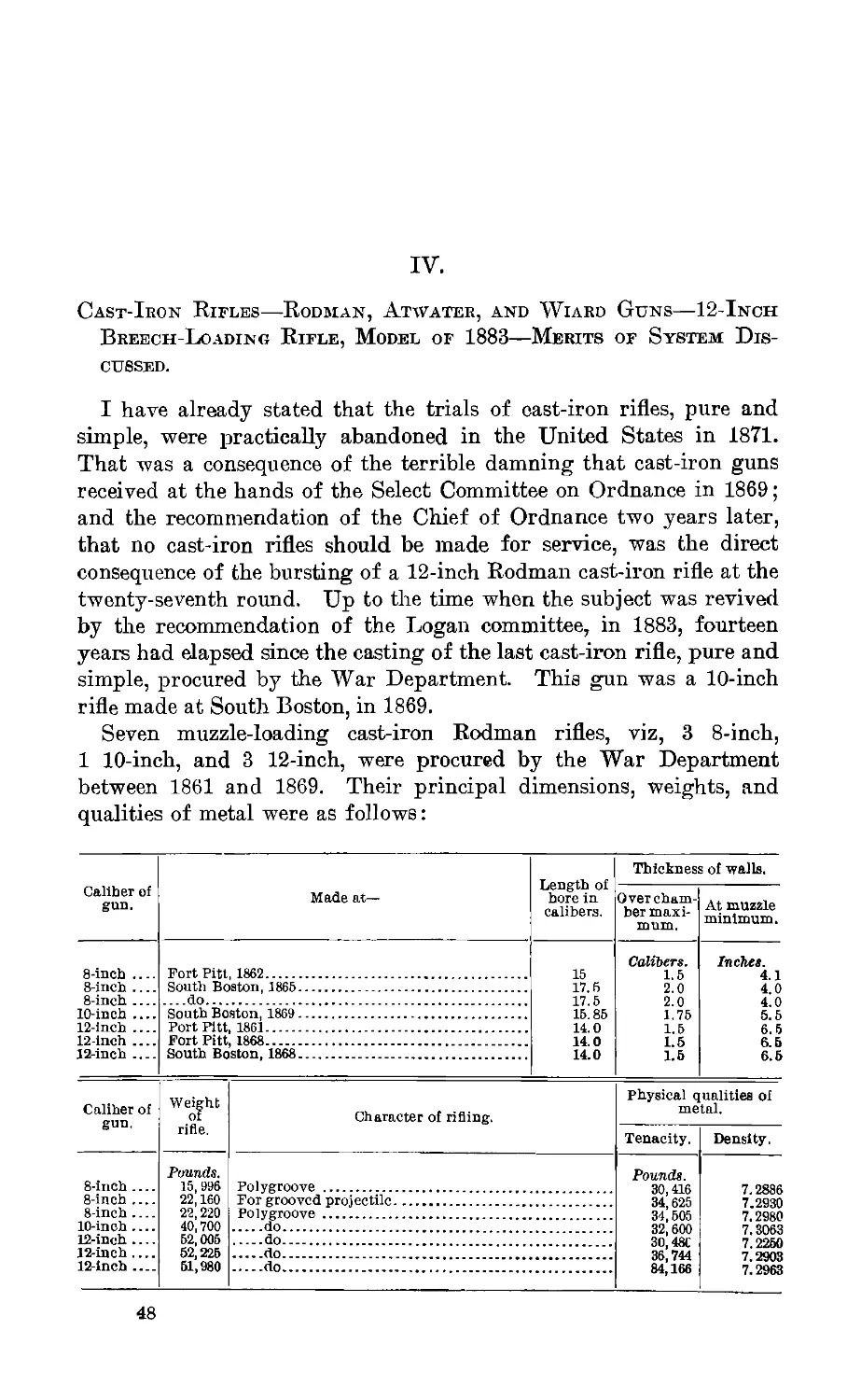
Cast-iron rifles.................................................... 48
Rodman rifles made 1861 to 1869.—Tests and endurance of Rodman rifles. —
Experiment to test effect of blows upon pressure gauge.
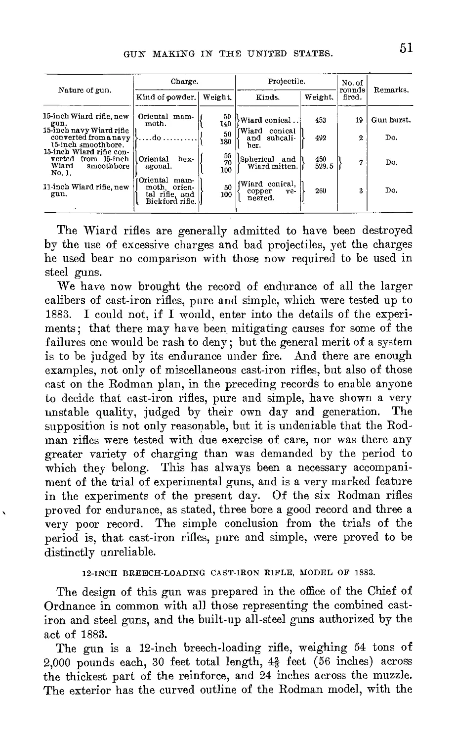
Atwater 12-inch rifle.—Wiard’s cast-iron rifles at Nut Island.......... 50-51
12-inch B. L. cast-iron rifle, model of 1883............................. 51
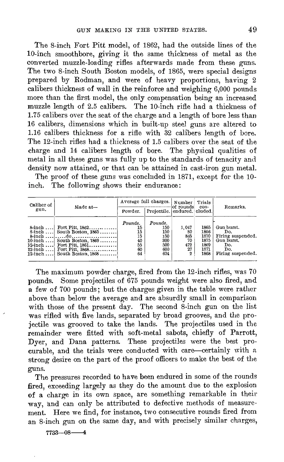
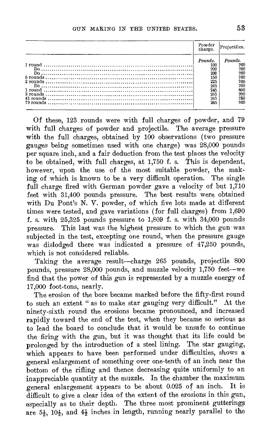
Firing tests and endurance.—Erosions of the bore.—Claims to improve-
ment in metal and methods of casting discussed.—Time required to
make large gun castings.—Conclusions.
3
4
TABLE OF CONTENTS.
V. Page.
Combined cast-iron and steel guns.................................-......... 58
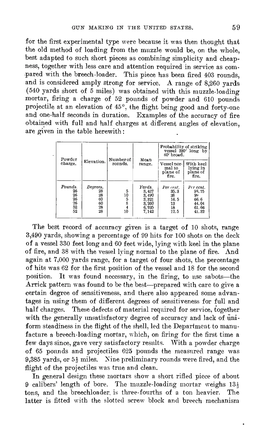
12-inch rifled mortars, steel hooped.—Tests of the M. L. mortar.—Pre-
liminary firings with B. L. mortar.—Construction of the rifled mortars.—
Steel hoops needed to give sufficient strength.
12-inch B. L. rifles................................-..................... 61
Cast-iron gun lined with half tube of steel.—Steel booped and tubed gun,
with cast-iron body.
Wire guns of recent design............................................... 62
10-inch wire-wrapped cast-iron rifle.—10-inch steel rifle, longitudinal bars,
wire wound.—Merits of wire-gun construction not yet decided.
VI.
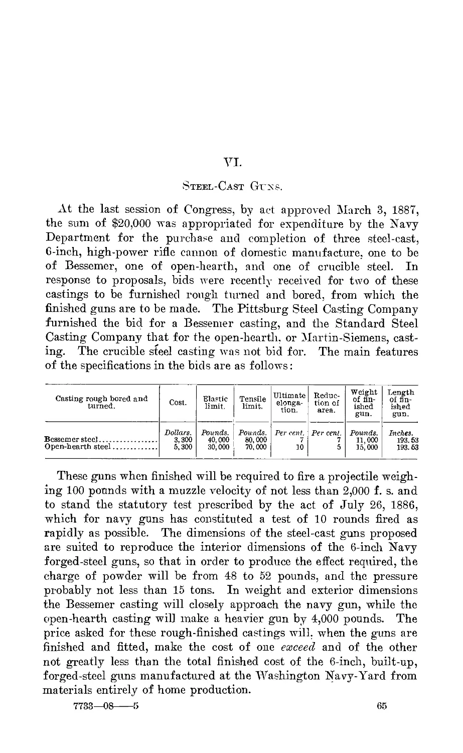
Steel cast gnus...................................................-......... 65
Two 6-inch gnns to be made.—Weights and special plant required for large
gun castings.—Defects of castings.—Proposed methods of casting.—
Elastic strength of neutral piece.—Utility of initial tension.
VII.
Bnilt-np forged steel gnns. —Claims of American inventors................... 70
Amount of gnu forgings procured by Army___________________________..----- 71
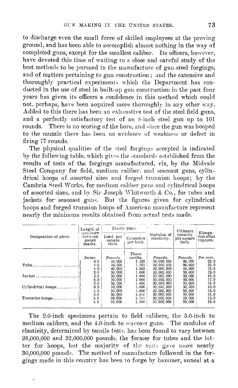
Progress made in construction of guns.—Physical qualities of steel for-
gings.—Superiority as a metal for gnns.
Elastic strength of guns................................................. 74
Relative strength of homogeneous guns.—Composite guns.
Experiments made by Army Ordnance Department................................ 78
Superiority of oil-tempered and annealed steel.—Similitude of specimen
and shrinkage tests.—Result realized in a complete gun cylinder.—Veri-
fication of formulas.—Effect of temporary exposure to high heat upon
qualities of forgings.—Frictional resistance to longitudinal separation due
to shrinkage.—Tests of forged trunnion hoop of American manufacture.—
Efficacy of annealing in removing stains from forgings.
Firing tests of steel gnns............................................. 86
3.2- inch B. L. field guns.—5-inch B. L. siege rifle.—7-inch B. L. siege
howitzer.—8-inch B. L. steel rifle.—Accuracy and high power.
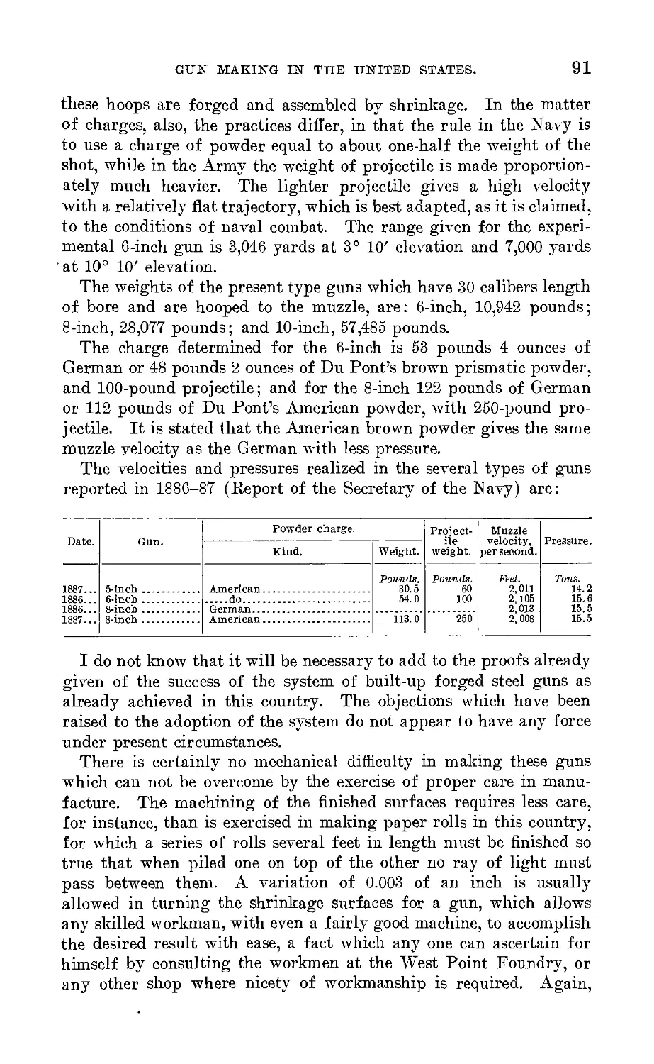
Work done by the Navy...................................................... 89
Amount of forgings procured and under contract with Midvale Steel Com-
pany and Bethlehem Iron Company.—Number of guns made or provided
for.—Fabricating capacity of the Washington Navy-Yard.—Tests of
guns.—Dimensions, weights, charges, and high power.
Replies to criticisms of construction of built-up steel guns................ 91
Commercial advantages of gnu and armor-forging plant...................... 93
The pneumatic dynamite torpedo gun...................................... 96
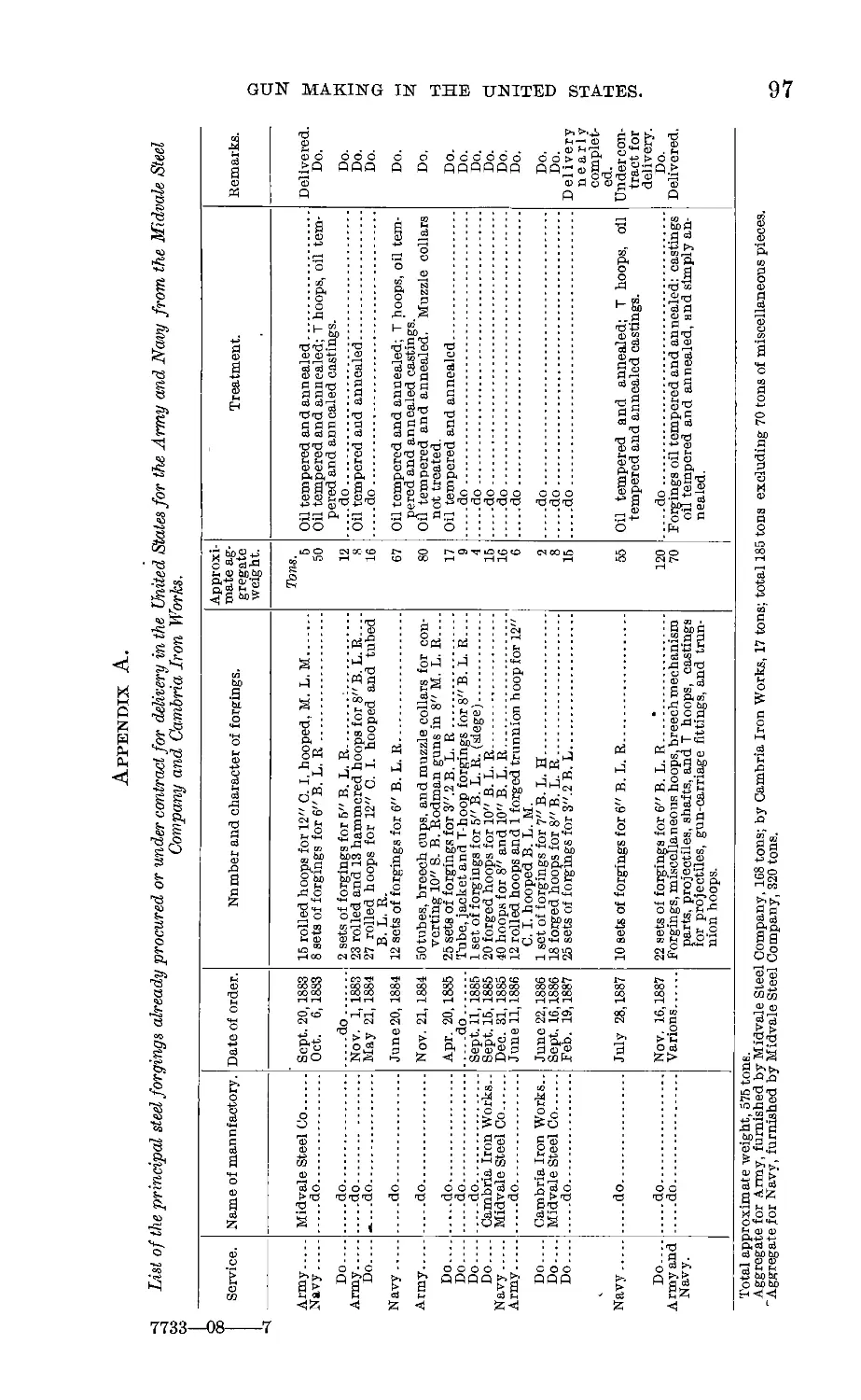
Appendix A. Steel forgings produced by Midvale Steel Company and the
Cambria Iron and Steel Works.......................................... 97
Appendix B. Initial tension in gun construction, discussed for a steel cast gun. 98
Appendix C. Alleged failures of steel guns.—Reply to report of Chamber of
Commerce, New York City, dated February 3, 1887 ...................... 108
Illustrations.
Plate III. 8-inch B. L. steel rifle............................ To face Preface.
Initial tension in cast-iron gun cylinder.............................. 16
Plate IV. Pressure apd strains in gun of solid wall..................... 76
I. Shrinkage tests of steel gun hoop.............................. 79
II. Shrinkages in full section of a bnilt-up gnu..................... 81
DISCUSSION.
Page.
Lieut. Commander F. M. Barker, IT. S. Navy..._________________ 115
Bvt. Brig. Gen. H. L. Abbot, Corps of Engineers................ 116
Bvt. Maj. J. B. Campbell, captain, Fourth Artillery............ 117
Joseph Morgan, Jr., Johnstown, Pa........................... 119
Theodore Cooper, С. E., New York______________________________ 120
J. R. Haskell, Esq____________________________________________ 121
Capt. Charles Shalbr, Ordnance Department.....-_______________ 124
Lieut. E. M. Weaver, Second Artillery...................... 124
William E. Woodbridge, Esq................................... 126
Capt. О. E. Michaelis, Ordnance Department. ............... 127
Prof. R. H. Thurston, Cornell University...___________________ 129
James E. Howard, С. E., Watertown Arsenal.................... 131
Commander R. D. Evans, U. S. Navy............................ 133
Capt. John G. Butler, Ordnance Department..___________________ 133
Lieut. William Crozier, Ordnance Department.................... 137
Capt. Rogers Birnib, Jr., Ordnance Department_________________ 140
5
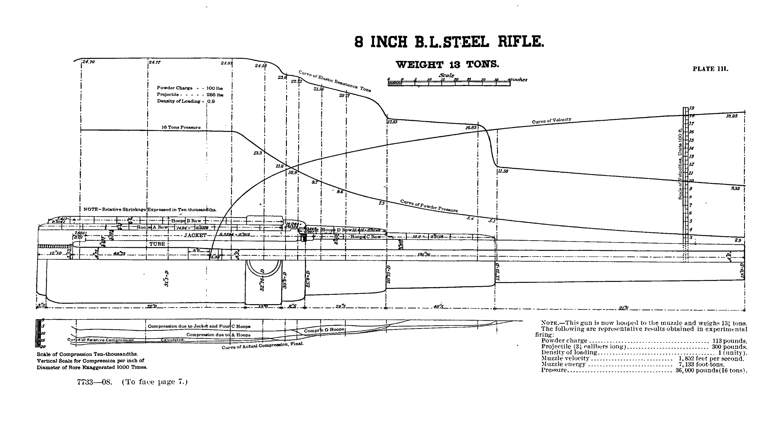
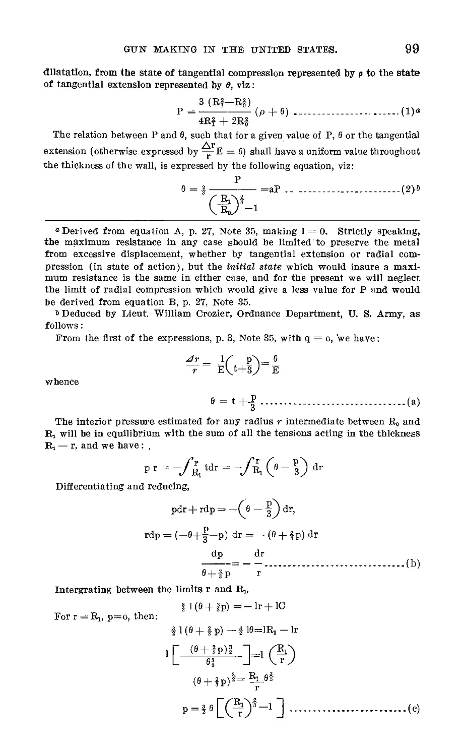
8 INCH В. L. STEEL RIFLE.
Scale of Compression Ten-thousandths.
Vertical Scale for Compression per inch of
Diameter of Bore Exaggerated 1000 Times.
Note.—This gun is now hooped to the muzzle and weighs 13-i tons.
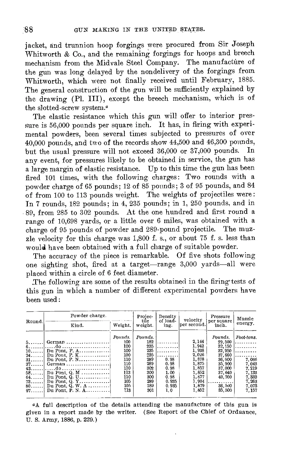
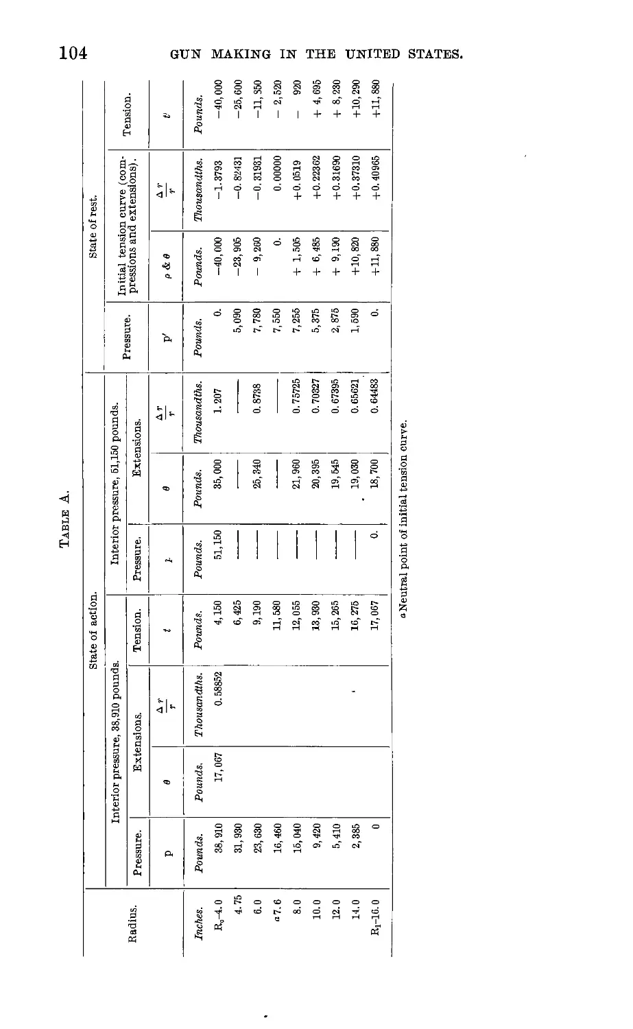
The following are representative results obtained in experimental
firing:
Powder charge........................................ 113 pounds.
Projectile (3i calibers long)........................ 300 pounds.
Density of loading.............................................. 1 (unity).
Muzzle velocity........................... 1,852 feet per second.
Muzzle energy............................ 7,133 foot-tons.
Pressure.................................. 36,000 pounds(I6 tons1'.
7733—OS. (To face page 7.)
PREFACE.
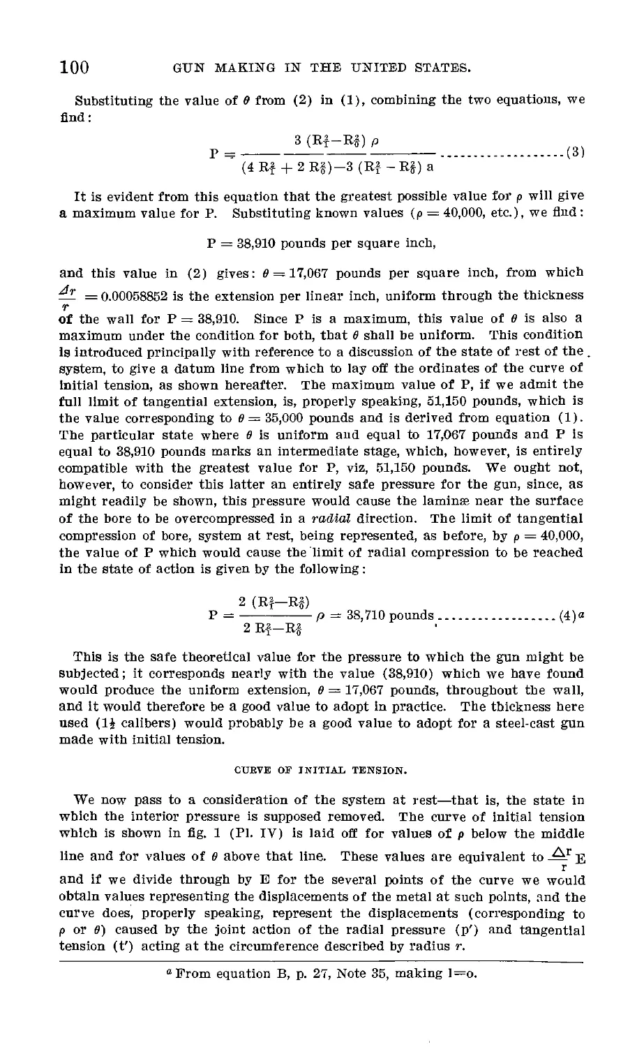
As a preface to that which follows, it is proper to state that the
conclusions and opinions expressed, except when otherwise stated,
represent the opinions of the writer and have no official sanction.
The subject-matter aims to be a history of the progress of gun making
and gun trials in the United States, especially with reference to the
part taken therein by the War Department, in the past fifteen years
or from the date of the Heavy Gun Board of 1872; and prior to
that of such matters as appear to have a bearing on current questions
of gun construction. The prominent part taken by the Navy Depart-
ment in being the pioneer of built-up forged steel guns—thanks to its
energetic efforts backed up by liberal and progressive Naval Com-
mittees of Congress—deserves the fullest recognition, and if a com-
paratively brief mention is made of the operations of that Depart-
ment in general it will be understood as due to the force of circum-
stances which render even a somewhat detailed account of matters
with which the writer is most familiar a matter requiring all the
time and attention at his disposal. The data given have been collected
from official reports or otherwise, with every regard for correctness.
The chronological order adopted for this description of events has
led to a much more extended treatise than was at first intended
and perhaps also to repetitions which may appear unnecessary; but
this order having an advantage in respect to the time necessary to
devote to the preparation of the paper has been adhered to.
COPYBIGHT.
THE MILITARY SERVICE INSTITUTION.
1888.
Republished by its Authority, 1907.
7
GUN MAKING IN THE UNITED STATES:
I.
Introductory—Early Inventions—Rodman Method of Casting—
Smoothbore Guns—Parrott Rifles.
By Capt. Rogers Birnie, Jr., U. S. Army, Ordnance Department.
Within the past few years the constituted authorities of both the
Army and Navy have, with a marked unanimity of opinion, advo-
cated the construction of built-up steel guns and have entered upon
their manufacture to the extent of available appropriations by Con-
gress. Until this time, with the exception of the Ordnance system
of converted guns, the art of gun making in the United States made
slow progress, compared with the rest of the world, from the time
when our Rodman and Dahlgren cast-iron, smoothbore guns reached
their best development and gave us a brief period of superiority.
That was some twenty-five years past, and the guns we have avail-
able for seacoast defense to-day comprise these same smoothbore
guns, supplemented only by a limited number of the converted
muzzle-loading rifles, which date back to 1872, and are now classed
as guns of third-rate power. The same was true of our field artil-
lery; but in this respect much has been, accomplished, and work is
now in progress that will give us at least a limited supply of the
best class of modern light field guns. In small arms, and machine
guns firing small ammunition, only has the United States main-
tained an advanced position.
The reason for this state of affairs is, I think, easy to discern.
The trade in munitions of war must, like every other industry, obey
the inevitable law of supply and demand. The demand for small
arms for general use in our own country, and the fact that the cost of
the development of these arms places the matter within reasonable
control of private industry and does not necessitate a very considerable
expenditure on the part of the Government, has maintained the nec-
o Read before Military Service Institution November 26, 1887, Major-General
Schofield in the chair.
9
10
GUN MAKING IN THE UNITED STATES.
essary skill in the art and has enabled our private makers to com-
pete successfully in the markets of the world. With guns of a
heavier caliber the case is very different. Governments alone need
a supply of these, and governments alone can create a demand for
them. The close of the civil war found us with an established sys-
tem of smoothbore, cast-iron guns possessing great merit. But
hardly had we time to congratulate ourselves upon this circumstance
before the advance of foreign powers in the manufacture of rifled
guns forced us to admit our inferiority. We all know the result of
the struggle which established the relative merit of smoothbore and
rifled guns. We placed implicit confidence in cast iron as a metal
for cannon, and so continued for a number of years to use that
metal in endeavoring to establish a system of rifled guns, while
other nations were coming to discard it more and more in favor of
wrought iron and especially steel. Our first rifled guns, introduced
in 1861, were made of cast iron, and a limited degree of success was
obtained; then others were tried, with signal failure, and the attempt,
for the time being at least, fell flat. In Congress the culmination
of the matter was reached in the terrific report of the Select Com-
mittee on Ordnance, 1869. And in the War Department, in his
annual report for 1871, the Chief of Ordnance said: “ The results
obtained will not warrant me in recommending that any cast-iron
rifle guns be procured for arming the forts.” All this happened
sixteen years since and should have been conclusive, yet there are
not wanting manufacturers and laymen to-day who still advocate
cast-iron rifles. Judging from the course of legislation since that
period, it appears that the country has scarcely yet recovered from
the paralysis occasioned by the discovery that our justly vaunted
cast-iron gun metal, which had done such excellent service in the
short heavy smoothbores, was not a reliable metal for rifled guns.
We have been stumbling along in the rear ever since. The idea
that if we were to have guns they should be made with existing
facilities in the United States, unaccompanied by any whole-hearted
effort to improve those facilities, has always been kept to the front.
It has retarded our progress and continues to do so. Certainly, I
say, the material for guns, and the guns themselves, must be of home
production; but why it should be considered of such doubtful policy
to encourage improvements in the manufacture of material and
guns, and thereby benefit commerce as well, is a position which is
difficult to explain. The very conservative course of legislation in
Congress in past years has been explained by saying that the rapidly
changing developments in guns and armor would enable us, by
waiting a few years, to take up the subject at an advanced stage and
thus derive the benefit of the vast amount of experimentation con-
tinuously being carried on in other countries. Meantime, the policy
GUN MAKING IN THE UNITED STATES.
11
has been pursued of maintaining a show of organization for the
Service and in testing immature inventions of various designs; and
board after board has been appointed with sufficient frequency to
keep the matter in apparently well-meant agitation. Finally, a
climax has been reached; we are now in a position to know that
navies have been established throughout the world which must exist
for years to come, and that equally with this the consensus of nations
has adopted a system of construction for guns which is capable of
overcoming these vessels and is, besides, the strongest and most
reliable ever made. In shooting qualities and endurance this sys-
tem—the built-up steel gun—is to-day without a rival, and as long
as these qualities remain essential to a gun it promises to remain
equal to the best. These facts have been exploited for several years
and gain new confirmation every day. Congress has given no appro-
priation for the armament of fortifications in two years past, and
the apparent reasons for this have been much discussed. The com-
mittees have been unable to decide for themselves what measures to
adopt. Two important questions were under consideration—first,
as to the kind of guns that should be provided, and, second, the
propriety of changing the present methods of administration in the
procurement of guns. To anyone who has had the privilege of
appearing before these committees and hearing the conflicting char-
acter of the testimony taken, the wonder is—supposing that equal
weight is given to the testimony of individuals, as appears to be the
case—the wonder is, I think, not that the committees should remain
undecided, but it would be strange that they should reach any con-
clusion at all. As to the proposed change in the method of admin-
istration—taking away from the present organized Bureau of the
War Department the control of these affairs and creating another
bureau under the same Department or else an independent commis-
sion of some sort—that is a matter about which Congress will, no
doubt, come to a wise conclusion. It is a question of the substitu-
tion of one set of agents for another, or of a multiplication of the
paraphernalia of government. It does not seem probable that the
laws will be so changed as to substitute a changeable commission
of mixed political affiliations for the individual responsibility now
held by the head of the War Department, and under him the Chief
of Ordnance, assisted, as he is, in the discharge of these duties by a
body of officers already trained at the expense of the Government,
appointed for life, and subject to removal only through bad behavior.
This much we may at least; hope—that the question of what guns
the Army shall use will remain intrusted to military men.
But the main question before us is as to the type of gun to be
adopted. And in this matter, I think, we should make a very clear
distinction between an existing established system and experimental
12
GUN MAKING IN THE UNITED STATES.
construction. By all means let experimentation go on, only this
should not interfere with the production of guns for service when
we have at hand the highest type of modern gun, the outcome
of years of experimentation, to work upon. The conception of a
new design for a gun is a very small part of its successful produc-
tion; the history of gun making abounds in new designs of form
and material, but how few in number have been the successful
types. It is a very small matter to perfect a small invention, but
to even approach perfection in a heavy gun is one of the most ex-
pensive and laborious questions of modern times. So it has been
proved the world over, and so it has been shown in such gun trials
as have been made in the United States in recent years, wherein
an opportunity has been afforded for the test of a number of differ-
ent systems, to which I will refer.
In reviewing as briefly as may be the history of gun making in
the United States in order to trace its effect upon questions of the
day, it will be necessary to begin a connected account with the period
of Rodman’s improvements in making cast-iron smoothbores. From
that period up to the present era of steel guns we will follow the
chronological order of the trials made under the supervision of the
War Department.
Some of the earlier designs of guns possess an interest, because
of the successful application of the principles involved in guns now
in use. Of such were those, dating from 1841, made after the plans
of Daniel Treadwell? Professor Treadwell’s first gun was made of
rings or short hollow cylinders of wrought iron joined together
end to end by welding. Each ring was made of several thinner rings,
placed one over or around the other and welded. Subsequently the
method of making the rings was somewhat changed by first making
a single ring of steel about one-third the thickness of the whole;
and upon the outside of this winding a bar of iron spirally, as a
ribbon is wound upon a block. Machinery was devised for making
the rings, welding them together, and forming the guns by means
of various molds, dies, and sets connected with a powerful hydrostatic
press. The breech was closed with a screw plug, and a trunnion band
formed by the machinery was screwed upon the outside of the gun.
The object of this method of manufacture was to so dispose the
metal as to place the direction of the fiber in opposition to tangential
rupture.
Professor Treadwell’s admirably conceived idea was to make a
gun of equal strength in all directions. He demonstrated the propo-
sition that, proportioned to the arena of resisting metal, the tendency
to tangential rupture would be several times greater than the ten-
short account of an improved cannon, and of the machinery and processes
employed in its manufacture, by Daniel Treadwell, Cambridge, 1845.
GUN MAKING IN THE UNITED STATES.
13
dency to transverse rupture; hence he arranged the metal to Dppose
its lines of greatest strength to the effort of the tangential strains,
and thus economized his material and approached, as nearly as could
be with the means employed, the conception of his ideal gun of equal
resistance. These guns were tested both by the Army and Navy.
The smaller calibers stood well, and the Ordnance Board in 1846
recommended batteries of 6 and 12 pounders and 12 and 24 pounder
howitzers, approved by the Secretary of War in 1847. Subsequently
it appears some guns of larger caliber—32 pounders—supplied to the
Navy did not prove successful. We can not find in this method of
construction more than a very remote resemblance to the principles
of the modern built-up gun, but its development was directly shown
in the after success of the coil system of wrought-iron gun construc-
tion, illustrated in the Armstrong and Woolwich guns of the period
1856 to about 1880, the breech bands of the Parrott guns, and the
coiled welded tubes of our converted guns.
The early development of the modern system of hooped guns is
traced through General Frederix, in Belgium, in 1830; Thiery in
France, whose first gun was constructed in 1833; Chambers’ Amer-
ican patent for a hooped wrought-iron gun, dated July 31, 1849,
and the English and American designers, Blakely and Treadwell,
in 1855. Between these two last there exists a question as to priority
of the principle of initial tension in hooped guns, or of giving to the
several layers of hoops such a shrinkage as would cause each to offer
its full strength in resisting the action of an interior pressure cal-
culated to rupture the gun. But we are most indebted, I believe, to
the investigations of Lame and Barlow for the origin of this prin-
ciple and to Rodman’s exposition of it, precedent to his endeavor
to apply it in a cast gun. Chambers’ patent of 1849 is especially
worthy of note, in that it embodies—
First. The slotted screw breech fermeture.
Second. The hinged movement of the breech mechanism, when
withdrawn to clear the way for loading through the breech.
Third. The loading tray or sleeve inserted in the breech to cover
the threads in loading.
Fourth. The biconical shape given to the shrinkage surfaces of the
hoops to afford longitudinal strength.
In design this gun was a wronght-iron breech-loading smoothbore,
built up with a tube extending in one piece from breech to muzzle,
and incased with several layers of hoops, shrunk on. The principle
of initial tension is not enunciated in the design, but it was provided
that the rings should be put on at a heat sufficiently low to prevent
oxidation. We find the slotted screw, the hinge movement of the
breech mechanism, and the loading tray in the perfected system now
designated the French breech mechanism. The biconical shape of
14 GUN MAKING IN THE UNITED STATES.
hoops is an idea not long since introduced in the De Bange guns,
but its utility is doubtful. As regards the Broadwell ring used in
the Krupp gun, it appears to have been derived from a patent taken
out by Broadwell in Russia. Broadwell’s patent was placed first in
Russia in 1861, second in England in 1864, and third in the United
States in 1866.
INITIAL TENSION IN CAST-IEON GUNS.
The great improvement in the manufacture of cast-iron smooth-
bore guns was due to the introduction of Rodman’s method of casting,
by cooling from the interior, coupled with the well-conditioned out-
side lines which he adopted for his gun. Major Wade’s report of
August 4, 1849, contains an account of the trial of the first gun made
on this plan. Two 8-inch Columbiads were cast at the same time
from the same metal. One was cast solid in the usual manner and
the other according to the Rodman plan. The first was burst at the
eighty-fifth round, while the second endured 251 rounds. An equal
and even greater degree of superiority was evinced in the succeeding
trials of 8 and 10 inch guns made in 1851. The object sought to be
attained by Rodman finds application to-day in what we consider
the highest principles of gun construction. Following the discussion
of the action of a central force as enunciated by Barlow some years
previously, Rodman, in 1851, pointed out not only the injurious
effect of exterior cooling as causing a zone of metal near the exterior
to remain in a state of compression and thus actually assist in the
rupture of the gun, but also showed that the effect of cooling from the
interior would be to so dispose the metal that in resisting an interior
pressure each concentric laminae of metal throughout the wall might
be equally strained to its limit to resist tangential rupture. To use
his own words, referring to a gun which had withstood 1,500 rounds
without bursting: “The object of my improvement was in part, if
not fully, attained, viz, to throw the gun upon a strain such that
* * * each one of the indefinitely thin cylinders composing the
thickness of the gun shall be brought to the breaking strain at the
same instant” Evidently a condition like this would give a maxi-
mum resistance, since it would be determined by the product of the
mean strain of the laminae into the thickness of the wall, and if each
laminae worked to its limit that product would be the greatest
possible.
But while we may not deny the utility of the Rodman process as a
whole, it was, and must continue to be, uncertain in its operation, inde-
pendent of the always existing uncertainty about the soundness of the
castings. A number of cases are known in which the castings burst
spontaneously on cooling, and in some cases after being put in the
lathe for finishing. And we know also that a frequent cause for rejec-
GUN MAKING IN THE UNITED STATES.
15
tion of these guns was the existence of cavities uncovered in the bor-
ing. The plan may be expected to do more than counteract the effect
of the hurtful strains arising from cooling solid castings in the usual
manner; it will, in fact, produce to an uncertain extent, however, the
proper direction of initial strains. It would be the merest accident
should there be brought about the perfect state indicated by the theory.
Nor was this to be expected, since the question of the proper degree of
temperature to be maintained at the exterior and the rate of cooling
from the interior was investigated only in a crude manner. A little
study of the problem will show that in order to produce an accurate
degree of tension in the indefinitely thin cylinders composing the
thickness of the wall the most delicate appliances would be necessary;
the exterior should remain heated to the very last and the cooling pro-
gress regularly, according to a certain fixed law, from the interior.
Again, it is impossible to maintain the heat of fusion at the exterior
sufficiently long for this process to be accomplished, so that the metal
there becomes set and prevents a zone of adjacent metal within from
contracting as it should upon the interior mass. These are not theo-
retical ideas; they are the results of careful investigations. The
method adopted for determining the amount of tension in the castings
was to cut off a thin cross section of the gun to form the “ initial ten-
sion ” ring, and then slot this ring through on one side along a radius,
the separation of the ring measured in the slot at the outer circumfer-
ence being taken as a measure of the tension. To what extent this
method gives a true measure of the initial tension strains is entirely
problematical and unknown; it can be said only to show the aggregate
result of the interior strains of every sort existing in the castings, and
either localized or general. In theory, it was desired to reach an ini-
tial tension of about 20,000 pounds, or two-thirds (66 per cent) of the
average resistance of the cast iron. In practice, however, it was found
that the initial tension of the 10-inch guns varied from 3,000 to 28,000,
or from 12 to 72 per cent of the actual tenacity of the iron, and the 15-
inch guns from 4,000 to 25,000, or from 15 to 61 per cent of the actual
tenacity. These results combine two equally important and unknown
factors, viz, the uncertainty of the method to produce the results
desired, and the inadequacy of the method used for determining the
initial tension. Investigations and extended attempts to introduce the
Rodman method of casting have been made in Russia and proved
unsatisfactory, because it was found, upon careful investigation, that
the desired state of initial tension could not be produced with any
degree of certainty.11
The results of an important investigation recently made at Water-
town Arsenal in this matter are given in Notes on the Construction of
a Notes on the Construction of Ordnance, No. 21, p. 7.
16
GUN MAKING IN THE UNITED STATES.
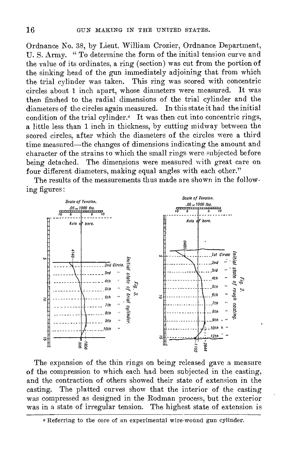
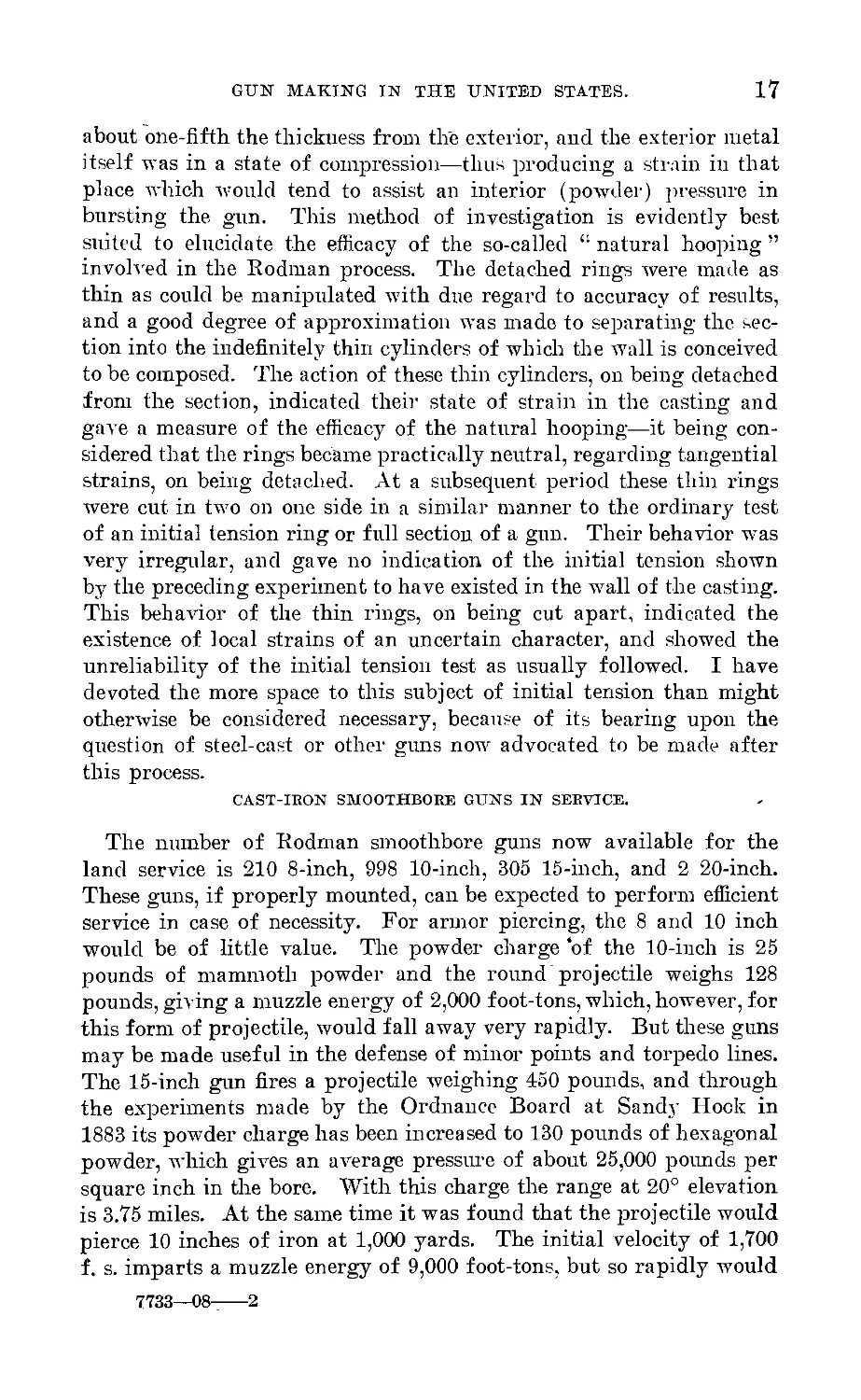
Ordnance No. 38, by Lieut. William Crozier, Ordnance Department,
U. S. Army. “ To determine the form of the initial tension curve and
the value of its ordinates, a ring (section) was cut from the portion of
the sinking head of the gun immediately adjoining that from which
the trial cylinder was taken. This ring was scored with concentric
circles about 1 inch apart, whose diameters were measured. It was
then flushed to the radial dimensions of the trial cylinder and the
diameters of the circles again measured. In this state it had the initial
condition of the trial cylinder.0 It was then cut into concentric rings,
a little less than 1 inch in thickness, by cutting midway between the
scored circles, after which the diameters of the circles were a third
time measured—the changes of dimensions indicating the amount and
character of the strains to which the small rings were subjected before
being detached. The dimensions were measured with great care on
four different diameters, making equal angles with each other.”
The results of the measurements thus made are shown in the follow-
ing figures:
The expansion of the thin rings on being released gave a measure
of the compression to which each had been subjected in the casting,
and the contraction of others showed their state of extension in the
casting. The platted curves show that the interior of the casting
was compressed as designed in the Rodman process, but the exterior
was in a state of irregular tension. The highest state of extension is
» Referring to the core of an experimental wire-wound gun cylinder.
GUN MAKING IN THE UNITED STATES.
17
about one-fifth the thickness from the exterior, and the exterior metal
itself was in a state of compression—thus producing a strain in that
place which would tend to assist an interior (powder) pressure in
bursting the gun. This method of investigation is evidently best
suited to elucidate the efficacy of the so-called “ natural hooping ”
involved in the Rodman process. The detached rings were made as
thin as could be manipulated with due regard to accuracy of results,
and a good degree of approximation was made to separating the sec-
tion into the indefinitely thin cylinders of which the wall is conceived
to be composed. The action of these thin cylinders, on being detached
from the section, indicated their state of strain in the casting and
gave a measure of the efficacy of the natural hooping—it being con-
sidered that the rings became practically neutral, regarding tangential
strains, on being detached. At a subsequent period these thin rings
were cut in two on one side in a similar manner to the ordinary test
of an initial tension ring or full section of a gun. Their behavior was
very irregular, and gave no indication of the initial tension shown
by the preceding experiment to have existed in the wall of the casting.
This behavior of the thin rings, on being cut apart, indicated the
existence of local strains of an uncertain character, and showed the
unreliability of the initial tension test as usually followed. I have
devoted the more space to this subject of initial tension than might
otherwise be considered necessary, because of its bearing upon the
question of steel-cast or other guns now advocated to be made after
this process.
CAST-IRON SMOOTHBORE GUNS IN SERVICE.
The number of Rodman smoothbore guns now available for the
land service is 210 8-inch, 998 10-inch, 305 15-inch, and 2 20-inch.
These guns, if properly mounted, can be expected to perform efficient
service in case of necessity. For armor piercing, the 8 and 10 inch
would be of little value. The powder charge of the 10-inch is 25
pounds of mammoth powder and the round projectile weighs 128
pounds, giving a muzzle energy of 2,000 foot-tons, which, however, for
this form of projectile, would fall away very rapidly. But these guns
may be made useful in the defense of minor points and torpedo lines.
The 15-inch gun fires a projectile weighing 450 pounds, and through
the experiments made by the Ordnance Board at Sandy Hook in
1883 its powder charge has been increased to 130 pounds of hexagonal
powder, which gives an average pressure of about 25,000 pounds per
square inch in the bore. With this charge the range at 20° elevation
is 3.75 miles. At the same time it was found that the projectile would
pierce 10 inches of iron at 1,000 yards. The initial velocity of 1,700
f. s. imparts a muzzle energy of 9,000 foot-tons, but so rapidly would
7733-08----2
18 GUN MAKING IN THE UNITED STATES.
this fall off that at 1,000 yards the energy would be considerably less
than that of the projectile of the, new 8-inch steel rifle, which starts
with an energy of 7,200 foot-tons.
PARROTT RIFLES.
Although all the Parrott guns are now classed as “ retained cali-
bers ” in the service—that is, only to be used in cases of necessity—
they performed a most important duty in our civil war, and are
especially worthy of mention as being the first extended system of
rifled guns introduced in the United States. Their founder and
maker will always be regarded as one of our most successful gun
makers, and remembered as a man distinguished in the art. He made
a wide reputation for himself and for the West Point Foundry, at
Cold Spring, N. Y., which, under his successors, has continued to
afford indispensable aid to the Government in the production of new
types of guns, and has materially assisted in maintaining and diffus-
ing a knowledge of gun making in the country. My personal obli-
gations in this respect are deep, for it has been my good fortune to
have remained on duty there as an inspector for nearly six years,
with opportunities for acquiring the practical knowledge that abounds
at the foundry.
The history of the Parrott guns is so well known that it will be
necessary to call attention only to certain features. The smaller cali-
bers showed in some cases a remarkable endurance in war service, and
the same was true to a less extent with the larger calibers, but failures
of the 100, 200, and 300 pounders were relatively numerous. Several
instances which have occurred in practice firing with these guns in
recent years have also, in connection with modern improvements in
construction, led to the obvious necessity of retiring them from service
as soon as they can be replaced. The uncertainty in endurance of the
heavier calibers must be regarded as evidence of the unsuitability of
cast-iron as a metal for making heavy rifled guns. Any system of
conversion for these guns would necessitate an enlargement of the
bore, and corresponding thinning down of the already weak walls;
moreover, the guns were made for quick burning powder and are too
short to realize a proper effect with slower burning powders. The
wrought iron reenforce band of these guns was made from a bar coiled
and welded in the form of a hollow cylinder, which was afterwards
finished for shrinkage. The effect of this was to dispose the fibers of
the iron to resist tangential rupture, and the band was probably not
expected to afford any resistance to longitudinal rupture. The cast-
iron wall of the 100-pound rifle, for instance, is one caliber (nearly)
in thickness, and the thickness of the reenforce band is one-half cali-
ber (3.2 inches). The shrinkage prescribed for the band was one-
GUN MAKING IN THE UNITED STATES. 19
sixteenth of an inch to the foot, or 0.0052 of an inch per linear inch.
This is fully four times as much as would now be regarded a useful
limit for the shrinkage of a wrought-iron gun hoop; however, these
bands were assembled at a high heat and the iron band was allowed
to adjust itself without exterior cooling; hence we do not find in
these guns an example of the practice of hooping, as now understood.
And the excessive shrinkage of the single band, by producing un-
duly heavy cross strains in the section of the cast-iron at the front,
tends to weaken the gun to resist longitudinal rupture, as may be
inferred from the manner in which a good proportion of the fail-
ures have taken place.
II.
Period from 1872 то 1881—Hitchcock, Mann, Lyman-Haskell,
and Woodbridge Guns—Converted Muzzle-Loading Rifles—
Converted Breech-Loading Rifles—Sutcliffe and Thompson
Guns—Field Guns.
The Heavy Gun Board of 1872 was appointed to meet in New
York City for the purpose of examining such models of heavy ord-
nance as might be presented to it, and of designating and reporting
to the Chief of Ordnance such models as might be selected for ex-
periment. Colonel Whitely, of the Ordnance Department, was
president of the board, and there were besides one officer of Engi-
neers, two of Ordnance, and two of Artillery as members. A spe-
cial appropriation was made in advance by Congress for the pur-
pose of carrying out the recommendations of the board. The board
examined into 40 inventions and proposals, and selected the 9 follow-
ing, arranged in the order of merit determined by the board, viz:
Muzzle-loading guns:
1. Dr. W. E. Woodbridge.
2. Alonzo Hitchcock’s.
3. Cast-iron guns, lined with wrought-iron or steel tubes.
Breech-loading guns:
1. Friedrich Krupp.
2. E. A. Sutcliffe.
3. Nathan Thompson.
4. French and Swedish system.
Miscellaneous:
1. H. F. Mann’s.
2. Lyman’s multicharge.
The Ordnance Department was occupied in the ten years following,
pursuant to enactments of Congress, in the construction and trial
of the guns recommended by this board. The Krupp gun was in-
tended to be tested for a trial of the breech mechanism as well as
the system of construction. However, no gun of Krupp’s system
was procured, for the reason the War Department was unable to
comply with his conditions, which necessitated the purchase of a
number of guns in case the trial gun should prove a success. Such
an agreement by the War Department could only have been made
20
GUN MAKING IN THE UNITED STATES.
21
in case Congress had already appropriated the money for the pur-
pose, and this was not done. But the Krupp breech mechanism
was subsequently tried in combination with the converted wrought-
iron lined guns recommended by the board, after the muzzle-loading
guns of the same type had been successfully tested.
The Hitchcock gun proposed was a 9-inch muzzle-loading rifle,
to be made by welding together disks or “ cheeses ” of wrought iron
forming sections of the gun to make a solid wrought-iron piece.
The work was conducted at the Springfield Armory under the
direct supervision of the inventor. After nearly three years’ labor
and the expenditure of a large amount of money the project was
abandoned as being too difficult and costly, if not impracticable,
to be fulfilled.
No provision was made in this period for a trial of the French
and Swedish system. The Mann gun considered by the board was
an 8-inch breech-loading rifle already in possession of the Ordnance
Department, which had already been fired about 50 rounds. Some
alterations were made, and the gun was fired 11 rounds at Sandy
Hook in 1875, after which it was moved to Philadelphia to be placed
on exhibition at the Centennial. The Lyman’s multicharge gun
in existence at this time was a 6-inch breech-loading rifle, designated
by its private owners as the “ Multicharge 100-pounder rifle gun.”
But since improved models of both the Mann and Lyman-Haskell
guns were tested at a period subsequent to this, further references
will be. deferred to an account of those trials.
WOODBRIDGE 10-INCH WIRE-WOUND GUN.
It appears from the record that Doctor Woodbridge first presented
a plan for a wire-wound gun to the War Department July 30, 1850,
which establishes his claim to priority in the idea. A 2.5-inch gun,
constructed upon his plans at the Washington Navy-Yard, was
tested for endurance at the Springfield Armory, where, in 1865,
Major Laidley reported that 1,327 rounds had been fired from
it and the firing had been stopped because the trunnion band broke
loose, but the gun itself was practically uninjured. The trial gun
decided upon in 1872 was a muzzle-loading rifle of 10-inch caliber.
It consisted of a thin steel tube strengthened by wire wound on its
exterior surface, tube and wire being subsequently consolidated
into one mass by a brazing solder melted into the interstices. The
tube extended through from breech to muzzle, was left solid for a
length of 19 inches to form the breech, and had a thickness of 1.5
inches around the bore. The length of the bore was 155 inches, or
15.5 calibers. The following brief description of the process of
22
GUN MAKING IN THE UNITED STATES.
manufacture is taken from report of Captain Prince, dated March
31, 1875:
Square wire is wound upon a steel core somewhat larger than the intended
bore of the gun, a sufficient number of wires being wound at once, side by side,
to produce the required obliquity of the turns. The successive layers have
opposite twist, their number being, of course, sufficient to give the desired
exterior, diameter to the gun. When thus wound, the whole mass is inclosed
In a tight case, to protect it from oxidation, and is heated therein to a tem-
perature somewhat above that required for the fusion of the metal to be used
for consolidating it. The soldering metal is then run in, filling all the inter-
stices of the mass. When properly cooled, the gun is bored and finished from
the mass in much the same way as if it were a common casting.
The construction of the gun was undertaken at Frankford Arsenal
in October, 1872, and after many delays and difficulties was com-
pleted in April, 1876. It was fired 10 rounds at Frankford Arsenal
with powder charges increasing from 40 to 70 pounds, and pro-
jectiles from 343 to 397 pounds. In these firings imperfect brazing
was developed and a crack was started on the exterior of the gun.
The same gun was taken up in 1881 and fired for endurance under
the supervision of the board on heavy ordnance and projectiles.
The charge principally used was 70 pounds hexagonal powder and
395-pound projectile. With a charge of 80 pounds of powder the
gun parted longitudinally after a total of 93 rounds, the “ fracture
being 26.75 inches from bottom of bore in the plane of openings
noted and measured during the firing.” Notwithstanding the poor
success of this gun, as shown in the difficulties attending its manu-
facture, and its subsequent failure under proof, the Getty Board,
being much impressed with the utility of continued experiments
with wire guns, recommended that a breech-loading gun of the same
construction be made and tried, with others of different designs
presented by Doctor Woodbridge. These later designs apparently
possess more merit and have superseded the first construction in
which the brazing of the wire formed almost the sole reliance for
longitudinal strength. The recommendation to try another brazed
wire gun has never been carried out.
CONVERTED MUZZLE-LOADING RIFLES.
These guns consist essentially of a cast-iron body or casing,
strengthened with a wrought-iron or steel rifled tube which has a
thickness of wall, over the seat of charge, equal to about one-third
the caliber of the gun. They constitute a system of built-up guns,
in which the shrinkage of the casing on the tube is negative, or there
is a play. The casing, except in a single gun of new construction—
the 12|-inch rifle—is formed of the Rodman smoothbore gun, from
which about fifteen one-hundredths of the caliber only in thickness of
cast iron is removed to enlarge the bore for the reception of the com-
GUN MAKING IN THE UNITED STATES.
23
paratively thick tube of reduced bore. In the wrought-iron tubes
formed by coiling and welding bars of the very best grade of wrought
iron, the fiber is arranged to resist directly the dangerous tangential
strain, and these tubes are, besides, reenforced over the seat of the
charge by a sleeve or jacket of wrought iron, similarly formed
and shrunk over. These wrought-iron tubes would alone support
an interior pressure of 13,000 pounds per square inch, or more than
one-third of the whole pressure that the guns are called upon to bear.
Even supposing the tube inert, its interposition causes a reduction
of about 31 per cent of the pressure in the bore in transmission to
the cast iron, because the pressure upon 1 square inch of the bore
would be distributed upon 1.7 square inches of the interior of the
outside cast-iron body. In the later constructions where steel is used,
the metal is a fine quality of highly ductile steel suited to the con-
struction, and the tube in itself is able to safely support an interior
pressure of 18,000 pounds per Square inch, or about one-half of the
whole strain upon the gun when fired.
In mode of conversion, these guns are divided into three classes,
viz: (1) The muzzle insertion with wrought-iron tube; (2) the
breech insertion with wrought-iron tube; (3) the muzzle insertion
with steel tube.
The difference between the plans of muzzle and breech insertion
lies principally in this: In the former the tube is supported longi-
tudinally from a force that would tend to open coil welds by the
muzzle screw collar; while in the latter, there are several shoulders
on the outside of the tube which bear against corresponding shoulders
in the casing, and the tube by this means is well supported longitu-
dinally from movement forward at several distances throughout its
length. A special importance attaches to this in the use of coil-
welded'tubes, which are more apt to develop a weakness at the coil-
weld joints than in any other part.
These guns were proposed as an expedient for converting the
comparatively useless 10-inch smoothbores into rifled guns to meet
the increasing thickness of armor carried by vessels. When this
system was inaugurated the 8-inch caliber was seen to be a gun that
would eqnal in power the existing English guns of like caliber, and
it was hoped that the extension of the system to guns of larger cali-
ber, would prove a success. As an additional reason for the adoption
of the system, our forts were, and still remain, constructed with
casemates adapted to accommodate a gun of about the dimensions
of the 10-inch Rodman, and the conversion of this gun into a rifle
afforded at that time, the best and the only available means for in-
creasing the efficiency of the casemated forts to a maximum. At the
same time, however, the Chief of Ordnance, General Benet, then
24 GUN MAKING IN THE UNITED STATES.
placed himself upon record as saying:a “ There is little doubt that
steel is the best material for guns.” He did not recommend an ex-
penditure of a large amount of money for a gun plant to make the
proposed conversion, but drew attention to the success of the tubing,
as enabling the smoothbore guns to be made strong enough for use as
rifles and recommended the system as an “ easy and economical mode
of converting our cheap cast-iron smoothbores into powerful and
efficient rifles.”
The lining of a cast-iron body with a steel tube, as a system of
construction for rifled guns (10-inch and 12-inch), was recommended
for trial by the Ordnance Board, convened under the order of the
War Department, dated December 16, 1867. The matter was brought
to the attention of the board of 1872 by Major Crispin, and this
board recommended the conversion of four 10-inch Rodman guns
upon the plans proposed, which were modeled upon the Palliser plan
of muzzle insertion, then successfully established in England, and
the Parsons (American) plan of breech insertion. The details of the
construction of the guns were subsequently arranged by boards of
ordnance officers, convened September 18, 1872, and October 10, 1874.
It was decided that two of the four experimental guns be made of
8-inch caliber and two of 9-inch caliber, one of each to be tubed from
the front, and one from the rear; the muzzle insertion to be wrought-
iron tubes and the breech insertions jacketed steel tubes.
The wrought-iron tubes were procured from Armstrong and the
parts of the steel tubes from the Bochum Steel Company, Germany.
The 8-inch gun, with wrought-iron tube inserted from the muzzle,
was at once established as a success. The 9-inch gun, of the same
model, was also successfully proved by firing 502 rounds, but this
caliber made the gun too light to compete successfully with foreign
guns of like caliber. The 8-inch gun, with steel-jacketed tube inserted
from the rear, was burst after firing 456 rounds, of which 286 were
fired after the development of a crack in the steel .tube at the one
hundred and seventy-fifth round. The 9-inch gun, of the same
model, was not fired to extremity. The steel procured for these
tubes was not of the uniform strength considered desirable, and its
elastic limit was what we would now consider exceedingly low—that
was from 23,000 to 25,000 pounds per square inch. Following the
success of the 8-inch muzzle insertion with wrought-iron tube a
gun of 10-inch caliber, converted from a 13-inch smoothbore, and also
a new construction—the 12.25-inch rifle—were made upon the muzzle-
insertion plan. The 12.25 inch was made 18.5 calibers in length of
bore and was, when made, one of the most powerful guns of that
caliber in existence. The trials of these guns of larger caliber devel-
oped the unsuitability of the muzzle-insertion plan when applied to
a Report of the Chief of Ordnance, 1875, p. 94.
GUN MAKING IN THE UNITED STATES.
25
them, owing to defects developed in the coiled welded tubes which,
in this plan of conversion, received longitudinal support only from
the muzzle screw collar. In the proof of the 10-inch gun the tube
was torn apart longitudinally, after a few rounds, and a large por-
tion of the muzzle end of the tube was projected forward out of the
gun. The tube was repaired, and the gun afterwards fired some
thirty rounds. This led to the substitution of the breech-insertion
plan as essential to the construction of guns of larger caliber than
8 inches. And by analogy the same reasoning led to the relinquish-
ment of the muzzle insertion for 8-inch guns. Experimental guns
of 8 and 11 inch caliber were made on the breech-insertion plan and
proved for endurance. Only a few of the 11 inch were made, as this
construction gave place to the 11-inch converted breech-loaders.
Thus it came about that the 8-inch gun was the only caliber of these
converted muzzle-loading rifles which was adopted and manufac-
tured for issue in service.
The wrought-iron tubes for the first two experimental guns were,
as already mentioned, procured from England, but the third was
procured from West Point Foundry, and the manufacture of these
tubes became, at a later period, a regular product of home produc-
tion. So also with the bar iron for making the tubes. The demand
for this production at home soon led to its procurement in the quan-
tity desired and in quality fully equal to foreign make. This iron
was manufactured at the Ulster Iron Works, Saugerties, N. Y. The
work of conversion was done at the West Point and South Boston
foundries.
The use of a steel tube, muzzle insertion, was introduced in the
50 guns last converted. At this time (1883) it had become apparent
not only that steel was the best material for guns, but also that
improvements in the manufacture of gun steel in other countries
had removed the doubts raised by our own trials of inferior metal.
It therefore became a highly important matter to encourage the pro-
duction of gun steel at home. It was found also that the steel-tube
conversion could be made at a considerably less coA than the
wrought iron. With these ends in view, an experimental gun was
first made and satisfactorily proved for endurance. The order for
50 tubes w as then placed with the Midvale Steel Works and suc-
cessfully filled. This was the largest order for steel forgings that
had up to that time been placed in the United States. A special
fine quality of steel was demanded, possessing great ductibility, com-
bined with a relatively low' elasticity and tenacity, and the fulfill-
ment of the order did much to advance the manufacture of gun
steel in this country, and as well to increase the experience of the
Midvale Steel Company and to establish the excellent reputation for
the manufacture of gun steel which that company now holds.
26
GUN MAKING IN THE UNITED STATES.
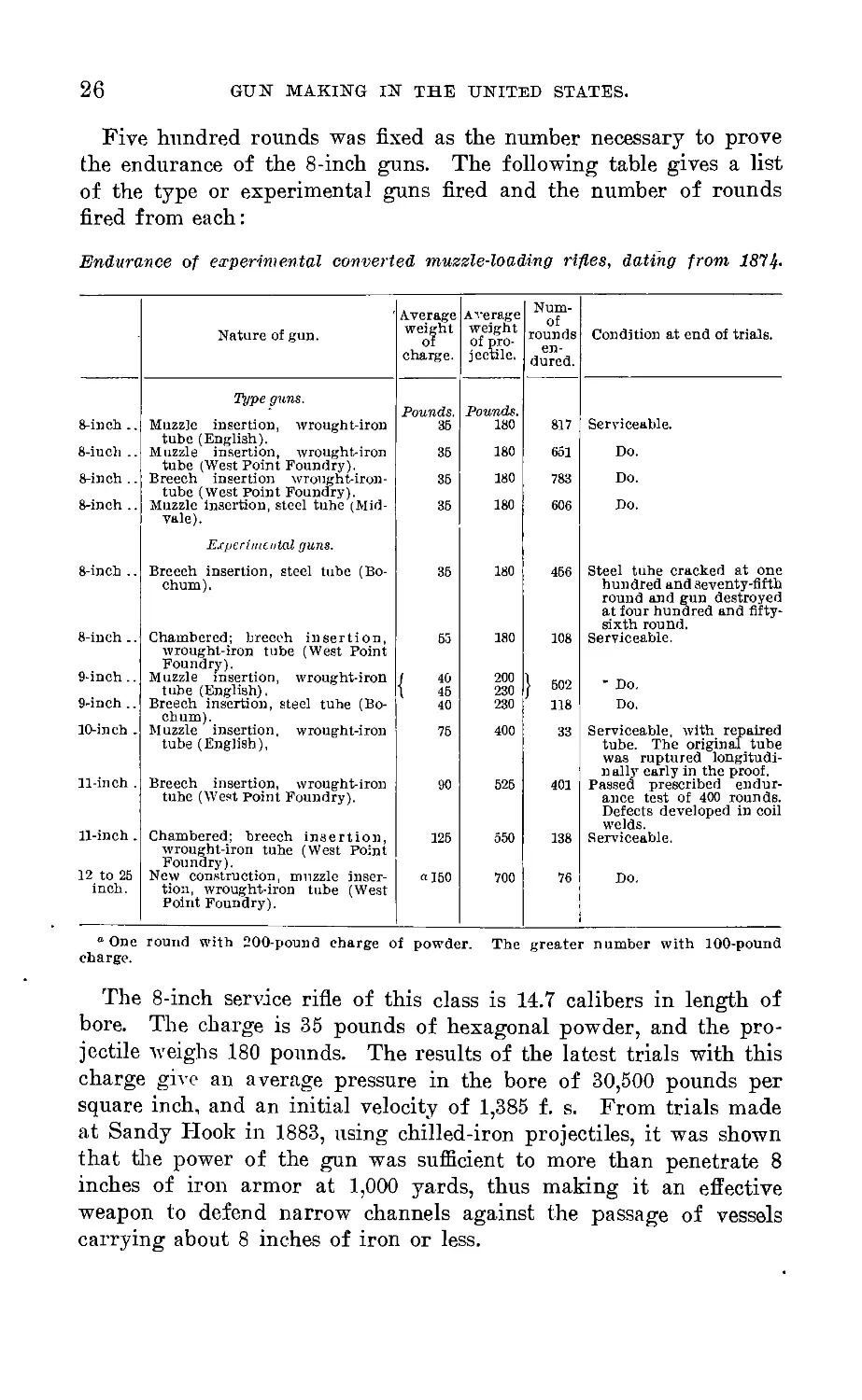
Five hundred rounds was fixed as the number necessary to prove
the endurance of the 8-inch guns. The following table gives a list
of the type or experimental guns fired and the number of rounds
fired from each:
Endurance of experimental converted muzzle-loading rifles, dating from 1814-
Nature of gun.
Average
weight
of
charge.
Average
weight
of pro-
jectile. .
Num-
of
rounds
en-
dured.
Condition at end of trials.
8-inch ..
8-inch ..
8-inch ..
8-inch ..
8-inch ..
Type guns.
Muzzle insertion, wrought-iron
tube (English).
Muzzle insertion, wrought-iron
tube (West Point Foundry).
Breech insertion wroiight-iron-
tube (West Point Foundry).
Muzzle insertion, steel tube (Mid-
vale).
Experimental guns.
Breeeh insertion, steel tube (Bo-
chum).
Pounds.
36
35
35
36
Pounds.
180
180
180
180
35 180
817 Serviceable.
651 Do.
783 Do.
606 Do.
8-inch ..
9-inch..
9-inch ..
10-inch .
Chambered; breeeh insertion,
wrought-iron tube (West Point
Foundry).
Muzzle insertion, wrought-iron
tube (English).
Breech insertion, steel tube (Bo-
chum).
Muzzle insertion, wrought-iron
tube (English),
180
200
230
230
400
11-in ch
Breech insertion, wrought-iron
tube (West Point Foundry).
525
11-inch.
12 to 25
inch.
Chambered; breech insertion,
wrought-iron tube (West Point
Foundry).
New construction, muzzle inser-
tion, wrought-iron tube (West
Point Foundry).
125
«150
550
700
456 Steel tube cracked at one
hundred and seventy-fifth
round and gun destroyed
at four hundred and fifty-
sixth round.
108 Serviceable.
502 ’ Do.
118 Do.
401
138
Serviceable, with repaired
tube. The original tube
was ruptured longitudi-
nally early in the proof.
Passed prescribed endur-
ance test of 400 rounds.
Defects developed in coil
welds.
Serviceable.
Do.
° One round with 200-pound charge of powder. The greater number with 100-pound
charge.
The 8-inch service rifle of this class is 14.7 calibers in length of
bore. The charge is 35 pounds of hexagonal powder, and the pro-
jectile weighs 180 pounds. The results of the latest trials with this
charge give an average pressure in the bore of 30,500 pounds per
square inch, and an initial velocity of 1,385 f. s. From trials made
at Sandy Hook in 1883, using chilled-iron projectiles, it was shown
that the power of the gun was sufficient to more than penetrate 8
inches of iron armor at 1,000 yards, thus making it an effective
weapon to defend narrow channels against the passage of vessels
carrying about 8 inches of iron or less.
GUN MAKING IN THE UNITED STATES.
27
CONVERTED BREECH-LOADING RIFLES.
The recommendation of the board of 1872 to test the Krupp sys-
tem was carried out in regard to the breech mechanism by its adapta-
tion to the converted breech-loading guns which were tried, follow-
ing the success obtained with the muzzle-loading rifles. In general
features of the tube construction the breech-loading gun was made
like the breech-insertion muzzle-loader. But the jacket was made of
a heavy steel piece, which projected to the rear to receive the Krupp
fermeture, and this jacket, being larger than the wrought-iron jacket
used in the muzzle-loader, considerably more of the thickness of cast
iron about the breech was removed, leaving a thinner casing of cast
iron. To compensate for this, and to add strength to the breech, a
steel hoop was shrunk upon the breech end of the truncated casing;
and, in addition to the screw thread used to secure the tube in place,
the casing in this construction was also shrunk upon the tube over the
length of its jacket. The first 8-inch gun was made and tried. The
steel used in this gun was furnished by Whitworth, and was of good
quality. The proof of this gun was entirely successful; it withstood
636 rounds, using the same charge as the muzzle-loading rifle without
injury, and remained in serviceable condition. Other guns of 8 and
11 inch caliber were then ordered.®
The orders given for the manufacture of the converted 8 and 11
inch guns were suspended and canceled when the second trial gun
of 8-inch caliber and the first of 11-inch caliber failed under the
proof to which they were subjected. These guns differed from the
first experimental breech-loading gun in being chambered to receive
increased charges of powder—the increase being for 8-inch, 55 pounds
instead of 35, and for 11-inch, 130 pounds instead of 90. One 8-inch
and the 11-inch gun failed after a few proof rounds, by a clear frac-
ture of the steel breech piece in a plane through the front angles of
the slot for breechblock. It is important to remark that in these
guns the angles at the front corners of the slot were cut square—a
feature which is stated to have caused several of the few recorded dis-
o Ал experimental 12-inch breech-loading chambered howitzer to be con-
verted from a 15-inch smoothbore, and four 12-inch breech-loading chambered
rifles of new construction, but .of the same general design as the converted
8-inch breechloader, were also projected, and their construction was begun in
1880. The 12-inch rifle was designed for 24 calibers length of bore, with a
total weight of about 50 tons, and use 200 to 300 pounds of powder with 800-
pound projectile. None of these guns, however, were completed. It became
necessary to abandon the construction, because steel of the requisite qualities
could not be supplied. The steel forgings for these guns were procured in Eng-
land. and brought to this country by the contractors, but when submitted for
the inspection of the officers of the Ordnance Department, the metal was found
to be wholly unsuitable, being materially below the standard guaranteed, and,
consequently, the forgings were rejected.
28
GUN MAKING IN THE UNITED STATES.
astrous failures in guns made by Krupp. Added to this, the tests of
the steel which ruptured in these guns showed a quality of metal
badly adapted to gun construction. Four specimens taken longi-
tudinally from the metal of the 8-inch piece gave an ultimate tenacity
varying from 79,000 to 112,000 pounds per square inch, and this
irregularity of strength was accompanied by an exceedingly low
ultimate extension, in one specimen as low as 4 per cent, and not
exceeding 9 per cent in the best of the four.
The 11-inch piece showed a much poorer quality of steel, though
of an entirely different nature. The average tenacity was uniform,
but low, ranging, for 12 specimens, about 66,000 pounds per square
inch. The elastic limit ranged between the low figures of 10,000 and
24,000 pounds per square inch, and the metal was soft and friable in
its nature. Analysis showed that it contained 0.247 of 1 per cent of
sulphur. Subsequently a second 8-inch gun, made at the same time
with that jiist described, was prepared for trial by rounding the front
corners of the slot. This gun gave an excellent record in its proof
for endurance. It was burst into many fragments at the one hundred
and twenty-seventh round, but for 6 rounds preceding that catastro-
phe had endured a 55-pound charge of powder that gave an average
of 51,000 pounds pressure per square inch in the bore, and for 15
rounds preceding the 6 named, an equal charge of somewhat slower
powder, that gave an average of 43,600 pounds pressure.
It was equally'unfortunate for the Krupp breech mechanism, and
for the advancement of steel gun construction in this country, that
the two guns should have failed so soon in the proof. It is not fair
to argue that it was the Krupp mechanism which caused the failure,
since the steel was of unsuitable quality, and the after proof of the
gun, with rounded angles, indicated a good endurance of the mechan-
ism, as did also the proof of the experimental gun which endured 636
rounds without failure; but the failure of these guns called particular
attention to that apparently ugly feature in the mechanism—the
amount of metal cut away by the slot—which, especially in large
guns, gives the appearance of longitudinal weakness. As to manipu-
lation, and in other respects, the Krupp mechanism, provided by home
manufacturers, gave a good degree of satisfaction. The only objec-
tionable feature of importance noted was the tendency of the seat for
the gas check to become oval, attributed to the presence of the slot and
the resultant of the longitudinal pull which is sustained by the sectors
of the metal left above and below, and is so unequally distributed
throughout the cross section of the jacket. In the converted 3.2-inch
breech-loading field guns this mechanism has given no serious cause
for complaint in the limited use to which it has been put in our
service. In Germany, however, it has been found necessary, in rough
service, to modify the Broadwell ring. The large surface of contact
GUN MAKING IN THE UNITED STATES.
29
between the exterior surface of this ring and its seat makes it diffi-
cult to preserve the close adjustment needed, and this ill fitting is
aggravated by the presence of any dust or dirt in the seat. The
modification, which has been applied with good results, consists
essentially in reversing the contour of the ring and limiting the sur-
face of contact to a blunt rounded lip which comes in contact with the
seat, to seal the escape of gas, only at the forward end of the ring.
As regards the utility and safety of the Krupp breech mechanism, as
a whole, its long-continued and successful application in guns made
by Krupp place it beyond doubt as one of the two best systems now
in vogue.
The effect of the failure of these guns in producing an unfavorable
opinion upon the use of steel in gun construction was also marked.
Not only was this opinion generally diffused, but it was taken up
by officers of our own service and others interested in the science of
gun construction. So it was uphill work with this metal for some
years afterwards to convince such doubters that there was taking
place a vast improvement in quality gained by knowledge and expe-
rience in its manufacture. Until finally, with more knowledge of
the quality of the metal required for guns, all must now turn to
steel to get a metal that can be readily made to exhibit the best com-
bination of the qualities required.
The two remaining guns recommended by the Board of 1872
were the 9-inch Sutcliffe and the 12-inch Thompson breech-loading
rifles. Both of these guns were made by the Government and
tested at Sandy Hook, but the first was fired in all only twenty-
six and the latter two rounds. Following this, in 1876, the pieces
were sent to Philadelphia for exhibition at the Centennial, after
which they were again returned to Sandy Hook. But thereafter
no experiments were made by reason, as it appears, that no specific
appropriations for the purpose were made by Congress. In each
of the succeeding years, 1878, 1879, and 1880, the Chief of Ordnance
recommended without avail an appropriation of $117,600 for the
tests of these guns, including the Woodbridge 10-inch rifle, the
Lyman multicharge gun, and the Mann 8-inch breech-loading rifle.
SUTCLIFFE 9-INCH BREECH-LOADING RIFLE.
In general construction this gun consists of a cast-iron body
with a comparatively thick steel tube inserted from the rear and
terminating at the front of the block, while in rear of the block and
its slot the cast-iron body is bored and threaded to receive a movable
hollow screw sleeve, which supports the block from the rear and
through which the charge is inserted. The breechblock is made in
the form of a disk, and is moved in its slot by rotating the sleeve.
A Broadwell ring is used as a gas check. It was the intention in
30 GUN MAKING IN THE UNITED STATES.
making this gun to provide both for a test of the breech mechanism
and the principle of steel lining in a cast-iron body, and the dimen-
sions given to the parts were considered sufficient to enable the bore
to be enlarged to 10 inches after firing 250 rounds, as a 9-inch gun.
The tube was inserted with a slight play in the casing and was
forced home by hydraulic pressure. Shoulders on the exterior of
the tube prevent its forward movement, and it is also held by a
screw muzzle collar and by a couple of securing pins through the
casing. A powder chamber 0.3 inch larger in diameter than the bore
is provided, and its axis is eccentric with that of the bore, being
placed 0.05 of an inch above it. In the 26 rounds fired the heaviest
charge contained 45 pounds of powder and a 250-pound projectile.
The maximum pressure observed was 29,250 pounds per square inch.
The test gave no measure of the strength of the system of tubing,
owing to the limited number of rounds fired and the surplus of
strength for a 9-inch gun, but in any event the breech mechanism
constitutes its most interesting features. It is difficult to explain
such features without the aid of a drawing, but an idea may be had
of the slot in which the block moves by supposing one side of the
Krupp slot left solid and the opening made in one side only. The
block which moves in this slot is a disk of steel—in this gun 12.4
inches thick, or, say, 1| calibers—which is moved by means of a steel
pin connecting with the movable screw sleeve operated from the out-
side rear. The pin is set in the block near its periphery and is free
to revolve in its seat in the sleeve. In giving the sleeve a half revo-
lution the pin is carried around and the block is constrained to move
in the slot, to open or close the breech, partly by rolling and partly
by sliding. An obturator plate similar to the Krupp is embedded
in the front of the block to support the Broadwell ring. The block
is pierced with an axial vent. This breech mechanism has few parts
and the motions are simple. It embodies the disadvantage of having
an unequal section of metal through the breech just in rear of
the place of maximum tangential strain, and where the longitudinal
strain is most felt, but to a less degree perhaps than the Krupp
mechanism. It also occupies a greater length of bore space than the
French system. It might be claimed to have an advantage over this
last, for longitudinal strength, because of the continuous thread of
the breech screw, but the diameter of this screw must be made so
great as to considerably reduce the cross section of metal that resists
the longitudinal strain. But the difficulty found in operating it
under fire, and that which appears to be the weakest point, is the
inadequacy of the arrangement for controlling and moving the
block. The stud pin which forms the only connection between the
block and the breech sleeve is subject to severe strains, and in a few
rounds fired it occurred that this pin became bent and the block was
operated with difficulty.
GUN MAKING IN THE UNITED STATES.
31
THOMPSON 12-INCH BREECH-LOADING RIFLE.
This gun is made of a cast-iron body, of the usual Rodman model,
in which is inserted, under a slight shrinkage, a thin steel lining tube
that extends through the bore and is secured by a screw thread at
the breech end. It was incomplete when received at the proving
ground and in this condition was fired two rounds before being sent
to Philadelphia in 1876, and thereafter, for reasons already stated,
the test was not resumed. In the form of slot for breechblock it re-
sembles the Sutcliffe gun. The face of the block when closed abuts
directly against the rear end of the tube and closes the opening.
The block is circular in cross section and is rolled laterally in the
horizontal slot to open or close the breech. It is fitted with cogs which
engage in a toothed rack laid in the bottom of the slot. Power is
applied by means of a lever attached to a shaft or spindle which is
secured to the center of the block and extends through the breech to
the rear, and is there geared to work in a rack. On applying power
the spindle and block revolve together and the spindle traverses a
horizontal slot cut throughout the length of the breech along one side
of the loading channel. The charge is inserted through the loading
channel which forms a prolongation of the bore to the rear. The back
of the block is faced with a cam, which, in the act of closing the
breech, comes in contact with a corresponding cam on the rear face of
the slot, by means of which the block is forced forward until its
beveled face is in close contact with the end of the tube fitted to re-
ceive it—thus closing the breech. When closed, the block is supported
in rear about its circumference, except across the opening made for
traversing the spindle. The width of the cam bearing round the block
is 1.5 inches.
When the gun was tried no means were provided for locking the
block in position when closed, nor was there any provision for a gas
check or vent proper. It was the intention of the inventor to use
center-primed metallic cartridge cases, to be discharged by a firing
pan passed through the center of the spindle and block. There are
no features about this mechanism, I believe, which call for any special
commendation in the light of present knowledge. The attempt to use
a metallic case for a gas cheek was subsequently tried in the Yates
8-inch breech-loading rifle, with very poor success. The difficulty of
holding the block up to place in the Thompson gun would be a serious
one, and it might be anticipated that the bearing surface of the block
in rear would prove insufficient, and the longitudinal strain to cause
disruption of the breech would be besides wholly thrown upon one
angle in the slot.
FIELD GUNS.
During the period 1873 to 1882 trials were also made at Sandy
Hook with breech-loading field guns, and the Dean 3.5 mandreled
32
GUN MAKING IN THE UNITED STATES.
bronze gun. The Dean gun was procurred in 1877. It was subjected
to a firing test of 50 rounds which, so far as it went, proved the ex-
cellent quality of the material, but it was a muzzle-loading gun,
made after a design already out of date, and gave inferior ballistic
results. The introduction of steel in new constructions operated
against the extension of the system. This system of manufacture has
been tried in Russia, Italy, and especially in Austria, where, under
General Uchatius' earnest supervision, it was finally introduced for
field and the lighter siege guns, but was not successful in application
to heavier guns.
The three systems of field guns principally tested were the Sutcliffe
3-inch, Moffat 3.07-inch, and the converted 3.2-inch field gun with
Krupp mechanism, made ou the plans of the Constructor of Ord-
nance.
The Sutcliffe breech-loading field gun was made by converting a
3-inch wrought-iron rifle, the breech mechanism being in all essen-
tial respects like that of the 9-inch gun. The trial gun was received
at the proving ground in 1876; it was fired 53 rounds, an average
charge being 1} pounds of powder and a 10-pound projectile, which
gave a velocity of 1,109 f. s. The reports state that, so far as tested,
the working of the breech mechanism was satisfactory.
The Moffat breech-loading gun was brought out in 1873. The
body is of steel, made from a solid piece. The breechblock, as in
the Mann gun, is secured by a strap or breeching pivoted on the
trunnions; and each arm of the strap is supported by locking into
lugs on either side of the breech of the gun. The strap rests upon
the head of the elevating screw, and the breech is raised clear of it
for loading by means of a lever pivoted on the screw. The block
is hinged to the underside of the breech, and has a conical face
which fits closely in the breech. The rear of the block is wedge
shaped, and in closing is pressed into its seat by contact with the
strap. When the breech of the gun is raised for loading, the block
revolves backward and rests upon the strap. This gun was fired
175 rounds, and gave a velocity of 1,124 f. s. with a charge of Im-
pounds of powder and 101--pound projectile.
The converted 3.2-inch breech-loading field gun, Krupp mechan-
ism, was first proposed in 1878, and trials were made with a gun of
3.17-inch caliber in 1879. Subsequently the caliber was increased,
and the 3.2-inch was decided upon. The conversion consists in cut-
ting off the breech of a 3-inch wrought muzzle-loading rifle near
the bottom of the bore and screwing in from the rear a steel breech
receiver through which the bore is prolonged. The breechblock
is supported in the breech receiver, which also extends forward
some 16 inches within the wrought-iron body, inclosing the chamber
GUN MAKING IN THE UNITED STATES.
33
and forming the rear portion of the bore. The breechblock is of
the Krupp pattern made in this country, and the Broadwell ring is
used for a gas check. By chambering, the power of this gun was
much increased over that previously obtained with guns of like
caliber, and as its trials were satisfactory, the gun was provision-
ally adopted for trial in service. A few have been made and issued
for service and are still in use. In trials reported in 1883 the first
gun shows a record of 849 rounds as far as tested. In prolonged
firing the principal difficulty was found with the gas check, which
became scored and allowed the escape of gas. With a new gas check
275 rounds were fired without material injury, and it was concluded
that one check would be good for about 300 rounds. The powder
charge is 3 pounds, and the solid shot weighs 12 pounds. With this
charge the pressure averages 25,633 pounds, and the muzzle velocity
is 1,548 f. s. The range at 20° elevation is 5,879 yards, or 3.34 miles;
at 15°, 4,978 yards; at 10°, 3,986 yards, and at 5°, 2,508 yards.
The gun weighs 826 pounds, and the muzzle energy of shot per
pound of piece is 541.2 foot-tons.
To sum up the results of the ten years ending in 1882, which were
devoted to the development of guns recommended by the board of
1872 (appointed by act of Congress) : The Woodbridge brazed,
wire-wound gun, and the Hitchcock gun, were thoroughly tried with
results already mentioned—the former presenting great difficulties
in manufacture and failing under proof, and the latter failing in
manufacture. The Sutcliffe 9-inch, Thompson, and Mann guns were
tested to a very limited extent, with results in the case of the first
two which did not at best give any marked prospect of success; but
Congress, by its refusal to appropriate money for the purpose, nega-
tived an exhaustive trial of them. Lyman’s multicharge gun comes
under the same category; however, tests already made at Reading
with the same gun that was awaiting trial at this time indicate that
the interests of the country did not suffer in the failure to test it
further.
The successful issue of the period was the Ordnance system of
converted muzzle-loading rifles whereby there was placed in service
210 8-inch rifles, each having at 1,000 yards range more than double
the power and three times the accuracy of. the 10-inch smooth-
bore which it replaced, besides made strong enough by the conver-
sion to endure fully as many, if not more, rounds as a rifled gun
than the old smoothbore would stand with its light charges. And
however poorly these rifles may now appear in comparison with the
modern gun, this much must be remembered—if a war should arise
to-morrow they are the only reliable rifles that we have available for
seacoast defense. The power of this gun to penetrate 8 inches of
7733—08----3
34
GUN MAKING IN THE UNITED STATES.
iron armor with backing, or 6 inches of steel armor, at 1,000 yards
range makes it effective against a large proportion of the war ships
of the world. It would of course be of little use in firing against
the heavily armored ships, but these constitute perhaps one-fourth
only of the whole number of such ships.
The 11-inch rifle of the same construction was successfully tested,
but was not made a service type, which was a wise course, seeing the
relative disparity of this caliber to those of other countries, when
it became a question whether to make these guns in quantity, and
noting also the present efficiency of the 15-inch smoothbore with
its increased charge. In other words, it did not then appear to be
a paying investment—and, with our present knowledge, it would
appear much less so—to sacrifice a 15-inch smoothbore to make an
11-inch muzzle-loading rifle. The converted 8-inch breech-loading
rifle of the same general construction, with Krupp mechanism,
unchambered, and firing a charge of 35 pounds of powder was a
practical success. The principal utility of the proof of this gun lay
in the trial of the breech mechanism; the gun proved abundantly
strong to withstand the charge which was used, but the design could
not be adopted as a service pattern, because it presented the disad-
vantage of increased cost with no corresponding increase of power
or efficiency over the muzzle-loader. The next step in the develop-
ment of this system was to obtain a satisfactory increase of power for
the converted breechloaders (8 and 11 inch) by chambering to use
a largely increased charge of powder, and to extend the system to new
constructions of large caliber, with increased length of bore to give
high power. The first 8 and 11 inch guns failed, we may infer,
because of the square angles of the slot, although the steel used in
them was not of suitable quality. The second 8-inch gun, with
rounded angles in the slot and the same make of steel, burst at the
one hundred and twenty-seventh round after enduring a series of high
pressures ending with six consecutive fires, giving pressure running
uniformly about 50,000 pounds and over. The inevitable conclusion
from these trials was that this system of converted breechloaders
did not possess the margin of strength which would warrant its
introduction in service. The extension of the system to large calibers
of new construction was abandoned, because it was impracticable to
obtain a suitable quality of steel in the forms required by the design.
One lesson may at least be learned from what took place in these
ten years, and that is that success in gun making depends not upon
the test and trials of different plans, however numerous, but upon a
steady and persistent effort upon one system; and when, as in our
own country, the sums appropriated for such purposes are small in
amount this course offers the only means of reaching auy degree of
success whatever.
in.
The Conclusions of Boards and Committees Appointed by Con-
gress—Money Expended for the Purchase of Cannon During
Twenty Years—Recent Plans of Gun Construction—The
Multicharge Gun—The Mann and the Yates Breech-Mech-
anism—The Slotted Screw Breech Mechanism.
Coming now to a later period, the course of legislation in Congress,
which governs these matters, has been such as to leave all questions of
policy in a state of the greatest uncertainty, and we find the War
Department laboring under the most adverse circumstances in endeav-
oring to further the manufacture of the best type of guns recom-
mended by the Logan committee, or the Senate ordnance report of
1883.
Beginning with the appointment of the Getty Board in 1881,- every
year thereafter, except 1882, when the report of that board was under
consideration in Congress, has been marked by the appointment of
a new board pursuant to act of Congress, until finally the subject of
boards reached a period of at least temporary exhaustion, when the
report of the Fortification Board was brought out in 1886. In that
year, and in the present, there was no board designated, but neither
was there any fortification bill passed.
The Board on Heavy Ordnance and Projectiles, of which General
Getty, an artillery officer, was president, was appointed pursuant to
the act of Congress appoved March 3, 1881, and submitted its report
in May, 1882. The Gun Foundry Board was appointed pursuant to
the act of March 3, 1883; the Armament Board pursuant to the act
of July 5, 188-1; and the Fortification Board pursuant to the act of
March 3, 1885. Besides which, in the same years, we have had
careful and detailed examinations and reports on the question of
heavy ordnance from the Senate committee, of which Senator
Logan was chairman, appointed August 2, 1882; the Senate
Select Committee on Ordnance and War Ships, with Senator Hawley
as chairman, appointed July 3, 1884; and a similar House com-
mittee, with Mr. Randall as chairman, appointed July 6,1884. There
is also the, standing committee of the Senate, with Senator Dolph
as chairman, which has charge of matters pertaining to ordnance.
The Select Committees on Ordnance and War Ships of the Senate
and House completed and submitted their reports in 1886. It is
not my purpose here to analyze the able reports of all these com-
mittees and boards; they contain a vast amount of valuable infor-
35
36
GUN MAKING IN THE UNITED STATES.
niation upon the subject which we can only regret has been put to so
little practical use, in so far as the land defenses are concerned. Of
all the subjects treated in these reports (if we omit the Armament
Board, which was convened for a distinct purpose apart from this
question) there was one of all others upon which there is a unanimity
of opinion, either explicitly expressed or directly implied, in their
conclusions, namely: That the solution of the gun question lies in
the manufacture of the built-up forged-steel gun. and that the indus-
try of malting forged steel for such guns should be established in
this country.
Another matter which also received general commendation was
that the recommendation of the Gun Foundry Board in regard to
the establishment of Government factories (for the Army and Navy),
with capacity to manufacture a limited number of these guns per
annum, should be adopted.
But the conclusions of these committees and boards have been
very useful in helping the Navy to get appropriations for this class
of guns in the quantities needed for vessels in course of construction.
And now that the policy of making them has been defihitely inaugu-
rated in one branch of the Government service, it will surely be ex-
tended to the land service. It has been said that the Ordnance Depart-
ment has expended millions and millions on guns and has nothing to
show for it. It may be useful information then to state the fact
that the total amount expended for cannon in the twenty years
beginning July 1, 1866, and ending June 30, 1886, by the Ordnance
Department, did not exceed one and one-half millions of dollars.
This does not include the amounts expended from the appropriations
for testing experimental guns and various inventions, including dyna-
mite, powder, projectiles, and material for service and reserve; but
it does include the first cost of all the cannon procured in the twenty
years, and in addition what had been expended upon those in
course of construction at the end of the period. It covers the cost
of the plant erected for the Woodbridge gun, the Hitchcock gun, the
money otherwise expended for those guns, and all other experimental
guns, and also of the following service cannon—318 in number—
which are now in use or available for issue, viz:
1 20-inch and 26 15-inch Rodman smoothbores.
1 12J-inch tubed muzzle-loading rifle.
5 11-inch
1 10-inch
210 8-lnch
muzzle-loading converted rifles.
4 8-inch breech-loading converted rifles.
1 12-inch muzzle-loading rifled howitzer.
1 8-inch breech-loading steel rifle.
7 3.2-inch converted breech-loading rifles.
25 3.2-inch steel breech-loading rifles.
36 steel Hotchkiss breech-loading mountain guns.
GUN MAKING IN THE UNITED STATES.
37
This sum of money, covering twenty years' expenditure for gun
making for the War Department, is just equal to the amount allowed
for the completion, exclusive of armament, of one of the new steel
cruisers, for which we are expected to afford harbors of refuge.
RECENT PLANS OF GUN CONSTRUCTION.
We now turn to the guns of the present period, which, for authority
to make by the War Department, are the outcome of the deliberations
of the Senate Ordnance Committee of 1883, from testimony taken by
that committee, from plans submitted to it, and from a review of the
recommendations of the Getty Board of 1881. The recommendations
of this committee were embodied in the fortification bill of 1883.
That act authorized the continuance of the conversion of 10-inch
smoothbores into 8-inch muzzle-loading rifles, and, in addition, the
trial of 5 different systems of gun construction and two distinct
types of breech mechanisnj, as follows:
1. Built-up forged-steel breech-loading rifles with slotted screw breech closure.
2. Cast-iron (simple) breech-loading rifles with slotted screw breech closure.
3. Combined cast-iron and steel built-up breech-loading rifles, and rifled mor-
tars on the same system, with slotted screw breech closure.
4. Wire-wound breech-loading rifles.
5. The multicbarge gun.
6. The Mann breech mechanism.
7. The Yates breech mechanism.
The two types of breech mechanism were selected by the Chief of •
Ordnance, under the requirements of the act which directed him to
“ select from the many breech-loading devices offered to the Getty
Board and Committee on Ordnance two that promise the greatest
success ” for test at the cost of the Government.
The five systems of construction as such, based on various plans,
had all, except the cast-iron rifle pure and simple, received the recom-
mendation of the Getty Board. The simple cast-iron rifle was not
recommended by the Getty Board, but was inserted in the act of 1883,
as stated:
In lieu of such of the guns the construction of which has not yet been com-
menced, as were provided for by the act making appropriations for fortifications,
etc., for the fiscal year ending June 30, 1881.
The Government had procured the iron, and preparations had been
made at the South Boston Foundry for the castings here alluded to,
which were intended for the 12-inch breechloaders that could not
be made for lack of a proper quality of steel for breech receivers.
Three of the systems, the built-up steel, the simple cast iron, and
the multicharge, and the two types of breech mechanism contem-
plated in the act of 1883, have been subjected to trial; another, the
combined .cast iron and steel, has been submitted to partial trial
38 GUN MAKING IN THE UNITED STATES.
only in the proof of a 12-inch muzzle-loading rifled mortar hooped
with steel, while the rifles made on the same system are in a more or
less forward state of completion, which has been arrested for two
years past through the lack of funds to pay for them, and the remain-
ing one, the wire-wound, is in the same category as the guns just
named; work on two of these wire guns, which has been in progress
at Watertown Arsenal, is stopped for lack of money.
Of the plans of guns under consideration, all those exemplifying
the built-up steel, the simple cast iron, and the combined cast iron
and steel guns, were made by the Ordnance Office. The plans of the
wire-wound guns are due to Doctor Woodbridge. Mr. Haskell is
the exponent of the multicharge gun. The Mann and Yates breech
mechanisms are designated by the names of their designers, and these
gentlemen each supervised the construction of the gun embodying his
plan. All work done, and material furnished for the manufacture
and test of the guns has been at the expense of the Government, ex-
cept for the multicharge gun, which was furnished at private expense,
and the costs of the tests only paid by the Government.
THE MULTICHARGE GUN.
The principal feature of this gun is well known to consist in the
application of the accelerating principle as applied to the action of
the powder upon the projectile, and this is sought to be obtained by
using a series of powder charges placed in pockets at intervals along
the bore near the breech, which are intended to be ignited by the in-
flamed gases of the breech charge following the passage of the pro-
jectile over the opening of each powder pocket into the bore. The
breech charge is relatively light to give a gradual impetus to the pro-
jectile, which is placed immediately in front of it and in rear of all
the pockets. The mechanical difficulties in this construction are many,
but two of the most important are: First, the necessity for a perfect
closure of the gas escape at the base of the projectile, to prevent a
premature ignition of any of the charges in the pockets; second,
the difficulty of making a gun of this kind strong enough to withstand
even the reduced pressures which may be obtained by an application
of the principle. This last is especially important, for when we talk
about safe pressures in a gun it is of course only a relative term and
applicable to the particular gun under consideration. As for instance,
a pressure of 50,000 pounds has been found quite as safe for a tubed
converted gun with a cast-iron body as 27,000 pounds for the tubed
multicharge g-un with a cast-iron body, since both of the guns rup-
tured under these pressures; only that the converted gun stood a
total of 127 rounds, and the multicharge a total of 33 rounds, before
its first failure, and of 53 rounds up to final rupture.
GUN MAKING IN THE UNITED STATES.
39
The brief account that I can give of this invention is taken from
statements made by its proprietors before the Board of 1872 and the
Getty Board, and the reports of some officers who have witnessed its
test. The system was patented by A. S. Lyman, who commenced to
make experiments to test the merits of his invention to have it brought
into use about 1856. Of the various experiments that may have been
made we have accounts of the performance of three guns only, viz, a
2|-inch gun tested at the Washington Navy-Yard, a 6-inch gun tested
at Reading, Pa., in 1870, and the 6-inch gun which was tested at
Sandy Hook, in 1883-84. The most striking experiments otherwise
described were made with a so-called gun, but rather a small-arm
tube, 10 feet 10 inches long, one-half inch caliber, giving the enormous
proportions of 260 calibers length of bore. In this tube was arranged
one breech charge and five additional pocket charges. The bullet was
of steel, 18 calibers in length. It is stated that with a total powder
charge of 8| ounces, and 7^ ounces, in the steel bullet, a penetration
was obtained through 12 plates of boiler iron bolted together; each
plate was something over three-eighths of an inch, and the total
thickness was 5| inches. This result showed a penetration of 10|
calibers. The initial velocity of the bullet was not measured, but a
computation by the engineer of the company made it 3,000 f. s.
Carrying the same proportions, and assuming corresponding results
with a 9-inch gun, there would truly appear, as an advocate of the
system has claimed, a penetration of 7 feet 10| inches of iron armor,
and he might have added the gun would be 195 feet long and the pro-
jectile 13| feet long. However, a better judgment can be formed by
showing the actual results obtained with the guns constructed, as this
is the only safe guide in such matters.
The 2^-inch gun at the Washington Navy-Yard penetrated a target
of wrought-iron plates 5 inches thick, backed by 18 inches of solid
oak timber. This gave a penetration of “ more than 2 calibers.” The
firing was done at point-blank range, 200 yards, with a total charge
of pounds of powder and a hardened steel projectile weighing 19f
pounds. This gun was afterwards fired at Sandy Hook for velocity;
the maximum obtained was 1,929 f. s. with 10 pounds of powder and
8-pound projectile.
An account is given of 13 rounds fired from the 6-inch gun at
Reading, Pa., in 1870. This gun had four accelerating pockets and
a total weight of about 11,000 pounds. The initial velocity was meas-
ured for 6 rounds, of which the best record is 1,093 f. s. To quote
from Captain Prince’s report of the trial which he witnessed:
The large local pressures and moderate velocities developed in this trial, where
precisely an opposite state of things might reasonably have been looked for, can
only be explained by supposing that the pocket charges in some cases became
ignited before the projectile has passed over their embouchures.
40 GUN MAKING IN THE UNITED STATES.
This is the gun, I believe, which was taken to Sandy Hook for trial,
pursuant to the recommendation of this system by the Board of 1872.
The trials at Sandy Hook in 1883-84 were made with a new 6-ineh
gun completed at Reading, Pa., in 1883. This gun, weighing 25 tons,
was made of a cast-iron body, lined throughout its length with a steel
tube, chambered for the breech charge, and having a length of bore
equal to 46 calibers. A breech-closing mechanism enabled the inser-
tion of the projectile and breech charge from the rear, and the four
powder pockets were loaded by pouring the powder into a channel
connecting with each pocket from the exterior. The typical method
of loading consisted in using five different kinds of powder in the
separate charges—relatively slow burning in the breech charge and in-
creasing in fineness of granulation and quickness of burning for each
successive pocket forward. In the later rounds of the proof this
arrangement was modified to use two powders of the same granula-
tion, but of different brand in the two pockets next the breech charge.
The proof was begun with a charge of 12 pounds of powder in the
breech and the pockets empty. This round gave a velocity of 1,067
f. s., with a projectile weighing 108 pounds. Working gradually up
by increasing the number of pockets loaded and the total powder
charge at the same time, at the thirteenth round the full number of
five charges was first used. In this round the total weight of powder
was 83 pounds and projectile 109 pounds. The pressure within the
chamber and pockets reached about 20,000 pounds, and the initial
velocity was 1,735 f. s. The firing was then continued with varying
charges of powder and projectiles up to the thirty-third round, when
the tube was cracked over a length of 9 feet from the muzzle to a
point near the foremost pocket. The pressure in these rounds varied
in the different charge receptacles from a minimum of 18,000 to 29,000
pounds, which was the maximum record of pressure obtained from
the gauges placed in the breech and in each of the four pockets. The
highest record of velocity in this trial, which appears also to be the
highest yet obtained from a 6-inch multicharge gun, was 2,101 f. s.,
obtained with a total powder charge of 96 pounds and a projectile
weighing 71 pounds. The gun was then strengthened by shrinking
several steel bands over the chase—the only part where the form of
the gun admitted the employment of this strengthening process. The
proof was then continued up to the fifty-third round, when the cast-
iron body was cracked and the piece permanently disabled. The
highest pressure that the gun had to endure in the proof was an
exceptional record of 31,550 pounds—an average of the pressures with
full charges being about 27,000 pounds per square inch. The best
record of energy obtained during the proof was given with a total
powder charge of 116 pounds and projectile four calibers in length
weighing 152 pounds, for which the velocity was 1,801 f. s. and muz-
zle energy 3,422 foot-tons.
GUN MAKING IN THE UNITED STATES.
41
I have no desire to pose in public as a hostile critic of the multi-
charge system exemplified in the guns just mentioned, but rather the
reverse, seeing the methods of attack that are used against those who
honestly oppose it. A large amount of private capital has been ex-
pended in the attempts to perfect the gun, and experiments with it
were earnestly pursued for many years. If the principle were really
valuable, we should have expected in the latest model some conclu-
sive evidence to that effect. The present status of these guns is a
matter of public concern, and the conclusion which I draw from the
actual results obtained is that the principle is not valuable in the
present advanced state of the art of gun construction. A higher
energy and a greater penetration than the multicharge gun has shown
is a matter of every-day record with guns using a single charge of
powder, and the greater effect of the single-charge gun is produced
at a much less cost for original construction and for maintenance, and
also with a much safer pressure in the gun. A pressure of 50,000
pounds, of which only about 70 per cent is needed for the service of
the piece, is entirely safe for a single-charge steel gun, but what a
multicharge steel gun would stand is highly problematical. A com-
parison of cast-iron lined construction has shown a better endurance
for the single-charge gun under 50,000 pounds pressure than for the
multicharge under 27,000 pounds. Probably the relative merits of
steel construction would be about the same. Most emphatically, then,
a higher energy has not been obtained with this gun, with its succes-
sive charges and with moderate and safer pressures, than can result
from any gun of the same caliber using only one charge, nor is there
any ground to hope that such a result can be expected.
THE MANN BREECH MECHANISM.
The principle involved in the Mann breech mechanism is to accom-
plish a complete separation of the longitudinal from the tangential
strains due to firing a gun. As illustrated in the 6.5-inch rifle, tested
in 1884, it comprises a heavy breechblock supported and threaded in
a transom, having no connection with the body of the gun at the
breech. The ends of the transom, which project beyond either side
of the breech, are fastened in heavy side straps that extend forward
and loop over the trunnions of the gun body. The gun body proper
is made with a tube open from end to end, and is counterpoised at the
trunnion bearings in the straps. The trunnions proper, which con-
nect the whole system with the carriage, form a part of the side straps,
and these straps support the longitudinal strain due to the pressure
on the breechblock. The breech is opened or closed by raising or
lowering the breech of the gun body, which revolves about its own
trunnions. The breechblock when closed covers the breech end of
the tube and supports the gas-check ring.
42 GUN MAKING IN THE UNITED STATES.
The Mann breech mechanism has been known and tried at different
times for a number of years. Mr. Mann stated to the Logan Com-
mittee that in 1862 a 3-inch gun was fired at Battery Fox, Wash-
ington, D. C., 437 times under the direction of Admiral Dahlgren,
and that during this firing the gun was fired 96 times in seventy-six
minutes without interruption. In the same year the Navy Depart-
ment gave him an order for an 8-inch breech-loading rifle made on
the same plan. This gun was completed in September, 1873. A
number of trials were made with this gun by the Navy Department,
and it was then turned over to the War Department. Tests were
made with it by Captain Edson, of the Army Ordnance Department,
at Fort Monroe Arsenal, Virginia, in 1865. He found the working
of the breech mechanism to be fairly satisfactory. This was the
gun considered by the board of 1872, and pursuant to the recom-
mendations of that board, and the plans of the inventor, the piece
was altered in several particulars and transformed into a gun of 8.4
inches caliber. Previous to this transformation the gun had been
fired fifty times. The only tests made of the piece after this were
two rounds fired at the foundry, and eleven at Sandy Hook, in 1875.
This record was sufficient to induce the Chief of Ordnance to select
this mechanism, under the act of 1883, as one of the two, out of all
those submitted to the Getty Board, which should be subjected to
trial and test. A new gun, conforming to patents taken out by the
inventor in 1882 and made under his supervision, was then procured
at the cost of the Government. This gun, as already stated, was
tested at Sandy Hook in 1884. The test was made under the Board
for Testing Rifled Cannon, instituted as a permanent board by the
act of July 5, 1884, which provides that hereafter all rifled cannon
manufactured at the cost of the United States shall be publicly
subjected to the proper test for the determination of the endurance
of the same * * * and further, if such guns shall not prove
satisfactory they shall not be put to use in the Government service.
The history of this test is, in brief, given in the report of the board:
This gun, having burst at the twenty-fourth round, its endurance was not
satisfactory to the board, and hence it cun not recommend that it be pnt to use
in the Government service. The highest recorded pressure was 27,500 pounds
per square inch. The failure of the gnn was occasioned by the fracture of the
transom near its left tenon. This transom was made of a superior quality
of Whitworth steel, and the fracture showed no defects in the metal. There
was evidence during the firing that the side straps did not hold the breechblock
np to its place, as the breech of the gnn body was slightly raised from its place
by the shock of discharge.
The principle of this breech mechanism appears to be a mistaken one; the
longitndinal strain in a well-bnilt gun does not materially detract from the
tangential strength. Some constructions, as in the case of wire guns, may
require a special provision to obtain the necessary longitudinal strength, but
these.should form an integral part of the gnn, and be solidly and firmly bnilt
GUN MAKING IN THE UNITED STATES.
43
into the structure. It would appear that any attempt made to separate the
parts designed to withstand the two kinds of strain must either result in au
essentially weak gun in one direction or the other, or else in the addition of a
surplus, if not a useless, amount of metal to accomplish the object sought.
Certainly in a built-up guu, such as was the body of the Mann 6.5-inch rifle,
there exists no reason for such a complication as the attempt to separate the
two kinds of strains. The trial was. however, a distinct test of the breech
mechanism.
THE YATES BREECH MECHANISM.
The Yates breech mechanism is the subject of a patent issued
June 28, 1881, to Colonel Yates, a retired officer of the Army. It is
novel in principle and application, and consists of a couple of con-
cave clamps (half sections) which, when closed, embrace the breech
of the gun exteriorly, and are intended to afford longitudinal support
to a solid head gas check or cartridge case of whatever nature that
may be used within the breech end of the tube for the actual gas-
sealing device. The gas check ring being a distinct feature, to be
operated independently of the breech-loading device, is not to be
understood as forming a part of it. To understand this distinction,
without intending to draw a parallel, the Yates breech mechanism
takes the place of the threaded block alone in the slotted screw
system, or the sliding block alone in the Krupp system. A parallel
can not be drawn, because, in each of the two systems named, the
block forms a ready means for supporting or supplementing the gas
check and making a complete automatic breech-opening device, while
in the Yates plan there is no connection between the gas check and
the rest of the mechanism: the breech is not opened or closed by the
operation of the mechanism, but there is required, in addition, a
heavy solid head gas check, which must be placed by hand in the
breech end of the tube and removed in the same way for every round
fired.
The “ clamps form a shell or envelope for the entire breech of the
gun divided into two equal parts or sections which meet in a vertical
plane through the axis of the gun. The front of each clamp is hinged
(in common) well forward on the reenforce of the gun, and grooves
or shoulders are cut circumferentially on the interior of the clamps
which when the sides are closed hook upon corresponding shoulders
cut around the reenforce of the gun and afford longitudinal support
to the clamps. The shell formed by closing the clamps comes to close
bearing over the breech end of the tube to support the gas check.
The sides open to uncover a little more than the diameter of the bore
at the breech. The opening and closing is done by means of a lever
attached to the underside of the breech of the gun and pins on either
clamp, which work in grooves cut in the lever. When closed, the
clamps are held together by an outside latch fastening placed above
44 GUN MAKING IN THE UNITED STATES.
the axial line of the gun. This, at least, was the original arrange-
ment; and the axial line was occupied by a firing device intended to
insert a pistol cartridge to be used in firing the charge, but the latch
fastening broke away after firing a few rounds, and was replaced by
a locking disk: and a radial vent was made to be used instead of the
axial vent.
The trial of a gun fitted with this mechanism was made by the
Board for Testing Rifled Cannon at Sandy Hook in 1885-86. The
gun, made at the cost of the Government, was an 8-inch rifle converted
from a 10-inch Rodman smoothbore. The work was done at South
Boston, under the supervision of the inventor. The breech of the
smoothbore gun was shaped and bored through, and the muzzle
lengthened by screwing on a cast-iron extension piece. The whole
was lined with a close-fitting steel (Nashua) tube, making a cham-
bered gun body of 20 calibers length of bore. In applying the ex-
terior parts of the breech mechanism to this gun, the outside of the
reenforce was necessarily turned off to provide the shoulders for the
support of the clamps. To complete the breech closure—that is, to
close the rear end of the bore and prevent the powder gases from act-
ing in and through the unsealed joint at the junction of the clamps—
the inventor designed a cartridge case of bronze, 12 inches total
length with thin walls, and heavy solid base weighing 48-J pounds.
This case was tapered on the outside corresponding to a seat made for
it in the. chamber of the gnn to facilitate withdrawal; and to pro-
vide against sticking a slot was made in the rear of the tube to catch
the head of the case with a hand-extracting tool. This case was in-
tended to be used for repeated firings, but was necessarily withdrawn
after each round—the work being done by hand as a distinct opera-
tion of opening the breech.
The gun was fired, in all 312 rounds, when it burst through the
body, and the breech mechanism was destroyed by the rupture of the
body. Except for the breaking of the latch in the early firings, there
was no failure of the breech-loading device, but the trial developed
its unsuitability as a breech mechanism. The board pronounced the
separation of the gas cheek from the mechanism to be a “ clumsy,
inconvenient, and objectionable " feature as proved by the trial; and
found that the “ obturation was imperfect,” the gas checks “ not
satisfactory ” and besides, “ heavy ” and “ difficult to handle,” and
“ liable to serious injury from accidental dropping or striking against
objects in rapid firing.” In the 312 rounds fired, 11 different forms
or dimensions of gas checks were tried and none was found satis-
factory. No attempt was made by the inventor to employ a gas
check which would not require the awkward handling mentioned.
As a consequence of this serious defect the Yates breech mechanism,
GUN MAKING IN THE UNITED STATES.
45
as applied to guns of heavy caliber, is not at present a practicable
breech-loading device.
It may be added, I think, as an objectionable feature in applying
this mechanism, and the same feature is even more pronounced in the
Mann system, that the complete truncation of the body directly in
rear of the powder chamber, whereby the maximum tangential strain
is required to be supported so near the end of the gun body, renders
these systems liable to enlargement and very obnoxious deformation
about the seat of the gas check. It also introduces a weakness against
tangential strain, which could only be met by a substantial increase
in the strength of the breech end over that required in the French sys-
tem at least. Krupp does strengthen his guns at this place by shrink-
ing on an additional hoop. Again the Yates plan necessitates a trim-
ming down of the reenforce to get shoulders for the clamps, but he
might, on the whole, still claim a margin of weight saving sufficient
to make an extra heavy gun at the breech end.
The result of this trial of Colonel Yates’ system in a gun of 8-inch
caliber is an example of the difficulties which arise with an increase
of the caliber; for I am informed that the device has been found to
work well in pieces of small caliber, such as yacht guns.
THE SLOTTED (INTERRUPTED) SCREW BREECH MECHANISM.
In the breech-loading guns to be subsequently discussed—that is,
in the experimental and standard types recently made or in process
of construction, after the plans of the Army Ordnance Department
and the Navy Bureau of Ordnance in the United States—the system
of breech mechanism used throughout is the slotted screw.
This system owes its inception, as I believe, to Chambers’ Ameri-
can patent of 1849 and to a further invention patented in this coun-
try by Schenkl in 1853, and was used in the construction of 6 guns
made at Boston, Mass., in 1855 for the British Government after
designs by an American named Castmann; but owing to clumsiness
of construction these guns were not mounted.11 The system was then
taken up in France and gradually developed upon a working plan.
It is shown and described in the Journal des Armes Speciales et de
I’fitat Major, V Serie, Tome XII, 1864, page 199; VI Serie, Tome II,
1868, page 161, and Armengaud’s Publication Industrielle, Tome
XX, 1872, page 297. The Journal des Armes Speciales for 1868
states that these guns, of a caliber of 12, 16, 24, and 27 centimeters,
had been adopted by the French for the navy, as well as for forts
and coast defense? As regards the United States there was then
a Holley’s Ordnance and Armor, p. 608.
ь See also Aide Meuioire for Officers of Artillery, chap. 1, Paris, 1880. (Pub-
lished by authority of the minister of war.)
46
GUN MAKING IN THE UNITED STATES.
no room for such development in the face of our (at that time)
superior armament of heavy smoothbores. The system was officially
recommended for trial by the Heavy Gun Board of 1872, having
been especially brought to the attention of that board by Lieutenant
Michaelis, of the Ordnance Department. That board also recom-
mended other systems of breech loading, including the Krupp sys-
tem, the tests of which have already been noticed. The slotted-
screw system is now generally used in native gun making in France,
Italy, England, and the United States. In France it is now mainly
used in connection with the gas check of de Bange, who in 1873 first
used an expansible pad of compressed asbestos and tallow for the,
purpose of transferring the pressure of the mushroom head to cer-
tain metal cups, which were thereby expanded radially so as to
check the gas. Some countries still use the Elswick cup and the
Broadwell ring to a certain extent in connection with the slotted-
screw breech mechanism. In the experiments conducted by the
Bureau of Ordnance of the Navy Department in 1883 and 1884
the de Bange gas check (which had previously been used only for
field guns in France and elsewhere in Europe) was found useless
for heavy guns, as the cups, when made of a large size, lacked elas-
ticity and stuck so badly as to seriously interfere with the working
of the breech mechanism in opening the breech. Much better suc-
cess was obtained by the Davis gas check, patented in 1885, which
retained the asbestos and tallow pad, but checked the gas by the
radial expansion of the thin edges of steel disks or rings." Hence
the term “ French breech mechanism ” is applicable only in a general
way to the various mechanisms which embody the slotted screw
as used in the United States and elsewhere.
The Krupp breech mechanism is, of course, extended in use to a
number of foreign countries where sales of his guns are made, and
it has been adopted in manufacture in Russia. It is not my pur-
pose here to discuss the relative merits of these two systems of breech
mechanism. It may be doubted, indeed, if there is much room to
choose between them, since both have been so thoroughly tested and
proved. It may be remarked, however, that the slotted-screw system
has been generally received by gun makers in choosing between one
or the other with more favor than the Krupp, and probably the
principal reason for this is that the Krupp requires a forging of
larger diameter for the block-carrying cylinder than does the slotted
screw, which may even be attached in the tube forging itself. The
size of the required forgings for 12-inch rifles, it will be recalled,
a The Gerdom gas check, patented in 1S95, is, however, more nearly perfect
and has gradually superseded the Davis. Tn this device the asbestos and tallow
pad is placed between resilient steel rings of peculiar cross section, made of
about 0.02 inch greater diameter than that of the gas-check seat.
GUN MAKING IN THE UNITED STATES. 47
and the inability of the English makers to produce them of requisite
quality, was what stopped the extension of the Krupp system in our
own service. A possible reduction in the size of forgings is, of
course, always a desideratum, and especially so in a country where
the manufacture of steel forgings is a comparatively new industry.
It undoubtedly also requires the best quality of steel to carry the
Krupp block, and where a cast-iron body is used, as in some of our
present constructions, the slotted-screw block is a necessary adjunct.
It may be said, then, that we are now using the slotted-screw system,
because it is one of the only two that have been proved reliable and
satisfactory; and of these it is the one which, on the whole, is best
adapted to our requirements and resources. These remarks do not
apply with the same force to small as to larger calibers, but it is
expedient to have a uniform system for all calibers.
IV.
Cast-Iron Rifles—Rodman, Atwater, and Wiard Guns—12-Inch
Breech-Loading Rifle, Model of 1883—Merits of System Dis-
cussed.
I have already stated that the trials of cast-iron rifles, pure and
simple, were practically abandoned in the United States in 1871.
That was a consequence of the terrible damning that cast-iron guns
received at the hands of the Select Committee on Ordnance in 1869;
and the recommendation of the Chief of Ordnance two years later,
that no cast-iron rifles should be made for service, was the direct
consequence of the bursting of a 12-inch Rodman cast-iron rifle at the
twenty-seventh round. Up to the time when the subject was revived
by the recommendation of the Logan committee, in 1883, fourteen
years had elapsed since the casting of the last cast-iron rifle, pure and
simple, procured by the War Department. This gun was a 10-inch
rifle made at South Boston, in 1869.
Seven muzzle-loading cast-iron Rodman rifles, viz, 3 8-inch,
1 10-inch, and 3 12-inch, were procured by the War Department
between 1861 and 1869. Their principal dimensions, weights, and
qualities of metal were as follows:
Caliber of
gun.
Made at—
Length of
bore in.
calibers.
Thickness of walls.
Over cham-
ber maxi-
mum.
At muzzle
minimum.
8-incb ....
8-inch ....
8-inch ....
10-inch ....
12-inch ....
12-inch ....
12-inch ....
Fort Pitt, 1862........................................
South Boston, 1865.....................................
....do.................................................
South Boston, 1869.....................................
Port Pitt, 1861........................................
Fort Pitt, 1868........................................
South Boston, 1868.....................................
Calibers.
15 1.5
17.5 2.0
17.5 2.0
15.85 1.75
14.0 1.5
14.0 1.5
14.0 1.5
Inches.
4.1
4.0
4.0
5.5
6.5
6.5
6.6
Caliber of
gun.
Weight
of
rifle.
Character of rifling.
Physical qualities of
metal.
Tenacity. Density.
8-inch .
8-inch .
8-inch .
10-inch .
12-inch .
12-inch .
12-inch .
Pounds.
15, 996
22,160
22,220
40,700
52,005
52,225
51,980
Polygroove .......................................
For grooved projectile............................
Polygroove........................................
....do.............................................
....do.............................................
....do.............................................
....do.............................................
Pounds.
30,416
34,625
34,505
32,600
30,48C
36,744
84,166
7.2886
7.2930
7.2980
7.3063
7.2250
7.2903
7.2963
48
GUN MAKING IN THE UNITED STATES.
49
The 8-inch Fort Pitt model, of 1862, had the outside lines of the
10-inch smoothbore, giving it the same thickness of metal as the
converted muzzle-loading rifles afterwards made from these guns.
The two 8-inch South Boston models, of 1865, were special designs
prepared by Rodman, and were of heavy proportions, having 2
calibers thickness of wall in the reinforce and weighing 6,000 pounds
more than the first model, the only compensation being an increased
muzzle length of 2.5 calibers. The 10-inch rifle had a thickness of
1.75 calibers over the seat of the charge and a length of bore less than
16 calibers, dimensions which in built-up steel guns are altered to
1.16 calibers thickness for a rifle with 32 calibers length of bore.
The 12-inch rifles had a thickness of 1.5 calibers over the seat of the
charge and 14 calibers length of bore. The physical qualities of
metal in all these guns was fully up to the standards of tenacity and
density now attained, or that can be attained in cast-iron gun metal.
The proof of these guns was concluded in 1871, except for the 10-
inch. The following shows their endurance:
Caliber of gun. Made at— Average full charges. Number of rounds endured. Trials con- cluded. Remarks.
Powder. Projectile.
Pounds. Pounds.
8-inch .... Fort Pitt, 1862 15 150 1,047 1865 Gun burst.
8-inch .... South Boston, 1865 15 150 80 1866 Do.
8-inch .... do 15 150 845 1870 Firing suspended.
10-inch .... South Boston, 1869 40 300 70 1875 Gun burst.
12-inch .... Fort Pitt, 1861 55 500 472 1869 Do.
12-inch .... Fort Pitt, 1868 60 600 27 1871 Do.
12-inch.... South Boston, 1868 64 624 2 1868 Firing suspended.
The maximum powder charge, fired from the 12-inch rifles, was 70
pounds. Some projectiles of 675 pounds weight were also fired, and
a few of 700 pounds; but the charges given in the table were rather
above than below the average and are absurdly small in comparison
with those of the present day. The second 8-inch gun on the list
was rifled with five lands, separated by broad grooves, and the pro-
jectile was grooved to take the lands. The projectiles used in the
remainder were fitted with soft-metal sabots, chiefly of Parrott,
Dyer, and Dana patterns. These projectiles were the best pro-
curable, and the trials were conducted with care—certainly with a
strong desire on the part of the proof officers to make the best of the
guns.
The pressures recorded to have been endured in some of the rounds
fired, exceeding largely as they do the amount due to the explosion
of a charge in its own space, are something remarkable in their
way, and can only be attributed to defective methods of measure-
ment. Here we find, for instance, two consecutive rounds fired from
an 8-inch gun on the same day, and with precisely similar charges,
7733—08---------4
50 GUN MAKING IN THE UNITED STATES.
gave: One a pressure of 90,000 pounds with 1,154 feet velocity, and
the next 23,000 pounds pressure with 1,044 feet velocity. In the
records of these pressures we find figures of 150,000 and even 240,000.
Some of the pressures were measured with outside pressure gauges,
and the result of balloting of the interior pressure gauge in pro-
ducing very erroneous measurements was not appreciated. In 1881
Capt. C. S. Smith tried the experiment of dropping the Rodman
pressure gauge complete from the balcony of the Western Union
lower at Sandy Hook. The housing, containing the knife, etc.,
was designedly dropped upon a stone at the bottom of the tower.
The height was such as to make the velocity of fall 63 f. s. Even
with this small velocity, the cuts made, on striking, corresponded
in one trial to 46,000 pounds, and in the second to 35,500 pounds
of pressure (Report Chief of Ordnance, 1882, p. 124). Noble and
Abie’s experiments gave a pressure of about 94,000 pounds per square
inch for a charge of powder exploded in a rigid envelope and com-
pletely filling its space. The action in the chamber of a gun can
never equal that in a rigidly inclosed space, and the old theory that
high pressures would be produced in a gun fired with a projectile
not pushed home is entirely exploded by the beneficial results obtained
from air spacing.
I am aware that the bursting of the guns has been attributed to
the breaking up of the projectiles, wedging of bands, uncertain pow-
ders, and other causes which suited the interests of those who pro-
pounded these reasons, but I believe the true reason to lie iu the
frailty of the guns themselves. In the 8-inch steel rifle, now at
Sandy Hook, for example, on two or more occasions, shot weighing
about 300 pounds have been broken in the bore by the shock of dis-
charge ; yet, in these cases, neither was there any marked increase of
pressure, nor was the gun in the least injured. And again, in the
trials at Annapolis, two loaded shells have burst within the muzzle
of the new steel guns without detriment to the guns.
Another 12-inch cast-iron rifle, tried in 1867, was the Atwater
rifle. In this gun some of the lands were removed near the muzzle
to decrease the friction of the projectile, and to illustrate some other
ideas of the inventor. The gun burst at the thirtieth fire, the
average full charge used being: Powder 55 pounds, and projectile
525 pounds. And there was also Mr. Norman Wiard’s gun, generally
known as the “ cart-wheel ” gun, which burst at the first round.
As an illustration of what cast-iron rifles will stand when badly
treated, we may extract the four of this class which were included
in Wiard’s somewhat notorious experiments at Nut Island, 1873-1875.
51
GUN MAKING IN THE UNITED STATES.
Nature of gun. Charge. Projectile. No. of rounds fired. Remarks.
Kind of-powder. Weight. Kinds. Weight.
15-inch Wiard rifle, new gun. 15-inch navy Wiard rifle converted from a navy 15-inch smoothbore. 15-inch Wiard rifle con- verted from 15-inch Wiard smoothbore No. 1. 11-inch Wiard rifle, new gun. Oriental mam- moth. ...do ( 50 t 140 1 50 t 180 f 55 70 [ 100 1 50 | 100 J-Wiard conical.. [Wiard conical <! and suhcali- [ her. [Spherical and [ Wiard mitten. [Wiard conical, < copper ve- [ neered. 453 | 492 1 450 f 529.5 | 260 19 2 } 7 3 Gun hurst. Do. Do. Do.
(Oriental hex- [ agonal. [Oriental mam- I moth, orien- j tai rifle, and I Bickford rifle.
The Wiard rifles are generally admitted to have been destroyed
by the use of excessive charges and bad projectiles, yet the charges
he used bear no comparison with those now required to be used in
steel guns.
We have now brought the record of endurance of all the larger
calibers of cast-iron rifles, pure and simple, which were tested up to
1883. I could not, if I would, enter into the details of the experi-
ments ; that there may have been mitigating causes for some of the
failures one would be rash to deny; but the general merit of a system
is to be judged by its endurance under fire. And there are enough
examples, not only of miscellaneous cast-iron rifles, but also of those
cast on the Rodman plan, in the preceding records to enable anyone
to decide that cast-iron rifles, pure and simple, have shown a very
unstable quality, judged by their own day and generation. The
supposition is not only reasonable, but it is undeniable that the Rod-
man rifles were tested with due exercise of care, nor was there any
greater variety of charging than was demanded by the period to
which they belong. This has always been a necessary accompani-
ment of the trial of experimental guns, and is a very marked feature
in the experiments of the present day. Of the six Rodman rifles
proved for endurance, as stated, three bore a good record and three a
very poor record. The simple conclusion from the trials of the
period is, that cast-iron rifles, pure and simple, were proved to be
distinctly unreliable.
12-INCH BREECH-LOADING CAST-IRON RIFLE, MODEL OF 1883.
The design of this gun was prepared in the office of the Chief of
Ordnance in common with all those representing the combined cast-
iron and steel guns, and the built-up all-steel guns authorized by the
act of 1883.
The gun is a 12-inch breech-loading rifle, weighing 54 tons of
2,000 pounds each, 30 feet total length, 4f feet (56 inches) across
the thickest part of the reinforce, and 24 inches across the muzzle.
The exterior has the curved outline of the Rodman model, with the
52 GUN MAKING IN THE UNITED STATES.
thickness of the wall decreasing toward the muzzle, and propor-
tioned to the powder pressure to be withstood in the different sec-
tions of the bore. The maximum thickness of the wall surrounding
the chamber is 21| inches, or a little over 1| calibers, expressed in
terms of the diameter of the chamber; the thickness over the seat
of the shot is also about 21 inches, or If calibers, and at the muzzle
6 inches, or one-half caliber. The bore is 28 feet, or 28 calibers, in
length, of which the powder chamber, 13.5 inches in diameter, oc-
cupies nearly 5-J calibers; and the rifling consists of 60 lands and
grooves 0.06 of an inch in depth, with a twist increasing from one
turn in 135 calibers at the origin, to a uniform twist of one turn in
40 calibers, which covers a length of 33 inches next the muzzle. The
full charge is 265 pounds of brown prismatic powder (density of
loading 0.84 a) and a projectile 3 calibers in length weighing 800
pounds. The breech mechanism is the slotted screw system, and the
steel block is held in a steel sleeve screwed into the cast-iron breech
of the gun to the depth of the block recess. Excepting the parts of
the breech mechanism and this sleeve, the gun is wholly of cast-iron
and is in one piece, cast with a core on the Rodman plan and cooled
from the interior to produce initial tension.
The gun was made under the supervision of the Ordnance Depart-
ment, by contract with the South Boston Iron Works. Eight months
were occupied by the contractors in preparing for and making the
casting, and eighteen months in all in finishing the gun. The casting
was made breech end up, with a riser of the full diameter 7 feet
long. Initial tension rings taken from the breech, and from the
muzzle, and cut through on a radius in the usual manner, gave
values of initial tension equaling 15,750 pounds for the breech end
and 3,500 pounds for the muzzle end.
The firing tests were conducted at Sandy Hook before the Board
of Testing Rifle Cannon. The report of that board upon tests made
to date will be found on page 113, Report of the Chief of Ordnance,
1886. In all, 137 rounds have been fired:
® “ Density of loading ” is the density of the products of combustion of the
powder charge, when expanded to fill the powder chamber, referred to water at
a standard temperature and density, as unity. Its value is expressed by the
quotient:
________Weight of charge expressed in pounds.
ensi у о oa mg — 5 volume of chamber space expressed in cubic feet.
GUN MAKING IN THE UNITED STATES.
53
Powder
charge.
Projectiles.
1 round ..
Do ...
Do...
6 rounds .
2 rounds .
Do ...
1 round ..
3 rounds.
41 rounds
79 rounds
Pounds.
100
200
230
150
225
245
245
265
265
265
Pounds.
700
700
700
700
700
700
800
700
750
800
Of these, 123 rounds were with full charges of powder, and 79
with full charges of powder and projectile. The average pressure
with the full charges, obtained by 100 observations (two pressure
gauges being sometimes used with one charge) was 28,000 pounds
per square inch, and a fair deduction from the test places the velocity
to be obtained, with full charges, at 1,750 f. s. This is dependent,
however, upon the use of the most suitable powder, the mak-
ing of which is known to be a very difficult operation. The single
full charge fired with German powder gave a velocity of but 1,710
feet with 31,400 pounds pressure. The best results were obtained
with Du Font’s N. V. powder, of which five lots made at different
times were tested, and gave variations (for full charges) from 1,690
f. s. with 25,325 pounds pressure to 1,809 f. s. with 34,000 pounds
pressure. This last was the highest pressure to which the gun was
subjected in the test, excepting one round, when the pressure gauge
was dislodged there was indicated a pressure of 47,250 pounds,
which is not considered reliable.
Taking the average result—charge 265 pounds, projectile 800
pounds, pressure 28,000 pounds, and muzzle velocity 1,750 feet—we
find that the power of this gun is represented by a muzzle energy of
17,000 foot-tons, nearly.
The erosion of the bore became marked before the fifty-first round
to such an extent “ as to make star gauging very difficult.” At the
ninety-sixth round the erosions became pronounced, and increased
rapidly toward the end of the test, when they became so serious as
to lead the board to conclude that it would be unsafe to continue
the firing with the gun, but it was thought that its life could be
prolonged by the introduction of a steel lining. The star gauging,
which appears to have been performed under difficulties, shows a
general enlargement of something over one-tenth of an inch near the
bottom of the rifling and thence decreasing quite uniformly to an
inappreciable quantity at the muzzle. In the chamber the maximum
general enlargement appears to be about 0.025 of an inch. It is
difficult to give a clear idea of the extent of the erosions in this gun,
especially as to their depth. The three most prominent guttering^
are 5|, 10|, and 4-J inches in length, running nearly parallel to the
54
GUN MAKING IN THE UNITED STATES.
axis of the gun and distributed at the top and right side of the bore
about the front slope of the powder and running into the shot cham-
ber. The impressions indicate flared openings having a depth of
about 0.15 of an inch, but can not show the depths of the fine extremi-
ties of the cracks.
Before drawing our conclusions from this new addition to the list
of cast-iron rifles that have been proved and tested, there should
be several points considered in reference to current methods of
manufacture and changed conditions of service due to the introduc-
tion of slow-burning powder. It is claimed—
1. That the metal now made is better than ever before.
2. That the ability to make a casting with the core extending
through the portion to be used for the gun body and casting breech
up removes all the objectionable strains incident to Rodman castings
of muzzle-loading smoothbores and makes a gun with the best con-
dition of metal throughout.
3. That castings of any desired size and length can be made to give
as high a power to cast-iron as to steel guns.
4. That existing facilities for manufacture or means ready at hand
to be applied permit the prompt manufacture of a large number of
cast-iron pieces at once—figures variously placed at something like
100 rifled mortars and 12 to 15 12-inch rifles per year.
5. That the introduction of slow-burning powders has made the use
of cast-iron rifles safe, reliable, and economical.
The claim for superior quality of metal has no foundation in fact,
as may be made apparent to anyone who will acquaint himself
with the tests of metal made when the manufacture of cast-iron guns
was a large and extensive business and the tests of the six large
castings made within the last few years.
The extension of the core barrel through the gun body does not
remove any objections heretofore existing to the Rodman method of
casting, first, because the heavy solid breech in the muzzle-loading
guns afforded an assistance not counterbalanced by the local strains
occurring at the junction of the bore and base, and, second, because
the principal objections taken to the Rodman method are not with
reference to the strains located at this junction, but to those located
along the barrel, where the results of the method are so uncertain.
The method of casting the breech up has many objectionable features,
which, probably, counterbalance any gain due to this method, but
in this connection I may mention two circumstances: A reason for
introducing this method here was because the Italians were using it;
yet we are informed now that it has been abandoned in Italy because
it does not give sound metal in the breech, where the greatest strength
of the gun is required. And the third casting attempted at South
Boston for the 12-inch tubed cast-iron rifle, made in this way, split
longitudinally while still in the pit.
GUN MAKING IN THE UNITED STATES.
55
The limits of size and length of casting appear to have been about
reached in those made for the 12-inch rifles, which required a weight
of about 108 tons of metal and a casting some 40 feet in length in the
rough; nor are existing facilities for manufacture such as would
enable any considerable number of cast-iron rifles to be finished before
we could, with home facilities, inaugurate a steady output of built-up
steel guns. The only facilities existing at present in this country, for
making long and heavy gun castings, are to be found at the South
Boston Iron Works. What has been done there is shown by the fol-
lowing record of the time required to turn out 6 castings recently
procured from that company, all requiring rough finishing only,
except the first on the list:
No. Nature of casting. Date of order. Date of cast- ing. Date of com- pletion. Remarks.
1 2 3 4 5 6 12-incb cast-iron r i fl e, simple. Body for 12-incb tubed rifle: First casting Sept. 24,1883 Sept. 24,1883 May 6,1884 July 9,1884 Dec. 23,1884 Oct. 16,1885 Apr. 5,1886 Oct. 31,1884 Mar. 28,1884 Mar. 1,1884 Jnly 30,1886 Apr. 1,1885 Cast breecb up with riser at breech 7 feet long. Flask gave way and metal depositedin bottom of pit. Cast breech down, lower portion of flask surround- ed by dry brick wall pack- ed around with- sand in pit. Casting broke across in several places in lathe. Cast breech up and ruptured longitudinally in pit. Cast breech up. Apparently sound casting. Cast breech down with riser at muzzle 18 inches long. Casting delayed in procur- ing proper grade of iron and makingtrial cylinders for test.
Second casting
Third casting
Fourth casting ... (a) Mar. 31,1885 Sept. 1,1884 Apr. 29,1884 Sept. 30,1886
Bodyfor 12-incb hoop- ed and tubed rifle. Bodyfor 10-inch wire- wrapped rifle. Mortars. Body for 12-inch muz- zle-loading rifled mortar. Body for 12-inch breech-loading rifled mortar. Sept. 24,1883 Sept. 24,1883 Sept. 24,1883 May 15,1886
a Not completed June 20, 1886, when contract expired hy limitation.
The simple cast-iron rifle, with which no accident occurred, was
eight months in casting and eighteen in finishing; and the five cast-
ings ordered September 24,1883, were not all made at the expiration
of two years and six months. The founders certainly had very hard
luck with the casting for one gun, which was only made at the fourth
trial, and my purpose in calling attention to these matters is simply
to show the time that has actually been occupied in such work and the
risk and difficulties which attend an attempt to make heavy cast-iron
rifles. The West Point Foundry could undertake the casting of the
short bodies required for the hooped mortars, but with this exception
I believe no other establishment than the South Boston Iron Works
has at present any proper facilities for the work. The hooping of the
56 GUN MAKING IN THE UNITED STATES.
mortars with steel will delay the output but little and will give what
has been proved to be a suitably strong construction. That 12-inch
cast-iron rifles may even be cast as long as may be required for modem
usage is much to be doubted in view of the experience quoted, but
the added length would not give the power of steel guns because of
the limitations of pressure imposed upon the cast-iron. Again, to
increase the length of a cast-iron gun entails a large increase of the
weight and cost, noting that in 1865, when General Rodman, in
revising the model of his 8-inch cast-iron rifle of 1862, imposed an
additional weight of 6,000 pounds to gain 2.5 calibers length of bore.
That the introduction of slow-burning powders has made it safe
to use cast-iron rifles is doubtful, and, besides, is only half stating the
question. They may be safe if the pressures are kept low enough, but
with a pressure as high as 28,000 pounds produced by a slow-burning
powder their endurance would be an uncertain factor. This pressure
would work the metal well up to the point of rupture, while in steel
guns the work of the metal is within its elastic limit and less than
half its limit of rupture. The new 12-inch cast-iron rifle has with-
stood an average pressure of 28,000 pounds, including a number of
somewhat higher pressures for a sufficient number of rounds to dem-
onstrate its ability to withstand such pressures and to entitle it to be
classed as a safe medium-power gun for the caliber. This much must
be conceded, and it may be anticipated that equally good guns can
be reproduced, but past experience of the uncertain strength of
cast-iron rifles does not warrant the assumption that it would be
safe to count upon such a result as a constant product of manufacture.
In addition to this, the slow-burning powder is very erosive in its
action, and of all the metals that might be used to form the bore of
a gun, cast iron is probably the most easily eroded. We have a good
example of this effect in the 12-inch cast-iron rifle, which began to
show marked erosion about the fiftieth round, while the 8-inch steel
gun shows none after 100 rounds.
A businesslike view of the problem—and it has been sufficiently
investigated by both figures and firings—will show that a built-up
forged-steel gun, giving 17,000 foot-tons muzzle energy at each round,
is a cheaper investment than this 16-inch cast-iron rifle giving the
same energy; that is, the greater endurance of the steel gun will
enable it to continue to deliver such shots enough longer than the
cast-iron gun to more than make up the difference in the original cost
of the guns. And beyond this, the difference of cost is all in favor
of the much lighter piece—the steel gun—for transportation, hand-
ling, and emplacement. This in itself is enough to establish the
superiority of the steel gun, but it is not the most important consid-
eration, which is, comparatively speaking, that the steel gun is safe
and the cast-iron gun is unsafe. It is not necessary to go abroad
GUN MAKING IN THE UNITED STATES.
57
for a confirmation of this statement; it can rest upon a comparison
of the records of cast-iron and built-up steel rifles made at home.
It is a good confirmation, however, to know that the practice of the
rest of the world proves the same thing.
The question whether cast-iron rifles shall be or shall not be made
rests with Congress. If they are to be made, let them be ordered at
once in the quantities determined upon, for there is certainly no need
for further experiments in this line. Let us sincerely hope, however,
that any action taken for their procurement will not interfere with
equally prompt action toward procuring a full supply of built-up
forged-steel guns; to fail in this respect would, in my humble
opinion, be the poorest sort of economy.
The ability which the officers of the Ordnance Department have
shown in designing so powerful a cast-iron rifle as the one lately
proved is an earnest of their desire and capacity to carry out what-
ever Congress may direct. Had the 12-inch cast-iron rifle been made
after a design presented to the Logan committee, that was to fire 150
pounds of powder with 700-pound shot and give a muzzle energy of
but 10,000 foot-tons instead of the 17,000 foot-tons procured in the
design actually used, but little interest would attach to a discussion
of its merits here or elsewhere.
V.
Combined Cast Ibon and Steel Guns—Rifled Mobtars—Breech-
Loading Rifles—Wibe Guns.
Including the rifled mortars, there are three different types of this
construction in hand at the present time, viz, a 12-inch breech-load-
ing rifle, mainly of cast iron, but lined with a steel tube inserted from
the rear, and forming about one-half the length of the bore; a 12-inch
breech-loading rifle, with cast-iron body, strongly reenforced by a
double row of steel hooping extending from the breech to a distance
forward of the trunnions—the trunnions themselves forming part of
one of the hoops—and a steel-tube lining, as in the first gun; and two
12-inch rifled mortars alike in general construction, but one is muzzle-
loading and the other breech-loading.
12-INCH RIFLED MORTARS, MUZZLE AND BREECH LOADING.
These are short, rifled pieces intended for high-angle fire, and
especially adapted for the defense of seaports. They throw a very
heavy, elongated shell, containing a large bursting charge, to a
distance of 5 miles with facility. The weight of shell is from 610 to
625 pounds, and its fall is sufficient to pierce about 8 inches of armor.
In the Russian-Turkish war a 6-inch mortar firing from shore dis-
abled two ironclads.
The arrangement of the pieces on shore will be made in groups of
16, as is proposed, placed in sunken batteries, and so trained that any
desired number of the pieces in the battery can be fired in the same
line of direction against a single ship. The most serious question
raised respecting the employment of rifled-mortar fire has been in
regard to its accuracy. Their employment in groups will do much to
overcome this difficulty by greatly increasing the chances of hitting,
and the problem of getting a very good degree of accuracy from a
single piece is one that the gun makers will not allow to remain
unsolved. Its solution seems to lie in the use of breech-loading pieces,
and we have just commenced the proof of a mortar of this kind at
Sandy Hook which promises the best results.
The first experimental rifled mortar—12-inch muzzle-loading—was
completed in 1884, and proved 1885-86 by the Board for Testing Rifled
Cannon. The reasons leading to the adoption of the muzzle-loader
58
GUN MAKING IN THE UNITED STATES.
59
for the first experimental type were because it was then thought that
the old method of loading from the muzzle would be, on the whole,
best adapted to such short pieces as combining simplicity and cheap-
ness, together with less care and attention required in service as com-
pared with the breech-loader. This piece has been fired 403 rounds,
and is considered amply strong for service. A range of 8,260 yards
(540 yards short of 5 miles) was obtained with this muzzle-loading
mortar, firing a charge of 52 pounds of powder and 610 pounds
projectile at an elevation of 45°, the flight being good and forty-one
and one-half seconds in duration. Examples of the accuracy of fire
obtained with full and half charges at different angles of elevation,
are given in the table herewith:
Powder charge. Elevation. Number of rounds. Mean range. Probability of striking vessel 330' long by 60' broad.
Vessel nor- mal to plane of fire. With keel lying in plane of fire.
Pounds. Degrees. Yards. Per eent. Per cent.
26 28 5 3,427 35.3 98.75
26 28 10 3,490 38 99
26 60 5 3,321 16.5 66.6
26 60 8 3,260 13 44.04
52 28 4 6,935 18 61.66
52 28 10 7,142 12.5 41.32
The best record of accuracy given is a target of 10 shots, range
3,490 yards, showing a percentage of 99 hits for 100 shots on the deck
of a vessel 330 feet long and 60 feet wide, lying with keel in the plane
of fire, and 38 with the vessel lying normal to the plane of fire. And
again at 7,000 yards range, for a target of four shots, the percentage
of hits was 62 for the first position of the vessel and 18 for the second
position. It was found necessary, in the firing, to use sabots—the
Arrick pattern was found to be the best—prepared with care to give a
certain degree of sensitiveness, and there also appeared some advan-
tages in using them of different degrees of sensitiveness for full and
half charges. These defects of material required for service, together
with the generally unsatisfactory degree of accuracy and lack of uni-
form steadiness in the flight of the shell, led the Department to manu-
facture a breech-loading mortar, which, on firing for the first time a
few days since, gave very satisfactory results. With a powder charge
of 65 pounds and projectiles 625 pounds the measured range was
9,385 yards, or 51 miles. Nine preliminary rounds were fired, and the
flight of the projectiles was true and clean.
In general design these mortars show a short rifled piece of about
9 calibers’ length of bore. The muzzle-loading mortar weighs 131
tons, and the breechloader, is three-fourths of a ton heavier. The
latter is fitted with the slotted screw block and breech mechanism
60
GUN MAKING IN THE UNITED STATES.
embodying a new and special design of retracting gear. In gen-
eral construction the two pieces are nearly alike. The principal
part is a cast-iron body, which forms about two-thirds of the whole
weight. On the outside of this two rows of steel hoops are shrunk
on, extending from the breech forward over about two-thirds of
the length of the piece. The trunnions are forged as part of one
of the steel hoops, which is shrunk on in the same way as the others.
Preparatory to making the first mortar an experimental compound
cylinder—a counterpart of the body of mortar around the-chamber—
was made by shrinking two of the lot of hoops upon a cylinder of
the iron for the purpose of testing the metals and verifying the
shrinkages computed for the construction of the mortar itself. In
this case, as in several other similar ones tried with the different
types of guns—combined cast-iron and steel, cast-iron wire-wrapped,
and all-steel guns—the results of these experimental constructions
confirmed in a highly satisfactory manner the results anticipated by
theory and the application of standard formulas.
These rifled mortars are apparently made very heavy in proportion
to their length. The necessity for this arises from the heavy weight
of projectile used, and because they are also subjected to a pressure
which may easily reach 30,000 pounds per square inch, for it is nec-
essary to use a relatively quick-burning powder. The ratio of
weight of projectile is only 1 to 50. Cast iron is a cheap metal,
and, if properly strengthened, appears well adapted to use in these
pieces to make up the weight. A number of persons, actuated gen-
erally, no doubt, by good motives, but principally, as I must assume,
because they have not carefully examined into the question, have
wished to make these mortars of cast iron alone. The reason why
it is not best to do this is because the simple cast iron would give
no assurance of safety in the service of the piece. With the pres-
sures used in these pieces, to repeat what has been said before, the
cast iron would be strained to near its limit of rupture. By shrink-
ing on the two rows of hoops—one row, unless the hoops were very
heavy, would not be sufficient—the strain upon the cast iron when
the piece is fired is reduced to somewhat less than one-half of what
it would be if there were no hoops. The hoops, therefore, are shrunk
on to give such a factor of safety as all structures demand, and none
need this factor of safety more than do guns. Added to this the cer-
tainty of good metal in the hoops surrounding the cast iron where
the strain is greatest relieves a constant source of anxiety regarding
the unsoundness of heavy cast-iron castings. We know that the
hoops will hold and that their presence will make up for a greater
or less degree of imperfection in the cast iron. The strength of these
mortars based upon strains that lie within the elastic limit of the
steel hoops and about equal for the cast iron to those which fail
to produce an appreciable permanent set of the metal, is nearly
GUN MAKING IN THE UNITED STATES.
61
27,000 pounds per square inch. That is to say, the elastic strength
of the mortar, banded with two rows of hoops, just about equals
the average strain anticipated in service.
12-INCH BREECH-LOADING RIFLES.
Neither of the large rifled guns of this system have yet been deliv-
ered, as has already been noted. The tubed gun has reached the
stage preparatory to the insertion of the tube in the cast-iron body,
and the hooped and tubed gun is completed, but can not be accepted
until the necessary legislation has been passed.
The trial of the tubed gun may be looked forward to with some
interest, as it may prove to afford a sufficient increase of strength
to make a safe medium-power gun, principally of cast iron, and at
the same time remedy the fault found in the erosion of a simple
cast-iron rifle firing large charges of slow-burning powder. Both
guns, the hooped and tubed one especially, belong to the transition
period from cast or wrought iron to the built-up steel gun. But
because we have delayed the adoption of all-steel guns in this
country to so late a period and take them up not as an experi-
mental but as an established system, we may well avoid the neces-
sity of expending time and money on the further purchase of these
composite guns, which ruled for a number of years in France and
Italy.
The tubed gun was originally designed to have the steel tube
wrapped with wire, and in that design, as does also the present design
of the hooped and tubed gun, represents an alternative system of
gun construction belonging to a period four years since. This was
before we had made any substantial progress in the manufacture
of gun-steel forgings in this country, and those designs, offering as_
they did a satisfactory amount of strength for the anticipated
medium power of the guns, were brought forward to meet emer-
gencies and home facilities. They also offered the advantage of
giving orders to our steel makers for steel forgings of a size adapted
to the early stages of that industry, and enabled them to acquire
experience looking toward the manufacture of larger forgings, such
as were figured in the built-up all-steel guns presented for manufac-
ture at the same time. Meantime it became necessary to go abroad
to purchase the larger forgings (tube and jacket) for the steel guns.
The tubed rifle, as it is now to be made with a simple steel tube,
will have the same general dimensions and weight as the 12-inch
cast-iron rifle already described. The tube does not extend through
to the breech, but is cut off at the rear at the base of the powder
chamber, and the breechblock is held in a steel sleeve screwed into
the cast iron, so that the longitudinal strain will be supported by the
cast-iron body alone.
62 GUN MAKING IN THE UNITED STATES.
The hooped and tubed rifle is two calibers shorter in the bore than
the preceding and will weigh 53 tons. This gun, built up by the
successive shrinkage of the cast-iron on tube and two rows of hoops
on the outside, is, when compared with a simple cast-iron rifle, or even
the tubed rifle, an exceedingly strong construction. The making of
the gun itself, in pursuance of a systematic plan adopted by the Ord-
nance Department for built-up gun construction, was preceded by
an experimental construction embodying a complete section of the
gun through the reinforce—that is, a compound cylinder forming a
counterpart of the gun section. The section of cast-iron cylinder
used in-this was cut from the body of the gun casting, and the steel
parts were of similar material to the forgings made for the gun.
The objects accomplished by this means were a verification of the
shrinkages calculated for the gun and a practical test of the metals
on the same scale as the gun itself. This gun will safely support an
interior pressure of 38,000 pounds per square inch without exceeding
the elastic limit of the metals, and thus affords at least double the
assurance of safety to be derived from a simple cast-iron gun, which,
under some 10,000 pounds less pressure, is strained to near the limit
of rupture of the metal, and, although a shorter gun than the cast-
iron rifle, it will, with the same chamber space, afford more power
than that gun, and with safety. A large charge of powder may be
used with a greater density of loading, and higher pressures, with
higher velocities, even with the same weight of shot, will be attain-
able, and will give an increased energy.
The half tube is inserted with a slight longitudinal shrinkage, in
addition to the circumferential, the object of this being to insure
a close joint in the bore where the steel tube ends and the bore passes
into the cast iron. The tube is also continued through to the breech,
being threaded and screwed into the cast-iron body for a length of
26 inches next the breech. This portion forms a reinforce on the
tube and admits of sufficient thickness of wall to cut the thread for
the breechblock in the tube itself. The screw connection between the
tube and the cast-iron body transmits the longitudinal strain to the
body. The steel parts of this gun make up a little more than two-
fifths of the total weight of the piece.
WIRE GUNS.
Two of these guns made after designs presented by Doctor Wood-
bridge are partly constructed. The work was under way at the Water-
town Arsenal, but was suspended in June, 1886, through failure of
appropriation for its continuance. On one of the guns, a 10-inch,
breech-loading, wire-wrapped, cast-iron rifle, the wire winding is
completed, and the gun has yet to be finished on the outside, bored,
GUN MAKING IN THE UNITED STATES. 63
rifled, and fitted with breech mechanism. The steel forgings and wire
for the construction of the second gun—a 10-inch breech-loading steel
rifle, longitudinal bars, wire wrapped—have been procured, but no
portions of the gun have yet been put together.
The 10-inch wire-wrapped cast-iron rifle will have 28 calibers
length of bore and weigh 29 tons. The cast-iron body weighs 17
tons, and is wrapped with 0".15 square wire with slightly rounded
corners, applied (for the most part) with a uniform tension at the
rate of 41,000 pounds per square inch of section of wire for nearly
one-half the length of the gun, beginning near the breech. The muz-
zle half of the cast-iron body is not covered. A steel trunnion band
is shrunk on the outside of the wire, and the portion of wire in front
of the band is covered by a steel sleeve, also shrunk on, which will
transmit the thrust of the trunnion band to another steel hoop shrunk
on the cast-iron body and backed up by a key ring screwed on cold.
In the section surrounding the powder chamber the thickness of cast-
iron is 9.835 inches and of wire 5.49 inches. This gun may be ex-
pected to stand with safety an interior pressure of 36,000 pounds per
square inch, which is computed to be the pressure necessary to produce
a tangential stress of 19,200 pounds per square inch on the cast-iron
metal at the inner surface of the chamber. An interesting experi-
ment embodying an investigation of the initial tension in the cast
iron, and the effect produced by winding on the wire, the efficacy of
the soldering proposed for the wire, and for general information re-
garding the construction of the gun, was conducted at the arsenal
preparatory to commencing work on the gun. It comprised the con-
struction of a complete section of the gun, and is described in Notes
on the Construction of Ordnance No. 38, to which reference has been
made in discussing the subject of initial tension in cast-iron guns.
An important result of this experiment was the apparent inadequacy
of the soldering process, arising from the failure of the solder to
thoroughly penetrate the mass. The soldering, although it would
afford some assistance in the longitudinal resistance, was intended
especially to hold the wires together to prevent slipping in a cir-
cumferential direction when the gun is fired. Another object was to
prevent the wire from unraveling if a strand were cut on the ex-
terior by a hit from a shot or other accident. A full account of the
construction of this gun, as far as progressed, including a discussion
of the strains by Lieutenant Crozier, is published in the Report of
the Chief of Ordnance for 1886, page 359 et seq. The wire-winding
machine used in this work is also of Doctor Woodbridge’s invention.
The type of wire-wrapped cast-iron rifles was commended by the Getty
Board as a cheap construction, coming within the manufacturing
facilities of the country. The design presented is not considered by
its advocates as at all presenting the highest type of wire gun.
64 GUN MAKING IN THE UNITED STATES.
The 10-inch steel gun, longitudinal bars, wire-wound, is intended
to reprensent such a type. The design presents a gun weighing 22
tons, with 30 calibers length of bore. The wire winding extends
from the breech to the muzzle. The tube is of steel, and extends en-
tirely through the gun, so that the breechblock screws directly into
it. One of the most important features of the gun is the means to
be provided to give longitudinal strength. This consists of a casing
of longitudinal bars or staves made to form a cylinder fitting the
tube over about one-half its length from the breech, and is connected
indirectly at its front end with the trunnion band and at its rear end
with the breechblock. The steel tube and trunnion hoops for this
gun were procured from Whitworth. The bars and the wire for both
guns are of home manufacture. The steel bars and billets were pro-
cured principally from the Otis Iron and Steel Company, Cleveland,
Ohio. The bars were cold rolled at the works of Jones & Laughlin,
Pittsburg, Pa., and the wire drawn at Trenton, N. J., at the works of
the Trenton Iron Company.
The Navy Department has in hand a 6-inch steel tube wire-wrapped
gun. It is partly completed, but no work has been done upon it for
some time past.
The tests of these guns when completed will best enable an opinion
to be formed of their merits. The advantage of wire wrapping on
the cast-iron body over steel hooping is not apparent, as the cast-iron
body could be sufficiently strengthened, for the limit of its endur-
ance, by the application of steel hoops, which would besides obviate
the danger to be apprehended from any accident which might cut and
loosen the outer strands of wire. Wire guns, however meritorious
may be the designs projected, and even the results of firing tests of a
number already constructed in other countries, have as yet scarcely
passed the experimental stage. Their object being to enable the use
of excessive charges the difficulty of making them a serviceable con-
struction is enhanced. The mechanical difficulties of the construction
enter in the attempt to make a compact and serviceable structure in
combining the parts designed to resist the two kinds of strain. There
are, however, able advocates of wire gun construction. It appears also
that continuous endeavors are being made to perfect the system, and
it is not my intention to discredit trials with this or any other system
which embodies as much promise of success as does the wire gun con-
struction.
VI.
Steel-Cast Guns.
At the last session of Congress, by act approved March 3, 1887,
the sum of $20,000 was appropriated for expenditure by the Navy
Department for the purchase and completion of three steel-cast,
6-inch, high-power rifle cannon of domestic manufacture, one to be
of Bessemer, one of open-hearth, and one of crucible steel. In
response to proposals, bids were recently received for two of these
castings to be furnished rough turned and bored, from which the
finished guns are to be made. The Pittsburg Steel Casting Company
furnished the bid for a Bessemer casting, and the Standard Steel
Casting Company that for the open-hearth, or Mar tin-Siemens, cast-
ing. The crucible steel casting was not bid for. The main features
of the specifications in the bids are as follows:
Casting rough bored, and turned. Cost. Elastic limit. Tensile limit. Ultimate elonga- tion. Reduc- tion of area. Weight of fin- ished gun. Length of fin- ished gun.
Bessemer steel Open-hearth steel Dollars. 3,300 5,300 D л Pounds. 40,000 30,000 Pounds. 80,000 70,000 Per cent. 10 Per cent. 7 5 Pounds. 11,000 15,000 Inches. 193.63 193.63
These guns when finished will be required to fire a projectile weigh-
ing 100 pounds with a muzzle velocity of not less than 2,000 f. s. and
to stand the statutory test prescribed by the act of July 26, 1886,
which for navy guns has constituted a test of 10 rounds fired as
rapidly as possible. The dimensions of the steel-cast guns proposed
are suited to reproduce the interior dimensions of the 6-inch Navy
forged-steel guns, so that in order to produce the effect required, the
charge of powder will be from 48 to 52 pounds, and the pressure
probably not less than 15 tons. In weight and exterior dimensions
the Bessemer casting will closely approach the navy gun, while the
open-hearth casting will make a heavier gun by 4,000 pounds. The
price asked for these rough-finished castings will, when the guns are
finished and fitted, make the cost of one exceed and of the other
not greatly less than the total finished cost of the 6-inch, built-up,
forged-steel guns manufactured at the Washington Navy-Yard from
materials entirely of home production.
7733—08----5 65
66 GUN MAKING IN THE UNITED STATES.
The physical qualities of the metal bear a poor comparison with
those obtained in forgings, as, for example, taking a piece of some-
what larger caliber, the forgings for tube of the 7-inch steel how-
itzer furnished the War Department by the Cambria Company
gave, elastic limit, 47,250 pounds; tensile limit, 92,750 pounds; ulti-
mate elongation, 21.1 per cent; reduction of area, 29 per cent.
We are not informed of the methods proposed to be used in the
manufacture of these castings and can only await the trial of the
guns to form conclusions. They mark the first step in an attempt to
establish the manufacture of steel-cast guns in this country, and our
great manufacturing facilities, together with the constant advances
now being made in the art of steel casting, may enable us to over-
come many of the difficulties encountered in like attempts already
made in other countries. And as this is the first step in a matter
which, if ever successful, will probably require a number of years to
extend itself to the successful production of guns of 12-inch caliber
and upward, it is perhaps unreasonable to cavil at the number and
comparatively diminutive size of the guns now to be made. The trial
of one 6-inch steel-cast gun of a given make may prove something in
regard to 6-inch guns, but, in the face of past experience and present
widespread distrust of the suitability of unforged (or unpressed)
steel guns, can do little to predicate what result will be obtained
with larger castings.
Another potent necessity for making the small calibers at present
appears to lie in the capacity of the steel works for making such
castings, for there is no doubt but that a special plant must yet be
provided for making the larger calibers of steel-cast guns. This is
one of the items of expense which, combined with others, will prob-
ably make the cost of production of a gun of large caliber quite as
expensive if made in this way as if made of forgings and built up.
The amount of metal used for the hollow castings made or attempted
for 12-inch cast-iron rifles was about 240,000 pounds, or somewhat
more than double the weight of the finished piece. The rule of
double the weight holds good in heavy steel castings. Taking, for
example, a 12-inch steel gun, the heaviest casting required for a
built-up forged-steel gun of this caliber is 40 tons, to be cast in the
simplest form of a solid ingot. This gives a rough-finished forging
of 14.5 tons weight, also less than half that of the casting. Applying
these rules to the massive casting of a 12-inch steel-cast gun, the
weight of casting, if made hollow, would exceed 100 tons, and if
made solid would exceed 120 tons at the least estimates allowable.
And for this massive casting a special plant, flask, and all the
adjuncts must be provided. If we go to 16 inches caliber, the com-
parison is 84 tons, as the heaviest casting for the forged-steel gun
against not less than 250 tons for the steel-cast gun. Considering
GUN MAKING IN THE UNITED STATES.
67
the extreme difficulty of making sound steel castings of even a few
tons weight at the present time, how long may it be before such
castings as these can be manipulated? For guns of such caliber,
then, it may be said the steel-cast system is, from present lights and
practices, a question for the future.
The feasibility of making castings for steel-cast guns up to 10-inch
caliber (weight of casting about 60 tons) seems within the reach of
appliances that might be readily provided, but that such guns or even
smaller ones can be made of good sound material possessing the
requisite physical qualities to compare in strength, endurance, and
power with built-up forged steel guns of the same caliber can not be
conceded. To even approach this it would be indispensable that the
steel-cast gun should be made with a proper degree of initial tension.
The Rodman method of casting has been proposed, but whether
intended to accomplish the introduction of initial tension or not has
not been made quite clear by its advocate-. The slow process of cool-
ing incident to this method would cause the formation of large weak
crystals in the castings, and apparently recognizing this the advocates
of the method have proposed to remove all the initial tension strains
by an after annealing. This would, moreover, appear to be a wise
precaution, inasmuch as this method of casting is so uncertain in
cast iron and would be much more so in steel, with its greater shrink-
age and liability to crack from internal strains in the casting. If,
then, the Rodman method is not used for the purpose of introducing
initial tension, the hollow casting is certainly a bad form, as proved
by Whitworth’s trials and tribulations with it. The unsoundness
found in the center of a solid cast ingot is in this case only trans-
ferred to the middle of the walls of the gun—a result in every way
bad, and which no subsequent treatment can correct.
The idea embodied in the making of steel-cast guns, viz, that steel
in a relatively weak condition is abundantly strong for the work
required of a gun is a decided step backward. The work now
required of a gun can not be measured by the days of Rodman and
Wade. A steel-cast gun is essentially not a gun of equal strength,
and no addition to the massiveness of the structure can make it so,
but only add to the inherent difficulties. The greatest gun-making
establishment in the world has gone through all these stages and
found this to be true. After years of trial with the massive (forged)
construction Krupp turned to making built-up guns.
The method of procuring initial tension in steel-cast guns seems
to be that followed by the Otis Iron and Steel Company, who pre-
sented a steel cylinder to the War Department for test in 1884. The
cylinder was cast solid, bored, and during three successive heatings in
a furnace cooled from the interior.. The initial tension thus produced,
tried by the obscure method of cutting a full ring, was indicated to
68 GUN MAKING IN THE UNITED STATES.
be 16,000 pounds per square inch. The tests of specimens of metal
taken from different* parts of the cylinder, which was 5 feet long,
24 inches outside and 6 inches interior diameter, did not, however,
warrant the making of a steel-cast gun.
It may be stated as a fundamental principle that to make a gun
safe to withstand repeated firings without undue enlargement or
rupture it should possess sufficient elastic tangential strength in its
walls to meet the strain due to the pressure of the powder gases, and
it is desirable to have a considerable margin above this. The elastic
resistance of a simple cylinder—that is, one of neutral metal—
expressed in terms of pressure of the bore can not equal the elastic
strength of the metal (determined by specimen tests). If we call
P the pressure and 0 the elastic limit of the material, the elastic
t agential strength of a simple cylinder may be determined by
the formula.'1
,.3(Rj-R§)
r-P4Ri+2R^
in which Rt and Ro stand for the exterior and interior radii. From
this—
If Rj^Rj,, thickness of wall — | caliber ; P=0.5 6
If Rj = 3R0, “ “ “ = 1 “ ; P=0.63 e
if R^iRo, “ “ “ = H “ ; P=o.68 e
If Rj = 5R0, “ “ “ = 2 “ ; P=0.71 o
A value of 0 equal to 35,000 pounds may be considered at least not
too low for the metal to be had in a steel-cast gun. This gives the
simple gun an elastic resistance of 23,800 pounds if the wall be 1.5
calibers thick, and 24,850 pounds if the wall be 2 calibers thick, and
is certainly far from satisfactory in a gun which will be subjected to
pressures of 36,000 pounds or more.
This leads to an examination of how much the elastic resistance of
the gun may be improved by the introduction of a proper state of
initial tension. An investigation of this question is given in Appen-
dix B. The physical properties of the metal assumed for the discus-
sion are:
p = Force corresponding to safe compression of metal = 40,000
0 = “ “ “ extension “ = 35,000
The example is for an 8-inch gun in which the thickness of wall is
taken equal to 14 calibers for the section in front of the chamber.
This is in excess of the present designs of 8-inch built-up guns. Re-
garding the liability of the gun to fail under either radial compres-
sion or tangential extension of the bore, the limit of its resistance
a Formula (17) Notes on the Construction of Ordnance, No. 35.
GUN MAKING IN THE UNITED STATES.
69
becomes in the first case 38,156 pounds per square inch, but if we
admit that the bore may be extended tangentially to the elastic limit
the resistance would be 49,130 pounds per square inch. This assumes
that the correct state of initial tension has been produced, a prac-
tical question which rests in the hands of the manufacturer to solve.
But taking even the failing limit under radial compression we find
that the introduction of a proper initial tension would increase the
elastic resistance over that of a simple cylinder some 14,500 pounds.
It appears that a thickness of wall equal to 1.5 calibers is well adapted
to the problem, as it gives nearly- the same value for the pressure
which would cause the failing limit under radial compression to be
reached and that which would produce an equal extension of the metal
throughout the thickness of the wall in the state of action. A purpose
of the discussion is also to call attention to what appears to be the
best practical method of experimentation in order to obtain a knowl-
edge of the actual state of initial tension introduced by any given
process of manufacture that may be adopted. With this knowledge
obtained and a careful record kept of the method of treatment it
might be hoped to reproduce the same result in successive castings.
A fundamental part of the operation would be to cause the tangential
compression of the metal at the surface of the bore to be brought
approximately at least to the elastic limit of compression of the metal
(in this case assumed to be 40,000 pounds per square inch). This is
indispensable to getting the best resistance that the gun will offer.
VII.
Built-up Forged Steel Guns—Progress Made in their Construc-
tion—Pneumatic Dynamite Torpedo-Gun—Commercial Value
of Gun-Forging Plant—Gun Shops—Conclusions.
/
This type of gun, as we make it to-day, is the embodiment of Pro-
fessor Treadwell’s clear idea of a gun of equal strength, as announced
in 1843; of Chambers’ mechanical ideas of breech mechanism and of
hooping in layers with the hoops of each layer breaking joints,
patented in 1849; of Rodman’s elegant exposition of the benefit of
procuring initial tension in a gun, published in the same year, and
finally of Professor Treadwell’s extension of this principle to the
application of layers of cylinders or hoops in making a built-up gun.a
All these men were Americans, and were pioneers in announcing
these principles, which cover about all the fundamental ones of the
built-up gun. These ideas went on their travels and took root in
Europe, where money is spent on guns and defenses, and where
slowly, but surely, side by side with forged or pressed steel, there was
developed at a comparatively recent date the modern type of built-up
forged steel gun, which now undoubtedly holds an unrivaled place.
The French worked up the breech mechanism, and Vavasseurs’ prac-
tical application of Treadwell’s first idea has introduced the jacket
piece which performs the double function of affording the means to
secure the requisite amount of longitudinal strength, and at the same
time properly assists the remaining layers in resisting the tangential
strains. The responsible officers of the Government realized some
years since what was taking place, and like sensible folk concluded
that it would be best to expend the public funds upon the best and
the only good article in the market. The Navy Bureau of Ordnance,
backed up by the Naval Committees of Congress with liberal appro-
priations, has been successful in doing this; the Ordnance Depart-
ment of the Army has received appropriations sufficient only to make
and test some experimental guns. Both have used their utmost
legitimate efforts to make the production of built-up forged steel
a I am aware that Blakely’s claim to this- is in dispute with Professor Tread-
well’s. Both patents were taken out in the same year (1855), and Blakely at
the same time announced the principle of “ varying elasticity,” but this latter
finds no special application to-day, and there is little doubt but that Professor
Treadwell’s claim to originality in this matter is a just one.
70
GUN MAKING IN THE UNITED STATES. 71
guns entirely a matter of home manufacture, and have studied for
themselves the principles of mechanical engineering involved.
What I shall have to say about these principles will give an outline
of the studies of this nature which the officers of the Army Ordnance
Department have made, and the knowledge which they have acquired
by care and practice in the construction of experimental guns, and in
efforts to improve the quality of the steel forgings. I will not be
understood as disclaiming our great indebtedness to foreigners for
the money and inventiveness and skill they have expended in estab-
lishing the superiority of the built-up forged steel gun; but we did
not import mechanical engineers to teach us how to build these guns,
and we in the Army hope very soon to be put in the present condition
of the Navy—that is, to have placed at our disposal a domestic supply
of the material required for making them. We already know that
our steel makers are capable to make the very best grades of gun
steel, and it has been shown, as in the case of the Navy Bethlehem
contract, that the only requisite to placing an order for steel forgings
in this country is that Congress shall appropriate a reasonable amount
for their purchase.
The amount of oil-tempered and annealed gun steel forgings which
the Ordnance Department has procured from home manufacturers,
since 1883, somewhat exceeds 200 tons, which has been supplied by
the Midvale Steel Company and the Cambria Iron and Steel Works.
A list of the principal forgings, showing when and where made, etc.,
is given in Appendix A. The forgings were procured for the follow-
ing purposes in built-up gun construction:
I. For experimental purposes incident to the making of guns.
(a) Shrinkage and specimen tests of steel hoops to determine qualities of
metal best suited for purposes of gun construction based on method
of treatment in manufacture (1883) (1).
(b) Construction of a compound cylinder representing a full section through
the reinforce (around chamber) of 8-inch breech-loading steel rifle
(1885) (2).
(c) Construction of same character for 12-inch muzzle-loading rifled mortar,
cast-iron body (3).
1. Notes on the Construction of Ordnance. No. 25.
2. Notes on the Construction of Ordnance, No. 32.
3. Report of the Chief of Ordnance. 1885, page 209.
4. Report of the Chief of Ordnance, 1885. pages 277 and 314.
5. Report of the Chief of Ordnance, 1885, pages 317 and 321.
6. Report of the Chief of Ordnance, 1886, page 22.
7. Notes on the Construction of Ordnance, No. 39.
8. Notes on the Construction of Ordnance. No. 41.
(<Z) Construction of same character for 12-inch hooped and tubed breecli-
loading rifle, cast-iron body (4).
(e) Effect of contact with molten cast-iron, and temporary exposure to a
high furnace heat, upon the qualities of oil-tempered steel (5).
72
GUN MAKING IN THE UNITED STATES.
I. For experimental purposes incident to the making of guns—Continued.
(f) Frictional resistance to longitudinal separation of finished steel cylin-
ders, shrunk one over the other as in gun construction (6).
(д') Shrinkage and specimen tests of forged steel trunnion hoop to deter-
mine qualities of metal throughout the forgings (1886) (7).
(h) Examinations of the strains produced by oil treatment, and the effect
of after annealing in removing injurious strains from the forgings
(1887) (8).
II. For the manufacture of guns.
51 complete sets of forgings for 3.2-inch breech-loading field guns, steel.
1 complete set of forgings for 5-inch breech-loading siege rifle, steel.
1 complete set of forgings for 7-inch breech-loading rifled howitzer, steel.
50 complete sets of forgings for 8-inch mnzzle-loading converted rifles,
including tubes, breech cups and muzzle collars.
110 forged (rolled or hammered) steel hoops for 8 and 10 inch breech-
loading rifles, steel, and two 12-inch rifled mortars, and one 12-inch
hooped and tubed breech-loading rifle, cast-iron bodies.
In order to complete the experimental guns authorized by the act
of 1883, the Department, being unable to procure in the United States
forgings of the size required, has purchased from Sir Joseph Whit-
worth & Co. the following, which have all been delivered, viz: Five
tubes (one 8-inch, two 10-inch, and two 12-inch short tubes), two
jackets (one 8-inch and one 10-inch) and five trunnion hoops (one
8-inch, two 10-inch, and two 12-inch). Since these orders were filled
the Midvale Steel Works has demonstrated its capacity to make
forged trunnion hoops as large as 12-inch, having made one of these
for the 12-inch breech-loading mortar, and has also succeeded in pro-
ducing a complete set of forgings, tube, jacket, and forged trunnion
hoop included, for an 8-inch steel rifle, the qualities of metal being
satisfactory throughout.
The progress made in the manufacture of built-up forged-steel guns
to date is as follows:
Twenty-six 3.2-inch breech-loading field guns, steel, have been completed; the
forgings for 25 additional guns are on band, and their manufacture has been
commenced at the Watervliet Arsenal.
One 5-inch breech-loading siege rifle, completed and in preparation for test.
One 7-inch breech-loading rifled howitzer, completed and in preparation for
test.
One 8-inch breech-loading rifle, steel; tested up to 101 rounds.
One 8-incb breech-loading rifle, steel; forgings procured and manufacture
commenced at Watervliet Arsenal.
One 10-inch breech-loading rifle, steel; forgings procured and manufacture
commenced at Watervliet Arsenal.
If one is disposed to ask why no more than this has been accom-
plished they may be respectfully referred to the Appropriations Com-
mittees of Congress, who, for two years pa-t, have deemed it wise to
make no appropriations for the armament of fortifications, and this
has so crippled operations that the Department has been compelled
GUN MAKING IN THE UNITED STATES.
73
to discharge even the small force of skilled employees at the proving
ground, and has been able to accomplish almost nothing in the way of
completed guns, except for the smallest caliber. Its officers, however,
have devoted this time of waiting to a close and careful study of the
best methods to be pursued in the manufacture of gun-steel forgings,
and of matters pertaining to gun construction; and the extensive and
thoroughly practical experiments which the Department has con-
ducted in the use of steel in built-up gun construction in the past four
years has given its officers a confidence in this method which could
not. perhaps, have been acquired more thoroughly in any other way.
Added to this there has been an exhaustive test of the steel field guns,
and a perfectly satisfactory test of an 8-inch steel gun up to 101
rounds. There is no scoring of the bore, and since the gun was hooped
to the muzzle there has been no evidence of weakness or defect in
firing 77 rounds.
The physical qualities of the steel forgings accepted is indicated
by the following table, which gives the standards established from the
results of tests of the forgings manufactured, viz, by the Midvale
Steel Company for field, medium caliber, and seacoast guns, cylin-
drical hoops of assorted sizes and forged trunnion hoops; by the
Cambria Steel Works, for medium caliber guns and cylindrical hoops
of assorted sizes, and by Sir Joseph Whitworth & Co., for tubes and
jackets for- seacoast guns. But the figures given for cylindrical
hoops and forged trunnion hoops of American manufacture represent
nearly the minimum results obtained from actual tests made.
Designation of piece. Length of specimen between gauge marks. Elastic Load, per square inch. limit. Modulus of elasticity. Ultimate tenacity per square inch. Elonga- tion after rupture.
Extension per inch.
Inches. Pounds. Thous- andths. Pounds, Pounds. Per cent.
[ 2.0 46, 000 1.533 30,000,000 86,000 22. C
Tube 3.0 46,000 1.533 30,000.000 86,000 20. C
I 4.0 4G,000 1.533 30,000, 000 86,000 19. C
f 2.0 50,000 1. 6G6 30,000.000 93,000 19. C
Jacket 3.0 50,000 1.666 30,000,000 93,000 18. C
1 4.0 50,000 1.666 30,000,000 93,000 17. C
f 2.0 50,000 1.66G 30,000, 000 90,000 18. C
Cylindrical hoops 3.0 50.000 1.666 30.030,000 зо: 000, 000 90,000 90.000 15. C
1 4.0 50,000 1.666 13. C
1 2.0 50,000 1. 666 30,000,000 90,000 18. C
Trunnion hoops 3.0 53,000 1. 766 30,000,000 95,000 15-C
[ 4.0 53,000 1.766 30.000, 000 95,000 13.0
The 2.0-inch specimens pertain to field calibers, the 3.0-inch to
medium calibers, and the 4.0-inch to seacoast guns. The modulus of
elasticity, determined by tensile tests, has been found to vary between
28,000,000 and 32,000,000 pounds, the former for tubes and the lat-
ter for hoops, but the majority of the tests gave more nearly
30,000,000 pounds. The method of manufacture followed in the for-
gings made in this country has been to forge by hammer, anneal at a
74
GUN MAKING IN THE UNITED STATES.
high heat (at least as high as that at which pieces are subsequently
treated for oil tempering), then oil temper, and subsequently anneal at
a lower temperature than that used in the oil-tempering process.
That Whitworth’s process may become the established one in this
country is highly probable, but the hammered forgings now made are
excellent.
The hardness of this steel (somewhat softer in the tube metal) is
about 21 as compared with copper at 3.33. And in the whole range of
physical properties the metal admirably fulfills the requisites of gun
construction, viz: A combination of strength, stiffness., extensibility,
and superior hardness as compared with any other grade of steel or
other metal adapted to the construction of guns now made or that
promises soon to be made in suitable commercial quantities. The
wide range of elastic extensibility, combined with great stiffness (or
resistance to displacement), and a high range of reserve ductility, are
the most valuable attributes of the metal.
The tangential strength of any properly constructed gun, unless
there be a decided difference in the moduli of the metal composing the
wall, is, in general, measured by the product of the movement, which
is produced in the metal at the surface of the bore, into the modulus
of resistance of the metal in the Avail surrounding the bore. To make
this clear, we will discuss only the tangential extension limit of the
metal and neglect the “ set " which might occur from excessive radial
compression of the Avail of tube. It is proper to .observe this latter
limit in deducting the shrinkages, etc., for the construction of a gun,
but from the various resistances which go to assist the tangential
resistance of the gun under fire Ave may assume that its resistance to an
interior pressure is not reached until the metal at the surface of the
bore is extended to its elastic limit of tangential or circumferential
extension. And, further, it Avill be understood that Ave are iioav dis-
cussing an all-steel gun, whether built up or solid, or any gun of metal
of nearly uniform modulus throughout.
With such premises the elastic tangential strength of any properly
constructed gun, based upon the well-established fact that the most
dangerous displacement of the metal, either in the state of rest or
action, takes place at the surface of the bore, is expressed very approx-
imately by the following formula :
P=C(a + b)E (D).
This equation is derived from (1) Appendix B, bv placing:
3(R?-Rg) _P ё
4R?+2 R* ’ a “Ё ’ b “ Ё
In which P represents the pressure per square inch Avithin the
bore for the state of action; Cis a constant Avhose value depends
only upon the interior and exterior radii of the Avail; a and b rep-
GUN MAKING IN THE UNITED STATES.
75
resent the limits of tangential compression and tangential extension
in the metal of the surface of the bore for the state of rest and action,
respectively, hence the sum (a-[-b) represents the whole range of
dilatation of the bore when the gun is fired; and E represents the
modulus of elasticity of the metal composing the tube and supposed
nearly constant throughout the wall.
Taking, for example, a gun with thickness of wall equal to 1|
calibers, R,=4R0 and the value of the constant C is 0.682, hence
equation (D) becomes,
P=0.682 (afi-b) E.
Now to apply this to various guns:
(a) The built-up forged steel gun is one in which the principle
of initial tension is applied with certainty, and the meta], at the
surface of the bore, is compressed with exactitude to the limit of
tangential compression in the state of rest. Hence the range of
dilatation of the bore under the action of the powder gas pressure, to
reach the limit of tangential strength, is expressed by the sum (a-|-b),
or, by 2a if we consider a equal to b (in general, however, a>b).
The value of a—the elastic extension or compression per inch—
taken from the table giving the physical qualities of the tube metal
is 0.001533, and E=30,000,000. Hence the elastic resistance of the
built-up forged-steel gun is:
P=0.682 (0.001533) 2X30,000,000=62,744 pounds per square inch.
The application of this formula also shows why it is advantageous
to the strength of the gun to have outside cylinders with a high
modulus of elasticity relatively to the tube—always supposing that
the tube combines a high degree of elastic extensibility in connection
with its low modulus, for, in that case, the value of E, which in the
formula represents the modulus of the tube metal, ought to be raised
to, about an average of the modulii of the metal in the different cyl-
inders to reach an estimate of the resistance of the gun.
(5) In the case of a steel-cast gun supposed to have been con-
structed with a properly regulated initial tension. (See Appendix B.)
If we retain the modulus E=30,000,000, and take a=0.001333 and
b=0.001166, the relative values corresponding to p=40,000 and 0=
35,000 pounds per square inch. The elastic tangential resistance of
the gun would be :
P=0.682 (0.0013334-0.001166) 30,000,000=51,150 pounds per
square inch, which is the same result as will be found deduced in
Appendix B. (See Plate IV.)
(c) If the steel-cast gun be supposed without initial tension, that
is a simple, neutral wall of metal, a becomes equal to zero, and
b=0.001166 as before, then the elastial tangential resistance will be:
P=0.682X0.001166X30,000,000=23,870 pounds per square inch.
76
GUN MAKING IN THE UNITED STATES.
In this case, there being no compression of the bore to start with,
the range of dilatation is on the plus side only, and the elastic tan-
gential strength is curtailed accordingly. And in general terms a
gun with neutral wall will have only one-half the strength of a
built-up wall, or one in which there has otherwise been introduced a
proper degree of initial tension.
(Й) A cast-iron Rodman rifle. For cast-iron E=18,000,000. Al-
though it can not be admitted that there is any certainty in the
amount of initial tension produced in a Rodman cast-iron casting,
we may assume a most favorable case by taking a=0.001222 and
GUN MAKING IN THE UNITED STATES.
77
b=0.000722, the relative values corresponding to p=22,000 and
0= 13,000 pounds per square inch. Then the elastic tangential resist’
ance of this gun would be:
P=0.682 (0.001222+0.000722) 18,000,000=23,870 pounds per
square inch,
or the same as the steel-cast gun without initial tension.
These guns are all taken to be 14 calibers in thickness of wall, and
a summary gives—
Relative tangential resistance of homogeneous guns:
(a) Built-up forged steel gun, 62,744 pounds per square inch.
(&) Steel-cast gun, with proper initial tension, 51,150 pounds per
square inch.
(c) Steel-cast gun, without initial tension, 23,870 pounds per square
inch.
(Й) Cast-iron Rodman rifle, 23,870 pounds per square inch.
The 12-inch cast-iron rifle recently tested at Sandy Hook has a
thickness of wall surrounding the powder chamber equal to 1| calibers
nearly, so that the value of the constant, C, remains equal to 0.682.
If now we may be permitted to assume that the initial tension in this
gun is represented by the value 15,750 pounds determined from the
breech initial tension ring by the very crude and entirely unsatis-
factory method of cutting open the ring as a whole. Then
a=T+rVinnro‘=O-OOO875,
and retaining, as before, b=0.000722, the elastic tangential resistance
of this gun is represented by:
P=0.682 (0.000875+0.000722) 18,000,000=20,607 pounds per
square inch.
It may be said with perfect propriety that this gun has stood a
number of rounds with greater pressure than this. So do other
guns stand pressures in excess of the calculated, but it is not safe to
subject them to such pressures, and we may find in this relative com-
parison of the strength of guns a very good reason why cast-iron
guns are not reliable. They are at every round with full charges
momentarily subjected to pressures which exceed a useful limit of-
strain, and approach the limit of rupture of the metal. The iron hav-
ing so little extensibility finally shows its failing point in a sudden
and disastrous rupture. There can be no good reason given why we
should base the strength of a cast-iron gun upon the rupture limit
of the metal. The advocates of cast-iron guns do this, but it provides
no factor of safety.
We can not apply the preceding rules to the composite guns made
with a cast-iron body as the main feature, because of the difference
in the moduli of the metals composing the wall; the computation
of the strength of these guns requires a more extended application
of the formulas. Evidently, however, in the case of the rifled
78
GUN MAKING IN THE UNITED STATES.
mortars hooped with steel, the value of the resistance P is much
increased over what it would be if the piece were simply cast-iron,
because of the much higher modulus of elasticity of the riietal of the
hoops, which are shrunk on to give their full assistance to the cast-
iron in resisting the pressure.
Again, if we take the combined cast iron and steel gun, with a steel
tube lining, it is not permissible to assume that the bore of the steel
tube can be made to range through the double limit of stretch. For,
in the first place, the bore of tube is not compressed to its limit in
the state of rest, as in fact the formulas show it to be best to put these
tubes in with a play, or at most a very slight; shrinkage; and, in the
second place, the little extensibility of the cast-iron body in the state
of action causes its limit to be reached before the bore of the tube
is extended to its limit. Hence, in these guns the limit of dilatation
of the bore is curtailed on both sides, and their elastic tangential
resistance is considerably below that of the built-up steel gun.
We will now revert to an account of actual operations. The scope
of the experiments undertaken to develop knowledge in the construe1
tion of built-up guns has already been mentioned, and the results
may be summarized. When the making of steel gains and steel forg-
ings for composite guns was authorized in this country there was
little known upon the subject of gun steel manufacture, and it was
difficult to obtain a correct knowledge of the method of treatment
pursued elsewhere. Up to this time the few small gun forgings that
had been made in this country had been simply annealed. The scope
of existing information is contained in a circular issued April 3,1883,
by the Chief of Ordnance to steel makers in the United States, and
afterwards published in his annual report for 1883, page 6 et seq.
The first experiment then undertaken by the Department with the
able cooperation of Mr. R. W. Davenport, superintendent of the Mid-
vale Steel Company, was to order three experimental steel hoops of
the size required for the guns. These hoops were furnished by the
Midvale Steel Company as follows:
One rolled hoop, annealed, oil tempered, and finally annealed
One rolled hoop, annealed simply.
One hammered hoop, annealed, oil tempered, and finally annealed.
The results of the specimen tests and the shrinkage testsa were,
first, to establish the superiority of the oil-tempered and annealed
metal on account of its high elastic limit and great extensibility within
that limit; and second, which was not of less importance, to establish a
striking similitude between the behavior of the metal in the specimen
tests and that of the hoops as a whole in the shrinkage tests. The first
of these results was to establish the manufacture of oil-tempered and
o See Notes on the Construction of Ordnance, No. 25.
GUN MAKING IX THE UNITED STATES.
79
annealed steel for future constructions; the second, which has been
repeatedly verified in experiments
since made, gave a basis for all future |
shrinkage work, since it is upon the [|
tests of detached specimens that we
must, in general, judge of the physical
properties of the metal.
Plate I, made for the hammered
hoop, is given as an illustration of
these tests. The figures will explain
themselves, but we may note that the
veiy slight permanent set of the hoop,
0.00115 of an inch on a diameter of
15.75 inches, following its release from
shrinkage, in the elastic tests is mainly
due to the fact that the hoop in this
test was distended beyond the elastic
limit of the metal as shown by the
specimen tests. The diagram illus-
trates the great elastic extensibility of
steel as a metal and its resilience even
when as in the strength test it was dis-
tended for hours to nearly double the
elastic limit of the metal. The waves
of the parts of the circumference of
the hoop corresponding to the lines
indicate the degree of uniformity of
strength in the different several stages
of the tests. These lines represent the
development of one-half of the interior
circumference of the hoop.
The next experiments undertaken
were the construction of compound
cylinders made to be a complete coun-
terpart of the guns through the re-
enforce for three different experi-
mental guns under construction, as
already mentioned. The purposes of
these experimental constructions were
fully realized. These purposes were,
in general terms: To obtain such data
as could be made available in the after
construction of the guns; to determine
the behavior of the elementary cylinders in combination under
the
As here reproduced the scale of the original drawing has been reduced 6$ times.
80
GUN MAKING IN THE UNITED STATES.
theoretical shrinkages previously deduced by a mathematical applica-
tion of the formulas and thus test the theories upon which the
formulas are based; to observe the individual behavior of the ele-
mentary cylinders; and, finally, to determine whether the shrinkages
so deduced should be applied in the after construction of the guns or
to what extent they should be modified for that construction. I will
here refer especially to the results derived from the construction of
the section of the 8-inch built-up steel gun.a
Shrinkage tests of hammered and oil-tempered hoop—Midrale No. 9SS3.
What we may call the “ hooping test ” in this case, which comprised
the successive shrinkages, one upon another of the 4 cylinders com-
posing the section of gun (see Pl. II) and the successive dis-
mantling of these cylinders in inverse order, was accompanied by
numerous specimen tests of metal cut from the forgings both before
and after their subjection to the hooping test. The several cylin-
ders in the section, viz, tube, jacket, A hoop, and В hoop, were
subjected to the same treatment as required in a gun—that is, they
were heated and shrunk in place, and when in place were sub-
jected to the same amount of strain that similar parts would have
in the built-up gun in what is called the “ state of rest ”—that is,
the normal state. The gun section was left in an assembled con-
dition for several weeks. Under these circumstances a comparison
of the specimen tests made before and after the hooping tests
showed: The elastic properties of the tube metal under compression
were decidedly improved and not materially affected in regard
to tensile qualities. The same was observed in regard to the jacket
metal which had been subjected to the heat of shrinkage, but the
improvement under compression tests was less marked than in
the case of the tube. The metal of both hoops showed a loss in
tensile qualities varying from 4.85 to 9 per cent, and as a result
of these tests it was concluded to give the hoops a margin of 10
per cent on their elastic strength over any anticipated strains in
the gun.
In proving the application of the formulas used in deducing
the shrinkages the radial changes of dimensions for all the cylin-
ders throughout the section were found to be practically the same
as those anticipated; in fact, the results more than fulfilled the
best anticipated, but in respect to changes of length in the cylin-
ders the formulas did not give accurate results. The formulas
applied in this case were Clavarino’s,6 and it was found that by a
modification of these formulas, which consisted in neglecting Clava-
a See Notes on the Construction of Ordnance, No. 32.
b See Notes on the Construction of Ordnance, Nos. 6 and 7.
GUN MAKING IN THE UNITED STATES.
81'
rino’s assumption that the interior and exterior normal pressures
acting upon a gun cylinder do also act upon the ends, as though
PLATE 11.a
closed. By neglecting this assumption a set of formulas* 6 was de-
®As here reproduced the scale of the original drawing has been reduced
times. _ . _ . . . _ _
6 See Notes, on the Construction of Ordnance, No. 35.
7733—08----6
82
GUN MAKING IN THE UNITED STATES.
duced, with which the results of the hooping test gave an almost
complete agreement. It must not be inferred from this, however,
that Clavarino’s formulas are considered unreliable. Their use will
probably enable the construction of as well proportioned a gun as
any other; but failing cases will be found in their application to
special features. A very careful consideration reached from this
experiment was that the preliminary specimen tests of the metal
of the forgings determine suitable values for the physical constants
to be used in the computations; and, second, conjointly with this,
the formulas applied can be relied upon to indicate with accuracy
the results which will be obtained in practice. That is to say, the
formulas are proved correct for the various changes and displace-
ments induced by the pressures produced in shrinking the hoops
together; hence they may be relied upon to indicate truthfully what
will take place in the augmentation of the same pressures in the
state of action.
Plate II, which has been carefully constructed to scale, represents
the measured changes of radial dimensions, exaggerated 100 times,
which took place in each of the cylinders when they were successively
shrunk together in this section. The anticipated compression of the
8-inch bore as deduced by the formulas was 0.0129 of an inch, and its
measured compression was 0.0131 of an inch; the anticipated exten-
sion of the exterior diameter of the outer hoop—31.5 inches—was
0.0285 of an inch and its actual extension was 0.0276 of an inch, an
absolute difference of less than one-thousandth of an inch, and entirely
inappreciable when regarded relatively as an extension per inch of
hoop diameter or circumference.11 The degree of accuracy obtained
is seen to be 98 per cent of the mathematical result anticipated. I
will call particular attention to the actual displacements of metal for
the different cylinders in order to emphasize the fact that in a built-up
gun the shrinkages are (and can be readily made so) so arranged that
the residuum of elastic displacement in each cylinder is sufficient to
meet the greatest interior pressure that the gun is computed to with-
stand ; and in addition to this the actual elastic resistance of the built-
up forged steel gun is always made much greater than is necessary to
withstand the powder pressure obtained in practice. Then it amounts
to this—none of the cylinders will be strained nearly to the elastic
limit by the powder pressure. Referring to Plate II, the maximum
strains in the several cylinders stand in relation to the elastic proper-
ties of the metal as follows:
Bore of tube compressed to 100 per cent of elastic limit.
Interior surface of jacket compressed to 20 per cent of elastic limit.
Interior surface of A hoop extended to 63 per cent of elastic limit.
® See Notes on the Construction of Ordnance, No. 32, p. 20.
GUN MAKING IN THE UNITED STATES.
83
Interior surface of В hoop extended to 65 per cent of elastic limit.
Now, when the interior pressure—which for this state of the sys-
tem is nil—is introduced, the bore of the tube has double its range of
elastic displacement to go through before the outer limit is reached,
the interior of jacket passes from a negative to a very moderate posi-
tive extension value, and the two hoops undergo a further extension
within the margin of elastic strength left in them—their displacement
being relatively small in comparison with that of the bore of the tube
because of their remoteness from the action of the central force. A
confirmation of these experimental results is shown in the drawing
(Plate III) made to represent the principal features of the construc-
tion of an 8-inch rifle.11 Lines are drawn to represent the measured
compression of the bore of tube due to the shrinkage of the several
series or layers of outer cylinders? The line of final compression is
seen to be in close proximity to that representing the anticipated com-
pression, the slight excess of the actual over and anticipated compres-
sion being accounted for by the fact that the tube actually used in this
gun was a somewhat more yielding one than that for which the shrink-
ages were computed. If we estimate this excess, however, for the
only part of the bore designed to be compressed to the full limit—
that is, for the powder chamber—we find the excess of compression to
be but 1 per cent more than the anticipated. With such results ob-
tained with* a gun weighing 13 tons and involving so many shrinkage
surfaces, is it not safe for one who has seen this done to claim that
the production of the proper degree of tensions in a built-up gun is a
certain process which, after the plans of the gun are made, requires
only competent workmen, good machines, and requisite care in in-
spection to effect its accomplishment ? Lieutenant Howard’s report °
upon the construction of a number of 3.2-inch field guns at the West
Point Foundry (where also the 8-inch rifle was put together) shows
by the coincidence between the anticipated and the actual tensions
obtained in these guns, which contain only one shrinkage surface, that
the construction is not only practicable, but its results are sure. A
single shrinkage surface makes the anticipated result more difficult
of accomplishment, because if there be two or more such surfaces any
error, except what might occur from actual carelessness on the part of
the workmen and inspector, due to finishing the work for a preceding
surface, can be corrected in the next shrinkage applied.
The experiments made to determine the effect of a high heat
upon oil-tempered steel exposed to its action for a short time
o The vertical scale of relative compression is actually exaggerated about 100
times only, instead of 1,000 times, as written on the drawing.
s See Report of the Chief of Ordnance, U. S. Army, 1886, p. 229.
c Appendix Report of the Chief of Ordnance, U. S. Army, 1887.
84
GUN MAKING IN THE UNITED STATES.
showed, in one case, that the physical properties of a short section
of an 8-inch tube were not materially affected by pouring a quantity
of molten iron into a mold surrounding the steel piece and leaving
the iron in contact with the outside of the steel for three and five-
tenths minutes. In another case the quality of the metal in a short
cylinder of Whitworth gun steel was not injured by the white heat of
a furnace applied a sufficient length of time to raise a part of the
outer surface of the piece to a dull red heat. In this instance the
steel cylinder was shrunk upon a core—one end and the outer
surface only being exposed directly to the heat. The utility of
these experiments is found in the necessity which sometimes, though
rarely, arises to remove a hoop or other cylinder after it has been
shrunk in place; indeed the whole gun can be dismantled in this
way if necessary. Pouring molten cast-iron around the piece to be
removed has been found to be the most practicable method. The
pieces thus removed can be used again, as it is known that the quality
of the metal is not materially affected when the operation is skillfully
performed.
The experiments “ to determine the amount of frictional resist-
ance to the sliding of one cylinder over another when shrunk
together, in the usual way, were made with special reference to
determining what would be the aggregate hold of the jacket shrunk
upon the tube in a gun due to this source of resistance alone. That
is, to determine what resistance the friction between the two surfaces
would offer to any longitudinal displacement of the tube in the
jacket. The tests were made with special reference to the plan of
pin coupling shown in the drawing (Plate III). The four pins
put in near the muzzle end of the jacket would offer an aggregate
resistance of about 1,131,300 pounds to shearing, but this being only
about one-third of the total effort (3,189,700 pounds) which would
be exerted to separate the tube and jacket longitudinally for a pres-
sure of 45,000 pounds per square inch on the breechblock, it was
necessary to depend upon the frictional resistance for material assist-
ance, and hence it was expedient to test the value of this frictional
resistance.
Several hoops, three and four inches in width, were carefully
prepared and shrunk upon a piece of gun tube. The pressure
which each exerted upon the tube was determined by the usual
formulas and noting the effect of the shrinkage. These hoops were
pushed off in the testing machine at Watertown Arsenal. From
the force required to start and keep these hoops moving under pres-
sure it was found that the frictional resistance somewhat exceeds
15 per cent of the normal pressure at the.contact surface of two steel
a Report of the Chief ef Ordnance, U. S. Army, 1885, pp. 317 and 321.
GUN MAKING IN THE UNITED STATES.
85
cylinders shrunk together as in gun construction. In the gun shown
in the drawing (Plate III) the least pressure at any time (i. e., in
the state of rest) existing at the contact surface between the tube and
jacket is 7.17 tons per. square inch, as computed by Clavarino’s for-
mulas. The area of the surface of contact between the two pieces is
3,816 square inches, making the aggregate normal pressure about
62,785,000. Taking, for safety, only 10 per cent of this, instead of
15 per cent, we have over 6,000,000 pounds resistance to sliding due
to the friction alone. And as the force tending to slide the pieces is
scarcely more than one-half of this, it may be concluded that the
resistance to longitudinal separation of the parts of this gun is amply
provided for, the pins being in the nature of a security against any
start taking place.
In 1885, an 8-inch forged steel trunnion hooped was procured
from the Midvale Steel Company. It was the first forged hoop of
this character—for seacoast guns—to be made in this country, and as
it was known that the manufacture would present special difficulties,
it was determined to make the first an experimental piece—that is,
for thorough specimen and shrinkage tests, to determine the quality
and uniformity of the metal to be obtained in a forging of that size
and character. This forging was treated in the usual way by oil
tempering and annealing. The resultsa of the tests showed an ex-
cellent, uniform quality of metal throughout the piece, and inci-
dentally demonstrated a thoroughly good effect of the oil tempering
and annealing treatment in a thick and irregular forging.
The gun shown in the drawing (Plate III) was first tested in the
condition there shown—that is, without chase hooping to the muzzle.
Since then, however, the piece has been hooped quite to the muzzle.
In the first state, after firing 24 rounds, the bore of the tube at some
15 inches from the muzzle was found to have enlarged 0.006 of an
inch. The enlargement, although small in reality, was considered
sufficiently serious to conclude that it would be best to put on the
chase hoops, a matter which had been discussed for the original con-
struction. This tube had been received from Whitworth & Co., and
it was not certainly known what method of treatment the steel had
received—that is, whether it had been carefully annealed after oil
tempering. The indications of the firing test pointed to a zone of
compressed metal near the exterior surface, probably due to lack of
annealing after oil tempering. Such a condition would, as we have
already discussed, tend to weaken the tube to support an iuterior
pressure. Then, although the gun steel procured from home manu-
facturers was known to be in all cases carefully annealed as a final
operation in manufacture, experiments were undertaken to analyze
the condition of strains left in a piece on the one hand when oil
“ Notes on the Construction of Ordnance, No. 39.
86
GUN MAKING IN THE UNITED STATES.
tempered as a final operation, and on the other when annealed after
the oil tempering. The method of examination pursueda was that
already indicated as proper in examining into the conditions of
initial strains existing in a Rodman casting. The results, in brief,
were that the pieces of tubes which were annealed as a final operation
were almost entirely free from internal strains, while the one which
was oil tempered, and not annealed, exhibited a state of compression
over its entire surface metal, exterior, bore, and ends, while the
interior of the mass was in a state of tension.* 6 It may be well here
to contradict an impression held by some that the after annealing of
the gun steel removes all the beneficial effect of the oil tempering.
This opinion would not be held by anyone made conversant with the
facts in the case, as have been demonstrated by numerous tests made
with steel of home manufacture. This question has been pretty
thoroughly treated in the discusion before the Naval Institute in
January of this year.c
The first of the new steel field guns—3.2-inch caliber—was made of
steel simply annealed. It has an excellent record for endurance, but
at the end of 100 rounds the bore showed an enlargement of 0.009 of
an inch at the bottom, thence gradually diminishing to 0.001 of an
inch at the muzzle. All subsequent forgings made for these guns
have been oil tempered and annealed. In order to test the compara-
tive merits of the two methods of treatment, 100 rounds were recently
fired from a new gun at Sandy Hook, with the result that there was
no appreciable enlargement of the bore, except a slight enlargement
near the seat of the shot?
Three and two-tenths inch breech-loading field guns, steel.—The
first of these guns e was made at the Watertown Arsenal in 1884,
after designs prepared by the Ordnance Board. The piece consists
of a tube covered in one layer by a jacket, trunnion hoop, sleeve, and
key ring. All of these parts are made of forged, oil tempered, and
annealed steel, and the outer layer, except the key ring, is assembled
by shrinkage on the tube. The jacket projects to the rear of the base
of the tube, and is threaded within the recess to receive the base ring,
which holds within it the slotted-screw breechblock. The trunnion
a See Notes on the Construction of Ordnance, No. 41.
6 This last condition of affairs was actually found to exist to some extent in
the 8-inch gun tube. When the outside of the chase was turned to prepare for
hooping to the muzzle the bore of the tube contracted as the metal was turned
off, which plainly indicated that there existed a zone of compressed metal at the
exterior of the tube. Now becomes apparent the utility of hooping, for a proper
degree of shrinkage having been computed for the muzzle hooping, the applica-
tion of the hoops put this part of the tube into the desired state of initial
tension, and all the firing since then has not enlarged be bore at all.
c Proceedings of the U. S. Naval Institute—steel for heavy guns No. 40, p. 62.
d Appendix 39, Report of the Chief of Ordnance, 1887.
e Report of the Chief of Ordnance, 1884, p. 509.
GUN MAKING IN THE UNITED STATES.
87
hoop is connected with the jacket in shrinkage by a lap joint; the
sleeve abuts against the trunnion hoop and the key ring, which is
screwed on cold—the male thread being cut on the tube—fits close
against the muzzle end of the sleeve. The breech mechanism can be
adapted to use either the Davis gas check or the Freyre, the latter
being a steel ring of triangular section at the side, with a thin front
rim or edge, which is forced outward to seal the escape of gas by a
conical forcing head on the spindle. Both descriptions of gas check
have been fired many rounds at Sandy Hook, and both have given
satisfaction.
The piece weighs 800 pounds, and has a length of bore equal to
26 calibers. The first gun made has been fired over 2,400 rounds
and is still serviceable; and several of the 25 guns recently finished
have been fired from 100 to 200 rounds, their endurance being en-
tirely satisfactory. The charge of hexagonal powder used with the
Freyre gas check is 3.75, and with the Davis 3.5 pounds; the weight
of projectile is 13 pounds. For muzzle velocity the 3.75 charge has
given 1,749 feet and the 3.5-pound charge 1.686. A range of 6,479
yards, or 3.75 miles, with a mean deflection of 95.6 yards to the right,
is given with 20° elevation. The mean deviation given at l-mile
range is about 3 feet. Taking an average of some 900 rounds,
the rapidity of fire obtained has been about 70 rounds per hour—
the maximum being 46 rounds in twenty-six minutes, or at the
rate of 120 rounds per hour. The type gun of this caliber has
been tested and accepted by the Board for Testing Rifled Cannon.
This board continued the test of the gun up to an endurance of 1,800
rounds. The data given above is taken from the results of trials
made by the testing board.
The 5-inch breech-loading siege rifle and 7-inch breech-loading
rifled howitzer were both made at the Watertown Arsenal under the
direction of Lieut. Col. F. H. Parker. Both guns are after designs
made by the Ordnance Board. In general plan of construction both
guns, and more especially the 5-inch siege rifle, are nearly a counter-
part on a larger scale of the 3.2-inch field gun. The forgings for
the rifle were made by the Midvale Steel Company. The weight of
piece is 3,500 pounds, and the length of bore 30 calibers. It is fitted
with the slotted-screw breech mechanism and Davis gas check. The
details of design of 7-inch howitzer were worked up by the late Lieut.
William Medcalfe. The piece is designed to give 6,000 yards range
to a shell weighing 105 pounds. The length of bore is 12 calibers,
nearly, and weight of piece 3,750 pounds. The forgings for this
piece were made by the Cambria Steel Works and fully meet the
high standard of quality prescribed by the Ordnance Department.
Eight-Inch breech-loading rifle, steel.—The manufacture of this gun
was completed at the West Point Foundry in June, 1886. The tube,
88
GUN MAKING IN THE UNITED STATES.
jacket, and trunnion hoop forgings were procured from Sir Joseph
Whitworth & Co., and the remaining forgings for hoops and breech
mechanism from the Midvale Steel Company. The manufacture of
the gun was long delayed by the nondelivery of the forgings from
Whitworth, which were not finally received until February, 1885.
The general construction of the gun will be sufficiently explained by
the drawing (Pl. Ill), except the breech mechanism, which is of
the slotted-screw system."2
The elastic resistance which this gun will offer to interior pres-
sure is 56,000 pounds per square inch. It has, in firing with experi-
mental powders, been several times subjected to pressures of over
40,000 pounds, and two of the records show 44,500 and 46,300 pounds,
but the usual pressure will not exceed 36,000 or 37,000 pounds. In
any event, for pressures likely to be obtained in service, the gun has
a large margin of elastic resistance. Up to this time the gun has been
fired 101 times, with the following charges: Two rounds with a
powder charge of 65 pounds; 12 of 85 pounds; 3 of 95 pounds, and 84
of from 100 to 113 pounds weight. The weights of projectiles were:
In 7 rounds, 182 pounds; in 4, 235 pounds; in 1, 250 pounds, and in
89, from 285 to 302 pounds. At the one hundred and first round a
range of 10,698 yards, or a little over 6 miles, was obtained with a
charge of 95 pounds of powder and 289-pound projectile. The muz-
zle velocity for this charge was 1,800 f. s., or about 75 f. s. less than
would have been obtained with a full charge of suitable powder.
The accuracy of the piece is remarkable. Of five shots following
one sighting shot, fired at a target—range 3,000 yards—all were
placed within a circle of 6 feet diameter.
The following are some of the results obtained in the firing’ tests of
this gun in which a number of different experimental powders have
been used:
Round.
Powder charge.
Kind. | Weight.
Projec-
tile
weight.
Density
of load-
ing-
velocity
per second.
Pressure
per square
inch.
Muzzle
energy.
5.
6.
10.
24
31
37.
43.
58.
64.
73.
80.
97.
German...................
____do....................
Du Pont, P. A.............
Dn Pont, P. К............
Du Pont, P. N............
German...................
____do....................
Du Pont, Q. M.............
Dn Pont, Q. U............
Du Pont, Q. Y............
Du Pont, Q. W. A.........
Du Pont, P. N. A.........
Pounds.
100
100
100
100
110
110
110
113
110
105
105
113
Pounds.
182
235
235
235
289
289
302
300
300
289
289
301
0.98
0.98
0.98
1.00
0.98
0.935
0.935
1.0
2,144
1,942
1,938
2,026
1,878
1,875
1,857
1,852
1,877
1,904
1,879
1,852
Pounds,
29,500
32,150
32,950
37,660
36,000
35,900
37,000
37,640
40,700
Foot-tons.
7,066
7,043
7,219
7,133
7,333
36,500
35,500
7,263
7,073
7,157
aA full description of the details attending the manufacture of this gun is
given in a report made by the writer. (See Report of the Chief of Ordnance,
U. S. Army, 1886, p. 229.)
GUN MAKING IN THE UNITED STATES.
89
The results obtained with the last samples of powder tried indicate
that the muzzle energy of the gun can be placed at 7,200 foot-tons,
obtained with a shot 3| calibers in length, weighing 300 pounds, and
without exceeding a pressure of 37,000 pounds.
WORK DONE BY THE NAVY DEPARTMENT.
The brief outline that can be given of the work of the Navy Bureau
of Ordnance will be devoted principally to showing the remarkable
progress that has been made by the Navy in the production of built-
up forged steel guns, and that the question whether this gun shall be
the established type of construction in this country is no longer an
open one. Not only is the type of gun established, but the home
manufacture of the forgings also.
The Midvale Steel Company, which is amply able to fill the orders
undertaken, has supplied, or is now under contract to supply, the
following complete sets of steel gun forgings, as given in Appendix
A, viz, 15 sets for 3-inch breech-loading boat howitzer, delivered; 2
sets for 5-inch breech-loading rifles, delivered; 52 sets for 6-inch
breech-loading rifles, of which 20 sets have been delivered.
The recent contract made by the Navy with the Bethlehem Iron
Company provides for the delivery of about 1,225 tons of steel gun
forgings for 6, 8, 10, and 12 inch calibers. Summarizing the whole
number of sets of forgings, procured or under contract for delivery,
by home manufacturers for the Navy, there are 148 sets, viz, 15
3-inch, 2 5-inch, 101 6-inch, 4 8-inch, 24 10-inch, and 2 12-inch: To
get at the whole number of guns made, or now provided for in the
Navy, there must be added to the above list 8 8-inch and 3 10-inch
rifles for which the forgings were mainly procured from Charles
Cammell & Co., and Whitworth in England. This makes a total of
159 steel rifles, of which 141 are built-up forged-steel guns of 6-inch
caliber and upward.
The first built-up forged-steel gun, which was also the first of its
kind made in this country, was an experimental 6-inch breech-loading
rifle. A contract was made for this gun by the Navy Bureau of
Ordnance with the South Boston Iron Works, January 5, 1880, the
Company to furnish the steel. The tube, of annealed metal, was
obtained from the Nashua Steel Company, but the jacket was sup-
plied by Firth, of oil-tempered steel. The two guns following were
also 6-inch, of annealed metal, the forgings for which were procured
from the Midvale Steel Company, under orders dated in May and
June, 1882. Beginning with 1883, the Midvale Steel Company have
delivered or contracted for 52 sets of annealed and oil tempered and
annealed forgings for 6-inch guns. The forgings to be delivered
under the contract made with the Bethlehem Iron Company are also
90 GUN MAKING IN THE UNITED STATES.
to be annealed, oil tempered and annealed, and it is stipulated that
the company shall begin the delivery of the 6-inch forgings August
1, 1888.
Since the commencement of the active work allowed by appropria-
tions in 1883 and subsequent years, the Navy Bureau of Ordnance
has procured the forgings for and has completed, or nearly so, 21
6-inch rifles, 8 8-inch rifles, and 2 10-inch. Work on a third 10-inch
rifle, to be 34 calibers in length of bore, has been commenced with
forgings now at the Washington Navy-Yard.
Of these guns the West Point Foundry contracted for the manu-
facture of 5 6-inch and 2 8-inch rifles. Four of the 6-inch are com-
pleted, and the three remaining guns are in the final stage of con-
struction. The South Boston Iron Company contracted for the
manufacture of 6 6-inch and 2 8-inch rifles. Five of the 6-inch are
completed, and the 2 8-inch are to be completed in March, 1888.
The Washington Navy-Yard has completed 2 5-inch, 10 6-inch, 4
8-inch, and 1 10-inch rifles, and has another 10-inch about three-
fourths completed. Carriages for all the guns have also been made
there, besides a number of 3-inch guns and projectile work.
This much has been accomplished since 1883, notwithstanding the
considerable delays made by waiting for the first deliveries of the
forgings and the lack of • machinery and plant for the new and
superior quality of work demanded. At present the Washington
Navy-Yard has worked up its plant to a capacity for a yearly product
of 25 6-inch and 10 8-inch guns and carriages, etc., or a proportionate
amount of work on other guns. Plans are now in process of develop-
ment which will make the yearly capacity of the yard equal to com-
pleting 25 6-inch, 4 8-inch, 6 10-inch, and 4 12-inch rifles or a
proportionate number of any given calibers.
The finished guns have been subjected to the proof required by law,
which constitutes a series of 10 rounds fired with all possible dispatch,
and a number besides have been subjected to additional firings at the
proving ground at Annapolis and in firing practice on shipboard.
All are officially reported to have withstood the firing tests per-
fectly and to give satisfaction in service. One 6-inch gun has been
fired about 300 times, and in the Report of the Secretary of the Navy
for 1885 it is stated that 6-inch gun No. 4 had been fired 57 rounds
and one 5-inch gun 26 rounds. In the rapid-firing tests the 6-inch
rifle was fired 10 rounds in eleven minutes, and the 8-inch 10 rounds
in fifteen minutes, although one of the shots was accidentally dropped
in this last trial and occasioned a delay.
In their main features the Navy and the Army steel guns are alike,
the most important difference in construction being that in the navy
guns the trunnion hoops are made of oil-tempered and annealed
castings and are screwed on cold, while in the Army gun designs
GUN MAKING IN THE UNITED STATES.
91
these hoops are forged and assembled by shrinkage. In the matter
of charges, also, the practices differ, in that the rule in the Navy is
to use a charge of powder equal to about one-half the weight of the
shot, while in the Army the weight of projectile is made proportion-
ately much heavier. The lighter projectile gives a high velocity
with a relatively flat trajectory, which is best adapted, as it is claimed,
to the conditions of naval combat. The range given for the experi-
mental 6-inch gun is 3,046 yards at 3° 10' elevation and 7,000 yards
at 10° 10' elevation.
The weights of the present type guns which have 30 calibers length
of bore and are hooped to the muzzle, are: 6-inch, 10,942 pounds;
8-inch, 28,077 pounds; and 10-inch, 57,485 pounds.
The charge determined for the 6-inch is 53 pounds 4 ounces of
German or 48 pounds 2 ounces of Du Font’s brown prismatic powder,
and 100-pound projectile; and for the 8-inch 122 pounds of German
or 112 pounds of Du Font’s American powder, with 250-pound pro-
jectile. It is stated that the American brown powder gives the same
muzzle velocity as the German with less pressure.
The velocities and pressures realized in the several types of guns
reported in 1886-87 (Report of the Secretary of the Navy) are:
Date. Gun. Powder charge. Project- weight. Muzzle velocity, per second. Pressure.
Kind. Weight.
1887... 1886... 1886... 1887... 5-inch 6-inch . American do Pounds. 30.5 54.0 Pounds. 60 100 Feet. 2,011 2,105 2,013 2,008 Tons. 14.2 15.6 15.5 15.5
8-inch German
8-inch American 113.0 250
I do not know that it will be necessary to add to the proofs already
given of the success of the system of built-up forged steel guns as
already achieved in this country. The objections which have been
raised to the adoption of the system do not appear to have any force
under present circumstances.
There is certainly no mechanical difficulty in making these guns
which can not be overcome by the exercise of proper care in manu-
facture. The machining of the finished surfaces requires less care,
for instance, than is exercised in making paper rolls in this country,
for which a series of rolls several feet in length must be finished so
true that when piled one on top of the other no ray of light must
pass between them. A variation of 0.003 of an inch is usually
allowed in turning the shrinkage surfaces for a gun, which allows
any skilled workman, with even a fairly good machine, to accomplish
the desired result with ease, a fact which any one can ascertain for
himself by consulting the workmen at the West Point Foundry, or
any other shop where nicety of workmanship is required. Again,
92 GUN MAKING IN THE UNITED STATES.
the shrinkages required to procure the maximum resistance of a gun
built up of several layers are susceptible of interchange; that is, a
certain aggregate effect is required which may be had by a relatively
heavy shrinkage of the first layer and a relatively light shrinkage
for the second layer, and so on, or the reverse. Measurements taken
of the bore after the first layer is applied give an accurate check upon
the result, and it is then easy to modify the shrinkage for the appli-
cation of the next layer if necessary. The question of making a
thoroughly good built-up gun of forged and oil-tempered steel is
practically a question of skilled workmanship only, and all the
allowances which are permitted in the accuracy of finish for the
work render it hot only entirely practicable but comparatively easy
of accomplishment.
The division of the gun into many parts has all the advantage of
procuring the very best of material, because of the thorough working
which each part receives and the facility for examination of the
quality of the material which is afforded. In the construction of
the gun these different parts are assembled to give a great economy
of material. The jacket affords all the requisite longitudinal
strength and also a due share in assisting the tube and hoops for
tangential resistance. The hoops are needed for the tangential and
not for longitudinal strength, and the methods pursued in their
manufacture and application in the gun structure essentially fit them
to afford the kind of resistance required of them.
It has also been objected that the heat and strains due to firing
would disturb the adjustment of the tensions of the several parts.
The best answer to this, of course, is that practice has proved the
contrary. Again, Gadaud mentions cases of hoops that were re-
moved from guns after long service—yet resumed practically their
original dimensions. When the gun is fired the heat is by no means
confined to the tube, but extends through the gun, so that the disten-
tion due to the heat is felt throughout the wall; but the heat due to
firing does not affect the strength of the metal, and the distention
produced by the heat is not an added strain, so that an equilibrium
is established between the force of the interior pressure and the
resistance of the gun with strains upon the metal due to this force
which scarcely exceed those occurring in the cold state. The tube
in a built-up gnn is subjected to the greatest strains in the structure,
and there is always left a large margin of elastic strength in the
outside parts. And supposing the tube to be heated in excess, this
effect would simply be equivalent to a case of a gun assembled with a
greater shrinkage. Then, in firing, the place of most dangerous
strain in the gun—that is, at the surface of the bore of the tube—
would be under a less instead of a greater strain. The principal
objection has been the idea that the introduction of the manufacture
GUN MAKING IN THE UNITED STATES.
93
would require so long a time as to make it expedient at least to adopt
some temporary system of gun construction for immediate use in
case of necessity. But this matter has now been neglected so long in
regard to the legislation needed for the making of guns for the land
service that at present the manufacturing facilities for making the
built-up guns are quite as complete as those for making any other
kind of guns; hence there is no reason on this score why we should
not at once proceed to manufacture the best gun.
COMMERCIAL ADVANTAGES OF GUN AND ARMOR FORGING PLANT.
The great necessity for purity and strength of material required
in the steel to be produced for war purposes will, as indeed it has
already done, give a rapid advancement in knowledge of how best
to treat the metal in order to get the best results in steel forgings of
every nature required for commercial purposes.
The substantial interests that will accrue to the commerce of the
country by the demand for guns and armor of home production are
manifold. We have good authority for the statement that the United
States is metallurgically independent as to its iron ores, iron, and
steel, but it is economically at a disadvantage in point of cost of
material and labor. This disadvantage works against the growth
of large forging or press plants, and also against the production of
the best grades of steel required for many commercial purposes. If
the Government will demand guns and armor of home or domestic
manufacture, it will enable our own steel makers to produce the
heavier forgings required for shipbuilding and other structural
purposes to compete with the foreign importations of such material
now made, to increase the demand for it in the United States, and to
compete with foreigners for the trade of neighboring countries. In
other ways, also, the scientific investigations connected with the manu-
facture of steel and its appliances for war purposes will assist the
commercial interests of the country.
The gun plant can be applied to make the best of steel for either
the purposes of war or commerce, as has been proven in the experience
of both the establishments that have up to this time furnished gun
forgings to the Government. The manager of one of these steel
works states:
Undoubtedly this experience has been of very great advantage to us in teach-
ing what the best molecular condition of the metal is, and we take advantage
of the plant erected for the ordnance work in our regular trade work to give
our customers the very best product and also to change or improve the physical
qualities of our commercial' products, to meet the demands of customers. If a
customer wants material in the very best possible condition, we use the proc-
esses for ordnance metal; and in meeting the demand for the very high grade
metal required for ordnance our studies have caused constant improvements ;
and shown us how to improve our regular product.
94
GUN MAKING IN THE UNITED STATES.
The force of this will be understood in mentioning an instance
where the ingots made for a lot of gun hoops in the first order under-
taken by a company did not meet the ordnance requirements and
called forth the statement by officers of the company that it would
be necessary for them to learn over again “ what constitutes sound
steel; ” and the next lot of ingots, produced by pursuing a different
method of manufacture, fully met the requirements.. The method
of improving the quality of car axles by treating by the so-called
water-tempering process at the Cambria Iron Works is very largely
due to the care and research made by the capable officers of. that com-
pany in studying the manufacture of ordnance metal.a If it be true,
as has been recently stated, that there is a present tendency to return
to wrought iron for boiler plates and axles, the reason can only lie
in a careless treatment of the steel manufactured for such purposes,,
and it will behoove the steel makers and mechanical engineers to
learn generally, what many of them do already know, that it is not
true even of mild steel that “ it can be badly worked and maltreated
with impunity, yet it can be trusted under all circumstances.” b
The shrinkage tests of steel hoops (already mentioned) made in
connection with gun work, and the formulas applicable to the shrink-
ages used in guns, already established to be so accurately consistent
with good practice, can be profitably studied in connection with the
application of hoops or rings for strengthening purposes generally,
as used in commerce. In general, if only a single hoop or row be
applied it will be sufficient to give a shrinkage somewhat within the
elastic stretch of the metal of the hoop to prevent an overstrain. In
the case of locomotive and car wheel tires it appears that the follow-
ing shrinkages are in use or recommended: By Krupp, one one-hun-
dredth of an inch per foot of interior tire diameter; Pennsylvania
Railroad Company, one-eightieth of an inch per foot of interior tire
diameter; Midvale Steel Company, one one-hundredth of an inch
per foot of interior tire diameter.
These rules give (neglecting the compression of the wheel due to
the pressure of the tire) an elongation of 0.833 or 1.04 thousandths
per linear inch of interior tire diameter (or circumference). They
observe the same care with regard to keeping the tension of the metal
within its elastic stretch as is done in making built-up guns. And
the tires on locomotive and car wheels are constantly subjected to
the worst sort of vibratory action, yet they hold their place for long
periods of time. It may be remarked, however, that when as in the
ordnance metal one has a steel possessing (for hoops) from 1.75 to
a Steel Car Axles, by John Coffin. Phila. Amer. Soc. of Meeh. Eng., Nov.,
1887.
b Edward Bates Dorsey, С. E. Paper read before the U. S. Naval Institute,
Jan. 5, 1887.
GUN MAKING IN THE UNITED STATES.
95
2.0 thousandths elastic stretch, the shrinkage of a strengthening ring
might well be made as great as 1.5 thousandths per linear inch of
interior diameter or between one-fiftieth and one-sixtieth of an inch
per foot, and this would presuppose a highly resistant interior body,
such, for instance, as the case of a ring shrunk upon a solid shaft.
With a hollow interior body where an overcompression from the ring
might be feared, it would of course be necessary to use a proper
thickness of ring. Economy of metal for the strength required
would always be obtained by using the highly elastic and strong-
ordnance metal with the greater degree of shrinkage to which it is
adapted.
To cite an actual case of a hammer used for forging: The hammer
head of steel is held in place by being shrunk on the end of the bar.
It had been assembled with a shrinkage of five sixty-fourths of an
inch on 19| inches diameter; with this shrinkage the socket of the
head broke or cracked under usage. The shrinkage was then reduced
to three sixty-fourths of an inch, but the results were still unsatis-
factory and the head was found to stretch and work loose. The
attention of the management then having been drawn to the shrink-
age tests of the gun hoops, the results were applied to the case of the
hammer head and a shrinkage of three one hundred and twenty-
eighths of an inch determined upon. This value gives a stretch not
to exceed 1.2 thousandths per linear inch of socket diameter. After
this, when the bar broke at one time and was removed the socket of
the head resumed its original diameter. Since the last application
with the proper shrinkage (three one hundred and twenty-eighths)
the hammer has been in constant use for about eighteen months and
no trouble has been experienced and no movement of the head has
taken place.
Mr. Morgan, of the Cambria Works, states that pieces of gun
steel rejected in the forgings made for that purpose can be worked
down to small sizes for commercial uses, and from the excellence of
the stock and its thorough working will bring the highest market
prices? Certainly also there would not be a total waste of any
rejected piece of forging, since it could always be handled by the
plant at hand, and, as a last resort, heated and cut up under the
hammer for remelting. Supposing that steel-cast guns were in
vogue, any rejected casting of large size would be a total waste, as
there would be, presumably, no hammer plant at hand of sufficient
size to handle or break it up. The large castings for steel-cast guns
might be cut up in lathes to dimensions sufficient to break up under
light hammers, but the cost of this operation would probably preclude
a Our Coast Defense, its Cost and its Mechanical Problems, by Jos. Morgan,
jr., Amer. Soc. of Meeh. Eng., fifteenth meeting. Washington, 1887.
96 GUN MAKING IN THE UNITED STATES.
its adoption. Finally, on this subject, the establishment of several
gun and armor forging plants will place the country in a position to
be independent of foreign products for its supply of such war ma-
terial—a position demanded in time of peace and absolutely essential
in time of war.
THE PNEUMATIC DYNAMITE TORPEDO GUN?
The pneumatic dynamite gun which has recently been brought for-
ward promises to serve an important place as an adjunct to other
means of torpedo defense and long-range armor piercing guns in
any system of harbor defense that may be adopted. The possibili-
ties of its use in naval warfare, especially on board of harbor defense
vessels, in which, probably, its greatest scope of usefulness will be
found, need not be more than mentioned here. But if the present
promise of the gun is borne out in extended application to suit the
varied conditions of service, it will become a necessity for the land
defense, and should be used as a gun of position forming part of the
shore armament. The trials which have been made with an 8-inch
gun of this caliber, at Fort Lafayette, have demonstrated the fact
that charges of 55 pounds of explosive gelatin and dynamite can be
thrown to a distance of about 1,800 yards, with a striking degree of
accuracy, the total weight of projectile in this case being 136^ pounds.
The same gun, according to the report of the naval board which wit-
nessed trials with the gun in March, 1887, gave a range of 3,868
yards or 2.2 miles with a projectile weighing 139| pounds.
The great advantage of this gun appears to lie in its ability to
throw large charges of high explosives with entire safety, using com-
pressed air as a propulsive force, which may be exploded with destruc-
tive effect upon the deck of a hostile ship, or with even greater effect
by means of the salt-water fuze used with the projectile beneath the
water under or near the ship.
The pneumatic gun can not be considered a simple contrivance,
nor will the establishment of a number of them in our seacoast forts,
if such a state of affairs is reached, be an inexpensive matter. Its
success so far, however, is certainly encouraging and has warranted
the recommendation of the Chief of Ordnance to purchase a gun of
the class for trial.
The range of modern heavy guns from shipboard is from 7 to 8
miles, and it is an absolute necessity for any properly arranged sys-
tem of seacoast or harbor defense that such guns should be met by a
number of equally effective guns from shore.
ъ See Journal of the Military Service Institution, June, 1887, vol. 8, No. 30, p.
169.
Appendix A.
List of the principal steel forgings already procured or under contract for delivery in the United States for the Army and Navy from the Midvale Steel w Company and Cambria Iron Works.
О 00 । Service. Name of mannfactory. Date of order. Nnmber and character of forgings. Approxi- mate ag- gregate weight. Treatment. Remarks. Q
Army Navy Midvale Steel Co Sept. 20,1883 Oct. 6,1883 15 rolled hoops for 12" С. I, hooped M. L. M. . . Tons. 5 50 12 8 16 67 80 17 9 4 15 16 6 2 8 15 55 120 70 Oil tempered and annealed Delivered. ы Do- £ Do. Й Do. й Do- § Do. ж A Do, H DO. И Do. И Do. Do. 3 Do. Й Do. H Do, Й Do. ° Delivery nearly complete [> ed. H Under con- Й tract for CQ delivery. Do. Delivered.
do 8 sets of fore’ine’s for 6" В L R? Oil tempered and annealed; T hoops, oil tem- pered and annealed castings. do
Do.... do 2 sets of fore’ine’s for 5" BLR
Army do Nov. 1, 1883 May 21, 1884 June 20,1884 Nov. 21, 1884 Apr. 20,1885 23 rolled and 13 hammered hoops for 8" B. L. R.... 27 rolled hoops for 12" С. I. hooped and tubed B. L. R. 12 sets of forgings for 6" В L R Oil tempered and annealed
Do.... Navy ^....do do
do Oil tempered and annealed; T hoops, oil tem- pered and annealed castings.' Oil tempered and annealed, Muzzle collars not treated. Oil tempered and annealed
Army do 50 tubes, breech cups, and muzzle collars for con- verting 10" S. B. Rodman guns in 8" M. L. R.... 25 sets of forgings for 3" 2 В L R
Do.... .. ...do
Do.... do Tube, jacket and T-hoop forgings for8"B. L. R.... 1 set of forgings for 5" B. L. R. (siege) do
Do.... do Sept. 11,1885 Sept. 15, 1885 Dec. 31,1885 June 11,1886 June 22,1886 Sept. 16,1886 Feb. 19,1887 July 28,1887 Nov. 16,1887 Varions do .. ..
Do.... Navy Army Cambria Iron Works.. Midvale Steel Co 20 forged hoops for 10" B. L. R 7.. .do
40 hoops for 8" and 10" B. L. R do
do 12 rolled hoops and 1 forged trunnion hoop for 12" С. I. hooped B. L. M. 1 set of forgings for 7" B. L. H . . do
Do.... Do.... Do.... Cambria Iron Works.. Midvale Steel Co do
18 forged hoops for 8" В L R do
do 25 sets of forgings for 3"-2 B. L. do
Navy do 10 sets of forgings for 6" В L R Oil tempered and annealed; T hoops, oil tempered and annealed castings. do
Do.... do 22 sets of forgings for б"1 В L R *
Army and Navy. do Forgings, miscellaneous hoops, breech mechanism parts, projectiles, shafts, and T hoops, castings for projectiles, gun-carriage fittings, and trun- nion hoops. Forgings oil tempered and annealed: castings oil tempered and annealed, and simply an- nealed.
Total approximate weight, 575 tone. Aggregate for Army, furnished by Midvale Steel Company, 168 tons; by Cambria Iron Works, 17 tons; total 185 tons excluding 70 tons of miscellaneous pieces. "Aggregate for Navy, furnished by Midvale Steel Company, 320 tons. CO
98
GUN MAKING IN THE UNITED STATES.
Appendix B.
INITIAL TENSION IN GUN CONSTRUCTION.
[DISCUSSED WITH REFERENCE ESPECIALLY TO ITS APPLICATION IN STEEL-CAST GUNS.]
The object here will be to show what state of initial tension should be intro-
duced in a hollow steel casting to put it in condition to resist the greatest inte-
rior pressure compatible with the dimensions of the cylinder and the quality of
its metal. It is immaterial to this discussion whether the tension be introduced
in cooling as with a hollow casting, or whether the casting be made solid, then
bored and put in the proper state of tension by subsequent operations—provided
only the metal is sound and good throughout.
To make the resistance to interior pressure a maximum, the state of initial
tension should be such that when the pressure acts from within, the thickness
of metal though the wall of the piece should be, as nearly as practicable, uni-
formly strained to the elastic limit of the metal.o The aggregate resistance of
all the cylindrical laminse would then evidently be a maximum, and it is this
aggregate resistance which holds the interior pressure in equilibrium. In the
initial state of a gun or cylinder constructed to fulfill this object, the interior
portion of the wall rests in a state of tangential compression which is greatest
at the surface of the bore, and the exterior portion in a state of tangential
extension which is greatest at the outside surface. The strains of compression
and extension are in equilibrium—the aggregates of the two being equal quanti-
ties. There will be a neutral lamina in the wall where the tangential strain is
virtually zero, and from this locality the compressions should increase progres-
sively toward the bore and the extensions, likewise, toward the outer surface.
If the initial tension be properly regulated, the maximum place of strain will be
at the surface Of the bore, hence if the tangential compression there be limited
to the elastic limit of the metal under compression the strain will nowhere
exceed the elastic limit of the metal.
To illustrate the problem, take the case of a gun of 8 inches caliber, having a
thickness of wall in front of the powder chamber equal to times the caliber
of the gun.
Let—
P = Interior pressure per square inch.
p = Force corresponding to compression of metal.
0 = Force corresponding to extension of metal.
p 1 The radial pressure and tangential tension for the state of action,
t ) at any point at the circumference of a circle of radius r.
|= Similar quantities for the state of rest.
Ro = Radius of bore, and R! = exterior radius of cylinder.
E = Modulus of elasticity of metal.
p and 0 may not exceed the limit of elasticity of the metal under free tests.
Considering the section in front of the powder chamber, we have R0=4 and
Rx = 16 inches, and, as representing the forces which would cause the limit of
elastic displacement of the metal to be reached under tests of free specimens, the
following values are considered fair, viz :
p = 40,000, e = 35,000 pounds per square inch.
The following equation gives the value of the interior pressure or the elastic
resistance upon the supposition that the surface of the bore undergoes a range of
® It will be shown hereafter that for a given quality of metal a condition of uniform
strain throughout the wall equal to the elastic limit of the metal can be attained for
a certain thickness of wall only, that is for a given value of the ratio w in which R,
represents the exterior and R» the interior radius of the piece.
GUN MAKING IN THE UNITED STATES. 99
dilatation, from the state of tangential compression represented by p to the state
of tangential extension represented by 0, viz:
3 (Rf—R|)
P=------------(p + 0) -------------------(l)e
4Rf + 2Rf
The relation between P and 0, such that for a given value of P, 0 or the tangential
/\r
extension (otherwise expressed by —E = 0) shall have a uniform value throughout
the thickness of the wall, is expressed by the following equation, viz:
P
0 = f---------=aP________________________(2)»
______________________________
a Derived from equation A, p. 27, Note 35, making 1 = 0. Strictly speaking,
the maximum resistance in any case should be limited to preserve the metal
from excessive displacement, whether by tangential extension or radial com-
pression (in state of action), but the initial state which would insure a maxi-
mum resistance is the same in either case, and for the present we will neglect
the limit of radial compression which would give a less value for P and would
be derived from equation B, p. 27, Note 35.
ь Deduced by Lieut. William Crozier, Ordnance Department, U. S. Army, as
follows:
From the first of the expressions, p. 3, Note 35, with q = o, we have:
^/r _ 1Z" pA_ 0
EV+V E
whence
8=t+-f...........-.................(a)
The Interior pressure estimated for any radius r intermediate between Ro and
R, will be In equilibrium with the sum of all the tensions acting in the thickness
R, — r, and we have : ,
p r = tdr = -/^ (0 - I) dr
Differentiating and reducing,
pdr + rdp = — Q0 — dr,
rdp = (-0+g-p) dr = — (0 + jp) dr
dp dr
------=--.............................(b)
® + rP r
Intergrating between the limits r and R,,
11 (« + i₽) =-ir + ic
For r = Rj, p=o, then:
i 1 (6 + jp)-il0=lR!-lr
(9+fp)l= w
.....................w
100 GUN MAKING IN THE UNITED STATES.
Substituting the value of 0 from (2) in (1), combining the two equations, we
find:
3(RJ-Rf)p
P .......................................-.......(3)
(4 Rf + 2 Rf)-3 (Rf - Rj) a
It is evident from this equation that the greatest possible value for p will give
a maximum value for P. Substituting known values (p = 40,000, etc.), we And:
P = 38,910 pounds per square inch,
and this value in (2) gives: 9 = 17,067 pounds per square inch, from which
— = 0.00058852 is the extension per linear inch, uniform through the thickness
r
of the wall for P = 38,910. Since P is a maximum, this value of 0 is also a
maximum under the condition for both, that 0 shall be uniform. This condition
is introduced principally with reference to a discussion of the state of rest of the
system, to give a datum line from which to lay off the ordinates of the curve of
initial tension, as shown hereafter. The maximum value of P, if we admit the
full limit of tangential extension, is, properly speaking, 51,150 pounds, which is
the value corresponding to 0 = 35,000 pounds and is derived from equation (1).
The particular state where 0 is uniform and equal to 17,067 pounds and P is
equal to 38,910 pounds marks an intermediate stage, which, however, is entirely
compatible with the greatest value for P, viz, 51,150 pounds. We ought not,
however, to consider this latter an entirely safe pressure for the gun, since, as
might readily be shown, this pressure would cause the laminse near the surface
of the bore to be overcompressed in a radial direction. The limit of tangential
compression of bore, system at rest, being represented, as before, by p = 40,000,
the value of P which would cause the limit of radial compression to be reached
in the state of action is given by the following:
2 (Rf-Rf)
P =------------p = 38,710 pounds.................(4)«
2 Rf-Rf
This is the safe theoretical value for the pressure to which the gun might be
subjected; it corresponds nearly with the value (38,910) which we have found
would produce the uniform extension, 0 = 17,067 pounds, throughout the wall,
and it would therefore be a good value to adopt in practice. The thickness here
used (1J calibers) would probably be a good value to adopt for a steel-cast gun
made with initial tension.
CURVE OF INITIAL TENSION.
We now pass to a consideration of the system at rest—that is, the state in
which the interior pressure is supposed removed. The curve of initial tension
which is shown in fig. 1 (Pl. IV) is laid off for values of p below the middle
line and for values of 0 above that line. These values are equivalent to _A.r
r
and if we divide through by E for the several points of the curve we would
obtain values representing the displacements of the metal at such points, and the
curve does, properly speaking, represent the displacements (corresponding to
p or 0) caused by the joint action of the radial pressure (p') and tangential
tension (t') acting at the circumference described by radius r.
From equation B, p. 27, Note 35, making l=o.
GUN MAKING IN THE UNITED STATES.
101
Substituting Ro for r, p becomes P, then
whence
.....................-...........— (<*)
(2)
In any state which we may consider (within proper limits of elasticity) the
force 9 at a radius r, which is created by the action of the interior pressure P,
is expressed by the following: «
./ 2Bj , 4R?R§
<3(R?-R§) + 3(R?-Rg) X
(5)
If we substitute —P for P, the resulting value of e will give the change that
occurs in 6 for the given variation in the pressure. We take that particular
state of the system in which 9=17,067 pounds is uniform throughout the wall
and for which P=38,910. Then from the horizontal line which represented this
value of 9 in fig. 1 we may lay off the several values found for changes in 9
corresponding to given values of r. To refer the points of the resulting curve
to the zero line of the figure and substituting P=—P=;—38,910, the above
equation is written,
9(p)- (3(R2_°R2)+3(R2_R§) r2 J) 38910+17067.(6)
The values of 9 for r=4".O, 4".75, 6".O, 8".O, 10".0, 12".O, 14".O and 16".O are
laid off in the figure to locate the curve, and are given in Table A, which follows.
It will be observed that at the point where the curve crosses the middle line
the displacement is zero. The particular value of r for this neutral point is
expressed as follows : 6
........(7)
This value depends only upon the fixed dimensions of the cylinder; it is
independent of the magnitude of the initial tension, hence, for a cylinder of
given dimensions, every curve of Initial tension (within proper limits) which
might occur should pass through the same point. If the neutral point were
found much removed from the place indicated, it would afford evidence of fault
and probably hurtful strains. At the same time, also, there might be dangerous
local strains, counterbalancing in effect, even though the neutral point were
found at its true position. A good idea of the adequacy of the initial tension
would be had by observing the expansion of a thin iron ring of metal detached
next the surface of the bore, but in order to make a proper examination an
entire section of the casting should be divided into thin rings, as exemplified in
«From equation (6) p. 4, Note 35, making as should be in the case P'=0.
i>For this point, 9 has the value given by the equation (2) or
9=5____.
Substituting this value for 9 in the first member of equation (5), dividing
through by P and reducing, we obtain the equation.
102
GUN MAKING IN THE UNITED STATES.
Notes on the Construction of Ordnance, No. 38. It would, of course, be neces-
sary to make this examination, at least in part, in order to locate the neutral
point.
The remaining curves shown on figs. 1 and 2 are deduced as follows:
First, take the state of action corresponding to P=38,910 and 9=17,067 con-
stant throughout the wail. The two forces whose combined action produces the
curve of uniform extension ( — E=0) corresponding to 0 are the radial pres-
r
sure and tangential tension p and t, and the equations of their curves are given
by formulas (c) and (a), viz:
Р-АэССт-/-1]..............(c)
t=e-Jp....................(a)
or, by combining these, the value of t expressed directly in terms of 9 and
dimensions of the cylinder becomes :
........<>
Again, considering this particular state of action, we may pass to the state of
rest by assuming the interior pressure removed, which is indicated by making
P=—P, as was done to determine the curve of initial tension. The variation in
the pressure at any point for radius r, corresponding to a variation In P, Is
expressed by the formula:“
Ro(Rj rn) _____J p
Pl~rS(R2-R2)P°
(8)
Po is placed equal to — P, and this value being assigned evidently indicates
the removal of the interior pressure, hence pi gives the variation of pressure in
passing from the state of action to the state of rest The pressure existing In
the state of rest is then the algebraic sum of the pressure previously existing for
the radius r in the state of action and the variation of that pressure, hence:
P'=P+Pi---------------------------(9)
The values of p to be introduced here are to be found from equation (c).
The deduced values of p' give the curve of pressure for the state of rest shown
In Fig. 1.
For the curve of tension in that state we have, similar to (a)
t'=9 (p)-J p'---------------------(10)
in which the values of 9 are to be found from equation (6).
As before remarked, the curve of initial tension represents a curve of displace-
ments due to the aggregate effect of the forces p' and t'.
Returning to the state of action shown in Fig. 2 and considering the pressure
P increased from 38,910 to 51,150 pounds, we have a positive variation of
51,150—38,910=12,240 pounds in the value of P. The variations in the value
of 9 corresponding to this variation will be laid off in a positive direction from
the line of uniform extension #=17,067, but in order to refer to the middle line
“The simplest form of equation (33), p. 26, Note 35, when E«=Ei (2 cylin-
ders).
GUN MAKING IN THE UNITED STATES.
103
of the figure as the datum line we use the form of equation (6). The curve of
extensions for P=51,150 is then determined by
6=Л____2 _____ I -4Е1 x J- \ P + 17067. . ..(11)
<3(R?-R§) + 3(R?-R*) x r,) + 1
in which P is equal to 12,240 pounds.0
The ordinates for the several curves as determined by the equations given for
progressive values of r, together with the displacement per linear inch corre-
sponding to p and e, are given in the following table. The modulus of elasticity
E is assumed to be 29,000,000 pounds. (See Table A.)
The indicated strains (values of — ) under “Initial tension curve” are
r
expressed in terms of the displacements per linear inch; they are negative or
compressions from the bore to the neutral point and positive or extensions thence
to the exterior.
The section to be examined should be preferably first turned and bored to the
dimensions of the finished piece and then cut into concentric rings, say 1 inch
in thickness. Before cutting, a light circle should be scored on the middle of
the face of each ring and several diameters carefully measured. These measure-
ments repeated after the separation of the ring will give a measure of the force,
whether positive or negative, by which the ring was held in restraint. The
mean expansion or contraction divided by the diameter of the measured circle
will give the value corresponding to — and this quotient multiplied by the
r ’
modulus of elasticity of the metal will give the value p or 6, corresponding
respectively to the measured expansion or contraction. If the diameter be
called D and the measured change of diameter d, the expansions are as
follows :b
° The curve designated approximate pressure curve for P=51,150 is so far
fixed only by the ordinates at the extremities. The interior one is given and the
exterior pressure is only the atmospheric pressure which is counted nil. The
form of (8) and (9) would be applied to determine intermediate points of the
curve.
6 The method of conducting this test is explained in Notes on the Construction
of Ordnance, No. 38.
Table A.
Radius. State of action. State of rest.
Interior pressure, 38,910 pounds. Interior pressure, 51,150 pounds. Pressure. Initial tension curve (com- pressions and extensions). Tension.
Pressure. Extensions. Tension. Pressure. Extensions.
P в Д -r r t в Ar P' p & & д r t
Inches. Pounds. Pounds, Thousandths. Pounds. Pounds. Pounds. Thousandths. Pounds. Pounds. Thousandths. Pounds.
K.-4.0 38,910 17,067 0.58852 4,150 51,150 35,000 1.207 0. -40,000 -1.3793 -40,000
4.75 31,930 6,425 — — — 5,090 -23,905 -0.82431 -25,600
6.0 23,630 9,190 — 25,340 0.8738 7,780 - 9,260 -0.31931 -11,850
a7.6 16,460 11,580 — — — 7,550 0. 0.00000 - 2,520
8.0 15,040 12,055 — 21,960 0.75725 7,255 + 1,505 + 0.0519 - 920
10.0 9,420 13,930 — 20,395 0.70327 5,375 + 6,485 +0.22362 + 4,695
12.0 5,410 15,265 — 19,545 0.67395 2,875 + 9,190 +0.31690 + 8,230
14.0 2,385 16,275 — 19,030 0.65621 1,590 +10, 820 +0,37310 +10,290
Ri-16.0 0 17,067 0. 18,700 0.64483 0. +11,880 +0. 40965 +11, 880
aNeutral point of initial tension curve.
GUN MAKING IN THE UNITED STATES.
GUN MAKING IN THE UNITED STATES.
105
+dE=P and -£=0...............(Il)a
The powder chamber would be made, we will say, with a diameter of 9.5
inches or R„=4.75. In order to avoid the disturbance of the initial state which
would result from enlarging to this size a bore made somewhat less than 8
inches in the rough, it would appear advisable to make the chamber nearly full
size in the rough form before introducing'the initial tension by either method
that might be used. However this may be, the uncertainties of the manufacture
are such that it is unimportant to consider here the disturbance which might
arise in reaming out the chamber, and we will assume the interior surface there
to be also compressed tangentially to the limit p=40,000.
Applying equation (1) we find, for the limit of tangential action (to compare
with P=51,150 for the sectiou in front of the chamber)
P=49,130 pounds per square inch.
The value which P would have when the extension 6 became uniform through-
out the wall is found from equation (3), viz, P=40,320, and the corresponding
value of the uniform extension from equation (2) is 9=21,554. Observe in
this case that the values of P and 9 for this particular state of action are both
greater than for the corresponding state for the thicker section in front of the
powder chamber where P=38,910 and 9=17,067.
CHARACTERISTICS OF THE RESISTANCE OF CYLINDERS DEPENDING UPON RADTAT. DIMEN-
SIONS AND MODE OF CONSTRUCTION.
It will be seen that the values of P from equation (1) for the limit of tangen-
tial action decrease with the thickness of the wall, while those of P from
equation (3) involving the uniformity of strain increase as the thickness
decreases. This may be readily seen also from an inspection of the equations,
and if we should plot the loci of the values of P, considering R„ as a variable
with successively increased values, from equations (1) and (3) the two lines
would intersect within the limits of the wall. The value of the radius Ro
corresponding to this point of intersection where the two values of P are equal
marks the interior radius of a cylinder (supposing It, to remain 16 inches and
the constants 9 and p as before) in which the extension is uniform and equal to
the limit (9) 35,000 when P has its maximum value for the limit of tangential
action. In a cylinder with such interior radius the whole of the metal would
be worked to its tengential limit and there would be a maximum utilization of
the metal in the resistance offered to an interior pressure.
•p
To make the case more general, let us find the value of the ratio ±U=b such
Ro
that 9 shall be uniform throughout the wall and equal to its maximum value
when P is a maximum for any cylinder.
The two equations of condition are (1) and (2) ; we must equate the value
T>
of P from these and find J. Placing the values of P from (1) and (2) equal, we
*4)
have:
* LUJ J- 4Rf -| 2 Щ (6 + p)
TJ
Substituting b = and reducing
Ko
6bf~6= 2^+2 (6+p)
whence b 36 + P b2 + 0.5 b? + ^ = 0....................(12)
106
GUN MAKING IN THE UNITED STATES.
From this equation, substituting p = 40,000, and в = 35,000, we find
b = 2.4722.
This value applies to the particular case in question where e = 35,000 and p =
40,000. If we retain R. = 16, we have Ro = 51 = 6.472 inches or a bore of 12.94
b
iuches, and a thickness of wall of 9.53 inches instead of 12 inches, as
originally considered in the section in front of the chamber. With this new
value of Ro and given constants we find the value of P from either of equations
(1), (2), or (3) to be 43,490 pounds. The maximum resistance is of course
decreased (from 51,150 pounds) by this decrease of the thickness, but the given
ratio determines the least weight of metal that will withstand an interior press-
ure of 43,490 pounds, and also indicates the most economical use of the metal
considering the tangential limit of extension alone. If the interior radius be
fixed, as, for instance, Ro = 4.75 (chamber section) we find R, = b X 4.75 =
11.743, or a cylinder with 9.5 interior and 23.49 exterior diameter should support
this pressure of 43,490 pounds.
If 6 = p, equation (12) becomes :
s i
bT — 2b2 +0.5 b^ + 0. 5 =0________________(13)
and from this we find,
b = 2.2946,
Then in any case, if 6 = p, the ratio 51 = 2.3 will, if Ro or Rj be assumed,
Rq
fix the dimensions of a cylinder (made with full initial tension or assembled
under such shrinkage that the compression of the bore shall equal p), which will
give a maximum resistance to tangential extension for the least weight of metal.
From this value of b we find the thickness of the wall expressed in terms of
the interior radius :
b = 51 = 2.2946
Ko
and Rj — Ro = 1.2946 Ro.
If the walls were thicker than 1.3 Ro, the condition of uniform extension
expressed by equation (3) would be reached before the resistance of the gun
was fully developed; if the wall were of less thickness than 1.3 Ro the state of
uniform extension could not be reached without the tangential extension exceed-
ing the limit в.
The values of P which we have just discussed would cause the radial com-
pression at the surface of the bore to be exceeded in the state of action. Based
on this limit the value of P for the chamber section, derived from equation (4)
would be 38,156 pounds to compare with a similar value of 38,710 pounds for
the section in front of the chamber. It will be generally considered safest and
best not to subject a gun to pressures much exceeding the value of P here
indicated.
If we equate the values of P from equations (1) and (4) we can determine a
R
value for the ratio such that the limits of tangential extension and of radial
GUN MAKING IN THE UNITED STATES.
107
compression would be simultaneously reached In the state of action. We have,
supposing p = e, from equations (1) and (4)
3(Rj Rg)
4 Щ + 2R0
(P + 6)
2(r; - R§)
2 R; — Ro '
Making p = в, and reducing, also placing = C;
Ro
3 _ 2
2C2 + 1 2C2 —1
whence C = \/| = 1.581,
Or, in terms of the thickness and the interior radius,
Rj — Ro = 0.58 Ro.
From this last it appears that if the thickness of wall exceeds 0.58 Ro, the
cylinder will first fail, in action, from radial compression and the theoretically
safe value of P would be derived from equation (4). If the thickness were less
than 0.58 R„ the cylinder would fail first from tangential extension, and equa-
tion 1 would be applied to find the value of P. These discussions will be under-
stood to refer to a cylinder having full initial tension or more generally to a
built-up gun in which the tube is compressed to the limit in the state of rest.
If we consider a simple cylinder without initial tension the limit of safety
would always first be passed under tangential extension when subjected to an
interior pressure only. The equations which give the pressure to be safely sup-
ported in this case are for tangential extension and radial compression, respec-
tively. (See p. 6, Note 35) :
-- 3 (R2 Rp) g p/2\ = 3 (Rj R<>) n
’ 4R“ +2R§ ’ ' ’ 4R?-2R§'
Since the denominator of the first exceeds that of the second in the sum of
4Rg and since в is for the metals used in gun construction, either equal to or
less than p, the safe, that is the least value of P, will be found from the first
equation which corresponds to the limit of tangential resistance.
Appendix С.
ALLEGED FAILURES OF STEEL GUNS.
The following is in reply to the statements made in Appendix C of a report
adopted by the Chamber of Commerce, New York City, February 3, 1887, in
regard to “ Failures of steel guns.”
The statement published in the aforesaid report does not include a single
authenticated case of disastrous failure of a gun representing the modern type
of built-up steel guns such as are now being made in the United States. And a
large majority of the cases cited refer to guns which were made largely of
wrought iron. Herewith follows the fourteen (14) separate cases of alleged
“ failures of steel guns,” contained in the report of the Chamber of Commerce
together with a counter-statement of each case prepared from official or other
authentic source of information. And it may be remarked that the source of
information used in preparing the report of the Chamber of Commerce has been
found to be frequently the first sensational accounts of the affairs published in
newspapers, sometimes through the instrumentality of rival business firms.
(1) The 6-inch gun aboard the Active.
Six-inch steel gun; burst, using half a charge of powder; investigation by
boards could not explain it. (H. M. S. Active.)
This was not a steel gun. It was an English construction, now abandoned,
comprising a steel tube reinforced with a wrought iron coiled piece. The gun
burst in the unhooped portion of the chase. It was a gun designed some five
years since, and made too light in the chase. The cause of the failure has been
sufficiently explained by the order since adopted, to place hoops upon the chase
of all guns like it.
(2) The gun aboard the Canada.
Gun burst, killing one man and wounding four others. (H. M. S. Canada.)
The cause of this accident was a premature explosion of the charge, which
occurred before the breechblock was properly closed.
It involved no fault of the material of the gun. The gun was not burst, only
the charge was blown through the breech to the rear.
(3) The 12-inch gun of the Collingwood.
Twelve-inch steel rifle burst with 3-4 charge, 221 pounds of powder, 714-pound
shot; tube burst 8 'feet from muzzle and split the pocket. (H. M. S.
Collingwood.)
The Collingwood guns were not steel guns. They were an English construc-
tion, now abandoned, consisting of a steel tube reiuforced by several mild steel
coils in front of the trunnions and by a coiled wrought-iron jacket and breech
piece. A considerable portion of the muzzle end of the tube was not hooped,
and was, moreover, but 2J inches in thickness at the neck of the chase. The
tube broke in front of the hooping, but It has since been demonstrated that the
108
GUN MAKING IN THE UNITED STATES.
109
steel (of old manufacture) was iuferior in quality, and that the tube forging
had not been annealed after oil tempering. These guns failed primarily because
of bad methods of treating the steel, and again because they were of weak
construction generally.
(4) The 100-ton Armstrong gun.
One hundred-ton Armstrong gun burst on the Italian ironclad after a very few
rounds. (Duillo.)
The 100-ton Armstrong gun which failed aboard the Duillo consisted of a thin
steel tube reinforced by wrought-iron coils. In firing the gun the coils parted
at the joints, and the steel tube being left unsupported broke away with them.
(5) The "I-in ch Armstrong gun.
Seven-inch Armstrong gun burst on Argentine vessel (Pavonia).
This is undoubtedly a mistake. The accident noted perhaps refers to a gun
built of wrought iron and steel. Reports state that a 6-inch Armstrong gun of
this character aboard the Argentine vessel Parana was found to be cracked in
the tube. There was no bursting. The gun was replaced by the maker.
(6) Bombardment of Alexandria.
Some of the guns failed at the bombardment of Alexandria. (Alexandria.)
There were no modern steel guns of large caliber aboard the ships at Alex-
andria. All were muzzle loaders, of Frazier system of construction. A 40-
pounder Armstrong was the heaviest steel gun aboard the fleet. The sum of
the failures amounted to a cracking of the tube in one or more of the large
muzzle loaders (old style).
(7) One hundred-ton Armstrong guns.
All the 100-ton guns furnished the Italian Government by Armstrong & Co.
have been condemned, although none of them have been fired 50 rounds.
(Duillo, Dandolo, Lepanto.)
These 100-ton Armstrong guns are made of wrought iron and steel. We do
not know how many of these failed, but the sole cause of failure arose from
defective jointing in the bore of the two parts which compose the tubes of these
guns. Nothing in the failures tells against steel. Moreover, it is believed that
the guns are still in service.
(8) Fourteen-inch rifle.
Four 14-inch rifles of latest design in English service failed in July last.
(Ajax.)
The so-called failure of the guns on the Ajax consisted simply in a damaged
vent. This was repaired, and the guns continued in service. Moreover, it was
an old construction, and not the latest design at all. Again, the heaviest gun
aboard the vessel was 12-inch, designed in 1871.
(9) The 100-ton steel gun.
One hundred ton steel gun blew off its muzzle at the proving ground at St.
Chamond, Venice.
This probably refers to a 75-ton French gun, in which a short piece of the
unhooped portion of the muzzle is said to have been broken off in firing at
110
GUN MAKING IN THE UNITED STATES.
Ruelle, France, but the gun was not thereby rendered unserviceable. Certainly
at the time of this accident there had been no 100-ton French steel guns made.
Nor was the gun that failed hooped to the muzzle, as is now practiced.
(10) Two 120-ton steel Krupp guns.
Two 120-ton steel Krupp guns, made for the Italian Government for coast
defense, failed in proof and were not accepted. (Spezzia.)
This statement is directly contradicted in a letter written by Mr. Krupp,
dated November 5,1886, to United States Consul Potter, of which the following is
an extract: “ In none of these four guns (referring to the whole lot ordered by
Italy) has the slightest defect been traced; on the contrary, even No. 19464 of
these guns, which had fired 82 rounds, partly with considerably heightened
charges, is in completely fit state for any service."
The report of the failure of these guns was propagated hy a rival firm.
It is known that three of the four guns have been accepted by the Italian
Government, and are now at Spezzia, Italy, awaiting emplacement in the forti-
fications. These guns were shipped by Krupp in September, 1886, and before
being shipped were subjected, respectively, to 9, 11, and 12 proof rounds each
at Krupp’s works. The fourth gun was not taken by Italy and Krupp has a
fifth gun in course of completion to fill the original order. This fourth gun has
been retained by Krnpp, and used by experimental firings to test powders—the
proof having been continued as stated above to the number of 82 rounds, the
gun still remaining in serviceable condition. The eightieth round was fired with
a charge of 847 pounds of powder and a projectile weighing 2,315 pounds, giving
the measured pressure of 19.5 tons per square inch with the Rodman gauge,
and 18.765 tons with the crusher gauge, an initial velocity of 1,900 feet per sec-
ond, corresponding to 57,933 foot-tons of muzzle energy, and a penetration of 41
inches of iron at the muzzle, or 39.4 inches at 1,094 yards. In regard to the con-
dition of this gun after the eighty-second round, Krupp’s firing record states
that there is no enlargement of the bore, and that in the powder chamber,
originally 93.03 inches in length, a maximum elongation of 1 mm., or 0.04 of an
inch, nearly, has been observed.
(11) The 6-inch Navy gun.
One 6-inch steel rifle at the Washington Navy-Yard, for the new cruiser, con-
demned for defects found in the bore upon final inspection, and two out of
five guns of same class, show similar defects in the bores. (U. S. Navy.)
There was but one gun condemned for this cause, and that gun was taken
apart in order to use the sound pieces In the construction of a new gun.
(12) The 8-inch Army gun.
The new 8-inch steel rifle made for United States Ordnance Department, of
Whitworth steel, showed enlargement of the tube after twenty-four rounds,
so that firing was suspended and the gun taken to the machine shop to be
reenforced by additional hoops. (U. S. Army.)
This 8-inch United States Army gun is an experimental gun. The necessity
for chase hooping was anticipated before any firing was done. The enlargement
of the bore did not injure the gun for any future service, and has been corrected
by hooping the chase. Seventy-seven rounds have been fired from the gun since
the chase hooping, and there is no sign of any weakness or defect. The tube
used in this gun, which was the only part of the metal that indicated weakness
GUN MAKING IN THE UNITED STATES.
Ill
in the first state of the gun, was procured from abroad, and its manufacture
was not supervised by the Department.
(13) Krupp guns at the siege of Paris.
At the siege of Paris more than half of the heavy Krupp guns failed during the
first fortnight of the bombardment, and during the Franco-Prussian war
more than 200 Krupp guns burst. (Major Haig, in a report read before
the Royal Artillery Institution.)
We will note, in the first place, that no heavy guns—that is, seacoast guns—
can be included in this statement; and for the rest, it is wholly denied hy
a letter written by Mr. Krupp in 1878. His letter stated that of the 17,000
of his guns made between the years 1847 and 1878 only 18 had failed (about
1 per 1,000), and those failures had been mainly in experimental firings
to extremity, or on ffccount of the square angles in the slot made for the breech-
block, which defect he had remedied in his later guns. Finally, the report refers
to steel guns made more than sixteen years since.
To this it may be added that a carefully prepared table, made up in Italy,
records the failure of but 11 Krupp guns between 1864 and 1882.
(llf) Gun in after-barbette of Collingwood.
The Admiralty Gazette says: “ The bursting of the lf3-ton gun on board the
Collingwood startled the country. But the Naval Annual, recently issued
by Lord Brassey, discloses the astounding fact that ‘similar guns in the
after-barbette of the Collingwood have been since tested, and one of them
burst when fired with a charge of powder of about two-thirds the weight
of that used in the trials of the guns in the fore-barbette.’ This has been
carefully kept quiet hitherto, and should, unquestionably, be investigated
by the ordnance inquiry commission.” (Army and Navy Journal.)
In the Naval Annual, page 175, there is simply a note stating the well-known
failure of the single Collingwood gun, namely, that in the after-barbette. This
case is the same as that referred to in reply (3). There was only one gun burst,
and that instance was published everywhere.
In preparing the foregoing replies every endeavor has been used to reach a
fair statement of the facts, by a reference to the files of the Office of Naval
Intelligence in cases wherever necessary. In summarizing the whole number of
cases it is seen that no instance is cited where a modern steel gun has failed to
such an extent as to render it unfit for service. The French gun in which the
muzzle was blown off was an all-steel gun, but was not hooped to the muzzle, and
the gun was continued in use by facing up the muzzle end of the tube. Moreover,
the companion guns of this model were shortened for service to the length of
the one with which the accident occurred; this was adopted as an alternative
to muzzle hooping. Except this case there are but three others in the list, viz :
The 116-ton Krupp, the 6-inch navy, and the 8-inch army guns, q. v., which refer
to modern steel guns ; that is, four cases out of the fourteen. The case of the
Krupp guns at the siege of Paris, q. v., whatever of truth there may be in the
flatly contradictory statements made on either side is not one with which we
are now concerned. The case of the second Collingwood gun (14) is an
undoubted canard. There remain eight more, all of which refer to combined
wrought-iron and steel guns, both breech and muzzle loading, and out of these
we can find only three cases in which the guns were burst, viz: The 6-inch on
the Active, one 12-inch on the Collingwood, and 100-ton Armstrong on the
Duillo.
112 GUN MAKING IN THE UNITED STATES.
This conclusion receives confirmation from an official return submitted to the
Parliament of Great Britain, dated January 29, 1887: “ Showing the number,
description, name of designer, place of manufacture, and position at the time,
of the rifled iron and steel guns that have burst or been temporarily disabled
through defective construction or from other causes in the land and naval
services from 1875-76 to 1885-86.” This list contains a total of 12 breech-
loaders and 19 muzzle-loaders of all calibers. It includes but three breech-
loading guns of 6-inch caliber or above, viz, the Active and Collingwood guns
and one 7-inch Armstrong gun burst at Sandown Fort, October 14, 1882. These
guns were all admittedly of a weak construction now entirely abandoned in
England, and their failure has no bearing whatever upon the question of the
endurance of modern steel guns.
N. B.—The very erroneous impressions conveyed in the report of the chamber
of commerce as to the endurance of cast-iron rifles pure and simple, and their
mistake in confounding the tubed guns with simple cast-fi'on guns (see their
Appendix D) have been shown elsewhere in this paper.
A. Discussion on
Gun Making in the United States
REPRINTED FROM‘JOURNAL OF THE
MILITARY SERVICE INSTITUTION
7733—08---8
113
A DISCUSSION OF CAPT. ROGERS BIRNIE’S PAPER ON “ GUN MAKING IN
THE UNITED STATES.”®
Lieut. Commander F. M. Barber, U. 8. Xary.
Gentlemen : Captain Birnie’s very exhaustive and correct treatment of the
subject leaves nothing to be said except in the way of praise. The year 1887
will be memorable in the history of gnn making in the United States from the
fact that never before have the advocates of the different material for and
methods of gun manufacture appeared before the various professional societies
of the country and laid before these judges the variety of information, theory,
and fact in possession of each for comparison.
Commencing with the Dorsey paper before the Naval Institute in January,
we have had that of Mr. Metcalf before the Society of Civil Engiueers, that of
Mr. Morgan before the Society of Mechanical Engineers, renewed discussion of
Mr. Metcalf’s paper in the Society of Civil Engineers, the paper of Mr. Cowles
before the Naval Institute, and, finally, that of Captain Birnie before the Mili-
tary Service Institution.
At the close of the discussion before the Society of Civil Engineers Mr. Met-
calf (who is an ardent and able advocate of steel-cast guns) paid a high tribute
to the ability and knowledge displayed by onr ordnance officers of the Army
and Navy and congratulated the community on the fact that officers had at
last been drawn out of their shells and bad given the public the benefit of their
information. I think that in coming out of his .«In'll Captain Birnie has shown
himself in this paper to be the largest sized Government mollusk that has yet
appeared in print. His assertions are supported by official records, his theories
are sound and are demonstrated by mathematical calculations that are irre-
futable, and they are proved by experimental observation of the most elaborate
character. The conclusion which he draws that the built-up forged steel gun,
which has been adopted by both Army and Navy, is at the present day the best
gun both from the manufacturer’s and an artillerist’s point of view, seems to
be perfectly sound and inevitably deducible from the facts in the case.
His mathematical discussion of the steel-cast gun and the line of practical
investigation which should be followed in order to develop its greatest possi-
bilities is new and particularly interesting, in view of the fact that there are
still many people in the United States who believe that the true solution of
the great gnn problem is to be found in making it of one piece of unforged cast
steel. In connection with this matter it is to be noted that within the week the
newspapers have reported the bankruptcy of the “ Compagnie des Fonderies et
Forges de Terre Noire,” in France, a wealthy company that a few years ago
employed more men than any other in the world, Krupp’s not excepted. This
firm made a specialty of unforged cast steel, bnt were never able to get beyond
hoops in eveu small-sized guns. They were the most famous firm in the world
for this kind of work and their process has been adopted with success by the
a Read before the Military Service Institution at Governors Island, New York
Harbor, November 26, 1887, and printed in Monograph VIII.
115
116
GUN MAKING IN THE UNITED STATES.
Swedish Government at Bofors for making solid steel guns up to 4 inches in
diameter. Above that, however, to 6 inches the guns are hooped; beyond that
they do not go at all.
The present published condition of the 6-inch steel-cast guns of the United
States, referred to by Captain Birnie on page 65, is as follows: “The Bessemer
gun has been successfully cast; it is solid, and is now being rough bored. The
open-hearth gun is to be cast hollow on the Rodman principle, but the attempt
has not yet been made. It may be interesting to tabulate the physical char-
acteristics thus far published regarding the metal of the Bessemer gun and
those required and obtained by the Naval Bureau of Ordnance in the tubes and
hoops of the 6-inch forged-steel guns made at Midvale.”
Specifications as bid for Bessemer gun: Tensile strength, 80.000; elastic limit,
40,000; elongation, 7 per cent.
Published as obtained after casting (unofficial): Tensile strength, 95,000;
elastic limit, 50,000; elongation, 12 per cent.
Midvale tube, after treatment (official) : Tensile strength, 80,000; elastic limit,
35,000 ; elongation, 22 per cent.
Midvale hoops, after treatment (official): Tensile strength, 96,000; elastic
limit, 47,000; elongation, 15 per cent.
The effect of treatment is to increase the tensile strength and elastic limit
and to diminish the elongation, the latter by about one-third or one-fourth, and
the Bessemer gun would not appear to have elongation enough even before
treatment. It is to be hoped that the Military Institute will be able to obtain
and publish with this discussion the results of the official tests soon to be made
of the specimens taken from different parts of the Bessemer gun.
Captain Birnie’s paper forms a fitting closing to the copious discussions of
the year and will furnish a final and convincing proof to the manufacturing
community that the constituted authorities of the Army and Navy know what
they want in gun metal and how to use it after they obtain it.
Brevet Brig. Gen. H. L. Abbot, Colonel, Corps of Engineers.
Captain Birnie has compressed into small space a very instructive statement
of the results of a series of experiments scattered through a term of years and
not heretofore easy of access. It is no small service to bring into one picture
the tombstones of past failures and to group them in a manner to indicate where
the path of safety for the future is to be found. This he has done, and, I trust,
in a way to carry conviction to disinterested minds. It is time to recognize
that there is such a thing as a science of gun making and that certain theories
which a quarter of a century ago were worthy of experimental investigation are
no longer so to-day.
As an engineer, I am specially interested in the experiments with mortars in
progress at Sandy Hook. There can be no doubt that this weapon is destined
to play a more important part in the defense of our coasts than heretofore. It
has been developed abroad under the name of Howitzer until a gain of fully
200 per cent in effective force of impact and a gain of upward of 300 per cent
in length of effective range have been secured. The cost of manufacture, and
especially of emplacement, is small as compared with that of guns. The Forti-
fication Board, of which Secretary Endicott was president in 1886, recommended
724 heavy mortars and 581 high-power guns of all calibers for the defense of our
entire seacoast. Evidently the development of the best pattern and mode of
construction is a matter of the highest importance; and it is earnestly to be
hoped that the Ordnance Department is not to be hampered, as heretofore, in
other directions, by the pressure of interested parties urging their own wares
upon the attention of Congress.
GUN MAKING IN THE UNITED STATES.
117
While heartily concurring in most of the views expressed by Captain Birnie in
this interesting paper, I am constrained to dissent from his estimate of the
practical value of the pneumatic gun in coast defense. Its short range restricts
its fire to the area obstructed by submarine mines, and we can not afford to
make every shot which misses the enemy a countermine to destroy them, and
thus open a route for his passage. The mines are indispensable, because steam
vessels can force their way through any unobstructed channel under cover of
darkness, whether the projectiles thrown at them contain gunpowder or
dynamite; and we can not introduce a new weapon that directly antagonizes
another of prime importance which it can not replace.
If it be suggested that the use of the “ aerial torpedo ” may be restricted to
the period of the siege when the submarine mines having been destroyed by the
enemy, he is ready to attempt to pass the forts, we must call to mind that this
invention is more nearly allied to a mortar than to a gun in the character of its
trajectory. Although an advocate of the use of vertical fire, where properly
applicable, I draw the line where the target is in rapid motion. When the
channel is once opened the ships will pass at full speed, and it will be of little
use then to assail them with any kind of mortar projectile. Outlay invested in
these pneumatic guns conld, in my judgment, be better spent for other means of
defense.
The weapon rests its claim for introduction into service upon its exclusive
ability to throw high explosives with safety; but it is stated on good authority
that mortar shells charged with 110 ponnds of wet gun cotton are even now fired
successfully in Germany, and improvements in the compositions of high explo-
sives is making so rapid progress that there is reason to expect an early use
for them even in guns. Under these circumstances I think the company has
done wisely in preferring to bring their invention to the attention of the Navy
rather than to that of the Army. As a counterminer to destroy submarine mines
it may have value, although without actual proof I should be loth to assume
that it could do more than moderately assist in the opening of that known and
well-defined channel from J/ to 6 miles long, without which no armored ship
will safely pass onr forts. The gallantry of our enemies is assumed, but there
will be conspicuous need for it in maneuvering an unarmed floating magazine,
containing many tons of dynamite under the fire of modern high-power guns
mounted on land at a range of 1 or 2 miles.
Brevet Maj. J. B. Campbell, Captain Fourth Artillery.
Captain Birnie’s paper begins by mentioning the period of brief superiority in
ordnance that the genius and industry of Rodman and Dahlgren vouchsafed the
United States, and laments the decline in the art of gnn making in our country,
except in the direction of small arms and machine guns.
He pointedly remarks that for the inception and proof of the principles and
practice of gun construction now acknowledged to be fundamentally correct, the
world is indebted to citizens of the United States, and leaves it to be inferred
that the want of support and development of these practices in our country is
due to want of appropriations by Congress.
He doubts the advisability of changing the direction or control of armament
construction from that of personal responsibility, assisted by a body of life-
long officers, trained for their business at Government expense, to any other
plan, and hopes that, in any event, the decision of the question what guns the
Army shall use will be intrusted to military men. If by military men he means
those who are to use the guns in repelling danger, he will have a large following.
It will be otherwise if the term is construed to mean the noncombatant corps
of designers, constructors, and inspectors that has heretofore controlled this
118 GUN MAKING I IN THE UNITED STATES.
question. Looking beyond the United States, it will be observed that almost all
of the really great progress in gun making has taken place in countries that have
no national foundries and gun shops, and no exclusive corps of ordnance
designers and manufacturers. In fact, the nations who were not encumbered
with the latter were the first to derive benefit in their armament from the
ingenuity and skill of private inventors and manufacturers. Whitworth and the
Elswick works in England occupy the attention of the world rather than the
national establishment at Woolwich, and the latter has been successively driven
from almost every one of its assumed positions by the superior practice and
productions of the finest establishments.
Krupp and Grusen are the dependence upon which the Government of their
country, as well as several foreign ones, rely. France, accepting through defeat
and humiliation the lesson taught her by the national patrons of private enter-
prise, realized that the official exclusiveness and perfunctory ruts of the
national shops and foundries of Gavre, Bourges, Ruelle, and Nevers were a poor
reliance in the supreme moment, and called to her aid in the necessity for reor-
ganization and rearmament the science, skill, emulation, and progress of St.
Etienne, Le Creusot, and St. Chamond.
Austria, with her Vienna establishment, her Von Lenk and Von Uchatius, and
their years of official failures, wholly or in part, has followed the example of her
more youthful and progressive neighbor, Italy, and now gets her armament
where it can be best, most successfully, and cheaply made.
In Russia only do government establishments appear to prosper and produce
acceptable material. It is a question whether this is not to be attributed to the
purely despotic and personal government, where the sovereign’s will, unimpeded
by turbulent scheming and pipe-laying legislatures says what shall be done, how
it shall be done, and itho shall do it. It is for the Czar’s interest and safety to
get the best attainable to serve him in all capacities, and he does it. Even in
Russia, following the general rule, government works are mere imitators.
Rarely if ever are original conceptions produced by public functionaries.
A small gun shop for experiment and investigation would probably be a desir-
able plant for the United States to possess, but the Government, whose chief and
only mission should be to make and administer the laws and protect the country
from exterior and interior harm, should never be a manufacturer or enter into
any other kind of business, for the simple reason that in competition with
private enterprise it falls behind and becomes extravagant; this will ever be the
case as long as a hired agent is inferior to a principal. The vitality and progress
inspired by successful competition and supported by the acumen necessary to
avoid the expense of failure, can not be expected of those whose existence is
equally comfortable in failure or success. Let the Government officers select the
gun best suited for the purposes desired—or invent it, if they can—inspect the
material of which it will be made, superintend if you will the work of con-
struction (although I believe neither of these are done in Europe), and test it
when completed; but let the American manufacturer make it.
The running history of guns, both conceived of and made, is very interesting
and instructive, accurate, and as full as could be made in the narrow limit of an
evening lecture.
The explanation of the principles of construction of built-up steel guns is
clearly and concisely put, and should go far to convince all of the fact that such
guns, when they are properly designed, and when the mechanical construction
accurately and faithfully follows the design, are within reach, powerful, reliable,
and safe, no matter what may be said of other guns. The worst that can be said
against them is the great difficulty in accomplishing the minute mechanical
accuracy of design that is indispensable to the safety and perfection of the
GUN MAKING IN THE UNITED STATES.
119
system in such large masses of metal; and of securing within them the desirable
uniformity of required or assigned physical properties. The liability of latent
interior defects in the masses' has practically disappeared with the introduction
of improved metallurgic methods, and in the latest, or De Bange development
of the system, wherein by decreasing the dimensions and proportionally multi-
plying the number of the masses, their homogeneity is rendered more certain,
the strength of the gun is increased, and the cost of the plant necessary to
manufacture them is decreased. Captain Birnie has been a faithful student of,
and an untiring investigator in, the interesting problem of the development of
the built-up steel gun, and his modesty has concealed the fact that both the
science and art of building steel guns on the principle of initial tension owe not
a little to his industry and ability.
The steel wire-wrapped guns of Longridge, Woodbridge, Schultz, and Arm-
strong may really be considered as the ultimate development of the hooped or
built-up gun. The perfect interior state of th£ walls of a gun, as far as initial
strain is concerned, can be made to more nearly and surely approach theoretical
requirement by wire winding them than by any other way. This construction
is receiving attention in all countries interested in gun problems, and it is hoped
experiments with it will not cease in the United States. While it is not con-
demned by Captain Birnie. he says little to encourage what he admits to be a
promising problem.
Captain Birnie, strong in his faith and admiration of wrought-steel tubes,
jackets, and frets, courageously attacks the rationality of attempting cast or
homogeneous steel gun constructions. In these days of rapid development of
the possibilities of metallurgy it is dangerous to predict what can not be done.
But a few years ago it would have been thought madness to undertake to make
a steel casting approximating in size to a 5-inch gun. To-day such a casting
is an accomplished fact, and the faith of its artisans in its inherent goodness
of quality aud strength is almost as great as is that of Captain Birnie in his
forgings. France and Italy have extensive and powerful armaments consisting
of cast-iron guns tubed aud fretted with wrought steel. It is within possibility
that a vastlj’ better gun could be made by substituting cast steel for cast iron
in such a combination, and it does not require a superabundance of credulity
to expect to see initial strain as surely and accurately engendered within a
homogeneous steel gun as in a built-up one. Such an achievement would not
be nearly as great an advance as has been made in the science of gun construc-
tion within the last fifteen years. Official conservatism must be kept out of
danger of getting into a traveled rut. The trials and triumphs of Sir Henry
Bessemer should ever be a warning restraint against unconsidered disapproval
of the ideas of intelligent specialists and investigators. It is useless to say that
the steel built-up gun marks the limit to improvement in ordnance with steel
as the material to be used, and equally unwise to believe or assert that another
metal or metallic alloy may not be found that, under proper treatment, will
relegate steel, with all its noble and surprising properties, as far to the rear in
the gun-making world as its intimate neighbors, cast and wrought iron, have
been.
Joseph Morgan, Jr., Esq.
So much has been written upon the subject of our proposed new ordnance,
and the very complete and able resume of Captain Birnie covers the ground
so thoroughly, there is nothing more to say. The work in direction of new
steel guns has been so well done by our ordnance officers that I hope they may
be allowed appropriations to continue it. My own views on this subject are
120
GUN MAKING IN THE UNITED STATES.
well known. Whether out guns cost 10 cents or $1 per pound is not material,
provided they are the most powerful tools of the kind to he had.
I believe forged and tempered steel of high elastic limit, properly assembled
by shrinkage, gives the best guns known.
If material with an elongation of 7 to 10 per cent and reduction of area 5 to 7
per cent, with an elastic- limit of 40,000 and ultimate of 80,000 is accepted, as in
naval cast guns now under contract, why not use forged steel of 80,000 elastic
limit, 135,000 ultimate, which has equal ductility, and raise the powder pressure,
getting greater range and penetration?
Theodore Cooper, Esq.
In Appendix В the author in his investigation makes an assumption which
is a very common one, but which is an erroneous one, viz, that a metal having
an elastic limit of 40,000 pounds per square inch, as determined by the usual
method of applying one kind of strain (tension or compression) from the zero
point of strain, can be subjected to alternating strains of +40,000 pounds to
—40,000; or, in other words, that the compressive force p and the tensile force 9
can each be worked to or near the above ordinary elastic limit.
Such a belief has been long prevalent and is still persistent. Many of the
mysterious failures of our machines and structures are due to this false doctrine.
In 186,7 Herr Wohler made a very valuable series of experiments upon iron
and steel subjected to continued changes of strain of various kinds. These
experiments were first published in English in Engineering, 1871, March to June.
From the results of these tests be concludes “ that variations of strain may,
with equal security, take place within the following limits, it being of course
assumed that in all cases the maximum strain is less than that required to pro-
duce fracture under a stated load: ”
1. Bars subjected to tension and compression:
Iron ___________________________ +17, 120 pounds to —17, 120 pounds.
+ 35, 310 pounds to 0 pounds.
+47, 080 pounds to +25, 680 pounds.
Cast steel for axles____________ +29, 960 pounds to —29, 960 pounds.
+51, 360 pounds to 0 pounds.
+85,600 pounds to +37,450 pounds.
Untempered cast steel for springs +53, 500 pounds to 0 pounds.
+ 74.900 pounds to +26,750 pounds.
+ 85, 600 pounds to +42, 800 pounds.
+ 96, 300 pounds to —64, 200 pounds.
2. Bars subjected to shearing strains :
Cast steel for axles____________ +23,540 pounds to —23,540 pounds.
+40, 660 pounds to 0 pounds.
Although these experiments extended over years and some of the test pieces
were subjected to as high a number of tests as 132,000,000, it must not be
assumed that the above limits are exactly determined even yet. They do, how-
ever, show that the capacity of a piece of metal to resist different kinds of
strains is variable.
The explanation usually adopted is covered by the term “ fatigue of metals,”
to my mind a very unscientific and absurd expression.
Upon reading the report of these tests when first published it seemed to me
that a much more probable explanation was that the position of the elastic limit
moved and should be measured from the initial strain; that the term “range
of elasticity ” would be more applicable. For example, in the case of his iron,
GUN MAKING IN THE UNITED STATES.
121
the elastic range, until we approach the breaking limit, would be about 35.000
pounds, whether measured from —17.000 or from 0.
To assume that a material having an elastic limit of 35,000 pounds would
ultimately break down under strains not exceeding one-half of this amount on
the fatigue theory would violate all conception of a perfect elasticity.
Whereas to accept the idea that our material did have an elastic range equal
to 35,000 pounds, which must be measured between the extreme limits of our
strains, is perfectly in harmony with a perfect elasticity.
In a recent number of Engineering, November 25. 1887. I And that Profes-
sor Bauschinger has made a series of experiments on the alteration of the elas-
tic limit of iron and steel, extending over several years.
He concludes upon the point under discussion that “the elastic limit in ten-
sion is, in general, very different from that of the material when subjected to
compression and artificially raising the elastic limit in tension, causes the limit
in compression to he decreased, and this may even pass through the point of
zero stress. In other words, a bar of steel or iron has two elastic limits, and
whatever position these occupy on the scale of loads, the range between them
is nearly a constant quantity. By alternately stretching a bar in tension and
compression just beyond the elastic limits, these, after a certain number of
repetitions, occupied positions equally distant from the point of zero load, and
the limits thus obtained are called by Bauschinger the natural elastic limits of
the bar. It was then noted that the stress corresponding to these limits
sensibly coincided with that found by Wohler as the limiting stress to which
a bar could be subjected to alternate tension and compression. It would thus
appear that a bar will bear an indefinite number of repetitions of stress, pro-
vided the range of stress does not exceed the elastic range mentioned above.”
This is a perfect confirmation of the views I have held for years, and is a
satisfactory explanation of what is usually called the fatigue of metals.
Holding this belief. I do not think the compression at the bore plus the
expected tension should exceed the elastic range of the material if the strains
as determined by the ordinary formula? are correct.
This would lead, I suppose, to a less initial compression at the bore and also
a less tension at the exterior.
And if the strains from temperature are considered, a still fbrther reduction
would be needed. For a lineal dilatation of 0.0012 for 180° F., and a modulus
of elasticity of 30,000,000, each 10 degrees of difference of temperature between
the surface of the bore and the exterior, would cause a uew strain of 2.000
pounds per square inch additional difference of strain between the interior and
exterior.
How much such difference of temperature would amount to I leave to those
better able to judge, though I would expect it to be considerable iu rapid firing
of heavy gnns.
I leave to those who are better posted in the application of the theoretical
formuke to determine iu what manner these views may affect the design and
construction of guns.
It is very doubtful to my mind whether the theoretical strains due to the hoop-
tension theory will obtain in practice. I should expect somewhat the same
failure of correspondence between the theory and practice, as we find in the
fiber stress of solid nietal beams under the analogous theory of elastic-beam
flexure.
J. R. Haskell, Esq.
Captain Birnie, in his criticism on the mnltiehnrge gun. says: “ Of the various
experiments made, we have accounts of the performance of three gnus only,
viz, a 21-inch gnu tested at the Washington Navy-Yard, a 6-inch gun tested at
122
GUN MAKING IN THE UNITED STATES.
Reading, Pa., in 1870, and the G-inch gun which was tested at Sandy Hook.”
Captain Birnie knows nothing about the many other experiments made with
multicharge guns.
I commenced making and experimenting with these gnns in connection with
Mr. A. S. Lyman in 1855. and we worked in concert until 1863, since which
time he has not been connected witli it. He is now dead. These experiments
have cost over $300,000 of private capital, and have consumed years of time.
I never asked a dollar of Government aid until I had demonstrated the success
of the multicbarge principle.
In 1857, through the friendship of Gen. Winfield Scott and at his request, I
obtained permission to test a 2I-inch accelerating or multicharge gun (which
I had constructed) at tbe Water Battery at West Point. In 1857 and 1858 I
made many experiments there. I had previously experimented with gnns of
different calibers, and made on different plans, but all embracing the accelerat-
ing principle.
The first official test was made at Fortress Monroe, Va., in 1858, before a
board of artillery officers, of which Col. H. Brown was president. I conducted
all these experiments in person.
It was after this that the 2|-inch bore gun was made, which was tested at
the navy-yard, Washington, in 1863. Captain Birnie says this gun “ penetrated
a target of wrought-iron plates 5 inches thick, backed by 18 inches of solid oak
timber. This gave a penetration of ‘ more than 2 calibers.’ The firing was done
at 200 yards, with a total charge of 64 pounds of powder and a steel projectile
weighing I9J pounds.”
Captain Birnie does not state the whole case. This target had been fired at
three times before by a 5-inch Whitworth gun, which was unable to penetrate
entirely through the 5-inch iron plate, and the gun was cracked at the third
discharge. The 21-inch multicharge gun was then put at the same place. The
first shot fired did not strike true, but " wabbled,” the shot breaking and stick-
ing in the iron plate. The second shot struck fair, penetrated entirely through
the target and backing, making a hole of about its own diameter, and struck the
water some distance in the rear.
• Subsequently the same gun was tried against a target representing a section
Sf tbe original monitor turret, made of the same kind of iron, and formed in
the same machine as the original turret. The target was improperly supported
so that it fell when struck by the snot, which “ wabbled ” some and did not
strike fair. The shot was broken in the target, but "penetrated 7-J inches, cut-
ting a hole 3 inches by 31 inches.” The officer in charge admitted that if the
shot had struck fair, and the target had been properly secured, the shot would
have penetrated entirely through the target—10 inches. He, however, refused
to allow another shot to be fired at it.
At that time no gun iu the world conld penetrate more than I caliber, and
few could do that. Here was a gun which actually penetrated 3 calibers, and
which it was admitted could penetrate 4 calibers. What encouragement did it
receive? Why, the officer in charge (who was subsequently Chief of Ordnance
of the Navy) reported the above facts, and then remarked “that he regarded
the gun as more curious than useful, and recommended that no further experi-
ments be made with it.”
The G-inch multicharge gun tested before the Ordnance Board at Sandy Hook
was made of very poor metal, the cast iron as well as the steel. The board
reports, “ It is admitted that the 6-inch gnn is made of inferior metal.” The
endurance of this gnu would therefore be no criterion by which to judge the
system. Besides, the gun was rifled on a very defective system, the same as
that now used in the new steel guns of the Army and Navy. This system
GUN MAKING IN THE UNITED STATES.
123
requires the use of either expanding or “slugging” projectiles, i. e.. where the
grooves and lands of the rifling are imprinted on soft metal bands at the
instant of discharge. This kind of projectile creates unnecessary friction in
the gun, helps to destroy it, and at the same time robs the shot of a great
portion of its force.
I was forced to adopt this system, because I could not have the guu rifled as
I desired by contract, and the treasurer of tbe-coinpany would not consent that
any work should be done by the day. Had the gun been properly rifled it would
have had much greater endurance in spite of the defective metal.
Captain Birnie states that after the tube was cracked “ bands were shrunk on
the chase of the gun, the only part where the form of the gun admitted the
employment of this kind of strengthening.”
The 21 inch multicbarge gun tested at Washington had wrought-iron bands
shrunk over the pockets, while no bands were put on the chase. One of the forms
of multicbarge guns I have designed has a central tube and the balance of the gun
is all “ built up ” by shrinking on bands, d’be built-up plan is therefore available
for multicharge guns as well as for single charge, and they can be made equally
strong. I do not, however, approve of built-up guns. I have much better and
stronger plans. I have made these guns in many different ways. Captain Birnie
has only seen one aud is not therefore competent to judge.
The enormous penetration accomplished by the one-half-incb bore model I made
excites the attention of Captain Birnie. That gun penetrated 104 calibers in
wrought irou and was not fully charged at that. The same gun can penetrate 12
calibers. It was made to prove that the multicharge system could be carried out
to almost any extent. We do not propose to make large guns of as great relative
power. If we did, a 12-inch gun would penetrate 12 feet of wrought iron. That
is more than is necessary, and the gun would be very long. We can, however,
with guns of moderate length, penetrate four or five calibers, or double as much
as any single-charge gun can do, and with less pressure.
The power developed by the 6-inch multicharge gun at Sandy Hook exceeded
anything ever before accomplished by any gun of that caliber, and with less
pressure, as the official reports show.
With a multicharge gun, the breech of which can be made of the same material
and as strong as any single-charge gun, the same charge of powder can be used
in the breech if desired, and with the same effect. After that additional charges
can be added and much greater results achieved.
Captain Birnie, on page 91. sajs the range of the 6-inch navy gun is 3,046
yards at an elevation of 3° 10'. The range of the G-inch multicbarge gun at Sandy
Hook was 3,000 yards at an elevation of 2° 55', using much less pressure than the
naval gun.
The range of the Krupp 11-incb gun at 4° 54' was 4,419 yards, weight of pro-
jectile 760 pounds, weight of powder 254 pounds. (See report “ Board on Fortifi-
cations and other Defenses,” p. 45.) The range of the 6-inch multicharge gun at
4° 30' elevation was 4,480 yards. Sixty-one yards greater than the Krupp gun,
with 24' less elevation, and using a pressure of 10,000 pounds per square inch
less than the Krupp gun.
Captain Birnie closes his remarks as follows: “ Most emphatically, then, a
higher energy has not been obtained with this gun with its successive charges and
with moderate and safer pressures than can result from any gun of the same
caliber using only one charge.” That is the statement of Captain Birnie. who
never witnessed an experiment with a multicharge gun. Against this I quote the
statement of the Ordnance Board, composed of officers of the same corps, out-
ranking Captain Birnie, and of much greater experience, who say in their official
report on the multicharge gun trials : “ There seems to be no doubt that a higher
124
GUN MAKING IN THE UNITED STATES.
energy has been obtained with this gnn with its successive charges and with
moderate and safer pressure than can result from any gun of the same caliber
using only one charge.”
T. G. Baylor. Colonel of Ordnance, President of Board,.
(Signed) Geo. W. McKee, Major of Ordnance.
Charles Shalbr, Captain of Ordnance.
Note.—For a more full and complete answer to all objections to the multicharge
system, reference is made to a paper read before the “American Association for
the Advancement of Science ” on August 16, 1887, by .1. It. Haskell, which has
been printed in pamphlet form, and can be had free on application to Mr. Haskell.
Capt. Charles Shaler, Ordnance Department.
One point made in Captain Birnie’s paper can not, I think, be too mueb dwelt
upon.
Suppose that it is desirable to try a steel gun cast in a single piece, why should
it be necessary to await the result of the trial before commencing to build guns
equal to the best?
Nothing is more certainly proven with reference to guns than that each caliber
must be tried for each different mode of construction. The history of gun trials
is full of accounts of structures which have answered for a certain caliber and
failed for a greater one.
If a 6-inch steel gun cast in one piece prove suitable after fabrication and trial,
it will teach us but little as to higher calibers. The larger gun must be made
and tried before similar ones can be issued to the service. All this requires in
each case increased plant and more time for experiment.
The most powerful pieces in existence to-day are, without any question, built-up
guns. A course of costly experiments extending through years has shown that for
each caliber used the method is good. We know that such guns can be constructed
if we obtain steel possessing certain characteristics declared by tbose who wish to
supply the material in this country within limits that can be reached by them,
because such material has been made in Germany. France, and England. There
is no peradventure about this, no careful passing from the known to the unknown,
no questions of relying on the statement of an expert that be can do what has
never yet been done, but certainly because we may all possess a knowledge of what
has already been done frequently. In other words, did the Government but
possess tbe plant for fabrication it could at once commence to supply an arma-
ment to defend tbe coast.
We do not know positively that a single cast-steel gun will answer the purpose.
It may do so, and if we are to wait until guns are made of all the materials pro-
posed, the coast will never be armed. Cast steel made by the open-hearth,
Bessemer, crucible, or mitis processes has been advocated; so has aluminum
bronze; so has a mixture of the cheapest kind of pig iron “ refined ” by adding
proper proportions of copper, lead, and mercury. Wire winding is urged, and so
year by year will other metals and methods, good, bad. and indifferent, come up.
By all means let them be tried in some suitable way. but when we know to-day
how to make guns equal to the best in existence, why continually delay their
manufacture lest something else may prove better.
To do so is to imitate the poet’s—“ Fools waiting for certainty.”
Lieut. E. M. Weaver, Second Artillery.
The gun users look at this question of gun making with a little impatience.
The gun makers in this country have been—ns Captain Birnie’s accouut
shows—experimenting with this, that, and another gun design for a score of
GUN MAKING IN THE UNITED STATES.
125
years, working along cast-iron muzzle-loading lines, then cast-iron breech-loading
lines, and have now settled down on what Captain Birnie regards as the ultimate
stage of development, in so far as design is concerned, namely, the built-up forged-
steel gun.
Captain Birnie’s advocacy of the forged-steel gun is certainly as emphatic as it
could well be; and in view of the clouds—small as yet, to be sure—on the horizon
of the forged-steel built-up gun, as represented by the cast-steel gun, and the use
of aluminum bronze as a gun metal, he is surely to be complimented on the frank
manner in which he states his opinion, all the more so inasmuch as what he says
will, per force, be accepted as the Ordnance view, notwithstanding the disclaimer
in the preface.
The Artillery would be thankful if it could think that the end to temporizing in
this matter had been reached; for if it ever come to be a fact, we may expect to
have a few first-class gnns mounted ; but on looking back our confidence is
impaired, for we recall the fact that there has from time to time, if not always,
heen some " code-sure ” idea advocated that has in due course retired before a
new fancy.
During all this time the coast has been without protection from shelling, and
the artillery has not had a single breechloader of larger caliber than a field gun
for practice purposes, notwithstanding the fact that there were good breech-
loaders of all calibers needed for a secure defense on the coast on the market,
and that there were several breechloaders at Sandy Hook, idle, that had been
sufficiently tested for drill purposes, it not for firing, that, considering their
breech mechanism alone, would have been a blessing as an object lesson to
artillerymen who have never seen a breechloader as large as a siege gun.
Captain Birnie places the responsibility for all this at the door of Congress;
but may it not he true that, it' the Ordnance Department had been less interested
in experiments, and more alive to what could have been had by other methods,
Congress would have been more liberal?
It must be admitted that there has been nd time within the period under
consideration that we could not have purchased and mounted on our coasts
guns that, for each epoch, would have protected our cities, and thus have given
some return, in the form of insurance against loss of property, to the citizens
who pay for the weapons. It seems to us the interest of the citizens of our
sea ports in this matter demands that we first give them protection, from what-
ever source or by whatever methods it can be secured, and then, after having
accomplished this, we may legitimately experiment with a view to developing
home gun making.
On the basis of this home-manufacture policy our seacoast has been forced to
await the development of the American idea in gun making, which has been, in
practice, the Ordnance idea. And what is the result? A servile adoption of
European ideas that might have been accepted twelve years ago, as clearly set
forth in Commander Simpson's report of his official visit to Europe.
The conditions are not different to-day. There are several gun designs claim-
ing attention, and our coasts are unprotected.
The guns we most need are those that will hold off the largest guns afloat to
a point beyond shelling range from the city being defended. It is these large
guns on our outside line of defense that will be needed within a hundred hours
after a declaration of war. Such guns should have greater ballistic power than
any gun that can be floated against them, and be able to pierce or shatter any
armor that can be carried into our waterways. It is economy to mount the
largest guns that can be secured, for the larger the gun the greater lead we
shall have over armor in the pending race, and, by anticipating its development,
our guns will be longer serviceable; also, since the effective range of guns
126
GUN MAKING IN THE UNITED STATES.
against armoi- increases very rapidly with increase of caliber, and the area
guarded increases as the square of the effective range, larger guns mean fewer
guns and fewer forts. Comparing, for the sake of illustration, a 20-inch with a
16-inch gun, the effective range of the former is seven times the latter; the area
guarded effectively, forty-nine times. It certainly does not cost forty-nine times
as much to mount a 20-inch gun as a 16-inch gun.
The necessity of large guns has been made imperative by the present and
prospective strength of steel and compound armor; we believe that nothing
below 1,500 foot-tons projectile energy per ton of plate can with safety be
assumed as a measure of plate strength for ballistic estimates.
It will be years before such guns can be supplied, if we depend on past
methods. The only way, it seems to us, to secure a speedy defense of the coast
on the outside line is to open contracts to all reputable gun makers of the
world, regardless of design, provided a reasonable safety of gun is guaranteed,
with modern mechanical appliances. It makes little difference to citizens and
artillerists whether a gun is or is not a few pounds heavier or feet longer than
another gun, if it gives proper ballistic results.
It would be a calamity, we believe, if, to arm our outside line, we should be
forced to wait for the gun makers of built-up forged-steel guns in this country
to creep tentatively through the stages from the present 8-inch standard to those
calibers absolutely necessary to defend our cities from shelling.
William E. Woodbridge, Esq.
I am compelled to say that the “ huilt-up ” gun finds more than a “ rival ” in
the 9.2-inch Woolwich steel-wire gun, which has imparted to its projectile of
385.8 pounds a velocity of 2,560 feet per second. And this is not a finality in
wire gun construction.
We need guns; and I would not, if I could, hinder the production of guns of
the Vavasseur type. But we must not, for the sake of uniting in a voice of “ no
uncertain sound,” conceal from ourselves the truth. While its structure is in
great measure theoretically correct, the principles accepted point to a higher
type. As yet practical proofs of the strength of the system are wanting. High
pressures are studiously avoided. As yet, it must be said (I might quote good
authority), “we are building our guns on hypotheses that have never been prac-
tically verified.” Assembling the guns with the most correctly estimated shrink-
ages and under the minutest inspection does not so far test the soundness of the
material, or its freedom from injurious initial strains, that it may not leave a
hoop at the point of rupturing from its own tension or a tube with an undetected
flaw of any magnitude not apparent upon the surface.
It is impossible to make here the corrections, and especially the additions to
the statements of the paper concerning wire guns, which would be necessary to
afford a basis for a full consideration of their merits. I add a few words, how-
ever. The 10-inch brazed wire gun was not originally intended or expected to
be altogether suitable for a test, but (as a 9-inch) was intended “to give the
necessary experience to the workmen to construct the 12-inch gun determined
on.” (“Ordnance Report,” 1872, p. 176.)
The powder used in the last three rounds was known to be of especial violence.
In the words of the board: “ It hurst into two parts just behind the trunnions
under a powder pressure of about 80,000 pounds to the square inch measured by
the Rodman gauge.” Nothing invalidated the indication of the gauge employed.
The rupture was in a plane of imperfect brazing. It should be noted that the
rear portion of the gun actually withstood the enormous pressure. The only
possible question as to the strength of the system was that of complete brazing,
all reasonable, doubt of which was negatived by a study of the experiment itself.
GUN MAKING IN THE UNITED STATES.
127
Wheu a “ built-up ” gun shall finish its career with an equal exhibition of
strength it will have acquired honors not yet won by any of the existing or
departed.
As a correction of the views expressed on page in the paragraph closing
with lines in italics, I refer to the “ Report ot' the Board on Heavy Ordnance,”
1882, page 17.
I think it necessary to avow the opinion that questions of national armament,
often as intricate as questions of law, may be better decided by a ” full bench ”
than bv a single judge, however competent and impartial.
No monopoly of qualification can be claimed for any department or profession.
The author, who has made ample exhibition of his learning and acquaintance
with the theories of Lame and Clavarino, offers a convenient illustration of this
statement, by an error which might be serious in practice, in treating theoret-
ically of the increase of resistance derived from a lining tube—on pages 22 and
23. I can neither quote the text nor hint the correction here, but shall trust to
the ability and candor of the author to make the correction.
I question whether the Army may prefer that the production of guns shall be
wholly “ intrusted to militar.v men.”
Benjamin Robins, “ the father of scientific gunnery,” was a civilian; so was
Doctor Hutton, who followed up his work; and Count Rumford, who investigated
the force ot gunpowder; so also the first to measure its actual pressure in guns ;
the inventor of the expanding projectile ; Treadwell, Benjamin Chambers, Doctor
Gatling, Hotchkiss, Parsons, Vavasseur—a few from a long list.
In 1850 we had here the (actual) wire gun—Treadwell’s excellent guns; the
expanding projectile, proved to be superior in accuracy to any cluster of shots
recorded in the Ordnance Department, superior in penetration, exploding by
percussion, and Chambers’ slotted-screw fermeture. There was needed not pro-
fessional ordnance skill to perfect them (that is not always its tendency), but
a competent tribunal to weigh their value. Such a tribunal, selected with the
greater care, from military, naval, and civil life, would have been in the past,
and, I judge, would in the future be of the greatest service.
I take this opportunity to declare my high appreciation of the services of
officers of the Ordnance Department, their ability and character.
Capt. О. E. Michaelis, Ordnance Department.
Captain Birnie certainly merits our gratitude for doing so well what to him
has been apparently a labor of love, presenting succinctly a resume of ordnance
progress in the United States since 1840. His presentation is clear and
unbiased. His own decided predilections control only when bearing upon our
latest official construction, the hooped steel-forged gun, and herein he certainly
must be held excusable, for we may well say of him in connection with this gun
“ Quorum magna pars fui.” The time limit assigned compels me to be brief, and
hence my remarks can necessarily touch but few points, and must be, in addition,
merely suggestive.
I rejoice to see that Captain Birnie does tardy justice to that wonderful man,
Daniel Treadwell. Some fifteen years ago I had the privilege of examining
some of his unpublished work, and I felt then that he was certainly a quarter of
a century in advance of his time, and that his name is worthy to be associated
with the names of Bomford, Dahlgren, and Rodman, great leaders of American
ordnance progress.
In discussing the subject of initial tension, the experiments of Mr. G. Leverich,
M. Am. Society of Civil Engineers, undertaken in 1875} while he was in charge
of the construction of the Thompson gun, should not be forgotten. He was the
128
GUN MAKING-IN THE UNITED STATES.
first to examine the tensions of successive concentric rings from interior to
exterior. His work will soon, 1 hope, be accessible to all interested.
The hooped forged steel gun, so far as military authority can make it so, is at
present the adopted model, and it is the duty of all navy and army experts to
do everything in their power to make it a practical success.
Still this sense of duty can not affect the right of private judgment. Per-
sonally I do not believe in the French fermeture; the objections to it are well
known and need not be iterated here.
Captain Birnie himself appears not to be its partisan, and I agree fully with
him that in the present state of onr metallurgical plants it is the only feasible
closure tor tbe adopted model of gun.
Further, I am an avowed enthusiastic believer in the thorough trial of steel-
cast guns. 1 recommended it nearly five years ago, and my belief in its feasi-
bility has strengthened year by year.
Krupp is the Cheval de battaille of the opposers to the Government trial of
great steel-cast guns. His array of 21,000 successful guns is showered upon us,
until we are apparently buried beyond possibility of exhumation.
The side that calls him must abide by the whole testimony of the witness;
there is a well-known legal maxim that applies.
The hooped forged-steel guns of which there has recently been question with
us, differ from Krupp guns in material, principle of construction, and breech
mechanism, and when Krupp guns are cited in support of our present construc-
tion, I can, with equal logic, cite, in support of my views, the thousands and
thousands of successful cast guns.
Krupp uses crucible steel at present, awaiting the impending improvements
in the open-hearth process, the only trustworthy homogeneous steel made—a
result due to the crucibles being solely a melting pot and not a refining appa-
ratus. Krupp does not make a hou/ied forged gun, in our sense—he makes
mantle or jacket guns. His underlying principle is the entire removal of longi-
tudinal strain from the gun tube. His field guns consist of but two parts, the
tube and the mantle, which carries trunnions and fermeture. His latest con-
structions, the 40-centimeter monsters, are also mantled and not hooped. Krupp
uses the wedge as a closure, carried independently of the gun body—we, the
screw, necessarily seated, directly or indirectly, in the body.
The Krupp ingots for the 16-inch guu bodies weighed over 70 tons each—
pretty fair-sized guns to start with.
I do not hesitate to announce my belief that the main beneficial effects of ham-
mering such a mass of steel lie in shaping the metal. I further believe that
whatever supposed improvement may be brought about in its physical condition
under hammering is due to successive heating and reheating. I am fully con-
vinced that steel can acquire all its mechanical properties without hammering,
and that in the near future we shall see both hammer and press used simply as
economical shapers.
I can not understand why there should be such opposition to the thorough
trial of steel-cast guns. Dahlgren, Rodman, and Woodbridge guns have been
tried at Government expense; why not then steel-cast guns, every step in
whose fabrication, whatever be the outcome, would add invaluable knowledge
to our metallurgical manipulations?
We are not without justifying data for our hopes of success. Steel is a curi-
ous alloy—every day develops new features in production and behavior. All cast
guns have been successfully made and tested in Sweden. An 8.4-centimeter gun,
Krupp model, tube and jacket both cast, has been fired over 2,000 rounds with
charges weighing 31 pounds and projectiles 14} pounds, and not the slightest
GUN MAKING IN THE UNITED STATES.
129
enlargement of chamber is perceptible. The metal was 38 carbon, with an
elastic limit and ultimate tenacity for the mantle of 53,700 and 100,200, for
the tube, 73,500 and 121,000, which shows that by proper treatment cast speci-
mens can be made to indicate any desired physical properties.
I fear I have already exceeded my time, and will therefore stop, merely
iterating the wish that the authorities would lead this investigation of the prac-
ticability of casting steel guns, an investigation that would in nowise antagonize
any present plans of gun construction, an investigation that would be of incal-
culable advantage to what promises to be the widespread art of steel founding.
R. H. Thurston, Esq.
I do not think that I can add anything valuable to the mass of facts presented
by Captain Birnie. It is a paper of such unusual extent and richness that it
could hardly be expected that any engineer, not a specialist in that field, should
be able to offer more than confirmatory sentiments in such parts of the subject
he might be somewhat familiar with.
The necessity of instant action, and that on an enormous scale, in view ot the
exceedingly critical position to which the blindness of the General Government
has reduced us, must, as it seems to me, be obvious to the most thoughtless and
least patriotic of our citizens. I am not sure that it can be said just where all
the responsibility lies, but I presume that it is mainly with the Appropriation
Committees of Congress, and especially in the House of Representatives. How-
ever, that is not the vital matter at the moment; the first thing to be done is to
render the nation safe against foreign foes at the earliest possible instant; and
it seems tolerably evident that much must be done in educating our representa-
tive bodies up to a point from which they may be able to form some faint idea of
the dangers to which they have exposed, and to which they are still exposing,
their country. Once Congress is fully aware of the situation, it is probable that
less will be said of a visionary “ surplus ” in the Treasury, and more of its expend-
iture in directions in which it, and more, should long ago have been placed—
coast defense, army and navy material, and interior and frontier improvements.
Should the business men of the country ever take active part in matters of
national importance, and work hand in hand with the legislative bodies and with
their natural advisers of the two branches of the service, we may cease to
apprehend such dangers as now threaten us; but I fear not until then. It is at
least a source of some comfort to find that our officers, in Army and Navy, are
doing their part, however much our legislators may neglect their highest duty.
I find myself greatly interested in the paper under discussion, both as giving
valuable and often new information and as representing the views of experi-
enced and thinking officers in regard to the best materials and constructions of
modern heavy guns. While recognizing the difficulties involved and the com-
parative imperfection of the familiar processes and apparatus used in the manu-
facture of large masses in steel, I have always had a strong conviction that
that metal would completely displace iron in all ordnance, as well as in nearly
all constructions of other sorts; and, further, that ways would sooner or later
be found to handle it in the largest masses that might be called for and to
give it its highest qualities whatever their magnitude. We evidently are still
a long way from the ideal state of the art to which we aspire; but we are as
evidently making continuous and somewhat rapid progress. The built-up gun
must obviously precede the solid in heavy ordnance; and the approach to the
ideal construction seems to me, in the light of existing knowledge and experi-
ence, to be likely to come rather through the gradual increase in size and
7735—08-------------9
130
GUN MAKING IN THE UNITED STATES.
decrease in number of parts of the buiit-up gun than through the—in some
respects—opposite course illustrated by Treadwell and' Woodbridge. It would,
however, be folly to dogmatize in that, as in any other matter of engineering.
The built-up gun is certainly to-day the representative of the highest modern
art in ordnance construction. The introduction of oil hardening and tempering
is an enormous step in advance; and the systematic ways now in vogue of
testing, experimenting, and scientifically determining the quality of the metal,
as variously treated, and of ascertaining the line in which further progress
must be made, are sure to give us safe and sure guidance. The history of this
progress, as presented by Captain Birnie, is an exceedingly interesting one,
valuable not only as a record of the past, but as guide for the future. In the
light of these systematically collected and arranged masses of knowledge, such
as are here illustrated, it is to be hoped and fully expected that we may in
time come to the construction of the heaviest of ordnance in single masses, or
in few pieces, in such manner as to bring out the very highest possible qualities
of metal in the best possible gun.
I have no doubt that the same succession of replacements of one construction
by another which has sent the old Rodman cast-iron gun into limbo and has
already sent the wrought-iron bnilt-up gun after it will in time dispose of the
steel built-np gun in precisely the same manner; but there is at the same time
no doubt to my mind that for heavy ordnance, such as we are now accustomed
to see adopted for the more important coast defenses and heavier iron-clads of
the day, the steel built-up forged gun represents the best existing system. I
agree heartily with the writer of the paper, as must every good citizen, that the
industry of making such guns should be fostered in this country, even at the
expense of large sacrifices by our taxpayers. This is a matter of simple self-
protection and insurance. One of the great dangers constantly threatening our
nation is that which comes of its persistent and criminal neglect to take the
most ordinary of precautions in self-protection against foreign possible enemies
among nations which have no such commercial interests to guarantee a peaceful
disposition as has, for example, our own mother country. Once we have the
material required for the manufacture of good guns, and establishments capable
of turning them out in large numbers, we have improved our chances of preserv-
ing the peace and of securing respectful consideration of our rights and interests
on the part of other nations enormously. It will probably be admitted on all
sides that the United States Government is not called upon, by motives of
either statecraft, business, or simple, wise provision of possible disputes with
other nations, to do more than to institute effective means of self-defense; but
it is probably quite as generally recognized as the part of wisdom to make our
defenses against any possible foreign aggression as absolutely safe as our knowl-
edge, skill, and wealth will allow. In this, as in most matters of business, the
best preparation and the best material are the cheapest in .the end.
Finally, in regard to the Treadwell and other systems of wire-wound guns,
it may be said that, while their theory is unquestionably in many respects cor-
rect and somewhat promising, we have, so far as I am aware, no evidence indi-
cating that the universally recognized practical difficulties to be overcome in
their manufacture and use are likely soon to be satisfactorily disposed of. As
to steel-cast guns, I have no doubt that they will come into use, but it will be
first necessary to insure that they do not represent the conditions enunciated by
Captain Birnie, and their advocates must be able to do more than assert that
“ steel in a relatively weak condition is abundantly strong for the work required
of a gun.” We—for, with this qualification, I am one of those advocates—must
first find means of securing greater resilience of mass per pound weight in
that gun than in the built-up gun. I think that in time the Whitworth and
GUN MAKING IN THE UNITED STATES.
131
Dean, or other processes or combination of processes, will bring about this desir-
able state of the art of great gun manufacture. With regard to the metal, it
may be said that no form of iron, steel, or other metal is “ strong enough ” and
tough enough for ordnance if we can, by any possibility, find another which is,
in the mass, stronger, whatever the material and however put together. A
nation on the defensive may not need many guns; but that is all the better
reason for insisting that those which are supplied shall be the representatives
of the highest skill the world can offer.
It is a singular fact that while nearly every great inventor in this field is
an American, trained in the school of the American mechanic and encouraged
by the grandly successful patent system of this country, they are all, invariably,
compelled to seek the reward of their industry, skill, ingenuity, and persistence
among the nations of Europe and among peoples who have never known the
advantages of this form of protection of home industry. It is to be hoped by
every good citizen that after a time, when the National Legislature shall have
awakened from its Rip Van Winkle slumber—if meantime some powerful foe
has not demolished our mock defenses and, like Prussia after the last Franco-
German war, inflicted a fine that shall cripple us completely—our inventors and
our long-suffering army and navy officers may see some slight attempt made
to at once secure for the country an insurance against such dangers and a
reward for their patriotic and earnest endeavors.
James E. Howard, Esq., Watertown Arsenal.
In the construction of modern forged steel guns, a superior metal is employed
which combines high elastic properties and tensile strength with a very con-
siderable amount of toughness, together with homogeneity and soundness of
structure.
This gun steel occupies an intermediate position in degree of hardness between
the mild structural steels and the higher grades of spring and tool steels. Very
elaborate tests of quality here have been made, which serve to establish its relia-
bility, and the thorough method of inspection employed identifies and secures the
acceptance of metal of the high standard of excellence which has been attained.
The requirements of a gun metal are necessarily severe; a certain strength it
must have, and it should have ample strength to compete on even terms with
any weapons which may be encountered; in other words, only the best metal
for the purpose should be employed.
The metal adopted in the construction of modern forged-steel guns seems to
possess in the aggregate the greatest number of desirable qualities now attain-
able.
To review briefly the physical properties, mild steels approach in qualities the
best grades of refined wrought iron; they are low in elastic limit and tensile
strength, but possess great toughness, as shown by the elongation of the metal
before rupture and by its contraction in area at the place of rupture.
Manipulation, cold, will elevate the elastic limit and tensile strength, but at
the same time detracts from its toughness.
This method of increasing its resistance is limited in its application prac-
tically to a number of simpler forms into which the metal may be put.
Mild steel is slightly affected, comparatively, by surface defects of limited
extent, such as indentations from hammer blows or cutting tools and the like,
the relative influence of such defects increasing in serious importance with the
increase in hardness of the steel.
The relative deleterious effects of interior defects of structure, such as may
exist, in different grades of metal are very difficult of ascertainment, such infor-
mation coming incidentally with a large experience in working the several
132
GUN MAKING IN THE UNITED STATES.
metals under a variety of circumstances. This much may he said, however, that
instances have been met wherein the very softest steels have suddenly fractured
with a display of brittleness unsurpassed by the higher grades of steel. No
steel which has been improperly treated seems to be exempt from this behavior,
and investigations have shown pretty clearly what is proper and what is
improper treatment. These remarks have reference to the mechanical treat-
ment of steel apart from questions of chemical composition. As. we advance to
the higher grades of metal, higher elastic limits and tensile strength are found
with less elongation and contraction of area.
Gun steel is characterized by its high elastic limit and tensile strength, com-
bined with an extraordinary degree of tougjiness.
The modulus of elasticity has been found to remain substantially the same in
steels extending over a wide range in chemical composition and not to be sen-
sibly different in tempered and annealed bars, hot rolled and cold rolled bars.
A reduction in the modulus of elasticity follows overstraining, but this has
been found transitory in all specimens thus far examined.
Under higher temperatures there is a reduction in the modulus of elasticity,
the reduction going on as the temperature increases, the practical effect of which
in a gun would seem to be the introduction of the principle of “ varying elas-
ticity ” while the gun had a temperature at the bore higher than at the exterior.
While the elastic limit is lower than at atmospheric temperatures, yet the ten-
sile strength, after showing a slight reduction in the vicinity of 250° F., in-
creases from this temperature or thereabouts until at 500° to 600° F. the
Increase in strength amounts to from 15 to 20 per cent of its strength cold.
It has been further observed that bars which have been strained while at
these higher temperatures by loads in excess of the strength cold were not
thereby weakened when afterwards tested to rupture at atmospheric tempera-
tures, but, on the other hand, were found to retain the strength due to the high
temperatures at which they had previously been strained.
The coefficient of expansion by heat appears to be influenced by the chemical
composition of the steel.
A series of observations made on steel bars, ranging in carbon from 0.10 per
cent to 1 per cent, the other elements present not varying in regular succession,
showed a progressive reduction in the coefficient of expansion as the percentage
of carbon increased.
The mild steels showing about the same rate of expansion as wrought iron,
the hard steels not reaching quite so low a coefficient as that of cast Iron, but
cast iron contains a much larger amount of carbon than the highest steels ex-
perimented upon.
Internal strains may exist in steels and other metals. They are an advantage
in guns when disposed according to certain laws governing the resistance of
cylinders.
When they exist locally and of great intensity, they become correspondingly
disadvantageous and may cause unexpected fracture of the metal.
The intensity of such strains is limited by the elastic limit of the metal, and
treatment that elevates the elastic limit thereby increases the capacity for
receiving internal strains.
The introduction of internal strains in well-annealed metal depends upon, at
least in a measure, changes in density, and to effect a permanent change of
density by cold treatment necessitates a permanent set or flow of the metal,
from which it follows that the higher the elastic limit the more difficult will it
be to Introduce internal strains by the application of external stresses.
The advantages which high grades of steel possess in the direction just
referred to are not known to be offset by counter disadvantages resulting from
moderate changes in temperature.
GUN MAKING IN THE UNITED STATES.
133
Commander R. D. Evans, U. S. Navy.
One can only speak in terms of the highest praise of this excellent article, and
had I the time to do so I would like to place myself properly on record with
reference to the matter of “ steel-cast ” guns. I have for many years advocated
the steel-cast gun and firmly believe that it will prove the gun of the future,
but, at the same time, I would not in any way interfere with or defer the mak-
ing of built-up guns, which we have reason to know are good. There seems to
me to be ample room for both systems, and I hope the great industry of steel
casting may have proper encouragement.
Capt. John G. Butlek, Ordnance Department.
As it is perhaps true that, after Mr. William P. Hunt, I am chiefly responsible
for the existence of the 12-inch breech-loading gun at Sandy Hook, it may follow
that I am qualified to speak upon that part of Captain Birnie’s able paper
devoted to cast-iron guns. But since the practical attainment of my own wishes
In the successful efforts of Mr. Hunt before the Logan committee, it has been
rather as “ a looker-on in Vienna ” that I have interested myself in the gun
question, and I am somewhat averse to entering the arena of discussion. Never-
theless, as I think that the prejudices of the author of “ Gun-Making ” have
stood a little in his way as a fair historian, I will undertake to correct two or
three of his statements, although I fear that it will be impossible to confine my
remarks within the limits which you find it necessary to assign to the discussion.
Captain Birnie is certainly the first ordnance officer who ever found anything
to admire in the report of the Select Committee on Ordnance, 1869. This com-
mittee announced a number of conclusions. Among them was one condemning
the Rodman, Dahlgren, and Parrott " systems ” as applied to rifles, and this he
considers so powerful a backing to his argument that he exults over it more than
once, and overlooks another conclusion of the committee condemning all Euro-
pean “ systems ” as showing “ no exemption from the rule of failure,” and dis-
countenancing their trial in this country. The committee in no place condemned
cast iron or cast-iron guns per se, as Captain Birnie seems to think, but its
report was made to do duty last winter in parading before Senators and Repre-
sentatives lists of Rodman, Dahlgren, and Parrott rifles which had failed, care-
fully suppressing the fine records of many of these guns and making no men-
tion of well-known causes of failure in others.
The argument for the fair trial of strong cast iron as a material for heavy
rifles was largely based upon the admirable performance of many cast-iron guns
and the brutal treatment, by vicious systems of projectiles and rifling, which
seemed to justify the failure of others. It has, perhaps, “ suited the interests ”
of the friends of cast iron to call attention to its record just as it now appears
to “ suit the interests ” of Captain Birnie to discredit that record and place his
individual opinion against the judgment of men who formed theirs at the proof
butts. Many officers of distinction witnessed these experiments more than
twenty years ago, while the author of “ Gun-Making ” was employed elsewhere.
The enormous strains to which the guns of that day were subjected were not
theoretical; the facts were there for observation. The then Chief of Ordnance,
General Dyer, fifteen years ago ordered a discontinuance of his own soft-base
projectile and directed the use of the Butler projectile in experiments with
powder then going on. Krupp shortly after abandoned his lead-jacketed pro-
jectiles, eccentric chamber, and narrowing grooves—a system which had hitherto
restricted his guns to the use of comparatively light charges—and adopted the
copper-banded projectile—and lo! the result at Meppen in 1878. The English
about the same time abandoned their studded projectiles and took up the
134
GUN MAKING IN THE UNITED STATES.
expanding system for their muzzle-loaders, and it is a perfectly noteworthy fact
that from the adoption of reliable muzzle-loading and breech-loading projectiles
it has all been smooth sailing for the development of guns and powders, the
pressures having been brought practically under control.
Captain Birnie is not more fortunate, I think, in ascribing the heavy pressures
formerly recorded to “ defective means of measurement ” or inexperience with
the Rodman gauge. The exterior gauge was rarely used; the interior gauge
had been used for years; the same officer (Colonel Baylor), who used it at Fort
Monroe, afterwards used it for years at Sandy Hook, and his experience with
this gauge and various ballistic instruments was larger than that of any officer
in this or perhaps any service. Again, the very same employee—Hickey—who
had prepared the gauge for years at Fort Monroe, both for Army and Navy
experiments, was afterwards employed at Sandy Hook in setting up the same
instrument, and is probably thus employed at the present time. In regard to
the few indications of pressure supposed to exceed that due to the explosion
of gunpowder when confined within its own volume, it is possible that when
this high limit has been approximated in the gun intense local action has inter-
fered with the normal action of the gauge.
I think I must mention one instance of Captain Birnie’s inconsistency in his
opinion that the “ true reason ” for the bursting of cast-iron guns was “ the
frailty of the guns themselves,” and in his emphatic “ opinion ” that bad pro-
jectiles and rifling had little to do with it. I refer to his own citation of experi-
ments at Nut Island with 15-inch guns rifled with two grooves. He says: “As
an illustration of what cast-iron rifles a will stand when badly treated (thereby
implying that they had not heretofore been “badly treated”) we may extract
the four guns of this class a (conveying the impression that they were “cast-
iron rifles ” in an ordinary sense) which were included in Wiatd’s somewhat
notorious experiments at Nut Island in 1873-1875,” and he then cites these
so-called “ rifles ” which burst at the nineteenth, second, and seventh rounds,
respectively, with charges of from 100 to 140 pounds of powder. Now, if the
Wiard projectiles did not burst these guns, how is their failure at the very outset
of the firing to be accounted for, in view of what Captain Birnie calls elsewhere
“ the present efficiency of the 15-inch guns with increased charges?” If, on the
other hand, the projectiles did burst the guns (if I may venture upon so rash an
hypothesis) his citation is inconsistent with the position which he has chosen to
take on the question. Even his qualifying admission that “ The Wiard rifles are
generally admitted to have been destroyed by excessive charges and bad projec-
tiles ” he can not bear to let stand, and therefore adds: “ Yet the charges he used
bear no comparison with those now required to be used in steel guns.” Very true,
neither in quantity, which he refers .to, nor in quality, which he does uot.
Nor do they bear comparison with the 265-pound charges of the 12-inch cast-
iron rifle; but how much over 100 pounds of powder, bottled up in the bore, or
operating behind a projectile which acts as a wedge, does Captain Birnie con-
sider necessary to burst a gun?
The concluding paragraph of the chapter on the cast-iron rifle touches me per-
sonally, and not very generously, and as the statements are entirely erroneous
and have appeared in newspapers, it is perhaps as well to at least notice them.
The paragraph covers a considerable portion of the history of the case, and I
beg to quote it entire:
“ The ability which the officers of the Ordnance Department have shown in
designing so powerful a cast-iron rifle as the one lately proved is an earnest of
their desire and capacity to carry out whatever Congress may direct. Had the
Italics marked are mine.
GUN MAKING IN THE UNITED STATES.
135
12-inch cast-iron rifle been made after a design presented to tbe Logan com-
mittee, that was, to fire 150 pounds of powder with 700-pound shot, and give a
muzzle energy of but 10,000 foot-tons, instead of the 17,000 foot-tons procured in
the design actually used—but little interest would attach to a discussion of its
merits here or elsewhere.”
Briefly, and perhaps flatly, I will say that I designed this and other of Mr.
Hunt’s guns which were before the committee, and that the design has been
adhered to in good faith by the Chief of Ordnance. In the light of many
months’ later experience a few changes were made by the Ordnance Office, with
this difference in our judgment, that, whereas, the only change of moment
(enlarging the chamber), which was made before initial proof, I would have
made later on and did anticipate and provide for three years previously.
I first urged for tbe trial of a 12-inch cast-iron rifle about fifteen years ago,
before the Heavy Gun Board of 1872, and on subsequent occasions have contin-
ued to argue that such a gun should be tested under the modern conditions of
improved powder and projectiles. In 1881 my friend Mr. Hunt and myself,
being nearly of one mind on the subject, I assisted him in the preparation of his
case for presentation to the Getty Board upon two conditions, namely: That
he should make no acknowledgement of my services (for one reason, that I
did not wish to appear before any committees), and that I should receive no
pecuniary compensation from his company. He urged before that board a
12-inch breech-loading cast-iron rifle (“ D ”) to be tested in comparison with the
four 12-inch B. L. rifles then under contract for tbe Government, but subse-
quently abandoned. Following this design (“D”) were two other (“E”) and
(“F”) exactly similar in outline and dimensions to the cast-iron rifle, but
differing from each other in that one was lined with a short steel tube and the
other was hooped with steel. This Gun Board of 1881-82—with the exception
of the two ordnance officers—became badly afflicted with the steel-wire craze,
and its report was not fully concurred in. The Logan committee was appointed,
and before it Mr. Hunt and others laid their plans. The cast-iron rifles designs
“ D ” and “ F ” were to be cast breech up, for reasons given; they had the
Rodman contour as far as the breech, a slight portion of which only was
cylindrical so as to conform to that outline which was most economical and
convenient for the hooped gun “ F.” A few inches of taper on the base of design
“ D ”—a question of taste, not utility—gives the curve of the gun at Sandy
Hook. In all designs for cast-iron guns, whether entirely of that metal or steel-
hooped, I introduced the feature of a steel sleeve, or housing, for the slotted
screw breechblock, so as to avoid cutting away half of the cast-irou thread, a
feature which has been retained. The character of tbe pitch was that which
I had urged for many years, now widely adopted, i. e., an increasing pitch in
which the angle at the breech bears a reasonable relation to that at the muzzle.
I provided for fewer grooves and an expanding projectile, because at the time
it was thought easier on tbe gun. The character of the rifling was otherwise
practically retained, the angle being slightly changed, but as 3 or 4 feet were
added to the muzzle—which Mr. Hunt would probably have added without sug-
gestion—I suppose that this little end of the gun was not considered Mr.
Hunt’s property, and so in it there is a sudden return to tbe old love and the
pitch made uniform for about 3 feet.
The test of these guns was especially urged (pp. viii, 79, 80. Hunt) as serving
to determine: 1. Whether a serviceable heavy breech-loading rifle could be made
of cast iron pure and simple. 2. The extent to which steel as an auxiliary
might be beneficial. 3. Whether it would be better to apply the steel inside as
a tube or outside as a jacket—the latter plan being the more expensive. The
report of the Logan committee was concurred in by Congress, and among the
136 GUN MAKING IN THE UNITED STATES.
guns appropriated for were two cast-iron 12-inch breech-loading rifles and one
cast-iron rifle banded or hooped with steel. As these guns had been urged, I
believe, by Mr. Hunt alone—the ordnance office favoring only the all-steel and
the French systems—it was considered that the three guns thus designated
meant Mr. Hunt’s, and as it was thought that the committee had intended to
add the words “ one to be lined with a steel tube,” after .the words “two 12-ineh
cast-iron rifles,” etc., Mr. Hunt suggested and obtained authority to put a steel
tube in one of them. I have seen this circumstance referred to as though it
marked some lack of confidence on Mr. Hunt’s part in the cast-iron gun, and
therefore deem it proper to say that he made the request at my written solicita-
tion. The argument for the test of the series of guns (“ D,” cast-iron; “ E,”
cast-iron lined; “ F,” cast-iron banded) was logically sound; my own argu-
ments on professional grounds fitted into his from a manufacturer’s standpoint;
we had worked hard to get the guns and succeeded. I believe that on his own
account Mr. Hunt would have preferred the two cast-iron guns intact, but he
cheerfully made the concession to me.
This gun was not originally designed to fire “ but 150 pounds of powder.”
Mr. Hunt was willing to guarantee such a charge, or 10,000 foot-tons energy,
and this being at the time well up to the standard for service guns of like
caliber abroad, he argued that the proof of the gun should be commenced with
that charge. But the identical figures (17,000 foot-tons) which Captain Birnie
now gives great credit for in another quarter was provided for as a contingent
proof for this gun as far back as July, 1881 (p. 33, Hunt). True, the charge
of 225 pounds of powder then provided for might not have quite accomplished
this result, but it was never pretended to accurately determine the chambers of
any of the guns until working drawings were required, and it was a year or
two after the appropriation for this rifle, and three years after the charge
of 225 pounds was suggested to the Getty Board, that the dimensions of the
chamber were finally fixed. This hardly constituted a “ design,” and it will
also be admitted, perhaps, that adding a little to the muzzle of a gun originating
with and produced by others, or making it exactly of 1-inch greater semi-
diameter at the breech, or adopting a slight change, or, in fact, any change of
rifling, is not designing a gun in any rational sense. Furthermore, I claim that
these changes were not dictated by the best judgment. Mr. Hunt’s programme
was to begin proof with charges giving, say, 10,000 foot-tons energy, which, if
sustained up to a certain number of rounds (100 rounds were guaranteed),
would by our agreement, which appeared to satisfy the committee, justify the
construction of this cheap gun. After this the chamber would have been
reamed up to hold the 225 ponnds specified, aud after further proof we could
ultimately reach 270 pounds, and perhaps 300 pounds of powder and 800-pound
shot, with which charge the proof could have been continued. This would have
left the chamber in perfect condition for the heavier charges. It was not a
well-ordered experiment to jump at ouce for the maximum effect. What was
wanted was the true measure of the gun’s strength or weakness, and this would
not give it; our programme would have developed the same power, but I think
more wisely, and the proof of the gun would have heen further and more
intelligently advanced. I think, therefore, that Captain Birnie is mistaken in
claiming for “ the officers of the Ordnance Department ”—whether this means
himself or coadjutors—any credit for “ designing ” what he is pleased to call
“ so powerful a cast-iron rifle as the one lately proved.” One would suppose
that he would hesitate before putting himself or friends into the peculiar
position of first energetically opposing the construction of a gun and afterwards
claiming credit for all there was in it. Mr. Hunt as the manufacturer, and I
as the designer, and both of us as the originators of the 12-inch breech-loading
GUN MAKING IN THE UNITED STATES.
137
cast-iron rifle, have to thank the Messrs. Du Pont for an excellent powder, and
there our obligation ends.
Another important contingency was provided for in connection with heavy
cast-iron guns. The admirable conservation of the bores of cast-iron rifles had
been observed, but with improvement in gunpowders the tendency would be to
increase of charge and weight of shot, and under the longer sustained heat and
action of the powder gases it was possible that the surface of the chamber and
of its junction with the bore might need protection. I therefore revived an
idea which occurred to me several years previously at Fort Monroe, upon exam-
ining the bottom of the bore of a gun which had been fired many times, and
suggested—as referred to in Mr. Hunt’s letters to the Getty Board, page 49—
a chamber lining of thin steel or copper, which would be removable at pleasure.
I think the chamber of the 12-inch gun should now be reamed up and this thin
steel-lining tube inserted. It has nothing to do with the strength of the struc-
ture and is now thought advisable, I believe, in heavy steel guns. Had the
chamber of this gun been made smaller in the first place a beautiful new sur-
face could have been presented for every one or two hundred rounds of
increasing proof charges.
For the rest, although I believe that the character of many of our harbors
and the enormous extent of our coast, combined with our grievous necessities,
should long since have prompted the definite settlement of the question how
far cast iron may he available for heavy coast guns, yet I am in hearty accord
with all efforts looking to the development of gun-steel industries and to the
highest type of the steel gun. Captain Birnie presents one of the ablest argu-
ments in this direction that has come to my notice, and although much that he
says is already familiar to ordnance officers—in part by his own excellent pro-
fessional work—yet I have read his paper with fresh interest and profit. Nor
is any apology necessary, in my opinion, for past failures; the Government is
rich enough to support experiment. The material is here, and if it needs
improvement, the metal workers are here to accomplish it. The mechanical
part of the problem is small, the “ designing ” is still less; the metallurgist will
create the “ gun of the future.” But I believe that a “ high-power gun ” should
mean a high-pressure gun (the variety of our powders is becoming too compli-
cated). We do not want a tube as long as the moral law, begging for easy
treatment by the powder, but a shorter, more compact, and more couvenient
weapon. “ High-power ammunition ” would be much more appropriate expres-
sion at the present time, for to the powder manufacturer is really due most
of the credit now so complacently absorbed by the gun exponents. Rodman is
occasionally named as a man well enough in his day, but I rarely see the name
of Du Pont mentioned.
Lieut. William Crozier, Ordnance Department.
Progress is the movement in the mechanical arts, traveling the parallel roads
of increased economy and increased efficiency.
A fixed belief in the excellence and serviceability of a type of mechanical con-
struction, while supplying the confidence necessary for engaging in its exten-
sive reproduction, is not incompatible with investigation as to the lines of
possible improvement.
The lecturer has stated his appreciation of this fact, and while urging the
manufacture of the built-up forged-steel gun, a satisfactory and now undoubt-
edly the best type, has had a not discouraging word for the two most prominent
attempted improvements under trial, viz, the steel-cast gun and the wire gun.
With reference to the former he has indicated very clearly the requirements,
the difficulty of attaining them, and the results of falling short of them.
138
GUN MAKING IN THE UNITED STATES.
I will call attention only to the fact that the progress attempted to be realized
in this effort is in the direction of economy only, the less important of the
two roads; and that, as far as efficiency is concerned, its advocates, while
claiming in general terms that it will be as great as in the built-up guns, prac-
tically concede in their specifications that it will be less; making, therefore, a
step backward in this direction.
The almost universal law of progress is that it is from the simple to the com-
plex; improvement in material and combination overcoming the disadvantage
of complexity, and increased expense being more than compensated for by
increased efficiency. A return to simplicity for simplicity’s sake at a sacrifice
of efficiency is rare indeed in the arts.
I will now try to indicate briefly what constitutes the promise of the wire
gun, what are the difficulties in the way of the fulfillment of the promise, and
what the probable lines along which the difficulties may be overcome. The
main object sought to be attained in wire guns is great tangential resistance
without corresponding sacrifice in other directions. The desirability of this
object may be explained as follows:
MM. Sebert and Hugoniot have established for the pressure on the base of
the projectile the formula
in which Po is the pressure at the breech, W is the weight of the projectile, and
C that of the charge. The energy of the projectile is
"Lr = /’Pdx= w /•
2g J W + 0
If we take the axis of the piece as the axis of abscissas and plat the pressure
curve the expression /Podx will represent the area under this curve, to which
area, therefore, the energy of the projectile is proportional.
If the strength of the gun permitted the use of a kind of powder or method
of forcing for the projectile (or both) such that the combustion of the charge
should be completed before the movement of the projectile commenced, the pres-
sure with the stated charge of 100 pounds and density of loading .9, would rise
at once to 33.6 tons and fall off to 4 tons at the muzzle, instead of rising to
16 tons after a movement of one and one-half calibers and falling to 2.9 tons,
as indicated in the plate accompanying the lecturer’s paper. The area under
the pressure curve would be increased about one-third, which represents the
proportion of gain. But with sufficient strength we are not limited to the use
of a charge of 100 pounds and density of loading .9. There can be put into
the chamber of the 8-inch breech-loading steel rifle a quantity of powder suffi-
cient to give a density of loading about 1.15, with which charge and the con-
dition of complete combustion before movement the pressure would rise to
about 45 tons and drop to 5.34 tons at the muzzle,0 more than doubling the
*Etude des Effects de la Poudre, by H. Sebert, Lieut. Col. de 1’art de la
Marine et Hugoniot, Capitaine de 1'art de la Marine.
° The pressures are computed by the formula of Messrs. Noble and Abel.
in which P„ is the pressure per square inch and v is the ratio of the volume
occupied by a weight of water equaling that of the charge to the volume occu-
pied by the products of combustion.
Researches on Explosives by Captain Noble and F. A. Abel, No. II.
GUN MAKING IN THE UNITED STATES.
139
area under the pressure curve. Hence the energy imparted to the projectile
would be more than double that under present conditions. The weight of the
projectile remaining the same, the velocity would be increased to one and one-
half times the present, or to 2,737 feet per second.
The gain from increased strength of construction is apparent. These con-
ditions can probably never be fully attained in practice, but subdivision of the
grains and the law that the rate of combustion is proportional to the pressure,
together with our ability to increase the severity of the forcing, are means
by which we can reach a very close approximation to them. That severity of
forcing increases and does not diminish. As has been stated, the energy of the
projectile is not only apparent from theoretical considerations, but has been
proved by experiments made with that object hy Messrs. Noble and Abel and by
MM. Sebert and Hugoniot.
Other considerations than that of tangential resistance of course enter, such
as erosion, limiting the useful pressure. I am only endeavoring to indicate the
limit toward which we may strive.
The difficulty of longitudinal resistance in wire guns is one with which all
are familiar. Various methods have been devised for overcoming it. They
can be divided into three general classes—those which place the resisting mem-
ber within the wire coil; those which place it without, and that of Doctor
Woodbridge, which brazes the wire coil into a solid mass.
But the difficulties of attaining, even theoretically, the high tangential
resistance claimed by most of its advocates for the wire construction is not so
generally understood. Misapprehension upon this point has been fostered by
the assumption of unattained and unattainable values for the physical con-
stants in cast iron and steel a and by their declining to be governed by the
rule, so strictly observed by the designers of built-up guns, that no part of
the structure shall be strained beyond the elastic limit of its material, either
at rest or under fire.
If the tube, which necessarily forms the core in all systems of wire con-
struction, is to be subjected to this law, then a wire gun can, in general, be
made no stronger than a built-up one of the same thickness. For the formula
p_3(Rj-R§)
0 4R2+2R2
(PH-S)
(see p. 99 of the printed lecture) giving, as it does, the admissible powder
pressure, under the supposition that the metal at the surface of the bore under-
goes a range of dilation from the elastic limit of tangential compression at
rest to that of tangential extension under fire, applies equally to built-up and
to wire guns.
We must disabuse our minds of the error, likely to find hasty lodgment there,
chat the wire affords a more rigid support to the tube than surrounding parts of
forged steel do. The rigidity of this support depends upon the modulus of elas-
ticity of the supporting material, and that for steel wire is no greater than for
forged steel.
The wire used in the construction of the guns at the Watertown Arsenal had
about 2,000,000 pounds less modulus than the forged steel used in gun construc-
tion, although this wire had an elastic limit of 100,000 pounds and a tensile
strength of 170,000 pounds per square inch.
The extreme range of the metal of the bore being obtainable in a built-up
gun of four concentric cylinders, we can go no further either by greater suh-
a i do not refer to the elastic limit of the steel wire; that has been generally
understated.
140 GUN MAKING IN THE UNITED STATES.
division or by increased strength of surrounding parts. The limit of the play
of the tube prevents the utilization of the great elastic strength of the wire.
Possible improvement lies either in such treatment of the tube that its elastic
limit may be raised at the expense of other qualities considered essential in the
built-up gun, or in partial emancipation from the law of elastic overstrain.
The tube may be made very thin and its office reduced to that of a mere core
tor the winding and medium for carrying the rifling. Ail that may be required
of it is that it shall stay in its place, affording no assistance to the strength of
the structure, which is amply secured by the wire.
Whether or not under these conditions the tube will remain intact when sub-
jected to alternating strains greater than its elastic limit is a matter to be decided
by experiment. Those of Woehler and Bauschinger indicate that if strained
without support through a range much greater than the elastic extension in one
direction only, it would ultimately give way. What would be the result if sup-
ported by an envelope with a large reserve of strength is unknown ; but the
superior ability of the wire to hold it together after it has ceased to afford any
assistance itself furnishes the hope of the ultimate, though perhaps slowly
progressing, substitution of wire for a part of the forged-steel envelope.
The indications are that the art of gun making has so far approached a
science that future improvement will be a growth, and that the day of radical
new departures is passed.
Capt. Rogers Birnie, Ordnance Department.
In closing this discussion the lecturer wishes first to remark that his advocacy
of the built-up forged-steel gun is based upon the belief that it is preeminently
the gun of the present; also that it is a good gun, and if a seacoast armament is
to be provided, the present development of this system of construction affords
an opportunity for going to work at once. Experiments are costly and tedious,
and may be made unending. When once a satisfactory degree of excellence has
been reached the results should be made available. No one will pretend to say
that this gun of to-day is the ultimatum of science, or that experiments and
tests of promising systems should be discontinued. I am not opposed to tests of
steel-cast guns, but hope they will be sufficiently tested to establish their true
status. The argument is directed chiefly against the delay and procrastination
which must be ever present with us if we continue to defer making guns in
quantity so long as plausible designs continue to be put forward.
The lecturer finds many points of agreement with Major Campbell in his
admiration for the grand civil establishments that exist in other countries for
the manufacture of ordnance, but it will scarcely be denied that each of these
establishments is provided with a special corps of ordnance designers and manu-
facturers, and that such men are the more valuable in proportion to their expe-
rience. Equally so is it necessary to have an experienced and trained body of
officers, who may intelligently represent the interests of the Government. In
every country officers are especially assigned to such duties, whether by one
designation or another, and I believe that an organization of this kind is the
more effective and useful in proportion as its personnel is able to devote the most
exclusive attention to its special duties. Knowing full well the devotion to duty
which actuates Major Campbell himself, I must ask him to credit the same spirit
to others of his profession, and disabuse his mind of the suspicion that in any
path of duty their existence is or can be “ equally comfortable in failure or
success.” The number of mixed boards that have been appointed in late years
to control questions of armament, and even the designs of the guns to be manu-
factured, does not permit one to say that any special corps has controlled the
GUN MAKING IN THE UNITED STATES.
141
question. So far as contemporaneous records teach us, the policy of the Gov-
ernment is to encourage hoth the making of steel and the fabrication of guns
by private manufacturers.
The lecturer must dissent entirely from the view advanced by Doctor Wood-
bridge, that dangerous initial strains will be found in gun hoops of steel as now
manufactured in this country. Careful experiments have proved that no initial
strains existed in a hoop taken from the ordinary run of manufacture, and there
is otherwise no proof of their existence; on the contrary, the actual firing tests
of many hooped guns and extended experiments show that the hoops, which are
carefully inspected before acceptance, are uniformly reliable.
The objection which Doctor Woodbridge makes to the statement referred to on
pages 22 and 23 appears to be based on a curious misapprehension of the mean-
ing of the word “ inert ” as used in the text. The nearest approach to the
“ inert ” lining tube that we have in practice is that of a split tube. Such a case
is exemplified in the experimental 8-inch rifle converted from a 10-inch Rodman
gun by lining with a steel tube, breech insertion. (See table, p. 26.) The gun
endured 281 rounds after the tube was cracked. The theoretically inert tube—
that is, inactive as regards tangential resistance, which is the plain meaning of
the text—is one conceived to be divided longitudinally by any number of me-
ridian planes.
It is a pleasure to discuss the able and pertinent criticism in regard to “ range
of elasticity ” contributed by Mr. Cooper. The comparatively small amount of
knowledge that exists on this subject certainly ought to be enlarged by extended
experiments. The lecturer does not hesitate to admit the force of this criti-
cism in the sense that he has neglected to take into account the laws indicated
by Woehler’s and Bauschinger’s experiments: That there exists a “ range of
elasticity ” under incessant changes of strain which, probably for all metals, is
less than the sum (p-j-0). In practice, however, a number of compensations
occur which must be considered. Taking the example quoted in Appendix B,
for instance, it is stated, page 100, that the theoretically safe pressure for the
gun is 38,710 pounds, for which the range of elasticity is expressed nearly by
the sum p+9 a =40,000+17,067=57,068 pounds, instead of 75,000 or 80,000. This
results from the direct application of the formulas, and is indicative of the aver-
age result. In another view of the case it seems reasonable to assume that the
range of elasticity deduced from experiments like Woehler’s may be increased
in a built-up gun structure. The gun is not subjected to incessant changes of
strain repeated millions of times, but to a relatively small number of changes
repeated at intervals; and further, in the whole of the structure there is only
a zone of metal near the bore of tube which is subjected to a range that would
in cases exceed what might be considered a fair value from Woehler’s experi-
ments. All the parts (cylinders) exterior to the tube act within a range that
even in the cylinder next the tube seldom equals the simple limit expressed by
the symbol 9. That present practices are not dangerous seems to be amply
proved by the endurance of hooped guns. I believe there has occurred no
instance of the bursting (splitting) of a steel-hooped gun through the reinforce.
Assuming a “ range of elasticity ” for the gun steel to have been determined
experimentally, no fundamental changes of formulae need follow. There would
at most be a change in the value of physical constants for the tube. In certain
cases there would follow a restricted value of Po, but in the majority of cases
the theoretical value of Po as now deduced would not be lowered. And there
would, in any case, still remain the superiority claimed over others for the built-
up steel gun.
® Value given line 8, p. 100, corresponding to P=3S,91O.
142
GUN MAKING IN THE UNITED STATES.
The several quotations made by Mr. Haskell from the paper under discussion
warrant the belief that the intention of the lecturer to give an account of the
best performances and most favorable results from the past trials of the
multicharge system has been appreciated. A statement now elicited is that the
6 inch gun tested at Sandy Hook, in 1S84, represented the outcome of the labor
of thirty years, and the expenditure of 8300,000 in experiment and construction.
Under these circumstances the presentation of the plea that the gun was made
of weak material lays all the burden of the argument upon its advocates. The
reasonable supposition is that the question of strength in this system was con-
sidered a matter of secondary importance. However that may be, the argu-
ment I have made that the question of strength in this gun is of primary im-
portance loses none of its force. The 6-inch gun failed after a comparatively
few rounds. As regards the question of strength, the gun therefore remains in
the category of systems that have been tried and have failed. Relatively low
pressures in this gun form no criterion for comparison of its strength with
single-charged guns. Whether cast solid or built-up, or hy whatever method
this gun be constructed, the irregularities of form and the attachment of the
pockets, for which the tube must be cut through in several places, present
numerous sources of weakness.
The ballistic effect realized from the 6-inch multicharge gun would be a more
pertinent subject for discussion if the strength of the system had been estab-
lished. In discussing this question at any time, however, a rational method
embracing ail its bearings should be adopted. Fair comparisons do not consist
in selecting one element out of many, as Mr. Haskell does. But even on his
own ground: The 6-inch Armstrong ribband-gun, weight 3 tons, and the 6.3-
inch Spanish gun, weight six tons, had each, at a prior date, given a higher
muzzle energy than the best record of the 6-inch multicharge weighing 25 tons.
The range of two guns at low angles of elevation affords no measure of their
comparative power. All sorts of absurd deductions would follow from such a
premise, e. g., the comparison which Mr. Haskell attempts to make between the
6-inch multicharge and the heavy caliber Krupp gun. In this case, moreover,
taking the Ill-pound shot with which the stated range of the multicharge gun
was obtained, the comparative ability of this and the Krupp projectile to over-
come the resistance of the air, is largely in favor of the Krupp. An approxi-
mately fair comparison could be made in this way in case the maximum range
alone, to be obtained with each gun, were considered. Taking the case of two
projectiles fired from the same gun, one of light weight and the other heavy,
and the muzzle energies of the two supposed about equal: The light shot would
give the greater range at small angles of elevation, while the heavy shot, owing
to its greater sectional density, would give the greater maximum range, and also
greater penetration and effect at any given range. When a projectile strikes
a target which it can not penetrate, it is brought to rest by the resistance of the
target, and the whole of the stored-up work in the projectile is exerted to over-
come the target. In its flight through the air, as in firing for range, the resist-
ance of that medium acts as a retarding force only, and the effective work of the
projectile is principally used up by the resistance of the earth on striking. It
is apparent, therefore, that the thickness of the wall of air (i. e., the range)
through which a projectile passes does uot afford a comparative measure of
either the penetration or striking energy of the projectile on reaching a com-
pact resistant material which absorbs the momentum of the projectile within
a path limited to a few feet or less in length. The proper measure of effect
can only be based upon the remaining energy at any given distance.
Captain Michaelis appears to have been led into error in comparing the
features of construction in the Krupp gun with our present designs. The two
GUN MAKING IN THE UNITED STATES.
143
are in the main similar. In the latter the jacket constitutes the block-carrying
cylinder, and performs the same functions as the corresponding piece in the
Krupp gun. In neither case is the closure seated in the tube, which is thus
relieved from the longitudinal strain due to the pressure on the breechblock.
In reply to Captain Michaelis’ remarks upon the success of cast guns in
Sweden, I will refer to Commander Barber’s remarks upon the same subject,
which are published with this discussion.
Captain Butler presents, in a new and interesting light, the authorship of the
designs of certain guns which he names. Ungenerous treatment on my part
toward himself can evidently not be substantiated, since he has here, for the
first time, so far as I know, divulged the nature and extent of a private and con-
fidential compact made with Mr. Hunt. He states that Mr. Hunt is indebted
to him for the designs of these guns. I am the more pleased to be able to call
attention to this because, in claiming credit for work done by officers of the
Ordnance Department, Captain Butler can by no means be left out. His care-
ful and able work iu the improvement of methods for attaching expanding
sabots to the base of the muzzle-loading projectile has alone given him a wide
reputation.
A letter dated Washington, March 3, 1887, signed Wm. P. Hunt, President
South Boston Iron Works, was published in the National Republican of March
4, 1887. I take from that letter the following extract:
“ In short the Getty Board gave me credit over all others for my design for
a steel breech-loading rifle, and recommended that a 10-inch steel rifle be made
after my design. With this diploma, I ventured to present my design for a
cast-iron 12-inch Rodman rifle to the Select Committee on Ordnance, of which
General Logan was chairman, and offered to make such a rifle at my own cost
and subject to a firing test of 100 rounds, with charges of 150 pounds of powder
and a 700-pound shot, and produce a muzzle energy of 10,000-foot tons. * * *
I then entered a contract for five heavy guns, as follows:
‘ One 12-inch breech-loading Rodman rifle, entirely of cast iron.’
<= * * + * * *
“ These guns were all designed by the Ordnance Office. I found that my
design, as given to the Logan Committee, had been increased in weight from
45 to 54 tons. This extra weight was placed mostly at the breech. Although
the entire length has been increased 2 calibers, the thickness of wail at the
muzzle was left the same. I found that my design, which provided for 150-
pound charge, was changed so as to provide for 265-pound charge.” * * *
From the information Captain Butler now gives, we learn that Mr. Hunt only
spoke of “ my design ” in the sense that these designs were the property of the
South Boston Iron Works. It is gratifying to know that the credit for them
attaches to an officer of the Ordnance Department. It leaves the South Boston
Iron Works with the credit of having made an excellent casting for this 12-inch
rifle—which all will freely admit. Mr. Hunt gives the credit for the design of
this gun as actually made to the Ordnance Office, and in this respect is more
generous than Captain Butler, yet I may not do other than admit that had the
latter been on duty in the Ordnance Office in place of the officers о who were
there at the time, he might have contributed equally well to the result accom-
plished.
It may not be denied that enormous pressures recorded in the trials of cast-
iron rifles, which are inconceivable when regarded as a register of the true pres-
a The writer was “ employed elsewhere ” at that time, and took no part in the
alterations and improvements made in Mr. Hunt's, or rather Captain Butler’s,
design of the gun in question.
144
GUN MAKING IN THE UNITED STATES.
sure in the bore, have been repeatedly used as an argument in their favor. In
the table given, page 126, Getty Board, the compilation of which it appears is
clue to Captain Butler himself, there is a selected record of twenty-seven pres-
sures, of which eleven exceed 98,000 pounds, and no doubt is thrown by the com-
piler upon the authenticity of two records of 150,000 pounds, two of 200,000
pounds, and one of 240,000 pounds. Is it not reasonable to suppose that the
pressure-gauges were more truthful in their record on June 14, 1870, when the
following results were obtained? Seven rounds were fired on that day from
8-inch rifle No. 2, rounds numbered 836 to 842, inclusive; the charge through-
out was 15 pounds of powder with Dyer solid shot of 150 pounds weight,
and the pressures were, respectively, 21,000, 30,000, 23,000, 25,000, 18,000, 25,000,
28,000.
Individual opinion is, I suppose, always open to the charge of being influenced
by prejudice. However, if the facts of a given case are substantiated, the public
may judge for itself, and, noting that Captain Butler has not refuted any of the
facts upon which were based my unfavorable conclusions upon the merits of
cast-iron rifles, I am satisfied to let the opinions stand for what they are worth.
The principal causes which led to the cessation of the manufacture of cast-iron
rifles in this country were the findings of the Select Committee on Ordnance,
1869, and the unfavorable results of the trials of guns which I have authentic-
ally given, and no defense is needed for stating these plain facts of history.
In conclusion I will express my thanks for the kind appreciation of the
gentlemen who have taken part in this discussion, and, at the same time, my
regrets that I have been unable to discuss more fully the arguments made for
and against the views presented in the lecture.
War Department,
Office of the Chief of Ordnance,
Washington, May 13, 1907.
Reprinted from the Journal of the Military Service Institution ; includes corrections
made by the author on May 1, 1907.
FoiiM No. 1755.
Revised May 1, 1907.
Ed. May 13-07—250.
О