/


Текст
BRASSEY’S WORLD MILITARY TECHNOLOGY
EXPLOSIVES,
PROPELLANTS and
PYROTECHNICS
BRASSEY'S WORLD MILITARY TECHNOLOGY
Series Editor: Colonel R G Lee, Royal Military College of Science, Shriuenham. UK
Incorporating Brassey’s earlier Land Warfare, Air Power and Sea Power series. Brassey's
World Military Technology encompasses all aspects of contemporary and future warfare.
Faced with the complexity and sophistication of modern hardware, the fighting soldier
needs to understand the technology to communicate his requirements to a design team.
The Brassey's World Military Technology series provides concise and authoritative texts
to enable the reader to understand the design implications of the technology of today and
the future.
Titles currently available: Aerospace Reconnaissance GJ Oxlee ISBN 1 «5753 138 8
Air Defence MB Elsam ISBN 0 08 034759 2
Air Superiority Operations JR Walker ISBN 0 08 035819 5
Amphibious Operations MHH Evans ISBN 0 08 034737 1
Battlefield Command Systems ISBN 1 85753 289 9
MJ Ryan Command and Control: Support Systems in the Gulf War MA Rice & A J Sammes ISBN 1 85753 015 2
Explosives, Propellants, Pyrotechnics A Bailey & SG Murray ISBN 1 85753 255 4
Guided Weapons J F Rouse ISBN 1 85753 237 6
Maritime Air Operations ISBN 0 08 040706 4
В Laite
Military Ballistics ISBN 1 85753 084 5
GM Moss. I)W Leeming & CL Farrar
Military Rotorcraft ISBN 1 85753 325 9
P Thicknesse. A Jones, К Knowles. M Kellett. A Mowat and M Edwards
Noise in the Military Environment ISBN 0 08 035831 4
RF Powell & MR Forrest Powering War PE) Foxton ISBN 1 85753 0489
Small Arms ISBN 1 85753 250 3
1)F Allsop & MA Toomey Strategic Offensive Air Operations ISBN 0 08 035805 5
M Knight Submarines JB Hervey ISBN 0 08 040970 9
Surveillance & Target Acquisition Systems ISBN 1 85753 137 X
MA Richardson. 1C Luckraft, RS Picton. AL Rodgers & RF Powell
The Aerospace Revolution RA Mason ISBN 1 85753 204 X
EXPLOSIVES,
PROPELLANTS AND
PYROTECHNICS
Professor A. Bailey and Dr S. G. Murray
Royal Military College of Science, Shrivenham, UK
BRASSEY’S
London
Copyright У 1989 Brassey’s (UK) Ltd
All Rights Reserved. No part of this publication may be
reproduced, stored in a retrieval system or transmitted in any
form or by any means; electronic, electrostatic, magnetic tape,
mechanical, photocopying, recording or otherwise, without
permission in writing from the publishers.
First English Edition 1989
Reprinted 1996
Reprinted 2000
UK editorial offices: Brassey’s. 9 Blenheim Court. Brewery Road. London N7 9NT
Л member of the Chrysalis Croup pic
UK orders: Littlehampton Books. 10 14 Eldon Way. Lineside Estate. Littlehampton
BN17 7HE
North American orders: Brassey’s. Inc.. 22841 Quicksilver Drive. Dulles. VA 20166, USA
A Bailey and SG Murray have asserted their moral right to be identified as the author of this
work.
Library of Congress Cataloging in Publication Data
Available
Rritish Library Cataloguing in Publication Data
A catalogue record for this book is available from the British Library
ISBN 1 85753 255 4 Hardcover
Front cover: Close-up of the Sheridan Shillelagh Weapon System being fired. Courtesy of the
Chrysalis Picture Library.
Printed in Great Britain by Redwood Books. Trowbridge. Wiltshire
Contents
List of Tables ix
List of Illustrations xi
Introduction xv
1. The Chemistry and Physics of Explosives 1
2. The Explosion Process: Detonation Shock Effects 21
3. The Explosion Process: Gas Expansion Effects 49
4. Initiation of Explosives 59
5. Gun Propellants 79
6. Rocket Propellants 99
7. Pyrotechnics 115
8. Pyromechanisms 141
9. The Manufacture and Filling Integrity of
Explosives Charges 147
Self Test Questions 159
Answers to Self Test Questions 165
Glossary of Terms 173
Index 185
vii
List of Tables
Chapter 1
Table 1.1 Calculated heats of explosion for some explosives 15
Chapter 2 Table 2.1 Functions of explosives 26
Table 2.2 Detonation velocities of some commercial explosives 33
Table 2.3 Detonation parameters for some military explosives 34
Chapter 3 Table 3.1 Power index values of some high explosives 53
Table 3.2 Lead block expansion values for some high explosives 53
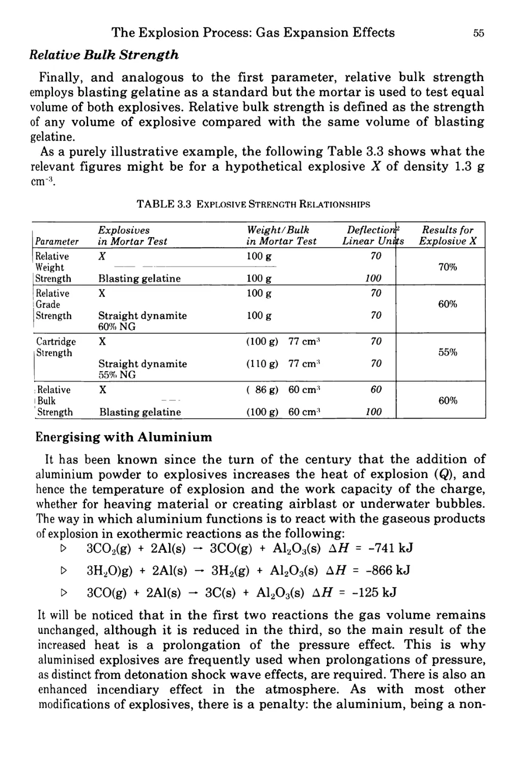
Table 3.3 Explosive strength relationships 55
Table 3.4 Comparison of properties and uses of explosives 57
Chapter 4 Table 4.1 Initiator compounds 61
Table 4.2 Booster compounds 63
Table 4.3 Ignition temperatures (°C) of some explosives 64
Table 4.4 Results of impact and friction tests 76
Chapter 5 Table 5.1 Firings in 105 mm tank gun using proof shot 88
Table 5.2 Possible functions of some propellant additives 94
Chapter 6 Table 6.1 Composition for a typical extruded double-base rocket propellant 105
Table 6.2 Composition for a typical cast double-base (CDB) rocket propellant 106
Table 6.3 Compositions for typical composite modified cast double-base propellants 108
Table 6.4 Typical compositions of composite propellants 111
Table 6.5 Composition (%) and performance of some typical rubbery composite propellants 113
Chapter 7 Table 7.1 Pyrotechnic special effects 116
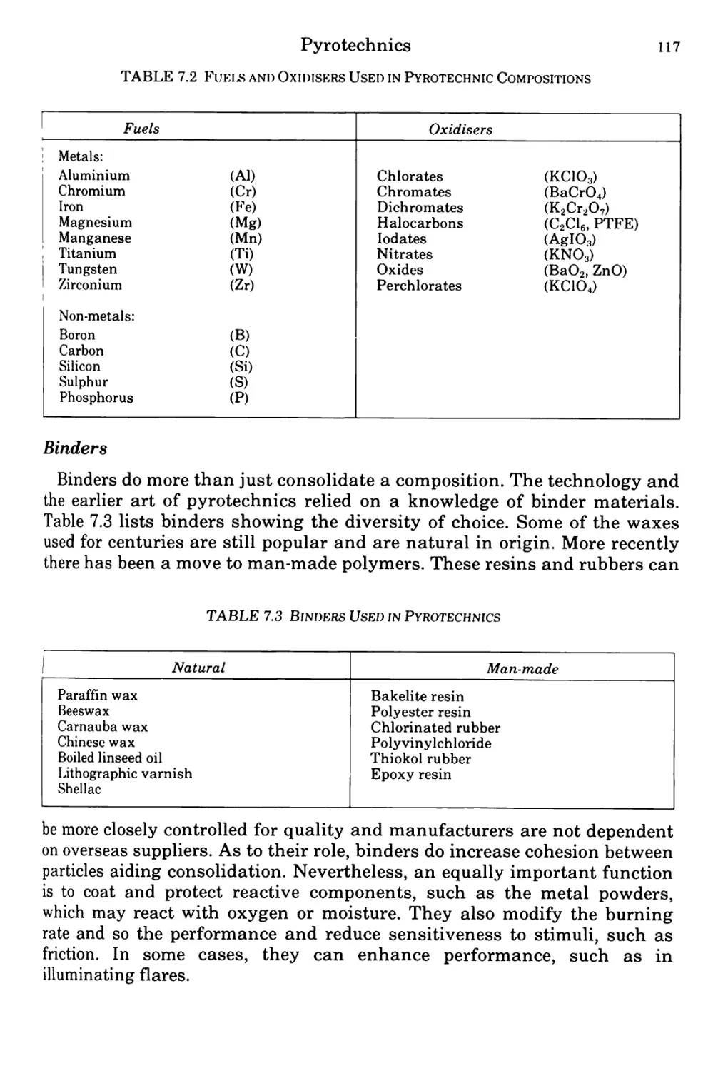
Table 7.2 Fuels and oxidisers used in pyrotechnic compositions 117
ix
List of Tables
Table 7.3 Binders used in pyrotechnics 117
Table 7.4 Heats of reactions of metals, metalloids and non-metals with oxygen (heat of combustion), sulphur and selenium 123
Table 7.5 Theoretical heat outputs for some metal/metal oxide combinations 124
Table 7.6 Slag producing first fire compositions 126
Table 7.7 Delay compositions 128
Chapter 9 Table 9.1 Physical properties of high explosives 147
Table 9.2 Advantages and disadvantages of melt casting 150
List of Illustrations
Chapter 1 Figure 1.1 Effect of oxygen balance on the heat of explosion 16
Chapter 2 Figure 2.1 Diagram of Dautriche apparatus 32
Figure 2.2 Theoretical and actual shapes of detonation shock waves 37
Figure 2.3 Shockwave propagation at plane interfaces 37
Figure 2.4 Shockwave propagation at curved interfaces 38
Figure 2.5 Explosive lenses 38
Figure 2.6 A schematic nuclear fission bomb 39
Figure 2.7 Inert pad wave-shaper 39
Figure 2.8 Explosive-metal wave-shaper 40
Figure 2.9 Cored charge 40
Figure 2.10 Detonation wave from a cylindrical charge 41
Figure 2.11 Shockwave from a plane-ended charge 41
Figure 2.12 Shockwave from a charge with a hemi-spherical end 41
Figure 2.13 Shockwave from a charge with a wedge end 41
Figure 2.14 Diagram of lined hollow charge 43
Figure 2.15 Linear cutting charge (enlarged) 46
Figure 2.16 Fracture tape 47
Chapter 4 Figure 4.1 Schematic of an explosive train 60
Figure 4.2 Explosive trains in a round of gun ammunition 60
Figure 4.3 Stab detonator from the United Kingdom 81 mm mortar bomb 62
Figure 4.4 Flash receptive detonator with integral booster explosive 62
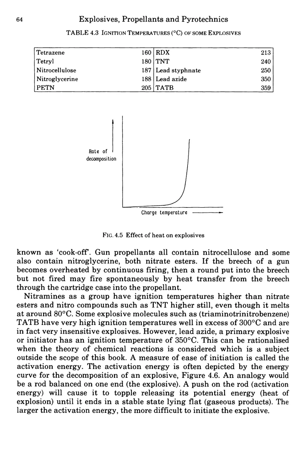
Figure 4.5 Rate of decomposition of an explosive as a function of temperature 64
Figure 4.6 Reaction profile of explosive decomposition showing activation energy 65
Figure 4.7 Percussion cap ignition 67
Figure 4.8 Arrangement of a stab detonator system 69
Figure 4.9 Bridgewire initiation 70
Figure 4.10 Conducting composition initiation 70
xi
xii List of Illustrations
Figure 4.1 1 Electric demolition detonator 73
Figure 4.1 2 Burning rate versus pressure 73
Figure 4.1 3 Profile of detonation pressure for donor and acceptor charges 74
Figure 4.1 4 Profile of detonation pressure for donor and acceptor
with inert barrier 75
Chapter 5
Figure 5. 1 Typical propellant grain geometries 80
Figure 5. 2 Schematic burning of a spherical propellant grain 82
Figure 5. 3 Propellant strand 82
Figure 5. 4 Strand burner 83
Figure 5. 5 Mass burning rate time curve for a propellant 84
Figure 5. 6 Effect of grain geometry on the pressure/time curve 86
Figure 5. 7 Variation ofgrain area with fraction of grain burnt 87
Figure 5. 8 Pressure-time profile for a propellant burning in a gun 88
Figure 5. 9 Heckler and Koch caseless ammunition 95
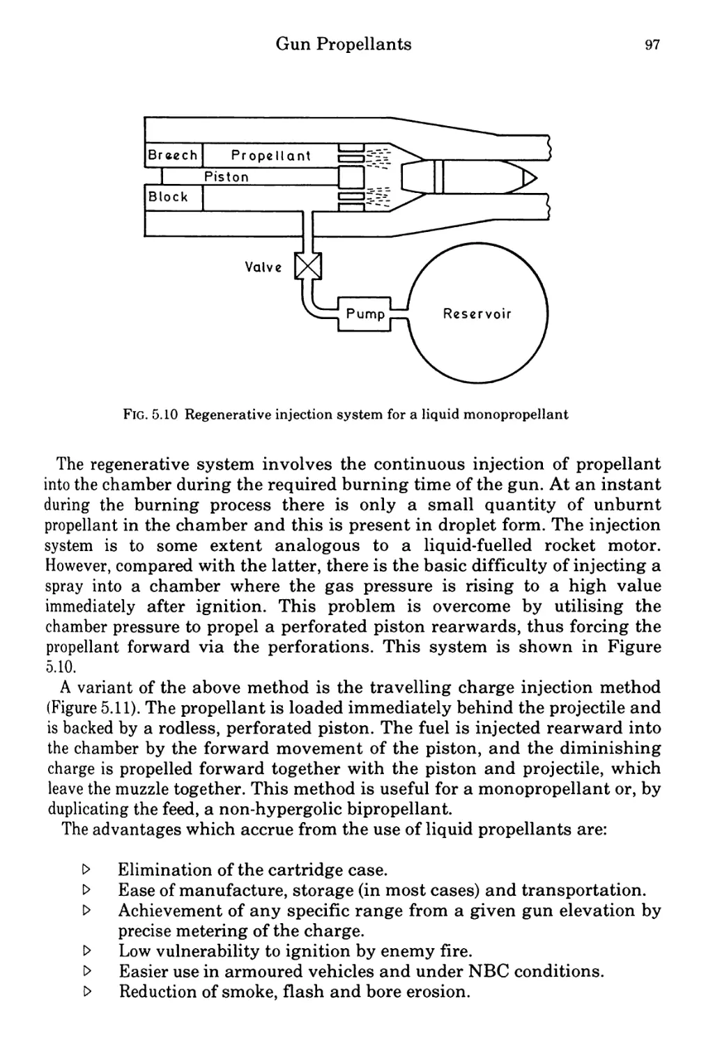
Figure 5.1 0 Regenerative injection systyem for a liquid monopropellant 97
Figure 5.1 1 Travelling charge injection system 98
Chapter 6
Figure 6. 1 Typical cross-sections of rocket propellant grains 102
Figure 6. 2 Shorts ground-to-air Javelin missile
(Courtesy of Short Brothers Limited) 103
Figure 6. 3 United Kingdom light anti-tank weapon (LAW)
(Courtesy of Hunting Engineering Limited) 104
Figure 6. 4 Solid rocket propellants 104
Figure 6. 5 Mould for the preparation of cast double-base rocket
propellants 106
Figure 6. 6 Effect of platonisation on the burning rate-pressure
relationship for CDB rocket propellants 107
Chapter 7
Figure 7. 1 Burning rate versus stoichiometry 121
Figure 7. 2 Cambric first-fire (X50) 126
Figure 7. 3 Schermuly signal smoke grenade—details
(Courtesy of Pains- Wessex Limited) 130
Figure 7. 4 Self-heating food can 130
List of Illustrations
xiii
Figure 7.5 Wallop Industries 5 inch reconnaissance flare, internal
details (Courtesy of Wallop Industries Limited) 133
Figure 7.6 Tracking flare, internal detail (Courtesy of Wallop Industries Limited) 134
Figure 7.7a Launch pod (Courtesy of Wallop Industries Limited) 135
Figure 7.7b ‘218’ infra-red flare (Courtesy of Wallop Industries Limited) 136
Chapters Figure 8.1 Pyromechanical actuators and thrusters 144
Figure 8.2 Undersea cable cut for a guillotine cutter 145
Figure 8.3 Guillotine bolt cutter for a release mechanism 146
Figure 8.4 Gas generator in the Lance missile 146
Chapter9 Figure 9.1 The solidification of TNT 148
Figure 9.2 Shell filling by the Meissner process 149
Figure 9.3 Die pressing of explosives 151
Figure 9.4 Incremental pressing of explosives 152
Figure 9.5 Hydrostatic pressing of explosives 152
Figure 9.6 Isostatic pressing of explosives 153
Figure 9.7 Various charge defects 157
Introduction
Gunpowder was undoubtedly the first explosive, recorded in a Chinese
manuscript, 1000 AD. It is of interest to note that this manuscript‘ Wu Ching
Tsung Yao’ was a treatise on military arts and that from that time, the
science and technology of explosives has been driven forward by military
requirements.
The next major event in the history of explosives came with the discovery
of nitric and sulphuric acids. This allowed chemists to ‘nitrate’ the wealth of
new compounds discovered by their science. Many nitrated materials were
made and many chemists lost their lives in the process, as it was soon
discovered that these materials were very energetic and often very unstable.
However, in 1861 Alfred Nobel, the father of modern explosives, constructed
a production plant for the manufacture of nitroglycerine at Heleneborg in
Sweden.
In the same decade, nitrocellulose became available. This, together with
nitroglycerine, gave the foundation for modern gun propellants, finally
ousting gunpowder by the turn of the century. Gunpowder had already been
replaced as a shell filling by picric acid (trinitrophenol) and then by TNT
(trinitrotoluene) before the end of World War I.
After 1918, major research programmes were inaugurated to find new and
more powerful explosive materials. From this programme came one of the
most used military explosives of today, that is, cyclotrimethylenetrinitramine
(RDX) also called Cyclonite or Hexogen. Since this time, other explosive
materials of military use have been discovered and will be discussed within
the relevant chapters. However, the vast majority of explosives and
propellants used today consist of the materials mentioned above, RDX, TNT,
nitroglycerine and nitrocellulose. This is something of a simplification since
other explosive types used in far smaller quantities are vital to the operation
of explosive devices. Thus, explosives are part of all munitions and obviously
vital to their performance. They must be considered as a method of storing
energy to be liberated on command to drive the weapon, be it a propellant
driving the shell from the gun barrel or the high explosive shell filling
driving the fragments formed from the shell case. It is the aim of this book to
explain the science and technology of the explosives used today within the
three main sub-groups of explosive materials: (high) explosives, propellants
and pyrotechnics.
Finally, to complete the story of gunpowder. As related above, gunpowder
has been replaced as a propellant and as a destructive filling however, it is
far from obsolete. Since gunpowder is used in delays, ejection charges for
carrier shells and igniter pads for propellants, it is still as vital to the
operations of a modern army as it was in the Middle Ages.
XV
1.
The Chemistry and
Physics of Explosives
The Nature of Explosions
Physical Explosions
An explosion is far easier to define than an explosive. Berthelot, in 1883,
defined an explosion as the sudden expansion of gases into a volume much
greater than their initial one, accompanied by noise and violent mechanical
effects. Explosions are common in nature. At one end of the scale, a
lightning strike may explosively split a tree trunk; at the other end, island
volcanoes, such as Krakatoa, have exploded with such violence that waves
have been created which swept over the oceans more than halfway round
the world to cause immense damage by flooding when they impacted on the
shore. In both cases, the explosions were due to the sudden vaporisation of
water without any chemical reaction taking place. The bursting of a balloon
or the rupture of a compressed gas cylinder remind us that heat is not a
necessary prerequisite for an explosion nor is the presence of a recognised
explosive substance. These physical explosions are nevertheless inherently
destructive and capable of causing damage by air blast and by the
propulsion of fragments at high velocity.
Nuclear Explosions
Nuclear explosions are a second class of explosions. These result in the
sudden release of enormous quantities of heat by fission or fusion processes.
The heat causes the rapid expansion of the air surrounding the device and
also vaporises material in the close vicinity which adds to the effect. The
radioactive elements are not themselves explosives in the conventional
sense but the device is triggered by the use of conventional explosives.
Chemical Explosions
The third class of explosion is called a chemical explosion. This is caused
by the extremely rapid reaction of a chemical system to produce gas and
heat. The reaction is usually a combustion process and is often accompanied
by the production of smoke and flame.
2
Explosives, Propellants and Pyrotechnics
Explosives
There are many substances known to chemists which are so unstable that
they may explode with little or no stimulus and are often used for party
tricks. If we simply define an explosive as a substance capable of causing an
explosion, we shall include many substances which have no practical value
and constitute little more than a nuisance in the laboratory. The legal
definition in Great Britain is given in the Explosives Act of 1875, where an
explosive is 'a substance used or manufactured with a view to produce a
practical effect by explosion" such as gunpowder, nitroglycerine and TNT.
Practical explosives must be inert to substances with which they may come
into contact, including air and moisture, and they must be thoroughly stable
under the expected conditions of storage and use. At the same time, they
must be sufficiently sensitive to be initiated by convenient means. For a
practical explosive, the minimum energy for initiation should be small in
comparison with the total amount of energy released on explosion. These
various properties collectively form the two essential requirements for any
useful explosive, namely, SAFETY and RELIABILITY. Many candidate
explosive substances are ruled out for practical use by the application of
these criteria.
To be useful, as implied by the Explosives Act, an explosive must also be
EFFECTIVE, that is it must be able to do work on its surroundings. This
takes place by the expansion of the hot high pressure gas produced in the
chemical reaction against the surroundings resulting in airblast, propulsion
of fragments, lift and heave effects. An explosive may therefore be defined
as a substance or mixture of substances which when suitably initiated,
decomposes explosively with the evolution of heat and gas.
High explosives are a very convenient source of power. When one
kilogramme of a detonating explosive is initiated in a bore hole, it will
generate power at a rate of 5000 megawatts over the duration of the
reaction. Such a charge occupies less than one litre of volume, and may be
stored for years. Yet at the touch of a button it may release its energy when
and where required.
The History of Explosives
Black Powder
Explosives, in the usual sense of that word, do not occur in nature.
Although explosions are not unknown in the natural world, they are usually
physical phenomena caused by the sudden vaporisation of water in some
way. The earliest man-made explosive is properly referred to as black
powder, but is more commonly called gunpowder because of the main use to
which it has been put during most of its existence. Black Powder is an
intimate mixture of saltpetre (potassium nitrate) with charcoal and sulphur.
The last two have always been available in many parts of the world, sulphur
The Chemistry and Physics of Explosives 3
occurs naturally in volcanic regions and charcoal is easily made by heating
wood. Saltpetre does not occur naturally in anything like a pure state, but it
forms an efflorescence on the ground when animal or vegetable matter
decomposes in situ. This process is a long one and occurs only in certain
climatic conditions, which are experienced in China and the Middle East
among other places. At some unknown time and place, one or more questing
minds found that charcoal and sulphur, which are only moderately
flammable when mixed with saltpetre, which is non-flammable, give rise to a
mixture which is not only flammable but violently so. On the balance of the
slim documentary evidence, the discovery was made by the Chinese, perhaps
around AD 700, and there are indications that by AD 1000 they had developed
weapons of war utilising black powder, though not what we now call guns.
News of the discovery spread only slowly round the world, but eventually it
reached the ears of scholars in Europe, one of whom was the man whose
name is most closely associated with black powder, the Englishman Roger
Bacon (born circa 1214, died 1292). Bacon graduated c.1240 and became a
Franciscan friar c.1257, but most of his life was devoted to languages,
mathematics, optics and experimental science. Amongst these activities he
experimented in the purification of saltpetre and made some effective black
powder: this much is known because he included the details, partly in
cypher, in a scientific work which he wrote for the attention of the Pope. The
experiment does not figure prominently in Bacon’s biography, which is
based largely on his own writing, in the virtual absence of cross-references.
He seems deliberately to have avoided spreading the knowledge further, for
reasons which can only be guessed at.
However, certain of Bacon’s learned contemporaries, such as Albertus
Magnus (c. 1200-1280) also knew about black powder and were less reticent
about it. Hence, before the end of the 13th century, it was being used in war
for the breaching of fortifications. By 1320 it was being used in guns, with
enormous consequences for the future of the world. The composition and
manufacture of powder were slowly improved over the next few centuries.
Its first recorded use for civil engineering was in the dredging of the bed of
the River Niemen in Northern Europe, 1548-72. Mineral blasting is said to
have been pioneered by Gaspar Weindl in Hungary in 1627 and to have been
introduced in England in 1689 by Thomas Esply senior, in the Cornish tin
and copper mines. Demolitions by black powder feature in British history in
the murder of Lord Darnley at Kirk O’Field in 1567, an abortive attempt on
the Houses of Parliament in 1605 and the destruction of fortifications during
and after the Civil War of 1642-6. The building of the Languedoc Tunnel in
France, 1666-81 involved what was probably the first major use of black
powder for public works tunnelling.
Nobel’s Nitroglycerine
The ultimate limitations of black powder as a blasting explosive became
frustratingly apparent during the great growth of communications in Europe
4 Explosives, Propellants and Pyrotechnics
and North America in the mid-nineteenth century, especially in such
formidable enterprises as the building of the trans-Alpine railway tunnels.
Fortunately, a remedy was forthcoming in the discovery, in 1846, of the
liquid explosive nitroglycerine (NG) by the Italian Professor Ascanio
Sobrero (1812-88). Sobrero realised that NG was far more powerful than
black powder but he soon lost interest in it, and it was taken up a few years
later by the Swedish inventor Immanuel Nobel. By 1863, the latter, together
with his third son Alfred Bernhard Nobel (1833-96), had set up a small
factory for NG manufacture at Heleneborg near Stockholm. Attempts by the
Nobel family to market the product were hampered, however, by the serious
disadvantages of NG: its inconsistency of response to initiation by ordinary
flame which is the standard method for black powder, and the difficulty and
danger of handling the explosive in its normal liquid state. This latter gave
rise to numerous accidental explosions, one of which destroyed the Nobels’
factory in 1864. Alfred Nobel, a very industrious science graduate,
eventually solved these problems by the invention of the fulminate
detonator (1864) and the discovery of an effective absorbent (Kieselguhr)
(1867). The twin products, ‘guhr dynamite’ and the detonator, provided an
invaluable combination far superior to black powder for most of the needs of
civil engineers and miners, and quickly amassed a fortune for Alfred Nobel.
He did not stop there, however: in 1869 he combined NG with mixtures of
nitrates and combustibles to form a new class of explosives known at that
time as ‘straight dynamites’. In 1875 he made a further definitive discovery,
namely that nitrocellulose mixed with NG forms a gel, and from this
stemmed the invention of blasting gelatine, gelatine dynamites and later, in
1888, the first ‘double-base’ gun propellant, ballistite.
Nitrocellulose
Nitrocellulose (NC) had been first prepared at about the same time as NG,
but being a more complex material it was developed in stages by different
workers, notably T.J. Pelouze in 1838 and C.F. Schonbein in 1845.
Schonbein used NC for mineral blasting and experimentally in guns,
demonstrating that as a propellant it was potentially better than
gunpowder, because it gives virtually smokeless combustion. Factory
production of NC began at Faversham, Kent, in 1846, but in the following
year an explosion destroyed the plant and two other NC disasters occurred
in France. In Austria attempts to manufacture NC in a safer, more suitable
form were persevered with, and in 1863 production was resumed in England
at Stowmarket, Suffolk, but an explosion there and another in Austria in
1865 halted the work in both countries. During these years Sir Frederick
Abel (1827-1902) had been working on the instability problem for the British
Government at Woolwich and Waltham Abbey, and in 1865 he published his
solution, which consisted of pulping, boiling and more thoroughly washing
the product. This breakthrough was followed by another in 1868 when
The Chemistry and Physics of Explosives 5
Abel’s assistant E.A. Brown discovered that dry compressed guncotton
(highly nitrated NC) could be detonated by the use of a fulminate detonator.
This paved the way for the effective use of NC as a military and commercial
high explosive.
Propellant Development
Because of the problems with NC, Schonbein’s early use of it as a gun
propellant was not successfully followed up for many years. In 1864 the
Prussian Schultze developed a propellant from nitrated wood, which,
though unsuitable for rifles, proved useful for shotguns. In 1870 the
Austrian manufacturer of this powder patented its partial gelatinisation
with ether and ethanol. During the next two decades the manufacture of
‘smokeless’ shotgun propellants was steadily improved, but it was not until
1884 that the Frenchman Paul Vieille produced the first NC propellant safe
for use in rifled guns. This was named Poudre B. Eventually, all such
powders, based on NC alone, became known as single-based types to
distinguish them from Nobel’s ballistite. In 1889, a year after the ballistite
patent, a rival product of similar composition to ballistite was patented by
the British Government in the names of Abel and Dewar, and was called
Cordite. In its various modifications it was to remain the preponderant
British service propellant until the 1930s when triple-base propellants,
containing nitroguanidine, were developed for ordnance. Cordite remained
in use for British small arms ammunition until after World War II, when a
change to single-base types was made.
Development of Commercial Explosives
Returning to commercial blasting explosives, the vast range of NG-based
explosives continued to dominate the market throughout the latter part of
the 19th century and the first half of the 20th, despite attempts to substitute
other bases such as chlorates, perchlorates or liquid oxygen. The period
1880-1914 was marked by determined attempts, particularly in France and
Britain, to eliminate unsuitable explosives from coalmines. This was the
result of long-term trends. In 1800 British coal production was 10 million
tons annually. Frequent underground explosions of natural methane or
suspended coaldust killed hundreds of miners until checked by the invention
of the Davy Lamp in 1815. Production rose rapidly, reaching 50 million tons
in 1850 with the increased use of black powder, and 133 million tons by 1875
with the additional help of dynamite. However, the growing use of
explosives brought a corresponding increase in the number of gas and dust
explosions, with appalling casualty totals. Scientists gradually deduced the
physical mechanisms by which explosives can ignite methane, and ‘testing
galleries’ similar to large boilers were built and successfully improved.
Those explosives which, even after modification, failed the gallery tests
were prohibited by law from use in coal-mines. They included dynamite and
6 Explosives, Propellants and Pyrotechnics
black powder. They were replaced by ‘permitted explosives’, which tended
increasingly to be based on ammonium nitrate, and other limitations were
also imposed, notably on the weight fired in each shot. By 1913 British coal
production reached an all-time peak of 287 million tons, consuming more
than 5000 tons of explosives annually, and by 1917 92 per cent of these were
ammonium nitrate-based. After the Great War the use of explosives declined
with total coal production, and also due to machine cutting, which by 1938
accounted for 59 per cent of production compared with 8 per cent in 1913.
Today the manufacture of permitted explosives in Britain is only a small,
though stable percentage of the total, reflecting both the fall of underground
coal production to 110 million tons by 1981 and the maximum use of coal-
cutting machines.
The Development of Military Explosives
The Great War of 1914/18 saw enormous production of explosives for
munitions. High explosive shells had been commonly filled with picric acid
since Turpin’s patents of 1885 and the British adoption of it in 1888 under
the name Lyddite. Around 1902 both the Germans and the British had
experimented with TNT, first prepared by Wilbrand in 1863. On the
outbreak of war the British hastily followed the Germans in making the
change to TNT, but almost immediately found that demand for it
outstripped supply, so they changed to a mixture of TNT and ammonium
nitrate called amatol. During the war some 238,000 tons of TNT were
produced in Britain alone. The production of tetryl for exploders in shells
also began in 1914 and accelerated greatly.
After the war, work on new explosives continued in many countries, and
much interest was centred on the compounds known in Britain as RDX and
PETN. RDX had been first prepared by the German Henning in 1899, but its
immense potential had been overlooked until 1920, when it was patented by
Herz. Efforts were made to overcome the difficulty and high cost of
manufacture, and problems of sensitiveness, in order to obtain explosive
mixtures far superior to those used in the Great War. The Germans
concentrated more on PETN. During World War II TNT and amatol were
again the main fillings for British shells and bombs, but RDX, produced at
the Royal Ordnance Factory at Bridgwater from 1939, was added to these
compositions insofar as supplies permitted. There was a greater usage of
aluminium as an additive (to give a high blast effect) than had been
possible in World War I. The generic composition ‘torpex’ (TNT/RDX/
aluminium,) became common. During the war, the marginally superior
analogue of RDX named HMX was first produced but not in great quantity.
Since 1945 it has become recognised in military circles that no practical
explosive superior in performance to RDX and HMX is ever likely to be
produced at an acceptable cost. British munition fillings have been largely
standardised on the RDX/TNT 60/40 mixture. Research has mainly been
The Chemistry and Physics of Explosives 7
aimed at optimising compositions for special applications, and identifying
and solving safety problems. The use of RDX and HMX has been extended
into the field of high-performance propellants for both guns and rockets.
Incorporation of RDX, HMX or PETN into oily or polymer matrices has
produced plastic or flexible explosives for demolitions, while other polymers
provide tough, rigid, heat-resistant compositions for conventional missile
warheads and for the implosion devices used in nuclear weapons.
The Development of Commercial Explosives
Developments in the field of commercial blasting since the 1939-45 war
have been more radical than those in the military one. The manufacture of
NG, a delicate and dangerous process upon which much of the explosives
industry has depended since Nobel’s time, had been revolutionised in 1929
by the Schmidt continuous nitration method, and in the 1950s it was further
improved by the introduction of the injector nitration method combined with
continuous centrifugal separation. However, the cost of NG-based blasting
explosives remained comparatively high, so in the early 1950s attention
turned to finding a more cost-effective alternative. The answer was
provided, as it had been to other problems, by ammonium nitrate, this time
in admixture with fuel oil, and the acronym ANFO was bestowed on the
product. In America annual consumption of ANFO increased from 268,000
tons in 1960 to 759,000 tons in 1970. A second revolution occurred a few
years after ANFO with the introduction of slurry explosives. These are also
based on ammonium nitrate used in the form of a saturated aqueous
solution gelled by a cross-linking agent, and with excess ammonium nitrate
held in suspension. Various fuels are added, such as carbonaceous material
or aluminium, and there must be some further additive, e.g. TNT,
methylamine nitrate or fine aluminium powder, to render the mixture
sensitive to initiation. The idea of aqueous slurry explosives dates back to
the turn of the century but its practical form is credited to Melvin A Cook
and dated 1957. The great increase in the use of ANFO and slurries,
combined with the decreased use of explosives in underground coal mining,
has had a depressing effect on the manufacture of NG-based blasting
explosives, but these still have a vital place in the demolition industry for
breaking metal and masonry, and for various other applications where
precision is more important than large scale and severe economy.
In recent decades, the commercial uses of explosives have extended
beyond the crude destruction methods of older times. Rapid changes in
society and industry, for example, have necessitated the demolition of
strong, fairly modern buildings such as factories, power stations and blocks
of flats, often in close proximity to vulnerable facilities. This has forced the
development of new and critical blasting techniques. The growth of the off-
shore oil industry has required the penetration of the seabed, and cutting of
submerged metal structures. Such requirements have led to the adaptation
8 Explosives, Propellants and Pyrotechnics
of hollow charge techniques, developed originally for military purposes, and
the use of modern explosive compositions formerly considered too expensive
for non-military users. Some engineering projects now include explosive
bolts, and explosives are also used for forming shapes in metal and for
welding metal plates. This proliferation of applications has justifiably led to
the concept that explosives technology is now a branch of engineering in its
own right.
Accidental Explosions
Early Problems
As with most of the dangerous commodities used by mankind, explosives
have caused innumerable deaths and injuries over the years, but with each
new category of accident the application of human intelligence sooner or
later finds a way to avoid a repetition. This is, of course, subject to
avoidance of human error, and perhaps the best advice available to all who
handle explosives is the old British Army adage; ‘We must never forget that
the ultimate purpose of an explosive is to explode’.
During the centuries when technology advanced only slowly, the use of
black powder for blasting was particularly dangerous because there was no
reliable way to convey the initiating flame to the charge with a delay time
sufficient for the operator to retreat safely. Trains of powder along floors, or
quills or rushes filled with powder, often caused a premature explosion and
a casualty, an eventuality immortalised by Shakespeare in the phrase ‘hoist
with his own petard’. In the Cornish mines of the 19th century, where
miners were particularly reckless, such occurrences were commonplace.
Then in 1831, William Bickford of Tuckingmill, Camborne, invented the
‘miner’s safety fuse’, which abruptly changed the situation worldwide and
remains in use today in a virtually unchanged form. As we have seen, the
mass explosions of NG in the 1860s impelled Alfred Nobel to find a remedy
in the form of dynamite, and the accidents with NC in the same period led to
Abel’s work which elevated that explosive to its rightful position of great
utility.
19th-century Reforms
In the latter part of the 19th century the increasing production of
explosives led to many forms of accident. In Britain, particular concern was
caused by the explosion of two powder magazines at Erith, Kent, which
killed 13 people, and there followed one at Messrs. Ludlow’s in Birmingham
which killed 53. The Government, in the reforming tradition of the time,
assumed the responsibility for preventing recurrences if possible, and
appointed Colonel Sir V.D. Majendie to investigate the Birmingham
incident. Afterwards he guided the resulting legislation which became the
Explosives Act of 1875. Under the Act, Colonel Majendie was appointed the
first permanent Inspector of Explosives to administer its provisions. He had
The Chemistry and Physics of Explosives 9
power to inspect all magazines and factories and to see that operations were
carried out in a reasonably safe manner. The result of the Act was a
dramatic cut in the average number of persons killed per annum in British
explosives factories;
1868-70 43
1871-74 32
1878-87 7.5
Notable Accidents
Other Governments followed suit and the international problem was
brought under control. It was found, however, that the carrying of
explosives on board ships posed higher risks than those on land, because of
the concentration of the cargo, the ease with which fire spreads and the
general proximity of port facilities to densely populated areas. A ship
explosion at Santander, Spain, in 1893 killed hundreds of people, and on 6
December, 1917, during the Great War, a ship carrying 2500 tons of
explosives blew up off shore at Halifax, Nova Scotia, Canada, killing 1963
people and destroying the town centre.
In Britain the war brought a number of accidental explosions, the largest
being at a TNT works in Silvertown, East London. The highest death toll,
however, was 134 killed at an explosives factory at Chilwell, Nottinghamshire,
on 1 July, 1918.
A series of explosions at a United States naval ammunition depot in New
Jersey in 1936, was caused by lightning and involved 1500 tons of
explosives and 21 deaths. It was significant in that it led to the adoption of
the quantity-distance (Q-D) concept, and rules were then applied in the
United States limiting the quantity of explosive which could be stored
within a given distance of other explosives or of inhabited buildings. This
concept is widely applied today but not always without its problems,
especially where explosives ships, port facilities and population centres exist
together.
A new cause of disaster was discovered in 1921. Some 4000 tons of
ammonium nitrate fertiliser, stored in a silo at a chemical works at Oppau,
near Mannheim, Germany, exploded without warning at 7.33 a.m. on 21
September. The village of Oppau was largely destroyed and out of its 5000
population 561 were killed and 1500 injured. The effects of the explosion
were felt up to 20 miles away.
Wartime Accidents
World War II, like its predecessor, brought a huge increase in the amount
of explosives existing around the world, often handled or stored under
difficult conditions by inexperienced personnel. In Britain there were
inevitable accidental explosions in factories, ammunition dumps and on
10 Explosives, Propellants and Pyrotechnics
trains, but their frequency was minimised by experience gained in the
previous war, and often by cases of personal bravery. An illustration of the
latter, and also of unforeseen cause and effect, occurred in Cambridgeshire
on the night of 1 June, 1944. A freight train loaded with 400 tons of aircraft
bombs was approaching Soham when it was found that the timber bed of
the leading wagon was on fire. The bombs which it was carrying contained
five tons of TNT. The crew stopped the train, coolly unhitched the
remaining trucks, then restarted the locomotive and drew the burning
wagon forward as far as Soham Station. There its load exploded, but due to
the marginal gap which had been opened up the remainder of the train load
did not. Two railwaymen were killed, and the station and 15 houses were
destroyed. The truck, as well as the locomotive tender, was demolished, but
subsequent investigation showed that it had previously been used for
carrying sulphur, and it was surmised that a spark from the engine had
ignited the residue, thus starting the fire. Appropriate recommendations
were made, as always to avoid a repetition.
The largest explosion in the country’s history occurred accidentally at
RAF Faulds, an underground bomb store near the village of Hanbury in an
agricultural part of Staffordshire. On 27 November, 1944 some 3500 tons of
bombs detonated almost simultaneously, killing 68 people and destroying
not only the depot but parts of Hanbury Village half a mile away. The cause
is believed to have been the use of a wrong tool on a tetryl exploder. The
crater, 100 feet deep and several acres in extent, is a tourist attraction to this
day. The same year of 1944, marking as it did the climax of the War, was a
bad one for explosives accidents. On 14 April a fire and explosion on a ship
in Bombay docks killed more than 1000 persons, and on 17 July at Port
Chicago, California, 1500 tons of explosives, mainly torpex, in railcars and
a ship’s hold, blew up killing 320 and injuring 390.
Post-war Problems
Another bad year occurred in 1947. This time the cause was not military
explosives but, as at Oppau, large quantities of ammonium nitrate fertiliser.
In France, 21 people died and 100 were injured at Brest when 3000 tons of
fertiliser exploded, and on 16/17 April of the same year, when two ships
caught fire at Texas City, USA, some 2280 tons of nitrate which they were
carrying exploded, causing 552 fatalities and leaving more than 3000
injured. It is said that these disasters served, ironically, to draw anew the
attention of the explosives industry to the capacity of ammonium nitrate to
detonate en masse, and hence paved the way for the introduction of ANFO
and slurries a few years later.
In recent decades there have been no incidents world wide of accidental
explosions causing casualities on the scale of the 1940s, and in general the
industries responsible for the manufacture, storage, transportation and use
of explosives can be said to have put their house in order. Indeed, the
The Chemistry and Physics of Explosives 11
chemical engineering industry has attracted more opprobium with disasters
involving other dangerous substances (e.g. Flixborough 1974, Movosibirsk
1979, Bhopal 1984) than has been caused by conventional explosives. The
discovery that ammonium nitrate ‘cooks off when exposed to a conflagration
had echoes in Britain in January 1977 in connection with another oxidising
salt, sodium chlorate, which until then had not been thought capable of
mass explosion. A warehouse at the Braehead container depot, Renfrew,
Scotland, containing 1700 drums of the substance accidentally caught fire
and, ten minutes later, exploded, propelling debris up to five miles, slightly
injuring 13 people and causing £6 million damage. As a result of this, the
storage of sodium chlorate is now subject to much stricter controls.
Incidents will always continue to happen with conventional explosives and
other dangerous materials, but experience, wisdom, care and new
technology can keep fatalities to a minimum.
The Nature of Explosives
Basic Features
Explosive systems exist in a wide range of physical forms. They may be
single compounds such as TNT or RDX or they may be mixtures of
substances. These mixtures may consist of chemical compounds or simple
elements and they may be liquids, solids, gases or, as frequently happens
with commercial explosive systems, two-phase systems. Solid or liquid
explosives are often called CONDENSED explosives.
The most usual chemical reaction which occurs in the explosion process is
combustion or oxidation. Here, the fuel elements, usually carbon and/or
hydrogen, react with the oxidising elements, normally oxygen or a halogen
such as chlorine or fluorine. Condensed explosives contain the necessary
oxidiser to permit reaction to take place in the absence of air and are thus
‘self contained’. In contrast, ordinary fuels such as paraffin, wood or coal
are not capable of rapid combustion unless they are finely divided and
provided with copious quantities of air, or more specifically, oxygen. The
corollary of this is that because explosives contain their own oxygen as well
as fuel, when combustion takes place, the total amount of energy they
release is considerably less than that from an equal weight of a straight
forward fuel. For example, 1 kilogramme of TNT releases 4080 kilojoules of
energy whereas the combustion of 1 kilogramme of petrol in an adequate
supply of air will release more than 30,000 kilojoules. The usefulness of an
explosive derives more from the speed at which it releases its energy than
from the quantity of energy released.
Explosive Mixtures
As we have already seen, explosives exist in a number of forms and the
simplest way to classify them is into mixtures and single chemical compounds.
12 Explosives, Propellants and Pyrotechnics
The simplest mixture we can consider is that of 2 volumes of hydrogen gas
and 1 volume of oxygen gas. Complete mixing occurs naturally, and when
initiated with a spark a violent explosion ensues with the production of
water
2H2 + O2 —> 2H2O
This reaction results in a decrease in the number of gas molecules and at
first appears to be contrary to the definition of an explosive which is that a
large volume of gas should be produced. However, no less than 13,260 joules
of heat per gramme of mixture are released by the combustion of hydrogen.
The expansion of the product water vapour due to the heat much more than
makes up for the reduction in the number of gas molecules on combustion
and an explosion results. Though gaseous fuel/air explosives have been
proposed for mine clearance, they are not practical military explosives and
‘condensed’ mixtures are more commonly encountered.
An example of a condensed explosive mixture is black powder or
gunpowder. Roger Bacon (1214-92) gave its composition as:
Potassium nitrate 37.5 per cent
Charcoal 31.25 per cent
Sulphur 31.25 per cent
This mixture was slow burning and not very powerful. Developments in
production methods took place which brought the constituents into much
more intimate contact and hence speeded up the combustion rate. ‘Corned’
(granulated) black powder burns much more rapidly than the older material.
Another improvement came when it was realised that there was not enough
oxygen held in the potassium nitrate oxidiser to combust all the fuel
elements. The formula for a modern black powder is typically
> Potassium nitrate 75 per cent
l > Charcoal 15 per cent
> Sulphur 10 per cent
The sulphur, as well as being a fuel element, reduces the ignition
temperature of the mixture. Black powder was invented long before the
advent of modern chemistry and even now it is not possible to describe its
combustion adequately in a simple chemical equation. An over-simplified
approximation to the reaction is as follows:
4KNO3 + 7C + S —> 3CO2 (gas) + 3CO (gas) + 2N2 (gas)
+ K2CO3 (solid) + K2S (solid)
Thus only about 43 per cent of the explosive is converted into gaseous
products which is about a quarter of that produced by an equal quantity of
an efficient modern explosive. Moreover, the solid products retain a
considerable proportion of the heat produced on explosion, further reducing
the efficiency of the black powder.
The Chemistry and Physics of Explosives 13
A much more efficient and commonly encountered condensed explosive
mixture is used commercially as a ‘prilled’ powder or as a slurry and about
25,000 tons was produced in the United Kingdom alone in 1986. The reaction
may be represented by the equation:
25NH4NO3 + C8H18 —> 8CO2 + 59H2O + 25N2
The products of this explosive mixture are entirely gaseous giving a very
cheap and efficient product.
Single Explosive Compounds
The development of the organic chemical industry in the mid-19th century
was stimulated by the search for synthetic dyestuffs which had a greater
fastness and colour range than those extracted from natural materials. Soon
a vast range of compounds was available. Many of the coloured compounds
resulted from the treatment of precursor materials with mixtures of nitric
and sulphuric acids. This treatment produced compounds containing one or
more (-NO2) groups (nitrogroups) many of which were explosives in their
own right. The oxygen for combustion is held in the (-NO2) group.
Such groups may be attached to oxygen atoms, carbon atoms or nitrogen
atoms in the molecules and are called ‘nitrate’, ‘Nitro’ or ‘nitramine’
compounds respectively. Examples of explosives of each type are shown
below:
CH2O - no2
cho - no2
I
CH,0 - no2
Glycerol trinitrate
(nitroglycerine)
Trinitrotoluene
(TNT)
no2
H2CX XCH2
I I
o2n-n xn-no2
H2
Cyclotrimethylene
trinitramine
(RDX)
These molecules will explode violently if stimulated in an appropriate
manner. The molecular structure breaks down on explosion leaving,
momentarily, a disorganised mass of atoms. These immediately recombine
to give predominantly gaseous products and evolve a considerable amount
of heat called the Heat of Explosion.
О C3 H.5 N3 O9 —►
Nitroglycerine
> C7 H5 N3 O6
TNT
0 C3 H6 N6 O6
RDX
3CO2 +2.5H2O + 1.5N2 + ,25O2
3.5CO +2.5H2O+ 1.5N2 + 3.5C (solid)
3CO +3H2O + 3N2
14 Explosives, Propellants and Pyrotechnics
Performance of Explosives
The effectiveness of an explosive depends on two factors. The first is the
amount of energy available in the explosive and secondly, the rate of release
of the available energy when the explosion occurs. To measure the
effectiveness of different explosives a variety of performance parameters
may be used such as:
> Heat of explosion
> Temperature of explosion
> Pressure of explosion
> Power index
l> Rate of burning
> Detonation velocity
> Detonation pressure.
These parameters may be measured experimentally or calculated from
theory. Theoretical calculations are more convenient and are useful in
comparing the relative performance of one explosive with another but in an
explosion the precise conditions are not known so it is doubtful whether
absolute performance figures for an explosive can be calculated precisely.
Where such absolute values are required then they must be determined by
experiment.
Heat of Explosion (Q)
When an explosive is initiated either to rapid burning or to detonation, its
energy is released in the form of heat. The heat so released under adiabatic
conditions is called the Heat of Explosion and determines the work capacity
of the explosive. For high explosives and for propellants in the breach of a
gun, the heat is measured or calculated under constant volume conditions
(QJ. For rocket propellants, where the products of combustion may expand
freely into the atmosphere, it is more appropriate to use conditions of
constant pressure and the heat obtained is Qp.
The heat of explosion is simply the difference between the heat of
formation of the products of explosion and the heat of formation of the
explosive compound itself. The heats of formation of gases such as carbon
dioxide, carbon monoxide and water are well known and have often been
measured. The heats of formation of chemical compounds may be calculated
from a knowledge of the individual bond energies between the atoms which
make up the explosive molecule thus enabling the heat of explosion to be
calculated easily. Table 1 lists values of Q for various common explosives:
The Chemistry and Physics of Explosives
15
TABLE 1.1 Calculated Heats of
Explosion for Some Explosives
(Water as Gas)
joules per gramme
Nitroglycol (EDGN) 6730
Nitroglycerine 6275
PETN 5940
RDX 5130
HMX 5130
Tetryl 4350
TACOT 4015
TNT 4080
DATB 3805
Lead azide 1610
RDX/TNT 60:40 4500
The experimental determination of heats of explosion has yielded rather
variable results, depending on the experimental conditions and the oxygen
content of the particular explosive. For instance, when the mixture of atoms
formed during an explosion recombines to form the gaseous products, the
precise mix of CO2, CO, H2O etc. depends on the loading density in the test
vessel and this factor also affects the measured heat of explosion.
Oxygen Balance
From the formulae of the three explosives given earlier, we can see
immediately that nitroglycerine has more than enough oxygen in its
structure to oxidise fully the fuel elements of the molecule. RDX is somewhat
oxygen deficient since the carbon has been oxidised to carbon monoxide
only. TNT is very oxygen deficient; not only has its carbon only been
oxidised as far as carbon monoxide but some carbon has not been oxidised
at all. This is the reason why TNT gives a black sooty smoke when it is
detonated.
Unlike explosive mixtures, where the oxygen content can be adjusted by
varying the proportions of the constituents until the fuel and oxidiser
elements are balanced, simple chemical compounds are rarely perfectly
balanced. The oxygen balance (П) of an explosive is defined as:
‘the percentage by weight of oxygen, positive or negative, remaining after explosion,
assuming that all the carbon and hydrogen atoms in the explosive are converted into
CO2 and H2O.*
All the explosive classes above — nitrate esters, nitrocompounds and
nitramines — contain only the elements carbon hydrogen oxygen and
nitrogen and are called CHNO explosives having the general formula:
Ca Hb Nc Od
Simple algebra shows that the oxygen balance is given by the formula:
П = (d - 2a - 6/2) x
16 Explosives, Propellants and Pyrotechnics
where M is the relative molecular mass of the explosive. Using the formula
we find the oxygen balance shown below:
Nitroglycerine
RDX
TNT
Oxygen balance
+3.5 per cent
-22 per cent
-74 per cent
The Effect of Oxygen Balance on Heat of
Explosion
When there is exactly enough oxygen in the explosive to fully oxidise the
carbon and hydrogen to carbon dioxide and water (i.e. fl = 0) then the heat of
explosion will be optimal. Any deviation from perfect oxygen balance either
positive or negative, will lead to a lower heat of explosion. Figure 1.1 shows
the dependence of the heat of explosion on oxygen balance. EGDN, for
which fl = 0 has the highest heat; nitroglycerine, with its positive oxygen
balance (fl = +3.5) has a smaller heat as do all the other explosives with
negative oxygen balances.
Fig. 1.1 Effect of oxygen balance on the heat of explosion
The Chemistry and Physics of Explosives 17
TNT is heavily oxygen deficient. Its performance can be improved by
mixing it with ammonium nitrate which is oxygen rich to form the
‘amatols’. An ammonium nitrate/TNT 80:20 mixture has П = 0. In this case,
though a high Q value is obtained, the detonation velocity suffers, being
only 5080 m s1 for amatol of density 1.45 g cm-3 compared with 6950 m s 1
for TNT at 1.58 g cm 3.
In blasting gelatine, the oxygen deficiency of the 8 per cent cellulose
nitrate content is compensated for by the addition of 92 per cent of
nitroglycerine. Hence the heat of explosion is higher than that of either
component alone and in addition, the mixture forms a gel of high density
and helps to account for the high velocity of detonation which is 7900 m s 1
at 1.55 g cm 3.
Composition of the Gaseous Products of Explosion
To calculate the heat of explosion and other explosive performance
parameters a knowledge of the composition of the gaseous products of
explosion is essential. This may be calculated from the equilibrium
constants of the water-gas and other reactions but it is a tedious process.
Recently, data banks and software have been compiled which allow
computer calculations to be made.
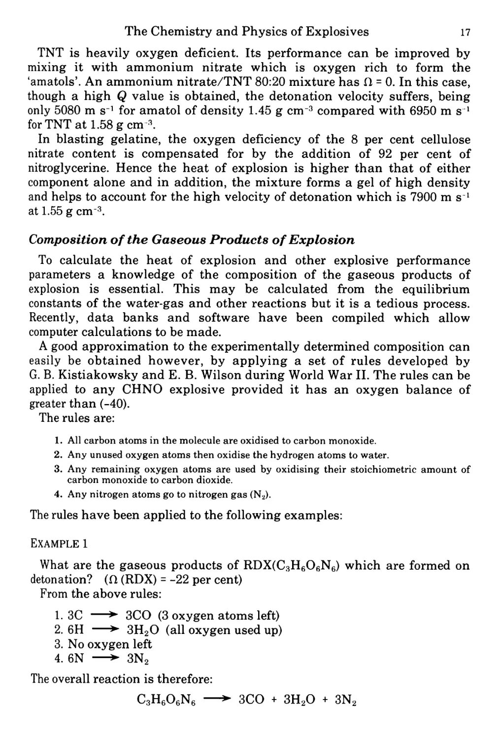
A good approximation to the experimentally determined composition can
easily be obtained however, by applying a set of rules developed by
G. B. Kistiakowsky and E. B. Wilson during World War II. The rules can be
applied to any CHNO explosive provided it has an oxygen balance of
greater than (-40).
The rules are:
1. All carbon atoms in the molecule are oxidised to carbon monoxide.
2. Any unused oxygen atoms then oxidise the hydrogen atoms to water.
3. Any remaining oxygen atoms are used by oxidising their stoichiometric amount of
carbon monoxide to carbon dioxide.
4. Any nitrogen atoms go to nitrogen gas (N2).
The rules have been applied to the following examples:
Example 1
What are the gaseous products of RDX(C3H6O6N6) which are formed on
detonation? (fl (RDX) - -22 per cent)
From the above rules:
1. 3C —► 3CO (3 oxygen atoms left)
2. 6H —► 3H2O (all oxygen used up)
3. No oxygen left
4. 6N —> 3N2
The overall reaction is therefore:
C3H6O6N6 —► 3CO + 3H2O + 3N2
18 Explosives, Propellants and Pyrotechnics
For explosives with a greater oxygen deficiency than (-10) the above rules
were modified as follows:
1. All hydrogen atoms in the molecule are oxidised to water.
2. Any unused oxygen atoms then oxidise carbon to carbon monoxide.
3. All nitrogen atoms go to nitrogen gas.
Example 2
What are the gaseous products of TNT(C7H5O6N3) which are formed on
detonation (fl(TNT) - -74%)
From the above rules we get:
1. 5H —► 2.5H2O (3.5 oxygen atoms left)
2. 3.5C —► 3.5CO (all oxygen used up)
5H 3.5 carbon atoms are left unoxidised
3. 3N —► 1.5N2
The overall reaction is therefore:
C7H5O6N3 —► 2.5H2O + 3.5CO + 3.5C (solid) + 1.5N2.
Temperature of Explosion
The maximum temperature which the gaseous products of explosion can
reach if no heat is lost to the surroundings is called the Temperature of
Explosion (Te) and is often used when calculating the ability of an explosive
or propellant to do work. Te is found to lie between 2500 and 5000°C for
military high explosives. It can be calculated quite easily if the quantities
and nature of the gaseous products and the heat of explosion (Q) are known
from the equation:
те- та=Я
Sc
Ta is the ambient temperature — generally taken to be 25 °C and Sc is the
sum of the mean molar heat capacities of the explosion products over the
temperature range Ta to Te. These are readily available from standard
thermochemistry tables.
In practice, the heat capacities of molecules are higher, the more atoms
there are in the gas molecules. It follows therefore, that if the product
molecules formed on explosion can be kept small (e.g. produce CO rather
than CO2) then higher values of Te may be achieved for the same heat of
explosion (Q). This is achieved by adjusting the oxygen balance of the
explosive so that it is somewhat negative. This will of course reduce the heat
of explosion so that in practice a compromise is established. For gun
propellants it is important not to have too high a temperature of explosion
or else erosion of the gun barrel will reach unacceptable levels.
The Chemistry and Physics of Explosives
19
Gas Volume
The volume of the gaseous products of explosion (V) is generally
calculated at a pressure of 1 bar and a temperature of 0°C (273K) and
generally lies between 700 and 1000 cm3 for military explosives. Inspection
of the equation for combustion gives the number of moles of gas produced
and since the volume of a mole of any gas occupies the same volume under
standard conditions (22,400 cm3) the value of V can be calculated readily.
Example
Calculate the volume, V, for the detonation of RDX, given that the
equation for reaction is:
—> 3CO + 3H2O + 3N2
—>• 9 moles of gas
C3H6O6N6 (RDX)
1 mole of RDX
222 g RDX
1 gRDX
—► 9 x 22,400 cm3 of gas
gives 9 x 22,400 cm3 of gas
222
V - 908 cm3 g-1
Pressure of Explosion
The pressure of explosion (Pe) is the maximum static pressure which may
be achieved when a given weight of explosive is burned in a closed vessel of
fixed volume. The pressures attained are so high that the Ideal Gas Laws
are not sufficiently accurate and have to be modified by using a co-volume (a):
At high pressures
Pe (V* - a) = nRTe
where V* is the volume of the closed test vessel, n is the number of moles of
gas produced per gramme of explosive and R is the universal gas constant.
Example
Calculate the pressure of explosion of Pe for the burning of 10 g of RDX in
a bomb of volume 10 cm3, given that n = 0.045 moles per gramme of RDX, Te
= 4255K and a = 0.54.
p = 0.0405 x 8.31 x 4255
e (1 - 0.54)
= 3113 MN nr2
= 31 kbar approx.
Pressures of explosion are of a much lower order of magnitude than
detonation pressures.
2.
The Explosion Process:
Detonation Shock Effects
Burning and Detonation
Intrinsic Energy
In Chapter 1 we saw that practical explosives are mixtures or single
compounds and that all but a few of them contain oxygen in some form,
together with the fuel elements carbon and hydrogen. We saw also that
nitrogen is usually present as a chemical companion to the oxygen. The
system is thus capable of producing, almost instantaneously, a large
quantity of the gases carbon dioxide, carbon monoxide, water and nitrogen.
Because such oxidation reactions are exothermic, the system also produces
much energy, which is treated as being initially in the form of heat and is
called the heat of explosion, designated Q. Since the explosive material is a
self-contained chemical system, and because energy cannot be created, it is
clear that the energy is contained within the explosive from the time of its
manufacture, waiting to be released by some initiatory stimulus.
Two Combustion Processes
When an explosive charge is initiated, the energy is released by one of two
possible combustion processes, burning or detonation. Most explosives are
capable of either process, depending on the method of initiation and the
conditions under which it occurs, particularly the degree of confinement. In
practice these factors are regulated in a way which ensures that the
explosive behaves in the desired manner. Because of this, it is sometimes
suggested that explosives can be divided into two categories, detonating and
deflagrating or rapidly burning, but this is a misleading over-simplification,
the more so as certain very useful explosive compounds are used
increasingly in both roles. It is better to divide all explosive processes into
either burning or detonation, and to bear in mind that in situations where
the conditions cannot be regulated, i.e. in unforeseen accidents, the question
as to which process happened is often decided by pure chance rather than
the type of explosive involved. There is an element of unpredictability in the
behaviour of explosives under all but tried and proven conditions.
22
Explosives, Propellants and Pyrotechnics
Burning
Virtually all explosives burn vigorously when ignited in a dry, unconfined
state, an exception to this are water-based slurries. Burning can also occur
in a confined state, since explosives do not rely on an external supply of
oxygen for their combustion. Burning comprises a series of chemical
reactions which take place in a zone or zones at or just above the surface of
the explosive. When the surface of the material is thus being converted into
gases, the surface itself can be regarded as receding in consecutive layers.
This concept is expressed in Piobert’s Law (1839): The surface of a burning
propellant recedes layer by layer in a direction normal to the surface.
The size of the discrete piece of explosive does not affect the concept: it can
be tiny grain of small arms propellant, or the propellant grain of a solid
rocket motor weighing tens of kilogrammes. The temperature of each layer
is brought in turn to the ignition point by means of heat radiated or
conducted from the reaction zone(s) into the solid material. Some heat is
also evolved by the relatively slow decomposition of the material just before
it reaches its ignition point, the model assumes that the surface is non-
porous, which does not apply to certain propellant compositions. The rate at
which the surface recedes depends on the rate of heat transfer into the
material. In turn, this depends on the temperature at the burning surface,
the thermal conductivity of the material, its transparency to radiation and
inversely on its thermal stability.
Rate of Regression
The rate of regression, or ‘linear’ burning rate, is designated r. For a given
explosive the main factor affecting r is the pressure P obtaining at the
surface at a given instant, since the effect of pressure is to thin the reaction
zone and thereby accelerate the flow of heat into the explosive. In 1862 de
Saint Robert deduced that the relationship, for black powder, between r and
P was given by
r = ppw>
where Д is called the coefficient of the burning rate and depends on the units
of r and P. Later, Paul Vieille found that the smokeless powders and other
new explosives of the Nobel era gave different values for the index and he
generalised the expression as
r - fiP<*
which is known as Vieille’s Law (1893).
Burning Rate Index
The index a, known as the burning rate index, has to be determined
experimentally using an apparatus called a Strand Burner. Strands of pro-
The Explosion Process: Detonation Shock Effects 23
pellant are burned at various pressures and the measured values of r are
plotted against P. Values of a for different propellants and other explosives
vary from about 0.3 to more than 1.0. If the index is exactly 1.0, the plot is a
straight line. An index higher than 1.0 gives a steepening curve, less than
1.0 gives a flattening one. The index is of great importance in the internal
ballistics of guns and rockets. It also indicates the tendency or otherwise of
an explosive to detonate in certain circumstances, as will be seen later. The
value of a for conventional gun propellants is about 0.8-0.9, while that for
certain rocket propellants is as low as 0.3.
Because of the pressure dependence of the linear burning rate, the effect of
heavy confinement on a burning explosive is very great. A strand of typical
gun propellant, ignited at one end in the open, burns quietly at around 5 mm
s l, but when confined in the breech of a gun, where the pressure can rise
some 4000 times higher, the burning rate is about 400 mm s1. Thus a solid
grain 2 mm thick would be consumed in 2.5 ms at maximum pressure. For
the purpose of internal ballistics this burning rate does not need to be
exceeded, but for any application requiring a more extreme burning rate the
appropriate technique is to combine heavy confinement with the provision
of porosity in the grains, so that the flame enters the particles and consumes
them faster than would surface burning. By such means an ultimate linear
burning rate of about 500 m s-1 is achievable.
Mass Rate of Burning
A different, but related, way of expressing the rate of burning is the mass
rate of burning, designated m. This is the mass of explosive consumed in
unit time. Consider a grain of explosive, of any shape, burning all over its
surface. If the surface area is A and the linear burning rate is r, the volume
of explosive consumed in unit time is r x A. Hence the mass consumed in
unit time is r x A x p where p is the density. This would apply to, say, a
single large propellant grain in a rocket motor or equally to an aggregate of
smaller grains in the breech of a gun. Now, it can be shown by geometry
that a large number of small grains has a much greater surface area per
unit mass, (specific surface), than a single grain of the same weight. In a
gun, therefore, A is large. The charge of grains is ignited quickly over its
entire surface, so the rapid generation of gas causes the pressure P to rise.
The linear burning rate r follows suit, and r and P then rise inter-
dependently to high values within one or two milliseconds. The net result is
the more or less explosive effect known as deflagration.
A Surface Phenomenon
The burning of a solid explosive, therefore, is essentially a surface
phenomenon, as is the case with most other combustible solids. The main
difference is that explosives do not need a supply of air to sustain their
burning. Confinement of burning paper, for example, will extinguish the
24 Explosives, Propellants and Pyrotechnics
flame, but confinement of an explosive does the opposite, it speeds up the
reaction and may lead to an explosion.
Detonation
Nature of a Detonation
As stated earlier, burning is one of the two alternative combustion
processes by which explosives release their energy. The other is detonation.
The first notable feature of detonation is a shock wave which passes
through the explosive material without being much affected by the relative
position of the surface. The second outstanding feature of detonation is its
great speed compared with any burning process. The velocity of the shock
wave in solid or liquid explosives is between 1800 and 9000 m s1, an order of
magnitude higher than that of a fast deflagration and two or three orders
higher than an average one. Whereas, in burning, the rate at which the
material decomposes is governed by the rate of heat transfer into the
surface, the rate of decomposition of the material in the wake of a
detonation wave is limited only by the velocity at which the material can
transmit the wave.
Basic Methods of Initiating a Detonation
The practical initiation of explosives takes place under conditions
regulated to produce either burning or detonation as required. The burning
of most explosives is quite easily started by simple ignition, and once
started is difficult to stop. Detonation is less easy to achieve in most cases.
Certain conditions have to be provided so that the shock wave is formed and
will propagate through the explosive material without attenuating and
fading. Although the velocity and pressure of the wave are enormous once it
is established, it is sometimes delicate and unpredictable in its early stage.
Initiation to detonation can occur in one of two ways:
> Burning to detonation.
> Shock to detonation.
Burning to Detonation
Burning to detonation, as the name implies, consists of a transition from
the burning process already described: an ignition of the explosive followed
by an abrupt acceleration of the flame front until it becomes transformed
into a shock wave. The conditions under which this can happen are various,
and also the readiness with which different explosives display the
phenomenon varies greatly. Perhaps the easiest case to visualise is when an
explosive is confined in a tube and ignited at one end. The gas generated
cannot escape easily, so pressure tends to build up at the burning surface. If
The Explosion Process: Detonation Shock Effects 25
the explosive has a burning rate index of more than 1.0, or if, as is
sometimes the case, the index is higher at high pressure than at low
pressure, pulses will be generated, and these may accelerate the linear
burning rate to sonic velocity. A shock wave will then be formed and the
transition to detonation is complete. A zone of total chemical decomposition
and formation of gases follows the wave until the charge is completely
consumed.
Burning to detonation can be brought about not only by confinement in a
tube but also by the presence of a critical mass of explosive. Thus one stick
of dynamite may merely flare when ignited whereas a bundle of similar
sticks may well burn to detonation. A loose heap of explosive can provide
self-confinement and thus either burn or detonate, according to its size and
to a property called explosiveness which will be discussed in a later chapter.
Shock to Detonation
The alternative way of initiating detonation, called shock to detonation,
requires the action of a shock wave from an already detonating charge,
called the donor, on the charge in question, the receptor charge. The two
charges usually need to be in contact, or nearly so. When the shock wave
passes through the receptor charge, the explosive material undergoes
compression and adiabatic heating. This liberates some of its chemical
energy, which has the effect of changing the natural deceleration of the
wave into acceleration. Hence the pressure in the wave front is increased,
more energy is released from the explosive and the wave continues to
accelerate until it reaches the characteristic velocity of sound in the shock-
compressed medium of the explosive. A burst of light (as revealed by high
speed cine photography) signals the onset of detonation. However, if the
shock wave from the donor charge is too weak, or if other conditions are
unfavourable, the entering wave will fail to accelerate and will die out,
leaving the bulk of the receptor charge chemically unchanged.
Although the final result of the two initiation systems is identical, there is
a wide difference of time scale between them. In a designed burning-to-
detonation system, such as a blasting detonator or a delay fuse, the delay
may be of milliseconds. In an accident situation, for example if a pile of
explosive is being disposed of by uncontrolled burning, it may convert to
detonation quite randomly, seconds or even minutes after ignition.
Compared with either of these two cases, the shock-wave may have to run a
distance of millimetres or centimetres into the receptor charge before
reaching detonation velocity, but this causes a delay of only a few
microseconds, so there is a difference of three orders of magnitude at least.
Given the proper conditions the shock-to-detonation method is the surest
and most convenient way in which to initiate a main charge to detonation.
However, from a wider viewpoint, shock-to-detonation is not an independent
alternative to burning-to-detonation, because it requires a donor charge, and
26 Explosives, Propellants and Pyrotechnics
that charge can only be initiated by a burning-to-detonation system at the
outset.
Functions and Classification of Explosives and
Pyrotechnics
In practice, explosives are employed to fill certain roles. The nature of the
role determines whether burning or detonation is required. The explosive
will then be caused to function under conditions regulated to ensure that it
behaves in the desired manner. Explosives can therefore be classified under
the role in which they are normally employed. Explosives which are
normally caused to detonate are called high explosives (HEs). Explosives
which normally function in a burning mode are sometimes called low
explosives. However, this term is now discouraged and because such
compositions are mostly propellants of various kinds, they are nowadays
called propellant explosives or simply propellants.
We can include in our scheme of functions the class of materials known as
pyrotechnics, although they do not share all the characteristics of
explosives which are set out in this Chapter. Pyrotechnics are mixtures of
oxidising and reducing solids, capable of self-sustained combustion at rates
which differ greatly from one composition to another. They are designed to
produce special effects which supplement or simulate those produced by
conventional explosives, and are outlined in part 3 of Table 2.1.
TABLE 2.1 Functions of Explosives
1. High explosives detonate to:
Create shock waves
Burst
Shatter
Penetrate
Lift and heave
Create airblast
Create underwater bubble pulses
2. Propellants burn to:
Propel projectiles and rockets
Start LC. engines and pressurise other
piston devices
Rotate turbines and gyroscopes
3. Pyrotechnics burn to:
Ignite propellants
Produce delays
Produce heat, smoke, light and/or noise
While some explosive compounds can be assigned exclusively to the
category of high explosives, others are more versatile. Nitrocellulose is
present in many commercial high explosives, but is also the universal
ingredient of all conventional gun propellants. Nitroglycerine is also present
in many commercial high explosives and in many propellants, while RDX,
The Explosion Process: Detonation Shock Effects 27
hitherto regarded simply as a high explosive, is also being incorporated in
more and more propellant compositions.
Another way of classifying explosives is by the readiness with which they
are ignited and exploded, that is, their sensitiveness to initiation. (The
difference in meaning between the words sensitivity and sensitiveness is a
fine one and in this instance is irrelevant). Substances which are readily
ignited or detonated by a small mechanical or electrical stimulus are called
primary explosives: those which are not readily initiated thus, and therefore
require the influence of an impinging shock wave to initiate them, are called
secondary explosives. Propellants are not normally initiated by either of
these methods in practice, but by the application of flame. Combining the
classifications, we can describe both the input normally applied to an
explosive and the response expected of it:
> A primary high explosive can be detonated easily.
> A secondary high explosive can be detonated, but less easily.
> A propellant explosive is not required to detonate at all.
> Whilst it is probably true that all primary explosives are capable of
detonation, some are not required to do so in use, but only to
deflagrate.
It must be stressed that the above statements are requirements, not firm
predictions as to the behaviour of explosive materials under all conditions.
For instance, in accident situations or under enemy attack, propellants may
detonate, and secondary explosives, given the wrong kind of initiatory
stimulus, may burn instead of detonating. The requirements presuppose
that the explosive system will function as it is designed to.
Partition of Energy
Propellants
Consideration of explosion processes reveals that the energy released by
an explosive undergoes several conversions and partitions within the brief
time-span of the explosion. For instance, in a gun the energy of the
deflagrating propellant is first released as internal energy of the gases,
manifested as high temperature and pressure. As soon as the projectile
begins to move up the bore, work is being done on it, and it acquires kinetic
energy at the expense of the internal energy of the gases. Further internal
energy is lost as the gases themselves accelerate and acquire kinetic energy.
When the projectile clears the muzzle, the gases vent and collide with the
atmosphere, transferring their kinetic energy to it in the form of a minor
blast wave. The remaining energy of the gases is lost directly to the
atmosphere and to the material of the gun in the form of sensible heat. In
general little of the energy of a deflagration is converted into wave energy.
28 Explosives, Propellants and Pyrotechnics
Detonations in Air
Taking now the case of a high explosive detonating in air, an appreciable
proportion of the released energy is contained in the shock wave which
passes through the charge. This wave spreads laterally, and at the far end
of the charge frontally, into the surrounding air, but decelerates abruptly
and is overtaken within a few charge diameters by the expanding gas front.
The gas front compresses the atmosphere ahead of it and creates a powerful
blast wave, containing much of the original energy of the explosive. Work
has been done by setting the air molecules in motion, but it is accomplished
more by the internal energy of the expanding gases than by the energy of
the detonation shock wave.
Confined Detonations
If the same explosive, instead of detonating in air, is inserted in a hole
drilled in solid rock and detonated there, the situation is somewhat different,
because the gas is not free to expand straightaway. The detonation shock
wave is transmitted more efficiently by a dense solid such as rock. It travels
freely through the material, but the impulse which it imparts is not of a type
which, by itself, can propel heavy pieces of rock over a distance and thus do
measurable work. Instead, it produces intense compression for a very short
time, and this tends to cause plastic and elastic flow in a homogeneous hard
material. Hence the energy of the wave is largely dissipated as frictional
heat. The usefulness of the wave lies in the fact that a brittle material will
fail under intense compression, and even a tougher one will fail in tension
when the initial compression phase of the wave is suddenly reversed by
reflection. These extreme forces produce spalling and cracking effects in
even the strongest materials, and the gases are then able to expand and
heave the broken mass in any required direction. Thus the energy released
by a detonation is partitioned between the shock wave and the internal
energy, which is the work capacity of the gases which expand behind it. For
some effects, such as breaking isolated boulders, only the shock wave
energy is of use, while for others, like blowing a crater in loose ground, it is
the heaving action which is important. Each separate application requires a
characteristic partition of the available energy. At a given detonation
velocity, every high explosive displays a specific partition of its energy, and
it is therefore possible to choose the explosive best suited to a particular
task.
Measuring the Partition of Energy
The best way to measure the partition is to detonate a charge under water:
the detonation wave moves rapidly away and is well clear before the gas
pressure fully expands the resulting bubble at a lower order of velocity.
Measurements can thus be made of the separate energies of the detonation
The Explosion Process: Detonation Shock Effects 29
wave and the bubble. Such experiments show that the maximum proportion
of the energy which goes into the shock wave is no more than about 50 per
cent, and that the explosives which display this proportion are those with a
high velocity of detonation.
Detonation Velocity and Pressure
Because of the partition of energy requirement, the velocity (D) at which
the detonation shock wave proceeds through a charge is an important
parameter of the explosive material. It can be predicted by calculation and
measured experimentally, and although a maximum value can be assigned
to a particular explosive, depending ultimately on its thermochemical
properties, practical results may be considerably lower, for reasons outlined
below.
> Effect of density of loading (A)
Since a detonation wave proceeds through the body of the
explosive, the energy which it releases within and behind itself
will depend on the mass of explosive traversed per unit area of the
wave front. Hence the more mass that is concentrated into a given
volume of explosive, the more energy the wavefront can release in
order to sustain itself at a high velocity. Provided the charge is of
reasonable diameter and well confined (see below), the velocity of
detonation appears to be almost exactly proportional to the
loading density and is covered by the relationship:
D. - D2 + 3500 (A) - A2)
where - velocity of detonation at density Al
and D2 - velocity of detonation at density A2
This formula applies to explosive compounds or mixtures of them,
and the result is that plots of D against A for different explosives
form more or less parallel straight lines. The achievement of high
loading density has importance in munitions in addition to its
effect on the velocity. High density is necessary if the maximum
amount of explosive is to be contained in a compact munition. In
commercial blasting, high density loading of shot-holes is usually
an advantage, but not always so: it depends on the burden to be
blasted.
To calculate the approximate velocity of detonation for a given
explosive at a particular loading density, Marshall’s formula is
used:
D (in metres per second) = 4307^ + 3500 (A-l)
where n is the number of moles of gaseous products per gramme of
explosive detonated,
30 Explosives, Propellants and Pyrotechnics
Td is the temperature of detonation, expressed in kelvins
and Д is the charge density in g cm-3.
This formula gives good agreement with observed results
although the calculation of from thermochemical data is
necessarily only approximate. It should be noted that both of the
foregoing formulae apply only to explosive compounds or mixtures
of such compounds. They do not apply to explosive mixtures of
fuel and oxidant: the detonation velocity of these falls off above a
critical density, and if compressed too much they become
undetonable. This is known as dead-pressing, or desensitisation.
t> Effect of diameter of charge
The velocity of detonation falls below its maximum when the
diameter of the charge is below a certain value, if the degree of
confinement is also small. This diameter varies for different
explosives, according to their sensitivity. For sensitive compounds
like NG and PETN it is a few millimetres, for less sensitive ones
like TNT, ANFO and slurries it is between 10 and 30 centimetres.
> Effect of confinement
In general, the stronger the confinement the higher is the
detonation velocity. The effect of confinement becomes more
marked as the diameter of the charge is reduced.
t> Effect of strength of detonator
Explosive charges and initiating systems used in military
munitions are designed to ensure that the fully velocity of
detonation is achieved in every round, for maximum effect.
However, the more ad hoc combinations of detonator and main
charge used in commercial blasting operations may result in the
detonator imparting an inadequate shock wave to the receptor
charge, and the velocity of detonation will then be markedly
decreased. Nitroglycerine-based explosives, commonly used for
rock blasting, but not in military detonating munitions, are
capable of two very different velocities. The use of too weak a
detonator may reduce the achieved velocity from more than 6000 m
s’* to a low as 2000 ms1.
The corollary of all the variabilities of detonation velocity is
that when quoting velocities it is necessary to state at least the
loading density to which a particular figure applies. Where any
other doubt is implicit, the diameter, confinement and strength of
detonator should also be stated. For military explosives, the
The Explosion Process: Detonation Shock Effects 31
velocities quoted are usually the maximum allowed by all the
variables. In any case, such compositions, being of high
performance, are less affected by the variables. The velocities of
commercial explosives are usually quoted, in this country, for an
unconfined column of explosive 1!4 inches (32 millimetre) in
diameter and initiated by a No. 6 detonator. These conditions
often produce a velocity far below the maximum achievable by
other means, as shown in the previous paragraph. Table 2.2 shows
velocities for commercial explosives and Table 2.3 shows values
for some military explosives. Table 2.2 is assembled from various
data and shows velocities which probably approach the maximum
achievable. Sales literature produced by manufacturers tends to
quote a range of velocity for any given explosive, to cover all
causes of variation.
The velocity of detonation shock waves is equal to the velocity
of sound (Q within the explosive material at the temperature and
pressure existing in the shock front, plus the velocity of the
material (iv) as it moves forward in the wave. This fact is known
as the Chapman-Jouguet condition:
D - C + tv
where C is about one-third higher than the speed of sound in the
charge before it is compressed by the detonation wave. For a
typical high explosive, say TNT, c is about 5400 m s1 in the
conditions of the wave and iv is about 1500 m s1, so D is about
6900 ms1.
The Experimental Measurement of Detonation
Velocity
The experimental measurement of detonation velocities has been greatly
improved in recent years with the introduction of electrical methods and
high-precision timing. A detonation shock front has a high electrical
conductivity compared with the undetonated explosive, so circuits can be set
up in the explosive which feed high-voltage pulses into a counter-timer. For
routine quality control in explosives factories, however, a much older
technique is used, known as the Dautriche method. This is a comparative
method, relying on a known velocity for detonating fuze. This velocity, of
course, has to be checked when necessary by an absolute method such as
above. The following is an outline of the Dautriche method.
The explosive under test is contained at the desired density of loading in a
steel tube and fired by the detonator, see Figure 2.1. Two detonators are
inserted at points A and В in the tube which are at a measured distance L
metres apart, and a length of detonating fuze of known velocity of
detonation connects the two detonators together. The centre portion of the
fuze is laid on a plastic plate P, the exact centre point of the fuze E being
32 Explosives, Propellants and Pyrotechnics
marked on the plate. As the detonation wave of the explosive travels along
the tube it fires the two detonators in turn, causing waves of detonation
travelling in opposite directions to pass around the fuze. Where these two
waves meet at F an indentation occurs on the plastic plate and the distance
EF is then measured.
Then if D2 is the velocity of the detonation of the fuze, the velocity of
detonation of the explosive is given by:
£> - DzL-
1 2EF
This formula may be easily derived thus: the time taken for the explosion
wave to travel from A to F in the fuze must be equal to the time taken for the
explosion wave to travel from A to В in the main explosive and then В to F
in the fuze. Hence:
AE = L + BF
D2 Dy D2
or AE + EF = L + BE - EF
D2 Dy D2
But AE - BE, hence:
Dy (BE + EF) - D2L + Dy (BE - EF)
Fig. 2.1 Diagram of Dautriche Apparatus
33
The Explosion Process: Detonation Shock Effects
TABLE 2.2 Detonation Velocities of some Commercial Explosives
Type Density g cm3 Detonation velocity m sl Remarks
Blasting gelatine (92% NG) 1.55 7900 Initiated with No.8 detonator
Polar ammon gelatine dynamite (50% NG) 1.5 6850
Gelignite (26% NG) 1.45 6400
Plaster gelatine 1.5 6300
TNT powder (18% TNT) 1.1 4850
Water-based slurries 1.4-1.7 3-4500 Depends on composition and diameter
ANFO 0.8 2-3000 Depends on diameter
Permitted powder explosive (10% NG, 12% sodium chloride) 0.7 1800-2000
Detonation Pressure
The peak dynamic pressure in the shock front is called the detonation
pressure (p) of the explosive. An empirical method of calculating it is due to
Cook, as follows:
p (kbar) = AD2 x 2.50 x Ю-6
where A is the charge density in g cm-3
and D is the velocity of detonation in m s1.
Example
Given the velocity of detonation of HMX at 1.50 g cm 3 as 7400 m s1,
calculate its detonation pressure (p) at the same density.
Then
p = 1.50 x 74002 x 2.5 x ю-e kbar
= 205 kbar
The calculated detonation pressures of some high explosives are given in
Table 2.3. It should be noted that it is traditional in explosives technology to
use the kilobar as a unit of detonation pressure, regardless of the nature of
the medium. Strictly, the bar and kilobar should only be used in connection
with fluids, so some modern literature on shock waves quotes pressures in
gigapascals (GPa), where 1 GPa is equal to 10 kbar. In the present work we
are adhering to tradition.
Fragmentation Munitions
Detonation pressure is the main factor in determining the property of
explosives called brisance, or shattering effect. It is derived from the French
34
Explosives, Propellants and Pyrotechnics
TABLE 2.3 Detonation Parameters for some Military Explosives
Type D/m s 1 at S/g cm 3 p/kilobar calc.
Secondary explosives
HMX 9110 1.89 392
RDX 8440 1.70 300
RDX/TNT 60/40 7900 1.72 268
DATB 7520 1.79 253
Nitroglycol 8100 1.50 246
Nitroglycerine 7700 1.60 237
Tetryl 7160 1.50 192
TNT 6950 1.57 190
Primary explosives
Lead azide 4500 3.8 192
Mercury fulminate 4500 3.3 167
Lead styphnate 4900 2.6 157
word briser - to break. The property of brisance enables a high explosive to
break its container, such as a shell or bomb, into small fragments which fly
at high velocities. There is no close analogy between this process and the
ejection of a projectile from a gun. The latter depends on the relatively
steady production of hot gas by the propellant, whereas fragmentation relies
on the shock wave to break up the case and begin the acceleration,
subsequently aided by the expanding gas. In modern munitions the ways in
which the fragments are produced are various. Whereas a HE shell or
mortar bomb is a plain cylinder which has to be strong enough to withstand
the shock of discharge, a missile warhead or an anti-personnel grenade may
have a liner of preformed fragments, or its case may be grooved on the
inside to produce a similar effect. Fragmentation is a complex topic and the
following is only a rough guide.
The fragment size, whether randomly produced or preformed, is optimised
for the type of target intended. An anti-personnel grenade projects very
small fragments, sometimes pieces of notched wire liner: they are required
only to incapacitate an enemy, not kill him, and should not be capable of
wounding the thrower at only a little greater distance. Fragments from
warheads, shells or bombs are optimised to damage aircraft or vehicles and
the preferred weight is in the range 5-10 grammes. The larger the velocity,
but the thinner the cloud of fragments is, the less is the chance of hitting the
target. Taking, then, the size of the randomly-formed fragments and the
velocity to be the most important parameters, they both depend to a large
extent on the ratio of charge weight to case weight. Provided this ratio is not
far from 1:1, the size of the fragments decreases as the detonation pressure
of the explosive increases. For moderately or very heavy cases the fragment
velocity tends to be a function more of explosive work capacity and
charge/case weight than of detonation pressure. In HE shells, which have
c:w ratios of about 1:10, velocities average 1000 m s1, while large bombs,
with ratios up to 2:3, can give velocities up to 4000 m s1. Fragments, being
of poor ballistic shape, decelerate more sharply than bullets: a typical
The Explosion Process: Detonation Shock Effects 35
fragment slows by more than half over a distance of 100 metres. It will
require a velocity of some 1000 m s1, depending on its shape, to penetrate 10
millimetres of steel. The effect of fragment shape on its penetration capacity
is less at higher velocities, and at 2000 m s1 it is said to be negligible.
Scabbing
Fragmentation is one of the ways in which high explosive shells are
designed to cause damage: another is scabbing. Scabbing is a technique for
damaging a thick metal plate, like armour, on one surface by exploding a
charge on the opposite surface. The charge must be detonated from a point
furthest from the metal, whereupon the shock front meets the metal in a
more or less parallel plane and passes through it as a compression wave.
When it encounters the other surface of the metal it is reflected, because of
the large acoustic difference between metal and air. The wave undergoes a
phase change on reflection, and travels back as a tension wave. Once the
tension wave has cleared the later portion of the compression wave the
momentum which has been imparted to the reflecting surface takes effect
and tears the metal apart at the weakest plane, which is that of the
returning tension wave. Thus a disc of metal, formed into a shallow dome
and called a scab, becomes detached from the surface of the plate and is
thrown forward at a speed of about 100 m s1. The diameter of the scab is
roughly equal to that of the charge producing it. The military application of
scabbing is in the defeat of thick armour plate on tanks. The vehicle is
attacked with a type of shell known as High Explosive Squash Head
(HESH). It has thin walls, a thin rounded nose and a base fuze. The shell is
filled with a soft, insensitive mixture of high explosive and wax, and when
it strikes the target the nose and walls deform under the impact and the
explosive becomes momentarily piled against the armour. After an optimal
delay of the order of a millisecond the fuze detonates the main filling and
the resulting scab, weighing several kilogrammes, ricochets round the
interior of the tank, causing sufficient damage and injury to put the vehicle
out of action. The filling of a squash-head shell must be of high detonation
pressure as well as low sensitiveness. A mixture of RDX and wax in the
appropriate proportions 90:10 is usual.
Rock Blasting
The same capacity of an explosive to impart a high pressure shock wave
to its surroundings, and the ability of rock, like metal, to reflect the wave at
an air interface, is vital to the blasting of rock by high explosives. Routine
blasting in quarries is called bench blasting, the bench being an artificial
cliff within 20° of vertical. Holes are drilled from the top surface, parallel to
the face and ending at or just below floor level. Each hole is filled to about
three-quarters of its length with explosive, initiated either by a detonator or
36 Explosives, Propellants and Pyrotechnics
by a detonating fuze. The remainder of the hole is stemmed with clay, sand
or gravel. In practice a row of such charges is detonated together, but we
will consider one hole for simplicity. The shock wave starts from the
initiator and travels down the hole, spreading radially into the surrounding
rock. Since the wave front is roughly conical, pressure is exerted in both
radial and axial directions. When the wave has moved clear of the hole,
these pressures are relieved unevenly and the rock, which is much weaker in
tension than in compression, begins to crack in radial orientations, starting
a little outward of the hole. The crack velocity is probably about 1000 m s l
whereas the shock wave is travelling several times faster. That portion of
the spreading wave which meets the cliff surface, often called the free face,
is reflected back as a tension wave, and on its return journey meets the
cracks which are spreading both away from the hole and towards it. The
interaction of the tension wave with those cracks which are nearest to
parallelity with it causes further reflection and cracking. As a result, the
whole rock mass within a 90° sector of the hole breaks up. The residual
pressure of the hot gas in the hole heaves the mass forward a little way
before it collapses to the quarry floor. The whole process is a combination of
shock wave effect and the work capacity of the explosive. If the burden (the
distance between the hole and the free face) has been judged correctly, and
the hole is properly stemmed, a minimum of the available energy is wasted
as heat, air blast and ground vibration. The explosive used must be chosen
for its characteristic velocity, and hence detonation pressure and brisance,
to match the strength of the rock and break it into the optimum size for
mechanical handling. Those pieces which are too big for this are subjected
to secondary blasting, one type of secondary blasting is known as plaster
shooting. A small slab of high velocity explosive or plaster gelatine, is laid
on the boulder, covered with mud and detonated. The interacting internal
reflections of the shock wave shatter the boulder. This is a shock wave effect
only, the internal energy of the gas is largely wasted.
Elementary Shock Wave Shaping
The damage capacity of an uncased explosive charge comprises two
effects, the detonation shock wave and the expansion of the gases. Both of
these effects rely fundamentally on the chemical energy which is the heat of
explosion of the charge, and since no practical high explosives of
significantly greater energy are ever likely to be discovered, much of the
research into explosives is devoted to making the best use of the energy
available. In particular, the detonation wave which travels through and
away from the main charge can be suitably shaped to produce a
concentration of energy in a particular direction. This section discusses the
shape of detonation waves and the ways in which they can be influenced.
Explosive charges of many sorts and sizes tend to be cylindrical in shape
for various reasons (e.g. ballistic shapes, drilled shot-holes, filled tubes) and
The Explosion Process: Detonation Shock Effects 37
they are often, though not always, detonated from one end. In a cylindrical
charge of very large diameter and initiated from one end, the detonation
wave would theoretically, spread spherically from the detonator and would
therefore approach planarity as it proceeded along the charge. In practice,
however, heat losses at the circumference cause the wave front to reach a
constant state of convexity (Figure 2.2).
Fig. 2.2 Theoretical and actual shapes of detonation shock waves
There are two stages at which the convexity of the wave front can be
modified. The first is during its progress through the bulk of the charge,
where an interface between two different explosive media, called an
explosive lens, can be contrived. The second possible stage is when the wave
leaves the outer surface of the charge, i.e. the explosive/air interface, the
geometry of which can be made to alter the wave shape. Methods relating to
these two stages will be referred to as internal wave shaping and surface
wave shaping respectively.
Internal Wave Shaping: Explosive Lenses
The simplest case of wave shaping arises in a composite cylindrical
charge consisting of two solid explosives of detonation velocities Dx and D2
respectively, bonded together at a planar interface whose centre is X (Figure
2.3). If D2> Du then when the central portion of the wave reaches X it will
accelerate from DA to D2 while the outer portion is still travelling at velocity
Dx. The curvature will then increase as shown in Figure 2.3.
This assumes that the second explosive charge at once assumes its own
characteristic velocity when initiated by the detonation wave from the first
charge. In a real situation the detonation shock wave crossing the interface
will decelerate or accelerate slightly depending upon the relative velocities
of Dx and D2.
Fig. 2.3 Shockwave propagation at plane interfaces
38 Explosives, Propellants and Pyrotechnics
A converse effect occurs when a wave in a steady state of curvature
decelerates at a planar interface. If the ratio of the velocities is correctly
matched to the initial curvature, an almost planar wave can be achieved.
Such wave-shaping effects are correspondingly greater when the interface
between two explosive media is not planar but curved. In Figure 2.4 it is
seen that a wave passing from a high velocity explosive to a lower velocity
one via an oppositely convex interface has its own curvature reversed.
High { Low
Fig. 2.4 Shockwave propagation at curved interfaces
There is an obvious analogy to the optical lens, which alters the parallel
nature of a beam of light by virtue of (a) the lower velocity of light in glass
compared with the air medium and (b) the curvature of at least one
interface. Because of this similarity the juxtaposition of different explosives
at a curved interface is called an explosive lens. The explosive lens can have
a reverse arrangement to that shown above and the two types are shown
together in Figure 2.5, both producing, in this case, planar waves.
Fig. 2.5 Explosive lenses
In practice the range of detonation velocities achievable in suitable solid
explosive charges lies in the range 4000-8500 metres per second. Bipartite
explosive lenses constructed from baratol (Z) = 4200 m s-1) and HMX/TNT (D
- 8400 m s1) achieve a detonation velocity differential of 1:2. Differentials of
1:4 probably represent the limit achievable, such could probably be attained
by using low velocity gelatines in conjunction with suitably bonded HMX.
The Implosion Device
One of the most important applications of the convergent explosive lens is
in the nuclear fission bomb or warhead. The implosion device of the prototype
The Explosion Process: Detonation Shock Effects 39
atomic bomb was developed by G. Kistiakowsky and operated successfully
in 1945 in New Mexico and at Hiroshima. It consisted of a set of twelve
bipartite charges arranged round a hollow core of fissionable material. The
charges were so shaped as to form a complete hollow shell of explosive
(Figure 2.6). The twelve detonators were fired simultaneously and the
resulting spherical wave impinged on the core to initiate the chain reaction.
The implosion device remains today one of the two normal methods for
triggering an atomic explosion.
low velocity
central
cavity
high velocity
fission core
Fig. 2.6 A schematic nuclear fission bomb
Other Types of Internal Wave Shaping
Inert Pad
In Figure 2.7 is shown a method of producing a
wave of approximately conical shape from the
normal convex one. The introduction of an inert
pad causes the wave to be propagated around the
pad but not through it, thus completely altering
the shape of the wave.
Fig. 2.7 Inert pad wave-shaper
Explosive-Metal Wave-shaper or Air Lens
In this system, shown in Figure 2.8, the low velocity component of the
explosive lens is replaced by a layer of metal in contact with the high
velocity component on the side of the approaching detonation wave and an
air cavity on the other side of the liner. When the detonation wave reaches
the metal liner, it is accelerated across the air gap with an overall velocity
less than that of the detonation wave. An air shock will travel ahead of the
liner but will be too weak to initiate detonation when it arrives at the far
side of the cavity. By suitable shaping of the cavity, the desired shape of
shock front can be produced. The example shown is equivalent to the
explosive lens system shown in Figure 2.5.
40
Explosives, Propellants and Pyrotechnics
Fig. 2.8 Explosive-metal wave-shaper
Cored Charge
The production of bipartite charges with
curved interfaces is difficult and costly. An
approximately planar wave can be obtained
less expensively from a cored charge,
showed in Figure 2.9, in which a cylindrical
core of low velocity explosive is inserted into
a cylindrical charge of a higher velocity
one.
Fig. 2.9 Cored charge
Surface Wave Shaping
Thus far we have considered only the shape of the wave as it passes
through the bulk of the charge. However, as has been noted, the shape of the
wave is also influenced by the geometry of the outer surface of the charge
which the wave ultimately reaches in its progress away from the initiation
point. There is a tendency for the wave to travel in a direction perpendicular
to the surface from which it emerges. Then, after the wave has passed into
the surrounding air, it is no longer supported by the release of chemical
energy from the charge. Therefore any edge or excrescence on the charge
surface produces an immediate local attenuation of the wave in excess of the
normal effect of lateral spreading.
The attenuated portion decelerates more rapidly than the remainder so the
entire wave front becomes distorted. Conversely, any concavity in the
charge surface produces a local strengthening of the wave which counters
the normal attenuation. These effects, known as Mach disturbances, will
now be considered in the case of the simple cylindrical charge and some
variants.
The Explosion Process: Detonation Shock Effects
If a cylindrical charge, such as
a stick of gelignite initiated to
detonation at one end, a convex
detonation wave travels along
the charge as we have seen. It
also expands into the air with a
lateral velocity component. The
wave front in air assumes a
pear-shaped form (Figure 2.10).
Fig. 2.10 Detonation wave from a
cylindrical charge
When the wave reaches the far end of the charge and emerges
completely into the surrounding air, its new shape will depend on the
geometry of the end of the charge. \
If the end is planar and perpendicular, the “
emerging wave front will contain an annular-
re-entrant distortion caused by attenuation ---------------—~~
at the circular edge (Figure 2.11). /
Fig. 2.11 Shockwave from a
plane-ended charge
If, however, the end is hemispherical no
Mach disturbances arise and the wavefront
is smooth and conical as shown in Figure
2.12.
Fig. 2.12 Shock wave from a
charge with a hemi-spherical end
Alternatively the end can be shaped into a
wedge, in which case the wave spreads
laterally from the two plane surfaces (Figure
2.13). This effect can be useful for the
splitting of rock or other hard material.
Fig. 2.13 Shockwave from a
charge with a wedge
42 Explosives, Propellants and Pyrotechnics
Finally, the forming of the end of the charge into a conical re-entrant shape
as in Figure 2.14 produces a unique effect: the conical shock front emerging
from the cavity produces a reflected wave behind it, which then becomes
superimposed on the parent wave and the reinforced narrow front moves
forward at great speed, followed by a jet of gas. The effect is very damaging
to targets such as metal sheets, producing a localised perforation not
achievable in any other way by the same quantity of explosive. The term
shaped charge is sometimes used to describe this kind of charge, but since,
as we have seen, the shape of any charge whatsoever affects its
performance, the term cannot be recommended because it is insufficiently
specific. The alternative term hollow charge though not perfectly explicit, is
better and will be used herein. The hollow charge effect was named the
Munroe effect after the American С. E. Munroe (1849-1938), the first man to
investigate it in any scientific way. Munroe himself did not understand the
phenomenon fully in 1888, which is not surprising, because even low
velocity waves in detonating gas mixtures had been first discovered only a
few years previously, and the study of waves in solid explosives was in its
infancy. Other names connected with the hollow charge effect are
Neumann, who investigated it in the period 1920-14, Lodati (1932) and
Neubauer (1937). Most of the work on it, however, has been done in
anonymity and great secrecy, appropriate to its immense military
importance.
Hollow Charges and Linear Cutting Charges
Improvements
The uprating of Munroe’s original discovery into a far more efficient
penetration method was based on two vital improvements:
> The hollow in the explosive was lined with a thin layer of inert
material, usually metallic. This was found to re-form into a
narrow, fluid jet which has much greater penetrating effect than
the gaseous jet which it largely replaces.
> In order to allow space for the jet to develop and lengthen, a gap
(‘stand-off) was provided between the mouth of the charge and the
target. This is an opposite requirement to most of the shock effects
of explosives, which rely on intimate contact between explosive
and target.
These discoveries were made in time for the 1939-45 war, in which hollow
charge weapons and demolition devices were used extensively. Today they
are used in an even greater variety of weapons, and also in the field of
commercial explosives.
The Explosion Process: Detonation Shock Effects 43
Configuration
A conical, lined hollow charge typically has a length of about one cone
diameter behind the apex of the cone and is invariably detonated from the
rear. A single detonator on the axis is usual. The charge does not need to be
cylindrical throughout its length, so it is often tapered to the rear (Figure
2.14).
Fig. 2.14 Diagram of lined hollow charge
Formation of Jet
Some means has to be found to provide a stand-off between the mouth of
the cone and the target of at least one cone diameter, and preferably about
three. For a static detonation only a simple support is needed, but for a
missile warhead some form of thin ballistic nose and one of several
alternative fuzing systems has to be provided.
It is important that the detonation shock front reaches the apex of the
cone with little convexity. It then presses the liner radially into the axis as it
proceeds. Thin though the liner is (average only 2.5 per cent of its diameter),
the material shears in the process, the front face moving forward to form a
narrow axial jet, while the material from the rear face forms a thicker
section, known as the slug or plug, near the original position of the apex.
The front of the jet emerges at an extremely high velocity, up to 8000 m s-1.
Behind the tip there is a gradient of velocity as well as temperature, so the
jet lengthens as it proceeds. Eventually it breaks up into discrete droplets of
metal, and it is just before this happens that its penetrating capacity is
maximal. The rearmost part of the jet, comprising material from the
periphery of the cone, has a velocity of only about 1000 ms1, and behind
that travels the slug at only about 300 ms1. Being less affected by the heat
and pressure of the detonation wave, it remains a little below its melting
point, in a state known to metallurgists as ‘pasty’.
Method of Penetration
The penetration capacity of the jet is due to its great kinetic energy
directed at a small area of impact. If the jet has mass M, velocity v and
44 Explosives, Propellants and Pyrotechnics
cross-sectional area A, then its penetration capacity is proportional to
Mv2/2A where v is very large and A is very small. The penetration of a
thick metal target by the jet is not due to the melting of the target material
or to erosion, but to plastic flow of the material when exposed to a pressure
of some 230-300 kbar for about four microseconds. No material is lost from
the hole unless the hole reaches the further surface. The hole is typically
narrow, tapering, not quite straight, and for a copper liner against steel,
about five cone diameters (CD) deep. (In the latest anti-tank missiles this
represents a penetration of up to 50 centimetres of steel). The slug does not
contribute to the penetration and is often to be found lodged in the entrance
of the hole.
Variables
Because of the long history and many applications of the hollow charge, a
large number of variables exists. These include
> Detonation parameters of the explosive
> Ratio of charge length: CD
l> Ratio of stand-off: CD
> Ratio of liner thickness: CD
> Liner geometry
> Liner material
> Fuzing mechanism (for a missile)
> Effect of spin (for a gun projectile)
> Cost effectiveness
Some of these variables interact with others, so the optimisation of a hollow
charge for a particular use needs a great deal of consideration. Taking only
two factors, the detonation parameters of the explosive and cost effectiveness,
it is found that penetration is a function of jet velocity and this in turn
depends on two other things, detonation velocity (D) and detonation
pressure (p). The latter depends on the former and both are related to the
charge density A:
detonation pressure p = k x Д x D2
Types of Explosives
Thus the penetration capacity of the jet, other things being equal, bears a
good linear relationship to the value of AD2 for the explosive employed.
Now, explosives of the highest D values tend to be the most expensive. For
an application where the maximum degree of penetration is essential, e.g. a
precision-guided anti-tank missile, a costly HMX-based composition is a
candidate, since the cost of the charge will anyway be small compared with
the sum of £10,000 or more represented by the whole round. However, for a
The Explosion Process: Detonation Shock Effects 45
less demanding military use, e.g. a trench-digging aid or the bomblets for a
cluster bomb, a cheaper RDX/TNT mixture is more cost-effective.
Commercial Uses
Hollow charges are used increasingly in commercial blasting. They vary
in size from small, precision-made ones, a few centimetres in diameter and
supplied complete with an adjustable support, to the large ones employed in
the Nobel Offshore Pack which are used in pallets of 81 for the simultaneous
blasting of an area of sea-bed. These charges, some 30 centimetres in
diameter, have aluminium liners and are filled with a liquid explosive just
prior to sinking and firing. Such a charge would have little effect on a thick
metal target but is cost-effective in blasting mud and rock. For the use of
any hollow charge under water it is necessary to exclude the water from the
hollow space of the cone, so that the jet can develop. This is done by an
insert of foamed plastic, or by interposing an axial container and driving
out the water by means of compressed gas from a cylinder.
Plate Charges
While most axial cavities in charges are conical for maximum
penetration, a hemispherical cavity can be used if a shallower but wider
penetration is required. Such charges have an advantage over conical ones
in that the liner can be produced in an ad hoc fashion by explosive forming,
given a stout metal mould and a disc of copper or some other malleable
metal. Once the liner has been formed and fitted into a suitable cylindrical
container, it is a simple matter to pack plastic explosive behind it, thus
making a surprisingly effective hollow charge. The liner material is
projected in a roughly tadpole-shaped mass which is more cohesive and
stable than a jet. If nothing is in its way, it will travel for hundreds of
metres.
Single Plane Shaped Charges
In order to provide the deepest penetration, a cone focuses the detonation
wave in two dimensions, but there are also applications for single-dimension
focusing, achieved by a re-entrant wedge shape in the charge and producing
a planar jet. Such a jet has a cutting effect on a hard target and is therefore
useful for the demolition of concrete and steel structures, such as bridges.
The simplest, most compact example is in a demolition store of the Hayrick
type which consists of a rectangular metal box, the bottom of which is
formed into a hollow wedge shape. The box is packed with high explosive
and initiated from the top, stand-off being provided by rudimentary legs.
46 Explosives, Propellants and Pyrotechnics
Cutting Charges
Another application of the same principle is in the linear cutting charge.
This consists of a flexible lead-alloy tube which is А-shaped in cross-section,
the triangular conduit is about 1 centimetre in internal dimension and filled
with a desensitised high-velocity explosive such as RDX or PETN (Figure 2.15).
The two projecting edges provide a minimal stand-off. When the tube, which
can be several metres long, is placed against metal plating and detonated
from one end, a linear cut is produced. There are several different makes and
gauges of cutting charge, denoted by the weight of explosive per metre: this
is in the region of 100 gm1. The heavier gauges can cut about 1 centimetre
of steel or 2 centimetres of aluminium alloy. For the cutting of metal pipes
under water, where the quick placement of the charge is important, a rigid
expendable collar can be made to the outside diameter of the pipe: the collar
is then cut into halves and hinged on one side. The recessed inner face
contains the linear cutting charge and the detonator. A diver has only to
secure the collar round the pipe and return to safety above the surface before
the charge is detonated.
Fig. 2.15 Linear cutting charge (enlarged)
Collision of Shock Waves
We have already seen in the Dautriche method for determining detonation
velocities, that detonation waves, when colliding head-on, produce a marked
radial damaging effect in the plane of the collision, known colloquially as
the pancake effect. Two further applications of this may be mentioned.
Fracture tape is a recent innovation. It is a ladder-shaped charge of plastic
explosive formed into the appropriately-shaped recesses of a mould of thin
plastics material, a few centimetres wide and of any required length (Figure
2.16). In order to fracture a thick steel plate, up to say 2 centimetres thick,
the fracture tape is laid upon it with the explosive touching the metal. When
the tape is detonated from one end, the detonation wave travels down both
sides of the ladder and branches inwards at each run in turn. The opposing
waves colliding in the centre of each rung produce a rapid succession of
The Explosion Process: Detonation Shock Effects
47
violent blows along the plate, causing it to fracture along the centre-line of
the tape.
Another application of colliding shock waves is seen in the off-shore oil
industry, where steel pipes, up to a metre diameter, lining shafts in the sea
bed are sometimes required to be severed. A large charge in a cylindrical
container is lowered down the tube to the target point and is detonated
simultaneously from both ends. The collision of the shock waves at its mid-
point fractures the surrounding metal more effectively than would a single-
point initiation.
3.
The Explosion Process:
Gas Expansion Effects
In the preceding chapter we have looked at the partition of energy of
explosives and considered those effects which are wholly or partly
attributable to the detonation shock wave:
> Fragmentation
> Scabbing
> Hollow charge penetration
> Collision of shock waves
We now turn to the effects which are derived from the expansion of the gas
behind the shock wave. They are:
> Lifting and heaving, including cratering
> Creation of airblast
> Creation of underwater bubble pulses
t > Propulsion of projectiles by propellant explosives
Whereas propellant explosives do not appear in the foregoing section
because they do not produce detonation effects, they will be mentioned in
the following section because their work capacity is of the same order of
magnitude as that of secondary high explosives even though their
combustion rate is far slower.
Gas Production
Balances
We saw in Chapter 1 that an explosive is required to produce a large
quantity of gas, in terms of moles per unit mass. The gas acts as a working
fluid. The chemical energy of the explosive is converted into the internal
energy of the gas, and hence, by virtue of the work done on projectiles of
various kinds and on the surrounding atmosphere, into kinetic energy and
wave energy respectively. Wave energy is a rapid alternation, for each
particle of the medium, between potential energy and kinetic energy. We
have seen also that for all practical explosives there is a rough inverse
relationship between the amounts of heat (Q) and gas (V) produced. To some
extent the balance between Q and V for a particular explosive determines its
usefulness for a particular role. One reason for this is that the value of Q
largely determines the temperature of explosion (7), which is an important
49
50 Explosives, Propellants and Pyrotechnics
consideration for certain roles. On explosion the energy released, assuming
that none is lost in a shock wave, is apportioned between the various
gaseous products according to their respective heat capacities (c).
Thus: T = Q + 298
1c
where 1c is the sum of the molar heat capacities of the evolved gases. These
c values do not differ greatly for different gas mixtures, so very
approximately it can be stated that
Tec Q
For a large Q value and a low V value, T will be high. Conversely, if V is
high and Q is low, T will also be low. Explosion temperatures are difficult to
establish accurately either by calculation or experiment, due to their high
magnitude and transient nature, but they vary from about 5000K for EGDN
and NG down to 2300K for nitroguanidine.
For a gun propellant it is important that the explosion temperature T, or
more specifically for a propellant, shall not be very high. If it is more
than 2800K, problems of excessive gunflash, barrel erosion and heating of
the gun arise. The corollary of a constraint on To is a high production of gas
(V), and this is a positive advantage for gun propellants. The chief
performance parameter of a propellant is its ‘force constant’, the maximum
amount of work which can be done by unit mass of propellant. In more
practical terms, as applied to internal ballistics, it is a measure of the
pressure which unit mass of propellant produces in a fixed volume, say the
breech of a gun.
Force (F) = tiRTq - pressure x volume
where n is the number of moles of gas per unit mass (and is proportional to
the parameter V as applied to high explosives), R is the molar gas constant,
and To is the flame temperature.
Propellant Optimisation
Since there is a constraint on To, and because is proportional to Q, then
Q is also limited. It follows that n will be high, so a high force constant is
achieved without an excessive value of To. In propellants for artillery and
tank guns this entails the use of large proportions (up to 55 per cent) of
nitroguanidine, which has the highest gas production of any common
explosive (V = 1077 cm3 g~l at STP) as well as the lowest explosion
temperature. In recent years certain high-performance propellants have
been developed in which part of the nitroguanidine is replaced by RDX to
give a higher force constant, though with some increase in combustion
temperature. The other ingredients of conventional propellants, nitrocellulose
The Explosion Process: Gas Expansion Effects 51
and nitroglycerine, are included more for their rheological properties than
for their thermochemical ones. Nitroglycerine, having a high Q value of
6275 J g"1 is too hot (energetic) altogether for some propellant requirements
and is excluded. Nitrocellulose, on the other hand, is a doubly useful
ingredient for propellants, because in addition to forming an extrudable
matrix, this explosive has a chemical composition which can be varied,
within limits, in the manufacturing stage and hence its values of Q and V
can be chosen for a particular propellant application.
Force, Power and Strength
Release of Energy
If an explosive charge merely deflagrates, as in a gun, the release of
energy is relatively slow and controllable compared with a detonation. No
energy is lost in a detonation shock wave, and in a modern gun some 30 per
cent of the heat of explosion of the propellant is converted into kinetic
energy of the projectile. It is a law of thermodynamics that whereas all the
work done in a system can be converted into heat, not all the heat can be
converted into work. Therefore, looked on as a simple form of heat engine,
the gun is remarkably efficient, about three times better than an internal
combustion engine. High explosives, on the other hand, release their energy
at a much higher rate and are much less controllable. Consequently there is
a much greater wastage of energy, even under the best conditions, than in a
gun. The energy is liberated in two fairly distinct ways, shock wave energy
and gas expansion. In single explosive compounds of the secondary type
(e.g. TNT or RDX) these mechanisms are roughly parallel properties, but for
mixed explosives the same is less true. Also, as we have seen, in rock
blasting the two effects work together and are not completely separable.
Because of these difficult distinctions, there are several ways in which the
performance of high explosives can be quantified, and this is further
complicated by the different terms used in Armed Service and commercial
circles.
Calculation of the Force Constant
The heat of explosion, which is the total energy contained in the charge, is
also called the absolute strength. As seen in Chapter 1, it can range from
6730 J g-1 for EGDN to 3805 J g'1 for DATB, and it is even lower for primary
explosives. The portion of this energy which can be utilised in doing
measurable work is the sum of force x distance travelled, and is called the
force constant. It is calculated as already shown and gives a much lower
energy per unit mass than the heat of explosion. Thus, for example, RDX
has a heat of explosion (Q) of 5130 J g1 but a force constant (F) of only
1430 J g"1. Although the performance of gun propellants is commonly
52 Explosives, Propellants and Pyrotechnics
calculated in this way, that of high explosives in a detonating mode is more
usually expressed on a comparative basis and called power.
Power Index
It must be stressed that this use of the word power is completely different
from the more general scientific definition, which is work done per unit time.
If the latter definition were used it could be argued, for example, that a 225 g
stick of dynamite of average energy would work at the rate of 30 megawatts,
but that would be looking only at the rate at which the energy is released,
not the rate at which it does work. The acceleration of rock or creation of
airblast may take longer by two or three orders of magnitude than the
detonation of the explosive, so the figure is fairly meaningless. Instead,
power in the present context is the work capacity (distinguished as
completely as possible from the shock wave energy) of the explosive,
compared with that of a recognised standard explosive.
There are two basic ways of arriving at figures of explosive power,
calculation and experiment. Taking calculation first, the method is an
adaptation of the expression for the force constant, F - nRT. The term n,
being the number of moles of gas per unit mass, is directly proportional to
V, the gas volume at standard temperature and pressure (STP) for the
explosive in question. Hence, working on a comparative basis, we can
substitute V for n. In the same way we can substitute Q for T because the
two are mutually proportional. Hence we can say that in an approximate
way:
Power = force = nRT cc QV.
The expression QV is sometimes called the characteristic product of an
explosive.
In the British service the standard explosive, the power of which is
assigned a figure of 100, is picric acid, for historical reasons. The Q and V
values for picric acid are 3745 J g1 and 780 cm g1 respectively. It is easy to
calculate the comparative power, or power index, of another explosive, say
RDX, given its respective Q and V values as 5125 J g 1 and 908 cm3 g1.
The power index is then
5125 x 9Q8 x юр = 159
3745 x 780
This is a percentage and is dimensionless. A set of such calculated power
indices is given in Table 3.1.
Trauzl Lead Block Expansion Values
The experimental determination of the power parameter has always
proved to be anomalous, due to the difficulty of separating the effects of
The Explosion Process: Gas Expansion Effects
53
TABLE 3.1 Power Index Values for some High Explosives
Secondary High Explosives Power Index (Calculated) Primary High Explosives Power Index (Calculated)
EGDN (nitroglycol) 170 Lead styphnate 21
PETN 161 Mercury fulminate 14
HMX 160 Lead azide 13
Nitroglycerine 159
RDX 159
RDX/TNT 60/40 138
DATB 132
Pentolite 50/50 129
Tetryl 123
TNT 117
Picric acid 100
shock wave and gas expansion. The classical method, dating from the
beginning of the century, used the Trauzl lead block. A cylindrical cast
block of lead, 20 centimetres in height and diameter, has an axial hole 2.5
centimetres wide to below the mid-point. A 10-gramme charge of the high
explosive, fitted with a prescribed detonator, is inserted in the hole, which is
then stemmed with sand and the charge is detonated. The net enlargement
of the hole is taken to be a measure of the explosive power. The rounded
figures in Table 3.2 are for enlargements by various explosives, measured in
cubic centimentres.
TABLE 3.2 Lead Block Expansion
Values for some High Explosives
Blasting gelatine 520
Nitroglycerine 515
Ammonal 470
Gelatine dynamite (63.5% NG) 415
Tetryl 340
Trinitrobenzene 330
Picric acid 305
TNT 285
It is usual, however, to express these results as a percentage of the figure for
picric acid, and such percentages show a reasonably close resemblance to
the calculated power indexes.
The Ballistic Mortar
A different method, much more economical in time and material, is the
ballistic mortar. A heavy steel mortar is suspended from a frame several
metres high and a charge standardised at about 100 g is loaded into a hole
tangential to the arc of swing. A substantial steel projectile is also loaded
into the cavity. Upon explosion the projectile is ejected and the recoiling
swing of the mortar is measured. The square of its value is an indication of
the power of the explosive. This method gives somewhat different results
from the lead block measurement, but is convenient for routine quality
54 Explosives, Propellants and Pyrotechnics
control in the manufacture of commercial explosives, provided they are
nitroglycerine-based.
Commercial manufacturers make use of the mortar results to indicate to
customers the performance of their products, but their terminology is rather
different from that already described. Instead of the power index there are
four different parameters:
> Relative weight strength
> Relative grade strength
> Cartridge strength
> Relative bulk strength
Relative Weight Strength
The first of these, relative weight strength, is the nearest to the concept of
a power index, but is determined by the ballistic mortar deflection (squared)
using blasting gelatine as a standard. It is defined as the strength of any
weight of explosive compared with the same weight of blasting gelatine.
Relative Grade Strength
For relative grade strength a different standard explosive, straight
nitroglycerine (NG) dynamite, is used and it is applied in a different way.
This type of dynamite can contain various percentages of NG, so the
deflection of the mortar given by a certain weight of the explosive under test
is equated with the percentage NG content of dynamite which gives the
same result for an equal weight. Hence relative grade strength is defined as
the percentage of NG in the straight NG dynamite, which produces the
same mortar deflection as an equal weight of the explosive. The anomaly in
this nomenclature system is that the strengths of various grades of
dynamite are not directly proportional to their NG content, therefore an
explosive of relative grade strength 60 per cent is not twice as powerful as
one with a grade strength of 30 per cent.
Cartridge Strength
In commercial blasting, the figure of strength per unit bulk is as
important as that of strength per unit weight. The comparison of an
explosive with straight NG dynamite on the basis of bulk produces an NG
percentage figure called the cartridge strength. It is defined as the
percentage of NG in the straight NG dynamite which produces the same
mortar deflection as an equal volume of the explosive. A cartridge of given
size, therefore, has the same blasting power as the same size cartridge of
any other explosive of the same cartridge strength. The same anomaly of
non-linearity applies as with relative grade strength.
The Explosion Process: Gas Expansion Effects 55
Relative Bulk Strength
Finally, and analogous to the first parameter, relative bulk strength
employs blasting gelatine as a standard but the mortar is used to test equal
volume of both explosives. Relative bulk strength is defined as the strength
of any volume of explosive compared with the same volume of blasting
gelatine.
As a purely illustrative example, the following Table 3.3 shows what the
relevant figures might be for a hypothetical explosive X of density 1.3 g
cm"3.
TABLE 3.3 Explosive Strength Relationships
Parameter Explosives in Mortar Test Weight/Bulk in Mortar Test Deflection Linear Uni 2 ts Results for Explosive X
Relative Weight Strength X 100 g 70 70%
Blasting gelatine 100 g 100
Relative I Grade Strength X Straight dynamite 60% NG 100 g 100 g 70 70 60%
Cartridge Strength X Straight dynamite 55% NG (100 g) (110 g) 77 cm3 77 cm3 70 70 55%
: Relative i Bulk Strength X Blasting gelatine ( 86 g) (100 g) 60 cm3 60 cm3 60 100 60%
Energising with Aluminium
It has been known since the turn of the century that the addition of
aluminium powder to explosives increases the heat of explosion (Q), and
hence the temperature of explosion and the work capacity of the charge,
whether for heaving material or creating airblast or underwater bubbles.
The way in which aluminium functions is to react with the gaseous products
of explosion in exothermic reactions as the following:
t> 3CO2(g) + 2Al(s) - 300(g) + A12O3(s) ДН = -741 kJ
t> 3H2O)g) + 2Al(s) - 3H2(g) + A12O3(s) ДН = -866 kJ
> 300(g) + 2Al(s) - 3C(s) + Al2O3(s) ДЯ = -125 kJ
It will be noticed that in the first two reactions the gas volume remains
unchanged, although it is reduced in the third, so the main result of the
increased heat is a prolongation of the pressure effect. This is why
aluminised explosives are frequently used when prolongations of pressure,
as distinct from detonation shock wave effects, are required. There is also an
enhanced incendiary effect in the atmosphere. As with most other
modifications of explosives, there is a penalty: the aluminium, being a non-
56 Explosives, Propellants and Pyrotechnics
explosive substance in itself, takes an appreciable time to react, and
therefore reduces the velocity of detonation. For most explosives the
maximum increase of work capacity is achieved with not more than 20 per
cent aluminium content. A higher proportion is counter-productive, except
for some military underwater compositions which may contain up to 40 per
cent aluminium.
Aluminium is added to both military and commercial explosives,
including TNT, RDX, HMX, water-based slurry explosives and certain types
of rocket propellant. It is not added to most NG-based blasting explosives or
gun propellants. Those commercial explosives to which aluminium is added
contain a lower percentage of it than do their military counterparts because
this additive is relatively expensive by commercial standards.
Explosive Properties Required for Particular Tasks
Shattering Materials
For the many different tasks required of explosives, it is necessary to
match the properties of the explosive to the effect required. An explosive like
blasting gelatine (92 per cent NG) has a high Q value, a high T value, a
relatively low V value and coincidentally a high density (A). Because of the
high T and A, its detonation velocity is high, hence much of the Q will be
imparted to the detonation shock wave. It will therefore have high brisance,
but because the gas volume V is not excessive and because some of the heat
is no longer available to sustain the temperature of the gas, the heaving
action required to follow up the shattering effect is somewhat limited. Hence
blasting gelatine is used for breaking metal and other very hard material
but not for moving large overburdens (soil, loose stones). Blasting gelatine is
not used by military forces, but an analogy would be waxed high explosive
used in the attack of armour by scabbing.
By contrast, an explosive such as ANFO has a medium Q value, a low T
value, a high V value and, again coincidentally, a low density (A). These
properties combine to give it a low detonation velocity, therefore little of its
initial energy goes into the detonation shock wave, but instead is converted
into internal energy of the gas. The main effect of the explosion will be a
sustained heaving effect by the copious hot gas, and ANFO is thus well
suited to the blasting of heavy burdens and overburdens. As the material
hardness of the target increases, a corresponding increase of charge weight
would compensate to some extent but a point would be reached where the
explosive would cease to be cost-effective.
The following Table 3.4 summarises, in a simplified way, the properties
required of explosives in both military and commercial applications, as far
as their performance parameters are concerned. There are, of course, other
properties to consider, such as sensitiveness, stability and water resistance,
and these will be covered in a later chapter.
The Explosion Process: Gas Expansion Effects 57
TABLE 3.4 Comparison of Properties and uses of Explosives
A. Detonation effect
Heat of Explosion Q* Detonation Velocity D Military Uses Commercial Uses
High-medium Very high Implosion charges for nuclear weapons, high-performance hollow charges, squash-head shells Breaking metal
Medium High Fillings for HE shells, mortar bombs, grenades, fragmentation warheads, ordinary hollow charges, exploders (boosters) for for less sensitive explosives Breaking of concrete, brick-work, hard rock, boosters for less sensitive explosives
High Medium (heavily aluminised explosives) Cratering charges, blast war- heads, aircraft bombs, torpedoes, sea-mines —
Medium Medium-low — Blasting of average rock and overburdens
Low Low — Blasting of coal under- ground
| Low Medium 1 (Primary explosives) Detonators Detonators
values:
High >5500 J g l
Medium 3500-5500 К g 1
Low <3500 J g1
D values:
Very high >7500 m s~l
High 7500-6000 m s 1
Medium 6000-3500 m s-1
Low <3500 m s 1
B. Deflagration effects
Heat of Explosion Q* Mass Burning Rate m Military Uses Commercial Uses
High-medium Low Rocket propellants Rocket propellants
Medium High Gun propellants Shotgun propellants
Low (Specifically, High black powder) Blank cartridges, primers for gun cartridges Blasting of slate and monumental stone
* Definition of Q values is as Table 3.4A.
4.
Initiation of Explosives
In modern warfare any munition must function accurately and reliably, also
it must be safe in storage, handling and use. The initiation of explosives can
be considered from two aspects, one being the functioning of the device, the
other the potential for unintentional initiation. It must be remembered that
there are two possible end effects of initiation, burning and detonation.
Some explosives are only capable of undergoing the burning process
whereas others may undergo either process depending on the method of
initiation or prevailing conditions such as confinement. Some explosives
will undergo the transition from burning to detonation and this has been
considered as relevant to the safety of munitions. So the evolution of
explosive devices has been towards increasing safety with high reliability.
This has been achieved above all by the employment of more than one
explosive material providing a chain of events leading to the correct
functioning of the munition; it is called an explosive train.
Explosive Trains
The main explosive filling of a munition must not be prone to accidental
initiation. To achieve this, explosive compositions are chosen which are
relatively insensitive but have large energy outputs to give the required
performance. Materials are known which are readily initiated by relatively
small energy inputs but, in general, they have fairly low energy outputs.
Also, due to their sensitiveness, it would be inadvisable to have a large
quantity for safety reasons. To utilise these two types of explosive, a booster
is used with properties intermediate between the two extremes. Together
they make up an explosive train as illustrated in Figure 4.1.
Great safety and reliability is achieved in this way. The safety arises from
the ability to break the chain either between initiator and booster or
between booster and the main charge. This is equivalent to a safe versus
armed situation. Virtually all explosive devices, unless they are very small,
such as some pyromechanisms, will have within them an explosive train.
The initiator, sometimes called primary explosive, is initiated by a small
energy input, and its explosive output initiates the booster, thus amplifying
the effect. The booster is chosen to be sufficiently insensitive not to be
susceptible to accidental initiation yet capable of initiation by the initiator.
In turn, the booster output initiates the main charge. Typically, the initiator
material will be present as a fraction of a gramme in weight whereas the
booster will weigh 1-50 grammes depending on the device and the main
charge can be of any size desired.
59
60
Explosives, Propellants and Pyrotechnics
Lew e st ojtpjt
(Primary expies ve)
Booster
Inte'mediate
?erforrrcnce
Vain charge
Least sensitive
Greatest cjtput
(Seconder/ explosive )
Fig. 4. 1 Schematic of an explosive train
Initiator
(igniter cap
Cartridge
Main filling
Booster-------
(primer tube)
Shell
Main filling
Booster
(exploder)
Initiator
(detonator)
Fig. 4. 2 Explosive trains in a round of gun ammunition
Explosive trains are relevant to situations in which burning or detonation is
the end result. Take, for example, a round of gun ammunition, Figure 4.2.
For the round to function, a stimulus is provided which initiates the primary
explosive held within a cap (1) (the initiator) in the base of the cartridge.
This ignites the explosive held in the primer tube (2) (booster) which flashes
onto the propellant (3) (main charge). These are all igniferous events. When
the shell hits a target, a primary explosive (4) (initiator) detonates. This, in
turn, causes the fuze magazine (5) (booster) to detonate which detonates the
Initiation of Explosives
61
main explosive filling (6) (main charge) via another booster (7) set into the
main charge. In this case it is a detonation train.
Reliability is achieved because the initiator composition is quite sensitive
and thus it is not difficult to provide sufficient stimulus for initiation. By
choosing a suitable initiator and booster, the explosive event is carried
through to the main charge.
Initiator and Booster Compositions
There are many explosive materials which are sensitive to initiation.
Some are far too sensitive for practical use, such as nitrogen triiodide, much
favoured for schoolboy pranks. Compounds to be used in initiator
compositions must be within a sensitiveness range whereby they are not
dangerously sensitive and yet readily initiated by an appropriate low energy
stimulus. These exacting requirements are extremely limiting and the range
of usable initiator compounds is small (Table 4.1). Also there are different
types of stimuli as described below and a wide range of igniters and
detonators.
To meet the requirements of a particular system it is usually not possible
to use a single compound since the initiator must match the type of stimulus
and the required output.
TABLE 4.1 Initiator Compounds
!Compound i Structure Comments
Lead azide | Silver azide PB(N;,)2 Ag(N:i) Detonated by all stimuli
|Lead styphnate i 1 ’ r.O^ ?o2’ H,0 Normally used in igniferous initiation
luead dinitroresorcinate (LDNR) Pb?* Normally used in igniferous initiation
Tetrazene I Н» NH_ N M г I 7/ II / \ 11 H20 NH if Used to sensitize other initiator materials to stab initiation
62 Explosives, Propellants and Pyrotechnics
Two methods are used to adapt the few suitable materials to provide reliable
initiation. One method is to use mixtures which will optimise sensitivity and
output. For example lead azide is not reliably initiated by stabbing,
however, the addition of 5 per cent tetrazene lowers the required stabbing
energy to around 10 per cent of that required for pure lead azide. To make
compositions receptive to flash initiation, lead styphnate is employed as in
ASA composition (lead azide, lead styphnate and aluminium powder). On
the other hand, the composition may be modified to provide sufficient
output. The von Hertz compositions, for example VH2, contain the sensitive
lead styphnate to give initiation and, essentially, a pyrotechnic composition
mixed in to boost the igniferous output. These complex compositions are
often used when percussion is the applied stimulus as in small arms
cartridges.
\ /-------- Needle
composition
Fig. 4.3 Stab detonator for United Kingdom 81 mm mortar bomb
The other method used to employ the modest list of usable compounds is to
press two or more layers of different compositions into a small container.
For example, the stab detonator employed in the United Kingdom 81 mm
mortar, Figure 4.3, has a stab sensitive mixture which is igniferous pressed
onto a layer of lead azide which instantly burns to detonation. In many
cases a booster explosive is present as a third layer particularly for
detonators, Figure 4.4.
----Flash receptive
— Lead azide
—Tetryl booster
composition
Fig. 4.4 Flash receptive detonator with integral booster explosive
Booster explosives which must have explosive properties intermediate
between initiators and main charges are also limited in number. Table 4.2
lists compounds which may be used as boosters in systems which detonate.
Boosters in igniferous systems usually employ either black powder
(gunpowder or derivative) or fine grain propellant, both of which are readily
ignited by the flash from the initiator and have good heat and gas pressure
to ignite reliably a gun propellant or pyrotechnic composition.
63
Initiation of Explosives
TABLE 4.2 Booster Compounds
The Effect of Heat on Explosives
It is important to consider the effect of heat on explosives since, in the
initiation of an explosive event, heat is deposited within the explosive. An
optimum value of thermal stability is required for each type of explosive;
initiator, booster and main charge. One method of assessing this stability is
to study the effects of heating the explosive materials. As the temperature of
an explosive substance is raised above ambient, a chemical reaction begins
which is in fact a thermal decomposition as shown in equation 4.1. It is
relatively simple to monitor this process by measuring the evolved gas and
Explosive —► gaseous products + heat (4.1)
so the rate of decomposition can be related to temperature. A typical
decomposition curve is shown in Figure 4.5. Below 100°C the curve rises
gently. However, at higher temperatures, the curve steepens until the
ignition temperature is reached where the reaction has reached a runaway
point and an explosion usually occurs. Ignition temperatures for selected
explosive compounds are given in Table 4.3. It is usual to measure these by
a standard procedure since the heating rate will usually alter the point at
which ignition occurs.
Low ignition temperatures certainly show compounds with low thermal
stability and care should be taken to ensure that compositions containing
them should not be heated, if at all possible. The nitrate esters, as a group,
have relatively low ignition temperatures and thus are susceptible to
accidental initiation by heat. A good example of this is the phenomenon
64
Explosives, Propellants and Pyrotechnics
TABLE 4.3 Ignition Temperatures (°C) oe some Explosives
Tetrazene 160 RDX 213
Tetryl 180 TNT 240
Nitrocellulose 187 Lead styphnate 250
Nitroglycerine 188 Lead azide 350
PETN 205 TATB 359
Rate of
decomposition
Fig. 4.5 Effect of heat on explosives
known as ‘cook-off. Gun propellants all contain nitrocellulose and some
also contain nitroglycerine, both nitrate esters. If the breech of a gun
becomes overheated by continuous firing, then a round put into the breech
but not fired may fire spontaneously by heat transfer from the breech
through the cartridge case into the propellant.
Nitramines as a group have ignition temperatures higher than nitrate
esters and nitro compounds such as TNT higher still, even though it melts
at around 80°C. Some explosive molecules such as (triaminotrinitrobenzene)
TATB have very high ignition temperatures well in excess of 300°C and are
in fact very insensitive explosives. However, lead azide, a primary explosive
or initiator has an ignition temperature of 350°C. This can be rationalised
when the theory of chemical reactions is considered which is a subject
outside the scope of this book. A measure of ease of initiation is called the
activation energy. The activation energy is often depicted by the energy
curve for the decomposition of an explosive, Figure 4.6. An analogy would
be a rod balanced on one end (the explosive). A push on the rod (activation
energy) will cause it to topple releasing its potential energy (heat of
explosion) until it ends in a stable state lying flat (gaseous products). The
larger the activation energy, the more difficult to initiate the explosive.
Initiation of Explosives
65
Energy
Fig. 4.6 Reaction profile of explosive decomposition showing activation energy
Methods of Initiation to Burning
Reliability and Safety
Now consider how this activation energy is provided to produce an
initiation to burning. It perhaps will not be surprising that all methods, in
fact, create heat within the explosive raising it to its ignition temperature.
Note also from Figure 4.6 that the amount of heat evolved by the
decomposing explosive is far larger than the activation energy and thus
only a tiny part of the charge needs to ignite to spread throughout that
charge.
As we consider below, the various energy inputs for activation, it is
important to consider them from two viewpoints: the practical usefulness in
a munition but also the potential for an accidental initiation. Reliability is
the result of the first consideration and safety the result of the second.
External heat
We have considered in some detail, the outcome of the action of heat on
explosives. It is certain that any explosive will be initiated to burning if the
temperature is raised sufficiently. However, the heating of an explosive
through a barrier, such as a cartridge case would certainly give unpredictable
behaviour, particularly the time to ignition. This rules out external heating
as a practical method of initiation.
66 Explosives, Propellants and Pyrotechnics
Accidental initiation by external heating must be avoided. The cook-off of
gun propellant described earlier is a good example of this type of hazard.
Even less controllable would be the case of fire which could raise the
temperature of filled munitions causing them to explode. We may have
situations where heating of an explosive occurs intentionally, such as in a
melt being poured to fill, say, shells or bombs. Great care and control is
obviously required.
As the performance of weapons increases, it is more likely that some
temperature increase of explosive fillings during use will occur. As missiles
are built to travel at higher velocities, the aerodynamic heating will pose
more of a problem and thus warheads must be protected from conducted
heat. Some systems must accept the direct heating of the explosive, such as
in caseless small arms ammunition, where the propellant must be in contact
with the hot breech of the gun. This requires the production of a high
ignition temperature propellant (HITP) as used in the Heckler and Koch Gil
rifle using caseless ammunition, the first of its kind.
Flash or Flame
An obvious method of raising the temperature of an explosive material is
by subjecting it to a direct flame. This flame may only be present for a mere
fraction of a second but that will be sufficient to induce initiation. The
potential for the accidental initiation of explosives by this method is clear
and will be left to the imagination of the reader.
The practical initiation of propellants and pyrotechnics by flash or flame
is a very important method; in fact the only method by which the output
from the initiatior or primary explosive is passed to the booster and from the
booster to main charge. A detonation train cannot be propagated by flash
and thus this method is not employed to initiate the booster or main charge.
However, it may be used to initiate the initiator composition within a
detonation train, since some explosives will reliably burn to detonation.
This will be discussed later in the chapter.
Although we are all familiar with the concept of flame, it is, in fact, a very
complex entity consisting of hot gases and, usually, hot particles. When the
composition used in igniters fires, there is a violent reaction which will
contain, by design, hot particles. These will penetrate the surface of the next
component and at the same time raise the ambient pressure. Since burning
rate increases with pressure, these effects all conspire to provide reliable
initiation. This is why gunpowder is such a good igniter of other explosive
materials, being susceptible itself to flash initiation.
Initiation of Explosives 67
Percussion
Percussion, the striking of an explosive with a sharp blow, will generally
initiate primary explosives and is a recognised method of practical
initiation. Since this initiation must be caused by raising the temperature of
the explosive it may not be obvious at first sight how this is achieved.
Consider a diesel engine, this operates by the piston rapidly compressing air
which becomes heated by a process called adiabatic compression. When
diesel fuel is sprayed into this hot air it spontaneously ignites indicating
that high temperatures are achieved. If the pressure can be increased
rapidly, by tenfold, then many explosive compositions will be initiated. At
the same time as this is occurring, particles of the composition will almost
certainly rub together, creating friction and thus another source of heat. The
friction effect is demonstrated by the fact that adding inert grit particles
will usually make compositions more sensitive to percussion. For adiabatic
compression to play its part, there must obviously be air occluded within the
explosive. Thus, compacted powders will be more sensitive than cast
material.
Since percussion would also equate to dropping or knocking explosives or
filled munitions, it must be considered as an ever present hazard.
Furthermore, if air is accidentally present in a filling, such as in the form of
a crack or air pocket in a sub-standard filling of a shell, then on setback as
the shell is fired the forces, say 10,000-70,000 g, will compress the gas and
perhaps cause the filling to ignite. This mechanism has been branded as the
culprit in some accidents where prematures, which is the explosion of a shell
inside the gun barrel, have occurred.
Fig. 4.7 Percussion cap ignition
68 Explosives, Propellants and Pyrotechnics
Percussion is, however, a useful method for reliable initiation of an
igniferous explosive train. All small arms cartridges, Figure 4.7, contain a
percussion cap which is filled with a primary explosive composition,
carefully chosen to be reliably initiated by the hammer of the weapon yet
still allowing safe handling. The output flashes through a flash channel on
to the propellant inside the cartridge case. Another example of the use of
percussion caps is in most hand grenades where a spring loaded lever hits a
percussion cap when the fly-off lever is released. The output in this case
ignites a delay column which in turn initiates the detonation train.
Friction
The generation of heat by friction is familiar to all and it is not difficult to
attain temperatures of sufficient magnitude to ignite explosive compositions.
Two examples of friction initiation of explosives utilise pyrotechnic
compositions; they are the household match and party crackers. Friction,
however, is not particularly suitable for use in explosive devices and is
generally limited to the firing of some pyrotechnic stores such as the
thunderflash, which is a flash-bang training device. Friction is, however, an
ever present hazard when bare explosive is present such as in manufacture
and filling. Crystalline or gritty compositions are more prone to friction
initiation and thus care must be taken to avoid this type of stimulus with
these materials. One group of explosives which come into this category are
pyrotechnic compositions which usually contain crystalline salts and fine
metal powders.
Stabbing
Although direct friction caused by two rubbing surfaces is not used in an
obvious manner as a common initiation method, friction must certainly play
a role in the initiation of primary explosives by the process known as
‘stabbing’. This is a very popular method of changing a physical stimulus
into an explosive event. The stab detonator depicted in Figure 4.8 shows a
typical stab initiator where a needle, usually spring-loaded, is poised above
a stab-sensitive composition. When the needle is allowed to strike and
penetrate the top layer of composition, frictional forces between the needle
and the explosive, as well as between explosive particles themselves, create
hot-spots. It may well be that a certain amount of adiabatic heating also
occurs as the explosive is pushed aside. Together, these effects will reliably
initiate the composition chosen for this device. As in the example given, it is
a normal practice first to have an igniferous event, as with a lead
dinitroresorcinate LDNR, barium nitrate and tetrazene composition. This
will then ignite either an igniferous booster, if the end event is igniferous, or
a composition which burns to detonation as in Figure 4.8, if the end
requirement is a detonation.
Initiation of Explosives
69
Fig. 4.8 Arrangement of a stab detonator system
Since the hot spots need only be small, in the order of IO-5 to IO-3
centimetres in diameter, the needle does not need to be large. A typical stab
needle is only a few centimetres in length. The point is typically at a 20°
angle. The striking velocity is required to be greater than one metre per
second and penetrate to a depth of at least 1.5 millimetres. The energy
required is of the order of 60 mJ. This is readily achieved by spring-loading
the needle. Stab initiators are found in a wide range of munitions including
shell fuzes (direct action, graze, time mechanical, time combustion and
base), tank mines, anti-personnel mines, integral fuzes in anti-tank rockets,
and aircraft bombs.
Electrical Systems
As a method of putting in energy, electricity would appear to be a highly
accurate method. This has led to electrical initiation being one of the two
most popular methods along with stabbing. The most common electrical
system is the bridgewire in which a resistance wire, surrounded by an
explosive composition, is part of an electrical circuit. Depending on the
particular use, this device can be activated either by a continuous current
being passed through the circuit or by the discharge of a capacitor. In either
70 Explosives, Propellants and Pyrotechnics
case the energy requirement is of the order of 10 mJ. This equates in many
fuzehead type devices, as shown in Figure 4.9, to an all-fire current of
between 1 and 5 amps. It is also usual to quote no-fire energy levels for
fuzeheads, thus indicating what safety requirements prevail. Hazards
associated with electro-explosive devices (EEDs) are discussed later.
Pyrotechnic
match-head
composition
Bridgewire
Solder
Insulator
Conductors
Fig. 4.9 Bridgewire initiation
Another method of using relatively low energy electrical inputs is to make
the primary explosive part of the electrical circuit itself, Figure 4.10. This
concept is known as conducting composition and relies on the inclusion of a
conducting material such as graphite in the composition. This method has
found favour particularly in the ignition of medium to large calibre guns
where vehicle mounting allows a convenient source of electrical energy.
Circuit
wires
Insulation
Conducting
composition
Fig. 4.10 Conducting composition initiation
Initiation of Explosives
71
Electrical Hazards
There are several instances where electrical energy could cause an
accidental initiation of an explosive device or composition. Perhaps the
most obvious of these is the discharge of static electricity which may range
in energy from a lightning discharge, with currents as high as 300 kA
supplying 1012 J of energy, down to the discharge of static accumulated on a
person releasing up to 0.02 J. Between these extremes are static charge
releases such as from moving machinery, high voltage electrical apparatus
and from granular explosives themselves where friction between the grains
on handling and pouring may build up a potential difference within the
material.
All explosives, under all conditions, must be considered vulnerable to
lightning strikes. It is estimated that the Earth receives about 100 such
strikes every second. Explosives stores and magazines must be protected by
earthed poles or Faraday cages to carry this energy to earth. In the open,
any use of explosives where an electro-explosive initiator is being employed
is vulnerable to lightning. Even a near miss may initiate an electro-
explosive device (EED) even though the circuit is not complete. In
commercial blasting, operations are suspended if a thunderstorm approaches
within about five miles.
The lower energy static hazards need to be guarded against primarily for
certain classes of highly sensitive materials such as primary explosives,
nitrocellulose powders and some pyrotechnic compositions. The hazard is
normally associated with handling the bare material and this is most
prevalent in manufacturing and filling processes. To eliminate an
accidental initiation, all buildings where these materials are handled have
special earthing systems to prevent a build up of static charge on equipment
or on people. Equipment is earthed directly and floors and benches are
covered by a conducting material usually of a rubbery nature containing
metallic powder or graphite. Workers can fasten themselves via a
conducting wrist strap to the bench top thus ensuring no potential
difference. Overshoes are normally worn which again are made from
conducting material. Finally, the humidity is kept at a high level, usually
above 65 per cent RH, since dry air encourages the formation of static
build-up.
Although not strictly relevant to types of initiation, there is one other
electrical hazard which should be noted. This is the phenomenon covered by
the general name Radhaz, that is, current induced into the circuit of an EED
by electromagnetic radiation. The actual initiation takes place by current
passing through the bridgewire or conducting composition just as it would
be when correctly fired. However, this current is inadvertently produced and
thus a hazard. Many things may induce current and the science behind this
is beyond the scope of this book. Care should be taken if EEDs are used near
powerlines or powerful radio, radar or microwave transmitters. All of these
are capable of inducing current in a wire particularly if the wire length is
72 Explosives, Propellants and Pyrotechnics
matched to the frequency. For a 300 megaherz radar transmitter of mean
power 1 kilowatt the minimum safety distance has been estimated as 300
metres for the use of EEDs.
Chemical Reaction
The only modern use of an exothermic chemical reaction as a practical
initiation method is in the hypergolic ignition of a liquid bi-propellant rocket
motor. This is simply the spontaneous ignition of the system occurring
when the liquid fuel and liquid oxidiser are allowed to mix within the
combustion chamber. An example of this is unsymmetrical dimethyl-
hydrazine UDMH reacting with red fuming nitric acid (RFNA) as used to
power the American battlefield rocket Lance.
There are many examples in the chemical literature of so-called
spontaneous reactions, such as aluminium powder and iodine moistened
with water, although very few of these are of practical interest. There have
been reports of devices initiated by the reaction of concentrated acid on a
sugar-potassium chlorate mixture and by the action of water on calcium
phosphide.
Methods of Initiation to Detonation
Burning to Detonation
There are three methods of initiating a detonation. The first of these has
already been mentioned, that is, choosing a composition which burns to
detonation. As we have seen it is not difficult to provide a burning stimulus
which can be designed to impinge onto the composition which can then
burn to detonation. The most common explosive which will undergo this
process in a confined or unconfined space is lead azide or compositions of it.
The transition is almost immediate and only small pellets are required to
provide a reliable detonation. This has allowed the development of
miniature detonators with cylindrical bodies 10 millimetres in length and 5
millimetres in diameter. Figure 4.8 shows a typical layered device where the
burning top layer initiates the azide to burning which then detonates.
Another example of this is the flash receptive azide-styphnate-aluminium
(ASA) composition in the UK L2A1 electric demolition detonator, Figure
4.11, which is initiated by the flash from the fuzehead.
Burning to detonation must also be considered as a hazard, since a high
order detonation is potentially more damaging and far reaching than a
rapid burning or deflagration. The rate of burning r is related to pressure p
by the simple equation as shown, equation 4.4, where a is the pressure
r = pa (4.4)
index. If a is less than 1 the increase in r as p increases is somewhat self
limiting (Figure 4.12(a)) whereas if a is greater than 1 (Figure 4.12(b)), there
Initiation of Explosives
73
Fig. 4.11 Electric demolition detonator
is potential for the rate to increase so rapidly that a transition to detonation
will occur. Thus, if an explosive composition has an a value > 1 and is
ignited in a confined space, there is potential for a high order event. This
may occur, therefore, when a munition is exposed to accidental heating as
described earlier. Primary or initiator explosives are purposefully initiated
to burn to detonation but secondary explosives are not.
Fig. 4.12 Burning rate versus pressure
Transfer of Detonation Wave
The initiation of the booster and main charge of a detonation train occurs
by the action of the detonation shock wave from the adjacent component as
it detonates. This is the second method of initiation to detonation. The
passage of the detonation shockwave through a charge causing propagation
of the detonation has been described in Chapter 2. If this shockwave at
great pressure leaves one charge (the donor) and impinges directly on
74 Explosives, Propellants and Pyrotechnics
another (the acceptor), (Figure 4.13), then at first the pressure will drop.
However, decomposition will occur and usually the pressure will then rise
until it reaches the value for a stable detonation. If the shock pressure is
reduced before entering the acceptor by interposing a barrier (Figure 4.14),
then the acceptor may or may not detonate depending on the magnitude of
the initial pressure from the donor, the thickness of the barrier or the ease of
initiation of the acceptor. Thus the acceptor with detonation pressure c
(dotted line) is difficult to initiate. Explosive a, as donor, has a sufficiently
high shockpressure so that reduction with the barrier is not so great as to
prevent initiation. Explosion b’s shockpressure, after reduction by the
barrier, is insufficient to promote detonation. Explosive d (solid line), being
easy to initiate will be detonated by either a or b through the barrier. Thus
close contact is important in a detonation train, if it is required to function
whereas an adequate barrier is required if it is not.
Detonat ion
pressure
Donor charge
Acceptor charge
Fig. 4.13 Profile of detonation pressure for donor and acceptor charges
The third method of initiation to detonation is a special device produced
originally to give an EED which was immune from the accidental initiation
of induced currents. The device is the exploding bridgewire or EBW which
utilises high electrical energy for initiation requiring appropriate firing
circuits and energy source. The usual method is to use a capacitor which on
discharge over a fraction of a microsecond produces currents of the order of
700 amps. This current, if passed through a resistance, the bridgewire, will
cause it to vaporise creating a shockwave. The shockwave is of sufficient
pressure to directly detonate a suitable secondary high explosive. A popular
choice is low density PETN which is a secondary explosive, far less
sensitive than any primary explosive. The bridgewire is set into the
explosive and this device is suitable to be left in line with the rest of the
detonation train without fear of accidental initiation.
A recent development akin to the EBW is a device whereby the electrical
energy release breaks off a small piece of brittle plastic. This then impinges
at high velocity on the explosive after a flight of a few millimetres and
detonates the explosive directly. The secondary explosive of choice is either
hexanitrostilbene (HNS) or low density PETN. Because of their method of
action, these are usually called slapper detonators.
Initiation of Explosives
75
Detonation
pressure
Fig. 4.14 Profile of detonation pressure for donor and acceptor with inert barrier
Safety Tests
Explosives must be capable of initiation to rapid decomposition, so there
is inherent danger in their use. Obviously some materials will be more
sensitive than others, for instance primary explosives. However, it is
important to know exactly how sensitive all explosives are to the various
stimuli described above. Tests have been evolved which fall broadly into two
categories: powder tests relevant mainly to manufacture and filling
processes, and charge tests to assess the vulnerability of larger charges
particularly in filled munitions.
Powder Tests
These tests are carried out to assess six possible initiation situations:
impact, friction, direct heat, naked flame, flash and spark. Countries which
manufacture or fill explosives will have tests to assess some if not all of
these stimuli. Impact testing is often the first test performed on a new
explosive and there are several types of apparatus all working on a similar
principle. A few milligrams of a sample, is contained below a piston or drift.
A weight is dropped from varying heights until the susceptibility to
initiation is assessed. In the United States this is called the Fallhammer
Test and quotes fall height or energy required to give at least one initiation
in ten shots. There is a German modification of this device. In the United
Kingdom the Rotter Impact Test is favoured. This is possibly a more
rigorous test whereby at least 200 shots of the sample and a standard are
attempted. This gives a Figure of Insensitiveness (F of I) related to the RDX
standard of 80. Table 4.4 shows the F of I and Fallhammer energies for а
representative sample of explosives.
76
Explosives, Propellants and Pyrotechnics
TABLE 4.4 Results of Impact and Friction Tests
Explosive Fall energy kp m (N m) Figure of Insensitiveness Pistil load kp
Lead azide 0.75 (7.5) 30 0.01
Lead styphnate 1.5 (15) 20 0.15
PETN 0.3 (3) 50 6
Tetryl 0.3 (3) 90-100 36
RDX 0.75 (7.5) 80 12
TNT 1.5 (15) 150 36
Friction is a potential hazard and there are several tests worldwide to assess
friction sensitiveness. All have some method of rubbing together two
surfaces with explosive trapped between. In the United Kingdom the Mallet
Friction Test was used whereby the explosive was placed on an anvil of
chosen hardness made of steel, brass, aluminium bronze, Yorkstone,
hardwood or softwood and given a glancing blow with a mallet of steel or
wood. Finding the combination where ignition occurred gave a measure of
sensitiveness. More recently, a new development has provided a more
quantitative test using a rotating drum. In America the Friction Pendulum
is employed whereby a steel or fibre shoe on a steel rod is allowed to swing
down onto an explosive sample on a flat surface. A more quantifiable test is
from Germany where a porcelain pistil is weighted on top of the sample
placed on a porcelain plate. The plate is moved to and fro and the loading
weight is increased in increments until an event occurs. A new sample is
used for each weight change. The result is recorded as the pistil loading
required to give an event and examples given in Table 4.4.
Direct heat initiation is assessed by the temperature of ignition test as
discussed earlier and some results are given in Table 4.3. Sensitiveness to
naked flame is tested in Britain by subjecting a sample in a 12 inch long
trough, 0.5 inch diameter, to a luminous natural gas (methane) flame. The
ability to support burning or a higher order event is assessed. Sensitiveness
to flash can be tested by allowing a standard flash to impinge on a sample
of the explosive. A suitable flash may be obtained from safety fuze
containing gunpowder. Again, the type of event is noted.
Spark sensitiveness can be readily and accurately assessed by spark
discharge from a capacitor through a sample of the explosive. Some
materials are exceptionally sensitive to this stimulus such as lead styphnate
(20 mJ) and zirconium powder of 2 micron particle size (1.5 aiJ). This latter
result is the zirconium-air reaction, however, all compositions containing
zirconium must be considered susceptible to spark initiation.
There are also tests designed to assess the hazards associated with larger
compacted charges. With these tests it is particularly important to assess
the type and magnitude of event when an initiation occurs. Take the Sealed
Vessel Test in which the charge is confined in a steel tube and then
initiation is attempted either with an internal igniter or by external heat.
Initiation of Explosives 77
After initiation the fragments are counted and if any one test gives more
than 15 fragments then that explosive is classed as a mass explosion hazard
and given the United Nations Hazard Division code 1.1. If in four attempts
the fragment count is always less than 10, the Hazard Division would be 1.3.
Finally, any munition must be tested for likely initiation by an accident
situation and to assess its potential to create damage. The Bonfire Test
assesses direct heat on the munition by placing the munition on a wood
bonfire. Other tests include the Drop Test where the munition is dropped
from a standard height on to a flat solid surface and the Spigot Test where
the munition lands on a spike. The third important impact test is the Bullet
Impact Test to assess vulnerability to projectiles. It has been clearly
demonstrated that accidents in explosive storage usually spread by
fragments impacting on neighbouring munitions.
5.
Gun Propellants
A gun, regardless of its size, is a device for converting the chemical energy of
the propellant into kinetic energy possessed by the projectile. The gun itself,
although it is essentially only a tube closed at one end, is a costly and in
some ways delicate piece of precision engineering. The propellant must be
carefully matched to its performance requirements, to its limitations of
mechanical strength and to its resistance to erosion, so it does not degrade
the effectiveness of the gun or shorten its useful life.
Conventional gun propellants consist of mixtures of one or more explosives
with various additives, formulated and carefully processed to burn smoothly
without detonating, under the conditions in which they are normally
employed. Gun propellants are sometimes called smokeless powders, a term
which originated in the 19th century to distinguish the newly-developed
nitrocellulose propellants from the traditional gunpowder ones. They are
indeed largely smokeless on firing, certainly so when compared with
gunpowder, which gives more than 50 per cent of its weight as solid products.
They are not, however, ‘powders’ in the ordinary sense of the word; they are
produced in characteristic shapes such as flakes, ribbons, spheres, cylinders
or tubes. The actual charge in a gun consists of an aggregate of such shapes,
which are called grains, or if greatly elongated, sticks. Even in small arms
cartridges, the individual grains are large enough for their characteristic
shape to be discernible to the naked eye. The volume of each grain rises in
rough proportion to the size of the gun, due to the lengthening time scale over
which they are required to burn. Some typical grain shapes are shown in
Figure 5.1.
In addition to the variation in size and shape, the range of gun propellants
is considerably extended by the many possible combinations of ingredients
which are used in their formulation.
79
80
Explosives, Propellants and Pyrotechnics
Fig. ,5.1 Typical propellant grain geometries
Properties Required in a Propellant
Despite the large number of compositions which have been manufactured
and tested over the years, no single formulation comes near to fulfilling all
user requirements. This is not surprising when considering the summarised
list below and bearing in mind that each separate requirement covers a
range of problems and in some cases mutually exclusive solutions, as will be
seen later. Briefly, then, an ideal propellant would possess the following
properties:
> An acceptable high energy/bulk ratio.
> A predictable burning rate over a wide range of pressures.
> An acceptably low flame temperature.
> A capability of being easily and rapidly ignited.
> An acceptably low sensitiveness to all other possible causes of
initiation.
> A capability of cheap, easy and rapid manufacture and blending.
> A long shelf life under all environmental conditions.
> A minimum tendency to produce flash or smoke.
> A minimum tendency to produce toxic fumes.
Gun Propellants
81
The Propellant Charge
The actual charge in the gun consists of aggregates of these grains,
packed at the required loading density in the cartridge case or charge bag.
When the gun is fired the charge is ignited by means of a primer. This
device is designed to produce an explosive burst of flame, which ignites the
propellant effectively within a short millisecond time scale. The flame burns
rapidly over the entire surface of the charge. Propellants are non-porous, in
order to provide the utmost ballistic regularity, but certain types of small
arms propellant are manufactured by processes designed to produce porosity
in the grains. When such a propellant is ignited, the flame penetrates the
pores of the grains and so the rate of burning increases rapidly. This
property is necessary in short-barrelled weapons such as pistols, and also in
blank cartridges, which offer little resistance to the escape of gas. The
following considerations, however, apply to the non-porous type of
propellant.
The Rate of Burning (r)
Piobert (1839) showed that the burning of non-porous propellant is a
surface phenomenon, in which the burning surface recedes, layer by layer,
in a direction normal to the surface at every point. In the simplest case of a
spherical grain, the sphere of solid propellant shrinks constantly as the
flame front travels radially into the propellant (Figure 5.2). The rate of
burning (r, in mm s1) is the velocity at which the flame front travels
inwards at right angles to the burning surface. It can also be defined as the
rate of regression of the burning surface.
The Burning Rate Law
The rate of burning (r) of a given propellant is in fact governed by the
instantaneous pressure at the burning surface. The dependence of r upon P
is expressed by the fundamental burning rate equation of Vieille (1893):
r = fiPa
where Д is the burning rate coefficient and a is the pressure index
(approximately 0.9 for most gun propellants).
Though Vieille applied this equation to the burning of black powder, the
relationship well describes the burning of modern propellants.
82
Explosives, Propellants and Pyrotechnics
Fig. 5.2 Schematic burning of a spherical propellant grain
Flame front
Fig. 5.3 Propellant strand
Gun Propellants
83
Fig. 5.4 Strand burner
The Experimental Determination of the
Burning Rate
The rate of burning of a solid propellant is conveniently measured by
burning a cylindrical strand of propellant at a constant pressure P.
Consider the burning of such a strand according to the law of Piobert
(Figure 5.3). By measuring the distance L travelled by the flame front in
time t, we get:
L
r =
To prevent the sides of the strand of propellant from burning, it is
inhibited by coating its surface with a flame-resistant film, leaving only the
end exposed. Burning rate measurements are made in a strand burner
(Figure 5.4). This consists of a closed isobaric bomb filled with argon at a
predetermined pressure and provided with electrical ignition and a means of
measuring the time taken for the flame to travel down the strand. The
propellant should be conditioned to a standard temperature (298K) before
use, because the rate of burning has a small but significant temperature
dependence.
84
Explosives, Propellants and Pyrotechnics
The Mass Rate of Burning
The value of the burning rate r, determined by the strand burner, is
required for the calculation of the mass rate of burning (dm/dt). This is the
rate of consumption of a grain of propellant, or of a whole charge, in units of
mass per unit time at a constant pressure P. Clearly, that volume of grain
which is consumed in unit time is the product of the burning surface area
(A) and the rate of regression (r). To convert volume into mass, we multiply
by the density (d). Therefore the mass burning rate at time t is given by:
dt
where At is the burning surface area at time t.
We can now adapt Vieille’s equation to the mass burning rate and state:
= kPad
dt
where k is a constant which takes into account the values of Д, At and d.
When we apply the parameter dm/dt to the gun, the isobaric condition
under which the fundamental parameter r was measured no longer exists.
By the time the propellant is ignited, the pressure has already been raised
by the explosion of the primer, and it continues to rise rapidly as the
propellant releases heat and gas, until relieved by shot travel and
completion of burning. The value of dm/dt will therefore also change with
time, but its rate of change will be related to the original parameter r. This
dependence is reflected in the shape of the pressure/time curve (Figure 5.5).
Fig. 5.5 Mass burning rate/time curve for a propellant
Gun Propellants
85
Grain Size and Specific Surface
For a given propellant burning at a defined pressure (P), the values of r
and d are constant so that the mass burning rate is proportional to the
propellant area (A).
The smaller the size of the grains of a given weight of a particular
propellant, the greater will be its total surface area per unit weight. Since
the propellant density is constant regardless of the grain size, then the total
surface area per unit volume of propellant will increase as the grain size is
reduced. The surface area per unit volume is called the specific surface of the
charge and is generally measured in units of cm"1.
Erosive Burning
The foregoing treatment of burning rates applies to an idealised condition
known as non-erosive burning. This simplifying assumption is not strictly
true. In practice, the turbulent flow of hot gases over the burning surface
can erode it faster than would normal flame-front travel, and at the same
time the enhancement of heat conduction and radiation at the edges causes
them to be rounded off as burning proceeds. These local variations in the
burning rate are called erosive burning, but in proceeding to discuss grain
geometry it is necessary to ignore this phenomenon and to maintain the
original assumption.
Grain Geometry
Ruling Factors
The precise geometric form of the individual propellant grain in its
unburned state is of great importance to the internal ballistics of the gun.
The grain geometry governs the following factors:
t> Burning surface area (A)
t> Loading density
> Ignition efficiency
The dependence of A on grain geometry will now be considered.
Solid Form
It is evident that solid propellant grains in the form of spheres, plates or
cylinders will undergo a decrease in surface area during burning. This
behaviour is termed ‘degressive burning’, and it results in a decrease of
dm/dt with time at a theoretical constant pressure.
86 Explosives, Propellants and Pyrotechnics
Single-perforated Forms
A tubular grain of propellant burns with maintenance of constant
burning area, because the surface of the perforation is increasing at
approximately the same rate as that at which the outer surface of the grain
is decreasing. This form of grain geometry is said to have a neutral burning
characteristic, resulting in a constant value of dm/dt at a theoretical
constant pressure.
Multiperforated Grains
The single perforation can be replaced by a larger number of holes, up to
ten or more if the grain is large enough, but as the geometry becomes more
complex some extra considerations arise. For a small number of relatively
large perforations, the combined effects of the enlarging inner surfaces will
exceed the decrease of the outer surface and burning will therefore be
progressive in its early stage. The degree of progressiveness will vary with
the number and relative diameter of the holes. In all multiperforated grains,
when the burning reaches the stage at which the perforations meet, the
grain disintegrates into a number of longitudinal slivers. This is known as
sliver-point, and the type of burning then changes from progressive to
degressive. In general, a large number of perforations entails a smaller
distance between burning surfaces and this causes sliver-point to occur
earlier. The overall effect of increasing the number of perforations beyond,
say, seven is to flatten the pressure/time curve of the charge (Figure 5.6).
Fig. 5.6 Effect of grain geometry on the pressure time curve
Gun Propellants 87
Slotted Tube
This is a common form of stick propellant. Although it is manufactured by
extrusion as tube and slotted in the process, it burns degressively like a flat
ribbon.
The Form Function
The way in which the surface area of a particular grain shape changes as
it burns can be calculated and a value 0, the ‘form coefficient’ obtained. This
has a negative value for progressive burning, a positive value for degressive
burning and is zero for neutral burning. Plots of the value of the changing
surface areas (expressed as a fraction of the original grain area) as a
function of the fraction of the grain burnt away for grains with different 0
values are shown in Figure 5.7.
Fig. 5.7 Variation of grain area with fraction of grain burnt
Effects of Propellant Temperature on
Burning Rate
As the flame front travels into the propellant during burning, each
successive layer ahead of the flame is preheated by conduction, radiation
and the heat from its own decomposition until its ignition temperature is
reached. Obviously, the higher the initial propellant temperature, the less
heat is required to raise it to its ignition temperature so the rate of burning
will be higher.
The effect of charge temperature on burning rate is small but sufficient to
cause an appreciable difference in gun chamber pressures and hence in
muzzle velocities.
88 Explosives, Propellants and Pyrotechnics
Table 5.1 shows the effects on chamber pressure and muzzle velocity for a
direct fire weapon. These effects translate into differences of several
hundred metres at extreme range. In use, efforts are made to protect artillery
cartridges against extremes of ambient temperature, and the actual charge
temperature is monitored and used to correct trajectories.
TABLE 5.1 Firings in 105 Millimetres Tank Gun, Using Proof Shot of Weight
6.384 Kilogrammes
Propellant Charge weight kg Ballistics at 20°C MN m '2 m s 1 Change per 10°C -40/2ГС MN m~2 m S’1 Change per 10°C 21/52°C MN m2 m s '
F527/333M NQ/M 4.76 5.68 391.2 1341 428.0 1418 6.94 11.08 4.17 5.27 28.0 18.0
The Performance of a Propellant in a Gun
Gun propellants are required to impart kinetic energy to a projectile. The
amount of energy acquired determines its muzzle velocity. If a plot of the
pressure in a gun against time is made for a particular combination of gun
and propellant, a curve similar to Figure 5.8 will result.
Fig. 5.8 Pressure-time profile for a propellant burning in a gun
Gun Propellants 89
It can be seen that initially there is a rapid pressure rise after ignition of
the propellant. As the projectile begins to move up the gun tube, the volume
available to the combustion product gases increases and the rate of pressure
rise falls. Eventually, the volume available increases faster than the gas
production rate and the pressure in the gun tube begins to fall. Soon, all the
propellant is consumed (all-burnt point) and the pressure falls more quickly
until eventually the projectile leaves the gun tube.
The area under the curve is a measure of the work done by the propellant
on the projectile and is related to its ‘Force Constant’. The shape of the
curve is determined by the way in which the propellant ignites, the
variation of the mass burning rate of the propellant under the changing
pressure and temperature conditions in the gun, the grain size and geometry
and the chemical make-up of the propellant.
This behaviour, which depends in a complex way on these various
parameters is called the ‘Vivacity’ of the propellant. It cannot be calculated
from theory and must be determined experimentally.
The shape of the pressure/time curve adopted by gun systems designers
represents a compromise between conflicting requirements. On the one
hand, to maximise performance and to ensure compactness of the
ammunition, a high ratio of energy to bulk in the propellant is required.
This entails a high force constant. On the other hand, there are limits to the
maximum pressures permitted throughout the length of a gun tube due to
the constraints on weight and the need for mobility. Furthermore, it is
necessary to keep the all-burnt point well back in the gun tube to avoid the
round-to-round variations in muzzle velocity which would result from high
pressures at the muzzle. So that the curve conforms to these restraints
careful optimisation of force constant and vivacity, coupled with rigorous
quality control of the propellant production is necessary.
The Chemical Nature of Propellants
All solid gun propellants contain nitrocellulose. This material, being a
nitrated natural polymer, gives the mechanical strength and resilience
necessary to prevent breaking up of the propellant grain during handling
and firing. Any such breakage would result in an altered ballistic
performance of the charge. The fibrous nitrocellulose is partially soluble in
some organic solvents such as acetone, ethanol, ether/ethanol mixtures and
nitroglycerine. When the mixture is worked, a gel is formed which retains
the physical strength derived from the polymer structure. The chemical
energy of the nitrocellulose may be adjusted by varying the degree of
nitration achieved during its manufacture.
Other important propellant ingredients are nitroglycerine and nitro-
guanidine (picrite). There are three basic types of composition called
respectively single-, double-, and triple-base propellants.
90 Explosives, Propellants and Pyrotechnics
Single-Base Propellant
A propellant in which nitrocellulose is the only explosive ingredient is
called a single-base. It is employed in all kinds of guns from pistols to
artillery weapons. The energy content (or Q value) is between 3100 and 3700
J g'1.
Double-Base Propellant
A double-base propellant contains nitroglycerine (NG) in addition to
nitrocellulose (NC). It is more energetic than single-base propellants and
has a Q value between 3300 and 5200 J g1 depending mainly on the
proportion of NG present. The percentage is now much lower than when
double-base propellants were first introduced in the late 19th century, due to
the erosive effect of hot propellants in modern automatic weapons. Double-
base compositions are now largely restricted to ammunition for pistols and
sub-machine guns. The NG constituent makes them incompatible with
celluloid and therefore unsuitable for use in mortar secondary charges.
Triple-Base Propellant
Triple-base propellants contain up to 55 per cent by weight of
nitroguanidine as well as nitrocellulose and a limited amount of NG.
Nitroguanidine, which has a pseudonym picrite, is a white crystalline solid,
and it is finely ground before being mixed with the NC/NG gel to form a
particulate suspension. The triple-base propellants have energy values,
intermediate between those of the other two types, ranging from 3200 to
3700 J g1. Their use is restricted to larger types of guns because of their
difficult ignition characteristics and because their chief virtue, the
production of minimal gun-flash, is of most value in that application.
There is a further class of compositions called ‘Energised Propellants’
which have recently been introduced. These contain a significant proportion
of the nitramine explosive, RDX.
Other Ingredients
In addition to the above compounds, all gun propellant compositions
include smaller amounts of additives to impart other desirable properties.
These can be classified according to their function as follows:
> Stabilisers
> Plasticisers
> Coolants
> Surface moderants
> Surface lubricants
> Flash inhibitors
> Decoppering agents
> Anti-wear additives
Gun Propellants
91
Some additives fulfil more than one of the functions listed above, and this
convenient means of simplifying the formulation of propellants is used
where possible.
There are three distinct ways in which an additive may be brought into
contact with the parent composition.
> The additive can be incorporated in the propellant mix during
manufacture, and thus be evenly dispersed throughout the
finished product. This is the sole method applicable in the case of
stabilisers, plasticisers and coolants.
> The additive can be applied to the grains after they have been
formed and can then exist either as an absorbed coating (surface
moderants) or a surface glaze (lubricant).
> In cartridges for larger guns, it is possible to insert the additive as
a separate component in the cartridge, so that it decomposes or
disintegrates under the influence of heat when the round is fired.
This is an option in the case of flash inhibitors, decoppering
agents and anti-wear additives.
The various classes of additive and the way in which they are used will now
be described.
Stabilisers
Nitrocellulose and nitroglycerine are nitrate esters and decompose slowly
at normal temperatures to form oxides of nitrogen, mainly nitrogen dioxide
NO2. If these oxides are not chemically removed from the system as they are
formed they catalyse further decomposition, thus shortening the storage life
of the propellant. All conventional gun propellants therefore contain an
additive to neutralise the products of decomposition. The desirable
properties of such stabilisers are:
> Capacity to absorb oxides of nitrogen
> Ability to neutralise acids
> Ability to form a colloid with NC and NG.
> Inertness to NC or NG before and after reaction with the
decomposition products.
Some candidate compounds for use as stabilisers are mentioned below.
Mineral Jelly (Vaseline)
This was one of the earliest stabilisers, and was employed in Mark I cordite
in 1893, originally in the hope that it would be deposited in the bore by each
round fired and would thus provide lubrication for the next projectile. Had
92 Explosives, Propellants and Pyrotechnics
this idea been successful in the way intended, mineral jelly would have been
classed as what we now call an anti-wear additive. In fact, no lubricating
effect was found, but it was discovered that mineral jelly, which is a mixture
of the higher alkanes from petroleum, contained small amounts of alkenes
which absorbed nitrogen dioxide from the propellant and thus acted as a
stabiliser. Mineral jelly was therefore retained in this role for several
decades and was included to the extent of 5-6 per cent in the early cordites.
Chalk
Mineral jelly does not neutralise the acids which are also products of
propellant decomposition; in the early cordites this was effected by the
calcium carbonate which was deposited in the mass of nitrocellulose by the
process of boiling in hard water during its manufacture. In some propellants
this uncertain amount of calcium carbonate was supplemented by a fixed
proportion of chalk (>1 per cent) incorporated in the mix.
Diphenylamine
This compound has been used in single-base propellants from their early
years to the present time. It is a white, crystalline solid which melts at 50°C.
Chemically it behaves as a base and reacts with the decomposition products
of NC to form nitrosodiphenylamine and some nitro-compounds. Diphenyla-
mine is used in the single-base NRN propellant for modern 7.62 millimetre
ammunition and also in the artillery propellants NH and FNH. It is too
basic for use with NG and is therefore not used in double- or triple-base
propellants. One disadvantage of diphenylamine is the difficulty of dispers-
ing it evenly through the mix. Its derivative nitrodiphenylamine has been
used as a superior replacement.
Carbamite
The successor of mineral jelly in double-base propellants, and later in
triple-base, was carbamite. This name is a pseudonym originally coined for
security reasons; the chemical name is diphenyl diethyl urea and it is
known outside the United Kingdom as ethyl centralite. Carbamite forms
white crystals which, when pure, melt at 72.5°C. Chemically it acts as a
weak base and reacts with the decomposition products to form nitro- and
nitroso-derivatives. In addition to its stabilising property it acts as a
plasticiser and a coolant (see below). It is used in the small arms propellants
NPP for 9 millimetre ammunition, NNN, and in the artillery propellants N
and NQ.
Methyl Centralite
This is the methyl analogue of carbamite, diphenyl dimethyl urea. It has a
melting point of 121 °C. It is a good stabiliser and serves alternatively but
not simultaneously as a surface moderant.
Gun Propellants 93
Plasticisers
In order to convert NC from its natural fibrous state into a gel, it must be
treated with a solvent. This may either be a volatile one, later removed by
evaporation, or the NG which is part of the propellant composition. In either
case, the process may require the assistance of a plasticiser. The versatile
substance carbamite fulfils this role well. Other plasticisers are liquid esters
of a viscous nature, having high boiling points, such as dibutyl phthalate
which is used in the single-base artillery propellants NH and FNH. Other
liquid plasticisers are diethyl phthalate and glycerol triacetate (‘triacetin’).
These liquid plasticisers double as coolants.
Coolants
It is necessary to impose a limit on the flame temperature of a propellant
in order to minimise erosion of the bore and other undesirable effects. This
can be done by incorporating a substance in the propellant which absorbs
heat when it decomposes during combustion; such an additive is called a
coolant. The original stabiliser, mineral jelly, doubled in this role and so
does carbamite. Dinitrotoluene represents 10 per cent by weight of the
artillery propellants NH and FNH and this accounts for the conveniently
low flame temperatures of these compositions. [Dinitrotoluene also imparts
a moisture-repellent quality to propellants (NH = non-hygroscopic).] The
three liquid plasticisers already mentioned, i.e. dibutyl phthalate, diethyl
phthalate and glycerol triacetate, double as coolants and are sometimes
referred to as coolant-plasticisers.
Surface Moderants
Some small arms propellants need to have their mass burning rate
reduced during the early part of the combustion process, to slow the rise of
chamber pressure. This is done by coating the surface of the grain with a
substance which reduces the chemical energy and flame temperature of the
composition. The substance is allowed to penetrate the outer layer to the
required depth. The volume of the grain thus ‘moderated’ (or ‘deterred’ in
American terminology) can be up to 40 per cent of its total volume. Thus the
distinction between ‘coolant’ additives and ‘surface moderants’ lies not in
their chemical identity but in the way in which they are incorporated in the
grain; a coolant is dispersed evenly through the grain whilst a surface
moderant is present only in the outer layer. Surface moderants can be either
solid or liquid. Solids such as dinitrotoluene or methyl centralite must be
dissolved in a suitable solvent in order to penetrate the grain, whilst liquids
such as dibutyl phthalate can be applied in their natural state. Modern
British small arms propellants e.g. NRN (for 7.62 millimetre ammunition)
and NNN, employ methyl centralite as the surface moderant. Carbamite
can be used as a surface moderant but it is more commonly employed in its
stabiliser/plasticiser/coolant role.
94 Explosives, Propellants and Pyrotechnics
At this point, it may be useful to summarise the possible functions of the
modern additives mentioned thus far, because of the overlapping of
chemical properties which is a feature of these substances.
TABLE 5.2 Possible Functions of Some Propellant Additives
ADDITIVE Stabiliser Plasticiser Coolant Surface Moderant Typical %
Chalk + 0.4
Diphenylamine + 1
Carbamite + + + + 1-9
Methyl centralite + + + + 4
Dibutyl phthalate + + + 2
Dinitrotoluene + + 10
Surface Lubricant
A glaze of graphite on the grains has been traditionally used in the case of
gunpowder. In recent times, it has been applied to more modern propellants,
including ballistite and NRN. The purpose of this is three-fold: it lubricates
the surface to allow easy filling into cartridges; it renders the surface more
resistant to moisture and it forms an electrical conductor to dissipate
electrostatic charges which may otherwise accumulate.
Decoppering Agents
In a large gun, the driving band of the shell becomes partially molten
during its passage along the bore and leaves a deposit of copper there. If
this deposit is allowed to accumulate, it eventually effects the ballistic
performance of the gun. To counter this, a decoppering agent is used with
the propellant. This can be done in one of two ways. First, the propellant
composition can contain compounds of lead or tin, or secondly a piece of
lead or tin foil can be juxtaposed to the propellant in the cartridge. In either
case, the metallic element combines with the copper deposit and forms a
brittle alloy, which is removed by friction when the next projectile is fired.
Anti-Wear Additives
The erosion of the gun bore can be excessive in modern weapons unless
steps are taken to control it. Coolants, as we have seen, reduce the overall
temperature of the combustion gases as they are formed: an alternative is to
produce a relatively cool layer of gas adjacent to the bore surface.
Substances which provide this effect are known as anti-wear additives.
They can either be incorporated in the propellant mix or can be a separate
component of the cartridge. In the former category is a combination of
titanium dioxide and talc (magnesium silicate). The latter category includes
polyurethane foam liners located in the cartridge and also Swedish additive,
which consists of talc incorporated in wax and wrapped in Dacron cloth.
Gun Propellants
95
Development of Flashless Propellants
One of the disadvantages of single and double-base propellants is that,
although they are smokeless, they give a very bright flash. In World War I,
the Germans overcame the problem by supplying bags of potassium chloride
for use with separate loading ammunition. These were used at night-time
when suppression of flash was important but, since the method gives rise to
the production of smoke, they were omitted during daylight.
Flash is due to the afterburning of the hot hydrogen and carbon monoxide
in the propellant gases when they mix with the air. Metal salts interrupt the
free radical reactions of the burning reaction but cause an increase in smoke
emission. Alternative approaches are to incorporate compounds such as
picrite or RDX into the propellant which release large volumes of nitrogen
on decomposition. If the flammable gases can be diluted to below their
Lower Explosive Limit (4 per cent for H2, 12.5 per cent for CO) by the
nitrogen, no afterburning will occur. Typically, a triple-base propellant will
contain up to 55 per cent of picrite. The effect of the picrite may be enhanced
by the addition of small quantities of metal salt flash inhibitors such as
potassium sulphate, potassium nitrate, potassium aluminium fluoride and
sodium aluminium fluoride (potassium and sodium cryolite).
Recent Developments in Gun Propellants
Caseless small arms rounds
The main functions of a cartridge case are to grip the bullet, to contain the
cap and propellant and to provide obturation. It also protects the propellant
from the environment and removes unwanted heat from the gun when it is
ejected. The cartridge case is however an expensive component and the
necessity for it to be ejected before the next shot can be fired restricts the
maximum firing rate which can be achieved. This has encouraged
manufacturers to develop caseless ammunition. An example is the Heckler
and Koch GII rifle with its associated caseless 4.7 millimetre ammunition.
Clearly the propellant has to be changed from its traditional form of loose
grains into a strong block to grip the bullet and contain the percussion cap.
It must also be strong enough to withstand the stresses of automatic
handling at high rates of fire. Figure 5.9 shows the form adopted by Heckler
and Koch.
Fig. 5.9 Heckler and Koch caseless ammunition
96 Explosives, Propellants and Pyrotechnics
Although the propellant must form a firm cohesive body up to the moment
of firing, it must break up in a controlled way to yield an adequate specific
surface and give a predictable burning rate on firing. The ignition system is
therefore in two parts. The percussion cap is in the base of the round as
usual and behind it is a booster explosive pellet which acts as an anvil for
the cap and when ignited, gives an optimised brissant effect which shatters
the rest of the propellant in a consistent way.
Since there is no brass cartridge case to remove heat from the gun, the
chamber gets hot and conventional nitrocellulose based propellant would
cook off. The problem has been overcome by developing a high ignition
temperature propellant (HITP) which is also insensitive to accidental
ignition by sparks and static electricity. Governments of several nations are
displaying an interest in the concept but are keeping an open mind as to its
ultimate possibilities.
Liquid Propellants for Guns
To the present time, conventional propellants for guns of all calibres have
been in some solid form. Their burning has been controlled by this precise
geometry. In recent years, the thermochemical performance of propellants
has advanced with the inclusion of RDX in the composition. It may be said
that the formulation and manufacture of solid propellants are nearing their
ultimate achievable development and any further improvement in perform-
ance will come from a completely different approach.
A possible alternative approach is the use of liquid propellants, designed
to be pumped directly into the chamber of the gun. Such liquids would be
quite different chemically as well as physically from conventional solid
propellants, and might conceivably provide higher performance than their
best available solid counterparts. The use of liquids would automatically
entail discarding the vast amount of expertise which has accumulated in the
formulation and manufacture of solid propellants. In its place a method
must be found to control the behaviour of a liquid in such a way that it
provides, at the moment of combustion, the necessarily predictable surface
area which solid propellants provide by virtue of their manufactured form.
The solution of this problem involves a redesign of the gun even more
revolutionary than that required by the caseless small arms round.
Research into liquid gun propellants dates back to a German programme in
World War II, by which time liquids had already been used in rockets for
nearly twenty years. The Americans followed up the German work during
the 1950s and there has been a resurgence of interest in the United States
and elsewhere in more recent times. Some of the results are available in the
open literature. At present the use of monopropellants is favoured and much
research into the behaviour of hydroxylammonium nitrate has been carried
out.
Amongst the various practical approaches to the problems outlined above
are the regenerative and travelling charge systems outlined below.
Gun Propellants
97
Fig. 5.10 Regenerative injection system for a liquid monopropellant
The regenerative system involves the continuous injection of propellant
into the chamber during the required burning time of the gun. At an instant
during the burning process there is only a small quantity of unburnt
propellant in the chamber and this is present in droplet form. The injection
system is to some extent analogous to a liquid-fuelled rocket motor.
However, compared with the latter, there is the basic difficulty of injecting a
spray into a chamber where the gas pressure is rising to a high value
immediately after ignition. This problem is overcome by utilising the
chamber pressure to propel a perforated piston rearwards, thus forcing the
propellant forward via the perforations. This system is shown in Figure
5.10.
A variant of the above method is the travelling charge injection method
(Figure 5.11). The propellant is loaded immediately behind the projectile and
is backed by a rodless, perforated piston. The fuel is injected rearward into
the chamber by the forward movement of the piston, and the diminishing
charge is propelled forward together with the piston and projectile, which
leave the muzzle together. This method is useful for a monopropellant or, by
duplicating the feed, a non-hypergolic bipropellant.
The advantages which accrue from the use of liquid propellants are:
> Elimination of the cartridge case.
> Ease of manufacture, storage (in most cases) and transportation.
> Achievement of any specific range from a given gun elevation by
precise metering of the charge.
> Low vulnerability to ignition by enemy fire.
0 Easier use in armoured vehicles and under NBC conditions.
0 Reduction of smoke, flash and bore erosion.
98
Explosives, Propellants and Pyrotechnics
Fig. 5.11 Travelling charge injection system
After some thirty years of intermittent research into liquid gun
propellants, an increased interest is being shown, since the use of metal
cases is becoming economically, logistically and technically less desirable
as time passes. It is believed also that certain types of liquid propellant
might give better performance than that of the best solid propellants. The
work done to date has shown a number of ways forward in the chemistry of
candidate substances and in the revolutionary gun designs which will be
necessary. However, all candidate liquid propellants have their own
disadvantages and none of the possible gun designs has so far come out
clearly ahead of the others. Liquid gun propellants may well come into
service eventually, but probably not before the end of the decade.
Currently some 25-30 per cent of all propellant is discarded when it is
removed to adjust the charge size. Liquid propellants would save this waste
resulting in reduced requirements and logistic overheads for storage and
transport.
6.
Rocket Propellants
Rocket propellants are explosives designed to burn smoothly without risk of
detonation to provide propulsive energy. Certain classes of rocket propellant
are very similar in composition to the gun propellants described in the last
chapter. However, due to quite different operating conditions and require-
ments, there are differences in formulation separating the two uses. Guns
tend to operate at internal pressures of up to 450 MPa resulting in a very
short burn time for the propellant. Rocket motors operate at 15 to 30 MPa
and the propellant may burn for hundreds of seconds. For guns, high
temperatures and residues are a major problem whereas this is less so for
rockets.
Chemical propellants provide a simple and effective way of creating
propulsion for flight. The earliest reports, from early in the millennium, are
of the Chinese using rockets to confuse the enemy but the first true military
use was by the Indians against British troops in the 18th century. By 1805
Sir William Congreve had devised a system for the British and these
provided an important military advantage in the following decade. By the
start of World War I, such rockets, all powered by gunpowder, had become
obsolete. The return of the military rocket came during World War II from
the desire to attack fast moving aircraft and to deliver strikes at great
distances in greater concentrations than is possible from guns. Since then
the importance of rocket powered weapons to attack on land, sea and in the
air is unquestioned.
In this chapter the emphasis will be on battlefield weapons where no
aspiration is required such as in ramjet engines. There are then two distinct
categories of rocket propellants to consider, solid propellants and liquid
propellants. The choice between these is based on the system requirements.
Also, there is another distinction, this time in the end use of the energy.
Chemical propellants are used both as the propulsive force to provide flight
in a true rocket motor and as the energy source in power supplies. The power
supply may well be within a missile or rocket taking the form of a small unit
which provides power for the system to operate. Essentially, they provide
hot gas under pressure which may execute a mechanical operation such as
to spin-up a gyroscope for guidance or operate switches or pistons. There is a
fine dividing line between power supplies and pyromechanisms. These will
be considered separately in Chapter 8.
The performance of a rocket motor can be considered from several aspects.
First, two parameters may be considered for the performance of the missile
itself. One is the velocity at all burnt, the missile velocity when all the
99
100 Explosives, Propellants and Pyrotechnics
propellant is consumed and the other the maximum range. The latter of
these depends on the type of flight, whether in an ideal ballistic trajectory or
an airborne trajectory.
Another quoted value for the rocket motor is its thrust. This depends on
specific impulse and on the mass rate of propellant consumption. The
performance of a rocket motor, and therefore the missile, depends on the
specific impulse (Is) of the motor. This depends on the design of the motor
and on the propellant used. Specific impulse is often quoted in either newton
seconds per kilogram of propellant (Ns kg-1) or simply metres per second (m
s1).
Liquid Propellants
Types
There are two types of liquid propellant employed in rocket motors: they
are monopropellants, in which a single component is present, and
bipropellants, with separate fuel and oxidiser. These will now be considered
separately.
Liquid Monopropellants
Liquid monopropellants consist of a single material which is capable of
spontaneous decomposition with the evolution of heat and gas. The
decomposition can be brought about either by simple thermal effects or in
certain cases by the use of a catalyst. In general, these propellants have low
specific impulse values: for example the Is for hydrazine is 1950 m s1 and
have found use only in such devices as attitude control thrusters on
satellites or space probes. Currently the most favoured monopropellant is
hydrazine (N2H4), a readily available chemical which can be effectively
decomposed on a catalyst such as 30 per cent iridium supported on alumina.
It can be stored for long periods in titanium alloy or stainless steel tanks
and the only drawbacks to its use are its toxicity and a relatively high
freezing point (2°C).
There are two decomposition reactions, the first (equation 6.1) is the
exothermic decomposition of the hydrazine followed by an endothermic
decomposition of a certain amount of the ammonia (equation 6.2). Under
normal working conditions of a thruster motor, the catalyst will operate
3N2H4 —> 4NH3 + N2 (6.1)
2NH3 —> N2 + 3H2 (6.2)
at about 1200°C and approximately 25 per cent of the ammonia will be
further decomposed. Other monopropellants have been employed but have
some drawbacks. Hydrogen peroxide was favoured before hydrazine became
Rocket Propellants 101
popular, however, it has storage decomposition problems. Nitromethane has
better performance but is difficult to initiate and iso-propylnitrate (IPN) is
prone to accidental ignition by adiabatic compression of trapped air bubbles
when pumped.
Liquid Bipropellants
Liquid bipropellants consist of two components, a liquid fuel and a liquid
oxidiser. They are injected into a combustion chamber where they are
ignited either spontaneously by their own reaction (hypergolic) or by an
igniter (non-hypergolic). They are very powerful systems and are used to
power large rockets such as space vehicle launchers and in some tactical
missiles such as the United States Army’s Lance battlefield missile. The
bipropellant system can be wholly or partly cryogenic, that is contain
components which must be stored at very low temperatures of approximately
-200°C. The other option is to utilise components which can be stored at
ambient temperatures sometimes called earth-storable as opposed to the
cryogenic space-storable.
Cryogenic systems are exemplified by the liquid hydrogen-liquid oxygen
bipropellant. Their boiling points at atmospheric pressure are -252°C and
-183°C respectively and are stored in special facilities to be filled into the
rocket immediately prior to launch. The NASA Space Shuttle main engine
and the third stage of the European Space Agency Ariane IV rocket employ
this combination. It is not envisaged that this type of system would be used
for battlefield weapons or even Intercontinental Ballistic Missiles (ICBMs).
Non-cryogenic bipropellant components can be sealed into containers for
long periods and are described in this use as packaged liquid bipropellants.
This allows constant readiness for use since the rocket is ready fuelled, an
important requirement for a battlefield weapon. An example in current
weapons is the system used to power the United States Army tactical
missile known as Lance. This missile carries a warhead of approximately
500 kilogrammes and is powered by an unsymmetrical dimethylhydrazine
(UDMH) - inhibited red fuming nitric acid (IRFNA) composition as fuel-
oxidiser. UDMH is a derivative of hydrazine and IRFNA is a mixture of
nitric acid, dinitrogen tetroxide with about 0.5 per cent hydrofluoric acid to
inhibit corrosion of the storage tank. This hypergolic combination will give
an value of around 2700 m s1 compared with a value of 3800 m s1 for
liquid hydrogen-liquid oxygen. Another example of a military use of a
bipropellant system is the air-launched RB05A from the Saab Bofors Missile
Corporation of Sweden.
Liquid rocket propellants have the advantage of high performance, clear
exhaust, controllable thrust and, in some cases, cheap materials. However,
there are also disadvantages such as complex plumbing and control and
either cryogenic or toxicity problems. On balance, these propellants are best
suited to power supplies or control motors using monopropellants and to
very powerful rockets for space exploration, using bipropellants.
102
Explosives, Propellants and Pyrotechnics
Fig. 6.1 Typical cross-sections of rocket propellant grains
Solid Propellants
Unlike liquid propellants where the propellant is pumped into a
combustion chamber from storage, the solid propellant rocket motor must
have all the propellant inside the combustion chamber on firing. Since we
are considering a burning solid, the burning surface is important. Thus the
control of a solid rocket motor is designed into the shape of the burning
surface. It is usual for a solid propellant motor either to burn up a channel
or channels in the filling or to end-burn like a cigarette. Thus, like gun
propellants they are manufactured in specific geometrical shapes known,
regardless of size, as grains. Some typical grain cross-sections and shapes
are shown in Figure 6.1. To control the burning surface further it is essential
that the flame cannot propagate around the outside of the grain and to
prevent this one of two methods can be employed. One method is to bond the
propellant grain to the motor casing (case-bonded) the other to have a flame-
resistant sheath bonded to the grain (inhibited). Case-bonding is probably
Rocket Propellants
103
Fig. 6.2 Short’s ground-to-air Javelin missile
the preferred method although some classes of solid propellant are not
amenable to this process. The chosen grain shape depends on the required
motor performance. Motors can be considered from two viewpoints, boost
and sustain. A boost motor needs to give rapid acceleration and have high
thrust. The larger the burning surface the greater the mass flow rate of
propellant: thus boost motors will have conduits to increase the initial and
subsequent burning surface. In the extreme some motors need to burn before
the missile leaves the launcher, sometimes called all-burnt on launch motors
(ABOL). This is a requirement for shoulder launched systems to protect the
soldier from the efflux. Depending on the weapon requirements there may
then be a second stage boost motor which fires once the missile is clear of
the operator such as in the Shorts ground-to-air Javelin missile shown in
Figure 6.2. In other examples the ABOL motor is the only propellant and the
missile then coasts to the target as for the United Kingdom light anti-tank
weapon (LAW) shown in Figure 6.3. The sustain type of motor will contain
104
Explosives, Propellants and Pyrotechnics
either a solid grain which burns in cigarette fashion or, for higher perform-
ance, a star cross-section grain whose surface area remains essentially
constant as the conduit burns outwards.
Fig. 6.3 United Kingdom Light Anti-tank Weapon (LAW)
The safe and efficient operation of a rocket motor depends on the motor
design but also on the chemical and thermal stability, burning characteris-
tics and mechanical strength of the propellant. Physical properties such as
mechanical strength are just as important as chemical properties, cracking
or shrinking may alter the burning surface. Thermal stresses, for example,
are a particular problem as grain size increases. The requirements for solid
rocket propellants are fulfilled by three families of materials as shown in
Figure 6.4.
Modified Double-Base
Double-Base
Extruded Cast
Composites
Composite Elastomer
Modified Modified
Plastic Elastic
(Rubbery)
Fig. 6.4 Solid rocket propellants
Rocket Propellants
105
Double-Base Propellants
The Nature of Double-base Propellants
In most respects the double-base rocket propellants are like the double-
base gun propellants discussed in Chapter 5. The explosive content is
similar to the original cordite composition. Thus they are essentially a rigid
colloidal mixture of nitrocellulose and nitroglycerine with a stabiliser such
as ethyl centralite to remove oxides of nitrogen formed by slow
decomposition in storage. Removal of these decomposition products is
essential since they promote further decomposition (autocatalysis) and
would give a very short storage life. Other additives include a plasticiser,
such as diethylphthalate, to aid extrusion and prevent possible cracking, a
burning performance modifier, like potassium sulphate, wax as a die
lubricant and carbon black to prevent radiated heat from the burning
surface causing premature sub-surface ignition.
Manufacture
There are two methods of manufacturing grains of double-base rocket
propellants, extrusion and casting. The extrusion method is similar to that
employed in the manufacture of gun propellants and is limited to a
maximum grain diameter of around 13 centimetres. Specialist large surface
area grains for use in ABOL motors are also formed by extrusion. Table 6.1
provides a typical composition for an extruded double-base composition and
this propellant would have an expected specific impulse (7S) value of around
2300 ms1.
TABLE 6.1 Composition eor a Typical Extruded Double-base
Rocket Propelij\nt
Nitrocellulose (13.25% N) 51.5% Nitroglycerine 43%
Diethylphthalate 3% Ethyl centralite 1%
Potassium Sulphate 1.25% Carbon black 0.2%
Wax 0.05%
The other method of manufacture, the cast process, relies on the use of a
casting powder and casting liquid. The casting powder is similar to single
base small arms propellant. It contains nitrocellulose, a stabiliser, such as
2-nitrodiphenylamine, and a plasticiser like dioctylphthalate. Unlike small
arms propellant this powder may also contain a platonising agent; this will
be considered later. The casting liquid is essentially nitroglycerine
desensitised with glyceryltriacetate (triacetin). To form the cast double-base
106
Explosives, Propellants and Pyrotechnics
Fig. 6.5 Extruded rocket propellant
grain, a mould is filled with the powder and then the liquid is added under
vacuum as shown in Figure 6.5. The powder absorbs the liquid and swells
coalescing into a solid mass. Pressure is applied to give good consolidation
and a curing process takes place at 60°C for a week or more. A composition
for a cast double-base (CDB) is given in Table 6.2. These propellants have a
higher percentage of nitrocellulose than the extruded type and will be of
lower specific impulse (Is) typically just in excess of 2000 ms1.
TABLE 6.2 Composition eor a Typical Cast Double-base (CDB)
Rocket Propellant
Nitrocellulose (12.6% N) 59% Nitroglycerine 24%
2-nitrodiphenylamine 2% Triacetin 9%
Dioctylphthalate 3% Lead stearate (platoniser) 3%
Advantages and Disadvantages
The double-base rocket propellants so far described have certain
disadvantages. Low temperature cracking and gas bubble formation on
storage are inherent problems. The extruded type cannot be case-bonded;
Rocket Propellants
107
however, this is possible for most CDBs. Also, due to the large negative
oxygen balance of this explosive composition, increasing the energetic
output by adding aluminium alone is not possible. There are, on the other
hand, distinct advantages to these compositions. The exhaust signature is
minimal, with essentially smokeless burning. Complex grain shapes can be
achieved with good rigidity. Also, due it is thought to the presence of
nitrocellulose, additives can be included which modify the burning process
such that the burning rate becomes almost independent of pressure over a
given pressure range.
Fig. 6.6 Burning rate-pressure relationships
Figure 6.6 shows the burning rate-pressure relationships for unmodified
double-base and for the modified or platonised composition. Platonisation is
normally achieved by the addition of metal salts such as lead stearate and
allows for less stringent control of the pressure within the motor.
Double-base rocket propellants are a popular choice for many systems.
Extruded double-base propellant is used in the Shorts Brothers Javelin with
an ABOL motor whereas the CDB type is used in the sustain motor for the
French Exocet MM38 anti-ship missile and in the AJ168 British Martel.
Modified Double-base Propellants
One of the problems with the standard double-base propellants is that the
specific impulse performance is somewhat low for high performance missiles.
108 Explosives, Propellants and Pyrotechnics
It is possible with explosives having an oxygen balance approaching zero to
increase their power by the addition of aluminium powder. This is not
possible for the double-base formulations; but, if another source of oxygen is
added then that plus aluminium will improve significantly the motor
performance. The oxidant of choice is ammonium perchlorate (AP) and
when this plus aluminium is added to a cast-double base composition it is
termed a composite modified cast double-base (CMCDB). When additives are
made to CDBs they are sometimes said to be filled CDBs. The performance
can be increased even further by addition of nitramine such as HMX. Table
6.3 gives a breakdown of two typical CMCDB formulations. These will have
specific impulse values of over 2600 m s1, however, there are penalties
incurred by such modifications. These propellants can no longer be
platonised and have a smoky efflux. The smoke arises from the presence of
aluminium oxidising to solid aluminium oxide together with hydrogen
chloride, which is a consequence of the ammonium perchlorate.
TABLE 6.3 Compositions for Typical Composite modified Cast Double-base
Propellants
Per cent Per cent
Nitrocellulose
(12.6% N) 20 22
Nitroglycerine 30 30
Triacetin 6 5
Ammonium perchlorate 11 20
Aluminium 20 21
HMX 11
Stabiliser 2 2
Hybrids
The CMCDBs are examples of hybrid rocket propellants. Another hybrid
type has been developed by IMI Summerfield Ltd in the United Kingdom.
Again, it is a modification of the conventional CDB but in this case the
object is to improve the physical properties. One of the drawbacks of CDBs
is that they are prone to low temperature cracking. The addition of an
elastomeric polymer to the colloidal matrix gives low temperature strain
capabilities and thus overcomes this problem. The extensibility of an
unmodified CDB at -50°C will be less than 3 per cent whereas that for an
EMCDB will be around 30 per cent. Environmental tests on production
motors will be performed in the range -50 to +70°C. These elastomer
modified cast double-base (EMCDB) propellants lose none of the advantages
of CDBs such as platonisation and case-bonding. The EMCDBs can also be
filled to improve performance as in CMCDBs without losing their low
temperature elasticity.
Rocket Propellants
109
Composite Propellants
Polymer Addition
The double-base propellants have, as their energy source compounds
which are explosives in their own right: that is, nitrocellulose and
nitroglycerine. However, after World War II, it was realised that the cordite
type of compositions were not ideal rocket propellants and that alternatives
should be sought. Since propellants do not detonate in their correct role, it
was considered that the fuel-oxidiser intimacy found in explosive molecules
might not be necessary and that fuel-oxidiser mixtures could give as much
energy. It was also realised that physical properties for this type of
propellant were critical and thus the newly discovered polymers might
provide a suitable fuel. Two classes of polymer are available: those which
are solid at ambient temperature but will flow at higher temperatures and
those which are cross-linked on final polymerisation and do not flow on
heating. When they are used in propellants, the first type are known as
plastic and the latter rubbery or sometimes elastic materials. The oxidiser is
then chosen on the grounds of thermodynamic requirements, physical
properties and safety.
The polymer or binder in a composite propellant usually accounts for only
10-15 per cent by weight of the composition. However, this binder largely
determines the mechanical properties of the final material. Perhaps the
most important of these properties is the elastomeric behaviour since it is
likely that the case of the motor and the propellant expand and contract at
different rates during heating and cooling cycles. If the propellant cannot
take up this difference in behaviour, it may well detach from the motor and
case-bonding will be lost. This would allow the flame front to burn over
surfaces previously unavailable and the motor might well over-pressurise
and explode. This may also be the consequence if cracking of the propellant
occurred. This could come about by the inability of the propellant grain to
absorb internal stresses. Thus, the general requirements for the binder are
high tensile and compressive strength with good elasticity. It must also be
capable of accepting a high solids loading and be amenable to
manufacturing processes. The material to be used in manufacture should be,
ideally, a liquid at relatively low temperatures (~100°C) with a workable
viscosity (1-10 Ns m 2) which converts to a solid on either cooling or curing.
It also must be non-hygroscopic, be compatible with other ingredients and
produce low molecular weight species with high heats of formation.
Oxidisers
The oxidiser makes up the largest part of the composite propellant
for up to 85 per cent by weight in some cases. Of the solid oxidisers
available, those with metal cations such as sodium nitrate, potassium
perchlorate etc are unsuitable since the metals will take up oxygen
110 Explosives, Propellants and Pyrotechnics
giving solid products and less heat output than if the oxygen was used to
oxidise carbon or hydrogen. Early formulations used ammonium nitrate but
it soon became clear that the best candidate for high energy output was
ammonium perchlorate. This salt is essentially non-hygroscopic, has a high
solid density (1.9 g cm’3) and, on combustion, liberates not only oxygen
required to oxidise the fuel matrix (equation 6.3), but also 193 kJ mole1 of
heat energy.
2NH4C1O4 —> N2 + Cl2 + 4H2O + 2O2 (6.3)
Other contenders such as chlorates are unsuitable since mixed with a fuel
they are too sensitive to use. Ammonium chlorate as such does not exist.
The ability of aluminium to increase the specific impulse of modified
CDBs when ammonium perchlorate is also added can now be seen to be a
true hybrid of these composite propellants with the double-base variety.
Thus composites can have aluminium added to great advantage since it is
only another fuel to be chemically balanced together with the binder against
the oxidising ability of the ammonium perchlorate.
Plastic composites
The first generation composite propellants were of the plastic type and
thermoplastic polymers such as polystyrene and polyvinylchloride were
employed, followed by poly isobutene (poly isobutylene) (PIB). The latter
material became the polymer of choice which, to aid manufacture, has a
plasticiser added such as ethyl oleate or dioctyl sebacate, giving a mixture
often termed plastisol. The balanced formulation for maximum output
should contain — 10 per cent binder/ — 90 per cent oxidiser ratio for
plastisol/ammonium perchlorate. In fact, the binder is present at about 15
per cent by weight due to an inadequate ‘solids capacity’ of the binder.
However, this type of propellant is very simple to manufacture and there is
no potential hazard of exothermic reactions occurring within the polymer,
since no curing reaction is necessary. The ingredients are mixed in an
incorporator at 70°C for around one hour then extruded into a vacuum
chamber to de-aerate the mixture. The plastic propellant is then loaded into
a hydraulic press and extruded into the motor case, which is pre-coated with
adhesive to give the case-bonding. This is a simple process compared with
the rubbery composites developed later. However, these newer composites
have superior mechanical properties, particularly as motor size increases.
Plastic composites can slump under their own weight and, in practice, these
materials are used in motors of less than 15 centimetres diameter.
Other additives which may be present in plastic composites include
aluminium and burning rate modifiers. Often the composition will burn too
quickly or at too high a temperature. To cool the burning, ammonium
picrate is added, often in high percentages. This also has the effect of
reducing the specific impulse. Copper chromate is another additive; this time
Rocket Propellants
in
it is to catalyse the burning process and thus increase the burning rate.
Oxamide may be added to produce a slight platonising effect although only
double-base propellants can be truly platonised. Finally lecithin is added to
act as a surfactant ensuring good contact between ingredients. Table 6.4
gives some typical composite propellant compositions.
TABLE 6.4 Typical Compositions of Composite Propellants
Per cent Per cent
Ammonium perchlorate 42 57
Ammonium picrate 38 30
Plasticised PIB 12 12
Aluminium 5 —
Oxamide 2 —
Lecithin 1 1
The advantages of plastic composites are that they are cheap to produce and
can be case-bonded. They have a high specific impulse compared to DB
propellants and can be aluminised to give specific impulse values of - 2600
m s1. A good shelf life is also expected. However, they have poor stress
resistance at low temperatures, particularly compared with rubbery
composites and are unsuitable for large motors due to slumping. Like all
composites they create a smoky efflux and they cannot be platonised. On
balance the plastic composite is less favoured than other alternatives and is
not often used. One example of an in-service use is in the United Kingdom
Bloodhound missile.
Rubbery Composites
The rubbery composites work on a very similar principle of a hydrocarbon
polymer fuel with ammonium perchlorate as oxidiser. In this case, however,
the polymer becomes cross-linked in a curing stage and thus has unique
physical properties. The development of these propellants owes much to
research in the field of polymer chemistry, which provided materials with
the physical properties desirable for propellant grain production. The first
rubbery type used polyurethanes (PU) as the fuel matrix and the method of
preparation will serve to illustrate the general method of rubbery composite
propellant production. The starting material is already a polymer, in fact a
polyester, which has a molecular weight of about 2000 and is a viscous
liquid at room temperature. The viscosity is such that the solid propellant
components can be readily incorporated, that is the ammonium perchlorate
oxidiser plus any additives such as aluminium powder, plasticiser,
nitramine etc. After warming and de-gassing under vacuum, this slurry is
112 Explosives, Propellants and Pyrotechnics
then cooled and a cross-linking agent added; in this case it is a diisocyanate.
The composition is then cast under vacuum into a motor case with formers
to give the internal channels as required. The mould and contents are then
held at an elevated temperature, ~ 60°C, for several weeks. During this time
the following reactions shown in equations 6.4 and 6.5 occur. The
diisocyanate reacts with two alcohol groups on the ester molecules. This
may link two polyester chains end to end increasing the molecular weight.
HO'— 'OH + OCN-R-NCO + HO>— «ОН
I
HO<--—> OC-N-R-N-CO'—--> OH
(6.4)
OH HO
This in itself will form a rubber but without the correct elasticity. The
reaction of hydroxyl groups positioned along the polyester chain gives cross-
linking to result in a three dimensional structure and a matrix structure
which gives the required physical properties. The control of the extent of
cross-linking is important since highly linked structures will be brittle. It
should be noted that the cross-linking reaction of isocyanate with the
hydroxyl group gives no other product.
CH2OH
CH2OH
NCO
R
NCO
CH2OH
---------,
CH2OH
CH2OH
CH2
6
c=o
I
---— N-H
I
R
N-H
6=0
I
о
CH2
—>c<_^---->
CH2OH
(6.5)
HO (CH2CH=CHCH2) nOH
I
HO2C (CH2CH=CHCH2) nCO2H
II
Polymer Composites
This first generation rubber composite has now largely been overtaken by
types based on polybutadiene. There are two sub-groups; hydroxyl
terminated polybutadiene (I) (HTPB) and carboxyl terminated polybutadiene
(II) (CTPB) based polymers.
Rocket Propellants
113
The polyurethanes are pre-polymers and, like polyester, they are liquids into
which the solids can be mixed before cross-linking. The cross-linking for
HTPB polymer agent, is a diisocyanate and the chemistry is similar to that
described above. Other cross-linking agents, such as epoxides (III) or
aziridines (IV), must be employed to cross-link the CTPB pre-polymer. These
will link two pre-polymer molecules via their carboxyl end-groups and, if
cross-linking agents are themselves polyfunctional, will cause true cross-
linking, giving the rubber matrix. Another carboxyl terminated pre-polymer
О
CH2-CH-R
III
R’
I
N
CH2-CH-R
(IV)
finding favour is a poly(butadiehe-acrylic acid-acrylonitrile) material known
as PBAN. This will be cross-linked by epoxides or aziridines. Again, the
curing process takes place after the mixture is cast into the motor body and
takes several weeks at 60°C. Table 6.5 gives some data on typical rubbery
composites.
The HTPB and CTPB propellants have excellent mechanical properties
over a wide temperature range (-55 to +70°C) and case bond extremely well.
For example, extensibilities of up to 35 per cent at the lower end of this
temperature range are claimed. It is more practical to form propellant grains
by casting, although by careful control of conditions it is possible to extrude
some of these materials before curing. They can be effectively aluminised and
TABLE 6.5 Composition (percent) and Performance of Some Typical Rubbery
Composite Propellants
Components PU PBAN CTPB HTPB
Ammonium perchlorate 70 69 63 70
Matrix polymer 21 11 10 12
Aluminium 8 15 17 18
1 Di-octyladipate 4
HMX 10
Bonding agent 1 1
Specific impulse 2400 2260 2600 2550
(m s '*)
the rubber matrix has a good solids capacity. Smooth burning, particularly
when aluminised, is another advantage. There are disadvantages to be
considered. The curing process must be controlled very carefully if the
optimum physical properties are to be achieved and stress cracking on
114 Explosives, Propellants and Pyrotechnics
storage has been noted. One of the major drawbacks is the very smoky
exhaust from all composite rocket motors due to the likelihood of hydrogen
chloride formation in the products as the motor burns. This gas will
immediately form droplets with water forming an aerosol or smoke giving a
large white plume. If aluminium is present the solid product, aluminium
oxide, will increase further the smoke output. The exhaust plume also may
interfere with electromagnetic radiation; thus guidance of rockets powered
by composite propellant motors from the firing point may be a problem. The
interference is caused by ionic species present at the high temperatures
found at the rocket nozzle. These species are probably ionised atoms or
molecules but may also include free electrons.
The list of applications for rubbery composites is enormous and thus a
representative sample is mentioned. Examples of the use of HTPB types are
in the American high-speed anti-radiation missile (HARM) AGM-88A and in
the large surface area grain ABOL motor of the British LAW 80. The latter
is an example of an extruded rubbery propellant. The French Super 530 air-
to-air missile uses a CTPB propellant and the American Shrike, AGM-35
air-to-surface missile uses a PU propellant in the improved MK 78.
7.
Pyrotechnics
Beginnings
The dictionary definition of pyrotechnics is ‘the art of making and using
fireworks’. It is not surprising, therefore, that military pyrotechnics are
considered by many to be large versions of the devices which we call
fireworks. There may be similarities in the types of output. However, there
the similarity ends. To produce fillings for military pyrotechnics very high
energy compositions are used, making these munitions truly explosive in
nature.
The pyrotechnic explosive compositions date back to antiquity and
gunpowder. The first recorded explosive, by any definition is a pyrotechnic.
Fireworks for pleasure developed over the centuries particularly in the East
and, by the 18th century, large displays were common in Europe. However,
it was by the mid-19th century that the use of pyrotechnics for signalling
began. Since that time, the military use of pyrotechnics has increased and
been refined.
Meanings
A literal translation of pyrotechnic could be heat or explosive actuated.
This, of course, is far too general, but it should be noted that in some texts
pyromechanisms containing detonating high explosives are called pyro-
technics. A clear distinction between pyrotechnics and pyromechanisms is
difficult. However, consideration of the definition below together with the
content of Chapter 8 on pyromechanisms should be sufficient. Most
pyrotechnics can be considered as 'materials capable of combustion when
correctly initiated to produce a special effect". There are three points to note
from this definition. First, these compositions should burn and not detonate,
but second, it is important to consider initiation. Some compositions are
capable of detonation if heavily confined or incorrectly initiated by over-
stimulus. The third point is what distinguishes pyrotechnics from other
explosive types and that is they provide special effects.
Effects
The special effects provided by pyrotechnics can be categorised as shown
in Table 7.1. All will produce heat, although for some uses the heat output is
the effect to be utilised. Light output could be regarded partly as a heat effect
115
116 Explosives, Propellants and Pyrotechnics
since high temperatures are required to create the radiant energy; also
screening and signalling smokes are heat dependent. The category labelled
‘light’ should in reality be ‘electromagnetic radiation’ since wavelengths
other than those in the visible spectrum are relevant. Infra-red radiation is
of great importance in the production of decoys.
TABLE 7.1 Pyrotechnic Special Effects
Effect Examples
Heat Igniters, Incendiaries, Delays, Metal producers, Heaters
Light Illumination (long and short periods), Tracking, Signalling, Decoys
Smoke Signalling, Screening
Sound Signalling, Distraction
Compositions
Basic Components
In most cases pyrotechnic compositions consist of a fuel and an oxidiser,
together with other additives to give the special effect as required. Nitrated
organic materials, such as tetranitrocarbazole (TNC) and nitroguanidine,
occur in some compositions but this is relatively rare. Also, there are
materials which do not burn and yet are considered as pyrotechnics. This is
because they produce an effect also created by the true pyrotechnic
compositions. For example, titanium tetrachloride (TiCl4) reacts with
moisture in the air to form a screening smoke. It is a hydrolysis and not a
combustion. Red and white phosphorus burn in air to give a screening
smoke and thus is considered a pyrotechnic event. It is an example of a ‘fuel
only’ composition.
Various Combinations
Unlike high explosives or propellants, where only a small number of
different materials are used, for pyrotechnics the range is extremely large
allowing careful tailoring of the composition. The fuels are usually
powdered elements, either metals or non-metals, all of which when oxidised
provide heat energy. A selection of fuels is given in Table 7.2. The oxidisers
are also varied and can be considered as classes of salts, examples are given
for each type in Table 7.2. Most are sources of oxygen. However,
halocarbons can also act as oxidising agents in the true chemical sense, the
halogen fluorine is the most energetic chemical oxidiser. As part of the
formulation there are other components which can be just as important to
the final composition as the fuel-oxidiser system.
Pyrotechnics
117
TABLE 7.2 Fueus and Oxidisers Used in Pyrotechnic Compositions
Fuels Oxidisers
Metals:
Aluminium (Al) Chlorates (KC1O3)
Chromium (Cr) Chromates (BaCrO4)
Iron (Fe) Dichromates (K2Cr2O7)
Magnesium (Mg) Halocarbons (C2C16, PTFE)
Manganese (Mn) Iodates (AgIO3)
Titanium (Ti) Nitrates (KNO3)
Tungsten (W) Oxides (BaO2, ZnO)
1 Zirconium i (Zr) Perchlorates (KC1O4)
Non-metals:
Boron (B)
Carbon (C)
Silicon (Si)
Sulphur (S)
Phosphorus (P)
Binders
Binders do more than just consolidate a composition. The technology and
the earlier art of pyrotechnics relied on a knowledge of binder materials.
Table 7.3 lists binders showing the diversity of choice. Some of the waxes
used for centuries are still popular and are natural in origin. More recently
there has been a move to man-made polymers. These resins and rubbers can
TABLE 7.3 Binders Used in Pyrotechnics
Natural Man-made
Paraffin wax Beeswax Carnauba wax Chinese wax Boiled linseed oil Lithographic varnish Shellac Bakelite resin Polyester resin Chlorinated rubber Polyvinylchloride Thiokol rubber Epoxy resin
be more closely controlled for quality and manufacturers are not dependent
on overseas suppliers. As to their role, binders do increase cohesion between
particles aiding consolidation. Nevertheless, an equally important function
is to coat and protect reactive components, such as the metal powders,
which may react with oxygen or moisture. They also modify the burning
rate and so the performance and reduce sensitiveness to stimuli, such as
friction. In some cases, they can enhance performance, such as in
illuminating flares.
118 Explosives, Propellants and Pyrotechnics
In the manufacture of any consolidated pyrotechnic composition, which is
known as a candle, the binder may simply be added into the mix. It is also
common first to coat a constituent, usually the metal powder, by
evaporating an organic solution of the binder on to the powder which, after
drying is mixed with the other ingredients. The man-made binders are often
cured after mixing to give a cross-linked rigid polymeric structure. This may
give large temperature rises on polymerisation. Even the natural materials
can create heat when used. Both lithographic varnish and boiled linseed oil
oxidise in air with evolution of heat. This reaction must be allowed to finish
before consolidation.
Material Properties
Problem of Degradation
In general, pyrotechnic compositions are far more susceptible to
degradation in storage than other explosive materials. This is not
surprising, since about two-thirds of all formulations contain finely divided
metals, often with high reactivity, such as magnesium. These metals have
the property of reacting with moisture, particularly in salt solutions.
Salts
Most oxidisers are salts of some variety. To compound the problem, these
oxidiser salts may well be hygroscopic and thus attract moisture from the
atmosphere. This means that finished stores must be sealed. However, if
moisture is already present, for instance in cardboard liners, then the
reaction of the metal with water produces hydrogen gas. This may
pressurise the device causing either a dangerous pressure build-up, or
perhaps breaking the integrity of hermetic sealing allowing more
atmospheric moisture to enter. All these things may render the device
unreliable. The complete reaction of one-tenth of a gramme of water, one
drop, can produce 60 millilitres of hydrogen gas. This emphasises the
importance of lacquers or varnishes used to coat and protect metal powders.
Impurities
Other less expected reactions may occur with pyrotechnic components.
For example, some screening smokes use zinc oxide (ZnO) in their
formulation. It can react with carbon dioxide from the atmosphere forming
zinc carbonate (ZnCO3) which can drastically modify the burning character-
istics of the smoke mix. Such an impurity may well be present in the stored
material prior to formulation and thus quality control of ingredients is vital
Pyrotechnics 119
in the preparation of pyrotechnics. It is not uncommon for a batch of
pyrotechnic devices to have their performance outside the specification
range due to the presence of impurities or to reactions on storage.
Chemical Reactions
The possibilities for the occurrence of chemical reactions are manifold and
the end result may not be just a degradation of performance, it may be a
spontaneous ignition. It is not usually recommended to use either sulphur or
phosphorus in combination with a chlorate salt as oxidiser, because both
fuels can form acids in the presence of moisture and oxygen. The acid then
reacts with the chlorate to form the highly reactive and unstable chloric
acid. Compositions do exist with chlorate and sulphur but always
containing an acid neutraliser such as calcium carbonate. A judicious
consideration of any possible chemical reactions should indicate which
compositions are the safest.
Sensitiveness
When considering safety of an explosive material, it is necessary to
consider the sensitiveness to the variety of stimuli already covered in
Chapter 3. In general, pyrotechnic compositions are mixtures of highly
reactive chemical compounds or elements. The particle sizes are usually
very small, microns or tens of microns, and thus have a large surface area
for reaction. They are also often sharp or gritty, being salts or metal
powders. It is not surprising, therefore, that these compositions are often
quite sensitive to various types of mechanical energy input.
As a generalisation, pyrotechnics are most sensitive to friction, flame and
electrical discharge and perhaps to a somewhat lesser extent, percussion. It
is probable with these materials that there is a significant frictional
component in the percussion initiation. The presence of certain ingredients
will often point to sensitive compositions such as potassium chlorate. Other
materials are well known for sensitiveness to particular stimuli. Zirconium
containing compositions are renowned for their spark sensitiveness and full
static precautions must be taken when they are manufactured and filled into
stores.
Thus sensitiveness is dependent on which materials are used in the
formulation. However, even when the type of materials has been chosen,
other factors also are important. For a given composition, changes in the
particle size of one or more ingredients may alter sensitiveness as may the
intimacy of mixing. Alternatively, keeping the properties of the various
ingredients constant but altering the mixing ratio may also change
susceptibility to initiation. These changes may alter sensitiveness but they
will have a significant effect on the performance of the pyrotechnic.
120 Explosives, Propellants and Pyrotechnics
Factors Affecting Performance
Constituents
Obviously, the performance of any pyrotechnic composition will depend
on the chosen constituents. What is under consideration here are the factors
which can influence the performance after the basic ingredients have been
chosen. Since a burning pyrotechnic composition is in fact a chemical
reaction occurring between the components, the first factor to consider is the
ratio or proportions of these reactants.
It can be said that any chemical reaction can be balanced by choosing the
correct ratio of reactants, so that all the reactants are consumed to give the
products. The ideal or correct ratio of reactants is called the stoichiometric
mix. At, or very near, this ratio, the composition will give its maximum
performance. Since these reactions are exothermic, it will also equate to the
maximum heat output which in turn will give the fastest burning rate. Any
composition change away from stoichiometry, either to fuel or oxidiser rich,
will reduce the heat output from the reaction. This will affect the overall
performance of the composition.
In some cases this concept applies quite straightforwardly such as for the
Si-PbO2 system where the silicon percentage for stoichiometry is around
9 per cent and maximum heat output is at about 10 per cent Si. However, if
oxygen in the atmosphere can be considered a reactant, such as in
Mg-NaNO3 flares, then the maximum output may well occur at magnesium
percentages far higher than expected. Also when attempting to calculate the
optimum mixture it may well be difficult to ascertain the chemistry
occurring. This is because chemistry at over 2000°C is not the type usually
considered by chemists. The most stable products at more normal
temperatures may well not form at these extremes. There have been cases
where the stoichiometric ratio has been found experimentally; the
composition has been found to give maximum heat output, and the
chemistry rationalised from this.
Burning Rate
The performance of any composition of most importance to the
pyrotechnician is the burning rate. The maximum burning rate is often
slightly to the fuel rich side of the stoichiometric mix, particularly if the fuel
is a metal powder. This is due to enhanced thermal transfer allowing the
burning layer more readily to heat the next layer and bring it to ignition
temperature. The shift is greatest for metals, then metalloids and negligible
if the fuel is a non-metal such as carbon or sulphur.
Since the burning rate has a maximum value for a given percentage of
fuel then if the fuel content is either increased or decreased, burning rate
will be slower. Consequently two compositions will have the same burning
rate, as shown in Figure 7.1, and thus a choice must be made. Logically it
Pyrotechnics
121
would be preferable to choose the one with the higher percentage of fuel
since it would probably be easier to mix and obtain homogeneity. Also on
the fuel rich side of the curve the slope is less steep and thus slight changes
in composition caused by poor mixing would have less effect on the burning
rate.
20 30 40 50 60 70
% Magnesium
Fig.. 7.1 Burning rate versus stoichiometry
Retardants
The composition in which small composition changes should have least
effect is at the top of the curve with the stoichiometric mix. However, this
may well burn too quickly for the desired performance. One way that this
performance may be altered without changing stoichiometry of the
reactants is to add an inert material. This is common practice and it is usual
to add materials such as clays, for example kaolin to slow burning rates.
Another type of additive used to slow compositions decomposes
endothermically reducing the overall heat output. A popular example of this
type of retardant is calcium oxalate which decomposes to calcium oxide,
carbon monoxide and carbon dioxide. It is usually added as the
monohydrate further adding to the cooling effect; see equation 7.1.
Ca(C2O4) . H20 —> CaO + CO2 + CO + H2O (7.1)
Any material added to a composition not directly involved with the fuel-
oxidiser reaction will modify the burning rate. This will include binders and
it has been noted that the addition of different binders, in the same
percentage, to some compositions, gives very different burning rates.
122
Explosives, Propellants and Pyrotechnics
Particle Size
Of great importance when considering materials is the specific surface. In
the simplest of terms this is particle size since we must consider the surface
area of the materials. It is easier for a reaction to take place on a large
surface area. Thus, the smaller the particle size of the ingredients the more
rapid the reaction. Metal powders are available from sub-micron sizes, often
called ultrafine, upwards. The usual range for metal powders is between 5 д
and 1000 д and these are produced by blowing compressed gas through the
molten metal giving it the name of blown or atomised material. Particles are
often approximately spherical although flake forms exist. However, simple
surface area criteria do not fully explain material reactivity. Firework
manufacturers often use a grade of aluminium called dark pyro because of
its good reaction properties: it will often out-perform blown aluminium of
smaller particle size.
What determines the reactive surface, or sites, is far more complex than
simple variations of surface area to volume of the macro-world. Reactivity
occurs at the atomic or molecular level. For solids to react as is often
required in pyrotechnic chemistry, atoms or molecules must be pulled away
from the surface, and those with the least attractive forces holding them
back will be most available. There is also an order of bond strengths to be
considered for the different types of materials. The strongest bonding in
solids is found in covalent lattices such as silicon. Ionic lattices come next
covering metal oxides and salts. This is followed by metallic bonding in
elemental metals and finally the weakest bonding is found in crystalline or
amorphous solids made up from discrete molecules such as sucrose or
hexachloroethane.
Micro-structure
Reactivity is highly dependent on the intimate structure of the solid
components. Any defects within the lattice structuring is a weakness and
may enhance reactivity. These defects may arise naturally as in non-
stoichiometric compounds such as zinc oxide, or may be caused by
impurities. Impurities may be present by accident, or can be engineered into
the compound by doping. For example, germanium reacts with molybdenum
trioxide as shown in equation 7.2. If the germanium is doped with small
amounts of arsenic, the reactivity is markedly increased.
Ge + 2MoO3 —> GeO2 + 2MnO2 (7.2)
Another example is the reaction of potassium chlorate doped with copper
chlorate when mixed with sulphur. After mixing, a spontaneous reaction
occurs on standing; whereas the un-doped potassium chlorate when mixed
with sulphur, will store for long periods without reaction. It should be noted
here that this mixture is extremely sensitive and it is not advisable to use
this combination.
Pyrotechnics
123
Heat and its Applications
Heat of Combustion
All pyrotechnics produce heat as they burn. In many uses or special
effects, this production of heat is the actual requirement. Since the majority
of compositions contain a metal as fuel, a first consideration of heat output
is the heat of combustion of the metals. Table 7.4 gives a representative
sample of heats of combustion of relevant metals and non-metals. Thus
some elements are prodigious energy producers whilst others have a modest
value. Note also that density plays a part if fixed volumes are considered.
TABLE 7.4 Heats of Reactions of Metals, Metalloids and Non-Met a us with
Oxygen (Heat of Combustion), Sulphur and Selenium kJ g 1 (kJ cm 3)
Oxygen Product Sulphur Product Selenium Product
Metals Al Mg Ti Zr Fe W A12O3 31.3 (84.5) MgO 24.8 (42.2) TiO> 20.0 (89.8) ZrO2 12.1 (77.2) Fe3O4 7.5 (58.9) WO3 4.6 (89.2) A12S3 9.4 (25.4) MgS 14.3 (24.3) FeS 1.7 (13.4) WS2 1.1 (20.3) MgSe 2.5 (4.25)
Metalloid В Si B2O, 57.8 (70.8) SiO2 31.3 (62.5)
Non-metal C CO2 32.7 (65.3) P4O10 24.0 (43.7) SO2 9.3 (18.6)
On a volume basis, tungsten (W) is as energetic as aluminium (Al),
whereas on a weight basis tungsten is much the inferior of the two. The
largest energy outputs for compositions are derived from mixtures of the
elements, usually metals, with oxidisers of the salt type. These oxidisers are
often metal salts of nitrates, chlorates or perchlorates and are high in
oxygen content and low in ballast, elements not taking part in energy
producing reactions. Examples are counter-ions (Na+, K+ etc), nitrogen or
chlorine, all with low atomic weights.
Also the energy required to decompose the oxidisers is either small for
nitrates, approximately zero for perchlorates and for chlorates heat is
actually evolved. Commonly heat outputs of over 8 kJ g1 are observed for
these mixtures. For a given fuel, the chlorate oxidisers give the greatest
output, however, compositions containing chlorates are usually more
sensitive to initiation than those containing nitrate or perchlorate.
124 Explosives, Propellants and Pyrotechnics
Thermitic Reactions
Another important group of oxidisers are the metal oxides. They will often
react with metals the so-called ‘thermitic reactions’. An example of such a
reaction is shown in equation 7.3.
2A1 + Fe2O3 —> A12O3 + 2Fe
(7.3)
From a thermodynamics viewpoint, the energy output of this type of
reaction depends solely on the heats of formation of the two oxides. Thus
heat of reaction (Д//г) is the difference between the heat of formation of
A12O3 and that for Fe2O3, (AHf A12O3 - SHf Fe2O3). The greater the heat
output, the more vigorous the reaction. As a general rule, a steady reaction
will occur if the difference between the heats of formation of the two oxides
is about 120 kJ mole-1. If the difference is greater than 160 kJ mole1 the
reaction tends to be violent as in the reaction of aluminium with lead
dioxide. On the other hand, as the difference gets smaller, the reaction
becomes sluggish and probably will not go to completion. Table 7.5 gives
some theoretical outputs for metal/metal oxide combinations.
TABLE 7.5 Theoretical Heat Outputs for Some Metal/metal Oxide
Combinations, kJ g-1 (kJ cm-3)
Metal PbO2 CuO MoO3
Al 3.1 (21.3) 4.1 (21.0) 4.7 (18.4)
Ti 2.4 (18.1) 3.1 (17.8) 3.1 (14.4)
Mg 3.9 (16.8) 4.3 (16.5) 4.8 (14.2)
Mn 1.1 (2.3) 1.4 (8.8) 0.7 (3.9)
W 0.8 (8.6) 0.9 (1.9) 0.2 (0.5)
Although it is not feasible to mix metals with elemental oxygen a reaction
also occurs between metal powders and the chalcogens (sulphur, selenium
and tellurium). These reactions have a modest heat output in general
although the best oxidiser (sulphur) together with metals giving large heat
outputs when reacting with oxygen (see Table 7.4) such as aluminium give
quite respectable reactions. Table 7.4 also shows the types of output possible
for some of these combinations. The organic halogens are another group of
oxidisers used in reactions with metal fuels. For example one of the first
smoke producing compositions utilised the reaction between zinc powder
and carbon tetrachloride, the so-called Berger mixture. More recently
magnesium and polytetrafluoroethylene (PTFE) have provided a prodigious
energy producer used in decoy flares.
Pyrotechnics
125
First Fires
Requirements
Pyrotechnic devices generally consist of the main composition pressed
into a container. On top of this is added a layer of composition; it is
designed to accept the output of an initiator such as an electric fuze head.
This layer has many names: first fire, igniter, priming composition, and
starter mixture are examples. Its role is to act as a booster between the
initial low energy output of the initiator and the main composition which
may be difficult to ignite. The electric fuze head will probably initiate most
loose powder compositions; however, the pressed candles usually require a
first fire.
The requirements for the first fire are surprisingly quite stringent. It must
be easy to ignite by the initiator output and generate a large amount of heat
but not too rapidly or violently. A violent reaction may cause the first fire to
blow off the surface which is to be ignited and cause a failure. It is
advantageous to produce some non-volatile products to leave a hot slag and
thus transfer the heat to the main composition. The components must be
compatible with those in the main charge since the first fire will be either
pressed as a final layer, or laid on to the surface of the main charge. For
example, a first fire containing sulphur should not be used with a main
charge containing chlorate. Finally, the composition should not be too
sensitive and should have an output matched to the relative ease of
initiation of the main filling. This is achieved by three types of composition.
Gunpowder and its Variants
The first of these is gunpowder and its variations. They will pick up flash
very easily and have a suitable output, which produces hot gases and thus
pressure and also hot particles. A popular method of employing gunpowder
is as an impregnated material known as Cambric. An enlarged view of this
material is shown in Figure 7.2.
Sulphur-free gunpowder is also produced for first fires where the main
charge would be incompatible with sulphur. This is particularly important
for compositions containing magnesium as this reacts on prolonged contact
with sulphur.
Organic Compounds
A second group, which are generally much cooler than gunpowder, is
organic compound plus oxidant. A good example of this is a 60/40
composition of potassium nitrate and lactose, used to ignite coloured smoke
compositions where over-ignitions could cause the main composition to
inflame and spoil the required effect.
126
Explosives, Propellants and Pyrotechnics
Fig. 7.2 Cambric first fire (X50)
Slag Producers
The third group with the hottest outputs is that of slag producers. They
are excellent igniters and are employed to give ignition in difficult
situations such as at altitude where reduced pressure affects burning rates.
They may be formulated either from fuel elements with salt oxidiser or from
thermite maerials, fuel element with a metal oxide. Table 7.6 gives examples
of this group of first fire compositions.
TABLE 7.6 Slag Producing First Fire Compositions
Composition Uses
B/KC104/thiokol General priming
B/KNO3 High altitude flare ignition
Mg/BaO2/C Tracer ignition
Al/Si/KNO3/Fe3O4/C HC smoke ignition
Si/PbO2/Cu2O Phosphorus ignition
Si/Ti/Pb3O4 Delay ignition
Pyrotechnics 127
Delays
Uses
The manufacture of delays is one of the prime uses of pyrotechnic
compositions and has led to the development of theories for pyrotechnic
combustion rather than the empiricism which has always surrounded
pyrotechnics. In its simplest form, a delay can be used for operator safety,
such as in safety fuze, which is used in blasting where accurate timing is
unnecessary. However, some delays are required with great accuracy of
burn time for use in delay detonators or to time function operations in
sophisticated missile systems.
Timing Consistency
There are many factors affecting the design of a pyrotechnic delay.
Perhaps the most important of these is the required time interval and
acceptable limits. Delay compositions are known with burn times from one
hundredth to forty seconds per linear inch. Thus desired timing can be
achieved by choosing the appropriate composition to give a burn rate
consistent with the space allowed to accommodate the delay column. For
consistent timing, the column length should always be greater than its
diameter. In fact, the volume and shape of the space available can affect
delay design. Delays are often prepared in lead tubes which, being flexible,
can be bent so as to fit the available space, for instance, into a spiral
configuration. There is, however, a problem over heat removal since low
gassing compositions have a temperature coefficient of 0.08 per cent °F (US
data).
The Effect of Gassing
Also of paramount importance is the choice between compositions
liberating large volumes of gas, such as gunpowder, and those which
chemically are considered gasless. The gassy compositions must be vented
to prevent pressure build-up, otherwise the burning rate would change as
pressure changes. However, even the so-called gasless compositions are not
truly gasless. Consider the reaction 7.4 where the reactants and products are
all solids at normal temperatures. This reaction will produce a temperature
PbO2 + Si —> SiO2 + Pb (7.4)
of over 2000°C and at this temperature there will be a high vapour pressure
of lead; thus it is not a gasless reaction. The more gassy a reaction, the more
dependent will be the burning rate on pressure. A completely gasless
pyrotechnic probably does not exist although those approaching it are
normally used in a closed or obturated system.
128
Explosives, Propellants and Pyrotechnics
Horses for Courses
The choice of composition will depend mainly on the time interval
required and whether the device is most suited to a vented or closed system.
The most energetic compositions will give the fastest burn times and will be
used in millisecond delays. Lower outputs will lead to longer time interval
delays. Table 7.7 gives examples of delay compositions.
TABLE 7.7 Deij^y Compositions
PbO2/Si
М0/КСЮ4
BaCrO4/PbO2/B
BaO2/Se
Fe/KMnO4
Sb/KMnO4
B/BaCrO4
KNO3/C/S
W/BaCrO4/KClO4/Superfloss
(40 sec in1)
Millisecond delays
Second delays
Long delays
Great care must be taken over quality control of the ingredients and
mixtures for delays, since changes in particle size and stoichiometry can
make great differences in burning rates. Other factors affecting burn time
are confinement, heat losses through the sheathing, and impurities.
Fire Starters and Incendiaries
If pyrotechnic compositions are to be used as fire starters, care must be
taken in choosing a suitable oxidiser. If potassium chlorate or perchlorate is
used, high temperatures will be achieved. However, one of the products, KC1,
is an excellent fire-proofing agent and would likely extinguish the fire once
started. Also, to effect ignition, a steady heat source is required not a very
large flash of energy. This is best supplied by the so-called napalm which is
a gelled fuel, such as kerosene; it is gelled by a mixture of aluminium
naphthenate and palmitate, two soap-like molecules. Napalm is really the
gelling agent but the word has been accepted in common parlance as
referring to the thickened fuel. It is not really a pyrotechnic but due to its
use as an incendiary is often considered as one. This type of material has
been used for large-scale destruction as a bomb filling but is also used in
small fire starters to aid survival in difficult circumstances. True
pyrotechnic incendiaries have been employed in the small incendiary bombs
used, to great effect by protagonists in World War II. Compositions such as
Al/Fe3O4/Ba (NO3)2/boric acid are designed to burn and not explode and
are required to ignite the bomb casing constructed from magnesium alloy.
These are often called ‘thermate’ compositions.
Pyrotechnics
129
Grenades filled with thermate materials are excellent for damaging metal
structures such as large pieces of ordnance, making them inoperable and
thus being useful for sabotage purposes. For example the American AN-M14
grenade penetrates one inch (2.5 centimetres) of mild steel in less than 30
seconds. Even higher performances have been noted for the device called the
‘Pyronol torch’ used by salvage crews for metal cutting in difficult
circumstances. The basic composition was Al/Ni/Fe2O3 but more recently
copper ferrite has been used increasing the output. It is thought that, on
burning, gaseous iron is formed which acts as the cutting agent. Pyronol
torches can cut through four inches of stainless steel at a depth of 2000 feet
in a fraction of a second.
Smoke Production (Non-Screening)
The production of an aerosol of a dye or chemical agent by pyrotechnic
means requires a composition which provides heat to vaporise the material;
on cooling in the air, it condenses back to a cloud of small particles. The
main problem is to provide enough heat for vaporisation but not to pyrolyse
and destroy the dye or chemical agent since these are organic molecules.
Also the heating composition itself should not produce smoke which would
adversely affect the quality of the required aerosol or leave a residue which
might impede release of vapour. Since low ignition temperatures must be
used, the oxidiser is invariably KC1O3. The fuel may be lactose, usually as a
50/50 mixture, with oxidiser mixed with the dye or chemical agent. The riot
control agent CS is an example. The other fuel used is sulphur which also
requires the presence of sodium bicarbonate (NaHCO3) to stabilise this
potentially dangerous mixture. Two typical coloured smoke compositions
are 25 per cent lactose/25 per cent KC103/50 per cent dye and 10 per cent
S/25 per cent KClO3/25 percent NaHCO3/40 per cent dye.
In military use, coloured smokes are used for ground to air and ground to
ground signalling. They are particularly useful for the marking of landing
or dropping zones as they are good wind speed and direction indicators.
They are also employed in search and rescue roles. Detail of a typical
coloured signal smoke grenade is shown in Figure 7.3. The riot control
agent, CS, has several delivery systems among which are cartridges for
special guns, usually around 38 millimetre calibre, and hand thrown
grenades similar to the coloured smoke grenade. Often barrel launched
grenades will have sub-munitions which scatter on landing thus making
them difficult to throw back.
Battery Activators
Modern weaponry is becoming increasingly dependent for electrical
energy on batteries which have very long storage lives. One answer is to use
a KCl-LiCl eutectic as the electrolyte which is solid at room temperature and
130
Explosives, Propellants and Pyrotechnics
Fig. 7.3 Schermuly Signal Smoke grenade - details
thus the battery is inactive. In order to be activated, the electrolyte is melted
by use of a pyrotechnic composition. This composition is usually a
Zr/BaCrO4 mixture impregnated on to silica paper forming a product
known as heat paper developed by the Catalyst Research Corporation in the
United States. By varying the stoichiometry and subsequent loading on the
support, highly accurate heat outputs per given area of paper support can be
achieved.
Self-heating Food Cans
Self-heating food cans were used extensively in the past, particularly by
special forces, to provide hot food in difficult conditions. The pyrotechnic
composition to be used must be relatively cool burning, gasless and it must
not expand. The mixture generally used is 50 per cent CaSi2/50 per cent
Fe3O4 with a CaSi2/Pb3O4/clay composition as first fire, held in a central
Fig. 7.4 Self-heating food can
Pyrotechnics 131
Light (Electromagnetic Radiation)
Units of Measurement
Before considering pyrotechnically produced light, it is necessary to
understand the rather complex units of measurement employed to quantify
performance. To cover all types of electromagnetic radiation, and not just
visible light, it is usual to assess energy outputs. Thus, the total energy
emitted in all directions by a source is called the radiant energy; it is
measured in watts seconds. The rate of energy production is the radiant
flux; it is measured in watts. Radiant energy and radiant flux describe
energy production in all directions. However, it is often necessary to
consider the flow of energy in a particular direction. Radiant flux emitted
from a surface element is called the radiant emittance (watts m-2) or if from
a point source, then radiant intensity (watts sr1) is used. The steradian (sr)
is the unit solid angle: there are 4тг steradians in a sphere. The radiant
intensity can be found by measuring the total energy over a given area of an
imaginary sphere surrounding the point source in watts. The solid angle
producing that area is simply the area divided by the radius squared.
Radiant intensity is then energy divided by the solid angle producing it
(watts sr1).
When visible light is considered, more specific units are used. Luminous
intensity, which is perceived brightness in a given direction, is measured in
candela (cd) whereas the luminous intensity or luminence, depends on the
area of the burning surface and is quoted as cd cm-2. The rate at which the
luminous energy is produced is called the luminous flux, measured in
lumens (Im), where 1 Im is the luminous energy radiated per second per
steradian by a uniform source of 1 cd luminous intensity. Specific luminous
flux then relates output to the mass of composition and is given in Im g-1.
The basis for these units, the candela, is based on the output from a black
body radiator of given area at a given temperature (2042K). To relate
luminous units to direct energy output is complex since this output will be
dependent upon the wavelength studied. For example, 1 watt is equal to
approximately 600 Im at a wavelength of 555 millimetres (green light).
Averaged over the whole visible spectrum, however, the value is around
200 Im W l.
The energy of emission from a radiating source is highly temperature
dependent. For a perfect radiator of energy, a black body, energy emission is
proportional to temperature to the fourth power (Stefan-Boltzman law). For
broad spectrum emission, strongly exothermic compositions are required,
forming solid products. For white light, the best combination is undoubtedly
Mg/NaNO3, which forms magnesium oxide (MgO) in the products. This
combination can produce flame temperatures of over 2500K. Other outputs
come from species present in the flame which would not exist at lower
temperatures. These are excited ions or molecules which emit at specific
wavelengths. One of them is important in the production of white light; it is
NaH+ which requires a source of hydrogen in the composition. This is why
flares containing a binder have better outputs than those without one.
132
Explosives, Propellants and Pyrotechnics
Illumination
Flares
Illumination of the ground is usually obtained by a flare candle burning
in cigarette fashion from the base and suspended on a parachute. It may be
deployed from aircraft or projected as mortars or shells. Figure 7.5 shows a
sectioned aircraft five-inch recce flare. The compositions used are made from
Mg/NaNO3/binder with intensity and burn time being optimised for the
particular end use by choosing a particular combination. For large area
illumination millions of candela for hundreds of seconds are required, such
output is achieved by the Bofors Super Lepus flare. The Schermuly
helicopter flare for reconnaissance or emergency night landing provides
180,000 candela for 80 seconds from a payload of around 0.5 kg. A trip flare
from the same company to identify infiltrators, provides 60,000 candela for
45 seconds from just over 1000 grammes of composition.
Photoflashes
To provide photoflashes for aerial photography at night much greater
outputs are required but only for a very short time. The original
photoflashes were true pyrotechnic compositions based on Ba(NO3)2/Mg/
KC1O4. However, they were unsafe since they were invariably initiated to a
high order explosive event by bullet impact. The explosion would have an
equivalence of 0.5 kg TNT/kg photoflash. The outputs peak at several
hundred million candela in about 10 milliseconds falling to one-tenth peak
output by around 80 milliseconds. The camera is activated by a photocell
with the shutter open during peak output. Modern photoflashes are not
really pyrotechnics since they consist of a finely divided metal powder or
flake. This is usually aluminium, which is burst into a cloud and
simultaneously ignited by a central high explosive burster charge. Five
hundred million candela peak intensity can be produced.
Signalling and Tracking
Signalling and tracking flares are usually coloured by adding materials to
the flame which emit light energy at specific wavelengths to produce colour
in addition to a white continuum produced by the other products. Green
light (500-550 nm) is provided by the presence of BaCP in the flame whereas
red light requires emission in the range 650-750 nm given out by SrCl+. The
compositions normally employed contain magnesium as fuel along with two
oxidisers: potassium perchlorate provides the chlorine and either strontium
or barium nitrate accompanies it.
The outputs of coloured lights are usually much lower than those found
for illumination compositions. This is due to the fact that the white light
background can wash out the colour if it is too intense. This is not a major
Pyrotechnics
133
Ignition system
Flare composition
(note increments)
Fig. 7.5 Wallop Industries 5 inch reconnaissance flare, internal details
134 Explosives, Propellants and Pyrotechnics
problem for red or green signals since the human eye is quite sensitive to
these colours. However, blue flares are not used since the eye is relatively
insensitive to the colour blue. The luminous intensity is normally less than
50,000 candela. Coloured flares for signalling may be fired either as stars or
with a parachute. There are also hand-held devices particularly for search
and rescue operations. They are designed to be readily distinguished at
some distance.
Tracking flares, however, have some more unique problems. They may
well operate at high altitude, and therefore reduced pressure and be set in
the tail of a supersonic missile. The output must also be matched to the
likely luminosity of the background which may be a bright sky. Several
specialist compositions have arisen from these requirements, for example
Ti/Sr (NO3)2, which also reduces smoke from the pyrotechnic. This is used
in the Rapier tracking flare, Figure 7.6.
Fig. 7.6 Tracking flare, internal detail
A further type of tracking composition is that used in tracers for shells and
small arms. The spin imparted to these projectiles and their high velocities
further complicates the job of the pyrotechnician. A typical spin rate for a
small arms round is 400,000 rpm with an acceleration of around 200,000 g.
Early tracer compositions had problems of propagation failure or burning
out too quickly. Modern tracers use compositions which have solid slag-like
products to hold the heat and aid propagation. It is also usual to have a
dark ignition mixture pressed on to the light producing composition, to
prevent blinding those shooting and not give away their exact location. The
tracer mixture must have a short burn time with high intensity. It is
common practice to use magnesium as fuel with a metal peroxide as
oxidiser, BaO2 (green), SrO2 (red). A PVC binder is often added.
Decoy Flares
Many modern missiles, anti-aircraft and anti-ship in particular, operate
on an infra-red homing guidance system. To counteract this threat, infra-red
flares have been developed to be fired to distract the incoming missile. Such
decoy flares require rapid rise times to maximum output and very high
output values. Take, for example, an aircraft decoy flare. It must appear as a
Pyrotechnics
135
more intense heat source than the exhaust of a jet engine. To achieve this
very high energy, compositions are required which are highly energetic and
have much of their output in the infra-red region of the spectrum. At this
time only one composition fills the requirements, a mixture of powdered
magnesium, teflon and viton. The oxidiser in this composition is the organic
polymer polytetrafluoroethylene (PTFE) which reacts with the magnesium
to produce MgF2 and around 10 kJ g 1 of energy.
The composition is often pressed to produce the candle but it can be
extruded. The standard devices for these flares are rectangular and are
denoted by their size in imperial units (inches). Two sizes are commonly
used for aircraft, 118 and 218. An example of the latter which measures
2x1x8 inches is shown in Figure 7.7. The cutaway shows the impulse
cartridge to eject the flare, and the firing unit which ignites the flare candle
as it leaves the container. This flare reaches a maximum output of 20 kW
srl in around 0.5 second and burns for about 4 seconds. Other shapes are
used: for example, the Royal Air Force Tornado carries the cylindrical
WI Cart CM55.
Fig. 7.7a Launch pod
(a)
136
Explosives, Propellants and Pyrotechnics
(b)
Impulse cartridge
Fig. 7.7b ‘218’ infra-red flare
When used to protect ships these flares are used in conjunction with chaff to
create maximum confusion. In this role they are often suspended by
parachute to give a relatively fixed emission point.
Screening Smoke
The Nature of Smoke
A smoke is a dispersion of particles in the atmosphere which settle under
gravity very slowly due to their small size, typically in the range 0.1 to
5 microns. As already discussed in the section on the uses of pyrotechnic
heat, the production of coloured smokes for signalling is achieved by the
volatilisation of a dye which recondenses to small solid particles in the
atmosphere: this produces material suitable for signalling. To give a
screening effect, other methods must be employed. These range from
burning pyrotechnic compositions to mechanical pulverisation and ejection
of the powder thus formed. The physical methods are outside the scope of
this book and will not be considered further.
Pyrotechnics
137
To understand the performance of screening smokes, it is necessary to
understand the physics of obscuration. Any observation system, whether
electronic or the human eye, is assessing contrast, that is the difference
between irradiance falling on the detector from the target (Rt) and that from
the background (Rq); equation 7.5. If a smoke is introduced
Contrast = t Rt - Rb (7-5)
between target and detector, then the contrast is reduced by a factor r,
equation 7.6, where г is the transmission through the cloud and has a value
between 1 and 0.
Contrast = т (Rt - Rb) (7.6)
Obscuration is achieved when the contrast falls below the threshold value
for the detector. Smokes are usually assessed by their attenuation or
extinction factor (1 - r) and this is normally expressed by the mass
extinction coefficient (a) which relates to r, path length through the cloud (L
m) and concentration of smoke particles in the atmosphere (C g nr3). The
relationship is given in equation 7.7 and for absolute values
a(X) = [- (lnr)\ ]/CL m2/g aerosol (7.7)
should be quoted at a given wavelength (Л). The attenuation in the visible
region is created by light scattering by the particles and in some cases a
simultaneous absorption also occurs. Of importance to these processes is the
particle size and shape.
Production of Smoke
The production of visual screening smokes by pyrotechnic compositions
relies on the formation of products which can absorb moisture from the
atmosphere. It often undergoes further chemical reactions in the process. A
good example of this, although not strictly a pyrotechnic composition, is
phosphorus, which is often used to produce screening smoke. In this case the
phosphorus burns in the air to form oxides of phosphorus. These in turn
react with atmospheric moisture to form phosphorus based acids which
absorb more moisture to give liquid droplets creating the smoke. An added
bonus in this case is that there is an increase in mass such that the yield
factor (Y), the ratio of smoke weight to composition weight is greater than 1.
Mass extinction coefficient values for phosphorus smokes of 6 m2 g-1 are
possible. More conventional compositions are based on hexachloroethane
(C2C16) and zinc oxide (ZnO) with fuel such as aluminium or calcium silicide
(CaSi2). They produce the smoke by forming zinc chloride (ZnCl2) which
again picks up moisture to give a hydrated system: (it also increases particle
138 Explosives, Propellants and Pyrotechnics
size, giving mass extinction coefficient values of around 4 m2 g1.) For these
types of screening smoke, the relative humidity in the atmosphere is critical
to the quality of the smoke. For example, with a phosphorus based smoke
around twice as much composition may be required to give the same effect
at 40 per cent relative humidity (RH) as a given weight at 100 per cent RH.
Phosphorus smokes can be produced either by a cartridge with a central
burster, usually gunpowder, or by mixing the phosphorus with a heat-
producing composition. It vaporises the phosphorus which subsequently
burns as it reaches the atmosphere from a vent hole. The hexachloroethane
based systems are pressed into containers and burn either cigarette fashion
or down a central channel. Aluminium is normally used as fuel, although
cool burning compositions using manganese have been formulated to
eliminate flame.
Infra-Red Smoke
Screening in the infra-red region (3-14 gm) is far more difficult and
compositions which are good visible screeners are much less effective in this
region. For example, the mass extinction coefficient (a) for a hexachloro-
ethane smoke may reach 5 m2 g1 in the visible region, however, the
maximum value in the infra-red region is around 0.1 m2 g-1. One answer
may be to increase the smoke concentration, although this may provide a
severe logistics burden since concentration would need to be cubed to screen
in the far infra-red. It would be preferable to find materials with higher a
values in the infra-red region. This has led to non-pyrotechnically generated
aerosol clouds of materials, such as metal flake with a values around 1 m2
g1.
Short Term Screening
To obtain a satisfactory screen, using burning materials, is possible if the
emission also contributes to the screening effect. This can be achieved using
phosphorus bursting munitions in a pattern around, say, an armoured
fighting vehicle, such as a main battle tank. To achieve rapid screening,
some or all of the munitions must airburst a short distance from the vehicle
and in line with the threat. Screening of this type is relatively short-lived
and it is likely that long duration infra-red screening will not use
pyrotechnic means. Research continues around the world to develop
screening smokes which will be effective over wavebands from 0.5 gm to
around 1 centimetre.
Sound
Producing Noise
Noise from any explosion is caused by a pressure wave in the air. These
waves travel at sub-sonic speeds. They are called acoustic waves and, in the
Pyrotechnics
139
case of a detonation, are degraded shock-waves. However, for pyrotechnics,
the acoustic wave is caused by a sudden release of high pressure gas. This
can be achieved in two ways. First, relatively slow burning compositions,
such as gunpowder, are ignited within a stout container, which is usually
manufactured from paper and glue to eliminate fragmentation. This method
relies on the burning rate accelerating due to the pressure rise within the
container. This causes the container to rupture and release gas. The second
method is to choose a very fast burning composition which can produce the
gaseous products so quickly as to produce a pressure wave with light
confinement or in some cases unconfined such as Pb3O4/Ti.
Uses of Noise
The choice of composition depends to a large extent on the use to which
the noise is being put. Noise-making stores have two major uses, signalling
and training aids for battlefield simulation. Some training aids do find a
third use which, although minor, is nonetheless worthy of mention. It is in
the area of internal security where hostage release requires use of minimum
force. Here, distraction and disorientation can be achieved by the use of
devices called stun grenades by the popular press. These grenades are a
variation of the training grenade containing a noise making composition.
Compositions
Particularly in the area of battlefield simulators, the compositions must be
carefully tailored to match the apparent sound from the actual weapon.
Some simulators contain only gunpowder; however, it is more usual to have
more energetic systems. The usual compositions for flash and sound are
based on either magnesium or aluminium or both together with potassium
perchlorate and sometimes antimony sulphide Sb2S3 is added. Another
series of compositions from the United Kingdom is based on ammonium
nitrate and paint grade aluminium. Some of these contain TNT and they are
all initiated by a detonator thus putting these compositions on the
borderline between pyrotechnics and high explosives. This latter series
gives good simulations for the larger weapons, such as mortars and large
guns.
Dangers
The high energy rapidly burning compositions are amongst the most
dangerous of pyrotechnics. Accidents have caused serious injuries when
pyrotechnics have exploded in air; and when they have exploded underwater
near divers, they have caused death. The pressure wave from this type of
store is extremely dangerous underwater. Even so it is common practice to
signal to clearance divers by dropping a thunderflash into the water.
140 Explosives, Propellants and Pyrotechnics
Whistling Compositions
Another fascinating pyrotechnically generated noise is the whistle. It has
long been known that certain compositions emit a loud whistle when burned
in tubes. They are based on aromatic (benzene based) acids or their salts,
together with a suitable oxidiser. Fuels which have been used to include,
gallic acid, potassium benzoate, picric acid and sodium salicylate. The
oxidiser may be potassium chlorate or perchlorate and also potassium
nitrate.
The whistle effect is caused by a regular intermittent burning at the
surface of the composition due to the crystalline nature of the fuel. The
shattering of the crystals as the burning surface proceeds causes the regular
speeding up, then slowing, of the burning rate at a set frequency, thus
producing a tone. The whistle so produced can be employed in simulators,
particularly for shell bursts, in which the whistling sound simulates the
shell flight before the simulated burst. Again, a note of caution must be
given with these compositions, since they are capable of high-order
detonation in some circumstances.
8.
Pyromechanisms
Categories
The title, pyromechanisms, covers a wide range of devices which fall
broadly into the following categories:
> Mechanical actuators
> Gas generators
> Explosive separators (using detonating explosive fillings).
They find their major uses in aerospace, aircraft, missiles, torpedoes and the
off-shore oil industry. The advantages associated with explosive-actuated
devices are that they have high power-to-weight ratios and can thus be
relatively small, together with high reliability and very short operating
times.
Explosive Fillings
Pyrotechnics (See also Chapter 7)
Mechanical actuators operate by the production of hot gas and can be
powered by almost any type of explosive material including those which
detonate. However, it is usually the practice to use an explosive which only
deflagrates. For pyromechanisms they fall into three categories. The first is
the true pyrotechnics. Fuel/oxidiser mixtures such as black powder, often
without the sulphur to prevent corrosion problems, are utilised. Other
pyrotechnic compositions used are aluminium or zirconium with potassium
perchlorate.
Single Compounds
The second type of explosives used is single compounds. A family of
compounds of this type are the lead salts of mono-, di- and trinitro-
resorcinate, known as LMNR, LDNR and lead styphnate, respectively. A
recent development has been the introduction of potassium dinitrobenzo-
furoxan (KDNBF). These materials are all sensitive primary explosives and
are found both as the first layer in a multi-component system or in very
small devices as the only explosive present.
141
142
Explosives, Propellants and Pyrotechnics
Propellants (See also Chapter 5)
The third category of explosives found in mechanical actuators are
propellant compositions. The types used are, single base containing
nitrocellulose and double-base having both nitrocellulose and nitroglycerine
content. The choice of material and its grain size and shape depends upon
the type of output required. For rapid pressure build-up, powders are used
with the individual grains being either spheres or flakes, the most rapid
deflagration being obtained with flake. As grain size increases the burn
time is extended giving a more prolonged thrust, probably with lower peak
pressure. For uses with a requirement of high accuracy double base
propellant is preferred as it is the more reliable in its initiation and in
quality of manufacture.
Gas generators will be normally powered by a propellant: they are usually
of the double-base type in the form of large extruded grains. This provides
large quantities of very hot gas for many seconds, for example, to provide
thrust to start a turbine. If, however, the gas is required for inflation devices
the gas must be relatively cool. This can be achieved by a physical process
to cool the hot gas from a double-base propellant or by choosing a very cool
burning composition. An example of this cool burning type is guanidine
nitrate and manganese dioxide (90/10) claimed in a Japanese report to burn
at 200°C.
Detonating Explosives
Detonating explosives are utilised by pyromechanisms where a more
shattering force is required than can be obtained by burning explosives. The
primary explosive of choice is usually lead azide which is readily initiated
by many stimuli. The main charge is often an explosive which would be
considered as a booster in more general explosives application. This is
because the pyromechanism will be quite small and thus the problem of
critical diameter must be considered. Explosives are required which will still
detonate when present in containers down to a few millimetres in diameter.
The two materials most often used are pure PETN and RDX/wax; the latter
has only a very low percentage of wax to make the composition a little less
sensitive than pure RDX. For larger devices tetryl may be used. However, as
the device becomes larger it is debatable whether they are still
pyromechanisms.
Initiation
Initiation in general terms has been described in Chapter 4. For
pyromechanisms the initiation stimulus is usually electrical and devices
thus initiated are known as electro-explosive devices (EEDs). A low energy
source is often used to heat a bridgewire which may be embedded in a first-
fire layer of composition or be present as part of a fuze-head. To ensure
Pyromechanisms 143
safety, the all-fire and no-fire conditions of such devices should be known so
as to choose the correct bridgewire to match operating conditions. For
example, a typical EED bridgewire igniter would have a resistance of 1 n, a
minimum all-fire current of 3.5 amps, a firing current for actual use of 5
amps and a no-fire current of 1 amp for five minutes. The no-fire conditions
must take into account the possibility of induced current within the firing
circuit. This problem can be alleviated to some extent by using a radio-
frequency filtering device to prevent induced currents and allowing a lower
firing current to be used. Alternatively, if the device uses a high explosive
filing, an exploding bridgewire initiation can be used with no possibility of
accidental initiation by induced current.
Many other methods may be employed for initiation of pyromechanisms
including stab and percussion. Due to the specialised nature of these devices
some more unusual methods have been employed. For example lasers have
been used to initiate power cartridges, the beam being carried to the device
via fibre optic links. Another less common method is to use a detonation
wave from a donor charge passing through a bulkhead to initiate a
deflagrating system on the other side. Thus transfer systems can be high
explosive, so they are very rapid and the through-bulkhead initiator steps
down from a detonation to an igniferous system. There is also an added
advantage that any likelihood of a blow-back through the device is
eliminated. These units withstand pressures as high as 50,000 psi.
Devices
Mechanical
Mechanical actuators are usually piston devices in which the firing of the
charge moves a piston within a barrel. Figure 8.1 gives some examples of
pyromechanical actuators. For an actuator the explosive composition is
usually in the body of the device. For larger devices it is usual to have the
mechanical part as a unit to which is screwed a power cartridge. These are
often called thrusters or pullers if the action is a push or a pull.
Alternatively, the power cartridge can drive a guillotine blade to cut a cable,
as in Figure 8.1, or wire or move a blade to close or open a valve. An
undersea cable cut by a pyromechanical cable cutter using 60 g of propellant
is shown in Figure 8.2 and a guillotine bolt cutter used to release torpedo
nose covers for recovery in testing in Figure 8.3.
From Figure 8.1 it can be seen that a piston as such is not always
necessary. In the dimple actuator and the bellows actuator, the actions
require no piston. One interesting advantage of the bellows actuator is that
it is able to turn comers with the aid of a guide.
Actuators can be used to operate switches, activate release mechanisms
such as shaft locks in torpedoes, or harness release for ejector seat systems
and numerous other applications. The small devices may simply contain an
144 Explosives, Propellants and Pyrotechnics
electric bridgewire or fuze-head with either black powder or a deflagrating
compound such as LDNR. As the size of the device increases, the move is
towards a propellant filling which can be either single or double-base.
Fig. 8.1 Pyromechanical actuators and thrusters
Gas Operated
Gas generators are usually powered by a large single grain of double-base
propellant, burning either on the inside of a central conduit or cigarette
fashion. The gas efflux can be used to spin up a gyroscope for missile
guidance systems. Another use for gas generators is to provide pressure on
piston surfaces to drive liquid fuel from storage tanks into the combustion
chamber of a rocket motor, The United States Lance missile, in Figure 8.4,
uses this system.
Detonating
Examples of the use of detonating systems are surprisingly quite
numerous. Since the explosive loading is usually small the damage from the
Pyromechanisms
145
Fig. 8.2 Undersea cable cut for a guillotine cutter
detonation can be contained or controlled. For instance, the transfer system
called Confined Detonating Fuze (CDF) has an explosive loading of at most
1 g nr1 contained in a metal tube, made of lead, aluminium or silver, which
is covered with nylon and fibreglass braid. All the products from the
explosion are retained within the structure. If containment is not required,
the device is called Mild Detonating Fuze (MDF). This may be used to create
specific damage to a structure. The zig-zag pattern seen on some aircraft
canopies is MDF whose role is to shatter the canopy prior to seat ejection.
Rapid release can be achieved in many circumstances by employing
explosive bolts, nuts, and shackles. Again a detonating explosive is used. Its
brisance shatters the structure, usually at a pre-weakened site.
146
Explosives, Propellants and Pyrotechnics
Fig. 8.3 Guillotine bolt cutter for a release mechanism
Fig. 8.4 Gas generator in the Lance missile
9.
The Manufacture and
Filling Integrity of
Explosive Charges
Explosives and propellant charges may be produced by a variety of
manufacturing techniques; those commonly employed in industry at present
include melt casting, pressing and polymer bonding. The particular
technique chosen is determined by the physical properties of the ingredients
of the explosive formulation. The vulnerability of the finished charge to
accidental initiation is in turn often determined by the production technique
chosen.
Melt-Casting of HE Charges
Typical ingredients of HE formulations include explosives such as TNT,
RDX and HMX, oxidisers such as ammonium nitrate and ammonium
perchlorate and aluminium as fuel. The physical properties of some
explosives are shown in Table 9.1.
TABLE 9.1 Physical Properties of High Explosives
Explosive Melting Point (°C) Ignition Temp. (°C) Density (g cm 3) VOD (km s x) FOI
a-TNT 80.9 240 1.65 6.9 160
RDX 204.1 213 1.80 8.78 80
Д-НМХ 246 300 1.90 9.1 60
DATB 286 305
TNT
The melting point of TNT is conveniently low so that it is readily melted
by steam heat, yet it is high enough to be unaffected by the normally
encountered environmental temperature range (-40 to + 70°C). Its ignition
temperature is well separated from its melting point so that the large-scale
melting of the explosive is a safe operation. Other high explosives melt at
above 200°C, at which temperature decomposition of the explosives is
beginning to occur. Furthermore, the ignition temperatures of the explosives
are dangerously close to their melting points, so that the melting operation is
147
148 Explosives, Propellants and Pyrotechnics
not an inherently safe procedure. For these reasons TNT forms the basis for
most melt-cast filling of munitions with high explosive formulations.
The melting point of commercial TNT ranges from 79.8°C to 80.6°C. The
lowering of the melting point is due to the presence of impurities produced in
the chemical preparation process. The impurities are useful; they plasticise
the TNT and help to prevent cracking of the charge at low temperatures but
they may give rise to exudation at high temperatures.
RDX and HMX
RDX and HMX cannot be melt-cast but when formulated into a slurry
with melted TNT they may be successfully processed. Alternatively they
may be cast in admixture with suitable waxes or cast, extruded or pressed
into munitions when blended with plastic binders.
Fig. 9.1 The solidification of TNT
The Meissner Process
Molten TNT shrinks by some 10.8 per cent on setting. A vessel filled with
molten TNT, loses heat through its walls so that the TNT solidifies at the
vessel walls. When solidification is complete a hollow pipe is left in the
centre of the charge (see Figure 9.1). Furthermore, any impurities in the
TNT are concentrated in the last portion of the liquid to solidify; this
material has a lower melting point and inferior strength to the rest of the
charge. Many production methods have been developed to overcome this
problem for TNT and TNT slurries of which the Meissner process is typical.
In this process, a header funnel is fitted to the munition to be filled so that
extra melt to fill up the potential pipe may be accommodated. A hot finger
heated by steam is inserted down the axis of the munition to the bottom of
the melt (see Figure 9.2). The hot finger is attached to a screw withdrawal
mechanism so that it may be removed slowly from the melt by a
programmed withdrawal. As the finger is removed, cooling and solidification
of the TNT-based melt occurs from the bottom of the munition. The
controlled cooling allows the explosive to be annealed as it sets thus
alleviating thermal stress and obviating the growth of planar TNT crystals
which would serve as weaknesses for cracking. Eventually, the header
The Manufacture and Filling Integrity 149
funnel together with the now solidified excess explosive in which any
impurity is concentrated is removed and is referred to as the ‘lost header’.
The Hot Finger is
withdrawn slowly
Fig. 9.2 Shell filling by the Meissner process
Cooling and solidification
occurs from the base
of the Shell
Typical TNT-based Melt Cast Formulations
Typical compositions include TNT, 60:40 RDX/TNT, Composition B,
various Torpex formulations containing RDX, TNT and Aluminium, Octols
containing TNT and HMX, and Explosives Department Composition No. 1.
(EDC 1) containing HMX, RDX, TNT and beeswax.
It should be noted that Composition В and 60:40 RDX/TNT are not
identical; the ‘RDX’ used in Composition В contains between 10 per cent and
16 per cent of HMX. RDX and HMX are slightly soluble in TNT (4 per cent
150 Explosives, Propellants and Pyrotechnics
approximately) and the sharper corners of the nitramine particles are
dissolved away, permitting better packing of the solid components of the
slurry.
Viscosity considerations limit the solids content of TNT slurries which
may be poured and cast to about 74 per cent (70 per cent solids, 4 per cent in
solution). Somewhat higher solids loadings may be achieved with vacuum
casting processes.
The packing of solids is markedly affected by the particle size and shape
of the solid. Spherical particles pack much more efficiently than other
shapes. Powders with particles all the same size give poor packing however
and practical explosives formulations require a polydisperse distribution of
sizes so that coarse, medium and fine particles are present in the ratio
100:10:1. In this case, the smaller particles are able to occupy the interstices
between the larger particles. Higher packing densities and hence better
explosive performance can be achieved in this way.
The strength and resistance to cracking of TNT-based charges is
determined to a large extent by the size and habit of the TNT crystals
produced when the formulation solidifies. As has been indicated above,
control of this is effected by the strict adherence to an optimum cooling
programme. The TNT crystal size and habit may also be modified by co-
crystallising small quantities of hexa-nitro stilbene (HNS) with the TNT.
The ultimate strength of the TNT charge is increased by at least a factor of
five by this method.
Some manufacturers use very crude methods to control the cooling and
solidification process. One method is to insulate the upper part of a
munition with a felt muff, leaving the lower part of the munition
uninsulated. Whilst such simple methods may be satisfactory for some
purposes, such munitions will show a greater frequency of defects on
inspection.
TABLE 9.2 Advantages and Disadvantages of Melt Casting
Advantages Disadvantages
Simple process Charges prone to cracking
Cheap plant Charges have high explosiveness and sensitiveness
Low unit costs Settling of ingredients during solidification can lead
High volume production easy to inhomogeneity
Pressing of High Explosive Fillings
Direct Pressing
The direct die pressing of explosives into a case results in very
reproducible fillings, does not usually call for very high temperatures and is
readily adaptable for automatic processing. An example of its use is in the
The Manufacture and Filling Integrity 151
production of shaped-charge bomblets for the MLRS system. Figure 9.3
illustrates such a scheme for the direct production of shaped charges: the
pressures used may be as high as 70 MPa.
Fig. 9.3 Die pressing of explosives
Uniformity of charge density is excellent when controlled to a fixed
pressure loading on the ram rather than to a fixed stop. To ensure
reproducibility, the crystal grist size of the explosive mixture must be
reproducible. It is possible to reach densities of 95 per cent of the crystal
density, and, if vacuum pressing techniques are employed so that the air
between the grains is not trapped, densities of 99 per cent of the crystal
density may be achieved. Vacuum pressing is essential if the explosive
undergoes plastic flow when pressed. This would result in the formation of
gas bubbles throughout the explosive charge.
In spite of the convenience and reproducibility of the method, it is very
expensive to develop and costs rise sharply as the permitted tolerances in
the tools decrease. Other disadvantages include safety problems where
explosive may be trapped in the clearances between the die and the ram.
When an explosive is pressed in a die or case by a ram, then friction at the
walls causes pressure and density gradients within the charge. Additionally,
one dimensional pressing is bound to give rise to anisotropy and residual
strains in the fabricated charge. This leads to charge distortion as strains
are gradually allowed to relax. The development of incremental pressing is
an attempt to reduce the magnitude of these problems.
Incremental Pressing
Instead of fabricating a charge in one stroke of the ram, the explosive is
added to the die and pressed after each addition. Figure 9.4 illustrates the
principle. The effects of wall friction are greatly reduced but variations in
the charge density are still extensive.
152
Explosives, Propellants and Pyrotechnics
Hydrostatic and Isostatic Pressing
Where dimensional stability, uniformity and high charge density are of
paramount importance then hydrostatic pressing or, if this does not result
in sufficient uniformity, isostatic pressing is used. The two processes are
illustrated in Figures 9.5 and 9.6.
Rubber Membrane
Fig. 9.5 Hydrostatic pressing of explosives
The Manufacture and Filling Integrity 153
With these techniques the explosive is contained by a rubber membrane
and evacuated before pressure is applied. Wall friction is completely
eliminated by these techniques but, with the directionality of compression
experienced by the explosive with the hydrostatic technique, there is still
some anisotropy and residual strain in the pressed charge. With the
isostatic technique, however, these problems are almost eliminated. The
quality of the charge can be enhanced by pressing at high temperatures,
typically about 120°C for some eight to ten hours. Typical pressures may be
135 - 200 MPa. The elimination of wall friction means that friction sensitive
explosives such as RDX and HMX are amenable to this process.
Explosive in a
Rubber Bag
Fig. 9.6 Isostatic pressing of explosives
Pressure vessels to withstand such high pressures are expensive. Use is
often made of gun barrels and since the largest calibre readily available is
sixteen inches the maximum dimensions of the explosive charge are limited.
Machining
After pressing, the charge will require machining. All standard machine-
shop operations such as turning, milling, drilling, boring and sawing can be
carried out on the explosive. Any shape of explosive surface which may be
required for various applications such as detonation wave shaping, metal
forming or other specialised output can be fabricated with ease to an
accuracy of 0.025 millimetre. The accuracy is limited by the dimensional
stability of the pressed explosive. For safety, machining operations are
154 Explosives, Propellants and Pyrotechnics
carried out remotely and cutting edges are generally liquid cooled. It is an
advantage to use as low a cutting speed as possible. Probably the most
difficult task is to ensure adequate cooling during the drilling of small
diameter holes. In all machining operations, care must be taken to collect all
dust and swarf to prevent the build-up of an explosive hazard.
Such operations are expensive and can only be justified for high cost
systems where performance is paramount and tolerances are tight.
Applications are often to be found in the design of trigger systems for
nuclear weapons.
Plastic-bonded Explosives (PBX)
The chief disadvantages of charges manufactured from TNT-based
formulations are their propensity to crack when roughly handled, their
inherent high explosiveness and sensitiveness, their potential inhomogen-
eity and their low temperature resistance. The upgrading of the requirements
for modern military explosive charges has led to the development of plastic-
bonded explosives (PBX) which have greater heat resistance than melt-cast
explosives. They also have much improved strength, dimensional stability
and cracking resistance. The temperature of the charge in a high velocity
missile may rise to as high as 200°C during flight; meltcast explosives could
not be expected to function reliably in this situation. Many ordnance
systems are required to remain safe if dropped from a considerable height or
if they are exposed to an accidental fire and again, TNT-based systems are
not satisfactory.
The sensitiveness and explosiveness of charges has been found to be
related amongst other factors to the shear properties and the strength of
binding of the individual explosives particles into the bulk charge. The
properties of PBXs may be more easily controlled and modified to
successfully resist the kinds of environmental stress a charge may
encounter than the older cast TNT charges.
Plastic-bonded Compositions
Most PBXs consist of a particulate explosive embedded in a continuous or
binder phase. The particulate explosives may be produced by a variety of
manufacturing techniques including precipitation, crystallisation, colloid
milling and fluid energy milling. The formulation is then made up to form a
slurry or paste if it is to be fabricated, using pour casting or extrusion
casting processes. It is presented in the form of a moulding powder if the
pressing processes discussed earlier are to be used.
The binders fall into two main classes.
> For casting or extrusion processing, binders which are cured in
situ are used. Typical binders include polyurethanes, silicones and
epoxy resins.
The Manufacture and Filling Integrity 155
> For pressing operations, pre-cured binders such as Viton rubber,
PTFE and KEL F are used.
In a cast charge there may be as much as 20 per cent of binder and for an
extruded composition the binder content may be in the region of 12 per cent.
A considerable improvement in explosive performance can be attained if the
binder is itself an energetic material; current research is aimed in this
direction. An improvement n explosive performance in charges fabricated
with conventional binders may be gained if an energetic plasticiser is
incorporated with the binder. The oldest and still used example of this is
nitroglycerine. It has disadvantages however. It is difficult to use because it
is very sensitive, thermally unstable and is toxic. Other more attractive
energetic plasticisers are now available.
PBX Binders
The requirements of a suitable binder for a PBX are:
> Thermal stability
> Low toxicity
> Compatibility with the incorporated explosives
> Availability
> Ease of processing i.e. small number of reagents, low viscosity,
room temperature mixing and long pot-life.
> Appropriate cure characteristics i.e. not violently exothermic and
reasonably short curing period.
> Low glass transition temperature.
PBXs may be cast directly into a casing or may be machined after curing to
any desired geometry. The advantages of the charges include good
mechanical properties, good charge safety and high thermal stability.
Disadvantages include the use of toxic ingredients, long cure times, large
numbers of ingredients in the system and, since the technology is relatively
recent, new mixing and filling equipment may be required.
The Integrity of Military Explosive Fillings
Filling Difficulties
The vast majority of charges in current military use are melt-cast TNT-
based fillings. A number of possible problems and defects may be
encountered due to inadequate control of the filling process or inappropriate
storage conditions. Some commonly encountered difficulties are described
here.
156
Explosives, Propellants and Pyrotechnics
Exudation
If an explosive contains an ingredient which becomes liquid in the
temperature range normally experienced by a munition, it may in some
circumstances be possible for the liquid to creep out of its casing via screw
threads and other joints, and then contaminate the outside of the munition,
giving rise to fire, toxic and possibly explosion hazards. This escape of the
liquid from the explosive charge is called exudation. Such low melting point
substances may have been intentionally incorporated in the explosive
charge in the form of plasticisers or may simply be low melting impurities in
a much larger quantity of a legitimate ingredient. Even non-explosives such
as the plasticiser diethyl phthalate will have explosives dissolved in them
and therefore would give rise to problems if exuded.
Low melting impurities in an explosive charge (for example, unsymmetri-
cal TNT or dinitrotoluenes in a symmetrical TNT filling) will normally be
distributed evenly throughout the charge and will be no trouble. Such
impurities are generally more soluble in cold explosive than in warmer
explosive and will tend to migrate down a temperature gradient. This
phenomenon is used industrially to concentrate and then remove impurities
from solids: it is called zone refining. In storage, munitions may be
subjected to repeated temperature cycling. If a differential temperature can
be set up along the munition, then impurities will be redistributed and
concentrated at one end of the munition. This could be achieved if the store
floor on which the munition stands keeps a fairly constant temperature but
the air temperature changes by a greater extent. Its concentration may
eventually become high enough for free liquid to form. If this liquid is at the
end closed by a threaded plug, then the liquid can exude.
Another source of exudation is the incorporation of plasticisers in
explosive charges. These may also be concentrated by zone refining or may
literally be squeezed out of the charge if the charge is kept under pressure by
anti-vibration pressure plates or other spring loaded retaining plates.
Cognizance of this must be taken into account by warhead designers by
incorporating ‘O’ ring seals to prevent the escape of plasticisers.
Other Charge Defects
Other defects which may arise as a result of inappropriate charge filling
or handling and storage are illustrated in Figure 9.7. These could be
discontinuities and cavities in the explosive charge which may serve as
potential hotspots for premature initiation under the influence of the set
back forces experienced by the charge when fired from a gun, or otherwise
violently accelerated.
Large cavities may be formed if the explosive mixture is not completely
melted and mixed before it is poured into the munition casing. Central
cavities or annular ring cavities may occur due to piping as the TNT binder
The Manufacture and Filling Integrity
157
Exudation
Cavities
Hollow spaces anywhere
within the solid
Annular ring cavities
Cavities of a ring-like
formation
Porosity
Collections of minute
cavities
Base separation
Piping
A cavity formed during
solidification of the
explosive
Cracks
A split, rift or
discontinuity in
the explosive
Cracks may be transverse
or longitudinal
A hairline crack
Fig. 9.7 Various charge defects
shrinks on setting, if care is not taken to control the cooling of the munition.
The explosive melt needs to be degassed before being cast otherwise small
gas bubbles will collect together as the charge cools and thereby create
porosity.
Rough handling of munitions may result in cracks in the explosive
charge. The frequency with which this occurs may be minimised by
ensuring the maximum strength of the TNT binder is attained when the
melt solidifies. The strength is controlled by the TNT crystal size and habit
and this is determined by strict adherence to the optimum cooling regime
and by the inclusion in the melt of substances which control the
crystallisation of the TNT.
Bonding of the explosive charge to the munition case is an essential
requirement for safety. Any separation between the charge and case will
result in a cavity. To enhance the bond between the case for an explosive
based on TNT, the inside of the case is coated with a bitumous paint. If this
coating is imperfect or if moisture is present in the bottom of the case when
it is being filled then adhesion will be poor in these regions and separation
of the charge and case may result.
158 Explosives, Propellants and Pyrotechnics
Finally, mention must be made of defects which arise as a result of the
inclusion of foreign bodies in the melt. Grit, metal fragments including nuts,
bolts, washers and splitpins have all been observed in radiographic
inspection and result from inadequate control of the filling process.
Self Test Questions
Chapter 1
Q.l. Define an explosion.
Q.2. Name the three classes of explosions.
Q.3. What two essential requirements must an effective explosive meet?
Q.4. Which inventions greatly improved the safety and usefulness of
explosives in the 19th century?
Q.5. In a typical black powder formulation, which ingredient is the
oxidiser, the fuel and the sensitiser respectively?
Q.6. Calculate the oxygen balance of picrite (CH4N4O2).
Q.7. Use the Kistiakowsky-Wilson rules (or the reversed rules as
appropriate) to complete the equation for the explosion of PICRITE.
CH4N4O2 —>
Chapter 2
Q.l. A cube shaped grain of black powder 3 centimetres across each face
was found to burn at a rate of 1 g per second under a given
confinement. What would the rate of burning be under the same
conditions if the 3 centimetre cube was subdivided into 1 centimetre
cubes?
Q.2. Classify the following as secondary explosives, propellants or
pyrotechnics: (a) TNT, (b) Dynamite, (c) Gunpowder, (d) ANFO, (e)
Cordite, (f) Safety fuze, (g) Aero engine starter cartridge, (h)
Illuminating flare.
Q.3. How much energy of a high explosive goes into the detonation shock
wave?
Q.4. Name the factors which influence the detonation velocity of a
secondary explosive.
Answers on page 165
159
160 Explosives, Propellants and Pyrotechnics
Q.5. How fast does the ‘jet’ from a ‘hollow charge’ travel?
Q.6. What causes scabbing when an explosive is detonated against metal
armour?
Chapter 3
Q.l. List the effects due to expansion of the hot gases from an explosion.
Q.2. Given the following information, list the explosives in descending
order of their power.
Explosive Q (J/g) V(l/g)
TNT 3923 0.790
EGDN 6850 0.738
RDX 5691 0.856
PETN 5964 0.788
Q.3. What can be added to an explosive to increase its power?
Q.4. What are the various indices of explosive power or strength?
Chapter 4
Q.l. What is an explosive train?
Q.2. Give an initiator (primary) explosive which (a) always detonates and
(b) is usually igniferous in use.
Q.3. Give two examples of explosives used as detonating boosters.
Q.4. What is the ‘activation energy’ as related to an explosive?
Q.5. List the ways in which initiation to burning may be achieved.
Q.6. How does percussion cause initiation of an explosive?
Q.7. List and describe the methods of igniferous electrical initiation.
Q.8. What explosives are at risk to accidental static discharge and how
should they be handled?
Q.9. List the three methods by which explosives may be caused to
detonate.
Answers on pages 165-167
Self Test Questions 161
Q.10. One of the answers to Question 9 is an electrical method, describe
this method and give two advantages of using it.
Chapter 5
Q.l. What is the burning rate law or Vielle’s equation?
Q.2. What is a typical value of the pressure index for a gun propellant?
Q.3. What is the name of the apparatus in which the burning rate of a
propellant is measured?
Q.4. How does the grain size and shape of a propellant influence the
burning rate?
Q.5. Some propellants display progressive burning. What is their
geometric characteristic?
Q.6. What are the main ingredients of a triple-base propellant?
Q.7. What function does the ingredient, carbamite, perform in the
composition of a double-base propellant?
Q.8. What are the main problems to be overcome in the design of case-
less ammunition?
Q.9. What are the disadvantages of incorporating a flash inhibitor in a
propellant composition?
Q.10. What is the lower explosion limit for carbon monoxide in propellant
gases?
Chapter 6
Q.l. What are the different operating conditions for rocket propellants
compared to gun propellants?
Q.2. What affects the value of specific impulse (7S) for a rocket motor?
Q.3. Give three examples of liquid monopropellants.
Q.4. Give an example of a cryogenic (space-storable) and an earth-
storable ‘packaged’ bipropellant.
Answers on pages 167-168
162 Explosives, Propellants and Pyrotechnics
Q.5. List the advantages and disadvantages of liquid bipropellants.
Q.6. For solid rocket propellants, what is the difference between case-
bonded and inhibited?
Q.7. What is an ABOL motor and why is it used?
Q.8. What are the advantages and disadvantages of double-base
propellants for rocket motors?
Q.9. What is platonisation?
Q.10. How are double-base propellants modified and to what end?
Q. 11. What are composite propellants?
Q.12. What are the advantages and disadvantages of composite
propellants?
Q.13. What is a rubbery composite?
Q.14. What high explosive compound is added to composite propellants?
Chapter 7
Q.l. Define ‘a pyrotechnic’.
Q.2. What are the four main categories of special effects which may be
produced by pyrotechnics?
Q.3. What are the various roles of binders?
Q.4. Which atmospheric component causes most problems for the storage
of pyrotechnics?
Q.5. In general, to what stimuli are pyrotechnic compositions most
sensitive?
Q.6. List the factors which affect performance of compositions.
Q.7. What is a ‘thermite’ type composition?
Q.8. What is a first fire?
Answers on pages 169-170
Self Test Questions 163
Q.9. How are coloured smokes produced by pyrotechnic means?
Q.10. What composition gives the best illumination of long duration?
Q.ll. How is coloured light produced?
Q.12. What is a decoy flare and what composition is used in these flares?
Q.13. What factors affect the mass extinction coefficient for a screening
smoke?
Q.14. Give two types of screening smoke composition.
Q.15. How efficient are visible screening smokes at screening in the infra-
red region (1-14)?
Chapter 8
Q.l. What type of devices are classed as pyromechanisms?
Q.2. What types of explosive filling are found in pyromechanical devices?
Give examples of each type.
Q.3. How is the choice of high explosive filling influenced by the small
size of pyromechanical devices?
Q.4. What methods can be employed to make detonating EED’s safe from
induced current caused by electromagnetic radiation such as radio
waves, radar etc.?
Q.5. What is the difference between an actuator and a power cartridge?
Q.6. What explosive type normally is used in gas generators?
Q.7. Give some examples of high explosive containing pyromechanisms.
Chapter 9
Q.l. Give three reasons why TNT is a good binder for explosive
formations.
Q.2. Name a common TNT processing system.
Q.3. What is the formulation of Torpex?
Answers on pages 170-171
164 Explosives, Propellants and Pyrotechnics
Q.4. What is ‘piping’ in munitions filling?
Q.5. What is the optimum ratio of coarse, medium and fine particles in a
melt-cast explosive filling?
Q.6. Name the three pressing techniques used in explosive charge
production.
Q.7. Name three precured binder polymers used for pressed explosive
charges.
Q.8. What does the term ‘exudation’ mean when applied to a round of
ammunition?
Q.9. How is adequate bonding assured between a shell case and its
explosive filling?
Q.10. What is the most common cause of separation of the charge from its
case?
Answers on pages 170-171
Answers to Self Test
Questions
Chapter 1
A.l. An explosion is the sudden release of high pressure gas.
A.2. Physical, Nuclear and Chemical.
A.3. It must have adequate SAFETY and RELIABILITY.
A.4. The developments of safety fuze, the fulminate detonator and
dynamite.
A.5. Potassium nitrate is the oxidiser, charcoal is the fuel and sulphur is
the sensitiser.
A.6. -30.76.
A.7. CH4N4O2 —> CO + H2O + H2 + 2N2
Chapter 2
A.l. 3 g per second.
A.2. (a), (b), (d) secondary explosive, (e) propellant, (c), (f), (g), (h)
pyrotechnic.
A.3. Approximately 50 per cent.
A.4. Density, confinement and heat explosion.
A.5. Up to 10,000 metres per second.
A.6. The reflection of the shock wave as a rarefaction at the rear metal/air
interface.
Chapter 3
A.l. Lift, heave, cratering, propulsion of fragments, blast.
165
166
Explosives, Propellants and Pyrotechnics
A.2. EGDN, RDX, PETN, TNT.
A.3. Aluminium.
A.4. Power index, Weight strength, Grade strength, Cartridge strength
and Bulk strength.
Chapter 4
A.l. An explosive train is a series of explosive compositions joined
together to give reliable initiation of the main charge. The first in the
series is the initiator or primary composition, the second a booster
and the third the main charge. These are in order of decreasing ease
of initiation and increasing output.
A.2. (a) Lead or silver azide, (b) Lead styphnate or LDNR.
A.3. Tetryl, PETN or RDX.
A.4. Activation energy is the energy input required to cause the explosive
to decompose thus releasing its energy.
A.5. External heat, flash or flame, percussion, friction, stabbing,
electrical and chemical.
A.6. Percussion causes adiabatic heating of occluded air within the
composition together with a certain amount of friction between
explosive particles.
A.7. 1. Bridgewire or fuzehead - a resistance wire embedded in the
explosive is heated by low tension electrical current raising the
temperature to the ignition temperature of the explosive.
2. Conducting composition - the composition has added graphite or
metal powder making it conduct electricity and having resistance
becomes heated if a current is passed through it.
A.8. Primary explosives, nitrocellulose powders and some pyrotechnic
compositions. When handled, the floors and benches should be
covered by conducting material and workers should ensure they are
in electrical contact with one of these surfaces. Furthermore,
humidity should be above 65 per cent RH.
A.9. 1. Burning to detonation, as for lead azide.
2. Impinging of a detonation shockwave from a donor to an acceptor
charge.
3. Exploding bridgewire (EBW).
Answers to Self Test Questions 167
A. 10. The exploding bridgewire using a high tension pulse vaporises a
resistance wire and the shockwave thus released directly detonates a
secondary explosive. Two advantages are: (i) the device contains no
primary explosive and is thus safer against accidental initiation,
(ii) induced current could not initiate an EBW and thus radhaz
problems are eliminated.
Chapter 5
A.l. r =
A.2. 0.9 approximately.
A.3. The Strand Burner.
A.4. The grain size and shape determines the ‘specific surface’ of the
grain. The burning rate is proportional to the specific surface.
A.5. Multitubular or perforated geometry.
A.6. Nitrocellulose, nitroglycerine and picrite.
A.7. It is a stabiliser.
A.8. The problems are how to obtain controlled fragmentation of the
propellant to give a uniform burning rate and how to prevent cook-
off.
A.9. Flash inhibitors tend to increase the propellant’s smoke output.
A.10. 12.5 per cent.
Chapter 6
A.l. Rocket propellants burn at 15-30 MPa pressure compared to 450 MPa
for gun propellants. Rocket propellants will generally have much
longer burn times, seconds versus microseconds, and residues are
much less of a problem, as is flame temperature.
A 2 20n1/2
Is - --- where Q is propellant energy (J g-1), M
M
is the average molecular weight of the exhaust gases and n is the
efficiency of the gas expansion process.
168 Explosives, Propellants and Pyrotechnics
A.3. Hydrazine, nitromethane, iso-propylnitrate.
A.4. (a) Liquid hydrogen/liquid oxygen, (b) UDMH/IRFNA.
A.5. Advantages: High performance, clear exhaust, controllable thrust,
often cheap.
Disadvantages: Complex plumbing, either cryogenic or toxic.
A.6. Case-bonded means that the propellant can be sealed directly to the
motor case and thermal stresses do not detach the bond. Inhibited
means that a flame-resistant sheath is put around the grain to
prevent burning on that surface since that propellant will not case-
bond.
A.7. ABOL stands for “all-burnt on launch’ and is used for shoulder fired
weapons to prevent injury to the firer from rocket efflux.
A.8. Advantages: smokeless exhaust, complex grain shapes are possible
and they can be platonised.
Disadvantages: low temperature storage problems, extruded double-
base cannot be case-bonded and cannot be aluminised to increase
their modest performance.
A.9. Platonisation is the addition of, usually, a lead salt which gives a
range of pressure where burning rate is independent of pressure.
A. 10. Composite modified cast double-base propellants have aluminium
and ammonium perchlorate added to increase specific impulse.
Elastomer modified cast double-base propellants include an elasto-
meric polymer to the composition to improve physical properties at
low temperature.
A. 11. Composite propellants have a polymer fuel intimately mixed with a
salt oxidiser, ammonium perchlorate. Aluminium is often included.
A. 12. Advantages: good performance, case-bond well, can be aluminised to
increase performance and generally have good physical properties.
Disadvantages: a very smokey exhaust and careful control of curing
processes are required for the rubbery type.
A.13. A rubbery composite has as polymer fuel a system whereby the
oxidiser can be added, the mixture put into a mould and then the
polymer cross-links to give a thermoset polymer.
A. 14. HMX (or possibly RDX).
Answers to Self Test Questions
169
Chapter 7
A.l. A pyrotechnic is a material capable of combustion when correctly
initiated to provide a special effect. They are usually fuel/oxidiser
mixtures.
A.2. Heat, light, smoke and sound.
A.3. Binders increase particle cohesion, coat and protect reactive
ingredients such as metal powders, modify performance and modify
sensitiveness.
A.4. Water is the main problem as it reacts with metal powders to produce
hydrogen. Salts in the composition are often hygroscopic and attract
the water vapour.
A.5. Friction, flame (flash) and spark.
A.6. Stoichiometry, burning rate additives, particle size and internal
structure of the component particles.
A.7. A thermite composition contains a metal plus metal oxide which
upon reaction produces heat as the oxygen swaps from one metal to
the other. It relies on the difference between the heats of formation of
the two metal oxides.
A.8. This is a composition pressed on to the main filling which picks up
the flash of an igniter and then initiates the main filling.
A.9. A dye is vaporised by an intimately mixed cool burning composition,
usually lactose/potassium chlorate, on reaching the atmosphere it
recondenses to small particles giving a coloured smoke.
A. 10. Magnesium/sodium nitrate/binder.
A.ll. From excited ions; SrCl+ (red), BaCl+ (green).
A. 12. A decoy flare is used to attract heat (infra-red) seeking missiles. The
current optimum composition consists of magnesium/teflon/viton
(MTV).
A. 13. Mass extinction coefficient (a) depends upon transmission (r) path
length and concentration of smoke particles.
A. 14. Phosphorus smoke and aluminium/hexachloroethane/zinc oxide.
170 Explosives, Propellants and Pyrotechnics
A. 15. Visible screening agents have poor infra-red screening properties,
e.g. hexachloroethane smokes have a - 5 m2 g1 in the visible but
only ~ 0.1 m2 g 1 in the infra-red.
Chapter 8
A.l. Although difficult to classify accurately, pyromechanisms include:
mechanical actuators, gas generators and explosive separators.
A.2. (i) True pyrotechnics such as black powder or metal/salt oxidiser, (ii)
explosive compounds of the primary explosive type such as LDNR,
lead styphnate, KDNBF, etc., (iii) propellants, usually double-base or
single-base, (iv) high explosives such as lead azide, PETN, RDX.
A.3. The high explosive compositions must have small critical diameters,
thus limiting choice.
A.4. Use either a radio-frequency filtering device or use an exploding
bridgewire detonator.
A.5. Terminology in this area is rather vague. An actuator will usually
have the explosive content within the body of the device whereas a
power cartridge will screw on to the mechanical part of the
mechanism to power it.
A.6. Usually double-base propellant.
A.7. Explosive bolts, nuts and shackles, mild detonating fuze or cord.
Chapter 9
A.l. (a) It can be melted by steam heat, (b) It melts well below its ignition
temperature, (c) It contributes to the overall explosives effect.
A.2. The Meissner process.
A.3. RDX, TNT, and aluminium.
A.4. It is the hollow ‘pipe’ left in an explosive charge due to the shrinking
which occurs when a molten explosive solidifies.
A.5. 100:10:1.
A.6. Incremental, hydrostatic and isostatic pressing.
Answers to Self Test Questions 171
A.7. PTFE, KEL F and Viton rubber.
A.8. It refers to the escape of any low melting liquid impurity or
plasticiser which may have been an ingredient of the explosive
filling of the munition.
A.9. The inside of the shell is coated with a bituminous paint.
A. 10. Presence of residual moisture in the munition case during the filling
process often leads to poor adhesion and separation of the charge
from its case.
Glossary of Terms
ABOL
All Burnt On Launch rocket motor.
Activation Energy
The minimum amount of energy which must be supplied to a chemical
system to initiate a chemical reaction.
Adiabatic Change
A change undergone by a system such that no heat enters or leaves the
system.
Adiabatic Flame Temperature (T{) for a gun propellant)
The maximum temperature ideally achievable during combustion under
adiabatic conditions.
AP
Ammonium perchlorate
Arrhenius Equation
An important equation in physical chemistry which expresses the way in
which the rate constant of a chemical reaction is influenced by temperature.
Ballistic Modifier
Any additive incorporated in a propellant composition to alter its rate of
burning.
Base Charge
The increment of secondary high explosive (commonly tetryl or PETN) in
the base of a composite detonator, to enhance the shock wave produced by
the primary explosive.
Binder
A wax, resin or polymer used to aid consolidation of a powdered explosive
composition. Mostly used in pyrotechnics.
Bipropellant
A propellant system consisting of two liquids (fuel and oxidiser) which are
mixed within the combustion chamber of the rocket motor.
Black Body Radiation
The energy spectrum emitted by a perfect absorber.
173
174 Explosives, Propellants and Pyrotechnics
Booster
Any component of an explosive train which is interposed between the
initiator and the main charge.
Bridgewire
An electrical filament which can be used to ignite a pyrotechnic or primary
explosive which is in contact with it, normally inside an igniter or
detonator.
Brisance
The shattering property exhibited by a detonating explosive.
Burning
The propagation of combustion by a surface process.
Candela (Cd)
The unit of luminous intensity.
Candle
A consolidated pyrotechnic composition.
Cap
A small metal container filled with a flame-producing explosive composition.
Case-bonding
The gas-tight adhesion of a rocket propellant grain to the walls of the
combustion chamber of the motor.
CDB
Cast Double-Base propellant containing nitrocellulose and nitroglycerine.
Chalcogen
One of the elements; sulphur, selenium or tellurium.
CMCDB
Composite Modified Cast Double-Base. A rocket motor composition
containing nitroglycerine, nitrocellulose and AP.
Combustion
An exothermic oxidation reaction producing flame, sparks or smoke. The
oxidant may be part of the material as in a propellant, or oxygen from the
atmosphere or other source.
Compatibility (as applied to explosives)
The possibility of one or more substances remaining in contact with an
explosive without adverse physical or chemical effect on either.
Glossary of Terms
175
Conducting Composition (CC)
An initiatory component (e.g. of a gun cartridge) in which the passage of an
electric current through a small quantity of conducting explosive heats it to
its ignition temperature. The use of a bridgewire is thus eliminated.
Cook-off
The initiation of an enclosed explosive by the conduction of heat through its
container. Applicable to, for example, munitions exposed to conflagrations,
or to live cartridges left loaded in hot guns.
Coolant
A substance added to propellants to reduce the flame temperature and hence
the rate of burning.
Covolume
A correction applied to the equation of state to take account of the fact that
at very high pressures (e.g. in a gun) the molecules of a gas occupy a finite
volume. Each propellant has a slightly different covolume figure, measured
in volume per unit mass.
CTPB
Carboxy-Terminated Polybutadiene, a polymer used in rubbery composite
propellants.
Dautriche Test
A routine comparative method for measuring experimentally the velocity of
detonation of explosives.
Decoy Flare
A flare fired to attract attention, usually of a heat-seeking missile.
Deflagration
A rapid burning in which convection often plays an important role.
Delay
A device incorporated into an initiation system so as to time the explosive
event. Usually a pyrotechnic composition.
Detonating Fuze
Plastic tubing filled with powdered secondary high explosive, which will
transmit a detonation wave over any required distance.
Detonation
An extremely fast explosive decomposition, in which an exothermic reaction
wave follows and also maintains a shock front in the explosive.
Detonation Pressure
The dynamic pressure in the shock front of a detonation wave.
176 Explosives, Propellants and Pyrotechnics
Detonator
An explosive device for starting detonation. It is small in size and may be
designed for initiation by one of several methods, e.g. stabbing, bridgewire,
etc.
Electro-Explosive Device (EED)
Any explosive device initiated by electrical input.
EMCDB
Elastomer Modified Case Double-Base, a rocket propellant composition
containing a polymer to modify the physical properties of a CDB.
Eutectic
A mixture of two or more materials in the proportions which give the lowest
melting point.
Exothermic
Giving out heat energy.
Exploding Bridgewire (EBW)
A detonator in which an electric filament is explosively vaporised by a high
tension pulse, and thereby sets up detonation in a surrounding secondary
explosive filling. The use of primary explosive is thus eliminated.
Explosion
A violent expansion of gas.
Explosiveness
The rate at which a particular explosive, when exposed to a given stimulus,
gives up its energy, and/or the degree to which it does so.
Explosive Power
The work capacity of an explosive, usually referring to high explosives. It is
not the rate of doing work, although in practice the rate may affect the
experimental measurement of values. Explosive power can be calculated as
a percentage of the work done by a standard explosive (commonly picric
acid or blasting gelatine) on the basis of the amount of heat and gas
generated. Experimental measurement by the lead block test or ballistic
mortar generally correlates well with calculation.
Explosive Train
An arrangement used to lead explosive reactions from one place to another.
The distance may be minimal, e.g. the assembly of fuze detonator,
magazine, exploder and main charge in a shell or bomb. Alternatively it
may be spread over a distance, e.g. by using detonating fuze in a demolition.
Regardless of its dimensions, an explosive train may be one of two kinds -
igniferous or disruptive.
Glossary of Terms
177
First Fire
A pyrotechnic composition used to ignite a main charge.
Flare
A pyrotechnically generated source of light (and heat).
Flash
A short-lived flame used as a method of initiation.
Flash-receptive Detonator
A type of detonator which is initiated by a flash.
Force, or Force Constant
The work capacity of an explosive, usually applied to gun propellants. It can
be calculated for high explosives or propellants and in the case of the latter
it can be determined experimentally by the use of the Closed Vessel.
Form Function
The mathematical function describing how the surface area of a propellant
grain of particular shape changes in the course of combustion.
Fragmentation
The shattering effect of an explosive upon its container, e.g. fragmentation
of a shell case by its explosive filling.
Friction Test
A test to assess the susceptibility of the explosive to initiation by friction.
Fuze
(a) Cord or tube for the transmission of detonation or flame.
(b) A compact, engineered assembly of explosive components, including
safe-arm devices, as a means of initiating a munition.
Note:
The spelling FUZE has been standardised in British service literature for
items under both definitions. Most other literature uses FUSE for items
under a and b.
Grain (as applied to propellants)
A discrete piece of a propellant composition, usually of a precise geometrical
shape, and irrespective of size.
HARM
High-speed anti-radiation missile.
Heat Capacity
The amount of heat absorbed by a substance when its temperature is raised
by IK. The unit of substance may be one of mass, giving a ‘specific heat
capacity’.
178 Explosives, Propellants and Pyrotechnics
Heat of Explosion
The amount of energy released when one mole or unit mass of explosive
burns or detonates under adiabatic conditions.
High Explosive
An explosive which is capable of detonation under the normal conditions of
use.
HMX
A nitramine secondary high explosive similar to RDX but with a higher
performance. Also called Octogen or tetramethylene tetranitramine.
HNS
Hexanitrostilbene. A secondary high explosive used in special applications.
Hollow Charge
A charge, usually cylindrical, having a cavity opposite the point of
initiation to exploit the Munroe effect. The cavity may be lined with metal to
enhance the effect.
Hot Spot
A small, localised region in an explosive substance which is characterised
by a temperature much higher than that of its surroundings. This is
relevant to mechanisms of initiation.
HTPB
Hydroxy-Terminated Polybutadiene, a polymer used in rubbery composite
compositions.
Hygroscopicity
The property of a substance of absorbing and retaining water from the
atmosphere.
Hypergolic
Term describing certain liquid bipropellant combinations which ignite
spontaneously on mixing.
Igniter
A device for starting the burning process in an explosive train.
Impact Test
A test to assess the susceptibility of the explosive to initiation by impact.
Incendiary
A pyrotechnic composition designed to give a large steady heat output to
cause fire or damage structural materials.
Glossary of Terms
179
Initiator
A device for igniting or detonating explosives or pyrotechnics, commonly an
igniter or detonator.
Insensitiveness, Figure of (F of I)
A figure relating to a particular explosive which indicates its comparative
insensitiveness to mechanical impact as determined in the Rotter Test. The
higher the figure, the less sensitive is the explosive to this form of initiation.
Intermediary
An explosive of which the sensitiveness to initiation by impact or shock
wave is intermediate between that of primary explosives and secondary
explosives.
Kistiakowsky - Wilson Rules (K-W Rules)
A set of empirical rules for calculating approximately the composition of the
gaseous products of a high explosive.
Lead Block Test (or Trauzl Test)
See Explosive Power.
Lumen
The luminous flux unit. It is equal to the luminous energy radiated per
second per steradian by a uniform source of one candela luminous intensity.
Luminous Output
As for the definitions of radiant output but now for visible light.
Molar (or Universal) Gas Constant (R)
A constant which appears in the equation of state for a perfect gas, viz.
PV-RT. Its value is the same for all gases.
Monopropellant
A liquid that burns in the absence of air to produce hot gas for propulsion
purposes.
Munroe Effect (or Neumann Effect)
A local concentration of shock wave energy which occurs when the wave
emerges from a detonating charge via a re-entrant shape in the charge
surface.
Oxygen Balance (CI)
For an explosive containing the usual elements carbon, hydrogen, nitrogen
and oxygen, it is the percentage by weight of oxygen, positive or negative,
remaining after combustion, assuming that all the carbon and hydrogen is
converted into carbon dioxide and water.
PBAN
Polybutadiene-Acrylonitrile, a co-polymer used in composite propellants.
180 Explosives, Propellants and Pyrotechnics
PETN
Pentaerythritol Tetranitrate, a secondary high explosive used as the filling
for detonating cords and as a booster in detonating explosive trains.
Photoflash
A pyrotechnic store designed to produce millions of candela in the
millisecond time scale.
Plasticiser
A substance added to double-base propellants to assist the gelatinisation of
the nitrocellulose content and reduce the chances of grain fragmentation
when burning.
Platonisation
The modification of the burning rate versus pressure curve of a double-base
rocket propellant to achieve constant burning rate over a given range of
pressure.
Pressure of Combustion (or of Explosion)
The maximum static pressure produced when a given weight of high
explosive or propellant is burned, without detonating, in a closed vessel of
given volume.
Primary Explosive
An explosive which is readily ignited or detonated by a small mechanical or
electrical stimulus.
Propellant
An explosive used to propel a projectile or missile, or to do other work by the
expansion of high pressure gas produced by burning, e.g. for starting
engines.
PTFE
Polytetrafluoroethylene, a fluorinated organic polymer, (-(CF2)n.).
PU
Polyurethane, polymer used in rubbery composite compositions.
Pyrotechnic
A material capable of combustion when correctly initiated to provide a
special effect. They are usually mixtures of fuel and oxidiser.
Quickness
A measure of both the pressure generated in a confined space by a
propellant of given composition and grain shape, and the speed with which
the pressure is produced. Effectively the product of force constant and
vivacity.
Glossary of Terms
181
Radhaz (Radio Frequency Hazard)
The danger of the accidental initiation of an electro-explosive device by
radio-frequency electromagnetic radiation.
Radiant Emittance
Radiant flux per given area of emitter (source).
Radiant Energy
Total energy emitted by an electromagnetic source (light or heat).
Radiant Flux
Rate of radiant energy production.
Radiant Intensity
Radiant flux per given solid angle from a point source.
Rate of Burning
(a) The rate of regression of the burning surface of an explosive, usually a
propellant grain, in length per unit time, under given conditions of
pressure and grain temperature. Designated r and sometimes referred to
as the ‘linear rate of burning’.
(b) The rate of consumption of a burning explosive, usually a propellant or
bipropellant combination, in terms of mass per unit time. Designated m.
RDX
A secondary high explosive also called Cyclonite or trimethylenetrinitra-
mine. Much used in high explosive formulations, for example: RDX/TNT or
RDX/wax.
Rotter Test
An empirical test in the United Kingdom to determine the sensitiveness of a
given explosive to mechanical impact, in this case a falling weight. An
important part of hazard assessment. Results are calculated as a Figure of
Insensitiveness. In the United States the Fallhammer Test is used.
Secondary Explosive
An explosive which can be made to detonate when initiated by a detonation
wave or other shock front but which does not normally detonate when
heated or ignited.
Sensitiveness
A measure of the relative ease with which an explosive may be ignited or
initiated by a particular stimulus.
Set-back
The inertial forces acting upon the contents of a projectile due to its
acceleration in a gun barrel on firing.
182
Explosives, Propellants and Pyrotechnics
Shaped Charge
This term usually implies some application of the Munroe effect in the
geometry of a HE charge.
Shock Front
A discontinuous change in the pressure and other parameters of a medium.
This change is propagated at supersonic speed.
Shock Wave
A shock front, together with its associated phenomena. It can be
transmitted through all kinds of matter and can be generated by explosive
or other means.
Simulator
A device used in training to simulate battlefield light and noise.
Smoke
An aerosol of particles which settle very slowly in air.
Spalling
The production of a fragment or fragments from the rear face of a solid
material which has been subjected to a detonation shockwave on the front
face.
Spark Test
A test to assess the susceptibility of an explosive to initiation by electric
discharge.
Specific Impulse
A measure of the output of a rocket motor.
Stabiliser
A substance which prevents or reduces autocatalytic decomposition of
explosives.
Stand-off
The distance of an explosive charge from a target at the instant of
detonation. There may be an optimum value at which best performance is
achieved.
Steradian
Unit solid angle; there are 4?r steradians in a sphere.
Stoichiometric Mix
A mixture of chemical reactants in which the quantities of each component
are such that they are balanced and all material reacts.
Glossary of Terms
183
Stoichiometry
The relative quantities of components in a reacting system.
Strand Burner
A device for measuring experimentally the rate of regression of the burning
surface of a length of propellant, burning endwise at a fixed pressure.
Surface Moderant
An additive applied to the surface of some gun propellants to reduce the
burning rate in the early stage of combustion.
Temperature of Ignition
The temperature at which an explosive ignites under specified conditions,
e.g. the rate of heating.
Tetryl
A secondary high explosive used as a booster in detonating explosive trains.
Thermal Explosion
Explosion resulting from exothermic reaction in an explosive charge in a
region where heat is liberated more rapidly than it can be transferred.
Thermate
A generic term for pyrotechnic compositions used to fill incendiary bombs.
Thermite Composition
A mixture of metal powder and a metal oxide providing heat in a gas-less
reaction.
Thermitic Reaction
Usually the reaction between a metal powder and metal oxide in a
pyrotechnic composition.
TNC
Tetranitrocarbazole, an organic compound used as energetic fuel in some
pyrotechnic compositions.
TNT
Trinitrotoluene, an insensitive secondary high explosive used in combina-
tion with RDX.
Tracer Composition
A pyrotechnic mixture designed to withstand the spin and acceleration of
shells or bullets. It is used to give illumination so that the firer can monitor
the flight of the projectile.
Tracking Flare
A relatively long burning pyrotechnic filling used to allow visual or
instrumental tracking of missiles.
184 Explosives, Propellants and Pyrotechnics
Velocity of Detonation
This is the speed at which a detonation wave progresses through an
explosive. When, in a given system, it attains such a value that it will
continue without change, it is called the Stable Velocity of Detonation for
that system.
Vivacity
The way in which a gun propellant charge of given composition and grain
dimensions behaves in respect of its mass burning rate during combustion
under adiabatic conditions. Experimental determination is necessary and
employs the Closed Vessel.
Index
Abel, Sir Frederick 4, 8
ABOL 103
Accidents 9
Activation energy 64, 65
Actuators 143
Adiabatic compression 67
Aerodynamic heating 66
All burnt point 89
Aluminium 55
Amatol 6, 17
ANFO 7
ASA 62
Bacon, Roger 3, 12
Ballistic mortar 53
Ballistite 4, 5
Battery activators 129
Bickford, William 8
Binders 117, 121
Bipropellants 101
Black powder 2, 12
Booster 59
Boost motor 103
Bridgewire 69
Brisance 33, 34, 36, 56
Burning rate 14, 22, 23, 72, 81, 84, 89, 120
index 22, 25, 81
Burning to detonation 25, 72
Cable cutter 143
Cambric 125
Carbamite 92, 93
Case bonded 102
Caseless ammunition 66, 95
Centralite 92
Chapman-Jouget 31
Characteristic product 52
Charcoal 2,3
Charge defects 156
Charge tests 76
Chemical explosion 1
Composite propellants 109
plastic 110
rubbery 111
Condensed explosive 10
Conducting composition 70
Confined detonating fuze 144
Confinement 21,23,25,30
Cook-off 10, 64
Coolant 93
Cordite 5
Corned powder 12
Critical diameter 142
Cryogenic 101
Dautriche 31
DATB 15, 147
Dead pressing 30
Decoy flare 124
Decoppering agent 94
Degressive burning 85
Delays 127
Detonation 24
pressure 14, 33, 36, 44
velocity 14, 29, 31
Detonator fulminate 4, 5
Diphenylamine 92
Double-base propellant,
gun 90
rocket 105
advantages and disadvantages 106
composite modified 107
elastomer modified 108
hybrid 108
manufacture 105
Dynamite 4, 5
EBW see Exploding bridgewire
EED see Electro-explosive device
Effect of heat 63
EGDN 15
Electrical hazards 71
Electro-explosive device 71,142
Energised propellant 90
Erosion 50
Exploding bridgewire detonator 74, 143
Explosive 1, 2
lenses 37
trains 59
Explosiveness 25, 154
Explosives Act 2, 8
Exudation 148, 156
Fallhammer test 75
Figure of insensitiveness 75
First fire 125
Flares 132
coloured 132
decoy 124, 134
illumination 132
signalling 132
tracking 134
Flashless propellant 95
185
186
Index
Force constant 50, 51, 89
Form function 87
Fragmentation 33, 34, 35
Friction pendulum 76
Fuel-air explosives 12
Fulminate detonator 4, 5
Fuze magazine 60
Linear cutting charge 46
Liquid propellants 96, 100
Glaze 91,94
Gun cotton 5
Gun flash 50
Gun powder, xii, 2, 12, 125
Gun propellants 79
Mach disturbances 40
Magnus Albertus 3
Mallet friction test 76
Melt casting 147
Mild detonating fuze 145
Miniature detonators 72
Moderant 91, 93
Monopropellants 100
Munroe effect 42
HAN 96
Heat
of combustion 123
of explosion 13, 14, 16
paper 130
HESH 35
High explosive 26
High ignition temperature propellant 66
HMX 6, 15, 147
Hollow charge 8, 42
Hot spot 69
Hydrazine 100
Hypergolic ignition 72,101
Igniters 66, 125
Ignition temperature 63
Illumination 132
Incendiaries 128
Inhibited propellants 102
Initiation 2, 59
by chemical reaction 72
by external heat 65
by flash or flame 66
by friction 68
by percussion 67
by stabbing 68
to detonation 72
Initiator 59
Isostatic pressing 152
Kieselghur 4
Kistiakowsy and Wilson 17
Lance 101
LDNR 61,68
Lead azide 15,61,72
Lead styphnate 61
Light 131
coloured 132
illumination 132
signalling 132
Neumann effect 42
Nitrocellulose 4, 26, 89
Nitroglycerine 3, 13, 15, 16, 26, 89
Nitroglycol 15
Nitroguanidine 89, 90
Nobel, Alfred xii, 4, 8
Noise 138
Nuclear explosion 1
Oxygen balance 15
Packaged propellants 101
Particle size 122
Partition of energy 28
PBX 154
Performance 14
Permitted explosive 6
PETN 6, 15, 63
Photo flash 132
Physical explosion 1
Picric acid 6
Picrite 89, 90
Piobert’s Law 22, 81
Plaster gelatine 36
Platonisation 107
Polymer bonding 147
Powder tests 75
Power 52
cartridge 143
index 14,52
Prematures 67
Pressing 147, 150
Pressure of explosion 14, 19
Prilled powder 13
Primary explosive 59
Priming 125
Progressive burning 86
Propellants 26,80-98
Pyromechanisms 141
Pyrotechnics 26, 115
binders 117
compositions 116
definitions 115
effects 115
Index
187
Quantity distances 9
Radhaz 71
Rate of burning 14, 23, 81, 84, 89
RDX 13, 15, 16, 18, 19, 26, 63, 147
RDX/TNT 15
Reliability 2, 65
Retardants 121
Rock blasting 35
Rocket propellants 99
Rotter impact test 75
Stabiliser 91
Stab initiation 62
Static electricity 71
Strand burner 22, 83
Strength 54
Stress cracking 1, 3
Stun grenade 139
Sulphur 2
Sulphur free gunpowder 125
Surface glaze 91, 94
Sustain motor 103
Safety 2,65
tests 75
Saltpetre 2, 3
Scabbing 35
Schonbein 4
Sensitiveness 154
Shaped charge 42
Shock to detonation 25, 73
Shockwaves 40-47
Silver azide 61
Single-base propellant 90
Slapper detonators 74
Slurry explosive 7
Small arms cartridges 68
Smoke
coloured 125, 129
CS 129
screening 136
signalling 129
Sobrero 4
Solid propellants, rocket 102
Sound 138
Spark sensitiveness 76
TACOT 15
Temperature
of explosion 14, 18
of ignition test 76
Tetrazene 61
Tetryl 6, 10, 15, 63
Thermite 124
TNT 6, 13, 15, 16, 147, 149
Torpex 6, 10
Tracers 134
Train, explosive 8
Trauzl lead block test 52
Triple-base propellant 90
Velocity of detonation 14, 29, 31
Vieille’s law 22, 81
Vivacity 89
Von Hertz 62
Whistle 140
Work capacity 14