/


Теги: military affairs ammunition
Год: 1952


Текст
CONFIDENTIAL - Security Informal.on
DEPARTMENT OF IKE ARMY TECHNICAL MANUAL
BRITISH EXPLOSIVE
ORDNANCE
DEPARTMENT OF THE ARMY • JULY 1952
CONFIDENTIAL
CONFIDENTIAL—Security Inforaation
DEPARTMENT OF THE ARMY TECHNICAL MANUAL
TM 9-1985-1
BRITISH EXPLOSIVE
4
ORDNANCE
DEPARTMENT OF THE ARMY
JULY 1952
United States Government Printing Office
Washington : 1952
CONFIDENTIAL
CONFIDENTIAL—Security Infonutlon
DEPARTMENT OF THE ARMY
Washington 25, D. C., 17 July 1972
TM 9—1985—1 is published for the information and guidance of all concerned,
f AG 300.7 (21 May 52) I
By окреп of the Secretary of the Arm y :
Official:
WM. E. BERGIN
Major General. USA
The Adjutant General
J. LAWTON COLLINS
Chief of Staff. United States Army
Distribution :
Act?re Army:
Tech Svc (1) : Tech Svc Bd (2): AFF (2); ЛЛ Comd (2); OS Maj
(’onul (5); Base Comd (2); MDW (1); Log Comd (2); A (2);
CHQ (2) : I) (2) : Sch (1), except 5 (5). 9 (50) ; Dep 9 (3) : POE
(2), OSD (1); PRGR 9 (3) : Ars 9(1): Dist 9 (1): Mil Dist (3) ;
T/O & E 9-500 FA, FB, FC, FE, FF (1).
NG: None.
ORG: None.
For explanation of distribution formula, see SR 310-90-1.
CONFIDENTIAL
CONFIDENTIAL
Security lnfenutiM
CONTENTS
Part I. Aircraft Bombs and Pyrotechnics Page
Chapter Chapter 1. 2. Introduction Fragmentation Bombs... 1 5
Chapter 3. General Purpose Bombs.. 13
Chapter 4. Medium Capacity Bombs. 27
Chapter 5. High Capacity Bombs.... 33
Chapter 6. Semi-Armor-Piercing and
Armor-Piercing Bombs 43
Chapter 7. Deep Penetration Bombs. 49
Chapter 8. Antisubmarine Bombs ... 53
Chapter 9. Aircraft Depth Charges.. 61
Chapter 10. Buoyancy Bombs 63
Chapter 11. Incendiary Bombs 65
Chapter 12. Smoke Bombs 81
Chapter 13. Light-Case (Chemical)
Bombs 89
Chapter 14. Practice Bombs 97
Chapter 15. Infantry Training Bombs. 103
Chapter 16. Miscellaneous Bombs .... 107
Chapter 17. Obsolete Bombs 112
Chapter 18. Target Identification
Bombs 127
Chapter 19. Flare and Photofiash
Bombs 143
Chapter 20. Aircraft Pyrotechnics.... 159
Chapter 21. Cluster Projectiles 179
Part 2. Pistols, Fuzes, and Detonators
Page
Chapter 1. Introduction............. 299
Chapter 2. High-Explosive Rockets... 304
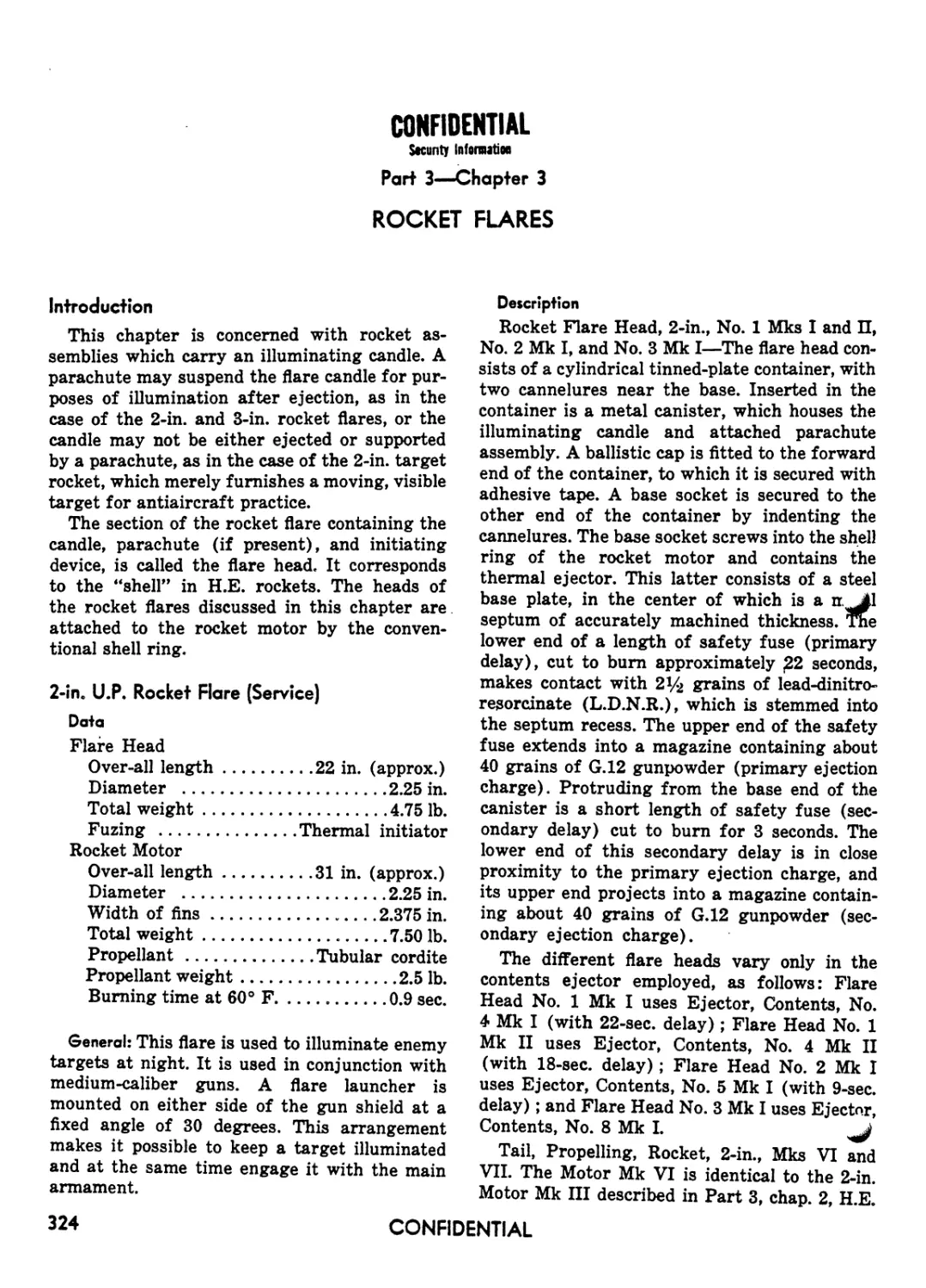
Chapter 3. Rocket Flares ........... 324
Chapter 4. Wire-Barrage Rockets .... 331
Chapter 5. Pyrotechnic Rockets....... 345
Part 4. Rocket Fuzes
Chapter 1. Introduction............. 351
Chapter 2. Rocket Nose Fuzes......... 353
Chapter 3. Rocket Base Fuzes.........369
Part £ Hand and Rifle Grenades
Chapter 1. Introduction..............371
Chapter 2. Anti-Personnel Grenades.. 373
Chapter 3. Anti-Tank Grenades........379
Chapter 4. Smoke, Illuminating, and
Incendiary Grenades .. 387
Part 6. Land Mines and Fuzes
Chapter 1. Introduction............. 398
Chapter 2. Anti-Tank Mines and Fuzes 399
Chapter 3. Anti-Personnel Mines......409
Part 7. Firing Devices and Demolition Stores
Chapter 1. Introduction ............ 205
Chapter 2. Pistols.................. 207
Chapter 3. Fuzes ................... 245
Chapter 4. Detonators................293
Chapter 1. Introduction............. 419
Chapter 2. Firing Devices ...........420
Chapter 3. Army Demolition Stores... 443
Chapter 4. Navy Demolition Stores... 451
CONFIDENTIAL
hi
CONFIDENTIAL
Security Information
Part I—AIRCRAFT BOMBS AND PYROTECHNICS
Chapter I
INTRODUCTION
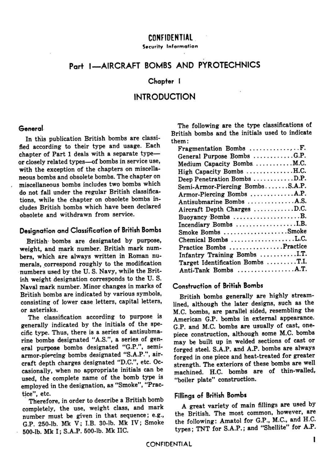
General
In this publication British bombs are classi-
fied according to their type and usage. Each
chapter of Part 1 deals with a separate type—
or closely related types—of bombs in service use,
with the exception of the chapters on miscella-
neous bombs and obsolete bombs. The chapter on
miscellaneous bombs includes two bombs which
do not fall under the regular British classifica-
tions, while the chapter on obsolete bombs in-
cludes British bombs which have been declared
obsolete and withdrawn from service.
Designation and Classification of British Bombs
British- bombs are designated by purpose,
weight, and mark number. British mark num-
bers, which are always written in Roman nu-
merals, correspond roughly to the modification
numbers used by the U. S. Navy, while the Brit-
ish weight designation corresponds to the U. S.
Naval mark number. Minor changes in marks of
British bombs are indicated by various symbols,
consisting of lower case letters, capital letters,
or asterisks.
The classification according to purpose is
generally indicated by the initials of the spe-
cific type. Thus, there is a series of antisubma-
rine bombs designated “A.S.”, a series of gen-
eral purpose bombs designated "G.P.”, semi-
armor-piercing bombs designated "S.A.P.”, air-
craft depth charges designated "D.C.”, etc. Oc-
casionally, when no appropriate initials can be
used, the complete name of the bomb type is
employed in the designation, as "Smoke”, "Prac-
tice”, etc.
Therefore, in order to describe a British bomb
completely, the use, weight class, and mark
number must be given in that sequence; e.g.,
G.P. 250-lb. Mk V; I.B. 30-lb. Mk IV; Smoke
500-lb. Mk I; S.A.P. 500-lb. Mk IIC.
The following are the type classifications of
British bombs and the initials used to indicate
them:
Fragmentation Bombs ............. F.
General Purpose Bombs..............G.P.
Medium Capacity Bombs..............M.C.
High Capacity Bombs................H.C.
Deep Penetration Bombs.............D.P.
Semi-Armor-Piercing Bombs........S.A.P.
Armor-Piercing Bombs...............A.P.
Antisubmarine Bombs................A.S.
Aircraft Depth Charges.............D.C.
Buoyancy Bombs.......................B.
Incendiary Bombs...................I.B.
Smoke Bombs.......................Smoke
Chemical Bombs.....................L.C.
Practice Bombs.................Practice
Infantry Training Bombs.............LT.
Target Identification Bombs........T.I.
Anti-Tank Bombs ...................A.T.
Construction of British Bombs
British bombs generally are highly stream-
lined, although the later designs, such as the
M.C. bombs, are parallel sided, resembling the
American G.P. bombs in external appearance.
G.P. and M.C. bombs are usually of cast, one-
piece construction, although some M.C. bombs
may be built up in welded sections of cast or
forged steel. S.A.P. and A.P. bombs are always
forged in one piece and heat-treated for greater
strength. The exteriors of these bombs are well
machined. H.C. bombs are of thin-walled,
"boiler plate” construction.
Fillings of British Bombs
A great variety of main fillings are used by
the British. The most common, however, are
the following: Amatol for G.P., M.C., and H.C.
types; TNT for S.A.P.; and "Shellite” for A.P.
CONFIDENTIAL
I
CONFIDENTIAL
Security InteniutiM ч
BRITISH EXPLOSIVE ORDNANCE
bombs. RDX/TNT combinations are also com-
monly employed in M.C. and H.C. bombs. Cur-
rent fillings are 60/40 Amatol for H.C. bombs,
and desensitized Pentolite or RDX/TNT for
all others.
Suspension ot' British Bombs
British bombs are suspended by a single sus-
pension lug attached to the bomb body by ma-
chine screws. Later designs of British bombs,
such as the M.C. series, are fitted with additional
dual suspension lugs for carrying in American
planes. Crutches or sway bars are used with
larger size bombs.
British Toil Assemblies
A unique type of tail assembly is regularly
employed by the British, consisting of a sheet-
steel cone with a cylindrical strut attached by
means of four sheet-steel fins. The unique fea-
ture is the fact that the arming vanes are an
integral part of the tail assembly. They are
attached to the tail pistol by means of a reach
rod with a fork on its lower extremity engaging
a similar fork on the tail pistol. A special short
tail, originally designed for use in American
built planes, is sometimes used to permit a
greater bomb load. A third type tail assembly,
rarely used, is designed to be employed in con-
junction with certain tail fuzes which have their
own arming vanes. The arming vanes on this
tail assembly are omitted, and the tail cone is
truncated to give clearance to the vanes on the
fuze.
Tail units are attached to bombs up to 1,000
lb. by a spring clip assembly, and to bombs of
1.000 lb. and over by means of bolts. Since each
individual bomb is provided with its own spe-
cific tail unit, the bomb designation and tail
number, which are stencilled on one of the tail
fins, cervc as a ready means of identifying the
bomb. The word "Mark” is omitted from both
the tail unit and the bomb designation. For ex-
ample, the tail unit, No. 2 Mk I, used on the
G.P. 500-lb. Bomb Mk IV, should appear on the
tail unit as "No. 2.1, G.P. 500-lb. IV”.
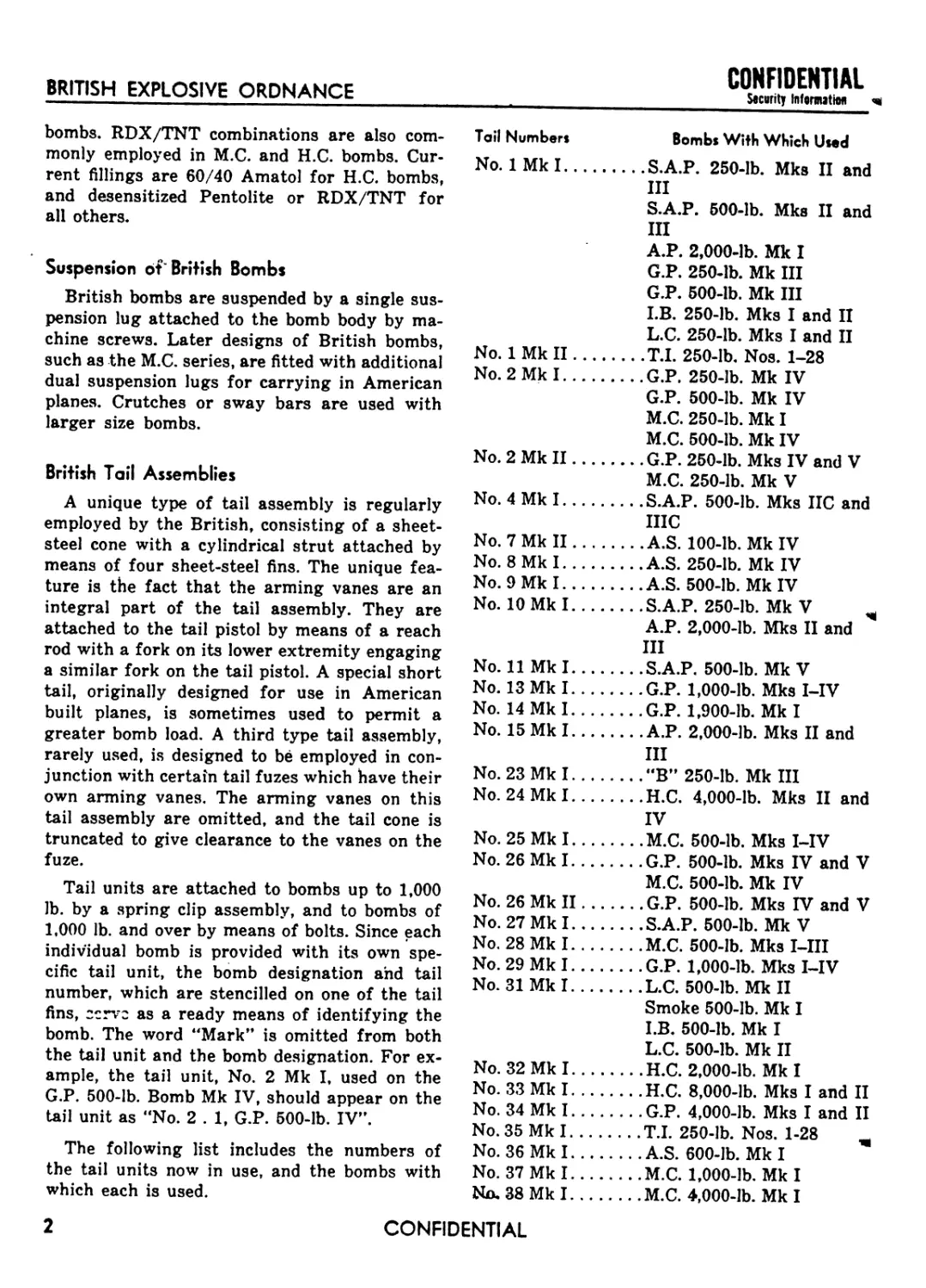
The following list includes the numbers of
the tail units now in use, and the bombs with
which each is used.
Toil Number» Bombs With Which lhed
No. 1 Mk I............S.A.P. 250-lb. Mks II and
III
S.A.P. 500-lb. Mks II and
III
A.P. 2,000-lb. Mk I
G.P. 250-lb. Mk III
G.P. 500-lb. Mk III
LB. 250-lb. Mks I and II
L.C. 250-lb. Mks I and II
No. 1 Mk II...........T.I. 250-lb. Nos. 1-28
No. 2 Mk I............G.P. 250-lb. Mk IV
G.P. 500-lb. Mk IV
M.C. 250-lb. Mk I
M.C. 500-lb. Mk IV
No. 2 Mk II...........G.P. 250-lb. Mks IV and V
M.C. 250-lb. Mk V
No. 4 Mk I............S.A.P. 500-lb. Mks IIC and
IIIC
No. 7 Mk II.........A.S. 100-lb. Mk IV
No. 8 Mk I..........A.S. 250-lb. Mk IV
No. 9 Mk I..........A.S. 500-lb. Mk IV
No. 10 Mk I...........S.A.P. 250-lb. Mk V
A.P. 2,000-lb. Mks II and
III
No. 11 Mk I........S.A.P. 500-lb. Mk V
No. 13 Mk I........G.P. 1,000-lb. Mks I-IV
No. 14 Mk I........G.P. 1,900-lb. Mk I
No. 15 Mk I........A.P. 2,000-lb. Mks II and
III
No. 23 Mk I..........."B” 250-lb. Mk III
No. 24 Mk I...........H.C. 4,000-lb. Mks II and
IV
No. 25 Mk I...........M.C. 500-lb. Mks I-IV
No. 26 Mk I...........G.P. 500-lb. Mks IV and V
M.C. 500-lb. Mk IV
No. 26 Mk II..........G.P. 500-lb. Mks IV and V
No. 27 Mk I...........S.A.P. 500-lb. Mk V
No. 28 Mk I...........M.C. 500-lb. Mks I-III
No. 29 Mk I...........G.P. 1,000-lb. Mks I-IV
No. 31 Mk I...........L.C. 500-lb. Mk II
Smoke 500-lb. Mk I
I.B. 500-lb. Mk I
L.C. 500-lb. Mk II
No. 32 Mk I...........H.C. 2,000-lb. Mk I
No. 33 Mk I...........H.C. 8,000-lb. Mks I and II
No. 34 Mk I...........G.P. 4,000-lb. Mks I and II
No. 35 Mk I...........T.I. 250-lb. Nos. 1-28
No. 36 Mk I...........A.S. 600-lb. Mk I
No. 37 Mk I...........M.C. 1,000-lb. Mk I
Na 38 Mk I............M.C. 4,000-lb. Mk I
2
CONFIDENTIAL
CONFIDENTIAL
Security Information INTRODUCTION TO AIRCRAFT BOMBS AND PYROTECHNICS
Tail Numbers Bombs With Which Used
No. 39 Mk I.........H.C. 2,000-lb. Mks II and
III
No. 40 Mk I.........I.B. 30-lb. Mks III and IV
No. 41 Mk I.........Smoke 120-lb. Mk I
No. 42 Mk I.........Cluster Projectile No. 14
Mk I
No. 43 Mk I.........Cluster Projectile No. 15
Mkl
No. 44 Mk I & II.... Cluster Projectile No. 4
Mk I
No. 45 Mk I.........Cluster Projectile No. 6
Mkl
No. 46 Mk II........Cluster Projectile No. 7
Mk I
No. 47 Mk I.........A.P. 2,000-lb. Mk IV
No. 48 Mks II & III .Cluster Projectile No. 16
Mk II
No. 52 Mk I.........H.C. 8,000-lb. Mks I and II
H.C. 12,000-lb. Mk II
No. 54 Mk I.........G.P. 500-lb. American
(M 64)
No. 55 Mk I.........G.P. 1,000-lb. American
(M 65)
No. 56 Mk I.........A.S. 100-lb. Mk VI
No. 57 Mk I.........T.I. 1,000-lb. Mk I
No. 63 Mks I & II.. .Cluster Projectile No. 17
Mk II
No. 65 Mk I.........Cluster Projectile No. 23
Mk I
No. 66 Mk I.........Cluster Projectile No. 24
Mk I
No. 69 Mk I.........Cluster Projectile No. 1
Mkl
No. 70 Mk I.........Cluster Projectile No. 2
Mk I
No. 75 Mks I & II.. .T.I. 250-lb. Nos. 1-28
No. 78 Mk I.........D.P. 12,000-lb. Mk I
No. 79 Mk I.........LB. 400-lb. Mk. I
No. 81 Mk I.........Smoke 500-lb. Mk II
No. 82 Mk I.........D.P. 22,000-lb. Mk I
Color Markings and Stencilling of British Bombs
The following list gives the color markings
employed on loaded British bombs.
Bomb Type Color Markings
F.............Dark green over-all with red band
forward of light green band on nose
Bomb Type Color Markings
G.P..........Dark green over-all with red nose
band, and light green body band
M.C..........Dark green over-all with red nose
band, and light green band on base
of ogive
H.C..........Dark green over-all with red nose
band, and light green band on for-
ward portion
S.A.P........Dark green over-all with a white
band just forward of a red band on
the nose
A.P..........Dark green over-all with nose
painted light green to point of
greatest diameter; white band be-
tween two red bands on nose
D.P..........Dark green over-all with red band
near nose
A.S..........Dark green over-all with red nose
band and light green band at base
of ogive
D.C..........Dark green over-all with red nose
band, and colored band indicating
filling forward of the suspension
lug
В..............Dark green over-all with red nose
band and green band on ogive
I.B..........Either dull red over-all, or have red
nose end. Most small sizes have a
bright red band between two black
bands around the nose. Large sizes
have a bright red band on the body
and another on the after body.
Smoke .... Dark green over-all with a red band
either around the nose, or the after
part of the body
L.C..........Grey over-all with colored bands to
indicate chemical filler; black band,
teargas; green band, lung irritant;
yellow band, vesicant-
Practice .. .White over-all with two green bands
around the tail cone
CONFIDENTIAL
3
CONFIDENTIAL
Security Information
BRITISH EXPLOSIVE ORDNANCE
Figure 1—Typical bomb markings
Bomb Type Color Markings
I.T.........Dark green over-all with red and
green bands on nose
T.I.........Black over-all with red band at base
of ogive. Color of band around nose
plug indicates color of candles. A
red cross on the after part of the
body indicates that explosive can-
dles are used.
Flares and Photoflash.......Black over-all with
red band near nose
Cluster Projectiles... .Painted an over-all color
according to the type of small
bombs carried
H.E. filled bombs were originally painted
yellow by the British. The change to dark green
was made at about the same time that the
United States changed to olive drab. Conse-
quently, yellow painted bombs may still be
found.
Complete information, including weight, type,
mark number, filling, date filled, filling stati^l
and lot number will be found stencilled on the
outside of all British bombs. Although the loca-
tion of the various stencillings differs with dif-
ferent bombs, the following sketch will indicate
the information to be found and its approximate
location on the outside of the bomb body.
4
CONFIDENTIAL
CONFIDENTIAL
Security Information
Part I—Chapter 2
FRAGMENTATION BOMBS
Introduction
• There are only two sizes of fragmentation
bombs now in use by the British. These are the
8-lb., and several different marks of 20-lb. frag-
mentation • bombs, including a modified U.S.
20-lb. fragmentation bomb.
The 20-lb. F. bomb is nose fuzed only, and is
similar in construction to the 40-lb. G.P. bomb.
It may be fitted with a standard tail for pur-
poses of stabilization, or either a standard para-
chute attachment, or a special small parachute
for use with the 500-lb. Cluster Projectile No. 17
Mk II may be used. The parachute attachments
are designed to reduce the bomb’s terminal ve-
locity and so insure detonation of the bomb on
impact before ground penetration takes place.
Fragmentation bombs are generally painted
dark green over-all with a red band and a light
.green band around the nose end.
These fragmentation bombs are used prin-
• cipally against personnel.
F. 8-lb. Mk I (Obsolete), and Mk II (Service)
Data
Fuzing.............Tail Fuze No. 880 or 881
Color markings.........Dark green over-all;
14-in. red band around after part, and
1/2-in. light green band around center of
bomb
Parachute No.......Tray No. 12, Mk I, with
parachute
Over-all length ...................4.2 in.
Body length ......................3.02 in.
Body diameter .......................5 in.
Wall thickness ..................0.125 in.
Total weight..................8 lb. approx.
Charge/weight ratio............22% approx.
Body Construction: The bomb body consists of
a pot-shaped, cast-steel cylinder which is open
at the top. A steel neck ring, having internal
threads to receive the adapter, is welded to the
open end of the body. The parachute tray is
secured to the adapter. Extending through the
adapter is the fuze, which is enclosed by a paper
tube 2-in. in diameter, extending through the
bomb body.
Parachute: The parachute is 12 in. in diameter
and is encased in a cylindrical steel tray having
a diameter slightly less than the maximum di-
ameter of the bomb body. A safety pin extends
through the parachute container, and is secured
by a spring clip.
Explosive Components: Main Filling — 1%. lb.
(approx.) or TNT, or RDX/TNT 60/40; lb.
(approx.) of Amatol 50/50 or 60/40, or Pento-
lite/D 1. (When filled with explosives other than
TNT, a 14,-in. topping of TNT is added.)
Remarks: The Mk I Bomb had a smaller filling
hole than the Mk II. The Mk I was never filled
or adopted for service use.
F. 20-lb., Stabilized, Mks I and II (Obsolescent),
Mk III (Service), and Mk IV (Obsolescent)
Data
Fuzing... .Nose Pistol No. 29, 34, 38, or 45;
Nose Fuze No. 873
Color markings..........Dark green over-all;
1/2-in. red band around nose; 1-in. light
green band 4 in. from nose
Over-all length ......................21.8 in.
Body length ..........................11.9 in.
Body diameter ........................3.95 in.
Wall thickness .......................0.35 in.
Tail length .............................9 in.
Tail width ...........................3.83 in.
Total weight ... .20 lb. (approx, with pistol)
Charge/weight ratio .......................15%
Body Construction: This bomb has a stream-
lined, one-piece, cast-steel body, with the nose
end open to take the exploder container. The
rear end is reduced to form a spigot for taking
CONFIDENTIAL
5
CONFIDENTIAL
Security Information
BRITISH EXPLOSIVE ORDNANCE
WIRE
MAIN
FILLING
PAPER
TUBE
BOMB
CASING
PARACHUTE
TRAY
WASHER
COMPOSITION
PAD
LAYER OF
TNT
LONG DELAY
BOMB FUZE
NO. 880
Figure 2—F. 8-lb. Bomb Mk II
the tail assembly. The boss on the spigot is
tapped and threaded to receive the tail-securing
rod. The exploder container is cemented in po-
sition, and locked by a locking screw.
Tail Construction: A cylindrical strut is at-
tached to the tail cone by four fins. The tail is
secured to the body by a tail rod screwed into
a boss on the body spigot, and passing through
a threaded adapter on the narrow end of the
tail cone. The locking nut and spring washer at
both the outer and inner ends of the rod lock
it in position.
Suspension
Mk I—Carried 12 in Small Bomb Contain-
ers, or on Light Series bomb carrier
if fitted with a suspension lug.
Mk II—Carried 12 in Small Bomb Contain-
ers, or on Light Series bomb carrier
if fitted with suspension lug or band.
Mk III—Suspension lug welded on bomb body
at center of gravity for carrying on
Light Series bomb carrier; can be
carried 12 in Small Bomb Container.
Explosive Components
Detonators—(See Part 2, chap. 4, Detona-
tors.)
Exploders—С. E. and TNT pellets (C.E. only
being used now).
Filling—3.3 lb. TNT or RDX/TNT. (When
RDX/TNT is used, a 1,4-in. to %-in. topping of
TNT is used in the nose.)
Remarks: The Small Bomb Container, 160 lb.,
contains eight of these bombs. The Small Bomb
Container, 250 lb., will hold 12 of these bombs.
These bombs are no longer being manufactured.
However, they may be encountered in the field.
They are being replaced by the 8-lb.-fragmen-
tation bomb.
In the Mk IV Bomb the exploder system va
changed to use only C.E. pellets, and a special
retarder tail was incorporated.
6
CONFIDENTIAL
CONFIDENTIAL
Security Information
FRAGMENTATION BOMBS
ADAPTER
FIN-
TAIL GONE
TAIL: ROD
SPIGOT
MAIN FILLING
PAPER TUBE
C.E. PELLETS
.DETONATOR
Figure 3—F. 20-lb. Bomb Mk I (Stabilized,
EXPLODER-
CONTAINER
STRUT.
CONFIDENTIAL
7
CONFIDENTIAL
Security Intormetioi.^^
BRITISH EXPLOSIVE ORDNANCE
COVER
LANYARD
STRUT
-FIN
PARACHUTE
-SHROUD LINES
-WIRE ROPE
TAIL TUBE
TAIL ADAPTER
ARMING LINK
TAPE
MAIN FILLING
TAPE
T.N.T. PELLET
C.E. PELLET
EXPLODER CONTAINER
PAPER TUBE
DETONATOR
TAPE
WASHER
COMPOSITION
Figure 4—F. 20-lb. Bomb Mk III (Parachute)
8
CONFIDENTIAL
CONFIDENTIAL
Security IgfsnutM
FRAGMENTATION BOMBS
F. 20-lb., Parachute, Mks I and II (Obsolescent),
and Mk III (Service)
Data
Fuzing.....................Nose Pistol No. 33
Color markings..........Dark green over-all;
Уг-in. red band around body % in. from
nose; 1-in. light green band 4 in. from nose
Over-all length.......................21.8 in.
Body length ..........................11.9 in.
Body diameter ........................3.95 in.
Wall thickness .......................0.35 in.
Tail length.............................10 in.
Tail width.............................3.9 in.
Total weight.................20 lb. (approx.)
Charge/weight ratio .......................15%
Body Construction: This bomb has a stream-
lined, one-piece, cast-steel body, with the nose
end open to take an exploder container. The
rear end is reduced to form a spigot for taking
the tail adapter. The boss on the spigot is tapped
and threaded to receive the tail adapter secur-
ing bolt. The exploder container, is cemented in
position and locked by a locking screw.
Tail Construction: The parachute tail unit con-
sists of a tail tube with a cylindrical strut con-
nected to its rear portion by four fins. The para-
chute, which is housed in a fabric cylinder, is
contained in tail tube. A loose-fitting metal cover
in the after end of the tube is attached to the
fabric cylinder. The parachute cords are con-
nected to a wire rope secured to an eyebolt
which connects the tail adapter and the body.
The tail adapter is secured in the front end of
the tail tube by four screws. When dropped, the
metal end cover in the tube is blown off by the
air slip, and acts as a pilot parachute to pull the
main parachute out of the tube.
Suspension
Mk I—Carried 12 in Small Bomb Contain-
ers, or on Light Series bomb carrier
if fitted with suspension lug.
Mk II—Carried 12 in Small Bomb Contain-
ers, or on Light Series bomb carrier
if fitted with suspension band.
Mk III—Suspension lug welded on bomb body
at center of gravity for carrying on
Light Series bomb carrier; can be
carried 12 in Small Bomb Container.
Explosive Components
Detonators—(See Part 2, chap. 4, Detona-
tors.)
Exploder—C.E. and TNT pellets.
Filling—Mk Ш, 3 lb. (approx.) RDX/TNT;
Mk I and Mk П, 3.3 lb. TNT.
Remarks: The Small Bomb Container, 160 lb.,
contains eight of these bombs. The Small Bomb
Container, 250 lb., contains 12 of these bombs.
These bombs are no longer being manufactured.
However, they may be encountered in the field.
They are being replaced by the 8-lb. fragmenta-
tion bombs.
F. 20-lb., For No. 17 Mk II Cluster Only (Service)
Data
Fuzing......................Nose Fuze No. 873
Color markings...........Dark green over-all;
i/2-in. red band around nose; 1-in. light
green band around body
Tail No.....No. 15 Mk I, or No. 16 Mk I para-
chute attachments
Over-all length ....................14.5 in.
Body length ........................11.9 in.
Body diameter .......................3.9 in.
Wall thickness .....................0.35 in.
Total weight................20 lb. (approx.)
Charge/weight ratio .....................15%
Body Construction: This bomb has a stream-
lined, one-piece, cast-steel body, with the nose
end open to take an exploder container. The rear
end is reduced to form a spigot for taking the
parachute attachment. The spigot is tapped and
threaded to receive the securing stud of the
parachute attachment. The exploder container is
cemented and locked in position. The No. 873
Nose Fuze is locked in position by a multi-tab
washer.
CONFIDENTIAL
9
BRITISH EXPLOSIVE ORDNANCE
CONHDENTIAL
LID
TRAY.
MAIN
7 FILLING
SHROUD
LINES-
PARACHUTE
EXPLODER
CONTAINER
EXPLODER
PELLETS----
Figuro 5—F. 20-lb. Bomb Mk II (for No. 17 Cluster only)
10
CONFIDENTIAL
CONFIDENTIAL
Stotritr htfonutiM
FRAGMENTATION BOMBS
LID-
TRAY,
PARACHUTE-
SHROUD
LINE
Figure 6—U. S. 20-lb. Fragmentation Bomb, Modified
MAIN
FILLING
ARMING
WIRE
ARMING
LINE
-.WXW
CONFIDENTIAL
II
BRITISH EXPLOSIVE ORDNANCE
Tail Construction: No tail is used with this
bomb, which is especially designed to be used
only in the No. 17 Mk II Cluster. It has a short
parachute attachment, secured to the body
spigot by a threaded stud. The* parachute tray
houses an 8-in. diameter fabric parachute with
six pairs of rigging lines; each pair terminating
in a whipped eye. These eyes pass through holes
in the tray and are threaded onto a metal cir-
clip, which is secured on the underside of the
tray. A lid over the parachute in the tray is
held in position by the fuze of the bomb behind
it. When the cluster opens, the air slip displaces
the lid, which pulls the chute free of the tray.
Suspension: This bomb has no suspension lugs,
as it is used only in the No. 17 Mk П Cluster.
Explosive Components
Exploder—Two TNT, and two perforated
C.E. pellets.
Filling—3.1 lb. (approx.) of TNT.
Remarks: The bomb is issued only in clustered
form, and, when clustered, the fuze has no
safety pin fitted. Hence, care should be exer-
cised in dealing with any individual bombs
which might break loose from a cluster in
handling.
U. S. 20-lb. Fragmentation Bomb, Modified
Data
Fuzing.......U.S. Nose Fuze AN-M 104, or
AN-M 120
Color markings.... Body section, olive drab;
nose and tail, yellow
Tail No..........No. 14 Parachute Housing
Over-all length...........16.2 in. (fuzed)
Body diameter ....................3.64 in.
Body length ......................11.3 in.
Wall thickness ................. 0.56 in.
Tail length .......................4.9 in.
Tail width........................3.64 in.
CONFIDENTIAL
Socurity htfonurtw
Body Construction: This bomb consists of a
U.S. 20-lb. Fragmentation Bomb, which has
been altered by the attachment of a special
British parachute housing. The bomb consists
of cast-steel nose and tail sections threaded to
a seamless steel inner tube. Helically wrapped
around this inner steel tube is a heavy, drawn-
steel wire to provide effective fragmentation.
The nose and tail sections are threaded inter-
nally ; the former to receive the nose fuze, and
the latter to receive the parachute housing.
Tail Construction: The British No. 14 Para-
chute Housing consists of a cast-aluminum tray
containing a 12-in. diameter parachute. The
tray is closed by a loosely fitting metal lid to
which the parachute is attached by a short loop
of cord. The shroud lines of the parachute are
fitted through holes drilled around the bottom
edge of the tray, and are secured by a metal ring
passed through the loops of the lines. Leading
from the parachute is an arming line, spliced to
the arming wire from the fuze. Release of the
parachute withdraws the arming wire from the
fuze, allowing the fuze to arm after a few
onds delay.
Suspension: Although the bomb is provided
with a single, U-shaped, steel eyebolt welded
•to the bomb body for individual suspension,
these bombs will be carried by the R.A.F. in
Cluster Projectiles No. 23 Mk I and No. 24 Mk
I. In these clusters the nose of one bomb bears
against the parachute lid of the one behind it,
holding the lid in place until the cluster opens.
The air slip then removes the housing lid, which
acts as a pilot parachute and pulls out the 12-in.
diameter parachute by which the bomb is sus-
pended.
Remarks: Because of the extreme sensitivity
of the Fuze AN-M 104, an extra spring, located
outside the fuze body beneath the pressure
plate, is added when this fuze is employed in
these bombs by the R.A.F.
12
CONFIDENTIAL
CONFIDENTIAL
Stcsrtty Istsnsitiss
Part I—Chapter 3
GENERAL PURPOSE BOMBS
Introduction
General Purpose bombs are heavy-cased
bombs ranging in weight from 40 lb. to 4,000 lb.
The smaller bombs are used mainly as anti-
personnel bombs, while the larger ones are used
for general bombardment purposes.
The earlier marks of these bombs are fitted
with central tubes to take the explodering com-
ponents, but later marks are fitted with exploder
containers at the nose end, or at the nose and
tail ends. Bombs with central tubes or with
exploder containers at each end may be fuzed
at both ends, or at either end, depending on the
operational requirements. Bombs fuzed at the
nose only are fitted with instantaneous detona-
tors, while bombs fuzed at the tail are usually
fitted with delay detonators. If bombs are fuzed
at both the nose and the tail with instantaneous
detonators, the nose assembly will function
first, on account of the direct action of the nose
pistol. The general practice is to ship G.P
bombs with a tail pistol in place, but without
detonators, altering the fuzing as may be de-
sired prior to loading the bombs on the plane.
G.P. bombs are generally streamlined in
shape, cast in one piece, and have a male base
plate. To facilitate handling in storage and
shipment, the bombs have a transit base of the
same diameter as the maximum diameter of the
bomb. Before using, bombs under 1,000 lb. are
equipped with a tail unit that clips in place.
Bombs of 1,000 lb. and over employ a tail unit
which is secured by wing bolts.
TNT, Amatol, and RDX/TNT are the explo-
sives commonly employed as main fillings to give
a charge/weight ratio of approximately thirty
per cent.
G.P. bombs are painted dark green over-all
and have a 1/^-in. red band at the nose, and a
1-in. light green band on which the type of
filling is stencilled.
G.P. 40-lb., Stabilized, Mks I, II, III (Service),
and Mk IV (Obsolescent)
Data
Fuzing... .Nose Pistol No. 29, 34, 38, or 45;
Nose Fuze No. 873
Color markings..........Dark green over-all;
• i/>-in. red band 1 in. from nose; 1-in. light
green band 5*4 in. from nose
Over-all length ..................27.25 in.
Body length ........................15.90 in.
Body diameter... .Mk I, 5.01 in.; Mks II and
III, 5.05 in.
Wall thickness .....................0.47 in.
Tail length .......................11.4 in.
Tail width...........t................4.88 in.
Total weight................38.5 lb. (Mk III)
Charge/weight ratio.....................17 %
Body Construction: The bomb body is made of
cast steel. The open hose end is threaded in-
ternally tu receive an exploder container, which
is screwed and cemented in position and locked
by a set-screw. The rear end of the bomb is
closed and reduced in diameter to form a spigot.
A boss on the spigot is drilled and tapped to
receive the forward threaded end of a tail rod.
The exploder container is in the form of a tube
closed at one end, the open end of which is
threaded internally to take the pistol.
Tail Construction: A cylindical strut is at-
tached to a tail cone by four fins. The tail unit
is secured to the body by a tail rod which ex-
tends axially through the tail cone. The forward
end of the rod, which screws into the central
boss on the spigot at the rear of the bomb body,
is locked by a spring washer and a lock-nut. The
rear end of tail cone is fitted with an internally
threaded flanged adapter, which screws on the
threaded rear end of tail rod, correctly locating
the tail cone on the bomb body. The tail is locked
in position by a spring washer and lock-nut
screwed against the adapter.
CONFIDENTIAL
13
2HI174 0—52
CONFIDENTIAL
Security lifonMtiw
BRITISH EXPLOSIVE ORDNANCE
STRUT-----------
ADAPTER---------
FIN-------------
TAIL ROD--------
TAIL CONE-------
MAIN FILLING----
PAPER TUBE------
T.N.T. EXPLODER-
C.E. EXPLODER----
DETONATOR-------
WASHER----------
COMPOSITION PAD-
EXPLODER CONTAINE
SET SCREW-------
Figure 7—G.P. 40-lb. Bomb Mk III (Stabilized)
14
CONFIDENTIAL
CONFIDENTIAL
Security Isforautin
Suspension
Mk I—Normally carried 6 in the 250-lb.
Small Bomb Container, although a
limited number have a single sus-
pension lug.
Mk II—Normally carried 6 in the 250-lb.
Small Bomb Container; may be fit-
ted with a suspension band.
Mk III—Has a suspension lug, and may be
carried 6 in the 250-lb. Small Bomb
Container, or on Light Series bomb
carriers.
Explosive Components
Detonators—(See Part 2, chap. 4, Detona-
tors.)
Exploders—TNT (1 oz. 7 dr.) and C.E. (4 oz.
6 dr.) retained by a waxed felt washer.
Filling—Mk I, 6.3 lb. «Amatol 80/20; Mk II,
6.5 lb. TNT, or 6.7 lb. RDX/TNT 60/40; Mk III,
6.5 lb. Amatol 60/40, or 6.7 lb. of RDX/TNT
60/40.
Remarks: This bomb is usually used as a frag-
mentation bomb, being almost identical to the
20-lb. fragmentation bomb except for size.
The exploder system of the Bomb Mk IV was
changed to use only C.E. pellets, and a special
retarder tail was incorporated.
G. P. 40-lb., Parachute, Mks I, II, and ill
(Service)
Data
Fuzing.............Nose Pistol No. 33 Mk I
Color markings........Dark green over-all;
i/^-in. red band 1 in. from nose; 1-in. light
green band 5^ in. from nose
Over-all length..................27.25 in.
Body length .....................15.90 in.
Body diameter... .Mk I, 5.01 in., Mks II and
П1, 5.05 in.
Wall thickness ...................0.47 in.
Tail length ......................11.4 in.
Tail width .......................4.88 in.
GENERAL PURPOSE BOMBS
Total weight......................38.5 lb.
Charge/weight ratio..................17%
Body Construction: This bomb has a cast-steel
body, the nose end of which is fitted with an
exploder container screwed and cemented in po-
sition, and locked by a locking screw. The
exploder container is threaded to take the pistol.
The rear end of bomb body is closed and reduced
in diameter to form a spigot with a central boss,
which is drilled and tapped to receive an eye-
bolt. The parachute tail unit is secured to the
body by means of the eyebolt.
Tail Construction: The parachute tail unit con-
sists of a cylindrical strut attached to the rear
end of a tail tube by four fins. The parachute
is packed in a fabric cylinder, which is closed
at its rear end and fits inside the tail tube. The
rear end of the fabric cylinder is connected by
pilot lanyards to a flanged cover which fits
loosely in the cylindrical strut and is retained in
position to close the rear end of the tube by
means of a wire transit clip.
Suspension
Mk I—Normally carried 6 in the 250-lb.
Small Bomb Container, although lim-
ited numbers have a single lug.
Mk II—Normally carried 6 in the 250-lb.
Small Bomb Container, but may be
suspended by a band around the
body.
Mk III—A single lug is welded to the body
for use when carrying on the Light
Series bomb carrier. Can be loaded
6 into 250-lb. Small Bomb Container.
Explosive Components
Detonator—(See Part 2, chap. 4, Detonators.)
Exploder—TNT and C.E. retained by a waxed
felt washer.
Filling—Mk I, 6.3 lb. Amatol 80/20; Mk II,
6.5 lb. TNT; Mk III, 6.5 lb. Amatol 60/40.
Remarks: This bomb is usually used as frag-
mentation bomb, and is identical to the 20-lb.
parachute fragmentation bomb except for size.
CONFIDENTIAL
15
CONFIDENTIAL
BRITISH EXPLOSIVE ORDNANCE
Security IMonurtw
-COVER < '
^LANYARD
^Rur;: у
; "J* * . ' ’ '
-FIW—C
7 PARACHUTE
-SHROUD CORDS
-WIRE ROPE ; 5
Sail tube
“TAIL ADAPTER
-ARMING LINK
TAPE
•MAIN FILLING J/
•TAPE
•EXPLODER,TN.T
-EXPLODER, C.E.
EXPLODER CONTAINER
•PAPER TUBE
DETONATOR
TAPE
COMPOSITION
FELT WASHER
Figure 8—G.P. 40-lb. Bomb Mk III (Parachute)
16
CONFIDENTIAL
CONFIDENTIAL
Socurity Information
GENERAL PURPOSE BOMBS
>00 о о о о о <
FIN
RETAINING
SHEAR PIN
TAIL PLUG
SECURING SCREW
TAIL SOCKET----
SECURING SCREW
COLLAR---------
CONE SOCKET—
LOCATING PIN---
DETONATOR HOLDER
TAIL CONE--------
LOCATING PIN-----
GLAND NUT
CONE RING -
SEALING COMPOSITION
FILLING PLUG'
FELT WASHER
MAIN FILLING
CENTRAL TUBE
COMPOSITION---
NOSE BUSH-----
SECURING SCREW
NOSE PLUG-----
Figure 9—G.P. 250-lb. Bomb Mk I
CONFIDENTIAL
17
BRITISH EXPLOSIVE ORDNANCE
DETAIL A
NOSE —
BUSHING
LOCK SCREW
PAPER TUBE
BASE PLATE
LOCKING SCREW
TAIL
BUSHING
COMPOSITION
PAD
NOSE PLUG
DETAIL A
COMPOSITION
PAD
Figure JO—G.P. 250-lb. Bomb Mk V
CONFIDENTIAL
Security Information
G.P. 250-lb., Mks I, II, and III (Service)
Data
Fuzing... .Nose Pistol No. 19; Tail Pistol No.
22, or Tail Pistol No. 17
Color markings.. Yellow over-all with a i^-in.
red band around nose, 1-in. light green band
around body; longitudinal green bar on
body and tail indicates explodering scheme.
Tail No..............No. 1 Mk I (Mk Ш only)
NOSE BUSHING
MAIN FILLING
CENTRAL
EXPLODER
TUBE
Over-all length....................54.2 in.
Body length..........................28 in.
Body diameter......................10.3 in.
Wall thickness .....................0.6 in.
Tail width.........................10.2 in.
Total weight.................247 lb. (TNT)
Charge/weight ratio.....................27%
WASHER
Body Construction: This bomb body consists of
a streamlined steel casting or forging threaded
at the nose to take a nose adapter, which holds
the central exploder tube. At the other end of
the casting is a threaded base plug through
which the exploder tube passes. Welded to the
end of the casting is a streamlined section j
thin metal, containing no explosive, but taperea
to take the tail ring. The exploder also passes
through this section.
Tail Construction: Four mild steel fins are fast-
ened to a truncated cone, and are reinforced
by a cylindrical strut. The cone fits over the
rear section of the bomb body and is held to it
by a lock nut over the exploder tube.
Suspension: A single suspension lug is secured
to the body by four screws.
Explosive Components
Detonators—Instantaneous.
Exploders—TNT, and C.E. pellets.
Filling—68 lb. TNT, or 63 lb. Amatol 80/20.
Remarks: Tail fins are usually painted red when
a time pistol is used.
This bomb, previously declared “Obsolete,”
has recently been returned to service use by
the R.A.F.
G. P. 250-lb., Mks IV, V, and VI (Service)
Data
Fuzing... .Mk IV—Nose Pistol No. 27, 42, or
44; Tail Pistol No. 28, 30, or 37
18
CONFIDENTIAL
CONFIDENTIAL
Security IHwartM
GENERAL PURPOSE BOMBS
Mk V—Tail pistol No. 17 (Long Delay)
only
Mk VI—See “Remarks.”
Color markings... .Dark green over-all with
1/2-in. red band 1-in. from nose, and 1-in.
light green band 6 in. from nose; 1-in. by
14-in. white line on the body base indicates
that bomb has been filled.
Tail No.....No. 2 Mk II (early Mk TV uses
No. 2 Mk I).
Over-all length ...................56.00 in.
Body length...............Mk TV—25.60 in.
Mk V—27.6 in.
Body diameter ......................10.2 in.
Wall thickness .....................0.52 in.
Tail length ........................27.7 in.
Tail width .........................10.2 in.
Total weight ........................230 lb.
Charge/weight ratio......................29%
Body Construction
Mk IV—The body consists of a hollow steel
casting open at each end. The nose end is inter-
nally threaded to house the exploder container,
which is locked in position by a locking screw.
The tail end is shaped to take the tail cone, and
is provided with four equally spaced supports,
which locate the spring clips on the tail. A male
base plate threads into the after end of the
body and has two threaded holes to receive the
transit base plate.
Mk V—The Mk V Bomb is the same exter-
nally as the Mk IV, but is fitted with a central
exploder tube instead of the exploder containers
at the nose and tail. This bomb does not take
a nose pistol, but uses only the No. 17 Long
Delay Pistol. The nose opening is filled by a
nose plug.
• Tail Construction: The No. 2 Mk I Sheet-Metal
Tail is attached to the body by four spring clips.
The tail consists of a tail cone with a cylindrical
tail strut attached to it by four fins. The spring
clips are fitted to the base of the cone, which is
slotted to engage the locating pin on the bomb
body. At the apex of the tail cone is fitted a
bush, locating one end of the arming spindle,
which is supported at the opposite end by a
diaphragm at the base of the tail cone. The
inner end of the arming spindle has an arming
fork attached to it which engages the arming
fork of the tail pistol of the bomb.
Suspension: The bomb has a single suspension
lug secured to it by four countersunk screws.
Explosive Components
Detonators—(See Part 2, chap. 4, Detona-
tors.)
Exploder—TNT and C.E.
Filling—67.75 lb. TNT, or 67 lb. Amatol
60/40.
Remarks: The Bomb Mk V was manufactured
to use up existing stocks of the Pistol No. 17
(long delay), which is too long to fit in the Bomb
Mk IV.
The No. 845 Anti-Disturbance Fuze, formerly
incorporated in the nose when the Tail Pistol
No. 37 was used, is now obsolete.
Tail fins are usually painted red when a time
pistol is used.
The Bomb Mk VI is made in the U. S. and uses
fuzes manufactured there to British designs:
Nose Fuze Mk VII, М3, and Tail Fuze Mk V, Ml.
G.P. 500-lb., Mks IV, V. and VI (Service)
Data
Fuzing... .Mk IV—Nose Pistol No. 27, 42, or
44; Tail Pistol No. 28, 30, or 37
Mk V—Tail Pistol No. 17 (long delay) only
Mk VI—See “Remarks.”
Color markings.........Dark green over-all;
1/2-in. red band 1 in. from nose; 1-in. light
green band 8 in. from nose; 1-in. by 1,4-in.
white line on body base indicates bomb has
been filled.
Tail No.....No. 2 Mk I, or No. 26 Mk I or П
Over-all length... .With No. 2 Tail, 70.6 in.;
with No. 26 Tail, 55.6 in.
Body length................Mk IV—37.2 in.
Mk V—36.4 in.
Body diameter .....................12.9 in.
Wall thickness ....................0.72 in.
Tail length...........No. 2 Mk I, 33.4 in.;
No. 26 Mk I, 20.4 in.
Tail width ........................12.9 in.
Total weight........470 lb. (with No. 2 tail)
Charge/weight ratio........31% (approx.)
Body Construction
Mk IV—The body consists of a hollow steel
casting open at each end. The nose end is inter-
nally threaded to house an exploder container,
which is locked in position by a locking screw.
CONFIDENTIAL
19
CONFIDENTIAL
Swirity htfmutw»
BRITISH EXPLOSIVE ORDNANCE
rswr*?
COMPOSITION PAD
FELT WASHER
GE. EXPLODER
PAPER TUBE
T.N.T. EXPLODER
FELT DISC
MAIN FILLING
FELT DISC
T.N.T. EXPLODER
PAPER TUBE
SUSPENSION
LUG_______
TRANSIT PLUG -
EXPLODER CONTAINER
О
C.E. EXPLODER-
FELT WASHER____
COMPOSITION PAD
FILLING PLUG___
EXPLODER
CONTAINER______
TRANSIT BASE
N0.7 MK I____
Figure 11—G.P. 500-lb. Bomb Mk IV
20
CONFIDENTIAL
CONFIDENTIAL
Security Information
GENERAL PURPOSE BOMBS
TRANSIT PLUG----
DETONATOR HOLDER
EXPLODER CONTAINER
FELT WASHER
NOSE BUSH
QE:EXPLODER
TNT. EXPLODER
PAPER TUBE
MAIN FILLING
TNT. EXPLODER-----
GE. EXPLODER------
EXPLODER CONTAINER
PAPER TUBE--------
LOCATING PIN
FILLING PLUG
TRANSIT BASE
NO. 24 MK I —
Figure 12—G.P. 1,000-lb. Bomb Mk I
CONFIDENTIAL
21
CONFIDENTIAL
Ssoirity NfwMrtiM
BRITISH EXPLOSIVE ORDNANCE
The tail end is shaped to take the tail cone, and
is provided with four equally spaced slots to lo-
cate the spring clips on the tail. A male base
plate threads into the after end of the body and
has two threaded holes to receive the transit
base bolts.
Mk V—This bomb is externally the same as
the Mk TV, but has a central exploder tube in-
stead of the exploder pockets at either end. The
fuzing is in the tail only, and the nose is closed
by a nose plug which has a cross cut in the end,
instead of a ring as in the Bombs Mk IV.
Tail Construction: The 500-lb. Tail No. 2 Mk I
differs from the 250-lb. Tail No. 2 Mk I only in
the weight and dimensions. The tail assembly
consists of a tail cone with a cylindrical tail
strut attached to it by four fins. It is attached to
the bomb body by four spring clips.
The 500-lb. Tail Assembly No. 26 Mk I is
similar to the 500-lb. Tail No. 2 Mk I, differing
mainly in weight and dimensions. It is used on
the 500-lb. G-P^-Bombs Mk IV or Mk V when
carried externally on high-speed fighter air-
craft, or internally on fighter bombers of the
Mosquito type. The tail and fins are shorter,
and it has a two-bladed arming vane instead
of the four-bladed arming vane used on the
Tail No. 2 Mk I.
Suspension: The bomb has a single suspension
lug slightly aft of center of gravity, and secured
to it by four countersunk screws.
Explosive Components
Detonators—(See Part 2, chap. 4, Detona-
tors.)
Exploders—Mk IV, TNT, and C.E.; Mk V, one
central exploder tube instead of the nose and
tail exploder containers. The exploder consists
of C.E. pellets and TNT.
Filling—144.5 lb. of TNT, or 143 lb. Amatol
60/40.
Remarks: Bomb Mk V was manufactured to use
up existing stocks of Pistols No. 17 (long delay),
which are too long to fit into the Bomb Mk IV.
The Anti-Disturbance Fuze No. 845, formerly
incorporated in the nose when the Tail Pistol
No. 37 was used, is now obsolete.
Tail fins are usually painted red when a time
pistol is used.
The Bomb Mk VI is made in the U.S. and
uses fuzes manufactured there to British de-
signs : Nose Fuze Mk VII, М3; Tail Fuze Mk V,
Ml.
G.P. 1,000-lb., MIcs l-IV (Service)
Data
Fuzing... .Mks I and II—Nose PistoLNo. 27,
42, or 44; Tail Pistol No. 28, 30, or 37
Mks III and. IV—Tail Pistol No. 28, 30, or
37
Color markings..........Dark green over-all;
1/2-in. red band 2 in. from nose; 2-in. light
green band 9*4 in. from nose
Tail No..........No. 13 Mk I, or No. 29 Mk I
Body length .........................52.5 in.
Body diameter ......................16.15 in.
Wall thickness ......................0.77 in.
Tail length.............No. 13 Mk I, 35.5 in.;
No. 29 Mk I, 20 in.
Tail width ............................16 in.
Over-all length... .With No. 13 Mk I Ta:’
86.5 in.; with No. 29 Mk I Tail, 71.0 in. vdr
Total weight... .1,072 lb. (with short tail
and Amatol filled)
Charge/weight ratio.......................33%
Body Construction
Mk I—The body consists of a hollow steel
casting open at each end, with the nose end
internally threaded to house a nose bush, which
is screwed and cemented in position. The bush
is bored and threaded for part of its length to
take an exploder container which is screwed and
cemented in position. The exploder container is
threaded internally in the open end to house a
detonator holder, which is also cemented in po-
sition and locked with a locking screw. The de-
tonator holder is threaded internally in the
open end to take a pistol or a transit plug. The
after end of the bomb body is shaped externally
to take a tail, and is provided wi+h <? locating
pin to locate the tail when in position on the
bomb. A male base plate screws into the tail
end of the body and is cemented in position. The
filling plug is bored and threaded internally to
receive an exploder container, which hous'
the detonator holder and is inserted and locked
in the same manner as the one used in the nose
of the bomb.
22
CONFIDENTIAL
CONFIDENTIAL
SKaritf lafonutiM
GENERAL PURPOSE BOMBS
Mk II—Similar to the Mk I, except that the
spigot on the tail end of the bomb body for lo-
cating the transit base and the seating on the
bomb body for the suspension lug, are omitted.
Mk П1—Similar to Mk I, except that the ex-
ploder containing and detonator holder are not
fitted; the nose being plugged with a special
adapter and transit plug which are welded in
position.
Mk IV—Similar to Mk II body, except that
the nose is permanently plugged in a manner
similar to the Mk Ш.
Tail Construction'
The No. 13 Mk I tail assembly consists of a
tail cone, a cylindrical strut attached to the
cone by four corrugated fins, and an arming
mechanism for arming the tail pistol. A tail ring
near the base of the tail cone is drilled to house
four wing bolts used for attaching, the tail to
the bomb body. The arming mechanism consists
of an arming spindle, one end of which is at-
tached to the fork that engages the arming fork
of the tail pistol.
No. 29 Mk I—Similar to the No. 13 Mk I, dif-
fering only in dimensions by having a shorter
tail strut and fins. The fins are not corrugated.
Arming vanes protrude beyond the cylindrical
strut.
Suspension: The bomb has a single suspension
lug 30 inches from nose plug tip, consisting of
a rectangular stop plate to which is welded a
lug. The plate is secured to the bomb body by
two screws.
Explosive Components
Detonators—(See Part 2, chap. 4, Detona-
tors.)
Exploders—TNT and C.E., with a wax-filled
washer between the C.E. and the detonator
holder.
Filling—357 lb. Amatol 60/40, or 378 lb.
RDX/TNT 60/40. Each end of the bomb has the
same sealing arrangement as the 1,900-lb. G.P.
Remarks: The Mks I and II may be fuzed nose
or tail, or both. Mks III and IV are fuzed in the
tail only. The Anti-Disturbance Fuze No. 845,
formerly incorporated in the nose when the
Tail Pistol No. 37 was used, is now obsolete.
The tail fins are usually painted red when a
time pistol is used.
G.P. 1,900-lb. Mks I and II (Service)
Data
Fuzing.... Nose Pistol No. 27, 42 or 44; Tail
Pistol No. 28, 30, or 37
Color markings..........Dark green over-all;
i/>-in. red band 2 in. from nose; 2-in. light
green band 11 in. from nose
Tail No..........................No. 14 Mk I
Over-all length ........................98 in.
Body length...........................63.2 in.
Body diameter ........................18.7 in.
Wall thickness .......................1.15 in.
Tail length...........................35.3 in.
Tail width ...........................18.7 in.
Total weight ........................1,785 lb.
Charge/weight ratio........................26%
Body Construction
Mk I—The body consists of a hollow steel cast-
ing open at each end, with the nose end threaded
internally to house a nose bush, which is screwed
and cemented in position. The bush is bored
centrally and threaded for part of its length to
take an exploder container. The exploder con-
tainer is locked to the nose bush by a locking
screw, and is threaded internally at the open
end to house a detonator holder, which takes a
pistol or transit plug. The after end of the bomb
body is shaped externally to take the tail, and
provided with a locating pin to locate the tail
when in position on the bomb. A male base plate
screws into the base of the body and is cemented
in position. It is bored and threaded internally
to receive an exploder container, which houses
a detonator holder in the same manner as that
at the nose. A flat seating at the center of grav-
ity is drilled and tapped to take four screws
which secure a suspension lug.
Mk II—Similar to Mk I, except that the spigot
on the tail end of the body for locating the tran-
sit base, and the seating on the bomb body for
the suspension lug, are omitted.
Tail Construction: The No. 14 Mk I tail assem-
bly consists of a tail cone, a cylindrical strut
attached to the cone by four fins, and an arming
mechanism for arming the tail pistol. The tail
cone is secured to the body by a tail ring, which
houses four wing bolts used to attach the tail
to the body. Attached to the tail cone at the
rear of the tail ring, is a spider in the form of
CONFIDENTIAL
23
CONFIDENTIAL
Sicirity IwfonturtkHi
BRITISH EXPLOSIVE ORDNANCE
MAIN FILLING
TRANSIT SCREW
SUSPENSION LUG
FILLING PLUG.
TRANSIT BASE
II
TRANSIT PLU G
DETONATOR HOLDER
EXPLODER CONTAI N ER—
NOSE BUSH-___
FELT WAS HERL
C.E. EXPLODER—.
T.N.T. EXPLODER
PAPER TUBE —
TN.T. EXPLODER
C.E. EXPLODER.
EXPLODER CONTAINER
LOCATING PIN
DETONATOR HOLDER
Figure 13—G.P. 1,900-lb. Bomb Mk I
24
CONFIDENTIAL
CONFIDENTIAL
Stcurity Information
GENERAL PURPOSE BOMBS
NOSE PLUG
HOISTING
BRACKET
SUSPENSION
LUG ------
HOISTING
BRACKET
COMPOSITION
COMPOSITION
NOSE BUSH
PAPER TUBE
TRANSIT
SCREWS
TRANSIT
SCREWS
EXPLODER
CONTAINER
TRANSIT
SCREWS
FILLING
PLUG
EXPLODER
CONTAINER
(IN PAPER
TUBE)
TN.T.
EXPLODER
MAIN
FILLING
LOCATING
PIN
SECURING
BOLT
TRANSIT
BASE
HOISTING BRACKETS
Figure 14—G.P. 4,000-lb. Bomb Mk II
CONFIDENTIAL
25
CONFIDENTIAL
Ssomty hifarmtica
BRITISH EXPLOSIVE ORDNANCE
a cross that supports the forked end of the
arming mechanism. The rear of the tail cone is
closed by a bush, which supports the arming-
vane end of the arming mechanism. The arming
spindle has a fork on one end, which engages
the fork in the tail pistol, and an arming vane
on the other end which is secured by a nut and
washer. The arming vane and spindle are pre-
vented from rotating during transit by a safety
clip.
Suspension: The bomb uses single suspension
in the form of a stop plate with an integral lug.
The plate has four holes for the securing screws
in attaching to the bomb body.
Explosive Components
Detonators—(See Part 2, chap. 4, Detona-
tors.)
Exploders—TNT and C.E.
Filling—470 lb. Amatol 60/40, sealed at the
nose end with a pad of approved composition,
and a ^-in. layer of TNT into which is pressed
a felt washer. The tail end is sealed with a
3/16-in. layer of TNT, a pad, and a glazeboard
washer. The exploder containers are protected
from the filling by paper tubes.
Remarks: The Anti-Disturbance Fuze No. 845,
formerly incorporated in the nose when the Tail
Pistol No. 37 was used, is now obsolete.
The tail fins are usually painted red when a
time pistol is used.
G.P. 4,000-lb., Mks I and II (Service)
Data
Fuzing... .Nose Pistol No. 27, 42, or 44; Tail
Pistol No. 28, 30, or 37
Color markings.........Dark green over-all;
i/_>-in. red band around nose; 2-in. light
green band around maximum diameter
Tail No....................... .No. 34 Mk I
Over-all length....................106.5 in.
Body length ..................... 79.3 in.
Body diameter .....................24.5 in.
Wall thickness ....................1.35 in.
Tail length .......................23.5 in.
Total weight.......................3,587 lb.
Charge/weight ratio....................30%
Body Construction '***
Mk II—The body consists of a hollow steel
casting open at each end, with six strengthening
beams welded inside the nose end. The nose bush
is screwed and welded into the nose, and a male
basje plate is screwed into the base. Exploder
containers are threaded into the nose bush and
the base plate, and are secured in place by lock-
ing screws. The rear end of the body is shaped
to receive the tail assembly. The rear face of
the body has two sets of four threaded holes
for the wing bolts of the tail assembly, or the
transit base.
Mk I—Similar to the Mk II, with the excep-
tion of two side fuze pockets near the rear end
of body, afforded by two adapters welded into
the body and fitted with exploder containers
which extend inward at a 45° angle to the axis
of the bomb.
Tail Construction: The tail assembly consists of
a cylindrical strut supported by four fins from
the tail cone, and an arming mechanism for the
tail pistol. The forward end of the arming sr:y
dle has a fork which engages another fork^
the tail pistol. The rear end is fitted with a four-
bladed arming vane. The arming vanes protrude
beyond the cylindrical strut.
Suspension: The bomb body has three sets of
tapped holes for the securing screws of a central
suspension lug, and the fore and aft hoisting
brackets. The suspension lug is secured by four
bolts at the center of gravity.
Explosive Components
Detonator—(See Part 2, chap. 4, Detonators.)
Exploder—TNT and C.E.
Filling—1,070 lb. Amatol 60/40 or 1,018 lb.
of Amatex 51/40/9. The filling is sealed nose
and tail with an approved composition.
Remarks: The Anti-Disturbance Fuze No. 845,
formerly incorporated in the nose when the Tail
Pistol No. 37 was used, is now obsolete.
Tail fins are usually painted red when time
pistol is used.
26
CONFIDENTIAL
CONFIDENTIAL
Security lefonutioe
Part I—Chapter 4
MEDIUM CAPACITY BOMBS
Introduction
These bombs are designed for general opera-
tional use as alternatives to the corresponding
G.P. bombs. They are comparable to the U. S.
G.P. series, with a loading factor of approxi-
mately 50%, parallel sides, and ogival noses.
They may be fuzed at the nose and tail, or at
the nose or tail only, if so desired. When
shipped, they are plugged at the nose and fitted
with a Tail Pistol No. 28 or No. 30 (without deto-
nators) , the pistol acting as a tail transit plug.
These bombs are painted dark green over-all,
with a red band around the bomb body near the
nose denoting that the bomb has been filled,
and a light green band around the nose end
indicating its H.E. nature. The type of filling
is stencilled around the bomb body, as is the
monogram of the filling station, date of filling,
etc. These bombs are supplied fitted with transit
bases, and the larger bombs have transit rings
in addition to the bases.
M.C. 250-lb. Mks I and II (Service)
Data
Fuzing... .Nose Pistol No. 27, 42, or 44; Tail
Pistol No. 28, 30, or 37
Color markings..........Dark green over-all;
i/>-in. red band around nose, 1-in. light
green band around base of ogive
Tail No.....................No. 2 Mks I or П
Over-all length ......................55.5 in.
Body length...........................27.5 in.
Body diameter...........................10 in.
Wall thickness ........................0.3 in.
Tail length ................27 in. (approx.)
Tail width..............................10 in.
Total weight................225 lb. (approx.)
Charge/weight ratio...........50% (approx.)
Body Construction: The bomb has a solid drawn
or rolled steel body. The exploder containers
screw into the nose and male base plates. This
bomb has parallel sides, with an ogival nose and
STRUT
FIN
C.E. PELLET
ARMING
VANE
EXPLODER.
CONTAINER
SINGLE
LUG
DUAI_____
LUGS
EXTENSION
ROD
>
Figure 15—M.C. 250-lb. Bomb Mk II
o
FORK
SPRING CLIP-
FUZE—
FILLING PLUG
ADAPTER—
EXPLODER-
CONTAINER
CE. PELLET
MAIN—
FILLING
CONFIDENTIAL
27
CONFIDENTIAL
Security Information .
BRITISH EXPLOSIVE ORDNANCE
LOCKING SCREW
WELD
NOSE BUSHING
EXPLODER -
CONTAINER
EXPLODER
CONTAINER
LOCATING PIN
FILLING PLUG""
TAIL BUSHING --
LOCKING SCREW -
Figure 16—M.C. 500-lb. Bomb
28
CONFIDENTIAL
CONFIDENTIAL
Security Information
MEDIUM CAPACITY BOMBS
a slight rear taper, similar to the construction of
U. S. General Purpose Bombs.
Tail Construction: The tail consists of a cylin-
drical tail strut secured to the tail cone by four
fins. The tail assembly is secured to the bomb
body by four spring clips, which engage slots in
the tail end of the body. A reach rod through
the tail cone, having arming vanes attached to
the after end, engages the arming fork in the
tail pistol.
Suspension: The Bomb Mk I has a single sus-
pension lug welded to the bomb body. The Bomb
Mk II has dual lugs welded to its case for sus-
pension from U. S. aircraft, in addition to a
single lug.
Explosive Components
Detonators—(See Part 2, chap. 4, Detona-
tors.)
Exploders—C.E. pellets
Filling—Amatol or Pentolite
Remarks: This bomb is supplied with a Tail
Pistol No. 28 or 30, and may or may not be
fuzed in the nose.
The Anti-Disturbance Fuze No. 845, formerly
incorporated in the nose of bombs fuzed with
the Tail Pistol No. 37, is obsolete.
Tail fins are usually painted red when a time
pistol is used.
M.C. 500-lb. Mks l-V (Obsolescent), and Mks
VI-XII (Service)
Data
Fuzing... .Nose Pistol No. 27, 42, or 44; Tail
Pistol No. 28, 30, or 37
Color markings... Dark green over-all; Ц-in.
red band around nose, 1-in. light green
band around base of ogive
Tail No.....No. 2 Mk I; No. 25 Mks I or II;
No. 26 Mk I; or No. 28 Mk I
Over-all length.... 70.6 in. (with long tail);
57.8 in. (with short tail)
Body length .......................41 in.
Body diameter .....................12.9 in.
Wall thickness.....0.3 in. Mks I, II, VI, VII;
0.42 in. Mks III, IV, V, VIII-XII
Tail length.... No. 25 Mks I, II, 28 in.; No. 28
Mks I, II, 14 in.
Tail width ........................12.9 in.
Total weight.......Mk VIII with short tail,
499 lb., Amatol filled
Charge/weight ratio..............;.... 50%
Body Construction: The bomb has parallel sides,
with an ogival nose and a slight rear taper,
similar in construction to U. S. General Purpose
bombs.
With the exceptions as given below, exploder
containers screw into the nose and base plate.
Mk I: fabricated; rolled steel sheet, welded, with
nose and tail welded on. Mk II: drawn tube;
nose formed by “bottling” process; tail welded
on. Mk III: cast. Mk IV: cast to 500-lb. G.P.
dimensions. Mk V: same as Mk III, but center
of gravity was off, so all were declared obso-
lescent immediately; used only with the long
tail unit. Mks VI, VII, VIII, and IX are same as
Mks I, II, III, IV, respectively, with American
dual suspension lugs added. Mk X: forged body;
solid nose; fuzed only in tail. Mk XI: Mk VII
with a solid nose. Mk XII: Mk VII with im-
proved welds at the after end, and fuzed both
nose and tail.
Tail Construction: The Tails No. 25 and No. 28
are similar in construction, each consisting of a
cylindrical strut attached to a tail cone by. four
fins. The tail assembly is secured to the body
by four spring clips which engage slots in the
tail end of the body. Turnbuckle fittings are
provided for two of the springs as a locking
device. A reach rod running through the tail
cone, engages the arming fork of the pistol, and
carries the arming vanes at its after end. The
arming vanes protrude beyond the cylindrical
strut and the fins on the short-type Tail Unit
No. 28.
Suspension: Mks l-V of this bomb have a single
suspension lug welded to the body, while Mks
VI-XII have dual lugs for suspension from U. S.
aircraft welded on in addition to a single lug.
Explosive Components
Detonators—(See Part 2, chap. 4, Detona-
tors.)
Exploders—C.E. pellets
Filling—(Mk VIII), 210 lb. Amatol 50/50 or
60/40; 226 lb. Amatex 51/40/9; 222 lb. RDX/
TNT 60/40; or 232 lb. Torpex 2.
CONFIDENTIAL
29
CONFIDENTIAL
Sacurity Information
BRITISH EXPLOSIVE ORDNANCE
-tailcone
TAIL RING
LOCATING PIN
DETONATOR
EXPLODERS
MAIN FILLING
✓ WING BOLT
EXPLODER
CONTAINER
DETONATOR
HOLDER
-VANE
SUPPORT
CYLINDRICAL
VANE
EXPLODERS
DETONATOR
Figure 17—M.C. 1,0004b. Bomb Mk I
EXPLODER
CONTAINER
DETONATOR
HOLDER
30
CONFIDENTIAL
CONFIDENTIAL
Security Information
MEDIUM CAPACITY BOMBS
Remarks: These bombs are supplied with a Tail
Pistol No. 28 or No. 30, and may or may not be
fuzed at the nose.
The short-type tail unit, such as the No. 28,
Mk I, is used when the bombs are dropped from
fighter-bomber aircraft.
The Anti-Disturbance Fuze No. 845, formerly
incorporated in the nose of bombs fuzed with
the Tail Pistol No. 37, is now obsolete.
Tail fins are usually painted red when time
pistol is used.
M.C. 1,000-lb. Mks I and II (Service)
Data
Fuzing... .Nose Pistol No. 27, 42 or 44; Tail
Pistol No. 28, 30 or 37
Color markings... .Dark green over-all; red
band around nose, light green band around
ogive of base.
Tail No..........................No. 37 Mk I
Over-all length......................72.6 in.
Body length .........................52.5 in.
Body diameter ......................17.75 in.
Wall thickness ......................0.48 in.
Tail length ...........................20 in.
Tail width...........................17.5 in.
Total weight..........1,021 lb., Amatol filled
Charge/weight ratio.......................47%
Body Construction: The bomb body is a hollow
steel casting having parallel sides, an ogival
nose, and a slight taper at the after end. The
exploder containers thread into the nose and
male base plate. This bomb is similar in appear-
ance to U. S. General Purpose Bombs.
Tail Construction: The tail assembly consists of
a cylindrical strut attached to the tail cone by
four sheet-metal fins. A reach rod with arming
vanes on the after end extends through the tail
cone and engages an arming fork in the tail
pistol. The tail is secured to the body by four
wing bolts and retained in the tail ring by split
pins. The arming vanes protrude beyond the
cylindrical strut.
Suspension: The Bomb Mk I has a single sus-
pension lug at the center of gravity attached to
two stop plates, and dual “U” bolt suspension
lugs, 180 degrees removed from the single lug,
for carrying in U. S. bomb racks. Both sets of
lugs are welded onto the body. The Bomb Mk II
has a strengthened form of U. S. lug for dive
bombers.
Explosive Components
Detonators—(See Part 2, chap. 4, Detona-
tors.)
Exploders—C.E. pellets
Filling—475 lb. Amatol 50/50 or 60/40, or
Amatex 9; 500 lb. of RDX/TNT; or 525 lb.
Torpex 2.
Remarks: This bomb is supplied with a Tail
Pistol No. 28 or No. 30 in position, and may or
may not be fuzed in the nose.
The Anti-Disturbance Fuze No. 845, formerly
incorporated in nose of bombs fuzed with the
Tail Pistol No. 37, is obsolete.
Tail fins are usually painted red when a time
pistol is used.
M.C. 4,000 lb. Mks I and II (Service)
Data
Fuzing... .Nose Pistol No. 27, 42, or 44; Tail
Pistol No. 28, 30, or 37
Color markings..........Dark green over-all;
red band around nose, and light green band
around ogive of base
Tail No..........................No. 38 Mk I
Over-all length......................109.5 in.
Body length ..........................74.5 in.
Body diameter...........................30 in.
Wall thickness .......................0.75 in.
Tail length.............................33 in.
Tail width..............................30 in.
Total weight............3,764 lb. Amatol filled
Charge/weight ratio........................58%
Body Construction: In the Bomb Mk I the ex-
ploder containers screw into the nose and male
base plate. The body has parallel sides, an ogival
nose, and a slight taper at the body base. It is
similar in appearance to U. S. General Purpose
Bombs. The Bomb Mk II has a strengthened
after end due to better welding.
Tail Construction: The bomb employs a short-
type tail unit, consisting of cylindrical strut at-
tached to a tail cone by four fins. A reach rod,
having arming vanes at its rear, extends
through the tail cone and engages the arming
fork of the tail pistol.
CONFIDENTIAL
31
CONFIDENTIAL
Security Infenaatir
BRITISH EXPLOSIVE ORDNANCE
ADAPTER
CLOSING
PLATE
COMPOSITION
PAD .
EXPLODER
CONTAINER
DETONATOR
HOLDER
TRANSIT-
SCREW
HOISTING
: BRACKET .
EXPLODER-
CARDBOARD
TUBE •
SUSPENSION
LUG.. :
WASHERS
TRANSIT
SCREWS
fe MAIN—
r FILLING
HOISTING
BRACKET
' NOSE BUSH
WELD
EXPLODER
CONTAINER
STRENGTH-
ENING BEAM
. DETONATOR
HOLDER
Figure 18—M.C. 4,000-lb. Bomb
Suspension: The bomb has a single lug 44 in.
from the nose fuze tip, for regular suspension,
and dual lugs 30 in. apart diametrically oppo-
site the single lug for suspension from U. S.
aircraft.
Explosive Components
Detonators—(See Part 2, chap. 4, Detona-
tors.)
Exploders—C.E. pellets
Filling—2,166 lb. Amatol 60/40; 2,195 lb.
Amatex 9; or 2,265 lb. RDX/TNT 60/40.
Remarks: The Anti-Disturbance Fuze No. 845,
formerly incorporated in the nose of bombs
fuzed with a Tail Pistol No. 37, is obsolete.
Tail fins are usually painted red when a time
pistol is used.
32
CONFIDENTIAL
CONnDENTIAL
Siarity WsnutiM
Part I—Chapter 5
HIGH CAPACITY BOMBS
Introduction
These bombs are thin-walled and have a high
charge/weight ratio. They are used for general
bombardment purposes on operations where
maximum blast damage is required. At the
present time this series includes bombs of 2,000,
4,000, 8,000, and 12,000 pounds.
The earlier marks of these bombs are provided
with side fuzing positions, which are used for
special operations; the bombs normally being
fuzed in the nose only. The later marks of the
2,000- and 4,000-lb. bombs, and all of the 8,000-
and 12,000-lb. bombs of the series, have three
nose-fuze pockets, all of which generally are
used.
Central exploder tubes are at present fitted
in all types of H.C. bombs, and where side fuz-
ing positions or nose fuzing positions offset
from the longitudinal axis of the bomb are used,
auxiliary exploder tubes connect the fuzing
positions to the central tube.
These bombs are characterized by dome-
shaped noses and parallel sides, and may be
fitted with nose attachments to retard the bomb
in flight. Drum-type tails are generally used,
although the 2,000-lb. bomb may be fitted with
a parachute attachment, and the 12,000-lb.
bombs sometimes incorporate the normal G.P.
type tail assembly, i.e., tail cone, cylindrical
strut, and four fins.
The body is usually welded together and the
tail bolted on. The 8,000- and 12,000-lb. bombs
consist of two and three body sections, respec-
tively, bolted together.
H.C. bombs are supplied uncrated, and are
fitted with transit rings. All fuzing positions are
plugged with transit plugs. Tails, nose attach-
ments, and parachute attachments are supplied
in separate packages.
H.C. 2,000-lb. Mks II and III (Service)
Data
Fuzing... .Mk III, Three Nose Pistols, No.
27, 42, or 44; Mk П, three nose fuze cavi-
ties present but only the center one can be
used, with one of the above pistols.
Color markings... Dark green over-all; Ц-in.
red band 6 in. from front edge of cylindrical
shell, and 2-in. light green band 16 in. from
edge
Tail No.......................No. 39 Mk I
Over-all length ....................131 in.
Body length .........................89 in.
Body diameter .....................18.5 in.
Wall thickness ....................0.19 in.
Tail length .........................40 in.
Tail width.........................17.9 in.
Total weight.........1,723 lb., Amatol filled
Charge/weight ratio.....................71%
Body Construction: The body is a steel fabri-
cated cylinder with a dome-shaped nose and
parallel sides, and is closed by a flat plate bolted
to a flange within the after end. The base flange
is fitted with locating pins for the tail, and holes
to receive the tail securing bolts are drilled
through it.
A central tube is cemented to the stem of the
central exploder container in the nose, and ex-
tends through the body almost to the closing
plate. All three nose fuzing positions house ex-
ploder containers, the two side ones extending
radially inward toward the central tube.
Tail Construction: The tail is a metal cylinder,
having an angle ring secured at each end. Hand
holes in the tail cylinder give access to the tail
securing bolts, which thread through tapped
bosses on the forward angle ring. Other holes in
the cylinder provide stability in flight.
Suspension: The bomb uses a single suspension
lug, 46 in. from the nose dome, secured by eight
screws.
Explosive Components
Detonators—(See Part 2, chap. 4, Detona-
tors.)
CONFIDENTIAL
33
CONFIDENTIAL
Swarity lufwmtim
BRITISH EXPLOSIVE ORDNANCE
HAND HOLE
PLUG
ANGLE RING
HOLE
ADAPTER
EXPLODER
CONTAINER
LOCATING
PLATE
CLOSING
PLATE
TAPPED BOSS
SECURING
BOLT
. TAIL
CYLINDER
ADAPTER-----
TAIL LOCATING
PIN
COMPOSITION
MAIN FILLING
WOODEN DISTANCE PIECE
EXPLODERS
BODY-----
DETONATOR
STOP-
NOSE
ATTACHMENT
EXPLODER
CONTAINER
NOSE
STOP
PISTOL-
ADAPTER
KNUCKLE
JOINT ASSEMBLY
ANGLE RING
BLOCK
FLANGE
CENTRAL TUBE
CENTRAL
TUBE
MAIN FILLING
PAPER TUBE
PISTOL
DETONATOR
HOLDER
Figaro 19—H.C. 2,000-lb. Bomb Mk II or Mk III
34
CONFIDENTIAL
CONFIDENTIAL
Stcwrty lafmutio»
HIGH CAPACITY BOMBS
RED
BAND
STOP PISTOL NOSE
PIECE
TAIL
GREEN
BAND
NOSE
ATTACH-
A
TRAN-
SIT
SCREWS
BEAM
TRANSIT
PLUG
ADAPTER
SUSPEN-
SION
LUG
STEEL-fe
BLOCK
TRANSIT PLUG
DETONATOR
HOLDER
CRUTCH
PADS—
BRACKET
CRUTCH
PAD
A-
TRANSIT
PLU
STOP*
ADAPTER
EXPLODER
NOSE
PIECE
HOIST-
ING
BRACKET
ANGLE
RING
STEEL.
BLOCKS
CENTRAL
TUBE—
BEAM4*,1
EXPLOD-
ER CON-
TAINER
[•BODY
i MAIN
-FILLING
EXPLOD-
ERS
DISCS
DIS-
TANCE
PIECE
CLOS-
ING
PLATE
HANDLE
SUSPENSION LUG
CRUTCH PAD
^DETONATOR
HOLDER
EXPLOD-
ER CON-
TAINER
STOP
CENTRAL
TUBE
MAIN
FILLING
FELT
WASH
BODY-
EXPLODER SECTION A-A
Figure 20—H.C. ZOOO-fb. Bomb Mk I
CONFIDENTIAL
35
CONFIDENTIAL
Swsrtty liifwrtiw
BRITISH EXPLOSIVE ORDNANCE
NOSE.'
PLATE
HOISTING
BRACKET
GREEN
BAND
BODY “
PAINTED
DARK GREEN
HOISTING
BRACKET
^PISTOL
SUSPENSION
TAIL
Figure 21—H.C. 4,000-lb. Bomb Mk IV
TRANSIT
SCREWS
PAPER
TUBE
ANGLE
RING
CLOSING
PLATE
NOSE
ATTACHMENT
LOCATING
PAD
RED-BAND' :
^'LOCATING
^^PAD.;
ADAPTER
DETONATOR
HOLDER M
STEEL -
BLOCK
BEAM r--
(мкл an
BOMBS
ONLY)
PLATE
EXPLODERS
BODY
DISCS
PLUG
TRANSIT
PLUGS ;
MAIN
FILLING
DISTANCE
PIECE
• CENTRAL
TUBE ..
EXPLODER?
container;
HANDLE
Exploders—C.E. exploder in pistol exploder
containers, and C.E. pellets in central tube.
Fillings—1,230 lb. Amatol 60/40 or 50/50;
1,285 lb. RDX/TNT 60/40; or 1,360 lb. Torpex 2.
Remarks: The bomb may have a nose attach-
ment consisting of a light-gauge metal cylinder
extending from the body shell forward around
the dome-shaped nose, to retard it in flight.
H.C. 4,000 lb. Mk I (Obsolescent)
Data
Fuzing.. .One Nose Pistol, No. 27, 42, or 44;
two side fuze pockets not used
Color markings... Dark green over-all; Vs!-in-
red band 1 in. from front edge of cylindrical
shell; 2-in. light green band 16 in. from
edge.
Tail No........................No. 24 Mk I
Over-all length.....................115 in.
Body length ...................... 88.5 in.
Body diameter........................30 in.
Wall thickness ....................0.31 in.
Tail length .........................27 in.
Tail width ........................29.3 л
Total weight......................3,920 UT
Charge/weight ratio.....................73%
36
CONFIDENTIAL
CONFIDENTIAL
Sscarity Infermatiop
HIGH CAPACITY BOMBS
Body Construction: The body is a cylindrical
shell which has a hollow, conical nose piece
welded to it, parallel sides, and a closing plate
bolted to an angle ring. The angle ring is welded
in position a short distance inside the after end.
The shell is strengthened by a T-section beam
welded to its inner surface. Steel blocks, con-
stituting pads for suspension lug and hoisting
brackets, are welded in the angles of the beam.
The central tube is fitted over, and cemented to,
the stem of the exploder container, extending
almost to the closing plate. Two exploder con-
tainers are fitted near the rear of bomb at 45°
angles to the strengthening beam.
Toil Construction: The tail is a cylinder of light-
gauge plate, closed at rear by a diaphragm plate
which is welded in position. Tail securing screws
thread into corresponding holes near the rear
edge of the body shell. The forward portion of
the cylinder has saw-cuts between adjacent
screw clearance holes, so that the tail can be
sprung into the rear of the bomb body.
Suspension: A single suspension lug at the
center of gravity is bolted to the body and in-
ternal strengthening beam.
Explosive Components
Detonators—(See Part 2, chap. 4, Detona-
tors.)
Exploders—Exploder containers house one
solid and two perforated C.E. pellets. The cen-
tral tube is filled with 36 pellets of pressed TNT.
Filling—2,882 lb. of Amatol 60/40.
Remarks: This bomb may be fitted with a nose
attachment to retard it in flight, consisting of
a light-gauge plate around the forward end of
the shell, which projects beyond it around the
conical nosepiece. Side fuze pockets are usually
not used, but might contain a Time Pistol No. 47.
H.C. 4,000-lb. Mks II and III (Obsolescent), and
Mks IV, V, and VI (Service)
Data
Fuzing... .Three Nose Pistols, Nos. 27, 42, or
44; side fuze pockets on Mk II not used
Color markings... Dark green over-all; i/o-in.
red band 8 in. from nose; 2-in. light green
band 2 in. from nose.
Tail No........................No. 24 Mk I
.110 in.
..82 in.
..30 in.
0.31 in.
. 27 in.
. .29 in.
Over-all length
Body length ..
Body diameter
Wall thickness
Tail length ...
Tail width ...
Total weight..........3,930 lb., Amatol filled
Charge/weight ratio....................75%
Body Construction: The body consists of a fab-
ricated steel, cylindrical shell with a domed
plate welded to the nose end, parallel sides, and
a closing plate bolted to the angle ring, which is
welded in position a short distance inside the af-
ter end. The closing plate has a central adapter
for a screw-in plug and two drop handles.
The nose dome houses three exploder containers,
the center one of which is extended through the
body by a central tube. The Mk II has two side
fuze pockets near the rear of the body. Mks II
and III have strengthening beams running fore
and aft, welded to the inner surface of the body,
and acting as a pad for the suspension lug and
hoisting brackets. The Mk IV has steel blocks
to support the suspension lug and hoisting
brackets, and has no beam.
Tail Construction: The tail is a cylinder of light-
gauge plate, closed at the rear by a diaphragm
plate which is welded in position. Tail securing
screws thread into corresponding holes near the
rear edge of the body shell. The forward portion
of the cylinder has saw-cuts between adjacent
screw clearance holes, so that the tail can be
sprung into the rear of the bomb body.
Suspension: A single suspension lug, 43 in. from
nose dome, is bolted to the bomb body and the
steel support block.
Explosive Components
Detonators—(See Part 2, chap. 4, Detona-
tors.)
Exploders—C.E. pellets in exploder contain-
ers and central tube.
Filling—Mk II, 2,954 lb. Amatol 60/40; Mk
III-VI, 2,960 lb. Amatol 50/50 or 60/40, 3,070 lb.
RDX/TNT 60/40, 3,088 lb. Minol 2, or 3,294 lb.
Torpex 2.
Remarks: These bombs may be fitted with a
nose attachment to retard them in 'flight, con-
sisting of light-gauge plate around the forward
CONFIDENTIAL
37
CONFIDENTIAL
Stcarity Information
BRITISH EXPLOSIVE ORDNANCE
KNUCKLE JOINT ASSEMBLY
RED BAND
MAIN FILLING
GUSSETS
RED BAND
MAIN FILLING
GUSSETS
ANGLE RING
TAIL
LIGHT GREEN
BAND
LIGHT GREEN
BAND
NOSE ATTACHMENT
HOISTING BRACKET
CHANNEL RING
GUSSETS
SUSPENSION LUG
HOISTING BRACKET
Figure 22—H.C. 8,000-lb. Bomb Mk II
HAND CLEARANCE
HOLES
ASSEMBLY BOLT
ASSEMBLY BOLT
38
CONFIDENTIAL
CONFIDENTIAL
Stority lafonMtiwi
HIGH CAPACITY BOMBS
end of the body shell which projects beyond it
around the nose piece. The side fuze pockets on
the Mk II are usually not used but might contain
a Time Pistol No. 47.
The Mk V is the same as Bomb Mk IV, but
was made and filled in the U. S. The Bomb Mk
VI was made in U. S., and has a metal box for
lugs and other fittings welded to the rear of the
bomb body.
H.C. 8,000-lb., Sectional, Mks I and II
(Obsolescent)
Data
Fuzing.......Three Nose Pistols, Nos. 27, 42,
or 44
Color markings... .Dark green over-all; 1-in.
bright red band and 2-in. light green band
around each of the bomb body sections
Tail No..........No. 33 Mk I, or No. 52 Mk I
Over-all length.....................133.6 in.
Body length... .Front Section, 3 ft. 11.15 in.;
Rear Section, 3 ft. 11.75 in.
Body diameter.........................38 in.
Wall thickness .......................0.5 in.
Tail length.............No. 33 Mk 1,36.5 in.;
No. 52 Mk 1,64.0 in.
Tail width...........................37.8 in.
Total weight........7,860 lb., Amatex 9 filled
Charge/weight ratio ....................68%
Body Construction: The bomb consists of two
cylindrical sections, each approximately 4 ft.
long and 3 ft. 2 in. in diameter, connected to-
gether by bolts. The front section has a domed
nose plate welded to the body, and houses three
exploder containers. A fiat closing plate at the
rear is bolted to an end ring, which is fitted with
assembly bolts for connecting the two sections.
An additional exploder container is fitted into
a central bush in the rear closing plate. The rear
section is closed at each end by plates. The for-
ward plate is welded to a channel ring having
holes circumferentially located to receive the
assembly bolts of the forward section. The ex-
ploder container fits into the forward closing
plate of the rear section. Central exploder tubes
extend through both sections. Joining rings are
cast in the Mk I and fabricated by welding in the
Bomb Mk II.
Tail Construction: The Tail No. 33 Mk I consists
of a hollow steel-plate cylinder open at the after
end, with an angle ring welded or riveted in its
forward end. The angle ring is drilled to take the
assembly bolts of the rear body section for at-
taching the tail. Hand clearance holes give
access to the assembly bolts during assembling
of the tail to the bomb.
• The Tail No. 52 Mk I has a cone with hand
holes for access to the securing bolts, and a
cylindrical strut attached to the cone by six fins
which are welded to both the strut and the cone.
Suspension: The bomb is suspended by a single
suspension lug, secured by four bolts to steel
block pads on the channel ring and immediately
abaft the ring on the rear body section, 50 in.
from the bomb nose. This point represents the
center of gravity.
Explosive Components
Detonators—(See Part 2, chap. 4, Detona-
tors.)
Exploders—All exploder containers and ex-
ploders in the central tube of both sections are
filled with C.E. pellets.
Filling—5,361 lb., Amatex 9; or 5,850 lb.,
Torpex 2.
Remarks: This bomb can be fitted with a cylin-
drical nose attachment, placed around the nose
of the forward section and protruding around
the domed nose, to retard bomb in flight. This
bomb is not composed of two regular 4,000 lb.
H.C. bombs, but of sections weighing approxi-
mately 4,000 lb., designed especially for it.
H.C. 12,000 lb., Sectional, Mk II (Service)
Data
Fuzing.......Three Nose Pistols, Nos. 27, 42,
or 44
Color markings... .Dark green over-all; 1-in.
bright red band and 2-in. light green band
around each of the bomb body sections
Tail No............No. 33 Mk I, or No. 52 Mk I
Over-all length .....................196 in.
Body length........Each of three sections ap-
proximately 4 feet long
Body diameter.........................38 in.
Wall thickness .....................0.50 in.
Tail length............No. 33 Mk I, 36.5 in.;
No. 52 Mk I, 64.0 in.
Tail width ...........................38 in.
CONFIDENTIAL
39
CONFIDENTIAL
Sswity ItfsaMfr л
BRITISH EXPLOSIVE ORDNANCE
OISTING BRACKETS APPROVED N0.4, MKI
COMPOSITION /PROTECTING
RING
» uvivirvoii
LmAIN FILLING
ADAPTER
NOSE PLATE
EXPLODERS
FELT DISC
EXPLODER
CONTAINER
DETONATOR
HOLDER
SECURING
SCREW—
NO. 3, MK I
PROTECTING
RING------
FELT DISC
PLUG
EXPLODERS
L
PAPER TUBES
EXPLODER
CONTAINER
CLOSING
PLATE
DISCS
CLOTH DISCS
ASSEMBLY
BOLT
I^END RING
PLUG
►^V-protECTING RING LOCATING PAD
NOSE SECTION
STEEL PADS
TRANSIT SCREWS
STEELBLOCKS
HOISTING ASSEMBLY
BOLT
PLUG
FELT DISC
EXPLODER
CONTAINER
CLOSING
PLATE
HOISTING
BRACKET
APPROVED ,
COMPOSITION
RING
SECURING
BOLT
PLUG
END RING
APPROVED
COMPOSITION
CLOSING
PLATE
WOODEN
DISTANCE
PIECE
DISCS
ADAPTER
EXPLODERS
NO. 4, MK I
PROTECTING
RING
NO. 4, MK I
PROTECTING
RING
CHANNEL RING
GUSSET
REAR SECTION
Figure 23—H.C. 8,000* and 12,000-lb. Bomb sections
40
CONFIDENTIAL
CONFIDENTIAL
SACTrity ЫопюЬм
HIGH CAPACITY BOMBS
Total weight.......11,936 lb., Amatex 9 filled
Charge/weight ratio..........70% (approx.)
Body Construction: The bombs consist of three
sections bolted together. It is identical to the
8,000 lb. H.C., with an additional rear body sec-
tion. Joining rings are fabricated by welding,
not cast as in Mk I section used in 8,000 lb. H.C.
Tail Construction: The Tail No. 33 Mk I is a
hollow steel plate cylinder open at the after end,
with an angle ring welded or riveted onto the
forward end and drilled to take the assembly
bolts of the rear body section for attaching tail.
Hand clearance holes give access to the assem-
bly bolts.
The No. 52 Mk I has a tail cone with hand
holes for access to the securing bolts and a
cylindrical strut, attached to the cone by six
fins which are welded to the strut and cone.
Suspension: The bomb is suspended by dual
suspension lugs, each secured by four bolts to
the two channel rings connecting the three
body sections.
Explosive Components
Detonators—(See Part 2, chap. 4, Detona-
tors.)
Exploders—C.E. pellets
Filling—8,040 lb. Amatex 9, or 8,760 lb. Tor-
pex 2
Figure 24—H.C. 12,000-lb. Bomb Mk II
CONFIDENTIAL
41
CONFIDENTIAL
Stoirity iBfannrtM
BRITISH EXPLOSIVE ORDNANCE
SUSPENSION
LUG
DETONATOR
HOLDER
LOCKING
SCREW
MAIN FILLING
PAPER TUBE
EXPLODER-
CONTAINER
GLAZEDBOARD
WASHER
LOCATING
PIN
-TNT
EXPLODER
Figure 25—S.A.P. 250-lb. Bomb Mk V
LOCKING
SCREW
COMPOSITION
PAD
FELT
WASHERS
TAIL
ADAPTER
^-BODY
/^PISTOL
4.
CONFIDENTIAL
CONFIDENTIAL
Stcurity tafffiutiM
Part I—Chapter 6
SEMI-ARMOR-PIERCING AND ARMOR-PIERCING BOMBS
Introduction
There are two British S.A.P. bombs in present
service use. They are designed for penetration
of resistant targets, such as reinforced con-
crete or medium armored targets, where pene-
tration is required before the bomb detonates.
Only one A.P. bomb, the 2,000 lb., is used by
the British. It is used for attacks against
heavily armored targets, such as capital ships,
and is so constructed and fuzed that the bomb
does not break up on impact. Detonation does
not occur until after the target is penetrated.
A 450-lb. A.P. bomb was used early in the war,
constructed along the same lines as the 2,000
lb., but it is now obsolete.
Both the A.P. and S.A.P. bombs are fuzed in
the tail only. Earlier marks were designed to
receive a tail fuze, but later marks are fitted for
a pistol/detonator combination. In later marks,
the pistol used for fuzing is supplied in position
in the bomb, without detonators, where it acts
as a tail transit plug.
S.A.P. bombs are dark green over-all, with a
white band on the nose just before a red band.
The actual construction is similar to the G.P.
bombs, but the case is thicker, and they are even
more streamlined. They are normally filled with
TNT, and have a loading factor of about 20 per
cent. Mks I, П, III, and IV have tails secured
by a fuze locking ring which is threaded left-
handed, while the Mk V has a clip-on tail.
A.P. bombs are dark green in color. The nose
is painted light green to the point of widest
diameter. Two white bands, separated by a
red band, are painted around the nose. The
bombs are of one-piece construction, and are
filled with shellite, which consists mainly of
picric and is very insensitive. The loading factor
is about 10 per cent.
S.A.P. 250-lb. Mks II and III (Obsolete), and
Mks IIC, IIIC and V (Service)
Data
Fuzing... .Mks II-IV, Tail Fuze No. 30; Mk
V, Tail Pistols No. 28 or No. 30
Color markings.. .Dark green over-all; i/2-in.
white band 3 in. from nose; Vfc-in. red band
ЗУ2 in. from nose; 1-in. light green band
6.5 in. from nose
Tail No.........Mks П and III, No. 1 Mk I:
Mk V, No. 10 Mk I
Over-all length ..................... .49 in.
Body length ........................31.5 in.
Body diameter ........................9.2 in.
Wall thickness......0.91 to 0.99 in. at maxi-
mum diameter and 0.61 to 0.69 in. at mini-
mum thickness beginning 16.8 in. abaft
nose
Tail length... .No. 10 Mk I and No. 5 Mk I,
18 in.
Tail width.........................9.2 in.
Total weight.......................245 lb.
Charge/weight ratio..................17%
Body Construction: The Mk V body is forged
steel with a pointed nose and an open base,
threaded internally to receive the exploder con-
tainer, which is cemented in position. The base
of the body is threaded externally to receive a
tail adapter, which is in form of a coned ring
with four equi-spaced slots to receive the spring
clips of the tail. Earlier marks were similar to
the Mk V, with slight variations in the tail
adapter.
Tail Construction: The Tail No. 10 Mk I has a
tail cone with a cylindrical strut attached by
four fins. It is attached to the bomb body by
four spring clips. The arming spindle engages
the fork in the tail pistol. The Tail No. 1 Mk I,
used on Bombs Mk II and III has no spring clips,
while the Tail No. 3 Mk I used on Bombs Mk
IIC, Mk IIIC, does have spring clips.
CONFIDENTIAL
43
CONFIDENTIAL
Security Infwimtieo
BRITISH EXPLOSIVE ORDNANCE
FUZE COVER
NO. 30 FUZE
TAIL NUT •
LOCKING SCREW
TAIL CONE
TAIL ADAPTER
LOCATING PIN
FUZE SECURING RING
LOCKING SCREW
LOCATING SLOT
EXPLODER CONTAINER
SEALING WASHERS
DISC
EXPLODER
BODY
PAPER TUBE
DISCS
MAIN FILLING
N0.27 MK I a II TAIL
CYLINDRICAL VANE
FINS
ARMING VANE
STOP PIN
SAFETY CLIP
NO. 30 FUZE
TAIL CONE
FUZE SECURING RING
TAIL ADAPTER
SPRING CLIP
LOCATING PIN ANO
LOCKING SCREW
LOCATING SLOT
PAPER TUBE
NO. 11 MK I TAIL
Figure 26—S.A.P. 500-lb. Bomb Mk V
44
CONFIDENTIAL
CONFIDENTIAL
Security Information
SEMI-ARMOR-PIERCING AND ARMOR-PIERCING BOMBS
Suspension: A single suspension lug is secured
to the body by four screws.
Explosive Components
Detonators—(See Part 2, chap. 4, Detona-
tors.)
Exploders—C.E. pellet in Mks II-IV, and H.E.
in the Mk V. On the Mk V, there is a separate
layer of TNT around the exploder.
Filling—Mk V, 40.5 lb. TNT/Beeswax; Mks
II-IV, 41.5 lb. TNT.
Remarks: The Tail Fuze No. 30 has left-hand
threads on the securing ring. Use of the Tail
Pistol No. 37 is unlikely.
Tail fins are usually painted red when the
Time Pistol No. 37 is used.
Any mark may be found fitted with a copper
driving band for proof firing from the B.L.
9.2-in. howitzer.
S.A.P. 500-lb. Mks II and III (Obsolete), and
Mks IIC, IIIC, and V (Service)
Data
Fuzing.........Mks II-IV, Tail Fuze No. 30;
Mk V, Tail Pistols No. 28 or No. 30
Color markings... Dark green over-all; ^-in.
white band 3 in. from nose; 1/2-in. red band
ЗУ2 in. from nose; 1-in. light green band
8 in. from nose
Tail No.....Mks II and III, No. 1 Mk I; Mks
IIC and IIIC, No. 4 Mk I; Mk V, No. 11 Mk
I, or No. 27 Mk I
Over-all length ......................62 in.
Body length ........................41.8 in.
Body diameter ......................11.5 in.
Wall thickness.........1.22 in. to 1.32 in. at
maximum diameter and 0.82 in. to 0.92 in.
at minimum thickness beginning 23 in.
abaft nose
Tail length......No. 6 Mk I, 21 in.; No. 11
Mk I, 20.4 in.; No. 27 Mk I, II, 9.24 in.
Tail width .........................11.5 in.
Total weight .......................490 lb.
Charge/weight ratio......................18%
Body Construction: The Mk V body is forged
steel with a pointed nose and an open base,
threaded internally to receive the exploder con-
tainer, which is cemented in position. The base
of the body is threaded externally to receive the
tail adapter, which is in form of a coned ring
with four equi-spaced slots to receive the spring
clips of the tail. Earlier marks were similar to
the Mk V, with slight variations in the tail
adapter.
Tail Construction: The Tails Nos. 27 Mks I and
II are the short-type tail unit with arming vanes
protruding beyond the strut and fins. The Tail
Assembly No. 11 Mk I consists of a tail cone
with a cylindrical strut attached by means of
four fins.- It is attached to the bomb body by
four spring clips. The arming spindle engages
the fork in the tail pistol. The Tail No. 1 Mk I
used on Bombs Mk II and Mk III has no spring
clips, while the No. 4 Mk I tail used on Bombs
Mk IIC and Mk IIIC does have spring clips.
Suspension: A single suspension lug is secured
to the body by four screws.
Explosive Components
Detonators—(See Part 2, chap. 4, Detona-
tors.)
Exploder—C.E. and TNT in Mks II-IV; C.E.
only in Mk V. There is no separate layer of TNT
around the exploder as in the 250-lb. S.A.P.
Mk V.
Filling—Mks II-IV, 90 lb. TNT; Mk V, 89 lb.
TNT.
Remarks: The Tail Fuze No. 30 has left-hand
threads on the securing ring.
Use of the Tail Pistol No. 37 is unlikely, but
if used, tail fins are usually painted red.
The Bomb Mk I is very old and will not be
found. The Mk IV bomb was manufactured, but
never filled.
A.P. 2,000-lb. Mks I, II, III and
IV (Service)
Data
Fuzing... .Mks I, II, and III, Tail Fuze No.
37; Mk IV, Tail Pistol No. 30
Color markings.... Dark green over-all, with
light green nose; three 1/2-in. bands, white,
red, and white respectively, painted 4 in.
to 51/2 in. from tip of nose
Tail No?... .Mk I, No. 1 Mk I; Mks II and III,
No. 10 Mk I; Mk IV, No. 47 Mk I
Over-all length ...................113.0 in.
CONFIDENTIAL
45
2ИИТ4 O-
4
CONFIDENTIAL
SwMrity Infonwation
BRITISH EXPLOSIVE ORDNANCE
COMPOSITION PAD
H.E. FILLING
(SHELLITE)
BODY
PAPER TUBE
C.E. EXPLODER
EXPLODER CONTAINER
GLAZEBOARD WASHER
FELT WASHER
GLAZEBOARD WASHER
DETONATOR HOLDER
COMPOSITION SEAL
SET SCREW
TAIL ADAPTER
Figure 27—A.P. 2,000-lb. Bomb
CONFIDENTIAL
46
SEMI-ARMOR-PIERCING AND ARMOR-PIERCING BOMBS
CONFIDENTIAL
Security lafomution
Body length .........................80.0 in.
Body diameter .......................13.5 in.
Wall thickness.............2.4 in. (approx.)
Tail length .........................35.5 in.
Tail width ..........................13.5 in.
Total weight........................1,934 lb.
Charge/weight ratio........................9%
Body Construction: The Bomb Mk I has a forged
steel body with a solid nose approximately 1.9
ft. long and a slight taper from the maximum
diameter to the tail. The base is threaded ex-
ternally to take a tail adapter, and internally to
take a base adapter, which receives the exploder
container. The fuze is locked in position by a
fuze securing ring. The Mks II and III are simi-
lar to the Mk I, except* for the tail adapter,
which has four equi-spaced holes threaded for
attachment of the tail. The Mk IV is modified
to take a Tail Pistol No. 30.
Tail Construction: The Tail No. 1 Mk I is of
aluminum alloy, consisting of a cylindrical strut
attached to the tail cone by four vanes. It fits
over the tail adapter and is secured by six
screws. The Tail No. 15 Mk I is similar to the
No. 1 Mk I, but is made of steel. It has a
strengthening ring two inches from the base,
and is secured to the tail adapter by four wing
bolts. The Tail No. 47 Mk I consists of a cylin-
drical strut secured to the tail cone by four fins
which are riveted on. A reach rod extends
through the tail cone, and is supported by a
spider.
Suspension: The bomb is suspended from the
plane by two suspension bands.
Explosive Components
Detonators—(See Part 2, chap. 4, Detona-
tors.)
Exploder—C.E. issued in position in exploder
container
Filling—166 lb. Shellite, with a composition
pad in the forward end of the cavity, sealed aft
with washers and cement. Shellite is a very
insensitive explosive consisting of 70% picric
and 30% dinitrophenol.
CONFIDENTIAL
47
CONFIDENTIAL
Security lafanutiM
BRITISH EXPLOSIVE ORDNANCE
EXPLODER CONTAINER
DETONATOR HOLDER
25’5"
BOMB BODY
BASE PLATE
STRUTS
R.D.X./BEESWAX
EXPLODERS
TAIL FIN-5° R.H. HELIX
RDX / BEESWAX
TAIL LOCATING RING
WOODMEAL/WAX'
TNT TOPPING
COWL'
TORPEX
RECESS
В
I Oil
*7 fO./>
Figure 28—D. P. 12,000-lb. and 22,000-lb. Bomb
PLYWOOD WASHER
WOODMEAL/WAX
TNT TOPPINGgJ
TORPEX
CARDBOARD
EXPLODER TUBE
C.E.
EXPLODERS
21’
6*
3 FUZE
POCKETS
ACCESS DOORS —
3 ARMING WIRES
ARMING WIRE FAIRLEAD
48
CONFIDENTIAL
CONFIDENTIAL
Sacttrity Informatio*
Part I—Chapter . 7
DEEP PENETRATION BOMBS
Introduction
These bombs were designed for special opera-
tional uses to give deep penetration of the earth
and to produce heavy shock waves as a result
of the explosion of their main charge. They have
a charge/weight ratio of about 45%, and are
not intended for use as armor- or concrete-
piercing bombs.
The two sizes of bombs are identical in all
respects, the 22,000-lb. D.P. being merely an
enlarged version of the 12,000-lb. D.P. A rather
unusual feature of these bombs is the use of a
cowl between the bomb body and the tail assem-
bly to enhance their streamlining. Both D.P.
bombs are tail fuzed only, each bomb using three
Tail Pistols No. 58 located 120 degrees apart in
the base plate.
These bombs have been adapted by the U. S.
for service use after slight modifications in the
method of construction.
D.P. 12,000-lb. Mk I, "Tallboy”, (Service)
Data
Fuzing........Three Tail Pistols No. 58 Mk I
Color markings.... Green over-all; red band
near nose
Tail No..........................No. 78 Mk I
Over-all length .......................21 ft.
Body diameter....................3 ft. 2 in.
Body length......................10 ft. 4 in.
Wall thickness............Near tail, 1.25 in.;
near nose, 4.1 in.
Tail length......................10 ft. 8 in.
Tail width............3 ft. 6 in. (across fins)
Total weight......................11,885 lb.
Charge/weight ratio..........45% (approx.)
Body Construction: The bomb body is manu-
factured of cast steel, with a solid nose plug,
and with three exploders fitted 120 е apart in
the base plate. The bombs are issued with ex-
ploders inserted, and the exploder tubes are
sealed with shipping plugs.
The tail is attached to the after end of the
bomb body by 12 studs. A cylindrical metal
cowling, placed between the bomb body and the
tail cone, enhances the streamlining of the
bomb.
The bomb body contains an explosive filling
of Torpex with a one-inch layer of TNT topping
added to the after end. Four inches of wood-
meal/wax composition is then added, and the
filling sealed with a Vfc-in- plyboard washer.
The three exploders pass through holes in this
washer and are held in place by a heavy base
plate, which is secured by bolts to the bomb
body.
Tail Construction: .The special tail unit, No. 78
Mk I, is constructed of light alloy and consists
of a cone to which are attached four fins of
streamlined cross-section. The fins are set at
an angle of 5° to the axis of the tail cone, giving
a slight right-hand spin to the bomb as it falls.
The tail fits over twelve 7/16-in. studs fitted into
the bomb body, and is securely fastened to the
studs by Simmonds nuts. Three hand-holes in
the tail cone give ready access to the three tail
pistols.
Suspension: The bomb is suspended in the plane
by twin suspension links. Each link is coupled
beneath the bomb by a special Vickers release
clip, capable of either electrical or manual
operation.
In addition to the suspension links, the bomb
is positioned in the plane by a standard crutch-
ing system.
Explosive Components
Detonators—Sensitive type, delays up to 60
min. as required operationally.
Exploders
Primary: 2 ring and 2 solid C.E. pellets; 4
solid RDX/Beeswax pellets
Secondary: 2 ring and 2 solid large RDX/
Beeswax pellets (placed in a special
CONFIDENTIAL
49
BRITISH EXPLOSIVE ORDNANCE
exploder tube into which the standard
exploder container fits).
Filling—Approximately 5,200 lb. Torpex sur-
mounted by a 1-in. topping of TNT.
Remarks: This bomb is designed for special
operational uses, and its employment will be
restricted to certain specified bomb commands.
The initials “D.P.” signify its deep penetration
characteristics, although the bomb is not de-
signed for armor or concrete piercing. Rather,
it is intended to produce heavy shock waves as
a result of the explosion of its heavy main
charge deep within the earth.
The bomb is carried on specially adapted
Lancaster aircraft. The striking velocity of the
bomb, when released at an altitude of 18,000 ft.
and an air speed of 200 m.p.h., is stated at 1,097
ft./sec., at which speed it has developed a rota-
tional velocity of 300 r.p.m.
The filling and exploder system of this bomb
is identical to that of the 22,000-lb. D.P. Bomb,
“Grand Slam.” The two bombs are identical in
all respects, the 22,000-lb. D.P. being merely
an enlarged version of the 12,000-lb. D.P. Bomb.
D.P. 22,000-lb. Mk I, "Grand Slam". (Service)
Data
Fuzing ...............Three Tail Pistols No.
58 Mk I
Color markings........Green over-all; red
band near nose
Tail No..........................No. 82 Mk I
Over-all length .................25 ft. 5 in.
Body diameter....................3 ft. 10 in.
Body length......................12 ft. 6 in.
Wall thickness........near tail, 1.75 in.;
near nose, 7.75 in.
Tail length.....................13 ft. 4 in.
Tail width...........4 ft. 4 in. (across fins)
Total weight.......................22,400 lb.
Charge/weight ratio..........42% (approx.)
Body Construction: The bomb body is manufac-
tured of cast steel, with a solid nose plug and
with three exploders fitted 120° apart in the
base plate. The bomb bodies are issued with
exploders inserted, and the exploder tubes
are sealed with shipping plugs.
The tail is attached to the after end of the
bomb body by 12 studs. A cylindrical metal
cowling, placed between the bomb body and the
CONFIDENTIAL
Security hiftnnatior a
tail cone, enhances the streamlining of the
bomb.
The bomb contains an explosive filling of
Torpex, with a one-inch layer of TNT topping
added to the after end. Four inches of wood-
meal/wax composition is then added, and the
filling sealed with a Vfc-in. plyboard washer. The
three exploders pass through holes in this
washer and are held in place by a heavy base
plate, which is secured by bolts to the bomb
body.
Tail Construction: The specialtail unit, No. 82
Mk I, is constructed of light alloy and consists
of a cone to which are attached four fins of
streamlined cross-section. The fins are set at
an angle of 5° to the axis of the tail cone, giv-
ing a right-hand spin to the bomb as it falls.
The tail fits over twelve 7/16-in. studs fitted
into the bomb body, and is securely fastened
.to the studs by Simmonds nuts. Three hand-
holes in the tail cone give ready access to the
three tail pistols.
Suspension: The bomb is suspended in the р!ам/
by twin suspension links. Each link is coupled
beneath the bomb by a special Vickers release
clip, capable of either electrical or manual op-
eration. In addition to the suspension links, the
bomb is positioned in the plane by a standard
crutching system.
Explosive Components
Detonators—Sensitive Type, delays up to 60
min, as required operationally.
Exploders
Primary: 2 ring and 2 solid C.E. pellets;
4 solid RDX/Beeswax pellets
Secondary: 2 ring and 2 solid large RDX/
Beeswax pellets (placed in a special ex-
ploder tube into which the standard ex-
ploder container fits).
Filling—Approximately 9,200 lb. Torpex sur-
mounted by a 1-in. topping of TNT.
Remarks: This bomb is designed for special
operational uses, and its employment will be
restricted to certain specified bomb commands.
The initials “D.P.” signify its deep penetration
characteristics, although the bomb is not
signed for armor or concrete piercing. Rather
it is intended to produce heavy shock waves as
50
CONFIDENTIAL
CONFIDENTIAL
• StouTty МопыЬм
DEEP PENETRATION BOMBS
a result of the explosion of its main charge deep
within the earth.
The bomb is carried on specially adapted
Lancaster aircraft. The striking velocity of the
bomb, when released at an altitude of 16,000 ft.
and an air speed of 200 m.p.h., is stated at
1,097 ft./sec., at which speed it has developed
a rotational velocity of 60 r.p.m.
The general arrangement of this bomb is
identical to that of the 12,000-lb. D.P. Bomb
“Tallboy.” The two bombs are identical in all re-
spects, the 22,000-lb D.P. being merely an
enlarged version of the 12,000-lb. D.P. bomb.
Grand Slam bombs made in the U. S. differ
somewhat in body construction from those made
in Britain. The body is built up of five sections
welded together. The solid nose and the base
sections are made of forged steel, while the
three center sections are made of rolled plate,
longitudinally welded, taper-bored internally,
and then set in a die to form the external con-
tours.
CONFIDENTIAL
51
CONFIDENTIAL
Smutty ItfMMtMl
BRITISH EXPLOSIVE ORDNANCE
BODY
PAD
FELT DISCS
PAPER TUBE
EXPLODER
TNT
LOCATING PIN
ri STOL
LOCKING
SCREW
_MAIN
FILLING
TRANSIT
BASE
TAIL
ADAPTER
FELT
WASHERS
SUSPENSION
LUG
" NOSE PLUG
FELT DISCS
EXPLODER
________CONTAINER
// J____DETONATOR
<Z J-----HOLDER
Figure 29—A.S. 100-lb. Bomb Mk IV
’TNT
52
CONFIDENTIAL
CONFIDENTIAL
Security lofunnatiM
Part I—Chapter 8
ANTISUBMARINE BOMBS
Introduction
A.S. bombs, ranging from 100 to 600 lb., are
at present in service use. They are thin-walled
bombs, having a high charge/weight ratio for
maximum blast effect on, or under, water. Air-
craft depth charges are used by the British as
alternatives for these bombs.
Earlier marks of the 100-, 250-, and 500-lb.
bombs employed a Nose Fuze No. 32, but later
marks incorporate a pistol/detonator combina-
tion at the tail only. The 600-lb. bomb uses a
tail fuze.
These bombs are painted green over-all, and
may be filled with Torpex, TNT, or Minol. Their
charge/weight ratio is from 50 to 80 per cent,
depending on the individual bomb and the filling.
The 100-, 250-, and 500-lb. bombs are stream-
lined in shape.
A.S. 100-lb. Mks I-IV (Obsolescent), and Mk VI
(Service)
Data
Fuzing... .Mks I-III, Nose Fuze No. 32; Mk
. IV, Tail Pistol No. 28 or No. 30; Mk VI, Tail
Pistol No. 30, or Tail Fuzes No. 875 or No.
895
Color markings.........Dark green over-all;
1/2-in. red band 1 in. from nose; 1-in. light
green band 4 in. from nose.
Tail No...............Mk IV, No. 7 Mk I; Mk
VI, No. 56 Mk I
Over-all length... .42 in. (Mk VI is several
inches longer with nose attachment.)
Body length..............Mks I-III, 31 in.
Mks IV-VI, 24.08 in.
Body diameter ......................8.05 in.
Wall thickness .....................0.11 in.
Tail length ..........................18 in.
Tail width.............................8 in.
Total weight .........................98 lb.
Charge/weight ratio.........45% (approx.)
Figure 30—Nose of A.S. 100-lb. Bomb Mk VI
Body Construction: The Mk IV body consists of
a hollow nose forging or casting, and a cast or
forged tail adapter, welded to a sheet steel cas-
ing. The hollow nose is threaded to take a solid,
flat nose plug, which is secured by a locking
screw. The casing is made of two parts, welded
together longitudinally. The tail adapter re-
ceives the exploder container, which is locked
and sealed in position, and houses the detonator
holder and pistol.
The Mk III body has a nose fitted with a nose
fuze adapter, three internal strengthening rings,
and a tail adapter. A ballistic cap screws onto
the nose to prevent ricochet.
In the Mk VI body, the nose plug and a cup
shaped nose attachment are welded on.
CONFIDENTIAL
53
CONFIDENTIAL
Security Informatioa
BRITISH EXPLOSIVE ORDNANCE
FIN
PAD
BALLISTIC CAP
STRUT
TAIL CONE
SPLIT PIN
TAIL ROD
TAIL CLOSING PLATE
LOCATING SCREW
MAIN FILLING
SUSPENSION LUG
EXPLODER
PAPER TUBE
EXPLODER CONTAINER
LOCKING SCREW
APPROVED COMPOSITION
LOCKING SCREW
NOSE BUSH
Figure 31—A.S. 250-lb. Bomb Mk III
54
CONFIDENTIAL
CONFIDENTIAL
Security Information
ANTISUBMARINE BOMBS
Tail Construction: The Bomb Mk IV uses a Tail
Assembly No. 7 Mk I which consists of a sheet-
metal tail cone with a cylindrical strut attached
by four fins. It is secured to the tail adapter
by four spring clips on the cone. The tail assem-
bly also has a reach rod, with arming vanes on
after end, which extends through the tail cone
to engage the arming fork of the tail pistol.
The tail of the Bomb Mk JU consists of a
cylindrical strut, attached by fins to a dome,
which is secured to the bomb by a central bolt.
The Bomb Mk VI uses a Tail No. 56 Mk I,
which is secured by four locking screws threaded
through four cone-securing bosses welded on
at an angle to tail cone. The screws thread in-
ward and aft to engage slots in the bomb body.
Suspension: The bomb is horizontally suspended
by a single lug, which is secured by screws pro-
jecting through the case and into a steel-block
support pad welded to the interior of the body.
Explosive Components
Detonators—(See Part 2, chap. 4, Detona-
tors.)
Exploders—C.E.
Filling—Mk IV, 45 lb. RDX/TNT 60/40 or
44 lb. TNT; Mk VI, 49 lb. Torpex (When filled
with Torpex, a topping of TNT is added at the
nose and base.)
Remarks: The Tail Pistol No. 30 with needle
striker is to be used in the Bomb Mk IV for
A/S bombing. The Pistol No. 28 can be used
in place of the No. 30 for land bombardment.
The Bomb Mk V was never produced.
A.S. 250-lb. Mks I, II, and III (Obsolescent) and
Mk IV (Service)
Data
Fuzing... .Mks I-III, Nose Fuze No. 32; Mk
IV, Tail Pistol No. 28 or No. 30
Color markings.........Dark green over-all;
Ц-in. red band 1 in. from nose; 1-in. light
green band 4Ц in. from nose
Tail No..............Mk IV—No. 8 Mk I
Over-all length......Mk III, 59 in.; Mk TV,
58 in.
Body length..........Mk Ш, 42 in.; Mk IV,
35.2 in.
Body diameter........Mk IV, 11.35 in.; Mk
1П, 11.2 in.
Wall thickness.......Mks 1П and IV, 0.14
in.; Mks I and П, 0.125
in.
Tail length...................Mk IV, 23.4 in.
Tail width ........................11.0 in.
Total weight..................Mk IV, 243 lb.
Charge/weight ratio.............Mk IV, 55%
Body Construction: The Mk IV body consists
of a hollow nose forging or casting and a cast
or forced tail adapter, welded to a sheet-steel
casing. The hollow, flat nose is threaded to take
a solid nose plug which is secured by a locking
screw. The casing is made of two parts, welded
together longitudinally. The tail adapter re-
ceives the exploder container, which is locked
and sealed in position, and houses the detonator
holder and pistol.
The Mk I-III bodies have the nose fitted with
an adapter for a nose fuze. Internal strengthen-
ing bands are welded to the body, which has no
tail adapter. A ballistic cap screws on the nose
to prevent ricochet.
Tail Construction: In the Bomb Mk IV, the tail
assembly consists of a sheet-metal cone with
a cylindrical strut attached to it by four fins.
The assembly is secured to the tail adapter by
four spring clips on the cone. A reach rod, with
arming vanes attached to after end, extends
through the cone and engages the arming fork
of the tail pistol.
The tails of the Bombs Mk I-III consist of
a cylindrical strut attached by four fins to a
dome-shaped tail cone, and secured to the bomb
by a central bolt.
Suspension: The bomb is horizontally suspended
by a single lug, secured by screws projecting
through the case and into a steel-block support
pad welded to the interior of the body.
Explosive Components
Detonators—(See Part 2, chap. 4, Detona-
tors.)
Exploders—C.E. pellets. (Early marks had
C.E. and TNT.)
Filling—Mk IV, 134 lb. RDX/TNT or 132 lb.
TNT (when RDX/TNT is used, bomb has Ц-in.
nose topping and 1-in. base topping of TNT);
Mk III, 149 lb. Baratol or 140 lb. TNT.
CONFIDENTIAL
55
CONFIDENTIAL
Stcanty taltmatiM
BRITISH EXPLOSIVE ORDNANCE
Figure 32—A.S. 500-lb. Bomb Mk IV
56
CONFIDENTIAL
CONFIDENTIAL
Security hfonMtiii
ANTISUBMARINE BOMBS
Remarks: These bombs are designed to give
maximum blast effect for use against subma-
rines. The Tail Pistol No. 30 with a needle striker
is to be used in the Bombs Mk IV for A/S bomb-
ing. The Pistol No. 28 can be used in place of
the No. 30 for land bombardment.
A.S. 500-lb. Mks l-IV (Obsolescent)
Data
Fuzing... .Mks I-III, Nose Fuze No. 32; Mk
IV, Tail Pistol No. 28 or No. 30
Color markings..........Dark green over-all;
i/2-in. red band 1 in. from nose; 1-in. light
green band 6 in. from nose
Tail No...................Mk IV, No. 9 Mk I
Over-all length......Mks I and II, 74.0 in.;
Mk III, 76.0 in.; ‘
Mk IV, 72.5 in. ,
Body length .........Mks I, II and III, 53
in.; Mk IV, 50 in.
Body diameter........Mks I and II, 14.0 in.;
Mks 1П and IV, 14.3 in.
Wall thickness.......Mks I and II, 0.16 in.;
Mks III and IV, 0.18 in.
Tail length.....................Mk IV, 24.2 in.
Tail width......................Mk IV, 14 in.
Total weight....................Mk IV, 490 lb.
Charge/weight ratio.........Mk III, 62-64%;
Mk IV, 58%
Body Construction: The Mk IV body consists of
a hollow nose forging or casting, and a cast or
forged tail adapter, welded to a sheet-steel cas-
ing. The nose is threaded to take a solid nose
plug, which is secured by a locking screw. The
casting is made in two parts, welded together
longitudinally. The tail adapter receives the
exploder container, which is locked and sealed
in position, and houses the detonator holder and
pistol.
The Mks I-III bodies have the nose of the
bomb fitted with an adapter for a hose fuze.
Internal strengthening bands are welded to the
body, which has no tail adapter. A ballistic cap
screws on the nose to prevent ricochet.
Tail Construction: The Tail Assembly No. 9 Mk
I consists of a sheet-metal cone with a cylindri-
cal strut attached to it by four fins. The assem-
bly is secured to the tail adapter by four spring
clips on the cone. A reach rod, with arming
vanes attached to the after end, extends through
the cone and engages the arming fork of the
tail pistol.
The tails of the Bombs Mks I-III consists of
a cylindrical strut attached by four fins to a
dome-shaped tail cone, and secured to the body
by a central bolt.
Suspension: The bomb is horizontally suspended
by a single lug, secured by screws projecting
through the case and into a steel-block support
pad welded to the interior of the body.
Explosive Components
Detonators—(See Part 2, chap. 4, Detona-
tors.)
Exploders—C.E. pellets. (Earlier bombs had
C.E. and TNT.)
Filling—Mk IV, 282 lb. TNT, or may be filled
with RDX/TNT (when RDX/TNT is used, bomb
has 1/2-in. nose topping and 1-in. base topping
of TNT); Mk III, 291 lb. TNT or 308 lb. Baratol
10/90.
Remarks: These bombs are designed to give
maximum blast effect for use against subma-
rines. The Tail Pistol No; 30 with needle striker
is to be used in the Bombs Mk IV for A/S bomb-
ing. The Pistol No. 28 can be used in place of the
No. 30 for land bombardment.
A.s: 600-lb. Mk I (Service)
Data
Fuzing....................Tail Fuze No. 862
Color markings.........Dark green over-all;
^-in. red band and 1-in. light green band
around body
Tail No........................No. 36 Mk I
Over-all length.....................56.7 in.
Body length... .36 in. (without nose attach-
ment)
Body diameter .....................17.5 in.
Wall thickness ....................0.125 in.
Tail length ........................20.5 in.
Tail width..........................17.5 in.
Total weight.........................550 lb.
Charge/weight ratio.........80% (approx.)
Body Construction: The body consists of three
pieces welded together; a concave nose, parallel
sides, and a tapered base to receive the clip-on
tail. The after end is closed off by the closing
plate, which houses the exploder container. A
CONFIDENTIAL
57
CONFIDENTIAL
Security Infonnato j
BRITISH EXPLOSIVE ORDNANCE
SPRING CLIP FOR
NOSE CAP-i
Figure 33—A.S. 600-lb. Bomb Mk I
58
CONFIDENTIAL
ANTISUBMARINE BOMBS
CONFIDENTIAL
Swwity Infonnatwn
round nose cap, attached to the nose for stream-
lining during air travel, breaks off on impact,
giving the bomb an unstable trajectory, and so
preventing ricochet.
Tail Construction: The clip-on type tail consists
of a cylindrical strut secured to the tail cone
by four fins. The tai1 cone is constructed of four
pieces and is held together by three rivets only.
There is no reach rod extending through the
tail cone, as the fuze is not the arming-vane
type. The tail breaks off on impact with water,
contributing to the unstable trajectory of the
bomb.
Suspension: The bomb may be. suspended from
British planes by the single lug, or from U. S.
aircraft by the dual lugs on either side of the
single lug. When either dual lugs or the single
lug are used, the remaining lug screw holes are
closed by transit screws.
Explosive Components
Exploder—C.E.
Filling—4-32 lb. of Minol II or 439 lb. Torpex.
(1/2-in. layer of TNT at base when filled with
Minol or Torpex)
Remarks: The fuze is fitted in an anticounter-
mining chamber.
CONFIDENTIAL
59
CONFIDENTIAL
Swurity hfwwatio*
BRITISH EXPLOSIVE ORDNANCE
MK X PISTOL AND
DEPTH ADJUSTER-
BUNG
PRIMER
MAIN FILLING
PRIMER TUBE
DETONATOR
SUSPENSION
LU G______
SPONGE RUBBER
PAD__________
Figure 34—DC. 250-lb. Bomb Mk VIII
60
CONFIDENTIAL
CONFIDENTIAL
SKUrity iRftnUtieR
Part I—Chapter 9
AIRCRAFT DEPTH CHARGES
Introduction
The depth charges included in this section
are those dropped from aircraft in antisubma-
rine warfare. Only one size, the 250-pound, is
currently in use. They are normally carried on
a bomb carrier.
These bombs consist of a cylindrical metal
case, with an explosive charge, and have a cen-
tral tube in which are housed a primer, a de-
tonator, and a tail pistol when the depth charge
is ready for use. The depth at which the depth
charge will detonate is determined by the pis-
tol, which operates by hydrostatic pressure. A
safety device is incorporated to render the depth
charge safe in the event of the carrying air-
craft’s sinking after a forced landing. This
safety device, however, does not always prevent
detonation if the depth charge is dropped safe,
as it may be affected by impact with the water.
Aircraft depth charges are thin-walled, with
a loading factor of about 65 per cent. They are
painted dark green over-all, with a red band,
and a colored band to indicate the nature of the
explosive filling. Attachments, comprising a
nose fairing and/or a tail, are usually fitted to
a depth charge to reduce the air resistance when
carried externally on an aircraft, and to in-
crease the stability of the air trajectory. Unless
fitted with a parachute, failure to detonate may
result if the depth charge is dropped from too
great a height or at too great a speed.
D.C. 250-lb. Mk VIII (Obsolescent)
Data
Fuzing... .Hydrostatic Tail Pistols Mks XIV,
XIV*, XVI, XVI*, or Mk X**
Color markings..........Dark green over-all;
1/2-in. red band near nose; 2-.in. light green
cross-hatched band near suspension lug
Over-all length ......................56 in.
Body length .......................38.15 in.
Body diameter ........................11 in.
Tail length.............................18 in.
Tail width ........................11 in.
Total weight...........................250 lb.
Charge/weight ratio ..................64%
Body Construction: The body consists of a
welded cylindrical outer case to which a convex
nose is welded. The bomb is sometimes fitted
with a concave nose attachment. The rear end
of the body is closed by an end cover dished in-
wards, which houses two filling holes that are
closed by bungs. On the cover are six equi-
spaced lugs for attaching the tail. A primer tube
fits into the rear cover and extends approxi-
mately half the length of the body. It has 3.5 in.
internal diameter, and contains the primer,
pistol, and depth adjuster.
Tail Construction: The tail is an open-ended,
cylindrical, sheet-metal tail supported internally
by a spiral wire stiffener. A strengthening
band on the forward end carries six brackets,
which are attached by studs and nuts to the six
lugs on the closing cover of the depth charge.
Three equally spaced ports are provided in the
tail, through one of which is passed the fuze-
setting control link when the depth charge is
loaded on the aircraft. The tail breaks off on
impact with the water.
Suspension: The bomb employs horizontal sus-
pension by a lug welded to the body at the center
of gravity. It may be fitted with two additional
lugs for suspension from U. S. aircraft bomb
racks.
Explosive Components
Detonators—Mk VII, A.S.A. mixture and C.E.
Primer—Mk VIII, one solid and one perfor-
ated pellet of C.E.
Filling—160 lb. Amatol.
Remarks: This depth charge is dropped from a
maximum height of 500 ft. and at a maximum
speed of 173 m.p.h.
CONFIDENTIAL
61
CONFIDENTIAL
Soeurtty InfwuHtion
BRITISH EXPLOSIVE ORDNANCE
*CASE
PRIMER TUBE
REAR END
COVER
SUSPENSION
LUG
BUNG
MK XVI
PISTOL AND
VALVE UNIT
Д HAIM СП 1 IMP
h MAIN г ILLINb
DETONATOR
PRIMER
PRIMER
SPRING
FRONT COVER
Figure 35—D.C. 250-lb. Bomb Mk XI
D.C. 250-lb. Mks XI and XI* (Service)
Data
Fuzing... .Hydrostatic Tail Pistols Mk XIV,
XVI, XIX, or XX
Color markings...........Dark green over-all;
1/2-in. red band and a colored band indi-
cating nature of explosive painted around
body in front of suspension lug
Tail No...........Mk III (Mk IV when using
Pistols Mk XIX or .XX)
Over-all length .....................54.8 in.
Body length...........................37 in.
Body diameter......................1ГЧЙ.
Tail length ......................17.8 in.
Tail width .........................11 in.
Total weight.......................265 lb.
Charge/weight ratio................66%
Body Construction: The body is a welded cylin-
drical case closed at each end by a cover which
is welded on. The central primer tube is welded
into an opening in the rear cover, and extends
approximately half way through the body. Equi-
spaced around the rear cover are three lugs,
each drilled and tapped to receive a stud used
for securing the tail to the depth charge. Two
filling holes, each closed by a bung, are provided
in the rear cover. The front cover is dished in-
ward to prevent ricochet.
Tail Construction: The Tail Assembly Mk III is
simply a cylindrical drum open at both ends.
A strengthening ring is welded to the front
end and provided with three equi-spaced brack-
ets, weakly riveted on, which fit over the studs
in the corresponding lugs on the rear end cover
of the body. The tail is strengthened by six
circumferential corrugations. The tail bre: A
off on impact with water. The front of the tail
has one large port for the fuze-setting control
link, and two small ports to give access to pistol
and valve unit when fitting the fuze-setting
control link.
The Tail Mk IV is designed with arming vanes
and a reach rod to arm Pistols Mks XIX and
XX, which are of the air-arming type and are
replacing the Tail Hydrostatic Pistols Mks
XIV and XVI. This tail is constructed with a
three-segment cone, to which are riveted three
fins supporting the three-segment cylindrical
strut. Three hand clearance holes are equi-
spaced around the forward end of the cone.
Suspension: The Bomb Mk XI has a single lug
welded to the case at the center of gravity for
British aircraft. The Bomb Mk XI* has dual
lugs welded to its case for suspension from
U. S. aircraft.
Explosive Components
Detonators—Detonator Mk VII of A.S.A. and
C.E.
Primer—Primer Mk VIII, one perforated a” ’
one solid C.E. pellet
Filling—175 lb. Torpex.
62
CONFIDENTIAL
CONFIDENTIAL
Security lifmutiM
Part I—Chapter IO
BUOYANCY BOMBS
Introduction
Only the 250-lb. buoyancy bomb has been
used by the British. The bomb is designed to be
dropped in front of ships under way, and to rise
and detonate on contact with the ship’s bottom.
The bomb consists primarily of an explosive
charge, a buoyancy chamber, and a clip-on tail.
It is fuzed with a Tail Fuze No. 850. The bomb
is painted dark gray over-all, and has a red
nose band and a green band at the base of the
ogive.
B. 250-lb. Mk IV (Service)
Data
Fuzing.....................Tail Fuze No. 850
Color markings............Dark grey over-all;
Vs-in. red band 3 in. from nose; Vfc-in. green
band 91/2 in. from nose
Tail No....................No. 23, Mk I with
the Mk III body
Over-all length .......................72 in.
Body length ...........................42 in.
Body diameter .......................14.3 in.
Tail length ...........................28 in.
Tail width ..........................14.3 in.
Total weight...............250 lb. (approx.)
Charge/weight ratio..........40% (approx.)
Body Construction: The bomb consists of a trun-
cated, cone-shaped charge case with a concave
nose welded on, a buoyancy chamber secured to
the charge case by twelve nuts, and a clip-on
tail. A convex nose attachment can be fitted to
the nose by means of three brackets, equi-
spaced around the edge of the nose. The buoy-
ancy chamber has twelve hand clearance pock-
ets around the forward end to permit access to
the twelve bolts securing the charge case. In-
ternal reinforcements are spot welded to the
interior forward half of the buoyancy cham-
ber, and two circular stiffeners extend athwart-
ships through the chamber, spot welded to the
chamber wall. An exploder tube extends cen-
trally through the buoyancy chamber and charge
case. It is welded at the rear to the joint ring
fitting inside the fuze pocket, and supported by
the stiffening ring in the middle of the buoy-
ancy chamber.
Tail Construction: The Tail No. 23 Mk I, used
on the Mk III body, consists of a tail cone with
cylindrical strut secured by four fins riveted to
the strut and tack welded to the tail cone. The
tail assembly is attached to the body by spring
clips, and breaks free on water impact.
Functioning: On striking the water, the nose
attachment is dished in and the tail breaks
away. When the tail breaks away, it uncovers a
wheel-shaped disc on the base of the bomb. This
is the contact disc, to which are attached three
chains, the opposite ends being fastened to the
support ring on the bomb base. If these chains
are tight, the fuze is armed as the contact disc
rises during the arming process. If the bomb
fails to hit a ship upon rising, it sinks after a
short dotation period.
Suspension: The bomb is suspended by a single
lug secured by four screws threaded into a
suspension-lug stiffener, and a boss, spot welded
to the interior of the buoyancy chamber.
Explosive Components
Exploders—C.E. exploders in central tube
Filling—113.2 lb. Torpex 2, with 3.25 lb. TNT
topping in after end of charge case
Remarks: This bomb is designed to be dropped
in front of ships under way, and to rise and
detonate on contact with the ship’s bottom. The
concave nose portion of this bomb is designed
to give better under-water ballistics, rather than
a Munroe effect.
CONFIDENTIAL
63
CONFIDENTIAL
Security iBtBflMtwn
BRITISH EXPLOSIVE ORDNANCE
IIZZI
CONTACT DISC
REAR_____
DIAPHRAGM
? X3dtRJL
DIAPHRAGM
LOCKING RING W
HUB SPRING CLIP
BRACKET
CLAMPS
TRANSVERSE
STIFFENER
t 1 i H—— Ji
• I
! < и !* i ii «! i r
STIFFENING I
RING ;
CENTRAL i
TUBE
SHELL
(BUOYANCY—►-
CHAMBER)
[BUOYANCY
CHAMBER
H TNT
Л EXPLODER
LONG
STIFFENER
POCKET---
FRONT____
DIAPHRAGM
CHARGE
CASE
MAIN___
FILLING
CENTRAL
TUBE
*3
Figure 36—B. 250-lb. Bomb Mk IV
«• SUSPENSION
S LUG
^COUPLING
- BOLT
Velt
' WASHER
\_LAYER
: OF TNT
_TNT
EXPLODER
SHELL
-«-(CHARGE
CASE)
BAKELIZED
PAPER TUBE
64
CONFIDENTIAL
CONFIDENTIAL
Smutty Munutiw
Part I—Chapter 11
INCENDIARY BOMBS
Introduction
Incendiary bombs of many various types,
ranging in weight from 4 to 250 lb., are at pres-
ent in service use for operations against dif-
ferent types of targets. The construction and
filling of these bombs differ with the individual
types, and no general description can be given
here to cover the complete range.
Some bombs, such as the 4-lb. series, have
bodies composed mainly of incendiary material,
such as magnesium alloy, and are filled with
solid incendiary compositions. Other bombs,
such as the 30-lb. I.B., have steel tubular bodies
and are liquid filled with a rubber/benzole solu-
tion, or may be partially filled with cast white
phosphorus. Liquid-filled bombs are provided
with an ejection charge. The obsolete 25-lb.
bomb has a faired steel tubular body containing
incendiary firepots which are ejected succes-
sively by small gunpowder charges.
A small percentage of 4-lb. incendiary bombs
contain an explosive charge, the object of which
is to render dangerous approach to the burning
bombs, because of the risk of flying splinters.
Attempts to extinguish these and standard non-
explosive bombs, which are dropped simultane-
ously, are thereby discouraged. If the explosive
charge is gunpowder, the bomb is distinguished
by the letter “E.” A tetryl (C.E.) explosive
charge is indicated by the letter “X.”
These bombs are either painted a dull red
over-all, or have the nose end painted red for
several inches. Most of them have two black
bands separated by a bright red band around
the nose end. Though formerly carried in the
250-lb. Small Bomb Container, Cluster Projec-
tiles (aimable clusters) are replacing the S.B.C.
as the favored method of carrying.
I.B. 4-lb. Mks I, IE, II, HE, III, and HIE, and
4-lb. "X" with 2- and 4-minute delays, Mk I
(Obsolescent)
Data
Fuzing........Integral simple impact striker
Color markings.... Mks I-III have dull red
nose, with two i/o-in. black bands separated
by 1/2-in. bright red band around nose. Mks
IE-IIIE also have bright red tail base and
additional 1/2-in. bright red band Ц in.
abaft dull red nose coloring.
Over-all length ....................21.4 in.
Width across flats... .1.67 in. (hexagonal in
shape)
Total weight.................4 lb. (approx).
Description: The Bomb Mk III consists of a
hollow, magnesium-alloy body, at one end of
which is a cast iron or steel nose; the body being
cast onto the nose during manufacture. A mag-
nesium-alloy tail plug, which may be of solid
or open construction, is screwed into the other
end of the body. Fixed to the tail plug by two
drive-screws is a tin-plate tail closed by a tail
cap.
The tail plug houses a striker, creep spring,
ferrule having four tabs, and a brass cap holder
containing a 1.7-grain detonator. When the
bomb is packed in its case, movement of the
striker towards the detonator is prevented by a
spring-loaded safety plunger housed in a sleeve
fitted into the tail plug. Two vent holes, plugged
by cork inserts, are provided in the body to
communicate with the space between the cap
holder and the filling of the bomb. A strip of
primed cambric is located in this space. The Mk
IIIE is identical to the Mk III, except for a black
powder exploder charge, just abaft the nose
plug in the body cavity, which replaces a small
quantity of the thermite filler.
CONFIDENTIAL
65
BRITISH EXPLOSIVE ORDNANCE
CONFIDENTIAL
Security iRfonutk
DETAIL OF
SAFETY PLUNGER
DULL RED
BLACK
BRIGHT RED
BLACK
DULL RED
TAIL CAP
TAIL
THERMITE PELLETS
NOSE
CORK INSERT
VENT HOLE
PRIMED CAMBRIC STRI
PRIMING PASTE
PRESSED PRIMING
COMPOSITION
DETONATOR
DETONATOR HOLDER
MAGNESIUM-ALLOY
BODY
TAIL PLUG
=STRIKER
-SAFETY PLUNGER
CREEP SPRING
DRIVE SCREW
FERRULE
Figure 37—I.B. 4-lb. Mk III
66
CONFIDENTIAL
CONFIDENTIAL
Security Infonnitioa
INCENDIARY BOMBS
Functioning: When the bomb is released, the
safety plunger springs out. On impact, the
striker overcomes the resistance of the creep
spring, bends the tabs on the striker support
(brass cross), and strikes and fires the detona-
tor. The products of combustion from the de-
tonator blow the cork inserts out of the vent
holes. The flash from the detonator is conveyed
by the primed cambric strip to the priming
paste (gunpowder-shellac paste) on the inside
of the washer, which ignites the pressed prim-
ing composition and in turn the thermite pel-
lets. The magnesium-alloy body starts to melt
about 25 sec. after the bomb is ignited, and
burns for about 10 minutes. In the Bomb Mk
HIE, after to 4 minutes, the powder in the
burster is ignited and explodes.
Suspension: The bombs are carried in the Small
Bomb Container, or in a Cluster Projectile.
Filling: The bcmbs are filled with thermite in-
cendiary pellets and the priming pellets which
ignite them. The incendiary material from which
the bodies are manufactured, a magnesium al-
loy, also contributes to the incendiary effect.
The “E” bombs have an added black-powder
burster charge, while the “X” bombs have a
C.E. burster charge.
Remarks: The LB. 4-lb. Mks II and HE are
similar to the Mk III and Mk HIE, but have
the following differences. The bomb bodies have
a smaller bore, and the bomb bodies have four
cork-plugged vent holes. The tail plugs and cap
holders are of solid magnesium-alloy, and the
noses are of steel.
The 4-lb. Bombs Mks I and IE are similar to
the Mks II and IIE respectively, but have only
a 1.62-grain detonator and are 21.4 in. long.
The 4-lb. X, with 2- and 4-minute delays, Mk
I is similar in construction to the Mk III, except
that a C.E. exploder is contained in the steel
nose plug; this exploder being initiated after
delay of either two or four minutes. The letter
“X” is stamped on the outside followed by a
number “2” or “4” indicating which delay is
incorporated in the bomb. The marking bands
are the same as on the Mk HIE, except that the
red band between the two black bands is 1 in.
wide instead of */> in., and the base of the tail
is not painted red.
LB. 4-lb. Mks IV, IVE. V. VE, and 4-lb. "X" with
2- and 4-minu+e delays, Mk II (Service)
Data
Fuzing........Integral simple impact striker
Color markings.... End face of nose, and
body abaft nose for 2 in. painted bright
red; Mk IVE has 1/2-in. bright red band
J/>-in. abaft bright red nose coloring.
Over-all length......................21.4 in.
Width across flats.......1.67 in. (hexagonal
у in shape)
Total weight ~................4 lb. (approx.)
Description: The Bomb Mk IV is hexagonal in
shape, having a hollow magnesium-alloy body,
and a cast iron nose, with the body cast to the
nose in manufacture. A tin-plate tail, closed
by a tail cover, is secured to the other end of
the body by three drive-screws, which also hold
a steel striker housing in position in the body.
At the tail end, the body is counter-bored to
accommodate an igniting mechanism consisting
of a striker, located in the striker housing, and
a steel plate seated at the bottom of the counter-
bore and containing a 1.7-grain detonator. One
end of the striker is pointed, and the other end
projects through a hole in the striker housing.
The edge of this hole is chamfered to permit a
thin brass cross, secured to the striker, to be
bent and pulled through the hole when the bomb
functions. This cross forms a striker support
during transit and storage. Movement of the
striker towards the detonator is, when the
bomb is packed in its case, prevented by a
spring-loaded safety plunger housed in a sleeve.
Two vent holes, plugged by cork inserts, are pro-
vided in the tail end of the body and communi-
cate with the space between the igniter mecha-
nism and the bomb main filling. A strip of
primed cambric is located in this space. The
Mk IVE is identical to the Mk IV except for a
black-powder burster charge, just abaft the
nose plug in the body cavity, which replaces a
small quantity of the thermite filler.
Functioning: When the bomb is released from
the container, the safety plunger springs out,
and, on impact with the target, the striker moves
down, breaking free from the brass cross striker
support and firing the detonator. The flash from
the detonator ignites the primed cambric strip
CONFIDENTIAL
67
CONFIDENTIAL
Security Information
BRITISH EXPLOSIVE ORDNANCE
PLAN
TAIL PLUG
STRIKER _
TAIL CAP
TAIL
SAFETY PLUNGER
DRIVE SCREW
FERRULE
DETONATOR
VENT HOLE
CREEP SPRING
DETONATOR HC
PRIMED CAMBRIC STRlPj^OB^
PRIMING PASTE
PLUG
SLEEVE
TUBE
WASHER
MAGNESIUM-ALLOY
BODY-----------
THERMITE PELLETS
DISTANCE PIECE
DELAY PELLETS
GUNPOWDER PELLET
INSTANTANEOUS FUZE
DETONATOR____
PAPER WRAPPER
CORK PLUG
PRIMING PELLETS
PERFORATED С. E.
PELLET
C.E. PELLETS
NOSE
FELT DISC
Figure 38—I.B. 4-lb. “X" with 2-minute delay, Mk I
68
CONFIDENTIAL
CONFIDENTIAL
Socarity Information
INCENDIARY BOMBS
STRIKER
SUPPORT
SAFETY
SECTION A-A
SLEEVE
SPRING
-SAFETY
PLUNGER
DETAIL OF
SAFETY PLUNGER
Figure 39—I.B. 4-lb. Mk IV
TAIL COVER
TAIL
DRIVE SCREW
STRIKER SUPPORT
STRIKER
STRIKER HOUSING
SLEEVE
SAFETY PLUNGER
DETONATOR
VENT HOLE
PRIMED CAMBRIC
STRIP
WASHER
PRIMING PASTE '
PRIMING PELLETS
THERMITE PELLETS
MAGNESIUM - ALLOY
BODY
NOSE
CONFIDENTIAL
69
CONFIDENTIAL
Security Information
BRITISH EXPLOSIVE ORDNANCE
PLUNGER
SECTION A-A
DETAIL OF
SAFETY
\PLUNGER
\
PLAN
TAIL CAP
TAIL
DRIVE SCREW
STRIKER SUPPORT
STRIKER
STRIKER HOUSING
DETONATOR
SLEEVE
SAFETY PLUNGER
VENT HOLE
CORK PLUG
PRIMED CAMBRIC
STRIP
PRIMING PASTE
PRIMING PELLETS
MAGNESIUM-ALLOY
BODY
THERMITE PELLETS
TUBE
DELAY PELLETS
WASHER
GUNPOWDER PELLET
DISTANCE PIECE
INSTANTANEOUS
FUZE
DETONATOR
PERFORATED
C.E. PELLET
PAPER WRAPPER
C.E. PELLETS
STEEL NOSE
FELT DISC
STEEL PLUG
Figure 40—I.B. 4-lb. "X" with 2-minute delay, Mk II
70
CONFIDENTIAL
CONFIDENTIAL
Security Informatics
INCENDIARY BOMBS
and the priming paste (gunpowder-shellac
paste), and the products of combustion blow the
cork inserts out of the ventholes. The paste ig-
nites the pressed priming composition which,
in turn, ignites the thermite pellets. The mag-
nesium-alloy body starts to melt about 25 sec.
after the bomb has ignited, and burns for about
10 minutes. In the Mk IVE, after U/2 to 4 min-
utes, the gunpowder in the burster is ignited
and explodes.
Suspension: These incendiaries are carried in
the Small Bomb Container or in Cluster Pro-
jectiles.
Filling: The bombs are filled with thermite in-
cendiary pellets and the priming pellets which
ignite them. The incendiary material from
which the bodies are manufactured, a magne-
sium alloy, also contributes to the incendiary
effect. The “E” bombs have an added black-
powder burster charge, while the “X” bombs
have a C.E. burster charge.
Remarks: The 4-lb. Mk V and VE are similar
to the Mks IV and IVE, except for the following
differences. The bomb is initiated by a cap and
anvil being struck by the striker, the striker
having a blunt point. The cap is supported by
an aluminum plate, and the striker housing is
made of aluminum. A different kind of pressed
priming composition is used, which is more vio-
lent than the priming compositions used in the
Bomb Mk IV, and causes some of the mag-
nesium-alloy to scatter when the bombs are
ignited. This bomb is actually the U. S. AN-M
50.
The 4-lb. X, with 2- and 4-minute delays, Mk
II is similar in construction to the Mk IV, ex-
cept that a C.E. exploder is contained in the
steel nose; this exploder being initiated after
delay of either two or four minutes. The nose
is painted dull red, for 31/» in., with two ^-in.
black bands separated by a 1-in. bright red band
painted on the nose. A second bright red band,
% in. wide and V2 in. abaft the dull red coloring,
indicates that the incendiary is of the explosive
type.
No “E” marks are now produced. The small
black-powder charge was not lethal, but served
only as a deterrent.
I.B. 30-lb. Mks I, II, and IlM (Obsolete), and III,
HIM, IV, and IVM (Service)
Data
Fuzing.............Mk I, Nose Fuze No. 38;
Mks II-IV, Nose Fuze No.
846
Color markings.... All marks dull red over-
all; Mk I has one bright red band around
nose; Mks II-III have two bright red bands,
one around the nose and one around the
rear of body.
Tail No.........................No. 40 Mk I
Over-all length.....................32.7 in.
Body length...........................18 in.
Body diameter..........................5 in.
Wall thickness ......................0.1 in.
Tail diameter .......................4.7 in.
Tail length ........................14.2 in.
Total weight .........................25 lb.
Description: The bomb consists of a cylindrical
body, with a hemispherical nose at one end and
a tail at the other; the cylindrical tail strut be-
ing connected by four equi-spaced fins to the
rear end of the tail cone.
The cylindrical body is made from welded
tube, the forward end of which is reduced
slightly to fit into the rim of the hemispherical
steel-plate nose to which it is welded. The nose
is pierced centrally and has a burster container
welded into it and closed by a screwed plug, the
outer surface of which conforms with the shape
of the bomb nose. A flanged tail plate is welded
in the rear end of the body, and has a hollow
spigot through which the bomb is charged in
the center. The spigot is closed by a screwed
plug, and is threaded externally for the attach-
ment of the tail. Riveted in the forward end of
the tail cone is a diaphragm plate having a
threaded boss, which screws onto the tail plate
spigot to secure the tail to the bomb body. A
10 per cent air space is left in the body when
it is filled. A 3-in. wide cylindrical strut is at-
tached to rear of the tail cone by four fins spot
welded to both strut and cone. The tail cone is
closed by an end cap.
Functioning: On impact, the firing of the gun-
powder in the magazine of the fuze disrupts the
bomb body along the weld, and scatters the
filling over a considerable area to produce a
large number of fires.
CONFIDENTIAL
71
CONFIDENTIAL
Satarity lattnMtiw
BRITISH EXPLOSIVE ORDNANCE
STRUT
FIN
TAIL CONE
PLUG
SPIGOT
DIAPHRAGM PLATE
TAIL PLATE
AIR SPACE
INCENDIARY FILLING
BODY
Figure 41—I.B. 30-lb. Mk III
BURSTER CONTAINER
FUZE NO. 848 MK I
WHITE PHOSPHORUS
NOSE
NOSE PLUG
SAFETY PIN
TRANSIT NUT
GRUB SCREW
72
CONFIDENTIAL
CONFIDENTIAL
Sttwity Мэтабм
INCENDIARY BOMBS
Suspension: The bombs are carried in a Small
Bomb Container, or suspended from a bomb
carrier by a lug on a suspension band. S.B.C.
250# will carry eight bombs.
Filling: One pound white phosphorus, and seven
pounds rubber-benzole or Perspex-benzole solu-
tion.
Remarks: The 30-lb. Bomb Mk I is similar to
the Mk IV except for the following differences.
The burster container is screwed and welded
into a flat nose plug, which is welded into the
end of the body, and a hemispherical nose fair-
ing fits onto the nose plug. The bomb employs
the Nose Fuze No. 38, and is filled with 1.5 lb.
of white phosphorus cast in the nose end of
the body and approximately 6 lb. of a 5 per cent
solution of rubber in benzole.
The 30-lb. Bomb Mk II is similar to the Mk
IV, except that the body is made from drawn
tube instead of being a welded tube; so the
bomb functions by tail ejection of the filling; the
tail plate and tail being blown off by the firing
of the magazine charge in the fuze. The weight
of white phosphorus cast in nose is 1.5 lb.
The Mk III is similar to the Mk IV, except
that the body is of heavier gauge metal.
The Mk HIM is similar to the Mk Ш, except
that body has two external pads to locate a
suspension band with lug, which may or may
not be used.
The Mk IIM is similar to the Mk II, except
that the body has two external pads to locate a
suspension band with a lug, which may or may
not be used.
The Mk IVM differs from the Mk IV only in
that it has a suspension band with a lug.
LB. 30-lb., Type J, Mk I (Service)
Data
Fuzing........Integral simple impact striker
Color markings.... Dull red over-all, with two
1-in. bright red bands around body; sten-
cilled in black on one band are letters
“C.T.F.,” and on other “O.C.C.”
Over-all length.......................21 in.
Body diameter ......................5.5 in.
Total weight..........................31 lb.
Wt. thermite...........................1 lb.
Burning time...............1 minute (approx.)
Description: The bomb consists of a cylindrical
steel body with a dished steel nose plate having
a central spigot welded on, a steel ring welded
to the nose plate, and a wooden nose covered by
a thin metal cap and secured by screws to the
ring. A tail plate is welded, near the other end
of the body, and a steel central tube, projecting
through the tail plate, is welded to the tail
plate and the spigot on the nose plate. A mag-
nesium-alloy striker is screwed to the central
tube and retains a detonator holder in position.
The striker is supported by a two-armed brass
cross which engages the top of the housing. A
spring-loaded safety plunger, contained in a
sleeve, projects into the path of the striker. The
safety plunger is held in position by a retaining
sleeve, which is secured to the parasheet con-
tainer.
An automatic valve is fitted to the tail plate
and has an auto-valve body screwed into a
socket welded into the tail plate. A tube exten-
sion, screwed into the inner end of the auto-
valve body, holds a flexible tube, which extends
to within three inches of the bottom of the
bomb. A jet having its outlet hole pointing ver-
tically out of the tail is screwed into the side
of the auto-valve body. The valve chamber
houses a spring-loaded piston having a rubber
sealing disk at its inner end, which normally
seals the central hole in the valve body.
The parasheet is housed in a container held
in the tail end of the bomb body by six retain-
ing screws, and its rigging lines are anchored to
the container. The container is closed by a loose
metal cover held in position by the end plates of
the cluster projectile. A safety pin retaining
sleeve, secured to the cover, is fitted into a cen-
tral guide tube in the parasheet container, and
houses a spring retainer in which is a com-
pressed spring.
Functioning: As the bomb falls free of the con-
tainer, the spring in the spring retainer of the
parasheet container forces the cover away and
releases the safety plunger, thus arming the
bomb. The cover is blown aft and withdraws the
parasheet. When the parasheet is fully with-
drawn, the drag on the cover breaks the linen
threads, so that the cover falls away.
On impact, the striker moves forward, bend-
ing the arms of the brass cross, and fires the
detonator. The flash from the detonator passes
CONFIDENTIAL
73
CONFIDENTIAL
Smrity bifMBitiM
BRITISH EXPLOSIVE ORDNANCE
STRIKER
CAP
VALVE CHAMBER
TAIL PLATE
STEEL PLUG
AUTO VALVE BODY
GAUZE FILTER
TUBE EXTENSION
BODY
THERMITE
CAP
OUTLET HOLE
JET
COUNTER
PRESSURE
VALVE BODY
SAFETY
PLUNGER
VENT
HOLES
CENTRAL
TUBE
RETAINING
RING
FLEXIBLE
TUBE
RETAINING
SCREW
LINEN THREAD
PARASHEET—
RETAINING
SCREW BODY
COVER
SPIGOT
CAP
NOSE
PLATE
STEEL
RING
MAIN
FILLING
WOODEN
NOSE
LEAD
WEIGHT
Figure 42—I.B. 30-lb., Type J, Mk I
STRIKER HOUSING
STRIKER
SUPPORT
STEEL
PLUG
PLAN OF AFTER
END OF BOMB
(PARASHEET&
CONTAINER
REMOVED)
74
CONFIDENTIAL
INCENDIARY BOMBS
CONFIDENTIAL
Stcarity lettnnrtMi.
through the paper disk covering the hole in the
cellophane washer and ignites the primings in
the central tube. The primings ignite the ther-
mite, and this heats the interior of the bomb,
thus raising the internal pressure. The mag-
nesium-alloy striker housing burns away to
afford additional venting to the filling in the
central tube. When the pressure has risen to
about 300 p.s.i. (pounds per square inch), the
piston in the automatic valve is raised and the
methane and petrol solution passes through the
flexible tube, into the valve chamber, through
the outlet hole in the jet, and through the hole
in the bottom of the parasheet container. As it
passes out of the jet, the liquid is ignited by
the flame issuing from the vent holes in the
striker housing as a result of the burning of
the thermite.
Because of the lead weight, the free end of
the flexible tube always falls to the lower side
of the bomb as it comes to rest, so that almost
all of the liquid charging passes out of the bomb
through the jet. It emits a flame 15 ft. high
and 2 ft. wide.
Suspension: Carried in batches of 14 in Cluster
Projectiles, 500-lb., No. 4 Mk I.
Riling: The main filling consists of a solution
of methane in 1.3 gallons of petrol. The bomb is
filled under pressure, so that the normal filled
pressure inside the bomb is from 90 to 110 p.s.i.
l.B. 45-lb. Mk I (Service)
Data
Fuzing..........................No fuze
Color markings.....Dull red over-all; stif-
feners and distance pieces painted black;
“HANDLE WITH CARE” stencilled be-
tween stiffeners
Over-all length ................18.3 in.
Width...................10 in. by 9.75 in.
Weight empty ......................7 lb.
Weight filled ....................45 lb.
Description: The bomb consists of a square-
section, tin-plate, 5-gallon, petrol can. On one
face are two corrugated stiffeners, which serve
to increase the strength of the can and also act
as distance pieces between the can and the drop
bar of the Small Bomb Container in which the
bomb is carried. A charging hole, with screwed
STIFFENERS
Figure 43—l.B. 45-lb. Mk I
CONFIDENTIAL
75
CONFIDENTIAL
Security InfOTatwi
BRITISH EXPLOSIVE ORDNANCE
NO 60 PISTOL
BAFFLE
EXPLODER.
CONTAINER
COWL-----
TAIL PLATE
NOSE
PLATE'
I Я I OOv
AdDNI 8И0Я
Ж
INCENDIARY S
FILLING
CAST IRON
WEIGHT
Figure 44—I.B. 400-lb. Mk I
76
CONFIDENTIAL
CONFIDENTIAL
Security lafonnatiow
INCENDIARY BOMBS
cap and washer, and another distance piece are
provided at the top of the can. At diagonally
opposite corners on the top of the can are two
metal loops for attachment of the 12-in. by
21-in. fabric tail, which acts as a flight stabilizer.
Two handles for lifting the bomb are soldered to
opposite- faces of the can. Bombs of later issue
may have a third handle, located on the face, to
which the stiffeners are soldered.
Functioning: The bomb is fuzeless and functions
by break-up. The igniter consists of droplets of
a liquid which reacts with water to produce
small sparks. The liquid is dispersed in a thick
oil, which floats on water.
The sparks produced are not sufficient to
ignite fuel oil or paraffin, but ignite petrol im-
mediately. Thus, when the K.O.F.Q.R. and petrol
charging is released on impact of the bomb with
the surface of the water, the K.O.F.Q.R. ignites
the petrol, which ignites the layer of oil floating
on the water.
Suspension: Three of the bombs are carried in
the Small Bomb Container, 250-lb.
Filling: The charging consists of 4Ц gal. of
aviation or M.T. petrol mixed with one quart of
K.O.F.Q.R. igniter.
Remarks: This bomb is intended for the igni-
tion of patches of fuel oil or petrol present on
the surface of the sea, rivers, or other inland
waterways, during attacks on oil-carrying ves-
sels or oil-storage installations.
I.B. 400-lb. Mk I (Service)
Data
Fuzing................Tail Pistol No. 60 Mk I
Color markings.......Dull red over-all; black
letter stencilling
Tail No..........................No. 79 Mk I
Over-all length .....................60.8 in.
Body length .........................40.7 in.
Body diameter .......................17.6 in.
Tail length .........................21.2 in.
Tail width ..........................17.5 in.
Body Construction: The bomb body consists of
a thin sheet-steel cylinder with a tail plate
welded at one end and a nose at the other. The
nose is recessed to accommodate a cast-iron
weight, which is secured in position with bolts.
Three perforated baffles are welded internally
to the bomb case to reduce surging of the filling
while the bomb is suspended aboard the aircraft.
An internally threaded adapter in the center of
the tail plate serves as a charging hole and also
for the fitting of the exploder container. A cowl
welded to the tail plate has six equi-spaced
springs riveted inside it. These springs form an
attachment for the six fasteners which secure
the tail unit to the bomb. These fasteners con-
sist of a stud and a leaf spring. The studs have
an external screw-driver slot and an internal
cam slot. The cam slot engages the spring at-
tached to the cowl.
Toil Construction: The Tail No. 79 Mk I consists
of a cylindrical strut attached to the tail cone by
means of three tail fins. The arming fork has
only one prong, which engages the T-bar of the
Pistol No. 60.
Suspension: This bomb is equipped for suspen-
sion in either British or American aircraft,
having on one side a single suspension lug, and
dual lugs 180° removed.
Filling:
Detonators—Sensitive type
Exploders—C.E., 3-ring, and 2 solid pellets
Filling—6% aluminum laurate, 2% creosole,
and 5% Napalm
Remarks: This bomb is filled with a highly vola-
tile, inflammable gel which is readily ignited
by naked flame, or by contact with water. The
filling may smell of gasoline, or carbolic acid.
Rubber boots, gloves, and eye-shields are rec-
ommended for all personnel engaged in disposal
operations on this bomb. If the filling comes into
contact with the skin, all traces should be
swabbed off with a rag soaked in gasoline or
paraffin, and the effected area should then be
washed with water and the patient treated for
alkali burns. Contaminated equipment should be
cleaned with gasoline or paraffin, and then
washed with water.
I.B. 500-lb. Mk I (Service)
Data
Fuzing.....................Tail Pistol No. 30
Color markings........Grey over-all; 3-in. red
band 7 in. from nose, 3-in. dull red band 9
in. from tail
21G174 «» .'i2
CONFIDENTIAL
77
CONFIDENTIAL
Security Infonution
BRITISH EXPLOSIVE ORDNANCE
TAIL LOCATING
RING
TAIL DOME
BURSTER
CONTAINER
BODY
CYLINDER
DUAL
LUGS
FILLING
PLUG
PLUG
ADAPTER
SUSPENSION
LUG
NOSE DOME
BURSTER
CONTAINER”
Figure 45—l.B. 500-lb. Mk I
78
CONFIDENTIAL
CONFIDENTIAL
Security Ыммйи
INCENDIARY BOMBS
Tail No...........................No. 31 Mk I
Over-all length ......................66 in.
Body diameter ......................13.1 in.
Wall thickness......................3/16 in.
Body length ........................41.0 in.
Tail length ........................28.0 in.
Tail width .........................13.1 in.
Body Construction: This bomb consists of a
cylindrical, metal container with a hemispheri-
cal nose and tail piece welded at either end.
Burster containers are located at either end of
the bomb, and, in the tail, to one side of the
burster tube, is a filling hole closed with a
threaded plug. A tail locating ring is welded
around the tail portion of the bomb body.
Although provision is made in the bomb for
alternate nose or tail fuzing, the nose pocket is
always closed with a plug, and only the tail
pocket is employed.
Tail Construction: The Tail No. 31 Mk I con-
sists of a sheet-metal tail cone to which are
riveted four vanes supported by a cylindrical
metal strut. The tail is attached to the bomb by
four spring clips which engage the tail locating
ring on the after end of the bomb body. Inside
the tail cone, supporting the lower end of the
reach rod, is located a diaphragm with four
large holes to allow air passage.
Suspension: A single suspension lug is provided
for carrying in British planes, and two addi-
tional lugs for U. S. suspension are 180° re-
moved.
Explosive Components
Detonator—No. 55 Mk I
Burster—No. 1 Mk I, Gunpowder
Filling—16 gallons of liquid phosphorus
Remarks: This is a special purpose bomb de-
signed primarily for low-level bombing opera-
tions. Its use will be restricted to special mis-
sions.
It is recommended that personnel engaged in
disposal operations on this bomb be equipped
with rubber boots and gloves, and that these be
kept damp. All equipment and protective cloth-
ing which may have come into contact with the
liquid phosphorus should be washed thoroughly
immediately after use.
The contents of this bomb will ignite imme-
diately with a highly incendiary effect upon
contact with the air. Following the bursting of
this bomb, a dense smoke screen will be emitted
for at least two hours.
CONFIDENTIAL
79
CONFIDENTIAL
Stcnrity Iwtonaation
BRITISH EXPLOSIVE ORDNANCE
Figure 46—Smoke 4-lb. Bomb Mk I
FABRIC DROGUE
SAFETY TAPE
STRIKER ---
DETONATOR -
ADHESIVE TAPE
SMOKE EMISSION HOLE
FLASH HOLE--------
STRAWBOARD WASHER
BODY
SMOKE COMPOSITION
SAFETY CAP
PLUG
LEAD BALL
ADHESIVE TAPE
SAFETY PIN
FUZE BODY
CREEP SPRING
LID
BAFFLE PLATE
PRIMED CAMBRIC STRIP
FUZE ADAPTER
MATCH COMPOSITION
IGNITER PELLET
80
CONFIDENTIAL
CONFIDENTIAL
Stcurity Infwmanofi
Part I—Chapter 12
SMOKE BOMBS
Introduction
There are at present in service use only four
smoke bombs, exclusive of those bombs con-
taining smoke spotting charges. These are the
4-, 100-, 120-, and 500-lb. smoke bombs. The
bombs are used to lay smoke screens to conceal
troop movements.
These bombs are fuzed in the tail, except the
120-lb., which takes a nose fuze.
Smoke bombs are colored dark green over-all
with a red band around the body. The 4-lb. bomb
is merely a cylindrical sheet-metal can. The
100-lb. is the same size and shape as the 45-lb.
incendiary, with a white phosphorus filling. The
120-lb. bomb consists of an outer container and
an inner smoke canister which is blown out of
the rear of the container by an ejection charge.
The 4-lb. bombs are preferably carried in
Cluster Projectile No. 6, Mk I, while the 100-lb.
and 120-lb. smoke bombs are generally carried
in the Small Bomb Container, 250-lb. The 500-
lb. bomb is suspended individually in most 500-
lb. bomb stations.
Smoke 4-lb. Mks I, II, and IV (Service)
Data
Fuzing...................Tail Fuze No. 859
Color markings.... Dark green over-all, with
red band around nose
Tail No.........................Fabric tail
Over-all length ...................7.5 in.
Body length .......................7.5 in.
Body diameter .....................3.6 in.
Total weight....................3 lb. 14 oz.
Burning time.. .Mk I, 4 min.; Mk II, 8-12 min.
Body Construction: The bomb consists of a
cylindrical metal body closed at both ends and
containing a smoke composition. At the tail end
of the bomb is a baffle plate secured to the body
and provided with a smoke emission hole cov-
ered by a strip of primed fabric held in place by
two strips of adhesive tape. Beneath the baffle
plate is an igniter pellet secured to a strawboard
washer. The hole in the washer is filled with
match composition which contacts the igniter
pellet. The igniter pellet is set in the smoke
composition.
Above the baffle plate is a lid secured to the
bomb body and provided with a screw-threaded
fuze adapter. The Fuze No. 859 Mk I is screwed
and cemented into the fuze adapter.
Functioning: When the bomb is released from
the Small Bomb Container, the safety cap of the
fuze is drawn off by the action of air resistance
on the fabric drogue. The lead sleeve on the
webbing tape attached to the safety pin causes
the free end of the tape to clear the waisted
portion of the fuze body and be caught in the
air stream, thus withdrawing the safety pin.
The fuze is now armed, with the lead ball.and
striker held away from the detonator by the
creep spring alone.
On impact with the target, the fuze functions.
The flash from the detonator passes through
the flash hole in the fuze body and fires the
primed cambric strip, which in turn ignites the
match composition. The match composition fires
the igniter pellet, and this ignites the smoke
composition.
The smoke generated passes through the
smoke-emission hole in the baffle plate and
builds up pressure beneath the lid, thus burst-
ing the adhesive tape covering the small smoke-
emission hole in the lid and permitting the
smoke to escape into the air. After a short
period of time the heat evolved in the bomb
melts the solder securing the lid to the bomb
body, and the pressure of the smoke then forces
off the lid.
Suspension: These bombs are designed to be
carried either in the 250-lb. Small Bomb Con-
tainer, or the 500-lb. Cluster Projectile No. 6
Mk I, Smoke. In the former, the bombs are
packed 14 in a metal case, and three cases are
CONFIDENTIAL
81
CONFIDEHTIAL
Security iBTonMbw
BRITISH EXPLOSIVE ORDNANCE
Figure 47—Smoke 100-lb. Bomb
MARK II
MARK I
82
CONFIDENTIAL
SMOKE BOMBS
CONFIDENTIAL
Security Information
placed in the Container. In the latter, 90 bombs
are carried in five tiers of 18 bombs each. They
are placed end to end longitudinally, with the
fuzes pointing in opposite directions in alternate
tiers.
Filling: The filling of the bomb consists of a
cambric strip primed with S.R. 252, a cambric
square primed with sulphurless gunpowder, Vi
lb. smoke composition S.R. 269 (M), and 3Vi lb.
smoke composition S.R. 264 A (M).
Remarks: Spontaneous ignition of smoke com-
positions may result if the filling is wetted,
especially by sea water. The bombs are dropped
from aircraft to produce a smoke screen to
cover land operations.
The Bomb Mk II is identical to the Mk I,
except that the smoke composition is slower
burning. The Bomb Mk IV is similar to the
Mk II, except that the closing lid of the bomb
body and the igniter pellet are slightly altered.
Smoke 100-lb. Mks I and II (Service)
Data
Fuzing..............Tail Fuze No. 854 Mk I
Color markings.... Dark green over-all, with
red band around lower part of body
Tail No.........................Fabric tail
Over-all length ..................18.3 in.
Body length ......................18.3 in.
Body diameter .............10 in. square
Tail length ........................21 in.
Tail width .........................12 in.
Total weight.....................92-95 lb.
Charge/weight ratio........85% (approx.)
Body Construction: The bomb consists of a thin
tin-plate can of square cross-section, to one face
of which are soldered two corrugated stiffeners,
which serve to increase the strength of the can
and also act as distance pieces between the can
and the drop bar of the 250-lb. Small Bomb Con-
tainer. A burster container, to take the Fuze
No. 854 Mk I and its burster, and an offset filling
hole are provided in the top of the can, together
with a large circular distance piece.
The burster container is closed, during transit
and storage, by a rolled-thread tin-plate, transit
plug. The filling hole is permanently sealed by
a rolled-thread filling-hole cap, seating on a seal-
ing disc. This cap must in no circumstances be
unscrewed from the bomb; and, as it is fitted
with a short Tommy bar, it may be readily dis-
tinguished from the transit plug.
Three handles for lifting the bomb are pro-
vided, and at two diagonally opposite corners
of the can are soldered metal loops for the at-
tachment of a fabric tail, which acts as a
stabilizer to the bomb.
Functioning: On impact of the fuzed bomb with
its target, the “all-ways” action fuze functions
instantaneously. The explosion of its burster
disrupts the bomb and scatters the white phos-
phorus filling, which, on contact with the air,
ignites spontaneously and begins to give off
smoke.
Suspension:These bombs are carried three in a
250-lb. Small Bomb Container. In the container,
they are separated from each other by the dis-
tance pieces on the end of each bomb.
Explosive Components
Burster—Gunpowder
Main filling—86 lb. white phosphorus
Remarks: The Bomb Mk II is similar to the
Mk I in operation, differing only in the following
minor structural details. The filling hole is cen-
trally located in the top of the can. Two small
distance pieces are provided at the top of the
can and are located at diagonally opposite cor-
ners, on either side of the filling hole. The two
metal loops to which the fabric tail is secured
differ slightly in design from those used on the
Bomb Mk I.
These bombs have a burning time of 15-20
minutes and provide an effective screen 250-300
yd. in length. They are dropped from aircraft
to produce smoke screens for covering land
operations.
Smoke 120-lb. Mks I and II (Service)
Data
Fuzing..............Nose Fuze No. 864 Mk I
Color markings.... Dark green over-all with
V->-in. red band around nose; tail is light
green
Tail No........................No. 41 Mk II
Burning time......................20 minutes
Over-all length ....................31 in.
Body length ........................15.8 in.
CONFIDENTIAL
83
CONFIDENTIAL
Security information
BRITISH EXPLOSIVE ORDNANCE
DRIVE SCREW
TAIL UNIT.
CLOSING PLATE
iwiv w: as
BOMB BODY
CONTAINER.
SMOKE
COMPOSITION-
CELLULOID DISC-1
SUSPENSION _
LUG-------
PRIMED CAMBRIC
STRAWBOARD
WASHERS
FLASHPLATE
CELLULOID
CAPSULE---
COLLAR
SLEEVE
NOSE PIECE
WASHER____
NOSE PLUG-
GUNPOWDER
ЭЯУ
Figure 48—Smoke 120-lb. Bomb Mk I
84
CONFIDENTIAL
SMOKE BOMBS
CONFIDENTIAL
Sscarity lafwnutisn
Body diameter .........................9.5 in.
Wall thickness .......................0.25 in.
Tail length ..........................15.1 in.
Tail width .............................10 in.
Total weight ..........................120 lb.
Body Construction: The bomb consists of a
cylindrical body to which the tail unit is secured.
The body houses a metal container filled with a
smoke composition, and a gunpowder ejection
charge contained in nine celluloid capsules. The
bomb body is a steel tube welded to a flattened
nose-piece. The nose-piece is centrally tapped to
receive the fuze, and, during transit and stor-
age, is sealed by a nose transit plug and leather
washer. A suspension lug is welded to the ex-
terior of the bomb body.
A steel flash plate, abutting the nose-piece
within the bomb body, has a steel collar secured
to it. A small centrally-located hole is drilled
through the flash plate, and is sealed by a paper
disc. The nine celluloid capsules, each filled with
1 oz. 1 drm. of gunpowder, are retained in the
collar by a cardboard sleeve, and felt and card-
board washers. The sleeve has six equi-spaced
holes near its inner end.
The metal container, filled with approximately
50 lb. of smoke composition (H.C.E.), is housed
in the bomb body against the flash plate. It has
a 3-in. diameter hole sealed with a celluloid disc.
Between this disc and the smoke composition
there are four strawboard washers, each with
a H/>-in. diameter hole; the hole so formed
being sealed by two squares of primed fabric.
The container is retained in position against the
flash plate by a closing plate fitted into the rear
end of the bomb body, and secured by four
turned-over metal tabs.
Tail Construction: The tail unit is secured to the
bomb body by eight drive screws, and consists
of a tail cone to which a cylindrical vane is
secured by four vane supports.
Functioning*. On impact of the bomb with the
target, the magazine of the fuze explodes after
a delay of not less than 14 sec., during which
period the bomb will have come to rest. The
flash from the fuze magazine, passing through
the hole in the flash plate and the celluloid disc,
ignites the two primed cambric squares, which
in turn ignite the smoke composition in the
container.
Concurrently with the ignition of the smoke
composition, the flash from the fuze magazine
also passes through the holes in the cardboard
sleeve to initiate the gunpowder ejection charge
contained in the nine celluloid capsules. The re-
sulting explosion of the gunpowder ejects the
tail, the closing plate, the container of burning
smoke composition, and the flash plate, clear of
the crater formed by the bomb.
Suspension: Two bombs may be carried in a
250-lb. Small Bomb Container, or the bombs
may be suspended individually by a single lug.
The Bombs Mk II may be fitted with twin lugs
for suspension in American aircraft.
Explosive Components
Magazine—Gunpowder
Ejector Charge—Gunpowder in nine celluloid
capsules
Main Filling—Smoke Composition (H.C.E.)
Remarks: The smoke composition contained in
these bombs is liable to spontaneous ignition if
it should become wet, particularly with sea
water. The Bomb Mk II is similar to the Mk I in
operation, the principal differences being a
modified tail assembly and arrangement for
twin suspension lugs for carrying in American
aircraft.
Smoke 500-lb. Mk I (Service)
Data
Fuzing.............Tail Pistol No. 30 Mk IV
Color markings.... Dark green over-all, with
a red band around the lower part of the body
Over-all length.....................66.0 in.
Body diameter ......................13.1 in.
Body length ........................41.0 in.
Tail No.........................No. 31 Mk I
Tail length .......................28.0 in.
Tail width ........................13.1 in.
Wall thickness ....................3/16 in.
Total weight...............400 lb. (approx.)
Charge/weight ratio ....................60%
Body Construction: This bomb consists of a
cylindrical metal container with a hemispheri-
cal nose and tail piece welded at either end.
Burster containers are located at each end of
the bomb and, in the tail, to one side of the
burster tube, is a filling hole closed with a
CONFIDENTIAL
85
CONFIDENTIAL
Security lafcrwatiw
BRITISH EXPLOSIVE ORDNANCE
FILLING PLUG
TAIL DOME
TAIL LOCATING
RING
PLUG ADAPTER
BURSTER
CONTAINER
BODY CYLINDER
DUAL LUGS
SUSPENSION
LUG
NOSE DOME
BURSTER
CONTAINER
Figure 49—Smoke 500-lb. Bomb Mk I
86
CONFIDENTIAL
CONFIDENTIAL
Sturity lattnMtioa
SMOKE BOMBS
FUZE ADAPTER
TAIL LOCATING RING
PRIMED CAMBRIC AND
CELLULOID TUBE
NOSE FAIRING
TAIL PLATE
BRASS RIVET
PERFORATIONS
SMOKE GENERATOR
IGNITER TUBE
LOADING PLATE
EJECTION CHARGE
NOSE PLATE
Figure 50—Smoke 500-lb. Bomb Mk II
CONFIDENTIAL
87
BRITISH EXPLOSIVE ORDNANCE
threaded plug. A tail locating ring is welded
around the after portion of the bomb body.
Although provision is made in the bomb for
alternate nose or tail fuzing, the nose pocket is
always closed with a plug, and only the tail
pocket is employed.
Toil Construction: The Tail No. 31 Mk I con-
sists of a sheet-metal tail cone to which are
riveted four vanes supported by a cylindrical
metal strut. The tail is attached to the bomb by
four spring clips, which engage the tail locating
ring on the after end of the bomb body. Inside
the tail cone, supporting the lower end of the
reach rod, is located a diaphragm with four
large holes to allow air passage.
Suspension: A single suspension lug is provided
for carrying in British planes, while two addi-
tional lugs are located 180° around from the
first for American suspension.
Explosive Components
Detonators—Detonator No. 55 Mk I
Burster—No. 1 Mk I, Gunpowder
Filling—White phosphorus, 270 lb.
Smoke 500-lb. Mk II (Service)
Data
Fuzing.........Tail Fuze No. 885 or No. 886
Color markings.... Green over-all; red band
near nose; black stencilling
Tail No.........................No. 81 Mk I
Over-all length .....................67 in.
Body length..........................46 in.
Body diameter .......................13 in.
Tail length..........................22 in.
Tail width ..........................13 in.
Body Construction: The bomb consists of a
cylindrical bomb body made of thin sheet steel,
with a nose plate welded to one end of the body.
Three catch brackets, spaced 120" apart, are
welded to the nose plate, and a nose fairing is
secured to the catch brackets by spring clips.
Immediately beneath the nose plate is located
a loading plate. An exploder pocket is welded to
the nose plate and contains an ejection charge.
A nose plug is screwed into the exploder pocket.
CONFIDENTIAL
Security Infonnstiwi
An igniter tube with four series of perfora-
tions extends down the center axis of the bomb
and contains a celluloid tube holding a primed
cambric tube. The igniter tube is held in place
by the igniter-tube holder, located in the center
of the tail plate. The remainder of the bomb
body is filled with three banks of smoke gen-
erators, each bank consisting of eight wedge-
shaped units fitted with drag plates.
A tail plate, to which is welded the fuze adap-
ter, is secured to the inside of the after end of
the bomb body by six brass rivets. A tail locat-
ing ring is fitted to the inside of the tail plate.
Tail Construction: The Tail No. 81 Mk I con-
sists of a cylindrical strut held in place on the
truncated tail cone by four sheet metal fins. The
tail is held in place on the bomb by the usual
four spring clips, which engage in four similar
recesses in the tail ring on the bomb body.
A locating pin in the tail ring engages a slot in
the bottom edge of the tail cone to position the
tail.
Functioning: When the bomb is released fr i
the aircraft, the fuze is armed. At a predetS*
mined height, the fuze functions and the flash
from the fuze magazine ignites the contents of
the igniter tube. The perforations in the igniter
tube allow the burning celluloid and primed
cambric to initiate the smoke generators and
eventually the ejection charge. The pressure of
the gases generated by the ignition of the ejec-
tion charge bears against the loading plate and
forces the whole inner assembly against the tail
plate, which shears the six brass rivets holding
it to the bomb casing. The tail plate and at-
tached tail unit are then thrown clear of the
bomb, and the bomb contents are ejected
through the tail.
Suspension: This bomb is equipped for suspen-
sion in either British or American aircraft,
having a single suspension lug on one side and
dual lugs 180° removed.
Remarks: Should water, especially sea water,
come into contact with the smoke composition
used in this bomb, the smoke composition is
liable to spontaneous combustion due to chemi-
cal action.
88
CONFIDENTIAL
CONFIDENTIAL
Security lotonutiM
Part I—Chapter 13
LIGHT-CASE (CHEMICAL) BOMBS
Introduction
There are at present in service use only four
sizes of L.C. (chemical) bombs. These are the
30-, 65-, 250-, and 500-lb. L.C. bombs. These
bombs are designed to contaminate an area by
dispersal of their gas filling.
The 30- and 65-lb. bombs are constructed of
very light gauge metal, and are designed to
operate either by break-up on impact, or by
functioning of their fuzes. The 250- and 500-
lb. bombs are made of slightly heavier gauge
metal, and are nose fuzed to function on impact
with a target, or possibly for aerial burst, in the
case of the 500-lb. bomb.
All L.C. bombs are painted grey over-all and
have additional color bands to indicate the type
of gas with which they are filled.
L.C. 30-lb. Mks I and IM (Service)
Data
Fuzing............Nose Fuze No. 38 Mk I or II
Color markings.........Grey over-all; colored
bands to indicate filling
Over-all length.............32.75 in. (fuzed)
Body diameter...........................5 in.
Total weight................30 lb. (approx.)
Body Construction: The bomb consists of a
steel, tubular body to which is welded a steel
tail plate, a steel nose plate, and a nose fairing.
The fuze container is screwed and welded into
the nose plate.
A spigot, having a central charging hole, is
welded into the tail plate and closed by the
charging-hole plug. The spigot has external
threads onto which the tail is threaded.
The inside of the bomb usually has a pro-
tective coating of bakelite varnish to retard
corrosion. The external areas around the charg-
ing hole plug and fuze container are painted
with khaki detector paint, which turns red when
exposed to gas.
Tail Construction: The tail consists of a tin-
plate cone, the apex of which is surrounded by
a cylindrical tail vane connected to the cone by
vane supports. A diaphragm, having a threaded
hole by which the tail is threaded onto the
spigot, closes the base of the tail; and a tail
adapter closes the apex of the tail. An adjusting
bolt, having a rounded head, is screwed into the
tail adapter and locked in position by a lock nut.
Functioning: On impact with a soft target the
fuze functions, and, after a short delay during
which time the bomb has come to rest, ignites
the gunpowder ejection charge, thus blowing off
the tail and tail plate and ejecting the chemical
filling. On impact with a hard target, the bomb
will normally break up and distribute the charg-
ing before the ejection charge functions.
Suspension: The Mk I and Mk IM can be carried
in the 250-lb. Small Bomb Container. The Mk
IM can be used on a Light Series bomb carrier
when fitted with a suspension band.
Remarks: The Bomb Mk I may be fitted with
retarding equipment consisting of a flat nose
cap, which replaces the nose fairing, and a fiat
steel retarder plate, which is held in place on
the tail by the adjusting bolt and lock nut.
The Mk IM bomb is the same as the Mk I ex-
cept for two locating pieces, welded to the body,
which serve to locate a suspension band.
L.C. 30-lb. Mk II (Service)
Data
Fuzing .................................. None
Color markings.... Grey over-all; color bands
to indicate filling
Over-all length ......................32.8 in.
Body diameter.............................5 in.
Total weight...................30 lb. (approx.)
Body Construction: The bomb has a cylindrical,
plated body of light-gauge metal. A steel nose
CONFIDENTIAL
89
CONFIDENTIAL
Security Information
BRITISH EXPLOSIVE ORDNANCE
-ADJUSTING BOLT
LOCK-NUT ----
TAIL ADAPTER “
TAIL’VANE~
VANE SUPPORT -
TAIL CONE ---
CHARGING HOLE PLUG
DIAPHRAGM----------
SPIGOT ------------
TAIL PLATE ---------
CHARGING HOLE -----
VARNISH -----------
AIR SPACE ---------
CHARGING ------
BODY ----------
FUZE CONTAINER
NOSE PLATE ----
SLOT ----------
NOSE FAIRING —
Figure 51—LC. 30-lb. Bomb Mk I
90
CONFIDENTIAL
CONFIDENTIAL
Security Information
LIGHT-CASE (CHEMICAL) BOMBS
RAISED PORTION
CLOSING CAP
TAIL
— CHARGING HOLE PLUG
TAIL SPIGOT
— ADHESIVE TAPE
AIR SPACE
4
CHARGING
BODY
COMPRESSION CHAMBER
NOSE SPIGOT
NOSE
SECURING SCREW
Figure 52—LC. 30-lb. Bomb Mk II
CONFIDENTIAL
91
CONFIDENTIAL
Swarity Iwfonnatiea
BRITISH EXPLOSIVE ORDNANCE
TRANSIT BASE
BODY
NOSE
TRANSIT PLUG
TAIL PLATE
SPIGOT
AIR SPACE
CHARGING
BURSTER
CONTAINER
CHARGING-
HOLE PLUG
Figure 53—L.C. 250-lb. Bomb Mk II
92
CONFIDENTIAL
CONFIDENTIAL
Sscsrity lafenmtiw
is threaded onto a nose spigot and held in posi-
tion by a securing screw. A compression cham-
ber in the nose of the bomb collapses if the bomb
is roughly handled, and so reduces the possi-
bility of rupturing the seams of the bomb.
The tail is screwed onto a tail spigot which
contains the charging hole and is closed by the
charging hole plug. Adhesive tape provides an
external seal between the tail and the bomb
body. The after end of the tail is closed by a
closing cap.
The inside of the bomb usually has a protec-
tive coating of bakelite varnish, and the areas
around the charging-hole plug and body seams,
also the adhesive tape, are painted with khaki
detector paint, which turns red when exposed
to gas.
Functioning: The bomb breaks upon impact with
a target and scatters the filling. It should not
be dropped on soft targets from over 1,000 ft.
Suspension: The bomb is carried in a 250-lb.
Small Bomb Container.
L.C. 65-lb. Mks I and II (Service)
Data
Fuzing ..................................None
Color markings..........Grey over-all; colored
bands to indicate filling
Over-all length......................18.3 in.
Body diameter................5 in. (square)
Total weight.................63 lb. (approx.)
Body Construction: The bodies of the Bombs
Mk I and Mk II are same as those of the Smoke
100-lb. Mks I and II, respectively, except that
the L.C. bombs do not have any provision for
fuzing. The tails of both L.C. and Smoke bombs
are exactly the same.
Functioning: On release from the Small Bomb
Container, the fabric tail of each bomb unfurls
and acts to stabilize the bomb in flight. On im-
pact with the target, the bomb breaks up and
the filling is scattered.
Suspension: Three bombs are carried in the
250-lb. Small Bomb Container.
L.C. 250-lb. Mks I, IB.V., II, and II* (Service)
Data
Fuzing........Nose Fuze No. 36 Mks I and II
when loaded in Universal-type bomb car-
LIGHT-CASE (CHEMICAL) BOMBS
rier; Nose Pistol No. 44 when tier-type
bomb stowage is used.
Color markings........Gray over-all; colored
bands to indicate filling
Tail No.........................No. 1 Mk I
Body length ......................34.25 in.
Body diameter........................12 in.
Tail length .......................27.2 in.
Tail width ..........................12 in.
Total weight..............250 lb. (approx.)
Body Construction: The Bomb Mk II consists
of a tubular steel body to which a hemispherical
nose is welded. A burster container is screwed
and cemented into the nose. A tail plate is
welded to the other end of the body and has
a spigot through which passes a charging hole.
The charging hole is closed by a square-headed
charging hole plug. The skirt of the tail plate is
provided with two bayonet slots and a circular
hole to retain the tail or transit base. The in-
terior of the bomb is varnished, and the areas
around the charging-hole plug and the burster
container are coated with khaki-colored detector
paint, which turns red when exposed to gas.
Tail Construction: The Tail No. 1 Mk I consists
of a tail cone at the apex of which a circular
strut is attached by fins. A skirt at the base of
the tail cone has two fixed pins and a third pin,
secured to a leaf spring, which engage the
bayonet slots and the hole in the skirt of the
tail.
Suspension: The bomb is fitted with a single
suspension lug for carrying on a Universal-type
bomb carrier. It is also carried in U. S. aircraft
using tier-type bomb stowage. The bomb may
also be equipped with a trunnion band for carry-
ing on dive bombers.
Explosive Components
Detonators—No. 52 Mk II (with Pistol No.
44)
Burster—Black powder
Filling—Chemical warfare agent
Remarks: The Bomb Mk II* is the same as the
Mk II, only the burster container is welded in
addition to being screwed and cemented in place.
The Bomb Mk I differs from the Mk II in that
the interior is unvarnished and the burster
container is secured by welding only. The Mk
IB.V. differs from the Mk II in that the burster
216174 0—52-----7
CONFIDENTIAL
93
CONFIDENTIAL
Secitritv hifmatm
BRITISH EXPLOSIVE ORDNANCE
Figure 54—L.C. 500-lb. Bomb Mk II
ARMING
VANE
CYLINDRICAL
STRUT
FIN
ARMING
SPINDLE
ARMING FORK
SPIDER
CHARGING
HOLE PLUG
DETONATOR
DETONATOR
HOLDER
BURSTER
BURSTER
BURSTER
CONTAINER
DETONATOR
DETONATOR
HOLDER
94
CONFIDENTIAL
CONFIDENTIAL
StoritT lifwrtiw
container is welded on, and the tail plate has a
slightly smaller internal diameter. The letters
B.V. stand for the “bakelite varnish” which is
applied internally to the walls of this bomb.
L.C. 500-lb. Mk li (Service)
Data
Fuzing........Aerial burst: U. S. Nose Fuze
Mill, Mill Al, or Mill A2; ground burst:
Nose Pistol No. 44 Mk I, II, or Ш, and Tail
Pistol No. 30 Mk IV
Color markings.........Grey over-all; colored
bands to indicate filling
Tail No.........................No. 31 Mk I
Over-all length .......................66 in.
Body length............................41 in.
Body diameter .................... 13.1 in.
Tail length............................28 in.
Tail width ..........................12.8 in.
Total weight................330 lb. (approx.)
Body Construction: The body consists of a light,
tubular container of welded sheet steel to which
a nose dome and tail dome, each fitted with a
burster container, are welded. The tail dome also
contains the charging hole, which is closed by a
LIGHT-CASE (CHEMICAL) BOMBS
steel charging hole plug. A tail locating ring is
welded to the tail dome.
The body has four rectangular slots and a
locating pin for the attachment of the tail. The
interior of the bomb is unvarnished.
Tail Construction: The Tail No. 31 Mk I con-
sists of a tail cone to which a cylindrical strut
is attached by four tail fins. The base of the
cone is fitted with four spring clips, each of
which is provided with a turnbuckle locking
clip. A slot on the base of the cone fits over the
locating pin on the bomb to insure correct posi-
tioning on assembly.
The conventional type of arming assembly is
fitted into the tail.
Suspension: A single suspension lug is present
for use on British planes, while two lugs, 180°
removed, provide for suspension on U. S. planes.
Explosive Components
Detonators—Aerial burst fuzing, No. D.38
Mk I; ground burst fuzing, two Detonators No.
52 Mk II or III
Bursters—No. 1 Mk I
Filling—141/2 gallons of the designated chem-
ical warfare agent
CONFIDENTIAL
95
CONFIDENTIAL
Sicwtty IrtinMtiii
BRITISH EXPLOSIVE ORDNANCE
CYLINDRICAL STRUT
TAIL TUBE
TITANIUM TETRACHLORIDE-^
PERFORATED DISC
LEAD-ANTIMONY BALLS
SUSPENSION LUG—
CENTER BODY
FIBER PEG
LEAD SHOT-
STRIKER ROD.
SAFETY WIRE
SAFETY PIN-
SAFETY PIN SPRING
STRIKER HEAD______
FIN
AIR SPACE
REAR BODY
FILLING PLUG
SUSPENSION BAND
SECURING SCREW
DETONATOR BURSTER
SHEAR WIRE
DETONATOR BURSTER
HOLDER
FORWARD BODY
SPLIT PIN
Figure 55—Practice 8.5-lb. Bomb Mk I
96
CONFIDENTIAL
CONFIDENTIAL
Sscerity lifinutiM
Part I—Chapter 14
PRACTICE BOMBS
Introduction
Included in this section are five sizes of prac-
tice bombs. These are the only ones specifically
designed for that purpose, although there are
currently in use several practice bombs which
are merely service bombs inert-loaded with
sand, water, or a chalk/lime solution. The stand-
ard practice bombs generally emit smoke as a
spotting charge to indicate bombing accuracy.
Standard practice bombs are painted white
over-all with two light green bands painted
around the center of the tail. Inert-loaded
service bombs used as practice are painted
black. Practice bombs containing an exploder
have a red band painted around the rear portion
of the body.
Practice 8-lb. Mk I (Service)
Data
Fuzing ................................. None
Color markings.......White over-all with two
1/2-in. green bands around after body
Over-all length .......................16 in.
Max. body diameter.....................4 in.
Total weight...................8 lb. (approx.)
Body Construction: The body consists of an
asbestos cement cylinder, in the nose of which
is cemented a glass flask containing about 1/2
pint of titanium tetrachloride. The rear of the
cylinder is hollow and acts as a tail unit. A light
metal suspension band is secured to the exterior
of the bomb body.
Functioning: On impact the bomb body and
glass flask break up, releasing the titanium
tetrachloride to form a smoke cloud. The bomb
contains no explosive.
Remarks: The bomb is designed for low-level
training purposes against airfield targets, and
is of such construction that it leaves no debris
injurious to aircraft tires.
Practice 8.5-lb. Mks I, II, and III (Service)
Data
Fuzing.......Simple, integral striker arrange-
ment with detonator burster No. 28 Mk I
Color markings.......White over-all, with two
1/2-in. green bands Ц in. apart around after
body.
Over-all length .........................16 in.
Body length.............................12 in.
Body diameter ...........................3.0 in.
Wall thickness ..........................0.5 in.
Tail length .............................4 in.
Tail width ..............................3 in.
Total weight...........................8.5 lb.
Body Construction: The Bombs Mk I and Mk III
have a molded plastic body, which is made in
three parts: a nose section housing the striker,
a center section housing the detonator burster
and filling plug, and a rear section which is hol-
low and closed at the after end. A perforated
disc inside the rear section supports the end of
the detonator burster holder. The center part of
the body is filled with lead-antimony balls, with
the interstices between them, and all but a 10%
air space in the rear section cone, filled with
titanium tetrachloride, or gunpowder and mag-
nesium turnings.
The striker head is retained in handling by a
cotter pin, safety pin, and shear wire. An an-
nular groove inside the nose portion is filled
with lead shot secured by wax.
The Bomb Mk II nose is fitted for an extension
rod.
Tail Construction: The tail assembly consists
of a tube molded into the rear section of the
body, with a cylindrical strut attached to the
tube by four fins.
Suspension: The bomb is suspended by a single
suspension lug on a band, which fits in a groove
in the body, and is secured in place by a secur-
ing screw.
CONFIDENTIAL
97
68
СОИЬЮЕИПУГ
Ъл8пк« 2Q—Басисе jQiP* BOUJP
21ЫКЕВ HEVD
SVbElA MIBE
ЫИ
CVb
21ВП1
„САПИОЫСУГ
гьгн ЫИ
2VLE1A ЫИ
21BIKEH BOD
ИОЭЕ CVSIIHG
chide впгн
8HEVB MI.BE
. евпв гсвЕм
CEniBvr ьгпе
ыгпие ьгпе
IVir СОИЕ
CEI/llBVrinBE
ivir ьгпе
JLVirinBE
BKIU2H ЕХБГО21ЛЕ OKDMVMCE
гкац(1 мкакио
COHEIDEMIIVF
CONFIDENTIAL
S«c*ity hifmatin
PRACTICE BOMBS
Explosive Components
Detonator burster—No. 28 Mk I consists of
10 grains fulminate of mercury and 7 C.E.
pellets.
Main filling—Bombs Mk I and Mk II contain
titanium tetrachloride, which, when exposed
to the atmosphere, forms a cloud of white
smoke, marking the point of impact. The Bomb
Mk III has a flash filling consisting of gun-
powder, and magnesium turnings.
Remarks: This bomb is designed for use against
certain targets where a bomb is required to
break on impact without causing damage to the
target. Because of its low terminal velocity, the
bomb is only suitable for low-altitude bombing.
The Bombs Mk I and Mk II have smoke
charges for day use, while the Mk III has a flash
filling for night use.
Practice 10-lb. Mk I (Service), Mk II (Obsolete),
and Mk III (Service)
Data
Fuzing... .Simple, integral striker assembly
with Detonator Burster No. 28 Mk I
Color markings........White over-all; 2 light
green bands x/> in. wide around tail cone
Over-all length ........................18 in.
Body diameter............................3 in.
Wall thickness.....................Solid body
Total weight ...........................10 lb.
Body Construction: The bomb has a solid cast-
iron nose with an axial bore housing the striker
head and rod, with a guide bush threaded into
the rear cavity, and internal rear threads to
take the central plug. The striker is retained
by a cotter pin (removed when loaded on air-
craft), safety p.in, and shear wire extending
through the striker rod and guide bush. The
central plug houses the central burster tube.
Tail Construction: The tail cone is closed at
the rear by a conical tail plug, and at the
front end by the central plug to which it
is attached. The central tube extends through
the tail cone to the tail plug, and holds the
detonator burster. A tapped hole, fitted with a
plug, is provided in the central plug for filling.
The tail tube, with four fins carrying a cylin-
drical strut, projects from tail plug. Its rear end
is closed by a cap.
Suspension: The bomb is suspended by a single
eyebolt, which screws into the bomb body oppo-
site the cavity for suspension from a Light
Series bomb carrier.
Explosive Components
Detonator burster—10 grains fulminate of
mercury and 7 C.E. pellets.
Smoke filling, Mk I—1 lb. Titanium Tetra-
chloride, which forms a white cloud on expo-
sure to atmosphere.
Flash filling, Mk III—1 lb. mixture of gun-
powder and magnesium turnings, which causes
a brilliant white flash on detonation.
Remarks: The Bomb Mk I with its smoke filling
is used for daytime practice operations. The
Bomb Mk III with its flash filling is used at
night. These bombs, because of the solid iron
nose, should not be used against lightly ar-
mored targets.
Mk II had a plastic tail, but was not satis-
factory ; so all were scrapped.
Practice 11.5-lb. Mk I (Service), and Mk II
(Obsolete)
Data
Fuzing......Simple integral striker assembly
with Detonator Burster No. 28 Mk I
Color markings... .White over-all; two V^-in.
green bands hi. apart around after body
Over-all length .....................18 in.
Body diameter.........................3 in.
Tail width ...........................3 in.
Total weight ......................11.5 lb.
Body Construction: The bomb consists of a nose
casting, fitted with a striker assembly and a
tail cone which constitutes a container for the
filling, and is fitted with a central tube for a
detonator burster. The nose casting is made of
iron, internally threaded at the rear to receive
the spigot portion of a central plug which closes
the forward end of the tail cone. The interior of
the nose is filled with lead, and has a clearance
hole for the striker rod. The striker secured
by a cotter pin (removed when loaded), a safety
pin spring-loaded outward, and a shear wire
through the guide bush.
Tail Con«+ruction: The sheet-metal tail cone,
constituting the container for the filling, is
CONFIDENTIAL
99
CONFIDENTIAL
Security lifwaitiM
BRITISH EXPLOSIVE ORDNANCE
t it i
К J!
CYLINDRICAL FlN->.
CAP
TAIL PLUG
CENTRAL TUBE
TAIL CONE
STRUT____
TAIL TUBE
SAFETY WIRE
SPLIT PIN___
STRIKER HEAD
SAFETY
PI N
FILLING PLUG
CENTRAL PLUG
GRUB SCREW
SHEAR WIRE
\ GUIDE BUSH.
' PARTITION-
STRIKER ROD
LEAD FILLING
NOSE CASTING
Figure 57—Practice 11,5-lb. Bomb
100
CONFIDENTIAL
CONFIDENTIAL
Starity lafwiutiM
PRACTICE BOMBS
CENTRAL TUBE
FILLING
SAFETY WIRE
CAST IRON---
NOSE SECTION
STRIKER HEAD--------
Figure 58—Practice 25-lb. Bomb
CONFIDENTIAL
TAIL TUBE
TAIL PLUG
TAIL CONE
FILLING PLUG
CENTRAL PLUG
SHEAR WIRE
STRIKER
STRIKER GUIDE
SPLIT PIN
SAFETY PIN
101
BRITISH EXPLOSIVE ORDNANCE
closed at the rear by a conical steel tail plug
and at the forward end by a central plug which
screws into the rear of the nose casting. A
tapped hole is provided in the central plug for
filling purposes. Secured to the tail plug is a
tail tube having four fins, which carry a cylin-
drical strut. The tail tube is closed at the rear
by a cap.
Suspension: The bomb is suspended by a single
eyebolt, which threads into the bomb case.
Explosive Components
Detonator-burster No. 28 Mk I—consists of
10 grains fulminate of mercury and 7 C.E.
pellets.
Smoke filling—1 lb. titanium tetrachloride,
which produces white smoke when the detonator
burster breaks open tail cone and exposes it to
the atmosphere.
Flash fihing—1 lb. mixture of gunpowder and
magnesium turnings, producing a brilliant white
flash on impact.
Remarks: The Bomb Mk I with smoke filling is
used for daytime practice. The flash-filled Mk I
is used at night.
The Bomb Mk II is made in the U. S. of bake-
lite, but have now been scrapped.
Practice 25-lb. Mks I and III (Obsolete) and
Mks IV and V (Service)
Data
Fuzing.......Simple, integral impact striker
with Detonator Burster No. 28 Mk I
Color markings... .White over-all; Mk I has
two 14-in. green bands on after body; Mk
III has two i/>-in. black bands on after body,
and one red band on nose.
Over-all length .......................22 in.
Body diameter .........................4 in.
Total weight.................25 lb. (approx.)
Body Construction: This bomb consists of a
solid, cast-iron nose section bored centrally to
house a striker head, to which are attached a
long striker rod and striker. A striker guide
bush is threaded into the after end of the cen-
tral bore. A shear wire through the guide bush
and the striker prevents the striker from con-
tact with the detonator burster in the unarmed
position. During transit and normal handling,
CONFIDENTIAL
Security Informal! j
" ........
the striker also is retained by a split pin and a
spring-loaded safety pin. The split pin is re-
moved when the bomb is loaded aboard the
plane, and the safety pin is ejected when the
bomb is released.
Tail Construction: The tail consists of a long
tail cone, closed at the wider end by a central
plug. A central tube for the detonator burster
passes through the tail cone. Located in the
central plug, slightly off-center, is a filling plug
through which the smoke or flash filling is in-
serted. As in most British practice bombs, the
filling is contained in what is actually a part of
the tail portion of the bomb. A tail tube is at-
tached to the after end of the tail cone and sup-
ports a cylindrical shroud and four fins. The
central plug is threaded externally and screws
.into the after end of the cast iron nose section
of the bomb.
Suspension: A single U-shaped suspension lug
is provided to suspend this bomb.
Explosive Components
Detonator Burster No. 28 Mk I—10 grams
fulminate of mercury and 7 C.E. pellets
Smoke filling, Bomb Mk I and Mk IV—Titan-
ium tetrachloride
Flash filling, Bomb Mk III and Mk V—Mag-
nesium shavings and gunpowder, or calcium
silicide and gunpowder.
Remarks: The smoke-filled bombs are used for
daylight operations; the flash-filled at night.
Because of their solid cast-iron noses, these
bombs should not be used against lightly arm-
ored targets.
The Bombs Mk I and Mk III are identical, ex-
cept for the fillings. The Mk IV, which replaces
the Mk I, is similar to it in construction, but
differs in the following respects: The safety
plunger and transit safety pin have been in-
creased in diameter. The plunger is retained by
a fl^viblp steel safety wire permanently attached
to a safety collar which is threaded internally
to accept the transit safety pin. The transit
safety pin is screwed into the safety collar, thus
retaining the assembly firmly until the bomb is
on the carrier.
The Bomb Mk V which replaces the Mk IItH&
mechanically identical to the Mk IV, but differs
in the filling.
102
CONFIDENTIAL
CONFIDENTIAL
Security InfonutiM
Part I—Chapter 15
INFANTRY TRAINING BOMBS
BODY
С E. EXPLODER-
FELT WASHERS
CARDBOARD
WASHER-
ADAPTER
WASHER-
SPLIT COLLAR
RIVET-------
CARDBOARD DISC
PAPER CUP
GLAZED BOARD
DISC------
FELT DISC
PAPER TUBE-
MAIN FILLING
я
Figure 59—LT. 6-lb. Bomb Mk I
Introduction
These bombs, of which there are two sizes,
are used to train infantry units under simulated
combat conditions. The bomb casing is splinter-
less, thus reducing the possibility of training
injuries, but the noise and flash produced are
comparable to those of the explosions of a med-
ium-sized bomb.
The bombs are fuzed with a pistol/detonator
combination. The 6-lb. bomb takes a Nose Pistol
No. 34, while the 60-lb. bomb takes a Nose Pistol
No. 42.
The bomb bodies are constructed of rolled
pressed paper, and are closed by a pressed-paper
head.
CONFIDENTIAL
103
CONFIDENTIAL
Security lufsnastw
BRITISH EXPLOSIVE ORDNANCE
PAPER PAPER
HEAD CHARGE
CONTAINER
I.T. 6-lb. Mk I (Service)
Dote
Fuzing..................Nose Pistol No. 34
Color markings..........Dark green over-all;
V^-in. red band 1 in. from nose; 1-in. light
green band 4 in. from nose
Over-all length .......................20 in.
Body length............................20 in.
Body diameter..........................3.8 in.
Total weight..................6 lb. (approx.)
Charge/weight ratio........................33%
Body Construction: The body consists of a
rolled-paper cylinder shellacked internally and
externally. At the nose end an adapter is at-
tached to a chamfered cardboard washer, and
threaded internally to receive the pistol. The
main filling is held in the body between a paper
cup amidships and two felt washers at the nose,
which position the exploder. The papei* cup is
supported by a cardboard washer, which is in
turn supported by a split collar secured to the
body by four rivets.
Tail Construction: No separate tail unit is
The empty after portion of the body serves as
a tail.
Suspension: The bomb is suspended by a sus-
pension lug on a band approximately six inches
from the nose.
Explosive Components
Detonator—No. 43
Exploder—3 C.E. pellets, two of which are
perforated
Filling—2 lb. of C.E. TNT 30/70, or desensi-
tized Pentolite Grade I
Remarks: This bomb is used to provide realistic
bombing attacks on infantry undergoing train-
ing. The bomb is splinterless, but the noise and
flash are comparable to those of a medium-
sized bomb used for dive bombing operations.
EXTENSION
ROD -----
lLOCK PIN
Figure 60—/.7. 60-lb. Bomb
I.T. 60-lb. (Service)
Data
Fuzing...................Nose Pistol No. 42
Color markings..........Dark green over-.^
!/2-in. red band and 1-in. light green band
around forward part of body
104
CONFIDENTIAL
CONFIDENTIAL
Security Intonwatioa
INFANTRY TRAINING BOMBS
Over-all length..........36 in. (without fuze
extension rod)
Body diameter .......................10.6 in.
Total weight.................60 lb. (approx.)
Body Construction: The body and tail unit are
in one piece, and are manufactured of rolled
and pressed paper. The rolled-paper charge con-
tainer, containing pentolite, rests on a felt
washer seated on a diaphragm in the body. The
head of the charge container is closed by a
rolled-paper head which is pinned, shellacked,
and taped in position. The head is recessed to
house the pistol adapter. A 6-in. extension rod
is fitted to the Nose Pistol No. 42, by means of
a spring washer, after the arming vane cap has
been removed.
Suspension: The bomb is suspended by a single
suspension lug approximately 10 in. from nose
of bomb, which is secured to the bomb body by
two bolts.
Explosive Components
Detonator — No. 52, non-delay, A.S.A. and
C.E. pellets
Exploder—3 C.E. pellets
Filling—Pentolite
Remarks: This bomb is designed to be used in
training operations of ground personnel, simu-
lating realistic bombing attacks.
CONFIDENTIAL
105
CONFIDENTIAL
Security lufonnatwa
BRITISH EXPLOSIVE
ORDNANCE
MK I
LID
.. STEEL TAB
TAILFIN
BATTEN
LEAFLETS
BLOCK ~
AMERICAN
TYPE LUGS
Л
EJECTION
CHARGE
MKII
TRANSIT
PLUG
Figure 61—“Nickle" Leaflet Bomb No. 2
106
CONFIDENTIAL
CONFIDENTIAL
Security luferuutieu
Part I—-Chapter 16
MISCELLANEOUS BOMBS
introduction
This chapter covers two bombs which do not
fall within the regular classification system.
One bomb is the “Nickle” Leaflet bomb, which
is a U. S. Army M26 flare modified to carry
propaganda leaflets. The other bomb is the Type
H, A.D. Apparatus, which is designed to pro-
vide aircraft with a defense against fixed gun
fighter planes by laying a parachute-supported
aerial mine in their path. It is similar in prin-
ciple of operation to several of the rocket-pro-
pelled A.D. apparatus.
"Nickle" Leaflet Bomb No. 2 Mks I and II
(Service)
Data
Fuzing..............Nose Fuze No. 860 Mk П
Color markings..........Grey over-all; white
stencilling
Over-all length .......................47 in.
Body diameter ..........................8 in.
Total weight ..........................64 lb.
Filling..................Propaganda leaflets
Body Construction: This bomb is an adaptation
of a U. S. Army Flare M26, whose purpose is to
scatter large quantities of propaganda leaflets
over enemy occupied territory.
The bomb consists of a light sheet-steel body,
closed at the front end by a plastic transit plug,
and at the after end by a light sheet-steel lid.
When the bomb is filled and ready for use, this
lid is held in place by four soft steel tabs, which
are welded.at one end to the bomb body and have
their free ends bent over the lid. Four tail fins
are secured to the after 4nd of the bomb casing.
Inside the body is a wooden frame consisting
of a block, which fits snugly in the nose of the
bomb but does not completely fill it, and three
equispaced battens, each of which is secured at
one end to the block. These battens extend the
full length of the bomb body between the block
and the lid. The leaflets are contained in the
wooden frame between the battens. The outer
end of the block is recessed to locate an ejection
charge containing 400 grains of G. 12 gunpowder
held in a muslin bag.
Since the bomb is an American weapon, it
must be somewhat modified for British use.
A special brass adapter is threaded into the nose
fuze pocket. The adapter is internally threaded
to receive the larger Fuze No. 860 Mk II. In the
base of the adapter is located a charge of G.12
gunpowder, sealed at either end by a waterproof
disc.
Suspension: The Bomb Mk I is designed only
for aircraft having American-type bomb stow-
age. It is fitted with two American type lugs
attached to suspension banas around the bomb
body. The Bomb Mk II is designed for suspen-
sion only in a Universal-type bomb carrier. The
bomb is fitted with both British- and American-
type suspension lugs, but the American lugs
have been moved out of position to fit beneath
the standard crutching forks of the Universal-
type carrier, and act as strengthening bands for
the light-gauge steel body.
Figure 62—Fuze adapter for “Nickle" Leaflet Bomb
CONFIDENTIAL
107
CONFIDENTIAL
Security IntonMtiwi
BRITISH EXPLOSIVE ORDNANCE
rDIMPLE
rPEG
RECESS
LID
HOOK
EYE
BOMB
SPLIT PIN
(-ATTACHMENT
RING
SUPPORT PARACHUTE
CARDBOARD SAFETY TUBE
BREATHER HOLE
LID RETAINING PIECE SPRING
LID RETAINING PIECE
PAPER STRIP
BOMB GUIDE
UPPER COIL FITTING
SUSPENSION LUG
CONE LI D
CANISTER
LOWER COIL FITTING
COIL SHEATH
CONE
COIL
EYE
CONE LOCATING RING
NIPPLE
RELEASE CORO
Figure 63—Type H., A.D. Apparatus Mk ft
BOMB SUPPORTING RING
BAG CONTAINING
TOWING PARACHUTE
SUPPORT PARACHUTE
SHROUD LINES
108
CONFIDENTIAL
CONFIDENTIAL
Seamy lufonwtM»
MISCELLANEOUS BOMBS
Functioning: When the fuzed bomb is released
from the plane, it falls freely until the fuze
functions, and the gunpowder in the adapter is
initiated. The flash from the gunpowder ignites
the ejection charge, and the pressure from the
explosion of the ejection charge forces the
wooden frame containing the leaflets out of the
after end of the bomb body. The lid is thrown
clear and the contents ejected from the tail.
After the ejection, the wooden frame falls end-
over-end, and the leaflets fall out of the frame
and scatter over the target.
Type H, A.D. Apparatus Mk II (Service)
Description: The apparatus consists of a hous-
ing cannister, support parachute, bomb, steel
cable, and towing parachute.
The cylindrical housing cannister is a metal
tube, the open end of which is closed by a lid.
A hinged metal flap is attached to the lid to
insure its release when the apparatus is dropped.
A lid-retaining assembly holds the lid and its
flap in place until the bomb is dropped.
The support parachute’s shroud lines are tied
to an attachment ring which is connected to the
double snatch link of the bomb fuze by circlips.
The discus-shaped bomb has a central fuze
hole, and a rolled edge to facilitate penetration.
The fuze is secured in place by a nut. The bomb
is filled with C.E./TNT.
The fuze incorporates an all-ways acting
striker mechanism, a double snatch link, and
a C.E. filled magazine, which is screwed into the
base of the fuze and closed by a plug. This plug
has an eye to which the cable is attached. The
fuze body houses a striker, creep spring, and
shutter. When the detonator in the shutter is
held out of line with the striker by the striker
point engaging a hole in the shutter, the fuze is
unarmed. If the striker point is withdrawn from
this hole, the shutter is moved into place by its
spring and held in alignment by a spring-loaded
locking pawl. The striker is retained in the
shutter hole against the pressure of its creep
spring by a safety plunger, which is retained in
position in the actuating rod by a headed rod.
A shear wire and the upper balls of the snatch
link connect the headed rod and the actuating
rod. The flanged head of the actuating rod is
housed in the fuze body.
HEAD
HEADED ROD
___CARDBOARD
SAFETY TUBE
UPPER BALLS
WASHER
SAFETY PLUNGER
ACTUATING ROD
SLEEVE
LOWER BALLS
RETAINING PLUG
FUZE BODY
STRIKER
STRIKER SPRING
LOCKING PAWL
SHUTTER
SHUTTER SPRING
PAPER DISCS
C.E. PELLET
DOUBLE SNATCH
LINK SPRING
STEMMED
C.E. CHARGE
DOUBLE SNATCH
LINK BODY
MAGAZINE
PLUG
LOCKING PAWL
SPRING
Figure 64—Special H.E. bomb fuze and double snatch
link for Type H., A.D. Apparatus
SHEAR WIRE
210174 0—52-----К
CONFIDENTIAL
109
CONFIDENTIAL
Swwity lifwiurtMS
BRITISH EXPLOSIVE ORDNANCE
SUPPORT PARACHUTE
CANISTER/
CABLE
'—LID
BOMB
I .CONTENTS WITHDRAWN FROM THE CANNISTER SHORTLY AFTER THE
APPARATUSISDROPPED.
RELEASE CORD
CANNISTER \
RUBBER BAND
TOWING
PARACHUTE
2 .CONTENTS FREED FROM THE CANNISTER. RUBBER BAND PREVENTS
OPENING OF THE TOWING PARACHUTE.
RUBBER BAND
3 . APPARATUS ASSUMES ITS VERTICAL OPERATING POSITION.
TOWING PARACHUTE
RUBBER BAND
4 . WIRE STRUCK BY AIRCRAFT SUPPORT PARACHUTE SEPARATES FROM
THE ASSEMBLY, AND TOWING PARACHUTE OPENS.
Figure 65—Operating sequence of the Type H., A.D. Apparatus
CONFIDENTIAL
110
CONFIDENTIAL
Stirity Ntfinutm
MISCELLANEOUS BOMBS
The double snatch link consists of a body
housing the actuating rod, which carries an
upper and lower set of balls, a washer, sleeve,
and compressed spring. The upper balls bear on
the washer, which presses against the upper
end of the spring, and the lower set of balls
bear against the under side of the flanged end
of the sleeve. The parachute attachment ring is
joined to the snatch link body by two circlips.
The support parachute, which is packed and
held together with rubber bands so it will open
only on sharp impact, is attached to the fuze
eye by a one hundred foot cable.
Functioning: When the apparatus is released
from the plane, the lid is blown off and, acting
as a pilot chute, withdraws the support para-
chute, followed by the bomb, cable, and towing
parachute. The cannister falls away and the
cable assumes a vertical position.
The opening of the support parachute im-
parts a jerk to the double snatch link, which
then releases the lower set of balls. When the
cable is completely unwound, the upper set of
balls is ejected and the juncture of the fuze to
the support parachute is transferred to the
shear wire.
When the pursuing enemy plane collides with
the cable, another jerk is transmitted to the
bomb and support parachute. The ends of the
shear wire are cut by the snatch-link washer,
which then engages the headed rod, and again
cuts the shear wire to release the safety rod
and arm the fuze. The support parachute and
snatch link are then freed from the assemblage.
The shock of impact also opens the towing para-
chute, which prevents the cable from slipping
over and away from the plane. The bomb is
whipped against the plane, and its hard edges
penetrate the skin. Penetration causes deflec-
tion of the actuating rod, which forces the
striker into the detonator and explodes the
bomb.
CONFIDENTIAL
CONFIDENTIAL
Stcwtty tafwwatie»
Part I—Chapter 17
OBSOLETE BOMBS
RETARDER PLATE
(REAR BOMB ONLY)
SLEEVE
REAR COVER
LOCATOR
FUZE NO.847
C.E.PELLET
FRONT COVER
NOSE CUP
EXPLODER
ONTAINER
PLATE OF
SAFETY TUBE
SAFETY TUBE
(REAR BOMB ONLY)
FILLING
06
Introduction
The various bombs of different types included
in this section have all been declared obsolete,
but because of the possibility that they still may
be encountered, it is deemed desirable to give
complete information regarding them.
Older obsolete bombs, included only as a mat-
ter of interest, are listed in chart form at the
end of the chapter.
A.T. 9-lb. Mk I (Obsolete)
Data
Fuzing......................Tail Fuze No. 847
Color markings...........Dark green over-all;
i/^-in. red band around nose
Over-all length .......................14 in.
Max. body diameter...................4^ in. sq.
Total weight...........................8.5 lb.
Charge/weight ratio.......................80%
Body Construction: The body is made of thin
metal, approximately rectangular in shape, hav-
ing a square cross section with rounded corners.
It tapers slightly from the rear toward the nose.
The body is closed at the nose end by a front
cover housing a nose cup, which is taped and
cemented in place. The nose cup of the и J
bomb forms a safety device for the fuze in tSe
front bomb of a pair, as bombs are dropped in
pairs. The rear cover is located approximately
in the middle of the bomb. The bomb incorpor-
ates a steel, cone-shaped charge.
Tail Construction; The tail is integral with the
body, being only a continuation of the thin metal
case. The rear bomb of a pair has a retarder
plate to pull the rear bomb free of the front one
when dropped from the container. The tail also
has a safety tube of light-gauge metal with a
cardboard inner sleeve, forming a safety device
for the fuze of the rear bomb of a pair. A lo-
cating plate near the rear of the safety tube
locates the tube in the tail of the bomb.
Suspension: These bombs are carried in the
250-lb. Small Bomb Container, which holds 24
bombs. They are loaded in pairs, with the nose
of the rear bomb housed in the tail of the front
bomb.
Explosive Components
Exploder—C.E. pellet housed in the bottom of
the exploder container ,
Filling—Nobel’s explosive No. 808, wiHF
shaped charge effect
112
CONFIDENTIAL
OBSOLETE BOMBS
CONFIDENTIAL
Swwity iBltnurtcii
Remarks: The bomb is designed for use against
tanks and armored vehicles. It will blow a hole
approximately nine inches in diameter in armor
plating 2 in. thick, and is effective at striking
angles up to 45 degrees.
The 9-lb. A.T. Practice Bomb Mk I is approxi-
mately the same shape, size, and filled weight,
and has the same approximate ballistic charac-
teristics. However, it has neither exploder nor
detonator. Its body breaks up on impact with
the target to release a white filling, clearly
visible from the air.
H.E. 20-lb. Mk I (Obsolete)
Data
Fuzing....................Nose Pistol No. 16
Color markings..........Dark green over-all;
Ц-in. red band and 1-in. light green band
around nose
Over-all length ......................25 in.
Body length.........11 in. (approx., without
tail adapter)
Body diameter .....................5.175 in.
Tail length.........12 in. (approx.) with tail
adapter
Tail width ................6 in. (approx.)
Total weight...............27 lb. (approx.)
Charge/weight ratio........20% (approx.)
Body Construction: The bomb has a steel, semi-
steel, or malleable-iron body, hollow and open at
both ends, with the forward end threaded inter-
nally to receive the nose adapter, and the after
end internally threaded to take the tail adapter.
The nose adapter has three different-sized
threads, to take the detonator holder and the
exploder container from the rear, and the pistol
from the front. The flange of the nose adapter
is externally threaded to receive a screw-on
pistol cover. The tail adapter is tapered to con-
form to the rearward streamlining of the body,
with a central bore threaded to receive the tail
rod.
Tail Construction: The bomb has a wooden tail
cone, conforming to the streamlined shape of
the body. Two diametrical saw-cuts at right
angles extend from the after end, over a slightly
greater length than that of the tail vanes, to
accommodate the four sheet-metal tail vanes,
which are made in integral pairs. The tail cone
is bored axially to take the tail rod, and fits into
the cavity in the tail adapter.
Suspension: A wrought-iron or mild steel sus-
pension lug is riveted to the bomb body.
Explosive Components
Detonator — Non-delay, fulminate composi-
tion and 2 C.E. pellets
Exploder—3 solid and 1 perforated C.E. pel-
lets
Filling—5 lb. (approx.) TNT
Remarks: This bomb was intended for attack-
ing personnel, air strips, and road transports.
R.L. 112-lb. Mks V, VI, and VIII (Obsolete)
Data
Fuzing.......Nose Pistol No. 8 Mk I, or Nose
Pistol No. 19 Mks I and II; Tail Pistol No.
5B Mks I and II
Color markings........Yellow over-all; Ц-in.
red band around nose and 1-in. light green
band around body
Over-all length ....................29.0 in.
Body length ........................25.3 in.
Body diameter .......................9.0 in.
Wall thickness ......................0.8 in.
Tail width ...........................18 in.
Total weight.......................126.0 lb.
Charge/weight ratio....................16.7%
Body Construction: The body of these bombs is
a single streamlined casting, steel for Mks V
and VII and iron for Mk VI, threaded at the nose
and tail to take adapters for the central ex-
ploder tube.
Tail Construction—Mk V: The tail of the Bomb
Mk V consists of four tail fins, which fit over
the body and are fastened in place with screws.
Two sets of box-type struts reinforce the tail
fins.
Tail Construction—Mks VI and VII: The tail as-
sembly of the Bombs Mk VI and Mk VII con-
sists of a tail cone, which slides over the after
end of the bomb body and is secured by a locknut
on the exploder tube. Four tail fins are riveted
on the cone and are held in place by two sets of
box-type struts.
CONFIDENTIAL
113
CONFIDENTIAL
Swwity tefmMtiw
BRITISH EXPLOSIVE ORDNANCE
Figure 67—H. E. 20-lb. Bomb Mk I
CONFIDENTIAL
FLANGED CAP
FINS
TAIL CONE
TAIL ROD
TAIL ADAPTER
MAIN FILLING j
EXPLODER
CONTAINER
PAPER TUBE
EXPLODER
DETONATOR
HOLDER
FELT WASHER
GRUB SCREW
NOSE ADAPTER
PISTOL COVE R
114
CONFIDENTIAL
Swwity Isfsnwtit»
OBSOLETE BOMBS
FI_N
MAIN FILLING
APPROVED
COMPOSITION
ADAPTER PLUG
GRUB SCREW
COUPLING SLEEVE '
FLANGED WASHER
GRUB SCREW
COLLAR
SET SCREW
SEALING MATERIAL
CENTRAL TUBE
EXPLODER
TAIL CONE
Figure 68—R.L. 112-lb. Bomb
STRUT
•EXPLODER NO. 13
NOSE NUT
Suspension: The Bomb Mk V has a U-shaped
eye-bolt secured to the body with screws at
the center of gravity.
The Bombs Mk VI and Mk VII have a U-
shaped eye-bolt fastened to a suspension band
around the center of gravity.
Explosive Components
Detonators—Instantaneous
Exploders—TNT and C.E. pellets
Filling—Amatol 80/20, or TNT
CONFIDENTIAL
115
CONFIDENTIAL
Security Infопыйм
BRITISH EXPLOSIVE ORDNANCE
SECURING SCREW
TAIL PLUG
FILLING PLUG
MAIN FILLING
CENTRAL TUBE
NOSE BUSH
NOSE PLUG
APPROVED —
COMPOSITION
APPROVED —
COMPOSITION
STRUT----
RETAINING
SHEAR PIN
FIN -----
TAIL SOCKET
SECURING SCREW
COLLAR------
CONE SOCKET
LOCATING PIN
DETONATOR —
HOLDER
TAILCONE —
LOCATING PIN
GLAND NUT —
CONE RING —
SECURING SCREW
Figure 69—G.P. 120-lb. Bomb Mk I
116
CONFIDENTIAL
CONFIDENTIAL
Sacarity lifonutiw
OBSOLETE BOMBS
G.P. 120-lb. Mks I and II (Obsolete)
Data
Fuzing .................Nose Pistol No. 19;
Tail Pistol No. 21
Color markings.......Yellow over-all; Ц-in.
red band around nose and 1-in. light green
band around body. Longitudinal green bar
on body and tail indicates explodering
scheme.
Over-all length ....................42.4 in.
Body length ........................21.5 in.
Body diameter .......................8.1 in.
Wall thickness ......................0.5 in.
Tail length ........................15.7 in.
Tail width ............................8 in.
Total weight.........120 lb. (Amatol 80/20)
Charge/weight ratio......................25%
Body Construction: The body is a streamlined
steel casting or forging, threaded at the nose to
take the nose adapter, which holds the central
exploder tube. At the other end of the casting
is a threaded base plug through which the ex-
ploder tube passes. Welded to the end of the
casting is a streamlined section of thin metal,
containing no explosive, which is tapered to take
the tail ring. The exploder passes through this
section also.
Tail Construction: A truncated cone fits over
the rear section of body and is held to it by a
locknut over the exploder tube. Three mild-steel
fins are fastened to the cone, and are reinforced
by a cylindrical strut.
Suspension: The bomb uses a single suspension
lug secured to the body by four screws.
Explosive Components
Detonators—Instantaneous
Exploders—TNT and C.E. pellets
Filling—32.5 lb. TNT, or 30 lb. Amatol 80/20
G.P. 500-lb. Mks I, II and III (Obsolete)
Data
Fuzing........Nose Pistol No. 19; Tail Pistol
No. 17 or 22
Color markings.......Yellow over-all; Ц-in.
red band around nose and 1-in. light green
band around body. Light green bar on body
and tail indicates explodering scheme.
Tail No.......No. 1 Mk I (Mk Ш bomb only)
Over-all length ....................68.7 in.
Body length ...................... 35.7 in.
Body diameter .......-...............13 in.
Wall thickness.........................% in.
Tail width ...........................13 in.
Total weight...............509 lb. TNT filled
Charge/weight ratio .....................28%
Body Construction: The body is a streamlined
steel casting or forging threaded at the nose to
take the nose adapter, which holds the central
exploder tube. At the opposite end is a threaded
base plug through which the exploder tube
passes. Welded to the after end of the body is
a streamlined cone of thin metal, containing no
explosive, which is tapered to take the tail ring.
The exploder also passes through this section.
Tail Construction: The tail has a truncated cone,
which fits over the rear section of the body and
is held to it by a locknut over the exploder tube.
Four mild-steel fins are fastened to the cone,
and are reinforced by a cylindrical strut.
Suspension: The bomb is suspended by a single
suspension lug secured to the body by four
screws.
Explosive Components
Detonators—Instantaneous
Exploders—TNT and C.E. pellets
Filling—143 lb. of TNT, or 134 lb. of Amatol
80/20
Remarks: The tail fins are usually painted red
when time pistols are used.
H.C. 2,000-lb. Mk I (Obsolete)
Data
Fuzing............Nose Pistol No. 27, 42, or 44
Color markings..........Dark green over-all;
Ц-in. red band, three Ц in. from front edge
of cylindrical shell, and 2-in. light green
band 16 in. from edge
Tail No.......No. 32 Mk I, or No. 10 Mk I or
II, or Parachute attachment
Over-all length .....................162 in.
Body length ........................99.5 in.
Body diameter ......................18.5 in.
Wall thickness .....................0.19 in.
Tail length ..........................60 in.
Tail width .........................18.6 in.
CONFIDENTIAL
117
CONFIDENTIAL
Swarity latwintiwi
BRITISH EXPLOSIVE ORDNANCE
BEAM
ANGLE
RING
CLOSING
PLATE -
LOCATING
PLATE
DETONATOR
HOLDER
STEEL
BLOCK-
“ADAPTER
EXPLODER
NOSE PIECE
EXPLODERS
EXPLODER
CONTAINER
MAIN
FILUNG
CENTRAL
TUBE
DISTANCE
PIECE
ADAPTER
ANGLE
PIECES
Figure 70—H.C. 2,000-lb. Bomb Mk I
118
CONFIDENTIAL
OBSOLETE BOMBS
CONFIDENTIAL
Sscsrih Informati—_________________________
Total weight .....................1,842 lb.
Charge/weight ratio ..................73%
Body Construction: The body consists of a cylin-
drical steel shell with a hollow, conical nose
piece welded to one end, parallel sides, and a
closing plate bolted to an angle ring which is
welded in position a short distance within the
other end. A radial strengthening band is
welded internally at the center of gravity, and
its ends are welded to a steel block. Holes tapped
through the shell and steel block receive the
suspension-lug screws. Side pockets for sup-
plementary fuzing are present near the base
end, but are not used. The shell is strengthened
longitudinally by two channel beams welded to
each end of a central steel block and to the shell
interior.
Tail Construction: The Tail No. 32 Mk I assem-
bly consists of a cylinder of light-gauge metal
with a metal tray secured in its forward end
and a strengthening ring in its open rear end.
The tray has a series of equispaced bayonet
dogs for attaching to the body bayonet joints
welded to it. The cylinder has a number of open-
ings to give it stability.
The parachute attachment has a parachute 5
ft. 6 in. in diameter, attached to a metal tray
having bayonet dogs for attaching it to the
body. The parachute is retained by waterproofed
fabric and a retaining pin. The retaining pin is
attached to a static cord stitched on the outside
of the last protective panel, and connected to the
bomb carrier or aircraft. On release the cord
pulls the retaining pin and chute free, and
breaks off from the plane when the chute is
extended.
Suspension: The bomb is suspended by a single
suspension lug bolted to the body and an in-
ternal steel block at the center of gravity. The
screw holes are closed by transit screws until
the bomb is to be used, at which time the lug
is attached.
Explosive Components
Detonators—(See Part 2, chap. 4, Detona-
tors.)
Exploders—A central exploder tube extends
from the nose exploder container. The tube con-
tains eight ЗЗ14 oz. TNT exploders. The ex-
ploder container contains a 9 oz. TNT exploder.
Filling—1,340 lb. Amatol 60/40 sealed at each
end with an approved composition.
Remarks: This bomb may be fitted with a nose
attachment of light-gauge metal to retard the
bomb in flight. It consists of a cylinder fitting
over the forward end of the body shell and pro-
jecting forward beyond it around the conical
nose piece. Two side fuzing pockets are usually
not used, but might contain the Time Pistol
No. 47.
A.S. 35-lb. Mks 1 and II (Obsolete)
Data
Fuzing.....................Nose Fuze No. 866
Color markings..........Dark green over-all;
14-in. red band and 1-in. light green band
around body
Over-all length ....................29.2 in.
Body length ........................17.2 in.
Body diameter..........................7 in.
Wall thickness ....................0.064 in.
Tail length.................17 in. (approx.)
Tail width ............................7 in.
Total weight .........................35 lb.
Charge/weight ratio......................46%
Body Construction: The bomb has parallel sides,
with a nose adapter and a tapered rear section.
A tail adapter secures the tail to the body. The
explosive charge is cone shaped, employing the
principle of the Munroe shaped charge. A cylin-
drical nose attachment is welded onto the nose
adapter by four tack welds. The exploder is in
the rear of the body, and is initiated by a flash
from the nose fuze, communicated through the
supporting tube extending from the nose cavity
to the exploder.
Tail Construction: The tail consists of a long
hollow tube with a cylindrical strut attached to
it by six fins. The tail threads into the tail
adapter, and is secured by a locking screw. The
six fins are formed by three sets of W-shaped
supports welded to the tail tube.
Suspension: The Bomb Mk I has a single lug
for suspension in aircraft. The Mk II has no lug,
as it is intended to be fired from shipboard.
Explosive Components
Exploder—C.E. pellets
CONFIDENTIAL
119
CONHDENTIAL
_______Setartty InfooutH
TAIL STRUT
TAIL TUBE
BRITISH EXPLOSIVE ORDNANCE
Figure 71—A.S, 35-lb. Bomb Mk I
TAIL ADAPTER
EXPLODER
SUPPORTING
TUBE
CONE
NOSE CAVITY
NOSE
ATTACHMENT
120
CONFIDENTIAL
CONFIDENTIAL
Security Information
OBSOLETE BOMBS
---PRIMER TUBE
r—LIFTING RING
’-LIFTING RING PRIMER TUBE CAP
---MK VII PRIMER
Figure 72—D.C. 450-lb. Bomb Mk VII
CONFIDENTIAL
121
BRITISH EXPLOSIVE ORDNANCE
Filling—16 lb. RDX/TNT 60/40. The after
end is sealed by a i/i-in. topping of TNT.
Remarks: The Bomb Mk I was designed for use
by the coastal command and was intended to be
dropped from aircraft. The Bomb Mk II has no
suspension lug, and is intended for spigot pro-
jection from shipboard.
D.C. 450-lb. Mk VII (Obsolete)
Data
Fuzing... .Mk X** pistol and depth adjuster
Color markings.... Dark green over-all with
circumferential red and green bands
Over-all length.....................67.25 in.
Body length ...:....................27.75 in.
Body diameter........................17.5 in.
Tail length.................32 in. (approx.)
Tail width...........................17.5 in.
Total weight .........................450 lb.
Charge/weight ratio.......................64%
Body Construction: The body consists of a
welded cylindrical case, closed by two covers
connected by a central tube called the primer
tube. This tube, housing the primer, pistol, and
depth adjuster, has an internal diameter of
3.5 in. Three lifting eyes with rings are pro-
vided, one on the cover at the primer end, and
two on the cover at the opposite end. The cover
at the primer end has two filling holes which
are closed by bungs. It may or may not have a
nose attachment and tail. The bomb is carried
on aircraft with the primer end forward, ex-
cept when fitted with the parachute attachment,
in which case the pistol and depth adjuster are
forward.
Nose Attachment: The bomb may use a hemi-
spherical hollow nose held on by the side straps,
which also secure the tail assembly.
Tail Construction: The tail, when fitted, con-
sists of a cylindrical strut attached to a hollow
tail cone by four fine. Three brackets, equi-
spaced around the cone, are fitted to take the
ends of the straps which secure the nose and
tail attachments, both of which break off on
impact with water. The bomb may have a para-
chute attachment on the primer end if dropped
from high-speed aircraft.
CONFIDENTIAL
________________________________Sscurity latonnrt»»
Suspension: The bomb is suspended by a single
lug on a suspension band around the center of
gravity.
Explosive Components
Detonator—Mk VII, A.S.A. and C.E.
' Primer—Mk VIII, 1 perforated and 1 solid
C.E. pellet
Filling—290 lb. Amatol
l.B. 25-lb. Mks I and II (Obsolete)
Data
Fuzing...............Simple impact striker
Color markings.......Dull red over-all, with
two %-in. black bands separated by ^-in.
red band painted around the nose
Over-all length..........................32.6 in.
Body diameter ......................5.03 in.
Tail length .... .\.......’........13.55 in.
Total weight .........................25 lb.
Description: The Bomb Mk I consists of a cylin-
drical steel tube secured to a hollow, sharp-
pointed nose by a nose adapter (built up ex-
ternally to streamlined form by a cardlr jj
fairing), a column of seven closed containers,
termed fire-pots, accommodated in the body
tube, a flanged base adapter which affords a
mounting for a cap holder, a tail cone with a
cylindrical tail vane secured to it by four vane
supports, and a tail tube which accommodates
a striker pellet, with a shear wire and creep
spring, and a safety rod.
Each of the seven fire-pots consists of a cylin-
drical container made of magnesium alloy and
formed with a central tube, which communi-
cates, through a fire hole, with a recess in a
central boss on the base of the container. The
container is closed by a magnesium alloy lid,
which has a shallow central recess in its outer
side. Holes through the lid place this recess in
communication with the interior of the con-
tainer. The ignition cap contains a layer of gun-
powder and a layer of detonating composition.
The central tube of each of the fire-pots
houses a delay charge and is surrounded by a
delay charge and a priming charge for the
thermite and magnesium filling, which occupies
the remainder of the annular chamber in the
fire-pot. A loop of quickmatch extends into ’’ j
bore of the central tube and has its two eMfs
carried out through the slots in the tube and
122
CONFIDENTIAL
CONFIDENTIAL
Stcarity Information
OBSOLETE BOMBS
Figure 73—I.B. 25-lb. Mk I
Sit 4
TAIL
?FATE ADAPTER -
VANE'SUPPORTS
SAFETY- ROD
TAIL-CONE
SHEAfewiRE .../
CREEP SPRING
CAP HOLDER
IGNITION CAP ; < t
-i.BASE ADAPTER
BLOWJ N G^CHAR GE
-; BODYjTU BE
FlREi POTS
J PAPER WRAPPI NGS Uz .
2 CAR D-В OAR D FA IR1N G
PAPER: WASHERS
-NOSE ADAPTER
_QUICK MATCH
- PRIMING CHARGE
— THERMITE :
- NOSE
CONFIDENTIAL
123
CONFIDENTIAL
Smutty laftnutiM
BRITISH EXPLOSIVE ORDNANCE
through two of the holes in the lid. An ejection
charge of gunpowder is retained in the recess in
a central boss of each fire-pot by a paper disc,
which is secured in position by shellac.
The tail cone fits over the flange of the base
adapter and is held assembled to the bomb body
by a tail nut, which screws onto the rear end of
the tail tube against a tail adapter. The tail
adapter fits into the rear end of the tail cone.
The striker pellet has a sharp point at the
forward end and is held in the safe position by
a shear wire passed through holes in the striker
pellet and tail tube. The ends of the shear wire
are soldered to prevent removal. The rear end of
the striker pellet receives the forward threaded
end of the safety rod. The creep spring is housed
in the forward end of the tail tube and bears
against the cap holder and the striker pellet.
The safety rod passes through the tail tube and
is screwed into the threaded bore of the striker
pellet.
The Bomb Mk II has only a slight difference
in the tail plate.
Parachute Attachment: Either a Parachute At-
tachment No. 1 Mk I or a No. 1 Mk II may be
used with this bomb. The Attachment No. 1
Mk I consists of a small parachute housed in a
container of sheet metal, consisting of a cylin-
drical housing plate and a cover. It fits loosely
in the cylindrical strut of the bomb tail. The
chute is 15 in. in diameter and vented at the
peak. The Attachment No. 1 Mk П is similar,
except that it is housed in a collapsible card-
board container between cardboard packing
discs.
Striker Attachment: There are two striker at-
tachments, the No. 1 Mk I, and the No. 1 Mk II.
No. 1 Mk I consists of a coupling fork, snatch
rod, striker rod, coupling socket, and a retaining
sleeve, which houses a spring. The No. 1 Mk II
is similar, except that the coupling fork is fitted
with a quick-release pin.
Functioning: When the bomb using the Para-
chute and Striker Attachments No. 1 Mk I is
released, the cover pulls the chute out. The
chute opens and pulls the snatch rod against
the action of the spring until the striker rod
retaining balls escape into the annular recess
in the retaining sleeve. The striker rod then
moves down against the striker pellet. On im-
pact, the inertia of the rod and pellet combine
to shear the shear wire, overcome the creep
spring, and pierce the ignition cap, igniting the
blowing charge and blowing the base adapter
and complete tail and parachute assembly from
the body tube. The quickmatch, which passes
through the lid and into the central tube of the
rearmost magnesium alloy fire-pot, is also ig-
nited, and, in turn, the quickmatch ignites the
delay charges in and around the central tube of
the fire-pot. While the central tube delay charge
is burning through, the outer delay charge ini-
tiates the surrounding priming charge, which,
in turn, ignites the incendiary composition
around it. Meanwhile the central delay charge
burns through and fires the ejection charge in
the base of the fire-pot. This has the effect of
ejecting the activated fire-pot from the bomb
and also igniting the quickmatch of the second
fire-pot, etc. Each ejected fire-pot will continue
to burn for approximately 10 minutes; the mag-
nesium alloy container and lid being consum' \
Finally, the quickmatch in the lid closing tire
nose of the bomb is ignited by the last ejection
charge and initiates the priming charge, which,
in turn, ignites the incendiary composition of
the nose, and provides an additional fire source.
When used with the Parachute and Striker
Attachments No. 1 Mk II, the parachute is
blown out of the cylindrical shroud on the tail
and the chute opens, freeing the striker mech-
anism. Functioning after this is same as that
with Attachments No. 1 Mk I.
Suspension: The bombs may be carried in a
Small Bomb Container, or from a bomb carrier
by a lug on a suspension band.
Incendiary Filling:......1 lb. Thermite, and
5 lb. 4 oz. magnesium
I.B. 250-lb. Mks I and II (Obsolete)
Data
Fuzing.............Nose Fuze No. 36 Mk П
with Ejector Charge No. 2 Mk I
Color markings.......Red over-all; two 2-'.
black bands separated by a 2-in. bright rea
band near the nose
124
CONFIDENTIAL
CONFIDENTIAL
Security IdgnMtian
OBSOLETE BOMBS
Tail No...........................No. 1, Mk I
Over-all length.........61 in. (approx.) with-
out fuze
Body length ......................34.1 in.
Body diameter ......................12 in.
Tail length........................27.2 in.
Tail width.........................11.7 in.
Fuel weight ........................68 lb.
Total weight........................193 lb.
Description: The bomb has a cylindrical body
with a hemispherical nose and parallel sides.
An ejector-charge container is screwed and ce-
mented into the nose and takes the nose fuze.
The tail consists of a tail cone and a cylindrical
strut attached to the cone by four fins. The
after end of the body is closed by a tail plate,
which is lightly secured to the body.
Functioning: On impact, the fuze functions and
ignites the gunpowder ejection charge, which
in turn ignites the incendiary filling and ejects
it with the tail and tail plate.
Suspension: The bomb is suspended by a single
suspension lug.
Filling: The Bomb Mk I is filled with a phos-
phorus-rubber-benzene mixture. The Bomb Mk
II is filled with a “sticky inflammable liquid.”
The ejector charge consists of blaok powder.
Ramarks: This bomb was intended primarily
for attacking forested areas, and can be dropped
from heights up to 3,000 feet.
21)1174 0—52-------0
CONFIDENTIAL
125
кэ
<ъ
OBSOLETE BOMBS
CONFIDENTIAL
Data G.P. 504b. Mkl R.L. 2504b. Mkll R.F.C. 2304b. Mks i, II, III R.A.F. 500-lb. Mkl R.L 520-lb. Mk! R.A.F. 550-lb. Mkl R.L 550-lb. Mkl S.N. 1400-lb.
Fuzing: Nose Pistol No. 19 Pistol No. 19 Pistol No. 20 None Pistol No. 8 Pistol No. 19 Pistol No. 9 Pistol No. 20 Pistol No. 8 Pistol No. 19 Pistol No. 9 Pistol No. 20 Pistol No. 13
Tail Pistol No. 21 Pistol No. 5B Pistol No. БВ Pistol No. 5B Pistol No. 5B Pistol No. 5B Pistol No. 5B Pistol No. 12
Over-all Length .... 30.7 in. 35.0 in. Б0.7 in. 61.6 in. 60.7 in. 61.1 in. 60.8 in. 133.1 in.
Body Length . 16.0 in. 30.5 in. 46.0 in. 55.0 in. 54.0 in. 46.5 in. 42.0 in. 93.0 in.
Body Diameter . Б.9 in. 12.5 in. 10.0 in. 19.0 in. 19.6 in. 15.0 in. 15.0 in. 18.5 in.
Wall Thickness 0.38 in. .... 0.22 in. 0.15 in. 0.25 in. 0.9 in. 0.9 in. 0.51 in.
Tail Length . 1Б.7 in. 19.0 in. 18.0 in. 19.0 in. 18.5 in. 21.0 in. 24.0 in. 49.0 in.
Tail Width Б.9 in. 18.0 in. 19.5 in. 19.0 in. 19.6 in. 15.0 in. 15.0 in. 20.0 in.
Type Filling . a. TNT b. Amatol TNT a. TNT b. Amatol a. TNT b. Amatol a. TNT b. Amatol a. TNT b. Amatol .... Amatol
Filling Weight . a. 9.31b. b. 11.8 1b. 86.0 lb. a. 1401b. b. 1101b. a. 356 lb. b. 280 lb. a. 3541b. b. 273 lb. a. 200 lb. b. 1571b .... 709 lb.
Total Weight . a. 45.3 lb. b. 47.8 lb. 255 lb. a. 240 lb. b. 2101b. a. 5361b. b. 4601b. a. 534 lb. b. 453 lb. a. 566 lb. b. 5231b. .... 1433 lb.
Charge/Weight Ratio . a. 20.4% . b. 24.3% 33.8% a. 58.5% b. 52.6% a. 66.5% b. 61.0% a. 66.5% b. 60.0% a. 35.4% b. 30.0% .... 49.5%
These bombs are all general purpose type bombs, which are now obsolete. All had a central burster tube running the entire length of the bomb.
CONFIDENTIAL
Security lafonnatiM
CONFIDENTIAL
Security lifonutiM
Part I—Chapter 18
TARGET IDENTIFICATION BOMBS
Introduction
Target identification bombs are designed to
illuminate or mark a target for night bombing,
but can also be used for emergency landings.
Not all T.I. bombs are filled with flare candles.
Some of them, such as the photoflash and sea
marker T.I. bombs, contain special fillings. But,
because the majority of these bombs do contain
candles, the following explanation is given in
order to simplify the discussion of the bombs.
Three general types of candles are employed.
They are the non-delay, delay, and explosive
candle. The non-delay candle may give illumi-
nation of various colors, and, as the name indi-
cates, the candle commences to function imme-
diately on initiation. This type of candle gives a
sky marking effect due to the illumination given
off during its fall.
The delay candle may also give illumination
of various colors, but only after a period of
delay, the length of which is determined by the
delay unit contained in the candle.
The explosive candle is used in ground marker
bombs, which contain a percentage of these can-
dles to discourage interference with marker
candles. They contain an illuminant which bums
until it ignites the explosive charge. This ex-
plosive charge is also a component of the
candle.
The specific types of candles are listed as
follows:
Type A—These are non-delay candles of three
minutes duration giving red, green, or yellow
illumination.
Type Bl—These are delay candles which bum
for a period of approximately two minutes with
a red, green, or yellow light after a delay of
two and one half or five minutes.
Type B2—These are delay candles which bum
with a red, green, or yellow light. The delay and
period of illumination depend upon the relative
amounts of the two compositions.
Type B3—These are long-delay candles which
employ safety fuse to give a delay of from
thirteen to thirty minutes. The candles bum
with a red, green, or yellow light for approxi-
mately three minutes.
Type C—These candles burn with a red,
green, or yellow light when initiated. A delay
composition separating the two illuminant sec-
tions provides a delay of two and one half to
eleven minutes between sections. This flare has
two burning periods.
Type D—These are explosive candles which
burn with a red, green, or yellow light until
the explosive charge is ignited.
Type E—These are explosive candles whose il-
luminant is ignited by safety fuse after a delay
of from fifteen to thirty-one minutes. The illu-
minant bums with a red, green, or yellow light
for approximately two minutes, after which it
ignites the explosive charge.
Type F—This is an explosive candle with two
illuminant sections separated by delay compo-
sition. The delay is from two and one half to
nine minutes, depending on the amount of flare
composition, which burns red, green, or yellow.
The second illuminant section ignites the explo-
sive charge.
Type G—These are non-delay candles equip-
ped with parachutes to give a skymarker effect.
They provide red, green, or yellow illumination
for approximately three minutes.
Type H—This is a non-delay candle, which
contains alternate colored flare pellets of red
and yellow, red and green, or yellow and green.
Each pellet burns for approximatey fifteen sec-
onds, giving a total burning time of approxi-
mately five and one half minutes.
Type J—This is another non-delay candle
containing alternate colored pellets, as well as
CONFIDENTIAL
127
BRITISH EXPLOSIVE ORDNANCE
an explosive charge. The flare burns for ap-
proximately two, three, or four minutes before
exploding, depending on the number of pellets
it contains.
Type к—These non-delay candles are similar
to and burn with the characteristic white illu-
mination of the 4-lb. incendiary bomb, but have
a different ignition system.
Type L—These are white, non-delay candles
similar to the Type K, but having a steel nose
containing a high explosive charge, which ex-
plodes after a delay period subsequent to the
illuminant’s burning out.
Type M—These are non-delay, change-color
candles similar to the Type H but having a
three-minute over-all burning time. The color
changes are red and yellow, yellow and green,
or red and green.
Type N—These are non-delay, change-color,
explosive candles similar to the Type J, but hav-
ing a period of illumination of two minutes and
color combinations of red and yellow, yellow and
green, or red and green.
Type P—This is a delay candle which burns
red, yellow, or green before exploding. The il-
luminating time depends on the relative quan-
tity of delay composition and illuminant.
Type Q—This is a delay candle which gives a
succession of white flashes of long and short
duration arranged in sequence as a Morse code
signal. A delay of three quarters of a minute
to twenty-three minutes is provided by safety
fuse.
Type R.—This is a non-delay candle, which
gives a succession of white flashes of long and
short duration arranged as a Morse code signal.
Red Rash Unit—This flash unit gives a red
flash of short duration after a predetermined
delay period.
T.I. bombs are painted black over-all with a
colored band around the nose plug to indicate
flare color, and a i/^-in. red filling band 8 in.
from the nose. The color of the flares is also
stencilled on the bomb body. A red cross near
the base of the bomb indicates that explosive
candles are used.
CONFIDENTIAL
Sttwity Wmutm
The corresponding marks of the 250-lb. bombs
No. 1-6, 9,10,15,16,17, and 23-28 are identical
in construction and operation, differing only in
the fillings. Consequently these bombs are
grouped for purposes of description.
The 1,000-lb. T.I. bombs are larger versions
of the 250-lb. size and correspond according to
the “Number” in the designation. Thus the T.I.
1,000-lb. No. B.22 would be the enlarged equiva-
lent of the T.I. 250-lb. No. 22 bomb.
T.I. 250-lb.
[No. 1 Mks I, IC, II, and Ш; No. 2 Mks
I, II, and III; No. 3 Mks I, IC, II, and III;
No. 4 Mks I, IC, II, and III; No. 5 Mk I; No. 6
Mk I; No. 9 Mk I; No. 10 Mk I; No. 15 Mk I;
No. 16 Mks I, IC, II, and III; No. 17 Mks I and
III; No. 23 Mks IC, and III; No. 24 Mks IC
and III; No. 25 Mks IC and III; No. 26 Mk
III; No. 27 Mk III; and No. 28 Mk III
(Service) ]
Data
Fuzing................Nose Fuzes No. 860 Mk
П, No. 848, or No. 896 Mk I; Tail Fuzt^Po.
867 Mk I
Color markings.............The bomb body is
painted black over-all with a colored band
around the nose to indicate the flare color,
and a Vi-in. red band 8 in. from the nose.
The color of the flare is also stencilled on
the bomb body. A red cross near the rear of
the bomb indicates that explosive candles
are used.
Tail No..............Bombs Mks I and II—No.
1 Mk II, No. 35 Mk I, or
No. 75 Mk П; Bombs Mk
IC and Mk Ш—No. 75
Mks I or II
Over-all length .......................61.7 in.
Body diameter ........................12 in.
Tail length....................... 27.2 in.
Tail width ....................... 11.7 in.
Total weight..............220 lb. (approx.)
Body Construction: The corresponding marks
of the numbered bombs listed in this section are
identical in construction and operation. They
differ only in the types of candles they contain.
Bombs Mk I and Mk II are nose-fuzed <
while Mks IC and III have provisions for ВотЬ
nose and tail fuzing.
128
CONFIDENTIAL
CONFIDENTIAL
Smrity Infonaatioci
TARGET IDENTIFICATION BOMBS
TAIL PLATE
PACKING DISC -
NOTCHED
WASHER
BAYONET
pPRIVET
*£4» hsw
STEEL NOSE
STEEL TUBE -
FELT STRIP -
CANDLE -----
PRIMED -----
CAMBRIC TUBE
DIVISION
GUNPOWDER
PRIMED
CAMBRIC
WOODEN
BATTEN
BURSTER
CONTAINER
CENTRAL
FLASH TUBE
EJECTOR
PLATE
FLASH HOLE
COTTON
CAMBRIC
Figure 74—T.I. 250-lb. Bomb No. I Mk I
SLOT
DISC
DISC
TRANSIT PLUG
Mk I Body—The Mk I bomb body consists of
a heavy-gauge steel tube, to one end of which
is welded a steel nose. The after end of the
body is closed by a tail plate held in place by
six brass rivets. The tail plate has two bayonet
slots and a hole to be engaged by a transit base
or the tail unit.
In the’ nose of the bomb is located the burster
container, which houses a 3-ounce black-powder
ejection charge in a cambric bag or celluloid
container.
Immediately abaft the burster container is
the ejection plate, slightly smaller than the
internal diameter of the bomb body, to which
the central flash tube is welded. The division
disc, which separates the two layers of candles,
is located at the opposite end of the flash tube.
The inside of the tube and both sides of the
division disc are covered with primed cambric.
The igniter ends of both layers of candles rest
against one of the primed discs.
The candles are held in position in the bomb
body by felt or corrugated paper strips lining
the inside of the body, a number of notched
packing discs located beneath the tail plate, and
a notched washer located against the ejection
plate. Three equispaced wooden battens, which
pass through notches in the division plate, ex-
tend between the ejector plate and tail plate in
order to force off the tail plate when the bomb
functions.
Mk II Body—The Mk II bomb body is identi-
cal to the Mk I except for the use of a different
type suspension lug, and a light-gauge steel
body which necessitates the use of a cast-iron
weight welded inside the nose.
CONFIDENTIAL
129
CONFIDENTIAL
S«ciirit! iBfinr j
BRITISH EXPLOSIVE ORDNANCE
BAYONET SLOT
V SLOT
LOCATING STUD
CANDLE
NOSE WEIGHT
EJECTOR
PLATE-
CENTRAL
FLASH TUBE
(•TRANSIT
PLUG
PACKING
WASHERS
PRIMED
CAMBRIC TUBE-
HOLE
TAIL PLATE
RIVET
LOCKING RING
BODY
DIVISION DISC
FLASH HOLE
CONTAINER
GUNPOWDER
Figure 75—T.I. 250-lb. Bomb No. 1 Mk III
TAIL FUZE
ADAPTER
PRIMED
CAMBRIC DISC
SUSPENSION LUG
COTTON
---CAMBRIC BAG
NOSE
TRANSIT PLUG
130
CONFIDENTIAL
TARGET IDENTIFICATION BOMBS
CONFIDENTIAL
Swurity fnfomiatMta ____________
Mk III Body—The body of the Bomb Mk III
consists of a light-gauge steel tube which has a
steel nose welded to one end. A cast-iron weight
is welded inside the nose section. The after end
of the body , is closed by a tail plate held in posi-
tion by three locating studs, which engage three
slots in the after end of the body, and is secured
in position by three brass rivets.
The tail plate has two bayonet slots and a
hole to be engaged by pins on a transit base, or
the securing screws of the Tail Unit No. 75 Mk
I or Mk II. A V-slot in the skirt of the tail plate,
aligned with one of the locating studs and dia-
metrically opposite the hole, receives the locat-
ing pin on the Tail No. 75 to assure that the tail
slot for the tail fuze lanyard is aligned with the
suspension lug of the bomb. The suspension lug
is of the same type used on the Mk II body.
The burster container is similar to that of
the Bomb Mk I, but is welded to the ejector
plate and internally threaded to receive the
forward end of the central flash tube. The after
end of this tube threads into the tail-fuze
adapter, which is locked in place, and the whole
assembly is secured to the tail plate by a locking
ring.
The two layers of candles are separated by
a division disc, and a priming system, similar
to the one used in the Bomb Mk I, is used to ig-
nite them. The candles are positioned as in the
Bomb Mk I, but the wooden battens are not
used, as the central flash tube serves to force
off the tail plate when the bomb functions.
Mk IC Body—This bomb is very similar to
the Mk III, but as it employs a Mk I body con-
verted for tail fuzing, its body is of thick-gauge
steel, and consequently the nose weight is dis-
pensed with. The central tube is welded to the
inner end of the burster container and is also
welded to the ejector plate.
Functioning.
Mks I and II—When the bomb is dropped, the
fuze is set in operation and the bomb falls freely
until the fuze explodes, igniting the burster
charge of the bomb. The flash from the burster
charge passes through the flash hole in the
burster container, and is conveyed to the primed
cambric discs on the division disc by the primed
cambric in the central flash tube. These division
discs ignite the candles.
Simultaneously, the gases from the burster
charge expand and force the ejector plate
toward the tail of the bomb. The wooden battens
force the tail plate and tail off the bomb, and
the ignited candles are ejected and function in
the normal manner.
Mks III and IC—If the bomb is tail-fuzed
only, the functioning of the fuze produces a
flash which ignites the primed cambric in the
central flash tube. This primed cambric conveys
the flash to the burster charge, which it ignites,
and also passes through holes in the central tube
to ignite the primed cambric discs on either side
of the division disc. These in turn ignite the
candles.
Simultaneously the explosion of the burster
charge shatters the burster container at a weak-
ened point, and the gases formed force the
ejector plate toward the tail of the bomb. The
central tube forces off the tail plate and tail
unit, and the candles are ejected to function in
the normal manner.
If the bomb is nose-fuzed only, it will func-
tion in a similar manner except that the burster
charge is ignited directly by the flash from the
fuze magazine and the primed cambric tube is
ignited by the burster charge.
Toil Construction
The Tail Units No. 1 Mk II, and No. 35 Mk I
consist of a tail cone to which a cylindrical strut
is attached by four fins. Three screws secure
the tail to the tail plate of the bomb.
The Tail Assembly No. 75 Mk I consists of
a tail cone to which a cylindrical strut is at-
tached by four fins. Three screws attach the
cone to the tail plate of the bomb, and a locat-
ing pin engages a V-slot in the tail plate to
position the tail. An arming assembly, consist-
ing of an arming spindle, arming vanes, and an
arming-spindle fork, is also present. The Tail
Mk II has cut-away fins to allow the arming
vanes to be recessed for protection. Both the
Tails Mk I and Mk II have inspection windows in
the tail cone.
Suspension: The bomb is suspended by a single
lug, which is welded to the body.
Filling
No. 1 Mk I—60 Type A, or 62 Type К candles
No. 1 Mks IC and III—60 Type К candles
CONFIDENTIAL
131
CONFIDENTIAL
Security IrfonBitiwi
BRITISH EXPLOSIVE ORDNANCE
BAYONET SL^
TAIL PLATE
PRIMED DISC
RIVET
FLASH UNITS
PRIMED STRIP
NOSE
WOODEN
BATTEN
PRIMED TUBE
CENTRAL TUBE
FLASH HOLE
BURSTER CHARGE
TRANSIT PLUG
Figure 76—T.I. 250-lb., Multi-Flash, Bomb No. 7 Mk I
BURSTER
CONTAINER
SUSPENSION
LUG
PRIMED WASHERS
EJECTOR PLATE
WEIGHT
HOLE IN
CENTRAL TUBE
132
CONFIDENTIAL
TARGET IDENTIFICATION BOMBS
CONFIDENTIAL
Sacsrity iBforauttM_________________________
No. 1 Mk II—60 Type A candles
No. 2 Mk I—56 Type A and 4 Type D candles,
or 56 Type К and 4 Type L candles
No. 2 Mks II and III—56 Type A and 4 Type D
candles
No. 3 Mks I, IC, П, and III—20 Type A and
40 Type Bl candles
No. 4 Mks I, IC, II, and III—16 Type A, 40
Type Bl, and 4 Type D candles
No. 5 Mk I—30 Type A and 30 Type Bl
candles
No. 6 Mk I—26 Type A, 30 Type Bl, and 4
Type D. candles
No. 9 Mk I—60 Type C candles
No. 10—Mk I—60 Type Bl candles
No. 15 Mk I—30 Type A and 30 Type D
candles
No. 16 Mks I, IC, II, and П1—9 Type A, 46
Type B2, and 4 Type F candles
No. 17 Mks I and III—60 Type M candles
No. 23 Mks IC and III—9 Type A and 39 Type
B2 candles
No. 24 Mks IC and III—11 Type A, 45 Type
С, 1 Type D, and 3 Type F candles
No. 25 Mks IC and III—23 Type B2,19 Type
B3,1 Type D, 1 Type E, and 2 Type F candles
No. 26 Mk III—11 Type A, 27 Type B2, 18
Type С, 1 Type D, 1 Type F, and 2 Type P
candles
No. 27 Mk III—39 Type Q and 1 Type R
candle
No. 28 Mk III—16 Type A, 40 Type C, and 4
Type D candles
T.l. 250-lb., Multi-Flash, No. 7 Mks I and II, and
No. 21 Mks I, II, III, and IC (Service)
Data
Fuzing..............Nose Fuze No. 860 Mk II,
No. 848, or No. 896 Mk I
Color markings...........The bomb is painted
black over-all with a 1/2-in. red filling band
located 8 in. from the nose. MULTI-
FLASH RED is stencilled in red letters on
the nose, and in white letters on the body.
Tail No..............No. 1 Mk II, No. 35 Mk
I, or No. 75 Mk II
Over-all length.....................67.75 in.
Body diameter .........................12 in.
Tail length .........................27.2 in.
Tail width ..........................11.7 in.
Total weight.................220 lb. (approx.)
Burning time........0.1 sec. (individual unit)
5 min. (total contents of bomb)
Body Construction:
No. 7 Mks I and II and No. 21 Mks I and II
Bodies—The actual construction of these bombs
is the same as that of the No. 1 T.l. Bomb Mk I
except for a different arrangement of the fill-
ing, which requires a different type of central
flash tube and priming, and eliminates the use
of the division disc.
The flash units are packed around the central
tube in seven layers, each of which contains
26 units; and an eighth layer, containing 28
units, is positioned above the central tube.
The flash units are positioned so that the primed
ends of each two layers contact one of the four
primed cambric washers for purposes of igni-
tion. Each of these washers engages a strip of
primed cambric, which is secured around a set
of holes in the central tube.
The Bomb No. 7 Mk II differs from the No. 7
Mk I as the No. 1 Mk II differs from the No. 1
Mk I.
No. 21 Mk HI and IC Body—The body, tail-
plate, burster container, and ejector plate of
this bomb are the same as in the T.l. Bomb No. 1
Mk I. The interior arrangement of the Bomb
No. 21 Mk III differs from the No. 7 and No.
21 Mks I and II in that the central flash tube
extends completely through the bomb to the tail
fuze pocket, thus displacing two of the flash
units. The Bomb No. 21 Mk IC differs from the
No. 21 Mk III as the No. 1 Mk IC differs from
the No. 1 Mk III.
Functioning
No. 7 Mks I and II, and No. 21 Mks I and II—
The explosion of the fuze magazine ignites the
burster charge, which transmits its flash to
ignite the primed cambric tube, the primed
strips around the central tube, the primed wash-
ers, and the flash units. The ejection of the
flash units is the same as for the Bomb No. 1
Mk I.
No. 21 Mk III and IC Bombs: The operation
of these bombs, when nose-fuzed, is the same as
that for the Mks I and II of the T.L Bombs No.
7 and No. 21. When tail-fuzed, the flash is
transmitted from the tail fuze to the nose
CONFIDENTIAL
133
CONFIDENTIAL
Security
BRITISH EXPLOSIVE ORDNANCE
TAIL PLATE
RIVET
FILLING HOLE
Ж
WOODEN BATTEN
IGNITER TUBE
LOCATING PIN
IGNITER BASE
COPPER DISCS
FLASH HOLE
INCENDIARY
COMPOSITION
CORRUGATED
PAPER WASHER
DIAPHRAGM
PLUG
BALE
STEEL BANDS
TWISTED WIRE
ODY
CENTRAL HOLE
EJECTOR PLATE
RING
BURSTER
NOSE
BURSTER CONTAINER
Figure 77—T.I. 250-lb., Spot Fire, Bomb No. 8 Mk I
SOLDER FILLED
SLIT
BAYONET SLOT
SUSPENSION
LUG
PLUG
134
CONFIDENTIAL
CONFIDENTIAL
$«carity InfwatiMi
TARGET IDENTIFICATION BOMBS
burster by the primed cambric tube which mean-
while ignites the units. Ejection is the same as
for the Bomb No. 1 Mk III.
Tail Construction: Same as for the No. 1 T.I.
bomb tails.
Suspension: The bomb is suspended by a single
lug, which is welded to the body.
Riling: No. 7 Mks I and II and No. 21 Mks I
and II, 210 red flash units; No. 21 Mks III and
IC, 208 red flash units.
Remarks: This bomb is used to distinguish a
genuine ground marker from one simulated by
the enemy.
T.l. 250-lb., Spot Fire, No. 8 Mk I, IC, II, and
III (Service)
Data
Fuzing..............Nose Fuze No. 860 Mk II,
No. 848, or No. 896 Mk I; Tail Fuze No. 867
Mk I
Color markings...........The bomb is painted
black over-all with a Vfc-in. red filling band,
8 in. from the nose. SPOT FIRE in red,
green, or yellow letters, according to the
filling, is stencilled on the nose; and SPOT
FIRE, preceded by the appropriate color,
is stencilled on the body in white.
Tail No............No. 1 Mk II, No. 35 Mk I,
or No. 75 Mk II
Over-all length ....................67.75 in.
Body diameter .........................12 in.
Tail length .........................27.2 in.
Tail width ..........................11.7 in.
Total weight........Mk I and IC, 205 lb.; Mk
II and III, 215 lb.
Burning time........Red, 20 min. (approx.);
green and yellow, 1 hr. (approx.)
Body Construction
Mk I Body—The bomb body, tail plate, and
burster are the same as those used in the T.L
Bomb No. 1 Mk I. However, the burster con-
tainer has a crossed slit on its inner end, filled
with solder, to pass the flash from the burster
charge to an igniter located in the impregnated
bale.
The ejector plate is held by screws against
a steel ring welded to the inside edge of the
nose. The ejector plate has a central flashhole
covered by a thin copper disc, which has two
crossed slits filled with solder. Three locating
pins are welded to the ejector plate, and locate
the bale igniter centrally over the flash hole.
The filling bale consists of rolled cotton wool
enclosed in cheesecloth, and held together by
wire and steel bands. Six wooden battens ex-
tend from the ejector plate to the tail plate and
serve to force off the tail plate when the bomb
functions.
The igniter at the nose end of the bale con-
sist of an igniter base into which a tube filled
with incendiary composition is screwed. A cen-
tral hole in the igniter base is located above the
flash hole in the ejector plate, and has a similar
closing disc of copper with a solder-filled cross
slit.
A diaphragm, soldered to the bomb body un-
der the1 tail plate, holds the bale in place.
Mark II Body—The Bomb Mk II differs from
the Mark I only in general body construction,
as the T.l. Bomb No. 1 Mk II differs from the
No. 1 Mk I.
Mk III Body—The Bomb Mk III is similar in
body and tail plate construction to the T.L Bomb
No. 1 Mk III. The internal arrangement of the
filling is similar to that in the Bomb No. 8 Mk 1.
However, as this bomb is arranged for tail
fuzing, a length of instantaneous fuse leads
from the tail fuze pocket, through a steel tube
located along the inside of the bomb body, and
into the forward end of the burster container.
A burster capsule is attached to each end of the
fuze.
Mk IC Body—The Mk IC bomb differs from
the Mk III as the T.L Bomb No. 1 Mk IC differs
from the No. 1 Mk III.
Functioning
Mk I and II—The functioning of the fuze
ignites the burster charge, which simultane-
ously ruptures the three soldered cross slits,
to initiate the incendiary charge in the igniter,
and forces the ejector plate toward the rear,
causing the wooden battens to push off the tail
plate and eject the bale. The incendiary charge
in the igniter heats its tube until the impreg-
nated cotton wool in the bale catches fire.
Mk III and IC—The operation, when nose-
fuzed, is the same as for the Mks I and II,
and, when tail-fuzed, differs only in that the
flash from the tail-fuze magazine is transmitted
CONFIDENTIAL
135
CONFIDENTIAL
Security Iwfonnaf ;
BRITISH EXPLOSIVE ORDNANCE
TAIL PLATE
FELT STRIP
FELT WASHER
TRANSIT PLUG
RIVET
PACKING DISCS
PACKING WASHER
CANDLE
PRIMED WASHER
BODY
CANDLE
PLUG
WOODEN BLOCK
EJECTOR PLATE
NOSE
REAR DIAPHRAGM
WOODEN BATTEN
CENTRAL TUBE
GUNPOWDER
PERFORATED DISC
PAPER DISC
IGNITER
BURSTER
CHARGE
PRESS CAP
AND OVERSEAL
FLASH
COMPOSITION
FRONT
DIAPHRAGM
BUSH
FLASH HOLE
BURSTER
CONTAINER
PHOTO-FLASH
BODY
PAPER TUBE
Figure 78—T.l. 250-lb., Photoflash, Bomb No. 13 Mk I
BAYONET SLOT
136
CONFIDENTIAL
CONHDENTIAL
Security Information
TARGET IDENTIFICATION BOMBS
to the burster container by the instantaneous
fuze, where the burster charge is ignited by
the burster capsule.
Tail Construction: Same as for the T.L Bomb
Tails No. 1.
Suspension: The bomb is suspended by a single
lug, which is welded to the body.
Riling: The filling consists of a bale of color-
impregnated cotton wool.
T.l. 250-lb., Pho+oflash, No. II Mkl, No. 12
Mk I, and No. 13 Mks I and II (Service)
Data
Fuzing..............Nose Fuze No. 860 Mk II,
No. 848, or No. 896 Mk I
Color markings...........The bomb is painted
black over-all with a 1/2-in. red filling band
8 in. from the nose. A colored band on the
nose indicates the color of the candles in
the bomb, while the color is also stencilled
in the appropriate shade on the body.
PHOTOFLASH is stencilled in white letters
on the nose.
Tail No.............No. 1 Mk II, No. 35 Mk I,
or No. 75 Mk II
Over-all length ...................67.75 in.
Body diameter..........................12 in.
Tail length ........................27.2 in.
Tail width .........................11.7 in.
Total weight...............210 lb. (approx.)
Flash illumination period.............0.1 sec.
Body Construction: The Bombs No. 13 Mk I and
Mk II have bodies, base plates, and burster con-
tainers identical to those of the corresponding
marks of the T.l. Bombs No. 1.
The ejector plate is perforated and has a
wooden block attached to it by screws. This
block houses the photoflash igniter. The photo-
flash unit has a thin metal body, and a central
burster tube filled with black powder.
The candles are arranged in two layers around
the central flash unit. A primed cambric washer
is located between the primed ends of the two
layers.
Functioning: When the fuze functions, it ignites
the burster charge, whose flash initiates both
the photoflash igniter and the primed cambric
disc, which ignites the candles. The expanding
gases of the burster eject the flare contents. The
candles function in their normal manner, and
the photoflash unit explodes with a vivid, white
flash about two seconds after ejection.
Tail Construction: Same as for the No. 1 T.l.
bomb tails.
Suspension: The bomb is suspended by a single
lug, which is welded to the body.
Riling: The filling of the Bomb No. 13 consists
of a photoflash unit, and 40 Type A candles.
Remarks: Both the 250 lb. T.l. Bombs No. 11
and No. 12 were manufactured in limited num-
bers, and have been superseded by the Bomb No.
13. Both bombs were similar to the No. 13, but
the No. 12 was filled with 40 Type B.l candles
packed around the photoflash unit, while the
No. 11 contained no candles, the space being
packed with sand to act as ballast.
T.l. 250-lb., Skymarker
[No. 14 Mks I, IC, II, and III, and Change
Color, No. 18 Mks I, IC, II, and HI (Service)]
Data
Fuzing..........•. .Nose Fuze No. 860 Mk II,
No. 848, or No. 896 Mk I; Tail Fuze No.
867 Mk I
Color markings...............The bombs are
painted black over-all with a i/>-in. red fill-
ing band 8 in. abaft the nose. The Bombs
No. 14 have a colored nose band to indicate
the color of the candles used, as well as
having the color stencilled on the bomb
body. SKYMARKER is stencilled on the
nose and body in white. The Bomb No. 18
has two 1/4-in. rings around the nose to
indicate the colors of the candles. The ap-
propriate colors are also stencilled on the
bomb body. CHANGE COLOR is stencilled
on the nose and body in white.
Tail No.............No. 1 Mk II, No. 35 Mk I,
or No. 75 Mk II
Over-all length ....................67.75 in.
Body diameter .........................12 in.
Tail length..........................27.2 in.
Tail width ..........................11.7 in.
Total weight................220 lb. (approx.)
Burning time..........No. 14, 3 min.; No. 18,
51/2 min.
CONFIDENTIAL
137
CONFIDENTIAL
S«curity Inforratiw
BRITISH EXPLOSIVE ORDNANCE
BODY
PRIMED
CAMBRIC DISC—
WEIGHT
GUNPOWDER
TAIL PLATE
PACKING DISC
FELT STRIP
EJECTOR PLATE
SUSPENSION
LUG------
RIVET
BAYONET SLOT
CANDLE
STEEL TUBE
FLASH HOLE
STEEL NOSE
BURSTER
CHARGE
BURSTER
CONTAINER
Figure 79—T.l. 250-lb., Skymarker, Bomb No. 14 Mk I
CONFIDENTIAL
TRANSIT PLUG
138
TARGET IDENTIFICATION BOMBS
CONFIDENTIAL
Security Information
Body Construction:
No. 14 Mks I and II, and No. 18 Mks I and II
—The body, tail plates and burster containers
of these bombs are the same as those of the
No. 1 Mks I and II. In addition, the No. 14
Mk I has a nose weight of cast iron. The Bombs
No. 14 and No. 18 have no central flash tube,
but use double-length candles, whose primed
ends rest against a primed cambric disc on the
perforated ejector plate. Steel tubes may be
substituted for wooden battens.
No. 14 Mks III and IC, and No. 18 Mks III
and IC—The body, tail plate, burster container,
central flash tube, and tail-fuze adapter of these
bombs are identical to those on the correspond-
ing marks of the T.I. Bombs No. 1. The Nos.
14 and 18 have an unperforated central tube
and no division disc, as double-length candles
are used. The candle’s primed ends rest against
a primed cambric disc on the perforated ejector
plate.
Functioning: No. 14 Mks I and II, and No. 18
Mks I and II—Functioning of the fuze ignites
the burster charge, which flashes through the
perforated ejector plate to ignite the cambric
and candles, and ejects the candles after forc-
ing off the base plate.
No. 14 Mks III, and IC, and No. 18 Mks III
and IC—If nose-fuzed, these bombs function
the same as the Mks I and II, except that the
central tube instead of battens forces off the
tail plate. If tail-fuzed, the flash of the fuze is
carried by the primed cambric tube to the nose
burster charge, after which the operation is the
same.
Tail Construction: Same as for the T.I. Bomb
Tails No. 1.
Suspension: The bomb is suspended by a single
lug, which is welded to the body.
Filling: No. 14, 24 Type G candles; No. 18, 24
Type H candles.
T.I. 250-lb., Sea Marker, No. 19 Mks I and II
(Service)
Data
Fuzing... .Nose Fuze No. 860 Mk II, No. 848,
or No. 896 Mk I
Color markings.... The bomb is painted black
over-all with a i/v-in. red filling band 8 in.
from the nose. SEA MARKER-FLAME is
stencilled on the nose, and SEA MARKER
is stencilled on the bomb body.
Tail No............No. 1 Mk II, No. 35 Mk I,
or No. 75 Mk II
Over-all length ....................67.75 in.
Body diameter .........................12 in.
Tail length .........................27.2 in.
Tail width ..........................11.7 in.
Total weight...............180 lb. (approx.)
Burning time...........5 to 8 min. (approx.)
Body Construction: The body, tail plate, and
burster container of the Bombs No. 19 Mk I and
Mk II are the same as those of the correspond-
ing marks of the T.I. Bombs No. 1.
The ejector plate is secured by screws to a
ring, which is welded to the inner edge of the
nose. A cannister of thin steel rests on the ejec-
tor plate, and is held in position by a thin dia-
phragm soldered to the inside of the body just
beneath the tail plate. The inside of the can-
nister is divided in two by a thin dished plate.
The upper part of the cannister forms a buoy-
ancy chamber, while the lower part is filled with
a sodium phosphide-phosphorus mixture. The
lower part of the cannister is pierced by several
water-inlet holes, which are covered by wire
netting. Six wooden battens extend along the
outside of the cannister to force off the tail
plate.
Functioning: When the fuze functions, the flash
from its magazine ignites the burster charge,
which forces the ejector plate aft, shearing its
securing screws and ejecting the cannister.
When the cannister falls into the sea, the
buoyancy chamber keeps it afloat while water
enters the inlet hole and reacts with the chemi-
cal filling to produce impure phosphine gas. This
gas escapes through the water-inlet holes and
ignites spontaneously on contact with air to give
a luminous flame about three feet long, as well
as a cloud of dense white smoke.
Tail Construction: Same as for the No. 1 T.I.
bomb tails.
Suspension: The bomb is suspended by a
single lug, which is welded to the body.
Filling: The bomb is filled with a sodium phos-
phide-phosphorus mixture.
CONFIDENTIAL
139
CONFIDENTIAL
BRITISH EXPLOSIVE ORDNANCE
TAIL PLATE
RIVET
RING
DISC
WOODEN
BATTEN
BUOYANCY
CHAMBER
SUSPENSION
LUG------*
DIAPHRAGM
DISHED PLATE
STEEL BAND-*-
PLUG
BAYONET
SLOT
MIXTURE OF
SODIUM PHOSPHIDE
AND PHOSPHORUS
WATER INLET
HOLES COVERED
WITH WIRE
— CANNISTER
BURSTER —
CONTAINER
GUNPOWDER
NOSE
TRANSIT PLUG
EJECTOR PLATE
FLASH HOLE
BURSTER
CHARGE
Figure 80—T.l. 250-lb., Sea Marker, Bomb No. 19 MK I
T.I. 1.000-lb.
[No. B.2 Mk I, No. B.4 Mk I, No. B.16 Mk I,
No. B.22 Mk I, No. B.24 Mk I, No. B.25 Mk I,
No. B.26 Mk I, No. B.28 Mk I, and No. B.29
Mk I (Service)]
Data
Fuzing......Tail Fuze No. 867 Mk I, or nose
fuze No. 896 Mk I. Bomb No. B.29 is nose-
fuzed only, with Nose Fuzes Mill, M111A1,
M111A2, No. 42 Mks II, II*. IM, or III, No.
848 Mks l-V, or No. 849 Mks I or III.
Color markings......Black over-all with red
band around nose end, and 2-in. ring around
nose to indicate color of contents; "X”
stencilled in red when explosive candles are
used.
Tail No.........................No. 57 Mk I
Over-all length......................73.6 in.
Body diameter .........................17 in.
Tail length ...........................20 in.
Tail width ..........................17.4 in.
Body length .........................53.6 in.
Total weight... .560 lb. (approx.); No. B.29,
730 lb. (approx.)
Body Construction: The bomb consists of a
cylindrical body with a dome-shaped nose cap
welded on. The after body of the bomb consi j
of a sheet steel body cone. This after cone sec^
tion is welded to a steel tail plate, which is
140
CONFIDENTIAL
CONFIDENTIAL
Security Information
TARGET IDENTIFICATION BOMBS
LOCATING PIN
BODY CONE
LOCATING RING
PLUG________
FUZE ADAPTER
Tail plate.
MILLBOARD
WASHER----
CARDBOARD
WASHER____
LOCKING NUT
CANDLE____
COTTON CAMBRIC I
DISC__________1
CARDBOARD
WASHER____
SUSPENSION LUG
CANDLES_______
CENTRAL TUBE.
COTTON CAMBRld
DISCS_____
J SUSPENSION
LUG_________
CARDBOARD
WASHER____
EJECTOR PLATE
PRIMED CAMBRIC
TUBE__________
BURSTER CONTAINER
GUNPOWDER
NOSE
BURSTER CHARGE
NOSE PLUG
Figure 81—7./. 1,000-lb. Bomb No. B. 2 Mk I
21«174 <1
CONFIDENTIAL
141
BRITISH EXPLOSIVE ORDNANCE
press-fitted into the after end of the central
cylinder. A small notch is cut out at one point
on the circumference of the tail plate. A pro-
jection from the end of the central body engages
in this notch, properly positioning the tail plate
and tail assembly. A steel tube, running axially
through the bomb, is welded to a burster con-
tainer at the nose end, and passes through a
central hole in the tail plate at the tail end. The
fuze adapter is threaded to this tube abaft the
closure plate, holding the closure plate and tail
assembly tightly in the bomb body.
Three banks of flares are placed in the central
body cylinder. The ignition ends of the flares
bear against one of two equispaced, primed
cambric discs. A primed cambric tube is in-
serted in the central tube, and holes in the cen-
tral tube provide a lead out to each of the primed
cambric discs.
An ejection plate is located just before the
first bank of flares and just abaft the hollow
nose portion of the bomb. This ejection plate is
welded to the central tube. In the nose is a short
burster container with a flash hole in its after
end, and additional flash holes located circum-
ferentially around its upper portion. These lat-
ter holes lead into the empty cavity formed by
the nose portion of the bomb and the ejection
plate.
The Bomb No. B.29 is the only bomb of this
series which does not contain candles. It is
similar to the Bomb No. B.2, but has no primed
cambric tube in the central tube, and no primed
cambric, cardboard, or millboard washers in the
bomb body. The bomb is filled with a quantity of
powdered, colored pigment.
Tail Construction: The Tail No. 57 Mk I con-
sists of a tail cone to which a cylindrical strut
is fastened by four fins. The arming assembly
consists of arming vanes, an arming spindle, and
an arming fork, which is positioned inside the
cone by a spider. A locating slot in the forward
edge of the cone engages a locating pin on the
bomb. The cone is secured to the bomb by four
bolts, housed in the cone ring which is riveted to
the inside of the cone. The cone also has two
celluloid inspection windows set into it.
CONFIDENTIAL
Security Informatiw
Functioning: These bombs, with the exception
of the No. B.29 which is always nose-fuzed, are
generally tail-fuzed. When the tail-fuze maga-
zine functions, the flash ignites the primed cam-
bric tube in the central tube, which ignites the
primed cambric washers and the candles. The
cambric tube also passes the flash to the nose
burster, which explodes, ejecting the candles.
When nose-fuzed, the flash from the nose-fuze
magazine ignites the burster directly. The flash
from the burster then ignites the primed cam-
bric tube, washers, and candles in turn. The
candles are ejected simultaneously.
Suspension: The bombs are equipped with a
single lug for British suspension, and two lugs,
180° removed, for suspension in American air-
craft.
Filling: A number of combinations of candles
may be incorporated in the 1,000-lb. bomb. The
following list gives the combinations used in
the various bombs:
No. B.2—200 Type A and Type D candles
No. B.4—62 Type A, 124 Type B2, 10 Type
D, and 4 Type F candles
No. B.16—200 Type A, and Type Bl or B2
candles
No. B.22—140 Types A, C, D, and F candles
No. B.24—200 Types A, C, D, and F candles
No. B.25—12 Type A, 121 Type B3, and 9
Type E candles
No. B.26—31 Type A, 93 Type B2, 62 Type C,
6 Type D, 4 Type F, and 4 Type P candles
No. B.28—62 Type A, 104 Type C, 10 Type D,
and 4 Type F candles
No. B.29—Red, green, yellow, or blue pigment
Remarks: This series of bombs is a larger ver-
sion of the 250-lb. T.I. Bombs, with the excep-
tion of the No. B.29, which has no parallel in
the 250-lb. series. The individual bombs within
the 1,000-lb. series, including the Bomb No.
B.29, differ mainly in their contents. The Bomb
No. B.29 is used as a daylight skymarker. It
emits a cloud of colored pigment which is effec-
tively visible for about four minutes. This bon^g
is called the “Skymarker Puff.”
142
CONFIDENTIAL
CONRDENTIAL
SKUrity iRfMUtiM
Part I—Chapter 19
FLARES AND PHOTOFLASH BOMBS
Introduction
This chapter includes the 4-in., 4.5-in., and
5.5-in. reconnaissance flares, the 7-in. hooded
flare, the 4.5-in. photoflash bomb, and the 1.7-in.
aircraft illuminator.
Reconnaissance flares are used as an aid in
night reconnaissance, as an aid to night bomb-
ing, and to assist in emergency forced landings.
The general construction of these flares is the
same, consisting of a flare body, a flare candle,
and a parachute which supports the candle after
the flare has functioned. These flares can be
stowed inside the aircraft and dropped from a
launching chute, or they may be fitted to a bomb
or flare carrier. However, they are most com-
monly carried in Cluster Projectiles.
The hooded flare has the conventional flare
body and parachute, and also a special flare
candle to which an asbestos shield is attached.
This shield, which is folded when contained in
the flare body and opens on ejection, deflects
the intense glare from the burning candle down-
ward. This protects the vision of the personnel
of the dropping plane, and allows much better
observation.
Photoflash bombs are used to provide illumi-
nation for night photography. They contain a
flash composition, which explodes with a loud
report and a vivid white flash to provide the
intense, instantaneous illumination necessary
for night photography.
Aircraft illuminators are small flares which
contain illuminating stars, but no parachute.
They have a short, three-second period of illumi-
nation, and are used by intercepting aircraft for
illuminating attacking enemy planes at night.
Aircraft Illuminator Flare No. I Mks I and II
(Service)
Data
Fuzing.........Special, integral electric fuze
Color markings.................Brown over-all
Over-all length... .Mk 1,11 in.; Mk II, 11.2 in.
Body diameter .......................1.7 in.
Total weight................12 oz. (approx.)
Candlepower...................... 3,000,000
Burning time................3 sec. (approx.)
Description: The flare consists of a cylindrical
body, which houses three illuminating stars. At
the lower end of the body is a conical wooden
nose, which insures easy entry of the flare into
the funnel tube of an ignition chute. The upper
end of the body is closed by a wooden plug and
a metal disc, the weight of which facilitates the
passage of the flare through the chute and off-
sets the up-draught and air drag as the flare
leaves the aircraft.
Each star is primed at both ends and has a
short strip of primed fabric wrapped around
the star and held in position by two threads.
A long strip of primed fabric extends along the
sides of the three stars and is held in position
by three additional threads, one around each
star, at a position between the threads securing
the short strip.
Between the metal disc and the top of the
upper star is an apertured felt washer which
contains a charge of gunpowder. A primed
fabric disc is located between the bottom of the
lower star and the upper surface of the nose.
Vent holes are provided in the nose, whose open
ends are sealed with paper sealing discs.
Two copper strips pass along the outside of
the body beneath a paper wrapper surrounding
the body. Their lower ends are connected to the
leads from the electric fuze, and their upper
ends emerge from, and are secured by, wire
staples to the wrapper. The portion of the outer
surface of the paper wrapper surrounding the
staples is sprayed with zinc to form contact
bands.
The Flare No. 1 Mk II is identical to the Flare
Mk I, with the following exceptions. The upper
end of the body is closed by a metal cap, and
the nose is made of moulded plastic material.
CONFIDENTIAL
143
CONFIDENTS*
Security Informatics?1
BRITISH EXPLOSIVE ORDNANCE
METAL CAP
METAL DISK
WIRE STAPLE
PRIMING
BODY
ILLUMINATING STARS
PAPER WRAPPER
THREAD
QUICKMATCH
PRIMING COMPOSITION
VENT HOLE
&
I
1ЧГ
- ..
*
£
!
SHORT PRIMED FABRIC STRIP
LONG PRIMED FABRIC STRIP
FELT WASHER
GUNPOWDER CHARGE
PRIMED FABRIC DISK
CONTACT BANDS
PRIMED PAPER DISK
COPPER STRIP
PLASTIC NOSE
DELAY PELLET
ELECTRIC FUZE
PAPER SEALING DISK
END OF COPPER
STRIP PRIMING
Figure 82—Aircraft Illuminator Flare No. 1 Mk II
144
CONFIDENTIAL
CONFIDENTIAL
Security Information
FLARES AND PHOTOFLASH BOMBS
PRIMED
CAMBRIC
WASHER
BURSTER
CHARGE
FELT
RING
POCKET
CRUTCH
PAD
FUSIBLE
CLOSING
DISK
Figure 83—4-in. Training Flare Mk IV
CONFIDENTIAL
RETAINING PIN
EYELETS
CANVAS FLAPS
AUXILIARY STATIC
CORD
PARACHUTE
AUXILIARY STATIC
CORD
REAR BODY
SUSPENSION ROPE
GROMMET
SECURING WIRE
SUSPENSION BOLT
SPLIT PIN
RETAINING PLATE
DIAPHRAGM
BASE
PULL PERCUSSION
IGNITER
SUSPENSION BAND
IGNITER PLUG
THREAD
PAPER TUBE
PRIMED CAMBRIC
TUBE
FRONT BODY
FLARE
COMPOSITION
CANDLE CASE
FELT STRIP
IGNITER
COMPOSITION
PRIMING
COMPOSITION
MILLBOARD DISK
145
BRITISH EXPLOSIVE ORDNANCE
A pellet of delay composition is used instead of
the length of delay safety fuse, and a length of
quickmatch is located between the bottom of
the lowest star and the priming composition.
Functioning: When the flare is launched through
the ignition chute, the contact bands make
rubbing contact with the spring wiper con-
tacts in the chute, and the electric fuze is fired.
This fuze ignites the delay safety fuse, igniting
the priming composition, which in turn fires the
long primed fabric strip. This strip initiates the
short primed fabric strips, igniting the stars.
The gunpowder charge ejects the stars from
the body.
When the Flare Mk II is launched, the elec-
tric fuze fires the pellet of delay composition,
initiating the priming composition. This ignites
the quickmatch, which in turn fires the long
primed fabric strip.
Remarks: A delay of approximately two sec-
onds occurs between the release of the flare and
its ignition.
4-in. Training Flare Mks I, III, IV, VII, and VIII,
and 4-in. Reconnaissance Flare, A.S., Mks I and
II (Service)
Data
Fuzing...............Pull-percussion igniter
Color markings........Black with l/j-in. red
band near nose
Over-all length .....................30 in.
Body diameter.........................4 in.
Tail diameter ......................5.5 in.
Parachute diameter .................. 11 ft.
Burning time.... A.S. flare, 50 sec.; training
flare, 3.25 min.
Candlepower..........Training flare, 600,000;
A.S. flare, 2,000,000
Description: The 4-in. Training Flare Body Mk
IV comprises a front body portion containing a
flare candle and a pull percussion igniter, and
а гея»- body portion containing an 11-ft. cotton
parachute, which is connected with the candle
unit. The front and rear body portions are con-
nected by a diaphragm, which closes one end of
the front body and supports the flare candle
and igniter. Two suspension bolts on the dia-
phragm provide an anchorage for the para-
CONFIDENTIAL
Security lufenautiMi
chute. The opposite end of the front bodjHis
closed by a millboard disc held in place by a
fusible closing disc. In addition to the igniter
plug, the igniter comprises an igniter body,
which houses a striker mechanism, and into
which the igniter plug is screwed. The igniter
body is held in place in the central tube by a
retaining plate.
The A.S. Reconnaissance Flare is identical
to the Training Hare except for a delay fuze
below the igniter, which gives about a 5-second
delay before burning starts.
Functioning: When the flare is released, the
long static cord, the free end of which has been
attached to the rear crutch holder of the carrier
or to the eyebolt on the lid of the launching
chute, is withdrawn from the elastic loop and
pulls the retaining pin out of the loop on one of
the flaps, thus releasing all flaps. The flare falls,
with the parachute being drawn out of the body
because of the connection between the short
static cord and the long cord attached to the
plane. Tautening of the auxiliary static cord
breaks the thin braided cord, separating ' э
flare from the cord attached to the plane.
After the chute has opened, the body of the
flare continues momentarily to fall freely until
the suspension rope is fully tensioned. The jerk
as the suspension rope tightens causes the se-
curing wire to bend and the clutch to be pulled
out, spring-loading and releasing the striker.
The striker, when released, moves downwards
and fires the percussion cap. This flash ignites
the gunpowder in the training flare, sending a
flash down the center tube by the primed cam-
bric tube, igniting the burster charge. (A per-
cussion cap ignites the safety fuse in the A.S.
flare.) The flash from the burster charge passes
through the holes in the apertured washer and
ignites the primed cambric washer and the
priming composition at the bottom of the flare
candle. The priming composition ignites the
flare composition, being assisted by the six por-
tions of igniter composition which ensure a
substantially even ignition of the flare compo-
sition. The fusible closing disc at the nose of the
flare melts and permits the candle to burn
freely.
Suspension: The flare has a suspension band^
which the lug is attached.
146
CONFIDENTIAL
FLARES AND PHOTOFLASH BOMBS
CONFIDENTIAL
S«c«rity Iwfomati—
Remarks: The 4-in. Training Flare Mk I has a
silk parachute, and a safety pin held by a split
pin instead of a securing wire. The flash from
the gunpowder is conveyed to the burster
charge by a length of instantaneous fuze in-
stead of by a primed cambric tube as in the
Flare Mk IV. The 4-in. Training Flare Mk III
has a silk parachute, but it is a stronger one
than is used in the Flare Mk I. The 4-in. Train-
ing Flare Mk VII has a slightly different cotton
parachute than the Flare Mk IV. The 4-in.
Training Flare Mk VIII has an igniter fitted
with a copper shear wire, which passes through
holes near the top of the igniter body and in
the clutch. The shear wire is fitted to assist
assembly during manufacture. It is broken by
the jerk which bends the securing wire and pulls
out the clutch. The parachute is similar to that
of the Mk VII.
The 4-in. A.S. Reconnaissance Flare Mk II
has the same changes as 4-in. Training Flare
Mk VIII.
These flares are used primarily for training
purposes, and, after being dropped from an air-
craft, are supported by their parachutes even
if they are not ignited. The flares can also be
used to assist in making an emergency landing
during night flying.
4.5-in. Reconnaissance Flare Mks I, II, III, IV,
and VII, and Target Flare Mk I (Service)
Data
Fuzing... .Nose Fuze No. 35, 42, 848, or 849.
May use No. 28B Mks II or III, or No. 860
with special permission.
Color markings... .Black over.-all with
red band around nose end
Over-all length .....................33 .in.
Body diameter ......................4.5 in.
Parachute diameter ..................11 ft.
Total weight ........................23 lb.
Burning time.......................3-4 min.
Candlepower......................... 750,000
Description: The Flare Mk IV has a tubular
body containing the candle unit, and the para-
chute, which is made of cotton. The tail end of
the body is closed by a closing dome, and has
four tail fins.
The body is closed at the nose end by a dia-
phragm having a bush into which is screwed a
nose plug or the fuze. The flare composition is
contained in a candle case together with some
priming composition and a primed cambric disc
at the nose end, a quantity of clay held between
millboard discs, and a felt washer at the tail
end. A lid is riveted to the tail end of the candle
case. A shackle attached to the lid connects the
candle unit with the suspension rope of the
parachute.
Functioning: When the fuzed flare is released
from the plane, the fuze is set in operation and
the flare drops freely until the flash from the
magazine charge of the fuze passes through the
flash hole in the diaphragm and ignites the
powder puff. The gases formed by the burning
of the gunpowder in the puff force the candle
unit towards the closing dome. The wooden
slats push off the dome, thus permitting the
candle unit and the parachute to be ejected
from the flare body. The flash from the puff
ignites the primed cambric disc and the priming
composition at the nose of the candle, and the
priming composition ignites the flare compo-
sition. The candle, which is now suspended on its
parachute, continues to burn from the nose end
until the flare composition is expended.
Suspension: A suspension band having two re-
movable suspension lugs, one for attaching the
flare to a Universal bomb carrier, and the other
for attaching it to a Light Series bomb carrier,
is secured to the flare body. Seven flares may be
carried in Cluster, No. 1 Mk I, and four in
S.B.C. 250-lb.
Remarks: The 4.5-in. Reconnaissance Flare
Mk I is similar to the Flare Mk IV, but has
larger tail fins, a Silk Parachute Mk II, a brass
disc over the flash hole in the diaphragm, and
a candle case which is not strengthened in the
region through which the lid rivets pass. The
Reconnaissance Flare Mk II is similar to the
Flare Mk IV, but has larger tail fins, a Silk
Parachute Mk IV, a brass disc over the flash
hole in the diaphragm, and a candle case which
is not strengthened in the region through which
the lid rivets pass. The Reconnaissance Flare
Mk III is similar to the Flare Mk IV, but it has
larger tail fins and a brass disc over the flash
hole in the diaphragm, and its candle case is not
CONFIDENTIAL
147
CONFIDENTIAL
Security lafonBitir,_J
BRITISH EXPLOSIVE ORDNANCE
FELT STRIPS
PRIMED CAMBRIC DISC 1
CLOSING DOME
TAIL FIN
PARACHUTE
SUSPENSION
ROPE
WOODEN SLAT
LID
FELT WASHER
MILLBOARD
DISCS
I \X CLAY
FLARE
COMPOSITION
CANDLE CASE
PRIMING
COMPOSITION
CRUTCH
CANDLE
FAD
UNIT
POWDER
FLASH HOLE
PUFF
FELT WASHER
WASHERS
PERFORATED DISC
QUICKMATCH BUSH
PAPER DISC- NOSE PLUG
Figure 84—4.5-in. Reconnaissance Flare Mk IV
DIAPHRAGM
strengthened in the region through which the
lid rivets pass. The Reconnaissance Flare Mk
VII is similar to the Flare Mk IV, but has a
modified parachute known as the Parachute
Mk VF.
The details of the Target Flare No. 1 Mk I
are generally the same as in the 4.5-in. Recon-
naissance Flare Mk IV, except for the stencilled
markings. This flare is manufactured to give
two types of steady colors, red or green, or four
combinations of colors and stars; green with
red stars, red with green stars, red with yellow
stars, or green with yellow stars. The red flare
has a candlepower of approximately 250,000
while the green flare is rated at approximately
175,000 candlepower. The flares themselves
burn for approximately three minutes. T’
stars, which burn for about 10 seconds, artr
ejected at intervals of approximately 20 sec-
onds.
148
CONFIDENTIAL
CONFIDENTIAL
Security Information
FLARES AND PHOTOFLASH BOMBS
-PARACHUTE
TAIL FIN
SUSPENSION ROPE
MILLBOARD DISCS :
SHACKLE
LID
FELT WASHER
CLAY
CANDLE UNIT
FLARE COMPOSITION
PRIMED CAMBRIC DISC
SAFETY FUSE
CANDLE CASE
PRIMING COMPOSITION
FELT STRIP
FELT WASHER
PERFORATED DISC
GUNPOWDER
WASHERS
BUSH
FLASH HOLE
Figure 85—4.5-in. Reconnaissance Flare Mk V
WOODEN SLATS
4.5-in. Reconnaissance Flare Mks V, VI, and
VIII (Service)
Data
Fuzing... .Nose Fuze No. 35, 42, 848, or 849;
No. 860 can be used only if specially au-
thorized
Color markings.... Black over-all with 1/0-in.
red band around nose end
Over-all length ......................33 in.
Body diameter ....................4.5 in.
Parachute diameter ................11 ft.
Total weight ......................23 lb.
Burning time..................3-4 minutes
Delay ............................2 min.
Candlepower ......................750,000
Description: The Flare Mk V has a tubular body
containing the candle unit and the Cotton Para-
chute Mk IVF. The tail end is closed by a closing
CONFIDENTIAL
149
BRITISH EXPLOSIVE ORDNANCE
dome, and has four tail fins. The body is closed
at the nose end by a diaphragm, having a bush
into which screws the nose fuze. The flare com-
position is contained in a candle case, and at the
nose end of the case is a quantity of priming
composition. The filling of the candle is held in
place at the nose end by a primed cambric disc
and a millboard washer, and at the tail end by
a felt washer and a lid secured to the candle
case. The lid is riveted to the candle case, and
the rivets pass through a hessian or cotton
canvas strengthening band around the candle
case. At the nose of the candle unit is a con-
tainer in which is coiled a length of safety fuse,
the ends of which are clamped and set in cement.
During manufacture, the end of the safety fuse
which is ignited by the powder puff is cut
square, dipped in moist powder, and dusted with
dry sulphurless mealed powder. The other or
inner end of the safety fuse terminates in a
small quantity of igniter composition, and is
covered by a shellacked paper tube and two
shellacked paper discs.
Functioning: When the fuzed flare is released
from a plane, the fuze is set in operation, and
the flare drops freely until the magazine charge
of the fuze bursts the paper disc covering the
flash hole in the diaphragm. The flash from the
magazine charge passes through the flash hole
and ignites the primed fabric of the powder puff
and the strands of quickmatch, which in turn
ignite the gunpowder in the powder puff. The
gases formed by the burning of the gunpowder
in the powder puff force the candle unit toward
the closing dome. The wooden slats push off the
closing dome, thus permitting the candle unit
and parachute to be ejected from the flare body.
The safety fuse is ignited by the flash from the
gunpowder in the powder puff, and after a delay
of two minutes, during which time the flare has
fallen 2,000 ft. supported by the parachute, the
safety fuse ignites the igniter composition at its
inner end. The flash from the igniter compo-
sition is conveyed by the primed cambric disc to
the candle primings, which are ignited and in
turn ignite the flare composition.
Suspension: A suspension band around the body
has two removable suspension lugs for attach-
ing to a Universal bomb carrier, or a Light
Series bomb carrier. Seven flares may be con-
CONFIDENTIAL
Sscarity tnfonnatic .j
tained in Cluster No. 1 Mk I, and four in the
250-lb. S.B.C.
Remarks: The 4.5-in. Flare Mk VI is similar to
the Flare Mk V, but is provided with a 4-minute
internal delay, so that the flare falls 4,000 ft.
suspended on its parachute, before the candle
is ignited. The Flare Mk VIII differs from the
Flare Mk V in that it has a modified parachute
known as the 11-ft. Parachute Mk VF.
The period of delay of these flares enables
the aircraft which has released the flare to get
into position for its bombing run and to make
the best use of the three- to four-minute period
of illumination given by the flare.
4.5-in. Skymarker Flare No. I Mks I, II, and III
(Service)
Data
Fuzing.........Nose Fuze No. 42, 848, or 849
Color markings..........Black over-all; i/2-in.
red band near nose
Over-all length ....................... 33 j
Body diameter ....................... 4.5 'iff
Parachute diameter .................... 11 ft.
Total weight.................28 lb. (approx.)
Burning time...............100 sec. (approx.)
Description: The flare has a tubular body con-
taining the candle unit and the Parachute Mk V.
The tail end of the body is closed by a closing
dome, and has four tail fins attached. The nose
end of the body is closed by a diaphragm to
which a bush is secured. The transit plug or the
nose fuze is screwed into this bush.
A flash hole in the diaphragm is covered by a
paper disc and gives access to a “powder-puff”
consisting of a primed cambric bag containing
gunpowder. The powder puff is secured to a per-
forated disc. Its purpose is, with the aid of the
perforated disc, to eject the candle unit and
parachute from the flare body and to ignite the
flare candle.
The candle unit comprises a steel container
closed at the top by a lid and at the bottom by
a dished washer. In the container is a mag-
nesium alloy candle body containing a small
quantity of gunpowder, some priming comT"-
sition, and a quantity of incendiary compositierf?
The hole in the washer is closed by a primed
cambric disc. The candle unit is held in place in
150
CONFIDENTIAL
CONFIDENTIAL
Secirity lafonnatioo
FLARES AND PHOTOFLASH BOMBS
PARACHUTE
BODY
WOODEN SLATS
SHACKLE
STEEL CONTAINER
CRUTCH PAD
LID
DISHED WASHER
CLOSING DOME
SUSPENSION ROPE
ENLARGED SECTION
OF NOSE
BUSH
PAPER DISC
CANDLE BODY
FELT STRIPS
GUNPOWDER
FELT WASHER
POWDER PUFF
DIAPHRAGM
WASHER
NOSE PLUG
FLASH HOLE
INCENDIARY
COMPOSITION
PRIMING
COMPOSITION
PRIMED
CAMBRIC DISC
PERFORATED
DISC
WASHERS
Figure 86—4.5-in. Skymarker Flare No. 1 Mk I
CONFIDENTIAL
151
CONFIDENTIAL
Scanty InfwratwB 5
BRITISH EXPLOSIVE ORDNANCE
NOSE FUSE
CLOSING DOME
TAIL FIN .....
REAR DIAPHRAGM-
PLUG
BODY
PRESS-CAP
AND
OVERSEAL
FLASH COMPOSITION
CENTRAL TUBE----
GUNPOWDER-------
FILLING HOLE
ENLARGED VIEW OF REAR
GUNPOWDER-----
CENTRAL TUBE-
SOCKET—
MUSLIN DISC---
FRONT DIAPHRAGM
BUSH----------
NOSE PLUG-----
SOCKET PLUG---
PAPER DISC----
FLASH HOLE----
PERFORATED DISC
ENLARGED VIEW OF NOSE
Figure 87—4.5-in. Photoflash Bomb
152
CONFIDENTIAL
CONFIDENTIAL
Stcunty IMonntttB
FLARES AND PHOTOFLASH BOMBS
the flare body by a felt washer, felt strips, and
three wooden slats. The slats extend beyond
the top of the candle unit and the closing dome,
and, when the flare is activated, push off the
closing dome to permit the candle unit and para-
chute to move out of the flare body. A shackle
attached to the lid connects the candle unit to
the suspension rope of the parachute.
Functioning: When the fuzed flare is released
from the aircraft, the fuze is set in operation,
and the flare falls freely until the magazine
charge explodes. The flash from the charge
passes through the flash hole in the diaphragm
and ignites the powder puff. The gases formed
by the burning of the gunpowder in the puff ex-
ert pressure on the under side of the perforated
disc, forcing the candle unit toward the closing
dome so that the wooden slats push off the dome.
The candle unit and parachute are ejected from
the flare body.
The flash from the puff passes through the
holes in the perforated disc to ignite the primed
cambric disc and the gunpowder at the nose of
the candle. The gunpowder ignites the priming
composition, which in turn ignites the incen-
diary composition. As the incendiary composi-
tion burns, the magnesium alloy candle body
also burns, and pieces of the burning candle fall
away, giving the appearance of a vertical chain
of white lights in the sky.
Suspension: A suspension band with two re-
movable suspension lugs is secured to the flare
body. The lugs are secured to the suspension
band by screws having a locking wire passing
through their heads. A crutch pad is also se-
cured to the flare body.
Remarks: These flares are similar in external
appearance to the 4.5 in. Reconnaissance Flare
Mk IV.
The Flare Mk II is similar to the Mk I, except
that, just below its lid, the candle unit is pro-
vided with a container filled with gunpowder.
This gunpowder is ignited by the incendiary
composition and ejects any magnesium alloy
which remains in the candle unit when the in-
cendiary composition is expended. This insures
that odd pieces of burning magnesium alloy do
not continue to fall after the flare has served its
purpose. The Flare Mk III is identical to the
Mk II, except that the burning time has been
increased to 120 sec. by use of a different type of
incendiary composition, and of a steel container
and magnesium alloy candle body which are 3 in.
longer than those in the Flare Mk II. The in-
creased length of the candle unit is accommo-
dated by reducing the space occupied by the
parachute.
4.5-in. Photoflash Bomb Mks I and II, and 4.5-in.
Heavy Photoflash Bomb (Service)
Data
Fuzing.......Nose Fuze No. 28B, 848, or 849;
No. 860 can be used only if specially au-
thorized
Color markings........Body black over-all; tail
red; i/»-in. red band 'around nose end;
FLASH printed plainly on the body near
the nose end
Over-all length .......................33,.in.
Body diameter ..........................4.5 in.
Total weight ...........................19 lb.
Illumination time............0.1 sec. (approx.)
Description: The Photoflash Bombs Mk I and
Mk II are similarly constructed, the only dif-
ference being that the Mk II has narrower tail
fins. Each flash has a tubular body, closed at the
tail by a closing dome and at the nose by a front
diaphragm having a bush into which is screwed
the nose fuze. The four tail fins are located at
the after end. A quantity of flash composition
is contained in the body between a front and
rear diaphragm. The filling hole is closed by a
press-cap and overseal. A central tube, closed
at each end, extends between the front and rear
diaphragms and is filled with gunpowder. A
socket secured to the front diaphragm houses a
perforated disc, and a muslin disc, which closes
the nose end of the central tube. The perforated
disc is held in position by a socket plug having
a flash hole covered by a disc, which, in earlier
issues, is made of brass, but in later issues is
paper.
Functioning: When the fuzed bomb is released
from an aircraft, its fuze is set in operation and
the flash falls until the magazine charge of the
fuze explodes. The flash from the magazine
charge passes through the perforated disc and
ignites the gunpowder in the central tube. The
CONFIDENTIAL
153
CONFIDENTIAL
Sscurity laftwatir г
BRITISH EXPLOSIVE ORDNANCE
..
CANDLE CASE ------
FLARE COMPOSITION -
PRIMING COMPOSITION
PRIMED CAMBRIC DISK
FELT STRIP
MILLBOARD WASHER
FELT WASHER ---
PERFORATED DISK
WASHERS —
QUICKMATCH
POWDER PUFF
DIAPHRAGM
BUSH -----
FLASH HOLE
METAL DISK
CLOSING DOME :
TAILFIN
PARACHUTE
SUSPENSION ROPE
’BODY
• WOODEN SLAT
SHACKLE
LID
FELT WASHER
MILLBOARD DISK
FLARE CANDLE
UNIT
just* •
ENLARGED SECTION
OF NOSE
Figure 88—5.5-in, Reconnaissance Flare Mk II
154
CONFIDENTIAL
FLARES AND PHOTOFLASH BOMBS
CONFIDENTIAL
Security Information
gunpowder explodes, bursts the body of the
photographic flash, and simultaneously ignites
the flash composition.
Suspension: The bomb is suspended by means
of a suspension band to which are secured two
suspension lugs, one for attaching to a Light
Series bomb carrier, and the other for attaching
to a Universal bomb carrier.
Remarks: These flash bombs are intended to
provide illumination for night photography,
and when activated they explode with a loud
report and a vivid white flash. It is important
to distinguish between flares and photoflash
bombs. They may be distinguished by the fol-
lowing characteristics. FLASH is stencilled on
the nose of all photoflash bombs, and the tail of
the bomb is red. Eight rivets are visible around
the body at the junction of the red and black
parts of the bomb. On removal of the tail dome
of a flash bomb, there is no parachute or shackle
visible.
Externally, the 4.5-in. Heavy Photoflash
Bomb is the same as the ordinary 4.5-in. photo-
flash. Internally, the construction is slightly
modified, as the rear diaphragm is moved to a
position nearer the closing dome, consequently
increasing the length of the central tube. A re-
taining diaphragm is positioned in the body 51/2
in. from the front diaphragm. A cast-iron
weight is located between the front and retain-
ing diaphragms, the flash composition being
housed between the rear and retaining dia-
phragms. The fuze is a U. S. Mechanical Time
Fuze M III, which has a fuze adapter in order
to fit it into the British bomb. When it is loaded,
the arming wire is fitted through the second
hole in the arming pin and passes through the
arming vane lock. The delay may be from 5 sec-
onds to 93 seconds. The heavy bomb weighs
40 lb.
5.5-in. Reconnaissance Flare Mks I and II
(Obsolescent)
Data
Fuzing................Nose Fuze No. 28B, 42,
or 848; may use No. 35 or 849; No. 860 can
be used only if specially authorized
Color markings.... Black over-all with 14-in.
red band 5 in. from the nose
Over-all length .....................48 in.
Body diameter ......................5.5 in.
Parachute diameter ..................18 ft.
Total weight ......................41.5 lb.
Burning time..............314—minutes
Candlepower.............1,000,000 (approx.)
Description: The Flare Mk II has a tubular
body, which contains the flare-candle unit and
its parachute. The body is closed at its nose end
by a diaphragm having a bush into which is
screwed a nose fuze.
The tail end of the body is closed by a closing
dome and has four tail fins. The diaphragm has
a flash hole, sealed by a thin metal disc. A pow-
der puff, consisting of a primed fabric bag con-
taining gunpowder and strands of quickmatch,
is located in position by washers, and a perforat-
ed disc to which it is secured. The candle unit
comprises a candle case containing the flare
composition and a quantity of priming com-
position. The nose end of the case is closed by
a primed cambric disc and a millboard washer,
and the tail end is closed by a lid. A shackle
attached to the lid connects the candle unit with
the suspension rope of the parachute.
Functioning: When the fuzed flare is released
from a plane, the fuze is set in operation and
the flare falls freely until the magazine charge
of the fuze is fired and perforates the metal disc
covering the flash hole in the diaphragm. The
flash from the magazine charge passes through
the flash hole and ignites the primed fabric of
the powder puff and the strands of quickmatch,
which in turn ignites the gunpowder in the
powder puff. The gases formed by the burning
of the gunpowder in the puff force the candle
unit towards the closing dome, and the wooden
slats push off the closing dome and permit the
candle unit and parachute to be ejected from the
flare body. The parachute then opens and sup-
ports the candle unit. Before ejection, the can-
dle is ignited by the flash from the gunpowder
in the powder puff; this flash being conveyed
by the primed cambric disc at the nose end of
the candle case to the priming composition,
which, in turn, ignites the flare composition.
Suspension: A suspension band with lug is pro-
vided for attachment to a Universal bomb car-
rier.
CONFIDENTIAL
155
CONFIDENTIAL
Security information
BRITISH EXPLOSIVE
ORDNANCE
LINK
FRAME
SUSPENSION LUG
CELLULOID CAP
SUSPENSION BAND
NOSE
CLOSING CAP
PARACHUTE
METAL CASE
DEFLECTOR
ASBESTOS HOOD
SHACKLE
CANDLE UNIT
CANDLE CAP
DELAY FUZE
METAL TUBE
BURSTER
TRANSIT PLUG
GUNPOWDER
CHARGE
PRIMING ---
COMPOSITION
REINFORCING
BANDS
Figure 89—7-in. Hooded Reconnaissance Flare No, 1 Mk I
156
CONFIDENTIAL
FLARES AND PHOTOFLASH BOMBS
CONFIDENTIAL
Security Information
Remarks: The 5.5-in. Reconnaissance Flare
Mk I is similar to the Flare Mk II, except that
the duration of burning is approximately 3.5
minutes, and a Parachute Mk I, which is not
as strong, is used instead of a Mk II.
7-in. Hooded Reconnaissance Flare No. I Mk I,
No. 2 Mk I, No. 3 Mk I, and No. 4 Mk I (Service)
Data
Fuzing................No. 1, Nose Fuze No.
848; No. 2, 3, and 4, Initiator No. C.5 Mk I
Color markings .... Black over-all with 1/2-in.
red band near nose
Over-all length......No. 1, 63 in.; No. 2, 3,
and 4, 60 in.
Body diameter.........................7 in.
Total weight...............85 lbs. (approx.)
Burning time.................3 to 4 minutes
Candlepower .......................750,000
Description: The Flare No. 1 consists of a
flare-candle unit contained in a thin metal case,
which is fitted with a heavy nose, and closed at
the tail end by a metal closing cap. Housed in
the rear of the casing is the parachute attached
by the shackle to the candle unit. A metal tube
containing a primed cambric tube connects the
powder puff in the nose of the flare with the
candle cap. A length of safety fuse, sealed at
each end with a celluloid cap containing a small
gunpowder charge, passes through the candle
cap to the gunpowder charge contained in the
nose of the candle. Attached to the side of the
candle unit is a frame to which is fixed the
sheet asbestos hood which directs the light
downward and shields the eyes of the bombar-
dier from the glare. The form, which folds
around the candle unit, has a square cross sec-
tion when open and extends beyond the ends
of the candle unit. The tail end of the hood is
partially closed by a deflector.
In the Flare No. 2, the heavy nose and the
suspension band are omitted, thereby reducing
the weight. The Flare No. 3 is the same as the
No. 1 except that it incorporates a 2/>-min.
delay; and the Flare No. 4 is also the same as
the No. 1 except that it has three 14-ft. para-
chutes.
Functioning: On release from the aircraft, the
flare falls in a normal manner until the fuze
functions. The flash from the fuze magazine
forces the parachute and candle unit out of
the metal case, at the same time igniting the
primed cambric. The primed cambric ignites the
celluloid cap of the safety fuse, and after a short
delay the safety fuse fires the gunpowder charge
in the nose of the candle. The explosion of the
gunpowder forces off the candle cap, at the same
time igniting the flare composition. The short
delay in the fuse allows the parachute and hood
to open before the flare functions.
Suspension: The Flare No. 1 is carried singly by
a suspension lug on a band fastened around the
body. Flares No. 2, 3, and 4 are carried in Clus-
ter No. 3 Mk Г, four flares in each cluster.
Remarks: The Hooded Flares No. 2, 3, and 4
are each fuzed with a 5-sec. Delay Initiator
No. C.5 Mk I. These initiators are ignited by
the functioning of the cluster fuze to give si-
multaneous and individual initiation to each
flare after the cluster has disintegrated.
21 til 74 <>- 52--------------11
CONFIDENTIAL
157
CONFIDENTIAL
Security Information
BRITISH EXPLOSIVE ORDNANCE
LID-
CAP
CLOTH TOP
CANISTER
GAUZE TUBE
OUTER____
FABRIC BAG
INNER_____
FABRIC BAG
NECK-----
CLOTH TOP
APERTURE-
PULL OFF
LINE
EYELETS
STITCHING
APERTURE
STITCHING
CALCIUM
PHOSPHIDE
STITCHING
STITCHING
LEATHER
PATCH
APERTURE
Figure 90—Navigation Flame Float Mk I
158
CONFIDENTIAL
CONFIDENTIAL
Security Infennation
Part I—Chapter 20
AIRCRAFT PYROTECHNICS
Introduction
This chapter includes data on flame floats,
marine markers, smoke floats, sea markers,
and smoke generators dropped from aircraft.
Flame floats and marine markers are devices
designed to give off a flame to illuminate sur-
rounding areas of water. Generally calcium
phosphide is used as the filler for flame floats.
When moistened, this chemical gives off phos-
phine, a gas spontaneously inflammable on con-
tact with air.
Smoke floats generate smoke by the combus-
tion of a smoke-composition filler. The smoke so
produced may be used for indicating a position,
for obscurement, or for signalling. Although
all smoke floats are designed primarily for use
at sea, they differ from each other in construc-
tion and design according to the purpose for
which the smoke is intended. There are three
essential types of smoke floats in use, one for
each of the following purposes: to mark a po-
sition at sea for navigational or bombing pur-
poses; to create a smoke screen; and to be
thrown by hand from a plane or dinghy to at-
tract attention following a forced landing.
Sea markers are designed to be dropped at
sea to produce a distinctive surface patch on
the water readily visible from the air in day-
light for purposes of navigation or identifica-
tion. Generally, aluminum powder with stearic
acid is used as the filling to form a slick.
Smoke generators are designed to emit smoke,
sometimes colored, upon ignition of their fill-
ing. Only one type of generator is discussed,
since it is the only one intended to be dropped
from aircraft in flight.
Navigation Flame Float Mk I (Obsolescent)
Data
Fuzing.................None; water initiated
Color markings.........Cylinder painted red
with yellow label on lid
Over-all length........Extended, 17 in.; col-
lapsed, 8 in.
Body diameter ........................3.7 in.
Filling...................Calcium phosphide
Filler weight ..........................2 lb.
Total weight..........................3.2 lb.
Burning time..........................5 min.
Description: The float consists of a cylindrical
tin-plate canister with a tin-plate lid, having a
central aperture, soldered over the top of the
canister, and a slotted brass sealing patch sol- >
dered over the aperture. Soldered to the lid
is an iron gauze tube, which extends axially
nearly to the bottom of the canister, and is
closed at its lower end. The annuallar space
outside the gauze tube is filled with gran-
ular calcium phosphide. At its base the canister
is closed by a cap, which fits over its outside.
The canister is surrounded by an outer fabric
bag, which is considerably longer than the can-
ister. Secured by a double row of stitching in-
side the outer fabric bag and above the canister,
is a second fabric bag, termed the inner fabric
bag. Two eyelets are located above the top of
the canister in the walls of the inner and outer
fabric bags at different levels. The pull-off line
passes through the aperture in the leather patch
at the top of the inner fabric bag and through
the neck of the outer fabric bag. The aperture
has a fairly snug fit on the line.
Functioning: When the flame float has been pre-
pared for use by removing the brass sealing
patch and has been dropped into the sea, water
enters the canister through the aperture in its
lid and passes through the eyelets. The water
enters the gauze tube, through which it pene-
trates into the calcium phosphide filling. Phos-
phine is then evolved, inflating the inner fabric
bag, and providing sufficient buoyancy to bring
the flame float to the surface of the sea. The gas
escapes from the neck of the outer fabric bag,
and takes fire spontaneously on contact with
the air, producing a highly luminous flame.
CONFIDENTIAL
159
CONFIDENT^
Security Information
BRITISH EXPLOSIVE ORDNANCE
STRUT
PAPER CAP
BODY.
SPIGOT
CAP.
CLOSING
DISC___
CENTRAL
TUBE___
CALCIUM
PHOSPHIDE
SOCKET
SEALING
DISC____
STRI KER
PUNCH
JOINT RING
VANE
SUPPORT
SEALING
CUP____
SECURING
WIRE
PROTECTING
CAP
BOUYANCY
CHAMBER
TAB
TAB
SLOT
DIAPHRAGM
NOSE
SECURING
WIRE
SECURING
WIRE
Figure 91—Navigation Flame Float Mk II
CONFIDENTIAL
___SAFETY
PI N
160
CONFIDENTIAL
Security Information
AIRCRAFT PYROTECHNICS
Remarks: The flare may be dropped from any
height and gives a reasonably steady and bright
flame for about five minutes. A flame continues
for an additional 15 minutes, but it becomes in-
creasingly feeble and intermittent. If the seal-
ing patch of the canister has been removed,
the flame float must be dropped or removed to a
safe place for disposal.
Navigation Flame Float Mk II, and No. 4 Mk I,
and Message Carrying Flame Float Mk I
(Service)
Data
Fuzing ..........Integral striker mechanism
Color markings ........Body, strut supports,
strut, and protecting cap painted red; tail
cone painted yellow
Over-all length .....................23.4 in.
Body diameter.........................5.9 in.
Filling ..................Calcium phosphide
Filler weight.........................1.8 lb.
Total weight ........................11.8 lb.
Effective illumination ...............6 min.
Description: The Flame Float Mk II consists of
two main parts, a body and a container. The
body is a cylindrical casting, to one end of
which three strut supports are riveted. A cylin-
drical strut is riveted to the supports. Secured
to the fin by a securing wire is a punch to
which is attached an instruction tag. The body
is thickened at the nose end, and has an at-
tached conical nose of thin sheet steel. A pro-
tecting cap is fitted over the nose, and a safety
pin passes through holes in both the cap and
nose.
The container consists of a sheet-metal cylin-
der, to one end of which is attached a sheet-
metal tail cone. The opposite end of the con-
tainer is closed by a cap. The cap is apertured
and carries a correspondingly apertured spigot
and a wire gauze socket on the side facing the
tail cone» Passing axially along the container
is a central tube, one end of which is soldered
to the narrow end of the tail cone, while the
other end fits into the socket. Near the tail end,
the tube is closed by a sealing cup, projecting
from which is a punch sleeve closed by a paper
cap. On the side opposite the spigot the cap
carries a diaphragm, which retains a striker.
The striker is bored to receive the safety pin.
The lower part of the container is filled with
granular calcium phosphide, which is held in
position by a closing disc. This material sur-
rounds the slotted portion of the central tube.
Beyond the closing disc the annular space be-
tween the container and the central tube forms
a sealed buoyancy chamber.
Functioning: Before the float is dropped, the
punch is removed from the strut by cutting the
securing wire, and the sealing cup on the punch
sleeve is punctured with it. After the sealing
cup has been broken, the flame float must be
dropped from the aircraft immediately.
On dropping from an aircraft, impact with
the water crushes the nose of the float and
causes the striker to penetrate the sealing disc.
At the same time the securing wires holding
the container to the body are broken, and the
container and tail cone are forced away from
the body. The buoyancy chamber maintains the
tail cone uppermost in the water. Water enters
the aperture in the cap, and passes through the
gauze socket and the slots in the central tube
into the calcium phosphide. The phosphine gen-
erated on entry of the water passes upwards
through the central tube, from which it emerges
through the hole pierced by the punch through
the sealing cup, and, on contact with the air,
takes fire spontaneously.
Remarks: The inner body of the Navigation
Flame Float No. 4 Mk I is identical to the
inner body of the Float Mk II.
The Message Carrying Flame Float Mk I is
almost identical to the Navigation Flame Float
Mk II in dimensions and construction. The es-
sential difference is that a message container is
suspended in the buoyancy chamber by a fixing
wire secured to a plug, which is screwed into
a bush in the tail cone. The plug is provided with
a handle to facilitate its removal from the bush,
and a washer on the plug insures a water-tight
joint. An arrow and the words MESSAGE
HERE are painted on the tail cone to direct at-
tention to the message.
Navigation Flame Float No. 3 Mk I (Obso-
lescent) and No. 3 Mk II (Service)
Data
Fuzing..................None; water initiated
161
CONFIDENTIAL
CONFIDENTIAL
Security Information
BRITISH EXPLOSIVE ORDNANCE
NECK
TAIL COVER
HOLE
TAPE-
NOSE
TAIL
FIN
SWANS-
DOWN
BAG---
WATER
INLET
HOLE
BUOYANCY
CHAMBER
FLANNEL
FINGER “
CALCIUM
MAGNESIUM
PHOSPHIDE
TEAR-OFF
SEAL----
TAIL CAP
PILLAR
RING
TAB
CHARCOAL^
BECKET
BODY*
GLASS
WOOL
COTTON
WOOL
TEAR
RING
IRON WIRE
GAUZE
ADHESIVE
TAPE
RUPTURE
DISC
PER-
FORATED
TUBE
Figure 92—Navigation Flame Float No. 3 Mk I
CONFIDENTIAL
162
CONFIDENTIAL
Security Information
AIRCRAFT PYROTECHNICS
Color markings .............Yellow over-all
Over-all length ...................18.5 in.
Body diameter .....................2.9 in.
Total weight ....................2.5 lb.
Filling.....Calcium magnesium phosphide
Effective illumination .................5 min.
Description: The Flame Float No. 3 Mk I has
a cylindrical tinplate body, the after end of
which has four attached tail fins. The tail
end of the body is closed by a tail cover having
a central hole. The neck of the tail cap is closed
by a thin rupture disk to which is secured a
small pillar having a ring passing through it.
The forward end of the body is closed by a
cast-iron nose having a central water-inlet
hole. The nose is contained in a tin-plate cover,
having a central hole covered by a tear-off seal
to which is secured either a ring or an eyelet.
Inside the body is a perforated zinc Central
tube surrounded by a swansdown bag contain-
ing calcium magnesium phosphide. Cotton wool
is packed around the tail end of the bag, and a
layer of glass wool is located between the bag
and the iron wire gauze. The charcoal is pro-
vided to absorb any slight traces of gas which
may be given off while the flame float is in
storage. The tail end of the body comprises the
buoyancy chamber of the flame float.
Functioning: Before dropping, the tear-off seal
at the nose is removed. When dropped, the
tail rupture disc is broken and the float rises to
the surface. Water enters through the water-
inlet hole in the nose, passes through the per-
forated zinc tube, and soaks through the flannel
finger into the swansdown bag, where it reacts
with the calcium magnesium phosphide to give
off spontaneously inflammable phosphine. The
phosphine, so generated, escapes through the
broken rupture disc and takes fire on contact
with air.
Remarks: Should either of the seals be broken
while in storage, the damaged flame float must
be removed to a dry place where the possibility
of its catching afire is an acceptable risk pend-
ing final disposal.
The Float Mk II differs from the Mk I in
that a rear seal and tear-off cord are substituted
for the tail rupture assembly of the Mk I. The
long perforated tube of the Mk I is considerably
shortened in the Mk II.
Marine Marker Mk I (Obsolescent)
Data
Fuzing.................None; water initiated
Overall length.................. .26.8 in.
Body diameter ......................5.8 in.
Total weight ........................16 lb.
Filling ...........Aluminum and magnesium
phosphides
Color ...........body and nose red; tail
and tail cap yellow
Effective illumination...............2 hours
Description: The marker consists of a light
metal body and tail, which are separated by a
diaphragm The tail is closed by a metal plate,
having a tail cap connected to the main outlet
tube. The forward end of the body is closed by
a heavy metal plate into which are set two
water-inlet valves. A tube passes from the cen-
tral valve, through the filling and spring-loaded
pressure plate, and amost to the diaphragm.
The pilot tube extends aft from the off-center
valve to the pressure plate. The pilot outlet tube
then continues to a strainer attached to the
diaphragm from which the main outlet tube
issues: The pressure plate retains the main
filling in the forward part of the body.
Functioning: When the marker has been pre-
pared for use and dropped into water, the water
jacket fills and the scallopped disc in the main
valve and the large disc in the pilot valve are
forced against the ledges in the valves, thus
preventing too great an ingress of water while
it is submerged. Some water, however, enters
the main outlet tube, passes through the pres-
sure plate, and reacts with the calcium phos-
phide. This reaction evolves impure phosphine
gas, which ignites spontaneously when the
marker surfaces. As it surfaces, the pressure
against the valves is relaxed, and the springs
return the discs against the circlips, thus per-
mitting the ingress of water through the scal-
lops in the disc to the bottom of the inlet tube
and pilot tube. The water entering the main
valve passes through the inlet tube into the
perforated tube, and after passing through the
perforated diaphragm percolates through the
flannel sheath and reacts with the main charge
to give off pure phosphine, which is not spon-
taneously inflammable. The cap over the free
CONFIDENTIAL
163
CONFIDENTIAL
Swurity InfarratioB
BRITISH EXPLOSIVE ORDNANCE
MAIN VALVE
BUOYANCY
CHAMBER
PER-
FORATED
TUBE
DIAPHRAGM
TAIL
CLIP
BODY
NOSE
SPRING
CIRCLIP
SPRING
INLET
TUBE-
MAIN
OUTLET
TUBE
PRESSURE
PLATE---
LARGE
GAUZE
DISK—
GAUZE
CUP
CAP
SPRING
GAUZE DISK
GAUZE CUP
PILOT VALVE
CIRCLIP
PRESS CAP
SPRING
PRESS-CAP
POTASSIUM
BISULPHATE
CALCIUM
PHOSPHIDE
GAUZE
PARTITION
Й SODIUM
И NITRATE
BODY
OPENING
SCOLLOPED DISK DISKS
WIRE
PLUG
STRAINER
PILOT
OUTLET
TUBE
‘ SMALL
SCOLLOPED
□_nic iz
Figure 93—Manne Marker Mk I
PER-
A FORATED
jz DIAPHRAGM
PILOT
TUBE CAP
SPIRAL
ALUMIN
UM AND
MAG-
NESIUM
PHOS-
PHIDES'
1- ) 1 - 1 »j , r -0 -A a
•-» c о J-
r*-PILOT TUBE
LARGE
SCOLLOPED DISK
end of the perforated tube prevents the water
from percolating through the part of the flan-
nel sheath above the pressure plate.
The water entering the pilot valve percolates
through the flannel disc and dissolves the po-
tassium bisulphate and the sodium nitrite. The
chemicals interact and evolve gaseous oxides of
nitrogen which mix with the phosphine in the
strainer. The mixed gases are spontaneously
inflammable in air, and, passing through the
main outlet tube, ignite immediately on reach-
ing the air. The flame thus produced continues
to burn evenly for approximately two hours,
during the whole of which time the gases re-
main spontaneously inflammable, so that even
if the flame is put out by a wave, it lights •
again as soon as contact with air is re-estafl^
lished.
164
CONFIDENTIAL
CONFIDENTIAL
Security Information
AIRCRAFT PYROTECHNICS
TAIL
FLANNEL WASHERS\
BRASS WASHER
GAUZE THIMBLE
VALVE SPRING '
ADHESIVE TAPE
NOSE TRANSIT
COVER
DIAPHRAGM
SPRING SUPPORTING
PLATE ----------
SPRING------
COVERED
OPEN-MESH
CYLINDER----__
FLANNEL SHEATH
•ф l«
GAUZE
PLATE
CALCIUM PHOSPHIDEXHsb
s
Figure 94—Marine Marker Mk II
MAIN OUTLET TUBE
BUOYANCY CHAMBER
PILOT OUTLET TUBE
И
SPRING
GAUZE WASHER
BRASS CAP
GAUZE PARTITION
GLASS WOOL
Si-GLASS CLOTH
MAGNESIUM-
ALUMINUM
7кЯ\ PHOSPHIDE
'potassium
BISULPHATE
SODIUM NITRITE
WATER INLET TUBE
BODY
BRASS TUBE
HOLE
VALVE BODY
CENTRAL HOLE
NOSE
BAKELITE DISC
STOPPER
Remarks: The flame is visible in daylight over
a distance of at least three miles, and at night
over a distance of about 20 miles. White smoke
is given off with the flame. In damp atmosphere,
after removal of the over-seals and press-caps,
this marker evolves spontaneously inflammable
phosphine, and for this reason should be pre-
pared for use only just before it is to be
launched.
Marine Marker Mk II (Service)
Data
Fuzing.................None; water initiated
Color markings.........Body and nose transit
cover painted red; tail, tail cap, and tail
transit cap painted yellow
Over-all length ......................30 in.
Body diameter ........................5.8 in.
CONFIDENTIAL
165
BRITISH EXPLOSIVE ORDNANCE
Total weight ...................19 lb.
Filling .... Magnesium-aluminum phosphide
Burning time ..................2 hours
Description: This marker consists of a body
with a steel nose at one end, having a central
hole closed by a stopper which forms part of a
thin bakelite disc secured to the nose by screws.
The disc is protected during transit and storage
by a nose transit cover held in position by ad-
hesive tape. The tail constitutes a buoyancy
chamber, and a main outlet tube extends be-
tween the diaphragm and a tail cap at the outer
end of the tail. The tail cap has a neck closed
by a thin rupture disc, to which is secured a
small pillar having a ring attached to it. Two
locating pieces, secured to the outside of the
body, are provided to locate a suspension band
in position if the marker is to be carried on a
Light Series Bomb carrier.
Functioning: When it is dropped into water, the
bakelite disc is broken by impact with the
water; the stopper falls away and the marker
rises to float on the surface. Water enters the
central hole in the nose, and after passing
through the gauze thimble, some of it soaks
through the flannel washer, passes through the
small hole in the valve body, and enters the
brass tube after soaking through .the flannel
washer in the tube. The remainder of the
water passes through the water-inlet tube, per-
colates through the open-mesh metallic cylinder
and its flannel sheath, and enters the body of
the marker. The brass cap prevents water from
passing through the sheath and coming into
direct contact with the calcium phosphide. The
water which enters through the nose reacts
with the magnesium-aluminum phosphide and
gives off pure phosphine, which is not spon-
taneously inflammable. Some water, however,
passes down the main outlet tube while the
marker is submerged, and this water reacts
with the calcium phosphide to produce a phos-
phine which, in contact with the air, is spon-
taneously inflammable. The supply of sponta-
neously inflammable gas lasts only about three
minutes, and the flame is thereafter maintained
by the phosphine envolved from the magnesium-
aluminum phosphide mixing with the gaseous
oxides of nitrogen given off by the interaction
of the potassium bisulphate and the sodium
CONFIDENTIAL
Security Information
nitrite, which are dissolved by some of
water which enters through the nose.
Marine Marker Mk III (Service)
Data
Fuzing.................None; water initiated
Color markings.............Blue grey over-all
Over-all length...........................36.8 in.
Body diameter ........................6.0 in.
Total weight ..........................21 lb.
Filling .... Magnesium-aluminum phosphide
Burning time.........................2 hours
Description: The outer casing of this marker
consists of a body and a tail which are con-
nected by a diaphragm. A heavy nose is se-
cured to the body. The nose has a cavity to re-
ceive the time valve, and a central hole at the
bottom of the cavity which is closed by a tran-
sit plug. The valve is a clockwork device which
permits the marker to remain in the water for
a period up to six hours before it functions. The
period of delay is determined by setting the
valve before the marker is released from the
aircraft. The main filling consists of magne-
sium-aluminum phosphide, and is packed ro* d
a gauze cylinder. Inside the gauze cylinder лИа
quantity of fast calcium phosphide, which also
extends over the top of the magnesium-alumi-
num phosphide. The main filling is held in
place by a thin steel plate having large holes
covered by brass gauze, and a large spring an-
chored to a spring-supporting plate, which
abuts against the diaphragm connecting the
tail to the body of the weapon. A layer of char-
coal is provided beneath the steel plate to ab-
sorb any small quantities of phosphine gas gen-
erated by traces of moisture which may be in
the body of the marker during filling, and a
layer of glass wool beneath the charcoal which
acts as a dust filter. The tail constitutes a buoy-
ancy chamber, and a main outlet tube extends
between the diaphragm and a tail cap at the
outer end of the tail.
Functioning: After entering the water, the
marker rises to the surface and floats tail up-
permost, water entering the nose cavity through
the two small holes in the side of the nose. At
the expiration of the delay set on the time valve,
the Welvic plug sealing the hole in the side of
the time valve is opened and the water pa: л
through the time valve and the central holeat
166
CONFIDENTIAL
CONFIDENTIAL
Security Information
AIRCRAFT PYROTECHNICS
BUOYANCY CHAMBER
DIAPHRAGM
CHARCOAL
GLASS WOOL
GLASS WOOL
BRASS TUBE
WATER INLET TUBE
CHARCOAL
FLANNEL WASHER
BRASS WASHER
SPRING
WASHER
NOSE
DIMPLE
FINE-MESH
CYLINDER
MAGNESIUM-
ALUMINIUM
PHOSPHIDE
TAIL
BRASS CAP
SPRING
LID
GAUZE PARTITION
FILTER WASHERS
BRASS NUT
SOLUBLE DISC
SMALL HOLE
BRASS CAP
TRANSIT PLUG
CAVITY
POTASSIUM
BISULPHATE
GAUZE COVERED
PLATE
MAIN OUTLET
TUBE
PILOT OUTLET
TUBE
STABILIZING
SPOILER
HOLE
Figure 95—Marine Marker Mk III
SPRING
SUPPORTING PLATE
SODIUM NITRITE
COARSE-MESH
CYLINDER
CALCIUM
PHOSPHIDE
FLANNEL SHEATH
GAUZE CYLINDER
INLET VALVE BOO
COVER
HANDLE
CONFIDENTIAL
167
CONFIDENTIAL
Security Informatioo
BRITISH EXPLOSIVE ORDNANCE
STRUT-----
TAIL PISTOL
GRUB SCREW
SEAL
PISTOL
ADAPTER
CARTRIDGE BASE
FLASH --------
COMPOSITION
TAIL CONE
BUOYANCY
CAP
BODY
CONTAINER
BAND
HEAD
NOSE
Figure 96—-Smoke Float No. J Mk IV
PAPER DISK
FIN------
SLEEVE---
SINKING DISK
CONTAINER
CAP TUBE
BUOYANCY
CENTRAL
CYLINDER
SMOKE
COMPOSITION
168
CONFIDENTIAL
AIRCRAFT PYROTECHNICS
CONFIDENTIAL
Security Information________________________
the bottom of-the nose cavity, into the water
inlet valve in the nose. Some of the water en-
tering the water-inlet valve soaks through the
flannel washer and passes through the small
hole in the inlet valve into the brass tube to
react with the filling in the brass tube. The re-
maining water, after dissolving the soluble disc
covering the nut, passes upwards through the
water-inlet tube, percolates through the coarse-
mesh cylinder, the flannel sheath, and the fine-
mesh cylinder, and enters the body of the
marker. The brass cap prevents water from
passing through that portion of the sheath
which is above the fine-mesh cylinder.
The water passing through the fine-mesh
cylinder, together with the small quantity which
passes down the main outlet tube while the
marker is submerged, reacts with the calcium
phosphide in the gauze cylinder and covering
the top of the main filling, to produce impure
phosphine, which, in contact with air, is spon-
taneously inflammable. This supply of gas lasts
only for a few minutes, and is thereafter main-
tained by the pure phosphine evolved from the
magnesium-aluminum phosphide mixing with
the gaseous oxides of nitrogen given off by the
interaction of the potassium bisulphate and the
sodium nitrite, which are dissolved by the water
entering the brass tube.
Remarks: When breaking the rupture disc, do
not hold the head directly over the tail cap of
the marker. This avoids possible injury to the
eyes which might be caused should sufficient
pressure be built up in the marker to force
phosphide dust particles past the glass wool
filter at the top of the main filling.
Smoke Float No. I Mks II, III, IV, and IVZ
(Service)
Data
Fuzing....................Tail Pistol No. 23
Color markings.........Body, head, and nose
painted green; tail cone vanes and strut
painted yellow; red ring 14-in. wide around
head near nose
Over-all length .....................22 in.
Body diameter........................6 in.
Total weight........................11.5 lb.
Duration of burning..................6 min.
Color of smoke.......................white
Description: The Smoke Float No. 1 Mk IV
comprises a cylindrical body, closed at one
end by a conical head and a heavy nose. A re-
tarding band is secured to the body adjacent
to the head. A tail cone, carrying three vanes
to support the vane ring, is secured to the
opposite end of the body. The end of the tail
cone houses a pistol adapter for the tail pistol,
which is locked in place by a grub screw. In-
serted in the pistol adapter is a cup, containing
a cartridge base and a small quantity of flash
composition, sealed with a paper disc. A sleeve
leads from the bottom of the pistol adapter into
the funnel-shaped upper end of the tube, known
as the container cap tube. The container for
the smoke composition has a fuzible cup in-
serted into the top of the smoke composition,
which is filled with pressed priming composi-
tion. Above this is a layer of loose priming com-
position, and a primed cambric disc through
which is threaded a length of quickmatch. The
container is closed by a container cap. A central
cylinder, provided with a ring of holes, sur-
rounds the container. The rest of the body and
the tail cone comprise a buoyancy chamber.
The tail cone is provided with a sinking disc,
which is scored, so that if a floating smoke float
is found, the disc can be easily pierced to sink
the float, the water entering the tail cone and
passing into the body through the holes in the
central cylinder.
Functioning: When the fuzed smoke float has
been dropped from the aircraft, impact of the
nose on the surface of the water causes the
striker of the pistol to hit the cartridge base,
and the ensuing flash ignites the flash compo-
sition. The flash from the flash composition
passes down the container cap tube and ignites
the primed cambric disc and quickmatch, which
ignite the primings. The fusible cup melts, and
the primings ignite the smoke composition.
Smoke rises up the container cap tube, and as
the pressure increases, bursts the seal of the
tail cone. The short period between impact with
water and bursting of the seal is sufficient to
enable the smoke float, after submerging, to
rise to the surface, owing to its buoyancy.
Suspension: A suspension lug provided on the
body permits attachment of the smoke float
to a Light Series Bomb carrier.
CONFIDENTIAL
169
CONFIDENTIAL
Security Information
BRITISH EXPLOSIVE ORDNANCE
SMOKE EXIT COVER
PISTOL ADAPTOR —
TRANSIT PLUG
SPIDER
DIAPHRAGM
CONDUCTOR
NOSE
PRIMING
LAYER
INCENDIARY
PELLET
SMOKE EXIT
TUBE
CENTRAL
TUBE
SMOKE
COMPOSITION
BODY
Figure 97—Smoke Float No. 2 Mk II
LID
STIFFENING
RINGS
BUOYANCY
CHAMBER
Remarks: In the Float No. 1 Mk II, the con-
tainer cap tube serves only to carry smoke from
the container to the sealed hole in the tail cone.
A length of safety fuse, giving a 20-sec. delay,
extends between the pistol adapter and the con-
tainer. In the Float No. 1 Mk III, the container
cap tube also serves only to carry the smoke
from the container to the sealed hole in the
tail cone. A separate flash tube guides the flash
from the flash compositon to the container.
The Float No. 1 Mk IVZ differs from the Float
Mk IV only in the nature of the smoke compo-
sition used.
Should water, especially salt water, come
into contact with the smoke composition, it is
liable to spontaneous combustion due to chemi-
cal action. «
170
CONFIDENTIAL
CONFIDENTIAL
Security Information
AIRCRAFT PYROTECHNICS
Smoke Float No. 2 Mks I and II (Obsolete)
Data
Fuzing.......................Tail Pistol No. 48
Color markings............Green over-all; red
band around nose; yellow band around tail
Over-all length ......................45.5 in.
Body diameter...........................13 in.
Total weight..................108 lb. (empty)
Duration of burning..............8-10 minutes
Description*. This float consists of a cylindrical
body with a rounded nose containing the smoke
composition. The nose piece is riveted to a
metal band passing around the body at the
joint. The rest of the body is cylindrical and
contains a central well filled with primed cam-
bric. At the after end of the central well is the
pistol well. The body has several internal stif-
fening rings.
Functioning: When the fuzed float is dropped,
the striker overcomes the creep spring on water
impact, and fires a detonator located below the
pistol in the pistol well. The flash is carried to
the smoke composition in the nose of the float
by means of the primed cambric in the central
well.
Suspension: The float is suspended by means of
a single lug attached near the nose.
Remarks: The Float No. 2 Mk I has its forward
end reduced in diameter about 11/2 in. for a dis-
tance of about one toot.
Smoke Float No. 3 Mk I (Obsolescent)
Data
Fuzing ...............Pull-percussion igniter
Color markings........Upper half of body is
yellow; lower half green, with red band
У2 in. wide 2 in. from bottom
Over-all length .....................10.1 in.
Body diameter..............6.7 in. by 4.95 in.
(rectangular)
Duration of burning....................40 sec.
Color of smoke ..........................Red
Description: The float consists of a thin metal
body at the upper end of which six smoke-emis-
sion holes, covered by a fabric seal, are located.
A wire gauze washer, held in place by an upper
and lower liner, divides the body into two por-
tions, the upper portion comprising a buoyancy
chamber, and the lower portion housing a num-
ber of large and. small smoke pellets disposed
around a pull-percussion igniter. The large
smoke pellets are arranged in tiers. The pellets
in the upper tier are each contained in a primed
cambric cylinder. Below the wire gauze washer,
a primed cambric washer rests on the upper
ends of the primed pellets, and strips of primed
cambric cross over the igniter. The igniter,
which is secured to the body, includes a split-
headed clutch which is movable lengthwise in
the igniter body. A whipcord becket is secured
to the head of the clutch and threaded through
a rubber disc. The upper end of the clutch is
sprung over one end of a striker, which is
spring-loaded when the clutch is pulled out.
Opposite the free end of the striker is a percus-
sion cap, and an anvil housed in an ignited plug
screwed into the igniter body. A length of safety
fuse, enclosed in a tube, terminates in a cap-
sule filled with igniter composition.
When the float is to be used, proceed as fol-
lows: Remove the adhesive tapes securing the
covers and remove both covers. Press in the
center of the press-cap to release the cap, and
then remove the cap. Pull the whipcord becket
and the clutch out of the float, and immediately
throw tne smoke float overboard to leeward.
Functioning: When the clutch is pulled out, the
striker is released and fires the percussion cap.
The flash from the cap ignites the safety fuse,
which fires the igniter compositon in the cap-
sule after a delay of not less than eight sec-
onds. The flash from the igniter composition is
conveyed by the primed cambric strips and the
primed cambric washer to the pellets in the
upper tier. The smoke produced raises the pres-
sure in the buoyancy chamber until the pressure
bursts the fabric seal, and the smoke escapes to
the atmosphere through the smoke-emission
holes.
Remarks: This smoke float is intended for use
from an emergency dinghy after a forced land-
ing has been made, to assist search planes.
Aluminum Sea Marker Mk I (Service)
Data
Fuzing...............None; impact initiated
CONFIDENTIAL
171
CONFIDENTIAL
Security tnfwimtw )
BRITISH EXPLOSIVE ORDNANCE
Color markings..............Aluminum over-all
Length ..............................4.5 in.
Width.......................3.5 in. (square)
Weight ................................1 lb.
Description: The marker consists of a fragile,
paper-sided body of square cross section, fitted
with wooden end pieces, and filled with alumi-
num powder. The outside is coated with alumi-
num paint. The body is surrounded by a loose
cardboard sheath to protect it from damage
while being handled.
Functioning: When the sea marker is dropped
from a plane, the cardboard sheath separates
from the marker, and the latter ruptures on
impact with the sea, leaving a patch of alumi-
num powder floating on the surface.
Remarks: This marker contains no explosives.
Aluminum Sea Marker Mk III (Service)
Data
Fuzing..................Simple impact striker
Color markings..............Aluminum over-all
HANDLE
FABRIC SEAL
PULL-OFF COVER
SMOKE EMISSION HOLES
ADHESIVE TAPE
BODY
PRIMED CAMBRIC STRIP
BUOYANCY CHAMBER
CAPSULE
WIRE GAUZE WASHER
UPPER LINER
PRIMED CAMBRIC WASHER
PRIMED CAMBRIC CYLINDER
SAFETY FUZE TUBE
SAFETY FUZE
IGNITER PLUG
ANVIL
PERCUSSION CAP
STRIKER
LOWER LINER
PULL-PERCUSSION IGNITER
IGNITER BODY
BUSH
CLUTCH
ADHESIVE TAPE
WHIPCORD BECKET
PULL-OFF COVER
RUBBER DISK
PRESS-CAP
HANDLE
Figure 98—Smoke Float No. 3 Mk I
CONFIDENTIAL
J
172
CONFIDENTIAL
Security Information
AIRCRAFT PYROTECHNICS
Over-all length ...................23.12 in.
Body diameter .......................4.4 in.
Total weight.......................10.25 lb.
Description: The sea marker consists of a cylin-
drical tin-plate body and tail cone containing
aluminum powder, and a detonator-burster
charge, which explodes when the marker is
dropped on the sea. The body has an internal
strengthening band near each end. The tail cone
is soldered to the body and carries the fins to
which a circular strut is secured. At the other
end, the body is closed by a steel diaphragm.
The diaphragm has a central opening, threaded
to receive a plug, which carries a detonator-
burster tube. A nose is fitted to this diaphragm
and secured in position by three set screws.
Screwed into the nose is a striker guide in which
slides a striker needle, secured to a striker head
which projects outside the nose. When in its
operative position, a transit safety pin engages
with the striker head, preventing it from mov-
ing inwards. A second safety pin is provided in
the nose. This pin is flanged and is spring-loaded
outward, but normally is held in positon by a
split pin to which a withdrawal wire is secured.
A securing wire is passed through the eye of the
split pin, around the head of the safety pin and
the nose of the marker, and through a boring
in the transit safety pin.
Functioning: When the sea marker has been pre-
pared for use and dropped on the surface of the
sea, impact of the striker head with the water
drives the striker needle inwards and explodes
the detonator-burster charge, which disrupts
the body and tail cone and scatters the alumi-
num powder.
Aluminum Sea Marker Mk V (Service)
Data
Fuzing................None; impact initiated
Color.......................Aluminum over-all
Over-all length (telescope)......Telescoped,
12.5 in.; extended, 20 in.
Body diameter..........................3 in.
Weight.................................10 1b.
Description: The sea-marker body has an inner
case of sheet metal, the lower end of which is
pressed on to a heavy, apertured head. The aper-
ture in the head is sealed by a paper disc and is
Figure 99—Aluminum Sea Marker Mk I
traversed by a pin. A circular retaining piece is
secured to the upper end of the inner case. In-
side the inner case is a fabric bag containing
aluminum powder, each end of the bag being
tied with thread to close it. The thread at the
lower end of the fabric bag is passed around
a pin, to hold the bag in contact with the head.
An outer case slides over the inner case. At its
upper end the outer case is closed by two mill-
board discs, and inside its lower end a circular
retaining piece is secured to provide a stop to
prevent its being withdrawn completely from
the inner case. A cutter is provided immediately
below the millboard discs. The cutter is a ring
secured inside the outer case and cut across in
four places at about 45 degrees. The cut ends are
bent up at right angles to form four sharp pro-
jections within the outer case.
Functioning: The head is the heaviest part of
the marker and consequently will strike the
CONFIDENTIAL
173
CONFIDENTIAL
Security Information
BRITISH EXPLOSIVE ORDNANCE
FIN
PLUG
TRANSIT
SAFETY PIN
DETONATOR-_
BURSTER TUBE
STRUT
TAIL CONE
STRENGTHENING
BAND
BODY
STRIKER
GUIDE
ALUMINUM
POWDER
Figure 100—Aluminum Sea Marker Mk III
STRENGTHENING
BAND
DIAPHRAGM
SHEAR WIRE
NOSE
STRIKER
FLANGE
SAFETY P'N
SECURING WIRE
STRIKER HEAD
WITHDRAWAL
WIRE
174
CONFIDENTIAL
CONFIDENTIAL
Security Information
AIRCRAFT PYROTECHNICS
MILLBOARD DISKS
CUTTER
OUTER CASE
RETAINING PIECES
INNER CASE
FABRIC BAG
CONTAINING
ALUMINIUM
POWDER
Figure 101—Aluminum Sea Marker Mk V
CONFIDENTIAL
175
CONFIDENTIAL
Security Infonnation
BRITISH EXPLOSIVE ORDNANCE
TAIL UNIT
STRIKER
ADAPTOR
SHEAR WIRE
SAFETY PIN
IGNITER BODY
CARTRIDGE BASE
PLASTER OF PARIS
BOTTOM LID
METAL DISK
QUICKMATCH
PRIMING
COMPOSITION
Figure 102—Smoke Generator No. 6
SMOKE EMISSION
HOLE
BAFFLE
VENT HOLE
IGNITER
COMPOSITION
CUP
TOP LID
SMOKE
COMPOSITION
176
CONFIDENTIAL
AIRCRAFT PYROTECHNICS
CONFIDENTIAL
Security Intortnation
water first when dropped. Impact with the sur-
face of the water breaks the paper disc sealing
the aperture in the head. Water enters this aper-
ture and carries the fabric bag rearwards from
the head, breaking the thread which anchors it
to the pin and also ejecting the millboard discs
sealing the aperture at the tail end of the outer
case. As the bag passes through this aperture,
it strikes the sharp projecting parts of the cut-
ter, which slit it, releasing its contents. As a re-
sult a slick of aluminum powder is formed on the
surface of the sea.
Remarks: This marker contains no explosives.
Smoke Generator No. 6 Mks I and II (Service)
Data
Fuzing....................Percussion igniter
Color markings..........Light green over-all
Over-all length ....................7.13 in.
Body diameter ......................2.42 in.
Total weight ..........................1 lb.
Emission time......................21/2 min.
Smoke color...........................Orange
Description: The generator consists of a cylin-
drical metal body containing smoke composition,
a plugged adapter containing igniter composi-
tion in a metal foil cup, a quantity of priming
composition, and a length of quickmatch. When
prepared for use, a percussion igniter replaces
the adapter plug. A tail unit is formed integrally
with the body, and the upper end of the body
is closed by a lid. The igniter consists of an ig-
niter body, a striker supported above the car-
tridge base by a shear wire, and a safety pin.
The cartridge base includes a small quantity of
cap composition located between a percussion
cap and an anvil.
Functioning: The safety pin is removed just be-
fore the generator is dropped. On impact the
striker moves downwards, breaks the shear
wire, and fires the cap composition in the car-
tridge base. The flash from the cap composition
ignites the quickmatch, which, in turn, ignites
the priming composition in the adapter. The
priming composition ignites the igniter compo-
sition, which then ignites the smoke composi-
tion. The heat due to the combustion of the
smoke composition loosens the metal discs cov-
ering the smoke-emission holes in the top lid,
and the pressure of the smoke forces the discs
off the top lid, allowing the smoke to escape to
the atmosphere.
Remarks: This smoke generator is designed to
be dropped from an aircraft to enable the pilot
to ascertain the direction of the wind on the
ground before making an emergency landing.
CONFIDENTIAL
177
CONFIDENTIAL
Security hiftrnHtio
BRITISH EXPLOSIVE ORDNANCE
- TAIL PLATE
PANEL
BAR
NOSE UNIT
SUSPENSION
BAR
CLUSTER
COMPONENTS
FLARES
PISTON
HOUSINGS
r- FLASH г IGNITER
FLASH -| r FUZE
TUBES ADAPTOR CHANNELS
IGNITION ASSEMBLY
Figure 103—Cluster Projectile 270-lb. No. 1 Mk I
178
CONFIDENTIAL
CONFIDENTIAL
Security Information
Part I—Chapter 21
CLUSTER PROJECTILES
Introduction
A cluster projectile is an assemblage of small
bombs or flares held together primarily by resil-
ient straps and beams. It is constructed so as
to be an aimable projectile, and is usually fitted
with a tail unit for purposes of stabilzation.
At present there are cluster projectiles for
flares, incendiary bombs, smoke bombs, and
small fragmentation bombs. The cluster pro-
jectiles are rapidly replacing the Small Bomb
containers as the preferred method for carry-
ing small bombs and flares. Advantages of the
cluster projectile include ease of loading and
installation in the aircraft, increased number of
bombs or flares contained in the same space, and
increased accuracy.
A new and improved type of cluster, called
the Nose Ejection Cluster, was put into pro-
duction just before the end of World War II.
These clusters are discussed in general at the
end of this chapter, and available details listed
in tabular form.
Fuzes are incorporated in the cluster projec-
tiles to disintegrate the cluster itself and so
permit the indivdual bombs or flares to disperse
and fall freely. Cluster projectiles have explo-
sive channels and pellets so designed as to
break up the cluster without injuring any of
the contained bombs. Flare and incendiary
clusters are fuzed either at the nose or at the
tail, while fragmentation and smoke bomb clus-
ters now in service are fuzed in the tail only.
Nose ejection clusters are tail fuzed only and
use two tail fuzes to insure functioning.
The bombs or flares are usually shipped al-
ready packed in the cluster projectile, so that
assembly of the complete round is not neces-
sary in the field. The fuze of the cluster is gen-
erally installed just prior to loading the pro-
jectile on the aircraft.
Cluster Projectile 270-lb. No. I Mk I (Service)
Data
Fuzing..........Nose Fuze No. 42, 848, 849,
or 860 Mk II
Color markings..........Dark green over-all
Contents................Seven 4.5-in. flares
Tail No........................No. 69 Mk I
Over-all length......................62.75 in.
Body diameter...........................18 in.
Total weight...........................260 lb.
Description: The cluster is a cylindrical metal
container consisting of a nose unit, recessed to
receive the noses of seven 4.5-in. reconnaissance
flares, and a fuze adapter, from which radiate
six flash tubes to the flare igniters and three
flash channels leading to the explosive pellets in
the piston housings. The nose unit is secured to
the panel locating plate and the tail plate by
the T-section suspension bar and the clamping
bars. The clamping bars consist of a bar to
which are welded two panels. The clamping bars
locate the panels and are secured through the
panel locating plates to the tail plate and to the
nose unit by spring washers and nuts. The nuts
securing the clamping bars to the piston hous-
ings are further secured by split pins. The tail
tie rod is screwed into the tail plate and the tail
unit fastened to it by a spring washer and nut.
The flares, from which the suspension lugs
and domed caps have been removed, are located
by the recesses in the nose unit and panel
locating plate. The flares are fuzed with special
igniters, consisting of the body and dome por-
tion of the Fuze No. 42 without the percussion
cap and striker mechanism, and sealed with
primed cambric.
Tail Construction: The Tail No. 69 Mk I con-
sists of a sheet-metal tail cone to which a cylin-
drical strut is attached by four fins. The tail
unit is attached to the tail plate of the cluster
by a tie rod, which passes down the center axis
of the tail wire.
CONFIDENTIAL
179
CONFIDENTIAL
Security Information
BRITISH
EXPLOSIVE ORDNANCE
CLUSTER COMPONENTS
ASSEMBLED CLUSTER
Figure 104—Cluster Projectile 140-lb. No. 2 Mk I
180
CONFIDENTIAL
CONFIDENTIAL
Security Information
CLUSTER PROJECTILES
Functioning:- On release from the aircraft, the
cluster falls normally until the fuze functions.
When the fuze functions, the flash from the
magazine passes through the flash tubes to ig-
nite the igniters in the nose of each flare, and
through the flash channels to explode the gun-
powder pellets in the piston housings. The ex-
plosion of the pellets forces the pistons out of
their housings, causing the clamping bars to
swing outwards, thus releasing the nose unit,
panels, and initiated flares. The flares then func-
tion in the normal manner.
Suspension: The cluster is suspended by a single
lug secured to a T-section suspension bar, which
runs from the nose to the base of the cluster.
Cluster Projectile 140-lb. No. 2 Mk I (Service)
Data
Fuzing..........Nose Fuzes No. 848, 849, or
860 Mk II
Color markings..........Dark green over-all
Contents...................Four 4.5-in. flares
Tail No.........................No. 70 Mk I
Over-all length ...................53.25 in.
Body diameter .....................12.35 in.
Total weight................140 lb. (approx.)
Description: This cluster is designed to hold
four 4.5-in. flares. The components of the cluster
consist of a nose unit, four flat caps which re-
place the dome-shaped tail closing caps of the
flares, a T-bar, a panel locating plate, a tail plate,
two clamping bars, two panels, and a tail unit.
When the cluster projectile is assembled, the
four flares are located between the nose unit
and the panel locating plate, and the assembly
is held together by the clamping bars. The tail
plate is also retained in position by the clamping
bars, and the tail unit is secured to the tail plate
by a nut and washers fitted to one end of a tie-
rod, whose other end is screwed into the taib
plate. The panels enclose the flares, and the
T-bar, which positions the panel locating plate
and the tail plate relative to the nose unit, car-
ries a suspension lug by which the cluster
projectile is attached to a bomb carrier.
Tail Construction: Tail Unit No. 70 Mk I con-
sists of a shortened tail cone, the base of which
fits over the rim of the tail plate, and a tail
strut secured to the tail cone by four fins. The
tail unit is attached to the tail plate of the
cluster by a tie-rod which passes down the
center axis of the tail cone.
Functioning: The fuzed cluster projectile is re-
leased from the aircraft, and the fuze is set in
operation. When the gunpowder in the fuze
magazine explodes, the flash ignites the gun-
powder contained in the small bag in the fuze
adapter of the nose unit. The boosted flash
passes through the six flash tubes, initiates the
igniters fitted to the four flares, and fires the
gunpowder in the piston housings.
The gases formed by the ignition of the gun-
powder in the piston housings force the pistons
out of the housings, shearing the brass shear
pins, and so causing the clamping bars to swing
outward on the U-bolts. This outward move-
ment of the clamping bars releases the nose
unit, the panels, and the initiated flares. The
parts of the disintegrated cluster fall sepa-
rately, and the flares, initiated by their igniters,
function in the normal manner.
Suspension: This cluster is designed for sus-
pension in British aircraft only. A single sus-
pension lug is fitted to the T-bar of the cluster.
Remarks: In addition to normal stencilling in
English, propaganda messages in German are
stencilled in white paint on the sides of the
panels.
Cluster Projectile 400-lb. No. 3 Mk I (Service)
Data
Fuzing......................Nose Fuze No. 860
Color markings .................Black over-all
Contents..............Four 7-in. hooded flares
Over-all length ......................72.5 in.
Body diameter ..........................18 in.
Total weight...........................400 lb.
Description: The cluster projectile consists of
a flare-supporting unit, heavy nose, half secur-
ing bands, and the hooded flares. The flare-sup-
porting unit consists of a square cast-iron plate,
on which is painted a narrow white alignment
strip, and a steel tube to which is welded a sus-
pension web. The rear end of the tube is flanged,
and four equispaced pins are riveted to the
flange. External threads on the fuze housing
receive the plate-securing ring, which secures
the plate to the tube. The tube is also internally
CONFIDENTIAL
181
CONFIDENTIAL
Security Information
BRITISH EXPLOSIVE ORDNANCE
11 L.fc-Hn--------DISTANCE PIECE
RELEASE MECHANISM
ASSEMBLED CLUSTER
CLUSTER COMPONENTS
Figure 105—Cluster Projectile 400-lb. No. 3 Mk I
182
CONFIDENTIAL
CLUSTER PROJECTILES
CONFIDENTIAL
Security Intonration_________________________
threaded at the nose end to receive the fuze and
a centrally drilled separating plug.
Four flash channels are drilled through the
walls of the fuze housing immediately above
the separating plug. Four flash tubes lead from
these flash channels to the four equispaced holes
in the plate drilled to receive the flare igniters.
The piston, flanged at the protruding tail end,
is housed in the tube and retained in position
at the nose end by two shear pins. A space be-
tween the nose end of the piston and the cen-
trally drilled separating plug forms a burster
chamber, which is filled with a small fabric bag
containing 80 grams of gunpowder when the
cluster is fuzed. The heavy cast-iron nose, on
which is painted a white alignment strip, and
to which the flare supporting unit is bolted, is
slotted to receive the flash tubes and the Fuze1
No. 860. The nose end plate is retained in posi-
tion by the fuze. The four flares are fitted with
special igniters instead of fuzes, and are re-
tained in position in the cluster by half securing
bands. The igniters are located in the drilled
holes in the plate.
The four half securing bands of the flare
securing unit are seated on the flange, and each
is retained in position by a socket, welded to the
outside of the band, engaging with a corre-
sponding dowel pin. The sockets are covered by
metal bridges in which are cut horizontal slots
to receive the flange of the piston. This prevents
premature displacement of the flares. The four
remaining half securing bands are placed in
position round the flares and bolted to the other
half bands. A cruciform distance piece is bolted
to the tail end of the piston.
Functioning: On release from the aircraft, the
cluster falls in a normal manner until the fuze
functions; The flash from the fuze magazine
passes through the flash channels and the flash
tubes to activate the igniters, and through the
separating plug to the burster charge. The ex-
plosion of the burster charge forces the piston
towards the tail end of the cluster to sever the
shear pins and to lift the half securing bands
off the dowel pins by means of the flange of the
piston engaging in the bridges. The four flares
are thus lifted off the plate of the flare support-
ing unit. A three-second delay in the flare ig-
niters allows the cluster to disintegrate before
the flares function.
Cluster Projectile 500-lb. No. 4 Mk I (Service)
Data
Fuzing................Tail Fuze No. 867 Mk I
or No. 885 Mk I
Color markings..........Dull red over-all; one
of tensioning straps painted bright red
Contents.......Fourteen 30-lb. type J incen-
diary bombs
Tail No.....................No. 44 Mkl or II
Over-all length ...............Mk I tail, 69 in.
Mk II tail, 75 in.
Body diameter............................15 in.
Tail length ...................Mk I, 25.75 in.
Mk II, 31.75 in.
Total weight............................477 lb.
Description: This cluster is hexagonal in shape,
and contains fourteen 30-lb. type “J” incen-
diaries, in two fagots of seven bombs each. The
bombs are placed nose-to-nose and arranged in
super-imposed rows of 2, 3, and 2 in each fagot.
The bombs are retained in positon by the front
and rear end plates, the top and bottom beams,
the side fairings, tensioning straps, and the
retaining bar. The front and rear end plates
secure the spring-loaded covers of the bomb
parasheet containers. Lateral pins on the retain-
ing bar engage with and hold the tabs of the
tensioning straps in position. A shear wire near
the end plate acts as a safety device for the
retaining bar. To the rear end of the retaining
bar is secured a pivoted lever, the lower end of
which engages with the piston in the fuze
adapter.
The fuze adapter is fixed to the channel plate,
which in turn is fastened to the rear end plate.
A nut, welded to the center of the rear end
plate, receives the tail tie rod to which the tail
unit is secured by a tension nut. A nose fairing is
secured to the front end plate, and fairings are
fitted to the top beam. The fairing adjoining the
rear end plate is slotted to receive the fuzing
lanyard of the fuze and the safety wire of the
tail unit.
Tail Construction: The Tail Unit No. 44 Mk I is
located by two dowel pins and is provided with
two inspection windows to ensure correct align-
ment of the arming forks. A tie rod connects
the tail unit to the cluster.
CONFIDENTIAL
183
CONFIDENTIAL
Security InfonwitiM
BRITISH EXPLOSIVE ORDNANCE
FUZING
LANYARD
SAFETY
WIRE
SECTION OF
TRANSIT
CASING
ASSEMBLED CLUSTER
TAIL NO. 44 MK I
ASSEMBLY
DETAILS
Figure 106—Cluster Projectile 500-lb. No. 4 Mk I
184
CONFIDENTIAL
CONFIDENTIAL
Security Information
CLUSTER PROJECTILES
TALTiEROD TAIL NO. 45 MK I
REAR END PLATE
NOSE COVER TOP BEAM CRUTCHING RAD / BRITISH TYPE SUSPENSION LUG
ASSEMBLED CLUSTER WITHOUT TAIL
Figure 107—Cluster Projectile 500-lb. No. 6
CONFIDENTIAL
185
BRITISH EXPLOSIVE ORDNANCE
Functioning: On release from the aircraft, the
fuze-setting control link withdraws the safety
wire from the tail unit and at the same time,
breaks the shear wire of the fuze by means of
the fuzing lanyard. The cluster falls normally
until the fuze functions. The explosion of the
fuze magazine forces the piston forward in its
housing to cause a rocking movement of the
pivoted lever. The sudden movement of the
pivoted lever exerts a pull on the retaining bar
to break its shear wire and disengage the lateral
pins from the tabs of the tensioning straps. The
straps, thus released, fly outwards to release
the 14 bombs, which function normally on im-
pact.
Suspension: A single suspension lug is fitted to
the top beam, and tapped holes are also provided
for the fitting of American lugs where nec-
essary.
Remarks: This cluster projectile is designed to
replace the Small Bomb Container as a means
of carrying 30-lb. type J incendiaries.
Cluster Projectile 500-lb. No. 6 Mks I and II
(Service)
Data
Fuzing...............Tail Fuze No. 885 Mk I
Color markings...........Dark green over-all
Contents...........Ninety 4-lb. smoke bombs
Tail No.......................No. 45 Mk I
Over-all length ......................72 in.
Width across flats....................16 in.
Tail length...........................27 in.
Tail width ...........................16 in.
Total weight.........................428 lb.
Description: The cluster is hexagonal in cross
section and comprises ninety 4-lb. smoke bombs,
arranged in five fagots of eighteen bombs each.
The bombs are arranged nose-to-tail longitudi-
nally, and in alternate rows the bomb fuzes
point in opposite directions. The bombs are held
in place by a front end plate and a rear end
plate, a top beam and a bottom beam, four side
plates, tensioning straps, and a retaining bar.
Lateral pins on the retaining bar engage tabs
forming part of shoes attached to the ends of
the tensioning straps. A shear wire passes
through the retaining bar and a bridge on the
top beam. The four side plates, together with
CONFIDENTIAL
Security Information
the two beams, completely surround the bomb
cluster. A channel secured to the rear end plate
supports a fuze adapter, the outer end of which
is closed by a transit plug and leather washer.
Inside the adapter is a piston through which is
a pin to engage the lower end of a pivoted lever.
The fuze adapter and piston are slotted to re-
ceive the lever, which is connected at its upper
end to the retaining bar.
The rear end plate has two dowels for locating
the tail in position, and a nut welded to the
center of the plate receives one end of a tail tie
rod when the tail unit is fitted to the cluster.
The front end plate has two dowels for locating
a nose cover in position. A securing bolt is
screwed into the center of the nose end plate to
receive a fixing nut, when the nose cover is
fitted to the cluster.
Tail Construction: The tail unit consists of a
tail cone with an approximately hexagonal base,,
and a tail strut secured to the cone by fins. At
the base of the tail cone are two holes to fit over
the dowels on the rear end plate of the cluste1*
A tie rod passes through the center of the ta^l
and one end of this rod is threaded to screw into
the central nut on the rear end plate. The other
end of the rod is fitted with a tensioning nut for
securing the tail to the cluster. The tail unit also
has an arming spindle mounted in bearings,
which has a fork at its inner end and an arming
vane at its outer end. The safety wire, when
fitted, passes through holes in a bracket, a pro-
jection on the support for the arming spindle
bearings, and a blade of the arming vane. Two
inspection windows in the tail cone are provided
to enable the armorer to watch the fork of the
arming spindle, when fitting the tail unit.
Functioning: When a cluster projectile fuzed
with a Fuze No. 867 is released, safety wire is
withdrawn from the tail-unit arming vane and
the shear wire of the fuze is broken to release
the fuze safety pin. After a period of delay
during which the cluster projectile falls freely,
the fuze magazine is fired. The products of com-
bustion of the magazine charge force the piston
in the fuze adapter against the lower end of
the pivoted lever, w’hich is thus rocked about its
pivot and exerts a pull on the retaining bar
the cluster. The pull breaks the shear wire
passing through the retaining bar, and moves
186
CONFIDENTIAL
CONFIDENTIAL
Security Information CLUSTER PROJECTILES
ASSEMBLED CLUSTER WITH BLUNT NOSE
ASSEMBLED CLUSTER WITH STREAMLINED NOSE
Figure 108—Cluster Projectile 500-lb. No. 7 Mk I
the bar so that its pins disengage the tabs on the
shoes attached to the tensioning straps. The
straps then fly outwards and the cluster dis-
integrates, its component parts falling away
separately. The individual bombs function on
impact.
Suspension: A British type suspension lug is
fitted to the top beam of the cluster, and tapped
holes are provided for fitting American type
lugs.
Remarks: The Cluster Mk I contains 90 4-lb.
Smoke Bombs Mk III. The Cluster Mk II is iden-
tical to the Mk I, except that it contains 90 4-lb.
Smoke Bombs Mk II** or Mk IV.
If the smoke composition used in the 4-lb.
smoke bombs gets wet, and especially if wetted
by sea water, it is liable to spontaneous com-
bustion through chemical action.
Cluster Projectile 500-lb. No. 7 Mk I (Service)
Data
Fuzing.................Tail Fuze No. 885 Mk I
Color markings.... Dark green over-all; one
tensioning strap painted red
Contents......Fifty-six 8-lb. F. Bombs Mk II
Tail No........................No. 46 Mk II
Over-all length.......................67 in.
Body diameter ........................15 in.
Tail length .......................27.75 in.
Tail diameter.........................18 in.
Total weight.........................550 lb.
Description: This cluster consists of eight
fagots of seven 8-lb. F. bombs each. The fagots
are retained by top and bottom beams, front
and rear end plates, side fairings, and four ten-
sioning straps. The tensioning straps are held
by lateral pegs on the release rod, which is
located in the top beam. The release rod is con-
nected to a lever and piston mechanism, the
cylinder of which also serves as the adapter for
the barometric fuze and is located on the rear
end plate. Before the fuze is fitted, the adapter
is closed by the inverted cup portion of the
safety device for the release mechanism.
To convert the cluster into an aimable cluster,
CONFIDENTIAL
187
CONFIDENTIAL
Security Information
BRITISH EXPLOSIVE ORDNANCE
FRONT END PLATE TOP BEAM J RELEASE ROD REAR END PLATE
ASSEMBLY DETAILS
REAR END PLATE AXIAL FILLING ARRANGEMENT
LONGITUDINAL FILLING ARRANGEMENT
Figure 109—Cluster Projectile 500-lb. No. 7 Mk I
188
CONFIDENTIAL
CONFIDENTIAL
Security Information
CLUSTER PROJECTILES
a blunt nose fairing, and drum-type tail are fitted
to the front and rear end plates, respectively.
A special streamlined nose fairing is provided
for use when the cluster is to be stowed ex-
ernally on the plane.
Functioning: On release from the aircraft, the
cluster falls until the fuze functions. The ex-
plosion of the magazine forces the piston for-
ward in its housing and causes a rocking motion
of the pivoted lever. The sudden movement of
the lever exerts a pull on the retaining bar and
breaks the shear wire, disengaging the lateral
pins from the tabs of the tensioning straps.
The straps are thus released and fly outwards,
releasing the contained bombs.
Cluster Projectile 500-lb. No. 14 Mk I (Service)
Data
Fuzing...............Noze Fuze No. 42 Mk IV
Color markings...........Dull red over-all; one
of tension straps painted bright red
Contents.............one hundred and six 4-lb.
incendiary bombs
Tail No..........................No. 42 Mk I
Over-all length ........................67 in.
Body diameter...........................14 in.
Tail length ............................21 in.
Tail diameter...........................14 in.
Total weight...........................450 lb.
Description: The cluster comprises two fagots
of 53 bombs each. The bombs in the two fagots
are arranged nose-to-tail, and with their safety
plungers inwards so that they are all depressed.
The bombs are held in place by a front end plate
and a rear end plate, a top beam and a bottom
beam, four wooden slats, tensioning straps, and
a retaining bar having lateral pins which engage
tabs on the tensioning straps. A shear wire
passes through a bridge and the retaining bar
at a position near the rear end plate. A channel,
secured to the rear end plate, supports a fuze
adapter, the outer end of which is closed by a
transit plug fitted with a leather washer. Inside
the adapter is a piston through which a pin is
arranged to engage the lower end of a pivoted
lever. The fuze adapter and the piston are slot-
ted to receive the lever. The upper end of the
lever is forked and is connected to the retaining
bar. The rear end plate has two dowels for locat-
ing the tail in position, and a nut welded to the
center of the rear end plate to receive one end of
a tail tie rod when the tail unit is fitted to the
cluster. A nose cover is fitted to the front end
plate to decrease the drag of the cluster.
Tail Construction: The Tail Unit No. 42 Mk I is
a shortened drum-type tail, having a tail cone to
which a tail ring is secured by fins. At the base
of the tail cone are two holes to fit over the
dowels on the rear end plate of the cluster. The
tail unit is fitted with a bearing for an arming
spindle, so that, if it should ever be required to
fuze the cluster with an air armed fuze, a suit-
able arming spindle with an arming vane could
be readily fitted. Also, to provide against this
contingency, a bracket to receive a safety wire
is welded to the tail cone and a hole passes
through a projection on the support for the arm-
ing-spindle bearings. A tie rod passes through
the center of the tail, and one end of the rod is
screw threaded to go into the central nut of the
rear end plate. Two windows, one of which is
open, are provided in the tail cone. The open
window is provided so that when the cluster is
prepared for use, the fuzing link, connected to
the pull percussion mechanism of the Fuze No.
42 Mk IV, can be passed through it and con-
nected’ to the fuzing unit of the bomb carrier.
Functioning: When a cluster is released from an
aircraft, the fuze functions, and after a period of
delay during which the cluster projectile falls
freely, the fuze magazine charge is fired. The
products of combustion of the magazine charge
force the piston in the fuze adapter against the
lower end of the pivoted lever, which is thus
rocked about its pivot and exerts a pull on the
retaining bar of the cluster. This causes the re-
taining bar to break its shear wire, and to move
so that the pins on the bar disengage the tabs
on the tensioning straps. The straps then fly
outwards and the cluster disintegrates, the com-
ponent parts falling away separately. The indi-
vidual 4-lb. bombs function on impact.
Suspension: A British type suspension lug is
fitted to the top beam, and tapped holes in the
beam are provided for fitting American type
lugs.
Cluster Projectile 750-lb. No. 15 Mk I (Service)
Data
Fuzing..................Nose Fuze No. 42 Mk IV
jU-,174 <>—.-,2 — j::
CONFIDENTIAL
189
CONFIDENTIAL
Security intermitiM
BRITISH EXPLOSIVE ORDNANCE
TAIL NO. 42 MK I
FILLING ARRANGEMENT
REAR FAIRING CRUTCHING R4D BRITISH LUG
ASSEMBLED CLUSTER WITHOUT TAIL
Figure 110—Cluster Projectile 500-lb. No. 14 Mk I
190
CONFIDENTIAL
CONFIDENTIAL
Security Information
CLUSTER PROJECTILES
TOP BEAM
HOLES FOR AMERICAN LUGS
CRUTCHING PAD /REAR FAIRING
RETAINING BAR
WOODEN SLAT
4 LB. INCENDIARY BOMBS
NOSE COVER -TENSIONING STRAP
ASSEMBLED CLUSTER WITHOUT TAIL
TAIL CONE
OPEN WINDOW
TRANSIT PLUG-i
FUZE ADAPTER-]
TAIL STRUT
BRACKET
PIVOTED LEVER
TOP BEAM
TAILFIN
RETAINING
BAR
DOWEL
CHANNEL-1
4 LB. INCENDIARY BOMB
BOTTOM BEAM
DOWEL HOLEJ
TAIL TIE ROD
NUT WELDED TO CENTER OF PLATE-1
TAIL NO 43 MK I
REAR END PLATE
Figure 111—Cluster Projectile 750-lb. No. 15 Mk I
CONFIDENTIAL
191
CONFIDENTIAL
Security Information
BRITISH EXPLOSIVE ORDNANCE
Color markings........Dull red over-all; one
tensioning strap painted bright red
Contents..............One hundred and fifty
eight 4-lb. incendiary bombs
Tail No..........................No. 42 Mk I
Over-all length........................67 in.
Body diameter .......................17.3 in.
Tail length............................21 in.
Tail diameter .......................17.3 in.
Total weight..........................668 lb.
Description: This cluster comprises two fagots
of 79 bombs each. The bombs in each fagot are
arranged nose-to-tail with their safety plungers
inwards so that they are all depressed. The
bombs are held in place by a front end plate and
a rear end plate, a top beam and a bottom beam,
four wooden slats, tensioning straps, and a re-
taining bar having lateral pins which engage
tabs in the tensioning straps. A shear wire
passes through a bridge and the retaining bar at
a position near the end plate. A channel secured
to the rear end plate supports a fuze adapter,
the outer end of which is closed by a transit
plug fitted with a leather washer. Inside the
adapter is a piston through which is a pin ar-
ranged to engage the lower end of a pivoted
lever. The fuze adapter and the piston are slot-
ted to receive the lever. The upper end of the
lever is forked and is connected to the retaining
bar. The rear end plate has two dowels for locat-
ing the tail in position, and a nut welded to the
center of the rear end plate to receive one end
of a tail tie rod when the tail unit is fitted to the
cluster. A nose cover is fitted to the front end
plate to decrease the drag of the cluster.
Tail Construction: The Tail Unit No. 43 Mk I
is a shortened drum-type tail, having a tail cone
to which a tail strut is secured by fins. At the
base of the tail cone are two holes designed to
fit over the dowels on the rear end plate of the
cluster. The tail unit is fitted with a bearing for
an arming spindle so that, if it should ever be
required to fuze the cluster with an air armed
fuze, a suitable arming spindle with an arming
vane could be readily fitted. Two windows, one
of which is open, are provided in the tail cone.
The open window is provided so that, when the
cluster is prepared for use, the fuzing link con-
nected to the pull-percussion mechanism of the
Fuze No. 42 Mk IV can be passed through it
and be connected to the fuzing unit of the borRT»
carrier.
Functioning: When a fuzed cluster projectile is
released, the fuze functions, and, after a delay
during which the cluster projectile falls freely,
the fuze magazine charge is fired. The products
of combustion of the magazine charge force the
piston in the fuze adapter against the lower end
of the pivoted lever, which is thus rocked about
its pivot and exerts a pull on the retaining bar
of the cluster. This causes the retaining bar to
break its shear wire and to be moved so that the
pins on the bar disengage the taps on the ten-
sioning straps. The straps then fly outwards and
the cluster disintegrates, the component parts
falling away separately. The individual 4-lb.
bombs function on impact.
Suspension: A British type suspension lug is
fitted to the top beam, and tapped holes in the
beam are provided for fitting American type
lugs.
Cluster Projectile 1,000-lb. No. 16 Mk II
(Service)
Data
Fuzing..............Nose Fuze No. 42 Mk IV
Color markings... .Dull red over-all; one ten-
sioning strap painted bright red
Contents..............Two hundred and thirty
five 4-lb. incendiary bombs
Tail No.................No. 48 Mks II and III
Over-all length...........73.5 in. (approx.)
Body diameter.............18 in. (approx.)
Total weight..........................935 lb.
Description:This cluster consists of three fagots
of 4-lb. incendiary bombs. The bombs in each
fagot are arranged nose-to-tail with their safety
plungers inward so that they are all depressed.
The bombs are held in place by a front end plate,
a rear end plate, a top and bottom beam, four
wooden slats, tensioning straps, and a retaining
bar. The retaining bar has a series of lateral
pins which engage tabs on the tensioning straps.
A shear wire passes through a bridge and the
retaining bar at a position near the front end
plate. A channel secured to rear end plate sup-
ports a fuze adapter, the outer end of which т
closed by a transit plug fitted with a leat?rt^
washer. Inside the adapter is a piston, through
192
CONFIDENTIAL
CONFIDENTIAL
Security Information
CLUSTER PROJECTILES
TAIL DRUM
TOP BEAM
TAB
CRUTCHING
PADS
RETAINING
BAR
ROLLER
THUM
SCREWS
1 г
:3«-
REAR END
PLATE
WOODEN
SLATS
4 LB
INCENDIARY
BOMBS
TENSIONING
STRAPS
NOSE
COVER
Figure J12—Cluster Projectile 1 ,OOO-lb. No. 16 Mk II
SUSPENSION
LUG
BRIDGE
•RELEASE
PAD
which a pin is passed, arranged to engage the
lower end of a pivoted lever. The fuze adapter
and the piston are slotted to receive the lever.
The upper end of the lever is forked and is con-
nected to the retaining bar. A nose cover is fitted
to the front end plate to decrease the drag of
the cluster. The tail unit is attached to a spring-
loaded rod extending through the center of the
cluster. The tail is held compressed against the
spring by an arming wire arrangement.
Tail Construction: The Tail No. 48 Mk II and III
is of the telescopic type and is supplied fitted to
the cluster in the closed position. It consists of
five fairings, forming a shortened cone, carried
by the rear end plate of the cluster, and a strut
mounted on supports, carried by an inner tube
which slides in an intermediate tube. The inter-
mediate tube extends through the whole length
CONFIDENTIAL
193
CONFIDENTIAL
Security Information
BRITISH EXPLOSIVE ORDNANCE
FUZING LANYARD
SPRING STOP
SPRING
CAP
FAIRING
SHACKLE
SAFETY WIRE
FERRULE ON
INNER TUBE
FERRULE IN
INTERMEDIATE
TUBE -—
INTERMED
TUBE
INNER TUBE
OUTER TUBE
TAIL DRUM
REAR END
PLATE —
Figure 113—Tail Unit No. 48 Mk II for Cluster Projectile No. 16 Mk II
of the outer tube, which is secured to the end
plate of the cluster. The intermediate tube re-
places the central bomb of the middle and tail-
end fagot of the cluster.
A spring is housed in the inner tube, with one
end bearing against a stop in the tube and the
other end bearing against a cap which closes
the inner end of the intermediate tube. The
spring, which is under compression, tends to
slide the inner tube out of the intermediate tube
to extend the tail. This movement is limited by
a ferrule on the inner tube, which engages a
ferrule in the intermediate tube when the tail is
fully extended.
The inner and intermediate tubes have holes
provided in them, which register when the tail
is closed. A safety w,ire is threaded through the
holes to retain the tail in its closed position
against the action of the spring. A 4-ft. fuzing
lanyard is attached to the eye of the safety wire
by a shackle, and a similar shackle is provided
at the free end of the lanyard.
Functioning: When a fuzed cluster projectile is
released from the plane, the arming wire is with-
drawn, starting the delay of the fuze and releas-
ing the tail unit, which then springs out on its
rod to the fully extended position. When the
fuze functions, the fuze magazine charge is
fired and the pressure of the gases forces the
piston in the fuze adapter against the lower end
of the pivoted lever. The lever is thus rocked
about on its pivot and exerts a pull on the retain-
ing bar of the cluster. This causes the retaining
bar to break its shear wire and to be moved so
that the pins on the bar disengage themselves
from the tabs of the tensioning straps. The
straps then fly outward, and the cluster disin-
tegrates, scattering the bombs, which fall away
separately. The individual incendiary bombs
function on impact.
Suspension: A British type suspension lug is
fitted to the top beam, and tapped holes in t1”
beam are provided for fitting American ty^
lugs.
194
CONFIDENTIAL
CONFIDENTIAL
Security Information
CLUSTER PROJECTILES
FRONT
END
PLATE .
TABS ON THUMB
TENSIONING STRAP SCREWS
ROLLER
BRIDGE
DRILLED
PLATE
ROLLER
SUPPORT
Г
N0.42 NOSE FUZE
SHEAR
WIRE
LTOP
BEAM
LATERAL PINS
— RETAINING BAR
Figure 114—Nose assembly details of Cluster Projectile No. 16 Mk II
Remarks: The fagpt at the nose end of the
cluster contains 79 bombs. The central end tail
fagot contains 78 bombs each, the central bomb
of each of these fagots being removed to allow
insertion of the outer tube, which accommodates
the stem of the tail and is secured to the rear
end plate of the cluster.
Cluster Projectile 500-lb. No. 17 Mk II (Service)
Data
Fuzing..............Tail Fuze No. 885 Mk I
Color markings..........Dark green over-all
Contents............Twenty-six 20-lb. frag-
mentation bombs, specially designed for
use in this cluster
Tail No.................No. 63 Mks I and II
Over-all length.....63 in. (with blunt nose)
Width across flats......15 in. (octagonal in
shape)
Tail length .........................27 in.
Total diameter ....................17.5 in.
Total weight ........................582 lb.
Description: The cluster comprises twenty-six
20-lb. fragmentation bombs arranged in two fag-
ots of thirteen bombs each. The bombs are held
in place by a front end plate and a rear end plate,
a top beam and a bottom beam, side plates,
which overlap each other, and tensioning straps
and a retaining bar, which hold the components
together. The bombs are completely enclosed.
Lateral pins on the retaining bar engage tabs
forming part of shoes attached to the ends of
the tensioning straps. A shear wire passes
through the retaining bar and a bridge on the
top beam. A channel secured to the rear end
plate supports a fuze adapter, the outer end of
which is closed by a transit plug and leather
washer. Inside the adapter is a piston through
which is a pin to engage the lower end of a
pivoted lever. The fuze adapter and piston are
slotted to receive the lower end of the lever. The
lever passes into the fuze adapter. Links connect
the upper end of the lever to a downwardly pro-
jecting plate, welded to the retaining bar. The
rear end plate has two dowels for locating the
CONFIDENTIAL
195
CONFIDENTIAL
Security information
BRITISH EXPLOSIVE ORDNANCE
ASSEMBLED. CLUSTER WITH STREAMLINED NOSE
ASSEMBLED CLUSTER WITH BLUNT
• Figure 115—Cluster Projectile 500-lb. No. 17 Mk II
NOSE^
tail in position, and a nut welded to the center
of the plate to receive one end of a tail tie rod,
when the tail unit is fitted to the cluster. The
front end plate has two dowels for locating
either a blunt nose fairing or a streamlined nose
fairing in position, and a nut welded to the cen-
ter of the plate to receive the securing stud of
the blunt nose fairing, or the tie rod of the
streamlined fairing. The blunt nose fairing is
fitted to the cluster if it is to be carried inter-
nally in an aircraft. The streamlined nose fairing
consists of a hollow metal dome, the base of
which is partly covered by an end plate welded
to the dome, and is to be fitted to the cluster
when carried externally on an aircraft.
Tail Construction: The Tail Unit No. 63 Mk I
consists of a tail cone, having an approximately
octagonal base and a tail strut secured to the
cone by six supports. The tail unit has an arm-
ing spindle mounted in bearings, and has a fork
at its inner end and an arming vane at its outer
end. Two inspection windows in the tail cone are
provided to enable the armorer to watch the
fork of the arming spindle, when fitting the tail
unit to a cluster fuzed with a Tail Fuze No. 855.
The Tail No. 63 Mk I is only used when the
cluster is carried internally in an aircraft. The
Tail No. 63 Mk II is similar to the MK I, except
that it is generally strengthened and has seven
tail drum supports as compared with the six of
the Tail No. 63 Mk I, and is to be used when the
cluster is carried externally on the aircraft.
Functioning: When the fuzed cluster projectile
is released, the fuze functions, and, after a pe-
riod of delay during which the cluster falls
freely, the fuze magazine is fired. The products
of combustion of the magazin charge force the
piston in the fuze adapter against the lower end
of the pivoted lever, which is thus rocked about
its pivot 2nd exerts a pull on the retaining bar
of the cluster. The pull breaks the shear wire
passing through the retaining bar and moves
the bar so that its pins disengage the tabs on the
tensioning straps. The straps then fly outwards
and the cluster disintegrates. Its comoon ^
parts fall away separately and the individual
196
CONFIDENTIAL
CONFIDENTIAL
Security Information
CLUSTER PROJECTILES
ASSEMBLY DETAILS
AXIAL FILLING ARRANGEMENT
LONGITUDINAL FILLING ARRANGEMENT
Figure 116—Cluster Projectile 500-lb. No. 24 Mk I
bombs descend, supported by their parachute,
to function in the normal manner.
Suspension: A British type suspension lug is
fitted to the top beam, and tapped holes in the
top beam are provided for fitting American type
lugs.
Cluster Projectile 350-lb. No. 23 Mk I, and
500-lb. No. 24 Mk I (Service)
Data
Fuzing................Tail Fuze No. 885 Mk I
Color markings .........Dark green over-all;
one tensioning strap painted red
CONFIDENTIAL
197
CONFIDENTIAL
Security Informatir д
BRITISH EXPLOSIVE ORDNANCE
CLUSTER PROJECTILE NO.23 MK I
CLUSTER PROJECTILE N0.24MKI
Figure 117—Assembled Cluster Projectiles
Contents............No. 23, 14 modified U. S.
20-lb. fragmentation bombs; No. 24, 20
modified U. S. 20-lb. fragmentation bombs
Tail No.............No. 23, No. 65 Mk I; No.
24, No. 66 Mk I
Over-all length.....Nos. 23 and 24, 62.25 in.
with blunt nose; No. 24, 71.75 in. wiith
streamlined nose
Body diameter ... .No. 23, 11.1 in.; No. 24,
14.5 in.
Tail length.........No. 23, 27.5 in.; No. 24,
30.5 in.
Tail diameter.......No. 23, 12.6 in.; No. 24,
18.0 in.
Total weight . .No. 23, 335 lb., No. 24, 467 lb.
Description: These clusters are identical in
construction, and function in a similar manner.
The Cluster No. 23 Mk I, however, is approxi-
mately hexagonal in cross-section, while the
No. 24 Mk I is roughly octagonal.
The bombs forming the cluster are retained
in two fagots of 7 bombs each in the No. 23
and 10 bombs each in the No. 24 by means of
top and bottom beams, front and rear end plates,
side fairings, and four tensioning straps. The
tensioning straps are held in position by lateral
pegs on the release rod, which is carried on
the top beam. The release rod is connected to
a lever and piston mechanism, the cylinder
of which also forms an adapter for the baro-
metric fuze and is located on the rear end
plate. Before the fuze is fitted, the adapter is
closed by a washered plug.
The cluster is converted into an aimable clus-
ter by the addition of a blunt nose fairing and a
drum-type tail. A special streamlined nose fair-
ing is designed only for the Cluster No. 24 Mk I,
when it is to be stowed externally on the air-,
craft.
Tail Construction: The Tail Unit No. 66 Mk I
of the Cluster No. 24 consists of a tail cone
having an approximately octagonal base *p
which a circular strut is attached by sew«i
tail fins. The cone is fitted with the conventional
arming assembly consisting of arming vanes,
198
CONFIDENTIAL
CLUSTER PROJECTILES
CONFIDENTIAL
Security Information
arming spindle, and an arming fork. The tail is
fastened to the cluster by a tie rod, and has two
dowel holes in its base to position it. The cone
is fitted with two inspection windows.
The Tail Unit No. 65 Mk I is similar to the
No. 66 Mk I except that it has a hexagonal base,
and only six tail pins.
Functioning: On release from the aircraft, the
cluster falls until the fuze functions. The ex-
plosion in the magazine forces the piston for-
ward in its housing and causes a rocking move-
ment of the pivoted lever. The sudden movement
of the lever exerts a pull on the retaining bar
and breaks the shear wire, disengaging the lat-
eral pins from the tabs of the tensioning straps.
The straps are thus released and fly outwards,
releasing the bombs.
Suspension: A British type suspension lug is
fitted to the top beam, and two crutching pads
bolted to the beam are used when a British
type bomb carrier is fitted to the cluster. Two
sets of four tapped holes are provided in the top
beam for the attachment of American type sus-
pension lugs. Two of the four holes at the nose
end of the beam normally house the bolts se-
curing one of the crutching pads to the beam.
If American type lugs are fitted, the British
type lug and crutching pads must first be re-
moved.
Nose Ejection Clusters
General Information: Experts have long strived
to obtain a better type of cluster projectile,
because of the inherent problems of aiming ac-
curacy, dispersion of contents, weight factor,
etc., presented by this type of ordnance. The
British believe that the solution to the search
lies in the use of the Nose Ejection type cluster
described herein, or its successor as modified by
further research.
Nose ejection clusters were put into produc-
tion near the end of World War II. The infor-
mation presented here is a generalized summary
of nose ejection clusters, due to the fact that
many of the individual clusters of this type are
still in the developmental stage.
General Requirements: The fundamental re-
quirement of any cluster is to provide a means
of placing cluster contents effectively on the
target, the effectiveness being regarded broadly
as a function of the angle and velocity of strike,
functioning of fuzes or strikers, density of pat-
tern, and accuracy of aim. Complementary re-
quirements of equal importance are that the
cluster shall provide an economical aircraft
bomb load, that its preparation for use shall be
simple and speedy, that it will withstand road,
rail, and ship transport without endangering its
safety or usefulness, and that it will meet the
strength requirements specified for carriage of
bombs in British and American aircraft.
The type of nose ejection cluster now being
developed and in production goes far towards
meeting these requirements in a simple and
direct manner. It is not possible to generalize
on the stability of nose ejection clusters as a
group, since this depends on weight and dimen-
sional characteristics, which are mainly due to
the type of cluster contents carried. Ballistic
stability resulting in an aiming error of between
2 and 6 mils is being obtained, and will be im-
proved upon as the development of folding and
telescopic tails progresses.
The effectiveness of cluster contents fron:
nose ejection clusters is largely fortuitous. It
appears to depend mainly on the inherent sta-
bility of the cluster contents and the parent
cluster, although the velocity and height of dis-
integration of the cluster has some bearing.
Control of cluster velocity at disintegration is a
problem now being explored. Earlier investiga-
tion showed that decreased velocity at disinteg-
ration is invariably accompanied by a closing in
of the scatter pattern, and much work on the
control of the scatter pattern remains to be
done.
Increasing the size of scatter patterns by
means of attachments to the cluster contents
and asymmetric parasheets is being investi-
gated, but the results so far obtained, though
promising, do not justify immediate embodi-
ment.
Body Construction: The cluster body consists
of a cylindrical steel shell made from 10- or 12-
gauge steel plate, and is closed at the rear end
by a steel plate of similar gauge, which is welded
in position. Two fuze pockets, which are deep
enough to accommodate the burster ejectors, are
attached to the end plate, which also embodies
a centrally tapped hole for attaching the cluster
tail. A test plug, by which air pressure is applied
at the filling factory to check that the rubber
CONFIDENTIAL
199
CONFIDENTIAL
Security iBfonnatH
BRITISH EXPLOSIVE ORDNANCE
RUBBER
rCAST IRON NOSE
BRITISH LUG----
rSHEAR SCREWS
KNIFE
ARMING
VANES
BURSTER-*
STRAP —1
DRIVING PLATE-1
____ARMING
SPINDLE
METHOD OF
SEALING NOSE
lNOSE PLATE
LAMERICAN LUGS
LNO. 886 FUZES (2)
Figure 118—Typical Nose Ejection Cluster
sealing joints in the nose are properly tight, is
also provided in this plate. The end plate is
shaped to form a shallow truncated cone, the
sloping surface of w'hich locates the tail cen-
trally on the cluster body. The nose end of the
cluster is closed by an iron casting secured in
place by a number of screws. On the inside of
the casting is an internal steel squash plate
secured by a central screw. Its purpose is to
compress the rubber sealing ring against the
internal surface of the cluster body to exclude
air. A knife is attached at the front end of the
cluster for the purpose of cutting the steel
straps as the fagot of cluster contents is ejected.
A pressure plate is assembled in the cluster
behind the fagot of cluster contents. Suspension
lugs for British and American type bomb stow-
age are permanently attached to the cluster
body.
The cluster is designed, manufactured, and
tested to withstand the climatic conditions ex-
perienced in the Far East. After assembly at
the filling factory, the rubber sealing joints in
the nose and under the knife fixing screws are
tested for tightness by an air-pressure test.
Tail Construction: Two types of cluster tail are
in use, the conventional type with a tail cone
and cylindrical strut, and one having collapsible
fins, which is used where the space available is
too small to permit the use of a normal-type tail.
Twin arming mechanisms are locked by means
of fuzing wires engaging holes in the arming
vanes. Windows are provided through which
the fuze can be observed as the tail is assembled
to the cluster. The tail is located on the tapered
end plate of the cluster body, and is secured by
a single central bolt. It is designed, manufac-
tured, and boxed for use in tropical climates.
Transit Bases: To prevent the cluster from sus-
taining damage affecting the oefety of its con-
tents, or destroying the hermetic seal in the
nose, each cluster is fitted with transit bases
which are intended to remain in position until
the cluster is prepared for use.
The transit bases consist of two light-gat^
steel rings filled with a material designed to
withstand shock loads resulting from rough
200
CONFIDENTIAL
CLUSTER PROJECTILES
CONFIDENTIAL
Security Intonnation
handling, and also to distribute the load over a
large area of the cluster and so prevent damage
to the nose seal, which would inevitably result
from a blow concentrated at any one point on
the nose cover. The material used in the Mk I
design is a resin-bonded sawdust, which is light
in weight and resistant to tropical climatic con-
ditions, fungi and insect growth, etc. The bases
are fitted one at each end of the cluster, and
secured by tie rods, which embody a quick re-
lease device designed to enable the bases to be
removed in a minimum of time.
Fuzing: One fuze and burster only are necessary
to disintegrate the cluster, but two of each are
used as an insurance against complete failure.
Clusters containing 4-lb. I.B.’s are fuzed with
two Tail Fuzes No. 42 Mk IV, while all others
use two Barometric Tail Fuzes No. 886.
Burster Ejectors: Ejection of the cluster con-
tents in effected by a burster ejector, which is
ignited by the cluster fuze. The bursters are
placed in the cluster at the time of fuzing.
There are two types of burster, the No. 6 Mk I
containing 70 grms. of G. 20 powder for large
clusters, and the No. 7 Mk I containing 50 grms.
of G. 20 powder for the smaller clusters. The
powder is contained in a plastic cylinder manu-
factured from a polyvinal chloride. This mate-
rial is fully resistant to tropical conditions and
does not affect the gunpowder. The cylinders
are provided with two small extrusions by which
they can be removed from the cluster if required.
For transport and storage the bursters are
packed two or four (according to size) in a
sealed metal cylinder, 18 of which are packed in
one wooden box. The metal cylinders are opened
by means of a tear-off metal strip.
Contents: The cluster contents are assembled
in two or more banks of bombs, with light-gauge
steel end plates and longitudinal steel struts, to
form a fagot, which is firmly secured by a num-
ber of circumferential steel straps. When prop-
erly assembled to a fagot, the cluster contents
are safe and the fuzes cannot arm accidentally.
Damage to components of the cluster contents
by the force of the ejector charge is prevented
by the steel struts, which transmit the force of
the explosion from the pressure plate directly to
the nose cover, and not through the bombs
themselves.
Functioning: On release from the aircraft, the
fuzing lanyards are withdrawn from the fuzes
and from the air arming vanes. When a folding
tail is used, the lanyard is also withdrawn from
the retaining device to allow the tail to assume
an expanded position. At a predetermined height
the fuzes operate and ignite the burster. The
expanding gases from the burster drive the
fagot of contents forward. As the fagot passes
the cutting edge of the knife, the steel straps
binding the cluster are severed, and the screws
holding the cluster noose in place are broken.
The contents are then fully ejected.
Developmental Priority: The following is a list of
nose ejection clusters in order of their develop-
ment priority. The first six items were cleared
for production on 7 July, 1945.
Cluster N. E., ANM 69 I.B., 600-lb. Mks I & II
Cluster N. E„ 18-lb. Mg. I.B., 800-lb. Mk I
Cluster N. E., J. 20-lb. I.B., 800-lb. Mk I
Cluster N. E., ANM 40 H.E., 600-lb. Mk I
Cluster N. E., ANM 40 H.E., 350-lb. Mk I
Cluster N. E., F. 8-lb. H.E., 550-lb. Mk I
Cluster N. E., F. 8-lb. H.E., 350-lb. Mk I
Cluster N. E., F. 8-lb. H.E., 1,000-lb. Mk I
Cluster N. E., ANM 69 I.B., 550-lb. Mk III
Cluster N. E., 4-lb. I.B., 800-lb. Mk I
Cluster N. E., J. 30-lb. I.B., 500-lb. Mk I
Cluster N. E., 4-lb. I.B., 500-lb. Mk I
Cluster N. E., 4-ft>. I.B., 950-lb. Mk I
Cluster N. E., ANM 69 I.B., 1,000-lb. Mk I
Cluster N. E., 3-lb. LB. 1,000-lb. Mk I
CONFIDENTIAL
201
CONFIDENTIAL
Security Informibon
BRITISH EXPLOSIVE ORDNANCE
DETAILS OF NOSE
Child Stores
Cluster Designation
Cluster N.E., ANM 69, 600-lb. Mkl............................
Cluster N.E., ANM 69, 600-lb. Mk II..........................
Cluster N.E., ANM 69, 600-lb. Mk III.........................
Cluster N.E., ANM 69, 1,000-lb. Mk I.........................
Cluster N.E., 18-lb. Mg. I.B., 800-lb. Mkl...................
Cluster N.E., J. 20-lb. I.B., 800-lb. Mkl....................
Cluster N.E., 4-lb. I.B., 800-lb. Mkl........................
Cluster N.E., 4-lb. I.B., 500-lb. Mk I................,......
Cluster N.E., 4-lb. l.B. 950-lb. Mk I........................
Cluster N.E., J. 30-lb. I.B., 500-lb. Mk I...................
Cluster N.E., 3-lb. I.B., 1,000-lb. Mk I.....................
Cluster N.E., ANM 40 H.E., 600-lb. Mk I......................
Cluster N.E., ANM 40 H.E., 350-lb. Mkl.......................
Cluster N.E., F. 8-lb. H.E., 550-lb. Mkl.....................
Cluster N.E., F. 8-lb. H.E., 350-lb. Mkl.....................
Cluster N.E., F. 8-lb. H.E., 1,000-lb. Mkl...................
No. Type Fuze
62 ANM 69 l.B. Striker Unit
62 ANM 69 LB. Striker Unit
54 ANM 69 l.B. Striker Unit
91 ANM 69 LB. Striker Unit
28 18-lb. Mg. LB. 873 Mod.
28 J. 20-lb. LB. 888
170 4-lb. LB. Striker Unit
110 4-lb. LB. Striker Unit
219 4-lb. LB. Striker Unit
14 J. 30-lb. LB. Striker Unit
255 3-lb. Mg. LB. Striker Unit
20 ANM 40 Para. Att. No. 14 ANM 104 or 120
14 ANM 40 Para. Att. No. 14 ANM 104 or 120
49 F. 8-lb. Para. Att. No. 12 Mk II 880 Mk IV or 881
21 F. 8-lb. Para. Att. No. 12 Mk II 880 Mk IV or 881
88 F. 8-lb. Para. Att. No. 12 Mk 11 880 Mk IV or 881
LEGEND
(C)—Conventional cone and strut tail. (N.A.)—Not Allotted.
(F)—Folding or retractable fin tail. (S) —Single cluster fuze.
202
CONFIDENTIAL
CONFIDENTIAL
Security Information
CLUSTER PROJECTILES
EJECTION CLUSTERS
Fuze Parent Cluster 'Height of Disintegration Transit Base Cluster Dimensions
Burster Tail
886(S) 6 Mk I 58 Mk II (C) 3,000 ft. 40 Mk I 19 in. x 68% in.
886 6 Mk I 58 Mk II (C) 3,000 ft. 40 Mk I 19 in. x 68% in.
886 6 Mk I (N.A.) 3,000 ft. (N.A.)
886 6 Mk I (N.A.) 3,000 ft. (N.A.)
886 6 Mk I 87 Mk I (F) 4,000 ft. 47 Mkl 16% in. x 74 in.
886 6 Mk I 87 Mk I (F) 4,000 ft. 47 Mk I 16% in. x 74 in.
42 Mk IV 6 Mk I 43 Mk II (C) 8-13,000 ft. 49 Mkl 17% in. x 67% in.
42 Mk IV 6 Mk I 42 Mk II (C) 8-13,000 ft. (N.A.) 14% in. x 67% in.
42 Mk IV 6 Mk I (N.A.) 8,13,000 ft. (N.A.)
886 6 Mk I 44 Mk II (C) 3,000 ft. (N.A.) 17 in. x 69 % in.
886 6 Mk I (N.A.) 3,000 ft. (N.A.)
886 6 Mk I 46 Mk III (C) 3,000 ft. 46 Mkl 15% in. x 61 in.
886 7 Mk I 65 Mk II (C) 3,000 ft. 45 Mkl 11% in. x 59 in.
886 6 Mk I 46 Mk III (C) 3,000 ft. 44 Mk I 15% in. x 57% in.
886 7 Mk I 68 Mk I (C) 3,000 ft. 11 % in. x 57 in.
886 6 Mk I 50 Mk I (F) 3,000 ft. 48 Mkl 17% in. x 72 in.
1NOTE: The height of disintegration shown as 3,000 ft. is a nominal figure, and may
be increased to obtain improved effectiveness of cluster contents.
CONFIDENTIAL
203
CONFIDENTIAL
Security InformiticH >
BRITISH EXPLOSIVE ORDNANCE
BODY
C.E.EXPLODER
FELT WASHER
NO.40, MK I
NOSE PLUG
APPROVED
COMPOSITION
DETONATOR
HOLDER
EXPLODER
CONTAINER
BOXCLOTH
WASHER
MAIN FILLING
PAPER TUBE
NOSE BUSH
TNT
EXPLODER
FELT DISC
BOXCLOTH
WASHER
PAPER TUBE -
MAIN FILLING
EXPLODER —
CONTAINER
FILLING PLUG
TNT
EXPLODER
BODY
C.E. EXPLODER
FELT WASHER
DETONATOR
HOLDER
LOCATING PIN
APPROVED
COMPOSITION
STRIKER
ARMING FORK
Figure 119—Typical fuzing arrangement for bombs over 500 lb.
204
CONFIDENTIAL
CONFIDENTIAL
Security Information
Part 2—PISTOLS, FUZES, AND DETONATORS
Chapter I
INTRODUCTION
General
Part 2 of this publication is concerned with
the devices used to initiate British aircraft
bombs and pyrotechnics. Included in this section
are all British pistols and fuzes currently in
service use. In addition, obsolescent pistols and
fuzes, which are no longer in manufacture, but
stocks of which are still available for use, are
also presented, as are certain pistols and fuzes
which have been declared obsolete, but are in-
cluded because of their former importance, or
as a matter of interest. More important obsolete
items, such as the Fuze No. 845, are presented
in the main body of this section. Other less
important obsolete items are included in chart
form.
A separate chapter summarizes the informa-
tion on detonators.
Classification
Initiating devices for British bombs are di-
vided into two distinct groups, pistols and fuzes.
The term pistol is used to describe an initiating
device which contains no explosive components
(primer, detonator, or booster) as it is normally
shipped or issued. A pistol is purely a mechani-
cal device, embodying certain arming and safety
features for initiating explosive components
which are inserted in the bomb as a separate
entity. These separate explosive components
used with pistols are termed detonators. Initiat-
ing devices which do contain explosive com-
ponents as integral parts, however, are termed
fuzes. Generally, in addition to a primer-deto-
nator combination, fuzes are also fitted with
burster charges, or boosters.
As a general rule, British pistols are used to
initiate high-explosive bombs, while British
fuzes are employed in miscellaneous types of
missiles, such as smoke bombs, flares, etc. How-
ever, many exceptions will be found to this rule.
Designation
British fuzes and pistols are designated by
a number and a mark. The number corresponds
to the U. S. “Mark” designation, and the mark
(always expressed in Roman numerals) is equiv-
alent to the U. S. “Modification.” Since some
British pistols carry the same number and mark
designations as a British fuze, the name “Pis-
tol” or "Fuze” must always accompany the
number and mark designation, as: Pistol No.
38 Mk I, Fuze No. 38 Mk I, etc. Minor changes
in marks are indicated by asterisks, capital
letters, or lower-case letters. Although the fuze
or pistol designation is almost invariably
stamped or stencilled on the external surface of
the fuze or pistol, in many cases this designation
is not visible when the fuze or pistol is inserted
in the bomb. Besides the number and mark des-
ignation, other information, such as the date of
manufacture and the manufacturer’s initials or
symbol, are stamped or stencilled on the fuze or
pistol.
Detonators are also designated by number
and mark, and have this designation, as well as
the delay time and date of manufacture, printed
on a paper washer, which is glued to the deto-
nator head.
Securing Devices
A novel type of device is employed by the
British to secure their pistols and fuzes in
bombs. This device consists of a spring clip
or “tab locking device” fitting around the base
of the pistol. The clip is attached to the pistol
or fuze body by a series of dents which fit into
cavities located around the body. A small tab,
about >4 in. long, projects below the clip. When
the pistol or fuze is screwed into the bomb, the
tab engages one of a series of small holes drilled
around the top of the exploder container. This
prevents the clip from moving around with the
21G1T4 о
— u
CONFIDENTIAL
205
BRITISH EXPLOSIVE ORDNANCE
pistol and provides a ratchet effect on the pistol
body. This device prevents the pistol or fuze
from working loose while in the plane, and yet
leaves it only hand-tight in the bomb, so that it
may be easily removed.
A beveled spring washer and a solid locking
ring are two other devices used to hold pistols
and fuzes in place in the bomb.
Detonators are held in place in the bomb or
detonator holder by the pistol, which fits over
them.
Fuzing Arrangement
Most British bombs are equipped for both
nose and tail fuzing, and occasionally dual fuz-
ing is used. However, it is the more common
practice for British armorers to fuze the bombs
in either the nose or the tail, using only one fuze.
Generally, if a delay is desired, the bomb is
fuzed in the tail, while nose pistols or fuzes will
be used for instantaneous action.
In most instances, fuzes and pistols are de-
signed so that they may be dropped safe by
leaving some form of safety device (safety fork,
safety pin, or safety clip) in place. Certain fuzes
and pistols, however, may not be dropped safe,
because of the absence of safety devices or the
CONFIDENTIAL
Security Information y
automatic removal of such devices when the
bomb is released.
Tail fuzes normally have arming vanes as an
integral part of the fuze mechanism. Tail pis-
tols, on the other hand, generally are armed by
an arming fork, which engages a similar fork
on the reach rod attached to the arming vanes.
This arming assembly is incorporated as an in-
tegral part of the standard British tail unit.
In most bombs of 500-lb. and under in weight,
fuzes cannot be used. Pistols are screwed di-
rectly into an exploder container, which contains
a detonator and booster pellets. In bombs weigh-
ing over 500-lb., the pistol is screwed into a
detonator holder, which, in turn, is threaded
into the exploder container of the bomb. In this
size bomb, if a fuze is to be used, the detonator
holder is omitted, and the fuze is screwed di-
rectly into the exploder container.
A discussion of the detonators used with
British pistols will be found in chapter 4. Rela-
tively insensitive anvil-type detonators are em-
ployed with pistols which have blunt strikers.
Sensitive “capsule” detonators are used w: J
pistols containing needle-pointed strikers.
Figure 119 shows the typical fuzing arrange-
ment for a bomb of more than 500 lb. in weight.
206
CONFIDENTIAL
CONFIDENTIAL
Security Information
Part 2—Chapter 2
PISTOLS
STRIKER
BASE
ARMING VANE
SPRING
SECURING
WIRE
VANE SPINDLE
AND PINION
SPINDLE
BUSH
SHEAR
WIRE
Figure 120—Nose Pistol No. 16 Mk I
Introduction
A pistol is a mechanical device, which con-
tains no explosive components and embodies cer-
tain arming and safety features, whose main
function is to initiate the explosive system of
the bomb in which it is used.
This chapter includes information on nose
pistols, tail pistols, pistols which can be used in
either nose or tail pockets, side-pocket or
athwartships pistols, and depth-charge pistols.
It includes examples of inertia impact, direct
impact, chemical delay, anti-withdrawal, aerial
burst, and hydrostatic action pistols.
For further information on pistols see the
Introduction to Part 2.
Nose Pistol No. 16 (Obsolete) and No. 16 Mk I
(Obsolescent)
Data
Bombs used in..............H.E. 20-lb. Mk I
Action............Instantaneous on impact
Armed condition........When striker can be
seen through central hole in base of fuze
Fuzes used with......................None
Arming time.......From 5 to 25 vane revolu-
tions depending on setting
Vane span..................3.1 in. (5 vanes)
Body diameter ......................3.3 in.
Over-all length........3.3 in. (less booster)
207
CONFIDENTIAL
BRITISH EXPLOSIVE ORDNANCE
Description: The body is a hollow, dome-shaped
casting, recessed at the bottom to take the
base, which is secured to the body by three
screws. The top of the body has a boss bored
to take an arming-spindle bush, which houses
an arming spindle and pinion. Located between
a shoulder in the bore of the boss and a shoulder
on the bush is a spring, which tends to keep the
bush from moving inwards should the shear
wire be broken. The bush has a slot cut in its
side, to accommodate a guide screw. The arming
vane is locked by a securing wire, which is
threaded through a hole in the arming vane
and a hole in a lug cast on the body. The base is
threaded at the lower end to screw into the
bomb body, and is bored centrally to allow the
striker access to the detonator in the bomb.
The safety gear train is formed by the arm-
ing spindle and a pinion, which engages with an
intermediate gear and pinion. The pinion of the
intermediate gear engages with teeth cut on the
striker holder, which is in the form of an inter-
rupted-tooth gear wheel, and has a triangular-
shaped stop on its upper surface which contacts
the arming spindle and pinion after a predeter-
mined number of revolutions of the arming
vane.
The striker is press-fitted into a hole in the
striker holder adjacent to the triangular stop,
and the striker is in alignment with the arming
spindle. The striker holder has the numbers 5,
10, 15, 20, and 25 marked on its under side on
the same pitch circle as the hole which houses
the striker. When any one of these numbers is
STRIKER___
HOLDER
STRIKER
HOLDER PIN
INTERMEDIATE
GEAR AND —
PINION
Figure 121—Safety gear train of Nose Pistol No. 16
Mk I
CONFIDENTIAL
________________________________Security Inf ornntio'
opposite the central hole in the base, approxi-
mately that number of revolutions of the arm-
ing vane will be required to bring the striker
opposite the central hole in the base. The normal
setting is 25. The striker holder rotates on a
striker holder pin, which is riveted to the base
of the pistol. The striker holder is retained on
the pin by a split pin.
Operation: On release of the bomb, the vanes
rotate and act through the arming spindle and
pinion to rotate the intermediate gear and its
pinion in a counterclockwise direction. The pin-
ion on the intermediate gear rotates the striker
holder in a clockwise direction. After a predeter-
mined number of revolutions, the triangular
stop on the upper surface of the striker holder
comes into contact with the arming spindle
pinion, aligning the striker with the arming
spindle and hole in the base, and preventing
further rotation of the striker holder. On im-
pact, the arming vanes, arming spindle and'
pinion, and spindle bush are forced inwards
against the spring, breaking the shear wi»-
The inner end of the arming spindle and pini*^
forces the striker into contact with the percus-
sion cap of the detonator in the bomb.
Remarks: If the pistol is not in the bomb, visual
inspection through the hole in the base will
indicate the number of vane revolutions re-
quired to align the striker with the pinion and
the hole in the base, since the numbers 5, 10,
15, 20, and 25 are marked on the bottom of the
striker holder and are visible when opposite the
hole in the base.
The Pistol No. 16 Mk I was formerly desig-
nated as the Pistol No. 7 Mk I.
Tail Pistol No. 17 Mks l-lll (Obsolescent)
Data
Bombs used in. .. .G.P., 250-lb. Mks I, II, III,
and V, and G.P., 500-lb. Mks I, II, III, and V
Action.......Chemical delay of from J/2 to 36
hours; A/W .if dropped
Armed condition........No external evidence
of arming
Fuzes used with......................No’"
Arming time...............8 vane revolution^
Vane span .......................4.6 in.
Body diameter.....................li/8 in.
208
CONFIDENTIAL
CONFIDENTIAL
Security Information
PISTOLS
SAFETY •
COLLAR
HAMMER
SECTION A-A
AMPOULE-----
SEATING
CELLULOID DISC
TIMING
SPRING
VANES
STRIKER
BODY
STRIKER
CREEP
SPRING
LOCKING
PELLET
COCKING
PELLET
CRUSHER
RELEASE CUP
LOCKING BALL
1 A
FIRING SPRING
AMPOULE
SAFETY STRIP
GAUZE DISC
DISTANCE
PIECE
BODY
EXTENSION
RETAINING BALL
SLEEVE
1KM
Figure J 22—Toil Pistol No. 17 Mk I
CONFIDENTIAL
209
CONFIDENTIAL
BRITISH EXPLOSIVE ORDNANCE
Security Information
Over-all length.......12% in. (only 1.67 in.
visible when in bomb)
Color........Part protruding from bomb is
painted red.
Description: This pistol employs three basic
principles of operation. They are mechanical
impact, chemical action, and anti-withdrawal
action. The principal parts consist of the arming
vanes, retaining balls, safety strips, sleeve,
striker, ampoule, firing pin, and locking balls.
Operation: After the safety pin has been with-
drawn and the bomb released, the arming vanes
rotate up and off in approximately eight revo-
lutions. On impact, the striker weight moves
down against the hammer, forcing it against
the crusher, which smashes the ampoule against
the perforated disc and ampoule seating. Two
other things occur simultaneously with this
action. The thin brass safety spider moves down,
the four protruding ends being pulled free from
above the safety collar, and the locking and
cocking pellets move down, the former pulling
the sleeve with it. As the sleeve clears the two
locking balls, their springs force them into the
narrower parts of the grooves in which they ride
and lock the lower part of the pistol body in the
exploder. Since the safety collar is no longer
retained by the safety spider, the two safety
strips resting against it are free to be forced up.
The acetone acts on the delay disc, the time of
the action being predetermined; and as the disc
is dissolved or softened, the timing spring forces
the firing-pin release cup up. Two projections on
this cup force the safety strips up with the cup.
These strips could not rise until after impact,
when the safety spider pulled free from above
the safety collar. As the firing-pin release cup
rises, the firing-pin retaining balls are forced
out by the cocked firing pin into the gradually
increasing area, until they finally clear the
groove in the upper part of the firing-pin spin-
dle, and release the firing pin to be forced
against the detonator.
If an attempt should be made to extract the
pistol after it has been dropped and the locking
balls have been forced by their springs between
the narrow part of the groove and the exploder,
such an attempt would merely tend to bind the
lower part of the pistol more firmly, the result
being that th? upper part would be unthreaded
and the firing-pin release cup pulled clear of the
firing-pin retaining balls. As the balls clear
groove in the firing-pin spindle, the cocked firing
pin would be forced against the detonator and
detonate the bomb. Approximately one or two
turns would activate the anti-withdrawal func-
tioning of the pistol.
Remarks: The delays which may be incorpo-
rated in this pistol, and the identifying color of
the groove in the lower body extension housing
the firing pin head, are as follows:
No. 17 Mk I—30 min.—Top red, bottom green
No. 17A Mk I—1 hr.—Top red, bottom black
No. 17B Mk I—2 hr.—Top red, bottom yellow
No. 17D Mk I—3 hr.—Top red, bottom blue
No. 17E Mk 1—6 hr.—White
No. 17F Mk 1—8 hr.—Yellow
No. 17G Mk 1—12 hr.—Green
No. 17H Mk 1—18 hr.—Red
No. 17J Mk 1—24 hr.—Black
No. 17K Mk 1—36 hr.—Light blue
The delay is engraved in the pistol body just'
above the colored groove. The letter added to
the fuze designation also indicates the dela,r
The Fuze Mk II has the same letter and tihdr
designations as the Mk I, but the anti-with-
drawal device is not present on the latter. The
Mk III is similar to the Mk II, except that it has
a lighter spider, and the safety pin hole is in-
creased in diameter. The fins of bombs using
.this pistol and the arming vanes are usually
painted red. Early fuzes had a lead anti-with-
drawal lug instead of locking balls.
This pistol should never be withdrawn from
a bomb that has been dropped from an aircraft.
Nose Pistol No. 19 Mks I and II, and No. 20
Mks I-III (Obsolescent)
Data
Bombs used in.......R.L. 112-lb. Mk VII and
Mk VIIC, R.L. 120-lb., R.L. 250-lb„ R.A.F.
500-lb. and 550-lb., G.P. 120-lb., and G.P.
250- and 500-lb. Mk I-III
Action.............Instantaneous on impact
Armed condition.......When vanes and vane
are off
Fuzes used with..........Tail Pistol No. 5B
Arming time..............6 vane revolutions
Vane span............................2% i j)
Body diameter ......................2.0 in?
Over-all length ....................4% in.
210
CONFIDENTIAL
CONFIDENTIAL
Security Information
PISTOLS
COVER
STOP PIN
ARMING VANE
VANE BUSH
BODY
PRESSURE
PLATE STOP
PI N______
OVER
STRIKER
SAFETY
CLI P
SHEAR
WIRE
PRESSURE
PLATE
EXTENSION
PIECE
Figure 123—Nose Pistol No. 19 A4k I
Color .... Black or aluminum vanes, alumi-
num vane cap, brass or aluminum upper
body, and brass lower body
Description: The pistol consists of an aluminum
upper body and a brass lower body which are
bored to receive the striker. The striker has a
flange, which can move in an enlarged channel
in the lower body. There is a 5/32-in. brass
shear pin through the striker and the upper
body, holding the striker up. On the upper part
of the striker is a pressure plate, which is
screwed on and which has eight notches in its
circumference. The vane cap, to which is riv-
eted the vane bush and the vanes, threads onto
the upper part of the striker. The vane cap and
pressure plate are provided with stop pins to
prevent the vane cap from screwing down and
binding on the pressure plate. Opposite sides of
the vane cap are cut away to receive the safety
clip, in which is a clip spring that goes around
the striker to hold the safety clip on. The stop
pin of the safety clip fits into one of the notches
SAFETY CLIP SAFETY CLIP
CLI P SPRI N G SAFETY PIN
Figure 124—Safety-clip arrangement of Nose Pistol
No. 19 Mk I
CONFIDENTIAL
211
CONFIDENTIAL
BRITISH EXPLOSIVE ORDNANCE Sm.m
Figure 125—Tail Pistol No. 21
in the pressure plate. A safety pin goes through
the ends of the arms of the safety clip.
Operation: The safety pin is pulled when the
bomb is put in the plane, as is the safety clip
when the bomb is released. The vanes and vane
cap are then free to rotate, and fall off after six
revolutions, leaving the end of the striker and
the pressure plate exposed. On impact the shear
wire is sheared, and the firing pin forced
against the detonator.
Remarks: The Fuzes No. 20 are similar to the
No. 19, except that they have Admiralty taper
nose threads instead of standard threads. Pistol
No. 19 Mk I is being reintroduced into service
use to be employed in the nose of the G.P. 250-
lb. bombs Mks I, II, and III, which were recalled
to service status.
Tail Pistols No. 21 Mks I and II, and No. 22
Mks I and II (Obsolete)
Data
Bombs used in......No. 21—G.P. 120-lb. Mks
I and II, and G.P. 50-lb. Mk I; No. 22—G.P.
250-lb. Mks I, II, III, and G.P. 500-lb. Mks
I, II, III
Action...............Instantaneous on impact
Armed condition........When vanes are off or
when red ring is visible on the striker neck
Fuzes used with............Nose Pistol No. 19
Vane span... .No. 21, 3.25 in.; No. 22, 5.5 in.
Body diameter..........Nos. 21 and 22,1.1 in.
Over-all length........Nos. 21 and 22, 4.0 in.
Color....................Nos. 21 and 22, brass
Description: The pistols consist of a brass body,
a steel striker, and a copper safety pin. The
body has two spanner flats above the threads,
and the lower end is threaded. The striker rides
on a creep spring, and has four longitudinal
grooves in the body, three of which are air-
escape grooves, while the fourth engages a
guide pin to prevent rotation of the striker. The
upper part of the striker is threaded to receive
the vanes and the vane collar, to which is
tached a cap to prevent dust from accumulat-
ing in the striker threads. On the upper end of
212
CONFIDENTIAL
CONFIDENTIAL
Security Information
the threaded striker spindle is a neck, which is
painted red. A transit spring rests between
the vane collar and the pistol body. The safety
pin fits through the pistol and striker bodies.
Operation: The transit spring is removed be-
fore the bomb is put in the plane, and the safety
pin when the bomb is placed in the rack. On
release, the vanes are freed and rotate up and
off, leaving the end of the striker exposed. On
impact, the creep spring is overcome, and the
striker hits the detonator.
Remarks: These pistols are of similar construc-
tion, except for their vane span. The Pistols
Mk I are converted Pistols No. 5B. These pistols
are obsolete, as are the bombs in which they are
used.
Pistol No. 22 Mk I is being reintroduced into
service use, to be employed in the tail of the
G.P. 250-lb. Bomb Mks I, II, and III, which also
have been recalled to service status.
Tail Pistol No. 23 and No. 23 Mk I (Service)
Data
Bombs used in.... Smoke Float No. 1 Mks I,
II, III, IV, and IVZ
PISTOLS
Action.............Instantaneous on impact
Armed condition.........When vanes are off
Vane span ............................3.1 in.
Body diameter ........................0.8 in.
Over-all length ......................3.7 in.
Color...................Aluminum or black
Description: The pistol consists of an aluminum
body threaded at the bottom to screw into the
float, and a steel striker which rests on a creep
spring and is prevented from rotating by a
longitudinal guide key moving in a groove in
the striker body. A safety pin passes through
the pistol and striker bodies. On the upper end
of the striker are threads for the vane collar
and the vanes, and to these is attached a vane
cap to protect the threads of the striker. A
transit clip fits between the vane collar and the
pistol body.
Operation: The transit clip is removed when
the pistol is put in the float, and the safety pin
when the float is placed in the dropping gear.
When dropped, the vanes and vane collar rotate
up and off, leaving the striker riding on its creep
spring. On impact, the spring is overcome, and
the sharp firing pin hits the detonator.
Figure 126—Tail Pistol No. 23
CONFIDENTIAL
213
CONFIDENTIAL
Security Information
BRITISH EXPLOSIVE ORDNANCE
Figure 127—Nose Pistol No. 27 Mk I
Remarks: This pistol is similar to the obsolete
No. 5B, except that the body is aluminum and
has no body threads. The arming vanes are
secured to the vane collar by screws, and the
No. 5B has a guide screw engaging the striker
groove, rather than a long key.
The Pistol No. 23 Mk I is the same as the
No. 23, except that it has a black plastic body.
Nose Pistols No. 27 Mks I, I* and II and No.
42 Mks I and II (Scr/ico)
Data
Bombs used in..........G.P. 250-lb. Mk IV, G.P.
500-lb. Mk IV, G.P. 1,000-lb. Mks I and II,
G.P. 1,900-lb., G.P. 4,000-lb., all M.C. ay j
H.C. bombs, and I.T. 60-lb.
214
CONFIDENTIAL
PISTOLS
CONFIDENTIAL
Security Information
Action.............Instantaneous on impact
Armed condition ... .When the vane boss is
3/16 in. above top of flange on body
Fuzes used with .. Pistols Nos. 28 and 30 Tail
Arming time...............3 vane revolutions
Vane span ............................4.0 in.
Body diameter ........................1.9 in.
Over-all length ......................4.2 in.
Color..............Aluminum or brass vanes,
brass body, and steel striker and pressure
plate. The No. 42 has a green painted vane
cap
Description: The construction of these pistols
is essentially the same, the differences being
noted below. The brass body has a flange on the
top, which has eight notches to receive the stop
pin of the safety clip. The lower end is reduced
in diameter to receive the detonator, with which
it makes a friction fit. The pistol body is bored
centrally to receive the steel striker, which
is threaded on one end, and onto which are
screwed the pressure plate and the vane cap.
Both the pressure plate and the vane cap have
stop pins to prevent the cap from being screwed
down and binding on the plate. A shear wire
through the striker and the pistol body holds
the striker up.
The vane cap is aluminum, with five vanes,
and is cast in one piece. On one of the vanes
is stamped the number and mark number of the
pistol. The vane cap is riveted to a brass vane
bush, which screws onto the striker. Opposite
sides of the vane cap are cut away to receive
the brass safety clip, having a steel clip spring.
The latter fits around the striker and holds the
safety clip in place, while the stop pin on the
safety clip fits into one of the eight notches in
the flange on the pistol body. The safety pin
goes through the ends of the arms of the safety
clip. A tab locking device fits around the pistol
body below the notched flange.
Operation: The safety pin is pulled out before
the bomb is put into the plane, and the safety
clip is removed when the bomb is released. The
vane cap is now free to rotate, and after ap-
proximately seven revolutions, falls off. The
pistol is now armed. On impact, the shear wire
is sheared and thfe firing pin hits the detonator.
Remarks: The Pistol No. 27 Mk I has a bronze
shear wire and blunt firing pin. The No. 42 dif-
fers from the No. 27 in that it has an aluminum
shear wire, a sharp firing pin, and a green
vane cap, vanes, and locking ring. The No. 42
is now replacing the No. 27.
Tail Pistols No. 28 Mks II*. Ill, and IV; No. 30
Mks III* and IV, and No. 65 Mk I (Service)
Data
Bombs used in.........No. 28-G.P. 250-lb. Mk
IV, 500-lb. Mk IV, 1,000-lb., 1,900-lb., and
4,000-lb.; all M.C. bombs; S.A.P. 250-lb.
Mk V, and 500-lb. Mk V; A.P. 2,000-Ib. Mk
IV A.S. 100-, 250-, and 500-lb. Mk IV, when
used for land bombardment; and L.C. 500-
lb. No. 30-A.S. 100-, 250-, and 500-lb. Mk
IV. May also be used in any of above bombs
when sensitive-type tail initiation is re-
quired
Action................ Instantaneous on impact
Armed condition .... When arming fork is
less than two rotations from being com-
pletely unthreaded from striker stem
Fuzes used with ... .Nose Pistols No. 27, 42,
or 44. Tail Pistol No. 28 might be found in
A.S. 100-lb. Mk V with Nose Fuze No. 858.
Arming time .... 13 arming fork revolutions
(arming fork unthreads completely in 15
revolutions)
Body diameter............................2 in.
Over-all length.......................3% in.
Color..........Brass body; No. 30 has green
groove around body.
Description: The Pistols No. 28 and No. 30 con-
sist principally of a body with 1.1-in. standard
threads, a striker threaded at the top end to
take the arming fork, and a creep spring to pre-
vent the striker from hitting the detonator un-
til impact. The creep spring is housed in a
creep spring holder, which threads into the
bottom of the pistol body. A tab locking device
for securing the pistol in the bomb is fitted
around the body just below the knurled section,
and a washer is fitted just above the body
threads. Until placed in the bomb, the arming
fork is prevented from rotating by a safety
plate resting on two narrow recesses inside
the upper part of the body, and extending be-
tween the arming fork arms.
CONFIDENTIAL
215
CONFIDENTIAL
Security Informati J
BRITISH EXPLOSIVE ORDNANCE
NO. 28 PISTOL
NO. 30 PISTOL
Figure 128—Tail Pistols No. 28 and No. 30
216
CONFIDENTIAL
CONFIDENTIAL
Security Information
PISTOLS
When issued, the pistols are covered at the
top by a press-cap and overseal. A guide pin,
threaded, into the side of the lower body exten-
sion, engages in one of two grooves in the
striker and prevents it from rotating.
The Pistol No. 28 has a %-in. knurled surface
around the upper part of the pistol body. The
Pistol No. 30 has the same type of knurled
surface with a 14-in. green groove in the center
of the knurled portion. The Pistol No. 28 has
a blunt striker, while the No. 30 has a needle-
type striker.
Operation: When the bomb is loaded in the
plane, the arming fork of the pistol is engaged
with the arming fork on the end of the reach
rod which extends through the tail unit. When
the bomb is released, the arming vanes on the
end of the reach rod rotate and thus unthread
the arming fork of the pistol until it rises clear
of the threaded end of the striker stem. At this
point the pistol is armed, and on impact the
weight of the striker body is sufficient to over-
come the creep spring and force the striker
point against the cap in the detonator.
Remarks: The Pistol No. 30, though originally
intended primarily for use in the A.S. bombs, is
gradually replacing the No. 28 in other types
of bombs in which a sensitive-type tail initia-
tion might be required. The No. 30 is now con-
sidered the standard British tail pistol.
No. 28 Mk II* is a converted Mk II, which
is obsolete, and the Mk III is of new manufac-
ture. The Mk IV is of similar construction, but
the body, safety plate, and creep spring holder
are of moulded plastic material. Also in the
Mk IV an internal projection in the central bore
replaces the guide pin of the earlier marks.
Pistols No. 30 Mk III* and Mk IV are similar
to the Pistols No. 28 Mk II* and Mk III, except
that the striker has a long, sharp point and the
knurled section of the body has a green groove
around it.
The Pistol No. 65 Mk I resembles the Pistol
No. 28 externally, while internally it differs
from it by having a sharp, sensitive striker
and a different type arming assembly. The
arming assembly consists of an arming screw,
pinned securely to the arming fork, and screwed
into a threaded central hole in the after end of
the striker.
Nose Pistol No. 33 Mk I (Service)
Data
Bombs used in .........F. 20-lb. (with para-
chute), and G.P. 40-lb. (with parachute)
Action...............Instantaneous on
impact
Armed condition ... When safety cap is off
Fuzes used with.........................None
Arming time..........Instantaneous with
opening of parachute
Body diameter ...........................2 in.
Over-all length..............’..........2% in.
Description: The pistol consists of a body bored
centrally to receive a striker, and counterbored
and threaded at one end to receive a screwed
collar which retains a 0.003-in. thick copper
shear washer in position on the bottom of the
counterbore. The lower end of the body is
threaded to screw into the bomb, and a tab lock-
ing device is fitted around the body above the
threads to secure the pistol in the bomb. A pres-
sure plate is threaded onto the upper end of the
striker, and the shear washer is located between
the bottom of the striker sleeve and the striker
shoulder. A dome-shaped safety cap is placed
over the pressure plate, and is retained by a
leaf spring. Two safety blocks project through
two slots in the safety cap between the pres-
sure plate and the pistol body. The outep ends
of the leaf spring each have a lug attached,
through which is inserted a safety pin to retain
the leaf spring in position during storage and
transit. Located between the pressure plate and
the safty cap is a conical, coiled safety cap
spring.
Operation: When the bomb is to be loaded on
the plane, the arming link of the parachute is
passed through the inner holes on the lugs.
When the bomb is released and the parachute
opens, the arming link is pulled free of the
lugs, allowing the leaf spring to fly off. The
coiled conical spring under the safety cap forces
the safety cap off, arming the pistol. On im-
pact, the pressure plate is driven inward. The
striker shears the thin shear washer, and
strikes the cap in the detonator.
Remarks: The striker of this pistol is of the
blunt type. The striker spindle could shear
CONFIDENTIAL
217
CONFIDENTIAL
Security InfMMtw*
BRITISH EXPLOSIVE ORDNANCE
STRIKER
TAB
Figure 129—Nose Pistol No. 33 Mk I
through the pressure plate on impact, even if
the leaf spring were still in position.
Nose Pistols No. 34 Mk I and No. 29 Mk I
(Service)
Data
Bombs used in............F. 20-lb. (stabilized),
G.P. 40-lb. (stabilized), and I.T. 6-lb.
Action ................Instantaneous on impact
Armed condition ... .When safety cap is off
Fuzes used with........................None
Arming time.. Armed immediately re-
lease from the plane
Body diameter ......................1.8 in.
Over-all length.....................2.46 in.
Color...........Brass body, steel striker and
pressure plate, and steel safety cap
Description: The pistol consists of a brass body,
218
CONFIDENTIAL
CONFIDENTIAL
Swarity laformatiM
Figure 130—Nose Pistol No. 34 Mk I
a steel striker, and a safety cap. The upper part
of the body has six notches to receive the stop
pin of the safety clip. The lower end is of re-
duced diameter to fit into the detonator. There
are twelve depressions around the pistol body to
hold the tab locking device. The striker is
threaded on the upper end to take the pressure
plate, while the lower end carries a blunt firing
pin. An aluminum shear wire passes through
the striker and pistol bodies, and holds up the
striker. The steel safety cap is slotted to re-
ceive the safety clip, which goes through these
slots and under the pressure plate. Under the
safety cap is the safety-cap spring, which
serves to throw the cap free when the safety
clip is removed. The safety pin passes through
the ends of the arms of the safety clip.
Operation: Before the bomb is put into the
plane, the safety pin is removed. The safety
CONFIDENTIAL
219
CONFIDENTIAL
Sscurity 1я1опм118
BRITISH EXPLOSIVE ORDNANCE
clip is removed upon release, and the safety
cap spring throws the safety cap free. The
pistol is now armed, and upon impact the shear
wire is sheared and the firing pin is forced down
on the detonator. When the bombs fuzed with
these pistols are used in the 250-lb. Small Bomb
Container, the arming forks are removed be-
fore the bombs are placed in the containers.
Remarks: The Pistol No. 29 is like the No. 34
except that 'it has no holes in the top of the
vane cap, and it has a bronze shear wire. The
No. 29 is an obsolescent pistol and is being
converted to the No. 34 because its spring can-
not push the safety cap off under certain cir-
cumstances. Later issues of Pistol No. 29 Mk I
have holes cut in the safety cap, making it
identical to Pistol No. 34.
Nose or Tail Pistol No. 35 Mk I (Service)
Data
Bombs used in... .G.P., M.C., and H.C. bombs
Action ..............Chemical long delay of
6 to 144 hr.
Armed condition ... .When the safety fork
is removed or when it has been dropped
Fuzes used with........................None
Body diameter ........................1.9 in.
Over-all length ......................4.9 in.
Color ................................Green
Description: This pistol is of the chemical long-
delay type, and has a two-piece body. The upper
body is a truncated cone containing a plunger,
which is spring-loaded downward. This spring
is compressed when the safety fork is under
the plunger cap. The upper body screws onto
the flanged lower body, in which is carried the
acetone ampoule, covered by a rubber disc to
prevent the escape of acetone into the upper
body. Beneath the acetone ampoule are cellu-
loid discs, Which hold up the striker retaining
screw. The striker retaining screw is attached to
the spring-loaded striker. The diameter of the
lower end of the pistol body is reduced to fit,
into the detonator.
Operation: When the bomb is dropped, the
safety fork is pulled, and the plunger is forc^l
down by its spring onto the acetone ampoule.
SAFETY CLIP
SPRING
WASHER
PLUNGER
BODY
AMPOULE
BODY
STRIKER SPRING
STRIKER ------
RUBBER DISC
COTTON
WASTE
CELLULOID
DISCS
STRIKER -
RETAINING SCREW
Figure J 31—Nose or Tail Pistol No. 35 Mk I
CONFIDENTIAL
220
CONFIDENTIAL
Security Idonnation PISTOLS
The ampoule is broken and the acetone allowed to flow down onto the celluloid discs, softening them enough to allow the spring-loaded striker to pull the striker retaining screw free, thus forcing the firing pin down onto the detonator. Remarks: The chemical delay of the pistol is from 5 hours to 144 hours, with settings varied as in the Chemical Long-Delay Pistol No. 37. It must be assumed that the acetone ampoule LOCKING PIN \ is broken if the bomb has been dropped, even though the safety fork is still in place. No anti- withdrawal device is used with this pistol as yet. Nose Pistol No. 36 Mks 1 and II (Service) Data Bombs used in Will fit any bomb that takes a No. 27 pistol Action Aerial burst / VANE CAP
STEEL BUSHING к THREADED SPINDLE SPINDLE GROOVE “ STRIKER 216174 0 — 52 \ / > ARMING \ / / VANE г**.*/ / / eBl JBj ^-JSS* safety Г-^Ml FORK STRIKER M SPRING JS? I I RETAINING 1 1 В BALL Figure 132—Nose Pistol No. 36 Mk II CONFIDENTIAL 221
CONFIDENTIAL
Sscwity lafwrtsii
BRITISH EXPLOSIVE ORDNANCE
Armed condition.........When safety fork is
removed
Fuzes used with. .Pistol No. 28 or No. 30 Tail,
Arming time ...................Instantaneous
Vane span............................4.0 in.
Body diameter .......................1.9 in.
Over-all length......................4.2 in.
Color ..........................Brass body
Revolutions to fire.............16 (approx.)
Description: This pistol is externally similar to
the Pistol No. 27, but is altered internally to
permit aerial-burst functioning. The top of the
pistol body is internally threaded to receive a
threaded spindle. Over the top of this spindle
are screwed the vanes and vane cap, the latter
being firmly secured to the spindle by a pin.
Fitting loosely around the spindle, immediately
above the fuze body, is located a steel bushing.
Around the lower part of the spindle is cut an
annular groove, which is engaged by two small
retaining balls located in holes in the striker.
The spindle in the unarmed condition is thus
firmly locked in engagement with the striker,
the balls being prevented from moving out of
engagement by the inner wall of the pistol body.
About two-thirds of the way up, the central
hole in the pistol body is enlarged sufficiently
to allow the retaining balls to move outward and
disengage the striker from the threaded spindle.
Opposite sides of the vane cap are cut away
to receive the brass safety fork, to which a
steel clip spring is attached. The latter fits
around the bushing and holds the safety fork
in place. Eight slots are cut in the outer perim-
eter of the top of the pistol body, and the lock-
ing stud of the safety fork fits into one of these
slots. A safety pin passes through the arms of
the safety fork. A tab locking device is located
around the pistol body below the slotted flange.
Operation: The safety pin is removed before
the bomb is loaded aboard the aircraft, and
the safety fork is pulled free when the bomb is
released. The vane cap is now free to rotate, and,
as it does, withdraws the threaded spindle and
the engaged striker, putting the striker spring
under compression. This continues until the re-
taining balls reach the enlarged recess in the
pistol body. The balls then move into the recess
and disengage the striker from the spindle.
The spindle continues to rise until it has moved
all the way out of the striker. The balls are then
allowed to move back into the striker, and the
striker is free to be forced by its spring into the
detonator.
Remarks: The pistol incorporates a blunt
striker, and therefore is used only with anvil-
type detonators. The Pistol No. 36 Mk I is an
earlier model of the No. 36 Mk II and is a con-
version of stocks of Pistols No. 27. The Mk I
differs from the Mk II only in that the former
incorporates a threaded bush to form the en-
larged recess in the pistol body, while the body
of the latter is machined from a single piece
of brass.
Tail Pistol No. 37 Mks IV, IV* IV** V, V*. and
VI (Service)
Data
Bomb used in............G.P. 250- and 500-lb.
Mks I, II, and IV, and 1,000-, 1,900-, and
4,000-lb.; M.C. Bombs, S.A.P. 250- and 500-
lb. Mk V; and A.P. 2,000-lb. Mks I, H,J.
The dimensions of this pistol are idenflral
to the Pistols No. 28 and No. 30, so theo-
retically they could be used in any bombs
that take these pistols.
Action .............. Chemical long delay of
6 to 144 hr.
Armed condition ........Assumed armed if
dropped; armed if arming fork is threaded
down to bottom of arming fork cavity in
pistol. Mks above IV* have white blotting-
paper ring in arming fork cavity to indi-
cate broken ampoule.
Fuzes used with.........None. Formerly used
with Anti-disturbance Nose Fuze No. 845,
which is now obsolete.
Arming time...........8 arming-fork revolu-
tions, or instantaneous if dropped from suf-
ficient height to break ampoule
Body diameter...................... 2 in.
Over-all length.................4.25 in.
Color................Brass body; body groove
painted white in Mks IV**, V*, and VI
Description: This is a chemical long-delay pistol
with a sensitive-type striker. Delays are S-
tained by the action of acetone on celluloid. 'Ч&
temative delays result when the number of
222
CONFIDENTIAL
CONFIDENTIAL
S>c»rity lifwajtMa
PISTOLS
TAB
AMPOULE
AMPOULE SEATING
LOCK RING
STRIKER SLEEVE
STRIKER SPRING
RETAINING BALLS
LOCKING
SCREW-
RUBBER
WASHER
RUBBER
WASHER
STEEL
WASHER
ARMING
SCREW-
GROOVE
COTTON WOOL
CELLULOID DISC
CELLULOID WASHER
STRIKER SCREW
STRIKER
RETAINING SLEEVE
SOFT RUBBER WASHER
Figure 133—Tail Pistol No. 37 Mk V
ZINC
DISC
BLOTTING
PAPER
RUBBER
WASHER
LOCKING
SPRING
ARMING
FORK
STRIKER SLEEVE SPRING
CONFIDENTIAL
223
CONFIDENT*!
Sscurity 1Мопм<Яи
BRITISH EXPLOSIVE ORDNANCE
celluloid discs is varied. The pistol is constructed
in three main parts, the head, body, and anti-
removal device. The head and body are screwed
together and locked by a locking screw. A rub-
ber insertion washer and a soft rubber washer
are located between the head and the body when
assembled. Into the head of the pistol is fitted
an arming screw, on the spindle of which is
placed a soft rubber washer and a steel washer.
This seals the acetone in the fuze when the
arming screw threads inward and breaks the
ampoule.
The glass ampoule containing acetone fits
into the pistol body and rests on a perforated
zinc disc over the wedge-shaped seating. This
seating is threaded into the body. The striker
spring is held compressed by the head of the
striker screw, which is engaged in a counter-
sunk celluloid disc inserted at the top of the
striker assembly. The striker sleeve is retained
by 16 retaining balls which seat on the retain-
ing sleeve. The compressed striker-sleeve spring
is located between a shoulder in the bore of the
pistol body and a shoulder on the striker sleeve.
The anti-withdrawal device is a soft rubber
washer assembled over a retaining sleeve, which
is screwed onto the bottom of the pistol body.
This sleeve is smaller at the bottom to fit into
the head of the detonator when in the bomb.
The soft rubber washer locks the retaining
sleeve into position in the detonator head. A step
on the retaining sleeve is positioned against a
corresponding step on a lock ring when in the
bomb. A lock screw secures the lock ring to the
pistol body. The pistol has a tab locking device.
The Pistol No. 37 is similar to Tail Pistols
No. 28 and No. 30 externally, except for a V-
shaped notch around pistol in center of knurled
exterior. Knurling is in form of cuts along the
longitudinal axis of the pistol, instead of cross-
cuts as in the Nos. 28 and 30.
Description: On release of the bomb, the arming
screw is screwed down by the arming vanes of
the bomb tail and crushes the ampoule, thus
releasing the acetone. In descending, the head
of the arming screw compresses the soft rubber
washer, sealing the acetone into the pistol. The
acetone attacks the celluloid disc or discs until
the countersunk screwhead of the striker is
released, thus allowing the striker to be moved
forward by the action of the striker spring.
The soft rubber washer locks the retaining
sleeve into the .detonator head. Any attempt
to unscrew the pistol body from the bomb will
result in the body’s unscrewing from the re-
taining sleeve. After approximately one-half
turn, the retaining balls are released and the
striker assembly moves forward by action of
the striker spring to force the striker against
the cap in the detonator.
Remarks: Mks I and II of the Pistol No. 37 are
obsolete. Mk I had no anti-withdrawal device.
Mk III incorporated an anti-wthdrawal device,
but the arming screw had left-hand threads.
Mk IV has a right-hand-thread arming screw.
Mks IV* and V are similar to Mk IV, but have a
white blotting-paper ring to indicate a broken
ampoule. These fuzes employ arming vanes
which are painted red.
Mks IV**, V* and VI of the Pistol No. 37
have no anti-withdrawal device. The V-shaped
groove is painted white. The Mks IV** and V*
are converted Pistols Mk IV* and Mk V. M1'VI
is manufactured to a modified design. The aim-
ing vanes employed with these pistols are
painted white.
Delays intended for this pistol are indicated
by a letter after the number: No. 37, 6 hours;
No. 37A, 12 hours; No. 37B, 36 hours; No. 37D,
72 hours; No. 37E, 144 hours.
Nose Pistol No. 38 Mks I, IM, II, IIM,
III, and IV
(Service)
Data
Bombs used in... .F. 20-lb. (stabilized), and
G.P. 40-lb. (stabilized)
Action.............Instantaneous on impact
Armed condition... When the safety cap is off
Fuzes used with.......................None
Body diameter...................2.0 in.
Over-all length......................2.5 in.
Color.........Unpainted or bronze-lacquered
aluminum body; aluminum vane cap and
vanes
Description: The pistol is made entirely of ma-
zak, a zinc-base alloy, and consists mainly ja
body, striker, and vane cap. The upper piSrol
body has four slots for locating the safety pin,
which passes through the vane cap and rests in
front of one of the parts of the pistol body, thus
224
CONFIDENTIAL
CONFIDENTIAL
Security Iwfonnation___________________________________________________________________PISTOLS
Figure 134—Nose Pistol No. 38 Mk III
preventing the rotation of the vanes. The lower
end of the pistol body is of reduced diameter
and fits into the detonator.
Around the body are twelve depressions,
which hold the tab locking device. The striker
and pressure plate are cast in one piece, with a
threaded hole in the top of the striker to re-
ceive the arming screw. On the top of the pres-
sure plate there is also a stop pin to prevent the
vane cap from being screwed down too tightly.
An aluminum shear wire passes through the
striker and the pistol body. The vane cap has
four vanes integrally cast with it, and it is
riveted to the vane screw. In the side of the
vane cap is a small hole to accommodate the
safety pin. Mks IM, IIM, III, and IV have a pair
of spring-loaded safety blocks under the pres-
sure plate.
Operation: When the bomb is put in the plane,
CONFIDENTIAL
225
CONFIDENTIAL
BRITISH EXPLOSIVE ORDNANCE stcwity i.fonnrtm.
PERFORATED DISC VANE CAP AIR VENT
Figure 135—Nose Pistol No. 44 Mk II
the safety pin is removed, and upon release the
vanes are freed to rotate. The vane screw
threads out of the pressure plate, and the vane
cap and vanes fall away, leaving the striker and
pressure plate exposed. The spring-loaded safety
blocks fly out on Mks IM, IIM, III, and IV when
the vane cap clears the lower edge of the pres-
sure plate. On impact, the shear wire is sheared
and the blunt firing pin hits the detonator.
Remarks: The Mk IM is like the Mk I except
that it has a pair of spring-loaded mazak safety
blocks fitted into opposite slots under the pres-
sure plate to prevent the pistol from firing when
dropped safe on a hard target. The Mk II is the
same as the Mk I except that the body, striker,
and vane cap are of brass rather than of ma'
The Mk IIM is simlar to the Mk II, but has ?wo
spring-loaded brass safety blocks under the
226
CONFIDENTIAL
PISTOLS
CONFIDENTIAL
Security tafwautiw
pressure plate. The Mk III is like the Mk IM
except that the shear wire is of brass. The Mk
IV is the same as the Mk ПМ, but has a brass
shear wire.
British Nose Pistols No. 44 Mks I, II, and III,
and No. 55 Mk I (Service)
Data
Bombs used in.... G.P. 250-lb. Mk IV, G.P.
500-lb. Mk IV, G.P. 1,000-lb. Mks I and II,
G.P. 1,900-lb., G.P. 4,000-lb., and all M.C.
and H.C. bombs
Action.........Instantaneous on impact; dia-
phragm operated
Armed condition............When vane cap is
removed
Fuzes used with... .Tail Pistols No. 28 and 30
Vane span.........No. 44, 4 in.; No. 55, 7.5 in.
Body diameter ......................f1.75 in.
Over-all length.......................3.8 in.
Color..................................Brass
Description: The pistol consists of a vane cap,
body, and body extension, all of which are made
of brass. The vane cap of the Pistol No. 44 is
cast and has five vanes. The No. 55 has four
vanes. There are two small holes on opposite
sides of the cap for the safety pin. There is a
steel stop pin in the top of the vane cap, and a
similar one on the pistol body to prevent the cap
from being screwed down too tightly. A steel
retaining disc is threaded in the upper pistol
body above the diaphragm. In this disc are
drilled seven holes to allow air passage. Under
the retaining disc is а ПД-т. sheet-brass dia-
phragm to which is soldered a 3’s-in. steel
needle striker which passes down into the body
extension. There are two air-pressure holes in
the pistol body to equalize air pressure under
the diaphragm, preventing firing due to air
compression while the bomb is falling. A brass
locking ring is located around the pistol body.
Operation: The safety pin is removed man-
ually when the bomb is loaded aboard the plane,
and the vanes are freed to rotate upon release.
The vane cap falls away after about 13 revo-
lutions, leaving the steel disc and diaphragm
exposed. Detonation occurs on impact, or by the
blast wave of the' preceding bomb. It has been
reported that the diaphragm has also been re-
versed by the cushion of air built up beneath
the bomb as it nears the ground.
Remarks: The Pistol No. 44 Mk II is similar to
the Mk I, except that the two air vents in the
side of the pistol are replaced by three air vents
in the base of the pistol body.
The Pistol No. 44 Mk III differs from the
Pistol Mk II in several respects. The vane cap
is retained by a new-type safety clip, the hook
end of which locates in a hole in one of the
arming vanes, while the plain end passes
through the single hole in the vane cap and
engages a safety-pin groove in the pistol body.
The two safety-pin holes in the vane cap and
the four notches in the top edge of the body are
omitted. The air-pressure relief groove is dia-
metrically opposite the safety-pin groove, and
extends from the top of the body to a point level
with the top of the safety pin groove.
The Pistol No. 55 Mk I is identical to the
No. 44 Mk III, except that four anemometer-
type vanes are used. The pistol is used in the
two off-center nose fuze pockets of H.C. bombs
having three nose fuze pockets. These pistols
are designed to replace the Pistol No. 27.
Nose Pistols No. 45 Mks I and II, and No. 52
Mks I and II (Service)
Data
Bombs used in... .No. 45, F. 20-lb. and G.P.
40-lb. bombs; No. 52, all U. S. AN-GP bombs
Action..............Instantaneous on impact
Armed condition.........When vane cap is off
Fuzes used with........................None
Arming time.............12 vane revolutions
Vane span.......No. 45, 4.0 in.; No. 52, 3.7 in.
Body diameter.......No. 45, 1.75 in.; No. 52,
2.0 in.
Over-all length.......................2.5 in.
Color.....Brass body and locking ring; No.
45, black cap and vanes; No. 52, brass cap
and vanes
Description: The Pistol No. 45 Mk I consists of
a vane cap, body, and body extension, or striker
guide. The pistol is similar to the Nose Pistols
No. 44 and No. 55, but has a shorter shank so
that it may fit smaller bombs. Six vanes in pairs
are riveted to the black vane cap. A steel stop
CONFIDENTIAL
227
CONFIDENTIAL
Security
BRITISH EXPLOSIVE ORDNANCE
STRIKER RING
Figure 136—Nose Pistol No. 52 Mk I
pin on the inside of the vane cap engages a
similar nin on, the top of the pistol body to pre-
vent the cap from screwing down too tightly and
binding. In the upper part of the pistol body
there is screwed a steel retaining disc, in which
are drilled seven holes to allow air passage.
Located under the disc is a sheet-brass dia-
phragm to which is soldered a steel needle
striker, which extends into the body extension.
There are two air-pressure holes in the side of
the body which equalize the pressure above and
below’ the diaphragm as the bomb falls. Around
the pistol body is a brass locking ring.
Operation: The safety pin is removed w’hen
the bomb is loaded aboard the plane. Upon re-
lease, the arming vanes rotate, and after
revolutions the vane cap and vanes fall awa$
leaving the retaining disc and diaphragm ex-
posed. On impact, the diaphragm is reversed by
228
CONFIDENTIAL
PISTOLS
CONFIDENTIAL
Security Intonnation
the compressed air beneath the fuze, and the
striker is driven into the detonator. The blast
wave of the preceding bomb may fire the pistol.
Remarks: The Pistol No. 45 Mk II is similar to
the Mk I, except that the two air vents in the
side of the pistol body are replaced by three air
vents in the base of the pistol body.
The Pistol No. 52 Mk I is similar to the No. 45
Mk II, except that only five vanes are used, and
the vanes and vane cap are of unpainted brass.
The Pistol No. 52 Mk II is similar to the No.
52 Mk I, except that the vane cap is retained by
a new-type spring safety clip, the hook end of
which locates in a hole in one of the arming
vanes, while the plain end passes through the
single hole in the vane cap and engages a safety-
pin groove in the pistol body. The two safety-pin
holes in the cap and the four notches in the fuze
body are omitted. The air-pressure relief groove
is diametrically opposite the safety-pin groove
and extends from the top of the body to a point
level with the top of the safety-pin groove.
Side-Pocket Pistol No. 47 Mk I (Service)
Data
Bombs used in.......G.P. 4,000-lb. Mk I, H.C.
2,000-lb. Mk I, and H.C. 4,000-lb. Mks I
and II
Action.........Chemical long delay of hr.
Armed condition.... When the arming screw
is down, or when the pistol has been
dropped
Fuzes used with... .Nose Pistols No. 27, 42,
or 44; Tail Pistols No. 28, 30, or 37
Body diameter .......................2.0 in.
Over-all length......................4.5 in.
Color... .Brass body with steel arming screw
GUIDE
WASHER
WASHER
SET SCREW
STRIKER
SPRING
AMPOULE
SEATING
DISK
RETAINING-
BALL
ARMING
SCREW
| WASHER
STRIKER
SLEEVE
0:1
П
CABLE
PULLEY
SAFETY
CLIP
L
a
SET SCREW
WASHER
TAB
LOCKING
DEVICE
AMPOULE
AMPOULE
SEAT
CELLULOID
DISK
THRUST
SLEEVE
STRIKER
Figure 137—Side-Pocket Pistol No. 47 Mk I
CONFIDENTIAL
229
CONFIDENTIAL
Security Information
BRITISH EXPLOSIVE ORDNANCE
Figure 138—Tail Pistol No. 48 Mk I
CONFIDENTIAL
230
CONFIDENTIAL
Security Information
PISTOLS
Description: This pistol is of the chemical long-
delay type used in the side pockets of the above-
mentioned bombs. Extending out of the brass
body is a steel arming screw. At the top of the
arming screw is fastened a brass or steel pulley,
around which is wrapped a phosphor-bronze
wire. This wire is secured to the pulley, runs out
through a guide key, and is soldered to the
safety clip, which is located between the pulley
and the head of the pistol. The safety pin passes
through the arms of the safety clip, preventing
the latter from being removed accidentally. Be-
low the arming screw is an ampoule of acetone,
which is sealed in by a rubber washer above it.
Below the acetone ampoule is a zinc seating disc,
which acts as a knife edge to break the ampoule,
and a celluloid disc, which holds up the spring
loaded striker and its retaining balls.
Operation: When the bomb is put in the plane,
the safety pin is removed. Upon release, the
safety clip is pulled out, and the wire, which
is attached to it and also around the pulley, is
reeled off the pulley. This screws the arming
screw down into the acetone ampoule, breaking
it and allowing the acetone to run out onto the
celluloid disc. When the celluloid has become
softened, the force of the compressed firing
spring cams the release balls out, and forces the
striker against the detonator.
Remarks: This pistol has a 14-hour delay, and
has no anti-withdrawal device incorporated in it.
Tail Pistol No. 48 Mk I (Service)
Data
Bombs used in... .Smoke Float No. 2 Mk II
Action..............Instantaneous on impact
Armed condition.... When the safety clip is
removed
Fuzes used with.......................None
Arming time .................Instantaneous
Body diameter.......................% in.
Over-all length ....................2% in.
Color........................Black or brass
Description: This pistol consists of a body con-
taining a simple inertia-type striker resting on
a creep spring. The pistol body is hexagonal,
and in each side, approximately in. from the
top, is a hole for the insertion of a safety pin.
The inside of the body is round, and accom-
modates a square striker, which is rounded at
the top to receive the safety clip. The creep
spring is attached to the firing pin. The lower
end of the pistol body is threaded to go into the
smoke float.
Operation: When the float is placed in the
dropping gear, the safety pin is removed. Upon
release, the safety clip is pulled, and the striker
is left riding on its creep spring. On impact, the
spring is overcome, and the firing pin hits the
percussion cap, which fires the ignition charge.
Remarks: This pistol is replacing the Fuze No.
844 for use in the Smoke Float No. 2.
Tail Pistol No. 53 and No. 53A (Service)
Data
Bombs used in... .G.P. 250- and 500-lb. Mks
I, II, and IV, 1,000-, 1,900-, and 4,000-lb.;
all M.C. bombs; S.A.P. 250- and 500-lb.
Mk V; A.P. 2,000-lb. Mks I, II, and III. The
dimensions of this pistol are identical to
those of the Pistols No. 28 and No. 30, and
so could be used in any bombs in which the
latter are used.
Action.... Chemical long delay of 1/2 or 1 hour
Armed condition............Assumed armed if
dropped; armed if arming fork is threaded
down to bottom of its cavity in pistol
Fuzes used with.........................None
Arming time.......Eight arming-fork revolu-
tions, or if dropped from sufficient height
to break ampoule
Body diameter............................2 in.
Over-all length......................4.25 in.
Color... .Brass body; V-shaped notch around
body painted white
Description: This pistol is similar in appear-
ance to the No. 37 Mk IV, except that the notch
around the knurled exterior is painted white,
and there is no anti-withdrawal device incor-
porated. Internally, the fuse differs from the
No. 37 Mk IV in that a modified striker assem-
bly is used to enable shorter delays to be ob-
tained. The striker is retained by a row of balls
around its head. The balls retain the striker by
their contact with a chamfered thrust sleeve,
which, in turn, is located by a celluloid disc. The
pistol is fitted with a device, similar to that
CONFIDENTIAL
231
CONFIDENTIAL
Security Information
BRITISH EXPLOSIVE ORDNANCE
BLOTTING PAPER
ARMING SCREW
STEEL WASHER
CELLULOID
DISC
RETAINING
BALL
Ж
AMPOULE
STRIKER
SET SCREW
STRIKER
SPRING
RUBBER
WASHER
RUBBER
WASHER
STRIKER
SLEEVE
THRUST
SLEEVE
RUBBER
WASHER
LOCKING
TAB
AMPOULE
SEAT
ii* *
ф у
Figure 139—Tail Pistol No. 53
AMPOULE
SEATING DISC
232
CONFIDENTIAL
PISTOLS
CONFIDENTIAL
Security Information
incorporated in the No. 37 Mk V, consisting of
a blotting-paper ring fixed to the base of the
pistol head. The arming screw is provided with
three slots along a portion of its screwed length.
If an ampoule breaks, the tinted acetone passes
through these slots into the head of the pistol
and stains the blotting paper.
Operation: These pistols are issued assembled
for use. When a bomb is fuzed with this pistol,
the press cap and safety plate are removed, and
the arming screw engaged by the arming fork
of the tail arming assembly. The standard arm-
ing vanes on the tail unit will be replaced by the
special red-colored vanes packed in the pistol
box.
When the bomb is released from the carrier,
the arming screw of the pistol is screwed down
by the rotation of the arming vane of the tail
unit, and crushes the ampoule, thus releasing
the acetone. The forward movement of the
arming screw then continues, and the head of
the screw compresses the soft rubber washer,
sealing the acetone in the pistol. The solvent
action of the acetone softens the celluloid disc
so that the thrust sleeve is allowed to move up-
ward, forced by the camming force of the re-
taining balls against its chamfered edges. The
balls are then released, and the striker allowed
to operate.
Remarks: The 30-minute delay is obtained with
Pistol No. 53, and the one-hour delay with Pistol
No. 53A. The alternative delays are provided by
varying the strength of the acetone, which is
tinted green for the thirty-minute delay and
violet for the one-hour delay. The pistols are
shipped with the ampoules assembled, and the
ampoules are not to be changed. The times of
delay quoted are subject to a variation of ap-
proximately plus or minus 30%. Should a bomb
fuzed with a Pistol No. 53 or No. 53A be
dropped from a height of 12 inches or more, the
bomb must be considered armed. It is the prac-
tice of the R.A.F. Bomber Command to paint
the arming vanes of the tail unit white, but
this practice is not general.
Tail Pistols No. 54 Mk I and No. 60 Mk I
(Service)
Data
Bombs used in.... No. 54—G.P. 250- and 500-
lb. Mk IV; G.P. 1,000-, 1,900-, and 4,000-lb.;
all M.C. bombs; S.A.P. 250- and 500-lb. Mk
V; A.P. 2,000-lb. Mk IV; and A.S. 100-, 250-,
and 500-lb. Mk V. No. 60—l.B. 400-lb. Mk I
Action.......Instantaneous on impact; semi-
all-ways action
Armed condition.... When arming spindle is
unscrewed from striker head
Fuzes used with.......No. 54, Nose Pistols No.
27, 42, or 44; No. 60, none
Arming time... .15 arming-fork revolutions
Body diameter .........................2.4 in.
Over-all length.......3.6 in. w/o striker guide
Color ............................Brass body
Description: The pistol consists of a brass body
with a hollow cavity into which is placed the
striker assembly, an inertia ring, a retaining
plate, and an arming fork with a threaded spin-
dle. The striker assembly is composed of a
tapered striker head, bored and threaded in-
ternally to receive the arming spindle, and a
needle striker, positively secured to the striker
head and positioned by a striker guide threaded
into the lower extension of the pistol body. A
creep spring bears upwards against the striker
head, and a guide pin, located in the pistol body
and riding in a groove in the striker head, pre-
vents the striker head from rotating. The body
is recessed to permit downward movement of
the striker head; and an internal shoulder is
provided in the large hollow cavity to seat the
retaining plate, which is held in place by three
grub screws. The arming spindle is pinned to
the arming fork, and threads through the re-
taining plate into the striker head. The inertia
ring fits loosely under the retaining plate and is
beveled internally to mate with the conical
shaped striker head.
A special locking washer is used with this
pistol. This washer has four studs bent down-
ward in such a manner that they engage in re-
cesses in the exploder container. When the pistol
is fully screwed home, one of the 19 external
tabs of the locking washer is bent upwards to
engage in one of the two grooves cut in the
base of the pisto’ head.
CONFIDENTIAL
233
CONFIDENTIAL
Security Information
BRITISH EXPLOSIVE ORDNANCE
Figure 140—Tail Pistol No. 54 Mk I
ARMING FORK
RETAING
PLATE
INERTIA RING
ARMING
SCREW
NEEDLE
STRIKER
CREEP
SPRING
Operation: When the bomb is released, the
arming vanes in the tail cone rotate, and thread
the arming fork and attached spindle upwards.
After approximately 15 revolutions, the arming
spindle is completely withdrawn from the
striker head and inertia ring, and the striker
head is now held up only by the creep spring.
On impact, the striker head overcomes the re-
sistance of the creep spring, and drives the
needle striker into the detonator.
If the bomb lands on its side, the inertia ring
moves sideways, bearing against the beveled
top of the striker head and driving it downward
against the creep spring, thus firing the deto-
nator.
Remarks: The Pistol No. 54 Mk I has been
developed to replace the Pistol No. 30 for low-
level attacks, when the bomb may be expected
to make side or angle impact. Although re-
sembling the Pistol No. 28 externally, this pistol
is considerably greater in diameter than the
No. 28. It is restricted to employment in low-
level bombing operations on fighter,'bomber air-
craft only. Therefore only sensitive-type deto-
nators of 11 seconds delay or longer may be
used.
Tail Pistol No. 60 Mk I is identical to the Pis-
tol No. 54 Mk I, except that the arming spindle
is considerably lengthened and the arming fork
is replaced by a T-bar firmly attached to the top
of the spindle.
Tail Pistol No. 58 Mk I (Service)
Data
Bombs used in.............D.P. 12,000-lb. and
22,000-lb.
Action........Instantaneous on impact; may
be used with detonators having delays up
to 11 seconds
Armed condition........When safety pin and
arming wire are withdrawn
Fuzes used with.........................None
Arming time.........Instantaneous on release
Body diameter..........................2 ' \
Over-all length .......................ЗУв^
Color .........................Brass body
234
CONFIDENTIAL
CONFIDENTIAL
Security Information
PISTOLS
BRASS CROSS
ARMING WIRE
•HOLES
-SAFETY PIN
-TAB LOCKING
DEVICE
BODY
STRIKER
Figure 141—Tail Pistol No. 58 Mk I
Description: This pistol is a simple impact
mechanism consisting of a brass body with a
central channel to accommodate a heavy striker.
The striker is retained by a small brass cross,
which is fastened to the top of the striker by
a copper pin. In the normal condition, the four
tabs of the brass cross extend outwards over
the top of the pistol body, preventing the striker
from descending.
Two arming-wire holes are drilled in separate
planes at 90° to each other. The hole to be used
is that which gives the more favorable angle of
pull-off for the arming wire from the pistol to
the fuzing unit. Parallel to one of these arming
wire holes, and about Vi in. above it, is located
a safety-pin hole.
Operation: When the bomb is released from
the aircraft, the arming wire is withdrawn from
CONFIDENTIAL
235
CONFIDENTIAL
Security Information
BRITISH EXPLOSIVE ORDNANCE
SAFETY PLATE
AMPOULE---------
INDICATOR-------
COTTON-WOOI_____
BRASS WASHERS___
STRIKER SPRING--
RETAINING SLEEVE
TRANSIT CAP
ARMING FORK
ARMING SCREW
TAB LOCKING
DEVICE
PIERCER
CELLULOID DISCS
STRIKER
BAKELITE CUP
Figure 142—Toil Pistol No. 62 Mk I
the pistol, leaving the striker supported only
by the brass cross. On impact, the inertia of the
striker bends the tabs of the brass cross, allow-
ing the striker to move forward and pierce the
detonator.
Remarks: Early issues of the Pistol No. 58 Mk I
were conversions of No. 30 pistol bodies. A
heavy brass plug was fitted into the top of the
pistol body and held in place with four screws.
The later Mk I body is machined from one
piece of brass. In addition, the early Mk I had a
circumferential groove cut around the knurling
on the outside of the pistol body similar to the
one in the No. 30 pistol, except, that the groove
was not painted green.
The use of this pistol is restricted to hign-
level bombing operations, as there is danger of
non-functioning from low altitudes. Three of
these pistols, located 120° apart in the base
plate, are used with the D.P. bombs. The striker
used with this pistol is of the needle type; thus
only sensitive-type detonators can be used.
Tail Pistol No. 62 Mk I (Service)
Data
Bombs used in.... G.P. 250- and 500-lb. Mks
I, II, and IV, 1,000-lb., 1,900-lb. and 4,000-
lb. bombs; and M.C. bombs. Theoretically
it can be used in any bomb that takes the
Pistol No. 30.
Action............Chemical long delay of 6 to
144 hours
Armed condition...............Assume armed if
dropped or if arming fork is threaded down
to bottom of arming fork cavity in pistol
Fuzes used with.........................None
Arming time.......8 vane revolutions, or in-
stantaneous on impact if dropped from suf-
ficient height to break acetone ampoule
Body diameter........................... 2 in.
Over-all length ..................... 4.25 in.
Description: This is a chemical long-delay type
tail pistol and does not incorporate an anti^
withdrawal device.
236
CONFIDENTIAL
pistols’
CONFIDENTIAL
Security Information
It consists of a head, which accommodates an
arming fork pinned to the screwed shank of a
brass ampoule, and a body which houses a
piercer, delay system, and striker assembly. The
head is screwed into the top of the body and is
locked by a set-screw. A device to indicate leak-
age of acetone is located in a hole drilled through
the side of the pistol body, and consists of a
yellow indicator paper which is visible through
a perspex covering. Leakage causes the paper
to burn blue.
The striker sleeve and assembly are located
in the lower part of the pistol body beneath the
piercer disc. The striker sleeve is secured by a
retaining sleeve, which is screwed on and locked
to the base of the pistol body. The striker as-
sembly consists of a pointed screw and a collar.
The screw is held in position by the screw head,
which is engaged by a countersunk celluloid disc.
The striker collar is internally threaded to re-
ceive the striker screw, and terminates in a
flange at the lower end. The striker spring is
held in compression by the flange of the striker
collar and the striker sleeve.
Functioning: On clockwise rotation of the arm-
ing fork, the ampoule is screwed into the pistol
body so that the piercer cuts out the thin am-
poule disc. The acetone is released, and is ab-
sorbed by the cotton wool. The cotton wool then
spreads the acetone evenly over the celluloid
disc. When the celluloid is dissolved, the striker
is released and moves forward under action of
the striker spring to fire the detonator in the
bomb.
Remarks: This pistol is similar to Tail Pistols
No. 28 and No. 30 in external appearance, and
resembles the Long-Delay Tail Pistols Nos. 37
and 53 in the fact that a V-shaped groove is cut
around the pistol at the middle of the knurled
head.
The delay depends upon the solvent action of
acetone on celluloid disc. Alternative delays are
obtained by varying the strength of the acetone,
anci. or the number of celluloid discs. In pistols
giving the longer delays, the brass washers are
replaced by incremental celluloid washers. Times
of delay for specific pistols (at 60° F.) are en-
graved on the proper fuze body. The following
list shows the delay as indicated after the letter
following the fuze number: No. 62 Mk I, 6-hour
IG
delay; No. 62A Mk I, 12-hour delay; No. 62B
Mk I, 36-hour delay; No. 62D Mk I, 72-hour
delay; and No. 62E Mk I, 144-hour delay.
Special two-bladed arming vanes, colored
white and of opposite hand to the normal type,
must be used on the arming mechanism of bomb
tail units fuzed with this pistol.
Depth-Charge Pistol Mk X** (Obsolete)
Data
Depth charges used in... .Depth Charges Mk
VII and Mk VIII
Action.....Hydrostatic; variable settings of
50, 100 and 150 feet
Armed condition.......No external evidence
of arming
Body diameter .................... 3.48 in.
Over-all length ................... 16 in.
Color .............................. Brass
Description: The depth adjuster comprises a
cylindrical body in which is housed an orifice
plate containing three leak holes of different
sizes, corresponding to firing depths of 50, 100,
and 150 feet. Located on top of the orifice plate
are a strainer plate and an adjuster spring,
which holds the strainer plate in position and
the orifice plate on its seating. The orifice plate
is mounted on a spindle, the lower end of which
fits in a hole in the bottom of the adjuster body
and is hollow and slotted to receive a safety rod.
Fitted loosely on the upper end of the spindle is
a spring barrel, an extension of which fits in a
hole in the center of an adjuster cover. A
pointer is secured to the spring-barrel extension,
and both extension and pointer are slotted for
the use of a winding tool. A pin in the bottom of
the spring barrel projects through the strainer
plate into a hole in the orifice plate. Coupled to
the bottom of the spring barrel at its lower end,
and to the adjuster cover at its upper end, is a
torsion spring, which tends to rotate the orifice
plate and the pointer in a clockwise direction.
The adjuster body is closed by the adjuster
cover. Marked on the cover is the word SAFE,
and the depth setting numbers 50,100, and 150.
At the side of the word SAFE is a hole to re-
ceive the safety stud, and beside each number,
a hole for a stop pin. Three inlet holes in the
cover allow water to enter the adjuster body.
In the safe position the pointer is secured to the
safety stud by a safety clip.
•J1G174 <>
CONFIDENTIAL
237
CONFIDENTIAL
Security Iwfarmjtioe
BRITISH EXPLOSIVE ORDNANCE
SAFETY STUD
SAFETY CLIP
REGISTER -----
ADJUSTER COVER
SPINDLE -----
(UPPER END)
SPRING BARREL
ADJUSTER
STRAINER
ADJUSTER
SPINDLE -
(LOWER END)
PIN -------
SAFETY ROD
GUIDE
SAFETY ROD
POINTER
SPLIT TAPER PIN
STOP PIN
SHAKE-PROOF WASHER
SECURING NUT
JOINT WASHER
RUBBER ADJUSTER
JOINT RING
TORSION SPRING
PIN
ORIFICE PLATE
FIBER WASHER
CAM
DISTANCE TUBE
SET SCREW
STOP PINS
RETAINING BALL
PISTOL BODY
PISTOL COVER
RING NUT
DIAPHRAGM
LEAD FOIL WASHERS
PLAN VIEW
WATER INLET
HOLES
END OF TORSION
SPRING
Figure 143—Depth Charge Pistol Mk X**
SPRING
PLATE
BODY
ЛИШНИ
VENTS
INNER SLEEVE
DISTANCE RING
OUTER SLEEVE
VENTS ------
FIRING SPRING
STRIKER -----
SPRING REGISTER
LOCKING NUT
RUBBER RING
COPPER DISK
DETONATOR
ENVELOPE
DETONATOR CARRIER
238
CONFIDENTIAL
PISTOLS
CONFIDENTIAL
Stcurity InfonnrtiMi
In the bottom of the adjuster body is a hole
which allows water to enter the primer tube of
a depth charge, when any particular leak hole
in the orifice plate is in line with it, but it is
blanked by a plain section of the orifice plate
when the depth adjuster is set at Safe.
Screwed to a spigot on the bottom of the
adjuster body is a safety-rod guide to which is
screwed the upper end of the distance tube.
This tube houses a safety rod, through the
upper end of which is inserted a pin which en-
gages in the slots in the orifice plate spindle and
also with two cams formed on the spigot on the
bottom of the adjuster body. When the depth
adjuster is set on SAFE, the safety rod is held in
the lowered position.
The pistol comprises a cylindrical body which
houses a firing mechanism. The body is closed
at the upper end by a pistol cover, which is
screwed to the lower end of the distance tube
and is secured in the pistol body by a ring nut.
In the pistol covev and the pistol body, respec-
tively, slide an inner and outer flanged sleeve,
each sleeve having a hollow stem, the stem of
the outer sleeve sliding over that of the inner.
Between the flanges of the sleeves is a double-
acting rubber diaphragm, the two discs of which
are separated by a distance ring. Between each
disc of the diaphragm and the distance ring is
a lead-foil washer to prevent adhesion. The
pistol cover, pistol body, and sleeves have, air
vents to equalize the internal pressure. The
pistol body and distance ring both have six
evenly spaced holes through which is trans-
mitted the pressure which expands the dia-
phragm, thereby moving the sleeves in opposite
directions. The fact that the inner and outer
sleeves move in opposite directions to operate
the firing mechanism renders the pistol inertia-
proof, as no shock can produce these opposed
motions simultaneously. The striker slides in
the stem of the inner sleeve and is held cocked
by two balls, located in the inner sleeve, engag-
ing in a groove in the striker. When the depth
adjusted is set on SAFE, the striker is prevented
from moving upwards by the safety rod.
Operation: On release from the plane, the
safety clip is pulled free by the fuze-setting
control link. When the 3epth charge becomes
submerged, water enters the adjuster body and
passes through the strainer plate, the particular
leak hole in the orifice plate, and the hole in the
bottom of the adjuster body, to the primer tube,
where pressure is built up. While the depth
charge is sinking, the increased pressure is
transmitted through the holes in the pistol body
and distance ring to the two discs of the dia-
phragm, w'hich begins to expand and move the
sleeves and striker, compressing the firing
spring. When the depth charge has sunk to its
set depth, the two sleeves have moved through
their maximum travel, and the balls are forced
out into a recess formed in the stem of the outer
sleeve, thereby releasing the striker, which
fires the detonator.
Remarks: Some Depth-Charge Pistols Mk X**
have an adjuster with holes drilled for 250, 350,
and 500 feet. This pistol, though no longer used
for aircraft depth charges, remains the stand-
ard depth-charge pistol for charges dropped by
surface craft. An identical copy of this pistol
has been developed and used by the Japanese.
Depth-Charge Pistols Mks XVI, XVI*. XIV and
XIV* (Service)
Data
Depth charges used in.......Depth Charges
Mks VII, VIII, XI, and XI*
Action.....Hydrostatic action; fixed setting
for XVI and XVI* of 20-24 ft. and for XIV
and XIV* of 14-18 ft.
Armed condition........When safety fork is
removed
Body diameter ......................3.5 in.
Over-all length......XVI and XVI*, 16 in.;
XIV and XIV*, 15.8 in.
Color................................Brass
Description: The depth-charge pistol consists of
a valve unit, distance tube, and pistol mech-
anism. The valve unit is made of brass and is
cylindrical, being threaded internally in the
upper part to receive the valve cover; the lower
end is also threaded externally to fit into the
connector of the distance tube. A hole is drilled
centrally through the valve cover in order to
take the valve spindle. Around this hole are four
smaller ones which act as water-entry ports.
Around the upper end of the valve spindle there
fits the safety clip, having flattened arms which
cover the water-entry ports. On the lower end
CONFIDENTIAL
239
CONFIDENTIAL
Security Information
BRITISH EXPLOSIVE ORDNANCE
SPLIT RING ---------
SET SCREW ----------
SHAKEPROOF WASHER
REGISTER -----------
SECURING RING ------
WASHER ------------
JOINT RING --------
VALVE COVER --------
VALVE SPINDLE -----
VALVE BODY ---------
VALVE --------------
WATER HOLE OUTLET
WASHER -------------
SPLIT PIN ---------
VALVE WASHER ------
CONNECTOR ---------
DISTANCE TUBE ------
DISTANCE TUBE
PISTOL COVER
RING NUT
INNER SLEEVE
RUBBER DIAPHRAGM
DISTANCE RING
OUTER SLEEVE
RETAINING BALL
STRIKER
FIRING SPRING
SAFETY CLIP -
STOP PIN -----
LOCKING CLIP
DETONATOR HOLDER
DETONATOR
PLAN VIEW
Figure 144—Depth Charge Pistol Mk XIV or XVI
240
CONFIDENTIAL
CONFIDENTIAL
Security Information
PISTOLS
of the valve spindle is a shoulder to which is
seated a valve washer held on by a cotter pin.
The washer seats on a shoulder of the lower
valve body. Continual press'ure is being exerted
downward by the compressed valve spring,
which rides between the valve cover and the
shoulder on the valve spindle. The valve cover
is held in place by a shakeproof washer and a set
screw.
The pistol mechanism is cylindrical and fits
into the primer tube. The pistol cover is held
into the pistol body by a locking ring and is
screwed into the lower end of the distance piece.
Around the sides of the pistol body are drilled
six water-entry ports. There are also entry ports
in the brass distance ring which fits in the rub-
ber diaphragm. This diaphragm fits between an
inner and outer sleeve. The diaphragm is double
acting and is separated from the distance piece
by a lead-foil ring, which keeps it from sticking.
In the inner sleeve are drilled two holes, which
contain two retaining balls engaged with a
grooved neck of the spring-loaded striker. The
striker spring rests between a shoulder on the
lower end of the striker and the outer sleeve,
so that, as the diaphragm expands and moves
the two sleeves apart, the striker spring is com-
pressed. To the lower end of the pistol body
are threaded the detonator carrier and deto-
nator.
Operation: On release from aircraft, the safety
clip is pulled, allowing the compressed valve
spring to close the valve, and uncovering the
water-entry ports. On water travel, water enters
the holes in the upper valve body and passes out
through those in the bottom of the valve cylin-
der into the primer tube. It then enters the
water-entry ports in the sides of the pistol body
and in the distance piece. This expands the rub-
ber diaphragm and moves the inner and outer
sleeves apart until, at the set depth, the balls
in the inner sleeve are cammed out into a groove
in the outer sleeve, and the compressed firing
spring forces the striker into the detonator.
When dropped safe, the safety clip covers the
water-entry ports, preventing the entry of
water into the primer tube. Leakage cannot
cause the diaphragm to expand, because the
valve is still up and pressure will be exerted on
both sides of the diaphragm.
Remarks: The Mk XVI* is the same as the Mk
XVI, except that it is modified to be secured
more easily into the Depth Charges Mk VIII
or IX, and an inertia safety clip is fitted. Also,
the distance tube is sweated to the adjuster
body to prevent leakage into the distance tube.
The Mk XIV* has the same modifications of the
Mk XIV as the Mk XVI* has of the Mk XVI.
Depth-Charge Pistols Mks XIX and XX (Service)
Data
Depth charge used in.... Depth Charges Mks
XI and XI* with a Tail Mk IV
Action.... Hydrostatic; fixed settings of 20-
24 ft. for the Mk XIX, and 14-18 ft. for the
MkXX
Armed condition........No external evidence
Body diameter.......................3.5 .in.
Over-all length ................... 15.75 in.
Color.... Brass valve and pi.-ol assemblies;
black distance tube
Description: The pistol and valve units are sep-
arated by a distance tube. The valve body is
internally threaded to receive the valve cover,
which is drilled centrally and tapped to accom-
modate the valve spindle. To the top of the valve
spindle is fixed an arming fork, which engages
a similar fork on the end of the reach rod of a
standard British tail unit. On the lower end of
the valve spindle is a shoulder to which is fitted
a beveled rubber washer, secured to the shoulder
by a cotter pin and fitting into the lower valve
body. The valve cover screws into the valve unit
and is held in place by a set screw.
On the lower end of the distance tube is lo-
cated the pistol assembly. The cover of the
pistol body is threaded to the distance tube and
is held into the pistol body by a locking ring.
Around the sides of the pistol body are six
water-entry ports, extending through the dis-
tance piece, which fits into the rubber dia-
phragm. The diaphragm is located between an
inner and an outer sleeve. In the inner sleeve
are two holes containing retaining balls, which
engage and retain the spring-loaded striker.
The striker spring rests on a shoulder on the
lower end of the striker, and on the outer
sleeve, so that as the diaphragm expands and
the sleeves move apart, the striker spring is
compressed. The detonator carrier is threaded
to the lower end of the pistol body.
CONFIDENTIAL
241
CONFIDENTIAL
Security Information
BRITISH EXPLOSIVE ORDNANCE
PRESS CAP--------
DRIVING PLATE----
TRANSIT PIN------
SECURING NUT-----
VALVE BODY COVER
WASHER —---------
JOINT RING-------
VALVE BODY-------
VALVE SPINDLE----
V A LV E---------
VALVE WASHER-----
SPLIT PIN--------
DISTANCE TUBE----
VALVE UNIT
Figure 145—Depth Charge Pistol Mk XfX or XX
DISTANCE TUBE-
PISTOL COVER-
RING NUT----
INNER SLEEVE
DI APHRAG M-
DISTANCE RING-
PISTOL BODY-----
OUTER SLEEVE-
RETAINING BALL
STRIKER---------
FIRING SPRING —
SPRING REGISTER
LOCKING CLIP.
LOCKING NUT
DETONATOR CARRIER
DETONATOR
Operation: When the depth charge is dropped,
the safety wire is pulled and the arming fork
is rotated by the reach rod and the vanes. After
about 11 revolutions of the vanes, the valve
spindle has threaded the valve down onto the
shoulder of the valve body, thus closing the
valve and preventing water from entering the
distance tube. After the depth charge enters
the watei, the water enters the water-entry
ports in the top of the valve unit, and pdsses
through to the primer tube. The water then
enters the entry ports on the side of the pistol
body and passes through the distance piece,
causing the rubber diaphragm to expand. This
moves the inner and outer sleeves apart. At the
depth of 20-24 feet the sleeves have traveled
sufficiently to allow the retaining balls to be
cammed out into a shoulder in the outer sleeve
The compressed striker spring then forces the*
striker into the detonator.
242
CONFIDENTIAL
OBSOLETE NOSE AND TAIL PISTOLS
Designation Bombs Used In Armed Condition Functioning Vane Span Body Diameter Over-all Length
Tail Pistols: No. 5B R.L. 112-, 250-, 520-, and 500-lb. Vanes off; red ring visible Impact 4.6 in. 1.1 in. 4.0 in.
No. 12 S.N. 1,400-lb. Vanes off Impact 7.5 in. 2.0 in. 20.5 in.
CONFIDENTIAL
Remarks: A safety wire is removed when the bomb is loaded aboard the plane, and the vanes are freed on release. The vanes and vane cap rotate off. On
impact, the striker overcomes the creep spring and hits the detonator.
CONFIDENTIAL
Security Information
Nose Pistols:
No. 8 R.L. 112-lb.and R.A.F. 500- and 550-lb. Vanes off Impact 6.0 in. 2.0 in. 4.9 in.
No. 9 R.L. 520- and 550-lb. Vanes off Impact 6.0 in. 2.0 in. 6.1 in.
No. 13 S.N. 1,400-lb. Vanes off Impact 2.6 in. 14.7 in.
Remarks: On Pistols No. 8, 9, and 13, a safety wire is withdrawn when the bomb is loaded aboard the plane, and the vanes are freed when the bomb is
released. The vanes and vane cap rotate off, and on impact a shear wire is sheared, and the striker hits the detonator.
No. 14 H.E. Bombs Vanes down; red ring visible Impact 4.6 in. 1.9 in. 3.8 in.
No. 15 H.E. Bombs Vanes down; red ring visible Impact 4.6 in. 1.9 in. 4.3 in.
Remarks: On Pistols No. 14 and No. 15, the vanes are freed on release from the plane and down, shearing a shear wire, and forcing the striker into the detonator. screw the striker down. On impact, a pressure plate is driven
CONFIDENTIAL
Sxmrity lufwiMtiwi
BRITISH EXPLOSIVE ORDNANCE
В
A
FUZE POWDER
SECTION B-B
SECTION A-A
(ARMING VANE
REMOVED)
ARMING VANE SPINDLE
FIRING ROD_________
ARMING VANE COLLAR
STOP SCREWS____
RETAINING PLATE
SPRING CLIP____
SAFETY PIN ____
TENSIONING RING
FIXING SCREW
FIXED RING___
DETONATOR CHAMBER
VALVE GUIDE
PAPER WASHER
BALL
VERTICAL FLASH
CHANNEI______
sews»
SETTING RING*?
PAPER WASHERj
?KFLANGE____
VALVE SPRING^tS£\\S
SECURING RING*^^
FUZE BODY
HORIZONTAL
FLASH CHANNEL
IGNITER PELLET
MAGAZINE PELLET
FLASH PELLET
FABRIC DISC
GUNPOWDER
FABRIC DISC
METAL WASHER
BASE PLUG
NEEDLE
DETONATOR
A
DETONATOR
BALL-
VALVE
ESCAPE HOLE
PELLET____
FLASH HOLE
METAL DISC
FUZE POWDER
SECTION D-D
FIRING ROD___
SETTING RING-^
Se-FIXED RING
c-
-D
SECTION C-C
(ARMING VANE
REMOVED)
Figure
146—Nose Fuze No. 288
244
CONFIDENTIAL
CONFIDENTIAL
Security Information
Part 2—Chapter 3
FUZES
Introduction
A fuze is a mechanical device which embodies
certain arming and safety features and contains
a small, integral explosive charge, whose main
function is to initiate the main explosive system
of the bomb in which it is used.
This chapter includes information on nose
fuzes, tail fuzes, and fuzes which can be used
in either nose or tail fuze pockets. It includes
examples of direct impact, inertia impact, anti-
disturbance, hydrostatic, barometric, and pyro-
technic aerial burst, and mechanical long-delay
action fuzes.
For further information on fuzes see the In-
troduction to Part 2.
Figure 147—Nose Fuze No 288 Mk III
Nose Fuze No. 28B Mks II and III (Obsolescent)
Data
Bombs used in..........Flares and photoflash
bombs
Action..............Pyrotechnic aerial burst
Armed condition... .When safety-pin hole in
arming spindle has risen 14 in. above fuze
body and firing rod has been withdrawn
Fuzes used with.......................None
Arming time.............12 vane revolutions
Over-all length ....................3.75 in.»
Body diameter ......................2.4 in.
Description: The No. 28B is a pyrotechnic de-
lay, aerial burst fuze, with possible time set-
tings from 0-22 seconds, although 7 seconds is
generally the minimum employdd. The fuze con-
sists of a body, an igniting mechanism, a fixed
ring and setting ring, each containing a pyro-
technic delay element, a valve mechanism to
prevent premature functioning of the fuze, and
a magazine containing a gunpowder charge for
igniting the photoflash or flare unit.
The fuze body has a flange, on the upper
surface of which the fixed ring and the setting
ring rest. Below the flange the body is exter-
nally threaded for insertion into the flash or
flare. A securing ring screws onto these threads
and locks the fuze in position.
A spring-loaded detonator is housed in a
chamber in the fuze body, opposite a fixed
striker, and is held in position by the firing rod,
movement of which is impeded by a spring-
loaded ball engaging a groove in the rod. A flash
channel extends from the detonator chamber to
the delay element in the fixed ring.
The movable setting ring rests on a flange on
the fuze body, and is placed below the fixed ring,
which is secured by a screw to the fuze body.
The delay elements are placed on the under sur-
face of each ring in a circular groove, broken
by a metal bridge. Communication between the
grooves is effected by a hole in the top of the
CONFIDENTIAL
245
CONFIDENTIAL
Security Information
BRITISH EXPLOSIVE ORDNANCE
WIRE
LUG
ROTATABLE GEAR WHEEL
STRIKER PELLETS
DETONATOR
SAFETY PiLLAR
LEAD SEAL
’END PIECE
ARM;NG VANE SPINDLE
ROTATABLE PINION
TAIL PIECE
ARMING SPINDLE
COUPLING NUT
LOCATING PIN
SEATING WASHER
CREEP SPRING
FUZE BODY
GAS ESCAPE HOLE
OILED BOXCLOTH
WASHERS
ARMING VANE
ARMING VANE SPIGOT
FLANGE
COUNTERWEIGHT
FIXED GEAR WHEEL
STOP PINS
LOCKING ROD
FLASH CHANNEL
FLASH PLUG
PIVOTED SHUTTER
DIAPHRAGM
STEMMED CHANNEL
MAGAZINE
IGNIFEROUS
DETONATORS
STOP PIN
SAFETY CLIP
Figure 148—Tail Fuze No. 30 Mk II
* г ! ^3
246
CONFIDENTIAL
CONFIDENTIAL
Security Information
FUZES
setting ring. An igniter pellet is placed in the
upper end of this hole, and, when the fuze is set
on safe, this pellet is masked by the bridge on
the fixed ring. When the fuze is set live, the
setting ring is moved to a position where its
delay powder is above a flash pellet, located in
a hole in the body. This hole communicates with
a horizontal flash channel, which opens into a
vertical flash channel. Freedom of movement of
the setting ring is restricted by a tensioning
ring, which is locked in position by fixing
screws.
A spring-loaded valve is located in the ver-
tical flash channel, and is supported in a valve
guide carried by a threaded arming-vane spin-
dle. To the upper end of the spindle an arming-
vane collar, with vanes attached, is secured by
a split pin. Rotation of the spindle is prevented
by the firing rod, part of which is located in a
groove in the arming-vane collar. A retaining
plate prevents the spindle and the arming vane
from being separated from the fuze. To prevent
the valve from binding if the vane should be
rotated downwards, a stop screw in the vane
collar can engage with a similar screw in the
retaining plate.
Two safety pins connected to a spring clip
prevent movement of the spindle and the firing
rod when they are in place.
Operation: When the firing rod is withdrawn
upon release from the plane, the spring-loaded
detonator is released and forced against the
fixed striker. The flash from the detonator
passes through the flash hole and ignites the
delay powder in the fixed ring. The delay pow-
der burns for an interval of time determined by
the position of the setting ring. At the end of
this interval the igniter pellet in the setting ring
is fired and ignites the delay powder in the
setting ring. The delay train in the setting ring
burns until it reaches the flash pellet, which is
then ignited.
While the fuze powder has been burning, the
arming van spindle has been rotating until the
valve has been raised from its seating, so that,
when the flash pellet is ignited, the flash can
pass through the horizontal and vertical chan-
nels and ignite the magazine pellet. The pellet
fires the magazine charge and ignites the flare
or photoflash into which the fuze is inserted.
Remarks: This fuze is obsolescent, and is simi-
lar to early Fuzes No. 28 which are now obso-
lete. Although the fuzes are calibrated from
0-22 seconds, generally the numerals from 0 to
4 are painted out, and in some cases the num-
bers start at 4. In actual practice, no setting
below 7 is authorized to be used, on account of
the possibility of “blinds” or misfires.
Tail Fuzes No. 30 Mks l-lll, and No. 37
Mk I (Service)
Data
Bombs used in........No. 30, S.A.P. 250- and
500-lb. Mks II-IV; No. 37, A.P. 2,000-lb.
Mks I-III
Action.... 0.1 sec. delay on impact; No. 30
Mk I only has additional special delay of
0.01 sec.
Armed condition........No external indication
Fuzes used with.........................None
Arming time............480 vane revolutions
(approx.)
Over-all length......No. 30,14.5 in.; No. 37,
23.3 in.
Body diameter........No. 30, 2.75 in.; No. 37,
2.75 in.
Color.... No. 30, brass and unpainted metal;
No. 37, black
Description: These fuzes are fundamentally the
same, the principal difference between the No.
30 and No. 37 being in length, and the fact
that, because of its additional length, the No. 37
arming spindle is fitted with two universal
joints. The No. 30 Mk II fuze body is of tubular
section and is externally threaded at one end
to receive a coupling nut, which secures a tubu-
lar tail piece to the fuze body. Screwed into a
flange on the fuze body is a locating pin for
insertion into the slot in the exploder container
of the bomb. The lower end of the fuze body is
closed by a C.E. filled magazine, which has a thin
bottom wall. The upper end of the magazine is
closed by a diaphragm having a firing channel
communicating with the magazine, the channel
being stemmed with C.E.
An arming vane is secured to the end of the
arming-vane spigot, and a flanged arming-vane
spindle supports a rotatable pinion and counter-
weight. The pinion meshes with two gear wheels,
one fixed to the tail piece and having 59 teeth,
CONFIDENTIAL
247
CONFIDENTIAL
Security Information
BRITISH EXPLOSIVE ORDNANCE
the other engaging the arming spindle and hav-
ing 60 teeth. Secured to the arming spindle is a
locking rod projecting into and retaining a piv-
oted shutter in the unarmed position. The shut-
ter contains a detonator, and has a spring which
forces it about its pivot to line up with the firing
channel when the locking rod is withdrawn.
The fuze has two identical delay mechanisms,
each consisting of a striker, a creep spring, an
igniferous detonator, a delay pellet, and an ad-
joining powder pellet, so positioned that the
powder pellet extends over a flash channel, and
that one end of the delay pellet adjoins a firing
hole, which opens into the bottom of the striker
chamber. The strikers are retained in the un-
armed position by the arming spindle, which is
screwed into the sides of the strikers. Stop pins
prevent the arming spindle and the strikers
from jamming.
Operation: When the fuzed bomb is released,
the safety clip is pulled free and the arming
vanes rotate. The pinion is revolved around the
fixed and rotatable gears, and, because of the
difference in the number of teeth, rotates the
movable gear and hence the arming spindle
once every 60 vane revolutions. As the arming
spindle is rotated, it unthreads from the strikers
and draws the locking rod out of the shutter.
When the locking rod clears the shutter, its
spring forces it about its pivot, aligning the
detonator with the firing channel. The shutter
is locked in this position by a pivoted, spring-
controlled locking pawl, which snaps into posi-
tion behind the shutter. The pawl is locked by
a spring-actuated plunger, which moves down
into a groove in the pawl. As the arming spindle
clears the strikers, it slides upwards through
the rotatable gear wheel. The fuze is now armed.
On impact the strikers move down, over-
coming the creep springs, and fire the igniferous
detonators. The flashes from the detonators pass
through the firing holes and ignite the delay
pellets, which in turn ignite the power pellets.
The flashes from the powder pellets pass
through the flash channel and the flash plug,
and ignite the detonator, which, by detonating
the C.E. in the stemmed channel, fires the C.E.
in the magazine. Impact of the fuzed bomb with
the the light superstructure of a ship, or with
the surface of the sea, is sufficient to cause the
fuze to function.
Remarks: The Fuze No. 30 Mk I includes a
special and a normal delay. The arming mech-
anism is the same, but the delay mechanism
differs in that the striker for the special delay
is supported by a shear wire when released by
the screwed arming spindle. There is no creep
spring beneath this pellet. The normal delay
activates the fuze as described above, but the
special delay functions when the fuzed bomb
strikes one-inch mild steel plate with a velocity
of 500 ft. per sec. When this occurs, the wire
supporting the striker is sheared, and the
striker moves against, and fires, the igniferous
detonator below it. The flash from the detonator
passes through the firing hole to the delay pel-
let, which ignites the powder pellet. The flash
from the powder pellet passes through the flash
channel and the flash plug and ignites the deto-
nator, which fires the C.E. in the magazine by
detonating the C.E. in the stemmed channel.
The No. 30 Mk I* is the same as the Fuze.
Mk II, above. The No. 30 Mk III is similar to
the Mk II, except that it is fitted with a stirrup
and a packing washer, and has a fork secured a
the safety clip to press the arming-vane spigW
firmly against the packing washer to form a
water-tight joint while the fuzed bomb is being
taxied over water.
Nose Fuze No. 32 Mks II* and III (Obsolescent)
Data
Bombs used in... . AS. 250-lb. Mks I-III and
AS. 500-lb. Mks I-III
Action... .Instantaneous on impact, or delay
of 0.5, 1.0, 1.5, or 2.0 seconds
Armed condition........No external evidence
Arming time..........200 ft. of air travel at
100 m.p.h.
Body diameter .......................2.5 in.
Over-all length......................7.0 in.
Color............Aluminum and brass; may be
painted black over-all.
Description: This fuze consists of a two-piece
body, the upper part of which is aluminum, and
the lower brass. The lower body is cylindrical,
while the upper body is sloping. Through the
upper body extend the vane hub and armi^
vanes, and on the sides are attachments for the
safety pillar and the safety wire. On the lower
248
CONFIDENTIAL
CONFIDENTIAL
Security Information
FUZES.
ARMING VANE
SAFETY PILLAR
SPIGOT
SPLIT PIN
ARMING VANE HUB
SPRING CLIP
SPIGOT
STOP PIN
STIRRUP
FLASH PELLETS
INERTIA PELLET
FLASH CHANNEL
GUNPOWDER
IGNIFEROUS
DETONATOR
COUNTER-
WEIGHT
CHAMBER
CLOSING PLUG
MOVABLE GEAR
FIXED GEAR
PINION GEAR
TOP CAP----
ARMING
NEEDLE
ARMING
GUIDE SCREW
CREEP SPRING
SLEEVE
STRIKER
DELAY RING
ARCUATE
GROOVE
DELAY RING
SPINDLE-
TENSIONING
RING-----
DELAY HOLE
PLUG-
COVER
FIRING HOLE
RUBBER RING
SECURING RING
DETONATOR----
SHUTTER------
STEMMED CHANNEL
MAGAZINE—
C.E.PELLET
BASE PLUG
Figure 149—Nose Fuze No. 32
SPINDLE
STRIKER
NUT
iL'i
ARMING VANE SPINDLE
LUG
CONFIDENTIAL
249
CONFIDENTIAL
Security Information
BRITISH EXPLOSIVE ORDNANCE
body is found the delay ring with the markings
ZERO, 0.5,1.0,1.5,2.0, and BRIDGE. The delay-
setting spindle is covered by the setting-ring
cap.
Within the upper body is housed the gear
system, consisting of a movable and stationary
gear. The former is attached to the end of the
arming spindle and has 60 teeth, while the latter
is fixed to a bearing in the fuze body and has
69 teeth. Around these move a rotatable pinion
and counterweight. To the lower end of the
arming spindle is threaded the arming nut,
into which is fitted the upper end of the striker.
The arming nut is prevented from rotating by
a guide screw, moving in a longitudinal slot in
the arming nut. In the unarmed condition the
striker rests in a hole in the spring-loaded shut-
ter, preventing it from moving into the armed
positon. When the gear system has moved the
arming nut up and removed the striker from
the detonator shutter, the shutter is forced
over by its spring and locked in place by a
spring-loaded plunger.
Located to one side of the arming nut is an
igniferous detonator, held off a needle striker
by a creep spring. This detonator is carried in
an inertia pellet, which contains a flash channel.
The pellet is prevented from moving against
the creep spring until after the arming nut is
raised on the spindle. At the lower end of the
flash channel in the inertia pellet are two cham-
ber-closing plugs, one of which contains loose
gunpowder. The plug containing this powder
has radial holes extending from the powder
cavity to an annular groove on the outside of
the plug. A flash channel from the annular
groove extends through the fuze body to a space
between the delay ring and the tensioning ring.
A hole housing the ignition pellet extends from
the tensioning ring to the delay ring, which
contains the circular groove holding the delay
train. A flash-hole pellet and two connecting-
hole pellets join the end of the delay train to
the firing hole. The firing hole leads into a deto-
nator located in the detonator shutter. Below
this is a C.E. stemmed channel which leads into
the magazine with its C.E. pellet. Around the
threaded lower body of the fuze is a securing
ring, above which a rubber ring is located to
afford a watertight seal in the bomb.
Operation: When the bomb is fuzed and loaded
aboard the plane, the safety pillar is removed.
The safety clip with the stop pin is pulled free
when the bomb is released. The vanes rotate
and turn the pinion gear and counterweight
around the movable and stationary gears. For
each sixty rotations of the vanes, the movable
gear is rotated once. This action threads the
arming nut upwards on the arming spindle, thus
removing the striker from its hole in the shut-
ter. The detonator shutter spring lines up the
detonator with the striker and the stemmed
channel. The shutter is locked in this position
by a spring-loaded plunger. The fuze is now
armed.
The delay mechanism is in operative condi-
tion as soon as the arming nut has been
threaded up the arming spindle. The inertia
pellet is then free to move forward and force
the igniferous detonator against the striker.
The fuze functions either instantaneously on '
impact or after a set delay. If it strikes steel
ph which is %-in. or thicker, the sides of the
upper body will crush and force the strik^
down into the detonator. If the fuze hits the
water when dropped from 500 to 4000 feet, or
hits a target not sufficiently hard to crush the
upper body, the igniferous detonator and the
inertia pellet move forward, compressing the
creep spring and hitting the needle striker.
The flash travels down the channel in the inertia
pellet and ignites the loose gunpowder. The flash
from the gunpowder passes through the flash
channel, firing the ignition pellet and the delay
train. When the latter has burned out, the flash-
hole pellets and the connecting-hole pellets are
fired and send a flash down through the firing
hole to the detonator. The magazine pellet is
then fired, initiating the explosion of the bomb.
Nose Fuze No. 35 Mks 1.1* II, II*. Ill, and IV
(Service)
Data
Bombs used in... .4.5 in. reconnaissance flare
Action..............Pyrotechnic aerial burst
Armed condition. When safety pin is removed
Fuzes used with.......................None
Arming time ..................Instantaneou^
Body diameter ................... 2.36 in.
Over-all length....................3.4 in.
250
CONFIDENTIAL
CONFIDENTIAL
Srewity lifonitiM
FUZES
TENSIONING
COVER
WHIPCORD
BECKET
RING
SETTING RING
FIXED DELAY RING
WASHER
FIRING PLUG
SECURING RING
Figure 150—Nose Fuze No. 35 Mk IV
Description: Fuze No. 35 Mk IV consists of a
body containing an igniter mechanism, a delay
system, a setting ring, magazine charge ignit-
ers, and a magazine holding a gunpowder
charge. The igniter mechanism comprises a
spring-loaded striker and a detonator located
in a horizontal channel in the fuze body. The
striker is held in a firing plug by two retaining
balls which engage an annular groove of the
striker. The firing plug protrudes from the fuze
body, and is attached to the aircraft by a fuzing
link. A safety pin, screwed into the body, re-
tains the striker in the safe position.
The delay system consists of a quantity of
delay composition contained in two grooves cut
into the upper and lower surfaces of the fixed-
delay ring. A bridge of metal separates the ends
of each groove, and a long pellet connects the
grooves. The powder in the lower groove pro-
vides a fixed minimum delay period and commu-
nicates with a firing channel located between the
detonator and the exhaust plug. The fixed-delay
ring is secured to the fuze body by a locating
pin. Its outer surface is graduated in hundreds
of feet up to 800, and thereafter in thousands
of feet, representing the distance of fall before
the magazine is fired.
The setting ring, on which a red setting arrow
is marked, contains two short igniter pellets.
A hole leads from the upper pellet to an annular
groove formed in the ring. This groove is
aligned with an annular groove cut in a spigot,
which is screwed into the fuze body. A number
of long igniter pellets, arranged in the form of
a cross in the spigot, communicate with the
groove in the spigot. A flash channel leads down
from the center of the cross, through the spigot,
and into another flash channel in the fuze body.
The latter channel leads to the magazine. A
tensioning ring, locked in positon with grub
screws, determines the ease with which the set-
ting ring may be rotated.
The magazine consists of an apertured maga-
zine cover held in position by a base plug, which
CONFIDENTIAL
251
KJ
<л
GRUB SCREW----
TENSIONING RING
ANNULAR
GROOVE
FLASH
CHANNEL
SPIGOT
LOCATING
PIN
SAFETY
PIN
CONFIDENTIAL
PLUG
SAFETY
PIN
LOCATING
PIN
FLASH
CHANNEL
LONG IGNITER
PELLETS
SETTING RING
FIXED DELAY
RING
GAS ESCAPE
HOLE
HOLE---------
SHORT IGNITER
PELLETS
LONG PELLET
WASHER
FLASH CHANNEL
ЙЗ-BODY
STRIKER
SECURING RING
GUNPOWDER
CHARGE
BASE PLUG
SECTION A-A
LOWER GROOVE
FUZE POWDER
J^TLONG PELLET
SPIGOT
FIRING PLUG
SECTION B-B
TENSIONING RING
DETONATO
SETTING RING
ANNULAR GROOVE
UPPER GROOVE SZ
FUZE POWDER ^4^
LOWER GROOVE
FIRING CHANNEL'
EXHAUST PLUG
TINFOIL DISK
GUNPOWDER
CHARGE
FIXED DELAY RING
SPIGOT
FLASH CHANNEL
BODY
RETAINING PLUG
BALLS
J*-FIRING PLUG
STRIKER
PAPER DISK
MAGAZINE COVER
BASE PLUG
FAPER DISK
c/>
m
О
<Z>
m
О
х»
и
О
m
SECTION C-C
LONG PELLET
FIRING CHANNEL’
PLUG
HOLE
ANNULAR GROOVE
SPIGOT
SAFETY PIN
SHORT IGNITER
PELLET
SETTING RING
SECTION D-D
(SETTING RING SHOWN IN SAFE POSITION)
3 =
Figure 151—Nose Fuze No. 35 Mk IV
CONFIDENTIAL
Security Information
FUZES
STRIKER
RIVET —
LEATHER
WASHER
STRIKER
SOCKET
BODY —
LEATHER
WASHER
TAB ----
SAFETY
PIN
SECURING
RING
CAP —
FIBER -
WASHER
DELAY
HOLDER
BLACK
POWDER
BRASS PLUG
STRIKER
PLUG
SAFETY
/CLIP
POWDER
PELLET
DELAY
PELLET
POWDER
PELLET
PLUG
BRASS
DISK
CREEP
SPRING
DETONATOR
INERTIA
PELLET
SCREWED
Figure 152—Nose Fuze No. 36 Mk H
is screwed into the bottom of the fuze body. A
paper disc covers the aperture in the magazine
cover, and a hole leading out of the base plug is
sealed with another paper disc. The magazine
contains a gunpowder charge of about 30 grains.
Operation: The safety pin is removed manu-
ally when the flare is loaded aboard the air-
craft. The firing plug is withdrawn upon release,
pulling back the striker against its spring un-
til the two balls are clear of the retaining plug.
The balls then fall away, and the striker is
forced by its spring against the detonator.
The flash passes up through the firing channel
and ignites the powder in the lower groove of
the fixed-delay ring. This fires the long pellet
connecting the upper and lower grooves, which
in turn ignites the powder in the upper groove.
After a time interval determined by the posi-
tion of the short igniter pellets in the setting
ring, these pellets are fired by the powder in
the upper groove. The flash from the short ig-
niter pellets passes through the hole commu-
nicating with the annular grooves in the set-
2КП74 O--52 -17
ting ring and spigot, and ignites the long ig-
niter pellets in the spigot. The flash from these
pellets passes downward through the flash chan-
nels in the spigot and the fuze body, and fires
the gunpowder charge in the magazine.
Remarks: Fuze No. 35 Mk I is identical to the
Mk IV, except that the fixed-delay ring is grad-
uated from 3^2 to 17, representing seconds of
delay. The magazine contains 50 grains of gun-
powder. The No. 35 Mk I* is identical to the
Mk I, except that the gunpowder charge is re-
duced to 30 grains. The No. 35 Mk II is identi-
cal to the Mk IV, except that the gunpowder
charge in the magazine is 50 grains. The No.
35 Mks П* and 1П are substantially identical to
the Fuze Mk TV.
Nose Fuze No. 36 Mks I and II, and No. 36
N.D. Mk II (Service)
Data
Bombs used in.......LB. 250-lb. Mks I and II
Action .............Instantaneous or short
delay on impact
253
CONFIDENTIAL
BRITISH EXPLOSIVE ORDNANCE
Armed condition.........When safety pin and
safety clip are removed and vane hub
screwed down
Body diameter ........................1.8 in.
Over-all length...........4.8 in. (Unarmed)
Color .................................Brass
Description: The Fuze No. 36 Mk II consists of
a brass body housing an inertia pellet and a
creep spring. Into the upper portion of the
fuze body is threaded a striker plug, which is
held in place by a set screw. The striker plug is
threaded internally to receive a threaded
striker, which is firmly fixed to the inside of
the arming-vane hub. A creep spring separates
the inertia pellet from the base of the striker
plug. A detonator is located in the top of the
inertia pellet, while a long firing channel ex-
tends through the pellet beneath the detonator.
Into the base of the fuze is screwed a delay
holder containing two powder pellets separated
by a distance tube and a delay pellet. Immedi-
ately below the delay holder is located an ini-
tiating charge of black powder. The fuze base
is closed with a base plug.
Safety during transit is provided by a safety
pin, inserted in the side of the fuze body, which
engages the top of the inertia pellet and pre-
vents it from moving upward against its spring.
In addition, a safety clip fits around the vane
hub, and a stud in the clip passes through the
vane hub into a locating hole in the striker plug
to prevent the vane hub from rotating.
The fuze body is threaded externally for in-
sertion in the bomb, and a securing ring is pro-
vided to lock the fuze in position.
Operation: The safety pin is removed from the
fuze when the bomb is loaded aboard the plane,
and a plug, normally located in a blind hole in
the fuze body, is placed in the safety-pin hole
to seal the fuze. The safety clip is pulled away
when the bomb is dropped, and the vanes are
free to rotate the vane hub, screwing the striker
down and exposing its sharp point. On impact
the inertia pellet moves against the creep
spring, bringing the detonator into contact with
the striker. The explosion of the detonator ini-
tiates the powder pellet, delay pellet, and sec-
ond powder pellet, located in the delay holder.
The second powder pellet fires the initiating
gunpowder charge, which then initiates the
Ejection Charge No. 2 Mk I in the bomb.
CONFIDENTIAL
Security Inform?
Remarks: The Fuze No. 36 Mk I is identical to
the No. 36 Mk II, except that the fuze body
above the external threading is greatly reduced
in diameter. The Fuze No. 36 N.D. Mk II is
identical to the No. 36 Mk II, except that the
powder pellets and delay pellet in the delay
holder are replaced by a quantity of loose gun-
powder, giving the fuze an instantaneous action.
Nose Fuzes No. 38 Mks I and II, No. 38 N.D.
Mk II, and No. 864 (Service)
Data
Bombs used in ... .No. 38 and No. 38 N.D.—
L.C. 30-lb. Mks I and II, and I.B. 30-lb. Mks
I and II; No. 864—Smoke 120-lb.
Action................No. 38, 0.5 sec. delay;
No. 38 N.D., instantaneous; No. 864, 2.5
sec. delay
Armed condition..........When the striker is
screwed down
Fuzes used with.......................None
Body diameter.......................2.25 in.
Over-all length..........5.5 in. (striker Jf)
Color ...............................d?ass
Description: The Fuze No. 38 Mk I consists of
a cap, body, and base piece. In the cap is screwed
the needle striker, which is locked by a lock
nut. Below this is a ferrule whose tabs support
a creep spring, which holds down an inertia pel-
let containing the detonator. A flash channel
below the detonator in the inertia pellet leads
to the delay element and the magazine.
Operation: When the bomb is put in the plane,
the lock nut is loosened, the striker is screwed
down, and the lock nut is then retightened. The
fuze is now armed. Upon impact, the inertia
pellet overcomes the creep spring and carries
the detonator against the striker. The flash
ignites the delay element, which in turn fires
the magazine.
Remarks: The Fuze No. 38 Mk II differs irom
the Mk I in that it does not have the strength-
ening collar to meet conditions of oblique im-
pact. This is also true of the Mk II N.D. The
No. 38 N.D. Mk II has gunpowder in place of
the delay element. The Fuze No. 864 Mk I
fers from the No. 38 by having a smaller maga-
zine.
254
CONFIDENTIAL
CONFIDENTIAL
Security Information
FUZES
STRIKER
SAFETY
FERRULE
DELAY CHAMBER-
CREEP SPRING
DETONATOR
INERTIA PELLET
LOCK NUT
BODY CAP
BODY
BASE PIECE
STRIKER
SPINDLE
MAGAZINE
FILLED WITH
C.E. IS CRIMPED
IN THIS GROOVE
Figure 153—Nose Fuze No. 38 Mk I
CONFIDENTIAL
255
CONFIDENTIAL
Security lilfwiwtiM
BRITISH EXPLOSIVE ORDNANCE
DRILLED
PLATE
THROAT
FUZE BODY
PAPER SEAL
MAGAZINE
BASE PLUG
DELAY -
CAPSULE
MAGAZINE
COVER
WATERPROOFED COVER
Eh
Figure 154—Note or Tail Fuze No. 42
SLEEVE
BALL CAGE
PULL
PERCUSSION
MECHANISM
II
RETAINING
BALL
SPRING
STRIKER
GUIDE
SAFETY PIN.
STRIKER
VENT
PERCUSSION
CAP
STRIKER
SOCKET
SEALING
STRIP
DOME
SPRING
LOCKING
CLIP
DIAPHRAGM
256
CONFIDENTIAL
FUZES
CONFIDENTIAL
Security InfonnatitMi
Nose or Toil Fuze No. 42 Mks l-l V (Obsolescent)
Data
Bombs used in .... 4.5-in. flare, 5.5 in. flare,
Cluster No. 1 Mk I, Cluster No. 14 Mk I,
and Clusters No. 15 Mk I and Mk II
Action...............Pyrotechnic aerial burst
Armed condition.........When safety pin is
removed
Armed time ..........Fired on release from
plane
Body diameter ......................3.0 in.
Over-all length................5.25 in.
Color...................Brass throat and alu-
minum fuze body
Description: The fuze consists of a brass throat
attached to an aluminum upper fuze body, and
a cast lower fuze,body. The upper body is at-
tached to the lower body by means of a bayonet
joint. The base piece containing the magazine is
attached to the lower fuze body by three screws.
Located in the throat is a pull percussion mech-
anism consisting of a drilled plate attached to
a- ball cage by a length of cord. The ball cage
contains two retaining balls, which engage in a
groove in the striker and bear against the wall
of the throat. A safety pin passing through the
striker and the throat is removed just before
the bomb is loaded aboard the plane. The striker
is spring-loaded downwards, and under it is lo-
cated the primer, which leads to the delay train.
The delay element is housed in the delay cap-
sule in the lower fuze body. In the safe condi-
tion this fuze may be found with a rubber water-
proof cover over the top of the throat, with only
the drilled plate extending out of it.
Operation: When the flare is loaded aboard the
plane, the safety pin is removed. The fuze is
then armed. Upon release the ball cage is jerked
out of the fuze and releases the spring-loaded
striker by allowing the retaining balls to fall
outward. The striker is forced into the primer,
which ignites the delay train in the delay cap-
sule. The magazine is fired upon the expiration
of the delay.
Remarks: The Fuze No. 42 Mk IV has a cap on
the delay pellet. The delay is variable, depending
upon the delay capsule used. A variety of cap-
sules with delays ranging from 4.0 sec. to 32.5
sec. is available, and should be chosen accord-
ing to the desired height of burst above the
ground. The proper capsule for a certain height
of burst can be chosen from tables prepared for
this purpose.
Tail Fuze No. 844 Mk I (Obsolescent)
Data
Bombs used in ... .Smoke Float No. 2 Mk I
Action..............Instantaneous on impact
Armed condition...........When safety pillar,
swivel block, safety rod, and pull-off spring
are removed
Fuzes used with..........................None
Body diameter .........................1.5 in.
Over-all length .......................3.0 in.
Description: The fuze consists of a cylindrical,
flanged body, which is externally threaded to
permit the fuze to be screwed into the after end
of a smoke float. A seating washer beneath the
flange ensures a watertight joint between the
fuze and the smoke float.
A cover fits over the body and is held in posi-
tion by a U-shaped securing wire which passes
through an annular groove in the body and two
holes in the cover. The wire does not prevent
rotation of the cover, which can be turned for
the purpose of adjustment. A base plug is
screwed into the body and supports a detonator
holder, which is in turn screwed into it. The
detonator holder houses a detonator and a gun-
powder pellet.
One end of the striker is screwed into a
striker head. A creep spring, which engages the
striker head and the base plug, holds the striker
clear of the detonator. A hole extending through
the striker head is aligned with two holes in
opposite sides of the cover. A safety pillar is
screwed into one of the holes in the cover and
projects into one end of the hole in the striker
head. A safety rod passes through the other
hole in the coter and extends into the opposite
end of the hole in the striker head. The safety
rod is retained in position by a pull-off spring,
which is locked between a fork-ended swivel
block and a shoulder on the safety rod. A pin
passing through the forked end of the swivel
block provides an anchorage for a fuze-setting
control link.
CONFIDENTIAL
257
CONFIDENTIAL
Sscsrity lBf»nMtiM
BRITISH EXPLOSIVE ORDNANCE
SAFETY PILLAR
SWIVEL BLOCK
COVER
PIN---
SAFETY ROD
PULL-OFF SPRING
SECURING WIRE
WASHER-------
STRIKER HEAD
CREEP SPRING
BODY-------
STRIKER —
DETONATOR
BASE PLUG-
DETONATOR HOLDER
GUNPOWDER PELLET
Figure 155—Tail Fuze No. 844 Mk I
A whipcord becket, extending around the
fuze, passes through the forked end of the
swivel block and a hole in the safety pillar.
Operation: The fuze is screwed into the tail end
of a smoke float, and the fuzed smoke float is
loaded into the carrier. The swivel block is con-
nected to the fuzing unit by a fuze-setting con-
trol link. Just before the airplane takes off, the
safety pillar is removed.
When the smoke float is released from the
carrier, the swivel rod, safety block, and pull-
off spring remain attached to the carrier by the
fuze-setting control link, so that the striker is
held away from the detonator only by the creep
spring while the smoke float is falling.
On ground or water impact, the striker moves
down, overcoming the creep spring, to pierce
the detonator. The detonator fires the gun-
powder pellet, and the flash from the gunpowder
pellet fires the igniter of the smoke float.
Nose Fuze No. 845 Mks I-IV (Obsolete)
Data -
Bombs used in...........G.P. 250-lb. Mks III
and IV, G.P. 500-lb. Mks III and IV, G.P.
1,000-lb. Mk I, and G.P. 1.900-lb. Mk I. Will
fit bombs which take any standard nose
pistol.
Action .............Fires upon disturbance
Armed condition.........When the vanes are
up or are broken off after impact
Fuzes used with.............No. 37 Mks I-VI
Arming time.........20 seconds after impact
Vane span ............................4.5 in.
Body diameter .......................2.25 in.
Over-all length ......................3.5 in.
Color ......................Unpainted steel
Description: The fuze consists of a body, arm-
ing vanes, and an electric circuit comprising a
dry cell, an igniter bridge, a sensitive mercury
switch, and a delay arming switch. The upp .
part of the fuze body is ogival to complete the
258
CONFIDENTIAL
CONFIDENTIAL
Security Information
FUZES
SAFETY CLIP
VANE
VANE STOP.
GROOVE
INERTIA RING
GUNPOWDER
PELLETS--
GROOVE
ANNULAR
SPRING
CONE
RETAINING BALL
BATTERY
BRIDGE
IGNITER
DELAY WASHER
CONTACT PLATE
SWITCH
MERCURY
Figure 156—Nose Fuze No. 845
ARMING
SPINDLE
PLASTIC
INSULATION
SAFETY PIN
VANE SPRING
CONFIDENTIAL
259
BRITISH EXPLOSIVE ORDNANCE
streamlining of the bomb. A safety clip, in-
serted between the vanes and the top of the
arming spindle, depresses the vanes against the
force of the van spring and prevents the vanes
from rotating by meshing two vane stops with
two grooves in the top of the fuze ogive.
Attached to the vanes is an arming spindle,
which is threaded down through the top of the
fuze. Half-way down the arming spindle is
located an annular groove, which interrupts
the threading of the spindle. The lower end of
the spindle is enlarged to prevent its falling
completely away from the fuze when rotated
by the vanes. Located beneath the spindle is a
cone, which rests in an inertia ring. A pin ex-
tends from the point of the cone and engages
the retaining ball of the spring-loaded delay
arming plunger. Below the delay arming
plunger is a plastic delay washer with a contact
plate located beneath it. The electric circuit
leads from the positive pole of the battery
through the fuze body to the delay arming
plunger, where the circuit is broken until the
plunger makes contact with the contact plate.
From the contact plate, the circuit leads to the
mercury switch, and from the mercury switch
through the igniter bridge to the negative pole
of the 1.5-volt dry-cell battery. Leading from
the igniter bridge to the exploder in the bomb
is a series of gunpowder pellets.
Operation: When the bomb is loaded aboard
the plane, the safety pin is removed from the
arms of the safety clip. On release from the
plane, the safety clip is removed. The vane
spring forces the vane stops up out of their
grooves, and the vanes are allowed to rotate
and thread the arming spindle upward until its
enlarged end engages the internal shoulder of
the fuze body. The momentum of the rotating
vanes is then sufficient to snap the arming spin-
dle at the weakened groove. The upper portion
of the spindle and the vanes then fall away from
the fuze. The cone is now held downwards only
by the seating spring. On impact, the cone and
attached pin are forced upward against the
spring, and the retaining ball moves out of en-
gagement with the delay arming plunger, which
is forced by its spring against the delay washer.
After 20 seconds, the delay washer is pierced
and the plunger makes contact with the contact
plate, thus completing the firing circuit except
CONFIDENTIAL
Snanty htwnutiw
for the mercury switch. Any subsequent move-
ment will cause the mercury to flow, complete
the circuit, and fire the fuze.
Remarks: The Fuze No. 845 Mk II is like the
Mk I except that it has a spring-link type safety
clip, and the nose of the fuze is shorter.
Nose Fuzes No. 846 Mk I and No. 879 Mk I
(Service)
Data
Bombs used in ...........I.B. 30-lb. Mks II,
IIM, III, and HIM
Action..............Instantaneous on impact
Armed condition ...........When safety pin
is removed
Fuzes used with........................None
Arming time .............Armed when bomb
is placed in Small Bomb Container
Body diameter .......................1.75 in.
Over-all length......................2.75 in.
Color ................................Brass
Description: The Fuze No. 846 consists
machined fuze body, bored centrally to house
an inertia pellet, which contains the detonator
and flash channel, a safety ferrule, a creep
spring, and a fixed striker, which is riveted into
the fuze body. One end of the creejp spring rests
against a shoulder on the inertia pellet, and
the other end is located in a circumferential
groove in the bore of the fuze body. The flash
channel in the inertia pellet leads directly from
the detonator to the magazine.
A magazine ring is threaded and cemented
onto external threads on the base of the fuze
body. A magazine containing a gunpowder
charge is crimped to the ring. The magazine
is closed by a cupped washer, the hole of which
is aligned with the flash channel in the inertia
pellet and is covered by a paper disc.
A hole in the fuze body at right angles to
the central bore houses a retaining ball, and
is closed at the outer end with a screwed plug.
The inner end of the hole is of reduced diameter
to permit the ball to protrude into, but not fall
into, the central bore. A second hole, parallel
to the bore, intersects the transverse hole
houses a transit safety pin, which retains
ball in such a position that it projects into the
260
CONFIDENTIAL
CONFIDENTIAL
Security Мопмйоя
FUZES
Figure 157—Hose Fuze No. 846 Mk I
TRANSIT SAFETY PIN
STRIKER
FERRULE
CREEP SPRING
DETONATOR
BALL
PLUG
INERTIA PELLET
FLASH HOLE
FUZE BODY
MAGAZINE RING
CUPPED WASHER
PAPER DISC
MAGAZINE
bore and prevents the inertia pellet from acci-
dental contact with the striker. The safety pin
has a ring passing through its head to facilitate
its withdrawal from the fuze.
The fuze has no external threads for fixing
into the bomb, but is held in place in the fuze
pocket by the threaded nose plug. Two recesses
are bored in the boss of the fuze to engage two
projections on the base of the nose plug. This
locking arrangement ensures that the safety-
pin hole in the nose plug is properly positioned
over the safety pin and safety-pin hole in the
boss of the fuze.
Operation: The transit safety pin in the fuze
is removed and replaced by a longer safety pin,
when the fuze is assembled in the bomb. This
long safety pin is removed manually when the
bomb is placed in the Small Bomb Container
before loading into the plane. The fuze is then
armed. On impact with the target, the inertia
pellet overcomes the resistance of the creep
spring, bends the tabs on the safety ferrule,
and impinges against the striker, to fire the
detonator. The flash from the detonator passes
through the flash hole in the inertia pellet, and
fires the gunpowder magazine, which initiates
the bomb.
Remarks: Normally these fuzes are shipped
in place in the bombs, thus requiring the long
shipping safety pin.
The Fuze No. 879 Mk I is identical to the
No. 846 Mk I except that it has five grams of
aluminum powder in the burster well.
Tail Fuze No. 847 Mk I (Service)
Data
Bombs used in...............A./T., 9 lb. Mk I
Action................Instantaneous on impact
Armed condition .. .When safety tape and
safety pin are removed
Fuzes used with..........................None
Body diameter ........................1.25 in.
Over-all length ... .................2.875 in.
Description: The fuze body houses a striker, a
spring, and a 10-grain percussion detonator.
CONFIDENTIAL
261
CONFIDENTIAL
Secarity Informal
BRITISH EXPLOSIVE ORDNANCE
PIN
STRIKER
SPRING
DETONATOR
SLEEVE
SAFETY
PIN
RUBBER
BAND
SAFETY
TAPE
FUZE CAP
FUZE BODY
BOOSTER
DETONATOR
PERFORATED
C.E. PELLET
Figure 158—Tail Fuze No. 847 Mk I
The striker is held by the action of the spring
against a pin riveted in the fuze body. A slot
is provided in the striker for this pin.
A safety pin passes through the striker and
the fuze body. It is attached to a safety tape,
which is wound around the fuze body and held
in position by a rubber band. Secured to the
fuze body is a sleeve, closed by a diaphragm.
This sleeve houses a perforated No. 6 C.E.
pellet. A booster detonator is housed in the C.E.
pellet. Fixed to the fuze body is a screw-threaded
fuze cap, to be screwed onto the locator in the
bomb when the latter is fuzed.
Functioning: When the fuzed bomb is dropped
from an airplane, the safety tape, which is loos-
ened during the fuzing of the bomb, unwinds
and withdraws the safety pin from the fuze.
On impact of the bomb with the target, the
striker overcomes the resistance of the spring
and fires the detonator. The percussion deto-
nator fires the booster detonator, which, in turn,
fires the C.E. pellet, and detonates the bomb.
Nose Fuze No. 848 Mks l-V (Service)
Data
Bombs used in ............4.5-in. flare, 5.5-in.
flare, 7.0-in. hooded flare, 4.5-in. photoflash
bomb, Cluster No. 1 Mk I, Cluster No. 2
Mk I, and 250-lb. T.L bombs
262
Action........Pyrotechnic delay aerial burst
Armed condition .......When the vane jjp
and safety pin are removed. (Still requires
10 vane revolutions to function.)
Arming time......................On release
Body diameter .....................3.0 in.
Over-all length.................. 5.25 in.
Color.........Aluminum vanes and vane as-
sembly, black vane cap, brass throat and
upper fuze body, and aluminum lower body
and base piece
Description: The Fuze No. 843 Mk V consists
of a vane assembly, throat and upper fuze body,
and lower fuze body and base piece. There are
ten small vanes of sheet steel attached to the
vane hub, to which is also attached the arming
spindle. A ring soldered to three clips is located
around the vanes to prevent damage to the
vanes and to hold the vane cap on. The spindle
threads down into the throat and holds down
a brass retaining cap or ball-release cap. The
retaining cap holds two retaining balls in
grooves in the upper part of the striker, which
is spring-loaded down. A safety pin passes
through the throat and the striker. In the 1c jr
part of the throat is the primer, which flasnes
down to a delay train housed in the lower fuze
CONFIDENTIAL
CONFIDENTIAL
Stccrity Information
FUZES
SPINDLE
VANE CAP —
ARMING VANE
STOP PIN —
RETAINING BALL
STRIKER SPRING
STRIKER
SLEEVE
PRIMER
VENT
DELAY CAPSULE
BICKFORD
SAFETY ---
FUZE
SAFETY
SHUTTER -
BODY -----
GUNPOWDER
BURSTER
BASE PLUG
BALL
“RELEASE
CUP
'"'^SAFETY
PIN
Figure 159—Nose Fuze No. 848 Mk V
CONFIDENTIAL
263
CONFIDENTIAL
Security Information
BRITISH EXPLOSIVE ORDNANCE
LUG-------------
PAPER SEAI______
ARMING VANE_____
SPRING CLIP_____
RETAINING CLIP__
SPINDLE_________
PLAT FO R M_____
BALL RELEASE CUP
RETAINING BALL
STRIKER SPRING
STRIKER_______
SAFETY PIN____
PARTITION PLATE
PERCUSSION CAP-
INDICATOR______
FIRE CHANNEI___
SHORT POWDER
PELLET_________
PRIMARY FUZE—
FUZE DRUM_
DELAY FUZE
FIRE HOLE-------'
LONG POWDER PELLETSX
Figure 160—Nose Fuze No. 849 Mk II
STOP PINS
.STRIKER TUBE
.OUTER COVER
VENT HOLE
PELLET
FUZE BRACKET
PRIMARY POWDER
PELLET
RED SEALING
STRIP
FUZE BODY
GUNPOWDER
FLASH HOLE
264
CONFIDENTIAL
FUZES
CONFIDENTIAL
Stcurifr Intormation
body. The base plug, which houses the magazine,
is attached to the lower fuze body.
Operation: When the bomb or flare is put in
the plane, the safety pin is removed from the
fuze. Upon release, the vane cap is pulled off
and the vanes are free to rotate and thread
the spindle out of the throat. When the spindle
has moved out, the retaining cap falls forward
under pressure from the retaining balls, re-
leasing the two retaining balls, and allowing
the striker to hit the primer. The primer fires
the delay train, which burns out and flashes
down to the magazine, firing the fuze.
Remarks: The delays, housed in capsules,
vary from 4.0 to 32.5 seconds, depending on
the capsule used.
The Fuze No. 848 Mk IV differs from the Mk
V in that instead of the arming spindle hold-
ing down the ball retaining cap, it has an arm-
ing cone which moves down inside a ball cage
and holds the retaining ball out, preventing
the ball cage and spring-loaded striker from
moving down.
Nose Fuze No. 849 Mks II and III (Service)
Data
Bombs used in ... .4.5-in. flare and Cluster
No. 1 Mk I
Action.........Pyrotechnic delay aerial burst
Armed condition...........When vane cap and
safety pin are removed
Arming time....................When dropped
Body diameter ........................3.0 in.
Over-all length ......................6.0 in.
Color................Black with a red sealing
strip joining the outer cover and body
Description: The vane and vane assembly of the
Fuze No. 849 Mk II consist of a vane cap, which
is held by three retaining clips, the vanes, and
the arming spindle. A steel ring is soldered to
the retaining clips to prevent damage to the
vanes, which are of sheet steel and are staked
to the arming spindle. The spindle threads into
the arming-vane support and down onto the
ball-retaining cap, which holds four retaining
balls in the groove in the top of the spring-
loaded striker. A safety pin passes through
the arming-vane support and the striker. Be-
low the striker is a percussion cap which flashes
down to the primary powder pellet. At right
angles to the flash channel below the cap, is a
vent hole and vent hole pellet. This vent hole
leads to the outside, but is sealed by the outer
cover in the unfired condition. At the outer end
of the primary pellet chamber is a short powder
pellet, which flashes through a flash channel in
the fuze drum to the length of Bickford-type
safety fuse contained in a lead foil sheath sur-
rounding the fuze drum. A short fire hole leads
from the safety fuse to the long powder pellets
which lead to the magazine. The magazine is
housed in the lower fuze body. On the outer
side of the fuze is a scale graduated from 0 to
95 seconds, with an indicator which moves
around it to set the fuze. A red sealing strip
joins the outer cover and fuze body.
Operation: When the flare is put in the plane,
the indicator on the side of the fuze is set at
the desired delay. When released, the safety pin
and vane cap are removed. As the flare falls,
the vanes rotate and raise the arming spindle,
allowing the ball-retaining cap to be moved
away by the pressure of the balls holding up
the spring-loaded striker. The striker is then
freed and hits the percussion cap, which flashes
down and fires both the vent-hole pellet and
the primary powder pellet. The products of
combustion break the seal of the vent hole in
the outer body. The flash passes to the short
powder pellet, and through the flash channel
to the delay fuse. This burns in a clockwise
direction, and flashes through the fire hole into
the lower fuze body and then along the long
powder pellets to fire the magazine.
Remarks: The No. 849 Mk III time-setting
disc is calibrated from 0 to 70 seconds and
includes a safe setting.
Tail Fuze No. 850 Mks I and II (Service)
Data
Bombs used in..............B. 250-lb. Mks III
and IV
Armed condition...........When safety pin is
removed and the bomb is found in water
Fuzes used with........................None
Action. Hydrostatic arming and contact firing
Body diameter ........................2.5 in.
Over-all length........14.25 in. (with gaine
assembled)
CONFIDENTIAL
265
CONFIDENTIAL
Security Information \
BRITISH EXPLOSIVE ORDNANCE
CYLINDER
PISTON WASHER
WASHER
WASHER
SHEATH
WASHER
RUBBER
WASHER
RELEASE
SPINDLE
PISTON ROD
LOCKING BALL
UPPER
PISTON
ROD
STRIKER
FIRING SPRING
LABEL
SECTION A-A
Figure 161—Tail Fuze No. 850 Mk I
LOWER PISTON ROD
FERRULE
GLAND
WASHER
CONTAINER
PISTON
SUPPORTING
STOP
RUBBER
WASHER
PORT---
STRIKER
LOCKING
DISTANCE TUBE
SAFETY CLIP
PLUNGER SPRING
FRICTION SPRING
PLUNGER
ACTUATING HEAD
LOCKING BALL
RING NUT
INERTIA BOLT
PLUNGER BALL
RETAINING PIN
ACTUATING HEAD
COLLAR
THRUST SPRING
DISTANCE TUBE
OUTER CASING
RELEASE SPINDLE
LOCKING BALL
MAGAZINE
SHUTTER
TRANSIT PIN
DETONATOR
MAGAZINE
C.E. PELLETS
266
CONFIDENTIAL
CONFIDENTIAL
Security Information
FUZES
Color................Fuze body of unpainted
steel with a brass colored gaine
Description: The Bomb Fuze No. 850 Mk I
is a hydrostatic-arming, contact-firing bomb
fuze specially designed for use in the 250-lb.
Buoyancy bombs. The fuze itself consists of
two portions, the upper portion housing the
hydrostatic mechanism, and the lower portion
forming the magazine.
The upper portion of the outer casing houses
the actuating head. The head is locked to the
casing by a ball lock, which is freed on impact
with water. The cylinder is of slightly smaller
diameter than the outer casing, leaving a small
annular space between the cylinder wall and
the casing. The lower end of the cylinder is in
the form of a disc and is contained in the lower
end of the outer casing to which it is soldered.
A piston-supporting stop, consisting of a metal
disc with protrusions on both faces, clamps a
rubber washer in position and also supports
the cylinder wall and the piston. The upper pro-
trusion of the piston-supporting stop is pro-
vided with ports, which, together with ports
formed in the lower end of the cylinder wall,
connect the space below the piston with that
between the cylinder wall and the outer casing.
The piston consists of a metal disc with a
central hole into which the lower portion of
the piston rod is inserted. This portion of the
piston rod has a shoulder at its upper end by
which the piston rod is raised when the piston
is forced up the cylinder by hydrostatic pres-
sure. The piston rod, which is hollow, is made
in two sections. The upper section of the rod
houses the release spindle, to which it is locked
by a ball. The lower portion of the piston rod is
threaded internally to accommodate a screwed
ferrule, which houses the upper end of the
striker. The upper end of the striker is locked
to the ferrule by a ball lock. The ferrule is
bevelled at its lower end, and forms part of a
lock that prevents the return of the piston after
the fuze has been armed. The lock consists of a
locking ball, housed in a conical recess formed in
the lower portion of the outer casing. A washer
and a distance tube are inserted in the lower
portion of the piston rod to support the upper
section of the piston rod.
The striker is locked to the screwed ferrule
in the lower section of the piston rod by a ball
lock, and protrudes through the lower end of
the ferrule. The lower end of the striker is
housed in a blind hole in the spring-loaded
shutter of the magazine, when the fuze is in
the safe position. The firing spring, encased in
a sheath, is interposed between the lower end
of the outer casing and a washer supported by
the striker shoulder.
A collar is screwed to the top of the release
spindle and forms a bearing surface for the
lower end of the actuating head. The thrust
spring is interposed between this collar and
the upper portion of the piston rod. The actu-
ating head is contained in the upper portion
of the outer casing, to which it is locked by a
ball lock. The actuating head is bored axially
to house a hollow inertia bolt, which accommo-
dates a spring-loaded plunger. This plunger is
retained in position by the fuze safety clip,
which passes through the inertia bolt and the
actuating head. A retaining pin prevents ejec-
tion of the plunger by its spring when the
safety clip is withdrawn.
A light friction spring is fitted to the actuat-
ing head and bears on the inertia bolt. This
spring engages in a groove in the inertia bolt
when the bolt moves downwards.
The magazine, containing two C.E. pellets, is
attached to the lower end of the sheath sur-
rounding the firing spring, and is arranged so
that thd fuze can accommodate itself to any
tolerance in the length of the central tube and
exploder column in the bomb. A spring-loaded
shutter, which carries a detonator, is incor-
porated in the magazine. The shutter is held
in the safe position by the striker and by a
transit pin during storage and transit.
The fuze is retained in position in the bomb
by a ring nut situated between the flange on
the actuating head and the upper portion of
the outer casing. A rubber washer around the
lower portion of the outer casing forms a water-
tight seating, when the fuze is assembled in the
fuze pocket of the bomb.
Operation
Bomb Dropped Live—On release from the
plane, the safety clip on the fuze is removed by
the fuze-setting control link, allowing the
plunger to move up under the action of its
spring. The plunger ball in the bore of the
CONFIDENTIAL
267
CONFIDENTIAL
Stcurit? Information
BRITISH EXPLOSIVE ORDNANCE
ACTUATING HEAD
RAISED BY PISTON
WATER INLET HOLE
RELEASE SPINDLE UNLOCKED
STRIKER LOCKING BALL FREED
OBSTRUCTING BALL MOVED
DOWN UNDER SHOULDER
STRIKER SPRING COMPRESSED
STRIKER RAISED BY PISTON
SHUTTER IN "LIVE-POSITION
RELEASE SPINDLE FORCED
DOWN BY ACTUATING HEAD
ACTUATING HEAD
DEPRESSED BY TARGET
PISTON RAISED BY WATER
PRESSURE
STRIKER FORCED INTO
DETONATOR
COCKED
POSITION
FIRED
POSITION
Figure 162—Tail Fuze No. 850 Л4к I
268
CONFIDENTIAL
FUZES
CONFIDENTIAL
Security laforraation
actuating head is then free to move into the re-
cess in the bottom of the bore.
On impact of the bomb with the water, the
nose attachment and tail break away. The
inertia weight in the fuze moves downward,
because of the retardation of the bomb in the
water, thus releasing the ball lock securing the
actuating head to the upper portion of the
outer case.
When the bomb is submerged, water enters
the outer casing of the fuze through the holes
in the upper portion of the outer casing, and
flows through the annular space between the
outer casing and the cylinder wall. It then en-
ters the cylinder through the ports in the cylin-
der wall and exerts pressure on the lower face
of the piston. The piston is thereby raised in
the cylinder, taking the piston rod assembly
with it. The striker, being locked to the release
spindle, moves upward with the piston, and the
washer on the shoulder of the striker com-
presses the firing spring. The raising of the
striker also frees the spring-loaded shutter in
the magazine, which moves over to align the
detonator with the striker.
The motion of the piston also raises the re-
lease spindle and the actuating head, which,
being attached to the contact disc of the bomb,
raises the contact disc to the limit of its se-
curing chains. The raising of the piston rod
frees the ball lock securing it to the release
spindle. The ball in the lower portion of the
outer casing moves under the bevelled shoulder
on the screwed ferrule, and so prevents return
of the piston, once arming of the fuze has been
achieved.
Having descended to its maximum depth, the
bomb ascends contact disc uppermost, at a
speed of 3^2 ft./sec. under the influence of
its buoyancy. Any possibility of the bomb’s fir-
ing due to water drag on the contact disc is
overcome by the thrust spring in the fuze. On
impact with the target during its upward mo-
tion, the contact disc is forced down relative
to the bomb, causing the actuating head to
move down relative to the outer casing of the
fuze. This, in turn, causes the release spindle
to move down relative to the piston rod, thus
freeing the ball lock by which the striker is
locked to the release spindle. The striker is
о .VJ --- is
then forced into the detonator by its spring,
and initiates the normal explosive train.
If the bomb fails to encounter any obstruction
during its upward motion, it will rise to the
surface and remain there for approximately ten
minutes. After this time sufficient water will
have entered through the two sinking holes in
the buoyancy chamber to cause the bomb to
sink to the bottom. If the contact disc is de-
pressed during the time that the bomb is float-
ing on the surface, the fuze will function and
detonate the bomb.
Bomb Dropped Safe—Provision is made in
the fuze for dropping the bomb safe. This is
necessary to provide for jettisoning the bomb
in the event of engine trouble during or shortly
after the aircraft takes off from a carrier.
Safe dropping is achieved by a ball, accommo-
dated in the bore of the actuating head, which
prevents the inertia bolt from moving suffi-
ciently in a downward direction to release the
actuating head ball lock.
On release from the plane, the safety clip
remains in position on the fuze. On impact with
the water, the break-up and removal of the
tail may cause the safety clip of the fuze to
be withdrawn accidentally. The retardation of
the bomb in the water causes the plunger to
move downward against the action of its spring,
preventing escape of the ball into the recess in
the bore of the actuating head. The inertia bolt
also moves downward, but it is obstructed by
the ball and cannot move sufficiently to release
the ball lock securing the actuating head to the
upper portion of the outer casing of the fuze.
The friction spring in the actuating head falls
into the groove in the inertia bolt, thus pre-
venting the actuating head from being lifted
by wave motions after the bomb has been
dropped safe, and ensuring that the bomb re-
mains in the safe condition.
Remarks: The Fuze No. 850 Mk II differs from
the Mk I in that the safety clip is replaced by
a cotter pin, which pierces both the plunger and
the actuating head.
Nose Fuze No. 855 Mk I (Service)
Data
Bombs used in............S.C. 400-lb. Mk I/A
“Flying Cow”
Action ........................Aerial burst
269
CONFIDENTIAL
CONFIDENTIAL
Security Information
BRITISH EXPLOSIVE ORDNANCE
BALL
PERCUSSION CAP
VANE HUB
ARMING VANE
VANE CAP
RETAINING
ARMING CONE
STRIKER RETAINER
STRIKER
STRIKER SPRING
SAFETY PIN HOLE
DETONATOR HOLDER
ARMING
SPINDLE
TRANSIT
PIN
Figure 163—Nose Fuze No. 855 Mk I
Armed condition............When the safety
pin is removed and the safety cap is off
Fuzes used with.......................None
Body diameter.......................2.75 in.
Over-all length.....................4.5 in.
Color... .Brass upper body, steel lower body,
and black vane cap
Description: The fuze has a black vane cap on
which is stamped the number and mark of the
fuze. This cap is held on by three retaining
clips, which are riveted to the shoulder of the
upper fuze body. The steel vanes are attached
to the vane hub connecting to the top of the
arming spindle. The arming spindle holds down
a black plastic arming cone, which rests in a
striker retainer and holds out three
balls. The striker retainer is screwed to the
upper end of a spring-loaded striker. A safety-
pin hole passes through the body and also the
striker. The striker retainer is grooved in order
to accommodate a transit pin. A detonator
holder, which carries the percussion cap, is
screwed to the bottom of the body.
Operation: The transit pin is removed when
the bomb is put in the plane. On release, the
safety cap is pulled and the vanes are then free
to rotate, threading the arming spindle up and
out of the arming cone. The vanes and arming
spindle rotate out and fall away. When the
arming spindle has threaded up, the three re-
taining balls are cammed in by a shoulder on the
fuze body, and move the arming cone up. This
allows the striker retainer to move down with
the blunt spring-loaded striker, and hit the per-
cussion cap to set off the fuze.
Tail Fuzes No. 859 Mk I and No. 854 Mk I
(Service)
Data
Bombs used in.... No. 859, 4-lb. smoke bomb;
No. 854, 100-lb. smoke bomb
Action............All-ways action on impact
Armed condition........When plastic cap and
safety pin are remove
Fuzes used with........................Non?*'
Body diameter ....................... 1.8 in.
270
CONFIDENTIAL
CONFIDENTIAL
Stcunty ^formation
FUZES
STRIKER
CYLINDER
FUZE BODY
FLASH HOLE
az
PIN
SAFETY
SPRING
SAFETY
PIN
SAFETY CAP
SPRING
SAFETY CAP
PLUG
LEAD BALL
STRIKER HEAD
WIRE SAFETY
FORK
в
WAIST
CREEP SPRING
COLLAR
DETONATOR
FUZE ADAPTER
PELLET HOLDER
POWDER PELLET
TINPLATE TUBE
GUNPOWDER
Figure 164—Tail Fuze No. 854 Mk I
Over-all length...................... 2.0 in.
Color.... Black plastic cap and fuze body, and
a tin magazine tube in Fuze No. 854
Description: The Fuze No. 859, which is of the
all-ways action type, has a bakelite body, waisted
to form two chamfered flanges. It is threaded
at its lower end to permit it to be screwed into
the fuze adapter. The fuze body houses a hollow
cylinder, at the lower end of which a detonator
is located over a flash hole in the body of the
fuze. The firing pin is positioned in the cylinder,
and is split at its lower end to form a double
striker. The striker is held away from the deto-
nator by a light creep spring, which also is
housed in the hollow cylinder.
The upper end of the striker terminates in an
enlarged head having a seating for a lead ball.
The ball is held in position by the concave
under-surface of a bakelite closure disc which
is screwed into the top of the fuze body. Just
below the striker head, the stem of the striker
is drilled to receive a safety pin, which extends
through the fuze body and has an enlarged head
housed in the waist of the body. A short length
of webbing tape, which is wound around the
waist of the fuze body, is secured to the head
of the safety pin. A lead sleeve, curved to fit
into the waist of the fuze body, is secured over
the free end of the webbing tape.
A bakelite safety cap is fitted over the fuze
body, and has a fabric drogue attached to it by
adhesive tape.
Operation: When the bomb is released from
the Small Bomb Container, the safety cap of
the fuze is drawn off by the action of air re-
sistance on the fabric drogue. The lead sleeve
on the webbing tape attached to the safety pin
causes the free end of the tape to clear the
waisted portion of the fuze body and to be
caught in the air stream, thus withdrawing the
safety pin. The fuze is now armed, with the lead
ball and the striker held away from the deto-
nator only by the creep spring.
On impact with the target, the momentum of
the lead ball and the striker overcomes the re-
sistance of the creep spring and cause the
CONFIDENTIAL
271
CONRDENTr'
Stcanfy
BRITISH EXPLOSIVE ORDNANCE
striker point to pierce and fire the detonator.
The flash from the detonator passes through
the flash hole in the fuze body, initiating the
action of the bomb.
If the bomb falls on its side, the ball, striker,
and cylinder move sideways as an assembly,
the ball riding up the curved surface of
the closure disc and the cylinder riding up the
curved surface of the body. The striker thus
operates and fires the detonator.
Tail impact of the bomb would cause the
hollow cylinder to move down against the creep
spring and impinge the detonator on the striker.
Remarks: The Fuze No. 854 Mk I is identical to
the No. 859 Mk I, except that the method of
arming differs slightly. In the No. 854 Mk I, both
the safety cap and safety pin are spring-loaded.
The safety cap holds the safety pin in place and
is itself retained by an arming fork which en-
gages the cap and the fuze body. The arming
fork is withdrawn as the bomb is released from
the Small Bomb Container, allowing the safety
cap and safety pin to be ejected by their springs.
The fuze is now armed. On impact with the
target, its action is identical to that of the Fuze
No. 859 Mk I.
The Fuze No. 854 Mk I has a long tubular
burster screwed and cemented to its lower por-
tion. This burster tube contains a powder pellet
and about 2 oz. of gunpowder. It is approxi-
mately 5*/> in. long, and the tubular portion is
0.9 in. in diameter.
Nose Fuzes No. 860 Mks I and II, and No. 896
Mk I. Tail Fuzes No. 867 Mk I, No. 885 Mk I,
and No. 886 Mk I (Service)
Data
Bombs used in
No. 860—4.5-in. Reconnaissance Flare Mks
I-VII, 5.5-in. Reconnaissance Flare Mks I
and II, 4.5-in. Photoflash, Cluster No. 1
Mk I, Cluster No. 2 Mk I, Cluster No. 3
Mk I, and T.I. 250-lb. bombs
No. 896—T.I. 1,000-lb. bombs
No. 867—Cluster No. 4 Mk I, T.I. 250-lb.
bombs, and T.I. 1,000-lb. bombs
No. 885—Cluster No. 4 Mk I, Cluster No. 6
Mks I and II, Cluster No. 17 Mks II and
III, Cluster No. 23 Mk I, Cluster No. 24
Mk I, Cluster No. 7 Mk I, and 500-lb.
Smoke Bomb Mk П
No. 886—500-lb. Smoke Bomb Mk II
Action..............Barometric aerial burst
Armed condition... .Vane cover, vanes, and
safety pin removed
Fuzes used with.....•................None
Body diameter .....................2.75 in.
Over-all length.....................6.5 in.
Color.......Black vane cap, aluminum upper
body, and zinc lower body
Description: The Fuze No. 860 Mk II consists of
a body into which is screwed a striker housing
and a gunpowder magazine fitted with a per-
cussion cap. Inside the striker housing a com-
pressed striker is retained by three retaining
balls. These balls engage a sloping shoulder on
the striker and the tapered internal surface of
a sleeve surrounding the housing. The sleeve is
held against axial movement, while the striker
is in the cocked position, by three larger ballsr
which are located in three upper holes in the
striker housing. These larger balls engage the
parallel portion of a cone-ended arming
which is secured to a boss in the end of*a
vacuum bellows. The non-pointed end of the
striker has a hole into which the pointed end of
the arming pin can enter.
One end of the vacuum bellows and a stop
plate form the closed end of a cylinder, which
passes over the striker housing and abuts
against a washer located in a cup. An arming
spring is compressed between the cylinder and
the fuze body. The vacuum bellows contain a
spring, which regulates expansion or contrac-
tion of the bellows by atmospheric pressure.
When the fuze is unarmed, the cylinder is
held down towards the magazine by an arming
screw, which is screwed through an arming-
vane support carried by a thin outer cover at-
tached to the fuze body by screws.
The arming screw supports an arming vane
which is so mounted that it is permitted half an
inch of free travel before it locks against the
head of the arming screw. Two stop pins, one
projecting from the arming-vane support and
the other from the arming-vane hub, prevent
these two parts from binding together.
The arming vane is protected against damage^
premature rotation, and freezing by an arming-
vane cover bedded against the outer cover of
the fuze. The arming-vane cover is fitted over
272
CONFIDENTIAL
CONFIDENTIAL
Stcurity Information
FUZES
LUG -----
VANE STOP
ARMING
VANE
CUP
SETTING
SCREW
SPRING
HOLE
CLIP-1
SHEAR
WIRE
PERCUSSION CAP
FUZE
BODY
STRIKER7
ARMING
VANE COVER
STOP PINS
ARMING VANE
SUPPORT
ARMING SCREW
STOP PLATE
OUTER COVER
VACUUM
BELLOWS
VENT HOLE
WHITE TAPE
BELLOWS
SPRING
CYLINDER
L-ARMING PIN
ARMING BALL
tfl'arSCREW
RED TAPE
STRIKER
HOUSING
STRIKER SPRING
ARMING SPRING
SLEEVE
RETAINING
BALL
SHEAR WIRE
SAFETY PIN
MAGAZINE
GUNPOWDER
Figure 165—Nose Fuze No. 860 Mk II
three clips riveted to the outer cover. A vane
stop, riveted to the inside of the arming-vane
cover, prevents premature rotation of the arm-
ing vane due to vibration. A lug is provided on
the arming vane cover for attachment to the
fuze-setting control link of a bomb carrier.
Four vent holes in the outer cover permit air
to escape from inside, thus relieving excess
pressure built up inside the fuze while falling
after the arming screw has fallen away. The
vent holes are covered by adhesive tape on
which is written: TO BE REMOVED AFTER
FLARE IS FIXED ON CARRIER.
A safety pin is housed in the fuze body be-
tween the striker and percussion cap, so that,
if the striker should be prematurely released,
the safety pin will prevent its firing the cap.
The safety pin is held in place by a shear wire
in a groove around the fuze body and in a slot
in the head of the pin. A spring, housed in the
body, is compressed beneath the head of the
safety pin. A clip is mounted on the shear wire
and can slide along the wire.
Operation: When the fuzed weapon is dropped
from the plane, the arming-vane cover is pulled
clear and the arming vane exposed. The shear
wire is broken and the spring ejects the safety
pin. The arming vane then rotates freely until
it becomes locked on the head of the arming
CONFIDENTIAL
273
CONFIDENTIAL
Sacarity laforautioB
BRITISH EXPLOSIVE ORDNANCE
I. AT GROUND LEVEL-
SAFETY PIN IN FUZE
2. AT ALTITUDE
ON PLANE
ARMING VANE' /
ARMING SCREW'
SETTING SCREW
STOP PLATE---
PERCUSSION CAP
SLEEVE
STRIKER
ARMING SPRING
SAFETY PIN
MAGAZINE -
SPRING---------
VACUUM BELLOWS
3. ARMED-JUST
AFTER RELEASE
4. AT INSTANT
OF FIRING
Figure 166—Operating sequence of Nose Fuze No. 860 Mk ll
274
CONFIDENTIAL
FUZES
CONFIDENTIAL
Security Information
screw. The screw rotates with the vanes until
they both fall away. The cylinder, together with
the vacuum bellows, will then have been moved
by the arming spring so that the stop plate
rests against the inner end of the setting screw.
This movement of the cylinder withdraws the
arming pin so that the balls engaged by the pin
rest against the core-shaped end of the pin.
As the weapon continues to fall, atmospheric
pressure increases, and the vacuum bellows con-
tracts, thus compressing the spring in the bel-
lows and withdrawing the arming pin. When the
weapon reaches the predetermined barometric
pressure, the arming pin will have moved up,
and the balls pressed into the striker housing
by the sleeve. This permits the sleeve to be
cammed away from the magazine end of the
fuze by the action of the striker spring, until
the balls engaging the striker are freed and fall
away. The striker is released and is forced by
its spring against the percussion cap, which
fires the gunpowder magazine.
Remarks: The Nose Fuze No. 860 Mk I differs
from the Mk II in that the zinc-colored section
of fuze is of greater diameter than the rest of
the body.
The Nose Fuze No. 896 is the same as the No.
860 Mk II, but a delay element has been intro-
duced between the cap and the magazine. The
fuze is designated either A2, A3, or A4, the
figure in each case indicating the length of de-
lay in seconds.
The Fuze No. 867 Mk I has no arming vane
but is instead fitted with a T-bar, which engages
an arming fork on the standard British tail unit.
The Tail Fuze No. 885 Mk I is the same as
the No. 867 Mk I, but has a 2-sec. delay.
The Tail Fuze No. 886 has a shear wire to
prevent arming at low speeds, and a 1-sec. delay.
Tail Fuze No. 862 Mks I and II (Service)
Data
Bombs used in..............A.S. 600-lb. Mk I
Action........Hydrostatic; fixed 30 ft. depth
setting
Armed condition..........When arming wire
is withdrawn
Fuzes used with.......................None
Body diameter ......................2.0 in.
Over-all length.....................5.5 in.
Color...................................Brass
Description: The fuze consists of an upper por-
tion housing a water chamber with six water
entry ports located in its side walls. This upper
portion is sealed from the lower fuze body by a
rubber diaphragm, which bears downward
against the top of the striker. The striker is
held in the raised position by two striker levers.
One'end of each lever engages a groove in the
striker. The opposite end is pivoted in a spring-
loaded lever block, which rides in a horizontal
keyway. A detonator chamber housing a deto-
nator shutter is located below and at right
angles to the striker. A groove, in which rides
the end of the striker, is cut in the upper side of
the detonator shutter. In the unarmed condition
the detonator shutter is held out of line with
the striker by a safety wire. A shutter bellows
is located on one end of the shutter, and a shut-
ter spring on the other end. This spring resists
the force of water pressure exerted on the shut-
ter bellows and acts as the delay arming feature
of the fuze. The lower part of the fuze body and
the upper part of the magazine are threaded
for insertion into the bomb. A rubber sealing
ring and a locking ring are screwed onto these
threads.
Operation: This fuze is designed so that it will
not function or arm, except on water travel.
Impact with a hard surface will cause a spring-
loaded detent located above the detonator shut-
ter to move down against its spring and lock the
detonator shutter out of line with the striker.
The striker levers are prevented from snapping
the striker past dead center on hard surface
impact by a shoulder on the detonator shutter.
Upon the termination of the force of inertia
after such impact, the spring-loaded lever blocks
and levers return the striker to its raised posi-
tion.
As the fuze enters the water, water flows in
the entry ports in the water chamber and ex-
erts pressure on the rubber diaphragm. At the
same time pressure is exerted on the shutter
bellows. Pressure on the rubber diaphragm
forces the striker down, moving the levers
downward and the lever blocks outward against
their springs. When the levers have passed dead
center, the springs behind the lever blocks force
the blocks inward, and the levers then snap the
CONFIDENTIAL
275
CONFIDENTIAL
Sscarity liifOTUtion
BRITISH EXPLOSIVE ORDNANCE
DETONATOR
MAGAZINE
LOCKING RING
SHUTTER
SPRING
RUBBER —
DIAPHRAGM
LEVER BLOCK
SPRING ----
WATER PORT
STRIKER
SHUTTER
Figure 167—Tail Fuze No. 862
SHUTTER
BELLOWS
STRIKER
LEVER
WATER
CHAMBER
RUBBER
SEALING
RING
SAFETY
WIRE HOLES
striker down into the detonator. The fuze will
fire only after water pressure on the shutter
bellows has aligned the detonator with the
striker by compressing the shutter spring.
Remarks: An anti-countermining chamber in
the fuze is designed to prevent the hydro-
static fuze from functioning from blast pres-
sure caused by the explosion of another bomb
valve in the top of the
the sudden increase in
nearby. A mushroom
chamber is closed bv
hydrostatic pressure caused by such an ex-
plosion. When this sudden pressure passes,
however, the valve opens again, and normal
water pressure is allowed to exert its force
against the fuze. ,
The fuze is set to explode at a depth of
feet of water. This setting cannot be altered.
276
CONFIDENTIAL
CONFIDENTIAL
Security Infwwrtoa
FUZES
DETENT
CLOSING
SCREW
COLLAR
STRIKER
BOOSTER
DETENT
SPRING
LOCKING
RING
DETONA-
TOR
SHUTTER
Figure 168—Nose Fuze No. 866 Mk I
FIRING PIN
EXTENSION
UPPER
BODY\
STRIKER
EXTEN-
SION
COLLAR
FIRING PIN
EXTENSION
SHEAR WIRE
LOWER BODY
CIR-
CULAR
PLATE
DETON>
ATOR
Nose Fuze No. 866 Mk I (Obsolescent)
Data
Bombs used in......A.S. 35 lb. Mks I and II
Action.............Instantaneous on impact
Armed condition.........When vanes are off
Arming time........7 revolutions of the vanes
Fuzes used with.......................None
Body diameter ....................2.25 in.
Vane span ........................3.75 in.
Over-all length ..................5.25 in.
Color ..............Brass vanes, black plastic
upper body, and brass lower body and lock-
ing ring
CONFIDENTIAL
277
CONFIDENTIAL
Security l«ftn»tiM
BRITISH EXPLOSIVE ORDNANCE
PLUNGER
HOLDER
ARMING
FORK
HEAD
TAPE
LOCKING Pl
LOCKING SLEEVE
BAYONET SLEEVE
BRAKE PLATE
FINGER
WASHER
RUBBER PAD
STEEL PLATE
BALL CAGE
MAIN SPRING
STEEL RING
STRIKER
MAIN BODY.
RUBBER
WASHE
RUBBER
WASHER
PAPER
WASHER
DELAY HOUSING
STEEL DIE
DELAY DISC
DELAY PLUNGER
LARGE LOCKING BALL
ARMING RING
TAB
PROJECTING HEAD
SCREW
BRAKE KNIFE
RELEASE SPRING
GUIDE FORK
DETONATOR
DETONATOR HOLDER
ARMING
PLUNGER
BUFFER
SPRING
SMALL LOCKING BAL
RETAINING BALL
BASE PLATE
11Г jp
v'y
Figure 169—Tail Fuze No. 871 Mk I
ARMING
SLEEVE
278
CONFIDENTIAL
FUZES
CONFIDENTIAL
SKMrity lntwwtiw
Description: The five vanes and vane cap are
cast in one piece. The vanes are staked to a
threaded collar, which fits down into the fuze
body and threads onto a striker extension col-
lar. A closing screw with a vertically flattened
head closes the upper end of the collar. A plas-
tic upper body is incorporated to prevent pre-
mature firing due to collision of the bombs with
each other in the air. Inside this plastic upper
body, projecting through the brass collar, are
three plastic firing-pin extensions, through
each of which passes a copper shear wire. A
fourth pin projects up through the center of
the striker extension collar. A detent, which
is spring-loaded forward, comes up beside
the striker extension collar, and while in the
unarmed positon, is held down by the threaded
collar of the vane cap. The detent holds the
spring-loaded detonator shutter out of line.
Below the striker extension collar is a circular
plate, resting on top of the striker, which is
held in place by a shear wire. The detonator
is carried in a shutter which is out of line with
the striker in the unarmed condition. The
booster cup extends down into the magazine,
and has a cone in the bottom which gives it a
cavity charge effect.
Operation: When the bomb is released from
the plane, the safety wire is pulled and the
vanes are then free to rotate! After seven
revolutions they fall away, allowing the spring-
loaded detent to move up out of the detonator
shutter, which then aligns the detonator under
the striker. On water impact, the plastic upper
body shears away, exposing the four plastic
firing-pin extensions. On impact with a hard
surface, one or more of these extensions shear
their shear pins and bear down against the
circular plate, which transmits the pressure to
the striker. The striker shear wire is broken,
allowing the striker to be forced into the deto-
nator. The flash from the detonator sets off
the booster. The jet from the cavity charge
in the base of the booster transmits the explo-
sion to the exploder tube in the bomb.
Tail Fuze No. 871 Mk I (Soon in service)
Data
Bombs used in..........Any bomb in which а
Tail Pistol No. 30 may be used
Action ..............Long delay, and anti-
disturbance
Armed condition ... .When arming sleeve is
screwed down
Fuzes used with........................None
Body diameter ......................1.75 in.
Over-all length.....................3.84 in.
Color.........................Brass or steel
Description: This fuze is a combination long-
delay, anti-disturbance tail fuze, and consists of
a No. 881 fuze mechanism placed in a No. 28
pistol body. There is a deep V-slot cut through
the base of the upper body, which is covered
with adhesive tape. The detonator in this fuze
is not shuttered.
Operation: When the bomb is released from
the plane, the arming fork is rotated by the
vanes and reach rod located in the standard
British tail unit. Rotation of the arming fork
screws the arming sleeve downward, until the
rubber washer in the shoulder of the sleeve is
firmly set against the top of the fuze body.
This action brings the delay assembly adja-
cent to the extended portion of the screw in
the top of the bayonet sleeve, and also brings
the chamfered edge of the arming ring oppo-
site the large locking ball, allowing the ball to
move inward and partially disengage the bayo-
net sleeve from the locking seeve. Variation in
the delay times of the fuze is accomplished by
varying the length of the buffer spring. This va-
ries the distance that the bayonet sleeve must
force the delay assembly upward before the
plunger begins to puncture the plastic delay
disc.
On impact the bayonet sleeve moves down-
ward by force of its inertia until stopped either
by its main spring or contact with the top of
the ball cage. This allows the small locking
ball to move into a recess in the bayonet sleeve
to disengage fully the locking sleeve from the
bayonet sleeve.
Although the main spring is assembled un-
der considerable torque tension, rotation has
previously been prevented by the ball lock be-
tween the locking sleeve and the bayonet sleeve.
The latter is firmly positioned by a pin extend-
ing down from the fuze body. The three upward-
extending fingers of the ball cage engage in
similar notches cut in the bottom edge of the
CONFIDENTIAL
279
CONFIDENTIAL
Stenrity tef»nutiw
BRITISH EXPLOSIVE ORDNANCE
PLUNGER HOLDER
BUFFER SPRING
PAPER WASHER
ARMING PLUNGER
STEEL DIE
DELAY DISC
DELAY PLUNGER
DELAY HOUSING
RUBBER WASHER
ARMING SLEEVE
ARMING FORK
SCREW
rTAPE
BRAKE KNIFE
BRAKE PLATE
BODY—>
MAIN
SPRING
SMALL
LOCKING BALL
ARMING RING
LOCKING SLEEVE
BALL CAGE
HOLDER
RUBBER
WASHER
RUBBER PAD
STEEL PLATE
SCREW DRIVER SLOT
GROOVE
•GUIDE FORK
SLOT
Figure 170—Exploded view of Tail Fuze No. 871 Mk I
PROJECTING HEAD
BRAKE
KNIFE
BAYONET
SLEEVE
HEAD
LARGE
LOCKING BALL
TAB
PIN
WASHER
^-♦LOCKING PIN
GROOVE FOR GUIDE FORK PRONG
HOLE FOR RELEASE SPRING
-NOTCH FOR FINGER
•RELEASE SPRING
-FINGER
280
CONFIDENTIAL
CONFIDENTIAL
Swnrity Infannrtwt
locking sleeve. When the locking sleeve and the
bayonet sleeves are disengaged, the main spring
exerts its torque influence and commences to
rotate the ball cage and locking sleeve in a
clockwise direction. However, this rotational
movement is slowed down by the brake plate
and knife assemblies. The brake plate assem-
bly consists of two perforated plastic discs held
in a metal housing. Tabs in the outer edges of
the brake-plate assembly are engaged by the
three fingers of the ball cage, causing the as-
sembly to rotate with the cage. The three
knife edges of the brake knife extend down-
wards through the perforations in the brake-
plate assembly and into three holes in the
top of the bayonet sleeve. Therefore, the brake
knife cannot rotate, but must cut through the
plastic discs of the brake-plate assembly when
the ball cage rotates. A small screw with a
long projecting head holds the brake-plate and
knife assemblies loosely in place. This screw
threads into the top of the bayonet sleeve.
Located inside the ball cage are the striker
and six retaining balls. The lower end of the
release spring is fitted into a screw-driver slot
in the top of the striker. The upper end of this
spring engages a hole in the base of the bayo-
net sleeve. The spring itself is loaded under
torque tension, and attempts to rotate the
striker, but the striker is prevented from ro-
tating by the guide fork. A notch cut in the
upper portion of the striker is engaged in a
slot cut in the guide fork, and two upward-
extending prongs on the guide fork engage in
similar grooves in the base of the bayonet
sleeve. The six retaining balls are arranged,
one on top of the other, in two layers of three
balls each. In the unarmed position, these balls
are held in place around the striker by the
inner walls of the ball cage. The ball cage is pre-
vented from rotating more than 60°, since
the fingers of the cage come up against the
ends of the slots in the base of the bayonet
sleeve at the end of that distance. Rotation of
the ball cage through 60°, however, presents
cutaway portions of its inner walls to the
balls. The balls are then prevented from scat-
tering only by point contact between them-
selves, the steel ring placed around the striker
above them, and the steel plate placed around
the striker below the balls. When the ball cage
_________________________________________FUZES
has completed its 60° rotation, the fuze is fully
armed.
A delay assembly in the top of the fuze con-
sists of a housing containing a metal plunger
and a plastic delay disc. When the bayonet
sleeve is disengaged from the locking sleeve, the
main spring forces the bayonet sleeve upwards,
bringing the extended portion of the screw
into contact with the plunger, which gradually
forces its way through the delay disc. When the
bayonet sleeve has risen sufficiently to disen-
gage the prongs of the guide fork, the striker
is allowed to rotate under the torque tension
of the release spring. The flick motion im-
parted to the striker scatters the balls and
allows the striker to be forced into the deto-
nator by the main spring, working through the
ball cage.
Disturbance of the fuze prior to its long-de-
lay functioning will scatter the balls from un-
der the striker, and the ball cage, under the
compression of the main spring, will move
downward, bringing the striker into contact
with the detonator.
Remarks: The detonator in this fuze is not
shuttered, but is at all times aligned with the
striker. An internal weakening groove is cut
around the inside of the head of the fuze, com-
pletely severing the fuze head except at four
equi-spaced places, which are 0.2 in. wide. Al-
ternatively, instead of the internal weakening
groove, a deep V-groove may be cut around the
outside of the fuze. The external open portions
of the groove are covered with adhesive tape.
The weakening groove ensures that the fuze
head will shear at the weakened point rather
than at another point where fuze functioning
might be obstructed. It also increases the diffi-
culty of identification by means of external fuze
characteristics, and eliminates surfaces to which
a wrench might be applied for extraction pur-
poses.
Nose Fuze No. 873 Mk I (Service)
Data
Bombs used in........F. 20-lb. and G.P. 40-lb.
Action...............Instantaneous on impact
Armed condition .... When the vanes and
vane cap are off
CONFIDENTIAL
281
CONFIDENTIAL
Security Information_
BRITISH EXPLOSIVE ORDNANCE
VANE CAP
DETONATOR
SHUTTER --
GRUB SCREW
SHUTTER SPRING
C.E. PELLET
CAP
Figure 17J—-Nose Fuze No. 873 Mk I
STUD
LEVER
STOP PINS
PERFORATED
RING
DIAPHRAGM
ARMING VANE
GROOVE
VENT HOLE
DETONATOR
FUZE BODY
SHUTTER -
STEMMED C.E.
VENT HOLE
STRIKER GUIDE
STRIKER
LEVER
STUD
LOCKING WASHER
LEATHER WASHER
MAGAZINE
282
CONFIDENTIAL
CONFIDENTIAL
Security Information FUZES
Arming time .........12 revolutions of the
vanes
Fuzes used with.........................None
Vane span...........................3.75 in.
Body diameter ......................1.75 in.
Over-all length......................3.0 in.
Color..................Unpainted steel vanes
and vane cap, and a brass body
Description: The vanes and vane cap of this
fuze are of unpainted steel. The five vanes are
cut out of one piece of sheet steel and soldered
onto the cap. In the top of the cap is a small
stop pin, which engages a stop pin on the fuze
body to prevent the cap from being screwed
down too tightly. The vane cap threads all the
way down the fuze body. In the upper part of
the fuze body is a sheet-metal diaphragm with
a needle striker soldered to its center. This rests
on a shoulder in the fuze body and is covered
by a sheet-steel retaining disc in which seven
holes are drilled to allow air passage. The re-
taining disc in this fuze is staked in place. In
the lower fuze body is a detonator shutter mov-
ing in a chamber at right angles to the striker.
In the unarmed position the shutter is out of
line, and the detonator is lined up under a
safety flash hole. On one end of the shutter
is the shutter spring. On the other end is a
detent, which holds the shutter out of line. The
detent rests in a hole that leads to the outside
and is held in the shutter chamber by a steel
clip which rests in a longitudinal groove along
the outside of the threaded fuze body. This
clip is pivoted on its lower end, and there is
continual pressure exerted on it by the detent,
which, in turn, is being forced out by the
shutter and shutter spring. Below the detonator
is a flash channel leading to the magazine.
Around the lower fuze body are a leather
washer and a spring locking ring.
Operation: When the bomb is dropped from
the plane, the safety wire is pulled out and
the vanes and vane cap are free to rotate. After
about 11 revolutions of the vanes, the vane cap
releases the steel clip in the fuze body, allowing
the clip to be pivoted down by the detent under
pressure of the shutter and shutter spring.
The detent is thus forced out of the fuze, and
the shutter is allowed to align itself with the
striker.
Remarks: This fuze is designed to give aerial
burst functioning on all but the first bomb of
a stick or cluster. The first bomb explodes on
impact, and blast pressure from its explosion
snaps the diaphragm of the fuze in the bomb
next above it. Blast pressure from the explosion
of the second bomb fires the third, etc., giving
a “stepped” explosion effect to the whole stick
or cluster.
Nose Fuze No. 874 Mk I (Service)
Data
Bombs used in..............250-lb. T.I. No. 8
Action...............Instantaneous on impact
VANE CAP
VENTHOLE -
FUZE BODY
LOCKING -
RING
LEATHER WASHER
STOP PINS
ARMING
VANE
DETONATOR
HOLDER
ADAPTER
ETONATOR
PERFORATED
RING
-^“STRIKER
-J GUIDE
' L
^^^fetyp.n
DIAPHRAGM
i »—I
Figure 172—Nose Fuze No. 874 Mk I
CONFIDENTIAL
283
CONFIDENTIAL
Security lattrautiM
BRITISH EXPLOSIVE ORDNANCE
SAFETY SCREW
GUIDE SPRING
STRIKER GUIDE
STRIKER
PELLET
SHUTTER
SPRING
SHUTTER
HOLDER
RETAINING -
BALLS
DELAY WIRE
? VERTICAL ----If zt
ARMING DETENT If
Л'
ARMING PIN
INERTIA PIN
HORIZONAL
ARMING DETENT
BODY
LOCKING DETENT
DETENT SPRING
STRIKER SPRINGS
I
STRIKER
DETONATOR
SHUTTER
Figure J 73—Tail Fuze No. 880 Mk II
284
CONFIDENTIAL
FUZES
CONFIDENTIAL
Security information________________________
Armed conditon........When vanes and vane
cap are off
Description: The pistol consists of a vane cap,
body, striker guide, and detonator holder. It is
similar in principle to the Pistol No. 45. The
main constructional differences between the
fuze and pistol are that the fuze includes a
detonator, and has a brass adaptor to permit it
to be threaded into the nose of a T.l. bomb.
Operation: The safety pin is removed when
the bomb is loaded aboard the plane. Upon
release, the arming vanes rotate up and off the
fuze body, thus arming the fuze by exposing
the diaphragm and retaining disc. On impact,
the diaphragm is reversed by the compressed
air beneath the fuze, and the striker is driven
into the detonator.
Tail Fuze No. 880 Mks I and II (Service)
Data
Bombs used in..................F. 8-lb. Mk II
Action..............Fatigue-type long delay
Armed condition.......When safety screw is
removed and arming pin withdrawn
Fuzes used with........................None
Arming time ........instantaneous on impact
Body diameter .......................2.2 in.
Over-all length .....................3.35 in.
Color ...........................Brass body
Delay times .... Ц min. to 6 hrs. at 50° F.
Description: The Fuze No. 880 Mk II consists
of a brass body, bored centrally to house a
striker guide and a striker-guide spring, which
is located between a shoulder at the top of
the striker guide and the top of the shutter
holder. The shutter holder is of machined brass,
and is threaded into the bottom of the fuze
body. It contains a spring-loaded detonator
shutter.
The striker guide contains a striker pellet
under a double spring load from the two striker
springs. An annular groove in the pellet is
engaged by three retaining balls, located in
holes in the striker guide, and prevented from
moving outward by the walls of the shutter
holder. Beneath the striker pellet, and loosely
fitted to it, is a striker block and striker. A
lead delay wire passes through the striker block
21G174 <> --Tj 1 Si
and the striker guide. A horizontal channel
bored in the top of the striker guide contains
two spring-loaded locking detents. In the un-
armed position, these detents bear against the
walls of the fuze body.
The striker guide is held compressed against
its spring by an arming pin and by the vertical
arming detent. The vertical arming detent, in
turn, is held in position by the end of the hori-
zontal arming detent. The horizontal arming
detent contains an inertia pin, which engages
a hole in the top of the fuze body, preventing
the horizontal detent from moving.
Safety during shipment and storage is pro-
vided by a threaded safety screw in the top of
the fuze body, which prevents accidental re-
moval of the arming pin. In addition, the end
of the striker in the unarmed position fits into
a blind hole in the detonator shutter and holds
the detonator out of alignment.
Operation: The safety screw is removed man-
ually when the bomb is loaded into its cluster,
and the arming pin is withdrawn by the para-
chute shrouds as the parachute opens. The
striker guide now is held depressed against its
spring only by the series of arming detents.
On impact, the inertia pin in the horizontal
arming detent moves downward against its
spring, and the horizontal detent is allowed
to be forced over the vertical arming detent,
which is pushed upward by the striker guide
and spring. When the striker guide rises, the
two locking detents are forced into the en-
larged recess in the top of the fuze body, firmly
locking the striker guide in the raised position.
Simultaneously, the retaining balls are freed,
and the spring-loaded striker pellet is forced
against the striker block. The striker has been
removed from the detonator shutter, which is
now caused by its spring to align the detonator
with the striker.
The entire force of the twin striker springs
now bears against the delay wire, which eventu-
ally shears and allows the striker to pierce the
detonator, initiating the bomb.
Remarks: The Fuze No. 880 is a fatigue-type
long-delay fuze with delay times designed to
vary from ’/•> min. to 6 hr. at 50° F. The de-
signed delay time is set during the manufacture
of the fuze and cannot be altered. The nominal
285
CONFIDENTIAL
CONFIDENTIAL
Security 1айпыб«_
BRITISH EXPLOSIVE ORDNANCE
DELAY ---
HOUSING
STEEL DIE
SAFETY
SCREW
ARMING PIN
LARGE
LOCKING
BALL
LOCKING
SPRING
LARGE
LOCKING
BALL
HEAD
FENCE
WASHER
PROJECTING
HEAD
SCREW
BRAKE KNIFE
RELEASE
SPRING
GUIDE FORK
SHUTTER
SPRING
Figure 174—Tail Fuze No. 881 Mk I
DELAY DISC
METAL —
PLUNGER
PIN ---
LOCKING
SLEEVE
SMALL -
LOCKING
BALL
BRAKE -
PLATE
BAYONET
SLEEVE
FINGER
WASHER
RUBBER
PAD
STEEL
PLATE
BALL CAGE
RETAINING
BALL
MAIN
SPRING
STEEL-
RING .
Lb
STRIKER
MAIN BODY
BASE
PLATE
SET —
SCREW
STEMMING
DISC
DETONATOR
SHUTTER
DETONATOR
lead- IN
286
CONFIDENTIAL
FUZES
CONFIDENTIAL
Swurity taftniwtiwi
delay time cannot be ascertained from the ex-
ternal appearance of the fuze. At temperatures
higher or lower than 50° F., the delay times
will vary considerably from those for which the
fuzes were designed. At below freezing tem-
peratures the fuze has been known to delay
26 hours before functioning.
The No. 880 Mk I is an earlier model of the
Fuze No. 880 Mk II, and is identical to the
Mk II, except that the arrangement of the
shutter holder is slightly different.
Tail Fuzes No. 881 Mkl and No. 883 Mk I
Data
Bombs used in................F. 8-lb. Mk II
Action.........No. 881, long delay and anti-
disturbance; No. 883, anti-disturbance
Armed condition........When safety screw is
removed and arming pin withdrawn
Fuzes used with.......................None
Body diameter .......................2.2 in.
Over-all length.....3.35 in. (without arm-
ing pin)
Color .......................Brass or steel
Description: The Fuze No. 881 Mk I is a combi-
nation long-delay and anti-disturbance fuze,
while the No. 883 Mk I is anti-disturbance only.
These fuzes are identical except that a brass
plug replaces the delay assembly in the No. 883.
Both are similar in external appearance to the
Fuze No. 880 Mk II, the only difference being
that the arming pins in the No. 881 and No.
883 are set off-center, while that of the No. 880
follows the central axis of the fuze.
Operation: When the fuzed bomb is fitted into
the cluster, the safety screw is removed and
the arming pin is linked to the parachute. When
the bomb is released from the cluster, the para-
chute opens and withdraws the arming pin. This
allows the detonator shutter to align the deto-
nator with the striker, and the two large lock-
ing balls to move into the space vacated by the
arming pin. The upper locking ball serves merely
to seal the arming-pin hole. The release of the
lower locking ball partially disengages the lock-
ing sleeve from the bayonet sleeve.
On impact the bayonet sleeve moves down-
ward by force of its inertia until stopped either
by the main spring or by contact with the top
of the ball cage. This allows the small locking
ball to move into a recess in the bayonet sleeve
to disengage fully the locking sleeve from the
bayonet sleeve.
Although the main spring is assembled under
considerable torque tension, rotation has been
previously prevented by the ball lock between
the locking sleeve and the bayonet sleeve. The
latter is firmly positioned by a pin extending
down from the fuze body. The three upward-
extending fingers of the ball cage engage in
similar notches cut in the bottom edge of the
locking sleeve. When the locking sleeve and the
bayonet sleeve are disengaged, the main spring
exerts its torque influence and commences to ro-
tate the ball cage and locking sleeve in a clock-
wise direction. However, this rotational move-
ment is slowed down by the brake-plate and
knife assemblies. The brake-plate assembly con-
sists of two perforated plastic discs held in a
metal housing. Tabs in the outer edge of the
brake-plate assembly are engaged by the three
fingers of the ball cage, causing the assembly
to rotate with the cage. The three knife edges of
the brake knife extend downward through the
perforations in the brake-plate assembly and
into three holes in the top of the bayonet sleeve.
Therefore, the brake knife cannot rotate, but
must cut through the plastic discs of the brake-
plate assembly when the ball cage rotates. A
small screw with a long projecting head holds
the brake-plate and knife assemblies loosely in
place. This screw threads into the top of the
bayonet sleeve.
Located inside the ball cage are the striker
and six retaining balls. The lower end of the
release spring is fitted into a screw-driver slot
in the top of the striker. The upper end of this
spring engages a hole in the base of the bayonet
sleeve. The spring itself is loaded under torque
tension, and attempts to rotate the striker, but
the striker is prevented from rotating by the
guide fork. A notch cut in the upper portion
of the striker is engaged in a slot cut in the
guide fork, and two upward-extending prongs
on the guide fork engage in similar grooves in
the base of the bayonet sleeve. The six retain-
ing balls are arranged, one on top of the other,
in two layers of three balls each. In the unarmed
position, these balls are held in place around
the striker by the inner walls of the ball cage.
CONFIDENTIAL
287
CONFIDENTIAL
BRITISH EXPLOSIVE ORDNANCE
STEEL DIE -----
DELAY DISC ----
METAL PLUNGER
LOCKING SLEEVE
SMALL ---------
LOCKING BALL
FENCE WASHER -
PROJECTING HEAD
SCREW -----
BRAKE KNIFE
BRAKE PLATE
TAB
PIN
HOLE FOR BRAKE -
KNIFE
HOLE FOR RELEASE
SPRING
MAIN SPRING
SET SCREW
BODY
DELAY HOUSING
SAFETY SCREW
ARMING PIN
LOCKING SPRING
LARGE LOCKING
BALLS
BAYONET SLEEVE
GROOVE FOR
GUIDE FORK PRONG
NOTCH FOR FINGER
RELEASE SPRING ’
FINGER
GUIDE FORK
SLOT
BALL CAGE
WASHER
RUBBER PAD
STEEL PLATE
SCREW DRIVER SLOT
NOTCH
RETAINING BALL
GROOVE
STRIKER
STEEL RING
BASE PLATE
SHUTTER SPRING
DETONATOR SHUTTER
DETONATOR
STEMMING DISC
Figure 175—Exploded view of Tail Fuze No. 881 Mk I
288
CONFIDENTIAL
CONFIDENTIAL
Swirih litwretiM
FUZES
The ball cage is prevented from rotating more
than 60°, since the fingers of the cage come up
against the ends of the slots in the base of the
bayonet sleeve at the end of that distance. Ro-
tation of the ball cage through 60°, however,
presents cut-away portions of the inner walls
to the balls. The balls are then prevented from
scattering only by point contact between them-
selves, the steel ring placed around the striker
above them, and the steel plate placed around
the striker below the balls. When the ball cage
has completed its 60° rotation, the fuze is fully
armed.
A delay assembly in the top of the fuze con-
sists of a housing containing a metal plunger
and a plastic delay disc. When the bayonet
sleeve is disengaged from the locking sleeve,
the main spring forces the bayonet sleeve up-
wards, bringing the extended portion of the
screw into contact with the plunger, which
gradually forces its way through the delay disc.
When the bayonet sleeve has risen sufficiently
to disengage the prongs of the guide fork, the
striker is allowed to rotate under the torque
tension of the release spring. The flick motion
imparted to the striker scatters the balls and
allows the striker to be forced into the deto-
nator by the main spring working through the
ball cage.
Disturbance of the fuze prior to its long-
delay functioning will scatter the balls from un-
der the striker, and the ball cage, under the
compression of the main spring, will move
downward, bringing the striker into contact
with the detonator.
Tail Fuzes No. 895 Mk I and No. 875 Mk I
(Service)
Data
Bombs used in... No. 895—A.S. 100-lb. Mk
VI, and A.S. 600-lb. Mk I; No. 875—A.S.
100-lb., Mk IV, A.S. 25-lb. Type A Mk I,
and A.S. 600-lb. Mk I
Action .......................Hydrostatic
Armed condition........When safety wire is
removed
SPRING-
HOUSING
STRIKER
RETAINING BALL
VALVE
DETONATOR
STRIKER
SPRING
IMPACT
LOCK
BALL
IMPACT
LOCK
SPRING
DETONATOR
SHUTTER
TOP CAP
MAGAZINE
IMPACT LOCK
SPRING
STRIKER
STRIKER
SLEEVE
STATIONARY
SLEEVE
DIAPHRAGM
ROD
BOTTOM CAP
Figure 176—Tail Fuze No. 895 Mk I
CONFIDENTIAL
PLUNGER
289
CONFIDENTIAL
Stnritv lsfsnw**~\
BRITISH EXPLOSIVE ORDNANCE
Fuzes used with.......................None
Body diameter........................2.9 in.
Over-all length......................7.2 in.
Description: Around the sides of the No. 895
fuze body are water entry ports, protected by
small spring-loaded valves, which serve as anti-
counter-mining devices. The water ports lead
into a rubber bellows, which rests on a shoulder
of the fuze body and also under the spring hous-
ing. Inside, and resting on the upper lip of the
spring housing, is a striker sleeve with two
holes drilled in it to accommodate two retain-
ing balls. The balls rest in a groove of the spring-
loaded striker and hold it back.
Around the striker sleeve is a stationary
sleeve having a cut-away top into which the
retaining balls can move. On the upper end of
the striker is a lock sleeve, which is held down
by a spring and which holds retaining balls
in a fixed housing. This device functions to
prevent the action of the fuze when the bomb
lands on its tail. Through the top of the fuze is
drilled a hole into which is fitted a safety
plunger, through which the safety and transit
wires are fitted. Below this is a rubber disc,
which seals the fuze body. In the unarmed po-
sition the striker fits down into the detonator
shutter and prevents it from moving into line.
The detonator shutter is of the rotary type and
is attached by a rod to the moving sleeve. Be-
low the detonator is the magazine, which' is
screwed into the lower part of the fuze.
Operation: When the bomb is put in the plane,
the transit wire is removed and a safety wire
inserted. On release, this wire is pulled, and the
fuze is armed. Upon entering the water, water
enters the fuze through the entry ports and fills
the bellows. As the bellows fill, the spring hous-
ing is moved up, carrying the striker sleeve with
it. This moves the striker up out of the detona-
tor shutter and compresses the striker spring.
It also moves the shutter into line, as it is
attached to it by means of a small rod. When
the bellows have expanded sufficiently to move
the striker sleeve to the cut-away portion of
the stationary sleeve, the striker cams the re-
taining balls out and the striker hits the de-
tonator and fires the fuze.
Remarks: Two issues of the No. 895 Mk I type
of fuze are at present in service use. The Fuze
No. 895A Mk I, with a setting of 18 ft., is used
in the A.S. 100-lb. Bomb Mk VI. The Fuze No.
895/30 Mk I, with a setting of 30 ft., is used
in the A.S. 600-lb. Bomb Mk I. The designation
of the later issue of the No. 895 Mk I type was
altered to include the nominal depth setting.
Changes in depth setting are accomplished by
the insertion of an additonal spring between
the top cap of the fuze and the spring housing.
The Fuze No. 875 is similar to the No. 895,
except that more positive detonator-shutter ac-
tion has been provided in the latter. The depth
settings of the No. 875 are set by the manufac-
turer and are designed for different uses. The
Fuze No. 875A, whose red color indicates an
18-ft. depth setting, is used with A.S. 100-lb.
Bomb Mk IV. The Fuze No. 875B, whose blue
color indicates a 22-ft. depth, is used in the A.S.
25-lb. Bomb Type A Mk I. The Fuze No. 875C,
whose green color indicates a 30-ft. depth set-
ting, is used in the A.S. 600-lb. Bomb Mk I.
The fuzes will not fire on a normal hard-sur-
face impact, as such an impact causes no move-
ment of the operating mechanism. If the b ib
should strike tail-first, firing is preventedHKy
the lightly spring-loaded lock sleeve.
Countermining, i.e. firing due to a sudden in-
crease in hydrostatic pressure resulting from
the nearby explosion of another bomb, is pre-
vented by small spring-loaded valves fitted over
the water entry ports.
Tail Fuze No. 895 Mk II (Service)
Data
Bombs used in.......A.S. 100-lb. Mk VI, A.S.
250-lb. Type C, and A.S. 600-lb. Mk I
Action................Hydrostatic firing, and
centrifugal arming
Armed condition.......When safety pin is re-
moved
Fuzes used with........................None
Body diameter.........................2.9 in.
Over-all length..............8 in. (approx.)
Description: This fuze is similar to the Fuze
No. 895 Mk I, except that the method of arming
is altered. The Fuzes No. 895 Mk II are armed
by the rotation of the vanes and tie-rod ii. A*-
porated in the standard British tail assembly.
The tie-rod engages the T-bar of the fuze and
290
CONFIDENTIAL
CONFIDENTIAL
Security infonrurtiofi
FUZES
SAFETY BAR
GUIDE PIN
SLOT
WEIGHT.
NUT____
SCREW.
ARMING SPRING
SPINDLE
CIRCULAR PLATE
STIRRUP.
SAFETY PIN
T-BAR
TOP CAP
WEIGHT.
GROOVE IN PLATE
STIRRUP.
GUIDE PIN
CIRCULAR
PLATE___
Figure 177—Tail Fuze No. 895 Mk II
A
NUT—
SCREWJS
GROOVE IN WEIGHT
SPINDLE
SAFETY BAR
STIRRUP
CIRCULAR PLATES
ARMING SPRING
ARMING PLUNGER
PLUNGER HOLDER
DETAILS OF
ARMING MECHANISM
SAFETY BAR
NUT
SLOT
SCREW
SPINDLE
«WEIGHT
SECTION A-A
CONFIDENTIAL
291
BRITISH EXPLOSIVE ORDNANCE
rotates the centrifugal arming mechanism. This
mechanism consists of a spindle, to which the
T-bar is attached, with its lower portion en-
larged and grooved to form two circular plates
located one above the other about *4 inch apart.
The central column of this spindle is drilled
from the bottom to allow insertion of the arm-
ing plunger, which is supported by a plunger
holder threaded into the top cap of the fuze.
Two semicircular weights are located between
the two plates formed from the enlarged por-
tion of the spindle. A projecting point on the
flat edge of each of these weights blocks any
upward movement of the arming plunger. Each
weight is held inward by a U-shaped stirrup.
The stirrups themselves are each held tightly
against the sides of the plates by an arming
spring. Two screws, located 180° apart, pene-
trate the circular plates of the spindle. One end
of each arming spring is fastened to one of
these screws, and the other end of the spring
is attached to one of the stirrups. Each screw
also serves as a pivot for one of the weights and
the corresponding stirrup. A nut threaded to
the upper end of each screw completes this as-
sembly. A guide pin is set into the top surface
of each weight. Each pin rides in a groove cut
in the upper circular plate on the spindle and
also is located in a slot cut in each end of a
diamond-shaped safety bar. This safety bar fits
freely around the upper portion of the spindle.
A safety pin engages the T-bar, penetrates the
cover of the fuze, and passes down along the
outside of one of the stirrups. The safety pin
thus holds one of the weights securely in po-
sition during storage and transit.
Operation: In the unarmed position, the arm-
ing plunger is prevented from rising by the
projecting points of the two weights. The
weights are held in position both by the arming
springs and the safety pin.
The safety pin is removed when the fuze is
assembled in the bomb. When the bomb is re-
leased from the plane, the arming vanes and
CONFIDENTIAL
Security lifwmtiM
tie-rod in the tail, which engages the T- ^jr,
rotate the spindle. The centrifugal force im-
parted by the rotation of the spindle causes
the weights to pivot outwards against the ac-
tion of the stirrups and arming springs. As the
weights move outwards, the central hole in the
base of the spindle is completely cleared, allow-
ing the arming plunger to move upward when
hydrostatic action causes the striker to rise.
Before arming is fully completed, the weights
have moved out far enough so that a groove in
the end of each weight is engaged by the edge
of a stirrup. When rotation of the vanes ceases,
the weights are thus prevented from returning
to their original position.
The purpose of the safety bar is to prevent
either of the weights from moving outward as
the result of a hard jolt or jar on the side of
the fuze after the safety pin has been removed.
Except for centrifugal action, any force caus-
ing one of the weights to move outward will
cause the other weight to move inward, and the
net effect of the force will be equalized through
the safety bar, with the result that neither
weight will move.
Once the weights have moved out and loc^l
in position, the fuze is fully armed. Except for
the offset detonator, subsequent functioning is
identical to that described for the Fuze No. 895
Mkl.
Remarks: The designation given to Fuzes No.
895 Mk II includes the nominal depth setting.
The Fuze No. 895/18 Mk П, having an 18 ft.
depth setting, is used in the A.S. 100-lb. Bomb
Mk VI, and replaces the No. 895A Mk I. The
Fuze No. 895/23 Mk II, having a 23-ft. depth
setting, is used in the A.S. 250-lb. Bomb Type
C. The Fuze No. 895/30 Mk П, having a 30-ft.
depth setting, is used in the A.S. 600-lb. Bomb
Mkl.
The greater depth settings are accomplished
by substitution of heavier striker springs, or
by an additional spring placed between the top
cap of the fuze and the spring housing.
292
CONFIDENTIAL
CONFIDENTIAL
Security Information
Part 2—Chapter 4
DETONATORS
Introduction
The main explosive charge of aircraft bombs
is relatively insensitive. To effect detonation, a
train of more sensitive explosives is normally
used, which may be either of two types: the
fuze-exploder-main-charge type, or the pistol-
detonator-exploder-main-charge type. The dis-
tinction between fuzes and pistols, as made in
the introduction to Part 2, pointed out that
fuzes have the initiating explosive charge in-
corporated in them, while pistols contain no
explosive whatsoever, but merely act as a me-
chanical device to activate the initiating ex-
plosive in a detonator inserted separately in
the bomb.
Detonators are of two types, the anvil type
employed with pistols having a blunt striker,
and the sensitive type employed with pistols
having a needle striker. Furthermore, they may
be instantaneous in functioning, or may have
a delay of from 0.025 sec. to 11 sec. for the
anvil type, or 0.01 to 25-30 sec. for the sensitive
type.
The most sensitive explosive in the pistol-
detonator firing train is usually contained in
the percussion cap of the detonator cap, and is
fired by impact or friction. The flash from the
cap composition fires a less sensitive composi-
tion known as the detonating composition,
which in turn initiates a still less sensitive ex-
plosive called the exploder, whose explosion
initiates the main charge. Sensitive-type de-
tonators, however, have no percussion cap or
anvil.
Detonators are filled with very sensitive high
explosives which will explode if they are sub-
jected to sudden shock or even a light blow,
or are subjected to heat. It is essential that all
detonators be handled with great care. The cap
composition usually used in British detonators
is A.S.A. mixture, composed of lead azide and
lead styphnate. Fulminate of mercury is also
used. Formerly, C.E. (tetryl) and TNT were
used in the exploder, but the use of TNT is being
discontinued and C.E. alone is now being used.
Bombs employing a pistol-detonator combi-
nation are generally shipped with the pistol in
place, but without the detonator, which is in-
serted prior to loading on the plane after first
removing the pistol. In small bombs (500 lb. or
under), the detonator generally fits into the
exploder, whereas in larger bombs it is housed
in a detonator holder, which threads into the
exploder container and is threaded itself to
receive the pistol.
Anvil-Type Detonators
Anvil-type detonators are used with pistols
having blunt strikers. There are two classes of
anvil-type detonators: those which employ a
Cartridge Base No. 28, complete with percus-
sion cap and anvil for their initiation, and those
in which a percussion cap is housed over an
anvil in a recessed plug, which screws into the
head of the detonator. These two classes are
called the “cartridge-base” and “anvil-plug”
classes, respectively.'The cartridge-base class
was used in bombs which are now obsolete,
whereas the anvil-plug class is currently used
in service bombs which employ the anvil-type
detonator.
The cartridge-base class of anvil-type detona-
tors is identifiable by a code of colors, associated
with their delays. The code color is painted on
the detonator head, and a corresponding colored
washer label is affixed to the head. The code of
colors is as follows:
Delay Color
Less than 1 second.................White
1 sec. and less than 2.5 sec......Yellow
2.5 sec. and less than 11.5 sec.....Green
11.5 sec. to 15 sec.................Blue
CONFIDENTIAL
293
CONFIDENTIAL
Swarity lnfonutiMi
BRITISH EXPLOSIVE ORDNANCE
WASHER LABEL
SLEEVE
DELAY FUZE
DETONATING
COMPOSITION
WASHER LABEL
SLEEVE
ANVIL -
STEM
DELAY FUZE
DETONATING
COMPOSITION
NO.4 MK! WASHER |_дВЕ1_
— HEAD
l| DETONATING-
COMPOSITION
GUNPOWDER
STEM
STEM
PERCUSSION
CAP
INSTANTANEOUS
FUZE
DETONATOR
TUBE
STEM
N0.I3MKI
г* HEAD
SLEEVE
DELAY FUZE
GUNPOWDER
WASHER
LABEL
DETONATING
COMPOSITION
SLEEVE
DETONATOR
TUBE
NO.2IMKI
N0.I4MKI
Figure 178—Examples of the Cartridge-Base Class of Anvil-Type Detonators
294
CONFIDENTIAL
CONFIDENTIAL
Swwity lifsnastiM
The anvil-plug class of anvil-type detonators
is also identifiable by a code of colors applied
as a band, % ^n- wide, painted around the de-
tonator head, and a correspondingly colored
washer label, affixed to the plug, bearing the
following particulars: type and mark number,
date of filling, filling contractor’s initials or
recognized trade mark, lot number, and delay.
The color code indicating delay is as follows:
Delay Color
Instantaneous .....................White
0.025 seconds .....................Black
0.12 seconds ......................Brown
1.0 seconds ......................Yellow
11 seconds..........................Blue
Sensitive Detonators
The sensitive-type detonators are employed
with pistols having needle strikers in bombs in
which sensitive-type initiation of the explosive
train is desired. Sensitive-type detonators differ
from the anvil type in that no percussion cap
DETONATORS
and anvil are provided, and they are made to a
standard length of approximately 3.5 inches.
Hence, they are interchangeable in service
bombs, and are selected according to the delay
incorporated in them. They may be identified
as a class by the stem, which is painted green
for a length of one inch from the closed end,
and by a green label secured to the detonator
plug with shellac and varnished over.
Sensitive detonators consist of a stem, and
a head into which is screwed a detonator plug.
The lower portion of the stem contains a quan-
tity of detonating composition, usually A.S.A.
mixture and C.E. In delay detonators, the upper
portion of the stem accommodates a sleeve,
which contains a quantity of delay composition,
the sleeve being retained in position by the de-
tonator plug. The initiating detonator consists
of a small metal cup having a flash hole through
its base. This hole is covered by a thin disc,
above which is a small charge of cap composi-
tion covered by a metal disc, a paper disc
DETONATING
COMPOSITION
WASHER
LABEL
STEM
PERCUSSION
CAP
HEAD
PAINTED
BAND
ANVIL PLUG
VENTS
ANVIL
FIRE HOLE
ELAY
COMPOSITION
SLEEVE
.WASHER
LABEL
EAD
1PERCUSS1ON
ЙЛСАР
KEY HOLE
ANVIL PLUG
ANVIL
//
MK II
.S.A. MIXTURE
EXPLODER
COMPOSITION
PERCUSSION
71 CAP
C-VENT
ANVIL
FIRE HOLES
SLEEVE
STEM
A.S. A. MIXTURE
EXPLODER
COMPOSITION
DELAY
COMPOSITION
HEAD
MK I
NO. 49
N0.43 MKI NO.35
Figure 179—Examples of the Anvil-Plug Class of Anvil-Type Detonators
CONFIDENTIAL
295
CONFIDENTIAL
Swarity laftnimwi
BRITISH EXPLOSIVE ORDNANCE
HEAD
LABEL
DETONATOR PLUG
GAS VENT
INITIATING DETONATOR
SLEEVE
STEM
DELAY COMPOSITION
A.S.A. MIXTURE
C.E. PELLETS
CUP
_ __„.„DISCS
CAP---------
COMPOSITION 4S2BS5/
INITIATING
DETONATOR
WASHER
HEAD
LABEL
DETONATOR PLUG
GAS VENT
INITIATING
DETONATOR
DELAY
COMPOSITION
A.S.A. MIXTURE
C.E. PELLETS
STEM
LABEL
Figure 180—Examples of the Sensitive-Type Detonators
secured with shellac, and a metal washer, which
are held in position by lugs turned inwards from
the rim of the cup onto the washer. Detonators
which have the delay composition located di-
rectly above the A.S.A. mixture, are termed
“inverse loaded”. Detonators No. 50 Mk II, No.
51 Mk II, No. 55 Mk II, No. 56 Mk П, and No.
57 Mk II are inverse loaded. This feature al-
lows greater safety in handling.
On impact of the fuzed bomb with the target,
the pistol striker pierces the initiating detona-
tor and fires the cap composition, which in in-
stantaneous detonators fires the detonating
composition in the stem, or, in delay detonators,
ignites the delay composition in the sleeve,
which in turn fires the detonating composition
in the stem.
The delay of sensitive-type detonators is indi-
cated by a single 3/g-in., or two 3/16-in. colored
bands around the head. The color code is as
follows:
Detonator Color Delay
No. 39 Mk I Yellow 1 sec.
No. 39 Mk П Yellow (Obsolescent) 1 sec.
No. 46 Mk I Green 2 sec.
No. 48 Mk I Red 0.04 sec.
No. 50 Mks I Brown 0.14 sec.
and II No. 51 Mks I Black 0.025 sec.
and II ..... „2 Mks I, White None
II, П1, and IV No. 53 Mk I Aluminum 0.5 sec.
No. 54Mkl Grey 3 sec.
No. 55 Mks I Blue 11 sec.
and II No. 56 Mks I White and Red 0.05 sec.
and II No. 57 Mks I Blue and Yellow 25-30 sec.
and II No. 59 Mk I White and Black 0.01 sec.
No. 60 Mk I White and Brown0.07 sec.
296
CONFIDENTIAL
ANVIL-TYPE DETONATORS
Cartridge-Base Class (Obsolete)
Filling
Bombs Used In
CONFIDENTIAL
Detonator Color Code Delay Length
No. 4 Mk I White None 3.3 in.
No. 13 Mk I Blue 12 sec. 7.1 in.
No. 14 Mk I Blue 16 sec. 13.6 in.
No. 18 Mk I White None 37.6 in.
No. 19 Mk I Green 2.6 sec. 37.6 in.
No. 20 Mk I Blue 16 sec. 37.6 in.
No. 21 Mk I Yellow 1 sec. 3.3 in.
No. 22 Mk I White None 13.6 in.
No. 23 Mk I Green 2.6 sec. 13.6 in.
No. 24 Mk I Blue 12 sec. 13.6 in.
No. 26 Mk I Yellow 1 sec. 13.6 in.
No. 26 Mk I Blue 12 sec. 37.6 in.
No. 27 Mk I Yellow 1 sec. 37.6 in.
No. 30 Mk I Blue 16 sec. 26 in.
No. 31 Mk I Yellow 1 sec. 26 in.
No. 32 Mk I Blue 12 sec. 26 in.
No. 33 Mk I White None 26 in.
Cap composition, and detonating composition
Cap and detonating composition, delay and instantaneous fuze, and
gunpowder
Cap and detonating composition, delay and; instantaneous fuze, and
gunpowder •
Cap and detonating composition, instantaneous fuze, and gunpowder
Cap and detonating composition, delay and instantaneous fuze, and
gunpowder
Cap and detonating composition, delay and instantaneous fuze, and
gunpowder ,
Cap and detonating composition, delay fuze, and gunpowder
Cap and detonating composition, delay and instantaneous fuze, and
gunpowder
Cap and detonating composition, delay and instantaneous fuze, and
gunpowder
Cap and detonating composition, delay and instantaneous fuze, and
gunpowder
Cap and detonating composition, delay and instantaneous fuze, and gunpowder
Cap and detonating composition, delay and instantaneous fuze, and
gunpowder
Cap and detonating composition, delay and instantaneous fuze, and
gunpowder
Cap and detonating composition, delay and instantaneous fuze, and
gunpowder
Cap and detonating composition, delay and instantaneous fuze, and
gunpowder
Cap and detonating composition, delay and instantaneous fuze, and
gunpowder
Cap and detonating composition, instantaneous fuze, and gunpowder
R.L. 112-lb. Mks VII and VIIC
G.P. 120-lb. Mks I and II
G.P. 260-lb. Mks I, II, and III
G.P. 600-lb. Mks I, II, and III
R.L. 112-lb. Mks VII and VIIC
G.P. 120-lb. Mks I and II
G.P. 260-lb. Mks I, II, and III
G.P. 600-lb. Mks I, II, and III
G.P. 600-lb. Mks I, II, and III
G.P. 600-lb. Mks I, II, and III
R.L. 112-lb. Mks VII and VIIC
G.P. 120-lb. Mks I and II
G.P. 260-lb. Mks I, II, and III
G.P. 120-lb. Mks I and II
G.P. 260-lb. Mks I, II, and III
G.P. 120-lb. Mks I and II
G.P. 260-lb. Mks I, II, and III
G.P. 120-lb. Mks I and II
G.P. 260-lb. Mks I, II, and III
G.P. 600-lb. Mks I, II, and III
G.P. 600-lb. Mks I, II, and III
G.P. 260-lb. Mks I, II, and III
G.P. 260-lb. Mks I, II, and III
G.P. 260-lb. Mks I, II, and III
G.P. 260-lb. Mks I, II, and HI
00
CONFIDENTIAL
ANVIL-TYPE DETONATORS
Anvil-Plug Class (Service)
Detonators Color Code Delay Length Filling Bombs Used In
No. 36 Mk I Blue 11 sec. 3.5 in. Cap, delay, and exploder composi- tions, A.S.A. mixture, and gun- powder S.A.P. 260- and 600-lb. Mk V G.P. 260-, 600-lb. Mk IV; 1,000-lb. Mks I-IV; 1,900-lb. Mks I and 11; 6,000-lb. Mks I and II M.C. 260-lb. Mks I and II; 600-lb. Mks I-XII; 1,000-lb. Mks I and II; 4,000-lb. Mks I and II H.C. 2,000-lb. Mks II and III; 4,000-lb. Mks I-IV; 8,000-lb. Mks I and II; 12,000-lb. Mks I and II
No. 36 Mk I White None 3.5 in. Cap and exploder compositions, A.S.A. mixture, and gunpowder G.P. 40-lb. Mks I-III; 260-, 600-lb. Mk IV; 1,000-lb. Mks I-IV; 1,900-, 4,000-lb. Mks III M.C. 260-lb. Mks I and II; 600-lb. Mks I-XII; 1,000-, 4,000-lb. Mks I and II H.C. 2,000-lb. Mks II and III; 4,000-lb. Mks I-IV; 8,000-lb. Mks I and II; 12,000-lb. Mk II
No. 37 Mk I Black 0.025 sec. 3.5 in. Cap and exploder composition, A.S.A. mixture, and gunpowder G.P. 40-lb Mk I
No. 43 Mk I White None 3.5 in. Cap and detonating compositions F. 20-lb. Mks I-III (Parachute); 20-lb. Mks I-III (Stabilized) G.P. 40-lb. Mks I-III (Parachute); 40-lb. Mks I-III (Stabilized); 2Б0-, 600-lb. Mk IV; 1,000-lb. Mks I-IV; 1,900-, 4,000-lb. Mks I and II M.C. 260-lb. Mks I and II; 600-lb. Mks I-XII; 1,000-, 4,000-lb. Mks I and II H.C. 2,000-lb. Mks II and III: 4,000-lb. Mks I-IV; 8,000-lb. Mks I and II; 12,000-lb. Mk II
No. 44 Mk I Yellow 1 sec. 3.5 in. Cap, delay, and exploder composi- tions, A.S.A. mixture, and gun- powder S.A.P. 260-, 600-lb. Mk V A.S. 100-, 260-, 600-lb. Mk IV G.P. 260-, 600-lb. Mk IV; 1,000-lb. Mks I-IV; 1,900-, 4,000-lb. Mks I and II M.C. 260-lb. Mks I„ and II; 600-lb. Mks I-XII; 1,000-, 4,000-lb. Mks I and II H.C. 2,000-lb. Mks II and III; 4,000-lb. Mks I-IV; 8,000-lb. Mks I and II; 12,000-lb. Mk II
No. 47 Mk I Brown 0.12 sec. 3.5 in. Cap, delay, and exploder composi- tions, A.S.A. mixture, and gun- powder S.A.P. 2Б0-, 600-lb. Mk V
No. 49 Mk I Black 0.025 sec. 3.5 in. Cap, delay, and exploder composi- tions, and A.S.A. mixture G.P. 40-lb. Mks I-III; 260-, 600-lb. Mk IV; 1,000-lb. Mks I-IV; 1,900-, 4,000-lb. Mks I and II M.C. 260-lb. Mks I and II; 600-lb. Mks I-XII; 1,000-, 4,000-lb. Mks I and II H.C. 2,000-lb. Mks II and III; 4,000-lb. Mks I-IV; 8,000-lb. Mks I and II; 12,000-lb. Mk II
CONFIDENTIAL
Sttaritj laftnutiM
CONFIDENTIAL
Security l(f«nubM
Part 3—ROCKETS
Chapter I
INTRODUCTION
General
The development of rocket-type ammunition
was begun by the British several years prior
to the entrance of Great Britain into World
War II. As early as 1936 experiments were be-
gun in the field of rocketry. It was fel.t that,
though experimentation should proceed in all
types of rocket weapons, the development of a
satisfactory antiaircraft weapon should be
given the greatest emphasis. Antiaircraft rock-
ets, though far less accurate than artillery, none
the less were inexpensive to produce and could
be manufactured in quantities sufficient to allow
complete saturation of a defensive area.
Accordingly, in 1940 when the German “blitz”
began, two antiaircraft rocket weapons were
introduced into service use, the 2-in. U.P. (2-
inch Unrotated Projectile) and the 3-in. U.P.
These consisted of high-explosive heads fitted
to a standard type, fin-stabilized rocket motor,
and fuzed with impact or pyrotechnic delay
aerial-burst fuzes.
Not much later, a novel type antiaircraft de-
fense was developed in the “Wire Barrage” or
“Aerial Mine Field” apparatus. This device
was propelled or towed by a standard rocket
motor. Its function was to suspend from a
parachute a steel cable or a long length of piano
wire with a small H.E. bomb attached. The ap-
paratus served to break up an aircraft, if it
struck the wire or cable, or to cause the air-
craft to take evasive action and thus leave its
target run. This type of apparatus was found
to be particularly effective for defense of mer-
chant ships against low-level or dive-bombing
aircraft.
At about the same time, a 5-in. chemical
rocket, the 5-in. U.P., was adopted for land
service use. The rocket proved to have few
profitable uses and was turned over to the
British Navy. The Navy manufactured a high
explosive, a smoke, and an incendiary shell for
the rocket, mounted the launcher on a con-
verted landing craft, and used it for beach bar-
rage purposes, christening it the “Sea Mat-
tress”.
Developments in other fields of rocketry in-
cluded aircraft rockets for attacks against
armored vehicles, merchant shipping, and sub
marines. More recently an assault rocket for
infantry use and a land barrage rocket, de-
signed as a medium-range artillery support
weapon, have been introduced.
Stabilization
Though all British service rockets are de-
signed solely for fin stabilization, more recent
types incorporate fins of greatly reduced sur-
face. To decrease the amount of dispersion
caused by venturi variations, spiral rails have
been fitted to the inside of the launcher barrel.
The short fins engage these rails and impart
a spin of about 800-900 r.p.m. to the rocket.
However, this is not spin stabilization in the
accepted sense of the term.
Propellant
The British rocket program was aided in its
early stages by the ready availability in large
quantities of a good and relatively inexpensive
rocket propellant. The British have long em-
ployed a type of cordite as their principal pro-
jectile propellant charge, and solventless ex-
truded cordite proved remarkably adaptable to
rocket use. Solventless cordite, identified by the
code letters “S.U.”, is a double-base powder
consisting of 41.5% nitroglycerine, 49.5%
nitrocellulose, and 9.0% carbamite, as a stabi-
lizer. Flashless cordite is obtained by adding
potassium cryolite. Flashless charges are iden-
tified by the symbol “/K.” added to the pro-
pellant code letters.
CONFIDENTIAL
299
CONFIDENTIAL
Security hrfonwtief^
BRITISH EXPLOSIVE ORDNANCE
Several different propellant shapes have been
designed by the British, always in an attempt
to gain the most efficient burning of the pro-
pellant. The charge shapes and identifying sym-
bols are as follows:
Propellant Shape Symbol
Tubular, drilled ..................../D.
Tubular, slotted ..................../S.
Tubular, slotted and grooved......./S.G.
Cruciform .........................../X.
Cogged ............................../С.
TUBULAR CHARGE
CRUCIFORM CHARGE
These code letters and symbols will be found
stencilled on all rocket motors giving a com-
plete description of the propellant grain used.
Thus the letters “S.U./K./X.” would indicate a
cruciform grain of flashless solventless cordite;
the letters “S.U./S.G.”, a tubular grain of sol-
ventless cordite, slotted and grooved; etc.
The standard ignition mechanism for British,
rockets consists of an electric squib (Fuze,
Electric, No. F. 53), inserted in a paper tube
or metal cylinder, which also contains a qur j
tity of igniting composition. The composition
comprises magnesium, potassium nitrate, and
a small amount of acaroid resin as a stabilizer.
The igniter is generally fitted into castellations
cut in the head of the propellant grain.
Nomenclature
British rocket nomenclature differs some-
what from that employed by U.S. forces. Ameri-
can and British equivalents follow.
American
British
Rocket motor
Body
Nozzle
chroud
Tetryl
Lead-dinitro-
resorcinate
’Propelling tail
Shell—with H.E., smoke,
chemical, or incendiary filling
Head—with flares, tar-
gets, etc.
Shot—solid steel bodies
Venturi
Drum
C.E.
L.D.N.R.
Wote. Propelling tail is the original British no-
menclature. It has been recently proposed by the
British to revise their nomenclature, using the term
rocket motor. Where applicable, the proposed new
nomenclature has been included in the discussion of
the individual rocket motors.
300
CONFIDENTIAL
INTRODUCTION TO ROCKETS
CONFIDENTIAL
Security Infonnatiow
Complete Round Assemblies
A complete assembly will usually consist of
a fuze, shell, a motor, and fins. Rockets employ-
ing separate shells generally employ a shell
ring to join the shell and the motor. The shell
ring consists of a cylindrical metal tube which
fits inside the motor body and is held in place
by a number of pins protruding from its wall.
These pins are spring-loaded outward by a cir-
cular spring, and engage holes in the forward
end of the motor body. The forward end of the
shell ring is threaded to take the shell. Motors
employing large tail fins usually employ sep-
arate fins for convenience in packaging for ship-
ment. These fins are fitted with a double set of
hooks, which engage slots in the after end of the
motor body.
The following charts set forth the available
information on complete round assemblies for
the various types of British rockets. They in-
clude the designation of the assembly, and the
designations of its various components, includ-
ing both the old and the proposed new designa-
tions for the propelling tail unit, or rocket
motor.
210174 O--52----20
Note: For table of complete round assemblies, see
pages 302-303.
CONFIDENTIAL
301
CONFIDENTIAL
Swtrity hfrBrtw
BRITISH EXPLOSIVE ORDNANCE
COMPLETE ROUND
Rocket Assembly
Shell Fuze
U.P. 2-in. Anti-aircraft Shell, H.E., 2-in., Mks I and II No. 720 Mk IV
Rocket Shell, Smoke Trace, 2-in., Mk I Thermal Initiator
2-in. Target Rocket Head, Rocket Target, 2-in., Mk I Pressure Armed Igniter
2-in. Flare Rocket U.P. 3-in. Anti-aircraft Rocket Head, Rocket Flare, 2-in., No. 1 Mk I Head, Rocket Flare, 2-in., No. 1 Mk II Head, Rocket Flare, 2-in., No. 2 Mk I Head, Rocket Flare, 2-in., No. 3 Mk I Shell, H.E., 3-in., No. 1 Mk I Shell, H.E., 3-in., No. 2, Mk I Ejector, Contents, No. 4 Mk I Ejector, Contents, No. 4 Mk II Ejector, Contents, No. 5 Mk I Ejector, Contents, No. 8 Mk I No. 700 Mks I-III, No. 730 Mk I, or
No. 731 Mk I
No. 701 Mk I
3-in. Assault Rocket, “Lilo” Shell, H.E., 3-in., No. 6 Mk I Shell, H.E., 3-in., No. 6 Mk I No. 297 Mk I
3-in. Barrage Rocket “Land Mattress” Shell, H.E., 29-lb., 3-in., Mk I No. 721 Mk I (with spoilers), or No. . 725 Mkl
Shell, H.E., 60-lb., F., 3-in., No. 1 Mk I/Air No. 899 Mk I
Shell, H.E., 60-lb., S.A.P., No. 1 (with delay) Mk I No. 865 Mk I
3-in. Aircraft Rocket Shell, H.E., 60-lb., S.A.P., No. 2 (without delay) Shot, 25-lb., S.A.PM Mk I Shot, 25-lb., A.P., Mk I Shot, 25-lb., A.P., Mk II Mk I No. 878 Mk I None
3-in. Aircraft Rocket, Air-to-Air Shell, H.E., 3-in., No. 2 Mk I No. 720 Mk IV
3-in. Aircraft Rocket Flare Head, Rocket Flare, A/C, 3-in., Mk I Ejeetor, Contents, No. 7 Mk I
U.P. 5-in. Barrage Rocket “Sea Mattress” Bomb, U., Smoke, 5-in., Mk I/L Bomb, U., Incendiary, 25-lb., 5-in., Mk I/L Shell, U., H.E., 29-lb., 5-in., Mk I/L No. 721 Mks I-III
5-in. Cordtex Net Rocket Cordtex Net (Obsolete)
Antisubmarine Rocket Assembly Depth Charge Mk XI Depth Charge Pistols Mks XTV and XVI
Wire Barrage. Rocket, Ap- paratus A.D. Type В Mk I Head Canister, A.D. Type В (Containing Bomb, H.E., A.A.D. No. 2 Mk I) Thermal Initiator Special Fuze
Wire Barrage Rocket, Ap- paratus A.D. Type J Mks J and II Head Canister, A.D. Type J Thermal Initiator
Wire Barrage Rocket, Ap- paratus A.D. Type L Mks I and II Head Canister, A.D. Type L, Mks I and II (Containing Bomb, H.E., A.A.D., No. 8 Mk I) Electric Squib and Safety Fuse Special Fuze
302
CONFIDENTIAL
CONFIDENTIAL
Stcnrity iBfonnatioa
INTRODUCTION TO ROCKETS
ASSEMBLIES
Propelling Toil or Rocket Motor Propellant
Old Nomenclature New Nomenclature
Tail Propelling, U. 2-in., Mks I-III Motor, Rocket, 2-in., No. 1 Mks I-III SU/D
Propelling, Rocket Target, 2-in., Mks I Motor, Rocket, 2-in., No. 4 Mks I and II SU/C
and II
Propelling Tail, Rocket Flare, 2-in., Mk VI Motor, Rocket, 2-in., No. 1 Mks VI and VII
and VII
SU or SU/K
Propelling Tail, U. 3-in., Mk I, or
Propelling Tail, U. 3-in., Mk II
Motor, Rocket, 3-in., No. 1 Mk I, or
Motor, Rocket, 3-in., No. 2 Mk I
Motor, Rocket, 3-in., No. 7 Mks I and П
SU, SU/D, SU/K,
or SU/K/D
SU/K/X
SU/C or SU/K/C
Propelling Tail, Rocket, U. 3-in., Mks II
and III
SU/X or SU/K/X
Motor, Rocket, A/C, 3-in., No. 1 Mks I Motor, Rocket, A/C, 3-in., No. 1 Mksl SU or SU/K
and II and II
Motor, Rocket, A/C, 3-in., No. 1 Mks II-IV
SU/X or. SU/K/X
Motor, Rocket, A/C, 3-in., Mks I and II (Sunflower-Seed) SU or SU/K
Motor, Rocket, A/C, 3-in., Mk I, Motor, Rocket, A/C, 3-in.. No. 1 Mk I, or Motor, Rocket, A/C, 3-in., No. 1 Mks II-IV Motor, Rocket, Л/C, 3-in., No. 4 Mk I, Motor, Rocket, A/C, 3-in., No. 1 Mk I, or Motor, Rocket, A/C, 3-in., No. 5 Mks ЦП SU, SU/K, SU/X, or SU/K/X
Propelling Tail, Rocket, U. 5-in., No. 1 Mk 6/N SU/SG
Motor, Rocket, 5-in., Cordtex Net, Mk I Motor, Rocket, 5-in., No. 3 Mk I SU or SU/K
Motor, Rocket, 2-in., No. 5 Mk П SU/K/CO 29
Special Motor SU/K
Propelling Tail, U. 2-in., Mk IVA or Propelling Tail, U. 2-in., Mk VA Motor, Rocket, 2-in., No. 2 Mk I, or Motor, Rocket, 2-in., No. 2 Mk II SU or SU/K
Propelling Tail, U. 2-in., Mk IVB, or Propelling Tail, U. 2-in., Mk VB Motor, Rocket, 2-in., No. 3 Mk I, or Motor, Rocket, 2-in., No. 3 Mk II SU or SU/K
CONFIDENTIAL
303
CONFIDENTIAL
Security taftnutiM
Part 3—Chapter 2
HIGH-EXPLOSIVE ROCKETS
Introduction
This chapter contains details of the various
rocket assemblies, whose main purpose is to
carry H.E.—charged shells. As a matter of
convenience, several other types of shells, such
as the smoke trace, S.A.P. shot, A.P. shot, etc.,
are discussed under the assembly with which
they are used.
Figure 182—Assembled 2-in. U.P. Antiaircraft Rocket
The types of rockets dealt with include anti-
aircraft rockets, land and sea barrage rockets,
aircraft-launched rockets, a demolition rocket,
and an antisubmarine rocket assembly.
2-in. U. P. Antiaircraft Rocket (Service)
Data
Shells H.E. Smoke Trace
Over-all length 5.25 in. 5.5 in.
Diameter .... 2.25 in. 2.25 in.
Total weight.. 2.251b.
Fuzes used ... No. 720 Thermal Initiator
Filling........TNT Smoke, P.N. 83 (M)
Filling weight. 9 oz. 5.6 oz. .
Rocket Motor
Over-all length
Diameter ....
31 in. (approx.)
........ .2.25 in.
Width of fins....................2.375 in.
Total weight ....................7.501b.
Propellant.................Tubular cordite
Propellant weight.................2.5 lb.
Burning time at 60° F.............0.9 sec.
General: This rocket is designed for ship-
board use against aircraft in close-range attack.
Because of the possible danger to adjacent craft
resulting from spent rounds, the H.E. shell is
fitted with a self-destroying fuze. The compo-
nents of the complete round include a fuzed
Shell, H.E., 2-in., Mks I or II or a Shell, Smoke
Trace, 2-in., Mk I, and a Propelling Tail, U.
2-in., Mks I-III, complete with fin assembly.
Dau.. Option
Shell H.E. 2-in., Mks I and П—This shell is a
normal H.E. type, internally threaded at the
nose to receive the fuze, and threaded exter-
nally at the base to screw into the shell rinr
of the rocket motor. The Shell Mk I, having la*
external threads per inch, will fit only the Mk
I Motor. The Shell Mk II is machined with 14
threads per inch, and will fit all other motors.
304
CONFIDENTIAL
CONFIDENTIAL
Stturity lifonutioo
HIGH-EXPLOSIVE ROCKETS
The shell is painted buff over-all, with a Ц-in.
red band around the nose portion of the shell,
and a Ц-in. green band around the body. The
initials of the filling are stencilled in black on
the green band.
Shell, Smoke Trace, 2-in., Mk I—This shell
consists of an H.E. Shell Body, Mk П, modified
by drilling and tapping the base of the shell.
A nose plug is threaded into the forward end
of the shell and is centrally drilled to allow
smoke emission. The drilled hole is closed by a
thin metal disc and a cotton cambric disc.
Upper and lower perforated tubes surrounded
by primed cambric are separated from the nose
plug by two millboard washers. The smoke
filling is loaded around these tubes in two in-
crements. Beneath the lower perforated tube is
located a metal container filled with 7 grains
of G.20 gunpowder.
The after end of the shell is closed by a
threaded thermal septum of accurately ma-
chined thickness, in the center of which are
pressed 2Ц grains of L.D.N.R. The shell is
painted light green over-all, with two Ц-in.
red bands painted around the body. Heat from
the rocket motor initiates the L.D.N.R., firing
the gunpowder charge and primed cambric,
which initiates the smoke composition. The
gunpowder explosion also blows the discs out
of the nose plug of the shell.
Tail, Propelling, U. 2-in., Mks 1-Ш—The mo-
tor consists of a welded steel cylinder, to the
head of which a threaded shell ring is attached
by means of spring-locked pins which engage
holes in the motor body. A venturi tube is
welded in the after end of the motor body. The
tubular cordite grain is castellated at the for-
ward end and rests in the motor body, sup-
ported by a metal grid at the after end. The
propellant is initiated by an electric igniter
placed in the castellations at the forward end.
The tail orifice is sealed by a cardboard, plastic,
or metal closing disc, and a silica gel bag is in-
cluded as a moisture-proofing measure.
Electric leads from the igniter pass through
the central channel of the cordite grain to the
four brass contacts on the tail. These contacts,
two positive and two negative, are so arranged
that proper contact is maintained with the knife
edges on the projector, regardless of the angle
at which the round is loaded.
The motor is generally painted white or green
over-all, with identification markings stencilled
on the outside. Proposed new nomenclature for
the motors is as follows: Motor, Rocket, 2-in.,
No. 1 Mks 1-Ш.
Remarks: These rounds must not be fired out-
side of the temperature range of 0° and 120° F.,
unless filled with flashless cordite, which may
be fired at temperatures between —5° and
130° F.
3-in. U.P. Antiaircraft Rocket (Service)
Data
H.E. Shells No. 1 Mkl No.2Mkl
Over-all length . .14 in. 9.29 in.
Diameter .3.25 in. 3.25 in.
Total weight ... .17.751b. 7.6 lb.
Explosive .TNT TNT
Explosive weight.4.28 lb. 2.125 lb.
Fuzing .No. 700 or No. 731 No. 701
Rocket Motors Mkl MkH
Over-all length . .55.19 in. 55.19 in.
Diameter .3.25 in. 3.25 in.
Width of fins ... .3.5 in. 3.5 in.
Total weight ... .31.2 lb. 31.5 lb.
Propellant .Tubular Cruciform
cordite cordite
Propellant wght. ..12.71b. 13.0 lb.
Burning time .. .1.6 sec. 2.25 sec.
General: These rockets are designed for anti-
aircraft purposes, and thus are always fitted
with some type of aerial-burst fuzing.
Description
Shell, H.E., No. 1 Mk I—This shell consists
of a steel cylinder, reduced in diameter at the
base and threaded externally to screw into the
shell ring of the rocket motor. The forward
end of the shell is threaded internally to re-
ceive the base of the Fuze No. 731 or the adapter
ring employed with the Fuze No. 700. Held in
the nose fuze cavity by a locking ring is an
exploder container with a booster charge, con-
sisting of a 26-dram C.E. pellet and a 4-ounce
TNT pellet, separated by a felt disc. A Gaine,
or Booster, No. 13 Mk I is employed with
fuzes used in this shell.
CONFIDENTIAL
305
CONFIDENTIAl
Stcirity
BRITISH EXPLOSIVE ORDNANCE
EMISSION HOLE
PRIMED
CAMBRIC
SMOKE
COMPOSITION
UPPER
PERFORATED
TUBE
CAMBRIC DISC
METAL DISC
NOSE PLUG
SHELL
SMOKE TRACE
LOWER
PERFORATED
TUBE
CONTAINER
GUNPOWDER
THERMAL
SEPTUM
MK I
L.D.N.R.
SHELL,H. E.,
TAIL, PROPELLING,
ROCKET,
U. 2 IN. MKS II & III
Figure 183—2-in U.P. Antiaircraft Rocket Component!
306
CONFIDENTIAL
CONFIDENTIAL
Saairity Шмибм
HIGH-EXPLOSIVE ROCKETS
Shell, H.E., No. 2 Mk I—This shell consists
of a light steel ogive struck with a 30-inch
radius. The after part of the shell body is re-
duced in diameter and threaded externally to
screw into the shell ring of the rocket motor.
An internally threaded fuze adapter is welded
to the forward end of the shell body. A card-
board exploder container is inserted into the
main explosive filler beneath the fuze adapter
and contains a 12-dram C.E. booster pellet.
Tail, Propelling, U. 3-in., Mks I and II—These
motors are identical, except that the Mk I con-
tains a tubular grain, while the Mk II grain is
cruciform in shape. The motor body consists of
a steel cylinder, slotted at the tail end to re-
ceive the four tail fins. A shell ring, fitted in
the head end of the body, is internally threaded
to receive the base of the shell, and has eight
holes to correspond with those in the motor
body. Locking pins, flanged on their inner ends,
are inserted through these holes and are re-
tained in position by two circular band springs.
A copper- or cadmium-plated steel obturator is
placed in the rear of the shell ring and is sep-
arated from the propellant grain by a card-
board disc and two cardboard washers.
The propellant grain is castellated at the
forward end to receive the igniter, and a
washer of dummy cordite, attached to the base
of the grain, bears against the ring of the grid.
Spacing discs and tabs are attached to the
exterior of the cordite grain by a special cement.
The igniter consists of a 10-gram charge of
magnesium with an electric squib enclosed in
a paper tube. The insulated electric leads pass
through the central channel of the cordite
grain to the contacts at the after end of the
motor body.
The tail obturator, positioned between the
grid and the venturi tube, is made in the form
of a steel cup with a central perforation. The
steel venturi tube is attached to the motor body
by screws and welding, and contains a small
bag of silica gel as a moisture-proofing measure.
The leads from the igniter are connected to the
four contacts around the outside of the motor
body, so positioned that they make contact with
the knife edges on the launcher, regardless of
the angle at which the rocket is loaded.
Figure 18-4—Assembled 3-in. U.P. Antiaircraft Rocket
CONFIDENTIAL
307
CONFIDENTIAL
Security lufonurtr j
BRITISH EXPLOSIVE ORDNANCE
C.E.
TNT
Шптт
SHELL, H.E.
NO. 2 MK I
C.E.
TNT BOOSTER
ADAPTER
T.N.T.
SHELL,H.E.
NO. I MK I
SHELL RING
PIN
OBTURATOR
IGNITER
CORDITE
LEADS
SPACING DISC
GRID
VENTURI
SILICA GEL
CONTACTS
Figure 185—3-in. U.P. Antiaircraft Rocket Components
TAIL,PROPELLING,
3 IN. NO.I MK I
OBTURATOR
308
CONFIDENTIAL
CONFIDENTIAL
Swarity tofonnatMii
HIGH-EXPLOSIVE ROCKETS
Though generally fin-stabilized, these rockets
are sometimes fitted with narrow %,-in. fins,
stabilization being obtained by spiralling the
rails on the inside of the launcher barrel.
Proposed new nomenclature for the rocket
motors is as follows: Motor, Rocket, 3-in., No. 1
Mk I for Propelling Tail, Rocket, 3-in., Mk I,
and Motor, Rocket, 3-in., No. 2 Mk I for Pro-
pelling Tail, Rocket, 3-in., Mk П.
Although originally designed for use in this
assembly, the H.E. Shell No. 2 Mk I has never
been so employed.
Remarks: The shells are painted buff over-all
and carry a stencilled ring of red crosses 1/fc-in.
wide 1 in. behind the forward end of the shell
body. A green band, upon which are stencilled
in black the letters TNT, is located 4.5 in. behind
the forward end of the shell. Complete identi-
fication, filling, and manufacturing information
is stencilled in black on the shell body between
these painted rings.
3-in. Assault Rocket, "Lilo" (Service)
Data
:.E. Shells 21 lb. No. 5 60 lb. No. 6
Over-all length .. 14.25 in. 17.50 in.
Diameter 3.25 in. 6.0 in.
Total weight .... 21 lb. 601b.
Fuzing No. 297 No. 297
Mkl Mkl
Filling TNT TNT
Filling weight .. .4 lb. 16.75 lb.
Rocket Motor
Over-all length ....................34.5 in.
Diameter .........................3.25 in.
Width of fins...........1.75 in. (approx.)
Total weight ....................18.25 lb.
Propellant............Cog-shaped, cordite
Propellant weight.................4.251b'.
Burning time at 60 °F.............0.5 sec.
General: This rocket is designed as a heavy
offensive weapon for infantry use against lightly
reinforced obstacles. Only small fins are pro-
vided on the rocket motor, so stabilization in
flight has been achieved by incorporating spiral
rails in the interior of the launcher body. The
rocket is fired from a small portable launcher
by means of a light dry-cell battery, a U.S.
Figure 186—Assembled 3-in. Assault Rocket
Army 10 cap exploder, or a U.S. Navy “Mag-
navox” firing key.
Description
Shell, H.E., 21-lb., No. 5 Mk I—This shell con-
sists of a steel cylinder closed at the forward
end by a flat steel nose plug. The after end is
externally threaded and reduced in diameter
to screw into the shell ring of the rocket mo-
tor. A steel spigot is threaded into the after
end of the shell body and contains the cordite-
filled auxiliary charge container. Separated
from the auxiliary cordite charge by a thin
steel plate are a small thermal unit and a gun-
powder pellet. Beneath this pellet the base per-
cussion Fuze No. 297 Mk I is threaded directly
into the shell body. A single C.E. exploder pellet
is located beneath the fuze in a cardboard ex-
ploder container.
CONFIDENTIAL
309
CONFIDENTIAL
Stccrity tofiautiM
BRITISH EXPLOSIVE ORDNANCE
SILICA GEL
METAL DISC
GRID
OBTURATOR
LEADS
CORDITE
^VENTURI
MOTOR NO.7
mks i а и
SHELL, H.E.,
N0.6 MK l/l
Figure 187—3-in. Assault Rocket Components
310
CONFIDENTIAL
CONFIDENTIAL
Starity lifniitiwi
HIGH-EXPLOSIVE ROCKETS
Shell, H.E., 60-lb., No. 6 Mk I—The 60-lb.
shell contains a Fuze No. 297 and an auxiliary
charge container almost identical to that in-
corporated in the 21-lb. shell. A slightly differ-
ent spigot arrangement is employed, however, as
the spigot itself is externally threaded for at-
tachment to the shell ring of the rocket motor.
The nose portion of the shell is ogival and
threads into the cylindrical shell body portion.
Motor, Rocket, 3-in., No. 7 Mks I and II—
The motor consists of a steel tube fitted with a
shell ring at one end and at the other with a
venturi tube. The threaded shell ring is held in
position by eight locking pins engaged by a
circular band spring.
The venturi is welded to the inside of the
motor body. A steel grid, separated from the
venturi tube by the tail obturator, supports
the cog-shaped cordite propellant grain. A metal
closing disc in the venturi tube supports the
igniter leads, which terminate in a two-pronged
plug. The after end of the venturi is sealed by
a cardboard closing disc. The igniter leads ex-
tend from the plug through the central annulus
of the propellant grain to the metal igniter
housing, which contains a small electric squib
surrounded by a charge of gunpowder. Behind
the metal closing disc in the venturi is located
a bag of silica gel as a moisture-proofing meas-
ure.
The four fins are assembled to the motor by
engaging their hooks in the fin slots in the
after end of the motor body and pressing home
the locking catches on the fins. A 10-yard ex-
tension cable is provided with each motor for
firing purposes, thus allowing personnel to take
cover when firing occurs. The extension is
plugged at one end and contains a two-hole
socket at the other for attachment to the plug
connected to the igniter leads of the motor.
The motor must not be fired outside the
temperature range of —5° to 135° F.
Remark»: The shells are painted buff over-all,
with a 1/2-in. red band around the nose and a
1-in. light green band around the body. On this
latter band are stencilled in black the letters
of the explosive filling. Two thin white bands
are painted around the body on either side of
the light green band.
3-in. Barrage Rocket, "Land Mattress"
(Service)
Data
H.E. Shell
Over-аП length.........................14.75 in.
Diameter ...........................5.0 in.
Total weight ................... 34.25 lb.
Fuzing.................No. 721 Mks II* and
III, and No. 725 Mkl
Filling............Amatol 60/40 or 50/50
Rocket Motor
Over-all length ..................55.19 in.
Diameter ........................ 3.25 in.
Width of fins............0.75 in. (approx.)
Total weight..........................301b.
Propellant...............Cruciform cordite
Weight of propellant...............11.5 lb.
Burning time at 60° F..........1.5 seconds
General: The Land Mattress rocket is de-
signed as a barrage rocket for land service use.
The motor employed is an adaptation of a 3-in.
aircraft rocket motor, the modification consist-
ing of cutting down the tail fins. Loss of stabili-
zation due to the reduced tail surfaces is re-
gained by imparting a spin to the rocket with
spiral rails in the barrel of the launcher.
Description
Shell, H.E., 29-lb., 3-in., Mk I—This shell is a
modification of the 29-lb. H.E. shell used with
the 5-in. barrage rocket. The modifications con-
sist of a threaded adapter screwed to the spigot
on the base plate of the shell. The adapter is
externally threaded to screw into the shell ring
of the 3-inch rocket motor. Further modification
of the shell includes alteration of the exploder
pocket to receive the larger booster assembly
of the Fuze No. 721. The shell is painted buff
over-all, with a red band painted around
the nose portion of the shell and a 1-in. green
band painted around the shell body. On this
band the initials of the type of filling used are
stencilled in black.
Motor, Rocket, A/C, 3-in., No. 1 Mk III—
This motor is identical to the Motor No. 1 Mk
П, except that a single-pronged plug has been
substituted for the two-pin plug on the end of
the igniter leads. The motor, when used with
the Land Mattress rocket, employs tail fins of a
reduced width instead of the standard 5-in. fins.
CONFIDENTIAL
311
BRITISH EXPLOSIVE ORDNANCE
Figure 188—Assembled 3-in. Barrage Rockef
Remarks: A novel method of varying range is
incorporated in this rocket. Two spoiler plates,
which consist of metal discs with three equi-
spaced, cut-out segments, are placed face to face
and are fitted to a spoiler bush. The spoiler bush
is a collar which fits over the top of the Fuze
No. 721 and is recessed so as not to foul the
protruding ends of the fuze shear wire. The
bush engages with the top cannelure of the
CONFIDENTIAL
SocuritY IrtmutH 4
fuze and is held attached to the fuze by a lock-
ing wire around the fuze body. The spoiler plates
are secured to the spoiler by a spring steel
circlip, which engages a groove in the bush just
above the spoiler plates. Four small holes are
drilled in one segment of each plate. Range
variations are obtained by varying the relative
positions of the spoiler plates to give different
areas of wind resistance. The setting given to
the spoiler plates is maintained by passing a
special locking pin through the aligned holes in
the plates.
Three different sizes of spoiler plates may be
used, the smallest of which is painted red on one
side, the medium- size, blue, and the largest,
white.
3-in. Aircraft Rocket (Service)
Data
H.E. Shells: 60 lb. F. 60 lb. S.A.P.
Over-all length. .22.0 in. 21.8 in.
Diameter 6.0 in.
Total weight .. . .46.9 lb. 60.0 lb.
Fuzing . .No. 899 Mkl No. 865 I, or No. 878 Mkl
Filling ..TNT or RDX TNT 60/40 TNT or Amatol 60/40
Filling weight. . .3.9 lb. 12.0 lb.
Solid Shot .... . .25 lb. A.P. and S.A.P. Mkl 25 lb. A.P. Mkll .
Over-all length . .12.4 in. 14.7 in.
Diameter........3.44 in. 3.8 in.
Total weight....25.0 lb. 24.751b.
Rocket Motor:
Over-all length......................55.19 in.
Diameter ...................... 3.25 in.
Width of fins.......................5 in.
Total weight..........................35.1 lb.
Burning time at 60° F........1.5 seconds
Propellant... .Mk I, tubular cordite; bias
П and III, cruciform cordite
Propellant weight..............Mk I, 12.6 lb.;
Mks II and III, 11.3 lb.
General: This is an aircraft rocket weatx.^
designed primarily for use against submarines
and merchant shipping, although more recently
312
CONFIDENTIAL
CONFIDENTIAL
Stcarity lnfonnrtw
HIGH-EXPLOSIVE ROCKETS
LOCKING WIRE
PIN
CIRCLIP
SPOILERS
SPOILER BUSH
FUZE
TNT
C.E.
AMATOL
ADAPTER
«►SHELL RING
CORDITE
GRID
OBTURATOR
SILICA GEL-
VENTURI
PLUG
OBTURATOR
IGNITER
INHIBITOR
STRIP
♦PIN
h- LEADS
SHELL,29 LB.,3IN. MKI
Figure 189—3-in. Barrage Rocket Components
MOTOR,
A/C,3IN. NO. I MK III
CONFIDENTIAL
313
BRITISH EXPLOSIVE ORDNANCE
Figure 190—Assembled 3-in. Aircraft Rocket
wide use of the rocket has been made against
land targets of an unarmored or lightly armored
nature. The round consists of a 3-in. aircraft
rocket motor and one of the five following
heads: Shell, H.E., 60-lb., F., No. 1 Mk I; Shell,
H.E., 60-lb., S.A.P., No. 1 Mk I (with delay);
Shell, H.E. 60-lb., S.A.P., No. 2 Mk I (without
delay); Shot, 25-lb., S.A.P., Mk I; Shot, 25-lb.,
A.P., Mk I; and Shot, 25-lb., A.P., Mk 1Г. In
addition, two concrete practice heads are also
used, one weighing 25 lb., the other 60 lb.
CONFIDENTIAL
Stcwity liiftnatm
Description
Shell, H.E., 60-lb., F., No. 1 Mk I—This shell
has been manufactured by modifying a 4.5-inch
Howitzer shell. The nose of the shell is recessed
and internally threaded to receive the nose fuze,
while the base portion carries a threaded spigot
for attachment to the shell ring of the rocket
motor. The shell is painted dark green over-all,
with the designation stencilled in Ц-in. yellow
letters around the shell body.
Shell, H.E., 60-lb., S.A.P., Nos. 1 and 2 Mk I—
This shell consists of a cylindrical steel body in-
ternally threaded to receive a heavy steel ogival
nose cap. The after portion of the body is inter-
nally threaded to receive a spigot, by which
the shell is attached to the shell ring of the
rocket motor. In the spigot are carried a gun-
powder thermal initiator and a base fuze, be-
neath which is located a C.E. booster pellet.
The shell is painted dark green over-all, with a
i^-in. white and a Ц-in. red band near the nose.-
A 1-in. light green band is painted around the
shell body, and on this band are stencilled the
initials of the explosive main filling.
The Head No. 1 Mk I employs the Fuze No.
865 Mk I (with delay) and the No. 2 Mk I uses
the Fuze No. 878 Mk I (without delay). This is
the only difference in the two shells.
Shot, 25-lb., S.A.P., Mk I—This is a solid steel
shot. The nose portion of the shot is ogival,
while the after portion terminates in a threaded
spigot of reduced diameter, which screws into
the shell ring of the rocket motor. The shot is
painted black over-all, except for the nose end,
which is painted white for a distance of one
inch.
Shot, 25-lb., A.P., Mk I—Externally this shot
appears identical to the S.A.P. shot. The nose
portion is ogival, and the after body consists
of a threaded spigot of reduced diameter, which
screws into the shell ring of the motor. This
spigot, in the case of the AJ?. shot, is a separate
component screwing into the internally threaded
base portion of the shot. The spigot is held in
place by a locking pin or a set-screw, which
pierces the spigot and engages the shell body.
The shot is painted black over-all, but carrier
Ц-in. white band in addition to the 1-in. whfrt^
tip on the nose.
314
CONFIDENTIAL
CONFIDENTIAL
Security Information
HIGH-EXPLOSIVE ROCKETS
A.P..MKII SHELL, H.E.,6OLB. S.A.P.,
NO.I MKI/g (WITH DELAY)
SHELL, H.E.,60LB. S.A.P.,
N0.2 MKI (WITHOUT DELAY)
Figure 191—3-in. Aircraft Rocket Components
CONFIDENTIAL
315
CONFIDENTIAL
Security l«fonnrton
BRITISH EXPLOSIVE ORDNANCE
SHOT, 25 LB. S.A.P.,
MK I
SHELL RING
PIN
SPRING
OBTURATOR
IGNITER
CORDITE
INHIBITOR
STRIP
LEADS
1
OBTURATOR
VENTURI
SILICA GEL
METAL DISC
PLUG
Figure 192—3-in. Aircraft Rocket Components
GRID
MOTOR, A/C
3IN., NO. I
MKII
316
CONFIDENTIAL
CONFIDENTIAL
Security Information
HIGH-EXPLOSIVE ROCKETS
Shot, 25-lb., A.P., Mk II—This shot consists
of a solid steel body machined externally to
form a double ogive. This contour is considered
to result in greater penetration and better un-
derwater ballistics. Penetration is also enhanced
by heat-treating the body of the shot. The after
end of the body is recessed to form an empty
cavity, and the base of this cavity is closed by
a threaded spigot which screws into the shell
ring of the rocket motor. The shot is painted
black over-all, with a 1-in. white tip and a ^-in.
white band on the nose.
Shell, 60-lb., Practice (Concrete), Mk I—This
is a blunt-nosed cylindrical head consisting of
an adapter, externally threaded to screw into
the shell ring of the motor and fitted with eight
steel reinforcing rods, welded into place. The
concrete is then formed around the reinforcing
rods and shaped to measure 20 inches over-all
and 6 .inches in diameter.
Shell, 25-lb., Practice (Concrete), Mk I—This
shell is manufactured in an identical manner to
the 60-lb. Practice Shell, but measures only 11.5
inches in length and 5 inches in diameter.
Motor, Rocket, A/C, 3-in., No. 1 Mk I—This
motor consists of a long steel cylinder with a
shell ring at the forward end held in place by
eight locking pins, which are held in engage-
ment by two circular band springs. A thin
metal-headed obturator is located beneath the
shell ring and is separated by cardboard wash-
ers from the forward end of the propellant
grain. The head of the grain is castellated to
accommodate the Igniter, Fuze, Electric, No.
53*. The base of the propellant grain is sup-
ported by a metal grid, which in turn rests
against the tail obturator. The steel venturi
tube is welded to the inside of the motor just
behind the tail obturator and contains a bag of
silica gel as a moisture-proofing measure.
The igniter leads extend from the igniter
through the central annulus of the tubular
cordite grain, along the outside groove of the
cruciform grain in the Motors No. 1 Mks II and
III, through the tail obturator and venturi, and
through the metal closing plate, and terminates
in a two-pronged plug. This plug connects with
a socket extension on the rail launcher, when
the rocket is loaded aboard the plane.
Eight slots are located in the motor body near
the after end for attachment of the four fins.
The rockets are suspended by two saddles, each
carrying a T-lug, which rides in the grooves of
the launcher rails.
Motor, Rocket, A/C, 3-in. No. 1 Mk II—This
motor differs from the No. 1 Mk I in that the
propellant grain is cruciform in shape rather
than tubular. The igniter leads are brought
along the outside grooves of the grain, rather
than through a central annulus, and a different
type grid is employed. Proposed new nomen-
clature for the Motor No. 1 Mk II is: Motor,
Rocket, A/C, 3-in., No. 5 Mk I.
Motor, Rocket, A/C, 3-in., No. 1 Mk III—The
main difference between the Motors Mk II and
Mk III is that the Mk III has a weak link pigtail
as against a niphon plug in the Mk II motor.
The proposed new nomenclature for this motor
is Motor, Rocket, A/C, 3-in., No. 5 Mk II.
Motor, Rocket, A/C, 3-in., No. 1 Mk IV—This
motor differs from the No. 1 Mk П1 in that a
small metal clip is loosely inserted over the
igniter leads between the niphon plug and the
attachment to the metal closing disc. The Motor
Mk IV also has a longer pigtail lead; this greater
length of lead being required for the lower
round when using the “tier carriage” scheme.
The proposed new nomenclature for this motor
is Motor, Rocket, A/C, 3-in., No. 5 Mk III.
Remark»: These motors are colored either
green or white over-all, with identification sten-
cillings in yellow.
3-in. Aircraft Rocket, Air-to-Air (Soon in
Service)
Data
H.E. Shell
Over-all length ..................9.29 in.
Diameter .........................3.25 in.
Total weight.......................7.6 in.
Filling ...............................TNT
Filling weight...................2.125 lb.
Fuzing.....................No. 720 Mk IV
Rocket Motor
Over-all length ...................31 in.
Diameter ........................3.25 in.
Width of fins....................0.75 in.
Total weight...............19 lb. (approx.)
Propellant......7 grains of tubular cordite
Propellant weight.................4.2 lb.
Burning time at 40° F............0.3 sec.
2111174 0—52-------21
CONFIDENTIAL
317
CONFIDENTIAL
Security laftnmto
BRITISH EXPLOSIVE ORDNANCE
SHELL RING
SPRING
PIN
OBTURATOR
IGNITER
CORDITE
GRID *
OBTURATOR
VENTURI
SILICA GEL
SHELL, H.E.,3’’
NO. 2 MK I
’’SUNFLOWER SEED”
MOTOR MK II
Figure 193—3-in. Aircraft Rocket (Air-to-Air) Components
318
CONFIDENTIAL
CONFIDENTIAL
Security Information
HIGH-EXPLOSIVE ROCKETS
General: This rocket was designed for upward
vertical firing from heavy bomber aircraft to
disrupt attacking formations of enemy fighters.
The rocket head is fitted with a self-destroying
fuze so that misses will not fall on friendly air-
craft or territory after expiration of the rocket
motor. The round consists of a 3-in. light ogival
Shell No. 2 Mk I fitted with a Fuze No. 720
Mk IV, and a Motor, Rocket, A/C, 3-in., Mks I
and II “Sunflower Seed.”
Description
Shell, H.E., 3-in., No. 2 Mk I—This shell
was originally designed for use with the'3-in.
antiaircraft rocket and the Fuze No. 701, but
has been slightly modified for use with this
rocket weapon. The shell consists of a light
steel ogive struck with a 30-inch radius. The
after part of the shell body is reduced in diame-
ter and is threaded externally to screw into the
shell ring of the rocket motor. An internally
threaded fuze adapter is welded into the for-
ward end of the shell body. A cardboard ex-
ploder container is inserted into the main ex-
plosive filling beneath the fuze adapter and con-
tains two 12-dram C.E. booster pellets.
The shell is painted buff over-all and carries
a stencilled ring of red crosses Ц-in. wide and
one inch below the forward end of the shell
body. A green band, upon which are stencilled
the black letters TNT, is located 4.5 in. below
the forward end of the shell. Complete identi-
cation, filling, and manufacturing information
is stencilled in black on the shell body between
these two rings.
Motor, Rocket, A/C, 3-in. Mks I and II “Sun-
flower Seed”—The rocket motor is a standard
3-in. proof motor reduced in length to 31 in. by
elimination of a cardboard spacer sleeve. The
motor consists of a cylindrical steel body, fitted
at the head end with a shell ring, which is held
in place by eight spring-locked pins. A head ob-
turator is located behind the shell ring. The
propellant consists of seven tubular grains of
flashless cordite, each grain measuring 1 in.
in diameter by 18 in. in length. The igniter leads
pass from the igniter along the outside of the
grains and end in a two-pronged niphon plug.
A tail obturator is located aft of the propellant
grains, and a venturi is located in the base of
the motor. A small bag of silica gel is placed in
the venturi as a moisture-proofing measure.
ь-т.н*
5 L 420
I
!
।
I
Figure 194—Assembled 5-in. Barrage Rocket
5-in. Barrage Rocket, "Sea Mattress"
(Service)
Data
H.E. Shell: H.E. Mk I/L
Over-all length ..................11.6 in.
Diameter ..........................5.0 in.
Total weight .......................29 lb.
Fuzing....................No. 722 Mk III
CONFIDENTIAL
319
CONFIDENTIAL
Stcurity lufonnatwi
BRITISH EXPLOSIVE ORDNANCE
C.E____
TNT____
AMATOL
SPIGOT.
PRESSURE
PLATE
SHELL,H.E.,M KI
NOSE
FAI RING
SMOKE
FILLING
ADAPTER___
TAPER PLUG
SHELL, SMOKE,
MK I
ADAPTER
IGNITER
CORDITE
LEADS
GRID
VENTURI
SILICA GEL
CONTACTS
•« о о
TAIL,PROPELLING,
ROCKET,5“ NO.I MKVI/N/
Figure 195—S’in. Barrage Rocket Components
320
CONFIDENTIAL
CONFIDENTIAL
Security Information
HIGH-EXPLOSIVE ROCKETS
Data (continued)
Filling............................Amatol (60/40 or
50/50) or Amatol and TNT
Chemical Shells: Smoke Incendiary
Mk I/L Mkl/L
Over-all length .. 19.7 in. 19.7 in.
Diameter 5.0 in. 5.0 in.
Total weight . .29 lb. 251b.
Fuzing No. 721 No. 721
Mks I-III Mks 1-Ш
Filling C.S.A., Perspex
F.M., or Benzole
W.P. Gel
Rocket Motor:
Over-all length 25.75 in.
Diameter 5.0 in.
Total weight 29.0 lb.
Propellant .... 11 grains of tubular cordite
Propellant weight 5.5 lb. (approx.)
Width of fins 1.9 in.
Burning time at 60° F. .., 0.35 sec.
General: These rockets are intended pri-
marily for beach barrage from landing craft.
The incendiary bomb is employed only for rang-
ing purposes, providing a visual indication of
the attainment of the proper range. A change-
over is then made to H.E., or smoke. The com-
plete round consists of H.E. Bomb, and Pro-
pelling Tail, Rocket, 5-in., No. 1 Mk VI/N; In-
cendiary Bomb, and Propelling Tail, Rocket,
5-in., No. 1 Mk VI/N; or Smoke Bomb, and
Propelling Tail, U. 5-in., Mk III/N.
Description
Bomb, H.E., 29-lb., 5-in., Mk I/L—This shell
consists of a thin-walled steel forging, closed
at the after end by an externally threaded base
plate. The base plate carries a threaded spigot
which screws into the shell adapter of the rocket
motor. Set into the explosive filling at the nose
end of the shell is an exploder container with
two perforated and one solid C.E. booster pel-
lets. The shell may be alternatively filled with
Amatol or an upper layer of TNT and a lower
layer of Amatol. If the former filling is em-
ployed, a TNT surround is located around the
exploder container. The shell is painted buff
over-all.
Bombs, Smoke, and Incendiary, 5-in., Mk
I/L—These shells are of identical construction,
differing only in the nature of the filling. The
shell body consists of a metal cylinder welded
to a closing plate at the nose end and to a tail
plate at the rear. The closing plate is internally
threaded to receive the fuze adapter, and a
spigot is welded into the central opening in the
base plate. This spigot is externally threaded to
screw into the rocket motor and' threaded in-
ternally to receive a tapered filling plug. For
better ballistic qualities, a sheel steel nose fair-
ing is fitted over the nose fuze, which protrudes
through a central opening in the fairing. The
fairing is held in place by a metal circlip around
the outside of the fuze body.
Tail, Propelling, Rocket, 5-in., No. 1 Mk VI/N
—This motor consists of a cylindrical steel body,
the forward end of which is closed by a cast-
iron pressure plate and a transit plug. Within
the after end is ,a cast-iron venturi tube, closed,
by a closure plate to which are attached the au-
tomatic contact leads. A drum and four fins are
attached to the after end of the motor for
stabilization.
Ignition of the cordite propellant is achieved
by a magnesium igniter fitted at the forward
end of the cordite grains. The igniter is fired
by an electric squib, Fuze, Electric, No. F. 53
Mk I, whose leads pass to two sockets fitted to,
but insulated from, the venturi closing plate.
An automatic contact disc.is fitted to the outer
side of the closure plate, two leads from which
are fitted to two sockets in the closure plate.
The automatic contact disc connects one of the
igniter leads to the “ground”, in this case the
motor body. The central brass disc of the auto-
matic contact disc makes contact with an in-
sulated spring finger on the projector.
These rocket motors must not be fired out-
side of the temperature range of 0 to 120° F.
Moisture-proofing is effected by a silica gel cap-
sule fitted into the after end of the venturi tube.
5-in. Cordtex Net Rocket (Service)
Data
Rocket Motor
Over-all length.................18.25 in.
Maximum body diameter...........4.75 in.
Propellant .............Tubular cordite
General: This motor was originally used to
tow a specialy constructed net of Cordtex
(Primacord), used for demolition purposes. The
CONFIDENTIAL
321
BRITISH EXPLOSIVE ORDNANCE
LEADS
CORDITE
PRESSURE
DISTANCE
COLLAR
NIPHON
PLUG
CLOSING
DISC
Figure 196—5-in. Cordtex Net Rocket Motor Mk I
PRESSURE
Ta-PLATE
PLUG
OBTURATOR
Tt-SILICA GEL
^DISTANCE
COLLAR
IGNITER
net itself has been declared obsolete and is not
in service use. The motor, however, remains a
service item and may be used in the future for
other purposes. The motor was originally called
Motor, Rocket, 5-in., Cordtex Net, Mk I. Pro-
posed new nomenclature for the motor is Motor,
Rocket, б-in., No. 3 Mk I.
CONFIDENTIAL
Security lafwrafa
Description: The motor consists of a steel cylin-
der, threaded at each end to receive a pressure
plate. The pressure plates are threaded inter-
nally, the forward one to receive a pressure
plate plug and obturator, the after plate to
receive the venturi. Two distance collars are
beneath the pressure plates to position the
cordite propellant grain, which is1 castellated
at the forward end to receive the igniter.
The igniter consists of an electric squib,
Fuze, Electric, No. F. 53, surrounded by a mag-
nesium charge enclosed in a cartridge. The
igniter leads pass through the central annulus
of the cordite grain and through the venturi
and closing disc, and end in a two-pronged
niphon plug. During shipment and storage, the
niphon plug and igniter leads are protected by
a tail closing cup, which is fastened to the
motor body by adhesive tape.
As a moisture-proofing measure, a bag of
silica gel is fitted in the forward end of the mo-
tor cylinder.
Figure 197—Antisubmarine Rocket Assembly
322
CONFIDENTIAL
CONFIDENTIAL
Security Information
HIGH-EXPLOSIVE ROCKETS
Antisubmarine Rocket Assembly
Data
Depth Charge
Over-all length....................37 in.
Diameter ..........................11 in.
Total weight......................2601b.
Explosive ........................Amatol
Explosive weight..................1801b.
Fuzing..............Depth Charge Pistols
Mk XIV or XVI
Rocket Motor
Over-all length .................20.25 in.
Diameter ........................2.25 in.
Total weight ......................6.01b.
Propellant.. .Cogged cordite (SU/K/C029)
Propellant weight..................1.31b.
Burning time........0.45 seconds at 60° F.
General: This ammunition is designed for har-
bor defense purposes and will probably not be
used afloat.
Description: The round consists of one Depth
Charge Mk XI, without tail (See Part 1, chapter
9, Depth Charges), fitted with 12 Propelling
Tails, Rocket, No. 5 Mk П. These motors are
mounted in a cylindrical shell encircling the
depth charge. The shell measures about 21 in.
long by 17 in. external diameter, and weighs
about 100 lb. The complete round assembled
weighs about 375 lb.
The round is fired electrically from a single-
mount, trough-type launcher. The electrical
circuit is selectively arranged so that from 4
to 12 motors may be fired, giving ranges vary-
ing from 65 to 500 yd. in 50-yd. increments.
Large fins may be fitted to the round, but at
ranges under 300 yd. fins are usually omitted
from the assembly.
Tail, Propelling, Rocket, No. 5 Mk II—This
motor consists of a cylindrical steel body with
a shell ring fixed in the forward end by eight
locking pins held in engagement by a circular
band spring. A metal-cased igniter is located
immediately behind the shell ring. An electric
squib is inserted in the base of the igniter, the
leads from the squib extending through the
central annulus of the cogged cordite grain and
the venturi, and ending in a two-pronged ni-
phon plug. Behind the igniter, positioned by a
SHELL
RING
PIN
SPRING
IGNITER
SQUIB-
SUPPORT
RING
CORDITE
LEADS
OBTURATORS
VENTURI
PLUG
SILICA GEL
CLOSING
DISC
TAI L,PROPELLI NG,ROCKET,
NO.5 MK II
Figure 198—Motor for Antisubmarine
Rocket Assembly
metal support ring is located the cordite grain,
which is supported at its after end by a metal
grid. Separating the grid from the venturi is
a thin metal tail obturator. The venturi is
located in the after end of the motor body and
contains a small bag of silica gel as a moisture-
proofing measure.
CONFIDENTIAL
323
CONFIDENTIAL
Security Infunutiun
Part 3—Chapter 3
ROCKET FLARES
Introduction
This chapter is concerned with rocket as-
semblies which carry an illuminating candle. A
parachute may suspend the flare candle for pur-
poses of illumination after ejection, as in the
case of the 2-in. and 3-in. rocket flares, or the
candle may not be either ejected or supported
by a parachute, as in the case of the 2-in. target
rocket, which merely furnishes a moving, visible
target for antiaircraft practice.
The section of the rocket flare containing the
candle, parachute (if present), and initiating
device, is called the flare head. It corresponds
to the “shell” in H.E. rockets. The heads of
the rocket flares discussed in this chapter are
attached to the rocket motor by the conven-
tional shell ring.
2-in. U.P. Rocket Flare (Service)
Data
Flare Head
Over-all length..........22 in. (approx.)
Diameter ........................2.25 in.
Total weight.....................4.75 lb.
Fuzing ................Thermal initiator
Rocket Motor
Over-all length..........31 in. (approx.)
Diameter ........................2.25 in.
Width of fins........................2.375 in.
Total weight................... 7.50 lb.
Propellant...............Tubular cordite
Propellant weight......................2.5 lb.
Burning time at 60° F.............0.9 sec.
General: This flare is used to illuminate enemy
targets at night. It is used in conjunction with
medium-caliber guns. A flare launcher is
mounted on either side of the gun shield at a
fixed angle of 30 degrees. This arrangement
makes it possible to keep a target illuminated
and at the same time engage it with the main
armament.
Description
Rocket Flare Head, 2-in., No. 1 Mks I and П,
No. 2 Mk I, and No. 3 Mk I—The flare head con-
sists of a cylindrical tinned-plate container, with
two cannelures near the base. Inserted in the
container is a metal canister, which houses the
illuminating candle and attached parachute
assembly. A ballistic cap is fitted to the forward
end of the container, to which it is secured with
adhesive tape. A base socket is secured to the
other end of the container by indenting the
cannelures. The base socket screws into the shell
ring of the rocket motor and contains the
thermal ejector. This latter consists of a steel
base plate, in the center of which is a n. Al
septum of accurately machined thickness. Tne
lower end of a length of safety fuse (primary
delay), cut to burn approximately £2 seconds,
makes contact with 21/-» grains of lead-dinitro-
resorcinate (L.D.N.R.), which is stemmed into
the septum recess. The upper end of the safety
fuse extends into a magazine containing about
40 grains of G.12 gunpowder (primary ejection
charge). Protruding from the base end of the
canister is a short length of safety fuse (sec-
ondary delay) cut to burn for 3 seconds. The
lower end of this secondary delay is in close
proximity to the primary ejection charge, and
its upper end projects into a magazine contain-
ing about 40 grains of G.12 gunpowder (sec-
ondary ejection charge).
The different flare heads vary only in the
contents ejector employed, as follows: Flare
Head No. 1 Mk I uses Ejector, Contents, No.
4 Mk I (with 22-sec. delay); Flare Head No. 1
Mk II uses Ejector, Contents, No. 4 Mk II
(with 18-sec. delay); Flare Head No. 2 Mk I
uses Ejector, Contents, No. 5 Mk I (with 9-sec.
delay); and Flare Head No. 3 Mk I uses Ejector,
Contents, No. 8 Mk I.
Tail, Propelling, Rocket, 2-in., Mks VI and
VII. The Motor Mk VI is identical to the 2-in.
Motor Mk HI described in Part 3, chap. 2, H.E.
324
CONFIDENTIAL
CONFIDENTIAL
Secsrih
ROCKET FLARES
Rockets, except that the obturator of the latter
is perforated, while that of the former is not,
but rather is rust-proofed to allow free con-
duction of heat to the thermal fuze in the flare
head. For this reason, Motors Mk VI are marked
T.I., indicating their use with thermal initia-
tors. No other motor may be used with the flare
head.
The Motor Mk VII differs from the Mk VI
in that the castellations in the charge are
omitted and a metal cased cylindrical igniter is
employed.
Operation: When the rocket is fired, heat from
the burning propellant grain is transmitted
through the head obturator and the thin septum
of the thermal ejector, igniting the L.D.N.R.
and initiating the lower end of the primary
delay. After a set delay, the primary ejection
charge is ignited, and the canister is ejected
from the container in a forward direction. The
secondary delay is initiated by the flash from
the primary ejection charge, and, after three
seconds, initiates the secondary ejection charge,
which ignites the candle and ejects the para-
chute, cable, and candle in a forward direction
from the canister. The parachute opens when
ejected from the canister, and the lighted flare
candle is suspended in mid-air.
The purpose of the secondary delay is to allow
the velocity of the canister to be reduced to a
speed at which the flare and parachute assembly
may be ejected without danger of break-up.
The flare is ejected at a range of about 5,000
yards and an altitude of about 2,000 feet. The
duration of burning of the flare is about 70 sec.
Remarks: This flare, fitted with 4-in. x 1-in.
fins, may be fired from a spiral launcher to ob-
tain greater accuracy.
The complete round (flare head and motor)
weighs 12.25 lb. and measures 51 inches in
over-all length.
2-in. U.P. Target Rocket (Service)
Data
Target Head:
Over-all length ..................15.75 in.
Diameter .........................2.25 in.
Total weight ......................4.51b.
Fuzing.....................Special igniter
Figure 199—Assembled 2-in. U.P. Rocket Flare
Rocket Motor
Over-all length ..................20.25 in.
Diameter ........................2.25 in.
Width of fins...................2.375 in.
Total weight .....................6.0 lb.
Propellant.................Cogged cordite
Propellant weight ................1.251b.
Burning time at 60° F...........0.45 sec.
CONFIDENTIAL
325
CONFIDENTIAL
Sacarttv Inftnuth»
BRITISH EXPLOSIVE ORDNANCE
BALLISTIC CAP
PARACHUTE
CONTAINER
FLARE
COMPOSITION
CANDLE
IGNITER
SPACER DISC
LEADS
CORDITE
SILICA GEL
CONTACTS
GRID
VENTURI
SHELL RING
PIN
CANISTER
SECONDARY
EJECTION CHARGE
SECONDARY DELAY
PRIMARY
EJECTION CHARGE
BASE SOCKET
PRIMARY DELAY
LBN.R.
SEPTUM
ZIN. TAIL, PROPELLING,ROCKET,
FLARE HEAD 2 IN.,MK VI 8 VII
Figurt 200—2-in. U.P. Rocket Flart Components
326
CONFIDENTIAL
CONFIDENTIAL
Sacarift lihmutwa
ROCKET FLARES
General: This rocket is designed to give, by
means of an integral flare, a visible aiming
mark for antiaircraft batteries. The target has
a range of about 5,000 yards at a speed of 250
to 400 knots. The target can be used at night
and is suitable for use from either aboard ship
or ashore.
Description
Head, Rocket Target, 2-in. Mk I—The target
head consists of a thin sheet-metal container
holding a flare candle. Separated from the flare
candle by a steeel washer is an externally
threaded spigot, by which the head is attached
to the shell ring of the rocket motor. The spigot
is fixed to the target head body by means of a
double crimp. A weight is fitted into the for-
ward end of the body and is fixed to the body
by four screws. A ballistic cap is crimped to
the forward end of the weight.
Four holes are drilled through the body and
the weight just before the flare candle, and a
similar set of four holes is drilled abaft the
candle through the body and the spigot. The
two sets of holes are covered with a strip of
tape 1.5 in. wide, which is wrapped around the
body.
An igniter mechanism, consisting of a dia-
phragm-operated striker, a percussion cap, and
a gunpowder charge, is inserted into the after
end of the spigot and is held in place by a
threaded locking ring.
Tail, Propelling, Rocket Target, Mk I—This
motor consists of a cylindrical steel body with
a shell ring fixed in the forward end by eight
locking pins held in engagement by a circular
band spring. Separated from the shell ring by
a steel, flanged support ring, is an igniter in a
cylindrical metal container. Leads from the ig-
niter extend through the central annulus of the
cogged cordite grain to four automatic contacts
fixed 45° apart on the after end of the motor
body. A metal grid supports the cordite grain
near the after end of the motor, and a thin
metal obturator separates the grid from the
venturi. A bag of silica gel is placed in the
venturi as a moisture-proofing measure.
This rocket motor must not be fired outside
the temperature range of —5 to 130° F. Pro-
posed new nomenclature for this motor is Mo-
tor, Rocket, 2-in., No. 4 Mk I.
Figure 201—Assembled 2-in. U.P. Target Rocket
Operation: Pressure of the gases from the
burning cordite propellant grain passes forward
into the spigot of the target head, reversing
the diaphragm of the igniter. This forces the
striker into the percussion cap and ignites
the gunpowder charge, which in turn initiates
the flare composition. The flare composition
burns brightly, emitting light from the two
sets of holes drilled in the body of the target
head.
CONFIDENTIAL
327
CONFIDENTIAL
Sacarity Щопмйм
BRITISH EXPLOSIVE ORDNANCE
BALLISTIC CAP
WEIGHT
TAPE
HOLES
FLARE CANDLE
CONTAINER
PYROTECHNIC
HOLES
TAPE
GUNPOWDER
SPIGOT
PERCUSSION CAP
STRIKER
DIAPHRAGM
SHELL RING
PIN
SPRING,
IGNITER
SQUIB
LEADS
CORDITE
GRID
OBTURATOR
VENTURI
SILICA GEL
CONTACTS
HEAD MKI
LOCK RING TA|L PROPELLING,
ROCKET, TARGET, MKI
Figure 202—2-in. U.P. Target Rocket Components
328
CONFIDENTIAL
CONFIDENTIAL
Security Information
ROCKET FLARES
FLARE BODY-,
INNER
CONTAINER -i
TAB
LID
QUICK-
MATCH
BAFFLE
PLATE-
FLARE
CANDLE
GUN-
POWDER
(PRIMARY
EJECTION'
CHARGE)
INNER CONTAINER
SAFETY
FUSE
BODY AND LID
ASSEMBLY
(SECONDARY
DELAY)
GUNPOWDER
(SECONDARY
EJECTION
CHARGE)
GUNPOWDER
(SECONDARY
EJECTION
CHARGE)
OUTER
BODY
FLARE
CANDLE
BAFFLE
PLATE
QUICK-
MATCH
PERCUSSION
CAP
TAB
LID
SOCKET
PYRO-
TECHNIC
CARD-
BOARD
HOUSING
INNER
CANISTER
PARA-
CHUTE
SAFETY
FUSE
(PRIMARY
DELAY)
EJECTOR,-1
CONTENTS
NO. 7 MKI
SAFETY
FUSE
(SECONDARY
DELAY)
STRIKER
LOCK
RING
DIA-
PHRAGM
SPIGOT
BASE —
FAIRING
Figure 203—3-in. Aircraft Rocket Flare Head Mk I
CONFIDENTIAL
329
CONFIDENTIAL
Smnty Itf ствСм
BRITISH EXPLOSIVE ORDNANCE
3-in. Aircraft Rocket Flare (Service)
Data
Flare Head
Over-all length ...................22.5 in.
Maximum diameter.........................5.45 in.
Total weight ........................14.71b.
Candle power.....................1,000,000
Burning time ....................... 70 sec.
Time to primary ejection...................16 sec.
Time to light up....................19 sec.
Range to light up... .4,800 yd. when fired
from ground; 5,600 yd. when fired from
aircraft at 140 knots
General: This head is designed for use with
3-in. A/C Rocket Motors described in Part 3
chap. 2, H.E. Rockets, and may be fired either
from aircraft or from ground launchers.
Description: The 3-in. A/C Flare Head Mk I
consists of an outer body assembly and an in-
ner canister. The inner canister is brought to
an ogive at its forward end to serve as a ballis-
tic cap. A parachute, enclosed in a cardboard
housing, is contained in the upper portion of
the inner canister. The long cylindrical portion
of the canister is then brought down inside
the main body assembly, and tabs on the bot-
tom edge of the canister are then bent over a
metal lid, retaining the lid in position. The lid
consists of a metal disc, perforated in the cen-
ter to accommodate the ends of two lengths of
safety fuse. A baffle plate is located between
the lid and the fiare candle. Lengths of quick-
match extend from the base of the candle
through the center of the baffle plate and into
a gunpowder charge located between the baffle
plate and the metal lid. This charge constitutes
the secondary ejection charge. The safety fuse
leading to it is the secondary delay.
A socket is fixed to the lower part of the
body assembly, and to the socket is welded a
spigot. The spigot is threaded externally to
screw into the shell ring of the rocket motor,
and is internally threaded to receive the Ejec-
tor, Contents, No. 7 Mk I. The contents ejector
consists of a threaded body, housing a dia-
phragm-operated striker, a percussion cap, and
a double length of safety fuse, which extends
into a gunpowder charge.
A base fairing is loosely assembled over the
lower portion of the body assembly. The after
end of the fairing is notched to form several
tabs, and a metal clip is placed around these
tabs and tightened to ensure a firm attachment
to the rocket motor. The fairing serves merely
to cover the joint between the flare head and
the rocket motor, enhancing the streamlining
of the complete round.
Operation: The pressure of the propellant
gases from the rocket motor reverses the dia-
phragm of the contents ejector, thus firing the
cap and the safety fuse in the ejector. After the
expiration of this primary delay (16 seconds)
the primary gunpowder ejector charge is fired,
expelling the inner container from the flare
body assembly. The explosion of the primary
charge also ignites the secondary delay.
When the secondary delay expires, the sec-
ondary ejection charge is initiated, which •*”»
nites the lengths of quickmatch beneath viK
flare candle, and blows the lid out of the after
end of the inner container, bending back the
tabs on the base of the container.
The flare candle and the parachute assembly
are now free to fall out of the after end of the
container. The flare has been ignited by the
flash from the lengths of quickmatch, and is
suspended in mid-air by the open parachute.
The purpose of the primary delay and ejection
charge is to allow the flare ample time to lose
velocity sufficiently so that an undue strain
will not be placed on the parachute.
The flare head is painted black over-all with
a Vi-in. red band painted around the flare body
near the base.
Remarks: This flare head may be employed
with the following motors: Motor, Rocket, A/C,
3-in. (Rocket Flare) Mk I; Motor, Rocket, A/C,
3-in. No. 1 Mk I; or Motor, Rocket, A/C, 3-in.
No. 1 Mks H-IV.
330
CONFIDENTIAL
CONFIDENTIAL
Sttarity lifmatiM
Part 3—-Chapter 4
WIRE-BARRAGE ROCKETS
Introduction
This chapter deals with four rockets, which
are designed to erect a vertical barrage con-
sisting of parachute-supported cables, or para-
chute-supported wires carrying H.E. bombs.
These devices provide a temporary lethal de-
terrent to planes employing low-level attacks
or dive-bombing tactics, and are supposed either
to destroy or^damage the attacking planes, or
to cause them to abandon the attack.
Apparatus A.D. Type В Mk I (Obsolescent)
Data
Over-all length ................. 37.0 in.
Diameter ............................7.0 in.
Total weight.........................371b.
Propellant..............л.. .Tubular cordite
Propellant weight....................3.91b.
Charge igniter......Magnesium (S.R. 371)
Separating charge .. 154 grains G.12 gun-
powder
Mine wire........1,000 ft. of steel piano wire
Bomb................H.E., A.A.D., No. 2 Mk I
Bomb weight..........................1 lb.
Explosive......................C.E. (tetryl)
Explosive weight ....................8 oz.
General: This rocket is employed to lay a cur-
tain of aerial mines in the path of low-level or
dive-bombing aircraft attacking a ship.
Description: The tail of the rocket consists of
a center tube containing the propellant charge,
the gases from which emerge through the ven-
turi to propel the projectile. The propulsive
force continues for about 1*4 seconds. Around
the center tube is fitted a fairing to which are
attached tail fins, protected by a cylindrical
shroud. The electric igniter leads pass through
the tail fins, enter the center body of the rocket,
and lead to the electric igniter. Connected in
parallel to the igniter is an electrically fired
time fuse, which burns through to ignite the
BASE
RELEASE CORD
30 IN. PARACHUTE
ARMING PIN
WIRE COIL
BOMB
CORD FROM BOMB
TO 7.5 IN.
\ PARACHUTE
'7.5 IN. PARACHUTE
^SPRING CLIP
^WEAK LINK
SHOCK ABSORBER
OUTER CASE
OUTER CONTAINER
INNER CONTAINER
AIN PARACHUTE
LID
^PRESSURE PLATE
SEPARATING
CHARGE
TIME FUZE
I
IGNITER
FIRING LEADS
FAIRING
PROPELLANT
CHARGE
Figure 204—Apparatus A.D. Wire-Barrage Socket
Type В Mk I
**S-FINS
VENTURI
GUARD RING
CONFIDENTIAL
331
CONFIDENTIAL
Security Itfwiwtfr i
BRITISH EXPLOSIVE ORDNANCE
STRIKER------
DETONATOR----
ARMING SPRING
SAFETY FUSE—
80Z. C.E.----
WIRE SHACKLE
ARMING PIN
FIRING PIN
f
PERCUSSION CAP
CENTRAL PELLET
DETONATOR
Figure 205—Bomb A.A.D. No. 2 Mk I for A.A.D. Wire-Barrage Rocket Type В Mk I
i
separating charge. The separating charge is
fired after about 10 seconds flight time, and
ejects the contents of the rocket head, which
consist of the bomb, the mine wire, and the
parachutes.
Operation: When the separating charge is ig-
nited, the outer container is ejected forward
from the outer case by the pressure of the
exploding charge against the pressure plate. As
soon as the outer container is clear of the outer
case, the pressure plate and the lid fall clear.
The lid acts as a pilot parachute and withdraws
the main parachute from the container. The
main parachute opens, and, since it is connected
by a spring shock absorber to the inner con-
tainer, it pulls the latter clear of the outer con-
tainer, which continues to fall, paying out the
coiled mine wire inside it as it falls.
Also attached to the outer container is a cord,
which pulls out the arming wire of the bomb as
the two containers separate. This cord subse-
quently breaks away to clear the wire which is
being paid out. The upper end of the mine wire
is attached to the bomb and jerks it clear of its
retaining-spring clip in the inner container.
The bomb is then suspended from the shock ab-
sorber by a length of light cord, termed the
weak link. This cord is secured to the shock
absorber at one end, and at the other to a
length of heavy cord leading from the bomb to
the 71/2-inch parachute carried in the inner
container. The heavy cord is thus slack between
the knot and the parachute.
When all the mine wire has been paid out,
the bottom bundle, containing the 30-inch para-
chute, is withdrawn from the outer container.
The canvas bands which protect the bundle
on its way out of the container are then pulled
clear by the release cord, and the bottom bundle
is left hanging from the wire. This state is
accomplished about eight seconds after sep-
aration of the outer container from the rocket.
When the mine wire is struck by an aircraft,
the weak link between the bomb and the shc^k
absorber breaks, and the 7V-> inch parach^l
is pulled clear of the inner container and springs
open. The tautening of the wire also rips the
332
CONFIDENTIAL
CONFIDENTIAL
Stcarity latonmtiwi
WIRE-BARRAGE ROCKETS
SEPARATING
CHARGE
EXPLODES
INNER____„
CONTAINER
7.5 INCH
PARACHUTE
WEAK LINK
WIRE
FULLY
UNREELED
OUTER
CONTAINER
FALLING
CLEAR
IOOO FEET
“BOTTOM
BUNDLE"
PROTECTING
BANDS
RELEASE
CORD
'BOTTOM
BUNDLE"
CONTAINING
30 INCH
PARACHUTE
LID
MAIN
PARACHUTE
SHOCK AB-
SORBER EX-
TENDED
7.5 INCH
PARACHUTE
WEAK LINK
PARTED
WEAK
LINK '
30 INCH
PARACHUTE
BOMB
(ARMING PIN
WITHDRAWN)
WIRE
WIRE COIL
OUTER
CONTAINER
WIRE UNREELING
7.5 INCH PARACHUTE
BOMB BEING DRAGGED DOWN
(5)
WIRE STRUCK
BY AIRCRAFT
30 INCH
PARACHUTE
>—OPEN
Figure 206—Operating sequence af A.A.D. Wire-Barrage Rocket Type В Mk I
216174 0—52-----22
CONFIDENTIAL
333
CONFIDENTIAL
S«airity lnftnwtiM
BRITISH EXPLOSIVE ORDNANCE
PROPELLANT
COMPOSITION
CAP
PARACHUTE
CONTAINER
QUICKMATCH
TUBE
CHOKE
BRIDLE
GUNPOWDER
BURSTER
CONICAL
HOLE
LOOP
CABLE
Figure 207—Apparatus A.D. Wire-Barrage Rocket
Typo D Mk III
bag of the bottom bundle, and the bottom 30-
inch parachute opens. As the aircraft pushes
the wire along, the bottom parachute acts as a
drogue and drags the wire across the aircraft,
pulling the bomb down into contact with it.
The Bomb No. 2 Mk I consists of a light
sheet-steel case filled with explosive and con-
taining a striker, detonator, and self-destroy-
ing assembly. When the arming pin is with-
drawn, the detonator is forced by its spring
into alignment with the striker. Simultaneously
the delay firing pin on the detonator carrier
strikes the cap and a length of safety fuse is
ignited. When the bomb strikes the aircraft, the
striker is forced in and fires the detonator, ex-
ploding the bomb instantaneously. If the wire
is not struck by the aircraft, the safety fuse
will burn through and detonate the bomb after
about 95 seconds. Thus the bomb is self-destruc-
tive after about 1,250 feet of fall.
Remarks: The round should not be subjected
to temperatures in excess of 110° F.
Apparatus A.D. Type D Mk III (Service)
Data
Over-all length.......34.25 in. (approx.)
Maximum diameter ................3.45 in.
Time to eject....................5 sec.
Lethal period ......................7 sec.
Visible deterrent .................12 sec.
General: This rocket is designed to erect lethal
wires vertically over a ship in the path of low-
level or dive-bombing aircraft. The wire is car-
ried into the air by a rocket and is suspended
by a parachute, which is carried in a container
in the head of the rocket motor. A parachute
on the lower end of the wire opens when a
plane strikes the wire and offers sufficient re-
sistance to throw the aircraft momentarily out
of control or to cause it to break up. The ap-
paratus remains lethal until its lower para-
chute strikes the *~ater, about 7 sec. after ejec-
tion of the upper parachute. It continues to act
as a visible deterrent for an additional 5 sec.,
by which time the upper parachute has fallen
to an ineffective height.
Description: The rocket consists of a tube filled
with rocket-propelling composition having a
conical hole down the center. This hole is aligned
334
CONFIDENTIAL
CONFIDENTIAL
Stcority Infomution
with that in a choke in the after end of the
tube. A length of quickmatch and a gunpowder
burster charge are located in the forward end
of the tube immediately below the parachute
container.- The parachute container holds the
folded parachute and is closed at the forward
end by a metal cap. The parachute is connected
to the forward end of the rocket motor tube.
A steel bridle and a cable are attached to the
motor tube. The cable is fitted with a loop for
attachment to the main cable from the lower
canister.
The lower canister consists of a cylindrical
or rectanguar box, which contains about 400
ft. of cable. To the lower end of the cable is
attached a 38-in. drag parachute. The forward
end of the cable is attached to the cable lead-
ing from the bridle on the rocket motor.
Operation: When the projector, loaded with
rocket and cartridge, is fired, the flash from
the cartridge ignites the rocket propellant com-
position, which propels the rocket along its
trajectory. As the rocket rises, it uncoils and
carries with it the main cable from the lower
container, which remains fixed to the rocket
projector. When the cable is completely un-
coiled, it withdraws the drag parachute from
the container. This parachute is fitted with an
explosive link arrangement, allowing the para-
chute to open 3 sec. after firing.
When the propellant composition is com-
pletely burned out, the length of quickmatch
in the head of the tube is ignited and in turn
initiates the gunpowder burster charge. This
charge ejects the upper parachute from its
container, leaving the rocket tube and the wire
cable suspended in the air.
When an aircraft strikes the wire, the lower
parachute opens and offers sufficient resistance
to throw the plane out of control or to cause it
to break up.
Apparatus A.D. Type J Mks I, I A, and II
(Service)
General: This rocket is designed to erect а
lethal wire vertically over a ship in the path
of low-level or dive-bombing aircraft. The wire
acts both to bring down the aircraft if it strikes
the wire, and as a visible deterent to force the
aircraft to abandon the attack.
WIRE-BARRAGE ROCKETS
Description: The head canister is a light cylin-
drical metal container, into which is packed a
62-inch parachute, called the top parachute, the
cords of which are firmly secured to the base
of the head canister. A thermal fuze is fitted
into the head canister and consists of a pellet
of L.D.N.R., a length of safety fuse, and 100
grains of G.12 gunpowder, which acts as an
ejection charge.
The Tails, Propelling, 2-in., Mks IVA and
VA are standard 2-inch rocket motors, with a
rigid stirrup welded to their after end. No fins
are fitted to the motor. Contained within the
motor body is a tubular cordite grain, into the
head of which is fitted an electrical igniter. The
after end of the motor is sealed off by a light
metal closing disc, through which pass the ends
of the igniter leads terminating in a two-pin
plug. The proposed new nomenclature for the
rocket motors is Motor, Rocket, 2-in., No. 2
Mks I and II.
The main container is a cylindrical-shaped
metal container about 14 inches in diameter,
with a removable lid. Inside the container are
two smaller concentric tubes, the outer of which
is cone-shaped, while the inner, is cylindrical.
Also encased within the main container are
825 feet of wire, a fabric bag into which is
packed a 62-inch diameter parachute called the
lower parachute, and a 20-inch diameter para-
chute called the trail parachute.
The wire is coiled down between the cone-
shaped cylinder and the main container, and
swivels are attached to the top and bottom ends
of the wire. The bottom swivel is shackled to
the ring at the foot of the cords of the lower
parachute, with the ring just protruding
through the fabric bag. Cords which keep the
bag closed are connected to the trail parachute
by a weak cord connection and a rip cord. The
trail parachute and fabric bag are packed into
the small central cylinder, and have the swivel
passing through a special slot. The cylinder is
then sealed with a light metal lid.
Operation: The rocket is fired when the attack-
ing plane is within about 800 yards of the ship.
The wire is fully run out 31/2 seconds after
firing, and pulls the lower parachute bundle
and the trail parachute up out of the inner
cylinder, the lid of which is ripped off by the
bottom swivel as it is pulled up. Meanwhile the
CONFIDENTIAL
335
CONFIDENTIAL
Security Information
BRITISH EXPLOSIVE ORDNANCE
SHELL
RING
PIN
IGNITER
CORDITE
LEADS
CYLINDER
CONED TUBE
BASE_____
THERMAL
INITIATOR
SPACER
DISC
STIRRUP
MOTOR, 2!' NO.2
MK II
TOP
PARACHUTE
SWIVEL
HEAD CANISTER
LOWER a TRAIL PARACHUTES
SWIVEL
WIRE CABLE
MAIN
CONTAINER
Figure 208^—Components of Apparatus A.D. Wire-Barrage Rocket Type J
336
CONFIDENTIAL
CONFIDENTIAL
Security Information
WIRE-BARRAGE ROCKETS
HEAD CANISTER
PROJECTOR RAILS-
RIGID STIRRUP
REMOVABLE
MAIN CABLE
CONTAINER
REMOTE
. PLUG
CLAMPING
BAND
BASE PLATE
PROJECTOR
OCKET
•BASE OF
HEAD
CANISTER
Figure 209—Loaded projector for A.A.D. Wire-Barrage Rocket Type J
— 2 INCH
ROCKET-
> PIGTAIL
CLAMPING
SCREW
SECURING
BOLTS
FLEXIBLE ч
LEAD
CONFIDENTIAL
337
CONFIDENTIAL
Security tofonwtir >
BRITISH EXPLOSIVE ORDNANCE
©WIRES NOW COMMENCE TO FALL; 5|
SECONDS LATER THE LOWER PARA-
CHUTE BUNDLE ENTERS THE WATER
©THE WIRES ARE LETHAL FOR 8|SECS.;
EFFECTIVE FOR 2O|SECS., DURING
WHICH THE PLANE MAY BECOME EN-
TANGLED AND LOSE CONTROL, OR....
©ABANDON THE ATTACK TO AVOID
THE BARRAGE.
Figure 210—Operating sequence of A.A.D. Wire-Barrage Rocket Type J
338
CONFIDENTIAL
CONFIDENTIAL
Security lufonartuu
WIRE-BARRAGE ROCKETS
heat from the burning cordite grain ignites the
L.D.N.R. pellet in the thermal fuze, and this in
turn ignites the safety fuse. The safety fuse
burns for about 61/2 seconds and then initiates
the gunpowder ejection charge, blowing off the
top part of the head canister and allowing the
top parachute to open. This occurs at an alti-
tude of about 1,100 feet. The lower parachute,
still wrapped in its bag, is suspended at the
bottom of the wire, and the trail parachute,
which is now open, is attached to the bundle
by the weak cord connection and the rip cord.
After the top parachute opens, the wire begins
to fall at about 42 ft./sec. Twelve seconds after
firing, the bottom parachute enters the water.
As soon as this occurs, the wire ceases to be
lethal, but it remains a visible deterrent for an
additional 12 seconds, by which time the top
parachute has fallen to an ineffective height.
If the plane strikes the wire during its lethal
stages, the pull on the wire breaks the weak
cord connection between the lower parachute
and the trail parachute. This allows the trail
parachute to pull the rip cord on the bundle,
opening the fabric bag and freeing the lower
parachute. The sudden jerk caused by the wind
operating on the lower and top parachutes is
sufficient to throw the plane momentarily out
of control, or in some cases to cause it to break
up.
Remarks: The round must not be fired outside
of the temperature range of 0 to 120° F., ex-
cept motors marked “S.U./K.” which may be
fired within the range of —5 to 130° F.
The Apparatus Mk I differs from the Mk II
in that the ceiling height of the rocket is 800
ft., and the wire is only 600 feet long.
Apparatus A.D. Type L Mks I, IA, II, and IIA
(Service)
Data
Canister length........32.7 in. (approx.)
Canister diameter.................6.8 in.
Motor length...........31 in. (approx.)
Motor diameter ..................2.25 in.
Use: The purpose of the Type L apparatus
is to lay a curtain of aerial mines in the path
of low-level or dive-bombing aircraft.
Description: The Canister Mk I consists of a
conical upper container, which is connected to
the tail of a 2-inch rocket motor by a short rod
and a stirrup. In the upper container are a
parachute to bring down the spent motor, etc.,
the main support parachute, a bomb steady
parachute, and the bomb. These items are all
held in position by three retaining cords, which
are controlled by an explosive link.
The swivel on the lower end of the bomb is
connected to the top end of a 1,000-ft coil of
steel piano wire, which is contained in the lower
container. The wire from the bomb passes to
the top of the coil through a slot cut in the
central tube. The central tube is provided to
aid in unspooling the wire and avoid failures
due to kinking. The lower end of the 1,000-ft.
coil of wire passes back through the slot in the
central tube and is connected to a long, light
shock absorber, whose lower end is attached
to the drag parachute assembly. This latter
consists of a 32-in. drag parachute housed, in
a bag and prevented from opening on the ini-
tial jerk at pick-up by four retaining cords con-
trolled by an explosive link. The junction be-
tween the upper and lower containers is effected
by crimping parts of the base of the upper
container lightly over the top of the lower con-
tainer.
The electric leads for igniting the electric
delay fuzes extend from the base of the lower
container and terminate in a two-pinned plug
which fits into a socket on the projector.
The Bomb, H.E., A.A.D., No. 8 Mk I consists
of a light sheet-steel cylinder filled with explo-
sive. A detonator is held in a shutter which is
normally kept out of alignment with the striker
by a clock spring. An arming vane is attached
to the outside of the bomb casing, and this
vane, by means of a pinion wheel, is enabled
to move the shutter sufficiently to align the
detonator with the striker.
The Tail, Propelling, 2-in., Mks IVB and VB
consists of a slightly modified 2-inch standard
rocket motor. A closing plug is placed in the
shell ring, and the electric leads terminate in a
two-pin plug, which engages a socket on the
projector. The propelling unit is connected to
the canister assembly by a 12-inch steel stirrup
and a steel connecting rod 18 inches long. A
quick-fastening bolt is provided in the top of
CONFIDENTIAL
339
CONFIDENTIAL
Security ^formation
BRITISH EXPLOSIVE ORDNANCE
NOSE CAP
TOP CONICAL CANISTER
CENTRALTUBE
1500 FT. WIRE COIL
1000 FT. WIRE COIL
DRAG PARACHUTE
LOWER EXPLOSIVE LINK
CANISTER MK II
Figure 211—Canisters for Apparatus A.D. Wire-Barrage Racket Type L
ROCKET SUPPORT PARACHUTE
6 FT. MAIN SUPPORT PARACHUTE
BOMB STEADY PARACHUTE 8 WEAK LINK
BOMB
LOWER CANISTER
SHOCK ABSORBER
UPPER EXPLOSIVE
LINK
CANISTER MK I
II 1 I I I H 1
V 1 1 1 1Ы
1 J t
340
CONFIDENTIAL
CONFIDENTIAL
Stcority InfwiMtiw
WIRE-BARRAGE ROCKETS
STIRRUP—
SILICA
GEL
SHUTTER RACK
PINION-----
CLOCK SPRING-
SHUTTER—
DETONATOR--
SECTION A-A
CONNECTING
ROD-------
MOTOR
NO.3MKII
BOMB A.A.D.
NO.8 MKI
Figure 212—Motor and bomb for A.A.D. Wire-Barrage Rocket Type L
CONFIDENTIAL
341
CONFIDENTIAL
Stairttr lifsnwtir
BRITISH EXPLOSIVE ORDNANCE
Figure 213—Loaded projector for A.A.D. Wire-Barrage
Rocket Type L
the canister for rapid connection to the con-
necting rod. The proposed new nomenclature
for the motor is Motor, Rocket, 2-in., No. 3 Mks
I and П.
Operation: When the projector switch is
closed, the rocket itself and the delay fuzes on
the upper and lower explosive links are ignited
simultaneously. The rocket motor tows the top
container into the air, and the wire is unspooled
from the lower container, which remains fixed
on the projector. At the end of unspooling, the
drag parachute assembly is picked up, the
snatch tension being kept within safe limits by
the long shock absorber. The upper and lower
explosive links are timed to operate when the
container has reached a height of about 2,000
feet.
On operation of the explosive link in the top
container, the bomb and parachutes are released
and pulled out of the container. Ejection of
the rocket-support parachute is facilitated by
a very weak cord connection between the
rocket-support parachute and the main paT"'-
chute. The operation of the lower explosive
removes the constraint from the drag parachute
and leaves the parachute free to open when a
plane makes contact with the wire.'
When a plane hits the wire, the drag para-
chute opens, and the weak link securing the 6-ft.
support parachute will part. The bomb is pulled
downwards onto the wing of the plane by the
drag parachute. When the bomb strikes the
aircraft, the striker is forced downwards by
the universal striker ring, firing the detonator.
Remarks: This rocket should not be fired out-
side of the temperature range of 0-120° F.
The Mk II canister is identical to the Mk I,
except that no shock absorber is fitted, one side
of the slot in the central tube is slightly flared
to assist unspooling, and the length of the
piano wire coil is 1,500 ft. instead of 1,000 ft.
342
CONFIDENTIAL
CONFIDENTIAL
Stcwity ИмвМм
WIRE-BARRAGE ROCKETS
ROCKET MOTOR----►
STI RRUP-------►
ROD-------------J
TOP CANISTER--►/-
WIRE CABLE ------H
WEAK LINK-
BOMB STEADY
PARACHUTE
BOMB-----
3'9" SUPPORT-
PARACHUTE
8 LB. CORD
6' SUPPORT
PARACHUTE
6' SUPPORT
PARACHUTE
WEAK LINK
SHOCK ABSORBER
SHOCK ABSORBER
DRAG PARACHUTE
IN BAG
LOWER CANISTER--->j.
DRAG PARACHUTE
WITH BINDINGS
RELEASED BY
LOWER EXPLOSIVE LINK
ROCKET MOTOR
STOP CANISTER
BROUGHT DOWN BY
3'9" SUPPORT
PARACHUTE -----
AFTER OPERATION OF
EXPLOSIVE LINKS
DRAG
PARACHUTE
BEFORE OPERATION OF
EXPLOSIVE LINKS
CONTACT OF PLANE
WITH CABLE
Figure 214—Operating sequence of A.A.D. Wire-Barrage Rocket Type L
CONFIDENTIAL
343
COHnDENTIAL
Swarity IMwiwf i
BRITISH EXPLOSIVE ORDNANCE
WOODEN
PLUG
CLAY
PAPER
DISK
ROCKET
COMPOSITION
CASE
VENT
GUNPOWDER
PRIMING
CHOKE
LACQUERED
PAPER DISC
MILLBOARD
WASHER
BRIDLE
HINGED
STIRRUP
Figure 2 J 5—Kite-Launching Rocket Mk II
STARS (28)
CLAY PLUG
WOODEN
PLUG
CONE
I1 1!ЦпП
CYLINDER
CASE
CHOKE
ROCKET
coMPOsmo
GUNPOWDER
PRIMING
TWINE
VENT
CLAY
ILLI NG
MEALED
POWDER
g
i.'t
CAVIT\J
SOCKtff
Figure 216—1-lb. Signal Rocket Mk III
344
CONFIDENTIAL
CONFIDENTIAL
Snority IntenutiM
Part 3-^Chapter 5
PYROTECHNIC ROCKETS
Introduction
Pyrotechnic rockets are relatively small pyro-
technic items, similar in principle to the familiar
sky-rocket, which are used mainly for signaling,
line-carrying, and illumination. In most cases
they are fired from a hand projector.
These items generally use a type of con-
struction in which the head and rocket tube are
integral. The rocket tube is filled with a pro-
pellant composition having a tapered, conical
vent hole in its center to facilitate burning. The
after end of the tube is constricted, or contains
a plug of narrower diameter than the rest of
the tube in order to concentrate the expanding
propellant gases. The choke and a short length
of the vent tube interior are coated with gun-
powder to assist in igniton of the propellant.
Kite-Launching Rocket Mk II (Service)
Data
Over-all length ..................10.25 in.
Maximum diameter ............... 1.25 in.
General: These rockets are used to enable kites
to be raised easily from emergency dinghies.
They are fired from a 1-in. signal pistol fitted
with a barrel extension.
Description: The main rocket propellant com-
positon is contained in the case, the nose of
which is closed by a wooden plug and a layer
of clay. The after end of the case houses a
plaster-of-paris choke, which is covered by a
millboard washer and a paper disc. A conical
vent in the rocket propellant is aligned with a
hole through the choke. The end of the vent
nearest the choke is coated with gunpowder
priming.
The rocket is fixed in a bridle having a hinged
stirrup, to which is attached a 2-ft. wire cable.
During flight, the cable end nearest the rocket
is protected from heat by an asbestos sheath.
The free end of the cable carries a loop for con-
nection with the kite tow-line.
The rocket is painted aluminum over-all, with
manufacturing and filling information sten-
cilled on the case in black letters.
Operation: When the pistol, loaded with rocket
and cartridge, is fired, the flash from the cart-
ridge ignites the gunpowder priming in the
rocket, and the priming ignites the rocket pro-
pellant composition. The rocket travels up-
wards for a distance of about 200 ft. until the
kite flying line is almost paid out. The kite-
cover retaining pins, which are attached to the
kite flying line, are then withdrawn. The kite
opens automatically, and the kite cover falls
away. The flying line then withdraws a st J
pin connecting the rocket tow-line to the top
of the kite, and the rocket is separated from
the kite. '
I-lb. Signal Rocket Mk III (Service)
Data
Over-all length .................16.4 in.
Maximum diameter .................1.8 in.
Total weight.............................1 lb.
Color of stars ..................White
Number of stars .......................28
General: This rocket is designed for day or
night signalling.
Description: The components consist of a pro-
pellant-composition filled case, closed by a
wooden plug, and an upper cylinder containing
28 white stars.
The case consists of a rolled paper tube
choked near the lower end to form a vent and
threaded below the choke to receive the wooden
plug. The tube is filled with rocket-propellant
compositon, the center of which has a conic j
cavity. A clay filling plug with a tapered hole
in its center is located in the top of the tube,
CONFIDENTIAL
345
CONFIDENTIAL
Stcarity Inforraation
BRITISH EXPLOSIVE ORDNANCE
WOODEN HEAD
WOODEN PLUG
CLAY PLUG
ROCKET COMPOSITION
VENT
CASE
GUNPOWDER PRIMING
BRIDLE
HINGED STIRRUP
CABLE
ASBESTOS SHEATH
CHOKE
PAPER DISC
MILLBOARD WASHER
Figure 217—Buoyant Line-Carrying Rocket No. 2 Mk I
and the recess and the face of the clay з
primed with mealed black powder. A sflfall
charge of rocket composition is dusted over
the top face of the clay. A clay plug with a
tapered hole is located immediately above the
choke. The recess and the choke are primed with
gunpowder. A metal socket for accommodating
the stick is glued to the outside of the case,
and also bound to it with twine.
The cylinder consists of a rolled paper tube
filled with 28 white stars. It is closed at one
end by a paper disc covered with a paper cone,
and at the other end is attached to the case.
The joints are sealed with paper strips.
The rocket is painted olive drab and carries
a white instructional label around the case.
Manufacturing and filling information is sten-
ciled on the cylinder.
Operation: When the wooden plug is removed,
the vent is exposed and the rocket is ignited
by applying a lighted portfire to the vent. When
the major part of the rocket composition has
burned, combustion spreads through the cavity
and primed hole in the clay filling to the rocket
composition in the cylinder, and thereby igif^
and ejects the stars. The burning stars we
ejected at a height of about 900 ft. and burn for
about nine seconds.
Buoyant Line-Carrying Rocket No. 2 Mk I
(Service)
Data
Over-all length.....................28.0 in.
Maximum diameter .................. 2.75 in.
Total weight ...................... 3.251b.
General: This rocket is fired from a hand-
firing rocket projector, and is initiated by a 30-
grain percussion cartridge. The rocket is de-
signed for rescue purposes on marine craft and
for use by airfields situated in coastal areas as
a means of contacting crews of aircraft which
have crashed into the sea immediately after
take-off.
Description: The rocket consists of a wooden
head made in two halves, held together with
screws, which engage the head of the rocket
tube. The rocket propellant compositon is con-
tained in the tube, the nose end of which !s
closed by a wooden plug and a clay plug.
346
CONFIDENTIAL
CONFIDENTIAL
Sicwity InfomatiflC
PYROTECHNIC ROCKETS
after end of the rocket tube houses a plaster-
of-paris choke, which is covered by a millboard
washer and an oiled paper disc. A conical vent
is formed in the rocket propellant composition
in line with a tapered hole in the choke. The
end of the vent nearest the choke and the hole
in the choke are coated with gunpowder prim-
ing.
A bridle with a hinged stirrup is attached to
the rocket, and a tail consisting of a wire cable
about 3 ft. long is secured to the stirrup. The
part of the tail nearest the rocket is protected
from the heat of the burning rocket composi-
tion by an asbestos sheath. The free end of the
tail carries a loop for connection to a buoyant
line.
The buoyant line consists of 250 yd. of orange
colored cotton cord, which is specially treated
so that it will float on water. It is coiled in a
square cardboard container whose lid is se-
cured by adhesive tape.
The wooden head is painted yellow over-all,
and filling and manufacturing information is
stencilled on the head in black letters.
Operation: When the projector, loaded with
rocket and cartridge, is fired, the flash from
the cartridge ignites the gunpowder priming
in the rocket and at the same time forces the
rocket out of the projector. The gunpowder
priming ignites the rocket composition, which
then takes over and propels the rocket along
its trajectory. The rocket draws the buoyant
line out of its container, and, when expended,
falls into the sea and floats on the surface.
3%-lb. Illuminating Rocket No. 2 Mk I
UD
PIN
FLARE
CANDLE
WOODEN
BLOCK
CARDBOARD
CYLINDER
ADHESIVE
TAPE
WIRE STRAP
WASHER
QUICKMATCH
CASE
ILLUMINATING
COMPOSITION
FLARE
CONTAINER
COTTON WOOL
PACKING
PRIMING
COMPOSITION
Ж
ROCKET
COMPOSITION
WOODEN
PLUG
MUSLIN
DISC
&
&
PARASHEET
VENT
(Service)
Data
Over-all length ....................30 in.
Maximum diameter .................2.25 in.
Total weight .....................3.75 lb.
Height of ejection......................750 ft.
Burning time...................45 seconds
Candlepower .......................180,000
LACQUERED
DISC
BRIDLE
___WOODEN
|j“" CHOKE
HINGED .
STIRRUP
General: This rocket is currently employed
only by the Air/Sea Rescue Service to assist in
sea rescue searches at night. It is fired from a
hand-firing projector, and is initiated by a 30-
grain percussion cartridge.
Figure 218—3%-lb. Illuminating Rocket No. 2 MkI
CONFIDENTIAL
347
BRITISH EXPLOSIVE ORDNANCE
Description: The rocket consists of a steel
rocket tube containing a rocket-propelling com-
position, which has a conical cavity in the cen-
ter. The rocket tube is fitted at one end with a
metal center. The rocket tube is fitted at one
end with a metal flare container housing a
wooden plug, a flare candle, and a cotton para-
sheet attached to the candle by a wire strap.
Crimped into the other end of the tube is a
wooden choke sealed by a paper disc.
Secured to the rocket tube is a steel bridle,
which extends beyond the wooden choke and
carries a hinged stirrup. One end of a steel
rope tail is screwed to the base of the stirrup.
The end of the tail is protected from the heat
of the burning propellant composition by an
asbestos sheath. The other end of the tail is
spliced to form a loop to which is attached a
12-ft. hemp rope. The rope is coiled into a paper
envelope, which has a cotton loop attached to
it. The envelope, with the rope inside, is at-
tached to the rocket by a rubber band when
supplied.
The wooden plug in the flare container car-
ries a recess which houses a small quantity of
gunpowder and a length of quickmatch. The
quickmatch contacts both the gunpowder and
the rocket composition.
The flare candle consists of a cardboard
cylinder held in place in the flare container with
cotton-wool packing, and closed at one end by
a wooden block. This block has a pin passing
through it to take one end of the wire strap
of the parasheet. At the other end of the card-
board cylinder is secured a washer, housing a
gunpowder charge which is held in place by a
muslin disc. Above this disc is placed a small
amount of priming composition. An illuminating
compositon fills the remainder of the candle.
The parasheet and the wire strap are packed
into the flare container with packing cylinders,
and the container is closed by a metal lid se-
cured with adhesive tape.
The flare container is painted aluminum
over-all. The filling and manufacturing infor-
mation is stencilled on the container in black
letters.
Operation: When the projector, loaded with
rocket and cartridge, is fired, the explosion of
the cartridge breaks the paper disc, and the
CONFIDENTIAL
Security lufonwtie*
flash passes through the choke and ignites the
rocket-propellant composition. The gases gen-
erated by the composition then take over and
force the rocket along its trajectory. When
the rocket composition is almost burned
through, it ignites the quickmatch. The flash
from the quickmatch initiates the gunpowder
in the wooden block. The flash from the gun-
powder ignites the priming composition in the
flare candle, which in turn fires the illuminat-
ing composition. Simultaneously, the pressure
of the gases from the exploding gunpowder
forces the lid from the flare container, and
ejects the ignited candle and its attached para-
chute. The tail and the hemp rope act as flight
stabilizers.
b^-lb. Illuminating Rocket No. I Mk I
(Service)
Data
Over-all length ...
Maximum diameter
Total weight .......
Height of ejection..
Burning time .......
Candle power ....,
..........22.5 in.
..........3.5 in.
..........6.2511? a
800 ft. (approx,
45 sec. (approx.)
..........300,000
General: This rocket is currenty used by the
Royal Observer Corps to indicate the presence
of low-flying enemy aircraft to patrolling fight-
ers, and by the Air/Sea Rescue Service to assist
in sea rescue searches at night. The rocket is
fired from a Type В Rocket Projector, Mk III
or IV, using a 60-grain percussion cartridge.
Description: The rocket consists of a rocket
tube, a slidng tail, and a flare container, which
houses a burster charge, flare candle, and para-
chute. The rocket tube is filled with a rocket-
propellant composition, having a conical cavity
in the center, and is closed at one end by a gun-
metal choke crimped in position. The choke is
closed by a paper seal. At the other end of the
rocket tube are a wooden block and a clay plug,
with a hole to receive a length of quickmatch.
The flare container is crimped to a metal junc-
tion head secured by screws to the wooden
block. Housed in the junction head are a wooden
washer, covered with primed cambric, and t J
burstei- charge, which is held in place by another
wooden washer.
348
CONFIDENTIAL
CONFIDENTIAL
Security hitonnation
PYROTECHNIC ROCKET J
The flare candle consists of a rolled paper
case, strengthened at one end by a tin-plate cup,
and held in place by felt packing. The strength-
ened end of the case contains a fusible metal
cup having a central hole. This cup houses a
quantity of priming composition, which is held
in place by a primed cambric disc and a paper
washer. The main illuminating composition of
the candle is held in place by a millboard disc.
A suspension cup, riveted to the paper case,
carries a piece of wire wrapped at both ends
with adhesive tape. One end of a wire strap is
looped around the middle of the wire. The other
end of the wire strap is attached to a 36-in.
parachute, which is packed into the flare con-
tainer between a wooden washer, millboard
spacers, and a wooden disc. The top of the flare
container is closed by a metal lid secured in
place with adhesive tape.
The sliding tail is of the drum type. When
the rocket is fired, the tail slides along the
rocket tube until arrested by the metal choke.
A leaf spring attached to one of the tail fins
then holds the tail in the extended positon.
The flare container is painted aluminum
over-all, with filling and manufacturing infor-
mation stencilled on the container in black let-
ters.
Operation: When the projector, loaded with
rocket and cartridge, is fired, the explosion of
the cartridge breaks the paper seal on the
rocket choke, and the flash passes through the
choke to ignite the rocket-propellant composi-
tion. The gases generated by the burning pro-
pellant then carry the rocket along its trajec-
tory. When the rocket composition is almost
burned through, it ignites the quickmatch and
the primed cambric, which in turn fires the
burster charge. The flash from the burster
charge ignites the flare candle and forces the
lid from the flare container, ejecting the ignited
candle and its attached parachute.
9-lb. Illuminating Rocket Mk II (Service)
Data
Over-all length ...................36 in.
Maximum diameter ..................6 in.
Weight .............................91b.
Height of ejection......1500 ft. (approx.)
Burning time ...............60-70 seconds
Candlepower ......................300,000
METAL LID
WOODEN,,
DISC //
a
WOODEN BLOCK
BURSTER CHARGE
SLIDING TAIL
VENT
PAPER
SEAL
ROCKET
TUBE
ROCKET
COM POSITION
PAPER CASE
FELT PACKING
TINPLATE CUP
FUSIBLE METAL
CUP
ILLUMINATING
COMPOSITION
PRIMING
COMPOSITION
MUSLIN DISC
CLAY, PLUG
WOODEN WASHERS
QUICKMATCH
ADHESIVE TAPE
MILLBOARD
SPACERS
PARACHUTE
FLARE
CONTAINER
WOODEN WASHER
STRAP
SUSPENSION CUP
WIRE
ADHESIVE TAPE
MILLBOARD DISC
&
GUNMETAL
CHOKE
Figure 219—6'A-lb. Illuminating Rocket No 1 Mk I
216174 0—52-----23
CONFIDENTIAL
349
CONFIDENTI»'
Sanrity htfinutfa^
BRITISH EXPLOSIVE ORDNANCE
METAL LID
ADHESIV
TAPE
CARDBOARD
SPACER—►
FLARE---•
CONTAINER
WOODEN
BLOCK----
millboard]!
DISC-----
ILLUMINAT
ING COM-
POSITION
FUSIBLE
CUP
IGNITER'
PELLET
MUSLIN
DISC
BURSTER
CHARGE
CLAY PLUG
ROCKET
COMPO-
SITION
f VSSSSS/S/SSSSSSSS//,,
WOODEN
GUN-
POWDER
QUICK.
MATCH
FLASH
HOLE
VENT
WIRE
STRAP
WOODEN
WASHER
PIN
31 PAPER
CASE
TINPLATE
CUP
PRIMING
COMPO-
SITION
ix 'WOODEN
l\ WASHER
Figure 220—9-lb. Illuminating Rocket Mk II
General: This rocket is currently used only by
the Royal Observer Corps to indicate to pa-
trolling fighters the presence of low-flying
enemy aircraft. The rocket is fired from a Type
В Rocket Projector Mk TV, using a 60-grain per-
cussion cartridge. t
Description: The rocket consists of a steel
rocket tube, a tail, and a metal flare container,
which houses a parachute, flare candle, and
burster charge. The rocket tube is filled with a.
propellant composition, with a conical cavity in
the center. At one end of the rocket tube is a
gun-metal choke crimped in position and closed
with a paper disc.
At the other end of the steel tube is a clay
plug provided with flash hole. The flare con-
tainer is fastened with screws to a metal junc-
tion head, which houses the burster charge and
a length of quickmatch. The burster charge is
held in position by a wooden washer, covered
with primed cambric. Attached to the flare
container is a waterproof sleeve, which fits < зг
the projector barrel to prevent rain fromMfi-
tering the barrel when the projector is loaded.
The flare candle consists of a rolled paper
case, strengthened at one end by a tin-plate cap
and held in place with felt packing. The
strengthened end of the cap contains a fusible
metal cup having a central hole. Housed in this
cup are a quantity of gunpowder, priming com-
position, and two igniter pellets. The gunpowder
and priming composition are held in place by a
muslin disc.
The main illuminating filling of the candle
is pressed in position and held in place by a
millboard disc. A wooden block, resting on the
millboard disc, has a central hole to receive one
end of a wire strap, 'which is looped around a
metal rod passing through the wooden block.
The block is riveted to the paper case. The other
end of the wire strap is attached to a 36-in.
parachute, packed in the flare container be-
tween a wooden washer, cardboard spacers, and
a wooden disc. The top of the flare container is
closed by a metal lid secured to the container
with adhesive tape.
The rocket is stabilized in flight by a tai
cured to the rocket tube. The tail consists of
four fins attached to a bridle, which is fitted
to the rocket tube.
350
CONFIDENTIAL
CONFIDENTIAL
Scanty lifowtiwi
The flare container is painted aluminum over-
all, with filling and manufacturing information
stencilled on the container in black letters.
Operation: When the projector, loaded with
rocket and cartridge, is fired, the flash from the
cartridge breaks the paper sealing disc, passes
through the choke, and ignites the rocket pro-
pellant composition, which then forces the
INTRODUCTION TO ROCKET FUZFg.
rocket along its trajectory. When the rocket
composition is amost burned through, the flame
passes through the flash hole and ignites the
length of quickmatch and the burster charge.
The flash from the burster charge ignites the
flare candle and forces the lid from the flare
container, ejecting the ignited candle and its
attached parachute.
part 4—ROCKET FUZES
Chapter I
INTRODUCTION
General
Rocket fuzes are mechanical devices which
initiate the explosive system of the rockets in
which they are used. Rocket fuzes, as well as
bomb fuzes, contain the more sensitive initiat-
ing explosives of the explosive system, such as
detonators, boosters, etc. No counterpart of
the bomb pistol is used in rockets.
Nose fuzing of rockets is more common than
base fuzing, as is shown by the comparative
number of nose and base fuzes. This tendency
can be explained to some extent by again not-
ing the British emphasis on antiaircraft rock-
ets, which use impact, or aerial-burst, nose
fuzes, and by the fact that the inherent delay
in base fuzes, acting on an inertia principle,
makes them most practical for employment in
the less widely used S.A.P. rockets.
Designation
Rocket fuzes are designated in the same
manner as bomb fuzes and pistols. A “Num-
ber”, corresponding to the U.S. “Mark”, and
a “Mark”, corresponding to the U.S. “Modifi-
cation” and always expressed in Roman numer-
als, are used to designate a particular fuze.
These numerical symbols are, of course, ac-
companied by the word “Fuze”. Minor changes
in marks are indicated by asterisks, capital let-
ters, or lower-case letters.
Types of Fuzes
Rocket nose fuzes employ various types of
action and arming. Instantaneous impact, in-
stantaneous impact-self destroying, pyrotech-
nic-delay aerial burst, and mechanical-delay
aerial burst are the common types of action.
The Fuze No. 731 Mk I, also known as the Kealy
fuze, is an interesting development of the use
of electrical time setting in an attempt to
eliminate “dead time”.
Gas pressure arming and impact firing ar
the main features of the rocket base fuzes dis-
cussed in this section.
CONFIDENTIAL
351
CONFIDENTIAL
Secenty iBfwntr- .
BRITISH EXPLOSIVE ORDNANCE
•Q;
DETONATOR -
C.E. PELLETS
PERFORATIONS
BRASS CAP
PLUNGER
PAWL HOUSING
CAP HOLDER
PERCUSSION CAP
VENT
FLASH CHANNELS
UPPER TIME RING
DELAY RING
TIME SETTING RING
GUNPOWDER CHARGE
Figure 221—More Fuze No. 700 Mk 0
STRIKER "
GAINE NO.I3
STRIKER SPRING
PAWL
352
CONFIDENTIAL
CONFIDENTIAL
Security Inftrnatioo
Part 4—Chapter 2
ROCKET NOSE FUZES
Nose Fuze No. 700 Mks I and II {Service)
Data
Rockets used in—Shell, H.E., 3-in., No. 1 Mk I
Action..............Pyrotechnic aerial burst
Armed condition........No external evidence
Arming time................1.2 sec. (approx.)
Body diameter.........................2.4 in.
Over-all length ......................4.7 in.
Color ................................Brass
Description: The Fuze Mk I consists of a brass
fuze body, a brass cap, an upper time ring, and
a lower time-setting ring.
The brass nose cap has a fiat top with five per-
forations, the center one leading to the striker
recess and the remaining four leading to the
recess accommodating the plunger. In this nose
cap are located the striker and the striker
spring. The spring is enclosed in an aluminum
alloy plunger. Supporting the striker and the
plunger are two brass pawls, pivoted in a pawl
housing which is screwed into the bottom of the
nose cap.
Pivoted in a recess in the fuze body is a
safety lever, the upper arm of which inter-
venes between the striker and the percussion
cap in the unarmed position. The lower end of
the lever is rectangular in. cross section and
fits into a spring-loaded catch. The outer end
of the catch engages a recess in the time setting
ring when the fuze is set on SAFE. A turning
movement is imparted to the safety lever when
the outer end of the catch leaves the recess in
the time-setting ring, thus removing the upper
lever arm from beneath the striker.
A flash channel leading to the upper time
ring is located beneath the percussion cap. A
second channel leads from the lower time-set-
ting ring to the charge of gunpowder in the base
of the fuze. Leading from the top of the fuze
body through to the base of the fuze is a third
channel provided for the escape of air pressure.
Operation: When the time-setting ring is
moved from the safe position, the safety catch
moves out of its recess and rotates the safety
lever from under the striker.
During the acceleration period of the rocket,
air enters the perforations in the top of the
brass cap. The pressure built up inside the fuze
forces the plunger down over the striker. The
lower edge of the plunger, bearing on the outer
end of the pawls, causes their inner ends to lift
the striker and compress the striker spring.
This movement continues until the inner ends
of the pawls are rotated clear of the striker,
which is then driven into the percussion cap,
initiating the delay train in the upper time ring.
This, in turn, ignites the delay train in the
lower time-setting ring, which burns for <
required period and then initiates the gun-
powder charge in the base of the fuze. The ex-
plosion of the gunpowder charge initiates the
Gaine No. 13, which is located in the adapter
ring below the fuze.
Remarks: Fuze No. 700 Mk II is identical to the
Fuze Mk I, except that the striker, pawls, and ’
spring are somewhat modified, and the safety
lever assembly is omitted.
The Fuzes Mk I and. Mk II are pyrotechnic
time fuzes, designed for antiaircraft purposes.
Variable settings, from 0 to 30 seconds, are
obtained by rotating the time-setting ring. The
time settings are indicated by numbered gradua-
tions, subdivided into 14-second intervals, en-
graved on the fuze body below the time-setting
ring.
Nose Fuze No. 701 Mkl (Service)
Data
Rockets used in—Shell, H.E., 3-in., No. 2 Mk I
Action..............Pyrotechnic aerial burst
Armed condition.......No external evidence
Arming time...........1.2 seconds (appro:^
Body diameter ........................2.4 in.
CONFIDENTIAL
353
CONFIDENTIAL
Security Infumutiy
PERFORATIONS
BRASS CAP
PLUNGER
STRIKER
STRIKER SPRING
PAWL
PAWL HOUSING
CAP HOLDER
• PERCUSSION CAP
•VENT
• FLASH CHANNEL
• UPPER TIME RING
DELAY RING
- TIME SETTING RING
- . GUNPOWDER CHARGE
-DISC
- DETONATOR
- C.E. STEMMED
- C.E.PELLET
- MAGAZINE
Figure 222—Nose Fuze No. 701 Mk I
Over-all length ........................4.7 in.
Color ..................................Brass
Description: This fuze is almost identical to the
Fuze No. 700 Mk II. Instead of employing Gaine
No. 13, however, this fuze is fitted with a
magazine containing two C.E. pellets, which is
an integral part of the fuze assembly. This
change is necessitated by the different shape
of the light ogival shell in which the fuze is
employed.
Operation: The operating sequence of this fuze
is identical to that of the Fuze No. 700 Mk II.
Remarks: Although this fuze is classified as a
service item, neither the fuze nor the shell
which it was designed has ever been employed
operationally.
354
CONFIDENTIAL
CONFIDENTIAL
Security Intermation
ROCKET NOSE FUZES
✓STRIKER SPINDLE
VANE CAP
PRO J ECHO
STRIKER
SLEEVE
GUNPOWDER
SHEAR
WIRE
DELAY
COMPOSITI
SET BACK
PIN-----
ARMING NUT ..
_ VANE
PELLET
C.E STEMMED
DELAY RING
'CHANNEL i
MAIN
DETONATOR
PERCUSSION
CAP
RETAINING
BALL
— NOTCH
SETBACK
PIN
FIRING
PIN
SPRING
Figure 223—Nose Fuze No. 720 Mk IV
FIRING PIN
PERCUSSIONS
CAP
C.E. PELLET
Nose Fuze No. 720 Mk IV (Service)
Data
Rockets used in......Shell, H.E., 3-in., No. 2
Mk I (Air-to-Air), and Shell, H.E., 2-in.,
Mks I and II
Action.........Impact instantaneous self-de-
stroying
Armed condition........When safety pin is
removed, and vane cup 0.2 in. above fuze
head
Arming time...............5 vane revolutions
Body diameter .......................2.1 in.
Vane span ...........................2.1 in.
Over-all length .....................2.85 in.
Color........Vanes, unpainted steel; body,
green painted alloy; base, bronze lacquer
brass
CONFIDENTIAL
355
CONFIDENTIAL
Stoirity tofwutiw
BRITISH EXPLOSIVE ORDNANCE____________________
Description: The fuze consists of a metal fuze
body, a vane cap, and a base piece containing
the magazine, the detonator, and the pyrotech-
nic delay ring leading from the self-destroying
assembly.
Firmly fixed to the vane cap is an arming
nut, into the bottom of which is screwed a
threaded striker spindle. The top of the spindle
is shaped to form a collar, preventing the striker
from unscrewing completely from the arming
nut. The other end of the spindle is fixed to the
striker, which is held in the striker sleeve by a
brass shear wire. Five vanes are attached to
the outside of the vane cap. These vanes project
into the inside of the vane cap, forming five
stops, one of which is engaged by a setback pin.
The striker sleeve is inserted into a central
channel in the fuze body and is held firmly
fixed in place by a set-screw. A safety pin passes
through the top of the fuze body and the
arming-vane cap.
Two spring-loaded setback pins located in the
top of the fuze body prevent the vane cap from
rotating until the rocket is fired. The first pin,
located outside the vane cap, engages a notch
cut in the bottom edge of the vane cap. The
second, located beneath the cap, engages one
of the five stops formed by the internal pro-
jections of the vanes.
Offset from the center of the fuze body is a
channel for the self-destroying mechanism, con-
sisting of a spring-loaded striker held up by
two retaining balls. The inner ball is kept en-
gaged in a groove in the striker by the arming
nut, and the outer ball, by the vane cap. A pyro-
technic delay ring leads from the percussion cap
of the self-destroying mechanism to the main
detonator. All explosive and pyrotechnic ele-
ments are located in the base piece, to which
the magazine is threaded.
Operation: The safety pin is removed man-
ually before firing. During the acceleration pe-
riod of the rocket, the two setback pins move
back against their springs and disengage the
vane cap, which is then allowed to rotate. As
the vane cap rotates, the arming nut unscrews
from the striker spindle. The vane cap and the
arming nut no longer confine the retaining balls
of the self-destroying device, and the balls move
out, releasing the striker and initiating the de-
lay ring. The delay ring burns out and fires the
detonator if the fuze has not been initiated by
impact before the delay elapses.
If, however, the fuze makes impact with the
target before the termination of the delay time
of the self-destroying element, the vane cap,
arming nut, and striker spindle drive the
striker through the shear wire and into the
detonator, initiating the shell directly.
Remarks: This fuze is a direct-acting impact
fuze in which is incorporated a spring-loaded
self-destroying device designed to detonate the
shell in the event of a miss. The fuze is designed
for Naval antiaircraft purposes.
The self-destroying element is normally de-
signed to function at an altitude of 4,500 ft.,
but an alternative filling composition for the
time rings can be provided to give self-destruc-
tion at 7,500 ft.
Nose Fuze No. 721 Mks II, II*, and III
(Service)
Data
Rockets used in... .Shell, H.E., 3-in., 29- J
Mk I; and Shells, Incendiary and Smoke,
5-in., Mk I
Action..............Instantaneous; on impact
Armed condition.........No external evidence
Arming time....................Instantaneous
Body diameter ........................2.33 in.
Over-all length.........6.4 in. (with cap and
magazine)
Color .... Safety cap, unpainted alloy; body,
black; magazine, brass
Description: This fuze is a simple impact fuze
consiting of a striker and an attached pressure
plate, which is held away from the detonator
by a thin aluminum shear wire. A safety cap
is screwed over the head of the fuze, and the
sides of the safety cap hold a safety clip in
position beneath the pressure plate of the
striker. The safety clip consists of two metal
segments riveted one at each end of a short
strip of spring steel.
The detonator is carried in a brass detonator
holder screwed into the underside of the body.
The channel in the bottom of the detonator
holder is stemmed with C.E. Above the hold*-
interposed between the detonator and
striker, is a small brass retaining disc sup-
ported on a washer of similar material.
356
CONFIDENTIAL
Figure 224—Note Fuze No. 721
The magazine consists of a brass cup crimped
to the body of the fuze.
Operation: Before firing, the safety cap is re-
moved, and the safety clip is ejected. The safety
cap is then replaced, insuring that the round
will not fire on water impact. On impact with a
hard surface, the safety cap is crushed, and
the pressure plate drives the striker through
the shear wire and into the detonator.
Remarks: Fuzes No. 721 Mks П* and 1П differ
from the Mk П only in that a solid horseshoe-
shaped metal safety block replaces the spring
safety-clip assembly.
It should be noted that an unexploded round
found with the safety cap in position is by
means to be considered safe, as the safety cap*
is replaced after the safety clip has been re-
moved.
CONFIDENTIAL
357
CONFIDENTIAL
Security hfsnwtj*
BRITISH EXPLOSIVE ORDNANCE
STOP PIN
HOL
SETBAC
COLLAR
VANE
VANE CAP
DEEP SLOT
STRIKER
GE. STEMMED
C.E. PELLET
STRIKER
SPRING
DETONATOR
SHUTTER
HUB
STRIKER RE-
TAINING PIN
PROJECTION
Figure 225—Nose Fuze No. 722 Mk III
SHALLOW SLOT
SETBACK
SPRING
STUD
Nose Fuze No. 722 Mk III (Service)
Data
Rockets used in. Shell, H.E., 5-in., 29-lb. Mk I
Action...............Instantaneous on impact
Armed condition ... .When safety clip is re-
moved, and vane cap and setback collar are
missing
Arming time........514 to 6 vane revolutions
Body diameter .....................2.14 in.
Over-all length ...................2.96 in.
Vane span ..........................2.1 in.
Color.......Vane cap, unpainted aluminum;
body, bronze lacquered brass
Description: The fuze consists of a vane can,
fuze body, and magazine. The vane cap is fir.^
attached to the vane cap hub, which is threaded
358
CONFIDENTIAL
CONFIDENTIAL
_
over a hollow projection on the top of the fuze
body. Extending down from the center of the
hub is a striker-retaining pin, which in the un-.
armed position, forces the striker downwards
against its spring. Two small pins are located
180° apart on the outer edges of the hub. In
the unarmed position these pins are engaged
in two shallow slots in the setback collar.
The setback collar is a brass sleeve fitting
around the vane hub and resting on the inertia
spring. On the bottom edge of the collar are
four studs, which engage in holes drilled in the
top of the fuze body when the fuze is unarmed.
The tapered top edge of the setback collar is
cut away in two places to form two shallow
slots and two deep slots, which are connected
by a cut-down portion of the collar.
In the lower portion of the fuze body is
located a shuttered detonator. This detonator
is held offset in the unarmed position by the
point of the striker. A magazine adapter is
screwed into the bottom of the fuze body, and
a thin metal magazine is screwed into the
adapter.
Operation: When the rocket is fired, the set-
back collar moves down against its spring and
disengages the stop pins on the hub from the
shallow slots. The arming vanes then rotate
through an arc of 45°, moving the hub around
until its stop pins come up against the tapered
edge of the setback collar. The fuze is held in
this position until the expiration of the burn-
ing period of the rocket. At this time accelera-
tion ceases, and the setback collar rises, allow-
ing the stop pins on the hub to move into the
deep slots in the collar. The collar is allowed
to move up far enough to disengage the four
studs from the holes in the fuze body. The vanes
are now free to rotate both the hub and the
setback collar through the remaining 5 or 5Ц
rotations necessary to arm the fuze. At this
point the whole arming assembly falls clear of
the fuze.
As the vane hub rises, the striker is forced
upward by its spring, eventually removing the
point of the striker from the detonator shutter.
The shutter spring then aligns the detonator
with the striker. On impact, the striker is driven
down against its spring into the detonator,
initiating the C.E. stemming in the stemmed
___________________ ROCKET NOSE FUZES
disc, which in turn fires the C.E. pellet in tne
magazine.
Remarks: The fuze is fitted with a shipping
safety clip (not illustrated), which engages in
one of the two drilled holes in the outside of
the fuze body and carries a stud which pre-
vents rotation of the arming vanes. The clip
is locked in place by a lead seal and is removed
manually before the rocket is fired.
Nose Fuze No. 725 Mk I (Service)
Data
Rocket used in—Shell, H.E., 3-in. 29-lb. Mk I
Action..............Instantaneous on impact
Armed condition........No external evidence
Body diameter ...................... 2.4 in.
Over-all length ....................5.75 in.
Color...........Nose cap, brass; body, alumi-
num; shipping cap, black
Description: This fuze consists of an aluminum
alloy fuze body with an ogival external con-
tour. A thin brass cup is crimped over the f л
ward end of the fuze body, which also Is
threaded to receive a black metal shipping cap.
A C.E. booster is housed in a magazine, which
threads into the base of the fuze.
A centrally located striker extends the full
length of the fuze. A mushroom-shaped pres-
sure plate is fixed to the top of the striker by a
split pin. The lower end of the striker termi-
nates in an integral firing pin, which extends
into a blind hole in the detonator shutter, re-
taining the detonator in the offset position when
the fuze is unarmed. A compressed spring sep-
arates the pressure plate from the forward end
of the fuze body and tends to force the striker
and plate upwards. This upward motion of the
striker is prevented until after firing by a half-
round rotary detent, which engages a slot cut
in the striker spindle.
Rotation of the half-round detent is
plished by an escapement-controlled arming
mechanism. This mechanism is powered on set-
back by the rearward movement of a pivoted
inertia block. Motion of the block causes the
attached gear train to rotate the detent. Spee*3
of arming is controlled through the escapement/
mechanism.
CONFIDENTIAL
359
BRITISH EXPLOSIVE ORDNANCE
CONFIDENTIAL
Switfr hrfWMtlw
C.E.-
SHUTTER
MAGAZINE
ESCAPEMENT
GOVERNOR
COUNTER
BALANCE
SPRING
SHIPPING CAP
BRASS CAP
INERTIA WEIGHT .
-HALF-ROUND
- DETENT •
PRESSURE
PLATE
STRIKER ARMING
SPRING
. STRIKER
Figure 226—Nose Fuze No. 725 Mk I
Operation: Partial arming results during the
setback or acceleration stage. The inertia block
moves through an angle of about 60°, initiating
the gear train, and rotating the detent through
about 135°. When the inertia block has reached
its aftermost position, the flat face of the de-
tent is presented to the slot in the striker. The
striker is now free to move upwards under
force of the arming spring and free the de-
tonator shutter, as soon as acceleration of the
round ceases. When deceleration begins, the
striker is moved upwards, the detonator aligned
beneath the striker, and the fuze is fully armed.
The thin brass nose cap is crushed on im-
pact, and the pressure plate and striker - j
forced down into the detonator, initiating мм
explosive train.
360
CONFIDENTIAL
CONFIDENTIAL
Swwity tefwifin
ROCKET NOSE FUZES
Remarks: This fuze was designed to replace
the No. 721 Mks II* and III, when used in the
“Land Mattress”, but its use may be extended
to include the 5-in. (H.E. Shell) “Sea Mattress”,
and the 60-lb. F. Shell, No. 1 Mk I for the 3-in.
Aircraft Rocket.
Nose Fuze No. 731 Mkl (Service)
Data
Rockets used in—Shell, H.E., 3-in., No. 1 Mk I
Action........Clockwork aerial burst; impact
instantaneous
Armed conditions......No external evidence
Arming time .........................0.4 sec.
Body diameter ......................3.25 in.
Over-all length ....................8.1 in.
Color........Black plastic, brass, and steel
General: This fuze, sometimes called the
“Kealy” fuze, has been designed for use with
rocket projectiles, particularly where a num-
ber of rounds are to be fired in salvos from
multiple launchers. It is adapted for automatic
setting on the launcher through the medium
of electric impulses transmitted from a control
point. Increase or decrease of the setting is
rapidly applied at will. Setting of individual
fuzes by hand may also be effected by means
of a time ring on the fuze body, if necessary.
For automatic fuze setting, the launcher is
fitted with two pairs of electric magnets for
each set of rails, the pole pieces of the magnets
extending to within Vi inch of the outside of the
rounds. One pair of magnets on each set of
rails serves to increase the fuze set, and the
other set to reduce it. The fuze incorporates
two soft-iron cruciform armatures, so posi-
tioned that, when the round is loaded on the
launcher, the ends of each armature are in
close proximity to the poles of a magnet. The
arrangement is such that an armature will
undergo a partial rotation against the action
of a spring, when an electric impulse passes
through the coils of the proximate electric mag-
net, and will be returned by the spring at the
end of the current pulse. Each oscillation causes
movement of a ratchet mechanism associated
with the armatures, and changes the fuze set-
ting by one-half second.
No mechanical connection exists between
the fuze and the launcher. The setting is effected
by the magnetic flux passing from the pole
pieces of the magnets, through the intervening
air gap and fuze casing, to actuate the arma-
tures. To ensure correct positioning of the arma-
tures with respect to the electro-magnet poles
when the round is loaded on the launcher, an
external mark is provided on the fuze, which
must be aligned with one of the tail flns on as-
sembly.
Timing is effected by a clockwork train and
escapement, which is ordinarily prevented from
running by a spring-loaded detent capable of
setting back on projection. The rate of retrac-
tion of the detent is so controlled by the es-
capement that an acceleration sustained for
about 0.4 second must be applied before the fuze
will arm. When the detent has completed the
setback movement, it allows a spring-loaded
shutter to move and uncover the detonator,
and at the same time locks the detent in posi-
tion.
When the fuze is set on SAFE, the detent is
locked, the detonator is moved out of the path
of the striker, and any automatic setting whi
may have been applied is cancelled. In addition
with the time ring moved beyond the AUTO po-
sition for manual setting, any automatic setting
is cancelled and the automatic gear put out of
action.
The percussion element will fire on impact
with relatively light structures such as are en-
countered in aircraft.
Description: The base of the fuze receives the
boss of the gaine, which is held in position with
screws. The latter may be loosened to permit
alignment of the fuze with the round for auto-
matic setting on the launcher. The base carries
the detonator shutter, which is provided with
lugs bearing on the surfaces of the projections
on the time ring. When the fuze is set on SAFE,
the lower lug bears on the lower portion of the
projection. Movement of the ring to the AUTO
position causes the lower portion of the pro-
jection to clear the lower lug and bring the
upper portion into contact with the upper lug,
rotating the shutter until the detonator is in line
with the axis of the fuze beneath the striker.
Simultaneously, the lobe of the shutter mov^-
out of the path of the arming detent, thereby/
allowing the fuze to arm on projection.
CONFIDENTIAL
361
CONFIDENTIAL
Stcttfity hfonnitiw
BRITISH EXPLOSIVE ORDNANCE
Figure 227—Nose Fuze No. 731 Mk I
SECTION 2
362
CONFIDENTIAL
CONFIDENTIAL
Security leformation
ROCKET NOSE FUZES
SLEEVE
CLOSING PLATE
BALLISTIC CAP
STRIKER
DETONATOR.
v
— FLASH
CHANNEL
SECTION I
FLASH -
CHANNEL
STRIKER
SPRING
TIME TRAIN
SPRING
HOLLOW
STRIKER
BALL I STIC. CAP
GEAR TRAIN
UPPER SLEEVE
ESCAPEMENT
RAMP
& j
PINION
ARMING
DETENT
TOP PLATE
STUD
RATCHET
WHEEL SPRING
ESCAPEMENT
PALLET
GROOVE
CATCH SPRING
CATCH
FINGER
FIRING PLATE
ARMATURE -----
SPRING
UPPER '
ARMATURE
SECTION 2
.Figure 228—Sectional enlargements of Nose Fuze No. 731 Mk I
CONFIDENTIAL
363
CONFIDENTIAL
Security liftnartw
BRITISH EXPLOSIVE ORDNANCE________________
The base of the fuze supports the timing and
release mechanism, which is carried by a num-
ber of plates and arranged axially around the
hollow striker. The mechanism is enclosed in
a brass casing held in position by a ballistic cap
of bakelite, which is screwed over the top flange
of the internal fuze mechanism. The forward
end of the ballistic cap carries the percussion
element, consisting of a striker, sleeve, and de-
tonator.
The clockwork train, which times the fuze,
is controlled by an escapement, movement of
which, in the unarmed position, is impeded by
the arming detent, extending into the path of
the pallet arm. The arming detent is removed
from the pallet on setback, starting the clock-
work. Rate of movement of the detent is gov-
erned by a gear train, and escapement through
the medium of a pinion engaging on a rack on
the edge of the detent. This control is such that
displacement is completed in about 0.4 seconds
when the fuze is subjected to a mean accelera-
tion of 60 g.
A safety shutter, carried on a spindle pivoted
in the base of the fuze, is normally held under
the striker by its arcuate arm, which bears
against the side of the detent. When the lat-
ter has moved to its full setback position, the
arcuate arm is allowed to move into a slot in
the detent, moving the safety shutter, under
the action of the shutter spring, out of the path
of the striker, and locking the detent in posi-
tion. A small initial movement of the detent
suffices to release the pallet arm and thus allow
the clockwork timing train to start with a mini-
mum delay on projection. The fuze will remain
safe until full displacement of the detent per-
mits movement of the arming shutter.
The striker is held cocked against the action
of the striker spring by a catch pivoted on the
top plate carried by the upper sleeve, to which
is attached the inner end of the time train
spring. The catch engages a groove in the
striker. A downwardly extending finger of the
catch, resting against the edge of the firing
plate, prevents movement of the catch under
action of the catch spring, and release of the
striker, until movement of the timing train
brings the finger into a position adjacent to
the slot in the firing plate. The time of release
of the striker is thus determined by the initial
position of the slot in the firing plate relative
to the catch finger. Since contact of the finger
with the firing plate during the setting opera-
tion would introduce undesirable friction, the
catch is provided with a stud which serves to
lift the finger from the firing plate by initially
engaging a ramp carried by a fixed plate of the
fuze. The stud rides off the ramp 'during the
early stages of the movement of the timing
train.
Automatic setting of the fuze is accomplished
by a pair of iron cruciform armatures, arranged
for limited rotary movement in opposite direc-
tions under the influence of magnetic impulses
against the action of the armature springs. The
upper armature carries a spindle of an upper
pawl, tending to be forced by the pawl spring
into contact with the ratchet wheel. The ratchet
wheel is carried on the same sleeve that carries
the firing plate. Normally, the upper pawl is
held out of contact with the ratchet wheel by
a depending leg on the pawl, abutting against
an arm “A” attached to the lower sleeve, to
which is also fixed the lower armature. Mo
ment of the upper armature against the action
of its spring will first break the contact of the
leg and arm and permit the upper pawl to en-
gage the ratchet wheel. Continued movement
will turn the ratchet wheel through a distance
of one tooth, against the action of the ratchet-
wheel spring. The lower pawl, having two de-
pending legs, which engages the ratchet wheel
when the fuze is set on AUTO, retains the
ratchet wheel, while the upper armature is
allowed to return to its original position. Repeti-
tion of the movement of the armature will
cause the ratchet wheel to move a distance of
one tooth for each oscillation, and, as each tooth
corresponds to half a second, the fuze setting
will be reduced from the maximum of 30.5 sec-
onds by the corresponding number of oscilla-
tions.
Reverse movement of the ratchet wheel in
automatic setting is effected by oscillation of
the lower armature and its attached sleeve,
which carries arm “A” and arm “B”. Movement
of arm “A” releases the upper pawl, which then
bears on the ratchet wheel halfway between
two teeth, while movement of arm “B” serv .
to lift the lower pawl away from the ratchet
wheel through the medium of the leg. The arms
364
CONFIDENTIAL
CONHDEMTIAL
Swurity lifvrnutiM
ROCKET NOSE FUZES
------------J
HOLLOW :
STRIKER
STOP
PIN
CAMPLATE
LOWER --
ARMATURE s.
LOWER PAWL
LONG LEG '
SHORT LEG
STUD ----
ARM "B" —
ARMATURE
SPRING
BRASS CASING
DETONATOR
SHUTTER
PINION
RACK
UPPER LUG
BASE ----
'AWL SPRING
TIME RING
OWER LUG
AINE
ATCHET WHEEL
EVER
ATCHET WHEEL
SPRING
TUD
PPER f>AWL
PPER
ARMATURE
LOT
OWER SLEEVE
HUTTER
SPRING
ARMING
DETENT;
ARCUATE ARM
SAFETY
SHUTTER
t*MjTPINION SLEEVE
II
SECTION 3
Figure 229—Sectional enlargement of Nose Fuze No. 731 Mk I
“A” and “B” are so designed that the upper
pawl bears on the ratchet wheel before the
lower pawl is lifted. The ratchet wheel is thus
allowed to move back the distance of half a
tooth under the action of its spring. When the
lower armature is allowed to return, the lower
pawl first engages the ratchet and then the up-
per pawl is raised, thereby permitting the
ratchet wheel to move backward a further
distance of half a tooth. Thus each oscillation
of the lower armature results in backward
movement of the ratchet wheel to the extent
of one tooth, and consequently results in an
increase of half a second in the fuze setting.
It will be noted that when the fuze time ring
is moved to the AUTO position for automatic
setting, the short leg of the lower pawl then
rests in a cut-away portion or recess of the C8"~
plate, and the lower pawl bears on the ratchet
wheel. However, when the time ring is moved
216174 (>—52----24
CONFIDENTIAL
365
CONFIDENTIAL
Security
BRITISH EXPLOSIVE ORDNANCE
CIRCLIP
VANE
SEMI-DISC
Figure 230—Nose Fuze No. 899 Mk I
366
CONFIDENTIAL
CONFIDENTIAL
Swwrty Mwatfai
to the SAFE or the manual setting, the short
leg will ride in the outer edge of the cam plate,
and the lower pawl will be out of contact with
the ratchet wheel. The latter will then be free
to return under action of its spring, thus can-
celling any setting given by automatic means.
Manual setting of the fuze is effected by
movement of the time ring, which is graduated
in half-seconds from 0 to 30. The time ring
carries an internal gear, which meshes with a
pinion assembly to rotate a pinion, its asso-
ciated pinion sleeve, and the cam plate. The
latter has an upwardly extending stud, which is
adapted to engage a lever mounted for free
movement about the axis of the fuze. The
ratchet wheel is provided with a similar stud
extending downwards into the path of the lever.
Movement of the time ring will cause counter-
clockwise movement of the cam plate until the
short leg of the lower pawl rises from the re-
cess of the cam plate, raising the lower pawl
from the ratchet wheel. The ratchet-wheel
spring then returns the ratchet wheel to the
maximum setting, in which position the pin
on the ratchet wheel bears on the stop, and
the cam-plate stud forces the lever into contact
with the ratchet-wheel stud. Further movement
of the timing ring will cause the ratchet wheel
and its associated firing plate to move as one
with the cam plate.
Functioning of the fuze on impact is caused
by operation of a striker and detonator arranged
in the nose cap. The striker is held by a metal
cup designed to collapse under about 150 lb.
pressure. The upper end of the striker bears
on the closing plate. On impact the plate forces
the striker into the detonator, crushing the cup.
The flash from the detonator passes down the
central tube and through the hollow striker.
If the fuze is armed, the shuttered detonator
will be set off by the blast. If the fuze is not
armed, the lower detonator will be sealed off by
the safety shutter.
Nose Fuze No. 899 Mk I (Service)
Data
Rockets used in........Shell, H.E., 60-lb., F.,
No. Mk I
__________________ROCKET NOSE FUZES
Action............Instantaneous on impSJct
Armed condition.....When vanes and semi-
discs are missing
Arming time.................0.6 to 0.8 sec.
Body diameter ....................2.33 in.
Over-all length ..................5.9 in.
Color.......Vanes, unpainted alloy; body,
black; magazine,'brass
Description: This fuze consists of the Rocket
Fuze No. 721 Mk III modified for safe carriage
on aircraft. These modifications consist of the
removal of the safety cap and safety clip from
the standard Fuze No. 721 Mk III and the addi-
tion of two semi-discs fitted with vanes, a
circlip, a setback collar, an inner sleeve, a
spring, and a spring-retaining washer.
In the unarmed position, the two semi-discs
are inserted between the pressure plate of the
striker and the head of the fuze body, prevent-
ing the striker from moving downwards. The
semi-discs are retained by a circlip which fits
into an annular groove machined around the top
of the two discs. Rotation of the vanes and the
semi-discs is prevented by two grooves on js
top edge of the setback collar in which Tne
vanes engage. A pin, located inside the setback
collar rides in a slot cut in the inner sleeve,
preventing the collar from rotating. The inner
sleeve, in turn, is prevented from rotating by
its engagement with the protruding ends of the
shear wire of the fuze. The setback collar is
held in the raised position by the inertia spring,
which is retained by the spring-retaining
washer.
Operation: When the rocket is projected from
the aircraft, the setback collar rides down
against the action of the inertia spring. The
semi-discs are thus disengaged from the set-
back collar, and are free to be rotated by the
attached vanes. When the rotational speed of
the semi-discs reaches about 3000 r.p.m., the
centrifugal force thus created overcomes the
restraint of the circlip, and the two semi-discs
fly free of the fuze.
Impact with the target causes the pressure
plate to force the striker through the alumi-
num shear wire into the detonator, firing the
magazine and exploding the shell.
CONFIDENTIAL
367
CONFIDENTIAL
Stcwity IMwratw
BRITISH EXPLOSIVE ORDNANCE
DETENT
C.E.
(STEMMED)
SHUTTER
ARMING ROD
STOP PIN
SECTION A-A-UNARMED
STRIKER
PERFORATED DISC-f44S£]
DETONATOR
CREEP SPRING
DIAPHRAGM
C.E.
DELAY PELLET
ARMING ROD
RETAINING BALL
SLOT
C.E.
(STEMMED)
/-SHUTTER
A
SLOT
Figure 23 J—Base Fuze No. 865 Mk I
CONFIDENTIAL
368
CONHDENTIAL
Security laftnutiM
Part 4—Chapter 3
ROCKET BASE FUZES
Base Fuzes No. 865 Mk I, No. 878 Mk I, and
No. 297 Mk I (Service)
Data
Rockets used in... .No. 865 and No. 878 in
Shell, H.E., 60-lb., S.A.P., No. 2 Mk I; No.
297 in Shell, H.E.,21-lb., S.A.P., No. 5 Mk I,
or Shell, H.E., 60-lb., S.A.P., No. 6 Mk I
Action.......No. 865 and No. 297—Delay on
impact; No. 878—Instantaneous on impact
Armed condition........No external evidence
Body diameter ........................2 in.
Over-all length ......................4.3 in.
Color ......................Unpainted brass
Description: These fuzes are identical except
that the No. 865 and the No. 297 incorporate
a delay element, whereas the No. 878 is in-
stantaneous. The No. 865 and the No. 297 differ
only in the length of delay used. These fuzes
are base detonating fuzes, armed by gas pres-
sure from the thermal unit, which is ignited
by the rocket motor.
The fuze consists of a cylindrical brass hous-
ing, closed at one end by a perforated brass
plug, and at the other end by a magazine cup
containing a booster charge of C.E. Immediately
beneath the perforated brass cup is located a
metal diaphragm, to which is attached a long
arming rod. This arming rod runs through a
channel drilled off-center through the fuze body.
In a central chamber in the fuze body are lo-
cated a pointed striker and creep spring. In
the unarmed position, this striker is held away
from the detonator by a retaining ball, which
engages an annular groove in the striker and
a hole in the fuze body. The ball is held en-
gaged in the striker by the arming rod.
Beneath the striker is located a detonator
containing about two grams of Composition A
or Al mixture, a delay pellet of G. 20 gunpowder
(in the No. 865 and No. 297), a second detona-
tor of lead azide, and a C.E. detonator lead-out.
Beneath the lead-out is located a shutter con-
taining a booster lead-in of C.E. In the unarmed
position, this lead-in is offset, and the explo-
sive channel is sealed off by the metal body of
the shutter. In the armed position, however,
the stemmed C.E. channel in the shutter is
aligned with the rest of the explosive train,
forming a direct line to the booster charge in
the magazine. The shutter is held offset in the
unarmed position by the lower part of the arm-
ing rod. Two notches are cut in the arming rod,
allowing passage to the shutter and clearance
for the retaining ball when the fuze is armed.
The fuze is armed by the pressure of gases
generated by the combustion of gunpowder in
the thermal initiator, which is used in con-
junction with the fuze. The initiator is p j
tioned in the base of the shell adapter; aSa
when the shell is threaded into the shell ring
of the motor, the initiator is brought closely
against the front obturator of the motor.
The initiator consists of a thin steel base,
adjacent to which is a septum containing
L.D.N.R. composition. Above the septum is a
chamber containing a charge of G. 20 gunpow-
der confined by a cardboard disc, which is held
in position by a metal disc with a central hole.
The heat from the burning propellant is con-
ducted through the head obturator in the mo-
tor and the base of the initiator to the L.D.N.R.
composition, which is ignited by the rise in
temperature. The L.D.N.R. composition in turn
initiates the G. 20 gunpowder, and the pressure
produced reverses the diaphragm of the fuze
and arms the fuze.
Operation: Depression of the diaphragm by
the explosion of the thermal initiator moves
the arming rod forward until the two notches
in the rod are adjacent to the retaining ball
and the pin on the lead-in shutter. The shutter
is then aligned by its spring with the rest J
the explosive train, and the retaining ball^S
CONFIDENTIAL
369
BRITISH EXPLOSIVE ORDNANCE
allowed clearance to move out of engagement
with the striker.
On impact, the striker rides forward against
its spring and strikes the detonator, which fires
the delay pellet (in the No. 865), which in turn
fires the secondary detonator, lead-out, lead-in,
and booster.
CONFIDENTIAL
Security Inftnutir'
Remark»: The explosive train in the No. 878
is identical to that of the No. 865, except that
the delay pellet is removed. The Fuze No. 297,
used in the shells for the 3-in. Lilo assault
rocket, is identical to the Fuze No. 865, except
for the length of the delay time.
370
CONFIDENTIAL
CONFIDENTIAL
Security hriociutlM
Part 5—HAND AND RIFLE GRENADES
Chapter I
INTRODUCTION
General
The various types of grenades used by the
British are the anti-personnel, anti-tank, smoke,
illuminating, and incendiary grenades. The in-
dividual grenades are generally hand thrown,
rifle projected, or, in some cases, may be either
hand thrown or rifle projected.
The British armed forces use anti-personnel
grenades of both the offensive and the defen-
sive types. Anti-tank grenades vary widely in
principle and construction, and sometimes in-
corporate a cavity charge to achieve greater
penetration. Smoke grenades are of simple con-
struction, and employ a white phosphorus
charge, a burning smoke composition, or a com-
bination of the two to produce a heavy smoke
screen. The rifle illuminating grenades consist
of a basically similar series of grenades, which
vary mainly as regards to filling. The single
incendiary bomb in this section is not desig-
nated as a grenade, but is included because of
its similarity and use.
Grenades are commonly initiated by firing
mechanisms resembling the Bouchon type ig-
niter, by all-ways action fuzes, or by integral
striker assemblies. Special items are equipped
for special initiation, such as the Grenade No.
76, which is ignited by reaction of its contents,
when exposed to air, or the Grenade No. 75,
which employs two separate chemical igniters
to initiate its explosive train.
Designation
Grenades generally follow the usual British
system of designation. They are identified by
a “Number”, corresponding to the U. S. Navy
“Mark”, and a Roman numeral “Mark”, corre-
sponding to the U. S. Navy “Modification.” Re-
cent issues have the mark written in Arabic
numerals.
Color and Markings
Grenade bodies are usually painted a solid
color to indicate their use, as follows:
Anti-personnel ...................Black
Anti-tank .........................Buff
Smoke ........................... Green
Illuminating ..................... Buff
Incendiary ........................ Red
There are some departures from this listing,
but it can be followed as a general rule.
A red band, generally located near the top
of an H. E. grenade, indicates that the grenade
is filled. A ring of red crosses signifies that the
filling is suitable for tropical storage. The type
of filling is identified by a colored band or
around the center of the grenade body. Tne
abbreviation of the filling is stencilled on this
band. '
Each grenade has the grenade designation
stamped, cast, or stencilled on the body. In
addition, the manufacturer’s initial or symbol,
and the month or year of manufacture are also
shown. When the grenade is filled, the initials
or symbol of the filling depot, the type of filling,
date of filling, and filling lot number are sten-
cilled on the grenade body.
In some cases, special markings may supple-
ment or replace the standard markings.
Firing Mechanisms
One type firing mechanisms commonly used
to initiate British grenades, is similar in prin-
ciple and operation to the Bouchon type igniter
used in U. S. grenades. These striker mecha-
nisms employ a fly-off safety lever which is
retained until use by a safety pin, a pivoted,
spring-loaded striker retained by the safety
lever, a percussion cap, a safety fuse delay, and
a detonator. The detonator is a separate u j
CONFIDENTIAL
371
CONFIDENTIAL
Security InfornatiM
BRITISH EXPLOSIVE ORDNANCE
which is inserted into the grenade beneath
the striker mechanism shortly before using.
The several striker mechanisms which are in
use differ from one another mainly in the shape
of the body or safety lever, material of con-
struction, or color of the safety lever.
The striker mechanisms used in smoke gre-
nades filled with a smoke composition do not
have a detonator. The composition is ignited by
a piece of primed cambric and priming composi-
tion, which are initiated by the delay fuse.
W.P. filled grenades employ detonators to burst
the container and expose the filling to the ac-
tion of the air.
Many grenades employ specialized igniters^
and fuzes, which are peculiar to them.
Fuze No. 247
The Fuze No. 247 .is an “all-ways” action fuze
commonly used in a number of British grenades.
The Fuze No. 247 Mk I has a body which is
closed at one end by a closing cap and has a
flash channel at the opposite end. A striker
creep spring, cap pellet, and a lead ball are
located inside the fuze body. The striker has^a
concave head, into which the ball fits, and a
split striker point.
The creep spring separates the striker and
cap pellet. A safety pin is inserted through
the fuze body and the striker body, and has a
length of fabric tape with a lead weight on the
end fastened to its head. A plastic cap fits over
the fuze body to hold the tape and weight in
place.
The Fuze No. 247 Mk II differs from the Mk I
in that it has a single point on the striker, and
uses a more powerful detonator, instead of a
percussion cap, in the cap pellet. The No. Ill is
the same as the No. II, except that the closing
cap is cast in one piece with the body, and is
closed instead by a plug in its base. Different
lengths of tape are used to change the arming
times of the fuze.
The Fuzes Mk I and Mk П are obsolete and
will not be used for future issues.
The Fuze No. 247 is very sensitive when
armed, and should be handled accordingly if
encountered in this condition. J
372
CONFIDENTIAL
CONFIDENTIAL
Security InfornutiM
Part 5—Chapter 2
ANTI-PERSONNEL GRENADES
A./P. Rifle or Hand Grenade No. 36M Mk I
(Obsolete)
Data
Over-all length .....................4 in.
Diameter ............................2.4 in.
Total weight.........1 lb. 11% oz. (approx.)
Filling ...........................Baratol
Delay...........4 seconds for hand grenades;
7 seconds for rifle grenades
Color......... .....................Black
Markings.........Green band around center;
red band or crosses around top
Description: This grenade consists of a lemon-
shaped, cast-iron body filled with high explosive.
The body has three holes in it; one in the base
for priming, one near the top for filling, and
one on the top through which the striker pro-
trudes. The body is serrated and relatively
thick, so as to give good fragmentation. A cen-
ter piece, containing a striker and spring, a
primer delay train, and a detonator, is located
within the body and surrounded by cast ex-
plosive.
The striker is held up and the striker spring
is held cocked by a lever which fits into a slot
in the top of the striker. The lever is secured
by a safety pin passing over it and through
holes in two shoulders, which project on the
outside of the body. The lever is shaped w>+h
FILLING HOLE PLUG STRIKER
STRIKER a SPRING
SAFETY LEVER
MAIN FILLING
CENTER PIECE
DETONATOR
CAST IRON BODY
PERCUSSION CAP
BASE PLUG GAS CHECK
Figure 232—A./P. Rifle or Hand Grenade No. 36M Mk I
CONFIDENTIAL
SAFETY PIN
373
CONFIDENTIAL
Security InftntutiOT
BRITISH EXPLOSIVE ORDNANCE
two small projections, which fit into notches in
these shoulders to provide a pivot. The lever
projects down the side of the grenade body,
matching the body contour. The filling hole is
closed by a screw plug. The base plug threads
into the base opening and is itself threaded to
receive a 2.5-in. diameter metal gas check disc
for use when the grenade is fired from the rifle
projector.
The igniter consists of a primer cap, a short
length of safety fuse, and a detonator. The
Igniters Mk V and Mk VI, which differ only in
the composition of the safety fuse, incorporate
a 4-sec. delay for use with hand grenades. These
igniters can be identified by the white safety
fuse employed. The Igniters Mk II and Mk III
incorporate a 7-sec. delay for use with rifle
grenades. They can be identified by the yellow
safety fuse used, and the fact that the deto-
nator body of the Mk II is copper, while that
of the Mk III is aluminum.
Operation: Priming consists of removing the
base plug,. inserting the igniter set, and re-
placing the base plug.
When the grenade is to be thrown, it is held
with the throwing hand over the safety lever,
and the safety pin is then removed. When the
grenade is thrown, the lever is released. The
striker spring forces the striker downward, ro-
tating the lever about its pivot and throwing
it off. The striker hits the cap igniting the de-
lay, which, in turn, sets off the detonator and
the main filling of the grenade.
If the grenade is to be fired from a rifle dis-
charger, it must be primed with the 7-second
igniter and the gas check disc must be threaded
tightly into the base plug. The grenade is placed
in the discharger, base first. When the grenade
is inside the discharger and the striker lever
is held by the sides of the discharger, the safety
pin is removed. As the grenade is fired and
leaves the discharger, the safety lever is no
longer retained and flies oil, anowing the striker
to hit the cap.
Remarks: This grenade is packed and marked
as a hand grenade with a 4-sec. delay igniter,
or as a rifle grenade with a 7-sec. delay igniter.
No weight of explosive is specified, as the
grenade is filled to capacity.
A./P. Hand Grenade No. 69 Mk I (Obsolete)
Data
Over-all length .......................5Ц in.
Diameter............................. 2% in.
Total weight ......................... 13 oz.
Filling....... .Amatol 80/20, Lyddite, or
Baratol 20/80 1
Filling weight.......................3*4 oz.
Fuze...................No. 247 Mk I, II, or III
Delay..................................None
Color....................................Black
Markings.... The grenade has a band of red
X’s on the upper body, and a colored filling
band around the base section.
Description: This grenade is a light, impact-
firing grenade for offensive action. The body is
made of bakelite. The area of burst is very lim-
ited, and it can, therefore, be thrown while
standing in the open. The two-piece body
threads together in the middle. There are a
filling hole and plug and a priming hole and
plug in the base section. The bakelite holder for
the fuze threads into a large indentation in
top section. There is a detonator well running
lengthwise through the filling.
The fuze is all-ways acting. The sinker rests
on a creep spring inside a striker sleeve. The
base of the sleeve carries a primer cap. The
striker head is cut to receive a lead ball. The
closing cap is shaped so that a convex surface
fits over the ball. A safety pin passes through
a hole in the fuze holder and beneath the striker
head to rest on the top of the striker sleeve.
A length of tape is attached to this pin. The
tape winds around the striker holder and has a
small lead weight on its free end. A light bake-
lite cap threads over this whole assembly and
is held securely in place by a piece of adhesive
tape.
Operation: The detonator is inserted open end
first into the base hole, and the base plug is
replaced. The adhesive tape is then removed
and the safety cap unscrewed in one half of a
turn. After the cap is removed, the tape must
be held in place by the forefinger and thumb.
When thrown, the weight on the end of the tape
causes the tape to unwind and pull out the saf j
pin. Only the creep spring is now holding Tfre
striker away from the primer cap. On impact
374
CONFIDENTIAL
CONFIDENTIAL
Stwity laformtiw
SAFETY CAP
ANTI-PERSONNEL GRENADES
CLOSING CAP
STRIP OF
ADHESIVE
TAPE----
RING OF
RED
CROSSES
Figure 233—А./Р. Hand Grenade No. 69 Mk I
i
SAFETY PIN—
LEAD BALL
TAPE, WITH
WEIGHT
CAP
PELLET
DETONATOR
DISTANCE
PIECE
BASE PLUG
FILLING PLUG
the striker is forced into the primer cap, which
initiates the detonator and explodes the grenade.
Remarks: Once the tape has unwound and the
safety pin is free of the striker, the grenade is
in a very sensitive condition and should be
carefully disposed of.
A./P. Hand Grenades No. 70 Mk I (Obsolete),
Mk II (Obsolescent), and III (Service), and No.
71 (Obsolete)
Data
Over-all length....................4Ц in.
Diameter ..........................1% in.
Total weight .......................1 lb.
Filling... .Mk II, Baratol or Amatol; Mk III,
RDX/TNT
Fuzing..............No. 247 Mk I, П, or III
Delay ............................ None
Markings.... Body is banded near the top in
red and semibanded near the middle with
two yellow bands separated by a green
band.
Description: The Grenade Mk II consists of a
cast-iron body, a fuze adapter, a base plug with
a rubber spigot, and a filling-plug hole. The body
is cup-shaped and threaded internally at the
top to accommodate a fuze adapter. It is closed
at the bottom by a threaded base plug to which
is cemented a spigot. A rubber washer is inter-
posed between the plug and the body. The adap-
ter of zinc-base alloy is threaded internally to
house a D.A. Percussion Fuze No. 247, Mk III,
and is formed with a central perforation to
position an aluminum detonator tube. A rubber
washer is positioned between the fuze and the
body. The filling hole in the side of the body is
closed by means of a molding plug and a rubber
washer..The body contains a filling of Baratol
or Amatol.
The Grenade Mk III differs from the Mk II
in that the filling hole and the thickening of
the case at that point have been completely
eliminated, and the Anatol or Baratol fillin"
has been replaced by RDX/TNT 50/50, with^
C.E. pellet.
CONFIDENTIAL
375
CONFIDENT**!
Ssority tofsnwflr
BRITISH EXPLOSIVE ORDNANCE
Figure 234—A./P. Hand Grenade No. 70 Mk Hl
Operation: The adhesive tape securing the
fuze safety cap and the cap itself are removed.
When the grenade is thrown, a weighted strip
of tape withdraws the safety pin to arm the
fuze. On impact, the striker overcomes the
creep spring, and fires the cap, which initiates
the detonator and, in turn, the main filling.
Remark*: The Grenade No. 70 Mk I was allo-
cated to a small number of experimental de-
signs not issued for service use.
The Hand Grenade No. 71 was a larger gren-
ade of the same type construction as the No. 70,
weighing approximately two pounds. The Gren-
ade No. 71 was never adopted for service use.
A./P. Hand Grenade No. 82 Mk I (Service)
Data
Total weight...................2 lb. approx.
Filling ...................Plastic explosive
Filling weight.................1 lb. approx.
Fuzing... .No. 247 Mk I, II, or III, with short
4^2 in. tape
Delay ............................... None
Color......Fuze, black; cup, buff; bag, black
Markings..........................Standard
Description: The body of this H.E. grenade,
formerly known as the “Gammon Bomb,” con-
sists of a fabric bag, open at each end. The
lower end of the bag is gathered, and an elastic
band inserted around the edge, while the upper
end fits under a steel cup. The edge is clamped
376
CONFIDENTIAL
CONHDENTIAL
Security lafonmtffli
ANTI-PERSONNEL GRENADetJ
ADHESIVE TAPE
STEEL CAP
RIVET '
CAP
FELT WASHER
PRIMER TUBE
C.E. PELLET
FABRIC BODY PLASTIC EXPLOSIVE
Figure 235—A./P. Hand Grenade No. 82 Mk I
FUZE
NQ82MKI\ HOUSING
FUZE NO. 247
^DETONATOR
FELT DISC
between the cup and the flange of a tinned plate
fuze housing by four equally spaced rivets. A
tin-plate cap, to the lower end of which is se-
cured an aluminum primer tube, is screwed over
the fuze housing.
The grenade is fuzed with the Fuze No. 247
wound with 41/0 in. of tape instead of the usual
12 in. The primer tube contains a C.E. pellet
over which is placed a felt washer. A central
perforation in the pellet accommodates a Deto-
nator No. 78 Mk I with a felt disc inserted be-
tween it and the bottom of the primer tube.
The grenade is issued with the bag empty.
The charge of plastic explosive is inserted
through the bottom of the bag under local ar-
rangements.
Operation: First the genade is primed and
the plastic explosive inserted. The adhesive tape
is then removed and the safety cap unscrewed
in one-half of a turn. After the cap is removed,
the tape must be held in place by the forefinger
and thumb. When thrown, the weight on the
end of the tape causes the tape to unwind and
pull out the safety pin. Only the creep spring
is now holding the striker away from the
primer cap. On impact, the striker is forced
into the primer cap, igniting the delay, which
initiates the detonator and explodes the grenade.
Remarks: The No. 82 Mk I/I differs from the
No. 82A Mk I in that it has a rot-proof fabric
bag.
This grenade has a general anti-personnel
application, but is used mainly by airborne
forces as an anti-tank weapon.
CONFIDENTIAL
377
CONFIDENTIAL
Steamy lafinutN*
BRITISH EXPLOSIVE ORDNANCE
TAIL UNIT, BUFF
GAS CHECK
VANES
SHEAR PIN
SAFETY PIN
STRIKER
CREEP SPRING
DETONATOR HOLDER
C.E. STEMMED
C.E. PELLET
MAIN FILLING
TO BE WHNMAWN
геомашммЕ
BEFOEE FtftINe.
BRASS DISC
BODY CAP
llllinillllllll
CUP LINER
WASHER
•BODY,BUFF
GREEN BAND
RED BAND
Figure 236—A./T. Rida Grenada No. 68 Mk II
378
CONFIDENTIAL
CONFIDENTIAL
Security MtnutiM
Part 5—Chapter 3
ANTI-TANK GRENADES
I'
A./T. Rifle Grenade No. 68 Mks l-VI (Obsolete)
Data
Over-all length ........................7 in.
Diameter .............................2.5 in.
Total weight....................1 lb. 151/2 oz.
Filling......RDX/BWX 91/9, P.S., Lyddite,
C.E./TNT 30/70 or Pentolite
Filling weight........................5.5 oz.
Delay ................................ None
Color.................................Buff
Markings.... Red filling band around top and
green band around center of body
Description: The grenade consists of a steel or
Mazak bell-shaped body fitted with a tail. The
open end of the body is fitted with a thin metal
cavity liner, which forms a hollow in the H.E.
fitting. The cup is secured by a screw collar.
The dome of the body is bored to carry the deto-
nator holder and threaded to receive the tail
section. The tail has four straight vanes and is
centrally recessed to receive the striker. A cop-
per shear wire and safety pin secure the striker
in position. The pin is removed before the gren-
ade is fired. The gas check plates are secured
either by metal rivets, or in an integral casting
with the fins of the grenade.
The following differences exist among the
various marks of this grenade. The Grenade
Mk I has small tail vanes and an additional small
set of vanes on the body. A steel gas check is
secured to the tail by a bakelite or brass screw.
The brass cavity liner is hemispherical in shape.
In the Grenade Mk II the small vanes were
removed from the body and the tail vane en-
larged. The gas check was secured by a brass
screw or by crimping the tail. In the Mk III a
cylindro-conoidal steel cavity liner was substi-
tuted for the hemispherical liner previously
used. The gas check was either secured by
crimping, or was made of Mazak cast integrally
with the tail unit. The Grenade Mk IV employed
a new type of detonator holder, and had the tail
unit and gas check cast integrally of Mazak.
The Grenade Mk V also employed the new deto-
nator holder, but used the steel gas check se-
cured by crimping.
The Mk VI was produced in the United States.
The tail unit consisted of a steel tail tube to
which the tail fins were spot welded. A wooden
plug, secured by a shoe rivet, closed the after
end of the tail tube.
Operation: Before the grenade is fired from
the discharger, the safety pin must be removed.
The striker is located slightly away from the
rear of the tube containing it. On setback, the
striker moves to the rear, shearing the shear
wire. It is then held only by the creep sprir j
On impact, the striker overcomes the creep
spring and hits the detonator to explode the
grenade. The effective range is given as 50 to
75 yards.
A./T. Hand Grenade No. 73 Mk I (Obsolete)
Data
Over-all length ...................91/) in.
Diameter .......................... 3*4 in.
Total weight ....................... 4 lb.
Filling.....Polar ammon gelatine dynamite
Filling weight .....................3*4 lb.
Fuzing................No. 247 Mk I, II, or III
Delay ................................ None
Color ............................... Buff
Markings.........Red filling ring around the
upper body and standard markings
Description: This is a thin-walled grenade in-
tended for use against armored forces vehicles,
but more generally used in demolition work.
The grenade consists of a tin-plate container
with a top of the same material, which screws
onto the body by means of interrupted threads.
A recess in the middle of the lid is threaded .
take the Fuze No. 247. The fuze is cemented m
position and issued with the grenade. The deto-
nator tube screws into the lower portion of the
CONFIDENTIAL
379
CONFIDENTIAL
Security InfemetiM
BRITISH EXPLOSIVE ORDNANCE
Figure 237—А./Т. Hand Grenade No. 73 Mk I
RED
RING
fuze housing. A commercial Detonator No. 8
is used. A felt disc at the top of the filling ab-
sorbs any exudate from the explosive. A strip
of adhesive tape secures the lid to the body on
issue.
Operation: Before use, remove the adhesive
tape, take off the lid, and unscrew the detonator
holder. Insert the detonator, and replace the
holder and lid. Then remove the adhesive tape
from the fuze and unscrew the fuze cap. After
the cap is removed, the safety tape must be held
in place by the thumb and forefinger. When
thrown, the weight on the end of the tape
causes the tape to unwind and pull out the safety
pin. Only the creep spring now separates the
striker and primer cap. On impact, the striker
is forced into the primer cap, which initiates
the detonator and explodes the grenade.
А.Д. Hand Grenade No. 74 Mks I and II
(Obsolete)
Data
Over-all length ........................9 in.
i
Diameter...........................41/2 in.
Total weight ......................2*4. lb.
Filling............Nobel’s No. 823 explosive
Filling weight .....................V/± lb.
Delay ............................5 seconds
Color.............Body, buff; handle, black
Markings........Red filling band around the
upper body
Description: The Grenade No. 74 Mk II con-
sists of a globular bakelite flask containing the
explosive filling, which is primarily nitro-gly-
cerine and nitro-cellulose, a bakelite handle
containing the firing mechanism, and an adhe-
sive-treated sock. During filling, an air space
is left to allow for expansion of the explosive.
The «ock covers the flask and is very sticky.
The handle threads directly into the flask.
Within the handle is a sharp striker and a
striker spring. A safety lever fits under a nut on
the head of the striker and down the handle
to hold the striker up and the spring cor ,
pressed. The top of the striker is spread
retain the nut. A safety pin passes through
380
CONFIDENTIAL
CONFIDENTIAL
Security Information
ANTI-TANK GRENADES
SPRING
CLIP
SEALING
RING
HANDLE
STRIKER
COCKED
SAFETY
CASE
FLASK
SAFETY LEVER
SPRING
PIN
SEALING PLUG
C.E. PELLET
SOCK AND ADHESIVE
DETONATOR
ASSEMBLY
PRIMER
TUBE
SPONGE
RUBBER
WASHER
Figure 238—A./T. Hond Grenade No. 74 Mk II
STRIKER NUT
2КИ74 O-
CONFIDENTIAL
381
CONFIDENTIAL
Security hftnutiM
BRITISH EXPLOSIVE ORDNANCE
PRESSURE PLATE
holes in projections on the safety lever, through
the handle, and under the striker. The flask is
closed at the neck by an externally threaded
safety plug into which the detonator assembly
is inserted immediately before use. The deto-
nator assembly consists of a percussion cap, a
5-second delay, a detonator, and a C.E. pellet.
A light metal container, made in two hemi-
spherical sections joined by a spring hinge,
clamps over the sticky flask for protection dur-
ing handling and shipping. Before the grenade
is used, this cover must be removed by releasing
the spring clip at the neck of the case. Several
small rubber projections on the inside of the
case separate it from the adhesive sock.
The detonator assembly is placed into the
well in the flask. The handle is then screwed
into the neck of the grenade and the casing re-
moved. The handle must be grasped firmly with
the hand over the safety lever before the safety
pin is withdrawn. After the safety pin is re-
moved, the handle is released and the striker
spring forces the striker down, throwing off the
safety lever and striking the percussion cap.
This grenade has been designed for use
against armored-force vehicles. It is supposed
to stick to the target, but will not adhere to a
sloping surface, should it be wet, muddy, or
oily. Although it can be thrown for short dis-
tances, far better effect will be obtained if the
grenade is placed directly on the target with
enough force to break the flask.
The viscous explosive filling tends to run
at moderate temperatures; thus storage tem-
peratures must be kept low. The grenades are
definitely subject to sympathetic detonation.
Remarks: The Grenade No. 74 Mk I is similar
to the Mk II in operation, but differs in several
constructional details. The Mk I had a glass
flask which proved to be too fragile and was
replaced by bakelite in the Mk II. The Mk I was
filled to capacity with explosive and conse-
quently leaked if expansion took place. The
handle was fastened to the body by a plastic
retaining ring which gave too weak a joint. The
blunt striker was a frequent cause of misfires.
The Mk I and II also employ slightly diffe^t
detonator assemblies.
382
CONFIDENTIAL
CONFIDENTIAL
Stiinty Infanartw
ANTI-TANK GRENADES
A./T. Hand Grenade No. 75 Mks I, II, and III
(Service)
Data
in.
in.
in.
lb.
Over-all length ....................6%
Width .............................36/8
Height .......................17/e
Total weight .......................2%
Filling........Nobel’s No. 704 B, Ammonal,
Burrowite, or TNT (all with exploders or
C.E. pellets)
Filling weight ....................1% lb.
Fuzing... .Mk I, Grenade Igniter No. 75 Mk
II; Mk П and Ш, Detonator No. 83
Delay .............................. None
Color..............................Buff
Markings.......Cap painted pink when Bur-
rowite or Ammonal filled; red filling ring
below cap indicates Victor Powder or Exp.
No. 673 exploder; ring of red crosses indi-
cates Polor Dynamite exploders
Pressure to fire...................300 lb.
IGNITER BODY
STRIKER PIN
GLASS CAPSULE
r
DETONATOR
NO.27 MK I
COTTON
WOOL
GLASS VIAL
FILLED WITH
ACID
LEAD
WASHER
FLASH
COMPOSITION
TIN TUBE
DETONATOR
N0.27 MK I
RUBBER
SLEEVE
Figure 240—No. 75 Grenade Igniter Mk ll
Figure 241—Detonator No. 83
Description: The Grenade Mk I consists of
1-pint capacity, flat, tin-plate can, which is
rectangular in shape, and has rounded corners.
It is filled through a hole in the end, over which
a tin cap is screwed and cemented to provide
watertightness. On one side of the can are two
metal pockets with slots cut in them, which
form the detonator holders. These pockets have
malleable metal tabs which are bent to close
them. The striker plate is supported above the
detonator holders by two brackets, one on each
end of the can. The striker plate is a light metal
plate with a transverse projection on the bottom
which serves as a striker. It is secured to the
brackets by two bent tabs, so that the striker is
immediately over the slots in the detonator
holders. The principal differences beween the
Grenades Mk I and Mk II lie in the fuze pockets,
which in the Mk II are set at an angle for easier
insertion of the fuze assemblies, and in the
detonator assemblies. The Grenade Mk III is
similar to the Mk II, but has no filling cap. It is
filled with 1% lb. TNT, and two C.E. pellets.
The fuze for the Grenade No. 75 Mk I con-
sists of an Igniter No. 75 Mk II and a detonato
Two of these units are used with each grenade.
CONFIDENTIAL
383
CONFIDENTIAL
BRITISH EXPLOSIVE ORDNANCE ш*
------------------------------------------------------------------------
Figure 242—A./T. Hand Grenade No. 75 Mk II
The igniter is a tin-plate tube closed at one end
by flattening, and it is painted red. It contains
an acid-filled glass ampoule, and ignition com-
position. A rubber tube is rolled onto the igniter.
The detonator is an aluminum tube open at one
end, and is smaller in diameter than the igniter.
The detonator is slipped into the open end of
the igniter, and the rubber tube rolled over the
joint to provide waterproofing.
In the Grenades Mk II and Mk III, the deto-
nator units are manufactured and issued in one
piece. Each Detonator No. 83 consists of a bake-
lite holder containing a glass ampoule, the end
of which is sealed with wax. A striker pin is
held in the top of the holder by means of a red
cellulose seal. The detonator fits tightly over a
tubular projection on the holder, and is sealed
on with glue. As with the Grenade Mk I, two
assemblies are provided with each mine. Pres-
sure on the plate forces the striker pins into
the ampoules, which fire the detonators and
thus the main charge. The Grenade Mk II uses
the C.E. filled Detonator No. 83 Mk I, while the
Mk III grenade uses the RDK filled Detonator
No. 83 Mk II, which is also designated No. 96
Mk I.
The grenade is so shaped that when thrown
it will come to rest with the striker plate either
on top or underneath. It will operate equally
well in either position.
Operation: For the Grenade No. 75 Mk I, in-
sert the open end of the detonator into the open
end of the igniter. Then roll the rubber tube
on the igniter to cover the joint. This provides
a water-tight seal. Insert a detonator assembly,
detonator end first, into each of the pockets of
the detonator holder through the hole in the
striker-plate bracket. Bend over the metal tabs,
thus securing the detonator assemblies in the
pockets. The red painted portions of the assem-
blies should now be visible in the slots of the
detonator holders. The grenade is thrown or
placed so that it will be run over. The pressure
of the vehicle upon the striker plate will ^^e
the strikers through the slots in the detonator
holders, crush the igniter tubes, and break the
384
CONFIDENTIAL
CONFIDENTIAL
Securityliftnution
ANTI-TANK GRENADES
CAVITY LINER
MAIN FILLING
BOOSTER
DETONATOR
CREEP SPRING
STRIKER
DIAPHRAGM
ARMING SPINDLE
LOCKING BALL
r
Figure 243—A./T. Rifle Grenade No. 85 Mk I
CONFIDENTIAL
385
CONFIDENTIAL
Swirity hifwitj»
BRITISH EXPLOSIVE ORDNANCE
glass capsules containing nitric and sulphuric
acid. The action of the acid on the potassium
chlorate and charcoal ignition composition pro-
duces an immediate flash, which sets off the
detonators and explodes the grenade.
In the Grenades No. 75 Mk II and Mk 1П, the
igniters are inserted in their pockets and the
tabs bent into place to secure them. When the
grenade is run over, the striker pin crushes the
glass ampoule and grinds the broken glass and
contained igniter composition together, igniting
the composition. The resultant flash initiates
the detonator, which explodes the grenade.
Remark*: When the Grenade No. 75 is filled
with Ammonal, the designation is changed to
No. 75 A. Ammonal is about 80% as powerful
as the regular fillings.
The Grenade No. 75 is actually employed
mainly as a land mine for defense against ar-
mored cars, tanks, and other vehicles. It will
disable light tanks and vehicles and is used
principally for hasty minefields.
The Grenade No. 75 is often referred to as
the “Hawkins” grenade.
A./T. Rifle Grenade No. 85 Mks I, II, and III
(Soon in Service)
Data
Over-all length ..................IOV2 in.
Diameter ......................... 1% in.
Total weight.....................1 lb. 6 oz.
Filling...........................RDX/TNT 50/50
Filling weight........................41/^ oz.
Fuzing.......No. 430 Mk I and No. 431 Mk I
Delay ................................. None
Description: The Grenade No. 85 is an anti-
tank, cavity-charge grenade patterned after
the U. S. Army M9A1 and similar in construc-
tion. The Mk I is fitted with Fuze No. 430 Mk I,
which will function satisfactorily on impact
up to 45° from the normal. There is no safety
pin to withdraw, and the fuze does not arm
until the grenade is fired. The Grenade Mk II
has the same head but is fitted with Fuze No.
431 Mk I, which differs from the Fuze No. 430
in that it has a longer booster, and is easier to
assemble and inspect.
The Grenade No. 85 Mk III is similar to the
Mk I except for the fact that the lower body
is wire wrapped to increase fragmentation, al-
lowing a dual employment as either an anti-
tank or anti-personnel grenade. The tail tube
and fuze are made of a light alloy in the Gren-
ade Mk III. This change of material gives the
fuze the designation No. 431 Mk I/L
Operation: Upon firing, the diaphragm is re-
versed by gas pressure, forcing the arming
spindle forward. This permits the locking ball
to slip into the groove in the arming spindle,
thus freeing the striker, which is held away
from the cap by the creep spring. Upon impact,
the striker compresses the creep spring to fire
the cap, the booster, and the main filling.
386
CONFIDENTIAL
CONFIDENTIAL
Secnrity lafwiMtltfl
Part 5—Chapter 4
SMOKE, ILLUMINATING, AND INCENDIARY GRENADES
Smoke Hand Grenade, W.P., No. 77 Mks I
and II (Service)
Data
Over-all length ..................4.65 in.
Diameter ..........................2.3 in.
Total weight .....................13.5 oz.
Filling..................White phosphorus
Filling weight ......................8oz.
Fuzing..............No. 247 Mk I, П, or III
Delay ..........................None
Color ...............................Green
Markings.... Mk II has red and white bands
around center.
Description: The tin-plate body is cylindrical
in shape except near the base, which is in the
form of a truncated cone. The coned portion has
a flat base in which the filling hole is formed.
The hole is closed by a soldered lid. The tin-
plate closing arrangement at the head of the
body includes a threaded socket with a central
pocket for the detonator. The socket receives
the housing for the attachment of the fuze.
The tin-plate housing serves as an adapter for
the attachment of the fuze to the body, and is
in the form of a cap with a knurled periphery
and a socket. The socket has a central hole and
is threaded to engage with the socket in the
body.
WHITE PHOSPHORUS
Figure 244—Smoke Hand Grenade, W.P., No. 77 A4fc I
CONFIDENTIAL 387
BRITISH EXPLOSIVE ORDNANCE
Operation: The housing, together with the
fuze, is removed by unscrewing the housing;
and the detonator is inserted in the pocket with
the open end towards the fuze.
The adhesive tape is then removed and the
safety cap unscrewed in one-half turn. After
the cap is removed, the tape must be held in
place by the forefinger and thumb. When
thrown, the weight on the end of the tape
causes the tape to unwindd and pull out the
safety pin. Only the creep spring is now hold-
ing the striker away from the primer cap. On
impact, the striker is forced into the primer
cap, which initiates the detonator and explodes
the grenade, scattering the white phosphorus.
The white phosphorus ignites spontaneously
on contact with air, causing a heavy white
smoke screen. The small fragments of phos-
phorous are of an incendiary nature.
Remarks: The Mk II model was introduced to
enable this grenade to be used for training
without incurring the risk of fire which attends
the use of the Mk I. The Mk II model has a
CONFIDENTIAL
Stcarity Istwitit
cylindrical body and is filled with titanium
tetrachloride. The Grenade Mk П is used only
in training and is not issued for use under serv-
ice conditions. The Grenade Mk I/I has a seam-
less body.
r
Smoke Hand Grenade No. 79 Mk I (Obsolete)
and Mk II (Service)
Data
Over-all length.....................7% in.
Maximum diameter .....................4 in.
Total weight... .1 lb. 10 oz., 1 lb. 12 oz., or
1 lb. 6 oz. depending upon filling
Filling and weight... .P.N. 83 (M), 14Ц oz.;
P.N. 398 or 436,1 lb. 3 oz.; P.N. 317 or 411,
1 lb. 5 oz.
Fuzing........’... .No. 247 Mk I, II, and 1П
Delay ...............................None
Color ....................... Light green
Markings.........................Standard
Description: This grenade has a cylindrical tin-
plate body. The lid is soldered in one or t
ADHESIVE
Figure 245—-Smoke Hand Grenade No. 79 Mk I
FUZE NO. 247
WASHER
LID
ADHESIVE
TAPE
CAMBRIC DISC
IGNITER
COMPOSITION
— SMOKE COMPOSITION
388
CONFIDENTIAL
CONFIDENTIAL
Security Information
SMOKE, ILLUMINATING, AND INCENDIARY GRENADA
GREEN—
BODY
Figure 246—Smoke Hand Grenade, W.P., No. 80 Mk I i
places to the body, and further secured by ad-
hesive tape. The body is closed by a disc, which
is pressed in and fitted with a container for the
igniter, while the lid carries a threaded socket
for the fuze holder.
The grenade is filled with a smoke mixture,
and the igniter container with P.N. 227 com-
position. A gunpowder-primed cambric disc is
fitted above the container to pick up the flash
from the fuze and ignite the P.N. 227.
Operation: The adhesive tape and the fuze
cap are removed. When the grenade is thrown,
the tape unwinds and withdraws the safety pin.
Only the creep spring is then holding the striker
away from the primer cap. On impact, the
striker is forced against the cap. Smoke emis-
sion commences about five seconds later and
continues for about li/> minutes.
Remarks: The Grenade Mk II is similar in con-
struction to the Mk I, but employs a Bouchon
type igniter designated Striker Mechanism
No. 5.
Smoke Hand Grenade, W.P., No. 80 Mk I
(Service)
Data
Over-all length.....................5.5 in.
Diameter ...........................2.4 in.
Total weight......................191/2 oz.
Filling.................White phosphorus
Filling weight ......................13 oz.
Fuzing............Striker Mechanism No. 2
Delay ...........................21/2-4 sec.
Color ............................... Green
Markings...........................Standard
Description: The empty components of this
smoke grenade comprise a cylindrical body,
top, detonator tube, bottom with filling hole,
and a filling-hole plug. All are of tin plate except
the detonator tube, which is of brass. The top
is secured to one end of the body by a folded
joint, which is soldered. A threaded recess ?
the top accommodates the striker-mechanism1
adapter and also carries the detonator tube,
which is secured to it by soldering. A charge of
CONFIDENTIAL
389
CONFIDENTIAL
Seauity lifanutiM
BRITISH EXPLOSIVE ORDNANCE
white phosphorus is contained in the body and
retained by a bottom plate folded over onto the
body and soldered. A filling hole in the bottom
is closed by a soldered plug. The Detonator No.
75 Mk II is of sufficient strength to burst the
grenade and scatter the W.P.
The striker mechanism comprises a zinc-base
alloy (Mazak) housing which carries the striker,
striker axis pin, and striker spring. It is suit-
ably shaped to accommodate the safety lever,
which is retained by a safety pin passed through
corresponding holes in the lever and housing.
The pin is provided with a ring to facilitate
withdrawal. This mechanism is very similar to
the Bouchon type igniter commonly used in
United States grenades.
Operation: The safety pin is removed, care
being taken to hold the safety lever firmly in
position. The grenade is then thrown. During
flight the striker spring causes the striker to
rotate about its axis, throwing off the safety
lever, and striking the percussion cap. The
grenade bursts in to 4 seconds and scatters
Figure 247—Smoke Hand Grenade, W.P., No. 81 Mk I
the white phosphorus, which ignites on contact
with air and emits a dense cloud of white smoke.
Smoke Hand Grenade, W.P., No. 81 Mk I
(Service)
Data
Over-all length...............,.!... 5.25 in.
Diameter ............................ .2.4 in.
Total weight .......................V/b lb.
Filling......W.P., and H.C. Smoke Mixture
Fuzing.......Striker Mechanism No. 3 Mk I
Delay ..........................2Ц to 4 sec.
Color .............................. Green
Markings..........................Standard
Description: The grenade is composed of two
parts; a bursting white phosphorus component
and a generator component. Both components
are made of tin plate, and construction follows
normal trade practice. They are cemented to-
gether immediately after filling. The W.P. com-
ponent is similar in construction to Grenade
No. 80, but is shorter and contains about half a
pound of W.P. It is initiated by means of Str1" *
Mechanism No. 3 Mk I, which fires a DetonSIWr
No. 75 Mk II. The striker mechanism is screwed
into a recess in the top of the W.P.| component
above a brass detonator tube. The adapter of
the striker is cemented in position. The housing
can be unscrewed for priming. This housing
carries the spring-loaded striker held back by
the safety lever and safety pin. The adapter
and housing castings are made of zinc-base
alloy.
The Detonator No. 75 Mk II consists of a cap
mounted in a die-cast cap chamber (similar to
Detonator No. 35M) with a length of Safety
Fuse No. 17 Mk I Bickford to which is crimped
a Detonator No. 78. The generator component
is filled with H.C. Smoke Mixture and is ignited
by a primed cambric disc, which is ignited by
the flash of the detonator. This component is
screwed and cemented to the bottom of the W.P.
component.
Operation: The grenade is primed by removal
of the housing assembly, insertion of detonator,
and reassembly of the striker mechanism. To
function, the lever is held firmly against the
grenade body and the safety pin removed,
soon as the grenade is thrown, the fly-off lever
leaves the body of the grenade and the cap is
390
CONFIDENTIAL
CONFIDENTIAL
Secarity Information
SMOKE, ILLUMINATING, AND INCENDIARY GRENADES
struck. The detonator fires after a delay of 2^
to 4 seconds, producing an immediate burst of
white phosphorus. The smoke and incendiary
effects are comparable with Grenade No. 77
Mk I, and the safety distance is a little greater.
The generator component is ignited when the
detonator bursts and attains full emission be-
fore the phosphorus smoke is dissipated. Rapid
smoke emission from the generator then follows
for about 45 seconds.
Colored Smoke Hand Grenade No. 83 Mks I
and II (Service)
Data
Over-all length.....................4.45 in.
Diameter ...........................2.55 in.
Total weight................16 oz. (approx.)
Filling...........P.N. 469A, red smoke;
PJT. 473A, yellow smoke;
P.N. 468A, green smoke;
P.N. 471A, blue smoke
Filling weight...............6 oz. (approx.)
Fuzing............Mkl, Match Composition
Igniter: Mk 2, Striker Mechanism No. 3
Mk I or No. 4
Delay ...
Color ...
Markings
Description: This smoke grenade is cylindrical
in shape and contains a perforated canister filled
with blue, green, red, or yellow smoke composi-
tion. The igniting arrangements are carried in
.. 4 sec.
.. Green
Standard
the head. The grenade body is of tin plate, while
all other empty components are of black plate.
The No. 83 Mk I has a flanged top secured to
one end of the body by a folded joint. The top
is recessed to accommodate the match head.
Four equi-spaced smoke-emission holes are pre-
pared around the top and sealed by shellacked
adhesive tape. Match composition P.N. 196 is
filled into the hole of a cylindrical cork match
head, the composition being built up on on the
outside to give a good striking medium. A
striker, in the form of a strawboard washer
primed with striker composition P.N. 288 on
one-half of one side, is carried in the top of the
body, primed side uppermost.
The canister body, with its perforations cov-
ered by a wrapping of paper coated with glue
or other adhesive, is fitted at one end with a
STRIKER SPRING
SAFETY PIN .
ADHESIVE TAPE
ADAPTER
.TOP
PRIMED
OR MUSLIN
CAP
MARK II
PERFORATED
CANISTER
PAPER
WRAPPING
COLORED
SMOKE
COMPOSITION
CANISTER
TOP
^.SAFETY
LEVER
STEEL STRIKER
HOUSI N G
CARDBOARD
DISC
—TISSUE PAPER PAD
STRIKER
STRIKER
DISC
ADHESIVE
TAPE
PRIMED
CAMBRIC
OR MUSLIN
MATCH
HEAD
MATCH
COMPOSITION
COMPOSITION
LI D
MARK I
Figure 248—Colored Smoke Hand Grenade No. 83
CONFIDENTIAL
391
CONFIDENTIAL
Swmty l»f»niuti»ii
BRITISH EXPLOSIVE ORDNANCE
flanged top folded over onto the body. The top
is shaped to seat the recessed top of the gre-
nade body containing the match head, and has
a one-inch square, or disc, of primed cambric
or muslin, shellacked to its underside with the
primed surface adjacent to about three drams
of composition stemmed into the neck of the
canister. The canister is closed by a cap and
retained in the grenade body by a bottom plate.
A lid fits over the body for transit purposes.
FILLING PLUG
WHITE PHOSPHORUS
SOCKET
BOOSTER
ADAPTER
DETONATOR
CREEP SPRING
STRIKER
ARMING SPINDLE
LOCKING BALL
DIAPHRAM
Figure 249—Smoke Hifie Grenade, W.P., No. 87 Mk I/L
392
CONFIDENTIAL
SMOKE. ILLUMINATING, AND INCENDIARY GRENADES
T
CONFIDENTIAL
Security Information
The junction of the lid and body is sealed with
a strip of adhesive tape formed with a tab to
facilitate removal. To prevent accidental func-
tioning of the match composition, a pad of tissue
paper is interposed between lid and igniter.
The Grenade No. 83 Mk П differs from the
Grenade Mk I in being fitted with a Striker
Mechanism No. 3 Mk I or No. 4, instead of a
match head. Into the recess in the top of the
grenade body is screwed a Mazak alloy adapter
for the striker mechanism. Fitting of the striker
mechanism precludes the fitting of a lid to the
grenade as in the Mk I.
Operation: First remove the lid and striker of
the Grenade Mk I. The striker must then be
drawn sharply across the match composition.
Smoke is emitted about four seconds after igni-
tion and continues for 20-40 seconds.
In the Mk II, no priming is necessary, as the
grenades are issued assembled with igniters
complete and ready for use. The safety pin is
removed and the fly-off lever held firmly in
position until the grenade is thrown. During
flight, the striker is rotated around the axis-pin
by its spring and the fly-off lever is thrown clear.
The striker fires the cap, and a delay of about
four seconds ensues before smoke emission com-
mences. Effective emission continues for about
25 to 45 seconds.
Description: The Grenade No. 87 is a smolce
rifle grenade. The complete grenade consists of
a white phosphorus filled head, an adapter, fuze,
and tail unit. The head is similar in construction
to the Smoke Grenade No. 77 Mk I. differing
only slightly in size and markings. An adapter,
which threads into the after section of the gre-
nade head, is itself internally threaded to take
the tail unit. The tail unit and fuze of this
grenade are similar to those used in the Rifle
Grenade No. 85.
Operation: Same as for the Grenade No. 85
except that explosion of the booster bursts the
grenade case, spreading the white phosphorus,
which ignites when exposed to air.
2.5-in. Signal and Illuminating Rifle Grenade
Nos. 57, 58, 59, 60, 61, and 62 (Obsolescent)
Data
Grenade No. 57
Type of grenade...............Illuminating
Number of stars......................
Burning time.....................5i/> sec.
Total weight.................. 1 lb. 1/2 oz.
Over-all length .................2% in.
Color...............................Buff
Markings........Red star in a white circle
Grenade No. 58
Remarlci: The Grenade No. 83 Mk I was never
produced. The Striker Mechanism No. 4 differs
from the No. 3 in that it has a plastic body.
Smoke Rifle Grenade, W. P., No. 87 Mk l/L
(Service)
Data
Over-all length ..................10.35 in.
Diameter ..........................2.13 in.
Total weight......................1 lb. 4 oz.
Filling ..............................W.P.
Filling weight........................9 oz.
Fuzing................No. 431 Mk I, П, or 1П
Delay.................................None
Color .............................. Green
Markings..........................Standard
Type of grenade
Illuminating with parachute
Number of stars .....................1
Burning time ....................28 sec.
Total weight..................1 lb. 7 oz.
Over-all length..................5 in.
Color............................Buff
Markings........Red star in a white circle
Grenade No. 59
Type of grenade...............Day signal
Number of stars......12 red, or 12 green,
or combination
Burning time..............7 sec. approx.
Total weight ....................1Ц lb.
Over-all length .................ЗУ2 in.
Color.............................Buff
Markings..........Colored or parti-colored
triangle to indicate star colors; “M” sten-
cilled on triangle
CONFIDENTIAL
393
CONFIDENTIAL
BRITISH EXPLOSIVE ORDNANCE
Stctfrity lifonutiM
STEEL CONTAINER
COMPLETE STAR
GUNPOWDER
BURSTER
SULPHURLESS 1
GUNPOWDER
STAR COMPOSITION
PRIMING
COMPOSITION
MILLBOARD WASHER
SUPPORTING STAR
MILLBOARD WASHER
PRIMED COTTON
FABRIC TUBE
GUNPOWDER
DELAY PELLET
Figurn 250—2.5-in. Illuminating Rifle Grenade No. 57 Mk I
i
Grenade No. 60
Type of grenade
Number of stars
......Night signal
12 red, or 12 green,
or combination
Burning time. .11Ц sec., red; 8 sec., green
Total weight.......................1Ц lb.
Over-all length ...................3% in.
Color.................................Buff
Markings..........Colored or parti-colored
disc to indicate star colors; “M” stencilled
on disc
Grenade No. 62
Type of grenade
Night signal with
parachute
Number of stars......3 red, or 3 green, or
combination
Buring time.... 12 sec., red; 19 sec., green
Total weight................1 lb. 41/2 oz.
Over-all length....................5% in.
Color ............................ Buff
Markings. .Three colored discs to indicate
star color
Grenade No. 61
Type of grenade
Day signal with
parachute
Number of stars.. 3 red, or 3 green, or
combination
Burning time.. .25 sec., red; 20 sec., green
Total weight................1 lb. 41/2 oz.
Over-all length.................51/2 in.
Color..............................Buff
Markings. .Three colored triangles to indi-
cate star color
Description: The construction of this entire
series of grenades is generally similar to that
of the 2.5-in. Illuminating Rifle Grenade No.
57 Mk I, whose description follows.
The body of the grenade consists of a cylin-
drical steel case, whose base is closed by a
steel base plate. The top of the body is closed
by several millboard discs. A friction-fit steel
lid, with a ring for easy removal, fits over the
base to protect the ignition system. j
The base plate of the grenade has a drilled
radial hole, which contains the ignition system.
394
CONFIDENTIAL
CONFIDENTIAL
Security Information
SMOKE, ILLUMINATING, AND INCENDIARY GRENADES
'^zz^zzzzzzzzzzzzzzzz
CROWN CORK
PRESSED ON
•AIR SPACE 10%
BENZINE
SMOKED
CRUDE
RUBBER
WATER
PHOSPHORUS
MIXTURE
Figure 251—Incendiary Hand or Rifle Grenade
No. 76 Mk I
A small hole connected to its outer end allows
the flash of the cartridge to contact the igni-
tion system, while a coned hole at its inner end
leads to the gunpowder burster in the interior
of the grenade. The ignition system, which is
retained in the radial hole by a screwed plug,
consists of a tube of primed cotton cambric, a
layer of gunpowder, a delay pellet, and another
small charge of gunpowder, which relays the
flash to the gunpowder burster of the grenade.
The paper-wrapped star rests on a millboard
disc, which separates it from the gunpowder
burster. The star composition is ignited by a
layer of priming composition, in turn ignited
by a small charge of sulphurless gunpowder;
all of which are integral components of the
star.
Operation: The base lid is removed and the
grenade inserted into the discharger cup base-
first. On firing, the propellant gases initiate
the ignition system of the grenade and pro-
pel it into the air. The delay allows the grenade
to reach a height of approximately 250 ft. be-
fore the burster ejects and ignites the star.
Remark»: These grenades are used in the 2’/>-
in. discharger cup and fired by means of the
0.303-in. H. Rifle-Grenade Cartridge Mk IZ.
The 2-inch mortar signal and illuminating
bombs have largely replaced this series.
Incendiary Hand or Rifle Grenade No. 76 Mk I
(Obsolete)
Data
Total weight.........................19 oz.
Filling.......128 cc phosphorus mixture
(75% phosphorus and 25% sulphide of
phosphorus) 21 cc water, 110 cc benzine,
and a stick of crude rubber З1/^ in. long
and 14 in. in diameter.
Markings.........Red caps indicate suitabil-
ity for hand throwing only; green caps
indicate suitability for hand throwing J
projecting.
CONFIDENTIAL
395
CONFIDENTIAL
Security hriansatm
BRITISH EXPLOSIVE ORDNANCE
ADAPTER
RUBBER
WASHER
ADHESIVE
TAPE
CAP CHAMBER
FUSE TUBE
SAFETY FUSE
PAPER SLEEVE
IGNITER CUP
PAPER CUP
PAPER DISC
CUP SECURING CAP CHAMBER ’
PRIMED COTTON CAMBRIC DISC
INCENDIARY
COMPOSITION
ADHESIVE
TAPE
IGNITER
COMPOSITIONS
)
INSTRUCTIONS
FOR USE.
STAND BOMS ON
BASE. REMOVE TAPE
AND SAFETY COVER
AND STRIKE CAP.
00 NOT TOUCH AFTER
FIRING.
SAFETY
COVER
RED BODY
Figure 252—1 '4 -/b. Incendiary Bomb Mk I
ICI 1-41 LOT 2
FILLED
j
396
CONFIDENTIAL
CONFIDENTIAL
Security iafenMtiw
SMOKE. ILLUMINATING, AND INCENDIARY GRENADES
Description: This grenade consists of a short-
necked, 1/2 pint glass bottle containing an in-
cendiary filling, and closed by a crown cap. Ten
per cent free space is left above the filling for
expansion. During storage, the strip of crude
rubber dissolves and increases the viscosity of
the liquid.
Operation: The grenade must be thrown or
projected with enough force to break on im-
pact. When broken, the phosphorus mixture
ignites on contact with the air, thus setting
the benzine alight. The grenade is designed to
be thrown against armored-force vehicles to
produce an incendiary and smoke effect.
Remarks: The grenade should not be shaken
before throwing, as agitation causes the for-
mation of an emulsion in which the droplets of
phosphorus are protected from the air by a
covering of water.
I V^-lb. Incendiary Bomb Mk I (Obsolescent)
Data
Weight.............................114 lb.
Filling................ Incendiary mixture
Delay..............................5 sec.
Color ................................Red
Description: The empty bomb consists of a
cylindrical tin-plate body which has an exter-
nally threaded neck, bakelite adapter and safety
cover, zinc-alloy cap chamber, tin-plate cup
securing cap chamber, and rubber washer. The
body is filled with an incendiary composition
and an ignition system which comprises \
igniter unit and fuse assembly.
The fuse assembly consists of a rim fire cap
secured to a length of safety fuse, which should
give a delay of approximately five seconds. The
cap chamber is passed over the safety fuse on to
the sleeve of the rim fire cap. A length of cop-
per tube is positioned over the fusfe and secured
by crimping. The igniter unit consists of igni-
ter composition housed in a tin cup. On top of
the igniter composition is a primed cambric
disc and a paper sleeve.
To assemble the whole ignition system, the
fuse assembly is inserted through the bakelite
adapter and the free end of the fuse tube is
secured to the paper sleeve in the igniter unit.
The cap chamber of the ignition system is se-
cured in position by screwing the cup securing
cap chamber onto the adapter. The adapter
with complete ignition system is screwed on to
the neck of the bomb body, the igniter unit
positioning itself in the paper cup in the body.
The safety cover is screwed down to the rubber
washer, housed in the adapter recess, thus
forming a seal. A patch of adhesive tape J
affixed to the adapter and safety cover. This
prevents removal of the safety cover during
transit.
Operation: Remove the adhesive tape and
safety cover. Place the bomb on its base in the
required position. Strike the cap with a hard
surface. The bomb is not to be touched after
striking the cap.
216174<
t— 52--26
CONFIDENTIAL
397
CONFIDENTIAL
Security Information
Part 6—LAND MINES AND FUZES
Chapter I
INTRODUCTION
General
British mine-warfare policy is nearly identi-
cal to American policy in all major respects.
The British employ anti-tank and anti-person-
nel mines according to the demands of the
situation. The available information on these
types of mines and their fuzes is presented in
this section. Each fuze is discussed under the
mine with which it is used. The “Hawkins”
Grenades No. 75 Mks I-III, which are com-
monly used as land mines, are discussed under
Part 5, chap. 3, Anti-Tank Grenades.
Designation
The British designation of their land mines
is slightly irregular. The anti-tank mines are
generally designated by a “Mark” in Roman
numerals, which corresponds to the U.S. Navy
“Mark”, and is preceded by the letters “G.S.”
or “E.P.” Two practice anti-tank mines are
designated by “Number” instead of “Mark”.
Anti-personnel mines vary considerably in the
form of their designation, but are most com-
monly designated by "Mark”, “Number”, or
both “Number” and “Mark”.
Construction
Anti-tank mines generally are of simple con-
struction, consisting of an explosive-filled body
containing a fuze housing, and a pressure plate
or spider, which fits over the top of the body.
Anti-personnel mines vary widely in con-
struction and are of greater complexity than
the anti-tank mines.
Filling
TNT and Baratol are the explosive fillings
most commonly used in anti-tank mines, while
anti-personnel mines may employ TNT, Ar j
tol, Gelignite, Pentolite 50/50, and RDX/TITT
50/50.
i
Color and Markings
Land mines are usually olive drab in color
and have the mine designation, filling, date of
filling, etc. stencilled on the body.
Special markings and coloring are used in
some cases.
398
CONFIDENTIAL
CONFIDENTIAL
Security Шоттами
Part 6—Chapter 2
ANTI-TANK MINES AND FUZES
A./T. Mine G.S. Mk II (Obsolete)
Data
Diameter ..........................71/2 in.
Height ............................. 3% in.
Total weight........................8V2 lb.
Explosive weight......................4 lb.
Explosive................TNT or Baratol
Material............................. Steel
Color........Sides and top dark green; bot-
tom yellow, with cross of red and green
Fuzing.......A./T. Contact Mine Fuze No.
1 Mk II
Pressure required........350 lb. (approx.)
Description: The Mine G.S. Mk П has three
main components: loaded body, cover, and fuze.
The mine cover fits over the body and is sup-
ported by a leaf spring. Pins on the sides of the
mine body engage bayonet sockets in the cover.
The cover of this mine must never be removed
after the mine is armed. Words to that effect
are stamped on the cover of the mine.
The mine body is cylindrical in shape. Pass-
ing through the center of the mine is a cavity
for the insertion of the mine fuze. During
ordinary shipping and storage, this cavity is
closed by a shipping plug. A booster charge
in a ring-shaped container is placed in this
central cavity. The remainder of the mine is
filled with the explosive main charge. The mine
is fired when the weight of a vehicle overcomes
the leaf spring under the cover and allows the
cover to force down the top of the fuze.
BRASS SLEEVE
HEAD
PLUNGER
STRIKER SPRING
LOCKING BALL
RESSURE PLATE
LEAF SPRING
DETONATOR
BRASS SAFETY
SLEEVE
TRIKER
PERCUSSION
CAP
FUZE NO. I
MK II
BOOSTER
CHARGE
MAIN
CHARGE
Figure 253—A./T. Mine G.S. Mk II
CONFIDENTIAL
399
BRITISH EXPLOSIVE ORDNANCE
The A.T. Contact Mine Fuze No. 1 Mk II
operates on the ball-release principle, and con-
sists of a cylindrical body containing a striker
mechanism, a brass safety sleeve, a percussion
cap, and a detonator. Over the top end of this
fuze is crimped a thin-walled brass sleeve. Four
prongs on a brass safety sleeve retain a plunger
in which are located a striker and striker
spring. The striker is retained by two locking
balls, which are held engaged in a groove in
the striker by the plunger. A pressure head is
fitted to the top of the plunger.
Pressure on the cover of the mine crushes
the thin-walled brass sleeve and forces the
pressure head and plunger downward. The four
prongs on the brass safety sleeve release their
grip, and the striker spring is compressed. The
locking balls are forced outward into a recess
in the plunger, and the striker fires the percus-
sion cap which explodes the detonator.
Use: This mine is used as a defense against
armored cars, tanks, or other vehicles. The
CONFIDENTIAL
________ Security Information
mine will break tracks of light and medial
tanks, and disable other vehicles.
Assembly and Arming: Place the mine on its
edge and unscrew the shipping plug from the
center of the bottom of the mine body. Remove
the fuze from its cardboard container and screw
it into the mine finger-tight. Place the mine
in its hole cover side up.
Neutralization: To neutralize the mine, reverse
the arming procedure outlined above.
Remarks: If mine is to be re-used, inspect
the fuze to see that the thin-walled brass sleeve
has not been crushed.
A./T. Mine G.S. Mk III (Obsolete)
Data
Diameter ............................6 in.
Height ..........................514 in.
Total weight..................5 lbs. 10 oz.
Explosive .......................... TNT
Material......Body, tin plate; cover, steel
COVER-----------
STRIKER---------
SPRING----------
DETONATOR HOLDER
MAIN CHARGE-----
NO. 27 DETONATOR-
FUZE NO. 2 MARK I
PERCUSSION CAP
C.E PELLET
TNT PELLET
TN T TOPPING
SHEAR WIRE
(SAFETY PIN
REMOVED)
I
Wl
Figure 254—A./T. Mine G.S. Mk III
CONFIDENTIAL
400
CONFIDENTIAL
Security Infonnatiea
ANTI-TANK MINES AND FUZES
Color ...................................Khaki
Fuze.. .A./T. Contact Mine Fuze No. 2 Mk I
Pressure required.......................350 lb..
Description: The Mine G.S. Mk 1П has three
principal components: the loaded mine body,
the mine cover, and the fuze. The mine cover
fits loosely over the top of the body when the
mine is laid, and is raised slightly at the center
to form a seating for the top of the fuze. For
transit purposes the cover fits over the bottom
of the mine and is secured with adhesive tape.
The loaded mine body is cylindrical in shape
and is closed at the top with a lid soldered
in place. After filling, the bottom of the mine
body is closed with a base plate, which is
pressed in and coated with cement for mois-
ture-proofing. A central well in the mine body
is provided for the insertion of the fuze. Imme-
diately below the fuze well is located a C.E.
booster pellet surrounding the Detonator No. 27,
and below that is placed a solid TNT pellet.
The A./T. Contact Mine Fuze No. 2 Mk I con-
sists of a brass housing tube containing a
spring-loaded striker retained by a shear wire.
A brass detonator holder is burred into the
lower portion of the housing tube. This holder
contains z 1.7-grain percussion cap, below which
is located a fire channel leading to the Detonator
No. 27. The detonator is crimped over the out-
side of the holder.
The mine is fired when the weight of a vehicle
forces the cover against the striker, shearing the
shear wire, and allowing the striker to be forced
by its spring against the percussion cap, thus
initiating the explosive train.
Use: This mine is used as a defense against
armored cars and other vehicles. The mine will
break the tracks of light and medium tanks,
and disable other vehicles.
Assembly and Arming: Place the mine in the
ground and insert the fuze in the fuze well.
Withdraw the safety pin from the fuze, and
place the cover of the mine over the fuze.
Neutralization: Reverse the arming procedure
outlined above.
Remarks: If the mine is to be re-used, inspect
the fuze to see that the shear wire is intact and
in position.
A./T. Mine G.S. Mk IV (Service)
Data
Diameter...................................8 in.
Height.................’...............5 in.
Total weight...........................121/) lb.
Explosive weight.........................8*4 lb.
Explosive....................TNT or Baratol
Material..............................Steel
Color............................Olive drab
Fuze... .A./T. Contact Mine Fuze No. 3 Mk I
Pressure required ...................350 lb.
Description: The Mine G.S. Mk IV has three
principal components: the loaded mine body,
the pressure plate, and the fuze. The pressure
plate covers the entire top of the mine and is
attached to the mine body by four pins, which
engage in four slots in metal clips attached to
the body. During normal shipment and storage,
adhesive tape binds the pressure plate to the
mine body.
The mine body is cylindrical in shape and con-
tains a central well for the insertion of the fuze.
Between the central well and the outside casing
of the mine is located'the explosive main charge.
The A./T. Contact Mine Fuze No. 3 Mk I
operates on the shear-pin principle) and consists
merely of a spring-loaded striker retained by
a shear wire. Below the striker is located a per-
cussion cap and detonator inserted in two C.E.
booster pellets. All components—striker mecha-
nism, cap and detonator, and booster—are con-
tained in the fuze body.
Pressure on the pressure plate forces the
striker through the shear wire, and the striker
spring then forces the striker into the percus-
sion cap, firing the mine.
Use: This mine- is used as a defense against
armored cars, tanks, and other vehicles.
Assembly and Arming: Remove the adhesive
tape binding the pressure plate to the mine
body, and then remove the pressure plate. Place
the mine in the ground and remove the paper
seal from the fuze well. Inspect the fuze to make
certain that the shear pin is in position, and
then insert the fuze and remove the safety pin.
Replace the pressure plate. Do not use force
when attempting to remove the safety pin. If it
does not come away easily, discard the fuze.
CONFIDENTIAL
401
CONFIDENTIAL
Stcurity Information
BRITISH EXPLOSIVE ORDNANCE
DETONATOR
STRIKER
BOOSTER
SHEAR
WIRE
PRESSURE
PLATE
SAFETY PIN
HOLE.
STRIKER
SPRING
I
PERCUSSION
CAP
MAIN CHARGE
Figure 255—A./T. Mine G.S. Mk IV
Neutralization: To neutralize this mine, remove
the pressure plate and insert a safety pin in the
safety-pin hole in the striker. Remove the fuze
from fuze well. Lift the mine from the ground
and replace the pressure plate.
Remarks: If mine is to be re-used, inspect the
fuze to make certain that the shear pin is in
position and- has not been cut or partially cut.
A./T. Mines G.S. Mks V and VC (Service)
Data
Diameter...................................8 in.
Height.................4 in. without spider
Total weight........................12^ lb.
Explosive weight..........................8% lb.
Explosive...................TNT or Baratol
Material..............................Steel
Color...........................Olive drab
Fuzing. .A./T. Contact Mine Fuze No. 3 Mk I
Pressure required...................350 lb.
Description: The Mine G.S. Mk V has three
main components: the loaded mine body, the
fuze, and the spider. Attached to the mine body
are four metal clips with bayonet joints, which
engage the pins on the spider.
The mine body is cylindrical in shape and
contains a central well for the insertion of the
fuze. During normal shipping and storage this
well is closed at the top by a pressure cap. *
rubber washer, on which rests the pressure сь<
is located on the top of the mine around the
fuze well.
A./T. Contact Mine Fuze No. 3 Mk I operates
on the shear-pin principle, and consists merely
of a spring-loaded striker retained by a shear
pin. Below the striker in the fuze body is located
a percussion cap and detonator, which is in-
serted into a booster of two C.E. pellets. All
components—striker mechanism, cap and de-
tonator, and booster—are contained in the fuze
body.
Pressure on the spider is transmitted to the
pressure cap, which forces the striker through
the shear wire. The striker is then forced by
its spring into the detonator, firing the mine.
Use: This mine is used as a defense against
armored cars, tanks, and other vehicles. The
mine will immobilize tanks and vehicles.
Assembly and Arming: After the mine has
been placed in the ground, remove the spider
and pressure cap. Inspect the mine fuze to ma ^l
certain that the shear wire is in place, and then
402
CONFIDENTIAL
CONFIDENTIAL
Security Infonmtiw
ANTI-TANK MINES AND FUZES
insert the fuze. Extract the safety pin from the
fuze, and replace the pressure cap so that it
rests on the rubber washer. Replace the spider,
making certain that the pins engage the slots
in the clips.
Neutralization: To neutralize this mine, remove
the spider and pressure cap and insert a safety
pin in the safety-pin hole in the striker head.
Remove the fuze from the well. Replace the
pressure cap and spider and remove mine from
its hole.
Remarks: The Mine G.S. Mk VC is identified
with the Mine G.S. Mk IV, and is handled in ex-
actly the same way. However, the Mk VC con-
tains only 41/2 lbs. of TNT or Baratol, giving it
a total weight of only 8 lb.
If the mine is to be re-used, inspect the shear
pin to see that it has not been cut or partially
cut. Straighten the clips and make certain that
the spider can be fitted over the pressure cap
without a strain.
А.Д. Mine E.P. Mk II (Obsolete)
Data
Diameter.............................10 in.
Height................................4 in.
Explosive weight....................4^2 lb.
Material .......................... Steel
Fuzing..............Mine Fuze E.P. Mk II
I*
Description: The Mine E.P. Mk П consists of
three principal parts: the loaded mine body, the
mine cover, and the mine fuzing arrangement.
The mine cover is mushroom-shaped and is at-
tached to the mine body by four hooked straps,
which engage a wire fastened to the bottom of
the mine cover.
The mine body is a mushroom-shaped con-
tainer with a central fuze well. On the side of
the mine body near the base is located a channel
which leads into the central well.. This channel
is closed by a small metal tab during shipment
and storage.
The A./T. Mine Fuze E.P. Mk II consists of
two separate parts. The first, the plunger sys-
SAFETY-PIN HOLE
SHEAR PIN_.____
PERCUSSION CAP
RUBBER WASHER
COVER
SPIDER
TNT FILLING
STRIKER SPRING
PRESSURE CAP
STRIKER
DETONATOR
BOOSTER
(C.E. PELLETS)
Figure 256—A./T. Mine G.S. Mk V
CONFIDENTIAL
403
BRITISH EXPLOSIVE ORDNANCE
tem, consists of a plunger inserted into the cen-
tral well and retained by a shear pin. The sec-
ond part consists of a detonator and ampoule
cartridge inserted in the channel in the side
of the mine body and held in position by the
metal tab. Pressure on the mine forces the
plunger through the shear pin and down against
the ampoule cartridge. The cartridge is crushed
and causes a chemical reaction, which fires the
detonator into which it is inserted. The deto-
nator fires the mine.
Use: This mine is used as a defense against
armored cars, tanks, and other vehicles.
Assembly and Arming: Insert the ampoule
cartridge, red end first, into the open end of
a Detonator No. 8 and seal with luting. Replace
the assembly in the detonator box. When ready
to lay the mine, remove the steel rod from the
hole in the mine body and insert the detonator
assembly, ampoule end first, without using
force. Bend the metal tab over the end of the
assembly and place the mine in the ground.
CONFIDENTIAL
Security Information
Neutralization: Mine E.P. Mk II should never
be neutralized unless absolutely necessary. They
can be disarmed if the detonator assembly will
come away easily without using force, but are
better destroyed in place.
Remarks: Once laid, these mines are not to be
used again even if disarmed. r
A./T. Mine E.P. Mk V (Obsolescent)
Data
Diameter................................8 in.
Height...............................21/& in.
Weight..................................8 lb.
Explosive weight......................4^2 lb.
Explosive ...........................TNT
Material......................Sheet metal
Fuze...........Exploder E.P. No. 1 or No. 2
Pressure required..............250-350 lb.
Description: The Mine E.P. Mk V consists of
three principal components: the loaded mine
body, the exploder mechanism, and the mine
cover. The cover is fastened to the mine body
Figure 257—A./7. Mine E.P. Mk II
CONFIDENTIAL
404
CONFIDENTIAL
Ssairity Information
ANTI-TANK MINES AND FUZES
SHEAR WIRE
COVER
EXPLODER
E.R NO. I ‘
11
BOOSTER
PLUNGER-
MAIN
CHARGE
IGNITER
AMPOULE
DETONATOR
Figure 258—A./T. Mine E.P. Mr V
by three pins, which engage slots provided in
three retaining straps attached to the mine
body.
The mine body is mushroom-shaped and con-
tains a central well for the insertion of the spe-
cial exploder.
Exploders E.P. No. 1 and No. 2 function on
the shear-wire principle. In effect the exploder
is nothing more than a miniature Mine E.P. Mk
П. It consists of a fuze body with a well in the
top located off-center for the insertion of a
plunger, which is packed separately in the same
box as the rest of the exploder mechanism. This
plunger is retained by a shear wire. In the side
of the exploder body, near the base, is a channel
for the insertion of the ampoule cartridge-de-
tonator combination.
The fuze functions when pressure on the mine
cover forces the plunger through the shear wire
and down onto the ampoule cartridge. The am-
poule is crushed, causing a chemical reaction
which fires the Detonator No. 8. The booster
charge, also located in the exploder body, is
then detonated, setting off the main charge of
the mine.
Use: This mine is used as a defense against
armored cars, tanks, and other vehicles. The
mine will break the tracks of light or medium
tanks and disable vehicles.
Assembly and Arming: Lay the mine in the
ground and remove the cover. Place an exploder
in the inverted cover (to keep dust, etc., from
the plunger), and insert an ampoule, red end
first, into a Detonator No. 8. Fill the open end
of the detonator flush with luting. Insert this
end of the detonator in the hole in the side of
the exploder body. Slide the assembly home and
seal in place with more luting. Grease the ex-
ploder before inserting it in the fuze well of
the mine. Refit the cover. (
Neutralization: To neutralize this mine, remove
the mine cover without putting any downward
pressure on the cover, and then lift the exploder
from the exploder well of the mine. Remove the
plunger from the exploder. Lift the mine and
replace the cover.
А.Д. Mine E.P. Mk VI (Obsolescent)
Data
Diameter ................................8 in.
Height.................................SV! in.
Weight ................................8У2 lb.
Explosive weight......................41/» lb.
Explosive..................................TNT
Material.........................Sheet metal
Fuzing. .A./T. Contact Mine Fuze No. 3 Mk I
Pressure required......................350 lb.
Description: The Mine E.P. Mk VI consists of
the following components: loaded mine body,
fuze mechanism, and mine cover. The mine
cover is fastened to the body by three pins
CONFIDENTIAL
405
CONFIDENTIAL
Sscsrity IsfonsitM»
BRITISH EXPLOSIVE ORDNANCE
SAFETY-PIN
HOLE.
COVER
STRIKER
MAIN CHARGE
PERCUSSION
CAP
SHEAR WIRE
DETONATOR
BOOSTER
STRIKER
SPRING
Figure 259—A./T. Mine E.P. Mk VI
which engage slots provided in three retaining
straps attached to the mine body.
The mine body is mushroom-shaped and con-
tains a central well for the insertion of the
fuze. The mine is similar to the Mine E.P. Mk
V, except that the fuze pocket is smaller to
accommodate the Fuze No. 3 Mk I, and the
Mine Mk VI is slightly heavier.
A./T. Contact Mine Fuze No. 3 Mk I operates
on the shear-wire principle, and consists merely
of a spring-loaded striker retained by a shear
pin. Below the striker is located a percussion
cap and detonator inserted in two C.E. booster
pellets. All components—striker mechanism,
percussion cap, detonator, and booster—are
contained in the fuze body.
Pressure on the mine cover forces the striker
through the shear wire, and the striker spring
then forces the striker into the percussion cap,
firing the mine.
Use: This mine is used as a defense against
armored cars, tanks, and other vehicles. The
mine will break the tracks of light or medium
tanks and disable other vehicles.
Assembly and Arming: Remove the m^jl
cover and place the mine in position in the
ground. Inspect the fuze to make certain that
the shear pin is in position. Then insert the
fuze and remove the safety pin. Replace the
mine cover.
Neutralization: To neutralize this mine, re-
move the mine cover and insert a safety pin
in the safety-pin hole in the striker. Remove
the fuze from the fuze well. Lift the mine from
the ground and replace the mine cover.
Remarks: If the mine is to be re-used, inspect
the fuze to make certain that the shear pin
is in position and has not been cut or partially
cut.
406
CONFIDENTIAL
ANTI-TANK MINES AND FUZES
CONFIDENTIAL
Sscwitr Information
Practice A./T. Mines E.P. No. 2 and No. 3
(Obsolescent)
Data
Diameter .............................8 in.
Height ............................21/2 in.
Explosive weight...............120 grains
Explosive..................G-20 gunpowder
Material ......................Sheet metal
Fuzing.........Practice Exploder E.P. No. 1
Pressure required...............250-350 lb.
Description: This mine has four principal com-
ponents: the mine body, the mine cover, the
exploder mechanism, and the Thunderflash gun-
powder charge. The mine cover is fastened to
the body by three pins which engage slots pro-
vided in three retaining straps attached to the
mine body.
The mine body is mushroom-shaped and con-
tains a central well for the insertion of the
special exploder. A hole is drilled in the side
of this well near the bottom to allow passage
of a short length of instantaneous fuse. Three
equi-spaced one-inch holes are drilled in the
top of the mine body to provide gas escape
vents.
Practice Exploder E.P. No. 1 functions on
the shear-wire principle. It consists of a fuze
body with an off-center well in the top for the
insertion of a plunger, which is retained by a
shear wire. In the side of the exploder body
near the base is a channel for the insertion of
the ampoule cartridge and instantaneous fuse.
The fuze functions when pressure on the
mine cover' forces the plunger through the
shear pin and down onto the ampoule cartridge.
The ampoule is crushed, causing a chemical re-
action firing the instantaneous red fuse, which,
in turn, sets off the Thunderflash.
The Thunderflash is merely a container filled
with 120 grains of G-20 gunpowder. It is con-
nected to the exploder by six inches of red in-
stantaneous fuse. The explosion of the fuse and
Thunderflash provide a realistic effect for prac-
tice purposes.
Use: This mine is used in practice minefields.
Assembly and Arming: Lay the mine in the
ground and remove the cover. Inspect the
plunger to make certain that the shear wire
is intact and in position. Insert the plunger
in the hole provided in the top of the exploder
and replace the mine cover.
Neutralization: Remove the mine cover and
plunger.
Remarks: A./T. Practice Mine E.P. No. 2 is
exactly similar to the Mine No. 3 described
above, except that a three-foot lepgth of red
instantaneous fuse is substituted for the
Thunderflash.
Although this mine is not anti-personnel,
the charge is by no means harmless, and due
precautions should be taken in disarming,
especially if the mine has been subjected to
blast.
CONFIDENTIAL
407
CONFIDENTIAL
Security IntwiMbun
BRITISH EXPLOSIVE ORDNANCE
DETONATOR PISTOL
SAFETY PIN
CARTRIDGE PISTOL
SAFETY PIN
STRIKER
DETONATOR
EXPLOSIVE
CHAMBER
SAFETY-
LEVER
SLOT
TRIP PLATE
STRIKER
INNER CASE
CARTRIDGE
SCREWS
Figure 260—A./P. Shrapnel Mine Mk II
STRIKER
SPRING
EXPANSION
CHAMBER
OUTER
CANISTER
if
408
CONFIDENTIAL
CONFIDENTIAL
Security Information
Part 6—Chapter 3
ANTI-PERSONNEL MINES
.....3^ in.
.....51/2 in.
.....10 lb.
.....1 lb.
.... Amatol
.....Steel
..... Yellow
Special fuze
.....4 lb.
lever is held in the retaining position both by
a safety pin and a long recess in the outer
canister into which it fits. When the lever is
released, the striker is forced by its spring into
a detonator placed in a well beneath the pistol.
The cartridge pistol is the activating mecha-
nism of the propellant charge of the mine. It
consists of a cylindrical body housing a spring-
loaded striker. This striker is retained by a
fork-shaped trip plate, which fits under a
shoulder on the top of the striker and above
A./P. Shrapnel Mine Mks I and II
Data
Diameter .....................
Height........................
Total weight..................
Explosive weight..............
Explosive ....................
Material......................
Color.........................
Fuzing .......................
Pull required.................
Description: The Mine Mk II consists of the
following component parts: the outer mine can-
ister, the inner case, the detonator-pistol mech-
anism, and the cartridge-pistol mechanism.
The outer mine canister is nothing more
than a container for the inner case and acts
as a small mortar to propel the inner case into
the air. The inner case rests on a shoulder in
the bottom of the outer canister. Below this
shoulder in the canister is a small recess acting
as an expansion chamber for the propellant
gases. A long recess is located on the outside
of the canister to retain the lever of the de-
tonator pistol.
The inner case is a cylindrical container for
the explosive charge. Two holes are located in
the top of the inner case, one of which passes
completely through the case for the insertion
of the cartridge pistol, while the other leads
into the explosive charge for the insertion of
the detonator-pistol mechanism. During normal
shipment and storage, the inner case is held
in the outer canister by two screws passing
through the bottom of the canister into the
case. These screws must be removed from the
mine before it is laid.
The detonator pistol is the actuating mecha-
nism for the explosive charge of the mine. It
consists of a cylindrical body containing a
spring-loaded striker retained by a small fork
attached to the end of a long lever arm. The
Figure 261—A./P. Shrapnel Mine Mk I
CONFIDENTIAL
409
CONFIDENTIAL
Security Information
BRITISH EXPLOSIVE ORDNANCE
WING NUT
PRESSURE PLATE
BALL RETAINING SLEEVE
STRIKER HOLDER
STRIKER
INSTANTANEOUS FUZE
STRIKER SPRING
V7ZZZZZZZZZZ7ZZ7/,
OPERATING SLEEVE
SAFETY SPIDER
TOP SPRING
DETONATOR
MAIN CHARGE
PERCUSSION CAP
COLLAR
RETAINING BALL
STRIKER HOLDER SLEEVE
CONTAINER
PROPELLANT CHARGE
Figure 262—A./P. Mine No. 3 Mk I
410
CONFIDENTIAL
CONFIDENTIAL
Security lufomatiM
ANTI-PERSONNEL MINES
the top of the fuze body. A slot for attaching
a trip wire is provided in the trip plate. A
safety pin passes through the top of the striker
and also through a groove cut in the trip plate,
thus preventing the trip plate from being with-
drawn.
Functioning: A pull of four pounds or more
on the trip wire will remove the trip plate
from the cartridge pistol, allowing the striker
spring to force the striker into the cartridge
located beneath the pistol. The explosion of
the ballistite cartridge provides the propellant
force which throws the inner case into the air.
When the inner case leaves the outer canister,
the lever arm is released, freeing the striker
in the detonator pistol, which then is forced
into the detonator located below the pistol. The
explosion of the detonator fires the main charge
of the mine.
Use: This mine is a bounding anti-personnel
mine designed to cause casualties up.to 30 yards.
Assembly and Arming: First make certain
that the two transit screws holding the inner
case in the outer canister are removed. Un-
screw the cartridge pistol with the spanner
provided. See that cartridge recess is clear and
then insert the ballistite cartridge provided
with each mine. Replace the cartridge pistol
and make certain that the safety pin is secure.
Remove the detonator pistol, making certain
that the safety pin is in place. Inspect the socket
to see that it is clear, and insert the detonator,
small end first, so that the cap end rests on a
shoulder in the socket. Replace the detonator
pistol so that its firing lever engages in the
recess on the outer canister. Make certain that
the safety pin is secure. Place the mine in the
ground and attach a loose trip wire to the
cartridge pistol. Remove the detonator-pistol
safety pin, and then the cartridge-pistol safety
pin. If the latter safety pin cannot be with-
drawn easily, release the tension and reset the
trip plate.
Neutralization: Replace the cartridge-pistol
safety pin, and then replace the detonator-pistol
safety pin. Cut the trip wire, and disarm the
mine by reversing the procedure for arming.
Remarks: The Mine Mk I is the earlier issue
of the shrapnel- mine and differs from the Mk
II in that the Mk I spring lever is shorter than
that provided for the Mine Mk II, and the re-
cess for it in the outer canister does not extend
the full length of the Mine. The Mk I mine has
a leather carrying strap. The detonator of the
Mine Mk I has a slight delay actipn, while that
of the Mk II is instantaneous.
Before re-using a shrapnel mine, test it as
follows: After disarming the pistols, lift the
mine and examine externally. In removing the
cartridge and detonator, note any tendency to
stick. If either cartridge or detonator cannot
be removed, discard the mine. Examine the
cartridge and detonator for corrosion. Examine
the empty pistol sockets, and cartridge and de-
tonator recesses for corrosion and wetting.
The detonator socket particularly should be ex-
amined for blue or green incrustation. If found,
discard the mine. Test some of the removed
ballistite cartridges and detonators by firing
separately.
A./P. Mine No. 3 Mk I (Obsolescent)
Data
Diameter.......................I.....2^ in.
Height ..............................6 Vs in.
Explosive weight.....................31/» oz.
Explosive .............................. TNT
Material ............................. Steel
Color ................................. Black
Markings..........1/2-in. ring of red crosses
near top; 14-in. green ring near base
Fuzing ..........................Special fuze
Pressure required.........At center of plate,
38 lb.; at edge of plate, 7 lb.
Description: The Mine No. 3 Mk I has four
principal components: the loaded mine body,
the pressure plate, the special percussion fuze,
and the base propellant charge. The pressure
plate is a steel disc, four inches in diameter,
threaded to the top of the fuze mechanism.
The mine body consists of a cylindrical, cor-
rugated-steel outer casing containing the ex-
plosive main charge, and a central tube,
threaded into the base of the mine body for
the insertion of the fuze mechanism and the
propellant charge. A long tubular recess is
provided in one side of the center tube for the
CONFIDENTIAL
411
CONFIDENTIAL
Security Information
BRITISH EXPLOSIVE ORDNANCE
LOOSE
EARTH
LUTIN SEAL
DETONATOR----
FITTED IN
OFFSIDE STICK
TO AVOID A
SHARP BEND
IN RED FUSE
3 HALF STICKS GELIGNITE, 8" X if
HRAPNEL
CHARGED READY FOR
USE
3
4’
UTIN
SEAL
INITIAL CHARGE
•RED
FUSE
SET IN
CONCRETE
RED
FUSE
_l" OF
SAFETY
FUSE
—NO. 27
DETONATOR
END SEALED WITH
FUSE SEALING COMPOUND.
CUT OFF fLENGTH OF
FUSE BEFORE USING.
FUSE CRIMPED IN
TUBE WITH AMPOULE
IGNITER TUBE PUSHED
TO END OF TUBE IN
PRESSURE SWITCH.
FUSE UNIT NO. I
(AS ISSUED)
PRESSURE SWITCH
E.P. NO. I, IN FIRING POSITION
Figure 263—A./P. Mine E.P. No. 4
412
CONFIDENTIAL
CONFIDENTIAL
Security Information
ANTI-PERSONNEL MINES
insertion of the instantaneous fuse' and de-
tonator.
The fuze mechanism consists of a striker
holder sleeve, one end of which is threaded
into the top of the mine, while the other end
is crimped over to retain the operating sleeve.
Threaded to the inside of the striker holder
sleeve is the tubular striker holder. The striker
rides in this holder, and the striker spring
abuts against the lower edge of the holder.
In the upper part of the striker holder are
three retaining balls, which engage a groove
in the striker, and retain it in the cocked posi-
tion. The balls are kept from moving outward
by the ball-retaining sleeve. Two annular
grooves are cut on the inside of the ball-re-
taining sleeve. The upper groove is deep and
the lower one shallow. In the cocked position,
the retaining balls ride in the lower groove,
which is shallow enough to force the balls into
the striker groove, but sufficiently deep to pre-
vent the ball-retaining sleeve from moving
freely inside the striker-holder sleeve. Imme-
diately above, and resting on the retaining
sleeve, is the operating sleeve. This sleeve is
held upward by the top spring, but is pre-
vented from being forced out of the fuze by
the turned edges of the striker-holder sleeve.
The top of the operating sleeve is threaded to
receive the pressure plate.
A safety spider with four prongs slips over
the threaded part of the operating sleeve, and
the prongs pass through four holes in the
pressure plate and bear against the top of the
stricker-holder sleeve. A wing nut holds the
safety spider securely in position. When the
safety spider is in position, the operating sleeve
is prevented from moving, thus making the
mine safe. The safety spider and wing nuts are
removed when the mine is armed.
The fuze functions when sufficient pressure
is placed on the pressure plate to tilt or force
the operating sleeve downward. This, in turn,
forces the ball-retaining sleeve down until the
retaining balls can move into the deep upper
groove. The striker is then released and initi-
ates the explosive system.
The base assembly consists of a threaded col-
lar into which is fitted the propellant-charge
container. This container holds a charge of
about 100 grains of G-20 Gunpowder, and is
closed at the bottom by a cup, which is crimped
into a groove on the outside of the container.
Two holes are drilled in the top of the con-
tainer and lead directly to the gunpowder
charge. The first hole contains a short length
of safety fuse, which leads to the percussion
cap and priming composition. The ^second hole
contains one end of the length of instantaneous
fuse to which the detonator is crimped. Be-
tween the detonator and the instantaneous fuse
are about 2i/> grains of sulphurless meal pow-
der, which provides a slight delay.
Functioning: When the striker hits the per-
cussion cap, the safety fuse is ignited and burns
from 1 to 2 sec., allowing sufficient time for the
enemy to move forward and remove his foot
from the mine. The flash from the safety fuse
ignites the propellant charge and. projects the
mine into the air. Simultaneously, the flash
from the gunpowder ignites the instantaneous
fuse, which fires the detonator when the mine
is about 2 to 4 feet in the air.
Use: This mine is a bounding anti-personnel
mine. The effective lethal range is estimated
at 30 yards radius.
Assembly and Arming: Place the riline in the
ground on a drilled block of wood to provide
support. Pack earth around the mine, and then
remove the wing nut and safety spider, being
careful not to exert any pressure on the pres-
sure plate.
Neutralization: Reverse the process outlined
for arming the mine.
Remarks: This mine was developed and pro-
duced by the Royal Engineers in India.
A./P. Mine E.P. No. 4 (Obsolete)
Data
Diameter ..............................2% in-
Height .................................4 in.
Weight ......................1 lb. (approx.)
Explosive weight........................% lb
Explosive.........3 sticks of Gelignite, each
4 in. x 1%. in. diameter
Material .....................Sheet metal
Fuze.........Fuze Unit No. 1, with any pull
or pressure switch, or with Pressure
Switch E.P. No. 1.
216174 o-
CONFIDENTIAL
413
CONFIDENTIAL
Security Inftrnnti'-'
BRITISH EXPLOSIVE ORDNANCE
PRESSURE
PLATE
STRIKER
HOUSING
BALL---
STRIKER
WfLI
I’
STRIKER
SPRING
COLLAR
DETONATOR
TUBE
DETONATOR
BODY
lj
BROWN
*“PAPER
BOOSTER
Figure 264—A./P. Mine No. 5 Mk I
414
CONFIDENTIAL
ANTI-PERSONNEL MINES
CONFIDENTIAL
Security lifenutiM
Description: The Mine E.P. No. 4 consists of
three component parts: the outer mine can-
ister, the inner loaded mine case, and the spe-
cial Fuze Unit No. 1.
The outer canister consists of a cylindrical
sheet metal container for the inner loaded case.
The outer canister acts as a mortar from which
the inner case is projected. A short tube pro-
jects from one side of the outer container
near the bottom. The instantaneous fuse passes
through this tube to the switch, when the
mine is laid. The top of the outer canister is
closed by a lid.
The inner loaded mine case contains shrapnel
set in concrete around the sides and bottom.
In the center of the case are located three
sticks of Gelignite, which comprise the main
explosive charge. Near one edge of the inner
case is located a hole to allow' passage of the
instantaneous fuse.
The Fuze Unit No. 1 consists of a length of
instantaneous fuse. Toward the center of this
length of fuse is fixed a charge of black pow-
der, which serves to propel the bomb from the
container. A Detonator No. 27 is crimped to
one end of the length of fuse. A one-inch
length of safety fuse intervenes between the
detonator and the instantaneous fuse to' pro-
vide the necessary delay. The other end of the
instantaneous fuse is led through the tube in
the base of the outer canister to the initiating
switch. The fuze unit is shipped in the bomb,
but is not assembled.
Functioning: Operation of the switch initiates
the red instantaneous fuse. The red fuse ignites
the black powder charge, which blows the inner
mine case out of the canister, and then flashes
on to ignite the safety fuse delay. The safety
fuze allows the bomb to fall back to the ground
before detonating.
Use: This mine is a bounding shrapnel mine
designed for anti-personnel purposes. When the
mine is fired, the bomb jumps from its con-
tainer, comes to rest on the surface of the
ground, and explodes.
Assembly and Arming: Remove the lid from
the mine, and withdraw the fuze unit and the
inner case. Thread the detonator end of the
fuze unit through the hole in the inner case.
Thread the other end through the hole in the
outer canister and draw it all the way through,
lowering the inner case gently into the canis-
ter. Attach the trip or pressure mechanism to
the fuze unit. Charge the bomb with three
sticks of Gelignite; insert the detonator into
one stick; and replace the lid of |he mine.
Neutralization: Cut the red instantaneous fuse
at the. most convenient place. Neutralize the
switch. Remove the lid from the outer canister
and pull the detonator from the charge. Re-
move the inner case from the container and
unthread the fuze unit.
Remarks: Although any British switch may
be used with this mine, the switch designed
especially for it is the Pressure Switch E.P.
No. 1. This switch consists merely of two steel
plates, which are hinged together. The upper
plate carries a pressure bar, which, when the
plates are forced together, crushes a chemical
igniter ampoule contained in a tube on the lower
plate. The end of this tube is open and is of
suitable diameter to accept instantaneous fuse.
The fuse is inserted as far as possible, and then
crimped in place.
A./P. Mine No. 5 Mk I (Service)
Data
Diameter ............................2 in.
Height ................................3% in.
Explosive weight.....................6% oz.
Explosive.........50/50 Pentolite or 50/50
RDX/TNT
Material............................Cardboard
Color ................................. Brown
Fuzing .........................Special fuze
Pressure required.........6-12 lb. (approx.)
Markings..........Red band around base;
black band between two green bands
around center when Pentolite filled; single
blue band at center when RDX/TNT filled.
Description: The mine consists of two princi-
•pal components: the loaded mine body and the
fuze mechanism.
The mine body consists of a cardboard cylin-
der and ends, containing the explosive main
charge. A central well is provided for the in-
sertion of the fuze. A 5-dram perforated C.E.
CONFIDENTIAL
415
CONFIDENTIAL
Sttnrifr Information
BRITISH EXPLOSIVE ORDNANCE
pellet booster is placed around the lower por-
tion of the central well.
The special fuze uses a waterproof igniter
unit, the Detonator No. 89 Mk I, which con-
sists of a 1.7-grain igniter cap spun into the
open end of a Detonator No. 8 or No. 27. A
hollow ebonite rod containing a spring-loaded
striker comprises the striker unit. The striker
is retained by two retaining balls, which are
held engaged in a groove in the striker by a
collar fitting over the outside of the rod. The
fuze functions when sufficient pressure is ex-
erted on top of the igniter to force the rod
down through the collar and release the re-
taining balls. This fuze unit is packed sepa-
rately from—but in the same crate as—the
mines in which it is to be used. During normal
shipment and storage the mines have a wooden
plug in the fuze well.
Functioning: Sufficient pressure on the fuze
forces the rod down through the collar and re-
leases the retaining balls. The spring-loaded
striker is freed to initiate the explosive train.
Use: This mine is a non-metallic anti-person-
nel mine, designed to prevent detection by
means of mine detectors. The only metallic
parts used in its construction are the detonator,
spring, balls, and striker.
Assembly and Arming: Place the mine in the
ground. Remove the wooden plug from the
fuze well and insert the Detonator No. 89 pro-
vided. Check the striker unit to make certain
that it is properly assembled, and insert the
striker unit in the fuze well above the igniter
unit. Be careful to exert no pressure on the
striker unit once it has been inserted in the
mine.
Neutralization: To neutralize this mine, care-
fully remove the striker unit, lift mine, and
remove detonator-igniter unit.
Remarks: Due to the non-metallic construction
of this mine and the small area, it will be very
difficult to detect this mine either with de-
tectors or by probing.
Because of the small effective pressure area
of the striker unit, it is recommended that this
area be increased by placing a small piece of
wood, etc., above the striker after laying. A
circular steel pressure plate is provided Mh
the later issues of this mine. The pressure plate
has a small bush on its under surface, which
fits over the top of the ebonite striker housing.
The use of this pressure plate will eliminate
the non-detectable feature of the mine, but will
increase the operating efficiency by increasing
the pressure area. f
A./P. and Anti-Tire Mine (Service)
Data
Diameter .........................2 in.
Height ............................IJ/e in.
Total weight..........................5 oz.
Explosive weight......................2 oz.
Material ........................... Steel
Color ......................Unpainted steel
Fuzing ............................ Special
Pressure required..............25 to 75 lb.
Description: This mine resembles a small,
round, tin ointment box, and consists of two
telescoping steel halves. The smaller bottom
half houses the igniter, while the larger jp
half contains the doughnut-shaped expldSve
charge, which is glued to the under side of
the top with a sticky adhesive substance.
The fuze consists of the brass cap holder,
cap holder sleeve, detonator holder, striker, and
striker spring. The cap holder is threaded into
the base of the lower portion of the mine body
and contains the percussion cap. A brass striker,
retained by a shear wire, and a striker spring
are located in the cap holder sleeve in the
lower half of the mine body. Two diametri-
cally opposed detonators are located in the de-
tonator holder. Two blast holes are drilled in
the lower portion of the cap-holder sleeve to
allow the flash from the percussion cap to con-
tact the two detonators.
Functioning: When the two halves of the mine
are compressed, the detonator holder slides
down over the cap-holder sleeve, compressing
the striker spring. At the same time it forces
the striker through the copper shear wire,
which passes through the head of the striker
and the walls of the cap-holder sleeve. The de-
tonator holder has two diametrically oppr ?d
longitudinal grooves, about one third of an MRh
long, which allow it to slide freely over the
416
CONFIDENTIAL
CONFIDENTIAL
Security Information
ANTI-PERSONNEL MINES
CAP HOLDER
DETONATOR
STRIKER
BLAST HOLE
DETONATOR
HOLDER
STRIKER
SPRING
MAIN
CHARGE
GROOVE
SHEAR WIRE
CAP HOLDER
SLEEVE
Figure 265—A./P. and Anti-Tire Mina
PERCUSSION
CAP
cap-holder sleeve without interference from
the two projecting ends of the shear wire. This
also serves to position the detonator holder
with reference to the cap-holder sleeve, so that
the two blast holes in the latter will be adjacent
to the two detonators in the former. When the
shear wire is sheared, the spring forces the
striker against the cap. The flame escapes out-
ward through the blast holes, exploding the
two round detonators and the main charge.
Use: This mine is designed for use by the
airborne forces. It will be found laid in fields,
along the edges of roads, or in other con-
spicuous places where the foot soldier or light
transport is likely to go. The charge is suffi-
cient to blow off a man’s foot or rupture the
tire of a vehicle. The mine can easily be de-
tected by any type of mine detector.
Assembly and Arming: Place the detonator
holder over the cap-holder sleeve and screw
the cap into the bottom half of the mine body.
Place the top half of the mine over the bottom
half, and lay the mine in the ground.
Neutralization: Reverse the procedure out-
lined for assembly and arming. This mine has
no safety device incorporated in it.
Remarks: This mine has been discovered fre-
quently in France. It was first reported to be
of German origin and labeled the “Ointment
Box Mine”.
Grenade No. 75 Mk I (Adapted for A./P. Use)
(Service)
Data
Height...............................1% in.
Length ............................6i/2 in.
Width ...............................3% in.
Total weight..........................3 lb.
Explosive weight...................li/2 lb.
Explosive.....Nobel’s No. 704 or Ammonal
Material .............................Steel
Color ................................ Buff
Fuzing........Grenade Igniter No. 75 Mk II
Pressure required............10 lb. (approx.)
Description: This grenade is commonly used
as an anti-tank mine, but may be adapted for
anti-personnel use. A complete description of
this mine as normally issued will be found in
Part 5, chap. 3, Anti-Tank Grenades. The de-
scription which follows will concern only the
adaptations made to accomplish an anti-per-
sonnel effect.
One striker bracket has been removed and
replaced by a small wooden block, as a safety
device. This block is temporarily held in posi-
tion by two thumb tacks through the slots in
CONFIDENTIAL
417
CONRDEKTIAL
BRITISH EXPLOSIVE ORDNANCE Security mformtion _
PRESSURE PLATE-\ THUMB TACKS-\ STRING LOOPS
Figure 266—Grenade No. 75 Mk I adapted for A./P. use
the pressure plate provided for the bracket
clips. A band of adhesive tape around the whole
mine positions the pressure plate.
Use: The mine is used as a blast-type anti-
personnel mine. The mine should be laid just
below the level of the ground, with a slight
covering of soil or foliage for concealment.
Care should be taken to ensure that stones or
small pieces of wood do not become lodged
between the striker plate and the mine body.
These mines should not be laid closer together
than three feet to avoid sympathetic detonation.
Assembly and Arming: The mine is armed in
the usual way. The detonator is inserted in
the igniter (open end to open end) and fastened
by the rubber tube provided. Insert the com-
plete assemblies into the pockets provided on
top of the mine body, with detonator inwards.
If armed correctly, the red of the igniter can
be seen in the gap in the fuze pocket. Close
cover tabs to prevent the detonators from fall-
ing out.
Lay the mine in the ground and remove the
two thumb tacks by pulling up on the two
string loops attached to them. Remove the
wooden block. Utmost precaution should be
taken to put no pressure on the mine pressure
plate after it has been set.
Neutralization: To neutralize this mine, raise
the pressure plate and reinsert the wooden
block, making it fast with thumb tacks. Open
the flaps on the fuze pockets and remove the
fuze assemblies. Take the fuze assemblies
apart, and store the detonators and igniters
separately.
Remarks: The A./T. Hand Grenades No. 75
Mks II and III (“Hawkins” Grenades) can be
similarly adapted for anti-personnel use.
418
CONFIDENTIAL
CONFIDENTIAL
Security hifenutioe
par+ 7—FIRING DEVICES AND DEMOLITION STORES
Chapter I
INTRODUCTION
General
British firing devices, referred to as switches,
are used to initiate booby traps or, in some
cases, demolition charges. Switches generally
operate by pull, pressure, release of pressure,
or various combinations of these actions. Time
or long-delay switches may utilize the corro-
sive reaction of acid with metal, or lead fatigue
to achieve the delay. Many types of improvised
switches of both electrical and mechanical types
may be constructed from common materials,
but are not dealt with in this publication.
Demolition stores include the more common
Detonators, primers, instantaneous fuse, safety
fuse, detonating fuse, prepared demolition
charges, and military explosives used by the
British. These stores are used chiefly in demo-
lition work, or in the preparation of booby-
trap charges.
Distribution
Switches are ordinarily designated by the
“type of action” (pull, pressure, etc.), a “Num-
ber” corresponding to the U.S. Navy “Mark”,
and a Roman numeral “Mark” corresponding
to the U.S. Navy “Modification.”
The designation of demolition stores varies
with the particular item, but usually follows
the common “Number” and “Mark” system.
CONFIDENTIAL
419
CONFIDENTIAL
Security Information
Part 7—Chapter 2
FIRING DEVICES
Pull Switch No. I Mk I (Service)
Data
Diameter..............................% in-
Length ...........4 in. (with fuse adapter)
Weight ............................2% oz.
Material .......................... Steel
Pull required.........................2 lb.
Color...........................Olive drab
Description: This switch consists of a housing
tube containing a release pin and spring, a plug,
a split-headed striker, and a striker spring. In
the cocked position, the split head of the striker
is spread over the top of the plug by the in-
sertion of the nib on the end of the release
pin. The striker is thus held under spring com-
pression. A safety pin is inserted through the
housing tube and the release pin, preventing
the latter from being disengaged from the
split head of the striker.
An anchor bracket is slipped over the hous-
ing tube to enable the switch to be anchored in
any convenient position, and a screwed collar
is threaded over the open end of the tube for
attachment of the cap holder.
Functioning: A pull on the trip wire attached
to the pull ring removes the release pin from
the split head of the striker, which contracts
sufficiently to pass through the opening in the
plug. The striker spring then drives the striker
into the percussion cap.
Use: This is a pull-type firing device used to
initiate either booby-trap installations or de-
molition charges. It is designed to operate when
a direct pull is exerted on a trip wire attached
to the release pin. It fires a percussion cap in
a holder which can be connected either to in-
stantaneous fuse or to a Detonator No. 8.
Installing: Remove the fuse adapter by un-
screwing the collar. Anchor the switch by
means of the bracket. Replace the collar with-
out the fuse adapter. Install a loose trip wire,
and connect the charge to the fuse adapter
with detonating cord. Replace the fuse adapter
on the switch by means of the collar. Withdraw
the safety pin gently. With proper installation,
the safety pin should be loose in the safety-pin
hole.
Disarming: Insert the safety pin in the safety-
pin hole. Cut the trip wire, and remove the
fuse adapter.
Remarks: To re-use this switch, make the fol-
lowing test. Unscrew the collar, and remove
the fuse adapter. Hold the switch with its
open end against a piece of wood. Remove the
safety pin and gently pull the release pin. The
striker should descend, driving its point well
into the wood. To recock, push back the striker
with a pencil or other wooden rod until theJe-
lease pin slips into the split head of the striker
and locks it in place. Reinsert the. safety pin.
To enable this switch to be used for electric
firing when desired, a special electric adapter
is supplied. This consists of a small unit made
of insulating material and fitted with two con-
tact points, from which are led two lengths
of rubber-insulated flexible wire. The contact
points are enclosed by a copper cap which is
spun in position on the insulating body, and
cannot be removed. The unit replaces the per-
cussion cap in its holder. When the striker
operates, instead of piercing the percussion cap,
it drives down the center portion of the copper
cap so that the two enclosed contacts are short-
circuited. Visual inspection will indicate
whether the copper cap has suffered accidental
damage. If it is dented at all, the adapter should
be discarded.
To fit an electric adapter, remove the collar
from the end of the switch. Remove the per-
cussion-cap holder and insert the copper-capped
end of the unit inside the tube. The collar may
now be threaded on over the wire leads jl
replaced. The adapter must be wired in series
420
CONFIDENTIAL
CONFIDENTIAL
Security luformatioo
FIRING DEVICES
with a battery and an electric detonator. Final
connection should not be made until the switch
has been installed.
PULL RING
SAFETY PIN
RELEASE PIN
SPRING-----
RELEASE PIN
PLUG
STRIKER SPRING
STRIKER
PERCUSSION
CAP-------
COLLAR----
FUSE ADAPTER
Figure 267—Pull Switch No. 1 Mk I
Pressure Switch No. 2 Mks I and II (Service)
Data
Width ...............................11/2 in-
Height ......................1Ув in. (armed)
Length...........4% in- (with fuse adapter)
Weight .................................6 oz.
Material......................r.......Brass
Pressure required..................30-40 lb.
Color.............................Olive drab
Description: The switch consists of a housing
tube mounted on a rectangular base plate. Inside
the housing tube is located a spring-loaded
striker, one end of which passes through the
head of the housing tube and is secured by a
transverse pin recessed into the end of the head.
An annular groove in this striker is straddled
by the milled-out end of a shearing stud, which
is inserted through a hole in the top of the hous-
ing tube and engages the striker with a chisel
edge. A flat, disc-shaped pressure head is lo-
cated on top of the shearing stud. A threaded
collar is screwed over the open end of the hous-
ing tube for attachment of the cap holder.
A safety pin may be inserted through the
shearing stud above the housing tube to prevent
the shearing stud from being forced downward.
Functioning: Pressure on top of the pressure
head will cause the V-shaped cutting edge of
the shear stud to break the striker spindle. The
striker, driven forward by the spring, fires the
percussion cap.
Use: This switch is used under boards, door-
mats, etc., in booby-trap installations where
initiation by pressure is desired. The switch
may also be used to initiate demolition charges.
Installing: Remove the pressure cap from the
base plate, to which it is attached during trans-
port. Insert the pressure cap through the hole
in the top of the housing tube, and position it to
straddle the striker. If properly placed, the
pressure cap cannot be rotated. Make certain
that the safety pin is securely in position. Un-
screw the collar and remove the fuse adapter.
Place the switch in position. Connect the charge
to the fuse adapter with instantaneous fuse.
Re-attach the collar and the fuse adapter, and
gently remove the safety pin. If desired, a De-
tonator No. 8 can be slipped directly into the
CONFIDENTIAL
421
CONFIDENTIAL
Security Infonmowi
BRITISH EXPLOSIVE ORDNANCE
Figure 268—Pressure Switch No. 2 Mk I
fuse adapter, and the connection made to the
charge with Cordtex.
Switch No. 1 Mk I, is supplied to enable this
switch to be used for electric firing, if so desired.
Disarming: Insert a safety pin in the safety-pin
hole in the pressure cap. Lift the pressure cap
out of the housing tube. Cut the length of fuse
connecting the switch to the charge. Remove
the fuse adapter.
Remarks: The Pressure Switch No. 2 Mk II is
almost identical to the Mk I, the principal dif-
ference being the fact that the base plate and
housing tube are cast in one piece in the Mk II,
while in the Mk I they are fastened together
with two screws. Also, in the Mk II the hole in
the housing tube for the insertion of the pres-
sure cap is surrounded by a raised collar, which
contains a rubber washer. The safety pin pierces
not only the shearing stud, but the collar and
washer as well. The Mk II is issued with the
pressure cap in place in the housing tube, rather
than secured to the base plate. The alterations
incorporated in the Mk II were designed to
increase the weather resistance of the switch.
To test the switch prior to re-use, remove the
fuse adapter and make certain that the striker
is in the cocked position. If the striker spindle
has been sheared, the striker will fall out of
the housing tube, and the switch cannot be re-
used.
A special electric adapter, also used with Pull
Release Switch No. 3 Mk I (Service)
Data
Width...........2 in. (without fuse adapted)
Height..............................5/e in-
Length .......................1....3 in.
Weight..............................434 oz.
Material......................Sheet steel
Minimum safe load.................I1/’ lb.
Color ........................Olive drab
Description: The body of the switch consists of
a shallow channel section with open ends, and
a hinged cover provided with an inclined tongue.
Into one side of the body is clipped the fuse
adapter, complete with percussion cap, by means
of a metal leaf. A two-leaf steel spring is at-
tached at one end to the same upright side as
the fuse adapter. A striker is fixed to the other
end of the spring. A brass block, with a hole
bored in its center, is fixed to the bottom of
the switch body. A safety-pin hole is drilled in
the side of the switch body opposite that to
which the striker spring and fuse adapter are
attached. A safety pin passes through the switch
body, striker head, and brass block.
Functioning: When pressure is removed from
the hinged lid of the switch, the pressure of jp
spring on the inclined tongue forces the mi
422
CONFIDENTIAL
CONFIDENTIAL
Security iimmutiM
FIRING DEVICES
upwards. The spring and the striker are then
released, and the striker is driven into the per-
cussion cap.
Use: This switch may be placed under crates,
packages, books, or other suitable objects in
booby-trap installations, where initiation by re-
lease of pressure is desired. Though rarely used
as such, this switch may be employed to initiate
demolition charges.
Installing: Bend the leaf spring back until the
hole in the striker comes opposite the safety-
pin hole in the switch body. Insert the safety
pin through the switch body, striker, and brass
block. Insert the fuse adapter in the hole in the
side of the switch body. Close the lid. Place the
switch under a concealing object so that the lid
is held tightly closed. Connect the fuse adapter
to the explosive charge with safety fuse. With-
draw the safety pin. If sufficient weight has
been placed on the lid of the switch, the safety
pin will come away easily. On no account should
the pin be withdrawn from the switch when the
charge is connected, if the pin is at all tight.
Disarming: If the device is accessible, insert a
safety pin in the safety-pin hole, cut the safety
fuse, and remove the device and the charge. If
the device is inaccessible, cutting the safety fuse
between the switch and the charge will have to
suffice.
Remarks: Test this device for re->Use by cock-
ing the switch and slowly releasing pressure on
the lid. After testing, recock. The striker may
require readjustment following test firing.
Pull Switch No. 4 Mk I (Service)
Data
Diameter.............................7/16 in.
Length...............................3% in.
Weight ..............................114 oz.
Material...............................Brass
Pull required........................6-8 lb.
Color.............................Olive drab
Description: This device consists of a housing
tube with two mounting eyes attached exter-
nally to assist in attaching the mechanism to
Figure 269—Release Switch No. 3 Mk I
CONFIDENTIAL
423
CONFIDENTIAL
Stcurity Information
BRITISH EXPLOSIVE ORDNANCE
□’SHAPED CLIP
SLOT—
SAFETY
PIN---
STRIKER
STRIKER
SPRING-
MOUNTING
EYE
PERCUSSION
CAP-------
FUSE
ADAPTER
Figure 270—Pull Switch No. 4 Mk I
any convenient object. The housing tube ha я a
fuse adapter screwed into one end, and con>^/s
a spring-loaded striker. A U-shaped clip, which
grips the rounded end of the striker assembly,
holds the striker in the cocked position. A safety
pin passes through the housing tube and the
rounded head of the striker.
Functioning: A pull on the trip wire attached
to the U-shaped clip will withdraw the clip and
release the striker, which will then be forced
by its spring into the percussion cap.
Use: This device is intended primarily for use
with a trip wire to fire booby-trap installations.
It may also be used to fire mines, flares, and
demolition charges.
Installing: To install this switch, unscrew the
fuse adapter. Attach the switch to any desired
object, and attach a trip wire to the U-shaped
clip. Adjust the tension of the trip wire until
the safety pin lies about half way along the slots
in the body. Connect the charge to the fuse
adapter with safety fuse, and screw the adapter
into the end of the switch. Withdraw the safety
pin. If there is too much tension on the ^p
wire, the safety pin will jam against the ends
of the slots and prevent easy withdrawal.
Disarming: If the switch is accessible, insert
the safety pin through the slot in the body and
through the safety-pin hole in the ball end of
the striker. Check both ends of the trip wire,
and then cut the trip wire. Cut the safety fuse
leading to charge, and remove the fuse adapter
from the switch. Remove the switch and charge.
If the switch is inaccessible, cutting the con-
necting safety fuse will suffice.
Remarks: To reset this switch, unscrew the
fuse adapter, and push the striker back with a
pencil as far as it will go. Use the safety pin
to twist the striker around until the safety-pin
hole is in line with the two slots in the body.
Fit the U-shaped clip over the ball end of the
striker, and allow the striker to move forward
about inch. Insert the safety pin. Screw in
a new fuse adapter with a percussion cap.
This switch is used only for special opera-
tions and for preparatory training in these
operations.
424
CONFIDENTIAL
CONFIDENTIAL
Security Information
FIRING DEVICES
SAFETY-PIN HOLE —* USTRIKER SPRING
Figure 271—Pressure Switch No. 5 Mk I
Pressure Switch No. 5 Mk I (Service)
Data
Width ............................Ш in.
Height............................% in.
Length..........3%, in. (with fuse adapter)
Weight .............................4% oz.
Material.........................Metal alloy
Pressure required... Above hinges, 50-60 lb.;
at end away from hinges, 21 lb.
Color............................Olivg drab
CONFIDENTIAL
425
CONFIDENTIAL
Security Information
BRITISH EXPLOSIVE ORDNANCE
Description: This mechanism consists of a body
enclosed in a case and covered by a hinged lid.
Two small holes in the bottom of the case facili-
tate attachment. Inside the case is located a
double trip lever, which engages a notch on the
underside of the striker and retains the striker
in the cocked position against the compression
of the striker spring. The open end of the switch
body is threaded internally to receive the fuse
adapter, which contains the percussion cap. The
trip lever is held in the raised position, engag-
ing the striker, by a double resistance spring.
A safety pin fits through opposite holes in the
body, under the trip lever, and through the
striker. A brass cylinder screws into a hole in
the lid and contains a threaded extension rod.
Functioning: Pressure on the lid or on the ex-
tension rod depresses the trip lever against the
pressure of the resistance spring and disengages
the trip lever from the striker. The striker
spring then forces the striker into the percus-
sion cap.
Use: This switch is designed to be used
in booby-trap installations where initiation by
pressure is desired. An adjustable extension rod
facilitates placement under such objects as rail-
road tracks, duckboards, etc.
Installing: To install the device without the
extension rod, place the device in the desired
position, and connect fuse adapter to explosive
charge with safety fuse. Withdraw the safety
pin.
To install the device with the extension rod,
screw the brass cylinder tightly into the lid, and
screw the extension rod to its lowest limit in
the cylinder. Set the device in position, and un-
screw the extension rod until contact is made
with the object under which it is laid. Connect
the fuse adapter to the explosive charge with
safety fuse, and withdraw the safety pin. Easy
withdrawal of the safety pin is prevented if
excessive pressure is apphea when setting up
on the extension rod. If the safety pin cannot
be withdrawn easily, release tension on the
extension rod.
Disarming: Insert a safety pin in the safety-pin
hole and cut the safety fuse connecting the
switch with the charge. Remove the fuse
adapter, and then remove the switch and charge.
Remarks: To recock this switch, unscrew the
fuse adapter and withdraw the striker. Reinsert
the striker and striker spring, with the striker
notch facing downward. Push back the striker
with a wooden rod until the lips of the trip lever
engage the notch. Insert the safety pin.
This device is issued only for special opera-
tions and for preparatory training in these
operations.
Release Switch No. 6 Mk I (Service)
Data
Width............................9/16 in.
Height..................................%, in.
Length............4i/> in. (with adapter)
Weight ...........................ЗУ2 oz.
Material......................Metal alloy
Minimum safe load...................6 lb.
Color.........................Olive drab
Description: This switch consists of a body,
over which is fitted a lid that is hinged at one
end. In the body is located a spring-loaded
striker, which is held in position by a safety
inserted through the sides of the body and
through the striker. In addition, when the lid
is seated firmly down on the body, a trip lever,
hinged in the sides of the body, engages a notch
in the striker and holds the striker back against
its spring. A stop pin limits the movement of
the trip lever in an upward direction. The body
is threaded internally at the open end to receive
a standard fuse adapter.
Functioning: When the restraining load on the
lid is removed, the pressure of the trip lever
forces the lid up. The trip lever is then allowed
to swing in a counterclockwise direction and
become disengaged from the notch in the
striker. The striker spring then forces the
striker into the percussion cap.
Use: This switch is designed for booby-trap
installations where initiation by release of pres-
sure is desired. Its design allows it to be inserted
into narrow openings, as under a door, behind
a drawer, etc. It is designed to withstand the
weight of heavy objects, such as packing cases,
etc.
Installing: Insert the necessary length of
safety fuse in the fuse adapter. Install the
426
CONFIDENTIAL
CONFIDENTIAL
Security Information
FIRING DEVICES
switch in the desired position, and connect the
other end of the safety fuse to the explosive
charge. Withdraw the safety pin, which should
come away easily, since the trip lever has forced
back the striker and unlocked the safety pin.
If the safety pin does not withdraw freely, the
weight on the switch lid is insufficient and
should be increased. Do not attempt to force
out a safety pin which seems difficult to remove.
Disarming: If the device is accessible, insert a
safety pin in the safety-pin hole, cut the safety
fuse connecting the switch to the explosive
charge, and remove the fuse adapter. If the
switch is inaccessible, cutting the safety fuse
will have to suffice.
Remarks: To reset this switch, unscrew the
fuse adapter and withdraw the striker and
spring. Throw the trip lever over until it rests
on the stop pin. Insert the spring and the
striker, with the notch on the striker upper-
most. Force back the striker with a pencil or
rod, and insert the safety pin. Throw the trip
lever forward, and close the lid. Screw in a new
fuse adapter with percussion cap.
This switch is used only for special operations
and for preparatory training in these opera-
tions.
Press-Pull Switch No. 7 Mk I (Obsolete)
Data
Width...............................2.6 in.
Height.............................0.95 in.
Length .............................4.0 in.
Weight................................8 oz.
Material................................Tin
Pull or pressure required..........5-35 lb.
(Depending on setting)
Color...........................Olive drab
Description: The switch consists of a tin case
with a bottom cap and spring to hold either a
service Battery, Dry, W, Mk I or a standard
3-cell, flat torch battery. The case is fitted in-
ternally with an operating mechanism and ex-
ternally on the top with two terminals for
CONFIDENTIAL
427
CONFIDENTIAL
Security Information
BRITISH EXPLOSIVE ORDNANCE
PLUNGER
SWITCH BAR
SAFETY PIN
SETTING STUD
SPRING
EXTENSION ROD
SAFETY PIN
BATTERY
BALL---
RELEASE
CATCH-
EXTENSION
ROD
PUSH OR
PULL PLATE
SWITCH BAR
PLUNGER
BALL
RELEASE
CATCH
SETTING
STUD
LOCK NUT
Figure 273—Press-Pull Switch No. 7 Mk I
TRIP-WIRE HOLE
TERMINALS
connection to the electric firing cable. The push
or pull mechanism on the side of the case con-
sists of a plunger fitted externally with a push
or pull plate, and internally with a switch bar
which completes the circuit when the plunger is
either pushed or pulled. Two holes are drilled in
the push or pull plate for the attachment of a
trip wire, and the plate is threaded centrally for
the insertion of an extension spindle.
The actuating tension or pressure is deter-
mined by the tension of the spring in the ball
release catch, which is located on the. side of
42&
CONFIDENTIAL
CONFIDENTIAL
Security Information
FIRING DEVICES
the plunger housing. The tension of the spring
is adjusted by the setting stud. The lightest
actuating tension is about five lb. and can be
increased to any desired amount up to 35 lb. by
screwing in the setting stud.
A safety pin with locknut prevents the plun-
ger from being pulled or depressed inadver-
tently. The safety pin cannot be withdrawn
unless the plunger is in the dead neutral posi-
tion and held so by the ball release catch.
Functioning: With the safety pin removed, nec-
essary pull or pressure on the plate overcomes
the pressure of the ball release catch, and the
switch bar completes the circuit, thus firing the
electric detonator to which the leads are at-
tached.
Use: This switch is designed for booby-trap
installations where initiation by either pull or
pressure is desired.
Installing: Place the mechanism either for
pressure or for trip-wire use, and adjust the ac-
tuating pressure as required. Connect the firing
leads to the terminals on the top of the case
and withdraw the safety pin.
Disarming: Remove the leads from the battery
terminals. Replace the safety pin and remove
the switch and charge.
Remarks: To test this switch for re-use, con-
nect to an electric detonator of the type to be
used. Withdraw the safety pin, and push or
pull the plunger to fire the detonator.
In December 1943, the following instructions
were issued by the Chief Engineer, Allied Force
Headquarters:
“This switch (No. 7) is defective, and if in
possession of units will be destroyed.”
A./P. Switch No. 8 Mk I (Service)
Data
Diameter... .Body, Ц in.; top plate, 1^2 in.
Length...........................53Д, in.
Total weight........................4 oz.
Material........................... Steel
Pressure required..........10 lb. (approx.)
Color.... Black, olive drab, or unpainted steel
Explosive.....................303 cartridge
Description: This switch consists of a hollow
BULLET
UMBRELLA
CATCH
SPINDLE
STRIKER
SLEEVE
SPRING
Figure 274—A./P. Switch No. 8 Mk I
FLANGE
metal spike, flanged at the open end, which can
be pressed into the ground or hammered with
care into a road. Inside the spike is placed the
firing assembly, consisting of a metal spindle,
216174 0—52-----2K
CONFIDENTIAL
429
CONFIDENTIAL
Security InfanMtiM
BRITISH EXPLOSIVE ORDNANCE
TENSION SPRING
LEAD BREAK
SAFETY PIN
STRIKER
PERCUSSION CAP
FUSE ADAPTER
SAFETY PIN
CLIP ----
Figure 275—L Delay Switch No. 9 Mk I
flanged at the base with an umbrella catch lo-
cated near the top. A spring and spring-retain-
ing sleeve fit over the spindle and are held com-
pressed by the umbrella catch. Over the top of
the spindle is placed a striker with a hollow
shaft, and on top of this is placed a rimless .3
cartridge, with a bullet which just protrudes
out of the spike.
Functioning: Slight pressure on top of the bul-
let forces the hollow shaft of the striker over
the umbrella catch, releasing the sleeve which
holds the spring in compression. The spring
drives the sleeve upwards against the striker
head, forcing the striker into the base of the
cartridge and firing the cartridge.
Use: This self-contained unit, which dis-
charges a bullet, is sunk into roads and path-
ways. Fired by pressure, the bullet will per-
forate a man’s foot or severely damage a pneu-
matic tire.
Installing: This assembly usually is issued
cocked and ready for use, being held in position
in the spike by a cork. If it is necessary to cock
the switch, first push the empty barrel into the
ground to the level of the flange. Place the
spring-retaining sleeve, rounded end down, over
the spring, and push down until the catch en-
gages over the top of the sleeve. Place the
cocked mechanism in the barrel of the swib^
and lower the striker into the barrel. At arm’s
length, lower the cartridge gently into the bar-
rel with the point upward. Hold the cartridge
between the fingers when inserting to minimize
the danger in case of premature firing.
Disarming: Carefully remove the cartridge
from the pistol by grasping it between the fin-
gers at arm’s length.
Remarks: Test this switch by cocking the
mechanism and inserting the striker. Depress-
ing the striker with the blunt end of a pencil
will compress the catch and release the spring-
retaining sleeve. The impact can be felt in the
pencil. Never use the cartridge for testing.
Never place the cartridge in the spike except
when laid.
L Delay Switch No. 9 Mk i (Service)
Data
Diameter..................................% in.
Length...............................48/e in.
Weight..................................1 oz.
Material.......................Metal аГ j
Color ....................... AluminiHn
430
CONFIDENTIAL
CONFIDENTIAL
Smrity Infonnation
FIRING DEVICES
Description: The operation of this time switch
relies on the fact that tellurium lead stretches
uniformly with time and will eventually break.
The switch consists of a tubular metal body,
housing a striker, spring, and lead-break as-
sembly. The lead-break consists of a short lead
rod grooved in the center to form a neck of
reduced diameter. The upper end of the rod is
pegged into a brass collar, which is crimped
into the top of the housing tube. The head of
the striker also consists of a brass collar, into
which the lower end of the rod is pegged. The
striker collar is an easy sliding fit in the housing
tube. The lower end of the tension spring is
anchored to the base of the housing tube, while
the upper end is hooked over a slot in the upper
end of the striker. An adapter with a percussion
cap is crimped into the base of the switch.
A safety pin, complete with retaining clip
and label showing the delay time in days or
hours, is provided to retain the striker against
the tension spring.
Functioning: When the safety pin is removed,
the pressure of the spring is taken by the lead-
break. The lead-break stretches and eventually
breaks, allowing the striker to be pulled down
by the spring into the percussion cap.
Use: This device is designed to explode a
demolition charge by delayed action.
Installing: Refer to the temperature-correction
table included with each box of switches, and
select the proper switch. Withdraw the safety
pin, and connect the switch to the explosive
charge. The safety pin is of the self-locking
variety, and should come away easily. If the
safety pin is locked in place or difficult to re-
move, the switch should be discarded. The de-
vice is in operation as soon as the safety pin
is withdrawn.
The switch may be connected to the explo-
sive charge, either with fuse, or with a deton-
ator and Cordtex. A service detonator may be
crimped directly over the fuse adapter of the
switch. If instantaneous or safety fuse is used,
however, an adapter sleeve must first be
crimped over the fuse adapter of the switch and
the fuse then crimped into the adapter sleeve.
Disarming: This switch is impossible to dis-
arm. If necessary to defuze, cut the detonating
cord or fuse connecting the switch to the explo-
sive charge, or disconnect the switch from the
charge.
Remarks: Two switches should be used for
each important charge to guard against risk
of failure. r
These switches are issued with ten different
delay times, determined during manufacture.
The delay time at 65°F. is indicated on the tab
attached to the safety pin. The timing of these
delays varies considerably with changes in tem-
perature-correction table is included with each
box of switches. To select the proper switch,
choose the nearest timing to the one decided
upon for the proper temperature, and then find
the underlined figure in that column. This figure
gives the labelling of the delay which should
be used. The degree of accuracy of the timing
is stated at plus or minus 30 per ecnt. However,
better performance is usually obtained, espe-
cially for timings greater than 24 hours.
Temperature Hours
35°F. 3 16 32 64
45°F. 2 11 23 46
55°F. П/2 8 17 33
65°F. 1 6 12 24
75°F. % 4 8 17
85°F. ¥2 3 6 12
95°F. X/2 2 41Л 8
105°F. ¥2 3 6
Temperature Days
35°F. 8 19 38 75
45 °F. 6 13 27 54
55°F. 4 10 19 39
65 °F. 3 7 14 28
75°F. 2 5 10 20
85 °F. V/2 4 7 14
95°F. 1 21/2 5 10
105°F. ¥2 2 4 7
Time Pencil Switch No. 10 Mk I (Service)
Data
Diameter...........................5/16 in.
Length.................................5 in.
Weight............................li/^oz.
Material................Aluminum and copper
Color ...........................Unpainted
CONFIDENTIAL
431
CONFIDENTIAL
Stcwrty iBtwwrtw
BRITISH EXPLOSIVE ORDNANCE
COPPER SLEEVE
GLASS VIAL OF
CORROSIVE
LIQUID
RETAINING WIRE
STRI KER
INSPECTION
HOLE
SAFETY AND
IDENTIFICATION
BAR
PERCUSSION CAP
FUSE ADAPTER
Figure 276—Time Pencil Switch No. 10 Mk I
STRIKER SPRING
• Description: This switch consists essentially of
a housing tube made up of two sections; a thin
copper sleeve containing a glass vial of corrosive
liquid, and a thin aluminum sleeve, housing a
spring-loaded striker retained by a retaining
wire. This retaining wire is attached to the up-
per end of the striker and fastened to the to^
of the copper sleeve. A fuse adapter and per-
cussion cap are crimped into the base of the
switch, and a safety bar pierces the housing
tube between the striker and the percussion cap.
Inspection holes are provided just above the
holes for the safety bar. v
Functioning: When the copper sleeve is crushed
and the glass vial broken, the corrosive liquid is
allowed to attack the retaining wire. When this
wire is eaten through, the striker spring drives
the striker into the percussion cap.
U»e: This device is designed to explode a
demolition charge by delayed action.
Installing: Refer to the table included with
each box of switches, and select the proper de-
lay. Look through, or pass a nail through, the
inspection holes to see that the striker has not
fallen and is not resting on the safety bar. Con-
nect the explosive charge to the fuse adapter.
A service detonator may be crimped directly
over the adapter, or instantaneous or safety
fuse may be used by crimping an adapter slee J
over the fuse adapter and crimping the fuse m
sleeve. Crush the copper sleeve flat, without
bending or fracturing the sleeve. Withdraw the
safety strip. Do not leave the safety strip be-
hind, as its color will indicate to the enemy the
delay time of the switch. Always use two
switches for each important charge, to guard
against risk of failure.
Disarming: This switch cannot be disarmed
safely. If it is essential to disarm it, insert the
safety bar or a nail through the inspection
holes, or cut the fuse connecting the switch to
the explosive charge. After inserting the safety
bar, remove the switch from the charge.
Remarks: If you can see through the inspec-
tion holes or insert a nail through them, the
striker is cocked. If the sleeve has been crimped,
discar'i switch. If the sleeve is intact, un-
screw the cap to see whether the glass vial is
intact. If so, the switch may be re-used.
The times of delay are indicated by the colors
of the safety bars. The following table, subject
to a 25% variation either way, shows th°
change of the delay times with the change
temperature:
432
CONFIDENTIAL
CONFIDENTIAL
Security lifgnnetiM
FIRING DEVICES
INSULATING
SPACER
SECTION
EXPLOSIVE BATTERY »
CHARGE
Figure 277—Contact Strip Switch No. 11 Mk I
Temperature -4°F. Red 75 min. White 19 hr. Green 314 days
14°F. 63 min. 13 hr. 21/2 days
32°F. 43 min. 5 hr. 16 hr.
50 °F. 31 min. 23Д hr. 8 hr.
59 °F. 27 min. 2 hr. 534 hr.
68 °F. 23 min. li/a hr. 4 hr.
77°F. 19 min. 114 hr. 3 hr.
991/2 °F. 121/2 min. З/4 hr. 11/2 hr.
1091/2’F. 91/2 min. 34 min. 80 min.
Temperature Yellow Blue
-4°F. 10 days •
14°F. 5 days
32°F. 28 hr. —
50 °F. 18 hr. 34 hr.
59°F. 12 hr. 24 hr.
68 °F. 9 hr. 20 hr.
77°F. 6 hr. 15 hr.
991/2 °F. 3hr. 6 hr.
1091/2 °F. 2 hr. 5 hr.
Do not use the switch with the blue delay if
the temperature is likely to be below freezing
when the explosion is due to occur. A switch
with a black safety bar, having a ten-minute
delay, is issued for training purposes only.
In the original pattern (S.R.I.E.), which is
now obsolete, the delay time was shown by
means of colored stripes painted around the
body of the switch.
This device is issued only for special opera-
tions and for preparatory training for these
operations.
Contact Strip Switch No. 11 Mk I (Service)
Data
Diameter.............................% in.
Length...............................6 ft.
Weight.................5 lbs. (with battery)
Material........................Rubber tube
Color ................................Red
Description: The device consists of two arms,
each 2 ft. 9 in. long, connected together by 6 in.
of double-lead, flexible wire, and having another
double lead of flexible wire provided with plugs
to fit into the battery supplied with the switch.
Each arm contains two brass strips held apart
by insulating spacers every six inches. The
strips are enclosed in red rubber tubing, the
ends of which are closed with waterproof rub-
ber plugs. Supplied with each set is a 9-volt
dry-cell battery, fitted with two sockets to re-
ceive the contact-strip plugs, and with two
screw terminals, to which are attached the leads
to the detonator of the main charge.
CONFIDENTIAL
' 433
CONFIDENTIAL
Security lifonxitiM
BRITISH EXPLOSIVE ORDNANCE
Functioning; The passage of a vehicle over
either arm forces the brass strips into contact
with each other, completing the electrical cir-
cuit. The battery sets off the electric detonator,
firing the explosive charge.
Use: This switch is employed in a specialized
form of trap designed to destroy wheeled or
track vehicles. It is laid across я road surface
in the probable path of enemy approach.
Installing: Before connecting the battery to
the charge, test the contact strips with an elec-
tric blasting cap to make certain that the brass
strips are not in contact, that pressure produces
ADHESIVE TAPE
SAFETY PIN
RETAINING
ROD
EXPLOSIVE
CONTAINER
DETONATOR
UNITv
H.E.
FILLING
FLANGE
PLATE
HOLLOW
STRIKER
SPINDLE
SPLIT
HEAD
TRANSIT
PIN
LOCKING
EYELET
STRIKER
HEAD
STRIKER
SPRING
BUSHING
MAIN
HOUSING
TUBE
SPRING
Figure 278—Release Switch No. 12 Mk I
the proper contact, and that contact is 1
maintained after the pressure ceases.
Disarming: Disconnect the detonator leads
from the battery.
Remarks: Because of the red covering of the
contact strips, each arm should be painted,
sprinkled with earth, or covered with grass,
etc., to conceal it. It must not, however, be
buried.
............3 in.
...........5% in.
RDX/TNT 50/50
............2 lb.
Release Switch No. 12 Mk I (Service)
Data
Diameter...........
Length.............
Explosive .........
Minimum safe load
Description: The switch consists of a shallow,
tapered explosive container, 3 in. in diameter
by 34 in. deep, from the center of which pro-
trudes a short tube containing a striker release
mechanism. This tube fits into the main housing
tube, which terminates in a spike enabling it to
be forced into the ground. A flange is fitted * .
the top end of the main housing tube and abuw^
against the base of the explosive container.
The tube of the striker release mechanism
houses a striker head, attached to a hollow
spindle which terminates in a small split head.
The striker spring is placed between the striker
head and a bush on the end of the short tube.
This bush has a hole in its center just large
enough to allow passage of the spindle’s split
head when collapsed. The split head protrudes
through the bush and has a retaining rod in-
serted into the split end to hold it in position.
When so located, the striker spring is com-
pressed.
The retaining rod, which has a small washer
on its bottom end, is located in the housing tube
and surrounded by the lift spring. The striker
release mechanism fits above it in the main
housing tube. The lift spring tends to force the
explosive container up and the release-mecha-
nism tube out of the main housing tube unless
prevented by a sufficient weight resting on top
of the explosive container.
The detonator unit consists of a 4-gr. deton-
ator spun into a tubular, windowed holder cc j
taining C.E. pellets. It is inserted through trie
434
CONFIDENTIAL
CONFIDENTIAL
$<c«ritT lifornitiwi
FIRING DEVICES
ADJUSTER
MUSHROOM HEAD
RELEASE PIN
Figure 279—Pull-Pressure-Release Switch No. 13 Mk I
center of the explosive container above the
striker.
A self-trapping safety pin passes through a
turned-over portion of the flange secured to the
main housing tube, and also through an eyelet
attached to the bottom of the explosive con-
tainer. When in place, this safety pin prevents
separation of the two parts and the resultant
release of the striker. The safety pin has an
annular groove in its stem which engages the
eyelet of the explosive container if an attempt
is made to remove the pin when the load on the
explosive container is insufficient to overcome
the pressure maintained by the lift spring. A
split transit pin is inserted through the end of
the safety pin to prevent its withdrawal before
preparation for use.
Functioning: When the weight is removed from
the explosive container, the lift spring forces
the container and release-mechanism tube up-
ward. This disengages the retaining pin from
the split striker spindle, and allows the striker
to be carried forward by the compressed striker
spring. The striker fires the detonator unit,
which explodes the main explosive charge.
Use: This switch is employed as an anti-
lifting device. It is ideal to prevent removal of
land mines.
Installing: Force the spike of the switch into
the ground. Place a sufficient weight on the
explosive container, and withdraw the safety
pin.
Disarming: If the switch is accessible, insert a
safety pin through the flange and eye. If it is
not readily accessible, destroy it in place.
Pull-Pressure-Release Switch No. 13 (Service)
Data
Width................................1/2 in.
Height............1 in. (without adjuster)
Length...............23/16 in. (without fuse
adapter)
Total weight.........................3 oz.
Material ............................Mazak
Color................................Black
Operating load .. Pull, 3 lb.; pressure, 35-
50 lb.; release, 2 lb.
Description The square body of this switch
is made of die-cast Mazak, and has two perfor-
ated lugs at the center to facilitate placement.
CONFIDENTIAL
435
BRITISH EXPLOSIVE ORDNANCE
The body is drilled longitudinally, and inter-
nally threaded at one end to take a fuse
adapter, which carries a 1.7 grain “B” compo-
sition detonator.
The spring-loaded striker and striker spring
fit into the body. The striker has a large head
to carry the striker point, a slender middle
stem, and a beveled flange on its after end.
The body carries a boss on its top face near
the after end. A small rotatable turret is se-
cured in the boss by a wire staple, and is cen-
trally drilled to receive a steel release pin, which
terminates in a mushroom head.
The turret and release pin are cross drilled
for insertion of a cross pin, which prevents
vertical movement of the release pin, but still
allows it to rotate with the turret. The cross
pin is secured to a short length of piano wire,
which passes through its center and is looped
at both ends. The top face of the turret has
narrow vertical slots leading to the cross-drilled
holes, so that the extension wire can escape
vertically when the cross pin has been with-
drawn sufficiently. These slots are not wide
enough to allow the escape of the cross pin
itself. When the release pin is in place and the
cross pin has been .inserted, the lower end of
the release pin engages the beveled flange on
the after end of the striker to hold the cocked
striker in position.
A slot through the body enables a flat safety
clip to be inserted between the striker and the
detonator. A central hole in the clip engages the
striker point, if the striker is released while
the clip is in place, and prevents withdrawal
of the safety clip, as well as any further for-
ward motion of the striker.
The mushroom head of the release pin is
centrally threaded to take an adjuster. This
adjuster is a rod having a flat head at one end
and two sets of threads at the opposite end.
The first set of threads screws into the release
pin, while the second set carries a knurled lock-
ing nut which enables the height of the flat head
to be adjusted between 3*4 in. and 4% in. above
the base of the switch.
This device may be used in booby-trap in-
stallations where pull-pressure, or release-of-
436
CONFIDENTIAL
Smrity hifonutiw
pressure operation is desired. It may also K<5
used to initiate demolition charges. Its adjuwC-
able head and release or pressure firing make
it suitable for use beneath railroad tracks,
crates, etc. The device is unaffected by water
and will function when immersed.
Installing and Functioning r
Pull Operation—The switch is fastened in
place and the charge connected. The fuse adapt-
er will take- either a Detonator No. 27 or a
fuse. The cross pin must be in place for pull
operation. Trip wires can be run from either
end of the cross pin in any direction, limited
to a single plane perpendicular to the vertical
axis of the release pin.- The device can also be
arranged to operate on release of tension by
slight improvisation. The safety clip must be
removed after setting. If the safety clip can
not be easily withdrawn, the device must be
either recocked or discarded and replaced by
a new device if faulty.
A pull on the trip wire of approximately
three pounds will retract the cross pin suffi-
ciently so that the extension wire is free
move up the vertical slots in the turret head,
thus leaving the. release pin free td move up-
ward. The beveled flange on the striker, which
is forced against the bottom of the release pin
by the compressed striker spring, cams the re-
lease pin upward, thus freeing the striker. The
striker fires the detonator.
Pressure Operation—The switch is secured
in place, the charge connected, and the safety
clip removed. The cross pin must be in place
for pressure operation. The adjuster may be
used in placing the switch.
When the mushroom head of the release pin
or the adjuster plate is subjected to a load
of 35 to 50 lb., the striker stem is fractured by
the bottom end of the release pin, freeing the
spring-loaded striker, which is forced forward
to fire the detonator.
Release Operation—The switch is secured in
position, the charge connected, the cross pin
removed, and the safety pin removed. The ad-
juster may be used in placing the switch. 4.
load of two pounds on the adjuster plate
CONFIDENTIAL
CONFIDENTIAL
Security Information
FIRING DEVICES
CARTRIDGE
CASE
SLOT
GROOVE
COLLAR
4 STRIKER
STRIKER SPRING
ANCHOR-CORD HOLE
Figure 280—Murray Combination Switch Mk I
release-pin head will maintain the switch in
the cocked position.
When the restraining weight is removed, the
beveled flange on the striker, which is forced
against the bottom of the release pin by the
compressed striker spring, cams the release pin
upward, thus freeing the striker. The striker
fires the detonator.
A switch set for release operation may also
be fired by pressure if sufficient weight is ap-
plied.
Disarming: If the fuse is set for pull operation,
check both ends of the trip wire, cut the trip
wire, and insert a safety clip in the switch. Dis-
connect the charge, and remove the fuse
adapter. When checking the trip wire, ascertain
that the switch has not been arranged to
operate by release of tension.
If the fuse is set for pressure operation, in-
sert the safety clip, and remove the switch after
making sure that the cross pin is properly in
place. Disconnect the charge and remove the
detonator.
If the switch is set for release operation,
insert a safety clip in place, insert a wire or
nail large enough to fill the hole into the cross
pin holes, and remove the switch. Disconnect
the charge and remove the detonator.
If the switch is not readily accessible, it may
be necessary to cut the fuse leading to the
charge, or to destroy the switch in place.
Murray Combination Switch (Australian) Mk I
(Service)
Data
Width..............................% in.
Height 11/2 in-
Length .............................ЗУ2.........................in-
Weight ..............................3%.oz.
(without cartridge)
Material .. Die-cast brass and sheet metal
Operating load .... Pull, 10 lb.; pressure,
11 lb. 2 oz.; release, 1 lb. 4 oz.
Color..................Unpainted metal
Description: This switch consists of a striker
assembly and a setting assembly. The striker
CONFIDENTIAL
437
CONFIDENTIAL
BRITISH EXPLOSIVE ORDNANCE Smrit, liimut.
BEFORE FIRING AFTER FIRING
RELEASE OPERATION
PULL OPERATION
Figure 281—Murray Combination Switch Mk I
CONFIDENTIAL
438
FIRING DEVICES
CONFIDENTIAL
Stcuritr Infomutiwi
assembly is a tubular body containing a spring-
loaded striker. One end of the body is threaded
to receive a collar, which fastens the cartridge
to it, while the other end is pierced by a hole
through which the striker head protrudes. A
projection on the body is pierced to take an
anchor cord, used to facilitate installation. The
striker head contains both a slot and an annu-
lar groove.
A release plate, release lever, trigger pin,
release pin, and safety pin comprise the set-
ting assembly. One face of the release plate has
a keyhole slot which can engage the annular
groove on the striker head. A circular hole in
another face takes the release pin. An upper
and lower hole are provided in two side flanges
to take a safety pin. One end of the release
lever engages the slot in the striker head,
when it is used. A hole in its opposite end is
provided for insertion of the release pin, which
is simply a stud having a hole in its narrow
end. The trigger pin, which is a metal pin with
an eye in one end, can be inserted through the
hole in the release pin.
The various components of the setting which
are used, determine the type of action obtained
from the switch.
Use: This device is designed for use in anti-
personnel mines and booby traps. It may be
used as a pressure, pull, or release-of-pressure
switch.
Installing and Functioning
Pressure Operation—To install this switch for
pressure operation, remove the release pin, trig-
ger pin, and release lever. Unscrew the collar,
and remove the cartridge. With the blunt end
of a pencil push back the striker until the
narrow part of the keyhole slot in the release
plate can engage in the groove in the striker.
Insert the safety pin in the lower safety-pin
hole. Replace the collar and the cartridge case,
and fit a detonator or fuse into the end of the
cartridge case. Attach the switch to the charge
or mine, and withdraw the safety pin.
Pressure on the release plate forces the plate
toward the switch body, moving the keyhole
slot downward, thus releasing the striker and
firing the percussion cap of the cartridge.
Release-of-Pressure Operation — To install
this switch for release operation, first set up the
device as for pressure operation; column 1.
Place the release lever in position over the
release plate, and transfer the safety pin from
the lower to the upper safety-pin hole. Push
the release lever and plate together toward
the switch body until the tongue on the release
lever engages in the slot in the end of the
striker. Install the device, with a weight re-
straining the lever, connect the charge, and
remove the safety pin.
When the restraining load is removed from
the switch, the release lever is disengaged
from the slot in the striker. The freed striker,
driven by its spring, then fires the percussion
cap of the cartridge.
Pull Operation—To install this switch for
pull operation, first set up the device as for
release operation (above). Insert the release pin
through holes in the release lever and plate,
and insert the trigger pin. Attach a trip wire
to a stake, tree, etc., and then to the trigger
pin. Connect the switch to the charge or mine,
and withdraw the safety pin.
A pull on the top wire withdraws the trigger
pin and allows the release lever to be disengaged
from the slot in the striker. The freed striker,
driven by its spring, then fires the percussion
cap of the cartridge.
Disarming: Insert the safety pin in the lower
safety-pin hole when the device is set for
pressure operation, and in the upper safety-pin
hole, when set for release or pull operation. Dis-
connect the switch and the detonator from the
charge or the mine, and then detach the de-
tonator from the switch.
Remarks: Prior to re-use of this switch, ex-
amine the cartridge case to see whether an
unfired cap is in place.
Percussion Igniter Switch Mk III (Obsolescent)
Data
Diameter.........................% in.
Length...............3 in. (with adapter)
Material ........................ Brass
Pull required....................2*4 lb.
Color..................Unpainted brass
CONFIDENTIAL
439
CONFIDENTIAL
Security IsfwiMtMii
BRITISH EXPLOSIVE ORDNANCE
SAFETY
PIN
STRIKER
COLLAR
Figure 282—Percussion Igniter Switch Mk III
STRIKER
SPRING.
PERCUSSlOh Z\
CAP '
FUSE
ADAPTER
Description: The igniter consists of a cylin-
drical housing tube containing a spring-loaded
striker. One end of the striker protrudes
through a hole in the cap on the top of t
housing tube, and is held cocked by a safety
pin. The lower end of the housing tube is
externally threaded to receive a collar, which
holds the fuse adapter in place.
Functioning: A pull on the trip wire will re-
move the safety pin from the striker. The
released striker will then be forced by its spring
against the percussion cap in the fuse adapter,
firing the fuse or detonator inserted in the
adapter.
Use: This device may be used as a manually
operated fuse lighter for non-electric firing of
demolition charges. Operated by a trip wire,
it may also be used to initiate improvised booby
traps and mines. The device will ignite safety
fuse directly, or fire detonators.
Installing: Fix the device in position, and con-
nect the device to the explosive charge. Lead a
trip wire from its anchor and attach it to the
safety pin.
Disarming: Examine each end of the trip wire,
and then cut the trip wire. Make certain th j
the safety pin is securely in place, and thfli
cut or detach the length of fuse or detonating
cord leading to the charge or mine.
Remarks: This device may be re-used by re-
cocking and replacing the percussion cap.
Trip Mechanisms No. 4, No. 5, and No. 6
(Obsolete)
Data
Diameter ... .No. 4, 0.65 in.; No. 5,1.5 in.;
No. 6, 0.75 in.
Length .... No. 4, 6.2 in. (with primer);
No. 5, 5 in., (with primer); No. 6, 4 in.
(with primer)
Operating load...........No. 5, 4 or 12 lb.
Color..................... Unpainted steel
General: These devices, Trip Mechanisms
Nos. 4, 5, and 6, are all obsolete and are in-
cluded in this publication for information only.
It is not expected that they will be encountered
in operational use. Special note should be taken
not to confuse these Trip Mechanisms with the
British Switches Nos. 4, 5, and 6, which a j
in service use.
440
CONFIDENTIAL
CONFIDENTIAL
Security Information
FIRING DEVICES
TOP PLATE
SPRING
INNER CASING
OUTER CASING 4
STUD
UPPER HOLE
Z-SHAPED SLOT ,
STRIKER
SAFETY PIN
SPRING
NO. 5
TRIPWIRE-
Figure 283—Trip Mechanisms No. 4, No. 5, and No. 6
CONFIDENTIAL
RETAINING BALL
LOWER HOLE
SAFETY
CUP
LEVER
LIGHT
SPRING
STRIKER
SPRING
PIN
STRIKER
RETAINING BALL
SAFETY PIN
STRIKER
NO. 4
NO. 6
441
BRITISH EXPLOSIVE ORDNANCE
Description
Trip Mechanism No. 4—This device is de-
signed on the hair-trigger principle and is
intended to be actuated by a very light pull.
It is so arranged that the pull can be taken in
any direction. A number of different trip wires
can be attached to the actuating lever. With the
safety clip removed, a pull on any trip wire
attached to the trip lever, will pivot the lever
from the top of the retaining pin, which is then
forced out of the striker by its spring. The
retaining balls are then allowed to move in-
wards, releasing the striker and firing the per-
cussion cap, which in turn sets off the detonator
and attached primer.
Trip Mechanism No. 5—This mechanism can
be used in any of three different ways, and is
provided with a light and a heavy spring which
can be used alternatively to create operating
conditions of greater or less force. A setting
stud is provided in a Z-shaped groove. To ob-
tain pressure operation, place the stud in the
“Press” position of the groove. Depending on
the spring use, a pressure of 4 or 12 lb. will
then cause the upper of the two holes in the
outer case to come opposite the retaining ball,
allowing the retaining ball to move outward and
release the striker to fire the percussion cap,
detonator, and primer.
CONFIDENTIAL
SwwitT Итмам
Release operation is accomplished by pla^g
the setting stud in the “Lift” position -wfth
a weight of more than 4 or 12 lb., depending
on the spring, placed on the top plate. Removal
of the weight will allow the spring to force the
inner casing upwards until the retaining ball
comes opposite the lower of the two holes in
the outer case. The ball then moves into this
hole and releases the striker.
The stud is placed in the “Press” position
for pull functioning, and a trip wire is attached
to the central plate in such a manner that a
light pull on the wire will rotate the outer case
until the stud is in the “Lift” position. Since
there is no weight to restrain the mechanism,
the device will function immediately as for
release operation, described above. A safety pin,
intervening between the striker and the percus-
sion cap, pierces the inner and outer casings.
Trip Mechanism No. 6—This is a very simple
device designated to be operated by direct pull
only. It consists of a spring-loaded striker, re-
tained by the end of a special composition wire.
A pull on the wire will release the striker
fire the device. Each mechanism is provided
with two feet of this wire, wrapped taround the
body of the device when issued. If a longer trip
wire is desired, a length of standard trip wire
is spliced to the free end of the special wire.
442
CONFIDENTIAL
CONFIDENTIAL
Security Information
Part 7—Chapter 3
ARMY DEMOLITION STORES
Detonators (blasting Caps)
The following are the standard British mili-
tary detonators.
No. 8 Mk VII
Type .......................Non-electric
Dimensions..................1% in. x 14 in.
Container...................Copper tube
Explosive..............Mercury fulminate
Explosive weight...............2 grams
Remarks.....................Colored red
No. 27 Mk I
Type ..................... Non-electric
Dimensions..................1% in. x 14 in.
Container...............Aluminum tube
Explosive...............A.S.A. and Tetryl
Explosive weight...............9 grams
Remarks.................Replacing No. 8
No. 33 Mk I
Type...........................Electric
Dimensions................13Д. in. x 14 in.
Container...............Aluminum tube
Explosive ..............A.S.A. and Tetryl
Explosive weight..................9 grams
Primers
Most British explosives are not initiated di-
rectly by a blasting cap or detonator, but rather
by a special “Primer,” or booster charge, placed
between the detonator and the main charge.
The following military primers are in use.
Dry Guncotton Mks I and II
Weight ...............................1 oz.
Dimensions......114 in. x 1-35 in. to 1.15 in.
Remarks... Surface gelatinized with acetone
C.E. (Tetryl)
Wreight ...............................1 oz.
Dimensions.......114 in- x 1-35 in. to 1.15 in.
Remarks............Wrapped in waxed paper
One-Centimeter
Dimensions................114 in- x 1 cm.
Remarks.... Copper tube filled with a mix-
ture of TNT and Tetryl, and P.E.T.N.
Explosive Charges
Refer to the chart on Army Explosive
Charges, page 444.
CONFIDENTIAL
443
J
ARMY EXPLOSIVE CHARGES
CONFIDENTIAL
Explosive Type Weight Length Diameter Width Height Explosive Explosive Weight
Gelignite Cartridge 1.6 OZ 3% in. % in. —— — 60% Gelatine 1.6 OZ.
Gelignite Cartridge % lb. 4 in. 14 in. — —— 60% Gelatine 4 oz.
“808” Cartridge % lb. 3%in. 1% in. — —— Desensitized Polar Blasting Gelatine 4 oz.
“808” Plastic Cartridge % lb. 3% in. 1% in. — — Desensitized Polar Blasting Gelatine (Plasticized) 4 oz.
Plastic H.E. Cartridge % lb. 4 in. 14 in. — — Plastic Explosive 4 oz.
Ammonal Cartridge % lb. 5 in. 1% in. — — Amatol/TNT 80/20, with powdered aluminum 4 oz.
Plastic H.E. Cartridge % lb. 8 in. 14 in. — — Plastic Explosive 8 oz.
Wet Guncotton Slab 11b. 6 in. — 24 in. 1% in. Wet Guncotton lib.
C.E./TNT Mks I and II Slab 1 lb. 4% in. — 24 in. 1% in. C.E./TNT 25/75 11b.
TNT Mk I Slab 1/jlb. 6 in. — 3 in. 1% in. TNT 1% lb.
Ammonal Block 25 lb. 94 in. — 9 in. 9 in. Amatol/TNT 80/20, with powdered aluminum 25 lb.
Ammonal Block 50 lb. 124 in. — 11% in. 10% in. Amatol/TNT 80/20, with powdered aluminum 50 lb.
Wrapper
Waxed paper
Waxed paper
Thin paper
(blue markings)
Thin paper
(red markings)
Cellophane
Rubberized
fabric
Waxed paper
None
Cardboard
Metal can
Metal can
CONFIDENTIAL
Security information
CONFIDENTIAL
Security Information
Bangalore Torpedoes
2-in. Bangalore Torpedo Mks I and II: This tor-
pedo, 62.5 in. long and weighing about 25 lb.,
consists of a steel body fitted with an ogival
hardwood head. It contains a charge of about
7 lb. of Ammonal with a Primer Mk II C.E.
fitted at the front end. Two studs are provided
near the rear end of the body for assembly of
the sections in series. The body is painted serv-
ice green or brown, with a red band, below
which are located identification stencillings.
Two %-inch buff bands enclose a 1-inch green
band on which the letter “A” is stencilled to
denote the Ammonal filling.
20-ft. Lightweight E.P. Bangalore Torpedo: This
torpedo is issued empty in sections 3 ft. long
and 3 in. in diameter. It is made of light sheet
steel. Each section is split longitudinally down
the center to form a top and bottom half-section.
A wooden nose plug, a wooden tail plug, six
junction bands, and nine junction rings are is-
sued with each outfit of seven complete sections
of the torpedo. The torpedo was originally de-
signed to be used in conjunction with the 20-ft.
Flexible Torpedo, described below, as its filler,
but it may be filled with cartridge-type explo-
sive without any canvas lining.
20-ft. Flexible E.P. Bangalore Torpedo: This tor-
pedo consists of a 20-ft. length of 2-in. diam-
eter canvas hose, filled with “808”, Gelignite,
or Ammonal. A double length of Cordtex, pass-
ing through regularly spaced primers, runs
through the explosive-filled hose. The torpedo
was designed as an assault-demolition weapon
to be used in single lengths, coiled or bundled,
or stretched out and tied to other lengths. When
rigidity is desired, this torpedo may be placed
inside the 20-ft. Lightweight Torpedo, described
above.
11/2-in. Lightweight Bangalore Torpedo Mk I: This
torpedo consists of a thin steel tube, 1% in. in
diameter. It is issued in two lengths, 6 ft. and
10 ft. The torpedo is painted brown, with a red
band, below which identification stencillings are
painted. Two 14-in. buff bands enclose a 1-in.
green band on which the letter “A” is stencilled
to indicate the Ammonal filler. An ogival wooden
head, fastened to a short metal sleeve with
screws, is provided with each set of four sec-
______________ARMY DEMOLITION STORES
tions. A studded metal band is provided with
each section for use in joining the sections
together.
Cavi+y Charges
Stock Charges: The 5-oz. Stock Demolition
Charge Mk I and 7-oz. Stock Demolition Charge
Mk II are exactly the same, except that the
latter is 2 in. longer than the former. The 5 oz.
Charge Mk I is a small, linear cavity charge,
consisting of a tin outer casing 6 in. x 1-5/16 in.
x 2 in., with an 80° angled copper arch fitted
so that the apex is 1% in. above the base. The
charge is designed to cut 1 in. of steel. Two
Cordtex leads are led through a groove in the
top of the charge, above a series of primer pel-
lets, and are held in place by four straps sol-
dered to the outer casing. About 4i/> in. of the
Cordtex project from either end of the charge
as leads. A 10-in. tinned copper wire is soldered
to each corner of the charge to provide a method
of fixing the charge, or of connecting two or
more charges together.
Beehive Charges
6-in. Beehive Demolition Charge No. 1 Mk
III—The 6-in. Beehive No. 1 Mk III is a ten-
pound cavity charge containing 6% lbs. of Pen-
tolite. The charge measures 6 in. in diameter and
7 in. in length, with three 41/2 in. legs attached
to the base to give the proper stand-off distance.
An 80° sheet steel cone is fitted to give a cavity-
charge effect. A removable cap on top of the
container covers a primer tube containing the
primers into which the detonator is inserted.
From time to time, other sizes of Beehives
have been used by the British Army, as follows:
16-25-lb. Demolition Charge No. 6 Mk I
30-lb. H./C. Demolition Charge Mk I (Nest-
ing)
35-50-lb. Demolition Charge No. 7 Mk I
60-lb. Demolition Charge No. 8 Mk I
75-lb. H./C. Demolition Charge No. 4 Mk I
Arched Charges
25-lb. Arched Demolition Charge No. 2 Mk I
(General Wade)—This charge is an arched lin-
ear charge, containing 26 lb. of Pentolite. The
container is made of tin-plate, and measures
9 in. x 12% in. x 6% in. The container is semi-
cylindrical, with a 2% in. radius arch fitted into
2ИИ74 <
CONFIDENTIAL
445
CONFIDENTIAL
Security information
BRITISH EXPLOSIVE ORDNANCE
Figure 284—Examples of Army Cavity Charges
ARCHED CHARGE
(GENERAL WADE)
BEEHIVE CHARGE
the bottom to give the cavity-charge effect. The
charge is designed to be a general purpose
charge, combining some of the advantages of
the coned type of charge with those of the or-
dinary contact type. It is thus adequate to
effect serious damage against the majority of
targets likely to be encountered by assault
troops, i.e., against reinforced concrete and
armor plate up to 2 in. in thickness.
26-lb. Arched Demolition Charge (M.S.
Shape)—This charge is a slight adaptation of
the General Wade; see page 445. The thick-
ness of the explosive at the top has been re-
duced to 2i/> in., and the base pressure charge
has been increased by about 50%, giving the
following dimensions, 9 in. x 17 in. x 5 in.
Hayrick Charges
15-lb. Hayrick Demolition Charge No. 3
446
CONFIDENTIAL
CONFIDENTIAL
Security InfonMtiofl
ARMY DEMOLITION STORES
Figure 285—Army Magnetized Charge-—Clam Mk HI
I—The Hayrick charge is a linear cavity charge
designed to cut the tension reinforcing bars of
reinforced concrete structures. It consists of
a mild steel body containing the H.E. filling,
with a blast plate fitted internally to provide
the cavity-charge effect. The body is rectangu-
lar in shape, measuring 1114 in. x 6 in. x 171/2
in. One end is open and formed with flanged
end plates, while the opposite end is shaped to
an apex and carries two detonator sleeves, a
sealing plate, and the fuze support. About 15 lb.
of Pentolite make up the H.E. filler, bringing
the total weight to about 27Уг lb.
Magnetized Charges
Clam Mk III: The Clam is a small time bomb
with a magnetic base, which enables it to be
attached instantly to any flat iron or steel sur-
face, such as engine blocks, railroad tracks,
steel plate, etc.
The body is a black plastic box with rounded
corners, measuring 5% in. x 2% in. x in.
At each end of the box is a magnet compart-
ment, in which the two magnets are loosely
mounted so that they can grip an uneven sur-
face. The center compartment of the box con-
tains about 8 oz. of the H.E. filler, usually
Tetryl/TNT 45/55. The box is closed by a flat
lid held in place with four screws.
A standard L. Delay Switch No. 9 Mk I, with
a Detonator No. 27 attached, serves as the delay
initiator. It slips into a groove in the top part
of the body and is held in place by a small clip.
Limpet Mk III: The Limpet is a small, self-
contained, delay-action mine with a magnetic
base, which allows it to be fitted instantly to
any iron or steel target, such as a tank or the
hull of a ship.
The Limpet is designed to function either on
land or under water, and carries a charge of
З1/2 lb. of H.E. filler, usually Tetryl/TNT 45/55,
which is sufficient to pierce 60-mm plate. Ex-
ceptionally powerful segmental magnets, flex-
ibly mounted, allow it a firm grip even on uneven
surfaces. It will remain in place on the average
vessel at speeds up to 16 knots.
The explosive container of the Limpet Mk III
is a separate unit, which can be detached from
the magnet ring so that the device can be used
CONFIDENTIAL
447
CONFIDENTIAL
Security information
BRITISH EXPLOSIVE ORDNANCE
Figure 286—Amy Magnetized Charge—Limpet Mk III
without magnets if desired. This container
weighs about 4% lb. filled. The magnet ring
weighs 514 lb., bringing the total weight of the
device to 914 lb. A carrying ring is fitted to the
top of the Limpet body.
A standard L. Delay Switch No. 9 Mk I, with
a Detonator No. 8 attached, serves as the delay
initiator. It is inserted in a special holder, which
gives a watertight joint when inserted in the
magazine.
The earlier Limpet Mk II was fitted with two
magazines, allowing the use of a duplicate ig-
niter system to provide against possible failure.
Rigid Limpet: The British Rigid Limpet is de-
signed for the destruction of tanks or other
steel structures. The device is painted field
gray and consists of a rectangular box of sheet
brass, 814 in. long x in. wide x 2Ц in. deep.
The box contains a charge of 2.5 lb. of plastic
H.E., moulded to accept a detonator at each end.
A pair of brass brackets are riveted to either
side of the brass body, and a brass rod is se-
cured between each pair of brackets. To each
rod are fitted three permanent U-shaped mag-
nets, each fastened by metal straps to a rubber
mounting. These magnets are retained in posi-
tion by flanges on the rod. The rubber mount-
ings allow limited movement to the magnets,
so that the Limpet can be readily attached to
uneven surfaces.
An internally threaded brass cap provides a
filling hole. A threaded adapter fixed centrally
to the brass filling cap and another threaded
adapter fitted to the other end of the body pro-
vide means for inserting the A.C. Delay Igniter
Mk I, with which the Limpet is fuzed.
This initiating mechanism, used only with
the Rigid Limpet, is a chemical-type long-delay
device, consisting of a brass body containing a
spring-loaded striker. The head of this str" jr
is sunk in a celluloid disc, retaining the striker
under spring compression.
448
CONFIDENTIAL
CONFIDENTIAL
Stcwity lahraitiM
ARMY DEMOLITION STORES
M ETAL STRAP
FLANGE
BRASS CAP
RUBBER
MOUNTING
ROD
BRACKET
BRASS
BODY
MAGNET
RIGID LIMPET
THREADED
COTTON WADDING
CELLULOID DISC
A. C. DELAY IGNITER MK I
Figure 287—Army Magnetized Charge—Rigid Limpet and Igniter
CONFIDENTIAL
449
CONFIDENTIAL
Sscurity lntonnrtioti
BRITISH EXPLOSIVE ORDNANCE
Immediately above the celluloid disc are lo-
cated cotton wadding and a glass ampoule of
solvent, accommodated in an enlarged recess in
the body. The top of the body is threaded ex-
ternally to receive a threaded cap. Screwed into
the center of the cap is a threaded spindle,
which bears on a rubber sealing disc. To the
top of the spindle is attached a wing bolt to
permit manual operation. A safety pin pierces
the threaded spindle and the cap, preventing
the spindle from being screwed down as long as
the pin is in place.
The device is put in operation by removing
the safety pin and screwing down the threaded
spindle, thus crushing the ampoule and allowing
the solvent to saturate the cotton wadding and
work on the celluloid disc. Eventually the cellu-
loid is sufficiently softened to release the striker,
which is then forced by its spring into the deto-
nator threaded to the lower end of the body.
Delay times can be varied by changing the
solvent ampoule. The color of the ampoule in-
dicates the delay at 20° C.
Dimensions and functioning details of the
igniter follow:
Over-all length ...................51/2 in.
Detonator length ..................41/2 in.
Body diameter’........................1 in.
Delay at 20° C.... Red ampoule, 4 hr.; orange
ampoule, 7 hr.; yellow ampoule, 14 hr.;
green ampoule, 22*/2 hr.; blue ampoule, 36
hr.; violet ampoule, 4% days
Delay times will increase at temperatures
above 20° C., and decrease if temperatures are
below that point.
Safety Fuse
Safety Fuse No. 11 Mks I and II: This fuse con-
sists of a column of fine gunpowder enclosed in
a jute yarn covering coated with bitumen
protected by a varnished black tape. The W
has a diameter of about 0.21 inches. It burns at
about 2 ft. per second and will function under
water.
Instantaneous Fuse
Instantaneous Fuse Mk III: This is not a deto-
nating fuse, but it can be ignited by safety fuse
or flame, and burns at not less than 90 ft. per
second. It is enclosed in an orange colored tape
binding.
Instantaneous Fuse Mk IV: This fuse is similar
to the Fuse Mk III, except that it is enclosed
in a red colored, waterproof tape.
Detonating Fuse
TNT Instantaneous Detonating Fuse Mk III (F.I.D.):
This fuse consists of a lead-and-tin alloy tube,
about 0.23 inches in diameter, filled with spe-
cially prepared TNT. It detonates at a rate of
about 5,000 meters per second.
Cordeau-BIckford Instantaneous Fuse: This f f
consists of a lead tube completely and uniforiffly
filled with TNT. It detonates at about 4,500
meters per second.
Cordtex Instantaneous Detonating Fuse Mk IV:
This fuse consists of a core of P.E.T.N. sur-
rounded by cellophane tape and enclosed in
layers of jute and cotton yarn, contained in a
tubular covering of waterproof composition,
which is aluminum in color. The external di-
ameter is 0.19 inches. The rate of detonation is
approximately 20,000 feet per second.
Some issues of Cordtex will be covered with
rubberized tape instead of cellophane tape.
Packages containing these issues will be marked
“R”. Packages containing Cordtex covered by
plastic instead of bitumen will be marked “P”.
450
CONFIDENTIAL
CONFIDENTIAL
SKaritj hfemutb»
Part 7—-Chapter 4
NAVY DEMOLITION STORES
Detonators
No. 21 Mk VII
Type ............................. Electric
Material ......................Copper tube
Explosive ..................... A.S.A./C.E.
Explosive weight..................33 grains
Remarks..........Obsolescent; to be replaced
by No. 6 Briskas
No. 25 Mk II
Type...........................Non-Electric
Material.......................Copper tube
Explosive .....................A.S.A./C.E.
Explosive weight..................33 grains
Remarks.......Obsolescent; to be replaced by
No. 6 Briskas; painted red
Brisks No. 6 Mk II
Type ..............................Electric
Explosive ....................A.S.A./R.D.X.
Explosive weight..................15 grains
Brisko No. 6 Mk III
Type...............................Electric
Explosive ................... A.S.A./R.D.X.
Explosive weight..................15 grains
Remarks.......Same as No. 6 Mk П1, but has
36-in. leads; limited use in salvage work
Brisks No. 6 Mk II
Type...........................Non-Electric
Explosive .....................A.S.A./R.D.X.
Explosive weight..................15 grains
I.C.I. Gasless Delay No. I
Type.................................Electric
Explosive .....................A.S.A./C.E.
Remarks........................1 sec. delay
Primers
C.E. Primers for Shipboard Use
Mks I and II—The Primer Mk I consists of a
watertight cylindrical *brass case, 2.25 in. x
1.18 in., containing 1 1/7 oz. of C.E. The Mk П
is identical to the Mk I, except that as a war-
time measure a paper wrapper has been sub-
stituted for the brass’ case. The Mk II is not
waterproof, but may be used under water pro-
vided immersion does not exceed one hour.
Mk Ш—This primer is identical in dimen-
sions and weight to the Mk П, but the detonator
recess is of smaller diameter to fit the Briska
Detonators No. 6 and the I.C.I. Gaseless Deto-
nator No. 1.
Polar Blasting Gelatine Primers for Shore Demolition
These two primers are plastic; thus have
no recess provided for the detonators. The
primers are paper-wrapped in cartridges. The
2-oz. primer measures 2% in. x 1Ц in., while
the 4-oz. primer measures 4 in. x 1?Л in. These
primers are for shore demolitions only and are
not for shipboard issue.
Explosive Charges
C.E./TNT Block Mk I
Explosive weight.......................14 oz.
Length ........................ 4% in.
Width ........................... 2% in.
Height............................1% in.
Total weight.......................14 oz.
Container ......................... Metal
Remarks......May be made iip into a 25-ft.
chain demolition charge.
TNT Block Mk I
Explosive weight...................ИЛ lb.
Length..............................6 in.
Diameter .........................2.4 in.
Total weight.......................1% lb.
Container ......................... Paper
Remarks.... Usually inserted in a TNT Con-
tainer Mk I, made of sheet steel.
CONFIDENTIAL
451
CONFIDENTIAL
Security iRlwiutioe
BRITISH EXPLOSIVE ORDNANCE
(SHOWING CHARGE
FITTED FOR EARTH
RETURN FIRING)
DET. ELECTRIC
BRISKA NO. 6
PRIMER
C.E. MK III
AIR
CAVITY
EARTH TERMINAL
5-LB. CHARGE
FAD. I.R.
Figure 288—Navy 5-lb. Cavity Demolition Charge Mk I
FIRING
CABLE
Amatol Charge Mk I
Explosive weight......................10 lb.
Length ............................8.3 in.
Diameter...........................6.5 in.
Total weight ..................... 18Ц lb.
Container.......................Mild steel
Remarks.........Receives one 4-oz. primer
and a Detonator No. 6.
Amatol Charge Mk I
Explosive weight........................25 lb.
Length ........................... 18.2 in.
Diameter .......................... 6.6 in.
Total weight......................391/2 lb.
Container........................Mild steel
Remarks..........Receives, two 4-oz. primers
and No. 6 detonators.
Amatol Charge Mk II
Explosive weight.................... 25 lb.
Length............................18.5 in.
Diameter.......................... 6.6 in.
Total weight........................41 lb.
Container...................... Mild steel
Remarks... .Receives one 1%-lb. TNT block.
Amatol Charge Mk I
Explosive weight....................50 lb.
Length ...........................18.5 in.
Diameter.............................9 in.
Total weight.....................70i/2 lb.
Container.....'.................Mild steel
Remarks.......Receives two 4-oz. primers and
No. 6 detonators*
In addition to these, heavy demolition is
sometimes accomplished by adapting Depth
Charges Mk VII, Mk VHI, Mk XI, and D Mks I
and П, and Mine Charge Case Mk V for demo-
lition firing.
452
CONFIDENTIAL
CONFIDENTIAL
Security Inform fliM
NAVY DEMOLITION STORES
Cavity Charges
5-lb. ЛОХДЬГГ Cavity Demolition Charge Mlt I:
This charge is a linear cavity charge designed
for cutting chain, steel wire rope, steel plate,
etc. The charge consists of approximately five
lb. of 60/40 RDX/TNT. The primer pocket will
accept either a C.E. Primer Mk I, П, or Ш, or
a 2-oz. Polar Blasting Gelatine Primer. The
charge has been designed for use with Briska
Detonators No. 6, and is not suitable for use
with Detonators No. 21 or No. 25. An I.C.I.
Gasless Delay Detonator No. 1 may be used
when the charge is fitted with a C.E. Primer
Mk Ш.
The thin sheet-steel case encloses the water-
tight cavity. The case and primer-tube bung
are watertight, allowing the charge to be used
in depths up to three fathoms. Two cleats and
6-ft. lanyards attached to the charge enable it
to be quickly secured to its target.
H A ND LE
FILLING
BUNG
---AIR
TESTING
PLU G .
Figure 289—Navy 5-lb. Cavity Demolition Charge Mk I
CONFIDENTIAL
453
CONFIDENTIAL
Security lefeniutiM
BRITISH EXPLOSIVE ORDNANCE
Safety Fuse
Safety Fuse No. 9 Mk IV: This is a standard
service fuse, frequently known as “Bickford’s”,
which is used for Detonators No. 25. The rate
of burning is approximately 2 feet per minute.
This fuse is of larger diameter than No. 11, or
No. 100, and when used with Briska Detonators
No. 6, the outer layer must be peeled back be-
fore the fuse can be inserted in the detonator.
Safety Fuse No. 11 Mk II: This fuse consists of
a column of fine gunpowder enclosed in a jute
yam covering coated with bitumen and pro-
tected by a varnished black tape. The fuse has
a diameter of about 0.21 inches. It bums at
about 2 feet per second and will function under
water.
Safety Fuse No. 100: This fuse is smaller in
diameter than service safety fuse and can be
used only with Briska Detonators No. 6. The
burning rate is approximately 2 feet per min-
ute. The fuse is weather-proofed, not water-
proofed, but will bum under water not exceed-
ing 10 fathoms in depth, provided it has
been immersed for more than 15 minutes.
Detonating Fuse
TNT Instantaneous Detonating Fuse Mk III (F.I.D.):
This fuse consists of a lead and tin alloy tube,
about 0.23 inches in diameter, filled with spe-
cially prepared TNT. It detonates at a rate of
about 5,000 meters per second.
Cordtex Instantaneous Detonating Fuse Mk IV:
This fuse consists of a core of P.E.T.N. sur-
rounded by cellophane tape and enclosed in
layers of jute and cotton yam, contained in a
tubular covering of waterproof composition,
which is aluminum in color. The external diam-
eter is 0.19 inches. The rate of detonation is
approximately 20,000 feet per second.
Some issues of Cordtex will be covered with
rubberized tape instead of cellophane tape.
Packages containing these issues will be marked
“R”. Packages containing Cordtex covered by
plastic instead of bitumen will be marked “P”.
454
CONFIDENTIAL
CONFIDENTIAL
Security Information
CONFIDENTIAL
CONFIDENTIAL
Security Infoimution
WARNING NOTICES
Authority for release of this document to о foreign gov-
ernment must be secured from the Assistant Chief of Staff,
G—?, Department of the Army.
When this document i$ released to a foreign government,
it is released subject Io the following conditions! This in-
formation i$ furnished with the understanding that if will
not be released to another notion without specific approval
of the United Stales of America, Deportment of the Army;
that it will not be used for other than military purposes;
that individual or corporation rights originating in the In-
formation whether patented or not will be respected: and
that the information will be offotded substantially the
some degree of security os afforded by the United States
of America, Deportment of the Army.
This document contains Information affecting the na-
tional defense of the United Stales within the meaning of
the Espionage Laws, Title 18 U. S. C.r sections 793 and 794.
The transmission or the revelation of its contents In any
manner to an unauthorized person Is prohibited by low.
CONFIDENTIAL