/


Теги: weapons military affairs firearms machine rifle
Год: 1917


Текст
No. 1926
HANDBOOK OF THE
BENET-MERCIE MACHINE RIFLE
MODEL OF 1909
WITH
PACK OUTFITS AND ACCESSORIES
THIRTY-ONE PLATES
MARCH, 1912
REVISED OCTOBER 8, 1915
REVISED JULY 31, 1916
REVISED SEPTEMBER 6, 1917
WASHINGTON
GOVERNMENT PRINTING OFFICE
1917
J (, 'j Ъ A S. >- •. i . > ‘
843978
1
I ASTOR, LENOX AND i
TILDEN FOUNDATIONS
tR 1919 L :
War Department,
Office of the Chief of Ordnance,
Washington, September 6, 1911.
This manual is published for the information and government of the Regular
Army and National Guard of the United States.
By order of the Secretary of War :
William Crozier,
Brigadier General, Chief of Ordnance.
(3)
LIST OF PLATES.
Faces
Page-
Т. Right side view of rifle in firing position............................. 8
II. Right side view of rifle in traveling position......................... 9
III. Plan view of rifle in firing position................................... 8
IV. Longitudinal section through rifle...................................... 9
V. Component parts of rifle............................................... 14
VI. Component parts of rifle............................................... 15
VII. Component parts of rifle.............................................. 20
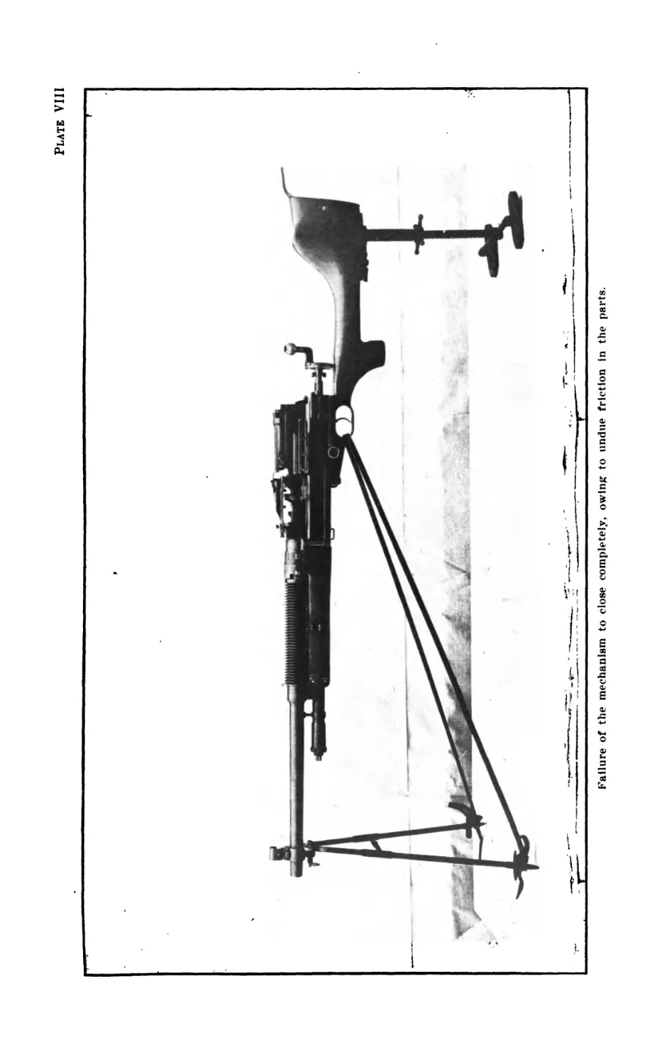
VIII. Failure of mechanism to close completely owing to undue friction in
parts................................................................. 38
IX. Showing where burrs are likely to be found on actuator................. 39
X. Testing to see if locking nut holds barrel tightly to the receiver.... 38
XI. Testing position of tongue............................................. 39
XII. Testing breechblock and extractor..................................... 40
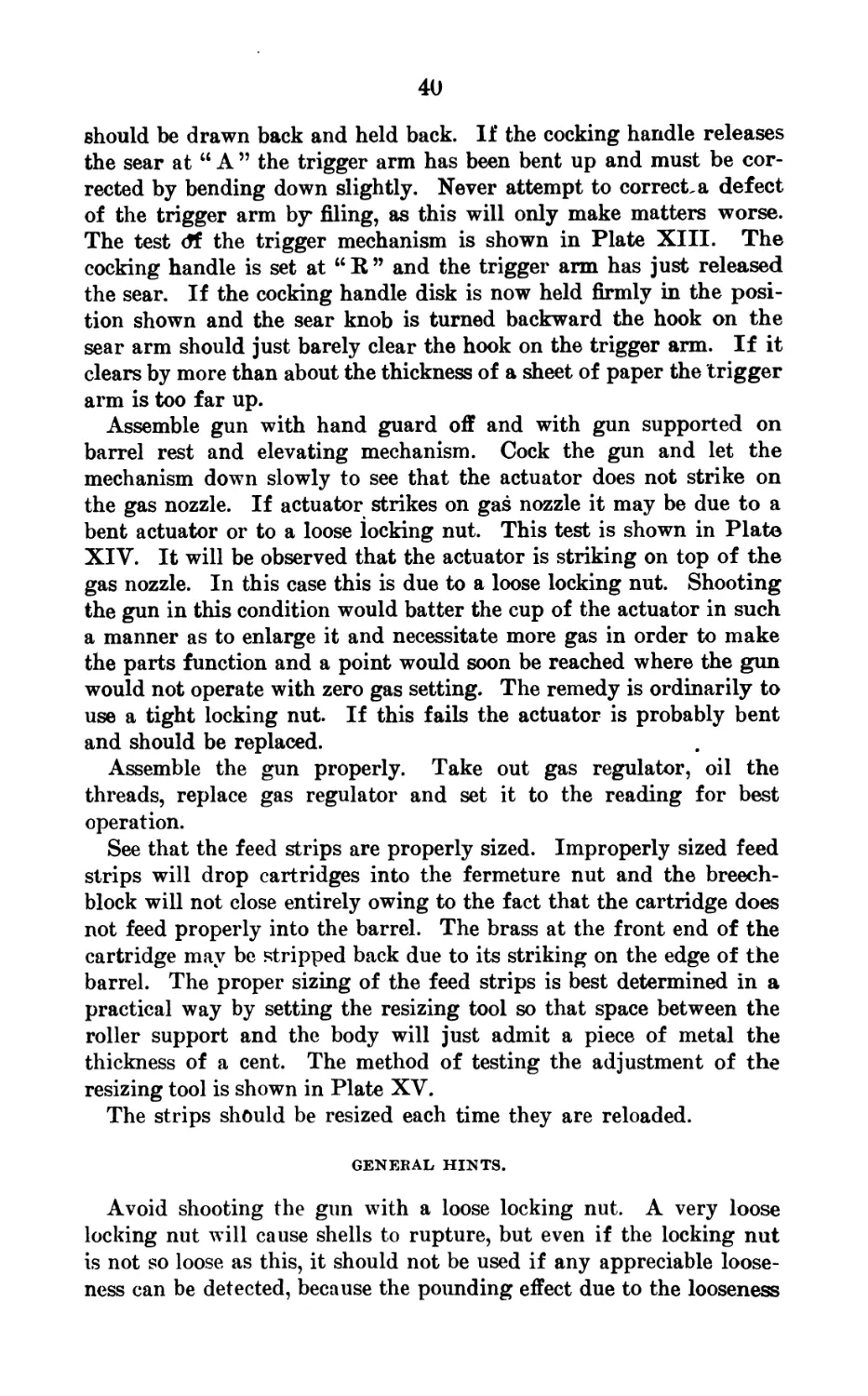
XIII. Testing the trigger mechanism......................................... 41
XIV. Actuator striking gas nozzle on account of loose locking nut. 40
XV. Testing the setting of the resizing tool.............................. 41
XVI. Defective cartridge extractor.......................................... 44
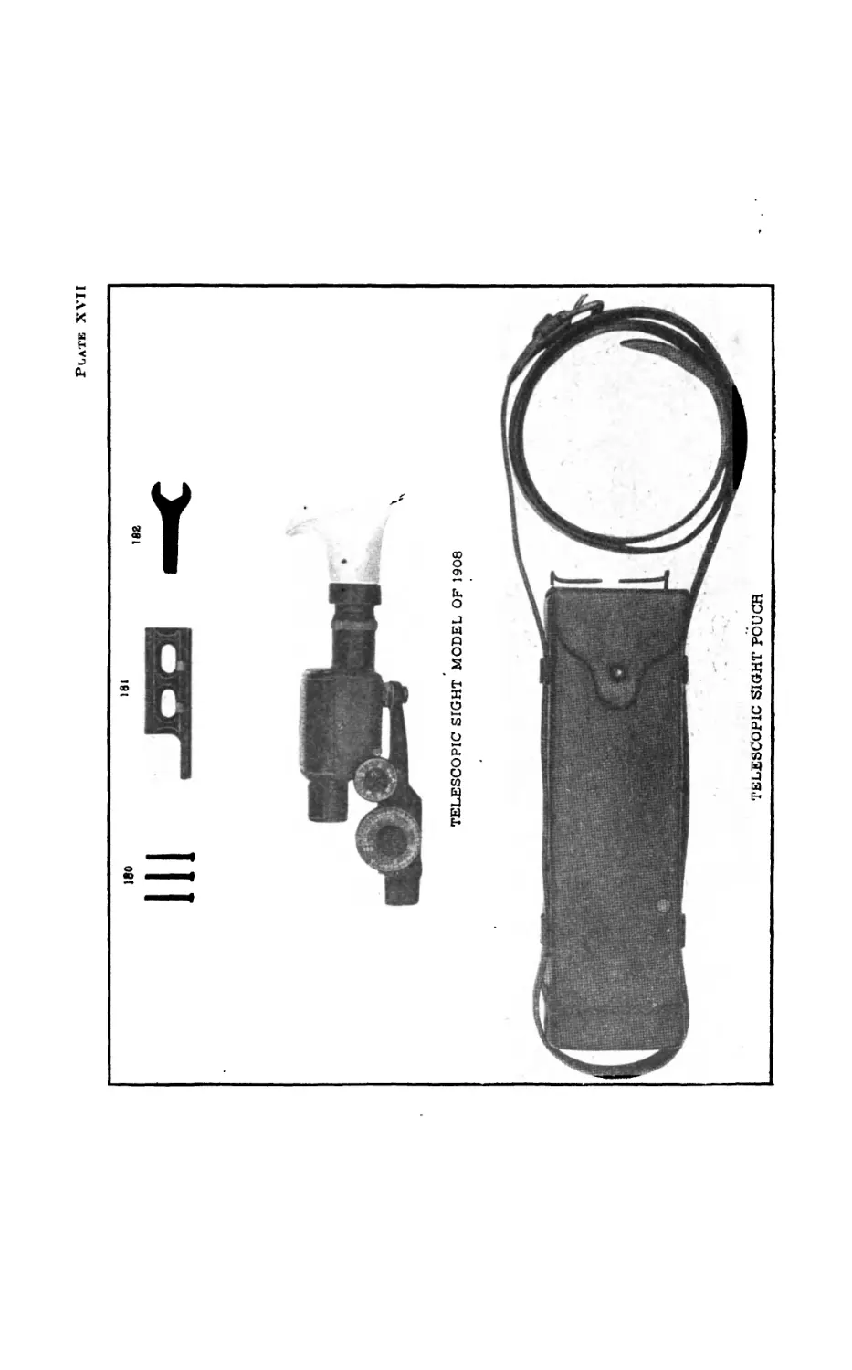
XVII. Telescopic sight and pouch............................................ 48
XVIII. Views of telescopic sight............................................... 49
XIX. Tools and accessories................................................. 52
XX. Ammunition box........................................................ 53
XXI. Cases................................................................. 56
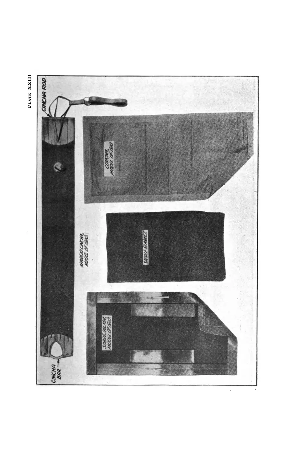
XXII. Pack harness.......................................................... 57
XXIII. Pack harness............................................................ 58
XXIV. Aparejo, model of 1911, frame (right half).............................. 59
XXV. Pack, first mule (right side).......................................... 62
XXVI. Pack, first mule (left side).......................................... 63
XXVII. Pack, second mule (right side)......................................... 62
XXVIII. Pack, second mule (left side)......................................... 63
XXIX. Pack, third mule (right side)........................................... 62
XXX. Pack, third mule (left side).......................................... 63
XXXI. Special pack equipment.................................................. 62
(5)
EQUIPMENT OF MACHINE GUN COMPANY OR TROOP.
Each machine-gun company or troop is provided with six rifles,
including ammunition, spare parts, tools, and accessories, together
with the necessary packs.
The equipment for each company or troop is carried on 24 mules,
constituting six sections of four each. The sections are essentially
complete units, although certain articles are not carried in every
section.
The equipment of each section consists of one rifle, ammunition, and
the necessary equipment for maneuvering the piece in the field.
The description is divided into the following parts:
Part I. The rifle with its ammunition and accompanying parts.
Part II. The pack harness.
Part III. The special pack equipment.
Part IV. The pioneer tools.
Part V. The total equipment of a machine-gun company or troop.
(7)
PART I.—THE RIFLE WITH ITS AMMUNITION AND
ACCOMPANYING PARTS.
Description of the Benet-Mercie Machine Rifle, Model of 1909.
GENERAL.
[Plates I, II, III, aud IV.]
The Benet-Mercie machine rifle, model of 1909, belongs to that type
of automatic arms known as the gas operative. The power that is
used to operate the mechanism is obtained from a small portion of
the powder gases that enter through a port in the barrel after the
bullet has passed. After the first shot the rifle is self-operative, until
the ammunition in the feed strip is exhausted or until the trigger is
released.
The ballistics of the Benet-Mercie machine rifle, model of 1909, are
similar to those of the service rifle, and the data given in the hand-
book of the service rifle, No. 1923, is equally applicable to the Benet-
Mercie machine rifle, model of 1909. The bullet suffers a slight de-
crease in muzzle velocity due to the gas used in operating the rifle,
but for general purposes the data quoted is sufficiently accurate.
In firing, the action of the mechanism is as follows:
When the rifle is fired and the bullet has passed the gas port in the
barrel a part of the powder gas passes into the chamber of the gas-
nozzle ring, and enters the gas cup of the actuator, forcing the latter
to the rear. Т11ё actuator in recoiling compresses the actuator spring,
the cam surface cut in its upper portion engaging the lug of the fer-
meture nut, causing the latter to rotate so as to disengage its threads
from those of the breechblock. At this part of the recoil the firing
pin, which has been drawn back by the actuator, engages its upper
lug in the ramp of the receiver. The firing pin then rotates on its
axis and its upper lug comes to rest in the transverse cut of the
breechblock, thus locking the latter to the actuator. The large lug of
the actuator strikes against the shoulder of the breechblock, drawing
the latter to the rear and thereby completing the opening of the
breech. The claw of the extractor engages the groove of the cartridge
case and draws it from the chamber. During the recoil of the breech-
block the head of the cartridge case strikes against the ejector, throw-
ing the case out of the rifle through the ejection opening in the re-
ceiver. When the actuator is partly recoiled the cam surface cut on
its right side engages the upper lug of the feed piece, causing the
latter to rotate from right to left on its axis. The feed arm of the
(8)
Plate I
Plate II
Plats III
SLlMWMt
SW£ |
еоапъяш
9
feed piece engages its lug in the central opening of the feed strip,
forcing the latter into the rifle and placing a cartridge in the loading
position in front of the chamber. The pawl of the feed-piece spring
engages in the lateral openings of the feed strip, thereby holding the
latter in place and preventing its being drawn to the right when the
feed arm of the feed piece, having advanced the feed strip one notch,
returns to its original position by sliding over the feed strip in order
to engage in the next hole. Finally, when the actuator is almost re-
coiled (supposing the rifle to be set for single shots), the sear engages
in the cocking notch of the actuator and the latter is held back ready
for the next shot.
When the trigger is pulled the sear is disengaged from the actuator,
which, now being free, is thrown forward, due to the force exerted
by the actuator spring. During this movement the actuator carries
forward the breechblock, to which it is connected by means of the
large lug of the firing pin. The breechblock strikes the cartridge,
forces it into the chamber, and the claw of the extractor engages the
groove of the cartridge case. As soon as the breechblock engages
the fermeture nut the large lug of the firing pin engages in the ramp
of the receiver, causing the firing pin to rotate so as to disengage
this lug from the transverse cut of the breechblock. The firing pin
is then free and may move forward. The actuator continues its
forward movement and its cam face engages the lug of the fermeture
nut, rotating the latter so as to cause its threads to engage with those
of the breechblock. The breech is now closed and locked. The firing
pin striking the primer fires the piece. During this forward move-
ment of the actuator, the small cam surface cut on its right side
engages the lower lug of the feed piece, causing it to rotate from left
to right. The feed arm is actuated by this movement, and its feed
glides over the feed strip and engages in the next opening of the
latter, ready to feed the feed strip another notch into the rifle when
the actuator again recoils.
The following table gives a serial list of component parts of this
rifle:
SERIAL LIST OF COMPONENT PARTS.
[Numbers before components refer to numbers shown on Plates IV, V, VI, VII, XVII, and
XVIII. Property classification : Class IV, section 1.]
1. Receiver.
2. Ejector bushing.
3. Rear feed guide.
4. Feed-guide assembling screw (7).
5. Bottom-plate rivet (11).
6. Bottom plate.
7. Front feed guide.
8. Actuator.
9. Actuator bushing pin.
10. Actuator spring.
11. Barrel rest (complete).
12. Front sight carrier.
13. Sight-carrier pin.
14. Barrel.
15. Gas-cylinder support.
16. Gas-cylinder support pin.
17. Gas-nozzle ring pin.
18. Gas-nozzle ring.
10
19. Orifice screw.
20. Radiator.
21. Radiator pin.
22. Locking-nut stop.
23. Elevating-mechanism feet (2).
24. Elevating-mechanism guide rod.
25. Inner elevating screw.
26. Elevating-mechanism foot pins(4).
27. End plug (2).
28. Outer elevating screw.
29. Elevating-screw tube, with cap.
30. Elevating-screw tube washer.
31. Front stiffening piece.
32. Body stiffening piece.
33. Assembling plates (2).
34. Hand-guard rivet, short (6).
35. Hand guard.
36. Catches for barrel rest leg (2).
37. Hand-guard rivet, long (8).
38. Leg catch spring (2). ’
39. Hand-guard rivets, short (10).
40. Regulator-piston.
41. Regulator sleeve.
42. Regulator-sleeve pin.
43. Spring-seat pin (2).
44. Guard.
45. Butt plate.
46. Stock.
47. Actuator-spring seat.
48. Cocking-handle knob.
49. Cocking-handle rivet (3).
50. Cocking-handle shank.
51. Actuator bushing.
52. Firing pin.
53. Closing spring.
54. Feed-piece housing cover.
55. Feed-piece spring button (2).
56. Cover-plate screw.
56a. Cover-plate screw washer.
57. Cover plate.
58. Feed-piece spring.
59. Feed-piece spring stud.
60. Feed-piece spring-stud rivet (2).
61. Feed-piece spring-pawl rivet (2).
62. Feed-piece spring pawl.
63. Extractor.
63a. Dismounting tool (extractor).
64. Breechblock.
65. Trigger.
66. Sear-spring pin.
67. Sear spring.
68. Sear.
69. Sear-spring lever.
70. Locking screw (2).
70a. Locking nut screw.
70b. Check nut.
71. Feed piece.
72. Fermeture nut.
73. Extractor spring.
74. Binder lever.
75. Elevating screw slide.
76. Elevating-screw slide pin.
77. Binder.
78. Locking nut.
79. Hand-guard stud.
80. Slide-guide pins (2).
81. Binder spring.
82. Slide spring.
83. Binder lever pivot.
84. Latch plate.
85. Latch-plate screw.
86. Slide-guide pin pins (2).
87. Butt-plate screw.
88. Butt-plate screw, wood (2)
89. Latch spring.
90. Spring screw.
91. Stock bolt.
92. Separator split pin.
93. Guard screw.
94. Connecting piece, female.
95. Connecting piece, male.
96. Plunger spring.
97. Plunger ring.
98. Plunger.
99. Barrel-rest head.
100. Separator nut.
101. Separator bolt.
102. Separator-bolt pin.
103. Separator axis (2).
104. Separator (2).
105. Front-leg axis (2).
106. Front-leg feet (2).
107. Foot rivets (2).
108. Front leg (2).
109. Front sight.
110. Hinge pin.
111. Cover screw (2).
112. Front-sight screw.
113. Front-sight cover.
114. Cartridge-stop spring.
115. Cartridge-base stop.
116. Ejector spring.
117. Ejector cap.
118. Ejector.
119. Cartridge stop.
120. Cartridge-stop holder.
121. Slide cap.
122. Leaf.
11
123. Slide.
124. Windage-screw knob.
125. Windage-screw pin.
126. Windage screw.
127. Windage-screw spring.
128. Windage-screw collar.
129. Elevating-screw head.
130. Elevating-screw pin.
131. Elevating screw.
132. Half-nut spring.
133. Half nut.
134. Pivot.
135. Pivot-spring.
136. Fixed-base screw.
137. Slide-cap screw, small.
138. Slide-cap screw, large.
139. Aperture disk.
140. Base spring.
141. Drift slide.
142. Movable base.
143. Leaf-joint pin.
144. Rear-sight fixed base.
145. Dismounting wrench.
146. Ejector key.
147. Resizing-tool frame.
148. Adjusting screws (2).
149. Resizing-tool roller.
150. Blocking screws (4).
151. Resizing-tool roller support.
152. Cleaning-rod handle and sleeve.
153. Cleaning-rod stem and sleeve.
154. Cleaning-brush holder.
155. Rammer.
156. Defective-cartridge extractor.
157. Hand extractor.
158. Screw driver.
159. Copper hammer.
160. Drift.
161. Loading-tool handle.
162. Lever axis.
163. Lever (one right, one left).
164. Loading-tool foot (2), short.
165. Pushing-bar guide slide.
166. Screw (4 long, 8 medium, 4 short).
167. Strip guide.
168. Loading-tool foot (long), 1.
169. Pushing bar.
170. Pushing-bar axis. /
171. Pushing-bar guide.
172. Pliers.
173. Grease brush.
174. Cleaning brush.
175. Feed strip.
176. Oil can, including nozzle cap and
chain.
177. Gas-cylinder cleaner.
178. Cooling sponge.
179. Grease pot
180. Sight-bracket screws (3).
181. Telescopic-sight bracket.
DETAILED DESCRIPTION OF THE RIFLE COMPONENTS.
The component parts of the rifle arranged alphabetically are given
in the following list:
[Numbers after components refer to numbers shown on plates. Property classification:
Class TV, section 1.]
Actuator (8).
Actuator bushing (51).
Actuator-bushing pin (9).
Actuator spring (10).
Actuator-spring seat (47).
Adjusting screws (148) (three).
Aperture disk (139).
Assembling plates (33) (two).
Barrel (14).
Barrel rest (complete) (11).
Barrel-rest head (99).
Base spring (140).
Binder (77).
Binder spring (81).
Binder lever (74).
Binder-lever pivot (83).
Blocking screws (150) (four).
Body-stiffening piece (32).
Bottom plate (6).
Bottom-plate rivet (5) (eleven).
Breechblock (64).
Butt plate (45).
Butt-plate screw (87).
Butt-plate screw, wood (88) (two).
Cartridge-base stop (115).
Cartridge stop (119).
Cartridge-stop holder (120).
Cartridge-stop spring (114).
Catches for barrel-rest leg (36) (two).
Check nut (70b).
Cleaning brush (174).
Cleaning-brush holder (154).
12
Cleaning-rod handle and sleeve (152).
Cleaning-rod stem and sleeve (153).
(’losing spring (53).
Gocking-handle knob (48).
Cocking-handle shank (50).
Cocking-handle rivet (49) (three).
Connecting piece, female (94).
Connecting piece, male (95).
Cooling sponge (178).
Copper hammer (159).
Cover plate (57).
Cover-plate screw (56). |
Cover-plate screw washer (56a). :
Cover screw (111) (two).
Defective-cartridge extractor (156).
Dismounting tool (extractor) (63a).
Dismounting wrench (145).
Drift (160).
Drift slide (141). I
Ejector (118). i
Ejector bushing (2). i
Ejector cap (117). '
Ejector key (146).
Ejector spring (116).
Elevating-mechanism feet (23) (two). |
Elevating-mechanism foot pins (26) •
(four). I
Elevating-mechanism guide rod (24).
Elevating screw (131).
Elevating-screw pin (130).
Elevating-screw slide pin (76).
Elevating-screw head (129).
Elevating-screw slide (75). |
Elevating-screw tube, with cap (29). I
Elevating-screw tube washer (30). j
End plug (27) (two). j
Extractor (63). ।
Extractor spring (73).
Feed-guide assembling screws (4)
(seven).
Feed piece (71).
Feed-piece housing cover (54).
Feed-piece spring (58).
Feed-piece spring button (55) (two).
Feed-piece spring pawl (62).
Feed-piece spring pawl rivet (61)
(two).
Feed-piece spring stud rivet (60)
(two).
Feed-piece spring stud (59).
Feed strip (175).
Fermeture nut (72).
Firing pin (52).
Fixed-base screw (136).
Front-feed guide (7).
Front leg (108) (two).
Front-leg axis (105) (two).
Front-leg foot (106) (two).
Foot rivets (107) (two). .
Front sight (109).
Front-sight carrier (12).
Front-sight cover (113).
Front-sight screw (112).
Front-stiffening piece (31).
Gas-cylinder cleaner (177).
| Gas-cylinder support (15).
: Gas-cylinder support pin (16).
Gas-nozzle ring (18).
Gas-nozzle ring pin (17).
Grease brush (173).
Grease pot (179).
, Guard (44).
| Guard screw (93).
i Half nut (133).
I Half-nut spring (132).
' Handle extractor (157).
, Hand guard (35).
Hand-guard rivet (37) (34) (39)
I (twenty-four.)
! Hand-guard stud (79).
। Hinge pin (110).
1 Inner elevating screw (25).
Latch plate (84).
Latch-plate screw (85).
, Latch spring (89).
। Leaf (122).
j Leaf-joint pin (143).
I Leg-catch spring (38) (two).
i Lever (1 right, 1 left) (163).
> Lever axis (162).
I Loading-tool foot (2) short (164).
Loading-tool foot, long (168).
Loading-tool handle (161).
Locking nut (78).
Locking-nut screw (70a).
Locking-nut stop (22).
Locking screw (70) (two).
Movable base (142).
Oil can, including nozzle cap and
chain (176).
Orifice screw (19).
Outer elevating screw (28).
Pivot (134).
Pivot spring (135).
Pliers (172).
Plunger (98).
Plunger ring (97).
Plunger spring (96).
13
Pushing bar (169).
Pushing-bar axis (170).
Pushing-bar guide (171).
Pushing-bar guide slide (165).
Radiator (20).
Radiator pin (21).
Rammer (155).
Rear feed guide (3).
Rear-sight fixed base (144).
Receiver (1).
Regulator piston (40).
Regulator sleeve (41).
Regulator-sleeve pin (42).
Resizing-tool frame (147).
Resizing-tool roller (149).
Resizing-tool roller support (151).
Screw (4 long, 8 medium, 4 short)
(166).
Screw driver (158).
Sear (68).
Sear spring (67).
Sear-spring lever (69).
Sear-spring pin (66).
Separator (104) (two).
Separator axis (103).
Separator bolt (101).
Separator-bolt pin (102).
Separator nut (100).
Separator split pin (92).
Sight-bracket screws (180) (three).
Sight-carrier pin (13).
Slide (123).
Slide cap (121).
Slide-cap screw, large (138).
Slide-cap screw, small (137).
Slide-guide pin (80) (two).
Slide-guide pin pins (86) (two).
Slide spring (82).
Spring screw (90).
Spring-seat pin (43) (two).
Stock (46).
Stock bolt (91).
Telescopic sight bracket (181).
Trigger (65).
Windage screw (126).
Windage-screw collar (128).
Windage-screw knob (124).
Windage-screw pin (125).
Windage-screw spring (127).
These parts are assembled into the following groups: The barrel
group, the receiver group, the firing-mechanism group, the feed-
mechanism group, the locking-mechanism group, the guard group,
the stock group, the elevating-mechanism group, the hand-guard
group, the barrel-rest group, and the rear-sight group.
THE BARREL GROUP.
[Plates V and VII.]
The barrel group contains the barrel, radiator, gas-nozzle ring,
front-sight carrier, gas-cylinder support, regulator, and front sight,
front-sight cover, front-sight screws, and cover screws.
The barrel is chambered and rifled the same as the barrel for the
United States rifle, caliber .30, model of 1903. The rear portion of
the barrel is turned down to provide seats for the radiator and the
gas-nozzle ring, and the front end for the seat for the front-sight
carrier. In rear of the radiator seat are the locking lugs, two inter-
rupted annular rings divided into three sectors, which engage in
similar lugs of the locking nut and secure the barrel to the receiver.
On the lower exterior surface of the barrel and in the rear of these
locking lugs is a small lug which fits in a slot in the receiver. This
small lug assures the alignment of the receiver and the barrel, also
of the gas-nozzle ring and the actuator. The rear end of the barrel
is turned down for the fermeture nut, which fits over the end of the
11586—17----2
14
barrel in assembling. On the upper surface of the rear end of the
barrel is a small bevel cut which guides ths cartridge into the
chamber, and on the left side is the clearance cut for the claw of
the extractor and extractor housing on breechblock. A gas orifice or
port is drilled through the underside of the barrel at the seat for
the gas-nozzle ring.
The radiator is about 7| inches in length and has cut on its exterior
surface a series of deep grooves. The center of the radiator is bored
out to a diameter somewhat less than that of its seat on the barrel and
is shrunk in place and secured by the radiator pin. The bottom of
he radiator is slabbed off for clearance. To its rear end, near the
bottom, is assembled the locking-nut stop. The purpose of the radi-
ator is to aid in the rapid radiation of the heat developed during
firing.
The gas-nozzle ring is assembled to the barrel in front of the
radiator and is shrunk in place and secured by the gas-nozzle ring
pin. A small hole is drilled from the bottom of the gas-nozzle ring
to connect with the gas port in the barrel. The exterior of the hole
is closed by the orifice screw. The rear end of the lower portion of
the gas-nozzle ring is shaped to form a nozzle and the front end is
shaped to form a gas chamber. The nozzle is of circular shape to fit
the gas cup of the actuator, and through its center is drilled a small
hole into the gas chamber, intersecting the vertical hole drilled from
the bottom of the gas-nozzle ring to the gas port in the barrel. The
interior of the gas chamber is bored out and tapped near the front
end for the regulator piston, and its exterior is graduated to aid in
adjusting the regulator sleeve. On the rear upper face of the gas-
nozzle ring is a horizontal lug on which the front stiffening piece of
the hand guard rests when the latter is assembled.
The front-sight carrier is secured to the front of the barrel by the
sight-carrier pin. On the upper part of the front-sight carrier is a
dovetailed transverse slot for the front sight. In front of this slot is
drilled and tapped a hole for the front-sight screw. On the under-
side of the front-sight carrier is a pivot which provides the means for
the attachment of the barrel rest. On the front of the pivot is a
recess into which the plunger of the barrel rest enters and secures the
latter in position.
The gas-cylinder support, designed to prevent injury to the gas-
nozzle ring during transportation, is assembled to the gas chamber
of the gas-nozzle ring, and is secured by the gas-cylinder support
pin, the ring on its lower part slipping over the gas chamber and the
U-shaped upper part resting against the barrel.
The regulator consists of the regulator sleeve secured to the regu-
lator piston by the regulator-sleeve pin. The regulator piston is
Plate V
Plate VI
—1-----------—ни «а» «Ml
90
15
a cylindrical bar having on its rear end three annular piston rings
which fit the gas chamber of the gas-nozzle ring. The purpose of
these rings is to check the escape of gas to the front and thus to serve
as air packing. The center section of the regulator piston is threaded
to fit the thread in the gas-nozzle ring; its front end has a square
head to aid in adjusting, disassembling, and assembling. The regu-
lator sleeve fits the cylindrical part of the regulator piston in rear of
the square head and is pinned thereto. The regulator sleeve covers the
piston back to and including the thread on the center section, suffi-
cient space being had between the regulator piston and the regulator
sleeve to permit the front portion of the gas-nozzle ring to enter with
a reasonably close fit. A tongue is milled in the barrel of the regu-
lator sleeve and provided with a small projection on the inside, near
the rear, which engages in a longitudinal groove on the underside
of the gas-nozzle ring and prevents the sleeve from rotating after ad-
justment. The front end of the regulator sleeve is knurled, so that
it car be more easily turned by the hand.
The purpose of the regulator is to increase or decrease the size
of the gas chamber of the gas-nozzle ring, thus controlling the ve-
locity of the rearward movement of the actuator in order to allow for
adjustments for various powder pressures, or for difference in the
friction of the parts.
The front sight has on its upper portion a thin leaf slightly beveled
to the front, and on each side is cut a circular groove to better define
the sight proper. On the lower portion is a dovetail lug which
engages in the dovetail groove of the front-sight carrier. This
method of assembling the front sight and front-sight carrier permits
of adjustment for deflection, and after the rifle is targeted the hole
in the front-sight carrier for the front-sight screw is extended into
the front sight and the front-sight screw inserted. Over the front
sight is placed the front-sight cover, secured by the cover screws.
THE RECEIVER GROUP.
[Plates V, VI, and VII.]
The receiver group consists of the receiver, ejector bushing, rear
feed guide, front feed guide, bottom plate, feed-piece housing cover,
and rear-sight fixed base; these parts constitute a receiver when
issued; and are permanently attached to the receiver by rivets or
screws. In assembling, components are assembled as follows: Closing
spring, ejector, ejector spring, ejector cap, cartridge stop, cartridge-
stop spring, cartridge-stop holder, cover plate, cover-plate washer,
cover-plate screw, feed piece, feed-piece spring, windage screw, rear
sight, telescopic-sight bracket, fermeture nut, and locking nut.
The receiver is a large steel forging, which contains the firing, feed,
and locking mechanisms, and also provides means for the assembling
16
of the barrel, the guard, the hand guard, and the rear sight. In the
front end of the receiver is drilled a large hole, which is the seat for
the fermeture nut and the barrel. A slot on the lower side of this
hole is for the purpose of locating the barrel and for assembling the
fermeture nut. In rear of this slot is a recess for the lug of the
fermeture nut. The front end of the receiver is threaded on the
exterior for the locking nut, which secures the barrel to the receiver.
On the top and directly in the rear are permanently assembled,
by means of the feed-guide assembling screws, the front and rear
feed guides, between which slides the feed strip during the firing.
The front feed guide contains a narrow slot, in which the feed strip
slides, and a large opening on the right for the cartridges. On top
and at the right are two undercut slots, slightly beveled, into which
is assembled the feed-piece spring. On the left is drilled and tapped
a hole for the cover-plate screw. The rear feed guide has a narrow
slot for the feed strip and also the cartridge opening on the right.
On the left is a dovetail groove for the cover plate and on the
right the seat for the feed piece. This seat consists of a hole drilled
vertically in the rear feed guide with an opening in its rear for
assembling the feed* piece. A large lug to the left of this hole, on
which the feed piece slides during the firing, and a smaller lug on
the right inclose the seat. On top to the right of dovetail groove
is an opening under large lug through which the feed-piece spring
pawl passes in assembling.
The feed guides are braced on the left by the cover plate, which is
secured to the front feed guide by the cover-plate screw and to the
rear feed guide by the dovetail slot. The cover-plate screw is held
securely by means of a split washer under head of screw, preventing
its working loose from vibration in firing. On the front of the rear
feed guide, just below and to the right of the dovetail slot, is assembled
the cartridge base stop, which limits the movement of the cartridges
to the left. In front of the rear feed guide is a tongue which enters
between the feed strip and the cartridge and forces the latter down-
ward. To the bottom and the front half of the receiver is securely
riveted the bottom plate. The latter has on its lower surface two
locking lugs, into which fit the trunnions of the guard. On top of
the receiver and directly in rear of the feed guides is an undercut
dovetail groove, in which is assembled the rear-sight fixed base, the
latter being secured in position by the fixed base screw. The rear-
sight fixed base contains the pivot lug for the movable base, the
undercut for the windage screw and the lip on the front end of the
movable base, and a lug on the rear end, which forms the undercut
for the lip on the rear end of the movable base.
Upon its rear upper surface are two zero marks for the wind-gauge
graduations. On the left side of the receiver is the ejection opening.
17
Above this opening is drilled and tapped the seat for the cartridge
stop. In the rear of the ejection opening is the dovetail seat for the
telescopic sight bracket, the latter being secured to the receiver by
three sight-bracket screws. On the right side of the receiver is the
feed-piece housing cover, which is attached to the bottom plate by
the hinge pin. The former is held in its closed position by the clos-
ing spring which is inserted in the housing of the bottom plate. In
the bottom of the housing of the bottom plate is drilled a small
vertical hole in which is inserted the lower end of the feed piece.
The ejector bushing is driven into a seat directly below the rear feed
guide and has an opening on its left end for the ejector, while on the
right are four small lugs, recessed to receive the lugs of the ejector cap.
The interior of the receiver has in its front section the seat for the
fermeture nut, which is beveled in the rear to insure that the ferme-
ture nut is always centered.
Within the rear section on the sides are the breechblock guide
slots, while on the top and to the left is the guide for the firing pin
which, ending in two cams, causes the firing pin to rotate in and out
of its recess in the breechblock.
In the rear and bottom part of the receiver are the locking-lug seats
for the guard.
On the left of the receiver near the rear end is a small hole, drilled
and tapped, into which is screwed the locking screw for securing the
guard to the receiver. A small slot in front holds the locking screw
in place. Two beveled undercut grooves in the front of the receiver
provide seats for the assembling of the hand guard.
THE FIRING-MECHANISM GROUP.
[Plates V and VI.]
The firing-mechanism group consists of the actuator, actuator
spring, breechblock, firing pin, extractor, and extractor spring.
The actuator is located below and parallel to the barrel and is the
piston which drives the mechanism of the rifle. It has on its upper
surface a long straight cut and in the rear two diagonal cam cuts in
which moves the lug of the fermeture nut. In the rear of these
cams is cut a deep recess in order to reduce the weight of the actuator.
In rear of this recess is a large lug, the center section of which is
cut away for the lower lug of the firing pin. On the front end of
the actuator is the gas cup, which fits over the nozzle end of the gas
nozzle ring. On the right side of the actuator are two cam surfaces,
upon which move the upper and lower lugs of the feed piece in re-
coiling and counterrecoiling. On the left side of the actuator is the
clearance cut for the trigger, and on the bottom is the sear notch in
which the sear engages when the rifle is cocked. On the lower surface
18
at the rear end is a slight ramp on which the sear rides near the end
of recoil. On the right and left sides, and also on the lower surface
of the actuator, are guides or bearing surfaces to control the move-
ment of the actuator during recoil and counterrecoil.
The actuator is hollow nearly its entire length, the rear portion
forming a housing for the actuator spring. About midway between
the ends of the actuator is secured the actuator bushing. This bush-
ing, which is threaded and screwed in position and secured with a
pin, serves as the front seat for the actuator spring and also forms a
seat for the lugs on the front end of the cocking handle when the
latter is used to retract the actuator.
The actuator spring is a long spiral spring located in the interior of
the actuator, with its front end resting against the actuator bushing
and its rear end against the actuator spring seat in the guard. As the
actuator recoils, this spring is compressed and the energy stored up
is used to move the actuator forward at the end of the recoil.
The breechblock contains the firing pin, extractor, and extractor
spring. The breechblock rests on the bottom of the guide slots in the
receiver, the large lug on the actuator entering a long longitudinal
slot in the rear part of the breechblock. At the rear end and left side
of this long slot is a deep recess into which the upper lug of the firing
pin rotates whenever the breechblock is in motion. In front of this
long slot the breechblock is cut away as clearance for the cartridge
stop, while at the top and rear end of the slot is a small ramp to aid
in disassembling and assembling the firing pin. On the right and left
sides of the breechblock at the rear are guides that move in the guide
slots of the receiver. On the front section of the breechblock are
interrupted threads divided into three sectors, which engage those
of the fermeture nut and securely lock the former to the latter during
firing. On the right side of the breechblock is a long clearance cut
for the ejector. On the left-hand side of breechblock at the front end
is the housing for the extractor; under this housing at the end of the
breechblock is a stud, which acts as a seat for the curved surface on
the bottom of the extractor at the rear of the extractor claw, pre-
venting extractor from pitching too far toward center of breechblock
to readily pass over cartridge case. On the inside of the housing a
bevel cut is the working point for the bevel cut on top of the ex-
tractor when, firing the rifle. The rear end of the housing forms a
seat for the shoulder on the extractor after the extractor is worn on
the bevel surface and on the bottom, thus increasing the life of the
extractor. At the rear of the housing is a slot for the extractor and
extractor spring; at the rear end of this slot is the extractor spring
seat. On the left side back of the extractor spring seat the breech-
block is cut away to facilitate the assembling and dismounting of
the extractor and extractor spring.
19
At the front end of the breechblock on the upper rim a shallow
seat is cut for carrying the cartridge into the chamber. The ends
of rim on each side of ejector groove are slightly closed toward
center of the breechblock to insure a good grip of cartridge case. The
front end of the breechblock is counterbored for the head of the car-
tridge, and in the center of this space is drilled a small hole for the
firing-pin point. The interior of the breechblock is bored out for
the barrel of the firing pin.
The firing pin is seated within the breechblock. The front portion
is cylindrical, terminating at the front end of the firing-pin point,
and has on its rear end a small and a large lug. The small lug is
on the underside and rests, when assembled, in the recess of the large
lug on the upper part of the actuator. This small lug causes the
firing pin to move to the rear in the first motion of recoil. The large
lug is on the upper side and has on its top two cam cuts, which move
in the cam cuts in the receiver and serve to rotate the firing pin in
and out of the recess in the breechblock. The front shoulder of this
upper lug rests against the front of this recess during counterrecoil
and carries the breechblock forward, the upper lug on the actuator
bearing against the rear end of the barrel of the firing pin. The
bottom and rear end of the upper lug is beveled to permit assembling
and disassembling.
The extractor is an irregular bar having on the underside of its
forward end a claw and on the upper side of the forward end an
incline which seats against the underside of extractor housing of the
breechblock, when passing over rim of cartridge case. At the rear
end of the extractor is a pivot on which the extractor spring seats
and forces the extractor downward over the cartridge head. When
the breechblock strikes the cartridge in loading, the extractor is
forced backward until the claw drops into the cannelure of the
cartridge.
The extractor is assembled to the breechblock by slipping the ex-
tractor spring over the pivot on the rear of the extractor, inserting
the front end of the extractor in the opening in rear of the extractor
housing and gradually forcing the extractor and spring into place
with the dismounting tool. The position of the extractor is deter-
mined by the small bevel cut on top of the extractor, the convex
cut on underside of extractor housing, and shoulder on the extractor.
The pivot on the extractor is bent slightly, so the pressure of the
extractor spring forces it into proper location. The extractor and
spring may be dismounted either by use of the dismouning tool or
by engaging a small screw driver behind the extractor spring in the
small slot provided in the extractor seat of the breechblock.
20
ТЛЕ bEED-MECHANISM GROVE.
[Plates VI and VII.]
The feed-mechanism group consists of the feed piece, the feed-
piece spring, the cartridge stop, the cartridge-stop spring,’the car-
tridge-stop holder, the ejector, the ejector spring, and the ejector cap.
The feed piece is of irregular shape, having at its upper end a feed
arm, on the end of which is a pointed lug which engages in the
central opening of the feed strip. On the top of the feed piece is
a small lug, which holds the feed-piece spring in position. On the
feed arm, near this lug, is a small cut into which the feed-piece spring
stud drops when the feed arm is moved to the left. Near the lower
end on the shaft of the feed piece are two lugs, one above the other,
that move on the cam surfaces of the actuator and give rotation to the
feed piece. When the last cartridge in a feed strip has been fired
the feed piece drops down, due to pressure of the feed-piece spring,
and the lower lug then prevents forward movement of the actuator.
The lower end of the feed piece is cross milled to prevent the finger
slipping when the feed piece is raised. Between the lugs and the feed
arm a portion of the shaft is made flat, in order to facilitate assem-
bling. The feed piece when assembled in the rifle is held in a vertical
position by the opening in the bottom of the housing on the bottom
plate and the circular opening in the rear feed guide on the receiver.
The feed-piece spring is an irregularly curved spring of sheet steel.
On its front end is riveted the feed-piece spring button, for use in the
disassembling and assembling of the spring, and at the rear and left
side is riveted the feed-piece spring pawl. The latter is> pointed on
its left side; and as the feed strip moves to the left the feed-piece
spring pawl engages in the rear openings of the strip, thus prevent-
ing the feed strip from moving to the right. On the right side,
near the rear, is riveted the feed-piece spring stud, while directly
in rear of this stud is a small opening through which passes the
small lug of the feed piece. As the feed piece rotates, the upper sur-
face of the feed arm strikes against this spring stud and slightly
raises the feed-piece spring, thus allowing the pawl to ride over the
feed strip. The feed-piece spring is assembled to the receiver by
forcing it into the undercut grooves on the right side of the front
feed guide.
The cartridge stop is a short cylindrical piece with a blunt conical
point, and is seated in the receiver just above the ejection opening.
It is held in position by the cartridge-stop spring and the cartridge-
stop holder, the latter containing a small opening through which the
end of the cartridge stop projects. The holder is also threaded for
the purpose of assembling it to the receiver. The principal function
of the cartridge stop is to act as a shock absorber. It also indicates,
in loading, whether or not the feed strip has been fully inserted.
Plate VII
21
The ejector is assembled in the ejector bushing of the receiver and
is held in position by the ejector spring and the ejector cap. The
ejector cap is circular in shape, having on its circumference four
small lugs which engage in corresponding slots in the ejector bush-
ing. Special attention should be paid, in the assembling of the
ejector cap, to insure that the small lugs on the sides of the cap are
properly located in the slots provided for them in the ejector bush-
ing; failure to properly locate these lugs will allow the ejector cap
to jump out against the feed piece during* firing and prevent the for-
ward movement of the firing mechanism. On the top of the ejector
cap are cut two slots at right angles to each other, into which fit the
ejector key used in dismounting and assembling. In the center of the
cap is a small hole which allows the end of the ejector to protrude.
THE LOCKING-MECHANISM GROUP.
[Plate VI.]
The locking mechanism group is made up of the locking nut, the
fermeture nut, the locking nut screw, the check nut, and the locking
screw. The action of the fermeture nut is an alternate locking and
unlocking for each round fired, while the locking of the barrel to the
receiver by the locking nut is more permanent in its nature.
The locking nut is cylindrical in shape, having two interrupted
annular rings of three sectors each on the inside to provide means
for locking the barrel to the receiver. In rear of these locking rings
is cut the thread for assembling the locking nut to the receiver. Two
small recess cuts are made on the front end of the locking nut for the
dismounting wrench, and also a large cut for clearance and stops for
the locking-nut stop on the radiator.
After the barrel is locked in position the locking nut is secured by
the locking-nut screw and check nut. The locking-nut screw is in-
serted in a small hole tapped and drilled near the rear end of the
locking nut on the left side. When the locking-nut screw is tightened
it bears against the receiver and thus prevents any motion of the
locking nut. After the locking-nut screw is tightened the check nut
is set up, thus preventing the locking-nut screw from being loosened
by the vibration. On the right side of the locking nut is the hand-
guard stud, which holds the hand guard in place while the barrel
is being removed. The locking nut is used for locking the guard
to the receiver.
The fermeture nut is cylindrical in shape and has on its under
side a large lug which moves in the cam cuts on the upper surface
of the actuator. The front end of the fermeture nut is counterbored
to receive the barrel, while directly in rear are interrupted threads
divided into three sectors for locking the breechblock. The left
22
sector of the fermeture nut is enlarged to allow passage of the ex-
tractor housing of the breechblock. An enlarged recess is provided
as clearance for the extractor housing as the fermeture nut rotates.
Between the lower and right-hand sectors is a deep cut which pro-
vides a cavity into which primers may drop should they become
dislodged from the cartridge case during firing. On top of the ferme-
ture nut is a long longitudinal cut from the rear, providing clearance
for the cartridge in loading; near the left rear end is a semicircular
cut, providing clearance for the front clip of the feed strip; and on
the top and right is the clearance for the feed strip. The rear shoulder
of the fermeture nut is beveled to enter the corresponding bevel in
the receiver. The function of the fermeture nut is to lock the
breechblock at the instant of firing and to unlock it immediately after
firing. The fermeture nut is located in the forward part of the
receiver, directly in rear of the barrel, and is held by a shoulder on
the barrel and a similar shoulder in the receiver, so as to prevent any
longitudinal movement but to permit of rotation about its axis.
ГНЕ GUARD GROUP.
[Plates V and VI.]
The guard group consists of the guard, actuator-spring seat, latch
spring, cocking handle, sear, sear spring, and trigger.
The guard, when assembled, closes the rear end of the receiver and
supports the stock. It is secured to the receiver by trunnions on its
front end which enter the locking lugs on the bottom plate, and also
by locking lugs on each side in the upper part of the guard near the
rear, which enter seats on the interior of the receiver. It is secured
in its seat by one of the locking screws^ which enters the guard
through the locking-screw hole of the receiver. Within the guard is
the recess and seat for the sear, and in the rear of this a long slot for
the trigger. Under the latter slot is the trigger bow. In the upper
part of the guard is a longitudinal hole in the top and bottom of
which are two slots, in which the actuator-spring seat is placed. The
latter is held in position by two large lugs on its perimeter and by
two spring-seat pins which are assembled to the guard directly in
front of the actuator-spring seat. Through the center of the actu-
ator-spring seat is drilled and slotted a small hole with two small lugs
180° apart. Through this hole passes the shank of the cocking
handle, the lugs sliding in the longitudinal grooves of the latter.
Three semicircular grooves cross the rear surface of the actuator-
spring seat, by means of which the cocking handle is locked into its
three positions. In rear of the actuator-spring seat is the locking-
lug seat of the cocking handle. Under the opening for the actuator-
spring seat is a rectangular opening for the tongue of the trigger.
23
An arrow is stamped over the cocking-handle opening to aid in set-
ting the latter in the desired position. On the rear of the guard is
a short tang and a long tang, by means of which it is assembled to
the stock. The latch spring is a flat steel spring assembled near the
bottom of the long tang by the spring screw.
. The cocking handle, consisting of the shank and knob riveted to-
gether, is located within the actuator and extends to the rear through
the actuator-spring seat opening of the guard.
The front end of the cocking-handle shank extends into the actu-
ator and terminates in a double-locking lug. In retracing the actu-
ator by hand this lug bears against the actuator bushing. The rear
portion of shank is provided with grooves which engage the two lugs
on the interior of actuator-spring seat.
The cocking-handle knob has two locking lugs which serve to lock
the guard to the receiver. These locking lugs are made with two
projections which engage in the notches of the actuator-spring seat
and thereby determine the position of “ safety ” or the kind of fire
desired. On the rear of the cocking-handle knob is a circular disk,
on the face and near the perimeter of which are stamped arrows
which show the various firing positions. The position for firing
automatically is marked “A,” that for firing semiautomatically is
marked “ R,” and that for safety is marked “ S.” An arm extends
out from this disk with a ball handle by means of which the cocking
handle is rotated into these positions and which also assists in dis-
mounting and assembling. The disk of the cocking-handle knob is
retained in position by means of two conical surfaces on its front face
which engage in corresponding surfaces on the rear end of receiver.
The disk of the cocking-handle knob has two notches cut therein,
with the knob set at A, the position of the lower notch permits the
tongue of the trigger to pass through, thereby allowing the trigger to
be pulled directly to the rear. The hook on the forward end of the
trigger engages the cocking arm of the sear, holding the cocking toe
on the sear below the sear notch on the actuator. This position of
knob will therefore give continuous or automatic fire.
With the knob set at R, the position of upper notch, which is pro-
vided with a cam surface, forces the tongue of the trigger downward
as the trigger is pulled to the rear, thereby causing the trigger to
release the sear for each shot. This position of knob will therefore
give single shots. With the knob set at S, neither of the notches is
opposite the tongue of trigger, and the latter can not, therefore, be
pulled, and this position of knob is therefore known as the “ safety
position.” With the knob set at C and D, the cocking handle can be
drawn to the rear. This position of knob is used when it is desired
to cock or draw back the actuator by hand and is also used when the
mechanism is to be dismounted. To set for the different positions
24
the cocking handle is rotated until the particular letter correspond-
ing to the position desired comes opposite an arrow marked on the
guard.
The sear is made with a knurled button head and a spindle on
which is the cocking toe, which engages in the sear notch of the
actuator. The cocking toe has on its underside a deep recess; the
spindle is made hollow and the head countersunk in order to reduce
its weight. Underneath the cocking toe, assembled and riveted to the
spindle, is the sear spring lever, by means of which the sear spring
is attached to the sear. Between the cocking toe and the knurled
button head is the cocking arm, which stands in an upright position
when the sear is assembled in the guard. On its top is a small cut
in which the hook of the trigger arm engages. On the spindle are
two flat cuts by which the sear is dismounted and assembled.
The trigger is of irregular shape, having a trigger arm with a hook
on its forward end which engages in the cut on the cocking arm of the
sear. This arm Extends to the rear sufficiently far to limit the motion
to the rear of the trigger, and is connected to the body of the trigger
by a curved arm which offsets the trigger arm to the left, so that it
will clear the actuator. The body of the trigger has a circular bevel
cut in the front end where the sear-spring pin is assembled. From
the bottom of the body extends the finger piece which passes through
the slot in the guard. On the rear of this body is a tongue having on
its upper surface a small ramp. This ramp, when the trigger is
pulled to the rear, slides into slots cut in the disk on the cocking
handle, which permits the trigger to move straight to the rear or
causes it to tilt slightly downward or prevent it moving at all. These
are the positions of automatic Л, semiautomatic /?, and safety 8,
respectively.
THE STOCK GROUP.
[Plates V and VI.]
The stock group consists of the stock, latch plate; elevating-screw
tube, and butt plate.
The stock is made of well-seasoned black walnut, cut down in front
so as not to interfere with the sighting. It has a pistol grip and is
recessed in front for the tangs of the guard, a small hole being drilled
at an angle about midway in the recess for the lower tang of the
guard for the guard screw, and a larger hole being drilled perpen-
dicularly through the stock near the rear end of the recess for the
upper tang for the stock bolt. In the bottom and rear of this grip
is a small recess for the end plug, a shallow groove for the latch
spring, and the seat for the latch plate, which is secured by the
latch-plate screw, a transverse hole being drilled for that purpose. In
the rear end of the stock is assembled the elevating-screw tube with
25
cap, in a hole drilled for this purpose, and the lower end is then spun
out over the washer. In the bottom and rear of the stock are drilled
two holes for the slide-guide pins and two smaller transverse holes,
through the above holes, for the slide-guide-pin pins. Between the
large holes and in front of the elevating-screw-tube opening is cut a
small recess for the slide spring. On the front end of the stock is a
small tenon which extends into the guard, taking the shock of recoil in
firing.
The butt plate has two side tangs and is secured to the butt of th*
stock by one butt-plate screw which passes through the tangs, and by
two butt-plate wood screws. Holes are drilled in the rear end of
the stock for the wood screws and a smaller hole is drilled through
the stock near its rear end for the butt-plate screw. On the upper
end of the butt plate is a long tang for supporting the weight of the-
rifle on the shoulder when firing without the elevating mechanism.
THE ELEVATING-MECHANISM GROUP.
[Plates V and VI.]
The elevating-mechanism group consists of the inner elevating
screw, the outer elevating screw, and the elevating-screw slide.
The inner elevating screw consists of the elevating-mechanism
guide rods, the end plugs, the elevating-mechanism feet, and the inner
elevating screw. The elevating-mechanism feet are flat pieces, ob-
long in shape, having on the top a large lug to which the elevating-
mechanism guide rod is assembled. On the underside is a large
recess, in the center of which is a small conical lug to prevent slip-
ping. The end plugs are notched on the top so as to engage in the
latch plate on the stock and thereby secure the elevating mechanism
when in the traveling position. On the elevating-mechanism guide
rod is assembled the inner elevating screw, and to its ends are riveted,
by means of the elevating-mechanism foot pins, the end plugs and
the elevating-mechanism feet. The body of the inner elevating
screw is hollow, in order to reduce its weight, and has cut on its
exterior a right-hand thread. At the lower end is a square head,
through which a small hole has been drilled for the elevating-mechan-
ism guide rod.
The outer elevating screw has on the exterior of its body a left-
hand thread extending nearly to the bottom. On the lower end are
four radial arms by means of which the outer elevating screw is
rotated. On the interior of the body, near the bottom, is cut a right-
hand thread to fit the corresponding thread on the inner elevating
screw. Below and above this thread the interior is counterbored
for clearance.
11586—17----3
26
The elevating-screw slide is designed to lock the elevating mechan-
ism when firing, and consists of the elevating-screw slide, the binder,
the binder lever, the binder-lever pivot, and binder spring. To the
elevating screw slide are assembled the parts just mentioned.
Slightly in the rear of its center is the elevating screw opening, the
rear end of which forms a half nut, which engages in the thread of
the outer elevating screw. In front of this opening is a dovetail
groove for the binder. In the rear end of this groove is assembled
the elevating screw slide pin against which rests the binder spring,
while in the front part is drilled a small hole for assembling the
spring. In front of the binder slot is also drilled a hole into which
is driven the binder lever pivot. Near each end of the elevating
screw slide are the slots for the two slide guide pins, which secure
the elevating screw slide to the stock. After the slide guide pins have
been assembled the slide guide-pin pins are driven transversely
through the stock and through a small hole in the slide guide pins,
thereby securing the latter in position. In the recess of the stock
under the elevating screw slide is assembled the slide spring.
The binder has on its upper side a dovetail lug containing a recess
for the binder spring and the rear end is made to fit the body of the
outer elevating screw. The binder is assembled to the elevating
screw slide by means of the dovetail lug engaging in the correspond-
ing groove on the slide.
The binder lever has on its left side a circular cam surface which
moves against the front end of the binder. In the center of the cir-
cular cam surface is drilled a hole for the binder lever pivot, and to
the right extends the lever arm, which is curved to the front so as
to fit the finger. The rear of this arm is cross milled to aid in operat-
ing the clamping device. A small lug on the upper surface of the
binder lever limits the motion of the lever arm to the rear.
The binder lever pivot is the axis for the binder lever, and has its
upper end turned down so as to have a driving fit in the pivot hole
of the elevating screw slide, while its lower end forms an eccentric
about which the binder lever rotates; the purpose of the eccentric
being to take up the wear between the binder and the binder lever.
On the bottom or head of the pivot is stamped an arrow which indi-
cates the high point of the cam.
The outer elevating screw can be quickly inserted into or removed
from the stock by drawing the elevating screw slide to the rear by
the binder lever. In the traveling position the elevating mechanism
is secured in front by the end plug engaging the latch plate on the
stock and in the rear by the clamping device.
27
THE HAND-GUARD GROUP.
[Plate V.]
The hand-guard group consists of the hand-guard body, front and
body stiffening pieces, assembl’ng plates, leg catches, and leg catch
springs.
The hand-guard body is made from a drawn-steel tube or from
sheet steel pressed to shape and brazed. It is reinforced at the front
end by the front and the body stiffening pieces which are securely
riveted and brazed to the hand-guard body. In the forward part of
the hand-guard body are punched a number of small holes which
permit the powder gases to escape after impinging on the actuator.
On the rear end of the hand guard are riveted the two assembling
plates which seat in the undercut grooves in the front of the receiver.
On each side of the hand guard are riveted the leg catches, under
which the leg-catch springs are assembled. These catches support
the front legs of the barrel rest when in the traveling position. When
assembled the hand guard is held in position by the undercut grooves
in the front of the receiver and the horizontal lug on the upper part
of the gas nozzle ring. The purpose of the hand guard is to protect
the gunner from escaping gases and also to provide protection from
the moving actuator, thus insuring that all moving parts of the rifle
are inclosed.
THE BARREL-REST GROUP.
[Plates V and VI.]
The barrel-rest group is made up of the following principal parts:
The barrel-rest head, the plunger, the connecting piece male, the
connecting piece female, the front legs, the front-leg feet, and the
separators.
The barrel-rest head is a steel piece which serves as a sleeve to the
connecting pieces, male and female, and into which the plunger,
plunger ring, and plunger spring are assembled. In the body of this
head are two holes, one being a small, vertical hole for the pivot on
the front sight carrier and the other a larger transverse hole for the
male and female connecting pieces. On the top at each side the body
of the head is cut away for the lug on the top of the front leg. In
front of the pivot hole is drilled a longitudinal hole in which is as-
sembled the plunger and plunger spring. The plunger secures the
barrel seat to the pivot at the bottom of the front sight carrier. The
plunger is held in place by the plunger ring, the latter being as-
sembled through a hole in the front part of the plunger.
The connecting piece, female, is drilled and tapped on one end to
match the thread which is cut on the body of the connecting piece,
male. The outer ends of both connecting pieces are slotted for the
front legs. The connecting pieces are assembled in the barrel-rest
28
head, the front legs are then inserted into the slots and riveted in
position by the front-leg axis.
The front leg is a long bar having at the top a flat lug. A notch
is cut across this lug which bears against the connecting piece, and
the barrel-rest head when the front legs are extended, and a hole is
drilled through this lug for the front-leg axis. Above the center of
the front leg is a section, larger in diameter than the remainder of
the bar, in which is cut a deep slot for the separators, and at right
angles to this slot is drilled the separator axis hole. At the lower end
of the front leg is riveted, by the foot rivet, the front-leg foot, the
latter being made with a flat plate, which prevents the front leg from
sinking in soft ground.
The separators which hold the front legs in the extended position
are riveted to the front legs by the separator axes. The separators
are secured to each other by the separator bolt. The separator bolt
is secured by the separator nut and the latter by the separator split
pin. A small lug on the end of each separator enters a slot in the
other separator and holds the legs extended.
THE BEAR-SIGHT GROUP.
[Plate VII.]
The rear-sight group is made up of the following principal parts:
The movable base, the base spring, the leaf, the elevating screw, the
slide, the half nut, the slide cap, the drift slide, the aperture disk, and
the windage screw.
The movable base has on its upper surface two ears in which are
the holes for the joint pin which serves as a hinge for the leaf. On
the rear end of the movable base are the wipd-gauge graduations,
each point of which corresponds to a lateral deviation of 4 inches for
each 100 yards. Both ends have lips which fit the undercuts of the
fixed base, the front lip having also a worm gear for engaging the
thread of the windage screw. The base spring fits in the spring seat
of the movable base.
The leaf is graduated from 0 to 2,800 yards. On the right side of
the sighting opening in the leaf is the groove and seat for the elevat-
ing screw, which is a long, thin screw, extending from the bottom of
the sighting opening to the top of the leaf, where it is secured in the
elevating screw head by the elevating screw pin. This elevating
screw allows minute corrections for elevation and also holds the slide
in position on the leaf by means of a half nut which is seated in the
slide and the half-nut spring, the latter forcing the half nut against
the thread on the elevating screw. The outer end of this half nut is
knurled, and by pressing in on the knurled head the half nut can be
released from the elevating screw and the slide quickly raised or
lowered.
29
The rear face of the slide is cut out for the leaf, and the drift
slide and the right half is made with a seat for the half-nut spring
and the half nut. The right and left ends are drilled and tapped for
the small slide-cap screw and the large slide-cap screw, which secure
the slide cap to the slide. The front face of the slide is slotted and
recessed for the pivot.
The slide cap has a circular cut in its upper surface which forms
a recess for rotating the aperture disk, and also apertures for sight-
ing and for reading the graduation on the leaf. The center is slotted
for the pivot. On the right and left sides are drilled the holes for
the small and large slide-cap screws. On the rear face at the bottom
of the slide cap is the open or battle sight.
The drift slide moves in the drift slots in the leaf. At the top is
a small open sight, while just below are two openings, the upper for
the pivot and circular lug on the aperture disk and the lower for a
sighting aperture. The drift slide is held in place by a lug on its
front face, which bears against the slide and by the lug which con-
tains the open sight. This latter lug extends to the rear and bears
against the top of the slide cap. On the lower edge of the open-
sight lug is another small lug, which engages in the notches on the
perimeter of the aperture disk, locking the latter in the desired
position.
The aperture disk is a circular piece containing five sight openings,
viz: Four peepholes, 0.04, 0.06, 0.08, and 0.10 inch in diameter, and
one large aperture which contains an open sight. A circular lug
on the front face engages in the central opening of the drift slide,
thus causing the aperture disk to conform to the movement of the
former. This lug is drilled and tapped for the pivot spring and the
pivot. The purpose of the pivot spring is to force the aperture disk
to the rear, so that one of the notches, which are cut on its perimeter,
will engage in the small lug on the drift slide and prevent rotation.
By pressing inward, the aperture disk can be released and rotated
until the desired aperture is opposite the sighting opening in the
drift-slide.
The windage screw consists of the windage screw, the windage
screw knob, the windage screw collar, the windage screw spring, and
the windage screw pin. It is seated in the front part of the fixed base.
DISMOUNTING AND ASSEMBLING THE RIFLE.
The rifle should not be assembled or disassembled except under
the direct supervision of an officer or a competent noncommissioned
officer.
Metal parts should not be struck directly with a hammer. If it is
necessary to strike any part of the rifle, interpose a buffer of wood or
copper between the parts struck and the hammer.
30
The firing mechanism of the rifle can be disassembled with the
rifle resting on the barrel rest and the elevating mechanism feet, but
for convenience it should be placed on box or bench. For the ordi-
nary dismounting that may be necessary to replace spare parts no
tools are required except a dismounting wrench when it is necessary
to replace a fermeture nut. To replace the barrel, ejector, and
cartridge stop, special tools are, however, necessary, and these are
furnished with the accessories. The rifle is disassembled as follows:
(1) Let down the -firing mechanism, if the rifle is cocked. Place
the thumb of the right hand on the top of the feed-piece housing
cover and with the forefinger on the bottom of the feed piece raise
the latter to its highest position. Set the cocking handle at any of
the positions for firing, and pull the trigger.
(2) Remove the cocking handle.—This is accomplished by rotating
the cocking handle until the cocking-handle knob is just beyond the
vertical position, as indicated by the arrow. Draw the cocking handle
directly to the rear for about one-half inch and then rotate it about
45° to the right, until the lugs of the actuator-spring seat come up
against the side of the dismounting slot in the cocking-handle shank.
The cocking handle is now free to be withdrawn from the guard.
(3) Remove the guard.—Unlock the guard by unscrewing the lock-
ing screw on the left side of the receiver. Grasp the bottom of the
receiver in the left hand and the small of the stock with the right,
then push the stock forward about three-eighths inch and then
straight downward, and remove from the receiver.
(4) Remove the actuator spring.
(5) Withdraw the actuator from the receiver.—Insert the cocking
handle into the actuator until the lug on the front end of the cocking
handle is engaged in the actuator bushing. Draw the actuator to the
rear.
(6) Remove the breechblock, firing pin, and extractor.—Lift the
breechblock from its seat on the actuator. Draw the firing pin to the
rear and by tapping the breechblock on its base the firing pin can be
removed from the breechblock. The extractor and spring are re-
moved by inserting the dismounting tool (claw to the front) in
rear of the extractor spring, and then rotating the dismounting tool
through an angle of 180°, at the same time pressing downward and
backward until the spring flies out of its seat. The extractor is then
pulled out to the rear. This is most conveniently done by holding
the breechblock in the left hand, head of block pointing to the front,
and manipulating dismounting tool with the right hand. Care should
be taken to avoid slipping of the dismounting tool, as by its careless
use a severe cut may be inflicted on the hand. In assembling the
extractor and spring it is best to so place the spring that one end of
the rear coil comes at the bottom part of the extractorrspring seat, in
31
the breechblock. This allows a slight opening between the upper part
of the extractor spring and extractor-spring seat, so that the point of
the dismounting tool can be more readily inserted behind the spring.
(7) Remove the feed-piece spring.—With the left hand raise the
rear of the feed-piece spring until it is free of the small lug on the
top of the feed piece. With the right hand grasp the feed-piece
spring button and draw the spring directly to the rear. In case the
spring can not be easily removed it can be best accomplished by
gently tapping the feed-piece spring button with the handle of a
screw driver.
Care must be taken to see that the feed-piece spring pawl on the
left of the feed-piece spring is clear of the rear feed guide before
attempting to remove the spring.
(8) Remove the feed piece.—Open the feed-piece housing cover
and raise the sight. Then grasp the feed arm of the feed piece, raise,
and rotate the latter through 180°. Remove the feed piece by with-
drawing the flattened part of the shaft through the opening in the
rear feed guide.
(9) Remove the ejector.—Release the ejector cap by pressing down-
ward with the ejector key and then rotate the cap through one-
eighth of a turn. Remove the cap and the ejector spring and then
withdraw the ejector.
(10) Remove the barrel.—This is accomplished by first backing off
the check nut slightly, then loosening the locking nut screw about one
turn. By means of the dismounting w rench then rotate the locking
nut until the hand-guard stud strikes against the hand guard, grasp
the barrel with the right hand and the receiver with the left hand
and draw the barrel straight to the front.
Do not attempt to operate the breech mechanism when the barrel is
disengaged, since the fermeture nut is not held vmder this condition
and the threads of the breechblock may jam.
(11) Remove the hand guard.—Rotate the locking nut to the left
by means of the dismounting wrench until the hand-guard stud is
free of the hand guard. Remove the hand guard from its seat in the
receiver.
(12) Unscrew and remove the locking nut from the receiver.
(13) Remove the fermeture nut.
(14) Remove the cartridge stop.—Unscrew the cartridge-stop
holder by means of the dismounting wrench. Then withdraw the
cartridge-stop spring and the cartridge stop.
(15) Remove the cover plate by unscrewing the cover-plate screw,
using the screw-driver end of the dismounting wrench. Remove the
cover-plate screw washer and drive the cover plate directly to the
front.
(16) Remove the sear, sear spring, and trigger from the guard.—
To remove the sear, disengage the cocking arm of the trigger from
32
the sear, grasp the knurled head of the latter with the left hand, the
right holding the guard. Then rotate and draw it outward until the
flattened portion of the sear is opposite the cut in the guard, when
the sear may be lifted from its seat. The trigger is then removed by
drawing the latter upward and then forward. Separate the sear
and trigger by detaching the sear spring from each.
In removing the trigger, care should be exercised that the arms of
the trigger do not become jammed or bent during dismounting, as
this part is comparatively fragile and can be easily deformed by ex-
cessive force, thus causing improper engagement of the trigger arms
with the cocking handle and sear.
(17) Remove the inner and outer elevating screws.—Release the
end plug from the latch plate by grasping the front end of the guide
rod firmly, press downward, at the same time drawing directly to
the rear. Unlock the outer elevating screw by rotating the binder
lever from front to rear. Draw the slide by means of the binder lever
directly to the rear. The outer elevating screw with the inner elevat-
ing screw are then free to be removed from the stock.
(18) Remove the stock.—This is accomplished by removing the
stock bolt and the guard screw.
(19) Remove the elevating-screw slide.—Drive out the slide-guide-
pin pins and then remove the slide-guide pins, by prying upward
under head of slide-guide pin with end of a small screw driver, plac-
ing some thin material between the screw driver and elevating screw
slide to avoid mutilation of the grooves for the slide-guide pin. The
slide-guide pins are slotted for the purpose of placing the pinhole of
the latter in prolongation of the pinhole in the stock.
(20) Remove the slide spring.
(21) Remove binder lever and binder.—The binder is removed by
driving out the binder lever pivot. Then remove the binder spring
by compressing the spring sufficiently to allow the pointed end of a
small wire to be inserted between the upper last coil of the spring and
edge of small hole in the slide. Pressing the wire at an angle from the
end of the spring will cause it to fly out of the slide and onto the wire,
through the small opening in the bottom of the elevating-screw slide.
The binder is then easily removed.
Note.—The binder lever pivot should not be removed unless neces-
sary^ as this part is a driving 'fit and removing it will cause it to
become loose so that it may drop out from the vibration of firing.
The barrel rest, the regulator, the butt plate, the latch plate, the
latch spring, the front sight, the rear sight, and the rear-sight fixed
base can be removed without further instructions.
The remaining parts are riveted and pinned and should not he
disassembled except at an armory or by a skilled workman with
proper tools.
33
ASSEMBLING THE RIFLE.
(1) Assemble the binder, the binder spring, the binder lever, and
the binder-lever pivot to the elevating-screw slide.
(2) Assemble the butt plate, the latch plate, the elevating-screw
slide, and the guard to the stock.
(3) Assemble trigger, sear spring, and sear to the guard.
(4) Assemble the closing spring, cover plate, cover-plate screw
washer, and cover-plate screw, fermeture nut, locking nut, the hand
guard, barrel, ejector, ejector spring, ejector cap, feed piece, feed-
piece spring, cartridge stop, cartridge-stop spring, cartridge-stop
holder, rear-sight fixed base, fixed-base screw, and rear sight to the
receiver, in the order mentioned.
On the inside of the ejector bushing between the grooves for
assembling the ejector cap are four U-shaped recesses to receive the
small lugs on the sides of the ejector cap. Care must be taken in
assembling to make sure that these small lugs are properly located in
the recesses provided for them, which can be determined by trying the
ejector cap with the ejector key. If the cap does not turn without
downward pressure the lugs are properly engaged. If the cap is not
properly located the action of the breechblock on the ejector when
firing the rifle causes the spring to force the ejector cap outward
against the feed piece at an angle which causes the ejector cap to act
as a wedge between the end of the ejector and the feed piece and
will prevent the forward movement of the firing mechanism.
Care must be taken in assembling the fermeture nut that the proper
end is inserted and that the lug is turned to the left into the recess in
the receiver.
The receiver should be assembled to the barrel before assembling
the firing mechanism to the guard. If the receiver is not assembled
to the barrel the fermeture nut is not held in place, and by letting
the firing mechanism down with the fermeture nut displaced a jam
of the teeth of either the fermeture nut or breechblock may be caused.
(5) Assemble the extractor, extractor spring and firing pin to the
breechblock and place the latter on the actuator and insert in the
receiver. In placing the breechblock on the actuator see that the
upper lug of the firing pin is in the recess on the left of the breech-
block. In inserting the actuator care must be taken that the actuator
is forced fully home, otherwise trouble will occur in the assembling
of the guard, due to the buckling of the actuator spring. While in-
serting the actuator in the receiver, raise the feed piece to its highest
position with the right hand.
(6) Insert the actuator spring.—If the actuator is fully seated the
spring will not protrude beyond the receiver more than half an inch.
Should the spring extend farther, it should be taken out and the
actuator seated properly by the aid of the cocking handle. A weak
34
actuator spring can usually be detected by its failure to protrude
slightly beyond the rear end of the receiver when assembling.
(7) Assemble the guard.—Grasp the small of the stock with the
right hand and the receiver with the left. Carry the guard forward
until the actuator spring rests upon the actuator-spring seat. Then,
holding the guard as close to the receiver as possible, force the former
forward until the trunnions slip into the locking lugs on the bottom
plate of the receiver. At this instant, raise the guard and draw the
latter back into its seat. Care must be taken not to buckle the actu-
ator spring, since this will interfere with the assembling of the cocking
handle. In the case of a stiff spring, the cocking handle may be
partially inserted into the guard before assembling the latter.
(8) Insert the cocking handle in a manner the reverse of disassem-
bling, thus locking the guard and receiver together while putting in
the locking screw. If the locking screw is inserted before the cocking
handle, the guard is liable to slip forward slightly^ allowing the sharp
end of the locking screw to shave and elongate the hole in the guard,
resulting in a looseness between the guard and receiver while cocking
the rifle by hand.
(9) Assemble the barrel rest and the elevating mechanism.
REPLACING EXTRACTOR OR EXTRACTOR SPRING.
The replacing of the extractor or extractor spring when the rifle is
dismounted is explained on another page. If the rifle is mounted
and it is desired to replace only the extractor or extractor spring, it
can be done as follows:
(1) Let down mechanism if the rifle is cocked.
(2) Pull back the breechblock by means of the cocking handle until
the extractor is in the middle .of the ejection opening of the receiver.
(Cocking handle can be retained in this position by placing a live or
fired cartridge between the end of cocking handle and guard so that it
is not necessary to hold it back with the hand.)
(3) Insert the dismounting tool in rear of spring and remove the
extractor and extractor spring.
(4) Kepiace with new extractor, extractor spring or both, and let
the firing mechanism go forward.
REPLACING FIRING PIN OR BREECHBLOCK.
(1) Let down the mechanism if rifle is cocked.
(2) Remove cocking handle.
(3) Remove the guard.
(4) Remove the actuator spring.
(5) Withdraw the actuator.
(6) Remove the firing pin or breechblock and replace.
Assemble in an order the reverse of disassembling.
35
REPLACING THE FEED PIECE AND THE EJECTOR.
(1) Proceed as in the case of exchanging the firing pin up to and
including the removal of the actuator.
(2) Remove the feed-piece spring.
(3) Remove the feed piece.
(4) Remove the ejector cap and spring and then replace the ejector
with a new ejector.
Assemble in an order the reverse of disassembling.
REPLACING THE FERMETURE NUT.
(1) Proceed as in the case of exchanging the firing pin, up to and
including the removal of the actuator.
(2) Remove the barrel.
(3) Remove the hand guard.
(4) Remove the locking nut.
(5) Remove the fermeture nut.
(6) Replace new fermeture nut and assemble in an order the re-
verse of disassembling.
OPERATION OF THE RIFLE.
Ordinarily the rifle will be operated by two men, a gunner who
will sight and fire the piece, reduce jams, etc., and a loader, who will
insert the feed strips and assist the gunner in reducing jams, etc.
TO PREPARE THE RIFLE FOR FIRING.
(1) Remove the rifle from the pack.
(2) Free the front legs from the catches in the handguard.
(3) Carry the legs forward until they are at right angles to the
barrel, and then by a quick movement separate the legs to their full
extent. Place the legs so that the muzzle points in the desired direc-
tion and force the feet into the ground.
(4) Raise the rear sight leaf. Cock the rifle by rotating the cock-
ing handle knob to the vertical position and then drawing it to the
rear until the sear engages in the sear notch of the actuator.
After the rifle has been aimed care must be used not to derange the
aim or move the rifle in cockings The gun can be cocked with the
least disturbance of aim if the loader will hold down the rifle by
placing his right hand on the barrel above the radiator while the
gunner cocks the piece. As the barrel may be hot the loader uses
an asbestos glove on his right hand. The gunner grasps the outer
elevating screw with his left hand and the cocking handle with his
right hand. He turns slightly on his left side, holds the gun steady
with his left hand, and snaps back the cocking handle with a quick
motion of the right hand, cocking the gun.
36
(5) Push the cocking handle forward, turn it to the right, and set
at “ S.” safety, until ready to fire.
(6) Remove feed strips from the ammunition box and place con-
veniently for loading.
(7) Set the sights as directed.
TO LOAD.
(1) Raise the feed piece to its highest position.
(2) To load the piece the gunner places the left hand on top of
the receiver over the rear feed guide, with the index finger on the
cartridge stop and the thumb on the rear feed guide at the right
side of the gun. With the index finger he can tell when the gun
is loaded and the position of the thumb serves as a guide for locat-
ing the strip in night loading. He then inserts the loaded feed strip
into the feed guide with the left hand, bearing down on the outer
end to be sure that the front edge of the feed strip does not get
below the front feed guide, and then pushes the feed strip to the
left until the cartridge is against the cartridge stop, which can be
determined by the protrusion of the cartridge stop from its holder.
The pawl on the feed-piece spring should then drop into the notch
in the feed strip, holding it in the loaded position.
TO FIRE.
Aim the gun at the target as follows:
(1) Unlock the elevating mechanism, by rotating the binder lever
to the right and rear, raise or lower the stock to approximately the
proper elevation. Release the elevating screw slide, adjust the outer
elevating screw to the proper elevation, and clamp by pushing the
binder lever forward.
(2) Turn the cocking handle to “R,” repeat, or “A,” automatic,
and fire the piece by drawing the trigger directly to the rear.
(3) Release the trigger when it is desired to stop the fire.
(4) Cool the barrel when necessary. This should be done after
about three hundred rounds of continuous firing. In cases of neces-
sity the rifle may be fired one thousand rounds without cooling, with-
out serious injury to the barrel, but this should be avoided as far as
possible.
PREPARING THE RIFLE FOR PACKING.
(1) Remove feed strip from rifle if partially fired. This can be
accomplished by first cocking the rifle, then with the right hand
pressing upward on the lower end of the feed piece until the pawl
of the feed-piece spring is clear of the feed strip. With the left hand
withdraw the strip from the rifle.
37
(2) Let down the mechanism.
(3) Lower the rear-sight leaf.
(4) Secure the elevating mechanism in the traveling position.
(5) Close the front legs and engage the latter in the leg catches
on the hand guard.
GENERAL INFORMATION CONCERNING THE USE OF THE RIFLE.
STEADYING THE RIFLE FOR ACCURACY.
On account of the very light weight of this rifle considerable
vibration in firing is sometimes experienced unless the mount is
properly used. A leather latigo strap 8 feet long by f of an inch wide
is issued with each rifle. By tying this strap to the lower end of one.
foot of the barrel rest and passing it through the trigger bow of the
guard and securing the other end to the other foot of the barrel rest
in such a manner that when the strap is pulled taut the barrel rest
will be inclined slightly backward from the ground toward the
muzzle, like the front two legs of a tripod, a very secure support for
the muzzle is obtained. In the absence of a strap an ordinary cord
will answer as well.
In yielding ground additional steadiness can be obtained by driv-
ing two bolos or bayonets into the ground, at an angle, behind the
front legs and over the strap.
ADJUSTMENT OF THE GAS REGULATOR.
For this rifle to operate at all it is essential for the gas to be
adjusted properly. Most of the trouble which inexperienced opera-
tors have found in operating this rifle is due to failure to properly
adjust the gas setting.
There is no normal setting for the regulator, as the setting varies
in individual guns according to the amount of lubrication, wear of
the parts, stiffness of the springs, resizing of the feed strips, and
other conditions which may cause a variation in the amount of power
required to operate the weapon. Use only sufficient gas for the
proper operation of the mechanism and no more. The maximum
effect of gas on the actuator occurs with the regulator set at zero.
To determine the proper setting of the regulator for any gun
proceed as follows: Place the gun on the ground in the firing position
and load. Set the gas regulator at 4.0 and turn the cocking handle
to “ K.” Fire one shot. If the amount of gas is not sufficient the
actuator will not be driven all the way back and the gun will fail
to eject the empty cartridge. Cock the gun, clear the empty shell
from the ejection opening, push the feed strip over if necessary,
screw down the regulator one or two turns, and repeat the test until
38
the gun fires a single shot for each pull of the trigger and gives a
good free ejection. Then turn the handle to “A” and fire several
shots to see that the gun is not racing. In the operation of adjusting
the gas a point will sometimes be reached where there is just sufficient
gas pressure to blow the actuator back far enough to eject the empty
shell and feed the fresh cartridge but not far enough for the actu-
ator to catch on the sear. In this case the gun will fire automatically
with the cocking handle set at “ R.” This condition is a sign of too
little gas, and the regulator should be screwed down until it no
longer occurs.
The gas should be adjusted for each barrel of each gun and the
setting of the regulator for best operation should be carefully
recorded.
EXAMINATION OF THE GUN BEFORE FIRING.
Most causes of trouble can be detected if the gun is examined in
the following manner before going on the range:
Cock the gun and let the mechanism down slowly by hand, observ-
ing the fermeture nut to see whether the mechanism locks entirely.
The mechanism should go down slowly and smoothly without show-
ing a tendency to stick or bind at any point. If the mechanism sticks
the cause of the trouble should be located and removed. This is
illustrated in the accompanying photography Plate VIII. The
mechanism of the gun has been let slowly down and has stopped with
the cocking handle some distance from the closed position. This is
caused by dirt, lack of oil, or friction from some cause.
Dismount the gun, clean all the parts, examine all parts for burrs,
if burrs are found remove them with a fine file. Burrs on the actua-
tor, breechblock or other hardened surfaces are best removed by
pounding them down lightly with a machinist’s hammer and after-
wards smoothing over the surface with a file. This is to prevent re-
moving the hardened surface and exposing the soft metal under-
neath. Plate IX shows points on the actuator where burrs are to be
expected.
Be sure that the fermeture nuts are free from dirt or chips of brass.
Assemble the barrel to the receiver, making sure that the locking
nut is tight; lay the barrel flat on a table or bench and let one man
hold firmly while another man tries to detect looseness between the
barrel and receiver. If looseness at this point can be detected, it can
generally be corrected by using a new locking nut. If this does not
correct the fault, try a new barrel. If a new barrel and new locking
nut do not correct the fault, the receiver has probably been strained
and the gun should be turned in to an arsenal for repair. The method
of testing the joint between the barrel and the receiver is shown in
plate X.
Plate VIII
Failure of the mechanism to close completely, owing to undue friction in the parts.
Plate IX
Showing where burrs are likely to be found on the actuator.
Plate X
11586—17—-4
Testing to see if locking nut holds barrel tightly to the receiver.
Plate XI
Testing position of tongue.
39
Be sure that the cartridge stop is screwed in tight and has no ten-
dency to unscrew. If cartridge stop holder has a tendency to un-
screw, tighten it by spreading the split part of the cartridge stop
holder with a screwdriver.
Be sure that the ejector cap is assembled properly. If the lugs on
the cap are not placed in the recesses cut for them in the ejector
bushing, the vibration of firing may cause the cap to spring out and
stop the gun.
Test the firing pin to ensure that it projects far enough to fire the
cartridge by placing it in the breechblock.
Test the tongue of the receiver by entering a cartridge underneath
it. The tongue should just allow a cartridge to pass under it with
a slight amount of clearance. It should not be bent either up or
down, and it should be straight—that is to say, it should not be bent
in the middle. If the stripping finger is bent up in the middle it will
allow the breechblock to underrun the cartridge and stop the feed-
ing. The method of testing the tongue is shown in plate XI. Any
defect should be corrected by bending the tongue carefully either up
or down as the case may require. In bending the tongue down a
bronze drift should be used and the force should be applied well back
on the part of the tongue near the cartridge stop and not near the
end. In correcting a defect of the tongue great care should be used
to avoid breakage since if this part is broken the receiver can not
be repaired except at an arsenal.
Examine bottom plate of the receiver to see whether or not a hump
has been raised in the thin part between the lugs. If so, the hump
must be removed, as it will interfere with the actuator.
Test the breechblock by placing a cartridge against the front of
the breechblock so that it is held by the extractor. In this position
the extractor should hold the cartridge tight enough to prevent it
from dropping when block is shaken slightly. If it does not hold it
the defect may be due to a worn extractor, weak or broken extractor
spring, or worn breechblock. The defects should be remedied by
supplying such new parts as may be necessary. This test is shown
in Plate XII. The breechblock is being shaken and the cartridge is
in the act of falling, showing that there is a defect either in the ex-
tractor, the extractor spring, or the breechblock.
Test trigger mechanism as follows:
Place the trigger mechanism in guard. Assemble cocking handle
in guard. Turn the cocking handle disk to “R.”
handle disk forward with both thumbs and pull
«should draw back the sear arm and then release it.
Press cocking
trigger. This
If it will not
release the sear arm, the trigger arm has been bent down and the
lefect must be remedied by bending the trigger arm up slightly.
Turn the cocking handle to “A” and repeat the test. The sear
40
should be drawn back and held back. If the cocking handle releases
the sear at “ A ” the trigger arm has been bent up and must be cor-
rected by bending down slightly. Never attempt to correct, a defect
of the trigger arm by filing, as this will only make matters worse.
The test df the trigger mechanism is shown in Plate XIII. The
cocking handle is set at “R” and the trigger arm has just released
the sear. If the cocking handle disk is now held firmly in the posi-
tion shown and the sear knob is turned backward the hook on the
sear arm should just barely clear the hook on the trigger arm. If it
clears by more than about the thickness of a sheet of paper the trigger
arm is too far up.
Assemble gun with hand guard off and with gun supported on
barrel rest and elevating mechanism. Cock the gun and let the
mechanism down slowly to see that the actuator does not strike on
the gas nozzle. If actuator strikes on gas nozzle it may be due to a
bent actuator or to a loose locking nut. This test is shown in Plate
XIV. It will be observed that the actuator is striking on top of the
gas nozzle. In this case this is due to a loose locking nut. Shooting
the gun in this condition would batter the cup of the actuator in such
a manner as to enlarge it and necessitate more gas in order to make
the parts function and a point would soon be reached where the gun
would not operate with zero gas setting. The remedy is ordinarily to
use a tight locking nut. If this fails the actuator is probably bent
and should be replaced.
Assemble the gun properly. Take out gas regulator, oil the
threads, replace gas regulator and set it to the reading for best
operation.
See that the feed strips are properly sized. Improperly sized feed
strips will drop cartridges into the fermeture nut and the breech-
block will not close entirely owing to the fact that the cartridge does
not feed properly into the barrel. The brass at the front end of the
cartridge may be stripped back due to its striking on the edge of the
barrel. The proper sizing of the feed strips is best determined in a
practical way by setting the resizing tool so that space between the
roller support and the body will just admit a piece of metal the
thickness of a cent. The method of testing the adjustment of the
resizing tool is shown in Plate XV.
The strips should be resized each time they are reloaded.
GENERAL HINTS.
Avoid shooting the gun with a loose locking nut. A very loose
locking nut will cause shells to rupture, but even if the locking nut
is not so loose as this, it should not be used if any appreciable loose-
ness can be detected, because the pounding effect due to the looseness
I’LATB XII
Testing breech-block and extractor.
Testing the trigger mechanism.
Plate XIII
Plate XIV
Actuator striking gas nozzle on' account of loose locking nut.
Plate XV
Testing the setting of the resizing tool.
41
between the head of the cartridge and the breech block will soon rack
every part of the gun. Guns have been seen in which the barrel, the
fermeture nut, the breechblock, and the receiver have all been so
strained as to render them unserviceable through the use of a locse
locking nut. In addition to this a loose locking nut is frequently the
cause of broken fermeture nuts, owing to the fact that the shock of
the excessive pounding is received directly upon the threads of the
fermeture nut. A loose locking nut will also cause the cup of the
actuator to strike the gas nozzle and in this way the cup of the actu-
ator and the gas nozzle will become so worn that the gas will escape
and fail to blow the actuator entirely back and the gun will fail to
function even with zero gas setting.
Avoid racing the gun by shooting it with a low gas setting, as
the excessive vibration will rack parts of the mechanism. Avoid
getting oil on the barrel. If oil is placed on the barrel it will burn
when the gun gets hot, causing smoke which will disclose the po-
sition of the gun.
Be sure that the handguard is not bent so that it will strike the
actuator and interfere with the operation. In case the handguard is
bent remember that the gun can be used without a handguard. Keep
the rear sight fixed base screw tight. If it shows any tendency to
unscrew burr down some metal on the edge of the screw. The stock
bolt and guard screw should be tightened periodically.
Utmost care should be taken to avoid getting old parts into the
spare parts case or the gunner’s pouch. If a part has become un-
serviceable it should at once be thrown away if an expendable part,
and if a part to be surveyed it should be marked by a file mark or
by tying a string on it so that it will not be used again and thus
cause malfunctioning at a critical time.
In setting up the check nut do not use any more force than is neces-
sary, as it is very easy to twist off the locking nut screw by setting
up the check nut too tightly.
JAMS, MALFUNCTIONS, AND STOPPAGES.
The most important causes of malfunctions in this gun are: Wrong
gas adjustment, loose locking nut, improperly sized feed strips.
Fortunately all these causes are avoidable and consequently with
a well-instructed gun squad malfunctions are of comparatively rare
occurrence.
While the causes mentioned above are responsible for most of the
stoppages, there are many other things which may cause trouble, some
of the most important of which are mentioned in the following pages.
42
IMPROPER MANIPULATION.
With a well-instructed gun squad none of these malfunctions will
occur.
(a) Wrong gas adjustment—not enough gas.
This will cause the gun to stop with the breechblock partly shut
with an empty cartridge in front of the breechblock. Or it may
blow the actuator back just far enough to eject the empty cartridge
and load the new one without causing the actuator to catch on the
sear. This will cause the gun to fire automatically with the regulator
set at “ K.”
(6) Wrong gas adjustment—too much gas.
This will cause the gun to race and is very bad for the mechanism ;
it may cause the gun to malfunction in any one of three ways, which
are as follows:
The very quick rearward motion of the breechblock may cause
the extractor to tear the rim off the cartridge and thus cause a
failure to extract.
The cartridge may be extracted with such force that it will strike
against the ejector hard enough for the ejector to cut through the
head of the cartridge and thus cause a failure to eject.
The feed strip may be fed into the gun so fast that the very quick
downward impulse given to the cartridge by the stripping finger may
be sufficient to cause it to fall from the feed strip into the receiver
before the empty shell has been ejected.
(c) Feed strip improperly entered in loading.
If the front edge of the feed strip is entered under the front feed
guide it will be fed down into the fermeture nut and the gun will
stop after one shot with the breechblock half open and with an empty
cartridge in front of it. The gun can not be cocked until the feed
piece is lifted up. To reduce this jam, lift the feed piece to its highest
point, cock the gun, and remove the feed strip.
(d) Feed strip too loosely sized.
(e) Dirt or grease in the chamber or dirt or grease on the
cartridge.
This will cushion the mechanism in closing so that the cartridge
will not fire and the gun will give symptoms of misfire. The barrel
and chamber should be carefully wiped out before firing and the
cartridges should be kept perfectly dry. Oil on the cartridges will
cause dust to stick to them and will cause the same trouble as dirt in
the chamber.
(g) Dirt or chips of brass in fermeture nut.
This may prevent the mechanism from locking completely. If the
edge of the chamber at the top has a sharp edge where the cartridge
enters it may shave pieces of brass off the entering cartridges. These
43
brass chips may clog the fermeture nut and thus stop the action of
the gun. The remedy is to dull the sharp edge with a half-round
file or scraper.
(Л) Ejector cap improperly assembled.
If the lugs on the ejector cap are not properly engaged in the
recesses for them in the ejector bushing, the vibration of firing may
cause the ejector cap to spring out against the feed piece and stop
the action of the gun.
(г) Hand guard improperly assembled.
If the front end of the hand guard is placed under the lug for it
on the rear end of the gas-nozzle ring, the actuator can not go all the
way forward and the cartridge can not be fired. When the trigger is
pulled the mechanism will go down but the piece will not fire, as the
cartridge can not be struck by the firing pin.
TROUBLES CAUSED BY FIRING THE GUN WITH LOOSE LOCKING NUT.
(a) Excessive head space, due to the fact that the locking nut does
not hold the barrel tightly against the receiver.
(6) This causes ruptured shells, for when the explosion takes place
the thin part of the cartridge at the front end is expanded against
the chamber by the pressure of the powder, and if the space between
the head of the cartridge case and the face of the breechblock (head
space) is excessive the rear end of the cartridge, being unsupported,
is tom off by the pressure and the front end of the separated case is
left in the chamber. The next cartridge can not fully enter the
chamber on account of the presence of the separated case and a stop-
page results. When this occurs the gun should be cocked, the live
cartridge which is pushed part of the way into the chamber should
be removed, the feed strip should be taken out, and the separated
case should be removed. The locking-nut screw and check nut should
then be loosened, the locking nut should be tightened as much as pos-
sible, the screw and check nut set up, and firing resumed. If sep-
arated cases recur, use a new locking nut. If this does not correct
the difficulty use a new barrel, and if this is not effective use a new
breechblock. If the trouble still persists use a new fermeture nut. If
none of these remedies overcome the difficulty the neck of the receiver
has probably been stretched and the gun should be turned in to an
arsenal for repair.
Shooting the gun with excessive head space will rapidly strain the
threads on the breechblock, the threads on the fermeture nut, the
threads on the receiver, and the threads on the locking nut on ac-
count of the fact that the loose play between the head of the cartridge
and the face of the breechblock causes a severe pounding effect
when the gun is fired. Shooting the gun in this condition will also
44
frequently break the fermeture nut, as the shock of the excessive
pounding thus produced is received directly on the threads of the
fermeture nut and breechblock.
TO REMOVE A RUPTURED CARTRIDGE CASE FROM THE CHAMBER.
A tool is provided for this purpose, called the defective cartridge
extractor. This tool is shown in Plate XVI and is used as follows :
1. Cock the gun, remove the feed strip and the live cartridge
which is jammed into the chamber.
2. Take the defective cartridge extractor with the spindle driven
back and the handle turned to the rear, as shown in “A” in the
plate, and insert it through the ejection opening into the chamber of
the gun.
3. Holding the handle of the defective-cartridge extractor back
parallel to the receiver, lift up the feed piece, and pull the trigger,
allowing the breechblock to go forward and strike on the spindle of
the defective-cartridge extractor.
4. Cock the gun.
5. Swing the handle of defective-cartridge extractor around toward
the muzzle of the gun. The bent part of the handle, will act as a
fulcrum against the forward part of ejection slot and will draw out
the body of the instrument with the defective cartridge firmly
wedged on, as shown at “ B” in the plate.
DEFOBMED OB WORN PABTS.
(a) Bent hand guard.
If the front stiffening piece of the hand guard gets bent down, it
will go under the shelf made for it on the gas nozzle-ring and will,
consequently, interfere with the movement of the actuator, prevent-
ing it from going all the way forward. A little care used in assem-
bling the gun will prevent this occurrence, but if the hand guard
does become bent at this point, or in cases of necessity, it can be left
off and the gun operated without it.
(ft) Worn breechblock.
If the lips at the front edge of the breechblock on each side of the
ejection slot are worn, the breechblock will not hold shells firmly,
and the cartridge may be only partially extracted and then dropped
in the receiver and the live cartridge will be fed down on top of it.
The same difficulty will be caused by a worn extractor or weak
extractor spring. This defect can be detected by testing the breech-
block as already described.
(c) Worn firing pin.
Sometimes the point of the firing pin wears or breaks off in such
a manner that the fracture can not be detected by the eye. This will
Platjd XVI
45
cause misfires. This defect can always be detected by testing the
firing pin in the breechblock as already described.
(d) Stripping finger bent up.
The tongue of the receiver (sometimes called the stripping finger)
may become bent up in the middle so that the breechblock underruns
the cartridge and thus fails to feed. This can be remedied by bending
the tongue down as already described, taking care to apply the force
well back near the middle of the tongue and not near the end.
(e) Bent feed-piece spring.
The feed-piece spring may be bent so that it rubs against the cover
plate or does not properly engage in the notches in the feed strip.
This can easily be determined by drawing an empty feed strip
through the gun and noting where the feed-piece spring engages.
Any defect may be corrected by bending the spring with a pair of
pliers. A notch may become worn in the pawl of the feed-piece
spring. If this occurs, remove it with a file.
(/) Stopped orifice.
This defect is comparatively rare. In most cases where a stopped
orifice is suspected it will be found that the use of a loose locking nut
has allowed the actuator to strike the gas nozzle, thus battering it
out and requiring the ufee of more gas. By occasionally shooting
two or three shots with the gas regulator removed the tendency of
the orifice to become stopped up may be overcome.
BREAKAGES.
Occasionally breakages will occur and the best method of over-
coming the jams or malfunctions which may be caused in this way is
for the gun crew to have a thorough knowledge of the mechanism
of the gun and the functions of each part.
One of the most serious jams to which this gun is subject is caused
by the breaking of one of the lugs on the firing pin. In this case
the gun can not be cocked. In order to reduce this jam proceed as
follows:
Lift up the feed piece.
Remove the feed strip.
Let one man hold the cocking handle back while another taps the
breechblock forward by means of a screw driver placed in the notch
on the left side of the breechblock.
Remove the cocking handle, guard, and actuator spring. Hook
the cocking handle in the actuator and draw it gently to the rear, at
the same time pushing back the top lug of the firing pin with the
extractor dismounting tool. This will usually free the jammed parts
and, allow their removal.
46
DEFECTIVE AMMUNITION.
Malfunctions may be caused by using reloaded ammunition or
ammunition of old manufacture. Never use reloaded ammunition in
machine guns, and always use ammunition of the latest manufacture
obtainable. Reloaded ammunition is marked on the box “0” or
“ 00.” Ammunition manufactured prior to 1909 should not be used.
POINTS TO BE OBSERVED BEFORE GOING ON THE FIRING LINE.
(a) Examine mechanism to verify readiness for action, as de-
scribed above. Correct any defects discovered.
(6) See that binder is properly adjusted.
(c) See that working parts are well oiled, and that no oil is
allowed to get on the outside of barrel.
(d) See that bore and chamber are free from dirt or foreign
substances.
(e) Set gas regulator to proper reading.
(/) See that latigo straps for barrel rest are properly adjusted.
(<?) See that spare barrel is in good condition, bore clear, and gas
regulator properly set.
(A) See that telescopic sights are clean and properly adjusted.
(i) See that oil cans are full.
(y) See that contents of gunner’s pouch and spare parts case are
in good condition.
(A) See that no worn or deformed parts are allowed to get into
gunner’s pouch or spare parts case.
(I) Be sure that feed strips are properly sized.
(ш) See that ammunition is clean and free from grease or dirt.
(n) Have cooling sponges -in good condition and ready for use.
POINTS TO BE ATTENDED TO DURING FIRING.
(a) Lay the gunner’s pouch on the ground near the gun. If it is
worn on the body it will be forgotten and left with the gunner if he
should become a casualty.
(6) During a cessation of fire replace a partly used feed strip with
a full one, and cool the gun or change the barrel if time permits.
(<?) Embrace every opportunity to oil the working parts of the
gun.
(d) Replenish the supply of ammunition on the firing line at every
opportunity.
(e) During a temporary cessation of firing, reset the barrel rest
legs if necessary.
(/) When barrel gets very hot, cool it with cooling sponge or
change barrel.
47
(g) Watch the ejection to see if gas setting is all right. When
ejection becomes weak, screw down the regulator several turns. This
becomes necessary after a few minutes’ firing, owing to the increase
of friction which occurs when the oil burns off or becomes mixed
with dust.
(A) If sand is blowing, cover up the receiver when the gun is not
firing.
(i) If telescopic sight is being used, verify the setting from time
to time, as the vibration of firing frequently causes the windage
setting to change.
POINTS TO BE ATTENDED TO AFTER FIRING.
(a) Before leaving the firing point, remove the feed strip and snap
the mechanism on an empty chamber to be sure the gun is unloaded.
(6) Clean and oil the bore of the gun immediately after firing and
once a day thereafter for 10 days.
(c) When time permits, dismount the gun, clean and oil all parts,
correct any defects that may have been discovered during the firing,
and reassemble.
(d) Tighten stock bolt and guard screw.
(e) Resize and reload all feed strips.
CLEANING AND CARE OF THE RIFLE.
In order that the rifle may work smoothly, it is necessary that it
be thoroughly cleaned and oiled after firing. All traces of fouling
from the powder gases should be removed from those parts exposed
to them. This is especially true of an automatic rifle of this type.
The actuator and regulator piston should be removed immediately
and thoroughly cleaned and oiled. Warm water, with bicarbonate
of soda in solution, will aid considerably in removing the fouling.
The small pieces of brass due to the shearing of the cartridge cases
on the clips of the feed strip should be carefully removed from the
mechanism.
It has been found that a deposit of metallic fouling is left in the
bore of the rifle when ball cartridges, caliber .30, model of 1906, or of
earlier manufacture, are used, and a solution for the removal of metal-
lic fouling has therefore been issued by the Ordnance Department to
all post ordnance officers for reissue to organizations in accordance
with the following table of annual allowances:
For a machine-gun company or troop: Ounces.
Ammonium persulphate ------------------------------------------ 30
Ammonium carbonate ____________________________________________ 30
Ammonia, 28 per centum_________________________________________120
11586—17-----5
48
One ounce of ammonium persulphate, 200 grains ammonium car-
bonate, 6 ounces ammonia (28 per cent), and 4 ounces water will
make a sufficient quantity to clean 20 rifles. If no scales are available
for weighing the ingredients, they may be measured, and the equiva-
lents are as follows:
1 ounce of ammonium persulphate equals two medium heaping spoonfuls.
200 grains ammonium carbonate equals one medium heaping spoonful.
6 ounces ammonia, 28 per cent pure, equals three-eighths of a pint.
4 ounces water equals one-fourth of a pint.
The spoon referred to above is the spoon issued by the Ordnance
Department for the mess outfit.
The solution is made as follows:
The carbonate and persulphate should first be pulverized and
mixed together and the ammonia and water added, after which the
mixture should be thoroughly stirred. The solution should stand
for half an hour before using. The bore of the rifle should be
plugged with a cork or wooden plug at the breech end and just below
the metallic fouling. The bore should then be filled with the solution
and the muzzle corked or plugged. The solution should remain in
the bore for about two hours, or long enough to cut the metallic foul-
ing, after which it should be removed and canton flannel or other soft
material run back and forth through the bore to remove the residue.
Great care must be taken to remove the solution from all metallic
parts, as it may start rusting in a very short time. Special care
should be used in removing it from the breech mechanism. The so-
lution may be used several times, but after it has been once used it
should be placed in a bottle and not mixed with any unused solution.
This solvent is expensive and should be used economically.
The nozzle and gas chamber of the gas-nozzle ring should be closed
with wooden plugs before the solution is poured into the bore.
The solvent should be prevented from entering the orifice by keep-
ing this point uppermost during the process. In some cases it has
been found advisable to remove the orifice screws and plug the orifice
completely before pouring in the solvent.
If the rifle is not to be used for some time, it should be thoroughly
cleaned and all the moving parts given a thin coat of cosmic. This
can be best accomplished by warming the latter and applying with
the grease brush. Before attempting to fire the rifle, all this cosmic
should Ъе removed, especially around the fermeture nut, otherwise
the rifle will not function properly. The moving parts of the mech-
anism should then Ъе lightly oiled before using.
Whenever it is noted that the regulator can not be rotated by hand,
it should be removed by the dismounting wrench and the gas chamber
cleaned of fouling by the gas-cylinder cleaner, which is furnished
with the accessories.
Plate XVII
Plate XVIII
49
The firing pin, the breechblock, and the actuator are casehardened,
and under no conditions should be touched by a file. After a series
of firings the front of the upper lug of the firing pin may appear
battered, due to that force which is required to carry the claw of the
extractor over the head of the cartridge case, which is exerted wholly
on this shoulder. Should this shoulder become battered sufficient to
cause the firing pin to bind in the breechblock, the former should be
removed and a new firing pin inserted. To file the firing pin would
make matters worse by exposing the soft steel beneath and increase
the trouble.
A jointed cleaning rod with six cleaning brushes is furnished with
each rifle.
Sperm oil only shall be used for lubricating metallic bearings and
contact surfaces.
DESCRIPTION OF THE TELESCOPIC SIGHT, MODEL OF 1908.
[Plates XVII and XVIII.]
Nomenclature.
[Numbers before components refer to numbers on Plates XVII and XVIII. Property
classification : Class VII, section 1.]
180. Sight-bracket screws. 1 Parts of
181. Telescopic sight bracket.] gun.
182. Screw-driver wrench.
183. Body.
184. Reticule holder.
185. Reticule.
186. Triple eyelens.
187. Triple eyelens holder.
188. Eye cap.
189. Eye-cap ferrule.
190. Focusing lock nut.
191. Objective.
192. Objective cell.
193. Body screws.
194. Prism holder.
195. Prisms.
196. Prism cap.
197. Prism-cap spring.
198. Prism cap.
199. Prisin-сар screws.
200. Wind and range table.
201. Drift table.
202. Table screws.
203. Slide.
204. Lever spring.
205. Range dial.
206. Range-dial washer.
207. Range-dial knob.
208. Spring cotter (for knob).
209. Catch.
210. Catch spring.
211. Catch nut
212. Range-dial-washer pin.
213. Lever.
214. Spanner nuts.
215. Spring cotters (for nuts).
216. Drift screw.
217. Drift-screw washer.
218. Drift dial.
219. Drift-dial washer.
220. Drift-dial screws.
221. Adjusting screw.
222. Adjusting-screw nut.
223. Drift-dial pin.
The telescopic sight consists of three essential parts—the telescope,
the lever on which the telescope is mounted by a vertical axis, and
the slide to which the lever is secured by a horizontal axis. Gradu-
ated dials provide means for turning the instrument on both of these
axes.
50
The telescope: In the telescope body is mounted the objective cell
for the objective, which has a clear aperture of thirteen-sixteenths
inch, a focal length of 7 inches, and gives, with the eyepiece, a power
of six diameters and a field of 4|°. The telescope is provided with
Porro erecting prisms, mounted in accurately milled recesses in the
prism holder and held in place under constant pressure by the prism-
cap springs of the prism caps, the caps being secured by the prism-
cap screws. The telescope has a reticule holder, into which is spun
the glass reticule, on which are etched vertical and horizontal cross
lines and a stadia line, the latter being so placed that it spans the
height (5 feet 8 inches) of an average man standing at a distance of
1,000 yards. The latest telescopic sights have three stadia lines for
ranges of 1,000, 1,500, and 2,000 yards, respectively. The telescope
has an eyelens holder for the Steinheil triple achromatic eyelens.
The holder has a long threaded portion which screws into the body,
and by which means for focusing is secured. The eyelens holder
is locked in position by the focusing lock nut and is provided with
an eye cap of soft rubber, fastened by the eye-cap ferrule. On each
telescope is fastened, by means of table screws, the wind and range
table and drift table, and on the rear face of the latest telescopes is
fastened a range plate which shows the ranges corresponding to the
three stadia lines.
The lever supports the telescope body by means of the adjusting
screw. This screw forms a vertical axis for the telescope, and the
segmental worm gear, together with the drift screw and its graduated
drift dial, provide means for turning the telescope on this axis for
drift and wind corrections.
The slide supports the lever on the horizontal axis. The pin of
the lever engages with the internal hardened-steel cam of the range
dial, and is kept in contact with it by the lever spring. The inner
circumference of the range dial is conical and fits in a conical bear-
ing, so that it can be clamped in any desired position by tightening
the range-dial knob against the keyed range-dial washer. By turning
the dial the telescope is rotated on the horizontal axis, giving the
proper depression angle for range correction.
The telescopic sight bracket is assembled to the receiver of the rifle
by means of screws. The sight is mounted on the bracket by means of
the dovetail in the slide and is held in position by means of the catch
which engages the notch in the bracket. The catch can be released by
pressing the knob.
ADJUSTMENT AND CARE OF THE TELESCOPIC SIGHT.
For focus.—In adjusting the instrument at the factory the reticule
is set exactly in the focal plane of the objective, which has a universal
focus beyond 100 feet, and the eyepiece is set for the vision of an
51
average observer. Should alteration of the focus of the eyepiece be
necessary to suit special conditions, unscrew the focusing lock nut
and screw the eyepiece out or in until the cross lines of the reticule
are sharply defined, and at the same time the image of the target is
clearly visible. Then move the head up and down, so that the eye
may travel across the eyepiece. If the focus has been correctly
found there will be no parallax—that is, no apparent motion of the
cross wires with reference to the target when the eye moves across
the field. The focus being accurately adjusted, be sure to lock the
eyelens holder by tightening the focusing lock nut. The rubber eye
cap can now be turned without affecting the focus to any desired
position. If the rubber cap does not turn easily, loosen the eye-cap
ferrule and tighten it again when the adjustment is made.
For elevation.—The range dial is graduated from 0 to 3,000 yards
by 20-yard divisions. To make elevation adjustment set the sight
of the rifle at 500 yards. Set the range dial of telescopic sight at
the same range and clamp it. The cross wires of the telescopic sight
and the line of sight of the rifle through the open sight should then
bisect the target exactly. If the cross wires of the telescopic sight
are too high, unscrew the hexagon adjusting-screw nut, using the
wrench provided with the sight, and turn the adjusting screw clock-
wise, which will cause the cross wires to drop oji the target. Turning
the adjusting screw in the opposite direction will make the cross
wires rise. After the adjustment is made be sure to tighten the nut.
The rifle is then fired several shots to test elevation, the necessary
correction being made by the movement of the adjusting screw until
a satisfactory elevation is obtained.
For drift.—The graduations on the drift dial correspond to 1 inch
on the traget at a range of 100 yards. Turning the dial clockwise
corrects to the right, as indicated by the letter E, and counterclock-
wise to the left, as indicated by the leter L. There are 38 points of
left and 46 points of right drift correction. The drift dial should
read “0” when the optical axis of the instrument is parallel with
the bore of the rifle. Should it be necessary to adjust the dial, make
the optical axis of the instrument parallel with the bore of the rifle,
loosen the two drift-dial screws, which will permit rotating the dial
without moving the drift screw, set the dial exactly at “0.” and
clamp the screws firmly again.
(ARE AND PRESERVATION.
Telescopic sights are necessarily delicate instruments and must
not be subjected to rough usage, jars, or strains. When not in use
the telescopic sight should be kept in its case and stored in a dry
place. It should be occasionally examined to insure its not being
corroded, and all traces of dust or moisture should be removed before
52
being put away. To obtain satisfactory vision the glasses should be
kept perfectly clean and dry. In case moisture collects on the
glasses, place the telescope in a gentle warmth; this is usually suffi-
cient to remove it. A piece of chamois skin or a clean linen hand-
kerchief will answer for cleaning purposes, care being taken that the
cleaning material does not contain any dirt or grit. These sights
before issue are carefully adjusted and their adjustment proven by
actual firings. The prism holder should never be opened except by
a competent person. The body of this telescope and its objective
must remain intact. The eyepiece can be removed after loosening
the focusing lock nut and the eyelens and reticule then cleaned.
Before incasing the prisms at the factory the interior of the body
is thoroughly cleaned and all particles of dust removed. If any
fine particles should be left in the body, or if the body should be
opened and particles enter, they will settle upon the reticule and,
when magnified by the eyelens, obscure the vision. Four small
holes are punched through the rubber eye cap to permit the escape
of air on recoil, thereby preventing suction on counter recoil.
POUCH, MODEL OF 1911, FOR TELESCOPIC SIGHT, MODEL OF 1908.
The pouch furnished for the telescopic sight is made of russet
collar leather. It is»provided with a double-hook and a leather
strap, so that it can be carried either on the cartridge belt or over
the shoulder.
ammunition.
The ammunition used in this rifle is the same as that provided for
the United States rifle, caliber .30, model of 1903. It is fed into
the rifle by means of feed strips, holding 30 cartridges each. The
cartridges are located in the feed strips by means of a loading tool.
FEED STRIP.
[Plate XIX.]
With each rifle are furnished feed strips made of sheet steel, spring
tempered, by means of which the cartridges are fed into the rifle.
Each feed strip is designed to hold 30 cartridges.
On each strip are punched three rows of large clips, which hold
the cartridges longitudinally, and one row of small clips, which align
and hold the cartridges transversely. Ten feed strips are packed in
each ammunition box.
THE AMMUNITION BOX.
[Plate XX.]
The ammunition box is designed to hold 10 loaded feed strips (300
cartridges), and is made of seasoned white oak or ash. It is about
Plate XIX
Plate XX
53
18 inches long and nearly 8 inches wide, exterior measurement; the
ends and sides are dovetailed together, and the bottom is secured to
the former by screws. The body contains five longitudinal partitions,
in each of which can be placed two feed strips, the feed strips being
separated at the bottom by a wooden cleat. The lid is secured to the
body by two strap hinges which extend around and are secured by
screws to three sides of the box. The lid is held in its closed position
by the lid catch. The latter is a brass L-shaped catch secured in a
brass-lid catch frame by a pin. The frame is attached to the lid by
three rivets and a brass plate. On the interior is a spiral spring
which supports one end of the lid catch and keeps the opposite end
engaged in the brass-box catch frame screwed to the body. By
pressing downward on the lid catch the cover can be released. The
interior of the box is given a coat of linseed oil and its exterior is
painted olive drab. On the left end of the box and the front side
are leather handles secured to the box by steel copper-plated pins.
The seats for the handles are recessed so the handles will be flush
with the sides of the box.
SPARE-BARREL CASE.
The barrel case used for carrying the spare barrel is ordinarily
carried on the animal, but may be carried by hand as well. It is
lined with sheet brass and has at its bottom a leather block called
bottom guide, which serves to hold the barrel in place.
The lid of the case contains another leather guide designed to
support the spare barrel in any position it may assume. The hinge
on the lid of the case is so located that the barrel may be withdrawn
without removing the case from the hanger. The chafing strips are
designed to prevent metal parts of the rifle hanger from damaging or
wearing the leather.
SPARE-PARTS CASE.
The spa re-pa its case is used for carrying certain spare parts for
the rifle. It is made up in the form of a leather cover, a pocket of
which carries a wooden block called spare-part case packing block.
This block is recessed and carries on the bottom side two spare
stocks and cleaning brushes, the latter being held in place by means
of the brush slides: on the other side of this block are carried certain
spare parts for the rifle. A duck cover is pulled tightly around the
block, which is then inserted into the leather cover. The case is de-
signed to be carried as a top load on the pack frame, but may be
carried by hand by means of a convenient handle.
54
THE LOADING TOOL.
[Plate XIX.]
The strip guide of the loading tool is a large plate on which are
two guides into which the feed strip slides. On the bottom of this
plate are riveted one long and two short .loading-tool feet, and also
four pushing-bar guide slides, each secured by four screws. Into
these slides are inserted the pushing-bar guides, which are securely
riveted to the pushing bar. The function of the latter is to force the
cartridges into the feed strip. This pushing bar is actuated by a
bent lever which rotates about the lever axis, the latter screwed to
the bottom of the strip guide. One end of the lever is slotted and
engages the pushing-bar axis on the guides, the other end is threaded
and has the handle attached. The handles are made hollow in order
to reduce weight.
To use the loading tool, separate the handles to their full extent
and insert a feed strip into the guides, with the edge having the
small clip toward the handles. The cartridges are then placed in the
clips and pushed forward as far as possible by hand. Then grasp the
handles, draw inward, and force the heads of the cartridges over the
small clip near the edge of the feed strip. Remove the loaded feed
strip by sliding the latter from the loading tool. The loading tool
can be used to great advantage with a number of men working, one
man with the loading tool forcing the cartridges into partially loaded
feed strips, while the others are starting the cartridges by hand into
the feed strip.
It has been found that the greatest speed in placing cartridges in
the feed strip can be obtained by removing one cartridge from each
clip, inserting it with the left hand into the strip, and at the same
time spreading the remaining four cartridges of the clip with the
right hand and thrusting them into the feed strip. The clip can then
be removed with the right hand.
In making requisitions for spare parts for the loading tool it should
be noted that there are three lengths of screws for assembling the
pushing-bar slide guide to the strip guide, viz, long, medium, and
short, according to the thickness of the strip guide at the point of
assembling. The length desired should be stated. There are loading-
tool levers, left, and loading-tool levers, right. The kind desired
should be stated in the requisition.
THE RESIZING TOOL.
[Plate XIX.]
The resizing-tool frame is made with a handle at each end. In the
center is a deep cut for the feed strip, while just above is the seat for
55
the resizing-tool roller support. On the bottom are the four holes
for the blocking screws. The resizing-tool roller support is as-
sembled to the frame with two adjustment screws, the four blocking
screws abutting against the underside of the support. In the center
of the support are two lugs to which the roller and its axis are
assembled.
To use the resizing tool, loosen the adjusting screws and raise tlie
support if necessary, by the blocking screws, until a feed strip can be
easily inserted. The feed strip should be inserted in the open side
of the support with center clips pointing to the rear. The support
should be so adjusted that the roller will force the center clip over
sufficiently so that the cartridge will be firmly held in the feed strip.
A piece of metal about the thickness of a penny (0.05) inserted under
the support will give the proper gage. Several trials will probably
have to be made before the proper adjustment is obtained. When a
vise is accessible, it will be found most convenient to hold the resizing
tool firmly in the vise, with a man on one side pushing the strips into
the resizing tool and another on the opposite side pulling them
through the tool.
The feed strips should be resized whenever it is noticed that the
cartridges are not being firmly held. It will usually be found best
to resize feed strips at each reloading, though some strips can be used
a number of times without resizing.
LOADING-TOOLS CASE.
This article is made of leather and carries the tools shown on page
66. It is intended to be lashed to the top of the pack frame when
on the road, but can be carried by the soldier as well.
gunners’ pouch.
The gunners’ pouch is designed to carry the articles shown on page
68. For transportation it is ordinarily carried in a leather pocket
on the underside of the rifle case, but in action it should be carried
by a soldier on his belt.
PART II______PACK HARNESS.
The group of parts of the pack outfit used for leading the animal
and carrying the load with its special holders is called the “pack
harness.” It consists of the blinder, halter bridle, corona, saddle
blanket, aparejo, sobrejalma, crupper, and aparejo cincha.
These parts are common to all aparejo outfits and may be used
without special frames for packing bundles and boxes.
BLINDER, MODEL OF 1916.
A pack mule is ordinarily blinded during harnessing and unhar-
nessing, loading and unloading. The blinder consists of an inner
and an outer piece of harness leather stitched together around the
outer edges and joined in the rear by leather thongs, the whole
shaped to fit closely around the animal’s eyes.
HALTER BRIDLE, MODEL OF 1910.
This article is designed to furnish a light, strong head harness for
a mule. When leading the animal on the march, the bit and its
straps are removed from the headstall and fastened to any convenient
place on the pack frame. The two snaps of the lead rein are then
fastened to the floating ring, the body of the rein forming a loop
convenient for holding in the hand.
In riding the animal the lead rein is used in combination with the
bit, headstall, and bit straps as a bridle.
When a mule is picketed to a line, the lead rein serves as a halter
strap.
The bit is made of nickel steel to prevent rusting.
CORONA, MODEL OF 1910.
The corona is the first piece of harness placed on the mule’s back.
It is a saddle pad made of four thicknesses of good quality gray
flannel blanket, protected from sweat by a lining of cotton duck. The
corona is made in three sizes, and each size is stenciled on the under-
side to correspond with the size of the aparejo it is intended to
accompany. The width is 26 inches for all sizes. In placing the
corona it is laid well forward on the mule’s back, canvas side down,
and then slid to the rear until its front edge is just behind the point
of the withers, care being taken that the hair lies smooth beneath it.
When manufactured in quantity, 10 per cent are 58-inch, 15 per
cent 60-inch, and 75 per cent 62-inch.
[56]
Plate XXI
Plats XXII
57
THE SADDLE BLANKET.
The saddle blanket forms additional padding under the aparejo.
It is carried under the aparejo and over the corona.
The blanket is made of pure wool of olive-drab shade, with an
olive-brown border of two stripes. The blankets are rectangular,
72 by 84 inches. Each blanket has the letters UU. S.” and the
bursting shell located in the center.
APAREJO, MODEL OF 1911.
This article consists of an aparejo body and one aparejo frame.
The aparejo body is made of two rectangular pieces of leather (back
and belly pieces) sewed together along the edges and through the
middle, forming two pouches. The edges, the middle seams, and
particularly the ends are reinforced with heavy leather facings.
Handholes for stuffing are left in the belly pieces, and holes and
slits laced with thongs are made in the back pieces, so that the frame,
or parts of it, may be inserted, removed, or replaced. The carrier
pieces and front facings have lacing holes for the attachment and
adjustment of the-crupper. Two steel chock staples attach the
sobrejalma and pack frame to the aparejo. The rib sticks are
furnished longer than necessary and should be sawed off to the
proper length after the boot and top sticks are firmly rammed home.
The first three sticks (starting at the front) are of uniform thickness.
The remainder are tapered to give the rear of the aparejo more
flexibility than the front. The sticks are stamped and are intended
to be arranged in a gradually diminishing thickness.
Cloth is tacked to the top stick to prevent the hay from slipping
down.
Note.—Aparejos are issued to the service with ribs in place. They
are furnished in 58, 60, and 62 inch sizes, as follows: 10 per cent, 58-
inch; 15 per cent, 60-inch; and 75 per cent, 62-inch. Should repairs
or alterations make it necessary to rib up, the butt of the fifth rib is
seated in its slot, the overlap at its slot in the top stick is marked
and cut away, and the other ribs are cut to the exact resulting length.
SOBREJALMA, MODEL OF 1910.
This article is a waterproof and wear-reducing covering for the
aparejo. It is made of one thickness of heavy cotton duck faced
around the edges on the upper side with collar leather. Two leather
reinforces are placed on the upper side to protect the duck from the
wear of the load. Holes are provided through which the chock
staples of the aparejo protrude; chock straps passing through these
chock staples hold the sobrejalma and pack frame on the aparejo.
11586—17----6
58
Sobrejalmas are made in three sizes, and when manufactured in
quantity 10 per cent are 58-inch, 15 per cent 60-inch, and 75 per cent
62-inch. The size stamped on the sobrejahna is the size of the
aparejo for which it is suited.
CRUPPER, MODEL OF 1912.
The crupper is made of russet collar leather, shaped (and padded
in the middle) to fit the animal. The side pieces extend forward,
across the aparejo, and are laced to it in front and held up at rear
by latigo-leather thongs. The depth of the side pieces affords a
broad surface to bear against the animal and also prevents the crup-
per from sagging. The side pieces are reinforced with leather, and
those portions which come in contact with the animal’s flanks are
lined with duck. Cruppers are made in one size only, 78 inches long.
APAREJO CINCHA, MODEL OF 1910.
The aparejo cincha is 10 inches wide and is made of cotton duck,
folded and stitched along the middle. Both ends are faced with
leather, and the end to which the cincha strap is fastened carries a
five-sixteenth-inch steel rod in the fold of the lacing-end piece, while
the other end has a curved piece of gas pipe (cincha bar). Fifteen
inches from the strap end of the cincha a leather thong (finger loop)
is attached, which is used to carry the slack of the cincha strap. The
cincha strap is of harness leather and has a rendering ring at one end;
this end is attached to the cincha body by a latigo-leather thong.
The metal parts are either of bronze or are copper plated to prevent
rotting of the leather. The cincha is made in three sizes and when
manufactured in quantity 10 per cent are 58-inch, 15 per cent 60-inch,
and 75 per cent 62-inch. The size stamped on the cincha is the size
of the aparejo for which it is designed.
INSTRUCTIONS FOB SETTING UF THE APABEJO.
To rib up.—Unlace the slits and handholes; soak the aparejo in
tepid water for about 15 minutes; drain it and lay flat; back pieces
up; insert the boot stick and the top stick through the slit in rear
and press them to their places at the boot and the center stitch line,
slotted sides up; insert the numbered set of nine ribs through the
slit in rear in their numerical order and seat them in that order from
collar to rear in the slots of the boot stick and top stick, butts at the
boot: secure the top of each rib as it is seated by inserting the aparejo
key at the front edge below the collar and passing it over the rib in
place; fasten the key bar to the collar by the thong.
Note.—The aparejo, after being set up, should under no circum-
stances be allowed to dry in the sun.
PbATE XXI11